Composite Repair of Military Aircraft Structures - NATO STO
302
330530 AGARD-CP-550 r ! /j U 0 a a ADVISORY GROUP FOR AEROSPACE RESEARCH & DEVELOPMENT 7 RUE ANCELLE, 92200 NEUILLY-SUR-SEINE, FRANCE I U T FOR DESTRUCTION AGARD CONFERENCE PROCEEDINGS 550 Composite Repair of Military Aircraft Structures (la Reparation composite des structures d’avions militaires) Papers presented at the 79th Meeting of the AGARD Structures and Materials Panel, held in Seville, Spain 3-5 October 1994 NORTH ATLANTIC TREATY ORGANIZATION I Published January 1995 Distribution and Availability on Back Cover
-
Upload
khangminh22 -
Category
Documents
-
view
2 -
download
0
Transcript of Composite Repair of Military Aircraft Structures - NATO STO

,
330530 AGARD-CP-550 r
! t I
i ! I I
j
/ j 1
I I I
I 1
t
U 0 a a
ADVISORY GROUP FOR AEROSPACE RESEARCH & DEVELOPMENT
7 RUE ANCELLE, 92200 NEUILLY-SUR-SEINE, FRANCE
I
U T FOR DESTRUCTION
AGARD CONFERENCE PROCEEDINGS 550
Composite Repair of Military Aircraft Structures (la Reparation composite des structures d’avions militaires)
Papers presented at the 79th Meeting of the AGARD Structures and Materials Panel, held in Seville, Spain 3-5 October 1994
NORTH ATLANTIC TREATY ORGANIZATION
I
Published January 1995
Distribution and Availability on Back Cover j 1


I - AGARD-CP-550
- North Atlantic Treaty Organization
ADVISORY GROUP FOR AEROSPACE RESEARCH & DEVELOPMENT
7 RUE ANCELLE, 92200 NEUILLY-SUR-SEINE, FRANCE
AGARD CONFERENCE PROCEEDINGS 550
Composite Repair of Military Aircraft Structures (la Reparation composite des structures d'avions militaires)
Papers presented at the 79th Meeting of the AGARD Structures and Materials Panel, held in Seville, Spain 3-5 October 1994
I
I

The Mission of AGARD
According to its Charter, the mission of AGARD is to bring together the leading personalities of the NATO nations in the fields of science and technology relating to aerospace for the following purposes:
-Recommending effective ways for the member nations to use their research and development capabilities for the common benefit of the NATO community;
-Providing scientific and technical advice and assistance to the Military Committee in the field of aerospace research and development (with particular regard to its military application);
- Continuously stimulating advances in the aerospace sciences relevant to strengthening the common defence posture;
- Improving the co-operation among member nations i n aerospace research and development;
- Exchange of scientific and technical information;
- Providing assistance to member nations for the purpose of increasing their scientific and technical potential;
- Rendering scientific and technical assistance, as requested, to other NATO bodies and to member nations in connection with research and development problems in the aerospace field.
The highest authority within AGARD is the National Delegates Board consisting of officially appointed senior representatives from each member nation. The mission of AGARD is carried out through the Panels which are composed of experts appointed by the National Delegates, the Consultant and Exchange Programme and the Aerospace Applications Studies Programme. The results of AGARD work are reported to the member nations and the NATO Authorities through the AGARD series of publications of which this is one.
Participation in AGARD activities is by invitation only and is normally limited to citizens of the NATO nations.
The content of this publication has been reproduced directly from material supplied by AGARD or the authors.
Published January 1995
Copyright 0 AGARD 1995 All Rights Reserved
ISBN 92-836-0010-X ' 1
Printed by Canada Communication Group 4.5 Socrd-Cmur Blvd., Hull (Qudbec), Conado KIA OS7
ii

Preface
The AGARD Structures and Materials Panel sponsored a Specialists’ Meeting in 1986 to evaluate state of the art technology for “The Repair of Aircraft Structures Involving Composite Materials”, AGARD-CP-402. The majority of the papers at this time focused on examples of depot or field level repairs of either metallic or composite structures and design criteria and analysis concepts for different types of aircraft structures. Eight years later, at the 79th Meeting in the Fall of 1994, the Structures and Materials Panel held a Specialists’ Meeting to address Composite Repair of Military Aircraft. The meeting focused on two main areas, repair of metal structures using composite patches and repair of composite structures using composite or metal patches, 24 papers were presented i n 3 sessions. The work presented had direct application to the maintenance and support of military aircraft. Repair of military aircraft provides both a means to extend the useful life of the airframe beyond the original design life and a method to maintain military readiness by returning damaged aircraft to service.
The application of composite patches to metal structure was used to extend the life of aircraft that had fatigue damage to primary structure. As the world’s fleet of aircraft age, this technology will be critical to maintaining fleet operational capability. Specific issues related to repair of metallic structure discussed during the workshop included; the use of carbon or boron epoxy patches, combined effects of temperature, moisture and loading on durability of adhesive bondlines, certification of repairs and effects of patches on local stiffness.
In the area of repair of composite structure, papers were presented on a wide variety of topics. Papers on repair of carbon epoxy monolithic structure showed that the general engineering procedures for the design and analysis of bonded and bolted repairs have been developed and have become standardized throughout the community. Other presentations focused on repairs for; battle damage, moisturized honeycomb structure, thermoplastic matrix composites and higher temperature polymer matrix composites.
Dr. D. PAUL Chairman Sub-committee on Composite Repair of Military Aircraft Structures
Prkface
Le Panel AGARD des structures et materiaux a organise une reunion de sgcialistes en 986 afin d’evaluer les nouve es technologies pour <<La reparation des structures d’aeronefs 1 I’aide de mab5riaux composites*, AGARD-CP-402. A cette Cpoque, la majorite des communications presentait des exemples de reparations effectuees en atelier ou sur place sur des structures metalliques ou composites, ainsi que des concepts analytiques et des critkres de conception pour differents types de structures d’akronefs.
Huit ans plus tard, lors de sa 79e”E reunion, en automne 1994, le Panel des structures et matkriaux a organise une reunion de sptkialistes sur la ¶tion des avions militaires 8 I’aide de materiaux composites. La reunion a examine deux grands domaines, la rbparation des structures mCtalliques 1 I’aide de rustines composites et la reparation de structures composites ?i I’aide de rustines mktalliques et composites. En tout, 24 communications ont CtC prCsentCes lors des trois sessions. Les travaux exposCs furent directement applicables 1 la maintenance et au soutien des avions militaires. La rkparation des avions militaires permet ?i la fois de prolonger la vie utile de la cellule au-del8 du cycle normal et de maintenir I’Ctat de prbparation militaire nCcessaire par la remise en service d’akronefs endommagks.
L’application de rustines composites aux structures metalliques a CtC le moyen utilise pour prolonger la vie d’aeronefs presentant des dommages dus 1 la fatigue au niveau de la structure primaire. Avec le vieillissement du parc dr ien mondial, ces technologies seront d’une importance capitale pour maintenir la flotte ophtionnelle.
Parmi les questions sphcifiques relatives 1 la reparation des structures mdtalliques examinees lors de I’atelier on distingue; I’utilisation de rustines en carbone ou en dsine Cpoxy de bore, les effets combinks de la tempt?rature, I’humiditk et la charge sur la durabilite des lignes de collage, la certification des reparations et les effets des rustines sur la rigidit6 locale.
Des communications couvrant une large gamme de questions ont et6 presentees dans le domaine de la rkparation des structures composites. Des communications sur la reparation des structures composites monolithiques en carbone ont montrC le dkveloppement et la banalisation de procedures d’ingCniCrie gknerales pour la dkfinition et I’analyse des reparations collees et boulonnkes. D’autres presentations encore mettaient I’accent sur la reparation des dommages infligCs au cours du combat, les structures alveolaires humidifiees, les matkriaux composites 1 matrice thermoplastique et les materiaux composites 8 matrice haute temperature.
iii

Structures and Materials Panel
Chairman: Mr. R. LABOURDETIE Directeur Scientifique
ONERA 29, AV. de la Div. Leclerc 92322 Chitillon Cedex France
des Structures
Deputy Chairman: Dr. 0. SENSBURG Chief Engineer Deutsche Aerospace AG Mi litaerflugzeuge Postfach 80 1 1 60 81663 Munich Germany
Sub-committee Members
Chairman: Dr. D. B. PAUL Wright Laboratory Flight Dynamics Directorate WUFIBE, Bldg 45 2130 Eighth Street Ste. 1 1, Wright-Patterson AFB
USA OH 45433-7552
Members: P. Armando D. Chaumette D. Coutsouradis EE. Gdoutos A. Guemes P. Heuler M. Kilshaw R. Labourdette
- FR - FR - BE - GR - SP - GE
UK - FR -
H.H. Ottens S. Paipetis H. Perrier R. Potter S.G. Sampath E. Sanchez D.L. Simpson J. Waldman
- NE - GR - FR - UK - us
SP - CA - us
-
Panel Executive
Dr Jose M. CARBALLAL. Spain
Mail from Europe:
7, rue Ancelle 92200 Neuilly-sur-Seine France
AGARD-OTAN Mail from US and Canada:
From US and Canada
PSC 116 APO AE 09777
AGARD-NATO/SMP
Tel: 33 ( I ) 4738 5790 & 5792 Telefax: 33 ( I ) 4738 5799
Telex: 610176F
iv

Contents
Preface
Structures a n d Mater ia l s Panel
Technical Evaluat ion Repor t by R. Cochran and G. Guenther
SESSION I: C O M P O S I T E REPAIRS AND MODIFICATION T O M E T A L L I C S T R U C T U R E S
Bonded Composite Repai r of Metallic Aircraft Components Overview of Australian Activities
by A.A. Baker
Status of Bonded BorodEpoxy Doublers for Military and Commercial Aircraft Structures by E.B. Belason
Adhesively Bonded Composite Patch Repair of Cracked Aluminium Alloy Structures by P. Poole, A. Young and A S . Ball
RCparations Composites de Structures MCtalliques - vingt ans d’ExpCrience Composite Repair of Metallic Airframe: Twenty Years of Experience by M. Druet
Bonded Composites Repai r of Thin Metallic Materials: Variable Load Amplitude a n d T e m p e r a t u r e Cycling Effets
by M.D. Raizenne, T.J. Benak, J.B.R. Heath, D.L. Simpson and A.A. Baker
Design a n d St ruc tura l Validation of CF116 Upper Wing Skin Boron Doubler by J. Smith
A Feam Based Methodology for Analyzing Composite Patch Repairs of Metallic Structures by D.S. Pipkins and S.N. Atluri
S t ruc tura l Modification and Repair of C-130 Wing S t ruc tu re Using Bonded Composites by J. Grosko
Evaluation of Pa tch Effectiveness in Repair ing Aircraft Components by G.C. Sih and E.E. Gdoutos
SESSION 11: F I E L D REPAIR CONCEPTS, MATERIALS, AND PROCEDURES F O R C O M P O S I T E S
Field Repair Materials for Naval Aircraft by R. Cochran, R. Trabocco, P. Mehrkam, and M. Diberardino
“On-Aircraf t” Repai r Verification of a Fighter A/C Integrally Stiffened Fuselage Skin by J. Bauer and A. Maier
Page
iii
iv
Reference
T
10
11
V

Rapid Repai r of Large Area Damage to Contoured Aircraft Structures by J.A. Frailey and D.W. Carter
Composite Repai r of a CF-18 - Vertical Stabilizer Leading Edge by A. Maier and G. Guenther
Composite Repai r Issues on the CF-18 Aircraft by A.J. Russel and J.S. Ferguson
Repair Technology for Thermoplast ic Aircraft Structures by M.W. Heimerdinger
Repair of High T e m p e r a t u r e Composite Aircraft S t ruc tu re by J.J. Connolly
Composite Repai r of Composite Structures by C.S. Frame
External Patch Repai r of CFRPAIoneycomb Sandwich by K. Wolf and R. Schindler
Scarf Repai rs t o GraphiteIEpoxy Components by A.A. Baker, R.J. Chester, G.R. Hugo and T.C. Radke
Scarf Joint Technique with Cocured a n d Precured Patches for Composite Repair by R. Elaldi, S . Lee and R.F. Scott
SESSION 111: DESIGN, MANUFACTURE, AND CERTIFICATION OF REPAIRS
Composite or Metallic Bolted Repairs on Self-stiffened Carbon Wing Panel of the Commute r ATR72, Design content, analysis, verifications by test Rtparations Boulonntes Composites ou Mttalliques sur Panneaux de Voilure Auto-raidies en Carbone de l’ATR72
by A. Tropis
Damage Occurrence on Composites During Testing and Fleet Service - Repair of Airbus Aircraf t
by G. Stemmer
Repairs of C F C P r i m a r y Structures by H. Garcia Nunez, A. Barrio Cardaba, and A. Franganillo
The Development of a n Engineer ing S tanda rd for Composite Repairs M.J. Davis
vi
12
13
14
15
16
17
18
19
20
I
21
22
2 3
24
T- 1
RECORDER’S REPORT
R. Cochran Naval Air Warfare Center
Aircraft Division Warminster PA USA
Introduction
0 . Gunther Deutsch Aerospace AG Military Aircraft Muenchen Germany
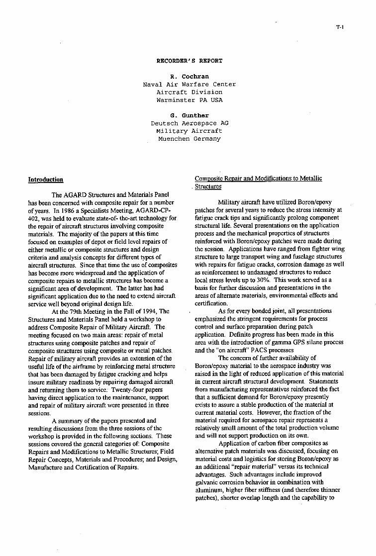
The AGARD Structures and Materials Panel has been concerned with composite repair for a number of years. In 1986 a Specialists Meeting, AGARD-CP- 402, was held to evaluate state-of- the-art technology for the repair of aircraft structures involving composite materials. The majority of the papers at this time focused on examples of depot or field level repairs of either metallic or composite structures and design criteria and analysis concepts for different types of aircraft structures. Since that time the use of composites has become more widespread and the application of composite repairs to metallic structures has become a sigruficant area of development. The latter has had significant application due to the need to extend aircraft service well beyond original design life.
Structures and Materials Panel held a workshop to address Composite Repair of Military Aircraft. The meeting focused on two main areas: repair of metal structures using composite patches and repair of composite structures using composite or metal patches. Repair of military aircraft provides an extension of the useful life of the airframe by reinforcing metal structure that has been damaged by fatigue cracking and helps insure military readiness by repairing damaged aircraft and returning them to service. Twenty-four papers having direct application to the maintenance, support and repair of military aircraft were presented in three sessions.
resulting discussions from the three sessions of the workshop is provided in the following sections. These sessions covered the general categories of Composite Repairs and Modifications to Metallic Structures; Field Repair Concepts, Materials and Procedures; and Design, Manufacture and Certification of Repairs.
At the 79th Meeting in the Fall of 1994, The
A summary of the papers presented and
Comuosite Repair and Modifications to Metallic Structures
Military aircraft have utilized Borodepoxy patches for several years to reduce the stress intensity at fatigue crack tips and sigruficantly prolong component structural life. Several presentations on the application process and the mechanical properties of structures reinforced with Borodepoxy patches were made during the session. Applications have ranged from fighter wing structure to large transport wing and fuselage structures with repairs for fatigue cracks, corrosion damage as well as reinforcement to undamaged structures to reduce local stress levels up to 30%. This work served as a basis for further discussion and presentations in the areas of alternate materials, environmental effects and certification.
emphasized the stringent requirements for process control and surface preparation during patch application. Definite progress has been made in this area with the introduction of gamma GPS silane process and the “on aircraft” PACS processes
The concern of further availability of Borodepoxy material to the aerospace industry was raised in the light of reduced application of this material in current aircraft structural development. Statements from manufacturing representatives reinforced the fact that a suflicient demand for Borodepoxy presently exists to assure a stable production of the material at current material costs. However, the fraction of the material required for aerospace repair represents a relatively small amount of the total production volume and will not support production on its own.
alternative patch materials was discussed, focusing on material costs and logistics for storing Borodepoxy as an additional “repair material” versus its technical advantages. Such advantages include improved galvanic corrosion behavior in combination with aluminum, higher fiber stiffness (and therefore thinner patches), shorter overlap length and the capability to
As for every bonded joint, all presentations
Application of carbon fiber composites as

T-2
monitor the crack in the substructure through the repair patch: Additional comments pointed out the advantages of the hgher fiber thickness that would ensure alignment during “in situ” patch curing and enhance repair effectiveness. In either case, the requirement for considering effects such as load path or neutral axis changes which result from applying external patch repairs where clearly shown by the CF116 upper wing skin repair example. Some concern was given to the long-term behavior of corrosion-preventing insulating layers between a carbon fiber composites and aluminum. Use of glass/epoxy layers is the most popular method of corrosion inhibition; however, possible edge damage to the glass/epoxy layer, allowing moisturelo penetrate into the interface between patch and substructure, was also raised as a concern.
subject of another presentation and discussion. Different environmental scenarios for military aircraft and civil transport aircraft were explored, with the latter showing damage as widespread fatigue on thin metal sheet structures and their hghest loads at low temperatures. Thus, temperature induced stresses cannot be neglected. The important point was made that while there is no singular “best” material, a careful selection of design criteria will lead to the most appropriate material for each patch. Other papers also indicated the effect of residual thermal stresses for bonded composite doubles. Both Borodepoxy and carbodepoxy laminates have substantially lower thermal expansion coefficients than the metal substructures and that this effect can not be neglected, especially with thicker patches and higher curing temperatures.
Discussions concerning thermal cycling for repaired metallic structure focused on the fact that stress levels in the substructure may initiate propagation of critical length cracks, even at relatively low mechanical load levels. The paper presented indicated that damage to the bondline will occur at the crack edge. Loading was considered severe but not unrealistic when compared to current usage scenarios of fighter aircraft. When time-wise links between maximum temperatures and maximum loads were discussed, it was pointed out that some simplification must be applied by “blocking” loadthermal parameters to control the test effort. Finally, agreement was achieved on the evidence of an effect of thermal cycling in the presence of high mechanical loads. Although no design criteria can be derived yet from the tests, this effect should be considered when primary aircraft structure which has been exposed to a severe thermal loading environment is repaired.
show a definite trend towards Finite Element (FEM)”globaVlocal” analysis, where the vicinity of the repair area is cut from the global model and a refined FEM is used to evaluate the repair details. Since this method is lacking the former “semiempirical” approach
Environmental effects on repairs was the
In general, the analysis methods presented
using closed form analywal methods, full understanding of the mechanical behavior of all repair components, especially the adhesive becomes an even greater demand.
Field Repair Conceuts. Materials and Procedures
The work presented in this session covered a wide range of efforts related to repair. In general, methods to repair carbon epoxy monolithic structure are well defined, and methods to design, install, inspect and certify these repairs are well accepted by the aircraft maintenance community.
Recent work has focused on development of repair materials, processes and equipment for specialized repairs such as those performed on aircraft, in a battle field environment, for honeycomb structures, for high temperature composites such as bismaleimides and for thermoplastic composites. The materials being developed are based on previously demonstrated formulations with enhancements for specific applications such as low temperature cure to minimize damage to wet honeycomb structure or metallic substructures. Other process requirements such as reduced curing pressures and ambient storage of materials are areas of current research programs. Quality assurance methods for real aircraft application and demand for simplified repair methods has resulted in a number of developments in this area. A presentation was made on a new viscous repair adhesive and a pressurized and heated resin injection device for repair of single or multiple delaminations in composite skins. The procedures for repair of bismaleimide and thermoplastic structures are similar to those used for epoxy composites. External and scarf patches to effect repairs are shaped to the structure and bonded using adhesives.
The effectiveness of flush scarf repairs to highly loaded monolithic and honeycomb structures was discussed. The consensus was that the current technology of scarf repairs will restore ultimate design strength to present structures; however, limitations exist with respect to part thickness and complexity level. Depot level repair concepts have been developed to bond precured patches to curved monolithic and honeycomb structures. The use of precured patches allow for the use of the same structural materials used in original manufacturing, this avoids the limitations mentioned previously for patch processing and the need for additional material data. Improvements in design, process control, material and process robustness may be required to improve either load capability or the ease of application of flush scarf repairs.
A promising new concept for rapid tooling for repair fabrication during battle damage repair of complex shaped structures was presented. The method uses a vacuum formed tool instead of chemical cured materials for copying the damaged surface. This

T-3
method will sigmticantly reduce the amount of tooling material and the complexity of performing battle damage repairs.
Desim. Manufacture and Certification of Reuairs
Certification was discussed in the context of damage tolerant requirements for bonded repairs and the demand for standardization and reliability of material properties for adhesives. Aircraft manufacturing and certification authority representatives discussed the extreme conservation of composite aircraft design. The consensus was that the adhesive bondline must never be the critical element in the repair link and that repairs must be tolerant by design to the presence of cohesive flaws. Initiatives to produce more reliable - and therefore more realistic - standards for adhesive testing were also proposed and discussed.
From a manufacturing point of view, concern was expressed that repair procedures and their application should be reviewed by the original manufacturer. It would be particularly risky if repairs were applied in structural areas with small margins of safety in the repair vicinity (load redistribution) or, as in the case of multiple repairs, each applied were to affect the one next to it.
The development of engineering standards for composite repairs was an area of interest to all attendees. Repair certification methods have many facets, including surface preparation, material selection, design properties, design methodology and material processing. However, there are as yet neither accepted standards to certlfy repairs nor authorized personnel to insure that the repair will provide specific life or strength. These are issues which need to be addressed in future presentations and meetings.
In summary, the papers presented at the workshop provided an important interchange of ideas, current developments and needs for the aircraft manufacturinglmaintenance community. The importance of composite materials for the repair of military aircraft was emphasized by all, particularly those individuals faced with requirements to maintain fleets of aging aircraft and to provide rapid, effective repairs maximizing use of available aircraft. The specific case of composite repairs to metallic structure has been very successful and will continue to grow. Methods to certlfy repairs for both composite and metallic structures are critically needed by all AGARD participants, as is the continuing development of specialized repairs for new types of composites and specific repair situations.

.

1-1
Bonded Composite Repair of Metallic Aircraft Components - Overview of Australian Activities
Dr. A.A. Baker Defence Science & Tech. Organization, Aeronautical & Maritime Res. Lab.
506 Lorimer Street, Fischermen’s Bend, Box 433 1 Melbourne, VA 3001, Australia
Summary After first providing an overview of the status of Australian applications of bonded composite repairs to metallic aircraft structure (mainly based on boron/epoxy composites) the problems in certifying composite repairs to critical cracks in primary metallic structure are discussed.
The development of acceptable generic certification procedures is essential if the use of this efficient cost-effective repair technology is to be widely employed in military and civil aircraft.
One requirement for certification is the ability to predict the fatigue-crack growth behaviour in patched components. An approach to developing this capability is described, based on Rose’s model to estimate stress intensity in patched panels. The model is extended to allow for disbonding damage in the patch system. Experimental results are presented to demonstrate the validity of this approach for borodepoxy-FM73 repairs to aluminium alloy 2024T3.
1. Background and Scope The repair of cracked (or otherwise defective) metallic aircraft components with adhesively-bonded composite reinforcements is becoming a well-established technology’. Bonded repairs are mechanically efficient, cost-effective, benign to the structure (no fastener holes) and can be applied rapidly (depending on complexity of the damaged region) to produce an inspectable damage-tolerant repair. Corrosion or fretting under the repair is not a problem because the interface is sealed by the adhesive.
Compared to metals, advanced fibre composites have the advantages of formability, tailorability of stiffness, high specific strength and stiffness, and immunity to corrosion or fatigue. Composites patches or reinforcements can be precured and secondarily bonded (first pre-formed and then bonded) or cocured (cured with the repair adhesive).
The development of adverse residual stress’ is the most significant disadvantage of using composite reinforcements for repairs. Residual stresses arise from differences in the coefficients of thermal expansion of the composite reinforcement and the metallic component.
Composite reinforcement3 can be used for a wide range of repairs to metallic aircraft components as follows:
Stiffen Underdesigned Regions - reduce deflection - reduce flutter - increase static strength - reduce fatigue strain
* Formally the Aeronautical Research Laboratory (ARL)
Restore StrengWStiffness - after corrosion removal - after flaw removal
Reduce Stress Intensity - in regions with fatigue cracks - in regions with stress-corrosion cracks - increase damage tolerance in safe-life components
Bonded composite repairs developed by Aeronautical and Maritime Research Laboratory (AMRL) of the Defence Science and Technology Organisation have been used extensively on Royal Australian Air Force aircraft in Australia for over twenty years. The main application is for the repair of cracking due to fatigue or stress corrosion - called Crack Patching; however, repairs for most of the other applications listed have also been developed.
Up to 1989 savings in Australia using this repair technology4 were estimated to have exceeded $AlOOM - several more- demanding applications have been developed since then.
The key to success with bonded composite repairs is the availability of:
Processes for reliable in situ implementation of highly durable repairs having the required mechanical properties.
Procedures to design optimised repairs.
The aim is to provide an adequate and sustainable reduction in stress (or stress intensity when repairing cracks) and minimum stress concentrations in regions adjacent to the ends of the repair.
Most Australian repairs to date have used borodepoxy as the reinforcement rather than graphite/epoxy by virtue of the following properties:
Better combination of strength and stiffness.
Non-conducting: avoids galvanic corrosion problem and allows simple eddy-current NDI
Higher coefficient of thermal expansion, minimising residual-stress problems.
Better fibre alignment under cocure conditions, as a result of much larger fibre diameter - 125pm compared with 8pn for graphite fibres.
However, boron/epoxy is less formable because of the large fibre diameter, is more costly and is less readily available. Thus graphite/epoxy is used whenever possible.
Paper presented at the 79th Meeting of the AGARD Structures and Materials Panel on “Composite Repair of Military Aircrafr Structures” held in Seville, Spain 3-5 October 1994.

1-2
The main adhesive used in these repairs is the epoxy-nitrile structural film adhesive FM 73, by Cytec. Reasons for this choice include the following:
0
0
0
0
The
Excellent strength and toughness from low to moderate temperatures (-50°C to about 80°C).
Resistance to aircraft fluids.
Ability to form strong durable bonds using pre-bond treatments based on silane coupling agent y-GPS*.
Ability to cure (with some sacrifice in properties) at relatively low temperatures' - as IOW as sooc (for long times) compared with the standard cure of 120".
first three advantages are typical of most moderate- temperature-curing structural epoxy-film adhesives. However, the low-temperature-cure capability of FM73 is both unusual and valuable in repairs where the higher temperatures cannot be achieved or where there is a need to reduce residual stresses. For higher-temperature applications the adhesive FM300-2, also by Cytec, is used. This adhesive also has a capacity to cure at a relatively low temperature (120°C) and provide properties typical of a 175°C curing adhesive - FM300, for example.
2. Research and Development Programs While the concept of composite reinforcement is simple, considerable research and development was needed to ensure its success in critical applications. The resulting capabilities at AMRL include:
Materials Engineering - assessment and modelling of patching efficiency - assessment of allowables for repair materials - minimum surface treatments for repair bonding - adhesive characterisation - generic repair application technology - assessment of off-optimum curing conditions for adhesives
and composites
Repair Analysis and Evaluation - analytical design approaches - finite-element design approaches, mainly for complex
- experimental strain analysis - structural testing
applications
Application Development - specific repairs - demonstrator repairs Table A1 (Appendix) lists selected published work on these topics. Of these capabilities only the topic of minimum surface treatment for repair bonding is mentioned here. The analytical design approach is basic to the work on 'fatigue patching efficiency described later.
2.1 Minimum Surface Treatment for Repair Bonding Durability of the adhesive bond is the most critical aspect of the repair technology since this determines the effectiveness of the reinforcement over the lifetime of the repair. Durability is largely determined by the pre-bonding surface treatment applied to the metal. Only very simple and safe treatments which can be applied under field conditions may be considered. The surface treatment must:
Be simple to apply in situ, that is it must:
a) involve no noxious chemicals since these may be used in a confined space
b) function at ambient temperature
c) encourage neither corrosion nor stress-corrosion cracking
d) involve no danger of electrical sparking, particularly if used in a fuel tank
e) be non-specific and therefore able to treat several types of adherend at once
Work at AMRL has centred largely on the use of silane coupling agents and primers applied to metal surfaces which have been mechanically treated by alumina grit blasting. The coupling agent we have found most suitable for epoxies is the epoxy- terminated silane y-GPS'.
This coupling agent provides durable bonds to aluminium alloys or to low-alloy steel with epoxy nitrile adhesives. It should also be effective with titanium alloys. The durability provided by the silane can be greatly enhanced by use of a primer. Figure 1 shows typical results for aluminium 2024T3, bonded with adhesive FM73.
401 W'C +loo% RH
- ?
grit-blest + y - GPS + Primer
25 1 I 1 1 1 1 1 1 1 I I 1 1 1 1 1 1 1 I 1 1 1 1 1 1 1 1 I 1 1 1 1
1 10 100 1000 Time Hours
Figure 1. Plots of crack growth versus time for Boeing-wedge- test specimens (illustrated inset) made of 2024T3 aluminium and subjected to the surface treatments indicated, prior to bonding with adhesive FM73. *
For the pre-cured (thermosetting) composite, surface removal by grit blasting is a highly effective treatment which provides excellent bond strength and durability. The standard peel-ply surface-treatment procedure is inadequate unless followed by grit-blasting or some other effective mechanical method of surface removal.
3. Applications of Bonded Composite Repairs Some of the Australian applications and demonstrator programs are listed in Tables 1 and 2. More details are provided in Table A2 of the Appendix. While many of these repairs are to primary structure, in most cases the repairs are not considered critical, so certification was not a major issue. The problems in certifying critical bonded repairs to primary structure are discussed later.
Produce a bond highly durable in the repair environment

1-3
C130 Wings Macchi Landing Wheels Mirage I11 Wings Mirage 111 Vertical Tail F11 I-C Wing Pivot Fitting F111- C Fuselage P3C Horizontal Tail Boeing 767 Keel Beam C141 Wings
Table 1: Bonded repair applications to military and civil aircraft
Emphasis at AMRL is now being placed on major repairs/reinforcements, for military aircraft such as the F111, and to broadening the range of applications to civil aircraft by demonstrator programs.
Further details are provided in the following section on selected applications and demonstrator programs.
QANTAS 747 - wing, tail and fuselage Boeing 747 - fatigue-test fuselage QANTAS 747 - fuselage lapheam joint Bell 206L - helicopter blade (Papua New Guinea) F/A- 18 - wing attachment bulkhead fatigue test Airbus A340 - fatigue-test fuselage lapheam joint
Table 2: Bonded composite repairs demonstrator programs, mainly to civil aircraf.
3.1 F l l l Wing-Pivot Fitting Reinforcement Fatigue cracks can initiate in the upper-skin of the FI 11 Wing Pivot Fitting (WPF) stiffener runout region shown in Figure 2. Initiation of cracks in this highly-stressed D6ac steel component can be traced back to the Cold Proof Load Test (CPLT) which the aircraft periodically undergoes to screen for small cracks. Borodepoxy doublers (shown schematically in Figure 3) were designed to provide local reinforcement of the critical region of the stiffener runout during the CPL76.
A strain reduction of over 30 per cent is required to avoid plastic yielding in this region'; plastic yielding results in
' tensile residual stress, leading to crack-initiation. The required strain reduction is particularly challenging due to the thick steel structure and high loading.
- stress-corrosion cracks in riser - fatigue cracking - fatigue cracks in skin - fatigue cracks in skin - fatigue problem in steel - stress-corrosion cracking in truss - corrosion pitting in skin - corrosion pitting in flange - fatigue cracks in stiffener
I I
Figure 2: Schematic of F I J I , showing location of critical area.
Residual stress resulting from thermal-expansion mismatch between the composite and metal is a particularly serious problem for the F111 reinforcement because of the thicknesses of the structure and the reinforcement. Three different methods
are used to minimise the development of residual stress'. Firstly, only the area to be repaired is heated so that the surrounding cold structure provides restraint against expansion. Secondly, the wing is compressively loaded during the heating cycle to counteract the thermal expansion and, thirdly, the adhesive is cured at the lowest temperature possible. Studies on the adhesive cure reaction for FM73 confirmed that this adhesive, although nominally a 120°C curing system, could be satisfactorily cured at temperatures as low as 80°C. However, in this application the adhesive is finally cured at the recommended temperature.
The pre-bonding surface treatment was a major issue, particularly since the surface treatment had to be applied in situ to the wing pivot fitting. The materials involved are: a) aluminium alloy 2024T851 b) D6AC steel and c) corrosion- resistant steel fasteners which pass through the wing skin and steel. Fortunately, all of these materials could be satisfactorily treated using a process' based on yGPS silane as the coupling agent.
Full-scale wing tests at ARL confirmed the design predictions that the doubler could survive the high loads and low temperatures (over -7g at -40°C) applied during the CPLT and produce the desired 30% strain reduction. These reinforcing doublers have successfully passed the CPLT at the USAF facility in Sacremento. Strain-gauge measurements taken from one of these aircraft confirmed that the desired strain reduction is achieved. Use of the doubler is estimated to increase the inspection interval for the stiffener run-out region from approximately 250 hours to approximately 4000 hours.
Application to the Australian FI 11 fleet is well advanced with about 18 aircraft being reinforced.
Figure 3: Configuration of borodepoxy doubler and its location of the on the FIll wing pivotfitting.
3.2 F l l l Wing Skin Recently a fatigue crack about 40 mm long was discovered in the aluminium alloy 2024T851 skin (3.5 mm thick) of the F111 wing-torque box. The crack appears to have initiated at a stress concentration resulting from a discontinuity in a stiffener in the lower wing skin. The discontinuity is a design feature incorporated to provide full fuel flow in the wing.
This repair differs from most others undertaken in that the crack is in primary structure and has the potential to reduce strength below the design ultimate strength. A borodepoxy repair for this region has been designed, in association. with RAAF

1-4
engineers, taking into account the full certification requirementsg
The borodepoxy repair was recently applied to the skin and is being closely monitored while the certification program is undertaken. This program involves a) finite element analysis, b) strain measurements on a test wing before and after patch application, and c) evaluation of the damage tolerance and strength of a structural-detail specimen. The requirement is for full restoration of ultimate strength and no further crack growth.
Until this program is complete the aircraft is restricted to a reduced flight envelope.
3.3 Lockheed C-141 Starlifter Wing-Skin Repair. Fuel weep holes in the wing skins of USAF C-141 aircraft have experienced fatigue cracking. Some of these cracks can be removed by reaming the holes, but many cracks are too large for this treatment. A borodepoxy repair has been designed for this problem and application techniques have been devised to enable the application of these repairs inside the fuel tanks. These repairs have been applied by a team from Composite Technology Incorporated and DynCorp and a separate team from Warner Robbins Air Logistics Centre. The cracked weep holes were scattered throughout the wing structure and were occasionally very close to other fittings - pumps, ribs, wing splices etc. The design and application of these repairs had to be flexible to suit the range of repair locations. Each crack was repaired with either three or five borodepoxy patches and, to date, more than 120 aircraft have been repaired with 466 individual patches.
3.4 Boeing 767 Keel Beam Repair Severe corrosion pitting was detected in the aluminium keel beam of an Ansett Airlines Boeing 767 aircraft. Removal of the damage reduced the thickness of the keel beam from 6.5 to 2.5 mm in several regions. In consultation with Ansett, a borodepoxy reinforcement was applied to restore the effective stiffness of the beam.
The repair was applied in less than one day with a 120°C-curing epoxy, compared with an estimate of more than 20 days to replace the keel beam. This repair has gained a Supplemental Type Certificate (STC) from the Australian Civil Aviation Authority and an Engineering Approval from the American Federal Aviation Administration. The durability of the repair is demonstrated by the operating life to date of over 5 years. A demonstrator reinforcement (applied to the keel beam with a room-temperature-curing acrylic adhesive to evaluate the durability of this type of adhesive) has also survived for this period without sign of degradation.
3.5 MD-82 Slat The leading edge slat of an MD-82 operated by Compass Airlines suffered from fatigue cracks initiating from fasteners on the rear face. A conventional repair would have involved the removal of the slat from the aircraft, fitment of a replacement slat, fabrication and installation of a finger-jointed doubler, and then re-fitment to the aircraft. A borodepoxy doubler was installed during a routine overnight service at significantly lower cost. Material selection was complicated by the higher than normal temperatures in this component, about 9O"C, arising from bleed air for de-icing purposes. Thus FM 300-2 by Cytec was used for this repair.
3.6 Demonstrator Repairs In conjunction with Australian Airlines (now part of QANTAS), the Australian Civil Aviation Authority and the US Department of Transportation, a demonstration reinforcement to a region of a lap-seam joint was applied to an Australian Boeing 727 aircraft and is being monitored to assess bond durability. To date, this reinforcement has experienced over 7000 flight hours without evidence of degradation. Fatigue tests on simulated lap joints at ARL have demonstrated that dramatic increases in life are obtained by the reinforcement procedure, even under severe environmental conditions.
In association with QANTAS Airways and Boeing Commercial Aircraft Company, simulated repairs were applied to a QANTAS B747-300 aircraft. The purpose was to demonstrate the ease and reduced time of application of the repairs and, subsequently, the durability of the repairs. It was clearly demonstrated that bonded repairs are much faster to apply than an equivalent metal repair. Time savings of a factor of five were observed, in agreement with previous experience on military aircraft. Repairs were applied to a number of regions subjected to harsh environmental conditions (Figure 4), including: (a) lower- fuselage skin, (b) trailing-edge flap, (c) engine-pylon fairing, (d) thrust-reverser cowling, and (e) leading-edge nose skin. Some of the repairs were applied using a room-temperature-curing acrylic adhesive rather than the structural-film epoxy that is normally used for such repairs. All these repairs have now experienced over 12,600 flight hours and 2660 landinghake-off (pressurisation) cycles with no evidence of failure or any other problems.
Actual repairs to damaged structure were applied in association with the Boeing Commercial Aircraft Company to the 747-400 and 747-SR fuselage test articles in Seattle. Fatigue cracks in the fuselage skin and various stiffeners and frames were repaired using borodepoxy patches and a structural film adhesive. Some of these repairs were subjected to 20,000 load (pressurisation) cycles without evidence of crack propagation.
More recently, bonded repairs were applied to an Airbus A340 fatigue-test article in Germany. These repairs were applied to artificial saw cuts in the lap-seam region. To date these repairs have survived 24,000 pressurisation cycles (out of a total of 67,000 planned for the program) with no evidence of crack growth.
Figure 4 Positions of demonstrator repairs on a QANTA! Boeing 747 - 300.
4. Certification Issues Application of critical repairs to primary structure is limited by the difficult problem of certification. A critical repair is defined
1-5
here as one in which the static strength of the (unrepaired) component would be reduced below design ultimate if the crack were to grow in service. Certification requirements are much more demanding if the (unrepaired) crack has reduced the strength of the component below ultimate or, even worse, below limit load.
4.1 Certification Requirements Essentially, certification requires demonstration that the repaired structure is as flightworthy as the original structure; possibly allowing for life already consumed. According to the latest regulations, FAR 25.571 (for civil aircraft), this demonstration must include damage-tolerant behaviour of the repaired structure. The certification requirements for bonded composite repairs have been discussed by Torkington." for civil applications and are discussed in reference 9 for the F111 wing- skin crack, described in section 3.2.
The Author's views are that certification of a repair to primary structure requires demonstration by analysis and/or test that the repaired structure can meet the following specific requirements:
.
Residual Strength
Provide a residual strength of 1.5 x limit load under the temperature and environmental conditions in which the aircraft is operated
Retain this level of residual strength through the remaining life of the airframe or for an suitable period - ideally coinciding with an acceptable multiple of the normal inpection interval
Damage Tolerance
Crack growth under the patch must be predictable, very slow, and readily detectable by standard NDI procedures
Even if the crack emerges from under the patch (due, for example, to faulty inspection), growth must be slow enough to be detected during the next scheduled inspection. In this period the structure should retain residual strength above limit load
Non-visible impact or other mechanical damage to the patch system should not result in residual strength of the repaired region falling below 1.5 x limit load
Durability
No local disbonding or other degradation of the patch that would require frequent patch replacement
There could also be other requirements related to deflection or flutter, but these would be fairly unusual.
While it is possible to demonstrate that these requirements are met by testing structural details or components with representative repairs (and, indeed, this approach will probably be needed for most critical repairs) the challenge is to accomplish it on a generic basis for a wide range of repairs. If this is not possible many technologically feasible repairs to primary structure will simply not be feasible because of development costs. The Flll wing skin crack previously referred to is a good example of a situation where a more generic approach may have been possible.
With mechanically-fastened repairs the cracked region is generally cut out prior to application of the repair. The resulting hole is filled with an insert and covered with a mechanically- attached reinforcing patch. A similar approach can be taken
using a bonded patch. However, removal of the crack can be a high-cost option and often is impractical.
The concern with mechanical repairs is generally the danger of initiation of a crack from one of the new fastener holes (usually in the first row where stresses are highest) and the difficulty in detecting it by standard NDI procedures until it emerges from under the repair. The crack may initiate because of high stress concentrations (usually at the first row of fasteners) or because of poor quality hole drilling - not an uncommon problem under field conditions. There is also the danger of cracks initiating from hidden corrosion which can develop under a poorly sealed mechanical repair - there are many examples of this.
The new crack may then be expected to exhibit very rapid growth, since mechanical repairs have relatively poor reinforcing efficiency. Thus these repairs are inherently not damage tolerant, especially when applied to old-generation aircraft made of alloys with poor crack-growth resistance.
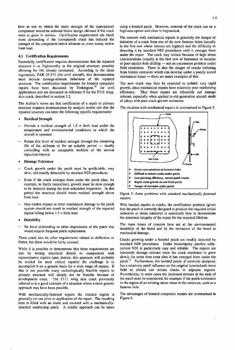
The situation with mechanical repairs is summarised in Figure 5.
+ + + + + + + + +
+ + + + i t + + + + + +
+ +.tsl;lt...*)
/ New Crack
Stress concentrations at fastener holes Difficult to detect cracks under patch Low patching efficiency, cannot patch cracks Rapid crack growth on exit fmm patch Danger of corrosion under patch
Figure 5: Some problems with standard mechanically fastened repairs.
With bonded repairs to cracks, the certification problem (given that the patch is correctly designed to produce the required initial reduction in stress intensity) is essentially how to demonstrate the structural integrity of the repair for the required lifetime.
The main issues of concern here are a) the environmental durability of the bond and b) the resistance of the bond to mechanical damage.
Cracks growing under a bonded patch are readily detected by standard NDI procedures. Under borodepoxy patches eddy- current NDI is particularly easy and reliable. The repairs are inherently damage tolerant since the crack continues to grow slowly for some time even after it has emerged from under the patch.'' Furthermore, the bonded patch, if correctly designed, has a relatively small influence on the original (uncracked) stress field so should not initiate cracks in adjacent regions. Nevertheless, in some cases the increased stresses at the ends of the patch must be considered, for example if the patch terminates in the region of an existing stress raiser in the structure, such as a fastener hole.
The advantages of bonded composite repairs are summarised in Figure 6.

1-6
B
b Minimises stress concentrations b
b
b
b
No damage to structure or hidden components
Slow crack growth even on excit from patch High patching emciency, can repair cracks Can detect crack growth under patch No corrosion Droblerns. sealed interface
Figure 6: Some of the advantages of bonded composite repairs.
4.1.1 An Approach to Generic Certification of Repairs A proposed approach is:
0
Undertake coupon and representative joint tests to obtain materials design data on patch and adhesive materials made under ideal conditions and tested over a range of temperaturdmoisture conditions. Data required for the adhesive includes shear stress/strain behaviour under static loading and damage growth rates under cyclic loading and for the composite strain allowables under static or cyclic loading.
Find knockdown factors from coupons and joints made under representative repair conditions allowing, mainly, for realistic levels of voids in the adhesive and (if cocured) in the composite material. However, use of knockdown factors for reduced bond strength or durability are unacceptable as there is no way of using these factors in repair design; it is essential to ensure by good quality control that high durability bonds are developed during the repair.
Validate Design Capability
Undertake detailed analysis of the repaired region for a range of generic repair situations, accounting for such factors as residual stresses, local stress concentrations at the ends of the patch, and load attracted to the repair region.
Test representative crackedpatched panels under representative temperature and moisture conditions at to measure a) initial residual strength, b) crack growth behaviour under constant- amplitude and/or spectrum loading (such as FALSTAFF) and c) residual strength at the conclusion of the fatigue test.
The analysis must predict the measured static and fatigue strength properties and must account for observed failure modes.
A major problem in many repair situations is the lack of knowledge concerning the actual stressing of the damaged region. In the absence of such knowledge, a conservative approach is to assume that the stress in the component at ultimate design load is the yield stress of the material in the component. The grounds for making this assumption are that at this load level the stress at stress concentrations in the component (for example filled fastener holes) at limit load would greatly exceed the tensile yield stress.
Obtain Design Allowables for Repair System
The result of being over-conservative (for example assuming limit load coincides with material yield) is that very thick repairs would be designed resulting, in the case of composite patches, in large residual stresses.
Insurance of Bond Quality
It must be clearly demonstrated that highly durable bonds can reliably be made under the repair conditions. Performance of candidate surface treatment procedures must be initially demonstrated by laboratory testing, using standard durability tests, such as the various wedge tests, and then by long-term flight experience with either simulated or non-critical repairs. Australian experience in these aspects is extensive and positive, as shown in Table A2.
The critical issue of developing reliable application procedures for bonded repairs has been thoroughly addressed by RAAF. Their approach includes:
Documenting of all repair processes and test procedures’’
Training technicians in these processes and procedures
5. Studies on Repair Efficiency in Patched Panels As part of the AMRL effort to certify bonded repairs’ work has continued on the evaluation and modelling of patching efficiency and on assessing the residual strength of patched panels. Some recent work on these topics is described here.
Although the desired patching outcome is to reduce the stress intensity range below the threshold level for fatigue crack growth, this may not be feasible at the higher stresses in the load spectrum. Thus the main aim of these studies was to develop a capability for predicting crack growth behaviour in patched cracks.
Provided, however, that the patch remains well bonded and the crack is well covered by rhe patch, the residual strength in a patched component should not be reduced by increasing crack length. Thus a knowledge of the rate of crack growth essentially provides an indication length of service for which the patch remains effective.
Ideally the analysis for predicting crack growth behaviour must allow for:
Damage (disbond) growth in the patch system.
Residual stresses resulting from thermal expansion mismatch between the composite patch and the underlying metal
The influence of temperature on patching efficiency, particularly if the adhesive system is able to absorb moisture.
Load sequence effects resulting, in part, from different damage rates in the repair system at different stress levels.
In early work’ an understanding was gained of some of the important features controlling fatigue-crack propagation behaviour.
For example, residual stress due to thermal expansion mismatch between the patch and component, while having some adverse affect on patching efficiency, did not appear to be a major problem.

1-7
It was also found that patching can result in significant retardation of crack growth in situations where the reduction in stress intensity is insufficient to prevent eventual slow further growth. This behaviour is associated with the plasticity at the crack tip prior to patching and the resulting reduction in stress intensity*. The use of elevated temperatures to bond the patch system was found to reduce these beneficial residual compressive stresses (probably by annealing out these stresses) and thus to encourage a much earlier onset of crack growth. Since the degree of retardation also depends on the level of stress experienced by the crack immediately prior to the repair a necessary but conservative assumption for analysis is no retardation, even though the actual retardation can be substantial, particularly with patch systems curing at low temperature. For example, very extensive retardation was found for patches bonded with modified acrylic adhesives, e.g. Flexon 241, curing at ambient temperature.
The experimental method used to estimate AKR (the effective stress intensity range following patching) was as follows:
a) Establish the relationship between dddN and AKa, where a is crack length, N the number of cycles and AKa the estimated stress intensity range for the (unpatched) cracked component.
b) Find (dddN), from a versus N plots for the patched panels.
c) Compare (dddN), with dddN to provide an estimate of AKR from a).
Generally, it was found that the approach used for predicting stress-intensity range in the patched cracks gave reasonable agreement with AKR.
In the study discussed here a different approach is taken; this is to attempt to predict the observed crack growth behaviour rather than AKR. However, the two approaches are essentially equivalent.
5.1 A Simple Model for Estimating Patching Efficiency and Crack Growth Behaviour In model developed by Rose13 (and adapted by Bake?*14) to estimate stress intensity in the patched crack a two-step approach, as illustrated in Figure 7, is used.
1 I
K, = [;E,,@U-.&]~
Step 1 Inclusion effect Step 2 Crack Reinforcement I Figure 7: Schematic illustration of the analytical approach to crack patching. The parallel lines represent a disbond, width 26, as discussed in section 5.2.
In the step 1, Figure 7, the patch is modelled as an inclusion in a large plate; the crack is assumed to be small compared to the patch. The stress remote from the crack and the ends of the patch is then given by $a,, where a- is the applied stress and Q a factor which accounts for the stiffness and shape of the patch. Because the patch attracts load the stress reduction is usually significantly less than predicted simply on the basis of ratio of patch stiffness to plate stiffness.
In the step 2, Figure 7, the region under the patch is modelled; the crack is considered to be semi-infinite in length. The stress intensity K , is then as given by the equation in Figure 7, where Ep is the panel stiffness and 6 the crack opening displacement. As 6 is estimated from a overlap joint that would be obtained by cutting a strip through the panel normal to the crack (Figure 7). 6 and therefore K , are upper-bound estimates.
Under the cyclic stress range Aa, the stress-intensity range AK, is given by:
Note that the crack length a does not feature in equation 1.
The displacement 6 is dependent on the thicknesses and stiffnesses of the patch and of the cracked component and on the thickness, shear modulus and effective shear yield stress of the adhesive. It is important to note that the adhesive properties are highly temperature and strain-rate dependent. They are also dependent on the residual stress level since this affects the level of external stress at which the adhesive will yield.
Equation 1 is strictly correct only for linear behaviour (no yielding of the adhesive) but provides a good estimate of A& provided shear yielding in the adhesive is limited, say, to less than 0.2.
It is important to note that this model is based on a one- dimensional analysis so does not account for peeling or other through-thickness stresses in the adhesive or patch. Within these limitations it will be shown that the model can provide useful results in predicting crack-propagation behaviour.
The crack growth behaviour can be predicted from the expression:
da/dN = A(AKw )” (2)
It is assumed that equation (2) is applicable to patched cracks. Thus if All, is constant then dddN should also be constant
In a more sophisticated analysis the influence of mean stress due to the residual stress could be incorporated using, for example, Forman’s equation15.
Finally, the relationship between crack length a and the number of cycles N can be obtained from:
N
0 a = A I (AK, )” dN (3)
An Excel spreadsheet was used to estimate dddN, and thus a versus N, based on the patching parameters and the experimentally estimated effective values for A and n, as indicated in the next section.

1-8
5.2 Extension of the Model for Growth of Disbond Damage in the Patch System The above analysis was developed in reference 14 to allow for the reduction in patching efficiency with disbond growth in the patch system. It is assumed in this analysis that a parallel disbond, size 2b, traverses the specimen, as illustrated in Figure 7.
Then the opening of the gap is increased by 2be, where e is the estimated strain in the reinforcement.
Then equation 1 becomes:
(4)
If it is assumed as a first approximation (based on previous fatigue tests on double-overlap joints2) that db/dN is a constant, then:
b = N ( g )
Thus the effect of disbond growth on crack growth behaviour can be estimated using equation 4. If the disbond size is constant, b simply remains constant in equations 3 and 4.
5.3 Crack Growth at Ambient Temperature
5.3.1 Experimental Details Fatigue crack propagation tests were conducted on 2024 T3 specimen 3.14 mm thick having starting cracks about 5mm long repaired with unidirectional borodepoxy patches 7 plies (0.9 mm) thick. The patches were bonded with adhesive FM 73 at 120"C, following surface treatment using the silane process2. For comparison, similar tests were conducted on unpatched specimens.
In the fatigue tests, two similar panels are simultaneously tested, joined together as a honeycomb sandwich panel, Figure 8. Tests were conducted at ambient temperature and at several temperatures from -40°C to 80°C. Tests were carried at R=O.I and a peak stress of either 120 MPa or 138MPa; the cyclic fre ency was approximately 3 Hertz.
Figure 8: Illustration of the test configuration used to evaluate patching efficiency in patched panels. Note that hvo patched panels are tested simultaneously in this configuration.
There are two reasons for using this configuration. The first is to minimise curvature following patching due to the residual stress oT which, as mentioned earlier, arises from the mismatch in
thermal expansion coefficient between the patch material and the metal panel. Thus, the patches were bonded to the panels at the same time as the panels were bonded to the honeycomb core. The second reason is to minimise the bending of the panels which would otherwise occur during testing. The bending moments arise from the displacement of the neutral plane by the patch. The resistance to bending resulting from the honeycomb support is considered to be a reasonable simulation of the support that would be provided by typical military aircraft structure. In almost all tests, similar rates of crack growth were observed for the two panels in the combination.
After testing, the patches were heated to 190°C for 2 hours and stripped from the test specimen (at the elevated temperature). The disbond regions are discoloured by oxidation during the heating and are thus clearly visible after stripping the patches.
5.3.2 Artificial Disbond Specimen A series of specimen were made with artificial disbonds (using teflon inserts) of length 2b ranging from 10 mm to 60 mm. Tests were conducted at a peak stress of 138 MPa and R = 0.1. The crack-growth results, Figure 5, show that, as expected, patching efficiency falls dramatically with increasing disbond size.
In these tests only minor disbond damage was noted after stripping the patches. Thus, on the basis of equation 2, da/dN should be constant. This is in accord with the approximately linear curve of a versus N found for each disbond size, as shown in Figure 9.
60 40
50
Y E m 111
5 30 al - Y e 20 0
10
t
b (rnrn.)
0 /
b (mm.) experimental - 0
10 . 30 40 ,
E 60
A 20
0 50 100 150 200 250 300 Thousands of cycles N
Figure 9: Plot of crack length (a) versus cycles ( N ) for a patched specimen having artipcial disbonds of various lengths; solid lines are theoretical estimates.
The results of these tests were used to obtain estimates for the effective values of the crack-growth parameters A and n which provided the best fit between the theoretical and experimental results. Details of the method used will be presented elsewhere.I6 Essentially the approach is:
Estimate the theoretical value for the ratio RK at the various disbond sizes defined as:
for the various values of disbond length 2b.
Find an experimental effective value for n from

1-9
(7)
where the dddN values are determined from the crack growth rates for different disbond rates. Note that in this specimen series there was very little disbonding in the patch.
Finally, the effective value for A was obtained from:
Independent estimates for A and n were also made from crack propagation tests on unpatched panels, using equation 2. These confirmed that values for n of about 3 and for A of about SxlO-" were reasonable. However, n was found to vary from 3 at relatively low stress intensity levels (typical of patching conditions) up to 4 at higher levels.
It must be stated that the results from the model are very sensitive to the value assumed for n; for example, sensible results cannot be obtained with the model if a value of 4 is assumed for n.
However, the reasonable agreement obtained between the results for the patched and unpatched specimens for the crack-growth parameters n and A is very encouraging and indicates that the model provides a reasonable representation of actual behaviour, at least for fixed disbond sizes.
Using these values for A and n with equations 3 and 4 with the various constant values for b, the predicted behaviour is shown as the solid lines on Figure 9. This plot shows that quite good agreement is obtained between the experimental and predicted crack-growth behaviour. Thus use of the model for growing disbonds appeared warranted and this is described in the next section.
5.3.3 Standard Patched Specimen Figure 10 plots crack length a versus cycles N at a peak stress of 120 MPa and R = 0.1 for two sets of panels having adhesive thicknesses of approximately 0.15 and 0.3 mm. The observed disbond shape, is shown inset in the figure. At this stress level the disbond size (2b) is very small, being slightly greater for the panel with the thinner adhesive since adhesive stresses are higher. Note that crack growth is approximately linear, after an initiation period, again confirming that AKR is approximately constant.
Figure 11 plots crack length a versus cycles N at a peak stress of 138 MPa and R = 0.1 for several sets of panels with an adhesive thickness of approximately 0.15 mm. At this stress level disbond growth, shown inset, was significant in some (early) specimens. In these tests significant disbond growth occurred at the patcNadhesive interface.
Figures 9 and 10 also show, as solid lines, the predicted behaviour, based on the foregoing analysis using equations 3, 4 and 5. The estimates for the disbond growth rates, db/dN, are based on the observed maximum disbond size observed in the tests. Thus the disbond growth rates assumed in producing the theoretical curves, although an overestimate, are a reasonable approximation.
50 L = - 0 -
H - t An 10 mm. t -"I a i
0 1 ' " * ' " ' I * I 0 50 100 150 200 250 ' 300
Thousands of cycles N
db/dN E-6
0.15 0.3 - 0.3 4.5
Figure 10: Plot of crack length (U) versus cycles ( N ) for patched panels tested at a peak stress of 120 MPa and R = 0.1. The table lists the thickness of the adhesive (tu) disbond-growth rate (db/dN) assumed in the theoretical plot (solid lines) and approximate values for the test specimen. For the experimental data the disbond growth rate listed is 2b/N, based on the maximum width of the disbond.
I 10mm F 0 ' . I ' ' I
0 50 100 150 200 250 300
Thousands of cycles N
I I t a l db/dN E-5 1
-0.15
-0.15 21
Figure 11: Plot of crack length (U) versus cycles ( N ) for patched panels tested at a peak stress of 138 MPa and R = 0.1. See Figure 10 caption for the other details.

1-10
In principle, the disbond rates in the adhesive (or compositdadhesive interface) can be obtained from tests on equivalent double-overlap joint specimens.* The main problem is to establish a suitable damage criterion for the adhesive (similar to stress intensity range for cracked metallic structures); in the preliminary tests the effective shear strain range in the adhesive (AyA) was used as the damage criterion. Further tests on these joints are in progress to establish damage behaviour and suitable criteria.
As seen in Figures 9 and 10 quite good agreement is obtained between the crack growth behaviour experimentally observed and that predicted theoretically.
5.4 Studies a t Elevated Temperature: Previous studies showed,14 unexpectedly, that for film adhesives FM 73 and FM 300 temperatures up to 100°C did not reduce patching efficiency. However, for the acrylic adhesive, Flexon 241, the patching efficiency dropped dramatically at about 60°C. An increase was expected because of the increase in 6 resulting from the reduced shear modulus and yield stress of the adhesive.
These current studies extended the range of temperatures evaluated to include the -40°C temperature and included adhesive thickness as a variable. Results are presented here only for specimens having patches bonded with FM73.
Figure 11 plots crack growth versus cycles for adhesives FM73 over the temperature range -40" C to + 80°C. The results are for two thicknesses of adhesive, approximately 0.15mm and 0.3mm.
a - '"I
n
IOrnrn. I 0 ' ' * ' ' I . ' . ' a I
0 50 100 150 200 250 300
Thousands of cycles N
I t a 1 dbldN E-5 a I 0.15 I 0
-0.3 2.9 -0.15 3.9
Figure 12: Plot of crack length (a) versus cycles (N) for patched panels tested at a peak stress of 138 MPa and R = 0.1. at various temperatures as indicated. See Figure 10 caption for the other details.
In this series of experiments (in contrast to the previous observations) the 80°C temperature produced a slight increase in the rate of growth for the specimens having patches bonded with the thinner adhesive. However, the influence on growth rate was much more marked for the specimen repaired using the thicker adhesive. There was no noticeable change in the rate of crack
growth at the low (-40°C) temperature for either adhesive thickness.
The influence of temperature on crack propagation behaviour in patched specimens is complex. Some of the complexities are:
A change in residual stress: residual stress reduces as temperature increases.
A change in patching efficiency: AKR is increased as temperature increases because of a decrease in adhesive shear modulus and yield stress, AKR is increased if the disbond damage increases with increasing temperature.
A change in the crack propagation properties of the alloy itself.
It is very difficult to separate the influence of these variables. However, if the residual stress is considered to have a minor effect and the crack-propagation behaviour of the alloy (as 'determined by n and A) is assumed to be unchanged by temperature, equations 3 and 4 may be used again to predict behaviour using the previously determined values at ambient temperature of A and n. In this case 6 is a function of temperature, increasing with increasing temperature. 6 is also a function of strain rate, particularly at the higher temperatures.
A problem in the analysis is the lack of data for the shear modulus and effective shear yield stress for the adhesive over the test temperature range at the high strain rates used in these tests. The values for these parameters used in this analysis were provided by Chalkley'' since his data cover a wider range of temperatures and strain rates than those available in the literature. Data for -40°C were, however, unavailable so were obtained by (a large) extrapolation. Errors in the extrapolation are expected to be relatively insignificant since strain-rate effects at low temperatures are small, and checks using the model showed little sensitivity to fairly large variations in values of shear modulus and shear yield stress at temperatures below ambient.
The resulting theoretical behaviour is shown as solid lines on Figure 12 for various realistic damage rates based on the measured disbond size, as described previously. The theoretical curves, solid lines in Figure 12, show reasonable qualitative agreement with the observed behaviour, i.e. insensitivity to temperatures below 80°C and an increase in growth rate at this temperature. However, the experimental agreement is not as good as hoped since the lower experimental curve should actually agree with the upper theoretical curve (and vice versa). This is because with the larger disbond size found in the specimen with the thinner adhesive the predicted growth behaviour is curve d; with the thicker adhesive the predicted curve is a. Furthermore, for the specimen with the thicker adhesive, the increase in the rate of growth observed at 80°C is much greater than in predicted curve a.
It is planned to check these results by testing at constant temperatures, avoiding the complications of the current test. It is also planned to obtain better data on adhesive properties at high and low temperatures.
5.5 Residual Strength of Patched Panels Fatigue-cracked unpatched panels were patched and tensile tested to assess residual strength. Tests on patched panels after fatigue testing have not been conducted but are planned.

Figure 13 plots the stress strain behaviour to failure of a) unpatched and b) patched panels. The strain plotted is measured from the strain gauge, shown on the diagram inset. Although in the patched panels the stress field is complex the strain in this region is reasonably uniform’.
The residual strength in the patched panel exceeds the yield stress 0, of 2024T3 (B allowable value, Mil Handbook 5C) satisfying one of the certification requirements listed in section 4.1. However, yielding in the patched specimen appears to occur at a higher stress level, as shown by the stress at departure from linearity.
400 t% 1 2024T3
2 300
j! 200 v) tuy
I PATCHED a = 30mm
UNPATCHED a - 33mm 2iOO ’ 3d00’ 400 ‘ & ’ 6WO * 7’kO ‘ 8;OO
Micro Strain
Figure 13: Plot of stress versus strain to failure for a ) a fatigue cracked unpatched panel and b) a panel initially fatigue cracked unpatched and then patched; strain readings are taken from the gauge position indicated.
Failure of the patched panel, as shown schematically in Figure 13 inset, occurred as a fracture though the patch, level with the crack but no evidence of any disbond. This failure mode could be caused by:
Exceeding the strain capacity of the patch when the crack grew under the patch
Exceeding the strain capacity of the patch over the existing crack.
Stress Intensity Analysis
The first mechanism requires that the critical stress intensity of the crack under the patch be exceeded. From the failure stress omax of unpatched panel, I<Edl can be obtained using the standard relationship for an edge-cracked panel (assumed to apply for this specimen configuration):
Kc,.it = 1.10,,,& (9)
Since a,, is 160 MPa and a is 33mm, is estimated to be about 56 MPa(m)ln. Similar results for &fi1 were obtained using several other unpatched panels. These values for I<Edt are in reasonable agreement with published values for 2024T3 panels of this thickness.
For the patched panel, patching theory suggests that K , is approximately 53 MPa(m).’” Although K , is fairly close to
, the former is an upper-bound estimate of stress intensity so it may be concluded that crack propagation in the metal was probably not the cause of failure.
1-11
Strain Capacity Analysis A direct estimate of net strain in the patch over the crack indicates a value of 7100 microstrain. However, if the extra load attracted to the patch (as a result of the inclusion effect) is considered the strain could be as high as 9500 microstrain. Since strain capacity of the borodepoxy is measured to be about 7300 microstrain the conclusion is that failure was probably a result of initial failure of the patch.
Furthermore, a three-dimensional finite-element analysis’*’* predicts a very pronounced stress concentration at the inner surface the patch over the region of crack.
For the patch configuration employed, the ratio (inner-surface strain)/(outer-surface strain) in the patch is estimated to be about 2.5. On this basis the inner strain could have exceeded 12,000 microstrain; however this would be very localised.
The conclusion is thus reached that failure in the patched panels resulted from initial failure of the patch, possibly associated with the strain concentration at the inner surface of the patch.
This failure mode may change where significant disbond growth occurs during fatigue cycling for two reasons:
Stress intensity K , may exceed &dl allowing the crack to grow catastrophically under the patch
The strain concentration in the patch over the crack will be reduced.
Thus, for a small disbond, say a few mm, residual strength is likely to increase because of the reduced stress Concentration in the patch.
Increasing the thickness of the patch, say to 9 layers (the current patch is 7 layers), should provide some increase in residual strength. However, at higher stress levels gross plastic flow in the metal around the patch (exacerbated by any stress concentration at the ends of the patch) will limit this increase. The failure mode will then change from patch failure to disbonding from at the ends of the patch.
6. Conclusions 1. Australian experience with “Composite Bonded Repairs”
(mainly based on borodepoxy patches bonded with a structural-film adhesive) over a period of about 20 years has been excellent in terms of a) reinforcement effectiveness, b) cost effectiveness and c) environmental durability.
2. The ability to predict the rate of fatigue crack growth in patched panels is an important requirement for certification of repairs. To achieve this capability, at least for simple patching configurations, Rose’s one-dimensional analytical model of patching efficiency was adapted to predict fatigue crack growth in patched panels and extended to allow for disbond growth in the patch system.
3. Preliminary experimental work indicates that this is a promising model for predicting crack-growth behaviour over
’ a limited range of variables including: a) artificial disbonds, b) growing disbonds, c) adhesive thickness and d) test temperature.
4. Further testing is required to validate this model over a wider range of variables, including other patching systems. Also, to complete the predictive capability, fatigue data are required on the rate of disbond growth in the adhesivelpatch system.

1-12
5. Residual strength in the patched panel tests was shown to exceed material yield for the 2024T3, which is one of the main requirements suggested for certification of bonded composite repairs in the absence of data on the design ultimate loads for the structure.
7. References
1 . Composite Repairs of Cracked Metallic Airframe Structures
2 . A.A Baker and R Jones Editors Bonded Repair of Aircrafi Structures, (Martinus Nijhoff, 107-173 1988). Chapter 6 A.A. Baker Crack Patching: Experimental Studies, Practical Applications.
3 . A.A. Baker, “Repair of Cracked or Defective Metallic Aircraft Components with Advanced Fibre Composites- An Overview of Australian work,” Composite Structures 2 (1984),
DOTIFAAICT-9U32.
pp. 153-181.
4 . Aeronautical Research Laboratory, Program Evaluation, Inspector-General’s Office (Australia) 1989.
5 . A.A. Baker and R.J. Chester, “Minimum Surface Treatments For Adhesively Bonded Repairs” International Journal of Adhesives and Adhesion 12 (1992). pp. 73-78.
6 . Molent, L. Callinan, R.J.and Jones, R., “Design of an all BorodEpoxy Doubler Reinforcement for the F-11 IC Wing Pivot Fitting:Structural Aspects”, Composite Structures 11
7 . A.F. Cox ,“Fatigue Cracking in the Upper Plate of Wing Pivot Fittings in F l l l Aircraft”, Defence Science and Technology Department Aeronautical Research Laboratory Report ARL-MAT-R- 121, 1988.
8 . A.A. Baker, R.J. Chester, M.J. Davis, J.A. Retchford and J.D. Roberts, “The development of a BorodEpoxy doubler system for the F111 Wing Pivot Fitting - Materials Engineering Aspects” Composites 24 (1 993), pp. 5 1 1 - 521.
9 . L.R.F. Rose, R. Callinan and A.A. Baker, “Validation Testing and Certification Issues for Composite Bonded Repairs”, to be presented at Australian Aeronautical Conference 1995.
10. C. Torkington “The Regulatory Aspects of the Repair of Civil Aircraft Metallic Structures”, International Conference on Aircraft Damage and Repair, Australian Institute of Engineers, (1991) Melbourne.
11 . A.A. Baker, “Bonded Composite Repair Technology” World Aerospace Technology 91 (1991), pp. 157-159
12. RAAF Engineering Standard for Bonded Composite Repairs C5033, shortly to be released
13 . L.R.F. Rose, “A Cracked Plate Repaired by Bonded Reinforcements” International Journal of Fracture 18 (1982)
(1989), pp. 57-83.
pp. 135 - 144.
14. A.A. Baker, “Repair Efficiency in Fatigue-Cracked Panels Reinforced with BorodEpoxy Patches” Fatigue and Fracture of Engineering Materials and Structures 16 (1993), pp. 753 - 765,.
15 . D. Broek The Practical Use of Fracture Mechanics, (Kluwer Academic Publishers 1988 123)
16. A.A. Baker and 0. Beninati , “Fatigue Crack Propagation Studies in Metallic Panels with Bonded Composite Repairs” to be published
17 P. Chalkley and W.K. Chiu, “An Improved Method for Testing the Shear Stress/Shear Strain Behaviour of Adhesives” International Journal on Adhesion and Adhesives 13 (1993). pp. 237-242. And results to be published.
18. R. Jones and J. Paul, Aeronautical Research Laboratories Structures Report 402 (1984)
19. R.J.Chester and J.D.Roberts, “Void Minimisation in Adhesive Joints”, Int. J. Adhesion and Adhesives, 9, (1989), pp. 129-138.
20 . D.R.Arnott, A.N.Rider, A.R.Wilson, L.T.Lambrianidis and N.G.Farr, ‘The Role of Surface Analysis Spectroscopies in the Assessment of Surface Preparation and Durability of Bonded Repairs”, Proceedings of the International Conference on Aircraft Damage Assessment and Repair, Melbourne 1991, The Institution of Engineers Australia, National Conference Publication 91/17, pp. 149-155.
21 . J.J.Paul, R.A.Bartholomeusz and R.Jones, “Bonded Composite Repair of Cracked Load-Bearing Holes”, Engineering Fracture Mechanics, 48, (1 994), pp. 455-46 I .
22 . I.Grabovac, R.A.Bartholomeusz and A.A.Baker, “Composite Reinforcement of a Ship Superstructure - Project Overview”, Composites, 24, (1993), pp. 501 -509.
23 , D.Rees, L.Molent and R.Jones, “Damage Tolerance Assessment of BorodEpoxy Repairs to Fuselage Lap-Joints”, ARL Structures Technical Memorandum 585, August 1992.
24 . M.J.Davis, “Bonded Repairs: Principles and Practice”, Proceedings of the International Conference on Aircraft Damage Assessment and Repair, Melbourne 1991, The Institution of Engineers Australia, National Conference Publication 91/17, pp.
25 . M.J.Davis, “The Development of an Engineering Standard for Composite Repairs”, AGARD Specialists meeting on Composite Repair of Military Aircraft Structures, 3-5 October 1994, Seville, Paper 24.
26 . R.A.Bartholomeusz, J.J.Paul. and J.D.Roberts, “Application of Bonded Composite Repair Technology to Civil Aircraft - B747 Demonstration Programme”, Aircraft Engineering, April (1993), pp. 4 - 7.
27. R.A.Bartholomeusz, R.Kaye, J.D.Roberts and R Jones, “Bonded Composite Repair of Representative Multi-Site Damage in a Full Scale Fatigue Test Article”, 5th Australian Aeronautical Conference, 13 - 15 September 1993, The Institution of Engineers Australia, National Conference Publication No. 93/6, pp 207 - 212.
28. L.Molent and J.D.Roberts, “Bonded Repair Application to the Boeing 747-400 Pressure Test Article - August 1990”, ARL Structures Technical Memorandum 573, August 1992.
29 . A.A.Baker, R.J.Callinan, M.J.Davis, R.Jones and J.G.Williams, “Repair of Mirage Ill Aircraft using the BFRP Crack-Patching Technique”, Theoretical and Applied Fracture Mechanics, 2, (1984), pp. 1-15.
92-99.

1-13
REPAIR TECHNOLOGIES
Materials Engineering
Application Technology
Structural Analysis and Design
Experimental Strain Analysis and Full Scale Test Facilities
~~~~
30 . P.D.Chalkley, “Mathematical Modelling of Bonded Fibre Composite Repairs to Aircraft”, ARL Research Report 7, 1993.
31 . A.A. Baker and R. Jones Editors Bonded Repair ofAircra. Structures, (Martinus Nijhoff, 1988). Chapter 5 L.R.F.Rose,. “Theoretical Analysis of Crack Patching”, pp.77- 106.
32 . L.R.F.Rose, “An Application of the Inclusion Analogy for Bonded Reinforcements”, Int. J. Solids and Structures, 17, (1981), pp. 827-838.
33 R.Jones, L.Molent, A.A.Baker and M.J.Davis, “Bonded Repair of Metallic Thick Sections”, in Analytical and Testing Methodologies for Design with Advanced Materials, eds G.C.Sih, J.T.Pindera and S.V.Hoa, Elsevier (North Holland), 1988, pp. 79-93.
34. D.Rees and L.Molent, “Analysis of Candidate Bonded
RESEARCH FIELDS
Materials characterisation Surface treatment Void minimisation Repair efficiency Disbond growth Damage Tolerance Minimisation of residual stress Heating technology Pressurisation methods
* Quality control Technology demonstrators Large-area repairs Field-repair implementation Analytical design approaches Finite-element design techniques Failure criteria
Multi-site damage Full-scale test procedures Structural detail test procedures Coupon testing Thermal strain analysis Thermoelastic stress analysis
Stress distribution in repaired structure
~~
35 . R.Jones, N.Bridgford, L.Molent and G.Wallace, “Bonded Repair of Multi-Site Damage”, in Structural Integriv of Aging Airplanes, eds. S.N.Atluri, S.G.Sampath and P.Tong, Springer Verlag, BerlidHeidelberg, (1991), pp.199-213.
36. L.Molent, N.Bridgford, D.Rees and R.Jones, “Environmental Evaluation of Repairs to Fuselage Lap Joints”, J. Composite Structures, 2 1 , ( 1992). pp. 12 1 - 1 30.
37. L.Molent, P.Ferrarotto and M.Davis, “Thermal Strain Survey of an F-111C Wing Pivot Fitting”, ARL Structures Report 426, March 1987.
38 . M.Heller, J.F.Williams, S.Dunn and R.Jones, ‘Thermomechanical Analysis of Composite Specimens”, J.Composite Structures, 11, (1989), pp. 309-324.
39 . L.R.F.Rose, “Crack Reinforcement by Distributed Springs”, Repairs for Cracks in the Weep Holes of USAF C-141 Aircraft, ARL Technical Note, 62, December 1993.
J. Mech. Phys. Solids, 35, (1987), pp. 383-405.
TABLEAI. Summary of AMRL work in the area ofbonded composite repair.
REFERENCES
8,17 0 5
19,20 13,21,22 13 23 8, 2 8, 11,24 8, 11 11,25 26,27,28 22 29 12,30,3 1,32,39
* 6 6,33 34 35,36 6,9 33,21,29,35 8,13 37 38

1-14
Fatigue cracking in magnesium alloy (MSR B) landing wheel Fatigue cracking in lower wing skin, aluminium alloy AU4SG, 3.5 mm thick Secondary bending in wing pivot fittings leading to a fatigue problem. Steel D6ac, 7 mm thick, with risers fastened to aluminium alloy wing
As above, 0.3 mm patch As above, 0.7 mm patch As above, 20 mm thick, doubler
Bell 206
Boeing 747
Boeing 767
Demonstration repair to blade near tip.
Simulated repairs to several regions including fuselage lap-joint, wing leading edge, trailing edge flap and engine thrust reverser cowl. Corrosion damage in fuselage keel beam; aluminium alloy 7150 T6511,6.6 mm thick
BlEp repair with structural film epoxy
Structural film epoxy or toughened acrylic adhesives used. As above, 1.5 mm thick doubler
As above, 0.5 mm thick patch
Two BlEp patches 0.76mm thick applied with structural film epoxy BlEp patch and structural film epoxy
capable adhesive. Helicopter operates in tropical environment; over 1400 hours of operation, some minor erosion of adhesive at leading edge. Demonstrator repairs; 12600 flying hours, 2660 landings with no problems Demonstrator repair experienced, 8300 flying hours, 5900 landings with no problems Recentdemonstrator repair as part of extensive test program; 5570 flying hours, 4670 landings with no problems Patches have survived over 28,000 pressurisation cycles to date with
. no disbonds or crack growth.
Repairs (other than one frame) withstood over 20,000 pressurisation cycles with no crack growth or disbonds.
Repair Unidirectional borodepoxy patch, 0.4 mm thick structural film adhesive
Remarks Over 3000 repairs. No growth in 19 years of service. Estimated savings $67MA
Problem
aluminium alloy 7075.3 mm thick
Macchi Life doubled, estimated savings $2M 180 wings repaired or reinforced. Estimated savings $28M Produces over 30% strain reduction in critical region. Eighteen aircraft reinforced to
Mirage 111
F11 I-C
problems experienced after 5 years of operation.
flange, aluminium alloy 7075T6 (wet lay up with EA 934 resin) and epoxy
Fatigue cracking in wing riser weep holes, BlEp patch (O",flO" 7075T6 plies), structural film
enoxv
C-141 (USAF) 55 aircraft repaired by Helitech/CTI*; over 260 patches applied. Doubler withstood over 10,000 hours severe cyclic loading. Strain reduction over 23%
FIA- 18 Fatigue cracking in fatigue test bulkhead, aluminium alloy 7050,6 mm thick
As above, 1 mm thick, doubler
Orion P-3C Corrosion pitting in horizontal tail, aluminium alloy 7075 T6
BlEp doubler and structural film epoxy
Recent repair. Use for repair of corrosion damage in Orion is expected to be extensive
MD 82 Fatigue cracking in leading edge slat, aluminium alloy 2014 T6 I used required use of high-temperature-
FM300-2 adhesive Bleed air through slat at 90°C
Boeing 727 Simulated damage in fuselage lap seam region, 2024 T3, 1 mm thick
Airbus A340 (Test fuselage- Munich)
Repairs to saw cuts in lap seam joint which were made to represent multi-site damage. Saw cuts were 170mm and 220mm long.
Repairs to fatigue cracks in a range of locations in the forward fuselage, including a shear tie, door skin and fuselage skin.
Boeing 747- 400 series (Test fuselage- Seattle)
TABLE A2 Some applications and demonstrator programs of bonded borodepoxy repairs to metallic aircraft structure * (Helitech is licensed by DSTO to market the bonded repair technology world wide.)

2- 1
STATUS OF BONDED BORON/EPOXY DOUBLERS FOR MILITARY AND COMMERCIAL AIRCRAFT STRUCTURES
E. B. Belason Textron Specialty Materials
2 Industrial Avenue Lowell, Massachusetts 01851 USA
SUMMARY
Bonded boron/epoxy doublers are an alternative method vs- riveted dou- blers for repair and reinforcement of metallic aircraft structures. The boron/epoxy doublers provide cost and/or performance advantages for many applications. Today over 4,500 are flying on military air- craft, mostly in Australia and the U.S.A., and the use is increasing. Commercial aircraft, which are also aging, are beginning to use this technology, with about 50 boron doublers flying for flight evalua- tion since 1989 (plus about another 100 since the mid 1970s in France).
This paper summarizes the major uses of boron/epoxy doublers, fo- cusing on recent and current U.S. applications (other papers at this Meeting describe activities in Australia, Canada, and France). These include a 1993 report summa- rizing the successful use on the wing pivot of over 400 F-111s for 20 years (no disbonds have been noted); fleetwide installations on the B-1 and C-141 (over 1800 dou- blers) ; and ‘flight testing on F- 16, T-38, C-130 and KC-135 air- craft. Commercially there have been successful flight evaluations on 2 Fed Ex 747s and the Lycoming ALF 502 engine cowl on 2 BAE 146s. A Service Bulletin has been issued for retrofit of over 1200 cowls for the latter.
This paper also summarizes the installation process (which is very viable), and describes two recent technical advances in chemically preparing aluminum surfaces for bonding of boron/epoxy doublers. This paper also presents the re- sults of an extensive test program sponsored by Textron at Boeing of 110 ultimate tensile strength and
143 fatigue tests of boron/epoxy doublers bonded to 7075-T6 aluminum with simulated cracks.
BACKGROUND
1.1 MATERIAL DESCRIPTION
Boron was the first high modulus, high strength, low density fiber to go into production (in the late 1960s) and to be used widely in the aerospace industry. There are over 185 kilotons (500,000 lbs) flying on aircraft structures, including the F-14, F-15, B-1, Space Shuttle, Mirage, and Blackhawk helicopter.
A few key properties of boron fiber and uni-directional boron/epoxy composites (V, = 50%) are presented below:
PROPERTY BORON FIBER BORON EPOXY*
Tensile Modulus 400 GPa 200 GPa (58 msi) (28 msi)
Tensile Strength 3600 MPa 1550 MPa (520 ksi) (225 (ksi)
Compressive - 2930 MPa Strength (425 ksi) Density 2.57 g m / c m 3 2.0 g/cm3
Specific Modulus - 100 GPa/g/cm’
Specific Strength - 775 MPa/g/cm3
*Values are for autoclaved 5521 resin. Autoclaved 5505 values are 5 to 15% high- er. Vacuum-bagged 5521 values are 5 to 15% lower.
The boron fiber diameter is large relative to other fibers because of the unique method of manufacture (by chemical vapor deposition), with 0.1 mm (4 mils) being the most
Paper presented at the 79th Meeting of the ACARD Structures and Materials Panel on “Composite Repair of Military Aircrafi Structures” held in Seville, Spain 3-5 October 1994.

2-2
commonly used. The normal packag- ing form is 152 mm wide (6 inch) B- staged epoxy prepreg tape, with the fibers collimated in one layer in the length-direction of the tape at 8.2 fibers per mm of tape width. Two standard resins are available: #5505 which cures at 177OC (350OF); and #5521 which cures at 121OC (250OF).
1.2 DOUBLER DESCRIPTION
The high modulus of boron/epoxy permits it to pick up load effi- ciently and effectively when bonded to a metallic structure. The load transfer occurs by shear through the adhesive. Most of the load transfer occurs in a short distance -- about 10 mm -- at the edges of the doubler. Thus proper bonding is crucial (see DOUBLER INSTALLA- TION PROCESS).
Figure 1 is a schematic of a typi- cal doubler showing some of the basic design principles. Fiber orientation is determined by the nature of the reinforcement re- quired. For unique installations, a finite element analysis (FEA) design is often conducted. Gener- ally the number of plies (i.e. doubler thickness), is determined by making the cross-sectional stif- fness of the doubler 1.0 to 1.5 times larger than that of the metal substrate in at least one direc- tion. Doubler edges are tapered in the thickness and lateral direc- tions to reduce stress concentra- tions in the bondline.
1.3 ADVANTAGES AND APPLICATIONS
The advantages of bonded boron/ epoxy doublers are summarized in Fig. 2, as are the sources of these advantages. Fig. 3 describes ap- plications which utilize these advantages and cites examples where doublers are flying on various aircraft. (Note: These flight applications are also summarized in Tables 1 and 2 which are introduced in Sections 3 and 4 later in this paper). Many of the flight appli- cations exhibit mulitple reasons for using the boron/epoxy doublers.
2. DOUBLER INSTALLATION PROCESS
The boron/epoxy doubler installa- tion process for aluminum surfaces is sumarized in Fig. 4. There are two points to re-emphasize for obtaining a reliable bond:
1) Experienced composites personnel must be used.
2) Surface preparation is the cru- cial process step.
With respect to surface prepara- tion, two relatively new methods are available which offer signifi- cant improvement: PACS and silane polymer.
2.1 PACS ANODIZE
PACS means Phosphoric Acid Contain- ment System equipment. It is Boe- ing-patented (U.S. Patent Numbers 4,882,016 and 4,988,414, and 4,085- ,012), and is manufactured under license by ATACS in Seattle, WA, USA. This portable equipment cre- ates tank anodize conditions in- situ on the aircraft and is ap- proved for use in the Boeing Struc- tural Repair Manual (SRM). The equipment costs about $5,000, is about the size of a portable hot bonder, and consists of a vacuum pump and electric power for an anodizing screen. The installation procedure is: (Ref. 1)
1) Scotch-brite abrade to a water break-free condition (30 seconds minimum). 2) Apply quick-cure epoxy to seams, rivet heads, cracks. 3 ) Install breather material, anodizing screen, and vacuum bag over the surface to be anodized and connect to PACS equipment. Attach phosphoric acid and rinse bottles to upstream end of vacuum bag, and collection bottle to downstream end. 4) Run PACS unit for 25 minutes on anodize cycle followed by 30 minute rinse cycle. 5) Disconnect and neutralize the collected fluid with baking soda. 6) Conduct polarized light inspec- tion test.
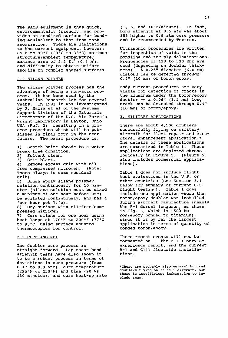
2-3
The PACS equipment is thus quick, environmentally friendly, and pro- vides an anodized surface for bond- ing equivalent to that from tank anodization. There are limitations to the current equipment, however: 85OF to 90°F (29OC to 33OC) maximum structure/ambient temperature; maximum area of 2.2 ft2 (0.2 m2) ; and difficulty to obtain uniform anodize on complex-shaped surfaces.
2.2 SILANE POLYMER
The silane polymer process has the advantage of being a non-acid pro- cess. It has been used by the Australian Research Lab for several years. In 1992 it was investigated by J. Mazza et a1 of the Systems Support Division of the Materials Directorate of the U.S. Air Force's Wright Laboratory in Dayton, Ohio USA (Ref. 2), resulting in a pro- cess procedure which will be pub- lished in final form in the near future. The basic procedure is:
1) break free condition. 2) Solvent clean. 3) Grit blast. 4) free compressed nitrogen. (Note: There always is some residual grit). 5) Brush apply silane polymer solution continuously for 10 min- utes (silane solution must be mixed a minimum of one hour before use; be agitated continuously; and has a four hour pot life). 6) Dry surface with oil-free com- pressed nitrogen. 7) Cure silane for one hour using heat lamps at 170°F to 200°F (77OC to 93OC) using surface-mounted thermocouples for control.
2.3 CURE AND NDI
The doubler cure process is straight-forward. Lap shear bond . strength tests have also shown it to be a robust process in terms of deviations in cure pressure (from 0.17 to 0.9 atm), cure temperature (225OF vs 250OF) and time (90 vs 180 minutes), and cure heat-up rate
Scotch-brite abrade to a water-
Remove excess grit with oil-
(1, 5, and 10°F/minute). In fact, bond strength at 0.5 atm was about 35% higher vs 0.9 atm cure pressure and is recommended by Textron.
Ultrasonic procedures are written for inspection of voids in the bondline and for ply delaminations. Frequencies of 110 to 330 Khz are used (depending on doubler thick- ness). A 0.25" diameter (6.4 mm) disbond can be detected through 0.4" (10 mm) of boron epoxy.
Eddy current procedures are very viable for detection of cracks in the aluminum under the boron/epoxy doubler -- a O . 0 6 l 1 (1.5 mm) long crack can be detected through 0.4" (10 mm) of boron/epoxy.
3. MILITARY APPLICATIONS
There are about 4,500 doublers successfully flying on military aircraft for fleet repair and stru- ctural enhancement application.* The details of these applications are summarized in Table 1. These applications are depicted chrono- logically in Figure 5. (Figure 5 also includes commercial applica- tions).
Table 1 does not include flight test evaluations in the U.S. or other countries (see Section 3.4 below for summary of current U . S . flight testing). Table 1 does include one application where the boron/epoxy doubler was installed during aircraft manufacture (namely the B-1 dorsal longeron, as shown in Fig. 6, which is -50% bo- ron/epoxy bonded to titanium), since it is by far the largest application in terms of quantity of bonded boron/epoxy.
Three recent events will now be commented on -- the F-111 service experience report, and the current B-1 and C141 fleetwide installa- tions.
*There are probably also several hundred doublers flying on Israeli aircraft, but there is insufficient information to in- clude them.

2-4
3.1 F-11 REPORT 3.3 C141 WING RISER WEEPHOLE CRACKS
During 1975-1983, the USAF had a relatively large doubler (0.5 x 0.5m) bonded to the lower surface of the wing pivot of the F-111 fleet (about 411 aircraft). Ref (3) is a report published in January 1993 by the USAF Sacramento Air Logistics Center (ALC) on the to- tally successful 20 years use of this boron doubler application. To quote from the report:
"The maintainability history o f the boron doubler i t s e l f has also been very posit ive. There have been no fai lures o f a boron doubler t h a t have caused any spec i f ic mainte- nance actions i n the USAF --- about 50% o f the U S A F a i r c r a f t have been inspected, and few a ircra f t have been inspected more than once. There have been no disbonds de- tected t o date on U S A F a i r c r a f t .
"The role o f the boron doubler i n the F-112 successfully meeting i t s original design goals cannot be disputed --- the doubler now p l a y s an even more important role i n the l i f e extension a s the usage o f the F-111 is even more severe than it was i n the earlier years."
This report is strong testimony that properly designed and in- stalled doublers are reliable and have a long life --- no debonds noted on over 800 doublers for up to 20 years' use.
3.2 B-1 25O LONGERONS
In 1991 the USAF noted hairline cracks at the shoulders of the 25O longerons (just forward of the wing carry-through box) on 37 B-1s (Ref. 4). They had Rockwell design a repair/reinforcement that consists of a bolted aluminum doubler plus a 2.5" x 20" (6 x 50 cm) x 50 ply boron doubler bonded to the ex- terior of the fuselage skin over the longeron on both sides of the aircraft. (See Figure 6). This repair is being installed by Air Force personnel on all 96 aircraft. To date, about half have been done.
In 1988-91, Lockheed successfully designed and installed about 35 doublers on 17 operational C141s in a variety of locations. One repair was on a crack emanating from the wing riser weepholes, as shown in Fig. 7. (Ref. 5). In 1993 this weephole cracking problem intensi- fied, and the USAF inspected all weepholes (-1500 per aircraft) on all -230 aircraft and in 1993-94 repaired as required (Ref 6). This included installing over 1,700 boron doublers (3 doublers per crack) of various sizes on about 140 aircraft. This was accom- plished with a team of 53 trained personnel manning a 7 day/week 24hr/day schedule, plus contractors (Composites Technology, Inc. and Chrysler Technologies). The USAF personnel used the silane polymer chemical treatment described in Section 2.2 above.
3.4 OTHER CURRENT USAF EFFORTS
A s the USAF fleet ages, boron/epoxy doublers are being designed and tested for other applications.
Flight test applications include:
1) A boron doubler successfully flew for -200 hours as a repair on a crack emanating from the lower wing fuel vent hole of a F-16 at Hill Air Force Base. The repair was designed by General Dynamics and installed by Wright Labs. (This plane is now retired). A second plane will soon be repaired. This repair is also flying on two Netherlands' F-16s. 2) A repair on an F-16 speed brake was installed in the Spring of 1994. 3) Northrop designed and installed four boron doublers on three T-38s on cracks on the frame of an access door on the lower wing in the Spring of 1994. It is likely that more repairs will be installed. 4) A boron repair on the nose landing gear door of a C-130 was designed and installed in 1992 by E-Systems. 5) Since 1992 a boron doubler has

2-5
flown on an undamaged 880 beam cap on a KC135. This was designed and installed by E-Systems. In the near future, a boron doubler will also fly on an upper wing skin fuel vent hole, also by E-Systems. 6) A fleetwide repair is probable on an unspecified location on the C-5 during the next year. 7) A boron repair was installed in 1993 on deep scratches on the lower skin of the horizontal stabilizer of a B-1.
4) COMMERCIAL APPLICATIONS
As is usual with new technology, commercial applications have lagged military use. Table 2 summarizes the known applications. There are about 150 boron doublers flying. About 100 have flown on Mercure door frames since the mid-1970s and are being reported elsewhere at this Meeting. About 12 boron dou- blers have flown on Australian- operated Boeing aircraft since 1989, one being a restoration to original stiffness of a 767 cor- roded keel beam chord. Boeing has successfully evaluated 24 repairs on 747 static fatigue test fuse- lages.
There are two recent U.S. installa- tions to report on: Fed Ex 747s and Lycoming ALF 502 engine cowls.
4.1 FED EX 747s
In early 1993, Fed Ex, after con- sulting with Boeing, installed 25 6" x 8" (15 x 20 cm) boron doublers on undamaged structures (on areas of future repair interest), on 2 operational 747s to evaluate the effects of flight exposure (aerody- namics; pressurization; aircraft fluids; ground debris). This is the first phase of a three phase test program. Locations included leading edges (wing; engine na- celle; horizontal and vertical stabilizers); pylons; fuselage underbody; fuselage door frame corners; main landing gear wheel- well; wing mid-flap skins.
There are several noteworthy points
about the installations (Ref. 7):
1) The doublers were installed by composites maintenance personnel simultaneously with other activi- ties during a regularly scheduled maintenance check --- i.e. real people in a real environment. 2) The PACS anodizing equipment described in Sec. 2.1 above was used. This is the first known use of commercially available PACS equipment on an aircraft. 3) Virtually all doublers were installed over rivets. 4) All doublers were installed at elevations requiring lifts, stag- ing, etc. 5) Two men could readily install a doubler in less than six hours (this includes all process steps shown in Fig. 4 except paint and seal).
The doublers have over 1,000 flights each and have been inspect- ed periodically and have performed excellently -- one small debond over one rivet head; and a 1 cm wide debond along two edges of one doubler attributed to improper application of masking tape (these latter debonds were noted after - 25 flights and have not grown).
4.2 LYCOMING ALF 502 ENGINE COWLS
The Lycoming ALF 502 engine has a steel cowl about 3 ft (1 m) in diameter which has lugs to which accessory equipment attaches. Cracks form at the base of these lugs. Welds do not permanently stop the cracks. There is insuffi- cient clearance on the inside diam- eter for a riveted repair. Since late 1992, six boron doublers have flown as crack repairs on each of two cowls on BAE 146s (Air Wiscon- sin and Ansett), (Ref. 8 ) , and suc- cessfully logged over 2,500 flights and 5,000 hours on,each aircraft. No crack growth has been noted. Lycoming has now released a Service Bulletin for this repair for the over 1,200 cowls in service. This is classified as a minor repair and is the first approved repair to fly commercially in the U.S.A..

2-6
5) FATIGUE AND STATIC ULTIMATE TEST PROGRAM
To accelerate commercial use of boron doublers, Textron sponsored a laboratory test program at Boeing that concluded in early 1994. The core of this program consisted of tensile tests of boron doublers bonded to 7075-T6 aluminum with a simulated 0.5" long (12.7 mm) crack which was stop-drilled. Fig. 8 shows the baselin'e specimen design and test conditions. 110 static ultimate and 143 fatigue tests were conducted. The fatigue tests were conducted at 3 ksi (21 MPa) to 20 ksi (138 MPa) at 5 Hz. 300,000 cycles was considered runout. This set of fatigue test parameters was considered as a conservative "enve- lope" condition in that it combined the high stresses seen on portions of low design life 747s* with the high design life of 737s (which are designed to a lower stress level). The use of the relatively brittle 7075-T6 aluminum also contributed to the overall conservatism of the test condition.
The test reults showed that the boron doubler performed as an ex- cellent repair for the cracked aluminum. To summarize the results:
1) The static ultimate tensile strength of the aluminum was resto- red -- eleven tests were conducted, and all broke at greater than 552 MPa which is the A/B statistical minimum strength for 7075-T6.
*The design stress level on portions of the 747 fuselage is actually about 0 to 18 ksi. However for these tests, 3 ksi was used as the lower stress to remove bending from the (unrestrained) specimen due to residual thermal stresses (from the 1 2 O O C cure and the differential coefficients of thermal expansion of the aluminum and boron/epoxy). This prevented reverse bending ("oil-canning'' ) when higher stresses were applied, a phenomenon which is not realistic on the airplane. The upper stress was raised to 20 ksi (vs 18 ksi) as compensation.
f l
2) In fatigue, there was no crack re-initiation for the baseline design at 300,000 cycles (13 tests). (For reference, control specimens with no boron doublers cracked completely across in 3100 cycles). Subsequently these speci- mens were tested for static ulti- mate strength and exceeded the 552 MPa A/B minimum for 7075-T6.
3 ) Many variables were evaluated in fatigue tests that did not cause crack re-initiation at 300,000 cy- cles, including: impact; hot-wet and Skydrol solvent immersion; 13 mm diameter voids at the edge of the bondline and over the stop- drill; various cure pressures and doubler geometries; and 25 mm crack length. Post-fatigue static ulti- mate tests in these specimens also gave strength greater than 552 MPa.
4) Some variables did result in crack re-initiation at less than 300,000 cycles. These included no stop-drill; a defect in the stop- drill (nick or burr); and too few plies. Post-fatigue static ulti- mate tests gave 552 MPa strength for those specimens where the crack did not propagate fully across the aluminum. Also, when crack re-ini- tiation occurred, crack growth rate was linear, reproducible, and inde- pendent of crack length. Finally, in no case did a boron doubler glo- bally debond prior to the crack propagating the full width of the aluminum. To summarize, if a crack re-initiated under the doubler, it propagated in a predictable manner, and the static ultimate strength still exceeded the 552 MPa A/B sta- tistical minimum for 7075-T6.
Reference (9 ) is a preliminary re- port of this test program.
6) CONCLUSIONS
Bonded boron/epoxy doublers are a highly effective method of repair- ing and reinforcing metallic aircraft structures. Recent advan- ces have improved what was already a viable installation process. History shows properly installed doublers have virtually no debonds,

2-7
even after 20 years. Military use is expanding. Commer- cial use is being initiated and is also expected to expand, in part due to the highly successful labo- ratory.test program sponsored at Boeing by Textron.
REFERENCES
1) Operating Instructions for "ATA- CS MODEL 0810 PACS," Document No 102391, Rev. B, Published by ATACS PRODUCTS, Seattle, WA, December, 1992. 2) "Composite Repair of Aluminum StructureIr , Data Updates for Contract F33615-89-C-5643, Prepared by University of Dayton Research Institute, 1992-1993. 3) Sutherland, W., "Boron Doubler Reinforcement Modification, F-111 Wing Pivot Fittings: Status Report," Sacramento California USAF Air Logistics Center, January 1993. 4) Bond, D. , "USAF Grounds Some B-1B Bombers, Strengthens Cracking Longerons,Il Aviation Week, August 12 , 1991.
5) Cochran, J. and Hammond, D. , 'IC141 Composite Material Repairs to Metallic Airframe Components," USAF SIP Conference, December, 1992. 6) Capaccio, T. , "Requiem for Broken, Unbowed C-141 Fleet Prema- ture: USAF," Defense Week, Febru- ary 22, 1994. 7) Belason, B., Miller, M., Sprin- ger, J.; et al, IIEvaluation of Bonded Boron/Epoxy Doublers for Large Commercial Transport Air- craft," 5th International Confer- ence on Structural Airworthiness of New and Aging Aircraft, Hamburg, Germany, June, 1993. 8) "Lycoming Sees Fleetwide Poten- tial for Composite Fan Housing Patches," Aerospace Propulsion, March 4, 1993. 9) Belason, B., Miller, M., et al, "Evaluation of Bonded Boron/Epoxy Doublers for Commercial Aircraft Aluminum Structures," FAA/NASA International Symposium "Advanced Stuctural Integrity Methods for Airframe Durability and Damage Tolerance, Hampton, Virginia , U.S.A., May 1994.
FIGURE 1 DESCRIPTION OF TYPICAL BONDED BORONIEPOXY DOUBLER
MULTI-PLY BONDED BORONIEPOXY DOUBLER
I BASIC DESIGN PFUNCIPLES
- PLY (F1BER)ORIENTAnON DETEWNED BY
- NUMBER OF PLIES DFIFRMINED BY: REINFORCEMENT THE DOUBLER IS TO PROVIDE
@') BORO"0XY ' @*) METAL Sl'RUcNRE IN AT LEAST ONE DIRECTION
. EDGE PROTECTION OF PLIES - COVER PLY (NOT SHO WN) RECOMMENDED FOR
- AVOID PLACING EDGES OF DOUBLER OVER RIVET HEADS - TAPERED EDGES TO REDUCE BONDLME sII(Ess CONCENTRAnONS
APPLIED STRESS
FILM ADHESIVE
METAL ST
(STOP-DRILLED CRACK SHOWN)

2-8
FIGURE 2 ADVANTAGES OF BONDED BORON/EPOXY DOUBLEKS
Ch'A RA CTERIS TICS
BONDED INSTALLATION
HIGH SPECIFIC MODULUS
NATURE OF BORONIEPOXY
A TTRlE?UT€S
NO HOLES TO DRILL
NO ANCILLARY DAMAGE
REDUCED STRESS CONCENTRATIONS I ONLY NEED ACCESS FROM I 1 SIDE
HIGH LOAD TRANSFER
33% TO 6r/. THINNER I 50% TO 75% LIGHTER
CONFORMABLE DOESN'T'CORRODE
GALVANICALLY INERT WITH ALUMINUM, STEEL, TITANIUM
E A S Y T O EDDY-CURRENT THROUGH
AD VANTAGES
C A N REINFORCE WHERE RIVETING IS NOT POSSIBLE
REDUCED COST FOR SOME APPLICATIONS
LONGER LIFE AGAINST:
FA TIGUE CORROSION
PERFORMANCE FEATURES
THINNER LIGHTER
FIGURE 3 APPLICATIONS WHiCH USE THE ADVANTAGES OF BORON DOUBLERS
DESCRIPTION f L YING EX/! ICIPL ES *
WHERE IT IS DlFFlCULTllMPOSSlBLE TO RIVET
VERY THICK MEMBERS
THINSKINS.
WHERE BACKFACE ACCESS IS DIFFICULT
REPAIRS WHICH REQUIRE MANY NEW RIVETS
WHERE THIN DOUBLER IS REQUIRED FOR FIT
AERODYNAMIC SURFACES (LESS EFFECT ON DRAG) DENT REPAIR
COMPLEX SKIN CURVATURE
IN-SITU REPAIR OF STRUCTURAL MEMBERS
REBUILD THICKNESS OF CORRODED METAL
LEADING EDGE DENT REPAIR t STRUCTURAL REINFORCEMENT QO PREVENT FATIGUE CRACKS)
WHERE RIVETED DOUBLER HAS INSUFFICIENT FATIGUE LIFE
F - i l l WING PIVOT
WING TRAILING EDGE FLAP, FED EX 747s
F-16 WING FUEL VENT 0 L l o l l DOOR CORNER REINFORCEMENT *%
LYCOMING ALF 502 ENGINE COWL
LEADING EDGES:
FED EX 747s 6-1s
ANSETT 767 KEEL BEAM
ANSETT 767 KEEL BEAM
F-ill WING PIVOT
B-1 2 5 O LONGERONS LIO11 DOOR CORNER ** C-141 WING-RISER WEEP-HOLES
LYCOMING ALF 502 ENGINE COWL'
*MANY APPLfCA JIONS USE MUL JfPLE ADVANJAGES **
IN DESIGN. FLY IN LA JE 1995

2-9 I FIGURE 4
Installation Process For Bonding Boron Epoxy Doublers Onto Aluminum Uses Existing Technology, Materials, Specifications, and Equipment Uses Experienced Composiles Personzel To Assure Proper Adhesion Requires Process Control
BORONWOXY DOUBLER '-1 ADEIESIVE
COVER PLY ALUMINUM SURFACE TREATMENT (e.g.
ALLOY SKIN POXY-COAT RIVET-
BASIC STEPS
1) SURFACE PREPARATION REMOVE PAINT AND SOLVENT CLEAN CHEMICAL TREATMENZ SEVERAL OPnONS:
ACID ANODIZE EOEING PATENTED PHOSPHORIC CONTAINMENT SYSTEM (PACS) EQUIPMENT
SILANE POLYMER PRIME (ER-127 OR EQUlVALENn
2) ASSEMBLE DOUBLER 8 PER DESIGN DRAWING
PRE-ASSEMEL Y RECOMMENDED CURING OPTIONS
PRE-CURE (AUTOCLAVE) CURE IN PLACE Le. CO-CURE WITH ADHESIVE)
8 PRE-CONSOLIDATE IF >8 PLIES
3) BOND ONTO AIRCRAFT LOCATE
8 USE FILM ADHESIVE (FM-73 OR EQUIVALENn CURE
THIS IS THE CRUClAl STEP
USE PROCRAMMABLTlRECORDlNG 'HOT BONDER'. TRIAL RUN RECOMMENDED TO CHECK FOR TEMPER- A N R E PROFILk ON 1ST APPUCATION TO NEW AREA
ROBUST PROCESS: INSENSITIVE TO MODEST I , DEVIATIONS IN PRESSURE. TEMP. TIME
PRESSURE OFN 0.5 ATMOSPHERE IS BEST
8 90 MINUTES AT 2500F (121OCl RAMP TO 2500 F Q 5 O F/MIN
RAMP DOWN Q 5OF/MIN.
4) 5) SEAL AND PAINT
INSPECT FOR BOND VOIDS AND DELAMINATIONS (ULTRASONIC & VISUAU I
TEFLON-FILLED URETHANE PAINT RECOMMENDED

2-10
MILITARY F-111 WING PNOT +
FIGURE 5 CHRONOLOGY OF BONDED BORON/EPOXY DOUBLER TECHNOLOGY
REINFORCEU
4
4
COMMERCIAL
WSTRAUAN AIR
DASZAULT: MERCURE
LYt 7 : FLIGHT
- * EVALl AEON FLE 3 REPAIR 4 s ):4 *-
SERVICE BULLETI 4 FE I EX 747 -LIGHT E'fALUATlOb _-
FAATC U011 DOOR CORN iR REINFOF CEMENT (LOCKH
INSTALL
NT ( - 4.f +- ' O R E REPAll
B-1 DORSAL I 4-+.
WRIGb f
OOR CORNEI
A1 4
BC -
MING ALF 5t
NG 747 r~u,r S T A T I ~ ~ T E S T S 1 1 1 TE RON-SP NSORE OATAP OGRAM T60EIN
COWL NBAE1 6 4 FIGURE 6
B-I APPLICATIONS OF BORON/EPOXY DOUBLERS BORON REINFORCED DORSAL LONGERON
LONGERON (BOTH SIDES)
i

2-11
FIGURE 7
U.S. AIRFORCE C141 WING RISER WEEP HOLE REPAIR Boron Epoxy Doub ers
\?Boron/Epoxy D o u b l e r s Boron
FIGURE 8
TEST PROTOCOL FOR PEWORMANCE TESTS A. BASELINE SPECIMEN DESIGN
40.6cm
LOAD
... . . _ . _ ... .
FIBER DIRECTION
WITH 6.4mm DIA. STOP-DRILL
B- TEST CONDITIONS
1. STATIC ULTIMATE STRENGTH
GOAL: > 80 ksi (550 ma): RESTORE A.5 STATISTICAL MINIMUM FOR 7075-T6 ALUMINUM
2. FATIGUELIFE - 3 bi (21 m a ) TO 20 ksi (138 m a ) @ 5 Hz
I d m m 707ST6
6 PLY BORONEPOXY DOUBLER
- COVER PLY ON TOP - SITFFNESS RATIO (EO BE E 1-4 (EO A L - PLY DROP-OFF RATIO: 3OX PLY THICKNESS - ( ~ 3 . 8 m m ) - DIMENSIONS OF SHOR-T PLY SHOWN
~~ _ ~ ~ _ .
LONGEST PLY ON BOTTOM - 0' FIBER ORIENIXTION (TO TIiE LOAD) - FABRICATED PER THE INSTALLATION PROCESS SPECIFICATION (05 a h . CURE PRESSURE)
- HIGH CYCLE FATIGUE LIFE @ IIIGR S W S - RELATNELY BRI1TLE ALUMINUM - UNRESTRAINED SPECIMEN
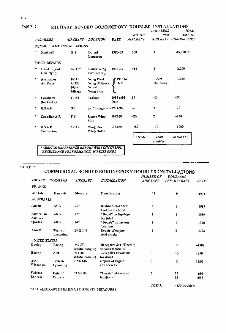
2-12
TABLE 1 MILITARY BONDED BORONDCPOXY DOUBLER INSTALLATIONS DOUBLERS TOTAL
NO. OF PER AMT. OF INSTALLER AIRCRAFT LOCATION DATE AIRCRAFT AIRCRAFT BOXONEPOXY
OEM-IN PLANT INSTALLATIONS
Rockwell
FIELD REPAIRS
U.S.A.F. (and Gen. Dyn.)
Australian Air Force
Lockheed (for USA0
U.S.A.F.
Canadian AX
U.S.A.F. Contractors
B-1
F-lll*
F-111 C-130 Macchi Mirage
C-141
3-1
F-5
C-141
Dorsal 1980-83 100 1 45,000 Ibs. Longaron
Lower Wing 1973-83 411 2 -2JOO
1975 to -1500 -1,000 Pivot (Steel)
Wing Pivot
Wheel Wing Skin
Various
Doublers
1988to91 17 -2 -30 Date
- +25O Longerons 1991-96 96 2 -2 0
Upper Wing 1992-99 -25 2 -120
Wing Riser 1993-94 -1.80 -1 0 -1000
Skin
Weep Holes I
-509000 Lbs- I TOTAL: -4500 Doublers
1 I I *SERYICE EXPERIENCE REPORT WRITEEN IN 1993. 1
EXCELLENCE PERFORMANCE. NO DISBOIWS I
TABLE 2 COMMERCIAL BONDED BORONEPOXY DOUBLER INSTALLATIONS
0 1 FXER INSTALLER
T R A N C E
Air Inter Dassault
-1VSTRALIA
Ansett ARL
Australian ARL Airlines Qantas ARL
Ansett Textron Lycoming
LL'SITED STATES Boeing Boeing
Boeing ARL
Air Textron Wsconsin Lycoming
Federal Federal Express Express
NUMBER OF AIRCRAFT IASTALLATION AIRCRAFT
Mercure Door Frames I 1
767 Re-build corroded 1
727 "Decal" on fuselage 1
747 "Decals" at various 1
keel beam chord
lap joint
locations
cowl cracks' BAE 146 Repair of engine 1
747-SR 10 repairs & 1 "Decal"; I
747-400 13 repairs at various 1
BAE 146 Repair of engine 1
(Static Fatigue) various locatious
(Static Fatigue) locations
cowl cracks
747-200F "Decals" at various 2 locations
DOUBLERS PER AIRCRAFT DATE
9 -1 974
2 1989
1 1989
9 1990
6 11/92
11 -1989
13 1990-
6 11/92
12 1/93 13 3/93
TOTAL * - C L AIRCRAFT IN DAILY USE, EXCEPT MERCURES
-150 Doublers

3-1
ADHESIVELY BONDED COMPOSITE PATCH REPAIR OF CRACKED ALUMINIUM ALLOY STRUCTURES
P Poole' A Young' A S Ball"
Defence Research Agency, Structural Materials Centre, Farnborough, Hants GU 14 6TD, United Kingdom.
.. British Aerospace Defence Ltd, Military Aircraft Division, Farnborough Aerospace Centre, Farnborough,
Hants GU14 6YU, United Kingdom.
SUMMARY Research at the Defence Research Agency [DRA] on adhesively bonded composite patch repair of fatigue cracked aluminium alloy structures is reviewed briefly. Theoretical and experimental results are reported which indicate the effectiveness of such repairs in terms of the reductions in stress intensity factor due to patching. The influence of warm-moist environments on the long-term performance of bonded patches is considered, and the advantages and disadvantages of using carbon fibre reinforced plastic [CFRP] patches, rather than boron fibre reinforced plastic [BFRP] patches, are discussed. An investigation by British Aerospace of the feasibility of using bonded composite patches to repair cracked primary aircraft structures is summarised. For the range of applications investigated, bonded composite patch repairs are shown to offer potential savings of 60-75%, compared to conventional repair methods. The current position regarding in-service trials is summarised, with no evidence of crack growth after 990 flying hours.
1. INTRODUCTION The use of adhesively bonded BFRP patches to repair metallic aircraft structures was pioneered by Australian workers','. They have used the technique to repair or reinforce a wide range of structures including upper and lower wing skins, wing planks, fin skins, door frames, landing wheels, fuselage keel beams and wing pivot fittings.' In the United Kingdom, British Airways' has used adhesively bonded CFRP patches to repair various structures, including wing leading edge panels, engine cowlings, undercarriage doors and fairing panels. In addition, bonded CFRP patches have been used by the RAF4 to repair fatigue damaged wing and fuselage skins, as well as various secondary structures, and by Westland Helicopters Ltd'to repair fatigue damage on an airframe full scale fatigue test.
Extensive research was required before the above composite patch repairs were applied successfully to in- service aircraft. However, additional research is in progress, in several different countries, where the main objectives are to assess the full potential of this method of repair and to develop optimum repair schemes for a wide range of applications. Theoretical and experimental research on bonded patch repair of fatigue cracked aluminium alloy structures has been in progress at DRA Farnborough for many years, as indicated by a paper6 presented in 1986 at the AGARD Conference on "The Repair of Aircraft Structures Involving Composite Materials". The research carried out at the DRA since that time is reviewed briefly in the first part of the present paper. This review includes an appraisal of the advantages and disadvantages of BFRP and CFRP patches, with particular reference to the results of a recent experimental investigation. The second part of the paper summarises an investigation by British Aerospace, Military Aircraft Division, of the feasibility of using bonded composite patches to repair cracked primary aircraft structures.
2. DRA RESEARCH
2.1 Durability of Repairs It is well known that the long-term durability of adhesively bonded metal joints depends on surface pretreatment, and that exposure to warm, moist environments can lead to rapid deterioration of joint properties unless appropriate surface treatments are used. In the case of in-situ patch repair of aluminium alloy aircraft structures, it has been shown that good durability can be achieved if the alloy is subjected to grit blasting followed by a silane treatment; details of the pretreatments used at the DRA are described elsewhere"'.
Paper presented at the 79th Meeting of the ACARD Struciures and Materials Panel on "Cornposiie Repair of Military Aircraji Structures" held in Seville, Spain 3-5 October 1994.

3-2
Surface treatment
GB
The results of fatigue tests to determine the effects of surface treatment and exposure to 7OoC/85%RH on the performance of cracked aluminium alloy panels repaired with adhesively bonded CFRP patches were reported at the 1986 AGARD conference'. 150mm wide test panels, containing 37.5mm long central fatigue cracks, were manufactured from 1.6mm thick sheets of 7075-T76 alloy. 1.26mm thick woven CFRP patches [52.5mm wide, 4 1.2mm high] were manufactured using XAS1914 prepreg, and bonded to one side of selected cracked panels. Patched and unpatched panels were subjected to constant amplitude loading [R=O. 11 and crack growth was continuously monitored using a pulsed direct current potential drop method. Repair performance was assessed in terms of the reduction in stress intensity factor range due to patching [AKpIAKu], which was determined from the crack growth rate data6. Similar values of AKpIAKu were obtained for a range of adhesives and surface treatments, and in all cases exposure to 70°C/85%RH for 2150 hours had no significant effect.
Exposure AKPIAKU period (h) (2a = 45mm)
0 0.57 2150 0.59 9792 0.59
Since 1986 additional fatigue tests have been carried out on similar patched panels exposed for more prolonged periods to the same environment. These panels were pretreated by one of the following three surface treatments before patches were applied using a 12OoC curing epoxy film adhesive Redux 3 1215:
GB + S
GB + PAA + P
GB - Grit blasting with 280 grade alumina grit
0 0.50 2150 0.60 9792 0.59
0 0.60 2150 0.60 9718 0.6 1
GB+S - Grit blasting followed by silane treatment.
GB+PAA+P - Grit blasting followed by conventional phosphoric acid anodizing and application of a corrosion inhibiting adhesive bonding primer BRI 27.
The results of these tests are summarised in Table 1. It is evident that patch performance [AKp/AKu] was not affected significantly by exposure to 70°C/85%RH for up to 9792 hours. Similar patched specimens [GB+S surface treatment only] are being subjected to natural weathering trials at a hot, wet jungle site, and at a marine atmospheric site, in Australia. These panels are loaded to a tensile stress of 60MPa throughout exposure. Fatigue tests were carried out recently on specimens which had been exposed for one year; no change in patch performance was observed for specimens from either site, in agreement with the results reported in Table 1. Other specimens will be tested after longer periods of exposure.
Although laboratory tests and in-service experience have shown that grit blast/silane pretreatments result in very good long term performance of bonded patch repairs, Australian workers have reported' that further improvements in bond durability can be obtained if an adhesive bonding primer is applied after silane
Table 1 Effect of surface treatment and exposure to 7O0C/85%RH on patch performance
treatment. However, the type of primer used, and the reasons for its effectiveness in enhancing durability, were not reported. It is possible that a corrosion inhibiting primer, such as BR127, may have been used because this type of primer is known to promote good bond durability when used with 12OoC curing epoxy adhesives and anodizing pretreatments. Thus, a series of Boeing wedge tests have been carried out recently at DRA in order to investigate the effect of the following surface treatments on bond durability:
GB - See above.
GB+S - See above.
GB+S+P - Grit blasting followed by silane treatment and BR127 primer.
GB+PAA+P - See above
Pretreated aluminium alloy adherends were bonded with a 12OoC curing epoxy film adhesive Redux 3 1215. Test specimens were precracked, by driving stainless. steel wedges into the bondline, and then exposed to 50°C/96%RH. Crack growth was monitored for periods up to 1100 hours, and for at least three specimens per pretreatment. Figure 1 shows mean crack growth data obtained during the first 48 hours of exposure. These data show that resistance to crack growth was relatively poor for GB treatment alone, but was greatly improved when a silane swab treatment was also applied [GB+S], in agreement with previous work'. However, no additional improvement was obtained when BRI 27 primer was applied after silane treatment [GB+S+P]. As expected, best resistance to crack growth was observed for [GB+PAA+P]. Similar ranking of surface treatments

3-3
Patched
was indicated by the crack growth data obtained for exposure periods up to 1100 hours.
14/15P 18/19P 16/17P 12/13P
h4ean
It is evident from the above that recent DRA research supports the view that grit blastinghilane treatment of aluminium alloy substrates enables durable CFRP patch repairs to be achieved.
2.2 Repair of Thick Sections DRA and ARL, Australia participated in a collaborative programme to investigate the effect of adhesively bonded BFRP patches on the fatigue performance of 1 1.2mm thick aluminium alloy sections containing surface cracks 40mm long and 5.7mm deep. Figure 2 shows the main ‘features of the symmetric patched specimens used for this investigation. Fatigue tests were carried out under constant amplitude loading [R=0.01, SM,,=68.9MPa] at ARL’, and FALSTAFF loading [peak stress 137.8MPal at DRA”.
Table 2 summarises the fatigue life data obtained at DRA for patched and unpatched specimens. These results show that, for FALSTAFF loading, patching increased fatigue life by a factor of 5.8. This is much lower than the factor of 22 reported by ARL’ for constant amplitude loading, and therefore the remaining two specimens were tested under constant amplitude conditions similar, but not identical, to those used by ARL. These two tests indicated that patching increased fatigue life by a factor of 28, which is in reasonable agreement with the ARL results.
At DRA the effect of patching on the growth of cracks
Table 2 Effect of patching on fatigue life
I I Loading sequence unpatched
9/22U
Constant 1 Unpatched 1 1/2U amplitude
Patched 20/2 1 P
Cycles to failure
344,039 326,056 41 1,595 334,778
354.1 17
1,954,783 2,699,357 1,923,680 1,632,406
2,052,557
37,687
1,04 1,557
was also studied”. Examination of fracture surfaces showed that cracks grew through the plates before any surface crack growth was detected. The growth of surface cracks was monitored continuously for patched and unpatched specimens. Figure 3 shows the effect of patching on the rate of crack growth during FALSTAFF loading. For some specimens, ultrasonic and SPATE techniques were used to monitor the extent to which debonding of patches occurred during fatigue testing. Extensive debonding in the vicinity of the crack was observed for specimens tested under FALSTAFF loading, as illustrated in Figure 4, but no debonding was detected in the case of the patched specimen tested under constant amplitude loading. This observation is consistent with the fatigue life and crack growth rate data, which indicated that patching was more efficient for constant amplitude loading than for FALSTAFF loading. It appears that the relatively high adhesive shear strains associated with high FALSTAFF loads may have been responsible for fatigue damage of the adhesive and debonding during FALSTAFF loading”.
Additional fatigue tests, using similar surface flaw specimens, have been carried out at DRA”. For these specimens, surface cracks in 12.4mm thick aluminium alloy plates were repaired with CFRP patches and a different 1 2OoC curing epoxy film adhesive. Again, the increases in fatigue lives and reductions in crack growth rates due to patching were more pronounced for constant amplitude loading than for FALSTAFF loading, and debonding was detected for FALSTAFF loading only. Debonding was reduced when patch thickness was increased or when adhesive thickness was increased, but a significant improvement in fatigue performance was only obtained when patch thickness was increased.
The research summarised above showed that surface cracks in relatively thick aluminium alloy sections can be effectively repaired using adhesively bonded composite patches. Although patch efficiency was reduced when debonding was deliberately induced by applying relatively high FALSTAFF loads, marked reductions in the rate of crack growth were still achieved.
2.3 Theoretical Studies Various methods are available for designing adhesively bonded patch repairs for cracked structures. These methods include finite element analysis [FEA]’*, boundary element analysis [BEA]”, analytical closed form expression^'^, and semi-analytical In general, detailed FEA is recommended for complex or critical repairs, although analytical formulae may be adequate for designing relatively simple repairs for thin skins.
Early theoretical research at DRA and Southampton University involved the development of a two- dimensional strip patch model” which was used for a

3-4
parametric study of patch repairs of cracked infinite sheets. This was followed by the development of a two- dimensional BE model'' which enabled a wider range of repair configurations to be analysed. More recently a three-dimensional B E F E model has been developed at DRA17.A B E F E approach was adopted because it was considered that the resultant computer program would be more accurate and economical, as well as easier to use, than if FEA alone had been used. The three- dimensional cracked member was modelled using boundary elements while the thin composite patch was modelled using mixed stress-displacement finite elements. The BE program contains an option for automatic inclusion of reflection symmetry about any of the coordinate planes. This enables either asymmetric single-sided patch repairs or symmetric double-sided repairs to be modelled using almost identical BE and FE input data files. However, many more elements are needed to obtain accurate results for single-sided repairs than for double-sided repairs, due to the vast difference in the complexity of the corresponding solutions.
Recent theoretical work at DRA has included a comparison of the reductions in stress intensity factor due to patching [AKp/AKu] predicted by three- dimensional BERE analysis, two-dimensional BE analysis and analytical formulae. This investigation, which is described in detail elsewhere", was confined to symmetric double-sided CFRP patch repair of aluminium sheets of varying thickness containing central cracks. Patch thickness varied in proportion to sheet thickness, ie the ratio of patch stiffness to sheet stiffness was constant. Figure 5 shows the values of AKpIAKu predicted by the different models for sheets of different thickness [2hs]. It is evident that similar values of AKpIAKu were predicted by all three models in the case of relatively thin sheets [hS<3.1mm], and that significantly higher values of AKp/AKu were predicted by the three-dimensional model than by the two- or one- dimensional models in the case of thick sheets [hS>3. Imm]. Thus, three-dimensional analysis is recommended for thick section repairs, even in the relatively simple case of symmetric double-sided patch repair of through-thickness cracks.
Values of AKpIAKu determined from experimental constant amplitude fatigue crack growth data for two double-sided patch repairs were compared" with corresponding values predicted by the three-dimensional model. Figure 6 shows that the predicted values of AKpIAKu were in good agreement with those determined from experimental data, providing the effect of residual stresses arising from differential thermal contraction of patch and sheet on cooling from the adhesive cure temperature were taken into account. In addition, patch surface stress distributions determined from SPATE and strain gauge measurements were in good agreement with distributions predicted by the three-dimensional model,
but in poor agreement with those predicted by the two- dimensional BE model. Thus, it is concluded that detailed, accurate analysis of thick section bonded patch repairs can be achieved using the three-dimensional B E F E model.
2.4 BFRP versus CFRP Patches Australian workers' have stated that they prefer BFRP, rather than CFRP, as the composite patch material because BFRP offers the following advantages:
a. Superior combination of strength and stiffness.
b. Low electrical conductivity, which avoids the danger of galvanic corrosion associated with -the use of CFRP, and allows the use of simple eddy current procedures to detect and monitor cracks under the patch.
c.Higher coefficient of thermal expansion, which reduces the severity of the residual stress problem.
In the UK, CFRP has been used as the patch material because, compared with BFRP, it is cheaper, more readily available, easier to handle and more suitable for curved surfaces. Furthermore, recent advances with CFRP have resulted in materials with tensile strengthktiffness properties similar to those of BFRP. Potential galvanic corrosion problems associated with CFRP patches can be avoided or minimised by appropriate protection measures. For example, galvanic contact may be avoided by using patches with a layer of GRP on the surface to be bonded. In addition, cracks should be sealed to avoid ingress of moisture from the unpatched side of the structure. Eddy current techniques have been used successfully at DRA to monitor the growth of fatigue cracks under both BFRP and CFRP patches, with no significant advantages apparent in the case of BFRP. The suitability of eddy current techniques to monitor crack growth under CFRP patches has been confirmed by British Aerospace and the RAF. It is well known that residual stresses arising from differential thermal contraction of patch and alloy will be lower for BFRP than for CFRP patches. However, it is difficult to estimate the precise improvement in resistance to fatigue crack growth that will be achieved by using BFRP rather than CFRP patches of the same stiffness. Thus, the investigation outlined below was undertaken recently at DRA.
Single and double-sided patch repairs were carried out on 108mm wide, 12.4mm thick L97 aluminium alloy specimens containing central through-thickness fatigue cracks [20mm or 40mm long]. 1.34mm thick BFRP and 1.65mm thick CFRP patches were manufactured from Textron 552 1 and Ciba-Geigy T800I924 prepregs, respectively. These thicknesses were selected in order to produce BFRP and CFRP patches of similar stiffnesses, assuming Young's modulus was 208GPa for BI5521 and

3-5
Singlet Double
168GPa for T800t924. The patches were 180mm long, including 30mm tapered portions at either end, and 108mm wide. Following grit blasting and silane treatment of the aluminium alloy surfaces, patches were applied using a 12OoC curing epoxy film adhesive. Patched and unpatched specimens were tested under constant amplitude loading [R=O. 1, SMAx=55MPa] and fatigue crack growth was monitored using plastic replica and eddy current techniques.
BFRPI AKptAKu CFRP
Theory Expt
Figure 7 summarises the crack growth rate data obtained for six patched and three unpatched specimens. It can be seen that the rate of crack growth was slightly lower for BFRP than for CFRP patches. As expected, double- sided patch repairs were much more effective than single-sided repairs in reducing the rate of crack growth.
The three-dimensional BE/FE computer program, described in section 2.3 above, was used to predict AKptAKu for single- and double-sided, BFRP and CFRP patch repairs. Theoretical values of AKptAKu predicted for crack lengths [2a] of 50mm and 70mm are summarised in Table 3. The program was also used to predict the effect of residual stresses on KPMIN/KPMAX [R- ratio] for patched specimens subjected to R=O. 1, SMAx=55MPa remote loading. For a=25mm,. the predicted values of KPMIN/KPMAx were 0.64 for BFRPtdouble, 0.68 for CFRPtdouble, 0.33 for BFRPtsingle, and 0.36 for CFRPtsingle patch repairs.
As in previous work", values of AKpIAKu were determined from experimental crack growth rate data. For example, in the case of double-sided BFRP patch repair and a crack length of 50mm [a=25mm], da/dN was obtained from Figure 7 and the value of AK corresponding to this datdN in datdN-AK data for R=0.64 loading [unpatched specimens] was assumed to be AKp. In the present work, datdN-AK data were determined experimentally for R=0.6, 0.4 and 0.1 loading, and data for other R-ratios [eg 0.641 were obtained by interpolation and from information in the literature concerning the effect of R-ratio. Nu was determined from the datdN-AK data for R=O. 1 loading, and thus AKptAKu=0.27 was estimated for double-sided BFRP patch repair and a crack length of 50mm.
Values of AKptAKu determined theoretically and experimentally are compared in Table 3 for two crack lengths. It is evident that excellent agreement between theory and experiment was obtained in the case of double-sided repairs, where large differences in crack growth rates were observed for patched and unpatched specimens. In the case of single-sided repairs, the predicted values of AKptAKu were lower than those determined experimentally. This may be explained in terms of debonding, which would be more likely to occur with single-sided than double-sided patch repairs. Support for this explanation is provided by the increase
in crack growth rate with crack length observed for single-sided repairs, but not for double-sided repairs, [see Figure 71. The theoretical and experimental work outlined above will be reported in detail e l~ewhere '~ .
Table 3 Comparison of theoretical and experimental values of AKptAKu
Half crack
length, a(mm>
25
35
B 0.66 0.70
C 0.66 0.71 S
B 0.27 0.29
C 0.27 0.28 D
B 0.61 0.66
C 0.61 0.67 S
B 0.20 0.20
C 0.20 0.21 D
It is concluded that the use of BFRP patches, rather than CFRP patches, resulted in slight improvements in resistance to crack growth, due to lower residual stresses and reduced KPM,N/KPMAx. However, it should be noted that full width patches were used in the present work, in order to induce large residual stress effects, and that for many structural repairs the effect of residual stresses will be less pronounced and, therefore, the associated benefit of using BFRP rather than CFRP patches will be of minor importance.
3. BRITISH AEROSPACE INVESTIGATION OF PRIMARY STRUCTURE REPAIRS
3.1 Background BAe(MAD) has been involved in the development and application of composite repairs to metallic aircraft since the late 1970's. The initial research in this field utilised BFRP patches. However, at the start of BAe(A4AD)'s development programme, it was identified that if the technique was to be widely accepted and suitable as a general repair method, CFRP should be used as the patch material. This decision was based on CFRP's availability and associated range of qualified materials, its flexibility to follow complex shapes, its ease of handling, and its

3-6
cost, relative to BFRP
To verify the results of repair behaviour and effectiveness studies, a programme to identify and apply a series of in-service trial applications of CFRP repairs to primary metallic aircraft structure was undertaken. The work, carried out under MOD contract, aimed to give practical experience on the suitability and limitations of composite patch techniques, including application methods and the overall effectiveness of the repairs.
3.2 Repair Assessment Known service defects, with existing metallic repair schemes, on a range of aircraft types were assessed for their suitability to be repaired using an adhesively bonded carbon composite patch. Applications considered included:
Harrier Fuselage Skin Cracking Harrier Airbrake Beam Cracking Hawk Leading Edge Skin Cracking VC 10 Spar Centre Member Cracks VC 10 Wing Tip Skin Repair VC 10 Undercarriage Bay Sidewall Repair Tornado Leading Edge Slat Repair Victor Alternator Cold Air Intake Skin Hercules Rear Fuselage Sloping Longeron Tornado Wing Pen Nib Fairing Repair
The assessment criteria used to identify suitable candidate applications were:
the use of a composite repair patch would significantly reduce the number of mechanical fasteners used, the aircraft had a significant anticipated service life ahead of it, the repair was such that i t utilised different aspects of the technique, adding to the overall range of esperience gained, the repair would act as a fatigue enhancement only, and not as a structural component critical for flight, the repair would be within its environmental limits, there was suitable access for application and inspection.
From the original selection of candidate applications, some defects were identified as unsuitable for repair. The two major reasons for exclusion from the program were either that the defect location was considered unsuitable, due to environmental constraints, or that there was no perceived financial benefit.
Typical of repairs that show no financial benefit, were cases where the patch would have to have a significant number of mechanical fasteners passing through it. For example, Figure 8 shows a typical defect case where a
composite patch would not be the most cost effective way to affect a repair. In Figure 8a, the cracked structure is repaired by adding a plate to reduce the load in the element. Since fasteners associated with the attachment bracket and the back-up fitting must be applied, only some of the fasteners from the traditional repair plate would be eliminated if, as shown in Figure 8b, a bonded composite patch was used in its place.
3.3 Repair Design Once an application had been assessed as a suitable candidate, the repair designs were derived using stiffness matching and simple closed form analytical methods. The effectiveness of these methods were substantiated with empirical data and finite element analysis. Individual trial repair designs were not directly verified by test.
The philosophy used in the repairs was one of fatigue life enhancement, and as such the designs ensured that the stress intensity factor range at the crack tip was reduced to a value which resulted in an acceptable rate of crack growth, i.e. effective crack arrest. It should be noted, however, that in most cases the structural loads causing the defects were uncertain and this can affect the accuracy of the crack growth predictions.
The basic patch designs were based on the stiffness of the underlying structure in the primary load direction, with the overall patch size, overlap etc. derived from simple thin patch theory*. It was important that the patches were not made overstiff, as they should not affect the overall structural load paths. The resulting designs ensured that the adhesive shear strain range and the patch strain range were low enough to avoid degradation of the adhesive or patch and thereby provide acceptable patch durability, while producing an enhancement to the fatigue life of the damaged structure.
To minimise thermally induced residual stress effects and application problems due to heat sinks, structural degradation etc, it is important that the adhesive cure temperatures is kept to a minimum. The choice of repair material systems used during the trials was mainly based on a need to keep cure temperatures to a minimum. However, the maximum in-service temperature that the repair would encounter sometimes required the use of a higher temperature curing system.
3.4 Repair Procedures Three basic repair techniques have been developed, and are employed dependent on application, service temperature and patch thickness.
The first method involves co-curing of the patch and adhesive on the structure, and is suitable for surfaces that involve moderate curvature and/or relatively thin patches. The second method uses a pre-cured patch that is profile

3-7
matched before it is bonded to the structure in a secondary process. This technique allows the patch to be post cured off the aircraft to enhance its structural properties. In addition, the patch can be inspected before application to ensure satisfactory consolidation has been achieved. The third method uses a simple wet lay-up technique, and is most applicable to areas of complex shape. However, due to the difficulty in controlling the quality of the repair this is suitable for secondary or tertiary structure only.
3.4.1 Surface Treatment Investigations by others6.*', and within BAe(MAD), have shown that strong, durable bonded patch repairs can be achieved if aluminium alloy substrates are subjected to grit blasting followed by a silane treatment [see section 2.11. This surface treatment was used on all trial repairs.
3.4.2 Single Stage Co-Cured Applications The use of prepreg and adhesive co-cured directly onto the structure has proved a most suitable repair technique. It provides a strong, reliable repair, using a relatively simple procedure. However, with an inability to inspect or post-cure the patch before it is bonded to the structure, this technique is limited to relatively thin patches (less than lmm) and in-service temperatures of up to 80°C. During the trials, problems were encountered in maintaining cure temperatures (1 25°C) within tolerance using heater blanket technology, but this was eventually achieved using insulation blankets, draught shields and frequent monitoring. This particular application technique was employed on repairs to the upper surface of a Hawk mainplane, and to Harrier fuselage side skins.
Current work being undertaken by BAe(MAD) includes an investigation into co-cure systems suitable for higher in-service temperatures, which will increase the range of applications for which this method is suitable.
3.4.3 Two Stage Patch Application This particular repair procedure has proved to be most suitable for thicker patches (> lmm) and/or structure with heat sinks and significant underlying structure. The technique uses a two stage method:
a. A pre-cured patch is manufactured to the required shape either by the use of a mould, representative of the actual structure, or on the aircraft itself. A release film between the patch and structure allows its removal, and if required it can then be post-cured at a higher temperature off the structure.
b. The patch is then bonded over the damaged area using a suitable structural adhesive.
Although more complex than the single stage co-cure system described in Section 3.4.2, this method is more
versatile. The ability to post-cure the patch allows the material properties and maximum in-service temperature to be improved without detrimental effects to the structure. The improvement in in-service temperature (from 80°C to lOO"C), resulted in this process being identified as suitable for several repairs to Tornado and Harrier aircraft. Another advantage of this repair procedure is that prior to application to the damaged structure the patch can be examined for consolidation to ensure that the required laminate quality has been achieved. This is more important with thicker patches, as vacuum only curing can lead to unacceptable porosity etc. In addition, for commonly occurring defects or for a fleet wide fit this method allows the patches to be produced in batches, allowing repair costs to be kept to a minimum.
However, as with the co-cure method, difficulties were experienced in the practical application of the repair patches. Some designs utilised materials with higher curing temperatures (1 75"C), in order to achieve acceptable in-service temperatures, and this magnified the problems in maintaining a uniform cure temperature over the patch surface. The effect of heat sinks within the underlying structure are significantly magnified as cure temperatures increase. Hence during the cure process the repair temperature must be monitored at discrete locations beneath the heater mat, to ensure that localised overheating or underheating does not occur. Although the use of a more accurate heater system such as computer controlled heater lamps can reduce the problems, within the timescales of the trial programme no repairs were successfully applied using the higher cure temperature materials.
Since the majority of the problems identified occur when curing in-situ, they could be alleviated by manufacturing the patches on moulds, or scrap components, and curing in autoclaves. However, lower temperature curing adhesives with improved performance at high in-service temperatures are also required in order to overcome the problems and thereby increase the applicability of the technique.
3.4.4 Wet Lay-Up Patch Application This particular technique creates the composite patch by applying fibre mat and resin to the structure independently. Available systems employ room temperature or low temperature curing cycles. The technique is considered to be suited to secondary or tertiary structure only, due to the variation in patch properties which can occur. However, this method allows patches to be quickly and simply manufactured, and is especially suited to highly curved surfaces.
3.4.5 Inspection Techniques During the course of a traditional metallic repair, the damaged structure is removed, or the crack is cut out,

3-8
and in general no additional inspections are required. However, with bonded composite patch repairs the crack remains within the structure. Further inspections of the crack during service are then required, with initial inspection intervals based on the unrepaired structure. As confidence grows with in-service experience, it is expected that inspection intervals will be lengthened and hence allow the full potential benefits of this repair technique to be exploited.
For the repairs considered, patches covered the damaged areas and visual inspection could not be employed. Non- destructive inspection was achieved using eddy current methods; problems associated with the conductivity of the carbon were overcome. This method, developed by CSDE and BAe(MAD), was shown to give accurate results when compared with visual measurements on test panels. In addition, it was used successfully during the trials to monitor crack lengths beneath the carbon patches, both immediately after the repair and at points in its service life.
3.5 In-service Applications
3.5.1 Hawk Leading Edge, Upper Wing Skin This defect, shown in Figure 9, consisted of fatigue cracks in the 2014A-T6 Hawk upper wing skin, emanating from fastener holes positioned behind the leading edge. It is believed that this cracking was due to buffet loading.
The traditional repair, shown in Figure 10, consists of a large number of fasteners and eight major components, affecting a large area around the defect. The composite version, shown in Figure 1 1, was designed on a stiffness basis, utilising finite element analysis, and crack growth prediction data, to clear the repair as a fatigue life enhancement on a Special Trial Fit basis. The crack growth prediction showed very low stress intensity factors after patching. It was felt that although the actual levels could be higher due to uncertainty in the actual loading, there was still a large enough reduction in the stress levels to give effective crack arrest.
Following grit blasting and silane treatment, a 125°C co- cure system was applied using a vacuum bag and heater blankets. This technique was chosen due to the relatively thin underlying skin, and in-service temperatures below 80°C. Following patch application the repairs were inspected using simple tap tests and ultrasonic methods for debonding and patch integrity.
3.5.2 Harrier Rear Fuselage Skin This defect, shown in Figure 12, consisted of fatigue cracks in the 2014A-T6 Harrier fuselage side skins, emanating from fastener holes.
The traditional repair, shown in Figure 13, again uses a large number of fasteners and a number of components. The composite version, shown in Figure 14, was designed on a stiffness basis, and crack growth prediction data were used to clear the repair as a fatigue life enhancement on a Special Trial Fit basis. Repair procedures, and inspections after patching, were as described above for the Hawk wing repair.
Two aircraft were repaired in the trials, and eddy current inspections were carried out at intervals consistent with that of the unrepaired structure. No crack growth had occurred after 70 and 209 flying hours, at which point the aircraft ceased flying.
3.6 Conclusions Following the trials on in-service aircraft, conclusions can be drawn between traditional metallic repair methods and the use of adhesively bonded composite patches.
The defects assessed and repaired during the trials all had existing metallic repair schemes. For comparison purposes the composite repairs were applied by Service personnel in the normal operating environment.
The main identified benefit was the reduced repair application costs, driven by a reduction in the man-hours taken to apply the patches which equated to approximately 40%. For selected repairs the overall application costs were reduced by 65%-75%. However, additional costs due to further inspections during the lifetime of the repairs have not been included, since this is dependent on gaining experience, knowledge and confidence, in the repair system.
There are identified limitations to the bonded composite patch technique, such as severe double curvature and high in-service temperatures, which must be considered when selecting suitable candidate repairs. However, the use of composite patches to repair metallic aircraft structures has been shown to give effective crack arrest and to provide a cost effective repair alternative to the traditional metallic methods. Patch endurance and effectiveness on a range of repairs has been demonstrated, with a life of 990 flying hours without crack growth.
Two aircraft were repaired in the trials, and eddy current inspections were carried out at intervals consistent with that of the unrepaired structure. No crack growth had occurred after 398 and 990 flying hours, at which point the structure was removed from service.

3-9
ACKNOWLEDGEMENT
The work described in this paper was funded by the Ministry of Defence.
0 British Crown Copyright 1994/DRA
Published with the permission of the Controller of Her Britannic Majesty's Stationary Office
REFERENCES
1.
2.
3.
4.
5.
6.
7.
8.
9.
Baker, A.A. and Jones, R., "Bonded Repair of Aircraft Structures", Martinus Nijhoff, 1987.
Baker, A.A., "Fibre Composite Repair of Cracked Metallic Aircraft Components", in "The Repair of Aircraft Structures Involving Composite Materials", AGARD CP 402, April 1986, Paper 15.
Armstrong, K.B., "Carbon Fibre Fabric Repairs to Metal Aircraft Structures", "Engineering with Composites", SAMPE, 1983, Paper 8.
Ford, T., "Strength in Unity", Aerospace Composites & Materials, 1 , 2, Winter 1988189, pp 4-7.
Overd, M.L., "Carbon Composite Repairs of Helicopter Metallic Primary Structures", Composite Structures, 25, 1993, pp 557-565.
Poole, P.. Stone, M.H. and Sutton, G.R. "Effect of Adhesive Bonding Variables on the Performance of Bonded CFRP Patch Repairs of Metallic Structures", in "The Repair of Aircraft Structures Involving Composite Materials", AGARD CP 402, April 1986, Paper 9.
Sutton, G.R. and Stone, M.H., "The Effect of Adhesively Bonded CFRP Patch Repairs on the Fatigue Crack Growth Resistance in 7075-T76 Aluminium Alloy Sheet", RAE TR 89034, July 1989.
Bartholomeusz, R.A., Paul, J.J. and Roberts, J.D., "Application of Bonded Composite Repair Technology to Civil Aircraft - 747 Demonstrator Program", in "Aircraft Damage Assessment and Repair", The Institution of Engineers, Australia, August 1991, pp 216-220.
Jones, R., "Recent Developments in Advanced Repair Technology", in "Aircraft Damage Assessment and Repair", The Institution of Engineers, Australia, August 199!, pp 76-84.
10. Poole, P., Brown, K. and Young, A., "Adhesively Bonded Composite Patch Repair of Thick
Aluminium Alloy Sections", RAE TR 90055 November 1990.
11. Poole, P., Lock, D.S. and Young, A., "Composite Patch Repair of Thick Aluminium Alloy Sections", in "Aircraft Damage Assessment and Repair", The Institution of Engineers, Australia, August 1991, pp 85-91
12. Jones, R., "Crack Patching - Design Aspects", in "Bonded Repair of Aircraft Structures", Martinus Nijhoff, 1988, pp 49-76.
13. Young, A., Cartwright, D.J. and Rooke, D.P., "The Boundary Element Method for Analysing Repair Patches on Cracked Finite Sheets", Aeronautical Journal, 92, 1988, pp 416-421.
14. Rose, L.R.F., "A Cracked Plate Repaired by Bonded Reinforcements", Int. J. Fracture, 18, 1982, pp 135- 144.
15. Dowrick, G., Cartwright, D.J. and Rooke, D.P., "The Effects of Repair Patches on the Stress Distribution in a Cracked Sheet", RAE TR 80098, 1980.
16. Ratwani, M.M., "Analysis of Cracked Adhesively Bonded Laminate Structures", AIAA Journal, 17, 9, 1974, pp 988-994.
17. Young, A., "Three-Dimensional Analysis of Patched Cracked Solid Using a Combined Boundary Element and Finite Element Model", DRA Working Paper MS4-93-WP-24, July 1993.
18. Poole, P. and Young, A., "Prediction of Performance of Bonded Patch Repairs to Cracked Structures", DRA TR 92076, January 1993.
19. Poole, P. and Young, A., DRA TR, to be published.
20. Baker, A.A. and Chester, R.J., "Minimum Surface Treatements for Adhesively Bonded Repairs", Int. J. Adhesion and Adhesives, 12, 2, April 1992.

3-10
1 x 1 0 ~
Figure 1 Effect of surface treatment on crack growth
0.0 os I 0.3 0.L 0.5 0.1 0 .l
Dimonrionr in mm
11.2 -
T 0 - Fracloprephy
Figure 3 Effect of patching on rate of growth of through cracks during FALSTAFF loading
Debond C y c l e s
1 1.00 x 10⁶
2 1.25 x IO6
3 1.50 x IO6 4 1.75 x IO6
I ,
1 5 1.88 x 10⁶
Figure 4 Development of debond during FALSTAFF loading (specimen l6/17P)
Figure 2 Patched surface flaw specimen

3-1 1
10
4 - 10 8 - "
F 5 J 'I) 10
a
& AK"
0.
a
a
. . . . I . . . . I . . . . I . . . . I . . . . I . . . . I . . . . I . . . . I . . . . l . . ' . j
o I) V R P I t WRP
i -m- Unpatchmd
Unpatchmd /. :
/n.. p a t c h - .. : c Doublm p a t c h -I
-
I I I J 12.4 h', mm 1.55 3.1 6.2
Figure 5 thickness [2h'] on AKp/AKu
Effect of analysis method and sheet
0.6
&P A KU
0.1
0.:
I
Throrrlical Erplal h'. mm
- 0 12.4
I I I I LO 50
' O a,mm 20
Figure 6 Comparison of theoretical and experimental values of hKP/hKu
i
Figure 8 Non-cost effective use of composite patch to repair a metallic structure

3-12
Figure 9 Hawk leading edge skin cracking typical defect
m Nodamageto underlying structure
U CandetectvaJ;lng
rn Minimises !tress concentrations
Figure 11 Scheme of bonded carbon composite repair for Hawk leading edge skin cracking
Damrgr to underlylng Nucturr
Addltionof numerous frnenrn
lnuruu ltruI concmmtionl
I DitfiNlt to detect futher rnJdng
-no new Whnology 0 simple to apply
Repair
structure
rn Addllion 01 numerou
lnutarrr rtrerr concrnuationr
I DiHitull to detect lulhrr cracking
rn Slmplc to apply -nonew technology
Figure 10 Scheme of existing metallic repair for Hawk leading edge skin cracking
Stringer
................ ............... . . . . . . ..................
Figure 12 Defect location for Harrier fuselage skin cracking
Allowable DelenLimiu i; / \
rn No damage to undrrlying rtructure
m Minlmliei stress concentrations
Figure 13 Scheme of existing metallic repair for Figure 14 Scheme of bonded carbon composite Hamer fuselage skin cracking repair for Harrier fuselage skin cracking

4- 1
RESUME.
REPARATIONS COMPOSITES DE STRUCTURES METALLIQUES VINGT ANS D'EXPERIENCE
COMPOSITE REPAIR OF METALLIC AIRFRAME TWENTY YEARS OF EXPERIENCE
BY Micheline DRUET
DASSAULT AVIATION - FRANCE 78, Quai Marcel Dassault
CEDEX 300 - 92552 SAINT CLOUD FRANCE
Dans les annees 70, la disponibilite chez Dassault Aviation de nappes unidirectionnelles de fils de bore permit de realiser des renforcements de structures metalliques par stratification directe sur le metal. Pour les appliquer sur avions, iI a fallu definir un systeme de resine d'impregnation dont la polymerisation n'induisait pas de contraintes thermiques dans le metal et dont les proprietes mecaniques restaient acceptables apres vieillissement. La validation a ete realisee par des essais sur eprouvettes elementaires, des essais complexes de cyclages thermiques simultanes a des cyclages de fatigue, des realisations de reparation sur la cellule d'essai de fatigue de I'avion.
Des reparations de ce type volent sans problemes depuis pres de 20 ans sur les avions de transport MERCURE.
SUM MARY.
During the 70'S, the availability of unidirectional boron fiber fabric at Dassault Aviation did allow reinforcement of metallic structures by direct ply lay up on the metal.
To be .able to apply these reinforcement on airplanes, it was necessary to' define a resin system inducing low thermal stresses in the metal during its cure, and with acceptable mechanical properties after ageing.
Validation was done by simple tests on samples, by complex test with simultaneous thermal and mechanical cycling, and application of test repairs on the major fatigue test of the Mercure airplane.
Reinforcements of that type are in service for almost 20 years on the Mercure airliner.
1 - INTRODUCTION.
L'apparition au debut des annees 70 de fibres a haute resistance de qualite industrielle (bore puis carbone) a conduit naturellement au developpement des structures en composites mais en mQme temps les caracteristiques de mise en oeuvre et de resistance de ces materiaux ont aussi conduit a s'interesser aux possibilites de renforcer et de reparer les structures metalliques par des composites.
Cet expose decrit I'experience de Dassault Aviation sur les renforts colles a base de fils de bore.
Les fils de bore ont ete retenus pour cette application par consideration de leur haut module (390 GPa), leur coefficient de dilatation (environ 4 fois superieur a celui du carbone) et par la disponibilite de nappes de fils de bore unidirectionnelles tramees (brevet BROCHIER DASSAULT).
Les domaines d'application envisages etaient :
- les renforts de pieces presentant un manque local d'epaisseur
- les reparations de pieces criquees en service.
2 - AVANTAGES ET INCONVENIENTS DES RENFORTS COLLES PAR STRATIFICA- TION DIRECTE.
2.1 - Avantaaes.
Les renforts peuvent Qtre realises directement sur des formes planes ou legerement galbees
Paper presented at the 79th Meeting of the AGARD Structures and Materials Panel on "Composite Repair of Military Aircrafi SIructures" held in Seville, Spain 3-5 Ocrober 1994.

4-2
gr5ce a I'emploi de la nappe tramee de fils de bore qui permet la manipulation de fils secs irnpregnables sur place apres decoupe.
Cette technique donne des renforts peu epais, compatibles avec I'aerodynamisme de I'avion.
II n'est pas necessaire de percer le metal pour fixer le renfort et ceci ameliore la tenue en fatigue.
2.2 - Inconvenients,
La difference de dilatation entre le bore et I'aluminium (8.10-6PC pour 24.1 O-6/oC) impose d'impregner avec des resines polymerisant a basse temperature pour eviter d'introduire des contraintes thermiques. Ces resines ne presentent pas toujours les qualites mecaniques requises en temperature apres vieillissernent.
La justification de la tenue en fatigue dans le cas ou les cycles thermiques se superposent avec les cycles mecaniques necessite soit des calculs sophistiques, soit des essais complexes.
Enfin, les reparations doivent Qtre protegees ,pendant les operations de decapage chimique des peintures.
3 - TRAVAUX REALISES CHEZ DASSAULT AVIATION.
Ces travaux se sont deroules de 1973 a 1976.
Les travaux ont porte sur :
- des eprouvettes elementaires avec essais elementaires.
- des eprouvettes representatives de structures avec des essais elementaires et complexes.
- des essais de faisabilite puis des reparations reelles sur la cellule d'essai de fatigue de I'avion de transport civil MERCURE
- des renforcements sur les MERCURE de serie (voir figure 1) et une piece d'avion militaire.
3.1 - Premier essai sur eprouvettes presentant un defaut local d'epaisseur.
Cet essai a servi a mettre au point une gamme de reparation transposable en atelier ou sur avion et a selectionner apres des essais de traction statiques et de fatigue un systeme d'impregnation et sa polymerisation.
La description de I'eprouvette est donnee en figure 2.
Plusieurs systemes de resine ont et6 essayes :
- I'AW 134B, - la BSL 408, et - la BSL 312.
Les essais, notamment I'essai combine cyclage thermique + mecanique du Q 3.3, ont conduit a ecarter I'AW 1348 qui donnait des resultats inferieurs.
Finalement, la BSL 408 a ete retenue comme donnant de bonnes performances avec un cycle de cuisson risquant moins d'induire des contraintes que celui de la BSL 312.
Les renforts obtenus ont une epaisseur par pli polymerise de 0,130 mm.
3.2 - A partir de la gamrne retenue, les possibilites de renforts et reparations ont ete etudiees sur des eprouvettes representatives :
- d'un renforcement d'un element typique de voilure (figure 3) avec des essais statique et de fatigue en traction regardant I'influence du vieillissement et de la temperature d'essai.
-de la reparation d'une crique dans un revQtement (figure 4) avec des essais de fatigue en traction regardant I'influence de la temperature et des taux de contrainte.
- de la reparation d'une crique entre 2 rivets sur une enture (figure 5) avec des essais de fatigue regardant I'influence de la temperature d'essai et du vieillissement.
Les resultats de ces essais montrent que dans tous les cas les reparations ou renforts sont efficaces pour augmenter considerablement la duree de vie des pieces et diminuer la vitesse de propagation de criques.

4-3
3.3 - Sur la cellule d'essai de fatigue du MERCURE, dans un premier temps, des renforts ont ete appliques a I'intrados de la voilure droite pour verifier la faisabilite et I'endurance. Puis des reparations reelles ont ete effectuees sur des zones criquees lors de I'essai de fatigue.
L'essai sur la cellule d'essai de fatigue ne recree pas le cyclage thermique entre sol et vol a haute altitude creant des contraintes thermiques combinees aux efforts de vol et n'est pas completement representatif.
Donc on a ete conduit a lancer un essai plus representatif combinant simultanement charges mecaniques et cyclage thermique.
Les eprouvettes representent la reparation d'une crique dans un fuselage pressurise. La partie utile en est representee figure 6. Elles etaient installees par groupe de 3 sur un b i t i de chargement a verin hydraulique, circulant entre une enceinte froide refroidie a I'azote liquide et une enceinte chaude chauffee aux tubes infra rouges.
La duree totale du cycle d'un vol representee figure .7 etait de 65 secondes de faqon a atteindre I'objectif de 40.000 cycles en environ 3 mois d'essais.
Les eprouvettes etaient prealablement vieillies a 70°C, 100 % d'humidite relative pendant 750 heu res.
Les eprouvettes en BSL 408 ont tenu plus de 40.000 vols avec seulement des microcriques.
Les eprouvettes en BSL 312 ont aussi tenu 40.000 vols.
Les eprouvettes en AW 1348 ont eu des decollements importants a partir de 15.000 cycles environ.
Les resultats de ces essais ont montre que les reparations composites a base de nappes de fils de bore impregnees de BSL 408 pouvaient Qtre utilisees sur fuselage pressurise d'avion civil. 4 - REPARATIONS ou RENFORTS
REALISES SUR AVIONS EN SERVICE ET SUR PIECES DE VOL.
4.1 - Les resultats des essais precedents et I'exploitation des resultats de I'essai de fatigue general du MERCURE ont conduit a I'application sur MERCURE de serie des renforts suivants :
- avant 13.000 vols renforcement des portes de soute cargo (figure 8).
- avant 13.000 vols renforcement au clair de porte passagers arriere (figure 9).
- avant 18.000 vols, renforcement de I'enture superieure du revetement entre les cadres 30 et 34 (figure 10).
Les reparations ont ete effectuees pendant les grandes visites d'entretien avec du materiel portatif (pompe a vide, regulateurs, etc...).
Remarques sur ces reparations :
- Ces reparations volent depuis 20 ans sur des avions qui ont depasse les 40.000 vols et n'ont jamais eu de problemes mis a part un cas de decapage chimique intempestif lors d'une operation de repeinture de I'avion. II est a noter que ces stratifies n'ont pas ete contrdes par ultrasons apres realisation (les techniques sur composites bore colles, n'etaient pas suffisamment fiables et exploitables a I'epoque).
5 - CONCLUSIONS.
L'experience DASSAULT sur avion civil montre que les renforts colles en bore sont efficaces et durables.
II faut toutefois garder a I'esprit :
-que ce sont des reparations delicates a realiser dans les conditions d'un chantier de grande visite d'un avion civil (risque de debranchement des pompes a vides des fils electriques, deterioration involontaire des sacs a vide, etc...).
- que les surfaces sont tres difficiles a depolluer sur avion en visite.
- que la manipulation des fils de bore presente toujours un certain danger de blessure du personnel.

4-4
FIGURE 1
la, ! Iw
FIGURE 2

4-5
\
FIGURE 3
FIGURE 4
f
t

4-6
FIGURE 5 REPARATION 4 PUS DE
NAPPE DE FILS DE SORE
I I
100 c
SECTION AA
I
L A
+-
I, A
240 *- - . . .. . .. , FIGURE 6

4-1
CONDITIONS D'ESSAIS - Temperature :
+30" C ; -35" c CHARGE: CORRESPONDANT A UNE CONTdAlNTE
8; ?P(daN) DE 90 MPa. SUR UNE EPROUVETTE. I
~_.._-I ...... / * /
-35 \i Temps d'un cycle 65 s . //
FIGURE 7
- ....... - 1
FIGURE 8

4-8
COTE CAUCHE
Porte Pasnagern Vue de I'Exc.
COTE DROIT
r o r c c service
FIGURE 9
VUE DE DESSUS - DRNS L'RXE AWlUN
FIGURE 10

5- 1
Bonded Composite Repair of Thin Metallic Materials: Variable Load Amplitude and Temperature Cycling Effects
M.D. Raizenne, TJ. Benak, J.B.R. Heath and D.L. Simpson Structures, Materials and Propulsion Laboratory
Institute for Aerospace Research National Research Council of Canada
Montreal Road Ottawa, Ontario, Canada
K1A OR6
A.A. Baker Department of Defence
Defence Science and Technology Organization Aeronautical and Maritime Research Laboratories
Melbourne, Australia SUMMARY An investigation into the effectiveness of bonded boronlepoxy composite patch repairs on edge notched AI 2024-T3 sheets has been completed. Testing was carried out under variable amplitude load and temperature cycling. Nine sandwich type specimens were precracked of which eight were repaired using bonded precured unidirectional boron fiber reinforced epoxy patches. Three structural adhesive systems were evaluated, two thermally activated epoxies, FM73 and FM300, and a m m temperature cure acrylic, Versilok 201. The variable amplitude load sequence used was FALSTAFF, a typical fighter aircraft loading spectrum. The temperature profile was derived from F/A- 18 usage data. Temperatures varied between -35°C and +80”C with a one in eight temperature cycle Occurrence of +108”C. The effect of moisture absorption in the adhesive and the matrix was also investigated. Bonded patches on three specimens were preconditioned to a moisture weight gain of 1.5 percent prior to testing. The data generated compares specimen fatigue crack growth rates between the three adhesives for three environments: m m temperature, temperature cycled and temperature cycled with moisture preconditioning.
1. INTRODUCTION Increased life expectancies of military and civilian aircraft demand advances in repair technology for cracked metallic structures. Traditional structural repair methods using metallic doublers with mechanical fasteners or complete part replacement are effective in many cases, however, they are expensive, and can compound the problem by introducing additional areas of stress concentration. The use of adhesively bonded graphite or boron fiber reinforced epoxy patches to repair or enhance metallic aircraft structures allows for cost effective and durable repairs.
Airworthiness is an important consideration in the application of bonded repairs, particularly for those applications involving primary or secondary structure. At a minimum, the initial design requirements must be met by the repaired structure. This means that the repair must be evaluated against the strength, stiffness and durability standards set by the applicable design requirements. One important aspect to be considered for bonded repairs is the long term effect of combined cyclic loading and environment on degrading the performance of a repair. These effects must be understood and addressed directly in any qualification program.
Earlier bonded repair work [ 11, can-id out on a collaborative basis between the National Research Council of Canada‘s Institute for Aerospace Research (IAR) and the Australian Aeronautical and Maritime Research Laboratory (AMRL). studied the effect of a fighter load spectrum, FALSTAFF (Fighter Aircraft Loading STAndard For Fatigue) [2] on the effectiveness of boron fibre reinforced epoxy (BFRE) precured patches bonded onto precracked 3.2 mm thick AI 2024-T3 sheet. In the Reference 1 study, three adhesive systems were evaluated: two thermally activated epoxy systems, Fh473 and AF163 and one room temperature cure acrylic system, Versilok 201. Life extensions of eight to ten times as compared to the unpatched condition were measured.
The next phase in the evaluation process was an investigation of the influence of service environment on the effectiveness of bonded BFRE patches. Temperature affects the magnitude of the thermal residual stresses present in a metallic substrate because of the difference in the coefficients of thermal expansion (CI’E) between the patch and the substrate. Current applications generally use an elevated temperature to cure the adhesive and on cooling. the thermal stability of the patch induces a residual tension stress in the substrate. This also implies that variations in service temperature will cause variations in the induced residual stress, for example, a lowering of the working temperature will cause an increased residual tension under the patch. Elevated temperature, on the other hand, reduces the adhesive shear modulus which degrades the load canying capacity of the adhesive making the patch less efficient. Temperature cycling is therefore an important first parameter to be investigated.
The second parameter that was investigated was the effect of moisture absorption on the properties of the adhesive bondline and the boron matrix. Exposure to moisture and temperature effects can significantly reduce the mechanical properties of polymer based materials [3]. Selected bonded patches were preconditioned to a 1.5% moisture weight gain prior to the start of the FALSTAFF/temperature cycling.
For the test program, nine sandwich type specimens were precracked and eight were repaired using bonded precured seven layer unidirectional BFRE patches. Three structural adhesive systems were selected for evaluation.
Paper presented at the 79th Meeting of the AGARD Structures and Materials Panel on “Composite Repair of Military Aircraji Structures” held in Seville, Spain 3-5 October 1994.

5-2
In this paper, fatigue crack growth data are presented which compare the effectiveness of BFRE patches with the three adhesive systems. The test matrix includes:
a. b. c. d.
FALSTAFF loading at rwm temperature, FALSTAFF loading at a -35°C temperature, FALSTAFF loading with temperature cycling, FALSTAFF loading with temperature cycling of moisture conditioned patches.
2. SPECIMEN CONFIGURATION
2.1 Design and Manufacture Specimen design, manufacture and the bonding of the patches were the responsibility of AMRL. Each specimen was made up of two single edge notched 3.2 mm thick A1 2024-T3 face sheets which had been precracked at IAR. The face sheets were bonded to an aluminum honeycomb core to form a "sandwich" type specimen. Boron patches were then bonded to the precracked face sheets. The patches were designed with an approximate equivalent stiffness such that the face sheet and the patch shared the applied load equally. This specimen configuration minimizes out-of-plane bending caused by the shift of the neutral axis of the face sheet with the addition of the stiff BFRE patch. Face sheet bending due to the induced residual stresses in the aluminum during the cure process was also reduced. Details of the specimen design are shown in Figures l(a) and l(b).
2.2 Patch Material The patch material used was Textron Specialty Materials 552114, a 0.132 mm/ply thick prepreg material with a recommended cure temperature of 120°C. The patches were fabricated with seven unidirectional prepreg plies, 0.924 mm thick in a semi-circular shape with a radius of 75 nun. The fibers were oriented perpendicular to the direction of crack growth.
2.3 Adhesives Three adhesives were chosen for this investigation, two thermally activated epoxy film systems, FM73 and FM300K. and one m m temperature cure acrylic system, Versilok 201. FM73 is a modified nitrile epoxy adhesive with a 120°C cure temperature, supported with a knit polyester carrier, a nominal weight of 210 gsm and thickness of 0.16 nun. FM300 is a nitrile epoxy adhesive with a 176°C cure temperature, supported with a knit polyester carrier, a nominal weight of 145 gsm and thickness of 0.13 nun. FM73 was tested with one and two layers and two cure temperatures, 80°C (8 hours) and 120°C (1 hour); FM300 was tested with one layer cured at 176T for one hour. Versilok 201 is a two part (adhesive and accelerator) acrylic adhesive. Versilok 201 was mixed with the accelerator prior to application., for a bondline thickness of approximately 0.4 mm. The adhesive test matrix is provided in Table 1.
2.4 Bonding Procedures The following surface preparation pmedures were used on the aluminum face sheets:
a. Abrade wet with Scotch-Brite, b. Degrease with MEK, c. Grit blast with 50 p n alumina, d. Wash with an aqueous solution of y-
glycidoxypmplytrimethoxy silane,
e. Apply corrosion inhibiting primer, f. Bond precured patch with selected adhesive.
3. TESTPROGRAM
3.1 Test Matrix The mechanical/temperature testing and the moisture preconditioning for this program was carried out at the IARMRC. Eight of the nine sandwich specimens were repaired with precured BFRE patches. The test matrix is provided in Table 1. The specimen numbering system for this program ,
identified the two face sheets on each sandwich specimen, i.e. ARL 10/11.
The testing consisted of two phases: constant amplitude precracking of the individual aluminum face sheets prior to assembly into the sandwich specimens and FALSTAFFI temperature cycling of the unrepaired and repaired specimens.
3.2. Constant Load Amplitude Precracking The face sheets were precracked to a crack length of 20 mm. A load shedding technique, described in Reference 1, was employed to minimize the size of the crack-tip plastic zone, thereby reducing crack growth retardation following the application of the patches. The change in crack tip stress intensity, AK, was in the range of 5.8 to 8.7 M P ~ ( I ~ ) O . ~ for the last two millimeters of crack growth.
3.3 Variable Load Amplitude - FACSTAFF Load Spectrum Variable amplitude fatigue loading of the sandwich specimens used the FALSTAFF load spectrum [2]. The FALSTAFF load spectrum (one block) consists of 200 flights (34,929 reversals) representing 200 flying hours. For this program, the peak load in the spectrum, corresponding to load level 32, was 127 kN, resulting in a maximum nominal stress for each face sheet of 248 MPa. This value was also the maximum stress level used in Reference 1.
Crack length measurements of the sandwich specimens were recorded by two techniques. The first technique, using radiography with an X-ray source, was developed specifically for the requirements of this specimen and is reported in Reference 4. This technique, shown in Figure 2, was capable of measuring fatigue cracks in both face sheets simultaneously. In order to enhance the definition of the crack tip, the specimen was subjected to a tensile load of 25 kN during the radiograph X-ray procedure. This allowed resolution of k0.2 nun on crack length measurements.
The second technique used was eddycurrent. Resolution of this procedure was approximately a . 2 mm. Due to the specimen geometry and the experimental test set-up, only the forward facing aluminum face sheet was accessible for fatigue crack measurement using this technique.
Ultrasonic immersion C-scan was investigated as a means of detecting debonding between the patch and the aluminum skin and delamination within the patch. One specimen, ARL 20/21, was removed from the load frame and inspected for debond growth at several crack length intervals.
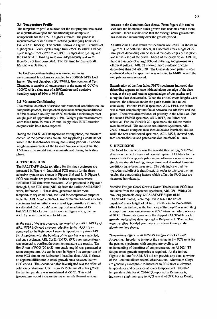
5-3
3.4 Temperature Profile The temperature profile selected for the test program was based on a profile developed for conditioning the composite components for the F/A-18 fighter aircraft. The profile is representative of one aircraft lifetime (4OOO flying hours or 20 FALSTAFF blocks). The profile, shown in Figure 3, consists of eight cycles. Seven cycles range from -35°C to +80"C and one cycle ranges from -35°C to +108"C. Temperature cycling and the FALSTAFF loading were run independently and were therefore not time correlated. The test time for one aircraft lifetime was 32 hours.
The 1Wtemperature testing was carried out in an environmental test chamber coupled to a lo00 kN MTS load frame. The test chamber, a SUNWELL Environmental Test Chamber, is capable of temperatures in the range of -50°C to +200"C with a slew rate of *20"C/minute and a relative humidity range of 10% to 95% [ 5 ] .
3.5 Moisture Conditioning To simulate the effect of service environmental conditions on the composite patches, four patched specimens were preconditioned at 95% relative humidity and 65°C to obtain a moisture percent weight gain of approximately 1.5%. Weight gain measurements were taken from 75 mm x 25 mm 14 ply thick BFRE traveler coupons with both faces exposed.
During the FALSTAFF/temperature testing phase, the moisture content of the patches was maintained by placing a container of water in the test chamber during non-testing periods . Periodic weight measurements of the traveler coupon, ensured that the 1.5% moisture weight gain was maintained during the testing phase.
4. TESTRESULTS The FALSTAFF blocks to failure for the nine specimens are presented in Figure 4. Individual FCG results for the three adhesive systems are shown in Figures 5.6 and 7. In Figure 8, FCG rate results are presented for three specimens where sufficient FCG data were measured. Also presented in Figures 4 through 8, are FCG data (ARL 6) from the earlier AMRUNRC work, Reference 1. These data, generated under room temperature dry conditions, are used for comparative purposes. Note that ARL 6 had a precrack size of 24 mm whereas all other specimens had an initial crack size of approximately 20 mm. It is estimated that it would have required an additional 15 FALSTAFF blocks over that shown in Figure 4 to grow the ARL 6 cracks from 20 mm to 24 mm.
At the start of the test program, test results from ARL 14/15 and ARL 18/19 indicated a severe reduction in the FCG life as compared to the Reference 1 room temperature dry data (ARL 6). A problem with the bonding of the patches was suspected, and one specimen, ARL 20/21 (FM73,SO"C cure temperature), was selected to confirm the room temperature dry results. The fiist 5 mm of FCG (20 to 25 mm crack length) was generated at room temperature. As can be seen in Figure 5 , a comparison of these FCG data to the Reference 1 baseline data, ARL 6, shows no apparent difference in crack growth rates between the two FCG curves. The second variable investigated was the effect of cold temperature on FCG. From 25 to 32 mm of crack growth, the test temperature was maintained at -35°C. This cold temperature would increase the mean tensile thermal residual
stresses in the aluminum face sheets. From Figure 5, it can be seen that the immediate crack growth rate becomes much more variable. It can also be seen that the average crack growth rate has increased measurably over the growth period.
An ultrasonic C-scan result for specimen ARL 20121 is shown in Figure 9. For both face sheets, at a nominal crack length of 29 mm, patch debonding can be seen at the outer edges of the patch and in the wake of the crack. Ahead of the crack tip on ARL 20, there is evidence of a large debond initiating and growing in a elliptical pattern. ARL 21 showed more evidence of edge debonding than did ARL 20. The C-scan debond patterns were confirmed when the specimen was returned to AMRL where the two patches were removed.
Examination of the four failed FM73 specimens indicated that debonding appears to have initiated along the edge of the face sheet, at the top and bottom tapered edges of the patches and along the face sheet cracks. When the critical crack lengths were reached, the adhesive and/or the patch matrix then failed cohesively. For one FM300 specimen. ARL 14/15, the failure was almost completely interfacial between the adhesive and the patch. There was also evidence of porosity in the adhesive. For the second FM300 specimen, ARL 16/17, the failure was cohesive. For the Versilok 201 specimens. the failure modes were interfacial. The moisture conditioned specimen, ARL 26/27, showed complete face sheevadhesive interfacial failure while the non-conditioned specimen, ARL 24/25, showed both face sheevadhesive and patcwadhesive interfacial failures.
5. DISCUSSION The focus for this work was the investigation of hygrothermal effects on the performance of bonded repairs. FCG data for the various BFRE composite patch repair adhesive systems under simulated aircraft loading, temperature, and absorbed humidity conditions have been measured. The data indicate that the hygrothermal effect is significant. In order to interpret the test results, the contributing factors which affect the FCG data are discussed individually.
Baseline Fatigue Crack Growth Data: The baseline FCG data are taken from the unpatched specimen, ARL 3/4. With a 20 mm long precrack, only 32 FALSTAFF flights (0.16 FALSTAFF blocks) were required to reach the critical unpatched crack length of 34 mm. There was no temperature effect for this failure, as the first temperature cycle was initiating a ramp from room temperature to 80°C when the failure cccured at 30°C. These data agree with the clipped FALSTAFF crack growth rate baseline data reported in Reference 1. The patches were therefore, bonded over near critical crack sizes in the aluminum face sheets.
Temperature Effect on AI 2024-T.3 Fatigue Crack Growth Properties: In order to interpret the change in the FCG rates for the patched specimens with temperature cycling, an understanding of the effect of temperature on the A1 2024-T3 fatigue crack growth properties is required. As the limited flights to failure for ARL 3/4 did not provide any data, a review of the literature allows several observations. Aluminum alloys are generally susceptible to increases in FCG rates at elevated temperatures and decreases at lower temperatures. Elevated temperature data for A1 2024T3, reported in Reference 6, indicates a slight increase in FCG rate at +108"C for an R-ratio

5-4
of 0.4. From Reference 7, for an R-ratio of 0.4, a -35°C service temperature could reduce the FCG rate in A1 2024-T3 sheet by as much as six times depending upon the crack length. This reduction in FCG rate at low temperatures is the result of the absence of water vapor in cold air. For the sandwich specimen geometry with the cracks covered with bonded patches, the cold temperature effect may not have been fully realized. Therefore, the temperature profie selected for this test program, -35°C to +SOT with a one in eight cycle peak of 108"C, should have had a beneficial effect on the FCG rate properties for the Al2024-T3 face sheet material.
Thermal Residual Stresses: The magnitude of the tensile residual stresses in the face sheets, induced by the selected adhesive cure temperature, significantly affected the FCG data. The dry FCG data for FM73 indicates that an increase in adhesive cure temperature from 80°C (ARL 18/19) to 120°C (ARL 7/8) can reduce the blocks to failure by a factor of two. However, the dry FM300 specimen (ARL 14/15) bonded at 176"c, does not show any more reduction in fatigue life than the 120°C cured FM73 specimen.
In order to estimate the magnitude of the peak thermal residual stress in the aluminum face sheets, the following expression was used [8]:
oT = (tpEp(aAl - aP)AT)/(tA'( 1 + tPEP/tA'EA1))
where tp is thickness of the patch, tAl is thickness of the face sheet, Ep is Young's modulus of the patch, EM is Youn s modulus of the face sheet, up is the CTE of the patch, ail is the CTE of the face sheet and AT is difference between the adhesive cure temperature and the test temperature. The following material properties were assumed:
Face sheet: tA1 = 3.2 mm EA1 = 71 GPa
Patch: tp = 0.924 mm Ep = 208 GPa aAl = 23 x 10-6(oC)'1
up = 4.5 x 10⁻⁶(oC)-1
As be seen in Table 2, temperature cycling can significantly increase the residual stresses in the face sheets at the low test temperatures. This results in a higher FALSTAFF mean stress level, which in turn leads to higher FCG rates, as observed in the FM73 and FM300 specimens and shown in Figures 5 and 6. The results in Table 2 do not consider the reduction in the adhesive shear modulus, Ga. with increasing temperature. This will limit the CTE effect at the elevated test temperatures. As can be seen in Table 2, an inherent advantage of using a room temperature cure adhesive is the CTE effect is greatly reduced.
The thermal residual stress effect was also observed during the -35°C soak applied to the ARL 20/21 specimen (FM73,8OoC cure). With the -35°C temperature, there is a predicted increase in tensile residual stress in the face sheets from 33 MPa at m m temperature to 69 MPa at -35°C. This resulted in a measurable increase in the FCG rate as observed in Figure 5 .
T h e m 1 Effect on Adhesive and Patch Shear Moduli: The adhesive shear modulus, Ga, plays an important role in the performance of the bonded repair. Elevated temperature greatly reduces Ga and therefore significantly degrades the load canying capacity of the adhesive. In earlier work [9], Huculak
investigated the combined effects of hygrothermal conditioning and stress history (clipped FALSTAFF) on the performance of bonded graphite repairs with a room temperature adhesive, Hysol EA934. Dynamic shear modulus measurements indicated Ga was degraded by a factor of four at +lOO"C. There is considerable discussion in the open literature on representative Ga values for use in the analysis of bonded joints, especially at elevated temperatures. The data in Table 3, taken from CYTEC performance data and McDonnell Aircraft Company F/A-18 repair design allowables [lo], illustrate the magnitude of change in Ga with increases in temperature but also *e differences between the sources of information.
FCG results for the three adhesive systems used in this program indicate that the decrease in Ga with increased test temperature is also a major factor in the observed increases in the variable temperature FCG rates over those observed at room temperature.
The interlaminar shear modulus of the patch, G, is less affected by temperature increases than the adhesive shear modulus. Limited data on Boron 550514, a 176°C cured composite material, indicates that there is approximately a 10% decrease in G measured at room temperature and at 95OC [ 111.
Moisture Conditioning: For this test program, traveler specimens were used to maintain an approximate 1.5% moisture weight gain level. The traveler specimens, 14 ply solid laminates fabricated from the identical boron epoxy material as the patch, did not contain an adhesive bond line. In the actual specimen, the moisture weight gain is distributed between the patch matrix and the adhesive.. The level of moisture absorption into the adhesive is unknown. The moisture conditioned FCG results for the two epoxy adhesives, Figures 5 and 6, indicate much slower FCG rates than the non-conditioned specimens. It is difficult to interpret these results as there appears to be a combined effect of matrix and adhesive degradation and induced residual stresses. The debond surfaces for the moisture conditioned FM73 (ARL 1W11) specimen do not indicate a change in the cohesive failure mode observed for the non-conditioned specimen, ARL 718.
For the Versilok 201 specimen, ARL 26/27, moisture conditioning appears to have totally degraded the interface between the adhesive and the aluminum face sheets resulting in total patch debond after 31 FALSTAFF flights, Figure 7. One of the disadvantages of acrylic adhesives is their sensitivity to humidity on metallic surfaces which restricts their use to benign conditions.
Fatigue Life Comparisons: As shown in Figure 4, the beneficial affect of the BFRE patches in extending the fatigue life of the cracked specimens is evident. Under FALSTAFF and temperature cycling, the two epoxy based adhesives provided a minimum of 150 times improvement in fatigue life compared to the unrepaired specimen. However, this improvement in fatigue life is seven times less than the FALSTAFF data (1 100 times) generated at m m temperature. Compared to the baseline dry room temperature FCG data, the FCG life for FM73 with the 80°C cure temperature was reduced by a factor of 3.5. For cure temperatures of 120" and 176"C, for the FM73 and FM300 specimens respectively, the FCG lives were reduced by a factor of seven. This indicates that the CTE effect from the combination induced residual cure stresses and the selected temperature cycling were the dominant factors in reducing the
I
I

FCG lives. The dry acrylic data, ARL 24/25 indicates that temperature cycling will also significantly degrade the performance of acrylic adhesives, and this is consistant with previous work using constant amplitude cycling [12]. The effect of moisture conditioning did not further reduce the FCG lives for the two epoxy adhesives. The moisture effect on the acrylic adhesive was dramatic.
The FCG rates for three dry specimens are compared to the room temperature data (Reference 1) in Figure 8. For a crack length of 40 mm, the FCG rate for the temperature cycled data is five to eight times greater than the room temperature data .
6. CONCLUSIONS The FCG data for this test program clearly indicates that representative testing is imperative to fully understand and qualify composite bonded repairs of primary and secondary metallic structure. The use of appropriate material allowables is critical in the design and analysis of bonded repair schemes.
The availability of such data is limited and further testing is required to confirm the trends noted by this limited data set. This is a difficult goal to achieve for the data presented in this paper was expensive to generate and time consuming.
The conclusions from this test program are the following:
1. Bonded composite repairs are an effective method of repairing significant cracks to aluminum aircraft structure. The life extensions of the repaired specimens compared to the unrepaired specimens ranged from 150 to 400 times under severe loading and environmental conditions.
2. The selected temperature range for the test program, -35°C to +80°C with a one in eight cycle peak of +108”C. may have had a minor beneficial effect on the FCG rate in the A1 2024-T3 face sheets.
3. FCG lives from 3.5 to 6 times as compared to the room temperature dry FCG data. FM73, cured at 80”C, was the best performing adhesive.
Temperature cycling of dry specimens caused reductions in
4. sheets significantly increased the FCG rates for the FM73 and FM300 specimens.
The temperature induced tensile residual stresses in the face
5 . The reduction in the adhesive shear modulus, Ga, with increasing temperature significantly decmsed the load transfer to the patches and resulted in higher FCG rates.
6. Compared to the dry temperature cycled FCG data, there was no significant decrease in FCG lives for the two moisture conditioned epoxy based adhesives, FM73 and FM300.
7. the cohesive failure mode for the FM73 adhesive.
Thermal cycling and moisture conditioning did not change
8. revealing extensive porosity. This indicates possible contamination of the patch face.
One FM300 specimen, ARL 14/15, debonded interfacially
5-5
7. ACKNOWLEDGEMENTS The work carried out at the NRC has been performed under IAR Program 3G3, Aerospace Structures, Structural Dynamics and Acoustics, Project JGN-00, Composite Repair Techniques for Primary Aircraft Structures.
8. REFERENCES 1.
2.
3.
4..
5.
6.
7.
8.
9.
10.
1 1 .
12.
M.D. Raizenne, J.B.R. Heath and T. Benak, ”‘ITCP FTP-4 Collaborative Test Program - Variable Amplitude Loading of Thin Metallic Materials Repaired with Composite Patches”, NRC Laboratory Technical Report LTR-ST- 1662,1988.
Various Authors, “FALSTAFF, Description of a Fighter Aircraft Loading Standard for Fatigue”, F&W, Switzerland, LBF, Germany, NLR, The Netherlands, IABG. Germany, March 1976.
J.P. Komorowski, “Hygrothermal Effects in Continuous Fibre Reinforced Composites, Parts I-IV”, NRC, NAE-AN- 4, NRC No. 20974, Ottawa, January 1983.
T.J. Benak, C.E. Chapman, “Radiographic Technique for the Measurement of Fatigue Crack Growth in Cracked AI 2024 Test Panels with BoronEpoxy Patches”, NRC Laboratory Memorandum ST-521, July 1988.
J.P. Komorowski and D.L. Simpson “Design Considerations, Environmental Testing Facility for Composite Materials and Structures”, NRC Laboratory Technical Report LTR-ST-1505, June 1984.
Damage Tolerant Design Handbook, MCIC-HB-OIR, Volume 3, 1983.
D. Broek, “Residual Strength and Fatigue Crack Growth in Two Aluminium Alloy Sheets at Temperatures Down to - 75”C”, NLR Report TR 72096,1972.
A.A. Baker and R. Jones, “Bonded Repair of Aircraft Structures”, Martinus Nijhoff Publishers, Dordrecht, 1988.
P. Huculak, M.D. Raizenne and R.F. Scott, “Influences of Environment and Stress History on the Composite Patch Repair of Cracked Metallic Structures”, Canadian Aeronautics and Space Institute Journal, Volume 34, No. 2. June 1988.
L.J. Hart Smith, “A4EI Bonded Joint Program”, McDonnell Aircraft Company Report A8372.1983.
AFML, “Advanced Composites Design Guide”, Third Edition, Vol IV, Materials, 1973.
A.A. Baker, “Repair Efficiency of Fatigue Cracked Aluminium Components Reinforced with BoronEpoxy Patches”, Fatigue Fracture Engineering Materials Structures, Vo1.16, No. 7, 1993.
9. The two Versilok 201 specimens debonded interfacially.

5-6
Cure Temp
24°C
80°C 120°C
176°C
Specimen No.
-35OC 24OC 8OoC 104OC 36 0 -33 -48 69 33 0 -15 93 57 24 9 127 91 58 43
Honeycomb Adhesive1 I Cure Temp (OC)
FM73 (McAIR) FM73 (CYTEC) FM300 (McAIR)
FM300 (CYTEC)
ARL 314 ARL 718 ARL 10111 ARL 14/15 ARLl 6/17 ARL 18/19 ARL 20/2 1 ARL 24/25 ARL 26/27
24OC Dry 85OC Dry 85OC Wet 104OC Dry 104OC Wet 355 135 60 20 840 260
390 204 160 170 125 910 445 190
FM731120 FM73/80 FM73BO FM3001176 FM3001176 FM73l80 FM73BO FM73/80 FM73BO
BFRE Patch Adhesive1 Cure Temp ("C) Not Repaired FM7Y 120 FM731120 FM300I 176 FM3001176 FM73BO FM73BO Versilok 201lRT Versilok 201/RT
Bondline Thickness (mm)
0.3 0.3 0.12 0.12 0.16 0.16 0.4 0.4
Moisture Conditioning
Dry
Dry
Dry
Dry
Dry
Wet
Wet
Wet
Notes: Environmental Conditioning:
1) Dry - no moisture conditioning of BFRE patch 2) Wet - specimen with exposed BFRE patches conditioned at 65°C and 95% relative humidity. Moisture weight gain of
1.5% measured using traveler BFRE coupons.
Table 1: Test Matrix
Table 2: Residual stresses, Oa, (MPa) in Aluminum Face sheets for Adhesive Cure Temperatures and Test Temperatures
Table 3: Adhesive Shear Modulus, Ga, (MPa) for Different Test Temperatures Using Two Data Sources

- 178nn -
254""
- 160nn - , -
MACHINED NOTCH PLUS PRECRACK (o=APPROX. 20nn)
Figure l(a): Non-Repaired Specimen
n 254nn
- 178nn -
REAR SHEET HONEVCOMB CORE
MACHINED NOTCH PLUS PRECRACK (n=APPROX. 20nn)
PRECURED 7 LAYER B COMPOSITE PATCH. ADHESIVELY BONDED
AL ALLOY 2024-T3 3.2nn THICK
FRONT SHEET
ALUMINUM SPACER BLOCK (12.78nm THICK)
5-7
REAR SHEET
AL ALLOY 2024-T3 3.2nn THICK
Figure l(b): BFRE Patch Repair Specimen

I i

A w 6 / 2 7 (Repaired - Versilok201/17, wet,
0.16 FALSTAFF Blh.)
ARL24R5 (Repaired - VersiIok201/17, dry, 15.48 temp. cycles)
ARLlWl7 (Repaired - FM300/176, wet, 8.71 temp. cycles, stopped
testing prior to failure)
- m ARL14/15 (Repaired-
temp. cycles) FM300/176, dry, 11.05 9
0 E N
.e $
FM73/120, wcf 11.26 $ e
.- 3
Y c
ARL7/8 (Repaired - .t - N,
,a e ARLIO/I I (Repaired - o
temp. cycles) m m . - rn (Y
.,,- FM73/120, dry, 11.51 temp. cycles) - $i
5 temp. & -35°C soak, 3
m
z stopped testing prior to N
E
FM73/ 80, dry, 23.67 s temp. cycles) .- 3
3
f
s I. (Y
ARLZORl** (Repaired - $ FM73/80, dry, mom
0
Li: .- i
ARL18/19(Repaired- m % 2
0
ARL6' (Repaired - - FM73/80, dry, roam E
temp., precrack = 24mm) I rn - - .. ;s
temp. cycle, precrack= B
e o
d .E
ARL3/4 (Not repaired,
20 mm, 0.16 FALSTAFF gg Blks.) g z
E 2 ARL7/ARL8* (Not .g,
2 5 2 5 o r
E. .9 repaired, mom temp., precrack = 5 mm)
* I m 0 * 0 0 m *
P N x , - N :: 2 0 m
FALSTAFF Blocks
h .I
2 w .
.. Q

5-10
70 'F
35
30
< 25
20
I S
Figore 5 FM73 FCG Results
0 20 40 60 80 1W 120 110 160
QAAWTAQQ Blmb Conplthd
Figure 6: FM300 FCG Results
70
61
60 g 51
;i A 45
5
< 25
= 40
i :: 20
I5 0 20 40 60 BO I W I20 I40 IM
FNSTAFQBIochCmapkhd
I 0 20 40 60 BO I W I20 I40 IM
FNSTAFQBIochCmapkhd
Figure 7: Versilok 201/17 FCG Results

1.00E-05
Y
k g 3 4 - 1.00E-06 .
U
C A
Q
A A ..
X
.X
0
w
.. X
x K
X ARL 6 IRepaired-FM73/80, dry, room temp. Ref. 1 t
0 ARL 14/15 (Repaired- FM300/176, dry, temp. Cycle)
A ARL 718 IRepaired- FM73/120, dry, temp. cycle1
ARLl8/19 IRepaired- FM73/80, dry, temp. cyclet
0.01
Average Crack Length, a (m)
Figure 8: Fatigue Crack Growth Rate Results
0. I

5-12
Face Sheet ARL 21 (Rear)
I'
P Face Sheet ARL 20 (Front)
25.4 mm (1 inch)
Figure 9: C-Scan Image of Specimen ARL 20/21, room temperatnre test conditions, 30.02 mm after 37.5 FALSTAFF blocks

6- 1
DESIGN AND STRUCTURAL VALIDATION OF CF116 UPPER WING SKIN BORON DOUBLER
t
J. Smith Bombardier Inc., Canadair Defence Systems Division 10,000 Cargo A-4 Street
Montreal International Airport - Mirabel Mirabel, Quebec, Canada
J7N 1H3
1. SUMMARY Cracks were found around fastener holes in the critical area known as the “Golden Triangle” on the upper wing skin of several CF116 aircraft. To restore the structural integrity of the wing, cracks around these fastener holes are removed and interference fit steel bushings are installed. A boron-epoxy doubler is then bonded over the reworked area to reduce stress levels. The doubler is viewed as a fatigue enhancement device and not as a repair to .a cracked skin. An analytical methodology is used to assess the bond line integrity and the load transfer in the doubler. A 49% reduction of stress level is predicted by the bonded joint analytical approach. A finite element analysis reveals that a 47% stress reduction is expected in the exterior surface of the wing skin, while a 37% reduction in the interior surface is predicted. Based on a strain survey performed following the installation of a doubler on the CF116 full scale fatigue test, it is shown that analytical predictions agree with experimental results.
2. INTRODUCTION The Canadian Forces operate the F5 AA3 aircraft (CF116 is the official designation) in the advanced jet trainer role as a lead-in to the F18 AA3 fighter aircraft. During the summer of 1991, several fatigue cracks were discovered in the upper wing skin of several CF116, at the attachment of the 44% spar to the root rib. These cracks initiate in either of the three fasteners holes known as the “Golden Trian- gle”, a region measuring approximately 2 inches by 2 inches. Tensile residual stresses due to compressive overloads are suspected to cause the cracking problem. Figure 1 shows the location of the “Golden Triangle” on the upper wing skin of the CF116 aircraft.
The repair in the damaged area consists of removing cracks by oversizing the fastener holes, followed by installation of interference fit steel bushings. A doubler is then installed over the “Golden Triangle” to reduce strain levels and inhibit crack initiation. Furthermore, the repair prevents crack growth, should a crack be present.
This article describes the design and validation process of the CF116 upper wing skin bonded doubler. The level of agreement between analytical predictions and full scale test measurements is emphasized throughout this text.
3. DESIGN CONSIDERATIONS
3.1 Repair Philosophy The composite doubler designed for the CF116 upper wing skin is a fatigue enhancement device intended to reduce stress levels by 30% to 40% in the “Golden Triangle” region. Repair limits for the “Golden Triangle” fastener holes are based on the premise that no doubler is bonded
n
TLplcal Fatlgus Crack Orlsntrtlm
Figure 1 Golden Triangle Location on CF116 Aircraft
over the critical region (Ref. 1). The bonded doubler is not a repair to a cracked skin and is not intended to transfer all the skin load.
3.2 Design Loads The major principal limit load in the “Golden Triangle” area of the upper wing skin is 45000 psi in compression, acting spanwise in the direction of the 44% spar. This load produces the maximum gross stress level in the “Golden Triangle”. This critical stress level results from a 7g symmetric pull-up manoeuvre.
The minor principal load in the “Golden Triangle”, i.e. the chordwise load, is approximately one tenth of the major principal load, and is tensile. The limit load in the minor principal direction is thus +4500 psi. The material used in the CF116 upper wing skin is 7075-T651 aluminium clad plate.
3.3 Selection of Doubler Material Textron 5505 boron-epoxy preimpregnated tape is selected for the doubler material. For this application, boron-epoxy is found superior to other composite materials on several standpoints. Boron-epoxy is stiffer and has a coefficient of thermal expansion closer to that of the aluminium wing
Paper presented at the 79th Meeting of the AGARD Structures and Materials Panel on “Composite Repair of Military Aircrafr Structures” held in Seville, Spain 3-5 Octoher 1994.

6-2
skin material. Boron fibres have better galvanic compati- bility with aluminium compared to graphite fibres. The electrical conductivity of boron also allows better eddy current inspection of the underlying structure. Boron-epoxy is well accepted as a doubler repair material for metal structures (Ref. 2).
3.4 Selection of Adhesive FM 73 film adhesive from Cyanamid is selected to bond the doubler to the aluminium wing skin. Film adhesives have more uniform properties than paste adhesives and are easier to apply. A vacuum bag curing process is used to bond the doubler in place. The range of cure temperatures for FM 73, between 180°F to 220”F, is expected to be maintained with relative ease, considering the large heat sink in the wing. Two layers of adhesive are used to ensure suitable adhesive content following cure.
3.5 Doubler Configuration The doubler has a uni-directional (0”) layup. Fibres are oriented in the direction of the maximum principal stress found in the wing skin. There are no transverse or cross plys in order to avoid transverse loading of the doubler.
The selected baseline shape of the doubler is a circle because this shape is expected to provide uniform stress levels in the skin across the width of the doubler (Ref. 3). Due to the proximity of the “Golden Triangle” to the straight edge of the skin, and to facilitate layup of individ- ual laminae, the actual doubler shape is an approximate half-circle shape defined by straight segments.
To achieve the required 30% to 40% stress level reduction, a joint stiffness ratio of 1.0 is determined. According to Bateman (Ref. 4), a circular patch with a 1.0 stiffness ratio bonded to an infinite sheet should produce a 40% stress reduction in the sheet. The stiffness ratio “S” is the ratio of the stiffness per unit width between the composite doubler and the wing skin:
In the above equation, E represents the modulus of elasticity, “t” is the adherent thickness and subscripts “d” and “s” identify the doubler and skin. Since a uni-directional layup is used, the modulus of the doubler is equivalent to the elastic modulus of boron-epoxy in the fibre direction. Based on a 0.34 inch skin thickness in the “Golden Triangle”, the doubler thickness is 0.1 167 inch which, based on a cured lamina thickness of 0.0052 inch, corresponds to 23 plys of boron-epoxy material.
4. BONDED JOINT ANALYSIS
4.1 Description of Methodology A bonded joint analysis is performed to assess if the doubler can statically sustain the predicted load transfer.
The methodology used for this application predicts load distributions in infinitely wide stepped-lap adhesive- bonded splices or doubler configurations under in-plane loading (Refs. 5 to 7). The methodology accounts for
adherent thicknesses, material properties of the adherents and adhesive, porosity and disbonds anywhere on the bond line. It also considers mismatch in stiffness and thermal expansion between the adherents. In addition to mechan- ical loads, the effects of thermal mismatch on the stress distributions are also considered. However, the methodol- ogy is unable to predict transverse shear and peel stresses in the adhesive and does not consider the actual adhesive thickness.
In this methodology, adhesive properties are approximated by an elastic-perfectly plastic stress-strain curve as shown in Figure 2. The shear modulus, maximum shear stress and maximum shear strain, which define this idealized adhesive behaviour, are determined experimentally.
The predicted load distributions serve to determine the elastic joint strength and the elastic-plastic joint strength. The elastic joint strength is the load level under which the adhesive first begins to yield. The. elastic-plastic joint strength is predicted when the adhesive reaches its failure strain (y max in Figure 2). The limit margin of safety of the bonded joint is determined by comparing limit load with the predicted elastic joint strength. The margin of safety for ultimate load compares the predicted elastic-plastic joint strength with the ultimate load.
For practicality, the methodology is available as a computer programme whereby the joint is modelled as a series of discrete steps, as shown in Figure 3. It is assumed that the entire load is applied to the first step of the skin and that no load is carried by the first step of the doubler. A calibrated adhesive thickness, established to allow predic- tions to agree with experimental results, must be entered in the adhesive input data of the programme.
4.2 Failure Criteria For the purposes of this application, the bonded joint failure criteria is established as follows:
1. The adhesive shall not deform plastically under limit load conditions.
2. The elastic-plastic adhesive failure shall occur when the adhesive shear strain reaches 80% of the plastic strain limit under ultimate load condi- tions to account for residual thermal stresses. The 20% gap provides a buffer against unforeseen thermal effects.
3. Since the doubler is bonded using a vacuum bag technique, which results in higher porosity than in an autoclave cure, the predicted joint strength shall be reduced by 30%.
The bonded joint analysis is performed by assuming that the ultimate loads corresponding to the 7g symmetric pull- up manoeuvre are applied to the “Golden Triangle” region of the upper wing skin. Only residual thermal stresses in the wing skin and doubler resulting from cold weather contraction of the wing are considered. Residual thermal stresses resulting from elevated temperature curing are neglected since local expansion of the wing in the “Golden Triangle” area is severely restricted by the large unheated portion of the wing.

6-3
S H E A R
S T R E S S
Ye 0.8 ymax ymax
SHEAR STRAIN
Figure 2 Idealized Adhesive Shear Stress vs Shear Strain Curve
4.3 Results of Bonded Joint Analysis
4.3.1 Doubler Based on the bond line analysis, it is predicted that the doubler is capable of sustaining ultimate loads, both in the thick flat region and at the edges. In the direction of the fibres, residual thermal stresses are considered. The strain levels are determined for cold temperature conditions of -60°F. At the edge of the doubler, the strain is estimated at -0.0084 i n h , while the estimated strain in the middle of the doubler is -0.00321 in./in. These strain levels are lower than the allowable compressive strain of -0.01367 in./in. (Ref. 8).
In the 90” fibre direction, the strain at the edge of the doubler is estimated to be 0.00064 in./in. In the middle of the doubler, the estimated strain level is 0.00060 in./in. These levels are much lower than the allowable strain of 0.00325 (Ref. 8). Thermal effects are neglected in this direction because thermal expansion coefficients of boron-epoxy and aluminium are similar.
4.3.2 Adhesive Figure 4 shows shear strain variations in the adhesive when ultimate load is applied and thermal effects are considered.
The bonded joint analysis predicts that the shear strain is too high at the edge of the doubler. Although not shown, similar behaviour is found for limit load conditions. How- ever, this is of minor importance since the adhesive is actually thicker than the calibrated thickness that must be used in the computer programme. A thicker bond line, especially at the edge of the doubler, decreases the shear strain in the adhesive, which should increase joint strength. Furthermore, since it is a fatigue enhancement device, failure of the doubler will not lead to failure of the wing. Further experimental work is recommended to determine adhesive design properties that will allow analysis of joints with two layers of adhesive. Figure 4 also shows that adhesive shear strain levels are high at the edge and decrease to zero in the middle of the doubler as the load transfer is completed.
Figure 5 illustrates the stress reduction in the wing skin resulting from the bonded joint analysis. A 49% stress level reduction is predicted for the “Golden Triangle” region. The assumption of infinitely wide joints, inherent to the bonded joint methodology, explains this higher than expected result.

6-4
Boron-Epoxy Doubler 7 Adhesive
7075-T651
1 STEP @ STEP @
Figure 3 Typical Modelling of Doubler for Bonded Joint Analysis
Adhesive Shear Strain / GAMMA max 1.4
1.2
1
0.8
0.6
0.4
0.2
0
. .. ...... .-
0 1
0 0.2 0.4 0.6
X Figure 4 Estimated Shear Strain in Adhesive from Edge to Middle of Doubler
0.8 1

6-5
Stress Reduction in Wing Skin (%) 60
50
4 0
30
20
10
0 / I I I I
0 0.2 0.4 0.6 0.8 1
X Figure 5 Expected Stress Reduction in Wing Skin from Edge to Middle of Doubler
Figure 6 shows the final configuration of the doubler as it actually appears on the CF116 upper wing skin. The portion of the doubler with the full thickness of 23 plys covers the entire “Golden Triangle”. The following table summarizes the doubler configuration.
Number of boron-epoxy plies in thick portion: Length of doubler in thick portion: Taper angle: 1.5” Total length of doubler: Thickness of FM 73 adhesive: 0.016 inch Layup: 0”
23 2.0 inches
10.76 inches
Upper Wing Skin
,-Boron-Epoxy Doubler
Wing Root Rib
% Spar
Forward
Figure 6 Final Doubler Configuration
5. FINITE ELEMENT ANALYSIS
5.1 Modelling The finite element analysis of the doubler and wing skin serves to verify the effect of doubler dimensions on the expected stress level, given the small size of the doubler relatively to the wing skin. The finite element analysis also allows an assessment of the variation of stress reduction through the thickness of the upper skin.
The analysis is based on the finite element model of the CFl l6 wing (Ref. 9), which has been modified to incorpo- rate a detailed mesh in the “Golden Triangle” region. The wing skin is modelled using four noded quadrilateral and three noded triangular, isoparametric plate elements. Plate elements with layered composite capabilities are added over the plate elements of the wing skin to model the boron-epoxy doubler. The adhesive between the doubler and the skin is not modelled because attention is directed to the region where adhesive shear strains are low. The finite elements simulating the doubler are rigidly con- nected to the skin elements, preventing any gradual load transfer between the skin and the doubler in the finite element model. However, this is not expected to greatly alter the predicted stress levels in the “Golden Triangle” region.
Figure 7 shows part of the finite element mesh of the wing in the “Golden Triangle” region of the upper skin. An outline of the boron-epoxy doubler is highlighted. The doubler taper is simulated by appropriately increasing the number of plys of the finite elements from the edge to the centre of the doubler.

6-6
Outline of Boron-Epoxy Doubler
5.2 Stress Reduction in Skin Finite element predictions of stress levels for a line going through 2 fastener holes in the “Golden Triangle” (Figure 8) are presented for the critical 7g symmetric pull-up manoeuvre. Figure 9 shows results at the exterior surface of the upper wing skin before and after the doubler is added. Similar results are presented for the interior surface (i.e. opposite to the bonded surface) in Figure 10. Figures 9 and 10 show stress levels in the major principal direction (i.e. spanwise), under limit load.
Inboard
- Forward
Figure 8 Location of X Axis on “Golden Triangle” for Figures 9 and 10
As Figure 9 shows, a reduction in stress levels of approxi- mately 47% is predicted on the exterior surface at the “Golden Triangle” when the boron-epoxy doubler is added. This prediction is higher than the 40% stress.level predic- tion based on Bateman’s work (Ref. 4).
A smaller reduction of approximately 37% is observed in Figure 10, for the interior surface of the upper wing skin. However, this prediction meets the required minimum reduction of 30% to 40% established at the beginning of this work. -
Forward
Figure 7 Finite Element Model in the “Golden Triangle” Region
5.3 Secondary Bending Finite element results show an augmentation of stress levels in the wing skin, near the doubler, as revealed in Figure 12. Out-of-plane bending is induced as a result of shifting of the neutral axis in the reinforced region of the wing skin. Since the skin is constrained by the substructure, residual stresses appear in the skin, near the edge of the doubler. The increase in stress level in this region is 28%. This bendine effect i s well documented in Ref. 10.
U

6-7
- 2 0 -
Exterior Surf ace
--- . - -. -. . -- .-- . - . - . - .. .. ... _. __ . .. ... . .. . ..- .-. . . . . .. . . .... . . .... . .- . . .- . . .. ..... .. . . .- . __ , - __.
- 20 ~
-+- Without Doubler ++ With Doubler Figure 9 Effect of Doubler on Stress Levels in “Golden Triangle”, Exterior Surface of Upper Wing Skin
Interior Surface
-100 I I I I I I
0 0.2 0.4 0.6 0.8 1 X
+- Without Doubler With Doubler
Figure 10 Effect of Doubler on Stress Levels in “Golden Triangle”, Interior Surface of Upper Wing Skin

6-8
- 1 0 -
Inboard
f
.---. .. . ...
X A Forward
Figure 11 Location of X Axis on Upper Wing for Figure 12
6. EXPERIMENTAL VALIDATION The CF116 Full Scale Durability and Damage Tolerance Test (FSDADlT) provided an excellent opportunity to validate the predicted stress reductions provided by the boron-epoxy doubler. The FSDADTT, conducted at Canadair between 1990 and 1994, aims to demonstrate a durability life of 6,000 equivalent flight hours (EFH) and to investigate the possibility of a life extension to 8,000 EFH.
Validation of the doubler began with one boron-epoxy doubler installed on the right-hand side of the upper wing of the test article. Strain gauge locations are shown in Figure 13. Gauges located on the exterior surface of the doubler are identified by the letter “T” at the end of their identification numbers. Similarly, gauges positioned below the doubler, on the exterior surface of the wing skin, are identified by the letter “B”. Numbers ending with “T/B” identify locations where one gauge was installed on each of these surfaces.
Figure 14 shows strain readings at 80% of the 7g symmetric pull-up manoeuvre. For gauge ZA-l4B, located in the middle of the “Golden Triangle”, the strain level is -4580 pin./in. before the doubler is bonded and -2300 pin./in. after the doubler is bonded. This translates into a reduction of 49.7%. The 47% prediction from the finite element analysis is thus slightly lower than the experimental result. Readings from gauge ZA-IOE, installed spanwise on the edge of the wing skin, indicate a strain reduction of 31%. The critical 7g symmetric pull-up manoeuvre occurred once every 14 simulated flight hours in the FSDADTT load spectrum.
The reader will note some inconsistency with readings from gauge ZA-22B in Figure 14. A comparison of these read- ings before and after the doubler is installed shows that the
Exterior Su r f ac e
- 20
- 30
- 40
- 50
I --- .. .- .. -. - ... .. .. .. ... ._ . ...I _ . _._.._.__..._._.___._I _ _ _ _
-60 1 I I I I I I I
0 0.25 0.5 0.75 1 1.25 1.5 1.75 2 X
-$- Without Doubler ?It With Doubler Figure 12 Bending Effect Near Edge of Doubler (Exterior Surface of Upper Wing Skin)

6-9
-2500
strain level on the exterior surface of the skin increases after the doubler is bonded in place, contrary to the effect that is expected. This inconsistent result is attributed to disbonding of the doubler and is supported by the results from the fifth strain survey, which uncovered a distinct break of linearity for this strain gauge. In addition, this linearity break coincided with the recording of an event by acoustic emission sensors installed in the vicinity of the "Golden Triangle". These phenomena are suspected to signal incipient disbonding of the doubler.
ZA-14B
ZA-38
ZR-12BA -
Figure 13 Strain Gauge Locations on Full Scale Test Article, First Doubler
-3000
-3500-
-4000
-4500
-5000
-5500
Micro Strain
ZR-12BA -
ZA-1OE v D
ZA-38 -
- ZA-14B
- ZA-1OE
I I I I I I I I I
A reading for strain gauge ZA-22B obtained at 40% of the load (-1 170 pin./in.) is extrapolated to evaluate the reading that should be expected in Figure 14. The results are shown in Figure 15. Based on this extrapolated result, the strain level reduction at this gauge location should be 24%.
As revealed by readings from strain gauge ZA-38 (Figures 14 or 15), strain levels increase by 29% in the skin near the edge of the doubler. This increase is a manifestation of the bending effect highlighted by Figure 12. The augmentation of strain level at the edge of the doubler is exactly predicted by the finite element analysis.
The disbond in the first doubler was reported to grow rapidly with continued load application, leading to failure. Although having strain gauges between the doubler and skin unfavourably affects the bond line integrity, it never- theless provided valuable data on the stress and strain levels in the wing skin just below the doubler.
After removal of the first doubler and careful preparation of the surface, a second doubler was bonded on the right- hand side of the wing. This time, no strain gauges were installed between the doubler and the wing surface. At 2000 hours, a 50% effectiveness was observed. A third doubler remained completely effective for 3800 hours after which the test was stopped. The effective life of 3800 hours is judged to be acceptable. Furthermore, the performance of this doubler does not support the predictions of inade- quate bond line strength established by the bonded joint analysis.
-E+ Before Doubler + After Doubler
Figure 14 Strain Gauge Readings, First Doubler (80% Critical Load)

6-10
Micro Strain - 2000
- 2500
-3000
-3500
-4000
- 4500
-5000
ZR-12BA
ZR-12BA
ZA-22B (Expected)
-. -. -. --. -. -. -. V=-. ZA-30
I ZA-14B
-5500‘ I I I I I I I I I
25 26 27 28 29 30 31 32 33 34 35
Wing Station (in)
-e- Before Doubler + After Doubler .--v---- Extrapolation
Figure 15 Strain Gauge Readings, Extrapolated ZA-228 Results, First Doubler (80% Critical Load)
7. CONCLUSIONS Cracks are found on several CF116 aircraft around three fastener holes in the critical area known as the “Golden Triangle” on the upper wing skin. The cracks are suspected to be caused by tensile residual stresses resulting from compressive overloads.
Rework limits around the fastener holes were established and a bonded boron-epoxy doubler was designed to act as a fatigue enhancement device. The aim is to decrease stress levels in the “Golden Triangle” by 30% to 40%.
Installation of a doubler on the CF116 full scale fatigue test reveals that the stress reduction in the exterior surface of the skin at the “Golden Triangle” is 49.7%.
A finite element analysis determines that the expected stress reduction is 47% at the exterior surface of the wing skin and 37% at the interior surface. These predictions are shown to be in general agreement with experimental results. In addition, the finite element prediction for the exterior surface is higher than the expected reduction of 40% established by Bateman (Ref. 4). The full scale test also reveals a bending effect at the edge of the doubler, predicted by the finite element analysis.
The bonded joint analysis predicts that the doubler can sustain the applied load. However, acceptable joint strengths could not be established because the methodol- ogy does not account for actual adhesive thickness. Further work is needed to determine adhesive design properties that will allow analysis of bonded joints that comprise two layers of adhesive. The bonded joint analysis predictions are not supported by results from the full scale test, which showed that the doubler can be effective for an acceptable period of time.
ACKNOWLEDGEMENTS The author wishes to thank the following persons for the precious help they provided during the writing of this article:
Messrs AIain Colle, Michel Beaulieu and Capt. Serge LeGuellec for reviewing this paper.
Messrs Jean Charest, Fadi AI-Ahmed and Yves Beauvais for retrieving some long lost files and for supplying results from the full scale test.
Messrs Thierry Klopp and FranGois Tanguay for generating some of the figures.
Finally, the enthusiastic contribution of Capt. Geoff Bateman during the design and analysis process is greatly appreciated.
REFERENCES
1. Rajotte, C. and Smith, J., “CF116 Upper Wing Skin “Golden Triangle” Repair. Analysis”, Canadair Report RAS-219-218, 31 March 1992.
2. Baker, A.A. and Jones R. (Editors), “Bonded Repair of Aircraft Structures”, Martinus Nijhoff Publishers, 1988 (ISBN 90-247-3606-4), p 109.
3. Bateman, G.R., “Composite Patch Repairs to Cracked Metal Sheets”, M.Sc. Thesis, College of Aeronautics, Cranfield Institute of Technology, September 1990, p 92.

6-1 I
4. Bateman, G.R., “Composite Patch Repairs to 7. Hart-Smith, L.J., “Adhesive Bonded Scarf and Stepped Lap Joints”, NASA CR 112237, 1973.
5. Hart-Smith, L.J., “Analysis and Design of 8. Military Handbook 17A, January 1971, p 4-129.
Cracked Metal Sheets”, p 124.
Advanced Composite Bonded Joints”, NASA 9. “NASTRAN Model Idealization/Validation”, CR 2218, 1973. Northrop Report NOR-78-7, June 1979.
6. Hart-Smith, L.J., “Adhesive Bonded Double-Lap 10. Baker, A.A. and Jones R. (Editors), “Bonded Joints”, NASA CR 112235, 1973. Repair of Aircraft Structures”, p 93.


7- 1
A FEAM BASED METHODOLOGY FOR ANALYZING COMPOSITE PATCH REPAIRS OF METALLIC STRUCTURES
D.S. Pipkins and S.N. Atluri Georgia Institute of Technology Computational Modeling Center
Rm. 225 French Bldg. Atlanta, GA 30332-0356, USA
SUMMARY A Finite Element Alternating Method based methodology applicable to the analysis of composite patch repairs of metallic structures is presented. The method is completely general and may be used to efficiently analyze factors affecting repair design such as: global stiffening of the aircraft structure due to the high stiffness of the composite patch; the effect of size, shape, thickness and material properties of the composite patch on the crack-tip stress intensity factors; the effect of the material properties of the adhesive on the crack-tip stress intensity factors; the effect of
thermal cycling on the composite repair; and the effect of disbonds on the effectiveness of the composite repair.
1.0 INTRODUCTION The current economic climate is forcing the operation of both military and civilian aircraft well beyond their original design lives. One consequence of this is the need to develop innovative repair techniques. One such technique is the use of adhesively bonded composite patches on metallic aircraft structure. Adhesively bonded composite
repairs of metallic structure have many advantages over riveted metal repairs such as: (i) no introduction of new stress concentrations into the repaired structure due to rivet holes; (ii) the composite patches are readily formed into complex shapes; (iii) high stiffness to weight and strength to weight ratios of the patch, (iv) high corrosion and fatigue resistance of the composite; and (v) inspection via eddy-current is possible for non-conducting fiber systems [l].
In order to properly design an adhesively bonded composite repair of a metallic
structure, many factors must be considered. These include:
global stiffening of the aircraft structure due to the high stiffness of the composite patch; the effect of size, shape, thickness and material properties of the composite patch on the crack-tip stress intensity factors; the effect of the material properties of the adhesive on the crack-tip stress intensity factors;
Paper presented at the 79th Meeting of the AGARD Structures and Materials Panel on "Composite Repair of Military Aircrafi Structures" held in Seville, Spain 3-5 October 1994.

1-2
the effect of thermal cycling on the
composite repair; and the effect of disbonds on the effectiveness of the composite repair.
This paper will describe a Finite Element Alternating Method (FEAM) based methodology for designing adhesively bonded composite patch repairs of metallic structures, which takes into account the above factors.
2.0 FINITE ELEMENT ALTERNATING
METHOD The Schwartz-Neumann alternating method is
a powerful technique which can be used to obtain the stress intensity factors associated
with a crack in a finite body. A detailed
description of this procedure can be found in [2]. The Schwartz-Neumann alternating method, as applied to fracture problems, makes use of two types of solutions.
Solution 1 : A general analytical solution for a crack (or cracks) in an infinite body subject to arbitrary crack face tractions. Solution 2: A numerical scheme (finite or boundary elements for instance) capable of solving for the stresses in an uncracked finite body.
For examples of analytical solutions which
may be used in the method, see [3] which pertains to an elliptical crack embedded in a
three dimensional infinite body and [4] which treats multiple cracks in a two dimensional infinite body. In the present paper, the finite element method will be used to solve for the stresses in the uncracked body. These two solutions are utilized in the following manner in the FEAM.
1. Solve the problem of the uncracked
finite body under the given extenial loads using the finite element method. The uncracked body has the same geometry as in the given problem except for the crack. Using the finite element solution of the uncracked body, compute the stresses at the crack location.
3. Compare these stresses calculated in step 2 with a permissible stress
magnitude. If the stresses are less
than the permissible stress magnitude, then stop.
The stresses at the crack location computed in step 2 are reversed to
create the traction free crack faces as in the given problem. The reversed stresses are applied to the infinite body problem and the analytical solution is obtained. The stress intensity factors for the infinite body problem are computed
analytically. The stresses at the location of the external surfaces of the finite body are determined from the analytical solution. The stresses computed in step 7 are reversed and treated as externally
applied tractions applied to the uncracked finite body.
Go to step 1, using the tractions computed in step 8 as the given external loading.
2.
4.
5.
6 .
7.
8.
9.
In practice, this process usually takes between three to five iterations to converge, depending upon factors such as the stress concentration

I
1-3
I
present in the uncracked body at the crack location. The overall stress intensity factors
are obtained by adding the stress intensity factors for all iterations.
The advantages of utilizing the FEAM to compute stress intensity factors are many.
However, they are all a result of the fact that only the uncracked structure is modeled with finite elements. The crack is specified simply
by giving crack tip coordinates in two dimensional problems and the major axis, minor axis and center coordinates of the ellipse which models the crack in three dimensional problems. As a consequence, the FEAh4 is extremely efficient from both a computational and manpower point of view
when performing parametric studies of crack size and location because the finite element
mesh remains the same. Note also that this property makes the FEAM ideal for
performing fatigue crack growth calculations.
3.0 COMPOSITE PATCH ALGORITHM The FEAM, as presented to this point, is a powerful tool for generating stress intensity
factors for cracks in homogeneous bodies. However, its application to metallic structure having adhesively bonded composite patches requires the introduction of a two step analysis procedure. This is because the analytical solution for an infinite body containing a crack (or cracks), whose faces
are subject to arbitrary tractions, is available only for certain homogenous bodies. The two
step analysis procedure used to generate stress intensity factors for structures repaired
with adhesively bonded composite patches is as follows. 1. Perform a finite element analysis of the
entire structure (i.e. original (metallic) structure, adhesive and composite patch)
under the given external loading. In this analysis, release the nodes at the location of the crack, but make no attempt to model the singular stress field which exists at the crack. Determine the equivalent nodal loads which exist at the interface of the adhesive and original structure. Perform the previously described FEAM analysis of the original structure with the initial external loading consisting of the given loading and the equivalent nodal loads calculated in step 1.
2.
Step 1 can in general be done using any finite
element software which allows the user to model the original structure, adhesive and the composite patch. The original structure is
modeled using solid elements if the crack is part-through or shell elements if the crack is through. The composite patch is modeled using a shell element. The adhesive is modeled using a special shear element which is compatible with the nodal degrees of
freedom of the elements modeling the original structure and composite patch [ 5 ] . Since a finite element analysis is used, various factors affecting the design of the repair are easily accounted for in Step 1. These include:
global stiffening of the aircraft structure due to the high stiffness of the composite patch; the effect of size, shape, thickness and material properties of the composite

1-4
patch on the crack-tip stress intensity factors;
the effect of the material properties of
the adhesive on the crack-tip stress intensity factors;
the effect of thermal cycling on the
composite repair, and the effect of disbonds on the effectiveness of the composite repair.
The importance of each of these design factors which may be accounted for in the
Step 1 analysis is now discussed briefly.
3.1 Global Stiffening Due to the high stiffness of the composite patch relative to the repaired aircraft structure (typically aluminum), the possibility of undesired stiffening of the structure must be considered in the repair design. The danger being that a significant increase in load flowing to the area of the repair could create
new fatigue problems at structural details (i.e. cut-outs, rivet holes, existing repairs, etc.) in
close proximity to the composite repair. In addition to being used to determine the load transfer between the adhesive and the structure, the Step 1 finite element solution can be used to study the stiffening effects of the repair. Stresses at these fatigue sensitive details near the composite repair can be determined from the Step 1 finite element solution and checked to make sure they are within an allowable range.
In the case of stiffened structure, a global-
local strategy [5 ] is used in conjunction with the two step analysis. The global analysis (Step 1 analysis) of the stiffened structure
makes use of shell elements to model the skin and beam elements to model frames, stringers, and fasteners. The composite patch and adhesive are modeled as discussed above. From this global analysis the fastener
reactions, in addition to the adhesive stresses, are determined. Then in the local analysis (Step 2 analysis) which analyzes the skin only, the fastener reactions are applied to the skin along with the adhesive stresses and the
given external loading and the.FEAM used to calculate the stress intensity factors.
3.2 Patch Properties
One of the primary advantages of composite patch repairs is the ability to tailor the geometry and material properties of the patch to specific situations. Of primary interest is the reduction in stress intensity factors achieved by the various candidate repairs.
The best way to reduce the stress intensity factors is to increase the stiffness of the
repair. This is done through an increase in either the patch thickness or elastic modulus.
However, there is an optimum stiffness beyond which increases produce little additional reduction in stress intensity factors.
Also, the increase in stiffness is known to increase the adhesive stresses near the ends of the repair. To reduce the high stresses in the adhesive at the ends of the repair, the patch can be tapered towards the end. The FEAM based methodology described in this paper allows a designer to efficiently, compare various patch sizes, shapes, thicknesses and material properties by altering the finite elements modeling the patch. This alteration is done in the Step 1

7-5
analysis. Therefore, using this technique, a designer can rapidly design a near optimum repair.
3.3 Adhesive Properties The most important characteristics of an adhesive are its shear modulus and shear
strain capability. The higher the shear modulus, the greater the reduction in stress intensity factors and the greater the adhesive stresses. Also, it is important that an
adhesive be able to sustain a relatively high shear strain, without failure. As such, the
ability to analyze the non-linear material behavior of the adhesive is important.
Further, the repaired structure will be subjected to sustained loads during flight. This necessitates the use of an adhesive
which creeps little under sustained load and recovers rapidly upon unloading. The present FEAM based methodology allows for the efficient analysis of repairs with differing shear modulus, non-linear material behaviors and creep characteristics. These adhesive characteristics are accounted for in the Step 1
analysis.
3.4 Thermal Cycling A composite repair is first subjected to thermal cycling during the installation process. This thermal cycling then continues during each flight of the repaired aircrafi.
The concern with the installation process is that during the elevated temperature curing of the adhesive, the metallic structure will expand much more than the composite patch. As a result, the repair process will produce a residual tension in the metallic structure.
Obviously, this residual tension reduces the
effectiveness of the repair and should be accounted for in the design. During operation
of the repaired aircraft, the differences in the thermal expansion properties of the composite patch and metal structure will produce loads which interact with the mechanical loading due to gusts, maneuvers, etc. Fatigue calculations which determine inspection intervals of the repair should take these thermal loads into account. The FEAM based
methodology described in this paper accounts for these thermally induced loads in the Step
1 Analysis.
3.5 Disbonds Disbonds can occur due to the development of high shear and normal (peel) stresses between the adhesive and the metallic structure. Regions near the crack and along the edges of the composite repair are particularly susceptible to disbonds. Another possible source of disbonds in composite patch repairs
is impact damage. Impact damage can be caused by runway debris, handling damage from fork lifis, dropped tools and similar mishaps. No matter what the cause, disbonds between the composite patch and repaired structure increases the stress intensity factors of the repaired crack and thus reduces the
effectiveness of the composite repair. Therefore, for a more realistic estimation of
the residual strength and life of the repaired structure, disbonds should be considered. To accomplish this, the present methodology models the disbond by releasing nodes connecting the adhesive elements and the elements modeling the original structure in

7-6
Step 1. This procedure allows for the
treatment of disbonds of arbitrary shape and
size. In the case of impact damage, Energy Methods are used to estimate the size and
location of the disbond for a given energy of impact. The loss of stiffness in the patch due to fiber-rupture during the course of impact is also accounted for.
4.0 NUMERICAL EXAMPLE Fatigue cracks which initiate at weep holes located in the risers emanating from the lower Wing surface panels have plagued the C-141
for some time. Such cracking was first observed in full-scale winglfuselage durability tests. As a result of these
observations, a rework procedure which consisted of reaming followed by low-
interference cold working was developed for the weep holes. Despite the application of
this rework procedure, weep hole cracking continues to adversely effect the structural integrity of the C-141 fleet.
The Air Force has recently begun using composite patches to repair lower wing panels in which weep hole cracks have been found. The ability to calculate the reduction in stress intensity factor due to the application of adhesively bonded composite patches to the lower wing panelhiser is demonstrated in
this section. The geometry and material parameters of the C-141 lower wing
panellriser are given in Figure 1. A critical stress intensity for a part elliptical crack in the riser was calculated to be 57.6 ksi& using NASA FLAGRO [6]. This number was based on a yield stress of 65 ksi, a plane
strain fracture toughness of 27 ksi& and a riser thickness of 0.18 in. The limit stress for
the lower wing panellriser is 34 ksi. All
applied loads in the analyses are uniformly
distributed over the cross section of the panellriser as shown in Figure 2. The mesh
in Figure 2 consists of 597 20 node brick elements and was used to model the metallic structure.
Reductions in stress intensity factor due to adhesively bonded composite patch repairs of cracked panels/risers were studied for four separate cracking cases. The patch and adhesive geometry and material parameters are given in Figure 3 (These are generic in nature). The patch material properties are representative of an 8 ply, uni-directional
boron-epoxy. For each cracking case, two
patching schemes are compared. Patch 1
models the riser patches only while Patch 2 models the riser patches as well a patch on the outer surface of the lower wing panel. This is done to study the effect that global stiffening of the structure has on the reduction in stress intensity factors. The global stiffening tends to induce local bending of the structure in the case of Patch 1 while this effect is lessened in the case of Patch 2.
Results for the four cracking cases are given in Figures 4-8. The stress intensity factors presented are for a 1 ksi unit load. The CPU time required for each run on a HP 9000/735 was about 11 minutes for the 597 element
mesh. Results for case 1, which required an 868 element mesh to model the metallic structure due to the severe stress

concentration (CPU time=25 minutes), indicate that while Patch 1 and Patch 2 significantly reduce the stress intensity factors, they do not restore sufficient residual strength to allow the structure to sustain the limit load of 34 ksi. Results for cases 2, 3 and 4 show significant reductions in stress
intensity factors due to the composite patches.
In all these cases, the Patch 2 scheme is superior to that of Patch 1 . This is particularly true for cracks below the weep hole which tend to be affected to a greater extent by the local bending induced by the global stiffening of Patch 1.
5.0 CONCLUSIONS A methodology to analyze composite repairs of cracked metallic aircraft structure based on
the FEAM has been presented. The methodology provides accurate solutions and is very efficient in terms of manpower and
computational times. The methodology is completely general and can be used in design
to assess factors such as: 0 global stiffening of the aircraft structure
due to the high stiffness of the composite
patch; 0 the effect of size, shape, thickness and ,
material properties of the composite patch on the crack-tip stress intensity
factors; the effect of the material properties of the adhesive on the crack-tip stress intensity factors; the effect of thermal cycling on the composite repair, and the effect of disbonds on the
effectiveness of the composite repair.
0
0
0
The methodology was demonstrated by using it to analyze a composite patch repair of a weep hole crack in a C-141 lower wing panel.
6.0 REFERENCES
S.N. Atluri, J.H. Park, P.E. O'Donoghue and R. Jones, "Composite Repairs of Cracked
Metallic Aircraft Structures", U.S. Dept. of Transportation Report No. DOT/FAA/CT-92/32, May 1993.
T. Nishioka and S. N. Atluri, "Analytical Solution for Embedded Elliptical Cracks and Finite Element Alternating Method for Elliptical Surface Cracks Subjected to Arbitrary Loading", Engineering Fracture
Mechanics, Vol. 17, 1983, pp. 247- 268.
K. Vijayakumar and S.N. Atluri, "An
Embedded Elliptical Crack, in an
M i t e Solid, Subject to Arbitrary
Crack Face Tractions", Journal of
AppliedMechanics, Vol. 103, NO. 1, 1981, pp. 88-96.
J.H. Park and S.N. Atluri, "Fatigue Growth of Multiple-Cracks Near a Row of Fastener-Holes in a Fuselage Lap-Joint", FAA Center of Excellence for Computational Modeling of Aircraft Structures Report Number 92- 1, 1992.

1-8
[5] J.H. Park, T. Ogiso and S.N. Atluri, "Analysis of Cracks in Aging Aircraft Structures, With and Without
Composite-Patch Repairs", Computational Mechanics, Vol. 10,
1992, pp. 169-201.
[6] R.G. Forrnan, NASA/FLAGRO Version 2.0 Users Manual, January 1993 Draft.

7-9
1.64"
UNPATCHED MODEL GEOMETRY AND
MATERIAL PARAMETERS
1 1.50"
4.1 8" I '
- ,
3.00"
4
Material: AL 7075T651 Young's Modulus: 10.3E+06 Shear Modulus: 3.9E+06 Poisson's Ratio: 0.33
Figure 1 : Geometry and Material Properties of the C-141 Lower Wing PaneYRiser

7-10
U
Figure 2: Finite Element Model of the C-141 Lower Wing Panel/Riser
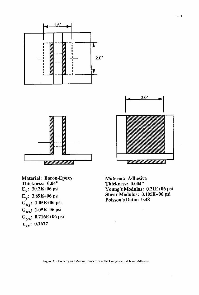
7-11
Material: Boron-Epoxy Thickness: 0.04" E,: 30.23+06 psi Ey: 3.693+06 psi GXy: 1.05E+06 psi Gxz: 1,05E+06 psi Gyz: 0.716E+06 psi vxy: 0.1677
.O"
2.0" r
Material: Adhesive Thickness: 0.004" Young's Modulus: 0.31E+06 psi Shear Modulus: 0.105E+06 psi Poisson's Ratio: 0.48
Figure 3: Geometry and Material Properties of the Composite Patch and Adhesive

7-12
CASE 1
25
20
15
10
5
0
1
I ' C I
a= 0.10" c= 0.08''
++ unpatched patch 1 - + *
pawn L
0 15 30 45 60
8 (degrees) 75 90
Figure 4: Stress Intensity Factors for Crack Case 1

CASE 2
1
0.8
0.4 I
l-4
0.2
a= 0.10" c= 0.08"
I I 1 I I
unpatched
0 0 15 30 45 60 75 90
8 (degrees)
7-13
Figure 5: Stress Intensity Factors for Crack Case 2

7-14
I I 1 I I - unpatched patch 1 patch 2
-+ --*-. -
n
CASE3 4 1
0.8
0.6
e r (
2 z- W
0.4
0.2
0
4-4 a= 0.10" c= 0.08"
0 15 30 45 60 75 90
8 (degrees)
Figure 6: Stress Intensity Factors for Crack Case 3

CASE
7-15
1
0.8
0.6
.r(
3 z- I
0.4
0.2
0
4 a= 0.10" c= 0.08"
I I I I I
-+- unpatched -0- * patch 1 ---)c-. patch 2 -
A V 3
1 I I I I
0 15 30 45 60 75 90
8 (degrees)
Figure 7: Stress Intensity Factors for Crack Case 4 (Upper Crack)

7-16
1
0.8
n
I
gH 0.4
0.2
CASE 4: Lower Crack n 4 - 4
a= 0.10" c= 0.08"
I I I I I
unpatched d
- * patch 1 *- patch2
- --
€3--
*---
0 0 15 30 45 60 75 90
8 (degrees)
Figure 8: Stress Intensity Factors for Crack Case 4 (Lower Crack)

STRUCTURAL MODIFICATION AND REPAIR OF C-130 WING STRUCTURE USING BONDED COMPOSITES
J. Gmko Engineer Specialist, Sr.
Lockheed Aemnautical Systems Company 86 South Cobb Drive
Marietta, Georgia 300634199 USA
1. SUMMARY Lockheed Aeronautical Systems Company (LASC)-in a pro- gram sponsored by the United Slates Air Force, Warner Robins Air Logistics Center, C-130 Directoratbhas devel- oped concepts wherein bonded high-modulus composite mate- rials can be applied to structurally repair or enhance the wing box of C-130 aircraff such as the one shown in E l p 1.
lko separate approaches are taken. In the first, boron/epoxy reinforcing strips are applied to wing box lower surface struc- ture to relieve high stress at a particular location in the wing
surface panel. This modification is ideally used on undamaged structure to prevent wing surface cracking. In the second approach, graphite reinforced patches are applied in the m e vicinity to m t crack growth. Both concepts were success- fully demonstrated on opposite sides of a full-scale wing test article.
Design details. the mateaids and processes, the methods of installation and the mutsund effectiveness of both the boron/ epoxy ships and the graphiteIepoxy patches are discussed below.
Figure 1. GI30 Aircrafl
Paper presented at the 79th Meeting of the AGARD Structures and Materials Pone1 on “Composite Repair oJMilirary Aircmfr Structures” held in Seville, S p i n 3-5 October 1994.

a-2
2. SYMBOLS a -
d -
h -
L -
b - r . Y -
A a -
E -
% - E r -
G -
Ga - s -
Crack Length from Bolt Centerline Figure 5 )
Characteristic Length
Adhemd Thickness, Crack Extension Specimen (Figure 5 )
Thickness of the Adhesive
Thickness of F’arent Material
Thickness of Repair Patch Material
Opening at Bolt Centerline. 0.75” from end of speci- men (Figure 5)
Crack Growth after Wedge Specimen Exposure (Figure 5)
Young’s Modulus
Young’s Modulus of Parent Material
Young’s Modulus of Repair Patch Material
Crack Extension Force (Figure 5 )
Shear Modulus of the Adhesive
Repair Patch (r)-to-Parent Material @) Stiffness Ratio,
i.e.. E, r f %,,, 3. INTRODUCTION Metallic aircraft components are susceptible to the develop ment of cracks in service by the various processes of fatigue or stress corrosion. These defects generally develop from sites of local stress concentration, such as fastener holes or other abrupt configurational changes. Conventional methods of repair for metallic aircraft sbuchue usuaUy include the use of bolted or riveted metallic reinforcement or patches. Schemes to modify aircraft structure generally use similar methods. While these procedures may be effective in the short term, they frequently introduce additional stress concentrations, leading to iiuther cracking and creating areas which are diffi- cult or impossible to inspect
The use of bonded high-modulus composites to modiry or repair metallic shuctun offen a means of avoiding abrupt load entry through bonding and tapering of the composite patch. It also provides a means by which the structure may be selec- tively stiffened to accomplish the repair without creating unnecessarily high stress levels in the vicinity of the added material. This concept eliminates the need for machined metallic details and m e c h c a l fasteners, resulting in a less expensive and more durable repair or sttnctural modification.
surface or using flat, precured ships or doublers eliminates the need for expensive tooling. Since initial applications around 1970. this concept has been demonstrated on more than 1,700 aircraft worldwide.
4. C-130 BONDED COMPOSITE APPLICATIONS Applications to C-130 aircraft studied under this program addnssed a lower wing surface site at the intersection of the wing and the fuselage. The selection of this site resulted hom a survey of C-130 operators at the outset of the program. The problem was found to be cracking in the lower wing surface panels starting at the fastener hole common to the wing rear spar cap. the EL 61 longeron, and the lower wing panel. This locatiou is illustrated in Figures 2 and 3.
Figure 2. 6130 Wing Structure
l k o separate solutions to the problem were studied. In the first borodepoxy reinforcing ships were applied to wing box lower surfam sttncture to relieve hi# stress in the wing sur- face panel at the uitical fastener location. This modification is ideally applied to undamaged structure as a preemptive pmce- dure to prevent wing surface cracking. In the second approach, graphitdepoxy patches were applied in the same general loca- tion to arrest the gmwth of existing cracks. Graphite reinforce- ment rather than higher modulus boron is used for these patches because of the need to drill h u g h the repair patch
Molding the composite patches directly onto the aircraft afterbonding.
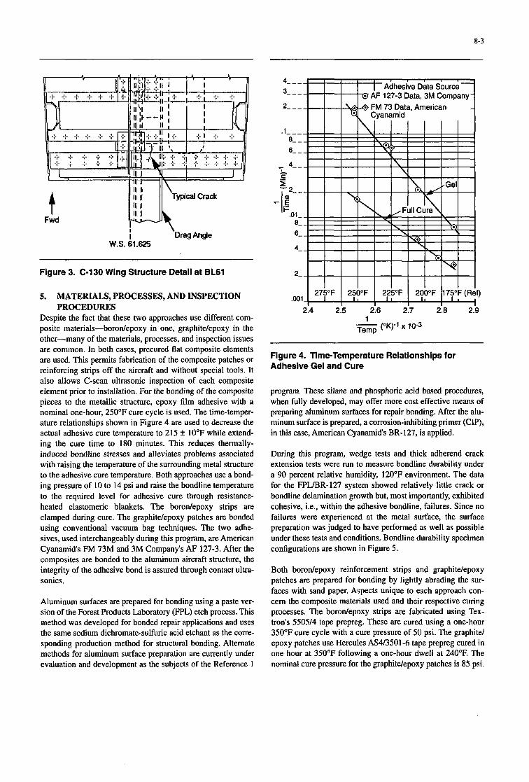
8-3
t Fwd
Figure 3. C-130 Wing Structure Detail at BL61
5. MATERIALS, PROCESSES, AND INSPECTION
Despite the fact that these two approaches use different com- posite materials-borodepoxy in one, graphitdepoxy in the other-many of the materials, processes, and inspection issues are common. In both cases, precured flat composite elements are used. This permits fabrication of the composite patches or reinforcing strips off the aircraft and without special tools. It also allows C-scan ultrasonic inspection of each composite element prior to installation. For the bonding of the composite pieces to the metallic structure, epoxy film adhesive with a nominal one-hour, 250°F cure cycle is used. The time-temper- ature relationships shown in Figure 4 are used to decrease the actual adhesive cure temperature to 215 f 10°F while extend- ing the cure time to 180 minutes. This reduces thermally- induced bondline stresses and alleviates problems associated with raising the temperature of the surrounding metal structure to the adhesive cure temperature. Both approaches use a bond- ing pressure of 10 to 14 psi and raise the bondline temperature to the required level for adhesive cure through resistance- heated elastomeric blankets. The borodepoxy strips are clamped during cure. The graphitdepoxy patches are bonded using conventional vacuum bag techniques. The two adhe- sives, used interchangeably during this program, are American Cyanamids FM 73M and 3M Company's AF 127-3. After the composites are bonded to the aluminum aircraft structure, the integrity of the adhesive bond is assured through contact ultra- sonics.
PROCEDURES
Aluminum surfaces are prepared for bonding using a paste ver- sion of the Forest Products Laboratory (FPL) etch process. This method was developed for bonded repair applications and uses the same sodium dichromate-sulfuric acid etchant as the corre- sponding production method for structural bonding. Alternate methods for aluminum surface preparation are currently under evaluation and development as the subjects of the Reference 1
Figure 4. Time-Temperature Relationships for Adhesive Gel and Cure
program. These silane and phosphoric acid based procedures, when fully developed, may offer more cost effective means of preparing aluminum surfaces for repair bonding. After the alu- minum surface is prepared, a corrosion-inhibiting primer (CIP), in this case, American Cyanamids BR-127, is applied.
During this program, wedge tests and thick adherend crack extension tests were run to measure bondline durability under a 90 percent relative humidity, 120°F environment. The data for the FF'L/BR-127 system showed relatively little crack or bondline delamination growth but, most importantly, exhibited cohesive, Le., within the adhesive bondline, failures. Since no failures were experienced at the metal surface, the surface preparation was judged to have performed as well as possible under these tests and conditions. Bondline durability specimen configurations are shown in Figure 5 .
Both borodepoxy reinforcement strips and graphitelepoxy patches are prepared for bonding by lightly abrading the sur- faces with sand paper. Aspects unique to each approach con- cern the composite materials used and their respective curing processes. The borodepoxy strips ate fabricated using Tex- tron's 550514 tape prepreg. These are cured using a one-hour 350°F cure cycle with a cure pressure of 50 psi. The graphite/ epoxy patches use Hercules AS413501-6 tape prepreg cured in one hour at 350°F following a one-hour dwell at 240°F. The nominal cure pressure for the graphite/epoxy patches is 85 psi.

8-4
Adherend Material 7075-T6 Bare Both Specimens
Specimen Length = 6.0" Specimen Width = 1 .On Adherend Thickness = 0.125"
+h2]
ah T 2
Wedge Test Specimen Thick Adherend Crack Extension Test Specimen
Flgure 5. Bondline Durability lest Specimen Conflgurations
6. STRESS REDUCTION BY STRUCTURAL
The specific reinforcement configuration associated with relieving the stresses in the lower wing surface was deter- mined through detailed finite element analyses of the entire aircraft. These analyses took advantage of the existence of a finite element model (FEM) of the entire C-130 aircraft. The center wing substructure of this model was modified to include sufficient detail to determine local stress contours in the vicin- ity of the proposed modification, specifically the area repre- senting the wing lower surface, spanwise stiffeners, and rear beam cap from BL 20 to BL 101. The modified portion of the model is shown in Figure 6. This area spanned the BL 61 focus of the modification which consisted of applying bonded rein- forcement to the vertical surfaces of the rearmost hat and stiff- eners and the rear beam cap to attract spanwise load to these elements and correspondingly reduce load in the wing lower surface.
MODIFICATION
Various reinforcement configurations were studied. The num- ber, thickness, length and taper of the borodepoxy strips were varied before deciding on the addition of five unidirectional borodepoxy strips as illustrated in Figures 7 and 8. These were 24 inches long and highly tapered, reaching a thickness of 0.191 inch (36 plies). These analyses included the effects of locally heating the structure during bonding of the reinforce- ment and subsequent temperature decreases to 80°F and then, in-service, to -67°F. Superimposed on these were the effects of 2.5 g positive symmetric maneuver wing loads and 11.25 psi fuselage pressure loads. The values shown in Table 1 summa- rize these analytical projections. Analyses of the critical fas- tener location show, at ultimate load, a 12.4 percent reduction in lower wing cover stresses at an ambient temperature of 80°F and a corresponding 9.1 percent reduction at -67°F. Figure9 presents a set of contours showing spanwise stress reductions at ambient temperature resulting from placement of the five straps as illustrated in Figure 8. This figure illustrates the relatively local effect of the borodepoxy strip modification on lower surface stresses.
,101
Figure 6. C-130 FEM Modification
Using these results, estimates of safety limit, i.e., time to develop critical crack length, were calculated for both the unreinforced baseline and the reinforced configuration. These crack-growth studies were based on a standard 29 mission operational flight spectrum as well as temperature and pres- sure cycles associated with altitude changes. These calcula- tions are summarized in Table 2 and show a 77 percent life increase at the critical location.

8-5
0 - 2: BorodEpoxy
00 Orientation I -Al l Plies
W = 0.75" Stringer) = 1.1 0" \Rear Spar
Cap)
Rear Beam C a p 4
I
8 Lower Surface at B.L. 61
~~
Figure 7. BoronEpoxy Reinforcement Strip Figure 8. BoronEpoxy Reinforcement Strip Placement
TABLE 1 PROJECTED SPANWISE STRESS REDUCTIONS DUE TO STRUCTURAL MODIFICATION
Load Case: 2.59 Positive Symmetric Maneuver Plus 11.25 psi A (T (psi) at BL 61/
Fuselage Pressure Rear Spar Interface
Induced during 215°F cure - 3550 Cool down from cure temperature (215°F to 80°F) + 4042
345!2
.1860
Stress reduction at ultimate load due to repair
Net at 80°F -6958 (1 2.4%)
Further cool down from 80°F to -67°F
Net at - 67OF - 5098 (9.lYo)
Front Spar
500
-500 -500
Rear Spar I
Load Case: 2.59 Positive Symmetric Maneuver Plus 11.25 psi Fuselage Pressure
Contours: Spanwise Tensile Stress Reduction in Lower Wing Surface

8-6
TABLE 2 SAFETY LIMITRIFE INCREASE RESULTING FROM REINFORCEMENT
Stress Reduction at Wing Cover Critical Location Safety Life
at Indicated Temperature' Limit Increase Configuration (-67" F) (80°F) ( W ("A) Baseline - No Straps -- -- 22,000 -- Rear Beam Cap and Two Rear Stringers Reinforced 9.1% 12.4% 39,000 77% Notes:
1. 2.
Stress reduction based on ultimate 2.59 positive symmetric maneuver plus 11.25 psi fuselage pressure. Safety limit based on operational flight spectrum.
7. If a crack already exists in the wing lower surface, its repair requires the bonding of a high modulus composite patch
CRACK REPAIR USING BONDED COMPOSITES
- 1 I 1 directly over the crack. Using a target repair patch-to-parent
structure stiffness ratio, S , of 1.2, the orientation of the graph- ite tape reinforced patch was determined to be
; I
1 :
1 : , - J - - /
e---- - - - c - - - ,/5 - - - \\ \
1-11 !I- 1 -
- - I \ \ I I \I I I
1, II
I I ((o",, f 45")290"3)s. It
. I - - I The unusual addition of 45-degree fibers in the patch is the
result of the requirement to restore the in-plane shear capabil- ity of the wing cover over the cracked portion of the wing surface.
The untapered length of the patch was determined using guidelines set forth in Reference 2, which establishes this length, L16d, where
I I
d = (ta/Ga* l&& /( 1+S)),"2
the distance from the patch edge to the point at which the stress is effectively zero.
Using reduced crack-growth rates predicted for the patched crack, the untapered width of the patch was sized to contain the crack through the life of the structure.
A maximum taper to the patch edges of 5 degrees was used for edges perpendicular to the primary (spanwise) load direction, while a maximum angle of 10 degrees was used for the for- ward edge of the patch. The aft edge of the patch, which coin- cided with the aft edge of the wing box, was ended abruptly with no edge taper.
16.54
f The final configuration of the repair, as shown in Figure 10, is a 34-ply patch of graphite/epoxy with an outer ply of 120 style fiberglass fabric/epoxy. The nominal thickness of the patch, assuming 0.0051 inch per ply for the graphite tape and 0.0035 inch per ply for the fiberglass, is 0.177 inch. Figure 10. GraF
~ ~~
iite/Epoxy Crack Repair Patch
I

sum1 I! analyses of both repi tur modifiu n was applied to the
8-1
lrticle left side. A ._ - . wing s u r f a m assume the existence of a 3-inch crack at the critical fastener location. Repaired. the crack-growth rate is reduced so that. under a typical 29 mission operational flight spectrum, it would take over 2M),000 Eight hours to extend the crack to the critical length of 6.29 inches. Unrepaired, the same 3-inch crack was projected to grow to its critical length in 5,500 f l iht hours.
S. FULL-SCALE WING lEsT VERIRICATION An existing test of a full-scale C-130 wing presented an oppor- tunity to directly measure the effectiveness of this bonded composite application and to compare the measured and calcn- lated stress reductions. The full-scale specimen consisted of the center fuselage. center wing, and outer wing of a C-130 aircraft. The test applied symmetrical upbending limit loads to the wing and simulated wing loading due to fuselage pressur- ization. The full-scale specimen is shown in Figure 11.
The graphite reinforced patches and the h n reinfod strips we= applied to the wing durahility article at different times during the test life. Cracking was detected along the right side BL 61.125 drag angle attachments in the lower Wing surface panels at 26,Mx) cyclic test hours (or 47.000 equiva- lent flight hours at BL 61). At that time, the borodepoxy shllc-
strain survey was conducted which measured the reduction in lower cover StreSses in the vicinity of the BL61-rear beam intersection. The 11.9 percent reduction calculated for limit load was closely approximated. Figure 12 shows the wing panel stress reduction test data versus analysis cordation measured during this symmetrical wing uphending test and Figure 13 is a photograph of the inhoard half of the boron/ epoxy strip modification.
After the strain survey, cyclic testing was resumed and the nnrepaired cracks on the specimen right side regularly checked. Figure 14 shows a comparison of these cracks at 26,000 and 34,000 cyclic test hours. At 34,OOO cyclic test hours (M 58000 flight hours at BL61), these cracks were approaching 3 inches and the decision was made to apply the repair. Figure 15 is a photograph of the graphiWepoxy repair patch being prefitted p r i ~ to bonding.
The test pmceeded to completioo-exceeding 58,000 cyclic test hours (or 79,600 flight hours at BL 61). Regular ultrasonic inspection for W i n e failures at the crack-tip locations indi- cated no crack extension throughout the remainder of the test. Furthermore. the lest was completed without initiation of cracks on the shllcturauy m&ed left side.
figure 11. 0130 Wing Durability Test Speclmen

8-8
2o t _ _ FEM TEST
Inside Wing Plank Surface Between - ' ' - RearBeamandSlrfnger#24
@ - Slringer#24andSIringerX23
A A - StringerM3 and Stringer 1122 . . IO-14% ...
+-. - - - 71 10%
- - - - - -
Predicted Reduction at Limit
%Reduction in Wing Surface Slres8
Flgure 12. Wing Panel Stress Reduction
Figure 13. BoronEpoxy Strip Modiflcatlon - Inboard of BL 61
26,000 Hours 34,000 Hours
inb'd 1.15
Figure 14. Wing Lower Surface Panel Crack Growth at BL 61 (View Looklng Down)

8-9
9. CONCLUSIONS %%e applications of bonded high-modulus composites clearly illustrate the powerful tool represented by this technol- ogy. Given the proper controls and personnel training, the sUucNral bonding of composites can be used to directly repair airrraft s m by arresting crack growth in damaged shuc- lure 01 to effect a shuctunl modification which will prcvent the onset of damage. In either case. this can be done efficiently and without the introduction of additional fasteners which accompany conventional metal q a i r s .
10. REJ!ERF,NCES 1. University of Dayton Research InstiNte, 'ylomposite
Repair Aluminum Shucnue," AP Contract No. F3361.5-89-C-5643, Materials Directorate, Wright Labommy, Wright-Patterson AFB, Ohio, Current propram.
2. Davis, M. J.. "On Application Methodology for Bonded Composite Repair of Aircraft:' Aeronautical Research Laboratory, Melbourne. Australia, to be Published.
Flgum 15. GraphlteEpoxy Patch Durlng Prefit

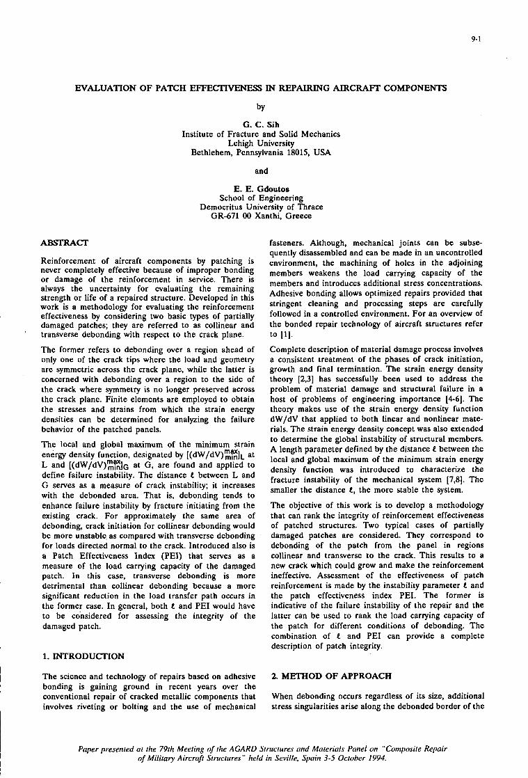
9- 1
EVALUATION OF PATCH EFFECTIVENESS IN REPAIRING AIRCRAFT COMPONENTS
by
G. C. Sih Institute of Fracture and Solid Mechanics
Lehigh University Bethlehem, Pennsylvania 18015, USA
and
E. E. Gdoutos School of Engineering
Democritus University of Thrace GR-671 00 Xanthi, Greece
Reinforcement of aircraft components by patching is never completely effective because of improper bonding or damage of the reinforcement in service. There is always the uncertainty for evaluating the remaining strength or life of a repaired structure. Developed in this work is a methodology for evaluating the reinforcement effectiveness by considering two basic types of partially damaged patches; they are referred to as collinear and transverse debonding with respect to the crack plane.
The former refers to debonding over a region ahead of only one of the crack tips where the load and geometry are symmetric across the crack plane, while the latter is concerned with debonding over a region to the side of the crack where symmetry is no longer preserved across the crack plane. Finite elements are employed to obtain the stresses and strains from which the strain energy densities can be determined for analyzing the failure behavior of the patched panels.
The local and global maximum of the minimum strain energy density function, designated by [(dw/dV):E]~ at L and [(dW/dv):%]~ at G, are found and applied to define failure instability. The distance between L and G serves as a measure of crack instability; it increases with the debonded area. That is, debonding tends to enhance failure instability by fracture initiating from the existing crack. For approximately the same area of debonding, crack initiation for collinear debonding would be more unstable. as compared with transverse debonding for loads directed normal to the crack. Introduced also is a Patch Effectiveness Index (PEI) that serves as a measure of the load carrying capacity of the damaged patch. In this case, transverse debonding is more detrimental than collinear debonding because a more significant reduction in the load transfer path occurs in the former case. In general, both e and PE1 would have to be considered for assessing the integrity of the damaged patch.
1. INTRODUCITON
The science and technology of repairs based on adhesive bonding is gaining ground in recent years over the conventional repair of cracked metallic components that involves riveting or bolting and the use of mechanical
fasteners. Although, mechanical joints can be subse- quently disassembled and can be made in an uncontrolled environment, the machining of holes in the adjoining members weakens the load carrying capacity of the members and introduces additional stress concentrations. Adhesive bonding allows optimized repairs provided that stringent cleaning and processing steps are carefully followed in a controlled environment. For an overview of the bonded repair technology of aircraft structures refer
Complete description of material damage process involves a consistent treatment of the phases of crack initiation, growth and final termination. The strain energy density theory [2,3] has successfully been used to address the problem of material damage and structural failure in a host of problems of engineering importance [4-61. The theory makes use of the strain energy density function dW/dV that applied to both linear and nonlinear m a t e rials. The strain energy density concept was also extended to determine the global instability of structural members. A length parameter defined by the distance e between the local and global maximum of the minimum strain energy density function was introduced to characterize the fracture instability of the mechanical system [7,8]. The smaller the distance e, the more stable the system.
The objective of this work is to develop a methodology that can rank the integrity of reinforcement effectiveness of patched structures. Two typical cases of partially damaged patches are considered. They correspond to debonding of the patch from the panel in regions collinear and transverse to the crack. This results to a new crack which could grow and make the reinforcement ineffective. Assessment of the effectiveness of patch reinforcement is made by the instability parameter and the patch effectiveness index PEL The former is indicative of the failure instability of the repair and the latter can be used to rank the load carrying capacity of the patch for different conditions of debonding. The combination of e and PE1 can provide a complete description of patch integrity.
to [l].
2. MITHOD OF APPROACH
When debonding occurs regardless of its size, additional stress singularities arise along the debonded border of the
Paper presented at the 79th Meeting of the AGARD Structures and Materials Panel on "Composite Repair of Military Aircraji Structures" held in Seville, Spain 3-5 October 1994.
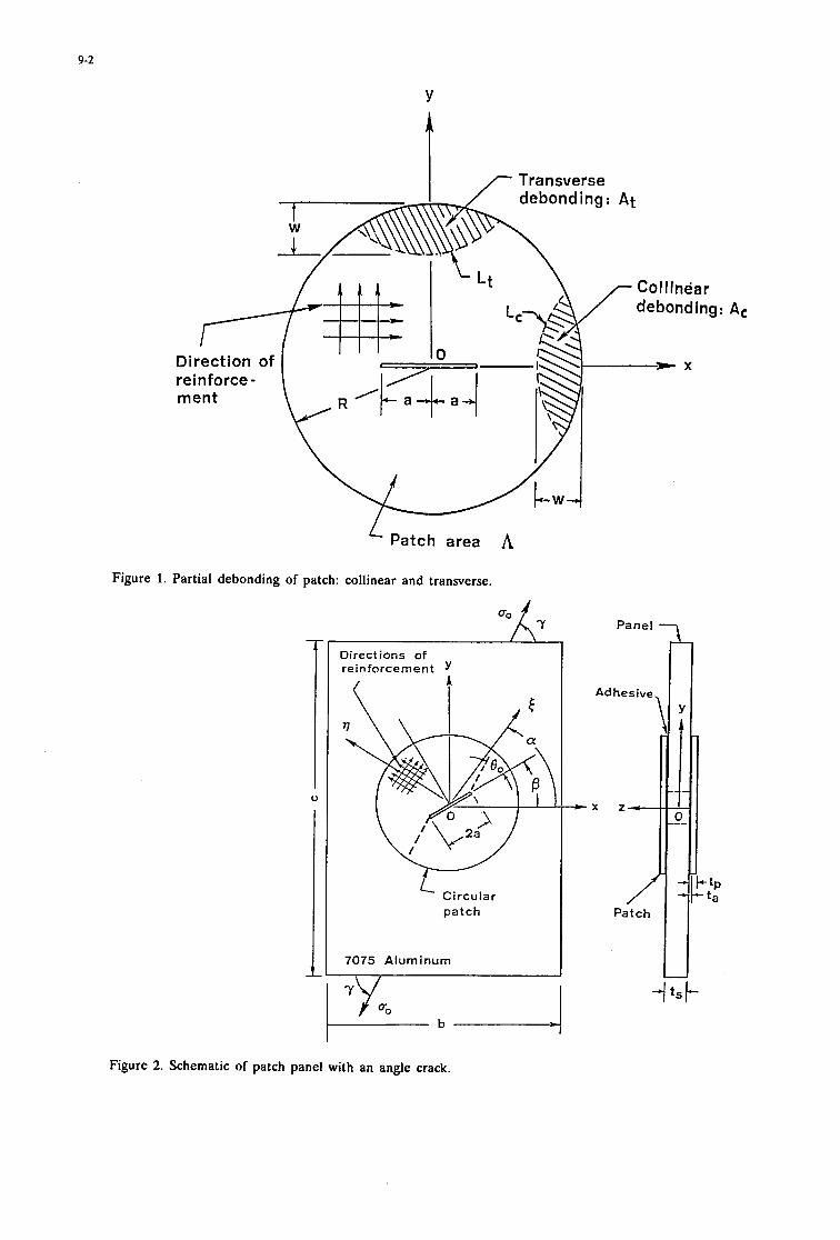
9-2
Y
Collinear debonding:
* x
Patch area A
Figure 1. Partial debonding of patch: collinear and transverse.
Y
Direct ions of re ir! force m e n t Y
Circular p a t c h
7075 Aluminum
Figure 2. Schematic of patch panel with an angle crack.

9-3
patch. This leads to local intensification of the strain energy density function which can be an order of magnitude higher than that away from the crack border. Debonding does not only reduce the bearing surface for load transfer but also introduces additional concentration of energy density.
Two types of damage will be considered. They are referred to as collinear and transverse debonding as shown in Figure 1. The patch area is denoted by A while Aj and Lj stand, respectively, for the detached portion of A and the corresponding crack border. The subscript j = c stands for collinear debonding and j = t for transverse debonding. New stress singularities arise on La (j = c,t) in addition to those for the original through crack of length 2a in the panel. The high elevation of the strain energy density along these borders L, and h must be consider- ed.
The concept of an effective energy density will be introduced. Let the local intensified energy density field along L, or & be estimated by considering the equivalent modulus E: defined as
in which the subscripts p, a and s refer to the patch, adhesive and panel, respectively. In equation (l), (E&). stands for the effective stiffness of the combination o/ patch and adhesive:
in which
The parameter A is the area. The orthotropic properties of the patch are reflected by the difference in the stiffness modulus in the x- and y-direction as defined in Figure 1. Although the adhesive can affect the load transfer in the thickness direction, its influence on the equivalent modulus in the xy-plane can be neglected. It suffices to employ equation (1) for finding the equivalent in-plane stresses a:, a; and a& everywhere in the patched region. An equivalent transverse normal stress component a: can thus be defined by invoking the condition of plane strain near L, or h, i.e.,
e e e az = v ( a x + ay) (4)
where v is approximately equal to the equivalent Pois- son's ratio ve.
Since U: would be the dominant stress component in debonding, an equivalent stress intensity factor can be written in the form
with a, being an equivalent crack length. Now, if r denotes the distance normal to L, or h in the xy-plane and knowing that '
dW - S dV r - - -
the form of*
( 1 + v ) ( l - 2 v ) 2 s, = %C 2nE
may be applied to yield
Here, E$ is taken as the equivalent Young's modulus of the patch/adhesive/panel in the z-direction. For an edge crack of length a, the ratio a,/r is approximately 20 and hence equation (8) simplifies to
Dependency of dW/dV on the stress squared over the modulus is familiar. The factor ten (10) in equation (9) represents the one order of magnitude increase in the strain energy density function in regions next to the crack border.
3. MATERIAL PROPERTIES AND DEBONDING CLASSIFICATION
Aside from debonding, the geometric configuration of the patch panel is shown in Figure 2. Values of the geometric parameters are given in Table 1. A uniform tensile load of a0 = 50 ksi is applied along the y-axis such that y = 90' in Figure 2. A half crack length of a = 1.50 in is taken. Table 2 gives the equivalent mechanical properties of patch/adhesive/panel.
Table 1. Dimensions in inches for cracked panel with edge debonding. 11
10 U) 4x10³
To be analyzed are seven (7) different types of collinear and transverse edge debonding. Refer to the classification
Here, KI, is the valid ASTM fracture toughness value.

9-4
Applied symmetric load
rnin L r [(dW/dV)maxl
-
Figure 3. Location of local and global maximum of minimum strain energy density function for symmetric loading.
to--
%-=-
Crack G
G
Patch
f edge
Distance ahead of crack
Figure 4. Conc pt of crack instability index.

9-5
Eex
10.74
in Table 3 in which CO and TO refer to a perfectly bonded patch with no debonding.
E; EeZ GB Ve
13.69 10.74 4.03 0.308
Table 2. Equivalent mechanical properties of patch/adhesive/panel x lo6 (psi).
case [(dw/dv)%%lL [(dw/dv)%%lG No. x (psi) x (psi)
CO 51.82 7.7775 c1 51.95 8.1499 c 2 51.48 83382 c3 51.87 8.2739
(in)
0.21 1.17 1.19 1.49
Table 3. Classification of collinear and transverse debonding.
CaSe No.
Collinear debonding
CO c1 c 2 c3
Transverse debonding
TO T1 T2 T3 T4
Debonding depth w (in)
0.0 0.5 0.9 1.2
0.0 1.0 1.5 2.0 2.4
Debonded area (in2)
O.OO0 0.%5 1.605 1.875
O.OO0 3.816 5.316 6.816 8.016
4. INSTABILITY OF CRACK PATCHING
The classical linear elastic fracture mechanics approach based on the concept of Klc considers only the onset of rapid fracture and does not yield any information of crack stability or instability. The tendency of a crack to arrest or to propagate unstably depends on the combined influence of loading, geometry and material. Such behavior is reflected by the local and global stationary values of the strain energy density function.
It is now well-known that at each point in a nontrivial stress and/or strain field, there exists at least one maximum and one minimum of dW/dV. These values are known as the local stationary values [(dw/dV),,]~ and [(dW/dV),i,]~ such that a new coordinate system is used for each point. When every point in the structure is referred to the same coordinate system, the resulting maxima and minima are known as the global stationary
ces between the local and global stationary values of dW/dV can serve as a measure of the failure stability of a system by yielding and/or fracture. If the discussion is limited to fracture instability, then only the distance C between [(dW/dV):r]~, say at L, and [(dW/dv):r]~, say at G, needs to be considered; it is indicative of the degree of crack instability. Illustrated in Figure 3 is a single crack system loaded symmetrically where both L and G would then lie on the same straight line. Crack
values [(dw/dv),,]~ and [(dW/dV),i,,]~. The distan-
growth is predicted to initiate from L to G. A system with large C is said to be more unstable as compared with that having a smaller C.
Depending on the combined influence of load, geometry and material, failure by fracture can either be confined locally to the crack tip region or extended beyond the patch into the panel once fracture initiation has occurred. This is illustrated schematically in Figure 4. Aside from the discontinuity of dW/dV at the patch edge, the top curve shows that G, the location of [ ( d W / d V ) g g ] ~ , is outside the patch while the lower curve shows that G lies inside the patch. For a given patch thickness tp C can be longer or smaller than R-a depending on the type of debonding. The location of L or [(dW/dV):r]~ occurs at ro which will be taken as in the present analysis. Once L and G are known, C can be obtained to assess the influence of edge debonding on the failure instability of patched panels.
4.1 Collinear Debonding
For collinear debonding, only a knowledge of dW/dV along the line y=O in Figure 1 is needed because the load and system geometry is symmetric about the x-axis. As a base line comparison, Figure 5 plots dW/dV against the distance x at y=O for Case CO which represents a perfectly bonded patch as defined in Table 3. Note that dW/dV attains the highest value near the crack tip. At a distance ro - 0.01 in, [(dW/dV):g]~ = 51.82 x psi is obtained, while [(dW/dV):r]~ = 7.7775 x psi occurs at G that is next to the crack tip. The value of (dW/dV),i,, = 7.7338 x loq2 psi at the patch edge r is not the maximum of (dW/dV),i,, ; it is less than [(dW/dV):g]~. A crack instability index value of C = 0.210 in is thus obtained. It is confined near the crack tip. Once debonding occurs, the potential of crack initiation increases. This is indicated by the increase in C as illustrated in Figure 6 for Case C1. While [(dW/dV):g]~ = 51.95 x psi remains locally near the crack tip, several global (dW/dV),i,, are found. The location of maximum (dW/dV),i, or [ ( d w / d v ) g r ] ~ = 8.1499 x psi locates G. This gives C = 1.170 in. Additional debonding further increases C. Oscillation patterns for Cases C2 and C3 show that G has moved to the debonded edge of the patch losing its effectiveness in reinforcement. Summarized in Table 4 are the crack instability index C and the corresponding maximum of the local and global (dW/dV),i,, for collinear debonding of the patch.
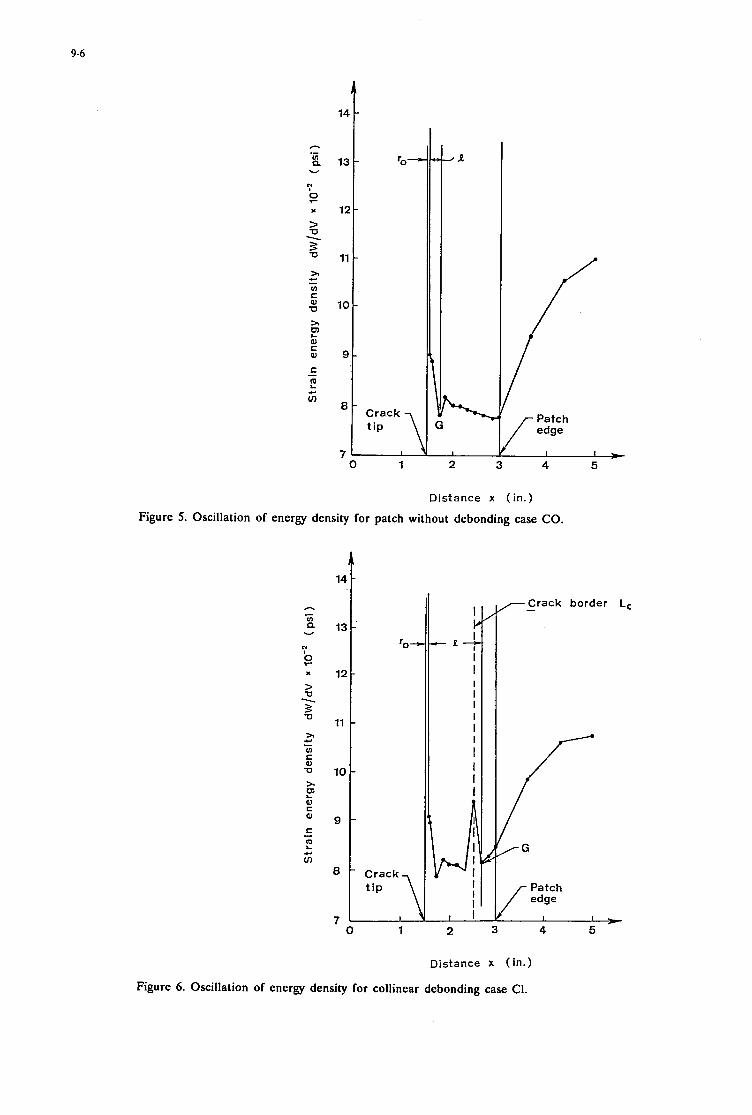
9-6
n .- E w
T
x 12-
% - 5 11- > VI C
c - g 10-
0 al K L
al 9 -
J I I ,
0 1 2 3 4 5
D i s t a n c e x ( i n . )
Figure 5. Oscillation of energy density for patch without debonding case CO.
0 1
I I. I - 2 7
I I I I I I I I I I I
I I I I
P a t c h , I , ~
2 3 4 5
D i s t a n c e x ( i n . )
Figure 6. Oscillation of energy density for collinear debonding case C1.

9-7
Collinear
Case "C
No. (%I CO 100 c1 86.6 c 2 85.1 c 3 84.0
4.2 Transverse Debonding
Transverse
CaSe nt No. (%I TO 100 T1 80.8 T2 73.6 T3 67.1 T4 62.6
Because of the lack of symmetry across the y-axis, the plane on which fracture will initiate must be found by obtaining the angle 0 at which dW/dV acquires a local minimum, i.e.,
emin (degree)
00 00 O0
3 9 to 36O 35Oto36O
This determines the position L as shown in Figure 7. The position G at which [(dW/dV)Eg]o occurs must be found by observing the maximum or minimum of dW/dV at points in the upper half-plane. Potential path of failure from L to G may deviate from the 00 plane if the transverse debonding is appreciab1.e.
To be analyzed are the Cases T1, T2, ..., T4 inclusive. The Case TO is the same as CO and will not be elaborated. Without going into details, the results given in Table 5 refer to those in the aluminum panel. They are obtained by using the material properties of the panel and not the effective properties for finding the strains in the patched panel. The coordinates of G and values of [(dW/dV):g]~ can be obtained from the constant strain energy density contours. For the case of T1, the debonded area is relatively small in comparison with the patch. The small amount of anti-symmetry about the y- axis has negligible influence on the direction of crack initiation. This gives a value of C - 0.22 in which is only slightly larger than that of the Case CO. Fracture is predicted to initiate from L with 80 - 0 where [ (dW/dV)mp]~ is an order of magnitude higher than
only a slight increase in C = 0.25 in is detected. The results in Table 5 reveal that significant increase in C occurs for cases T3 and T4. The angle 80 now differs significantly from zero. Crack instability is also seen to increase with increasing transverse debonding.
[(dW/dV),,,in]~. RU As debonding is increased to Case T2,
K m / W m i JL [(m/Wrni JC XlOG (psii
51.82 7.78 51.13 7.90 51.13 8.00 63.01 8.10 76.15 8.10
022
125
In general, it is desirable to localize crack initiation by minimizing &. This can be accomplished by increasing the patch thickness parameter tp = 0.005 in which corres- ponds to using only one ply of the boron/epoxy patch. It is not uncommon to have a six-ply patch with tp = 0.03 in in which case, both & and dW/dV near the crack can be lowered.
5. PATCH EFFECTIVENESS INDEX
The load carrying capacity of debonded patches decreases
with increasing damage. A patch effectiveness index n can be defined to rank the patch performance; it considers the intensification of the local strain energy density as the patch edge debonds creating a crack-like border between the patch/panel interface.
Let (dW/dV)A stand for the strain energy density at the patch/panel interface for the undamaged patch. The released energy density during debonding would be (dW/dV)Ai where j =c,t with (dW/dv)&Aj being the difference between (dW/dV)A and (dW/dV)Aj. Creation of the new crack border Lj gives rise to the local concentration (dW/dV)Lj, an estimate of which has been made by equation (9) using the equivalent stiffness modulus approach. Hence, a superscript e would be used. The ratio of the strain energy density at the patch/panel interface before and after debonding is defined as the patch effectiveness index:
Values of ni (j=c,t) for edge-bonding as described in Table 3 are summarized in Table 6. Comparison of nc and nt when weighed with reference to the debonded area in Table 3 shows that transverse debonding is much more detrimental than collinear debonding. The patch effecti- veness index nt is much smaller than nc for approximately the same area of debonding. The location of the damaged area of the patch in relation to the crack in the panel can greatly affect the load carrying capacity of the system. In general, the patch effectiveness tends to decrease with increasing area of debonding. Such a parameter is useful for ranking the effectiveness of damaged patch and it includes all the combined effects of loading, geometry, material and the type of damage.
6. CONCLUDING REMARKS
Analyzed in this work is the effect of patch debonding on the remaining strength of reinforced panels that contain initial cracks. The influence of the patch thickness, adhesive layer and panel thickness are accounted for by applying the effective stiffness concept in conjunction with the finite element procedure. Two types of edge-debond- ing are considered; they correspond to debonding in regions

9-8
Load direction
Debonded area tr Failure path
fracture can be stabilized and localized in the vicinity of the original crack. The means for monitoring crack growth can then be developed to assure safe service life of the reinforcement.
e Using the undamaged patch as the base line, a patch effectiveness index is defined so that different damage areas and locations can be ranked in terms of a single parameter for comparison. This additional information can be used to determine the remaining strength of damaged reinforcement.
Even though useful information has been obtained without resorting to a three-dimensional analysis, additional refinements can be made to improve on the failure prediction of reinforced panels with damaged patches. This may include the effect of plastic deformation, directional interaction of loading and debonding and subcritical crack growth. These additional considerations, however, will be left for future work. - Patch I REFERENCES
Figure 7. Unsymmetric crack initiation for transverse debonding
collinear and transverse to the crack whose plane is assumed to be normal to the applied load. When a portion of the patch is detached from the panel, free surfaces are created giving rise to a new crack border. This crack lies in a plane normal to that in the panel. An effective patch/adhesive/panel medium is defined for calculating the local intensification of the strain energy density function. Among the important contributions are the concept of crack instability parameter and patch effectiveness index. The distance t between the local and global maximum of the minimum strain energy density function given an indication of failure instability by fracture. Instability tends to increase with t . For about the same size of patch damage, collinear debonding leads to more unstable fracture than transverse debonding. The patch effectiveness index PE1 measures the load carrying capacity of the damaged path. In this case, transverse debonding is less favorable as compared with collinear debonding. In general, both t and PE1 must be considered for assessing the integrity of the damaged patch.
Although crack patching analyses have been published in many previous publications that are available in the open literature, the majority of the works were concerned with determining the displacements and stresses in the structure rather than developing predictive capability. In this respect, the major contributions of the present investigation can be summarized as follows:
0 The local and global maximum of the minimum strain energy density function are obtained to define crack patching instability for collinear and transverse edge- debonding. Geometric and material parameters can thus be optimized for specified loading conditions such that
[l] Baker, A.A. and Jones, R., (Eds) "Bonded Repair of Aircraft Structures", Engineering Application of Fracture Mechanics, Vol. 7, Editor-in-Chief G.C. Sih, Martinus Nijhoff Publishers, The Netherlands, 1988.
[2] Sih, G.C., "Introductory Chapters", in Mechanics of Fracture" Vol. 1-7, edited by G.C. Sih, Hague, The Netherlands, Noordhoff Int. Publ., 1973-1988.
[3] Gdoutos, E.E., "Fracture Mechanics. An Intro- duction", Dordrecht, The Netherlands", Kluwer Academic Publishers, 1993 (15BN 0 7923 1932 X), pp.
[4] Sih, G.C. and Chen, C., "Non-Self-similar Crack Growth in an Elastic-Plastic Finite Thickness Plate", J. Theor. Appl. Fract. Mech., 3, 1985, pp. 123-139.
[5] Sih, G.C. and Moyer, E.T. Jr., "Path Dependent Nature of Fatigue Crack Growth", Engng Fracture Mech., 17, 1983, pp. 269-280.
[6] Gdoutos, E.E., "Problems of Mixed-Mode Crack Propagation" Hague, The Netherlands, Martinus Nijhoff, 1985 (1SBN 90 247 3055 4).
[7] Sih, G.C. and Chu, R.C., "Characterization of Material Inhomogeneity by Stationary Values of Strain Energy Density", Theor. Appl. Fract. Mech., 5,
[8] Gdoutos, E.E. and Thireos, C.G., "Fracture Instability of Notched Cracked Plates Characterized by the Strain Energy Density Theory", Theor. Appl. Fract. Mech., 9, 1988, pp. 239-247.
195-238.
1986, pp. 151-161.

I
10-1
FIELD REPAIR MATERIALS FOR NAVAL AIRCRAm
R. Cochran R. Trabocco P. Mehrkam
M. DiBerardino Naval Air Warfare Center
Aircraft Division Warminster, PA 18974 USA
CODE 6064-POB5152
SUMMARY
The Navy is unique in that a portion of the maintenance actions performed on operational aircraft must be accomplished on board ship or in remote field locations. Historically, Navy driven com- posite repair programs have addressed materials and concepts specifically directed at accomplishing repairs in the fleet oper- ating environment. This paper discusses recent developments in the area of composite repair materials for the application of bonded patches to honeycomb and complex shaped monolithic composite structure. A two part adhesive that meets the storage and processing requirements for field repair applications was evaluated for use in repair of honeycomb structure. Low tem- perature adhesive processing and honeycomb compatibility tests were investigated. In another effort, wet lay-up repair resins and processes were characterized for repair of highly curved composite structure. The materials and equipment used in the study are fully compatible with field repair requirements.
Composite repair materials for application of bonded patches to honeycomb and complex shaped monolithic composite struc- ture are described. Low temperature adhesive processing de- velopment for bonding composite patches to moisturized struc- ture is described. Cure temperatures as low as 9OoC were used for curing a two part ambient storable adhesive. Mechanical properties and thermal stability of the cured adhesive is reported using a number of cycles. In another effort wet lay-up repair resins and processes were characterized which allow for the fab- rication of fully inspectable wet lay-up patches. The materials and equipment are fully compatible with field repair require- ments. Laminate mechanical properties and resin storage sta- bility were characterized and reported.
1. INTRODUCTION
New naval aircraft embody significant amounts of composite materials. Composites provide enhanced strength and stiffness while eliminating degradation in service life due to corrosion and fatigue. This combination of high strength and durability is critical for carrier based aircraft. As the service time of the com- posite materials increases, the incidence and types of damage observed also increases. In order to decrease maintenance cost and reduce aircraft downtime, it is desirable to perform struc- tural repairs at the forward field or carrier level.
The requirement to perform repair actions at remote locations has placed a number of constraints on the repair materials de-
veloped for these applications. These conditions necessitate special consideration for repair of aircraft composite compo- nents. Materials selected for repair must be storable at ambient temperatures, be processable with vacuum badheat blanket equipment and be capable of restoring original load bearing ca- pability to composite components. Emphasis must also be placed on relatively simple procedures which are compatible with field level maintenance personnel capabilities and training.
Current and emerging aircraft designs rely on honeycomb sand- wich structures because of their high structural efficiency. Ser- vice experience has shown that these composite structures are particularly susceptible to damage. These structures, while pro- viding increased strength and stiffness also present unique chal- lenges for repair at the fleet level. In the Navy operating envi- ronment honeycomb sandwich structures are highly susceptible to moisture entrapment within the honeycomb cells. Repairs performed using high temperature processes in conjunction with entrapped moisture can produce skin to core disbonds in the structure. In order to perform repairs to these structures at tem- peratures far above the boiling point of water, a lengthy drying cycle is required to remove any moisture within the honeycomb core. Elevated temperature cure cycles are generally required to achieve thermally stable repairs capable of maintaining struc- tural integrity at the aircraft operating temperature.
The conventional repair concepts for honeycomb structure use production film adhesives. These materials require freezer stor- age and shipment and high temperature cure cycles. The freezer storage requirements and the drying cycles required before el- evated temperature cures can be performed, place significant logistical and time constraints on the repair facility. Reducing the cure temperature of an adhesive has been shown to reduce the glass transition temperature and may result in lower hot-wet mechanical properties [ 13. There is a need for repair materials which can be processed at temperatures lower than 149OC and still provide mechanical strength to 82OC in the moisturized condition.
An additional consideration for aircraft components is that they have complex shapes and highly curved surfaces which are dif- ficult to repair using precured composite patches or bolt-on metal plates. In order to repair complex structures, a wet lay-up patch is required. A wet lay-up patch will provide the capability to fabricate a highly conformable repair. Current wet lay-up repair materials require freezer shipment and storage, are difficult to handle and have very short working times. vpical wet lay-up
Paper presented at the 79th Meeting of the AGARD Structures and Materials Panel on ‘‘Composite Repair of Military Aircrafr Structures” held in Seville, Spain 3-5 October 1994.

10-2
patches have poor mechanical properties, contain significant amounts of porosity, and are impossible to inspect using ultra- sonic techniques due to the high void content. Composite re- pair developmental efforts at the Naval Air Warfare Center (NAWCADWAR) led to the successful development and imple- mentation of double vacuum bag procedures to produce high quality, flexible patches that can be formed to contoured sur- faces with the application of heat and vacuum pressure. The properties of such laminates are comparable to autoclave pro- cessed' materials.
temperature cure procedures for bonding repair patches. Stud- ies have shown that a cure cycle of 93OC for 2 hrs is sufficient to meet the repair specification requirements for 104OC wet ser- vice applications (5,6). The EA 9391 adhesive can be used to bond precured, staged, or wet lay-up patches. Adhesive ther- mal stability and mechanical property data developed for a range of cure cycles is presented. In addition, results of a program to develop highly inspectable wet lay-up patches for repair of com- plex shaped structure is also provided. Laminate quality im- provements and mechanical properties of standard repair patches and double vacuum debulked patches are presented.
1.1 Adhesive Development 2. EXPERIMENTAL
An adhesive was formulated for the repair of graphite/epoxy composites that would meet the requirements for field level re- pair applications (2,3). The approach taken was to develop a two part epoxy paste adhesive which would have storability by virtue of the physical separation of the epoxy resin and curing agent. The adhesive was designed to have a low gel tempera- ture (below 100°C) to prevent moisture vapor from migrating into the bondline and a viscosity in excess of 100 poise through- out the cure cycle to prevent void formation. To meet the mini- mum viscosity requirement, the adhesive was adducted. This technique provided the increased viscosity during cure without the need for filler. (3). The mechanical properties of this adhe- sive formulation are comparable with that of production film adhesives such as Cytec's FM-300. The NAWC developed material was used as a basis for the development of a specifica- tion for a repair adhesive: h4IL-A-85705A (4). An adhesive based on this formulation is produced by Dexter Hysol with the designation EA 9391. The EA 9391 adhesive is storable at room temperature for at least a year and has viscosity characteristics which prevent void formation during vacuum bag cure. The adhesive is currently qualified to h4IL-A-85705A with a 300°F cure for 1 hr.
1.2 Patch Material
Highly curved composite structure cannot be repaired using precured composite or metallic patches due to formability limi- tations. In order to repair this type of structure a wet lay-up patch must be used. The wet lay-up process involves the appli- cation of a resin to an unimpregnated reinforcing fabric. The wet lay-up resin has a low viscosity so that it can wet out the fibers using a manual spreading technique. The patch is then fabricated by cutting the impregnated fabric into plies and stack- ing them together to form a composite laminate. The repair patch is then cured in place using a heat blanket and vacuum bag. Typical patches formed in this manner have significant amounts of porosity which prevent ultrasonic inspection and reduce mechanical properties. Several resin systems are avail- able with variations in pot life, cure time and mechanical prop- erties while providing the required shipping and storage needs of the fleet. In order to reduce the levels of porosity in wet lay- up patches, processes have been developed using double vacuum bagging methods previously used for fabrication of patches from unidirectional prepreg tape (7,8).
The paper describes efforts at NAWCADWAR to develop low
2.1 Approach
The EA 9391 paste adhesive was chosen as the system to inves- tigate reduced temperature cure cycles because it meets all the requirements for field level use. The effect of various cure tem- peratures were determined through thermal stability and me- chanical strength tests. Table 1 shows the cure temperatures for EA 9391 evaluated in this study. The thermal stability of the adhesive for the various cure cycles was determined through glass transition measurements. Mechanical strength tests in- cluded single lap shear tensile and climbing drum peel tests. Lap shear strengths were determined as a function of cure cycle. Climbing drum peel tests were performed on EA 9391 and Cytec's FM 300K. FM 300K is currently used as the produc- tion and repair adhesive for a number of honeycomb sandwich components and thus served as a baseline material for honey- comb bonding.
Two wet lay-up resins were evaluated for the repair of highly curved structures. Both resins meet the requirements for fleet level use. Dexter Hysol EA 9390 is a two part epoxy system for wet lay-up fabrication of composite patches. The resin can be stored at ambient conditions, has low viscosity, and has a long pot life, all of which make it ideal for wet lay-up applications. Studies have shown that the material can be stored at room tem- perature up to 12 months. Dexter Hysol EA-9396 is a two part epoxy resin system. It can be stored at ambient temperatures, has low viscosity and a pot life of 60 minutes at 25OC. The resin can be cured at room temperature for 7 days or using an elevated cure temperature of 82OC for 1 hour. Laminates were fabricated using these two resins. Interlaminar shear tests and photomicrographic analysis were performed to evaluate lami- nate performance.
2.2 Processing
Lap shear, specimens were fabricated with EA 9391 using vari- ous cure temperatures. Climbing drum peel specimens were bonded with EA 9391 and FM 300K. Climbing drum peel speci- mens using EA 9391 were cured at 93OC for 2 hours and 149OC for 1 hour. Climbing drum peel specimens using Fh4 300K were cured at 177OC for 1 hour and 149OC for 4 hours. All specimens were cured using 15 psi autoclave pressure to simu- late vacuum bag pressure except the 177OC cured FM 300K which was cured using 0.28 MPa (40 psi) autoclave pressure.

10-3
The FM 300K specimens cured at 149OC were first staged at 1 10°C to 121OC for 25 min under vacuum per procedures used at the Naval Aviation Depot, North Island. The staging step was employed to reduce the flow of the adhesive and provide better skin to core bonds.
Wet lay-up panels were fabricated using 5 harness AS4 carbon cloth. Sheets of graphite cloth were impregnated with resin while sandwiched between sheets of release film. The sheets were cut into 25cm X 25cm plies. The plies were laid up into 8 ply lami- nates. Panels were cured using the manufacturers suggested cycles under vacuum bag pressure. Several double vacuum cure cycles were used to develop an optimum process to remove all voids. M e r cure laminates were inspected using ultrasonic NDT.
2.3 Test Methods
The glass transition temperature (Tg) tests were performed on a Rheometrics dynamic mechanical analyzer @MA) at a rate of S°C/min. The Tg of EA 9391 was measured as a function of cure temperature and time as determined from the loss modulus (G') curve. The DMA specimens were prepared as neat resin castings and cut to size (12 mm X 2.5 mm X 5.1 mm). Glass transition temperature tests were performed dry and after expo- sure to 6OoC, 95% relative humidity for 30 days.
Single lap shear tests were performed according to ASTM Stan- dard D-3164. Test conditions were ambient temperature, 82OC, 82'C/wet 104OC, and 104°C/wet. Specimens were moistur- ized for 30 days in a 6OoC, 95% relative humidity environment.
Honeycomb climbing drum peel tests were performed on EA 9391 and FM 300K according to ASTM standard D-1781-76. Test conditions for the climbing drum peel tests were: ambient temperature, 82OC 82OC/wet, 104OC, and 104°C/wet. Speci- mens were moisturized for 30 days in a 6OoC, 95% relative hu- midity environment. Since honeycomb structures are used in weight critical areas, the amount of paste adhesive used to bond the honeycomb peel specimens was limited to 0.44 kg/m2 (0.09 Ibs/ft2). This is comparable to the weight of the FM 3 0 0 adhe- sive, 0.40 kg/m2 (0.08 Ibdft2). In order to prevent the paste adhesive from flowing into the honeycomb cells, a pre mea- sured amount of adhesive was spread onto the aluminum face sheet. A scrim cloth was placed over the adhesive and then the face sheet placed onto the honeycomb core.
Interlaminar shear tests were performed on the wet lay-up pan- els using 1 cm X 2.54 cm specimens and a span to thickness ratio of 4. Testing was performed according to ASTM D2344- 84. Specimens were also examined by photomicrographic analy- sis to determine void content and resin distribution.
3. RESULTS
The testing performed in this study provides sufficient informa- tion to allow an analysis of the effect of low temperature cure cycles on material performance. The thermal stability of EA 9391 was determined as a function of the adhesive cure cycle. The results of the glass transition tests are presented in Table 1.
The baseline cure cycle, 149OC/l hour, provides a Tg of 128OC. This Tg for EA 9391 is somewhat lower than that found earlier for the NAWC adhesive(3). This indicates that the chemistry of EA 9391 may be different than that of the original formulation (1). The effect of reduced temperature cures on the Tg depends on the degree of undercure. The effect of low temperature short time cure cycles such as the 66'C/2 hour cycle shows a signifi- cant reduction (3OoC) in the thermal stability of the adhesive compared to the baseline adhesive Tg. As the cure temperature was increased the Tg of the adhesive increased. With a cure cycle of 12loC for 2 hours the Tg of this system reached 132OC. Beyond this temperature, there is no additional improvement in thermal stability with increasing cure temperature. These data indicate that the maximum Tg for this particular adhesive chem- istry is approximately 1 3OoC. These results are consistent with the Time-Temperature-Transition concept described by Gillham for thermosetting materials (7). Most epoxies are sensitive to plasticization by moisture. The Tg of the adhesive after expo- sure to a humidity environment shows a 26OC drop compared to the unexposed material. For this study, the interest is focused on adhesive materials which could be used in the Navy's oper- ating environment at 82OC. In order to assure material perfor- mance under these conditions, it is necessary to maintain a wet Tg above this temperature. Adhesive properties were determined after subjecting the material to cure cycles which provided a good range of thermal stability in the polymers.
The results of the lap shear tests are shown in Table 2. The shear results indicated that in the highest undercure state, 66OC, for 4 hours, there is only a marginal reduction in the room tempera- ture strength. As expected, there was a more marked decrease in the shear strength at 82OC. The 93OC, 2 hour cure cycle provided properties comparable to those of the higher tempera- ture cure cycles when tested at 82OC in the moisturized condi- tion. One additional result with the lap shear tests was that the 12loC cured materials had good properties at a test temperature of 104OC. This result correlates well with the thermal stability data. The maximum Tg for the system is attained at a cure tem- perature of 121OC. Higher temperature cure cycles do not pro- vide any additional benefit in materials performance.
The climbing peel results are shown in Table 3. The data indi- cate that the EA 9391 system provided higher peel strength than the FM 300K in these honeycomb specimens. The 93'C/2 hour cure cycle provided good performance at the 82OC test tem- perature. In addition, the 149OC/1 hour cycle provided supe- rior performance at a test temperature of 104OC even though the FM 300K material was processed at a higher temperature, 177OC. The reason for the improved performance in the EA 9391 mate- rial can be explained by consideration of the filleting behavior of the material. There was significantly better filleting with the EA 9391 material, providing a better skin to core bond. In ad- dition, there is evidence of porosity in the FM 300K material which could have contributed to the results obtained. These filleting characteristics and the good quality bondline translated into superior peel performance.
These results demonstrate that it is possible to obtain adequate thermal stability after a 93OC/2 hour cure for EA 9391. Since

10-4
this temperature is below the boiling point of water, this cure will eliminate the need for any predrying phase during a repair action to honeycomb structure. The use of EA 9391 will sig- nificantly decrease the down time required for completion of honeycomb bonded repair procedures.
Two wet lay-up resins that offered ambient temperature storability were examined; EA 9390 and EA 9396. The processability and mechanical properties of the resins were evaluated. Both resins were cured using the manufacturer’s recommended cure cycle and double vacuum processing. A double vacuum debulking step was added to the processing of the EA 9390 and the EA 9396 resins. A 1 hour debulking step was used for the EA 9390 system but due to the short pot life of the EA 9396, only a 30 minute debulking step was used. Initially, the laminate stack is exposed to the double vacuum assembly and heat is applied to reduce the viscosity of the resin. The resin does not signifi- cantly advance during this process due to the low temperature. However, the lower viscosity allows for more efficient removal of entrapped air from the resin. During the double vacuum debulking step, outer vacuum prevents atmospheric pressure from being applied to the laminate, this prevents pinching off of the laminate edges. The inner vacuum removes entrapped air from the laminate. The double vacuum process allows for more volatile materials to be removed in a shorter time due to the more efficient action of the inner vacuum when the edges of the patch are not sealed off. Since the patch is not cured or staged, the laminate is flexible and will easily conform to a highly con- toured surface.
Micrographs of the EA 9390 laminates with and without double vacuum processing are shown in figure 1. The double vacuum laminates have significantly less voids than the vacuum only laminates. The voids are smaller and tend to be dispersed through out the laminate. A comparison of the laminate physical prop- erties (Table 4) quantifies the decrease in void content associ- ated with the use ofthe double vacuum process. The interlaminar shear strength of the double vacuum processed laminates are shown in table 5 . This data indicates that the double vacuum process produces higher strength. This data also shows that the properties of the double vacuum laminates are greater than the currently used EA 956 resins. Table 6 summarizes the addi- tional mechanical property tests conducted on wet lay-up resins using the optimum processing cycle. These data show very little difference in mechanical properties between the two systems except for hot wet properties where EA 9390 exhibited lower moisture gain and higher mechanical properties than EA 9396.
Differential Scanning Calorimetry @SC) studies were used to examine the storage stability of the resin systems. These results show that both systems retain nearly all of their initial cure exotherm out to 300 days at 38OC. This is not surprising since the two components of the resin are physically separated and prevented from reacting and there are no reactive species in the resin.
4. SYNOPSIS
be maintained with reduced cure temperatures and extended cycle times. Curing the adhesive at 93OC for 2 hours resulted in me- chanical properties that were acceptable for an operational tem- perature of 82OC. The EA 9391 paste material also showed superior climbing drum peel strengths compared to the FM 300K film adhesive. In addition, the techniques used for paste adhe- sive application provided adhesive bondline weights comparable to those of film adhesives.
The use of a double vacuum debulking step prior to curing EA 9390 and EA 9396 produced better quality laminates with im- proved mechanical properties than single vacuum processed laminates.
EA 9390 laminates had better hot wet mechanical properties and a longer working time than EA 9396 laminates.
The short potlife of EA 9396 will limit its use in the field due to the time required to fabricate and install patches on aircraft.
5.
1.
2.
3.
4.
5.
6.
7.
8
REFERENCE SECTION
W.M. Pless, Development of Low Temperature Curine. Res- ins/Adhesives, Wright Research and Development Center/ Materials Laboratory, Wright Patterson AFB, OH, AFWAL- TR-88-4261, March 1989. D.J. Crabtree, “Adhesive for Field Repair of Graphite/ EpoxyComposite Structures,” Naval Air Warfare Center, Aircraft Division, Warminster, PA, Report No. NADC- 79286-60, November 1981.
R.C. Cochran, T.M. Donnellan, J.G. Williams, and J.J. Katilaus, “Adhesive for Field Repair of Composites,” Naval Air Warfare Center, Aircraft Division, Warminster, PA, Re- port No. NADC-88072-60, June 1988.
Military specification Mil-A-85705A, “Adhesive, Aircraft, for Structural Repair,” Feb. 27, 1987.
P.A. Mehrkam and T.M. Donnellan, “Development of 121 OC Adhesive for Composite Repair Applications,” Closed Pro- ceedinm of 22nd International SAMPE Technical Confer- - ence, Society for the Advancement of Material and Process Engineering, Covina, CA, November 1990, pp 81-93.
P.A. Mehrkam, M.F. DiBerardino, R.C. Cochran, and I.S. Lim,”Low Temperature Cure Adhesive for Honeycomb and Composite Repair Applications,” Proceedings of 6thInter- national Svmposium on Structural Adhesives Bonding, American Defense Preparedness Association, May 4-7,1992, PP
L.J. Buckley, R.E. Trabocco, and E.L. Rosenzweig, “Non- Autoclave Processing for Composite Material Repair,” Na- val Air Warfare Center, Warminster, PA, Report No. NADC- 83084-60, 1983.
M. F. Diberardino, J. Dominguez, R. Cochran, “ Bonded Field Repair Concepts Using Ambient Storable Materials” Pro- ceedings of the 34 SAh4PE Symposium, Reno NV, 1989.
This study has shown that the thermal stability of EA 9391 can
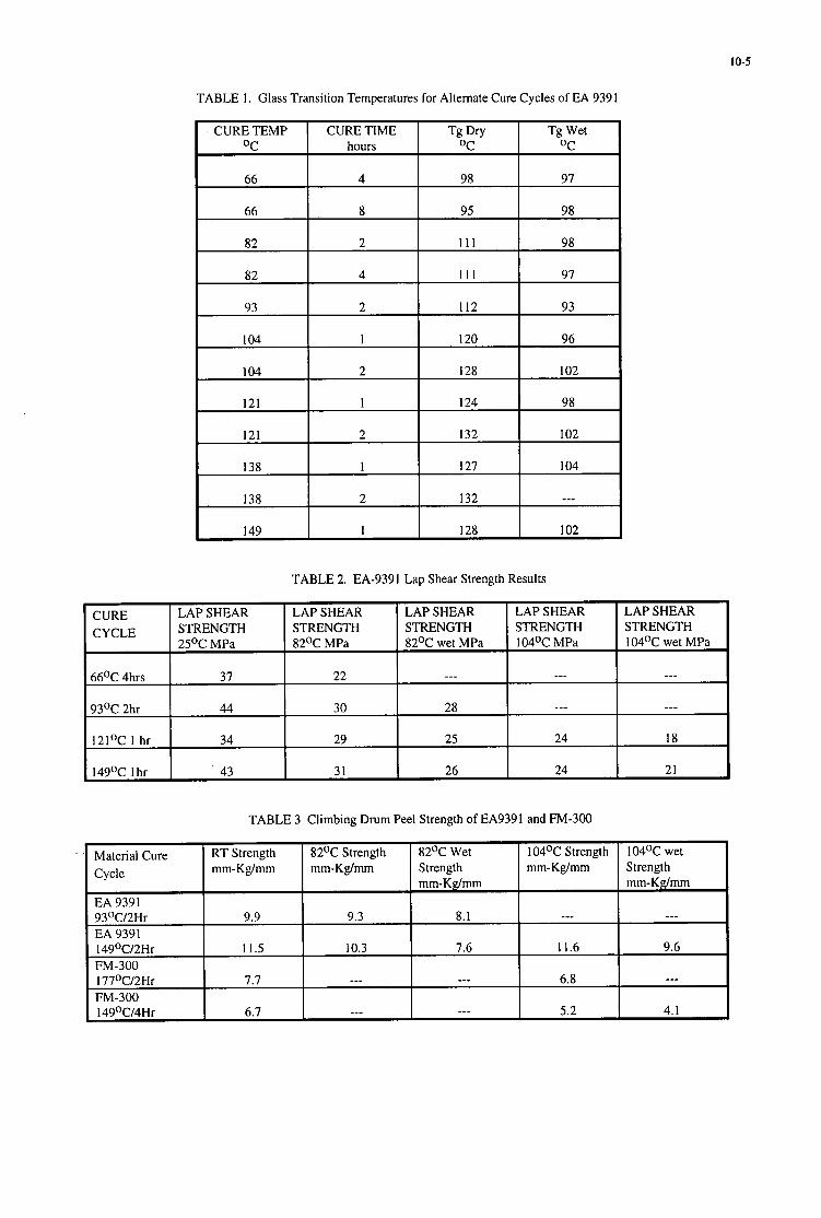
10-5
CURE TEMP CURE TIME OC hours
Tg Dry Tg Wet OC OC
82 111 98
82
93
104
104
131
4 111 97
2 112 93
1 120 96
2 128 102
1 124 98
121
138
2 132 102
1 127 104
TABLE 2. EA-9391 Lap Shear Strength Results
138
149
TABLE 3 Climbing Drum Peel Strength of EA9391 and FM-300
2 132 ---
1 128 102
Cycle mm-Kg/mm 82OC Wet 104OC Strength Strength mm-Kg/mm mm-Kg/mm
--- 8.1
7.6 11.6
--- 6.8
EA 9391 93OC/2Hr 9.9 EA 9391 14g°C/2Hr 11.5 FM-300 177OC/2Hr 7.7 FM-300 14g°C/4Hr 6.7
104OC wet Strength mm-Kg/mm
---
9.6
--_
82OC Strength mm-Kg/mm
_ _ _
9.3
5.2 4. I
10.3
_ _ _
I _--

10-6
Material/ Process
EA-9390 D/V1
EA-9396 D N 1
EA-9390
EA-9396
EA-956
TABLE 4. Physical Properties of Wet Layup Patches
Void Resin Fiber Content Content Volume
1-3% 33% 54%
I-3% 33% 54%
7% 35% 50%
6-7% 34% 5 2%
1-3% 45% 44%
Material RT Strength MPa 82OC Strength MPa
EA-9390 D N ' 50.4 43.7
EA-9396 DN' 51.1 35.1
EA-9390 30.7 31.2
1 Double Vacuum Processed prior to cure
82OC Wet' Strength MPa
39.3
25.2
---
1 Double Vacuum processed prior to cure. 2 Moistureized 30 days @ 6OoC/95% RH.
TABLE 6. Mechanical Properties of Wet Layup Patches.
Interlaminar Shear

10.7
-
I Figure 2: Magnobond 108-134 Laminates -a. Vacuum cure only; b. Double vacuum at 38OC (IOOOF) for 1 hr.


11-1
"ON AIRCRAFT" REPAIR VERIFICATION OF A FIGHTER A/C INTEGRALLY STIFFENED FUSELAGE SKIN
J. Bauer A. Maier
Military Aircraft Division Deutsche Aerospace Airbus 8 1663 Munchen, Germany DEPT. LME22, POB80460
1.0 ABSTRACT
A considerably large four point bending test box was available simulating the curved integrally stiffened CFC fuselage skin of a fighter aircraft. This box was used for a skin repair trial with subsequent testing. The repair was performed in the environment of an external test laboratory, i.e. abroad of the original shop or maintenance facilities. "On Aircraft" conditions have been simulated with all the referring access, tooling and quality assurance difficulties. The repaired test box demonstrated during static testing, loading the repair in tension, compression and shear, that the applied repair procedure is feasible to be applied on CFC structures. The repair procedure and the subsequent testing will be presented and the results will be discussed.
2.0 INTRODUCTION
The EF2000 centre fuselage structure consists of an integrally stiffened CFC skin which is bolted on Aluminum frames as detailed in Fig. 1 .The volume between the skin and the air-intake ducts is used as fuel tank without any further devices for fuel containment. I.E. the tank is a pure integral one and such the CFC structure is loaded by the internal
fuel pressure in addition to the bending and torsional loads of the whole fuselage.
During the development and qualification of the CFC skin several test items have been generated to investigate stability and strength purposes and subsequently to demonstrate the applicability of the whole configuration. This includes the sealing concept which must be considered as a major concern in conjunction with integral fuel tanks.
One of these test items is detailed in Fig. 2. Such a 4.2 m test box became available as a fall-out of the structural development phase for a repair exercise. This activity was sponsored by the german MOD and offered the great advantage not only to perform a repair under "On Aircraft" conditions but in addition to demonstrate the residual strength of the repaired zone (Ref.2).
The test box was repaired applying the DASA-LM baseline method, the so-called "Hard Patch Repair'' @ef. 1). This method is based on the preparation of a scarf in the parent structure and subsequently the generation of a tool in which the hard patch is cured under usual autoclave conditions. The Hard Patch and the parent structure are finally bonded together under "On Aircraft" conditions, i.e. using a heat blanket and applying vacuum pressure.
Paper presented at the 79th Meeting of the AGARD Structures and Materials Panel on "Composite Repair of Military Aircraji Structures" Iield in Seville, Spain 3-5 October 1994.

11-2
This repair method fulfils the basic structural requirements for a fighter aircraft with Mach 2 performance. I.e. it restores the design strength of a service temperature of 100°C and achieves all quality assurance purposes regarding the material, like porosity and defects. Bearing this in mind it is accepted, for the time being, that the repair procedure is time consuming and requires skilled personnel.
3.0 TEST BOX PROPERTIES AND RESTRICTIONS
The test specimen has a span of 4.2 m and the CFRP stiffened panel is bolted on a metallic substructure, i.e. Aluminum frames and steel side panels. A cross section is detailed in Fig. 3, showing the curved CFRP test item and an Aluminum frame with test load introduction lugs.
The metallic substructure provides a representative load introduction into the CFRP side skin and was originally designed to the limits of the EF2000 centre fuselage loading conditions.
The configuration of the test set-up is shown in Fig.4 . The test principle can be described as a 4-point bending configuration with the possibility to superpose torsional loads. Such the test area is located in the centre of the box with a length of 1 m. The rest of the test box length serves for load introduction purposes.
Tensile and compressive stresses may be created in the test area by bending the box and shear stresses are created introducing torsional loads. The test box was designed according to EF2000 design principles and with respect to EF2000 load levels. This incorporates certain limitations which are insuperable for the
repair verification test load cases. In more detail, buckling limitations are to be considered in the CFRP skin itself when the test area is loaded in compression and shear. In case the test area is loaded in tension, buckling of the metallic substructure limits the loading of the box and such the maximum applicable tensile stresses in the CFC side skin.
The CFC side skin is manufactured from the prepreg system Narmco 5245C/r800. This is a 175'C curing BMI modified Epoxy system. The skin lay-up is dominated by +/- 45" plies. In the test area 15 % fibres are directed longitudinally, 23 % in circumferential direction and 62 % are +/- 45' fibres. Between the Aluminum frames the skin is supported by CFRP stiffeners which prevent buckling and take loads originated by the fuel pressure. The complete stiffened panel, shown in Fig. 2, is manufactured in the co-cure technique, i.e. the skin laminate and the stiffeners are cured together in one autoclave cycle. Thus no extra cure cycle is necessary to bond the stiffeners on the skin laminate. A cross section of the stiffeners is given in Fig. 5.
Since the stiffened panel is curved, the local,defonnations in the test area are somehow sophisticated.This is demonstrated in Fig. 6a to Fig. 6c in which Moire measurements are detailed (Ref.3). These make evident that bending effects in the skin take place even when relative small loads are applied. Such bending effects are to be considered when the test area is loaded in compression and in tension, whereas shear loads do not generate large out of plane deflections of the skin.
The simulated damage was placed into the highest loaded zone of the CFRP side-skin, which is the apex in the centre
11-3
of the test area as shown in Fig. 7 . Considering the verification test conditions, the repaired zone was then exposed not only to two-dimensional in- plane loads but in addition these have been superposed with considerable skin bending.
4.0 THE REPAIR
4.1 BASIC CONDITIONS FOR THE REPAIR
In order to demonstrate that the applied repair method is feasible to be carried out under "depot conditions", the repair action on the box was carried out abroad from all DASA production and maintenance facilities. The test box was located in the test Lab of the IABG (Industrieanlagen- Betriebsgesellschaft), at Ottobrunn which is about 90 km far away from any of the DASA manufacturing and maintenance facilities. The repair was performed from skilled DASA maintenance and manufacturing personnel under usual time restrictions. I.e. no specific priority, e.g. overtime, was applied during the duration of the repair and the required time period for the repair action itself was demonstrated
,
I I under realistic industrial conditions.
The simulated damage was located in the highest loaded zone on the apex, in the centre of the test area and had a size of 50. mm diameter. It did not affect any stiffeners; i.e. only the skin laminate had to be repaired. Further geometrical details are given in Fig. 7. Both sides of the damaged zone had been accessible, although, in principle, the repair method allow single side access
I
!
I
t conditions.
was to demonstrate the strength capability of the Hard Patch repair or, if this turns out not to be possible, to learn from any failure originated by the repair. Preference was laid more to load the box and thus the repair up to their limits than to apply EF2000 load cases. Naturally the repair had such to sustain loading conditions far in excess of the D.U.L. (design ultimate load) derived from the EF2000. Stress calculations leaded to the conclusion that a scarf angle of 20:l should recover the required strength according to the EF2000 design allowables. Regarding fatigue, the Hard Patch Repair method is seen to restore the structural integrity for the rest of the aircraft service life.
4.2 THE HARD PATCH REPAIR METHOD
4.2.1 REPAIR APPROACH
Besides the requirement for sufficient static and fatigue strength of the repair itself, it should not change the overall stiffness of the repaired component to avoid additional load concentrations in the structural repair area. "Hard" repair patches are made from unidirectional prepreg tape, cured in an autoclave using standard curing processes. To avoid the effort and time needed for dismantling the damaged structures, the repair on aircraft should be possible by single side access conditions.
4.2.2 REPAIR STEPS
The principal flow of work can be divided into ten single steps as shown in Fig. 8
I From the stress point of view, the aim
11-4
Ste 1 Damage localization and characterization by non- destructive inspection (NDI).
The damage is supposed to be a through- the-thickness damage. NDI-testings are performed by using mobile ultrasonic/x- ray equipment.
Step 2: Scarfing of the repair area and NDI for soundness of the remaining structure
In order to get reproducible results, a circular section is cut out. The cut-out is scarfed by routing cutter and sanding paper. The scarf ratio is usually 20:1, but can vary because of laminate thickness and geometric design restrictions. Grinding a scarf needs some workmans- hip experience. The outline of the individual layers may serve as guidelines as they become visible. After machining non-destructive inspection of remaining structure by mobile ultrasonic should show no further damage.
Step 3: Manufacturing, trimming and bonding of the CFRP bottom- plate
In order to provide a moulding surface to the tool and to get vacuum sealing during the repair a pre-cured CFRP-laminate is fitted to the component. Since it is assumed to have no access to the backside, the bottomplate is slipped through the repair hole and bonded to the back face by a room temperature curing adhesive. The advantage of this method is the availability of the whole scarf area for structural load transfer compared to a " fitted-in" bottom plate.
Step 4: Manufacturing of the GFRP male tool
a glass fabric laminate and a room temperature curing epoxy material which is wet laid up and cured at elevated temperature. The bondline thickness is simulated by release f h s to match the repair patch loft.
Step 5: Manufacturing of the CFRP female tool
The CFRP female tool is manufactured by shaping to the male tool. It is made by a room temperature curing epoxy material which is wet laid up and cured at elevated temperature. In order to get thermal stability the female tool is post cured at the temperature of the repair material (175oC). This tool represents an exact copy of the repair-scarf.
Step 6: Manufacturing of the repair patch including NDI
The CFRP female tool is used to manufacture the repair patch. This usually consists of the original prepreg lay-up plus additional cover layers, but can vary according to stress/strength purposes. The lay-up and curing is carried out according to the manufacturing process specifications i.e. with full process pressure in an autoclave. The cured repair patch is inspected by NDI and has to pass quality assurance requirements identical to those of normal production components.
Step 7: Staging and embossing of the film adhesive
The film adhesive is treated by staging and embossing. This is in order to reduce volatiles and to eliminate low viscosity components of the adhesive. Simultaneously a continuous groove pattern is embossed to the film adhesive by honeycomb. This creates channels
The GFRP male tool is manufactured by

11-5
where moisture can be sucked out during the cure cycle.
Step 8: Check of the bondline by a simulated bonding procedure
The bondline is checked in-situ by a simulated bonding procedure. The film adhesive is separated from the structure and the repair patch by two release foils. The Curing Process will be performed according to Step 9. After the cure cycle, the film adhesive can be inspected for manufacturing tolerances (visible inspection), thickness, thickness distribution and in addition by physics- chemical analysis (degree of cure, glass transition temperature).
Step 9: Bonding of the repair patch
The bonding of the repair patch to the structure is carried out by a mobile repair kit. The film adhesive is put onto the scarfed cut-out, and then the patch is mounted in place. After applying vacuum the adhesive is cured by a heat blanket. The cure temperature is reduced from the original 175'C to 150°C and the curing period extended in order to avoid thermal damages in the parent structure. In addition low temperature curing offers advantages during on-aircraft applications on structures which have been already exposed to humidity.
Step 10: NDI of the repair
The complete repair has to be inspected by ultrasonic and has to pass the quality assurance requirements for production bondlines.
4.3 EXPERIENCE FROM THE TEST BOX REPAIR
The repair action was performed without deviations from the previously defined time-schedule which is an undoubtful sign that unforeseen difficulties did not occur. The complete repair lasted less than 3 weeks or 14 working days in which all the 10 steps of Fig. 8 have been performed and the test box was ready for static testing.
The verification of the bonding procedure by the "verifilm-technique" (see Step 7 in Fig. 8) demonstrated that the cured film adhesive has a constant thickness. This is the result of a visual inspection. The thickness measurements are within a narrow range. Physics-chemical analysis, by Differential-Scanning Calorimetry, demonstrated a completed cure of the adhesive and a glass transition temperature which is well above the service temperature requirement of the EF2000. The fmal ultrasonic inspection (see step 10 in Fig. 8) didnot indicate any unacceptable defect and it can be summarized, that the repair passed all quality assurance measures without any concession.
5.0 VERIFICATION TESTS
The CFRP-skin was pre-conditioned before all the test and repair activities started. Its humidity content was controlled by travellers. In order to avoid a drying out, particularly due to the 100°C tests, the test area was generally exposed to humidity. The content of humidity in the Narmco 5245CD800 structure and had been 0.67% at the beginning of the test programme and decreased to 0.65% at the fmal failure test. Before any repair activity on the test box have been started, reference tests were conducted which delivered strain gauge

11-6
measurements for comparison with those from similar tests after the repair. In the verification test programme these tests represented phase 1 and have not been driven up to 100 % limit load (L.L.), mainly due to buckling considerations which should not damage the CFC skin and, more important, the metallic substructure.
In phase 2, i.e. after the repair, limit load (L.L.) tests have been performed and phase 3 represents the ultimate load (U.L.) and final failure test. The complete test programme is detailed in Fig. 9 including the definition of L.L. conditions expressed in strains present in the repaired zone. U.L. can be derived from L.L. applying the safety factor j = 1.4.
The test box and the repair passed the phase 2 tests without any significance except some groaming originated by the metallic substructure. Concluding the strain gauge measurements no difference between phase 1 and phase 2 became evident. I.E. the repair did not affect the load distribution in the skin. Differences between RT and 100°C measurements arised and are explained by the effect, that the coefficient of thermal expansion of the metallic substructure is larger than the one the CFC side skin and thus thermal stresses are generated.
More interesting is phase 3, the ultimate load and fiial failure test. This had to be performed loading the repaired zone in compression due to a severe buckling restriction of the metallic substructure in the tension load case. The test temperature was 100°C. The strain gauge measurements indicated the large secondary bending effects in the skin and the repair zone. These finally originated the final failure but the crack in the skin
did not at affect the repair. I.e. its presence was not the origin of the skin failure, which was located near one of the two metallic frames representing the borderlines of the test area. Such this area is not free from load introduction effects which increase the already existing secondary bending. Both together caused excessive bending of the skin laminate in the vicinity of the main frames and originated the final failure of the skin laminate.
Final failure occurred at 1.52 x L.L. and such ultimate load has been exceeded by about 9 %. From the strain gauge measurements the in-plane and bending conditions in the repair bondline could be extracted. These have been introduced in a FEA and the shear and peel stresses were calculated at j = 1.52. These calculated stress distributions are shown in Fig. 10. The maximum shear stress tums out to be relative large and it must be assumed that in reality this value will not be achieved. This peak should have been reduced by non-linear, i.e. plastic effects in the adhesive.
Regarding the D.U.L. of the repair, which is represented by the ultimate load design allowable in compression for the skin and considering the load redistribution due to non-linear effects in the box, it was concluded, that the repair was loaded up to 95 % of its D.U.L. This indicates, that the repair was highly loaded and only small reserves can be assumed until fiial fdu re of the repair takes place, if the test box would have allowed further load increase. Nevertheless the target, to demonstrate, that the Hard Patch Repair achieves the design strength of the original structure was reached to 95% under quite unfavourable conditions.

6.0 CONCLUSIONS
11-7
7.0 REFERENCES
The test box repair exercise continued the serie of promising test results, which have been experienced up to date with the Hard Patch Repair Method. It approved to be applicable "On Aircraft" and was demonstrated under "depot" conditions from skilled personal. The duration of the repair must be regarded as massif, but this disadvantage should be summed-up with the standard of quality, which is achievable. The hard patch is manufactured from the same type of prepreg material and to the identical manufacturing standards as the original structure. I.e. no porosity is present in the patch. The "verifi i- technique" offers the extraordinary possibility to control the bonding process by DSC and the bondline thickness before the final bonding procedure has been carried out. This allows to perform the repair procedure within narrow tolerances of all relevant parameters and generates a high level of reliability. From the materials point of view the environmental requirements of a Mach 2 fighter are met without any concessions. The mechanical properties are satisfactory, i.e. the structural integrity is recovered completely. Summing-up all these aspects there are reasons enough that airworthiness certification is achievable. Regarding the future, the Hard Patch Repair offers possibilities for further developments and derivations, aiming to speed-up the repair procedure and to reduce the financial effort.
Ref. 1: Paper of the ICCM/9 Madrid A. Maier,G. Gunther, J. Vilsmeier Repair of Aircraft Structure Using "Hard" Composite Patches
Ref.2: MBB-FE221 -CFK-R-0019-A Strukturversuch Reparaturbox Anhang L Reparaturbericht Anhang M: Statische Auswertung
Ref. 3: TPSB-T-25/90 IABG Technische Mitteilung,Pfister
Verformungsmessungen an der R E P A R A W O X / CFK-Schale mit dem Schattenmoireverfahren

11-8
:/: €FA Rumpfrnittelteii la Centre Fuselage
Figure 1: Structural Arrangement of the EF2000 Centre Fuselage
i
I

c-
Figure 2: Buckling Test Box prior to Final Assembly
\ ' z 1-2 YI -2
Figure 3: Cross Section of the Test Box

11-10
Figure 4: Principle of the Test Set-up
CIR- PLIES
+ 45 DEGREE AND ‘IERTICAG PLIES
r ,U SKIN I
Figure 5: Frame Cross Section and Lay-up

11-11
R o p o r o t u r b o x / CFK-Schalo ( R I LFI ( D r u c k l , J - a.6 S c h n r t t E - F
ew-a a a 1;
d 7 \ ,p\ \ ,p: -I 7 : -I I -I - -1 a
\ I \ I
'\ i i \ / \
LI a \ ' \ I
'I\! I \J I I
I . ab &ma id# 3. IS# 3. I. -U .I#
m..ia
:I .... I - 1.. ..m
Figure 6a:
Figure 6 b Defomation of the Test Area under Tensile Loading at 0.5 L.L
Figure 6c: Deformation of the Test Area under pure Shear at 0.8 L.L.

11-12
Figure 7: Geometrical Details of the Repaired Zone

11-13
step 1: Damage localisation and characterisation by NDI
Scarfing of repair area and NDI for soundness of remaining structure
I I I I
Step 3: Manufacturing, trimming and bonding of CFRP bottomplate
Step 4: Manufacturing of GFRP male tool
I
1 I I I I
I I I I step 5: Manufacturing of CFRP female tool
Manufacturing of repair patch including NDI
I I I I
Step 7: Stageing and embossing of film adhesive
I I 1
step a: Check of bondline by simulation of bonding procedure
Fig. 8 The Hard Patch Repair Method

11-14
Fig. 9 The Verifintion Test Programme
N
2
Deutsche Aerospace -8- L.L waa &&md pccrrdiDg to limit& main allowable% m i l e 55W
~ m ~ ~ c s s i v c - 4 u x ) micro-Stminr D.U.L., i.e. 39M) L.L. mino-rtrains D.U.L., i.e. -3000 L.L.
TEST PHASE 1: Reference 1- b c h rcpSir : RT + b/W TESTPHASE2 LL.testr&orCpair: RT+b/W TEST PHASE 3 U.L. tesI and find f d m : RT + b/W

121
Rapid Repair of Large Area Damage to Contoured Aircraft Structures
James A. Frailey LOCKHEED Fort Worth Company
P.O. Box 748, M.Z. 2824 Fort Worth. TX 76101-0748
United States of America
Douglas W. Carter Wright Labs, United States Air Force
WZJMLSE Building 652 2179 12th Street, Suite 1
Wright Patterson AFB. OH 45433-7718 United States of America
1. SUMMARY
In a program sponsored by Air Force Wright Laboratory (WUFIVST), Lockheed Fort Worth Company has developed field-level procedures for repair of large area damage to highly contoured aircraft structures. The combination of aircraft structures designed with enhanced survivability and the utilization of larger and more powerful ballistic threats have resulted in the requirement to develop new. creative approaches for rapid repair of large area structural damage. Furthermore, current aircraft design employing advanced composite materials on highly contoured surfaces increases the challenge of implementing workable battle damage repairs. This paper details the development of an advanced battle damage repair concept designed to repair damage up to approximately 15 inches in diameter on highly contoured surfaces. It employs a quick, reusable tooling mold that replicates the contour of the damaged aircraft for the purpose of processing a composite patch. Several one year room temperature storable, thermoset, composite systems were examined for processability, handleability and mechanical performance to determine their suitability as repair patch materials. The most promising were further tested and demonstrated in a large scale validation test.
2. INTRODUCTION
History has shown that rapid repair of battle damaged aircraft is critical to maintaining high sortie rates necessary in the early stages of combat. The United States Air Force (USAF) recognizes this need and has established an Aircraft Battle Damage Repair (ABDR) program. The USAF ABDR program has provided training requirements, technical manuals, and deployable trailers stocked with simple tools and materials needed to perform wartime repairs to battle damaged aircraft. Application of ABDR dictates use of only very simple tools and operations, easily accomplished by personnel working under austere conditions. Also. the repair materials should have long shelf lives and be easily storable.
The standard ABDR concept of aircraft metallic structures involves cleanup of the damaged area, fabrication of an aluminum patch, and installation of the patch over the damage using blind fasteners. This repair procedure is quick and effective. However, damage in an area of complex curvature presents a challenge of bending the aluminum patch in many directions to match the original aircraft skin contour. Even the most experienced structural repair technician has difficulties making a complex curved patch with equipment currently available on ABDR trailers.
Therefore, repair concepts for damaged, complex contoured, aircraft structures that can be performed quickly and easily are needed for development.
Repair concepts for damaged, multipie contoured structures have been investigated utilizing advanced composite patches. However, these repair concepts are incompatible with the ABDR concept. They involve the timely and costly fabrication of a one-time-use tooling mold. Relatively simple "splash" molds have ken developed utilizing plaster or ceramic curing compounds. However, when considering application of these tooling mold techniques for ABDR. several problems arise. The most obvious concerns are: the requirement that large quantities of material must be stored to perform several repairs. unacceptably long downtime of an equivalent undamaged aircraft while the mold is curing, and high costs associated with the one-time-use nature of the mold. Furthermore, typical composite material handling and processing methods require cold storage of materials, utilize "clean room" equipment that are bulky, heavy and expensive, and require extensive training and experience for personnel.
Clearly, an entirely new approach for ABDR of damaged complex contoured structures is needed. The approach should not limit the capability of technicians to repair highly contoured structures, and at the same time insuring the equipment and methods associated with the proposed approach are compatible with wartime limitations.
3. DEVELOPMENT OF BATTLE DAMAGE REPAIR EQUIPMENT
It was assumed in the early stages of this research that a composite patch would be required to provide the flexibility necessary for repairing complex contoured S~NC~UES. Some have recommended the use of a thin. flexible backing plate to support a cure-in-place composite repair. This approach is most beneficial when damage is limited to approximately 4-6 inches. When the damage size is any larger. the backing plate becomes difficult (if not impossible) to conform to multiple contours and lacks the required bending stiffness to adequately support the repair. Consequently. it was felt that large area damage, on the order of 15 inches, would necessitate the need for tooling to create the composite repair.
Thus, the challenge was issued to develop appropriate equipment and techniques for composite patch manufacturing in an austere ABDR environment. Due to strict requirements on repair time and procedure simplicity, a unique approach
Paper presented a1 the 79th Meeting of the AGARD Slrucrures and Marerials Panel on "Composire Repair of Military Aircr.fr Slructures" heId in Sevilk Spain 3-5 October 1994.

12-2
was needed with the first challenge to develop a field usable tooling mold system.
3.1 Field Usable Tooling Mold Development
One of the most difficult and potentially time consuming aspects of large area, contoured composite patch production in the field environment is tooling fabrication. To provide a basis for comparison of different tooling options, a list of requirements was assembled and is presented below.
Field Usable Tooling Mold Requiremenfs Acceptable quality of mold surface and contour accuracy Ability to sustain composite processing temperatures - Minimal elapsed time to fabricate mold Minimal mold weight Ease of mold fabrication Low initial and recurring costs
Three advanced tooling mold concepts were evaluated and are discussed relative to the requirements listed above. The first concept considered uses the damage location on a geometrically equivalent, undamaged aircraft as the tooling mold surface. The primary disadvantage of this technique is the threat of introducing damage to the equivalent aircraft due to the application of composite processing temperatures to the aircraft surface. Furthermore, this technique requires the second aircraft to be inactive from service for considerable time while the repair patch is curing.
The second concept considered may be classified as a chemically hardened tooling technique employing castable ceramic. gypsum, epoxy or expanding foam material. The proposed technique involves building a form to contain the tooling mix on the damage location of an equivalent aircraf4 preparing the tooling material, pouring the material into the form, allowing the material to harden. and removing the mold from the equivalent aircraft. Primary challenges of this technique are: (1) form fabrication to contain the tooling material is expected to be labor intensive especially on complex contoured surfaces, (2) unpredictable mold quality and setting time for various ambient conditions. (e.g. setting or hardening behavior of ceramic materials is highly dependent on surrounding humidity and temperature), (3) procedure complexity increases for sideward and downward facing surfaces, (4) extremely high raw material gross weight and space consumption to stock ABDR trailers with reasonable repair quantities, and (5 ) high costs associated with one-time-use molds and periodic restocking of materials due to shelf life limitations.
The third and final concept considered in this research effort is a mechanically hardened tooling technique. This method uses a sealed rubber bag containing a lightweight granular filler. When the internal pressure is equal to atmospheric, the bag is compliant and easily shaped to an equivalent aircraft surface. Once positioned over the damage location on an equivalent aircraft, vacuum is drawn within the sealed bag causing the rubber skin to constrict on the filler, effectively locking the filler in a firm arrangement. While vacuum is maintained within the sealed mold bag, it may be removed from the equivalent aircraft and the surface of the mold bag which contacted the aircraft (or mold surface) now contains the surface geometry of the damage location. When the mold has served its purpose i t may be reused for a different repair project by releasing the internal vacuum thus unlocking the rigid arrangement of the filler, repositioning the softened mold hag on a different aircraft surface and repeating the steps just mentioned. This method of tooling mold formation affords several advantages relative to the previously discussed methods, such as: (1) low lifetime costs due to its reusable capability, (2) the weight of the mold bag
of 350 F
is approximately 30 pounds and because only one unit need be stocked in the repair trailer the total weight (to accomplish multiple repairs as compared to the second concept) is extremely low, (3) no potentially harmful chemicals or temperatures are applied to the equivalent aircraft, (4) because the mold hardens in less then 10 minutes, the equivalent aircraft is required for only a brief time compared to the earlier two concepts and is then free to contribute to the ongoing conflict. and ( 5 ) the overall procedure is simple requiring little training and special equipment.
Each of the three tooling mold concepts were evaluated with respect to the requirements mentioned earlier. The vacuum- mold bag concept was considered the most optimum and was further developed during the remainder of the research effort.
The next step in a typical repair procedure is to position an uncured composite patch on the tooling mold and apply vacuum consolidating pressure. Details of composite patch material selection and composite bagging procedures are discussed later. The current section of this paper will concentrate on development of equipment pertaining to applying vacuum consolidation pressure to the patch. Using the Vacuum-Mold Repair System (VMRS) the composite patch is processed on the released vacuum-mold surface. An oufer rubber vacuum bag is positioned around the inner vacuum-mold bag as shown in Figure 1. The outer vacuum bag serves to provide consolidating pressure to the patch while the inner vacuum-mold bag maintains mold shape and rigidity. The outer bag is provided in two parts; a top and bottom half. The bottom half is permanently bonded to the inner mold bag. The top half seals to the bottom half around the edge of the mold. Of the two primary requirements for processing composite materials (heat and pressure) the outer vacuum bag bas provided vacuum consolidating pressure. The next step is to apply controlled heat.
Vacuum Nozzle to Outer Bag
h e r Mold Bag LBoitotn Half of Outer Vaccum Bag
Vacuum Nozzle to Inner Mold Bag Seal Connecting thelwo Halves of the Outer Bag
Figure I. Primary Components of the Vacuum-Mold Bag
3.2 Development of Field Operable Heating Methods
The typical means of controlled part heating in a field environment is with a heat blanket and controller. This method was considered as the starting place for prnviding cunng beat to a composite patch on the VMRS. It was soon discovered that the vacuum-mold system could replicate severe complex contours beyond the capabilities of even extra flexible heat blankets. An alternative form of controlled heating was needed that would not limit the extent of repair contour and size. Two unique forms of heat provision were developed in this research effort. Although the second method is preferred, for thoroughness sake a brief description of the first method is now presented.

12-3
volume of the collapsed oven. Although not shown in Figure 3, insulated covers have been fabricated to minimize heat loss through the top silicone rubber sheet and the feed and return air hoses. The mold filler is a natural insulator, thus no insulation is required on the bottom of the mold bag. Like the collapsible oven, the integral heating device is designed for operating temperatures up to 350 F.
3.2.1 Collapsible Oven
The first form of controlled heat developed in t lus research project is a collapsible oven. An oven was considered convenient from the stand point that it provides even heat distribution and does not impose limits on the contour of the repair as long as the vacuum-mold fits inside the oven. However, typical concerns in using an oven for field use are weight and size. Consequently, a light-weight, collapsible oven was designed and fabricated to provide the advantages of an oven mentioned earlier while elevating typical concerns of oven size and weight for field use. When collapsed in storage, the oven is roughly 1 x 4 ~ 4 feet. When deployed the oven occupies a volume of 4 x 4 ~ 4 feet having sufficient space to contain the tooling mold. The oven side walls are hinged in the middle allowing them to fold inward as shown in Figure 2. When collapsed. the front and back walls rest flat on the top side of the oven and during assembly swing down and lock in place. A sling hanging from the top of the oven is used to support the mold hag. The total weight of the oven is about 130 pounds and may be camed easily by two people. The oven is designed for opcrating temperatures up to 350 F by use of 2,300 Watts of resistive heating elements positioned in front of a circulating forced air blower to maintain even temperature distribution.
F i g w 2. CoNapsible Oven for Field Processing of Composite Repair Patches
3.2.2 Integral Heating Device
The second (and preferred) form of controlled heat consists of a modification to the vacuum-mold repair system such that the heating environment is self contained on the mold rather than a separate enclosure such as with the collapsible oven. This system is termed the integral heating device and is shown in Figure 3. Note in Figure 3 that an additional layer of silicone rubber has been bonded around the periphery to the top half of the outer vacuum bag and between these two layers of rubber. heated air is channeled to cure the composite patch. A slight positive pressure is maintained between these layers of rubber by circulating air into the air volume through a 3 in. diameter feed hose and exiting air through a 2 in. diameter return hose. The feed and return air hoses connect to a controller case that contains the heating element, blower, controlling logic and auxiliary thermocouple monitors. The controller case weighs approximately 50 pounds and occupies a quarter of the
1. Return Hose 2. Feed Hose 3. Additional Layer of Siliine Rubber 4. Repair Controller Case
a. Thermocouple Inputs b. Cooling Fan c. Temperature Controller d. Auxil1aryT.C. Monrtors e. Power Switch f. Power Cord Connector
Figum 3. Primary Components of the Integral Heating Device for Field Processing of Composite Patches
4. COMPOSITE PATCH MATERIAL DEVELOP- MENT
A major concern with the use of composite material for ABDR is promoting a repair method that is too difficult to work. requires elaborate and lengthy processes, and has unpredictable mechanical behavior. Therefore, much research and optimization must be given to choosing the easiest material to work with, while streamlining associated processes so that patch laminates, with acceptable mechanical propemes, may be fabncated at minimum cost in time and complexity.
4.1 Composite Patch Material Selection
Four thermoset composite materials were assessed for suitability for composite ABDR. Table 1 provides a brief description of these materials.
Each material was evaluated in three areas: handleability. processabihty, and mechanical performance. Handleability refers to the relative ease to use the material in a field environment to process large repair patches on a complex contour surface. Predominantly handleability is bed to the drape and tack characteristics of a material. The AS4/3502 material was advanced staged under vacuum pressure at 250 F for 2 hours. The material was then cooled causing vltrification into a glassy state thus blocking most chemical crosslinking at room temperature. The evaluation of the processing and handling of this material was based on this form, instead of the out-of-freezer prepreg form normally associated with AS4/3502. Assuming this basis. in order to form a complex contoured patch, AS4/3502 would require a hot-forming process. The laminate would be reheated to 250

I 2-4
F, at which temperature the material viscosity reduces and the tack increases, and the patch can be hand formed to a tooling surface.
Sp377/CF5 had little to no tack and was very bnardy. With Sp377 each ply of material must be hot-tacked to a preceding ply to control lamina location. The boardy. tackless characteristics of SP377 make it extremely difficult to form over complex contoured shapes. On the other hand, F3T584/HX1567 exhibited extreme tack at room temperature, making it almost too difficult to work with. Furthermore. this material requires careful moisture-free packaging in order to achieve the desired shelf life.
The wet layup material, T300VEA9396, inherently requires resin mixing and manual fabric impregnation which are difficult from a handling perspective. However, once the wet layup is impregnated the material possesses excellent tack and drape qualities.
In the area of processability. the SP377 is the most impressive. This material can be cured in 5 minutes at 300 F. The wet layup material EA9396 is the next best, curing in 30 minutes at 200 F. The third best is HX1567 curing in 2 hours at 250 F. The least desirable material from a processability viewpoint was AS4/3502 requiring a 2 hour cure at 350 F. Mechanical performance was based on °ree flexure and flatwise interlaminar tension tests with results shown in Table 1. These tests provide an excellent means of comparing matrix dominated properties for each material. AW3502 produced the highest strength and stiffness values for the interlaminar shear test and the second highest interlaminar tension values. SP377 produced the second highest interlaminar shear values followed by T300BA9396 and then by F 3 T 5 m 1 5 6 7 .
Results from the handleability. processability and mecbanical performance studies discussed above, guided a decision tu select for further development two of the four materials. These materials are AW3502 and T3001EA9396.
4.2 Composite Patch Kit Development
It is considered highly desirable to eliminate the need for ply-by-ply laminate building in the ABDR environment. An alternative approach employs 3-ply kits of carbon fabric with lay up [0,45,01 as shown in Figure 4. The Odegree direction is labeled the "Primary Load Direction" on the
MATERIAL' Foww
Prepreg, Advanced
for 2 hrs. AS4/3502 Staged 250 F
SP377lCF5 prepreg
F3T5WHx1567 Prepreg
T3w/EA9396 Wet lavuo
outside of a protective wver encompassing each kit as noted in Figure 5. Kits are provided in standard repair sizes such as 12x12, 15xl5, 20x15, and 20x25 inches. To simplify the field repair process, kits am used as building blocks in constructing a repair patch. For the purposes of this project, assume the patch should be 10% thicker than the damaged skin. Thus for a 0.10 inch thick skin a patch should be approximately 0.11 inch thick. In this case a 3-kit repair should be used (sce Table 2). Each kit is stacked directly on top of the other, aligning the primary load directions. Because each kit is a symmetric sublaminate. the final laminate. regardless of thickness. is also symmetric.
The two material systems selected for further development, AS4l3502 and T30wEA9396. are prepared in kit form. To prepare a kit of AS4/3502, a [0,45,0] laminate is laid up, staged for 2 hours at 250 F, and enclosed in a protective cover. Likewise, a kit of wet layup patch system, ' B W 9 3 9 6 , wns~sts of a [0,45,0] laminate of 'M00 fabric sewn around the edges to maintain correct ply placement and reduce fraying of the dry fabric. The T300 kit is then enclosed in a protective cover. In both cases kit stacking sequence is ensured by either staging (for the case of AS4/3502) or sewing (for the case of T300 fabric). The proposed battle damage repair method developed in this program will stock kits of either material in the ABDR trailer.
INTERUMINAR IMERLAMlNAR SHEAR4 TENSlONJ RECOMMiZNDED
CURE S6ungth Mcdulus f W W*/J Strangthf@i)
2 hours at 350 F 139.6 9.03 1491
5 minutes at 300 F 120.2 8.59 1450
2 hours at 250 F 106.1 7.62 931
30 minutes at 200 F 114.9 8.29 1684
A
Figure 4. Three Plies of Fabric are Combined to Maka One Kit
Table 1. Candidate Composite Patch Materials
~~
Notes: 1. All materials considered are carbon fabric, [Ole 2. Rectangular specimen tested in flexure as a beam in 3 point loading fixture (ASTM D790-86) 3. Square specimen bonded to flatwise load tabs and tasted in normal tension

125
5.2 Forming a Tooling Mold
Place the softened vacuum-mold hag on the equivalent aircraft over the previously defined damage area. By pulling the edges of the mold surface sheet outward, wrinkles are removed. While maintaining f m contact of the vacuum- mold surface to the equivalent aircraft, attach the vacuum pump line to the mold and run the pump for at least 7 mmutes. Place the hardened mold bag and attached vacuum line with mold surface facing up on a working surface for patch fabrication. For repairs to sideward or downward facing surfaces, a support strap with vacuum cups attached has been developed to hold the mold in place while air evacuation ocenrs (see Figure 7).
/ Pmhtiw Cover
Figure 5. Primary Load Direction Labeled on Each Kit
Table 2. Number of Kits Required for Different Patch Thicknesses
I Desired Thickness of I Number of I
Note that both materials have adequate shelf life for ABDR considerations. Staging of AS4/3502 causes transformation of the matrix into a partial glassy state blocking most additional reaction at room temperature. While ohviously kits prepared of dry T300 fahric are stable at any reasonable storage temperature for an indefinite time perind.
5. IMPROVED BATTLE DAMAGE REPAIR PROCEDURE
This section describes the integration of developed repair equipment and selected composite patch materials into an improved overall method to accomplish battle damage repair. The following steps describe repair procedures using the equipment and techniques developed in this program.
5.1 Define Damage Limits and Repair Size
While conducting damage assessment, the ABDR technician should note the damage size and location on the original aircraft. Next, mark and locate the damage limits on an equivalent, undamaged aircraft. The size of repair is dependent on the size of damage plus the required number of fasteners to effectively transfer load. This total patch size should then be located and marked on the equivalent aireraft in a manner that can be easily detectable on the mold surface as shown in Figure 6.
Figure 6. ldentimng Damage Limits
L
Figun, 7. Support Strap Holding Vacuum-Mold Bag Against Equivalent Aircraff
5.3 Patch Layup
Place Teflon tape on the mold surface as a release harrier. Next, locate and mark the primary load direction on the mold. For wet layup patch preparation, open and mix the two parts of the epoxy resin. Place a dry fahric kit (described earlier) on a flat working surface, open the protective cover and pour the epoxy onto the fabric. Close the protective cover. squeegee epoxy over surface of fabric on both sides. and use a rolling pin to gently compress the kit. Repeat for each kit needed in the patch. Open the top side of the protective cover of each kit and stack impregnated kits while carefully aligmng the primary load direct(on8 shown 00 the protective covers. Next, place the stack of wet layups on the vacuum- mold surface, (see Figure 8) aligning the primary load direcuon of the kits with the primary load direction labeled on the mold bag. Plaee two thermocouple leads next to the edge of the patch. Cut and stack perforated Teflon, bleeder cloth, non-perforated Teflon, and breather cloth as shown in Figure 9. Position top half of outer vacuum hag over the mold surface and seal to the bottom half. Connect vacuum line to the outer vacuum hag and evacuate the air, thereby compressing the wet layup patch.
5.4 Curing the Composite Patch
Once the composite patch has been prepared, the integral heating devicc (described earlier) is used to cure the patch. First connect thermocouple wires to the controller. Connect feed and refurn hoses to the repair eontroller case and the mold bag as shown in Figure IO. The curiog profiles for the

1 2-0
two patch materials have been pre-programmed into the controller. The approximate curing time for the wet layup profile is ahout two hours. The last step of the curing cycle cools the part down to ambient temperature. Remove the vacuum lines and thermocouples and demold the patch. The patch is now ready for attachment using any method of choice.
A
Figure 8. Placing Uncured Patch on Mold Surface
-7 6
4 5
-2 ~ ~ : ~ ~ ~ ~ ~ ~ : ~ ~ ~ ~ ~ . ~ ~ ~ . . ~ . . ~ . ~ . . : .. .: .: .: .:..:..: :.. .............................. .._..: .. .... :.:..:..:.:hl
1. Vacuum-Mold Bag 2. Composite Repair Patch 3. Perforated Teflon 4. Bleeder Cloth 5. Teflon 6. Breather Cloth 7. vacuum Bag
Figure 9. Composite Patch Sagging Sequence
Figure 10. Curing the Composite Patch Using the htegml HeathQ Device
6. REPAIR PROCEDURE STRUCTURAL VER- IFICATION
A full-scale, cantilevered wing box test was conducted to verify repair procedures developed in this research program. The design configuration of the test component is shown in Figure I 1 and consists of a three-cell hnx 26 inches wide by 58 inches in length. The thickness in the test section is 4.5 inches. The structure consists of an upper and lower skin, four C-channel spars, an outboard load rib, and inboard root nb. AU spars, ribs and the upper skin are fabricated from 2OWT851 while the lower skin is 7075-T651 aluminum.
Note: All dimensions given in Inches
Figure I I. Wng Sox Jest Component Showing Damage Size
6.1 Wing Box Damage Description
Holes were cut in the upper and lower slans to resemble cleaned up battle damage. Since in this program substructure repair techniques have not been developed, no damage was introduced to the C-channel spars. Given the extent of skin damage that was introduced to the wing box component it is reasonable to expect considerable substructure damage would also exist. It was assumed, however, this damage would be repaired to full load carrying capability using existing ABDR techniques.
The size and location of the damage were the same on the upper and lower skins and are shown in Figure 11. The overall dimensions of the damage are 12 inches io the span direction and I 1 inches in the transverse direction. The damage was located in the center of the test component With respect to the transverse direction. In the span direction the damage was positioned toward the higher loaded end (i.e. the root) of the component. The shaded portion on Figure 11 represents B linear taper of the skin thickness from 0.5 inches in the root section down to 0.25 inches in the test section.
6.2 Wing Box Repair Description
The wing box upper skin was repaired with a 6 kit. [0.45,016. wet layup patch constructed from T300EA9396. The patch was fabricated using the equipment and procedures described earlier in this paper.
The wing box lower skin was repared with a 6 kit, [0,45,016, IM7/977-3 staged prepreg patch. Due to the unavailability of AS413502 at the time of testing, IMll977-3 was substituted. It was expected that both materials would behave similar under the conditions of the wing box test sequence. IM7/977-3 was staged in 3-ply kits similar to AS4/3502 as described in section 4.1.
Both patches were fabricated from standard 20x15 kits and were subsequently trimmed to 19 inches in the span direction and 14 inches in the transverse direction. The average cured patch thickness of the wet layup T300iEA9396 patch was 0.287 inches while the IM7/933-3 patch was on average 0.265 inches.

12-7
following the 1.25 Design Limit Load (DLL) test are in error and are, therefore, withheld from publication.
1 -500
-9 in.- + **+ +++ +*++* * ++++ * + + ++ +* ++
14 in. +++ * + + +
e e e m m m m m e m e e m m m e e e m e + + ++ + + I + +* I+ + ++ ++ . f l * + + + +
0.3125 in. Fasteners + 0.250 in. Fasteners
Figure 12. Mng Box Repair Fastener Pattern
-421 -395 -358 -377
The top skin of the wing box was repaired first. After fastener hole drilling, threaded steel fasteners (MS21296-8) were used to pick up the 0.3125 inch existing fastener holes along the middle two spar Lines. These fasteners were used to attach to Davis nuts utilized on the top flange of the middle two spars. Next, 0.250 inch NAS1669-4L9 blind fasteners were installed in additional fastener holes as shown in Figure 12. Next, the bottom skin was repaired with the only difference from the top skin repair being the use of NAS1669-5L13 blind fasteners along the spar lines. This was necessary since the wing box was COnStNCted with standard lock nuts for all skin-to-spar fasteners (rather than Davis nuts) on the bottom skin.
6.3 Summary of Wing Box Test Sequence
A 9-step test sequence was conducted on the cantilevered wing box test component to verify the structural integrity of the repair procedures developed in this program. Table 3 outlines the test sequence.
Table 3. Wing Box Test Sequence
2 3
4
500 437 441 402 427 -1010 -1046 -1088 -1152 -1119 1028 1062 1081 1115 1135
'1.25 design limit load corresponds to 25,000 pounds end load. This load was applied in both directions; positive and negative wing bending.
5
A total of five strain surveys were conducted at different steps during the test sequence. Strain surveys consisted of slowly loading the wing box in pure bending to a maximum end load of 9,000 pounds in positive wing bending (top skin in compression). Strain and deflection data were sampled at locations shown in Figure 13. The purpose of the strain surveys was to detect any significant load redistribution or stiffness change during the course of the test. 6.4 Discussion of Wing Box Test Results
Table 4 presents data at the maxlmum load level for the five strain surveys. Deflection results for the strain survey
-1041 -214 -266 1 -182 I -274
-- I- - Note: All dimensions given in inches
0 Denotes Top Skin Strain Gage 0 Denotes Bottom Skin Strain Gage
ADenotes DeRection Measurement
Step 1 2 3 4 5 6 7 8 9
Figure 13. Measurement Locations for Mng Box Tea
Description Strain Survey, Undamaged Condition Damage and Repair Structure Strain Survey Fatigue Test, 100 Hours Service Load Strain Survey Static Test, 1.25 Design Limit Load * Strainsurvey Fatigue Test, 100 Hours Service Load Strain Survey
Table 4. Strain Survey Results at 9,W Pounds End Load
6 1005 247 266 241
After After After 1.25 Sage Initial After
No. I Cond. I Repair1 HbOub I DLL I I
255
I I I I I Hours I
1 2 3
0.7713 0.7392 0.7134 0.7231 0.7672 0.7811 0.7743 0.7800 0.7519 0.6803 0.7324 0.7246
Deflection Results (Inches)
Graphical representation of data in Table 4 is provided in Figures 14 and 15. Figure 14 contains tip deflection values for each of the five strain surveys. Figure 15 contains strain values for the wing box top skin for each strain survey. Bottom skin strains are not plotted due to similar behavior to Figure 15, Top skin strain values from the 1.25 DLL static demonstration test are provided in Figure 16.
The first observation that can be made from the wing box verification test is that the component survived the required loadings with no significant structural effect. This can be quickly seen by observation of Figure 14. 'Ilk figure shows the maximum tip deflection at the location of the three load rams for each strain survey (except the survey following the 1.25 DLL demonstration due to deflection measurement error). This figure shows that no significant change in the

12-8
component stiffness occurred throughout the entire test procedure. If major structural failure had occurred in one or both of the patches, a nohceable change in the tip deflection for all strain surveys following that occurrence would be evident. No sueh change is observed.
Referring to Figure 15, notice that the strain at Gage 9 significantly dropped (about an 16% reduction) from the initial condition to the after repair condition. This reflects the inability of the repair to completely restore the load paths of the original structure. Furthermore. it should be noted that Gage 5 does not represent the maximum stram in the patch. The maximum strain in the patch, according to Finite Element analysis, is approximately -1000 micro- inlin. and is located toward the center of the patch. At the location of Gage 5. load bas already started dumping out of the patch into the skin causing the reduced strain.
Figure 16 shows strain profiles for gages on the top skin during the 1.25 DLL static test. Notice there are no discontinuities in the strain profiles during loading, implying the top skin and patch successfully carried the required load. All the stram profiles are hear except for the gage on the patch (gage 5) . Notice the rounding of the
profile of gage 5 indicating the onset of buckling in the patch. However, the patch continued to carry load as is indicated by the lack of observable changes in the other strain profiles.
A Finite Element math model was constructed of the wing box component in the three basic configurations: ( I ) undamaged condition, (2) damaged unrepaired. and (3) damaged repaired. Strain data can be compared with test results for the initial and repaired conditions. However, the analysis can also provide insight into the effectiveness of the repair by looking at the strain in the damaged. unrepaired configuration as shown in Figure 17. Notice at the location of Gage 7 the repair effectively reduced the strain 30% from the damaged unrepaired state.
In conclusion. the wing box survived two 100 hour segments of equivalent flight hours of Fatigue loading as well as static testing equivalent to f 1.25 DLL. No significant change in the component stiffness or strains was detected as the test sequence progressed. Buckling occurred io the compression loaded patches during the 1.25 DLL tests, however, no residual effect was noticed.
0.9 , 0.8
6 0.7 5 0.6 ! 0.5 2 0.4 .G 0.3 k
0.2 0.1 0
- E
Ram 1 Ram 2 Ram 3
Figure 14. wing Box l i p Deflections for Strain Surveys
-1400 ,
Initial Condition
B After Repair
R After 1W Hours
UAhrSecondlWHours
81 l n b l Condiiion
After Repair
E After 100 Hours
61 After 1.25 DU
nmsemndiww,u~
Gage 1 Gage 3 Gage 5 Gage 7 Gage 9 Figure 15. Top Skin Axial Strains for Strain Surveys

12-9
-3500 7 I I I I i
-3000
-2500 '7 -2000
5 -1500
c
.- D
2 -1000 C .-
-500
0
-X- Gage I
-Gage 3
Gage 5 - Gage 7
Gage 9
0 5000 10000 15000 20000 25000 End Load (Ibs.)
Figura 76. Top Skin Axial Strains for 1.25 Design Limit Load Test
-1200 - 1 4 0 0 2 c
Test Data
2 -1000 ._ -800 .- - E -600
5 -200 -400
0 Initial Condition Damaged
Unrapaired Repaired
Figun, 17. Effect of Repair et Strain Gaga 7


13-1
Composite Repair of a CF18 - Vertical Stabilizer Leading Edge
A.E. Maier G. Giinther
Deutsche Aerospace AG
D-81663 Muenchen Military Aircraft
This paper describes the engineering and manufacturing procedures that were applied in a repair task bf a CF18 Vertical Stabilizer Leading Edge, made out of CFC honeycomb structure with multiple in-service impact damages in an aerodynamic sensitive area of the fin. "On-aircraft" damage assessment, manufacturing of a relatively thin contoured CFC doubler, replacement of metal honeycomb core and finally quality assurance and strength verification procedures of the repair are described to restore full design strength of the component and the operational aircraft capability.
LIST OF SYMBOLS
CF DASA AIC V-Stab L/E w SRM CREDP
CFC WC Al Ti NDI us RT AR H/W SLS FWT ILS ULT LL M.S.
Canadian Forces Deutsche Aerospace Aircraft Vertical Stabilizer Leading Edge Right Hand Side Structural Repair Manual Composite Repair Engineer. Development Program Carbon Fibre Composite Honeycomb Aluminium Titanium Non Destructive Inspection Ultra Sonic Room Temperature "As Received" Hot Wet Single Lap Shear Flatwise Tensile Interlaminar Shear Ultimate Load Limit Load Margin of Safety
DSC Differential-
Tg Glass Transition Temperature a Degree of Cure
Scanning-Calorimetry
Composite repair development has seen increasing activities initiated by aircraft industry and customers through the introduction of secondary and primary CFC-structures in service. While manufacturing techniques for advanced composites are developed and optimized for a well known production environment, structural composite repair requirements and scenarios vary to a large extent with respect to different materials, component- assembly-status and accessibility, inspection and cure cycle limitations and process control capabilities. The often unknown environmental condition of the damaged part
Paper presented a1 h e 7Ylh Meeling of the ACARD Structures and Materials Panel on "Composite Repair of Milirary Aircraft Structures" held in Seville. Spoin 3-5 October 1994.

13-2
contributes additional risks and requires attention when selecting repair methods and manufacturing processes.
One of the most challenging tasks is the in situ repair of complex curved parts on the aircraft, when removal of the A/C part is impossible or not economical and production tools of the damaged component are not available to manufacture precured repair doublers in the autoclave. Since quality control of major manufacturing processes can only be performed through non-destructive techniques of the produced part the target of repair-method development must be a "step by step" build-up of the repair with as many quality assurance checks as possible to prevent a situation where the aircraft has been brought to an unacceptable structural status due to an unsatisfactory or failed repair.
The Hard-Patch repair method described herein was developed with these considerations in mind and has been successfully applied to service aircraft in "On-Aircraft" scenarios.
2. I"
A (3-18 aircraft sustained extensive structural damage during operation. The right hand vertical stabilizer leading edge made of aluminium honeycomb core and graphite/epoxy skins was damaged by multiple impacts. Two damages affecting skin and honeycomb core which were not covered by the Structural Repair Manual (SRM) required Engineering Disposition. As the affected leading edge couldn't be disassembled the repair had to be done "on aircraft'' in a "manufacturer-" or
"depot-level-'' environment and focused on a permanent repair solution, restoring the airframe to original condition without any implication on structural or performance limits.
3. DAMAGE ASSESSMEN T
3.1 Description of Aircraft Structure
The vertical stabilizer leading edge consists of graphite/epoxy skins stabilized by a full depth aluminium alloy honeycomb core. This composite structure is originally made using an 175 deg C autoclave curing unidirectional prepreg system. The thickness of the CFC-skins is about 0.5 mm and increases to about 2.5 mm at the attachment area. The leading edge has a bonded-on titanium erosion protection skin. The remaining edges are closed by formed titanium ribs which are bonded to the skins and core. The leading edge is attached to the surrounding structure by countersunk titanium bolts (Figure 3.1).
Figure 3.1

3.2 Description of Damages
All the damaged areas were on the outboard surface of the right hand vertical stabilizer. They were localized and characterized by using a mobile US equipment for minimum detectable defect size of 3 mm x 3 mm. For ease of reference they are labelled F1 through F5 as shown on Figure 3.2.
Damage F1 consisted of a about lOOmm diameter skin damage. The honeycomb core underneath was crashed to a depth of about 15mm (Figure 3.2.1)
F2
Figure 3.2
Figure 3.2.1

134
Damage F2 consisted of two scratches with a length of about 4.5" and a maximum depth of up to six plies. (Figure 3.2.2)
b DAMAGES
Figure 3.2.2
Damage F3 consisted of a small area of delamination as shown on Figure 3.2.2
Damage F4 The skin damage was restricted to a small area with surface abrasion with a very local damage caused by impact with a sharp object. However this was found to be surrounded by a larger area of debonding.(Figure 3.2.3)
I ., I
Figure 3.2.3

13-5
Damage F5 consisted of a elliptical delamination with a scratch on the surface.(Figure 3.2.4)
Figure 3.2.4
3.3 Engineering Disposition
All damage was categorised as repairable damage according to the SRM for Vertical Stabilizer Leading Edge Ill. Damages F2, F3 and F5 were minor damages which were covered by the SRM for Typical Repairs 121.
Due to the relatively thin skin laminates, bolted repairs and scarfed repairs for the damages F1 and F4 were impossible. Thus, these repairs had to be designed as external doublers, bonded to the repaired core area and the surrounding skin by film adhesive. As the repair situation didn't allow to dismantle the damaged structure, the repair had to be done on aircraft under "vacuum only" cure conditions. Manufacturing test within previous programs by "vacuum only" -curing of the original 175 deg C curing prepreg system used for the V-Stab L E showed
an unacceptable amount of porosity for application to primary aircraft structure 131. Porosity lowers mechanical properties and decrease stiffness but more important, porosity makes inspection of the adhesive bondline beyond the CFC-material difficult or even impossible. The inspection of the bondline however is mandatory to fulfil the basic quality assurance requirements that all structural components in a primary loadpath must be fully inspectable by NDI. For these reasons a bonded repair with a precured patch was used for repairing F1 and F4 damages according to DASA developed "Hard Patch Repair Method" 141. Within this repair method a tool is moulded after the core replacement has been made and is an exact copy of the repair. This tool then is used for manufacturing of the repair patch. The repair patch consisting of the original prepreg material can be cured in an autoclave using standard curing process at elevated temperature and with full process pressure. The patch is inspected by NDI and has to pass quality assurance requirements for standard production components. The repair patch is bonded to the aircraft structure by a single ply of film adhesive which is treated by "stageing and embossing". This is in order to reduce volatiles and to eliminate low viscosity parts of the adhesive. Simultaneously a continuous groove pattern is embossed to the film adhesive by Al-honeycomb. This creates channels where moisture can be sucked out during cure. Such a treated film adhesive can be cured porous free without autoclave pressure (vacuum only cure) and at reduced temperature (< 175 deg C) but

13-6
for a longer period because fully assembled parts are not designed to such high thermal loads. Low temperature cure also offer advantages during on-aircraft application at wet structures. Another special step within this repair method is the "veryfilm" technique. The bondline is checked by simulation of the bonding procedure. The film adhesive is separated from structure and repair patch by two release foils and curing process is performed according to bonding process.
After cure the film adhesive can be inspected for manufacturing tolerances (visible inspection), thickness, thickness distribution and also by physico-chemical analysis (a,Tg). This repair method provides full autoclave repair laminate quality and a well checked bonding procedure. The bondline is fully inspectable by NDI. The bonding process itself can be checked by SLS accompany specimens. Figure 3.3.1 shows the "Hard Patch Repair Method" for H/C sandwich structure.
"Hard Patch Repair Method" for CFC H/C Sandwich Structure Principle Flow of Work
Step 6 Manufacturing of repair pach
Step 1 Damage localisation and characterisation by NDI
Step 8 Check of bondline by Redrying of remaining
honycomb SNC~UE veryfilm technique
Step 4 Splicing in and stabilizing of core plug
Step 9 Bonding on of repair patch
gure 3.3.1-1

13-7
Detailed working steps for "Hard Patch" tooling
I Scarfed Repair Doubler ReDair
Scarfi of re ir awa and NDI for I B o u ~ s s oEmming StrucNre 1 I I
Manufacturing f GFRP male J
LE TODL
ManufacNrin of repair patch including ND? I I
Replacing of damaged area I Mmutscluring of GFRP bo1
VanufacNr'n of repair patch I ~ ~ i u d ~ n g Nb? I I I
CF-18 V-Stab UE Doubler Rep
Replacing of damaged honeycomb ccfe
ManMaccurin of repair patch I including ND?
I - w Figure 3.3.1-2
Figure 3.3.2 shows a diagrammatic sketch of a H/C Structure Repair
Oi imm. ic S h h d H a y c o m b H d P s h R-r
I 7--" I
I SFC-CU
Figure 3.3.2
Composite sandwich structures, which has been already in service, usually pick up a significant amount of moisture and in worst case moisture physically trapped in the core material. Expansion of the moisture if allowed to boil during cure can cause delamiantions in the CFC-skin or disbonds between skin and core of H/C sandwiches. If the internal part pressure is higher than the flatwise tensile strength of the film adhesive then skin to core bond failure results.
Figure 3.3.3 available to DASA by CF CREDP shows test results of FTS (epoxy film adhesive) and internal H/C pressure versus temperature. At the point of intersection of the two lines at a temperature of about 140°C bond failure occurs.

13-8
In order to avoid that risk in any case, it was decided to apply heat of 130°C maximum, taking heat distribution tolerances of the heat blankets in account. Baseline for that decision was the cure cycle development results for the epoxy film adhesive which were performed by DASA Central Laboratories. The curing temperature was reduced but curing time was extended to ensure an adequate Tg-level and a 100% degree of cure. Figure 3.3.4 shows curing temperature and Tg versus curing time.
Figure 3.3.4
Curing conditions at 130 deg C for 24 hours results in a Tg of 160 deg C (arithmetic average value of the Tg step determined by DSC according to DIN 53567) which is well above fighter A/C service temperature.
It was also decided to redry all CF18 WE structure which was exposed to the bonding temperature as precautionary measure against bond failure and also to avoid porosity in the bondline caused by moisture.
3.4 Strength Analysis
Strength analysis focused on the damages No. F1 (Figure 3.2.1) and F4 (Figure 3.2.3) with damage sizes exceeding the repair limits of the structural repair manual. The composite material properties for the repair were identical to the original skin material data for the hot/wet design condition without reduction factors due to the autoclave curing process of the repair patch. For the film adhesive a 0.8 reduction factor was used for strength values to account for reduced cure pressure and temperature through the "on Aircraft" repair process.
The area of damaged skin of damage F extended in to the thickened region along the spar attachment. The patch design was therefore thicker than the basic skin. To take this into account, the patch was tapered at its edges to provide smooth load transfer into the patch and reduce peel stresses, Figure 3.4.1.
Lay-up was a standard 0/45/90 Deg. coordinate system.
Repair Patch of Damage F1
Tapered End
Figure 3.4.1

13-9
For strength analysis the loading of the patch and the adhesive was calculated using max. skin loads in span- and cordwise direction, conservatively combined as an envelope load case.
The patch was checked for individual lay-ups in each step with the actual local step-load using the max. fibre strain criteria for laminates where at least one direction aligns with a loading direction. Other positions used the modified TSAI-HILL failure criteria for individual ply analysis. Since in this case the margins are calculated against laminate failure a minimum M.S. of 50% was required for ULT condition.
The adhesive was checked for combined shear stress distribution in the span- and chordwise loading direction as a result of the elastic stress distribution for tapered adherents, taking the changes in local stiffness of the repair patch into account.
A typical shear load distribution is shown in Figure 3.4.2.
Typcal Film MhesseShwrSIress Distnbmmol Repair br BKllrmionsl Loading
Fa
Figure 3.4.2
Design criteria for the adhesive were max. shear stress at ultimate load not to exceed 80% of failure stress and Limit load stress not to exceed 80% of yield stress, Figure 3.4.3.
Shear S l m - Slrain Behavior of Film Mheswe
~ [ N h m z ]
Figure 3.4.3
4. REPAIR PROCEDURE
All repairs were performed to DASA’s process specifications in accordance with the aircraft manufacturer specifications and the procedures outlined in the SRM.
4.1 Repair of minor Damage
Repair of Damage F2 The scratches had a maximum depth of up to six plies but were mainly little more than superficial. Analysis showed no structural repair is required. Therefore they were filled with paste adhesive.
Repair of Damage F3 The small area of delamination was no strength problem as analysis showed but

13-10
was rectified by injection of adhesive. In addition two blind titanium rivets were installed as a precautionary measure to prevent any possible spread. Potting compound was injected into the rivet holes to stabilise the underlying core. (Figure 4.1.1)
L REPAIRS
L A
Figure 4.1.1
Repair of Damage F5 The small area of delamination is treated by injecting adhesive. In addition four blind titanium rivets were installed, spaced around the edge of the delaminated area, as a precaution against any tendency of the delamination to spread. Figure 4.1.2
REPAIR
Figure 4.1.2
4.2 Repair of major Damages
The "Hard Patch Repair Method" was applied to damages F1 and F4.
4.2.1 Redrying First the moisture content of the A/C structure was estimated by fully redrying a cut out sample of F1-damage
The moisture content was 0.6 % by weight. For monitoring the redrying procedure CFC travellers were conditioned up to moisture content of remaining A/C structure and were applied to the A/C redrying area. It was also intended to use these travellers for SLS accompany specimen. Thus laminate lay up and size of the travellers were as defined for that specimens.
H/C-Skin.
Redrying was accomplished by IR-heaters according to the following cycle:

13-11
The Period X is Detennined as Function of the Weigth Results Obtained on the Traveller
The redrying effect was monitored by the weight loss of damage cut outs and traveller specimens. Figure 4.2.1 shows the average weight loss versus redrying time.
'igure 4.2.1
4.2.2 Repair Procedures Repair of Damage F1 After removing the surface protection by sanding and redrying the damaged skin was cut out to a diameter of 100mm. The crushed core was removed to the same diameter to a depth of 15 mm which removed all of the damaged core but left as much of the undamaged core as possible intact. A precured disc of a four ply CFC-laminate was positioned above the existing core and bonded by a core splice adhesive. Upon this, a plug of stabilized aluminium honeycomb was spliced in using core splice adhesive. The core was trimmed flush with the skin surface and stabilized again by film
adhesive. The CFC-repair patch was pre-cured on a mould matched to the skin curvature and then after applying "veryfilm technique" bonded in place using staged and embossed film adhesive according to the "Hard Patch Repair Method" (see also Figure 3.3.1-2). Bonding of repair patch to structure was carried out by DASA developed mobile repair unit Thermitron. Figure 4.2.2 shows the installation of the repair patch on damage F1.
m-
I I
&-- - A \--
Figure 4.2.2

13-12
Repair of Damage F4 Damage F4 extended very close to the bonded-on Titanium erosion protection cover leaving only approx, 12mm stripe parallel to the Ti-cover. For ease of repair it was intended not to remove the Ti-cover or to bond on the repair patch over the Ti-cover. Calculations resulted that an overlap for the external patch of 12 mm would be sufficient. A similar repair to that described under F1 was used. As there was no skin edge pad-up at this position the patch had the same lay-up as the basic skin. The areas bemeen Ti-erosion protection cover and the repair patch was blended 8a7WH-n
(Io -, into loft using 4 epoxy m e r Figure 4.2.3 shows the installation of the repair patch on damage F4. W C C m m w n
rrm
Figure 4.2.3

13-13
5. VERIF ICATION OF R EPAIR
All critical steps within the "Hard Patch Repair Method" are checked. As mentioned in Para. 3.3 the most critical step of the repair is the bond on of the repair patch to the aircraft structure. Therefore several verification methods are applied to this step.
The verification of the single working steps and targets for the hard patch repair of the V-Stab L/E are shown in the following
Table 1.
tep 2
tep 3
teP 4
tep 6
tep I
tep 9
Verification of CF-18 V-Stab UE Repair Working Step
Adhesive treatment by stageing and embossing
Verification Method
Visual inspection
Target
Soundness of remaining A/C strucutre
Standard quality assurance requirements
Standard quality assurance requirements
Adhesive Specified material
Table 1

13-14
5.1 Redrying 5.3 Film Adhesive Treatment by Staging and Embossing
The moisture level threshold for repair procedure was determined to be < 0.2 % by weight. Moisture content of all traveller specimen recorded during redrying procedure was less than 0.1 % by weight. This indicated a dry CFC-structure but gave no information about the possibility of trapped moisture in the H/C cells. The moderate curing temperature of 130 deg C for the film adhesive was st i l l recommended. Bonding cycle had to be started within 3 days after redrying to avoid reconditioning of the aircrafl structure.
5.2 Manufacturing of Repair Patches
The repair patch consisted of the prepreg lay up as defined by analysis. Within a previous program several CF-18 composite material laminate properties were established using DASA manufacturing techniques. This was initiated to provide the CF with confidence in DASAs ability to meet CF-18 laminate requirements /3/. Therefore curing of the repair patches was carried out according to that manufacturing process specification at elevated temperature and with pressure in an autoclave to meet standard laminate quality. Process quality assurana for the CFC-repair laminates included Tg and ILS specimens. All results gathered herein were within the requirements. The cured repair patches were also inspected by NDI and passed standard quality assurance requirements for production parts.
This process was checked by DSC of an adhesive specimen. Degree of cure and Tg met DASA specified material properties.
5.4 Verifilm Technique
The cured film adhesives produced by verifilm technique showed a constant thickness distribution by visual inspection. The thickness measurements were within a range of 0.15 mm. For checking the repair patch bond-on process itself an adhesive traveller specimen for determination of the degree of cure and Tg after cure was requested by the engineering department. Physico-chemical analysis by DSC of that adhesive traveller specimens showed an entire cure of the adhesive. The Tg value is well above service temperature of the fighter aircraft. Figure 5.1 shows Tg values of adhesive specimen. For comparison the specified value (see Figure 3.3.5) is given too.
-lr m m 1 Figure 5.1

13-15
The SLS specimens show a mixed cohesive failure of laminate and adhesive and no adhesion failure. The general requirement for structural bonded joints of a cohesive failure mode were fulfilled by all specimens. The failure strength and failure mode of accompany SLS-specimen indicate that the adherents of F1 and F4 - repairs are well joined by film adhesive.
5.5 Accompany Specimen
For quantification of bonding of the repair patch onto aircraft structure, single lap shear specimens were produced by secondary bonding of redried traveller specimens simultaneously with the repairs. The specimen surfaces were pre-treated by sanding and cleaning according to repair patches treatment. For each Repair F1 and F4 two accompaning SLS-specimens were bonded together to the corresponding repair bonding cure system. Figure 5.2 shows the drawing of SLS- specimen.
Sketch of Single Lap Shear Specimen
y ~p: (omm/so/o/o) sym pecirrmn Width: 25 mm
Figure 5.2
Failure strength of SLS-specimen was determined at RT/AR condition. The bond properties achieved by these specimens met the value used for the stress analysis of the repair and prove a successful bonding process (Figure 5.3).
1 SLS -n)l spamn 1 n t Raub I
= i i i i I I I I I I
5.6 Non Destructive Testing
NDI-testing were performed using mobile US equipment. The repairs passed the quality assurance requirements for production bondlines.
6. CONCLUSIONS
A CF18 Vertical Stabilizer Leading Edge, made out of CFC honeycomb structure with multiple in-service impact damages in an aerodynamic sensitive area of the V-Stab L/E was repaired by using "Hard" composite patches. "On-aircraft'' damage assessment, repair procedures and finally quality assurance and strength verification tests of the repair are described. "On aircraft" replacement of metal honeycomb core and bonding on of a relatively thin contoured CFC doubler required extensive process developments, physico/chemical investigations of the repair method and well trained and highly skilled workmanship. The "verifilm-technique" offers an extraordinary possibility to check manufacturing tolerances and also material behaviour prior to final bonding process. The Hard Patch Repair Method allows to control all relevant parameters.

13-16
All results gathered by verification tests within this repair method met process limits, passed quality assurance
requirements and prove a sufficient repair with a high level of reliability.
7.JtEFER ENCES
111 Organization and Intermediate I31 Maintenance Structural Repair Vertical Stabilizer Leading Edge A1-F18AC-SRM-240 028 00
/U Organization and Intermediate Maintenance Structural Repair Typical Repair AI-F18AC-SRM-250 018 00
141
G. Guntherm. Neumaier/U.Bob "MBB/CF-18 Material Characterization Programm" MBB Report FE2 12-CF18-STY -0003-A
A.E. Maier "Repair of Aircraft Structures using 'Hard' Composite Patches"
Madrid. Spain ICCM-9, 12-16 July, 1993
14-1
Composite Repair Issues on the CF-18 Aircraft
A.J. Russell and J.S. Ferguson Defence Researcb Establishment Pacific
F.M.O.Victoria, B.C., Canada VOS 1BO
1. SUMMARY
This paper addresses three separate composite repair issues currently being investigated at the Defence Research Establishment Pacific (DREP) in support of Canada’s CF-18 aircraft. First, the problem of skidcore debonding tha t can occur during elevated temperature bonded repairs of honeycomb sandwich structure is discussed and the results of tests which help to quantify the role played by bondline degradation are presented. Next, the final development phase of an on-going effort to establish a reliable and effective means of repairing delamination damage is reported. In particular, the design of a resin injection device and a series of testa to evaluate ita performance are described. Finally, a battle damage repair issue, namely the advantages and disadvantages of cleaning up the damaged composite material found around entry and exit holes created by live fire, is discussed. Test data is presented which compares the different consequences under tensile and compression loading.
2. LIST OF SYMBOLS
d o characteristic distance for determining point streas
Kt- stress concentration factor R radius of hole 0 0 un-notched material failure stress ON- notched material hilure stress
3. INTRODUCTION
Although they provide significant advantages in specific strength and stiffness compared to traditional metallic designs, composite aircraft wmponenta create new challenges for maintenance personnel due to the unique nat t t re of the i r damage modes. While wmposites offer the potential for significant savings in life cycle costs due to their excellent fatigue and corrosion resistance, their susceptibility to impact damage, especially in thin sections, requires more careful handling as well as the development of appropriate repair methods. On the CF-18 the most frequently required composite repair is to impact damage of t he lightweight honeycomb sandwich structure. These repairs oRen involve removal of the damaged skin and core, the splicing in of new core material and the adhesive bonding of an external patch. Although these repairs are normally quite effective in restoring the component’s performance to pre-damage levels occasional problems have been encountered
during elevated temperature curing of the repair adhesive. In particular, sufficient pressure can develop within the cells of the honeycomb to blow the skin fmm the wre. The probable origine of this problem as well as the remedial action t h a t has been t aken will be described. In addition, testa carried out in order to gain a better understanding of the precise mechanisms responsible will be presented.
The monolithic carbodepoxy structure on the CF-18 is also prone to impact. However, t he greater skin thicknesses a n d the i r correspondingly h ighe r thresholds for impact damage have meant that relat ively few repa i r s h a v e been necessary. Nevertheless, t he abi l i ty to effectively repa i r delaminations that exceed a critical size without having to remove the wing skin or resort to a bolted patch repair is considered to be both desirable and cost effective. The topic of delamination repair as it pertams to the carbodepoxy wing skins of the CF-18 has been discussed in some detail in a previous paper presented at the AGARD specialists meeting on Delamination and Debonding in 1992 [U. The successful development of an epoxy resin, specially formulated for injection repair of delaminations, was described as well as ita ability to completely restore the through-the-thickness laminate properties. More recently, follow-on work has focused on developing the necessary equipment and procedures to inject the resin into delaminations in-situ These latest efforts will he reported here.
Damage infheted in the course of combat is by its very nature quite different from tha t encountered during peacetime. Also, time and logistics constraints during conilict limit the type and extent of repairs that can be implemented. Because of this, Aircraft BattIe Damage Repair (ABDR) is generally considered separately from other repair activities. Nevertheless, the key decisions that must be made are the same: does the damage need to be repaired? and, if so, how can i t be done? I n the case of composites, battle damage oRen takes the form of jagged edged through-thickness holes surrounded by a region containing delaminations, matrix cracking and plies peeled from the back surface Since much of this damage can not be seen and since other inspection techniques such as ultrasonic scanning a re not amenable to an ABDR environment, repairlno repair decisions must be based on the size of the visible damage and a prior knowledge of the s t ructural significance of damage of this type The results of tests carried out in order to address this particular ABDR issue will also be presented in this paper.
Paper presenfed ai fhe 79fh Meefing of fhe ACARD Sfrucfures and Maferiah Panel on “Composife Repair of Milifary Aircm3 Sfrucfures” held in Seville, Spain 3-5 Ocfober 1994.

jj: 200-
$ 150- 100 50
b
0 1
Figure 1 - Bond Strength and Vapor Pressure versus
with FM-300. The total pressure is calculated by adding the air pressure with the vapor pressure at the desired temperature. Clearly the risk of skdcore debonding can be reduced by lowering the repair temperature and by completely drying the skin prior to repair. While the qualification of a new 121°C curing adhesive for F-18 r e p a h has st i l l to be completed, extending the drying cycle to up to four days and increasing the drying temperature has not in itself eliminated skidcore debonding during repair. Because of this. further inveatigation of the prohlem w a ~ initiated.
One possible failure mode that was not initially considered is moisture induced degradation of the alurmndadhesive interface. Such a mechanism is consistent with the latent development of the debonding problem and the lack of any pre-bond s d c e treatment or application of primer during fabrication of the F-18 carbodepoxy and aluminum honeycomb sandwich structure. In order to study this possihihty further, a number of climbing drum peel specimens, which were representative of the honeycomb structure on the CF-18
Temperature in Honeycomb Structure.
A FlatwiseTensile
*\ 0 TotalPressure Air Pressure
I 0
Strength
.-
.- O :
,-,
were manufactured. Facesheets, made up of three unidirectional plies of ASU3501-6 carbodepoxy in a 10/90/01 lay-up, were adhesively bonded with FM-300 film adhesive to 12.5 mm thick 5066 aluminum alloy core. The facesheets were made as thin as possible to reduce the moisturizing time and yet sufficiently strong to carry the load needed to fail the bondline. After sealing the specimen edges with silicone sealant some of the test specimens were moisturized in a 100% relative humidity environment at 67°C. The change in specimen weight, which was monitored periodically during conditioning, is shown in Figure 2. Compared
86.0
,-. - M G 85.5 2 3 ' 85.0
F- m
Fickian Diffueion for a Solid Laminate
Memured Values
Fickian Diffueion for a Solid Laminate
Memured Values 1
0 50 100 150 200 Time (Days)
Figure 2 -Weight Gain Curve for Climbing Drum Peel Specimen Conditioned at 100% R.HJ6O"C.
with normal Fickian diffusion in solid laminates, Figure 2 shows a steady state region (between 60 and 130 days) where the rate of increase in weight is constant indicating that the core is acting as an effective sink for the absorbed moisture.
Mechanical testing was carried out in a similar manner to that described in ASTM D 1781 but at 121°C and 149°C. Prior to testing, the moisturized Specimens were dried at 88°C under vacuum for two days followed hy two days at 107'C. Even with this extended drying cycle, which duplicates one that has been recommended for F-18 honeycomb components, a small percentage of the absorbed moisture remained. Figure 3 shows a typical load versus displacement plot obtained from one of the climbing drum peel tests. The
- 0
Figure 3 ~ Load-Displacement Plot for Climbing Drum Peel Test at 149°C dry.
peel strength was determined from the average of the peak loads after subtracting the average load measured during unloading. Data from the initial portion of the curve was discarded. Figure 4 shows the peel strengths measured for each of the Merent conditions examined. Also shown are the minimum values that must be met during routine quality control testing of

80 T
143
continues to drive some of the absorhed water inwards. For components that can be readilly removed from the aircraft it may be possible to overcome the vapour pressure by applying an opposing pressure in an autoclave. However, if this approach is taken it would probably be preferable to limit the area heated during the repair by using a localized heating blanket rather than the autuclave air.
RT 0 121T
149OC
Minimum days days
Rgure 4 - Climbing Drum Peel Strength of Honeycomb Samples.
FM-300. It is quite evident that the conditioned and dryed specimens have lost a significant amount of their original peel strength. Moreover the peel strength has lost its dependancy on the test temperature. Conditioning beyond 90 days has no further effeet on the strength. Examination of the failure surfaces revealed that the failure mode had also changed While the failure surfaces of the unconditioned specimens showed about 95% cohesive failure with adhesive fillets left bonded to most of the core, the conditioned specimens exhibited approximately 95% adhesive failure with the core pulling cleanly out of the adhesive mets. This latter mode of failure has been observed on a U.S. Navy F-18 trailing edge flap that bad debonded during repair [21.
It has been well established that the durability of aluminum adhesive bonds depends on the stability of the oxide layer [31. In the absence of appropriate pre- bond surface treatments moisture can transform the oxide to boehmite which has poor adhesion to the aluminum substrate, thereby reducing the bond strength. An important variable that affects the rate of this reaction is the temperature, with significantly longer induction times being required below 50°C [41. Additional climbing drum peel specimens are currently undergoing conditioning at 30°C to ascertain if similar degradation occurs at that temperature but these have not yet absorhed sufiicient moisture to warrrant tasting.
There would appear to be two distinct ways of preventing skin core debonding problems during on- aircraft elevated temperature repaim. On the one hand, repair temperatures could be restricted so that the vapour pressure generated is insufficient to exceed the strength of the skidcore bond. Alternatively, drying times could be extended until no moisture remained to raise the pressure above that of the expanded air thus allowing the use of higher temperature curing adhesives. Both approaches have their drawbacks. Lower temperatures generally produce lower hothet adhesive properties which may restrict the severity of the damagdstrain level combinations that can be repaired. Complete drying of honeycomb skins, which may he up to 30 phes thick, could take several weeks based on the present results. Not only would this adversely affect aircraft availability, the prolonged exposure to higher temperatures is also likely to exacerbate bondline degradation. During the early stages of drying the humidity level in the core may actually increase as the prevailing moisture gradient
5. DELAMINATION REPAIR
One of the key findings of the previously reported work on delamination repair [11 was that in order to fully infiltrate the tight delaminations typically found in laminates over 5 mm in thickness it was necessary to maintain a high hydrostatic pressure on the resin throughout the entire m e cycle. Consequently, a resin injection device for on-aircraft repair of delaminations should be capable of simultaneously heating and pressurizing the resin. Other factors that were considered in the design of a prototype resin injection device were the ability to inject resin at several points at the same time, i.e. at several diemete locations around a fastener, on a gently enrved surface and on both upper and lower wing skins. Figure 5 shows a section through a prototype device that was constructed. A
Disposable plastic tube \-e ~~ Air oressure
Exit holes Entry boles Figure 5 - Schematic showing essential elements of the
resin iqjedion device.
vacunm applied to the region between the O-ring and outer seal is used only for holding the device to the aircraft surface. This provides sufficient clamping force to allow the resin contained within the 25 mm diameter O-ring to be injeeted at pressures of up to 100 psi. A standard hot bonder can be used to provide a source of vacuum and control for the electrical heating element. Fittings (not shown) allow the resin cavity to be evacuated prior to and during introduction of the resin.
A series of tests were undertaken to evaluate the effectiveness of the prototype resin injection device itself and to optimize on-aircraft resin injection procedures. Twelve plates, 20 cm x 20 em, were cut from a 6 mm thick AS4l3501-6 earbozdepoxy laminate having the following lay-up: [46,/-452/02/45/- 45/90d45/-45~0~45/-45/0645/-45/90/091. . Six of the plates were then subjected to low velocity impacts that produced a delaminated region appruximately 5 cm in diameter at the centre of each plate. A row of 6.3 mm diameter fastener holes were drilled a m s each of the remainingaix plates and delaminations induced around the centre hole in each plate by loading the countersunk surface of the hole while supporting the back surface against a plate having a circular cut-out. This

14-4
Test Condition Failure Load Failm Strain (rn) (PtraiIl)
No Damage 306 8740
Impact Only' 151 4310
Impact + Repair I4 236 6740 I5 300 8570 .
procedure which yielded delaminations up to 4 em in diameter is described in more detail in reference 111. Lengths of aluminum angle "iron" were then attached with titanium aerospace fasteners to the back surface of each plate to simulate the wing substructure. All twelve plates were then s m e d ultrasonically to produce both amplitude and time-of-night C-scan images.
Injection repairs were made using a flow-through procedure rather than an evacuate and fill procedure since it is not possible to seal cracks or maintain a vacuum on the inside surface of a wineskin when carrying out on-aircraft repairs. Because of this, plonged use of a vacuum is likely to draw air into the delaminations through back surface cracks. Several failed attempts were made before consistently successful repairs were obtained. While the resin injection device behaved more or less as anticipated a hid and error apprnach had to be taken to optimize the number, size and location of entry and exit holes for infiltrating the resin into the delaminations. The best results were obtained when 6 to 8 entry holes, each 1 mm in diameter were drilled 80% to 90% through the thickness dose to the centre of the delaminated region. In the case of the holed laminates the injection holes were placed circumferentially around the head of the fastener. Four 1 mm exlt holes equally spaced around the outer portion of the delaminated region were drilled all the way thruugh the laminate, plugged with bleeder cloth to act as a resin dam and &en sealed on top to prevent entry of the vacuum. A pressure of 100 pa, a heating rate of 2"C/min and a cure of 2 ho rn at 140°C were used for most of the repairs. C-scan images of some of the successfully repaired delaminations are shown in Figures 6 and 7.
Figure 6 - Ultrasnnic C-scan image8 of repaired fastener hole delaminations.
Although the earlier results had indicated that the C- scans alone gave a good indication of the extent to which the static strength of the repaired laminah was restored, the only fatigue testing that had been done had been limited to characterising the mode I1 interlaminar fatigue properties. Moreover, injection

14-5
but better results were obtained by reducing the depth of the injection holes and applying up to the full 100 psi of air pressure. Figure 9 shows examples of the Cscan images that were obtained using both repair
As a final validation of the resin injection repair procedures several demonstration repairs were made to impact damaged regions on an actual aircraft component. One of the outer wings salvaged from a damaged CF-18 aircraft was used for this purpose. One surface of the wing was first inspected ultrasonically to ensure that no non-visible damage was present. A portable drop weight impactor was then used to create delaminated regions at various loeations on the wing. The impact energies of around 50 Joules were chosen to produce delaminations approximately 50 mm in diameter but with no back surface damage. Ultrasonic C-scans, similar to that shown in Figure 8, were obtained and actual size images printed out on transparent film. By placing the transparency on the
'I
Figure 8 - Time-of-Flight C-scan image of impact damage in CF-18 outer wing.
surface of the wing and using the fastener heads for loeation purposes entry and exit holes could be drilled into the delaminations in the same manner as described above. Because of the presence of ply-drops, great care had to be exercised in drilling the injection holes close to the back surface without penetrating the laminate. Use was made of the C-scan time-of-flight data, manufacturing drawings of the wing and thickness measurements made through the exit boles. The holes were drilled with a small portable drill mounted to a stand fitted with a micrometer feed. The first repair attempta were once again unsuccessful. This time an immediate problem arose as the resin pressure was being increased. At between 50 and 60 psi the back surface plies delaminated and cracked allowing the resin to leak out. Subsequent repairs carried out at lower injection pressures were moderately successful
.: ~
I
Figure 9 - Ultrasonic C-wane showing in-situ repairs to impact damaged wing skin. (a) reduced pressure. (b) reduced hole depth.
procedures. The original outline of the delaminations are superimposed on the images.
6. BATPLE DAMAGE REPAIR One of the issues concerning battle damage repair of composites that is oRen neglected or glossed over involves the cleaning up of through hole damage. From an analytid point of view it is considerably simpler to assess the loss of strength and stiffness and to design a repair if all of the adjacent cracked and delaminated material is removed first so as to form a circular or oval hole. There, are however, two problems with this approach. First, in most ABDR scenarios it is unlikely that non-destructive test support will be available to accurately determine the extent of delamination around a hole. Secondly, depending on the nature of the damage itself, it may be necessary to significantly increase the size of the hole in order to remove all of the delaminated material. While there is a danger that delaminations that are left in place may grow under compressive loads, the ability of the delaminated material to carry tensile and in-plane shear loads is clearly lost once it is removed. In an attempt to try and quant* this trade-off, a series of tests were undertaken to measure and compare the loss in strength and stiffness of panels which had perforation impact damage with those of panels having machined boles.
The test panels, which were made from Hercules AS4.4501-6 carbonepoxy pre-preg, were 140 mm wide and approximately 3.5 mm thick. Two different laminates were examined, with one having a quasi- isotropic lay-up:
[45/-45/0/90/-45/45/0/90/45/-45/0/901~
and the other an orthotropic stacking sequence more representative of the CF-18:
[45/-45/0d90/0/-45/0/45/0~-45/ 45/02/45/0/-45/0/90/0~-45/451~
The penetration damage to the panels was carried out at the University of British Columbia, using their high speed gas gun facility [61. The paneh were loosely held against a steel frame having a 100 mm by 200 mm cut-

166
out. Three different hemi-spherical tipped impadors having diameters of 7.6, 12.7,and 25 mm and masses of just over 300 grams were k e d at the centre of the panels at velocities between 28 and 30 d s e c . Instrumentation on the impactors indicated that the percentage of the incident energy absorbed during penetration was approximately 25% for the 7.6 mm spheres, and between 40% and 50% for the larger impactor sizes. After sealing off the delaminated regions around the holes with tape to prevent water
600-
500 - 2 400 E 2 300 y1
w
3 200 U
Figure 10 - Ultrasonic timeaf-flight images showing delamination amund holes in quasi-isotropic panels. (a) 7.6 mm, (b) 12.7 mm and (c) 25 mm impactors.
, Quasi-Isotropic (do= 1.35mm)
0 Impactor Diamefer + Drilled Diameter
Delamination Diameter
-..,
---- Predicted .-
+.'*... . .. .- . .-.__. . ---._ +...--. -..
I-. .-
0
t 0 1 0 IO 20 30 40 50 60
Diameter (mm)
Figure 11 -Tensile Reeulta for the Quasi-Isotropic P d .
The results for the panels tested in tension are shown in Figure 11 for the quasi-isotmpic laminate and in Figure 12 for the orthotropic lay-up. The failure stress of the panek containing tlie through hole damage is plotted against both the impactor diameter and the delamination diameter as measured perpendicular to the loading direction. The measured performance is compared to predictions based on a point stress failure criterion, which is calculated using the following equation pl, 81 :
za
~ ~ + 5 z + ~ 5 z - ~ ~ - ~ ~ ~ ~ 5 z - ~ 5 2 ) 1 - 0
2 4 6 8 aN =
where:

14-7
900
800
700 a" 2 600
500 G 2 400 a
300
200
v v)
d
- -f
--I + Drilled Diameter
Orthotropic (Q = 0.92 mm)
0 Impactor Diameter
0 Delamination Diameter -- **.
- - - - Predicted
a -- -- 0
$4 0 -a. -. 0 0 0
*+.-. -. . .+. __. *--*.--..--t- -- --
100 t 0 10 20 30 40 50 60
Diameter (mm)
Figure 12 - Tensile Results for the Orthotropic Panels.
The parameter do which gave the best fit to the experimental data was found to be 0.92 mm for the orthotropic lay-up and 1.35 mm for the quasi-isotropic. These values are similar to the 1.02 mm reported by Nuismer and Whitney [7,91 for a similar brittle matrix carbodepoxy composite. It is evident from both of these figures that the point stress failure criteria fits the drilled hole da ta extremely well. The loss in tensile strength of t he orthotropic laminate caused by the perforation damage is almost identical to t ha t of machined holes having the same diameter a s the impactor and considerably less than tha t of machined holes having the same diameter as the delaminations around the hole. In the case of the quasi-isotropic laminate, the loss in strength is greater than tha t of impactor size machined holes but not a s great as i t would be if all of the delaminated material were removed. These results are consistent with numerous other investigations tha t have demonstrated the notch blunting effects of damage (especially fatigue damage) around holes in composite laminates loaded in tension.
Figures 13 and 14 show the results of the compression testing of the quasi-isotropic and orthotropic panels.
6oo Quasi-isotropic 1: 500 *., Impactor Diameter
+ Drilled Diameter 0 Delamination Diameter
- - - - Predicted
IOo t 0
0 4 I
0 IO 20 30 40 50 60 Diameter (mm)
Figure 13 - Compression Results for the Quasi- Isotropic Panels.
0 Impactor Diameter + Drilled Diameter
100 - 0 4 I
0 10 20 30 40 50 60 Diameter (mm)
Figure 14 - Compression Results for the Orthotropic Panels.
Here again the point stress predictions and measured failure strengths for the drilled holes are in reasonable agreement. However, the loss in compression strength due to the perforation damage is now greater than that of machined holes having the same diameter as the delaminations. This implies that the delaminated plies are not simply failing to carry load as they buckle outward but tha t the delaminations a re extending towards the panel edges during the failure process. This is supported by a noticeable difference between the two sets of failed panels, in tha t with the perforated specimens the outer plies had buckled outwards across the entire width without breaking, whereas in the machined hole panels all of the plies had fractured. There would therefore seem to be some potential for reducing the loss in compression strength by stabilizing the delaminated plies and inhibiting delamination growth through the use of blind fasteners to clamp the laminate. Ideally, this could be incorporated into a typical bolted patch repair scheme. Although further investigation is clearly required to verify this concept, previous bolted joint testing [ lo] which showed tha t delaminated plies can carry 80% of the shear load of undamaged laminates, suggests that a bolted repair in which fasteners a re inserted through both good and damaged material may have some merit.
7. CONCLUDING REMARKS
Investigation of the skidcore debonding encountered during elevated temperature repairs has clearly shown the role of moisture degradation of the aluminum epoxy interface. While several options are. available for reducing or eliminating i ts occurrence during repair, the broader implications of bondline degradation relate more to the long term durability of bonded honeycomb structure. In particular, is the un-treated aluminum core t radi t ional ly used with a luminum skins appropriate for use with composite skins where moisture will eventually reach the bondline by diffusion?
The work on delamination repair reported here has shown tha t resin injection can be an effective and practical means of restoring the strength of impact damaged composite components. With fur ther

14-8
development work i t should even prove possible to devise the necessary jigs and modifications to allow repairs on the underside of a wing or on a steeply sloping vertical stabilizer skin. Nevertheless, the degree of skill required to implement repairs of this type as well as the need for a n ultrasonic C-scan capability will limit its use to a third line (ie. depot level) repair facility.
The experiments to assess t h e need to remove delaminations associated with batt le damage holes have demonstrated tha t the penalty in terms of tensile strength is at least as great as the gain in compressive strength. When the constraints of carrying out repairs in a n ABDR environment a re taken into account it would appear tha t the best approach may be to explore “blind” repair concepts which combine ply stabilization with load transfer into a bolted patch.
8. ACKNOWLEDGEMENT
The authors wish to acknowledge the following individuals for their valuable contributions to the work presented in this paper: Mr. D Lindahl of LCM Corp., Vancouver, BC for development of the resin injection device, Dr. D. Delfosse of the University of British
high velocity impact testing and Mr. E. Jensen and Mr. T. Miller of DREP for their assistance in carrying out most of the other experimental tasks.
9. REFERENCES
[l] ,Russell, A.J. and Bowers, C.P., “Repairing Delaminations with Low Viscosity Epoxy Resin”,
[2] Perl, D., Private communication, Naval Air Depot, San Diego, 1993.
AGARD-CP-530, 1992, p.27-1
131 Venables, J.D., McNamara, D.K., Chen, J.M., Ditchek, B.M., Morgenthaler, T.I., Sun, T.S. and Hopping, R.L., “Effect of Moisture on Adhesively Bonded Aluminum Structures”, Proceedings of 12th National SAMPE Technical Conference, 1980, p. 909- 923 [4] Alwitt, R.S., “The Aluminum-Water System”, in Oxides and Oxide Films, Vol4, Diggle, J.W. and Vijh, A.K., eds., Marcel Dekker, New York, 1976, Chap 3. [5] Ostrom, R.B., Stone, R.H., Fogg, L.O. and Smith, L.W., “Field Level Repair for Composite Structures”, NADC Report No. 79174-60,1985. [6] Delfosse, D., Pageau, G., Bennet , R. and Poursartip, A., “Instrumented Impact Testing at High Velocities”, Journal of Composites Technology & Research, Vol. 15, No. 1, 1993, p. 38-45. [I Nuismer, R.J. and Whitney, J.M., “Uniaxial Failure of Composite L a m i n a t e s C o n t a i n i n g S t r e s s Concentrations”, Fracture Mechanics of Composites, ASTM STP 593, American Society for Testing and Materials, 1975, p. 117-142. [8] Peterson, R.E., Stress Concentration Factors, Wiley-Interscience, 1974, p. 110-111.
[9] Whitney, J.M. and Nuismer, R.J., “Stress Fracture Criteria for Laminated Composites Containing Stress Concentrations”, Journal of Composite Materials, Vol. 8,
[lo] Russell, A. J., and McDougall, G., “A Preliminary Evaluation of Blind Fasteners for Battle Damage Repair of CF-18 GraphitelEpoxy Components”, DREP Technical Memorandum 92-30, September 1992.
July 1974, p. 253 - 265.

15-1
Repair Technology for Thermoplastic Aircraft Structures
M.W. Heimerdinger, et al Senior Technical Specialist
Northrop Grumman Corporation Aircraft Division
One Northrop Avenue Hawthorne, California 90250
USA
1. Summary The Flight Dynamics and Materials Directorates of the U.S. Air Force Wright Aeronautical Laboratories jointly sponsored a program for “Repair Technology for Thermoplastic Aircraft Structures” (REPTAS) performed by Northrop Corporation, Aircraft Division. In the program Northrop developed, validated and demonstrated on-aircraft repair design concepts and processes for field repair of advanced thermoplastic structures. The REPTAS program was accomplished through the performance of a 48-month effort comprising three phases. Phase I assessed field level repair facilities and technology that are currently available and identifed their applicability to repair thermoplastic (TP) structures. A baseline aircraft structure was selected to validate the selected repair process. Currently available thermoplastic materials were reviewed and materials selected for evaluation. In the selection process the objective was to select one semicrystalline, one amorphous, and one pseudo-thermoplastic material. APC-2 was evaluated aS the baseline material for the process development efforts. Novel processing techniques were investigated for the repair procedures. Phase II developed the selected technologies for the on-aircraft repair of TP structures at a coupon and subelement level. Design concepts were developed that are compatible with field level capabilities and restore structural integrity to the aircraft. The scarfed joint patch concept was included in the
analysis phase for comparison with the other concepts. It was not included in the scale-up to Subelement A as machining at the field level of the scarfed configuration to the necessary tolerances was not considered adequate for on-aircraft application at the present time. In the process of developing a bonding procedure using polyetheretherketone (PEEK) as the bonding film, it became apparent that the required bonding temperature of 385OC (725OF) created internal thermal stresses in the base structure and resulted in unacceptable delaminations. As an alternative, an investigation of amorphous bonding was included which demonstrated its feasibility for TP repair. In Phase HI a full-scale advanced thermoplastic composite structural component was selected and used as a demonstration article for the selected design concept (Figure 1). The “Design and Manufacture of Advanced Thermoplastic Aircraft Structures @MATS)” Program (reference 1) being conducted in parallel at Northrop with the REFTAS program provided the ideal vehicle to demonstrate an on-aircraft repair. Following a design limit load test of the completed full-scale structure, a 3-inch diameter hole was cut into the structure to simulate a damage area then repaired using the REPTAS procedure. Following the repair the structure was subjected to a design ultimate load test (DUL). Failure of the structure occurred at 115% of the DUL with no change in the bond integrity of the patch repair.
Paper presented at the 79th Meeting of the AGARD Structures arid Materials Panel 011 “Composite Repair qf Military Aircrajl Structures” held in Seville. Spain 3-5 October 1994.

15-2
structural repair techniques for advanced thermoplastic structures. The nature and characteristics of thermoplastic composites presented the need for new concepts and processing procedures for the repair of these structures. As a result, “Repair Technology for Thermoplastic Aircraft Structures,” Contract F33615-88-C- 3218, was awarded to develop this technology. Repair procedures to be used on an aircraft were deemed required to meet the following criteria: 1. Rapid repairs that are structurally sound, 2. Equipment must operate safely under
3. Low power requirements 4. Simple and compact equipment 5. Easy execution of repair procedures 6. Affordable and user supportable and 7. Technology development must support
normal field conditions
R&M 2000 objectives.
v. Repair Test Article
Figure 1. Full Scale Repair Demonstration Component
2. INTRODUCTION Structural composites have emerged during the past 20 years as a primary material in Air Force weapon systems. Their use is continually increasing and is expected to reach the 50 percent level in next generation aircraft. Low cost requirements for next generation Air Force aircraft are driving the development of new reduced cost composite processes. To meet this challenge, material suppliers developed new classes of high performance materials, such as thermoplastic composites, that meet the new aerospace performance and process requirements. Several thermoplastic resins, both semicrystalline and amorphous, meet these needs, and commitments are being made for production use in composite aircraft structures. The use of fiber reinforced thermoplastic composites in aircraft structures necessitates the development and validation of efficient structural repair procedures. Although extensive repair technology exists for graphitelepoxy structures there has not been sufficient development in applying this existing technology or developing new
3. Results and Discussions 3.1 Phase I - Assessment of Thermoplastic Materials and Repair Technology The processing requirements of thermoplastic composites pose new challenges to repair technology development. In addition to the higher temperatures required, high pressures are also required to melt and consolidate the thermoplastic prepreg. Typically, pressures of 200 psi are required to achieve void free composites. As a result, thermoplastic composite structures require the repair patch to be shaped to the aircraft mold line configuration before the patch is joined to the structure. This is significantly different from thermosetting composite repairs where the patch is shaped to the desired configuration during lay-up on the damaged area and then cured. Joining of the patch requires techniques that can selectively heat the joint area in a relatively short time without heating the surrounding composite structure. Heating of the structure with heat blankets or similar approaches could result in significant damage to the structure.

15-3
Laminate Adehsive Process Materials Film Temp (OF)
Field Leve 1 Facilities and Technology Assessment. To assist in the development of thermoplastic structures repair procedures, a visit was made to several Air Force and Navy Bases to determine processing limitations and guidelines. The following information was obtained for these visits. 1. Simple, rapid composite repair procedures are needed. 2. Structural integrity must be restored to the aircraft for its remaining lifetime. 3. Specific ground support equipment (GSE) required for repairs must be minimized. Any GSE equipment must be capable of being readily transportable to remote areas. Power requirements must be compatible with existing power sources. 4. Procedures for the repairs must be capable of being performed on the aircraft and with single side access. 5. Base facilities currently consist primarily of metal working tools and equipment. High temperature ovens are available that are normally used for heat treating. Vacuum and temperature controlling equipment is available for temperatures up to 350°F for repair of thermosetting epoxy-type structures. These temperature controllers are capable of monitoring and controlling thermocouple temperatures up to 990°F. 6. Freezer storage is available but is limited considering the number of materials that currently require refrigeration. 7. The skill level of repair personnel is high but turnover rates limit the experience level that is available. 8. Composites repair training is provided to personnel specifically assigned to repair operations. The quality of the composite repair training program is high with extensive hands-on repair training.
ermodastic Materials Svstems Selection The varied processing characteristics and resultant properties of the available thermo- plastic composite systems dictated the means with which field level repairs could be made. Thermoplastic composite systems were selected that displayed the broad process
I
I I
parameters required for in-service repairs. The materials were selected to meet the required aircraft service temperatures as well as a wide range of processing characteristics such as melt temperature or flow properties, processing temperature and bond compatibility. In addition, thermoplastic f h for each material selected must be available for use as an adhesive. The candidate materials tentatively selected for this task were AS4PEEK and ITX from Imperial Chemical Industries (ICI), KDT from DuPont and Radel8320 from Amoco Performance Products, Table 1.
APC-2 rn
Table 1. Processing Matrix and Temperature for 8-Ply Book Book Bonding for Patch
Fabrication
PEEK 720 PEEK 720 R4Dm
8320 650
RADEL8320 RADEL 650 720 8320
PEEK
RADEL8320 RADEL 650 720 8320
PEEK
Process Tec hniques Se lection Currently used thermoset field repair bonding techniques were developed around the use of vacuum bags for pressure application and resistance heated blankets for achieving cure temperatures. The nature of thermoplastics, however, requires temperatures and pressures that preclude the use of these techniques for on-aircraft repairs of thermoplastic composite structures. Also, while thermoset repair patches are shaped to the desired configuration during lay-up on the
KDT KFX- 1 680 PEEK 720 RADm 650
8320
15-4
area being repaired, thermoplastic patches must be formed to the aircraft part configuration off-the aircraft using techniques capable of producing structural quality composite repair patches. Novel processing techniques that provide solutions with the highest potential for user implementation and acceptance are required for repair of thermoplastic structures. Novel techniques were developed in this task that meet these criteria. The developments required for thermoplastic composite on- aircraft repair involved (1) fabrication of the composite patch, (2) forming of the patch to the shape of the damaged area, and (3) bond- ing of the patch to the structure. This task addressed each of these areas separately. Patch Fabrication A series of 24-ply quasi-isotropic laminates representing each of the four materials selected for study were fabricated by bonding three 8-ply preconsolidated books using a thermoplastic film adhesive in accordance with Table 1. Vacuum pressure was used for each of the panels with a minimum hold time at temperature of 10 minutes. Ultrasonic inspection was performed on each laminate to verify the quality of the low pressure bonding. The APC-2 8-ply books were readily bonded using only vacuum pressure and a single bag technique. The RADEL 8320 and ITX were able to be bonded with modifications of the bagging procedure. Only the KDT was determined to be unsuitable for use by any vacuum bag processing method and it was eliminated from further study. The use of the “Therm-X” process was investigated as a second method. This method used prepreg tape consolidated to the patch configuration in a pressure vessel employing trapped silicone crumb rubber for the pressure medium. Although this produced satisfactory laminates, the added cost of the ‘Therm-X’ equipment and training required for operation of the equipment did not offset the minor advantage of using single ply unidirectional tape as compared to 8-ply preconsolidated books. As a result vacuum bag bonding of preconsolidated books was selected for the remainder of the program.
Patch Joining Joining methods were selected for evaluation based on the feasibility of their use for an on-aircraft repair. Fusion bonding of thermoplastics was considered the most desirable as surface preparation is less critical for fusion bonding and the materials used have an indefinite shelf life when stored at room temperature. Development efforts used APC-2 adherends and PEEK film for joining studies. The heating processes selected for evaluation were resistance heating, induction heating, and ultrasonic welding. The heating processes for bonding of the patches were developed and evaluated by the Edison Welding Institute (EWI), Columbus, Ohio as a subcontractor on the program. Lap shear coupons were used for all effort in the development of patch joining methods. Lap shear adherends were 1- x 4-inch, 24-ply quasi-isotropic APC-2 laminates. A 1-inch overlap of the adherends was employed as the bond joint m s i w HeaIiuJ Resistance heating utilizes the electrical resistance characteristics of carbon fibers to produce heat when a voltage is applied across a given length of the fibers. Resistance elements for evaluation were fabricated from APC-2 unidirectional prepreg, commingled woven mat, commingled braided tube, and preconsolidated woven fabric. Direct current @C) power was applied to the carbon fibers from a welding unit power supply. Satisfactory bonds were obtained only with unidirectional prepare tape. Induction Heating, The application of an induction field to a given susceptor is know to generate heat in the susceptor. By placing a susceptor in the bondline of an assembly, heat can be generated in the adhesive to create a bonded structure. Inductively heating an internal susceptor was considered a viable means for bonding thermoplastic assemblies. A 40- by &-mesh by 0.005-inch diameter nickel Screen was employed as a susceptor in order to eliminate any potential corrosion problems. The nickel susceptor was encapsulated in a total of 10 mils (5 mils per side) of PEEK film in a heated platen laboratory press.

15-5
I
I
I
Ultrasonic Welding Ultrasonic welding is widely used in seam welding of thermoplastic assemblies and thermoplastic frlms. The speed and simplicity of ultrasonic welding made it a candidate for thermoplastic structures. Several energy director designs were evaluated and one selected. The successful energy director design was a square pattern of 0.063-inch high cones on 0.125-inch centers. This design resulted in lap shear strengths on the order of 2000 psi using 24-ply APC-2 adherends with a PEEK enriched welding surface. b~ Shear Test Results for Patch Joining grocedu res. Based on the results of the screening experiments, sets of 1-inch wide lap shear test specimens were fabricated using optimum conditions for the three selected processes: resistance heating, induction heating, and ultrasonic heating. As shown in Table 2, the resistance heated specimens exhibited the highest average lap shear strength, 4575 psi and the smallest standard deviation, 480 psi. Induction heating also produced high lap shear values for the small one inch overlap lap shear coupons but with a much higher standard deviation. Ultrasonic bonding was extremely high in the standard deviation and produced both charred and partially bonded specimens.
Based on these results resistance and induction heating were selected for scale-up process development in Phase 11. Both methods were suitable for on-aircraft application and provided rapid heat-up potential. Phase II - On-Aircraft Repair Concepts Evaluation In this phase a building block approach was used in the development and evaluation of the procedure for an on-aircraft repair. Develop- ment effort was limited to the repair of AFT-2 thermoplastic structures using the resistance heating method. The results obtained in Phase I showed resistance heating capable of producing consistently reliable bonds in lap shear specimens and facilities for resistance heating are readily available at both field and depot level bases. The build- ing block approach as shown in Figure 2 utilizes the bonding procedures developed on lap shear coupons in Phase I as the starting point for scale-up of the selected process. Mechanical testing began with large bond area specimens fabricated and tested to establish process variability over large repair areas. The next step in the scale-up employed a repair configuration using a compression test specimen similar to a compression after impact test specimen. A 1-inch diameter hole in the center of the 6- x 8-inch specimen was repaired. Following these Subelement A
Table 2. Patch Joining Mechanical Test Results TENSILE SHEAR RESULTS (PSI)
I StandardDev(psi) I 480 I 778 I 841

15-6
LARGE BOND AREA SPECIMENS
7 INCH
AREA -36.-------4 DAMAGE 1x1;. lL, PROCESS VERIFICATION SPECIMENS COMPRESSION TEST AND TENSION
SUBELEMENT 'B'
Figure 2. Building Block Scale-up of Selected Process
tests, contoured specimens with a 4-inch diameter damage area (Sub-element B) were repaired and evaluated by ultrasonic inspection. Full-scale process verification specimens with a 4-inch diameter damage area were repaired and tested in tension and compression. Satisfactory results from all of the structural test specimens provided the data to allow simulated damage and repair of the DMATS structure with the subsequent structural test in Phase HI. Large Bo nd Area SEC imens Large bond area specimens were selected to provide a transition from one inch square bonds in lap shear coupons to full size repairs of up to 95 square inches. In addition, it was necessary to consider the effects of bonding adherends of varying thickness such as those encountered in scarf tapered repairs. For this reason the initial large bond area specimens for development of process parameters used an external tapered bond specimen. This provided a varying thickness in the upper adherend with a constant thickness in the lower adherend. Six sets of external tapered specimens of this configuration were fabricated with APC-2 for development of process parameters for the induction and resistance bonding process. The bonded specimens were machined into four 1-inch wide coupons and notched to provide a 1-inch overlap.
The induction heated coupons produced very low bond strengths averaging less than 2000 psi. Visual examination showed a wide range of bond integrity ranging from complete lack of melting and fusion to 100 percent charring of the joint. The overheating that occurred also resulted in delamination of the laminates. The resistance heated coupons produced bond strengths that averaged in excess of 6000 psi. Visual examination did not show any delaminations in the laminates and no indication of overheating. As the result of these tests, further work with the induction heating process was halted. All remaining test specimens were fabricated with the resistance heating process. Subelement A. S-wc h e n s On completion of the fabrication and testing of the large bond area specimens, the next step in the scale-up process was the fabrication and testing of the Subelement A specimens. The repair patch was a 24-ply, 3- book stepped configuration bonded to the base laminate. Significant processing challenges were addressed in the course of generating Subelement A test data. Initial specimens were characterized by severe delaminations in both the repair patch and the base laminate. The rapid heating that was employed for the bond cycle was believed to be resulting in excessively high temperature that caused the delaminations. This issue was addressed by employing a proportional integrating differ- ential (PID) controller to more effectively control bondline temperatures. With bondline temperatures controlled to the PEEK processing temperature of 385 f1O"C (725 f15"F) delaminations still occurred. In an attempt to establish a process window for fusion bonding composites using PEEK film, further studies on smaller test coupons was initiated. This testing involved controlled evaluations of PEEK film processing temperature. The results showed dramatically that no process window existed for low pressure consolidation using PEEK film with the repair geometry. Bonding below 385°C was found to be inadequate for a satisfactory repair and above 385°C reiulted in

15-7
shear specimens. Average shear strengths for both panels exceeded 3000 psi and subse- quent testing moved to Subelement A specimens. The Subelement A specimens were tested in compression using side rail supports to prevent buckling. In all cases the added stiffness of the repair patch resulted in buckling failure adjacent to the grip area of the fmture. Ultimate compression load on each of the repaired specimens tested at room temperatm exceeded the undamaged test specimens. A summary of the test results for the Subelement A specimens is given in Figure 4.
Ihammts Six Full-scale test elements were fabricated using the amorphous bonding process and tested. The specimens were 24-ply quasi- isotropic layup. The patches were composed of three 8-ply books bonded with PEEK film at 385°C (725OF) under vacuum pressure. A 5 mil ply of PE1 film was also consolidated to the bondline surface of the patch during the book bonding cycle. The structural testing was performed on a 200 Kip MTS test unit. Repaired and unrepaid specimens were tested in uniaxial tension and compression for both monolithic and angle stiffened designs. A comparison of the calculated panel loads with the test results is shown in Table 3. Results of the evaluation provided the data to allow damage and repair of the full-scale on-aircraft demonstration circle. 5.0 Phase III - Full Scale Component on-Aircraft Repair Verification The DMATS Program provided an ideal structure (Figure 5) to demonstrate the thermoplastic composite repair prccedure. The DMATS structure is a full-scale fuselage section and used APC-2 (PEEK) composite. The structural test phase coincided with the validation and verification phase of the REPTAS program. The DMATS structural test was divided into two stages. The first stage subjected the structure to design limit loads (DLL). Upon successful completion of that stage, the structure was then tested to
e Process Verifi-
delamination of the structure and patch laminates. As the result of the bonding problems associated with using PEEK film for bonding the repair patch to the aircraft structure, polyetherhide (PEI) film was evaluated as a means of bonding at lower temperatures. ICI's amorphous bonding technique employing PEI film provided such process charactehtics with claims of 5000 psi lap shear strengths with APC-2 adherends (reference 2). A sample patch using amorphous film demonstrated the potential of achieving delamination free thermoplastic bonds. In the IC1 amorphous bonding process a layer of the PEI film is qui red to be fused to both bonding surfaces at the PEEK bonding temperature of 385°C (725°F). Since this would not be practical for the aircraft structure repair surface, it was disclosed by IC1 that a surface preparation procedure was available that could be performed at room temperature. Based on the IC1 surface preparation procedure six large bond area panels were prepared for process verification. Six other panels were coated with a 5-mil ply of amorphous PEI film consolidated at the PEEK fusion temperature of 720 flO°F and 30 psi. This configuration represented the repair surface of the aircraft with the room temperature treated surface and the patch with coconsolidated PEI film on one surface. Configured as shown in Figure 3, six panels measuring 5 x 6 inches, were used to establish the repair processing window for amorphous bonding using vacuum pressure only for the bond cycle. Four samples, bonded under vacuum pressure in an oven at 56OoF, 58OoF, and 600°F exhibited excessive porosity. Signifcant improvements in bondline quality were achieved when a 1 hour hold at 300°F was included to eliminate moisture in the bond components. Based on the bond cycle using a one hour hold at 149°C (300°F) for moisture bakeout and bonding at 315°C (600OF) for 30 minutes, two large bond area test panels were bonded using the resistance heating process and vacuum pressure. Test panels incorporating a 3- x 5-inch bond area were fabricated and machined into one inch wide

a
24 PLY APC-2 LAMINATE
BASE STRUCTURE)
24 PLY APC-2 LAMINATE (PATCH)
/ PEI CCCONSOLIDATED FILM SURFACE/ / RESISTANCE HEATING ELEMENT
(APC-2 +PE1 FILM ON BOTH SURFACES)
,005 PE1 FILM'
ETCHED 8 PRIMED SURFACE
Figure 3. Large Bond Area Specimen Configuration for Amorphous Bonding
.. g; m m 7m.c m m m u n o,.c
Figure 4. Subelement A Ultimate Compression Failure Load
Vm W W E I
Table 3. F'rocess VerifEation Test Panels Calculated Vs. Actual Test Loads
Figure 5. Repair Test Article in DMATS Structural Test Assembly

15-9
Assembly with the resulting repair being performed in the overhead position. the panel selected was a monolithic hat stiffened panel with skin thickness ranging from 0.053 to 0.135 inches with a slight convex curvature inboard to outboard. Damage Area Preparation A 3-inch diameter hole was machined in the skin with one flange of the hat stiffener totally in the damage area (Figure 6). Machining was performed with a router and disc sander. Damage to the stiffener flange as the result of the machining was minimal and it was left in place to provide support to the hat section moss the patch.
design ultimate load (DUL) in the second stage with failure occurring at 115% of DUL. The damage repair using the thermoplastic composite repair procedures developed in the REFTAS program was performed after the DLL test and prior to the DUL test 5.1 Task I - Structural Repair Design and Test Plan Data developed by EWI showed that the heating element needed to extend beyond the patch by two inches to maintain bondline temperature uniformity during the bonding process. This limited the size of the damage area to three inches to eliminate interference from the frame fasteners forward of the repair patch and the aluminum load introduction bulkhead at the aft end of the structure. The 3-inch diameter hole required an 8.0 inch diameter patch which allowed m m for the 12 inch wide heater ply plus one-inch on al l sides for vacuum bag sealing. The thermoplastic composite patch was produced from three eight ply books of a concentric circular configuration to produce an effective 15 to 1 taper. The structural test and test loads were as designated for the DMATS structure. In addition to the strain gages installed for the basic DMATS structural evaluation, strain gages were also installed and strain data recorded in the area of the repair. Two gages were used for this purpose on the inner surface of the lower skin and three gages were installed on the repair. UltrasOnic inspection using contact pulse echo pmedures was performed in the area of the repair on completion of the design limit load test No defects or delaminations were detected in the structure. Following the fust stage test the 3-inch diameter hole was machined into the structure and the repair implemented. The repair procedure utilized the mistance heating process as validated in Phase II. Task 2 - Repair Demonstration and Test The repair demonstration was performed with the assembly installed in the structural test fixture. The repair article was the lower aft panel of the DMATS Structural Test
Figure 6. Three Inch Diameter Hole in DMATS Lower Skin Panel for Repair
Demonstration Damage Area Contour Replication A female tool of fiber glass and ultra violet (w) curing resin (Sun Rez) was used to replicate the damage area contour. A wet layup with the W resin was performed at the repair site. The wet layup was sandwiched between polyvinyl alcohol (PVA) film for ease of handling. The layup with the PVA f h was placed over the repair area and held in place overhead with a light spray of Fast Tack Pressure Sensitive Adhesive. The layup was vacuum bagged and cured with a hand held UV light (Figure 7). If the repair were performed out of doors, the UV from the sun would cure the laminate. Fiber glass stiffeners were fabricated into the laminate with the Sun Rez material to provide a rigid splash mold. The stiffened splash mold was then used to fabricate the CARE MOLD ceramic male tool for forming the thermo- plastic repair patch. Polyethylene foam

15-10
Figure 7. Sun Rez Glass Layup for Splash Mold Tool Fabrication
blocks were pushed into splash mold edges to form a dam to contain the CARE MOLD slurry. Pouring the CARE MOLD tool slurry into the female splash is shown in Figure 8. The completed male tool was cured at 385°C (725OF) for 30 minutes in an oven.
I Figure 8. CARE MOLD Cermaic Male Tool
for Patch Fabrication Process Patch Fabrication Three concentric circles (books) 4.5.5.2 and 8 inches in diameter were cut from an 8 ply APC-2 laminate. One 4.5 inch and one 5.2 inch ply of PEEK f h was placed between the books and one 8 inch ply of PEI Ultem lo00 film was placed on the outer surface of the 8 inch diameter book. Each of the components was solvent wiped with isopropyl alcohol and wiped dry with a clean cloth. One ply of Kapton slightly larger than the repair patch was placed on the CARE MOLD ceramic tool to act as axelease film and minimize any small irregularities in the ceramic tool surface. The entire mold with patch assembly (Figure 9) was placed in a
Upilex film bag, formed and bonded in an oven under vacuum for 30 minutes at 385°C (725OF). The bonded repair patch was removed from the tool and fit checked on the DMATS structure in preparation for the repair.
Figure 9. Patch Contouring and Bonding on CARE MOLD Male Tool
Heater Ply Fabrication The heater ply consisted of one ply of APC-2 unidirectional tape with one layer of .005 inch Ultem loo0 PE1 film preconsolidated on both sides of the APC-2. This was performed in an autoclave at 385OC (725OF) and 30 psi pressure for 30 minutes. For field use the preconsolidated heater ply would be supplied in a repair kit along with consolidated 8 ply laminate stock The heater ply was cut to 12-inches wide by 16-iiches in length. the filament orientation of the APC-2 was in the 16-inch direction. The heater ply was clamped between two 0.10 aluminum sheets leaving one inch exposed. A propane torch as shown in Figure 10 was used for the burning operation. This took approximately 30 minutes for each end. The charred resin was carefully removed so as not to cause extensive breaking of the filaments. Surface Preparation The bonding surface of the structure was thoroughly scrubbed with Turco 4430 solvent and Scotch Brite pads to remove any release agent or other contaminants. The area around the damage hole approximately 10 inches x 10 inches was outlined with Mylar tape and the joint around the hole plug was masked off with the tape. Tetra Etch solution was then brushed on the bonding surface allowed to stand for 10 minutes. At the end
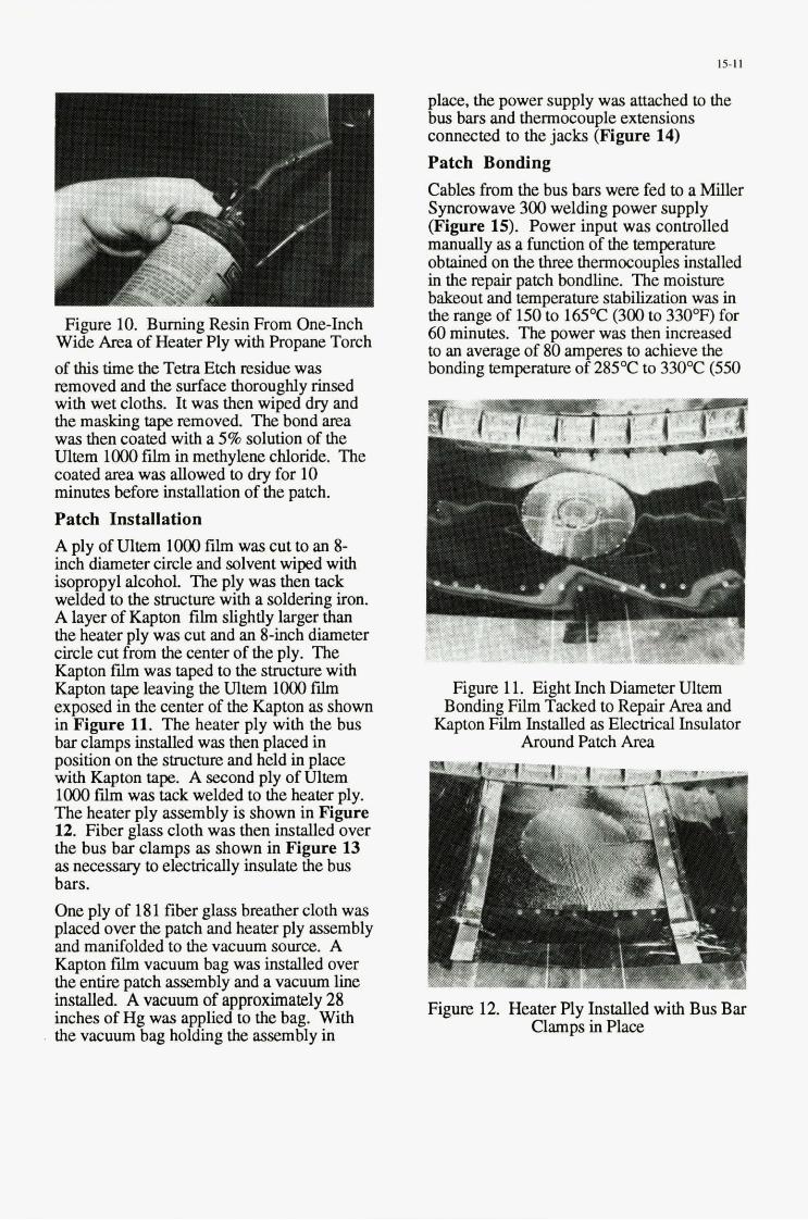
15-11
place, the power supply was attached to the bus bars and thermocouple extensions connected to the jacks (Figure 14) Patch Bonding Cables from the bus bars were fed to a Miller Syncrowave 300 welding power supply (Figure 15). Power input was controlled manually as a function of the temprature obtained on the three thermocouples installed in the repair patch bondline. The moisture bakeout and temperature stabilization was in the range of 150 to 165'C (300 to 330°F> for 60 minutes. The power was then increased to an average of 80 amperes to achieve the bonding temperature of 285'C to 330'C (550
Figure 10. Burning Resin From One-Inch Wide Area of Heater Ply with Propane Torch of this time the Tetra Etch residue was removed and the surface thoroughly rinsed with wet cloths. It was then wiped dry and the masking tape removed. The bond area was then coated with a 5% solution of the Ultem lo00 film in methylene chloride. The coated area was allowed to dry for 10 minutes before installation of the patch. Patch Installation A ply of Ultem loo0 film was cut to an 8- inch diameter circle and solvent wiped with isopropyl alcohol The ply was then tack welded to the structure with a soldering iron. A layer of Kapton film slightly larger than the heater ply was cut and an 8-inch diameter circle cut from the center of the ply. The Kapton film was taped to the structure with Kapton tap leaving the Ultem lo00 film exposed in the center of the Kapton as shown in Figure 11. The heater ply with the bus bar clamps installed was then placed in position on the structure and held in place with Kapton tape. A second ply of Ultem lo00 f h was tack welded to the heater ply. The heater ply assembly is shown in Figure 12. Fiber glass cloth was then installed over the bus bar clamps as shown in Figure 13 as necessary to electrically insulate the bus bars. One ply of 181 fiber glass breather cloth was placed over the patch and heater ply assembly and manifolded to the vacuum source. A Kapton film vacuum bag was installed over the entire patch assembly and a vacuum line installed. A vacuum of approximately 28 inches of Hg was applied to the bag. With the vacuum bag holding the assembly in
Figure 11. Eight Inch Diameter Ultem Bonding Eh Tacked to Repair Area and
Kapton Film Installed as Electrical Insulator Around Patch Area
Figure 12. Heater Ply Installed with Bus Bar Clamps in Place

15-12
Figure 13. Fiber Glass Installed Over Bus Bar Clamps for Thermal and Electrical
Insulation
Figure 14. Power Cables and Thermocouple Extensions in Place in Vacuum Bagged
Repair Assembly
Figure 15. Miller Synchrowave 300 Welding Power Supply
to 626°F). All three bondline thermocouples remained within the processing window for the required 30 minutes.
Patch Clean-up and NDT Removal of the excess heakr ply was performed with a DOTCO grinder with a right angle head and 100 mesh grinding wheel. The Kapton film located between the heat ply and the structure aided in preventing any damage to the structure in the cleanup operation. A close-up of the natch is shown in Figure 16.
‘.,plG &U. LUl”plGLGi4 L.qJLuL ‘CaL\rl. N L C l
Completion of Structural Test to 115% of Design Ultimate Load
Structural Test Results The DMATS structure with the completed repair was subjected to 115% of design ultimate load at which point structural failure occurred in the right hand forward keel web panel. The repair patch showed no effect from the structural test and NDT also showed no change in the repair. Conclusions The resistance heating process for repair of thermoplastic structures is a viable on-aircraft procedure and could be performed at the field-level by aircraft maintenance personnel with a minimum of training. The necessary equipment for this process is normally available at field level repair facilities. References 1. R Ramkumar, et al, “Thermoplastic
Fighter Fuselage Structure, DMATS Phase IC:’ Final Report WL-TR-92-8066.
2. Smiley, A.J., “A New Concept for Fusion Bonding Thermoplastic Compositrs,” SME “Joining Composites Conference, 1989,” Garden Grove, CA Mach 28-29, 1989.

REPAIR OF HIGH TEMPERATURE COMPOSITE AIRCRAFT STRUCTURE
Jerome J. Connolly MIS 194/26
Vought Aircraft Company PO Box 655907
Dallas, Texas 75265-5907
1.0 SUMMARY
This paper describes the h a 1 portion of a high temperature composite repair development program sponsored by Wright Patterson Materials Directorate. Initially, BMI adhesives and prepregs were selected based on their compatibility with in-service repair cure scenarios. These typically involve curing in a non-autoclave environment using vacuum consolidation only. The selected material system were then used to develop a comprehensive repair procedure for highly curved aircraft structure. Once developed, the procedure was then applied to a curved structure representative of a flight surface leading edge. Baseline and repair specimens were fibricated and tested in compression at both mom temperature dry and elevated temperature dry conditions. The results of these test validated the repair procedure.
2.0 INTRODUCTION
The performance requirements of existing and future military vehicles are such that high temperature composites must be used in order to reach M acceptable compromise between constraints of operational needs and vehicle weight limits. The use of these high perfqmance materials on operational vehicles presents the military support servicea with some new and unique repair requirements.
The objectives of this research were to dehe , develop, verify and evaluate repair concepts and procedures for high temperature composite materials. For this particular study the bismaleimide @MI) material group was focused upon.
While graphite/epoxy repair experience is not readily transferable to high temperature applications, a large number of existing procedures may be modified to acu~mmcdate the needs of a high temperature environment. Repair techniques were developed for field and depot level execution. Equipment requirements were limited to those aIready available or easily obtainable at these facilities.
The overall approach was to develop M o n - a h f t flush repair over a highly contoured composite surface that had single side access limitations. In the context of the above approach, the additional constraints which were selected to apply to this repair development are detailed below.
Structural repairs would be conducted out of the autoclave, using vacuum consolidation with heat applied by heat blankets, etc. This was to simulate actual "on the aircraft" repair conditions. At first glance this may appear to be very risky; however, Reference 1 contains data which indicate that high temperature materials may be successfully processed using vacuum consolidation pressure only.
The background research on which the curreut work was based has previously been published in References 2, 3 and 4.
3.0 REPAIR DEVELOPMENT
3.1 Repair Specimen
The repair specimen was selected to be representative of a fight vehicle structure. A highly curved monolithic structure was chosen to conduct repairs. This symmetric structure is approximately 38 cm in length, 25.4 cm in width, 17.8 cm in height, and hns a radius of 9.4 cm. The specimen was selected to be representative of a typical leading edge part. Figure 1 shows the physical configuration of the selected specimen. Baseline (undamaged) specimens were also constructed to verify the effectiveness of the repair.
The tab, substrate, and repair material used for this task was IM7 5250-4 BMI unidirectional tape. The lay-up of the U-shaped specimens was [2[0/~45/9011 lay-up. Internal and external tabs for the specimens were 5 cm wide with a'[3[0/*45/90]], lay-up. Two U-shaped BMI panels were fabricated to make the four U-shaped specimens and the tabs. The tab and specimen substrate configurations are shown in Figure 2. A Missile Airframe Integrated
Paper presented at the 79th Meeting af the AGARD Structures and Materials Panel on "Composite Repair of Military AircraJi Structures" held in Seville, Spain 3-5 October 1994.

16-2
Technology (M.A.I.T.) fuselage development bond mold, 122 cm in length, was used for tooling.
The IM7 5250-4 internal and external tah plies were cured on an extended section of the substrate (prolongation). This prolongation was only used as a tooling aid for the tabs. The tabs were cured on the prolongation to achieve the appropriate radii and to avoid minkling the substrate during cue. The internal tabs were co-cured on the prolongation, but separated fmm the prolongation using release film. The external tabs were cured later on the previously cured prolongation, again separated from the prolongation using release film. All tabs were bonded with Hysol's EA 9673 adhesive at 177°C for one hour using a heat up rate between 22°C and 3.9OC per minute, per veudor recommendation. Autoclave pressure of 25 MPa was applied before heating the parts and maintained until cool down. The controlling thermocouple was located near the bondline. The BMI substrate, tabs, and tab adhesive were free standing post-cured at 246°C f 55°C for four hours in an air circulating oven. Post-cure heat up and cool down rates were at 2 . 8 T per m u t e . The tabs on the unrepaid baseline specimens were machined and cut after the post-cure. Specimens reserved for repair had the tabs machined and cut after the repair was completed. The repair process is discussed below.
3.2 Repair profess
To simulate the presence of damage and its removal, a 5 cm diameter through hole was produced in the center of the specimen. Eight equally spaced #40 holes for Cleco's were drilled throughout the substrate, 1.3cm to 1.6cm fmm the edge of the hole. A 2-ply (cross plied) 10 cm diameter internal doubler with orientation of O"190" was pre-cured separately using an ovenlvacuum cure. The doubler and the substrate were prepared for bonding (i.e. abraded, solvent wiped, and air dried for 10 minutes, minimum) and attached to the IML using Cleco's. The internal doubler was oriented at +45/-45 on the substrate. Adhesive cure was performed under an insulated dome with hot air guns. After cure and removal of the Cleco's, the Cleco holes were filled with Ciba-Geigy RP1250. The RP1250 was cured at 54.4"C for one hour. The substrate panel in the repair area was then ground to a uniform 30: 1 scarf angle. A 3 0 1 scarf angle was selected based on analysis reported in Reference 4.
Prior to laying up the replacement repair plies, the
panels were dried and vacuum integrity verified. The area of repair ply lay-up, plus a 2.5 cm oversize. area for the cap plies, were prepared for bonding (sanded with 120 grit paper then wiped with MEK). The ply lay-up configuration is shown in Figure 3. The first ply down was a layer of EA 9673 film adhesive. This ply extends 2.5 cm beyond the top of the scarf taper to accommodate the cap plies. The first two repair plies (the smallest repair plies with equal diameter) were placed within the 5 cm hole area. Plies 3 through 16 graduated in diameter such that ply 16 terminates at the top of the scarf angle. The lirst cap ply of the external doubler extended 1.3 cm beyond ply 16. The second cap ply extended 1.3 cm beyond the first cap ply. The external doubler plies hacl an orientation symmetric to the internal doubler plies. Cap ply #2, shown in Figure 3, had its edges serrated with standard pinking shears. The repaired specimen was then bagged and cured using a heat blanket and vacuum consolidation. The cure cycle is shown in Figure 4. The entire repair was post-cured using a heat blanket at 232°C for six hours. Post- cure heat up and cool down rates were at 2.8"C per minute. Loading tabs were machined and trimmed aftet the repair was complete.
4.0 TESTPLAN
The four U-shaped panels were designed for compression loading. Compression testing was selected since it was considered the worst case load condition for repairs. It was desirable to see how a scarf repair would perform in a buckliig environment. Figure 5 shows a sketch of the compression test specimen. Figure 6 shows a repaired specimen prior to being tested. Baseline (undamaged) tests were also conducted in order to verify the effectiveness of the repair.
A steel test fixture was fabricated as a stabfiler to preclude buckling on the flat sides of the specimen. Figure, 7 sbows a front view of a specimen mounted inside the test fixture. Steel blocks and shims were used to support the fixture, thus preventing it from interfering with the tabs and causing premature failure.
Each specimen bad four thermocouples attached and ten strain gages mounted back-to-back at the locations shown in Figure 8.
Room temperature dry (RTD) and 232"CIDry were the environments selected for testing. Although the service temperature for BMI's is typically 177OC, it

163
catastrophic failure; however, the failure load was higher than predicted, approximately 20 5%. This is not unusual due to the conservative analysis methods used and the difficulty in predicting boundary condition degree of fixity. The RTD repair specimen failed prematurely and in a mode not consistent with prediction. It was determined that the repnired specimens experienced a small degree of distortion due to the repair process. This distortion is hest described by reference to Figure 13. The net effect of this distortion was to put a small side load on the specimen which was reacted by the stabilizhg future. This, in turn, caused local bending in the specimen which induced failure.
The ETD baseline specimen failed as expected, buckling precipitating catastrophic failure. The ETD repair specimen failed at the load level expected but the strain gage data did not indicate any buckling prior to failure. It is suspected that the repair related distortion previously discussed may have initiated failure. The reason why it did not initiate failure earlier is because the distortion was smaller in this specimen and the stabilizing fixture was positioned so as to minimize the possibility of interference. Tabs were mechanically fastened to the RTD baseline specimen because NDI showed poor tah bondig. The other three specimens relied on the tab adhesive (EA 9673) to introduce the load into the specimen.
The strain data shown in Table 1 came. from two sources. The first column was from test failure. load and predicted modulus. The second column came from an experimental modulus. After destructively testing the RTD baseline specimen it was taken to WPAFB Materials Directorate where the undamaged sections were cut up into test coupons. These coupons were used to obtain an experimental compression modulus. This modulus was then used with the failure loads from both RTD and ETD specimens to compute new failure strains. WPAFB Materials Directorate also verified that buckling failure caused catastrophic failure in the RTD baseline specimen.
Post failure NDI of the repair area indicated that the repair was intact with no signs of failure within the repair itself. At approximately 8.6 Mg all the strain gages on the repaired ETD specimen registered a small off-load and then they all continued to load as before with no redistribution. At this point it is not clear if the fixturing slipped a little or if there was an electronic problem. In any event, there was no perceptible impact on the test.
was thought desirable to exceed that temperahue so that the repair patch's maximum capability could be evaluated. In practice, short term excursions above service temperature are typical. It was thus thought desirable to demonstrate the repair for such an excursion.
The RTD test &-up is shown in Figure 7. An environmental chamber, shown in Figure 9, was used for all elevated testing. The entire test fixture was enclosed inside the environmental chamber. A hole was cut in the top of this chamber to enahle the loading pole and a hot air tube from a Liester hot box to pass through. It was found that the available environmental chamber required supplemental heat to arrive at 232OC in a reasonable time. This supplemental heat was supplied using a Liester hot box and the aforementioned tubing. The end loading plate and the specimen (with fixture mounted) were then assembled inside the envimnmedal chamber. Hot air was then circulated inside the chamber. The o v e d test &-up for elevated temperature testing is shown in Figure 10.
All specimens were tested in a 45 Mg Instron Universal Test Machine. Shims were used to assure proper test panel alignment. Test panel alignment was calibrated using the existing strain gage response (less than 10% longitudiilstrain gagevariation from highest to lowest was considered satisfactory alignment) to a small 227 kg preload. This 227 kg base load was then maintained to prevent the test panel from shifting. Tbe specimens were then loaded to failure. The base load of 227 kg was also used for the elevated temperature specimens prior to mechanical testing. This load was maintained during the heat up. The heating ramp rate did not exceed 28"Clmin. The elevated temperature specimens were soaked at the desired test temperature of 232°C f 2.8"C for ten minutes prior to testing. The compression test results are. shown in Table 1. Figure 11 shows the RTD baseline failure. Figure 12 shows the failure of a repaired ETD specimen. Both of the repaired specimens had a slight distortion which occurred during the repair process. Figure 13 shows exaggerated schematic of the distortion.
5.0 DISCUSSION OF RESULTS
The undamaged (haseliine) and damagedlrepaiied specimens were successfully tested at RTD and ETD (232OC) conditions. Failures occurred outside the repaired area. The RTD baselie specimen failure mode was as expected, buckling precipitating

16-4
The RTD repair specimen had twelve Cleco holes for the backface doubler and the ETD repair specimen had eight. It was initially planned to have eight Cleco holes; however, twelve were iaadvertently used on one of the specimens. This specimen was then tested satisfactorily and each concept is considered acceptable.
6.0 CONCLUSIONS
A highly contoured composite struchue, constrained to single si& access, was successfully repaired using equipment that is typically available at the field or depot level.
The test results indicate that the baseline RTD specimen failed as expected - buckling precipitating catastrophic failure. The repaired RTD specimen faiied prematurely due to distortion induced interference with the stabilizing fixture. The baseline elevated temperature dry (ETD) specimen failed as expected -buckling precipitating catastrophic failure. The repaired ETD specimen failed at the same load level as the baseline ETD but there was no evidence of buckling. Distortion induced interference is suspected. Experimental evidence suggests that during ETD testing there is measurable load bypass in the repair am. Post-failure NDI of the repaired RTD and ETD specimen indicated that the repair remained intact through failure.
7.0 REFERENCES
1. COMolly, J. J. and Van Nice, D., "Development of PMR-15 Repair Concepts", 34th International SAMPE Symposium and Exhibition, May 1989.
2. C~MOUY, J. J., Matejka, J., and Holdridge, D. D., "Joining and Repair of High Tempersture CompositeMaterials", ThirdDoDmASA Composites Repair Technology Workshop, January 1991.
3. Connolly, J. J. and Matejka, J., "Evaluation of High Temperature Adhesives for Structural Repair Applications", 37th International SAMPE Symposium and Exhibition, March 1992.
4. COMOIIY, J. J., "Joining and Repair of Heat Resistant Composites", Interim Report No. WL.-TR- 9 2 4 3 9 , Air Force Materials Directorate, Wright- Patterson AFB, April 1989 - March 1992.
8.0 ACKNOWLEDGEMENT
This research was sponsored by Wright-Patterson AFB Materials Directorate under contract number F33615-89-C-5644. The authors wish to thank that organization for their permission to publish this work. In addition, they wish to thank Mr. Frank Fechek, the Air Force Program Monitor, for his help and guidance during this research.

16-5
Spccimen Load kg
RTD
RTD (Repaired)
ETD
ETD (Repaired)
Stress M Pa
30,300
19,015
18,226
17,618
267
173
166
2.792
2,676
2,587 160
3,223
3,089
2,986
Suain pc
4.3 16 4,981
D Based on LAMSTRESS data of E and failure suess we calculated the failure suain (Analysis).
D The first specimen RTD was sent to WPAFE and coupons were cut from it to deu.nnine actual E's. These data were then used to re-compucc the suains for all four spccimens.
Table 1. Compression Test Results
,., .
Figure 1. Physical Configuration of Specimens

16-6
Figure 2. Panel Configuration and Fiber Orientation
Che PLI I2 KIP F16 3 ULP FLY I1
/ / / ~ i \ I
EOP F 3 -1 / I ‘ I
I EOP P1 c P 2 --+ 1
I
1
I - 1 4 ER. SPh. --+ I
i
smsTRAm 7- P-
Figure 3. General Repair Ply Configuration

167
Pressure: Full Vacuum 150.0 cm Hg min. maintained throughout cure
Heat up: RT to 121°C at 0.6 to 2.8"Uminute
Hold: 121°C for 45 f 5 minutes
Heat up: 121 - 191°C at 0.6 to 2.8"C/minute
Hold: For 116 minutes at 191°C
Cool Down: At 0.6 - 2.8OUminute
Figure 4. Vacuum Consolidation Cure Cycle
Figure 5. Design Verification Compression Test Specimen

Figure 6. Repaired Specimen
I I I
Figure 7. Test Specimen in Stabilizing Fixture

169
I 4
U
N 4 -
I
.. .d 4-
Lu
8
2 a M
m r?
t

Figure 9. Test Specimen in Environmental Chamber
Figure 10. Qv;erall Test tea Testing

Figure 11. RTD Baseline Failure
. .
,
16-11

Figure 13. Specimen Distortion

17-1
1 COMPOSITE REPAIR OF COMPOSITE STRUCTURES
C.S. Frame British Aerospace Defence Limited
Military Aircraft Division Warton Aerodrome
Pres ton Lancashire PR4 IAX
UK
SUMMARY
Coiiiposite repair results froin previous Pliases of tlie Ministry of Dcfence/Britisli Aerospace fiiiided "Defect, Damage and Repair" (DDR) programme are uscd to illustrate tlie ability to perform adequate strength repairs to composite stnictiires using coiiiposite inatcrials. Problems iiiliibitiiig tlie widcr iisc of composite rcpairs are discussed and work i n progrcss in the current Phasc of tlie DDR prograinme. aimed at overconiing these problems, is presented.
1. INTRODUCTION
Under Ministry of Defciice fiiiidiiig tlie Defect. DaIiiiige and Repair (DDR) prograniiiie started i n the early 1980's and from that tiine i t lias produced much valuable data on the e k t s of both dcfects and daniage in coiiiposite iiiaterials as well' iis addressing tlic siibjcct of the repair of coiiiposite structures.
The repairs have all been gearcd towards the end iiscr and liave been devised for in-situ application in tlie field i.e. all tools have been liaiid held, tlie power soiirce lias been standard 13 amp, only infra-red lamps or electrical lieater iiiats used for lieatiiig and vaciiiiiii only pressure was used.
A significant number of repairs liave exceeded the design allowable values and several have coiiic close lo or reached laniinatc un-notclied failurc.
By way of 'example. two topics froin Phase 2 are given
E.rump/e 1 - is the "Repair of Hoiieycoiiib Sandwicli Beams" - see Figure I . The test speciiiiciis were curved sandwich beams 105Omni long x 250mm wide and 25mm core depth witti the repairs einbodied to tlie centre section of the 2.5nim thick coinpression skin. The upper band of the results sliow tlie control (undamaged) niean whilst tlie lower band is the damaged (no repair) iiieaii. I n between are shown the results for tliree different repair configora1ions:-
= damaged core replaced. skin insert and doubler i n parent 1iia1eri;il XAS/9 14. I75OC cure. vaciiiiiii only.
damaged skin filled, doubler in T300 clotli hand-wetted witti Araldite AY 105/HY95 I , 60°C cure.
dainaged skin filled. meclianically f2istened mctallic patcl1.
All repairs achieved a sigiiificaiit iiiiproveiiieiit coinpared with the damaged, no repair valucs and all failure strains were well above usual design ultimate strains. Note tliat tlic corc aiid skin repair in parent iii;iterial were quite close to tlic undamaged values. Also tlic liand-wctted clotli rcpair, curcd at 6OoC, pcrforiiied very successfully when tested at 8So/l% moisture.
E.rump/es 2 - is the "Major Box Repairs" - see Figiirc 2 . The four-point bend boses were 2440mlii long s 290mni wide aiid had a 8.0iniii thick coiiipressioii skin with repairs embodied i n tlie centre section. The results for both undamaged and repaired boses sliow tliat in a l l cases the bondcd coiiiposite repairs (adding 0.9kg) perforiiied better tliaii tlie bolted metallic ones wliicli added 4.5kg. Again, tlie hand-wetted cloth repairs perforiiied surprisingly well evcii when tested at 85"C/1% moistures.
So wli.v ure tlietv not more bonded composite r e p i r s being used?
2. T H E PROBLEMS
I . Because most in-situ repairs are carried out rising vaciiiiiii only instead of an autoclave, tlicy tciid to be porous. This porosity iiiakes conventional iiltrasonic NDT very difficult, if not impossible. Hence the bondliiie voids. no bonds or incliisioiis/foreigii bodies cannot be detccted.
2 . I t may not always be possible Io carry out a repair using the same iiiaterial iis the parent stnicture particularly if substructure sea1;ints limit repair teinperatures to 120OC.
3. If tlie repair materials are limited to a 12OoC cure teiiiperatiwz-
a) How good is their Iiot/wet perforniance?:
Paper presented at the 79th Meeting of the AGARD Structures and Materials Panel on "Composite Repair of Military Aircrafr Structures" held in Seville, Spain 3-5 October 1994.

17-2
b) Are they qualificd niaterials for tlial aircraft'? pre-curcd skin inscrls. 1 .Oniiii thick [(+4S", -4S", ')oo, ~)") , , lSyn,
c) How do we qualify theni'? Araldite AY lOSMY9SI adhesive
4. The logistics are poor. Operators ni;iy wed to hold stocks of inany different iiiaterids i n order to repair aircrafi from different iniiii~if~lcturers. all which require refrigcr;ited storage for ;i liinited life.
3. THE SOLUTIONS?
The current phase (Phase 3) of the DDR prograiiiine is atteiiiptirig (aniongst other things) to find solutions to the above problenis.
The main repair aspects in DDR Phase 3 are:-
1. Tlie use of thin, pre-cored laniinates.
2. The additional pressure required for low porosity.
3. The modification to ciirc cycles/l;iy-ups to achieve low porosity i n 175°C and 120°C pre-pregs aiid low temperalure curing Iiand-wetting systenis.
3.1 Thin, Pre-Cured Lilniitiiltes The reasoning behind this potciitiiil solution is that pre-curing i n an autoclave will produce laiiiiiiates of known low porosity aiid almost infinite shelf life without refrigeration aiid yet be flesible enough to forin to all but the tightest of radii such as leiidilig edgcs
Tlie initial work was to deteriniiie llie nuniber of t h i n ( I .Omin) prc-cured laminates which could be bondcd together i n oiic shot bcforc the cuniiilativc porosity i n the adhesive layers inhibited the ultrasonic NDT. This was done by using a "Step Wedge" :is sliown i n Figure 3 wliere a four layer stack was asseiiibled with film adhesives, the bottom one of wliicli had 25min di;imeter pre-cured regions to give a no-bond condition.
The NDT identification of the no-bonds varied with the type of adhesive used, generally tlie porosity i n the adliesive allowed detection of no-bonds through one or two laiiiiiiates only. This would ineaii tliat a built-up repair would liave to be done one layer at a time i.e. a repair to a 4.0mni thick skill plus an cstcriial doublcr would require 4 s e p m t c bonding spccifications with NDT following every step.
Tlie 3.Omm thick tensile and 4.Omin thick coinpressive test specimens used to verify this repair technique (siniulating single sided access) and tlie rcsnlls obtained to date (ambient. as received) are shown i n Figure 4. The test T800/924 coupons used a scarf tapcr ratio of 20: 1 and consisted of:
pareiir laniinate [(+45". -44". 90". o"),,( ry,,,
. pre-cured internal doubler. 0.375nini thick (0". 00". 0°)
blind. countcrsunk rivets, 2.4nini diaiiictcr
Filiii adhesives:- Redus 322 ( 175°C cure) AF 163-2K ( 1 20°C cure)
All repairs achieved well above typical design ultiinate strains with tlie Redus 322 performing better i n coinpression 11ian AF 163-2K. Under tensile loading the trciid was reversed.
With these encouraging results, further static tests under Iiothvet conditions and fiitiglle (cycled at ambicnt/wet, residual strength at liot/wet) are being carried out.
the laiiiiiiates arc pre-cured in a n autoclave and are gnaranrecd liigli quality, low porosity.
the pre-cured laminates Iiavc aliiiost iiifiiiitc shelf life and do not require refrigerated storage.
at I .Oniiii thick, tlie prc-cured laiiiiiiales are suficicntly flesible to coiiforiii to iiiost surface shape escept tliosc with a high degree of curvature, such as 1e;iding edgcs.
= to givc a n NDT verified repair, only one or two pre-curcd laininatcs can bc bondcd at a liiiie due lo the porosity i n tlic adliesive. This would give a slow repair time, especially for thicker stnicturcs.
eiicli laiiiiiiate has to be accurately tapered to match the scarf i n the parent laminate.
tlie lecliniqiie is not suitable for liiglily curved surfaces.
the stifliiess of tlic prc-cured laminates may not iiialcli that of the parent. If i t docs not, does i t mt ter '?
3.2 Ad tl i t iollill Prcssu rc Most of tlie coiiiposite parent inaterials used today are designed for autoclave ciiring uiider high prcssure (approsiniately 6 bar) which gives low porosity. Wlieii tliese materials are cured uiider vacutiiii only, equivalent to I bar. then they are usually .very porous. I t is believed that soincwhere i n bctweeii these two values is a prcssure which gives suficiently IOW porosity to ciiable effective ultrasonic NDT inspection.
This task is bciiig carried out i n three stages:-

17-3
Stage 1 - to evaluate a iitiinber of pre-preg materials at different curing pressures i n order to determine tlie amount of pressure, additional to vaciiiiiii. required to give low porosity.
Stage 2 - to determine and deiiioiistrale ii method by wliicli tlie required total prcssiirc ciiii be applied to an in-situ repair.
Stage 3 - to verify the additional pressure application nietliod iisiiig representative test coupon repairs.
The results to date are :is follows:-
Stage 1 - The additional pressure required varied with both tlie material iindcr consideration and tlic degree of life espiry of that material in tliat tlie test speciiiieiis (200mm s 200mni s 4.Onini) made from a iiew batch of inaterial sliowcd diffcreiit results from those made froin niaterial close to it's espiry date. With this ii i mind. the tests gave tlie following results:-
AS4t8552
AStSP377-2
3O+psi
2O+psi I
7, are being manufaclured using tlie pressure box tcclinique.
the repair can be carried out using parent laiiiiiiate mate r ia I .
tlie additional pressure eiisiires low porosity and hence NDT detection of no bonds and any inclusions.
with the bos being held to tlie repair surface by vac+im. tlie process is suitable for repairs to vertical and inverted surfaces such as fins, under sides of wings etc.
altliougli tlie bos shape will easily catcr for flat or sliglitly curved surfaces, tighter radii surfaces would reqiiire a specifically Shiiped profile to fit that surface.
Intensifier blocks of different sizes may be ncedcd, depending on the repair arca, to get tlie correct additional pressure.
thin repair skins may be distorted due to the arca under vaciiiiiii, reacted at tlie bos peripliery.
tT800/924 I 15-20 psi I 3.3 Modified ittld Lower Tcmperilture Cures
After tlie initial trials, work on tlie first three iiiaterials was discontinoed: ASt350 1-6 was still very porous at jOpsi, AS4/8552 was still unacceptably porous at 3Opsi: AS/SP377-2 was ii vcry rigid pre-preg with little tack and gave high porosity at over 2Opsi.
New batch T80Ut924 inaterial gave reasoiiably low porosity a t I 5psi and very low porosity at 2Opsi and was thus selected for iise i n tlie fiinlier stagcs.
Stage 2 - Tlie work i n this stage considered tlie practical application of additional pressure to an in-situ repair. The result was a bos shown diagraniatically i n Figure 5 . The bos is placed over tlie repair pack (including electrical lieater mat). sealed with viiciiiini putty to thc repair surface and held in place by vaciiiiiii. Witliiii the box is a large nibber diaphragm which, with tlie assistance of pressure, pushes down oiito an intensifier block. This. in torn. applies pressure to the repair itself. The pressure magnification being obtaiiied by differential areas.
A working prototype Iias been designed, manufactured and verified by iiiakiiig a number of 2001nni s 2001niii s 4.0 i n i n thick la mi nates i 11 T800/921 which were veri lied by ultrasonic NDT to have acceptably low porosity.
Stage 3 - Tlie final stage is currently i n progress where representative repair test pieces, shown i n Figures 6 and
3.3.1 Moditiciltiotls to 175OC Cure Inforinat ion from ollier soiirces lias indicated that out of life material lias often produced low porosity laminates when cured under vaciiiiiii only, possibly because of a lower volatile content. This phenomenon, together with a n investigation into modifying tlie nornial cure cycle, is bciiig evaluated. For this work tlie material selected was T800/924.
To date, there lias been very little success'in reducing tlie porosity by altering tlic cure cycle e.g. introducing more or longer/sliorter dwells.
The work on reducing porosity by "pre-drying" tlie pre-preg (and hence driving off some of the volatiles) at a variety of drying tinies and temperatures has shown soiiie success. Pre-drying for less than 60 minutes at 60°C lias produced filial laminates with significantly lower porosity than without pre-drying. The work is continuing and will be verified by performing simulatcd in-situ repairs using tlie tensile and compression coupons and lioneyconib sandwich beams as shown i n Figures 6 and 7.
tlie repair can be carried out using parent laminate material.

17-4
low porosity arid lietice NDT detection of no-bonds and inclusions is possible.
Disuc1vuritugcs:-
tlic pre-drying may be dtficult to monitor and coiitrol with cliangcs i n aiiibicnt covironnicn~ e.g tropic to artic.
3.3.2 100-12OoC Prc- l ) rq The work initially screened some 1 0 candidate pre-pregs with curing temperatures i n the 100-1 20°C range. 4.0miii thick quasi-isotropic laniinates 2OO1iini s 20Oniiii were laid up aiid cured under lieater iiiat and vaciiitiii only. Ultrasonic NDT \vas used to assess the laiiiiiiate qualify iiiid porosity. Following [his. the iiiosl proiiiising inaterials were fiirther iiivestigated and soiiie variations in clire cycle or lay-up vaciiiiiii pack were also all e m pled.
So far. the results liave becti encouraging \villi 4 iiiaterials having acceptable low porosity when cured with modified clire cycles and/or changes to the viiciiitiii pack. These are currently being checked for acceptability of ~iiechanic;il properties following which they will be used for siiiiu1;rted in-situ repair coupons and lioneycoiiib beatiis ;is slio\\;n in Figures 0 and 7 .
Ai1vuntugcs:-
oiicc rpl i f ied. the ni;ilcrial could bc uscd for tlic majority of t l ic repairs to current coiiiposttc stntclurcs.
operators only need to stock one basic repair iiiaterial instead of iiiaiiy different pareiit iiiatcrials.
may not be adcquate for high tetnpcrat~ircliiioist requirenients.
opcrators still liave lo hold rcfrigeraled, lifed iiia t eria I ,
3.3.3 HiIlItl-Wcttctl Fi1hi.ic Approsiiiiately 10 resin systenis witti low leniper;ilure (less that 100°C) ciires wcre screened for hand-\vettiiig dry. T300 5H satin fabric. The screening and evaluation process was siiiiilar to that used i n the 100-120°C cure work. again with soiiie niodificatioti to the lay-up. bagging and citre.
To date the results Iiave identified 2 or 3 rcsiiis wlriclt have giveir quite low porosity under Iiealer tiial and vaciiiiiii cure. These are curretills being cliccked for accepta bi I ity of niecha nical properties fol Iowi ng wl i icli they will be used for siiiiulated in-situ repair coupons aiid hotieycoiiib beailis as shown in Figurcs 6 and 7.
m a y be applied to iiiost rcpair situations i n current coiiiposites.
operators do not need to hold refrigeralcd stocks of rcpair iiiaterials.
= shclf life of rcsiiis arc usu;illy iiiuch longcr than for prc-prcgs.
niay not bc adequate for high Icniperatiire/iiioist rcquircniciits.
. resin to fibre ratios ni;iy need accurate coiitrol
tlic hand wettiilg proccdiirc iiccds lo be acciirately defiocd illid adliered lo.
4. CONCLUSIONS
The work currcntly bciiig utidcrtakcii :is part of the Dcfect, D;iniagc and Repair prograiiiiiic is addrcssitig thc iiiost pcrtitieiit problciiis associatcd with the gciicral acceptance of in-situ coinposite repairs.
The work is producing encouraging results which either ilidi\iduillly. or i n conibinatioti, have a very high cliance of overcoiiiiiig the prescnl problems aiid which will ciiablc more widespread acceptancc of in-situ coiiiposirc repairs to coiiipositc striicturcs.

17-5
BEAM SKIN - 2.5mm XAS/914 30% O o REPAIR AREA 60% +45O REACT 10% 900
14 000
12 000
c. 0
y 10 000 CI
5 5 8 000
1 3 U 2 6 000
4 000
2 000
HAND-WETTED FABRIC REPAIR
(6OOC)
- 20 40 60 80 100 120
TEMPERATURE (OC)
FIGURE 1 - HONEYCOMB SANDWICH BEAM REPAIRS

17-6
f BOX S K I N = ~ . O I I I I I I XAS/914 REPAIR AREA 20% 00 62.5% +45O 12.5% 90°
REACT 32
la 0 pi B z 8 n W
3 E Lr 0 W U
z W U ec W pc
E5
"T
FIGURE 2 - MAJOR BOX REPAIRS

17-7
-
0 N N
-
230
/ - \ 0
‘1 I
\ \ I
PRE-CURED AREAS FOR NO-BOND -3
SECTION A-A (EXPLODED)
FIGURE 3 - STEP WEDGE SPECIMEN

17-8 - - FILM ADHESIVE TENSILE REPAIR COUPON
0 . 3 7 5 PRE-CURED
- - FILM ADHESIVE
10 000
0 a Y
z 8 000
2 B tn
6 000 s U
2 =1 4 000 . . tn
E 3
2 000
: 2 000
z 2 5 4 000
Y
Y a s
2
I4 2 6 000
Y
tn tn W 8 000 a PI E 0 U
10 000
COMPRESSIVE REPAIR COUPON
i
t
FIGURE 4 - REPAIRS WITH THIN, PRE-CURED LAMINATES

17-9
RUBBER DIAPERAGH
REPAIR PACK V A C W H PRESSURE INLET BOX VACWM
BOX
+ GUIDE ANGLES
+ HEATER MAT
SEAL
FIGURE 5 - ADITIONAL PRESSURE BOX (SCHEMATIC)

17-10
280 d
-
0 0 rl
-
TENSILE SPECIMEN
150
I I I 00 I I I
I I
I 1
4 d
I I I I
COWPRESSIVE SPECIMEN
15 20 2O:l SCARF RATIO EXTERNAL - - I,
ERT 3.0 COMP - ADHESIVE - - 'P I PASTE ADHESIVE
BLIND RIVET' 2.4 Dia.
REPAIR SECTION (SCHEMTIC)
\ INTERNAL DOUBLER 0.375
FIGURE 6 - REPAIR VERIFICATION, COUPONS

17-1 1
I 1050 I 1 I
7- I COMPRESSION it 1 SKIN RIBBON 00
N z
REACT LOAD LOAD REACT
0
SKIN INSERT- 7 DOUBLER
ADHESIVE/RESIN
RE REPAIR (IF REQ'D)
REPAIR SECTION' (SCHEMATIC)
FIGURE 7 - REPAIR VERIFICATION, SANDWICH BEAMS


18-1
External Patch Repair of CFRPLHoneycornb Sandwich
K.Wolf and R.Schindler Eurocopter Deutschland GmbH
D-81699 Munchen Germany
ABT o/EM12 POB 80 1140
1, SUMMARY This paper adresses the repair of impact-damaged honeycomb sandwich structures with thin skins made of carbon fibre reinforced plastic (CFRP). An experimental study concerned with evaluating several types of bonded external patch repairs is presented. The evaluation included cocured as well as precured patch techniques utilizing advanced repair materials. Three repair schemes were applied to honeycomb sandwich manufactured from 125°C as well as 175°C curing carbon fibre reinforced fabric prepregs. The effectiveness of the repairs was examined through a series of static and fatigue compression tests. Based on the mechanical test results and a comparison of the repair procedures it was found that the bonded precured patch concept is the most suitable approach for repairing impact-damaged sandwich structures under field-level maintenance limitations.
1. INTRODUCTION Pushed by stringent weight saving requirements composite sandwich construction has evolved as a basic structural design concept applied to airframe structures of advanced rotorcrafts such as the “90 or the ECI35. Particularly sandwich composed of laminated carbon fibre reinforced plastic (CFRP) facesheets and non-metallic honeycomb core is increasingly used in primary airframe components, owing to the achieveable high strength- and stifiess-to-weight ratios. Other major advantages of CFRP sandwich construction are excellent resistance to fatigue damage, and immunity to corrosion, thus eliminating most of the maintenance and repair problems associated with metallic structures.
However, the inherently brittle nature of the rather thin laminated skins make CFRP sandwich structures susceptible to impact damage caused by such events as dropping tools, rough ground
handling, and debris thrown up during take-off and landing. Although primary composite airframe structures are designed to meet damage tolerance requirements, clearly visible impact damage such as facesheet puncture can have detrimental effects on the load carrying capability of the affected component. In that case restoration of the original strength and service life capability is necessary to keep the aircraft airworthy. Basically, the structural performance of a damaged component can be restored either by replacing it or by repairing the damage. As advanced composite airframes normally utilize modular manufacturing concepts based on large cocured subassemblies replacement would be a rather costly effort, leaving in situ repair as the only economic alternative. If the repair can be accomplished in the field, both down-time of the aircraft and repair costs can be reduced significantly. However, this approach requires repair techniques which are adaptable to the constraints of field maintenance facilities.
This paper reports on an experimental program which was initiated to evaluate the applicability of several repair techniques to helicopter primary fuselage structures made of CFRP sandwich. The study was part of a collaborative research project between European helicopter manufacturers and research establishments (Ref. l), which adressed problems associated with defects in composites. The sandwich repair effort was particularly aimed at techniques capable of restoring the structural integrity of impact damaged sandwich panels under the limitations of field-level repair. Various sandwich repair concepts have been established in previous research programs (e.g. Ref. 2, 3, 4). In the recent program, therefore, emphasis was placed on modifications of generic concepts in order to simplify the procedures and on the assessment of recently developed materials such as low energy curing repair prepregs (e.g. Ref. 5 , 6) .
Paper presented at the 79th Meeting of the AGARD Structures and Materials Panel on “Composite Repair of Military Aircrafi Structures’’ held in Seville, Spain 3-5 October 1994.

18-2
2. REPAIR METHODS The repair evaluation program was based on a sandwich configuration composed of thin CFRP skins adhesively bonded to aramid-type honeycomb core. This kind of sandwich is representative of flat or shallow curved helicopter fuselage panels which are designed to sustain in-plane shear and compression loads. The strength of such panels is governed by local stability failure such as face wrinkling or shear crimping. In-service damage which has to be anticipated in this type of structure is most likely attributed to low energy impacts resulting in punctured skin laminates and crushed cores. Experience has shown that most of the resultant damage is less than 50 mm in diameter and almost always restricted to one facesheet and the underlying core with the skin opposite the impact remaining unaffected.
The basic repair philosophy applied to this kind of damage is to restore the full structural integrity and operational capability at a minimum expenditure of time, money and effort within depot as well as field level repair environment. This philosophy results in the following basic requirements which should be met by the repair methods employed: - Restoration of original stren for all design
- Minimum weight increase. - Capability for repair on the aircraft. - No elaborate tooling. - Low level of personnel skill.
environments with minimum c P ange in stifiess.
Additionally, field level repairs should utilize only materials which require simple portable cure equipment (vacuum pump, heater blankets, radiant heater lamps), can be cured in reasonable time at temperatures below the boiling point of water without chymg the repair area, and have long term ambient temperature shelf lifes.
Based on these criteria as well as on experience with secondary structures repair the bonded external patch concept was considered to be the most suitable approach to meet the requirements of both depot as well as field level repair. Consequently, only repair techniques based on this generic concept were envisaged. Three different repair schemes were examined. These repairs, denoted RS1 to RS3, are shown schematically in Figure 1.
RS1 is a cure-in-place patch repair utilizing the same materials as the parent sandwich. Both damaged skin and honeycomb core are removed with
a router leaving a straight hole which is filled with a honeycomb core plug bonded with splice adhesive. The patch is made of circular prepreg plies cut to different diameters. The plies are stacked to dublicate the original skin lay-up starting with the smallest layer adjacent to the sandwich face. The largest ply is placed on top. This stepped layer arrangement improves bond line sealing and reduces peeling stresses at the edges. A film .adhesive cut to the size of the outer patch layer is placed between the patch and sandwich skin. Finally the complete assembly is cocured using the original manufacturing process. Although the applicability of RS 1 is rather limited to factory or depot level due to the need for autoclave cure, it was included in the evaluation program as baseline repair.
RS2 is a cure-in-place repair as well. It mainly differs from RS1 in a simplified procedure for repairing the damaged core and in the materials used to manufacture the patch. After removal of the damaged skin area the crushed core is stabilised by a lightweight filler paste which is cocured with the patch. The patch is made of low temperature curing prepregs using the same ply arrangement as with RS 1. For the evaluation program recently developed repair prepregs with mechanical properties similar to the parent material were selected in order to investigate whether these materials could meet the requirements of field repair as promised by the manufacturers.
RS3 is by far the simplest repair method to cany out and, therefore, is particularly suited to field-level application. A precured patch made of the parent skin material and laid up in the same sequence is bonded in place using low temperature curing two part paste adhesive. Prior to patch placement loose skin fragments have to be removed and the impact dent is filled up with a lightweight filler paste.
3. EXPERIMENTAL PROGRAM AND TEST
The experimental program consisted of two phases. In the first phase the processibility of the different repair procedures as well as their capability to restore the static strength were assessed. Based on the results obtained two repair techniques were selected for further investigation in the second phase. In that phase conditioned sandwiches were repaired and compression tested under hot/wet conditions. Additionally, the durability of the repairs was investigated through fatigue testing.
PROCEDURES

18-3
non-destructively tested. Different ultrasonic techniques (see Ref. 1) were used including portable equipment which can be employed for in-field
debonds. The residual strength of the repairs was assessed by conducting static compression tests at room temperature and ambient conditions. The test set-up used is shown in Figure 4. No anti-buckling guides were applied because skin failure was expected to happen long before global buckling. All specimens were strain-gauged in order to monitor stif€ness changes.
I inspection. The inspections revealed no patch I
I I
The sandwich samples used in the program were manufactured from two-ply fabric skins with a [k45,0/90] lay-up sequence cobonded to a 15 mm thick aramid-type honeycomb core (48kg/m3 density; 3.2mm cell width). For skin fabrication two different CFRP prepreg systems curing at 125 "C and 175 "C were chosen which are termed Material 1 and Material 2 respectively in the following. Large sandwich panels were autoclave cured and then cut to specimens of 350 x 200 mm size. The load introduction areas of specimens earmarked for mechanical testing were reinforced by fillers and end tabs leaving a gauge area of 200 x 200 mm (see Figure 2). To simulate in-service impact damage all repair specimens were impacted by dropping a steel indentor with a hemisperical tup 25mm in diameter, resulting in punctured faces and partially crushed cores. The average diameter of the damage zones was 35mm. Though being rather small this damage appeared to be sufficiently serious to investigate the effect of repairs.
The selection of appropriate repair materials and cure processes was made on the basis of information obtained through a preliminary experimental study. This study included DMA tests to determine the glass transition temperature of resins as well as lap shear strength tests under hotlwet conditions. The criterion applied to select repair prepregs and adhesives was that curing should be possible with vacuum pressure only at temperatures considerably lower than those of the parent skin materials. The screening test results were also used to define cure process parameters of the selected repair materials, aiming at adequate hot/wet joint strengths.
Detailed procedures specifylng damage removal, surface and patch preparation, and processing were defined on the basis of trial repairs. The patches employed were designed to provide sufficient bonding strength even in the presence of small voids and minor disbonds. Some of the preliminary repair specimens were cross-sectioned to examine the quality of the core repairs. It was found that both the core plug repair of RS1 as well as the lightweight filler paste approach of RS2 and RS3 performed very well. As shown in Figure 3 the paste material completely fills the hollow space between patch and crushed honeycomb material and no voids can be observed.
For the first phase of the mechanical test program dry specimens of each sandwich configuration were damaged and repaired; four with each repair technique. After repair all specimens were
In Phase 2 of the program two repair techniques, one for each sandwich configuration, were selected to undergo more thorough testing. One of the major concerns of field level repair is the problem of absorbed moisture in the parent sandwich structure which may affect the quality of the patch bond line. In order to address this problem all repairs of the second phase were carried out on specimens which were moisture conditioned for several months at 70°C / 85 % relative humidity (R.H.). Three Material 1 and three Material 2 specimens were reconditioned after repair and subsequently subjected to a static compression test at 75°C and lOO"C, respectively. The remaining aged specimens were fatigue tested under ambient conditions. Constant amplitude tests with a stress ratio of R=10 were conducted under load control at a frequency of 5 Hz using the same test set-up as for the static tests. Specimens which did not fail after lo6 load cycles were destructively tested to obtain their residual strength. During fatigue testing ultrasonic C-scans were made in order to detect and monitor any damage growth in the repaired section.
4. RESULTS AND DISCUSSION The results of the static compression tests performed at ambient conditions on Material 1 and Material 2 specimens are summarized in Figure 5 . Additionally, strength values of both undamaged as well as impacted sandwiches are shown (from Ref. 7). All failure loads plotted are normalized relative to the average compressive strength of undamaged reference samples. The bar charts clearly indicate that all repair techniques are capable of recovering the original compression strength of the sandwiches whose load carrying capacity was considerably reduced by the impact damage. The effectiveness of the repairs is confirmed by the fact that most specimens failed by a skin wrinkling failure mode outside the repair region and neither delaminations in the patch laminates, nor patch disbonds could be

18-4
observed. Only Material 1 specimens repaired with low temperature curing prepregs failed through the patch. This might be explained by a resin defiency which appeared in the centre area of the patches after cure. Probably, this low resin content is due to the prepreg resin being absorbed by the paste material used to fill the crushed core.
Figure 6 shows the hodwet performance of the repair methods RS2 and RS3 applied to aged Material 2 and Material 1 samples. The results are given in percentage of undamaged strength of the unaged sandwiches. Both repair configurations examined show a reduction in strength compared to the tests results obtained under ambient conditions on dry specimens. This could be expected, because moisture and high temperatures mainly weaken the stiflkess of the honeycomb, thereby reducing the stability limit of the sandwich faces. All Material 1 specimens failed outside the repaired section (see Figure 7) which indicates that ageing had no effect on the strength of this repair. This is confirmed by the results of a theoretical approach using analytical methods reported in Ref. 8. The sandwich strength predicted for the hodwet environment compares very well with the failure load of the repaired sandwich. In contrast to this the hodwet performance of the repaired Material 2 samples falls short of the predictions which could not be explained solely by the effect of the higher test temperature on the honeycomb properties. Also, these specimens failed through the patches which were partially disbonded (Figure 8). As was revealed by the response of strain gauges positioned on the patches, buckling appeared in the centre of each patch (see Figure 9). Probably, the buckling caused peeling stresses in the bond line resulting in a premature failure of the patch. Obviously, the hodwet environment had a detrimental effect on the properties of the paste material used to fill the impact hole, thus limiting its ability to support the patch.
In Figure 10 fatigue test results of specimens repaired after ageing are compared to the S-N-curves of the undamaged sandwiches (Ref. 7). The maximum fatigue stresses are plotted as a function of the static strength. The fatigue diagrams clearly show that both repair methods investigated are capable of restoring the fatigue properties of the original sandwich. This is underlined by the fact that none of the specimens which failed during the fatigue tests showed any damage in the repair section. Further, the residual strength of Material 1 specimens is comparable to the static strength which
also indicates that no serious fatigue damage had been developed in the patch bond lines.
In Table 1 the main characteristics of the three repair methods evaluated are summarized. Obviously, benefits can be achieved compared with the baseline concept by employing either the cure-in-place patch method RS2 or the precured patch technique RS3. Both repairs can be accomplished on the aircraft in shorter time and are easier to carry out. Moreover, they utilize simpler equipment, and materials which don’t have to be stored frozen. They also l l l y restore the compression strength and fatigue performance under ambient conditions. Nevertheless, the precured patch repair procedure appears to be better suited for field-level application, because it excels the other techniques regarding ease of handling, shorter cure cycles, lower cure temperatures, and hotlwet performance. If preformed patches are used this technique can even be applied to shallow curved sandwich panels.
The main shortcomings of the cure-in-place patch technique utilizing repair prepregs are the poor hodwet performance due to the weakness of the core filler and cure temperatures exceeding the boiling point of water. Thus, water entrapped in the structures may volatilize affecting the quality of the bond line. All the worse, such temperatures can cause steam pressure in honeycomb cells containing moisture which may lead to skin debonds in the vicinity of the damaged area. To avoid these effects structures have to be dried before repair which is a rather time consuming procedure for sandwich. The problem resulting from the core damage repair approach applied can be solved by replacing it by a honeycomb core plug. This approach, however, adds to the complexity of the repair procedure.
5. CONCLUSIONS An experimental program was conducted in order to evaluate the application of external patch techniques to repair impact-damaged honeycomb sandwich structures with thin CFRP faces. One of the main aims of the study was to identify repair methods which can be accomplished on the aircraft even under the limitations of field-level facilities. Two basic techniques, cure-in-place patches and bonded precured patches, were examined. Based on the test results obtained it can be concluded that the precured patch method is the most suitable approch for field level application. It is by far the simplest

18-5
Equipment
procedure, can be processed with portable equipment, and proved to be capable of restoring full compressive strength and fatigue performance even when applied to aged sandwich. The cure-in-place patch approach using repair prepregs appears not to be able to meet all requirements defined for field-level repair. This is mainly due to the high cure temperatures which were found to be necessary to obtain adequate hot/wet laminate properties.
Cure -in-place patch, Honeycomb core plug
Autoclave, Heater lamp or blanket, router vacuum equipment,
Cure -i n- place patch, Lightweight core filler
router
6. ACKNOWLEDGEMENTS Part of the work reported was financially supported by the European Commission (Contract No. BREU-0085) which is gratefully acknowledged. The authors wish to thank all colleagues from Agusta, CIRA, RIS0, and Westland Helicopters which were involved in the project for their support.
Preparation Ti me
Personnel Skill
7. REFERENCES 1. Merletti, L.G., "Simulation, Detection and Repair
of Defects in Polymeric Composite Materials - An European Research Program", in "Proceedings of ECCM 6", Abington, UK, Woodhead Publishing
2. Brown, H., "Composite Repairs", SAMPE Monograph No.1, Society for the Advancement of Materials & Process Engineering, 1985.
Ltd. , 1993, pp 11-18.
100% -70%
100% -80%
3.Torres, M. and Plissonneau, B.,' "Repair of Helicopter Composite Structure: Techniques and Substantiation", in T h e Repair of Aircraft Structures Involving Composite Materials", AGARD CP402, 1986, Paper 6.
4. Trabocco, R.E., Donnellan, T.M. and Williams, J.G., in "Bonded Repair of Aircraft Structures", Dordrecht, Netherlands, Martinus Nijhoff Publishers, 1988, pp 175-209.
5.Lee, F., Brinkerhoff, S., McKinney, S., "Low Energy Cured Composite Repair Systems", in "Bonding and Repair of Compositest1, Guildford, UK, Butterworth Scientific Ltd., 1989, pp 87-91
6. Subrahmanian, K.P., Davis, J.W., Marteness, B.A., "A new low-temperature rapid curing composite material for structural repair", in "Bonding and Repair of Composites", Guildford, UK, Butterworth Scientific Ltd., 1989, pp
7. Merletti, L.G. et al., "Simulation, Detection and Repair of Defects in Polymeric Composite Materials", Brite-EuRam Synthesis Report, to be published, 1994
8. Dreher, G., "Stability Failure of Sandwich Structures", in "Proceedings of 2nd Int. Conf. on Sandwich Construction", Gainesville, USA, 1992
10 1-1 06
Cure Time
Cure Temperature
Repair Methods
RS1 I RS2
1' 12" h
135' I 175.. "C
400* % / 100" %
74' 168" %
~~
Storage of Repair Materials Frozen Room temperature I
Cure Pressure 3' 14" bar
Compr. Strength Restoration: Static (room temp. I ambient) 103.6' 100.5.' % Static (hot 1 wet) Fatigue (room temp. I ambient )
Vacuum
97.2' % 1 102.5"% 82" % 100- %
RS3 Bonded precured patch; Lightweight core
Heater lamp or blanket, vacuum equipment
Room temperature
-50%
-50%
200' % 1 50** %
48. 151.. %
Vacuum
100.5'%/106.1"% 101. % 100. %
Table 1: Comparison of evaluated repair methods ( Material 1 / ** Material 2 )

18-6
Repair Technique RS1 (External cure-in-place patch with honeycomb core plug)
7
1 CFRP fabric plies; [+45,0/90] lay-up 2 Honeycomb core 3 Film adhesive 4 Splice adhesive 5 Honeycomb plug (same material as No. 2) 6 Film adhesive (same as No. 3) 7 Repair patch plies (same material as No. 1)
2 1 4
Repair Technique RS2 (External cu re-i n-place patch)
5
1 CFRP fabric plies; [545,0/90] lay-up 2 Honeycomb core 3 Film adhesive 4 Filler paste 5 Low temperature curing repair prepreg plies
I Y 1 ' 2 1 4
Repair Technique RS3 (External pre-cured patch)
5 6 1 CFRP fabric plies; [+45,0/90] lay-up 2 Honeycomb core 3 Film adhesive 4 Filler paste 5 Low temperature curing paste adhesive 6 Pre-cured patch
(same material and lay-up as No. 1)
I 2 1 4
Figure 1: Evaluated honeycomb sandwich repair methods

18-7
Figure 2: Test spechen
DETAIL Z FIBER LAY-UP
SCMMATIC
2 . 8 - +45' 2 .8 =om
Figure 3: Cross-sections of repaired spechens (Material 1 / Repair RS 1 and RS3)
Figure 4: Compression test set-up

Undamaged Damaged Repaired - Figure Sa: Compression strength of Material 1 sandwich specimem (room temperaturdambient)
1.4 I
Undamaged Damaged - Repaired - Figure 5b: Compression strength of Material 2 sandwich specimens (room temperaturdambient)

1.4 I
Analytical Prediction
Analytieal Prediction
Room Temp. 1 Ambient 75-2 I 85% R.H.
Figure 6a: Hot/wet compression strength of Material 1 specimens conditioned before repair (Repair RS3)
r-n Analytical Prediction
Analytieal Prediction
0.0 Room Temp. I Ambient 100°C 105% R.H.
Figure 6b: Hotlwet compression strength of Material 2 specimens conditioned before repair (Repair RSZ)

Figure 7: Failure mode of Material 1 specimen tested at 75'C I85 % R.H. (RS3; conditioned before repair)
100
80
2 Y g 60 U
-I C 0 U) U)
.- 40
E 0
20
0 I
100°C 185% R.H.
Back Face Patch
/ I'
c
Stan Gauge Position I
I , , . , . , .
0 Figure 8 : Failure mode of Material 2 specimen
tested at 100°C / 85 % RH. (RS2; conditioned before repair)
Room Temp. I Ambient
pa/ \ I BackFace
/ 0.2 0.4 0.6 0.8 1.0 0.0 0.2 0.4 0.6 0.8 1.0
Strain (%) Strain (%)
Figure 9: Compressive strain response of repaired Material 2 specimens (Repair U21

18-1 I
1.2 5 cn C al L 2 1.0 9) 0, m
U 5 c 0.8 3
2 2 0.6
9) 0,
. U) U)
!! 6 0.4 0 U) cn .-
: fj 0.2
d 0
2
I- I I
Undamaged: - Average Fatigue Failure
Repaired:
Repaired after Conditioning: - Run Out
+ Static Strength
0 Fatigue Failure
0 Residual Strength
0.0’ ‘ “ 1 1 1 1 1 ‘ ‘ “ l l l t l l ‘ “ 1 1 1 1 1 1 ‘ “ 1 1 1 1 1 1 ‘ “ ‘ 1 1 1 1 ‘ ‘ “ 1 1 1 1 1 ‘ ’ ““’- 1 E+O 1 E+l 1 E+2 1 E+3 1 E+4 1 E+5 1 E+6 I E+7
Number of Cycles
Figure loa: Fatigue test data of Material 1 specimens (stress ratio R=lO; room temperaturehnbient)
1.2 5
!! 6
0) C
1.0 cn E d - 3 0.8
2
5 0.6
!! 6
al cn 9) >
U) U)
0.4 .- U) Ln
g 6 0.2
d
E
z 0.0
1 E+O I E+l 1 E+2 1 E+3 1 E+4 1 E+5 1 E+6 1 E+7 Number of Cycles
Figure lob: Fatigue test data of Material 2 specimens (stress ratio R=lO; room temperaturehnbient)


19-1
Scarf Repairs to GraphiteEpoxy Components
A.A. Baker R.J. Chester G.R. Hugo
T.C. Radtke
Aeronautical and Maritime Research Laboratory, Defence Science and Technology Organisation, Australia.
Summary Significant damage to graphite/epoxy laminates up to 16 plies in thickness is often repaired with a bonded external patch. This type of repair is well suited to honeycomb panels and is relatively easy to apply even under field conditions. Thicker laminates generally carry too much load for external patch repairs and so either bolted patches or scarf repairs are generally used. Scarf repairs exhibit a nominally uniform shear stress distribution within the joint and have the advantage of low peel stress due to the lack of eccentricity in the load path. Scarf repairs are, however, difficult to produce, may involve the removal of a significant amount of parent material, and the uniform shear stresses may make the joint susceptible to creep failure. An experimental program was undertaken to determine the strain capacity of a scarf repair to a 21 ply laminate. The aim of the program is to demonstrate a strain capability in the repair of at least 5200 microstrain when tested under hotlwet conditions. Although some of the specimens tested have achieved this strain level, the performance of the current scarf joint is marginal under these conditions. Detailed analysis of this joint shows that high stresses arise from ply drop-offs within the repair doubler and at the ends of the scarf taper. Good correlation has been observed between the results from the Finite-Element models and those from experimental specimens, indicating that the models are a useful tool to assist in the design of joints of this type.
1. Introduction Repair strategies for impact damage to composite laminates depend on the thickness of the laminate and the extent of the damage. Significant damage to graphite/epoxy (gr/ep) aircraft structures is usually repaired with either external patches or scarf patches. External patches are comparatively easy to apply and may be either adhesively bonded or mechanically fastened to the structure. Scarf repairs are always adhesively bonded and are more difficult to install due to the need for accurate machining of the damaged structure and precise fabrication of the repair laminate.
Scarf repairs are normally used to repair damage to laminates that are thicker than approximately 2 to 3 mm because simple external patch repairs generally do not have sufficient load capability at these thicknesses (Ref 1). Scarf or flush patches are also employed where it is desired to a) maintain aerodynamic smoothness, b) minimise radar cross section or c) maintain clearance or separation - for example where a moving component, such as a flap, must fit into a restricted space.
This research program is aimed at understanding the mechanics of scarf repairs to graphitelepoxy honeycomb structures. The program forms part of an ongoing collaborative program, called the Composite Repair Engineering Development Program (CREDP), between the US Navy, the Canadian Forces and the Royal Australian Air Force (RAAF) in support of the composite components on the FIA-18. A specific focus of the program is the repair to a damaged R4AF F/A- 18 horizontal stabilator. This component suffered impact damage near the spindle attachment point in a high- strain region, and the component was therefore deemed to be unrepairable. While most of the design ultimate strains in the stabilator are around 3750 microstrain (PE) the peak design ultimate strain close to the spindle is quite high at 5200 PE. To evaluate the strain capability of scarf repairs to such highly strained structure, the present research program was undertaken using both the damaged stabilator and a series of coupon beam tests.
The damaged stabilator was repaired with a scarf patch at the US Naval Aviation Depot at North Island (NADEP-NI) and this component has been returned to Australia for testing. Results of this full-scale test program will be reported separately. The coupon beam specimens were manufactured to enable detailed studies of a number of repair and test variables. In particular, the coupon beam specimens were extensively tested under hotlwet conditions as this is the critical design condition for the compressive skin of the stabilator.
Finite-Element (FE) analyses were undertaken to gain an understanding of the stress distribution within the scarf joint. The results show good agreement with the experimentally observed strains obtained from the beam
Paper presented at the 79th Meeting of the AGARD Structures and Materials Panel on “Composite Repair of Military Aircrafi Structures” held in Seville, Spain 3-5 October 1994.

19-2
specimens. The FE results predict stress concentrations at ply drops in the doubler plies, at the top of the scarf and at particular locations within the tapered region.
2. Experimental Program
2.1 Approach
The coupon beam specimen developed for this program is shown schematically in Figure 1. This specimen is representative of a slice cut through the actual repair to the damaged F/A-18 stabilator. Two types of aluminium-honeycomb sandwich beam specimens were manufactured for this program; a gr/ep-skinned version closely resembling the actual repair to the stabilator and an aluminium-skinned version. The latter version was produced to study the load-strain behaviour without the complicating effects of the composite construction. The main difference between these coupon specimens and the stabilator itself is the grade of honeycomb used; the coupon specimens have a heavier grade of honeycomb than the stabilator to avoid local crushing of the core under the loading rollers, or shear failure parallel to the skin. The small cell size of the honeycomb in the coupon specimens also provided a large area of bonding between the skin and the core, minimising the risk of skin-to-core failure by shear.
Both gr/ep and aluminium skinned beams were loaded in four-point bending with the repaired region either in tension, as depicted in Figure 1, or compression. Tests were undertaken using an electro-mechanical testing machine at a loading rate of approximately 5 mm/min. The tests were performed at temperatures of +104"C, -40°C (using an environmental chamber) and at room temperature.
2 1 GI G2
2.2 Specimen Details
2.2.1 Graphite/Epoxy-Skinned Beam Specimens Parent and repair skins were made of AS4/3501-6, a 175°C-curing gr/ep prepreg supplied by Hercules, USA. Figure 2 shows the ply configuration of the parent laminate, 21 plies thick, and the repair scarf laminate, 26 plies thick.
The beams were manufactured by first preparing the parent composite skins from the prepreg as sheets 0.75 m x 0.3 m in size using conventional autoclave cure conditions. These were then adhesively bonded to a high-density aluminium-alloy core Hexcel CR 111-1/8- 5052-12.5, using FM300 or FM300K, both 175" C curing epoxy-nitrile film adhesives. On one side of the core a complete skin was bonded, while on the other side, where the repair was to be made, only a half-length skin was bonded.
As shown in Figure 2, the scarf joint essentially consists of the same ply configuration as the parent material with extra 45" plies at the bottom and extra 0" and 45" plies at the top within the repair doubler. The bottom- most 45" ply is folded up as indicated to prevent plies shifting and crimping during processing. This repair configuration conforms to the practice employed for scarf repairs by the US Navy. The purpose of the outermost five plies (repair doubler) is mainly to hold down the plies at the tip of the scarf and protect them from damage.
The repair joint was made as follows: a) a 3" taper angle was machined into the half skin, b) a layer of adhesive, either FM300 or FM300K, was placed over the taper and the honeycomb core, c) the plies of repair material (with the lay-up indicated in Figure 2) were then placed in position and d ) the assembly was then
4 213 213 2 213 b
735
Figure 1. Test geometry of honeycomb sandwich beam specimens showing location of strain gauges; G1 on the parent plies adjacent to the repair and G2 on the repair plies above the scarf centre line.

19-3
/
1 -45 +45
I
I
I
t
;; +4;
-45 90 -45 0
O +45 O O
-45 +45 90
U -45
90 -45 O O
O O 90 -45
0 +45
-45 +45 +45
Figure 2. Ply configuration of parent laminate (21 plies) and repair scarf laminate (26 plies). The adhesive (shown shaded) is either FM300 or FM300K structural film adhesive, and the scarf angle is nominally 3".
either bagged and cured in an autoclave at 175°C for 1 hour or pre-cured using a process called double bagging before the final autoclave cure. In the double-bagging process, the repair plies are pre-consolidated and pre- bled under a double vacuum bag (Ref 2). An equal vacuum is initially applied to the inner and outer bags and then, after a hold at 120°C for 60 minutes, the outer vacuum is vented and the laminate allowed to consolidate for 30 minutes. This procedure has been shown to reduce the void content and improve the resin distribution (Ref 3). Some of the autoclave-cured panels and all of the double-bagged panels were prepared by the US Naval Aviation Depot (NADEP) - San Diego and all of these repairs employed adhesive FM300. All of the AMRL-manufactured panels were autoclave- cured and used adhesive FM300K. The gr/ep-skinned beam specimen test program is shown schematically in Figure 3.
The panels were cut into test beams 40 mm wide using a diamond-impregnated cutting wheel. The gr/ep- skinned beams were conditioned to a moisture level of 0.7% in an environmental chamber running at 95% humidity and 70°C. Small traveller specimens, twice the thickness of the skin, were conditioned at the same time to allow estimation of moisture absorption by weighing.
To avoid corrosion of the core and moisture penetration of the skin/core adhesive interface, the edges of the beams were sealed with polysulphide rubber and wrapped with aluminium foil. Most of the beams were instrumented with resistance strain gauges at one or both of the positions G1 and G2 as indicated in Figure 1. One beam from panel P5 was tested with additional strain gauges located across the repair surface at the locations shown in the inset to Figure 5.
l
I
~
I
Test Program
AMRL prepare basic panels
AMRL NADEP autoclave
P3 (CMI) autoclave double bag/autoclave
P3 (HIW) P4 (HIW) P5 and P6 (HMI)
P# = panel'number A= ambient /wet & dry HMI = hoVwet 0.7%, 104°C CMI = coldhet 0.7%, -4O'C
Figure 3. Test program involving the Aeronautical and Maritime Research Laboratory (AMRL) and the Naval Aviation Depot (NADEP).
2.2.2 Aluminium-Skinned Beam Specimens The aluminium-skinned beams were fabricated from 7075-T651 alloy sheet. Use of this high-strength A1 alloy enabled loading of the scarf joint to a sufficiently high strain without causing yielding of the A1 alloy skins. Matching 3" tapers were machined into the skins and the scarf joint. The beams were bonded using FM73, a 120°C-curing epoxy-nitrile film adhesive. The scarf joints incorporated an external doubler which was equivalent in stiffness to the five doubler plies included in the scarf joint on the gr/ep-skinned beam specimens. The aluminium skins were bonded to an identical honeycomb core as the gr/ep-skinned beam specimens, also using FM73 film adhesive. FM73 was chosen for the aluminium-skinned beams because of its lower curing temperature, thus avoiding excessive softening of the 7075 alloy which would occur at the higher cure temperature of 175°C required for FM300 or FM300K.

19-4
The aluminium-skinned beam specimens were using load-strain plots measured for strain gauged subsequently tested at room temperature and at +80"C. beams from the same panel; these estimated values are
. Since the elastic/plastic stress-strain behaviour of Fh473 denoted by the letter E. at + ~ O T is simiiar to that of FM300K at +104"C (Refs
tested at +8O"C simulated that of the gr/ep-skinned beams at +104"C.
The results shown in Tables 1-3 are summarised in
the measured or estimated failure strain for each beam.
4, 5)9 the behaviour Of the beams ~i~~~~ 4 which shows a plot of the failure load against
2.3 Graphite/Epoxy Beam Results The experimental test results are provided in Tables 1, 2 and 3 for tests at ioom temperature, +104"C and -40°C respectively. Whkre the beam was strain gauged, the values of failure 'microstrain given are the measured values from the Strain above the parent material and above the centre of the scarf (Figure 1, locations G1, G2). These measured values are indicated by the letter M. For beams wl?ich were not strain gauged, the strain values were estiniated from the measured failure load
1
From these results it is apparent that the hot/wet test condition is the critical load case for this type of structure. Results from tests carried out under ambient or coldwet conditions show significantly higher failure loads and strains than those tested at +104"C. For example, Figure 4 shows beams from panel P3 tested at both -40°C and +104"C. The failure strain is reduced by nearly 50% at the higher temperature. There was also a change in failure locus for the high-temperature tests: whilst beams tested at room temperature and at -40°C generally failed under the loading rollers, leaving the scarf repair intact, the beams tested at +104"C failed
Failure Details
Table 1. Roorri temperature tests on both dry and moisturised gr/ep-skinned beams.
I 1
Failure Details
tension 13.6 2941 M I in scarf region tension 16.1 I 7100E I in scarf region
Table 2. Results of elevated temperature tests (+104"C) on moisturised gr/ep-skinned beams.

19-5
Cold Temperature Tests - Wet I Specimen Number Loading Details Failure Load Failure Microstrain Failure Details
kN G1 G2 P3-3 compression 18.9 9082M 8601 M outside scarf
, P3-5 tension 19.9 8668 M 10,000 M no failure
8
6
4
2
0
within the scarf region, typically by an apparent cohesive failure of the adhesive.
The load-strain results for beam P5-1, which was instrumented with additional strain gauges, are shown in Figure 5. The locations of the gauges are indicated in the inset schematic of the beam in Figure 5. For both room temperature and hot/wet tests on this beam, the highest strains were observed within the repair doubler plies, at gauge location G8, above the top of the scarf. Figure 5 shows the behaviour of the beam at +104"C when the cross-head displacement was held fixed at the maximum load. Evidence of stress relaxation was observed at all gauge locations, with most gauges exhibiting elastic unloading as indicated by G1 and G2. The gauges located above the scarf tip, however, showed an increase in strain with time. This was most noticeable for gauge G8 and to a lesser extent gauge G6. The normalised strains from both the room temperature and hot/wet tests on beam P5-1 are plotted in Figure 8. The differences between the strains recorded on the parent adherend (gauge G1) and on the repair plies
................... .................... ................... .................... ................... ................... ................... ...................
................ .................... .........
................ ................... .........
i j i i i i 1 d i
-1 i i
................... .........
__ i !
i. i
' 1 1 1 1 1 I l l l l " " l l l l l l l l l l ~ I I I I ~ I l l l ~ l l l l ~ " "
away from the repair region (gauge G3) are consistent with the increased thickness of the repair skin compared to that of the parent.
2.4 Aluminium-Skinned Beam Results
Typical load strain results at +80"C for the aluminium- skinned beams are shown in Figure 6. Similar behaviour is observed as for the grlep-skinned beam shown in Figure 5; in particular there is some stress relaxation.of the adhesive in the joint when the cross- head displacement is held at maximum load. This is most noticeable at strain gauge location G8. The normalised strain distribution across the repair surface of the beam is shown in Figure 7, together with normalised strains from the FE model, Section 3.2. An increase in strain at gauge location G8, immediately above the top end of the scarf taper, was observed for the aluminium-skinned beams. This is consistent with the trend observed for the gr/ep-skinned beams, Section 2.3, and the results of the FE models, Section 3.3.
22
20
Figure 4. Graph of measured and estimated failure loads and strains for the gr/ep-skinned beam specimens. Open and closed symbols denote the results of tests with the repair region in tension or compression respectively.

7000 - -
6000 - -
5000 - -
4000 - h z - v
3000 - 0 J -
2000 - -
1000 - -
0 -
G2 G6 G1 G8
' " / / '
/ ,
G7 G6 G8 G2 G5 G3 Reparr -
Figure 5. Load, strain behaviour observed on the top surface of gr/ep scarf repair beam specimen P5-1, tested at +104"C. Inset schematic indicates position of strain gauges. The beam was loaded to 6400 N and held at a fixed cross-head displacement for 740 seconds. Measured strains for gauges G3, G5 and G7 are omitted for clarity since these closely approximate the strains for gauges G1, G2 and G6 respectively.
6ooo r 5000
4000
2 3000 v
U m 3 2000
1000
0
G2 GI G6 G8
0 /
Figure 6. Lo?d strain results for aluminium-skinned beam specimen tested at +80"C. Strain gauge locations are {is for Figure 5 inset. The beam was loaded to 5300 N and held at a fixed cross-head displacement for 400 seconds. Measured strains for gauges G3, G5 and G7 are omitted for clarity since these all closely approximate the strain for gauge G2.

1.2 1
-
0.6
19-7
I I
0 FERoomTemp 0 Experimental Room Temp
I I I I I I 1
G2 G5 G3 0 0 0 0 0 ~ 0 0 0 0 0 000 00 0 0 0 0.0 0000 - 0 :o 0 0 0 0
Figure 7. Normalised room temperature experimental and FE modelled strain distribution on the top surface of aluminium scarf repair beam specimens. Strain gauge locations are as for Figure 5 inset.
3. Analytical Program
3.1 Shear Stress in Scarf
Scarf repairs are normally produced with a very low scarf angle to reduce the amount of peel stress in the joint. For scarf angles (8) of approximately 2-3" the peel stress is insignificant compared with the shear stress. The shear stress in a tapered scarf joint is nominally uniform along the taper for isotropic adherends (Ref 1). Laminated composite adherends alter this simple situation due to the varying compliances of the different ply orientations within the laminate.
A simple analysis of the shear stress in the scarf joint can be made by assuming a uniform (average) modulus (E) through the thickness of the gr/ep laminates. The shear stress on the adhesive is given by: z = Psin28 / 2t
and the applied load P is given by:
P = E s h n eUtskin = 2 ~ , , t , ~ , , / s in28
where e l is the strain in the parent skin close to the scarf. To calculate Tav, the average stress in the adhesive in the scarf, we first determine e: by assuming:
el = Eskin tskin [Eskintskin +Edoublertdoubler]
where e, is the ultimate design strain for the parent material and Eskin. Edoubler, tskin and tdoubler are the elastic moduli and thicknesses of the skin and doubler respectively.
I
Setting e, = 5200 p . ~ (the peak design ultimate strain for the repaired region of the stabilator), Eskin = 80 GPa, tsKn = 2.7 mm, Edoubler = 47 GPa and tdoubler = 0.6 mm gives e: = 4600 JIE. Solving for 8 = 3" gives Tav = 19 MPa.
,
Values for Esfin and Edoubler were calculated using the computer program GENLAh4 (Ref 6).
Because the in-plane stiffness of the gdep skin varies in the through-thickness direction, the shear stress along the scarf will not be constant. An estimate of the variation in shear stress along the scarf may be obtained by assuming that the shear stress in the adhesive adjacent to each ply is proportional to the load carried by that ply, which is in turn assumed to be proportional to the relative stiffness of the ply. An analysis on this basis should give an upper bound (i.e. an over estimate) for the variation of adhesive shear stress along the scarf.
The average shear stress Zav is given by:
=av = [ where TOO, 2450 and TWO represent the shear stress in the adhesive adjacent to 0", 45" and 90" plies respectively, and n is the number of plies.
The ratio of the laminate stiffnesses is 1 (0"): 0.23 (45"): 0.07 (90") and so the equation can be rewritten as
=av =
Substituting the previously calculated value of Tav = 19 MPa, and solving for 200 (using no0 = 10, 11,450 = 8 and ngoo = 3 for the parent laminate, Figure 2)
no0 700 + n450 7450 + n900 7900 J n total
[nooToO + n 4 5 0 ~ . 2 3 ~ 0 0 + n 9 0 0 ~ . ~ 7 ~ 0 0 ]
n total

I
individually as separate elements. This ply-by-ply model was developed to provide a more detailed assessment of the effect of ply orientation on the distribution of shear stress within the scarf joint, compared with the simple analysis in Section 3.1. The scarf region in the gr/ep-skinned beam specimens comprises a machined 3" angle on the parent side with a series of steps, associated with ply drops, as each of the repair plies terminates on the other side of the bondline (Figure 2). For the FE analysis, the parent adherend was modelled as a series of discrete steps (of height equal to one ply thickness), rather than as a smooth taper. Low-angle elements, such as those required for a 3" taper, can lead to ill-conditioning in the FE analysis, and the use of rectangular elements in the ply-by-ply model obviates this potential problem. This difference is not expected to alter significantly the distribution of shear stress within the scarf region. A 3D FE analysis was used to ensure that coupling between the plies within the laminate was properly accounted for. Linear elastic properties were assumed in modelling the adhesive behaviour.
I
I
19-8 1
gives ZOO = 1 . 7 4 ~ 2 ' ~ " = 33.5 MPa, with ~ 4 5 0 = 0.23XZoo = 7.7 MPa and z ~ - = 0 . 0 7 X ~ o ~ = 2.3 MPa.
The peak shear stress value of 33.5 MPa for 200 is well above the hot/wet yield allowable for FM300 of 16 MPa (Ref 7), and from this very simple analysis the scarf may be expected to yield and then fail before a strain of 5200 p in the skin.
More detailed analyses were made of the stress distribution within the scarf joint using two dimensional (2D) and three dihensional (3D) FE models. The first model (2D) is for the aluminium-skinned beam specimens and W!IS developed to investigate the high strain values repokted in Section 2.4. The second more detailed 3D model, was developed to examine further the shear stress distribution within the gr/ep-skinned beam specimens and til confirm the surface strain results reported in Section 2.3.
3.2 Isotropic kE Model
A 2D elastic statiy FE model of the aluminium-skinned beams containing' a 3" scarf was developed using room temperature adhesive properties. The PAFEC finite element package (Ref 8) was used for all FE analyses. The strains calculated with the model are shown in Figure 7, togethkr with the experimentally measured strains from the beams. Both calculated and measured strains are normhlised by dividing the strain at each location by the st'rain in the parent material at location G1. Good co,rrelation is observed between the calculated and measured strains. The highest strain on the repaired surface of this specimen is seen to occur above the top end of the scarf taper. The shear stress in
1
I
I
I
the scarf is shown in Figure 9 and has a uniform value I along the taper of approximately 19 MPa.
FE model with 24°C adhesive properties W experimental beam P5-1 tested at 104°C 0 experimental beam P5-1 tested at 20°C
G7 G6 GB 62 G5 63 G1 r PlMl
-0.5 I I I I I -50 0 50 100 150
I I I I 1
Figure 8. Obse'rved and predicted values of the normalised strain distribution on the top surface of gr/ep scarf repair beam specimens. The scarf angle was modelled using a series of fine steps.

19-9
v - 2.
rx
v) 20 - 2 - G ;ii 15 -
2 10 -
2 5 - 5
v)
a, c - v,
.- v) a, - c
U.
given the uncertainty in the location of the strain gauges of kO.5 mm and the averaging of the strains over the gauge length of 2 mm.
The calculated shear stress distribution in the bondline for the ply-by- ply model is shown in Figure 9. Values are included for both room temperature and hot/wet adhesive properties. The shear stress is observed to'vary with position along the bondline, with the maximum stress occurring adjacent to the ends of 0" plies, as expected from the simple model outlined in Section 3.1. The magnitude of the variation in shear stress along the bondline is, however, less than that predicted by the simple analysis of Section 3.1. This is consistent with the interpretation that the simple analysis defines an upper bound for the variation in shear stress.
--o-2D AI beam,
4- 3D Gr/Ep room temp adhesive properties
temp adhesive properties
I I I I I I I I I I I I
4. Discussion The hodwet te,st environment is the critical test condition for the adhesively bonded scarf joint examined in this program. While the beams tested under coldwet and ambient conditions all exhibited failure strains greater than 7500p~, those tested under hot/wet conditions failed at strains between 3000 and 7 0 0 0 ~ ~ . This is illustrated by the results from panel P3. Beams from this panel were tested under both the coldwet and hot/wet conditions. The higher test temperature reduced the failure strain by nearly 50% and there was a corresponding change in failure locus. Those beams tested at +104"C failed within the scarf region, while those tested at the other two temperatures generally failed under the loading rollers leaving the scarf region undamaged.
Considerable scatter was observed in the faiIure strains measured at gauge location G2 (above the scarf) in the +104OC tests. The failure strains measured at G2 for
panels P4, P5 and P6 were considerably less than those measured at location G1 and also significantly less than the values expected from load-strain calibrations at room temperature. The strains measured at location G1 also showed more consistent linearity with load over all the tests and are considered to provide the more reliable assessment of the strain capabilities of the repairs. The reasons for the anomalous behaviour of the strains measured at G2 are not entirely clear. Significant variation in strain with position is observed in the FE results for the strain in the repair plies above the scarf, Figure 8. The strain in the repair plies above the scarf taper is also predicted to be less than the strain in the repair plies remote from the scarf (gauge location G3). However, neither this reduction, nor the variation with position, of the predicted strain in the repair plies above the scarf is sufficiently large to account for the observed variation in the strains measured experimentally at location G2 for beams P4, P5 and P6.
A local increase in strain was observed in the repair adherend immediately above the top end of the scarf taper for the aluminium-skinned beam specimens, as shown in Figure 7. Since the aluminium adherends are homogeneous and isotropic, this increase must be associated with the repair geometry, rather than with any material effect. The same behaviour is also seen in the results for the gr/ep-skinned beams, as shown in Figure 8. This increase in strain was also predicted in the FE models and good correlation is observed between the predicted and the measured values.
The origin of this strain increase may be related to the shear deformation of the adhesive within the scarf. Since the shear stress in the adhesive is approximately uniform along the length of the scarf, there will be a corresponding uniform shear deformation of the adhesive within the scarf, which will lead to a relative
30 40 50 60 70 80 90
Distance along adhesive bondline along scarf taper (mm)
Figure 9. Calculated shear stress distribution along the scarf for FE models of aluminium and gr/ep scarf repair beam specimens.

I
19-10
displacement between the two adherends. However, the adhesive beneath the doubler will not be stressed uniformly and, dhe to the elastic 'trough' which is characteristic of lap joints (Ref 9), the shear stress and strain in the adhesive will be approximately zero over most of the lengtb of the doubler. Consequently, there will be negligible displacement between the adherends in the doubler rkgion compared to the significant displacement bet\?een the adherends across the scarf. This incompatibility of the relative displacements of the adherends betweell the doubler and scarf regions of the joint leads to an (increased tensile strain in the repair adherend at the trhsition between the doubler and scarf regions of the joint.
The observations 'of shear strain being concentrated at the top of the s c k are also important in proposing a failure mechanism. It seems likely that the failure sequence begins with shear displacement in the scarf and then failure1 is associated with the high strain experienced at the tip of the scarf. Some corroborative evidence for this is given by the aluminium-skinned beam which was loaded to failure. The repair skin broke through the doubler section adjacent to the top end of the scarf in the region where the highest surface strain was obser!ed. In the case of the gr/ep-skinned beams, post-failu,re analysis is not as straightforward due to the complexity of the failure surfaces. For the
I gr/ep-skinned beams tested at +I 04"C, the general I observation can be made that the failures appear to have
mainly occurred through the scarf. However, it is not yet possible to confirm the failure initiation point or the failure sequence lor these beams. Detailed fractographic analysis of selectt;d beams from this program is planned and these results ;will be reported separately.
The stress concentration at the top of the scarf is exacerbated by the general stress relaxation behaviour of the joint and this is visible in Figures 5 and 6 for both the aluminium ifnd gr/ep-skinned beams. At gauge location G8 ancl to a lesser extent, G6, the strain increases and th,e load decreases with time when the displacement of , the cross-head is fixed. Gauges at locations G1 and G2 displayed decreasing strain and decreasing load ' typical of stress relaxation. These. observations are konsistent with an increase with time in the shear strain in the adhesive within the scarf under sustained loading at elevated temperature. This leads to a relaxation of load at constant cross-head displacement and a consequent reduction in the strains at locations GI and G2. Hoivever, as discussed previously, since the stress under the doubler is approximately zero over most of its length, thire is an accumulation of strain in the repair adherend at the transition between the doubler and the scarf regions. This is reflected in the increase in strain with tinie at locations G8 and G6.
The shear stre,ss in the scarf joint with isotropic adherends is calculated using the FE model to be uniform along the joint (Figure 9), as is expected from a theoretical analisis. However, as discussed i n Section
I
3.1, the variation of compliance with ply orientation through the thickness of the gr/ep adherends disturbs the uniform distribution of shear stress in the scarf joint. The FE results for the gr/ep-skinned beams are in qualitative agreement with the simple analyses proposed in Section 3.1 i n terms of the overall means of load transfer. However, the simple model (as expected) over- estimates the variation in shear stress along the scarf because it assumes that all the load in each ply is transmitted into the adhesive and no load is transferred back into the adjacent plies in the adherend. As such it represents an upper bound.
The calculated shear stress distribution, Figure 9, is significantly more uniform for the hotlwet adhesive properties than for the room-temperature adhesive properties. This difference may be related to a change in the shear compliance of the adhesive. Under hodwet conditions, the shear compliance of the adhesive is about four times greater than that measured at room temperature (Ref 5). The hotlwet shear compliance of the adhesive is also an order of magnitude greater than the interlaminar shear compliance of the gr/ep adherends (Ref 6). Consequently, under hodwet conditions, most of the load 'released' at each ply drop is transferred back into the remaining plies in the adherend, rather than being transferred directly into the adhesive. This tends to average out the expected variation in adhesive shear stress along the scarf under hodwet conditions.
The simple model outlined in Section 3.1 does not accurately represent the shear stress distribution under hotlwet conditions. The model may be useful i n qualitatively visualising the variation in shear stress within the joint under ambient and cold/wet conditions. However, as discussed above, the FE results in Figure 9 indicate that the very wide variation in shear stress at the ends of the 0" and the 45/90" plies predicted by the simple model does not occur.
One of the advantages of the scarf joint is the low level of peel stress and the lack of load eccentricity. The uniform shear stress is, however, more susceptible to creep as it does not have the "elastic well" found in lap joints. Due to the mechanics of composite laminae, it may be possible to optimise the ply configuration to reduce the very high stress found at the ends of the 0" plies while at the same time having a variation of shear stress within the bondline that serves to protect the joint from creep. Another possibility is to investigate the capability of a stepped-lap joint, which may have the advantages of load path linearity and locally varying shear stresses.
Variations in the bondline thickness from 0.05 to 0.5 mm were observed in one of the beams (P3-5). The scarf angles were also observed to vary from 2.3" to 2.8" in measurements made on beams from panels P1, P3, P5 and P6. These variations serve to illustrate the difficulty in producing scarf joints to gr/ep structure. All the

19-1 1
beams were made under either depot-level or laboratory conditions, which are close to ideal for the production of joints of this type. Scarf joints of any structural significance are unlikely ever to be made under field conditions due to the complexity of the techniques, the need for specialised equipment and the desirability of humidity and temperature control. Thus, although most scarf joints would be made under ‘‘ideal’’ conditions, in practice, the variation of strength observed between panels in this program suggests that a safety factor may be necessary in the design process. A clear understanding of the need for, and the magnitude of, a safety factor would best be determined by a statistically- based experimental program.
Another important repair variable is the level of moisture absorption in the component to be repaired. Work at AMRL has shown (Ref 10) that moisture levels of about 0.7% can be expected in aircraft components after several years of service. If a laminate is repaired in this condition, severe voiding is observed in the bondline due to the moisture released from the surface plies during the cure of the adhesive. To reduce the level of voiding it is necessary to dry the component so that the surface plies have less than 0.3% moisture prior to repair. It is usually not possible to determine the actual moisture content of a component and therefore a standard drying procedure is generally used to reduce the moisture content in the surface plies. A desiccant is often used to determine whether a significant amount of moisture is still being evolved from the surface of the component during the drying operation. If the component cannot be dried, a further safety factor would be necessary to account for the voids in the bondline.
Another difference between the manufacture of the coupon beams in this program and an actual scarf repair to a stabilator is the level of pressure that can be applied to the component in the autoclave. F/A-18 stabilators are able to withstand 10-25 psi in an autoclave depending on whether or not the aluminium leading edge is installed (Ref 7). As the beam specimens are made with a heavier gauge of honeycomb they were repaired at 40 psi. This difference in pressure should not affect the mechanical properties of the adhesive and the joint efficiency should also be unaffected as long as uniform adhesive flow has occurred in the joint at the lower pressure.
The test beams were designed to represent the scarf repair to the stabilator and therefore use the same materials and repair geometry. However, they cannot be fully representative as they have only a single load path along the axis of the beam. Alternative load paths exist in the stabilator through the sound structure around the repair. If the stabilator were to be loaded so that the adhesive in the repair began to yield, the load would be re-distributed into the adjacent structure, resulting in stress concentration at the repair edge. This does not occur in the coupon beam specimens so the results from these tests need to be considered in this light. The beam
test results are conservative in that if the beams were able to withstand the required strain of 5200p~, the repair to the stabilator should definitely be viable. As the failure strains from the beams are marginal compared to the design ultimate strain of 5200p&, it is necessary to consider further the effect on the stabilator of the structure adjacent to the repair before it is possible to validate the effectiveness of the repair.
Further work is planned in which the stiffness of the repair region will be measured under the critical hotfwet test conditions and compared with the stiffness of the unrepaired structure. These parameters will then be examined using an FE model of the region to see the effect of the change in stiffness of the repair zone. Creep may be an important factor as the stiffness could change with time.
5. Conclusions 1. The hotfwet test environment was the critical test condition for meeting the design ultimate strain requirement for the stabilator scarf repair. Failure strains from beams tested under hotfwet environmental conditions were generally 50% lower than for those specimens tested under ambient or cold/wet conditions.
2. A strain concentration has been observed at the top of the scarf in both graphite/epoxy and aluminium- skinned beam specimens. Good agreement has been observed between the measured strains and those calculated from FE models. The strain concentration arises from the incompatibility of the shear displacement in the scarf and the comparative lack of shear displacement at the doubler plies.
3. The shear stress in the scarf joint has been calculated to be non-uniform for the graphite/epoxy- adherends at room temperature. This contrasts with the uniform shear stress which has been calculated for the (isotropic) aluminium-skinned beam specimens. Under hotfwet test conditions the shear compliance of the adhesive is significantly increased and this greatly increases the uniformity of the shear stress distribution in the composite specimens.
4. It appears therefore that failure under hotfwet conditions is not associated with local increases in adhesive shear stress adjacent to the zero degree plies. Since under these conditions the shear stress is approximately uniform, failure is probably due to exceedence of either the hot/wet shear strength of the adhesive or, more likely, the hotfwet strength under sustained loading, for which creep deformation is signficant - as shown by the experimental observations.
5. Variations in joint geometry were observed between experimental panels produced under ideal conditions. To account for such variations in aircraft

19-1 2
repairs it may be necessary to use safety factors in the 9. Goland, M and Reissner, E, J. Appl. Mech., 2, design process. (1944), A-17.
6. The expeiimental specimens used in this study 10. Chester, R.J., Environmental Degradation Of
closely represent, a section through an actual scarf Graphite EPOXY Composites* Proceedings of the 4th repair. However, ,they do not have the alternative load International Conference on Fibre Reinforced paths which exist through the sound structure around a Composites* March 1990* LiverPoolv U K y IMechE repair to an aircrift that can redistribute load shed from the repair. At complete analysis of structurally significant joints1 such as these must consider the influence of such iload paths on the effectiveness of the repair.
l990 - 3 3 PP 273 - 278.
6. Acknowledgements The authors wish' to acknowledge the collaboration with Guy Theriault, Pkggy Williams and Doug Perl from the Naval Aviation1 Depot (San Diego), and the contributions of .:rohn Roberts, John van den Berg and Grant Callow in; manufacturing and testing the beam specimens. The contribution of Nick Batzakis in developing the ;anisotropic FE model of the gr/ep coupon specim'ens is also gratefully acknowledged.
I
7. Referendes 1. Baker, A.A., Repair Techniques for Composite Structures, Comilosite Materials for Aircraft Structures, Middleton, D.H., editor, Ch. 13, pp. 207-227. Longman Scientific and Technical, 1990.
2. Bucklei, L.J., Non-autoclave Processing for Composite Material Repair, Naval Aviation Development Centre (NADC) report no. 83084-60, January 1984.
3. Marien, M.E. and Perl, D.R., Double Bag Staging Investigation For Composite Repair, Naval Aviation Depotj North Island, Doc No. CRED001-91, June 1991.
4. Cyananpd €3473 Film Adhesive Data Sheet, No. 8-4-645 3K 1/89, American Cyanamid Company, Havre de Grace,iMD, USA.
5. Cyan+id FM300 Film Adhesive Data Sheet, NO. 90-4-641 5K 2/90, American Cyanamid Company, Havre de Grace, MD, USA.
6. GENL!M Version 2.00, Think Composites, Dayton, USA, 1990.
7. Advanbed Composites Engineering Design Methodology Handbook for the Repair of Damage F/A- 18 Horizontal 1 Stabilators, Aeronautical Engineering Report No. 004-90, Naval Aviation Depot - North Island.
I
8. Nottingham, U!K.
PAFEC Level 7.4, Finite Element Package,
20- 1
SCARF JOINT TECHNIQUE WITH COCURED AND PRECURED PATCHES FOR COMPOSITE REPAIR
F.Elaldi Technical Department
K.K.Teknik Daire Turlush Land Forces Command, 06 100 Ankara, Turkey
S h e and R.F. Scott Structures and Materials Laboratory
Institute for Aerospace Research, National Research Council Montreal Road
Ottawa, Ont. Canada K1A OR6
SUMMARY
The scarf joint technique is one of the latest techniques used for repairing composite aircraft structures. This paper describes scarf joints comprised of vacuum and autoclave precured and cocured fibre glass epoxy patches bonded to autoclave and vacuum precured parent fiber glass epoxy laminates. Autoclave and vacuum cured parent laminates and the scarfjoints were prepared and exposed to the same temperature and moisture environment for comparison. All specimens were loaded in tension at three temperatures. Interlaminar shear strength (ILSS) tests were also carried out for the parent materials. As expected, the tensile strength and ILSS decrease when the material has been exposed to moisture and tested at elevated temperature. No significant difference was reported for either tensile strength or ILSS between autoclave and vacuum cured materials. The room temperature repair efficiencies are reported for single scarf repairs comprised of vacuum cocured and precured patches. These repair efficiencies were found to be similar to the efficiency of the autoclave precured patch repair. This result supports the feasibility of scarf joint repairs in base level facilities.
INTRODUCTION
The technology for the repair of advanced composite aircraft structures has progressed considerably in the past decade. Earlier efforts to repair composite materials have generally resorted to an external patch concept. Such a repair may be adequate in specific cases (field repair), but it may suffer from high shear and peel stresses at the ends of the patch area (1).
By contrast, a scarf repair shown in Figure 1, seems to be more suitable for composite materials. As a general rule when repairing a large area, the flush scarf repair has the following advantages over an external patch; (1-9)
. strength
. aerodynamic smoothness
. weight
. stiffness
. appearance
. durability
However, this repair technique is still being developed.
Investigations, therefore, are going on to determine the environmental effects of oil, fuel, paint stripper, and absorbed moisture on the repaired laminates (10-13) and also to determine the differences between the properties of vacuum bag cured and autoclave cured laminates (1,7,14). The geometric effects including laminate material tluckness, stacking order, structural form, accessibility and protrusion limitations are also being investigated (1,2,4,7).
This study has two major objectives. The first one is to determine the effects of vacuum bag and autoclave curing processes on the mechanical properties of the parent materials and scarf repaired parent materials. The second one is to determine the environmental effects, i.e. moisture uptake and service temperature, on the tensile and interlaminar shear strengths of repaired laminates.
2. TEST MATERIALS AND PROCESSES
2.1. Prepreg Materials
The material used in this study was Ciba Geigy Fibredux 913617781 fabric prepreg which consisted of woven glass reinforcement impregnated with epoxy resin. A film adhesive, (FlM 73), manufactured by American Cyanamid, was used in scarf joint type repairs and the repairs were cured under vacuum at a temperature of 125 OC, see Figure 1.
2.2. Curing Processes
The mechanical properties of laminates and adhesives may be affected by the curing process. In this study, two curing processes (autoclave and vacuum bag cure) have been used to process parent materials and precured patches. Patches were also processed by vacuum curing in-situ with cured parent laminates (cocure). The effects of each curing process and environmental exposure on the material properties have been investigated. The curing procedures for these two processes are given in Figure 2.
2.3. Specimen Preparation
2.3.1. Parent Material Specimen
Glass fibre reinforced epoxy laminates which consisted
Paper presented at the 79th Meeting of the AGA RD Structures and Materials Panel on “Cotnposi te Repair of Military Aircraj Structures” held in Seville, Spain 3-5 October 1994.

20-2
of 8 plies of fabric; prepreg, were processed in either an autoclave or a vaciium bag. The stacking sequence of the laminates was (+45/-45/0/90),. After cure, the panels were machined ;into tensile specimens with a configuration of 200x25~2 mm and interlaminar shear strength (ILSS) :specimens with a configuration of 20x10~2 mm according to ASTM D3039-76 and ASTM D2344-84, respect,ively.
weight gain percentages for the specimens is given in Table 2. The average moisture uptakes of ILSS specimens and tension specimens were 1.3 % and 1.2 % respectively. For the repair tensile test specimens , the average moisture uptake was approximately 1.8 % .
As shown in Table 2, a higher moisture content was obtained for the repaired parts. This was probably due to higher void content of the repaired area.
2.3.2. Scarf Repair Specimen 4. TESTING
The above parent llaminates were used to evaluate repair techniques based on precured and cocured patches. Precured scarfed ,patches and tapered plies of prepreg were bonded to parent laminates under vacuum cure conditions. After :cure, the panels were machined into tensile specimens according to ASTM D3039-76, see Table 1.
I
In the preparation of a scarf joint, the scarfing of the parent laminate 4 a s accomplished with a portable power driven sander. Patch patterns with a staclung sequence of (90/0/90/0)s which were almost identical to the parent laminate (since the reinforcements were woven fabric) were pre-cut, and! some of the patches were precured as required. A layer ,of film adhesive (FM73) was used for the repair, see Figure 1. Both types of patches were easily fitted into the scdfed cut-out.The cocured patches always provided a flush and smooth repair surface after cure.
3.MOISTURE C,ONDITIONING OF SPECIMENS
To determine tb;e effects of moisture uptake on the mechanical prop,erties of the parent materials and repaired specimehs , some specimens were conditioned in an environmeiit controlled at 70° C and 85 % relative humidity until they were saturated. Conditioning of the specimens was carried out at the Metallurgical Engineering Dedmment of the Middle East Technical University, Ankara,Turkey .
For the moisture] conditioning, tension and interlaminar shear strength (ILSS) specimens were kept in sealable glass vessels tha6 contained a saturated calcium chloride solution. The spdcimens were supported from the cover plate in the humidified air space above the solution. The glass vessel was illaced in an oven which operated at the conditioning temperature with a variation of less than 1oc.
The specimens were weighed before,during and after conditioning. T$ey were removed from the vessel at predetermined i,ntervals and placed in a transient storage box unti,l they cooled to ambient temperature, then they were weighed to the nearest 0.001g. After the weighing, the specimens were returned immediately to the vessel. This weighing process was repeated until the y:i!;':+9rn vades of moisture uptake in the specimens were obtained. 1 The weight gains were recorded as a function of timeland the moisture uptake, determined as percent weight rgain,was plotted versus the square root of time, see F i b r e 3. Moisture absorption in terms of
Tests were conducted on the specimens in the Structures and Materials Laboratory of the Institute For Aerospace Research of National Research Council, Canada.
4.1. Tension Tests
4.1.1. Test Procedure
The tests were conducted according to ASTM D3039- 76. A strain gauge was bonded to each specimen to measure the longitudinal strain. The specimens were installed in an Instron Universal Testing Machine using wedge grips. The strain gauge and load cell outputs were collected by a Computer Controlled Data Acquisition System, see Figure 4. A cross-head loading rate of 1 mm/min was used. Tension tests were camed out at three temperatures; room temperature, 7OoC and 100°C. For the tests at elevated temperature, an environmental chamber was used. The test temperature was pre-set and the testing was initiated when the specimen reached the test temperature w h c h required approximately 5 minutes.
4.1.2. Test Results
The stress-strain plot for each specimen was obtained from the test data. The linear portions of the stress- strain curves were used to calculate the elastic moduli. The nominal thickness and width of each specimen were used for calculating strength. The ultimate strengths for autoclave and vacuum cured specimens were obtained and utilized to calculate the efficiency of repairs at dif€erent temperatures. Repair efficiency is defined as strength of the repair expressed as a percentage of the dry parent laminate strength at room temperature. Data obtained from all tests were normalized to 60 % fibre content by volume so that a comparison between two cure procedures could be made.
4.2. Interlaminar Shear Strength Testing (ILSS)
4.2.1. Test Procedure
For the interlaminar shear strength tests,specirnens were placed in a specially designed fixture to apply three point bending, see Figure 5 .
4.2.2. Test Results
Ultimate loads for calculating ILSS were determined

20-3
from the load vs. displacement chart of the test machine.
5. TEST RESULTS AND DISCUSSION
5.1. Tensile Strength
The average tensile strength,strain and modulus determined from static tests performed at room temperature, 7OoC and 100°C on dry and conditioned specimens from both autoclave and vacuum cure cycles along with their standard deviations are presented in Table 3.
5.1.1. Tensile Properties of Material Processed By Autoclave and Vacuum Cure
The average ultimate tensile strength (343 MPa) of dry specimens at R.T. for the autoclave cure is 10 % higher than the strength ( 309 MPa ) of dry specimens for the vacuum cure. The wet specimens had differences in tensile strength between the autoclave and vacuum cures of 9% and 6 % at 70 and 100°C respectively, see Figure 6. These differences are considered insignificant for this application and they indicate that vacuum cured patches could be an alternative to autoclave cured patches for repair in the base facility.
5.1.2. Effect of Moisture and Temperature on Tensile Properties of the Material
It was noted that moisture (wet) conditioned specimens showed a reduction in tensile strength of up to 8% (from 343 MPa to 316 MPa) at a test temperature of 7OoC and up to 23 % (from 343 MPa to 268 MPa) at 100°C for autoclave cured material. Similar results were obtained for vacuum cured specimens. The maximum reduction in strength was about 23% which was the effect of com- bining moisture, temperature and cure process,see Fig. 7. Therefore, in design it is important to take the elevated temperature strength for this material into account as the room temperature strength is significantly higher.
No signifcant change in strain at failure was observed in tension loading at different temperatures after moisture exposure, but a slight decrease of modulus was found for both cure processes as the test temperature increased, see Table 3.
5.1.3. Test Results of Repair Specimens
The results of the tension tests at room temperature (RT), 7OoC and 100°C on dry and wet repair specimens are given in Table 4.
In general, the ultimate tensile strength of repair specimens dropped rather drastically at elevated temperature (7OoC and 100OC). However the difference in tensile strength between precured (A and B in Table 4) and cocured (C and D in Table 4) repair specimens was not significant at room temperature, see Table 4.
At room temperature the highest repair efficiency (8 lo/)
was obtained for the dry scarf repair (A) with an autoclave precured patch, see Table 5, in which the baseline data is based on dry parent material strength. With a vacuum precured patch (B), the repair specimens used in the study were capable of retaining 75 % of the parent material strength, see Table 5. For repairs with cocured patches (C,D) the repair efficiency was also approximately 75% at room temperature.A typical repair failure at room temperature can be seen in Figure 8 a.
At elevated temperature (7OoC and 100°C), repair efficiencies were low, and all of the failures occurred in the adhesives (FM 73). By examining the fracture surfaces, (Figure 8 b and 8 c), a considerable number of voids and blisters can be observed. These defects may have been caused by the entrapped moisture during the conditioning.The presence of the voids is expected to contribute to the degradation of the shear strength of the adhesive. The shear strength obtained from these specimens was found to be relatively low, see Table 6.
In general scarf repair efficiency is affected by factors such as matching of plies, quality of adhesive, scarf angle and tolerance between scarfed surfaces. In all cases, the plies in a patch must be carefully cut so that they match the surrounding laminate orientation. There is a trade-off between precured and cocured scarfed patch repairs. A precured scarfed patch repair (AB) is easy to install against the prepared surface, it gives excellent aerodynamic smoothness for flat surfaces and it permits a high strength patch to be incorporated into the repair. However,the precured patch repair is not suitable for contoured surfaces. Cocured scarfed patch repair (C,D) in general is useful for flat and contoured surfaces, but it may not be suitable for some repairs where access is limited to a single exposed surface.
5.1.4. General
These repairs have not been subjected to extensive testing hence they can not be considered to be qualified.
5.2. Interlaminar Shear Strength (ILSS)
The ILSS values measured at RT,70°C and 100°C are presented in Table 7.
The results of the short-beam three point bend tests show that the ILSS of saturated specimens dropped considerably at test temperatures of 7OoC and 100°C, but no significant dflerence was observed between the ILSS of the autoclave and vacuum cured materials, whch was similar to the tensile results, see Figure 9.
6. CONCLUSIONS
From the present investigation of glass fabric reinforced epoxy material, the following conc1usi;ns arc made:
1. the tensile strength and interlaminar shear strength, (ILSS), decrease when the material has been exposed to a combination of moisture and elevated test temperature.

20-4
The maximum reduction from dry, room temperature test results whch ,include cure process is about 23 % for tensile strength and about 55 % for ILSS;
2. no sigruficant difference was found for either tensile strength or ILSS /between autoclave and vacuum cure materials:
3. single scarf repair with a vacuum co-cured or vacuum pre-cured patch 1 gave a repair efficiency at room temperature of 75 % which was very close to the efficiency of the autoclave precured patch repair (81%); therefore, repairs' with vacuum pre-cured or vacuum cocured patches appear to be good alternatives to repairs with autoclave prd-cured patches; and,
4. the repair techuques investigated in this study should be possible using base level facilities. However, these repairs are not qbalified since only limited testing has been conducted y d other properties, such as fatigue, were not investigated.
REFERENCES 1
1. Labor, J.D. and Mhyre, S.H., 'I Repair Guide for Large &ea Composite Structure Repair 'I,
AFFDL-p-79-3039, Northrop Corp., March 1979
2. Myhre, S.H. and Beck, C.E., 'I Repair Concepts For Advanced Composite Structures 'I, J. of Aircraft, ' Vol. 16, No: 10, Article No:78-479R, 1978
3. Vilsmeir; J. W:, " Composite Repair of Aircraft Structures 'I, AGARD report no.716, 1984, Italy
Beck, C.P., " Advanced Composite Structure Repair Gyide 'I , F-33615-79-03217, Northrop Corp.,March 1982.
4.
5 . Donnellan, T.M., Rozenmeig, E. , Trabocco, R.E., Williams, J.G., I' Repair of Composites 'I,
6.
7.
8.
9.
10.
11.
12.
13.
14.
AGARD report No.716,April 1984.
Kelly, L.G., 'I Composite Structure Repair I(,
AGARD report No.716, October 1983.
Kieger, R.W. and Myhre , S.R., "Large Area Composite Structure Repair", AFFDL-TR-78- 83, Northrop Corp., July 1979
Myhre, S.H., "Advanced Composite Repair- Recent Developments and Some Problems", 26 th. National SAMF'E Symposium, April, 1981
Hall, S.R., Raizenne, M.D., Simpson, D.L. , A Proposed Composite Repair Methodology For Primary Structure 'I, Composites, V01.20, No.5, p.479-483, 1989.
Johansson, T., It Mechanical Degradation of Carbon Fibre Reinforced Plastics Due to Mois- ture Absorption At Different Tempera- tures1',FFA-TN-1982-30,The Aeronautical Re- search Inst. of Sweden.
Douglas, C.D. and Pattie, E.R., I' Effects of Moisture on The Mechanical Properties of Glass/Epoxy Composites 'I, Army Materials and Mechanics Research Center Massachussets, USA.
Myhre, S.H., Labor, J.D. and Aker, S.C., lo
Moisture Problems in Advanced Composite Structural Repair", Composites, July, 1982.
Clark, G.Saunders, D.S.,Blaricum, T.J. and Richmond, M., 'I Moisture Absorption in Gp/Ep Laminates", Composite Science and Tech.,Vol. 3 9,1990.
Ankara, A., Weisgerber, D. and Wilsmeir, J., "
Effect of Postcuring on Properties of Carbon Fibre-Epoxy Composites 'I, Material Science and Technology, V01.2, p.647, July, 1986.
1
(SO/ 0 J 90 IO)=
PLIES' ( PATCH )
(45 I 4 s 0 I g o ) , ADHESIVE FILM
PLACEMENT PARENT LAMINATE
I
FIG.l : REPAIR OF A FLAT LAMINATE WITH SINGLE SCARF TECHNIQUE

205
11 - 0 Bo 120 1 w I 11 0 Bo 120 1BD TIME (min) TIME (mln)
(a) AUTOCLAVE CURE CYCLE (b) VACUUM CURE CYCLE
FIG. 2 : CURE CYCLES FOR 913G/7781 PREPREG MATERIAL (a) AUTOCLAVE PROCESS, (b) VACUUM PROCESS
MOISTURE UPTAKE, wt (%) 3.0
2.4
1.6
0.8
I I I
20 40 60 80 100
SQUARE ROOT OF TIME IN HOURS, t%
FIG. 3: TYPICAL MOISTURE UPTAKE vs SQUARE ROOT OF TIME

FIG. 4: TEST SET-UP FOR TENSILE TEST
1-
FIG. 5: TEST FIXTURE FOR INTERLAMINAR SHEAR STRENGTH (ILSS)

400 . m 8%
300 I' c U g 200 Y) Y 4
I- 2 loo
O DRY. RT WET, 70% WET. 100-c
SPECIMEN CONDITION AND TEST TEMPEWTURE
FIG.6 : EFFECT OF CURE PROCESS ON TENSILE STRENGTH FOR TWO SPECIMEN CONDITIONS AND THREE TEST TEMPERATURES
AUTOCLAVE VACUUM PROCESS PROCESS 500
0 0 a 400
c I'
2 300
; 100
U $ 200 Y d
I-
O
FIG.7 : EFFECT OF MOISTURE AND TEMPERATURE ON TENSILE STRENGTH OF MATERIAL CURED USING TWO PROCESSES

20-8
I (a) TYPICAL REPAIR FAILURE FROM ROOM
TEMPERATURE TESTS
I , . .: - .
. I
a . , .. ,
(b) ADHESIVE FAILURE IN WET SPECIMENS TESTED AT 70%
(c) ADHESIVE FAILURE IN WET SPECIMENS TESTED AT 100'C
FIG.8 : FRACTURE SURFACES FROM SPECIMENS TESTED AT (a) ROOM TEMPERATURE, (b) 70"C, (c) 100°C

AUTOCLAVE PROCESS I' 60 I- o K c v1 K 40
E
S . 5: 2 20
!!I
K
B + z o
SCARF REPAIR
Repair with precured patch, A
Repair with precured patch, B
Repair with cocured patch, C
Repair with cocured patch, D
FIG.9:EFFECTS OF MOISTURE AND TEMPERATURE ON THE INTERLAMINAR SHEAR STRENGTH ( ILSS ) OF FIBERDUX 913Gl7781 FOR MI0 CURE PROCESSES
COMBINATION REPAIR PROCESS
a + FM 73 +a*
b + FM 7 3 + b-
a + FM 73 +e-
b + FM 73 + c-
Vacuum
Vacuum
Vacuum
Vacuum 1 * a means autoclave cured 913017761 laminate - b means vacuum cured 913017781 laminate - c means the patch material ( 913017781 ) t o be cured with parent material

20-10
SPECIMENS
ILSS
Tension
VACUUM PROCESS AUTOCLAVE PROCESS
1.3 1.3
1.2 I .2
Tension Scarf
Repair
TABLE 3: MATERIAL TENSILE TEST RESULTS
A I .8 B I .8 C 1.8 D 2.0
AUTOCLAVE PROCESS
ULTIMATE
TEST TEMP. SPECIMEN STRENGTH MICRO STFAN MODULUS TENSILE ULTIMA%
(‘C) CONDITION (MPa) (RnJnw (GP4
R.T. DRY 343 f 2 16000 f 250 26.2 f 0.2
70 WET” 316 f 6 16800 f 600 22.7 f: 0.6
I 0 0 WET” 268 f 4 17500 f 250 22.0 f 0.6
VACUUM PROCESS
ULTIMATE
STRENGTH MICRO STRAIN MODULUS TENSILE ULTIMATE
(MPa) (-1 (GP4
309 f 1.4 16000 f 220 24.1 f 0.2
286 f 5.5 16700 f 520 21.4 f 0.5
251 f 5.5 17400 f 310 18.6 f 0.5

20-1 I
DRY, R.T.
281 f 2.0
228 f 2.0
245 f 2.0
236 f 0.4
TABLE 4: SCARF REPAIR ULTIMATE TENSILE STRENGTH RESULTS
WET, 70°C
97 f 25
136 f 9.0
REPAIR
SPECIMEN COND. AND TEST TEMPERATURE
SPECIMEN CONDITION
AND TEST TEMPERATURE
DRY, R.T.
WET, 70°C
WET, 100°C
Precured Scarf Repair A
Precured Scarf Repair B
Cocured Scarf Repair C
Cocured Scarf Repair D
REPAIR EFFICIENCY, % FAILURE MODE Precured Scarf Precured Scarf Cocured Scarf Cocured Scarf
Repair A Repair B Repair C Repair D
MATERIAL TENSION 81 75 71 76
28 44 ADHESIVE
13 10 10 13 ADHESIVE
ULTIMATE TENSILE STRENGTH (MPa) 1
WET, 100°C
45 f 2.0
29 f 2.0
34 f 0.06
41 f 0.6
TABLE 5 : REPAIR EFFICIENCIES AND FAILURE MODES FOR SPECIMENS TESTED AT THREE TEMPERATURES

20-1 2
R.T., DRY
70°C, WET
TABLE 6 : INTERFACIAL SHEAR STRENGTH OF REPAIRS
10.5 f 0.20 8.75 f 0.45 9.15 f 0.85 9.45 f 0.75
3.80 f 1.15 5.50 f 0.55
TEST TEMPERATURE f"C1
AUTOCLAVE PROCESS AND TEST
INTERFACIAL SHEAR STRENGTH (MPa)
VACUUM PROCESS
. . I I REPAIRA I REPAIRB I REPAIRC I REPAIRD AND SPECIMEN
CONDITION
lOO"C, WET I 1.65 f0.05 I l.lOf0.10 I 1.25 f0.05 I 1.70f0.20
TABLE 7 : INTERLAMINAR SHEAR STRENGTH (ILSS) OF FIBERDUX 913G/7781 FOR TWO CURE CONDITIONS
ISPECiMEN CONDiTiONl INTERLAMINAR SHEAR STRENGTH, ILSS, (MPa)
DRY, R.T.
WET, 70°C
WET, 100°C
59 f 2.0
39 f 1.4
26 f 2.7
57 f 2.7
36 f 2.7
27 f 2.0

COMPOSITE OR METALLIC BOLTED REPAIRS
CARBON WING PANEL OF THE COMMUTER ATR72 DESIGN CRITERIA, ANALYSIS, VERIFICATION BY TEST
ON SELF-STIFFENED
Mr. A. Tropis Aerospatiale, Composite Structures 316, Route de Bayonne, BP 3153 31060 Toulouse Cedex 03, France
ABSTRACT :
The introduction into service, in 1989, of ATR72 with an outer wing in carbon led Aerospatiale to develop primary structure repair processes which fulfill Airworthiness requirem.ents and which could be performed maintenance conditions.
by the airlines in typical
This paper describes the two types of bolted repairs developed within the scope of the wing certification : composite doubler or metallic doubler. An analytical microcomputer calculation program allows the critical area and the strength capability of the repaired panel to be determined. This program is validated by tests.
Paper presented at the 79th Meeting of the AGARD Structures and Materials Panel on “Composite Repair of Military Aircrafr Structures ” held in Seville, Spain 3-5 October 1994.

21-2
I - INTRODUCTION
The ATR72 is the first civil transport aircraft, equipped in its basic definition with a C.F.R.P outer wing (figure l), to have been certified by the French D.G.A.C. and the American F.A.A.. Its entry into service in 1989 led Aerospatiale to develop, with the ATR product support, repair procedures fo the carbon primary structure that met the regulatory requirements and could be performed by the airlines in typical maintenance conditions.
= CARBON SELF .STIFFENED STRUCTURE
CARBON MfflDLrmC STRUCWIUFIE
a KEVLARlNDMM SANDWICH
WITH S l l m N N O CARBON
)b STR. WEIGHT 6 C 0 M P 0 SIT E S
STR. WEIGHT
21500 Kg 12200 Kg 7300 Kg
1650 Kg
GLASS FBEWNDHM SANDWICH WEIGHT SAVING
1 1 360 Kg I
Figure 1 : View of the composite parts on the ATR72

I1 - OUTER WING DESIGN
21-3
The outer wing of the ATR72 has a span of 8,5 meters and a chord of 1,l meters, over a length of approximately 4 meters it also acts as a fuel tank (figure 2).
,/-- FIXED FORWARO PANEL
FUEL TANK EN0 RIB REMOVABLE AFT PANEL
REAR SPAR
MULTITENSION
OUGH PIANO
BOLTS
FITTlNO
Figure 2 : Exploded view of the ATR72 outer wing.
The items connected to the outer wing are themselves made of composite materials (figure 3) :
- leading edge of sandwich design : kevlar-nomex honeycomb,
- trailing edge structures made of carbon and kevlar, - moving surfaces : ailerons, spoiler, flaps made of
ca rbon . FIXE0 LEAOING EOGE
WITH
INTEGRATED DE-ICING BOOT -OUTER FLAP
Figure 3 : Section of the ATR72 outer wing.

21-4
The outer wing box is made .of integrally-stiffened carbon panels (T300 /Ciba 914 or Hexcel HTA7IEH25) associated with a substructure composed of two carbon spars (same material as the panels) and metallic ribs. Panel design is based on construction principles over which Aerospatiale has good command, that is :
made by positioning U-shaped sections against a skin of varying thickness, the skin and stiffeners being co-cured (figure 4).
- integrally-stiffened panels the stiffeners of which are
Figure 4 : Section of the ATR72 outer wing panel.
- all ribs are made .of aluminium alloy, - all mechanical attachments are made by fasteners,
blind rivets or bolts.

I11 - REPAIR DEFINITION AND JUSTIFICATION PRINCIPLE
21-5
The repairs defined for the outer wing must meet the regulatory requirements, that is, reestablish the structural integrity of the repaired component which, in addition to required mechanical strength, protection against corrosion an lightning strikes, must be achievable in typical maintenance conditions.
The following principle was therefore applied :
Damage where resulting strength is greater or equal than ultimate loads Damage resulting in strength lower than ultimate loads
"Cosmetic" repair : - sealing (resin), - bonded wet lav-uD reDair. Structural repair : * Damage to skin : - temporary repair by bolted aluminium plate ; - definitive repair by riveted carbon patches. * Damage to skin + stiffener : - dual-face doubler made of aluminium sheet. This repair imposing panel removal is outside the scope of the Structural ReDair Manual.
This document will therefore deal with the structural repairs included in the Structural Repair Manual, and their justification by means of corrosion, lightning strike and mechanical tests and calculations.
I11 - 1 CORROSION
In order to define a corrosion-proof repair principle, various types of doubler (aluminium, stainless steel, carbon) associated with several protection methods (glass fabric, alodine, bronze mesh, painting, etc ...) were tested on detail specimens (figure 5) subjected to salt spray tests and natural adverse weather conditions in an urban environment.

21-6
In addition, an electrical bonding check was conducted between the repair and the basic carbon panel for all configurations tested.
12s .-1
Figure 5 : Detail corrosion test specimen
The test conditions in the most unfavorable cases (certain solutions were abandoned before completion of the tests) were :
- 750 hours salt spray at 35°C ; - 6 months exposure to natural adverse weather
- 550 hours salt spray at 35°C. conditions in urban environmental conditions ;
On the basis of these findings, two structural repair principles were selected :
- for temporary repair, the solution which consists of a T3 clad 2024 doubler protected by alodine applied by pad (figure 6). This definition allows to have an acceptable compromize between correct electrical bonding and protection of the metal against galvanic corrosion.
WET INSTALLATION OF FASTENERS(8) 1
ON THE PERIPHERY OF DOUBLER. I APPLICATION OF A BEAD OF PR140SG(6)
WET INSTALLATION OF FASTEN ER S(B )
ON THE PERIPHERY OF DOUBLER.
I
ALODINE(lD)+ PAC 35(11) ON Two FACES + flNlSH PAlNT(l2) ON EXTERNAL FACE
Figure 6 : Repair by external aluminium alloy doubler

21-7
- for definitive repair, a solution consisting of riveted precured carbon patches (figure 7) was chosen. As, in this case, the material of the original panel and the doubler are the same, there will be no galvanic coupling problems.
WET INSTALLATION OF
Figure 7 : Repair by precured carbon modules
111 - 2 LIGHTNING
Justification tests on the lightning behaviour of the repair principles, both cosmetic (wet lay-up) and structural (solutions within and outside the scope of the Structural Repair Manual), were conducted on a test box structure representative of the ATR72 outer wing thus allowing a realistic assessment of the damage and the sparking associated with the lightning strike to be obtained. This box structure (figure 8) consits of upper and lower surface panels, 3 ribs and 2 spars.
Figure 8 : Lightning test box structure
21-8
The tests were conducted in compliance with the regulatory requirements of Advisory Circular AC20.53 A dated 12.04.85 and a complete check was performed during and after lightning strike :
- observation of sparking, - assessment of the temperature in the impacted area, - possible dissection of the test specimens.
Subsequent to these tests, the following findings were made : - lightning current transfer on a panel repaired with the
previously defined solutions leads to no sparking or damage to the repairs ;
- swept lighning strikes showed no evidence of sparking phenomena and damage in the impacted areas is minimal and limited to the surface (painting, surface protection of the repair), the carbon panel under the repair was not damaged.
The fuel area repair solutions selected subsequent to the corrosion tests (anodized aluminium alloy doubler with inserted bronze mesh, carbon modules covered by bronze mesh) use exterior doublers attached to the wing box panel by blind rivets. Although the rivet tails are not protected, the results demonstrate the validity of the principles retained to the direct and indirect effects of lightning as no sparking or damage to the repairs or the panels occured.
I11 - 3 CALCULATION METHOD
The mechanical validation of the structural repair solutions retained was achieved via tests on subassemblies with the aim of validating the chosen calculation methods then by making two typical repairs on the fatigue and damage tolerance test wing, one temporary (metallic doubler), the other definitive (precured carbon module doubler) as described in the Structural Repair Manual.
111 - 3 - 1 Calculation method
In order to meet the dimensioning criteria for a wing-type primary structure bolted repair, the calculation method developed and programmed on the microcomputer allows :
- the mechanical loads passing through each repair fastener and, therefore, the doubler, to be determined

21-9
considering the normal load and shear load contributions and, for metallic repair cases, the thermal effects ;
- the mechanical strength of the wing panel and the repair to be calculated (strength at fastener holes and bearing strength) ;
- the shear strength of the rivets to be checked ;
- the strain at location of damage after repair to be determined ;
- the buckling strength of the structure thus repaired to be determined taking possible local buckling of the panel, variations in rigidity and offset of the neutral line due to the repair, into account ; and therefore to validate the repair by finding the minimum margin after repair.
The main difficulty with this type of analytical approach lies in determining the loads passing through the doubler and their distribution at each fastener. To do this, the method chosen was based on an analysis of the rigidity and the deformation compatibility between the panel, the doubler and the fasteners. This analytical approach was validated by finite element calculations, varying the various rigidity parameters (thickness of the panel and/or the doubler, rigidity of the panel and/or the doubler, number of fasteners, diameter of rivets, etc ...) and is summarized in the two following figures :
- figure 9 : calculation of the normal flow passing through normal flow and the doubler (Nxr as a function of panel by-pass
panel/doubler/fasteners relative rigidities) ;
- figure 10 : calculation of the load transfered by the most loaded fastener of the joint panel/doubler.

21-10
0 0 0 0 0 0 0
0 0 0 0 0 0 0
0 0 0 0 0 0 0
i o 0 0 0 0 0 0 1
x diruuon repair materia sullneu area
RI,
- \ n : nombre de fixations L: r : rigiditt d'une fixation
Rx, Rx,+Rx, 1 N x , = N x . -
Ear,. e,. a,'
L ,'
1.:
- n r
Ear,. e,. n,' Rx.n
-*n r
figure 9 : calculation of the normal flow passing through the doubler

21-1 I
N,.b n n II I I I I
\ I I N . b I N1.b I -
I I I I I
I I
I I I I I I I I I I I I I I I
r (stiffness of the fastener) I
N
&+A j-,
a = 1 A l -+-. - + a r r a r
i-====5 A + a A a r
2 A + a A a r
r + - a=
l i -
i hlMlhlllCl IOAI) ON 1 l l E Is1 I:ASl'CNlil(
a f , = I , 15 .- . b . N,
6
figure 10 : calculation of the load transfered by the most loaded fastener of the joint panel/doublei-.

21-12
I11 - 3 - 2 Validation of the analytical approach by sub- comDonent tes t s
Mechanical tests on sub-components (integrally-stiffened panels - figure 11) were conducted in tension and compression. This specimens were tested under the following conditions :
- a wet aging phase, - undulating fatigue cycling equivalent to 3 aircraft
- a residual test at a temperature of 50°C. lives,
Figure 1 1 : Integrally-stiffened panel for validating repairs under compression loads
Comparison between the test results and the values forecast by calculations validates the analytical program. This program was used to determine the rupture mode and the failure level. Also, these tests validate the definition of the principles selected

21-13
Fat igue c y c l i n g r e su l t s
Nothing to r e p o r t
during test
Nothing to r e p o r t
during test
Nothing to r e p o r t
during test Nothing to
r e p o r t during test
both for the temporary table below).
Rat io test result/ Failure mode calculated
v a l u e
1,09 Buck l ing f a i l u r e
1,03 Buck l ing f a i l u r e
Failure at 1,29 first row in
doubler area Failure at
1,28 first row in doubler area
Test c o n f i g u -
r a t i o n
1,38
Compression test with meta l l ic d o u b l e r
Compression test with c a r b o n d o u b l e r
Tension test with metallic
d o u b l e r Tension test with carbon
d o u b l e r
Buck l ing f a i l u r e
Compression test with meta l l ic
doubler on skin +
s t i f f e n e r Tension test with metallic
doubler on skin +
s t i f f e n e r
Nature of the d a m a g e
Damage to s k i n
Damage to s k i n
Damage to s k i n
Damage to s k i n
Damage to skin +
s t i f f e n e r
Damage to skin +
s t i f f e n e r
and for the definitive repairs (see
Nothing to r e p o r t
during test
Nothing to Failure at
during test o u t e r r e p o r t first row in
doubler area
Note :
conditions and to be in compliance with the previously defined principles (corrosion and lightning), the light alloy doubler was protected by alodine applied by brush plus paint primer on the outer face of the doubler. It is to be noted that after wet aging simulation (1 month in an atmosphere with 95% relative humidity and a temperature of 70°C), there were no traces of corrosion on the temporary repairs ;
- in order to place ourselves in realistic on-site repair
- for the carbon doubler case, the doublers were bent to simulate possible difficulties which may be encountered due to the evolutive curvature of the wing panels and the bending induced by this. No specific problems were encountered in doing so ;

21-14
- the two last tested configurations (with skin + stiffener damaged) are not included in the Structural Repair Manual as the impact energies required to cause this type of damage are extremely high and therefore statistically improbable.
I11 - 3 - 3 Validation bv assemblv test
A a complete outer wing. Damages corresponding to that identified in the Structural Repair Manual were made on the test specimen which was subjected to the following phases :
fatigue-damage tolerance justification test was conducted on
- Check for no-growth of impact damage under cycling : for this, the wing was subjected to fatigue loading : * with a barely visible impact damage (B.V.I.D.) during one aircraft life with a load spectrum increased to cover the scatter inherent of the material and not truncated (largest amplitude cycle = limit load) ; * with a visible impact damage (V.I.D.) during an inspection interval with the same spectrum as for B.V.I.D.
- Aging of the carbon patches before use for repairs in order, in compliance with regulatory requirements, to be in the"worst environmental conditions" ;
- Making of repairs in accordance with the Structural Repair Manual : in order to test 2 types of repairs, one carbon module-type repair was made on the wing upper panel and one metalic plate-type on the lower surface ;
- Fatigue cycling for 24,000 flights with same increased spectrum ;
- Residual test under ultimate load associated to worst temperature condition : design static case for repaired areas.
All these tests on the fatigue-damage tolerance test wing were conducted without the least incident with good correlation between calculations and tests justifying, in addition to the subassembly test approach, the validity of the selected repair principles and the analytical microcomputer calculation program developed.
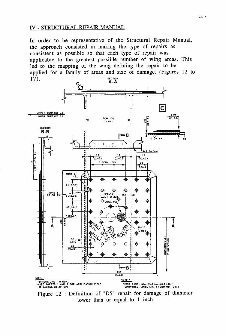
21-15
IV - STRUCTURAL REPAIR MANUAL
In order to be representative of the Structural Repair Manual, the approach consisted in making the type of repairs as consistent as possible so that each type of repair was applicable to the greatest possible number of wing areas. This led to the mapping of the wing defining the repair to be applied for a family of areas and size of damage. (Figures 12 to 17). SECTION
UPPER SURFACE L.E LOWER SURFACE T.E.
SECTION
B-B
F
. . NOTE :
NOTE 1 : - -0IUENSIONS : mm(m.) -SEE SHEETS 1 AND 2 FOR APPLICATION FIELD FIXED PANEL Min. X-24mm(O.94Jin.) -0 DAMAGE 25.4(1.00) REMOVABLE PANEL Min. X=ZBmm(l.l01n.)
Figure 12 : Definition of "D5" repair for damage of diameter lower than or equal to 1 inch

21-16
+) ATR72 - STRUCTURAL REPAIR RANUAL
NOTE : UPPER SURFACE SKIN
- DIMENSIONS : m m (in.) -
APPLICATION FIELD 0 DAMAGE ?S.A(l.OO)
a
'0
Skins and S t i f f e n e r s Repair on Upper and Lower Surface
(Scheme D5)
9 N a
n N a
lo N a
h N a
( S k i n Only)
Figure 13 : "D5" repair application areas for upper panel

21-17
+# ATR72 - STRUCTURAL REPAIR NANUAL
0 0
I 0 s a
9
0 0
t PI
h Y)
Lo * a
I I I I I I I I
O I I I I I I
I I O I I I I 1 0 I I I I.
l l l l l l l l $ 1
Ill I I I i I I I I I
NOTE : LOWER SURFACE SKIN
- DIMENSIONS : rnm (in.)
- APPLICATION FIELD 0 DAMAGE ZS.O(l.DO)
- - -
Skins and St i f feners Repair on Upper and Lower Surface (Skin Only)
(Scheme 05)
Figure 14 : "D5" repair application areas for lower panel

21-18
C CI SECTION
I , , A-A, I
I I
SECTION A-A I
REM 102 U UPPER SURFACE L.E. -
I -LOWER SURFACE T.E.
(0.1 1 2
Icl -7
21 4 ... gTJ-! (8.41) -
-0IUENSIONS : mm(in.) -SEE SHEETS 1 AN0 Z FOR APPLICATION FIELO
-2S.A(1 .OO) C 0 OAUAGE < SA(2.12)
I
I
Figure 15 : Definition of "D11" repair for damage of diameter lower than or equal to 54 mm

21-19
98 ATRR - STRUCTURAL REPAIR MANUAL
S
81 0
--c
Y) I I i'i-
I I- t-
I I- 1- z -i I I- c-
K i I 1
z -1- I I 1
(D N - - K
I 1
I 1 I I I- r -
h I I
: - 1 -
I , m
I 1
m a N -
I ,
I I I- r-
a l n -
c I I I I I I I I n -,-A-I-+
1 1 1 1 1 1 1 1 a
NOTE : UPPER SURFACE SKIN
- DIYENSIONS : mm (in.)
- APPLICATION FIELD 25.4(1.00) < 0 DIUIAQE 4 SA(Z.12)
Skins and Stiffeners Repair on Upper and Lower Surface (Skin Only)
(Scheme D11)
Figure 16 : "D11" repair application areas for upper panel .--%T= P-

21-20
+) ATRR - STRUCTURAL REPAIR MANUAL
a -- a
m a - --
:: -- a
c N -- a
N N -- U
n n ---kr-+-I-4-
NOTE : LOWER SURFACE SKIN
- DIMENSIONS : mm ( in.)
- APPLICATION FIELD ZS.A( l .00) C 0 DAUAGE .$ S A ( 2 . 1 2 )
Skins and St i f feners Repair on Upper and Lower Surface
(Scheme D l l ) (Skin Only)
Figure 17 : "D11" repair application areas for lower panel

V - CONCLUSION
21-21
The entry into revenue service of the ATR72 in 1989 with a composite outer wing led Aerospatiale to develop repair principles meeting both the regulatory requirements in terms of lightning, corrosion and mechanical strength, and the requests niade by the airlines. It must be possible to make the repairs under typical maintenance conditions without inducing specific difficulties due to the introduction of a carbon primary structure. This was achieve thanks to close cooperation between Aerospatiale, ATR Product Support and the Airworthiness Authorities and led to the development of a microcomputer analytical calculation program allowing the mechanical aspect of the repairs to be justified (load transfer, bearing stress, shear stress, buckling, etc ...)


22- 1
Damage occurrence on composites during testing and fleet service - Repair of Airbus aircraft
G. Stemmer Deutsche Aerospace Airbus
Kreetslag 10 21 127 Hamburg
Germany
Summary
The application of composite materials to civil aircraft structure was growing during the past 25 years with every new aircraft which went into service. With these materials in commercial use it became necessary to define repairs in the case the component becomes damaged.
During fatigue testing at component level the limits for al- lowable damage and maximum repair sizes were deter- mined for standard damage events and manufacturing de- fects. The values are depending on structural design, material behavior and local strains or stresses. For simple damages on regular structures necessary repair actions are defined in the Structural Repair Manual.
With an approved inspection philosophy the structure is under observation during airline service.
when the A320 appeared in the sky it had the complete empennage made from composites. Parallel to this pro- cess the moveables at the wing were replaced step by step by composites also starting with the spoilers of the A3 10 in 1985.
Today nearly all moveables at the wing, the hole empen- nage, the engine cowlings, the undercarriage doors and fairings, the cabin floor beam struts and most of all ser- vice panels are made from composites at nearly all mod- els in production. For the Airbus A340 an overview is given below.
With the first series applications of composites it became necessary to define repair solutions for these designs and materials for the case that an unforeseen event causes damages to the components. This need was increased with the growing worldwide fleet of Airbus aircraft.
It will be presented how the repair philosophy within Air- bus Indusme partner companies is defined and which damages were reported on aircraft already in service. Some examples should explain the lessons we have learned from those failures O C C ~ during component testing and airline service.
Airbus philosophy for repairs on composites Depending on the experience accUn’~ulated during the de- velopment Phase and With other composite P m already in production and service, repair solutions for the Struc- ture of the CFRP components were established.
Composite applications at the Airbus A340
/
The structure must be repaired in such a way, that it’s able to sustain all static loads including ageing and environ mental effects from the day of repair until the aircraft is phased out.
The repair philosophy described below is used by Deutsche Airbus. The other partner companies within Airbus Indusme are using the same principles but with some national variations.
Introduction
First series application of a large and essential structural composite component at the Airbus took place in 1982 with the introduction of the CFRP sandwich rudder at the A310-200 model. Some three years later the whole fin box was build from carbon and put into production with the long range variant A310-300. Shortly afterwards,
Paper presented at the 79th Meeting of the AGARD Structures and Materials Panel on “Composiie Repair of Military Aircraft Structitres” held in Seville, Spain 3-5 October 1994.

22-2
Depending on the type of damage (surface protection de- fects, delaminations, cracks, partial rupture) and it’s loca- tion at the structure three ways for repairing the structure are possible:
LARGE DAMAGES which are reducing the load carrying capability of the component below Ultimate Load, must be repaired immediately, This repair could be a temporary field repair using metal sheets and sections. The temporary repair must be replaced by a permanent shop repair in time.
MINOR DAMAGES which are able to sustain Ulti- mate Load must be repaired within a defined period of flighthours or landings. Measures to prevent further da- mage due to airstream or water ingress or to prevent da- mage propagation during continued service should be ap- plied immediately.
NEGLIGIBLE DAMAGES resulting only to a cos- metic repair to restore the surface.
The repair can be carried out by riveting or by bonding. All repair actions are defined in the Structural Repair Manual (SRM). The procedure starts with a detailed da- mage evaluation. Depending on the component, respec- tively its structural importance for the aircraft and the da- mage size the necessary repair action is defined. This results either to a standard repair or because the geometry is more complex to a specific repair for this component.
-
-
-
Possible repairs on composites
I Repair procedure I Repair material I I Permanent cosmetic repair I Temporary repair
bolted repair aluminium alloy parts
I 1 Permanent repair
bolted repair bonded repair laminated repair
Permanent repair after temporary repair
bolted repair bonded repair
precured parts precured parts RT cure wet lay up or hot bond prepreg
precured parts precured parts
Maximum sizes of permitted defects for bonded repairs in the lightning strike zones 1 to 3, which could be done by airline staff are stated in the SRM. For such kinds of repair it must be assumed, that the bonding may fail in ser- vice. So the structure is dealt further as an ’unrepaired area’. If a bonded repair is failing in service, it resulted to a barely visible damage which needs to be repaired a se- cond h e .
Bonded repairs for larger defects in lighming strike zone 3 carried out by airline personal have to be approved by the manufacturer or carried out by the manufacturer him- self.
In lightning strike zone 1 and 2 large defects will be re- stored by riveted or bonded repairs proofed for direct lightning strike. Strength justification of repairs is in general done by cal- culation with loads corresponding to the design strain level of the component. For the repaired structure an al- lowable strain level is calculated taking into account the laminate and bearing strength restrictions and compared with the design strain level under hodwet conditions. If the tolerable strain level for the repaired area is beyond the design strain level, the actual strain of the application area is used to determine the reserve factor.
Repair material properties under hodwet conditions used for the laminate failure analysis are the same than those used for the analysis of the undamaged structure. Bearing strength allowables are B-level values for hodwet condi- tions which were established by means of test results.
Buckling is not a failure criteria for the repaired structure, because the additional material fitted to the repaired structure increases the critical buckling stress in all cases.
Fatigue justification of repairs was done by test only. These tests were the different full scale test components which included typical repair solutions on monolithic and sandwich structures. These repair solutions have been validated up to ultimate load under hodwet conditions af- ter fatigue cycling.
The behavior of repairs under lightning strike conditions was evaluated with an A320 component test specimen of the fin box and rudder. It was found, that repair patches on monolithic and sandwich structures withstood light- ning strikes as long as they were not hit by a direct strike themselves. This event causes the same damage size of approximately 150mm in diameter to the structure a hit on an undisturbed skin. These damages do not effect flight safety.
Some of the test strikes were directly attached to metal parts within the CFRP-structure (rivets, screws, diverter straps and rudder trailing edge). The damages found after the hit were arc root damages at the attaching point as ex- pected on pure metallic surfaces. The CFRP structure suf- fered only minor damages and burn marks at the border of the metal component. It can be concluded that only negligible local destructions will occur in the case of a di- rect lightning strike to a metal component within a CFRP structure. This is confirmed by several lightning strike events happened during flight on aircraft in service.
Damage Statistics Most airlines do record occurring damages and repairs on their aircraft in any case and paper. For the time period 1986 to 1991 the trouble reports for all wing moveables and the empennage components established by Deutsche Lufthansa AG for their fleet of Boeing 727.737 and Air- bus A310, A320 and A300-600 aircraft were evaluated. These components are the favorite candidates for compo- site application today. Not all of these structures were made from composites on the aircraft operated by Deutsche Lufthansa AG in that years.
The contend of these reports was from very small dam- ages up to completely destroyed components. Not noticed for the evaluation were the are corrosion events which do appear on metal materials only. The investigation covers 128 aircraft with an overall service period of 450 years. During this time 188 trouble cases were reported. That

22-3
,
means that every aircraft was struck with a trouble case every 29 month on the selected components.
Damage occurrence on DLH aircraft during the years 1986 to 1991
/ 73% I
93%
specific composite composite
W
Nearly one quarter of all damages were noticed or re- ported when they happened on ground or during the flight phase. These events are the most severe ones and are caused mainly by collisions on ground with other aircraft or any service cars and equipment as well as mishandling during maintenance. Those events noticed during the flight phase are caused by lightning, hail or bird strike. All other defects were detected first by walkaround check or scheduled maintenance inspections.
Most of all cases were small damages like dents or scratches on surfaces or small cracks and abrasion on edges or damaged or broken fasteners. All these defects are independent from design and material of the compo- nent. Only 7% of all damages reported were composite specific damages or could only occur on composite de- signs like delaminations or fluid ingress in sandwich structures.
But these damages are those ones which are resulting to extensive and time consuming repair actions and are de- creasing the reputation on composites in service.
Some of these events happened in the past will be given as examples below.
Repair of A320 Fin Box full scale test The test component was a standard production fin box in- cluding the rudder and leading edge dummies. It included artificial fabrication defects and impact damages as well as typical repairs on monolithic and sandwich elements. The test was scheduled for 72 000 flights (1’5 lifes) under hot and wet environmental conditions and a final static test up to Ultimate Load.
The test was running in accordance with the test specifi- cation and suffered a failure after 37 496 flights at the for- ward attachment fitting at the left hand side of the box. The damage was detected during a maneuver load case with approximately 60% of Limit Load while the control system noticed an overload of one actuator.
The design of the front spar attachment fitting and its tran- sition into the skin panel is given below. The lug itself consists of an inner and outer precured part. These parts are integrated into the lay up of the skin panel and bonded by excess resin of the ’wet’ skin layers. Thickness toler- ances are filled by compensating ’wet’ layers.
Main attachment fitting outer precured
Skin \ / Part
/ / \ inner
Rib 1 / / Front spar angle angle
precured Pm
Stress calculation was done by EM-analysis with the loads from a global model (complete fin and rear fuse- lage) applied to a second, much more detailed model of the lower f i box portion and results to a maximum strain of 4.3 o/w parallel to the front spar under Ultimate Load conditions. This strain level results under strain and sta- bility requirements to a theoretical reserve factor of 1,49. Strain gauge measurements at different locations indi- cated a good compliance between calculation and test values.
The damaged area was cut out and used for fractographic investigations. It was found that the delaminations were located between precured and ’wet’ laminates and be- tween the attach angle and the inner precured fitting part. Delamination started in the front bottom comer and prog- ressed into the rear and upward direction.
It is assumed that the damage was initiated by the debond- ing of the attachment angle of rib 1. Through continuous load cycles the delamination prograted into the field. As a result of the growing delamination the reinforcement withdrew from the load transfer and the failure happened when the remaining cross section was insufficient to carry the load.
These facts resulted to a reinforcement of the skin area by additional layers to lower the local strain level and the installation of screws through the rib 1 angle and the skin to prevent separation of the angle. This modified design had been tested on a subcomponent up to RF= 1.66 under the same load conditions as it failed above.
I

22-4
Failure of the A320 Fin Box test component
tificial Delaminations
Failure areas were detected by visual inspection and proved by ultrasonic and X-Ray technics
A new front spar attachment fitting was cut from a new manufactured shell and inserted into the test box with butt straps and riveting only with those technics and compo- nents taken from the Structural Repair Manual. The rein- forcing angle and the fixing screws at rib 1 were introduced at both sides. This repair has to transfer a load of about 32 tons at Limit Load from the surrounding skin into the main attachment lug.
Repair of the front spar area ,
additional 0 screws
The fatigue test was started again from the beginning and was finished after 1 3 lives, for which a load enhancement factor of 1,15 was used, with aresidual strength test which was stopped after 2.0 times Limit Load were applied without any failure. This result proved the effectiveness of the design as well as that of the repair.
Repairs at the CFRP wing test component During the years 1992 to 1994 a static and fatigue test with a technical demonstrator of a CFRP wing box was running. One major aim of this program was to build a wing with manufacturing technics which offer a high po- tential for a low cost production. All design elements were build up from tape and cured separately. Groups of elements (like skin with reinforcement layers and string- ers) were joined by bonding or bonded together in a com- bined curing and bonding process. Final assembly of the major components (shells, ribs and spars) was done by riveting.
The component was designed for a defined strain level with the load distribution of a real wing of comparable size. The strain level was defined by the limitations re- sulting from the material properties (compression after impact strength, local stability and tension open hole strength). The allowable strain level for the compression loaded upper shell was defined with 5.0%0, that one for the tension loaded lower shell with 4.0%0.

22-5
The test component has had a span of 12 m and included artificial fabrication defects and impact damages as well
the spar positions. The metal spar was cut into several DeaceS and removed from the wing. The area was cleaned h d the new sp&r was joined in situ from two precured angles and a precured web plate by mechanical fasteners.
as two small repairs at the s e g e r web. The tank area was filled permanently with 50 C warm water.
' Engine pylon
To hold the manufacturing costs for the test componen down eight, out of sixteen ribs were made from alumin- ium alloy sheets. The two load introduction ribs in the py- lon area, some cover plates and the whole rear spar were milled from plate material. Especially the rear spar suf- fered many cracks during the fatigue test phase. One rea- son was the applied high strain level and the other the aggressive environmental conditions caused by the pres- ence of warm water. After 18 500 flights were accom- plished, it became necessary to replace the inner portion of the rear spar between ribs 1 and 11. This was done by a CFRP spar assembled in situ. After all loading equip- ment was disassembled the test component was leveled in the zero position by means of two stiff beams supporting
Replacement rear spar upper shell
PIP-
milled SPS
-3
lower shell
Actuators
Tolerance gaps were filled with shim which was cured be- fore riveting took place. Finally all edges were sealed from the tank side.
After one fatigue life and the appropriate static testing up to Limit Load was finished without any reportable com- plaints at all composite components and on the repairs a p plied to these structures, it was decided to enlarge some of the artificial damages and to investigate a repair build up from stainless steel. This repair was located in the compression loaded upper shell of the tank area between ribs 6 and 7.
Stainless steel repairs could be a candidate for those oper- ators who do not have special composite shop facilities and so always have a problem with repairs on composite structures. Aluminium parts are not useable for final re- pairs because they are corroding in combination with car- bon composite due to electolytical effects. Repairs with aluminium repair parts are only allowed for temporary applications until repaired with CFRP parts.
A hole of 240 x 126 mm was cut into the skin witch has a thickness of 5.5mm in this area. The piece taken out was used again as a filler for the hole. All load carrying ele- ments like plates and sections were manufactured from stainless steel with cross sections and fasteners which were sufficient to cany the local loads.

22-6
- repair parts: stainless steel 3.0mm thick - fasteners: skin 06,4mm, stiffener web 08,Omm - all parts installed wet - all edges sealed
-:~~{~==~~----------------------..-. .--- _---------------- ---- ~ ----- _---_ ______---._________________________ _ _ _ _ _ _ _ _ _ _ _ _ _ _ _ _ _ _ _ .'--- ---&=/ I , . .. I , , , , I .
Skinlstringer repair at the upper shell
During the residual strength test with a vertical gust case an unexpected rupture happened in the area of the steel re- pair at an load level representing 135% of the Limit Load.
Failure damages at the wing test box
Delamination in rear spar
\
and cracks in
Failure of the component was expected first at an level higher than 160% of the Limit Load in the area of rib 10 where the tank is ending.
The component suffered heavy destructions at both the upper and lower shell and at the front and rear spar. Still under load the skin of the upper shell presented a de- formation in the form of a long wave with a width of 200 mm and a high of 30 mm running in flight direction until the trailing edge. In this area all stringers were delami- nated and broken. One large crack was located parallel to stringer P10 in the upper shell. It ended at rib 4 where skin thickness is significant increased. At this crack the skin and the ribs beyond were sheared through. The other crack was located in the lower shell and separated the skin from the front spar, it ends also at rib 4.
Close examination revealed that the failure was initiated within the area of the steel repair starting at the location of the first fastener in the smnger web.With this knowl- edge the finite element model of the test component was modified in such a way that the stiffness of the steel repair parts was added to the basic stiffness of the skin for two elements between ribs 6 and 7. These elements have a length of l/3 of the rib spacing. The stiffness E - A of the steel elements is 2,5 times higher than the basic stiffness.
The results from this simple calculation were indicating a strain increase in the surrounding elements in stringer direction of approximately 20%. This strain increase con- sumed nearly the whole strength reserve which was calcu- lated for this area with 23%.
A more derailed analysis with an existing FE model of a typical repair to be used at the A320 upper f i i box showed a more dramatic increase of the strains around the repair area.
in front spar At the application area of this repair the skin consists of

22-1
three fabric layers (1.02mm), the CFRP parts have to be of the original thickness plus one additional layer (1.36mm) and the metal spar parts have the same thick- ness 1.40mm). The model is loaded for this comparative investigation with a constant strain of 3.20/00 (which is the design strain level for this area) in longitudinal direction only. For the plotting of the results the stringer inner flange and the repair parts are not presented for clearness.
The results could be interpreted as:
b the higher the overall stiffness of the repair area the more is the overall strain in this area reduced.
b the higher the overall stiffness of the repair area the more is the strain before and after the repair area increased.
These effects are caused by the constraint that the overall elongation in stringer direction is remaining constant for every cut. It could be expressed by the equation:
u=const=EA,,~Eo~Lo=E~~&o~ (Lo-L~) + EAR-ER'LR
I- L R 4
Repair with CFRP parts
These effects are very local and are dying away very rapid. For the investigated stiffness parameters a strain in- crease of the following amount was found:
unrepaired CFRP skin 100% strain level CFRP skin repaired with CFRP parts 110% strain level CFRP skin repaired with alu. parts 156% strain level CFRP skin repaired with steel parts 169% strain level
A similar strain increase could be found in the transverse direction due to Poisson ratio effects and also if shear loads are applied.
From these results we could learn, that for repairing a component with spar parts which offer a much higher youngs modulus:
b the thickness had to be as low as possible
b thick sheets should be stepped when ever possible
b if filler plates are necessary, they should be taken from a more weak material e.g. glass fiber sheets.
Repair with steel parts
Distribution of longitudinal strains around a repair (A320 Fin Box upper shell under constant strain of 3.2%0)

22-8
Repairs at the A320 belly fairing The belly fairing is 12 m long and covers the wing to fuse- lage connection, the main landing gear housing and the associated wiring and piping as well as other equipment. The support structure is made from aluminium alloy walls, the cover panels are single removeable G W / AFRP sandwich plates. Overall thickness of the panels is varying from 15 to 45 mm. The aft belly fairing is contrib- uted by Deutsche Airbus.
A320 Belly Fairing
Belly fairing (shown without
In the past there were reported many trouble cases due to delaminations between the honeycomb and the inner face sheet. These delaminations were in most cases caused by fluid ingress due to leaking hydraulic pipes or connec- tions or due to condensated water which was dropping down from the fuselage wall. Especially the very aft pan- els with their high curvature were subjected to delamina- tions.
These findings resulted to a repair by replacing the inner face layers and the contaminated honeycomb by a wet lay up repair. Some panels must be restored by a 120°C cur- ing prepreg repair due to very high service temperatures on the surface caused by a hot air outlet, The repair ac- tions are in principle not very complicated, but very vex- ating.
During the last spring these trouble cases increased to an intolerable amount. It was decided U, change the design in order to get a more fluid resistant surface of the sand- wich panels.
The lay up of the cover sheets starts now at the honey- comb surface with a 120 style glass prepreg to decrease the diameter of possible porosities and to increase the adhesive capability between the materials. Finally the lay up is covered by a Tedlar foil which is nearly tight against all fluids. This lay up had been proved very well on other components in production on which we have had no prob- lems with fluid ingress in service.

23- I
REPAIRS OF CFC PRIMARY STRUCTURES
H.Garcfa Ndiiez A.Barrio CArdaba
A.Franganillo Engineering Directorate
Construcciones AeronAuticas, S.A. Avda. John Lennon s/n
Getafe, Madrid Spain
1. SUMMARY
The use of composites in the last decades has been mainly restricted to secondary structures, with repair methods well known to the airlines.
In today aircraft, a significant amount of primary structure is designed and built in high strength composite materials. Repairs for these elements must take into consideration the restoration of structural strength and stiffness, still being easy to be applied by aircraft operators, with a minimum of special facilities, and requiring a minimum of aircraft-on-ground time.
A large number of important structural elements in
/ 23
CFC now in service have been designed and manufactured by CASA. This paper describes how composite repairs are dealt with at CASA, starting from the design board, and the analyses and tests carried out to demonstrate compliance with certification requirements.
Typical repair methods for the different types of CFC structure are described.
I I
2. INTRODUCTION
The use of Carbon Fibre Composite Materials (CFC) in aircraft structural components is becoming more usual each day, accounting for a significant part of the total structural mass of civil and military aircraft.
4
11he /
Figure 1: A340 Composite Application
19120 21'
Paper presented at the 79th Meeting of the AGARD Structures arid Materials Panel on "Composite Repair of Military Aircrafi Structures" held in Seville, Spain 3-5 October 1994.
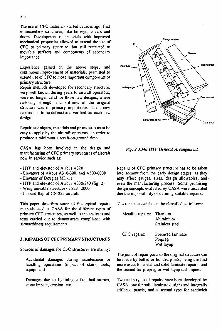
23-2
The use of CFC materials started decades ago, first in secondary structures, like fairings, covers and doors. Development of materials with improved mechanical properties allowed to extend the use of CFC to primary structure, but still restricted to movable surfaces and components of secondary importance.
Experience gained in the above steps, and continuous improvement of materials, permitted to extend use of CFC to more important components of primary structure. Repair methods developed for secondary structure, very well known during years to aircraft operators, were no longer valid for those new designs, where restoring strength and stiffness of the original structure was of primary importance. Then, new repairs had to be defined and verified for each new design.
Repair techniques, materials and procedures must be easy to apply by the aircraft operators, in order to produce a minimum aircraft-on-ground time.
CASA has been involved in the design and manufacturing of CFC primary structures of aircraft now in service such as:
- HTP and elevator of Airbus A320 - Elevators of Airbus A3 10-300, and A300-600R - Elevator of Douglas MD-11 - HTP and elevator of Airbus A330/340 (fig. 2) - Wing movable structure of Saab 2000 - Inboard flap of CN-235 aircraft
This paper describes some of the typical repairs methods used at CASA for the different types of primary CFC structures, as well as the analyses and tests carried out to demonstrate compliance with airworthiness requirements.
3. REPAIRS OF CFC PRIMARY STRUCTURES
Sources of damages for CFC structures are mainly:
Accidental damages during maintenance or handling operations (impact of stairs, tools, equipment)
Damages due to lightning strike, hail storms, stone impact, erosion, etc.
Screwjack fining
Fig. 2 A340 HTP General Arrangemenl
Repairs of CFC primary structure has to be taken into account from the early design stages, as they may affect gauges, sizes, design allowables, and even the manufacturing process. Some promising design concepts evaluated by CASA were discarded due the impossibility of defining suitable repairs.
The repair materials can be classified as follows:
Metallic repairs: Titanium Aluminium
' Stainless steel
CFC repairs: Precured laminate Prepreg Wet layup
The joint of repair parts to the original structure can be made by bolted or bonded joints, being the first more usual for metal and solid laminate repairs, and the second for prepreg or wet layup techniques.
Two main types of repairs have been developed by CASA, one for solid laminate designs and integrally stiffened panels, and a second type for sandwich

23-3
construction. Next subsections describe both types.
3.1. Repairs of solid laminates and integrally stiffened panels.
These types of design are mainly used at CASA for skins, spars, and ribs. Repairs are done by precured patches, mechanically fastened to the damaged original structure. The material of this precured patch is the same than the original, cured in autoclave in the same conditions than the original parts.
In some cases, metal plates (usually Titanium or stainless steel), also mechanically fastened, are used instead of CFC laminates. This allows to decrease the thickness of the repair, as the modulus of those materials is higher than the average modulus of the CFC solid laminate.
The fasteners used to attach the repair plate to the original structure are Hi-lok or Jo-Bolt, depending on access. Fastener material is titanium or steel to avoid galvanic corrosion
SECTION A-A
I I
' I '
SECTION B-B
SECTION C-C
Figure 3: 2)picdflush repair of A340 HTP skin

23-4
I I C T I O N
c-c
R
U S f C I I O N
A-A
Figure 4: Dpical external repair of A320 HTP skin
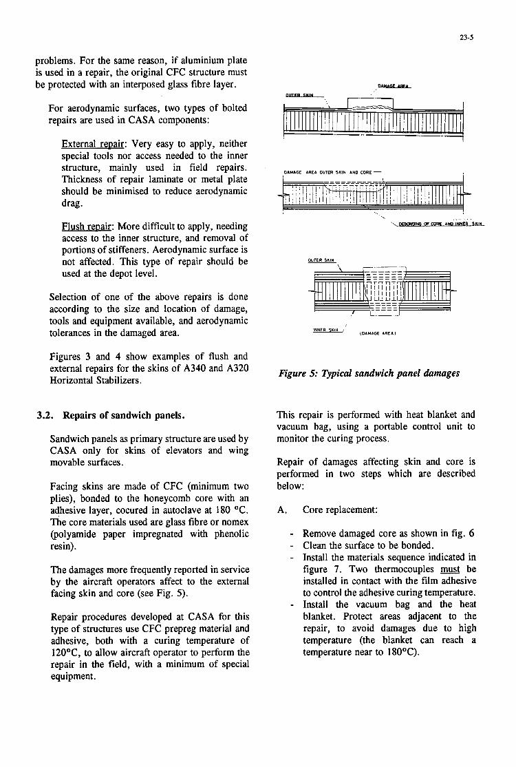
23-5
problems. For the same reason, if aluminium plate is used in a repair, the original CFC structure must be protected with an interposed glass fibre layer.
For aerodynamic surfaces, two types of bolted repairs are used in CASA components:
External reDair: Very easy to apply, neither special tools nor access needed to the inner structure, mainly used in field repairs. Thickness of repair laminate or metal plate should be minimised to reduce aerodynamic drag.
Flush reDair: More difficult to apply, needing access to the inner structure, and removal of portions of stiffeners. Aerodynamic surface is not affected. This type of repair should be used at the depot level.
Selection of one of the above repairs is done according to the size and location of damage, tools and equipment available, and aerodynamic tolerances in the damaged area.
Figures 3 and 4 show examples of flush and external repairs for the skins of A340 and A320 Horizontal S tabil hers.
3.2. Repairs of sandwich panels.
Sandwich panels as primary structure are used by CASA only for skins of elevators and wing movable surfaces.
Facing skins are made of CFC (minimum two plies), bonded to the honeycomb core with an adhesive layer, cocured in autoclave at 180 OC. The core materials used are glass fibre or nomex (polyamide paper impregnated with phenolic resin).
The damages more frequently reported in service by the aircraft operators affect to the external facing skin and core (see Fig. 5).
Repair procedures developed at CASA for this type of structures use CFC prepreg material and adhesive, both with a curing temperature of 12OoC, to allow aircraft operator to perform the repair in the field, with a minimum of special equipment.
DAMAGE AREb OUTER SKIN AND CORE -
._ . -M OF CORE bND INNER 5RIN
(DAMAGE A R E I J INNER SKIN /
Figure 5: Qpical sandwich panel damages
This repair is performed with heat blanket and vacuum bag, using a portable control unit to monitor the curing process.
Repair of damages affecting skin and core is performed in two steps which are described below:
A. Core replacement:
- Remove damaged core as shown in fig. 6 - Clean the surface to be bonded. - Install the materials sequence indicated in
figure 7. Two thermocouples u t be installed in contact with the film adhesive to control the adhesive curing temperature.
- Install the vacuum bag and the heat blanket. Protect areas adjacent to the repair, to avoid damages due to high temperature (the blanket can reach a temperature near to 18OOC).
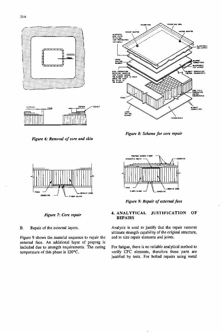
23-6
?k V A C M U U T O R
-PAINT
Figure 8: Scheme f o r core repair Figure 6: Removal of core and skin
Figure 9: Repair of external face
Figure 7: Core repair 4. ANALYTICAL JUSTIFICATION O F REPAIRS
B.
Figure 9 shows the material sequence to repair the external face. An additional layer of prepreg is included due to strength requirements. The curing temperature of this phase is 120OC.
Repair of the external layers. Analysis is used to justify that the repair restores ultimate strength capability of the original structure, and to size repair elements and joints.
For fatigue, there is no reliable analytical method to verify CFC elements, therefore these parts are justified by tests. For bolted repairs using metal

23-7
I O M - P E R f O I A T E D
0 TAR1
IHEPWC E I I O C O W L E
V A C u u l R E P A ~ R PLIES ( R L C U C € D P L I t l t LXTRA
4 . V A C W
NOTE: GLASS YARNS RUST BE COLOCATED
Figure IO: Vacuum bag and heat blanquet
plates, both plates and bolted joints are analyzed taking into account flight and ground loads, and thermal loads due to the different thermal expansion coefficients of CFC and metal.
4.1. Solid laminate and integrally stiffened panels
Only bolted repairs are used for these types of design (see section 3.1). Strength justification is done for the original structure and repair elements using the internal loads extracted from the applicable FEM model. Bolted joints are checked taking into account bypass and transfer loads, according to a set of allowables derived from a comprehensive test program.
For more complex repairs, where local load paths may change, a local FEM of the repaired area is generated and used to calculate the new internal loads, and loads transferred through the bolted joints.
i The minimum reserve factor calculated according
to the above must be equal or greater than the minimum reserve factor of the original structure in the repaired area.
4.2. Analytical justification of sandwich panels
The bonded repairs in sandwich panels can affect the external face, the core and the internal face. This section describes the method of justification for the most common repair, the replacement of a core portion and the external CFC plies.
The analysis of such repair must cover both the repair patch and the stepped bonded joint used to transfer the load to the original facing skins.
The material of the repair patch is selected to have strength and stiffness similar to the original CFC material, to avoid significant changes in the local stiffness that may modify the failure mode of the panel. Material allowables are derived from test results.
The stepped bonded joint transfers progressively the internal loads of the original structure to the repair patch by means of the adhesive layer. This loads transference is done on each step proportionally to the stiffness of the adherents.
Joint stresses are calculated using in house software, that takes into account the elasto-plastic behaviour of the adhesive, the thicknesses and stiffness properties of both laminates, and the allowables of both CFC materials and adhesive.
5. TESTING OF REPAIR SOLUTIONS
5.1. Design criteria for repairs
The main criteria for design of repair solutions are:
- Restore the original strength of the structure
- Withstand fatigue loads corresponding to one fatigue life, without developing cracks or delaminations in the repair and the original structure.
- Withstand ultimate load after the complete operational life

23-8
- No need of additional inspection requirements, except for very specific cases
Demonstration of the above is done, apart from the analytical procedure shown in chapter 4, by a set of tests comprising:
Full scale static test
- Typical repair solutions, covering the expected in service damages, are included in the test specimen, that is tested to limit and ultimate load. Additional load factors are included to account for environmental conditions and moisture contents of CFC material.
Full scale fatigue test
- Repair solutions are included in the test specimen from the beginning. After fatigue loads corresponding to 1.5 lives, the specimen is tested to several ultimate load cases.
To account for the larger scatter of CFC materials, a load enhancement factor of 1.15 is applied to fatigue loads.
SubcomPonent tests
The objectives of these tests are:
- To check the feasibility of repair solutions
- To check combinations of repairs and conditions that cannot be included in the full scale tests.
- To derive degradation factors for moisture and temperature.
- To validate the methods used to analyse the repairs.
CouDon tests
These tests are used to select repair materials and adhesive, derive basic allowables, and select the method for conditionning elements for suhcomnonent tests.
5.2. Repairs for solid laminates and integrally stiffened panels
Some typical repairs are included in the full scale static and fatigue test specimens, as described in section 5.1. These repairs are selected to cover most of the expected in service damages.
Test results are used to justify the repairs and to validate the methods of analysis.
5.3. Repairs for sandwich panels
Repairs for sandwich structures need a more comprehensive test program, due to the number of combinations to be considered:
- Basic skins laminates
- With/without core removal
- Panel/chamfer/insert areas
- Different repair materials and methods
- Combination of structural and cosmetic repairs
Following subsections describe the tests performed to validate the repair procedures.
Coupon tests
Two types of test have been performed:
Lap joint tests to evaluate the behaviour of adhesives and repair materials, under different environmental conditions and moisture. More than 100 coupons have been tested.
Flatwise tensile tests: over 100 specimens tested to evaluate the adhesive behaviour, under different conditions. These specimens have been extracted from:
Elevator panels after been in service
Panels manufactured in laboratory without conditionning and after water inmersion at 7OoC during 15 days.
Repaired areas of panels

23-9
60.000 mm2 (Structural)
I
Test results have been used to select the most suitable materials and the conditioning to be applied for subcomponent tests.
1) 72000 fatigue flights with load enhancement factor of 1.15
2) Ultimate load with load environmental factor of 1.11
3) RuDture
Figure 11: Test panel
3 1 None
SubcomDonent tests
Rupture (reference panels)
Test panels, with dimensions 1225 by 1750 mm, which are representative of the elevator skins design, have been used to evaluate different combinations of repairs and damages, and to compare with panels without repair. A typical
These panels have been subjected to in-plane shear loads, applied by means of a picture frame test rig (see figure 12).
A summary of test conditions and results is enclosed in Table 1.
All tests were performed at room temperature.
6. CONCLUSIONS
During the operational life of the aircraft, CFC elements, like metal structure, are subjected to in service damage from several sources, like impacts, lightning strike, hailstone, etc.
Therefore, specific repair procedures have to be developed for CFC elements. Repair materials and techniques have to be easy to apply by aircraft operators, needing a minimum of special equipment, to avoid long periods of aircraft grounding time.
These repairs have to be considered in the design _ -
test panel is shown in figure 11.
no. Test I Repairs Test Sequence
1 1) Ultimate load with environmental factor of 1.11
I 15.000 mm2 (Cosmetic) I 2) Rupture
Test results average %
98
105
100
Several panels tested for each test type, results shown are average of all tested panels All panels with impacts (failure mode by stress concentration in impact hole) Conditioning by immersion in water at 7OoC during 15 days Note increase of residual strength after fatigue cycles
T a b l e 1: Tests f o r r e p a i r s of sandwich pane l s

23-10
phase, as some innovative designs could result to be very difficult and expensive to repair for in service damages.
To demonstreate the airworthiness of the repaired structure, a comprehensive test program has to be defined, taking into account different combinations
of repair solutions, and the range of environmental conditions that may affect the behaviour of basic and repair materials.
Furthermore, analytical methods have to be defined and validated with test results, to size and justify the repairs.
I- r! 1
Figure 12: Test rig for subcornpone& test panels

24- 1
THE DEVELOPMENT OF AN ENGINEERING STANDARD FOR COMPOSITE REPAIRS.
M. J. Davis Aero-Mechanical Technologies and Standards
Logistics Systems Agency, Royal Australian Air Force 501 Wing, RAAF Amberley 4306
Australia
SUMMARY
The RAAF has used bonded composite patches for structural repairs to aircraft for nearly twenty years, and they are now seen as a reliable alternative to mechanically fastened repairs. To control the implementation of the repair technology, RAAF propose to adopt Engineering Standard C5033 on Composite Materials and Adhesive Bonded Repairs. The Standard addresses repair authorisation and design, as well as repair methodology and quality control.
This paper will describe the philosophy of repair design contained in the standard, and outline the materials and process controls necessary for performance of repairs which comply with IS0 900 1.
A long term objective is to refer afl bonded repair procedures for all aircraft types to this Standard. Such a practice will eliminate variations in procedures between aircraft types, and eliminate erroneous procedures contained in existing repair manuals. Common training in procedures which are not aircraft specific will provide greater flexibility in service postings, and by use of modular training, personnel will be trained only to the level appropriate for each aircraft type.
Rapid incorporation of advances in processes developed by DSTO laboratories is also facilitated by the use of a single publication. Any amendment would automatically apply to all aircraft types which use the specific procedure being changed.
2. APPLICATION OF THE STANDARD 1. INTRODUCTION
Bonded composite repairs have been used by RAAF to repair defective metallic structures since May 1975 [ 1,2,3]. These repairs have achieved significant cost savings for RAAF. Some benefit is derived from the reduced application time (up to a factor of six) and the longer fatigue life of the repairs, compared to mechanically fastened repair. However, other savings have been identifed which are more significant than the short term advantages provided by the method. For example, the use of simple bonded boron/epoxy patches on C-130-E aircraft has enabled the RAAF fleet to achieve life-of-type without wing plank replacement programs, which have been forced on many other operators.
The RAAF now sees bonded repair technology as a viable alternative to mechanically fastened repairs. To control the use of the technology, RAAF will adopt an Engineering Standard on Composite Materials and Adhesive Bonded Repairs (Eng. Std. (3033). The purpose of this Standard is to formalise procedures in such a way that repair designs are addressed in a manner appropriate to their criticality, and application procedures are standardised to specific processes which have been validated by scientific testing.
Repairs are to be considered as a total package, with the design engineer having responsibility for
Defect Assessment. 0 Repair Design. 0 Materials Selection. 0 Application Processes. 0 Quality Management. 0 Aircraft Restoration. 0 NDI Requirements.
This level of control recognises the deficiencies experienced by RAAF in bonding techniques in approved Original Equipment Manufacturer (OEM) manuals for repair of sandwich panel and composite structure [4].
3. REPAIR DESIGN
Repairs are designed as bonded joints, using an analytical approach which is a combination of AMRL “crack patching” technology [5,6] and John Hart- Smith’s bonded joint analysis [7,8,9]. This method is permitted for secondary and tertiary structural elements. The method may be used for preliminary design for primary structure, however validation by Finite Element methods and/or experimental methods is mandatory.
Paper presented at the 79th Meeting of the ACARD Structures and Materials Panel on “Composite Repair of Military Aircra) Structures” held in Seville, Spain 3-5 Octolwr 1994.

24-2
Design is a multi-stage process (see Fig. 1) which involves:
0 Checking Rapid Repairability Criterion (adhesive load capacity).
0 Calculating required overlap length and patch dimensions.
0 Verification of integrity of repaired structure. 0 Verification of repair durability. 0 Calculation of tolerable bond defect size.
, I - Check Structural Determine Patch
Repairability Criterion Geometry
I CheckFatigue E=.: I Requirements Susceptibility
I I '
Figure 1. Process flow for repair design.
3.1. Patch Thickness
Patch thickness is determined from stiffness requirements. As a minimum requirement, the patch stiffness Et should match the stiffness of the parent structure, in order to restore load intensity capacity.
3.2. Rapid Repairability Criterion
A major advantage of adhesive bonding is that the load capacity of an adhesive bond can be designed to be GREATER than the unnotched yield strength of the parent material (see Fig. 2). (Note; not just design ultimate) [9]. This provides a simple test to determine if simple design methods may be used by field engineers, i.e. a Rapid Repairability Criterion. If the load capacity of the adhesive is greater than the unnotched yield strength of the parent material, together with a reasonable safety factor, then the repair can be designed using simple methods.
If this requirement can not be met, or if any of the remaining design requirements can not be satisfied, then the repair is directed to a design authority for comprehensive repair design. Note that a failure to meet the Rapid Repairability Criterion does not mean that the structure is unrepairable. It simply means that a higher level design is required.
The load capacity is calculated using Hart-Smith's equations for double overlap joints [8]. Single overlap repairs which have restraint against out-of-plane bending are analysed as a double overlap joint on a structure twice as thick as the actual structure. The load capacity is given by the lesser value of
P = (a, - a,)ATE,t, + 2 tfr - y e + y p 2E,t, 1 +- i 4: 1 [ 2,) and
P=(a , -a , )AT2E, t ,+ 2qrp - y , + y , E,t, 1+- \I (: ) [ % ) The variables are shown in Fig. 3. If the adhesive load capacity is greater than the unnotched strength of the parent structure, knowledge of actual loads is unnecessary for assessment of the adhesive strength, as such designs automatically satisfy all other load cases.
/
Figure 2. Load capacity of bonded joints, showing that adhesives may be designed for a load capacity greater than the strength of the parent structure [9].
E h i c M o d n h Ei ThrmuloxpsndoncafEcimai /
70 shmshdnl
Figure 3. Variables used in load capacity calculation for double overlap repair.
The standard requires the adhesive load capacity to be greater than 1.2 times the unnotched yield strength of the parent material.
P > 1.2 x t,oy
For noncritical structure, any repair design which meets this requirement is repairable, provided the remaining structural integrity and durability checks are acceptable. Where this requirement can not be met, the repair is referred to a Design Authority, possibly for a full Finite Element analysis at Design Ultimate Load. (Note that FE methods which replace the patched area with equivalent stiffness elements are not

24-3
recommended. FE analysis must correctly represent the behaviour of the adhesive layer.)
For repairs designed to this requirement, the adhesive will never be the critical element in the repair. The structural integrity is then limited by the strength of the patch, or the strength of the repaired structure. Note that this design procedure results in very conservative designs, as shown in Fig. 4.
Load Increasing Design Limit
I
I
0
Safety Factor betmen DLL and DUL
Design Ultimate 0
Margin of Safety between DUL and Component Ultlmate
Swucnrrol Failure
Parent smcture would yield at notch at Load = YieldKt Stress Concentration Factor between notched and unnotched material
Unnotched Moterial Yield
Unnotched m a t e d
> 1.2 Unnotched Material Yield
Design Requiremenrfw Load C'apaciv Unnotched material
Adhesive Load Capacity > 1.2 Unnotched Yield Parcnt sbuchue would yield before adhedvc faila
Adhesive load capaciry design allowr for:Safety Factor Mar@? of Safety Strcu Conccnmtion Factor Factor of 1.2 above Unnotched M a t e d Yield
Figure 4. Design requirements for aircraft repair. By designing the adhesive load capacity above material yeld, the adhesive is never the critical element in the repair. There is a significant margin of safely between Design Limit or Design Ultimate and the required load capacity for the adhesive.
3.3. Overlap Lenhth
Shear stresses in bonded joints and repairs peak at the ends of the overlap. At higher loads, the adhesive becomes plastic at the ends. For the analysis, the adhesive is assumed to be ideally elastic-plastic, so a plastic zone exists at the ends of the joint at high loads (see Fig. 5) . The fact that the adhesive is allowed to exceed the plastic limit does not have the same connotations as for normal structural designs. For adhesive bonds, a very significant proportion of the load capacity is achieved due to plastic behaviour in the adhesive [9].
If the plastic zones are designed to be large enough to cany ALL the load at material yield (see Fig. 6) the joint will always have a load capacity greater than the parent material [9]. An elastic zone is essential for creep resistance and damage tolerance.
/ L o a d e d above elastic limit
' Loaded below elastic limit
Figure 5. Assumed shear stress distribution in adhesive in bonded joints showing the plastic zones developed at the ends of the joint at higher loads.
TP
Shear Stress
T
I ' '' I 1 I
Figure 6. Repair overlap lengths for elastic and plastic zones, such that the load capacity will be greater than the parent structure [9].
In bonded repairs designed this way, the adhesive is never the critical element. The adhesive is therefore damage tolerant, provided the calculated length of the plastic zone always exists in the bond line. Although this design philosophy requires larger overlaps than crack restraint designs or designs based on actual ultimate load values, the simplification of the design process inherent in this approach greatly facilitates repair management. It is also conservative, and the reserve factors built into the designs will readily accommodate variations in material properties and repair geometry experienced in practical repairs.
This method of repair management provides a clear delineation between a conservative design method suited for less critical repairs, and repairs to critical components, where a more exacting analysis is appropriate.
4. STRUCTURAL INTEGRITY ASSESSMENT
Integrity of the repair depends on:
0 Integrity of the adhesive. 0 Patch strength. 0 Strength of the repaired structure.
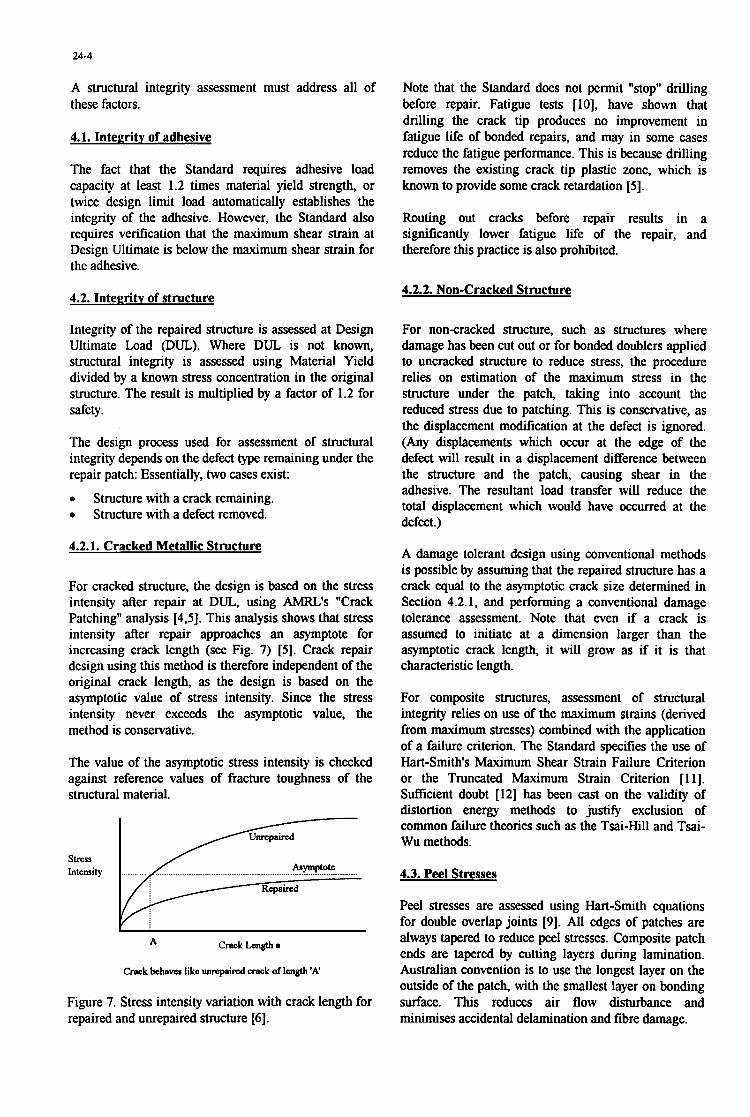
24-4
Intensity StreSS
A structural integrity assessment must address all of these factors.
______.__.__._. krymptok
4.1. Integrity of adhesive
The fact that the Standard requires adhesive load capacity at least 1.2 times material yield strength, or twice design limit load automatically establishes the integrity of the adhesive. However, the Standard also requires verification that the maximum shear strain at Design Ultimate is below the maximum shear strain for the adhesive.
4.2. Integrity of structure
Integrity of the repaired structure is assessed at Design Ultimate Load (DUL). Where DUL is not known, structural integrity is assessed using Material Yield divided by a known stress concentration in the original structure. The result is multiplied by a factor of 1.2 for safety.
The design process used for assessment of structural integrity depends on the defect type remaining under the repair patch: Essentially, two cases exist:
0 Structure with a crack remaining. 0 Structure with a defect removed.
4.2.1. Cracked Metallic Structure
For cracked structure, the design is based on the stress intensity after repair at DUL, using AMRL's "Crack Patching" analysis [4,5]. This analysis shows that stress intensity after repair approaches an asymptote for increasing crack length (see Fig. 7) [SI. Crack repair design using this method is therefore independent of the original crack length, as the design is based on the asymptotic value of stress intensity. Since the stress intensity never exceeds the asymptotic value, the method is conservative.
The value of the asymptotic stress intensity is checked against reference values of fracture toughness of the structural material.
Repaired -
~~~
A Crack Length a
Crack behaves like unrcpaircd crack of length 'A'
Figure 7. Stress intensity variation with crack length for repaired and unrepaired structure [6].
Note that the Standard does not permit "stop" drilling before repair. Fatigue tests [lo], have shown that drilling the crack tip produces no improvement in fatigue life of bonded repairs, and may in some cases reduce the fatigue performance. This is because drilling removes the existing crack tip plastic zone, which is known to provide some crack retardation [ 5 ] .
Routing out cracks before repair results in a sigruftcantly lower fatigue life of the repair, and therefore this practice is also prohibited.
4.2.2. Non-Cracked Structure
For noncracked structure, such as structures where damage has been cut out or for bonded doublers applied to uncracked structure to reduce stress, the procedure relies on estimation of the maximum stress in the structure under the patch, taking into account the reduced stress due to patching. This is conservative, as the displacement modification at the defect is ignored. (Any displacements which occur at the edge of the defect will result in a displacement difference between the structure and the patch, causing shear in the adhesive. The resultant load transfer will reduce the total displacement which would have occurred at the defect.)
A damage tolerant design using conventional methods is possible by assuming that the repaired structure has a crack equal to the asymptotic crack size determined in Section 4.2.1, and performing a conventional damage tolerance assessment. Note that even if a crack is assumed to initiate at a dimension larger than the asymptotic crack length, it will grow as if it is that characteristic length.
For composite structures, assessment of structural integrity relies on use of the maximum strains (derived from maximum stresses) combined with the application of a failure criterion. The Standard specifies the use of Hart-Smith's Maximum Shear Strain Failure Criterion or the Truncated Maximum Strain Criterion [ll]. Sufficient doubt [12] has been cast on the validity of distortion energy methods to just@ exclusion of common failure theories such as the Tsai-Hill and Tsai- Wu methods.
4.3. Peel Stresses
Peel stresses are assessed using Hart-Smith equations for double overlap joints [9]. All edges of patches are always tapered to reduce peel stresses. Composite patch ends are tapered by cutting layers during lamination. Australian convention is to use the longest layer on the outside of the patch, with the smallest layer on bonding surface. This reduces air flow disturbance and minimises accidental delamination and fibre damage.

24-5
4.4. Calculation of Tolerable Bond Defect Size
Following from the design philosophy on which the Standard is based, a critical defect is defined as one which causes the adhesive to be the critical element in the repair [9]. A critical defect will cause the adhesive to become fully plastic at yield stress in the parent material (see Fig. 8). The overlap length necessary to stop the adhesive becoming fully plastic is factored by 1.5 and then subtracted from the actual design overlap length. The result is the tolerable defect size. Any defect smaller than this will not cause the adhesive in the repair to be fully plastic, and therefore the joint will still have the capacity to carry load at material yield.
WIN1 STRENGTH
0 / ADHEREND STREXGTH
I FULLY PLdSTlC
/ / DESIGN
O\'vRl.AP
BSTABLISHMEM OF M.L.UM YBMWIULE LOCAL Y U \ \ S I U
Figure 8. Estimation of tolerable defect size on the basis of load capacity being above the strength of the parent material. [Adapted from Ref. 91
Note that this approach applies only to defects which occur during repair application. In-service defects are discussed in the Section 5.3 under "Interfacial Adhesive Failures".
5. REPAIR DURABLLITY
Four possible durability aspects must be addressed: 0
0 Fatigue of the patch. 0
0 Interfacial adhesive failures.
Fatigue related elements are assessed at loads which are assumed to be 60% of Design Limit Load. If DLL is not known, the'standard allows the use of 0.533 times material yield.
Fatigue of the parent structure.
Fatigue of the adhesive bond.
5.1. Fatime of the Parent Structure and Patch
For uncracked structure, the maximum stress is estimated on the basis of the stress concentration factor, and is checked against fatigue threshold stress values from MIL HANDBOOK 5F or other references. The calculated patch stress is checked for fatigue susceptibility in a similar manner.
In a similar manner to the structural integrity check, a damage tolerant approach may be undertaken by assuming that a crack exists of a size equal to the
asymptotic crack size using the AMRL "crack patching" approach.
For cracked structure, the stress intensity after repair is calculated using AMRL's "crack patching" technology. The value estimated is used to check the crack growth reduction. MIL HANDBOOK 5F or other reference data may then be used to estimate the anticipated crack growth rate at the repaired stress intensity range. Note that this estimate is usually conservative, particularly for repair to longer cracks, as the approach ignores crack closure effects which frequently result in zero crack growth for a considerable period.
5.2. Fatime of the Adhesive Bond
Adhesive bonds are strongly resistant to fatigue, if designed and applied correctly. Although the static strength design allows for the adhesive to yield, the fatigue design analysis allows for only limited adhesive yielding. Fatigue testing of bonded joints at AMRL has shown that joints may be subjected to repeated fatigue cycles at loads above the plastic limit for the adhesive [5 ] . The opening displacement of an overlap joint was measured at loads which caused the adhesive to yield (see Fig. 9).
400.
g m o . & :: f 's
Figure 9. Joint opening displacement for a bonded joint subjected to cyclic loading [SI.
The results of these tests show that creep effects due to loading above the elastic limit for the adhesive are only sigmticant for the first few cycles. Repeated load application does not result in an accumulation of damage in the adhesive.

24-6
The Standard calls for the maximum shear strain in the adhesive to be less than 2ye, the elastic shear strain limit for the adhesive when loaded to the maximum fatigue stress. Recent AMRL work enables prediction of debond growth under fatigue, and prediction of the changed stress intensity behaviour [ 131. The Standard does not currently address h s aspect.
5.3. Interfacial Adhesive Failures
Past experience with repairs applied using processes specified by OEMs has shown that very poor procedures are common [4]. Many repair failures result from debonding due to interfacial failure between the adhesive and one of the bonding surfaces.
Interfacial failures are invariably the result of poor surface preparation during application, or the incorrect cure of the bond. There is no mechanism for prediction of growth of interfacial failures, and therefore design for interfacial failure growth is intractable and dangerous.
Injection "repairs" are commonly used to correct interfacial failures. These methods are prohibited by the Standard. Resin or adhesive is injected under vacuum or pressure to fill the void created by the debond. Such attempts at re-bondmg the defective area are futile, as no surface preparation is possible. An interface which has degraded to the extent that the adhesive debonds will not be corrected by the simple addition of more adhesive. Similarly, if the debond is due to accidental inclusion of a release layer, injection of more adhesive will not result in re-bonding of the defective area.
Interfacial failures must be repaired by removal of defective areas and repair using better surface preparation processes. The Standard permits the use of injection repairs only as a temporary measure, and only if a secondary patch is applied, to reduce out-of-plane displacement of the debonded region. Permanent repair measures are stipulated at the next aircraft servicing. Potted repairs for sandwich panels are only approved if a secondary patch is applied over the region.
(Note: Some benefit in static strength restoration by injection of delaminations in composites has been reported [14] using a low viscosity modified adhesive. Other tests [15] have shown that drastic reductions in fatigue lives have resulted from injection of delaminations in composites, when compared to no repair at all.)
6. MATERIAL PROPERTIES DATA
Reliable material properties required for repair design have proven difficult to obtain. Data used by the original equipment designer [ 161 has proven to be ultra- conservative, and may result in a repair load capacity lower than that calculated from the adhesive manufacturer's data [17] by a factor of three. Many repair designs which would be acceptable using the
adhesive manufacturer's data would be rejected using the aircraft manufacturer's data.
Most adhesive manufacturers provide data which shows compliance with standards MMM 132 or MIL A 25463B. The standard of data provided is typical of that obtained from short overlap shear tests, which provide an acceptable comparative measure, but the strength measured is unrelated to that achieved in a practical bonded joint. This data may set a bench mark for repair design, but there is no specification of, or design data for:
0 Shear Modulus. 0 Elastic Strength. 0 Elastic Strain Limit. 0 Plastic Strain Limit. 0 Peel Strength.
Without reliable data, design must be based on conservative values, with a consequent loss of efficiency of the repair procedure. Recent data has been derived by CYTEC Corporation which provides some of the above variables, but the values M e r widely from the aircraft manufacturer. Given that this data is essential for proper design of bonded structural joints formed during aircraft construction, the paucity of reliable data must bring even ,original structural designs into question.
RAAF would support efforts to establish adequate testing methods and standards to allow generation of reliable repair design data for adhesives in common use for repair, and for environments expected in service.
7. MATERIALS AND PROCESSES
Design must be seen as only part of the repair development. The repair design procedure is tolerant to geometric and materials variations, since the adhesive is designed never to be the critical element. However, even small changes in processing methods can lead to a significant reduction in repair durability. The static strength of an adhesive bond is usually not strongly influenced by processing variables. Unless a bond is very poorly formed, the strength will not change significantly, provided the joint is tested soon after manufacture. For this reason, the traditional lap-shear test is a poor quality control test. It is even worse as a research tool to validate surface preparation techniques.
Processing deficiencies have most effect on the longer term durability of a repair. The usual mechanism is degradation by hydration of the interface between the adhesive and one of the materials being bonded. The frequent use of inadequate processes or the poor performance of good processes has led to the widely held lack of confidence in adhesive bonding for aircraft repair.

24-7 I
I
I
Aspects which must be considered in the development of a repair include:
0 Materials selection and processing. 0 Application processes.
Even the best design can not make allowances for poor processing.
7.1. Patch Material
The success of bonded patches depends primarily on the adhesive bond; patch materials are a secondary factor. Patches may be made of most structural materials such as metals or composites, provided stiffness requirements are met.
Composite patches have the advantages of:
0 Formability. 0 Better NDI. 0 Lighter repairs. 0 Thinner repairs. 0 Better fatigue performance. 0 Better corrosion resistance.
Boron composite patches are thinner and smaller due to high stiffness, which is why they are preferred for repairs in Australia. The advantages of boron composites include:
0 Better aerodynamics. 0 Reduced bending effects. 0 Reduced interference between adjacent moving
components. 0 May be applicable for repairs with limited bond
overlap length.
For general stress fields, such as may be required for corrosion repairs, use of metallic or quasi-isotropic laminates is required.
7.2. Amlication Processes
The current authority for repairs in RAAF is the applicable aircraft Structural Repair Manual (SRM). This practice will continue. To implement the standard, amendments to the SRMs are proposed, which will replace specific bonding procedures with a referral to the appropriate Process Specification in the Standard. For example, a solvent cleaning step would be replaced with the instruction:
"Perform solvent cleaning IAW Engineering Standard C5033 Volume 11, Process Specification 6.1 .'I
For repairs outside the SRM limits, the design engineer can spec@ repair processes by direct reference to the standard. Application process control is fundamental to successful repair. This area has led to most in-service failures of bonded repairs. The Engineering Standard addresses many aspects of bonded repair processes including:
0 Approved Materials. 0 Adhesive Of€-Optimum Cure Cycles. 0 Adhesive Quality Control. 0 Patch Fabrication and Cure. 0 Surface Preparation. 0 Temperature Measurement and Control. 0 Vacuum Bagging.
Processes currently specified in aircrafl repair manuals for repairs to sandwich panels and composite structures are grossly inadequate. The main areas of deficiency are: 0 Surface preparation. 0 Distribution of heat sources. 0 Temperature control.
7.3. Surface PreDaration
Given the susceptibility of bonded repairs to process variations, the Standard closely controls surface preparation by providing detailed Process Specifications for all aspects of the tasks. The Standard emphasises the importance of the fundamental requirements of a proper surface preparation. These are:
0 Removal of soluble surface contamination by solvent cleaning.
0 Exposure of a fresh, chemically active surface by abrasion, preferably grit blasting.
0 Chemical modification of the active surface.
These steps are fundamental to bond durability. For metallic surfaces, all of the above steps must be performed, but for composite materials, the chemical modification process may be omitted. Process steps must follow the above sequence exactly, as steps can not be interchanged. Each step must be performed to exacting standards which far exceed those commonly described in repair manuals. Any short cuts will result in inferior bond performance.
The Standard has adopted the AMRL silane process for the standard chemical modifcation process for metallic structures. The absence of acidic materials and ease of performance are the main reasons for this selection. If properly performed, the performance approaches that for more complex acidic methods, such as phosphoric acid anodising or chromic acid etching.
7.4. Distribution of Heat Sources
Almost every repair manual which provides instructions for application of heat to structures relies on the use of a single heater blanket. Even on uniform structures, single heater blankets exhibit significant temperature variations. If used on complex structural elements, there is a high probability of either undercure of adhesive in regions which do not achieve the cure temperature or overheating of the parent structure. RAAF has experienced repairs departing aircraft in flight due to adhesive undercure, and has also had panels destroyed by heat damage during repair.

24-8
The Standard calls for the use of multiple heat sources, with the configuration determined to suit the distribution of thermal masses within the repair zone. Each zone is heated by a separate heater blanket controlled by a thermocouple located within that zone. Using this approach, areas with a low thermal mass receive only sufficient heat to reach the control temperature, while thicker structure will be supplied with more heat to raise the temperature to the control temperature. Using this method, a more adequate temperature distribution is achieved.
I
The Standard prohibits the use of "multi zone" heater blankets which are fabricated with concentric heated zones, as these systems do not allow correct configuration of the heat sources. Use of these systems on complex structure carries a real danger of cure deficiencies or structural damage.
7.5. TemDerature Control
The Standard requires that temperature control is performed by use of thermocouples located on the surface being heated. Thermocouples located within the heater blanket are not permitted. Control of heat by a thermocouple not within the heated zone is also prohibited.
Thermocouples perform two functions in bonded repairs:
Control of temperatures to ensure the structure is not overheated. Assurance of adhesive or composite cure.
Both of these functions are essential to successhl repair implementation. To achieve these requirements on repairs, thermocouples must be located in a specific manner:
0 For control of heat sources, thermocouples must be located in fhe heated zone at the location where the highest temperature occurs. For cure assurance, thermocouples must be located adjacent to the repair such that the lowest temperature is measured.
This practice requires equipment capable of supporting multiple heat sources, and capable of reading sufficient thermocouples to meet the above requirements. RAAF could not identify a suitable commercially available temperature control unit to meet these requirements, and which gave adequate data presentation to enable high level control of heating processes. Hard copy of all measured temperatures was also considered essential for quality control.
RAAF engaged an Australian company to develop a high quality temperature controller for hot bonding. The
controlled power outlets, each with core
'watech HBC-43 unit has the following features:
' relay protection.
Maximum power capability is 14.4 kW on 3 phase 415 Volt power. Similar capabilities can be achieved on 3 phase US power systems. Sixteen thermocouples, optically isolated from the control unit. Computer control using a PC. Software which presents data in graphical or digital form. All measured parameters can be displayed on one Screen in digital form. Data is in color, enhancing operator perception. Control is based on zones .corresponding to thermocouples located under each controlled heat source. The system automatically controls by the hottest temperature in the particular zone. Cure cycle duration is automatically determined, based on specified acceptance thermocouples located around the repair. Cure cycles are determined by pre-programmed cure cycle envelopes to suit the specific adhesive. The system automatically determines the coldest temperature form the specified thermocouples. Faults are recorded and indicated in plain language. Noncritical faults initiate audible and visual alarms, as well as hard copy output. Critical faults result in automatic shut down with conditions recorded on hard copy. The process can be re-started after power failure. Process variables can be changed while the system is running. Hard copy of all measured parameters is provided at programmed intervals, and at the end of the cycle.
This system has been adopted as the standard control unit for repairs in RAAF, and has been in service for approximately fifteen months. It has proven reliable, and with limited training, operators find the units easy to use. Identification of problems and performance of corrxtive actions has been substantially improved when compared to other hot bonding units.
8. QUALITY CONTROL
Because bonded repairs are a single fastener system which is susceptible to processing variations, a vigorous quality plan is essential to success. Measures are required before repair to assure materials quality and adequate recording of repair details. After repair, testing is needed to ensure adequate bond strength and durability has been provided by the repair.
8.1. Qualitv Before ReDair
Quality assurance of adhesives and pre-pregs is essential. Cure cycle data and pre-application NDI on precured composite patches is required. Detailed and accurate NDI records are required of the location, size and nature of the defect being repaired. Failure to record this information will lead to confusion during later inspecUons.

24-9
There is no test which can provide ZOO% assurance of bond integrity.
Note that stress corrosion cracks being repaired should be inspected no more than one week prior to repair, as this form of crack frequently propagates even while the aircraft is grounded. Failure to accurately record the crack details can lead to erroneous conclusions in relation to the effectiveness of the repair following later inspections.
8.2. Oualitv After ReDair
Common practice is to use standard Lap Shear Test coupons cured with the repair as a quality control test. This test is frequently coupled with a "Coin Tap" test after bonding to give assurance of bond integrity. More sophisticated tests use ultrasonics. Some recent publications have recommended concurrently prepared Boeing Wedge Tests for validation of surface preparation.
The lap shear test is not a suitable method for assurance of adhesive cure, when formed under a heater blanket adjacent to a structural repair. The lap shear test is quite insensitive to surface preparation, and only very bad surface preparation will be detected by this test. The results in respect to the degree of cure are influenced by the location of the specimens relative to the heater system. Also, unless the specimen is cured on a flat section of the structure, the distortion of the specimens will cause erroneous results. Any specimen which gives different results depending on the location of the samples is not a reliable quality control method. Lap shear testing is really only suited to acceptance testing of adhesive supplies.
The concept of concurrent preparation of Boeing Wedge Test specimens prepared at the time of repair application appears at first to have some merit, as surface preparation is a common source of deficient repairs. However, this test is costly to perform on a regular basis and results are usually not available for several days after the completion of the repair. There is also the danger that .the operator will pay more attention to the specimen than to the repair.
A further disadvantage is the time involved in preparation of the sample, and the fact that preparation of the sample will impinge on the exposure of the repair to the risk of contamination while the sample is being prepared. Giyen that the sample is prepared as a 150 mm (six inch) square, the probability of finding a flat area of that size near the repair is remote. The specimen will also interfere with heating of the structure.
NDI tests and coin tap tests after repair validate necessary, but not suflicient conditions for repair integrity assurance. They may indicate bond line defects, but the lack of any bond line defects is not an assurance of acceptable bonding, as they have no relevance to surface preparation.
One signifcant method for detecting deficiencies in adhesive bonds is by inspection of the flash around the repair (see Fig. 10). A good bond should always exhibit a well formed fillet. Absence of adhesive flash or poor filleting may be due to poor pressurisation or cure of the adhesive with a slow heat-up rate. A frothy appearance in the adhesive flash may be due to heating at a rapid rate, causing gelation of the adhesive before voids have migrated. Frothy adhesive may also be due to moisture contamination in the adhesive, inadequate drying or excessive grit blasting during surface preparation.
8.3. ReDair Oualitv Standards
Repair quality management is possible in accordance with AS 3901 (IS0 9001) on Quality Systems. Para 4.9.2. of that Standard applies to "Special Procedures", those for which there is no validation test. Adhesive bonding is such a process.
The required procedure for control of "special processes", and hence bonded repairs, is to certifL compliance with validated process specifications by adequately trained personnel.
I Well filleted bond
I 1
I Absence of adhesive flash
I 1
I ~~
Poor adhesive fillet
,
Porous adhesive fillet
Figure 10. Adhesive flash conditions which are indicative of adhesive bond quality.
This process requires:
0 Validated procedures. 0 Adequate process specification. 0 Training and recertification of technicians.
These aspects are addressed by the Standard. Processes specified in the Standard are based on experimental results from reliable sources, usually AMRL. Where possible, validating data is sought from independent sources [ 181.

24- I O
The standard proposes to manage quality by:
0
0
0
Assurance of adhesive quality before repair. NDI of composite patches before installation. Use of hard copy data produced during repair cure to vertfy that the adhesive has seen the full cure cycle. Inspection of the adhesive flash for evidence of deficiencies in cure. Tap testing, and/or ultrasonics NDI to vertfy the absence of bond line defects.
The lap shear test is not specified, nor is the use of a Boeing Wedge Test. As discussed in Section 8.2, these tests have limited value when prepared with the repair.
The Standard proposes that surface preparation quality is managed by ensuring that the technician is correctly trained, assessed and regularly requalified using the Boeing Wedge Test to verify that adequate standards can be achieved. The quality of performance of repair tasks is checked by recording the time between steps during the preparation process.
If the operator can demonstrate the ability to correctly perform the processes for requalification, then adequate specification of the processes, together with certification requirements and control of the time to perform tasks should provide adequate assurance of surface preparation.
9. TRAINING
0
0
The standard specifies the qualifications for technicians involved in repair application, as well as the design engineer. Currently RAAF conducts its own training for technicians and engineers.
Technical training is provided to tradesman level for Aircraft Structural Fitters (metalworkers). The current course is six weeks long. RAAF intention is to review the course with the objective of modularisation so that training will be provided only to the required standard for particular weapon systems. All levels will be instructed in correct methods for surface preparation, but only those who require added training will progress to the level in which elevated temperature adhesive bonding and composite fabrication procedures would be taught.
RAAF proposes to introduce twelve monthly re- qualification testing of technicians who perform bonded repairs to assure maintenance of standards after training.
Most junior RAAF engineers receive a familiarisation course in composite materials and adhesive bonded repairs. This course extends over eight days, and includes a large proportion of hands-on exposure to bonding processes. A general view of the design procedures for bonded repairs is presented.
A further course has been established in which engineers required to design bonded repairs are trained in the use and application of the Engineering Standard.
10. COMMENT
Aircraft manufacturers have in the past been seen as the paramount authority for repairs. Their expertise in structural design, component manufacture and aircraft assembly is well established.
This author suggests that reliance by airworthiness authorities on OEM support may not be the appropriate method of management of adhesive bonding technology for field applications. Repair technology for field application differs significantly from production processes. For example the tank surface preparation methods with which most manufacturers are familiar are impractical under field conditions. Manufacturers who have familiarity with autoclave bonding processes may not be competent in the performance of the same processes using localised heater blankets and vacuum bags.
Experience with OEM approved repair manuals for sandwich panels and composites indicates a poor understanding of field level repair technology by the OEM authors. As part of a review of repair practices at one RAAF facility, 367 Defect Reports were reviewed. Of these reports, 194 (53y0) refer to non-impact related adhesive bond damage, i.e. debonding or corrosion. Of those 194 defects, 79 (41% of the non-impact related bond defects, or 21% of the total number of defects) are repairs to area where previous defective repairs have been applied. Those defective repairs were applied following the aircraft repair manuals approved by the OEM. Examples of deficient practices have been presented elsewhere, [4].
Australian Defence experience is that the technology must be controlled from a position of specialist expertise, using validated process specifications, focussed training programs and a design standard.
11. CONCLUSIONS
Bonded and composite repair is becoming an established technology for aircraft maintenance in Australia.
The Standard aims to check that:
0
0
0
0
The adhesive is never the critical element in the repair. Static strength is acceptable at Design Ultimate. Fatigue behaviour is acceptable at 80% of Design Limit. The adhesive is damage tolerant by determination of a critical defect size.
RAAF is adopting the repair technology in-principle, with formal control by an Engineering Standard combined with appropriate training and process control measures. Bonded repairs are approached as a "whole technology". Application is based on validated processes which are compatible with field requirements, and which must be correctly specified and performed.

24-1 I
Acknowledgments
The Engineering Standard is a compilation of material from a varied number of sources, and numerous people have provided assistance and guidance throughout the development of the publication. The author acknowledges their support, in particular Drs. Alan Baker, Richard Chester and Francis Rose, and Mr. Peter Pearce and Laurie Molent of AMRL,, and SQNLDRs Roy McPhail and Mal Benfer, and FLTLT Kel Kearns from RAAF.
References:
Baker, A.A., Callinan, R.J., Davis, M.J., Jones, R., and Williams, J.G., "Repair of Mirage 111 Aircraft Using the BFRP Crack Patching Technique", Theor. and Appl. Fract. Mech., 2,l- 15, 1984.
Baker, A.A., "Fibre Composite Repair of Cracked Metallic Aircraft Components - Practical and Basic Aspects", AGARD Conference Proceedings No. 402, AGARD Conference on Repair of Metallic Structures Involving Composite Materials, Oslo, Feb 1986
Baker, A.A. Chester, R.J., Davis, M.J., Retchford, J.A., and Roberts, J.D., "The Development of a Boron/Epoxy Doubler System for the F-111 Wing Pivot Fitting - Materials Engineering Aspects", Int. Cod. on Aircraft Damage Assessment and Repair, Melbourne, Aug. 1991.
Davis, M.J., "Bonded Repairs: Principles and Practice", Int. Conf. on Aircraft Damage Assessment and Repair, Melbourne, Aug. 1991.
Baker, A.A., "Crack Patching: Experimental Studies, Practical Applications", Bonded Repair of Aircraft Structures (A.A. Baker, R. Jones (editors)) Martinus Nijhoff, 1988.
Rose, L.R.F., "Crack Reinforcement by Distributed Springs", J. Mech. Phys. Solids, V35, pp 383-405, 1987.
Hart-Smith, L.J., "Adhesive Bonded Single Lap Joints", NASA CR 112236, January 1973.
Hart-Smith, L. J., "Adhesive Bonded Double Lap Joints", NASA CR 112235, January 1973.
Hart-Smith, L.J., "Effects of Flaws and Porosity on Strength of Adhesive-Bonded Joints", Douglas Aircraft Company Report MDC J4699, November 198 1.
Labor, J.D., and Ratwani, M.M., "Development of Bonded Composite Patch Repairs for Cracked Metallic Structure", Vol I, Rept. No. NOR-80- 160 Vol I, Sept. 1979, Contract N62269-79-C- 0271, Proj. F41422, Task wF41422206.
Hart-Smith, L.J., "A Scientific Approach to Composite Laminate Strength Prediction", 10th
ASTM Symp. on Composite Materials: Testing and Design, San Francisco, Apr. 24-25 1990.
Hart-Smith, L.J., "The Role of Biaxial Stresses in Discriminating Between Meaningful and Illusory Composite Failure Theories", 9th DoD/NASA/FAA Conf. on Fibrous Composites in Structural Design, Lake Tahoe, Nov. 199 1.
Baker, A.A., "Bonded Composite Repair of Metallic Aircraft Components: Overview of Australian Activities", AGARD SMP Meeting, October 3-5 1994, Seville.
Russell, A.J., and Bowers, C.P., "Repair of Delaminations and Impact Damage in Composite Aircraft Structures", Composite Structures 6, pp 145-159, Elsiver Applied Science, London, 1991.
Anon., "Field Level Repair for Composite Structure" NADC Interim Report No. 79173-60.
Rodriguez, M.M., "Advanced Composite Engineering Design Methodology Handbook for the Repair of Damaged F/A-18 Horizontal Stabilators", Aeronautical Engineering Report No. 004-90, Naval Aviation Depot North Island, 30 Aug. 1990.
Data Sheets for FM-300 Adhesive, Cytec Corporation.
Composite Repair of Aluminum Structure Data Update Number 5 , Report on Wright Laboratories Research Contract Number F33615- 89-C-5643, University of Dayton Research Institute, dated 25 May 1993.


REPORT DOCUMENTATION PAGE
1. Recipient’s Reference 2. Originator’s Reference 3. Further Reference
AGARD-CP-550 ISBN 92-836-0010-X
4. Security Classification
UNCLASSIFIED of Document
5. Originator Advisory Group for Aerospace Research and Development North Atlantic Treaty Organization 7 rue Ancelle, 92200 Neuilly-sur-Seine, France
6. Title Composite Repair of Military Aircraft Structures
7. Presented at The 79th Meeting of the AGARD Structures and Materials Panel, held in Seville, Spain 3-5 October 1994
8. Author(s)lEditor(s) Multiple
10. Author ’s/Editor’s Address
Multiple
9. Date
January 1995
11. Pages
298
12. Distribution Statement There are no restrictions on the distribution of this document. Information about the availability of this and other AGARD unclassified publications is given on the back cover.
13. KeywordslDescriptors
Military aircraft Aircraft repair Composite materials Airframes Repair Damage Composite structures
14. Abstract
The AGARD Structures and Materials Panel held a Specialists’ Meeting to address Composite Repair of Military Aircraft. The meeting focused on two main areas, repair of metal structures using composite patches and repair of composite structures using composite or metal patches. Thc work presented had direct application to the maintenance and support of military aircraft. Repair of military aircraft provides both a means to extend the useful life of the airframe beyond the original design life and a method to maintain military readiness by returning damaged aircraft to service.


t; W z Y \o
00 W
e e X
t
7 RUE ANCELLE 92200 NEUILLY-SUR-SEINE
FRANCE
Tdlecopie (1)47.38.57.99 T6lex 610 176
a@-
DIFFUSION DES PUBLICATIONS
AGARD NON CLASSIFIEES
NATO -@- OTAN
I
information Division NASA Headquarters (JTT) Washington D.C. 20546 Etats-Unis
45,
Springfield Virginia 22161 Etats-Unis (accessible Cgalement en mode interactif dans la base de donnees bibliographiques en ligne du NTIS, et sur CD-ROM)
Imprimt par le Groupe Communication Canada boul. Sacrt-CEur, Hull (Qutbec), Canada K I A OS7

.-
IE ANCELLE 92200 NEUILLY-SUR-SEINE
FRANCE
Telefax (1 )47.38.57.99 Telex 61 0 176
7 R DISTRIBUTION OF JNCLASSIFIED
AGARD PUBLICATIONS
NATO -&- OTAN
AGARD holds limited quantities of the publications that accompanied Lecture Series and Special Courses held in 1993 or later, and of AGARDographs and Working Group reports published from 1993 onward. For details, write or send a telefax to the address given above. Please do not relephone. AGARD does not hold stocks of publications that accompanied earlier Lecture Series or Courses or of any other publications. Initial distribution of all AGARD publications is made to NATO nations through the National Distribution Centres listed below. Further copies are sometimes available from these centres (except in the United States). If you hive a need to receive all AGARD publications, or just those relating to one or more specific AGARD Panels, they may be willing to include you (or your organisation) on their distribution list. AGARD publications may be purchased from the Sales Agencies listed below, in photocopy ‘or microfiche form.
NATIONAL DISTRIBUTION CENTRES BELGIUM LUXEMBOURG
See Belgium Coordonnateur AGARD - VSL Etat-major de la Force aCrienne Quartier Reine Elisabeth Rue d’Evere, 1140 Bruxelles
Director Scientific Information Services Dept of National Defence Ottawa, Ontario KIA OK2
Danish Defence Research Establishment Rvvangs All6 1
CANADA
DENMARK
P.O. B:x 2715 DK-2100 Copenhagen 0
FRANCE O.N.E.R.A. (Direction) 29 Avenue de la Division Leclerc 92322 Chkillon Cedex
Fachinformationszentrum GERMANY
Karlsruhe D-76344 Eggenstein-Leopoldshafen 2
GREECE Hellenic Air Force Air War College Scientific and Technical Library Dekelia Air Force Base Dekelia, Athens TGA 1010
Director of Aviation c/o Flugrad Reykjavik
ICELAND
Y
NETHERLANDS Netherlands Delegation to AGARD National Aeros ace Laboratory, NLR P.O. Box 90508 1006 BM Amsterdam
Norwegian Defence Research Establishment NORWAY
Attn: gblioteket P.O. Box 25 N-2007 Kjeller
PORTUGAL ForGa ACrea Portuguesa Centro de DocumentaGiio e Informa@o Alfragide 2700 Amadora
SPAIN INTA (AGARD Publications) Pintor Rosales 34 28008 Madrid
TURKEY Milli Savunma Bavkanligi (MSB) ARGE Dairesi Bavkanligi (MSB) 06650 Bakanliklar-Ankara
UNITED KINGDOM Defence Research Information Centre Kentigem House 65 Brown Street Glasgow G2 8EX
UNITED STATES ITALY NASA Headquarters Code JOB-I Washington, D.C. 20546
Aeronautica Militare Ufficio del Delegato Nazionale all’AGARD Aeroporto Pratica di Mare 00040 Pomezia (Roma)
The United States National Distribution Centre does NOT hold stocks of AGARD publications. Applications for copies should be made direct to the NASA Center for Aerospace Information (CASI) at the address below.
Change of address requests should also go to CASI. SALES AGENCIES
Aerospace Information (CASI) European Space Agency Document Supply Centre NASA Center for ESA/Information Retrieval Service The British Library
800 Elkridge.Landing Road 10, rue Mario Nikis Boston Spa, Wetherby Linthicum Heights, MD 2 1090-2934 West Yorkshire LS23 7BQ United States France United Kingdom Requests for microfiches or photocopies of AGARD documents (including requests to CASI) should include the word ‘AGARD’ and the AGARD serial number (for example AGARD-AG-3 15). Collateral information such as title and publication date is desirable. Note that AGARD Reports and Advisory Reports should be specified as AGARD-R-nnn and AGARD-AR-nnn, respectively. Full bibliographical references and abstracts of AGARD publications are given in the following journals:
75015 Paris
Scientific and Technical Aerospace Reports (STAR) niihlinhed hv NASA Scientific and Technical
Government Reports Announcements and Index (GRAM) oublished bv the National Technical Information Service
+330530++P+UL+