SUPERSONIC INLETS - NATO STO
176
rs n GO U ^ iT u AGARDograph 102 AGARDograph SUPERSONIC INLETS I7WJ MAY 1965
-
Upload
khangminh22 -
Category
Documents
-
view
6 -
download
0
Transcript of SUPERSONIC INLETS - NATO STO

rs
n GO
U
^ iT
u AGARDograph 102
AGARDograph
SUPERSONIC INLETS
I7WJ
MAY 1965

AGARDograph 102
NORTH ATLANTIC TREATY ORGANIZATION
ADVISORY GROUP FOR AEROSPACE RESEARCH AND DEVELOPMENT
(ORGANISATION DU TRAITE DE L'ATLANTIQUE NORD)
SUPERSONIC INLETS
by
lone D. V. F a r o
May 1965

This is one of a ser ies of publications by the AGARD-NATO Fluid Dynamics Panel.
Professor Wilbur C. Nelson of The University of Michigan is the Editor.
This document has been made available through the cooperation of the U.S. Department of the Navy, Bureau of Naval Weapons
a

SUMMARY
The design and operation of supersonic inlets is discussed as fully as the extent of this report will allow. The means by which the incoming flow may be decelerated to a subsonic velocity are enumerated and evaluated. This report covers diffusers which employ internal compression, external compression or a combination of the two. Experimentally determined values of the total pressure recovery, the capture-area ratio and the inlet drag are compared with those determined from available theories for all types of diffusers. The discussions which in general refer to axisymmetric configurations usually may be applied with equal validity to two-dimensional diffusers. However, some specific problems of the latter are treated. The effects of boundary layer are considered in some detail as are the problems of oscillating flow.
SOMMAIRE
On discute la mise au point et le fonctionnement de pr ises d 'air supersoniques, dans la mesure admissible par 1'etendue de cet expose. Les moyens de ralentissement de 1'ecoulement d'entree a. une vitesse subsonique ont ete denombre et estime. L'espose comprend des diffuseurs de compression interne et externe, aussi bien qu'en combinaison. On compare les valeurs experimentales de la recuperation de pression d'arrek, du rapport de surface de capture d'air, et de la tratnee ext6rieure de 1'entree, aux valeurs deduites a part ir de theories etablies pour tous types de diffuseurs. Le plus souvent, les considerations, bien que rapportant a la configuration axisymmetrique, pourront s'appliquer de toute validite aux diffuseurs bidimensionnels. Toutefois, on traite des questions particulieres aux ceux-ci. Les effets de la couche limite ont ete aborde, aussi bien que des questions posees par 1'ecoulement pulsatoire.
533. 697.2:533.6.011. 5
u i


CONTENTS
Page
Summary (Sommaire) iii
Symbols vii
1. Introduction 1
2. Diffuser Performance Parameters 2 2.1 Total Pressure Recovery 2 2.2 Capture-Area Ratio or Mass-Flow Ratio 3 2.3 Inlet Drag 5
3 . Internal-Compression Diffusers 9
3.1 Normal-Shock Diffusion 9 3.2 Variable-Area Diffusers 11 3.3 Perforated Convergent-Divergent Diffusers 14
Figures 16
4. Oblique-Shock Diffusers 19
4 .1 Single-Cone Diffusers 20
4 .1 .1 Probe Diffusers 25
4.2 Double-Cone Diffusers 26
Tables 31
Figures 33
5. Isentropic-Spike Diffusers 57
5.1 Design Considerations 57
5.1.1 Length 57 5.1.2 Practical Limits of External Compression . . . 58 5.1.3 Inviscid Compression Surface Design . . . . 60 5.1.4 Duct Design in the Cowl Lip Region 61
5.2 Off-Design Operation 63
Figures 67
6. Comparative Evaluation 97
6.1 Mach Number Range of Basic Diffusers 97 6.2 Performance Comparison 97
Figures 100

Page
7. Two-Dimensional Diffusers 103
Figures 105
8. Boundary-Layer Problems I l l
8.1 Basic Boundary-Layer Equations I l l
8 .1 .1 Boundary-Layer Thickness in Two-Dimensional Flow . 113 8.1 .2 Boundary-Layer Correction for Axially Symmetric
Flow 114 8.2 Boundary Layer on the Compressing Surface . . . . 116 8.3 Boundary Layer in the Throat Region 117 8.4 Boundary Layer in the Subsonic Diffuser 121 8.5 Fuselage Boundary Layer 121
Tables 124 Figures 134
9. Diffuser Buzz 141
9.1 Theories of Buzz 142 9.2 Methods of Control 144 9.3 Interaction with Engine Design 145
Figures 147
References 153
Distribution
v i

SYMBOLS
Only those symbols which are frequently used are defined here; all others are defined where they are used.
A cross-sectional area
a local velocity of sound
C . n additive drag coefficient
C n supercritical external drag coefficient
Cj. cowl-drag coefficient
c specific heat at constant pressure
c specific heat at constant volume
D drag; flow distortion parameter; diffuser characteristic slope
D. additive drag
D cowl drag
F thrust
f frequency of pulsation, cps
t length
M Mach number = V/a
M Mach number at cowl lip c *
M n design Mach number
M shock Mach number s
m mass; mass flow
p pressure
R universal gas constant = 1715 f t a / sec 3 0 F
Re Reynolds number
s specific entropy
T temperature
vii
V J J J

V volume; velocity
x axial distance
y radial distance
a angle of attack
y ratio of specific heats = c / c
6
6*
6 e
6. 1
\
B
ex
6 s
9w
M
P
tp
^c
o, l ,2 . .
00
c
e
s
t
w
boundary-layer thickness; cowl-lip angle
boundary-layer displacement thickness
external cowl-lip angle
internal cowl-lip angle
diffuser efficiency
boundary-layer momentum thickness
cowling parameter
cone semi-angle
shock-wave angle
coefficient of viscosity
density
flow angle
flow angle at cowi lip
Subscripts
. designated stations
f ree-s t ream
cowl-lip
exit station
innerbody surface
stagnation or total
wall
v ia

Superscripts
sonic or critical conditions
average value of parameter
ix


1. Introduction
This report is intended to give a reasonably comprehensive and yet, at the same time, a concise outline of the subject, from simple definitions to the current research of specialists in each area . The conciseness has been achieved by omitting those theoretical developments which are readily available in textbooks and by relying heavily on reference material . In this way the reader not only is given an insight into the present state-of-the-art, but also is directed to the individuals and organizations currently working on the specialized problem in which he may be interested.
The function of a ramjet diffuser is to decelerate the air from its free-stream velocity at the intake to a combustor velocity which is compatible with the available flame velocity. Because the latter is usually a low velocity, the diffuser also helps to minimize the drag across the combustor itself. Efficient diffusion permits a high static pressure which will support the maximum momentum that can be imparted to the air by heating.
It is usual to define a supersonic diffuser as one which decelerates a supersonic stream to approximately sonic speed and a subsonic diffuser as one which completely converts the kinetic energy in a subsonic stream into pressure energy. However, a complete ramjet diffuser is often called a supersonic diffuser although it is generally composed of both a supersonic and a subsonic diffuser, i . e . , the inlet speed is usually supersonic and the combustor Mach number has a low subsonic value. Although a ramjet diffuser designed for a supersonic missile usually is axisymmetric, a two-dimensional design is often used when the ramjet is incorporated into a more complex vehicle. For hypersonic speeds the two-dimensional diffuser may even be preferred. Although the discussions that appear in this report generally refer to axisymmetric configurations, they may be applied in general with equal validity to the two-dimensional configurations.
Diffusion may be effected either inside the diffuser itself or external to it, or it may be effected by a combination of external and internal compression. Diffusers may also be classified according to their shape or according to the type and number of shocks effecting the compression.
The basic design of a highly efficient diffuser for the flow of an ideal non-viscous gas at a constant free-stream Mach number presents relatively few problems. However, viscous forces cannot be ignored since they cause complex shock patterns, shock instability, and separated flow in the duct as well as vortex sheets in the spilled flow. Some of these effects may be accounted for by semi-empirical theories but many can be assessed only by experimental means. Thus, although the existing aerodynamic theory permits accurate computation of certain portions of the flow field, the over-all design of an inlet is largely an ar t requiring compromise and the exercise of considerable judgment based on experience. The wide variations in Mach number that a vehicle experiences in accelerating to a steady flight speed, as well as the variations in angle of attack often required in climb and maneuver, increase many fold the problems in the design of an optimum diffuser. The material presented herein is intended to indicate not only the important performance indices, diffuser types and methods of computing the flow fields and diffuser shapes, but also to aid the reader in understanding the areas in which judgment is essential to the

design of a practical, efficient inlet. Typical experimental results will i l lustrate the non-theoretical aspects of the design process and will indicate the performance levels attainable with certain basic and conventional designs. They will also show the effect of many modifications made to specific models tested under limited conditions. Many problems and alternatives will be discussed, but the ultimate solution and the choice of a diffuser design will depend on the desired flight character is t ics and physical limitations of the proposed vehicle.
2. Diffuser Performance Paramete r s
Before discussing the various diffuser designs it is necessary to e s tablish some standards by which their usefulness and efficiency may be assessed. The performance of an inlet diffuser is related to three basic character is t ics . They a re the magnitude and quality of the pressure recovery, the capture-area ratio (or mass-flow ratio), and the total drag of the diffuser. These character is t ics are discussed briefly in this section. They will be treated in more detail in relation to the various types of diffusers to be discussed in the following sections. Quantitative values derived from simple theory will be compared with those obtained experimentally. The over-all worth of a diffuser must always be determined by simultaneously assessing all three character is t ics since the gain in one is often achieved at the expense of another. It should also be borne in mind that the most serious aspect of the engine-inlet problem is concerned with off-design operation: none of the characteris t ics should deteriorate rapidly under conditions of overspeed or underspeed or at angles of attack. Experimentally determined performance data will be presented in subsequent sections for each diffuser type and modification.
In actual vehicles many compromises have to be made in order to achieve an acceptable performance throughout the variations of flight Mach number, angles of attack, and sideslip as well as variations in the properties of the atmosphere. A variable-geometry inlet often achieves a better compromise than may be possible with a fixed-geometry diffuser.
2.1 Total P ressu re Recovery
Although efficient diffusion prescr ibes that the final static pressure be as high as possible, it is more usual to measure the efficiency in terms of the total pressure recovery. Since at any Mach number the ratio between the static and total p ressures is a constant, there is no loss of generality in using one form of pressure rather than the other. Diffuser efficiency, v . , is then defined as
"d - \ \ ( 2 " 1 }
where subscripts l and B refer to the inlet and exit (combustor) stations r e spectively.
The total pressure loss is composed of the viscous losses and the shock losses, neither of which are amenable to exact calculation. The shock loss may be estimated by a knowledge of some of the properties of the shock, i . e . , whether normal or oblique, the Mach number at which it occurs, or the position at which it occurs . In actual practice only the losses through attached bow shocks may be known with any degree of accuracy. The nature of most

other shocks is complicated by the interaction of the shock and the boundary layer. What is usually treated as a simple normal shock in the throat of a diffuser channel actually is a complex shock system occupying a length many times the equivalent diameter of the duct. Total pressure losses, calculated for basic diffuser configurations with the assumption of simple, normal shocks at known stations, will be included in each section and will be compared with experimental data.
One of the important features of the total pressure recovery that is sometimes ignored when assessing diffuser performance is the quality of the flow at the exit, i . e . , the pressure (or velocity) distribution over the exit area. This is most critically affected during angle-of-attack operation, at which time, large, separated areas may occur in the subsonic ducting. Unevenly distributed mass flow may cause less efficient burning than a lower but evenly distributed pressure recovery over the combustor region. An often-used measure of the flow quality or flow distortion, D, is given by
D = (p. - P. . )/p„ (2-2) *t max *i m m / / h i av v
However, such an expression should also be supplemented by a pressure contour in order to make it of real value. Examples of such contours and d is tortion factors are shown in Fig. 2 -1 , taken from Ref. 1.
2.2 Capture-Area Ratio or Mass-Flow Ratio
The second characteristic of a diffuser that is used in rating its effectiveness is its capture-area ratio or its mass-flow ratio.
AN
In the sketch above
A = cross-sectional a rea of the entering stream tube
A. = cross-sectional area of the diffuser entrance.
The capture-area ratio is defined as A /A. . When the shock is swallowed, A = Aj . When the shock is expelled some of the air that would have entered the diffuser is spilled around the lips. The ratio of the mass that enters to the maximum mass that could enter i s
m m p V A °° o _ o o o
mx " nttx ' pQ VQ Ax

which reduces to the capture-area ratio, A /A, . It may be noted that here, and in cases where the diffuser entrance is in the free stream, the subscripts o and • are used interchangeably for the flow character is t ics at station o.
The capture-area ratio may be measured in a wind tunnel by the use of a throttling plug (preceding page) which is adjusted to produce a sonic throat of "effective" area A-.. Continuity of mass flow gives
A p V = AXT p. . V.. o ^o o N KN N
(2-3)
which by assuming that the total temperature remains constant down the duct, may be transformed into
\
x. N
AT H = n M
N d A, (2-4)
where the total pressure , p , is assumed to be the same as p , the recovery *N r
pressure actually measured by a rake upstream of the throttle. The value of A_ usually is determined beforehand as a function of the throttle setting by
using a simple normal-shock diffuser with swallowed shock. As the area A
is decreased, the normal shock is forced farther upstream in the diffuser until, at the critical condition, the shock res t s on the r im. Since A0 = A1 as long as the shock remains in the duct ( i . e . , during supercritical operation) and since TJ may be measured, the effective value of AN can be calculated from Eq. 2-4 for each position of the throttle setting.
A few typical curves of pressure recovery as a function of capture-area ratio are shown in the sketch below. Such curves will be discussed fully under the headings of the various types of diffusers (Sections 3 and 5).
u CO > o u
CD * m
u a. CO c<
CD &
u PH
.—< O
H
0 . 9 r
0.8
0.3
0.2
0.1
0 0
M
M =3 .85
M = 5.4
_-"-n
0.2 0.4 0.6 0.8 T o Capture-Area Ratio, A _/Ai
In general the pressure recovery r i ses rapidly to a peak value as A „ is decreased. The peak pressure recovery may or may not coincide with the cr i t i cal point. As the shock is expelled, the pressure recovery drops with varying

degrees of rapidity. While it is usually desirable to have complete flow capture at the design Mach number, it is sometimes advisable to accept some spill-over at the design condition in order to give improved engine performance at angles of attack (see Subsec. 2.3). Plots of TJ VS A Q / A J with Mach number and angle of attack as parameters usually are obtained by means of wind-tunnel testing for each specific diffuser. Examples will be given in conjunction with the discussion of particular diffuser designs in Sections 3 and 5.
2.3 Inlet Drag
The third parameter by which the merit of a diffuser is assessed is the total drag of the diffuser. The first component of the total drag is that of the cowl itself and is made up of the wave drag and skin-friction drag. At small angles of attack with no spill-over, the cowl wave drag is amenable to calculation by the methods discussed in Subsec. 6.3 of Section 8 of the Handbook of Supersonic Aerodynamics (Ref. 2). The skin friction is discussed in the same volume (Subsec. 6.10) and will be treated more fully in Sections 13 and 14 of the previously mentioned Handbook. When the drag of the diffuser is to be considered separately from that of the whole missile, it is necessary to take the reference station far enough downstream of the cowl shoulder for the ambient pressure to have recovered from the effect of the bow shock wave. The theoretical cowl drag is based on a sharp lip and must be corrected for the presence of a blunt lip where one is used. The change in cowl drag due to spill-over at various angles of attack is usually found experimentally.
Another component of the spill-over drag is known as the additive drag, D . , and is the sum of the pressure forces acting parallel to the axis
along the streamlines AB. When A = Ax, i . e . , when there is no spill-over,
there is no additive drag. The additive drag is usually kept relatively small in the supercritical regime, i . e . , swallowed shock, by suitable diffuser design, but in the subcritical regime of operation, i . e . , expelled shock, it r i ses rapidly with increased spill-over and accounts for a large part of the sub-critical drag.
An internal-compression diffuser operating with a detached normal shock is not only a good illustration of how the additive drag ar ises , but is one in which the value may be calculated in a simple manner.
B
— T 4 - ' -j . ' M . n . M , p , n A
oo 7 o o ' " o o O
M 1 > P 1
1P i \
Application of Newton's second law of motion to the flow shown in the above sketch gives
A p + D. - A. pj = pj A, Vf - p A V2 . (2-5) o °° A : ^ x l o o o

Since the additive drag will ultimately be combined with the cowl drag it is necessary that the pressures for both be considered on the same basis, i . e . , as differences between the measured pressure and the free-stream static p re s sure, p . Using this fact, Eq. 2-5 may be written as
Poo A i £ L (i P_
+ y M3) - 1 ^ M 3
AT 2-6
Assuming that the shock is normal to the f ree-s t ream direction over the c ross section, AC, it is possible by means of normal-shock and isentropic-flow tables, to calculate D . from Eq. 2-6 in te rms of A Q / A J , the known free-s t ream conditions and the known value of A-. .
Moeckel (Ref. 3) considers a more realistic shape for the detached shock and obtains an expression for the additive drag of two-dimensional and axisymmetric diffusers which have the sonic point at the cowl lip. However, since a diffuser with a detached shock would be avoided in all practical considerations, both of the above methods are of somewhat academic interest.
The additive drag of paramount importance to the ramjet designer is that due to spill-over caused by operation at below-design Mach numbers. Such spill-over for an isentropic-spike diffuser is shown in the sketch below.
The additive drag is found by integrating the pressure over the surface AB. This demands a detailed knowledge of the properties of the flow field in the vicinity of AB. For two-dimensional diffusers the flow field is readily amenable to calculation since the compression waves are linear. For axially symmetric diffusers, the flow field must be analyzed by means of a character is t ics calculation (Refs. 4, 5, and 6). A detailed example of such a calculation is given in Ref. 7. The calculated additive drag for isentropic-spike diffusers designed for M = 3.5 and M = 5 is shown in Figs. 5-15, 5-17, and 5-21 as a function of the cowl-lip position and the f ree-s t ream Mach number. Figures 5-22, 5-23, and 5-24 give similar information as a function of design Mach number in the range of 2 s Mp. s 5.
It has been shown experimentally that better angle-of-attack performance may be obtained if about 4% flow spillage is allowed for at the design Mach number and zero angle of attack. It is fortunate that under such conditions the total external drag is not always increased. When the normal shock is expelled, the spilled flow is subsonic, and thus the cowl-lip pressure drag may decrease significantly and compensate for the additive drag due to spill-over. However, where a conical shock from an innerbody falls outside

the cowl lip and causes supersonic spill-over, the cowl-lip drag will increase unless the Mach number behind the shock is less than about 1.4.
Sometimes the diffuser performance is improved by bleeding off some or all of the boundary layer on the innerbody or inner cowl surfaces (see Sec. 8). In such cases the drag must take into account the introduction of the bleed air into the free stream.
The following sketch shows how the total external drag at zero angle of attack and at a constant Mach number is made up and particularly how rapidly the additive drag increases with increased spill-over.
The following sketch from Ref. 1 shows the typical variation of the drag components for supercritical flow as a function of Mach number for a diffuser designed to operate at M = 3 .
A Total Drag
p-. Cowl Pressure Drag Plus Calculated Additive Drag
O Cowl Pressure Drag
2.2 2.4 2.6 2.8 F r e e - S t r e a m Mach Number, M
3.2

Diffusers designed to optimize the pressure recovery, capture-area ratio, and external drag are discussed in Ref. 8 as well as in the next three sections. The analysis of experimental results has shown that the diffuser drag is of such importance in the design of long-range cruise missi les that it is often desirable to compromise the external compression in order to minimize the cowl drag. For a maximum-thrust missile, the pressure recovery is of paramount importance, and hence design emphasis is laid on the inlet rather than the cowl.
a = 0° a = 15°
|Q,
u m.
+-> o E ni U a 0.
C
o
u o
+J DO •H Q I
w o
0.4
0.3
0.2
0.1
Source: Ref. 1
0 2 4 6 3 1 0 1 2 1 4 16
Angle of At tack , a cleg.
F i g . 2 - 1 . Typ ica l flow d i s t o r t i o n a t d i f f u s e r e x i t ; M = 3,
3. Internal-Compression Diffusers
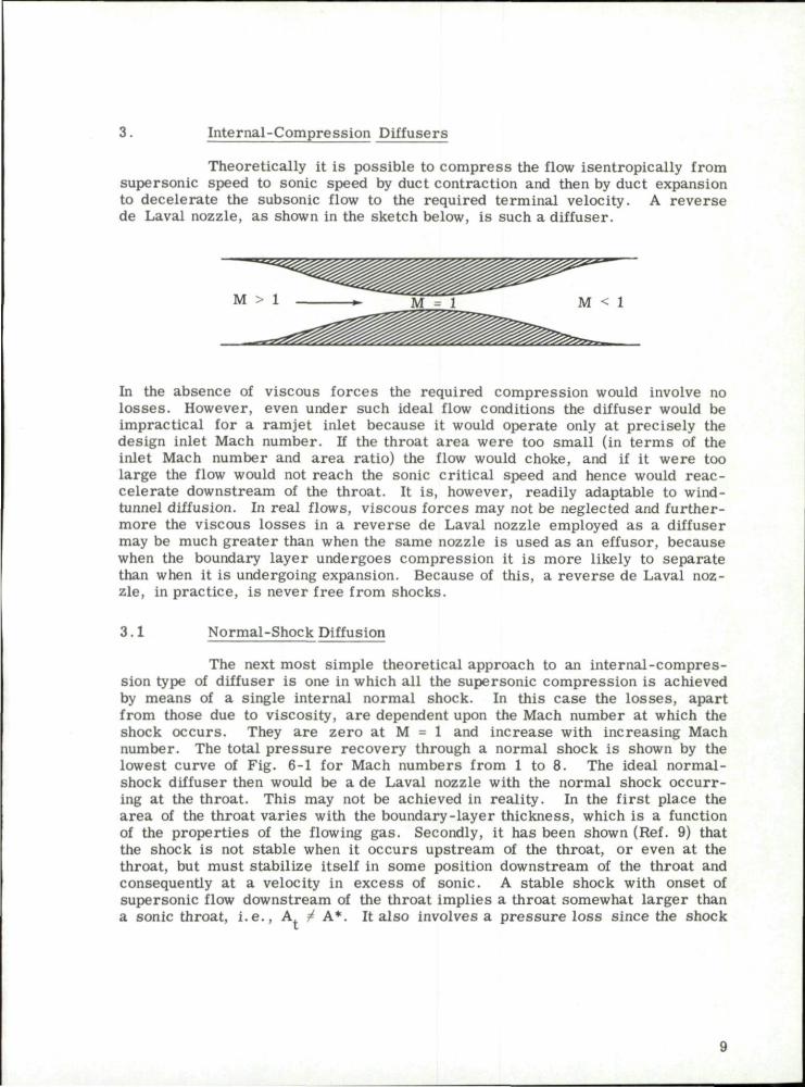
Theoretically it is possible to compress the flow isentropically from supersonic speed to sonic speed by duct contraction and then by duct expansion to decelerate the subsonic flow to the required terminal velocity. A reverse de Laval nozzle, as shown in the sketch below, is such a diffuser.
In the absence of viscous forces the required compression would involve no losses. However, even under such ideal flow conditions the diffuser would be impractical for a ramjet inlet because it would operate only at precisely the design inlet Mach number. If the throat area were too small (in terms of the inlet Mach number and area ratio) the flow would choke, and if it were too large the flow would not reach the sonic critical speed and hence would reac-celerate downstream of the throat. It is, however, readily adaptable to wind-tunnel diffusion. In real flows, viscous forces may not be neglected and furthermore the viscous losses in a reverse de Laval nozzle employed as a diffuser may be much greater than when the same nozzle is used as an effusor, because when the boundary layer undergoes compression it is more likely to separate than when it is undergoing expansion. Because of this, a reverse de Laval nozzle, in practice, is never free from shocks.
3.1 Normal-Shock Diffusion
The next most simple theoretical approach to an internal-compression type of diffuser is one in which all the supersonic compression is achieved by means of a single internal normal shock. In this case the losses, apart from those due to viscosity, a re dependent upon the Mach number at which the shock occurs. They are zero at M = 1 and increase with increasing Mach number. The total pressure recovery through a normal shock is shown by the lowest curve of Fig. 6-1 for Mach numbers from 1 to 8. The ideal normal-shock diffuser then would be a de Laval nozzle with the normal shock occurring at the throat. This may not be achieved in reality. In the first place the area of the throat varies with the boundary-layer thickness, which is a function of the properties of the flowing gas. Secondly, it has been shown (Ref. 9) that the shock is not stable when it occurs upstream of the throat, or even at the throat, but must stabilize itself in some position downstream of the throat and consequently at a velocity in excess of sonic. A stable shock with onset of supersonic flow downstream of the throat implies a throat somewhat larger than a sonic throat, i . e . , A, 4 A*. It also involves a pressure loss since the shock

no longer actually occurs at M = 1. If the back pressure is such that the shock occurs upstream of the throat, it will emerge from the duct and stand in front of the opening creating an effective external compression diffuser, as shown below.
Flow Spill-over
\ m m T Z Z Z S Z Z Z L m m \ a m \ \ a T Z Z m m m *
A* or A
r* Expelled Shock
This diffuser cannot be started, or the shock re-swallowed once it has been expelled, unless the throat-to-inlet a rea ratio is equal to or greater than that shown in curve B of Fig. 3 - 1 . This limiting area ratio is found by assuming that the normal shock is on the lip, i . e . , in the critical position. The area ratio, A /A. , is that found from the Mach number behind a normal shock at
1 (y+D , „ _ , M / S / .. i \V-l
M
= (A*/A) M P
+ tpw) (i Z. -ryo--yr + 1
M ;
(3-1)
The values shown in Fig. 3-1 are based on y - 1.4. Once the flow is started, i . e . , the shock swallowed, the area may be reduced to the value shown in curve A.
Actual a rea ratios at which such diffusers have operated are shown for comparison in Fig. 3 - 1 . The difference between the theoretical curve A and experimental data gives a good estimate of the viscous losses . It may be seen that the curve of experimental values follows curve A quite closely, a l though the increase in actual throat a rea varies from about 16% of the isentropic value at M = 2 to 100% at M = 5.
If a ramjet having such a diffuser with fixed area ratio, (A*/Aj or A./A.), is accelerating as shown by the arrow in Fig. 3-1 , the shock will not
be expelled at the point P but will remain swallowed until the Mach number of point Q is reached. However, if the same missile is decelerating, the shock will not be expelled at Q but will remain swallowed until point P is reached. Thus the position of the shock for conditions between curves A and B will depend on its previous history. To offset this "hysteres is" effect, the diffuser will require a "start ing" value of A /A. (curve B), or else the missile will
have to overspeed until the shock is swallowed.
This type of diffusion is applied to wind tunnels more successfully than to ramjets .
10

The total pressure recovery for a single-shock internal-compression diffuser, assuming non-viscous flow is shown in Fig. 3-2. In the optimum case, i . e . , with area ratios of curve A in Fig. 3 -1 , the shock would occur at a sonic throat giving a shock pressure recovery of 1.0. If the throat has the minimum area required for starting (curve B of Fig. 3-1), the highest pressure recovery is achieved when the normal shock occurs at the throat. The Mach number at which this shock occurs is found by compressing isentropically from Mm at the inlet area, A. , to M, at the given throat area, A .
The pressure recovery in this case is given by curve B in Fig. 3-2. When the shock of this diffuser is at the point of being expelled, i . e . , at the entrance, the pressure recovery is shown by curve B' which is the normal-shock recovery at the free-stream Mach number. In actual practice, the pressure losses due to viscous effects will have to be included. They will depend on the Reynolds number of the flow, i . e . , on the temperature, pressure, and velocity of the air flow and the length of the duct.
The outstanding advantages of the simple, fixed-throat, normal-shock diffuser are the low external drag that may be associated with it and the simplicity of construction. The main disadvantage is that the large area ratio r e quired for starting such a diffuser gives rise to low efficiency once the shock is swallowed. The efficiency may be much improved by closing down the throat after shock-swallow; however, the mechanical complexity of such an operation and the additional weight required do much to counter its usefulness in a ramjet. A second disadvantage of the normal-shock diffuser is that the length of the convergent section required to compress to sonic conditions without flow disturbance gives r ise to a thick boundary layer at the throat. Thirdly, the duct requires an extended throat region for the complex normal-shock system. At moderate Mach numbers, it has been shown that a throat length of about four times the throat diameter gives the most satisfactory resul ts . The throat length may, however, be reduced by the insertion of a vortex trap or subsonic dump. The above features of the simple inlet are increasingly detrimental as the free-stream Mach number increases.
For these reasons, this type of diffuser usually is limited to flight Mach numbers less than about 1.6 where the pressure recovery is high and the hysteresis effect small. This type of diffusion is applied to wind tunnels more successfully than to ramjets. However, because of its inherent simplicity and low drag, a good deal of effort has been exerted toward finding methods of overcoming its disadvantages. Methods of varying the inlet-to-throat area ratio will be discussed in the next section. Methods of controlling the boundary layer and minimizing flow distortion will be treated in Section 8.
3.2 Variable-Area Diffusers
Performance of a fixed-geometry diffuser deteriorates rapidly at Mach numbers other than the design Mach number. Above the optimum Mach number, the throat area is larger than necessary and the efficiency drops off due to increasing throat shock losses. Below the optimum Mach number, the throat is not large enough and the inlet flow breaks down giving a strong shock in front of the diffuser with attendant high drag and low efficiency. It is therefore theoretically desirable to employ variable-geometry devices to alleviate these adverse effects as well as to overcome the heavy penalty of the starting
11

area ratio. Many ways of varying the throat a rea have been devised. One of the most direct methods is by employing flexible plates to form two opposite walls of a two-dimensional diffuser. Investigation of such a diffuser for flows in the Mach number range from 2.5 to 4 .0 is described by Gunther in Ref. 10. Flexible plates of constant thickness were deflected by two sets of levers as shown in the following sketch
Lip Edge Lever
Throat Block Lever
P ivot P o i n t s
The mechanism functioned satisfactorily but the resulting pressure recoveries were limited by the thick boundary layers which developed in the throat region especially on the side walls. Substantial improvement in the diffuser efficiency was achieved by several methods of bleeding off the boundary layer. The plate surfaces were designed to give isentropic compression to sonic velocity at the throat. Actually, because of the effective area change due to the boundary layer, the lowest Mach number at which the normal shock occurred was about 1.4. Since the boundary-layer problem, in varying degrees, is common to most diffusers, a general discussion of it will be found in Section 8.
A second method of varying the contraction ratio is by means of a translating centerbody in an axisymmetric duct. A typical configuration is shown in the sketch below
Starting Position
12

In an arrangement of this type, the duct entry area and the minimum area are varied simultaneously giving r ise to quite rapid changes in the contraction ratio. A typical plot of the contraction ratio as a function of the translation of the centerbody is shown in the following sketch. The diffuser with which this ratio is associated was designed for operation at Mach numbers from 2 to 3.
<
0.65
0.55
0.45
0.35 2.4
The most stringent requirements of the starting contraction ratio are further ameliorated by the presence of the oblique shock caused by the centerbody tip. For completely internal compression this shock must lie within the duct. (Operation with the shock outside the duct is discussed in Section 4 . ) The shock and its reflections from the duct walls reduce the Mach number at which the normal shock occurs. Mossman and Pfyl in Ref. 11 describe an experimental investigation of axisymmetric diffusers with translating innerbodies. Their first model had a conical-tipped innerbody and a small-angle conical frustum as the annulus. In the second model, the two surfaces were designed to give a uniform longitudinal pressure gradient from entry to throat. A third model was designed by the method of characterist ics to eliminate all strong shocks from entry to throat. They concluded that the first model gave the best pressure recovery in the range 2.1 £ M £ 2.7 and the second in the range 2.7 s M « 3 .0 . In all models, even the third one, there is a small inclination between the free stream and the inner cowl surface. This virtual wedge angle produces an oblique shock (and reflections) that further reduces the Mach number at which the normal shock occurs. The values of the pressure recovery for several internal-compression diffusers are shown in Fig. 3-2.
Similar oblique shocks, of course, also occur in a practical reverse de Laval nozzle in which the purely isentropic nozzle is shortened to prevent undue boundary-layer growth. Although it has been shown in Ref. 11 that p res sure recovery is greatly improved by the use of boundary-layer bleeds, the net value of such bleeding is questionable when the drag increment due to the spillage is taken into account. This study has not been pursued since interest is now focused on high supersonic Mach numbers for which isentropic-spike diffusers are more appropriate.
13

3.3 Perforated Convergent-Divergent Diffusers
Varying the physical contraction ratio of a diffuser by means of flexible plates or a translating spike, as discussed in the preceding subsection, is readily applicable to wind-tunnel diffusion. As an inlet diffuser for ramjet vehicles its beneficial effect is somewhat cancelled by the added weight of the required mechanisms. In addition, the rapid velocity fluctuations that may occur in flight would necessitate a very sensitive and rapid throat control. It must also be remembered that if the shock is ever regurgitated during flight, an extreme change of contraction ratio would be required for restarting the diffuser.
As an alternative to controlling the area ratio, one may control the mass flow passing through the throat. This control may be achieved by perforating the convergent section of the diffuser. Eward and Blakey (Ref. 12) calculated the required size and spacing of such perforations as a function of the local Mach number and inlet geometry and estimated the subsonic flow coefficient through the holes. Tests were made at M = 1.85. At zero angle of attack, the total pressure recovery was increased from 0.838 to 0. 931 by means of the perforations. It dropped back to 0.920 at three degrees angle of attack and to 0.906 at five degrees .
One of the attractive features of such a diffuser is its "self-adjusting" capability. If the shock is detached and the flow in the converging section is subsonic, the pressure differential (assuming a f ree-s t ream static pressure on the outer surface) causes flow through the perforations, thereby reducing the spill-over and moving the shock closer to the inlet. If the perforated area is large enough the shock is ultimately swallowed. When the flow in the convergent section is supersonic, the mass flow is greatly reduced, due to the combined effect of the reduced pressure differential and the increased speed of the flow past the holes. The relationship between free-s t ream speed, mass flow through the perforations, and the shock position is shown in the following sketch taken from Ref. 12.
M > 1 M < 1
— Shock
(a) Normal Shock Ahead of Inlet
M > 1 M < 1 > - I
- U L ^ L L L L U I
Shock—1 M > 1
^M\ Shock —
M ~ 1
(b) Normal Shock Partly Swallowed (c) Normal Shock Near Throat
14

Further tests were made by Hunczak and Kremzier (Ref. 13) for similar inlets at M = 1.9. The average diameter of the sharp-edged ( i . e . , countersunk) holes was of the order of 0.1 in. Under these test conditions the subsonic flow coefficient was determined to be 0 .5 . A maximum total pressure recovery of 96% was obtained with 18% of the mass flow being spilled through the perforations of a diffuser with a contraction ratio of 1.63. A maximum relative mass flow of 98% was obtained with a peak pressure recovery of 90% in an inlet with a contraction ratio of 1.40. During supercritical operation the theoretical and measured values of the mass-flow ratios agreed within about 1%.
Perforated nozzles were also tested at M = 2.5 by Clark (Ref. 14) and by Wu (Ref. 15). Although they obtained a high pressure recovery in the throat, the pressure recovery in the divergent section was greatly reduced by flow separation. Wu determined that the perforations were most effective in the region close to the throat where the static pressure difference through the perforations was greatest. Although these results appear very promising, they have never been assessed in terms of the external-drag increment due to the escaping air . Perhaps the continuation of this study has been limited by the fact that the interest is now focused on high flight Mach numbers and isentropic-spike diffusers.
15

<
+J td a.
a o
CJ a u
4->
c o u
3 4 5 6 Entry Mach Number, M
Fig. 3-1. Comparison of theoretical and experimental contraction ratio vs Mach number; M = 1 to 8; y - 1.4.
16

1.0
3 4 5 6
Free-Stream Mach Number, M
Fig. 3-2. Comparison of theoretical and experimental total pressure recovery vs Mach number; all internal compression; Ma = 1 to 8; y = 1.4.
17

18

4. Oblique-Shock Diffusers
The use of an internal oblique shock as a means of reducing the Mach number at which the normal shock occurs has been described in the p re ceding subsection. Greater flexibility of operation is achieved if the compression through the oblique shock takes place externally. The shock attached to the tip of a central body eliminates the starting problem and the hysteresis effect associated with the internal-compression diffuser.
Since this idea was put forward by Oswatitsch, such diffusers usually bear his name. The basic principles are illustrated in the following sketch.
C o n i c a l ^ Shock
The diffuser is said to be operating critically when the heat released by the burner is of such magnitude that the back pressure maintains the normal shock at the cowl lip. If the back pressure is less than its critical value, the shock is in a stable position downstream of the cowl lip. Such operation is said to be supercritical. When the back pressure exceeds its critical value, the normal shock is detached from the cowl lip giving subcritical flow. These three flow regimes are shown in the sketch below.
C r i t i c a l Operat ion
S u p e r c r i t i c a l Operat ion
S u b c r i t i c a l Operat ion
At the design Mach number the conical shock is usually assumed to graze the cowl lip, i . e . , there is no supersonic flow spill-over. The relationship between the pressure recovery and the capture-area ratio during the three types of operation may be seen in the sketch on page 4. During supercritical operation the mass capture is a maximum and the pressure recovery increases as the shock moves toward the cowl lip. If there is 100% mass capture, the p re s sure recovery reaches its peak as the shock reaches the cowl lip, i . e . , the critical point, and drops as soon as the normal shock is expelled. If the conical shock does not impinge upon the lip, supersonic flow is spilled even in the supercritical regime, and the mass-flow ratio is less than one. The peak pressure recovery does not always occur at the maximum mass-flow ratio, but is dependent on the cowl geometry and the relative position of the innerbody and the cowling. By a judicious combination of external compression and variation of the duct area, a diffuser may be designed to operate over a wide range of flight conditions.
19

In the absence of boundary-layer effects, the recovered stagnation pressure increases as the number of oblique shocks increases, since the sum of the total pressure losses across a ser ies of weak shocks is less than the loss ac ross a single oblique shock leading to the same terminal Mach number. The same principle may be carried to its limit and a continuous curve designed which will give r ise to an infinite number of very weak waves. By means of such an "isentropic surface" the flow velocity may be reduced, in theory, to the sonic value without incurring any shock losses . The limitations which are imposed upon such an isentropic compression will be discussed in Subsec. 5 . 1 . A single-cone inlet will give adequate performance at low Mach numbers (less than about 2.0) but at higher flight Mach numbers a double-cone or isentropic-spike inlet is generally more efficient.
The primary design variables which affect the performance of an oblique-shock diffuser are :
1. The shape of the external compressing surface, i . e . , a single cone or wedge (Subsec. 4.1), a double cone or double wedge (Subsec. 4.2), or an isentropic spike or ramp (Section 5).
2. The position of the cowl lip with respect to the innerbody tip.
3 . The position and shape of the "shoulder" of the innerbody with r e spect to the cowl lip.
4. The geometry of the cowl lip.
5. The cross-sect ional area distribution of the annular diffuser downstream of the inlet, as determined by the inner surface of the cowl and the aft portion of the innerbody.
The last named is often considered a secondary design variable since its effect on the pressure recovery is usually small in comparison with the external compression. However, it may have far-reaching effects on the flow stability (Section 9) and on the boundary-layer development in the duct (Section 8).
4 .1 Single-Cone Diffusers
The simplest oblique-shock diffuser employs an innerbody with a conical nose.
- < L -
20

The basic design parameters are:
6 = semi-angle of the nose cone s
e^ = angle between the axis and the line joining cone tip and cowl lip
6. = interior cowl lip angle
6 = exterior cowl lip angle
The maximum diameter of the innerbody, its shape at the maximum diameter, and the shape of the inner and outer cowl walls also must be chosen to give stable, unseparated flow in the duct as well as minimum external drag.
The nose angle, 6 , should be chosen small enough to prevent shock detachment at the lowest Mach number it will encounter and yet sufficiently large to minimize the length of the conical tip and the boundary-layer growth thereon. Angles between 25 and 30 deg have been found satisfactory at Mach numbers from 1.8 to 5.4 (Refs. 16, 17, and 18). Inlet length is also a significant consideration for many applications.
The theoretical pressure recovery for inviscid flow has been calculated as a function of the Mach number and the cone angle. The calculations assume that the cowl lip is situated on the conical shock. A first case assumes that the normal shock occurs at the duct entrance. A second case incorporates the maximum contraction ratio (apply curve B of Fig. 3-2) for shock-swallow associated with the average Mach number, M3, at the duct entrance. The different flow regions are shown in the sketch below.
The values of the Mach number and streamline angle behind the conical shock, M. , and the Mach number, M , along any ray from the cone tip in the coni-
s cal flow field may be found as a function of Mm and 6 in Kennedy's tables of supersonic conical flow (Ref. 19). The average Mach number, Ma , before the normal shock is taken as {M1 + M )/2, although this value is only approximately
B
true in axisymmetric flow. The calculated pressure recovery for both the above cases is shown in Fig. 4-1 as a function of M^ and 8 . From this figure the
advantage of a combination of external and internal compression may be seen. Although there is definitely an optimum cone angle for each Mach number, its value is not crit ical . The spread of cone angles within which the pressure r e covery drops by 2% from the maximum is indicated by the bars on the curves of Fig. 4 - 1 . Figure 4-2 gives the optimum cone angle as a function of Mach
21

number and also shows the pressure recovery associated with that optimum value for both cases . Experimental data from several sources are included for purposes of comparison with the theoretical values. The difference between the calculated and the experimental values consists largely of the viscous losses which are ignored in these calculations.
The internal cowl-lip angle, 5., usually is designed to be slightly
smaller than the normal streamline angle produced in the conical flow field. While this produces a weak wedge shock, giving further local compression on the interior cowl-lip surface, it also tends to minimize the wave drag on the cowl exterior surface. Care should be taken to avoid, at the lowest flight Mach number, a detached internal lip wedge shock since this shock would cause excessive air spillage. The external cowl-lip angle, 6 , is usually determined
by the value of 6., the degree of sharpness of the lip, and the cowl thickness
dictated by structural requirements. In most cases a sharp lip is preferred in order to minimize the pressure drag; however, a blunt lip may reduce the additive drag by delaying the expulsion of the normal shock. This phenomenon is due to the fact that the stagnation point moves inside the cowl as the inlet mass-flow ratio diminishes. Such an effect is illustrated below.
With no spill-over the stagnation point is at A, but it moves around to B as the capture-area ratio diminishes.
For optimum performance at the design Mach number and zero angle of attack, the bow shock from the conical nose should impinge on the cowl lip. In this position there is no additive drag, i . e . , A Q / A . = 1. At the same time
the internal ducting should be designed to give a slightly increasing area behind the lip in order to stabilize the shock on the r im. The design was first suggested by Fe r r i and such a diffuser often bears his name. More often the duct is of the convergent-divergent type with the throat area optimized for s tar t ing the diffuser. The area variation of the internal ducting is usually the r e sult of a compromise between the desire for a flat, low-drag cowl and the need for a gradual turning of the innerbody to prevent flow separation.
For off-design operation the position of the innerbody in relation to the cowl and the distribution of the duct cross-sectional a rea must be optimized. As the centerbody is translated along the axis the longitudinal distribution of
22

the duct cross-sectional area var ies . In the ultimate design of a ramjet vehicle many compromises must be made. The operating characterist ics at all required Mach numbers and angles of attack must be known in order to calculate the performance throughout the whole range of a flight. Even when the geometry may be varied in flight, it may be necessary to take less than optimum conditions at the design Mach number in order to provide sufficient thrust during climbout or to assure stable operation during the high angles of attack demanded by prescribed maneuvers.
Tests at M = 5.4 which are described in Ref. 18 show how critical the relative position of nose and cowl lip may be. The design model operated supercritically at a mass-flow ratio, m-j/m^, of 0.96. Retraction of the cone
by 0.01 in. , i . e . , an increase of f) (~32 deg) by 0.2 deg allowed 100% mass
capture for all supercritical operation. How critical this improved flow capture may be is ultimately dependent on the tactical requirements of the vehicle. Perhaps more significant is the fact that when the bow shock was slightly within the cowl, the inlet operated with high mass-flow ratios for angles of attack of 3 and 4 deg whereas with shock-on-rim, there was a large amount of flow spillage even at 2 deg angle of attack.
The most suitable position of the throat in the duct is dependent on the nose and inlet geometry and on the flow parameters . When the spike is translated to give the maximum mass-flow ratio at several Mach numbers, the optimum rate of internal expansion is strongly dependent on the Mach number range within which the diffuser must operate. The shape that gives a gradual rate of internal expansion for the highest Mach number may give a too-rapid internal contraction when operating at the lowest Mach number.
It is also important that the rate of change of the duct area be very small in the region of the throat. It has been shown to be even better to have a constant-area section at the throat. The optimum length of this section varies with Mach number. However, in a diffuser with internal as well as external compression, the normal shock occurs at an almost constant Mach number not much greater than one and hence the throat length need not vary. At moderate free-stream Mach numbers it has been shown that a throat length of about four times the throat height gives the most satisfactory resul ts .
Typical total pressure recoveries for single-cone inlets are shown in Fig. 4-3 as a function of mass-flow ratio for M^ = MQ = 1.8, 2.0, 3.85,
and 5.4. The effect of small angles of attack (under slightly different test conditions) is shown in Fig. 4-4. The systematic degradation of pressure recovery with increasing angle of attack may be seen for all Mach numbers.
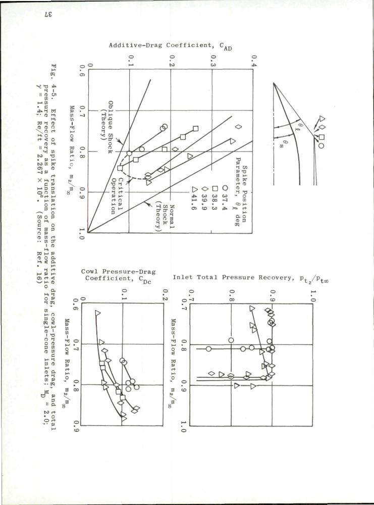
The effect of translating the spike was tested at M = 1.8 and 2.0 and reported in Ref. 16; some of these results are shown in Fig. 4-5 . As the spike was moved out of the inlet to reduce d, from 41,6 deg to 37.4 deg, the
effect on the additive drag and the drag of the cowl was quite marked, whereas the pressure recovery showed relatively little change.
23

Two basic modifications were made in the test models of Ref. 17. The first was concerned with reducing the cowl drag and the second with improving the pressure recovery by bleeding off the low-energy boundary layer. By going from a relatively steep cowl (6 = 3 8 . 3 deg and 6. = 29.2 deg) to a
flat cowl ( 6 = 4 deg and 6. = 0 deg), the pressure-drag coefficient at M = 3.85
was reduced from 0.112 to 0.007. However, at the same time the maximum inlet mass-flow ratio was reduced from 0.95 to 0.81 and the total pressure recovery from 0.32 to 0.285. The pressure loss is due primarily to separated flow in the vicinity of the sharp shoulder of the innerbody dictated by the shape of the low-drag cowl as shown in the sketch below.
^ > l / 8 " Holes
High-Angle Cowl Low-Angle Cowl
The reduced value of the pressure recovery was later restored to the original value and the inlet mass-flow rate increased to 0.925 by bleeding off the boundary layer through a double row of staggered 1/8 in. -diameter holes immediately downstream of the shoulder of the conical innerbody (Ref. 17). In the tests at M = 1.8 and 2.0, the boundary layer was bled off through three subinlets which consisted of slots in the inner wall of the cowl downstream of the narrowest section as shown in the sketch below.
S u b i n l e t
Each inlet carried about 3% of the total mass flow. The inlets not only improved the pressure recovery by two or three per cent, but also resulted in a better pressure distribution at the diffuser outlet as shown in Fig. 4-6. This latter improvement was most marked at 6 deg angle of attack. It may be noted that these inlets had no significant effect on the mass-flow ratio. With the inlets closed there was a considerable region of separated flow in the duct which did not appear when the boundary layer was removed.
Car r ie re and Leynaert in Ref. 20 have used conical flow theory to compute the mass flow on a conical-spike inlet at angles of attack. Figure 4-7 compares, very favorably, their calculations for M = 2 with wind-tunnel measurements. The lift coefficient has also been calculated for a conical-spike inlet at angles of attack which are below the critical angle, i . e . , less than the angle
24

at which the shock just grazes the cowl lip. The slope of the lift curve is given in Fig. 4-8 for free-stream Mach numbers from 1.5 to 3 .5 . The limiting value is also shown as a function of the Mach number.
4 .1 .1 Probe Diffusers
Occasionally a bluff surface, in which a dish homing system may be installed, is required in the centerbody of a diffuser. The consequent detached shock, with its high pressure losses and high drag, demands heavy penalties from both the aerodynamic and propulsive viewpoints. A simple probe protruding from the nose cap may produce a flow regime comparable to that of a conical tip and thus it may satisfy the aerodynamic requirements without jeopardizing the guidance system. The performance of such a probe on a hemispherical and on a flat-capped central body of a diffuser is described by Dean in Ref. 21. Sketches of the two models are shown below.
ASSESS ^ ^ ^ ^ ^
Tests in which the probe length was varied were run in a free jet at M = 1.8. When equilibrium is established the flow field resembles that due to a conical spike. In order to facilitate comparison, a 22.75 deg cone diffuser was run under the same test conditions. Typical flow sketches of the two models, with different probe lengths, are shown in Fig. 4-9 for both swallowed-shock and detached-shock conditions. The flow was unstable for detached-shock conditions with the greater probe length. The measured total pressure recovery at zero angle of attack is shown as a function of the capture-area ratio in Fig. 4-10 where it is compared with that of a single-cone diffuser. It may be seen that the pressure recovery of the probe attached to a spherical head is as high (~ 0.875) as that of the single-cone diffuser. However, since there is more spill-over in the probe configuration the additive drag will also be higher. It may also be seen from this figure that the flow field due to the probe becomes unstable as the spill-over increases and that the diffuser is inoperable for capture-area ratios between about 0.73 and 0.87. The effect on the pressure r e covery of angles of attack of 3 and 6 deg is shown in a similar manner in Fig. 4-11. The formation of a strong shock on one side of the diffuser and the loss of a large part of the separation cone on the other side results in lower pressure recoveries. However, if the probe is aligned with the free-stream when the diffuser is at an angle of attack, the losses are reduced as shown in Fig. 4-12.
The length of the probe was shown to be an important parameter in determining the stability of the diffuser operation. At the test Mach number
25

the maximum probe length for stable operation was found to be about three t imes the radius of the base of the separation cone. The position of the bluff body with respect to the cowl inlet was also found to be a critical function of probe length.
Similar tes ts at Mach numbers of 1.76, 1.93, and 2.10 are reported by Moeckel and Evans in Ref. 22. They also found that at zero angle of attack the pressure recovery and mass-flow ratio are comparable to those of a solid conical-nosed innerbody. However, even at small angles of attack the diffuser efficiency is greatly reduced.
4 .2 Double-Cone Diffusers
A diffuser with two oblique shocks will give a better pressure r e covery than one with a single shock. The addition of some internal compression not only improves the pressure recovery but may also ass is t in stabilizing the normal shock.
The double-cone diffuser is usually designed to allow the two oblique shocks to coalesce at the cowl lip as shown in the sketch below.
- - < ! ,
In the region behind the bow shock, AB, the flow is conical and isentropic. When this flow str ikes the second cone a curved shock, BC, is produced, the curvature being due to the variation of flow angle and Mach number in the conical region. In the region downstream of the curved second shock the flow is rotational. A normal shock, BD, may occur at the lip or it may occur near a throat in the annular duct, i . e . , the double-cone diffuser may employ all external compression or a combination of external and internal compression.
By means of the method of characteris t ics , Kennedy (Ref. 23) has analyzed the flow field around several biconic bodies for a wide range of Mach numbers. Calculations which include the effect of the rotationality show that even at the highest Mach numbers used (~ 5) the accuracy of the resul ts is not appreciably impaired (s 1.5% change in M) when this entropy variation is neglected. Included in Ref. 23 are the cartesian coordinates, the Mach number, and the flow orientation for all mesh points, as well as the flow var i ables on both sides of the curved shock and along the cone surfaces. Equations for the curved shocks and for the loci of the point of intersection of the conical and curved shocks are also included. Table 4 - 1 , derived from this material , permits the reader to reconstruct the curved shock front for many
26

different biconic inlets over a wide range of Mach numbers. Table 4-2 and Figs. 4-13 and 4-14 give the position of the point of intersection of the two shocks as well as the flow characterist ics immediately behind it as a function of the free-stream Mach number and the cone angles.
The total pressure recovery may be obtained from the data in Ref. 23 by using
% \ \ %
where the total pressure is assumed constant in any region between shocks, i . e . , p. = p. and p. = p (see sketch below).
H t a l 3 t i
P t / P t 1 cc
is obtained from either oblique or normal-shock tables using any pair of values from among M^, M1, 9 , and tp. .
p / p is found in a similar manner for each mesh point along the shock and 3 3 averaged.
p. / p is the normal-shock recovery found by using the mesh point values of 6 M4 averaging the pressure ratio.
If the normal shock occurs within the duct rather than at the entrance, it may be assumed to occur at the station of least cross-sectional area. The Mach number at that station is found by comparing A with A.. In order to avoid
time consuming averaging of the values at the curved shock and at the diffuser entrance, a short-cut method has been based on that of Connors and Meyer (Ref. 24). In it the average Mach number, Ma , is taken as (M. + M )/2
s and the average flow deflection in front of the second shock as {v + <pa)/2. The flow direction behind the second shock is taken as (0 + 6 ) (see above sketch) throughout its length. l s
This method has been used to construct the curves of Fig. 4-15 which give the pressure recovery of double cones for Mach numbers from 2 to 6 and a wide range of cone angles. Two limiting cases have been considered. The first case deals with both external and internal compression, the internal contraction being the "starting throat" for the average entering Mach number. In
27

the second, the compression is completely external with the terminal normal shock occurring at the cowl lip. Figure 4-16 gives the maximum pressure r e covery as a function of Mach number and shows the values of the first and second cone angles that are associated with maximum pressure recovery. It may be seen from this figure that the optimum first cone angle is relatively insensitive to Mach number, but that the optimum second cone angle varies rapidly with Mach number, particularly in the Mach number range below four.
Calculations using average values from the Kennedy data and those using the simplified method of Ref. 24 were compared for 25-40 deg biconic noses at Mach numbers of 2.3604, 3.9260, and 5.1233. In spite of the unrealistic assumptions, the short method underestimated the total pressure r e covery by only about one-half of one per cent at the lowest Mach number and by two per cent at the highest Mach number. The simpler method does not, of course, give any information about the flow field as does the Kennedy method.
The calculation of the internal compression contains two known areas of over-simplification. In the first place, it is assumed that the ultimate compression is achieved by a single, simple normal shock at the throat. In r e ality the shock is usually a complex shock system and is stable only when it occurs downstream of the throat. This shock system does, however, allow a somewhat smaller throat than the one calculated under the simple assumptions and thus provides a compensating e r r o r .
The second over-simplification is that the internal compression before the normal shock is assumed to be isentropic, i . e . , that 6. is equal to
the flow angle and creates no oblique shocks. If the entering flow angle is large, a high cowl drag would be associated with the maximum pressure r e coveries shown in Fig. 4-16.
Representative measured pressure recoveries for double-cone diffusers are taken from Refs. 17 and 25. When the inlets were operated at be-low-design Mach numbers, the spike was translated to allow the second shock to touch the cowl lip. The measured maximum pressure recoveries are shown in Fig. 4-16. The difference between the actual pressure loss and the theoretical one increases as the Mach number increases and is due mainly to the viscous forces that are neglected in the calculations.
Tests designed to a s sess the relative meri ts of optimizing the internal flow and minimizing the external cowl drag are reported in Ref. 1. Two versions of the 20-35 deg biconic spike were made. In one the internal flow was turned very gradually and in the other, much more sharply. The projected a reas of the cowl were 20% and 40% of the maximum cross-sectional a rea . The pressure recovery as a function of the mass-flow ratio and angle of attack is shown for the two models at four Mach numbers in Fig. 4-17.
The total-drag coefficient for the same models was obtained by force measurements and the cowl drag from integrated pressure measurements. The skin friction was computed and the additive drag determined by subtracting the last two components from the total drag. The values of thrust-minus-drag are shown as a function of Mach number in Fig. 4-18. They are normalized
28

with respect to the ideal thrust coefficient, i . e . , that with no pressure losses . It may be seen that the drag penalty of the deeper cowl more than outweighs the improved flow due to the more gradual turning at the shoulder of the innerbody.
The critical total pressure recovery at angle of attack is shown in Fig. 4-19 together with the associated supercritical mass-flow ratio. For a valid assessment of the worth of such a diffuser at angles of attack, these graphs should be considered in conjunction with those of Fig. 4-20 which gives the flow-distortion contours at the diffuser exit. Large areas of separated flow or an unbalanced pressure distribution at the exit due to angle of attack operation would be unsatisfactory for the propulsion requirements. In the particular diffuser of these tests, the flow-distortion parameter (Ref. 1) was, as would be expected, greater with the low-drag cowl than with the high-drag one.
The external and internal cowl-lip angles for these models were 32.6 deg and 27.6 deg. The latter angle is smaller than the flow angle of the entering stream at that point and therefore causes another oblique shock from the lip. It is often advantageous to position the spike so that the second oblique shock strikes the inner surface of the cowl rather than grazing the lip. This ensures an internal oblique shock and consequent improved pressure r e covery.
The effect of translating the spike at the design Mach number is shown in Fig. 4-21. When the spike is moved further from the cowl lip both the mass-flow ratio and the pressure recovery deteriorate. With spike r e traction, 100% mass flow is achieved at the expense of an 8 to 10% loss in critical total pressure recovery. Furthermore, the retracted spike in conjunction with the gradually curved shoulder of the innerbody gives stable sub-critical flow down to a mass-flow ratio of 0.6. The same effect was obtained at MD = 3.85 (Ref. 17) by a slight extension of the cowl.
The effect of translating the spike to give the optimum shock configuration at Mach numbers less than the design Mach number is shown in Fig. 4-22. The critical pressure recovery of the model with the translating spike shows a slight improvement over that of a fixed-geometry model for Mach numbers between 2 and the design Mach number of 3. The improvement of the mass-flow ratio is much more marked. The same figure shows the slight further improvement in both critical pressure recovery and mass-flow ratio due to a more gradual expansion of the subsonic duct (see tests of Ref. 25).
Figure 4-23 (from Ref. 25) shows a comparison of the supercritical external-drag coefficient for the fixed-geometry model and for the two versions of the translating-spike diffuser. A significant decrease in drag is obtained by the variable geometry at Mach numbers less than 3.0. This improvement, however, will ultimately have to be assessed in t e rms of the additional weight required for the translating mechanism.
Boundary-layer effects show up very strongly in the operation of the two-cone diffuser. The advantage due to the double cone is often offset by the
29

"bridging" effect of the boundary layer at the junction of the two conical surfaces, as shown in the sketch below.
This flow separation and subsequent re-attachment not only changes the effective spike geometry but also may induce a greatly modified shock pattern. It is generally agreed that such separation takes place only in laminar flow and thus may be alleviated or entirely eliminated by roughening the spike tip to ensure boundary-layer transition before the juncture of the two surfaces. Figure 4-24 shows the effect of tip roughness on the pressure recovery at M = 3.85 for a biconic inlet; both pressure recovery and mass-flow ratio a re much improved at all angles of attack included in the test except the highest (9 deg). Almost identical resul ts were obtained by applying suction to a ring of holes just upstream of the juncture between the surfaces. This latter method allowed the diffuser to operate up to an angle of attack of 11 deg. Off-setting this improvement is the fact that the mass flow is reduced by the amount of the bleed flow. Bridging has also been alleviated by the use of a porous innerbody through which passed about l\k to 2% of the total mass flow (Ref. 17).
The presence of a thickened boundary layer may cause poor quality flow at the diffuser exit and, under critical conditions, may be responsible for premature choking of the subsonic duct. Methods of boundary-layer control which provide improved duct flow are discussed in Section 8.
The interaction of the shock system with the boundary layer initiates flow instability or "buzz". This will be discussed in Section 9.
30

Table 4-1
Coefficients in the Equation of the Curved Shock of a Biconic Diffuser
20
B
10
20 12.5
20 15
20 20
25 10
25 15
25 20
2.1297 2.4431 2.8387 3.3694 4.1538 5.5457
2.1297 2.4431 2.8387 3.3694 4.1538
2.1297 2.4431 2.8387 3.3694 4.1538 5.5457
2.4431 2.8387 3.3694 4.1538 5.5457
2.0665 2.3604 2.7296 3.2188 3.9260
2.3604 2.7296 3.2188 3.9260 5.1233
2.7296 3.2188 3.9260 5.1233
0.00300 0.00172 0.00095 0.00052 0.00020 0.00009
0.00267 0.00144 0.00076 0.00035 0.00006
0.00302 0.00118 0.00057 0.00035 0.00014 0.00006
0.00134 0.00048 0.00005 0.00007 0.00004
-0.00025 0.00086 0.00077 0.00039 0.00012
-0.00051 0.00045 0.00019 0.00012 0.00003
0.00034 0.00012 0.00006 0.00002
0.41889 0.56011 0.68393 0.80130 0.91795 1.04145
0.33701 0.49121 0.61930 0.73369 0.84559
0.24096 0.42031 0.55024 0.66545 0.77296 0.88047
0.24045 0.40333 0.52581 0.62818 0.72099
0.13050 0.31332 0.44802 0.56032 0.66438
0.14089 0.31503 0.43879 0.54276 0.63992
0.13727 0.30283 0.41575 0.51109
0.014181 0.014385 0.015033 0.015889 0.016811 0.017531
0.015552 0.014633 0.014956 0.015466 0.015859
0.018494 0.015433 0.015208 0.015209 0.015577 0.015850
0.019465 0.016134 0.014625 0.014956 0.016271
0.019890 0.016952 0.016448 0.016834 0.016555
0.021571 0.017628 0.016428 0.016086 0.015888
0.022852 0.017201 0.015952 0.015225
0.0001995 0.0002264 0.0002682 0.0003286 0.0004121 0.0005204
0.0002356 0.0002341 0.0002819 0.0003310 0.0003847
0.0003274 0.0002752 0.0003060 0.0003413 0.0004131 0.0005149
0.0004315 0.0003658 0.0003360 0.0004476 0.0006712
0.0003524 0.0003122 0.0003467 0.0004147 0.0004260
0.0004826 0.0004089 0.0004080 0.0004468 0.0005148
0.0006600 0.0004587 0,0004837 0.0005259
Equations of the shock fronts: x = -A + By + Cy2 - Dy3 (see Subsec. 3.3.2) where the origin is at the juncture of the cone surfaces.
31

Table 4-2
Paramete r s at Point of Intersection of Curved and Conical Shocks of a Biconic Diffuser
9. M (Op w.
20
20
20
20
25
25
2 5
10
12.5
15
20
10
15
20
2.1297 2.4431 2.8387 3.3694 4.1538 5.5457
2.1297 2.4431 2.8387 3.3694 4.1538
2.1297 2.4431 2.8387 3.3694 4.1538 5.5457
2.4431 2.8387 3.3694 4.1538 5.5457
2.0665 2.3604 2.7296 3.2188 3.9260
2.3604 2.7296 3.2188 3.9260 5.1233
2.7296 3.2188 3.9260 5.1233
11.065 10.775 9.833 8.576 7.146 5.625
8.641 8.791 8.225 7.243 6.062
6.589 7.138 6.840 6.121 5.163 4.068
4.246 4.546 4.271 3.693 2.959
4.193 5.181 5.370 5.097 4.559
2.779 3.429 3.485 3.228 2.812
1.781 2.226 2.224 1.994
18.129 14.883 11.919 9.314 7.035 5.038
16.359 13.592 10.974 8.600 6.502
14.861 12.517 10.160 7.999 6.059 4.331
10.635 8.813 7.008 5.336 3.827
12.798 11.175 9.392 7.669 6.083
9.265 7.988 6.595 5.261 4.042
6.797 5.758 4.639
T) 3.568
1.441 1.640 1.871 2.148 2.500 2.976
1.351 1.547 1.769 2.036 2.369
1.256 1.449 1.667 1.923 2.238 2.652
1.234 1.442 1.677 1.956 2.329
1.215 1.402 1.607 1.842 2.127
1.203 1.408 1.634 1.895 2.224
1.187 1.417 1.666 1.958
19.093 20.852 22.491 24.018 25.433 26.751
21.409 23.304 25.034 26.589 28.011
23.635 25.726 27.517 29.122 30.560 31.863
30.33 32.51 34.30 35.84 36.861
23.13 25.14 26.90 28.49 29.842
29.84 31.92 33.63 35.12 36.279
36.456 38.413 39.971 41.301
36.124 33.045 30.435 28.180 26.199 24.433
36.124 33.045 30.435 28.180 26.199
36.124 33.045 30.435 28.180 26.199 24.433
33.045 30.435 28.180 26.199 24.433
41.644 38.495 35.873 33.651 31.737
38.495 35.873 33.651 31.737 30.066
35.873 33.651 31.737 30.066
The units of x_ and y p a re
determined by the required dimensions of the inlet.
32

*
>, u CJ
> C
u Cv X Cy U ~ J . ZJ
u
0
1.0
0.9
0.8
0.7
0.6
0.5
0.4
0.3
0.2
0.1 1.
£ Limits of Cone Half-Angle in Order to Give -2% Change from max p. /p. .
• 2 «aa
All External Compression External and Internal Compression
i l \ \
12 16 20 24 28 32 36 40
Cone Half-Angle, 6 deg
Fig. 4-1. Theoretical total pressure recovery for a single-cone diffuser vs cone half-angle; M = 1.6, 2, 3, 4, 5, and 6; y - 1.4.
33

u G < I
*H H rt pa o a o u E 9 E
•H
a o
32
30
28
26
24
22
( / /
/ /
/ 1 *
* ' m
" • » - .
" " " - . ,
2 3 4 5
Free-Stream Mach Number, M„ ' 00
Fig. 4-2. Maximum total pressure recovery and the cone angle at which it occurs as a function of Mach number (some experimental values); M = 1 to 6; y - 1.4.
34

0.9
0.8
0.7
04
u 0 > c u B ill h - j Si •Si
-.
0.6
rt
o H
0.5
0.4
0.3
0.2
0.1
0
D
A
O
«D
1.8
2.0
3.85
5.4
Gs
25°
25°
30° 27°
Compression
External and Internal
External and Internal
External
External and Internal
Re/ft
1.030 x 10⁶
2.307 x 10⁶
Cowl Lip
Blunt
Blunt
y
J
Sharp
Sharp
Reference
58
17
18
0.2 0.3 0.4 0.5 0.6 0.7
Mass-Flow Ratio, m2/m
Fig. 4-3. Experimental total pressure recovery vs mass-flow ratio for single-cone inlets operating at design Mach number; M = 1.8, 2.0, 3.85, and 5.4; y = 1.4.
35

0 . 9 5
0.93
A M oo = 1 . 8
^ R e / f t = 2 . 0 4 0 x 106
( R e f . 16 )
Blunt Lip Boundary-Layer Bleed
0.90
*-' 0.88
or
0J > o u
s mm
u p. ts. Cu u
PA F — 1
OJ mJ. O H
S -p-4 3
0.86
e = 25° s
y M = 2.0
R e / f t = 2 . 2 6 7 x 10 s
( R e f . 1 6 )
B l u n t L i p B o u n d a r y - L a y e r B l e e d
U . 0 6
0 . 3 0
0 . 2 8
n OR
6 s
-- 35°
1 Mm = 3 . 8 5
n °° R e / f t = 1 .030
(Re f . 17 )
K 10S
0 . 1 5
0 . 1 3
9 k s = 27°
1 1 M = 5 . 4
O °° . R e / f t = 2 . 3 0 7 x
( R e f . 18 ) 1 1
106
4 6 8 A n g l e of A t t a c k , a deg
10
Fig. 4-4. Experimental maximum total pressure recovery vs angle of attack for single-cone inlets; 11 = 1.8, 2.0, 3.85, and 5.4; y = 1.4; a = 0 to 9°.
36
LZ
Additive-Drag Coefficient, C AI)
r* 9H
<a
II CD cn
t-> cn • c
- • (0
33
a
n
i Ol
• 1 i n n o < <m
CO . »3
iss cn O i
X M , >. C P
M 3 3 o n cn
0>r+ M • p - p
O rt 3 r*
— o ml. O 3
H) O
3 3 P
O c
o (B cn • • cn
» M P t o o -M I * a
•1 f+ M P H-O j r + < v_/ H- (D
O a Hi r j O P 1 era cn H- o 3 o
TO i * l-l I-1
(6 I I "O
<T> cn c
ct) a r+ ^ tn P — n
cr P 3
II a M rt • 0 O rt
- • p,
• is IJ!
I -1 H 0
pa rt
Cowl Pressure -Drag C o e f f i c i e n t , C^ ' Dc
I n l e t To ta l P res su re Recovery, p. / p . ' ' t ,7 to

0.82
0.82
S E P A R A T I O N
Subinlet
0.80
In l e t s Closed a = 6°
e t = 4 i .6° Dis tor t ion = 18.2$
In l e t s Open a = 6°
B t = 41.6° Dis tor t ion = 12$
0.9
« 0.
01 u
Cu IH
a
0.7
o 0.
Source: Ref. 16
Single-Cone Diffuser
O In le t s Open # I n l e t s Closed
0.6 0.7 0.8 0,9 0.8 0.9 Inlet Mass-Flow Ratio, m2/m
Fig. 4-6. Experimental total pressure recovery vs mass-flow ratio with and without boundary-layer bleed; M^ = 2.0; a = 0 and 6°; y = 1.4; Re/ft = 2.267 x 10s. T
38

1.001 0.75r
I 0 . 8 5
0 .83
QjL = 38°
Laminar Boundary L a y e r
Onse t of T u r b u l e n c e
0.4£
2 4 a , deg
—10.431 6 0
[.
ftl =
^ ^ Z Z m l
30°
^*""HI
2 4 n , deg
Fig. 4-7. Mass flow ratio for an intake at angle of attack; conical spike. (Source: Ref. 20)
1.8
1.8
n
1.4
1.2
Air Intake
Solid Cone .
1.5 2.0 2.5 M
3X3
3.0 3.5
Fig. 4-8. C„ vs free-stream Mach number; 0 "V s
Sj. = 33°. (Source: Ref. 20)
25°;
39

Fig. 4-9. Sketches of typical flow conditions with long and short probes on blunt-nosed diffusers; shock detached and swallowed; M = 1.8; y = 1.4. (Source: Ref. 21)
40

0.90
0.85
>> U
I u
•si
t 4% r—t
0.80
tm 0 . 7 5
0.70
0.65
0.60 0.5
Unstable Flow S tab le Flow
O Sphe r i ca l Cap D F l a t P l a t e A S o l i d 22.75° Cone ONorraal Shock
0.6 0.7 0.8 0.9
Capture-Area Ra t io , A /A,
1.0
Fig. 4-10, Comparison of experimental total pressure recovery for two probe diffusers, a single-cone diffuser, and a normal-shock diffuser vs capture-area ratio; M =1.8; a = 0°; y = 1.4. (Source: Ref. 21)
41

4^ t o
0.90
a JP 0.85
o s mj Cm
a
Cfl
g ft
0.80
0.75
0.70
- I 1 1 T "
Sol id 22.75° Cone
Unstable Flow. S t a b l e Flow
a = ;
0 ° "
—
1 1 S p h e r i c a l Cap
* /
. 6 ° —
( S
.»•
u /A t
y \
.
a
—6°=
1 1 F l a t P l a t e
= 0° J S
-3° —
/ /
/
.s\
\ /
> i
\ 0.5 0.6 0.7 0.8 0.9 1.0 0.5 0.6 0.7 0.8 0.9 1,
Capture-Area Ratio, A^A,
0 0.5 0.6 0.7 0.8 0.9 1.0
Fig. 4-11. Comparison of the measured total pressure recovery vs capture-area ratio for a single-cone inlet and two probe diffusers; a • 0, 3, and 6°; M = 1.8; y = 1.4. (Source: Ref. 21)

0.90
0.85
0.80
> 0.75
a.
& ° 8 u 0)
o
S o, a S
70 0
90
n — i — i r Flat Plate, a = 3
Unstable Flow
Stable Flow
1 1 F l a t P l a t e ,
A
> /
B /
/
/ i /
•
1 a = 6
/ 'N
0
y\ e
5 0.6 0.7 0.8 0.9 1.0 0.5 0.6 0.7 0.8 0.9 1.0
c H 0.85
0.80
0.75
Spherical Cap, a - 3'
—r /
i / /
/
A - Body and Probe at a B - Body only at a
.70 0.5
I I I I Spherical Cap, a = 6'
-A: ' \
0.6 0.7 0.8 0.9 1.0 0.5 0.6 0.7 0.8 0.9 1.0
Capture-Area Ratio, A^Aj
Fig. 4-12. Effect of off-axis probe alignment for two probe diffusers at angle of attack; M^- 1.8; a - 3 and 6°; y = 1.4. (Source: Ref. 21)
43

3.2
ft
a o — J J-J
u <D Cfli
iV
i6 CJ O
Sm
i •mJ M CO
a 2 I I u a
2 .0 2.4 2 .8 3.2 3.6 4 .0 4 .4 4 .8 5.2 5.6 Free-Stream Mach Number, M„
' CO
Fig. 4-13. Mach number behind point of shock intersection vs free-stream Mach number for biconic inlets; M = 2 to 5.6; fl = 20 and 25°; d a + 6 a = 30, 35, 40, and°°45°; y = 1.4.
44

42
40 —
38
0) T3
ft 9
36
0 o
a CO
u O
Xm •J.
\w • r - l
CJ
a p
^
34
32
30
28
26
5 24 fe
22
20
18
— 9 s . "
- o Si
/
/
f
9 = 9 Si s
/
4
/
3 SS
/ s
f
3
1 20°
:25°
e"
= 45° • •
y s
yy ss n°
y > y
0°
^ ^ y
*
I * " "
**~
*
,,—•-'-"
* - - " " "
M CX)
• — — '
\ / . m
^y-v±> I I
1
2.0 2.4 2.8 3.2 3.6 4.0 4.4 4.8
Free-Stream Mach Number, M
5.2 5.6
Fig. 4-14. Flow inclination behind point of shock intersection vs free-stream Mach number for biconic inlets; M = 2 to 5.6; 9 =20
00 s i
and 25°; 9 + 9 =30, 35, 40, and 45°; y = 1.4. (Source: Ref. 23) s l s s
45

Ok
>> U 0)
> o
I °-CC QJ U o tfl Cfl
® e. k °-Om rt +J 0 H
980
975
970
21.0
/
20.0°
o r
M 00
6s
= 2
= 17.5°
0.810
9,. deg s2
10 12
0.805
0.800
0.795
U . i O J
0.230
0.225
6s. =
M = 6 00
17.5°
\
19.25°
20.0° N
18 20 22 24 t9 deg s2
Fig. 4-15a. Calculated total pressure recoveries of biconic inlets as a function of cone angles and free-stream Mach number; external and internal compression; M = 2, 3, 4, and 6; y = 1.4.
46

0.965
0.960
0.955
o, \
S 0.950 a 6
> o u 0) OS
<u 0.760 h Ifl DO O
u tx
25.0°
M 00
^ v 22.
! 2
= 20.0°
\ \
5°
0.500
4->
0 H
0.755
0.750
0.745
0.740
10
9-- deg S2
12 14
0.495
0.490
0.485
0.480
0.190
0.185
0.180 22 20
9C deg
Fig. 4-15b. Calculated total pressure recoveries of biconic inlets as a function of cone angles and free-stream Mach number; all external compression; M = 2, 3, 4, and 6; y = 1.4.
47

tSJ o -a
•a
a
cr
Cfl Cu
be a < i
rt
m Cu G 0
U
E
B •H * J
a 5
1.0
a >. h > 0 0 o
RE V rV
'71
Cu
h
rt
o H
E 9
rt
0.8
0.6
0 . 4 _
0.2
==^^_
\ N \ S
O^
^ E x t e r n a l and In t Compression (Ref
O A l l E x t e r n a l (Re
1
\ , \ \ \ \ \
\ \ > \ \
\ \
e r n a l . 17) • f. 25)
^ E x t e r n a l and I n t e r n a l ^ C o m p r e s s i o n (Ref. 25)
1 1
\ \
\ \ \ \
\ N
\
2 3 4 5 Free-Stream Mach Number, M
Fig. 4-16. Comparison of calculated and experimental maximum pressure recovery and associated cone half-angles for biconic inlets vs free-stream Mach number; M = 1 to 6; y = 1.4.
48

/
J -'
Open Sj
Closed
1 r
'mbols: i
Symbols
y i
S
i
y = 0°
: a = 10
<y)
J n—cr
* •
>
— •
ii
o
L 20^
>
| D-
O 0
Cowl
0.6 0.9 1.0 0.5 0.6
Mass-Flow Ratio, m2/m
0.7 0.8 0.9 1.0
Fig. 4-17. Experimental total pressure recovery vs mass-flow ratio for high- and low-drag cowls; biconic spike, M = 1.97, 2.44, 2.73, and
3.01; a = 0 and 10°; Re/ft = 2.5 X 10⁶; y = 1.4. (Source: Ref. 1)
A -mO

tn O
c mi
-H u
o 0 u +-> J]
3
ja H »J O K
2.2 2.4 2.6 2.8
Free-Stream Mach Number, M
3.2
Fig. 4-18. Experimental values of thrust minus drag as a function of free-stream Mach number for high- and low-drag cowls; biconic
spikes; y = 1.4; Re/ft = 2.5 X 1Q6. (Source: Ref. 1)

n a.
% rH 'Urn
I (0 cn 8 Ri E = 5 \
N rH E rt 0
ki U u o a. 3
-> 0 tl cc Cm
rJ 3 W in -M o a ^ \ a -
rt
1.0
0.9
0.8
0.7
0.6
0.5
c H
rt U
U
1
. M
2 .7 ;
2 . 4 4 ^
1 .97<^
1
= 3 . 0
SE5
i
^ " - - ^ • • ^ i -
*~ ~. ^
* - ^
0 ft
0 8
0 7
0 6
0 5
0 4
- -
M = 1. OO
40$ C
- 2 0 # C
S o u r c e :
9 7 -
~ - 2 . 4 4 _
3Wl
3Wl
' — ^ .
"* "»,
• ^ T . ? ^
"* ^ « ** "
Ref. 1
- 3 . 0 1 ^
" ^ - ,
•**. •*•»
" D = 3
0 2 4 6 8 10 12 14 16
Angle of Attack, a deg
Fig. 4-19. Critical total pressure recovery and associated supercritical mass-flow ratio as a function of angle of attack for high- and low-drag cowls; biconic spikes; M = 3.01, 2.73, 2.44, and 1.97; Re/ft = 2.5 x 10⁶.
51

20$ Cowl Inlet 40$ Cowl Inlet
a = 10°
Pt /Pt = 0.46
a = 0'
Pt/Pt = °-60
a = 10°
pt/ pt =0.46
Fig. 4-20. Flow-distortion contours at the diffuser exit for two cowls at M^ = 3.01; a = 0 and 10°; y = 1.4;
Re/ft = 2.5 x 10s. (Source: Ref. 1)
52
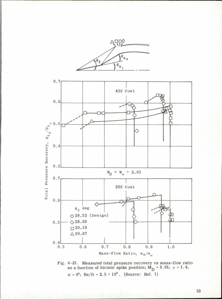
ADOO
0.7
0.6
8 0 . 5 T-r*
\
>. u o > c u o BE tl
3 Ifl X tl -a re
O
H
0.4
n - ' ' ' ' '
,L> —LrL, A
^ •
40$ (
4 *
:owi
• O A n
O
0 . 7 0 . 8 0 . 9
Mass-Flow R a t i o , m2/m
Fig. 4-21 . Measured total pressure recovery vs mass-flow ratio as a function of biconic spike position; M_ = 3. 01; y • 1.4;
a = 0°; Re/ft = 2.5 x 10 8 . (Source: Ref. 1)
53

tl U o 10 8
cn -t->
— « rt
•(-> -
O >. H ^
t) ^A > rt O O U
•H I ) •M Ofi
m.
o
0.8
0, 7
0.6
\ ^ A \ ^
1 N
N
s x ^ O v x
M D = 3.01
BE
i o
rH
x X ci
a u
rJ
u !H
t) ft 3
03
O Translating Spike* (Ref. 25)
A Translating Spike*, 20% Cowl (Ref. 1)
•Second Oblique Shock on Cowl Lip
1.8 2 .0 2.2 2.4 2.6 2 .8 F r e e - S t r e a m Mach Number, M
3.0 3.2
Fig. 4-22. Off-design performance of translating biconic-spike inlets as a function of free-stream Mach number;
y = 1.4; Re/ft = 2.5 x 10a. (Source: Ref. 25)
54

u° 0.4
4J 3 -
ml m OJ 0 a u n h a rH rt 3
-- J
rt CJ
h 0 r l 0 o. 3 71
0.3
0.2
0.1
0
. 0 20% Cowl (Ref. 1)
0 40% Cowl (Ref. 1)
A Translating Spike (Ref. 25)
O Fixed Geometry (Ref. 25) i i
Second Oblique Shock on Cowl Lip
1.8 2.0 2.2 2.4 2.6 2.8
F r e e - S t r e a m Mach Number, M
3.0 3.2
Fig. 4-23. Comparison of supercritical external-drag coefficient vs free-stream
Mach number for various biconic spikes; 2 £ M £ 3; Re/ft = 2.5 X 10 s.
cn cn

0.45
0,40
-M ft
+J ft
> z ma
Cm
BE 0 • -
3 to cfl O H a
rt - > C H
0.35
0.30
0.25
0.20
0,15
Open S;
Closed
M» = "D
Separati on Top H
of Con(
/ :
i fmbols; No Rough
Symbols; Tip Ro
Uns tab le Flow | O a = 0°
A a = 3° 0 a - 5 .5° d a = 9°
- y y ^ -
= 3.85
on / alf y
s
-*•
e
s / S
/
/ / /
s
I
1 ness ughness
y
t s
»
s s s S / /
• • • •
/ / /
ee-S
s
y s Source :
Sepa ra t i
y
S
' / S
/ / / s s s
ee-S s
Ref, ]
on
• S s
P''A ; e* r \ ' 'yi yy y /
ft mS 1
.7
(
e
\
(
J
.4 r
1
i <
1
1
1
0.3 0,4 0.5 0.6 0.7 0.8 Mass-Flow Ratio, m2/m
0.9 1.0
Fig. 4-24. Effect of tip roughness and angle of attack on measured total pressure recovery vs mass-flow ratio for biconic inlets; MO0= 3.85; a = 0 , 3 , 5.5 , and 9°; y = 1.4; Re/ft = 1.0 x lQa,
56

5. Isentropic-Spike Diffusers
If the external compression is achieved by means of multiple shocks rather than by one or two shocks as described in preceding subsections, the pressure recovery will improve as the shock strength diminishes. Carrying this concept to its limit, the spike may be designed so that the flow is isentropic, i . e . , all shocks are reduced to Mach waves and may be made to coalesce at a single point. Such compression, if continued to the sonic velocity, theoretically involves no total pressure loss. Practical design considerations such as available length, viscous effects, the limit of external compression dictated by a consistent shock solution at the point of coalescence, and reasonable cowl-lip drag preclude a completely isentropic compression to the sonic velocity. However, several practical inlets have been developed which are based on the principle of isentropic compression. The various aspects of these designs will be discussed.
5.1 Design Considerations
5.1.1 Length
The length of a true isentropic spike would be impractical. Not only would the needle-like tip be structurally unstable but the long spike would give rise to a boundary layer which would be very thick by the time the flow entered the subsonic duct. Furthermore, in most practical engine installations, the over-all length allowance is limited and a very low initial spike angle would be impractical. Consequently a conical tip is used in conjunction with an otherwise isentropic spike. The value of the pressure recovery associated with a conical tip may be found from
y
'(y+l) M3 - 1 - 8 ° ->y_:
y sin8 9
w
(y-1) M2 sin3 9 + 2 w
(y+D
2y M3 sin3 9 - (y-1) w
1 y-1
(5-1)
where M = free-stream Mach number
9 = shock-wave angle.
The bow shock may be considered as a plane shock everywhere except in the vicinity of the nose itself.
Associated values of M, 9 , and the cone semi-angle, 9 , may be
found from such tables as Refs. 26 through 29. Calculated values of the p res sure recovery are shown in Fie. 5-1 as a function of the Mach number for various values of 9 . The best choice for an initial cone angle usually is made
after a composite design study of the vehicle has brought out the relative influence of pressure recovery, inlet length, and angle of attack on anticipated thrust, maneuver, and range requirements. Connors and Meyer (Ref. 24) suggest the use of a conical tip whose attached shock has a total pressure recovery of 99%. Brumbaugh and Konrad, in unpublished studies on diffuser design for Mach numbers from 3 to 7, use a constant tip angle of 15 deg in order to maintain a spike of short length. A large amount of data is also available for an isentropic spike with a 20 deg (semi-angle) cone tip designed for Mach 4.15 flight of a ramjet engine with a severely limited volume.
57

5.1.2 Practical Limits of External Compression
The ideal isentropic compression is limited in extent. There are two entirely separate and distinct design cr i te r ia to be observed for satisfactory performance of an isentropic spike; one dependent on the shock waves' coalescence phenomenon and the other on the shock waves and resulting drag associated with the cowl lip.
Shock-Wave Coalescence. - -F rom the point of intersection of the shock wave and the compression fan there a r i ses a vortex sheet and also there is usually a reflected wave as shown in the sketch below. The vortex sheet adjusts itself until the pressure and the flow direction are the same on either side of it, i . e . , p = p. in the terminology of the sketch. The pressure ratio,
p„/?„, as a function of M^, and the flow deflection, cp, is most easily obtained
from graphs (Refs. 27 and 28) since there is no convenient explicit function by which it may be calculated. The curves of p / p vs <p for various values of
Mro a re shown in Fig. 5-2. The same figure shows the value of p / p for an
isentropic compression. They are obtained by the use of reverse Prandtl-Meyer expansions. These calculations are valid only in the immediate vicinity of the point P . When a conical tip is used the expansion begins at the Mach number behind the bow shock and the static pressure recovery is the product of that through the bow shock and that due to the flow deflection along the isentropic part of the spike surface.
Shock
Vortex Sheet
Reflected Wave
If there is no reflected wave the p ressures p and p will be equal, 3. C
and the only possible flow deflection angle at each Mach number will be that given by the intersection of the p / p and p / p ^ curves. Where there is a reflected wave, its deflection will be equal in value but opposite in sign to that of the isentrope. Possible values of the flow deflection will be found where lines of such slope intersect the shock polars . The limiting condition occurs
58

at a point on the isentrope, e . g . , A, B, or C, from which the reflected wave will be tangent to the polar. The tangent points, T . , T R , and T„ , are shown
in Fig. 5-2, Enlargements of the critical regions at Mach numbers of 3 and 6 are shown in Fig. 5-3, since they exemplify, respectively, a compressive and an expansive reflection wave. In these enlargements the local pressures have been related to the stagnation rather than the static pressure . The values of the limiting compression Mach number, M , and the limiting flow angle, <pp,
are shown as a function of the free-stream Mach number and the cone tip angle in Fig. 5-4. The maximum pressure recovery associated with these conditions is shown in Fig. 5-5 for the cases of a normal shock occurring either just inside the lip or at the minimum "starting" throat. In a practical design, the cowl lip is often placed slightly below the point of intersection of the compression waves and on the conical shock of the design Mach number. This ensures that the vortex sheet does not enter the diffuser where it could cause serious flow separation.
Cowl Lip Flow Conditions. --The second criterion for the limiting value of the isentropic expansion is derived from a consideration of the flow characterist ics at the cowl lip. Experimental investigation has shown the cowl-lip angle to be one of the most critical design parameters . The nomenclature used in connection with the cowl lip is shown in the sketch below.
It is required that the shock caused by the incoming flow will not detach from the internal or external cowl-lip surfaces. The critical incidence,6., of the
inner cowl surface must be evaluated at the lowest Mach number anticipated, and hence may be defined by
6 i = *P - ( 6 ) M p
where <pp and M_ are the flow direction and Mach number after the last per
missible compression wave, and (6)M is the limiting wedge angle for shock P
attachment at M p . For a given free-stream Mach number and flow direction,
each value of M p uniquely determines a value of <pp and (6)M and hence of
6.. Critical values, i . e . , lower limits, of 6. vs M_ for free-stream Mach i ' i P
numbers from 2 to 8 and various tip configurations are shown as curves A in
59

Figs. 5-6a, b, and c. An upper limit (shown by curve B) is placed on 6 by
the requirement of an attached shock at the free-s t ream Mach number. The value of (6 - 6.) usually is defined by structural requirements as about 3 or
4 deg and hence an upper limit may be placed on 6., This limit for a lip angle
of 4 deg is shown as curve C in Fig. 5-6b. Also shown by curve D on the same set of figures is the limiting value of M p determined from the vortex-sheet criterion. The values of 6. that lie to the left of curve D and above curve
i C are those that fulfill the requirements of both the vortex-sheet and the attached lip-shock cr i ter ia . The limiting values taken from Fig. 5-6 are shown as a function of Mach number in Fig. 5-7. The difference between 6 and 6.
° e i should include not only the lip thickness but also a safety factor of about 4 deg in order to allow for viscous effects and ensure only supersonic spillage and hence minimum additive drag during all cri t ical and supercritical operation. An analysis also should be made of the effect of the proposed cowl lip on the flow character is t ics at all anticipated off-design Mach numbers and angles of attack (see Subsec. 5.2). It may be necessary to sacrifice efficiency at the design Mach number in order to increase the range of operable conditions.
The pressure recovery will increase as M p decreases , and as M
decreases , the crit ical value of 6. increases . i
may be indirectly associated with higher values of 6.. On the other hand, high values of 6. mean still higher values of 6 and a consequent increase in the
The fact that 6. has a lower limit means that there is i
always at least a minimum cowl drag for this type of diffuser whereas an al l-internal-compression diffuser may be designed to have zero cowl drag. The optimum value will be determined not only by consideration of 6 and 6. but
will also have to take into account the allowable contraction ratios given by the geometry of the innerbody and the annular ducting.
Thus, high pressure recovery
external wave drag.
5.1.3 Inviscid Compression Surface Design
After having decided on the tip angle of the isentropic spike and the eternal compression ( i . e . , '
viscid isentropic surface of the spike. extent of external compression ( i . e . , M p ) , the next step i s to design the in
P Non-Compressing Surface
Spike
60

The calculations start at P, a point on the conical nose shock which is a specified distance from the cone axis. Values of M and <p (flow direction) at P, as well as along all rays emanating from the cone tip, may be determined by the Taylor-Maccoll method and are listed in cone-flow tables such as Refs. 19 and 30. The method of characterist ics for irrotational, axisymmetric flow is then used to calculate the local Mach number and streamline angle in all parts of the field. Irrotational flow may be assumed since no entropy gradient exists normal to the streamlines aft of the straight conical shock. The left running characteristic from P has an inclination of <j. + n + 180 deg, where » is
the Mach angle at P . The boundary curve, PQ, of the characterist ics net is constructed in short segments whose end points lie on adjacent rays in the conical field. The inclination of each segment is made equal to the average of the inclinations of the two ends. This construction is continued until the characteristics line meets the cone surface at Q. Each subsequent characterist ics line s tar ts from P, has an arbitrary increment of turning, and is continued until it meets the streamline passing through Q. This streamline forms the isentropic surface and is developed incrementally until the flow inclination behind the last characterist ics line from P is equal to some predetermined value (equal to or less than that given in Fig. 5-4). The non-compressing surface is generated by a straight line which is drawn tangent to the compressing surface at the terminal point R. The Mach number increase along this surface, and along all the streamlines of the non-compressing flow, results in an approximately constant Mach number along a line normal to the flow drawn from the point of shock intersection.
An example of the calculation of an axially symmetric isentropic spike is given by Kennedy in Ref. 31. A more detailed method for the use of characterist ics in axially symmetric flow may be found in Refs. 6 and 32, Contours have been calculated by Connors and Meyer (Ref. 24) for isentropic spikes with conical tips whose shocks cause a 1% loss in total pressure . The coordinates of the surfaces are given in Fig. 5-8 and the surface Mach number and flow direction in Fig. 5-9 for design Mach numbers from 2 to 4. Similar information from the same source is given for two-dimensional wedge-type inlets in Figs. 5-8 and 5-10. The position of the focal point is indicated in the figures . The Mach number at the focal point is that given by the compression limitations in Fig. 5-4. Figure 5-11 gives the surface coordinates for a ser ies of axisymmetric isentropic spikes with 15 deg tips and Fig. 5-12 gives the surface Mach number and flow inclination. Design Mach numbers from 2.5 to 6.5 were considered. Similar information is available for other initial cone angles.
5.1.4 Duct Design in the Cowl Lip Region
Subsequent to the external compression process, the flow must negotiate the strong bow shock system, usually referred to as the normal shock. At the same time the flow within the cowl lip must be turned to the axial direction as rapidly as possible in order to minimize cowl drag. A too-rapid turn may lead to high internal total pressure losses. An optimum design may be evolved for a given application by weighing the relative effect of these two factors.
For operation with the normal shock at the cowl lip, or just inside it, the turning surface of the spike and the inner surface of the cowl must be
61

adjusted as shown in the following sketch. Both the inner and outer cowl surfaces in this case a r e composed of two straight sections extended by tangent a r c s .
Surface
A line from the cowl lip, normal to the flow, intersects the non-compressing surface at N. From this point the turning surface begins. The shape of the arc is determined by the required area variation in the entrance of the annulus.
If the required cowl-lip angles and the flow direction allowed by the limiting compression result in too great a contraction ratio, it may be necessary to undercut the turning surface as shown below.
Where the cowl angles a re crit ical , i . e . , the drag or the structural load is crit ical, it may be necessary to sacrifice some of the allowable external compression (see Fig. 5-4) in order to stay within the possible range of flow turning.
It is often desirable to incorporate some internal compression by means of area variation in the ducting. In a typical long-range missile, an area reduction of 0.09 A. slightly downstream of the cowl lip was found to give
the lowest shock loss and highest pressure recovery in the turning region. In this case it is necessary to place a further limitation on the turning surface to
62

prevent the normal shock from occurring at the lip. The required geometry is shown in the sketch below.
Non-Compressing Surface
-Isentropic •15° Wedge Compressing
Surface
The point of critical importance is the intersection, T, of the non-compressing surface and the oblique shock from the cowl lip. If the turning of the surface is delayed beyond the point T the flow deflection will be too great, causing the reflected shock to detach from the surface and form either a Mach reflection or a lambda shock. On the other hand, if the surface turns before T an expansion fan will occur upstream of the oblique shock causing an increase in the total pressure loss. Careful choice of the point T with respect to the flow field is of increasing importance as the free-stream Mach number increases.
The desired rate of change of the cross-sectional area along the annular duct will depend on the type of operation for which the diffuser is intended. The same considerations that were discussed in relation to conical innerbodies also will apply to isentropic tips. Experience has shown that for an all-external-compression inlet it is desirable to have the surfaces of the cowl lip generated by straight lines which lead tangentially into the a rcs which generate the remaining cowl surfaces. A short constant-area section downstream of the lip has been found to have a stabilizing influence on the normal-shock system in lower Mach number investigations.
At Mach numbers in excess of about three, the inlet duct area is affected by the differential heating rates of the innerbody and the cowl structures . The materials from which they are constructed and the position and thickness of the struts which join them are among the factors that disturb the matching between diffuser and combustor as a function of time. Buzz (see Section 9) or thrust degradation may result .
5.2 Off-Design Operation
The determination of the performance of a supersonic diffuser at Mach numbers below the design value is a factor of paramount importance in the ultimate assessment of the total worth of a vehicle in terms of its prescribed mission.
For an isentropic-spike diffuser, the off-design flow analysis is almost the reverse of the design analysis. In the latter the shock intersection
63

and consequent character is t ics network determines the surface variables whereas in the off-design analysis the surface variables and the free-s t ream Mach number star t the network and determine the flow variables near the cowl. In particular, one is able to determine the capture-area ratio, the additive-drag coefficient, and the flow parameters at the cowl lip for any free-s t ream Mach number and prescribed surface. The character is t ics curves do not coalesce in the off-design network as they do in the on-design analysis.
A below-design Mach number flow analysis also has been carried out by Kennedy (Ref. 7) for 15 deg conical-tipped isentropic spikes designed for M = 3.5 and 5. The cowl was translated first along the design conical shock and then in an axial direction as illustrated in the following sketch.
D i r e c t i o n of D i r e c t i o n of r Translation Translation C— —— C
i -m- X
The following parameters were considered: 1) maximum allowable compression (see Fig. 5-4) and compression less than maximum; 2) three free-stream Mach numbers less than the design Mach number; 3) five to eight positions of the cowl at each free-s t ream Mach number. The values of these parame te r s may be seen in Figs. 5-13 through 5-20 which show the calculated values of the additive drag, the capture-area ratio, the Mach number, and the flow inclination at the cowl lip as functions of the cowl-lip position, f ree-stream Mach number, and design Mach number. To estimate the pressure recovery for any of these cases it is necessary to set the mass flow of the entering stream tube (station o) equal to that in front of the normal shock at the cowl lip, i . e . ,
A P. o *t.
A t \
(A/A*)Q " W & a \
or
A.
(5-2)
(A/A*)t " 7To • AT ' p f ( A / A # ) o
64

A /A. is given in Figs. 5-14 and 5-18; p / p is the pressure recovery through t lo
the bow shock; (A/A*) is found from tables. The throat area, A , generated
by CN is a cone frustum whose radii are y (known) and y.. (to be found either graphically or by computation). (A/A*) derived from Eq. 5-2 allows the evaluation of M and the ratio p / p . from tables. The pressure recovery of the
t ts t.
inlet is then p / p • p / p . Figure 5-21 shows the shock pressure recovery U \ \ *o
calculated by this method for a few representative cases for the M_ = 3 . 5 diffuser. The associated additive drag is also shown in this figure.
Cross-plots of the additive-drag and capture-area ratio as a function of both design and free-stream Mach numbers from 2.25 to 5 are given in Figs. 5-22 through 5-24 for y / y p of 1.0, 0.98, and 0.96 and the cowl lip on
the design conical shock where y p is the ordinate of the focal point of the compression waves at the design Mach number. These figures (from Konrad) show the effect of operating at below-design Mach numbers. The vertical scales on Figs. 5-23 and 5-24 have been exaggerated to facilitate the reading of the data.
A diffuser designed to give a maximum total pressure recovery at the design Mach number may be severely limited in its climb-out capabilities due to excessive spillage and consequent additive drag at below-design Mach numbers. However, it must be remembered that a reduced mass flow may allow the engine to burn a r icher fuel mixture and hence produce a greater gross thrust. At the same time the net thrust may be reduced by the associated additive drag. The optimum mass-capture ratio will depend on the vehicle configuration and the combustion characteris t ics . One means of increasing the capture-area ratio without excessive additive drag at below-design Mach numbers is to locate the cowl lip on the conical shock of the design Mach number but at a radial position less than that of the intersection of the conical shock and compression fan. In this case the reduction of additive drag is ac companied by a reduction in the total pressure recovery at the design Mach number. Other methods of reducing the additive drag involve the use of variable-geometry features such as variable cowl vents or a translating spike. The variable vents discharge the spillage flow at a very low angle. It has been amply demonstrated that the additive drag may be much reduced by this method.
The extreme angles of attack sometimes encountered during lateral maneuvers of the vehicle tend to cause an inlet to expel a strong bow shock on the leeward side. This bow shock imposes a pressure gradient on the inner-body boundary layer which may cause a gross flow separation from the body, resulting in large discontinuities in the external aerodynamic characterist ics and the possibility of engine flame-out.
Major effects on the limits of flow separation have been obtained by altering the position of the normal shock in the inlet, i . e . , by varying the mass spillage through cowl vents or by modulating the combustor heat release. This effect was also demonstrated by varying the cowl-lip position and thus affecting the shock position, pressure recovery, and air capture at angle of attack. A change of inlet and exit a reas would produce the same resul ts . The inlet flow area may be reduced by forward translation of the nose cone.
65

Agreement in the angle of attack at which separation occurred was observed between various scaled models by proper simulation of flight model geometry, Mach number, and Reynolds number where no heat transfer to or from the model walls was present.
A satisfactory inlet design for a given ramjet application can be evolved only after a proper assessment of the operating requirements over the whole range of flight Mach numbers, altitude, angle of attack, and required thrust level. The overriding importance of the off-design effects on air capture, additive drag, and pressure recovery characteris t ics can scarcely be over-emphasized.
66
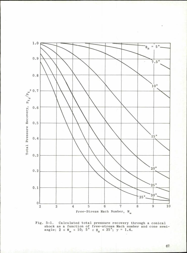
1.0
0.9
0.8
8 0,7 4->
a,
a
£ 0.6 r.
0 o 0)
« 0.5 cu 3 Ifl Cfl' 0 ti a
0 H
0.4
0.3
0.2
0.1
~~~*s =
7
i — -
5° ,
.5°
10°
15°
2'
^ 2 !
"35° I
\
)°
)°
)°
4 5 6 7
Free-Stream Mach Number, M
10
Fig. 5-1, Calculated total pressure recovery through a conical shock as a function of free-stream Mach number and cone semi-angle; 2 s M a 10; 5° tm 9„ * 35°; y = 1.4.
oo S
67

20 25 30
Flow Deflection, <p
Fig. 5-2. Theoretical pressure-deflection polars; y = 1.4; M = 2, 3, and 4.
68
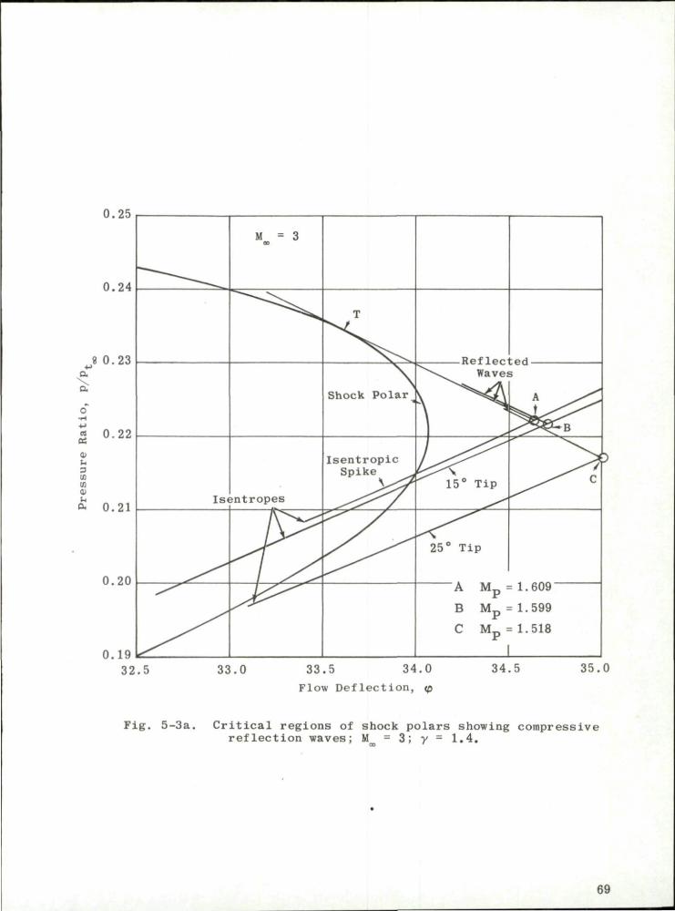
0.25
0.24
8 0.23
Cm
5 0.22 OS t>
u 3 S. (fl tt £ 0.21
0.20
0.19
. ^ ^
Is<
M = 3 ao
jn t ropes
T
Shock Polar^
I s e n t r o p i c Spike .
\ y y
Rf>f 1 p p t n J
^ v . Waves
* ^ y \ 15° Tip
25° Tip
A ^ y $ s ^ y ^ ^ y^y^f3
^ e ^ C
A M p = 1. 609
B M p = 1.599
C M p = 1.518
' 1 32.5 33.0 33.5 34.0
Flow Def l ec t ion , <p 34.5 35.0
Fig. 5-3a. Critical regions of shock polars showing compressive reflection waves; M = 3; y = 1.4.
69

0.034
0.032
0.030
A->
c
0.028
+ J
I3m
CC
0) U
w 0.026 cn cu u a
0.024
0.022
0.020
X
k 15° Tip
Isentropic Spike
A M p = 2.872
B M p = 2.728
C M p = 2.338
- - Isentrope
— Reflected Wave
37 38 39 40
Flow Deflection, <p
Fig. 5-3b. Critical regions of shock polars showing expansive reflection waves; M = 6; y - 1.4.
70

3.8
3.4
a, 7. a . B -C • 3 • AS 0 a • a o •n
Ifl C « a x H M c •H
*-* •H
E •H
-
4 5 6
Free-Stream Mach Number, M
Fig. 5-4. Limits imposed on flow parameters by the vortex-sheet criterion vs free-stream Mach number; isentropic spike, 15 and 25° tip; y = 1.4; 2 s M^s 8.
71

1.0
0.9
0.8
c "• 0.7
0.6
>. (U
> c u -
cc D
5 0.5 en ifl -
« 0.4 o
S 3
CS
0.3
0.2
0.1
- External Compression Only
- External and Internal Compression
J L 3 4 5 6 7
Free-Stream Mach Number, M
Fig. 5-5. Maximum pressure recovery allowed by vortex—sheet criterion as a function of free-stream Mach number; isentropic spike, 15 and 25° tip; y = 1.4; 2 £ M M S 8.
72
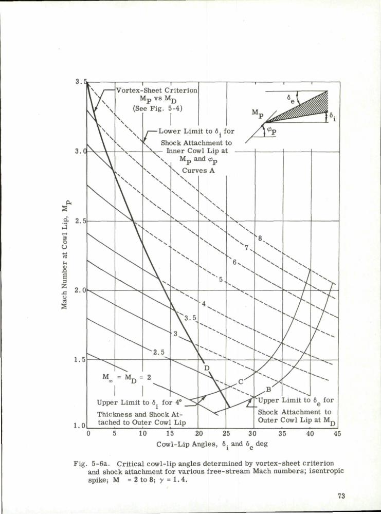
10 15 20 25 30 35 Cowl-Lip Angles, 6. and 6g deg
Fig. 5-6a. Critical cowl-lip angles determined by vortex-sheet criterion and shock attachment for various free-stream Mach numbers; isentropic spike; M « 2 to 8; y - 1 . 4 .
73

Cowl-Lip Angles, 6. and 6 deg
Fig. 5-6b. Critical cowl-lip angles determined by vortex-sheet criterion and shock attachment for various free-s t ream Mach numbers; 15° cone tip; M = 2 to 8; y = 1.4.
74

3.0
s
3
u
r .
Sm
Upper Limit to 6 for
Shock Attachment to Outer Cowl Lip at M_
10 15 20 25 30 35
Cowl-Lip Angles, 6. and 6g deg
40 45
Fig. 5-6c. Critical cowl-lip angles determined by vortex-sheet criterion and shock attachment for various free-stream Mach numbers; 25° cone tip; M = 2 to 8; y = 1.4.
75

45
40
bfl
•a C
s. Cm
- A
bfl C <
rJ
rH
ft c u
35
30
25
20
15
10
Maxi
Atta
^ N
mum 6_ f
ched Sho
\ ^k
or
ck
M p
Pp
•
6 i e \¥<Ap
Mini
25° T:
\ 15° N. T
Isen Sp
mum 6 •
Cone •P
Cone IP
tropic ike
j«T _
2 3 4 5 6 7 8
Design Mach Number, M^
Fig. 5-7. Maximum and minimum cowl-lip angles determined by vortex-sheet and shock-attachment criteria vs design Mach number; isentropic spike, 15 and 25° tip; y = 1.4
76

1.0
0.8
0.6
0, V*. \ >.
0 •rA
• M
a OS
0) 0 c et + J CO
• H
Q r H
d • H
•o et a.
0.4
0,2
U
1 .0
0.8
0.6
0.4
I s e i
End o C o n i c a l '
0
i t r o p :
f r i p
. c Rati i p s
«D
1
= 2 /
0
\ /
— O O
2 . 2 5 ,
| O 1
2.5
p-
2 . 7 5 y
2.0
s
3
rO 1
/ _ 3 . 2
y
<y<yy 3.5 3.75 4
5 / ' *
KM / / /
Q F o c a l P o i n t 1
3 0
0.2
0 0.2 0.4 0.6 0.8 1.0 1.2 1.4 1.6 1.8 2.0 2.2 2.4 2.6 2.8 3.0 3.2 3.4
Axial-Distance Ratio, x/yp
Fig. 5-8. Coordinates of isentropic spikes and ramps with \% pressure loss due to nose shock; Mp = 2 to 4; y = 1.4. (Source: Ref. 24)

- J 00
Ml o
cr>
0-
C < is 0
rH
0 u C3
h 3 M
70
60
50
40
30
20
10
«D : ! 2 J
2.2
2.
5 /
*\
5 /
/
/
7^
-1
r 3
/ /
Isentrop
/
t 3.
3.25 /
/
/
Lc As
T r r
o a
5
/
/
/
/ f
1 7 1 . (J
1
/
/ /
| 4
1
isymmetric Spike.
1.0 2.0 Axial-Distance Ratio, x/y,
3.0 3.4
Fig. 5-9a. Surface flow angle vs axial-distance ratio; isentropic axisymmetric spike; MJJ = 2 to 4; y = 1.4. (Source: Ref. 24)
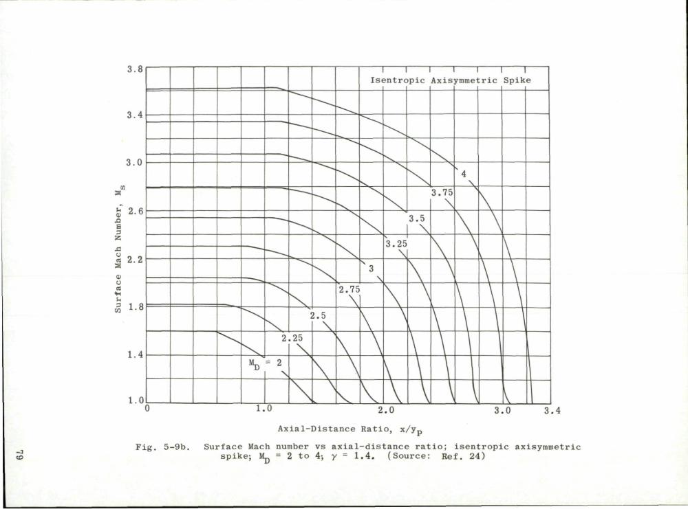
3.8
3.4
3.0
& 2-Sl e
s. \ 2.
o> « SH rl 3 CO
1.8
1.4
1.0
«D
2
= 2 \
1
.25
,
\
2.5
\ >
V
2.75
\
\
1 1 Isentropic
V 3
\
\
V
•* o c O . U
3.25
\
\
\
\
v
\
\
\
~"1 Axis
3.75
\
,
\
\
\
1 1 1 ymmetric Spike
S4
V \
r t T
\
\ 1.0 2.0 3.0 3.4
-3 to
Axial-Distance Ratio, x/yp
Fig. 5-9b. Surface Mach number vs axial-distance ratio; isentropic axisymmetric spike; SL - 2 to 4; y - 1.4. (Source: Ref. 24)

00 O
0) •O
S3 CD
[fl
9-
M C <
o rH ba
CD O S3
•H h 3
DQ
70
60
50
40
30
20
10
i s e i i t r o j 5ic R amp
«D - 2 -
2
i /]
. 2 5 /
! /
2
y / y
. 5 /
2.75
3
/ /
/
/
s 3.5
3.25 /
/
/ , i
/
/ I
r
/
4
T i
1 1 /
/
3.0 3.4
F i g . 5-10a.
1.0 2.0 Axial-Distance Ratio, x/yp
Surface flow angle vs axial-distance ratio; isentropic ramp; MJJ = 2 to 4; y = 1.4. (Source: Ref. 24)
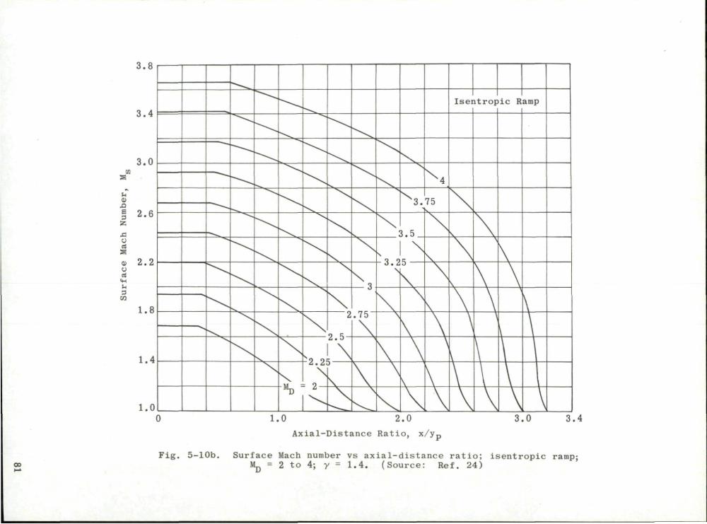
3.8
3.4
3.0
u o
aQ
3 ^ ' S5
0 rt
s o) 2, CJ
ri u 3 M 1.8
1.4
1.0
~ _
2
o c A . U
- o - U p .
)
rt
.75
3 .
0 . 3
1 O^ 0 . Z j
\
\
\
\
M
75
\
\
I sen t rop
\
\
\
i _
\
\
\
\
i c Ramp
\
\ \
\
\
\
\
\
\ 1.0 2.0
Axial-Distance Ratio, x/yp
3.0 3.4
Fig. 5-10b. Surface Mach number vs axial-distance ratio; isentropic ramp; Mp = 2 to 4; y = 1.4. (Source: Ref. 24)

00 1.0
o.
0 •H A->
ne 0 t.
S i .o
• " D - y 6 0
— e~l °1 e 5^/,
* ' ^ £
Foca 1 Point 1
6'
09
-2
-rt K
M_ "D
• 2.E
y p •
1
= Ord.
3
mate
1 °1
5 ^
s A . D
sA;6.5
of the Focal Point
i i i
1.0 2.0 Axia l -Dis t ance Ra t io , x / y p
3.0
Fig. 5-11. Coordinates of 15° tip isentropic spike; M = 2.5 to 6.5; y = 1.4.

1 1
40
bo 0) T3
cn
II
in
9-
iJ 30 mm.
a <
0 r -4
Urn
1) O ri
3 co
9f l
14
«E " ' ! .5
/ 3
o
/
/
y
/
/ /
/ /
/
/
/
/
/ 4 4
/
/
i
1 .5
/
/ /
/
/ f
5
/ ,
\
\ 1 1
5.5 /
11
11 1
1
|
/ /
6.5
/ 1
1.0 1.5 2.0 Axial-Distance Ratio, x/y,
2.5 2.9
CO CO
Fig. 5-12a. Surface flow angle vs axial-distance ratio; 15° tip isentropic spike; Mp = 2.5 to 6.5; y • 1.4.

00
1.0 1.5 2.0 Axial-Distance Ratio, x / y p
2.9
Fig. 5-12b. Surface Mach number vs axial-distance ratio; 15° tip isentropic spike-Mp • 2.5 to 6.5; y = 1.4.

0.40
0,30
0.20
a < o
— 3
v • H
u •H IH ^ H
0 0 u i f l rt
~ G
0
> • H
M • H
•a -c <
0.10
0
0.40
0.30
0.20
0.10
0
Source: Ref. 7
Maximum Compression Allowed by Vortex-Sheet Criterion,
= 41°
Compression Less than Maximum,
0.92 0.94 0.96 0,98 1.00
Radial Distance to Cowl Lip, y c /(y c)design
F i g . 5 -13 . C a l c u l a t e d a d d i t i v e - d r a g c o e f f i c i e n t a t o f f -des ign Mach numbers; cowl l i p on des ign c o n i c a l shock; \L = 3.5
and 5.0; 2.23 s M s 4 .59; 15° t i p i s e n t r o p i c s p i k e s .
85

1.0
<
<
+J rt Bd
K 0) r-
<
h 3 *J ft rt U
0.8
0.6
0.4
<mj " -1
C ^ " " * ^ :
S o u r c e : Ref . 7
MD :
~ ° * ^ , s ^ - ^
^ * ^ ^ * * " * * N ^ ^ " " ^
• 3 .5
^ i
Maximum Compression Allowed by Vortex-Sheet Criterion, i.e., cps = 41°
Compression Less than Maximum, i.e., <p„ = 36°
1.0
^6 °'8
<
* J
re cc
re OJ
u < I 0/ U 3 •M tx Cm
u
0.6
0,4
0.2
MD =
A
M 00
O 2.23
• D 2.58
O 3.02 Ci 3.63
0 4.59
A
= 5.0
A A ^ / — v —
—^^^
^ - < L
T
^^^^/"\
0 ^ = ^Q
0.92 0.94 0.96 0.98 1.00
Radial Distance to Cowl Lip, y c / ( y c ) d e s i g n
F i g . 5-14. C a l c u l a t e d c a p t u r e - a r e a r a t i o a t o f f - d e s i g n Mach numbers; cowl l i p on des ign c o n i c a l shock; 15° t i p i sent r o p i c s p i k e s ; M = 3.5 and 5 .0; 2 .23 t. M^ s 4 . 5 9 .
86

0, mi
o u •J
o r-
0) O E s s-y rt
-Maximum Compression Allowed by Vortex-Sheet Criterion, i.e., <PS = 41°
Compression Less than Maximum, i.e., <PS - 36°
0.98 1.00
Radial Distance to Cowl Lip, yc/(yc)design
Fig. 5-15. Calculated Mach number at cowl lip at off-design Mach numbers; cowl lip on design conical shock-, 15° tip isentropic spikes; M~ = 3.5 and 5.0; 2.23 <. M^ s 4.59.
87
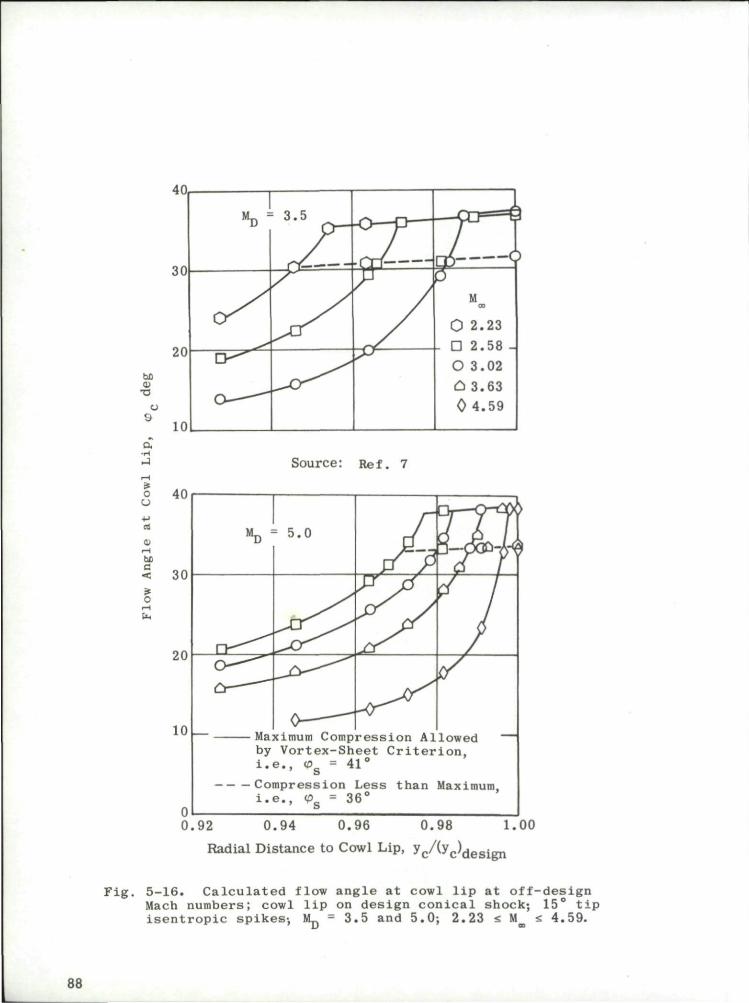
bo Co T3
a •H
-J
c U
rt
tx c <
o
4 U
30
20
10
I M D =
L V ^
•• 3 . 5
f ^ r \ | , - _— «i.i— • • cp <?
M 00
0 2.23 - D 2.58 -
O 3.02 C. 3.63 0 4.59
40
30
20
10 _
Source: Ref. 7
Maximum Compression Allowed by Vortex-Sheet Criterion, i.e., cpg = 41°
Compression Less than Maximum, i . e . , co = 36°
0.92 0.94 0.96 0.98 1.00
Radial Distance to Cowl Lip, y c / (y c )d e s ign
F i g . 5-16. C a l c u l a t e d flow ang le a t cowl l i p a t o f f - d e s i g n Mach numbers; cowl l i p on des ign c o n i c a l shock; 15° t i p i s e n t r o p i c spikes-, MD = 3.5 and 5 .0; 2 .23 s M t. 4 .59.
88

0 1.9
0.4
<
•** 0 . 3 -c o
2.0 2,1 2.2 2 .3 Axial Distance to Cowl Lip, x
c / ( y c ) d e sign
li z u tfl rt -
>
V <
0.2
0.1
MD -
Max by i.e
— Com i.e
5.0 1
Reference Area for C A D = A,
imum Compression Allowed Vortex-Sheet Criterion, ., <PS = 41° pression Less than Maximum, y ., <PS = 36° ^
JT
/
'JL. Ii j
) F
u/ 2.3 2.4 2.5 2.6 2.7
Axial Distance to Cowl Lip, xc / ( y c ) d e s i g n
2.8
Fig. 5-17, Calculated additive-drag coefficient at off-design Mach numbers; cowl lip at constant radial distance; 15° tip isentropic spikes; M. D 3.5 and 5.0; 2.23 <: M s 4.59.
89

1.0
<
- J
n K
rt Cv U < Co U 3
* J
a n U
Axial Distance to Cowl Lip, x /(y ) . *' c •'c'design
Axial Distance to Cowl Lip, xc A y c ) d e s i g n
F i g . 5-18. C a l c u l a t e d c a p t u r e - a r e a r a t i o a t o f f - d e s i g n Mach numbers; cowl l i p a t c o n s t a n t r a d i a l d i s t a n c e ; 15° t i p i s e n t r o p i c s p i k e s ; MD = 3.5 and 5.0; 2 .23 <• M <. 4 . 5 9 .
90

Q, •rH
rj rH 2
C U
h 0)
Si
e 3 S5
0 tA
Maximum Compression Allowed' by Vortex-Sheet Criterion, i.e. °. 41 Compression Less than Maxi mum.
Ol 1 . 9
i . e . , <Pg = 36 '
2.0 2.1 2.2 2.3
Axial Distance to Cowl Lip, x /(y ) ,
2.4
sign
Axial Distance to Cowl Lip, x /(y ) , r' c J c design
Fig. 5-19. Calculated Mach number at cowl lip at off-design Mach numbers; cowl lip at constant radial distance; 15° tip isentropic spikes; M = 3.5 and 5.0; 2.23 -. U^ a 4.59.
91

2.4
Axial Distance to Cowl Lip, * c / ( y c ) d e s i g n
b£
9
a •rH
- J
r - l
a*
0
u rt
1) — i
M 3 <
0
u.
30
20
10
0
1 »«., —J r .
1 _j « ^ n r . r m ^ . m. * 1 1 „ „ • .-. ,1 F T — '
by Vor tex-Sheet C r i t e r i o n , / <! i . e . , <Pg = 41° Q J
— Compression Less tha Ms
•""Ua
Lr -
Lximum, i . e . , <Pg
Source: Ref. 7
1 i
i n # 36- y /
"D = = 5.0
2.4 2.5 2 .6 2.7
Axial Distance to Cowl Lip, x /(yJde
2.8
sign
Fig. 5-20. Calculated flow angle at cowl lip at off-design Mach numbers; cowl lip at constant radial distance; 15° tip isentropic spikes; M_ = 3.5 and 5.0; 2.23 <. M s 4.59.
\J 00
92
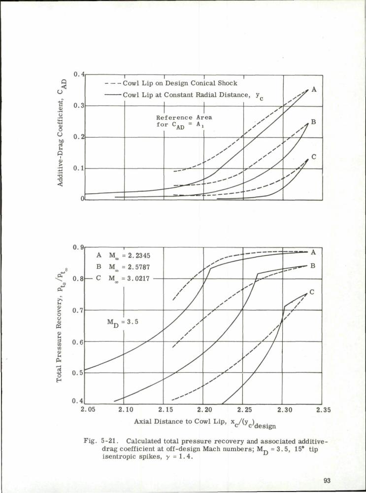
0.4 Q
£ 0.3
8 ° 0.2 bo rt h
P i
£ o.i
T 1 1 r Cowl Lip on Design Conical Shock Cowl Lip at Constant Radial Distance,
-J
0 0
c2
u
§ BQ CO SH
Pa
O H
0.9
0.8
0.7
0.6
0.5
0.4
A
B
— C
i - -
M =2.2345 00
M = QO
M = OO
M D =
• 2.5787
- T n? i7
3.5
s /
/ /
y / S s
S ' r s /
/ /
m^y
^ ^ ^ s y ^ ^
s s s s s s s /
s S s
s'
[ y ^ SI
S I
/ I / I / 1
/ /
y e / /
2.05 2.10 2.15 2.20 2.25 2.30 2.35
.Axial Distance to Cowl Lip, x /(y ) , c / V JVdesign
Fig. 5-21. Calculated total pressure recovery and associated additive-drag coefficient at off-design Mach numbers; M n = 3 .5 , 15° tip isentropic spikes, y = 1.4.
93

A-> c cu
0)
o CJ bfl rt U a i o >
•a •a <
0.3
0.2
0 .1
0
R t
1 e fe rence or C AD
1 Area A,
M = 00
= 2.'.
/
55 ?.
/
. s " 2 . 75
3.25 ^
3.7J) 2 5 ^ ^ S
/ " 4 .5 ^
y' r
i . U
- r 0 fi
0 •H
rt W 0.6 rt C r4 < 1 0)
* 0 4 a rt 0
0.2
y> ' y P • • l . ( 10
M = CD
2.2
2 .
5
V
75 - v .
3
3.5 > N v
\
4
' 4 . 5 K
^
2.0 2.4 2 .8 3.2 3.6 4 .0 D e s i g n Mach Number, Mn
4.4 4.8
Fig. 5-22. Theoretical additive-drag coefficient and capture-area ratio for 15° tip isentropic-spike diffusers at below-design Mach numbers; cowl lip at design focal point; 2.0 t. M_ s 5.0; 2.25 £ M_ <. 4.75. u
94

Q <
c o
— c
u
be ri u a I
0.3
0.2
0.1
•o
< 0
1 1 Reference f or >-AD
/
1 Area A i
s
/
M 00
' 2.25-"
^2.5 ***
„2.75""
3.5-
4-"^--^475"
<
rt oi
re
h
< tH 3 *J a re U
0.8
0.6
0.4
0.2
y> '*P! = 0.' )8
M OB = 2.
2
25
.75 * 3
s . •
'4
^ 4 ^ 5 "
•^
2.0 2 .4 2 .8 3.2 3.6 4 ,0 D e s i g n Mach Number, Mp
4.4 4.8
Fig. 5-23. Theoretical additive-drag coefficient and capture-area ratio for 15° tip isentropic-spike diffusers at below-design Mach numbers; cowl lip on design conical shock; 2.0 fi M^ s 5.0; 2.25 s M s 4.75; radial-distance ratio • 0.98.
95
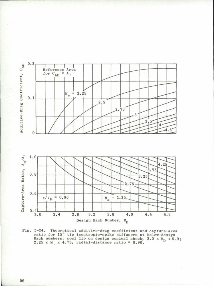
a <
•H C
CO O U b£ rt u P i 0)
>
•a •a
0.2
0 .1
1 Reference Area f or C
/
AD A,
M • CO
•• 2 . 2 5
2 .5
2 .75
,-.v ^ . 3 L 5 ^ 4"
„4
_ ^ -
. 5 " "
<r i . o
o •H •H rt K
rt cu U < l 0 u 3
4-> D. rt U
0.8
0.6
0.4
y / y? = : O . i )6 M OS
= 2 .
3
2 5 ^
75
3.25
5.75 4.2F
^
F i g .
2 .0 2 .4 2 .8 3.2 3.6 4 .0 Design Mach Number, M_
4.4 4.8
5-24. Theoretical additive-drag coefficient and capture-area ratio for 15° tip isentropic-spike diffusers at below-design Mach numbers; cowl lip on design conical shock; 2.0 fi M^ fi5.0; 2.25 s M fi 4.75; radial-distance ratio = 0.96.
96

6. Comparative Evaluation
Throughout this section, s t ress has been laid upon the fact that the ultimate evaluation of a ramjet diffuser can be made only in te rms of the associated engine characterist ics and of its prescribed range or mission. However, a few generalized comparisons may be made which will ass is t the designer in limiting the field of choice for a given range of desired operating conditions.
6.1 Mach Number Range of Basic Diffusers
The maximum theoretical pressure recovery for the basic diffuser types operating in frictionless flow is shown in Fig. 6 -1 . Two extreme cases are shown. The first assumes a simple normal shock at the lip and the second has the maximum internal contraction allowed by the entering Mach number with a simple normal shock at the associated minimum throat. These values must be considered in conjunction with the diffuser drag and off-design performance.
It has been shown that not only does the performance of the normal-shock diffuser deteriorate rapidly with increasing Mach number but at the same time the hysteresis effect increases. Its drag, however, may be kept very small. The single- and double-cone innerbodies give high pressure recoveries in the low Mach number range, but as the number of oblique shocks is increased the drag is also increased, and hence there may be but little gain in the net thrust.
6.2 Performance Comparison
Connors and Woollett (Ref. 17) have combined the experimentally determined characterist ics of a single-cone, a double-cone, and an isentropic-spike diffuser with the performance of a hypothetical ramjet engine operating at zero angle of attack. The pressure recovery and the mass-flow ratio of the diffusers which were designed for a Mach number of 3.85 are given in Figs. 4-3, 4-24, and 6-2 for the three innerbody noses. They are compared in the next two sketches.
Maximum Total Pressure Recovery Mass-Flow Ratio
0.6 0.75 1.00
where
aggj Single Cone
b JZZZ. Single Cone (Low-Angle Cowl)
c E 3 Double Cone (Tip Roughness)
d E2i Isentropic Spike
97

•The external drag coefficient comprises three par ts . The cowl p re s sure drag was determined experimentally. The friction drag was computed with the assumption of an average skin-friction coefficient of 0.0013. The additive drag was also calculated. In the case of the isentropic spike, since the character of the flow spillage may vary, two extreme possibilities were considered. Supersonic flow spillage was assumed to give a minimum additive drag, and a complete loss of momentum in the spilled flow resulted in a maximum additive drag. The comparison of the external drag coefficients for the three diffusers is shown in the next sketch.
Ex te rna l -Drag C o e f f i c i e n t
0.3 A - Add i t ive C = Cowl F = F r i c t i o n
The missile is assumed to cruise at 80, 000 ft; the fuel-to-air ratio is 0.024 and the combustion efficiency is 90%. A comparison of the specific fuel com-sumption for each missile is shown in the next sketch.
1.0
Specific Fuel Consumption
1.5 2.0 2.5
B^SI^^^^^^^^i^^^ m*-*;
The single cone with the low-drag cowl, the double cone and the isentropic spike (with minimum additive drag) have approximately equal fuel consumption which is about 14% lower than that of the single cone with high-drag cowl.
If the hypothetical engine in each case is to produce the same net thrust, the relative engine size may be considered an index of efficiency. The following sketch relates the engine diameters to that of the single-cone engine.
Maximum Diameter in Te rms of Single-Cone Diameter
0 0 .2 0 .4 0 .6 0 .8 1.0
This cri terion indicates that smaller engine sizes are linked to high pressure-recovery inlets.
98

Within the scope of their investigation, i . e . , angles of attack up to 9 deg at M = 3.85, Connors and Woollett (Ref. 17) found that the isentropic inlets which gave the highest pressure recoveries at zero angle of attack were more sensitive to angle-of-attack effects than either the single- or double-cone inlets. However, by accepting a decrease in the mass-flow ratio at zero angle of attack, i . e . , by retracting the cowl, the range of angle-of-attack operation could be extended without flow separation from the upper portion of the spike surface.
99

a
-H
a.
u a> > o y Co
CC
OJ
'a*
3 DO !/. -
rt
C H
£ 3 E •H
X rt P.
X . ml
0.9
0 .8
0.7
0 .6
0 5
0.4
0 3
0.2
0 1
0
r"^"*Nj^N«w vs \ \ N
\ \ \ \ \ \ \
^»^"^
^ \ N
wA \ \V \w
' \ \ \ > \ \ \ \ \\v
^ \ \ \ v \ x
\ M \ \ \ \ * \ \ \ \ \ \ \ \ \ \ \ \ \
\ \ \ \ \ \
1
. E x t e r n a l C o m p r e s s i o n Only \
\ \ \ \ \ \ \ \ \
k \ \ \
l \ \ \ v \ \ \ \
\ \ \ \ \ \ \ \ \ \ \
i \ a, * \ \ \ \ \ \ \
V \ ^ \ \ \ \ \ \ \ \
\ \
Norma l-5;-~\ Shock ^ \
E x t e r n a l and C o m p r e s s i o n
V \ \ \ \ \
\ \ \ \ \
\ \ \ \
PT^ \ \ \ \ \ \ \ \ \ ^
\ \ x
\ \ V
\ \ \ \
\ \ \ \
^ \ \ >
\
^ \ ^>_ >v
X. s
^ \ \
\ \ \
\ . v
\ \
\ \ \ \
\ \ \
N. s
\ • ^ .
s ^ ^ *V^
I n t e r n a l
\
} 1
I 1
m m
> y I s e n t r o p i c
v S
/ \
Doubl
p i k e
\
e ^ s . Cone
S i n g l e - Cone
— ^ J ^ _ - -~~
1 2 3 4 5 6 7 8 Design Mach Number, M^
Fig. 6-1. Maximum theoretical total pressure recovery vs design Mach number for various basic diffusers; M_ = 1 to 8; y - 1.4. "
100

0.65
0.60
0.55
0,50
0,
£ 0.45
>. u 01
tS 0.40 u o
OS
B
g 0.35 tn •m,
* 0.30 0 H
0.25
0.20
0.15
0.10
O a = 0° D a " 3° 0 a - 6° C. a = 9°
O a = 9-1° — Unstable Flow
s
y S
s y s
D
s s
s ~ r
tm:
s s s
s s s
s
s
s /
/ /
/ /
/ / / /
. . / / / •
/ / . '
/ / /
/ / s ^ — 7 ^
/ s s s
s s
s
. ' s s
s s
s
s s
s
s ^
/
/
s s "7"
y y
s s
Separation on Top Half of Cone
1
T
/
, '
/
/ i
/ s
0 i y
TJ--
o
6°
Open Symbols: Smooth Tip
Closed Symbols: Roughened Tip
0.3 0.4 0.5 0,6 0.7 0.8
Mass-Flow Ratio, n i j ^
0.9 1.0
Fig. 6-2. Effect of tip roughness on total pressure recovery of an isentropic-spike inlet vs mass-flow ratio; a - 0 to 9°; M^ = 3.85; y = 1.4; Re/ft = 1.0 x 10s. (Source: Ref. 17)
101

102

7. Two-Dimensional Diffusers
Feasibility studies concerned with a hypersonic transport (Ref. 33) have indicated a preference for two-dimensional engine configurations for very high Mach number flight applications. Such a design offers a number of aerodynamic as well as mechanical advantages over an axisymmetric design. Aerodynamically, the two-dimensional design allows additive lift to be associated with diffuser additive drag and by using a plug exit nozzle, lift is obtained as a result of the under-expanded exit flow from the nozzle. Mechanically, the two-dimensional design permits simpler geometric variations in both the diffuser and the exit nozzle. Furthermore, the plug exit nozzle allows the supersonic portion of the nozzle to be cooled by radiation.
The theoretical limitations imposed on the compression produced by an isentropic wedge may be computed in a manner similar to that of the axisymmetric case (Subsec. 5.1). The results of such calculations for initial-wedge angles from 0 to 15 deg for Mach numbers from 2 to 8 are shown in Fig. 7-1 which also shows the maximum pressure recovery for the case of a horizontal cowl with no internal compression, i . e . , with a normal shock on the cowl lip. It may be seen from this figure that the requirement of a horizontal cowl causes a significant reduction in the pressure recovery over that allowed by the vortex-sheet criterion. However, the pressure recovery may be improved by including some internal contraction. For the near-optimum case of M = 1.4 behind the wedge shock from the cowl lip, the pressure recovery is shown in Fig. 7-2.
In order to meet the requirements of all the cr i ter ia of Subsec. 5.1 in a diffuser to operate over a range of high Mach numbers, it is essential that both the shape of the innerbody and its position with respect to the cowl lip be readily varied. Calculations in the range of M = 3 to M = 7 for such two-dimensional inlets with initial wedges of 9 deg and 15 deg have been carried out by Konrad (unpublished APL study). Figure 7-3 illustrates the flexibility required in the isentropic surface as well as the cowl position and throat area. It may be noted that the axial motion of the throat position associated with the 15 deg wedge is about half of that for the 9 deg case. The 15 deg initial wedge results in greater throat heights and is thus less sensitive to inaccuracies of positioning the throat normal to the inner cowl surface. These mechanical advantages associated with the larger wedge angle may well outweigh the decrease in pressure recovery in comparison with the smaller wedge angle.
A two-dimensional internal-compression inlet for Mach numbers from 2.5 to 4 .0 has been discussed briefly in Subsec. 3.2 and will be discussed more fully in the next section, since boundary-layer bleed and the consequent drag penalty are critical.
Carr iere and Leynaert in Ref. 20 have calculated the mass flow of a two-dimensional intake of limited width. They have investigated the effects of spill-over at angles of attack up to 10 deg in the presence and absence of side plates. They show that the side plates reduce the mass-flow loss to a small percentage of the total mass flow even at below-design Mach numbers. On the other hand, these losses amount to as much as 10% when the side plates are taken off. The theoretical values have been checked by experiments at Mach numbers of 1.63 and 1.96.
103

Leynaert and Brasseur in Ref. 34 describe a two-dimensional diffuser for use under the wing of a Mach 2 transport. The elements of the wind-tunnel test model are shown in the sketch below.
Scoop
1
2
Cowling
Entering Ramp Wey/ssyssyssyAb
The throat area may be varied for off-design flight conditions by means of a rotating ramp (2) which assures that the compression waves are always focused at the cowl lip. This ramp is a continuous compression profile; at its downstream edge is a variable-entry boundary-layer trap which prevents flow separation. The tunnel wall represents the wing surface; the diffuser is placed a short distance from it to simulate a trap for the wing boundary layer (see Subsec. 8.5). In the model, the initial angle of the compressing surface was 16 deg and the final angle was 19 deg. The slope of the first part of the subsonic diffuser was -2 deg. Although the flow turned through 21 deg, there was no evidence of separation and the flow distribution in the diffuser was reasonably uniform. The mean efficiency of the inlet was 0.935 when 2.5% of the mass flow was taken into the t rap. Operation below the design Mach number was also satisfactory.
Molder and Szpiro in Ref. 36 have calculated the thermodynamic and oblique-shock data for hypersonic double oblique shocks in a real gas and have applied their resul ts to the two-dimensional intake of a hypersonic diffuser. It is shown that the two important parameters are the entropy increase and the kinetic energy coefficient. These a re shown in Figs. 7-4 through 7-7 for Mach numbers from 6 to 30, angles of attack from 0 to 6 deg, and for wedge angles from 5 to 30 deg.
Henderson in Refs. 59 and 60 uses a mapping procedure to obtain a systematic qualitative description of the flow conditions at the three-shock confluence of a simple wedge intake. The free-s t ream Mach number is varied from 1 to 5 and the wedge angle from 0 to 40 degrees.
104

A-. Q .
>. U 9 > c y cu
cc
~ h 3 X DO o u S
re
c H
8 0.7
3 4 5 6 F r e e - S t r e a m Mach Number, M
Fig . 7 - 1 . Theoretical total pressure recovery based on limits imposed on compression by the vortex—sheet criterion and shock attachment; isentropic wedge, Q = 0 to 15°; shock attached to
s i
horizontal cowl; M = 2 to 8.
105

3 4 5 6
Free-Stream Mach Number, M
Fig. 7-2. Theoretical total pressure recovery vs free-stream Mach number for an isentropic—wedge diffuser operating at on-design Mach numbers; 9 0 to 15°; horizontal cowl; M = 1 to 8.
106

>. \ >.
c: cc
CJ 0 3 rt W Si
•H
Q I
« BJ
n u
0
15° Wedge M =
00
Mo=
3 -N
^ J O
^ 4
V
- 7 - < : s
i c
5 6
—s~f£
0 A '
0
>-i w\ ll\m\
0
of I n i t i a l Wedee
End of I s e n t r o p i c Comp r e s s i n g S u r f a c e
End of Non-Compress ing • i i i r f a r p • n i f f n a a * T h r n u t
O Foca 1 P o i n t i 1 i —
0
0
1 1 y p = Ordinate of
focal point
» .
M i
3
\ = 3 * )
L
4 ^J
r^y^
r
y ^
' 6-f D
^ 5
5 A
^K"/ ^
/
7
\ ^ r
>u
9° Wedge
1.0 2.0 Axial-Distance Ratio, x/yp
3.0 3.8
Fig. 7-3. Geometry of two isentropic wedges designed for Mach numbers from 3 to 7; y = 1.4.
o

(T?) 3 2
/
d = 3( / )V
2 5 ° '
2 0 ° '
—
S o u r c e 1
\y . 1 5 °
^ i o ° " - "
» ° — •
Ref , 36 1 1
8 10 12 14 16 18 20 22 24 26 28 30
F i g . 7 - 4 . E n t r o p y i n c r e a s e v s M f o r a = 0 d e g ; d = 5 , 10 , 1 5 , 2 0 , 2 5 , and 30 d e g .
As_ R
<L^2£
< ^ 2 2
* ~-~~i2—
T O —
——Sfc-r^""'
, *•» ^
r=**^^l~_
~——_---~—'
_ „ , . -
_ ^ a a - •**
^ , ~ - ~ ' ~ "
_,,— - '
a" ^
,
-
S o u r c e :
a ^m~a
-
Reg ion 3
R e g i o n 4 Ref . 36
^« . "
, . -
7 ^ ^
a , deg F i g . 7 - 5 . E n t r o p y i n c r e a s e v s a f o r M
from 8 t o 30 ( e v e n n u m b e r s ) .
108

'KE3
0.7
0.6
0.5
0.4
0.3
0.2
0.1
0
Source: Ref. 36
= 10° =
8 12 16 20
M_
24 28
Fig. 7-6. Kinetic energy coefficient vs M for d = 5, 10, 15, 20, 25, and 30 deg; a = 0 3eg.
'KE
0.15
0.14
0.13
0.12
0.11
0.10
0.09
0.08
0.07
CKE =
«c^_U£v
<Clio n r ^ ^ l °
<^2o,,,---
<4CT""—
Source:
i* 0 0
= 8 „ - —
--—
^Z^*~^
Ref. :
)" . .
a*
m ' " '
* - > * ^ -^-"
a -
•
, - - "
r ^ - _
J6
*»
f R
^ ' "
_ - '
a*"
a»
egion 3 eg ion 4
0 1 2 3 4 5 a, deg
F ig . 7 -7 . K i n e t i c energy c o e f f i c i e n t vs a for Ma from 8 t o 30; d = 10 deg.
109

110

8. Boundary-Layer Problems
The growth of boundary layer on the surfaces of a ramjet inlet may cause problems in many areas of the diffuser. The boundary-layer displacement thickness effectively changes the surface contours, often critically affecting nose shapes and minimum area regions. Not only does the boundary layer vary with altitude and missile velocity, but it is also affected by the pressure gradient and heat transfer associated with each surface. Contour corrections may be made to include (at a particular Reynolds number), the effects of the first two parameters but at present, quantitative effects of pressure gradient and heat transfer cannot be determined with accuracy.
Under the effect of adverse pressure gradients caused by either the surface slope or shock interactions, the boundary layer may cause flow separation from the diffuser walls. Under certain conditions, as shown below, the pressure recovery may be improved by boundary-layer effects but this improvement is at the expense of air capture.
Non-Viscous Flow Viscous Flow
The sketch also illustrates the effect of boundary-layer growth on the shape of the surface. In this case the biconic inlet has virtually been changed to a multiconic inlet at off-design conditions.
Boundary-layer problems indiffusers may be divided into two groups: growth and separation on the compressing surface and shock-interaction effects in the throat region with subsequent separation in the subsonic regime. It will be seen that this division is somewhat arbi t rary. When the minimum section occurs at the cowl lip its boundary-layer problems are closely related to those of the compressing surface, i . e . , are due more to boundary-layer build-up than to the shock interactions that complicate the flow at a minimum section in the annulus. In this section the problems will be discussed briefly and a description given of some corrective measures that have been suggested.
8.1 Basic Boundary - Laye r Equations
In most problems, satisfactory solutions may be obtained by considering the inlet flow as composed of two more-or - less independent components, i . e . , a potential non-viscous flow and a boundary-layer flow. However, in reality the presence of shock waves not only produces rotational flow but may set up iterative interactions between the shock regions in the boundary layer and in the so-called potential flow.
I l l

In laminar flow, the velocity distribution is usually assumed to bear a linear relation to the boundary-layer thickness, 6, i . e . ,
(8-1)
f - = (f) 0 < y < 6
V = V at y * 6
where
V = s tream velocity at any distance, y, from the wall
V = f ree-s t ream velocity co
In turbulent flows the velocity distribution is usually given by
^ - ,1) 0 < y < 6 (8-2)
where
n = a numerical parameter
and as before
V = V at y M 00 J
Reference 37 gives the empirical relation between n and the Reynolds number as
n = 2.6 R e 1 / H (8-3)
The Reynolds number may be given in t e rms of the density and the viscosity, either of the free s t ream or of the flow adjacent to the wall, i . e . ,
V p x V p x Re = ^ _ ! L _ or ~ w .
When Re is 10 , Eq. 8-3 gives n ~ 7. This value has been verified experimentally and is often used in calculations over a much wider range of Reynolds numbers than Eq. 8-3 would allow.
The boundary-layer displacement thickness, 6*; indicates the d is placement distance of the streamlines due to the boundary layer and is given by
- • T ( 1 - P 5 : ) * (8"4)
112

A third useful form of boundary-layer thickness is known as the momentum thickness, 6, or the thickness which will account for the loss of momentum due to the boundary layer. It is given by
J PoNf1 - v j y=0 v '
v-1 (8-5)
Numerical values of the ratio, S/6, 6*/6, and 6*/e are tabulated to five decimal places in Ref. 37 for 0.1 < M < 1.0 (AM = 0.1) and 1.0 < M < 10.0 (AM = 0.4) with n = 5, 7, 9, and 11. The values of 6*/6 and 6*/ft for n = 7 are repeated here in Table 8-1 to four significant figures.
In calculating duct flow characterist ics, viscous corrections are usually made by considering the "effective" area, i . e . , the geometric area reduced by the boundary-layer displacement thickness. The displacement thickness, 6*, generally is taken as the appropriate correction in order to maintain the continuity of mass flow. It will be shown that 6* is dependent upon the Reynolds number of the flow and that the geometric correction therefore will be accurate for only a limited range of pressures and temperatures at the design Mach number. However, when an inlet, corrected for a specific Reynolds number, is used for off-design Reynolds numbers, a further correction may be made by calculating the difference between the actual and initial boundary-layer thickness.
8.1.1 Boundary - Laye r Thickness in Two-Dimensional Flow
Some of the most easily applied formulas derived by Tucker (Ref. 37) for the calculation of boundary-layer thickness along a surface are summarized below.
Zero Pressure Gradient. --In a duct of uniform cross section and moderate length, the Mach number and static pressure are not changed appreciably by the growth of boundary layer. In this case the change in momentum thickness between two points, a and b, may be expressed as
0 . - 6 = 0.0254 b a M t V ^
p t M(l + *-^- M2)
1 / 7
fc 6 / 7 - X
6 / 7 • (8-6)
for y = 1.4 and "wall" values of density and the coefficient of viscosity, \x
or
6 , . - 0 = 0.0254 b a
• t v ^ ( L P,
1 + V M'] M
.-W7
/ 7 me 6 / 7 '
< V " - xa > (8-7)
for free-stream values of the parameters,
113

where
x = distance measured from effective origin of boundary-layer development
M = average f ree-s t ream Mach number in the interval a to b.
The numerical coefficient in the above equations is dimensional, and thus the method requires careful use of consistent units ( i . e . , the slug-foot-second system with temperature in degrees Rankine). The required boundary-layer d i s placement thickness, 6*, is found from 6*/8, which is given as a function of M in Ref. 37 and also in the last column of Table 8 -1 .
Since the Mach number is assumed to be constant along a duct in which there is no pressure gradient, point a may be chosen as the beginning of the duct and b as the point at which boundary-layer corrections are required.
Positive or Negative Pressure Gradient. --Where a negative p res sure gradient exists, i . e . , where dM/dx is positive, one has
Mt r t \ „ dx 6. = 0.0218 - 4 ^ B, ^ (D, - D J + 6„ AQ B. (8-8) b \ x p J b dM b a a a b
For a positive pressure gradient
\ x p t / 5 b = 0.0218 I - ± - A A , % (Cb - Ca) + 6 a A b B& (8-9)
where 6 is given in wall values of the parameters . The values of A, B, C, and D are given in Ref. 37 for the same range of parameters as 6/6, e t c . , (see p. 113), and are presented in Table 8-1 for n = 7. According to Eq. 8-3 these values should be restr icted to regimes where the Reynolds number is in the neighborhood of 106 (based on free-s t ream characterist ics) .
In Eqs. 8-8 and 8-9, x is the average distance from the origin of the boundary layer to all points in the interval a to b, and M is an average Mach number in the interval. The accuracy required and the value of dM/dx will dictate the length of the interval to be chosen.
8 .1.2 Boundary-Layer Correction for Axially Symmetric Flow
Tucker (Ref. 37) also describes an iterative method for boundary-layer calculation in an axially symmetric duct. The duct is divided into a number of segments, each of which is replaced by a conical section passing between the end points of the segment as shown in the following sketch.
114
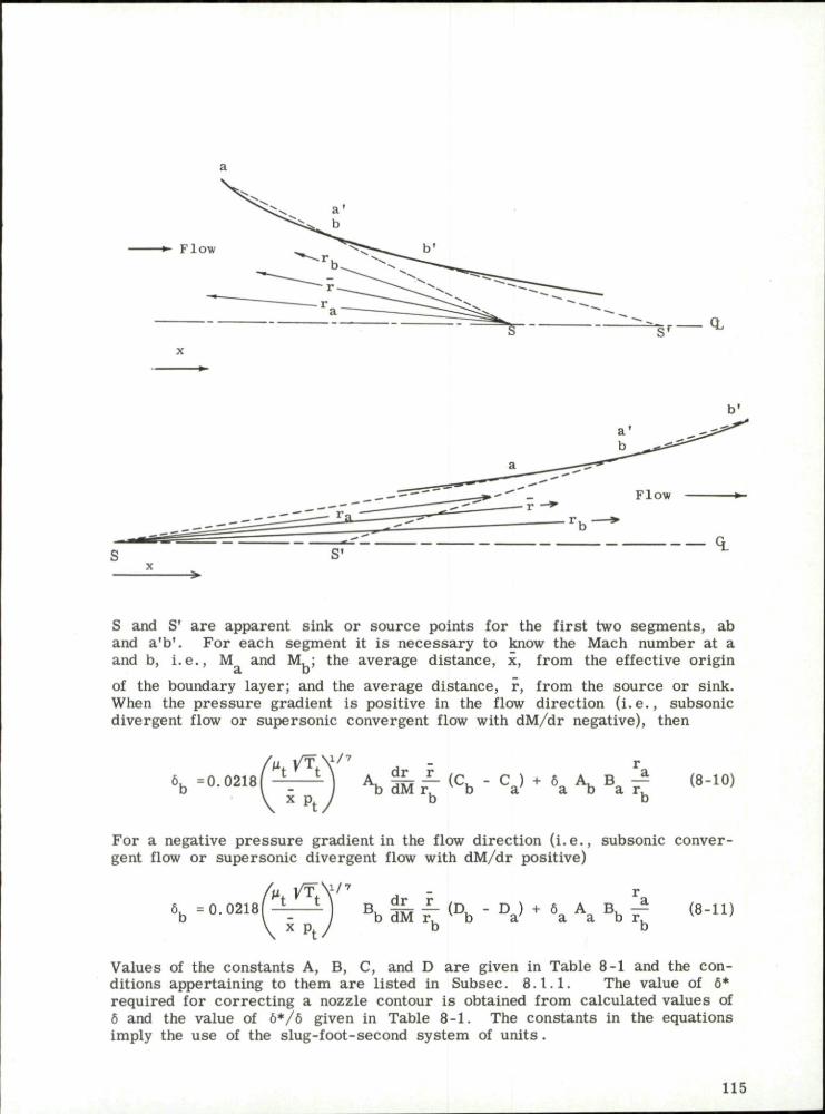
CL
S and S' are apparent sink or source points for the first two segments, ab and a 'b ' . For each segment it is necessary to know the Mach number at a and b, i . e . , M and M,; the average distance, x, from the effective origin
cl D
of the boundary layer; and the average distance, r, from the source or sink. When the pressure gradient is positive in the flow direction ( i . e . , subsonic divergent flow or supersonic convergent flow with dM/dr negative), then
^ / 7
= 0. 02181 ^ M A b 5 M r - ( C b - C a ) + 6 a A b B a - ^ (8-10) x Pf
For a negative pressure gradient in the flow direction ( i . e . , subsonic convergent flow or supersonic divergent flow with dM/dr positive)
6b =0.0218 ' ^ t ^ t Y 7 dr r ~ L B, §£- — (Du - D ) + 6 A B, — - / b dM r, b a a a b r. x p. J b b
(8-11)
Values of the constants A, B, C, and D are given in Table 8-1 and the conditions appertaining to them are listed in Subsec. 8 . 1 . 1 . The value of 6* required for correcting a nozzle contour is obtained from calculated values of 6 and the value of 6*/6 given in Table 8-1. The constants in the equations imply the use of the slug-foot-second system of units .
115

In moderate Mach number flow, the boundary-layer correction is usually small compared with the dimensions of the core of potential flow. In hypersonic flow the boundary layer thickens rapidly with increasing Mach number and it may easily occupy a large part of the cross-sectional area . Large temperature differentials give r ise to great variation in the heat-transfer rates between the gas and the walls. It becomes evident that the viscous effects may no longer be regarded as corrections to the potential flow, but must be taken into account in the basic flow equations.
Persh and Lee (Refs. 38 and 39) have refined the methods of calculating turbulent boundary layer by including the variation in skin friction due to heat transfer. The effects of pressure gradient have not been included. However, it is felt that their influence on the skin friction and on the velocity profile will be relatively small. Both the two-dimensional and the axially symmetric cases are fully worked out by Persh and Lee. Table 8-2, taken from Ref. 39, presents values of 6*/6 and 0/6 for Mach numbers from 0 to 20, (T - T )/T from -10 to +10, and n = 5, 7, 9, and 11. In the foregoing, w c T is the actual wall temperature, T is the equilibrium wall temperature, and
n is the velocity exponent (see Eq. 8-3)
Van Driest (Ref. 40) gives turbulent skin-friction and heat-transfer coefficients for a flat plate as a function of Reynolds number for M from 0 to 10 and T / T from 1.0 to T./T at each Mach number. The Prandtl number
w °° t °° is assumed to be unity. Equations are given from which the boundary-layer thickness may be calculated.
Enkenhus and Maher (Ref. 41) have made boundary-layer calculations which include real -gas effects. The factors taken in account are:
1. The change in the thermodynamic and transport properties of air at high temperatures.
2. The diffusion of atomic species which recombine and release additional heat to the wall.
3 . The effect on skin friction and heat transfer of a highly cooled wall.
Since the formulas used are of a semi-empirical nature, the resul ts must be treated with some reservation until they have been justified experimentally. In particular, it is known that the boundary-layer thickness is very sensitive to the skin-friction law employed. In order to determine the growth of a turbulent boundary layer under conditions that exist in ramjet air- intakes, Standen (Ref. 42) has employed the concept of mass entrainment. He has used this concept to derive an auxiliary equation for the calculation of the shape parameter , H.
8.2 Boundary Layer on the Compressing Surface
The frictional resistance of a compression surface to the flow will produce a boundary layer of significant thickness. An effective compression surface is thereby produced which will affect the entire compression field and can profoundly alter the a i r capture, pressure recovery, and drag character istics of the inlet, even in the absence of separation. For some inlet designs,
116

therefore, it may be desirable to calculate boundary-layer displacement thickness along the surface and "correct" the geometrical surface to produce the desired inviscid flow field.
The specific flight condition for which a compression surface should be corrected is not generally obvious except in the case of a cruise vehicle, where a single operating point is outstandingly important. Any correction to the spike contour for displacement thickness will be associated with a specific altitude and Mach number, and since the performance of an air inlet is very sensitive to the relative positions of the cowl lip and the effective compression surface, the performance of the corrected diffuser should be evaluated for all other conditions of interest. Where the performance is critical, the process may require iteration.
Adjustment of a compression surface is not always practiced. If an inlet is to be operated over a wide range of Mach numbers, altitudes, and angles of attack, a highly compromised design, based upon its off-design performance characterist ics, will have to be chosen. The considerable effort required to carry out the boundary-layer calculations probably is not justified in such situations. For hypersonic inlets, the calculations are more justifiable since the boundary layer is thick and viscous phenomena are of major importance.
At high altitudes the boundary layer may be laminar over the entire length of the inlet spike. The positive pressure gradients produced by a double-cone or isentropic compression surface usually will cause a gradual thickening and separation of the laminar boundary layer. This is sometimes called "bridging" since the flow re-attaches to the surface downstream. This bridging will, however, present a drastically altered compression surface to the inviscid flow, causing an altered shock system which leads to lower air capture (with the associated increase in additive drag) and reduced pressure recovery. It has been shown that this phenomenon occurs only in laminar flow and hence one simple remedy is to apply sufficient roughness to create boundary-layer transition upstream of the discontinuity in the slope. Tests on biconic inlets at M = 3.85 show not only an increased supercritical mass-flow ratio due to a roughened tip but also show that the flow detachment at the engine face was delayed from 6 deg angle of attack to nearly 9 deg by the roughness (Ref. 17).
A second method of alleviating bridging is by means of boundary-layer suction. Bridging did not occur and the total pressure recovery increased from 0.56 to 0.62 when about 2% of the air mass-flow was withdrawn through a porous isentropic spike made of sintered bronze (Ref. 17). Angle-of-attack performance was also improved by this technique. However, in comparison tests it was shown that the roughened tip gave better results than in the case of the porous spike.
8.3 Boundary Layer m the Throat Region
The boundary layer in the throat region may give r ise to many problems. Even under the simplified assumption of a single normal shock in the minimum-area section the boundary-layer displacement thickness is crit ical. High pressure recovery through the nose shock demands a long slender spike which produces a thick boundary layer by the time the flow reaches the inlet.
117

The lower the Mach number at the throat the less the shock loss but also the thicker the boundary layer that may easily occupy a large percentage of the area, which is a minimum at this point. Problems also ar ise from the complex interactions of the boundary layer with the oblique or normal shock of the diffuser.
If the throat is at or very near the cowl lip, boundary-layer separation is apt to occur when the flow is turned too rapidly over the innerbody near the diffuser throat. The most obvious remedy, that of turning the flow more gradually, implies an increased cowl-lip angle and hence an increased external-drag penalty. Boundary-layer bleed immediately downstream of the sharp turn has been found effective provided there is no internal compression. Both circular perforations and slots have proved satisfactory for about a 1% bleed flow. The sketches below are of two configurations that have prevented flow separation.
Variable Bleed Slot
Isentropic Spike
•1/8" Holes
S ing le Cone (Low-Angle Cowl)
Fe r r i (Ref. 43) used boundary-layer suction slots on the tips of both 25 and 30 deg conical noses; however, they were too close to the tip and allowed the boundary layer to separate further downstream. Three variations of boundary-layer bleed at the diffuser entrance are described in Ref. 25 and are shown in the sketch below.
Ram Scoop 1 Ram Scoop 2 Flush Slot
The first two are ram scoops and the third is a flush slot. The middle one, with a sharp entrance tip in the flow direction, and height equal to the boundary- layer thickness, gave the most satisfactory resul ts . Figure 8-1 shows the crit ical pressure recovery and the supercritical mass-flow ratio as a function of Mach number in the test range from M = 1.97 to the design Mach number of 3 .0 . It may be noted that the maximum recovery improvement occurred at the design Mach number using the first ram scoop, but at all test Mach numbers below this value the shock detached. The best performance through the test range was shown by the scoop with its entrance normal to the s tream.
118

The recovery gains are reduced as the Mach number decreases . Part of the reduction in mass-flow ratio is due to the 2% by-passed flow. The effectiveness of the optimum bleed system at angles of attack up to 10 deg is shown in Fig. 8-2. The gain in pressure recovery is reduced as both the angle of attack and the free-stream Mach number increase, but even at 10 deg and M = 3.0 the bleed system still has a slight advantage over the system without bleed. The increase in cowl and flow-spillage drag with this scoop is shown in Fig. 8-3 together with the net thrust ratio (F - D c - D . ) / F . . .
which is based on the assumption of engine matching at the critical condition for each Mach number. At M = 3.0 the use of bleeds increases the propulsive thrust by 22% even after accounting for the bleed-flow drag.
In diffusers with a considerable amount of compression the boundary layer reacts with the normal shock and creates an extensive shock region. Elongating the throat tends to stabilize the shock, but at the same time increases the boundary-layer thickness and often creates flow separation. In such a case the desired pressure recovery may be bought at the cost of a poor pressure distribution at the diffuser exit, as well as the penalty of additional weight due to the long throat.
One of the most successful ways of improving the throat flow is by means of what is known as a dump or sometimes as a vortex t rap. In the sketch below the dump is preceded by a boundary-layer bleed gap.
*'SSSSSSSSSSSSSSSSSSSSSSSSSSSSSSS/SSSSSSSSSSSSSSSSSS^
Subsonic Dump
Bleed Flow
In tests of such a diffuser at M_ = 3.85 (Ref. 44) it was shown that the overall performance was the same as for a well-designed conventional diffuser. However, the pressure recovery had achieved its peak value at a distance equal to 1.25 diameters from the cowl lip (point A on the sketch) which is about one-quarter of the length of the conventional diffuser. This saving in weight and internal drag is of considerable importance in assessing the over-all performance of the vehicle. The frictional losses of the long, conventional annulus are traded for losses in dynamic head due to the incomplete mixing at the abrupt area discontinuity. The pressure distribution at three stations along the dump diffuser is shown in Fig. 8-4 for recovery levels corresponding to supercrit ical, critical, and subcritical flow regimes. The flow distortion is seen to be quite small, especially in the case of the critical flow. It may also be noted from this figure that the high-energy air is at the inner wall of the annulus in supercritical flow and moves across to the outer wall during subcritical operation. The diffuser gave good recovery characterist ics up to 8 deg angle of attack.
119

Another method of improving the conditions at the minimum annulus section is by means of a scoop or pitot device. Many modifications of such a method were incorporated by Carr and Gunther in a two-dimensional diffuser (Ref. 45) and were tested at Mach numbers of 3.5 to 5.0. The essentials of the diffuser are shown in the sketch below.
Bleed Flow
Both the contoured compression plates and the enclosing side plates were flexible and capable of being shaped by means of mechanical actuation in order to provide suitable a rea ratios for starting and for steady supersonic flow. The throat height was also adjustable. The supersonic compression of the diffuser proved very efficient but the normal-shock system was stable only when situated far downstream of the minimum section. Since the relatively high Mach number at that station resulted in poor normal-shock recovery, this part of the diffuser to a great extent nullified the good performance of the supersonic portion. The remedy consisted of capturing only the high-energy central core of the throat flow. By this means the subsonic pressure recovery was much improved. The penalties, however, are high. Compensation must be made for the internal drag of the scoop itself as well as its additional weight. In these particular tests up to one-third of the air mass was bled off. This presents not only the problem of reduced mass flow to the engine face but also the problem of either using the bleed or dumping it overboard. If the by-passed air is re-expanded to f ree-s t ream static pressure and ejected as a rearward jet it will, at least theoretically, provide a source of thrust to compensate for a part of the drag increase. Many design refinements have been tried with both subsonic and supersonic flow in the by-pass ducts and though considerable improvements have been made in the net thrust, the standard of achievement is still below that required.
An axially symmetric diffuser with much less boundary-layer suction than that described in the above paragraph has already been discussed and i llustrated on page 24 and its pressure recovery shown in Fig. 4-6. The drag penalty associated with the by-pass flow was not estimated. It may be noticed from the second sketch on page 24 that there is also a rearfacing step in the innerbody of the diffuser. This device has been found helpful in stabilizing the normal shock and also in preventing separation of the boundary layer.
A boundary-layer trap employed in the two-dimensional inlet of a supersonic transport is described by Leynaert in Ref. 35 and is shown in the sketch below.
Dead Air
120

The flow deflection behind the normal shock is about 25 deg causing flow detachment as it is turned to its original direction; giving an unacceptable velocity profile. The rudimentary form and the large size of the trap provide a high degree of freedom for a wide range of flows. The flow divides at R, the leading edge of the downstream vane of the trap. The more rapid air s treams can overcome the local compression near R and flow along the wall into the diffuser. The less rapid ones recompress near R and expand into the dead-air region in the form of a jet. The dividing streamline is determined in practice by the flow conditions in the downstream part of the diffuser, and thus the fluctuations in the combustion region are automatically compensated by the variations in the mass flow through the trap.
In most of the preceding examples the penalties of extra weight and additional drag associated with boundary-layer bleeding have been pointed out. In the final analysis the complexity of operation, the volume required, and the cost of manufacture would have to be considered.
8.4 Boundary Layer in the Subsonic Diffuser
Shoemaker and Henry (Ref. 46), in an effort to obtain high performance in a short subsonic diffuser, investigated the effectiveness of boundary-layer suction in the annulus downstream of the minimum section. The boundary layer was removed through four, six, or eight rows of equally spaced holes on both outer and inner walls of the diffuser as shown in the sketch below.
A (1/2" d.)
B (3/8" d.)
C,D (1/4" d.)
Four-row suction employed rows A and B; six-row and eight-row suction added row C and rows C and D respectively. The equivalent conical angle of the diffuser was 10 deg. It was found that the pressure recovery was quite sensitive to the ratio of the mass flows through the inner and outer walls. Figures 8-5a and b show the improvement in pressure recovery due to removing 5% and 10% of the total mass flow. Measured pressure recoveries (from Ref. 47) of a 10 deg and a 5 deg diffuser without suction are shown for comparison. It may be seen that less than 5% suction in the short diffuser achieves a pressure r e covery as good as that in a 5 deg diffuser without the penalty of added weight and skin-friction drag. This gain has to be weighed against the power required to perform the suction.
8.5 Fuselage Boundary Layer
So far only the diffuser of an independently operating ramjet has been considered. Sometimes a two-dimensional diffuser or a part of an axisymmetric diffuser may be located along the fuselage or under the wing of a larger craft. In this case the accumulated boundary layer of the fuselage may
121
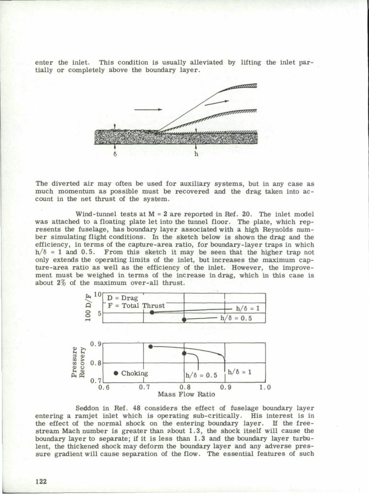
enter the inlet. This condition is usually alleviated by lifting the inlet partially or completely above the boundary layer.
The diverted a i r may often be used for auxiliary systems, but in any case as much momentum as possible must be recovered and the drag taken into account in the net thrust of the system.
Wind-tunnel tests at M = 2 are reported in Ref. 20. The inlet model was attached to a floating plate let into the tunnel floor. The plate, which represents the fuselage, has boundary layer associated with a high Reynolds number simulating flight conditions. In the sketch below is shown the drag and the efficiency, in t e rms of the capture-area ratio, for boundary-layer t raps in which h/6 = 1 and 0 .5 . From this sketch it may be seen that the higher t rap not only extends the operating limits of the inlet, but increases the maximum capture-area ratio as well as the efficiency of the inlet. However, the improvement must be weighed in t e rms of the increase in drag, which in this case is about 2% of the maximum over-all thrust.
UA 10
o o
D = Drag F = Total Thrust
—-^^————j—W' <
— h/6 = 1 » h/6 = 0.5
0.8 Mass Flow Ratio
1.0
Seddon in Ref. 48 considers the effect of fuselage boundary layer entering a ramjet inlet which is operating sub-critic ally. His interest is in the effect of the normal shock on the entering boundary layer. If the free-stream Mach number is greater than about 1.3, the shock itself will cause the boundary layer to separate; if it is less than 1.3 and the boundary layer turbulent, the thickened shock may deform the boundary layer and any adverse p re s sure gradient will cause separation of the flow. The essential features of such
122

flow are shown in the following sketch
X Shock
Free Stream m-
Separation Poinb
.rtBaiTnrrmTmaa.
WJe\wmeySn7nm^ External Dead Air Region Reattached
Boundary Layer Boundary Layer
Behind the separation point is a dead-air region extending into the duct and separated from the main duct flow by a zone of turbulent mixing. The extent of this region is dependent on further pressure gradient and is, therefore, to some extent controllable. An experimental study has shown that the pressure loss due to the turbulent mixing may be the major term in the total pressure loss. This is shown in the sketch below.
1.0
m>
> o o tu
CK
0) !-, 3 10 0)
JJ o
En
123

Table 8-1
Functions for Use in Turbulent Boundary-Layer Correction. Plane Flow (Subsec. 8.1.1) and Axisymmetric Flow (Subsec. 8.1.2)
(y = 1.4 and n = 7)
M
0.10
0.20
0.30
0.40
0.50
0.60
0.70
0.80
0.90
1.00
A
1.000
9.5605
35.0436
86.1217
109.1174
287.0373
439.2610
621.7789
827.9143
1049.2641
(a)
B
1.000
0.1046
0.02854
0.01161
0.005913
0.003484
0.002277
0.001608
0.001208
0.000953
Subsonic
C
0
0.4999
0.5708
0.5929
0.6025
0.6075
0.6106
0.6126
0.6141
0.6152
Flow
D
0
5.6783
31.2372
100.4080
243.5969
494.4231
885.9813
1447.3937
2201.1412
3161.3698
6*/6
0.1253
0.1264
0.1281
0.1305
0.1336
0.1373
0.1416
0.1465
0.1519
0.1578
6*/9
1.290
1.304
1.326
1.357
1.398
1.447
1.505
1.572
1.649
1.734
124

H
1.00 1.04 1.08 1.12 1.16
1.20 1.24 1.28 1.32 1.36
1.40 1,44 1.48 1.52 1.56
1.60 1.64 1.68 1.72 1.76
1.80 1.84 1.88 1.92 1.96
2.00 2.04 2.08 2.12 2.16
2.20 2.24 2.28 2.32 2.36
2.40 2.44 2.48 2.52 2.56
2.60 2.64 2.68 2.72 2.76
A
1.0000 1.0865 1.1733 1.2600 1.3459
1,4307 1.5137 1.5946 1.6730 1.7485
1.8208 1.8897 1.9548 2.0160 2.0732
2.1261 2.1749 2.2193 2.2594 2.2952
2.3268 2.3541 2.3774 2.3966 2.4120
2.4236 2.4316 2.4361 2.4373 2.4354
2.4304 2.4227 2.4124 2.3996 2.3844
2.3672 2.3479 2.3268 2.3041 2.2798
2.2541 2.2272 2.1992 2.1702 2.1403
Table 8-1
(b)
B
1.0000 0.9204 0.8523 0.7937 0.7430
0.6990 0.6606 0.6271 0.5977 0.5719
0.5492 0,5292 0.5116 0.4960 0.4824
0.4703 0.4598 0.4506 0.4426 0.4357
0.4298 0.4248 0.4206 0.4173 0.4146
0,4126 0.4113 0.4105 0.4103 0.4106
0.4115 0.4128 0.4145 0.4167 0.4194
0.4225 0.4259 0.4298 0.4340 0.4386
0.4436 0.4490 0.4547 0.4608 0.4672
(Cont)
Supersonic Flow
C
0 0.3886 0.7450 1.0741 1.3795
1.6646 1.9319 2.1838 2.4223 2.6488
2.8650 3.0720 3.2709 3.4626 3.6481
3.8279 4.0028 4.1734 4.3402 4.5036
4.6641 4.8221 4.9780 5.1319 5.2844
5.4355 5.5857 5.7351 5.8840 6.0326
6.1810 6.3295 6.4783 6.6276 6.7774
6.9280 7.0795 7.2321 7.3859 7.5411
7.6979 7.8563 8.0164 8.1786 8.3427
D
0 0.4226 0.8774 1.3643 1.8827
2.4320 3.0114 3.6199 4.2564 4.9196
5.6082 6.3208 7.0559 7.8120 8.5873
9.3805 10.1897 11.0134 11.8499 12.6977
13.5552 14.4209 15.2932 16.1708 17.0522
17.9362 18.8214 19.7067 20.5908 21.4729
22.3518 23.2265 24.0963 24.9603 25.8178
26.6679 27,5102 28.3441 29.1689 29.9843
30.7898 31.5851 32.3698 33.1435 33.9061
6*/«
0.1578 0.1603 0.1629 0.1656 0.1683
0.1711 0.1739 0.1768 0.1798 0.1828
0.1859 0.1890 0.1922 0.1954 0.1987
0.2020 0.2053 0.2087 0.2121 0.2156
0.2191 0.2226 0,2261 0.2297 0.2333
0.2369 0.2405 0.2441 0.2478 0.2515
0.2552 0.2589 0.2626 0.2663 0.2700
0.2738 0.2775 0.2813 0.2850 0.2888
0.2925 0.2962 0.3000 0.3037 0.3075
6*/e 1.7336 1.7701 1.8080 1.8474 1.8882
1.9303 1.9739 2.0190 2.0654 2.1132
2.1625 2.2132 2.2653 2.3188 2.3737
2.4300 2.4877 2.5469 2.6074 2.6694
2.7328 2,7975 2.8637 2.9313 3.0003
3.0706 3.1424 3.2156 3.2902 3.3662
3.4436 3.5223 3.6025 3.6841 3.7671
3.8514 3.9372 4.0243 4.1129 4.2028
4.2942 4.3869 4.4810 4.5765 4.6734
125
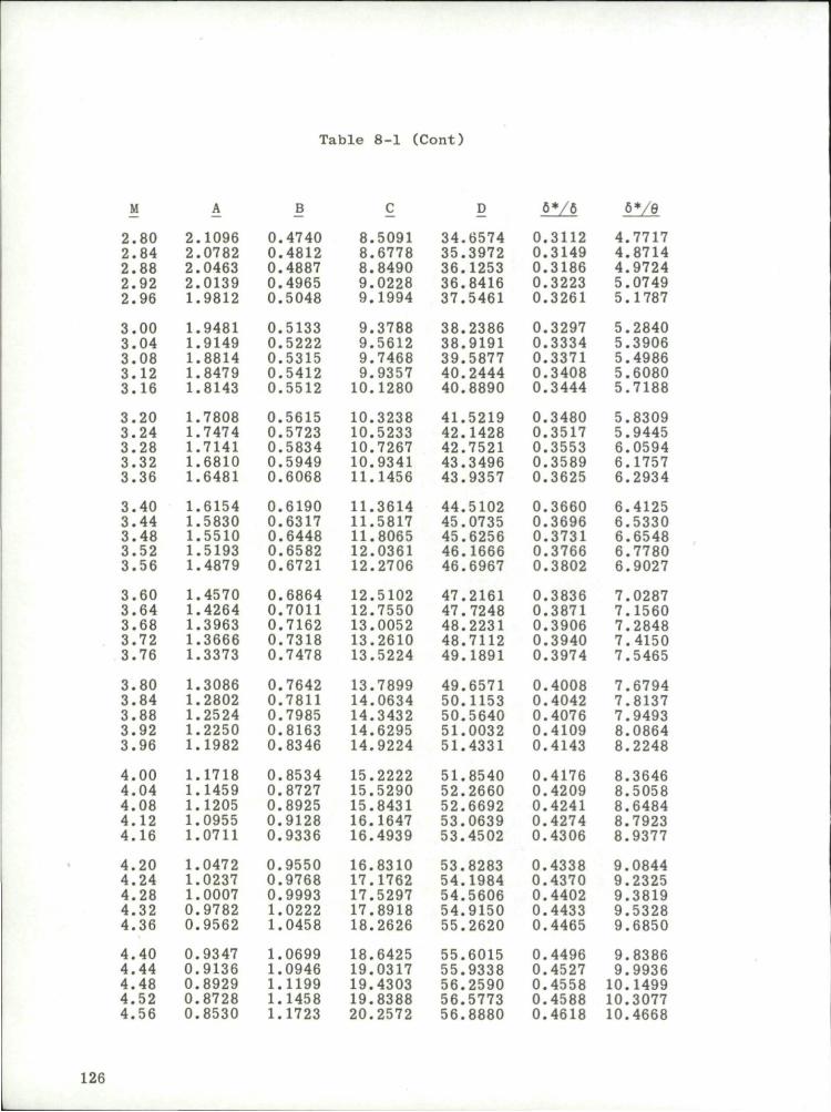
Table 8-1 (Cont)
M B D 6-/6 6-/0
2.80 2.84 2.88 2.92 2.96
3.00 3.04 3.08 3.12 3.16
3.20 3.24 3.28 3.32 3.36
3.40 3.44 3.48 3.52 3.56
3.60 3.64 3.68 3.72 3.76
3.80 3.84 3.88 3.92 3.96
4.00 4.04 4.08 4.12 4.16
4.20 4.24 4.28 4.32 4.36
4.40 4.44 4.48 4.52 4.56
2.1096 2.0782 2.0463 2.0139 1.9812
1.9481 1.9149 1.8814 1.8479 1.8143
1.7808 1.7474 1.7141 1.6810 1.6481
1.6154 1.5830 1.5510 1.5193 1.4879
1.4570 1.4264 1.3963 1.3666 1.3373
1.3086 1.2802 1.2524 1.2250 1.1982
1.1718 1.1459 1.1205 1.0955 1.0711
1.0472 1.0237 1.0007 0.9782 0.9562
0,9347 0.9136 0.8929 0.8728 0.8530
0.4740 0.4812 0.4887 0.4965 0.5048
0.5133 0.5222 0.5315 0.5412 0.5512
0.5615 0.5723 0.5834 0.5949 0.6068
0.6190 0.6317 0.6448 0.6582 0,6721
0.6864 0.7011 0.7162 0.7318 0.7478
0.7642 0.7811 0.7985 0.8163 0.8346
0.8534 0.8727 0.8925 0.9128 0.9336
0.9550 0.9768 0.9993 1.0222 1.0458
1.0699 1.0946 1.1199 1.1458 1.1723
8.5091 8.6778 8.8490 9.0228 9.1994
9.3788 9.5612 9.7468 9.9357 10.1280
10.3238 10.5233 10.7267 10.9341 11.1456
11.3614 11.5817 11.8065 12.0361 12.2706
12.5102 12.7550 13.0052 13.2610 13.5224
13.7899 14.0634 14.3432 14.6295 14,9224
15.2222 15.5290 15.8431 16.1647 16.4939
16.8310 17.1762 17.5297 17.8918 18.2626
18.6425 19.0317 19.4303 19.8388 20.2572
34.6574 35.3972 36.1253 36.8416 37.5461
38.2386 38.9191 39.5877 40.2444 40.8890
41.5219 42.1428 42.7521 43.3496 43.9357
44.5102 45.0735 45.6256 46.1666 46.6967
47.2161 47.7248 48.2231 48,7112 49.1891
49.6571 50.1153 50.5640 51.0032 51.4331
51.8540 52,2660 52.6692 53.0639 53.4502
53,8283 54,1984 54.5606 54.9150 55.2620
55.6015 55.9338 56.2590 56.5773 56.8880
0.3112 0.3149 0.3186 0.3223 0.3261
0.3297 0.3334 0,3371 0.3408 0.3444
0.3480 0.3517 0.3553 0.3589 0.3625
0.3660 0.3696 0,3731 0.3766 0.3802
0.3836 0.3871 0.3906 0.3940 0,3974
0.4008 0.4042 0.4076 0.4109 0.4143
0.4176 0.4209 0.4241 0.4274 0,4306
0.4338 0.4370 0.4402 0.4433 0.4465
0.4496 0.4527 0.4558 0.4588 0.4618
4.7717 4.8714 4.9724 5.0749 5.1787
5.2840 5.3906 5.4986 5.6080 5.7188
5.8309 5.9445 6.0594 6.1757 6.2934
6.4125 6,5330 6.6548 6.7780 6.9027
7.0287 7.1560 7.2848 7.4150 7.5465
7.6794 7.8137 7.9493 8.0864 8.2248
8.3646 8.5058 8.6484 8.7923 8.9377
9.0844 9.2325 9.3819 9.5328 9.6850
9.8386 9.9936 10.1499 10.3077 10.4668
126

Table 8-1 (Cont)
6-/6 6*/0
4.60 4.64 4.68 4.72 4.76
4.80 4.84 4.88 4.92 4.96
5.00 5.04 5.08 5.12 5.16
5.20 5.24 5.28 5.32 5.36
5.40 5.44 5.48 5.52 5.56
5.60 5.64 5.68 5.72 5.76
5.80 5.84 5.88 5.92 5.96
6.00 6.04 6.08 6.12 6.16
6.20 6.24 6.28 6.32 6.36
0.8337 0.8149 0.7964 0.7784 0.7608
0.7436 0.7268 0.7104 0.6943 0.6787
0.6634 0.6484 0.6339 0.6196 0.6057
0.5921 0.5789 0.5660 0.5533 0.5410
0.5290 0.5172 0.5058 0.4946 0.4837
0,4730 0.4626 0.4525 0.4425 0.4329
0.4234 0.4142 0.4052 0.3965 0.3879
0.3795 0.3714 0.3634 0.3556 0.3480
0.3406 0.3334 0.3263 0.3195 0.3127
1.1994 1.2272 1.2556 1.2847 1.3144
1.3448 1.3759 1.4077 1.4402 1.4735
1.5075 1.5422 1.5777 1.6139 1.6510
1.6888 1.7275 1.7670 1.8073 1.8485
1.8905 1.9334 1.9772 2.0219 2.0676
2.1142 2.1617 2.2102 2.2597 2.3102
2.3617 2.4142 2.4677 2.5224 2.5781
2.6348 2.6927 2.7518 2.8119 2.8732
2.9357 2.9994 3.0643 3.1304 3.1978
20.6859 21.1252 21.5753 22.0366 22.5091
22.9934 23.4897 23.9982 24.5193 25.0533
25.6005 26.1613 26.7360 27.3249 27.9283
28.5467 29.1804 29.8297 30.4951 31.1769
31.8754 32.5912 33.3246 34.0760 34.8459
35.6346 36.4427 37.2705 38.1186 38.9873
39.8772 40.7887 41.7224 42.6787 43.6580
44.6611 45.6884 46.7403 47.8175 48.9206
50.0500 51.2064 52.3903 53.6025 54.8434
57.1937 57.4922 57.7843 58.0702 58.3501
58.6241 58.8923 59.1548 59.4118 59.6635
59.9098 60.1511 60.3873 60,6186 60.8450
61.0668 61.2840 61.4968 61.7051 61.9092
62.1091 62.3050 62.4968 62.6848 62.8689
63.0494 63.2262 63.3994 63.5692 63.7357
63.8988 64.0586 64,2153 64.3690 64.5196
64,6673 64.8120 64.9540 65.0932 65.2298
65.3636 65.4950 65.6238 65.7502 65.8741
0.4649 0.4679 0.4708 0.4738 0.4767
0.4796 0.4825 0,4854 0.4883 0.4911
0.4939 0.4967 0.4995 0.5023 0.5050
0.5077 0.5104 0.5131 0.5158 0.5184
0.5210 0.5236 0.5263 0.5288 0.5314
0.5339 0.5364 0.5389 0.5414 0.5438
0.5463 0.5487 0.5511 0.5535 0.5559
0.5582 0.5606 0.5629 0.5652 0.5675
0.5698 0.5720 0.5742 0.5765 0.5787
10.6273 10.7891 10.9524 11.1170 11.2830
11.4504 11.6192 11.7893 11.9608 12.1337
12.3079 12.4836 12.6606 12.8390 13.0187
13.1999 13.3824 13.5663 13.7516 13.9382
14.1262 14.3156 14.5064 14.6986 14.8921
15.0870 15.2833 15.4809 15.6800 15.8804
16.0822 16.2853 16.4898 16.6957 16.9030
17.1117 17,3217 17.5331 17.7459 17.9601
18.1755 18.3925 18.6107 18.8304 19.0514
127
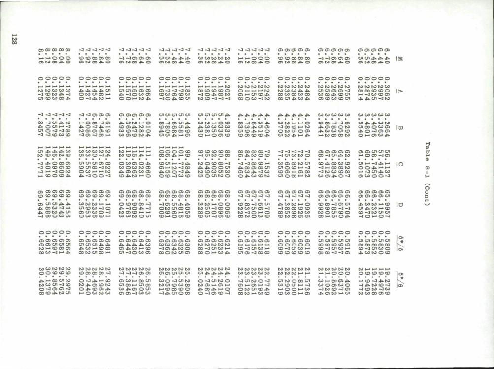
t o 00
co oo oo oo oo -3 -a -a -a -a - a - 3 - 4 - 3 - 4 - q - 3 - 3 - 3 - 3 - 3 - 4 - 4 - 3 - j - 3 - 3 - J - 3 - 3 0101010101 0101010101 en a i en en a .
>-. H- 'O o o O U V J O D i f c O
CO CD 00 00 00 Cs to CO tC- o
—3 —3 Ol Ol Ol Ol [O CO JS. o
en oi ji. Ji JS. OS to CO Ji o
CO co to to to as co co J S . O
I-1 i-1 o o o cs to CO JJ. O
CO co CO 00 CO -J —3 OS Oi Oi Ol (OOO Js-O OS tO 00 JJ. O
o o o o o o o o o o o o o o o o o o o o o o o o o o o o o o o o o o o o o o o o o o o o o
to to co co co -3 CO to JJ. -a 01 CO CO CO JJ.
jj.ji.jj.jj.cn
OIOWOOM O -J J> tO l-»
cn cn oi oi os j> -a o c o oi O O M N 3 * %
O i - q - 3 - J CO CD CO O i CO CO - J O i*. CO CJI
M H M M M CO CO COCO o - J O . J > C t ) M t o co - J -3 -a
to to to to to O H M H W C i I-> cn CD JS. CO O C O - J t o
to to to to to t o c o co j> j> CO CO CO coco 00 cn ji. co ji.
to to to to to ui cnoi oi -3 co co J", CD cn os co co CD cn
to to to toco oo ao co c o o r- -J CO CD CT. Ji. ji. cn ~J to
l>
-J -j-j-J-j -3 -J os Oi Oi Oi OS OJ Oi oi cn cn cn cn cn cn cn cn cn j> ji.ji.ji.ji.ji. js.js.js.js.js. co co CO co co co co co co co
CO -J Ul Ji. to * O Ul H -J cn o -a-J oo -a -a co co co
h-. O CO -3 OS J> O -4 Js. t-1
CO CO Ol Oi CO -3 oi -a oo i-*
J i 00 tO ( - " 0 CD OS J i . tO r -CO CD - 3 0 0 o CO O l CO t O J i .
00 - 3 C 1 Cn J j . C D 0 0 O 1 c n J > >J> 0 0 0 0 0 CD c n c n j i . i - . o i
cn j i J i . J i . c o CO CO O i CO CD
CO CO CO t o t o o i co o -3 a*
C O M M M M t o co o i as. p->
o o o o c o CO OS J i . h-. CD
CO CO l-» O CD JS. CO CO c o c o CO o o c n CO CO O *-* O O s CO
CO CO CO CD 00 -3 Ul CO o o o
00 -3 Ol cn Ji. CO co ji. cn cs cnco ujs.i-'O CO CS CD CD Js.
00 00 00 CO —3 OS Ji-CO O C D
CO CO H-» t-'O -q 00 CO i- to o to en ooi Ul to Ji. I— Ji.
-4 -3 -J -J -4 -3 U1C0 to O
CD 00 -3 -3 Ol Ji. CS CO o to ji. co co en co H-i co oo co to
Ol OS OS OS OS 00 -J Ul Ji. tO
—J Ji. O OO CS -3 O CO Ol CO -3 H-» -3 O IO
p t o o o *
cn ui uioi oo C D cn oo -J co O CO r- r- tO Ji. - 3 0 0 -J
O C O Ol O Js. CO O CO CO Ol Ji. CS CS CO cs CD Ji tO r- O
COU1 h->-3 Ji. Ol H-HO -3 00 Js.cn o -3 Ji O C O -3 00 CO
CO O CO 00 -3 Ji Ji O O Ui co co co cnco cn o m to o
-J -3 00 CD l-» lis. oo oi oo en cs co ji. -J co O Js. CO CD to
co oi oo co cn Ul O CO r-» -3 CD Ol i-'Ol 00 Ul 0 0 0 M tO
CD JS. CO CO CO -3 t-'OO 00 CO -3 CO CO CD 00 CO OS Ji. O -3
Ul Ji JS. co to cn 00 O COOl J i O - J c s c s O r - CS CO J i
o i Oi encnen M O 0 0 - 5 0S
U l M - O J i M O O l r . H H 4-a -m. c n J i CO Ol CO O O -3
1«
IO
-3 p 9
00 I
C l O i O l O l O l CD CO co CD CD
O l O l O l O i O l CO CO CD CO CO
O i O l O l Ol C1 CD 0 0 00 0 0 0 0
O i O l Oi Oi O i 0 0 0 0 CO 0 0 0 0
O i O i O i O i O i CO 00 CO 00 00
O l O i O l O i O l - 3 - 3 - 3 - 4 - J
O i O l O l O l O i - J ~3 - J - 3 - 3
oi o i oi oi oi O l O l O l O i O l
O l Ul Ul J i JS. J i . 0 0 0 0 - 3 M J i CO tO J i Ul - 3 CO O CO O l
CO tO CO r-> h-> u i coco - J o Oi cnco o -3 O C O O l CO I-1
O CD CD 0 0 - 3 J i - J O J i - J co oi co i-» i-" W CO co o en
-qOl Ul Js. Js. o t o cnoo o OCDOi i- 'cn CO M O O ) CO
00 tO r- O O CO Ul -3 CO O 00 O O CD Ol CD cn -3 Oi CD
CD 00 -3 01 Ul to co cn oi -3 N - J O M O 00 tO O C O CD
Ji. CO CO r- O -3 00 00 CO CD 00 Ul CD COCO CO CO CO Ol Ol
CD CO ~3 O l Ul CO CO 0 0 - 3 - 3 to o cn co o O O M O l O i l i
oi oi oi Oi oi oi oi oi oi ui
Ji CO tO l— CD Ul Ji. O0 r-> CD co -3 to cn cn -a o •- o -3
o o p
IC
o o o o o o o o o o o o o o o o o o o o o o o o o o o o o o
O l O l O i O i O i
o o o o o o o o o o o o o o o
O l O l O i O l O l C l O l u i m m CO I—* CO 0 0 O l 0 0 CO - 3 I-1 J s .
O i O i O l O l O l U l U l U l JS. J s . J i C-. a-. CD 0 0 oo co cn oo H-'
O i O l O l O i O l J i J i J i J i . 00 CS J i O0 r - CD cn - j o c o o i
O l O i O i Ol O l CO CO CO CO CO —iai js.co o CD o t o Ul CS
O l O l O l O l O l CO CO CO c o c o CO - 3 U 1 C 0 H-CD O I— OO J i
CO - 3 U l CO l - " cn os -JOO Co
O l O l O i O l O l o o o o o co -3 cn co >-• CO CO CO CO CO
cn cn m m ui CO CO CD CO CD CO - 3 U1CO )-> CO 00 - 4 —3 O l
cn u i cn cn m 00 00 00 CO 00 co -3 cnco o JS. CO CO O C O
»
coco co to CO O O CD CD CO
CO CO CO CO CO CD 00 00 00 - 3
CO CO CO c o t o - 3 - 0 - 3 O l O l
CO CO CO CO CO Oi o i u i cn cn
CO CO CO c o t o on js. js. Js. j >
t o t o CO t o CO COCO CO CO CO
CO CO CO CO t o CO CO CO (-> h-«
coco to coco H-> M O O O
( O M M H r " O COCO COCO
* J i h - ' O O U l IO coco cn -3 co O - 3 OS OS - 3 CD CD J i tO U l
O - 3 JS. i-" CO t o J s . O l CD IO O J i CD OS JS. •-» O CO CO CO
os co i-« co on ui oo (->cn oo CO Js . O l O U l O l O l - J CO CO
CO o - 3 U l CO CO U l CO CO 00 i - i CD 00 CO O -3 J > u i o o o
o - J cn co o CO O l h-> O l 4—' J s . 0 0 J s . i - ' O O - 3 O l CD - 3
- 3 U I C O O - 3 O l P-" O l t - 1 - 3 O IO Ul CO J i CO t O I - . 0 0 CD
enco o oo m O0 CD Ul r - - J H O O H U C O W O H O J
CO r-> 0 0 O J J i CO O O l CO o - 3 CO CD — l O l J s . O l CO I - - U I
4-a CD —3 JS.CO - J J i CO CD - 3 - 3 COCO - 3 CO t O CO CD CS CD

Table 8-1 (Cont)
M 6*/6 6*/0
8.20 8.24 8.28 8.32 8.36
8.40 8.44 8.48 8.52 8.56
8.60 8.64 8.68 8.72 8.76
8.80 8.84 8.88 8.92 8.96
9.00 9.04 9.08 9.12 9.16
9.20 9.24 9.28 9.32 9.36
9.40 9.44 9.48 9.52 9.56
9.60 9.64 9.68 9.72 9.76
9.80 9.84 9.88 9.92 9.96
0.00
0.1251 0.1228 0.1206 0.1184 0.1162
0.1141 0.1120 0.1100 0.1080 0.1061
0.1042 0.1023 0.1005 0.09873 0.09698
0.09527 0.09360 0.09196 0.09035 0.08878
0.08724 0,08573 0.08425 0.08280 0.08138
0.07999 0.07862 0.07728 0.07597 0.07469
0.07343 0.07220 0.07099 0.06980 0.06864
0.06750 0.06638 0.06528 0.06421 0.06315
0.06212 0.06110 0.06011 0.05913 0.05818
0.05724
7.9931 8.1427 8,2947 8.4490 8.6058
8.7649 8.9266 9.0906 9.2572 9.4264
9.5981 9.7724 9.9493 10.1289 10.3111
10.4961 10.6838 10.8743 11.0677 11.2638
11.4629 11.6648 11.8697 12.0775 12.2884
12.5023 12.7193 12.9393 13.1626 13.3889
13.6185 13.8514 14.0875 14.3269 14.5697
14.8158 15.0654 15.3184 15.5750 15.8350
16.0986 16.3658 16.6367 16.9112 17.1895
17.4715
156.2238 159,7433 163.3368 167.0059 170.7520
174.5762 178.4802 182.4654 186.5332 190.6851
194.9227 199.2475 203.6609 208.1646 212.7601
217.4492 222.2333 227.1143 232.0936 237.1735
242.3552 247.6406 253.0316 258.5299 264.1373
269.8559 275.6873 281.6337 287.6968 293.8788
300.1817 306.6073 313.1579 319.8352 326.6417
333.5795 340.6508 347.8575 355.2020 362.6866
370.3136 378.0854 386.0043 394.0728 402.2931
410.6677
69.6997 69.7537 69.8069 69.8593 69.9108
69,9615 70.0114 70.0605 70.1088 70.1564
70.2033 70,2494 70.2948 70.3395 70.3835
70.4268 70.4694 70.5115 70.5528 70.5936
70.6337 70.6732 70.7122 70.7505 70.7883
70.8255 70,8622 70.8983 70.9339 70.9690
71.0036 71.0376 71.0712 71.1043 71.1369
71.1690 71.2007 71.2319 71.2627 71.2931
71.3230 71.3525 71.3816 71.4103 71.4385
71.4664
0.6644 0.6660 0.6675 0.6691 0.6706
0.6721 0.6736 0.6751 0.6766 0.6781
0.6796 0.6810 0.6825 0.6839 0,6853
0.6868 0.6882 0.6896 0.6910 0.6923
0.6937 0.6951 0.6964 0.6977 0,6991
0.7004 0.7017 0.7030 0.7043 0,7056
0.7069 0.7081 0.7094 0.7106 0.7119
0.7131 0,7143 0.7156 0.7168 0.7180
0.7191 0.7203 0.7215 0.7227 0.7238
0.7250
30.7051 30.9908 31.2778 31.5661 31.8560
32.1471 32.4396 32.7336 33.0288 33.3254
33.6234 33.9230 34.2236 34.5258 34.8293
35.1343 35.4406 35.7481 36.0573 36.3677
36.6794 36.9926 37,3072 37.6230 37.9402
38.2590 38.5789 38.9003 39.2232 39.5474
39,8730 40.1998 40.5280 40.8578 41.1887
41.5212 41,8552 42.1902 42.5267 42.8646
43.2040 43.5448 43.8867 44.2302 44.5750
44.9212
129

Table 8-2
Displacement Thickness Ratio and Momentum Thickness Ratio as a Function of Mach Number and Heat Transfer for n = 5, 7, 9, and 11*
M
8 10 12 14 16 18 20
8 10 12 14 16 18 20
6 8
10 12 14 16 18 20
6 8
10 12 14 16 18 20
n 6*/6
0.5924 0.7099 0.7774 0.8215 0.8525 0.8753 0.8927
0.6205 0.7220 0.7837 0.8253 0.8549 0.8769 0.8938
0.4827 0.6438 0.7328 0.7896 0.8288 0.8572 0.8784 0.8948
0.5334 0.6637 0.7426 0.7952 0.8322 0.8593 0.8799 0.8959
= 5 0/6
0.0402 0.0242 0.0165 0.0121 0.0093 0.0074 0.0060
0.0358 0.0226 0.0158 0.0117 0.0091 0.0072 0.0059
0.0574 0.0324 0.0213 0.0152 0.0114 0. 0088 0.0071 0.0058
0.0484 0.0297 0.0201 0.0146 0.0111 0.0087 0.0070 0.0057
* Two-dimensional flow;
n 6*/6
0.5304 0.6552 0.7304 0.7810 0.8173 0.8443 0.8651
0.5590 0.6682 0.7375 0.7853 0.8201 0.8462 0.8664
0.4189 0.5833 0.6801 0.7442 0.7894 0.8227 0.8480 0.8677
0.4683 0.6042 0.6909 0.7504 0.7933 0.8253 0.8497 0.8689
= 7 0/6
T - T W 6
T 00
0.0366 0.0229 0.0159 0.0118 0.0092 0.0073 0.0060
T - T w e
T at
0.0330 0.0215 0.0153 0.0115 0.0089 0.0072 0.0059
T - T w e
T GO
0.0507 0.0302 0.0204 0.0147 0.0112 0.0088 0.0071 0.0058
T - T w e
T 0.0438 0.0278 0.0193 0.0142 0.0109 0.0086 0.0069 0.0057
see Subsec. 8.1 or
n 6*/6
-10
0.4826 0.6110 0.6915 0.7468 0.7870 0.8174 0.8409
-8
0.5112 0.6248 0.6991 0.7515 0.7901 0.8195 0.8424
-6
0.3720 0.5358 0.6373 0.7063 0.7560 0.7931 0.8215 0.8438
-4
0.4195 0.5573 0.6487 0.7131 0.7603 0.7959 0.8235 0.8452
Ref. 39.
= 9 0/6
0.0335 0.0216 0.0153 0.0115 0.0090 0.0072 0.0059
0.0306 0.0204 0.0148 0.0112 0.0088 0.0071 0.0058
0.0454 0.0282 0.0194 0.0142 0.0109 0.0086 0.0070 0.0057
0.0398 0.0261 0.0185 0.0137 0.0106 0.0084 0.0068 0.0057
n 6*/6
0.4441 0.5742 0.6581 0.7170 0.7604 0.7934 0.8191
0.4725 0.5883 0.6662 0.7221 0.7637 0.7957 0.8208
0.3355 0.4971 0.6012 0.6738 0.7269 0.7669 0.7979 0.8223
0.3812 0.5187 0.6131 0.6810 0.7314 0.7700 0.8000 0.8239
= 11 0/6
0.0310 0.0205 0.0147 0.0112 0.0087 0.0070 0.0058
0.0285 0.0194 0.0142 0.0109 0.0086 0.0069 0.0057
0.0412 0.0264 0.0185 0.0137 0.0106 0.0084 0.0068 0.0056
0.0366 0.0246 0.0177 0.0133 0.0103 0.0082 0.0067 0.0056
130

Table 8-2 (Cont)
M „ 6*/6 0/6 6*/6 0/6 6*/6 0/6 6*/6 0/6 n
6*/6 = 5
0/6 n = 7
6*/6 0/6
T - T w e
n 6*/6
-2
= 9 (
n = 11
4 6 8
10 12 14 16 18 20
0.3916 0.5722 0.6809 0.7516 0.8003 0.8354 0.8614 0.8814 0.8969
0.0726 0.0422 0.0274 0.0191 0.0140 0.0107 0.0085 0.0068 0.0056
0.3287 0.5072 0.6226 0.7009 0.7563 0.7970 0.8277 0.8515 0.8701
0.0630 0.0387 0.0259 0.0184 0.0137 0.0106 0.0084 0.0068 0.0057
T - T w e
0.2846 0.0557 0.2515 0.0499 0.4579 0.0356 0,4187 0.0330 0.5763 0.0244 0.5380 0.0231 0.6593 0.0176 0.6241 0.0169 0.7195 0.0133 0.6877 0.0128 0.7644 0.0103 0.7358 0.0101 0.7987 0.0082 0.7730 0.0081 0.8254 0.0067 0.8021 0.0066 0.8466 0.0056 0.8254 0.0055
0 i
0 0.1674 0.1188 0.1257 0.0970 0.1005 0.0817 0.0837 0.0704 2 0.2847 0.0927 0.2278 0.0786 0.1904 0.0680 0.1638 0.0599 4 0.4669 0.0584 0.4000 0.0523 0.3516 0.0471 0.3146 0.0429 6 0.6032 0.0375 0.5391 0.0348 0.4899 0.0323 0.4504 0.0301 8 0.6959 0.0254 0.6389 0.0242 0.5932 0.0229 0.5554 0.0217
10 0.7598 0.0182 0.7100 0.0176 0.6691 0.0169 0.6344 0.0162 12 0.8052 0.0135 0.7619 0.0132 0.7255 0.0129 0.6942 0.0124 14 0.8384 0.0104 0.8006 0.0103 0.7683 0.0101 0.7401 0.0098 16 0.8635 0.0083 0.8301 0.0082 0.8013 0.0081 0.7758 0.0079 18 0.8828 0.0067 0.8531 0.0067 0.8272 0.0066 0.8042 0.0065 20 0.8979 0.0056 0.8713 0.0056 0.8479 0.0055 0.8269 0.0054
T - T w e _ 0
T " l
00
0 0.3315 0.0820 0.2682 0.0712 0.2258 0.0626 0.1953 0.0558 2 0.3967 0.0700 0.3302 0.0618 0.2839 0.0551 0.2495 0.0496 4 0.5204 0.0494 0.4528 0.0450 0.4028 0.0412 0.3638 0.0379 6 0.6289 0.0338 0.5660 0.0317 0.5172 0.0296 0.4776 0.0278 8 0.7093 0.0237 0.6534 0.0227 0.6085 0.0216 0.5711 0.0205
10 0.7674 0.0173 0.7185 0.0168 0.6782 0.0162 0.6439 0.0155 12 0.8098 0.0131 0.7671 0.0128 0.7313 0.0125 0.7003 0.0121 14 0.8414 0.0102 0.8040 0.0100 0.7721 0.0098 0.7441 0.0096 16 0.8654 0.0081 0.8324 0.0081 0.8039 0.0079 0.7786 0.0078 18 0.8841 0.0066 0.8547 0.0066 0.8291 0.0065 0.8061 0.0064 20 0.8988 0.0055 0.8725 0.0055 0.8492 0.0054 0.8283 0.0054
131

Table 8-2 (Cont)
n = 5 n = 7 n = 9 n = 11 M e 6V6 0/6 6_V6 0/6 6*/6 0/6 5*/6 0/6
T - T w e
0 2 4 6 8
10 12 14 16 18 20
0 2 4 6 8
10 12 14 16 18 20
0.4249 0.4691 0.5613 0.6506 0.7213 0.7744 0.8141 0.8442 0.8673 0.8854 0.8998
0.4887 0.5214 0.5939 0.6693 0.7321 0.7809 0.8182 0.8469 0.8691 0.8867 0.9007
0.0644 0.0571 0.0430 0.0308 0.0223 0.0166 0.0126 0.0099 0.0079 0.0065 0.0054
0.0536 0.0486 0.0382 0.0284 0.0210 0.0159 0.0122 0.0097 0.0078 0.0064 0.0053
0.3562 0.4000 0.4942 0.5890 0.6666 0.7264 0.7721 0.8073 0.8347 0.8563 0.8736
0.4189 0.4523 0.5280 0,6091 0.6785 0.7337 0.7768 0.8104 0.8368 0.8578 0.8747
T 00
0.0576 0.0516 0.0397 0.0291 0.0214 0.0161 0.0124 0.0098 0.0079 0.0065 0.0054
T - T w e
T GO 0.0489
0.0446 0.0357 0.0269 0.0203 0.0155 0.0120 0.0096 0.0078 0.0064 0.0053
T - T w e
= 4
0.3079 0.0518 0.2717 0.0470 0.3503 0.0469 0.3125 0.0428 0.4438 0.0367 0.4039 0.0341 0.5408 0.0274 0.5014 0.0258 0.6224 0.0204 0.5854 0.0195 0.6867 0.0155 0.6528 0.0150 0.7367 0.0121 0.7060 0.0117 0.7757 0.0096 0.7480 0.0094 0.8064 0.0078 0.7813 0.0076 0.8308 0.0064 0.8081 0.0063 0.8505 0.0054 0.8297 0.0053
= 6
0.3683 0.0446 0.3294 0.0410 0.4014 0.0410 0.3618 0.0378 0.4777 0.0332 0.4376 0.0310 0.5615 0.0255 0.5224 0.0241 0.6350 0.0194 0.5985 0.0185 0.6946 0.0149 0.6612 0.0144 0.7419 0.0117 0.7116 0.0114 0.7792 0.0094 0.7518 0.0092 0.8088 0.0077 0.7840 0.0075 0.8325 0.0063 0.8099 0.0062 0.8518 0.0053 0.8311 0.0052
8 J.
00
0 0.5361 0.0461 0.4669 0.0427 0.4155 0.0394 0.3754 0.0365 2 0.5617 0.0424 0.4936 0.0395 0.4424 0.0366 0.4021 0.0340 4 0.6208 0.0344 0.5565 0.0323 0,5065 0.0304 0.4663 0.0285 6 0.6856 0.0263 0.6267 0.0251 0.5799 0.0238 0,5412 0.0226 8 0.7419 0.0199 0.6873 0.0198 0.6466 0.0185 0.6105 0.0177
10 0.7869 0.0152 0.7406 0.0149 0.7021 0.0144 0.6690 0.0139 12 0.8221 0.0119 0.7813 0.0117 0.7468 0.0114 0.7168 0.0111 14 0.8494 0.0094 0.8134 0.0093 0.7825 0.0092 0,7554 0.0090 16 0.8709 0.0076 0.8389 0.0076 0.8111 0.0075 0.7865 0.0074 18 0.8879 0.0063 0.8593 0.0063 0.8342 0.0062 0.8118 0.0061 20 0.9016 0.0053 0.8758 0.0053 0.8530 0.0052 0,8324 0.0052
132

M c o 00
0 2 4 6 8
10 12 14 16 18 20
n 6*/6
0.5732 0.5940 0.6435 0.7000 0.7509 0.7926 0.8257 0.8519 0.8726 0.8892 0.9025
= 5 0/6
0.0406 0.0378 0.0313 0.0245 0.0189 0.0146 0.0115 0.0092 0.0075 0.0062 0.0052
Table 8-2
n 6*/6
0.5053 0.5273 0.5805 0.6424 0.6994 0.7470 0.7855 0.8163 0.8409 0.8607 0.8768
= 7 0/6
T - T w e T
00
0.0380 0.0355 0.0297 0.0235 0.0183 0.0143 0.0114 0.0091 0.0075 0.0062 0.0052
(Cont)
n 6*/6
• 10
0.4539 0.4764 0.5313 0.5964 0.6573 0.7091 0.7515 0.7857 0.8134 0.8359 0.8542
= 9 0/6
0.0353 0.0332 0.0280 0.0224 0.0176 0.0139 0.0111 0.0090 0.0074 0.0061 0.0052
n 6*/6
0.4133 0.4358 0.4914 0.5582 0.6217 0.6765 0.7218 0.7588 0.7890 0.8136 0.8337
= 11 0/6
0.0330 0.0310 0.0264 0.0214 0.0169 0.0134 0.0108 0.0088 0.0072 0.0060 0.0051
133

8 I.Q
-E
x X
rt U
rl U c a
5
A Ram Scoop (Ref. 25)
Ram Scoop of Height Equal to Boundary—Layer Thickness (Ref. 25)-
• Flush Slot (Ref. 25)
No Bleed, 20$ Cowl (Ref. 1)
I (See p. 118) l
2.3 2.5 2.7
Free-Stream Mach Number, M
3.1
Fig. 8-1. Comparison of critical performance of double-cone diffusers utilizing various types of suction slots for boundary-layer control; 1.9 < M < 3.1-, Re/ft = 2.5 x 10⁶,
134

Ram Scoop of Height Equal to 0 Boundary-Layer Thickness (Ref. 25)
No Bleed, 20$ Cowl (Ref. 1)
0.4 4 6 8
Angle of Attack, a deg 10 12
Fig. 8-2. Effect of boundary-layer bleed on critical performance of double-cone diffusers at angle of attack; a = 0 to 12°; 2.44 s Mo s 3.01; y • 1.4;
Re/ft = 2.5 X 10⁸.
135

rV
0* •H
rt
I
w
SB
= Cowl-Pressure Drag , = Additive Drag A
F. = Thrust with no Total ideal pressure Loss
1.9 2.1 2.3 2.5 2.7
Free-Stream Mach Number, Ma
Fig. 8-3. Effect of ram scoop on net-thrust ratio and cowl-plus-spillage drag coefficient; double-cone di fuser;
1.9 < M < 3.1; Re/ft = 2.5 * 10e 1.4.
136

4-i
a
>. u o > c 0 OJ
OS
« 3 X X o IH fi
ra A-> o H
0.40
0.35
0.30
>...Y—<.
0.45
0.40
0.35
Source: Ref. 44
0.45
0.40 •*
#
r^=i-^_ ' ' "-s/* " 3 ^
0.2 0.4 0.6 0.8 1,0
Annular Distance, y in, 1.2 1.4
Fig. 8-4. Total pressure profile at various axial stations along a dump diffuser; M = 3.85; Re/ft = 8.6 x 10*.
137

0.18
CL, <l
C <JO
H-H
V a u
(0 O
r-i
<D
9 • • i l
OH
rt •P O H
0.16
0.14
0.12
0.10
0.08
0.06
0.04
0.02
-60
x s / 6
Fig. 8-5a. Effect on total pressure loss of suction in subsonic ducting; suction = 5% of total mass flow; 1.41 < M < 1,46.
s 138

o.iar
a. ^
+J a o
4->
*H H-o c u
I o h 3 X X Co
* - > o H
0.16
0.14
0.12
0.10
0.08
0.06
0.04
0,02
Reference Station
x
Estimated Subsonic Loss
y One-Dimensional y Shock Loss
•10 -20 -30
V 6 ' -40 •50 -60
Fig. 8-5b. Effect on total pressure loss of suction in subsonic ducting; suction = \Wo of total mass flow; 1.41 < M < 1.46.
139

140
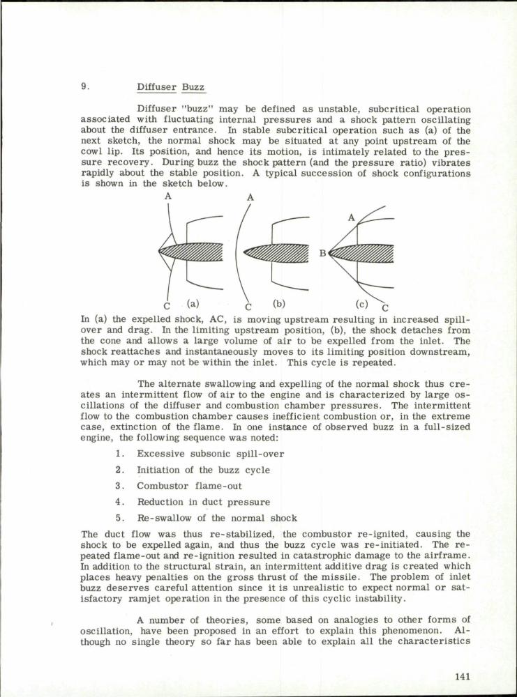
9. Diffuser Buzz
Diffuser "buzz" may be defined as unstable, subcritical operation associated with fluctuating internal pressures and a shock pattern oscillating about the diffuser entrance. In stable subcritical operation such as (a) of the next sketch, the normal shock may be situated at any point upstream of the cowl lip. Its position, and hence its motion, is intimately related to the p res sure recovery. During buzz the shock pattern (and the pressure ratio) vibrates rapidly about the stable position. A typical succession of shock configurations is shown in the sketch below.
A
C (a) c (b) (c) C
In (a) the expelled shock, AC, is moving upstream resulting in increased spillover and drag. In the limiting upstream position, (b), the shock detaches from the cone and allows a large volume of air to be expelled from the inlet. The shock reattaches and instantaneously moves to its limiting position downstream, which may or may not be within the inlet. This cycle is repeated.
The alternate swallowing and expelling of the normal shock thus c re ates an intermittent flow of air to the engine and is characterized by large oscillations of the diffuser and combustion chamber pressures . The intermittent flow to the combustion chamber causes inefficient combustion or, in the extreme case, extinction of the flame. In one instance of observed buzz in a full-sized engine, the following sequence was noted:
1. Excessive subsonic spill-over
2. Initiation of the buzz cycle
3 . Combustor flame-out
4. Reduction in duct pressure
5. Re-swallow of the normal shock
The duct flow was thus re-stabilized, the combustor re-ignited, causing the shock to be expelled again, and thus the buzz cycle was re-initiated. The r e peated flame-out and re-ignition resulted in catastrophic damage to the airframe. In addition to the structural strain, an intermittent additive drag is created which places heavy penalties on the gross thrust of the missile. The problem of inlet buzz deserves careful attention since it is unrealistic to expect normal or satisfactory ramjet operation in the presence of this cyclic instability.
A number of theories, some based on analogies to other forms of oscillation, have been proposed in an effort to explain this phenomenon. Although no single theory so far has been able to explain all the characterist ics
141

of buzz, each one has added to the understanding of the problem. Some of the more fruitful theories, along with their application, will be discussed in the following subsection.
9.1 Theories of Buzz
According to F e r r i ' s vortex-sheet theory (Ref. 43) the intersection of the conical shock with the expelled normal shock creates a vortex sheet, as shown in the sketch below (see also Subsec. 5.1).
As the normal-shock system (BD) moves upstream, the vortex sheet (AC) approaches the cowl lip and ultimately, under certain off-design conditions, may enter the diffuser. The entrance of the vortex sheet within the inlet t r iggers the oscillatory cycle. Since this vortex sheet is associated with a low-energy field, it causes boundary-layer separation which in turn chokes the diffuser. This choking expels more air , creating a stronger shock and allowing the vortex sheet to move upstream and turn toward the innerbody. This permits the boundary layer to reattach and the vortex sheet to move toward the inner cowl lip, thus re-entering the buzz cycle.
When boundary-layer separation occurs on the innerbody, a lambda-shaped Shockwave is present as illustrated in the sketch below.
A vortex sheet a r i ses from the lambda shock and approaches the cowl lip. This initiates the oscillatory cycle in the same manner as the vortex sheet described previously.
F e r r i and Nucci (Ref. 43) tested a number of inlets at Mach numbers from 1.9 to 2.7 in order to confirm the vortex-sheet theory. It was found that the minimum entering mass flow for stable operation is essentially a function of the Mach number and of the external geometry upstream of the
142

inlet. Figure 9-1, taken from this reference, shows the minimum stable mass flow as a function of the cowling parameter for a cone tip of 40 deg at various Mach numbers. The effect of varying the cone angle is shown in Fig. 9-2. As with the other theories that have been advanced, Fe r r i ' s vortex-sheet theory provides an adequate explanation for some cases but by no means for all. In one conical-nose inlet, the vortex sheet traveled along the entire inlet at a below-design Mach number without inciting buzz and, in the same inlet, buzz occurred at an above-design Mach number when the vortex sheet was observed to be far removed from the cowl lip.
Pearce (Ref. 49) noted that if the stagnation pressure vs mass-flow ratio curve has a positive slope of sufficient magnitude, then the system is unstable under the influence of small disturbances. However, if the slope is negative or very slightly positive, the flow will be stable in the presence of these same disturbances. Thus the diffuser characteristic curve is an indication of the stability of the system. It may be said that a positive slope is necessary for the oscillations to begin, but is not in itself sufficient to originate the instability.
According to Dailey (Ref. 50), an initial disturbance causes choking of the inlet which in turn forces the normal-shock system to move upstream along the cone. The pressure in the combustion chamber builds up and is d is charged from both ends of the engine, so that the engine resonates as would an organ pipe. The normal shock then moves toward the inlet and is swallowed to a supercritical position. Since the inlet flow rate is then greater than the exit discharge rate, the pressure in the combustion chamber again increases rapidly and the shock pattern moves upstream, re-entering the cycle.
Sterbentz and Evvard (Ref. 51) found that the frequency and wave characteristics of the oscillations occurring in a given diffuser are dependent upon the internal geometry of the ramjet. This led to the idea of comparing the buzz phenomenon to a Helmholtz resonator. During a buzz cycle the air is alternately accelerated and decelerated as the shock is swallowed and expelled. A portion of this mass flow could then act as an inertial plug resonating against the combustion chamber in a manner analogous to that of an organ pipe or a Helmholtz resonator. The frequency of pulsation is given by the expression
a-. ' - » m - <•-»>
where
l = length of diffuser
V = volume of combustion chamber c
a3 = velocity of sound at a point downstream of the perturbations
Ai = cross-sectional area of inlet
Experimental and calculated values of the frequency are compared in Fig. 9-3 from Ref. 50 where it may be seen that the experimental values agree with the theoretical within 15%. Experimental and calculated values of the slope of the
143

pressure-recovery curve, d(p / p ) /d (m s /m ) are also given in Fig. 9-3. It
may be seen that Pearce ' s condition of a small positive slope as a condition of instability holds for most of these data.
In spite of its success, there have been several cr i t ic isms of the resonator theory. One objection which would tend to support the vortex-sheet theory is the fact that buzz begins abruptly; in resonance it would build up slowly. However, the two theories may be compatible rather than opposing, since the entrance of the vortex sheet within the diffuser may provide the initial disturbance which is then propagated as a resonating column of a i r . The entrance of a vortex sheet will also cause an abrupt change in the positive slope of the pressure recovery characteris t ic , which tends to fit Pea rce ' s explanation and F e r r i ' s observations. It is generally true that an inlet designed to give high pressure recovery will be somewhat more sensitive and inherently less stable in the presence of spill-over than an inlet giving low pressure recovery since the slope of the pressure recovery characterist ic curve will tend to be more positive.
Nicolas in Ref. 52 describes experiments at M = 1.45 with a simple open-nose inlet without a centerbody. The length of the duct, the diffuser angle, and the bluntness of the lips were varied. Two frequencies were observed; one a high frequency of about 2, 000 cps which was virtually independent of the parameters being studied, and the other a low frequency whose wave length was about four times the duct length. The latter pulsation was not always p re s ent. Increasing the bluntness of the lip did not eliminate the separation which appears to be associated with the onset of pulsation. The diffuser slope, on the other hand, seemed to be of considerable importance. Any circumstance that causes sufficient variation in the propagation velocity of the normal-shock wave may be the point of departure for a regime of self-sustained oscillation of the internal flow.
Mirels in Ref. 53 analyzes buzz by means of the acoustic analogy and comes to the same conclusion as Pearce; i . e . , that decreasing the slope of the inlet characterist ic curve during subcritical operation will tend to increase the range of stable operation. He also deduces a relationship between stability and the real part of the acoustic impedance of the inlet.
9.2 Methods of Control
The onset and character of diffuser buzz are dependent upon many factors, some of which have been theoretically analyzed or experimentally tested in order to find a means of controlling or delaying the buzz phenomenon. One method of eliminating buzz would be to prevent subcritical operation by assur ing that the exit nozzle is large enough to maintain the normal-shock system within the annular ducting of the diffuser at all missile or engine operating conditions.
According to Eq. 9-1 the frequency is inversely proportional to the square root of the resonating volume. Theoretically, at least, it would be possible to reduce the frequency to a negligible value by ensuring a large enough resonator. Computed values of the frequency for two combustion chamber volumes, one of which was more than twice the size of the other, are compared
144

with test results at M = 2 in Fig. 9-4. As was expected, the frequency decreased when the volume was increased. However, a resonating chamber which would phase-out the oscillations would demand a volume prohibitively large for most practical applications.
More recently the problem has been substantially solved for two specific types of diffusers, although neither method offers a complete understanding of the phenomenon. One type of diffuser employed dampers in the form of can combustors. The effect of the dampers on buzz frequency and amplitude are shown in Fig. 9-5 in which it may be seen that the largest can combustor completely stabilized the system at zero angle of attack. Unfortunately the dampers also reduced the pressure recoveries by about 4%.
Since a positive slope of the diffuser characteristic curve is associated with the oscillation, anything which can prolong a negative slope will delay buzzing. Rae, in unpublished OAL tests, designed and tested a two-shock step-nose diffuser. This diffuser has a characteristic curve which "knees-over" rather than turning abruptly, as shown in Fig. 9-6 for two angles of attach at M = 2. 23. It may be seen that not only was the range of stable operation increased with this type of diffuser, but the pressure recovery was also improved .
It should be noted that although diffuser buzz is definitely a detr i ment to efficient combustion, it is ultimately of more academic than practical interest. The undue emphasis that has been placed on it by ramjet designers stems from the fact that most diffuser performance data are derived from wind-tunnel tests where conditions are particularly favorable to unstable operation. In actual flight where the diffuser operates as an integral part of an entire engine system, buzz is less likely to occur partly because of the stabilizing effect of the combustion and partly because of the presence of such factors as the air scoops that are included for many purposes.
9.3 Interaction with Engine Design
In designing a propulsion system the problem of practical importance is to ensure stable operation at all t imes. The application of transient flow theory is concerned more with the determination of the limits of stable inlet operation within which the engine may operate rather than with the description of the modes of unstable operation. The techniques of mass-flow matching between the inlet and the engine to ensure efficient performance over the range of flight conditions are well understood once the performance of each component is defined. It is standard practice to determine the relations between inlet mass flow and efficiency for a given inlet geometry from wind-tunnel tests, since one-dimensional theory is not sufficiently well developed to permit its determination. It is possible to derive similar transient functions for the propulsion system and thus permit the application of one-dimensional theory to the complete system.
In conducting wind-tunnel tests to determine stability limits, two general types of inlets and associated characterist ics have been observed. The first type has a relatively long high-velocity duct separating the inlet from the combustion chamber. The duct is followed by a short, almost dump-type subsonic diffuser, and highly resistive aerodynamic grid for flow smoothing. In
145

the many tests conducted with this configuration, good agreement of the stability limit (one to two per cent on mass capture) has been obtained between one-third scale models tested (without simulated combustor damping), and full-scale free-jet tests (with and without combustor operation). This might be anticipated since the combustor is effectively divorced from the inlet by the long, high-velocity duct. The resistance of such a duct to the upstream feeding of perturbations is very high. It is thus possible to determine the proper inlet stability limits by means of wind-tunnel tests with a small-scale model of this type of ramjet engine.
The second type of inlet which has been tested is one which is closely coupled to the combustor by means of a relatively short subsonic diffuser section. Since the duct lacks high natural impedance, flow perturbations originating in the combustion chamber may have a significant effect on the inlet flow. A proper determination of inlet buzz limits for this arrangement is a more complex problem. In small-scale experiments, the stability limit was shown to be a function of the flow impedance or damping in the simulated combustion chamber . Buzz frequency is , of course, a function of receiver geometry and amplitude a function of the combustor damping character is t ics once the oscillations commence. It has been concluded, therefore, that for a ramjet arrangement having low impedance coupling between the combustor and inlet, the stability limits may not be adequately defined by a small-scale wind-tunnel test of the inlet alone, but would require a full-scale test of the complete engine with the combustor operating.
At high angles of attack, the leeward flow separation phenomenon, described ear l ie r in Subsec. 5.2, may occur instead of the classical buzz phenomenon observed at low angles of attack. The flow separation may lead to engine flame-out, which will cause the flow to re-attach, leading to re-ignition and initiation of the entire cycle again. This will, of course, closely resemble buzz. The determination of the l imits of buzz or flow separation or both may be accomplished with the same set of experiments. The stability limit for a given diffuser geometry and simulated flight condition may then be expressed in te rms of a minimum Mach number at the diffuser exit.
Once the stability limits have been experimentally determined, fabrication tolerances and inlet transient heating effects should be considered ca re fully when specifying appropriate engine inlet and exit a r eas .
F ra i se r (Ref. 54) has applied the small perturbation theory to an approximation of the differential equation for compressible duct flow and has thus obtained the duct transfer function and response character is t ics . Equations are developed which describe the duct natural frequency as a function of duct a reas and volumes, and the damping ratio as a function of the slope of the steady-state mass flow, pressure recovery curve. The calculated response agreed reasonably well with the measured response from tests of a fixed-geometry inlet with by-pass for matching a i r flows.
In carrying out the measurements described above or in making flight measurements of transient system character is t ics , it is always important to be sure that the propert ies measured really correspond to the aerodynamic phenomena and are not intrinsically tied to the method of measurement. For instance, care must be taken to ensure that there are no natural modes of the recording element, the transducer, or the mounting of the transducer in the duct system which might interfere with the validity of the determination.
146
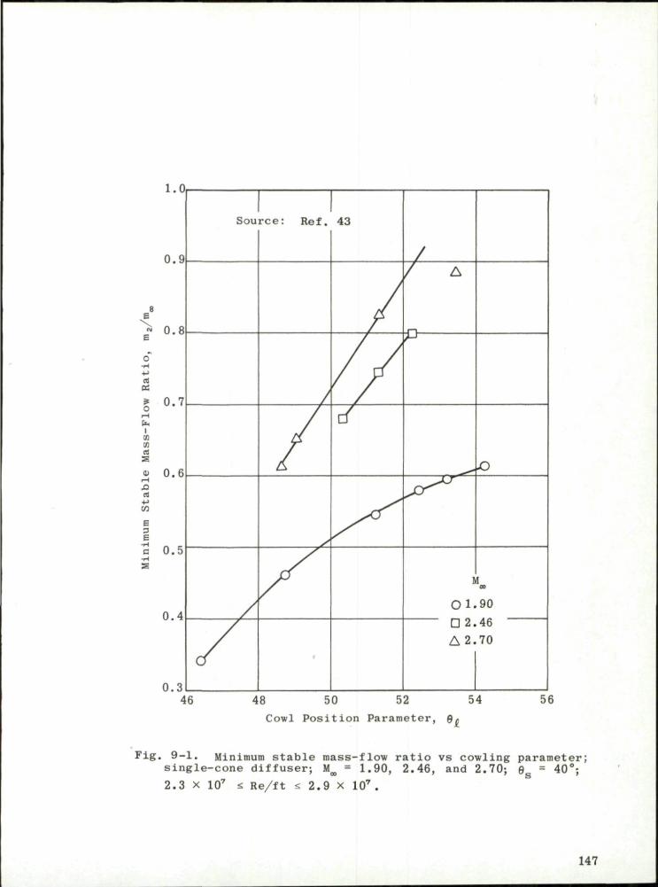
— rt
CC ? O
X X Cm
Si Cm
*» 09
E 3 E •H C •H
48 50 52 54
Cowl Position Parameter, ft*
Fig. 9-1. Minimum stable mass-flow ratio vs cowling parameter; single-cone diffuser; M = 1.90, 2.46,
2.3 x 10' * Re/ft < 2.9 x 10⁷ and 2.70; 0g = 40'
147
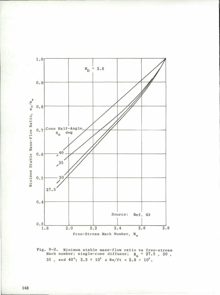
1.0
0.9
« 0.8 B
cc
i o r-l
Um X X Cm
Xi rt +-> OT
E 3 -
0.7
0.6
0.5
0.4
0.3
Cone Half-0S d.
40 •
35 S
i n y
27 .5
"D
-Anele, / 2g y Y
•- 2 . 8
Soi i r c e : Ref . 43
1.8 2.0 2.2 2.4 2.6
Free-Stream Mach Number, M
2.8
Fig. 9-2. Minimum stable mass-flow ratio vs free-stream Mach number; single-cone diffuser; 9r = 27.5 , 30
35 , and 40°; 2.3 x 1Q7 <. Re/ft s 2.9 9S = 27.5
107.
148

•mi
Q, z
r- l OT X
u
0.4
0.2
w -J
o rt -rt
I O Stable
Q Unstable
Theoretical o
d ( p / p t ) • 00
D " d(ma/mj
Unstable Flow
^>n
O
O
o Stable Flow.
x a o
c c rt
>. o e o 3 o-B -rV
30
20
10
0Q_
O Experimental
—Theoretical
M_ = 1.8
JSl
^K
0.2 0.4 0.6 0.8 OO-
M„ = 1.9
1.0 0.2 0.4 0.6
Mass-Flow Ratio, m2/m
.m CD
Fig. 9-3. Frequency of pulsation and slope of diffuser pressure-recovery curve vs mass-flow ratio (experimental and calculated values); single-cone diffusers; M^ = 1.8 and 1.9. (Source: Ref. 50)

DO D , CJ
C O
•rA
• M
a x
>> o c 8 3 CT co U
U H
22
20
18
16
14
12
10
c
A
D
Small Volume, V,
O Experimental
A Theoretical
Large Volume V
• B
2 « 2.3\
Experimc
Theoreti
ntal
cal
O
C
D C
1 1 Source: Ref. 50
f-\ D
h^\°
°\
D
|—1,\ Ln U
D
0.3 0.4 0.5 0.6 0.7 0 .8 Mass-Flow R a t i o , m2/mo
0.9 1.0
Fig, 9-4. Effect of combustion-chamber volume on frequency of pulsation in various single-cone diffusers (experimental and theoretical values); V2 s« 2.3V,; M^ = 2.0.
150

Can Combustion-Type Dampers
tn 250 a u
£ 200 u a 0)
\T 150 o h fa
0
O c A D
O—,
l e a n amper
>1X •
Duct No.
r j Damper No. Damper No,
pcAr? r **
i 2 3
^ r tx
W ^ i - i
yfju L o- " < & — -A
BS 15
0) -3
a E <
10
0 0.5
o-H M tr r * * =
* ^ * - i ^
Z i 1
Nx t ^ • & : 5 @ ^
"&__ 0.6 0.7 0.8 0.9
Capture-Area Ratio, A /A,
1.0
Fig. 9-5. Effect of dampers on frequency and amplitude of diffuser buzz; single-cone diffuser; 0 = 22.75°; M_ = 1.73. S
151

Single-Cone Diffuser Two-Shock Step-Nose Diffuser
0.7
>> a j
0) > c o 0)
a; co rA
3 X X
2 o.
rt
o H
0.6
0.5 0.6
°s JP"':JL9Z
O a = 0'
O a = 2' Two-Shock Step-Nose Diffuser
0.7 0.8 0.9 1.0 Capture-Area Ratio, A /A,
Fig. 9-6. Performance of single-cone and step-nose diffusers; M = 2.23.
152

REFERENCES
1. Connors, J . F . , Wise, G. A. , and Lovell, J . C. Investigation of Trans-lating-Double-Cone Axisymmetric Inlets with Cowl Projected Areas 40 and 20 Percent of Maximum at Mach Numbers from 3.0 to 2 .0 . NACA RM E57C06, May 1957.
2. Holder, D. W., Pearcey, H. H., and Gadd, G. E. The Interaction Between Shock Waves and Boundary Layers. ARC CP 180.
3. Moeckel, W. E. Approximate Method for Predicting Form and Location of Detached Shock Waves Ahead of Plane or Axially Symmetric Bodies. NACA TN 1921, July 1949.
4. Warren, I. L . , Abbadessa, R. B . , and Pietrangeli, G. J . Application of the Method of Characterist ics to the Supersonic Rotational Flow Through a Circular Conical Inlet. CM-668, Applied Physics Laboratory, The Johns Hopkins University, September 1951.
5. Cronvich, L. L. "Numerical-Graphical Methods of Characteristics for Plane Potential Shock-Free Flow Problems," J . Aeronaut. Sci. , Vol. 14, No. 4 (April 1947), pp. 237-242.
6. Cronvich, L. L. "A Numerical-Graphical Method of Characteristics for Axially Symmetric Isentropic Flow," J . Aeronaut. Sci., Vol. 15, No. 3 (March 1948), pp. 155-162.
7. Kennedy, E. C. Axisymmetric Isentropic Spike Surface of a Ramjet Diffuser Operating at Below-Design Mach Numbers. OAL/CM 957, August 1959.
8. Carr iere , P . Role de la Pr ise D'Air dans le Bilan Propulsif D'un Reacteur. ONERA, Par is , France.
9. Oswatitsch, K. Gas Dynamics. New York: Academic Press Inc., 1956.
10. Gunther, F . Development of a Two-Dimensional Adjustable Supersonic Inlet. JPL/CIT Progress Report 20-247, November 1954.
11. Mossman, E. A. and Pfyl, F . A. An Experimental Investigation at Mach Numbers from 2.1 to 3.0 of Circular-Internal-Contraction Inlets with Translating Centerbodies. NACA RM A56G06, October 1956.
12. Evvard, J. C. and Blakey, J . W. The Use of Perforated Inlets for Efficient Supersonic Diffusion. NACA TN 3767, September 1956.
13. Hunczak, H. R. and Kremzier, E. J . Characterist ics of Perforated Diffusers at Free-Stream Mach Number 1.90. NACA RM E50B02, May 1950.
153

14. Clark, J . P . C. An Experimental Investigation of a Supersonic Two-Dimensional Perforated Inlet at a Nominal Free Stream Mach Number of 2 .5 . UTIA TN 24, November 1958.
15. Wu, J . H. T. An Experimental Study of Perforated Intake Diffusers at a Mach Number of 2 .5 . UTIA Report 69, September 1960.
16. Hearth, D. P . , Anderson, B. H. , and Dryer, M. Performance Comparison at Mach Numbers 1.8 and 2.0 of Full-Scale and Quarter-Scale Translating-Spike Inlets, NACA RM E57D16, October 1957.
17. Connors, J . F . and Woollett, R. R. Performance Characterist ics of Several Types of Axially Symmetric Nose Inlets at Mach Number 3.85. NACA RM E52I15, November 1952.
18. Bernstein, H. and Haefeli, R. C. Investigation of Pressure Recovery of a Single-Conical-Shock Nose Inlet at Mach Number 5.4. NACA RM E53A12, April 1953.
19. Kennedy, E. C. Tables of Supersonic Conical Flow. OAL Memo. 143 (CM-973), May 1960.
20. Car r ie re , P . and Leynaert, J . "Recherches sur les P r i ses D'Air Supersoniques," Jahrbuch 1959 der WGL (1959), pp. 80-89.
21. Dean, F . A. Study of a Probe Diffuser. CM-723, Applied Physics Laboratory, The Johns Hopkins University, April 1952.
22. Moeckel, W. E. and Evans, P . J . , J r . Preliminary Investigation of Use of Conical Flow Separation for Efficient Supersonic Diffusion. NACA RM E51J08, December 1951.
23. Kennedy, E. C. Calculation of the Flow Fields Around a Series of Biconic Bodies of Revolution Using the Method of Characterist ics as Applied to Supersonic Rotational Flow. OAL/CM 873, June 1956.
24. Connors, J . F . and Meyer, R. C. Design Cri ter ia for Axisymmetric and Two-Dimensional Supersonic Inlets and Exits. NACA TN 3589, January 1956.
25. Connors, J . F . , Lovell, J . C , and Wise, G. A. Effects of Internal-Area Distribution, Spike Translation, and Throat Boundary-Layer Control on Performance of a Double-Cone Axisymmetric Inlet at Mach Numbers from 3.0 to 2 .0 . NACA RM E57F03, August 1957.
26. Applied Physics Laboratory, The Johns Hopkins University. Handbook of Supersonic Aerodynamics, NAVORD Report 1488, Vol. 2, Sec. 5, "Compressible Flow Tables and Graphs, " 1953.
27. Ames Research Staff. Equations, Tables, and Charts for Compressible Flow. NACA Report 1135, 1953.
154

43. Ferr i , A. and Nucci, L. M. The Origin of Aerodynamic Instability of Supersonic Inlets at Subcritical Conditions. NACA RM L50K30, January 1951.
44. Connors, J . F . and Flaherty, R. J . High Mach Number, Low-Cowl-Drag, External-Compression Inlet with Subsonic Dump Diffuser. NACA RM E58A09, May 1958.
45. Carr, J . H. and Gunther, F . C. Further Development of Adjustable Supersonic Internal-Compression Air Inlets. JPL/CIT Report No. 20-121, June 1958.
46. Shoemaker, C. J. and Henry, J . R. Effects of Suction Boundary-Layer Control on the Performance of a Short Annular Diffuser with an Upstream Terminal Normal Shock. NASA TN D-1241, April 1962.
47. Gorton, G. C. and Dryer, M. Comparison at Supersonic Speeds of Translating Spike Inlets Having Blunt- and Sharp-Lip Cowls. NACA RM E54J07, January 1955.
48. Seddon, J . The Effects of the Interaction on the Performance of Supersonic Intakes. C .P . 180, A .R .C . Technical Report. London: Her Majesty 's Stationery Office, 1955.
49. Pearce, R. B. "Causes and Control of Powerplant Surge, " Aviation Week, Vol. 52, No. 3 (January 1950), pp. 21-25.
50. Dailey, C. L. "Supersonic Diffuser Instability," J . Aeronaut. Sci. , Vol. 22, No. 11 (November 1955), pp. 733-749.
51. Sterbentz, W. H. and Evvard, J . C. Criterions for Prediction and Control of Ram-Jet Flow Pulsations. NACA TN 3506, August 1955.
52. Nicolas, J . "Etude Experimentale des Ecoulements Pulsatoires dans une Prise D'Air Supersonique," La Recherche Aeronautique, No. 58 (1957), pp. 23-28.
53. Mirels, H. Acoustic Analysis of Ram-Jet Buzz. NACA TN 3574, November 1955.
54. Fraiser , H. R. "Supersonic Inlet Dynamics," J . Aero/Space Sci. (June 1960), pp. 429-436.
55. Luidens, R. W. and Flaherty, R. J . Use of Shock-Trap Bleed to Improve Pressure Recovery of Fixed- and Variable-Capture-Area Internal-Contraction Inlets, Mach Number 2.0 to 3.0. NACA RM E58D24, August 1958.
56. Scherrer, R. and Anderson, W. E. Investigation of the Performance and Internal Flow of a Variable-Area, Variable-Internal-Contraction Inlet at Mach Numbers of 2.00, 2.50 and 2.92. NACA RM A58C24, July 1958.
155

28. Dailey, C. L. and Wood, F. C. Computation Curves for Compressible Fluid Problems. New York: John Wiley and Sons, Inc., 1949.
29. Hypersonic Wind Tunnel Staff. Charts and Tables for Analysis of Hypersonic Flow. GALCIT Hypersonic Wind Tunnel Memo. 4_. Guggenheim Aeronautical Laboratory, California Institute of Technology, May 1951.
30. Kopal, Z . , et al . Tables of Supersonic Flow Around Cones. TR 1, Massachusetts Institute of Technology, 1947.
31 . Kennedy, E. C. "Calculation of Axisymmetric Isentropic Spike Surfaces, " J . Aeronaut. Sci. , Vol. 25, No. 7 (July 1958), p. 463.
32. Sauer, R. Method of Characterist ics for Three-Dimensional Axially Symmetric Supersonic Flows. NACA TM 1133, January 1947.
33. Pietrangeli, G. J . and Nice, E. V. The Feasibility of a Mach 7 Transport Employing Airbreathing Propulsion Systems. CF-2900, Applied Physics Laboratory, The Johns Hopkins University, November 1960.
34. Leynaert, J . and Brasseur, J -M. "Problemes D'Aerodynamique Interne Poses par L'Avion de Transport Supersonique "Mach 2 , " La Recherche Aeronautique, No. 91 (1962), pp. 15-22.
35. Leynaert, J . Aspects Aerodynamiques des Problemes de P r i se s D'Air et de Sorties de Reacteurs pour un Avion de Transport Supersonique. ONERA, Par i s , France.
36. Molder, S. and Szpiro, E. J . Shock Reflection and Interaction at Hypersonic Speeds. Report No. 63-8, McGill University, Montreal, May 1963.
37. Tucker, M. Approximate Turbulent Boundary-Layer Development in Plane Compressible Flow Along Thermally Insulated Surfaces with Application to Supersonic-Tunnel Contour Correction. NACA TN 2045, March 1950.
38. Persh, J . and Lee, R. A Method for Calculating Turbulent Boundary Layer Development in Supersonic and Hypersonic Nozzles Including the Effects of Heat Transfer. NAVORD Report 4200, U.S. Naval Ordnance Laboratory, June 1956.
39. Persh, J . A Theoretical Investigation of Turbulent Boundary Layer Flow with Heat Transfer at Supersonic and Hypersonic Speeds. NAVORD Report 3854, U.S. Naval Ordnance Laboratory, May 1955.
40. Van Driest, E. R. "Turbulent Boundary Layer in Compressible Fluids ," J . Aeronaut. Sci. , Vol. 18, No. 3 (March 1951), pp. 145-160.
41 . Enkenhus, K. R. and Maher, E. F . The Aerodynamic Design of Axisymmetric Nozzles for High-Temperature Air. NAVWEPS Report 7395, U.S. Naval Ordnance Laboratory, February 1962.
42. Standen, N. M. Calculation of Integral Paramete rs of a Compressible Turbulent Boundary Layer Using a Concept of Mass Entrainment. Report 64-14, McGill University, Montreal, August 1964.
156

57. Stitt, L. E. and Obery, L. J . Performance of an All-Internal Conical Compression Inlet with Annular Throat Bleed at Mach Number 5. 0. NACA RM E58E14, August 1958.
58. Ferr i , A. and Nucci, L. M. Theoretical and Experimental Analysis of Low Drag Supersonic Inlets Having a Circular Cross Section and a Central Body at Mach Number 3.30, 2.75, and 2.45. NACA RM L8H13, November 1948.
59. Henderson, L. F. "On the Confluence of Three Shock Waves in a Pe r fect Gas , " The Aeronautical Quarterly, Vol. XV (May 1964), p. 181.
60. Henderson, L. F. "The Three-Shock Confluence on a Simple Wedge Intake ," The Aeronautical Quarterly, Vol. XVI, Par t I (February 1965), pp. 42-53.
61. Trommsdorff, W. Untersuchung an Triebwerkseinlaufen. Durchgefuhrt in der Abteilung "Triebwerksaerodynamik" des Institutes fur Angewandte Gasdynamik der Deutschen Versuchsanstalt fur Luft- und Raumfahrt e.V, August 1964. (This report was received too late to be incorporated in the text. It t reats with theoretical and experimental investigations of axially symmetric external-internal compression diffusers and includes studies of diffuser buzz.)
157

158

DISTRIBUTION
Copies of AGARD publicat ions may be obtained in the va r ious count r ies at the a d d r e s s e e given below.
On peut se p r o c u r e r des exempla i r e s des publicat ions de 1'AGARD aux a d r e s s e s su ivan tes .
BELGIUM BELGIQUE
Cen t r e National d 'Etudes et de Reche rches Aeronaut iques 11, rue d 'Egmont , Bruxe l les
CANADA Di rec to r of Scientific Information Serv ice Defence R e s e a r c h Board Depar tment of National Defence 'A' Building, Ottawa, Ontar io
DENMARK DANEMARK
Danish Defence R e s e a r c h Board Os te rb rogades K a s e r n e , Copenhagen, 0
FRANCE O . N . E . R . A . (Direction) 25, Av. de la Division L e c l e r c Cha t i l lon-sous-Bagneux (Seine)
GERMANY ALLEMAGNE
Z e n t r a l i s t e l l e fiir Luftfahrtdokumentation und Information 8 Munchen 27 M a r i a - T h e r e s i a - S t r . 21 Attn: Dr . H . J . Rautenberg
GREECE GRECE
Greek National Defence Genera l Staff B . JSG, Athens
ICELAND ISLANDE
D i r e c t o r of Aviat ion c /o F lugrad , Reykjavik
ITALY ITALIE
Ufficio del Delegate Nazionale all 'AGARD Minls te ro Difesa - Aeronaut ica Roma
LUXEMBURG LUXEMBOURG
Obtainable through Belgium
NETHERLANDS PAYS BAS
Nether lands Delegation to AGARD Michiel de Ruyterweg 10, Delft
NORWAY NORVEGE
Norwegian Defence R e s e a r c h Es tab l i shment Kjel ler p e r Li l les t rOm Attn: Mr. O. Bl ichner

PORTUGAL Delegado Nacional do 'AGARD' Direccao do Service de Material de Forca Aerea Rua de Escola Politecnica, 42 Llsboa
TURKEY Ministry of National Defence TURQUIE Ankara
Attn: AGARD National Delegate
UNITED KINGDOM Ministry of Aviation ROYAUME UNI T . I . L . . Room 135
Leysdown Road, Mottingham, London S.E. 9.
UNITED STATES National Aeronautics and Space Administration ETATS UNIS (NASA)
Washington. D.C. 20546
$
Printed by Technical Editing and Reproduction Ltd Harford House, 7-9 Charlotte St. London. W. 1.

AGARDograph 102 North A t l a n t i c Treaty Organizat ion, Advisory Group for Aerospace Research and Development SUPERSONIC INLETS lone D.V. Paro 1965 158 pp.
The des ign and o p e r a t i o n of s u p e r s o n i c i n l e t s i s d i s c u s s e d as f u l l y as t he e x t e n t of t h i s r e p o r t w i l l a l l o w . The means by which t h e incoming flow may be d e c e l e r a t e d t o a s u b s o n i c v e l o c i t y are enumerated and eva lua ted . This r e p o r t covers d i f f u s e r s which employ i n t e r n a l c o m p r e s s i o n , ex t e rna l compression or a combination of t he two. E x p e r i m e n t a l l y d e t e r m i n e d v a l u e s of t h e t o t a l
P.T.O.
AGARDograph 102 North A t l a n t i c Treaty Organizat ion, Advisory Group for Aerospace Research and Development SUPERSONIC INLETS lone D.V. Faro 1965 158 pp.
The des ign and o p e r a t i o n of supe r son ic i n l e t s i s d i s c u s s e d a s f u l l y as the e x t e n t of t h i s r e p o r t w i l l a l l o w . The means by which t h e incoming flow may be d e c e l e r a t e d t o a s u b s o n i c v e l o c i t y are enumerated and evalua ted . This r epo r t covers d i f f u s e r s which employ i n t e r n a l c o m p r e s s i o n , e x t e r n a l compression or a combination of t h e two. E x p e r i m e n t a l l y d e t e r m i n e d v a l u e s of t h e t o t a l
P.T.O.
533.697.2:533.6 .011.5
533.697.2:533.6 .011.5
AGARDograph 102 North At l an t i c Treaty Organizat ion, Advisory Group for Aerospace Research and Development SUPERSONIC INLETS lone D. V. Faro 1965 158 PP.
The design and ope ra t i on of supe r son ic i n l e t s i s d i s cus sed as fu l ly as t he e x t e n t of t h i s r e p o r t w i l l a l l o w . The means by which t h e incoming flow may be d e c e l e r a t e d t o a subson i c v e l o c i t y are enumerated and eva lua ted . This r epo r t covers d i f f u s e r s which employ i n t e r n a l c o m p r e s s i o n . ex te rna l compression or a combination of the two. E x p e r i m e n t a l l y d e t e r m i n e d v a l u e s of t h e t o t a l
P.T.O.
AGARDograph 102 North At l an t i c Treaty Organizat ion, Advisory Group for Aerospace Research and Development SUPERSONIC INLETS lone D. V. Faro 1965 158 pp.
The design and o p e r a t i o n of supe r son ic i n l e t s i s d i s c u s s e d as f u l l y as t h e e x t e n t of t h i s r e p o r t w i l l a l l o w . The means by which t h e incoming flow may be d e c e l e r a t e d t o a subson i c v e l o c i t y are enumerated and eva lua ted . This r epo r t covers d i f f u s e r s which employ i n t e r n a l c o m p r e s s i o n , ex te rna l compression or a combination of the two. E x p e r i m e n t a l l y d e t e r m i n e d v a l u e s of t h e t o t a l
P. T. 0.
533.697.2:533.6.011.5
533.697.2:533.6.011.5

pressure recovery, the capture-area ratio and the inlet drag are compared with those determined from available theor ies for a l l types of diffusers . The discussions which in general refer to axisymmetric configurations usually may be applied with equal val idi ty to two-dimensional diffusers. However, some specific problems of the l a t t e r are treated. The effects of boundary layer are considered in some detail as are the problems of osci l la t ing flow.
pressure recovery, the capture-area rat io and the inlet drag are compared with those determined from avai lable theories for a l l types of diffusers . The discussions which in general refer to axisymmetric configurations usually may be applied with equal val idi ty to two-dimensional diffusers. However, some specif ic problems of the l a t t e r are treated. The effects of boundary layer are considered in some detai l as are the problems of osci l la t ing flow.
pressure recovery, the capture-area ratio and the inlet drag are compared with those determined from available theor ies for a l l types of diffusers . The discussions which in general refer to axisymmetric configurations usually may be applied with equal val idi ty to two-dimensional diffusers. However, some specific problems of the l a t t e r are t reated. The effects of boundary layer are considered in some detail as are the problems of osci l la t ing flow.
pressure recovery, the capture-area rat io and the inlet drag are compared with those determined from avai lable theor ies for a l l types of d i f fusers . The discussions which in general refer to axisymmetric configurations usually may be applied with equal va l id i ty to two-dimensional diffusers. However, some specific problems of the l a t t e r are treated. The effects of boundary layer are considered in some detail as are the problems of osc i l la t ing flow.