Pressureless sintering of internally synthesized SiC-TiB2 composites with improved fracture strength
8
This article appeared in a journal published by Elsevier. The attached copy is furnished to the author for internal non-commercial research and education use, including for instruction at the authors institution and sharing with colleagues. Other uses, including reproduction and distribution, or selling or licensing copies, or posting to personal, institutional or third party websites are prohibited. In most cases authors are permitted to post their version of the article (e.g. in Word or Tex form) to their personal website or institutional repository. Authors requiring further information regarding Elsevier’s archiving and manuscript policies are encouraged to visit: http://www.elsevier.com/copyright
Transcript of Pressureless sintering of internally synthesized SiC-TiB2 composites with improved fracture strength

This article appeared in a journal published by Elsevier. The attachedcopy is furnished to the author for internal non-commercial researchand education use, including for instruction at the authors institution
and sharing with colleagues.
Other uses, including reproduction and distribution, or selling orlicensing copies, or posting to personal, institutional or third party
websites are prohibited.
In most cases authors are permitted to post their version of thearticle (e.g. in Word or Tex form) to their personal website orinstitutional repository. Authors requiring further information
regarding Elsevier’s archiving and manuscript policies areencouraged to visit:
http://www.elsevier.com/copyright
Author's personal copy
Journal of Alloys and Compounds 509 (2011) 990–996
Contents lists available at ScienceDirect
Journal of Alloys and Compounds
journa l homepage: www.e lsev ier .com/ locate / ja l l com
Pressureless sintering of internally synthesized SiC-TiB2 composites withimproved fracture strength
Dusan Bucevaca,b,∗, Branko Matovicb, Snezana Boskovicb, Slavica Zecb, Vladimir Krstica
a Department of Mechanical and Materials Engineering, Queen’s University, Kingston, Ontario K7L 3N6, Canadab Institute of Nuclear Sciences Vinca, University of Belgrade, P.O. Box 522, Belgrade 11001, Serbia
a r t i c l e i n f o
Article history:Received 6 June 2010Received in revised form15 September 2010Accepted 17 September 2010Available online 20 October 2010
Keywords:Silicon carbideCeramicsSinteringMechanical propertiesOptical microscopy
a b s t r a c t
SiC-TiB2 particulate composites were fabricated by converting TiO2 to TiB2 through the reaction betweenTiO2, B4C and C. The presence of initially very fine, in-situ created, TiB2 particles increased driving forcefor sintering and enabled fabrication of a dense composite utilizing pressureless sintering and the liquidphase created between Al2O3 and Y2O3 additives. The effect of volume fraction of the in-situ formed TiB2
on density, microstructure and flexural strength was discussed. It was found that the presence of TiB2
particles suppressed the growth of SiC grains and enhanced fracture strength. The fracture strength ofsamples containing 12 vol% TiB2 was more than 30% higher than that of the monolithic SiC. The effect ofSiC grain size on fracture strength was also analyzed.
© 2010 Elsevier B.V. All rights reserved.
1. Introduction
SiC possesses unique combination of thermo-mechanical prop-erties which makes it one of the most suitable structural ceramicsfor both high- and low-temperature applications [1]. However,wider application of SiC as structural material is limited byrelatively low fracture toughness and service reliability. The devel-opment of elongated SiC grain structure has been a powerfulmethod of increasing fracture toughness of the sintered SiC [2,3].The presence of elongated SiC grains was found to be beneficialfor activation of toughening mechanisms such as crack bridging[4] and crack deflection [5]. Although the elongation of SiC grainsis beneficial in raising fracture toughness, their presence increasesthe scatter in properties and leads to a decrease in fracture strength[6,7]. One of the methods of improving both the strength and frac-ture toughness of SiC is the reinforcement with particles havingdifferent elastic and thermal properties such as TiC [8] and TiB2[9]. It is believed that the difference in elastic, thermal and frac-ture properties between the reinforcements and SiC matrix servesto activate some of the toughening mechanisms typical for theparticular composites. For example, higher thermal expansion coef-
∗ Corresponding author at: Institute of Nuclear Sciences Vinca, University of Bel-grade, P.O. Box 522, Belgrade 11001, Serbia.Tel.: +381 11 340 8662; fax: +381 11 340 8224.
E-mail address: [email protected] (D. Bucevac).
ficient of TiB2 (˛ = 8.65 × 10⁻⁶ ◦C−1) [10], compared to that of SiCmatrix (˛ = 4.75 × 10⁻⁶ ◦C−1) [11], creates a compressive residualthermoelastic stress around the TiB2 particles during cooling fromthe fabrication temperature. This compressive stress interacts withthe tensile stress at the crack tip resulting in a new relaxed crack tipstress filed and in an increase in fracture toughness of the compos-ite [12]. In addition to toughening effect, the presence of reinforcingparticles could also suppress growth of SiC grains which normallyleads to improved strength [13].
So far, two different methods have been used to fabricate denseSiC-TiB2 composites. One is the so-called solid state sintering withthe addition of B and C [13] and the other is the liquid phase sinter-ing in the presence of liquid forming additives such as Al2O3 andY2O3 [10,14]. The major problem with the solid state sintering isthat it requires very high sintering temperature (>2200 ◦C) whichcreates problems with exaggerated grain growth and evaporationof TiB2 phase. Liquid phase sintering, on the other hand, requiresmuch lower sintering temperature but the driving force for sinter-ing is too low to give sufficiently high density without the use ofhot pressing. For this reason hot pressing has been the preferen-tial method of densification for SiC ceramics with externally addedTiB2 particles [10,14].
In this work, TiB2 particles were created by the internal syn-thesis involving TiO2, B4C and carbon as raw materials. Newlycreated TiB2 particles, which are initially very fine and active, pro-vide additional driving force for sintering and allow fabricationof the composite with densities exceeding 98% of the theoretical
0925-8388/$ – see front matter © 2010 Elsevier B.V. All rights reserved.doi:10.1016/j.jallcom.2010.09.152

Author's personal copy
D. Bucevac et al. / Journal of Alloys and Compounds 509 (2011) 990–996 991
density (TD), without the need for hot pressing. The internal syn-thesis of TiB2 is based on the following reaction which takes placeat temperature lower than the sintering temperature [15]:
2TiO2 + B4C + 3C → 2TiB2 + 4CO ↑ (∼1450 ◦C) (1)
The present work describes the effect of the volume fraction ofin-situ formed TiB2 on density and strength of pressureless sinteredSiC-TiB2 composites. The sintering was performed at 1940 ◦C in thepresence of Al2O3 and Y2O3 as liquid forming additives. The sin-tering temperature of 1940 ◦C was selected based on the resultsobtained in the previous study [16] which showed that 1940 ◦C isthe temperature that provides highest density and fracture tough-ness of the composites.
2. Experimental
2.1. Sample preparation
Commercially available �-SiC (0.7 �m) (Functional Materials ManufacturingInc.), Al2O3 powder (Alcoa A-16 SG, Bauxite, USA), high purity Y2O3 powder(Alpha Aesar), sub-micrometer TiO2 powder (Fuji Titan Kogyo, anastase type), sub-micrometer B4C powder (Electro Abrasive, USA) and high surface area graphitepowder (Aldrich Chemical Company, Inc, USA) were used as starting materials. Theamount of TiO2, B4C and C was adjusted so as to yield volume fractions of TiB2 parti-cles ranged from 6% to 50%. The amount of Al2O3 and Y2O3 sintering aids used in thepresent work was 4.3 wt% and 5.7 wt%, respectively. The initial powders and binder(5 wt% polyethylene-glycol) were mixed by ball milling in a plastic jar using ZrO2 asmilling media and methanol as a liquid vehicle. After milling for 12 h, the mix wasdried at 90 ◦C followed by sieving and pressing into pellets (35 mm × 16 mm × 8 mm)under a pressure of 50 MPa. In order to increase the green density and make ituniform, all green compacts were isostatically pressed at a pressure of 250 MPafor 2 min. Before sintering, the green compacts were slowly heated to 650 ◦C inorder to remove the organic binder. The sintering was done by first heating thesamples to 1450 ◦C under vacuum (∼5 × 10⁻² torr) and holding at that tempera-ture for 1 h in order to allow the conversion reaction to be completed. After 1 h,argon was introduced and the samples were heated to 1940 ◦C to complete thedensification. The pressure in the furnace was adjusted to be equal to the atmo-spheric pressure. The samples were held at 1940 ◦C for 1 h before cooling to roomtemperature.
2.2. Characterization
The sintered samples were machined into rectangular bars with approximatedimensions 3 mm × 4 mm × ∼27 mm. The density of the samples was measuredusing Archimedes’ method. The relative density was calculated based on the theoret-ical density assuming a rule of mixture. Four-point flexural strength measurementwas carried out on a tool steel jig with an inner span of 13.27 mm and the outerspan of 23.88 mm. The samples used for hardness measurements were chosenfrom the broken pieces from the flexural strength test. Hardness was estimatedby measuring diagonal length of the indent made by 5 kg load Vicker’s indenter. Themicrostructures of polished, etched and fractured surfaces were observed by opticaland scanning electron microscopies. The polished surfaces were electrochemicallyetched in KOH solution.
3. Results and discussion
3.1. Density and weight loss
The effect of volume fraction of TiB2 on density and weight lossof sintered samples is presented in Fig. 1. The observed weight loss,which varies between 3% and 5%, is due to the evaporation of mate-rial through the reaction between SiC and the Al2O3 sintering aid[17]. As Fig. 1 shows, the weight loss of sintered samples decreasesafter the addition of up to 18 vol% TiB2 and stays almost constantwith further increase in volume fraction of TiB2. The main reasonfor a decrease in weight loss of the samples containing TiB2 is thereduced contact area between SiC and Al2O3 due to partial replace-ment of SiC with TiB2 which in turn reduces the likelihood of thereaction between SiC and Al2O3.
As displayed in Fig. 1, the density increases with the volumefraction of TiB2 reaching a maximum value for samples containing18 vol% TiB2. The increase in density indicates that the presence
2
3
4
5
94
95
96
97
98
99
100
50403020100
Weig
ht
loss (
%)
Re
lati
ve
de
ns
ity
(%
TD
)
Volume fraction of TiB2 (vol%)
Density
Weight loss
Fig. 1. Effect of volume fraction of TiB2 on relative density and weight loss of sinteredsamples.
of extremely fine, in-situ created TiB2 particles as well as suppres-sion of weight loss is sufficient to improve the density of SiC-TiB2composites compared to that of a monolithic SiC. However, whenthe volume fraction of TiB2 exceeds 18% the density of the com-posite starts to decrease. The decrease in density, despite almostconstant weight loss, points out that the additional porosity, cre-ated due to the release of CO gas during TiO2 → TiB2 conversion, isresponsible for the decrease in density. It is worth noting that evensamples with 30 vol% TiB2 can be densified in excess of 97% TD.However, low density of the samples containing more than 30 vol%TiB2 suggests that the high porosity created by the conversion reac-tion cannot be eliminated even though the fraction of fine, newlycreated TiB2 particles is high. For example, the density of sampleswith 50 vol% TiB2 immediately after conversion of TiO2 to TiB2 isonly 32% TD whereas the green density of samples without TiB2 isover 52% TD. The properties of samples with 50 vol% TiB2 will not bediscussed further as they will not be used for mechanical propertytesting.
3.2. Phase composition
The X-ray patterns of the samples with different volume frac-tions of TiB2 are shown in Fig. 2. The figure shows that the structureconsists of two major crystalline phases, SiC and TiB2, and twominor crystalline phases, YAG (3Y2O3·5Al2O3) and a 1:1 phase withthe formula Y2O3·Al2O3 [18]. The minor phases are the result ofcrystallization of the liquid phase created by Al2O3 and Y2O3 addi-tives. The characteristic (strongest) peak of TiO2, at approximately48◦, was not detected indicating that the content of residual TiO2was below detection limit (∼1–3%). It is important to note that anincrease in the volume fraction of TiB2 is followed by the decrease inthe amount of 1:1 phase. The formation of YAG phase is expectedsince the Y2O3/Al2O3 ratio in this compound is the same as the
Fig. 2. X-ray patterns of sintered samples with different volume fractions of TiB2.
Author's personal copy
992 D. Bucevac et al. / Journal of Alloys and Compounds 509 (2011) 990–996
Y2O3/Al2O3 ratio in the added mixture of Y2O3 and Al2O3 (57 wt%Y2O3/43 wt% Al2O3). The formation of 1:1 phase is considered tobe due to the reaction between SiC and Al2O3 additive the result ofwhich is highly volatile Al2O. This reaction decreases the amount ofAl2O3 in the liquid phase causing crystallization of 1:1 phase whichcontains lower fraction of Al2O3 (70 wt% Y2O3/30 wt% Al2O3) thanthe YAG phase. Large amount of 1:1 phase in the samples withoutTiB2 (Fig. 2) is the result of intensive reaction between Al2O3 andSiC and the consequent lack of Al2O3 in the liquid phase.
3.3. Microstructure
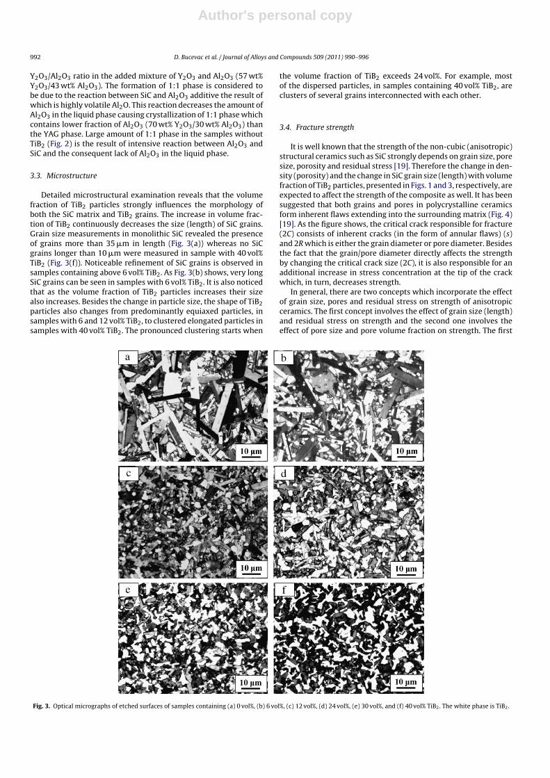
Detailed microstructural examination reveals that the volumefraction of TiB2 particles strongly influences the morphology ofboth the SiC matrix and TiB2 grains. The increase in volume frac-tion of TiB2 continuously decreases the size (length) of SiC grains.Grain size measurements in monolithic SiC revealed the presenceof grains more than 35 �m in length (Fig. 3(a)) whereas no SiCgrains longer than 10 �m were measured in sample with 40 vol%TiB2 (Fig. 3(f)). Noticeable refinement of SiC grains is observed insamples containing above 6 vol% TiB2. As Fig. 3(b) shows, very longSiC grains can be seen in samples with 6 vol% TiB2. It is also noticedthat as the volume fraction of TiB2 particles increases their sizealso increases. Besides the change in particle size, the shape of TiB2particles also changes from predominantly equiaxed particles, insamples with 6 and 12 vol% TiB2, to clustered elongated particles insamples with 40 vol% TiB2. The pronounced clustering starts when
the volume fraction of TiB2 exceeds 24 vol%. For example, mostof the dispersed particles, in samples containing 40 vol% TiB2, areclusters of several grains interconnected with each other.
3.4. Fracture strength
It is well known that the strength of the non-cubic (anisotropic)structural ceramics such as SiC strongly depends on grain size, poresize, porosity and residual stress [19]. Therefore the change in den-sity (porosity) and the change in SiC grain size (length) with volumefraction of TiB2 particles, presented in Figs. 1 and 3, respectively, areexpected to affect the strength of the composite as well. It has beensuggested that both grains and pores in polycrystalline ceramicsform inherent flaws extending into the surrounding matrix (Fig. 4)[19]. As the figure shows, the critical crack responsible for fracture(2C) consists of inherent cracks (in the form of annular flaws) (s)and 2R which is either the grain diameter or pore diameter. Besidesthe fact that the grain/pore diameter directly affects the strengthby changing the critical crack size (2C), it is also responsible for anadditional increase in stress concentration at the tip of the crackwhich, in turn, decreases strength.
In general, there are two concepts which incorporate the effectof grain size, pores and residual stress on strength of anisotropicceramics. The first concept involves the effect of grain size (length)and residual stress on strength and the second one involves theeffect of pore size and pore volume fraction on strength. The first
Fig. 3. Optical micrographs of etched surfaces of samples containing (a) 0 vol%, (b) 6 vol%, (c) 12 vol%, (d) 24 vol%, (e) 30 vol%, and (f) 40 vol% TiB2. The white phase is TiB2.

Author's personal copy
D. Bucevac et al. / Journal of Alloys and Compounds 509 (2011) 990–996 993
Fig. 4. Schematics of aggregate of grains in polycrystalline hexagonal ceramicsshowing annular flaws (s) emanating from the central grain/pore [19]. �a is theapplied stress.
concept is presented by the following equation [20]:
�f =[
�E�eff
L(1 + s/R)(1 − �2)
]1/2
− AP˚t (2)
where �f is the fracture strength, E is the Young’s modulus, �eff isthe effective fracture energy, L is the grain length, s is the annularflaw size, R is the grain half-length (L = 2R), � is the Poisson’s ratio,A is a constant related to the level of residual stress relaxation, Pis the residual thermoelastic stress and ˚t is a constant expressedas:
˚t = 1 −(
1 − 1
(1 + s/R)2
)1/2
+ 1
2(1 + s/R)3/2
(1 − 1
(1 + s/R)2
)1/2
(3)
The residual stress P is given by the modified Selsing’s equation[21]:
P = 2E(˛max − ˛min)(Tmax − Tmin)3(1 − �)
= 2E �˛ �T
3(1 − �)(4)
where ˛max is the linear thermal expansion coefficient in the direc-tion of the highest thermal contraction (expansion), ˛min is thelinear thermal expansion coefficient in the direction of the low-est thermal contraction (expansion), Tmax is the temperature fromwhich the sample is cooled (1940 ◦C) and Tmin is the temperatureto which the sample is cooled (room temperature). The maximumanisotropic residual stress is expected to be generated when thecentral grain is oriented with the respect to the neighboring grainssuch that the axis of minimal thermal expansion (contraction) of thecentral grain is parallel to the axis of maximum thermal contractionof the surrounding grains. Under these conditions, the surroundinggrains are subjected to the tensile stress which, in addition to theapplied stress, causes the increase in the stress concentration at thecrack tip and consequent decrease in strength. It is also worth not-ing that the annular flaw size (s) and grain half-length (R), given inEq. (2), are not related to each other [19].
It is evident from Eq. (2) that the large value for grain length (L)is expected to reduce the strength of anisotropic material. Basedon Eq. (2) it is clear that low fracture strength of samples with 0and 6 vol% TiB2, given in Fig. 5, is due to the presence of relatively
4
8
12
16
350
400
450
500
550
403020100
Aavera
ge len
gth
(µ
m)
Fra
ctu
re s
tren
gth
(M
Pa)
Volume fraction of TiB2 (vol%)
Strength
Average length
Fig. 5. Change of fracture strength and average length of elongated SiC grains withvolume fraction of TiB2.
long SiC grains known to reduce the strength of polycrystalline SiC[6,7]. As Fig. 5 shows, the average length of elongated SiC grains insamples containing no TiB2 is ∼17 �m. However, some of the SiCgrains are as long as 85 �m and these grains actually determine thestrength of the composite (see Fig. 6(a)). At approximately 12 vol%TiB2, the average length of the SiC grains is reduced to ∼10 �m atwhich point the strength reaches the highest value. For this com-position, careful observation of polished surfaces revealed no grainlonger than 50 �m.
Fig. 6. Samples without TiB2 (a) etched surface showing exaggerated SiC graingrowth and (b) polished surface showing pore size. Magnification 400× and 1000×,respectively.

Author's personal copy
994 D. Bucevac et al. / Journal of Alloys and Compounds 509 (2011) 990–996
One can also argue that the higher strength of samples con-taining 12 vol% TiB2 compared to that of monolithic SiC is also theresult of higher density of the samples with 12 vol% TiB2 (Fig. 1).Although it is well known that density (porosity) strongly affectsstrength, it is reasonable to assume that in compositions in whichthe length of SiC grains is much larger than the pore size, theeffect of SiC grain length on strength is more pronounced thanthe effect of porosity. As Fig. 6(b) shows, there is large num-ber of pores in samples without TiB2 but the pore size is below20 �m which is much smaller than the length of big SiC grainsof ∼85 �m.
Above approximately 12 vol% TiB2, the relationship betweenstrength and SiC grain length is opposite. As Fig. 5 shows, anincrease in the volume fraction of TiB2 above 12 vol% causes adecrease in the SiC grain length which is followed by a decreasein the fracture strength of the composite. Considerable decrease instrength was observed in samples containing above 24 vol% TiB2.The observed decrease in strength with a decrease in SiC grainlength cannot be explained by Eq. (2) as it clearly shows that thedecrease in SiC grain length (L) is expected to increase strength.This implies that the strength of samples with more than 12 vol%TiB2 is not controlled by the SiC grain length.
In order to further examine the relationship between the frac-ture strength and SiC grain length in samples containing 0–30 vol%TiB2, the change of strength (from Eq. (2)) with SiC grain length(L) for various s/R values is presented in Fig. 7. Samples with 40and 50 vol% TiB2 are not discussed as their density was below97% TD which is considered too low for structural applications.The effective fracture energy (�eff) of 30 J/m2, Young’s modulus of415 GPa and Poisson’s ratio of 0.17 [10] were used for calculation.The residual stress P was estimated through Eq. (4) using values forlinear thermal expansion coefficients of SiC, ˛max = 4.9 × 10⁻⁶ ◦C−1,˛min = 4.6 × 10⁻⁶ ◦C−1 [11] and �T = 1900 ◦C. It was assumed thatcomplete relaxation of anisotropic stress occurs during coolingfrom sintering temperature all the way to ∼800 ◦C and the stressbuild up starts below 800 ◦C. On that basis, the value for con-stant A was selected to be ∼0.42. The constant ˚t was calculatedthrough Eq. (3). In this calculation, the presence of TiB2 particleswas assumed to have only minor effect on the anisotropic behaviorof the SiC matrix.
Fig. 7 shows that the decrease in SiC grain length is followed bythe increase in fracture strength for all s/R values. Good fit betweenpredicted and measured values is found for samples containing upto 12 vol% TiB2. Based on Eq. (2), it is predicted that s/R ratio rangesfrom 1.4 in samples without TiB2 to 1.8 in samples with 12 vol%TiB2. It is also predicted from Eq. (2) that the annular flaw size isreduced from ∼60 �m in samples with 0 and 6 vol% TiB2 to ∼45 �min samples with 12 vol% TiB2. This decrease in flaw size indicates
Fig. 7. Change of predicted values of fracture strength (solid lines) with SiC grainlength for various s/R values (from Eq. (2)) and measured values for strength (des-ignated as �) of samples containing 0–30 vol% TiB2.
that not only does the presence of 12 vol% TiB2 decrease the SiCgrain length but also it reduces the flaw size (s).
The decrease in strength of samples with more than 12 vol%TiB2 despite further decrease in SiC grain length can be explainedby the increase in the inherent flaw size (s). From Fig. 7 one cansee that samples with 30 vol% TiB2 have relatively large inherentflaw size of ∼80 �m and s/R ratio of 11.3. However, the detailmicrostructural analysis reveals that it is more plausible that thebig pores are the origin of fracture in samples containing more than12 vol% TiB2 rather than the elongated SiC grains with large ema-nating flaws. As Fig. 8(a) and (b) shows, the largest pore diameterin samples with 12 vol% and 24 vol% TiB2 is 40 �m, approximately.These big pores are considered to be the origin of fracture in sam-ples with 24 vol% TiB2 since their diameter is larger than the SiCgrain length which does not exceed 30 �m. In samples with 12 vol%TiB2 it was much more difficult to determine the origin of fractureas the length of the longest SiC grain (∼50 �m) was close to thesize of the largest pore. Very small variation of strength of sam-ples containing 12–24 vol% TiB2 (∼18 MPa), indicates that the causeof fracture in these compositions is the same, i.e., the presenceof big pores. As the volume fraction of TiB2 increases the size ofthe large pores also increases and for samples with 30 vol% TiB2 itreaches the level of ∼60 �m (Fig. 8(c)). The increase in pore size isbelieved to be the main reason for sharp drop in strength of thesesamples (Fig. 5).
The effect of porosity on fracture strength can be explained onthe basis of the following equation [19]:
�f =[
��eff Eo
D(1 + s/r)(1 − �2)
]1/2[1 + 4Vp(1 − �2)(1 + s/r)3
�
]−1/2
(5)
which relates the pore volume fraction, Vp, the pore diameter, D,and the inherent flaw size, s. Other parameters in Eq. (5) are theeffective fracture energy, �eff, the Young’s modulus of the pore freematerial, Eo, the pore radius, r, and the Poisson’s ratio, �.
Eq. (5) shows that an increase in pore volume fraction (Vp) isexpected to reduce the fracture strength. The support to this isfound in Fig. 9 which depicts both calculated values for strengthas a function of pore volume fraction for various s/R values andthe measured strength of samples containing 18–40 vol% TiB2. Asthe figure shows there is the decrease in measured strength aspore volume fraction is increased (see Fig. 9). It can also be seenthat the s/R ratio decreases continuously as the volume fractionof TiB2 increases, which is believed to be the result of SiC grainsrefinement.
In conclusion, the presence of TiB2 particles in SiC matrix playsan important role in inhibiting growth of SiC grains resulting inan increase in strength of the composite. While grain refinementis beneficial in enhancing the strength it limits the grain pull-outand excludes the possible crack bridging mechanism for toughen-ing known to operate in SiC ceramics. The role of elongated SiCgrains in strengthening of the composite is discussed in the nextsection.
3.5. Fracture surface
The nature of crack propagation in monolithic SiC and SiC with24 vol% TiB2 is revealed in Fig. 10 which shows SEM micrographs ofthe fracture surfaces. The examination of Fig. 10 reveals no signs ofcrack bridging which is one of the frequently observed mechanismsof strengthening and toughening in SiC. As can be seen in Fig. 10(a),a number of long SiC plates (>20 �m) in monolithic SiC fracturetrans-granularly.
Contrary to what was expected, the less elongated SiC grainsas well as equiaxed TiB2 grains in the samples containing 24 vol%TiB2 (Fig. 10(b)) appear to participate in crack deflection much

Author's personal copy
D. Bucevac et al. / Journal of Alloys and Compounds 509 (2011) 990–996 995
Fig. 8. Optical micrographs of polished surfaces showing porosity (black areas)in samples containing (a) 12 vol%, (b) 24 vol% and (c) 30 vol% TiB2 (whiteareas).
300
350
400
450
500
550
600
4,53,52,51,50,5
Fra
ctu
re s
tren
gth
(M
Pa)
Pore volume fraction (vol%)
18 %
24 %
30 %
40 %s/R=1.6
s/R=1.8
s/R=2.1s/R=2.3
Fig. 9. Change of predicted values of fracture strength (solid lines) with pore volumefraction for various s/R values and the measured values for strength (designatedas �) of samples containing 18–40 vol% TiB2. Predicted values for strength weredetermined by substituting appropriate values for �eff = 30 J/m2, Eo = 420–435 GPa,and D = 40 �m (samples with 18 and 24 vol% TiB2), D = 60 �m (samples with 30 and40 vol% TiB2) in Eq. (5).
Fig. 10. SEM micrographs of fracture surfaces of samples with (a) 0 vol% TiB2 (sec-ondary electrons) showing trans-granular fracture of long SiC plates (arrows) and(b) 24 vol% TiB2 (back scattering electrons) showing crack deflection (the arrowsindicate TiB2 particles).
Author's personal copy
996 D. Bucevac et al. / Journal of Alloys and Compounds 509 (2011) 990–996
10
11
12
13
14
15
16
17
18
94
95
96
97
98
99
100
50403020100
Hard
ness (
GP
a)
Rela
tive d
en
sit
y (
%T
D)
Volume fraction of TiB2 (vol%)
Density
Hardness
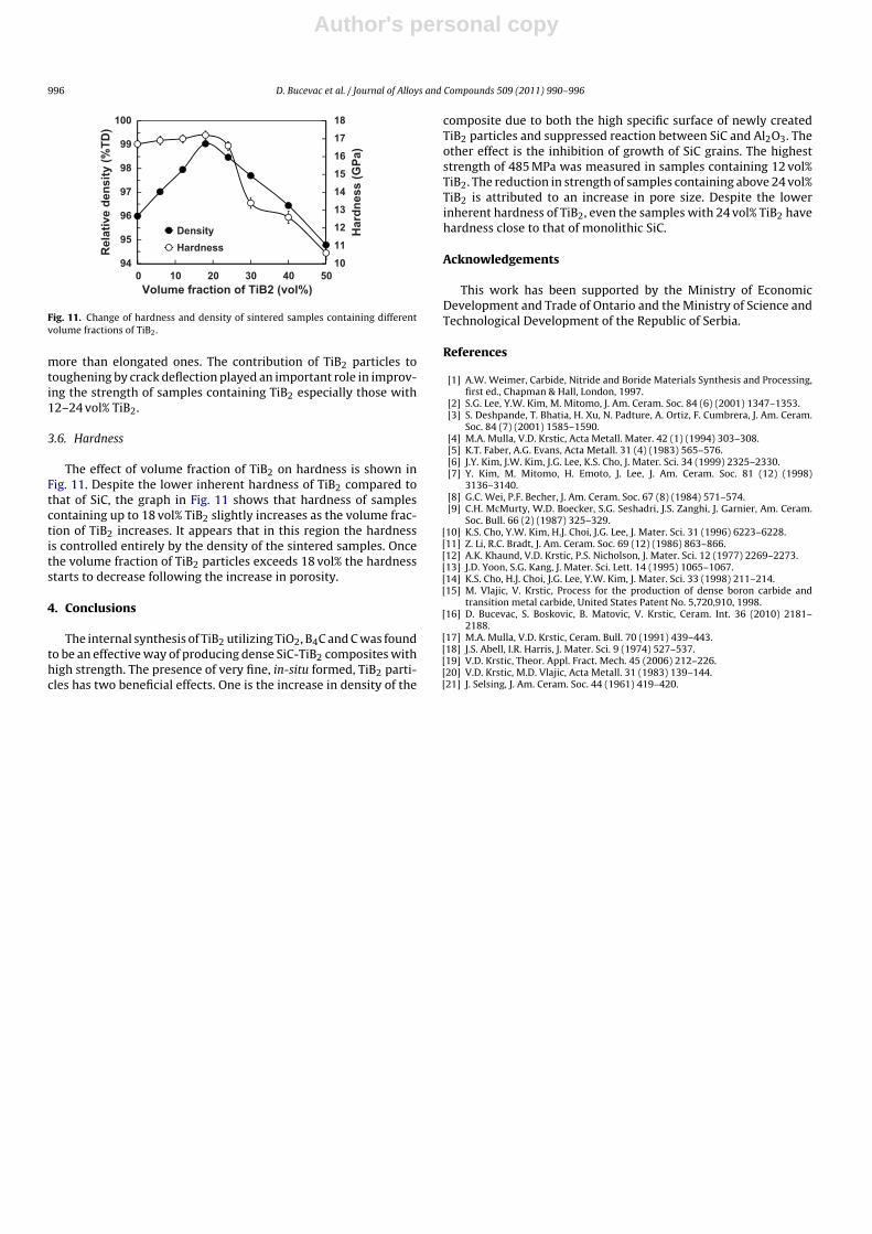
Fig. 11. Change of hardness and density of sintered samples containing differentvolume fractions of TiB2.
more than elongated ones. The contribution of TiB2 particles totoughening by crack deflection played an important role in improv-ing the strength of samples containing TiB2 especially those with12–24 vol% TiB2.
3.6. Hardness
The effect of volume fraction of TiB2 on hardness is shown inFig. 11. Despite the lower inherent hardness of TiB2 compared tothat of SiC, the graph in Fig. 11 shows that hardness of samplescontaining up to 18 vol% TiB2 slightly increases as the volume frac-tion of TiB2 increases. It appears that in this region the hardnessis controlled entirely by the density of the sintered samples. Oncethe volume fraction of TiB2 particles exceeds 18 vol% the hardnessstarts to decrease following the increase in porosity.
4. Conclusions
The internal synthesis of TiB2 utilizing TiO2, B4C and C was foundto be an effective way of producing dense SiC-TiB2 composites withhigh strength. The presence of very fine, in-situ formed, TiB2 parti-cles has two beneficial effects. One is the increase in density of the
composite due to both the high specific surface of newly createdTiB2 particles and suppressed reaction between SiC and Al2O3. Theother effect is the inhibition of growth of SiC grains. The higheststrength of 485 MPa was measured in samples containing 12 vol%TiB2. The reduction in strength of samples containing above 24 vol%TiB2 is attributed to an increase in pore size. Despite the lowerinherent hardness of TiB2, even the samples with 24 vol% TiB2 havehardness close to that of monolithic SiC.
Acknowledgements
This work has been supported by the Ministry of EconomicDevelopment and Trade of Ontario and the Ministry of Science andTechnological Development of the Republic of Serbia.
References
[1] A.W. Weimer, Carbide, Nitride and Boride Materials Synthesis and Processing,first ed., Chapman & Hall, London, 1997.
[2] S.G. Lee, Y.W. Kim, M. Mitomo, J. Am. Ceram. Soc. 84 (6) (2001) 1347–1353.[3] S. Deshpande, T. Bhatia, H. Xu, N. Padture, A. Ortiz, F. Cumbrera, J. Am. Ceram.
Soc. 84 (7) (2001) 1585–1590.[4] M.A. Mulla, V.D. Krstic, Acta Metall. Mater. 42 (1) (1994) 303–308.[5] K.T. Faber, A.G. Evans, Acta Metall. 31 (4) (1983) 565–576.[6] J.Y. Kim, J.W. Kim, J.G. Lee, K.S. Cho, J. Mater. Sci. 34 (1999) 2325–2330.[7] Y. Kim, M. Mitomo, H. Emoto, J. Lee, J. Am. Ceram. Soc. 81 (12) (1998)
3136–3140.[8] G.C. Wei, P.F. Becher, J. Am. Ceram. Soc. 67 (8) (1984) 571–574.[9] C.H. McMurty, W.D. Boecker, S.G. Seshadri, J.S. Zanghi, J. Garnier, Am. Ceram.
Soc. Bull. 66 (2) (1987) 325–329.[10] K.S. Cho, Y.W. Kim, H.J. Choi, J.G. Lee, J. Mater. Sci. 31 (1996) 6223–6228.[11] Z. Li, R.C. Bradt, J. Am. Ceram. Soc. 69 (12) (1986) 863–866.[12] A.K. Khaund, V.D. Krstic, P.S. Nicholson, J. Mater. Sci. 12 (1977) 2269–2273.[13] J.D. Yoon, S.G. Kang, J. Mater. Sci. Lett. 14 (1995) 1065–1067.[14] K.S. Cho, H.J. Choi, J.G. Lee, Y.W. Kim, J. Mater. Sci. 33 (1998) 211–214.[15] M. Vlajic, V. Krstic, Process for the production of dense boron carbide and
transition metal carbide, United States Patent No. 5,720,910, 1998.[16] D. Bucevac, S. Boskovic, B. Matovic, V. Krstic, Ceram. Int. 36 (2010) 2181–
2188.[17] M.A. Mulla, V.D. Krstic, Ceram. Bull. 70 (1991) 439–443.[18] J.S. Abell, I.R. Harris, J. Mater. Sci. 9 (1974) 527–537.[19] V.D. Krstic, Theor. Appl. Fract. Mech. 45 (2006) 212–226.[20] V.D. Krstic, M.D. Vlajic, Acta Metall. 31 (1983) 139–144.[21] J. Selsing, J. Am. Ceram. Soc. 44 (1961) 419–420.