Fabrication and characterization of sol–gel derived 45S5 Bioglass ceramic scaffolds
Upload
independentCategory
view
20download
0
A
Tm5rcDhd1h©
K
1
r2e4Ptesft
P
0d
Available online at www.sciencedirect.com
Journal of the European Ceramic Society 29 (2009) 3299–3306
Sintering and crystallisation of 45S5 Bioglass® powder
Oana Bretcanu a,1, Xanthippi Chatzistavrou a, Konstantinos Paraskevopoulos b,Reinhard Conradt c, Ian Thompson d, Aldo R. Boccaccini a,∗
a Department of Materials, Imperial College London, Prince Consort Rd., London SW7 2BP, UKb Department of Physics, Aristotle University of Thessaloniki, Thessaloniki 54124, Greece
c Institut fuer Gesteinshuettenkunde, RWTH Aachen, 52056 Aachen, Germanyd Department of Biomaterials, King’s College London Dental Institute, London SE1 9RT, UK
Received 29 March 2009; received in revised form 14 June 2009; accepted 24 June 2009Available online 24 July 2009
bstract
he sintering process of 45S5 Bioglass® powder (mean particle size < 5 �m) was investigated by using different thermal analysis methods. Heatingicroscopy and conventional dilatometry techniques showed that bioactive glass sinters in two major steps: a short stage in the temperature range
00–600 ◦C and a longer stage in the range 850–1100 ◦C. The optimal sintering temperature and time were found to be 1050 ◦C and 140 min,espectively. Differential thermal analysis (DTA) showed that Bioglass® crystallises at temperatures between 600 and 750 ◦C. The characteristicrystalline phases were identified by Fourier Transformed Infrared Spectroscopy (FTIR), Transmission Electron Microscopy (TEM) and X-Rayiffraction (XRD). The crystallisation kinetics was studied by DTA, using a non-isothermal method. The Kissinger plot for Bioglass® powdereated at different heating rates between 5 and 30 ◦C/min yielded an activation energy of 316 kJ/mol. The average value of Avrami parameter
etermined using the Augis–Bennett method was 0.95 ± 0.10, confirming a surface crystallisation mechanism. After sintering at 1050 ◦C for40 min, the main crystalline phase was found to be Na2Ca2Si3O9. The results of this work are useful for the design of the sintering/crystallisationeat treatment of Bioglass® powder which is used for fabricating tissue engineering scaffolds with varying degree of bioactivity.2009 Elsevier Ltd. All rights reserved.
ctura
fsTsbhsfcs
eywords: A. Sintering; B. Microstructure-final; C. Thermal properties; E. Stru
. Introduction
45S5 Bioglass® is a commercially available inorganic mate-ial, which has been used as bone replacement for more than0 years.1 This is the first bioactive glass developed by Hencht al. in 1969 2 and has the following chemical composition:5 wt.% SiO2, 24.5 wt.% Na2O, 24.5 wt.% CaO and 6 wt.%2O5. This glass is highly bioactive and it is both osteoinduc-
ive and osteoconductive, enabling its application in bone tissuengineering.3,4 Moreover, it has been shown that the ionic dis-olution products of 45S5 Bioglass® may enhance new bone
ormation (osteogenesis) through a direct control over geneshat regulate cell induction and proliferation.5∗ Corresponding author. Tel.: +44 2075946731; fax: +44 2075946757.E-mail address: [email protected] (A.R. Boccaccini).
1 Current address: Materials Science and Chemical Engineering Department,olitecnico di Torino, Italy.
soeft
ta
955-2219/$ – see front matter © 2009 Elsevier Ltd. All rights reserved.oi:10.1016/j.jeurceramsoc.2009.06.035
l applications; Bioglass®
45S5 Bioglass® has been used for fabrication of scaffoldsor bone tissue engineering by sintering powders of particleize < 5 �m and employing the foam replication technique.6
he success of the scaffold fabrication process depends on theintering ability of the Bioglass® powder since this particularioactive glass composition is prone to crystallisation at theigh temperature required for sintering, as also investigated byeveral authors.7–11 Therefore, the requisite for optimising theabrication of Bioglass® scaffolds is to understand the sinteringonditions of Bioglass® particles and the interaction betweenintering and crystallisation of the material. By knowing thetructural transformations which occur during the heat treatmentf Bioglass®, the scaffold fabrication process can be tailored,.g. in terms of achieving the highest possible density of theoam struts and the required crystallinity which itself controls
he material bioactivity.12Previous studies have shown that there are five structuralransformations during the heating of Bioglass® up to 1000 ◦C:
first glass transition, a glass-in-glass phase separation, two

3 pean
cMfot
os(stbm(
2
2
tcfm
2
dtaAsota∼iiaatf
s
wA
whi2hta
pe
s
wa
asardBwshts
S
S
waSr
abacsoc
k
Iat
2
wcbto measure the shrinkage of the samples during heating up to1150 ◦C with a heating rate of 10 ◦C/min. The relative variation
300 O. Bretcanu et al. / Journal of the Euro
rystallisation processes and a second glass transition.12–14
odelling of the sintering behaviour of bioactive glass scaf-olds has been also considered recently15 but there is still a lackf knowledge about the effect of different process variables onhe final microstructure of the partially crystallised Bioglass®.
The aim of this work was to study the sintering processf 45S5 Bioglass® powder by using different thermal analy-is methods; including dilatometry, differential thermal analysisDTA) and, for the first time, heating microscopy to investigateintering anisotropy effects. The crystalline phase characterisa-ion after the crystallisation and sintering process was carried outy Fourier Transformed Infrared Spectroscopy (FTIR), Trans-ission Electron Microscopy (TEM) and X-Ray Diffraction
XRD) techniques.
. Experimental procedures
.1. Materials
Bioglass® (type 45S5) powder (NovaMin USA) of mean par-icle size <5 �m was used in this investigation. The chemicalomposition was given in Section 1. This glass is being used forabrication of tissue engineering scaffolds by the foam replicaethod,6 as mentioned above.
.2. Heating microscopy
The sintering process of Bioglass® powder compacts wasirectly observed by heating microscopy. This technique allowshe quantification of sintering variables by measuring the vari-tion of the sample dimensions during the heating process.16
Leitz-Wetzlar heating stage optical microscope was used andintering was investigated in air atmosphere, using a heating ratef 20 ◦C/min. The samples were obtained by pressing manuallyhe Bioglass® powder using a rectangular die. The nominal rel-tive density of the fabricated samples (“green” density) was0.50. The specimens were observed by a video camera and
mages of the specimen silhouettes during sintering were reg-stered up to 1150 ◦C. The shrinkage–temperature curves werenalysed by using three different samples and the results wereveraged. The samples’ shrinkage was calculated at specificemperatures from the variation of the samples’ area, using theollowing equation, which assumes isotropic shrinkage:
hrinkage(%) = A0 − AT
A0100 (1)
here A0 = the initial area of the specimen at room temperature;T = the area of the specimen at temperature T.
The variation of sample shrinkage with time and temperatureas registered by heating the samples up to 1050 ◦C using aeating rate of 20 ◦C/min. In addition, isothermal sintering wasnvestigated by holding the green body samples at 1050 ◦C for
00 min in the heating microscope. Images of the sample sil-ouettes were taken every 5 min. The experiment was repeatedhree times, using three different samples and the results wereveraged. The samples’ shrinkage was calculated at each timeodca
Ceramic Society 29 (2009) 3299–3306
oint from the variation of the samples’ area, using the followingquation:
hrinkage(%) = At0 − At
At0100 (2)
here At0 = the area of the specimen at time 0 at 1050 ◦C; At = therea of the specimen at time t at 1050 ◦C.
In a separate set of experiments to assess possible shrinkagenisotropy, heating microscopy was carried out on cylindricalpecimens monitoring the axial (height) and radial shrinkaget temperatures of up to 1150 ◦C using three different heatingates: 3, 10 and 20 ◦C/min. The starting samples were of 2 mmiameter and 2 mm height and were obtained by pressing theioglass® powder in a cylindrical die. Three different specimensere used for each heating rate. During the sintering process, the
pecimens’ silhouettes were recorded by a video camera. Theeight and diameter of the silhouettes were measured at differentime points and the results were averaged. The axial and radialhrinkage were calculated using the following equations:
H = �H
H0= H0 − Hi
H0(3)
D = �D
D0= D0 − Di
D0(4)
here SH = axial shrinkage; H0 = initial height of the samplest room temperature; Hi = height of the samples at time i;D = radial shrinkage; D0 = initial diameter of the samples atoom temperature; Di = diameter of the samples at time i.
If the samples sinter isotropically, the axial and radial shrink-ge are equal (SH = SD). On the contrary, for anisotropic sinteringehaviour, SH /= SD. By plotting the axial versus radial shrink-ge, the isotropic/anisotropic characteristics of the specimensan be determined.17 A more convenient way to quantify thehrinkage anisotropy of sintering materials is the calculationf the shrinkage anisotropy factor k. This parameter can bealculated with the following equation17:
= SD
SH
(5)
f k = 1, the sintering is isotropic; if k /= 1, the sintering isnisotropic. In the present study the evolution of k with sinteringime was investigated.
.3. Dilatometry
The sintering temperature of Bioglass® powder compactsas also determined using dilatometry measurements. Cylindri-
al pellets having 5 mm diameter and 8 mm length were obtainedy uniaxial pressing. A Netzsch dilatometer 402 E was used
f the sample’s length (�L/L0) during heating was measuredirectly by the instrument where L0 is the initial length of theylindrical sample and �L is the variation of the sample’s lengtht a given temperature.

pean
2
mwiuTpwkTt
l
wT(
o
db
n
wmfv
tt
s
H
wpt
t
2
tmt2taiv1
2
F
O. Bretcanu et al. / Journal of the Euro
.4. Differential thermal analysis (DTA)
DTA of Bioglass® powder was performed on a PL Ther-al Sciences STA 1500 DCI instrument. The measurementsere carried out in air, up to 1250 ◦C, using a range of heat-
ng rates between 5 and 30 ◦C/min. Pure alumina powder wassed both as reference material and for base line determination.he Bioglass® characteristic temperatures (glass transition tem-erature, crystallisation temperature and melting temperature)ere determined directly from the DTA plots. The crystallisationinetics was studied by DTA using a non-isothermal method.he activation energy for crystallisation (E) was calculated from
he Kissinger equation18:
n
(α
T 2p
)= − E
RTp+ constant (6)
here E = activation energy (kJ/mol); α = heating rate (K/min);p = peak crystallisation temperature; R = gas constant8.32 J K−1 mol−1).
By plotting [− ln(α/T 2p )] versus 1/Tp the activation energy
f crystallisation can be calculated from the slope of the curve.The mechanism of nucleation and growth of crystals can be
efined by the Avrami parameter, n, which can be determinedy the Augis–Bennet equation.18
= 2.5
�T
RT 2p
E(7)
here �T (K) is the width of the crystallisation peak at the halfaximum. If n ≈ 1, crystallisation occurs from the surface (sur-
ace crystallisation). If n ≈ 3, crystallisation takes place from theolume (volumetric crystallisation).19 When surface crystallisa-
twm
ig. 1. Heating microscope silhouettes of a cubic Bioglass® sample at different charac
Ceramic Society 29 (2009) 3299–3306 3301
ion is dominant (n = 1), the nuclei are formed prior to or duringhe thermal treatment.20
Another parameter used for evaluation of the glass crystalli-ation ability is the Hruby coefficient (Hr) given by Eq. (8):
r = Tp − Tg
Tm − Tp(8)
here Hr = Hruby coefficient; Tp = peak crystallisation tem-erature; Tg = glass transition temperature; Tm = onset meltingemperature (beginning of the melting process).
The higher the value of Hr, the lower is the crystallisationendency of the material.21
.5. FTIR
FTIR measurements were carried out by using a Bruker spec-rometer IFS 113 V, the spectra were collected in the reflectance
ode, in MIR region (5000–400 cm−1) and for each spec-rum 128 consecutive scans were recorded with a resolution ofcm−1. Samples of Bioglass® powder were characterised before
he heat treatment and at characteristic temperatures (570, 700nd 800 ◦C). The sample preparation was performed by obtain-ng a quantity of Bioglass® in powder form and pressing it in aacuum press at 7 t, in order to produce pellets with diameter of3 mm and thickness of 0.8 mm.
.6. TEM
The TEM study was performed on samples of Bioglass® heatreated up to 800 ◦C, using a conventional TEM (JEM 100C)orking at 100 kV. Appropriate specimens were prepared byechanical polishing and ion beam thinning.
teristic temperatures during sintering up to 1100 ◦C with heating rate 20 ◦C/min.

3302 O. Bretcanu et al. / Journal of the European Ceramic Society 29 (2009) 3299–3306
Ft
2
m1dau(
3
3
sdrccatatsgpt
as
FB
m5ssdaamtBwFsTrT1psapaisftsrf
D
TS
T
HD
ig. 2. Variation of shrinkage of Bioglass® powder compacts as function ofemperature for a heating rate of 20 ◦C/min (cubic samples).
.7. XRD
XRD measurements on Bioglass® powders before heat treat-ent, after crystallisation at 800 ◦C and after sintering at
050 ◦C for 140 min were carried out using a Philips X’Pertiffractometer with Cu K� radiation, using a step of 0.04◦ (2θ)nd a time per step of 2 s. The diffraction lines were identifiedsing “X’Pert HighScore” program, with PCPDFWIN database2002 JCPDS-International Centre for Diffraction Data).
. Results and discussion
.1. Heating microscopy
Typical heating microscope silhouettes of cubic Bioglass®
amples during sintering at a heating rate of 20 ◦C/min and atifferent characteristic temperatures are shown in Fig. 1. Theeduction of the sample dimensions during the sintering pro-ess can be noticed. The dimensional changes of the samplean be clearly appreciated by comparing the two images at 50nd 1100 ◦C. The sample seems to keep the cubic shape upo 1100 ◦C (Fig. 1a–e). At 1100 ◦C the sample started to meltnd the shape of the silhouette changes (Fig. 1f). Increasinghe temperature further, the glass becomes softer and viscosityignificantly decreases. Melting starts from the surface and thelass specimen deforms under its own weight, thus, the bottomart of the sample expands becoming more rounded, while the
op of the sample starts to distort.The variation of shrinkage as function of sintering temper-ture (Eq. (1)) is illustrated in Fig. 2. Two distinct sinteringteps can be distinguished: a first stage (step 1) and a longer and
rcds
able 1intering characteristic temperatures determined from the shrinkage–temperature cur
ype analysis T1 (◦C) T2 (◦
eating microscopy (rate 20 ◦C/min) 500 600ilatometry (rate 10 ◦C/min) 530 620
ig. 3. Variation of shrinkage versus time during isothermal sintering ofioglass® powder compacts at 1050 ◦C (cubic samples).
ore marked stage (step 2). The first densification step starts at00 ◦C (T1) and ends at 600 ◦C (T2). The second densificationtep starts at 950 ◦C (T3). The shrinkage associated to the firsttep is around 12%. While samples were found to shrink moreuring the second densification step (around 36%). Between T2nd T3, the samples shrink about 5% and the plotted shrink-ge curve indicates a horizontal plateau. All samples start toelt at around 1100 ◦C (T4). The four characteristic tempera-
ures are indicated in Table 1. The sintering temperatures for theioglass® samples are included in the interval 1000–1100 ◦Chen the higher densification is obtained. As can be seen inig. 1e, the sample still keeps its shape at 1050 ◦C, however pos-ible anisotropic shrinkage effects are considered further below.he study of shrinkage versus time (Eq. (2)) was therefore car-
ied out at 1050 ◦C. The obtained graphic is presented in Fig. 3.he optimum sintering time at 1050 ◦C can be considered to be40 min, where the curve of shrinkage (%) versus time reaches alateau. The isothermal sintering study confirms that additionalhrinkage occurs (about 15%), resulting in a total shrinkage ofbout of 55%. Therefore under isothermal conditions Bioglass®
owder compacts should be sintered at 1050 ◦C for 140 min tochieve maximal densification. This finding is very importantn terms of understanding the structural transformations duringintering of Bioglass® powder leading to dense materials. Theurther fine tuning of these parameters will be required to develophe optimised fabrication process for porous scaffolds from theame Bioglass® powder. Indeed sintering at temperatures in theange 1000–1100 ◦C was used in previous studies to fabricateoam-like scaffolds with open porosity and highly dense struts.6
The variation of sample dimensions (height H and diameter) of cylindrical samples during sintering at different heating
ates is shown in Fig. 4. To put in evidence the rate of densifi-ation, shrinkage is plotted against sintering time for the threeifferent sintering rates investigated (3, 10 and 20 ◦C/min). Thehape of the curves is similar for both height and diameter and
ves by heating microscopy and dilatometry techniques.
C) T3 (◦C) T4 (◦C) T5 (◦C)
950 1100 –850 1130 1050
O. Bretcanu et al. / Journal of the European Ceramic Society 29 (2009) 3299–3306 3303
Foa
ta(oowctcthhis
vsAt
Fs
Fr
ucbtmvtfhctrhIcosed
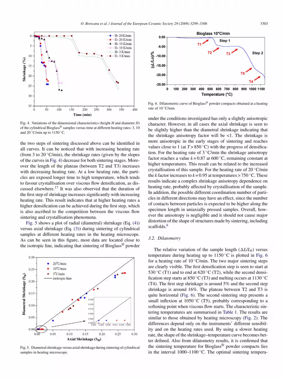
ig. 4. Variations of the dimensional characteristics (height H and diameter D)f the cylindrical Bioglass® samples versus time at different heating rates: 3, 10nd 20 ◦C/min up to 1150 ◦C.
he two steps of sintering discussed above can be identified inll curves. It can be noticed that with increasing heating ratefrom 3 to 20 ◦C/min), the shrinkage rates (given by the slopesf the curves in Fig. 4) decrease for both sintering stages. More-ver the length of the plateau (between T2 and T3) increasesith decreasing heating rate. At a low heating rate, the parti-
les are exposed longer time to high temperature, which tendso favour crystallisation over viscous flow densification, as dis-ussed elsewhere.17 It was also observed that the duration ofhe first step of shrinkage increases significantly with increasingeating rate. This result indicates that at higher heating rates aigher densification can be achieved during the first step, whichs also ascribed to the competition between the viscous flowintering and crystallisation phenomena.
Fig. 5 shows a plot of radial (diametral) shrinkage (Eq. (4))
ersus axial shrinkage (Eq. (3)) during sintering of cylindricalamples at different heating rates in the heating microscope.s can be seen in this figure, most data are located close tohe isotropic line, indicating that sintering of Bioglass® powder
ig. 5. Diametral shrinkage versus axial shrinkage during sintering of cylindricalamples in heating microscope.
s
3
tfa5fi(sqsstsdirtti
ig. 6. Dilatometric curve of Bioglass® powder compacts obtained at a heatingate of 10 ◦C/min.
nder the conditions investigated has only a slightly anisotropicharacter. However, in all cases the axial shrinkage is seen toe slightly higher than the diametral shrinkage indicating thathe shrinkage anisotropy factor will be <1. The shrinkage is
ore anisotropic in the early stages of sintering and reachesalues close to 1 (at T > 850 ◦C) with the progress of densifica-ion. For the heating rate of 3 ◦C/min the shrinkage anisotropyactor reaches a value k = 0.87 at 600 ◦C, remaining constant atigher temperatures. This result can be related to the increasedrystallisation of this sample. For the heating rate of 20 ◦C/minhe k factor increases to k = 0.95 at temperatures > 750 ◦C. Theseesults indicate a complex shrinkage anisotropy dependence oneating rate, probably affected by crystallisation of the sample.n addition, the possible different coordination number of parti-les in different directions may have an effect, since the numberf contacts between particles is expected to be higher along thepecimen length in uniaxially pressed samples. Overall, how-ver the anisotropy is negligible and it should not cause majoristortion of the shape of structures made by sintering, includingcaffolds.6
.2. Dilatometry
The relative variation of the sample length (�L/L0) versusemperature during heating up to 1150 ◦C is plotted in Fig. 6or a heating rate of 10 ◦C/min. The two major sintering stepsre clearly visible. The first densification step is seen to start at30 ◦C (T1) and to end at 620 ◦C (T2), while the second densi-cation step starts at 850 ◦C (T3) and melting occurs at 1130 ◦CT4). The first step shrinkage is around 5% and the second stephrinkage is around 16%. The plateau between T2 and T3 isuite horizontal (Fig. 6). The second sintering step presents amall inflexion at 1050 ◦C (T5), probably corresponding to aoftening point when viscous flow starts. The characteristic sin-ering temperatures are summarised in Table 1. The results areimilar to those obtained by heating microscopy (Fig. 2). Theifferences depend only on the instruments’ different sensibil-ty and on the heating rates used. By using a slower heating
ate, the shape of the shrinkage–temperature curve becomes bet-er defined. Also from dilatometry results, it is confirmed thathe sintering temperature for Bioglass® powder compacts liesn the interval 1000–1100 ◦C. The optimal sintering tempera-
3304 O. Bretcanu et al. / Journal of the European Ceramic Society 29 (2009) 3299–3306
F
twi
3
rptciDaet
fhciwbBatiic
TD
R
11223
F7s
tifrosctaFi
ig. 7. DTA curves obtained for Bioglass® powder at different heating rates.
ure can be chosen in the centre of this interval, i.e. at 1050 ◦C,hen viscous flow sintering dominates, as also indicated by the
sothermal sintering study (Fig. 3).
.3. DTA analysis and phase characterisation
DTA curves of the Bioglass® powder at different heatingates in the range 5–30 ◦C/min are shown in Fig. 7. All curvesresent a large exothermic peak, between 600 and 750 ◦C, andwo small endothermic peaks, in the range 1150–1250 ◦C. Afterooling to room temperature, all samples had a glassy aspect,ndicating that at least partial melting has occurred during theTA measurement. The large, broad exothermic peak mentioned
bove corresponds to Bioglass® crystallisation, while the twondothermic peaks represent melting processes, e.g. melting ofwo crystalline phases, as discussed in the literature.13
The characteristic temperatures (Tg, Tp and Tm) for the dif-erent heating rates are shown in Table 2. By increasing theeating rate, the glass transition temperature (Tg) and the peakrystallisation temperature (Tp) increase, while the onset melt-ng temperature (Tm) decreases. These results are in agreementith those presented by Clupper and Hench.20 For heating ratesetween 5 and 30 ◦C/min, the Tg varies in the range 500–550 ◦C.ioglass® crystallises between 600 and 750 ◦C and starts to meltt temperature between 1150 and 1180 ◦C. During the crys-
allisation process the development of two crystalline phasess detected. The main crystalline phase is a sodium calcium sil-cate phase and the secondary one is a phosphate phase, whichan be identified by FTIR. The FTIR spectra at the characteris-able 2TA parameters at different heating rates.
ate (◦C/min) Tg (◦C) Tp (◦C) Tm (◦C) Hr n
5 505 650 1174 0.28 1.1700 536 664 1172 0.25 0.9645 544 674 1168 0.26 0.9090 549 676 1165 0.26 0.8865 553 686 1160 0.28 0.8910 551 690 1155 0.30 0.886
tctpiath
TC
a
1
ig. 8. FTIR spectra of Bioglass® before heat treatment, heat treated up to 570,00 and 800 ◦C. Additionally, the characteristic spectra of the sodium calciumilicate (Na2Ca2Si3O9) phase is presented for comparison.
ic temperatures during and after heat treatment at temperaturesn the range 600–800 ◦C are shown in Fig. 8, confirming theormation of the specific crystalline phases in this temperatureange under the particular heat treatment used. The FTIR spectraf Bioglass® before heat treatment and of the sodium calciumilicate phase are also shown for comparison. The melting pro-ess of the two crystalline phases results in the occurrence ofhe two endothermic peaks at 1150–1180 ◦C. These findingsre confirmed by previous work in the literature.11,13,14 TheTIR spectra appear similar to those presented by Filho et al.21
ndicating a high degree of crystallinity under the specific heatreatment. The observation of the Na2Ca2Si3O9 phase was alsoonfirmed by TEM in samples heat treated under the same condi-ions (Fig. 9), while the identification of the secondary phosphatehase was not possible. The Na2Ca2Si3O9 phase crystallised
n hexagonal system and the characteristic lattice parametersre presented in Table 3. However, the presence of both crys-alline phases was also confirmed by XRD analysis in sampleseat treated up to 800 ◦C (Fig. 10). XRD analysis enabled theable 3haracteristic lattice parameters of Na2Ca2Si3O9 crystal, hexagonal system.
b c α β γ
0.561 10.561 13.199 90◦ 90◦ 120◦

O. Bretcanu et al. / Journal of the European Ceramic Society 29 (2009) 3299–3306 3305
FNh
pwe
fTpfdpctt
astflB
Fc
F
msotiitsao
Tficavtaivt
ig. 9. TEM dark field image and electron diffraction pattern of thea2Ca2Si3O9 phase formed during heat treatment of Bioglass® at temperaturesigher than 600 ◦C.
recise identification of the secondary phosphate phase whichas identified as silicorhenanite phase (Na2Ca4(PO4)2SiO4), as
xpected also from the literature.14
The DTA characteristic temperatures are slightly differentrom data obtained by heating microscopy and dilatometry.hese differences can be explained in terms of sample mor-hology. In the case of DTA, the samples were powders, whileor the other techniques, the powder was compressed into pow-er compacts. In the last case, the compaction force reducesorosity between glass particles (green body density) and vis-ous flow sintering is facilitated. Therefore, the characteristicemperatures obtained using powder compacts are lower thanhose determined from DTA.
Considering the results from DTA, heating stage microscopynd dilatometry measurements, we can conclude that the first
tep of densification occurs shortly after the glass transitionemperature is reached, when sintering takes place by viscousow and particles are connected through sintering necks.14 Theioglass® particles crystallise in the range 600–750 ◦C, so theig. 10. XRD pattern of Bioglass® powder heat treated up to 800 ◦C, after theompletion of the crystallisation process.
oaar
Ft�
ig. 11. Calculation of the activation energy for crystallisation from DTA results.
aterial is highly crystalline prior to undergoing the secondtage of densification (above 850 ◦C). The shrinkage plateaubserved between the two stages of sintering corresponds tohe crystallisation process. During crystallisation, the viscosityncreases and viscous flow sintering is inhibited.17,22,23 Withncreasing temperature the viscosity decreases again, leading tohe second sintering stage. Bioglass® powder compacts start theecond stage of sintering above 850 ◦C. According to Lefebre etl.,12,13 the second stage of sintering occurs after crystallisationf the secondary phosphate phase, in agreement with our results.
The plot of [− ln(α/T 2p )] versus 1/Tp is presented in Fig. 11.
he correlation parameter (R2 = 0.9829) indicates a very goodtting. The value of the activation energy for crystallisation cal-ulated from the slope is 316 kJ/mol (Eq. (6)). This value is ingreement with the results obtained by other authors.13,20 Thealues of the Avrami parameter n (Eq. (7)) for Bioglass® crys-allisation at different heating rates are listed in Table 2. Theverage value is 0.95 ± 0.10 and thus a surface crystallisations predominant in this material, as it was expected due to theery small particle size of the studied powder, which enhanceshe surface crystallisation mechanism.23 The calculated values
f the Hruby coefficient (Hr) (Eq. (8)) at different heating ratesre shown in Table 2. The low mean value 0.27 ± 0.02 confirmshigh crystallisation ability of Bioglass®, which has also beeneported in the literature.20
ig. 12. XRD patterns of Bioglass® powder compacts before the heatreatment and after sintering at 1050 ◦C for 140 min (�= Na2Ca2Si3O9,
= Na2Ca4(PO4)2SiO4).

3 pean
hssbtpt(mmmti
4
bTt8smpwBtMtmhcwcocupBc
A
TiC
R
1
1
1
1
1
1
1
1
1
1
2
2
2
306 O. Bretcanu et al. / Journal of the Euro
The XRD patterns of Bioglass® powder compacts beforeeat treatment and after sintering at 1050 ◦C for 140 min arehown in Fig. 12. Before sintering, the XRD pattern of Bioglass®
hows, as expected, that the material is completely amorphousut the sintered material exhibited a diffraction pattern charac-eristic of a glass–ceramic structure. The identified crystallinehases are the same to those observed on samples heat treated atemperatures after the completion of the crystallisation processe.g. 800 ◦C) (Fig. 10). It is thus confirmed that the crystallineicrostructure develops before the completion of sintering. Theain crystalline phase is identified as Na2Ca2Si3O9, in agree-ent with our previous results on fabrication of scaffolds from
he same Bioglass®.6,14 The minor crystalline phase was alsodentified as Na2Ca4(PO4)2SiO4 by Lefebre at al.13
. Conclusions
The sintering process of 45S5 Bioglass® powder was studiedy using different thermal analysis and microscopic methods.he Bioglass® powder sinters in two major steps: the first one in
he temperature range 500–600 ◦C and the second one between50 and 1100 ◦C. After sintering at 1050 ◦C for 140 min, con-idered to be the optimal isothermal sintering conditions, theain crystalline phase is Na2Ca2Si3O9 but other crystalline
hases are possible under different heat treatment conditions,hich are discussed in the literature13. It was confirmed thatioglass® crystallises in the temperature range 600–750 ◦C,
he exact crystallisation temperature depends on heating rate.oreover, it was shown that Bioglass® powder has a high crys-
allisation ability and it crystallises by a surface crystallisationechanism (Avrami parameter n = 0.95), so that the material is
ighly crystalline prior to undergoing the second step of densifi-ation (above 850 ◦C). Under the conditions of the experiments,hich were carried out with equiaxed glass particles, there is no
onsiderable shrinkage anisotropy during sintering. The resultsf the present investigation describing the interaction betweenrystallisation and viscous flow sintering in Bioglass® powdernder different heat treatment conditions are relevant to sup-ort the fabrication of bone tissue engineering scaffolds fromioglass®, which should exhibit tailored porosity, controlledrystallinity and enhanced bioactivity.
cknowledgements
The authors acknowledge experimental assistance of Msania Hoffer (RWTH Aachen) with the heating microscopy
nvestigation and financial support from the EU via the Marieurie fellowship scheme (Grant MEIF-CT-2005-024248).
eferences
1. Hench, L. L., Bioceramics. J. Am. Ceram. Soc., 1998, 81, 1705–1728.2. Hench, L. L., Splinter, R. J., Allen, W. C. and Greenlee, T. K., Bonding
mechanisms at the interface of ceramic prosthetic materials. J. Biomed.Mater. Res., 1971, 2, 117–141.
2
Ceramic Society 29 (2009) 3299–3306
3. Hattar, S., Asselin, A., Greenspan, D., Oboeuf, M., Berdal, A. and Sautier,J. M., Potential of biomimetic surfaces to promote in vitro osteoblast-likecell differentiation. Biomaterials, 2005, 26, 839–848.
4. Reilly, G. C., Radin, S., Chen, A. T. and Ducheyne, P., Differential alkalinephosphatase responses of rat and human bone marrow derived mesenchymalstem cells to 45S5 bioactive glass. Biomaterials, 2007, 28, 4091–4097.
5. Xynos, I. D., Hukkanen, M. V., Batten, J. J., Buttery, L. D., Hench, L. L.and Polak, J. M., Bioglass 45S5 stimulates osteoblast turnover and enhancesbone formation in vitro: implications and applications for bone tissue engi-neering. Calcif. Tissue Int., 2000, 67(4), 321–329.
6. Chen, Q. Z., Thompson, I. D. and Boccaccini, A. R., 45S5 Bioglass-derivedglass–ceramic scaffolds for bone tissue engineering. Biomaterials, 2006, 27,2414–2425.
7. Peitl, O., LaTorre, G. P. and Hench, L. L., Effect of crystallization on apatite-layer formation of bioactive glass 45S5. J. Biomed. Mater. Res., 1996, 30(4),509–514.
8. Clupper, D. C., Mecholsky, J. J., LaTorre, G. P. and Greenspan, D. C., Sin-tering temperature effects on the in vitro bioactive response of tape cast andsintered bioactive glass-ceramic in Tris buffer. J. Biomed. Mater. Res., 2001,57(4), 532–540.
9. Rizkalla, A. S., Jones, D. W., Clarke, D. B. and Hall, G. C., Crystallisationof experimental bioactive glass compositions. J. Biomed. Mater. Res., 1996,32, 119–124.
0. Peitl, O., Zanotto, E. D. and Hench, L. L., Highly bioactiveP2O5–Na2O–CaO–SiO2 glass–ceramics. J. Non-Cryst. Solids, 2001,292(1–3), 115–126.
1. Chatzistavrou, X., Zorba, T., Kontonasaki, E., Chrissafis, K., Koidis, P. andParaskevopoulos, K. M., Following bioactive glass behaviour beyond melt-ing temperature by thermal and optical methods. Phys. Stat. Sol. (a), 2004,201, 944–951.
2. Lefebvre, L., Gremillard, L., Chevalier, J., Zenati, R. and Bernache-Assolant, D., Sintering behaviour of 45S5 bioactive glass. Acta Biomater.,2008, 4, 1894–1903.
3. Lefebvre, L., Chevalier, J., Gremillard, L., Zenati, R., Thollet, G., Bernache-Assolant, D. and Govin, A., Structural transformations of bioactive glass45S5 with thermal treatments. Acta Mater., 2007, 55, 3305–3313.
4. Boccaccini, A. R., Chen, Q. Z., Lefebvre, L., Gremillard, L. and Chevalier,J., Sintering, crystallisation and biodegradation behaviour of Bioglass®-derived glass–ceramics. Faraday Discuss., 2007, 136, 27–44.
5. Huang, R., Pan, J., Boccaccini, A. R. and Chen, Q. Z., A two-scale modelfor simultaneous sintering and crystallization of glass–ceramic scaffolds fortissue engineering. Acta Biomater., 2008, 4, 1095–1103.
6. Boccaccini, A. R. and Hamann, B., In-situ high temperature opticalmicroscopy. A review. J. Mater. Sci., 1999, 34, 5419–5436.
7. Boccaccini, A. R., Stumpfe, W., Taplin, D. M. R. and Ponton, C. B., Den-sification crystallization of glass powder compacts during constant heatingrate sintering. Mater. Sci. Eng., 1996, A219, 26–31.
8. Liu, Y., Xiang, Q., Tan, Y. and Sheng, X., Nucleation and growth of needle-like fluorapatite crystals in bioactive glass–ceramics. J. Non-Cryst. Solids,2008, 354, 938–944.
9. Guo, X., Yang, H., Han, C. and Song, F., Crystallization and microstructureof Li2O–Al2O3–SiO2 glass containing complex nucleating agent. Ther-mochim. Acta, 2006, 444, 201–205.
0. Clupper, D. C. and Hench, L. L., Crystallization kinetics of tape cast bioac-tive glass 45S5. J. Non-Cryst. Solids, 2003, 318, 43–48.
1. Filho, P. O., LaTorre, P. G. and Hench, L. L., Effect of crystallization onapatite-layer formation of bioactive glass 45S5. J. Biomed. Mater. Res., 1996,30, 509–514.
2. Prado, M. O., Fredericci, C. and Zanotto, E. D., Non-isothermal sinter-ing with concurrent crystallization of polydispersed soda–lime–silica glass
beads. J. Non-Cryst. Solids, 2003, 331, 157–167.3. Chatzistavrou, X., Zorba, T., Chrissafis, K., Kaimakamis, G., Kontonasaki,E., Koidis, P. and Paraskevopoulos, K. M., Influence of particle size onthe crystallization process and the bioactive behavior of a bioactive glasssystem. J. Therm. Anal. Calorimet., 2006, 85, 253–260.
Copyright © 2022 FDOKUMEN