Modelling of the temperature distribution during field assisted sintering
10
Modelling of the temperature distribution during field assisted sintering K. Vanmeensel a , A. Laptev b , J. Hennicke c , J. Vleugels a, * , O. Van der Biest a a Department of Metallurgy and Materials Engineering (MTM), K.U. Leuven, Kasteelpark Arenberg 44, B-3001, Heverlee, Belgium b Department of Mechanical Engineering, Donbass State Engineering Academy, 72, Shkadinova Street 72, U-84313, Kramatorsk, Ukraine c FCT Systeme Gmbh, Gewerbepark 11, D-96528, Rauenstein, Germany Received 19 April 2005; accepted 31 May 2005 Available online 2 August 2005 Abstract The evolution of the current density and temperature distribution in the punch-die-sample set-up during field activated sintering (FAST), also known as spark plasma sintering or pulsed electric current sintering, was modelled by finite element calculations sup- ported by in situ measured electrical and thermal input data. The thermal and electrical resistances induced by the contacts of the different constituent parts of the die-punch-sample set-up were assessed experimentally by comparing the in situ thermal and elec- trical response of three different graphite set-ups with increasing complexity during FAST heating, allowing for the differentiation of the influence of horizontal as well as vertical contact resistances. In the present investigation, graphite paper was used in all contacts to ensure good electrical and thermal contact conduction. The measured pulsed direct current (DC) input was converted into an equivalent constant DC current for finite element (FE) method calculations. This allowed the theoretical determination of the cur- rent and power needs in order to realize a preset temperature profile. Using the developed FE code, case studies with an electrical conductor (TiN) and an electrical insulator (ZrO 2 ) were performed. In the case of a TiN sample, the radial temperature gradient in the sample was much larger compared to the temperature gradient in an electrically insulating ZrO 2 sample. However, independent of the sampleÕs electrical properties, the proposed temperature measurement design allowed a very accurate temperature control since the temperature difference between the centre of the sample and the controlling pyrometer was always below 5 °C. Ó 2005 Acta Materialia Inc. Published by Elsevier Ltd. All rights reserved. Keywords: Field assisted sintering; Spark plasma sintering; Finite element modelling; Temperature distribution; Temperature control 1. Introduction The field assisted sintering technique (FAST), also known as spark plasma sintering (SPS) or pulsed electric current sintering (PECS), belongs to a class of sintering techniques that employ a pulsed direct current (DC) to intensify sintering [1]. Some general advantages of field assisted sintering, compared to traditional hot pressing or hot isostatic pressing, are technological advantages such as short processing time, the use of high heating rates thereby minimising grain growth, which often leads to improved mechanical [2], physical [3] or optical [4] properties, and elimination of the need of sintering aids. No precise understanding of the benefit of the use of a pulsed current exists, although it is claimed that a ma- jor beneficial feature of this technique originates from the interaction of current pulses with particle contact points, potentially causing micro-sparks, which remove surface oxides on conductive surfaces and enhance sur- face grain boundary diffusion kinetics [5]. Zavaliangos et al. [6] mentioned the importance of the evaluation of temperature distributions during FAST to allow proper comparison between FAST and traditional sintering techniques and to optimise process- ing parameters in larger size specimens. 1359-6454/$30.00 Ó 2005 Acta Materialia Inc. Published by Elsevier Ltd. All rights reserved. doi:10.1016/j.actamat.2005.05.042 * Corresponding author. Tel.: +32 16 321244; fax: +32 16 321992. E-mail address: [email protected] (J. Vleugels). Acta Materialia 53 (2005) 4379–4388 www.actamat-journals.com
Transcript of Modelling of the temperature distribution during field assisted sintering

Acta Materialia 53 (2005) 4379–4388
www.actamat-journals.com
Modelling of the temperature distribution during fieldassisted sintering
K. Vanmeensel a, A. Laptev b, J. Hennicke c, J. Vleugels a,*, O. Van der Biest a
a Department of Metallurgy and Materials Engineering (MTM), K.U. Leuven, Kasteelpark Arenberg 44, B-3001, Heverlee, Belgiumb Department of Mechanical Engineering, Donbass State Engineering Academy, 72, Shkadinova Street 72, U-84313, Kramatorsk, Ukraine
c FCT Systeme Gmbh, Gewerbepark 11, D-96528, Rauenstein, Germany
Received 19 April 2005; accepted 31 May 2005Available online 2 August 2005
Abstract
The evolution of the current density and temperature distribution in the punch-die-sample set-up during field activated sintering(FAST), also known as spark plasma sintering or pulsed electric current sintering, was modelled by finite element calculations sup-ported by in situ measured electrical and thermal input data. The thermal and electrical resistances induced by the contacts of thedifferent constituent parts of the die-punch-sample set-up were assessed experimentally by comparing the in situ thermal and elec-trical response of three different graphite set-ups with increasing complexity during FAST heating, allowing for the differentiation ofthe influence of horizontal as well as vertical contact resistances. In the present investigation, graphite paper was used in all contactsto ensure good electrical and thermal contact conduction. The measured pulsed direct current (DC) input was converted into anequivalent constant DC current for finite element (FE) method calculations. This allowed the theoretical determination of the cur-rent and power needs in order to realize a preset temperature profile. Using the developed FE code, case studies with an electricalconductor (TiN) and an electrical insulator (ZrO2) were performed. In the case of a TiN sample, the radial temperature gradient inthe sample was much larger compared to the temperature gradient in an electrically insulating ZrO2 sample. However, independentof the sample�s electrical properties, the proposed temperature measurement design allowed a very accurate temperature controlsince the temperature difference between the centre of the sample and the controlling pyrometer was always below 5 �C.� 2005 Acta Materialia Inc. Published by Elsevier Ltd. All rights reserved.
Keywords: Field assisted sintering; Spark plasma sintering; Finite element modelling; Temperature distribution; Temperature control
1. Introduction
The field assisted sintering technique (FAST), alsoknown as spark plasma sintering (SPS) or pulsed electriccurrent sintering (PECS), belongs to a class of sinteringtechniques that employ a pulsed direct current (DC) tointensify sintering [1]. Some general advantages of fieldassisted sintering, compared to traditional hot pressingor hot isostatic pressing, are technological advantagessuch as short processing time, the use of high heatingrates thereby minimising grain growth, which often leads
1359-6454/$30.00 � 2005 Acta Materialia Inc. Published by Elsevier Ltd. A
doi:10.1016/j.actamat.2005.05.042
* Corresponding author. Tel.: +32 16 321244; fax: +32 16 321992.E-mail address: [email protected] (J. Vleugels).
to improved mechanical [2], physical [3] or optical [4]properties, and elimination of the need of sintering aids.
No precise understanding of the benefit of the use ofa pulsed current exists, although it is claimed that a ma-jor beneficial feature of this technique originates fromthe interaction of current pulses with particle contactpoints, potentially causing micro-sparks, which removesurface oxides on conductive surfaces and enhance sur-face grain boundary diffusion kinetics [5].
Zavaliangos et al. [6] mentioned the importance ofthe evaluation of temperature distributions duringFAST to allow proper comparison between FAST andtraditional sintering techniques and to optimise process-ing parameters in larger size specimens.
ll rights reserved.
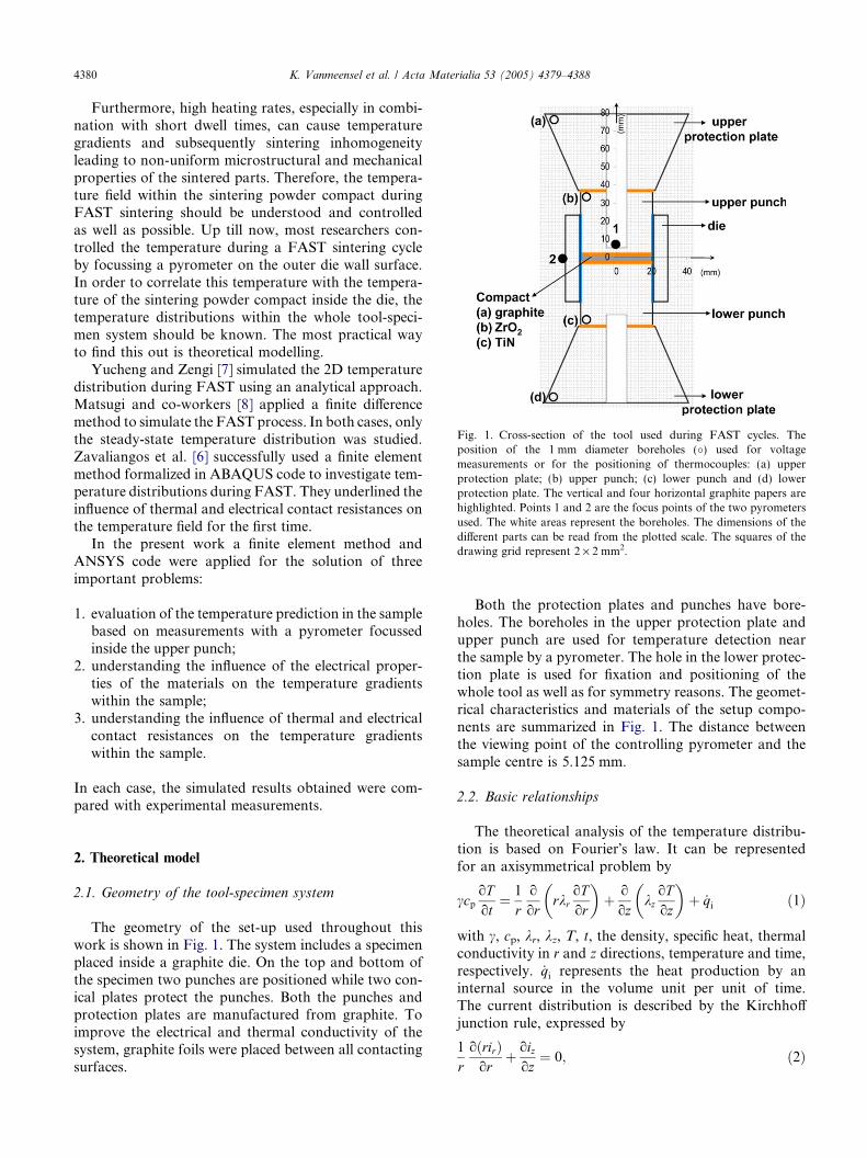
Fig. 1. Cross-section of the tool used during FAST cycles. Theposition of the 1 mm diameter boreholes (�) used for voltagemeasurements or for the positioning of thermocouples: (a) upperprotection plate; (b) upper punch; (c) lower punch and (d) lowerprotection plate. The vertical and four horizontal graphite papers arehighlighted. Points 1 and 2 are the focus points of the two pyrometersused. The white areas represent the boreholes. The dimensions of thedifferent parts can be read from the plotted scale. The squares of thedrawing grid represent 2 · 2 mm2.
4380 K. Vanmeensel et al. / Acta Materialia 53 (2005) 4379–4388
Furthermore, high heating rates, especially in combi-nation with short dwell times, can cause temperaturegradients and subsequently sintering inhomogeneityleading to non-uniform microstructural and mechanicalproperties of the sintered parts. Therefore, the tempera-ture field within the sintering powder compact duringFAST sintering should be understood and controlledas well as possible. Up till now, most researchers con-trolled the temperature during a FAST sintering cycleby focussing a pyrometer on the outer die wall surface.In order to correlate this temperature with the tempera-ture of the sintering powder compact inside the die, thetemperature distributions within the whole tool-speci-men system should be known. The most practical wayto find this out is theoretical modelling.
Yucheng and Zengi [7] simulated the 2D temperaturedistribution during FAST using an analytical approach.Matsugi and co-workers [8] applied a finite differencemethod to simulate the FAST process. In both cases, onlythe steady-state temperature distribution was studied.Zavaliangos et al. [6] successfully used a finite elementmethod formalized in ABAQUS code to investigate tem-perature distributions during FAST. They underlined theinfluence of thermal and electrical contact resistances onthe temperature field for the first time.
In the present work a finite element method andANSYS code were applied for the solution of threeimportant problems:
1. evaluation of the temperature prediction in the samplebased on measurements with a pyrometer focussedinside the upper punch;
2. understanding the influence of the electrical proper-ties of the materials on the temperature gradientswithin the sample;
3. understanding the influence of thermal and electricalcontact resistances on the temperature gradientswithin the sample.
In each case, the simulated results obtained were com-pared with experimental measurements.
2. Theoretical model
2.1. Geometry of the tool-specimen system
The geometry of the set-up used throughout thiswork is shown in Fig. 1. The system includes a specimenplaced inside a graphite die. On the top and bottom ofthe specimen two punches are positioned while two con-ical plates protect the punches. Both the punches andprotection plates are manufactured from graphite. Toimprove the electrical and thermal conductivity of thesystem, graphite foils were placed between all contactingsurfaces.
Both the protection plates and punches have bore-holes. The boreholes in the upper protection plate andupper punch are used for temperature detection nearthe sample by a pyrometer. The hole in the lower protec-tion plate is used for fixation and positioning of thewhole tool as well as for symmetry reasons. The geomet-rical characteristics and materials of the setup compo-nents are summarized in Fig. 1. The distance betweenthe viewing point of the controlling pyrometer and thesample centre is 5.125 mm.
2.2. Basic relationships
The theoretical analysis of the temperature distribu-tion is based on Fourier�s law. It can be representedfor an axisymmetrical problem by
ccpoTot
¼ 1
ro
orrkr
oTor
� �þ o
ozkzoToz
� �þ _qi ð1Þ
with c, cp, kr, kz, T, t, the density, specific heat, thermalconductivity in r and z directions, temperature and time,respectively. _qi represents the heat production by aninternal source in the volume unit per unit of time.The current distribution is described by the Kirchhoffjunction rule, expressed by
1
roðrirÞor
þ oizoz
¼ 0; ð2Þ

K. Vanmeensel et al. / Acta Materialia 53 (2005) 4379–4388 4381
where ir, iz represent the current density in the r and z
directions, respectively. The specific power _qi is relatedto the current density by Ohm�s law
_qi ¼ irqr þ izqz ð3Þwhere qr and qz are the electrical resistivity in r and z
directions, respectively.During FAST, heat is generated by Joule heating, _qi,
of all components through which an electrical currentflows. Heat is transferred by conduction and lost byradiation from all graphite parts, especially at high tem-peratures, and by conduction of heat towards the pro-tection plates, which are in close contact with thewater cooled electrodes.
The heat transfer by radiation between free surfacesand towards the surrounding environment can be deter-mined by the Stefan–Boltzmann law
_qr ¼ rSeðT 4e � T 4
aÞ ð4Þ
with rS, the Stefan–Boltzmann constant; Te, the temper-ature of the emitting surface; Ta, the temperature of theabsorbing surface or space; e, the emissivity and _qr, theheat loss per unit of time per surface unit.
In the present case the heat transfer from the tool dueto the contact of the protection plates with the watercooled electrodes was modelled as a convective heattransfer. Convection can be described by
111213141516171819
0 500 1000 1500 2000
Temperature (˚C)
Res
isti
vity
(m
Oh
m.m
)
1.8551.861.8651.871.8751.881.8851.891.8951.91.905
Den
sity
(g
/cm
³)
a b
Fig. 2. Comparison between experimentally determined (open symbols) profunction of temperature: (a) resistivity and density and (b) thermal conducti
Table 1Thermo-electrical properties of TiN, 3Y-ZrO2 and the graphite foil [12–20]
Material Direction Thermal conductivity (W/(m �C))
TiN In-plane andthickness
k = 18.5 + 4.50 · 10�2 ÆT� 1.07 · 10�4 ÆT2 +1.25 · 10�7 ÆT3
� 6.89 · 10�11 ÆT4 + 1.46 · 10�14 ÆT(25 �C–1500 �C)
3Y-ZrO2 In-plane andthickness
2.929 (25 �C–1500 �C)
Graphite (foil) In-plane k = 153.91�0.1713 ÆT + 0.0001 ÆT2
� 3 · 10�8 ÆT3 (25 �C–1750 �C)Thickness 7 (25 �C–2000 �C)
_qconv ¼ hðT p � T wÞ ð5Þwith Tp, Tw and h the temperature of the protectionplates near the contact surfaces, the temperature of thecooling water and the convection coefficient, respec-tively. Eqs. (1)–(5) are incorporated into the ANSYScode.
2.3. Material properties
In order to be able to simulate thermo-electrical phe-nomena using finite element codes, reliable high temper-ature thermal (thermal conductivity, specific heat,thermal expansion coefficient) and electrical (electricalresistivity) input data are needed. In this section, we de-scribe how these data were obtained and how theyshould be interpreted within the finite elementsimulations.
The electrical resistivity of graphite grade FE 779 wasexperimentally determined using current and voltagemeasurements at several temperatures using a graphitedummy as will be discussed below. The results obtainedare in good agreement with the data of the supplier(Schunk) [9] as shown in Fig. 2(a). The resistivity ofgraphite as stated by the supplier was used duringmodelling.
The thermal properties of graphite were measuredusing the laser flash technique up to 1100 �C (Anter
40
45
50
55
60
65
70
0 500 1000
Temperature (˚C)
Th
erm
al c
on
du
ctiv
ity
(W/(
m.˚
C)
0
500
1000
1500
2000
2500
Sp
ecif
ic H
eat
(J/(
kg.˚
C))
perties of graphite FE 779 and literature data (closed symbols) as avity and specific heat [9,10].
Electrical resistivity (mX m) Density (g/cm3)
5
r = 39.648 + 0.0176 ÆT(25 �C–1600 �C)
q = 5.43 � 1.36 · 10�4 ÆT(25 �C–1327 �C)
r = 1.12 · 1012 � 1.07 · 109 Æ T(25 �C–1500 �C)
q = 6.10�1.36 · 10�4 ÆT(25 �C–1500 �C)
1.5–2.5 (25 �C–1750 �C) 1 (25 �C–1750 �C)
3–4 (25 �C–1750 �C) 1 (25 �C–1750 �C)

4382 K. Vanmeensel et al. / Acta Materialia 53 (2005) 4379–4388
Flashline 3000, Belgian Ceramic Research Centre, Mons,Belgium). The obtained characteristics are in good corre-spondence with the data of Enweani et al. [10], which areavailable for higher temperatures. Therefore, the data ofEnweani et al. were used during modelling (Fig. 2(b)).The density of graphite at several temperatures was calcu-lated using the thermal expansion coefficient reported bySchunk. The results are presented in Fig. 2(a).
The emissivity of graphite only slightly depends ontemperature and was taken to be 0.8, in agreement withliterature data [11].
Three different sample specimens (thickness: 4.25 mm)were used. One of them was manufactured from graphiteFE 779 with identical properties as the tool material. Thesecond specimen was an electrically conductive titaniumnitride sample (Starck grade C, d50 = 0.8–1.2 lm, den-sity = 5.34 g/cm3). The third specimen was an insulatingzirconia sample (Daiichi HSY-3U, d50 = 50 nm, den-sity = 6.05 g/cm3), which is an electrical insulator. Thethermal and electrical properties for both TiN and ZrO2
were taken from literature [12–19] and are summarisedin Table 1. Isotropic material properties were assumed.Electrical resistivity values of TiN are only available attemperatures below 1200 �C [17]. At higher temperaturesa linear extrapolation has been used. The thermal conduc-tivity of Y-ZrO2 only slightly depends on temperature.Therefore a constant value of 2.929 W/(m �C) was usedduring modelling. For the same reason a constant specificheat of 0.655 J/(g �C) has been applied at temperaturesabove 1100 �C.
Since only fully dense samples were used, the chang-ing material properties with densification were not in-cluded in the model.
The graphite paper (Sigraflex N 998) has stronglyanisotropic properties as shown in Table 1. Its electricalresistivity is sufficiently higher and its thermal conduc-tivity is significantly lower compared to graphite. Thespecific heat of the graphite paper was taken to be sim-ilar to that of graphite.
3. Experimental procedure
3.1. Experimental setup
Experiments were performed on an FCT FAST de-vice (Type HP D 25/1, FCT Systeme, Rauenstein, Ger-many), which is a FAST furnace equipped with a250 kN uniaxial-press. The process chamber can beevacuated down to 0.05 Pa. The power supply can pro-vide a pulsed DC up to 8000 A at a voltage up to 10 Vthrough the electrodes to the die set that contains thespecimen. Graphite protection plates are placed betweenthe punches and the water cooled electrodes (Fig. 1). Apulsed as well as a constant DC with on/off cycles of0–255 ms (on-time)/0–255 ms (off-time) can be gener-
ated. During the presented experiments, a pulse–pausecombination of 10–5 ms is used throughout all theexperiments. A preset time–temperature is generatedby controlling the power, which is done by controllingthe voltage difference over the electrodes. In this way,the current flowing through the specimen–punch–dieset-up is controlled. During the experiments, the temper-ature is measured by a central pyrometer with a focuspoint at the bottom of the central borehole of the graph-ite set-up, 2.88 mm from the bottom of the upper punchand 5.125 mm from the centre of a 4.25 mm thick sam-ple inside the die (Fig. 1). The temperature of the die ismeasured by a second two-colour pyrometer, focussedon the outer die wall surface at the same height as thecentre of the compact (Fig. 1).
The electrical currents, flowing through the upperelectrode in close contact with the upper protectionplate, were measured using a Rogowski Coil current sen-sor (Type 1112, Rocoil Ltd., Harrogate, UK) and a dig-ital oscilloscope was used to store the waveforms. Thevoltage was measured between the upper and lower pro-tection plates, between the upper protection plate andthe upper punch, and between the upper punch andthe lower punch, at the locations indicated in Fig. 1.
Two types of experiments were performed in order todetermine: (a) the high temperature electrical propertiesof the graphite (Schunk grade FE 779 isostaticallypressed graphite) used during the experiments; (b) theinfluence of the thermal and electrical contact resis-tances on the temperature distribution inside the sam-ple–die–punch set-up; and (c) the radial temperaturedistribution inside a fully dense ZrO2 (Daiichi gradeHSY-3U) and TiN (Starck grade C) sample.
Each sinter cycle contained six segments: (1) applyinga constant current until the central pyrometer reached atemperature of 450 �C, the onset temperature of thepyrometer, (2) applying a linearly increasing currentresulting in a heating rate of 200 �C/min in the temper-ature region between 450 and 1050 �C, (3) applying aconstant current during the dwell period at 1050 �C(during this dwell period the pressure was increasedfrom 5 to 28 MPa), (4) applying a linearly increasingcurrent resulting in a heating rate of 200 �C/min in thetemperature region between 1050 and 1500 �C, (5)applying a constant current during the dwell period at1500 �C (during the first minute of this dwell period witha total length of 6 min, the pressure is increased from 28to 56 MPa), and (6) applying no current during coolingfrom 1500 �C down to room temperature and loweringthe pressure at the same time.
3.2. Case studies
The first set of experiments was performed usinggraphite dummies with different geometries as shown in

F SPP GRA
Fig. 3. Overview of the different dummy geometries. Thick horizontallines indicate the presence of horizontal graphite papers while the thickvertical lines indicate the presence of the vertical graphite paper.
K. Vanmeensel et al. / Acta Materialia 53 (2005) 4379–4388 4383
Fig. 3. The component dimensions can be determinedfrom Fig. 1. The first dummy (F: full dummy) is a mono-lithic graphite set-up with central holes for temperatureregistration by the central pyrometer (Fig. 3(a)). The sec-ond dummy (SPP: separate protection plates) containstwo protection plates, separated from the central mono-lithic graphite block by graphite papers (Fig. 3(b))whereas the third dummy (GRA: graphite sample) con-sists of two protection plates, two graphite punches, agraphite die and a 4.25 mm thick graphite specimen, sep-arated from the protection plates and the die by graphitepapers (Fig. 3(c)). From now on, the combination of pro-tection plates, punches, die, sample and graphite paperswill be called the �tool�. Both in the SPP and GRA dum-mies, the graphite papers will introduce extra thermaland electrical contact resistances to the system, whichprobably influence the temperature distribution in thesample.
A second set of experiments was performed using dif-ferent materials inside the die. Cycles using a heatingrate of 200 �C/min up to 1500 �C applying a load of56 MPa with a fully dense ZrO2 sample and a fully dense
Fig. 4. Typical �on�-part of a 10/5 ms on/off pulsed current signal. The pulsedcalculated resistance over the tool is obtained by dividing the pulsed voltageFEM calculations generating the same power as the pulsed DC signal, is ind
TiN sample inside the die (GRA configuration) wereperformed and simulated.
3.3. Correlation between experimentally measured and
applied current, voltage and resistance during FE
simulations
Since a constant DC current was used as the inputcurrent during the FE simulations, a correct conversionbetween the experimentally applied and measuredpulsed DC current and the applied FE constant DC cur-rent had to be performed. Therefore, the constant DCsignal should contain the same amount of power asthe measured pulsed DC signal. In the case of a pulsedDC signal with a pulse time of 10 ms and pause durationof 5 ms, the relationship between the pulsed current Ip,as it is experimentally measured, and the constant cur-rent Ic, as it is applied during the simulations, can be ex-pressed as
Ic ¼ Ip
ffiffiffi2
3
r. ð6Þ
The same relationship exists between the voltage overthe tool during a constant DC signal, Vc, and the voltageover the tool during a pulsed DC signal, Vp. The re-ported experimentally determined current and voltagealready include the conversion of the pulsed signal toa constant signal.
Since the pulsed current signal originates from apulsed voltage over the tool and since this pulsed voltageover the tool is delayed with respect to the pulsed outputvoltage of the transformer, the pulsed current and volt-age signals over the tool are not rectangular, as shown inFig. 4. Therefore, attention should be paid to the calcu-lation of ohmic resistances, derived from experimentallymeasured pulsed current and voltage values. Only after
voltages over the transformer and over the tool are shown as well. Theover the pulsed current. The constant DC current signal used duringicated as well.

4384 K. Vanmeensel et al. / Acta Materialia 53 (2005) 4379–4388
a certain time of applying a current/voltage pulse (a fewms, depending on the amount of current and voltage)the resistance of the tool is fully ohmic. In the beginningof the pulse it is a combined ohmic-inductive resistance,of which the inductive resistance decreases after a fewmilliseconds. Reported resistance values, based onexperimentally measured currents and voltages, are ta-ken from the final part of the pulsed signal, as indicatedin Fig. 4, i.e., from 2 to 10 ms.
4. Results and discussion
4.1. Electrical resistivity of graphite and convectioncoefficient
The F dummy was used to check the electrical resis-tivity of the FE 779 graphite and to determine the con-vection coefficient in formula (5). This dummy washeated up to temperatures of 179, 440, 765 and1020 �C. At the same time, the temperature was mea-sured by three other thermocouples located at differentpositions in the F dummy as indicated in Fig. 1. Oncea steady state temperature distribution was achieved,the current and voltage drop over the dummy were mea-sured. These data were used to calculate the dummyresistance and electrical resistivity of graphite. The re-sults are summarised in Fig. 2(a).
The convection coefficient was determined from acooling curve after the F dummy had been heated at1500 �C. Using a value of h = 880 W/(m �C) resultedin a perfect match between the experimentally observed
Time (s)
Cu
rren
t (k
A)
350
550
750
950
1150
1350
1550
0 500 1000
Tem
per
atu
re (
˚C)
FEMExperimental
0.00.51.01.52.02.53.03.54.04.5
Time (s)
Vo
ltag
e (V
)
FEMExperimental
0 100 200 300 400 500 600 700 800 900
Po
wer
(kW
)
a b
dc
Fig. 5. Comparison between simulated and experimentally measured: (a
cooling curve and the cooling curve as it was calculatedfrom the FE model (Fig. 5(a)).
4.2. Contact resistances
Using the convection coefficient determined in theprevious paragraph, the voltage drop over the F dummyas well as the current and power needed to follow a pre-set temperature profile as described in Section 3.1, werecompared with the input data for FE modelling.Fig. 5(b)–(d) confirms the excellent agreement obtainedbetween experimentally determined data and those usedin the FE simulations. However, as the dummy geome-try becomes more complex by the introduction of con-tacting surfaces (SPP and GRA dummy), aquantitative description of both the electrical and ther-mal contact resistances becomes necessary.
Based on the experimentally measured electrical resis-tance at different temperatures using different graphitedummy geometries, the electrical contact resistancescould be determined as a function of temperature and ap-plied pressure. Fig. 6 summarises the electrical resistance,determined from the experimentally measured currentand voltage, as function of temperature for the differentdummy geometries. It is clear that the resistance of theSPP and GRA dummies is sufficiently higher than thatof the F dummy. Only an increasing amount of contactresistances can be the reason for these differences. TheSPP dummy has two additional horizontal contacts be-tween the protection plates and the punches comparedto the F dummy (Fig. 3). The resistance of these contactsand the graphite papers themselves should be taken into
0.0
0.5
1.0
1.5
2.0
2.5
3.0
3.5
4.0
2000 400 600 800
Time (s)
ExperimentalFEM
0
2
4
6
8
10
12
14
16
0 100 200 300 400 500 600 700 800 900Time (s)
FEM
Experimental
) temperature profile; (b) input current; (c) voltage and (d) power.

0.5
1
1.5
2
2.5
0 200 400 600 800 1000time (s)
Res
ista
nce
(mO
hm
)02004006008001000120014001600
Tem
per
atu
re (˚
C)
Fo
rce
(x10
) (kN
)temperature (˚C)
force (x10) (kN)
GRA
SPP
F
Fig. 6. Calculated graphite dummy (F, SPP and GRA) resistances derived from experimentally measured current and voltage data.
K. Vanmeensel et al. / Acta Materialia 53 (2005) 4379–4388 4385
account when the temperature distribution in the SPPdummy is to be simulated. Since contact resistances cannot be implemented in the finite element software pack-age that was used for modelling, the thermal and electri-cal resistance of the graphite papers were adjusted in sucha way that their values correspond to the combination ofthe intrinsic thermal and electrical resistance of thegraphite paper and their respective contact resistances.The apparent electrical resistivity of the horizontalgraphite paper was calculated as a function of tempera-ture from the resistance difference between the F dummyand the SPP dummy. The obtained results are presentedin Fig. 7. The horizontal contacts and graphite papers donot only create an additional electrical but also an addi-tional thermal resistance. In this way, the horizontalgraphite papers are sources of a local decrease of thermalconductivity within the system. Similar to the electricalresistivity, the contact gap in thermal conductivity wasrelated to the properties of the horizontal graphite paper.The thermal conductivity was assumed to be inverselyproportional to the electrical resistivity
kp ¼ gkgrqgr
qp
; ð7Þ
where kp and qp are, respectively, the apparent thermalconductivity and electrical resistivity (Fig. 7) of the hor-izontal graphite paper; kgr and qgr are, respectively, thethermal conductivity and electrical resistivity of the FE
0.1
0.2
0.3
0.4
0.5
0.6
0.7
0.8
0 500 1000 1500
Temperature (˚C)
Ele
ctri
cal R
esis
tivi
ty
(Oh
m.m
m)
0
0.002
0.004
0.006
0.008
0.01
0.012
Th
erm
al C
on
du
ctiv
ity
(W/(
mm
.˚C
))
Fig. 7. Apparent electrical resistivity and thermal conductivity forhorizontal contacts as a function of temperature.
779 graphite (Fig. 2(a) and (b)); g is a fitting coefficient.The additional thermal resistances directly influence thetemperature distribution in the tool and specimen andindirectly the power needed to follow a preset tempera-ture profile. The best correlation between the calcu-lated and experimentally measured current during theexperiments with both the SPP and GRA dummy wasobtained when g was taken to be 2.85. The correspond-ing apparent thermal conductivity of the horizontalgraphite paper as a function of temperature is shownin Fig. 7.
Compared with the SPP dummy, the GRA dummycontains two additional horizontal contacts betweenpunches and graphite sample and three additional verti-cal contacts between the die, punches and sample(Fig. 3(c)). During GRA modelling, the same apparentelectrical resistivity and thermal conductivity as in theSPP case were used for the two additional horizontalcontacts. The corresponding data for the vertical con-tacts were found by fitting the calculated current andvoltage profile to the experimental one. It was assumedthat the apparent electrical resistivity of the verticalgraphite paper was directly proportional to the resistiv-ity of the horizontal graphite paper, while the apparentthermal conductivity of the vertical graphite paper wasassumed to be inversely proportional to the thermalconductivity of the horizontal graphite paper. After ajoint treatment of both the experimental and the simu-lated data the fitting coefficient was found to be equalto 7 for both q and k. This means that the apparent elec-trical resistivity of the vertical graphite paper is seventimes larger than the resistivity of the horizontal one,while the apparent thermal conductivity of the verticalgraphite paper is seven times smaller than the one fromthe horizontal paper.
Using the experimentally determined properties ofthe graphite, the different graphite papers and the differ-ent contact resistances, the temperature distributionwithin the different dummies was simulated. Fig. 8 sum-marises the experimentally measured and simulated tem-perature differences between the central controllingpyrometer and the external pyrometer for the different

-20
30
80
130
180
230
115 315 515 715 915time (s)
tem
per
atu
re d
iffe
ren
ce(˚
C)
GRA - FEMSPP - FEMF - FEMGRA - expSPP - expF - exp
Fig. 8. Simulated and experimentally measured temperature differ-ences between the central and external pyrometer, focusing on the die,for the different graphite dummy geometries. The shown valuesindicate an average value of three measurements with their respectivestandard deviations.
4386 K. Vanmeensel et al. / Acta Materialia 53 (2005) 4379–4388
dummy geometries. The temperature differences be-tween the central and external pyrometer for the differ-ent graphite dummies is largely dependent on thepresence of the vertical graphite paper. In the cases ofthe F and SPP dummies, the simulated temperature dif-ference during the dwell period at 1500 �C is comparable(113 �C) whereas the large thermal contact resistancecaused by the vertical graphite paper increases this dif-ference up to 206 �C. It is worth noticing that in the caseof the GRA dummy, the current mainly flows throughthe graphite sample and only a small amount of currentflows through the die, as illustrated in Fig. 9. This fact
Fig. 9. Current densities (A mm�2) inside the G
also contributes to the increase in temperature differencementioned above.
4.3. Sintering cycles with fully dense Y-ZrO2 and TiN
specimens inside the die
Additionally, two heating cycles were performedreplacing the graphite sample in the GRA dummy byan electrically insulating Y-ZrO2 or a conductive TiNceramic. Current and voltage measurements were per-formed during these cycles. The temperature distribu-tions inside the tool and the specimens were simulatedusing the experimentally determined properties fromthe dummy experiments in combination with the litera-ture data for 3Y-ZrO2 and TiN (Table 1).
Fig. 10(a) and (b) reveals that the radial temperaturegradient inside the TiN sample is much larger (79 �C)than in the 3Y-ZrO2 sample (25 �C) during the finaldwell period at 1500 �C. This observation is explainedby the difference in electrical properties of the samples.In the case of a good electrical conductor, such asTiN, the main part of the current flows through the sam-ple while the current is forced to flow through the die inthe case of a strong electrical insulator, such as 3Y-ZrO2. In the latter case, the Joule heating in the diecounteracts heat losses due to radiation from the outerdie wall surfaces. However, since the sample is smallcompared to the tool and since the graphite has a goodthermal conductivity, the heat is quickly transferred tothe 3Y-ZrO2 sample resulting in a homogeneous temper-ature distribution inside the 3Y-ZrO2 specimen. Fig. 11
RA dummy during the dwell at 1500 �C.

Fig. 10. Temperature distribution inside the ZrO2 (a) and TiN (b) specimen during the dwell at 1500 �C. The steady-state temperature distribution,reached 15 s after the full load was applied, is shown.
Fig. 11. Temperature differences between the centre of a ZrO2 sampleand the focus point of the central pyrometer, the border of the ZrO2
specimen and the die wall surface, during FAST sintering with aheating rate of 200 �C/min up to 1500 �C under a load of 56 MPa.
K. Vanmeensel et al. / Acta Materialia 53 (2005) 4379–4388 4387
shows the temperature differences, obtained from the FEsimulation, between the viewing point of the centralpyrometer and the centre of the 3Y-ZrO2 specimen aswell as between the viewing point of the central pyrom-eter and the point on the die surface located at the sameheight as the sample centre. This graph clearly indicatesthat in the case of a 4.25 mm thick 3Y-ZrO2 sample thetemperature inside the sample can be controlled veryaccurately by focussing the central pyrometer on thebottom of the borehole in the upper punch.
In the case of the TiN sample, the temperature con-trol by the central pyrometer is also very accurate andthe maximal temperature difference between the focuspoint of the central pyrometer is only slightly higher inthe case of the TiN sample compared to a ZrO2 sample(5 �C versus 2 �C, respectively). As shown in Fig. 10, theradial temperature gradients are however large in theTiN sample, leading to inhomogeneous sintering andconcomitant inhomogeneous mechanical propertiessuch as hardness and strength. Therefore, measuresshould be taken to minimise the radial temperature gra-dient inside electrically conductive samples. In order to
suppress the thermal gradients inside electrically con-ductive samples, it would be useful to surround thegraphite die with porous graphite insulation in orderto minimise the heat losses due to radiation. If heatlosses can be minimised in such a way, less power isneeded to follow a preset temperature profile. The useof the graphite insulation would therefore also providea tool to use the FAST technique in a more economicalway.
5. Conclusions
To allow a better understanding of the temperaturedistributions during the field assisted sintering tech-nique, a finite element model, based on experimentallymeasured material properties as well as on thermaland electrical measurements during real FAST cycles,was successfully developed. A theoretical investigationof all the present heat generation and heat transfer pro-cesses allowed the estimation of the temperature gradi-ents inside fully dense ceramic samples with differentelectrical properties. It was stated that the present ther-mal gradients inside the samples are mainly dependenton the presence of contact resistances between contact-ing parts and on the electrical properties of thespecimen.
Both theoretical and experimental results indicatedthat the temperature distribution inside the tool andspecimen is not homogeneous during the field assistedsintering technique. Therefore, attention should be givento a proper temperature measurement. A good solutionis to focus a pyrometer on the bottom of a borehole in-side the upper punch about 5 mm away from the speci-men centre inside the tool. Using such a design, theactual temperature values are much less dependent onboth the presence of contact resistances and on the elec-trical properties of the specimen, both factors having alarge influence on the temperature measurements when

4388 K. Vanmeensel et al. / Acta Materialia 53 (2005) 4379–4388
a pyrometer is focussed on the outer die wall surface.For practical applications and accurate temperaturecontrol the pyrometer positioning presented should bepreferred.
The thermal and electrical contact resistances be-tween the tool components and the specimen have alarge influence on the temperature field as well as onthe current and power needs during the heating cycles.Therefore, to increase the industrial applicability ofthe FAST technique, the repeatability of the contactproperties should be guaranteed to process reproduciblehigh quality materials.
The electrical properties of the specimen have animportant influence on the temperature distributions in-side the tool as well as in the specimen. Much higherthermal gradients were observed in an electrically con-ductive TiN sample compared to an insulating 3Y-ZrO2 sample under identical FAST cycles. In the caseof ZrO2, the current only flows through the punchesand die, in such a way compensating the heat lossesdue to the radiation from the exposed tool surfaces.When using a TiN sample, the current mainly flowsthrough the specimen itself. The radiation heat lossesare not compensated and the temperature distributionin the sample becomes largely inhomogeneous.
Acknowledgements
This work was supported by the GROWTH programof the Commission of the European Communities underproject contract No. G5RD-CT2002-00732. Prof. Lap-tev would like to thank the K.U. Leuven ResearchCouncil for his 8-month research fellowship (No.F/02/096). Ir. Samuel Meulenyzer (BCRC, Mons, Bel-gium) is greatly acknowledged for the high temperaturethermal property measurements.
References
[1] Groza JR. Field assisted sintering, In: ASM handbook; PowderMetall, vol. 7; 1998. p. 583–9.
[2] Shen Z, Zhao Z, Peng H, Nygren M. Formation of toughinterlocking microstructures in silicon nitride ceramics by dynamicripening. Nature 2002;417:266–9.
[3] Khor KA, Cheng KH, Yu LG, Boey F. Thermal conductivity anddielectric constant of spark plasma sintered aluminium nitride.Mater Sci Eng A 2003;347:300–5.
[4] Su X, Wang P, Chen W, Shen Z, Nygren M, Yibing C, et al.Effects of composition and thermal treatment on infrared trans-mission of Dy-a-sialon. J Eur Ceram Soc 2004;24:2869–77.
[5] Nagae T, Yokota M, Nose M, Tomida S, Kamiya T, Saji S.Effects of pulse current on an aluminum powder oxide layerduring pulse current pressure sintering. Mater Trans2002;43(6):1390–7.
[6] Zavaliangos A, Zhang J, Krammer M, Groza JR. Temperatureevolution during field activated sintering. Mater Sci Eng A2004;379:218–28.
[7] Yucheng W, Zhengui F. Study of temperature field in sparkplasma sintering. Mater Sci Eng B 2002;90:34–7.
[8] Matsugi K, Kuramoto H, Hatayama T, Yanagisawa O. Temper-ature distribution at steady state under constant current dischargein spark sintering process of Ti and Al2O3 powders. J MaterProcess Technol 2003;146(2):274–81.
[9] Schunk graphite FE 779 data sheet, Schunk Graphite Technology,LLC.
[10] Enweani BN, Davis JW, Haasz AA. Thermal diffusivity/conduc-tivity of doped graphites. J Nucl Mater 1995;224:245–53.
[11] Matsumoto T, Ono A, Noumaru Y, Takeda F. Measurements ofspecific heat capacity and emissivity of graphite samples using pulsecurrent heating at high temperatures. In: Proceedings of the 17thJapan symposium on thermophysical properties; 1996. p. 183–6.
[12] Mevrel R, Laizet J-C, Azzopardi A, Leclercq B, Poulain M,Lavigne O, et al. Thermal diffusivity and conductivity ofZr1�xYxO2�x/2 (x = 0, 0.084 and 0.179) single crystals. J EurCeram Soc 2004;24(10–11):3081–9.
[13] Ahmaniemi S, Tuominem J, Vippola M, Vuoristo P, Mantyla T,Cernuschi F, Gualco C, Bonadei A, Di Maggio R. Characterisa-tion of modified thick thermal barrier coatings. In: Proceedings ofthe thermal spray 2003, Ohio, USA; 2003, p. 1477–86.
[14] Schlichting KW, Padture NP, Klemens PG. Thermal conductivityof dense and porous yttria-stabilized zirconia. J Mater Sci2003;36:3003–10.
[15] Stevens R. Zirconia and zirconia ceramics. 2nd ed. Manches-ter: Magnesium Elektron Ltd.; 1986. p. 29–30.
[16] Pierson HO. Handbook of refractory carbides and nitrides –properties, characteristics, processing and applications. Norwich,NY: Noyes Publications; 1996. p. 183–8 [chapter 11: Interstitialnitrides: properties and general characteristics].
[17] Weimer AW. Carbide, nitride and boride materials synthesis andprocessing. London: Chapman & Hall; 1997. p. 653–4 [AppendixD].
[18] Williams SW. Electrical properties of hard materials. J RefractMet Hard Mater 1999;17:21–6.
[19] Lengauer W, Binder S, Aigner K, Ettmayer P, Guillou A,Debuigne J, et al. Solid state properties of group IVb carbonit-rides. J Alloys Compd 1995;217:137–47.
[20] Sigraflex graphite foil N 998 data sheet, SGL Carbon Group.