Strength assessment of spot-welded sheets of interstitial free steels
Upload
independentCategory
view
1download
0
Journal of Alloys and Compounds, 198 (1993) 1-24 1 JALCOM 665
Review
Preparation, structural and magnetic properties and stability of interstitial SmzFe17-carbonitrohydrides
C h r i s N. C h r i s t o d o u l o u a n d T a k u o T a k e s h i t a Central Research Institute, Mitsubishi Materials Corporation, 1-297 Kitabukuro-cho, Omiya, Saitama 330 (Japan)
(Received January 25, 1992)
Abstract
Sm2FelT-carbides, -nitrides, -hydrides, -carbonitrides, -carbohydrides, -nitrohydrides and -carbonitrohydrides were synthesized by reacting Sm2Fe~7 powder with the appropriate gases (acetylene, nitrogen or hydrogen). Carbonation, nitrogenation and hydrogenation were performed at about 600 °C, 450 °C and 250 °C respectively. Low-carbon concentration carbides were prepared by conventional melting. The structural and magnetic properties were measured for each of the prepared compounds. Nitrogen and carbon can partially or fully occupy the 9(e) octahedral interstices. In addition to these, hydrogen can also partially occupy the 18(g) tetrahedral interstices. Interstitial carbon, nitrogen and hydrogen atoms cause an expansion of the lattice of the parent compound. Hydrogenation of the saturated Sm2Fe17-carbide or saturated Sm2Fe~7-nitride causes preferential lattice expansion along the c-crystallographic direction. Hydrogen atoms cause the largest increase in saturation magnetization, followed by nitrogen and carbon atoms. The largest increase in the anisotropy field is caused by the nitrogen atoms followed by the carbon atoms. The hydrogen atoms cause a decrease in the anisotropy field. The nitrogen atoms cause the largest increase in the Curie temperature followed by the carbon and hydrogen atoms. Nitrogen atoms are very strongly bonded to the samarium atoms and weakly to the iron atoms, whereas carbon atoms are strongly bonded to both the samarium and iron atoms. This strong bonding makes the reversible removal of the nitrogen and carbon atoms impossible. However, hydrogen bonding is much weaker and therefore, hydrogen atoms can be absorbed and desorbed easily without any change in the Sm2Fe17 structure. Nitrogen and carbon atoms can replace the hydrogen atoms in the 9(e) sites.
1. Introduction
The discovery of the R2Fea7-nitrides (R is a rare earth element) by Coey et al. [1] opened a new horizon in magnetic materials. Since then, many studies have been published, each one dealing with different aspects regarding the structure [2-9], intrinsic [10-14] and permanent [15-26] magnetic properties of such ma- terials. Apart from the fundamental interest of such interstitially modified R2Fe17 compounds, the focal point is the SmzFe17-nitrides and -carbides which exhibit interesting intrinsic magnetic properties (such as high Curie temperature, large saturation magnetization and large anisotropy field), making them good candidates for permanent magnet materials.
Generally in the literature, one finds much infor- mation about SmzFelT-nitrides (see previous refs.) pre- pared by reaction of SmzFe~7 powders with Nz gas,
some information about Sm2Fe17-carbides [2%36], very little about SmzFe17-hydrides [20, 37, 38] and SmzFely- carbonitrides [39] and no information about SmzFe17- nitrohydrides, SmzFe~7-carbohydrides and Sm~Fe~7-car- bonitrohydrides. The present study was undertaken to prepare all of these Sm2Fe17-based compounds and to present a complete picture regarding their special prep- aration conditions, the mechanisms of the interstitial process, their possible composition, structure, prefer- ential site occupancy, thermal stability and the changes occurring in their intrinsic magnetic properties (To, Ms, Ha) as interstitial carbon and/or nitrogen and/or hy- drogen atoms are introduced into the Sm2Fel7 lattice.
2. Experimental details
The SmzFe17 alloy was prepared by induction melting of the constituent elements (99.9 wt.% pure or better)
0925-8388/93/$6.00 © 1993- Elsevier Sequoia. All rights reserved
2 C.N. Christodoulou, T. Takeshita / Interstitial Sm2Fe17-carbonitrohydrides
and further heat treatment at 1000-1200 °C to ensure thermodynamic equilibrium. During melting, care was taken that the final composition of the alloy should be stoichiometric or slightly samarium poor to avoid pre- cipitation of the SmFe3 compound. The final alloy was found to consist of the Sm2Fe17 compound (Th2Zn17- type) and a very small amount of a-Fe (less than 1 wt.%). The above alloy was crushed and hand pulverized into powder of particle size of less than 45 /xm in diameter, under argon in a glove box. This powder was used for all the experiments. The purity of H2, N 2 and argon gases used in the present study was greater than 99.999 vol.% and that of the hydrocarbons (such as CH4 and C2H2) was better than 99.9 vol.%.
The absorption-desorption characteristics of the gas-solid reactions were studied using a low (constant) volume reactor, the isochorothermal analyzer or ITA [20, 36, 38, 40-42], which is similar to the thermopiezic analyzer (TPA) used by other researchers (for instance Coey et al. [1]) in their studies of gas-solid reactions. The ITA provides pressure vs. temperature/time data which one can transform into atoms of gas absorbed by or desorbed from the solid, by taking into account the pressure variation due to the heated volume (about 5 vol.% is heated).
Phase analyses were done by X-ray diffraction (XRD) and thermomagnetic analysis (TMA). XRD patterns were obtained with a Philips automated diffractometer using a Cu Ktr monochromatic radiation. The easy direction of magnetization (EDOM) was determined from the XRD patterns of the random and magnetically aligned powders. TMA traces were obtained with a magnetic balance under a field of 1 kOe and in the temperature range of between 25 and 850 °C and the phases present were identified by their corresponding Curie temperature (To).
Magnetization data were obtained with a vibrating sample magnetometer (VSM) at 25 °C and in a maximum magnetic field of 15 kOe. Before obtaining the mag- netization data, the samples were premagnetized in a pulse field of 75 kOe. The saturation magnetization Ms was taken as the magnetization of the sample at the largest available magnetic field of 15 kOe. The anisotropy field (H,) was estimated by applying the extrapolation method to magnetization data obtained along and perpendicular to the alignment direction of powders fixed in epoxy resin. Both Ms and Ha may be underestimated because of the low available magnetic field, but the relative values among the different samples can still be used for comparison between them.
3. Structural considerations
3.1. Geometrics of interstitial sites Before presenting the results and discussion, it seems
appropriate to review the R2Fe17 (R is rare earth)
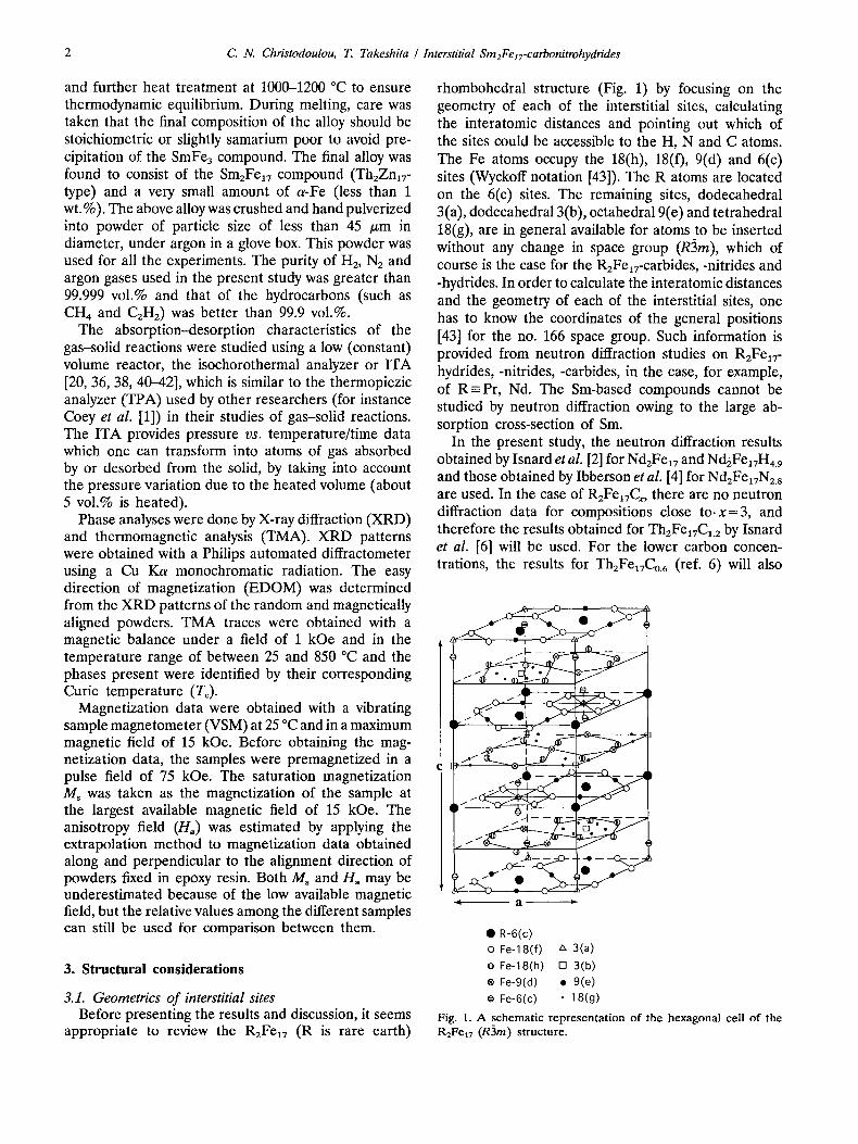
rhombohedral structure (Fig. 1) by focusing on the geometry of each of the interstitial sites, calculating the interatomic distances and pointing out which of the sites could be accessible to the H, N and C atoms. The Fe atoms occupy the 18(h), 18(f), 9(d) and 6(c) sites (Wyckoff notation [43]). The R atoms are located on the 6(c) sites. The remaining sites, dodecahedral 3(a), dodecahedral 3(b), octahedral 9(e) and tetrahedral 18(g), are in general available for atoms to be inserted without any change in space group (R3m), which of course is the case for the R2Fe17-carbides, -nitrides and -hydrides. In order to calculate the interatomic distances and the geometry of each of the interstitial sites, one has to know the coordinates of the general positions [43] for the no. 166 space group. Such information is provided from neutron diffraction studies on R2FelT- hydrides, -nitrides, -carbides, in the case, for example, of R - P r , Nd. The Sm-based compounds cannot be studied by neutron diffraction owing to the large ab- sorption cross-section of Sm.
In the present study, the neutron diffraction results obtained by Isnard etal. [2] for Nd2Fe17 and Nd2Fe17H4. 9 and those obtained by Ibberson et al. [4] for Nd2Fe~7N2.s are used. In the case of R2Fe17Cx, there are no neutron diffraction data for compositions close to. x=3, and therefore the results obtained for TheFe17C1.2 by Isnard et al. [6] will be used. For the lower carbon concen- trations, the results for Th2Fe17Co. 6 (ref. 6) will also
st a ~'
• R-6(c) o Fe-18(f) A 3(a)
O Fe-18(h) [ ] 3(b)
® Fe-9(d) • 9(e)
o Fe-6(c) • 18(g)
Fig. 1. A schemat i c r ep re sen ta t ion o f the hexagona l cell o f the R2Fe17 (R3m) s t ructure .
C. N. Christodoulou, 72 Takeshita / interstitial Sm2FelT-carbonitrohydrides 3
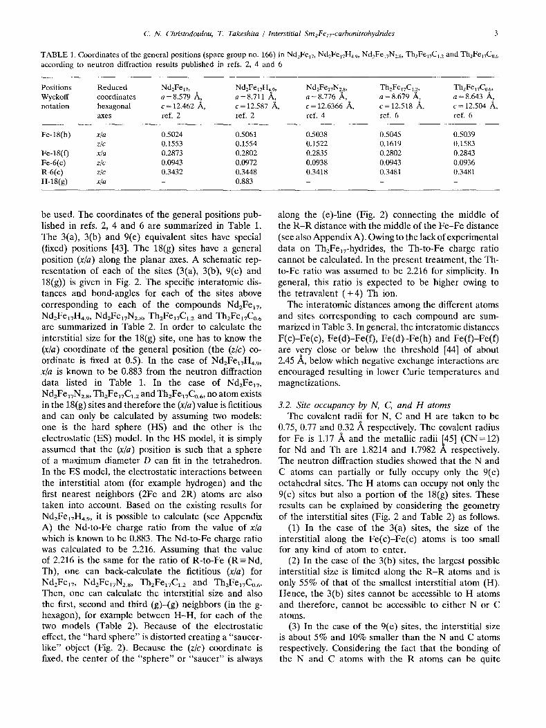
TABLE 1. Coordinates of the general positions (space group no. 166) in NdzFelv, Nd2FelTH4.9, NdzFeiTNzs, Th2Fe17CI.2 and Th2Fe17C0.6 according to neutron diffraction results published in refs. 2, 4 and 6
Positions Reduced Nd2Fet7 , Nd2FeI7H4.9, Nd2FelvN2.8, TheFeITC~. 2, Th2Fe17C0.6, Wyckoff coordinates a=8.579 /~, a=8.711 /~, a=8 .776 ~ , a=8 .679 ~ , a=8 .643 /~, notation hexagonal c = 12.462 /~, c = 12.587 /~, c = 12.6366 ~, c = 12.518 ~ , c = 12.504 ~ ,
axes ref. 2 ref. 2 ref. 4 ref. 6 ref. 6
Fe-18(h) x/a 0.5024 0.5061 0.5038 0.5045 0.5039 z/c 0.1553 0.1554 0.1522 0.1619 0.1583
Fe-18(f) x/a 0.2873 0.2802 0.2835 0.2802 0.2843 Fe-6(c) z/c 0.0943 0.0972 0.0938 0.0943 0.0936 R-6(c) z/c 0.3432 0.3448 0.3418 0.3481 0.3481 H-18(g) x/a - 0.883 - - -
be used. The coordinates of the general positions pub- lished in refs. 2, 4 and 6 are summarized in Table 1. The 3(a), 3(b) and 9(e) equivalent sites have special (fixed) positions [43]. The 18(g) sites have a general position (x/a) along the planar axes. A schematic rep- resentation of each of the sites (3(a), 3(b), 9(e) and 18(g)) is given in Fig. 2. The specific interatomic dis- tances and bond-angles for each of the sites above corresponding to each of the compounds NdzFe17, NdzFeavH4.9, Nd2Fe17N2.8, ThzFe17Ca.2 and ThzFeavCo.6 are summarized in Table 2. In order to calculate the interstitial size for the 18(g) site, one has to know the (x/a) coordinate of the general position (the (z/c) co- ordinate is fixed at 0.5). In the case of Nd2FeaTH4.9, x/a is known to be 0.883 from the neutron diffraction data listed in Table 1. In the case of Nd2Fe17, Nd2FelTN2.8, ThaFe~7C1. 2 and Th2Fe17Co.6, no atom exists in the 18(g) sites and therefore the (x/a) value is fictitious and can only be calculated by assuming two models: one is the hard sphere (HS) and the other is the electrostatic (ES) model. In the HS model, it is simply assumed that the (x/a) position is such that a sphere of a maximum diameter D can fit in the tetrahedron. In the ES model, the electrostatic interactions between the interstitial atom (for example hydrogen) and the first nearest neighbors (2Fe and 2R) atoms are also taken into account. Based on the existing results for NdzFe17H4.9, it is possible to calculate (see Appendix A) the Nd-to-Fe charge ratio from the value of x/a which is known to be 0.883. The Nd-to-Fe charge ratio was calculated to be 2.216. Assuming that the value of 2.216 is the same for the ratio of R-to-Fe (R-=Nd, Th), one can back-calculate the fictitious (x/a) for NdzFe17, NdzFe17N zs , ThzFe17C1. 2 and ThzFe17Co.6.
Then, one can calculate the interstitial size and also the first, second and third (g)-(g) neighbors (in the g- hexagon), for example between H-H, for each of the two models (Table 2). Because of the electrostatic effect, the "hard sphere" is distorted creating a "saucer- like" object (Fig. 2). Because the (z/c) coordinate is fixed, the center of the "sphere" or "saucer" is always
along the (e)-line (Fig. 2) connecting the middle of the R -R distance with the middle of the Fe-Fe distance (see also Appendix A). Owing to the lack of experimental data on Th2FelT-hydrides, the Th-to-Fe charge ratio cannot be calculated. In the present treatment, the Th- to-Fe ratio was assumed to be 2.216 for simplicity. In general, this ratio is expected to be higher owing to the tetravalent (+4) Th ion.
The interatomic distances among the different atoms and sites corresponding to each compound are sum- marized in Table 3. In general, the interatomic distances F(c)-Fe(c), Fe(d)-Fe(f), Fe(d)--Fe(h) and Fe(f)-Fe(f) are very close or below the threshold [44] of about 2.45 A, below which negative exchange interactions are encouraged resulting in lower Curie temperatures and magnetizations.
3.2. Site occupancy by N, C, and H atoms The covalent radii for N, C and H are taken to be
0.75, 0.77 and 0.32/~ respectively. The covalent radius for Fe is 1.17 A and the metallic radii I45 ] (CN= 12) for Nd and Th are 1.8214 and 1.7982 A respectively. The neutron diffraction studies showed that the N and C atoms can partially or fully occupy only the 9(e) octahedral sites. The H atoms can occupy not only the 9(e) sites but also a portion of the 18(g) sites. These results can be explained by considering the geometry of the interstitial sites (Fig. 2 and Table 2) as follows.
(1) In the case of the 3(a) sites, the size of the interstitial along the Fe(c)-Fe(c) atoms is too small for any kind of atom to enter.
(2) In the case of the 3(b) sites, the largest possible interstitial size is limited along the R - R atoms and is only 55% of that of the smallest interstitial atom (H). Hence, the 3(b) sites cannot be accessible to H atoms and therefore, cannot be accessible to either N or C atoms.
(3) In the case of the 9(e) sites, the interstitial size is about 5% and 10% smaller than the N and C atoms respectively. Considering the fact that the bonding of the N and C atoms with the R atoms can be quite

4 C N. Christodoulou, T. Takeshita / Interstitial Sm2FelT-carbonitrohydrides
3(a)
3(b)
9(e)
18(g)
@ Fe-6(c) Fe(c) b_¢l~ b Oblate.Spheroid
O~e-18~0 Fe(~re~r)
re(c) R(c)
O Fe-18(h) b d Fe(h)
• R-6(c) F e ( ~ b . Oblate Spheroid
a ~ ~ : e ~ e /
Fe(h) / e
Fe(h) "Fe(h) ~ _
R(c)
Fe- 18(0 Fe(h) OO Fe-18(h) ~ , General~Ellipsoid
/" I\ "~e / [ [ \ \ • R-6(c) Fe(f) /bl ~ . ~ R(c) d r A cl\° a " A
A ¢o. ~ . . ~ \ a $,.
R(c) a / I;e(f)
Fe(b)
O Fe-18(h) • R-6(c)
1) Hard Sphere R(c)
e(h)
S Fe(h)
R(c)
Fig. 2. A schematic representation of the 3(a) dodecahedral, 3(b) dodecahedral, 9(e) octahedral and 18(g) tetrahedral sites with the corresponding interstitial shape.
strong, this size difference can be regarded as within acceptable limits. In the case of the H atom, the interstitial size is at least 2.2 times larger. Therefore, the H atoms can enter the 9(e) sites very easily. In fact, because of the positive size difference, the H atoms can as easily vacate the 9(e) sites. That is why hydrogen can be absorbed and desorbed reversibly from the R2Fe17 compounds, depending, of course, on the pressure and temperature conditions. One also has to remember here that the stability of an interstitial atom decreases not only when the interstitial size is very small but also when the interstitial size is very large with respect to the size of the atom under consideration.
(4) In the case of the 18(g) sites, the interstitial size (assuming the HS model) is 68% and 60% of that of the N and C atoms respectively. If one takes into account the electrostatic effect (ES model), the inter- stitial size becomes larger towards one direction (for instance towards R) and at the same time even smaller in the other direction (for instance towards Fe). It can therefore be concluded that N and C atoms cannot enter the 18(g) sites. In the case of H atoms (for example, Nd2Fea7H,.9), the interstitial size (HS model) is at least 1.6 times larger than the H atom. Even if one assumes the ES model, the interstitial size still remains at least 1.2 times larger. Therefore, it can be concluded that the H atoms can enter the 18(g) sites rather easily. The total number of (g) sites per R2Fe17 formula unit is six (6). If one assumes that three H atoms completely occupy the 9(e) sites, it means that only two H atoms enter the 18(g) sites. The partial occupation of the 18(g) sites by H atoms can be explained by considering the H-H distances (in the H-hexagon) between H atoms located in the 18(g) sites (Table 2). As suggested by Isnard et al. [2], one can apply Swi- tendick's rule [46] which states that in most hydrides a repulsive force between the H atoms leads to a minimum H-H distance of about 2.1 /~. From Table 2, in the case of Nd2Fea7H4. 9 the H-H distance closer to the value of 2.1 is 2.038 ]k (ES model, (g)-(g2)). The other distances are far below 2.1 A, and therefore in each hexagon formed by the (g) sites (Fig. 1), statistically only two H atoms can coexist. That means that statistically only one third of 18(g) sites can be occupied by H atoms. That accounts for two H atoms per formula unit, which in addition to the three H atoms per f~rmula unit occupying the 9(e) sites brings the total to five H atoms per RzFea7 formula unit, which is about the same concentration which has been measured experimentally.
4. Results and discussion
The compositional, structural and magnetic char- acteristics of different kinds of Sm2Fe17-carbonitrohy- drides prepared during the course of the present study are summarized in Table 4.
4.1. Structural considerations of. Sm2Fe lT- carbonitrohydrides
Previously (Section 3), the neutron diffraction results for Nd2Fe17, NdzFea7H4.9, Nd2FelvNzs, ThzFe17C1.2 and Th2Fea7Co.6 were used to calculate the geometrics of the interstitial sites and other interatomic distances. In this section, the same analysis will be applied to the Sm-based compounds in order to relate the ex- perimental results directly to the details of the structure.

C. N. Christodoulou, T. Takeshita / Interstitial SmeFe17-carbonitrohydrides 5
TABLE 2. Geometrics of the interstitial sites in Nd2Fe~v, Nd2FelTH4.9, NdzFex7Nz.s, Th2Fe17Cl.z and ThzFe~TCo.6, according to refs. 2, 4 and 6; the symbols a, b . . . . . qS, 0 . . . . etc., represent distances (]k) and angles (deg) as illustrated in Fig. 2
Interstitial Distances (~k) NdzFel7, Nd2Fel7H4.9, Nd2FelTN2.s, Th2FeI7C1.2, ThzFei7C0.6, sites and a=8.579 ,~, a=8.711 /~,, a=8.776 ~, a=8.697 ~, a=8.643 /~, Wyckoff angles (deg), c = 12.462 ~ , c = 12.587 ~, c = 12.6366 ~ , c= 12.518 ~ , c = 12.504 /~, notation interstitial size ref.2 ref.2 ref. 4 ref. 6 ref. 6
3(a) a 2.465 2.441 2.488 2.437 2.457 b 2.731 2.730 2.756 2.708 2.722 c 1.175 1.223 1.185 1.180 1.171
Interstitial: Oblate spheroid Along Fe(f)-Fe(O c 2.589 2.542 2.636 2.636 2.574 Along Fe(c)-Fe(c) a 0.010 0.106 0.030 0.010 0.001
3(b)
Interstitial: Oblate spheroid Along Fe(h)-Fe(h) Along R(c)-R(c)
a 2.528 2.622 2.617 2.582 2.562 b 3.272 3.344 3.387 3.239 3.268 c 1.954 1.954 1.999 1.900 1.936 d 3.098 3.174 3.164 3.168 3.142 e 2.516 2.611 2.598 2.580 3.556 4' 86.77 86.89 85.96 88.68 87.65 0 93.23 93.11 94.04 91.32 92.35
c 2.692 2.882 2.856 2.820 2.772 a 0.265 0.265 0.355 0.204 0.276
9(e)
Interstitial: General ellipsoid Along R(c)-R(c) Along Fe(f)-Fe(f) Along Fe(h)-Fe(h)
a 3.079 3.164 3.169 3.162 3.118 b 2.660 2.734 2.704 2.786 2.720 c 2.114 2.098 2.144 2.116 2.110 d 3.098 3.174 3.164 3.168 3.142 e 3.193 3.206 3.202 3.295 3.235 4' 90 90 90 90 90 0 88.21 89.41 89.30 89.30 88.29 Y 90 90 90 90 90 w 74.71 76.49 75.70 76.44 75.45
a 1.317 1.395 1.429 1.440 1.402 b 1.310 1.490 1.460 1.484 1.388 c 1.888 1.856 1.948 1.892 1.880
18(g) a 3.908 3.907 3.998 3.801 3.871 b 3.272 3.344 3.387 3.239 3.268 c 3.098 3.174 3.164 3.168 3.142 d 2.528 2.622 2.617 2.582 2.562 e 2.176 2.257 2.244 2.233 2.211 4' 90 90 90 90 90 0 9O 90 90 9O 9O oJ 41.93 40.87 41.70 40.39 41.20 y 46.67 47.35 46.93 47.51 47.06
Interstitial size: (1) HS g(x/a) 0.865
D 0.903 (2) ES effect with R-to-Fe charge ratio of 2.216 g(x/a) 0.812
Saucer-like From (g) to R(c) a 0.681 From (g) to Fe(h) b 0.235 Distances between HS 1st neighbors (g)-(g) 1.161 2nd neighbors (g)-(gl) 2.010 3rd neighbors (g)-(g2) 2.321 shortest (g)-(e) 2.611
0.858 0.864 0.859 0.863 0.982 1.015 0.930 0.943
0.883 (ref.2) 0.913 0.827 0.822
0.382 0.718 0.246 0.472 0.633 0.304 0.795 0.471
ES HS ES HS ES HS ES HS 1.563 1.237 1.019 1.194 1.566 1.229 0.752 1.185 2.706 2.143 1.765 2.069 2.712 2.129 1.303 2.053 2.487 2.475 2.038 2.389 3.131 2.459 1.505 2.371 2.487 2.620 2.706 2.653 2.537 2.611 2.819 2.617
ES 1.497 2.593 2.994 2.518
HS, hard sphere model; ES, electrostatic model.
6 C .N . Christodoulou, T. Takeshita / Interstitial Sm2Felr-carbonitrohydrides
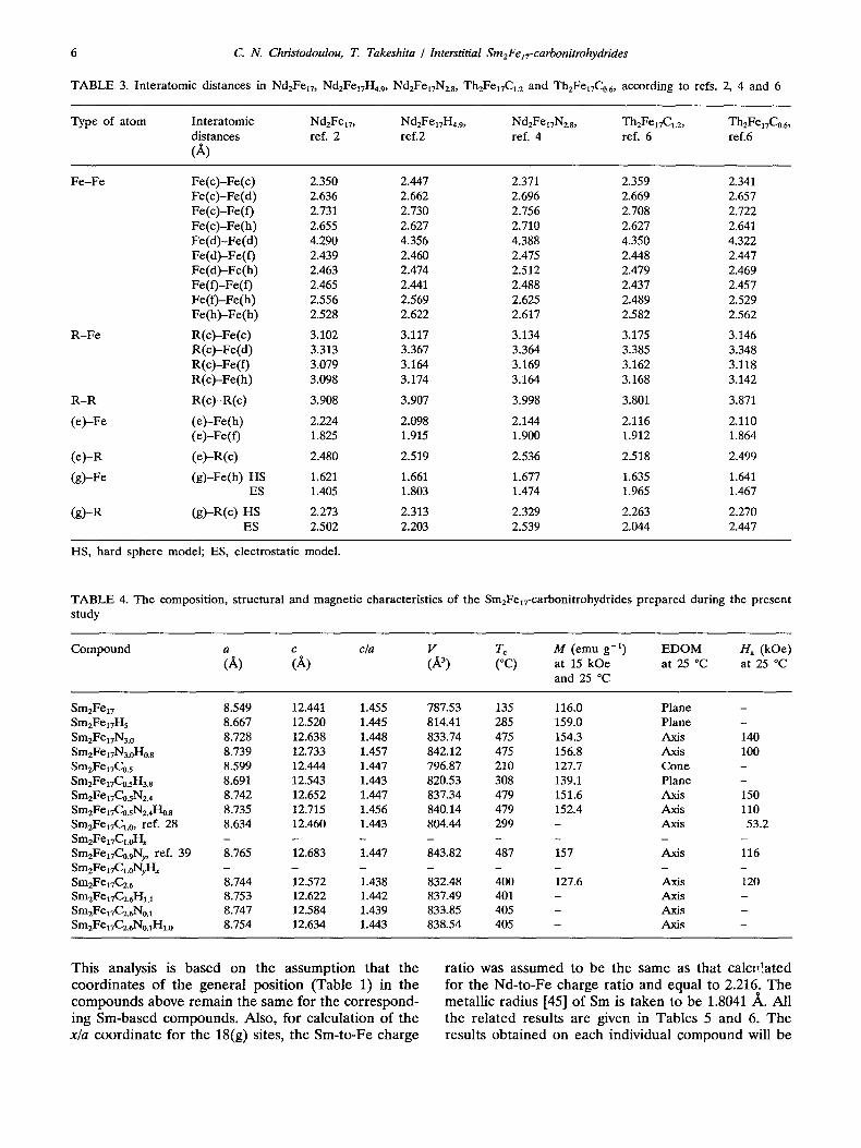
TABLE 3. Interatomic distances in Nd2Fe17, Nd2FelTH4.9, Nd2Fex7Nz8, Th2Fex7C1.z and Th2Fe17Co.6, according to refs. 2, 4 and 6
Type of atom Interatomic NdzFe17, Nd2Fe17H4.9, N d 2 F e ~ 7 N 2 . 8 , T h 2 F e 1 7 C 1 . 2 , Th2Fe17Co.6, distances ref. 2 ref.2 ref. 4 ref. 6 ref.6 (A)
Fe-Fe Fe(c)-Fe(c) 2.350 2.447 2.371 2.359 2.341 Fe(c)-Fe(d) 2.636 2.662 2.696 2.669 2.657 Fe(c)-Fe(f) 2.731 2.730 2.756 2.708 2.722 Fe(c) -Fe(h) 2.655 2.627 2.710 2.627 2.641 Fe(d) -Fe(d) 4.290 4.356 4.388 4.350 4.322 Fe(d)-Fe(f ) 2.439 2.460 2.475 2.448 2.447 Fe(d) -Fe(h) 2.463 2.474 2.512 2.479 2.469 Fe(f) -Fe(f) 2.465 2.441 2.488 2.437 2.457 Fe( f ) -Fe(h) 2.556 2.569 2.625 2.489 2.529 Fe(h ) -Fe(h ) 2.528 2.622 2.617 2.582 2.562
R - F e R(c)-Fe(c) 3.102 3.117 3.134 3.175 3.146 R(c ) -Fe(d) 3.313 3.367 3.364 3.385 3.348 R(c)-Fe(f) 3.079 3.164 3.169 3.162 3.118 R(c ) -Fe(h) 3.098 3.174 3.164 3.168 3.142
R - R R(c) -R(c) 3.908 3.907 3.998 3.801 3.871
(e ) -Fe (e ) -Fe(h) 2.224 2.098 2.144 2.116 2.110 (e)-Fe(f) 1.825 1.915 1.900 1.912 1.864
( e ) -R (e)-R(c) 2.480 2.519 2.536 2.518 2.499
(g)-Fe (g)-Fe(h) HS 1.621 1.661 1.677 1,635 1.641 ES 1.405 1.803 1.474 1,965 1.467
(g) -R (g)-R(c) HS 2.273 2.313 2.329 2.263 2.270 ES 2.502 2.203 2.539 2.044 2.447
HS, hard sphere model; ES, electrostatic model.
TABLE 4. The composition, structural and magnetic characteristics of the Sm2FexT-carbonitrohydrides prepared during the present study
Compound a c c/a V Tc M (emu g - l ) E D O M Ha (kOe) (/~) (A) (A 3) (°C) at 15 kOe at 25 °C at 25 °C
and 25 °C
Sm2Fe17 8.549 12.441 1.455 787.53 135 116.0 Plane - SmzFeI7H5 8.667 12.520 1.445 814.41 285 159.0 Plane - Sm2Fe17N3.0 8.728 12.638 1.448 833.74 475 154.3 Axis 140 Sm2Fe17N3.oHo. 8 8.739 12.733 1.457 842.12 475 156.8 Axis 100 Sm2Fe17C0. 5 8.599 12.444 1.447 796.87 210 127.7 Cone - Sm2Fet7f0.sH3. s 8.691 12.543 1.443 820.53 308 139.1 Plane - Sm2FeI7Co.sN2.4 8.742 12.652 1.447 837.34 479 151.6 Axis 150 Sm2Fe17C0.sN2.4Ho.s 8.735 12.715 1.456 840.14 479 152.4 Axis 110 Sm2FelTC1.0, ref. 28 8.634 12.460 1.443 804.44 299 - Axis 53.2 Sm2Fea7CI.oH x - . . . . . . . Sm2Fe17Co.gNy , ref. 39 8.765 12.683 1.447 843.82 487 157 Axis 116 SmzFe 17Cl.oNyH x . . . . . . . . Sm2Fel7C2.6 8.744 12.572 1.438 832.48 400 127.6 Axis 120 Sm2FeaTC2.6I-I1.1 8.753 12.622 1.442 837.49 401 - Axis - Sm2Fel7f2.6No. 1 8.747 12.584 1.439 833.85 405 - Axis - Sm2FezTC2.6No.aH1. o 8.754 12.634 1.443 838.54 405 - Axis -
This analysis is based on the assumption that the coordinates of the general position (Table 1) in the compounds above remain the same for the correspond- ing Sm-based compounds. Also, for calculation of the x/a coordinate for the 18(g) sites, the Sm-to-Fe charge
ratio was assumed to be the same as that calo,!ated for the Nd-to-Fe charge ratio and equal to 2.216. The metallic radius [45] of Sm is taken to be 1.8041 ~ . All the related results are given in Tables 5 and 6. The results obtained on each individual compound will be

C. N. Christodoulou, T. Takeshita / Interstitial Sm2FezT-carbonitrohydrides 7
";3 M.
E 2
.I-
I ~ 4
04 E 3~ ¢/)
1- 2-
W e i g h t = 9 . 5 1 m g
I n i t i a l P r e s s u r e = 1 2 1 . 4 3 k P a
l n i l i a l H / S m 2 F e l 7 r a t i o = 3 0 . 4 5
4 1 t / C o o l i n g r a t e = 2 ° C / r a i n
l a ) " - , ,
0 t ' i ' - " ~ , " ~ ' - , . . , . . , . , ,. , , .
0 200 400 600 800 1000 Temperature (°C)
6- H / C o o l i n g r a t e : 2 ° C / r a i n
b - W e i g h t : 8 . 4 2 m g
: ' \
~ . • . ~ _ . . .
: ] . , .
b) " ~ ;
. . , . . . , . . , . . , , . . .
200 400 600 800 1000 TemperatlJre (°C)
Fig. 3. (a) ITA trace for the "Sm2Fe17+H2" system, (b) ITA trace for Sm2Fe~TH5 obtained under initial vacuum conditions.
8 . 8 -12.7
o4
a)
8 . 7
8.6"
• c (A)
8.6 ' ' ' ' Sm2Fe17-H5.0 -N3.0 -C2.6
Composition
12.6
=,~
12.5
12.4
8 4 0 "500
830' b ) b ) / ~ 400
O 300 o
¢,,} 1--
20O
790 ~V • Tc (~C)
780 ' ' ' ~ I O0 Sm2Fe17-H5.0 -N3,0 -C2.6
Composition
Fig. 4. (a) The "a" and "c" lattice parameters and (b) the Curie temperature Tc and rhombohedral cell volume V of Sm2Fe~7, SmzFeITHs, Sm2FetTN3 and Sm2FelTCa.6.
820'
8 1 0
8 0 0
presented below, and any arguments related to the structure will be referred to Fig. 2 and Tables 5 and 6.
4.2. Sm2Fe z7-hydrides Figure 3(a) shows the ITA trace for the
"Sm2Fea7 + H2" system. The SmzFe17 compound absorbs about 2.4 H atoms at 250 °C. As the temperature is increased, almost all the H is desorbed and at about 510 °C the SmzFe17 compound decomposes into c~-Fe and Sin-hydrides. On cooling down to room temperature before the decomposition, reabsorption of hydrogen occurs and the composition becomes SmzFelTHs. SmzFelvH5 desorbs and adsorbs reversibly in the tem- perature range 25-500 °C. The desorption characteristics of Sm2FeavH5 are also shown in the ITA trace of Fig. 3(b) obtained under initial vacuum conditions. The hydride begins to desorb hydrogen at about 100 °C and up to 510 °C, where decomposition takes place to form Sm-hydride and a-Fe. If continuous vacuum conditions (for example at about 200 °C) are applied instead, the entire amount of H2 can be desorbed, resulting in a hydrogen-free Sm2Fe~7 parent compound. The ease with which H atoms can be driven in and out of the SmzFe17 structure is an indication that the H bonds with Sm and Fe atoms are relatively weak. More information about the SmzFelT-hydride can be found in refs. 20 and 38.
Hydrogen occupies [2] completely the 9(e) and par- tially the 18(g) interstitial sites causing an increase in both the "a" and "c" lattice parameters (Fig. 4(a)) and a volume expansion of about 3.4% (Fig. 4(b)). A previous study of the Nd2Fe~7-hydrides [47] showed that at low hydrogen concentrations the "a" lattice parameter expands while the "c" parameter remains almost unchanged. When more hydrogen is introduced, both "a" and "c" increase. This is an indication that the H atoms entering the structure fill up the 9(e) sites first and then the 18(g) sites. The H atoms absorbed by Sm2Fe17 as shown in Fig. 3(a), most probably enter the 9(e) sites. During cooling, the H atoms complete the filling of the 9(e) sites and subsequently, they partially occupy the 18(g) sites. As can be seen from Table 5, the 9(e) sites are more accessible to the H atoms than the 18(g) sites, because of their larger interstitial size.
The H-Sm interatomic distances (Table 6) are 2.51 for the 9(e) sites and 2.18 /~ (ES) to 2.29 ]k (HS)
for the 18(g) sites. The predominantly ionic in nature H-Sm bond in SmH2 (CaF2-type, a = 5.366 ~ from ref. 40) has a length of 2.32 /~,. This is smaller than the H-Sm bond found for the 9(e) sites (2.51/~) and larger than that found for the 18(g) sites (2.18-2.29 ~). One could argue that the H-Sm bond in the 9(e) sites is weakly covalent (or metallic) in nature and that in the
8 C.N. Christodoulou, T. Takeshita / Interstitial Sm2Few-carbonitrohydrides
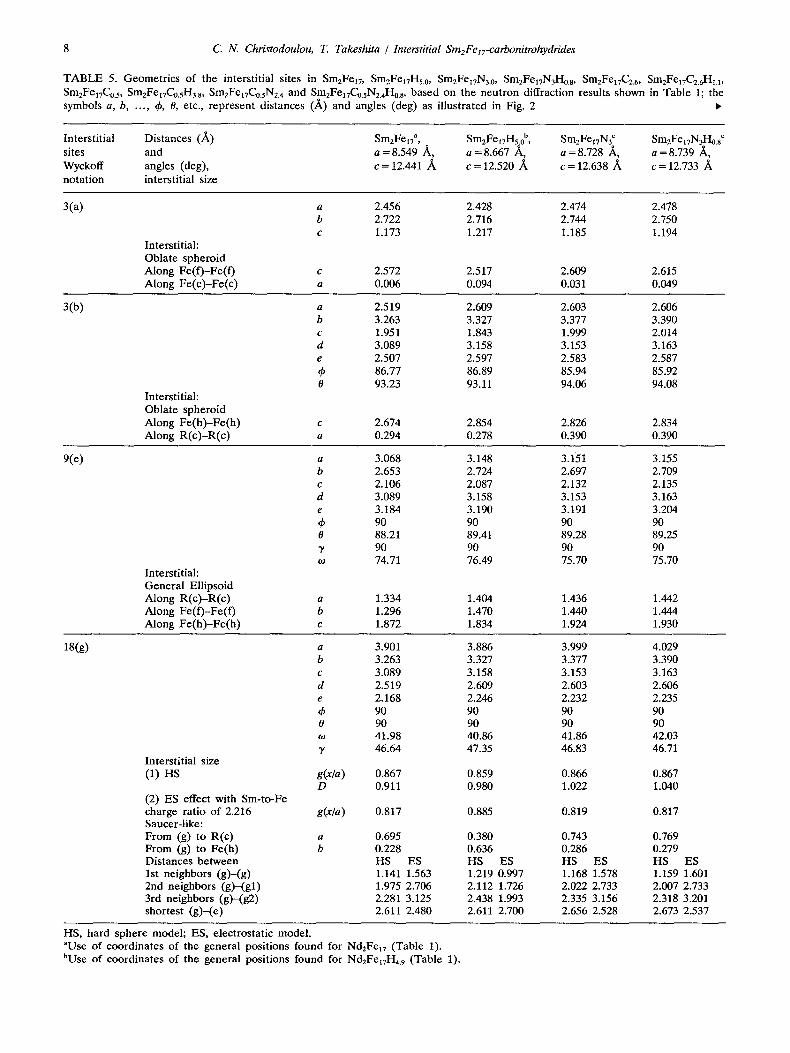
TABLE 5. Geometrics of the interstitial sites in Sm2Fel7 , SmzFe17H5.0, Sm2Fet7N3.0, Sm2Fel7N3n0.8, Sm2Fel7C2.6, Sm2Fel7f2.tHl.l, Sm2Fe17Co.5, Sm2FeITC0.sH3.8, Sm2FelTC0.sN2.4 and Sm2FelvC0.sN2.4H0.8, based on the neutron diffraction results shown in Table I; the symbols a, b, ..., ~b, 0, etc., represent distances (/~) and angles (deg) as illustrated in Fig. 2 •
Interstitial Distances (/~) Sm2Fel7 a, SmzFewHs.0 b, SmzFet7N3 c Sm2FetvN3Ho.s c sites and a = 8.549 /~, a = 8.667 /~, a = 8.728 /~, a = 8.739 /~, Wyckoff angles (deg), c = 12.441 ~ c = 12.520 ]k c = 12.638 /~ c = 12.733 /~ notation interstitial size
3(a) a 2.456 2.428 2.474 2.478 b 2.722 2.716 2.744 2.750 c 1.173 1.217 1.185 1.194
Interstitial: Oblate spheroid Along Fe(f)-Fe(f) c 2.572 2.517 2.609 2.615 Along Fe(c)-Fe(c) a 0.006 0.094 0.031 0.049
3(b)
Interstitial: Oblate spheroid Along Fe(h)-Fe(h) Along R(c)-R(c)
a 2.519 2.609 2.603 2.606 b 3.263 3.327 3.377 3.390 c 1.951 1.843 1.999 2.014 d 3.089 3.158 3.153 3.163 e 2.507 2.597 2.583 2.587 ~b 86.77 86.89 85.94 85.92 0 93.23 93.11 94.06 94.08
c 2.674 2.854 2.826 2.834 a 0.294 0.278 0.390 0.390
9(e)
Interstitial: General Ellipsoid Along R(c)-R(c) Along Fe(f)-Fe(f) Along Fe(h)-Fe(h)
a 3.068 3.148 3.151 3.155 b 2.653 2.724 2.697 2.709 c 2.106 2.087 2.132 2.135 d 3.089 3.158 3.153 3.163 e 3.184 3.190 3.191 3.204 ~b 90 90 90 90 0 88.21 89.41 89.28 89.25 3" 90 90 90 90 to 74.71 76.49 75.70 75.70
a 1.334 1.404 1.436 1.442 b 1.296 1.470 1.440 1.444 c 1.872 1.834 1.924 1.930
18(g)
Interstitial size (1) HS
(2) ES effect with Sm-to-Fe charge ratio of 2.216 Saucer-like: From (g) to R(c) From (g) to Fe(h) Distances between 1st neighbors (g)-(g) 2nd neighbors (g)-(gl) 3rd neighbors (g)-(g2) shortest (g)-(e)
a 3.901 3.886 3.999 4.029 b 3.263 3.327 3.377 3.390 c 3.089 3.158 3.153 3.163 d 2.519 2.609 2.603 2.606 e 2.168 2.246 2.232 2.235 ~b 90 90 90 90 0 90 90 90 90 to 41.98 40.86 41.86 42.03 3' 46.64 47.35 46.83 46.71
g(x/a) 0.867 0.859 0.866 0.867 D 0.911 0.980 1.022 1.040
g(x/a) 0.817 0.885 0.819 0.817
a 0.695 0.380 0.743 0.769 b 0.228 0.636 0.286 0.279
HS ES HS ES HS ES HS ES 1.141 1.563 1.219 0.997 1.168 1.578 1.159 1.601 1.975 2.706 2.112 1.726 2.022 2.733 2.007 2.733 2.281 3.125 2.438 1.993 2.335 3.156 2.318 3.201 2.611 2.480 2.611 2.700 2.656 2.528 2.673 2.537
HS, hard sphere model; ES, electrostatic model. aUse of coordinates of the general positions found for Nd2Fe17 (Table 1). bUse of coordinates of the general positions found for Nd2Fe~7H4. 9 (Table 1).
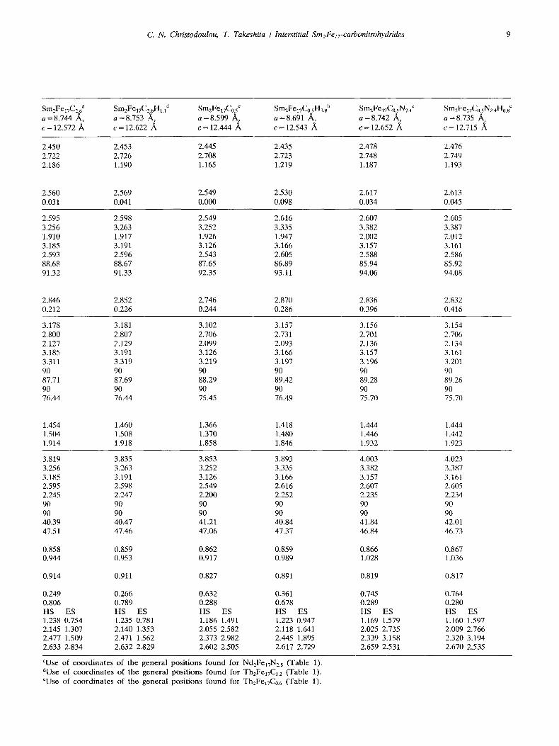
C. N. Christodoulou, T. Takeshita / Interstitial Sm2FelT-carbonitrohydrides 9
Sm2Fe17C2.6 d SmEFelTCz6HH d SmzFe17C0.5 c Sm2FeITC0.5H3.8 ° SmzFe17Co.sNz.4 c Sm2FeITC~.sN24H0.8 c a =8 .744 ~ , a =8 .753 /~, a =8 .599 ~ , a =8 .691 ~ , a =8 .742 ~ , a = 8.735 ~ , c = 1 2 . 5 7 2 ~ c = 12.622 ~ c = 12.444 /k c = 12.543 ~ c = 1 2 . 6 5 2 ~ c = 12.715
2.450 2.453 2.445 2.435 2.478 2.476 2.722 2.726 2.708 2.723 2.748 2.749 2.186 1.190 1.165 1.219 1.187 1.193
2.560 2.569 2.549 2.530 2.617 2.613 0.031 0.041 0.000 0.098 0.034 0.045
2.595 2.598 2.549 2.616 2.607 2.605 3.256 3.263 3.252 3.335 3.382 3.387 1.910 1.917 1.926 1.947 2.002 2.012 3.185 3.191 3.126 3.166 3.157 3.161 2.593 2.596 2.543 2.605 2.588 2.586 88.68 88.67 87.65 86.89 85.94 85.92 91.32 91.33 92.35 93.11 94.06 94.08
2.846 2.852 2.746 2.870 2.836 2.832 0.212 0.226 0.244 0.286 0.396 0.416
3.178 3.181 3.102 3.157 3.156 3.154 2.800 2.807 2.706 2.731 2.701 2.706 2.127 2.129 2.099 2.093 2.136 2.134 3.185 3.191 3.126 3.166 3.157 3.161 3.311 3.319 3.219 3.197 3.196 3.201 90 90 90 90 90 90 87.71 87.69 88.29 89.42 89.28 89.26 90 90 90 90 90 90 76.44 76.44 75.45 76.49 75.70 75.70
1.454 1.460 1.366 1.418 1.444 1.444 1.504 1.508 1.370 1.480 1.446 1.442 1.914 1.918 1.858 1.846 1.932 1.923
3.819 3.835 3.853 3.893 4.003 4.023 3.256 3.263 3.252 3.335 3.382 3.387 3.185 3.191 3.126 3.166 3.157 3.161 2.595 2.598 2.549 2.616 2.607 2.605 2.245 2.247 2.200 2.252 2.235 2.234 90 90 90 90 90 90 90 90 90 90 90 90 40.39 40.47 41.21 40.84 41.84 42.01 47.51 47.46 47.06 47.37 46.84 46.73
0.858 0.859 0.862 0.859 0.866 0.867 0.944 0.953 0.917 0.989 1.028 1.036
0.914 0.911 0.827 0.891 0.819 0.817
0.249 0.266 0.632 0.361 0.745 0.806 0.789 0.288 0.678 0.289 HS ES HS ES HS ES HS ES HS 1.238 0.754 1.235 0.781 1.186 1.491 1.223 0.947 1.169 2.145 1.307 2.140 1.353 2.055 2.582 2.118 1.641 2.025 2.477 1.509 2.471 1.562 2.373 2.982 2.445 1.895 2.339 2.633 2.834 2.632 2.829 2.602 2.505 2.617 2.729 2.659
ES 1.579 2.735 3.158 2.531
0.764 0.280 HS ES 1.160 1.597 2.009 2.766 2.320 3.194 2.670 2.535
cUse of coord ina te s o f the genera l posi t ions found for Nd2FeI7N2. s (Table 1). dUse of coord ina te s of the genera l posi t ions f o u n d for TheFelTCm (Table 1). ¢Use of coord ina te s of the genera l posi t ions f o u n d for TheFe17C0. 6 (Table 1).
TA
BL
E
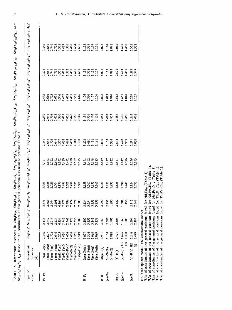
6.
Inte
rato
mic
d
ista
nce
s in
S
m2F
e17,
Sm
2Fe1
7Hs,
S
m2F
elT
N3,
Sm
2Fel
TN
3Ho.
8,
Sm2F
e17C
2.6,
Sm
2Fel
TC
2.6H
l.1,
Sm2F
e17C
o.5,
Sm
2FeI
TC
o.sH
3.8,
Sm
2Fel
TC
o.sN
2.4
and
Sm
2Fel
TC
o.sN
2.4H
o.s,
bas
ed o
n th
e co
ord
inat
es o
f th
e g
ener
al p
osi
tio
ns
also
use
d t
o p
rep
are
Tab
le 5
Typ
e of
In
tera
tom
ic
atom
di
stan
ces
(~)
Sm2F
e17 a
Sm
2Fel
TH
~ b
Sm2F
elT
N3 ¢
Sm
2Fel
TN
3Ho.
s c Sm
xFel
TC
2.6 d
Sm
2Fel
TC
2.6H
l.1 d
SmzF
elT
Co.
s e Sm
2Fel
TC
0.sH
a.s b
Sm
zFe1
7Co.
sN2.
4 e
SmzF
elvC
o.sN
z.4H
o.s c
Fe-
Fe
Fe(
c)-F
e(c)
2.
346
2.43
4 2.
371
2.38
9 2.
371
2.38
1 2.
330
2.43
8 2.
374
2.38
5 F
e(c)
-Fe(
d)
2.62
7 2.
649
2.68
3 2.
688
2.68
3 2.
687
2.64
4 2.
656
2.68
7 2.
686
Fe(
c)-F
e(f)
2.
722
2.71
6 2.
744
2.75
0 2.
722
2.72
6 2.
708
2.72
3 2.
748
2.74
9 F
e(c)
-Fe(
h)
2.6
46
2.
614
2.69
8 2.
704
2.64
1 2.
644
2.62
8 2.
621
2.70
2 2.
703
Fe(
d)-
Fe(
d)
4.27
5 4.
334
4.36
4 4.
370
4.37
2 4.
377
4.30
0 4.
346
4.37
1 4.
368
Fe(
d)-
Fe(
f)
2.43
4 2.
447
2.47
2 2.
486
2.46
0 2.
468
2.43
5 2.
452
2.47
5 2.
483
Fe(
d)-
Fe(
h)
2.45
4 2.
461
2.49
8 2.
501
2.49
2 2.
494
2.45
6 2.
468
2.50
2 2.
500
Fe(
f)-F
e(f)
2
.45
6
2.42
8 2.
474
2.47
8 2.
450
2.45
3 2.
445
2.43
5 2.
478
2.47
6 F
e(0
-Fe(
h )
2.5
51
2.
556
2.62
2 2.
637
2.50
2 2.
510
2.51
6 2.
561
2.62
5 2.
634
Fe(
h)-
Fe(
h)
2.51
9 2.
609
2.60
3 2.
606
2.59
5 2.
598
2.54
9 2.
616
2.60
7 2.
605
R-F
e R
(c)-
Fe(
c)
3.09
7 3.
100
3.13
4 3.
158
3.19
1 3.
203
3.13
1 3.
106
3.13
8 3.
153
R(c
)-F
e(d
) 3.
304
3.35
2 3.
354
3.36
7 3.
402
3.41
0 3.
331
3.36
0 3.
358
3.36
4 R
(c)-
Fe(
f)
3.06
8 3.
148
3.15
1 3.
155
3.17
8 3.
181
3.10
2 3.
157
3.15
6 3.
154
R(c
)-F
e(h
) 3.
089
3.15
8 3.
153
3.16
3 3.
185
3.19
1 3.
126
3.16
6 3.
157
3.16
1
R-R
R
(c)-
R(c
) 3.
901
3.88
6 3.
999
4.02
9 3.
819
3.83
5 3.
853
3.89
3 4.
003
4.02
3
(e)-
Fe
(e)-
Fe(
h)
2.10
6 2.
087
2.13
2 2.
135
2.12
7 2.
129
2.09
9 2.
093
2.13
6 2.
134
(e)-
Fe(
f)
1.81
8 1.
905
1.89
0 1.
892
1.92
2 1.
924
1.85
5 1.
910
1.89
3 1.
891
(e)-
R
(e)-
R(c
) 2.
471
2.50
6 2.
522
2.52
5 2.
531
2.53
4 2.
487
2.51
3 2.
526
2.01
2
(g)-
Fe
(g)-
Fe(
h)
HS
1.
626
1.66
0 1.
681
1.69
0 1.
642
1.64
7 1.
628
1.66
5 1.
684
1.68
8 E
S
1.39
8 1.
806
1.45
6 1.
449
1.97
6 1.
959
1.45
8 1.
848
1.45
9 1.
450
(g)-
R
(g)-
R(c
) H
S
2.26
0 2.
294
2.31
5 2.
324
2.27
6 2.
281
2.26
2 2.
299
2.31
8 2.
322
ES
2.
499
2.18
4 2.
547
2.57
3 2.
053
2.07
0 2.
436
2.16
5 2.
549
2.56
8
~o
xl
HS
, h
ard
sp
her
e m
od
el;
ES
, el
ectr
ost
atic
mo
del
. aU
se o
f co
ord
inat
es o
f th
e g
ener
al p
osi
tio
ns
fou
nd
fo
r bU
se o
f co
ord
inat
es o
f th
e g
ener
al p
osi
tio
ns
fou
nd
fo
r C
Use
of
coo
rdin
ates
of
the
gen
eral
po
siti
on
s fo
un
d f
or
dUse
of
coo
rdin
ates
of
the
gen
eral
po
siti
on
s fo
un
d f
or
rUse
of
coo
rdin
ates
of
the
gen
eral
po
siti
on
s fo
un
d f
or
Nd2
Fe17
(T
able
1)
. N
d2Fe
lTH
4.9
(Tab
le
1).
Nd2
FexT
Nzs
(T
able
1)
. T
h2Fe
17C
1. 2
(Tab
le
1).
Th2
FelT
Co.
6 (T
able
1)
.
C. N. Christodoulou, T. Takeshita / Interstitial Sm2Fe17-carbonitrohydrides 11
r " '23
(D C
E "6 5 0
r r
CO
(303)
8 ~11 ~ 5m2be17H5 ~q o ~ [~ o Randonl ~g | o ~ nil ~ a=8.667 A
I (220)
(300) [ Sm2Fe 17115 b) t II' Aligned
20 25 30 35 40 45 50
2g-Angle (degrees)
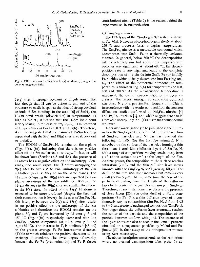
Fig. 5. XRD patterns for Sm2Fe17Hs: (a) random, (b) aligned in 20 kOe magnetic field.
18(g) sites is strongly covalent or largely ionic. The fact though that H can be driven in and out of the structure so easily is against the idea of strong covalent or ionic H-Sm bonding. In the case [40] of SmH2, the H-Sm bond breaks (dissociation) at temperatures as high as 725 °C, indicating that the H-Sm ionic bond is very strong. In the case of Sm2Fe~7Hs, H is desorbed at temperatures as low as 100 °C (Fig. 3(b)). Therefore, it can be suggested that the nature of H-Sm bonding associated with the 9(e) and 18(g) sites is weak covalent or metallic.
The EDOM of Sm2FelvH5 remains on the c-plane (Figs. 5(a), (b)), indicating that there is no positive effect on the Sm sublattice anisotropy. In fact, as will be shown later (Sections 4.5 and 4.6), the presence of H atoms has a negative effect on the anisotropy. Gen- erally, one would expect the H atoms occupying the 9(e) sites to give rise to axial anisotropy of the Sm sublattice (because they tie on the same plane). The H atoms occupying the 18(g) sites are expected to favor planar anisotropy of the Sm sublattice. Because the H-Sm distance in the 18(g) sites are smaller than those in the 9(e) sites, the effect of the 18(g) H atoms is expected to be more profound (despite the fact that their concentration is lower). In the case of Sm2FelTHs, this interplay between the 9(e) and 18(g) sites results in no positive effect on the anisotropy of the Sm sublattice and therefore the EDOM remains on the plane. Ms and Tc are increased by 43 emu g-a and 150 °C (Fig. 4(b)) respectively, compared with the Sm2Fe17 parent compound (Ms=l l6 emu g-1 and Tc = 135 °C). The increase in Tc is attributed [48, 49] to the greater average Fe-Fe interatomic distances (Table 6) which reinforce the positive character of the exchange interactions. The lower degree of overlap between the Fe-Fe (predominantly) and Fe-R (lower
contribution) atoms (Table 6) is the reason behind the large increase in magnetization.
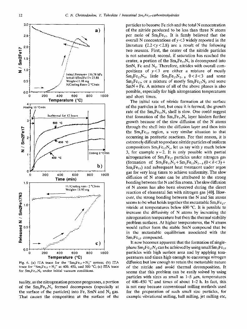
4.3. Sm2Fe zT-nitrides The ITA trace of the "Sm2Fe17 + N2" system is shown
in Fig. 6(a). Nitrogen absorption begins slowly at about 250 °C and proceeds faster at higher temperatures. The Sm2Felv-nitride is a metastable compound which decomposes into SmN+Fe in a thermally activated manner. In general, below 500 °C the decomposition rate is relatively low but above this temperature it becomes very significant. At about 600 °C, the decom- position rate is very high and leads to the complete decomposition of the nitride into SmN, Fe (or initially Fe-nitrides which quickly decompose into Fe + N2) and N2. The effect of the isothermal nitrogenation tem- perature is shown in Fig. 6(b) for temperatures of 400, 450 and 500 °C. As the nitrogenation temperature is increased, the overall concentration of nitrogen in- creases. The largest nitrogen concentration observed was three N atoms per Sm2Fe~7 formula unit. This is in accordance with the results obtained from the neutron diffraction studies performed on NdzFe~v-nitrides [4] and PrzFeav-nitrides [3], and which suggest that the N atoms can occupy only the 9(e) sites in the rhombohedral structure.
A detailed investigation (to be published in the future) on how the SmzFea7-nitride is formed during the reaction of Sm2Fe~7 particles and Nz gas has revealed the following. Initially (for the first few minutes), N is absorbed on the surface of the particles forming a thin (less than 1 p~m) film (diffusion layer) of SmzFe17Ny with a range of compositions varying continuously from y < 3 at the surface to y =0 at the length of the film. As time passes, the composition at the surface reaches saturation (y=3) and the thin diffusion layer moves inwards with the Sm2Fe~TN3 shell growing bigger. The depth of the diffusion layer increases but remains very small (below 5 Ixm). At the same time the core of the particles extending from the length of the diffusion layer to the center of the particles remains pure Sm2Fe17. Therefore, at any instant one may observe the presence of three layers [26]: the outer shell of uniform com- position (Sm2Fe~7N3), a thin diffusion layer of a con- tinuously varying composition (Sm2Fea7N3_8) from 6 < 3 to 3 = 0, and a core of unchanged composition (Sm2Fe~7). For longer times, the diffusion layer eventually reaches the center of the particle and the composition of the particle becomes uniform with y = 3. The existence of the layers above can also be seen in the domain patterns obtained on nitrogenated particles by Mukai and Fu- jimoto [50] in their study of the nitrogenation process using Kerr microscopy.
The above description corresponds to ideal conditions where no thermal decomposition takes place. In ac-
12 C . N . C h r i s t o d o u l o u , T . T a k e s h i t a / I n t e r s t i t i a l S m 2 F e 1 7 - c a r b o n i t r o h y d r i d e s
3.0"
2.5
I',- 2.0 g II 04 1.5 E
Z 1.0
0.5
0.0
4 Heat n,
% a)
// /
.; initial Pressure= 116.76 kPa ," Initial H/Sm2Fel7= 23.88
J -. Weight=l 1.98 mg s.' / H/Cooling Rate= 2 °C/min
It" J : "
200 400 600 800 1
Temperature (°C) 10 °C/mln
~00
3
u 04 2 E
Z 1
1.5 ¸
03 Z
o) ii 1 . 0 o4 E
(/]
Z
"~ 0.5 ¢1 ta
0 0
i• Isothernlal for 12 hours ~,-
500 °C .__,~.:._..,p,=_, ........ ._. , , , . - - ,~
.,.~..~--~- .,....-..-.--.
/ j < " Cooling 2 °~min ( .e"" 400 °C
200 400 600 800 1000
Time (min)
_~-..
II / Cooling rate= 2 °C/rain Weight= 11.93 mg
. . . . . . . . . . ----..---. : - ' -=-~
///- _7.--
__ :---
- ) . ._ . . l= '~ C oTY"
0.0 : . " . ' - , " . . . . . . . . . . . . ' . . 0 200 400 600 800 1000
Temperature (°C) Fig. 6. ( a ) I T A t r a c e for t he " S m 2 F e 1 7 + N 2 " sy s t em; (b) I T A t r a c e for " S m 2 F e 1 7 + N 2 " a t 400, 450, a n d 500 °C; (c) I T A t r a c e fo r Sm2FeITN3 u n d e r i n i t i a l v a c u u m c o n d i t i o n s .
tuality, as the nitrogenation process progresses, a portion of the Sm2Fea7N3 formed decomposes (especially at the surface of the particles) into Fe, SmN and N2 gas. That causes the composition at the surface of the
particles to become Fe rich and the total N concentration of the nitride produced to be less than three N atoms per mole of Sm2Fe17. It is firmly believed that the overall N concentrations ofy < 3 widely reported in the literature (2.2<y<2.8) are a result of the following two reasons. First, the center of the nitride particles is not saturated; second, if saturation has reached the center, a portion of the Sm2Fe17N 3 is decomposed into StuN, Fe and N2. Therefore, nitrides with overall com- positions of y < 3 are either a mixture of mostly SmzFe17N3, little Sm2Fea7N3_ 8 0 < 3 < 3 and some Sm2Fea7, or a mixture of mostly Sm2FeaTN3 and some StuN + Fe. A mixture of all of the above phases is also possible, especially for high nitrogenation temperatures and short times.
The initial rate of nitride formation at the surface of the particles is fast, but once it is formed, the growth rate of the Sm2Fe17N3 shell is slow. One could suggest that formation of the Sm2Fe17N 3 layer hinders further growth because of the slow diffusion of the N atoms through the shell into the diffusion layer and then into the Sm2Fea7 region, a very similar situation to that occurring in peritectic reactions. For that reason, it is extremely difficult to produce nitride particles of uniform compositions Sm2Fe17Ny, let us say with y much below 3, for example y =2. It is only possible with partial nitrogenation of Sm2Fe17 particles under nitrogen gas (formation of Sm2Fea7N3 + Sm2Fe17N3_ ~ (0 < 6 < 3) + Sm2Fe17) and subsequent heat treatment under argon gas for very long times to achieve uniformity. The slow diffusion of N atoms can be attributed to the strong bonding between the N and Sm atoms. The slow diffusion of N atoms has also been observed during the direct reaction of elemental Sm with nitrogen gas [40]. How- ever, the strong bonding between the N and Sm atoms seems to be what holds together the metastable Sm2Fe17- nitride at temperatures below 600 °C. It is possible to increase the diffusivity of N atoms by increasing the nitrogenation temperature but then the thermal stability problem surfaces. At higher temperatures, the N atoms would rather form the stable SmN compound that be in the metastable equilibrium associated with the SmaFel7 compound.
It now becomes apparent that the formation of single- phase Sm2Fe17N 3 can be achieved by using small Sm2Fea7 particles with high surface area and by applying tem- peratures and times high enough to encourage nitrogen diffusion but low enough to retain the metastable nature of the nitride and avoid thermal decomposition. It seems that this problem can be easily solved by using particles with sizes as small as 1-5 /zm, temperatures of 400-450 °C and times of about 1-2 h. In fact, this is not easy because conventional milling methods used for the preparation of such small size particles, for example vibrational milling, ball milling, jet milling etc,
C. N. Christodoulou, 7". Takeshita / Interstitial Sm2Fe17-carbonitrohydrides 13
introduce contamination (O, C, H, N) and defects, especially on the surface of the particles. The presence of such contamination and defects causes incontrollable reactions and easier decomposition of the SmzFe17 - nitride. One could argue here that the presence of defects may increase the diffusivity of N atoms and therefore favor the nitrogenation reaction kinetics. This may be true but at the same time it is also true that the mobility of Sm and Fe atoms will increase, con- tributing to the instability of the compound. Easy motion of N, Sm and Fe atoms will strongly encourage the formation of stable SmN and Fe phases. Therefore, one must use large particles (approximately 45 /zm) produced by applying a low energy milling process in order to minimize contamination and surface defects. In this case longer times are needed and the possibility of decomposition increases.
It becomes obvious there is always a trade-off in any direction that one chooses to follow. Recently [26] we showed that the overall process for the production of nitrides can be improved largely by nitro-hydrogenation, a reaction between "clean" SmzFe17 particles (ap- proximately 45 p.m) prepared by a special interstitial hydrogen absorption desorption (IHAD) process and a mixture of N a + H 2 gases. In that way and after dehydrogenation at low temperatures, high quality Sm2Fea7N3 anisotropic powders have been prepared exhibiting an ~H~ of 8.35 kOe and (BH)max of 36 MGOe, assuming full density. It is believed that during ni- trohydrogenation, H diffuses easily opening paths and creating new surfaces readily available for the N atoms to saturate forming SmzFeaTN3 . More information about the nitrohydrogenation process will be given later in Section 4.5 and in future publications.
The metastable nature of SmzFeaTN3 is also shown in the ITA trace of Fig. 6(c), obtained under initial vacuum conditions. At about 220 °C, a portion of the Sm2FetTN3 begins to decompose into SmN and Fe (or Fe-nitride). This is evident from the increasing amount of nitrogen gas released during heating (Fig. 6(c)). X- ray studies showed that N is not interstitially desorbed, but is released as a product of the decomposition reaction
1 Sm2FelTN 3 ~ 2SmN + 17Fe + 7 N2
The effect of the N atoms on the structure and magnetic properties of Sm2Fe~TN3 can be summarized as follows.
(1) They produce a negative electric field gradient at the Sm 6(c) sites, giving rise to axial anisotropy of the Sm sublattice resulting in an increase in the total magnetocrystalline anisotropy field of the nitride (the anisotropy of the Fe sublattice is planar). In fact, the EDOM changes from planar in the case of Sm2Fea7
to strongly uniaxial in the case of the nitride, exhibiting an anisotropy field of 140 kOe (Table 4).
(2) They cause a small overlap with the 18(h)Fe and a larger overlap with the 18(f)-Fe nearest neighbor atoms, resulting in a small decrease in their magnetic moment. The extent of the overlap is kept to a minimum because of the simultaneous increase in the Fe(h)-Fe(h) and Fe(f)-Fe(f) nearest neighbor distances (Table 5). At the same time, the Fe-Fe distances between the other sites (for example, the (c)-(c) distance) increase (Table 6) resulting in an increase in the corresponding Fe moments. In addition to these, some contribution may also come from the decrease in the overlap between the Sm and Fe atoms. Altogether, the total magneti- zation of the nitride is increased from 116 to 154.3 emu g-a (Table 4).
(3) They cause an expansion (5.9%) of the lattice (Figs. 4(a),(b)) leading to an increase in the average Fe-Fe distances (Table 6); as a consequence an increase in the exchange interactions (from negative to more positive) occurs resulting in an increase in the Curie temperature from 135 to 475 °C (Fig. 4(b)).
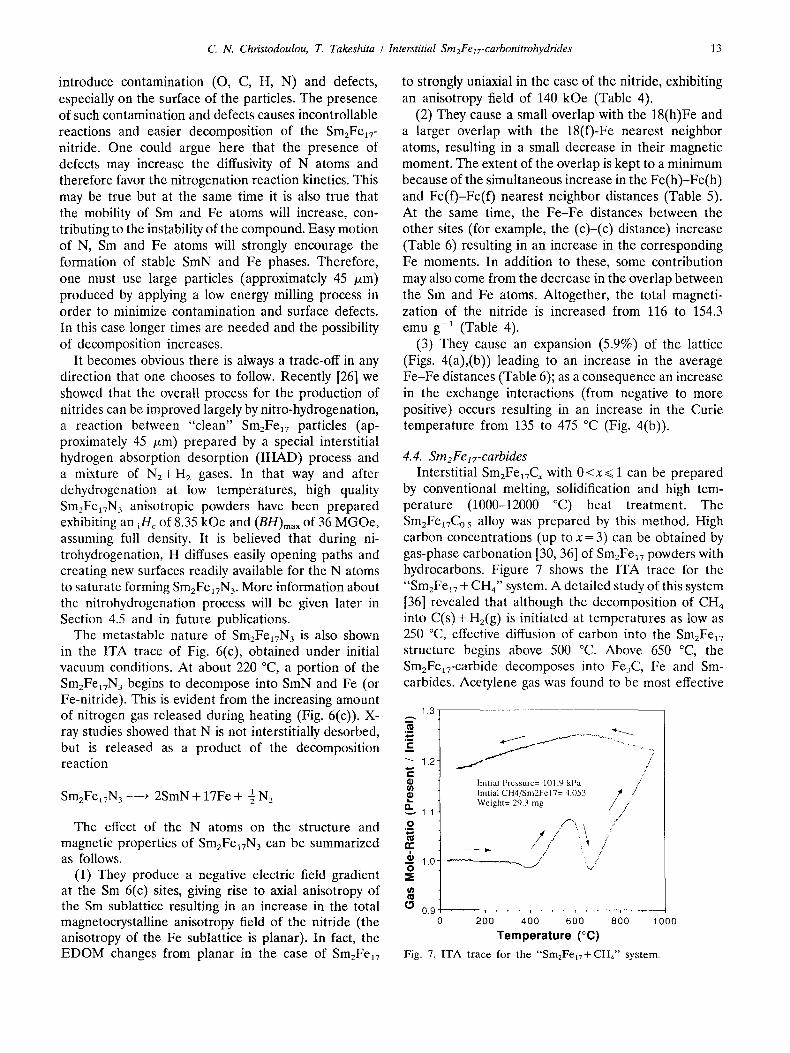
4.4. Sm2Fe~7-carbides Interstitial SmzFe~7Cx with 0 <x ~< 1 can be prepared
by conventional melting, solidification and high tem- perature (1000-12000 °C) heat treatment. The SmzFe17Co. 5 alloy was prepared by this method. High carbon concentrations (up to x = 3) can be obtained by gas-phase carbonation [30, 36] of SmzFe17 powders with hydrocarbons. Figure 7 shows the ITA trace for the "Sm2Fe~7 + CH4" system. A detailed study of this system [36] revealed that although the decomposition of CH4 into C(s)+ H2(g) is initiated at temperatures as low as 250 °C, effective diffusion of carbon into the Sm2Fe~7 structure begins above 500 °C. Above 650 °C, the SmzFeav-carbide decomposes into F%C, Fe and Sin- carbides. Acetylene gas was found to be most effective
, m
e-
,fi
o . B
n -
k o
1.3
1.2
1.1
1.0
/ Initial Pressure= 101.9 kPa / Initial CH4/Sm2FeI7= 4.053 / / 4 / J / ' Weight= 29.3 mg
.1
/7 ( / ,"
., :. /
0 200 400 600 800 1000
Temperature (°C) Fig. 7. I T A trace for the " S m 2 F e l v + C H 4 " system°
14 C. N. Christodoulou, T. Takeshita / Interstitial Sm2Felz-carbonitrohydrides
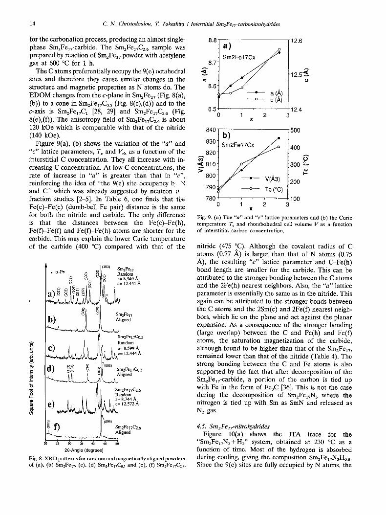
for the carbonation process, producing an almost single- phase Sm2Fe~v-carbide. The Sm2Fea7C2.6 sample was prepared by reaction of Sm2Fea7 powder with acetylene gas at 600 °C for 1 h.
The C atoms preferentially occupy the 9(e) octahedral sites and therefore they cause similar changes in the structure and magnetic properties as N atoms do. The EDOM changes from the c-plane in Sm2Fea7 (Fig. 8(a), (b)) to a cone in Sm2Fea7C0.s (Fig. 8(c),(d)) and to the c-axis is SmzFe~vCa [28, 29] and Sm2FeaTCz.6 (Fig. 8(e),(f)). The anisotropy field of Sm2Fe~7C2.6 is about 120 kOe which is comparable with that of the nitride (140 kOe).
Figure 9(a), (b) shows the variation of the "a" and "c" lattice parameters, T~ and Vrh as a function of the interstitial C concentration. They all increase with in- creasing C concentration. At low C concentrations, the rate of increase in "a" is greater than that in "¢", reinforcing the idea of "the 9(e) site occupancy b "~ and C" which was already suggested by neutron o fraction studies [2-5]. In Table 6, one finds that tbc Fe(c)-Fe(c) (dumb-bell Fe pair) distance is the same for both the nitride and carbide. The only difference is that the distances between the Fe(c)-Fe(h), Fe(f)-Fe(f) and Fe(f)-Fe(h) atoms are shorter for the carbide. This may explain the lower Curie temperature of the carbide (400 °C) compared with that of the
003) Sm2Fel 7
Sm2Fel7 Aligned
Sm2Fel7C0.5 Random
~; 1 a=8.599 A II I c= 12.444 ,~
o
g
", ' , ,A,#.,,A& L,,.,fl W,.,,, ;
-- | Sm2Fel7C0.5 Aligned
"6 "~ Sm2Fe 17C2.6 o Random re I I [ ~ a=8.744/~
e) 12.572/ .
k(0o6 ) [ ~ Sm2FeI7C2.6
Aligned
20 as ao as 4o 4s 50
20-Angle (degrees)
Fig. 8. X R D patterns for random and magnetically aligned powders of (a), (b) Sm2Fe17, (c), (d) Sm2Fel7Co.5 and (e), (f) Sm2Fe17C2. 6.
8.8
8.71 A
8.6
a)
) --o-- c (A)
12.6
8.5 12.4 0 1 2 3
X
A
• 12 5~,,~.. t,,}
840 500 b)
~" 820830 S m 2 ~ 400 o"
~ 810 300 o > #.
8 0 0 / , V(A3) 200 790 ---o--- Tc (°C) 780 100
0 1 2 3 X
Fig. 9. (a) The " a " and " c " latt ice parameters and (b) the Cur ie t empera ture T c and rhombohedra l cell volume V as a function of interstitial carbon concentration.
nitride (475 °C). Although the covalent radius of C atoms (0.77 /~) is larger than that of N atoms (0.75 /k), the resulting "c" lattice parameter and C-Fe(h) bond length are smaller for the carbide. This can be attributed to the stronger bonding between the C atoms and the 2Fe(h) nearest neighbors. Also, the "a" lattice parameter is essentially the same as in the nitride. This again can be attributed to the stronger bonds between the C atoms and the 2Sin(c) and 2Fe(f) nearest neigh- bors, which lie on the plane and act against the planar expansion. As a consequence of the stronger bonding (large overlap) between the C and Fe(h) and Fe(f) atoms, the saturation magnetization of the carbide, although found to be higher than that of the SmzFe17, remained lower than that of the nitride (Table 4). The strong bonding between the C and Fe atoms is also supported by the fact that after decomposition of the Sm2Fe~7-carbide, a portion of the carbon is tied up with Fe in the form of Fe3C [36]. This is not the case during the decomposition of Sm2FelTN3 where the nitrogen is tied up with Sm as SmN and released as N2 gas.
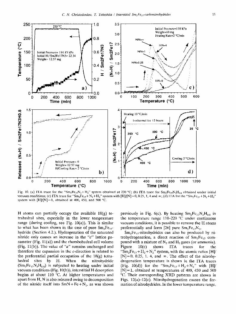
4.5. Sm2Fe lT-nitrohydrides Figure 10(a) shows the ITA trace for the
"SmzFe17N3+H2" system, obtained at 230 °C as a function of time. Most of the hydrogen is absorbed during cooling, giving the composition SmEFe17N3Hos. Since the 9(e) sites are fully occupied by N atoms, the
C. N. Christodoulou, T. Takeshita I Interstitial Sm2FelT-carbonitrohydrides 15
250
2 0 0
p 150
~. 100
F- 50
0 0
230 °C 1 .0 3.5" Initial Pressure=118 kPa Weighl= 10 mg
3.0 tlealing Rate=2 °C/min ::: 0 . 8 H/N:~
I~ 2.5 " ' " ~ - . H/N=4 4 "i~:"5:~t v -
0.6 ~ f .;:;7 ln i l ia lH/Sm2FelTN3=22.34 l I ® ~ 20 ,,,,. ,, ,.,, " '"~,.:::... i ..+:': m. [ . . . . . . - : . . . . , - , .
O,I H/N=0.25 " .": "X " x . v']i:" t ' " E ~ , 1.5 . .. .,,.; ...,.. , . ; y . 0 . 4 ~ -1- . ~,,.:, % / , :
"1" Z 1.0" . :-. .;: <%_.._.~ .¢ .
0.2 : : . H/N=0 ---,~%;." - 0.5"
a~_ " " : ' ~ "X. i
- ' ..~,' -" . . . . . . . , . " C ) . . . . . . . . , ' . . '-,'~'~ . . . . . " - 0.0 0.0 ~.,~,,,,,~.~,.n~}~'." ...... -" . . . . . .
200 400 600 800 1000 0 100 200 300 400 500 600 Time (min) Temperature (°C)
00 1.5 0 "I" ¢q Z I",. g IL 1.0 ~N E U)
2 ÷
Z 0.5-
' 0
a :
- 4 - - - - - - &-,.
5
/ /
5 2
2
._--"
. .C2.&- - . - - ~ ' ~ "
. 7 "
t / ' : - Inilial Pressure= (I Weighl= 12.57 mg II/Cooling Ralc= 2 °C/nlin
4 . . . _ _ 2
0.0 . . . . . . . . . . . , . . . . . . . 0 200 4 0 0 600 800 1000
Temperature (°C)
4 '
3
,,=
=, Z l
b)
Heating I0 °C/min
"4 t l / I t o / ! 1 i 2s oc
2so oc soo c I ../~/ I
t 11_!-~ I Cooling 2 °C/min I
/ 1 0 2 0 0 4 0 0 6 0 0 8 0 0 1 0 0 0 1 2 0 0
Time (min) Fig. 10. (a) I T A trace for the "Sm2FelTN3+Hz ' ' sys tem ob ta ined at 230 °C; (b) I T A trace for Sm2FelTN3H0.8 ob ta ined u n d e r initial v a c u u m condi t ions ; (c) I T A trace for "SmzFe17 + N2 + H2" sys tem with [H]/[N] = 0, 0.25, 1, 4 and o0 ; (d) I T A for the "SmzFei7 + N 2 + H2" sys tem with [HI/IN] = 1, ob ta ined at 400, 450, and 500 °C.
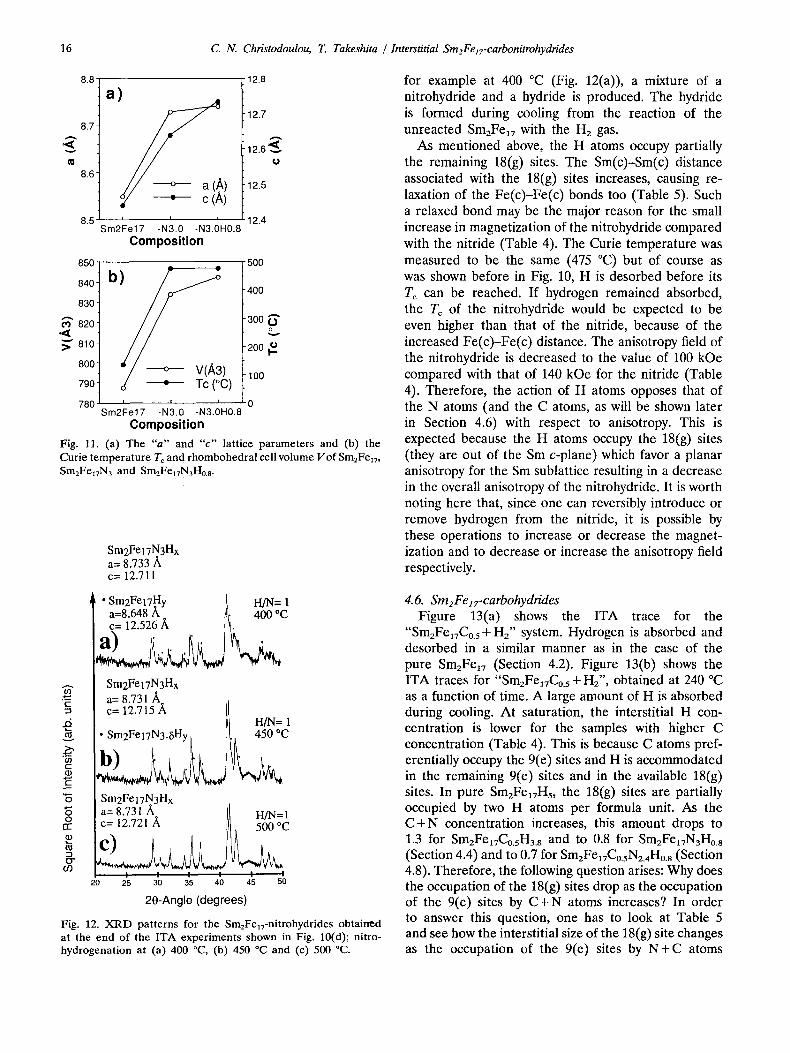
H atoms can partially occupy the available 18(g) te- trahedral sites, especially in the lower temperature range (during cooling, see Fig. 10(a)). This is similar to what has been shown in the case of pure SmzFe17- hydride (Section 4.2.). Hydrogenation of the saturated nitride only causes an increase in the "c" lattice pa- rameter (Fig. 11(a)) and the rhombohedral cell volume (Fig. ll(b)). The value of "a" remains unchanged and therefore the expansion in the c-direction is related to the preferential partial occupation of the 18(g) tetra- hedral sites by H. When the nitrohydride (SmzFe17N3H0.8) is subjected to heating under initial vacuum conditions (Fig. 10(b)), interstitial H desorption begins at about 110 °C. At higher temperatures and apart from H, N is also released owing to decomposition of the nitride itself into SmN + Fe + N2, as was shown
previously in Fig. 6(c). By heating Sm2Fea7N3H0.8 in the temperature range 110-220 °C under continuous vacuum conditions, it is possible to remove the H atoms preferentially and form [26] pure Sm2Fe17N 3.
Sm2FelT-nitrohydrides can also be produced by ni- trohydrogenation, a direct reaction of Sm2Fe17 com- pound with a mixture of N2 and H2 gases (or ammonia). Figure 10(c) shows ITA traces for the "Sm2Fe17 + H2 + N2" system, with the atomic ratios [HI/ [N]=0, 0.25, 1. 4, and ~. The effect of the nitrohy- drogenation temperature is shown in the ITA traces (Fig. 10(d)) for the "Sm2Fe~7+H2+N2" with [HI/ [N] = 1, obtained at temperatures of 400, 450 and 500 °C. Their corresponding XRD patterns are shown in Figs. 12(a)-12(c). Nitrohydrogenation causes the for- mation of nitrohydrides. In the lower temperature range,
16 C. N. Christodoulou, T. Takeshita I Interstitial Sm2FelT-carbonitrohydrides
8.8
8.7
v
8.6
8.5
a)
• c£ i i i
;m2Fe17 -N3.0 -N3.0H0.8 Composition
850 - ¢
840. b)
830
¢O 820'
~ " 810
800
790 )
780 ' ' ' Sm2Fe17 -N3.0 -N3.0H0.8
Composition Fig. 11. (a) The "a" and "c" lattice parameters and (b) the Curie temperature Tc and rhombohedral cell volume Vof Sm2Fez7, S m 2 F e I 7 N 3 a n d S m 2 F e 1 7 N 3 H o . 8.
12.8
12.7
12.6~--_~ O
12.5
12.4
50O
40O
' 300 " " (.}
' 2 0 0
"100
0
c'-
~d
tO ¢.. 0) E "6
O t-r"
t~ "3 12"
CO
Sm2Fe 17N3Hx a= 8.733/~ c= 12.711
• Sm2Fel7Hy [ H/N= 1 a=8.648/~. ~1' 400 °C c= 12.526 A I L
sm2gel7N3Hx a= 8.731/~ c= 12.715/~ It
H/N= 1 III • Sm2FeI7N3-6Hy [ ]t~ 450 °C
Sm2FeI7N3Hx a= 8.731 ~ ! c= 12.721 /~ I
I I I I 2 0 2 5 3 0 3 5 4 0
H/N=I
I ! 4 5 5 0
2 0 - A n g l e (deg rees )
Fig. 12. XRD patterns for the Sm2Fe17-nitrohydrides obtained at the end of the ITA experiments shown in Fig. 10(d); nitro- hydrogenation at (a) 400 °C, (b) 450 °C and (c) 500 °C.
for example at 400 °C (Fig. 12(a)), a mixture of a nitrohydride and a hydride is produced. The hydride is formed during cooling from the reaction of the unreacted SmzFe~7 with the H2 gas.
As mentioned above, the H atoms occupy partially the remaining 18(g) sites. The Sm(c)-Sm(c) distance associated with the 18(g) sites increases, causing re- laxation of the Fe(c)-Fe(c) bonds too (Table 5). Such a relaxed bond may be the major reason for the small increase in magnetization of the nitrohydride compared with the nitride (Table 4). The Curie temperature was measured to be the same (475 °C) but of course as was shown before in Fig. 10, H is desorbed before its Tc can be reached. If hydrogen remained absorbed, the Tc of the nitrohydride would be expected to be even higher than that of the nitride, because of the increased Fe(c)-Fe(c) distance. The anisotropy field of the nitrohydride is decreased to the value of 100 kOe compared with that of 140 kOe for the nitride (Table 4). Therefore, the action of H atoms opposes that of the N atoms (and the C atoms, as will be shown later in Section 4.6) with respect to anisotropy. This is expected because the H atoms occupy the 18(g) sites (they are out of the Sm c-plane) which favor a planar anisotropy for the Sm sublattice resulting in a decrease in the overall anisotropy of the nitrohydride. It is worth noting here that, since one can reversibly introduce or remove hydrogen from the nitride, it is possible by these operations to increase or decrease the magnet- ization and to decrease or increase the anisotropy field respectively.
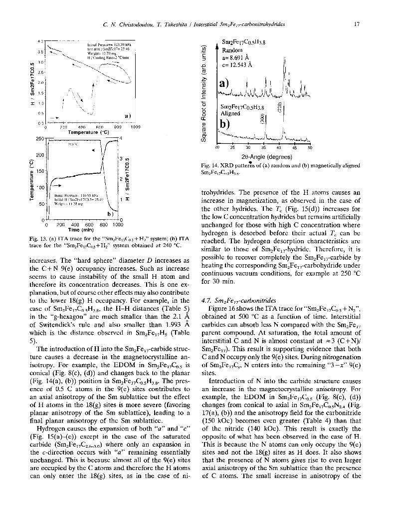
4.6. Sm2Fe lz-carbohydrides Figure 13(a) shows the ITA trace for the
"SmEFeITCo.5+H2" system. Hydrogen is absorbed and desorbed in a similar manner as in the case of the pure Sm2Fe17 (Section 4.2). Figure 13(b) shows the ITA traces for "Sm2Fe17Co.5 + HE", obtained at 240 °C as a function of time. A large amount of H is absorbed during cooling. At saturation, the interstitial H con- centration is lower for the samples with higher C concentration (Table 4). This is because C atoms pref- erentially occupy the 9(e) sites and H is accommodated in the remaining 9(e) sites and in the available 18(g) sites. In pure Sm2Fea7Hs, the 18(g) sites are partially occupied by two H atoms per formula unit. As the C + N concentration increases, this amount drops to 1.3 for SmEFea7Co.sI-Ia.s and to 0.8 for Sm2Fel7N3Ho.8 (Section 4.4) and to 0,7 for Sm2FelTC0.sN2 ,Ho.8 (Section 4.8). Therefore, the following question arises: Why does the occupation of the 18(g) sites drop as the occupation of the 9(e) sites by C + N atoms increases? In order to answer this question, one has to look at Table 5 and see how the interstitial size of the 18(g) site changes as the occupation of the 9(e) sites by N + C atoms
C. N. Christodoulou, T. Takeshita / Interstitial Sm2Fe17-carbonitrohydrides 17
4 0
3 5
3 . 0
o (..) 2 5
It. 2.0
E 15
"It 10
0.5
0.0
250-
20O
.~ 150 ~
~. loo E
I.-- 50
O 0
Initial Pressure= 123.39 kPa "x,.~, . Initial H / Sm2Fel7= 23.46
" ~ Weight= 12.70 mg ~'~ II / Cooling Rate=2 °C/rnin
] "%~;" x.~ ::
_~ a)
20o 4o0 60o 800 I000 Temperalure (°C)
4 . . . . . . . . . . ;~;;c. . . . . .
3u~
Initial Pressure= 116.95 kPa hfilial tl /Snl2Fel7C0.5= 25.49 "l" Wcighl= I 1.28 nlg
0 200 400 600 800 1000
Time (rain)
Fig. 13. (a) ITA trace for the "Sm2Fe17Co.5-t-H2" system; (b) ITA trace for the "Sm2Fet7C0.5+Hz" system obtained at 240 °C.
increases. The "hard sphere" diameter D increases as the C + N 9(e) occupancy increases. Such as increase seems to cause instability of the small H atom and therefore its concentration decreases. This is one ex- planation, but of course other effects may also contribute to the lower 18(g) H occupancy. For example, in the case of Sm2FelvCo.sH3.8, the H-H distances (Table 5) in the "g-hexagon" are much smaller than the 2.1 A of Switendick's rule and also smaller than 1.993 ,~ which is the distance observed in Sm2FeaTH5 (Table 5).
The introduction of H into the Sm2FeaT-carbide struc- ture causes a decrease in the magnetocrystalline an- isotropy. For example, the EDOM in Sm2FeaTCo.5 is conical (Fig. 8(c), (d)) and changes back to the planar (Fig. 14(a), (b)) position in SmzFe~TCo.sH3.8. The pres- ence of 0.5 C atoms in the 9(e) sites contributes to an axial anisotropy of the Sm sublattice but the effect of H atoms in the 18(g) sites is more severe (favoring planar anisotropy of the Sm sublattice), leading to a final planar anisotropy of the Sm sublattice.
Hydrogen causes the expansion of both "a" and "c" (Fig. 15(a)--(c)) except in the case of the saturated carbide (Sm2Fea7C2.6_3.o) where only an expansion in the c-direction occurs with "a" remaining essentially unchanged. This is because almost all of the 9(e) sites are occupied by the C atoms and therefore the H atoms can only enter the 18(g) sites, as in the case of ni-
t -
~d v
09 t -
t'-
"6 "6 O rr
"3 12" O9
Sm2FeI7C0.5H3.8 Random a= 8.691/~ /1 c= 12.543 ~ /1
Sm2FeI7C0.5H3.8 Aligned ~/ ~
b) / I I I I I I
20 25 30 35 40 45 50
2 0 - A n g l e ( d e g r e e s )
Fig. 14. XRD patterns of (a) random and (b) magnetically aligned Sm2FelTCo.sH3.8 .
trohydrides. The presence of the H atoms causes an increase in magnetization, as observed in the case of the other hydrides. The Tc (Fig. 15(d)) increases for the low C concentration hydrides but remains artificially unchanged for those with high C concentration where hydrogen is desorbed before their actual Tc can be reached. The hydrogen desorption characteristics are similar to those of Sm2Fe17-hydride. Therefore, it is possible to recover completely the SmzFe17-carbide by heating the corresponding Sm2Fe~7-carbohydride under continuous vacuum conditions, for example at 250 °C for 30 min.
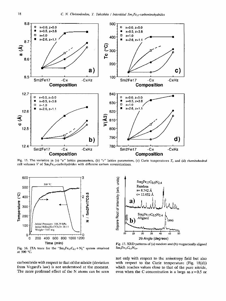
4. 7. Sm2Fe ]7-carbonilrides Figure 16 shows the ITA trace for "Sm2Fe17Co. 5 4- Nz",
obtained at 500 °C as a function of time. Interstitial carbides can absorb less N compared with the Sm2Fe17 parent compound. At saturation, the total amount of interstitial C and N is almost constant at = 3 (C + N)/ SmzFeaT). This result is supporting evidence that both C and N occupy only the 9(e) sites. During nitrogenation of Sm2FelTCx, N enters into the remaining " 3 - x " 9(e) sites.
Introduction of N into the carbide structure causes an increase in the magnetocrystalline anisotropy. For example, the EDOM in Sm2FelTCo.s (Fig. 8(c), (d)) changes from conical to axial in Sm2FelTCo.sN2.4 (Fig. 17(a), (b)) and the anisotropy field for the carbonitride (150 kOe) becomes even greater (Table 4) than that of the nitride (140 kOe). This result is exactly the opposite of what has been observed in the case of H. This is because the N atoms can only occupy the 9(e) sites and not the 18(g) sites as H does. It also shows that the presence of N atoms gives rise to even larger axial anisotropy of the Sm sublattice than the presence of C atoms. The small increase in anisotropy of the
18 C. N. Christodoulou, T. Takeshita / Interstitial Sm2Fet7-carbonitrohydrides
V
m
8.8"
8.7
8.6
0
[ ]
500 x=O.O, z=5.0 x=0.5, z=3.8 x=l.0 f x=2.6, z=1.1
" ~ a )
I ! I
-CxHz
400
A
0 300
0 I--
200
0
D
x=O.O, z=5.0 x=0.5, z=3.8 x=l.0 _- x=2.6, z=1.1 / 1 -
e l 8.5 100 ' ' J
Sm2Fe17 -Cx Sm2Fe17 -Cx -CxHz Composition Composition
'"'t o 40]t x=0.0, z=5.0 o x=0.0, z=5.0 • x=0.5, z=3.8 830~ • x=0.5, z=3.8 . / ~ [] x=l.0 _ [] x=l.0 / • ~ ] • x=2.6, z=1.1 12.6] x=2.6, z=1.1 820
12.5 / / 800
b ) 790 ] d ) 12.4" ' J ' 780"
Sm2Fe17 -Cx -CxHz Sm2Fe17 -Cx -CxHz Composition Composition
Fig. 15. The variat ion in (a) " a " lat t ice parameters , (b) " c" latt ice parameters , (c) Curie t empera tu res Tc and (d) rhombohedra l cell volumes V of Sm2Fe~7-carbohydrides with different carbon concentra t ions .
600"
500-
O 400-
'~ 300
8. E 200-
1--
100
3
5(X) °C
E
Z . Inilial Pressure= I 18.39 kPa Inilial N/Sn,2Fel7C0.5= 28.11 \ Weight= 9.87 nlg
0 . . . . . . . . . . . . . . . . . . . . . . . 0 0 200 400 600 800 10001200
Time (min) Fig. 16. ITA trace for the "Sm2Fe17Co.s+N2" system ob ta ined at 500 °C.
carbonitride with respect to that of the nitride (deviation from Vegard 's law) is not unders tood at the moment . The more profound effect of the N atoms can be seen
t - "-I
~d
co t -
t -
"6
O r r -
t~ .-.i 12"
Sm2Fe 17C0.5N2.4 Random /
a= 8.742 ./~ It ~= 12.652 ,~
20 25 30 35 40 45 50
20-Angle (degrees) Fig. 17. X R D pa t te rns of (a) r andom and (b) magnetically aligned Sm2Fel7Co.sNz4.
not only with respect to the anisotropy field but also with respect to the Curie tempera ture (Fig. 18(d)) which reaches values close to that of the pure nitride, even when the C concentration is a large as x = 0.5 or

C N. Christodoulou, T. Takeshita I Interstitial Sm2Felz-carbonitrohydrides 19
8.8
. ) ,o I 8,o
=3.(I. z=0.8
8.6 I 00t , ° ,:0. , . ,:7
. ,,01 ' 780" ' ' J '
Sm2Fel7 -Cx -GxNy -CxNyHz
Composition
12.8 500-
II'i12'6 ~ / / / / 0---O.O,y=3.0, z=0.8 I-- / / . / / • ,=o.~.,:~.,.,.--o.,
12.5 200. / ~ / , , , ~ , . , , , : ?
12.4 100 ~'- G" I X:2.6, y:0. l,z:l.') Sm2Fe17 -Cx -CxNy -CxNyHz Sm2Fe17 -Cx -CxNy -CxNyHz
Composition Composition Fig. 18. The variation in (a) "a" lattice parameter, (b) Tc "c" lattice parameter, (c) rhombohedral volume V and (d) Curie temperature Tc for different compositions of SmzFelT-carbides, Sm2Fex7-earbonitrides and SmzFe~7-earbonitrohydrides.
0.9. In the case of the saturated carbide (Sm2Fe17Cz.6_3.o), almost no N atoms (y=0.1) enter the structure (the 9(el sites are fully occupied) and Tc remains essentially unchanged (405 °C).
The introduction of N in SmzFelTCx causes an increase in both the "a" and "c" lattice parameters (Fig. 18(a), (b)), except in the case of the saturated carbide (SmzFe17C2.6_3.o) where all 9(el sites are occupied and essentially no N can enter the structure. The values of "a" and "c" for the carbonitrides vary between those of the saturated carbide (Sm2FelTC2.6_3.o) and saturated nitride (SmzFeaTN3), depending on the C and N con- centrations. Of the C and N atoms, the C atoms cause the larger expansion of the "a" and N atoms the "c" lattice parameters. This can be attributed to the larger covalent radius of C atoms (expansion of "a") and to the stronger bonding between the 18(h) Fe atoms with C rather than with N atoms (less expansion of "c"). In general, the c-plane is closely packed and therefore "a" depends on the size of the covalent radius of the interstitial atom. This is not the case in the c-direction where the 18(h) Fe-Fe interatomic distances are quite long and '<c" is not limited by size effects but rather
by the bond strength between the Fe(h) and the in- terstitial atom, and which is greater for C.
4.8 Sm 2Fe s7-carbonitrohydrides Figure 19 shows the ITA trace for the
"SmzFelvCo.sN2. 4-t- H2" system obtained at 240 °C as a function of time. Most of the H was absorbed during cooling and the final composition becomes Sm2FelvCo.sN2.aHo.8. The process is exactly the same as the hydrogenation of SmzFelTN3 where the H atoms partially occupy the available 18(g) sites. As was shown above (Section 4.7), the SmzFe17C/-nitrides (x<l) ex- hibit similar magnetic properties to those of pure Sm/Fe17N3. Consequently, their corresponding hydrides are also expected to exhibit similar magnetic properties. Hydrogenation of the carbonitrides leads to a small increase in the magnetization and a large decrease in anisotropy field (Table 4), in accordance with what has been observed in all hydrides. Despite the decrease in the anisotropy field, SmzFe17Co.sN2.4Ho.8 remains mag- netically uniaxial (Fig. 20(a), (b)). As was explained previously, the decrease in anisotropy is related to occupation of the 18(g) sites by H atoms.

20 C. N. Christodoulou, T. Takeshita / Interstitial Sm2Felz-carbonitrohydrides
250 1.0
200 # 0.8 '~"
0 z
150 0.6 8
~. 100 0.4 I= E
I,- -... 5 0 \ 0.2 "1--
0 0.0 0 200 400 600 800 1000
Time (rain)
Fig. 19. ITA trace for the "Sm2Fe17Co.sN2. 4 + H2" system obtained at 240 °C.
t---
g, O3 c-
t--
Sm2Fe17C0.5N2.4H0.8 Random I a= 8.735/~ It c= 12.715/~ tl
~6 ~. Sm2Fe 17C0.5N2.4H0.81~006)
I~" Aligned
/ I I I I I I 20 25 30 35 40 45 5 0
20-Angle (degrees)
Fig. 20. XRD patterns of (a) random and (b) magnetically aligned SmzFe 17Co.sN2.4H0.8.
The "a" lattice parameters (Fig. 18(a)) of the SmzFeaT- carbonitrohydrides remain essentially unchanged with respect to the corresponding Sm2FelT-carbonitrides. However, the "c" lattice parameters (Fig. 18(b)) increase in the same way as was observed previously in the case of nitrohydrides and carbohydrides. This is also at- tributed to partial occupation of the 18(g) sites by the H atoms. The Tc (Fig. 18(d)) of the carbonitrohydrides remains artificially the same as that of the corresponding carbonitrides, since H escapes before its actual Tc can be reached.
5. Stability of the interstitial SmzFe~7-carhides, -nitrides and -hydrides
5.1. SmeFe17C3 SmEFe17C3 is a metastable compound and decomposes
in a thermally activated manner. The decomposition
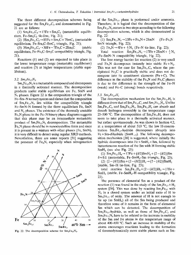
products [36] of Sm2Fe17C 3 are Fe, Fe3C and Sm- carbides. In the XRD patterns [36] (ambient conditions) of the decomposition products at 800 °C, one can clearly detect Fe and Fe3C phases. The Sm-carbides are very difficult to detect directly (by XRD) because they decompose (under ambient conditions) into 8m203 and hydrocarbons. Therefore, the presence of Sm203 in the XRD patterns [36] is indirect evidence that the de- composition products of SmzFe17C3 contain Sm-car- bides. Figure 21 is the composition triangle of the Fe-Sm-C ternary system and one can see that there are three existing Sm-carbide phases: Sm3C , 8m2C3 and SmC2.
Based on the observation that under stable equilib- rium conditions (at about 800 °C) Fe and Fe3C are present, the composition of the Sm-carbide should be Sm3C. The Sm3C phase is the only stable phase forming a compatibility triangle (enclosing the composition of SmzFe17C3, Fig. 21) with Fe and Fe3C.
In the case where the decomposition occurs at a lower range of temperatures, the metastable equilibrium products of Fe + SmaC 3 (along the Fe-Sm2C3 tie-line, Fig. 21) and/or Fe+Sm3C+SmC2 (inside the com- position triangle Fe-SmaC-SmCE, Fig. 21) are expected to be present. Notice that in this case no precipitation of Fe3C occurs. This is in accordance with the results obtained during the carbonation [36] of SmzFe17 with CH4 and where, in the lower temperature range (below 600 °C), the precipitation of Fe occurs without any precipitation of FeaC. In the intermediate temperature range it is possible that all the above phases (Fe, Fe3C, Sm3C, Sm2C3 and SmC2) could be present as a product of both stable and metastable equilibrium.
C
:4°/ A o, /\ / /\ iV/V:"
3o / /V / \./"
Sm2Fel7 SmFes SmFe2 at% Sm
Fig. 21. The decomposition scheme for SmzFe17C s.
C. N. Christodoulou, T. Takeshita / Interstitial Sm2Fet7-carbonitrohydrides 21
The three different decomposition schemes being suggested for the S m 2 F e 1 7 C 3 and demonstrated in Fig. 21 are as follows:
(1) Sm2Fe17C3 ~ 17Fe + Sm2C3 (metastable equilib- rium, Fe-Sm2C3 tie-line, Fig. 21);
(2) 5Sm2Fea7C3 ~ 85Fe + Sm3C + 78mC2 (metastable equilibrium, Fe-Sm3C-SmC2 triangle, Fig. 21);
(3) 3Sm2Fe~TC3 ~ 30Fe - 7Fe3C + 28m3C (stable equilibrium, Fe-Fe3C-Sm3C compatibility triangle, Fig. 21).
Reactions (1) and (2) are expected to take place in the lower temperature range (metastable equilibrium) and reaction (3) at higher temperatures (stable equi- librium).
5.2. SmeFe17N 3 Sm2Fe17N 3 is a metastable compound and decomposes
in a thermally activated manner. The decomposition products under stable equilibrium are Fe, SmN and N2 phases. Figure 22 is the composition triangle of the Fe-Sm-N ternary system and shows that the composition of Sm2Fe17N3 lies within the compatibility triangle Fe-SmN-N formed by the three equilibrium Fe, SmN and N2 phases. The existence of the thermally unstable Fe4N phase in the Fe-N binary phase diagrams suggests that this phase may be an intermediate metastable product of Sm2Fe17N3 decomposition. The metastable FeaN phase should be in nanocrystalline form and since it is present in a mixture with other phases (Fe, SmN), it is very difficult to detect using regular XRD methods. Nevertheless, there are some reports [51] suggesting the presence of FeaN, especially when nitrogenation
F e
- o . . . . . ., S m F e 2 . . . . . . . .
Fig. 22. The decompos i t ion scheme for Sm2Fe17N3.
of the Sm2Fe17 phase is performed under ammonia. Therefore, it is logical that the decomposition of the Sm2Fe~vN3 occurs in two steps according to the following decomposition scheme, which is also demonstrated in Fig. 22:
(1) Sm2FelvN3 ~ 13Fe + Fe4N + 2SmN (Fe-Fe4N- SmN triangle, Fig. 22);
(2) Fe4N--, 4Fe + -~ N 2 (Fe-N tie-line, Fig. 22); 1 Total reaction Sm2FeITN3~ 17Fe+2SmN+ 7 N 2
(Fe-SmN-N compatibility triangle, Fig. 22). The free energy barrier for reaction (2) is very small
and Fe4N decomposes instantly into stable Fe+N2. This was not the case for SmzFe17C3 where the pre- cipitated Fe3C is practically stable and does not de- compose into its constituent elements (Fe+C). The difference in the stability of the Fe4N and Fe3C phases is due to the difference in the strength of the Fe-N (weak) and Fe-C (strong) bonds respectively.
5.3. S m 3 F e 1 7 H x
The decomposition mechanism for the Sm2Fe17Hx is different from that of Sm2Fe17C3 and Sm2Fe17N 3. Unlike Sm2Fe17C3 and Sm2FelvN3, Sm2FeavHx can absorb and desorb hydrogen reversibly in the temperature range 25-500 °C. The decomposition of Sm2FeaTHx does not seem to take place in a thermally activated manner, but rather spontaneously. As was shown in Section 4.2, at a temperature of about 510 °C, the low H-concen- tration Sm2FelT-hydride decomposes abruptly into Fe + Sm-dihydride (SmH_2). The following decompo- sition mechanism [38] is suggested, where initially the hydride decomposes into Fe + SmH2 + Sm, followed by instantaneous reaction of the Sm with H forming stable SmH2 (see also Fig. 23):
(1) Sm2FelTH~ ~ 17Fe + (6/2)SMH2 + ( 2 - (6/2))Sm 3=0.1 (metastable, Fe-SmH2-Sm triangle, Fig. 23);
(2) (2 - (6/2))Sm + (2 - (6/2))H2--* (2 - (8/2))SMH2 (stable, Sm-H tie-line, Fig. 23);
total reaction Sm2Fe17H~ + ( 2 - (6/2))H2---, 17Fe + SmH2 (stable, Fe-SmHz-H compatibility triangle, Fig. 23).
The presence of elemental Sm as a product of the reaction (1) was found in the study of the S m z F e a 7 + H 2
system [38]. This was done by reacting Sm2Fe~7 with H 2 in a closed system under an initial ratio of H to Sm2Fea7 of unity. The amount of H is not enough to tie up (as SmH2) all of the Sm being produced and therefore some of it remains in the form of elemental Sm which can be detected. The decomposition of Sm2FelT-hydride, as well as those of Sm2Fea7C 3 and Sm2Fe~TN3 have to be related to the increase in mobility of the Sm and Fe atoms in the temperature range of about 400-650 °C. Such an increase in mobility of the atoms encourages reactions leading to the formation of thermodynamically more stable phases such as Sm-

22 C. N. Christodoulou, T. Takeshita /Interstitial Sm2FelT-carbonitrohydrides
Fe
H / /
¢ 4o/ / \ .+,
30
2O
10
2 I 2
Fig. 23. T h e decompos i t i on s c h e m e for Sm2FexTHs.
carbides, StuN and SmH2. In fact, the decomposition temperatures are inside the range of temperatures where hydrogen or nitrogen gases were found to react with elemental Sm, forming the corresponding SmHz and SmN compounds [40].
6. Conclusions
(1) The SmzFe17Hz exhibit an H solubility of 0 <z < 5 correspond to temperatures of between 500 and 25 °C where they desorb and absorb H reversibly. At tem- peratures above 510 °C they decompose into Sm-hy- drides and Fe. The Sm2FelTNy (0 <y ~ 3) and Sm2Fe17Cx (0<x~<3) are metastable compounds and decompose with increasing temperature. A maximum decomposition rate occurs at 600 °C for the nitrides and 650 °C for the carbides. The final decomposition products are (SmN + Fe + NE) and (Sin-carbides + Fe3C-I- Fe) for the nitride and the carbide respectively.
(2) The SmzFeaT-nitrohydrides, -carbonitrides and -carbonitrohydrides can be prepared (based on their thermal stability) by first preparing the carbide (by direct melting or gas phase carbonation at 550--600 °C), then nitrogenation (450-500 °C) and finally hydrogen- ation (180-250 °C). The nitrohydride can be produced directly by nitrohydrogenation in a mixture of N2 + HE or ammonia at between 450 and 500 °C. The SmzFe17- carbonitrohydrides can also be prepared by gas phase reaction of SmzFe17 powders with a mixture of a hy- drocarbon (for example C2Hz)+N2+ H2 at about 500 °C.
(3) The C and/or N atoms in the interstitial carbides, nitrides and carbonitrides can occupy partially of fully the 9(e) octahedral sites, reaching a maximum con- centration of 3(C+ N) atoms per mole of SmEFeaT. In Sm2FelTHs, H atoms occupy fully the 9(e) octahedral and partially the 18(g) tetrahedral sites. In the case of unsaturated carbides (or nitrides), the H atoms fill up the remaining 9(e) sites and then partially occupy the 18(g) sites. The occupation of the 18(g) sites by H atoms decreases as the occupation of the 9(e) sites by (C+N) atoms increases.
(4) Carbon and N atoms cannot be replaced or removed reversibly after they have entered the structure. Nitrogen and C atoms can expel and replace the H atoms from the 9(e) sites. The N atoms are very strongly bonded to Sm atoms and weakly to the Fe atoms, whereas the C atoms are strongly bonded to both the Sm and Fe atoms. The H bonding is much weaker and therefore hydrogen can be driven in and out of the structure easily without any change in the structure itself.
(5) The initial introduction of C or N atoms into the structure causes an increase in the "a" lattice parameter and subsequently an increase in both the "a" and "c" lattice parameters. Hydrogenation of sat- urated carbides or nitrides causes preferential expansion in the c-direction of the rhombohedral structure, which is associated with the partial occupation of the 18(g) sites by H atoms.
(6) The introduction of C, N or H atoms into the Sm2Fea7 structure causes an increase in the average Fe-Fe distances, leading to an increase in both the magnetization and the Curie temperature. The increase in magnetization is greater for the H than for the N than for the C atoms. The effect on the Curie tem- perature is greater for the N (475 °C) than for C (400 °C) than for H (285 °C) atoms.
(7) Nitrogen atoms are more effective than C atoms in increasing the anisotropy field, while H atoms oc- cupying the 18(g) sites behave in an opposite way; they cause a decrease in the anisotropy field.
(8) The presence of a mixture of C and N atoms (with x=0.5) seems to be beneficial in achieving high Tc (479 °C) and a high anisotropy field (150 kOe). In addition, the presence of some C atoms could increase the stability of the compound.
(9) The largest "a" lattice parameter observed is 8.754 ~ corresponding to the carbonitrohydride (Sm2Fe17C2.rNo.aHa.o). The largest "c" lattice parameter observed is 12.733/~ corresponding to the nitrohydride (Sm2FeITN3Ho.8).
C. N. Christodoulou, T. Takeshita / Interstitial Sm2FelT-carbonitrohydrides 23
References
1 J. M. D. Coey, H. Sun and Y. Otani, in S. G. Sankar (ed.), A new family of rare earth iron nitrides, Proc. Sixth Int. Syrup. on Magnetic Anisotropy and coercivity in Rare Earth-Transition MetalAlloys, Carnegie Mellon University, Pittsburgh PA, 1990, p. 36.
2 0 . Isnard, S. Miraglia, J. L. Soubeyroux and D. Fruchart, Solid State Commun., 81 (1992) 13.
3 0 . Isnard, S. Miraglia, J. L. Soubeyroux, D. Fruchart and J. Pannetier, Phys. Rev. B, 45 (1992) 2920.
4 R. M. Ibberson, O. Moze, T. H. Jacobs and K. H. J. Buschow, J. Phys. Condens. Matter, 3 (1991) 1219.
5 R. B. Helmholdt and K. H. J. Buschow, J. Less-Common Met., 155 (1989) 15.
6 0 . Isnard, J. L. Soubeyroux, D. Fruchart, T. H. Jacobs and K. H. J. Buschow, Z Alloys Comp., 186 (1992) 135.
7 S. S. Jaswal, W. B. Yelon, G. C. Hadjipanayis, Y. Z. Wang and D. J. Sellmyer, Phys. Rev. Lett., 67 (1991) 644.
8 J. M. D. Coey, J. F. Lawler, H. Sun and J. E. M. Allan, J. Appl. Phys., 69 (1991) 3007.
9 T. W. Capehart, R. K. Mishra and F. E. Pinkerton, Appl. Phys. Lett., 58 (1991) 1395.
10 K. H. J. Buschow, R. Coehoorn, D. B. de Mooij, K. de Waard and T. H. Jacobs, J. Magn. Magn. Mater., 92 (1990) L35.
11 M. Katter, J. Wecker, L. Schultz and R. Gr6ssinger, J. Magn. Magn. Mater., 92 (1990) L14.
12 D. P. F. Hurley and J. M. D. Coey, J. Magn. Magn. Mater, 99 (1991) 229.
13 J. M. D. Coey, H. Sun and D. P. F. Hurley, J. Magn. Magn. Mater., 101 (1991) 310.
14 M. Katter, J. Wecker, C. Kuhrt, L. Schultz, X. C. Kou and R. Gr6ssinger, J. Magn. Magn. Mater., 111 (1992) 293.
15 K. Schnitzke, L. Schultz, J. Wecker and M. Katter, Appl, Phys. Lett., 57 (1990) 2853.
16 M. Endoh, M. Iwata and M. Tokunaga, J. AppL Phys., 70 (1991) 6030.
17 M. Katter, J. Wecker and L. Schultz, J. Appl. Phys., 70 (1991) 3188.
18 C. N. Christodoulou and T. Takeshita, Sm2Felv-nitride-based permanent magnets produced by rapid solidification, J. Alloys Comp., 196 (1993) 161.
19 H. Nakamura, K. Kurihara, T. Tatsuki, S. Sugimoto, M. Okada and M. Homma, Variation of magnetic properties of Sm2Fe17Nx alloys by hydrogen treatment, Digests 15th Annu. Conf. on Magnetics in Japan, Magnetic Society of Japan, Tsukuba, 1991, p. 379 (in Japanese).
20 C. N. Christodoulou and T. Takeshita, Sm2FexT-nitride-based permanent magnets produced by the H D D R process, J. Alloys. Comp., 196 (1993) 155.
21 J. M. D. Coey and H. Sun, J. Magn. Magn. Mater., 87 (1990) L251.
22 M. Q. Huang, L. Y. Zhang, B. M. Ma, Y. Zheng, J. M. Elbicki, W. E. Wallace and S. G. Sankar, J. Appl. Phys., 70 (1991) 6027.
23 K. Kobayashi, T. Iriyama, N. Imaoka, T. Suzuki, H. Kato and Y. Nakagawa, Permanent magnetic material of Sm2Fe17N~ compounds obtained by reaction in NH3-H2 mixed gas at- mosphere, Proc. 12th Int. Workshop on RE Magnets and their Applications, July 1992, Canberra, The University of Western Australia, Canberra, 1992, p. 32.
24 A. Fukuno, C. Ishizaka and T. Yoneyama, Effect of com- position and phase on the magnetic properties of Sm2Fe~7N~, Proc. 12 °' Int. Workshop on RE Magnets and their Applications,
July 1992, Canberra, The University of Western Australia, Canberra, 1992, p. 60.
25 W. Rodewald, M. Velicescu, B. Wall and G. W. Reppel, Preparation and characterization of bonded anisotropic SmzFe~7Nx-magnets, Proc. 12th Int. Workshop on Re Magnets and their Applications, July 1992, Canberra, The University of Western Australia, Canberra, 1992, p. 191.
26 C. N. Christodoulou and T. Takeshita, Sm2Fe~7-nitride-based permanent magnets produced by rapid solidification, H D D R and powder metallurgy techniques, Rep. Magnetics Working Committee, MAG-92-245, Magnetics Conf., Meiji University, Tokyo, December 3, 1992, IEEE, Tokyo, 1992, pp. 53~6.
27 S. Luo, G.-W. Zhang, Z.-H. Liu, X.-D. Pei, W. Liang and W.-W. Ho, J. Magn. Magn. Mater., 70 (1987) 311.
28 X. C. Kou, R. Gr6ssinger, T. H. Jacobs and K. H. J. Buschow, J. Magn. Magn. Mater., 88 (1990) 1.
29 J.-F. Liu, J. Wan and L.-Z. Dai, Structure and magnetic properties of Sm-Fe42 compounds, Proc. 7th Int. Syrup. on Anisotropy and Coercivity in Re-TM Alloys, July 1992, Canberra, The University of Western Australia, Canberra, p. 208.
30 J. M. D. Coey, H. Sun, Y. Otani and D. P. F. Hurley, J. Magn. Magn. Mater., 98 (1991) 76.
31 B. Ping and G.-G. Liu, Solid State Commun., 79 (1991) 785. 32 L. X. Liao, X. Chen, Z. Altounian and D. H. Ryan, Appl.
Phys. Lett., 60 (1992) 129. 33 H. Sun, Y. Otani and L. M. D. Coey, J. Magn. Magn. Mater.,
104-107 (1992) 1439. 34 X. Chen, L. X. Liao, Z. Altounian, D. H. Ryan and J. O.
Str6m-Olsen, J. Magn. Magn. Mater, 109 (1992) 271. 35 J. M. D. Coey and D. P. F. Hurley, 3". Magn. Magn. Mater.,
104-107 (1992) 1098. 36 C. N. Christodoulou and T. Takeshita, J. Alloys Comp., 190
(1992) 41-48. 37 Wang Xiang-Zhong, K. Donnelly, J. M. D. Coey, B. Chevalier,
J. Etourneau and T. Berlureau, J. Mater Sci., 23 (1988) 329. 38 C. N. Christodoulou and T. Takeshita, Hydrogenation of
Sm2Fe17, J. Alloys Comp., 194 (1993) 113. 39 X. C. Kou, R. Gr6ssinger, X. Li, J. P. Liu, F. R. de Boer,
M. Katter, J. Wecker, L. Schultz, T. H. Jacobs and K. H. J. Buschow, J. Appl. Phys., 70 (1991) 6015.
40 C. N. Christodoulou and T. Takeshita, J. Alloys Comp., 190 (1992) 99-106.
41 C. N. Christodoulou and T. Takeshita, Hydrogenation and nitrogenation of SmFe~ J. Alloys Comp., 194 (1993) 31.
42 C. N. Christodoulou and T. Takeshita, Hydrogenation and nitrogenation of SmF% J. Alloys Comp., 191 (1993) 279.
43 T. Hahn (ed.), International Tables for Crystallography, Reidel, Tokyo, 1987, p. 535, 2nd revised edn.
44 D. Givord and R. Lemaire, C.R. Acad. Sci. Paris, 274 (1972) 1166.
45 K. A. Gschneidner, Jr., Bull, Alloy Phase Diagrams, 11 (1990) 216.
46 A. C. Switendick, in G. Alefeld (ed.), Hydrogen in Metals, Springer, 1978.
47 B. Rupp and G. Wiesinger, J. Magn. Magn. Mater, 71 (1988) 269.
48 O. Isnard, S. Miraglia, J. L. Soubeyroux, D. Fruchart and S. Stergiou, J. Less-Common Met., 162 (1990) 273.
49 O. Isnard, S. Miraglia, D. Fruchart and J. Deportes, J. Magn. .Magn. Mater., 103 (1992) 157.
50 T. Mukai and T. Fujimoto, J. Magn. Magn. Mater, 103 (1992) 165.
51 T. Iriyama, K. Kobayashi, H. Kato and Y. Nakagawa, Ni- trogenation process and magnetic properties of Sm2FelTNx, in K. Inomata (ed.), Proc. 78th Topical Symp. of the Magnetics Society of Japan, Recent Developments in Nitromagnetics, Sendai,

24 C. N. Christodoulou, T. Takeshita I Interstitial Sm2Felz-carbonitrohydrides
January 13-14, 1993, The Magnetics Society of Japan, Tokyo, 1993, pp. 9-14.
Appendix A
A schematic representation of the 18(g) tetrahedral site is shown in Fig. A1. The position of the interstitial atom (I) is restricted by symmetry to lie along the AB line which connects the middle of the R - R distance with the middle of the Fe-Fe distance. In fact this line (AB) is parallel to the c-plane and is also perpendicular to the R-R and Fe-Fe bonds. The electrostatic force between the interstitial atom (I) and the first nearest neighbor atoms, 2Sm and 2Fe, is assumed to be of the
• 1-18(g)
R(c) 0 Fe-I 8(h)
Il l l I r . ~ \ , 1 F I =lAh-I i ~ O~ I~B..~F2
Fe(h)
R(c)
Fig. A1. A schematic representation of the 18(g) tetrahedral sites and the electrostatic forces acting on the interstitial atom (for example H).
same kind; whether it is attractive or repulsive, it does not matter. Let us assume an attractive force acting from the 2Sm and 2Fe atoms on the I atom. Then, the I atom will move on the AB line and equilibrate at a point where the acting forces cancel each other. In that position, one can write the equation representing the equality of the net forces along the AB line:
Fa = 2 [R~I_____] cos 0a =F2 = 2 [Fe][I]
ra r] cos O2
where [R], [Fe] and [I] are the effective charges of the rare earth (R), iron (Fe) and interstitial (I) atoms respectively. Here, one can also write rl =da/cos 01 and F2=d2/cos 0 2. Also, tan 01=hi~d1 and tan 02=h2/ d2=hz/(d-dl). By combining the relationships above, one can write the ratio of the effective charges as follows:
= [ 1+ hl/al)2 L [Fe] \ -ad Ll+[hd(a-d,)]2J where ha, h2 and d can be calculated from the atom positions and dl is directly related to the (x/a) coordinate of the general position for the 18(g) sites: dl = a[1 - (x/a)] where a is the lattice constant. If the known quantities (x/a =0.883) for Nd2Fe17H4. 9 (as found from neutron diffraction, ref. 2) are substituted, [R]/[Fe] can be calculated to be equal to 2.216. It is now possible, by assuming [R]/[Fe] = 2.216 to he the same for R --- Nd, Th, Sm (or even assigning other values) to backcalculate the (x/a) general position of the 18(g) sites for any particular compound.
Copyright © 2022 FDOKUMEN