PowerSeries Pro v1.1 installation guide
36
Quick Setup 1 Plan Plan the installation including all alarm detection devices, zone expanders, keypads and other required modules. 2 Mount Decide on a location for the alarm panel and secure it to the wall using suitable mounting hardware. 3 Wire Complete all wiring including modules, zones, bells/sirens, telephone line connections and ground connections. Record module serial numbers on page 24. 4 Power Connect the battery and power up the system. The battery must be connected. 5 Enroll First Keypad Hardwired: Wire the keypad to the Corbus, power up the alarm panel then press any button on the keypad. Wireless: Wire the HSM2Host to the Corbus, then power up the alarm panel and a wireless keypad. Press any button on the keypad to enroll it. The HSM2Host is then enrolled on the alarm panel. Alternately, enroll an RF keypad. 6 Enroll modules [*][8][Installer Code][902] subsection [000]. Press [*] to begin auto-enrollment. Module slots are automatically assigned. Use scroll keys to view slots. Change slot by typing a 2-digit number. 7 Enroll wireless devices [*][8][Installer Code][804] subsection [000]. Note: An HSM2HOST or RF keypad must be enrolled first. 8 Program Basic programming: [*][8][installer code] [001]/[002]> Zone Type/Zone Attribute [005]>[001] Partition 1 Timers: – Entry Delay 1 – Entry Delay 2 – Exit Delay [301]>[001] Phone #1 [310]>[000] System Account Code. 9 Test Test the panel completely to ensure that all features and functions operate as programmed. – [901] Walk Test – [904] [000] Wireless Placement Test. Compatible Devices Throughout this document, x in the model number represents the operating frequency of the device as follows: 9 (912-919 MHz), 8 (868 MHz), 4 (433 MHz). Note: Only models operating in the band 912-919 MHz are UL/ULC listed where indicated. For UL/ULC certified installations, use only UL/ULC listed devices. Only models marked with xxx UL are UL/ULC listed. Table 1-1 Compatible Devices Modules Wireless keypads: HS2LCDWFPROx UL HS2LCDWFVPROx UL Hardwired keypads with PG host HS2LCDRFPROx UL Hardwired keypads: HS2LCDPRO UL Touchscreen keypad: HS2TCHPRO(BLK) UL Note: For ULC-s559 Listed applications the HS2TCHPRO(BLK) touchscreen keypad is for supplementary use only. 2-way wireless transceiver: HSM2HOSTx UL 8-zone expander: HSM3408 UL 8-zone expander: HSM2108 UL 8 low current output expander: HSM2208 UL Power supply/relay output/Corbus repeater module: HSM3204CX UL 3 A power supply: HSM3350 UL 4 high current output expander: HSM2204 UL 1 A Power supply: HSM2300 UL Audio verification module: HSM2955(R) UL USB to WiFi adapter: HSM3WIFI Alternate communicator: LE9080 UL 3G9080-EU 3G9080 UL TL880LT N UL TL8803G N UL Hardwired Devices 2-wire smoke detectors: FSA-210x UL FSA-210xT UL FSA-210xS UL FSA-210xST UL FSA-210xLST UL FSA-210xR UL FSA-210xRT UL FSA-210xRS UL FSA-210xRST UL FSA-210xLRST UL y= A, B, or C A: ULC listed models B: UL listed models C: European and Australian models 4-wire smoke detectors: FSA-410x UL FSA-410xT UL FSA-410xS UL FSA-410xST UL FSA-410xLST UL FSA-410xR UL FSA-410xRT UL FSA-410xRS UL FSA-410xRST UL FSA-410xLRST UL y= A, B, or C A: ULC listed models B: UL listed models C: European and Australian models CO detectors: CO-12/24 UL 12-24SIR UL FW-CO12 FW-CO1224 CO1224 Wireless Devices PowerG wireless short range ceiling mount detector with temperature monitoring PGx862 UL PowerG wireless long range ceiling mount detector with temperature monitoring PGx872 UL PowerG wireless outdoor curtain PIR PGx902 UL PowerG wireless PRI motion detector with optional animal resistance PGx904(P) UL PowerG wireless PIR motion detector with temperature monitoring PGx914(P) UL PowerG wireless curtain PIR motion detector PGx924 UL PowerG wireless PIR motion detector with camera PGx934(P) UL PowerG wireless outdorr PIR motion detector with camera and with anti- masking PGx944 UL PowerG wireless mirror optic PIR motion detector PGx974(P) UL PowerG wireless dual technology (PIR and MW) with anti-masking PGx984(P) UL PowerG wireless outdoor PIR motion detector with anti-masking PGx994 PowerG wireless recessed door/window contact PGx307 PowerG wireless outdoor contact with auxiliary input, temperature monitoring, and anti-masking PGx312 UL PowerG wireless door/window contact with auxiliary input PGx945 UL PowerG wireless vanishing door/window contact PGx975 UL / PGx303 UL PowerG wireless glassbreak detector PGx912 / PGx922 UL PowerG wireless shock detector with auxiliary input PGx935 UL PowerG wireless flood detector PGx985 UL PowerG wireless temperature detector PGx905 UL PowerG wireless temperature probe extender (requires PGx905) PGTEMP-PROBE PowerG wireless CO detector (US only) PGx913 UL PowerG wireless CO detector with temperature monitoring PGx933 UL PowerG wireless smoke and heat detector PGx916 UL PowerG wireless smoke and heat detector with temperature monitoring PGx936 UL PowerG wireless smoke detector PGx926 UL WARNING: This manual contains information on limitations regarding product use and function and information on the limitations as to liability of the manufacturer. The entire manual should be carefully read. To download the full installation and user manuals and register your product, please visit: www.DSC.com/m/29010134 or scan the QR code to the right. PowerSeries Pro Alarm Control Installation Guide PowerSeries Pro is a feature-rich, scalable alarm system designed for commercial use. It features integrated phone line and Ethernet (IP) communicators, and supports both hardwired and wireless devices. Three models are available: HS3248 (248 zones), HS3128 (128 zones), and HS3032 (32 zones).
-
Upload
khangminh22 -
Category
Documents
-
view
1 -
download
0
Transcript of PowerSeries Pro v1.1 installation guide
Quick Setup1 Plan Plan the installation including all alarm detection devices, zone
expanders, keypads and other required modules.
2 Mount Decide on a location for the alarm panel and secure it to thewall using suitable mounting hardware.
3 Wire Complete all wiring including modules, zones, bells/sirens,telephone line connections and ground connections. Recordmodule serial numbers on page 24.
4 Power Connect the battery and power up the system. The battery mustbe connected.
5 Enroll FirstKeypad
Hardwired: Wire the keypad to the Corbus, power up the alarmpanel then press any button on the keypad. Wireless: Wire theHSM2Host to the Corbus, then power up the alarm panel and awireless keypad. Press any button on the keypad to enroll it. TheHSM2Host is then enrolled on the alarm panel. Alternately,enroll an RF keypad.
6 Enroll
modules
[*][8][Installer Code][902] subsection [000]. Press [*] to beginauto-enrollment. Module slots are automatically assigned. Usescroll keys to view slots. Change slot by typing a 2-digit number.
7 Enrollwirelessdevices
[*][8][Installer Code][804] subsection [000]. Note: AnHSM2HOST or RF keypad must be enrolled first.
8 Program Basic programming: [*][8][installer code] [001]/[002]> ZoneType/Zone Attribute [005]>[001] Partition 1 Timers: – EntryDelay 1 – Entry Delay 2 – Exit Delay [301]>[001] Phone #1[310]>[000] System Account Code.
9 Test Test the panel completely to ensure that all features andfunctions operate as programmed. – [901] Walk Test – [904][000] Wireless Placement Test.
Compatible DevicesThroughout this document, x in the model number represents the operatingfrequency of the device as follows: 9 (912-919 MHz), 8 (868 MHz), 4(433 MHz).
Note: Only models operating in the band 912-919 MHz are UL/ULClisted where indicated. For UL/ULC certified installations, use onlyUL/ULC listed devices. Only models marked with xxxUL are UL/ULClisted.
Table 1-1 Compatible DevicesModulesWireless keypads: HS2LCDWFPROxUL HS2LCDWFVPROxUL
Hardwired keypads with PG host HS2LCDRFPROxUL
Hardwired keypads: HS2LCDPROUL
Touchscreen keypad: HS2TCHPRO(BLK)UL
Note: For ULC-s559 Listed applications the HS2TCHPRO(BLK) touchscreen keypad is for supplementaryuse only.
2-way wireless transceiver: HSM2HOSTxUL
8-zone expander: HSM3408UL
8-zone expander: HSM2108UL
8 low current output expander: HSM2208UL
Power supply/relay output/Corbus repeatermodule:
HSM3204CXUL
3 A power supply: HSM3350UL
4 high current output expander: HSM2204UL
1 A Power supply: HSM2300UL
Audio verification module: HSM2955(R)UL
USB to WiFi adapter: HSM3WIFIAlternate communicator: LE9080UL
3G9080-EU3G9080UL
TL880LT NUL
TL8803G NUL
Hardwired Devices2-wire smoke detectors: FSA-210xUL
FSA-210xTUL
FSA-210xSUL
FSA-210xSTUL
FSA-210xLSTUL
FSA-210xRUL
FSA-210xRTUL
FSA-210xRSUL
FSA-210xRSTUL
FSA-210xLRSTUL
y= A, B, or CA: ULC listed modelsB: UL listed modelsC: European and Australian models4-wire smoke detectors: FSA-410xUL
FSA-410xTUL
FSA-410xSUL
FSA-410xSTUL
FSA-410xLSTUL
FSA-410xRUL
FSA-410xRTUL
FSA-410xRSUL
FSA-410xRSTUL
FSA-410xLRSTUL
y= A, B, or CA: ULC listed modelsB: UL listed modelsC: European and Australian modelsCO detectors: CO-12/24UL
12-24SIRUL
FW-CO12
FW-CO1224CO1224
Wireless DevicesPowerG wireless short range ceiling mount detector with temperaturemonitoring
PGx862UL
PowerG wireless long range ceiling mount detector with temperaturemonitoring
PGx872UL
PowerG wireless outdoor curtain PIR PGx902UL
PowerG wireless PRI motion detector with optional animal resistance PGx904(P)UL
PowerG wireless PIR motion detector with temperature monitoring PGx914(P)UL
PowerG wireless curtain PIR motion detector PGx924UL
PowerG wireless PIR motion detector with camera PGx934(P)UL
PowerG wireless outdorr PIR motion detector with camera and with anti-masking
PGx944UL
PowerG wireless mirror optic PIR motion detector PGx974(P)UL
PowerG wireless dual technology (PIR and MW) with anti-masking PGx984(P)UL
PowerG wireless outdoor PIR motion detector with anti-masking PGx994PowerG wireless recessed door/window contact PGx307PowerG wireless outdoor contact with auxiliary input, temperaturemonitoring, and anti-masking
PGx312UL
PowerG wireless door/window contact with auxiliary input PGx945UL
PowerG wireless vanishing door/window contact PGx975UL / PGx303UL
PowerG wireless glassbreak detector PGx912 / PGx922UL
PowerG wireless shock detector with auxiliary input PGx935UL
PowerG wireless flood detector PGx985UL
PowerG wireless temperature detector PGx905UL
PowerG wireless temperature probe extender (requires PGx905) PGTEMP-PROBEPowerG wireless CO detector (US only) PGx913UL
PowerG wireless CO detector with temperature monitoring PGx933UL
PowerG wireless smoke and heat detector PGx916UL
PowerG wireless smoke and heat detector with temperature monitoring PGx936UL
PowerG wireless smoke detector PGx926UL
WARNING: This manual contains information on limitations regarding product use and function and informationon the limitations as to liability of the manufacturer. The entire manual should be carefully read.
To download the full installation and user manuals and register your product, please visit:www.DSC.com/m/29010134 or scan the QR code to the right.
PowerSeries Pro Alarm Control Installation GuidePowerSeries Pro is a feature-rich, scalable alarm system designed for commercial use. It features integrated phone line and Ethernet (IP) communicators,and supports both hardwired and wireless devices. Three models are available: HS3248 (248 zones), HS3128 (128 zones), and HS3032 (32 zones).
PowerSeries Pro Installation Guide
PowerG wireless indoor siren PGx901UL
PowerG wireless outdoor siren PGx911UL
PowerG wireless repeater PGx920UL
PowerG wireless 1-button securtiy panic keyfob PGx938UL
PowerG wireless 2-button securtiy panic keyfob PGx949UL
PowerG wireless 4-button securtiy panic keyfob PGx929UL / PGx939UL
Central Station ReceiversSG-System I, II, III, IV, 5
Safety instructions for service personnelWarning:When using equipment connected to the telephone network,always follow the basic safety instructions provided with this product.Save these instructions for future reference. Inform the end-user of thesafety precautions that must be observed when operating this equipment.Before installing the equipmentEnsure your package includes the following items:
l Installation and User manuals, including the safety instructions.l Read and save these instructions.l Follow all warnings and instructions specified within this doc-
ument and/or on the equipment.l HS3032/HS3128/HS3248 alarm controllerl Power Supply, direct plug-in
Selecting a suitable location for the alarm controllerUse the following list as a guide to find a suitable location to install thisequipment:
l Locate near a telephone socket and power outlet.l Select a location free from vibration and shock.l Place alarm controller on a flat, stable surface and follow the
installation instructions.l Do not locate this product where people may walk on the sec-
ondary circuit cable(s).l Do not connect alarm controller to electrical the same circuit as
large appliances.l Do not select a location that exposes your alarm controller to dir-
ect sunlight, excessive heat, moisture, vapors, chemicals or dust.l Do not install this equipment near water. (e.g., bath tub, kit-
chen/laundry sink, wet basement, near a swimming pool).l Do not install this equipment and accessories in areas where risk
of explosion exists.l Do not connect this equipment to electrical outlets controlled by
wall switches or automatic timers.l Avoid interference sources.l Avoid installing equipment near heaters, air conditioners, vent-
ilators, and refrigerators.l Avoid locating equipment close to or on top of large metal objects
(e.g., wall studs).l See "Locating detectors and escape plan" on page 26 for inform-
ation on locating smoke and CO detectors.Safety precautions required during installation
l Never install this equipment and/or telephone wiring during a light-ning storm.
l Never touch uninsulated telephone wires or terminals unless thetelephone line has been disconnected at the network interface.
l Position cables so that accidents can not occur. Connected cablesmust not be subject to excessive mechanical strain.
l Use only the power supply provided with this equipment. Use ofunauthorized power supplies may cause damage.
l For direct plug-in versions, use the power supply module sup-plied with the device.
Warning: This equipment has no mains on/off switch. The plug of thedirect plug in versions of this equipment is intended to serve as thedisconnecting device. It is imperative that access to the mains plug andassociated mains socket/outlet is never obstructed. For permanently
connected versions of this equipment the fuse in the connector block is thedisconnect device. If the neutral wire cannot be identified, then thisequipment must be connected to a mains source that comes from adisconnect device that simultaneously disconnects both poles (Line andNeutral).Important note for international market (EU, Australia, NewZealand)This equipment is stationary-fixed and must be installed by SkilledPersons only. Skilled Person is defined as a person with relevanteducation or experience to enable him or her to identify hazards and to takeappropriate actions to reduce the risks of injury to themselves and others.
l It must be installed and used within an environment that providesthe pollution degree max 2, over voltages category II, in non-haz-ardous, indoor locations only.
l Use authorized accessories only with this equipment. Do not placeany object on the top of the cabinet of this equipment! Do not spillany liquids on the cabinet.
l Do not touch the equipment and its connected cables during anelectrical storm; there may be a risk of electric shock.
l Ensure that cables are positioned so that accidents cannot occur.Connected cables must not be subject to excessive mechanicalstrain. Do not use the Alarm system to report a gas leak if the sys-tem is near a leak.
l These safety instructions should not prevent you from contactingthe distributor and/or the manufacturer to obtain any further cla-rification and/or answers to your concerns.
InstallationCompatible EnclosuresThe PowerSeries Pro main board can be installed in the followingenclosures:
l Model HSC3010C (hinged door) made of 18 Ga steel, paintedwhite, dimensions 372 mm x 412 mm x 114 mm, weight: 9.75 lbor 4.2 kg
l Model HSC3010CR (hinged door) made of 18 Ga steel, paintedred, dimensions 372 mm x 412 mm x 114 mm, weight: 10.0 lb or4.5 kg
l Model HSC3030CAR (hinged door) made of 18 Ga steel (base)and 16 Ga (door), painted white, dimensions 375 mm x 412 mm x114 mm, weight: 11.45 lb or 5.2 kg
l Model HSC3020C (removable door) made of 18 Ga steel, paintedwhite, dimensions 459 mm x 414 mm x 103 mm, weight: 4.3 kg(no batteries)/12 kg (17 Ah)
l Model HSC3020CP (removable door) made of PC-ABS, colorwhite, dimensions 368 mm x 489 mm x 108 mm, weight: 2.3 kg(no batteries)/7.7 kg (17 Ah)
The equipment enclosure must be secured to the building structure beforeoperation. Use 4 screws (appropriate for the wall material on which it isattached) inserted through the four mounting holes provided in the back ofthe enclosure base.For EN50131-1 Grade 2 or Grade 3 compliant installations use onlymodels HSC3020C and HSC3020CP.All enclosures are UL/ULC listed, except the HSC3020CP. Do not usemodel HSC3020CP in UL/ULC certified installations.
Mounting the enclosureThis section provides basic instructions for wall-mounting the availablePowerSeries Pro enclosures. Mount in a dry location, near an unswitchedAC power source and Ethernet and phone connections. If mounting ondrywall, ensure all four screw holes align with wall studs.Complete all wiring before applying AC or connecting the battery.
- 2 -
PowerSeries Pro Installation Guide
Note: The weight of the enclosure and contents cannot be supported bydrywall only. Use mounting hardware sufficient to support up to threetimes the panel weight, including equipment, cables, conduit and hardware(approximately 210 lbs/ 95 kg). Select hardware suitable for the mountingsurface.
Recommended minimum screw size: M4 (#8) x 4, 25.4 mm (1 inch) long,pan head.To mount the enclosure, complete the following steps:1. Position the enclosure in the mounting location and mark the two top
screw holes and the tamper bracket hole.2. Remove the enclosure, then install the two top screws part way and an
anchor for the tamper bracket, if necessary. Do not mount the tamperbracket directly into drywall.
3. Hang the enclosure on the installed screws then mark the two bottommounting holes.
4. Remove the enclosure from the wall and install the components in thefollowing order:l Plastic standoffs for alarm controller and optional modulesl Tamper switch and bracketl Power supply, including GND connection for HSC3010C,
HSC3010CR, and HSC3030CAR enclosures (see diagram). Notethat the ground nut mounts from the back of the cabinet.
5. Hang the enclosure on the top two screws again then fasten the tamperbracket to the wall.
6. Install the two bottom screws. Ensure that all four screws are securelytightened.
7. Install the alarm controller. For models HSC3010C, HSC3010CR,HSC3030CAR and HSC3020C enclosures, use the supplied metalstandoff and screw in bottom-right mounting hole as indicated infigure 2-1.
8. Install optional modules and wire according to the instructionsprovided with the module.
9. Wire the tamper switch into any available zone. Configure the tamperfor normally closed (NC) supervision. Zone must be programmed for24-hour latching or non-latching tamper.
10. Install the batteries only after the enclosure has been permanentlysecured to the wall.
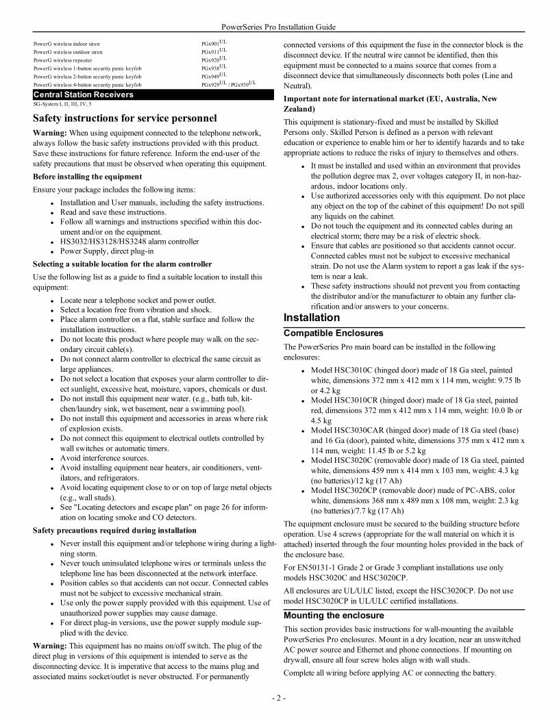
Note: For NFA2P certified systems, when using the cellularcommunicator 3G9080-EU, install also the tamper bracket part number09000996. See Figure 1-1
Figure 1-1 Installing the tamper bracket
The following diagram indicates the mounting location of the alarmcontroller PCB, power supply module and tamper bracket inside theenclosure.
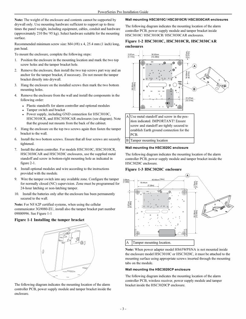
Wall mounting HSC3010C/ HSC3010CR/ HSC3030CAR enclosures
The following diagram indicates the mounting location of the alarmcontroller PCB, power supply module and tamper bracket insideHSC3010C/ HSC3010CR/ HSC3030CAR enclosures.
Figure 1-2 HSC3010C, HSC3010CR, HSC3030CARenclosures
30.93cm
[12.28in]
35.50cm
[13.98in]
31.27cm
[12.31in]
16.69cm
[6.57in]
2.97cm
[1.17in] 2.57cm
[1.01in]
B
A
A Use metal standoff and screw in the pos-ition indicated. IMPORTANT! Ensurescrew and standoff are tightly secured toestablish Earth ground connection for thePCB.
B Tamper mounting location
Wall mounting the HSC3020C enclosure
The following diagram indicates the mounting location of the alarmcontroller PCB, power supply module and tamper bracket inside theHSC3020C enclosure.
Figure 1-3 HSC3020C enclosure
40.64cm [16in]
18.44cm
[7.26in]
2.69cm
[1.060]
2.79cm
[1.10in]
35.38cm
[13.93in]
0.97cm
[0.38in]
A
A Tamper mounting location.
Note:When power adapter model HS65WPSNA is not mounted insidethe enclosure model HSC3010C or HSC3020C, it must be attached to themounting surface using appropriate screws inserted through the mountingtabs on the module.
Wall mounting the HSC3020CP enclosure
The following diagram indicates the mounting location of the alarmcontroller PCB, wireless receiver, power supply module and tamperbracket inside the HSC3020CP enclosure.
- 3 -
PowerSeries Pro Installation Guide
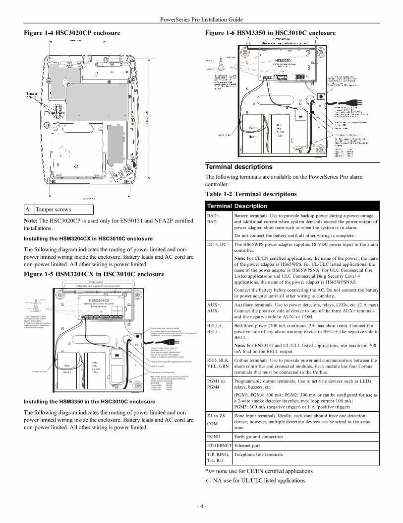
Figure 1-4 HSC3020CP enclosure
A Tamper screws
Note: The HSC3020CP is used only for EN50131 and NFA2P certifiedinstallations.
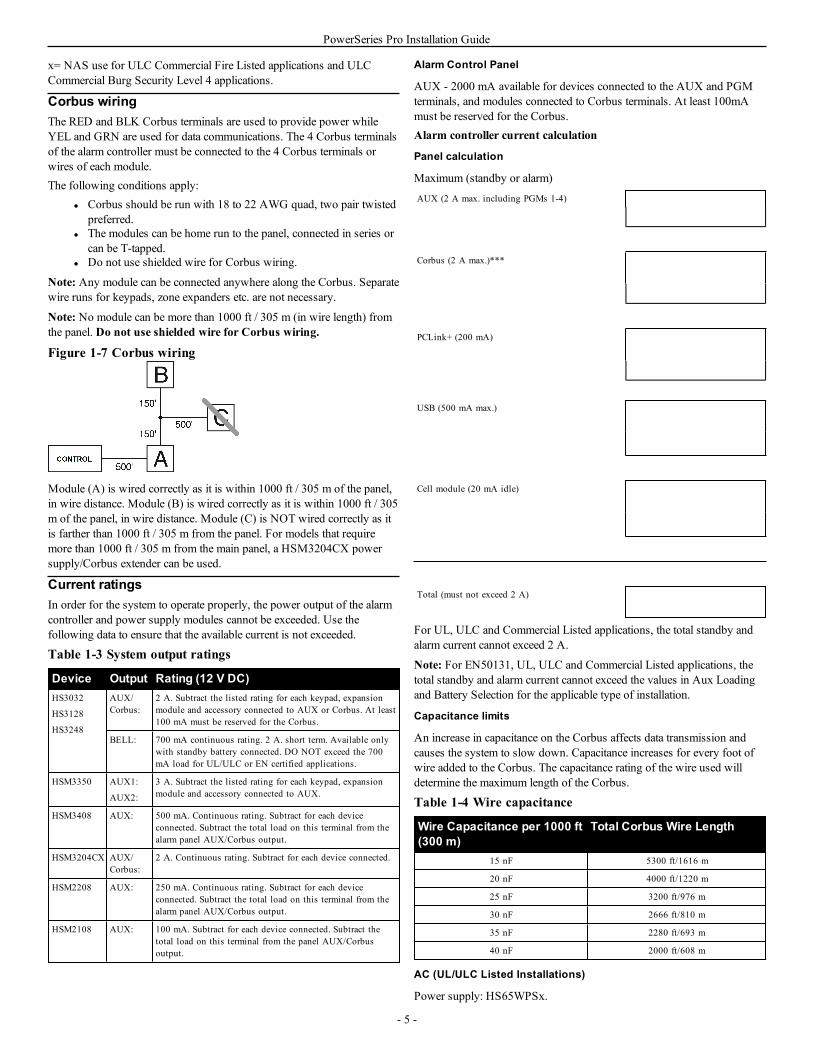
Installing the HSM3204CX in HSC3010C enclosure
The following diagram indicates the routing of power limited and non-power limited wiring inside the enclosure. Battery leads and AC cord arenon-power limited. All other wiring is power limited.
Figure 1-5 HSM3204CX in HSC3010C enclosure
STAND OFF
PC BOARD
CABINET
POWER LIMITED
Cable ties (not supplied) recommended
1. Insert standoff into cabinet
mounting hole in the desired
location. Snap in place.
2. Position circuit board mounting
holes over standoffs. Press firmly
on board to snap in place.
Primary: 120VAC, 60Hz, Class VI
Secondary: 18V DC, 3.6A
Power adapter module: HS65WPSNA
Note: Do not connect Power adapter
module to receptacle controlled by a switch
4Ah
7Ah
2 x 7Ah
17Ah
Red -
Black +
Plastic grommet strip (Not supplied) recommmended
Power supply mounting screws
Cable tie required
Tamper switch and mounting bracket
Note: Power supply may be mounted outside the
cabinet. Use the following guide to determine
sutiable distance and guage:
DISTANCE GAUGE
2 meters/6.5ft 22AWG
3 meters/10ft 20AWG
4 meters/13ft 18AWG
Cable tie required
Wire tamper switch to any Corbus zone.
Program zone as 24-Hour Latching or Non-Latching tamper.
Supports NC, EOL or DEOL supervision.
HSM3204CXWarning: Disconnect AC power
before servicing.
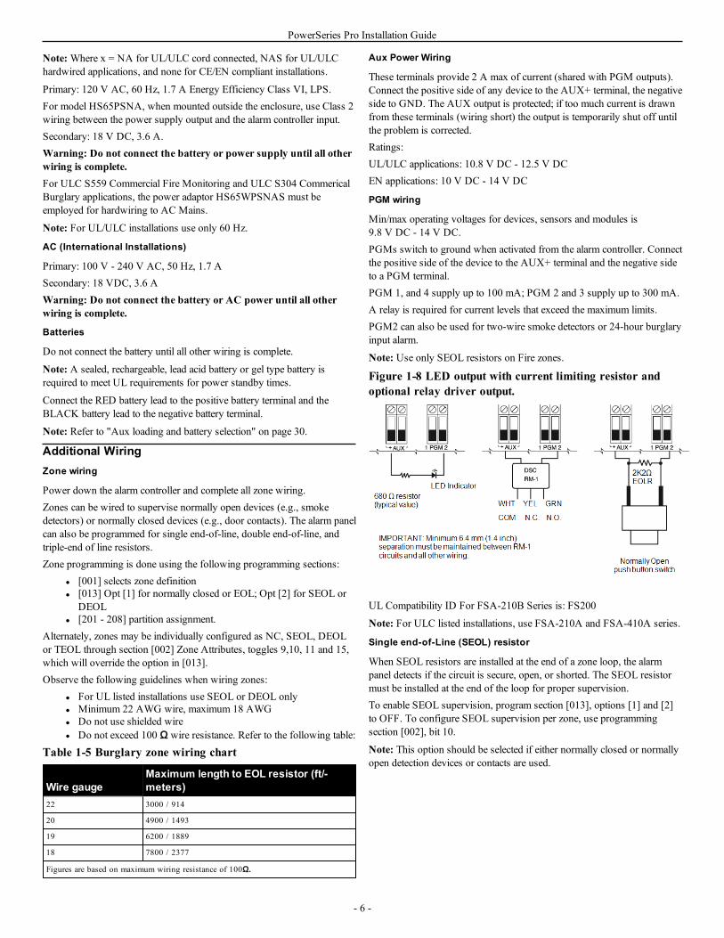
Installing the HSM3350 in the HSC3010C enclosure
The following diagram indicates the routing of power limited and non-power limited wiring inside the enclosure. Battery leads and AC cord arenon-power limited. All other wiring is power limited.
Figure 1-6 HSM3350 in HSC3010C enclosure
Terminal descriptionsThe following terminals are available on the PowerSeries Pro alarmcontroller.
Table 1-2 Terminal descriptions
Terminal DescriptionBAT+,BAT-
Battery terminals. Use to provide backup power during a power outageand additional current when system demands exceed the power output ofpower adapter, short term such as when the system is in alarm.
Do not connect the battery until all other wiring is complete.
DC +, DC - The HS65WPS power adapter supplies 18 VDC power input to the alarmcontroller.
Note: For CE/EN certified applications, the name of the power , the nameof the power adapter is HS65WPS. For UL/ULC listed applications, thename of the power adapter is HS65WPSNA. For ULC Commercial FireListed applications and ULC Commercial Burg Security Level 4applications, the name of the power adapter is HS65WPSNAS.
Connect the battery before connecting the AC. Do not connect the batteryor power adapter until all other wiring is complete.
AUX+,AUX-
Auxiliary terminals. Use to power detectors, relays, LEDs, etc. (2 A max).Connect the positive side of device to one of the three AUX+ terminalsand the negative side to AUX- or COM.
BELL+,BELL-
Bell/Siren power (700 mA continous, 2A max short term). Connect thepositive side of any alarm warning device to BELL+, the negative side toBELL-.
Note: For EN50131 and UL/ULC listed applications, use maximum 700mA load on the BELL output.
RED, BLK,YEL, GRN
Corbus terminals. Use to provide power and communication between thealarm controller and connected modules. Each module has four Corbusterminals that must be connected to the Corbus.
PGM1 toPGM4
Programmable output terminals. Use to activate devices such as LEDs,relays, buzzers, etc.
(PGM1, PGM4: 100 mA; PGM2: 300 mA or can be configured for use asa 2-wire smoke detector interface, max loop current 100 mA;PGM3: 300 mA (negative trigger) or 1 A (positive trigger)
Z1 to Z8
COM
Zone input terminals. Ideally, each zone should have one detectiondevice; however, multiple detection devices can be wired to the samezone.
EGND Earth ground connection
ETHERNET Ethernet port
TIP, RING,T-1, R-1
Telephone line terminals
*x= none use for CE/EN certified applicationsx= NA use for UL/ULC listed applications
- 4 -
PowerSeries Pro Installation Guide
x= NAS use for ULC Commercial Fire Listed applications and ULCCommercial Burg Security Level 4 applications.
Corbus wiringThe RED and BLK Corbus terminals are used to provide power whileYEL and GRN are used for data communications. The 4 Corbus terminalsof the alarm controller must be connected to the 4 Corbus terminals orwires of each module.The following conditions apply:
l Corbus should be run with 18 to 22 AWG quad, two pair twistedpreferred.
l The modules can be home run to the panel, connected in series orcan be T-tapped.
l Do not use shielded wire for Corbus wiring.
Note: Any module can be connected anywhere along the Corbus. Separatewire runs for keypads, zone expanders etc. are not necessary.
Note: No module can be more than 1000 ft / 305 m (in wire length) fromthe panel. Do not use shielded wire for Corbus wiring.
Figure 1-7 Corbus wiring
Module (A) is wired correctly as it is within 1000 ft / 305 m of the panel,in wire distance. Module (B) is wired correctly as it is within 1000 ft / 305m of the panel, in wire distance. Module (C) is NOT wired correctly as itis farther than 1000 ft / 305 m from the panel. For models that requiremore than 1000 ft / 305 m from the main panel, a HSM3204CX powersupply/Corbus extender can be used.
Current ratingsIn order for the system to operate properly, the power output of the alarmcontroller and power supply modules cannot be exceeded. Use thefollowing data to ensure that the available current is not exceeded.
Table 1-3 System output ratings
Device Output Rating (12 V DC)HS3032
HS3128
HS3248
AUX/Corbus:
2 A. Subtract the listed rating for each keypad, expansionmodule and accessory connected to AUX or Corbus. At least100 mA must be reserved for the Corbus.
BELL: 700 mA continuous rating. 2 A. short term. Available onlywith standby battery connected. DO NOT exceed the 700mA load for UL/ULC or EN certified applications.
HSM3350 AUX1:
AUX2:
3 A. Subtract the listed rating for each keypad, expansionmodule and accessory connected to AUX.
HSM3408 AUX: 500 mA. Continuous rating. Subtract for each deviceconnected. Subtract the total load on this terminal from thealarm panel AUX/Corbus output.
HSM3204CX AUX/Corbus:
2 A. Continuous rating. Subtract for each device connected.
HSM2208 AUX: 250 mA. Continuous rating. Subtract for each deviceconnected. Subtract the total load on this terminal from thealarm panel AUX/Corbus output.
HSM2108 AUX: 100 mA. Subtract for each device connected. Subtract thetotal load on this terminal from the panel AUX/Corbusoutput.
Alarm Control Panel
AUX - 2000 mA available for devices connected to the AUX and PGMterminals, and modules connected to Corbus terminals. At least 100mAmust be reserved for the Corbus.Alarm controller current calculation
Panel calculation
Maximum (standby or alarm)AUX (2 A max. including PGMs 1-4)
Corbus (2 A max.)***
PCLink+ (200 mA)
USB (500 mA max.)
Cell module (20 mA idle)
Total (must not exceed 2 A)
For UL, ULC and Commercial Listed applications, the total standby andalarm current cannot exceed 2 A.
Note: For EN50131, UL, ULC and Commercial Listed applications, thetotal standby and alarm current cannot exceed the values in Aux Loadingand Battery Selection for the applicable type of installation.
Capacitance limits
An increase in capacitance on the Corbus affects data transmission andcauses the system to slow down. Capacitance increases for every foot ofwire added to the Corbus. The capacitance rating of the wire used willdetermine the maximum length of the Corbus.
Table 1-4 Wire capacitance
Wire Capacitance per 1000 ft(300 m)
Total Corbus Wire Length
15 nF 5300 ft/1616 m
20 nF 4000 ft/1220 m
25 nF 3200 ft/976 m
30 nF 2666 ft/810 m
35 nF 2280 ft/693 m
40 nF 2000 ft/608 m
AC (UL/ULC Listed Installations)
Power supply: HS65WPSx.
- 5 -
PowerSeries Pro Installation Guide
Note:Where x = NA for UL/ULC cord connected, NAS for UL/ULChardwired applications, and none for CE/EN compliant installations.
Primary: 120 V AC, 60 Hz, 1.7 A Energy Efficiency Class VI, LPS.For model HS65PSNA, when mounted outside the enclosure, use Class 2wiring between the power supply output and the alarm controller input.Secondary: 18 V DC, 3.6 A.Warning: Do not connect the battery or power supply until all otherwiring is complete.For ULC S559 Commercial Fire Monitoring and ULC S304 CommericalBurglary applications, the power adaptor HS65WPSNAS must beemployed for hardwiring to AC Mains.
Note: For UL/ULC installations use only 60 Hz.
AC (International Installations)
Primary: 100 V - 240 V AC, 50 Hz, 1.7 ASecondary: 18 VDC, 3.6 AWarning: Do not connect the battery or AC power until all otherwiring is complete.
Batteries
Do not connect the battery until all other wiring is complete.
Note: A sealed, rechargeable, lead acid battery or gel type battery isrequired to meet UL requirements for power standby times.
Connect the RED battery lead to the positive battery terminal and theBLACK battery lead to the negative battery terminal.
Note: Refer to "Aux loading and battery selection" on page 30.
Additional WiringZone wiring
Power down the alarm controller and complete all zone wiring.Zones can be wired to supervise normally open devices (e.g., smokedetectors) or normally closed devices (e.g., door contacts). The alarm panelcan also be programmed for single end-of-line, double end-of-line, andtriple-end of line resistors.Zone programming is done using the following programming sections:
l [001] selects zone definitionl [013] Opt [1] for normally closed or EOL; Opt [2] for SEOL or
DEOLl [201 - 208] partition assignment.
Alternately, zones may be individually configured as NC, SEOL, DEOLor TEOL through section [002] Zone Attributes, toggles 9,10, 11 and 15,which will override the option in [013].Observe the following guidelines when wiring zones:
l For UL listed installations use SEOL or DEOL onlyl Minimum 22 AWG wire, maximum 18 AWGl Do not use shielded wirel Do not exceed 100 Ω wire resistance. Refer to the following table:
Table 1-5 Burglary zone wiring chart
Wire gaugeMaximum length to EOL resistor (ft/-meters)
22 3000 / 914
20 4900 / 1493
19 6200 / 1889
18 7800 / 2377
Figures are based on maximum wiring resistance of 100Ω.
Aux Power Wiring
These terminals provide 2 A max of current (shared with PGM outputs).Connect the positive side of any device to the AUX+ terminal, the negativeside to GND. The AUX output is protected; if too much current is drawnfrom these terminals (wiring short) the output is temporarily shut off untilthe problem is corrected.Ratings:UL/ULC applications: 10.8 V DC - 12.5 V DCEN applications: 10 V DC - 14 V DC
PGM wiring
Min/max operating voltages for devices, sensors and modules is9.8 V DC - 14 V DC.PGMs switch to ground when activated from the alarm controller. Connectthe positive side of the device to the AUX+ terminal and the negative sideto a PGM terminal.PGM 1, and 4 supply up to 100 mA; PGM 2 and 3 supply up to 300 mA.A relay is required for current levels that exceed the maximum limits.PGM2 can also be used for two-wire smoke detectors or 24-hour burglaryinput alarm.
Note: Use only SEOL resistors on Fire zones.
Figure 1-8 LED output with current limiting resistor andoptional relay driver output.
UL Compatibility ID For FSA-210B Series is: FS200
Note: For ULC listed installations, use FSA-210A and FSA-410A series.
Single end-of-Line (SEOL) resistor
When SEOL resistors are installed at the end of a zone loop, the alarmpanel detects if the circuit is secure, open, or shorted. The SEOL resistormust be installed at the end of the loop for proper supervision.To enable SEOL supervision, program section [013], options [1] and [2]to OFF. To configure SEOL supervision per zone, use programmingsection [002], bit 10.
Note: This option should be selected if either normally closed or normallyopen detection devices or contacts are used.
- 6 -

PowerSeries Pro Installation Guide
Figure 1-9 SEOL wiring
Double end of Line (DEOL) resistors
When double end-of-line (DEOL) resistors are installed at the end of azone loop, the second resistor enables the panel to determine if the zone isin open, closed, tampered or faulted.
Note: Any zone programmed for Fire or 24-hr Supervisory must be wiredwith a SEOL resistor regardless of the type of zone wiring supervisionselected for the panel. If you change the zone supervision options fromDEOL to SEOL or from NC to DEOL, power the system downcompletely, then power it back up for correct operation.To enable DEOLsupervision per zone, program section [013], option [1] to OFF and option[2] to ON. To configure DEOL supervision per zone, use programmingsection [002], bit 11.
Figure 1-10 DEOL wiring
Triple end-of-line (TEOL) resistor
The TEOL resistor supervises anti-masking functionality in hardwiredmotion detectors. To configure TEOL supervision per zone, useprogramming section [002], bit 15.
Figure 1-11 TEOL wiring
Note: Resistor values are configurable in section [004].
Bell wiring
These terminals supply 700 mA of current at 10.8 - 12.5 VDC forcommercial/ residential installations. To comply with NFPA 72 Temporal
Three Pattern requirements, section [013] Opt [8] must be ON. Note thatsteady, pulsed alarms are also supported. Temporal 4 cadence for COalarm notification is also supported.
Figure 1-12 Bell wiring
The Bell output is supervised and power limited by 2 A hardwareprotection. If unused, connect a 1000 Ω resistor across Bell+ and Bell- toprevent the panel from displaying a trouble.
Telephone line wiring
Wire the telephone connection terminals (TIP, Ring, T-1, R-1) to an RJ-31x connector as indicated in the following diagram. For connection ofmultiple devices to the telephone line, wire in the sequence indicated. Use26 AWG wire minimum for wiring.
Figure 1-13 Telephone line wiring
Telephone format is programmed in option [350]. Telephone calldirections are programmed in options [311]- [318].
Earth ground wiring
Using the supplied insulated green wire, connect the earth ground terminalon the HS65WPSx power adapter to the earth ground screw and nutassembly as shown in the diagram.The earth ground screw and nut assembly must be mounted to the cabinet
to one of the designated holes marked with the earth ground symbol .
Figure 1-14 Earth ground installation
1
3
4
5
2
6
Item Description1 Nut
- 7 -
PowerSeries Pro Installation Guide
Item Description2 Earth ground connection from building electrical installation.
Note: This ground connection goes to HS65WPSNA poweradapter EGND connections when this power adapter is mountedin the cabinet.
3 Cabinet
4 Star washer
5 Bolt
6 Earth ground symbol
EnrollmentAll optional modules and devices must be enrolled on the system. Duringenrollment, the electronic serial number (ESN) of each device is identifiedto the control panel and zones are assigned. A wireless transceiverHSM2HOST or an RF keypad must be enrolled first before wirelessdevices can be enrolled.
Enrolling modulesDuring automatic and manual enrollment, if an attempt is made to enrollmore than the maximum number of modules, an error tone sounds and amessage is displayed on LCD keypads.Modules can be enrolled automatically or manually using section [902] ofInstaller programming.To confirm that a module has been successfully enrolled, use Installerprogramming section [903].
Enroll wireless devicesWireless devices are enrolled via the wireless transceiver module andInstaller Programming section [804][000].
Auto enrollment
To enroll a wireless device using this method, press and hold the Enrollbutton on the device for 2-5 seconds until the LED lights then release thebutton. The alarm panel automatically recognizes the device and the keypaddisplays a confirmation message. The device ID and next available zonenumber are displayed. Press [*] to accept or scroll to another availablezone number. Batteries must be installed in the wireless device in order toenroll.
Pre-enrollment
Pre-enrollment is a two step process. The first step requires entering eachdevice ID ([804][001]-[716]). Every wireless device has an ID printed onthe sticker attached to the device. The format is XXX-YYYY where:
l XXX identifies the type or model of the devicel YYYY is a short encrypted ID used by the system to identify the
specific devicePre-enrollment can be done at a remote location and using DLS/SA. Thesecond step is to press the enrollment button on the device, usually doneon location. Installer Programming does not have to be entered at this step.Both steps must be performed in order to complete the enrollment.
Programming methodsThe alarm system can be programmed using the following methods:
Table 1-6 Programming Methods
Method Description ProcedureTemplateprogramming
Use pre-defined templatesto quickly apply basicprogramming and to set upDLS downloading.
Press [899] at the “EnterSection” screen.See Template Programmingbelow for details.
DLSprogramming
Download and applyprogramming using DLS 5
For local DLS, use a microUSB cable or a Wi-Fi dongleand laptop with DLS-5software installed.For remote DLS, use atelephone line, cellularnetwork or the Internet.
Installerprogramming
Manually program all alarmsystem and device options.
Press [*][8][installer code]while the system is disarmed.
Viewing programmingProgramming sections can be viewed from any system keypad.Generally, programming options are accessed in the following way:1. Enter Installer Programming mode ([*][8]).2. Navigate to a specific programming section.3. Select an option to view or change its programming.All programming options are numbered and can be accessed by navigatingthrough the menu, or by keying in the program section number. For toggleoptions, the name of the option is displayed.Use the keypad numbers to toggle options on or off. Sections requiringdata input, such as phone numbers, display the full data in fields up to 32characters long. To input data, use the scroll keys to select a character thenpress the keypad button corresponding to the number/letter required. Scrollto the next character and repeat the procedure as needed. Press the [#] keyto save changes and exit the program section.
Minimum Required ProgrammingOnce basic installation of the alarm panel is complete, the followinggeneral configuration options can be set.
Time and DateUse this section to program the alarm system clock.Menu: [*][6][Master Code] > Time and DateKeypad: [*][6][Master Code] + 01Enter time and date using the following format: (HH:MM); (MM-DD-YY). Valid time entries are 00-23 hours, 00-59 minutes. Valid date entriesare 01-12 months, 01-31 days.
[000] Language selection
To select a language:1. Enter Installer Programming: [*][8][Installer Code].2. Enter programming section [000]>[000].3. Key in the 2-digit number corresponding to the language required. See
the following table.
Table 1-7 Language codes01 = English 11 = Swedish 22 = Bulgarian
02 = Spanish 12 = Norwegian 23 = Latvian
03 = Portuguese 13 = Danish 24 = Lithuanian
04 = French 14 = Hebrew 25 = Ukrainian
- 8 -
PowerSeries Pro Installation Guide
05 = Italian 15 = Greek 26 = Slovakian
06 = Dutch 16 = Turkish 27 = Serbian
07 = Polish 18 = Croatian 28 = Estonian
08 = Czech 19 = Hungarian 29 = Slovenian
09 = Finnish 20 = Romanian
10 = German 21 = Russian
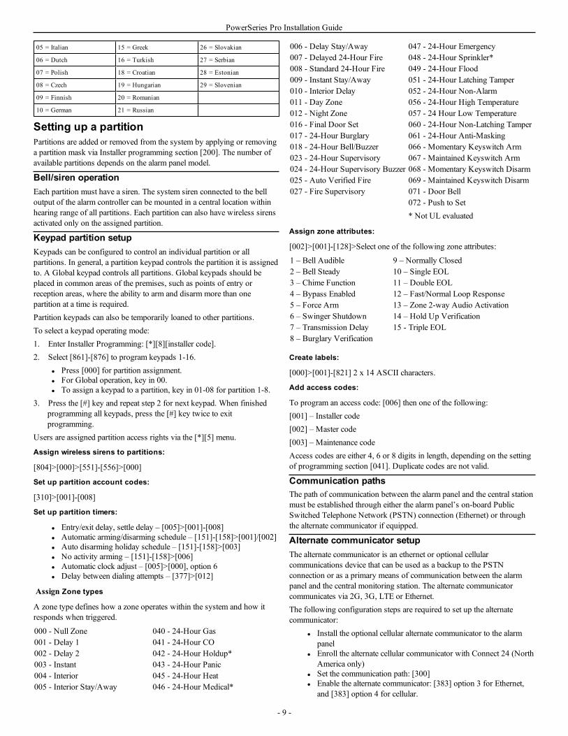
Setting up a partitionPartitions are added or removed from the system by applying or removinga partition mask via Installer programming section [200]. The number ofavailable partitions depends on the alarm panel model.
Bell/siren operationEach partition must have a siren. The system siren connected to the belloutput of the alarm controller can be mounted in a central location withinhearing range of all partitions. Each partition can also have wireless sirensactivated only on the assigned partition.
Keypad partition setupKeypads can be configured to control an individual partition or allpartitions. In general, a partition keypad controls the partition it is assignedto. A Global keypad controls all partitions. Global keypads should beplaced in common areas of the premises, such as points of entry orreception areas, where the ability to arm and disarm more than onepartition at a time is required.Partition keypads can also be temporarily loaned to other partitions.To select a keypad operating mode:1. Enter Installer Programming: [*][8][installer code].2. Select [861]-[876] to program keypads 1-16.
l Press [000] for partition assignment.l For Global operation, key in 00.l To assign a keypad to a partition, key in 01-08 for partition 1-8.
3. Press the [#] key and repeat step 2 for next keypad. When finishedprogramming all keypads, press the [#] key twice to exitprogramming.
Users are assigned partition access rights via the [*][5] menu.
Assign wireless sirens to partitions:
[804]>[000]>[551]-[556]>[000]
Set up partition account codes:
[310]>[001]-[008]
Set up partition timers:
l Entry/exit delay, settle delay – [005]>[001]-[008]l Automatic arming/disarming schedule – [151]-[158]>[001]/[002]l Auto disarming holiday schedule – [151]-[158]>[003]l No activity arming – [151]-[158]>[006]l Automatic clock adjust – [005]>[000], option 6l Delay between dialing attempts – [377]>[012]
Assign Zone types
A zone type defines how a zone operates within the system and how itresponds when triggered.
000 - Null Zone 040 - 24-Hour Gas001 - Delay 1 041 - 24-Hour CO002 - Delay 2 042 - 24-Hour Holdup*003 - Instant 043 - 24-Hour Panic004 - Interior 045 - 24-Hour Heat005 - Interior Stay/Away 046 - 24-Hour Medical*
006 - Delay Stay/Away 047 - 24-Hour Emergency007 - Delayed 24-Hour Fire 048 - 24-Hour Sprinkler*008 - Standard 24-Hour Fire 049 - 24-Hour Flood009 - Instant Stay/Away 051 - 24-Hour Latching Tamper010 - Interior Delay 052 - 24-Hour Non-Alarm011 - Day Zone 056 - 24-Hour High Temperature012 - Night Zone 057 - 24 Hour Low Temperature016 - Final Door Set 060 - 24-Hour Non-Latching Tamper017 - 24-Hour Burglary 061 - 24-Hour Anti-Masking018 - 24-Hour Bell/Buzzer 066 - Momentary Keyswitch Arm023 - 24-Hour Supervisory 067 - Maintained Keyswitch Arm024 - 24-Hour Supervisory Buzzer 068 - Momentary Keyswitch Disarm025 - Auto Verified Fire 069 - Maintained Keyswitch Disarm027 - Fire Supervisory 071 - Door Bell
072 - Push to Set* Not UL evaluated
Assign zone attributes:
[002]>[001]-[128]>Select one of the following zone attributes:
1 – Bell Audible 9 – Normally Closed2 – Bell Steady 10 – Single EOL3 – Chime Function 11 – Double EOL4 – Bypass Enabled 12 – Fast/Normal Loop Response5 – Force Arm 13 – Zone 2-way Audio Activation6 – Swinger Shutdown 14 – Hold Up Verification7 – Transmission Delay 15 - Triple EOL8 – Burglary Verification
Create labels:
[000]>[001]-[821] 2 x 14 ASCII characters.
Add access codes:
To program an access code: [006] then one of the following:[001] – Installer code[002] – Master code[003] – Maintenance codeAccess codes are either 4, 6 or 8 digits in length, depending on the settingof programming section [041]. Duplicate codes are not valid.
Communication pathsThe path of communication between the alarm panel and the central stationmust be established through either the alarm panel’s on-board PublicSwitched Telephone Network (PSTN) connection (Ethernet) or throughthe alternate communicator if equipped.
Alternate communicator setupThe alternate communicator is an ethernet or optional cellularcommunications device that can be used as a backup to the PSTNconnection or as a primary means of communication between the alarmpanel and the central monitoring station. The alternate communicatorcommunicates via 2G, 3G, LTE or Ethernet.The following configuration steps are required to set up the alternatecommunicator:
l Install the optional cellular alternate communicator to the alarmpanel
l Enroll the alternate cellular communicator with Connect 24 (NorthAmerica only)
l Set the communication path: [300]l Enable the alternate communicator: [383] option 3 for Ethernet,
and [383] option 4 for cellular.
- 9 -
PowerSeries Pro Installation Guide
l The Ethernet or Cellular receivers IP and Port: [851]l Enable event reporting: [307]/[308]l Program communication delay timer: [377]l Program DLS access: [401] option 07
Refer to Section 5: Programming for details.
[300] Panel/Receiver Communication Paths
This section is used to select the path of communications between thealarm system and the central station.
Testing the systemInstaller Walk TestWalk test enables the installer to test the operation of each detector bytripping zones, causing an actual alarm. Enter section [901] to initiate awalk test. When a zone is tripped, all system sirens emit a tone to indicatethat the zone is working correctly.After 15 minutes without zone activity, the walk test terminatesautomatically. To manually exit walk test mode, enter [901] again.
Viewing the event buffer
The event buffer contains logs of events that have occurred on the alarmsystem beginning with the most recent. The capacity of the event buffer isscalable and can hold 500/1000 events (depending on panel model) beforerolling over. The buffer displays events according to their time stamp,beginning with the most recent. The event buffer can be uploaded usingDLS.Each event displays the time and date, a description of the event, the zonelabel, access code number or any other pertinent information. To view theevent buffer, press [*][6][Master Code][*].
TroubleshootingLCD programmable-message keypad:
l Press [*][2] followed by access code if required to view a troublecondition
l The trouble light flashes and the LCD displays the first troublecondition
l Use the arrow keys to scroll through all trouble conditions presenton the system
Note:When additional information is available for a specific troublecondition, a [*] is displayed. Press the [*] key to view the additionalinformation.
[*][2] Trouble DisplayThis feature is used to view system troubles. If a trouble is present, thekeypad Trouble indicator illuminates and an audible indication is emitted(two short beeps every 10 seconds, except while in AC failure). Silencethe audible indicator by pressing [#].Troubles may be viewed while the system is armed or disarmed. Thesystem may be programmed to show all troubles while armed or only firetroubles.The system can be configured to require a user code to view [*][2] systemtroubles. See section [023] option 5.To view trouble conditions:
l Press [*][2] to enter the Trouble menu.l On an LCD keypad, scroll to a trouble type then press [*] to view
the specific trouble. The zone name and trouble condition for eachtrouble are displayed on the screen.
Note: The trouble beeps generated by fire trouble are only silenced after[*][2]trouble menu is exited. A keypress in the keypad will not silence the
fire trouble beeps. For UL installations, set the value in section [023] bit 5access code required for [*][2] to enabled.
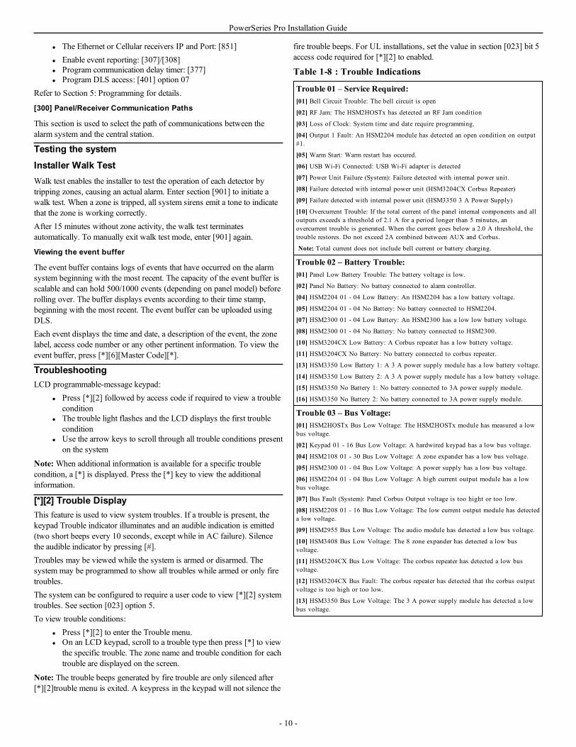
Table 1-8 : Trouble Indications
Trouble 01 – Service Required:[01] Bell Circuit Trouble: The bell circuit is open
[02] RF Jam: The HSM2HOSTx has detected an RF Jam condition
[03] Loss of Clock: System time and date require programming.
[04] Output 1 Fault: An HSM2204 module has detected an open condition on output#1.
[05] Warm Start: Warm restart has occured.
[06] USB Wi-Fi Connected: USB Wi-Fi adapter is detected
[07] Power Unit Failure (System): Failure detected with internal power unit.
[08] Failure detected with internal power unit (HSM3204CX Corbus Repeater)
[09] Failure detected with internal power unit (HSM3350 3 A Power Supply)
[10] Overcurrent Trouble: If the total current of the panel internal components and alloutputs exceeds a threshold of 2.1 A for a period longer than 5 minutes, anovercurrent trouble is generated. When the current goes below a 2.0 A threshold, thetrouble restores. Do not exceed 2A combined between AUX and Corbus.
Note: Total current does not include bell current or battery charging.
Trouble 02 – Battery Trouble:[01] Panel Low Battery Trouble: The battery voltage is low.
[02] Panel No Battery: No battery connected to alarm controller.
[04] HSM2204 01 - 04 Low Battery: An HSM2204 has a low battery voltage.
[05] HSM2204 01 - 04 No Battery: No battery connected to HSM2204.
[07] HSM2300 01 - 04 Low Battery: An HSM2300 has a low low battery voltage.
[08] HSM2300 01 - 04 No Battery: No battery connected to HSM2300.
[10] HSM3204CX Low Battery: A Corbus repeater has a low battery voltage.
[11] HSM3204CX No Battery: No battery connected to corbus repeater.
[13] HSM3350 Low Battery 1: A 3 A power supply module has a low battery voltage.
[14] HSM3350 Low Battery 2: A 3 A power supply module has a low battery voltage.
[15] HSM3350 No Battery 1: No battery connected to 3A power supply module.
[16] HSM3350 No Battery 2: No battery connected to 3A power supply module.
Trouble 03 – Bus Voltage:[01] HSM2HOSTx Bus Low Voltage: The HSM2HOSTx module has measured a lowbus voltage.
[02] Keypad 01 - 16 Bus Low Voltage: A hardwired keypad has a low bus voltage.
[04] HSM2108 01 - 30 Bus Low Voltage: A zone expander has a low bus voltage.
[05] HSM2300 01 - 04 Bus Low Voltage: A power supply has a low bus voltage.
[06] HSM2204 01 - 04 Bus Low Voltage: A high current output module has a lowbus voltage.
[07] Bus Fault (System): Panel Corbus Output voltage is too hight or too low.
[08] HSM2208 01 - 16 Bus Low Voltage: The low current output module has detecteda low voltage.
[09] HSM2955 Bus Low Voltage: The audio module has detected a low bus voltage.
[10] HSM3408 Bus Low Voltage: The 8 zone expander has detected a low busvoltage.
[11] HSM3204CX Bus Low Voltage: The corbus repeater has detected a low busvoltage.
[12] HSM3204CX Bus Fault: The corbus repeater has detected that the corbus outputvoltage is too high or too low.
[13] HSM3350 Bus Low Voltage: The 3 A power supply module has detected a lowbus voltage.
- 10 -
PowerSeries Pro Installation Guide
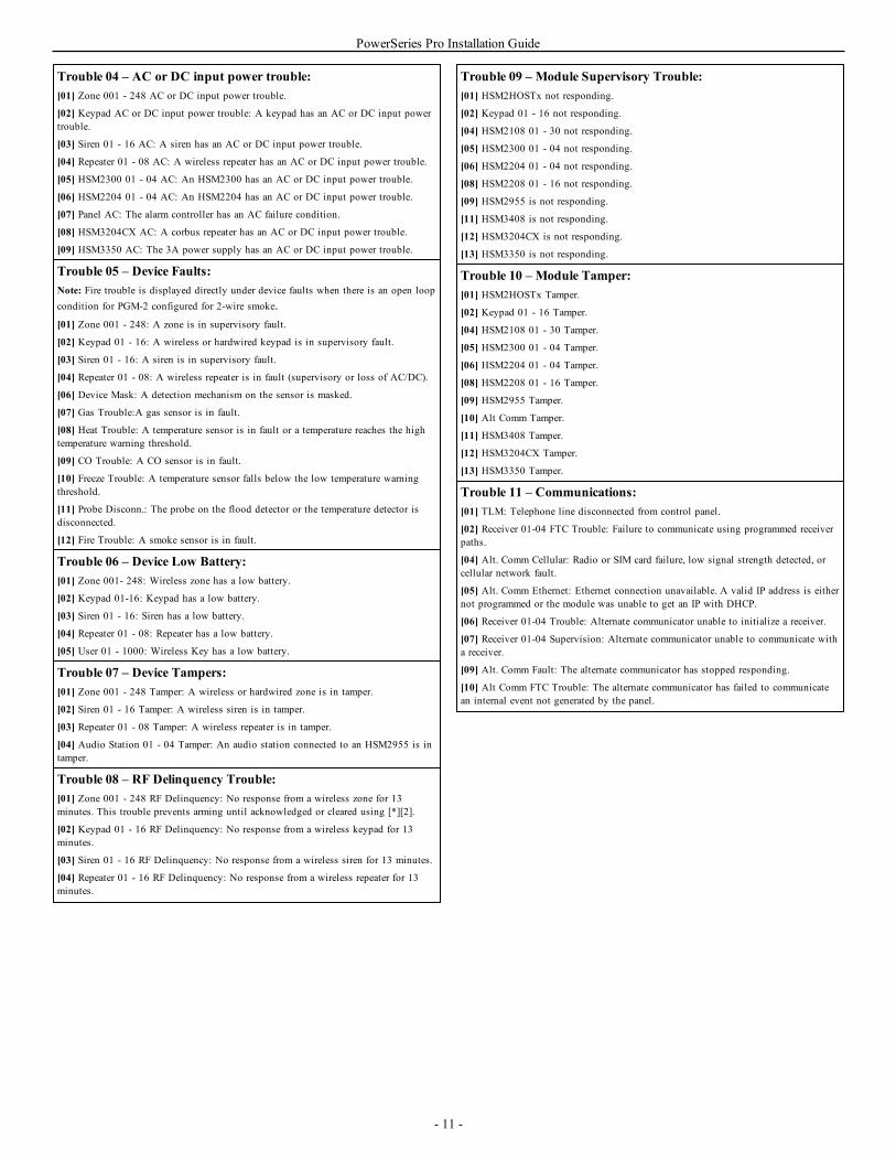
Trouble 04 – AC or DC input power trouble:[01] Zone 001 - 248 AC or DC input power trouble.
[02] Keypad AC or DC input power trouble: A keypad has an AC or DC input powertrouble.
[03] Siren 01 - 16 AC: A siren has an AC or DC input power trouble.
[04] Repeater 01 - 08 AC: A wireless repeater has an AC or DC input power trouble.
[05] HSM2300 01 - 04 AC: An HSM2300 has an AC or DC input power trouble.
[06] HSM2204 01 - 04 AC: An HSM2204 has an AC or DC input power trouble.
[07] Panel AC: The alarm controller has an AC failure condition.
[08] HSM3204CX AC: A corbus repeater has an AC or DC input power trouble.
[09] HSM3350 AC: The 3A power supply has an AC or DC input power trouble.
Trouble 05 – Device Faults:Note: Fire trouble is displayed directly under device faults when there is an open loopcondition for PGM-2 configured for 2-wire smoke.[01] Zone 001 - 248: A zone is in supervisory fault.
[02] Keypad 01 - 16: A wireless or hardwired keypad is in supervisory fault.
[03] Siren 01 - 16: A siren is in supervisory fault.
[04] Repeater 01 - 08: A wireless repeater is in fault (supervisory or loss of AC/DC).
[06] Device Mask: A detection mechanism on the sensor is masked.
[07] Gas Trouble:A gas sensor is in fault.
[08] Heat Trouble: A temperature sensor is in fault or a temperature reaches the hightemperature warning threshold.
[09] CO Trouble: A CO sensor is in fault.
[10] Freeze Trouble: A temperature sensor falls below the low temperature warningthreshold.
[11] Probe Disconn.: The probe on the flood detector or the temperature detector isdisconnected.
[12] Fire Trouble: A smoke sensor is in fault.
Trouble 06 – Device Low Battery:[01] Zone 001- 248: Wireless zone has a low battery.
[02] Keypad 01-16: Keypad has a low battery.
[03] Siren 01 - 16: Siren has a low battery.
[04] Repeater 01 - 08: Repeater has a low battery.
[05] User 01 - 1000: Wireless Key has a low battery.
Trouble 07 – Device Tampers:[01] Zone 001 - 248 Tamper: A wireless or hardwired zone is in tamper.
[02] Siren 01 - 16 Tamper: A wireless siren is in tamper.
[03] Repeater 01 - 08 Tamper: A wireless repeater is in tamper.
[04] Audio Station 01 - 04 Tamper: An audio station connected to an HSM2955 is intamper.
Trouble 08 – RF Delinquency Trouble:[01] Zone 001 - 248 RF Delinquency: No response from a wireless zone for 13minutes. This trouble prevents arming until acknowledged or cleared using [*][2].
[02] Keypad 01 - 16 RF Delinquency: No response from a wireless keypad for 13minutes.
[03] Siren 01 - 16 RF Delinquency: No response from a wireless siren for 13 minutes.
[04] Repeater 01 - 16 RF Delinquency: No response from a wireless repeater for 13minutes.
Trouble 09 – Module Supervisory Trouble:[01] HSM2HOSTx not responding.
[02] Keypad 01 - 16 not responding.
[04] HSM2108 01 - 30 not responding.
[05] HSM2300 01 - 04 not responding.
[06] HSM2204 01 - 04 not responding.
[08] HSM2208 01 - 16 not responding.
[09] HSM2955 is not responding.
[11] HSM3408 is not responding.
[12] HSM3204CX is not responding.
[13] HSM3350 is not responding.
Trouble 10 – Module Tamper:[01] HSM2HOSTx Tamper.
[02] Keypad 01 - 16 Tamper.
[04] HSM2108 01 - 30 Tamper.
[05] HSM2300 01 - 04 Tamper.
[06] HSM2204 01 - 04 Tamper.
[08] HSM2208 01 - 16 Tamper.
[09] HSM2955 Tamper.
[10] Alt Comm Tamper.
[11] HSM3408 Tamper.
[12] HSM3204CX Tamper.
[13] HSM3350 Tamper.
Trouble 11 – Communications:[01] TLM: Telephone line disconnected from control panel.
[02] Receiver 01-04 FTC Trouble: Failure to communicate using programmed receiverpaths.
[04] Alt. Comm Cellular: Radio or SIM card failure, low signal strength detected, orcellular network fault.
[05] Alt. Comm Ethernet: Ethernet connection unavailable. A valid IP address is eithernot programmed or the module was unable to get an IP with DHCP.
[06] Receiver 01-04 Trouble: Alternate communicator unable to initialize a receiver.
[07] Receiver 01-04 Supervision: Alternate communicator unable to communicate witha receiver.
[09] Alt. Comm Fault: The alternate communicator has stopped responding.
[10] Alt Comm FTC Trouble: The alternate communicator has failed to communicatean internal event not generated by the panel.
- 11 -
PowerSeries Pro Installation Guide
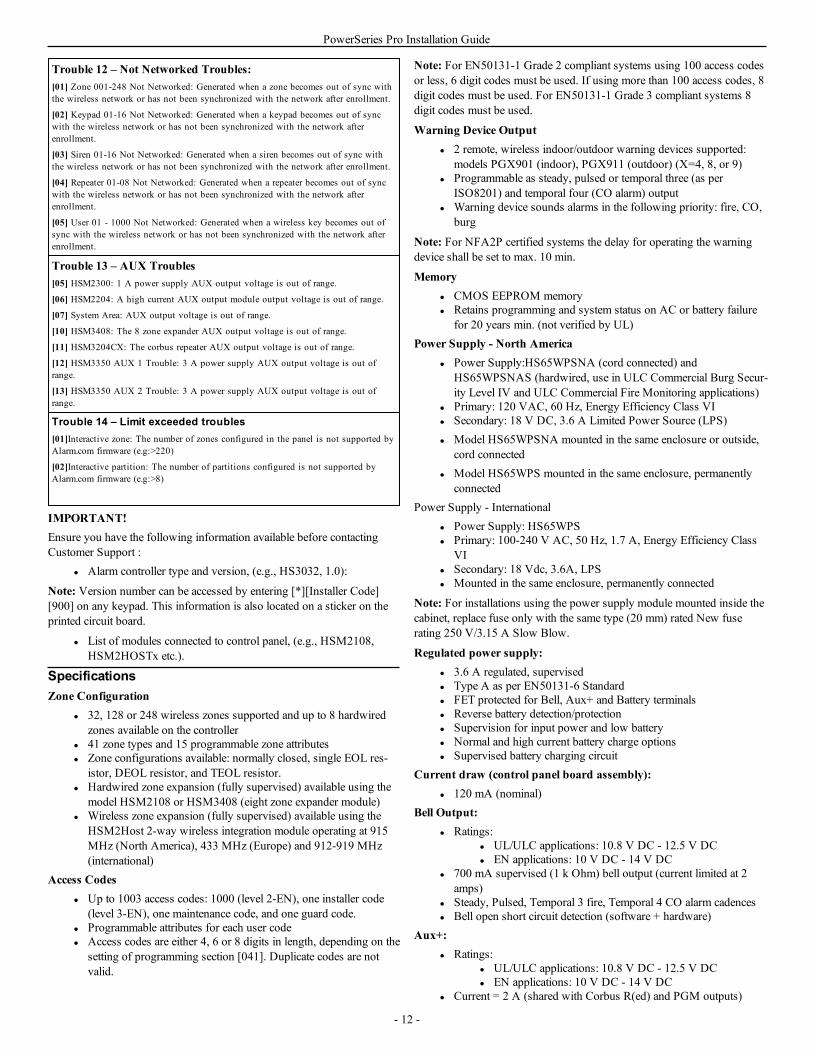
Trouble 12 – Not Networked Troubles:[01] Zone 001-248 Not Networked: Generated when a zone becomes out of sync withthe wireless network or has not been synchronized with the network after enrollment.
[02] Keypad 01-16 Not Networked: Generated when a keypad becomes out of syncwith the wireless network or has not been synchronized with the network afterenrollment.
[03] Siren 01-16 Not Networked: Generated when a siren becomes out of sync withthe wireless network or has not been synchronized with the network after enrollment.
[04] Repeater 01-08 Not Networked: Generated when a repeater becomes out of syncwith the wireless network or has not been synchronized with the network afterenrollment.
[05] User 01 - 1000 Not Networked: Generated when a wireless key becomes out ofsync with the wireless network or has not been synchronized with the network afterenrollment.
Trouble 13 – AUX Troubles[05] HSM2300: 1 A power supply AUX output voltage is out of range.
[06] HSM2204: A high current AUX output module output voltage is out of range.
[07] System Area: AUX output voltage is out of range.
[10] HSM3408: The 8 zone expander AUX output voltage is out of range.
[11] HSM3204CX: The corbus repeater AUX output voltage is out of range.
[12] HSM3350 AUX 1 Trouble: 3 A power supply AUX output voltage is out ofrange.
[13] HSM3350 AUX 2 Trouble: 3 A power supply AUX output voltage is out ofrange.
Trouble 14 – Limit exceeded troubles[01]Interactive zone: The number of zones configured in the panel is not supported byAlarm.com firmware (e.g:>220)
[02]Interactive partition: The number of partitions configured is not supported byAlarm.com firmware (e.g:>8)
IMPORTANT!Ensure you have the following information available before contactingCustomer Support :
l Alarm controller type and version, (e.g., HS3032, 1.0):
Note: Version number can be accessed by entering [*][Installer Code][900] on any keypad. This information is also located on a sticker on theprinted circuit board.
l List of modules connected to control panel, (e.g., HSM2108,HSM2HOSTx etc.).
SpecificationsZone Configuration
l 32, 128 or 248 wireless zones supported and up to 8 hardwiredzones available on the controller
l 41 zone types and 15 programmable zone attributesl Zone configurations available: normally closed, single EOL res-
istor, DEOL resistor, and TEOL resistor.l Hardwired zone expansion (fully supervised) available using the
model HSM2108 or HSM3408 (eight zone expander module)l Wireless zone expansion (fully supervised) available using the
HSM2Host 2-way wireless integration module operating at 915MHz (North America), 433 MHz (Europe) and 912-919 MHz(international)
Access Codesl Up to 1003 access codes: 1000 (level 2-EN), one installer code
(level 3-EN), one maintenance code, and one guard code.l Programmable attributes for each user codel Access codes are either 4, 6 or 8 digits in length, depending on the
setting of programming section [041]. Duplicate codes are notvalid.
Note: For EN50131-1 Grade 2 compliant systems using 100 access codesor less, 6 digit codes must be used. If using more than 100 access codes, 8digit codes must be used. For EN50131-1 Grade 3 compliant systems 8digit codes must be used.
Warning Device Outputl 2 remote, wireless indoor/outdoor warning devices supported:
models PGX901 (indoor), PGX911 (outdoor) (X=4, 8, or 9)l Programmable as steady, pulsed or temporal three (as per
ISO8201) and temporal four (CO alarm) outputl Warning device sounds alarms in the following priority: fire, CO,
burg
Note: For NFA2P certified systems the delay for operating the warningdevice shall be set to max. 10 min.
Memoryl CMOS EEPROM memoryl Retains programming and system status on AC or battery failure
for 20 years min. (not verified by UL)Power Supply - North America
l Power Supply:HS65WPSNA (cord connected) andHS65WPSNAS (hardwired, use in ULC Commercial Burg Secur-ity Level IV and ULC Commercial Fire Monitoring applications)
l Primary: 120 VAC, 60 Hz, Energy Efficiency Class VIl Secondary: 18 V DC, 3.6 A Limited Power Source (LPS)l Model HS65WPSNA mounted in the same enclosure or outside,
cord connectedl Model HS65WPS mounted in the same enclosure, permanently
connectedPower Supply - International
l Power Supply: HS65WPSl Primary: 100-240 V AC, 50 Hz, 1.7 A, Energy Efficiency Class
VIl Secondary: 18 Vdc, 3.6A, LPSl Mounted in the same enclosure, permanently connected
Note: For installations using the power supply module mounted inside thecabinet, replace fuse only with the same type (20 mm) rated New fuserating 250 V/3.15 A Slow Blow.
Regulated power supply:l 3.6 A regulated, supervisedl Type A as per EN50131-6 Standardl FET protected for Bell, Aux+ and Battery terminalsl Reverse battery detection/protectionl Supervision for input power and low batteryl Normal and high current battery charge optionsl Supervised battery charging circuit
Current draw (control panel board assembly):l 120 mA (nominal)
Bell Output:l Ratings:
l UL/ULC applications: 10.8 V DC - 12.5 V DCl EN applications: 10 V DC - 14 V DC
l 700 mA supervised (1 k Ohm) bell output (current limited at 2amps)
l Steady, Pulsed, Temporal 3 fire, Temporal 4 CO alarm cadencesl Bell open short circuit detection (software + hardware)
Aux+:l Ratings:
l UL/ULC applications: 10.8 V DC - 12.5 V DCl EN applications: 10 V DC - 14 V DC
l Current = 2 A (shared with Corbus R(ed) and PGM outputs)
- 12 -
PowerSeries Pro Installation Guide
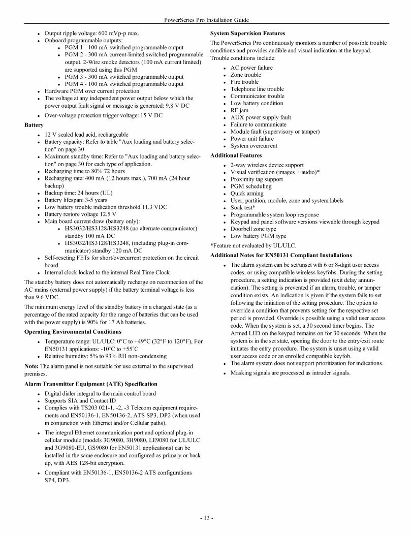
l Output ripple voltage: 600 mVp-p max.l Onboard programmable outputs:
l PGM 1 - 100 mA switched programmable outputl PGM 2 - 300 mA current-limited switched programmable
output. 2-Wire smoke detectors (100 mA current limited)are supported using this PGM
l PGM 3 - 300 mA switched programmable outputl PGM 4 - 100 mA switched programmable output
l Hardware PGM over current protectionl The voltage at any independent power output below which the
power output fault signal or message is generated: 9.8 V DCl Over-voltage protection trigger voltage: 15 V DC
Batteryl 12 V sealed lead acid, rechargeablel Battery capacity: Refer to table "Aux loading and battery selec-
tion" on page 30l Maximum standby time: Refer to "Aux loading and battery selec-
tion" on page 30 for each type of application.l Recharging time to 80% 72 hoursl Recharging rate: 400 mA (12 hours max.), 700 mA (24 hour
backup)l Backup time: 24 hours (UL)l Battery lifespan: 3-5 yearsl Low battery trouble indication threshold 11.3 VDCl Battery restore voltage 12.5 Vl Main board current draw (battery only):
l HS3032/HS3128/HS3248 (no alternate communicator)standby 100 mA DC
l HS3032/HS3128/HS3248, (including plug-in com-municator) standby 120 mA DC
l Self-reseting FETs for short/overcurrent protection on the circuitboard
l Internal clock locked to the internal Real Time ClockThe standby battery does not automatically recharge on reconnection of theAC mains (external power supply) if the battery terminal voltage is lessthan 9.6 VDC.The minimum energy level of the standby battery in a charged state (as apercentage of the rated capacity for the range of batteries that can be usedwith the power supply) is 90% for 17 Ah batteries.Operating Environmental Conditions
l Temperature range: UL/ULC: 0°C to +49°C (32°F to 120°F), ForEN50131 applications: -10˚C to +55˚C
l Relative humidity: 5% to 93% RH non-condensing
Note: The alarm panel is not suitable for use external to the supervisedpremises.
Alarm Transmitter Equipment (ATE) Specificationl Digital dialer integral to the main control boardl Supports SIA and Contact IDl Complies with TS203 021-1, -2, -3 Telecom equipment require-
ments and EN50136-1, EN50136-2, ATS SP3, DP2 (when usedin conjunction with Ethernet and/or Cellular paths).
l The integral Ethernet communication port and optional plug-incellular module (models 3G9080, 3H9080, LE9080 for UL/ULCand 3G9080-EU, GS9080 for EN50131 applications) can beinstalled in the same enclosure and configured as primary or back-up, with AES 128-bit encryption.
l Compliant with EN50136-1, EN50136-2 ATS configurationsSP4, DP3.
System Supervision FeaturesThe PowerSeries Pro continuously monitors a number of possible troubleconditions and provides audible and visual indication at the keypad.Trouble conditions include:
l AC power failurel Zone troublel Fire troublel Telephone line troublel Communicator troublel Low battery conditionl RF jaml AUX power supply faultl Failure to communicatel Module fault (supervisory or tamper)l Power unit failurel System overcurrent
Additional Featuresl 2-way wireless device supportl Visual verification (images + audio)*l Proximity tag supportl PGM schedulingl Quick armingl User, partition, module, zone and system labelsl Soak test*l Programmable system loop responsel Keypad and panel software versions viewable through keypadl Doorbell zone typel Low battery PGM type
*Feature not evaluated by UL/ULC.Additional Notes for EN50131 Compliant Installations
l The alarm system can be set/unset wth 6 or 8-digit user accesscodes, or using compatible wireless keyfobs. During the settingprocedure, a setting indication is provided (exit delay annun-ciation). The setting is prevented if an alarm, trouble, or tampercondition exists. An indication is given if the system fails to setfollowing the initiation of the setting procedure. The option tooverride a condition that prevents setting for the respective setperiod is provided. Override is possible using a valid user accesscode. When the system is set, a 30 second timer begins. TheArmed LED on the keypad remains on for 30 seconds. When thesystem is in the set state, opening the door to the entry/exit routeinitiates the entry procedure. The system is unset using a validuser access code or an enrolled compatible keyfob.
l The alarm system does not support prioritization for indications.l Masking signals are processed as intruder signals.
- 13 -
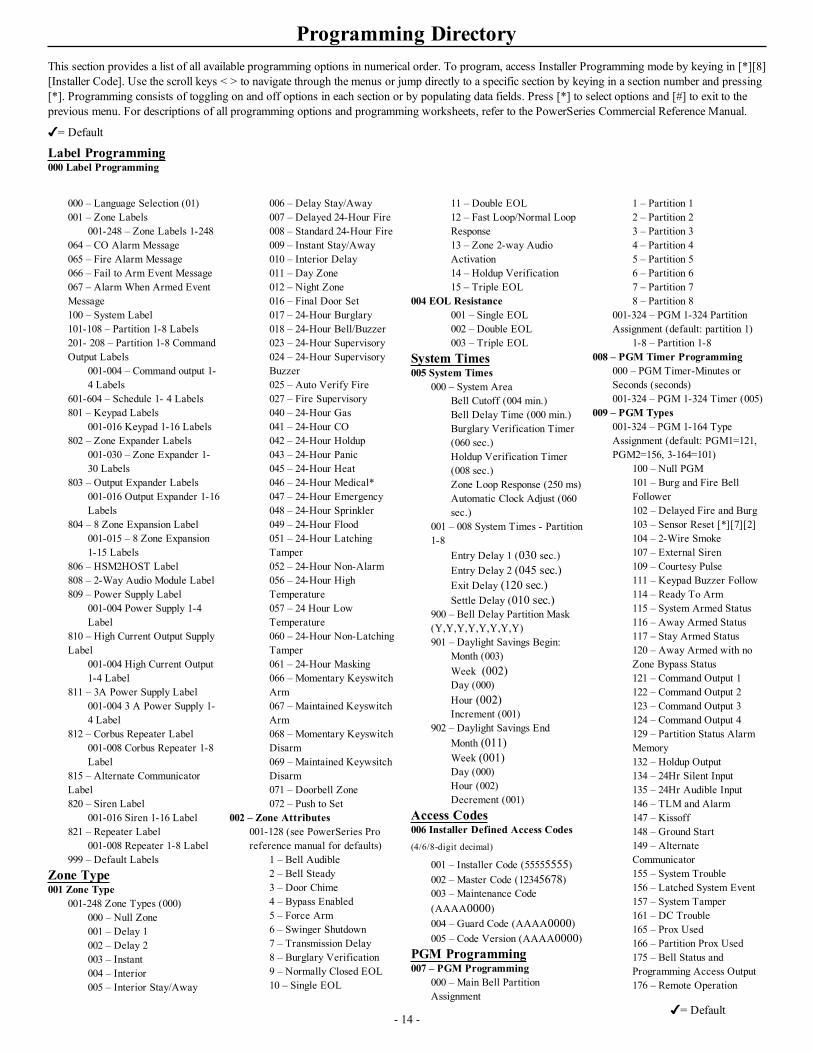
Programming DirectoryThis section provides a list of all available programming options in numerical order. To program, access Installer Programming mode by keying in [*][8][Installer Code]. Use the scroll keys < > to navigate through the menus or jump directly to a specific section by keying in a section number and pressing[*]. Programming consists of toggling on and off options in each section or by populating data fields. Press [*] to select options and [#] to exit to theprevious menu. For descriptions of all programming options and programming worksheets, refer to the PowerSeries Commercial Reference Manual.
= Default
Label Programming000 Label Programming
- 14 -
000 – Language Selection (01)001 – Zone Labels
001-248 – Zone Labels 1-248064 – CO Alarm Message065 – Fire Alarm Message066 – Fail to Arm Event Message067 – Alarm When Armed EventMessage100 – System Label101-108 – Partition 1-8 Labels201- 208 – Partition 1-8 CommandOutput Labels
001-004 – Command output 1-4 Labels
601-604 – Schedule 1- 4 Labels801 – Keypad Labels
001-016 Keypad 1-16 Labels802 – Zone Expander Labels
001-030 – Zone Expander 1-30 Labels
803 – Output Expander Labels001-016 Output Expander 1-16Labels
804 – 8 Zone Expansion Label001-015 – 8 Zone Expansion1-15 Labels
806 – HSM2HOST Label808 – 2-Way Audio Module Label809 – Power Supply Label
001-004 Power Supply 1-4Label
810 – High Current Output SupplyLabel
001-004 High Current Output1-4 Label
811 – 3A Power Supply Label001-004 3 A Power Supply 1-4 Label
812 – Corbus Repeater Label001-008 Corbus Repeater 1-8Label
815 – Alternate CommunicatorLabel820 – Siren Label
001-016 Siren 1-16 Label821 – Repeater Label
001-008 Repeater 1-8 Label999 – Default Labels
Zone Type001 Zone Type
001-248 Zone Types (000)000 – Null Zone001 – Delay 1002 – Delay 2003 – Instant004 – Interior005 – Interior Stay/Away
006 – Delay Stay/Away007 – Delayed 24-Hour Fire008 – Standard 24-Hour Fire009 – Instant Stay/Away010 – Interior Delay011 – Day Zone012 – Night Zone016 – Final Door Set017 – 24-Hour Burglary018 – 24-Hour Bell/Buzzer023 – 24-Hour Supervisory024 – 24-Hour SupervisoryBuzzer025 – Auto Verify Fire027 – Fire Supervisory040 – 24-Hour Gas041 – 24-Hour CO042 – 24-Hour Holdup043 – 24-Hour Panic045 – 24-Hour Heat046 – 24-Hour Medical*047 – 24-Hour Emergency048 – 24-Hour Sprinkler049 – 24-Hour Flood051 – 24-Hour LatchingTamper052 – 24-Hour Non-Alarm056 – 24-Hour HighTemperature057 – 24 Hour LowTemperature060 – 24-Hour Non-LatchingTamper061 – 24-Hour Masking066 – Momentary KeyswitchArm067 – Maintained KeyswitchArm068 – Momentary KeyswitchDisarm069 – Maintained KeywsitchDisarm071 – Doorbell Zone072 – Push to Set
002 – Zone Attributes001-128 (see PowerSeries Proreference manual for defaults)
1 – Bell Audible2 – Bell Steady3 – Door Chime4 – Bypass Enabled5 – Force Arm6 – Swinger Shutdown7 – Transmission Delay8 – Burglary Verification9 – Normally Closed EOL10 – Single EOL
11 – Double EOL12 – Fast Loop/Normal LoopResponse13 – Zone 2-way AudioActivation14 – Holdup Verification15 – Triple EOL
004 EOL Resistance001 – Single EOL002 – Double EOL003 – Triple EOL
System Times005 System Times
000 – System AreaBell Cutoff (004 min.)Bell Delay Time (000 min.)Burglary Verification Timer(060 sec.)Holdup Verification Timer(008 sec.)Zone Loop Response (250 ms)Automatic Clock Adjust (060sec.)
001 – 008 System Times - Partition1-8
Entry Delay 1 (030 sec.)Entry Delay 2 (045 sec.)Exit Delay (120 sec.)Settle Delay (010 sec.)
900 – Bell Delay Partition Mask(Y,Y,Y,Y,Y,Y,Y,Y)901 – Daylight Savings Begin:
Month (003)Week (002)Day (000)Hour (002)Increment (001)
902 – Daylight Savings EndMonth (011)Week (001)Day (000)Hour (002)Decrement (001)
Access Codes006 Installer Defined Access Codes(4/6/8-digit decimal)
001 – Installer Code (55555555)002 – Master Code (12345678)003 – Maintenance Code(AAAA0000)004 – Guard Code (AAAA0000)005 – Code Version (AAAA0000)
PGM Programming007 – PGM Programming
000 – Main Bell PartitionAssignment
1 – Partition 12 – Partition 23 – Partition 34 – Partition 45 – Partition 56 – Partition 67 – Partition 78 – Partition 8
001-324 – PGM 1-324 PartitionAssignment (default: partition 1)
1-8 – Partition 1-8008 – PGM Timer Programming
000 – PGM Timer-Minutes orSeconds (seconds)001-324 – PGM 1-324 Timer (005)
009 – PGM Types001-324 – PGM 1-164 TypeAssignment (default: PGM1=121,PGM2=156, 3-164=101)
100 – Null PGM101 – Burg and Fire BellFollower102 – Delayed Fire and Burg103 – Sensor Reset [*][7][2]104 – 2-Wire Smoke107 – External Siren109 – Courtesy Pulse111 – Keypad Buzzer Follow114 – Ready To Arm115 – System Armed Status116 – Away Armed Status117 – Stay Armed Status120 – Away Armed with noZone Bypass Status121 – Command Output 1122 – Command Output 2123 – Command Output 3124 – Command Output 4129 – Partition Status AlarmMemory132 – Holdup Output134 – 24Hr Silent Input135 – 24Hr Audible Input146 – TLM and Alarm147 – Kissoff148 – Ground Start149 – AlternateCommunicator155 – System Trouble156 – Latched System Event157 – System Tamper161 – DC Trouble165 – Prox Used166 – Partition Prox Used175 – Bell Status andProgramming Access Output176 – Remote Operation
= Default
PowerSeries Pro Installation Guide
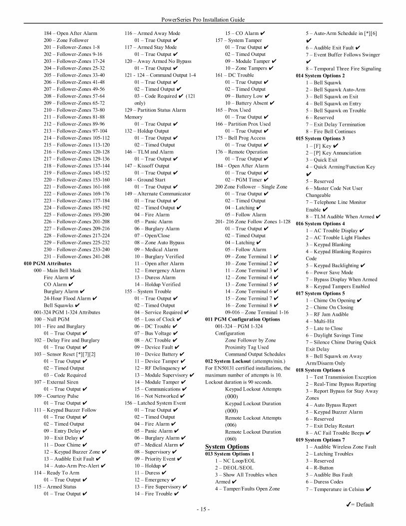
184 – Open After Alarm200 – Zone Follower201 – Follower-Zones 1-8202 – Follower-Zones 9-16203 – Follower-Zones 17-24204 – Follower-Zones 25-32205 – Follower-Zones 33-40206 – Follower-Zones 41-48207 – Follower-Zones 49-56208 – Follower-Zones 57-64209 – Follower-Zones 65-72210 – Follower-Zones 73-80211 – Follower-Zones 81-88212 – Follower-Zones 89-96213 – Follower-Zones 97-104214 – Follower-Zones 105-112215 – Follower-Zones 113-120216 – Follower-Zones 120-128217 – Follower-Zones 129-136218 – Follower-Zones 137-144219 – Follower-Zones 145-152220 – Follower-Zones 153-160221 – Follower-Zones 161-168222 – Follower-Zones 169-176223 – Follower-Zones 177-184224 – Follower-Zones 185-192225 – Follower-Zones 193-200226 – Follower-Zones 201-208227 – Follower-Zones 209-216228 – Follower-Zones 217-224229 – Follower-Zones 225-232230 – Follower-Zones 233-240231 – Follower-Zones 241-248
010 PGM Attributes000 – Main Bell Mask
Fire Alarm
CO Alarm
Burglary Alarm
24-Hour Flood Alarm
Bell Squawks 001-324 PGM 1-324 Attributes100 – Null PGM101 – Fire and Burglary
01 – True Output 102 – Delay Fire and Burglary
01 – True Output 103 – Sensor Reset [*][7][2]
01 – True Output 02 – Timed Output03 – Code Required
107 – External Siren01 – True Output
109 – Courtesy Pulse01 – True Output
111 – Keypad Buzzer Follow01 – True Output 02 – Timed Output09 – Entry Delay10 – Exit Delay11 – Door Chime 12 – Keypad Buzzer Zone 13 – Audible Exit Fault 14 – Auto-Arm Pre-Alert
114 – Ready To Arm01 – True Output
115 – Armed Status01 – True Output
116 – Armed Away Mode01 – True Output
117 – Armed Stay Mode01 – True Output
120 – Away Armed No Bypass01 – True Output
121 - 124 – Command Output 1-401 – True Output 02 – Timed Output 03 – Code Required (121only)
129 – Partition Status AlarmMemory
01 – True Output 132 – Holdup Output
01 – True Output 02 – Timed Output
146 – TLM and Alarm01 – True Output
147 – Kissoff Output01 – True Output
148 – Ground Start01 – True Output
149 – Alternate Communicator01 – True Output 02 – Timed Output 04 – Fire Alarm05 – Panic Alarm06 – Burglary Alarm07 – Open/Close08 – Zone Auto Bypass09 – Medical Alarm10 – Burglary Verified11 – Open after Alarm12 – Emergency Alarm13 – Duress Alarm14 – Holdup Verified
155 – System Trouble01 – True Output 02 – Timed Output04 – Service Required05 – Loss of Clock06 – DC Trouble 07 – Bus Voltage 08 – AC Trouble 09 – Device Fault 10 – Device Battery11 – Device Tamper 12 – RF Delinquency13 – Module Supervisory14 – Module Tamper 15 – Communications16 – Not Networked
156 – Latched System Event01 – True Output 02 – Timed Output04 – Fire Alarm
05 – Panic Alarm
06 – Burglary Alarm
07 – Medical Alarm
08 – Supervisory09 – Priority Event 10 – Holdup11 – Duress 12 – Emergency13 – Fire Supervisory14 – Fire Trouble
15 – CO Alarm
157 – System Tamper01 – True Output 02 – Timed Output09 – Module Tamper 10 – Zone Tampers
161 – DC Trouble01 – True Output 02 – Timed Output09 – Battery Low
10 – Battery Absent 165 – Prox Used
01 – True Output 166 – Partition Prox Used
01 – True Output 175 – Bell Prog Access
01 – True Output 176 – Remote Operation
01 – True Output 184 – Open After Alarm
01 – True Output 02 – PGM Timer
200 Zone Follower – Single Zone01 – True Output 02 – Timed Output04 – Latching05 – Follow Alarm
201- 216 Zone Follow Zones 1-12801 – True Output 02 – Timed Output04 – Latching05 – Follow Alarm09 – Zone Terminal 110 – Zone Terminal 211 – Zone Terminal 312 – Zone Terminal 413 – Zone Terminal 514 – Zone Terminal 615 – Zone Terminal 716 – Zone Terminal 809-016 – Zone Terminal 1-16
011 PGM Configuration Options001-324 – PGM 1-324Configuration
Zone Follower by ZoneProximity Tag UsedCommand Output Schedules
012 System Lockout (attempts/min.)For EN50131 certified installations, themaximum number of attempts is 10.Lockout duration is 90 seconds.
Keypad Lockout Attempts(000)Keypad Lockout Duration(000)Remote Lockout Attempts(006)Remote Lockout Duration(060)
System Options013 System Options 1
1 – NC Loop/EOL2 – DEOL/SEOL3 – Show All Troubles whenArmed4 – Tamper/Faults Open Zone
5 – Auto-Arm Schedule in [*][6]6 – Audible Exit Fault 7 – Event Buffer Follows Swinger
8 – Temporal Three Fire Signaling014 System Options 2
1 – Bell Squawk2 – Bell Squawk Auto-Arm3 – Bell Squawk on Exit4 – Bell Squawk on Entry5 – Bell Squawk on Trouble6 – Reserved7 – Exit Delay Termination8 – Fire Bell Continues
015 System Options 31 – [F] Key2 – [P] Key Annunciation3 – Quick Exit4 – Quick Arming/Function Key5 – Reserved6 – Master Code Not UserChangeable7 – Telephone Line MonitorEnable 8 – TLM Audible When Armed
016 System Options 41 – AC Trouble Display2 – AC Trouble Light Flashes3 – Keypad Blanking4 – Keypad Blanking RequiresCode5 – Keypad Backlighting6 – Power Save Mode7 – Bypass Display When Armed8 – Keypad Tampers Enabled
017 System Options 51 – Chime On Opening2 – Chime On Closing3 – RF Jam Audible4 – Multi-Hit5 – Late to Close6 – Daylight Savings Time7 – Silence Chime During QuickExit Delay8 – Bell Squawk on AwayArm/Disarm Only
018 System Options 61 – Test Transmission Exception2 – Real-Time Bypass Reporting3 – Report Bypass for Stay AwayZones4 – Auto Bypass Report5 – Keypad Buzzer Alarm6 – Reserved7 – Exit Delay Restart8 – AC Fail Trouble Beeps
019 System Options 71 – Audible Wireless Zone Fault2 – Latching Troubles3 – Reserved4 – R-Button5 – Audible Bus Fault6 – Duress Codes7 – Temperature in Celsius
- 15 -= Default
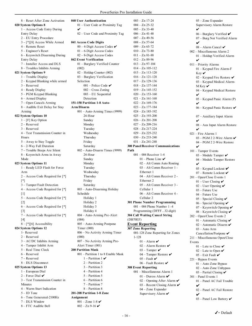
PowerSeries Pro Installation Guide
8 – Reset After Zone Activation020 System Options 8
1 – Access Code Entry DuringEntry Delay2 – EU Entry Procedure3 – [*][8] Access While Armed4 – Remote Reset5 – Engineer's Reset6 – Keyswitch Disarming DuringEntry Delay7 – Installer Access and DLS8 – Troubles Inhibits Arming
021 System Options 91 – Trouble Display2 – Keypad Blanking while armed3 – Reserved4 – Ready Display5 – PGM Keypad Blanking6 – Armed Display7 – Open Cancels Arming8 – Audible Exit Delay for StayArming
022 System Options 101 – [F] Key Option2 – Reserved3 – Reserved4 – Test Transmission Counter inHours5 – Away to Stay Toggle6 – 2-Way Full Duration7 – Trouble Beeps Are Silent8 – Keyswitch Arms in AwayMode
023 System Options 111 – Ready LED Flash for ForceArm2 – Access Code Required for [*][*]3 – Tamper/Fault Detection4 – Access Code Required for [*][1]5 – Access Code Required for [*][2]6 – Access Code Required for [*][3]7 – Access Code Required for [*][4]8 – [*][6] Accessibility
024 System Options 121– Reserved2 – Reserved3 – AC/DC Inhibits Arming4 – Tamper Inhibit Arm5 – Real Time Clock6 – Reserved7 – Reserved8 – DLS Disconnect
025 System Options 131 – European Dial2 – Force Dial 3 – Test Transmission Counter inMinutes4 – Warm Start Indication5 – ID Tone6 – Tone Generated-2100Hz7 – DLS Window8 – FTC Audible Bell
040 User Authentication01 – User Code or Proximity Tag
02 – User Code and Proximity Tag
041 Access Code Digits00 – 4-Digit Access Codes 01 – 6-Digit Access Codes02 – 8-Digit Access Codes
042 Event Verification01 – Burglary Verified Counter(002)02 – Holdup Counter (002)03 – Burglary VerificationSelection
001 – Police Code 002 – Cross Zoning003 – EU SequentialDetection
151-158 Partition 1-8 Auto-Arm/Disarm
001 – Auto-Arming Times (9999)24-HourSundayMondayTuesdayWednesdayThursdayFridaySaturday
002 – Auto-Disarm Times (9999)24-HourSundayMondayTuesdayWednesdayThursdayFridaySaturday
003 – Auto-Disarming HolidaySchedule
Holiday 1Holiday 2Holiday 3Holiday 4
004 – Auto-Arming Pre-Alert(004)005 – Auto-Arming PostponeTimer (000)006 – No Activity Arming Timer(000)007 – No Activity Arming Pre-Alert Timer (001)
200 Partition Mask001 – Partition 1 to 8 Enable Mask
1 – Partition 12 – Partition 23 – Partition 34 – Partition 45 – Partition 56 – Partition 67 – Partition 78 – Partition 8
201-208 Partition 1-8 ZoneAssignment
001 – Zone 1-8002 – Zn 9-16
003 – Zn 17-24004 – Zn 25-32005 – Zn 33-40006 – Zn 41-48007 – Zn 49-56008 – Zn 57-64009 – Zn 65-72010 – Zn 73-80011 – Zn 81-88012 – Zn 89-96013 – Zn 97-104014 – Zn 105-112015 – Zn 113-120016 – Zn 121-128017 – Zn 129-136018 – Zn 137-144019 – Zn 145-152020 – Zn 153-160021 – Zn 161-168022 – Zn 169-176023 – Zn 177-184024 – Zn 185-192025 – Zn 193-200026 – Zn 201-208027 – Zn 209-216028 – Zn 217-224029 – Zn 225-232030 – Zn 233-240031 – Zn 241-248
300 Panel/Receiver CommunicationsPath
001 – 004 Receiver 1-401 – Phone Line 02 – Alt Comm Auto Routing03 – Alt Comm Receiver 1 -Ethernet 104 – Alt Comm Receiver 2 -Ethernet 205 – Alt Comm Receiver 3 -Cellular 106 – Alt Comm Receiver 4 -Cellular 2
301 Phone Number Programming001 – 004 Phone Number 1 -4Programming (DFFF...32-digit)
304 Call Waiting Cancel String(DB70EF)Event Reporting307 Zone Reporting
001-128 Zone Reporting for Zones1-128
01 – Alarm
02 – Alarm Restore 03 – Tamper 04 – Tamper Restore 05 – Fault 06 – Fault Restore
308 Event Reporting001 – Miscellaneous Alarm 1
01 – Duress Alarm02 – Opening After Alarm
03 – Recent Closing Alarm
04 – Zone ExpanderSupervisory Alarm
05 – Zone ExpanderSupervisory Alarm Restore
06 – Burglary Verified07 – Burg Not Verified Alarm08 – Alarm Cancel
002 – Miscellaneous Alarm 201 – Holdup Verified Alarm
011 – Priority Alarms01 – Keypad Fire Alarm-FKey02 – Keypad Fire Restore 03 – Keypad Medical Alarm-M Key04 – Keypad Medical Restore
05 – Keypad Panic Alarm (P)
06 – Keypad Panic Restore
07 – Auxiliary Input Alarm
08 – Aux Input Alarm Restore
021 – Fire Alarms 103 – PGM 2 2-Wire Alarm
04 – PGM 2 2-Wire Restore
101 – Tamper Events03 – Module Tamper 04 – Module Tamper Restore
05 – Keypad Lockout 07 – Remote Lockout
201 – Open/Close Events 101 – User Closing02 – User Opening03 – Future Use04 – Future Use05 – Special Closing06 – Special Opening07 – Keyswitch Opening08 – Keyswitch Closing
202 – Open/Close Events 201 – Automatic Closing02 – Automatic Disarm
03 – Auto ArmCancellation/Postpone
211 – Miscellaneous Open/CloseEvents
01 – Late to Close 02 – Late to Open05 – Exit Fault
221 – Bypass Events01 – Auto Zone Bypass02 – Auto Zone Unbypass03 – Partial Closing
301 – Panel Events 101 – Panel AC Fail Trouble02 – Panel AC Fail Restore03 – Panel Low Battery
- 16 -= Default
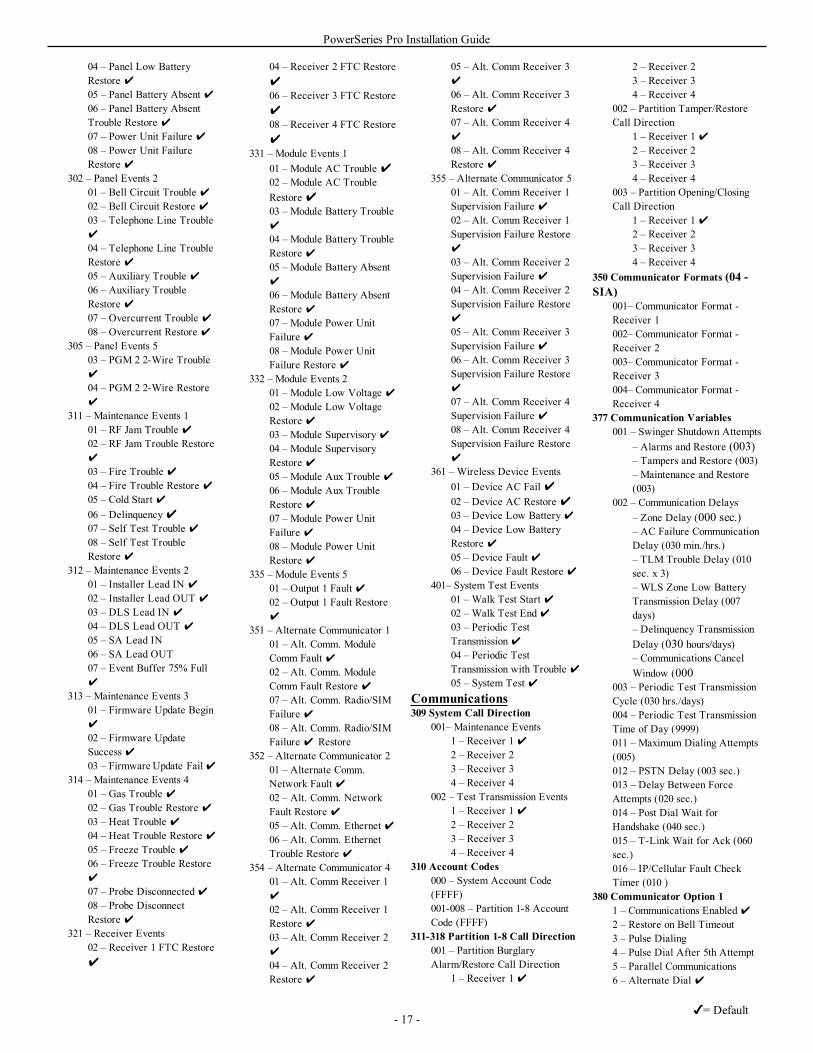
PowerSeries Pro Installation Guide
04 – Panel Low BatteryRestore 05 – Panel Battery Absent 06 – Panel Battery AbsentTrouble Restore 07 – Power Unit Failure 08 – Power Unit FailureRestore
302 – Panel Events 201 – Bell Circuit Trouble 02 – Bell Circuit Restore 03 – Telephone Line Trouble
04 – Telephone Line TroubleRestore 05 – Auxiliary Trouble 06 – Auxiliary TroubleRestore 07 – Overcurrent Trouble 08 – Overcurrent Restore
305 – Panel Events 503 – PGM 2 2-Wire Trouble
04 – PGM 2 2-Wire Restore
311 – Maintenance Events 101 – RF Jam Trouble 02 – RF Jam Trouble Restore
03 – Fire Trouble 04 – Fire Trouble Restore 05 – Cold Start 06 – Delinquency07 – Self Test Trouble 08 – Self Test TroubleRestore
312 – Maintenance Events 201 – Installer Lead IN
02 – Installer Lead OUT
03 – DLS Lead IN
04 – DLS Lead OUT
05 – SA Lead IN06 – SA Lead OUT07 – Event Buffer 75% Full
313 – Maintenance Events 301 – Firmware Update Begin
02 – Firmware UpdateSuccess 03 – Firmware Update Fail
314 – Maintenance Events 401 – Gas Trouble 02 – Gas Trouble Restore 03 – Heat Trouble 04 – Heat Trouble Restore 05 – Freeze Trouble 06 – Freeze Trouble Restore
07 – Probe Disconnected08 – Probe DisconnectRestore
321 – Receiver Events02 – Receiver 1 FTC Restore
04 – Receiver 2 FTC Restore06 – Receiver 3 FTC Restore08 – Receiver 4 FTC Restore
331 – Module Events 101 – Module AC Trouble 02 – Module AC TroubleRestore 03 – Module Battery Trouble
04 – Module Battery TroubleRestore 05 – Module Battery Absent
06 – Module Battery AbsentRestore 07 – Module Power UnitFailure 08 – Module Power UnitFailure Restore
332 – Module Events 201 – Module Low Voltage 02 – Module Low VoltageRestore 03 – Module Supervisory04 – Module SupervisoryRestore 05 – Module Aux Trouble 06 – Module Aux TroubleRestore 07 – Module Power UnitFailure 08 – Module Power UnitRestore
335 – Module Events 501 – Output 1 Fault 02 – Output 1 Fault Restore
351 – Alternate Communicator 101 – Alt. Comm. ModuleComm Fault 02 – Alt. Comm. ModuleComm Fault Restore 07 – Alt. Comm. Radio/SIMFailure 08 – Alt. Comm. Radio/SIMFailure Restore
352 – Alternate Communicator 201 – Alternate Comm.Network Fault 02 – Alt. Comm. NetworkFault Restore 05 – Alt. Comm. Ethernet 06 – Alt. Comm. EthernetTrouble Restore
354 – Alternate Communicator 401 – Alt. Comm Receiver 1
02 – Alt. Comm Receiver 1Restore 03 – Alt. Comm Receiver 2
04 – Alt. Comm Receiver 2Restore
05 – Alt. Comm Receiver 3
06 – Alt. Comm Receiver 3Restore 07 – Alt. Comm Receiver 4
08 – Alt. Comm Receiver 4Restore
355 – Alternate Communicator 501 – Alt. Comm Receiver 1Supervision Failure 02 – Alt. Comm Receiver 1Supervision Failure Restore
03 – Alt. Comm Receiver 2Supervision Failure 04 – Alt. Comm Receiver 2Supervision Failure Restore
05 – Alt. Comm Receiver 3Supervision Failure 06 – Alt. Comm Receiver 3Supervision Failure Restore
07 – Alt. Comm Receiver 4Supervision Failure 08 – Alt. Comm Receiver 4Supervision Failure Restore
361 – Wireless Device Events01 – Device AC Fail 02 – Device AC Restore 03 – Device Low Battery04 – Device Low BatteryRestore 05 – Device Fault 06 – Device Fault Restore
401– System Test Events01 – Walk Test Start 02 – Walk Test End03 – Periodic TestTransmission04 – Periodic TestTransmission with Trouble 05 – System Test
Communications309 System Call Direction
001– Maintenance Events1 – Receiver 12 – Receiver 23 – Receiver 34 – Receiver 4
002 – Test Transmission Events1 – Receiver 12 – Receiver 23 – Receiver 34 – Receiver 4
310 Account Codes000 – System Account Code(FFFF)001-008 – Partition 1-8 AccountCode (FFFF)
311-318 Partition 1-8 Call Direction001 – Partition BurglaryAlarm/Restore Call Direction
1 – Receiver 1
2 – Receiver 23 – Receiver 34 – Receiver 4
002 – Partition Tamper/RestoreCall Direction
1 – Receiver 12 – Receiver 23 – Receiver 34 – Receiver 4
003 – Partition Opening/ClosingCall Direction
1 – Receiver 12 – Receiver 23 – Receiver 34 – Receiver 4
350 Communicator Formats (04 -SIA)
001– Communicator Format -Receiver 1002– Communicator Format -Receiver 2003– Communicator Format -Receiver 3004– Communicator Format -Receiver 4
377 Communication Variables001 – Swinger Shutdown Attempts
– Alarms and Restore (003)– Tampers and Restore (003)– Maintenance and Restore(003)
002 – Communication Delays– Zone Delay (000 sec.)– AC Failure CommunicationDelay (030 min./hrs.)– TLM Trouble Delay (010sec. x 3)– WLS Zone Low BatteryTransmission Delay (007days)– Delinquency TransmissionDelay (030 hours/days)– Communications CancelWindow (000
003 – Periodic Test TransmissionCycle (030 hrs./days)004 – Periodic Test TransmissionTime of Day (9999)011 – Maximum Dialing Attempts(005)012 – PSTN Delay (003 sec.)013 – Delay Between ForceAttempts (020 sec.)014 – Post Dial Wait forHandshake (040 sec.)015 – T-Link Wait for Ack (060sec.)016 – IP/Cellular Fault CheckTimer (010 )
380 Communicator Option 11 – Communications Enabled2 – Restore on Bell Timeout3 – Pulse Dialing4 – Pulse Dial After 5th Attempt5 – Parallel Communications6 – Alternate Dial
- 17 -= Default
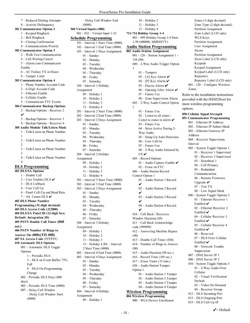
PowerSeries Pro Installation Guide
7 – Reduced Dialing Attempts8 – Activity Delinquency
381 Communicator Option 21 – Keypad Ringback2 – Bell Ringback4 – Closing Confirmation8 – Communications Priority
382 Communicator Option 32 – Walk Test Communication4 – Call Waiting Cancel5 – Alarm.com CommunicatorEnable6 – AC Failure TX in Hours8 – Tamper Limit
383 Communicator Option 41 – Phone Number Account Code2 – 6-Digit Account Code3 – Ethernet Enable4 – Cellular Enable5 – Communicate FTC Events
384 Communicator Backup Options2 – Backup Options - Receiver 2
3 – Backup Options - Receiver 34 – Backup Options - Receiver 4
385 Audio Module Talk/Listen Mask1 – Talk/Listen on Phone Number12 – Talk/Listen on Phone Number23 – Talk/Listen on Phone Number34 – Talk/Listen on Phone Number4
DLS Programming401 DLS/SA Options
1 – Double Call2 – User Enables DLS
3 – DLS Callback4 – User Call Up6 – Panel Call-Up and Baud Rate7 – Alt. Comm DLS
402 DLS Phone NumberProgramming (31-digit decimal)403 DLS Access Code (212800)404 DLS/SA Panel ID (12-digit hex;Default: Integration ID)405 PSTN Double Call Timer (060sec.)406 PSTN Number of Rings toAnswer On (000)(TIS 008)407 SA Access Code (FFFFFF)410 Automatic DLS Options
001 – Automatic DLS ToggleOptions
1 – Periodic DLS3 – DLS on Event Buffer 75%Full8 – DLS On ProgrammingChange
002 – Periodic DLS Days (000days)003 – Periodic DLS Time (0000)007 – Delay Call Window
– Delay Call Window Start(0000)
– Delay Call Window End(0000)
560 Virtual Inputs (000)001 - 032 – Virtual Input 1-32
Schedule Programming101 – Interval 1 Start Time (0000)102 – Interval 1 End Time (0000)103 – Interval 1 Days Assignment
01 – Sunday02 – Monday03 – Tuesday04 – Wednesday05 – Thursday06 – Friday07 – Saturday
104 – Interval 1 HolidayAssignment
09 – Holiday 110 – Holiday 211 – Holiday 312 – Holiday 4
201 – Interval 2 Start Time (0000)202 – Interval 2 End Time (0000)203 – Interval 2 Days Assignment
01 – Sunday02 – Monday03 – Tuesday04 – Wednesday05 – Thursday06 – Friday07 – Saturday
204 – Interval 2 HolidayAssignment
09 – Holiday 110 – Holiday 211 – Holiday 312 – Holiday 4
301 – Interval 3 Start Time (0000)302 – Interval 3 End Time (0000)303 – Interval 3 Days Assignment
01 – Sunday02 – Monday03 – Tuesday04 – Wednesday05 – Thursday06 – Friday07 – Saturday
304 – Interval 3 HolidayAssignment
09 – Holiday 110 – Holiday 211 – Holiday 312 – Holiday 4 201 – Interval2 Start Time (0000)
402 – Interval 4 End Time (0000)403 – Interval 4 Days Assignment
01 – Sunday02 – Monday03 – Tuesday04 – Wednesday05 – Thursday06 – Friday07 – Saturday
404 – Interval 4 HolidayAssignment
09 – Holiday 1
10 – Holiday 211 – Holiday 312 – Holiday 4
711-714 Holiday Group 1-4001 – 099 Holiday Group 1-4 Date1-99 (000000, MMDDYY)
Audio Station Programming802 Audio Station Assignment
001 - 128 – Station Assignment 1 -128 (00)600 – 2-Way Audio Trigger Option1
01 – Tampers03 – [A] Key Alarm
04 – [P] Key Alarm
05 – Duress Alarm06 – Opening After Alarm
07 – Future Use08 – Zone Supervision Alarm
603 – 2-Way Audio Control Option1
01 – Future Use02 – Listen to all zones /Listen to zones in alarm
03 – Future Use04 – Siren Active During 2-Way Audio05 – Hang-Up Auto Detection06 – User Call-In07 – Future Use08 – 2-Way Audio Initiated byCS
605 – Record Options01 – Audio Capture Enable 02 – Erase on FTC
606 – Audio Station RecordControl Option 1
01 – Audio Station 1 Record
02 – Audio Station 2 Record
03 – Audio Station 3 Record
04 – Audio Station 4 Record
610 – Call Back / RecoveryWindow Duration (05)611 – Call Back Acknowledgecode (999999)612 – Answering Machine Bypass(00)613 – Double Call Timer (030)614 – Number of Rings to Answer(00)615 – Audio Duration (90 sec.)616 – Record Time (105 sec.)617 – Erase Timer (15 min.)620 – Audio Station TamperOption 1
01 – Audio Station 1 Tamper02 – Audio Station 2 Tamper03 – Audio Station 3 Tamper04 – Audio Station 4 Tamper
Wireless Programming804 Wireless Programming
000 – WLS Device Enrollment
Zones (3-digit decimal)Zone Type (2-digit decimal)Partition AssignmentZone Label (LCD only)WLS KeysPartition AssignmentUser AssignmentSirensPartition AssignmentSiren Label (LCD only)KeypadsKeypad AssignmentKeypad Label (LCD only)RepeatersRepeater Label (LCD only)
001 - 128 – Configure WirelessZones
Refer to the installation instructionsprovided with the HSM2Host formore wireless programmingoptions.850 Cellular Signal Strength851 Communicator Programming
001 – Ethernet IP Address002 – Ethernet IP Subnet Mask003 – Ethernet Gateway IPAddress004 – Receiver SupervisionInterval005 – System Toggle Options 1
01 – Receiver 1 Supervised02 – Receiver 3 Supervised03 – Heartbeat 104 – Cell Primary05 – RedundantCommunications06 – Remote FirmwareUpgrade 07 – Test TX08 – Low Signal Mask
006 – System Toggle Options 201 – Ethernet Receiver 1Enabled02 – Ethernet Receiver 2Enabled04 – Cellular Receiver 3Enabled05 – Cellular Receiver 4Enabled06 – Reserved07 – DLS Over CellularEnabled08 – Network TroubleSuppression
007 – DNS Server IP 1008 – DNS Server IP 2010 – System Toggle Options 3
01 – 2-Way Audio OverCellular02 – Visual VerificationDefault03 – Video On Demand04 – Receiver Group
012 – DLS Incoming Port013 – DLS Outgoing Port015 – DLS Call-Up IP
- 18 -= Default
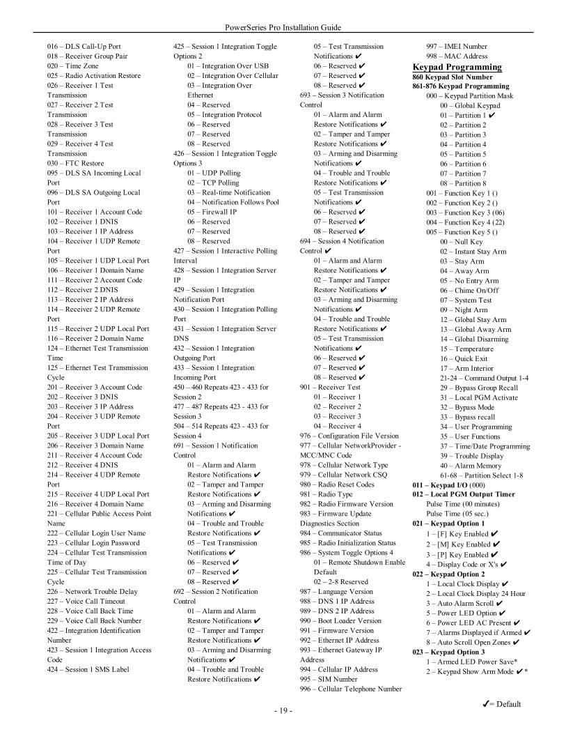
PowerSeries Pro Installation Guide
016 – DLS Call-Up Port018 – Receiver Group Pair020 – Time Zone025 – Radio Activation Restore026 – Receiver 1 TestTransmission027 – Receiver 2 TestTransmission028 – Receiver 3 TestTransmission029 – Receiver 4 TestTransmission030 – FTC Restore095 – DLS SA Incoming LocalPort096 – DLS SA Outgoing LocalPort101 – Receiver 1 Account Code102 – Receiver 1 DNIS103 – Receiver 1 IP Address104 – Receiver 1 UDP RemotePort105 – Receiver 1 UDP Local Port106 – Receiver 1 Domain Name111 – Receiver 2 Account Code112 – Receiver 2 DNIS113 – Receiver 2 IP Address114 – Receiver 2 UDP RemotePort115 – Receiver 2 UDP Local Port116 – Receiver 2 Domain Name124 – Ethernet Test TransmissionTime125 – Ethernet Test TransmissionCycle201 – Receiver 3 Account Code202 – Receiver 3 DNIS203 – Receiver 3 IP Address204 – Receiver 3 UDP RemotePort205 – Receiver 3 UDP Local Port206 – Receiver 3 Domain Name211 – Receiver 4 Account Code212 – Receiver 4 DNIS214 – Receiver 4 UDP RemotePort215 – Receiver 4 UDP Local Port216 – Receiver 4 Domain Name221 – Cellular Public Access PointName222 – Cellular Login User Name223 – Cellular Login Password224 – Cellular Test TransmissionTime of Day225 – Cellular Test TransmissionCycle226 – Network Trouble Delay227 – Voice Call Timeout228 – Voice Call Back Time229 – Voice Call Back Number422 – Integration IdentificationNumber423 – Session 1 Integration AccessCode424 – Session 1 SMS Label
425 – Session 1 Integration ToggleOptions 2
01 – Integration Over USB02 – Integration Over Cellular03 – Integration OverEthernet04 – Reserved05 – Integration Protocol06 – Reserved07 – Reserved08 – Reserved
426 – Session 1 Integration ToggleOptions 3
01 – UDP Polling02 – TCP Polling03 – Real-time Notification04 – Notification Follows Pool05 – Firewall IP06 – Reserved07 – Reserved08 – Reserved
427 – Session 1 Interactive PollingInterval428 – Session 1 Integration ServerIP429 – Session 1 IntegrationNotification Port430 – Session 1 Integration PollingPort431 – Session 1 Integration ServerDNS432 – Session 1 IntegrationOutgoing Port433 – Session 1 IntegrationIncoming Port450 – 460 Repeats 423 - 433 forSession 2477 – 487 Repeats 423 - 433 forSession 3504 – 514 Repeats 423 - 433 forSession 4691 – Session 1 NotificationControl
01 – Alarm and AlarmRestore Notifications02 – Tamper and TamperRestore Notifications03 – Arming and DisarmingNotifications04 – Trouble and TroubleRestore Notifications05 – Test TransmissionNotifications06 – Reserved07 – Reserved08 – Reserved
692 – Session 2 NotificationControl
01 – Alarm and AlarmRestore Notifications02 – Tamper and TamperRestore Notifications03 – Arming and DisarmingNotifications04 – Trouble and TroubleRestore Notifications
05 – Test TransmissionNotifications06 – Reserved07 – Reserved08 – Reserved
693 – Session 3 NotificationControl
01 – Alarm and AlarmRestore Notifications02 – Tamper and TamperRestore Notifications03 – Arming and DisarmingNotifications04 – Trouble and TroubleRestore Notifications05 – Test TransmissionNotifications06 – Reserved07 – Reserved08 – Reserved
694 – Session 4 NotificationControl
01 – Alarm and AlarmRestore Notifications02 – Tamper and TamperRestore Notifications03 – Arming and DisarmingNotifications04 – Trouble and TroubleRestore Notifications05 – Test TransmissionNotifications06 – Reserved07 – Reserved08 – Reserved
901 – Receiver Test01 – Receiver 102 – Receiver 203 – Receiver 304 – Receiver 4
976 – Configuration File Version977 – Cellular NetworkProvider -MCC/MNC Code978 – Cellular Network Type979 – Cellular Network CSQ980 – Radio Reset Codes981 – Radio Type982 – Radio Firmware Version983 – Firmware UpdateDiagnostics Section984 – Communicator Status985 – Radio Initialization Status986 – System Toggle Options 4
01 – Remote Shutdown EnableDefault02 – 2-8 Reserved
987 – Language Version988 – DNS 1 IP Address989 – DNS 2 IP Address990 – Boot Loader Version991 – Firmware Version992 – Ethernet IP Address993 – Ethernet Gateway IPAddress994 – Cellular IP Address995 – SIM Number996 – Cellular Telephone Number
997 – IMEI Number998 – MAC Address
Keypad Programming860 Keypad Slot Number861-876 Keypad Programming
000 – Keypad Partition Mask00 – Global Keypad01 – Partition 102 – Partition 203 – Partition 304 – Partition 405 – Partition 506 – Partition 607 – Partition 708 – Partition 8
001 – Function Key 1 ()002 – Function Key 2 ()003 – Function Key 3 (06)004 – Function Key 4 (22)005 – Function Key 5 ()
00 – Null Key02 – Instant Stay Arm03 – Stay Arm04 – Away Arm05 – No Entry Arm06 – Chime On/Off07 – System Test09 – Night Arm12 – Global Stay Arm13 – Global Away Arm14 – Global Disarming15 – Temperature16 – Quick Exit17 – Arm Interior21-24 – Command Output 1-429 – Bypass Group Recall31 – Local PGM Activate32 – Bypass Mode33 – Bypass recall34 – User Programming35 – User Functions37 – Time/Date Programming39 – Trouble Display40 – Alarm Memory61-68 – Partition Select 1-8
011 – Keypad I/O (000)012 – Local PGM Output Timer
Pulse Time (00 minutes)Pulse Time (05 sec.)
021 – Keypad Option 11 – [F] Key Enabled2 – [M] Key Enabled3 – [P] Key Enabled4 – Display Code or X's
022 – Keypad Option 21 – Local Clock Display2 – Local Clock Display 24 Hour3 – Auto Alarm Scroll 5 – Power LED Option6 – Power LED AC Present 7 – Alarms Displayed if Armed8 – Auto Scroll Open Zones
023 – Keypad Option 31 – Armed LED Power Save*2 – Keypad Show Arm Mode *
- 19 -= Default
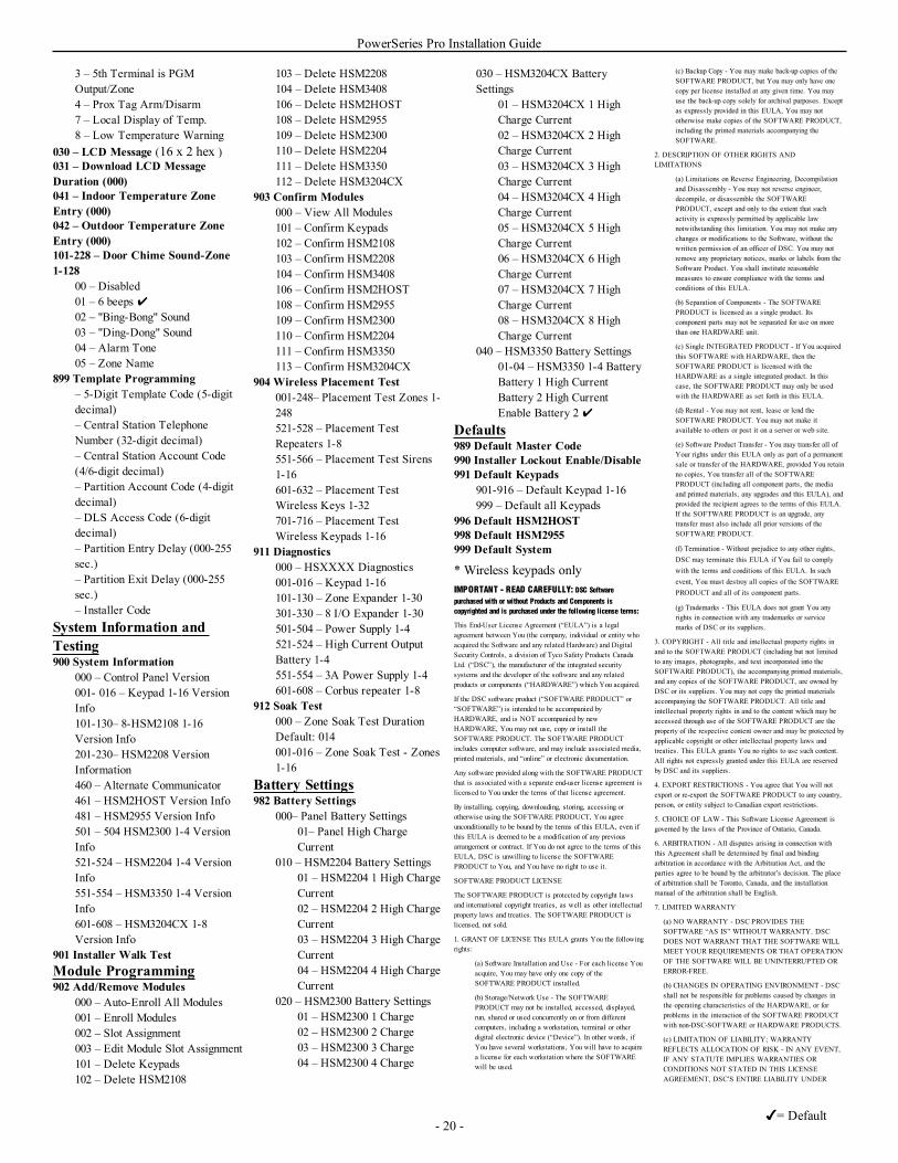
PowerSeries Pro Installation Guide
3 – 5th Terminal is PGMOutput/Zone4 – Prox Tag Arm/Disarm7 – Local Display of Temp.8 – Low Temperature Warning
030 – LCD Message (16 x 2 hex )031 – Download LCD MessageDuration (000)041 – Indoor Temperature ZoneEntry (000)042 – Outdoor Temperature ZoneEntry (000)101-228 – Door Chime Sound-Zone1-128
00 – Disabled01 – 6 beeps 02 – "Bing-Bong" Sound03 – "Ding-Dong" Sound04 – Alarm Tone05 – Zone Name
899 Template Programming– 5-Digit Template Code (5-digitdecimal)– Central Station TelephoneNumber (32-digit decimal)– Central Station Account Code(4/6-digit decimal)– Partition Account Code (4-digitdecimal)– DLS Access Code (6-digitdecimal)– Partition Entry Delay (000-255sec.)– Partition Exit Delay (000-255sec.)– Installer Code
System Information andTesting900 System Information
000 – Control Panel Version001- 016 – Keypad 1-16 VersionInfo101-130– 8-HSM2108 1-16Version Info201-230– HSM2208 VersionInformation460 – Alternate Communicator461 – HSM2HOST Version Info481 – HSM2955 Version Info501 – 504 HSM2300 1-4 VersionInfo521-524 – HSM2204 1-4 VersionInfo551-554 – HSM3350 1-4 VersionInfo601-608 – HSM3204CX 1-8Version Info
901 Installer Walk TestModule Programming902 Add/Remove Modules
000 – Auto-Enroll All Modules001 – Enroll Modules002 – Slot Assignment003 – Edit Module Slot Assignment101 – Delete Keypads102 – Delete HSM2108
103 – Delete HSM2208104 – Delete HSM3408106 – Delete HSM2HOST108 – Delete HSM2955109 – Delete HSM2300110 – Delete HSM2204111 – Delete HSM3350112 – Delete HSM3204CX
903 Confirm Modules000 – View All Modules101 – Confirm Keypads102 – Confirm HSM2108103 – Confirm HSM2208104 – Confirm HSM3408106 – Confirm HSM2HOST108 – Confirm HSM2955109 – Confirm HSM2300110 – Confirm HSM2204111 – Confirm HSM3350113 – Confirm HSM3204CX
904 Wireless Placement Test001-248– Placement Test Zones 1-248521-528 – Placement TestRepeaters 1-8551-566 – Placement Test Sirens1-16601-632 – Placement TestWireless Keys 1-32701-716 – Placement TestWireless Keypads 1-16
911 Diagnostics000 – HSXXXX Diagnostics001-016 – Keypad 1-16101-130 – Zone Expander 1-30301-330 – 8 I/O Expander 1-30501-504 – Power Supply 1-4521-524 – High Current OutputBattery 1-4551-554 – 3A Power Supply 1-4601-608 – Corbus repeater 1-8
912 Soak Test000 – Zone Soak Test DurationDefault: 014001-016 – Zone Soak Test - Zones1-16
Battery Settings982 Battery Settings
000– Panel Battery Settings01– Panel High ChargeCurrent
010 – HSM2204 Battery Settings01 – HSM2204 1 High ChargeCurrent02 – HSM2204 2 High ChargeCurrent03 – HSM2204 3 High ChargeCurrent04 – HSM2204 4 High ChargeCurrent
020 – HSM2300 Battery Settings01 – HSM2300 1 Charge02 – HSM2300 2 Charge03 – HSM2300 3 Charge04 – HSM2300 4 Charge
030 – HSM3204CX BatterySettings
01 – HSM3204CX 1 HighCharge Current02 – HSM3204CX 2 HighCharge Current03 – HSM3204CX 3 HighCharge Current04 – HSM3204CX 4 HighCharge Current05 – HSM3204CX 5 HighCharge Current06 – HSM3204CX 6 HighCharge Current07 – HSM3204CX 7 HighCharge Current08 – HSM3204CX 8 HighCharge Current
040 – HSM3350 Battery Settings01-04 – HSM3350 1-4 BatteryBattery 1 High CurrentBattery 2 High CurrentEnable Battery 2
Defaults989 Default Master Code990 Installer Lockout Enable/Disable991 Default Keypads
901-916 – Default Keypad 1-16999 – Default all Keypads
996 Default HSM2HOST998 Default HSM2955999 Default System
* Wireless keypads onlyIMPORTANT - READ CAREFULLY: DSC Softwarepurchased with or without Products and Components iscopyrighted and is purchased under the following license terms:
This End-User License Agreement (“EULA”) is a legalagreement between You (the company, individual or entity whoacquired the Software and any related Hardware) and DigitalSecurity Controls, a division of Tyco Safety Products CanadaLtd. (“DSC”), the manufacturer of the integrated securitysystems and the developer of the software and any relatedproducts or components (“HARDWARE”) which You acquired.
If the DSC software product (“SOFTWARE PRODUCT” or“SOFTWARE”) is intended to be accompanied byHARDWARE, and is NOT accompanied by newHARDWARE, You may not use, copy or install theSOFTWARE PRODUCT. The SOFTWARE PRODUCTincludes computer software, and may include associated media,printed materials, and “online” or electronic documentation.
Any software provided along with the SOFTWARE PRODUCTthat is associated with a separate end-user license agreement islicensed to You under the terms of that license agreement.
By installing, copying, downloading, storing, accessing orotherwise using the SOFTWARE PRODUCT, You agreeunconditionally to be bound by the terms of this EULA, even ifthis EULA is deemed to be a modification of any previousarrangement or contract. If You do not agree to the terms of thisEULA, DSC is unwilling to license the SOFTWAREPRODUCT to You, and You have no right to use it.
SOFTWARE PRODUCT LICENSE
The SOFTWARE PRODUCT is protected by copyright lawsand international copyright treaties, as well as other intellectualproperty laws and treaties. The SOFTWARE PRODUCT islicensed, not sold.
1. GRANT OF LICENSE This EULA grants You the followingrights:
(a) Software Installation and Use - For each license Youacquire, You may have only one copy of theSOFTWARE PRODUCT installed.
(b) Storage/Network Use - The SOFTWAREPRODUCT may not be installed, accessed, displayed,run, shared or used concurrently on or from differentcomputers, including a workstation, terminal or otherdigital electronic device (“Device”). In other words, ifYou have several workstations, You will have to acquirea license for each workstation where the SOFTWAREwill be used.
(c) Backup Copy - You may make back-up copies of theSOFTWARE PRODUCT, but You may only have onecopy per license installed at any given time. You mayuse the back-up copy solely for archival purposes. Exceptas expressly provided in this EULA, You may nototherwise make copies of the SOFTWARE PRODUCT,including the printed materials accompanying theSOFTWARE.
2. DESCRIPTION OF OTHER RIGHTS ANDLIMITATIONS
(a) Limitations on Reverse Engineering, Decompilationand Disassembly - You may not reverse engineer,decompile, or disassemble the SOFTWAREPRODUCT, except and only to the extent that suchactivity is expressly permitted by applicable lawnotwithstanding this limitation. You may not make anychanges or modifications to the Software, without thewritten permission of an officer of DSC. You may notremove any proprietary notices, marks or labels from theSoftware Product. You shall institute reasonablemeasures to ensure compliance with the terms andconditions of this EULA.
(b) Separation of Components - The SOFTWAREPRODUCT is licensed as a single product. Itscomponent parts may not be separated for use on morethan one HARDWARE unit.
(c) Single INTEGRATED PRODUCT - If You acquiredthis SOFTWARE with HARDWARE, then theSOFTWARE PRODUCT is licensed with theHARDWARE as a single integrated product. In thiscase, the SOFTWARE PRODUCT may only be usedwith the HARDWARE as set forth in this EULA.
(d) Rental - You may not rent, lease or lend theSOFTWARE PRODUCT. You may not make itavailable to others or post it on a server or web site.
(e) Software Product Transfer - You may transfer all ofYour rights under this EULA only as part of a permanentsale or transfer of the HARDWARE, provided You retainno copies, You transfer all of the SOFTWAREPRODUCT (including all component parts, the mediaand printed materials, any upgrades and this EULA), andprovided the recipient agrees to the terms of this EULA.If the SOFTWARE PRODUCT is an upgrade, anytransfer must also include all prior versions of theSOFTWARE PRODUCT.
(f) Termination - Without prejudice to any other rights,DSC may terminate this EULA if You fail to complywith the terms and conditions of this EULA. In suchevent, You must destroy all copies of the SOFTWAREPRODUCT and all of its component parts.
(g) Trademarks - This EULA does not grant You anyrights in connection with any trademarks or servicemarks of DSC or its suppliers.
3. COPYRIGHT - All title and intellectual property rights inand to the SOFTWARE PRODUCT (including but not limitedto any images, photographs, and text incorporated into theSOFTWARE PRODUCT), the accompanying printed materials,and any copies of the SOFTWARE PRODUCT, are owned byDSC or its suppliers. You may not copy the printed materialsaccompanying the SOFTWARE PRODUCT. All title andintellectual property rights in and to the content which may beaccessed through use of the SOFTWARE PRODUCT are theproperty of the respective content owner and may be protected byapplicable copyright or other intellectual property laws andtreaties. This EULA grants You no rights to use such content.All rights not expressly granted under this EULA are reservedby DSC and its suppliers.
4. EXPORT RESTRICTIONS - You agree that You will notexport or re-export the SOFTWARE PRODUCT to any country,person, or entity subject to Canadian export restrictions.
5. CHOICE OF LAW - This Software License Agreement isgoverned by the laws of the Province of Ontario, Canada.
6. ARBITRATION - All disputes arising in connection withthis Agreement shall be determined by final and bindingarbitration in accordance with the Arbitration Act, and theparties agree to be bound by the arbitrator’s decision. The placeof arbitration shall be Toronto, Canada, and the installationmanual of the arbitration shall be English.
7. LIMITED WARRANTY
(a) NO WARRANTY - DSC PROVIDES THESOFTWARE “AS IS” WITHOUT WARRANTY. DSCDOES NOT WARRANT THAT THE SOFTWARE WILLMEET YOUR REQUIREMENTS OR THAT OPERATIONOF THE SOFTWARE WILL BE UNINTERRUPTED ORERROR-FREE.
(b) CHANGES IN OPERATING ENVIRONMENT - DSCshall not be responsible for problems caused by changes inthe operating characteristics of the HARDWARE, or forproblems in the interaction of the SOFTWARE PRODUCTwith non-DSC-SOFTWARE or HARDWARE PRODUCTS.
(c) LIMITATION OF LIABILITY; WARRANTYREFLECTS ALLOCATION OF RISK - IN ANY EVENT,IF ANY STATUTE IMPLIES WARRANTIES ORCONDITIONS NOT STATED IN THIS LICENSEAGREEMENT, DSC’S ENTIRE LIABILITY UNDER
- 20 -= Default
PowerSeries Pro Installation Guide
ANY PROVISION OF THIS LICENSE AGREEMENTSHALL BE LIMITED TO THE GREATER OF THEAMOUNT ACTUALLY PAID BY YOU TO LICENSETHE SOFTWARE PRODUCT AND FIVE CANADIANDOLLARS (CAD$5.00). BECAUSE SOMEJURISDICTIONS DO NOT ALLOW THE EXCLUSIONOR LIMITATION OF LIABILITY FORCONSEQUENTIAL OR INCIDENTAL DAMAGES, THEABOVE LIMITATION MAY NOT APPLY TO YOU.
(d) DISCLAIMER OF WARRANTIES - THISWARRANTY CONTAINS THE ENTIRE WARRANTYAND SHALL BE IN LIEU OF ANY AND ALL OTHERWARRANTIES, WHETHER EXPRESSED OR IMPLIED(INCLUDING ALL IMPLIED WARRANTIES OFMERCHANTABILITY OR FITNESS FOR APARTICULAR PURPOSE) AND OF ALL OTHEROBLIGATIONS OR LIABILITIES ON THE PART OFDSC. DSC MAKES NO OTHERWARRANTIES. DSCNEITHER ASSUMES NOR AUTHORIZES ANY OTHERPERSON PURPORTING TO ACT ON ITS BEHALF TOMODIFY OR TO CHANGE THIS WARRANTY, NORTO ASSUME FOR IT ANY OTHERWARRANTY ORLIABILITY CONCERNING THIS SOFTWAREPRODUCT.
(e) EXCLUSIVE REMEDY AND LIMITATION OFWARRANTY - UNDER NO CIRCUMSTANCES SHALLDSC BE LIABLE FOR ANY SPECIAL, INCIDENTAL,CONSEQUENTIAL OR INDIRECT DAMAGES BASEDUPON BREACH OF WARRANTY, BREACH OFCONTRACT, NEGLIGENCE, STRICT LIABILITY, ORANY OTHER LEGAL THEORY. SUCH DAMAGESINCLUDE, BUT ARE NOT LIMITED TO, LOSS OFPROFITS, LOSS OF THE SOFTWARE PRODUCT ORANY ASSOCIATED EQUIPMENT, COST OF CAPITAL,COST OF SUBSTITUTE OR REPLACEMENTEQUIPMENT, FACILITIES OR SERVICES, DOWNTIME, PURCHASERS TIME, THE CLAIMS OF THIRDPARTIES, INCLUDING CUSTOMERS, AND INJURYTO PROPERTY.
WARNING: DSC recommends that the entire system becompletely tested on a regular basis. However, despite frequenttesting, and due to, but not limited to, criminal tampering orelectrical disruption, it is possible for this SOFTWAREPRODUCT to fail to perform as expected.
- 21 -= Default
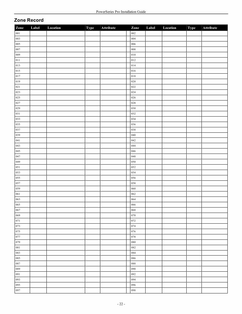
PowerSeries Pro Installation Guide
Zone RecordZone Label Location Type Attribute Zone Label Location Type Attribute001 002
003 004
005 006
007 008
009 010
011 012
013 014
015 016
017 018
019 020
021 022
023 024
025 026
027 028
029 030
031 032
033 034
035 036
037 038
039 040
041 042
043 044
045 046
047 048
049 050
051 052
053 054
055 056
057 058
059 060
061 062
063 064
065 066
067 068
069 070
071 072
073 074
075 076
077 078
079 080
081 082
083 084
085 086
087 088
089 090
091 092
093 094
095 096
097 098
- 22 -

PowerSeries Pro Installation Guide
Zone Label Location Type Attribute Zone Label Location Type Attribute099 100
101 102
103 104
105 106
107 108
109 110
111 112
113 114
115 116
117 118
119 120
121 122
123 124
125 126
127 128
129 130
131 132
133 134
135 136
137 138
139 140
141 142
143 144
145 146
147 148
149 150
151 152
153 154
155 156
157 158
159 160
161 162
163 164
165 166
167 168
169 170
171 172
173 174
175 176
177 178
179 180
181 182
183 184
185 186
187 188
189 190
191 192
193 194
195 196
197 198
- 23 -
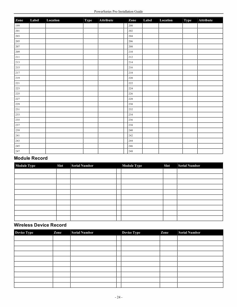
PowerSeries Pro Installation Guide
Zone Label Location Type Attribute Zone Label Location Type Attribute199 200
201 202
203 204
205 206
207 208
209 210
211 212
213 214
215 216
217 218
219 220
221 222
223 224
225 226
227 228
229 230
231 232
233 234
235 236
237 238
239 240
241 242
243 244
245 246
247 248
Module RecordModule Type Slot Serial Number Module Type Slot Serial Number
Wireless Device RecordDevice Type Zone Serial Number Device Type Zone Serial Number
- 24 -
PowerSeries Pro Installation Guide
Installer-Defined Access Codes001 – Installer Code:
002 – Master Code:
003 – Maintenance Code:
System Account Code
- 25 -
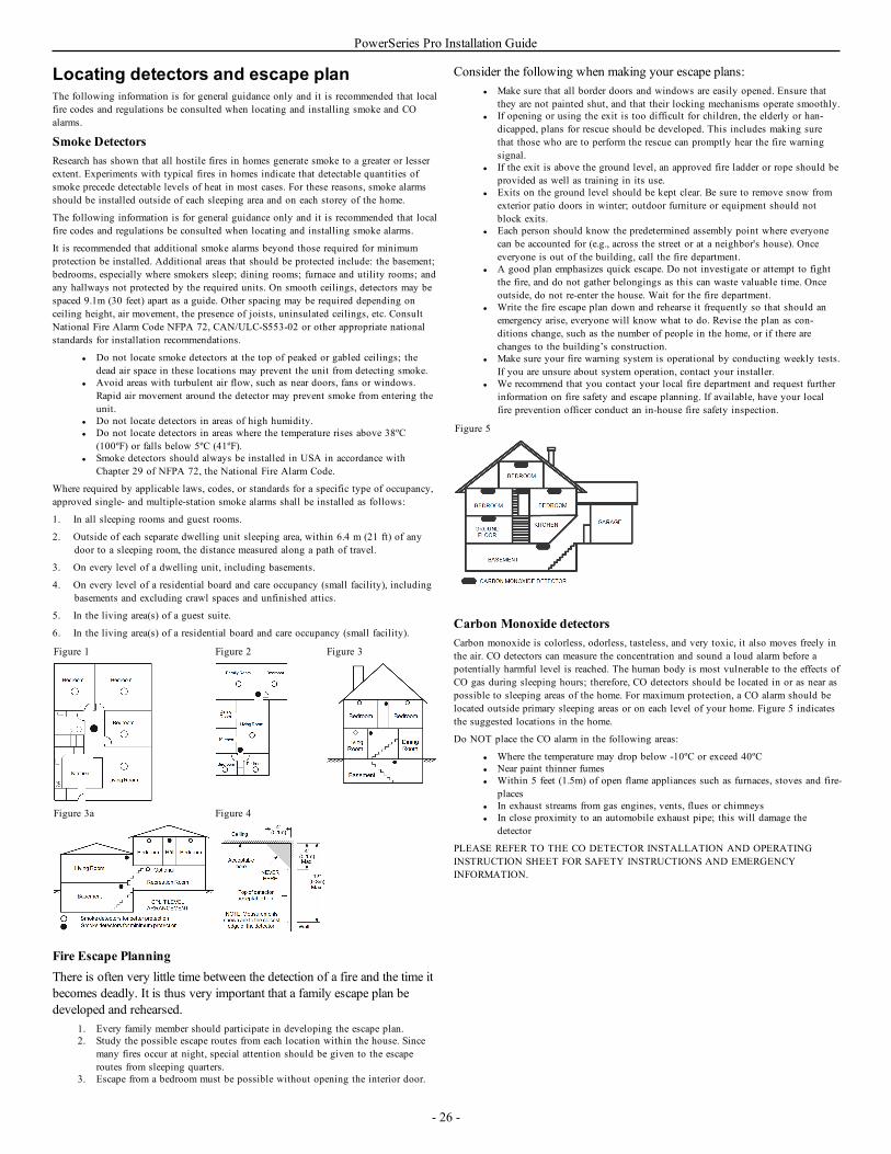
PowerSeries Pro Installation Guide
Locating detectors and escape planThe following information is for general guidance only and it is recommended that localfire codes and regulations be consulted when locating and installing smoke and COalarms.
Smoke DetectorsResearch has shown that all hostile fires in homes generate smoke to a greater or lesserextent. Experiments with typical fires in homes indicate that detectable quantities ofsmoke precede detectable levels of heat in most cases. For these reasons, smoke alarmsshould be installed outside of each sleeping area and on each storey of the home.
The following information is for general guidance only and it is recommended that localfire codes and regulations be consulted when locating and installing smoke alarms.
It is recommended that additional smoke alarms beyond those required for minimumprotection be installed. Additional areas that should be protected include: the basement;bedrooms, especially where smokers sleep; dining rooms; furnace and utility rooms; andany hallways not protected by the required units. On smooth ceilings, detectors may bespaced 9.1m (30 feet) apart as a guide. Other spacing may be required depending onceiling height, air movement, the presence of joists, uninsulated ceilings, etc. ConsultNational Fire Alarm Code NFPA 72, CAN/ULC-S553-02 or other appropriate nationalstandards for installation recommendations.
l Do not locate smoke detectors at the top of peaked or gabled ceilings; thedead air space in these locations may prevent the unit from detecting smoke.
l Avoid areas with turbulent air flow, such as near doors, fans or windows.Rapid air movement around the detector may prevent smoke from entering theunit.
l Do not locate detectors in areas of high humidity.l Do not locate detectors in areas where the temperature rises above 38ºC
(100ºF) or falls below 5ºC (41ºF).l Smoke detectors should always be installed in USA in accordance with
Chapter 29 of NFPA 72, the National Fire Alarm Code.
Where required by applicable laws, codes, or standards for a specific type of occupancy,approved single- and multiple-station smoke alarms shall be installed as follows:
1. In all sleeping rooms and guest rooms.
2. Outside of each separate dwelling unit sleeping area, within 6.4 m (21 ft) of anydoor to a sleeping room, the distance measured along a path of travel.
3. On every level of a dwelling unit, including basements.
4. On every level of a residential board and care occupancy (small facility), includingbasements and excluding crawl spaces and unfinished attics.
5. In the living area(s) of a guest suite.
6. In the living area(s) of a residential board and care occupancy (small facility).
Figure 1 Figure 2 Figure 3
Figure 3a Figure 4
Fire Escape PlanningThere is often very little time between the detection of a fire and the time itbecomes deadly. It is thus very important that a family escape plan bedeveloped and rehearsed.
1. Every family member should participate in developing the escape plan.2. Study the possible escape routes from each location within the house. Since
many fires occur at night, special attention should be given to the escaperoutes from sleeping quarters.
3. Escape from a bedroom must be possible without opening the interior door.
Consider the following when making your escape plans:l Make sure that all border doors and windows are easily opened. Ensure that
they are not painted shut, and that their locking mechanisms operate smoothly.l If opening or using the exit is too difficult for children, the elderly or han-
dicapped, plans for rescue should be developed. This includes making surethat those who are to perform the rescue can promptly hear the fire warningsignal.
l If the exit is above the ground level, an approved fire ladder or rope should beprovided as well as training in its use.
l Exits on the ground level should be kept clear. Be sure to remove snow fromexterior patio doors in winter; outdoor furniture or equipment should notblock exits.
l Each person should know the predetermined assembly point where everyonecan be accounted for (e.g., across the street or at a neighbor's house). Onceeveryone is out of the building, call the fire department.
l A good plan emphasizes quick escape. Do not investigate or attempt to fightthe fire, and do not gather belongings as this can waste valuable time. Onceoutside, do not re-enter the house. Wait for the fire department.
l Write the fire escape plan down and rehearse it frequently so that should anemergency arise, everyone will know what to do. Revise the plan as con-ditions change, such as the number of people in the home, or if there arechanges to the building’s construction.
l Make sure your fire warning system is operational by conducting weekly tests.If you are unsure about system operation, contact your installer.
l We recommend that you contact your local fire department and request furtherinformation on fire safety and escape planning. If available, have your localfire prevention officer conduct an in-house fire safety inspection.
Figure 5
Carbon Monoxide detectorsCarbon monoxide is colorless, odorless, tasteless, and very toxic, it also moves freely inthe air. CO detectors can measure the concentration and sound a loud alarm before apotentially harmful level is reached. The human body is most vulnerable to the effects ofCO gas during sleeping hours; therefore, CO detectors should be located in or as near aspossible to sleeping areas of the home. For maximum protection, a CO alarm should belocated outside primary sleeping areas or on each level of your home. Figure 5 indicatesthe suggested locations in the home.
Do NOT place the CO alarm in the following areas:
l Where the temperature may drop below -10ºC or exceed 40ºCl Near paint thinner fumesl Within 5 feet (1.5m) of open flame appliances such as furnaces, stoves and fire-
placesl In exhaust streams from gas engines, vents, flues or chimneysl In close proximity to an automobile exhaust pipe; this will damage the
detector
PLEASE REFER TO THE CO DETECTOR INSTALLATION AND OPERATINGINSTRUCTION SHEET FOR SAFETY INSTRUCTIONS AND EMERGENCYINFORMATION.
- 26 -
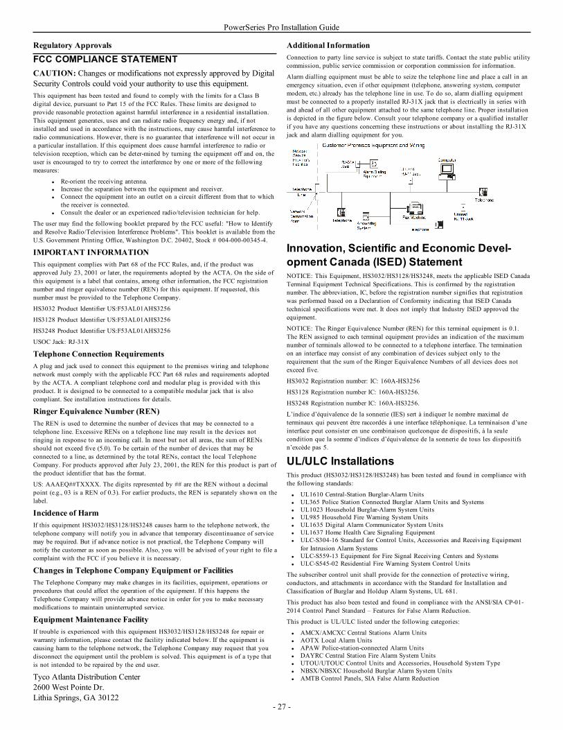
PowerSeries Pro Installation Guide
Regulatory Approvals
FCC COMPLIANCE STATEMENTCAUTION: Changes or modifications not expressly approved by DigitalSecurity Controls could void your authority to use this equipment.This equipment has been tested and found to comply with the limits for a Class Bdigital device, pursuant to Part 15 of the FCC Rules. These limits are designed toprovide reasonable protection against harmful interference in a residential installation.This equipment generates, uses and can radiate radio frequency energy and, if notinstalled and used in accordance with the instructions, may cause harmful interference toradio communications. However, there is no guarantee that interference will not occur ina particular installation. If this equipment does cause harmful interference to radio ortelevision reception, which can be deter-mined by turning the equipment off and on, theuser is encouraged to try to correct the interference by one or more of the followingmeasures:
l Re-orient the receiving antenna.l Increase the separation between the equipment and receiver.l Connect the equipment into an outlet on a circuit different from that to which
the receiver is connected.l Consult the dealer or an experienced radio/television technician for help.
The user may find the following booklet prepared by the FCC useful: "How to Identifyand Resolve Radio/Television Interference Problems". This booklet is available from theU.S. Government Printing Office, Washington D.C. 20402, Stock # 004-000-00345-4.
IMPORTANT INFORMATIONThis equipment complies with Part 68 of the FCC Rules, and, if the product wasapproved July 23, 2001 or later, the requirements adopted by the ACTA. On the side ofthis equipment is a label that contains, among other information, the FCC registrationnumber and ringer equivalence number (REN) for this equipment. If requested, thisnumber must be provided to the Telephone Company.
HS3032 Product Identifier US:F53AL01AHS3256
HS3128 Product Identifier US:F53AL01AHS3256
HS3248 Product Identifier US:F53AL01AHS3256
USOC Jack: RJ-31X
Telephone Connection RequirementsA plug and jack used to connect this equipment to the premises wiring and telephonenetwork must comply with the applicable FCC Part 68 rules and requirements adoptedby the ACTA. A compliant telephone cord and modular plug is provided with thisproduct. It is designed to be connected to a compatible modular jack that is alsocompliant. See installation instructions for details.
Ringer Equivalence Number (REN)The REN is used to determine the number of devices that may be connected to atelephone line. Excessive RENs on a telephone line may result in the devices notringing in response to an incoming call. In most but not all areas, the sum of RENsshould not exceed five (5.0). To be certain of the number of devices that may beconnected to a line, as determined by the total RENs, contact the local TelephoneCompany. For products approved after July 23, 2001, the REN for this product is part ofthe product identifier that has the format.
US: AAAEQ##TXXXX. The digits represented by ## are the REN without a decimalpoint (e.g., 03 is a REN of 0.3). For earlier products, the REN is separately shown on thelabel.
Incidence of HarmIf this equipment HS3032/HS3128/HS3248 causes harm to the telephone network, thetelephone company will notify you in advance that temporary discontinuance of servicemay be required. But if advance notice is not practical, the Telephone Company willnotify the customer as soon as possible. Also, you will be advised of your right to file acomplaint with the FCC if you believe it is necessary.
Changes in Telephone Company Equipment or FacilitiesThe Telephone Company may make changes in its facilities, equipment, operations orprocedures that could affect the operation of the equipment. If this happens theTelephone Company will provide advance notice in order for you to make necessarymodifications to maintain uninterrupted service.
Equipment Maintenance FacilityIf trouble is experienced with this equipment HS3032/HS3128/HS3248 for repair orwarranty information, please contact the facility indicated below. If the equipment iscausing harm to the telephone network, the Telephone Company may request that youdisconnect the equipment until the problem is solved. This equipment is of a type thatis not intended to be repaired by the end user.
Tyco Atlanta Distribution Center2600 West Pointe Dr.Lithia Springs, GA 30122
Additional InformationConnection to party line service is subject to state tariffs. Contact the state public utilitycommission, public service commission or corporation commission for information.
Alarm dialling equipment must be able to seize the telephone line and place a call in anemergency situation, even if other equipment (telephone, answering system, computermodem, etc.) already has the telephone line in use. To do so, alarm dialling equipmentmust be connected to a properly installed RJ-31X jack that is electrically in series withand ahead of all other equipment attached to the same telephone line. Proper installationis depicted in the figure below. Consult your telephone company or a qualified installerif you have any questions concerning these instructions or about installing the RJ-31Xjack and alarm dialling equipment for you.
Innovation, Scientific and Economic Devel-opment Canada (ISED) StatementNOTICE: This Equipment, HS3032/HS3128/HS3248, meets the applicable ISED CanadaTerminal Equipment Technical Specifications. This is confirmed by the registrationnumber. The abbreviation, IC, before the registration number signifies that registrationwas performed based on a Declaration of Conformity indicating that ISED Canadatechnical specifications were met. It does not imply that Industry ISED approved theequipment.
NOTICE: The Ringer Equivalence Number (REN) for this terminal equipment is 0.1.The REN assigned to each terminal equipment provides an indication of the maximumnumber of terminals allowed to be connected to a telephone interface. The terminationon an interface may consist of any combination of devices subject only to therequirement that the sum of the Ringer Equivalence Numbers of all devices does notexceed five.
HS3032 Registration number: IC: 160A-HS3256
HS3128 Registration number IC: 160A-HS3256.
HS3248 Registration number IC: 160A-HS3256.
L’indice d’équivalence de la sonnerie (IES) sert à indiquer le nombre maximal determinaux qui peuvent être raccordés à une interface téléphonique. La terminaison d’uneinterface peut consister en une combinaison quelconque de dispositifs, à la seulecondition que la somme d’indices d’équivalence de la sonnerie de tous les dispositifsn’excède pas 5.
UL/ULC InstallationsThis product (HS3032/HS3128/HS3248) has been tested and found in compliance withthe following standards:
l UL1610 Central-Station Burglar-Alarm Unitsl UL365 Police Station Connected Burglar Alarm Units and Systemsl UL1023 Household Burglar-Alarm System Unitsl UL985 Household Fire Warning System Unitsl UL1635 Digital Alarm Communicator System Unitsl UL1637 Home Health Care Signaling Equipmentl ULC-S304-16 Standard for Control Units, Accessories and Receiving Equipment
for Intrusion Alarm Systemsl ULC-S559-13 Equipment for Fire Signal Receiving Centers and Systemsl ULC-S545-02 Residential Fire Warning System Control Units
The subscriber control unit shall provide for the connection of protective wiring,conductors, and attachments in accordance with the Standard for Installation andClassification of Burglar and Holdup Alarm Systems, UL 681.
This product has also been tested and found in compliance with the ANSI/SIA CP-01-2014 Control Panel Standard – Features for False Alarm Reduction.
This product is UL/ULC listed under the following categories:
l AMCX/AMCXC Central Stations Alarm Unitsl AOTX Local Alarm Unitsl APAW Police-station-connected Alarm Unitsl DAYRC Central Station Fire Alarm System Unitsl UTOU/UTOUC Control Units and Accessories, Household System Typel NBSX/NBSXC Household Burglar Alarm System Unitsl AMTB Control Panels, SIA False Alarm Reduction
- 27 -
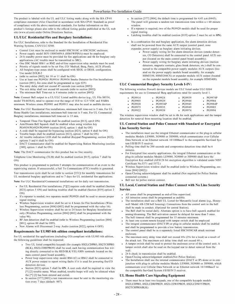
PowerSeries Pro Installation Guide
The product is labeled with the UL and ULC listing marks along with the SIA CP-01compliance statement (Also Classified in accordance with SIA-CP-01 Standard) as proofof compliance with the above mentioned standards. For further information on thisproduct’s listings please also refer to the official listing guides published at the UL website (www.ul.com) under Online Directions Section.
UL/ULC Residential Fire and Burglary Installations:For ULC Installations, refer to the Standard for the Installation of Residential FireWarning Systems, CAN/ULC-S540.
l Control Unit must be enclosed in model HSC3010C or HSC3020C enclosure.l Power supply model SOY-1800360NA (HS65WPSNA) must be employed.l 24 h standby power must be provided for fire applications and 4h for burglary only
applications (AC trouble must be transmitted to SRC).l One DSC Model RM-1 or RM2 end-of-line supervision relay module must be used.l Priority of signals needs to be set Fire, CO/ Medical, Burg, Panic, AUX (Flood).l All burglary-type zones shall be configured with SEOL or DEOL configuration.
Use model EOLR-2l (refer to section [002], bit 10 or 11 shall be ON)l Use at least one PG9926/ PG9916/ PG9936 Smoke Detector for Fire Installations
(section [001], fire zone shall be programmed as type 025)l The entry delay shall not exceed 45 seconds (see section [005])l The exit delay shall not exceed 60 seconds (refer to section [005])l The minimum Bell Time-out is 4 minutes (refer to section [005])
Note: Connect Bell output to a UL/ULC Listed audible device (e.g., UL File S8534,model TS-443S-6), rated to operate over the range of 10.8 to 12.5 VDC and 85dBAminimum. Wireless sirens PG9901 and PG9911 may also be used as audible devices.
Note: For ULC Residential Fire installations, minimum bell time-out is 5 min. For ULHome Health Care installations, minimum bell time-out is 5 min. For UL CommercialBurglary installations, minimum bell time-out is 15 min.
l Temporal Three Fire Signal shall be enabled (section [013], opt.8 ON)l Arm/Disarm Bell Squawk shall be enabled when using wireless key
PG4939/PG4929/PG4949 (section [014], option 1 shall be ON)l A code shall be required for bypassing (section [023], option 4 shall be ON)l Trouble beeps shall be enabled (section [022], option 7 shall be ON)l AC trouble indication LED shall be enabled (Keypad Programming, section [022],
options 5 and 6 shall be ON)l DACT Communicator shall be enabled for Supervising Station Monitoring (section
[380], option 1 shall be ON)
Note: The DACT communicator for this product has no line security.
Telephone Line Monitoring (TLM) shall be enabled (section [015], option 7 shall beON)
This product is programmed to perform 5 attempts for communication of an event to thesupervising station. If unsuccessful, a Fail To Communicate (FTC) trouble is generated.
Test transmission cycle shall be set (refer to section [351]) for monthly transmission forUL residential burglary applications and to 7 days for UL residential fire applications.
Note: For ULC Residential/Commercial installations set for daily test transmission.
l For UL Residential Fire installations, [*][2] requires code shall be enabled (Section[023] option 5 ON) and latching troubles shall be enabled (Section [019] option 2ON)
l If a repeater is needed, two repeaters model PG9920 shall be used to ensure propersignal routing.
l Wireless Supervision window shall be set to 4 hours for Fire Installations (Wire-less Programming, section [804]>[802] shall be programmed with the value 16).
l Wireless Supervision window shall be set to 24 hours for Burglary Installationsonly (Wireless Programming, section [804]>[802] shall be programmed with thevalue 96).
l RF Jam detection shall be enabled (refer to Wireless Programming (section [804][801], option 00 shall be OFF).
l New Alarms will Disconnect 2-way Audio (section [022], option 6 OFF).
Requirements for UL985 6th edition compliant installations:For UL residential fire applications (including CO) compliant with UL985 6th edition,the following guidelines shall be respected:
l Two UL listed compatible keypads (for example HS2LCDPRO, HS2TCHPRO(BLK), HS2LCDRFPRO9) shall be used, each having communication bus wir-ing directly connected to the RED/BLK/YEL/GRN terminals located on themain control panel board assembly.
l Power loop supervision relay model RM-1(C) or RM-2 shall be connected toAUX power output to report wiring faults if it is used for powering fire/COdetection devices.
l Section [023] option 5 shall be ON. A user code shall be required to view the[*] [2] trouble menu. When enabled, trouble beeps will only be silenced whenthe [*] [2] has been entered and exited.
l In section [377] [003] a test transmission must be sent to the monitoring sta-tion every 7 days (default: 007).
l In section [377] [004], the default time is programmed for 4.45 a.m (0445).The panel will generate a random test transmission time within a ± 60 minutewindow.
l If a repeater is required, two of the PG9920 models shall be used for propersignal routing.
l Latching troubles shall be enabled (section [019] option 2 must be set to ON).
l In a combination fire and burglary application, fire alarm detection devicesshall not be powered from the same AUX output (control panel, zoneexpander, power supply) as burglary alarm initiating devices.
l Power supply wiring for fire alarm detection devices (smoke detect-ors, CO Detectors) shall be connected to the control panel AUX out-put (located on the main control panel board assembly).
l Power supply wiring for burglary alarm initiating devices (motiondetectors, magnetic contacts, glass break detectors, etc.) shall be con-nected to the compatible power supply modules AUX outputs (loc-ated on the power supply module board assembly, for exampleHSM3350, HSM3204CX) or expander module AUX output (locatedon the expander module board assembly, for example HSM3408).
ULC Commercial Burglary Security Levels I-IV:The following wireless PowerG devices models are ULC listed under ULC-S304requirements for use in Commercial Burg applications rated for security level 1.
l PG9914l PG9905l PG9920l PG9975l PG9922
l PG9924l PG9929l PG9934Pl PG9935l PG9938
l PG9939l PG9944l PG9945l PG9949l PG9974
l PG9974Pl PG9984l PG9984Pl PG9985l PG9994
The wireless supervision window shall be set to 4h for such applications and the tamperdetection for removal from mounting location shall be enabled.
UL Central Station and Police Connect with Standard or EncryptedLine Security Servicel The installation must use the integral Ethernet communicator or the plug-in cellular
modules Models LE9080, 3G9080 or 3H9080, which communicates over CellularData Network or an Ethernet network 10/100BaseT to the compatible Sur-Gard Sys-tem I/II/III/IV/5 receiver.
l Polling time shall be 200 seconds and compromise detection time shall be 6minutes.
l For Encrypted line security applications, the integral Ethernet communicator or theplug-in cellular modules Models LE9080, 3G9080 or 3H9080 shall have theEncryption Key enabled (AES128 bit encryption algorithm is validated under NISTCertificate No.5371 and 5372.)
l Wireless Supervision window shall be enabled (refer to Wireless Programming, sec-tions [804]>[802].)
l Open/Closing acknowledgment shall be enabled (Not required for Police Stationconnected systems.)
l Bell test for police station connect.
UL Local, Central Station and Police Connect with No Line SecurityServicel All zones shall be programmed as end-of-line supervised.l All intrusion zones shall be programmed as audible.l The installation shall use a Bell UL Listed for Mercantile local alarms (e.g., Honey-
well Model AB-12M bell housing). Connections from the control unit to the bellshall be made in conduit. (Optional for central Station).
l The Bell shall be tested daily. Alternate option is to have bell squawk enabled forarming/disarming. The Bell activation cannot be delayed for more than 5 mins.
l The bell timeout shall be programmed for 15 minutes minimum.l At least one system remote keypad with tamper switch shall be employedl The integral communciator (DACT/IP) or plug-in cellular module shall be enabled
and shall be programmed to provide a low battery transmission.l The control panel shall be in a separately listed HSC3030CAR attack resistant
enclosure.l The maximum entry delay time shall not exceed 45s (25s for a local) as a result of
the attack test. The maximum exit delay time shall not exceed 60 s.l A tamper switch shall be used to protect the enclosure cover of the control unit. A
tamper switch shall also be used on the keypad rear to detect removal from thewall.
l 24 h check in transmission shall be enabled.l Open/Closing acknowledgement enabled.(Not Police Station).l The Installation shall use the internal communicator (DACT or IP) alone or in con-
junction with plug-in cellular modules Models LE9080, 3G9080 or 3H9080, whichcommunicate over Cellular Data Network or an Ethernet network 10/100BaseT tothe compatible Sur-Gard System I/II/III/IV/5 receiver.
UL Home Health Care Signaling Equipmentl There must be at least two keypads, one of the compatible keyapds models
HS2LCDPRO, HS2LCDRFPRO9, HS2LCDWFPRO9, HS2LCDWFVPRO9,HS2TCHPRO(BLK).
- 28 -
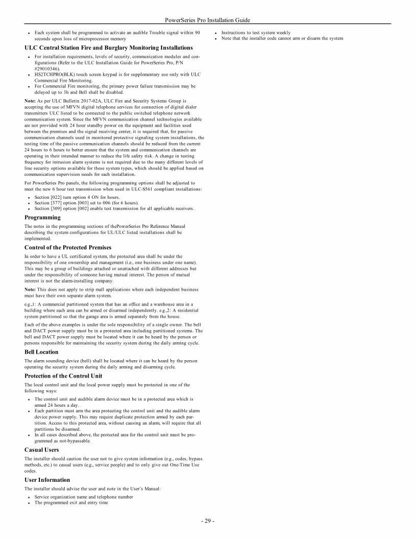
PowerSeries Pro Installation Guide
l Each system shall be programmed to activate an audible Trouble signal within 90seconds upon loss of microprocessor memory
ULC Central Station Fire and Burglary Monitoring Installationsl For installation requirements, levels of security, communication modules and con-
figurations (Refer to the ULC Installation Guide for PowerSeries Pro, P/N#29010346).
l HS2TCHPRO(BLK) touch screen keypad is for supplementary use only with ULCCommercial Fire Monitoring.
l For Commercial Fire monitoring, the primary power failure transmission may bedelayed up to 3h and Bell shall be disabled.
Note: As per ULC Bulletin 2017-02A, ULC Fire and Security Systems Group isaccepting the use of MFVN digital telephone services for connection of digital dialertransmitters ULC listed to be connected to the public switched telephone networkcommunication system. Since the MFVN communication channel technologies availableare not provided with 24 hour standby power on the equipment and facilities usedbetween the premises and the signal receiving center, it is required that, for passivecommunication channels used in monitored protective signaling system installations, thetesting time of the passive communication channels should be reduced from the current24 hours to 6 hours to better ensure that the system and communication channels areoperating in their intended manner to reduce the life safety risk. A change in testingfrequency for intrusion alarm systems is not required due to the many different levels ofline security options available for these system types, which should be applied based oncommunication supervision needs for each installation.
For PowerSeries Pro panels, the following programming options shall be adjusted tomeet the new 6 hour test transmission when used in ULC-S561 compliant installations:
l Section [022] turn option 4 ON for hours.l Section [377] option [003] set to 006 (for 6 hours).l Section [309] option [002] enable test transmission for all applicable receivers.
ProgrammingThe notes in the programming sections of thePowerSeries Pro Reference Manualdescribing the system configurations for UL/ULC listed installations shall beimplemented.
Control of the Protected PremisesIn order to have a UL certificated system, the protected area shall be under theresponsibility of one ownership and management (i.e., one business under one name).This may be a group of buildings attached or unattached with different addresses butunder the responsibility of someone having mutual interest. The person of mutualinterest is not the alarm-installing company.
Note: This does not apply to strip mall applications where each independent businessmust have their own separate alarm system.
e.g.,1: A commercial partitioned system that has an office and a warehouse area in abuilding where each area can be armed or disarmed independently. e.g.,2: A residentialsystem partitioned so that the garage area is armed separately from the house.
Each of the above examples is under the sole responsibility of a single owner. The belland DACT power supply must be in a protected area including partitioned systems. Thebell and DACT power supply must be located where it can be heard by the person orpersons responsible for maintaining the security system during the daily arming cycle.
Bell LocationThe alarm sounding device (bell) shall be located where it can be heard by the personoperating the security system during the daily arming and disarming cycle.
Protection of the Control UnitThe local control unit and the local power supply must be protected in one of thefollowing ways:
l The control unit and audible alarm device must be in a protected area which isarmed 24 hours a day.
l Each partition must arm the area protecting the control unit and the audible alarmdevice power supply. This may require duplicate protection armed by each par-tition. Access to this protected area, without causing an alarm, will require that allpartitions be disarmed.
l In all cases described above, the protected area for the control unit must be pro-grammed as not-bypassable.
Casual UsersThe installer should caution the user not to give system information (e.g., codes, bypassmethods, etc.) to casual users (e.g., service people) and to only give out One-Time Usecodes.
User InformationThe installer should advise the user and note in the User’s Manual:
l Service organization name and telephone numberl The programmed exit and entry time
l Instructions to test system weeklyl Note that the installer code cannot arm or disarm the system
- 29 -
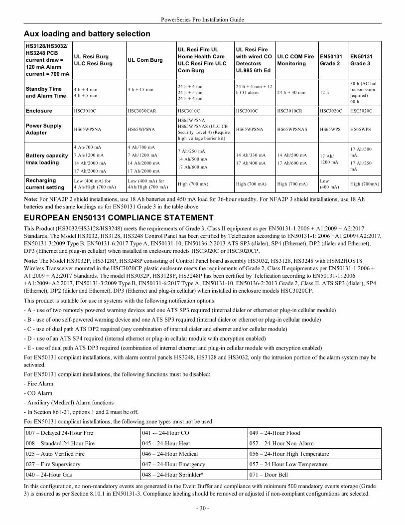
PowerSeries Pro Installation Guide
Aux loading and battery selectionHS3128/HS3032/HS3248 PCBcurrent draw =120 mA Alarmcurrent = 700 mA
UL Resi BurgULC Resi Burg UL Com Burg
UL Resi Fire ULHome Health CareULC Resi Fire ULCCom Burg
UL Resi Firewith wired CODetectorsUL985 6th Ed
ULC COM FireMonitoring
EN50131Grade 2
EN50131Grade 3
Standby Timeand Alarm Time
4 h + 4 min4 h + 5 min
4 h + 15 min 24 h + 4 min24 h + 5 min24 h + 4 min
24 h + 4 min + 12h CO alarm 24 h + 30 min 12 h
30 h (AC failtransmissionrequired)60 h
Enclosure HSC3010C HSC3030CAR HSC3010C HSC3010C HSC3010CR HSC3020C HSC3020C
Power SupplyAdapter HS65WPSNA HS65WPSNA
HS65WPSNAHS65WPSNAS (ULC CBSecurity Level 4) (Requirehigh voltage barrier kit)
HS65WPSNA HS65WPSNAS HS65WPS HS65WPS
Battery capacity/max loading
4 Ah/700 mA
7 Ah/1200 mA
14 Ah/2000 mA
17 Ah/2000 mA
4 Ah/700 mA
7 Ah/1200 mA
14 Ah/2000 mA
17 Ah/2000 mA
7 Ah/250 mA
14 Ah/500 mA
17 Ah/600 mA
14 Ah/330 mA
17 Ah/400 mA
14 Ah/500 mA
17 Ah/600 mA17 Ah/1200 mA
17 Ah/500mA
17 Ah/250mA
Rechargingcurrent setting
Low (400 mA) for4 Ah/High (700 mA)
Low (400 mA) for4Ah/High (700 mA) High (700 mA) High (700 mA) High (700 mA) Low
(400 mA) High (700mA)
Note: For NFA2P 2 shield installations, use 18 Ah batteries and 450 mA load for 36-hour standby. For NFA2P 3 shield installations, use 18 Ahbatteries and the same loadings as for EN50131 Grade 3 in the table above.
EUROPEAN EN50131 COMPLIANCE STATEMENTThis Product (HS3032/HS3128/HS3248) meets the requirements of Grade 3, Class II equipment as per EN50131-1:2006 + A1:2009 + A2:2017Standards. The Model HS3032, HS3128, HS3248 Control Panel has been certified by Telefication according to EN50131-1: 2006 +A1:2009+A2:2017,EN50131-3:2009 Type B, EN50131-6:2017 Type A, EN50131-10, EN50136-2:2013 ATS SP3 (dialer), SP4 (Ethernet), DP2 (dialer and Ethernet),DP3 (Ethernet and plug-in cellular) when installed in enclosure models HSC3020C or HSC3020CP.
Note: The Model HS3032P, HS3128P, HS3248P consisting of Control Panel board assembly HS3032, HS3128, HS3248 with HSM2HOST8Wireless Transceiver mounted in the HSC3020CP plastic enclosure meets the requirements of Grade 2, Class II equipment as per EN50131-1:2006 +A1:2009 + A2:2017 Standards. The model HS3032P, HS3128P, HS3248P has been certified by Telefication according to EN50131-1: 2006+A1:2009+A2:2017, EN50131-3:2009 Type B, EN50131-6:2017 Type A, EN50131-10, EN50136-2:2013 Grade 2, Class II, ATS SP3 (dialer), SP4(Ethernet), DP2 (dialer and Ethernet), DP3 (Ethernet and plug-in cellular) when installed in enclosure models HSC3020CP.
This product is suitable for use in systems with the following notification options:- A - use of two remotely powered warning devices and one ATS SP3 required (internal dialer or ethernet or plug-in cellular module)- B - use of one self-powered warning device and one ATS SP3 required (internal dialer or ethernet or plug-in cellular module)- C - use of dual path ATS DP2 required (any combination of internal dialer and ethernet and/or cellular module)- D - use of an ATS SP4 required (internal ethernet or plug-in cellular module with encryption enabled)- E - use of dual path ATS DP3 required (combination of internal ethernet and plug-in cellular module with encryption enabled)For EN50131 compliant installations, with alarm control panels HS3248, HS3128 and HS3032, only the intrusion portion of the alarm system may beactivated.For EN50131 compliant installations, the following functions must be disabled:- Fire Alarm- CO Alarm- Auxiliary (Medical) Alarm functions- In Section 861-21, options 1 and 2 must be off.For EN50131 compliant installations, the following zone types must not be used:
007 – Delayed 24-Hour Fire 041 -– 24-Hour CO 049 – 24-Hour Flood
008 – Standard 24-Hour Fire 045 – 24-Hour Heat 052 – 24-Hour Non-Alarm
025 – Auto Verified Fire 046 – 24-Hour Medical 056 – 24-Hour High Temperature
027 – Fire Supervisory 047 – 24-Hour Emergency 057 – 24 Hour Low Temperature
040 – 24-Hour Gas 048 – 24-Hour Sprinkler* 071 – Door Bell
In this configuration, no non-mandatory events are generated in the Event Buffer and compliance with minimum 500 mandatory events storage (Grade3) is ensured as per Section 8.10.1 in EN50131-3. Compliance labeling should be removed or adjusted if non-compliant configurations are selected.
- 30 -

PowerSeries Pro Installation Guide
Notes for EN50136-1:2012 compliant installations - Applicable to integrated phone line and Ethernet communicator only.The communicator operates in pass-through mode and it does acknowledge the alarm to the compatible control panel after an acknowledgement has beenreceived from the compatible alarm receiver.
1. The integrated communicator is monitored by the control panel and is programmed via the menu available from the compatible keypad connectedto the alarm control panel HS3248, HS3128, HS3023.
2. The communicaton path is immune to conducted and radiated RF fields, with levels up to 10V/m as tested per EN50130-4 Standard.3. The control panel with integrated communication module conforms with radiated emissions levels for Class B equipment as per standards
EN61000-6-3/EN55032/CISPR32.4. The control panel has two integrated communication paths: Phone line dialer and Ethernet (IP) communication path. These can be used in an
ATS with the following categories:l Single Path mode SP3 (Phone line dialer) or SP4 (IP path), orl Dual Path mode DP2 integrated Ethernet (IP) path in conjunction with the compatible control panel HS3248/HS3128/HS3032
integrated PSTN communicator, orl Dual Path DP3 integrated Ethernet (IP) path in conjunction with the plug-in cellular module 3G9080-EU or GS9080.
5. The integrated Ethernet (IP) communication path uses sequential authentication for substitution security and encryption AES128 bit for inform-ation security. The AES128-bit key is validated by NIST, Certificate No. 5371.
6. The integrated communicators have been tested for compliance in conjunction with the following applicable standards: EN50136-1:2012,EN50136- 2:2013, EN50131-10:2014, Grade 3, Class II, ATS configuration: SP3, DP2, DP3. For EN50131-1:2006/A1:2009 /A2:2017 com-pliant installations, the following programming options must be set as described: Supervision heartbeat set to 180 seconds for SP4 and DP3 con-figuration, along with the ARC receiver supervison window set to 180 seconds. For DP2 configuration, the supervison must be set to 30minutes.
This product is in conformity with the Electromagnetic Compatibility Directive 2014/30/EU, the Low Voltage Directive 2014/35/EU, and the RoHS3Directive (EU) 2015/863.The product is labelled with the CE mark as proof of compliance with the above mentioned European Directives. Also, a CE declaration of conformity(DoC) for this product can be found at www.dsc.com under the Agency Listings section.
SIA False Alarm Reduction Installations: Quick ReferenceMinimum required system consists of one Control unit model HS3032, HS3128, or HS3248, and any one of the compatible listed keypads (refer toModel comparison).The following wireless keyfobs can also be used in SIA compatible installations: PG9929, PG9939,PG9949.
Note: For models PG9929 and PG9939, the panic/emergency key shall be disabled for SIA compliant installations.
For a list of the default values programmed when the unit is shipped from the factory, and for other programming information, refer to the followingtable.The following optional subassembly modules also bear the SIA CP-01-2014 classification and may be used if desired: HSM2108 zone expander,HSM2208 PGM output module, HSM2300 auxiliary power supply, HSM2204 output module, HSM2HOST9 2-way wireless transceiver, PG9901indoor siren, PG9911 outdoor siren, and LE9080/3G9080/3H9080 cellular and PSDN communication module.Caution
l For SIA FAR installations use only modules/devices that are listed on this page.l Fire Alarm Verification feature (Auto Verified Fire Zone type [025]) is not supported on 2-wire smoke detectors zones, model FSA-210B(T)
(S)(ST)(LST)(R)(RT)(RD)(RST)(LRST). This feature may be enabled for 4-wire smoke detectors only (FSA-410B(T)(S)(ST)(LST)(R)(RT)(RST)(LRST) and wireless detectors PG9916/PG9926). The fire alarm delay is 60s.
l Call Waiting Cancel (Section [382], option 4) on a non-Call Waiting line will prevent successful communication to the supervising station.l All system smoke detectors must be tested annually by conducting an Installer Walk Test. Prior to exiting Walk Test mode, a sensor reset must
be done on the system, [*][7][2], to reset all latching 4-wire smoke detectors. Refer to the installation instructions supplied with the detector fordetails.
Notesl Programming at installation may be subordinate to other UL requirements for the intended application.l Cross zones have the ability to individually protect the intended area (e.g. motion detectors which overlap).l Cross zoning is not recommended for line security Installations nor is it to be implemented on exit/entry zones.l This control panel has a communication delay of 30 seconds. It can be removed or increased up to 45 seconds by the end user with installer con-
sultation.l The system shall be installed with the sounding device activated and the communicator enabled for transmission using SIA or CID format.l ULC commercial burglary installations require DEOL resistors.
- 31 -
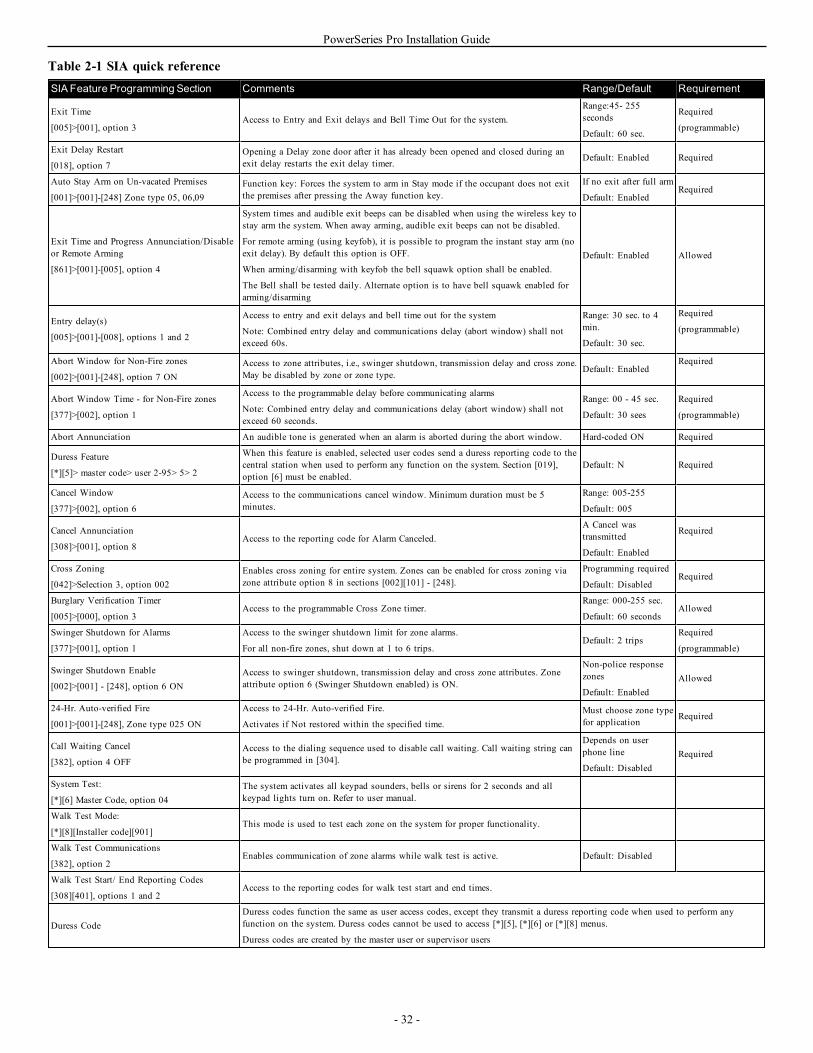
PowerSeries Pro Installation Guide
Table 2-1 SIA quick referenceSIA Feature Programming Section Comments Range/Default Requirement
Exit Time
[005]>[001], option 3Access to Entry and Exit delays and Bell Time Out for the system.
Range:45- 255seconds
Default: 60 sec.
Required
(programmable)
Exit Delay Restart
[018], option 7Opening a Delay zone door after it has already been opened and closed during anexit delay restarts the exit delay timer. Default: Enabled Required
Auto Stay Arm on Un-vacated Premises
[001]>[001]-[248] Zone type 05, 06,09Function key: Forces the system to arm in Stay mode if the occupant does not exitthe premises after pressing the Away function key.
If no exit after full arm
Default: EnabledRequired
Exit Time and Progress Annunciation/Disableor Remote Arming
[861]>[001]-[005], option 4
System times and audible exit beeps can be disabled when using the wireless key tostay arm the system. When away arming, audible exit beeps can not be disabled.
For remote arming (using keyfob), it is possible to program the instant stay arm (noexit delay). By default this option is OFF.
When arming/disarming with keyfob the bell squawk option shall be enabled.
The Bell shall be tested daily. Alternate option is to have bell squawk enabled forarming/disarming
Default: Enabled Allowed
Entry delay(s)
[005]>[001]-[008], options 1 and 2
Access to entry and exit delays and bell time out for the system
Note: Combined entry delay and communications delay (abort window) shall notexceed 60s.
Range: 30 sec. to 4min.
Default: 30 sec.
Required
(programmable)
Abort Window for Non-Fire zones
[002]>[001]-[248], option 7 ONAccess to zone attributes, i.e., swinger shutdown, transmission delay and cross zone.May be disabled by zone or zone type. Default: Enabled
Required
Abort Window Time - for Non-Fire zones
[377]>[002], option 1
Access to the programmable delay before communicating alarms
Note: Combined entry delay and communications delay (abort window) shall notexceed 60 seconds.
Range: 00 - 45 sec.
Default: 30 sees
Required
(programmable)
Abort Annunciation An audible tone is generated when an alarm is aborted during the abort window. Hard-coded ON Required
Duress Feature
[*][5]> master code> user 2-95> 5> 2
When this feature is enabled, selected user codes send a duress reporting code to thecentral station when used to perform any function on the system. Section [019],option [6] must be enabled.
Default: N Required
Cancel Window
[377]>[002], option 6Access to the communications cancel window. Minimum duration must be 5minutes.
Range: 005-255
Default: 005
Cancel Annunciation
[308]>[001], option 8Access to the reporting code for Alarm Canceled.
A Cancel wastransmitted
Default: Enabled
Required
Cross Zoning
[042]>Selection 3, option 002Enables cross zoning for entire system. Zones can be enabled for cross zoning viazone attribute option 8 in sections [002][101] - [248].
Programming required
Default: DisabledRequired
Burglary Verification Timer
[005]>[000], option 3Access to the programmable Cross Zone timer.
Range: 000-255 sec.
Default: 60 secondsAllowed
Swinger Shutdown for Alarms
[377]>[001], option 1
Access to the swinger shutdown limit for zone alarms.
For all non-fire zones, shut down at 1 to 6 trips.Default: 2 trips
Required
(programmable)
Swinger Shutdown Enable
[002]>[001] - [248], option 6 ONAccess to swinger shutdown, transmission delay and cross zone attributes. Zoneattribute option 6 (Swinger Shutdown enabled) is ON.
Non-police responsezones
Default: EnabledAllowed
24-Hr. Auto-verified Fire
[001]>[001]-[248], Zone type 025 ON
Access to 24-Hr. Auto-verified Fire.
Activates if Not restored within the specified time.Must choose zone typefor application Required
Call Waiting Cancel
[382], option 4 OFFAccess to the dialing sequence used to disable call waiting. Call waiting string canbe programmed in [304].
Depends on userphone line
Default: DisabledRequired
System Test:
[*][6] Master Code, option 04The system activates all keypad sounders, bells or sirens for 2 seconds and allkeypad lights turn on. Refer to user manual.
Walk Test Mode:
[*][8][Installer code][901]This mode is used to test each zone on the system for proper functionality.
Walk Test Communications
[382], option 2Enables communication of zone alarms while walk test is active. Default: Disabled
Walk Test Start/ End Reporting Codes
[308][401], options 1 and 2Access to the reporting codes for walk test start and end times.
Duress CodeDuress codes function the same as user access codes, except they transmit a duress reporting code when used to perform anyfunction on the system. Duress codes cannot be used to access [*][5], [*][6] or [*][8] menus.
Duress codes are created by the master user or supervisor users
- 32 -
PowerSeries Pro Installation Guide
Limited WarrantyDigital Security Controls warrants the original purchaser that for a periodof twelve months from the date of purchase, the product shall be free ofdefects in materials and workmanship under normal use. During thewarranty period, Digital Security Controls shall, at its option, repair orreplace any defective product upon return of the product to its factory, atno charge for labour and materials. Any replacement and/or repaired partsare warranted for the remainder of the original warranty or ninety (90)days, whichever is longer. The original purchaser must promptly notifyDigital Security Controls in writing that there is defect in material orworkmanship, such written notice to be received in all events prior toexpiration of the warranty period. There is absolutely no warranty onsoftware and all software products are sold as a user license under theterms of the software license agreement included with the product. TheCustomer assumes all responsibility for the proper selection, installation,operation and maintenance of any products purchased from DSC. Customproducts are only warranted to the extent that they do not function upondelivery. In such cases, DSC can replace or credit at its option.International WarrantyThe warranty for international customers is the same as for any customerwithin Canada and the United States, with the exception that DigitalSecurity Controls shall not be responsible for any customs fees, taxes, orVAT that may be due.Warranty ProcedureTo obtain service under this warranty, please return the item(s) in questionto the point of purchase. All authorized distributors and dealers have awarranty program. Anyone returning goods to Digital Security Controlsmust first obtain an authorization number. Digital Security Controls willnot accept any shipment whatsoever for which prior authorization has notbeen obtained.Conditions to Void WarrantyThis warranty applies only to defects in parts and workmanship relating tonormal use. It does not cover:
ll damage incurred in shipping or handling;l damage caused by disaster such as fire, flood, wind, earthquake or
lightning;l damage due to causes beyond the control of Digital Security
Controls such as excessive voltage, mechanical shock or waterdamage;
l damage caused by unauthorized attachment, alterations,modifications or foreign objects;
l damage caused by peripherals (unless such peripherals weresupplied by Digital Security Controls Ltd.);
l defects caused by failure to provide a suitable installationenvironment for the products;
l damage caused by use of the products for purposes other thanthose for which it was designed;
l damage from improper maintenance;l damage arising out of any other abuse, mishandling or improper
application of the products.Items Not Covered by WarrantyIn addition to the items which void the Warranty, the following items shallnot be covered by Warranty: (i) freight cost to the repair centre; (ii)products which are not identified with DSC's product label and lot numberor serial number; (iii) products disassembled or repaired in such a manneras to adversely affect performance or prevent adequate inspection ortesting to verify any warranty claim. Access cards or tags returned for
replacement under warranty will be credited or replaced at DSC's option.Products not covered by this warranty, or otherwise out of warranty due toage, misuse, or damage shall be evaluated, and a repair estimate shall beprovided. No repair work will be performed until a valid purchase order isreceived from the Customer and a Return Merchandise Authorizationnumber (RMA) is issued by DSC's Customer Service.Digital Security Controls Ltd.’s liability for failure to repair the productunder this warranty after a reasonable number of attempts will be limited toa replacement of the product, as the exclusive remedy for breach ofwarranty. Under no circumstances shall Digital Security Controls be liablefor any special, incidental, or consequential damages based upon breach ofwarranty, breach of contract, negligence, strict liability, or any other legaltheory. Such damages include, but are not limited to, loss of profits, lossof the product or any associated equipment, cost of capital, cost ofsubstitute or replacement equipment, facilities or services, down time,purchaser’s time, the claims of third parties, including customers, andinjury to property. The laws of some jurisdictions limit or do not allow thedisclaimer of consequential damages. If the laws of such a jurisdictionapply to any claim by or against DSC, the limitations and disclaimerscontained here shall be to the greatest extent permitted by law. Some statesdo not allow the exclusion or limitation of incidental or consequentialdamages, so that the above may not apply to you.Disclaimer of WarrantiesThis warranty contains the entire warranty and shall be in lieu of any andall other warranties, whether expressed or implied (including all impliedwarranties of merchantability or fitness for a particular purpose) and of allother obligations or liabilities on the part of Digital Security Controls.Digital Security Controls neither assumes responsibility for, nor authorizesany other person purporting to act on its behalf to modify or to change thiswarranty, nor to assume for it any other warranty or liability concerningthis product. This disclaimer of warranties and limited warranty aregoverned by the laws of the province of Ontario, Canada.WARNING: Digital Security Controls recommends that the entire systembe completely tested on a regular basis. However, despite frequent testing,and due to, but not limited to, criminal tampering or electrical disruption, itis possible for this product to fail to perform as expected.Out of Warranty RepairsDigital Security Controls will at its option repair or replace out-of-warranty products which are returned to its factory according to thefollowing conditions. Anyone returning goods to Digital Security Controlsmust first obtain an authorization number. Digital Security Controls willnot accept any shipment whatsoever for which prior authorization has notbeen obtained.Products which Digital Security Controls determines to be repairable willbe repaired and returned. A set fee which Digital Security Controls haspredetermined and which may be revised from time to time, will becharged for each unit repaired.Products which Digital Security Controls determines not to be repairablewill be replaced by the nearest equivalent product available at that time.The current market price of the replacement product will be charged foreach replacement unit.WARNING - READ CAREFULLYNote to InstallersThis warning contains vital information. As the only individual in contactwith system users, it is your responsibility to bring each item in thiswarning to the attention of the users of this system.System FailuresThis system has been carefully designed to be as effective as possible.There are circumstances, however, involving fire, burglary, or other types
- 33 -
PowerSeries Pro Installation Guide
of emergencies where it may not provide protection. Any alarm system ofany type may be compromised deliberately or may fail to operate asexpected for a variety of reasons. Some but not all of these reasons maybe:Inadequate InstallationA security system must be installed properly in order to provide adequateprotection. Every installation should be evaluated by a securityprofessional to ensure that all access points and areas are covered. Locksand latches on windows and doors must be secure and operate as intended.Windows, doors, walls, ceilings and other building materials must be ofsufficient strength and construction to provide the level of protectionexpected. A reevaluation must be done during and after any constructionactivity. An evaluation by the fire and/or police department is highlyrecommended if this service is available.Criminal KnowledgeThis system contains security features which were known to be effective atthe time of manufacture. It is possible for persons with criminal intent todevelop techniques which reduce the effectiveness of these features. It isimportant that a security system be reviewed periodically to ensure that itsfeatures remain effective and that it be updated or replaced if it is foundthat it does not provide the protection expected.Access by IntrudersIntruders may enter through an unprotected access point, circumvent asensing device, evade detection by moving through an area of insufficientcoverage, disconnect a warning device, or interfere with or prevent theproper operation of the system.Power FailureControl units, intrusion detectors, smoke detectors and many other securitydevices require an adequate power supply for proper operation. If a deviceoperates from batteries, it is possible for the batteries to fail. Even if thebatteries have not failed, they must be charged, in good condition andinstalled correctly. If a device operates only by AC power, anyinterruption, however brief, will render that device inoperative while itdoes not have power. Power interruptions of any length are oftenaccompanied by voltage fluctuations which may damage electronicequipment such as a security system. After a power interruption hasoccurred, immediately conduct a complete system test to ensure that thesystem operates as intended.Failure of Replaceable BatteriesThis system’s wireless transmitters have been designed to provide severalyears of battery life under normal conditions. The expected battery life is afunction of the device environment, usage and type. Ambient conditionssuch as high humidity, high or low temperatures, or large temperaturefluctuations may reduce the expected battery life. While each transmittingdevice has a low battery monitor which identifies when the batteries needto be replaced, this monitor may fail to operate as expected. Regular testingand maintenance will keep the system in good operating condition.Compromise of Radio Frequency (Wireless) DevicesSignals may not reach the receiver under all circumstances which couldinclude metal objects placed on or near the radio path or deliberatejamming or other inadvertent radio signal interference.System UsersA user may not be able to operate a panic or emergency switch possiblydue to permanent or temporary physical disability, inability to reach thedevice in time, or unfamiliarity with the correct operation. It is importantthat all system users be trained in the correct operation of the alarm systemand that they know how to respond when the system indicates an alarm.
Smoke DetectorsSmoke detectors that are a part of this system may not properly alertoccupants of a fire for a number of reasons, some of which follow. Thesmoke detectors may have been improperly installed or positioned. Smokemay not be able to reach the smoke detectors, such as when the fire is in achimney, walls or roofs, or on the other side of closed doors. Smokedetectors may not detect smoke from fires on another level of the residenceor building.Every fire is different in the amount of smoke produced and the rate ofburning. Smoke detectors cannot sense all types of fires equally well.Smoke detectors may not provide timely warning of fires caused bycarelessness or safety hazards such as smoking in bed, violent explosions,escaping gas, improper storage of flammable materials, overloadedelectrical circuits, children playing with matches or arson.Even if the smoke detector operates as intended, there may becircumstances when there is insufficient warning to allow all occupants toescape in time to avoid injury or death.Motion DetectorsMotion detectors can only detect motion within the designated areas asshown in their respective installation instructions. They cannotdiscriminate between intruders and intended occupants. Motion detectorsdo not provide volumetric area protection. They have multiple beams ofdetection and motion can only be detected in unobstructed areas coveredby these beams. They cannot detect motion which occurs behind walls,ceilings, floor, closed doors, glass partitions, glass doors or windows.Any type of tampering whether intentional or unintentional such asmasking, painting, or spraying of any material on the lenses, mirrors,windows or any other part of the detection system will impair its properoperation.Passive infrared motion detectors operate by sensing changes intemperature. However their effectiveness can be reduced when the ambienttemperature rises near or above body temperature or if there are intentionalor unintentional sources of heat in or near the detection area. Some of theseheat sources could be heaters, radiators, stoves, barbeques, fireplaces,sunlight, steam vents, lighting and so on.Warning DevicesWarning devices such as sirens, bells, horns, or strobes may not warnpeople or waken someone sleeping if there is an intervening wall or door.If warning devices are located on a different level of the residence orpremise, then it is less likely that the occupants will be alerted orawakened. Audible warning devices may be interfered with by other noisesources such as stereos, radios, televisions, air conditioners or otherappliances, or passing traffic. Audible warning devices, however loud,may not be heard by a hearing-impaired person.Telephone LinesIf telephone lines are used to transmit alarms, they may be out of service orbusy for certain periods of time. Also an intruder may cut the telephoneline or defeat its operation by more sophisticated means which may bedifficult to detect.Insufficient TimeThere may be circumstances when the system will operate as intended, yetthe occupants will not be protected from the emergency due to theirinability to respond to the warnings in a timely manner. If the system ismonitored, the response may not occur in time to protect the occupants ortheir belongings.Component FailureAlthough every effort has been made to make this system as reliable aspossible, the system may fail to function as intended due to the failure of a
- 34 -
PowerSeries Pro Installation Guide
component.Inadequate TestingMost problems that would prevent an alarm system from operating asintended can be found by regular testing and maintenance. The completesystem should be tested weekly and immediately after a break-in, anattempted break-in, a fire, a storm, an earthquake, an accident, or any kindof construction activity inside or outside the premises. The testing shouldinclude all sensing devices, keypads, consoles, alarm indicating devicesand any other operational devices that are part of the system.Security and InsuranceRegardless of its capabilities, an alarm system is not a substitute forproperty or life insurance. An alarm system also is not a substitute forproperty owners, renters, or other occupants to act prudently to prevent orminimize the harmful effects of an emergency situation.
- 35 -
The trademarks, logos, and service marks displayed on this document are registered in the United States [or other countries]. Any misuse of thetrademarks is strictly prohibited and Tyco will aggressively enforce its intellectual property rights to the fullest extent of the law, including pursuitof criminal prosecution wherever necessary. All trademarks not owned by Tyco are the property of their respective owners, and are used withpermission or allowed under applicable laws.Product offerings and specifications are subject to change without notice. Actual products may vary from photos. Not all products include allfeatures. Availability varies by region; contact your sales representative.© 2018 Tyco Security Products. All Rights Reserved.Tech Support: 1-800-387-3630 (Canada & U.S.) or 905-760-3000www.dsc.com
29010770R002