
HPC301 User Manual V1.1 - New Star Environmental
33
Page 1 of 33 V1.1 HAL-HPC301 Handheld Particle Counter Operational Manual 7970 Cherry Ave., Suite 303 Rancho Cucamonga, CA 91730 USA Phone: (866) 438-4258 Fax: (855) 402-9190 [email protected] http://haltechnologies.com
-
Upload
khangminh22 -
Category
Documents
-
view
1 -
download
0
Transcript of HPC301 User Manual V1.1 - New Star Environmental

Page 1 of 33 V1.1
HAL-HPC301
Handheld Particle Counter
Operational Manual
7970 Cherry Ave., Suite 303
Rancho Cucamonga, CA 91730 USA
Phone: (866) 438-4258
Fax: (855) 402-9190
http://haltechnologies.com

Page 2 of 33 V1.1
This page intentionally left blank

Page 3 of 33 V1.1
Table of Contents
Version Table ................................................................................. 4
Disclaimer ...................................................................................... 5
1. Introduction ............................................................................... 8
1.1 Features ........................................................................................................ 10
1.2 Specifications ................................................................................................ 10
2. Basic Operation ....................................................................... 12
2.1 Handheld Unit Overview ................................................................................ 12
2.2 Key Functions ................................................................................................ 12
2.3 Graphical User Interface (GUI) ...................................................................... 13
2.3.1 Main Screen ................................................................................................ 13
2.3.2 Measure Screen ......................................................................................... 14
2.3.3 Browse Screen ........................................................................................... 16
2.3.4 Settings Screen .......................................................................................... 17
2.3.5 Modifying Parameters (Settings) ................................................................. 19
3. Data Downloader Instructions ................................................ 25
4. Troubleshooting ...................................................................... 26
5. Warranty ................................................................................... 28
Contact Information ............................................................................................. 30
6. Glossary ................................................................................... 32
Page 4 of 33 V1.1
Version Table
Date Version Comment
February 10, 2017 1.1 Added Data Downloader instructions
December 20, 2016 1.0 Formal Release
April 15, 2015 0.2 Pre-release updating
April 7, 2015 0.1 Pre-release Version
Page 5 of 33 V1.1
Disclaimer The information in this manual is believed to be accurate, however, Hal Technology
assumes no responsibility for any inaccuracies that may be contained in this manual.
Under no circumstances will Hal Technology be liable for direct, indirect, special,
incidental, or consequential damages resulting from any defect or omission in this
manual, even if advised of the possibility of such damages. In the interest of continued
product development, Hal Technology reserves the right to make improvements or
changes in this manual and the products it describes at any time, without notice or
obligation.
Published in the United States of America
Copyright © 2016 by Hal Technology
All rights reserved. No part of the contents of this manual may be reproduced,
transmitted, stored, or translated into any other language in any form by any means
without the written permission of Hal Technology LLC.
Quality Assurance
• This product has met Hal Technologies product specifications. All the test
instruments and standard materials used for calibration are traceable.
• This certification is for new products only. It is not valid for previously
owned or exhibition units.
Commonly Used Symbols
The following symbols are used throughout this manual:
The action described could lead to harmful damage of the instrument.
Page 6 of 33 V1.1
Noting items of interest or instrument features and/or requirements.
Unpacking and Inspection
• Inspect the receiving package and notify the shipper immediately if there appears
to be susceptible damage during shipping.
• Please verify that the enclosed items coincide with the shipping package list.
This Instrument is designed to be the class-1 laser equipment. Removing the cover without authorization may result
in exposing to the laser radiation or high voltage. This Instrument also contains static sensitive components that
may be damaged by improper handling. The warranty is void for any unauthorized opening of the instrument.
Environmental Requirements
To avoid accidents or damage to the instrument, please avoid using the instrument in the
following situations:
• DO NOT expose to combustible or explosive environments.
• DO NOT expose to environments where rust or radioactivity are present.
• DO NOT expose to an environment exceeding the specified limits.
Technical Support and Warranty
Within one year from the date purchased, the manufacturer will provide free technical
support and software upgrades, if applicable. For additional help, please contact
It is strongly recommended that the instrument should be calibrated semi-annually or
Page 7 of 33 V1.1
annually at least. Please contact Hal Technology to schedule your calibration or any
services needed. The HAL-HPC301 can only be serviced at Hal Technology or by a Hal
Technology authorized professional.

Page 8 of 33 V1.1
1. Introduction
Figure 1: HAL-HPC301
Figure 1 shows the HAL-HPC301 three-channel handheld particle counter. The HAL-
HPC301 handheld optical particle counter utilizes laser technology for single particle
detection. A sampling flow is directed through a proprietary chamber designed to collect
scattered light and generate electrical pulses proportional to the size of the incident
particles. The HAL-HPC301 is a completely self-contained particle counter, that is, no
other parts are required to start monitoring or making particle count measurements. A
plethora of optional accessories are available to increase measurement confidence and
accuracy. Included software allows users to download the unit’s stored records via USB
connection. Bluetooth enabled wireless printing is also available to minimize cabling
requirements.

Page 9 of 33 V1.1
The HAL-HPC301 has three adjustable particle size channels starting at 0.3 microns at
a flow of .1 CFM (2.83 LPM). Particle count data is displayed as Cumulative, Differential
or Concentration mode (Counts/Liter or Counts/Cubic foot, Counts/Cubic Meter). Options
are available to include Mass Concentration and Particulate Matter measurements.
Optional accessories also include a digital temperature, relative humidity, and pressure
probe as well as an isokinetic probe for more accurate air sampling. The HPC301 has
more than enough memory storage, as it is capable of storing over 5000 sample records.
It is in compliance with the international standards (JIS B 9925:1997 and ISO14644-1)
and supports both metric and English systems.

Page 10 of 33 V1.1
1.1 Features
• User settable channel sizes (0.3 μm, 0.5 μm, 0.7 μm, 1.0 μm, 2.0 μm, 2.5 μm, 5
μm, 10 μm, and 15 μm)
• User adjustable start delay, sampling time, and sampling interval
• USB interface for data downloading (Software included)
• Audible Count Limit Warning: FED (Standard), ISO (Standard), and user defined.
• Error status indicator: The instrument will automatically monitor the sensor status
and battery charge status
• Over 5000 data points of storage capacity.
• Average of multiple times of measurements
• External digital temperature, relative humidity, and pressure to assure accurate
measurement
• Up to 260 unique location labels
• No less than 6 hours of continuous operation
• Bluetooth® (Wireless) printing capabilities
• Compatible with Window XP/7/8/10 operation systems
1.2 Specifications
• Size Range: 0.3 μm to 25 μm.
• Channel Sizes: All channel sizes configurable by user (Choose from 0.3 μm,
0.5 μm, 0.7 μm, 1.0 μm, 2.0 μm, 2.5 μm, 5 μm, 10 μm, 15 μm, 20 μm)
• Light Source: Laser diode (more than 100,000 hours MTBF)
• Coincidence Loss: <5% @ 70,000 particles/Litre
• Warm-up Time: < 1 minute for most accurate results
• Flow Rate: 2.83 Litre/min (0.1 cfm)
• Counting Efficiency: 50±20%@0.3μm; 100±10%@0.5μm
• Test Standard: JIS-B-9921 (1997), ASTM-F649-01, ASTM-F328-98 (NIST
traceable)
• Sampling Time: 1 sec to 59 minutes and 59 seconds (User adjustable)
• Number of Sampling Count: 1 to 999 (User adjustable)

Page 11 of 33 V1.1
• Count Limit Warning: FED STD 209E (Class 1 to 100,000), ISO 14644-1
(Class 3 to 9), and user defined (custom).
• Measurement Mode: Cumulative, Differential, Number Concentration, Mass
Concentration and PM values
• Save Option: Single, Multiple or Average
• Error Indicator: Count limit, loss of laser power, battery discharged
• Interface: USB, Bluetooth
• Power: Rechargeable Lithium ion battery (7.4V/5200mAh); AC adapter 100~
240VAC to 9VDC/1.5A
• Dimension: 93 (W) 180 (H) 48 (D) mm
• Weight: Approximately 900 grams
• Environmental Conditions: Operating: 5~ 45C, <90%RH; Storage: -20 ~
50C, <90%RH
• Standard accessories: an Iso-kinetic probe, an AC charger, a USB cable, a
CD with data download software and user manual
• Optional accessories: Temperature, relative humidity, and pressure probes,
zero count filter, tripod mount, Bluetooth® printer
Page 12 of 33 V1.1
2. Basic Operation
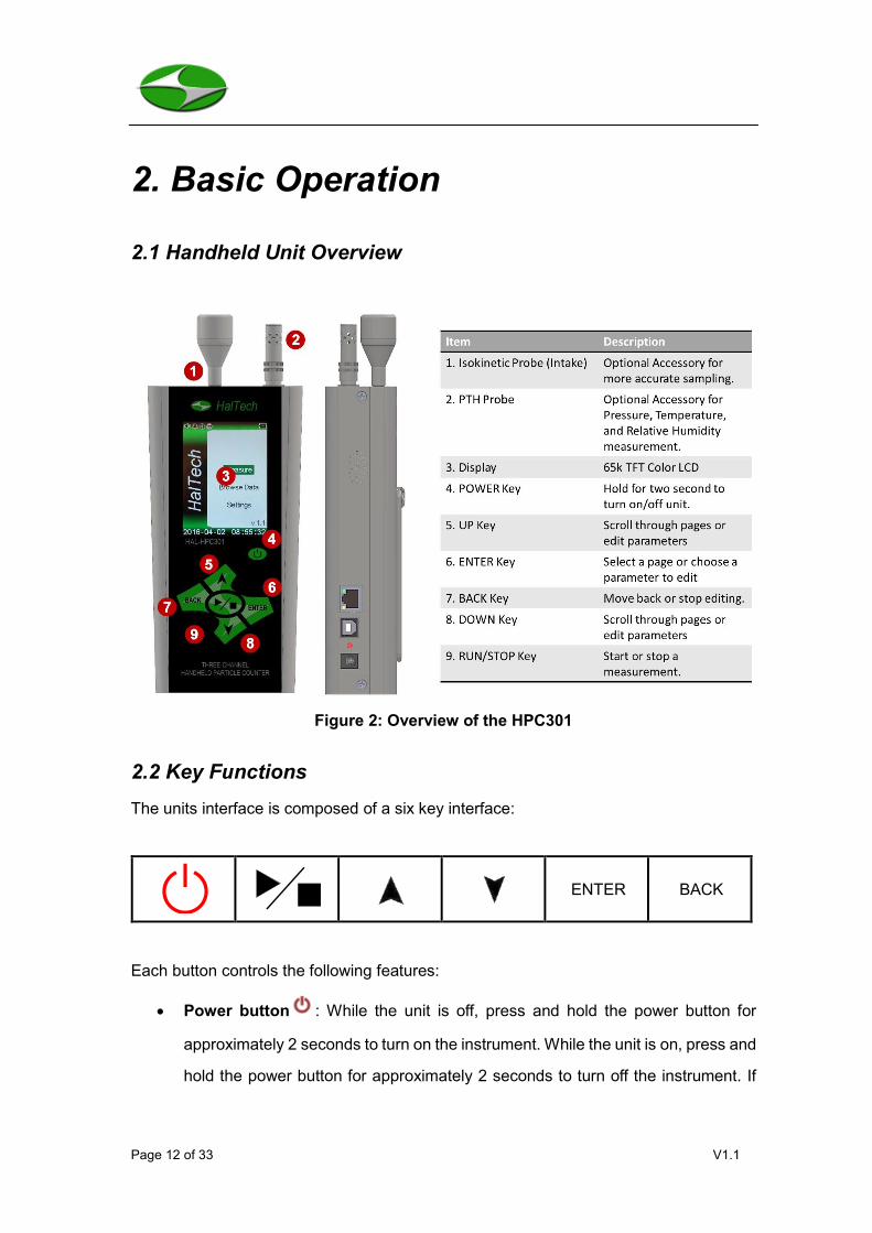
2.1 Handheld Unit Overview
Figure 2: Overview of the HPC301
2.2 Key Functions
The units interface is composed of a six key interface:
ENTER BACK
Each button controls the following features:
• Power button : While the unit is off, press and hold the power button for
approximately 2 seconds to turn on the instrument. While the unit is on, press and
hold the power button for approximately 2 seconds to turn off the instrument. If

Page 13 of 33 V1.1
the instrument is not actively sampling it will automatically power off after 5
minutes of inactivity.
• : Start or stop measuring/sampling.
• : Move the cursor to select desired screen or item.
• ENTER: Confirm the current selection or edit a parameter.
• BACK: Back to the previous page or cancel.
The side of the enclosure includes
• USB Interface: Connect the USB interface to a computer for data downloading.
• POWER port: An AC charger plug-in port: 9 VDC @ 1.5 A.
• Charge Status LED: LED flashes during charge cycle and becomes steady after
the charge cycle is finished.
• Ethernet Interface: This feature is not standard for the HPC301 and is a future
option.
2.3 Graphical User Interface (GUI)
2.3.1 Main Screen
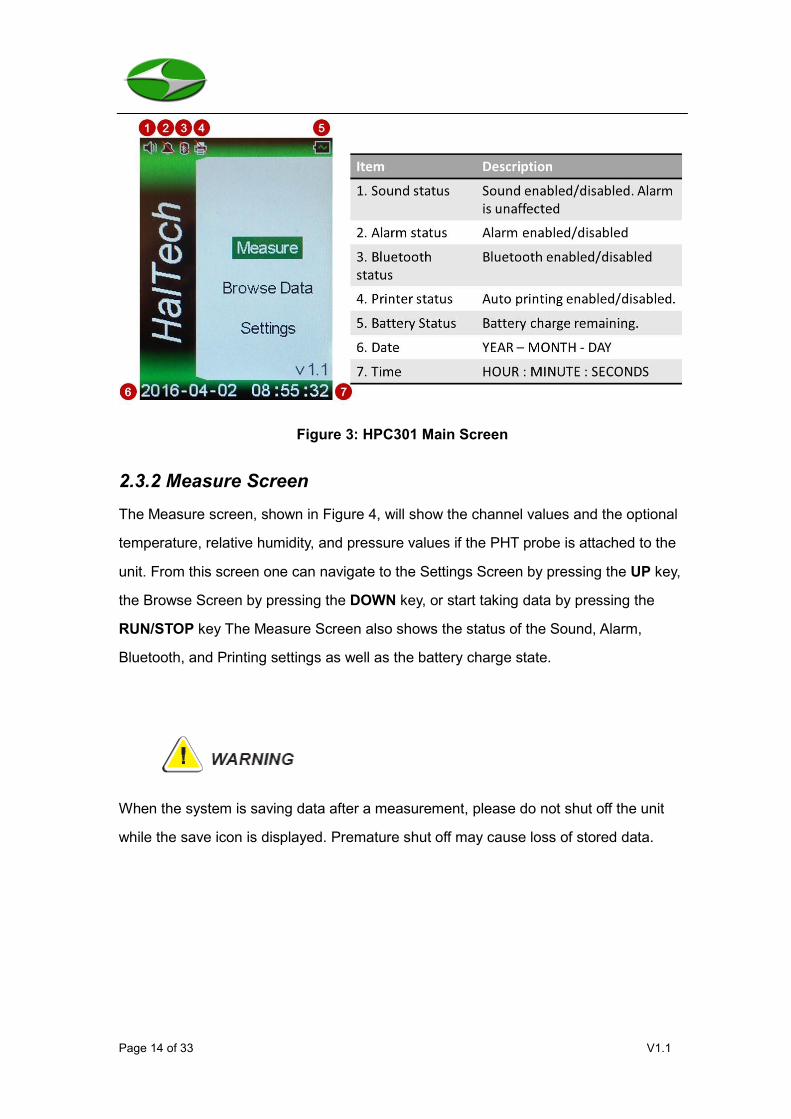
When the unit is turned on it will default to the Main Screen as shown in Figure 3. From
this screen the user may select Measure, Browse, or Settings by using the UP and
DOWN keys and confirm the selection using the ENTER key. As indicated in the table
below (items 1-5), it is possible to view the status of the Sound, Alarm, Bluetooth, and
Printing settings as well as the battery charge state at any time. The time and date are
also displayed on the bottom of the screen.
Page 14 of 33 V1.1
Figure 3: HPC301 Main Screen
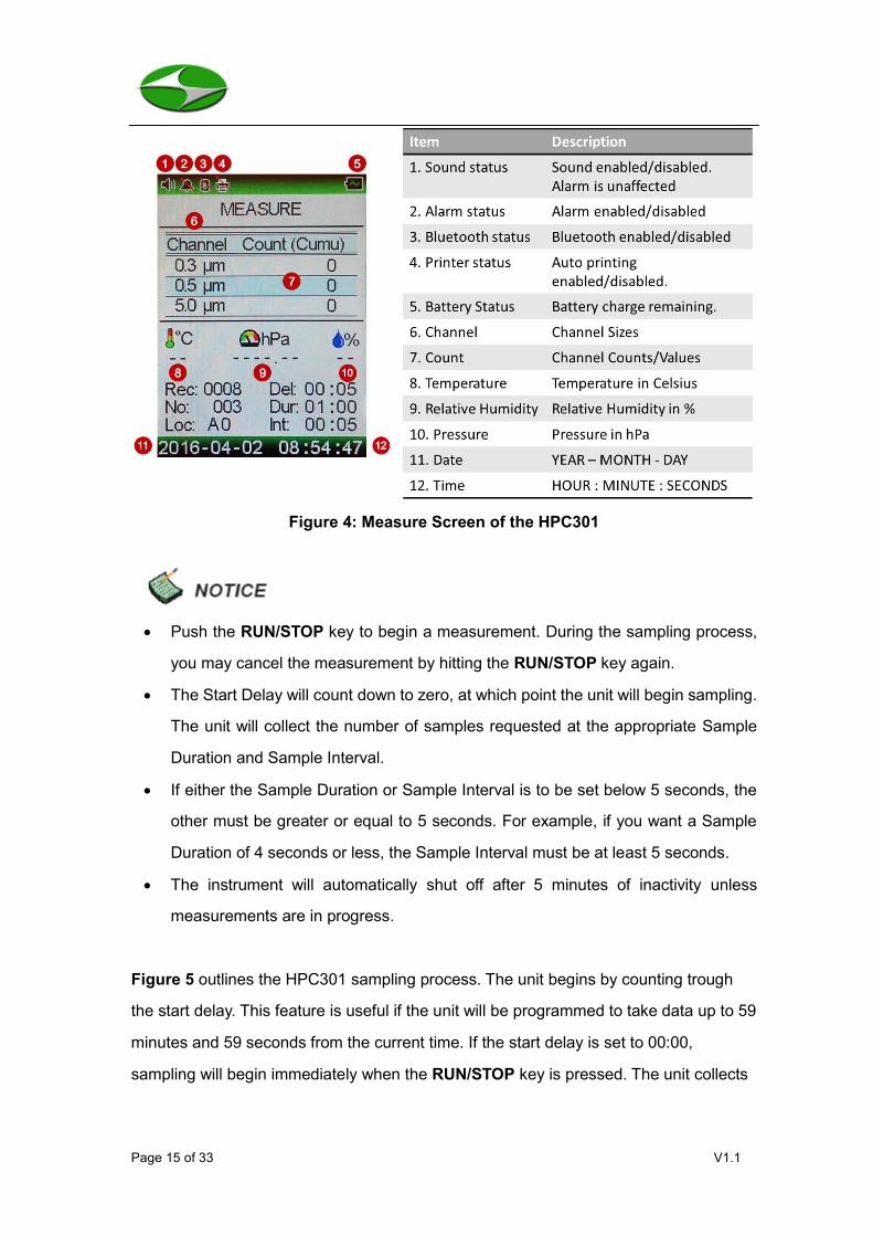
2.3.2 Measure Screen
The Measure screen, shown in Figure 4, will show the channel values and the optional
temperature, relative humidity, and pressure values if the PHT probe is attached to the
unit. From this screen one can navigate to the Settings Screen by pressing the UP key,
the Browse Screen by pressing the DOWN key, or start taking data by pressing the
RUN/STOP key The Measure Screen also shows the status of the Sound, Alarm,
Bluetooth, and Printing settings as well as the battery charge state.
When the system is saving data after a measurement, please do not shut off the unit
while the save icon is displayed. Premature shut off may cause loss of stored data.
Page 15 of 33 V1.1
Figure 4: Measure Screen of the HPC301
• Push the RUN/STOP key to begin a measurement. During the sampling process,
you may cancel the measurement by hitting the RUN/STOP key again.
• The Start Delay will count down to zero, at which point the unit will begin sampling.
The unit will collect the number of samples requested at the appropriate Sample
Duration and Sample Interval.
• If either the Sample Duration or Sample Interval is to be set below 5 seconds, the
other must be greater or equal to 5 seconds. For example, if you want a Sample
Duration of 4 seconds or less, the Sample Interval must be at least 5 seconds.
• The instrument will automatically shut off after 5 minutes of inactivity unless
measurements are in progress.
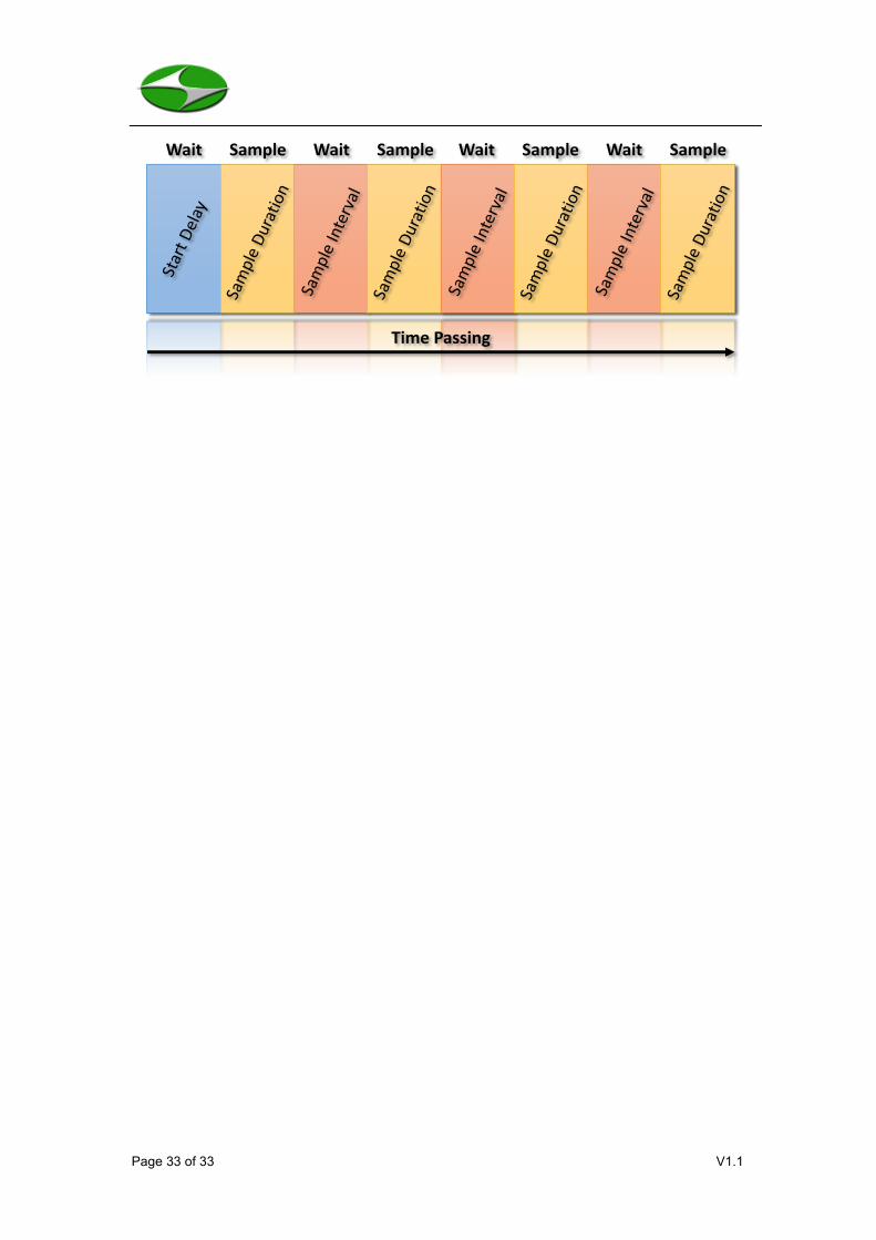
Figure 5 outlines the HPC301 sampling process. The unit begins by counting trough
the start delay. This feature is useful if the unit will be programmed to take data up to 59
minutes and 59 seconds from the current time. If the start delay is set to 00:00,
sampling will begin immediately when the RUN/STOP key is pressed. The unit collects

Page 16 of 33 V1.1
data for the Sample Duration and then counts through the Sample Interval. The Sample
Duration and Sample Interval times will be repeated for the requested number of
samples. Figure 5 specifically shows the sampling process when the unit is set to a
non-zero Start Delay and 4 samples are taken.
Figure 5: Measurement Procedure for the HPC301
The total time for an ensemble of measurements can be calculated as:
𝑇𝑖𝑚𝑒 = 𝑆𝑡𝑎𝑟𝑡 𝐷𝑒𝑙𝑎𝑦 + 𝑁𝑜. 𝑜𝑓 𝑆𝑎𝑚𝑝𝑙𝑒𝑠 𝑥 [𝑆𝑎𝑚𝑝𝑙𝑒 𝐷𝑢𝑟𝑎𝑡𝑖𝑜𝑛 + 𝑆𝑎𝑚𝑝𝑙𝑒 𝐼𝑛𝑡𝑒𝑟𝑣𝑎𝑙]
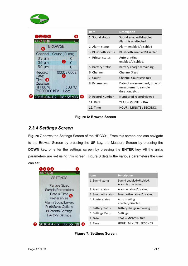
2.3.3 Browse Screen
Figure 6 shows the Browse Screen of the HPC301. From this screen one can navigate
to the Measure Screen by pressing the UP key, the Settings Screen by pressing the
DOWN key, or start viewing record by pressing the ENTER key. If entered, the record
displayed will be the latest record in memory. Every record will display all the parameters
shown in Figure 6. Note, the time parameters correspond to when the measurement
finished. To get the start time, simply subtract the Sample Duration.
Time Passing
Wait Sample Wait Sample Wait Sample Wait Sample
Page 17 of 33 V1.1
Figure 6: Browse Screen
2.3.4 Settings Screen
Figure 7 shows the Settings Screen of the HPC301. From this screen one can navigate
to the Browse Screen by pressing the UP key, the Measure Screen by pressing the
DOWN key, or enter the settings screen by pressing the ENTER key. All the unit’s
parameters are set using this screen. Figure 8 details the various parameters the user
can set.
Figure 7: Settings Screen

Page 18 of 33 V1.1
Figure 8 shows the parameters that can be set via the Setting Screen.
Figure 8: The parameters that can be set via the Settings Screen
Once the user has entered the Settings Screen by pressing Enter, scroll through the
various options using the UP and DOWN keys. Enter a sub-menu by pressing ENTER.
Once selected, a parameter will highlight in blue. For example, if the user wishes to edit
the sample duration setting in the Sample Parameters screen they will first press the
ENTER key while Sample Duration is selected. The first portion of the entry will
highlight blue, like so 00:00. Pressing the UP or DOWN key will move between minutes
and seconds (00:00). Pressing the ENTER key will highlight the selected portion in red
and enable editing (00:00). The UP and DOWN keys will now edit the Sample Duration
appropriately. When finished press the BACK key to stop editing (00:00).
Particle Sizes – Modify particle sizes on Channels 1 - 6
Sample Parameters – Modify Start Delay, Interval, Duration, Number of Samples, Material Density (MC and PM only), Count Mode, and Location
Date & Time – Modify the units Date & Time settings
Preferences – Modify the units color theme and temperature unit
Alarm/Sound Levels – Modify the alarm (FED, ISO, or manual) and the Sound settings. Turning off the sound does not inhibit the alarm.
Print/Save Options – Modify the Print (On or Off) settings and the Save (On, Off, or Average) settings.
SETTINGS
Particle SizesSample Parameters
Date & TimePreferences
Alarm/Sound LevelsPrint/Save OptionsBluetooth Settings
Factory Settings Bluetooth Settings – Modify settings for the optional printer.
Factory Settings – Firmware update (reserved), Calibration (protected), Clear Last Record, and Factory Reset.

Page 19 of 33 V1.1
2.3.5 Modifying Parameters (Settings)
Particle Sizes:
This three-channel particle counter allows the user to select three predefined
channel sizes from 0.3 μm, 0.5 μm, 1.0 μm, 2.0 μm, 2.5 μm, 5.0 μm, 10.0 μm, and
15.0 μm. Channel 1 will always be the smallest size, followed by channel 2 and 3. If
the FS209E/ISO alarm is enabled, the channels will be locked to 0.3 μm, 0.5 μm,
and 5.0 μm and cannot be changed until the FS209E/ISO alarm has been disabled.
Sample Parameters:
The sample parameters screen will allow the user to modify the following parameters
over the following ranges:
• Start Delay: 00:00 to 59:59
• Sample Interval: 00:00 to 59:59
• Sample Duration: 00:00 to 59:59
• Number of Samples: 0 to 500
• Material: PSL, Sand, Lead, Carbon, or User Defined
• Count Mode: Cumulative, Differential, Counts per Liter, Counts per Cubic
Foot, Counts per Cubic Meter, Mass Concentration (option) or Particulate
Matter (option)
• Location: A0 to Z9
Start Delay
The start delay is defined as the time before ANY measurements are taken. This
feature is a timer for a sampling process to occur at a later time. The sample
Particle SizesSample Parameters
Date & TimePreferences
Alarm/Sound LevelsPrint/Save OptionsBluetooth Settings
Factory Settings
Page 20 of 33 V1.1
delay can be set between 00:00 and 59:59.
Sample Interval
The sample interval is defined as the time between measurements. No data is
collected during the interval. The sample interval can be set between 00:00 and
59:59.
Sample Duration
The sample duration is defined as the time between measurements. No data is
collected during the interval. The sample duration can be set between 00:01 and
59:59.
Number of Samples
The number of samples to be collected. If the Save mode is set to Auto, the unit
will collect and store every sample. If the Save Mode is set to Avg, only the
average across the number of samples will be stored.
• When setting this number, keep in mind the run time of the entire
sampling procedure. Depending upon the battery charge, the user may
wish to plug the unit in to ensure all data is collected.
Material
This parameter only affects Mass Concentration (MC) and Particulate Matter (PM)
measurements. The particle density is used in MC and PM measurements, and
the standard usage is a Polystyrene Latex (PSL) particle. The HPC301 allows
users to choose from a list of predetermined densities. If the particle you are
measuring does not appear in the list, choose the User Defined option. Simply
enter the particle density of the particles to be measured, if known, in units of
g/cm3, i.e., the density of PSL is 1.05 g/cm3.

Page 21 of 33 V1.1
• Particulate Matter and Mass Concentration measurement capabilities are
optional accessories for the HPC301. If your unit does not have this
capability and you require it, contact Hal Technology at
[email protected] or [email protected] for a quote.
Count Mode
All channels are counted as cumulative counts, and processed according to the
Count Mode setting. The user may choose from the following standard Count
Modes:
• Cumulative Counts,
• Differential Counts,
• Counts Per Liter,
• Counts Per Cubic Foot,
• Counts Per Cubic Meter,
and the following optional Count modes:
• Mass Concentration,
• Particulate Matter.
Location
Location codes can be made to correspond to facility locations. These codes will
be internal to the facility. For example, a main office may be set to M0, while a
branch office may be set to B0. Total of 260 unique identifiers are available.
Date & Time:
The date Format is YEAR – MONTH – DAY or YYYY – MM – DD. The time is
represented as a 24 hour clock and is formatted as HOUR : MINUTE : SECOND or
HH : MM : SS.
Page 22 of 33 V1.1
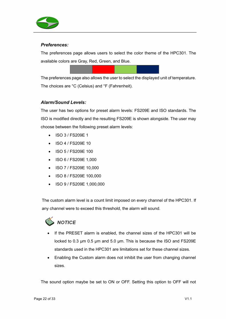
Preferences:
The preferences page allows users to select the color theme of the HPC301. The
available colors are Gray, Red, Green, and Blue.
The preferences page also allows the user to select the displayed unit of temperature.
The choices are °C (Celsius) and °F (Fahrenheit).
Alarm/Sound Levels:
The user has two options for preset alarm levels: FS209E and ISO standards. The
ISO is modified directly and the resulting FS209E is shown alongside. The user may
choose between the following preset alarm levels:
• ISO 3 / FS209E 1
• ISO 4 / FS209E 10
• ISO 5 / FS209E 100
• ISO 6 / FS209E 1,000
• ISO 7 / FS209E 10,000
• ISO 8 / FS209E 100,000
• ISO 9 / FS209E 1,000,000
The custom alarm level is a count limit imposed on every channel of the HPC301. If
any channel were to exceed this threshold, the alarm will sound.
• If the PRESET alarm is enabled, the channel sizes of the HPC301 will be
locked to 0.3 μm 0.5 μm and 5.0 μm. This is because the ISO and FS209E
standards used in the HPC301 are limitations set for these channel sizes.
• Enabling the Custom alarm does not inhibit the user from changing channel
sizes.
The sound option maybe be set to ON or OFF. Setting this option to OFF will not
Page 23 of 33 V1.1
affect the alarm.
Print/Save Options:
A Bluetooth enabled printer is required for printing; contact Hal Tech for a quote. The
Print option can be set to either ON or OFF. When set to ON, the unit will print results
after a measurement based on the setting of the Save option. If the save option is set
to ON or OFF and the print option is ON, then every measurement will be printed. If
the save option is set to Average and the print option is on, only the average
measurement will be printed at the end of the measurement process.
The save option can be set to one of three options: ON, OFF, and Average. If set to
Off, no data is saved. If set to On, every sample is saved. If set to Average, only the
average of all the measurements is saved.
• The optional Bluetooth printer is required to print. If you would like to purchase
the printer, contact Hal Technology ([email protected]).
Bluetooth Settings:
The Bluetooth settings are for the optional Bluetooth enabled printer, which would be
included with the HPC301 if purchased. If you do not use the printing feature of this
unit, be sure to set the Bluetooth Power option to OFF. This will decrease the drain
on the battery. The Address option can be modified, and will correspond to the 6-byte
(48-bit) Bluetooth address of the printer. If the printer was purchased from Hal
Technology when the HPC301 was ordered, the printer will already be configured.
Selecting Connect and pressing the ENTER key will test the Bluetooth connection
between the module and the printer. Be sure that the printer is turned on before
attempting the Connect test.
Factory Settings:
The firmware update option is reserved for future use by Hal Technology, and the

Page 24 of 33 V1.1
calibration option is password protected for safety reasons. If a calibration is required,
contact [email protected]. The Clear Last Record option is available in
case the unit were to lose power while saving data. If this were to occur, it is possible
the last record could be corrupted. The Factory Reset option will return the unit to a
preset state (All memory will be cleared).
Page 25 of 33 V1.1
3. Data Downloader Instructions The HPC301 Data Downloader software installs on most recent Windows operating
systems. To install the HPC301 Data Downloader software, please follow the
instructions in the file named Readme.txt that is usually provided on the compact disc.
After successful installation, it is preferable to have the HPC301 powered off when using
the software to download data from the HPC301. Certain USB devices may cause a
conflict with the operation of the HPC301 Data Downloader. One should, temporarily
disconnect any conflicting device while downloading data.

Page 26 of 33 V1.1
4. Troubleshooting
If none of the suggested remedies work for your particular problem, contact
[email protected] for further assistance.
Symptom Possible Remedy
The unit will not turn on. 1. Hold the Power Button down until the
unit turns on.
2. Plug the unit in using the supplied
power adapter or charger, wait a few
minutes, and try turning it on.
When entering the Browsing Page, the
displayed data appears garbled.
Is it possible the unit lost power while
saving the last record? Go to the Factory
Settings page under Settings and Clear
the last record. If this does not fix the
problem, try a Factory Reset (all memory
will be cleared).
The unit does not appear to be saving my
changes in the Settings Page.
After making changes to the settings it is
important to exit the Settings Page. All
settings are saved upon exiting the
Settings Page. If changed were made,
and the unit was turned off before exiting
the Settings Page, those settings are lost.
Pump sounds like it is working hard. 1. Ensure the inlet cap is removed.
2. If tubing is attached to the inlet, ensure
there is no obstruction.
Running the unit while the flow is
obstructed will cause a significant
reduction in the pump life.

Page 27 of 33 V1.1
Printer does not print. 1. Ensure the printer is in working order
(turned on and has thermal paper).
2. Ensure Bluetooth is enabled on the
HPC301.
3. Run a connection test from the
Bluetooth Settings Page.
Page 28 of 33 V1.1
5. Warranty Hal Technology provides a one-year limited warranty of the Model HPC301 Handheld
Particle Counter, but not including the necessary calibration service.
• Warranty begins from the shipping date.
• The user is responsible for the cost of shipping if any service or repair is required.
• The warranty is limited to the HPC301 instrument and HAL TECHNOLOGY does
not extend this liability to accessories or any other equipment damage, body injury,
and loss of properties due to abnormal use.
•
The following are not included in the warranty:
• Improper connection to a power source, resulting in damage of the instrument.
• Any physical damage due to mechanical forces (e.g., collision or dropping) that
may cause any damage of the front panel, LCD screen, switch and internal
components, etc.
• Unauthorized opening of the instrument.
• Damage due to operation in an un-specified environmental condition.
• Abnormal operation due to required instrument calibration.
Limitation of Warranty
A. Hal Technology warrants that all equipment shall be free from defects in material and
workmanship under normal use for a period of one year from the date of shipment to
Buyer except that Hal Technology does not warrant that operation of the software will be
completely uninterrupted or error free or that all program errors will be corrected. Buyer
shall be responsible for determining that the equipment is suitable for Buyer’s use and
that such use complies with any applicable local, state, or federal law. Provided that
Buyer notifies Hal Technology in writing of any claimed defect in the equipment
immediately upon discovery and any such equipment is returned to the original shipping
point, transportation charges prepaid, within one year from date of shipment to Buyer
and upon examination Hal Technology determines to its satisfaction that such equipment
is defective in material or workmanship, i.e. contains a defect arising out of the
Page 29 of 33 V1.1
manufacture of the equipment and not a defect caused by other circumstances, including,
but not limited to accident, misuse, unforeseeable use, neglect, alteration, improper
installation, improper adjustment, improper repair, or improper testing, Hal Technology
shall, at its option, repair or replace the equipment, shipment to Buyer prepaid. Hal
Technology shall have reasonable time to make such repairs or to replace such
equipment. Any repair or replacement of equipment shall not extend the period of
warranty. If the Instrument is modified or in any way altered without the explicit written
consent of Hal Technology, then the warranty is null and void. This warranty is limited to
a period of one year, except as noted below, without regard to whether any claimed
defects were discoverable or latent on the date of shipment.
B. If Buyer shall fail to pay when due any portion of the purchase price or any other
payment required from Buyer to Hal Technology under this contract or otherwise, all
warranties and remedies granted under this Section may, at Hal Technology’s option, be
terminated.
C. Warranty repairs shall be completed at a Hal Technology authorized service location,
by an authorized service technician, or on site at buyer’s facility by a Hal Technology
authorized employee. Buyer pays shipping costs to factory; seller will pay standard return
shipping costs during the warranty period. A buyer may select a faster method of
shipment at his/her own expense.
Warranty of Repairs after Initial One (1) Year Warranty
A. Upon expiration of the initial one-year warranty, all parts and repairs completed by an
authorized Hal Technology repair technician are subject to a six (6) month warranty.
B. Other than the above, Hal Technology makes no warranty of any kind, expressed or
implied, except that the products manufactured and sold by Hal Technology shall be free
from defects in materials and workmanship and shall conform to Hal Technology’s
specifications; Buyer assumes all risk and liability resulting from use of the products
whether used singly or in combination with other products. If instrument is modified or in
any way altered without the explicit written consent of Hal Technology, then the warranty
is null and void.
C. Warranty repairs shall be completed at a Hal Technology authorized service location,
Page 30 of 33 V1.1
by an authorized service technician, or on site at buyer’s facility by a Hal Technology
authorized employee. Buyer pays shipping costs to factory; seller will pay standard return
shipping costs during the warranty period. Buyers may select a faster method of shipment
at their own expense.
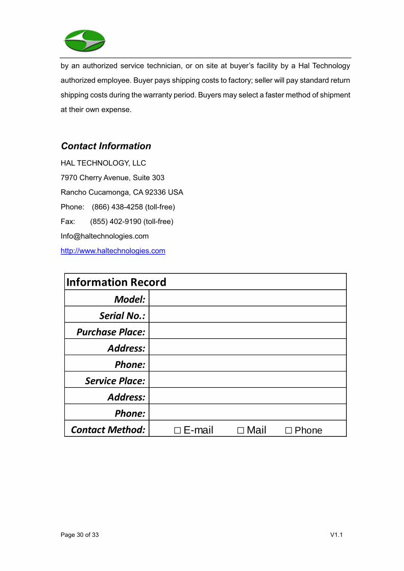
Contact Information
HAL TECHNOLOGY, LLC
7970 Cherry Avenue, Suite 303
Rancho Cucamonga, CA 92336 USA
Phone: (866) 438-4258 (toll-free)
Fax: (855) 402-9190 (toll-free)
http://www.haltechnologies.com
Model:
Serial No.:
Purchase Place:
Address:
Phone:
Service Place:
Address:
Phone:
Contact Method: □ E-mail □ Mail □ Phone
Information Record
Page 31 of 33 V1.1
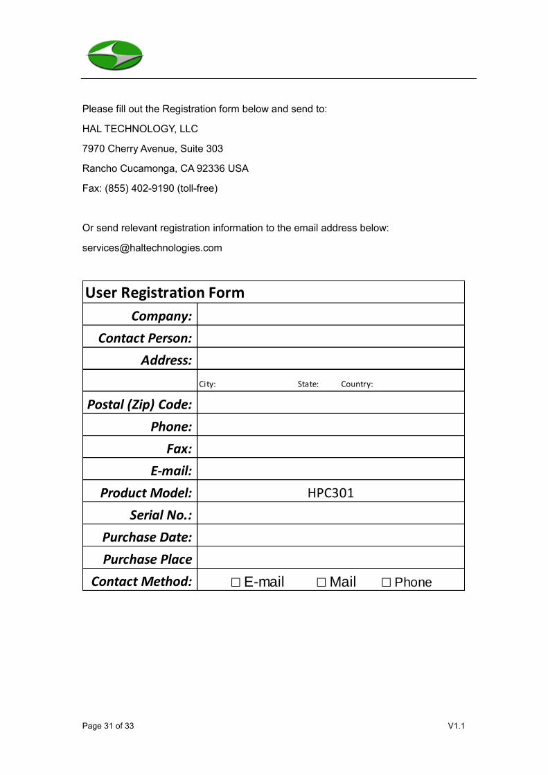
Please fill out the Registration form below and send to:
HAL TECHNOLOGY, LLC
7970 Cherry Avenue, Suite 303
Rancho Cucamonga, CA 92336 USA
Fax: (855) 402-9190 (toll-free)
Or send relevant registration information to the email address below:
Company:
Contact Person:
Address:
City: State: Country:
Postal (Zip) Code:
Phone:
Fax:
E-mail:
Product Model: HPC301
Serial No.:
Purchase Date:
Purchase Place
Contact Method: □ E-mail □ Mail □ Phone
User Registration Form

Page 32 of 33 V1.1
6. Glossary
Counts per Cubic Foot – The number of counts in a sample volume (cubic feet). This
is calculated using the parameters of the unit and the flow conditions.
Counts per Cubic Meter - The number of counts in a sample volume (cubic meter). This
is calculated using the parameters of the unit and the flow conditions.
Counts per Liter – The number of counts in a sample volume (liter). This is calculated
using the parameters of the unit and the flow conditions.
Cumulative Counts – The absolute number of counts for a channel. For example,
suppose the HPC301’s channel sizes are set to 0.3 μm, 2.5 μm, and 10.0 μm. Particles
are counted based on thresholds, and any particle that meets the 2.5 μm threshold also
meets the 0.3 μm threshold. So, both the 0.3 μm and 2.5 μm channel counts are
incremented.
Differential Counts – The relative number of counts for a channel (referenced to the
next largest channel). For example, suppose the HPC301’s channel sizes are set to 0.3
μm, 2.5 μm, and 10.0 μm. If the cumulative counts for the channels are 24576, 8754,
and 48 respectively, then the differential counts are 15822, 8706, and 48 respectively.
Sample Delay – The time before the first measurement is taken in a series of samples.
No data is collected during the sample delay. The sample delay can be set between
00:00 and 59:59.
Sample Duration – The time during which samples are actually taken. Data IS collected
during the sample duration. The sample interval can be set between 00:01 and 59:59.
Sample Interval – The time between measurements. No data is collected during the
sample interval. The sample interval can be set between 00:00 and 59:59.
Page 33 of 33 V1.1
Time Passing
Wait Sample Wait Sample Wait Sample Wait Sample