µTasker LCD User's Guide - uGLCDLIB V1.1 - uTasker
48
uTaskerLCD.doc/1.03 Copyright © 2010 M.J.Butcher Consulting μTasker Document μTasker – LCD User’s Guide uGLCDLIB V1.1
-
Upload
khangminh22 -
Category
Documents
-
view
4 -
download
0
Transcript of µTasker LCD User's Guide - uGLCDLIB V1.1 - uTasker

uTaskerLCD.doc/1.03 Copyright © 2010 M.J.Butcher Consulting
�����������������
µTasker Document
µTasker – LCD User’s Guide uGLCDLIB V1.1

www.uTasker.com µTasker – LCD User’s Guide
uTaskerLCD.doc/1.03 2/48 29.08.2010
Table of Contents 1.� Introduction .....................................................................................................................3�2.� Character LCD ................................................................................................................4�
2.1.� Connecting an LCD to a Processor .....................................................................6�2.2.� Trying the LCD out in the µTasker Simulator ......................................................7�2.3.� Setting the SW interface to the Target ................................................................8�2.4.� Initialisation Procedure ........................................................................................ 10�2.5.� Inter-Task Details ................................................................................................. 10�2.6.� A closer Look at the Hardware Setup ................................................................ 11�
3.� Monochrome Graphical LCD ........................................................................................ 12�3.1.� T6963C LCD Controller and its Configuration .................................................. 14�3.2.� T6963C LCD Initialisation ................................................................................... 16�3.3.� GLCD Operation .................................................................................................. 16�3.4.� Bus Timing - T6963C .......................................................................................... 24�3.5.� Bitmap Conversion using the Utility µTaskerFileCreate .................................. 25�3.6.� Posting a Bitmap to the GLCD via Web Browser ............................................. 27�3.7.� KS0108B LCD Controller and its Configuration ................................................ 28�3.8.� GLCD User Interface ........................................................................................... 30�
4.� OLED – 16 Gray Levels using SSD1329 LCD Controller .............................................. 35�4.1.� OLED use in GLCD Emulation Mode on Luminary Micro Evaluation Boards36�
5.� TFT using SDRAM and LCD Controller ....................................................................... 37�5.1.� TFT use in GLCD Emulation Mode on Olimex LPC2478 Board ..................... 38�
6.� CGLCD on AVR32 EVK1105 ...................................................................................... 40�6.1.� CGLCD use in GLCD Emulation Mode on EVK1105 ....................................... 42�
7.� CGLCD on Luminary EK_LM3S3748 .......................................................................... 44�7.1.� Colour LCD use in GLCD Emulation Mode on Luminary EK_LM3S3748...... 45�
8.� NOKIA 6100 on Olimex SAM7X and LPC2378 Evaluation Boards .............................. 46�9.� Conclusion .................................................................................................................... 48�

www.uTasker.com µTasker – LCD User’s Guide
uTaskerLCD.doc/1.03 3/48 29.08.2010
1. Introduction
LCD displays are very popular as part of a MMI (Man Machine Interface) in many types of devices, from industrial controls to games consoles. The µTasker project supports various types of display in order to allow simple and efficient work with such devices and to establish a generic application layer interface. Furthermore, when working with the µTasker simulator, all types of displays are accurately simulated to allow application software to be tested in a practical and efficient environment together with various other embedded peripherals on the target processor.
The µTasker V1.3 project supported only a character LCD. From µTasker V1.4 also monochrome graphical LCD support is included, together with a foundation for further colour LCDs.
This document describes the uGLCDLIB V1.1 development state, which includes various drawing functions and emulation of monochrome GLCDs using various LCD types (OLED, TFT etc.).

www.uTasker.com µTasker – LCD User’s Guide
uTaskerLCD.doc/1.03 4/48 29.08.2010
2. Character LCD The uTasker project supports character displays which conform to the HD44780 standard interface (which is probably just about all). The display can be from the smallest type (1 x 8) up to 4 x 40 and its interface uses either an 8 bit or 4 bit data bus connection. The 8 bit interface is slightly faster since all read/writes to/from the display can be made in one access cycle, whereas the 4 bit interface saves bus/port lines because the data interface is less wide - accesses require two cycles in this mode and so it is a bit slower. Generally the access speed is not a big issue when interfacing to this type of LCD so 4 bit mode is often preferred.
Character LCDs usually support a character set comprising the ASCII 7 bit characters (0x20..0x7f) followed by a set of extended ASCII characters (0x80..0xff) as shown below:
The first 16 locations initialise to random content but can be user programmed to create user definable characters or symbols. There are in fact only 8 user programmable characters since 0x00..0x07 are repeated at 0x08..0x0f.

www.uTasker.com µTasker – LCD User’s Guide
uTaskerLCD.doc/1.03 5/48 29.08.2010
Characters LCDs can be ordered with different extended character sets, such as Cyrillic, which allows Russian text to be displayed. The extended characters in this case are shown in the following figure:
The uTasker simulator aids in developments since it includes a configurable simulated LCD. The Cyrillic extended character set can be enabled by adding the define LCD_CYRILLIC_FONT to the LCD configuration in config.h.
The demonstration project shows an example of initialising and controlling the LCD with a simple message oriented application interface.

www.uTasker.com µTasker – LCD User’s Guide
uTaskerLCD.doc/1.03 6/48 29.08.2010
2.1. Connecting an LCD to a Processor The LCDs have an interface which follows the following pattern. The actual connector type can vary widely, being a single or double row of pins. This example describes a typical pin-out, which is easily translated to other type as well. Pin 1 Vss Ground for the power supply Pin 2
VDD +ve voltage power supply, eg. 5V or 3V3
Pin 3
VO Contrast control voltage typically 0..1.5V when powered by 5V or a slightly negative value when powered by 3V3
Pin 4
RS Data/Instruction select
Pin 5
R/W Read/Write
Pin 6
E Enable signal
Pin 7
DB0 Data Bus 0 - not connected in 4 bit mode
Pin 8
DB1 Data Bus 1 - not connected in 4 bit mode
Pin 9
DB2 Data Bus 2 - not connected in 4 bit mode
Pin 10 DB3 Data Bus 3 - not connected in 4 bit mode Pin 11
DB4 Data Bus 4 - always connected
Pin 12
DB5 Data Bus 5 - always connected
Pin 13
DB6 Data Bus 6 - always connected
Pin 14
DB7 Data Bus 7 - always connected
Pin 15
LEDA Backlight LED - if available - Anode - connect positive backlight drive voltage to this - 5V with current limiting resistor recommended
Pin 16 LEDC Backlight LED - if available - Cathode - connect negative backlight drive voltage to this
If connecting a 5V LCD to a 3V3 processor it may be necessary to use a level shifter. Note also that the processor not only drives the data bus but can also read back data. In particular DB7 is read back to check whether the LCD is busy so this should also be supported. If your processor is 5V tolerant this is of course no problem at all.

www.uTasker.com µTasker – LCD User’s Guide
uTaskerLCD.doc/1.03 7/48 29.08.2010
2.2. Trying the LCD out in the µTasker Simulator If you want to test drive the LCD without actually having to connect one to a target the simulator comes in very handy. It can also be used for developing applications which require an LCD to display text (and a limited amount of graphics). In config.h the LCD demo can be activated and the LCD type configured: #define SUPPORT_LCD // enable a task for interfacing to an LCD #ifdef SUPPORT_LCD #define LCD_LINES 2 // use 2 x 16 LCD #define LCD_CHARACTERS 16 // Options are 1:8 / 1:16 / 1:20 / 1:24 / 1:40 / 2:x / 4:x #define LCD_ON_COLOUR (COLORREF)RGB(60,220,60) // RGB colour of LCD when backlight is on #define LCD_OFF_COLOUR (COLORREF)RGB(70,160,0) // RGB colour of LCD when backlight is off #define LCD_PARTNER_TASK TASK_APPLICATION #endif
Various LCDs sizes can be selected and the text and background colours configured. Real LCDs have limited colour choice so best choose realistic colour settings to avoid disappointment..!
The following description is valid when USE_TIME_SERVER has not also been activated (otherwise the LCD will display the present time). The result is an LCD with the defined characteristics displayed when the simulator is running, showing "Hi uTasker!" continuously moving left and right. A typical image is shown below:

www.uTasker.com µTasker – LCD User’s Guide
uTaskerLCD.doc/1.03 8/48 29.08.2010
2.3. Setting the SW interface to the Target In order to actually control an LCD the processor must be connected to it via the control lines as previously specified. Each target in the uTasker project has an LCD setup to allow it to operate with a standard demo board and to easily be adapted to almost any other board. The set up is defined in the header file app_hw_xxx.h (where xxx is the target processor in question). Here is an example for the M5223X project. // LCD interface: Backlight control Port AS bit 0 : Data bus (4 Bit) Port TA 0..3 : RS Port AS bit 1, RW Port AS bit 2, E Port AS bit 3 // typedef unsigned char LCD_BUS_PORT_SIZE; // we use 8 bit ports typedef unsigned char LCD_CONTROL_PORT_SIZE; //#define LCD_BUS_8BIT // data bus in 8 bit mode #define LCD_BUS_4BIT // data bus in 4 bit mode #ifdef LCD_BUS_8BIT #define LCD_BUS_MASK 0xff #define DATA_SHIFT_RIGHT 0 // no shift required to bring data into position #define DATA_SHIFT_LEFT 0 #else #define LCD_BUS_MASK 0x0f #define DATA_SHIFT_RIGHT 4 // nibble shift down required to bring data into position #define DATA_SHIFT_LEFT 0 #endif #define O_CONTROL_RS PORT_AS_BIT1 #define O_WRITE_READ PORT_AS_BIT2 #define O_CONTROL_EN PORT_AS_BIT3 #define O_LCD_BACKLIGHT PORT_AS_BIT0 #define O_CONTROL_LINES (O_CONTROL_RS | O_WRITE_READ | O_CONTROL_EN) #define IO_BUS_PORT_DDR DDRTA #define O_CONTROL_PORT_DDR DDRAS #define IO_BUS_PORT_DAT PORTTA #define IO_BUS_PORT_DAT_IN PORTIN_SETTA #define O_CONTROL_PORT_DAT PORTAS // Drive the control lines R/W + LCD Backlight '1', RS + E '0' and the data lines with all high impedance at start up #define INITIALISE_LCD_CONTROL_LINES() IO_BUS_PORT_DDR = 0; IO_BUS_PORT_DDR = 0; \ O_CONTROL_PORT_DDR &= ~(O_CONTROL_LINES | O_LCD_BACKLIGHT); O_CONTROL_PORT_DAT &= ~(O_CONTROL_LINES | O_LCD_BACKLIGHT); O_CONTROL_PORT_DAT |= (O_LCD_BACKLIGHT | O_WRITE_READ); \ O_CONTROL_PORT_DDR |= (O_CONTROL_LINES | O_LCD_BACKLIGHT); #define LCD_DRIVE_DATA() IO_BUS_PORT_DDR |= LCD_BUS_MASK; IO_BUS_PORT_DDR |= LCD_BUS_MASK; // ensure data bus outputs (delay) by repetitions according to processor speed #define CLOCK_EN_HIGH() O_CONTROL_PORT_DAT |= (O_CONTROL_EN); \ O_CONTROL_PORT_DAT |= (O_CONTROL_EN); // clock EN to high state - repeat to slow down (delay) #define DELAY_ENABLE_CLOCK_HIGH() O_CONTROL_PORT_DAT &= ~(O_CONTROL_EN);
Although the configuration may look quite complicated initially, it is simply defining some port macros to be used by the generic interface code; with a little understanding it should be possible to adapt to almost any other configuration, as long as a few rules are adhered to:
• First of all, the mapping of the LCD control lines to real ports has to be defined. The above example is set to operate in 4 bit bus mode and controls the LCD via port AS on this particular chip. The bus interface is required to be on a single port and the bits are assumed to be next to each other in an ascending row. In the example port TA is used and the 4 data bits are situated from TA0..TA3.

www.uTasker.com µTasker – LCD User’s Guide
uTaskerLCD.doc/1.03 9/48 29.08.2010
• The control lines are assumed to be all on a single port but their position on the port is not important.
The routines actually controlling accesses do so using macros (like LCD_DRIVE_DATA()) where the exact method of achieving this for this particular processor is defined above. Note that µTasker V1.4 introduced a standard set of port macros which further aid in code compatibility (or simplified portability) between different processor types and in some cases such code will also be found in these definitions.
Since modern processors are quite fast (although port bit banging may not necessarily be as fast as expected) the actual routines may be too fast for the LCD interface. Depending on the processor and its speed setting, it is sometimes necessary to slow down accesses by introducing 'wait-states' - this can be performed by repeating instructions in the macros as follows:
#define CLOCK_EN_HIGH() O_CONTROL_PORT_DAT |= (O_CONTROL_EN); \ O_CONTROL_PORT_DAT |= (O_CONTROL_EN); \ O_CONTROL_PORT_DAT |= (O_CONTROL_EN); \ O_CONTROL_PORT_DAT |= (O_CONTROL_EN); \ O_CONTROL_PORT_DAT |= (O_CONTROL_EN);
It may be a good idea to tune the accesses by looking at the LCD signals with an oscilloscope (or logic analyser) to ensure that the accesses are not too fast (check the times in the data chip for the LCD used) but also not unnecessarily slow due to too many wait-states.
As a reference, the M5223X running at 60MHz doesn't need any wait states to operate with a display in 8 bit mode. In 4 bit mode the inter-cycle gap (when it does two back-to-back nibble reads) is at the limit so and so DELAY_ENABLE_CLOCK_HIGH() is used to ensure that this cannot become an issue.

www.uTasker.com µTasker – LCD User’s Guide
uTaskerLCD.doc/1.03 10/48 29.08.2010
2.4. Initialisation Procedure
When the define SUPPORT_LCD is activated in the uTasker demo project an LCD task is added to the system (see lcd.c). On start up this task configures the ports used by the LCD interface using the macro INITIALISE_LCD_CONTROL_LINES().
It then works through an LCD initialisation sequence:
1. The task is started by the application task after a delay of 100ms to ensure that the LCD is ready to respond to data.
2. The first command sent to the LCD is the INIT_FUNCTION_SET command (always in 4 bit mode after power up).
3. After a delay of at least 4.1ms (one system tick is used) the command is repeated again.
4. After a delay of at least 100us (one system tick is used) the command is repeated again before finally issuing the INIT_FUNCTION_SET_MODE. The task is set to polling mode where it reads the busy bit of the LCD to see when the next command can be performed.
5. The INIT_FUNCTION_SET_MODE is then repeated with final configuration settings.
6. Still operating in polling mode (meaning that the ready bit is being polled to identify when the last instruction has completed), the next command is DISPLAY_OFF_NO_CURSOR - to ensure that no cursor is being displayed.
7. Followed by CLEAR_DISPLAY, to ensure nothing is visible and the (invisible) cursor is at the top left.
8. Followed by DISPLAY_ON_NO_CURSOR so that any text written will actually be seen.
2.5. Inter-Task Details The character LCD solution involves communication between the application task and the display task. The application task determines what is displayed and the LCD task just does what it is told. It starts by informing the application task when the initialisation has completed by sending an event E_LCD_INITIALISED.
The application task then sends a welcome text to the LCD task which writes it to the display.
When the LCD task writes to the display it does so from a text/command queue. It operates in polling mode until the commands in the queue have been completely written. It sets itself to the sleep state (to avoid unnecessary polling) and informs the application task (using event E_LCD_READY) that the previous command has completed. The application task can then send the next text or commands.
This solution requires the application task to wait for an acknowledge from the previous commands before continuing. Individual commands/text sequences are queued in the LCD task itself.

www.uTasker.com µTasker – LCD User’s Guide
uTaskerLCD.doc/1.03 11/48 29.08.2010
2.6. A closer Look at the Hardware Setup
As long as the control lines are on one single port the configuration involves simply masking out the port bits as required. Should they have to be spread over different ports the standard routine is no longer compatible and so will have to be adapted to suit. Therefore try to plan these on the same port to save any extra work.
The data lines are very simple if working in 8 bit mode on an 8 bit port. #define LCD_BUS_MASK 0xff #define DATA_SHIFT_RIGHT 0 // no shift required to bring data into position #define DATA_SHIFT_LEFT 0
This means that bytes to be written are passed to the write routine and require no manipulation to be written to the bus (PORT = byte_of_data). Also when reading it is just as simple (read_byte = PORT).
If the port width is not 8 bit but 16 or 32, it is equally simple as long as the data bus is aligned with the lowest 8 bits.
Should the port width be 32 for example and the bus be connected to port bits 5..12 then the set up will be #define LCD_BUS_MASK 0x1fe0 #define DATA_SHIFT_RIGHT 5 // right shift required to bring data into position #define DATA_SHIFT_LEFT 0
This causes the correct port bits to be masked and then the value to be shifted into position. When reading from the bus, the inverted process takes place.
Working in 4 bit mode is a little trickier. It should be remembered that it is the higher 4 bit nibble which is important, so if the lower 4 bits of a port are connected to the LCD lines 7..4, the following setting is required:
#define LCD_BUS_MASK 0x0f #define DATA_SHIFT_RIGHT 4 // nibble shift down required to bring data into position #define DATA_SHIFT_LEFT 0
When writing, the byte is passed as two nibbles (each positioned to the higher nibble position). This explains why a right shift of 4 bits is required to position it correctly in the byte to be physically written. When reading, the nibble is read at the lower nibble position and so the opposite (left shift) is performed to reconstruct the complete byte (two read cycles).
It is assumed that the data bus lines are all next to each other on a port and that the sequence is the same as the LCD (0,1,2,3 /0,1,2,3 and not 4,3,2,1...). If this is not the case, more manipulation in the code is required to get it right, so a simple physical wiring will also keep the coding simple.
Note that reading from the LCD is important to ensure that following write cycles are not performed while the LCD is still busy. If this is not respected, text and commands will

www.uTasker.com µTasker – LCD User’s Guide
uTaskerLCD.doc/1.03 12/48 29.08.2010
probably not all be correctly interpreted which results in either the display not operating or doing so only unreliably.
3. Monochrome Graphical LCD
The µTasker V1.4 adds monochrome graphical LCD support to all supported processors. The LCD controller types supported in the µTasker V1.4 uGLCDLIB V1.1 are the Toshiba T6963Cand Samsung KS0108B types. Furthermore the uGLCDLIB V1.1 supports monochrome GLCD emulation using various other LCD types, allowing many standard evaluation and development boards to be used to test this mode of operation..
Before introducing the Toshiba and Samsung controllers and looking at the µTasker graphical LCD interface it is worth explaining the history up to the decision to add this support to the µTasker package and some terminology used:
• Graphical monochrome and colour LCDs have become very popular recently with processor evaluation board manufacturers typically adding such a device to their boards; sometimes connected to a dedicated interface such as the LCD controller in the LPC2478, an external memory interface such as the AVR32, via SPI such as some OLEDs on Luminary Micro evaluation boards, or more generally via GPIOs (bit-banging).
• In addition, the semiconductor manufacturers have identified the trend and promote the use of their own devices by supplying graphic libraries as part of demonstration code (Luminary Micro, Atmel, etc.). These graphic libraries are however generally restricted to use with particular microprocessors (licensing) and are not compatible.
• The result of these developments and research into real user requirements led to the decision to add processor-independent graphical LCD support to the µTasker project together with practical graphical LCD simulation support to accelerate project development.
• The first step in the process is the addition of monochrome LCD support including an accurate LCD simulator which can be simply added to all processors via GPIO connections. The initial support (uGLCDV1.0) was restricted to text and bit-maps but uGLCDLIB V1.1 adds drawing functions for lines, rectangles, linking objects and screen scrolling.
• In addition to the monochrome graphical LCD support, as explained in this section, various preparations have been made as foundation for extensions to colour support. The simulator, for example, is already capable of accurately simulating colour LCD controllers as well as processors with internal TFT LCD controller (like the LPC2478). The µTasker projects with such evaluation boards available for them also include a demonstration of this capability although it is not generally contained in the first release of the µTasker V1.4 project. See the following chapters for examples of these where applicable.
• To fully support LCD use various conversion utilities are required. A utility for converting bitmaps as generated with standards graphics programs (paint, etc.) is included as detailed later in this section.
• Research and practical tests with various LCD types has shown that it is not practical to use a single low level interface. The main reason is due to the memory requirements – a monochrome graphical LCD requires about 1k of RAM in order to back-up the display memory contents, which is generally affordable and thus allows

www.uTasker.com µTasker – LCD User’s Guide
uTaskerLCD.doc/1.03 13/48 29.08.2010
an efficient method of content manipulation and LCD updates based on changed pixels only. A colour LCD may, on the other hand, require 230k RAM to do the same thing, which is generally not practical. There interfaces are also faster, especially when the display memory is in SDRAM used by an internal LCD controller to automatically refresh, and so there is in this case no advantage in trying to restrict accesses. These conflicting requirements led to the decision to optimise the low level interface to best suit each LCD type and so the monochrome graphical LCD interface was initially designed specifically to suit its inherent characteristics.
• Monochrome graphical displays often work very similarly but may have also some special commands to perform special tasks which are restricted to certain controllers. For this reason the first version of the graphical LCD driver concentrates on building a generic foundation based on standard commands. Specific advantages offered by certain display types may be used in the future to optimise operations should this be identified as being beneficial.
• The monochrome graphical LCD is identified from the character LCD in the µTasker project by the name GLCD (Graphical LCD). Colour graphical LCDs are further distinguished by the name CGLCD (Colour Graphical LCD).
• The uGLCDLIB V1.1 includes GLCD emulation using a number of other LCD types (OLED, TFT, etc.) as available on various evaluation and demo boards. This allows a GLCD application to be run not only on a monochrome graphical LCD but also on colour displays for development and test purposes.

www.uTasker.com µTasker – LCD User’s Guide
uTaskerLCD.doc/1.03 14/48 29.08.2010
3.1. T6963C LCD Controller and its Configuration
The T6963C LCD controller from Toshiba is used in a number of monochrome graphical LCDs in the 128 x 128 to 240 x 128 range. The LCD is interfaced with the controlling processor via an 8-bit parallel bus, which is often implemented by bit-banging port bits on a general purpose processor.
The LCD controller has a RESET input which needs to be held low for at least 2µs after powering up the circuit (or to recognise a reset during operation). Before being used to display graphics and text the LCD controller is initialised using a series of commands and parameters; parameters – if any – are sent in data mode and then commands are sent in command mode.
The LCD task in the µTasker project should be started after a short delay to ensure that the reset line to the device is held low for the required period of time. Generally the LCD task is started from the application task, which is usually delayed by 100ms. This is adequate for the reset timing if the RESET signal is controlled via a GPIO. If the RESET line is controlled from the reset signal to the processor it is necessary to ensure that this signal has adequate duration.
The GLCD support is enabled in the µTasker demonstration project by activating the define SUPPORT_GLCD in config.h. Other LCD defines should be deactivated (eg. SUPPORT_LCD). Further defines configure the LCD size and colour: #define LCD_PARTNER_TASK TASK_APPLICATION #define GLCD_X 160 // horizontal resolution of the LCD display in pixels #define GLCD_Y 80 // vertical resolution of the LCD display in pixels #define BIG_PIXEL // display double size in the simulator #define LCD_PIXEL_COLOUR (COLORREF)RGB(255,255,255) #define LCD_ON_COLOUR (COLORREF)RGB(0,0,255) // RGB colour of LCD when backlight is on #define LCD_OFF_COLOUR (COLORREF)RGB(0,0,255) // RGB colour of LCD when backlight is off
The fonts supported are also configured in config.h: #define EN_FIVE_DOT // define the fonts that should be available #define EN_FIVE_DOT_FIX // available #define EN_SIX_DOT // available //#define EN_SIX_DOT_FIX // not available //#define EN_SEVEN_DOT // not available #define EN_NINE_DOT // available //#define EN_TEN_DOT // not available //#define EN_FIFTEEN_DOT // not available //#define EN_EIGHTEEN_DOT // not available
The final parameter set in config.h concerns the maximum text length that will be sent to the display as a single command and is used to dimension the text buffer in the GLCD driver. #define MAX_TEXT_LENGTH 64 // maximum text length when writing fonts
A further important parameter is set in app_hw_xxxx.h and concerns the amount of GLCD write accesses performed when drawing text characters or bit maps. #define MAX_GLCD_WRITE_BURST 20 // the maximum number of writes to the GLCD before the task yields

www.uTasker.com µTasker – LCD User’s Guide
uTaskerLCD.doc/1.03 15/48 29.08.2010
This limits the amount of write operations before the LCD task yields to allow other tasks in the system to be scheduled. Since the GLCD’s accesses require some time, including polling the ready state between operations, a complete screen refresh could otherwise block the scheduler for a period causing noticeable reaction times to other system events based on task processing (not interrupts). This value can thus be configured to restrict the maximum GLCD processing burst time.
The hardware connection, based on general purpose ports, is also defined in app_hw_xxxx.h. The following is an example for the AVR32: #define GLCD_RST PX36 #define GLCD_C_D PX35 #define GLCD_WR PX14 #define GLCD_RD PX13 #define CONFIGURE_GLCD() _CONFIG_DRIVE_PORT_OUTPUT_VALUE(3, (GLCD_RST | GLCD_WR | GLCD_RD | GLCD_C_D), (GLCD_WR | GLCD_RD | GLCD_C_D)); _CONFIG_PORT_INPUT(3, 0xff); #define GLCD_DATAASOUTPUT() _DRIVE_PORT_OUTPUT(3, 0xff) #define GLCD_DATAASINPUT() _FLOAT_PORT(3, 0xff) #define GLCD_DATAOUT(data) _WRITE_PORT_MASK(3, data, 0xff) #define GLCD_DATAIN() _READ_PORT(3) #define SET_PULL_DOWNS() #define REMOVE_PULL_DOWNS() #define GLCD_WR_H() _SETBITS(3, GLCD_WR) #define GLCD_WR_L() _CLEARBITS(3, GLCD_WR) #define GLCD_CD_H() _SETBITS(3, GLCD_C_D) #define GLCD_CD_L() _CLEARBITS(3, GLCD_C_D) #define GLCD_RD_H() _SETBITS(3, GLCD_RD) #define GLCD_RD_L() _CLEARBITS(3, GLCD_RD) #define GLCD_DELAY_WRITE() //GLCD_WR_L() // no write delay since the data is stable for long enough at full speed #define GLCD_DELAY_READ() GLCD_RD_L() // one extra operation to ensure set up time of read #define GLCD_RST_H() _SETBITS(3, GLCD_RST) #define GLCD_RST_L() _CLEARBITS(3, GLCD_RST)
The configuration of the GPIOs and the control macros used are similar to those used by the character LCD. This example makes use of the port macros as standardised in the µTasker V1.4 project. It is assumed that an 8 bit port is available for use as 8 bit data bus. In addition it defines a further 4 control lines (RST, C/D, WR and RD).
The macros SET_PULL_DOWNS() and REMOVE_PULL_DOWNS() are used at the start of the GLCD initialisation to try to detect whether the GLCD is physically available. In this example they are left as dummy macros since the AVR32 doesn’t support internal pull-down resistors. If the GLCD data lines 0 and 1 have pull downs connected to them the detection will then work normally.

www.uTasker.com µTasker – LCD User’s Guide
uTaskerLCD.doc/1.03 16/48 29.08.2010
3.2. T6963C LCD Initialisation
Before the GLCD can be used to display text and images it must be correctly configured. The GLCD task (see GLCD.c in \uTasker\uGLCDLIB) performs this initialisation when it starts. The initialisation consists of first taking the GLCD out of reset, configuring its size and mode by writing appropriate values to its internal registers, and then informing the application task (LCD_PARTNER_TASK) that the GLCD is ready for use by sending it the E_LCD_INITIALISED event.
3.3. GLCD Operation
As in the case of the LCD the GLCD task uses a command queue. The application task sends either text or images to the display and receives an acknowledgement when these have been completed. However the internal queue allows multiple texts, objects or images to be queued, acks to be sent only when specific tasks have been completed, as well as the writes to be performed only in the backup display memory (not actually written to the GLCD) or the screen to be refreshed with all pending pixel changes.
This is best illustrated by studying the application interface in application_lcd.h (which is included from application.c): case TASK_LCD: fnRead( PortIDInternal, ucInputMessage, ucInputMessage[MSG_CONTENT_LENGTH]); // read the complete message if (E_LCD_INITIALISED == ucInputMessage[0]) { GLCD_TEXT_POSITION text_pos;// = {PAINT_LIGHT, 2, 0, FONT_NINE_DOT}; GLCD_RECT_BLINK rect1;// = {(BLINKING_OBJECT), {42, 54, 103, 68}, (DELAY_LIMIT)(0.10*SEC)}; // draw a blinking rectangle GLCD_LINE_BLINK line1;// = {(BLINKING_OBJECT), {8, 54, 41, 68}, (DELAY_LIMIT)(0.35*SEC)}; // draw a blinking line text_pos.ucMode = PAINT_LIGHT; text_pos.usX = 2; text_pos.usY = 0; text_pos.ucFont = FONT_NINE_DOT; rect1.ucMode = BLINKING_OBJECT; rect1.rect_corners.usX_start = 42; rect1.rect_corners.usY_start = 54; rect1.rect_corners.usX_end = 103; rect1.rect_corners.usY_end = 68; rect1.blink_half_period = (DELAY_LIMIT)(0.10*SEC); fnDoLCD_rect(&rect1); line1.ucMode = BLINKING_OBJECT; line1.line_start_end.usX_start = 8; line1.line_start_end.usY_start = 54; line1.line_start_end.usX_end = 41; line1.line_start_end.usY_end = 68; line1.blink_half_period = (DELAY_LIMIT)(0.35*SEC); fnDoLCD_line(&line1); fnDoLCD_text(&text_pos, "Welcome to the"); text_pos.usY = 15; text_pos.ucFont = (FONT_NINE_DOT); fnDoLCD_text(&text_pos, "uTasker GLCD demo!"); text_pos.usY = 40; text_pos.ucFont = (FONT_FIVE_DOT); text_pos.ucMode = (REDRAW | GIVE_ACK); // an ack is requested on completion fnDoLCD_text(&text_pos, "Starting..."); } else if (E_LCD_READY == ucInputMessage[0]) { // an acknowledgement from the display task (last job has been completed) uTaskerMonoTimer(OWN_TASK, (DELAY_LIMIT)(1*SEC), E_NEXT_PIC); // start a timer which is used to display various images } break;

www.uTasker.com µTasker – LCD User’s Guide
uTaskerLCD.doc/1.03 17/48 29.08.2010
• When the application task receives the E_LCD_INITIALISED event it sends some objects and text messages, where the start coordinates, font and other characteristics are also defined for each line. All commands are sent into the GLCD task queue (the queue must be dimensioned adequately so that it doesn’t overflow) and an acknowledgement is only demanded for the final text (GIVE_ACK).
• Note that the GLCD is only updated after the last line of text has been written. At this point in time the fonts have been set to a backup memory array representing the GLCD pixel content. When the REDRAW command is processed (after the final text is written) all changed bytes in the backup memory array (that is, each byte which contains at least one pixel which has a different value to the corresponding location in the real GLCD) are written to the physical GLCD. If no pixels have actually been changed, no GLCD display access is required!
• The first write to the display shows some text as follows:
• The GLCD handles the conversion of the text to pixels at the correct location using
font information contained in the file \uTasker\uGLCDLIB\glcd_fonts.h. It also regulates the physical accesses to the GLCD, performing these in busts of maximum length as defined by MAX_GLCD_WRITE_BURST as explained in section 3.1. Once the complete display refresh has been performed, as commanded by the final parameter REDRAW, the application receives confirmation through the E_LCD_READY event.

www.uTasker.com µTasker – LCD User’s Guide
uTaskerLCD.doc/1.03 18/48 29.08.2010
• The application uses the E_LCD_READY event to start a 1s timer, which is then handled by the following code:
else if (E_NEXT_PIC == ucInputMessage[ MSG_TIMER_EVENT ]) { static int iCnt = 0; GLCD_PIC test_pic;// = {(REDRAW | GIVE_ACK), 0, 0, 0}; test_pic.usX = 0; test_pic.usY = 0; test_pic.ucMode = (REDRAW | GIVE_ACK); switch (iCnt++) { // cycle through some demonstration bitmap images and other tests case 0: test_pic.ptrPic = (GBITMAP *)uTaskerPic1; fnDoLCD_pic(&test_pic); // send the command to the GLCD task to draw image break; case 1: test_pic.ptrPic = (GBITMAP *)uTaskerPic3; fnDoLCD_pic(&test_pic); // send the command to the GLCD task to draw image break; case 2: test_pic.ptrPic = (GBITMAP *)uTaskerPic2; fnDoLCD_pic(&test_pic); // send the command to the GLCD task to draw image break; case 3: { #define ABOVE_LEFT_X 0 #define ABOVE_LEFT_Y 0 #define BOTTOM_RIGHT_X (GLCD_X - 1) #define BOTTOM_RIGHT_Y (GLCD_Y - 1) GLCD_LINE line1;// = {PAINT_LIGHT, {ABOVE_LEFT_X, ABOVE_LEFT_Y, BOTTOM_RIGHT_X, ABOVE_LEFT_Y}}; // first line from top left to top right GLCD_LINE line2;// = {PAINT_LIGHT, {BOTTOM_RIGHT_X, ABOVE_LEFT_Y, BOTTOM_RIGHT_X, BOTTOM_RIGHT_Y}}; // second line from top right to bottom right GLCD_LINE line3;// = {PAINT_LIGHT, {BOTTOM_RIGHT_X, BOTTOM_RIGHT_Y, ABOVE_LEFT_X, BOTTOM_RIGHT_Y}}; // third line from bottom right to bottom left GLCD_LINE line4;// = {PAINT_LIGHT, {ABOVE_LEFT_X, BOTTOM_RIGHT_Y, ABOVE_LEFT_X, ABOVE_LEFT_Y}}; // fourth line from bottom left to top left GLCD_LINE diagonal1;// = {PAINT_INVERTED, {ABOVE_LEFT_X, ABOVE_LEFT_Y, BOTTOM_RIGHT_X, BOTTOM_RIGHT_Y}}; // draw a cross in the middle GLCD_LINE diagonal2;// = {(PAINT_INVERTED), {BOTTOM_RIGHT_X, ABOVE_LEFT_Y, ABOVE_LEFT_X, BOTTOM_RIGHT_Y}}; GLCD_RECT_BLINK rect1;// = {(BLINKING_OBJECT | PAINT_INVERTED), {42, 54, 103, 68}, (DELAY_LIMIT)(0.10*SEC)}; // draw a blinking rectangle GLCD_RECT_BLINK rect2;// = {(BLINKING_OBJECT | PAINT_INVERTED), {82, 9, 100, 42}, (DELAY_LIMIT)(0.20*SEC)}; // draw a blinking rectangle GLCD_LINE_BLINK line5;// = {(BLINKING_OBJECT | REDRAW | GIVE_ACK), {8, 54, 41, 68}, (DELAY_LIMIT)(0.35*SEC)}; // draw a blinking line rect1.ucMode = (BLINKING_OBJECT | PAINT_INVERTED); rect1.rect_corners.usX_start = 42; rect1.rect_corners.usY_start = 54; rect1.rect_corners.usX_end = 103; rect1.rect_corners.usY_end = 68; rect1.blink_half_period = (DELAY_LIMIT)(0.10*SEC); fnDoLCD_rect(&rect1); rect2.ucMode = (BLINKING_OBJECT | PAINT_INVERTED); rect2.rect_corners.usX_start = 82; rect2.rect_corners.usY_start = 9; rect2.rect_corners.usX_end = 100; rect2.rect_corners.usY_end = 42; rect2.blink_half_period = (DELAY_LIMIT)(0.20*SEC); fnDoLCD_rect(&rect2); line1.ucMode = PAINT_LIGHT; line1.line_start_end.usX_start = ABOVE_LEFT_X; line1.line_start_end.usY_start = ABOVE_LEFT_Y; line1.line_start_end.usX_end = BOTTOM_RIGHT_X; line1.line_start_end.usY_end = ABOVE_LEFT_Y; fnDoLCD_line(&line1); line2.ucMode = PAINT_LIGHT; line2.line_start_end.usX_start = BOTTOM_RIGHT_X; line2.line_start_end.usY_start = ABOVE_LEFT_Y; line2.line_start_end.usX_end = BOTTOM_RIGHT_X; line2.line_start_end.usY_end = BOTTOM_RIGHT_Y; fnDoLCD_line(&line2); line3.ucMode = PAINT_LIGHT; line3.line_start_end.usX_start = BOTTOM_RIGHT_X;

www.uTasker.com µTasker – LCD User’s Guide
uTaskerLCD.doc/1.03 19/48 29.08.2010
line3.line_start_end.usY_start = BOTTOM_RIGHT_Y; line3.line_start_end.usX_end = ABOVE_LEFT_X; line3.line_start_end.usY_end = BOTTOM_RIGHT_Y; fnDoLCD_line(&line3); line4.ucMode = PAINT_LIGHT; line4.line_start_end.usX_start = ABOVE_LEFT_X; line4.line_start_end.usY_start = BOTTOM_RIGHT_Y; line4.line_start_end.usX_end = ABOVE_LEFT_X; line4.line_start_end.usY_end = ABOVE_LEFT_Y; fnDoLCD_line(&line4); diagonal1.ucMode = PAINT_INVERTED; diagonal1.line_start_end.usX_start = ABOVE_LEFT_X; diagonal1.line_start_end.usY_start = ABOVE_LEFT_Y; diagonal1.line_start_end.usX_end = BOTTOM_RIGHT_X; diagonal1.line_start_end.usY_end = BOTTOM_RIGHT_Y; fnDoLCD_line(&diagonal1); diagonal2.ucMode = PAINT_INVERTED; diagonal2.line_start_end.usX_start = BOTTOM_RIGHT_X; diagonal2.line_start_end.usY_start = ABOVE_LEFT_Y; diagonal2.line_start_end.usX_end = ABOVE_LEFT_X; diagonal2.line_start_end.usY_end = BOTTOM_RIGHT_Y; fnDoLCD_line(&diagonal2); line5.ucMode = (BLINKING_OBJECT | PAINT_INVERTED | REDRAW | GIVE_ACK); line5.line_start_end.usX_start = 8; line5.line_start_end.usY_start = 54; line5.line_start_end.usX_end = 41; line5.line_start_end.usY_end = 68; line5.blink_half_period = (DELAY_LIMIT)(0.35*SEC); fnDoLCD_line(&line5); } break; case 4: { GLCD_LINE diagonal1;// = {PAINT_INVERTED, {ABOVE_LEFT_X, ABOVE_LEFT_Y, BOTTOM_RIGHT_X, BOTTOM_RIGHT_Y}}; // draw a cross in the middle GLCD_LINE diagonal2;// = {(PAINT_INVERTED | REDRAW | GIVE_ACK), {BOTTOM_RIGHT_X, ABOVE_LEFT_Y, ABOVE_LEFT_X, BOTTOM_RIGHT_Y}}; GLCD_RECT_BLINK rect1;// = {(BLINKING_OBJECT | PAINT_LIGHT | REDRAW), {42, 54, 103, 68}, 0}; // cancel a blinking rectangle and paint it dark GLCD_RECT_BLINK rect2;// = {(BLINKING_OBJECT | PAINT_DARK | REDRAW), {44, 56, 101, 66}, (DELAY_LIMIT)(1*SEC)}; // restart a blinking rectangle and paint it dark diagonal1.ucMode = PAINT_INVERTED; diagonal1.line_start_end.usX_start = ABOVE_LEFT_X; diagonal1.line_start_end.usY_start = ABOVE_LEFT_Y; diagonal1.line_start_end.usX_end = BOTTOM_RIGHT_X; diagonal1.line_start_end.usY_end = BOTTOM_RIGHT_Y; fnDoLCD_line(&diagonal1); diagonal2.ucMode = (PAINT_INVERTED | REDRAW | GIVE_ACK); diagonal2.line_start_end.usX_start = BOTTOM_RIGHT_X; diagonal2.line_start_end.usY_start = ABOVE_LEFT_Y; diagonal2.line_start_end.usX_end = ABOVE_LEFT_X; diagonal2.line_start_end.usY_end = BOTTOM_RIGHT_Y; fnDoLCD_line(&diagonal2); rect1.ucMode = (BLINKING_OBJECT | PAINT_LIGHT | REDRAW); // ensure object painted light rect1.rect_corners.usX_start = 42; rect1.rect_corners.usY_start = 54; rect1.rect_corners.usX_end = 103; rect1.rect_corners.usY_end = 68; rect1.blink_half_period = 0; // stop this object blinking fnDoLCD_rect(&rect1); rect2.ucMode = (BLINKING_OBJECT | PAINT_DARK | REDRAW); rect2.rect_corners.usX_start = 44; rect2.rect_corners.usY_start = 56; rect2.rect_corners.usX_end = 101; rect2.rect_corners.usY_end = 66; rect2.blink_half_period = (DELAY_LIMIT)(1*SEC); fnDoLCD_rect(&rect2); } break; case 5: { static GLCD_RECT rect = {(PAINT_INVERTED | REDRAW | GIVE_ACK), {12, 8, 12, 8}}; // draw a rectangle fnDoLCD_rect(&rect); if (++rect.rect_corners.usX_end < 60) { rect.rect_corners.usY_end++; iCnt = 5; }

www.uTasker.com µTasker – LCD User’s Guide
uTaskerLCD.doc/1.03 20/48 29.08.2010
else { rect.rect_corners.usX_end = 12; rect.rect_corners.usY_end = 8; } } break; case 6: case 7: { GLCD_SCROLL scroll;// = {(REDRAW | GIVE_ACK | KILL_BLINK_OBJECTS), 0, 9}; GLCD_TEXT_POSITION text_pos;// = {PAINT_LIGHT, X, Y, FONT_SIX_DOT}; scroll.ucMode = (REDRAW | GIVE_ACK | KILL_BLINK_OBJECTS); scroll.sX_scroll = 0; scroll.sY_scroll = 9; fnDoLCD_scroll(&scroll); text_pos.ucMode = (PAINT_LIGHT | REDRAW | GIVE_ACK); text_pos.usX = 0; text_pos.usY = (GLCD_Y - 8); // position on very bottom of display text_pos.ucFont = (FONT_SIX_DOT); if (iCnt == 6) { fnDoLCD_text(&text_pos, "Test of scrolling up"); } else { static CHAR cTest[] = "abcdefghijklmnop"; int i = 0; fnDoLCD_text(&text_pos, cTest); while (i < 16) { if (cTest[i] == 'z') { cTest[i] = 'a'; } else { cTest[i]++; } i++; } } iCnt = 6; } break; } }
• On each timeout a sequence of commands is executed. This starts by sending three different bit maps. Each bitmap message contains the coordinates to start drawing the bitmap on the display (0,0 in this case since each bitmap is a full screen bitmap but other locations are possible since any area not fitting on the display will be automatically cropped). The bit maps can be of any size, starting at 1 x 1 pixel up to the pixel size of the display.
• Each bitmap message to the GLCD commands it to redraw the screen and to send back an acknowledgement when the work has been completed so that the next 1s timer can be started, which then causes the next of the images to be displayed in a sequence.
• The bitmap itself is not sent to the LCD as message content but instead a pointer to its location in memory is sent. The format of the bitmap is defined especially for the µTasker project use, containing its pixel width and height and further characteristics as required. Section 3.5 explains the use of the µTaskerFileCreate utility for converting a single Windows bit map to the GLCD format or a complete set of project images for simple inclusion in the project.
www.uTasker.com µTasker – LCD User’s Guide
uTaskerLCD.doc/1.03 21/48 29.08.2010
• The following two images are included in the demonstration project showing a typical logo plus an example of the limited imaging capabilities of the GLCD. These were automatically created using the conversion utility and a script file – the third image is simply an inverted image of the same logo.
Example logo
Example photo type image
www.uTasker.com µTasker – LCD User’s Guide
uTaskerLCD.doc/1.03 22/48 29.08.2010
• The next involves adding some blinking objects (two rectangle areas and a diagonal line), drawing a box around the images and a cross through it.
Objects being added to the image
• In order to show the properties of drawing in inverse mode (where the object is drawn in the inverse colour of the original content) the cross is redrawn – effectively cancelling it and returning the content before it was written.
• A previous blinking area is cancelled and a new blinking object added.
• A pattern is built up using a square in inverse drawing mode to further show the inverse drawing characteristics. The result of this procedure during this test is shown in the following screen short:

www.uTasker.com µTasker – LCD User’s Guide
uTaskerLCD.doc/1.03 23/48 29.08.2010
• Finally the scroll function is demonstrated by writing lines of text and scrolling the screen up one line between each. The following screen shot shows this after a few lines have been written, whereby the scrolling test then continues forever:
Screen scrolling in progress
Full details of the commands used in the demonstration can be found in the GLCD command interface chapter.

www.uTasker.com µTasker – LCD User’s Guide
uTaskerLCD.doc/1.03 24/48 29.08.2010
3.4. Bus Timing - T6963C The following figure shows the bus timing of the T6963C. As in the case of the graphical LCD it is worth verifying the GPIO timing obtained using the target processor at its specific operating frequency. In case of critical timing, additional wait states can be added by repeating macro content.
C/D
CE
D0..D7 (READ)
D0..D7 (WRITE)
RD, WR
tCE, tRD, tWR (>= 80ns)
tCDS (>=100ns) tCDH (>= 10ns)
tDS (>= 80ns)
tACC (<= 150ns)
tDH(>=40ns)
tOH(10..50ns)

www.uTasker.com µTasker – LCD User’s Guide
uTaskerLCD.doc/1.03 25/48 29.08.2010
3.5. Bitmap Conversion using the Utility µTaskerFileCreate A µTasker code bitmap can be created from any monochrome (black/white) bitmap or from a 24 bit colour bitmap. In the case of a 24 bit colour bitmap it will be converted to black/white levels based on the colour strength which can result in good monochrome images but this cannot be guaranteed – generally one will work with black/white images.
To convert a Windows bitmap called input.bmp to a c-file (or h-file as in this example) called output.h the following command can be used uTaskerFileCreate –bmin input.bmp output.h“
The parameter –bm must be set so that the bitmap conversion is activated. The additional parameters ‘i’ and ‘n’ cause the resulting µTasker bitmap to be inverted (‘i'), or mirrored from top to bottom and negated (‘n’), or black and white pixels inverted. This is required in most cases for compatibility with Windows bitmaps.
The output file will contain an array with the bitmap content looking similar to the following:
static const unsigned char array[] = { 0x00,0x00,0xA0,0x00,0x50, 0x00,0x00,0x00,0x00,0x00,0x00,0x00,0x00,0x00,0x00,0x00,0x00,0x00,0x00,0x00,0x00,0x00,0x00,0x00,0x00,0x00,0x00,0x00,0x00,0x00,0x0F,0xFF,0xFC,0x00,0x00,0x00,0x00,0x03,0xFC,0x00,0x00,0x00,0x00,0x00,0x00,0x00,0x00,0x00,0x00,0x00,0x0F,0xFF,0xFC,0x00,0x00,0x00,0x00,0x03,0xFC,0x00,0x00,0x00,0x00,0x00,0x00, 0x00,0x00,0x00,0x00,0x00,0x0F,0xFF,0xFC,0x00,0x00,0x00,0x00,0x03,0xFC,0x00,0x00,0x00,0x00,0x00,0x00,0x00,0x00,0x00,0x00,0x00,0x0F,0xFF,0xFC,0x00,0x00,0x00,0x00,0x03,0xFC,0x00,0x00,0x00,0x00,0x00,0x00,0x00,0x00,0x00,0x00,0x00,0x0F,0xFF,0xFC,0x00,0x00,0x00,0x00,0x03,0xFC,0x00,0x00,0x00,0x00,0x00,0x00, 0x00,0x00,0x00,0x00,0x00,0x0F,0xFF,0xFC,0x07,0xF0,0x00,0xFE,0x03,0xFC,0x7E,0x07,0xF8,0x07,0xF8,0xC0,0x00,0x00,0x00,0x00,0x00,0x0F,0xFF,0xFC,0x1F,0xF8,0x03,0xFF,0x83,0xFC,0x7E,0x07,0xFC,0x07,0xF9,0xC0,0x00,0x00,0x00,0x00,0x00,0x00,0x7F,0x80,0x3F,0xFE,0x07,0xFF,0xC3,0xFC,0xFE,0x0F,0xFF,0x07,0xFB,0xC0, 0x00,0x00,0x00,0x0F,0xF0,0x7F,0xFF,0x80,0x7F,0xFF,0x0F,0xFF,0xE3,0xFC,0xFC,0x1F,0xFF,0xC7,0xFF,0xC0,0x00,0x00,0x00,0x15,0x50,0xD5,0x7F,0x80,0xFF,0xFF,0x1F,0xFF,0xF3,0xFC,0xFC,0x3F,0xFF,0xC7,0xFF,0xC0,0x00,0x00,0x00,0x1A,0xB0,0xAA,0xFF,0x81,0xFE,0x7F,0x9F,0xEF,0xF3,0xFD,0xFC,0x3F,0x9F,0xE7,0xFF,0xC0, .... .... .... 0x00,0x00,0x00,0x00,0x00,0x00,0x00,0x00,0x00,0x00,0x00,0x00,0x00,0x00,0x00,0x00,0x00,0x00,0x00,0x00,0x00,0x00,0x00,0x00,0x00,0x00,0x00,0x00,0x00,0x00,0x00,0x00,0x00,0x00,0x00,0x00,0x00,0x00,0x00,0x00,0x00,0x00,0x00,0x00,0x00,0x00,0x00,0x00,0x00,0x00,0x00,0x00,0x00,0x00,0x00,0x00,0x00,0x00,0x00,0x00, 0x00,0x00,0x00,0x00,0x00,0x00,0x00,0x00,0x00,0x00,0x00,0x00,0x00,0x00,0x00,0x00,0x00,0x00,0x00,0x00,0x00,0x00,0x00,0x00,0x00,0x00,0x00,0x00,0x00,0x00,0x00,0x00,0x00,0x00,0x00,0x00,0x00,0x00,0x00,0x00,};
The first line contains the image size (160 x 80) and the rest the pixel information.
This file content could be pasted or linked into a project and accessed by the name array[].

www.uTasker.com µTasker – LCD User’s Guide
uTaskerLCD.doc/1.03 26/48 29.08.2010
Generally a project will contain a number of such images, which we generally call ‘widgets’ and the following shows how to automatically generate a complete set of widgets for use in a project. The resulting file is called widgets.h and is included by the GLCD application. The images are contained in the folder \Applications\uTaskerV1.4\Images. The conversion is then started by calling the bat file widgets.bat in the application directory, containing the following command.
SET PATH=%PATH%;..\..\Tools uTaskerFileCreate -fb user_pics.txt widgets.h
This uses the file user_pics.txt to define the input bitmaps. The output is the h-file widgets.h, which is simply linked into the project.
An example of the content of the user_pics.txt is below:
// This file is used as input to which bit maps are to be added to the graphic widgets code (bmp should be 24 bit color or mono-chrome) images\waving_girls.bmp -i uTaskerPic3 // input waving_girls.bmp. It should be inverted (top/bottom) and the uTasker bitmap array is called uTaskerPic3 images\uTasker.bmp -i uTaskerPic1 // input uTasker.bmp. It should be inverted (top/bottom) and the uTasker bitmap array is called uTaskerPic1 images\uTasker.bmp -i -n uTaskerPic2 // input uTasker.bmp. Inverted (top/bottom), display negative and the uTasker bitmap array is called uTaskerPic2 // end
This causes the input files waving_girls.bmp and uTasker.bmp to be converted into a single file, where the µTasker code bitmaps have the names uTaskerPic1, uTaskerPic2 and uTaskerPic3 according to the use in the GLCD application. The input file uTasker.bmp is used to generate both a negative and a positive bitmap of the same basic image.

www.uTasker.com µTasker – LCD User’s Guide
uTaskerLCD.doc/1.03 27/48 29.08.2010
3.6. Posting a Bitmap to the GLCD via Web Browser The µTasker V1.4 demonstration project allows a bitmap to be posted to the GLCD when used together with processors that support Ethernet. A 24 bit colour bit map up the size of the GLCD can be posted and will be converted to monochrome image (based on the colour density of each pixel). The GLCD web page also displays the presently GLCD content by converting the present backup memory buffer content to a Windows compatible 24 bit colour bit map – the content is just two colours but according to the real colour of the LCD and not just black and white.
The following shows the upload of a test image via the web browser showing it then being displayed as bitmap in the web page (the original colour image can be seen in later sections showing colour image operation):

www.uTasker.com µTasker – LCD User’s Guide
uTaskerLCD.doc/1.03 28/48 29.08.2010
3.7. KS0108B LCD Controller and its Configuration The Samsung controller is commonly used in displays of 64 x64 pixel size, or multiples thereof. A display of 128 x 64 will be constructed of two controllers, each controlled by its own chip select line, to construct the complete display.
The main difference between the Toshiba and Samsung types is however the way that the pixels are organised. The following image shows the way that pixels are arrange in the two display, illustrating that the bitmap data sent to each type needs to be quite different in order to result in the same image!
������
������
������������������������������������
������
����������� ���������������������������
������� ������ ������
������
������
������
������
�����
�����
������
�����
�������
�������
�������
�������
�������
�������
������
������ ������
������������ ��� ���������
The GLCD driver automatically adjusts and objects to be drawn or bitmaps, whereby fonts are considered to be small bitmaps, to the appropriate format when a Samsung type controller is being used so that external fonts and bitmaps, and all drawing functions are fully compatible. Also the control of the chip select line in case of multiple controllers (larger than 64 x 64) is automatically performed.
To activate Samsung controller support, rather than the default Toshiba controller support, the define _GLCD_SAMSUNG should be set in config.h. The hardware connection, based on general purpose ports is defined in app_hw_xxxx.h. The following is an example for the AVR32: #define GLCD_RST PX36 // reset #define GLCD_RS PX35 // GLCD Register Select #define GLCD_RW PX14 // GLCD Read/Write #define GLCD_ENA PX13 // GLCD Enable #define GLCD_CS0 PX12 // LCD Controller 0 Chip Select - 2 controller chips for 128 x 64 #define GLCD_CS1 PX11 // LCD Controller 1 Chip Select #define SET_PULL_DOWNS() #define REMOVE_PULL_DOWNS() #define CONFIGURE_GLCD() _CONFIG_DRIVE_PORT_OUTPUT_VALUE(3, (GLCD_RST | GLCD_RW | GLCD_ENA | GLCD_RS | GLCD_CS0 | GLCD_CS1), (GLCD_RW)); _CONFIG_PORT_INPUT(3, 0xff); #define GLCD_DATAASOUTPUT() _DRIVE_PORT_OUTPUT(3, 0xff) #define GLCD_DATAASINPUT() _FLOAT_PORT(3, 0xff) #define GLCD_DATAOUT(data) _WRITE_PORT_MASK(3, data, 0xff) #define GLCD_DATAIN() _READ_PORT(3)

www.uTasker.com µTasker – LCD User’s Guide
uTaskerLCD.doc/1.03 29/48 29.08.2010
#define GLCD_RS_H() _SETBITS(3, GLCD_RS) #define GLCD_RS_L() _CLEARBITS(3, GLCD_RS) #define GLCD_RW_H() _SETBITS(3, GLCD_RW) #define GLCD_RW_L() _CLEARBITS(3, GLCD_RW) #define GLCD_CS0_H() _SETBITS(3, GLCD_CS0) #define GLCD_CS0_L() _CLEARBITS(3, GLCD_CS0) #define GLCD_CS1_H() _SETBITS(3, GLCD_CS1) #define GLCD_CS1_L() _CLEARBITS(3, GLCD_CS1) #define GLCD_DELAY_WRITE() // no write delay since the data is stable for long enough at full speed #define GLCD_DELAY_READ() GLCD_RW_H()// one extra operation to ensure set up time of read #define GLCD_RST_H() _SETBITS(3, GLCD_RST) #define GLCD_RST_L() _CLEARBITS(3, GLCD_RST) #define GLCD_ENA_H() _SETBITS(3, GLCD_ENA) #define GLCD_ENA_L() _CLEARBITS(3, GLCD_ENA) #define MAX_GLCD_WRITE_BURST 80 // the maximum number of writes to the GLCD before the task yields
Compare this configuration with the Toshiba setup in chapter 3.1, where further relevant details are discussed.
Apart from the configuration for the Samsung type controller all further user interfaces are fully compatible between this type and the Toshiba type. This means that all further details of such interfaces are interchangeable.

www.uTasker.com µTasker – LCD User’s Guide
uTaskerLCD.doc/1.03 30/48 29.08.2010
3.8. GLCD User Interface The GLCD user interface involves a queued interface to the LCD task as already seen in use in the demonstration interface code (see section 3.3).
The monochrome GLCD interface is based on a pixel buffer which has the same dimensions as the physical GLCD. A 160 x 80 pixel Toshiba type display will thus have a 20 byte x 10 byte array which is initially cleared (all content set to zero). The array has one bit for each GLCD pixel and is constructed in a manner according to either the Toshiba or Samsung type operation (see previous section).
A second update buffer is maintained which keeps track of the synchronisation of each byte in the pixel buffer and the physical GLCD. Since it keeps track of bytes (pixels in GLCD are writable on a byte basis so a single byte write can change up to 8 pixels) its size if smaller that the pixel buffer – eg. 160 x 80 pixel Toshiba type display will have an update buffer of 3 bytes x 10 bytes to keep track of all bytes.
The idea of the pixel buffer is to allow the user to make changes to the display content without always requiring an immediate update (and possible redraw disturbance). Several changes can then be made before the new content is finally transferred to the physical GLCD. Furthermore, only necessary physical writes are made to the GLCD by respecting the update buffer; when it indicates that the content of individual bytes has not changed the write can be avoided to improve general efficiency.
The pixel buffer (and ultimately the GLCD) has a width and height of GLCD_X respectively GLCD_Y pixels. The pixels are addressed as array from 0..(GLCD_X – 1) and 0..( GLCD_Y- 1) where the x direction if from left to right and the y direction is from top to bottom.
The way that the user can control the modification of pixel buffer content and redraw of the physical GLCD will be seen when the user interface commands are discussed.
The LCD task is responsible for initialising the LCD and setting all of its content to zero (no pixels on), after which it informs the LCD partner task that it can start using it (using the E_LCD_INITIALISED event). After the application partner receives this event it can start using the queued interface by calling one of the following messaging routines:
extern void fnDoLCD_text(GLCD_TEXT_POSITION *text_pos, const CHAR *cText);
Write a string cText to the LCD at co-ordinates and with characteristics defined in text_pos.
Example of use - GLCD_TEXT_POSITION text_pos;// = {PAINT_LIGHT, 2, 0, FONT_NINE_DOT}; text_pos.ucMode = PAINT_LIGHT; // the text should be drawn light (rather than PAINT_DARK) whereas PAINT_LIGHT is the default and the same as 0. text_pos.usX = 2; // the left of the first text character is to be positioned to this display location text_pos.usY = 0; // the top of the first text character is to be positioned to this display location text_pos.ucFont = FONT_NINE_DOT; // 9 point font is to be used fnDoLCD_text(&text_pos, "Hello, World!!"); // command the display to write the string to the pixel buffer but not jet to the physical GLCD.
Note that the physical display is not refreshed in this example since this was not commanded with REDRAW in the ucMode parameter. There is also no acknowledgement from the LCD
www.uTasker.com µTasker – LCD User’s Guide
uTaskerLCD.doc/1.03 31/48 29.08.2010
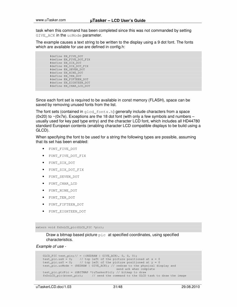
task when this command has been completed since this was not commanded by setting GIVE_ACK in the ucMode parameter.
The example causes a text string to be written to the display using a 9 dot font. The fonts which are available for use are defined in config.h: #define EN_FIVE_DOT #define EN_FIVE_DOT_FIX #define EN_SIX_DOT #define EN_SIX_DOT_FIX #define EN_SEVEN_DOT #define EN_NINE_DOT #define EN_TEN_DOT #define EN_FIFTEEN_DOT #define EN_EIGHTEEN_DOT #define EN_CHAR_LCD_DOT
Since each font set is required to be available in const memory (FLASH), space can be saved by removing unused fonts from the list.
The font sets (contained in glcd_fonts.h) generally include characters from a space (0x20) to ~(0x7e). Exceptions are the 18 dot font (with only a few symbols and numbers – usually used for key pad type entry) and the character LCD font, which includes all HD44780 standard European contents (enabling character LCD compatible displays to be build using a GLCD).
When specifying the font to be used for a string the following types are possible, assuming that its set has been enabled:
• FONT_FIVE_DOT
• FONT_FIVE_DOT_FIX
• FONT_SIX_DOT
• FONT_SIX_DOT_FIX
• FONT_SEVEN_DOT
• FONT_CHAR_LCD
• FONT_NINE_DOT
• FONT_TEN_DOT
• FONT_FIFTEEN_DOT
• FONT_EIGHTEEN_DOT
extern void fnDoLCD_pic(GLCD_PIC *pic);
Draw a bitmap based picture pic at specified coordinates, using specified characteristics.
Example of use - GLCD_PIC test_pic;// = {(REDRAW | GIVE_ACK), 0, 0, 0}; test_pic.usX = 0; // top left of the picture positioned at x = 0 test_pic.usY = 0; // top left of the picture positioned at y = 0 test_pic.ucMode = (REDRAW | GIVE_ACK); // redraw to the physical display and send ack when complete test_pic.ptrPic = (GBITMAP *)uTaskerPic1; // bitmap to draw fnDoLCD_pic(&test_pic); // send the command to the GLCD task to draw the image

www.uTasker.com µTasker – LCD User’s Guide
uTaskerLCD.doc/1.03 32/48 29.08.2010
Note that the bitmap image (GBITMAP *)uTaskerPic1 contains bit map data content, plus a header with its size – see the section on the uTaskerFileCreate utility for more details.
In this example a redraw is requested; this will first draw the bitmap to the pixel buffer and then update all differences between the pixel buffer content and the physical GLCD. An acknowledgement (event E_LCD_READY) is sent back from the LCD task once the command has been fully completed.
extern void fnDoLCD_line(void *line);
Draw a line between two points at specified coordinates, using specified characteristics as defined by line, whereby line can be of type GLCD_LINE or GLCD_LINE_BLINK.
Example of use for non-blinking line - #define ABOVE_LEFT_X 0 #define ABOVE_LEFT_Y 0 #define BOTTOM_RIGHT_X (GLCD_X - 1) #define BOTTOM_RIGHT_Y (GLCD_Y - 1) GLCD_LINE line1;// = {PAINT_LIGHT, {ABOVE_LEFT_X, ABOVE_LEFT_Y, BOTTOM_RIGHT_X, BOTTOM_RIGHT_Y }}; line1.ucMode = PAINT_LIGHT; line1.line_start_end.usX_start = ABOVE_LEFT_X; line1.line_start_end.usY_start = ABOVE_LEFT_Y; line1.line_start_end.usX_end = BOTTOM_RIGHT_X; line1.line_start_end.usY_end = BOTTOM_RIGHT_Y; fnDoLCD_line(&line1);
This example results in a single-pixel wide line being drawn to the pixel buffer starting at pixel location (0,0) (top left corner of screen) and ending at ((GLCD_X-1), (GLCD_Y-1)); bottom right corner. The line is drawn light (other possibilities are PAINT_DARK or PAINT_INVERTED, whereby the original background pixels are inverted).
There is neither a redraw nor an acknowledgement requested in the command so changes are only written to the physical GLCD the next time a command with REDRAW is sent.
Example of use for blinking line - GLCD_LINE_BLINK line1;// = {(BLINKING_OBJECT | PAINT_INVERTED | REDRAW | GIVE_ACK), {8, 54, 41, 68}, (DELAY_LIMIT)(0.35*SEC)}; line1.ucMode = (BLINKING_OBJECT | PAINT_INVERTED | REDRAW | GIVE_ACK); line1.line_start_end.usX_start = 8; line1.line_start_end.usY_start = 54; line1.line_start_end.usX_end = 41; line1.line_start_end.usY_end = 68; line1.blink_half_period = (DELAY_LIMIT)(0.35*SEC); fnDoLCD_line(&line1);
This example results in a single-pixel wide line being drawn to the pixel buffer starting at pixel location (8, 54) and ending at (41, 68). The line is drawn inverted (other possibilities are PAINT_DARK or PAINT_LIGHT).
Since the characteristic BLINKING_OBJECT is set the struct used is of type GLCD_LINE_BLINK and has an entry defining the blink period. The LCD task controls

www.uTasker.com µTasker – LCD User’s Guide
uTaskerLCD.doc/1.03 33/48 29.08.2010
thereafter the blinking of the defined object (a line in this case) without further application intervention. Blinking involves inverting the pixels as defined by the object once every period (0.3s in this case).
The maximum number of blinking objects is defined by MAX_BLINKING_OBJECTS (in config.h), whereby each object can have its own individual blink frequency.
Blinking causes the complete pixel buffer to be written to the physical GLCD and so can cause other waiting changes to be updated.
A blinking line can be cancelled by resending the line command with the same line end coordinates but the blink_half_period set to zero.
extern void fnDoLCD_rect(void *rect);
Draw a rectangle between two diagonal corners at specified coordinates, using specified characteristics as defined by rect, whereby rect can be of type GLCD_RECT or GLCD_RECT_BLINK.
Example of use for non-blinking rectangle - GLCD_RECT rect1;// = {( PAINT_LIGHT | REDRAW | GIVE_ACK), {5, 5, 100, 33}}; rect1.ucMode = (PAINT_LIGHT | REDRAW | GIVE_ACK); // ensure object painted light rect1.rect_corners.usX_start = 5; rect1.rect_corners.usY_start = 5; rect1.rect_corners.usX_end = 100; rect1.rect_corners.usY_end = 33; fnDoLCD_rect(&rect1);
This example results in a filled rectangle being drawn to the pixel buffer between diagonal corners at pixel location (5,5) - top left corner - and (100, 33) - bottom right corner. The line is drawn light (other possibilities are PAINT_DARK or PAINT_INVERTED, whereby the original background pixels are inverted).
A redraw and acknowledgement are requested so the LCD partner task will receive an E_LCD_READY event when the action has been fully completed.
Example of use for blinking rectangle - GLCD_RECT_BLINK rect1;// = {( BLINKING_OBJECT | REDRAW | GIVE_ACK), {5, 5, 100, 33}, (DELAY_LIMIT)(1.00*SEC)}; rect1.ucMode = (PAINT_LIGHT | REDRAW | GIVE_ACK); // ensure object painted light rect1.rect_corners.usX_start = 5; rect1.rect_corners.usY_start = 5; rect1.rect_corners.usX_end = 100; rect1.rect_corners.usY_end = 33; rect1. blink_half_period = (DELAY_LIMIT)(1.00*SEC); fnDoLCD_rect(&rect1);
This example results in the same filled rectangle being drawn being drawn (inverting the present background pixels) as in the previous example.
Since the characteristic BLINKING_OBJECT is set the struct used is of type GLCD_RECT_BLINK and has an entry defining the blink period. The LCD task controls thereafter the blinking of the defined object (a rectangle in this case) without further

www.uTasker.com µTasker – LCD User’s Guide
uTaskerLCD.doc/1.03 34/48 29.08.2010
application intervention. Blinking involves inverting the pixels as defined by the object once every period.
The maximum number of blinking objects is defined by MAX_BLINKING_OBJECTS (in config.h), whereby each object can have its own individual blink frequency.
Blinking causes the complete pixel buffer to be written to the physical GLCD and so can cause other waiting changes to be updated.
A blinking line can be cancelled by resending the rectangle command with the same diagonal coordinates but the blink_half_period set to zero.
extern void fnDoLCD_scroll(GLCD_SCROLL *scroll);
Scroll the complete screen (left/right/up/down)as specified by scroll.
Example of use for terminal type display output - GLCD_SCROLL scroll;// = {(REDRAW| GIVE_ACK | KILL_BLINK_OBJECTS), 0, 9}; GLCD_TEXT_POSITION text_pos;// = {PAINT_LIGHT, X, Y, FONT_SIX_DOT}; scroll.ucMode = (REDRAW | GIVE_ACK | KILL_BLINK_OBJECTS); scroll.sX_scroll = 0; scroll.sY_scroll = 9; fnDoLCD_scroll(&scroll); text_pos.ucMode = (PAINT_LIGHT | REDRAW | GIVE_ACK); text_pos.usX = 0; text_pos.usY = (GLCD_Y - 8); // position on very bottom of display text_pos.ucFont = (FONT_SIX_DOT); fnDoLCD_text(&text_pos, "Test of scrolling up");
This example results in the screen being scrolled up by 9 pixels so that there is space for a new line of text to be written to the bottom line.
The scroll command disables all blinking objects since these will not be scrolled and could otherwise cause disturbance to the terminal type mode. A redraw and an acknowledgement have are commanded so that the new pixel buffer content is sent to the physical GLCD and the LCD partner task receives an E_LCD_READY event when the action has been fully completed.
Warning: the scroll command presently only supports positive vertical scrolling (upwards) and neither horizontal nor negative scrolling (downwards).
www.uTasker.com µTasker – LCD User’s Guide
uTaskerLCD.doc/1.03 35/48 29.08.2010
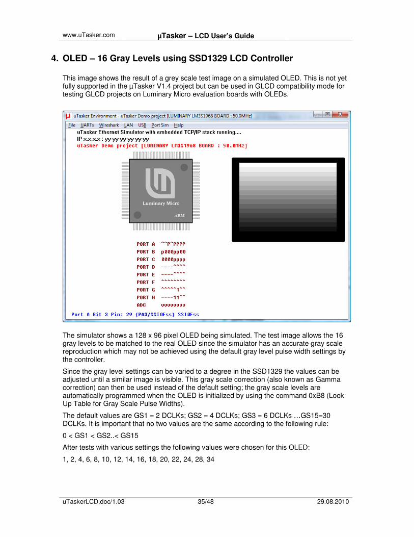
4. OLED – 16 Gray Levels using SSD1329 LCD Controller This image shows the result of a grey scale test image on a simulated OLED. This is not yet fully supported in the µTasker V1.4 project but can be used in GLCD compatibility mode for testing GLCD projects on Luminary Micro evaluation boards with OLEDs.
The simulator shows a 128 x 96 pixel OLED being simulated. The test image allows the 16 gray levels to be matched to the real OLED since the simulator has an accurate gray scale reproduction which may not be achieved using the default gray level pulse width settings by the controller.
Since the gray level settings can be varied to a degree in the SSD1329 the values can be adjusted until a similar image is visible. This gray scale correction (also known as Gamma correction) can then be used instead of the default setting; the gray scale levels are automatically programmed when the OLED is initialized by using the command 0xB8 (Look Up Table for Gray Scale Pulse Widths).
The default values are GS1 = 2 DCLKs; GS2 = 4 DCLKs; GS3 = 6 DCLKs …GS15=30 DCLKs. It is important that no two values are the same according to the following rule:
0 < GS1 < GS2..< GS15
After tests with various settings the following values were chosen for this OLED:
1, 2, 4, 6, 8, 10, 12, 14, 16, 18, 20, 22, 24, 28, 34

www.uTasker.com µTasker – LCD User’s Guide
uTaskerLCD.doc/1.03 36/48 29.08.2010
4.1. OLED use in GLCD Emulation Mode on Luminary Micro Evaluation Boards
Several Luminary Micro evaluation board include an OLED connected via SPI.
As well as supporting Toshiba and Samsung type mono-chrome graphical LCDs (SUPPORT_GLCD for Toshiba type and SUPPORT_GLCD and _GLCD_SAMSUNG for Samsung type) the µTasker project for Luminary Micro supports the use of the OLED in GLCD emulation mode to test GLCD projects using this type of built in display on the evaluation board.
To activate the OLED GLCD emulation mode the define OLED_GLCD_MODE needs to be activated as well as SUPPORT_GLCD.
The GLCD user interface (and thus the demo test code) remains compatible but the driver controls the OLED via the SPI interface in black and white mode (not using its gray scale possibilities). Depending on the size of the OLED on the board it may be that the image is cropped or else that only a part of the display is used. For example, the demonstration project running on the LM3S8962 Evaluation Board with an OLED of 128 x 96 pixels will not show the complete 160 x 80 image but the lines around the display and the cross will adjust to suit:
www.uTasker.com µTasker – LCD User’s Guide
uTaskerLCD.doc/1.03 37/48 29.08.2010
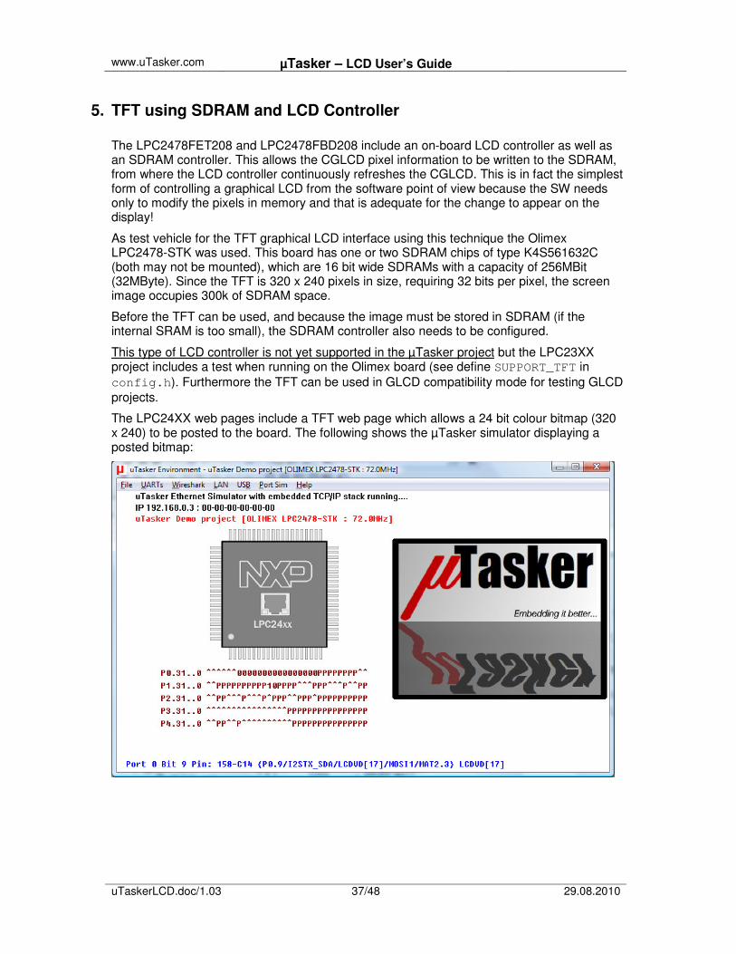
5. TFT using SDRAM and LCD Controller The LPC2478FET208 and LPC2478FBD208 include an on-board LCD controller as well as an SDRAM controller. This allows the CGLCD pixel information to be written to the SDRAM, from where the LCD controller continuously refreshes the CGLCD. This is in fact the simplest form of controlling a graphical LCD from the software point of view because the SW needs only to modify the pixels in memory and that is adequate for the change to appear on the display!
As test vehicle for the TFT graphical LCD interface using this technique the Olimex LPC2478-STK was used. This board has one or two SDRAM chips of type K4S561632C (both may not be mounted), which are 16 bit wide SDRAMs with a capacity of 256MBit (32MByte). Since the TFT is 320 x 240 pixels in size, requiring 32 bits per pixel, the screen image occupies 300k of SDRAM space.
Before the TFT can be used, and because the image must be stored in SDRAM (if the internal SRAM is too small), the SDRAM controller also needs to be configured.
This type of LCD controller is not yet supported in the µTasker project but the LPC23XX project includes a test when running on the Olimex board (see define SUPPORT_TFT in config.h). Furthermore the TFT can be used in GLCD compatibility mode for testing GLCD projects.
The LPC24XX web pages include a TFT web page which allows a 24 bit colour bitmap (320 x 240) to be posted to the board. The following shows the µTasker simulator displaying a posted bitmap:

www.uTasker.com µTasker – LCD User’s Guide
uTaskerLCD.doc/1.03 38/48 29.08.2010
The web page also sends the present CGLCD contents to the browser as a 24 bit Windows compatible bitmap:
�
�
5.1. TFT use in GLCD Emulation Mode on Olimex LPC2478 Board As well as supporting Toshiba and Samsung type mono-chrome graphical LCDs (SUPPORT_GLCD for Toshiba type and SUPPORT_GLCD and _GLCD_SAMSUNG for Samsung type) the µTasker project for the LPC2478 supports the use of the TFT in GLCD emulation mode to test GLCD projects using this type of built in display on the evaluation board.
To activate the TFT GLCD emulation mode the define TFT_GLCD_MODE needs to be activated as well as SUPPORT_GLCD.
The GLCD user interface (and thus the demo test code) remains compatible but the driver controls the TFT SDRAM memory in a two-colour mode (not using its full colour capabilities). Usually the TFT’s pixel dimensions are larger than a GLCD and so the image usually only occupies a part of the screen as shown below – the outer frame and diagonal will however be adjusted to fit the display:

www.uTasker.com µTasker – LCD User’s Guide
uTaskerLCD.doc/1.03 39/48 29.08.2010
The colour for background and active pixels can be defined in config.h by setting
#define LCD_PIXEL_COLOUR (COLORREF)RGB(255,0,0) // red pixels
and
#define LCD_ON_COLOUR (COLORREF)RGB(200,200,200) // on silver background

www.uTasker.com µTasker – LCD User’s Guide
uTaskerLCD.doc/1.03 40/48 29.08.2010
6. CGLCD on AVR32 EVK1105
The ATMEL AVR32 EVK1105 includes a colour 320 x 240 CGLCD (TFT) connected via its external memory interface.
This type of LCD controller is not yet supported in the µTasker project but the AVR32 project includes a test when running on the EVK1105 board (see define AVR32_EVK1105 in the GLCD configuration in config.h). Furthermore the TFT can be used in GLCD compatibility mode for testing GLCD projects.
The AVR32 web pages include a TFT web page which allows a 24 bit colour bitmap (320 x 240) to be posted to the board. The following shows the µTasker simulator displaying a posted bitmap:

www.uTasker.com µTasker – LCD User’s Guide
uTaskerLCD.doc/1.03 41/48 29.08.2010
The web page also sends the present CGLCD contents to the browser as a 24 bit Windows compatible bitmap:
�
�

www.uTasker.com µTasker – LCD User’s Guide
uTaskerLCD.doc/1.03 42/48 29.08.2010
As alternative, the define USE_AVR32_IMAGE can be activated in the file CGLCD.c (in the AVR32 project’s application folder) to view the ATMEL test TFT image:
This includes a large file called avr32_image.h containing the original image from the AVR32 studio demonstration. This increased the project image size by about 150k bytes. It also uses some of the ATMEL library routines to paint the image and draw the coloured boxes showing that the µTasker CGLCD simulator can also be used together with other graphics libraries when required!
6.1. CGLCD use in GLCD Emulation Mode on EVK1105 As well as supporting Toshiba and Samsung type mono-chrome graphical LCDs (SUPPORT_GLCD for Toshiba type and SUPPORT_GLCD and _GLCD_SAMSUNG for Samsung type) the µTasker project for the AVR32 supports the use of the CGLCD in GLCD emulation mode to test GLCD projects using this type of built in display on the evaluation board.
To activate the GLCD GLCD emulation mode the define CGLCD_GLCD_MODE needs to be activated as well as SUPPORT_GLCD.
The GLCD user interface (and thus the demo test code) remains compatible but the driver controls the CGLCD SDRAM memory in a two-colour mode (not using its full colour capabilities). Usually the CGLCD’s pixel dimensions are larger than a GLCD and so the image usually only occupies a part of the screen as shown below – the outer frame and diagonal will however be adjusted to fit the display:

www.uTasker.com µTasker – LCD User’s Guide
uTaskerLCD.doc/1.03 43/48 29.08.2010
The colour for background and active pixels can be defined in config.h by setting
#define LCD_PIXEL_COLOUR (COLORREF)RGB(255,255,0) // yellow pixels
and
#define LCD_ON_COLOUR (COLORREF)RGB(128,128,255) // on light blue background

www.uTasker.com µTasker – LCD User’s Guide
uTaskerLCD.doc/1.03 44/48 29.08.2010
7. CGLCD on Luminary EK_LM3S3748
The Luminary LM3S3748 evaluation board includes a colour 128 x 128 CGLCD connected via GPIOs.
This type of LCD controller is not yet supported in the µTasker project but the Luminary project includes a test when running on the EK_LM3S3748 board (see define EK_LM3S3748in the GLCD configuration in config.h). Furthermore the CGLCD can be used in GLCD compatibility mode for testing GLCD projects.
The following image shows the µTasker simulator working with this type of display and running some of the Luminary Micro demonstration code – the display is first black and fades to white; then the LUMINARY MICRO logo is fades in. This again shows that the µTasker CGLCD simulator can also be used together with other graphics libraries when required!
The configuration used to run this test uses the (provisional) application file CGLCD.c, containing the Luminary Micro reference code.

www.uTasker.com µTasker – LCD User’s Guide
uTaskerLCD.doc/1.03 45/48 29.08.2010
7.1. Colour LCD use in GLCD Emulation Mode on Luminary EK_LM3S3748 As well as supporting Toshiba and Samsung type mono-chrome graphical LCDs (SUPPORT_GLCD for Toshiba type and SUPPORT_GLCD and _GLCD_SAMSUNG for Samsung type) the µTasker project for Luminary Micro supports the use of the colour LCD in GLCD emulation mode to test GLCD projects using this type of built in display on the evaluation board.
To activate the CGLCD GLCD emulation mode the define CGLCD_GLCD_MODE needs to be activated as well as SUPPORT_GLCD.
The GLCD user interface (and thus the demo test code) remains compatible but the driver controls the CGLCD via the GPIO interface in dual-colour mode (not using its full colour capabilities). Depending on the size of the CGLCD on the board it may be that the image is cropped or else that only a part of the display is used. For example, the demonstration project running on the LM3S3748 Evaluation Board with a CGLCD of 128 x 128 pixels will not show the complete 160 x 80 image but the lines around the display and the cross will adjust to suit:
The colour for background and active pixels can be defined in config.h by setting
#define LCD_PIXEL_COLOUR (COLORREF)RGB(0,0,255) // blue pixels
and
#define LCD_ON_COLOUR (COLORREF)RGB(255,255,0) // on yellow background

www.uTasker.com µTasker – LCD User’s Guide
uTaskerLCD.doc/1.03 46/48 29.08.2010
8. NOKIA 6100 on Olimex SAM7X and LPC2378 Evaluation Boards
This type of LCD controller is not yet supported in the µTasker project but the CGLCD can be used in GLCD compatibility mode for testing GLCD projects on OLIMEX SAM7X and LPC2378 evaluation boards, which include NOKIA colour LCDs connected via SPI.
To activate the GLCD emulation mode the define NOKIA_GLCD_MODE needs to be activated as well as SUPPORT_GLCD.
Although the pixel dimensions of the NOKIA 6100 are 132 x 132 the topmost and rightmost 2 pixels are not visible, leaving useful 130 x 30 pixels.
The GLCD user interface (and thus the demo test code) remains compatible (apart from teh fact that the two non-visible pixels may have to be accounted for) but the driver controls the CGLCD via the SPI interface in dual-colour mode (not using its full colour capabilities). Depending on the size of the CGLCD on the board it may be that the image is cropped or else that only a part of the display is used. For example, the demonstration project running on the Olimex boards with a CGLCD of 132 x 132 pixels will not show the complete 160 x 80 image but the lines around the display and the cross will adjust to suit:

www.uTasker.com µTasker – LCD User’s Guide
uTaskerLCD.doc/1.03 47/48 29.08.2010
The colour for background and active pixels can be defined in config.h by setting
#define LCD_PIXEL_COLOUR (COLORREF)RGB(255,0,0) // red pixels
and #define LCD_ON_COLOUR (COLORREF)RGB(0,0,255) // on blue background
The setting for the contrast of the display varies between displays and it may be necessary to adjust this (by trial and error) to get optimum display contrast results on a particular development board. The setting is hard-coded in glcd_nokia.h as values for the VOLTCTRL command sent during the initialisation: WriteSpiCommand(VOLTCTRL); // voltage control WriteSpiData(0x1f); // middle value of V1 WriteSpiData(0x03); // middle value of resistance value

www.uTasker.com µTasker – LCD User’s Guide
uTaskerLCD.doc/1.03 48/48 29.08.2010
9. Conclusion
The µTasker character LCD support which has existed from the µTaskerV1.2 version has been presented along with details of interfacing standard processors to devices in 4-bit or 8-bit modes.
The µTasker V1.4 adds monochrome graphic LCD support (based on T6963C and Samsung KS0108B controllers) to all supported processors and builds the foundation for further development of powerful graphic capabilities together with an accurate graphical LCD simulator.
The uTaskerFileCreate utility has been discussed, which allows multiple standard bit maps to be automatically embedded into project code.
uGLCDLIB V1.1 adds drawing support allowing lines and rectangles to be drawn, optionally with individual blinking attributes, plus screen scrolling.
Although colour graphical LCDs are not generally supported in the first release of the V1.4 project ground work has been made to allow this to be progressively added. The demonstration project already includes impressive colour simulation and practical examples of colour graphical LCDs on several popular evaluation boards, allowing images to be posted to the display via web browser and the present LCD contents to be displayed as bitmaps on a web page. Some of these examples show how the µTasker colour graphic LCD simulator can already be used together with semiconductor manufacturers’ graphic libraries.
A GLCD emulation mode is included in uGLCDLIB V1.1 to enable typical colour graphic LCDs, as found on well known evaluation boards, to be used in monochrome GLCD compatible mode, allowing them to be used to develop and test projects requiring GLCDs.
Modifications:
V1.00 21.7.2009: Initial version
V1.01 6.10.2009: uGLCDLIB V1.1 with drawing functions and GLCD emulation
V1.02 7.10.2009: Completed uGLCDLIB V1.1 description for all boards
V1.03 29.8.2010: Added character LCD character set for standard LCD and Cyrillic display