Thermo Scientific Multifuge X Pro / Megafuge ST Plus Serie ...
Upload
khangminh22Category
view
0download
0
DOC0023
Installation Manual iBOS® Pro 6 Series
October 2019 Version 1.7

Philadelphia Scientific® iBOS® Pro 6 Series Installation Manual Page 2 of 87
Table of Contents iBOS® Pro 6 Series 1. Introduction ................................................................................................................................................... 4
1.1 System overview ..................................................................................................................................... 4 1.2 Organization of this Manual .................................................................................................................... 4 1.3 Contact Information ................................................................................................................................ 5 1.4 Installation Outline .................................................................................................................................. 5
2. System Components .................................................................................................................................... 6 2.1 Individual Components ........................................................................................................................... 6 2.2 Control Box ............................................................................................................................................. 7 2.3 BOS-CB6700 Ports ................................................................................................................................. 8 2.4 BOS-CB6710 Ports ................................................................................................................................. 8 2.5 Control Box Rear of Front Door .............................................................................................................. 9 2.6 Sentinel™ BOS-SU6003 Anatomy ....................................................................................................... 10 2.7 System Components ............................................................................................................................ 11
Sentinel™ ................................................................................................................................................ 11 Scrolling Display ..................................................................................................................................... 11 Wireless Display ..................................................................................................................................... 11 Sentinel™ Data Cable and Coupler 25’ (7.6 m) (CAT3) ........................................................................ 11 Sentinel™ Data Cable and Coupler 100’ (30.5 m) (CAT3) .................................................................... 11 Peripheral Data Cable (CAT5e) and Coupler 50’ (15.2 m) .................................................................... 12 External Shouter ..................................................................................................................................... 12 Custom Sentinel™ Data Cable Kit ......................................................................................................... 12
2.8 Wireless Display System Diagram ....................................................................................................... 13 2.9 Scrolling Display System Diagram ....................................................................................................... 13
3. Planning / Specifying Job ........................................................................................................................... 15 3.1 Decide on Pools .................................................................................................................................... 15 3.2 Count Chargers in Each Pool ............................................................................................................... 15 3.3 Wireless Display Location .................................................................................................................... 16 3.4 Scrolling Display Location .................................................................................................................... 17 3.5 Control Box Location ............................................................................................................................ 17 3.6 Sentinel™ Data Cable Requirements .................................................................................................. 18 3.7 Installation Service ................................................................................................................................ 20
4. Pre-Installation ............................................................................................................................................ 21 4.1 Check data connection availability ....................................................................................................... 21 4.2 Check power availability ....................................................................................................................... 21 4.3 Control Box Dimensions ....................................................................................................................... 22 4.4 Charger Configuration .......................................................................................................................... 22 4.5 Pre-installation Phone Conference ....................................................................................................... 22 4.6 Useful Tools and Materials ................................................................................................................... 22 4.7 Pre-Install Checklist .............................................................................................................................. 23
5. Installing System Components ................................................................................................................... 24 5.1 Installing Control Box ............................................................................................................................ 24
5.1.1 Install Mounting Bracket ................................................................................................................ 24 5.1.2 Mounting the Control Box .............................................................................................................. 24 5.1.3 Securing the Control Box to Wall .................................................................................................. 24
5.2 Installing the Battery Backup into the Control Box ............................................................................... 24 5.2.1 UPS in Control Box ........................................................................................................................ 24 5.2.2 Route UPS Cable to Power ........................................................................................................... 25
5.3 Installing the Sentinel™ ........................................................................................................................ 25 5.3.1 Run Sentinel™ Data Cable to 1st Sentinel™ of Each Bus ............................................................ 25 5.3.2 Connect Sentinel™ Data Cable to Sentinel™ Socket .................................................................. 26 5.3.3 Mount Sentinel™ ........................................................................................................................... 27 5.3.4 Connect Sentinel™ to charger ...................................................................................................... 28
5.4 Install Scrolling Display(s) .................................................................................................................... 29

Philadelphia Scientific® iBOS® Pro 6 Series Installation Manual Page 3 of 87
5.4.1 Install Scrolling Display .................................................................................................................. 29 5.4.2 Program Display Settings .............................................................................................................. 30
5.5 Install Wireless Display ......................................................................................................................... 32 5.5.1 Wireless Display Antenna Install: .................................................................................................. 33
5.6 Label Battery Chargers and Bays ........................................................................................................ 34 5.6.1 Number your chargers and bays ................................................................................................... 34
5.7 Data Uploads ........................................................................................................................................ 35 5.8 Install External Shouter......................................................................................................................... 35
6. System Configuration and Settings ............................................................................................................ 37 6.1 Language Setting .................................................................................................................................. 37 6.2 Date and Time Setting .......................................................................................................................... 38 6.3 Configuring Pools and Chargers .......................................................................................................... 41 6.4 Configuring Internet Connections ......................................................................................................... 45 6.5 Password Settings ................................................................................................................................ 49 6.6 Display Pools ........................................................................................................................................ 50 6.7 Volume Adjustment ............................................................................................................................... 51 6.8 Sentinel Outputs ................................................................................................................................... 51 6.9 Message Length ................................................................................................................................... 52 6.10 Linked Pools ....................................................................................................................................... 53
6.10.1 Name the Pools ........................................................................................................................... 53 6.10.2 Select Link Pools ......................................................................................................................... 53 6.10.3 Set Pool Pairs .............................................................................................................................. 53
6.11 Home Screen Display ......................................................................................................................... 54 6.12 Running System Dark ......................................................................................................................... 55
7. Final Inspection and Testing ....................................................................................................................... 56 7.1 Sentinels™ ............................................................................................................................................ 56
7.1.1 Status ............................................................................................................................................. 56 7.1.2 Quarantine ..................................................................................................................................... 57 7.1.3 Sentinel List ................................................................................................................................... 58 7.1.4 System Information ........................................................................................................................ 59
7.2 Scrolling Display(s) ............................................................................................................................... 60 7.3 Shouter .................................................................................................................................................. 60 7.4 Check Data Upload to Web .................................................................................................................. 61 7.5 Wireless Communications Test ............................................................................................................ 62
8. Troubleshooting .......................................................................................................................................... 64 8.1 Version Determination .......................................................................................................................... 65 8.2 Control Box ........................................................................................................................................... 66 8.3 Sentinel™.............................................................................................................................................. 67 8.4 Shouter .................................................................................................................................................. 68 8.5 Scrolling Displays ................................................................................................................................. 70 8.6 Wireless Touch Screen......................................................................................................................... 72 8.7 System Trouble Shooting Reference ................................................................................................... 73
8.7.1 System Information. ....................................................................................................................... 73 8.7.2 Wireless Display RF Antenna Relocation ..................................................................................... 73 8.7.3 Changing out a Sentinel™............................................................................................................. 74 8.7.4 Reconfiguring a Sentinel™ that has been configured for the wrong charger .............................. 76 8.7.5 Troubleshooting with Blue Light .................................................................................................... 76
Appendix A – Sentinel™ Information ............................................................................................................. 77 Appendix B – Scrolling Display Information ................................................................................................... 78
Section 1 – Sign Types ............................................................................................................................... 78 Section 2 – Type B Signs ........................................................................................................................... 79 Section 3 – Type A Signs ........................................................................................................................... 80
Appendix C – Internet Connection Requirements .......................................................................................... 83 Appendix D – Display Protection .................................................................................................................... 84 Appendix E – Custom Sentinel™ Data Cable ................................................................................................ 85 Appendix F – Glossary ................................................................................................................................... 86

Philadelphia Scientific® iBOS® Pro 6 Series Installation Manual Page 4 of 87
1. Introduction
1.1 System overview This manual will give you all the information you need to install the iBOS® battery management system. Once installed this system will help create a smooth-running battery room and provide valuable management information on the batteries and chargers. Before getting into all the details of installation, a quick overview of how the system works may be helpful. Once the system is installed, every charger will have a small monitoring device attached to it called a Sentinel™ that works on all voltages (12-80v). The Sentinel’s™ basic function is to detect when the charger finishes charging and to tell the Control Box that a fully charged battery is now available for use. The Sentinel™ also detects when a battery is connected without the charger starting. After 24 hours in this state, the Sentinel™ will terminate and return the battery to the rotation, even though the battery was not charged, to avoid stranding the battery indefinitely. A charger no-start record will appear on the iBOSworld Web Service website indicating charger #, date and time. All Sentinels™ are wired via a daisy chained bus into the Control Box which keeps track of all the charged batteries. The chargers are grouped into pools, one pool for each type/size of battery in the facility. One or more scrolling LED displays, mounted on the wall, or a wireless display, mounted on the battery changer, tells the operator which battery to pick next. The battery that is fully charged and that has been cooled down the longest will appear on the display, assuming there are no “charger no start” batteries. There is also a built-in shouter which announces a message in one of seven languages telling the operator when they have picked an incorrect battery. This enables the system to ensure proper battery rotation. The procedure for the operators is:
• When a truck comes in for a new battery, the operator looks at the display for that pool.
• It will tell him/her which battery to take. For example, they may see a message like: “Take next REACH TRUCK battery from charger 102.”
• The operator goes to the slot marked “102” to get the battery for that type of truck. The Control Box is also capable of sending data to a website where it can be analyzed, and reports are generated. These reports contain information necessary for keeping the battery selection process running smoothly and can be used to predict when a drift in process is due to too many/too few batteries, malfunctioning chargers, and operators following instructions improperly. The connection to the internet is either a standard direct network Ethernet or via cellular modem. The Ethernet method saves money over the cellular service but requires IT department approval and installation. The cellular modem requires a signal to a cell tower but can be a quick and reliable alternative. Once data is being sent out, users who have the proper login permission can log into the website and see information about the performance of the battery room. This information can help determine if the site is running short of batteries or has too many, if all the chargers are working properly, and if the operators are correctly following the instructions.
1.2 Organization of this Manual This manual has been divided into sections for each of the stages of an installation project:
• Section 2 – System components. This section is simply to help you get familiar with what the various parts of the system are and what they look like.
• Section 3 – Planning the job. When you are specifying a job, there are some useful guidelines that we have found to be helpful in initially specifying the system.
• Section 4 – Pre-installation. You have ordered the system and are ready to go on the installation trip. The steps in this section are invaluable in preparation for when you are on site. Our goal is that you only need to make one trip to complete the installation.

Philadelphia Scientific® iBOS® Pro 6 Series Installation Manual Page 5 of 87
• Section 5 – Installing the hardware. Finally, the actual installation steps to get everything mounted and wired.
• Section 6 – Configuring the software. This is how you tell the Control Box the names of the pools, the charger numbers and other configuration information.
• Section 7– Final Inspection and testing
• Section 8– Troubleshooting
• Appendixes- on various topics to support the installation and your system understanding.
1.3 Contact Information
Philadelphia Scientific LLC 207 Progress Drive Montgomeryville, PA 18936 USA Phone: 215-616-0390 Fax: 215-616-0500 Email: [email protected]
Philadelphia Scientific UK Ltd. Atlas Mill Bolton BL14LB United Kingdom Phone: +44 (0) 1204-467777 Fax: +44 (0) 1204-493300 Email: [email protected]
Philadelphia Scientific-Asia/Pacific 2/17 Norman Street NSW, 2225 Australia Phone: +61 2 8004-2447 Fax: +61 2 9012-0383 Email: [email protected]
1.4 Installation Outline Once you get on site, the installation can be divided into three basic stages.
I. Control Box and peripherals – This stage requires some knowledge of battery rooms and can involve some customer input.
a. Mount Control Box b. Mount Scrolling Displays or Wireless Display c. Mount External Shouter alarm (Optional) d. Connect Ethernet (Installed prior to iBOS® installation, preferably) or cellular modem e. Review battery pools and charger/battery slots
II. Connecting chargers – This takes the longest time, is repetitive, and someone who is familiar with
general electrician-type work can be trained quickly. a. Wiring bridge from the Control Box to the 1st Sentinel™ of each bus. b. Mounting Sentinels™ on each charger c. Running the Sentinel™ Data Cable between Sentinels™ d. Label chargers and battery bays
III. Testing and configuring the system – This step is probably the quickest (unless problems with
wiring are found and must be fixed). It is also the most iBOS® specific. a. Name pools b. Configure chargers c. Test upload capability d. Set system for operations or running dark period e. Operator Training

Philadelphia Scientific® iBOS® Pro 6 Series Installation Manual Page 6 of 87
2. System Components
2.1 Individual Components The iBOS® Pro 6 Series Control Box is manufactured in two versions:
- BOS-CB6700 – can connect up to 200 Sentinels™ with Scrolling Displays or wireless display - BOS-CB6710 – can connect a max of 350 Sentinels™ with wireless display
-
Wireless Display
Control Box
Built in Speaker
Mounting Feet
Sentinels™
External Shouter
Cellular Modem
Touch Screen Interface
Locking Tab
Scrolling Display
Mounting Bracket

Philadelphia Scientific® iBOS® Pro 6 Series Installation Manual Page 7 of 87
2.2 Control Box
Battery Backup Compartment
2 Wireless Radio Modem Mounting Locations (used with Wireless Display)
Cable Tray
Power Socket Connection to Control Box
3 Wiring Ports (3/4” ID and (2) 1 ½” OD)
Wireless Radio Antenna Mount
USB Port Interface
Mother Board Panel Cover (Do not remove)
Cell Modem
Mounting Location

Philadelphia Scientific® iBOS® Pro 6 Series Installation Manual Page 8 of 87
2.3 BOS-CB6700 Ports
2.4 BOS-CB6710 Ports
No Scrolling Displays
Programming
Wireless Display
Connections 1st and 2nd
Ethernet
Accessory
Scrolling Displays (x3)
Sentinel™ Bus (x4) – Max 50 Sentinels™/ bus
USB Ports
External Shouter
Sentinel™ Bus (x7) – Max 50 Sentinels™/ bus
Programming
Ethernet
Accessory
USB Ports
External
Shouter
Wireless Display
Connections 1st and 2nd

Philadelphia Scientific® iBOS® Pro 6 Series Installation Manual Page 9 of 87
2.5 Control Box Rear of Front Door
SD Card for Touch
Screen
Front Locking
Slot
Internal Shouter
Power (12v) to Display
Audio to Shouter
Closure
Screws
Closure Screws

Philadelphia Scientific® iBOS® Pro 6 Series Installation Manual Page 10 of 87
2.6 Sentinel™ BOS-SU6003 Anatomy
Reverse Side –
Slotted End Cap
Enclosure
24” (.61m) Sensing cables
Flexi-Taps
Sentinel™ Board
Sentinel™ End Cap
Shipping Caps (discard)
Data Sockets (2x)
Software Version Serial Number of Sentinel (SN)

Philadelphia Scientific® iBOS® Pro 6 Series Installation Manual Page 11 of 87
2.7 System Components
Sentinel™ BOS-SU6003
Scrolling Display BOS-DSPT
Wireless Display BOS-WD6000
Sentinel™ Data Cable and Coupler 25’ (7.6 m) (CAT3) BOS-143
Sentinel™ Data Cable and Coupler 100’ (30.5 m) (CAT3) BOS-161

Philadelphia Scientific® iBOS® Pro 6 Series Installation Manual Page 12 of 87
Peripheral Data Cable (CAT5e) and Coupler 50’ (15.2 m) BOS-200
External Shouter BOS-SH6000
Custom Sentinel™ Data Cable Kit BOS-159
Philadelphia Scientific® iBOS® Pro 6 Series Installation Manual Page 13 of 87
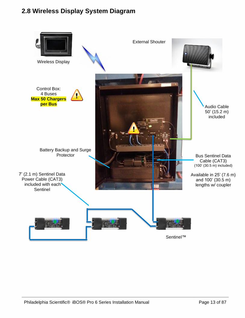
2.8 Wireless Display System Diagram
Wireless Display
External Shouter
Sentinel™
Control Box: 4 Buses
Max 50 Chargers per Bus
Audio Cable 50’ (15.2 m)
included
Bus Sentinel Data Cable (CAT3)
(100’ (30.5 m) included)
Available in 25’ (7.6 m) and 100’ (30.5 m) lengths w/ coupler
7’ (2.1 m) Sentinel Data Power Cable (CAT3) included with each
Sentinel
Battery Backup and Surge
Protector
Philadelphia Scientific® iBOS® Pro 6 Series Installation Manual Page 14 of 87
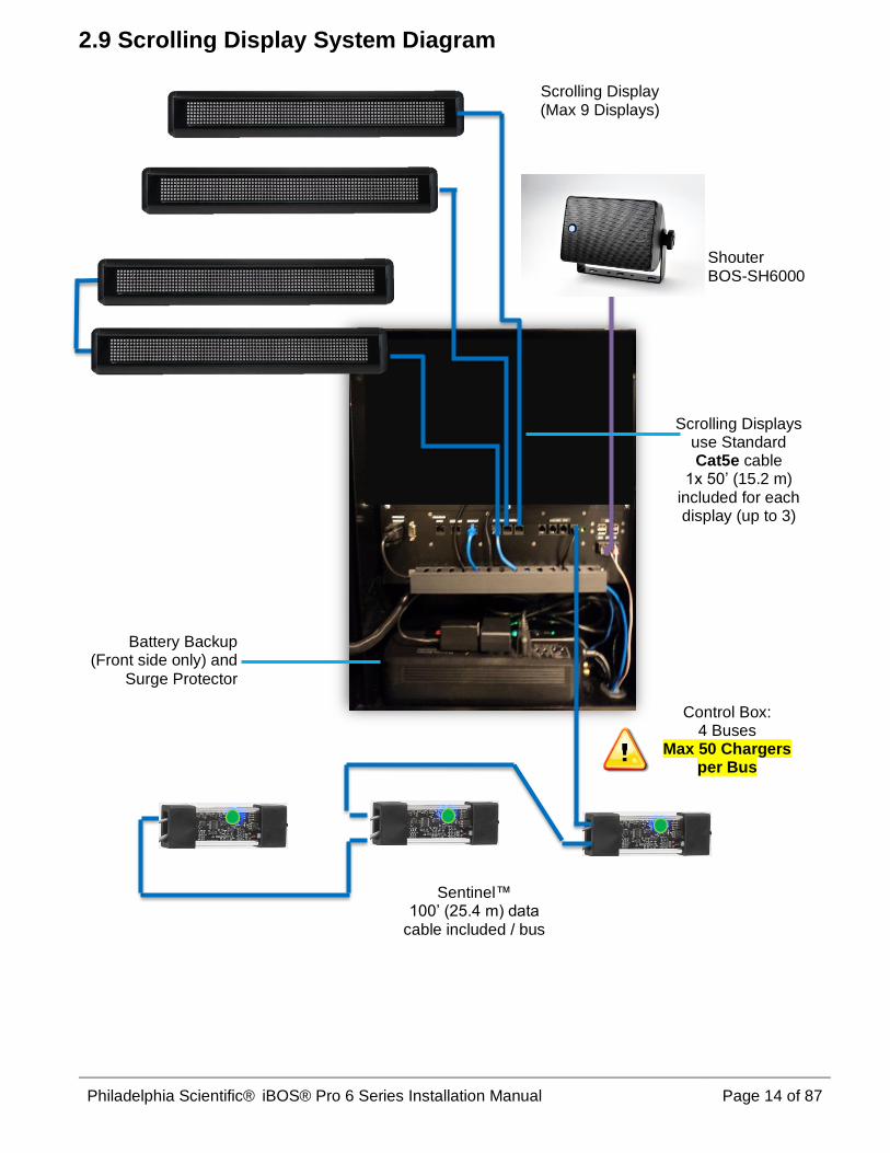
2.9 Scrolling Display System Diagram
Shouter BOS-SH6000
Sentinel™ 100’ (25.4 m) data
cable included / bus
Scrolling Display (Max 9 Displays)
Control Box: 4 Buses
Max 50 Chargers per Bus
Battery Backup (Front side only) and
Surge Protector
Scrolling Displays use Standard Cat5e cable
1x 50’ (15.2 m) included for each display (up to 3)

Philadelphia Scientific® iBOS® Pro 6 Series Installation Manual Page 15 of 87
3. Planning / Specifying Job
3.1 Decide on Pools
The first step is to make a list of all the pools in the facility. The groups of different kinds/sizes of
batteries are put into pools. For example, all of the reach truck batteries would be considered one pool.
All of the Pallet Jack batteries would be a different pool.
For example, if a distribution center has 12 chargers for pallet jacks, 9 chargers for reach truck batteries,
and 7 for turret truck batteries, we would have 3 pools.
Pool 1 → “PALLET JACK” Pool 2 → “REACH TRUCK” Pool 3 → “TURRET”
As shown in this example there will always be at least one pool for each battery type/size in the facility.
There can be more pools in some situations
If a distribution center has 2 battery changers you may want to configure 2 pools for each battery type.
Assume that each battery changer has 40 chargers for pallet jacks and 25 chargers for reach trucks.
You would probably want to set up 4 pools:
Pool 1 → “PALLET (LEFT)” Pool 2 → “REACH (LEFT)”
Pool 3 → “PALLET (RIGHT)” Pool 4 → “REACH (RIGHT)”
NOTE: The names of the pools need to be 13 characters or less.
3.2 Count Chargers in Each Pool
You will need one Sentinel™ for each charger. The Sentinels™ are universal voltage and work from 12v
to 80v DC.

Philadelphia Scientific® iBOS® Pro 6 Series Installation Manual Page 16 of 87
3.3 Wireless Display Location
(if applicable for your system)
- Wireless Display (BOS-WD6000) is
normally mounted on the battery changer.
- Power Requirements:
o 110 / 220 VAC outlet
Surge protector is recommended. See appendix
D- Display Protection.
- It can also be mounted on a wall or
anywhere that is convenient.
(BOS-174 optional mounting bracket shown in use.)

Philadelphia Scientific® iBOS® Pro 6 Series Installation Manual Page 17 of 87
3.4 Scrolling Display Location
(if applicable for your system)
• The Scrolling Display shows which battery
to take. The people who change the
batteries must be able to see the display
easily.
• Method 1 Grouped: locate all of the
Scrolling Displays together, i.e. at the end
of the battery changer bay. Many installers
find it helpful to install the displays and
shouters on a backboard before going to
the site to make a very professional look
and to make installation easier (Appendix
C).
• Method 2 Per Pool: If you have two
battery changers, the Scrolling Displays for
each battery changer can be put in the bay
for that changer.
• The Scrolling Displays can also be
mounted near the pool for that display.
NOTE: It is highly recommended that each
display is protected with a surge protector
(see Appendix D).
Scrolling Displays mounted together (Method 1)
Displays mounted next to each pool of batteries (Method 2)
3.5 Control Box Location
Locate Control Panel in a clean, dry safe area:
• Near battery chargers.
• Close to the Scrolling Displays. Ideally less
than a 50’ (15.2 m) run for the display
cable.
• Less than 6’ (1.8 m) from an AC outlet
• Out of the way, so it won’t be damaged by
lift trucks or other moving objects
• At eye level for display for programming –
Installing the hanger bracket at eye level
will accomplish this.
Use appropriated anchors as dictated by the wall material you are mounting the Control Box (35 lbs. (15.9 kg))

Philadelphia Scientific® iBOS® Pro 6 Series Installation Manual Page 18 of 87
• Where it won’t obstruct anything
• Where it will be easy to run cable from the
chargers.
3.6 Sentinel™ Data Cable Requirements
Data Cables are required to be run from the Control Box to the first Sentinel™ as well as from Sentinel™ to
Sentinel™ for the rest of the chargers in a daisy chain method for a max of 50 Sentinels™ per Bus. Model
BOS-CB6700 has 4 Buses with a system max of 200 Sentinels™ and model BOS-CB6710 has 7 buses
with a system max of 350 Sentinels™. Using non-approved cable may not work and could void your
warranty.
• 7’ (2.1 m) Sentinel™ Data Cables (supplied with each Sentinel™)
• 25’ (7.6 m) Sentinel™ Data Cables w/coupler (must be ordered) BOS-143
• 100’ (30.5 m) Sentinel™ Data Cable w/coupler (1 per Bus is supplied with control box) BOS-161
• Custom Cable Kit (must be ordered) BOS-159
You need to purchase enough cable to reach the first Sentinel™ for each Bus you are using.
Here are some sample layouts of a typical battery room layout.

Philadelphia Scientific® iBOS® Pro 6 Series Installation Manual Page 19 of 87
Sample 1: Layout 2 pool on one bus.
Sample 2: Layout - 3 pools on 4 Buses.
(A) A single Bus can run multiple pools.
(B) One Pool can span across multiple buses.
(C) The distance from control box and the first Sentinel™ can vary as required.
(D) Bridges can be installed between different racks with varied distances as required
These samples above show that you can mix voltages and pools on one bus. The limitation is that you can
only have up to 50 Sentinels™ on one bus.

Philadelphia Scientific® iBOS® Pro 6 Series Installation Manual Page 20 of 87
Two examples of Bus cabling are shown in the picture above:
Bus 1: 50’ (15.2 m) of cable needed even though it was only 10’ (3 m) from the Control Box to the first
Sentinel™.
Bus 2: 100’ (30.5 m) of cable needed even though it was only 30’ (9.1 m) from the Control Box to the first
Sentinel™.
Resources – Length of prepared data extension cable available: 25’ (7.6 m), 100’ (30.5m) and a bulk
custom cable kit of 1000’ (305 m).
3.7 Installation Service
We offer installation services. Having us come and do the installation along with you on your first job can
help train you and ensure a successful first installation and many to follow.
1st Sentinel
1st Sentinel

Philadelphia Scientific® iBOS® Pro 6 Series Installation Manual Page 21 of 87
4. Pre-Installation These are items that should be done before installation begins.
4.1 Check data connection availability You can save time on installation day if you make sure that everything is ready ahead of time for the data connection. In general, the customer does not have to supply much for you to be able to do the job. The most complicated thing the customer must supply is a way to connect the Control Box to the internet. There are two ways the Control Box contacts the website:
• Network connection – The Control Box can be plugged into a standard computer network jack (Ethernet RJ45) and can reach the internet through the customer’s computer network. This generally requires coordination with the customer’s IT department. Usually the IT department will have to configure the company firewall to allow communication from the Control Box to get to the website. If the customer is interested in this refer their IT department to Appendix C in this manual.
• Cellular Modem – BOS-133 – This unit will upload data to iBOSworld.com through the local cellular tower. The standard modem uses Verizon Wireless Service to upload iBOS® event data. You can verify a good signal is available using any Verizon based phone. If no signal is available in the battery room an outside antenna can be installed to get a signal. If you have no Verizon coverage in the location but have AT&T, you will need to make a special order, and we can set that up. Global coverage is by Vodafone and is also available. Note: Additional charges for cellular service are required.
4.2 Check power availability The customer must supply 120 VAC/240 VAC for the Control Box and the display(s). Sometimes the system is installed using extension cords and the facility electricians come by later and install new A/C outlets after the locations of the Control Box and displays have been locked in.
iBOS® Component Power Requirements
Voltage Amperage
Control Box 110 - 220 VAC 1.3A
Wireless Display 110 - 220 VAC 0.9A
External Shouter n/a
Scrolling Display 110 - 220 VAC 1.8A
Cellular Modem 110 - 220 VAC 0.6A
Layout Planning Restrictions to Consider:
• Cord (audio cable) length included is 50’ (15.2 m) long to Shouter. This can be replaced
with a longer length of standard audio cable.
• Extension cords can be used, and surge protectors are highly recommended for Scrolling
Displays.

Philadelphia Scientific® iBOS® Pro 6 Series Installation Manual Page 22 of 87
4.3 Control Box Dimensions Be sure that there is adequate clearance around the control box to connect cables. (Power, Ethernet, etc.)
4.4 Charger Configuration To maximize system performance and avoid operator confusion, check the charger settings to ensure they are not programmed to
- Delay Start - Delay Equalize Charge - Cool Down delay
iBOS® will manage which battery to take next and maximize the cool down for the pool so delay settings are no longer needed and may create delays and confusion if left in place.
4.5 Pre-installation Phone Conference Part of the service that Philadelphia Scientific® provides with each iBOS® is a pre-installation phone call. One of our experienced iBOS® technicians will verify receipt of the materials for your installation and review the Control Box set-up procedures. Finally, he or she will answer any questions about the iBOS® product and installation. This usually takes 30 minutes for a complex installation.
4.6 Useful Tools and Materials There are some tools that are essential to have when installing an iBOS®. Tools and Supplies for Installation:
➢ Drill (for mounting the Control Box)
▪ Cordless Drill (hammer-drill combo) ▪ Hammer Drill bits

Philadelphia Scientific® iBOS® Pro 6 Series Installation Manual Page 23 of 87
▪ Anchors (for mounting the Control Box) ➢ Level (for mounting the Control Box)
➢ 10 mm Nut Driver (Klein 630-10MM) (used to secure Scrolling Display to mounting brackets)
➢ Phillips Screw Driver (opening Control Box)
➢ Diagonal-Cutting Pliers (for snipping off the cable ties on the Sentinels™) (Klein D228-8) ➢ Multi-meter
➢ Ladders
➢ Flashlight (head mount lamps are helpful for 2 hand Sentinel™ mounting).
➢ Extension cords
➢ Other Items:
▪ Vinyl stick-on numbers (for marking battery locations. 1” (25.4 mm) white
number sets. 100 characters 10 each of 0-9. McMaster-Carr® part number
5752T545.)
▪ Single-Channel or Uni-Strut® Slotted-Hole Channel, (for Sentinel™ Data
Cable bridging from Control Box to 1 5/8” x 1 5/8”, Zinc-Plated Steel Sold by the foot
McMaster-Carr® part number 3310T201)
4.7 Pre-Install Checklist
Task Status
Plan for location of Control Box:
• Power to Control Box.
• Proximity to chargers.
• Protected from heavy traffic.
• Plan for Sentinel™ Data Cable run to the 1st Sentinel™ in each bus.
• Ensure enough Sentinel™ Data Cable (CAT3) is ordered.
Gather all required tools and equipment:
• Ladders and/or Scissor Lifts.
• Power Tools – for mounting Control Box, etc.
• Hand Tools – wire cutters, Phillips-head screwdriver.
• Extension cords for temporary power.
• Anchors for mounting components based on mounting wall.
Additional items to purchase:
• Get surge protection for the Scrolling Displays and/or Wireless Touch Screen (not included).

Philadelphia Scientific® iBOS® Pro 6 Series Installation Manual Page 24 of 87
5. Installing System Components
5.1 Installing Control Box
5.1.1 Install Mounting Bracket
• Secure the Mounting Bracket at eye level
using one anchor screw. Ensure the Prongs
are pointing up and out.
• Level the Mounting Bracket and then secure
the other end in place.
5.1.2 Mounting the Control Box
• Simply slide the top support feet of the Control
Box over the prongs of the Mounting Bracket.
This holds the Control Box in place for you to
continue install.
5.1.3 Securing the Control Box to Wall
• Level Control Box after mounting
• Secure the Control Box to the wall with four
more screws as needed.
5.2 Installing the Battery Backup into the Control Box
5.2.1 UPS in Control Box
• Connect the leads on the back up
battery inside the UPS to enable the
battery back-up.
• Connect the Control Box’s power cord
to an outlet on the ‘Battery Backup’
side of the Battery Backup.

Philadelphia Scientific® iBOS® Pro 6 Series Installation Manual Page 25 of 87
5.2.2 Route UPS Cable to Power
• Remove the grommets from the bottom port in
the Control Box to allow for easier wiring of
the UPS power cord.
• Thread the power cable of the Battery Backup
through the bottom grommet and connect to
power.
5.3 Installing the Sentinel™
5.3.1 Run Sentinel™ Data Cable to 1st Sentinel™ of Each Bus
• Be sure to use only the supplied Sentinel™
Data Cable.
• If you are creating custom cable, see
Appendix E.
• You may need to run a bridge to the 1st
Sentinel™ of the bus from the Control Box as
the Control Box is often mounted on the
exterior wall and you need to reach the
battery/charger rack safely.
• With 50 sentinels, you can go 300’ (91.4 m)
max to the first sentinel using the CAT3 (24
gauge) standard wire provided with each
bus.
• The limiting factor is 19 Volts min voltage on
the last Sentinel™. When the system is
installed, you can look at the System Info
screen to check if your lowest voltage on the
bus is above the 19 Volt limit.
Power Cable
Grommets

Philadelphia Scientific® iBOS® Pro 6 Series Installation Manual Page 26 of 87
5.3.2 Connect Sentinel™ Data Cable to Sentinel™ Socket
Sentinel™ Wiring:
• Remove the Sentinel™, Sentinel™ Data
Cable, and Mounting Tool (wire-ties) from the
box.
• Remove the slotted end cap.
• Squeeze the end cap to open the slot and
allow easier insertion of Sentinel™ Data
Cables.
• Insert the Sentinel™ Data Cable into the
socket with tab down.
• Connect the Sentinel™ Data Cable from the
previous Sentinel™ (for all the Sentinels™
after the first in a pool) as well as a second
Sentinel™ Data Cable for next Sentinel™
through the slotted end cap to either of the
ports (independent of order).
• With the upstream sentinels™ connected to
the powered Control Box, check the green
LED which should be solid indicating power
and communication.
• Slide the end cap back onto the Sentinel™.

Philadelphia Scientific® iBOS® Pro 6 Series Installation Manual Page 27 of 87
5.3.3 Mount Sentinel™
• Mount on or near the charger in a visible,
stable area for better LED identification and
troubleshooting.
• Do not mount Sentinels™ inside chargers as
some chargers (notably high frequency ones)
have too much electrical noise inside the
cabinet.
• It is best to use the cable ties to mount the
Sentinel™ for maximum security.
• Note: When a battery is connected and the
Sentinel™ is powered, the amber light should
be illuminated.
• Use the cable tie to reduce stress on the
Sentinel™ Data Cable between Sentinels™
by securing the Sentinel™ Data Cable to the
Sentinel™. Leave some slack on the cable
in the loop.
• The RJ12 sockets on the board can be
damaged if the Sentinel™ Data Cable is
pulled forcefully.
Note: Connect each Sentinel™ to the upstream unit to
ensure all the connections are completed.

Philadelphia Scientific® iBOS® Pro 6 Series Installation Manual Page 28 of 87
5.3.4 Connect Sentinel™ to charger
Make sure charger is turned off.
• Remove the tubing from the ends of the
Flexi-Tap.
• Connect one Flexi-Tap to a positive cable
and one Flexi-Tap to a negative cable.
Keeping the pin centered on the cable, push
the cable fully to the bottom of the recess of
the Flexi-Tap allowing the pins to completely
penetrate the insulation and the charger
cable.
• Flexi-Taps are not polarity sensitive.
• Be careful to not bend the pins.
• Ensure each Flexi-Tap is secure with a wire-
tie.
• Verify the amber LED illuminates with a
battery connected. If not, check that the pins
on Flexi-Taps have not been bent during
installation.
Note: if the connector is re-installed or replaced, do not
use the same holes for the electrical connection. Better
electrical connection is achieved by making a new set of
holes.
Flexi-Tap Installation Diagram

Philadelphia Scientific® iBOS® Pro 6 Series Installation Manual Page 29 of 87
5.4 Install Scrolling Display(s)
5.4.1 Install Scrolling Display
(if applicable)
• Attach to wall, charger rack, Uni-strut®
bridge or any other available structure.
• 1 mounting bracket is attached to the
side of each Scrolling Display.
• Many installers find that mounting the
displays and the shouter on plywood
prior to installation on the wall makes
the installation process much easier.
• One display will be mounted for each
pool.
• Plug the included splitter into the side
of the Scrolling Display.
• Plug the cable from the Control Box
into the splitter. If there is more than
one pool, plug the 1-foot cable into the
first display’s splitter and the other end
of the cable into the next display. If
there is another display(s), plug the
cable from the previous sign into the
splitter and repeat the previous step.
• These splitters are attached to the
back of each Scrolling Display.
• 50 ft. (15.2 m) Cat 5 cable is supplied
with iBOS® Control Box that is
configured for the first 3 Scrolling
Displays.
Splitter

Philadelphia Scientific® iBOS® Pro 6 Series Installation Manual Page 30 of 87
• Sign output ports are labeled on the
Control Box. Use one for each
Scrolling Display.
• Each Scrolling Display requires
110 / 220 VAC at 1.8 A.
• Use a surge suppressor
• 11’ (3.4 m) Power cord and plug are
included.
• Do not use an extension cord.
• Connect the transformer power jack
into the side of the display unit.
• Diagram of a daisy chained Scrolling
Display install.
5.4.2 Program Display Settings
• Each Scrolling Display must be
programmed to show the correct pool.
If this has been completed by the
factory the Scrolling Displays will have
a label indicating the pool number.
Point the remote control at the sign and
press the ESC key. The words SERIAL
Control Box

Philadelphia Scientific® iBOS® Pro 6 Series Installation Manual Page 31 of 87
ADDR will appear.
• Press the ENT key. The sign’s number
will appear (example: ADDR=1).
• At the top of the remote control, press
the PREV or NEXT keys to lower or
raise the number to correspond with
the pool number associated to that
sign.
• When the sign’s ADDR number
matches the pool number, press the
ENT key.
• Press the ESC key. The words SERIAL
ADDR will appear (if not, continue
pressing the ESC key until SERIAL
ADDR appears).
• Press the left arrow key on the remote
control. The word BAUDRATE will
appear.
• Press the ENT key. The sign’s baud
rate will appear (example: 9600).
• If the resulting number is not 9600,
press PREV or NEXT keys to lower or
raise the baud rate to 9600.
• Press the ENT key. The sign will exit
its set-up mode automatically within 10
seconds.
Remote for Scrolling Display

Philadelphia Scientific® iBOS® Pro 6 Series Installation Manual Page 32 of 87
5.5 Install Wireless Display
• Determine Mounting location in
relation to a power source.
• Diamond Base Plate is useful for
mounting to the exchanger
dashboard and is included.
• Test location on the dashboard to
ensure operator vision is not blocked
and access to power is available.
• Flat Base Plate (BOS-174) (optional)
is useful for mounting with U-
Brackets and is an option to the
dashboard mounting.

Philadelphia Scientific® iBOS® Pro 6 Series Installation Manual Page 33 of 87
• Mount Base Plate to the selected
mounting surface:
• Attach the Double Socket Assembly
to 1” (25.4 mm) ball on base and
display unit and tighten tension arm.
• NOTE: Always loosen the tension
arm before adjusting position.
• The communication to the display
comes from the RF Modem in the
Control Box. The antenna on the
Control Box should be positioned for
best reception. Additional coax
cable is included (BOS-163) to
extend the position of the antenna
for better reception.
For Unit operation see Section 7.
5.5.1 Wireless Display Antenna Install:
• Wireless Display unit comes with an
antenna, a 30’ (9.1 m) extension
cable, and a magnetic mount. This
can be attached to any external part
of the Control Box.
• The antenna should not be placed
near conduits.
• Check communication – see section
7.5 Wireless Communication Test.
BOS-203 RF Antenna Extension

Philadelphia Scientific® iBOS® Pro 6 Series Installation Manual Page 34 of 87
5.6 Label Battery Chargers and Bays
5.6.1 Number your chargers and bays
Every battery location needs a number so that the
operator can find the right battery. These numbers
should be clearly marked on the racks next to the
battery location.
Example Chart: a three-high battery changer with
12 pallet batteries and 9 reach batteries.
Note: Sometimes your chargers and bays already
have numbers that the customer is used to. You
can use them if they are not longer than 6
characters. You can use letters and numbers. For
example, the pallet battery locations could be
labeled P1, P2, P3, etc. and the reach battery
locations could be R1, R2, R3, etc.
Pallet Reach
101 102 103 104 201 202 203
105 106 107 108 204 205 206
109 110 111 112 207 208 209
We recommend using three-digit numbers. Start
at 101 for the first charger in the first pool and 201
for the first charger in the second pool, etc.

Philadelphia Scientific® iBOS® Pro 6 Series Installation Manual Page 35 of 87
5.7 Data Uploads An Internet connection is required for the iBOS® Pro 6 Series to deliver data and generate reports. There are two ways to connect the Control Box for uploads:
1) Ethernet directly to the Internet via a company’s local network 2) Cellular Modem through wireless carrier to the Internet
.
5.7.1 Ethernet
• A 50-ft (15.2 m) CAT5e Peripheral Data
Cable is included with the Control Box for
connection from the Ethernet jack labeled
in the Control Box to the location’s nearest
Ethernet hub. If you need more than 50’
(15.2 m), you will need to acquire
additional CAT5e Peripheral Data Cable.
• A quick fact sheet is available in Appendix
C if you need to give this to the IT
department.
CB Ethernet Port Wall Port Ethnernet
5.7.2 Cellular Modem (Optional) • This option should be used if your network
policy does not allow uploads through a
company’s local network.
• The cellular modem connects to the
Ethernet port on the Control Box via the
supplied 1’ (305 mm) yellow CAT5 cable.
Use the Automatic DHCP Settings on the
controller when setting up.
• For installation see “Cellular Modem
Installation Manual” DOC0052
5.8 Install External Shouter
• The external Shouter (Optional) should be
mounted above the Control Box within the
50’ (15.2 m) of provided audio cable.
• Connect the two leads into the audio spring
close sockets (Red/Black).

Philadelphia Scientific® iBOS® Pro 6 Series Installation Manual Page 36 of 87
• Disconnect the Shouter from the mount to
mount the bracket then reconnect and
adjust angle of sound.
• Volume is controlled via the touch screen
settings. See section 6.7.

Philadelphia Scientific® iBOS® Pro 6 Series Installation Manual Page 37 of 87
6. System Configuration and Settings
Click “Settings” and you will see
these headings, from which you can
set the following:
Click the down arrow to get to the
2nd Settings screen
6.1 Language Setting
Set a Language. The language in white
becomes the system language and will
change the audio message and text on
screens.

Philadelphia Scientific® iBOS® Pro 6 Series Installation Manual Page 38 of 87
Note: When you change language all
system settings also change to that
language.
6.2 Date and Time Setting
The system time is controlled by this
feature. This should be checked to
ensure the location time is correct. The
default is set at the factory for EST. (-
4GMT)
The system is currently set to EST Time
Zone.

Philadelphia Scientific® iBOS® Pro 6 Series Installation Manual Page 39 of 87
Select your local time zone.
Then click ok.
This will take you back to the time/date.
Set Local Time/Date

Philadelphia Scientific® iBOS® Pro 6 Series Installation Manual Page 40 of 87
Adjust as needed, and then click “Save
and Reboot”.
During system reboot, the touch screen
will become temporarily grey and
inoperable. Please wait for system to
complete the time/date change.
Time/Date is now reset.

Philadelphia Scientific® iBOS® Pro 6 Series Installation Manual Page 41 of 87
6.3 Configuring Pools and Chargers After the chargers are connected and labeled, they must be configured at the Control Box. The steps to follow to correctly configure pools and chargers are outlined below. (Default password is: “919191”)
To configure the chargers, click
“Settings on the Home screen.
Enter Default Password “919191” then
click OK.
Click the “Pools and Chargers” key.

Philadelphia Scientific® iBOS® Pro 6 Series Installation Manual Page 42 of 87
Click on the first blank Pool key.
Type in the name of the pool and click
“OK.”
Notice the Pool name is now set up.
Click on the “Set V” button that
corresponds to the pool‘s voltage.

Philadelphia Scientific® iBOS® Pro 6 Series Installation Manual Page 43 of 87
Click on arrow until you reach the correct
pool voltage.
Click “OK”.
The Voltage “24” now appears for the
pool.
Now that we have named the pool and
set the pool voltage we can add chargers
to the pool.
Click on Add Charger.
Note: (0) shows no chargers are
assigned to this pool yet.

Philadelphia Scientific® iBOS® Pro 6 Series Installation Manual Page 44 of 87
When you click on the Add Charger
button, the Add Charger to Pool window
will appear. You are now in the Wizard
mode.
Next, go to the charger you want to add,
note the charger number, then
disconnect and reconnect the charger.
When you reconnect, the next screen will
appear.
This screen will pop up when iBOS®
detects the connected battery.
Entered the desired ID number and click
“OK.

Philadelphia Scientific® iBOS® Pro 6 Series Installation Manual Page 45 of 87
Repeat steps for the remainder of the
batteries and chargers in the pool.
Set up additional pools and chargers in
the same method.
6.4 Configuring Internet Connections
Select the Internet button.

Philadelphia Scientific® iBOS® Pro 6 Series Installation Manual Page 46 of 87
Select Set Mode.
There are 2 options to set up the internet
connection.
You can set up:
• Automatic (Dynamic) Use this
setting with cell modem option.
• Fixed IP (Static IP) The address
numbers need to be given to the
installer from the site’s network
administrator.
The screen to right shows Automatic and
is the factory default.
If connecting through a corporate local
network, get the assigned
• IP address
• Netmask
• Gateway
from the IT Dept., then press Fixed IP.

Philadelphia Scientific® iBOS® Pro 6 Series Installation Manual Page 47 of 87
The green arrows will illuminate to the
right allowing you to enter the data into
each address.
Press the green arrow to the right of IP
Address.
Enter numbers into IP address and click
ok.
Do this also for both the Netmask and
Gateway.
When data is entered click on the Reboot
button to save the setting. The Control
Box will reboot. Please wait for the
Control Box to reboot. It will return to the
Settings screen when complete.
Ensure that the Ethernet cable is
connected to the appropriate live port.
The Control Box will establish
communications with the network at this
time.

Philadelphia Scientific® iBOS® Pro 6 Series Installation Manual Page 48 of 87
DNS settings should only be used by
an experienced network administrator.
To set the DNS addresses, press the
arrow to the right of DNS 1 or 2, enter the
address, and press OK.
Press Reboot when complete.
Destination IP address settings should
only be used by an experienced
network administrator.
To set the Destination IP address, press
Continue and the arrow to the right of
Destination. Enter the address, press
OK, and press Reboot.
Press Network Information to see upload
details.

Philadelphia Scientific® iBOS® Pro 6 Series Installation Manual Page 49 of 87
A Network Information screen will appear.
Other option on the Internet Settings
Screen:
Press Reboot to restart the Control Box.
This is a “soft” reboot that does not power
down the Sentinels.
Press Upload Now to send the most
recent data to iBOSworld.com.
Pressing Factory Reset will reset the
Internet Settings to factory default
settings.
6.5 Password Settings
To set a new system password, you may
do so by clicking the “Settings” tab, then
click “Settings Passcode” and enter your
number.

Philadelphia Scientific® iBOS® Pro 6 Series Installation Manual Page 50 of 87
The default passcode is 919191. If you
would like to remove it during install leave
it blank and then click ok.
It’s recommended to reinstall the
password before leaving the site.
Password Recovery – the password can
be recovered from Philadelphia
Scientific® if lost by contacting us with
the system Control Box serial number.
The Maintenance Mode Passcode is set
in the same way.
The default passcode is 11111. If you
would like to remove it during install leave
it blank and then click ok.
It’s recommended to reinstall the
password before leaving the site.
6.6 Display Pools
The touchscreen display can be set to
display Pools 1-5, 6-9, or 1-9.
Typically, the control box is set to display
Pools 1-9. If there are two battery
extractors that work with two different
sections of battery racking, one may be
set to display Pools 1-5 while the other is
set to display Pools 6-9.

Philadelphia Scientific® iBOS® Pro 6 Series Installation Manual Page 51 of 87
6.7 Volume Adjustment
To set the system volume, press Volume
and adjust up to 5 for max volume. To
turn volume off adjust to zero. The good
pick and the bad pick are independent
settings.
The test button will sound the alarm once.
6.8 Sentinel Outputs
The Sentinel Outputs screen controls the
function of the blue LED and the output
relay on the Sentinel.
The blue light can be used as the pick
light, the charger switch light, or turned
off. An additional light can be attached to
the output relay and can be used in the
same way.
To change the function of the blue LED or
output relay, use the arrows to scroll until
you have reached the desired function.

Philadelphia Scientific® iBOS® Pro 6 Series Installation Manual Page 52 of 87
6.9 Message Length
If you have Scrolling Displays you can
change the length of the message from
Long:
“Take Next Pallet battery / 102”
If you change the length of the output to
Short, the sign output will be:
“Pallet / 102”

Philadelphia Scientific® iBOS® Pro 6 Series Installation Manual Page 53 of 87
6.10 Linked Pools
6.10.1 Name the Pools
This allows the user to have a pool split
into two sections. The result is seen on
the website and is used with the iBOS®
Traffic Cop™ module.
To set up linked pools first make the pool
names the same and add a suffix like
A/B, 1/2 or L/R or other useful way to split
the pool. Our example uses A and B to
differentiate the pools.
6.10.2 Select Link Pools
Go to the 2nd page of the settings screen
and select Link Pools.
Note that no pools are currently linked.
6.10.3 Set Pool Pairs
Use the arrows to select the pool
numbers for the link pair.
In our examples, we’ll link pool 1 and pool
2. Note the pool numbers in gray under
the Pool # in sec 6.10.1 define the pool
number.

Philadelphia Scientific® iBOS® Pro 6 Series Installation Manual Page 54 of 87
Once set, click on the OK button to
confirm and link the pools.
You have now successfully linked the
pools 1 and 2. If you made a mistake,
you can go back and unlink or change as
needed.
6.11 Home Screen Display
The home screen will automatically
display up to 9 pools as you create new
pools by naming them.
The upper left bars indicate if the display
is communicating with the controller.
Note this is shown on both wired and
wireless versions.
The (blue) boxes show the next battery to
take for each of the pools.
This screen is intended to remain on top
during operation.

Philadelphia Scientific® iBOS® Pro 6 Series Installation Manual Page 55 of 87
6.12 Running System Dark
To quantify the benefits of the iBOS® System, it is suggested that you begin with a benchmark period of two weeks where the system “runs dark.” This means that the system is gathering information but there is no battery selection guidance provided. This way you can tell what is really happening in your battery room, so you can compare the raw data with the improved performance once the system is giving commands. Here’s how to set the unit for benchmark mode:
Unplug power to the Scrolling Display(s)
and/or the wireless modem.
Unplug power to the Wireless Display on
the on the control box.
Turn off the blue LED “pick” lights:
Using the settings screen on the Control
Box, scroll down to the second page and
select “Pick Light.” Turn the blue pick
lights off.
Disable all sound:
Open the Control Box door and unplug
the green power socket on the inside of
the door.
When you are ready to go live with the system, simply reverse the above steps.

Philadelphia Scientific® iBOS® Pro 6 Series Installation Manual Page 56 of 87
7. Final Inspection and Testing
7.1 Sentinels™
7.1.1 Status
If you have successfully run the
installation wizard for all of the
Sentinels™, then the green LED is solid
on each Sentinel™.
If you want to double check the
connection, you can disconnect a battery
from a charger and then watch the
system status screen. You should see
the charger ID. If you don’t see the pool
and charger ID you expected, then the
system may be misconfigured.
The charger ID will move from column to
column as the status changes.
Note: a 10-charger pool you should see
all 10 charger IDs.
Available = Charged and ready to use.
The top of the queue is 102 and this
charger ID will be the Next Battery on the
Scrolling Display or on home screen.

Philadelphia Scientific® iBOS® Pro 6 Series Installation Manual Page 57 of 87
7.1.2 Quarantine
The Quarantine column shows the quantity of chargers that have not started or have not completed the charge of a battery that has been connected to it for 24 hours. The system quarantines the battery by taking it out of the queue, and if the issue is not resolved within 72 hours, the battery is returned to the queue. 72 hours is the default factory setting.
• If any charger ID’s are listed in
the column marked “Quarantine”,
check to see if the charger
indicates a fault.
• Confirm that the amber LED is
illuminated on the Sentinel™, and
that a battery is connected.
• If the display and all indicator
lights on the charger are blank,
check to see if there is power to
the charger.
• If the charger is functioning
properly, check the voltage of the
battery as some chargers will not
recognize an over discharged
battery.
• To remove the battery from
Quarantine, disconnect and
reconnect the battery.
To change the number of days that a battery is in Quarantine, press Quarantine under the Settings screen.

Philadelphia Scientific® iBOS® Pro 6 Series Installation Manual Page 58 of 87
Scroll to the desired number of days in Quarantine by pressing the arrows on the screen.
7.1.3 Sentinel List
Check the Unassigned Sentinel™ list on
the touch screen.
This is a very useful screen. You’ll be
able to see the serial numbers of the
unassigned Sentinels™.
When the system is fully configured all
Sentinels™ will be assigned.
Press the green arrow at the end of a
Sentinel row to see the Sentinel Edit
screen.

Philadelphia Scientific® iBOS® Pro 6 Series Installation Manual Page 59 of 87
To find an unassigned Sentinel or
determine if a Sentinel has been
assigned properly, press Blue On. This
will turn the blue LED on the Sentinel on.
Press Blue Off when finished.
A Sentinel can be moved to a different
Pool by scrolling through Pool ID.
The charger number can be changed by
pressing Charger ID.
7.1.4 System Information
When the system is installed, you can
look at the System Info screen to check
that your lowest voltage on any bus is
above the 19 Volt limit.
The limiting factor is 19 Volts min voltage
on the last Sentinel™ on a bus.

Philadelphia Scientific® iBOS® Pro 6 Series Installation Manual Page 60 of 87
7.2 Scrolling Display(s)
Each pool has a corresponding Scrolling
Display. Make sure that each display
shows only the pool and charger numbers
for that pool. For example, if you are
taking a battery from the Pallet Jack pool,
the Scrolling Display should reflect this. If
the Scrolling Display instead indicates
that you should take a battery from the
Reach Truck pool, then it is incorrectly
programmed.
7.3 Shouter
To test the shouter, unplug any battery
other than the battery indicated on the
Scrolling Display. You should hear the
shouter say, “Stop! You have selected the
wrong battery...”
Alternatively, you can just use the set
volume setting to test the shouter. Press
the Test button.

Philadelphia Scientific® iBOS® Pro 6 Series Installation Manual Page 61 of 87
7.4 Check Data Upload to Web
After you have connected the Control Box
to a cellular modem or Ethernet port,
reboot the Control Box. To do this, go to
“Settings,” “Internet,” and “Reboot.” You
are now ready to do a data upload test.
Click on the “Settings” screen (default
factory password is 919191) and select
the “Internet” button.
Select the “Upload Now” button.
Exit out of this screen using the back-
arrow button.
This will take you back to the home
screen. Then click the “Status” key.
Screen automatically adjusts to named
pools.
Also note, the upper left symbol displays
the level of communication with Control
Box.

Philadelphia Scientific® iBOS® Pro 6 Series Installation Manual Page 62 of 87
Wait 5 minutes, then check the “Time
Since Last Upload” on the bottom left
corner of the status screen.
7.5 Wireless Communications Test
The wireless display is operated via its
touch-screen. Test the communications
for the wireless display. Use the trouble
shooting guide if you are not able to get
acceptable % consistently to improve
reception. Test the wireless display from
each end of the battery room and the
center.
Run a Communication Test
To test the data flow between the Control
Box and the Wireless Display.
Sent and received should read 100%.
Use this test to ensure good RF antenna
placement to service the entire run of the
battery changer.
A good “Received” % test range is +95%.

Philadelphia Scientific® iBOS® Pro 6 Series Installation Manual Page 63 of 87
Task Status
Make sure all Sentinels™ are displaying a solid green light.
Make sure all Sentinels™ are assigned and reporting via the “Sentinel List” under
“Settings” on the home screen.
Test the Shouter(s) for “Correct” and “Incorrect” battery pick sounds from the
menu. Test this by clicking “Settings” then “Volume.” Also select desired volume
at this time.
Test the upload capabilities of the iBOS® System via the Internet.
If the passwords were disabled during installation, reset the Maintenance default
password to “11111” and the Settings default password to “919191”. Or set
passwords of your own choosing.
Make sure the date and time are set correctly.
Make sure all chargers are labeled by Pool (101, etc.)
Check Charger Settings to make sure “Cool Down” setting and “Delay
Equalization Charge” are set to “Off.”

Philadelphia Scientific® iBOS® Pro 6 Series Installation Manual Page 64 of 87
8. Troubleshooting
Box Stopped
Uploading
Charger Mispicks
Can’t Log onto
Website
Charger “No
Start”
Charger Not
Reporting to
Website
See Page 4 “Control Box”,
Control Box
Version
Identification
Sentinel LED
Indentification
Scrolling Display
Communication
Issues
Contact Philadelphia Scientific for assistance
with Username & Password verification
See Page 9 “Shouter”
See Page 7 “Sentinels”,
See Page 7 “Sentinels”,
See Page 2 “Control Box
Versions”
See Page 5 “ Scrolling Displays”
See Page 8 “Sentinel LED
Functions”
Verify Computer is
connected to web
O/C On-Charger
Mispicks
Zero Available
Picks
Seen where no batteries are
charged when operator needed a
battery.
Are all chargers operating?
Are batteries losing capacity?
Have additional trucks been added to
pool that needs more batteries?
Issue Reference Section
Use the forgot password
option on the log in page

Philadelphia Scientific® iBOS® Pro 6 Series Installation Manual Page 65 of 87
8.1 Version Determination
Legacy Control Box, 3 Series PLC Controlled4 Series Control Box
5 Series Wireless Control Box 6 Series Control Box
PLC based programming,
Refer to original installation guide
for help or CONTACT
PHILADELPHIA SCIENTIFIC
CUSTOM SERVICE FOR
ASSISTANCE.
Real Time Monitor connects via the
5 Port Phone Jack in the top left-
hand corner.

Philadelphia Scientific® iBOS® Pro 6 Series Installation Manual Page 66 of 87
8.2 Control Box
Control Box is not
uploading to
website
Check
Ethernet
Connection
Check
Cellular
Modem
Verify CAT5 Cable
is plugged into
“Ethernet” jack on
Control Panel
Verify Green LEDs
are lit on modem
Power/Status
Signal
Strenght 1 or
none
Ethernet
LNK/SPD
CD= Carrier
Detect CONTACT
PHILADELPHIA
SCIENTIFIC for
further assistance
Check Plug
View iDisplay
settings/Ethernet Check Cable
Connection
Clock has STOPPED and
system is frozen. Display
signs may show “System
Fault”
Disconnect Control Box from AC Power to
reset. Reconnect after 1 minute. (Reboot will
take about 5 minutes).
Determine upload
method Ethernet or
Cellular Modem
Check Battery Back-
up (UPS) Battery inside the UPS may only last 2 years
from installation date.
If battery expires, UPS will only be a surge
protector and not offer backup power
protection.
Power can be shut off completely at the
UPS, (On/Off button on front, top, right
corner of the UPS)
System powers up,
fully operational
System does not
power up, verify AC
power at outlet
Check AC power,
verify 110VAC
(+/- 5v)
Improper power
supply can affect
Control Box
operation
Further assistance may be
necessary to verify proper
power supplied to the
Control Panel internally,
CONTACT PHILADELPHIA
SCIENTIFIC for further
assistance
Verify CAT5 Cable
is plugged into
“Ethernet” jack on
Source Panel and
is live (use laptop).
Use iDisplay
to Test Upload
Ethernet is
working?
Yes
CONTACT Site IT department
for further assistanceNo
All Displays read
“System Fault”
Check Ethernet
Cable to control
box
Tighten
Antenna
Move Modem
To better
location to
increase
signal.
Use Verizon
cell Phone to
find good
signal in
building
Use CAT5e
cable to move
modem to
better
location.
Order Internal
or Outside
Signal
Enhancer
Confirm Settings/
Ethernet are
correct
Yes

Philadelphia Scientific® iBOS® Pro 6 Series Installation Manual Page 67 of 87
8.3 Sentinel™
Check connection to the input
socket on the sentinel
Yes
No
LED’s not lighting
up
Is the Controller on?
Green LED is
flashing
CHARGER NO
START – Amber LED
Flashing
Connected for more than 5
minutes (charger didn't start)
Verify all Charger
systems (Fuses, AC
Power, Circuit Boards)
and check battery
capacity.
Slow Flash
(1/sec)
Indicates the Sentinel is registered
with the controller but has not received
or has lost the assigned voltage
Charger shows in
queue but charger
is still charging
This may also appear
on the Scrolling
Display as a battery
to take
Check Charger
programmed settings,
some chargers are set to
force a cool down by
appearing to still be
charging a battery
Modify CHARGER
SETTINGS if
needed.
Battery was taken as
indicted by Display
but truck/pallet jack
gauge showed
“EMPTY”
Verify truck/pallet jack
calibration is correct
based on battery fleet
needs
Verify VPC on
battery, look for weak
cells or low acid
CALL TRUCK
SERVICE
COMPANY
Charger may be in a
Refresh charge
Push STOP on
charger and take
battery
SCORE CARD:
Charger “Not
Reporting In”
Check SentinelSentinel has no
power (no LED’s
are on)
Sentinel has power
(LED’s are on)
Verify Charger is
operational, trouble
shoot charger
Check Upstream
Sentinel is lit.
For assistance, Contact
Philadelphia Scientific
Customer Service
Check Cable to sentinel is CAT3
and passes the straight through
wire test.
No
Was there a Charger
No Start? Check
charger function.
Fast Flash
(>1/sec)
Slow Flash
(1/sec)
Fast Flash
(>1/sec)
Indicates the Sentinel is not
registered but is getting power.
Connected for more than 7
days with no charger activity
Connect a Battery if
still flashing check
quick tap
Verify Pins are
straight. If bent,
straighten and
reinstall at new
location
Sentinel is powered
by control box,
check power to the
bus on the control
box.
Sentinel still not
functioningYes
Ensure Pool Voltage is
set in the control box.
Settings/Pool &
Chargers
Check
connection to
the input socket
on the sentinel
Check Cable to
sentinel is CAT3
and passes the
straight through
wire test.
See Appendix A for further information on Sentinels™.

Philadelphia Scientific® iBOS® Pro 6 Series Installation Manual Page 68 of 87
8.4 Shouter
Shouter
sounding due to
operator mispick
Shouter
sounding with no
operator
interaction.
Check all
connections
SB Connectors
Springs faulty
(broken or weak)
Charger Cable
Mount not secured
tightly
Charger Cable
Mount
SB Connector
housing broken
Charger Cable
Mount Pins bent
inside Charger
Cable
Heavy Arching
(Welding) marks
on lugs causing
poor connection
Use Settings/
System Info to find
a “Repeat
Offender” that
could be causing
all mystery
Shouter Alarms
History will display when you drill
down to what Chargers is either
having “Mispicks or On Charge
Mispick”
When the Shouter sounds, if you go to settings/system info will
display the last action. This last action will most likely be Mispick or
On Charger Mispick, which is what is causing the Shouter to
sound. The iDisplay will give the following information; Pool Name,
Charger Number, Event, Input Channel and so on. This
information will help direct you to the Charger/Sentinel causing the
Shouter to sound.
CONTACT
PHILADELPHIA
SCIENTIFIC
CUSTOMER
SERVICE
Replace SB
Connector on
Battery/Charger
Consult drivers,
retrain how to
utilize system
Remove Charger Cable
Mount, straighten pins
and reinstall in new
location on Cable

Philadelphia Scientific® iBOS® Pro 6 Series Installation Manual Page 69 of 87
Shouter Sounds
when user selects the battery
indicated on the display
Check the SBC connector on the charger
and on the battery. A loose connector can
cause in intermittent contact.
Make sure that the sign on the battery slot
matches the charger ID programmed in the
control box. To do this, connect the battery to the
charger and then look at the LCD display in the
control box. It should indicate that a battery
connect happened and will show the charger ID.
Make sure the charger ID matches.
Shouter Sounds
when battery is connected
This can happen when the connection is made
and broken several times while the operator is
connecting. Often this is due to loose connectors
that sometimes are in need of repair or
replacement. Sometimes it is due to a stiff
connection where the user has to wiggle the
connector to get it to go on.

Philadelphia Scientific® iBOS® Pro 6 Series Installation Manual Page 70 of 87
8.5 Scrolling Displays
Scrolling
Display is
blank
Check AC power connected
“Scanning
for Available
Batteries”
All batteries in Pool are currently being charged and
not ready to be pulled for use. Display will show
battery number when charging cycle is complete.
Power on the display with the remote. If the display
powers on, try to reach the menu by pressing ESC on
the remote. If you can reach the menu it may be a
communication issue between the control box and the
scrolling display. Follow the steps for when a scrolling
display shows “SYSTEM FAULT” message.
If connected and still blank, Contact Philadelphia
Scientific Customer Service
Not updating
with new
battery
number
Does sign
display “System
Fault”?
Sign in “DEMO
MODE”
(Demo Mode is
when the display
will scroll items
like, “Good
Morning, Happy
Holiday” as well
as shapes and
various colors)
Use Remote Control to Turn
OFF and ON display.
Disconnect completely from
Power Supply and wait 1
minute to reconnect
No
Yes
Verify all CAT5 Cable connections
are secure @ Control Box & @
each display connection
Connections secure
Still in Demo Mode
Verify all CAT5 Cable
connections are secure
@ Control Box & @ each
display connection
Connections loose – Reconnect,
look for update on display
All Connection
secure
Connections
loose –
Reconnect,
look for update
on display
Not Fixed
Connections
tightened, no
change
Check the
Sentinel Wire
connection. Is it
pinched/
shorted?
Check the I/O point
with RTM Disonnect
Battery # on sign.
Short in Panel?
Wire OK
Use Remote Control to Turn
OFF and ON display.
Change pool # to other Pool
# then back to original pool.
Not Fixed
If connected and still in Demo Mode, Replace Sign
Does one sign or all
show System Fault?
Single
Display
Not Fixed
Not Fixed
All Displays
Next
Page
Move Wires to
new I/O point
and reconfigure
with RTM
Yes
Panel OK
Yes
Fix or
Replace wire
run
Contact Philadelphia Scientific
Customer Service
Contact Philadelphia Scientific
Customer Service

Philadelphia Scientific® iBOS® Pro 6 Series Installation Manual Page 71 of 87
All Displays
are
showing
“System
Fault”
Open Control Box &
look @ LCD Screen
(middle, top).
“Time Since Last
Event” clock
Clock has stopped,
not counting up
Clock is running and
counting up
Reset Control Box
by disconnecting
from power, shut-
down for 1 minute
then reconnect to
power (5 minute
reboot)
Contact Philadelphia
Scientific Customer
Service
Reboot of system
fixed issue, Clock
running, Displays
updating
Reboot didn’t
work,
Open Control Box &
make sure CAT5 @
“DISPLAY OUTPUT”
connection is secure
Connections
tightened, no
change
Connection
unplugedReconnect
Displays updating
Displays not
updating
From
Previous
Page
See Appendix B for further information on Scrolling Displays.

Philadelphia Scientific® iBOS® Pro 6 Series Installation Manual Page 72 of 87
8.6 Wireless Touch Screen
Touch Screen isn’t
updating to next
available battery
Open Control
Box to view LCD,
“Time Since Last
Event” clockClock still
counting up
Clock has
STOPPED
Disconnect Control Box from AC Power to
reset. Reconnect after 1 minute. (Reboot
will take about 5 minutes.
Reset Touch
Screen by
unplugging
Disconnect Touch
Screen from power at
110V on the Battery
Changer & reboot
Check Wireless
Modem in Control
Box
Verify proper Voltage on
110 AC on Battery Changer
Still not working
Reconnect to power,
after reboot, touch
screen to verify
response.
Screen doesn’t
respond
Reconnect to power,
after reboot, touch
screen to verify
response.
CONTACT PHILADELPHIA
SCIENTIFIC CUSTOMER
SERVICE for further assistance
Screen
doesn’t
respond
Power connected?
Light is flashing on bottom?
Connected to Port 1?
Touch Screen is
dark (screen off)
Check power to display
&
Check on button to
display.
Touch Screen is on
but not responding
Are the buttons
at the bottom
green?
Reboot screen by
pressing power
button on display
Yes
No
Are the sentinels
fast flashing or
other?
Yes
No
Check CF Card is
in place securely.
Check DB9 cable
to display is
secure.
Yes
No
Reconnect and
test

Philadelphia Scientific® iBOS® Pro 6 Series Installation Manual Page 73 of 87
8.7 System Trouble Shooting Reference
8.7.1 System Information.
Shows
• versions of the software for
both the display and the
control box
• Lowest bus voltage
• Bus statistics
• Last Event
• Ethernet Upload Setting
8.7.2 Wireless Display RF Antenna Relocation
• If reception is not good to the
mounted wireless display, an
additional 20’ (6.1 m)
Antenna Extension Cable
(BOS-203) can be purchased
to move the antenna to an
improved reception location.
• Once relocated, use the
wireless communications test
to verify location
New Location with direct line of site
System Tip: Always leave batteries connected to a charger. The charger will automatically
refresh the battery to keep it ready to go, as long as a refresh interval has been set and the
charger is capable of refreshing.

Philadelphia Scientific® iBOS® Pro 6 Series Installation Manual Page 74 of 87
8.7.3 Changing out a Sentinel™
• Carefully cut the wire ties
securing the Sentinel™.
Remove the Flexi-Taps from
the DC charging cables.
Disconnect the data cables
from the Sentinel™.
• Replace with another
Sentinel™ according to the
instructions listed in Section
5.3 Installing the Sentinel™.
• Press Settings
• Enter the Settings passcode.
• The default passcode is
919191.

Philadelphia Scientific® iBOS® Pro 6 Series Installation Manual Page 75 of 87
• Press Sentinel List
• Find the charger ID matching
the Sentinel that was just
removed.
• Press the green arrow at the
end of the row containing the
charger ID.
• Press Delete Sentinel
• Press the back arrow until
you arrive on the Settings
page.

Philadelphia Scientific® iBOS® Pro 6 Series Installation Manual Page 76 of 87
• Press Pools & Chargers and
follow the directions in 6.3
Configuring Pools and
Chargers to add a charger to
the pool where the new
Sentinel™ belongs.
8.7.4 Reconfiguring a Sentinel™ that has been configured for the wrong charger
• Follow the instructions in
Section 8.7.3 starting with
“Press Settings” on the
control box touch screen.
8.7.5 Troubleshooting with Blue Light
• As an aid in physically
locating a Sentinel™, there is
an option to turn on its blue
light from the control box.
• To turn on the blue light on a
Sentinel™, locate the
corresponding charger ID or
serial number on the
Sentinel™ list.
• Press the green arrow at the
end of the row.
• Press “Blue ON” to turn the
blue light on.
• Press “Blue OFF” when you
are finished.

Philadelphia Scientific® iBOS® Pro 6 Series Installation Manual Page 77 of 87
Appendix A – Sentinel™ Information The Sentinel’s™ job is to detect when a charger is finished charging and a battery is ready to be selected. Normally the battery is connected, and the charger turns on. The Sentinel™ observes the voltage as it changes over time. When the charger turns off, the Sentinel™ can detect that and signal that the battery has just gone through a complete charge. Sometimes chargers have a cool down timer that will make the “charge complete” light come on several hours after the charger turns off. In these cases, the Sentinel™ will correctly terminate when the charger turns off and not when the “charge complete” light illuminates on the charger. In addition to a normal charge cycle, the Sentinel™ can terminate in two other ways. Both happen in a situation where the charger does not turn on. This can either be because the battery is over-discharged, and the charger does not start, or if a fully charged battery is connected and the charger senses this and does not start. Status LED’s The Sentinel™ has three LED’s on it that can help diagnose what the Sentinel™ is doing. Green LED
A solid green light indicates a good connection to the Controller.
All Sentinels™ should have a solid green light. Upon initial connection, the green light will flash
fast, then slower, before settling at solid green. If the green light remains fast flashing, check the
wire connection to the Sentinel™.
Amber LED
When the amber light is on, the battery is connected.
If the amber light does not turn on, check the Flexi-Taps to ensure that the pins have fully
penetrated the cables.
If you disconnect a battery and the amber light does not turn off, check for leaking voltage from
the charger.
Blue LED
A bright blue with momentary flashing light indicates the next battery to pick in that pool.
If you do not want to use the blue light as a pick light indicator, it can be turned off in the
settings panel. Click “Settings,” then “Pick Light,” and turn it off.

Philadelphia Scientific® iBOS® Pro 6 Series Installation Manual Page 78 of 87
Appendix B – Scrolling Display Information
Section 1 – Sign Types There are multiple type signs that are compatible with the iBOS® system. To identify which type of sign you have: Type A or B see below. The Scrolling Display is potentially the most confusing part of the iBOS® charger management system to trouble shoot. The Scrolling Display continuously displays information even when it loses its connection with the Control Box or if the Control Box stops working. This description of how it works and how it communicates with the controller may help in understanding how to trouble shoot the system if there are problems. Each display is set to a particular “channel”. So just like a television, each display will only display the information that is broadcast on that channel. The sign ID is equivalent to the TV channel. The sign set to ID 1 will display Pool 1 information. The sign set to ID 2 will display Pool 2 information etc. In section 5 of this manual are instructions on how to set the sign ID on the Scrolling Display. If there is a problem with the wiring to the Scrolling Display or if the Control Box stops working, then the Scrolling Display will not receive a sign update every 15 seconds. The Scrolling Display has a memory buffer in it and it will keep displaying the message in the buffer over and over until another message is received. The Scrolling Display can continue to show information even if the Control Box is disconnected. The way you will know that the Scrolling Display is not receiving updates is that you will see the message “***** SYSTEM FAULT ******” appear on the display following the normal message. If the communication to the Control Box is lost (or the Control Box stops working) then you will start to see the words “SYSTEM FAULT” come up after the normal communication. The Control Box loads a long message that would take about 45 seconds to scroll across the display. But the message is interrupted before it finishes. The first 15 seconds are the real message, for example “Take next REACH TRUCK battery from charger 101”. The next 30 seconds of the message display “SYSTEM FAULT”. When things are working correctly, the Control Box sends a new message every 15 seconds. This will always interrupt the message just after the real message is displayed but before the “SYSTEM FAULT” portion. So under normal circumstances the only thing that is displayed is the normal message.
Type A Scrolling Displays: Are labeled on the back for use with “Use with 9 VAC”. Type A signs also use a telephone cable (RJ11) for a data connection.
Type B Scrolling Displays: Are labeled on the side with “Use with 5 VDC”. Type B signs also use a Cat 5 cable for data connection.

Philadelphia Scientific® iBOS® Pro 6 Series Installation Manual Page 79 of 87
Section 2 – Type B Signs Troubleshooting a scrolling iBOS® Type B display
1. Trace the cable from “faulty” Scrolling Display to display connection jack inside the iBOS® Control Box and verify connections.
2. Inspect the cable connecting the Control Box to Display that you are troubleshooting. Control Boxes are connected to Scrolling Displays with standard Ethernet cable. Verify that crossover cable has not been used. A crossover cable is a type of Ethernet cable used to connect computing devices together directly such as directly connecting two personal computers via their network adapters. When looking at the clear connector with the tab facing down and the cable coming to you, is the order of the colored wire the same on both ends? If the color order is inverted, this is a CROSSOVER cable and cannot be used with the Scrolling Display.
3. Verify that the display is assigned to the correct pool. The pool 1 display would need to be set as ID01. Turn off the power to all the displays except the one you are programming.
a. Point the remote control at the sign and press the ESC key. The words SERIAL ADDR will appear.
b. Press the ENT key. The sign’s number will appear (example: ADDR=1). c. At the top of the remote control, press the PREV or NEXT keys to lower or raise the number
to correspond with the pool number associated to that sign. d. When the sign’s ADDR number matches the pool number, press the ENT key. e. Press the ESC key. The words SERIAL ADDR will appear (if not, continue pressing the ESC
key until SERIAL ADDR appears). f. Press the left arrow key on the remote control. The word BAUDRATE will appear. g. Press the ENT key. The sign’s baud rate will appear (example: 9600). h. If the resulting number is not 9600, press PREV or NEXT keys to lower or raise the baud
rate to 9600. i. Press the ENT key. The sign will exit its set-up mode automatically within 10 seconds.
Depicted with the tap facing down and away from you
Orange/White
Orange
Green/White
Brown
Green
Brown/White
Blue/White Blue

Philadelphia Scientific® iBOS® Pro 6 Series Installation Manual Page 80 of 87
4. Switch ID# from ID01 to ID02 to verify if you can receive any signal at all. Using the remote control
that comes with the Scrolling Display, follow the steps from step 3. Go to another POOL display, switch ID# from ID02 (or whatever that display is assigned to), to ID01 to verify Control Box is sending message correctly for ID01.
Section 3 – Type A Signs In order to connect a Type A sign to an iBOS® system Series 5 or higher you will need to construct an adaptor. The follow diagram illustrates how the adaptor is connected.
Conversely a 4-conductor phone wire can be connected directly by using a RJ45 jack, using the diagram. As with all electrical connections all wires must be properly crimped for good connections.
RJ45 Male Jack (tab down)
RJ11 Female Jack
RJ45 to RJ11 Adaptor
Positions 2 & 3
Position 1
Three wires are used when building this adaptor; they can be any color. In this example we have used Blue/White, Orange and Orange/white
Tab Down View
Assembled RJ45 to RJ11 Adaptor

Philadelphia Scientific® iBOS® Pro 6 Series Installation Manual Page 81 of 87
For Type A signs there is a special diagnostic channel which can help when checking sign communication. It is channel “0A” (the channel right after channel 9). If you set your sign to this channel you will see a single digit number scroll across the screen. The digit will change every second if there is communication to the sign. If you see any of the following on the screen, it means that there is no communication at present:
• Same number not changing.
• Blank.
• The “Take next battery ...” message. Note: this feature is present in version 4.15 and higher. Troubleshooting a Type A iBOS® display
1. Trace phone cord from “faulty” Scrolling Display to the 5 Port Phone Jack inside the iBOS® Control Box and move cord to another jack to verify if signal can be received by the Display from another connection.
2. Inspect the phone cord connecting the Control Box to Display that you are troubleshooting. a. Is the phone cord no longer than 25’ (7.6 m)? b. Is it a Cross-Over Cable? NON-CROSS-OVER CABLE = When looking at the clear phone
connector with the tab facing down and the phone cord coming to you, is the order of the colored wire the same on both ends? BLACK, RED, GREEN, YELLOW. If one end is Black, Red, Green, Yellow and the other is Yellow, Green, Red, and Black this is a CROSS-OVER Cable and will not work with the Scrolling Display.
3. Verify that the display is assigned to the correct pool. The pool 1 display would need to be set as ID01. Turn off the power to all the displays except the one you are programming.
c. Press ESC (display shows Ed Rn Del Set) d. Press S (for set). e. Press Enter. Continue to press until you see the ID number displayed. f. Press and to change ID number. Use 1 for pool 1. g. Press Enter until you see Ed Rn Del Set h. Press R i. Press P j. Press A
RJ11 Wire
RJ45 Male Jack (tab down)
Black
Red
Green
Yellow

Philadelphia Scientific® iBOS® Pro 6 Series Installation Manual Page 82 of 87
4. If steps 1-4 have not resolved the problem, clear out all the
memory buffers in the Scrolling Display. To do this use the following steps using the display remote control:
k. Press ESC (display shows Ed Rn Del Set) l. Press D screen will show Page Tmr Gfx m. Press P, screen will show Page (A-Z, Del)? n. To Delete Page A: Press A, then screen will show
SURE Y/N? o. Press Y, to confirm deletion & exit to main menu p. Press ESC, to end the editing q. Press R r. Press P s. Press A, you will initially see a rainbow color phrase
“Good Morning” formed on the screen, within 13 seconds updated message should be received from Control Panel by the Scrolling Display and you will see a message like, “Take next available forklift battery…”
5. Switch ID# from ID01 to ID02 to verify if can receive any
signal at all. Using the remote control that comes with the Scrolling Display follow the steps from step Go to another POOL display, switch ID# from ID02 (or whatever that display is assigned to), to ID01 to verify Control Box is sending message correctly for ID01.
Type A Sign - Remote

Philadelphia Scientific® iBOS® Pro 6 Series Installation Manual Page 83 of 87
Appendix C – Internet Connection Requirements This appendix is provided to present all the information that an IT department would need in order to connect an iBOS® system to the iBOSworld website. The iBOS® system is used in the battery room to provide rotation of battery usage to maximize the useful life of the battery and to give management information about the optimum number of batteries and chargers needed and also if all of the chargers are working properly. Description of hardware: The iBOS® system is installed in the battery room of the distribution center. There is a sensor connected to each of the chargers and they are all wired to a central Control Box. The Control Box monitors the charger activity, displays messages on a Scrolling Display for the battery room operators, and collects data on the activities in the battery room. The Control Box has a Pentium® computer running Linux™ inside it. The Linux is an embedded Ubuntu GNU/Linux®. The Control Box is equipped with Ethernet for uploads to the web. Description of data: The data collected is: which chargers are being picked from, the number of fully charged batteries available at any time, and the times when an operator picks a battery other than the one they should. The data is stored in a proprietary comma delimited format and transmitted via FTP to a server on the internet maintained by Philadelphia Scientific, LLC. The size of the data files is dependent on the size of the installation and the activity level. For example, a typical 20 charger site that pulls a battery from each charger every day would generate about 4k of data per day. In addition, the configuration file for the Control Box is uploaded to the server whenever it is changed. This helps us do remote technical support by being able to see how the box is configured and provides a backup of the configuration information in case hardware needs to be replaced.
Connecting to the Internet
Method 1 – Ethernet
Option A: DHCP Dynamic Host Configuration Protocol (DHCP) is an automatic configuration protocol
used on IP networks. This setting allows for the easiest connection to the web. The Control Box will be assigned an IP address for the network on boot up. The installer will configure the Control Box to Ethernet
auto mode.
Option B: To connect the Control Box to a corporate network, the Control Box is typically configured with
a fixed IP address. The IT department needs to allocate an IP address and provide that information to the installer. Two-way data flow is necessary to enable software updates and establish confirmation for file uploads. The installer will then configure the Control Box to Ethernet mode and configure the IP address of the Control Box. The IT department then needs to configure the firewall to allow the information to get to the server. Our server’s address is www.ibosworlddata.com. We only need SFTP on Port 22 enabled. If the IT department limits access to the Internet, our server’s address may need to be set for DNS server access. We use the standard Google global Domain Name System (DNS) to resolve the URL for uploads. (IP: 8.8.8.8 and 8.8.4.4.) DNS addresses can be changed via the Internet button on the Settings screen. Also, all communication is initiated by the Control Box. We are not enabling an ability to remotely initiate a communication session from the outside. When we use the Ethernet method we generally set the upload frequency to once per hour.
Method 2 – Cellular Modem
Connect and turn on cellular modem then boot the Control Box. An IP address will be assigned through DHCP during the boot up process. NOTE: Our system comes configured for Verizon as its carrier. AT&T configuration is available by special order. Call Philadelphia Scientific® at 215-616-0390 and ask for Customer Service.

Philadelphia Scientific® iBOS® Pro 6 Series Installation Manual Page 84 of 87
Appendix D – Display Protection Philadelphia Scientific® strongly recommends the use of a surge suppressor device on each of the displays (both Scrolling Displays and Wireless Displays). The device must be purchased by the owner of the equipment; this protects your investment in the iBOS®. For the displays devices the surge suppressor must have the following minimum requirement:
• 400 volts clamping voltage
• 750 Joule rating
• 15 amp
• 60hz
The Tripp Lite™ Spike Cube™ has been found to meet these requirements. Model #: SPIKECUB
Furthermore, Philadelphia Scientific® also strongly recommends the use of a surge protector and uninterruptable power supply for the Control Box.

Philadelphia Scientific® iBOS® Pro 6 Series Installation Manual Page 85 of 87
Appendix E – Custom Sentinel™ Data Cable Step1: Cat 3 bulk Sentinel™ Data Cable is measured out to the desired length and then cut and Step 2: Terminate the cable with the following as in the RJ12 EZ Diagram.
Pin 1 – Orange Pin 2 – Orange/White Pin 3 – Blue Pin 4 – Blue/White Pin 5 – Green Pin 6 – Green/White
RJ12 EZ Sentinel™ Data Cable Termination 1
Step 4: Check to ensure there are no crossed wires and all are seated evenly in the jack, then crimp firmly. The tool will remove the excess wires at the end. Step 5: Test the continuity of the wire with the cable tester in the kit. Do the quality test twice.

Philadelphia Scientific® iBOS® Pro 6 Series Installation Manual Page 86 of 87
Appendix F – Glossary Data Cable – Is a six wire CAT3 construction which has both the power and data that supplies each Sentinel™. Using non-standard cable is not recommended and may void warranty. Mispick – When an incorrect battery is selected. Information about mispicks is recorded and available for viewing through the website. Port or Receptacle – Slot into which a specified jack is inserted Quarantine – When a charger does not start or does not complete the charge of a battery that has been connected to it for 24 hours, the system removes the battery from the queue. If the issue has not been resolved within 72 hours, the battery is returned to the queue. Running Dark – When the system is gathering information but there is no battery selection guidance provided. This allows personnel to collect raw data to compare it with performance after iBOS® system is implemented. Scrolling Display- a 24” LED display that is an option to communicate next battery. There is one per pool. Sentinel™ – Charger monitoring device that monitors the voltage from the DC cable and communicates to the Control Box via a wired bus. Sentinel™ Bus – This is the chain of Sentinels™ that are connected to the Control Box. Standard Control Box has 4 buses to connect up to 200 Sentinels™. The limit is 50 Sentinels™/bus. Spring-latch audio socket – Connects the optional External Shouter to the Control Box with spring-loaded connectors. Touch Display – Touch screen (Wireless or Wired) display communicates with the Control Box and shows next battery to take. This interface removes the need for RTM software on a separate computer. Unknown – The Unknown column shows the number of chargers with an unknown status according to the system. Upload (data) – through the Ethernet connection event data and system settings will upload to the iBOSworld.com website on a periodic basis (usually a few times/day). This is not a user settable feature. iBOSworld.com – Website portal for all system data. Login access is created by Philadelphia Scientific® and the site requires an active subscription for viewing data.

Philadelphia Scientific® iBOS® Pro 6 Series Installation Manual Page 87 of 87
© 2019 Philadelphia Scientific LLC. All Rights Reserved. Philadelphia Scientific, the PS logo and iBOS are registered trademarks of Philadelphia Scientific LLC. iBOSworld and Real-Time Monitor are trademarks of Philadelphia Scientific. E&O.E. Ubuntu is a registered trademark of Ubuntu, Inc. Windows 7, Windows Vista, Windows XP and Microsoft .NET are all registered trademarks of Microsoft Corporation. Pentium is a trademark of Intel Corporation. Unistrut is a registered trademark of Unistrut Corporation. McMaster-Carr is a registered trademark of McMaster-Carr Supply Company.
Copyright © 2022 FDOKUMEN