POWER WAVE AC/DC - Lincoln Electric
48
POWER WAVE AC/DC ™ OPERATOR’S MANUAL IM718 June 2002 Safety Depends on You Lincoln arc welding and cutting equipment is designed and built with safety in mind. However, your overall safety can be increased by proper installation ... and thought- ful operation on your part. DO NOT INSTALL, OPERATE OR REPAIR THIS EQUIPMENT WITHOUT READING THIS MANUAL AND THE SAFETY PRECAUTIONS CONTAINED THROUGHOUT. And, most importantly, think before you act and be careful. For use with machines having Code Numbers: 10849 Date of Purchase: Serial Number: Code Number: Model: Where Purchased: ISO/IEC 60974-1 • Sales and Service through Subsidiaries and Distributors Worldwide • Cleveland, Ohio 44117-1199 U.S.A. TEL: 216.481.8100 FAX: 216.486.1751 WEB SITE: www.lincolnelectric.com • World's Leader in Welding and Cutting Products • Copyright © 2002 Lincoln Global Inc. R This manual covers equipment which is no longer in production by The Lincoln Electric Co. Specifications and availability of optional features may have changed.
-
Upload
khangminh22 -
Category
Documents
-
view
0 -
download
0
Transcript of POWER WAVE AC/DC - Lincoln Electric

POWER WAVE AC/DC ™
OPERATOR’S MANUAL
IM718June 2002
Safety Depends on YouLincoln arc welding and cuttingequipment is designed and builtwith safety in mind. However, youroverall safety can be increased byproper installation ... and thought-ful operation on your part. DONOT INSTALL, OPERATE ORREPAIR THIS EQUIPMENTWITHOUT READING THISMANUAL AND THE SAFETYPRECAUTIONS CONTAINEDTHROUGHOUT. And, mostimportantly, think before you actand be careful.
For use with machines having Code Numbers: 10849
Date of Purchase:Serial Number:Code Number:Model:Where Purchased:
ISO/IEC 60974-1
• Sales and Service through Subsidiaries and Distributors Worldwide •
Cleveland, Ohio 44117-1199 U.S.A. TEL: 216.481.8100 FAX: 216.486.1751 WEB SITE: www.lincolnelectric.com
• World's Leader in Welding and Cutting Products •
Copyright © 2002 Lincoln Global Inc.
R
This manual covers equipment which is no longer in production by The Lincoln Electric Co. Speci�cations and availability of optional features may have changed.

FOR ENGINEpowered equipment.
1.a. Turn the engine off before troubleshooting and maintenancework unless the maintenance work requires it to be running.
____________________________________________________1.b. Operate engines in open, well-ventilated
areas or vent the engine exhaust fumes outdoors.
____________________________________________________1.c. Do not add the fuel near an open flame
welding arc or when the engine is running.Stop the engine and allow it to cool beforerefueling to prevent spilled fuel from vaporiz-ing on contact with hot engine parts andigniting. Do not spill fuel when filling tank. Iffuel is spilled, wipe it up and do not startengine until fumes have been eliminated.
____________________________________________________1.d. Keep all equipment safety guards, covers and devices in
position and in good repair.Keep hands, hair, clothing andtools away from V-belts, gears, fans and all other movingparts when starting, operating or repairing equipment.
____________________________________________________
1.e. In some cases it may be necessary to remove safetyguards to perform required maintenance. Removeguards only when necessary and replace them when themaintenance requiring their removal is complete.Always use the greatest care when working near movingparts.
___________________________________________________1.f. Do not put your hands near the engine fan.
Do not attempt to override the governor oridler by pushing on the throttle control rodswhile the engine is running.
___________________________________________________1.g. To prevent accidentally starting gasoline engines while
turning the engine or welding generator during maintenancework, disconnect the spark plug wires, distributor cap ormagneto wire as appropriate.
iSAFETYi
ARC WELDING CAN BE HAZARDOUS. PROTECT YOURSELF AND OTHERS FROM POSSIBLE SERIOUS INJURY OR DEATH.KEEP CHILDREN AWAY. PACEMAKER WEARERS SHOULD CONSULT WITH THEIR DOCTOR BEFORE OPERATING.
Read and understand the following safety highlights. For additional safety information, it is strongly recommended that youpurchase a copy of “Safety in Welding & Cutting - ANSI Standard Z49.1” from the American Welding Society, P.O. Box351040, Miami, Florida 33135 or CSA Standard W117.2-1974. A Free copy of “Arc Welding Safety” booklet E205 is availablefrom the Lincoln Electric Company, 22801 St. Clair Avenue, Cleveland, Ohio 44117-1199.
BE SURE THAT ALL INSTALLATION, OPERATION, MAINTENANCE AND REPAIR PROCEDURES AREPERFORMED ONLY BY QUALIFIED INDIVIDUALS.
WARNING
Mar ‘95
ELECTRIC AND MAGNETIC FIELDSmay be dangerous
2.a. Electric current flowing through any conductor causes localized Electric and Magnetic Fields (EMF). Welding current creates EMF fields around welding cables and welding machines
2.b. EMF fields may interfere with some pacemakers, andwelders having a pacemaker should consult their physicianbefore welding.
2.c. Exposure to EMF fields in welding may have other healtheffects which are now not known.
2.d. All welders should use the following procedures in order tominimize exposure to EMF fields from the welding circuit:
2.d.1. Route the electrode and work cables together - Securethem with tape when possible.
2.d.2. Never coil the electrode lead around your body.
2.d.3. Do not place your body between the electrode andwork cables. If the electrode cable is on your right side, the work cable should also be on your right side.
2.d.4. Connect the work cable to the workpiece as close aspossible to the area being welded.
2.d.5. Do not work next to welding power source.
1.h. To avoid scalding, do not remove theradiator pressure cap when the engine ishot.
CALIFORNIA PROPOSITION 65 WARNINGS
Diesel engine exhaust and some of its constituentsare known to the State of California to cause can-cer, birth defects, and other reproductive harm.
The engine exhaust from this product containschemicals known to the State of California to causecancer, birth defects, or other reproductive harm.
The Above For Diesel Engines The Above For Gasoline Engines
POWER WAVE AC/DC

iiSAFETYii
ARC RAYS can burn.4.a. Use a shield with the proper filter and cover
plates to protect your eyes from sparks andthe rays of the arc when welding or observingopen arc welding. Headshield and filter lensshould conform to ANSI Z87. I standards.
4.b. Use suitable clothing made from durable flame-resistantmaterial to protect your skin and that of your helpers fromthe arc rays.
4.c. Protect other nearby personnel with suitable, non-flammablescreening and/or warn them not to watch the arc nor exposethemselves to the arc rays or to hot spatter or metal.
ELECTRIC SHOCK cankill.3.a. The electrode and work (or ground) circuits
are electrically “hot” when the welder is on.Do not touch these “hot” parts with your bareskin or wet clothing. Wear dry, hole-free
gloves to insulate hands.
3.b. Insulate yourself from work and ground using dry insulation.Make certain the insulation is large enough to cover your fullarea of physical contact with work and ground.
In addition to the normal safety precautions, if weldingmust be performed under electrically hazardousconditions (in damp locations or while wearing wetclothing; on metal structures such as floors, gratings orscaffolds; when in cramped positions such as sitting,kneeling or lying, if there is a high risk of unavoidable oraccidental contact with the workpiece or ground) usethe following equipment:
• Semiautomatic DC Constant Voltage (Wire) Welder.• DC Manual (Stick) Welder.• AC Welder with Reduced Voltage Control.
3.c. In semiautomatic or automatic wire welding, the electrode,electrode reel, welding head, nozzle or semiautomaticwelding gun are also electrically “hot”.
3.d. Always be sure the work cable makes a good electricalconnection with the metal being welded. The connectionshould be as close as possible to the area being welded.
3.e. Ground the work or metal to be welded to a good electrical(earth) ground.
3.f. Maintain the electrode holder, work clamp, welding cable andwelding machine in good, safe operating condition. Replacedamaged insulation.
3.g. Never dip the electrode in water for cooling.
3.h. Never simultaneously touch electrically “hot” parts ofelectrode holders connected to two welders because voltagebetween the two can be the total of the open circuit voltageof both welders.
3.i. When working above floor level, use a safety belt to protectyourself from a fall should you get a shock.
3.j. Also see Items 6.c. and 8.
Mar ‘95
FUMES AND GASEScan be dangerous.5.a. Welding may produce fumes and gases
hazardous to health. Avoid breathing thesefumes and gases.When welding, keepyour head out of the fume. Use enoughventilation and/or exhaust at the arc to keep
fumes and gases away from the breathing zone. Whenwelding with electrodes which require specialventilation such as stainless or hard facing (seeinstructions on container or MSDS) or on lead orcadmium plated steel and other metals or coatingswhich produce highly toxic fumes, keep exposure aslow as possible and below Threshold Limit Values (TLV)using local exhaust or mechanical ventilation. Inconfined spaces or in some circumstances, outdoors, arespirator may be required. Additional precautions arealso required when welding on galvanized steel.
5.b. Do not weld in locations near chlorinated hydrocarbon vaporscoming from degreasing, cleaning or spraying operations.The heat and rays of the arc can react with solvent vapors toform phosgene, a highly toxic gas, and other irritating prod-ucts.
5.c. Shielding gases used for arc welding can displace air andcause injury or death. Always use enough ventilation,especially in confined areas, to insure breathing air is safe.
5.d. Read and understand the manufacturer’s instructions for thisequipment and the consumables to be used, including thematerial safety data sheet (MSDS) and follow youremployer’s safety practices. MSDS forms are available fromyour welding distributor or from the manufacturer.
5.e. Also see item 1.b.
POWER WAVE AC/DC
FOR ELECTRICALLYpowered equipment.
8.a. Turn off input power using the disconnectswitch at the fuse box before working onthe equipment.
8.b. Install equipment in accordance with the U.S. NationalElectrical Code, all local codes and the manufacturer’srecommendations.
8.c. Ground the equipment in accordance with the U.S. NationalElectrical Code and the manufacturer’s recommendations.
CYLINDER may explodeif damaged.7.a. Use only compressed gas cylinders
containing the correct shielding gas for theprocess used and properly operatingregulators designed for the gas and
pressure used. All hoses, fittings, etc. should be suitable forthe application and maintained in good condition.
7.b. Always keep cylinders in an upright position securelychained to an undercarriage or fixed support.
7.c. Cylinders should be located:• Away from areas where they may be struck or subjected tophysical damage.
• A safe distance from arc welding or cutting operations andany other source of heat, sparks, or flame.
7.d. Never allow the electrode, electrode holder or any otherelectrically “hot” parts to touch a cylinder.
7.e. Keep your head and face away from the cylinder valve outletwhen opening the cylinder valve.
7.f. Valve protection caps should always be in place and handtight except when the cylinder is in use or connected foruse.
7.g. Read and follow the instructions on compressed gascylinders, associated equipment, and CGA publication P-l,“Precautions for Safe Handling of Compressed Gases inCylinders,” available from the Compressed Gas Association1235 Jefferson Davis Highway, Arlington, VA 22202.
iiiSAFETYiii
Mar ‘95
WELDING SPARKS cancause fire or explosion.6.a. Remove fire hazards from the welding area.
If this is not possible, cover them to preventthe welding sparks from starting a fire.Remember that welding sparks and hot
materials from welding can easily go through small cracksand openings to adjacent areas. Avoid welding nearhydraulic lines. Have a fire extinguisher readily available.
6.b. Where compressed gases are to be used at the job site,special precautions should be used to prevent hazardoussituations. Refer to “Safety in Welding and Cutting” (ANSIStandard Z49.1) and the operating information for theequipment being used.
6.c. When not welding, make certain no part of the electrodecircuit is touching the work or ground. Accidental contactcan cause overheating and create a fire hazard.
6.d. Do not heat, cut or weld tanks, drums or containers until theproper steps have been taken to insure that such procedureswill not cause flammable or toxic vapors from substancesinside. They can cause an explosion even though they havebeen “cleaned”. For information, purchase “RecommendedSafe Practices for the Preparation for Welding and Cutting ofContainers and Piping That Have Held HazardousSubstances”, AWS F4.1 from the American Welding Society(see address above).
6.e. Vent hollow castings or containers before heating, cutting orwelding. They may explode.
6.f. Sparks and spatter are thrown from the welding arc. Wear oilfree protective garments such as leather gloves, heavy shirt,cuffless trousers, high shoes and a cap over your hair. Wearear plugs when welding out of position or in confined places.Always wear safety glasses with side shields when in awelding area.
6.g. Connect the work cable to the work as close to the weldingarea as practical. Work cables connected to the buildingframework or other locations away from the welding areaincrease the possibility of the welding current passingthrough lifting chains, crane cables or other alternate cir-cuits. This can create fire hazards or overheat lifting chainsor cables until they fail.
6.h. Also see item 1.c.
POWER WAVE AC/DC

ivSAFETYiv
PRÉCAUTIONS DE SÛRETÉPour votre propre protection lire et observer toutes les instructionset les précautions de sûreté specifiques qui parraissent dans cemanuel aussi bien que les précautions de sûreté générales suiv-antes:
Sûreté Pour Soudage A L’Arc1. Protegez-vous contre la secousse électrique:
a. Les circuits à l’électrode et à la piéce sont sous tensionquand la machine à souder est en marche. Eviter toujourstout contact entre les parties sous tension et la peau nueou les vétements mouillés. Porter des gants secs et sanstrous pour isoler les mains.
b. Faire trés attention de bien s’isoler de la masse quand onsoude dans des endroits humides, ou sur un planchermetallique ou des grilles metalliques, principalement dans les positions assis ou couché pour lesquelles une grandepartie du corps peut être en contact avec la masse.
c. Maintenir le porte-électrode, la pince de masse, le câblede soudage et la machine à souder en bon et sûr étatdefonctionnement.
d.Ne jamais plonger le porte-électrode dans l’eau pour lerefroidir.
e. Ne jamais toucher simultanément les parties sous tensiondes porte-électrodes connectés à deux machines à souderparce que la tension entre les deux pinces peut être letotal de la tension à vide des deux machines.
f. Si on utilise la machine à souder comme une source decourant pour soudage semi-automatique, ces precautionspour le porte-électrode s’applicuent aussi au pistolet desoudage.
2. Dans le cas de travail au dessus du niveau du sol, se protégercontre les chutes dans le cas ou on recoit un choc. Ne jamaisenrouler le câble-électrode autour de n’importe quelle partiedu corps.
3. Un coup d’arc peut être plus sévère qu’un coup de soliel,donc:
a. Utiliser un bon masque avec un verre filtrant appropriéainsi qu’un verre blanc afin de se protéger les yeux du ray-onnement de l’arc et des projections quand on soude ouquand on regarde l’arc.
b. Porter des vêtements convenables afin de protéger lapeau de soudeur et des aides contre le rayonnement del‘arc.
c. Protéger l’autre personnel travaillant à proximité ausoudage à l’aide d’écrans appropriés et non-inflammables.
4. Des gouttes de laitier en fusion sont émises de l’arc desoudage. Se protéger avec des vêtements de protection libresde l’huile, tels que les gants en cuir, chemise épaisse, pan-talons sans revers, et chaussures montantes.
5. Toujours porter des lunettes de sécurité dans la zone desoudage. Utiliser des lunettes avec écrans lateraux dans les
zones où l’on pique le laitier.
6. Eloigner les matériaux inflammables ou les recouvrir afin deprévenir tout risque d’incendie dû aux étincelles.
7. Quand on ne soude pas, poser la pince à une endroit isolé dela masse. Un court-circuit accidental peut provoquer unéchauffement et un risque d’incendie.
8. S’assurer que la masse est connectée le plus prés possiblede la zone de travail qu’il est pratique de le faire. Si on placela masse sur la charpente de la construction ou d’autresendroits éloignés de la zone de travail, on augmente le risquede voir passer le courant de soudage par les chaines de lev-age, câbles de grue, ou autres circuits. Cela peut provoquerdes risques d’incendie ou d’echauffement des chaines et descâbles jusqu’à ce qu’ils se rompent.
9. Assurer une ventilation suffisante dans la zone de soudage.Ceci est particuliérement important pour le soudage de tôlesgalvanisées plombées, ou cadmiées ou tout autre métal quiproduit des fumeés toxiques.
10. Ne pas souder en présence de vapeurs de chlore provenantd’opérations de dégraissage, nettoyage ou pistolage. Lachaleur ou les rayons de l’arc peuvent réagir avec les vapeursdu solvant pour produire du phosgéne (gas fortement toxique)ou autres produits irritants.
11. Pour obtenir de plus amples renseignements sur la sûreté,voir le code “Code for safety in welding and cutting” CSAStandard W 117.2-1974.
PRÉCAUTIONS DE SÛRETÉ POURLES MACHINES À SOUDER ÀTRANSFORMATEUR ET ÀREDRESSEUR
1. Relier à la terre le chassis du poste conformement au code del’électricité et aux recommendations du fabricant. Le dispositifde montage ou la piece à souder doit être branché à unebonne mise à la terre.
2. Autant que possible, I’installation et l’entretien du poste seronteffectués par un électricien qualifié.
3. Avant de faires des travaux à l’interieur de poste, la debranch-er à l’interrupteur à la boite de fusibles.
4. Garder tous les couvercles et dispositifs de sûreté à leurplace.
Mar. ‘93
POWER WAVE AC/DC

Thank You for selecting a QUALITY product by Lincoln Electric. We want youto take pride in operating this Lincoln Electric Company product••• as much pride as we have in bringing this product to you!
Read this Operators Manual completely before attempting to use this equipment. Save this manual and keep ithandy for quick reference. Pay particular attention to the safety instructions we have provided for your protection.The level of seriousness to be applied to each is explained below:
WARNINGThis statement appears where the information must be followed exactly to avoid serious personal injury orloss of life.
This statement appears where the information must be followed to avoid minor personal injury or damage tothis equipment.
CAUTION
Please Examine Carton and Equipment For Damage ImmediatelyWhen this equipment is shipped, title passes to the purchaser upon receipt by the carrier. Consequently, Claimsfor material damaged in shipment must be made by the purchaser against the transportation company at thetime the shipment is received.
Please record your equipment identification information below for future reference. This information can befound on your machine nameplate.
Model Name & Number _____________________________________
Code & Serial Number _____________________________________
Date of Purchase _____________________________________
Whenever you request replacement parts for or information on this equipment always supply the informationyou have recorded above.
vv

vivi TABLE OF CONTENTSPage
Installation .......................................................................................................Section ATechnical Specifications - POWER WAVE AC/DC ...............................................A-1Safety Precautions.................................................................................................A-2Select Suitable Location ........................................................................................A-2
Lifting...............................................................................................................A-2Stacking ..........................................................................................................A-2
Machine Grounding ...............................................................................................A-2High Frequency Protection ....................................................................................A-2Input Connection....................................................................................................A-3Input Fuse and Supply Wire Considerations .........................................................A-3Input Voltage Changeover Procedure ...................................................................A-3Welding with Multiple Power Waves......................................................................A-4
Multiple Arc Configuration ...............................................................................A-5Electrode and Work Cable Connections................................................................A-6
Cable Inductance and its Effects on Pulse Welding........................................A-6Voltage Sensing .............................................................................................A-7
Control Cable Connections Between Power Source and Wirefeeder....................A-8Control Cable Connections Between Power Sources Run in Parallel ...................A-8Control Cable Connections between a Power Source and Phase Generator ......A-8Control Cable Specifications, Ethernet Connections.............................................A-8
External I/O Connector....................................................................................A-9High Speed Gear Box .....................................................................................A-9Dip Switch Settings and Locations...............................................................A-10Control Board Dip Switch ..............................................................................A-10Feed Head Board Dip Switch........................................................................A-10DeviceNET/Gateway Board Dip Switch, .......................................................A-11Multiple-Arc System Description ...................................................................A-12
________________________________________________________________________Operation .........................................................................................................Section B
Safety Precautions.................................................................................................B-1Graphic Symbols that appear on this machine or in this manual...........................B-2Definiition of Welding Terms..................................................................................B-3General Description ...............................................................................................B-4Recommended Processes and Equipment ...........................................................B-4Required Equipment ..............................................................................................B-4Limitations..............................................................................................................B-4
Duty Cycle and Time Period ...........................................................................B-4Case Front Controls ........................................................................................B-5Constant Voltage Welding...............................................................................B-6Pulse Welding .................................................................................................B-7
________________________________________________________________________Accessories .....................................................................................................Section C
Optional Equipment ...............................................................................................C-1Factory Installed..............................................................................................C-1Field Installed..................................................................................................C-1
________________________________________________________________________Maintenance ....................................................................................................Section D
Safety Precautions ................................................................................................D-1Routine, Periodic, Calibration Specification...........................................................D-1
________________________________________________________________________Troubleshooting ..............................................................................................Section E
How to use Troubleshooting Guide .......................................................................E-1Troubleshooting the Power Wave / Power Feed System using the Status LED ...E-2Troubleshooting Guide.............................................................................E-3 thru E-6Error Codes for the Power Wave ...................................................................E-7, E-8
________________________________________________________________________Diagrams ..........................................................................................................Section F
Wiring Diagram ......................................................................................................F-1Pin, Lead Connector, Connection Diagrams, and Dimension Print..........F-2 thru F-5
________________________________________________________________________Parts Lists ................................................................................................................P392

A-1INSTALLATION
POWER WAVE AC/DC
A-1
TECHNICAL SPECIFICATIONS - POWER WAVE AC/DC (K1860-1)
OUTPUT
RECOMMENDED INPUT WIRE AND FUSE SIZES
PHYSICAL DIMENSIONS
TEMPERATURE RANGES
INPUT AT RATED OUTPUT - THREE PHASE ONLYINPUT VOLTS
50/60HZ.3 PHASE
460/500/575V
OPENCIRCUIT
VOLTAGE
90VDC
INPUTVOLTAGE /
FREQUENCY50/60HZ
460V500V575V
HEIGHT38 in
965 mm
WIDTH19 in
483 mm
DEPTH33 in
838 mm
WEIGHT490 lbs.222 kg.
TYPE 75°C(SUPER LAG)OR BREAKERSIZE (AMPS)
454035
TYPE 75°CGROUND WIRE IN
CONDUIT AWG[IEC]SIZES (MM2)
10 (6)10 (6)10 (6)
TYPE 75°CCOPPER WIRE IN
CONDUIT AWG[IEC]SIZES (MM2)
8 (10)8 (10)10 (6)
PROCESS CURRENT RANGES (AC or DC)
SAW / MIG / MAGFCAWPulse
CURRENT
50-500 Average Amps 40-500 Average Amps15-725 Peak Amps
PULSEVOLTAGE
RANGE
5 - 55 VDC
AUXILIARY POWER(CIRCUIT BREAKER
PROTECTED)
40 VDC AT10 AMPS
115 VAC AT10 AMPS
PULSE ANDBACKGROUNDTIME RANGE
100 MICRO SEC. -3.3 SEC.
CURRENTRANGE
DC
20-500
PULSEFREQUENCY
0.15 - 1000 Hz
INPUTCURRENT
AMPS
31/29/25
IDLEPOWER
800 WattsMax.
POWER FACTOR@ RATED OUPUT
.95 MIN.
EFFICIENCY@ RATED OUPUT
84%
OUTPUTCONDITIONS
OPERATING TEMPERATURE RANGE-20°C to +40°C
STORAGE TEMPERATURE RANGE-40°C to +40°C

LIFTING
Lift the machine by the lift bail only. The lift bail isdesigned to lift the power source only. Do not attemptto lift the Power Wave with accessories attached to it.
STACKING
Power Wave AC/DC machine cannot be stacked.
MACHINE GROUNDING
The frame of the welder must be grounded. A groundterminal marked with the symbol is located insidethe reconnect/input access door for this purpose. Seeyour local and national electrical codes for propergrounding methods.
HIGH FREQUENCY PROTECTION
Locate the Power Wave away from radio controlledmachinery.
The normal operation of the Power Wave mayadversely affect the operation of RF controlledequipment, which may result in bodily injury ordamage to the equipment.
------------------------------------------------------------------------
A-2INSTALLATION
POWER WAVE AC/DC
A-2
SAFETY PRECAUTIONSRead this entire installation section before youstart installation.
ELECTRIC SHOCK can kill.
• Only qualified personnelshould perform this installa-tion.
• Turn the input power OFF atthe disconnect switch or fusebox before working on thisequipment. Turn off the input
power to any other equipment connected to thewelding system at the disconnect switch or fusebox before working on the equipment.
• Do not touch electrically hot parts.
• Always connect the Power Wave grounding lug(located inside the reconnect input access door)to a proper safety (Earth) ground.
-------------------------------------------------------------
SELECT SUITABLE LOCATIONDo not use Power Waves in outdoor environments. ThePower Wave power source should not be subjected tofalling water, nor should any parts of it be submerged inwater. Doing so may cause improper operation as wellas pose a safety hazard. The best practice is to keep themachine in a dry, sheltered area.
Do not mount the PowerWave over combustible sur-faces. Where there is a combustible surface directlyunder stationary or fixed electrical equipment, thatsurface shall be covered with a steel plate atleast.060" (1.6mm) thick, which shall extend not less than5.90" (150mm) beyond the equipment on all sides.
Place the welder where clean cooling air can freelycirculate in through the rear louvers and out throughthe case sides and bottom. Dirt, dust, or any foreignmaterial that can be drawn into the welder should bekept at a minimum. Do not use air filters on the airintake because the air flow will be restricted. Failure toobserve these precautions can result in excessiveoperating temperatures and nuisance shutdowns.
WARNING
CAUTION

A-3INSTALLATION
POWER WAVE AC/DC
A-3
INPUT CONNECTION
Only a qualified electrician should connect theinput leads to the Power Wave. Connectionsshould be made in accordance with all local andnational electrical codes and the connection dia-gram located on the inside of the reconnect/inputaccess door of the machine. Failure to do so mayresult in bodily injury or death.
-------------------------------------------------------------
Use a three-phase supply line. A 1.75 inch (45 mm)diameter access hole for the input supply is located onthe upper left case back next to the input access door.Connect L1, L2, L3 and ground according to the InputSupply Connection Diagram decal located on the
inside of the input access door or refer to Figure A.1 .
INPUT FUSE AND SUPPLY WIRE CONSIDERATIONSRefer to the Technical Specifications at the beginningof this Installation section for recommended fuse andwire sizes. Fuse the input circuit with the recommend-ed super lag fuse or delay type breakers (also called“inverse time” or “thermal/magnetic” circuit breakers).Choose an input and grounding wire size according tolocal or national electrical codes. Using fuses or circuitbreakers smaller than recommended may result in“nuisance” shut-offs from welder inrush currents, evenif the machine is not being used at high currents.
INPUT VOLTAGE CHANGE OVER(FOR MULTIPLE INPUT VOLTAGEMACHINES ONLY)Welders are shipped connected for the highest inputvoltage listed on the rating plate. To move this con-nection to a different input voltage, see the diagramlocated on the inside of the input access door.
If the Auxiliary (A) lead is placed in the wrong position,there are two possible results. If the lead is placed in aposition higher than the applied line voltage, thewelder may not come on at all. If the Auxiliary (A) leadis placed in a position lower than the applied line volt-age, the welder will not come on, and the two circuitbreakers in the reconnect area will open. If thisoccurs, turn off the input voltage, properly connect the(A) lead, reset the breakers, and try again.
FIGURE A.1 - CONNECTION DIAGRAM ON CONNECTION/INPUT ACCESS DOOR
X
A
Do not operate with covers removed
Disconnect input power before servicing
Do not touch electrically live parts
Only qualified persons should install,use or service this equipment
NOTE: Turn main input power to the machine OFF before performing connection procedure. Failure todo so will result in damage to the machine.
WARNING
A-4INSTALLATION
POWER WAVE AC/DC
A-4
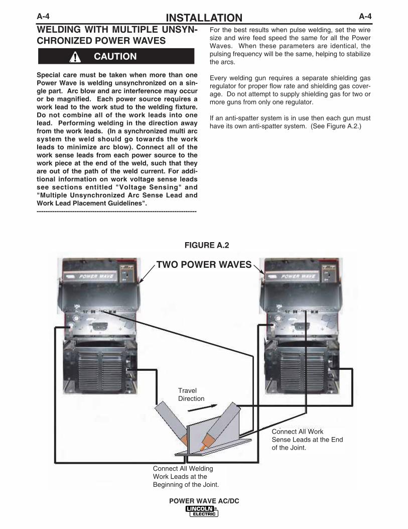
WELDING WITH MULTIPLE UNSYN-CHRONIZED POWER WAVES
Special care must be taken when more than onePower Wave is welding unsynchronized on a sin-gle part. Arc blow and arc interference may occuror be magnified. Each power source requires awork lead to the work stud to the welding fixture.Do not combine all of the work leads into onelead. Performing welding in the direction awayfrom the work leads. (In a synchronized multi arcsystem the weld should go towards the workleads to minimize arc blow). Connect all of thework sense leads from each power source to thework piece at the end of the weld, such that theyare out of the path of the weld current. For addi-tional information on work voltage sense leadssee sections entitled "Voltage Sensing" and"Multiple Unsynchronized Arc Sense Lead andWork Lead Placement Guidelines".------------------------------------------------------------------------
TWO POWER WAVES
For the best results when pulse welding, set the wiresize and wire feed speed the same for all the PowerWaves. When these parameters are identical, thepulsing frequency will be the same, helping to stabilizethe arcs.
Every welding gun requires a separate shielding gasregulator for proper flow rate and shielding gas cover-age. Do not attempt to supply shielding gas for two ormore guns from only one regulator.
If an anti-spatter system is in use then each gun musthave its own anti-spatter system. (See Figure A.2.)
CAUTION
FIGURE A.2
TravelDirection
Connect All WorkSense Leads at the Endof the Joint.
Connect All WeldingWork Leads at the Beginning of the Joint.

A-5INSTALLATION
POWER WAVE AC/DC
A-5
MULTIPLE UNSYNCHRONIZED ARC SENSE LEAD AND WORK LEAD PLACEMENT GUIDELINES
Work #2Sense # 2
PowerSource
#2
PowerSource
#1
Arc #1
Arc #2
Work #1Sense #1
Work # 2 PowerSource
#2
PowerSource
#1
Arc #1
Arc #2
Work # 1
Sense #1Sense # 2
Current Flow
PowerSource
#1
PowerSource
#2
Work #1Sense #1
Work #2Sense #2
Arc #2
Arc #1
Current Flow
fl Current flow from Arc #1affects sense lead #2
fl Current flow from Arc #2affects sense lead #1
fl Neither sense lead picks upthe correct work voltage,causing starting and weldingarc instability.
BAD
fl Sense #1 is only affected by weldcurrent from Arc #1
fl Sense #2 is only affected by weldcurrent from Arc #2
fl Due to voltage drops across work piece,Arc voltage may be low, causing needfor deviation from standard procedures.
BETTER
fl Both Sense leads are out of the currentpaths.
fl Both Sense leads detect arc voltageaccurately.
fl No voltage drop between Arc and Senselead.
fl Best starts, best arcs, most reliableresults.
BEST
Current Flow

A-6INSTALLATION
POWER WAVE AC/DC
A-6
ELECTRODE AND WORK CABLECONNECTIONSDue to the PowerWave AC/DC’s ability to produce eithera DC positive, DC negative or AC output the electrodeand work connections do not need to be reversed for thedifferent polarities. Additionally no DIP switch changesare required to switch between the different polarities. Allof this is controlled internally by the Power Wave AC/DC.The following directions apply to all polarities:
Connect a work lead of sufficient size (Per Table 1) andlength between the "work" stud (located beneath thespring loaded output cover on the front of the machine)and the work. For convenience, the work lead can berouted behind the left strain relief (under the springloaded output cover), along the channels, and out theback of the machine. Be sure the connection to the workmakes tight metal-to-metal electrical contact. The workpiece connection must be firm and secure. Excessivevoltage drops caused by poor work piece connectionsoften result in unsatisfactory welding performance, espe-cially if pulse welding is planned. To avoid interferenceproblems with other equipment and to achieve the bestpossible operation, route all cables directly to the workand wire feeder. Avoid excessive lengths and do not coilexcess cable.
Connect the electrode cable between the wire feeder andthe "electrode" stud on the power source (located behindthe cover plate on the lower right side). For convenience,the cable can be routed through the oval hole in the rearof the machine before being connected to the output ter-minals. Connect the other end of the electrode cable tothe wire drive feed plate. Be sure the connection to thefeed plate makes tight metal-to-metal electrical contact.The electrode cable should be sized according to thespecifications given in (Table A.1).
Suggested Copper Cable Sizes - 100 Duty Cycle CombinedLength of Electrode and Work Cables (Table A.1)Cable Length (ft (m) Parallel Cables Cable Size0 (0) to 100 (30.4) 1 4/0 (120mm2)100 (30.4) to 200 (60.8) 2 2/0 (70mm2)200 (60.8) to 250 (76.2) 2 3/0 (95mm2)
When using inverter type power sources like thePower Wave, use the largest welding (electrode andwork) cables that are practical. When pulsing, thepulse current can reach very high levels. Voltagedrops can become excessive, leading to poor weldingcharacteristics, if undersized welding cables are used.NOTE: K1796 coaxial welding cable is recommendedto reduce the cable inductance in long cable lengths.This is especially important when Pulse welding up to350 amps.
CABLE INDUCTANCE, AND ITS EFFECTSON PULSE WELDINGFor Pulse Welding processes, cable inductance willcause the welding performance to degrade. For thetotal welding loop length less than 50 feet, traditionalwelding cables may be used without any effects onwelding performance. For the total welding loop lengthgreater than 50 feet, the K1796 Coaxial WeldingCables are recommended. The welding loop length is defined as the total of elec-trode cable length (A) + work cable length (B) + worklength (C) (See Figure A.3).
For long work piece lengths, a sliding ground shouldbe considered to keep the total welding loop lengthless than 50 feet. (See Figure A.4.)
FOR A DETAILED CONNECTION DIAGRAM USINGK1796 COAXIAL CABLE, SEE PAGE F-4.
When pulsing, the pulse current can reach veryhigh levels. Voltage drops can become excessive,leading to poor welding characteristics, if under-sized welding cables are used.------------------------------------------------------------------------
CAUTION
B
A
C
FIGURE A.3
POWERWAVE
WORK
A
C
B
POWERWAVE
FIGURE A.4
K1796 COAXIAL CABLE
MEASURE FROM ENDOF OUTER JACKET OFCABLE
C
A
B
WORK
SLIDING GROUND

VOLTAGE SENSINGThe best arc performance occurs when thePowerWave AC/DC has accurate data about the arcconditions. Depending upon the process, inductancewithin the electrode and work lead cables can influ-ence the voltage apparent at the studs of the welder.Voltage sense leads improve the accuracy of the arcconditions and can have a dramatic effect on perfor-mance. Sense Lead Kits (K490-series) are availablefor this purpose.
If the voltage sensing is enabled but the senseleads are missing, improperly connected, or if theelectrode polarity switch is improperly configuredextremely high welding outputs may occur.
In extremely sensitive applications requiring volt-age sense leads, it may be necessary to route thecontrol cable (67 lead) and the work voltage senselead (21 lead) away from the electrode and workwelding cables. For more information regardingthe placement of voltage sense leads, see the sec-tion entitled "Welding with Multiple IndependentPower Waves."
------------------------------------------------------------------------The ELECTRODE sense lead (67) is built into theK1795 control cable. The WORK sense lead (21) con-nects to the Power Wave at the four-pin connectorlocated underneath the output stud cover.Enable the voltage sense leads as follows:
TABLE A.2Process Electrode Voltage Work Voltage
Sensing 67 lead * Sensing 21 leadGMAW 67 lead required 21 lead optional**GMAW-P 67 lead required 21 lead optional**FCAW 67 lead required 21 lead optional**GTAW Voltage sense at studs Voltage sense at studsSAW 67 lead required 21 lead optional
* The electrode voltage 67 sense lead is part of thecontrol cable to the wire feeder.
** For consistent weld quality, work voltage sensing isrecommended.
Work Voltage SensingThe Power Waves are shipped from the factorywith the work sense lead disabled.
To use work voltage sensing, connect the (21) workvoltage sense lead from the Power Wave to the work.Attach the sense lead to the work as close to the weldas practical. Enable the work voltage sensing in thePower Wave as follows:
ELECTRIC SHOCK can kill.
• Do not touch electrically live partsor electrodes with your skin or wetclothing.
• Insulate yourself from the work andground.
• Always wear dry insulating gloves.
-----------------------------------------------------------
1. Turn off power to the power source at the discon-nect switch.
2. Remove the front cover from the power source.
3. The control board is on the left side ofthe power source. Locate the 8-positionDIP switch and look for switch 8 of theDIP switch.
4. Using a pencil or other small object,slide the switch to the OFF position ifthe work sense lead is NOT connected.Conversely, slide the switch to the ONposition if the work sense lead is pre-sent.
5. Replace the cover and screws. The PC board will(read) the switch at power up, and configure thework voltage sense lead appropriately.
Electrode Voltage SensingEnabling or disabling electrode voltage sensing isautomatically configured through software. The 67electrode sense lead is internal to the cable to thewire feeder and always connected when a wire feederis present.
WARNING
O N1
23
45
67
8
CAUTION
A-7INSTALLATION
POWER WAVE AC/DC
A-7

CONTROL CABLE CONNECTIONSBETWEEN POWER SOURCE ANDWIREFEEDERConnect the control cable between the power sourceand wire feeder. The wire feeder connection on thePowerWave AC/DC is located under the spring loadedoutput cover, on the case front. The control cable iskeyed and polarized to prevent improper connect.
For convenience, the control cables can be routedbehind the left or right strain relief (under the springloaded output cover), along the channels of the PowerWave, out the back of the channels, and then to thewire feeder.
Excessive voltage drops at the work piece con-nection often result in unsatisfactory pulse weld-ing performance.------------------------------------------------------------------------
CONTROL CABLE CONNECTIONSBETWEEN POWER SOURCES RUNIN PARALLELThe connectors located on the rear of the machine areused for synchronizing the operation of multiplemachines. To run machines in parallel connect thecontrol cable (K1795 series) between power sourcesthat are to run in parallel. The bottom (male) connec-tor on the master connects to the top (female) connec-tor on the slave. If needed the bottom connector onthe slave machine is then used to connect to anotherslave machine. This connection scheme is duplicatedfor any additional slaves.
CONTROL CABLE CONNECTIONSBETWEEN A POWER SOURCEAND PHASE GENERATORIf multiple arcs need to be synchronized an externalphase generator is required. The phase generator isconnected to all of the master machines. A controlcable (K1795 series) should be connected betweenthe phase generator and the top (female) connectoron the rear of the master machine.
CONTROL CABLE SPECIFICATIONSIt is recommended that genuine Lincoln control cablesbe used at all times. Lincoln cables are specificallydesigned for the communication and power needs ofthe Power Wave / Power Feed system.
The use of non-standard cables, especially inlengths greater than 25 feet, can lead to communi-cation problems (system shutdowns), poor motoracceleration (poor arc starting) and low wire dri-ving force (wire feeding problems). Use the short-est length of control cable possible. Do not coilexcess cable as this can cause communicationproblems (system shutdowns).------------------------------------------------------------------------Lincoln control cables are copper 22 conductor cablein a SO-type rubber jacket.
The K1795 series of control cables can be added inseries as needed. Do not exceed more than 100 feet(30.5 m) total control cable length.
ETHERNET CONNECTIONS
The PowerWave is equipped with an Ethernet con-nector, which is located under the spring loaded out-put cover. All Ethernet cables external to either a con-duit or an enclosure should be solid, shielded with adrain, cat 5 cable. The drain should be grounded. Donot use cat 5+, cat 5E, cat 6 or stranded cable. If con-nection failure during welding persists reroute cablesaway from any other cables that carry current or otherdevices that would create a magnetic field. See FigureA.4a.
FIGURE A.4a
CAUTION
CAUTION
A-8INSTALLATION
POWER WAVE AC/DC
A-8
POWER WAVEPOWER WAVEPOWER WAVE
POWER WAVE POWER WAVE
PHASEGENERATOR
CAT 5 CABLESOLID, SHIELDED,WITH A DRAIN(MAX LENGTH = 3 METERS)
JUNCTION BOX
CONDUIT WITH CAT 5 UTP CABLE
ENVIRONMENTALENCLOSURE
ETHERNET SWITCH
PATCH PANEL
POWER WAVE ETHERNET LAYOUT SETUP
- MAX TOTAL CABLE LENGTH IS 70 METERS (FROM POWER WAVE TO PATCH PANEL)
- SHIELDED CABLE SHOULD BE GROUNDED AT JUNCTION BOX
- REFER TO ISO / IEC 11801 FOR SPECIFICATIONS
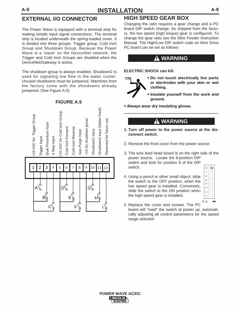
EXTERNAL I/O CONNECTOR
The Power Wave is equipped with a terminal strip formaking simple input signal connections. The terminalstrip is located underneath the spring-loaded cover. Itis divided into three groups: Trigger group, Cold InchGroup and Shutdown Group. Because the PowerWave is a ‘slave’ on the DeviceNet network, theTrigger and Cold Inch Groups are disabled when theDeviceNet/Gateway is active.
The shutdown group is always enabled. Shutdown2 isused for signaling low flow in the water cooler.Unused shutdowns must be jumpered. Machines fromthe factory come with the shutdowns alreadyjumpered. (See Figure A.5)
A-9INSTALLATION
POWER WAVE AC/DC
A-9
D
E
F
1 2 3 4 5 6 7 8 9 10 11 12
G
H
I
A
B
C
+15
VD
C fo
r T
rigge
r G
roup
Trig
ger
Inpu
t
Dua
l Pro
cedu
re In
put
4 S
tep
Inpu
t
+15
VD
C fo
r C
old
Inch
Gro
up
Col
d In
ch F
orw
ard
Col
d In
ch R
ever
se
Gas
Pur
ge In
put
+15
for
shut
dow
n gr
oup
Shu
tdow
n1 in
put
Shu
tdow
n2 in
put (
Wat
er F
ault)
Res
erve
d fo
r fu
ture
use
FIGURE A.5
HIGH SPEED GEAR BOXChanging the ratio requires a gear change and a PCboard DIP switch change. As shipped from the facto-ry, the low speed (high torque) gear is configured. Tochange the gear ratio see the Wire Feeder InstructionManual. The High/Low DIP switch code on Wire DrivePC board can be set as follows:
ELECTRIC SHOCK can kill.
• Do not touch electrically live partsor electrodes with your skin or wetclothing.
• Insulate yourself from the work andground.
• Always wear dry insulating gloves.
-----------------------------------------------------------
1. Turn off power to the power source at the dis-connect switch.
2. Remove the front cover from the power source.
3. The wire feed head board is on the right side of thepower source. Locate the 8-position DIPswitch and look for position 8 of the DIPswitch.
4. Using a pencil or other small object, slidethe switch to the OFF position, when thelow speed gear is installed. Conversely,slide the switch to the ON position whenthe high speed gear is installed.
5. Replace the cover and screws. The PCboard will "read" the switch at power up, automati-cally adjusting all control parameters for the speedrange selected
O N1
23
45
67
8
WARNING
WARNING

A-10INSTALLATION
POWER WAVE AC/DC
A-10
DIP Switch Settings and LocationsDIP switches on the P.C. Boards allow for customconfiguration of the Power Wave. To access the DIPswitches:
• Turn off power at the disconnect switch.------------------------------------------------------------------------• Remove the top four screws securing the front
access panel.• Loosen, but do not completely remove, the bottom
two screws holding the access panel.• Open the access panel, allowing the weight of the
panel to be carried by the bottom two screws. Makesure to prevent the weight of the access panel fromhanging on the harness.
• Adjust the DIP switches as necessary.• Replace the panel and screws, and restore power.
WARNING
CONTROL BOARD DIP SWITCHSwitch Description Comments1 Object Instance LSB (see table A.3)2 Object Instance MSB (see table A.3)3 Equipment Group 1 Select4 Equipment Group 2 Select Used for ArcLink5 Equipment Group 3 Select configuration6 Equipment Group 4 Select7 Reserved for future use
Used for configuringwork sense lead(See Work VolktageSensing in Section A)
OBJECT INSTANCEswitch 2 switch 1 Instance
off off 0off on 1on off 2on on 3
TABLE A.3
(default)
FEED HEAD BOARD DIP SWITCH:Switch Description Comments1 Object Instance LSB (see table A.3)2 Object Instance MSB (see table A.3)3 Equipment Group 1 Select4 Equipment Group 2 Select Used for ArcLink Configuration5 Equipment Group 3 Select6 Equipment Group 4 Select
Used for configuring electrode polarity (see Electrode and Work
7 Cable Connection in this Section)No changes required for PowerWave AC/DCUsed for configuring wirefeeder
8 gear ratio (see High Speed GearBox in this Section)
Bank S1Switch Description Comments1 Object Instance LSB (see table A.3)2 Object Instance MSB (see table A.3)3 Equipment Group 1 Select4 Equipment Group 2 Select Used for ArcLink Configuration5 Equipment Group 3 Select6 Equipment Group 4 Select7 Reserved for future use8 Reserved for future use
Bank S2:Switch Description Comments1 DeviceNet Baud Rate2 (See Table A.4)34 Used for DeviceNet 5 DeviceNet Mac ID Configuration6 (See Table A.5)78
ETHERNET BOARD DIP SWITCH:
DeviceNet Baud Rate:switch 1 switch 2 Baud rate
off off 125Kon off 250Koff on 500Kon on Programmable value
TABLE A.4
off work sense lead not connected
on work sense lead connected8
off Electrode polarity positive (default)
on Electrode polarity negative
off Low speed gear (default)
on High speed gear

A-11INSTALLATION
POWER WAVE AC/DC
A-11DEVICENET MAC ID
TABLE A.5Mac I.D. Switch 8 Switch7 Switch6 Switch5 Switch4 Switch 3
0 0 0 0 0 0 0 Software Selectable1 0 0 0 0 0 12 0 0 0 0 1 03 0 0 0 0 1 14 0 0 0 1 0 05 0 0 0 1 0 16 0 0 0 1 1 07 0 0 0 1 1 18 0 0 1 0 0 09 0 0 1 0 0 110 0 0 1 0 1 011 0 0 1 0 1 112 0 0 1 1 0 013 0 0 1 1 0 114 0 0 1 1 1 015 0 0 1 1 1 116 0 1 0 0 0 017 0 1 0 0 0 118 0 1 0 0 1 019 0 1 0 0 1 120 0 1 0 1 0 021 0 1 0 1 0 122 0 1 0 1 1 023 0 1 0 1 1 124 0 1 1 0 0 025 0 1 1 0 0 126 0 1 1 0 1 027 0 1 1 0 1 128 0 1 1 1 0 029 0 1 1 1 0 130 0 1 1 1 1 031 0 1 1 1 1 132 1 0 0 0 0 033 1 0 0 0 0 134 1 0 0 0 1 035 1 0 0 0 1 136 1 0 0 1 0 037 1 0 0 1 0 138 1 0 0 1 1 039 1 0 0 1 1 140 1 0 1 0 0 041 1 0 1 0 0 142 1 0 1 0 1 043 1 0 1 0 1 144 1 0 1 1 0 045 1 0 1 1 0 146 1 0 1 1 1 047 1 0 1 1 1 148 1 1 0 0 0 049 1 1 0 0 0 150 1 1 0 0 1 051 1 1 0 0 1 152 1 1 0 1 0 053 1 1 0 1 0 154 1 1 0 1 1 055 1 1 0 1 1 156 1 1 1 0 0 057 1 1 1 0 0 158 1 1 1 0 1 059 1 1 1 0 1 160 1 1 1 1 0 061 1 1 1 1 0 162 1 1 1 1 1 0 Default Setting

A-12INSTALLATION
POWER WAVE AC/DC
A-12
Bank S3 and S4
A-13INSTALLATION
POWER WAVE AC/DC
A-13
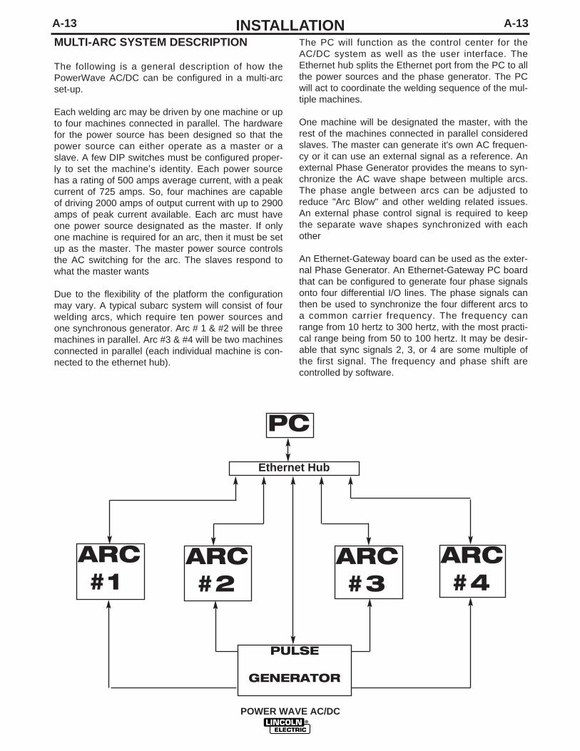
MULTI-ARC SYSTEM DESCRIPTION
The following is a general description of how thePowerWave AC/DC can be configured in a multi-arcset-up.
Each welding arc may be driven by one machine or upto four machines connected in parallel. The hardwarefor the power source has been designed so that thepower source can either operate as a master or aslave. A few DIP switches must be configured proper-ly to set the machine’s identity. Each power sourcehas a rating of 500 amps average current, with a peakcurrent of 725 amps. So, four machines are capableof driving 2000 amps of output current with up to 2900amps of peak current available. Each arc must haveone power source designated as the master. If onlyone machine is required for an arc, then it must be setup as the master. The master power source controlsthe AC switching for the arc. The slaves respond towhat the master wants
Due to the flexibility of the platform the configurationmay vary. A typical subarc system will consist of fourwelding arcs, which require ten power sources andone synchronous generator. Arc # 1 & #2 will be threemachines in parallel. Arc #3 & #4 will be two machinesconnected in parallel (each individual machine is con-nected to the ethernet hub).
The PC will function as the control center for theAC/DC system as well as the user interface. TheEthernet hub splits the Ethernet port from the PC to allthe power sources and the phase generator. The PCwill act to coordinate the welding sequence of the mul-tiple machines.
One machine will be designated the master, with therest of the machines connected in parallel consideredslaves. The master can generate it's own AC frequen-cy or it can use an external signal as a reference. Anexternal Phase Generator provides the means to syn-chronize the AC wave shape between multiple arcs.The phase angle between arcs can be adjusted toreduce "Arc Blow" and other welding related issues.An external phase control signal is required to keepthe separate wave shapes synchronized with eachother
An Ethernet-Gateway board can be used as the exter-nal Phase Generator. An Ethernet-Gateway PC boardthat can be configured to generate four phase signalsonto four differential I/O lines. The phase signals canthen be used to synchronize the four different arcs toa common carrier frequency. The frequency canrange from 10 hertz to 300 hertz, with the most practi-cal range being from 50 to 100 hertz. It may be desir-able that sync signals 2, 3, or 4 are some multiple ofthe first signal. The frequency and phase shift arecontrolled by software.
Ethernet Hub
PC
ARC#1
ARC#2
ARC#3
ARC#4
PULSE
GENERATOR

B-1OPERATIONB-1
POWER WAVE AC/DC
SAFETY PRECUATIONSRead this entire section of operating instructionsbefore operating the machine.
ELECTRIC SHOCK can kill.
• Unless using cold feed feature, whenfeeding with gun trigger, the electrodeand drive mechanism are always elec-trically energized and could remainenergized several seconds after thewelding ceases.
• Do not touch electrically live parts or electrodeswith your skin or wet clothing.
• Insulate yourself from the work and ground.
• Always wear dry insulating gloves.
FUMES AND GASES can be dan-gerous.
• Keep your head out of fumes.
• Use ventilation or exhaust to removefumes from breathing zone.
WELDING SPARKS can cause fireor explosion.
• Keep flammable material away.
• Do not weld on containers that haveheld combustibles.
ARC RAYS can burn.
• Wear eye, ear, and body protection.
Observe additional guidelines detailed in the begin-ning of this manual.
WARNING

B-2OPERATIONB-2
POWER WAVE AC/DC
INPUT POWER
ON
OFF
HIGH TEMPERATURE
MACHINE STATUS
CIRCUIT BREAKER
WIRE FEEDER
POSITIVE OUTPUT
NEGATIVE OUTPUT
3 PHASE INVERTER
INPUT POWER
THREE PHASE
DIRECT CURRENT
GMAW
FCAW
GTAW
OPEN CIRCUIT VOLTAGE
INPUT VOLTAGE
OUTPUT VOLTAGE
INPUT CURRENT
OUTPUT CURRENT
PROTECTIVEGROUND
WARNING
GRAPHIC SYMBOLS THAT APPEAR ONTHIS MACHINE OR IN THIS MANUAL
U0
U1
U2
I1
I2
SMAW

B-3OPERATIONB-3
POWER WAVE AC/DC
DEFINITION OF WELDING TERMS
NON-SYNERGIC WELDING MODES
• A Non-synergic welding mode requires all weldingprocess variables to be set by the operator.
SYNERGIC WELDING MODES
• A Synergic welding mode offers the simplicity ofsingle knob control. The machine will select the cor-rect voltage and amperage based on the wire feedspeed (WFS) set by the operator.
WFS• Wire Feed Speed
CC• Constant Current
CV• Constant Voltage
GMAW (MIG)• Gas Metal Arc welding
GMAW-P (MIG)• Gas Metal Arc welding-(Pulse)
GMAW-PP (MIG)• Gas Metal Arc welding-(Pulse-on-Pulse)
GTAW (TIG)• Gas Tungsten Arc welding
SMAW (STICK)• Shielded Metal Arc welding
FCAW (INNERSHIELD)• Flux Core Arc Welding
SAW• Submerged Arc welding

RECOMMENDED EQUIPMENT/INTERFACE Robotic OperationAll welding programs and procedures are configuredthrough software for the robotic Power Waves. Withthe proper configuration, Fanuc robots equipped withRJ-3 or RJ-3iB controllers may communicate directlyto the Power Wave via ArcLink or DeviceNet. Properconfiguration and options allow other equipment suchas PLC’s or computers to interface with a PowerWave through a serial, DeviceNet, ArcLink, orEthernet interfaces. All wire welding processes requirea robotic Power Feed wire feeder.
Hard AutomationOperating the Power Wave AC/DC in a hard automa-tion application requires a PC or PLC for the userinterface. The power source communicates with thePC via Ethernet. A wire feeder can be controlledthrough Arc-link, DeviceNET or Ethernet.
SemiAutomatic OperationOperating the Power Wave AC/DC in the semi-auto-matic mode requires an Arc-Link compatible wirefeeder and user interface.
EQUIPMENT LIMITATIONS
• The Power Waves are not to be used in outdoorenvironments.
• Only Arc-Link Power Feed wire feeders may beused with standard interfaces. Other Lincoln wirefeeders or non-Lincoln wire feeders can only beused with custom interfaces.
• Operating Temperature Range is –20C to + 40C.• The Power Wave AC/DC will support a maximum
average output current of 500 Amps at 100% DutyCycle.
REQUIRED EQUIPMENT• Control Cables (22 pin to 22 pin), K1795-10,-25,-50,-100• Control Cables (for use on FANUC robot arm, 22 pin to 14
pin, 10 ft), K1804-1 • Control Cables (for use on FANUC robot arm, 22 pin to 14
pin, 18 in), K1805-1• Control Cables (for use on FANUC robot arm, 22 pin to 14
pin, 18 in), K1804-2
DUTY CYCLE AND TIME PERIODThe Power Wave AC/DC is capable of welding at a100% duty cycle (continuous welding).
B-4OPERATIONB-4
GENERAL DESCRIPTIONThe Power Wave AC/DC power source is designed tobe a part of a modular welding system. Each weldingarc may be driven by a single machine or by a numberof machines in parallel. Additionally with the use of anexternal Phase Generator the phase angle and fre-quency of different machines can be synchronized.
The Power Wave AC/DC is a high performance, digi-tally controlled inverter welding power source capableof complex, high-speed waveform control. The PowerWave AC/DC is capable of producing a variable fre-quency and amplitude AC output, a DC positive out-put, or a DC negative output. The Power WaveAC/DC can support constant current, constant voltageand pulse welding modes.
The Power Wave AC/DC is designed to communicatewith other Arc-Link equipment. Additionally it can com-municate with other industrial machines viaDeviceNET. Also the Power Wave AC/DC machinesare capable of communicating by Ethernet. The resultis a highly integrated and flexible welding cell.
RECOMMENDED PROCESSES ANDEQUIPMENT
RECOMMENDED PROCESSES
The Power Wave AC/DC can be set up in a number ofconfigurations, some requiring optional equipment orwelding programs. Each machine is factory prepro-grammed with multiple welding procedures, typicallyincluding SAW, GMAW, GMAW-P, FCAW, GTAW fora variety of materials, including mild steel, stainlesssteel, cored wires, and aluminum. It carries an outputrating of 500 amps, 44 volts (at 100% duty cycle).
The Power Wave AC/DC can be configured for robot-ic, hard-automation or semi-automatic use.
PROCESS LIMITATIONS
The Power Wave AC/DC is suitable only for theprocesses listed.
POWER WAVE AC/DC
B-5OPERATION
POWER WAVE AC/DC
B-5
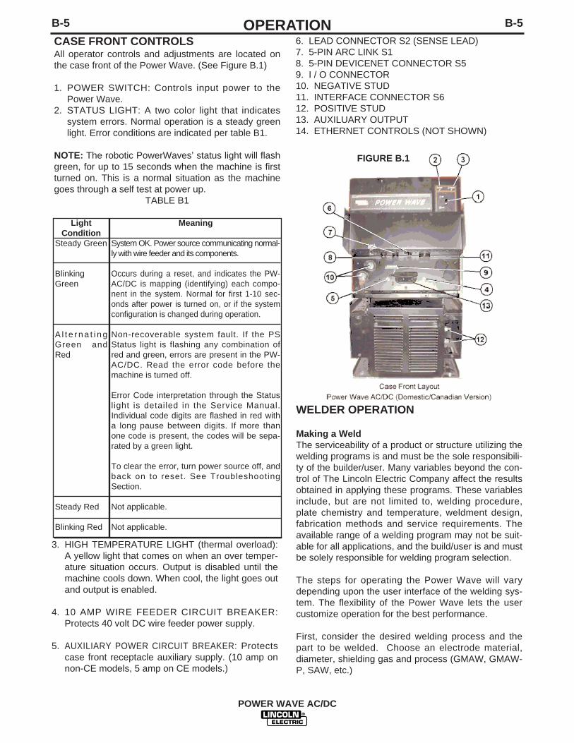
CASE FRONT CONTROLSAll operator controls and adjustments are located onthe case front of the Power Wave. (See Figure B.1)
1. POWER SWITCH: Controls input power to thePower Wave.
2. STATUS LIGHT: A two color light that indicatessystem errors. Normal operation is a steady greenlight. Error conditions are indicated per table B1.
NOTE: The robotic PowerWaves’ status light will flashgreen, for up to 15 seconds when the machine is firstturned on. This is a normal situation as the machinegoes through a self test at power up.
TABLE B1
LightCondition
Steady Green
BlinkingGreen
A l t e r n a t i n gGreen andRed
Steady Red
Blinking Red
Meaning
System OK. Power source communicating normal-ly with wire feeder and its components.
Occurs during a reset, and indicates the PW-AC/DC is mapping (identifying) each compo-nent in the system. Normal for first 1-10 sec-onds after power is turned on, or if the systemconfiguration is changed during operation.
Non-recoverable system fault. If the PSStatus light is flashing any combination ofred and green, errors are present in the PW-AC/DC. Read the error code before themachine is turned off.
Error Code interpretation through the Statuslight is detailed in the Service Manual.Individual code digits are flashed in red witha long pause between digits. If more thanone code is present, the codes will be sepa-rated by a green light.
To clear the error, turn power source off, andback on to reset. See TroubleshootingSection.
Not applicable.
Not applicable.
6. LEAD CONNECTOR S2 (SENSE LEAD)7. 5-PIN ARC LINK S18. 5-PIN DEVICENET CONNECTOR S59. I / O CONNECTOR10. NEGATIVE STUD11. INTERFACE CONNECTOR S612. POSITIVE STUD13. AUXILUARY OUTPUT14. ETHERNET CONTROLS (NOT SHOWN)
FIGURE B.1
3. HIGH TEMPERATURE LIGHT (thermal overload):A yellow light that comes on when an over temper-ature situation occurs. Output is disabled until themachine cools down. When cool, the light goes outand output is enabled.
4. 10 AMP WIRE FEEDER CIRCUIT BREAKER:Protects 40 volt DC wire feeder power supply.
5. AUXILIARY POWER CIRCUIT BREAKER: Protectscase front receptacle auxiliary supply. (10 amp onnon-CE models, 5 amp on CE models.)
WELDER OPERATION
Making a WeldThe serviceability of a product or structure utilizing thewelding programs is and must be the sole responsibili-ty of the builder/user. Many variables beyond the con-trol of The Lincoln Electric Company affect the resultsobtained in applying these programs. These variablesinclude, but are not limited to, welding procedure,plate chemistry and temperature, weldment design,fabrication methods and service requirements. Theavailable range of a welding program may not be suit-able for all applications, and the build/user is and mustbe solely responsible for welding program selection.
The steps for operating the Power Wave will varydepending upon the user interface of the welding sys-tem. The flexibility of the Power Wave lets the usercustomize operation for the best performance.
First, consider the desired welding process and thepart to be welded. Choose an electrode material,diameter, shielding gas and process (GMAW, GMAW-P, SAW, etc.)

B-6OPERATIONB-6
POWER WAVE AC/DC
Second, find the program in the welding software thatbest matches the desired welding process. The stan-dard software shipped with the Power Waves encom-passes a wide range of common processes and willmeet most needs. If a special welding program isdesired, contact the local Lincoln Electric sales repre-sentative.
To make a weld, the Power Wave needs to know thedesired welding parameters. ArcLink allows full cus-tomization for exacting performance. The PowerWave can be programmed with specific values forStrike, Run-in, Crater and other parameters as need-ed.
The Power Wave supports advanced features, liketouch sensing and through-the-arc-seam tracking(TAST).
WELDING ADJUSTMENTS
All adjustments are made on through the user inter-face which can vary. Because of the different configu-ration options your system may not have all of the fol-lowing adjustments. Regardless of availability, all con-trols are described below.
GENERAL WELDING ADJUSTMENTS
1. WFS / AMPS:In synergic welding modes (synergic CV, pulseGMAW) WFS (wire feed speed) is the dominantcontrol parameter, controlling all other variables.The user adjusts WFS according to factors such asweld size, penetration requirements, heat input, etc.The Power Wave then uses the WFS setting toadjust its output characteristics (output voltage, out-put current) according to pre-programmed settingscontained in the Power Wave. In non-synergicmodes, the WFS control behaves more like a con-ventional CV power source where WFS and voltageare independent adjustments. Therefore to maintainthe arc characteristics, the operator must adjust thevoltage to compensate for any changes made to theWFS.
2. VOLTS / TRIM:In constant voltage modes (synergic CV, standardCV) the control adjusts the welding voltage.
In pulse synergic welding modes (pulse GMAWonly) the user can change the Trim setting to adjustthe arc length. It is adjustable from 0.500 to 1.500.A Trim setting of 1.000 is a good starting point formost conditions.
3. WELDING MODE:May be selected by name (CV/MIG, CC/Stick Crisp,Gouge, etc.) or by a mode number (10, 24, 71,etc.). Selecting a welding mode determines the out-put characteristics of the Power Wave powersource
4. ARC CONTROL:Also known as Inductance or Wave Control. Allowsoperator to vary the arc characteristics from "soft" to"harsh" in all weld modes. It is adjustable from -10.0to +10.0, with a nominal setting of 0.0.
B-7OPERATIONB-7
CV WELDING
Synergic CV:For each wire feed speed, a corresponding voltage ispreprogrammed into the machine through special soft-ware at the factory. The nominal preprogrammed volt-age is the best average voltage for a given wire feedspeed, but may be adjusted to preference. With syner-gic programs, when the wire feed speed changes thePower Wave will automatically adjust the voltage cor-respondingly to maintain similar arc characteristicsthroughout the WFS range.
Non Synergic CV:This type of CV mode behaves more like a conven-tional CV power source. Voltage and WFS are inde-pendent adjustments. Therefore to maintain the arccharacteristics, the operator must adjust the voltage tocompensate for any changes made to the WFS.
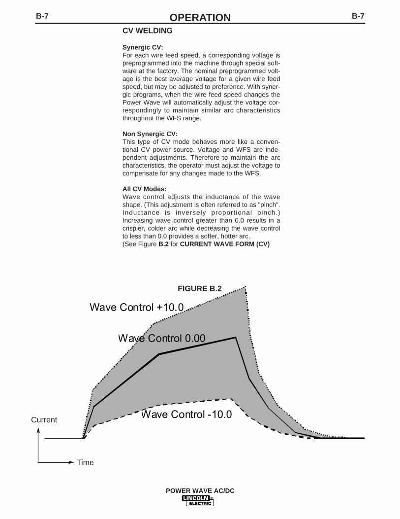
All CV Modes:Wave control adjusts the inductance of the waveshape. (This adjustment is often referred to as "pinch".Inductance is inversely proportional pinch.)Increasing wave control greater than 0.0 results in acrispier, colder arc while decreasing the wave controlto less than 0.0 provides a softer, hotter arc.(See Figure B.2 for CURRENT WAVE FORM (CV)
POWER WAVE AC/DC
Wave Control 0.00
Wave Control +10.0
Wave Control -10.0
FIGURE B.2
Current
Time
B-8OPERATIONB-8
PULSE WELDING
Pulse welding procedures are set by controlling anoverall "arc length" variable. When pulse welding, thearc voltage is highly dependent upon the waveform.The peak current, back ground current, rise time, falltime and pulse frequency all affect the voltage. Theexact voltage for a given wire feed speed can only bepredicted when all the pulsing waveform parametersare known. Using a preset voltage becomes impracti-cal, and instead the arc length is set by adjusting"trim".
Trim adjusts the arc length and ranges from 0.50 to1.50, with a nominal value of 1.00. Trim values greaterthan 1.00 increase the arc length, while values lessthan 1.00 decrease the arc length.
Most pulse welding programs are syngeric. As thewire feed speed is adjusted, the Power Wave willautomatically recalculate the waveform parameters tomaintain similar arc properties.
POWER WAVE AC/DC
Wave Control 0.0
Wave Control +10.0
Wave Control -10.0
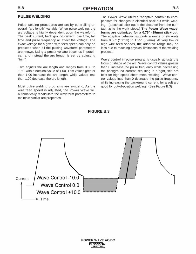
The Power Wave utilizes "adaptive control" to com-pensate for changes in electrical stick-out while weld-ing. (Electrical stick-out is the distance from the con-tact tip to the work piece.) The Power Wave wave-forms are optimized for a 0.75" (19mm) stick-out.The adaptive behavior supports a range of stickoutsfrom 0.50" (13mm) to 1.25" (32mm). At very low orhigh wire feed speeds, the adaptive range may beless due to reaching physical limitations of the weldingprocess.
Wave control in pulse programs usually adjusts thefocus or shape of the arc. Wave control values greaterthan 0 increase the pulse frequency while decreasingthe background current, resulting in a tight, stiff arcbest for high speed sheet metal welding. Wave con-trol values less than 0 decrease the pulse frequencywhile increasing the background current, for a soft arcgood for out-of-position welding. (See Figure B.3)
FIGURE B.3
Current
Time

C-1ACCESSORIESC-1
OPTIONAL EQUIPMENT
FACTORY INSTALLEDThere are no factory installed options available for thePower Wave.
FIELD INSTALLED OPTIONS / ACCESSORIES
Required Accessories
For Paralleling machines
• Control Cables (22 pin to 22 pin), K1795-10,-25,-50,-100
In Robotic Applications
• Control Cables (for use on FANUC robot arm, 22 pin to14 pin, 10 ft), K1804-1
• Control Cables (for use on FANUC robot arm, 14 pin to22 pin, 18 in), K1805-1
• Control Cables (for use on FANUC robot arm, 22 pin to14 pin, 18 in), K1804-2
Optional Accessories
• Work Voltage Sense Lead Kit K940• Gas Guard Regulator, K659-1• Coaxial welding Cable, K1796
Compatible Lincoln equipment
• PF-10/R Wire Feeder, K1780-1• Any arc-link compatible wire feeding equipment
POWER WAVE AC/DC

D-1MAINTENANCED-1
POWER WAVE AC/DC
SAFETY PRECAUTIONS
ELECTRIC SHOCK can kill.
• Only Qualified personnel shouldperform this maintenance.
• Turn the input power OFF at thedisconnect switch or fuse boxbefore working on this equipment.
• Do not touch electrically hot parts.
ROUTINE MAINTENANCE Routine maintenance consists of periodicallyblowing out the machine, using a low pressureairstream, to remove accumulated dust and dirtfrom the intake and outlet louvers, and the cool-ing channels in the machine.
PERIODIC MAINTENANCECalibration of the Power Wave AC/DC is critical toits operation. Generally speaking the calibrationwill not need adjustment. However, neglected orimproperly calibrated machines may not yield sat-isfactory weld performance. To ensure optimalperformance, the calibration of output Voltageand Current should be checked yearly.
CALIBRATION SPECIFICATIONOutput Voltage and Current are calibrated at thefactory. Generally speaking the machine calibrationwill not need adjustment. However, if the weld per-formance changes, or the yearly calibration checkreveals a problem, contact the Lincoln ElectricCompany for the calibration software utility.
The calibration procedure itself requires the useof a grid, and certified actual meters for voltageand current. The accuracy of the calibration willbe directly affected by the accuracy of the mea-suring equipment you use. Detailed instructionsare available with the utility.
WARNING

E-1TROUBLESHOOTINGE-1
POWER WAVE AC/DC
If for any reason you do not understand the test procedures or are unable to perform the tests/repairs safely, contact yourLocal Lincoln Authorized Field Service Facility for technical troubleshooting assistance before you proceed.
CAUTION
This Troubleshooting Guide is provided to help youlocate and repair possible machine malfunctions.Simply follow the three-step procedure listed below.
Step 1. LOCATE PROBLEM (SYMPTOM).Look under the column labeled “PROBLEM (SYMP-TOMS)”. This column describes possible symptomsthat the machine may exhibit. Find the listing that bestdescribes the symptom that the machine is exhibiting.
Step 2. POSSIBLE CAUSE.The second column labeled “POSSIBLE CAUSE” liststhe obvious external possibilities that may contributeto the machine symptom.
Step 3. RECOMMENDED COURSE OF ACTIONThis column provides a course of action for thePossible Cause, generally it states to contact yourlocal Lincoln Authorized Field Service Facility.
If you do not understand or are unable to perform theRecommended Course of Action safely, contact yourlocal Lincoln Authorized Field Service Facility.
HOW TO USE TROUBLESHOOTING GUIDE
Service and Repair should only be performed by Lincoln Electric Factory Trained Personnel.Unauthorized repairs performed on this equipment may result in danger to the technician andmachine operator and will invalidate your factory warranty. For your safety and to avoid ElectricalShock, please observe all safety notes and precautions detailed throughout this manual.
__________________________________________________________________________
WARNING

E-2TROUBLESHOOTINGE-2
POWER WAVE AC/DC
Observe all Safety Guidelines detailed throughout this manual
CAUTIONIf for any reason you do not understand the test procedures or are unable to perform the tests/repairs safely, con-tact your local authorized Lincoln Electric Field Service Facility for technical assistance.
PROBLEMS(SYMPTOMS)
POSSIBLE AREAS OFMISADJUSTMENT(S)
RECOMMENDEDCOURSE OF ACTION
OUTPUT PROBLEMSMajor physical or electrical damageis evident when the sheet metalcovers are removed.
Input fuses keep blowing, or inputbreaker keeps tripping.
Machine will not power up (nolights, no fan, etc.)
1. Contact your local authorizedLincoln Electric Field Servicefacility for technical assistance.
1. Make certain that fuses orbreakers are properly sized.See Installation section of thismanual for recommendedfuse and breaker sizes.
2. Welding procedure is drawingtoo much output current, orduty cycle is too high.Reduce output current, dutycycle, or both.
3. There is internal damage tothe power source. Contact anauthorized Lincoln ElectricService facility.
1. Make certain that the PowerSwitch (SW1) is in the “ON”position.
2. Circuit breaker CB4 (in recon-nect area) may have opened.Reset. Also, check input volt-age selection, below.
3. Input voltage selection madeimproperly. Power down,check input voltage reconnectaccording to diagram onreconnect cover.
If all recommended possible areasof misadjustments have beenchecked and the problem persists,contact your local LincolnAuthorized Field Service Facility.

E-3TROUBLESHOOTINGE-3
POWER WAVE AC/DC
Observe all Safety Guidelines detailed throughout this manual
CAUTIONIf for any reason you do not understand the test procedures or are unable to perform the tests/repairs safely, con-tact your local authorized Lincoln Electric Field Service Facility for technical assistance.
PROBLEMS(SYMPTOMS)
POSSIBLE AREAS OFMISADJUSTMENT(S)
RECOMMENDEDCOURSE OF ACTION
OUTPUT PROBLEMSThermal LED is lit.
Machine won’t weld, can’t get anyoutput. (CR1 will not pull in.)
1. Machine ’s thermostat hasopened. Check for proper fanoperation. There are two mainfans in the PowerWave AC/DC.One machine is located in thelower portion of the machinewhich should be running when-ever the machine is on. Theother fan is located in the upperportion of the machine and onlyruns when the machine is trig-gered. Check for material block-ing intake or exhaust louvers, orfor excessive dirt clogging coo-ing channels in machine.
2. DC Bus PC board thermostathas opened check for excessiveload on 40VDC supply.
3. Be sure process does notexceed duty cycle limit of themachine.
1. Input voltage is too low or toohigh. Make certain that inputvoltage is proper, according tothe Rating Plate located on therear of the machine.
2. If the Thermal LED is also lit,see “Yellow Thermal LED is Lit”section.
3.Primary current limit has beenexceeded. Possible short in out-put circuit. Turn machine off.Remove all loads from the outputof the machine. Turn back on. Ifcondition persists, turn power off,and contact an authorizedLincoln Electric Field Servicefacility.
4. This problem will normally beaccompanied by an error code.Error codes are displayed as aseries of red and green flashesby the status l ight. See"Troubleshooting the PowerWave / Power Feed SystemUsing the Status LED" sectionof this text.
If all recommended possible areasof misadjustments have beenchecked and the problem persists,contact your local LincolnAuthorized Field Service Facility.
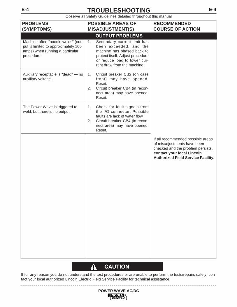
E-4TROUBLESHOOTINGE-4
POWER WAVE AC/DC
Observe all Safety Guidelines detailed throughout this manual
CAUTIONIf for any reason you do not understand the test procedures or are unable to perform the tests/repairs safely, con-tact your local authorized Lincoln Electric Field Service Facility for technical assistance.
PROBLEMS(SYMPTOMS)
POSSIBLE AREAS OFMISADJUSTMENT(S)
RECOMMENDEDCOURSE OF ACTION
OUTPUT PROBLEMSMachine often “noodle welds” (out-put is limited to approximately 100amps) when running a particularprocedure
Auxiliary receptacle is “dead” — noauxiliary voltage .
The Power Wave is triggered toweld, but there is no output.
1. Secondary current limit hasbeen exceeded, and themachine has phased back toprotect itself. Adjust procedureor reduce load to lower cur-rent draw from the machine.
1. Circuit breaker CB2 (on casefront) may have opened.Reset.
2. Circuit breaker CB4 (in recon-nect area) may have opened.Reset.
1. Check for fault signals fromthe I/O connector. Possiblefaults are lack of water flow
2. Circuit breaker CB4 (in recon-nect area) may have opened.Reset.
If all recommended possible areasof misadjustments have beenchecked and the problem persists,contact your local LincolnAuthorized Field Service Facility.
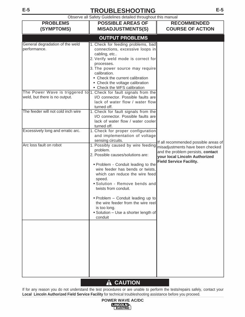
E-5TROUBLESHOOTINGE-5
POWER WAVE AC/DC
Observe all Safety Guidelines detailed throughout this manual
If for any reason you do not understand the test procedures or are unable to perform the tests/repairs safely, contact yourLocal Lincoln Authorized Field Service Facility for technical troubleshooting assistance before you proceed.
CAUTION
PROBLEMS(SYMPTOMS)
POSSIBLE AREAS OFMISADJUSTMENTS(S)
RECOMMENDEDCOURSE OF ACTION
General degradation of the weldperformance.
The Power Wave is triggered toweld, but there is no output.
The feeder will not cold inch wire
Excessively long and erratic arc.
Arc loss fault on robot
1. Check for feeding problems, badconnections, excessive loops incabling, etc..
2. Verify weld mode is correct forprocesses.
3. The power source may requirecalibration.• Check the current calibration• Check the voltage calibration• Check the WFS calibration
1. Check for fault signals from theI/O connector. Possible faults arelack of water flow / water flowturned off.
1. Check for fault signals from theI/O connector. Possible faults arelack of water flow / water coolerturned off.
1. Check for proper configurationand implementation of voltagesensing circuits.
1. Possibly caused by wire feedingproblem.
2. Possible causes/solutions are:
• Problem - Conduit leading to thewire feeder has bends or twists,which can reduce the wire feedspeed.
• Solution - Remove bends andtwists from conduit.
• Problem – Conduit leading up tothe wire feeder from the wire reelis too long.
• Solution – Use a shorter length ofconduit
If all recommended possible areas ofmisadjustments have been checkedand the problem persists, contactyour local Lincoln AuthorizedField Service Facility.
OUTPUT PROBLEMS

E-6TROUBLESHOOTINGE-6
POWER WAVE AC/DC
USING THE STATUS LED TOTROUBLESHOOT SYSTEM PROBLEMS
The Power Wave is equipped with a status light if aproblem occurs it is important to note the condition ofthe status light.Therefore, prior to cycling power to thesystem, check the power source status light for errorsequences as noted below.
Included in this section is information about the powersource Status LED, and some basic troubleshootingcharts for both machine and weld performance.
Troubleshooting the Power Wave Using the StatusLED
The STATUS LIGHT is a two color light that indicatessystem errors. Normal operation is a steady greenlight. Error conditions are indicated in the followingchart.
Steady Green
Blinking Green
Alternating Green and Red
Steady Red
Blinking Red
System OK. Power source communicating normallywith wire feeder and its components.
Occurs during a reset, and indicates the Power Waveis mapping (identifying) each component in the system.Normal for first 1-10 seconds after power is turned on,or if the system configuration is changed during opera-tion
Non-recoverable system fault. If the PS Status light isflashing any combination of red and green, errors arepresent in the Power Wave. Read the error codebefore the machine is turned off.
Error Code interpretation through the Status light isdetailed in the Service Manual. Individual code digitsare flashed in red with a long pause between digits. Ifmore than one code is present, the codes will be sepa-rated by a green light.
To clear the error, turn power source off, and back onto reset.
Not applicable.
Not applicable.

E-7TROUBLESHOOTINGE-7
POWER WAVE AC/DC
Observe all Safety Guidelines detailed throughout this manual
If for any reason you do not understand the test procedures or are unable to perform the tests/repairs safely, contact yourLocal Lincoln Authorized Field Service Facility for technical troubleshooting assistance before you proceed.
CAUTION
ERROR CODES FOR THE POWERWAVEThe following is a list of possible error codes that the Power Wave AC/DC can output via the status light (see"Troubleshooting the Power Wave / Power Feed System Using the Status LED").
Error Code #
31 Primary overcurrent error.
32 Capacitor "A" under voltage (Left side facing machine)
33 Capacitor "B" under voltage (Right side facing machine)
34 Capacitor "A" over voltage (Left side facing machine)
35 Capacitor "B" over voltage (Right side facing machine)
36 Thermal error
37 Softstart error
41 Secondary overcurrent error
43 Capacitor delta error
49 Single phase error
Other
Indication
Excessive Primary current present. May be related to a switch board oroutput rectifier failure.
Low voltage on the main capacitors. May be caused by improper inputconfiguration, or an open/short circuit in the primary side of themachine.
Excess voltage on the main capacitors. May be caused by improperinput configuration, , excessive line voltage, or improper capacitor bal-ance (see Error 43)
Indicates over temperature. Usually accompanied by Thermal LED.Check fan operation. Be sure process does not exceed duty cycle limitof the machine.
Capacitor precharge failed. Usually accompanied by codes 32-35.
The secondary (weld) current limit has been exceeded. When thisoccurs the machine output will phase back to 100 amps, typically result-ing in a condition refered to as "noodle welding" NOTE: For the PowerWave AC/DC the secondary limit is 500
The maximum voltage difference between the main capacitors hasbeen exceeded. May be accompanied by errors 32-35. May be causedby an open or short in the primary or secondary circuit(s).
Indicates machine is running on single phase input power. Usuallycaused by the loss of the middle leg (L2).
Error codes that contain three or four digits are defined as fatal errors.These codes generally indicate internal errors on the Power SourceControl Board. If cycling the input power on the machine does not clearthe error, contact the Service Department.
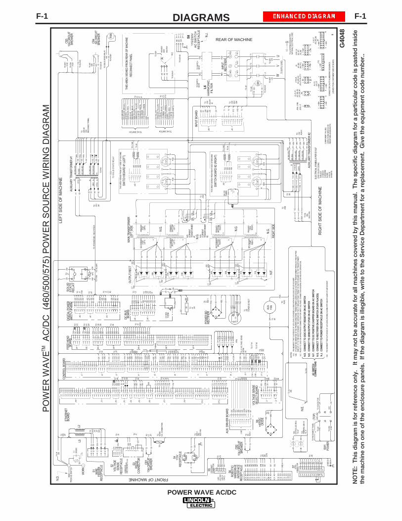
F-1DIAGRAMSF-1
POWER WAVE AC/DC
NO
TE
: T
his
dia
gra
m is
fo
r re
fere
nce
onl
y.
It m
ay n
ot
be
accu
rate
fo
r al
l mac
hine
s co
vere
d b
y th
is m
anua
l. T
he s
pec
ific
dia
gra
m f
or
a p
artic
ular
co
de
is p
aste
d in
sid
eth
e m
achi
ne o
n o
ne o
f th
e en
clo
sure
pan
els.
If
the
dia
gra
m is
ille
gib
le, w
rite
to
the
Ser
vice
Dep
artm
ent
for
a re
pla
cem
ent.
Giv
e th
e eq
uip
men
t co
de
num
ber
..
505
1
THIS
ARE
A VI
EWED
FR
OM
RIG
HT S
IDE
OF
MAC
HINE
85 7
INPU
T BO
ARD
6
J60
321 4
12
PRIM
ARY
(BO
TTO
MLE
FT)
PRIM
ARY
(BO
TTO
MR
IGH
T)
SECO
NDAR
Y(B
OTT
OM
LEFT
)
15
SW. B
D.
D2A
S1 S1 S1
RIG
HT
SID
E
S2 S1
D1B
H1612
TO T
P3
11
C4
652
405
404
403
6
J50
54
506
32
504
503
THIS
AR
EA V
IEW
ED F
RO
M R
EAR
OF
MAC
HIN
E
REC
ON
NEC
T PA
NEL
13
C5
D4B
D3A
S4
+
H5 H6
406
V
T1 T2 612
H1D
TO
T3
CR1
SW1
CB4
AC3
TO J
61
TO J
60
601
X4
J60
TO A
SYS
TEM
GRO
UND
PER
CR1
TO
UTO
SUP
PLY
LINE
S
G
550-
575V
TO S
W1
N.C
.500V
'A'
S3
D2B
D1A
S2 S2
SECO
NDAR
Y(B
OTT
OM
RIG
HT)
202
TO J
9 C1
TP1
.05/
600V
- -W
OR
K
2B1W
2W1B
612B
TO C
B4
TO S
W1
POS
+
TO J
1AD
TO
PO
WE
R B
D. R
EC
TIF
IER
L1
L1A
TO S
W1
D3B
S3
THER
M.
S2
TO J
1AD
TM
LEF
T S
IDE
OF
MA
CH
INE
CB4
6A C
IRC
UIT
BREA
KER
TO A
UX
#2H
1A
612A
CB3
10A
CIR
CUIT
BREA
KER
N.C
. PL
ACE
"A" L
EAD
ON
APPR
OPR
IATE
CO
NNE
CTI
ON
FO
R IN
PUT
VOLT
AGE.
CO
NNEC
TIO
N S
HO
WN
IS F
OR
550
-575
V O
PERA
TIO
N.
RIG
HT
SID
E O
F M
AC
HIN
E
N.A
. P
IN N
EARE
ST T
HE F
LAT
EDG
E O
F LE
D LE
NS
(CAT
HO
DE) A
LIG
NS
WIT
H B
LACK
LEA
D O
F LE
D S
OCK
ET.
NO
TES:
C
PRIM
ARY
(TO
PR
IGH
T)
SECO
NDAR
Y(T
OP
RIG
HT)
NATI
ON
AL E
LECT
RIC
AL C
ODE
.
T1
L2
W
L3
T2
L3A
TO S
W1
T3
AC2
CR
1
TO A
UX
#1
COM
PONE
NT
VALU
ES:
W=W
HIT
EU
=BLU
ER
=RED
AC1
TO S
WIT
CHBD
#1
FAN
X5444
TO A
UX#1
612A
TO A
UX #
1
CB3
TO J
61
SWIT
CH
BO
ARD
#2
(RIG
HT)
SWIT
CH
BO
ARD
#1
(LEF
T)
TO S
OLI
D S
TATE
REL
AY
NEG
TO S
WIT
CH
BD #
2
INPU
T
REAR OF MACHINE
TO CR1
AUX
#1
601
X3 238
604
232
231
S3
TO J
7ST
ATU
S LE
D (R
/G)
N.K
.
N.A
.TH
ERM
AL L
ED (Y
)TO
J7
TO J
920
6
AUX.
DRI
VER
BO
ARD
MAI
N T
RAN
SFO
RMER
LEFT
SID
E
POS
POS
REC
TIFI
ER
AUX
#1
NEG
1098
J61
7654321
S4S4
SECO
NDAR
Y(T
OP
LEFT
)
11
S3
14PO
SC
12
431
J40
16
THIS
AR
EA V
IEW
ED F
ROM
LEF
T SI
DE
OF
MAC
HIN
E
SW1
POW
ER
PRIM
ARY
(TO
PLE
FT)
S4
CB4
TO AUX
#2
D4A
REC
ONN
ECT
PANE
L
OU
TPU
T R
ECT
TO CB3
N=B
RO
WN
CAPA
CIT
OR
S=M
FD/V
OLT
SR
ESIS
TORS
=OH
MS/
WAT
TS
AUXI
LIAR
Y TR
ANSF
OR
MER
#2
ELEC
TRIC
AL S
YMBO
LS P
ER E
1537
LEAD
CO
LOR
CODI
NGB=
BLAC
KG
=GR
EEN
TO CB1
S1W
IRE
FEED
ERRE
CEP
TACL
E
J47
223
221
J14 5
3R3R 3W238
15
TO LED
THER
M
223
222A
POW
ER B
DRE
CTI
FIER
AC
212A
216A
213A
CON
TRO
L BO
ARD
J425
1
20C
J47
1 2 3 4 6
1 2 3 4
+
D
202
225A
J7
2
5
J2
206
52
J5
1 2 3 4 5 6 7
J3
4 5 6N
EG
X1
POS
50
TO L2CB
110
A C
IRC
UIT
BREA
KER
TO WO
RK
J47
TP3
NEG
7
X2 NEG
1
POS
2 3
C3
J2
TO J9
2W
216
2B
511
604
S2VO
LTAG
ESE
NSE
REC
EPTA
CLE
S3R
S232
CON
NEC
TOR
FRONT OF MACHINE
1 2J7
4
12
J76
21A
2
51
3 4
54
E
53
J9
1514
J71
11 12
TO
J70
8311667
A
4
J46
321PO
SPO
S
DC B
US B
OAR
D
12
J41
TO
1 2 3 4 5 6 7 8 91 2 3 4 5 6 87 9
J8 J9
228
226
1
240
220
504
302
505
4
301
23
211A
2 37 8
21A
418
W51
4 R
1
273
274
5 6 2 1
512
4321
VOLT
AGE
SENS
ESE
LECT
BO
ARD
9 1 2 3 4
1 2 3 4
J72
J75
FEED
HEA
DBO
ARD
11
J42
6543222
51 10987654
273
3
228
274
226
4
TO S3
1 2
J43
251
253
254
J19
13
7
ETHE
RNET
BOAR
D
1486541 32
NEG
DIG
ITAL
PO
WER
SUPP
LY B
OAR
D
221
231
232
1 32161051 2
651
987654
1
9876
475
477
1 247
647
83 4
J6
5 6
253
7
225
4
8
3
9
4
13
B
11
A
10
L2
43
1 2 3 4
TO J
1 VO
LTAG
E S
ENSE
WO
RK
J10A J11
J1AD
J42
J43
10
10 151411 12 13 161011 1210 14 1511 12 13 1610
POS
POS
NEG
NEG
AC
52
CO
NNE
CTO
RD
EVIC
ENET
51 42 3 CONN
ECTO
R12
PIN
3 421 5 6
ROBO
TIC/
WIR
EDRI
VEIN
TER
FACE
RECE
PTAC
LES2
J2
67B
67A
1W 1B
892
892 85
185
285
385
485
585
6
154
32A
222
891
TO J75
7 8 9 10
857
858
859
860
3 CO
NDUC
TOR
TWIS
TED
/SH
IELD
EDSH
IELD
GRO
UND
TO
CAS
E
L4
J85
TO
267
266
268
TO J40
J50
J60
67
TO J43
J82
S5
S6
S7
GND
-AG
ND-
B
267
266
268A
893
894
67S1 S6
227
227
C3TO AUX
1
N P R S T U V W XA B C D E F G H I J K L M
841
844
842
843
845
846
847
67B
539
541
521
522
GN
D-A
11 1286
186
2
TO S5
J82
154
153
4321
500
540
TO J11
J47
TO S6
846
845
844
843
842
841
J84
651 2 3 4
847
87
TO S6 D688
088
652
252
154
153
9
J83
651 2 3 4
TO S7 J1VS
856
855
854
853
852
851
J85
651 2 3 4
857
87
511
512
862
861
860
859
9 1512 1614131110
858
651 2 3 4 87 9 10
J86
651 2 3 4 87 9 10
J87
11 12 13 14 15 16
TO J85
+24V
+24V
GN
DC
AN_H
CAN
_L
800
840
1
518
W2
414
R
J10B
405
404
893
891
894
1 2 3 4
J73
53 54TO S1 S9TO J8
1
743
741
800
840
TO J72
765431
50 540
475
476
477
51
ATO
REC
ON
NEC
T PA
NEL
TO J
61H
1D
(TO
P)LO
AD L
INE
TO C
B361
2B
TO C
ONT
ACTO
RL3
A
L1A
A.0
1
W R41
H5 (5
00)
H4 (4
40-4
60)
H3
(380
-415
)
H1
6H5
A
3 14
H3A
2
H4A
H2 (2
20-2
30)
(115
V)
H2A
H1A
H6 (5
50-5
75)
5H6
AP5
0
TO S
4,CB
2,AU
X. F
AN
350 352
8
147
98
1
1216
7
10
8
CON
NEC
TOR
CAV
ITY
NUM
BERI
NG
SEQ
UEN
CE
(VIE
WED
FR
OM
CO
MPO
NEN
T SI
DE O
F BO
ARD
)
1
1 6
5
61
3
56
4
41
1
J10A
, J10
B,
J2VS
, J7
21
34
1 2
J2,J
5,J1
1,J4
1,J4
6,J7
2J7
3,J7
6,J8
1J8
2
J1VS
,J9,
J14,
J40,
J42,
J50,
J75,
J83,
J711
J8,
J47,
J60
J84,
J712
J1AD
,J3
J61,
J77,
J79,
J86
J4,J
13,
J43,
J71
J1,J
6,J7
J10,
J70,
J85
J87
250
0
J81
741
743
4321
2.7
10W
2.7
10W
2.7
10W 2.7
10W
847
8
TO CB1
J41
J82
S1
TO
SO
LID
ST
AT
E R
ELA
YX
3ATO F
AN
X1
R(1
15V)
N(2
4V)
X4H
2AH3A
H1H2
H3H4
H4A
X2U
(51V
)
X3W
X3 X5
W
H5A
H5
H6A
H6
.022
800V
.022
800V
.022
800V
.022
800V
1816 14 17 13
TO J
6
TO J
6
AUXI
LIAR
Y TR
ANSF
OR
MER
#1
J6
12
16
C6
18
C7
+
NEG
+ C17
NEG
C15
N.B
.C
URRE
NT
TRAN
SFO
RM
ER#2N
.B.
CUR
REN
TTR
ANSF
OR
MER
#1
R5
SID
E O
F CT
TO
TH
E SW
ITCH
BO
ARD
. THE
AR
ROW
ON
THE
CT
SHO
ULD
POIN
T FR
OM
THE
SW
ITC
H BO
ARD
TO
TH
E TR
ANSF
OR
MER
.N
.B.
CTs
MUS
T BE
OR
IENT
ED IN
THE
PR
OPE
R DI
REC
TIO
N. T
RANS
FORM
ER L
EADS
SHO
ULD
GO
FR
OM
TRA
NSF
ORM
ER T
HRO
UGH
TH
E DO
TTED
TO C
T #1
TO C
T #2
830
TO J4 J11
R5
262
220
292A
TO
AU
X#1
+3RT
O3W
J7
X3A
TP
444
4
TO
FA
N
34
-
SO
LID
ST
AT
ER
ELA
Y
21
518
WH
ITE
514
RED
POS
NEG
32135
035
233
A4
262
268
268A
R5
DC
BUS
THER
M
TO
4
32 33
1 6
33A
2(2
30V)
E
G40
48
115/
230V
AC
SW
ITC
HR
EC
EP
TA
CLE
S8
TO J2VS J73
J47
CB1
L5
TO J84
J2VS
J83
TO J4 J1AD
TO J47 TO C3
TO J4 J43
TO J46
POW
ER B
D R
ECT
TO J4 J6 J40
J42
J50
TO S8
TO J10B
TO J10A
TO A
UX #
1
TO A
UX #
2
HA
RM
ON
ICF
ILT
ER
L6
J1AD
18
J710
352A
AUX.
FAN
352A
3 421 5 6 7 8 9 10 11 12
J77
1 32 987654 10
J79
1 32 987654 10
CB2
AUX
2TO
32
115V
REC
EPTA
CLE
S4
31
CB2
10A
CIR
CUI
TBR
EAKE
RTO S4 AU
X 2
31 33
TO
886
880
DIO
DE
J83
D6
+40V
DC
ACAC
32A
AUX
FAN
J710
J712
J1AD
1 2 3 4 5
301
225
622
5A7
403
406
8 9 10
222
503
506
222A
302
4 5 61 32 7 8 4 5 61 32 7 8
1211
414
RED
418
WH
ITE
16
733
734
TO J3 J6 J7
771
772
773
774
775
776
777
778
779
711
TO S9
712
713
714
715
716
717
718
281
282
285
286
778
S9
774
776
J77
771
TO J77
773
775
777
772
779
285A
BLU
E28
6A B
LACK
(BLU
E)
733
YELL
OW
734
BLAC
K (Y
ELLO
W)
285B
YEL
LOW
286B
BLA
CK
(YEL
LOW
)
711
BLUE
211A
WHI
TE21
2A B
LACK
(WHI
TE)
224A
240
TO J8 J712
J7
717
WHI
TE
216A
GRE
EN
718
BLAC
K (W
HITE
)
712
BLAC
K (B
LUE)
714
BLAC
K (G
REE
N)71
3 G
REEN
716
BLAC
K (R
ED)
715
RED
H4
440-
460V
H5 (5
00)
H4 (4
40-4
60)
H3 (3
80-4
15)
H1H2 (2
20-2
30)
H6 (5
50-5
75)
N.E.
N.F
.N.
G.
N.G
.
N.G
.
N.G
.
N.E
. CO
NN
ECT
TO 2
06B
OU
TPU
T ST
UD
ON
AC
SW
ITCH
N.F
. C
ON
NEC
T TO
DC
PO
SITI
VE C
HO
PPER
BO
AR
D O
N A
C S
WIT
CH
N.G
. CO
NN
ECT
TO R
ECTI
FIER
ON
AC
SW
ITCH
(FO
UR P
LAC
ES)
N.D
. C
ON
NEC
T TO
202
C O
UTP
UT
RES
ISTO
R O
N A
C S
WIT
CH
224
J73
N.J
. C
ON
NEC
T TO
PO
WER
REC
EPTA
CLE
ON
AC
SW
ITCH
AC
SW
ITCH
CO
NN
ECTI
ON
S
N.J.
TO S4
TO AUX2
202A
224A
N.E.
CO
NNE
CTI
ON
J5 TO
N.D
.
N.K
. P
IN N
EARE
ST T
HE
FLAT
ED
GE
OF
LED
LEN
S (A
NO
DE)
ALI
GN
S W
ITH
BLAC
K LE
AD O
F LE
D S
OCK
ET.
FRO
M A
C S
WIT
CH
21 3 54 6 87
282A
282B
281A
281B
285A
285B
286A
286B
P7A
281A
BRO
WN
282A
BLA
CK
(BRO
WN)
281B
RED
282B
BLA
CK (R
ED)
213A
BLA
CK (G
REEN
)
TO AC SWITCH TO AC SWITCH
733A
734A
292A
224B
224
224B
220
292A
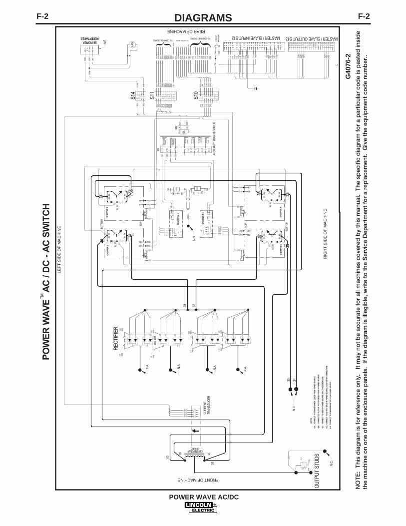
F-2DIAGRAMSF-2
POWER WAVE AC/DC
NO
TE
: T
his
dia
gra
m is
fo
r re
fere
nce
onl
y.
It m
ay n
ot
be
accu
rate
fo
r al
l mac
hine
s co
vere
d b
y th
is m
anua
l. T
he s
pec
ific
dia
gra
m f
or
a p
artic
ular
co
de
is p
aste
d in
sid
eth
e m
achi
ne o
n o
ne o
f th
e en
clo
sure
pan
els.
If
the
dia
gra
m is
ille
gib
le, w
rite
to
the
Ser
vice
Dep
artm
ent
for
a re
pla
cem
ent.
Giv
e th
e eq
uip
men
t co
de
num
ber
..
TM
LEF
T S
IDE
OF
MA
CH
INE
N.C
. C
ON
NEC
T TO
206
A IN
PO
WER
SO
URC
E (V
OLT
AG
E FE
EDB
ACK
)
RIG
HT
SID
E O
F M
AC
HIN
E
N.A
. C
ON
NEC
T TO
TRA
NSF
ORM
ER L
EAD
S FR
OM
PO
WER
SO
URCE
NO
TES:
REAR OF MACHINE
FRONT OF MACHINE
282B
281B
733
734
285A
286B
711
718
224A
240
722
211A
712
N.B
. C
ON
NEC
T TO
OU
TPUT
REC
TIFI
ER H
EATS
INK
IN P
OW
ER S
OU
RCE
CHO
PPER
D
RECT
IFIE
R2.
710
W
2.7
10W
2.7
10W 2.7
10W
.022
800V
.022
800V.0
2280
0V
.022
800V
N.A.
N.A.N.A
.
N.A.
286DB8
285D
281D
282D
286C
285C
281C
282C
N.B.
3433
34 3335
3738
211216
1234
212213
CENTERTAPCHOKE
36
40
38
3635
40
39
C1
TP1
OU
TPU
T ST
UD
S
N.C
.
32 4
350A
352B
33B
1
N P R S T U V W XA B C D E F G H I J K L M
717A
714A
718A
722A
713A
N P R S T U V W XA B C D G H I J K L M73
373
4C
GN
D
722
MASTER / SLAVE INPUT S12 MASTER / SLAVE OUTPUT S13
717
212A
216A
714
713
213A
716
282A
281A
285B
286A
715
711
718
717
712
714
713
716
715
715A
716A
713A
714A
722A
718A
717A
716A
715A
S8 POWERRECEPTACLE
31 2 5 67 84 9
282B
281B
285A
286B
721
282A
281A
285B
286A
S11
282D
281D
285C
286D
282C
281C
285D
286C
31 2 5 6 7 84 9
240
212A
213A
224A
211A
216A
S10
324
212
213
320
211
216
350B
FAN
AUXI
LIAR
Y TR
ANSF
ORM
ER
brow
n
blue
1
4 5 8763
6
230
VAC
230
VAC
( vio
let)
2118
VAC
( whi
te)
18 V
AC(g
reen
)
18 V
AC( y
ello
w)
18 V
AC( r
ed)
633
2
1633
3
133
0
1133
1
230
VAC
(ora
nge)
S23
352C
350C
S22
SNUB
BER
# 2
SNUB
BER
# 1 1 2
J133
233
3320
321
Ther
mos
tat
324
323
321
322
Ther
mos
tat
323
322 Ther
mos
tat
206B
345
50W
346
341
344
N.D
.
N.D
. C
ONN
ECT
TO O
UTP
UT
STU
D IN
PO
WER
SO
URC
E (C
ENTE
RTA
P C
ON
NEC
TIO
N)
202C
CIRC
UIT
BREA
KER
734B
734C
734
342
347
50W
348
343
N.E.
N.E
. C
ONN
ECT
TO P
OW
ER R
ESEP
TACL
E IN
PO
WER
SO
URC
E
C
G40
76-2
CHO
PPER
B
CHO
PPER
CC
HOPP
ER A
+ -
B3, B
6
B2, B
5
B1, B
4
3
12
4317
315
318
316
J2
E F
+-
B3, B
6
B2, B
5
B1, B
4
+-
B3, B
6
B2, B
5
B1, B
4
+ -
B3, B
6
B2, B
5
B1, B
4
TOP
BOTT
OM
TOP
BOTT
OM
CUR
REN
TTR
ANSD
UCER
J15
Ther
mos
tat
1 2J1
330
331
3
12
4313
311
314
312
J2
39
37
314
311
312
313
317
316315
318
345
344
31 2 4S14
352B
350B
352C
350C
B7
B8
B7
B8
B7
B8
B7
TO ETHERNET BOARD
721
TO CONTROL BOARD
DRAI
N
DRAI
N
TO CONTROL BOARD

F-3PIN, LEAD CONNECTOR SETUPSF-3
POWER WAVE AC/DC
TABLE F.5 DEVICENET CONNECTOR S5
Pin Lead # Function2 894 +24vdc Devicenet3 893 Commom Devicenet+4 892 Devicenet H5 891 Devicenet L
TABLE F.2 WIRE FEEDER RECEPTACLE S1
Pin Lead # FunctionA 53 Arclink LB 54 Arclink HC 67A Electrode Voltage SenseD 52 Ground(0v)E 51 +40vdc
TABLE F.6 EXTERNAL I/O S7
Pin Lead # Function1 851 +15vdc for Trigger group2 852 Trigger input3 853 Dual procedure input4 854 4 Step input5 855 +15vdc for cold inch group6 856 cold inch forward7 857 cold inch reverse8 858 gas purge input9 859 +15vdc for shutdown group10 860 shutdown1 input11 861 shutdown2 input12 862 input B
TABLE F.4 RS232 CONNECTOR S3
Pin Lead # Function2 253 RS232 Receive3 254 RS232 Transmit4 # S3 Pin55 # S3 Pin46 ## S3 Pin2020 ## S3 Pin67 251 RS232 Common
TABLE F.3 VOLTAGE SENSE RECEPTACLE S2
Pin Lead # Function3 21A Work Voltage Sense
Pin Robotic Interface Connector (S6) Master / Slave Input(S12) Master / Slave Output(S13)
A +15vdc Tach voltage Reserved for future use Reserved for future useB Tach common Reserved for future use Reserved for future useC Tach 1A differential signal Sync In Reserved for future useD Tach 1B differential signal Sync In Reserved for future useE Tach 2A differential signal Ready In Ready InF Tach 2B differential signal Ready In Ready InG Single Tach Input Polarity Out Polarity OutH Reserved for future use Polarity Out Polarity OutI Voltage sense lead GroundJ Motor "+" Reserved for future use Reserved for future useK Motor "-" Reserved for future use Reserved for future useL Reserved for future use +40v (COM) Reserved for future useM Reserved for future use +40v ("+") Reserved for future useN +40vdc for solenoid Reserved for future use Reserved for future useP solenoid input Reserved for future use Reserved for future useR Reserved for future use Reserved for future use Reserved for future useS Reserved for future use Reserved for future use Reserved for future useT Shield ground to case Drain (ethernet) Drain (ethernet)U Reserved for future use Kill Out Kill OutV Reserved for future use Kill Out Kill OutW Reserved for future use Reserved for future use Reserved for future useX Reserved for future use Reserved for future use Reserved for future use
Table F.1 INTERFACE CONNECTOR WIRING

F-4CONNECTION DIAGRAMF-4
POWER WAVE AC/DC
K1796 COAXIAL WELD CABLE
User suppliedwork lead
User suppliedelectrode lead
- +
POWERWAVE
CONTROL CABLE K1805-1
WORK SENSE LEAD K940
DEVICENET CABLE
K1804-1 CONTROL CABLE ORK1804-2 AND ANY K1795 CONTROL CABLE
User suppliedwork lead
User suppliedelectrode lead
CONTROL CABLE K1805-1
Robotic Set Up, Electrode Positive, CV/PulseConfiguration
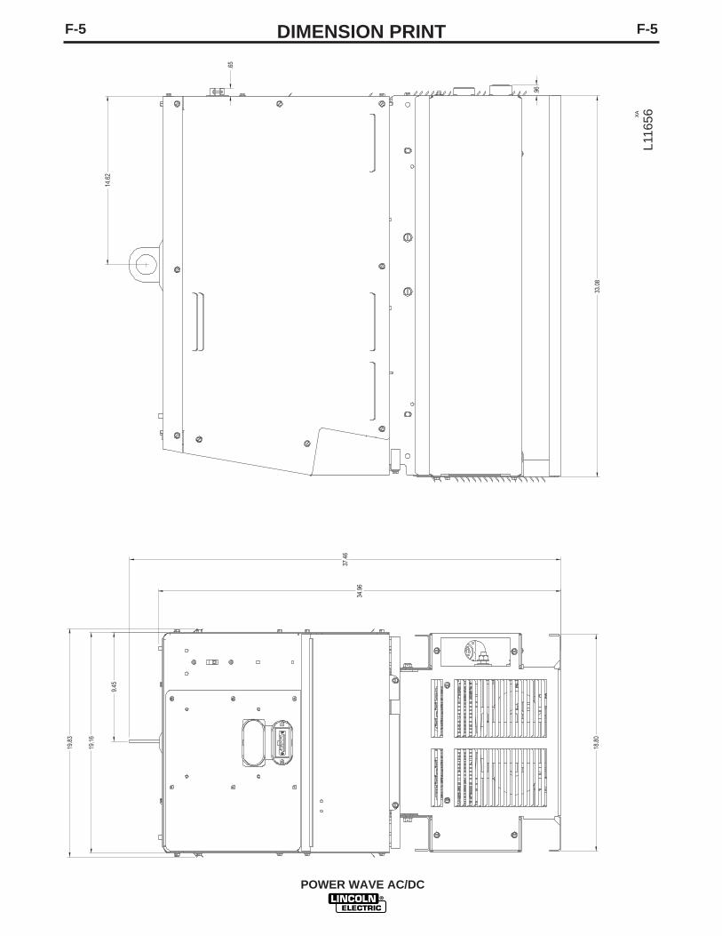
F-5DIMENSION PRINTF-5
POWER WAVE AC/DC
XA
9.45
19.1
6
19.8
3
14.6
2
37.4
6
18.8
033
.08
.65
.96
34.9
6
L116
56

NOTES
POWER WAVE AC/DC

NOTES
POWER WAVE AC/DC

Now Available...12th EditionThe Procedure Handbook of Arc Welding
With over 500,000 copies of previous editions publishedsince 1933, the Procedure Handbook is considered by many to be the “Bible” of the arc welding industry.
This printing wil l go fast so don ’t delay. Place your order now using the coupon below.
The hardbound book contains over 750 pages of weldinginformation, techniques and procedures. Much of this material has never been included in any other book.
A must for al l welders, supervisors, engineers anddesigners. Many welding instructors will want to use the bookas a reference for all students by taking advantage of the lowquantity discount prices which include shipping by4th class parcel post.
$15.00 postage paid U.S.A. Mainland
How To Read Shop Drawings
The book contains the latest information and applicationdata on the American Welding Society Standard WeldingSymbols. Detailed discussion tells how engineers anddraftsmen use the “short-cut” language of symbols to passon assembly and welding information to shop personnel.
Practical exercises and examples develop the reader’s abilityto visualize mechanically drawn objects as they will appearin their assembled form.
187 pages with more than 100 illustrations. Size 8-1/2” x 11”Durable, cloth-covered board binding.
$4.50 postage paid U.S.A. Mainland
New Lessons in Arc WeldingLessons, simply written, cover manipulatory techniques;
machine and electrode characteristics; related subjects,such as distortion; and supplemental information on arcwelding applications, speeds and costs. Practice materials,exercises, questions and answers are suggested for each lesson.
528 pages, well illustrated, 6” x 9” size, bound in simulated,gold embossed leather.
$5.00 postage paid U.S.A. Mainland
Need Welding Training?The Lincoln Electric Company operates the oldest and
most respected Arc Welding School in the United States at itscorporate headquarters in Cleveland, Ohio. Over 100,000 stu-dents have graduated. Tuit ion is low and the training is “hands on”
For details write: Lincoln Welding School22801 St. Clair Ave. Cleveland, Ohio 44117-1199.
and ask for bulletin ED-80 or call 216-383-2259 and ask for theWelding School Registrar.
Lincoln Welding SchoolBASIC COURSE $700.00
5 weeks of fundamentalsThere is a 10% discount on all orders of $50.00 or more for shipment at one time to one location.Orders of $50 or less before discount or orders outside of North America must be prepaid with charge, check or money order in U.S. Funds Only.Prices include shipment by 4 thClass Book Rate for U.S.A. Mainland Only. Please allow up to 4 weeks for delivery.UPS Shipping for North America Only. All prepaid orders that request UPS shipment please add:
$5.00 For order value up to $49.99$10.00 For order value between $50.00 & $99.99$15.00 For order value between $100.00 & $149.00
For North America invoiced orders over $50.00 & credit card orders, if UPS is requested, it will be invoiced or charged to you at cost.Outside U.S.A. Mainland order must be prepaid in U.S. Funds. Please add $2.00 per book for surface mail or $15.00 per book for air parcel post shipment.METHOD OF PAYMENT: (Sorry, No C.O.D. Orders)
CHECK ONE:Name: _______________________________________________
Please Invoice (only if order is over $50.00)Address: _______________________________________________
Check or Money Order Enclosed, U.S. Funds only _______________________________________________
Credit Card - Telephone: _______________________________________________
Signature as it appears on Charge Card:Account No. |_|_|_|_|_|_|_|_|_|_|_|_|_|_|_|_|_|_|_|_|_| Exp Date |_|_| |_|_| ______________________Month Year
USE THIS FORM TO ORDER: Order from: BOOK DIVISION, The Lincoln Electric Company, 22801 St. Clair Avenue, Cleveland, Ohio 44117-1199BOOKS OR FREE INFORMATIVE CATALOGS Telephone: 216-383-2211 or, for fastest service, FAX this completed form to: 216-361-5901.
Lincoln Welding School Titles: Price Code Quantity Cost(ED-80) New Lessons in Arc Welding $5.00 L
Seminar Information Procedure Handbook “Twelfth Edition” $15.00 PH(ED-45) How to Read Shop Drawings $4.50 H
Educational Video Information Incentive Management $5.00 IM(ED-93) A New Approach to Industrial Economics $5.00 NA
James F. Lincoln Arc Welding The American Century of John C. Lincoln $5.00 ACFoundation Book Information Welding Preheat Calculator $3.00 WC-8
(JFLF-515) Pipe Welding Charts $4.50 ED-89SUB TOTAL
Additional Shipping Costs if anyTOTAL COST
MasterCard
VISA ®
AMERICAN EXPRESS
MasterCardMasterCard®
AMERICAN EXPRESS
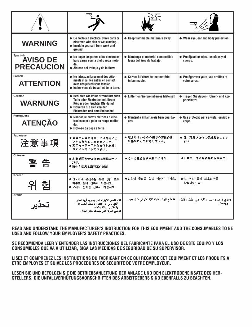
WARNING
AVISO DEPRECAUCION
ATTENTION
WARNUNG
ATENÇÃO
Spanish
French
German
Portuguese
Japanese
Chinese
Korean
Arabic
READ AND UNDERSTAND THE MANUFACTURER’S INSTRUCTION FOR THIS EQUIPMENT AND THE CONSUMABLES TO BEUSED AND FOLLOW YOUR EMPLOYER’S SAFETY PRACTICES.
SE RECOMIENDA LEER Y ENTENDER LAS INSTRUCCIONES DEL FABRICANTE PARA EL USO DE ESTE EQUIPO Y LOSCONSUMIBLES QUE VA A UTILIZAR, SIGA LAS MEDIDAS DE SEGURIDAD DE SU SUPERVISOR.
LISEZ ET COMPRENEZ LES INSTRUCTIONS DU FABRICANT EN CE QUI REGARDE CET EQUIPMENT ET LES PRODUITS AETRE EMPLOYES ET SUIVEZ LES PROCEDURES DE SECURITE DE VOTRE EMPLOYEUR.
LESEN SIE UND BEFOLGEN SIE DIE BETRIEBSANLEITUNG DER ANLAGE UND DEN ELEKTRODENEINSATZ DES HER-STELLERS. DIE UNFALLVERHÜTUNGSVORSCHRIFTEN DES ARBEITGEBERS SIND EBENFALLS ZU BEACHTEN.
● Do not touch electrically live parts orelectrode with skin or wet clothing.
● Insulate yourself from work andground.
● No toque las partes o los electrodosbajo carga con la piel o ropa moja-da.
● Aislese del trabajo y de la tierra.
● Ne laissez ni la peau ni des vête-ments mouillés entrer en contactavec des pièces sous tension.
● Isolez-vous du travail et de la terre.
● Berühren Sie keine stromführendenTeile oder Elektroden mit IhremKörper oder feuchter Kleidung!
● Isolieren Sie sich von denElektroden und dem Erdboden!
● Não toque partes elétricas e elec-trodos com a pele ou roupa molha-da.
● Isole-se da peça e terra.
● Keep flammable materials away.
● Mantenga el material combustiblefuera del área de trabajo.
● Gardez à l’écart de tout matérielinflammable.
● Entfernen Sie brennbarres Material!
● Mantenha inflamáveis bem guarda-dos.
● Wear eye, ear and body protection.
● Protéjase los ojos, los oídos y elcuerpo.
● Protégez vos yeux, vos oreilles etvotre corps.
● Tragen Sie Augen-, Ohren- und Kör-perschutz!
● Use proteção para a vista, ouvido ecorpo.
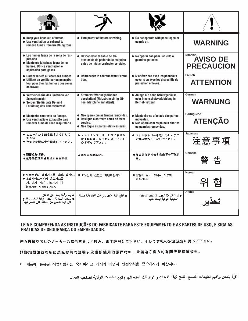
WARNING
AVISO DEPRECAUCION
ATTENTION
WARNUNG
ATENÇÃO
Spanish
French
German
Portuguese
Japanese
Chinese
Korean
Arabic
LEIA E COMPREENDA AS INSTRUÇÕES DO FABRICANTE PARA ESTE EQUIPAMENTO E AS PARTES DE USO, E SIGA ASPRÁTICAS DE SEGURANÇA DO EMPREGADOR.
● Keep your head out of fumes.● Use ventilation or exhaust to
remove fumes from breathing zone.
● Los humos fuera de la zona de res-piración.
● Mantenga la cabeza fuera de loshumos. Utilice ventilación oaspiración para gases.
● Gardez la tête à l’écart des fumées.● Utilisez un ventilateur ou un aspira-
teur pour ôter les fumées des zonesde travail.
● Vermeiden Sie das Einatmen vonSchweibrauch!
● Sorgen Sie für gute Be- undEntlüftung des Arbeitsplatzes!
● Mantenha seu rosto da fumaça.● Use ventilação e exhaustão para
remover fumo da zona respiratória.
● Turn power off before servicing.
● Desconectar el cable de ali-mentación de poder de la máquinaantes de iniciar cualquier servicio.
● Débranchez le courant avant l’entre-tien.
● Strom vor Wartungsarbeitenabschalten! (Netzstrom völlig öff-nen; Maschine anhalten!)
● Não opere com as tampas removidas.● Desligue a corrente antes de fazer
serviço.● Não toque as partes elétricas nuas.
● Do not operate with panel open orguards off.
● No operar con panel abierto oguardas quitadas.
● N’opérez pas avec les panneauxouverts ou avec les dispositifs deprotection enlevés.
● Anlage nie ohne Schutzgehäuseoder Innenschutzverkleidung inBetrieb setzen!
● Mantenha-se afastado das partesmoventes.
● Não opere com os paineis abertosou guardas removidas.

• Sales and Service through Subsidiaries and Distributors Worldwide •
Cleveland, Ohio 44117-1199 U.S.A. TEL: 216.481.8100 FAX: 216.486.1751 WEB SITE: www.lincolnelectric.com
• World's Leader in Welding and Cutting Products •