
Power Distribution Systems - Morek
189
Power Distribution Systems Gesamtkatalog Main catalogue Catalogue général www.ftg-germany.de
-
Upload
khangminh22 -
Category
Documents
-
view
5 -
download
0
Transcript of Power Distribution Systems - Morek

Power Distribution Systems
GesamtkatalogMain catalogueCatalogue général
www.ftg-germany.de

Sehr geehrte Leserinnen und Leser,
FTG ist wichtiger Arbeitgeber in der Region des Südschwarzwaldes, Teil einer weltwei-ten Gruppe, wichtiger Partner für Kunden wie auch tatkräftiger Unterstützer in sozi-alen, regionalen Bereichen. Seit Gründung 1962 wächst das Unternehmen kontinuier-lich und entwickelt sich stetig weiter.
Die Verteilung und Verbindung von elekt-rischen Strömen ist unser Fachgebiet. Wir sind führender Hersteller weltweit, unser Produktsortiment erweitert sich ständig und ist nach gängigen Normen zertifiziert. Unsere Produkte finden in zahlreichen Branchen Anwendung, wie in Windkraft- & Photovoltaikanlagen, Kraftwerken, Industrie & Anlagenbau, Mobilität oder die Stromun-terverteilung in jeglicher Art von Gebäuden. Eine sichere, störfreie Energieversorgung ist ein zentrales Element bei der Erreichung von Fortschritt und Wohlstand.
Wir sind für Sie weltweit präsent und bera-ten und informieren Sie zu mehr als 10.000 Produkten. Zudem entwickeln wir mit Ihnen optimale Lösungen für ihre spezifischen Anforderungen. Wir sind für Sie da, um Ihre Visionen zu verwirklichen.
Wir wünschen Ihnen viel Spaß beim Lesen.
Chers Lecteurs,
FTG est un employeur important de la régi-on du sud de la Forêt-Noire: Faisant partie d’un groupe mondial, il est un partenaire important pour les clients ainsi qu’un puissant soutien dans des projets sociaux et régionaux. Depuis sa création en 1962, l’entreprise poursuit sa croissance conti-nue et ne cesse de se développer.
La répartition et l’interconnexion en électricité constituent notre domaine de spécialisation. Nous sommes un fab-ricant leader mondial, notre gamme de produits s’accroit sans cesse et est cer-tifiée selon les normes en vigueur. Nos produits sont utilisés dans de nombreux secteurs tels que les éoliennes et les ins-tallations photovoltaïques, les centrales électriques, l’industrie et la construction d’équipements, la mobilité ou la distri-bution électrique dans des bâtiments en tous genres. Un approvisionnement éner-gétique sûr et sans pannes constitue un élément central du progrès et de la pro-spérité.
Nous sommes à votre disposition partout dans le monde et vous conseillons et vous informons sur plus de 10.000 produits. De plus, nous élaborons avec vous des solu-tions optimales pour vos exigences spéci-fiques. Nous sommes à votre disposition pour mettre en œuvre vos visions.
Nous vous souhaitons une bonne catalogue.
Dear Readers,
FTG is an important employer in the sou-thern Black Forest region, part of a world-wide group, an important partner for its customers and an active supporter when it comes to social and regional matters. The company has been steady growing since it was established in 1962 and is continuing to develop today.
We are specialised in electrical power dis-tribution and connection. We are a lea-ding manufacturer of busbars; our pro-duct portfolio is growing all the time and is certified under the leading standards. Our products are used in many areas, from building services through machine con-trol to electrical infrastructure. Ensuring a safe, uninterrupted power supply is our primary objective and a crucial element in achieving progress and prosperity.
We are there to help you across the globe and to offer you advice and informati-on about our range of more than 10,000 products. In addition, we work with you to develop the best possible solutions for your specific requirements. We‘re on hand to make your visions come true.
We hope you enjoy reading our catalogue.
VorwortForeword | Préface

ALLGEMEINE INFORMATIONEN | General information | Informations générales 4-7 Historie | History | Histoire 4 Aus dem Schwarzwald in die Welt | From the Black Forest across the globe | De la Forêt-Noire au monde entier 5 Breites Produktsortiment | A wide product portfolio | Large gamme de produits 6
FTG PHASENSCHIENEN | FTG Busbars | FTG Peignes 8 1. EINPOLIGE PHASENSCHIENEN | One-phase busbars | Peignes unipolaires 12-27 Eurovario | Eurovario | Eurovario 14 Gabel/Steg | Fork/Pin | Fourche/Pointe 18 Phasenschienen für Hilfsschalter H1+ H2 | Busbars for Auxiliary switches H1 + H2 | Peignes pour auxiliare H1 + H2 22 Sonderlösungen | Special busbars | Barres spéciales 26
2. ZWEIPOLIGE PHASENSCHIENEN | Two-phase busbars | Peignes bipolaires 28-39 Eurovario | Eurovario | Eurovario 30 Gabel/Steg | Fork/Pin | Fourche/Pointe 34 Phasenschienen für Hilfsschalter H1+ H2 | Busbars for Auxiliary switches H1 + H2 | Peignes pour auxiliare H1 + H2 36 Sonderlösungen | Special busbars | Barres spéciales 38
3. DREIPOLIGE PHASENSCHIENEN | Three-phase busbars | Peignes tripolaires 40-53 Eurovario | Eurovario | Eurovario 42 Gabel/Steg | Fork/Pin | Fourche/Pointe 48 Phasenschienen für Hilfsschalter H1+ H2 | Busbars for Auxiliary switches H1 + H2 | Peignes pour auxiliare H1 + H2 50 Sonderlösungen | Special busbars | Barres spéciales 52
4. VIERPOLIGE PHASENSCHIENEN | Four-phase busbars | Peignes tétrapolaires 54-63 Eurovario | Eurovario | Eurovario 56 Gabel/Steg | Fork/Pin | Fourche/Pointe 58 Phasenschienen für Hilfsschalter H1+ H2 | Busbars for Auxiliary switches H1 + H2 | Peignes pour auxiliare H1 + H2 60 Sonderlösungen | Special busbars | Barres spéciales 62
5. PHASENSCHIENEN ZUBEHÖR | Busbar Accessories | Peigne Accessoires 64-67 Endkappen | End covers | Embouts 66 Berührschutzkappen | Contact protection covers | Protections contre les contacts directs 67
6. PHASENSCHIENEN FÜR NH-TRENNER | Busbars for NH fuse switch disconnectors | Peignes pour interrupteurs-fusibles 68-79 Phasenschienen | Busbars | Peignes 70 Zubehör | Accessories | Accessoires 78
7. UL PHASENSCHIENEN | UL Busbars | UL Peignes 80-87 UL508 | UL508 | UL508 82 UL489 | UL489 | UL489 84 ULcut | ULcut | ULcut 85 Zubehör | Accessories | Accessoires 87
8. FLEXIBLE PHASENSCHIENENSYSTEME | Flexible busbars | Systèmes de peignes flexibles 88-105 Auxigaine | Auxigaine | Auxigaine 90 Auxiclic | Auxiclic | Auxiclic 96 FCBeasy | FCBeasy | FCBeasy 98 Easyvation | Easyvation | Easyvation 102 EasyBreak | EasyBreak | EasyBreak 104
InhaltContent | Enquête
9. PAN ASSEMPLY 106-111 VBA-System, luftisoliert | VBA–System, air insulated | VBA–System isolé à l‘air 108 VBR-System, vollvergossen | VBR–System, resin moulded | VBR–System surmoulé résine 108 Zubehör | Accessories | Accessoires 110
10. MSS/VSMEASY 112-123 Motorschutzschalterschienen | Busbars for Motor Protection Switsches | Peigne pour disjoncteurs - moteur 114 Vollvergossene Ausführung | Completely sealed design | Exécution entièrement en pot 116 Adapterplatten | Adapter plates | Adaptateurs 120 Zubehör | Accessories | Accessoires 121 SPSeasy | SPSeasy | SPSeasy 122
11. EINSPEISEKLEMMEN 124-133 Einspeiseklemmen | Feed-in terminals | Bornes de raccordement 126 Einspeiseblöcke | Feed-in terminal blocks | Bornes d’alimentation 132
12. VERTEILERKLEMMEN | Distribution Terminals | Terminaux de distribution 134-163 Kompaktverteiler | Power Distribution Blocks | Répartiteurs compacts 136 Durchgangsklemmen KVIAC | Feed-through terminals KVIAC | Bornes KVIAC 144 Hauptleitungsabzweigklemmen | Electric main branch terminals | Blocs de jonction 146 LPDB | LPDB - PDB for street lighting | LPDB - Blocs de distribution pour éclairage public 148 ECB - Easy Connection Boxes | ECB - Easy Connection Boxes | ECB - Easy Connection Boxes 150 MiniClic | MiniClic | MiniClic 152 Stahlklemmen | Steel Terminals | Pinces en acier 154 Null– und Schutzleiterklemmen | Neutral and Earthing terminals | Barres de neutre et terre 158
13. SCHALTSCHRANKZUBEHÖR | Accessories for cabinet | Armoire de distribution accessories 164-167 Blindabdeckungen| Blanking plates | Obturateurs 166 Sammelschienenabdeckung| Busbar cover | Cache jeux de barres 166
14. ERDUNGSMATERIAL | Grounding material | Matériel de mise à la terre 168-173 Erdungsbandschellen | Ground strap clamps | Attaches pour bandes de mise à la terre 170 Potentialausgleichschiene | Potential equalization bar | Barre de liaison équipotentielle 171 Erdungszubehör | Accessories | Accessorires 172
15. VERDRAHTUNGSBRÜCKEN | Cable bridges | Ponts de câblage 174-179 Flexible Verdrahtungsbrücken | Flexible cable Bridges | Ponts de câblage souple 176 Reihenverbindungen | Row connectors | Pontage vertical 178
ALLGEMEINE LIEFERBEDINGUNGEN FTG | General Terms and Conditions | Conditions générales de livraison 180-185
NOTIZEN | Notes | Notes 186-187
| Connecting Visions4
Allgemeine Informationen | General information | Informations générales
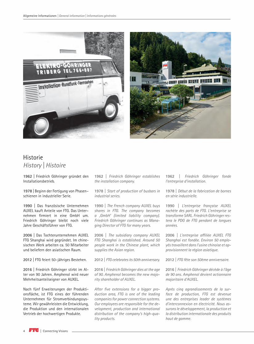
Historie History | Histoire
1962 | Friedrich Göhringer gründet den Installationsbetrieb.
1978 | Beginn der Fertigung von Phasen– schienen in industrieller Serie.
1990 | Das französische Unternehmen AUXEL kauft Anteile von FTG. Das Unter– nehmen firmiert in eine GmbH um. Friedrich Göhringer bleibt noch viele Jahre Geschäftsführer von FTG.
2006 | Das Tochterunternehmen AUXEL FTG Shanghai wird gegründet. Im chine-sischen Werk arbeiten ca. 50 Mitarbeiter und beliefern den asiatischen Raum.
2012 | FTG feiert 50–jähriges Bestehen.
2016 | Friedrich Göhringer stirbt im Al-ter von 90 Jahren. Amphenol wird neuer Mehrheitsanteilseigner von AUXEL.
Nach fünf Erweiterungen der Produkti-onsfläche, ist FTG eines der führenden Unternehmen für Stromverbindungssys-teme. Wir gewährleisten die Entwicklung, die Produktion und den internationalen Vertrieb der hochwertigen Produkte.
1962 | Friedrich Göhringer fonde l’entreprise d‘installation.
1978 | Début de la fabrication de bornes en série industrielle.
1990 | L’entreprise française AUXEL rachète des parts de FTG. L’entreprise se transforme SARL. Friedrich Göhringer res-tera le PDG de FTG pendant de longues années.
2006 | L’entreprise affiliée AUXEL FTG Shanghai est fondée. Environ 50 emplo-yés travaillent dans l’usine chinoise et ap-provisionnent la région asiatique.
2012 | FTG fête son 50ème anniversaire.
2016 | Friedrich Göhringer décède à l’âge de 90 ans. Amphenol devient actionnaire majoritaire d‘AUXEL.
Après cinq agrandissements de la sur-face de production, FTG est devenue une des entreprises leader de systèmes d’interconnexion en électricité. Nous as-surons le développement, la production et la distribution internationale des produits haut de gamme.
1962 | Friedrich Göhringer establishes the installation company.
1978 | Start of production of busbars in industrial series.
1990 | The French company AUXEL buys shares in FTG. The company becomes a ‚GmbH‘ (limited liability company). Friedrich Göhringer continues as Mana-ging Director of FTG for many years.
2006 | The subsidiary company AUXEL FTG Shanghai is established. Around 50 people work in the Chinese plant, which supplies the Asian region.
2012 | FTG celebrates its 50th anniversary.
2016 | Friedrich Göhringer dies at the age of 90. Amphenol becomes the new majo-rity shareholder of AUXEL.
After five extensions for a bigger pro-duction area, FTG is one of the leading companies for power connection systems. Our employees are responsible for the de-velopment, production and international distribution of the company‘s high-qua-lity products.
Allgemeine Informationen | General information | Informations générales

www.ftg-germany.de 5
FTG GERMANYElectrical Equipment
AMPHENOL Global Interconnect Systems
Allgemeine Informationen | General information | Informations générales
Wir von FTG sind Teil einer internationa-len Gruppe. Tradition und Bodenständig-keit verbinden wir mit hohen Ansprüchen an Innovation und Qualität.
An unseren Produktionsstandorten fertigen wir nach höchsten Qualitäts-standards und eine ständige Kontrolle garantiert eine einwandfreie Funktionali-tät unserer Produkte.
Seit Juli 2016 ist FTG Teil der Amphenol Gruppe, die 1932 gegrün-det wurde. Das Unternehmen ist eines der weltweit größten Hersteller für Steckverbindungen und verfügt über eine breit gefächerte Präsenz auf stark wachsenden Märkten wie der Automo-bilindustrie, Breitbandkommunikation, Luftfahrtindustrie, Industrieanlagen, In-formationstechnologie und Datenkom- munikation, Verteidigung, mobile Geräte und Mobilfunknetze. Global gehören über 62.000 Mitarbeiter der Amphenol Gruppe an und ist in über 30 Ländern vertreten.
Aus dem Schwarzwald in die WeltFrom the Black Forest across the globe | De la Forêt-Noire au monde entier
At FTG, we are part of an international group. We combine a sense of tradition and a down-to-earth attitude with high standards of innovation and quality.
At our production sites, we manufacture to the highest quality standards, and con-tinuous monitoring guarantees that our products work perfectly.
Since July 2016, FTG has been part of the Amphenol Group, which was founded in 1932. The company is one of the world‘s largest manufacturers of plug connec-tions and is widely represented across a range of fast growing markets, such as the automobile industry, broadband com-munication, aerospace industry, indust-rial plants, information technology and data communication, defense, mobile devices and mobile telephones. Globally, the Amphenol Group has over 62,000 employees and is represented in over 30 countries across the world.
Chez FTG, nous faisons partie d’un groupe international. Nous allions la tradition et l’ancrage régional à des exigences éle-vées en termes d’innovation et de qualité.
Sur nos sites de production, nous fab-riquons nos produits en appliquant les normes de qualité les plus strictes et un contrôle continu garantit la fonctionna-lité impeccable de nos produits.
Depuis juillet 2016, FTG fait partie du groupe Amphenol fondé en 1932. L’entreprise est un des plus grands fabri-cants de connexions enfichables du mon-de et dispose d’une vaste présence dans des marchés à forte croissance tels que l’industrie automobile, la communication large bande, l’industrie aéronautique, les installations industrielles, la technologie d’information et la communication de données, la défense, les appareils mobiles et les réseaux de téléphonie mobile. Dans le monde, plus de 62.000 personnes font partie du groupe Amphenol qui est pré-sent dans plus de 30 pays.

| Connecting Visions6
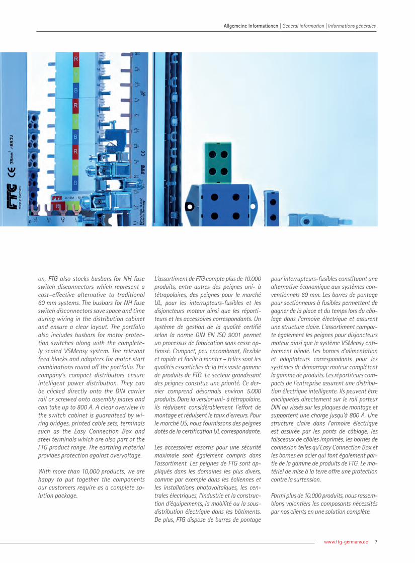
Mehr als 10.000 Produkte führen wir bei FTG im Sortiment, unter anderem Phasenschienen für 1– bis 4–polige An-wendungen, Schienen für den UL–Markt, für NH–Trenner und Motorschutzschal-ter sowie Kompaktverteiler und dem entsprechenden Zubehör. Ein nach DIN EN ISO 9001 zertifiziertes Qualitätsma-nagement ermöglicht einen sich stets optimierenden Herstellungsprozess. Kompakt, platzsparend, flexibel dazu schnell und einfach montiert – das sind die Kerneigenschaften des sehr um-fangreichen Produktsortiments von FTG. Allen voran der stetig wachsende Bereich der Phasenschienen. Dieser umfasst inzwischen rund 5.000 Produkte. In der 1– bis 4–poligen Variante reduzie-ren sie merklich den Montageaufwand und senken die Fehlerhäufigkeit. Für den US–Markt liefern wir Phasenschienen mit entsprechender UL–Zertifizierung.
Das passende Zubehör für maximale Sicherheit findet sich ebenso im Sorti-ment. Phasenschienen von FTG werden in den unterschiedlichsten Gebieten angewandt, wie in Windkraft– & Photo-voltaikanlagen, Kraftwerken, Industrie & Anlagenbau, Mobilität oder die Strom-unterverteilung von Gebäuden.
Weiter verfügt FTG über NH–Trenner-schienen, die eine kostengünstige Alter-native zu herkömmlichen 60 mm Syste-men darstellen. Die NH–Trennerschienen sparen Platz und Zeit bei der Verdrahtung im Verteilerschrank und sorgen für einen übersichtlichen Aufbau. Im Sortiment finden sich ebenfalls die Phasenschie-nen für Motorschutzschalter sowie das vollvergossene VSMeasy–System. Dazu-gehörige Einspeiseblöcke und Adapter für Motorstarterkombinationen runden das Portfolio ab. Für eine intelligente Stromverteilung sorgen Kompaktvertei-ler des Unternehmens. Sie lassen sich direkt auf die DIN–Tragschiene aufras-ten bzw. auf Montageplatten verschrau-ben und sind bis zu 800 A belastbar. Übersicht im Schaltschrank liefern Verdrahtungsbrücken, bedruckte Kabel-sätze, Anschlussklemmen, wie die Easy Connection Box und Stahlklemmen, welche gleichermaßen zur Produkt-palette von FTG gehören. Schutz vor Überspannung bietet das Erdungsmaterial. Mit mehr als 10.000 Produkten stellen wir unseren Kunden gerne die von Ihnen benötigten Komponenten als komplettes Lösungspaket zusammen.
Breites Produktsortiment | A wide product portfolio | Large gamme de produits
At FTG, we carry over 10,000 products in our portfolio, including busbars for 1– to 4–pole applications, for the UL market, for NH fuse switch disconnec-tors and motor protection switches as well as Power Distribution Blocks with the corresponding accessories. A quality management system certi-fied under DIN EN ISO 9001 means that production processes are constantly being optimised. Compact, space–sa-ving, flexible, and quickly and easily assembled – these are the core charac-teristics of FTG‘s very extensive product range. At the top of the list comes the constantly growing range of busbars, which now comprises around 5,000 pro-ducts. In the 1– to 4–pole variant, they offer a considerable time saving during assembly and reduce the frequency of errors. For the US market, we supply bus-bars with corresponding UL certification. The portfolio also covers the right acces-sories for maximum safety.
FTG busbars are used in a wide range of areas, such as wind and solar power sys-tems, power stations, industry & plant engineering, mobility or power distri-bution systems in buildings. In additi-
Allgemeine Informationen | General information | Informations générales Allgemeine Informationen | General information | Informations générales
www.ftg-germany.de 7
L’assortiment de FTG compte plus de 10.000 produits, entre autres des peignes uni- à tétrapolaires, des peignes pour le marché UL, pour les interrupteurs-fusibles et les disjoncteurs moteur ainsi que les réparti-teurs et les accessoires correspondants. Un système de gestion de la qualité certifié selon la norme DIN EN ISO 9001 permet un processus de fabrication sans cesse op-timisé. Compact, peu encombrant, flexible et rapide et facile à monter – telles sont les qualités essentielles de la très vaste gamme de produits de FTG. Le secteur grandissant des peignes constitue une priorité. Ce der-nier comprend désormais environ 5.000 produits. Dans la version uni- à tétrapolaire, ils réduisent considérablement l’effort de montage et réduisent le taux d’erreurs. Pour le marché US, nous fournissons des peignes dotés de la certification UL correspondante.
Les accessoires assortis pour une sécurité maximale sont également compris dans l’assortiment. Les peignes de FTG sont ap-pliqués dans les domaines les plus divers, comme par exemple dans les éoliennes et les installations photovoltaïques, les cen-trales électriques, l’industrie et la construc-tion d’équipements, la mobilité ou la sous-distribution électrique dans les bâtiments.De plus, FTG dispose de barres de pontage
on, FTG also stocks busbars for NH fuse switch disconnectors which represent a cost–effective alternative to traditional 60 mm systems. The busbars for NH fuse switch disconnectors save space and time during wiring in the distribution cabinet and ensure a clear layout. The portfolio also includes busbars for motor protec-tion switches along with the complete-ly sealed VSMeasy system. The relevant feed blocks and adapters for motor start combinations round off the portfolio. The company‘s compact distributors ensure intelligent power distribution. They can be clicked directly onto the DIN carrier rail or screwed onto assembly plates and can take up to 800 A. A clear overview in the switch cabinet is guaranteed by wi-ring bridges, printed cable sets, terminals such as the Easy Connection Box and steel terminals which are also part of the FTG product range. The earthing material provides protection against overvoltage.
With more than 10,000 products, we are happy to put together the components our customers require as a complete so-lution package.
pour interrupteurs-fusibles constituant une alternative économique aux systèmes con-ventionnels 60 mm. Les barres de pontage pour sectionneurs à fusibles permettent de gagner de la place et du temps lors du câb-lage dans l’armoire électrique et assurent une structure claire. L’assortiment compor-te également les peignes pour disjoncteurs moteur ainsi que le système VSMeasy enti-èrement blindé. Les bornes d’alimentation et adaptateurs correspondants pour les systèmes de démarrage moteur complètent la gamme de produits. Les répartiteurs com-pacts de l’entreprise assurent une distribu-tion électrique intelligente. Ils peuvent être encliquetés directement sur le rail porteur DIN ou vissés sur les plaques de montage et supportent une charge jusqu’à 800 A. Une structure claire dans l’armoire électrique est assurée par les ponts de câblage, les faisceaux de câbles imprimés, les bornes de connexion telles qu’Easy Connection Box et les bornes en acier qui font également par-tie de la gamme de produits de FTG. Le ma-tériel de mise à la terre offre une protection contre la surtension.
Parmi plus de 10.000 produits, nous rassem-blons volontiers les composants nécessités par nos clients en une solution complète.
Allgemeine Informationen | General information | Informations générales

| Connecting Visions8
Eine sichere und moderne Verdrahtung von Schutzgeräten der Elektrotechnik (u. a. Fehlerschutzschalter, Leitungsschalter, Neozed-, D/D0 – Sicherungssockel, Über-spannungsschutz- und Blitzschutzgeräte) wird mit Hilfe von Phasenschienen durch-geführt. Diese Schienen stehen unserem Kunden in der 1-pol., 2-pol., 3-pol. und 4-pol. Ausführung zur Auswahl. Weiter-hin werden die Schienen in Querschnit-ten bis zu 95 mm², in verschiedenen Bauformen (90° gebogen, E/L/T/Z/SPM/SKN–Form) und in den Ausführungen mit Steg bzw. Gabel geliefert. Gefertigt werden unsere Produkte nach den Nor-men EN 60947-1:207, EN 61439-1:2011, DIN 60947-1:207 und DIN 61439-1:2011. Durch den Einsatz von Phasenschienen erhalten Kunden eine sichere, kompakte, schnelle und kostensparende Montage ihrer Anwendung, gegenüber einer bis-her üblichen, aber veralteten Verdrahtung mit Kabeln. Als Standardausführung zu erhalten sind diese Produkte als isolierte Meterschienen. Mit Hilfe dieser Schienen können anfallende Verdrahtungen schnell und flexibel, durch eigenes Zurechtsägen auf benötigte Längen, umgesetzt werden. Mit abschließender Montage der End-kappen erhält der Kunde ein technisch sicheres Produkt in der Schutzklasse IP20,
zum Einsatz für individuelle Anwendun-gen. Auf Kundenwunsch können die Pha-senschienen in unserem Werk in Triberg auf die entsprechende Länge bzw. Tei-lungseinheiten gefertigt werden.
Benötigen Kunden für ihre Anwendung eine noch effektivere, schnellere und platzsparende Verschienung, dann ist das Eurovario-System genau das Richtige. Das Eurovario–System ist sehr kompakt aufgebaut, steht aber auch hier in Sachen Qualität und Stromtragfähigkeit den Meterschienen in keiner Weise nach. Zu-dem lassen sich die Schienen durch ihre Bauart problemlos mittels Überlappung weiterverbinden, falls eine Verteilung zu erweitern ist. Durch das Überlappen lässt sich ebenso eine Verdoppelung des Quer-schnittes auf bis zu 50 mm² realisieren. Phasenschienen dieser Serie sind sofort einsetzbar, da diese Schienen in vorge-fertigten Längen zur Verfügung stehen. In dieser Serie entfällt das aufwendige Zurechtsägen, Entgraten und Säubern zu 100 %. Um den Montageaufwand auf das Minimalste zu reduzieren, sowie Monta-gefehler zu vermeiden, steht eine neue Ge-neration des Eurovario–Systems, mittels aufgeschweißter Anschlussklemme, zur Verfügung.
FTG Phasenschienen | FTG Busbars | FTG Peignes
The safe, modern wiring of electrotechni-cal protection devices (including ground leakage circuit breakers, line circuit-breakers, Neozed, D/D0 fuse mounts, over-voltage and lightning protection devices) is guaranteed using busbars. These bars are available to our custo-mers in 1-pole, 2-pole, 3-pole and 4-pole versions. In addition, the busbars are supplied in cross-sections up to 95 mm², in various shapes (90° curved, E/L/T/Z/SPM/SKN shape) and in versions with a pin or fork. Our products are manufac-tured in accordance with the standards EN 60947-1:207, EN 61439-1:2011, DIN 60947-1:207 and DIN 61439-1:2011.
By using busbars, customers can be sure that their application is mounted in a way that is safer, more compact, faster and more cost-effective than the out-dated methods using cables that have so far been common practice. These products are available as insulated metre busbars in the standard version. Using these busbars, any connections can be cut to the required lengths for fast, flexible connection. When the end covers are then attached, customers have a technically safe product in protection category IP20, for use in individual applications.
FTG Phasenschienen | FTG Busbars | FTG Peignes

www.ftg-germany.de 9
FTG Phasenschienen | FTG Busbars | FTG Peignes
Un câblage sûr et moderne de disposi-tifs de protection de l’électrotechnique (entre autres interrupteurs de protec-tion, disjoncteurs, socles de fusibles de type Neozed, D/Do, dispositifs de pro-tection contre les surcharges et para-foudres) est réalisé au moyen de peignes. Ces peignes sont disponibles en version uni-, bi-, tri- et tétrapolaire. De plus, les peignes sont livrés dans des sections jusqu’à 95 mm², dans des formes diver-ses (coudée 90°, forme en E/L/T/Z/SPM/SKN) et dans des versions avec poin-te ou fourche. Nos produits sont fab-riqués selon les normes EN 60947-1:207, EN 61439-1:2011, DIN 60947-1:207 et DIN 61439-1:2011. Grâce à l’utilisation de peignes, nos clients bénéficient d’un montage sûr, compact, rapide et écono-mique de leur application, contrairement au câblage avec câbles conventionnel, mais dépassé. En version standard, ces produits sont livrés sous forme de barres d’un mètre isolées. A l’aide de ces barres, il est possible de réaliser rapidement et de façon flexible les câblages à réaliser en sciant les barres à la longueur souhaitée. Avec le montage terminal des embouts d’extrémité, le client bénéficie d’un pro-duit fiable au niveau technique avec in-dice de protection IP20, pour l’utilisation
If customers require, the busbars can be manufactured in the required length or division units in our factory in Triberg.
If customers require an even more effecti-ve, faster and space-saving busbar system for their application, the Eurovario system is the right choice for them. The Eurovario system is extremely compact but is just as good as the busbars by the metre in terms of its quality and current-carrying capacity. In addition, the bars are desig-ned in such a way that they can easily be connected by overlapping, if a distribution system needs to be expanded. Overlapping also means that the cross-section can be doubled to up to 50 mm². Busbars in this series are supplied ready for use, since these bars are available in pre-cut lengths. With this series, there is thus absolutely no need for time-consuming cutting, debur-ring and cleaning. To reduce the assembly time and effort to a minimum and to avoid installation errors, a new generation of the Eurovario system with welded terminal is available.
dans des applications individuelles. À la demande du client, les peignes peu-vent être fabriqués dans la longueur souhaitée ou en unités souhaitées dans notre usine à Triberg.
Si les clients ont besoin de peignes en-core plus efficaces, plus rapides et plus compacts pour leur application, le sys-tème Eurovario est la solution idéale. Le système Eurovario a une structure très compacte, mais avec la même qualité et une capacité de charge du courant iden-tique à celles des barres au mètre. De plus, les barres peuvent être interconnectées sans problème avec un chevauchement, si une distribution doit être élargie. Le chevauchement permet également de réaliser un doublage de la section jusqu’à 50 mm². Les peignes de cette série peu-vent être utilisés immédiatement, car ces peignes sont disponibles en longueurs préfabriquées. Dans cette série, le client n’a plus besoin de scier, ni d’ébavurer ni de nettoyer. Afin de réduire l’effort de montage au minimum et d’éviter des er-reurs de montage, une nouvelle généra-tion du système Eurovario est disponible avec une borne de raccordement soudée.
FTG Phasenschienen | FTG Busbars | FTG Peignes

| Connecting Visions10
EVEurovario EurovarioEurovario
Gabel/StegFork/PinFourche/Pointe
H1 / H2
SO
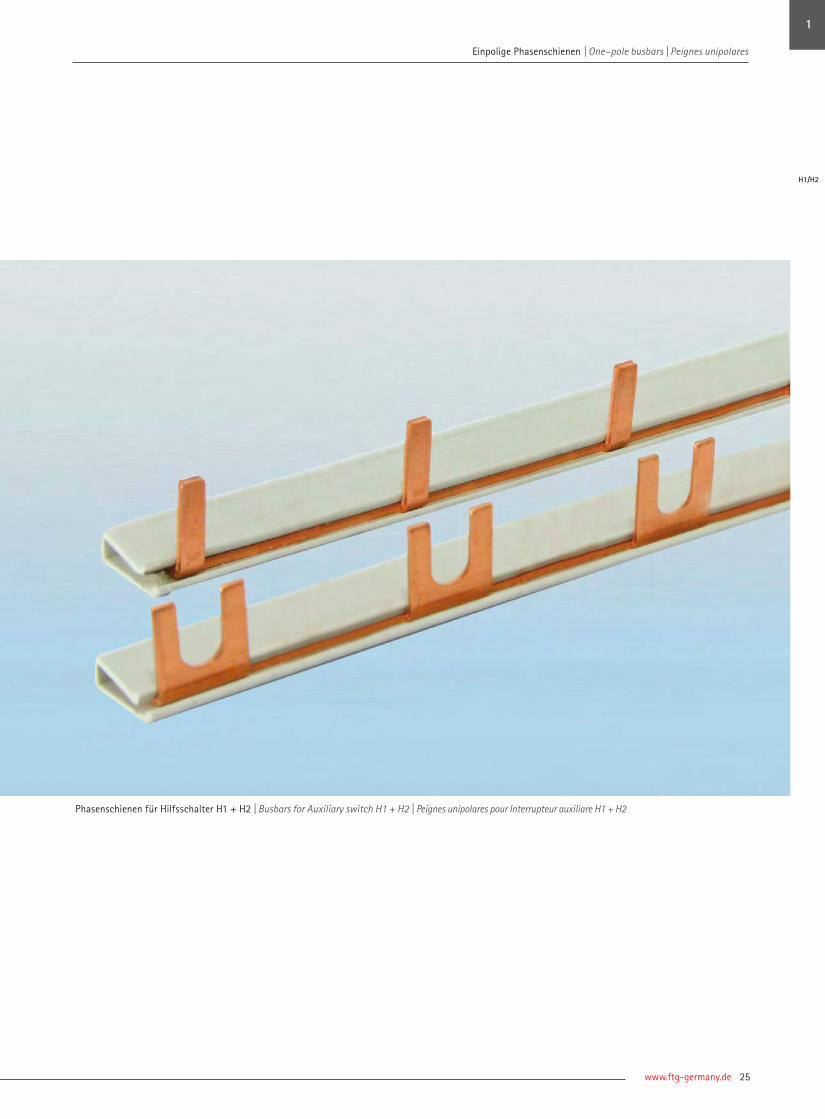
Phasenschienen für Hilfsschalter H1+ H2Busbars for Auxiliary switches H1 + H2Peignes pour auxiliare H1 + H2
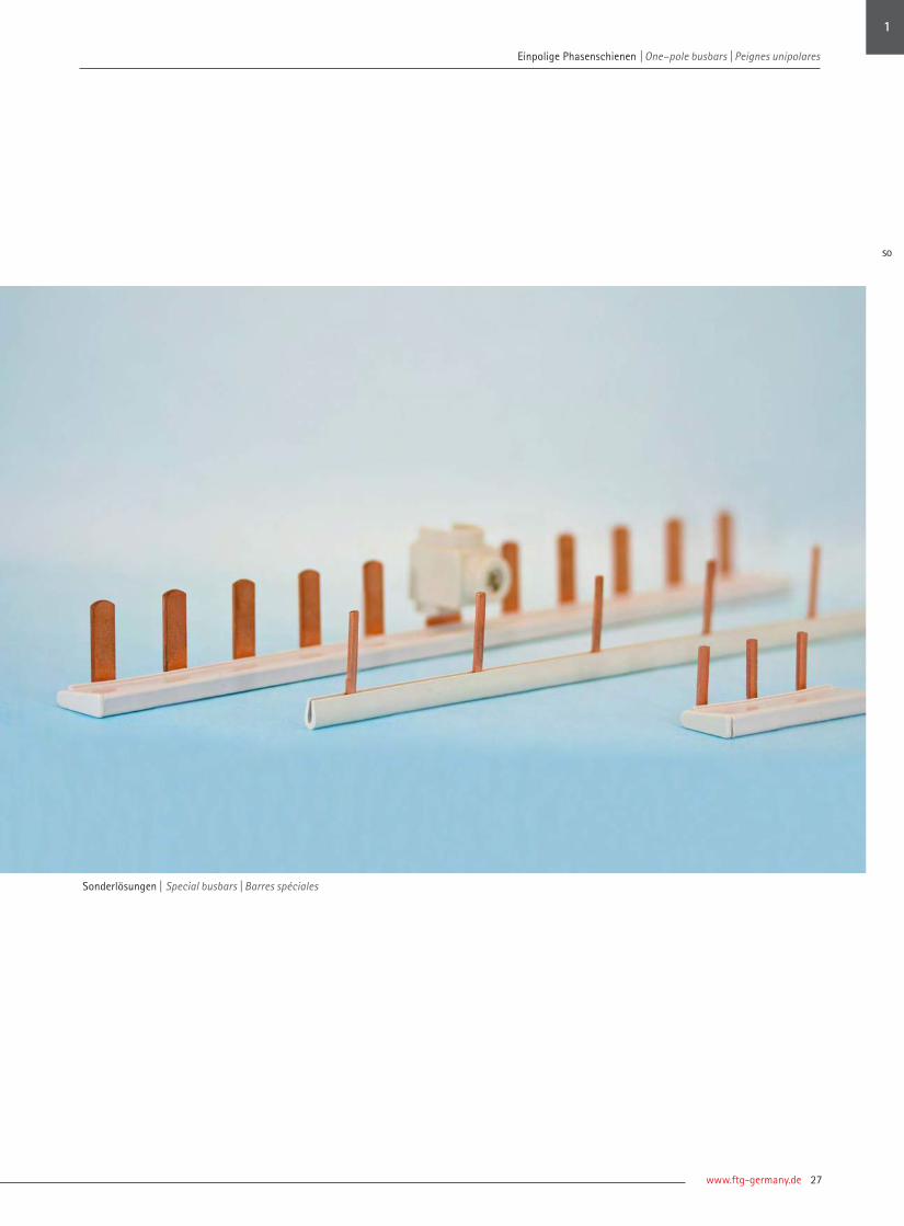
SonderlösungenSpecial busbarsBarres spéciales
UnterkapitelSubchapter Sous-chapitres
www.ftg-germany.de 11
FTG PhasenschienenFTG Busbars | FTG Peignes
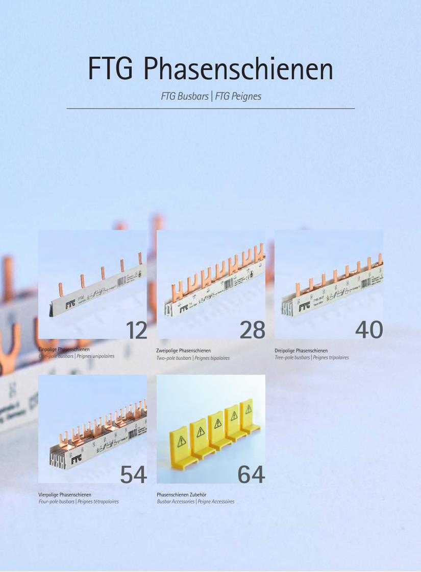
Einpolige Phasenschienen One-pole busbars | Peignes unipolaires
Zweipolige Phasenschienen Two-pole busbars | Peignes bipolaires
12 28Dreipolige Phasenschienen Tree-pole busbars | Peignes tripolaires
40
Vierpolige PhasenschienenFour-pole busbars | Peignes tétrapolaires
54Phasenschienen ZubehörBusbar Accessories | Peigne Accessoires
64
| Connecting Visions12
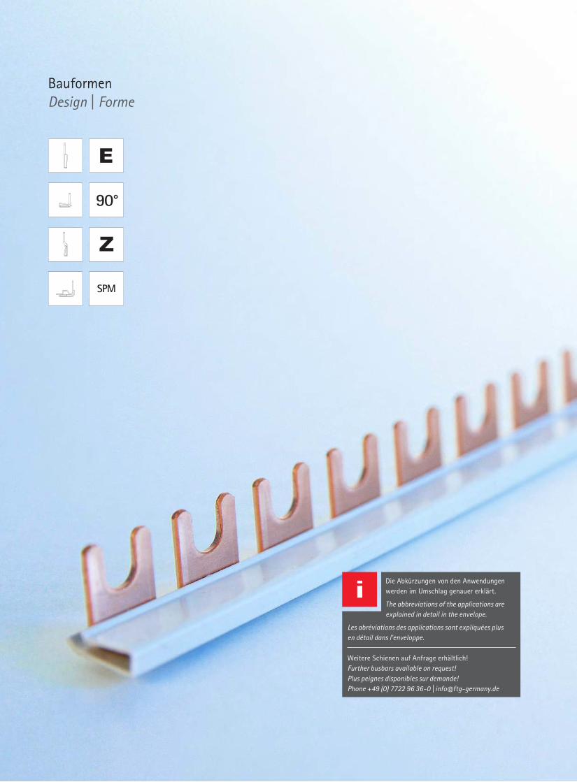
Bauformen Design | Forme
SPM
90°
Die Abkürzungen von den Anwendungen werden im Umschlag genauer erklärt. The abbreviations of the applications are explained in detail in the envelope.
Les abréviations des applications sont expliquées plus en détail dans l'enveloppe.
Weitere Schienen auf Anfrage erhältlich! Further busbars available on request!Plus peignes disponibles sur demande!Phone +49 (0) 7722 96 36-0 | [email protected]
www.ftg-germany.de 13
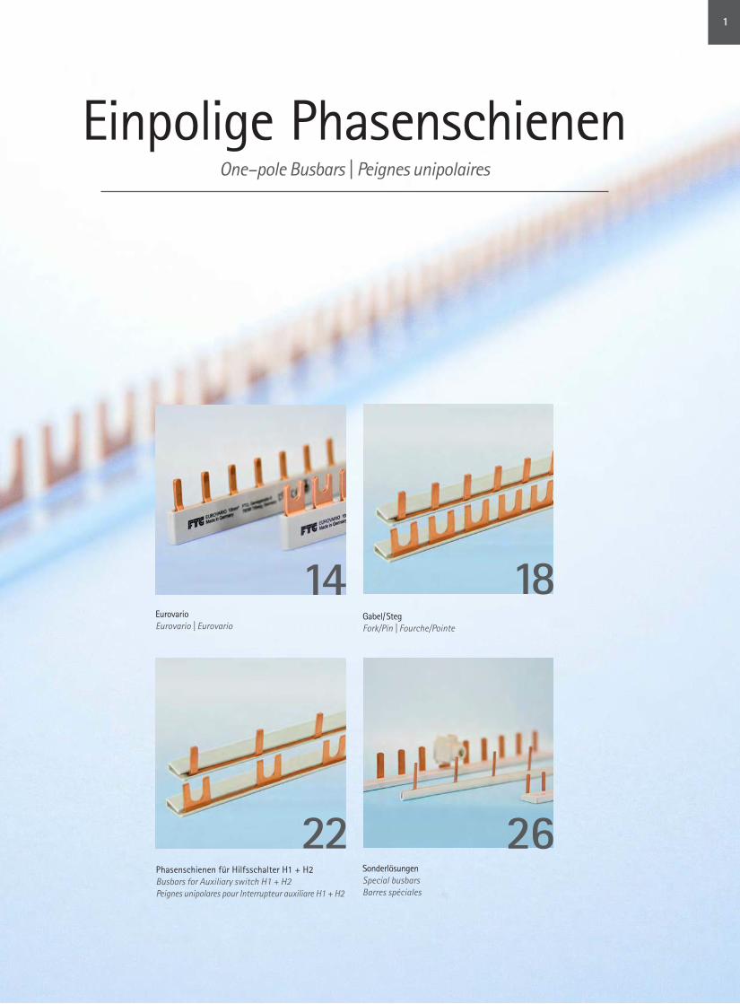
Einpolige PhasenschienenOne–pole Busbars | Peignes unipolaires
14Eurovario Eurovario | Eurovario
18Gabel/ Steg Fork/Pin | Fourche/Pointe
Sonderlösungen Special busbarsBarres spéciales
22 26Phasenschienen für Hilfsschalter H1 + H2Busbars for Auxiliary switch H1 + H2 Peignes unipolares pour Interrupteur auxiliare H1 + H2
1

| Connecting Visions14
Einpolige Phasenschienen | One–pole busbars | Peignes unipolares Einpolige Phasenschienen | One–pole busbars | Peignes unipolares
Artikel-Nr. Part # Référence
A B [mm]
C [mm]
D E [mm]
F G [mm]
H [mm]
I J AnwendungApplicationApplication
VPE Qty UV
ES 10210 10 mm² 17,8 17,8 2 12 L,L,… 33 M6 C E LS 50
ES 10310 10 mm² 17,8 17,8 3 12 L,L,… 51 M6 C E 50
ES 10610 10 mm² 17,8 17,8 6 12 L,L,… 105 M6 C E 20
ES 11210 10 mm² 17,8 17,8 12 12 L,L,… 212 M6 C E 20
ES 12410 10 mm² 17,8 17,8 24 12 L,L,… 428 M6 C E 20
ES 1FI10LS 10 mm² 17,8 17,8 11 12 L,H2,L,L,… 212 M6 C E FI – LS 20
ES 12702 10 mm² 17,8 | 27 27 2 12 L1,H1,...| L,L 51 M6 C / N E LS + H1 / D - D0
20
ES 12703 10 mm² 17,8 | 27 27 3 12 L1,H1,...| L,L 81 M6 C / N E 20
ES 12709 10 mm² 17,8 | 27 27 9 12 L1,H1,...| L,L 242 M6 C / N E 20
ES 10210H2F 10 mm² 17,8 35,6 2 12 L1,H2,... 51 M6 C E LS + H2 50
ES 10310H2F 10 mm² 17,8 35,6 3 12 L1,H2,... 105 M6 C E 50
ES 10216 16 mm² 17,8 17,8 2 12 L,L,… 33 M6 C E LS 50
ES 10316 16 mm² 17,8 17,8 3 12 L,L,… 51 M6 C E 50
ES 10616 16 mm² 17,8 17,8 6 12 L,L,… 105 M6 C E 20
ES 11216 16 mm² 17,8 17,8 12 12 L,L,… 212 M6 C E 20
ES 12416 16 mm² 17,8 17,8 24 12 L,L,… 428 M6 C E 20
ES 1FI10LS–16 16 mm² 17,8 17,8 11 12 L,H2,L,L,… 212 M6 C E FI – LS 10
ES 12702–16 16 mm² 17,8 | 27 27 2 12 L1,H1,...| L,L 51 M6 C / N E LS + H1 / D – D0
20
ES 12703–16 16 mm² 17,8 | 27 27 3 12 L1,H1,...| L,L 81 M6 C / N E 20
ES 12709–16 16 mm² 17,8 | 27 27 9 12 L1,H1,...| L,L 242 M6 C / N E 20
ES 10216H2F 16 mm² 17,8 35,6 2 12 L1,H2,... 51 M6 C E LS + H2 50
ES 10316H2F 16 mm² 17,8 35,6 3 12 L1,H2,... 105 M6 C E 50
ES 11225 25 mm² 17,8 17,8 12 12 L,L,… 212 M6 C E LS 10
Einpolige Eurovario Phasenschienen
One-pole Eurovario Busbars | Eurovario peignes unipolares
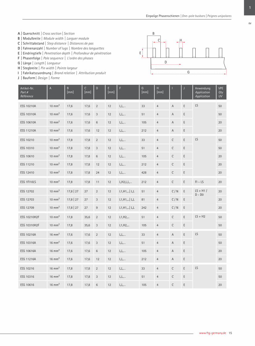
A | Querschnitt | Cross section | Section B | Modulbreite | Module width | Larguer module C | Schrittabstand | Step distance | Distances de pas D | Fahnenanzahl | Number of lugs | Nombre des languettesE | Eindringtiefe | Penetration depth | Profondeur de pénétrationF | Phasenfolge | Pole sequence | L'ordre des phases G | Länge | Length | Longueur H | Gabelöffnung | Fork width | Ouverture de fourcheI | Fabrikatszuordnung | Brand relation | Attribution produitJ | Bauform | Design | Forme
B
HC
E
D
G
www.ftg-germany.de 15
Einpolige Phasenschienen | One–pole busbars | Peignes unipolares
Artikel-Nr. Part # Référence
A B [mm]
C[mm]
D E[mm]
F G [mm]
H [mm]
I J AnwendungApplicationApplication
VPE Qty UV
ESS 10210A 10 mm² 17,6 17,6 2 12 L,L,… 33 4 A E LS 50
ESS 10310A 10 mm² 17,6 17,6 3 12 L,L,… 51 4 A E 50
ESS 10610A 10 mm² 17,6 17,6 6 12 L,L,… 105 4 A E 20
ESS 11210A 10 mm² 17,6 17,6 12 12 L,L,… 212 4 A E 20
ESS 10210 10 mm² 17,8 17,8 2 12 L,L,… 33 4 C E LS 50
ESS 10310 10 mm² 17,8 17,8 3 12 L,L,… 51 4 C E 50
ESS 10610 10 mm² 17,8 17,8 6 12 L,L,… 105 4 C E 20
ESS 11210 10 mm² 17,8 17,8 12 12 L,L,… 212 4 C E 20
ESS 12410 10 mm² 17,8 17,8 24 12 L,L,… 428 4 C E 20
ESS 1FI10LS 10 mm² 17,8 17,8 11 12 L,H2,L,L,… 212 4 C E FI – LS 20
ESS 12702 10 mm² 17,8 | 27 27 2 12 L1,H1,...| L,L 51 4 C / N E LS + H1 / D - D0
20
ESS 12703 10 mm² 17,8 | 27 27 3 12 L1,H1,...| L,L 81 4 C / N E 20
ESS 12709 10 mm² 17,8 | 27 27 9 12 L1,H1,...| L,L 242 4 C / N E 20
ESS 10210H2F 10 mm² 17,8 35,6 2 12 L1,H2,... 51 4 C E LS + H2 50
ESS 10310H2F 10 mm² 17,8 35,6 3 12 L1,H2,... 105 4 C E 50
ESS 10216A 16 mm² 17,6 17,6 2 12 L,L,… 33 4 A E LS 50
ESS 10316A 16 mm² 17,6 17,6 3 12 L,L,… 51 4 A E 50
ESS 10616A 16 mm² 17,6 17,6 6 12 L,L,… 105 4 A E 20
ESS 11216A 16 mm² 17,6 17,6 12 12 L,L,… 212 4 A E 20
ESS 10216 16 mm² 17,8 17,8 2 12 L,L,… 33 4 C E LS 50
ESS 10316 16 mm² 17,8 17,8 3 12 L,L,… 51 4 C E 50
ESS 10616 16 mm² 17,8 17,8 6 12 L,L,… 105 4 C E 20
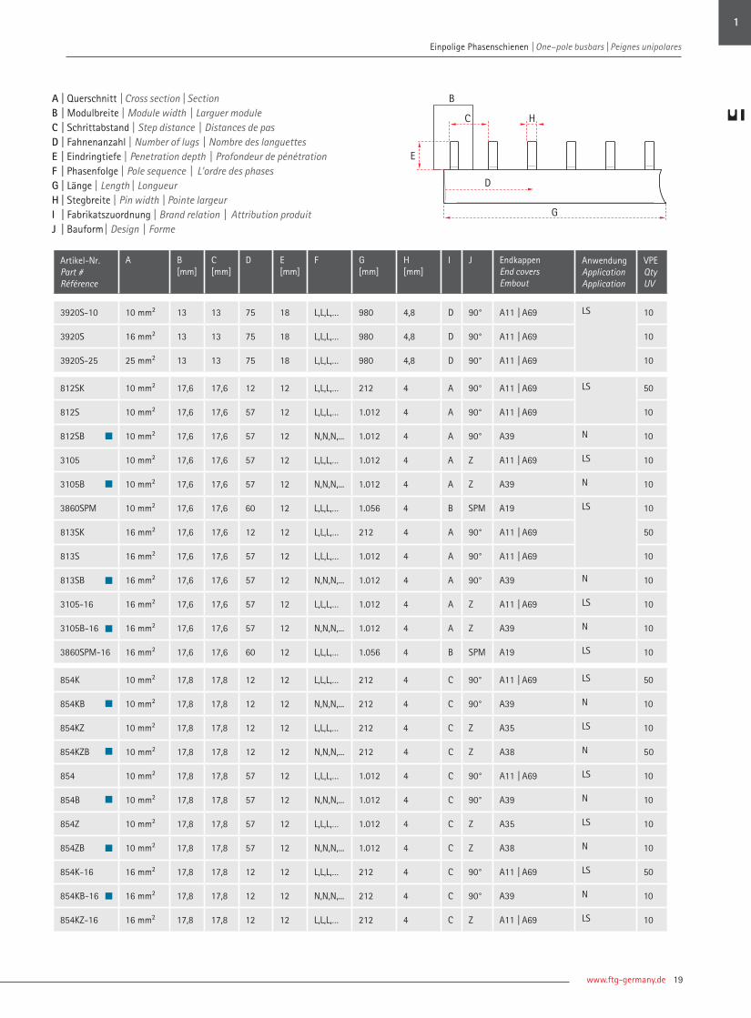
A | Querschnitt | Cross section | Section B | Modulbreite | Module width | Larguer module C | Schrittabstand | Step distance | Distances de pas D | Fahnenanzahl | Number of lugs | Nombre des languettesE | Eindringtiefe | Penetration depth | Profondeur de pénétrationF | Phasenfolge | Pole sequence | L'ordre des phases G | Länge | Length | Longueur H | Stegbreite | Pin width | Pointe largeurI | Fabrikatszuordnung | Brand relation | Attribution produitJ | Bauform | Design | Forme
H
B
E
D
G
C
1
EV

| Connecting Visions16
Einpolige Phasenschienen | One–pole busbars | Peignes unipolares Einpolige Phasenschienen | One–pole busbars | Peignes unipolares
Artikel-Nr. Part # Référence
A B[mm]
C[mm]
D E[mm]
F G [mm] H [mm] I J AnwendungApplicationApplication
VPE Qty UV
ESS 11216 16 mm² 17,8 17,8 12 12 L,L,… 212 4 C E LS 20
ESS 12416 16 mm² 17,8 17,8 24 12 L,L,… 428 4 C E 20
ESS 1FI10LS–16 16 mm² 17,8 17,8 11 12 L,H2,L,L,… 212 4 C E FI – LS 10
ESS 12702–16 16 mm² 17,8 | 27 27 2 12 L1,H1,... | L,L 51 4 C / N E LS + H1 / D – D0
20
ESS 12703–16 16 mm² 17,8 | 27 27 3 12 L1,H1,... | L,L 81 4 C / N E 20
ESS 12709–16 16 mm² 17,8 | 27 27 9 12 L1,H1,... | L,L 242 4 C / N E 20
ESS 10216H2F 16 mm² 17,8 35,6 2 12 L1,H2,... 51 4 C E LS + H2 50
ESS 10316H2F 16 mm² 17,8 35,6 3 12 L1,H2,... 105 4 C E 50
ESS 11225 25 mm² 17,8 17,8 12 12 L,L,… 212 4 C E LS 10
Definierte Einspeisung durch aufgeschweißte AnschlussklemmePredefined feed-in by welded feed-in terminal | Alimentation définie par borne de raccordement soudée
ESS 11210-K25 10 mm² 17,8 17,8 12 12 L,L,… 212 4 10 C EV 10
ESS 11216-K25 16 mm² 17,8 17,8 12 12 L,L,… 212 4 10 C 10
ESS 11225-K50 25 mm² 17,8 17,8 12 12 L,L,… 212 4 10 C 10
A | Querschnitt | Cross section | Section B | Modulbreite | Module width | Larguer module C | Schrittabstand | Step distance | Distances de pas D | Fahnenanzahl | Number of lugs | Nombre des languettesE | Eindringtiefe | Penetration depth | Profondeur de pénétrationF | Phasenfolge | Pole sequence | L'ordre des phases G | Länge | Length | Longueur H | Stegbreite | Pin width | Pointe largeurI | Fabrikatszuordnung | Brand relation | Attribution produitJ | Bauform | Design | Forme
H
B
E
D
G
C

www.ftg-germany.de 17
Einpolige Phasenschienen | One–pole busbars | Peignes unipolares
Einpolige Eurovario Phasenschienen | One-pole Eurovario busbars | Eurovario peignes unipolaires
1
EV

| Connecting Visions18
Einpolige Phasenschienen | One–pole busbars | Peignes unipolares
Artikel-Nr. Part # Référence
A B[mm]
C[mm]
D E[mm]
F G [mm]
H [mm]
I J Endkappen End coversEmbout
AnwendungApplicationApplication
VPE Qty UV
3920-10 10 mm² 13 13 75 18 L,L,L,… 980 M5 D 90° A11 | A69 LS 10
3920 16 mm² 13 13 75 18 L,L,L,… 980 M5 D 90° A11 | A69 10
3920-25 25 mm² 13 13 75 18 L,L,L,… 980 M5 D 90° A11 | A69 10
852K 10 mm² 17,8 17,8 12 12 L,L,L,… 212 M6 C 90° A11 | A69 LS 50
852 10 mm² 17,8 17,8 57 12 L,L,L,… 1.012 M6 C 90° A11 | A69 10
852Z 10 mm² 17,8 17,8 57 12 L,L,L,… 1.012 M6 C Z A11 | A69 10
853K 16 mm² 17,8 17,8 12 12 L,L,L,… 212 M6 C 90° A11 | A69 50
853 16 mm² 17,8 17,8 57 12 L,L,L,… 1.012 M6 C 90° A11 | A69 10
853Z 16 mm² 17,8 17,8 57 12 L,L,L,… 1.012 M6 C Z A11 | A69 10
853-20 20 mm² 17,8 17,8 56 12 L,L,L,… 1.012 M6 C 90° A11 | A69 10
853-25 25 mm² 17,8 17,8 56 12 L,L,L,… 1.012 M6 C 90° A11 | A69 10
6905 35 mm² 17,8 17,8 57 12 L,L,L,… 1.012 M6 C 90° A20 | A61 10
8905 50 mm² 17,8 17,8 57 12 L,L,L,… 1.012 M6 C 90° A20 | A61 10
3633 10 mm² 18 18 56 12 L,L,L,… 1.012 M6 K 90° A11 | A69 LS 10
3636 16 mm² 18 18 56 12 L,L,L,… 1.012 M6 K 90° A11 | A69 10
3077SO 16 mm² 27 27 37 15 L,L,L,… 985 M6 N 90° A11 | A69 D0 10
3080SO 20 mm² 27 27 37 15 L,L,L,… 985 M6 N 90° A11 | A69 10
3080SO-25 25 mm² 27 27 37 15 L,L,L,… 985 M6 N 90° A11 | A69 10
6902SO 35 mm² 27 27 37 15 L,L,L,… 1.012 M6 N 90° A20 | A61 10
8902SO 50 mm² 27 27 37 15 L,L,L,… 1.012 M6 N 90° A20 | A61 10
Einpolige Phasenschienen in Gabel/Steg
One-pole Busbars fork/pin | Peignes unipolares fourche/pointe
A | Querschnitt | Cross section | Section B | Modulbreite | Module width | Larguer module C | Schrittabstand | Step distance | Distances de pas D | Fahnenanzahl | Number of lugs | Nombre des languettesE | Eindringtiefe | Penetration depth | Profondeur de pénétrationF | Phasenfolge | Pole sequence | L'ordre des phases G | Länge | Length | Longueur H | Gabelöffnung | Fork width | Ouverture de fourcheI | Fabrikatszuordnung | Brand relation | Attribution produitJ | Bauform | Design | Forme
B
C
E
D
G
H
Einpolige Phasenschienen | One–pole busbars | Peignes unipolares
www.ftg-germany.de 19
Einpolige Phasenschienen | One–pole busbars | Peignes unipolares
Artikel-Nr. Part # Référence
A B[mm]
C[mm]
D E[mm]
F G [mm]
H [mm]
I J Endkappen End coversEmbout
AnwendungApplicationApplication
VPE Qty UV
3920S-10 10 mm² 13 13 75 18 L,L,L,… 980 4,8 D 90° A11 | A69 LS 10
3920S 16 mm² 13 13 75 18 L,L,L,… 980 4,8 D 90° A11 | A69 10
3920S-25 25 mm² 13 13 75 18 L,L,L,… 980 4,8 D 90° A11 | A69 10
812SK 10 mm² 17,6 17,6 12 12 L,L,L,… 212 4 A 90° A11 | A69 LS 50
812S 10 mm² 17,6 17,6 57 12 L,L,L,… 1.012 4 A 90° A11 | A69 10
812SB 10 mm² 17,6 17,6 57 12 N,N,N,... 1.012 4 A 90° A39 N 10
3105 10 mm² 17,6 17,6 57 12 L,L,L,… 1.012 4 A Z A11 | A69 LS 10
3105B 10 mm² 17,6 17,6 57 12 N,N,N,... 1.012 4 A Z A39 N 10
3860SPM 10 mm² 17,6 17,6 60 12 L,L,L,… 1.056 4 B SPM A19 LS 10
813SK 16 mm² 17,6 17,6 12 12 L,L,L,… 212 4 A 90° A11 | A69 50
813S 16 mm² 17,6 17,6 57 12 L,L,L,… 1.012 4 A 90° A11 | A69 10
813SB 16 mm² 17,6 17,6 57 12 N,N,N,... 1.012 4 A 90° A39 N 10
3105-16 16 mm² 17,6 17,6 57 12 L,L,L,… 1.012 4 A Z A11 | A69 LS 10
3105B-16 16 mm² 17,6 17,6 57 12 N,N,N,... 1.012 4 A Z A39 N 10
3860SPM-16 16 mm² 17,6 17,6 60 12 L,L,L,… 1.056 4 B SPM A19 LS 10
854K 10 mm² 17,8 17,8 12 12 L,L,L,… 212 4 C 90° A11 | A69 LS 50
854KB 10 mm² 17,8 17,8 12 12 N,N,N,... 212 4 C 90° A39 N 10
854KZ 10 mm² 17,8 17,8 12 12 L,L,L,… 212 4 C Z A35 LS 10
854KZB 10 mm² 17,8 17,8 12 12 N,N,N,... 212 4 C Z A38 N 50
854 10 mm² 17,8 17,8 57 12 L,L,L,… 1.012 4 C 90° A11 | A69 LS 10
854B 10 mm² 17,8 17,8 57 12 N,N,N,... 1.012 4 C 90° A39 N 10
854Z 10 mm² 17,8 17,8 57 12 L,L,L,… 1.012 4 C Z A35 LS 10
854ZB 10 mm² 17,8 17,8 57 12 N,N,N,... 1.012 4 C Z A38 N 10
854K-16 16 mm² 17,8 17,8 12 12 L,L,L,… 212 4 C 90° A11 | A69 LS 50
854KB-16 16 mm² 17,8 17,8 12 12 N,N,N,... 212 4 C 90° A39 N 10
854KZ-16 16 mm² 17,8 17,8 12 12 L,L,L,… 212 4 C Z A11 | A69 LS 10
A | Querschnitt | Cross section | Section B | Modulbreite | Module width | Larguer module C | Schrittabstand | Step distance | Distances de pas D | Fahnenanzahl | Number of lugs | Nombre des languettesE | Eindringtiefe | Penetration depth | Profondeur de pénétrationF | Phasenfolge | Pole sequence | L'ordre des phases G | Länge | Length | Longueur H | Stegbreite | Pin width | Pointe largeurI | Fabrikatszuordnung | Brand relation | Attribution produitJ | Bauform | Design | Forme
H
B
E
D
G
C
1

20 | Connecting Visions
Einpolige Phasenschienen | One–pole busbars | Peignes unipolares Einpolige Phasenschienen | One–pole busbars | Peignes unipolares
Artikel-Nr. Part # Référence
A B [mm]
C[mm]
D E[mm]
F G [mm]
H [mm]
I J Endkappen End coversEmbout
AnwendungApplicationApplication
VPE Qty UV
854KZ-16 16 mm² 17,8 17,8 12 12 L,L,L,… 212 4 C Z A11 | A69 LS 10
854KZB-16 16 mm² 17,8 17,8 12 12 N,N,N,... 212 4 C Z A39 N 10
854-16 16 mm² 17,8 17,8 57 12 L,L,L,… 1.012 4 C 90° A11 | A69 LS 10
854-16B 16 mm² 17,8 17,8 57 12 N,N,N,... 1.012 4 C 90° A38 N 50
854-16Z 16 mm² 17,8 17,8 57 12 L,L,L,… 1.012 4 C Z A11 | A69 LS 10
854-16ZB 16 mm² 17,8 17,8 57 12 N,N,N,... 1.012 4 C Z A11 | A69 N 10
854-16DC 16 mm² 17,8 17,8 57 12 L,L,L,… 1.012 4 C 90° A11 | A69 LS / DC 1.500 V
10
854-20 20 mm² 17,8 17,8 57 12 L,L,L,… 1.012 4 C 90° A11 | A69 LS 10
6905S 35 mm² 17,8 17,8 57 12 L,L,L,… 1.012 5,5 C 90° A20 | A61 10
6905S-DC 35 mm² 17,8 17,8 57 12 L,L,L,… 1.012 5,5 C 90° A20 | A61 LS / DC 1.500 V
10
8905S 50 mm² 17,8 17,8 57 12 L,L,L,… 1.012 5,5 C 90° A20 | A61 LS 10
8905S-DC 50 mm² 17,8 17,8 57 12 L,L,L,… 1.012 5,5 C 90° A20 | A61 LS / DC 1.500 V
10
3380 10 mm² 18 18 57 12 L,L,L,… 1.012 4 K 90° A11 | A69 LS 10
3636S 16 mm² 18 18 57 12 L,L,L,… 1.012 4 K 90° A11 | A69 10
3083K 10 mm² 27 27 9 12 L,L,L,… 245 4 N 90° A11 | A69 DO 50
3083 10 mm² 27 27 37 12 L,L,L,… 990 4 N 90° A11 | A69 10
3086K 16 mm² 27 27 9 12 L,L,L,… 245 4 N 90° A11 | A69 50
3086 16 mm² 27 27 37 12 L,L,L,… 990 4 N 90° A11 | A69 10
3086-DC 16 mm² 27 27 37 12 L,L,L,… 990 4 N 90° A11 | A69 DO / DC 1.500 V
10
3087 20 mm² 27 27 37 12 L,L,L,… 990 4 N 90° A11 | A69 DO 10
3083-25 25 mm² 27 27 37 12 L,L,L,… 990 4 N 90° A11 | A69 10
A | Querschnitt | Cross section | Section B | Modulbreite | Module width | Larguer module C | Schrittabstand | Step distance | Distances de pas D | Fahnenanzahl | Number of lugs | Nombre des languettesE | Eindringtiefe | Penetration depth | Profondeur de pénétrationF | Phasenfolge | Pole sequence | L'ordre des phases G | Länge | Length | Longueur H | Stegbreite | Pin width | Pointe largeurI | Fabrikatszuordnung | Brand relation | Attribution produitJ | Bauform | Design | Forme
H
B
E
D
G
C

www.ftg-germany.de 21
Einpolige Phasenschienen | One–pole busbars | Peignes unipolares
Artikel-Nr. Part # Référence
A B[mm]
C[mm]
D E[mm]
F G [mm] H [mm] I J Endkappen End coversEmbout
AnwendungApplicationApplication
VPE Qty UV
3083-25-DC 25 mm² 27 27 37 12 L,L,L,… 990 4 N 90° A11 | A69 DO / DC 1.500 V
10
6902S 35 mm² 27 27 37 12 L,L,L,… 990 5,5 N 90° A20 | A61 DO 10
6902S-DC 35 mm² 27 27 37 12 L,L,L,… 990 5,5 N 90° A20 | A61 DO / DC 1.500 V
10
8902S 50 mm² 27 27 37 12 L,L,L,… 990 5,5 N 90° A20 | A61 DO 10
8902S-DC 50 mm² 27 27 37 12 L,L,L,… 990 5,5 N 90° A20 | A61 DO / DC 1.500 V
10
A | Querschnitt | Cross section | Section B | Modulbreite | Module width | Larguer module C | Schrittabstand | Step distance | Distances de pas D | Fahnenanzahl | Number of lugs | Nombre des languettesE | Eindringtiefe | Penetration depth | Profondeur de pénétrationF | Phasenfolge | Pole sequence | L'ordre des phases G | Länge | Length | Longueur H | Stegbreite | Pin width | Pointe largeurI | Fabrikatszuordnung | Brand relation | Attribution produitJ | Bauform | Design | Forme
H
B
E
D
G
C
1

| Connecting Visions22
Einpolige Phasenschienen | One–pole busbars | Peignes unipolares
Artikel-Nr. Part # Référence
A B[mm]
C[mm]
D E[mm]
F G [mm]
H [mm]
I J Endkappen End coversEmbout
AnwendungApplicationApplication
VPE Qty UV
3923-10 10 mm² 13 19,5 50 18 L1,H1,... 990 M5 D 90° A11 | A69 LS + Hi 10
3923 16 mm² 13 19,5 50 18 L1,H1,... 990 M5 D 90° A11 | A69 10
3923-25 25 mm² 13 19,5 50 18 L1,H1,... 990 M5 D 90° A11 | A69 10
3075 10 mm² 17,8 27 9 12 L1,H1,... 245 M6 C 90° A11 | A69 LS + Hi 50
3074 10 mm² 17,8 27 37 12 L1,H1,... 990 M6 C 90° A11 | A69 10
3078 16 mm² 17,8 27 9 12 L1,H1,... 245 M6 C 90° A11 | A69 50
3077 16 mm² 17,8 27 37 12 L1,H1,... 990 M6 C 90° A11 | A69 10
3080 20 mm² 17,8 27 37 12 L1,H1,... 990 M6 C 90° A11 | A69 10
3080-25 25 mm² 17,8 27 37 12 L1,H1,... 990 M6 C 90° A11 | A69 10
6902 35 mm² 17,8 27 37 12 L1,H1,... 990 M6 C 90° A20 | A61 10
8902 50 mm² 17,8 27 37 12 L1,H1,... 990 M6 C 90° A20 | A61 10
3164K 10 mm² 17,8 35,6 6 12 L,H2,... 212 M6 C 90° A11 | A69 LS + 2Hi 10
3164 10 mm² 17,8 35,6 28 12 L,H2,... 980 M6 C 90° A11 | A69 10
3167K 16 mm² 17,8 35,6 6 12 L,H2,... 212 M6 C 90° A11 | A69 10
3167 16 mm² 17,8 35,6 28 12 L,H2,... 980 M6 C 90° A11 | A69 10
3167/35 35 mm² 17,8 35,6 28 12 L,H2,... 980 M6 C 90° A20 | A61 10
3167/50 50 mm² 17,8 35,6 28 12 L,H2,... 980 M6 C 90° A20 | A61 10
Phasenschienen für Hilfsschalter H1+H2
Busbars for Auxiliary switch H1+H2 | Peignes pour auxiliare H1+H2
A | Querschnitt | Cross section | Section B | Modulbreite | Module width | Larguer module C | Schrittabstand | Step distance | Distances de pas D | Fahnenanzahl | Number of lugs | Nombre des languettesE | Eindringtiefe | Penetration depth | Profondeur de pénétrationF | Phasenfolge | Pole sequence | L'ordre des phases G | Länge | Length | Longueur H | Gabelöffnung | Fork width | Ouverture de fourcheI | Fabrikatszuordnung | Brand relation | Attribution produitJ | Bauform | Design | Forme
B
HC
E
D
G
Einpolige Phasenschienen | One–pole busbars | Peignes unipolares

www.ftg-germany.de 23
Einpolige Phasenschienen | One–pole busbars | Peignes unipolares
Artikel-Nr. Part # Référence
A B[mm]
C[mm]
D E[mm]
F G [mm]
H [mm]
I J Endkappen End coversEmbout
AnwendungApplicationApplication
VPE Qty UV
3923S-10 10 mm² 13 19,5 50 18 L1,H1,... 990 5,5 D 90° A11 | A69 LS + Hi 10
3923S 16 mm² 13 19,5 50 18 L1,H1,... 990 5,5 D 90° A11 | A69 10
3923S-25 25 mm² 13 19,5 50 18 L1,H1,... 990 5,5 D 90° A11 | A69 10
3857-10 10 mm² 17,6 26,4 39 12 L1,H1,... 1.012 4 A 90° A11 | A69 LS + Hi 10
3857 16 mm² 17,6 26,4 39 12 L1,H1,... 1.012 4 A 90° A11 | A69 10
3340 10 mm² 17,6 26,4 39 12 L1,H1,... 1.012 4 A Z A11 | A69 10
3340-16 16 mm² 17,6 26,4 39 12 L1,H1,... 1.012 4 A Z A11 | A69 10
3861SPM 10 mm² 17,6 26,4 38 12 L1,H1,... 1.012 4 B SPM A19 10
3861SPM-16 16 mm² 17,6 26,4 38 12 L1,H1,... 1.012 4 B SPM A19 10
3083K 10 mm² 17,8 27 9 12 L1,H1,... 245 4 C 90° A11 | A69 LS + Hi 50
3083 10 mm² 17,8 27 37 12 L1,H1,... 1.012 4 C 90° A11 | A69 10
3083B 10 mm² 17,8 27 37 12 L1,H1,... 1.012 4 C 90° A39 N + Hi 10
3083Z 10 mm² 17,8 27 37 12 L1,H1,... 1.012 4 C Z A11 | A69 LS + Hi 10
3083ZB 10 mm² 17,8 27 37 12 L1,H1,... 1.012 4 C Z A39 N + Hi 10
3086K 16 mm² 17,8 27 9 12 L1,H1,... 245 4 C 90° A11 | A69 LS + Hi 50
3086 16 mm² 17,8 27 37 12 L1,H1,... 1.012 4 C 90° A11 | A69 10
3086B 16 mm² 17,8 27 37 12 L1,H1,... 1.012 4 C 90° A39 N + Hi 10
3086Z 16 mm² 17,8 27 37 12 L1,H1,... 1.012 4 C Z A11 | A69 LS + Hi 10
3086ZB 16 mm² 17,8 27 37 12 L1,H1,... 1.012 4 C Z A39 N + Hi 10
3087 20 mm² 17,8 27 37 12 L1,H1,... 1.012 4 C 90° A11 | A69 LS + Hi 10
3083-25 25 mm² 17,8 27 37 12 L1,H1,... 1.012 4 C 90° A11 | A69 10
6902S 35 mm² 17,8 27 37 12 L1,H1,... 1.012 5,5 C 90° A20 | A61 10
8902S 50 mm² 17,8 27 37 12 L1,H1,... 1.012 5,5 C 90° A20 | A61 10
A | Querschnitt | Cross section | Section B | Modulbreite | Module width | Larguer module C | Schrittabstand | Step distance | Distances de pas D | Fahnenanzahl | Number of lugs | Nombre des languettesE | Eindringtiefe | Penetration depth | Profondeur de pénétrationF | Phasenfolge | Pole sequence | L'ordre des phases G | Länge | Length | Longueur H | Stegbreite | Pin width | Pointe largeurI | Fabrikatszuordnung | Brand relation | Attribution produitJ | Bauform | Design | Forme
H
B
E
D
G
C
1
H1/H2

| Connecting Visions24
Einpolige Phasenschienen | One–pole busbars | Peignes unipolares Einpolige Phasenschienen | One–pole busbars | Peignes unipolares
Artikel-Nr. Part # Référence
A B[mm]
C[mm]
D E[mm]
F G [mm]
H [mm]
I J Endkappen End coversEmbout
AnwendungApplicationApplication
VPE Qty UV
3862S 10 mm² 17,6 35,2 30 12 L,H2,... 1.050 4 A 90° A11 | A69 LS + 2Hi 10
3862S-16 16 mm² 17,6 35,2 30 12 L,H2,... 1.050 4 A 90° A11 | A69 10
3862Z 10 mm² 17,6 35,2 30 12 L,H2,... 1.050 4 A Z A11 | A69 10
3862Z-16 16 mm² 17,6 35,2 30 12 L,H2,... 1.050 4 A Z A11 | A69 10
3862SPM 10 mm² 17,6 35,2 30 12 L,H2,... 1.050 4 B SPM A19 10
3862SPM-16 16 mm² 17,6 35,2 30 12 L,H2,... 1.050 4 B SPM A19 10
3170 10 mm² 17,8 35,6 28 12 L,H2,... 980 4 C 90° A11 | A69 LS + 2Hi 10
3170B 10 mm² 17,8 35,6 28 12 L,H2,... 980 4 C 90° A39 N + 2Hi 10
3170Z 10 mm² 17,8 35,6 28 12 L,H2,... 980 4 C Z A11 | A69 LS + 2HiAFDD1
10
3170ZB 10 mm² 17,8 35,6 28 12 L,H2,... 980 4 C Z A39 N + 2HiAFDD1
10
3173 16 mm² 17,8 35,6 28 12 L,H2,... 980 4 C 90° A11 | A69 LS + 2Hi 10
3173B 16 mm² 17,8 35,6 28 12 L,H2,... 980 4 C 90° A39 N + 2Hi 10
3173Z 16 mm² 17,8 35,6 28 12 L,H2,... 980 4 C Z A11 | A69 LS + 2HiAFDD1
10
3173ZB 16 mm² 17,8 35,6 28 12 L,H2,... 980 4 C Z A39 N + 2HiAFDD1
10
3173/35 35 mm² 17,8 35,6 28 12 L,H2,... 980 5,5 C 90° A20 | A61 LS + 2Hi 10
3173/50 50 mm² 17,8 35,6 28 12 L,H2,... 980 5,5 C 90° A20 | A61 10
A | Querschnitt | Cross section | Section B | Modulbreite | Module width | Larguer module C | Schrittabstand | Step distance | Distances de pas D | Fahnenanzahl | Number of lugs | Nombre des languettesE | Eindringtiefe | Penetration depth | Profondeur de pénétrationF | Phasenfolge | Pole sequence | L'ordre des phases G | Länge | Length | Longueur H | Stegbreite | Pin width | Pointe largeurI | Fabrikatszuordnung | Brand relation | Attribution produitJ | Bauform | Design | Forme
1 passend für Siemens-Geräte | suitable for Siemens devices | convient pour les appareils Siemens 2 für Schrack- / Eaton-/Doepke-Geräte | for Schrack- / Eaton-/Doepke-devices | pour appareils Schrack- / Eaton-/Doepke
H
B
E
D
G
C
www.ftg-germany.de 25
Einpolige Phasenschienen | One–pole busbars | Peignes unipolares
Phasenschienen für Hilfsschalter H1 + H2 | Busbars for Auxiliary switch H1 + H2 | Peignes unipolares pour Interrupteur auxiliare H1 + H2
1
H1/H2

| Connecting Visions26
Einpolige Phasenschienen | One–pole busbars | Peignes unipolares
Sonderlösungen
Special busbars | Barres spéciales
A | Querschnitt | Cross section | Section B | Modulbreite | Module width | Larguer module C | Schrittabstand | Step distance | Distances de pas D | Fahnenanzahl | Number of lugs | Nombre des languettesE | Eindringtiefe | Penetration depth | Profondeur de pénétrationF | Phasenfolge | Pole sequence | L'ordre des phases G | Länge | Length | Longueur H | Gabelöffnung | Fork width | Ouverture de fourche Stegbreite | Pin width | Pointe largeurI | Bauform | Design | Forme
Artikel-Nr. Part # Référence
A B[mm]
C[mm]
D E[mm]
F G [mm]
H [mm]
I Endkappen End coversEmbout
AnwendungApplicationApplication
VPE Qty UV
3745 16 mm² 17,8 17,8 57 14 L,L,L,… 1.012 M6 Z abbrechbar separableséparable
L1 10
3741 16 mm² 17,8 17,8 57 14 L,L,L,… 1.012 M6 Z L2 / L3 10
3749 16 mm² 17,8 17,8 57 14 L,L,L,… 1.012 M6 Z N 10
3760 L1 16 mm² 17,8 17,8 112 14 L,L,L,… 1.012 4 Z abbrechbar separableséparable
L1 10
3760 L2 16 mm² 17,8 17,8 112 14 L,L,L,… 1.012 4 Z L2 10
3760 L3 16 mm² 17,8 17,8 112 14 L,L,L,… 1.012 4 Z L3 10
3764 16 mm² 17,8 17,8 112 14 L,L,L,… 1.012 4 Z N 10
3752 L1 16 mm² 17,8 17,8 112 14 L,L,L,… 1.012 6 Z abbrechbar separableséparable
L1 10
3752 L2 16 mm² 17,8 17,8 112 14 L,L,L,… 1.012 6 Z L2 10
3752 L3 16 mm² 17,8 17,8 112 14 L,L,L,… 1.012 6 Z L3 10
3756 16 mm² 17,8 17,8 112 14 L,L,L,… 1.012 6 Z N 10
3825 4 mm² 17,8 17,8 12 11 L,L,L,… 205 2,5 75° - Hi 10
3826 4 mm² 17,8 17,8 57 11 L,L,L,… 1.012 2,5 75°
3848 10 mm² 45,5 45,5 21 12 L,L,L,… 920 1,6 Z A11 | A69 Minischütz Mini contactor Mini contacteur
10
3848B 10 mm² 45,5 45,5 21 12 L,L,L,… 920 1,6 Z
SKS 0217 2,3 mm² 25,4 25,4 18 3 L,L,L,… 442 0,64 Z inkl. Elektronik ElectronicsElectronique
10
SKS 0258 10 mm² 17,8 17,8 2 x 13 12 L,L,L,… 2 x 223 4,2 Z 90°
inkl. Set SetKit
10
SKS 0585-02TE 50 mm² 33 33 2 18 L,L 62 17,5 Z A36 N 10
SKS 1165 4 mm² 26,7 26,7 8 13 L,L,L,… 200 2 Z - Hi
10SKS 1166 4 mm² 26,7 26,7 8 17 L,L,L,… 200 2 Z -
SKS 1167 4 mm² 35,6 35,6 6 13 L,L,L,… 200 2 Z -
SKS 1168 4 mm² 35,6 35,6 6 17 L,L,L,… 200 2 Z -
Einpolige Phasenschienen | One–pole busbars | Peignes unipolares
www.ftg-germany.de 27
Sonderlösungen | Special busbars | Barres spéciales
Einpolige Phasenschienen | One–pole busbars | Peignes unipolares
1
SO

L
T
SPM
SKN
Bauformen Design | Forme
Die Abkürzungen von den Anwendungen werden im Umschlag genauer erklärt. The abbreviations of the applications are explained in detail in the envelope.
Les abréviations des applications sont expliquées plus en détail dans l'enveloppe.
Weitere Schienen auf Anfrage erhältlich! Further busbars available on request!Plus peignes disponibles sur demande!Phone +49 (0) 7722 96 36-0 | [email protected]

Zweipolige PhasenschienenTwo–pole Busbars | Peignes bipolaires
Sonderlösungen Special busbarsBarres spéciales
Phasenschienen für Hilfsschalter H1 + H2Busbars for Auxiliary switches H1 + H2 Peignes unipolares pour Interrupteur auxiliare H1 + H2
36 38
30 34Eurovario Eurovario | Eurovario
Gabel/ Steg Fork/Pin | Fourche/Pointe
2
| Connecting Visions30
Zweipolige Phasenschienen | Two–pole busbars | Peignes bipolaires Zweipolige Phasenschienen | Two–pole busbars | Peignes bipolaires
Artikel-Nr. Part # Référence
A B[mm]
C[mm]
D E[mm]
F G [mm]
H [mm]
I J AnwendungApplicationApplication
VPE Qty UV
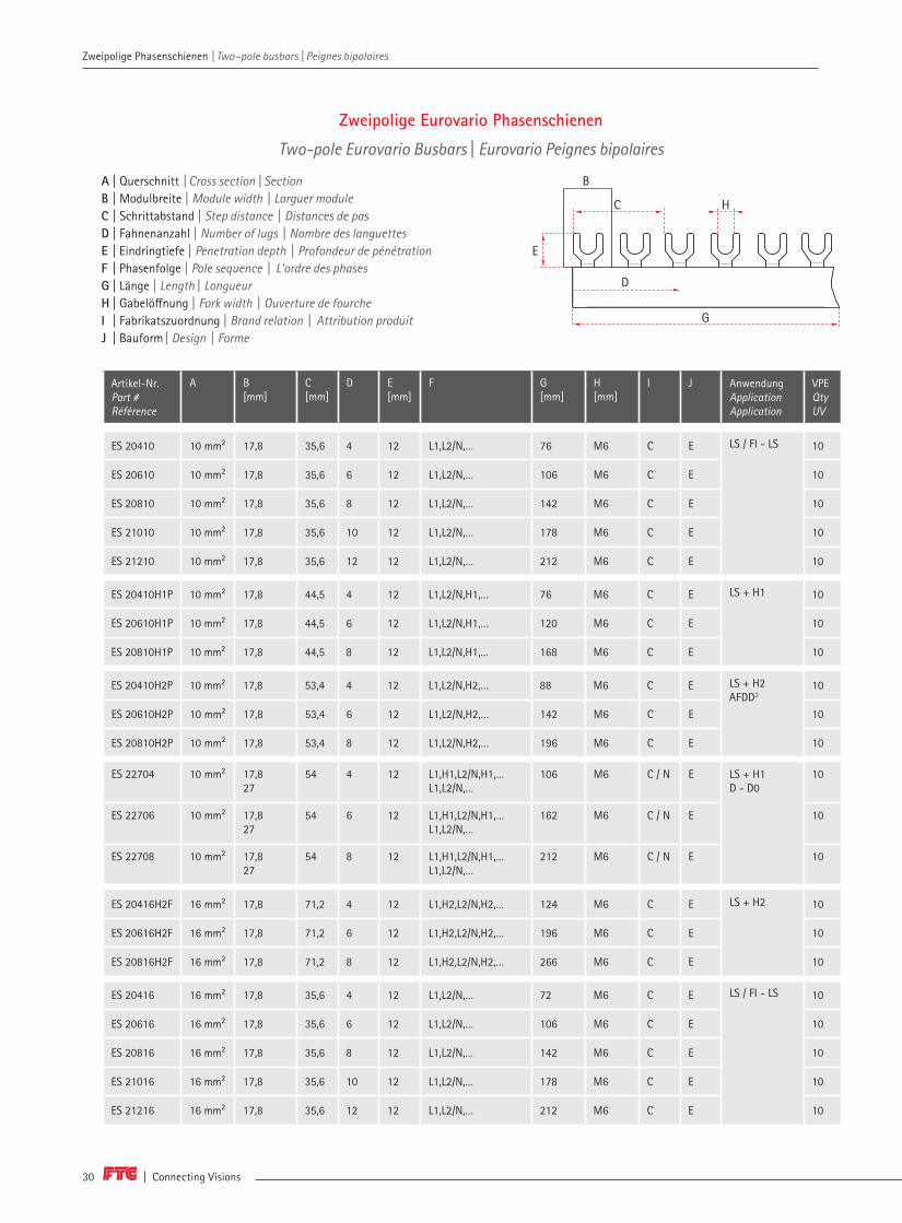
ES 20410 10 mm² 17,8 35,6 4 12 L1,L2/N,… 76 M6 C E LS / FI - LS 10
ES 20610 10 mm² 17,8 35,6 6 12 L1,L2/N,… 106 M6 C E 10
ES 20810 10 mm² 17,8 35,6 8 12 L1,L2/N,… 142 M6 C E 10
ES 21010 10 mm² 17,8 35,6 10 12 L1,L2/N,… 178 M6 C E 10
ES 21210 10 mm² 17,8 35,6 12 12 L1,L2/N,… 212 M6 C E 10
ES 20410H1P 10 mm² 17,8 44,5 4 12 L1,L2/N,H1,… 76 M6 C E LS + H1
10
ES 20610H1P 10 mm² 17,8 44,5 6 12 L1,L2/N,H1,… 120 M6 C E 10
ES 20810H1P 10 mm² 17,8 44,5 8 12 L1,L2/N,H1,… 168 M6 C E 10
ES 20410H2P 10 mm² 17,8 53,4 4 12 L1,L2/N,H2,… 88 M6 C E LS + H2AFDD2
10
ES 20610H2P 10 mm² 17,8 53,4 6 12 L1,L2/N,H2,… 142 M6 C E 10
ES 20810H2P 10 mm² 17,8 53,4 8 12 L1,L2/N,H2,… 196 M6 C E 10
ES 22704 10 mm² 17,8 27
54 4 12 L1,H1,L2/N,H1,…L1,L2/N,…
106 M6 C / N E LS + H1 D - D0
10
ES 22706 10 mm² 17,8 27
54 6 12 L1,H1,L2/N,H1,…L1,L2/N,…
162 M6 C / N E 10
ES 22708 10 mm² 17,8 27
54 8 12 L1,H1,L2/N,H1,…L1,L2/N,…
212 M6 C / N E 10
ES 20416H2F 16 mm² 17,8 71,2 4 12 L1,H2,L2/N,H2,… 124 M6 C E LS + H2 10
ES 20616H2F 16 mm² 17,8 71,2 6 12 L1,H2,L2/N,H2,… 196 M6 C E 10
ES 20816H2F 16 mm² 17,8 71,2 8 12 L1,H2,L2/N,H2,… 266 M6 C E 10
ES 20416 16 mm² 17,8 35,6 4 12 L1,L2/N,… 72 M6 C E LS / FI - LS 10
ES 20616 16 mm² 17,8 35,6 6 12 L1,L2/N,… 106 M6 C E 10
ES 20816 16 mm² 17,8 35,6 8 12 L1,L2/N,… 142 M6 C E 10
ES 21016 16 mm² 17,8 35,6 10 12 L1,L2/N,… 178 M6 C E 10
ES 21216 16 mm² 17,8 35,6 12 12 L1,L2/N,… 212 M6 C E 10
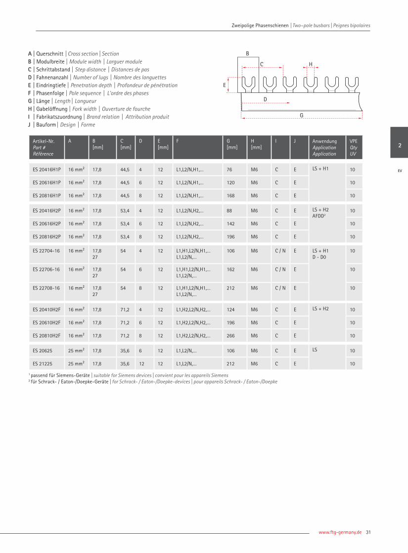
Zweipolige Eurovario Phasenschienen
Two-pole Eurovario Busbars | Eurovario Peignes bipolaires
A | Querschnitt | Cross section | Section B | Modulbreite | Module width | Larguer module C | Schrittabstand | Step distance | Distances de pas D | Fahnenanzahl | Number of lugs | Nombre des languettesE | Eindringtiefe | Penetration depth | Profondeur de pénétrationF | Phasenfolge | Pole sequence | L'ordre des phases G | Länge | Length | Longueur H | Gabelöffnung | Fork width | Ouverture de fourcheI | Fabrikatszuordnung | Brand relation | Attribution produitJ | Bauform | Design | Forme
B
C
E
D
G
H
www.ftg-germany.de 31
Zweipolige Phasenschienen | Two–pole busbars | Peignes bipolaires
Artikel-Nr. Part # Référence
A B[mm]
C[mm]
D E[mm]
F G [mm]
H [mm]
I J AnwendungApplicationApplication
VPE Qty UV
ES 20416H1P 16 mm² 17,8 44,5 4 12 L1,L2/N,H1,… 76 M6 C E LS + H1 10
ES 20616H1P 16 mm² 17,8 44,5 6 12 L1,L2/N,H1,… 120 M6 C E 10
ES 20816H1P 16 mm² 17,8 44,5 8 12 L1,L2/N,H1,… 168 M6 C E 10
ES 20416H2P 16 mm² 17,8 53,4 4 12 L1,L2/N,H2,… 88 M6 C E LS + H2 AFDD2
10
ES 20616H2P 16 mm² 17,8 53,4 6 12 L1,L2/N,H2,… 142 M6 C E 10
ES 20816H2P 16 mm² 17,8 53,4 8 12 L1,L2/N,H2,… 196 M6 C E 10
ES 22704-16 16 mm² 17,8 27
54 4 12 L1,H1,L2/N,H1,…L1,L2/N,…
106 M6 C / N E LS + H1D - D0
10
ES 22706-16 16 mm² 17,8 27
54 6 12 L1,H1,L2/N,H1,…L1,L2/N,…
162 M6 C / N E 10
ES 22708-16 16 mm² 17,8 27
54 8 12 L1,H1,L2/N,H1,…L1,L2/N,…
212 M6 C / N E 10
ES 20410H2F 16 mm² 17,8 71,2 4 12 L1,H2,L2/N,H2,… 124 M6 C E LS + H2 10
ES 20610H2F 16 mm² 17,8 71,2 6 12 L1,H2,L2/N,H2,… 196 M6 C E 10
ES 20810H2F 16 mm² 17,8 71,2 8 12 L1,H2,L2/N,H2,… 266 M6 C E 10
ES 20625 25 mm² 17,8 35,6 6 12 L1,L2/N,… 106 M6 C E LS 10
ES 21225 25 mm² 17,8 35,6 12 12 L1,L2/N,… 212 M6 C E 10
1 passend für Siemens-Geräte | suitable for Siemens devices | convient pour les appareils Siemens 2 für Schrack- / Eaton-/Doepke-Geräte | for Schrack- / Eaton-/Doepke-devices | pour appareils Schrack- / Eaton-/Doepke
A | Querschnitt | Cross section | Section B | Modulbreite | Module width | Larguer module C | Schrittabstand | Step distance | Distances de pas D | Fahnenanzahl | Number of lugs | Nombre des languettesE | Eindringtiefe | Penetration depth | Profondeur de pénétrationF | Phasenfolge | Pole sequence | L'ordre des phases G | Länge | Length | Longueur H | Gabelöffnung | Fork width | Ouverture de fourcheI | Fabrikatszuordnung | Brand relation | Attribution produitJ | Bauform | Design | Forme
B
C
E
D
G
H
2
EV

| Connecting Visions32
Zweipolige Phasenschienen | Two–pole busbars | Peignes bipolaires Zweipolige Phasenschienen | Two–pole busbars | Peignes bipolaires
Artikel-Nr. Part # Référence
A B[mm]
C[mm]
D E[mm]
F G [mm] H [mm] I J AnwendungApplicationApplication
VPE Qty UV
ESS 20410A 10 mm² 17,6 35,2 4 12 L1,L2/N,… 76 4 A E LS / FI - LS 10
ESS 20610A 10 mm² 17,6 35,2 6 12 L1,L2/N,… 106 4 A E 10
ESS 20810A 10 mm² 17,6 35,2 8 12 L1,L2/N,… 142 4 A E 10
ESS 21010A 10 mm² 17,6 35,2 10 12 L1,L2/N,… 178 4 A E 10
ESS 21210A 10 mm² 17,6 35,2 12 12 L1,L2/N,… 212 4 A E 10
ESS 20410 10 mm² 17,8 35,6 4 12 L1,L2/N,… 76 4 C E LS / FI - LS 10
ESS 20610 10 mm² 17,8 35,6 6 12 L1,L2/N,… 106 4 C E 10
ESS 20810 10 mm² 17,8 35,6 8 12 L1,L2/N,… 142 4 C E 10
ESS 21010 10 mm² 17,8 35,6 10 12 L1,L2/N,… 178 4 C E 10
ESS 21210 10 mm² 17,8 35,6 12 12 L1,L2/N,… 212 4 C E 10
ESS 20410H1P 10 mm² 17,8 44,5 4 12 L1,L2/N,H1,… 76 4 C E LS + H1 10
ESS 20610H1P 10 mm² 17,8 44,5 6 12 L1,L2/N,H1,… 120 4 C E 10
ESS 20810H1P 10 mm² 17,8 44,5 8 12 L1,L2/N,H1,… 168 4 C E 10
ESS 21010H1P 10 mm² 17,8 44,5 10 12 L1,L2/N,H1,… 212 4 C E 10
ESS 20410H2P 10 mm² 17,8 53,4 4 12 L1,L2/N,H2,… 88 4 C E LS + H2AFDD1
10
ESS 20610H2P 10 mm² 17,8 53,4 6 12 L1,L2/N,H2,… 142 4 C E 10
ESS 20810H2P 10 mm² 17,8 53,4 8 12 L1,L2/N,H2,… 196 4 C E 10
ESS 22704 10 mm² 17,8 27
54 4 12 L1,H1,L2/N,H1,…L1,L2/N,…
106 4 C / N E LS + H1 D - D0
10
ESS 22706 10 mm² 17,8 27
54 6 12 L1,H1,L2/N,H1,…L1,L2/N,…
162 4 C / N E 10
ESS 22708 10 mm² 17,8 27
54 8 12 L1,H1,L2/N,H1,…L1,L2/N,…
212 4 C / N E 10
ESS 20410H2F 10 mm² 17,8 71,2 4 12 L1,H2,L2/N,H2,… 124 4 C E LS + H2 10
ESS 20610H2F 10 mm² 17,8 71,2 6 12 L1,H2,L2/N,H2,… 196 4 C E 10
ESS 20810H2F 10 mm² 17,8 71,2 8 12 L1,H2,L2/N,H2,… 266 4 C E 10
ESS 20416A 16 mm² 17,6 35,2 4 12 L1,L2/N,… 76 4 A E LS / FI - LS 10
ESS 20616A 16 mm² 17,6 35,2 6 12 L1,L2/N,… 106 4 A E 10
ESS 20816A 16 mm² 17,6 35,2 8 12 L1,L2/N,… 142 4 A E 10
ESS 21016A 16 mm² 17,6 35,2 10 12 L1,L2/N,… 178 4 A E 10
ESS 21216A 16 mm² 17,6 35,2 12 12 L1,L2/N,… 212 4 A E 10
A | Querschnitt | Cross section | Section B | Modulbreite | Module width | Larguer module C | Schrittabstand | Step distance | Distances de pas D | Fahnenanzahl | Number of lugs | Nombre des languettesE | Eindringtiefe | Penetration depth | Profondeur de pénétrationF | Phasenfolge | Pole sequence | L'ordre des phases G | Länge | Length | Longueur H | Stegbreite | Pin width | Pointe largeurI | Fabrikatszuordnung | Brand relation | Attribution produitJ | Bauform | Design | Forme
H
B
E
D
G
C

www.ftg-germany.de 33
Zweipolige Phasenschienen | Two–pole busbars | Peignes bipolaires
Artikel-Nr. Part # Référence
A B[mm]
C[mm]
D E[mm]
F G [mm]
H [mm]
I J AnwendungApplicationApplication
VPE Qty UV
ESS 20416 16 mm² 17,8 35,6 4 12 L1,L2/N,… 72 4 C E LS / FI - LS 10
ESS 20616 16 mm² 17,8 35,6 6 12 L1,L2/N,… 106 4 C E 10
ESS 20816 16 mm² 17,8 35,6 8 12 L1,L2/N,… 142 4 C E 10
ESS 21016 16 mm² 17,8 35,6 10 12 L1,L2/N,… 178 4 C E 10
ESS 21216 16 mm² 17,8 35,6 12 12 L1,L2/N,… 212 4 C E 10
ESS 20416H1P 16 mm² 17,8 44,5 4 12 L1,L2/N,H1,… 76 4 C E LS + H1 10
ESS 20616H1P 16 mm² 17,8 44,5 6 12 L1,L2/N,H1,… 120 4 C E 10
ESS 20816H1P 16 mm² 17,8 44,5 8 12 L1,L2/N,H1,… 168 4 C E 10
ESS 21016H1P 16 mm² 17,8 44,5 10 12 L1,L2/N,H1,… 212 4 C E 10
ESS 20416H2P 16 mm² 17,8 53,4 4 12 L1,L2/N,H2,… 88 4 C E LS + H2AFDD1
10
ESS 20616H2P 16 mm² 17,8 53,4 6 12 L1,L2/N,H2,… 142 4 C E 10
ESS 20816H2P 16 mm² 17,8 53,4 8 12 L1,L2/N,H2,… 196 4 C E 10
ESS 22704-16 16 mm² 17,8 27
54 4 12 L1,H1,L2/N,H1,…L1,L2/N,…
106 4 C / N E LS + H1 D - D0
10
ESS 22706-16 16 mm² 17,8 27
54 6 12 L1,H1,L2/N,H1,…L1,L2/N,…
162 4 C / N E 10
ESS 22708-16 16 mm² 17,8 27
54 8 12 L1,H1,L2/N,H1,…L1,L2/N,…
212 4 C / N E 10
ESS 20416H2F 16 mm² 17,8 71,2 4 12 L1,H2,L2/N,H2,… 124 4 C E LS + H2 10
ESS 20616H2F 16 mm² 17,8 71,2 6 12 L1,H2,L2/N,H2,… 196 4 C E 10
ESS 20816H2F 16 mm² 17,8 71,2 8 12 L1,H2,L2/N,H2,… 266 4 C E 10
ESS 20625 25 mm² 17,8 35,6 6 12 L1,L2/N,… 106 4 C E LS 10
ESS 21225 25 mm² 17,8 35,6 12 12 L1,L2/N,… 212 4 C E 10
1 passend für Siemens-Geräte | suitable for Siemens devices | convient pour les appareils Siemens 2 für Schrack- / Eaton-/Doepke-Geräte | for Schrack- / Eaton-/Doepke-devices | pour appareils Schrack- / Eaton-/Doepke
A | Querschnitt | Cross section | Section B | Modulbreite | Module width | Larguer module C | Schrittabstand | Step distance | Distances de pas D | Fahnenanzahl | Number of lugs | Nombre des languettesE | Eindringtiefe | Penetration depth | Profondeur de pénétrationF | Phasenfolge | Pole sequence | L'ordre des phases G | Länge | Length | Longueur H | Stegbreite | Pin width | Pointe largeurI | Fabrikatszuordnung | Brand relation | Attribution produitJ | Bauform | Design | Forme
H
B
E
D
G
C
2
EV
| Connecting Visions34
Zweipolige Phasenschienen | Two–pole busbars | Peignes bipolaires Zweipolige Phasenschienen | Two–pole busbars | Peignes bipolaires
Artikel-Nr. Part # Référence
A B[mm]
C[mm]
D E[mm]
F G [mm]
H [mm]
I J Endkappen End coversEmbout
AnwendungApplicationApplication
VPE Qty UV
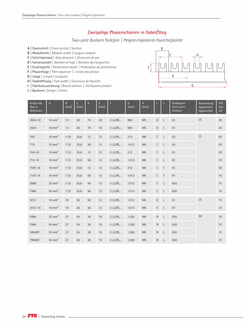
3924-10 10 mm² 13 26 74 18 L1,L2/N,… 980 M5 D L A1 LS 20
3924 16 mm² 13 26 74 18 L1,L2/N,… 980 M5 D L A1 20
705 10 mm² 17,8 35,6 12 12 L1,L2/N,… 212 M6 C L A3 LS 50
715 10 mm² 17,8 35,6 56 12 L1,L2/N,… 1.012 M6 C L A3 20
704-16 16 mm² 17,8 35,6 12 12 L1,L2/N,… 212 M6 C L A1 50
714-16 16 mm² 17,8 35,6 56 12 L1,L2/N,… 1.012 M6 C L A1 10
704T-16 16 mm² 17,8 35,6 12 12 L1,L2/N,… 212 M6 C T A1 50
714T-16 16 mm² 17,8 35,6 56 12 L1,L2/N,… 1.012 M6 C T A1 10
5996 35 mm² 17,8 35,6 56 12 L1,L2/N,… 1.012 M6 C L A26 10
7996 50 mm² 17,8 35,6 56 12 L1,L2/N,… 1.012 M6 C L A26 10
3012 10 mm² 18 36 56 12 L1,L2/N,… 1.012 M6 K L A1 LS 10
3012-16 16 mm² 18 36 56 12 L1,L2/N,… 1.012 M6 K L A1 10
5994 35 mm² 27 54 38 16 L1,L2/N,… 1.026 M6 N L A26 D0 10
7994 50 mm² 27 54 38 16 L1,L2/N,… 1.026 M6 N L A26 10
5994DC 30 mm² 27 54 38 16 L1,L2/N,… 1.026 M6 N L A26 10
7994DC 50 mm² 27 54 38 16 L1,L2/N,… 1.026 M6 N L A26 10
Zweipolige Phasenschienen in Gabel/Steg
Two-pole Busbars fork/pin | Peignes bipolaires fourche/pointe
A | Querschnitt | Cross section | Section B | Modulbreite | Module width | Larguer module C | Schrittabstand | Step distance | Distances de pas D | Fahnenanzahl | Number of lugs | Nombre des languettesE | Eindringtiefe | Penetration depth | Profondeur de pénétrationF | Phasenfolge | Pole sequence | L'ordre des phases G | Länge | Length | Longueur H | Gabelöffnung | Fork width | Ouverture de fourcheI | Fabrikatszuordnung | Brand relation | Attribution produitJ | Bauform | Design | Forme
B
C
E
D
G
H

www.ftg-germany.de 35
Zweipolige Phasenschienen | Two–pole busbars | Peignes bipolaires
Artikel-Nr. Part # Référence
A B[mm]
C[mm]
D E[mm]
F G [mm]
H [mm]
I J Endkappen End coversEmbout
AnwendungApplicationApplication
VPE Qty UV
3924S-10 10 mm² 13 26 74 14 L1,L2/N,… 980 7 D L A1 LS 10
3924S 16 mm² 13 26 74 14 L1,L2/N,… 980 7 D L A1 10
3626 10 mm² 17,6 35,2 12 12 L1,L2/N,… 212 4 C L A1 LS 50
3627 10 mm² 17,6 35,2 56 12 L1,L2/N,… 1.020 4 C L A1 10
3628 16 mm² 17,6 35,2 12 12 L1,L2/N,… 212 4 C L A1 50
3630 16 mm² 17,6 35,2 56 12 L1,L2/N,… 1.020 4 C L A1 10
3626SPM 10 mm² 17,6 35,2 12 12 L1,L2/N,… 212 4 A SPM A5 50
3627SPM 10 mm² 17,6 35,2 56 12 L1,L2/N,… 1.020 4 A SPM A5 10
3628SPM 16 mm² 17,6 35,2 12 12 L1,L2/N,… 212 4 B SPM A5 50
3630SPM 16 mm² 17,6 35,2 56 12 L1,L2/N,… 1.020 4 B SPM A5 10
705S 10 mm² 17,8 35,6 12 12 L1,L2/N,… 212 4 C L A3 LS 50
715S 10 mm² 17,8 35,6 56 12 L1,L2/N,… 1.012 4 C L A3 10
704S-16 16 mm² 17,8 35,6 12 12 L1,L2/N,… 212 4 C L A1 50
714S-16 16 mm² 17,8 35,6 56 12 L1,L2/N,… 1.012 4 C L A1 10
5996S 35 mm² 17,8 35,6 56 12 L1,L2/N,… 1.012 5,5 C L A26 10
7996S 50 mm² 17,8 35,6 56 12 L1,L2/N,… 1.012 5,5 C L A26 10
5996SDC 30 mm² 17,8 35,6 56 12 L1,L2/N,… 1.012 4 C L A26 LS / DC 1.000 V
10
7996SDC 50 mm² 17,8 35,6 56 12 L1,L2/N,… 1.012 4 C L A26 5
3012S 10 mm² 18 36 56 12 L1,L2/N,… 1.012 4 K L A1 LS 10
3012S-16 16 mm² 18 36 56 12 L1,L2/N,… 1.012 4 K L A1 10
5994S 35 mm² 27 54 38 12 L1,L2/N,… 1.026 5,5 N L A26 D0 10
7994S 50 mm² 27 54 38 12 L1,L2/N,… 1.026 5,5 N L A26 10
5994SDC 30 mm² 27 54 38 22 L1,L2/N,… 1.026 6,5 N L A26 10
7994SDC 50 mm² 27 54 38 22 L1,L2/N,… 1.026 6,5 N L A26 10
A | Querschnitt | Cross section | Section B | Modulbreite | Module width | Larguer module C | Schrittabstand | Step distance | Distances de pas D | Fahnenanzahl | Number of lugs | Nombre des languettesE | Eindringtiefe | Penetration depth | Profondeur de pénétrationF | Phasenfolge | Pole sequence | L'ordre des phases G | Länge | Length | Longueur H | Stegbreite | Pin width | Pointe largeurI | Fabrikatszuordnung | Brand relation | Attribution produitJ | Bauform | Design | Forme
H
B
E
D
G
C
2

| Connecting Visions36
Zweipolige Phasenschienen | Two–pole busbars | Peignes bipolaires
Artikel-Nr. Part # Référence
A B [mm]
C[mm]
D E[mm]
F G [mm]
H [mm]
I J Endkappen End coversEmbout
AnwendungApplicationApplication
VPE Qty UV
3926-10 10 mm² 13 32,5 60 18 L1,L2/N,H1,… 1.000 M5 D L A1 LS 10
3926 16 mm² 13 32,5 60 18 L1,L2/N,H1,… 1.000 M5 D L A1 10
3925-10 10 mm² 13 39 50 18 L1,H1,L2/N,H1,… 980 M5 D L A1 LS 10
3925 16 mm² 13 39 50 18 L1,H1,L2/N,H1,… 980 M5 D L A1 10
3095 10 mm² 17,8 44,5 44 12 L1,L2/N,H1,… 970 M6 C L A1 LS 10
3098 16 mm² 17,8 44,5 44 12 L1,L2/N,H1,… 970 M6 C L A1 10
3101 10 mm² 17,8 44,5 44 12 L1,L2/N,H1,… 970 M6 C T A1 10
3104 16 mm² 17,8 44,5 44 12 L1,L2/N,H1,… 970 M6 C T A1 10
3416 10 mm² 17,818
54 38 12 L1,H1,L2/N,H1,… 1.016 M6 C K
T A1 LS 10
3418 16 mm² 17,818
54 38 12 L1,H1,L2/N,H1,… 1.016 M6 C K
T A1 10
3202T 10 mm² 18 45 44 12 L1,L2/N,H1,… 980 M6 K T A1 LS 10
3202T-16 16 mm² 18 45 44 12 L1,L2/N,H1,… 980 M6 K T A1 10
3176 10 mm² 17,8 53,4 38 12 L1,L2/N,H2,… 1.012 M6 C L A1 LS
AFDD2
AFDD2
10
3179 16 mm² 17,8 53,4 38 12 L1,L2/N,H2,… 1.012 M6 C L A1 10
3182T 10 mm² 17,8 53,4 38 12 L1,L2/N,H2,… 1.012 M6 C T A1 10
3181 16 mm² 17,8 53,4 38 12 L1,L2/N,H2,… 1.012 M6 C T A1 10
3692-10 10 mm² 17,8 71,2 28 12 L1,H2,L2/N,H2,… 1.012 M6 C T A1 LS 10
3692 16 mm² 17,8 71,2 28 12 L1,H2,L2/N,H2,… 1.012 M6 C T A1 10
3203 10 mm² 18 54 38 12 L1,L2/N,H2,… 1.012 M6 K T A4 LS 10
3203-16 16 mm² 18 54 38 12 L1,L2/N,H2,… 1.012 M6 K T A1 10
3204 10 mm² 18 72 28 12 L1,H2,L2/N,H2,… 1.012 M6 K T A1 LS 10
3204-16 16 mm² 18 72 28 12 L1,H2,L2/N,H2,… 1.012 M6 K T A1 10
1 passend für Siemens-Geräte | suitable for Siemens devices | convient pour les appareils Siemens 2 für Schrack- / Eaton-/Doepke-Geräte | for Schrack- / Eaton-/Doepke-devices | pour appareils Schrack- / Eaton-/Doepke
A | Querschnitt | Cross section | Section B | Modulbreite | Module width | Larguer module C | Schrittabstand | Step distance | Distances de pas D | Fahnenanzahl | Number of lugs | Nombre des languettesE | Eindringtiefe | Penetration depth | Profondeur de pénétrationF | Phasenfolge | Pole sequence | L'ordre des phases G | Länge | Length | Longueur H | Gabelöffnung | Fork width | Ouverture de fourcheI | Fabrikatszuordnung | Brand relation | Attribution produitJ | Bauform | Design | Forme
Phasenschienen für Hilfsschalter H1+H2
Busbars for Auxiliary switches H1+H2 | Peignes pour auxiliare H1+H2
B
C
E
D
G
H
Zweipolige Phasenschienen | Two–pole busbars | Peignes bipolaires

www.ftg-germany.de 37
Zweipolige Phasenschienen | Two–pole busbars | Peignes bipolaires
Artikel-Nr. Part # Référence
A B [mm]
C[mm]
D E[mm]
F G [mm]
H [mm]
I J Endkappen End coversEmbout
AnwendungApplicationApplication
VPE Qty UV
3926S-10 10 mm² 13 32,5 60 14 L1,L2/N,H1,… 1.000 7 D L A1 LS 10
3926S 16 mm² 13 32,5 60 14 L1,L2/N,H1,… 1.000 7 D L A1 10
3925S-10 10 mm² 13 39 50 14 L1,H1,L2/N,H1,… 980 7 D L A1 LS 10
3925S 16 mm² 13 39 50 14 L1,H1,L2/N,H1,… 980 7 D L A1 10
3661 10 mm² 17,6 44 44 12 L1,L2/N,H1,… 960 4 A L A1 LS 10
3665 16 mm² 17,6 44 44 12 L1,L2/N,H1,… 960 4 A L A1 10
3661SPM 10 mm² 17,6 44 44 12 L1,L2/N,H1,… 960 4 B SPM A5 10
3665SPM 16 mm² 17,6 44 44 12 L1,L2/N,H1,… 960 4 B SPM A5 10
3110 10 mm² 17,8 44,5 44 12 L1,L2/N,H1,… 970 4 C L A1 LS 10
3113 16 mm² 17,8 44,5 44 12 L1,L2/N,H1,… 970 4 C L A1 10
3417 10 mm² 17,617,818,0
54 38 12 L1,H1,L2/N,H1,… 1.016 4 ACK
L A1 LS 10
3419 16 mm² 17,617,818,0
54 38 12 L1,H1,L2/N,H1,… 1.016 4 ACK
L A1 10
3202S 10 mm² 18 45 44 12 L1,L2/N,H1,… 980 4 K L A1 LS 10
32025-16 16 mm² 18 45 44 12 L1,L2/N,H1,… 980 4 K L A1 10
3666 10 mm² 17,6 52,8 38 12 L1,L2/N,H2,… 980 4 A L A1 LS 10
3667 16 mm² 17,6 52,8 38 12 L1,L2/N,H2,… 980 4 A L A1 10
366SPM 10 mm² 17,6 52,8 38 12 L1,L2/N,H2,… 980 4 B SPM A5 10
3667SPM 16 mm² 17,6 52,8 38 12 L1,L2/N,H2,… 980 4 B SPM A5 10
3182 10 mm² 17,8 53,4 38 12 L1,L2/N,H2,… 995 4 C L A1 LS
AFDD1
10
3185 16 mm² 17,8 53,4 38 12 L1,L2/N,H2,… 995 4 C L A1 10
3692S-10 10 mm² 17,6 17,8
71,2 28 12 L1,H2,L2/N,H2,… 980 4 A C
L A1 LS 10
3692S 16 mm² 17,6 17,8
71,2 28 12 L1,H2,L2/N,H2,… 980 4 A C
L A1 10
3203S 10 mm² 18 54 38 12 L1,L2/N,H2,… 1.012 4 K L A1 LS 10
3203S-16 16 mm² 18 54 38 12 L1,L2/N,H2,… 1.012 4 K L A1 10
3204S 10 mm² 18 72 28 12 L1,H2,L2/N,H2,… 1.012 4 K L A1 LS 10
3204S-16 16 mm² 18 72 28 12 L1,H2,L2/N,H2,… 1.012 4 K L A1 10
A | Querschnitt | Cross section | Section B | Modulbreite | Module width | Larguer module C | Schrittabstand | Step distance | Distances de pas D | Fahnenanzahl | Number of lugs | Nombre des languettesE | Eindringtiefe | Penetration depth | Profondeur de pénétrationF | Phasenfolge | Pole sequence | L'ordre des phases G | Länge | Length | Longueur H | Stegbreite | Pin width | Pointe largeurI | Fabrikatszuordnung | Brand relation | Attribution produitJ | Bauform | Design | Forme
H
B
E
D
G
C
2
H1/H2
| Connecting Visions38
Zweipolige Phasenschienen | Two–pole busbars | Peignes bipolaires
Artikel-Nr. Part # Référence
A B[mm]
C[mm]
D E[mm]
F G [mm]
H [mm]
I Endkappen End coversEmbout
AnwendungApplicationApplication
VPE Qty UV
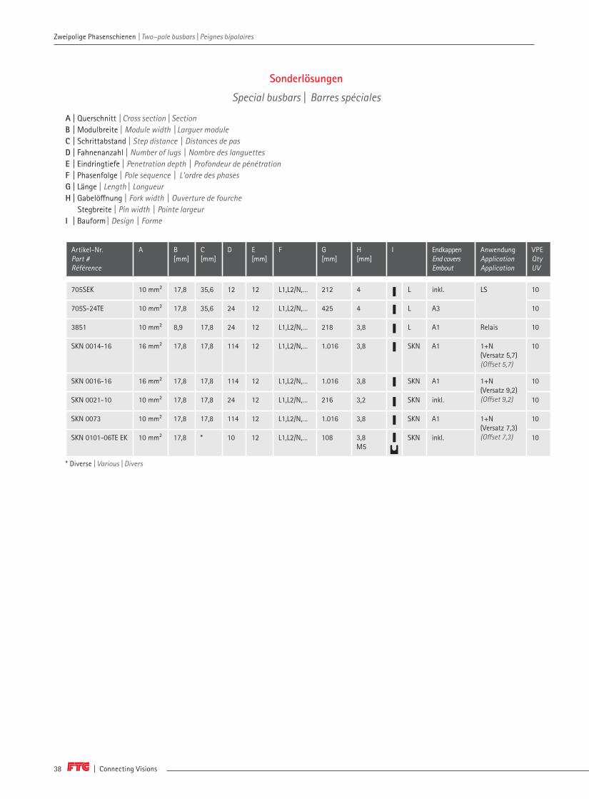
705SEK 10 mm² 17,8 35,6 12 12 L1,L2/N,… 212 4 L inkl. LS 10
705S-24TE 10 mm² 17,8 35,6 24 12 L1,L2/N,… 425 4 L A3 10
3851 10 mm² 8,9 17,8 24 12 L1,L2/N,… 218 3,8 L A1 Relais 10
SKN 0014-16 16 mm² 17,8 17,8 114 12 L1,L2/N,… 1.016 3,8 SKN A1 1+N (Versatz 5,7) (Offset 5,7)
10
SKN 0016-16 16 mm² 17,8 17,8 114 12 L1,L2/N,… 1.016 3,8 SKN A1 1+N (Versatz 9,2)(Offset 9,2)
10
SKN 0021-10 10 mm² 17,8 17,8 24 12 L1,L2/N,… 216 3,2 SKN inkl. 10
SKN 0073 10 mm² 17,8 17,8 114 12 L1,L2/N,… 1.016 3,8 SKN A1 1+N (Versatz 7,3)(Offset 7,3)
10
SKN 0101-06TE EK 10 mm² 17,8 * 10 12 L1,L2/N,… 108 3,8M5
SKN inkl. 10
* Diverse | Various | Divers
Sonderlösungen
Special busbars | Barres spéciales
A | Querschnitt | Cross section | Section B | Modulbreite | Module width | Larguer module C | Schrittabstand | Step distance | Distances de pas D | Fahnenanzahl | Number of lugs | Nombre des languettesE | Eindringtiefe | Penetration depth | Profondeur de pénétrationF | Phasenfolge | Pole sequence | L'ordre des phases G | Länge | Length | Longueur H | Gabelöffnung | Fork width | Ouverture de fourche Stegbreite | Pin width | Pointe largeurI | Bauform | Design | Forme
Zweipolige Phasenschienen | Two–pole busbars | Peignes bipolaires

www.ftg-germany.de 39
Zweipolige Phasenschienen | Two–pole busbars | Peignes bipolaires
Sonderlösungen | Special busbars | Barres spéciales
2
SO

L
T
SPM
Bauformen Design | Forme
Die Abkürzungen von den Anwendungen werden im Umschlag genauer erklärt. The abbreviations of the applications are explained in detail in the envelope.
Les abréviations des applications sont expliquées plus en détail dans l'enveloppe.
Weitere Schienen auf Anfrage erhältlich! Further busbars available on request!Plus peignes disponibles sur demande!Phone +49 (0) 7722 96 36-0 | [email protected]
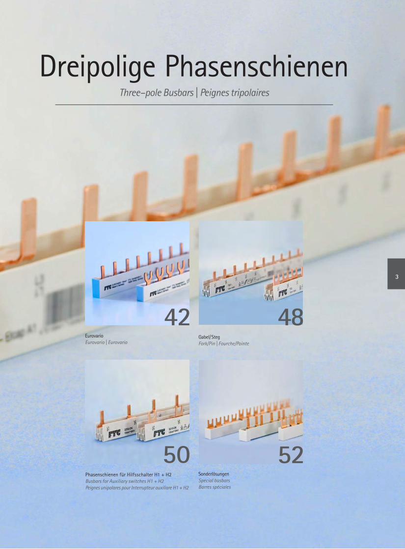
Dreipolige PhasenschienenThree–pole Busbars | Peignes tripolaires
Phasenschienen für Hilfsschalter H1 + H2Busbars for Auxiliary switches H1 + H2 Peignes unipolares pour Interrupteur auxiliare H1 + H2
42 48
50 52Sonderlösungen Special busbarsBarres spéciales
Eurovario Eurovario | Eurovario
Gabel/ Steg Fork/Pin | Fourche/Pointe
3

| Connecting Visions42
Dreipolige Phasenschienen | Three–pole Busbars | Peignes tripolaires Dreipolige Phasenschienen | Three–pole Busbars | Peignes tripolaires
Artikel-Nr. Part # Référence
A B[mm]
C[mm]
D E[mm]
F G [mm] H [mm] I J AnwendungApplicationApplication
VPE Qty UV
ES 30610 10 mm² 17,8 53,4 6 12 L1,L2,L3,… 102 M6 C E LS 10
ES 30810 10 mm² 17,8 53,4 8 12 L1,L2,L3,… 142 M6 C E 10
ES 30910 10 mm² 17,8 53,4 9 12 L1,L2,L3,… 158 M6 C E 10
ES 31010 10 mm² 17,8 53,4 10 12 L1,L2,L3,… 178 M6 C E 10
ES 31110 10 mm² 17,8 53,4 11 12 L1,L2,L3,… 192 M6 C E 10
ES 31210 10 mm² 17,8 53,4 12 12 L1,L2,L3,… 212 M6 C E 10
ES FI3LSSO 10 mm² 17,8 53,4 6 12 L1,L2,L3,H2,L1,L2,L3 122 M6 C E FI - LS 10
ES FI4LSSO 10 mm² 17,8 53,4 7 12 L1,L2,L3,H2,L1,L2,L3,L1 142 M6 C E 10
ES FI5LSSO 10 mm² 17,8 53,4 8 12 L1,L2,L3,H2,L1,L2,L3,L1,L2 158 M6 C E 10
ES FI6LSSO 10 mm² 17,8 53,4 9 12 L1,L2,L3,H2,L1,L2,L3,L1,L2,L3,... 178 M6 C E 10
ES FI8LSSO 10 mm² 17,8 53,4 11 12 L1,L2,L3,H2,L1,L2,L3,L1,L2,L3,... 212 M6 C E 10
ES 30610H1P 10 mm² 17,8 62,3 6 12 L1,L2,L3,H1,… 116 M6 C E LS + H1 10
ES 30910H1P 10 mm² 17,8 62,3 9 12 L1,L2,L3,H1,… 178 M6 C E 10
ES 31210H1P 10 mm² 17,8 62,3 12 12 L1,L2,L3,H1,… 240 M6 C E 10
ES 30610H2P 10 mm² 17,8 71,2 6 12 L1,L2,L3,H2,… 122 M6 C E LS + H2 10
ES 30910H2P 10 mm² 17,8 71,2 9 12 L1,L2,L3,H2,… 192 M6 C E 10
ES 31210H2P 10 mm² 17,8 71,2 12 12 L1,L2,L3,H2,… 266 M6 C E 10
ES 32706 10 mm² 17,827
81 6 12 L1,H1,L2,H1,L3,H1,…/L1,L2,L3,... 158 M6 CN
E LS + H1D - D0
10
ES 32709 10 mm² 81 9 12 L1,H1,L2,H1,L3,H1,…/L1,L2,L3,... 236 M6 E 10
ES 32712 10 mm² 81 12 12 L1,H1,L2,H1,L3,H1,…/L1,L2,L3,... 316 M6 E 10
ES 30610H2F 10 mm² 17,8 106,8 6 12 L1,H2,L2,H2,L3,H2,… 192 M6 C E LS + H2 10
ES 30910H2F 10 mm² 17,8 106,8 9 12 L1,H2,L2,H2,L3,H2,… 302 M6 C E 10
ES 30616 16 mm² 17,8 53,4 6 12 L1,L2,L3,… 102 M6 C E LS 10
ES 30816 16 mm² 17,8 53,4 8 12 L1,L2,L3,… 142 M6 C E 10
ES 30916 16 mm² 17,8 53,4 9 12 L1,L2,L3,… 158 M6 C E 10
ES 31016 16 mm² 17,8 53,4 10 12 L1,L2,L3,… 178 M6 C E 10
ES 31116 16 mm² 17,8 53,4 11 12 L1,L2,L3,… 192 M6 C E 10
ES 31216 16 mm² 17,8 53,4 12 12 L1,L2,L3,… 212 M6 C E 10
Dreipolige Eurovario Phasenschienen
Three-pole Eurovario Busbars | Eurovario peignes tripolaires
A | Querschnitt | Cross section | Section B | Modulbreite | Module width | Larguer module C | Schrittabstand | Step distance | Distances de pas D | Fahnenanzahl | Number of lugs | Nombre des languettesE | Eindringtiefe | Penetration depth | Profondeur de pénétrationF | Phasenfolge | Pole sequence | L'ordre des phases G | Länge | Length | Longueur H | Gabelöffnung | Fork width | Ouverture de fourcheI | Fabrikatszuordnung | Brand relation | Attribution produitJ | Bauform | Design | Forme
B
C
E
D
G
H

www.ftg-germany.de 43
Dreipolige Phasenschienen | Three–pole Busbars | Peignes tripolaires
Artikel-Nr. Part # Référence
A B[mm]
C[mm]
D E[mm]
F G [mm] H [mm] I J AnwendungApplicationApplication
VPE Qty UV
ES FI3LS16SO 16 mm² 17,8 53,4 6 12 L1,L2,L3,H2,L1,L2,L3 122 M6 C E FI - LS 10
ES FI4LS16SO 16 mm² 17,8 53,4 7 12 L1,L2,L3,H2,L1,L2,L3,L1 142 M6 C E 10
ES FI5LS16SO 16 mm² 17,8 53,4 8 12 L1,L2,L3,H2,L1,L2,L3,L1,L2 158 M6 C E 10
ES FI6LS16SO 16 mm² 17,8 53,4 9 12 L1,L2,L3,H2,L1,L2,L3,L1,L2,L3,... 178 M6 C E 10
ES FI8LS16SO 16 mm² 17,8 53,4 11 12 L1,L2,L3,H2,L1,L2,L3,L1,L2,L3,... 212 M6 C E 10
ES 30616H1P 16 mm² 17,8 62,3 6 12 L1,L2,L3,H1,… 116 M6 C E LS + H1 10
ES 30916H1P 16 mm² 17,8 62,3 9 12 L1,L2,L3,H1,… 178 M6 C E 10
ES 31216H1P 16 mm² 17,8 62,3 12 12 L1,L2,L3,H1,… 240 M6 C E 10
ES 30616H2P 16 mm² 17,8 71,2 6 12 L1,L2,L3,H2,… 122 M6 C E LS + H2 10
ES 30916H2P 16 mm² 17,8 71,2 9 12 L1,L2,L3,H2,… 192 M6 C E 10
ES 31216H2P 16 mm² 17,8 71,2 12 12 L1,L2,L3,H2,… 266 M6 C E 10
ES 32706-16 16 mm² 17,827
81 6 12 L1,L2,L3,H2,L1,L2,L3 158 M6 CN
E LS + H1D - D0
10
ES 32709-16 16 mm² 81 9 12 L1,L2,L3,H2,L1,L2,L3,L1 236 M6 E 10
ES 32712-16 16 mm² 81 12 12 L1,L2,L3,H2,L1,L2,L3,L1,L2 316 M6 E 10
ES 30616H2F 16 mm² 17,8 106,8 6 12 L1,H2,L2,H2,L3,H2,… 192 M6 C E LS + H2 10
ES 30916H2F 16 mm² 17,8 106,8 9 12 L1,H2,L2,H2,L3,H2,… 302 M6 C E 10
ES 30625 25 mm² 17,8 53,4 6 12 L1,L2,L3,… 106 M6 C E LS 10
ES 30925 25 mm² 17,8 53,4 9 12 L1,L2,L3,… 158 M6 C E 10
ES 31225 25 mm² 17,8 53,4 12 12 L1,L2,L3,… 212 M6 C E 10
ES FI8LS25SO 25 mm² 17,8 53,4 11 12 L1,L2,L3,_,_,L1,L2,L3,… 212 M6 C E FI - LS 10
ES 32706-25 25 mm² 17,827
81 6 12 L1,L2,L3,H2,L1,L2,L3 158 M6 CN
E LS + H1D - D0
10
ES 32709-25 25 mm² 81 9 12 L1,L2,L3,H2,L1,L2,L3,L1 236 M6 E 10
ES 32712-25 25 mm² 81 12 12 L1,L2,L3,H2,L1,L2,L3,L1,L2 316 M6 E 10
A | Querschnitt | Cross section | Section B | Modulbreite | Module width | Larguer module C | Schrittabstand | Step distance | Distances de pas D | Fahnenanzahl | Number of lugs | Nombre des languettesE | Eindringtiefe | Penetration depth | Profondeur de pénétrationF | Phasenfolge | Pole sequence | L'ordre des phases G | Länge | Length | Longueur H | Gabelöffnung | Fork width | Ouverture de fourcheI | Fabrikatszuordnung | Brand relation | Attribution produitJ | Bauform | Design | Forme
B
C
E
D
G
H
3
EV
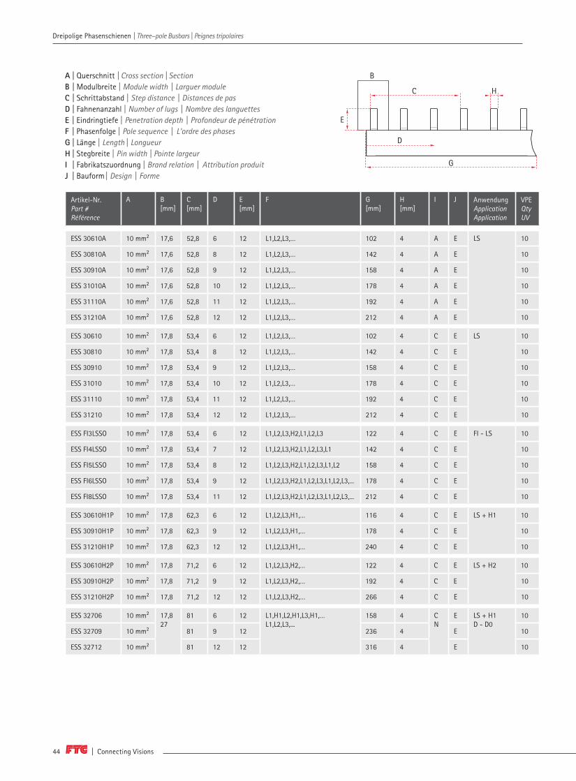
| Connecting Visions44
Dreipolige Phasenschienen | Three–pole Busbars | Peignes tripolaires Dreipolige Phasenschienen | Three–pole Busbars | Peignes tripolaires
Artikel-Nr. Part # Référence
A B[mm]
C[mm]
D E[mm]
F G [mm]
H [mm]
I J AnwendungApplicationApplication
VPE Qty UV
ESS 30610A 10 mm² 17,6 52,8 6 12 L1,L2,L3,… 102 4 A E LS 10
ESS 30810A 10 mm² 17,6 52,8 8 12 L1,L2,L3,… 142 4 A E 10
ESS 30910A 10 mm² 17,6 52,8 9 12 L1,L2,L3,… 158 4 A E 10
ESS 31010A 10 mm² 17,6 52,8 10 12 L1,L2,L3,… 178 4 A E 10
ESS 31110A 10 mm² 17,6 52,8 11 12 L1,L2,L3,… 192 4 A E 10
ESS 31210A 10 mm² 17,6 52,8 12 12 L1,L2,L3,… 212 4 A E 10
ESS 30610 10 mm² 17,8 53,4 6 12 L1,L2,L3,… 102 4 C E LS 10
ESS 30810 10 mm² 17,8 53,4 8 12 L1,L2,L3,… 142 4 C E 10
ESS 30910 10 mm² 17,8 53,4 9 12 L1,L2,L3,… 158 4 C E 10
ESS 31010 10 mm² 17,8 53,4 10 12 L1,L2,L3,… 178 4 C E 10
ESS 31110 10 mm² 17,8 53,4 11 12 L1,L2,L3,… 192 4 C E 10
ESS 31210 10 mm² 17,8 53,4 12 12 L1,L2,L3,… 212 4 C E 10
ESS FI3LSSO 10 mm² 17,8 53,4 6 12 L1,L2,L3,H2,L1,L2,L3 122 4 C E FI - LS 10
ESS FI4LSSO 10 mm² 17,8 53,4 7 12 L1,L2,L3,H2,L1,L2,L3,L1 142 4 C E 10
ESS FI5LSSO 10 mm² 17,8 53,4 8 12 L1,L2,L3,H2,L1,L2,L3,L1,L2 158 4 C E 10
ESS FI6LSSO 10 mm² 17,8 53,4 9 12 L1,L2,L3,H2,L1,L2,L3,L1,L2,L3,... 178 4 C E 10
ESS FI8LSSO 10 mm² 17,8 53,4 11 12 L1,L2,L3,H2,L1,L2,L3,L1,L2,L3,... 212 4 C E 10
ESS 30610H1P 10 mm² 17,8 62,3 6 12 L1,L2,L3,H1,… 116 4 C E LS + H1 10
ESS 30910H1P 10 mm² 17,8 62,3 9 12 L1,L2,L3,H1,… 178 4 C E 10
ESS 31210H1P 10 mm² 17,8 62,3 12 12 L1,L2,L3,H1,… 240 4 C E 10
ESS 30610H2P 10 mm² 17,8 71,2 6 12 L1,L2,L3,H2,… 122 4 C E LS + H2 10
ESS 30910H2P 10 mm² 17,8 71,2 9 12 L1,L2,L3,H2,… 192 4 C E 10
ESS 31210H2P 10 mm² 17,8 71,2 12 12 L1,L2,L3,H2,… 266 4 C E 10
ESS 32706 10 mm² 17,8 27
81 6 12 L1,H1,L2,H1,L3,H1,…L1,L2,L3,...
158 4 C N
E LS + H1 D - D0
10
ESS 32709 10 mm² 81 9 12 236 4 E 10
ESS 32712 10 mm² 81 12 12 316 4 E 10
A | Querschnitt | Cross section | Section B | Modulbreite | Module width | Larguer module C | Schrittabstand | Step distance | Distances de pas D | Fahnenanzahl | Number of lugs | Nombre des languettesE | Eindringtiefe | Penetration depth | Profondeur de pénétrationF | Phasenfolge | Pole sequence | L'ordre des phases G | Länge | Length | Longueur H | Stegbreite | Pin width | Pointe largeurI | Fabrikatszuordnung | Brand relation | Attribution produitJ | Bauform | Design | Forme
H
B
E
D
G
C

www.ftg-germany.de 45
Dreipolige Phasenschienen | Three–pole Busbars | Peignes tripolaires
Artikel-Nr. Part # Référence
A B[mm]
C[mm]
D E[mm]
F G [mm]
H [mm]
I J AnwendungApplicationApplication
VPE Qty UV
ESS 30610H2F 10 mm² 17,8 106,8 6 12 L1,H2,L2,H2,L3,H2,… 192 4 C E LS + H2 10
ESS 30910H2F 10 mm² 17,8 106,8 9 12 L1,H2,L2,H2,L3,H2,… 302 4 C E 10
ESS 30616A 16 mm² 17,6 52,8 6 12 L1,L2,L3,… 102 4 C E LS 10
ESS 30816A 16 mm² 17,6 52,8 8 12 L1,L2,L3,… 142 4 C E 10
ESS 30916A 16 mm² 17,6 52,8 9 12 L1,L2,L3,… 158 4 C E 10
ESS 31016A 16 mm² 17,6 52,8 10 12 L1,L2,L3,… 178 4 C E 10
ESS 31116A 16 mm² 17,6 52,8 11 12 L1,L2,L3,… 192 4 C E 10
ESS 31216A 16 mm² 17,6 52,8 12 12 L1,L2,L3,… 212 4 C E 10
ESS 30616 16 mm² 17,8 53,4 6 12 L1,L2,L3,… 102 4 C E LS 10
ESS 30816 16 mm² 17,8 53,4 8 12 L1,L2,L3,… 142 4 C E 10
ESS 30916 16 mm² 17,8 53,4 9 12 L1,L2,L3,… 158 4 C E 10
ESS 31016 16 mm² 17,8 53,4 10 12 L1,L2,L3,… 178 4 C E 10
ESS 31116 16 mm² 17,8 53,4 11 12 L1,L2,L3,… 192 4 C E 10
ESS 31216 16 mm² 17,8 53,4 12 12 L1,L2,L3,… 212 4 C E 10
ESS FI3LS16SO 16 mm² 17,8 53,4 6 12 L1,L2,L3,H2,L1,L2,L3 122 4 C E FI - LS 10
ESS FI4LS16SO 16 mm² 17,8 53,4 7 12 L1,L2,L3,H2,L1,L2,L3,L1 142 4 C E 10
ESS FI5LS16SO 16 mm² 17,8 53,4 8 12 L1,L2,L3,H2,L1,L2,L3,L1,L2 158 4 C E 10
ESS FI6LS16SO 16 mm² 17,8 53,4 9 12 L1,L2,L3,H2,L1,L2,L3,L1,L2,L3,... 178 4 C E 10
ESS FI8LS16SO 16 mm² 17,8 53,4 11 12 L1,L2,L3,H2,L1,L2,L3,L1,L2,L3,... 212 4 C E 10
ESS 30616H1P 16 mm² 17,8 62,3 6 12 L1,L2,L3,H1,… 116 4 C E LS + H1 10
ESS 30916H1P 16 mm² 17,8 62,3 9 12 L1,L2,L3,H1,… 178 4 C E 10
ESS 31216H1P 16 mm² 17,8 62,3 12 12 L1,L2,L3,H1,… 240 4 C E 10
A | Querschnitt | Cross section | Section B | Modulbreite | Module width | Larguer module C | Schrittabstand | Step distance | Distances de pas D | Fahnenanzahl | Number of lugs | Nombre des languettesE | Eindringtiefe | Penetration depth | Profondeur de pénétrationF | Phasenfolge | Pole sequence | L'ordre des phases G | Länge | Length | Longueur H | Stegbreite | Pin width | Pointe largeurI | Fabrikatszuordnung | Brand relation | Attribution produitJ | Bauform | Design | Forme
H
B
E
D
G
C
3
EV
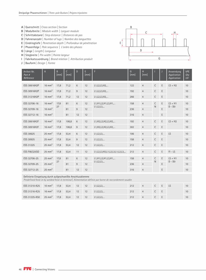
| Connecting Visions46
Dreipolige Phasenschienen | Three–pole Busbars | Peignes tripolaires Dreipolige Phasenschienen | Three–pole Busbars | Peignes tripolaires
Artikel-Nr. Part # Référence
A B[mm]
C[mm]
D E[mm]
F G [mm]
H [mm]
I J AnwendungApplicationApplication
VPE Qty UV
ESS 30616H2P 16 mm² 17,8 71,2 6 12 L1,L2,L3,H2,… 122 4 C E LS + H2 10
ESS 30916H2P 16 mm² 17,8 71,2 9 12 L1,L2,L3,H2,… 192 4 C E 10
ESS 31216H2P 16 mm² 17,8 71,2 12 12 L1,L2,L3,H2,… 266 4 C E 10
ESS 32706-16 16 mm² 17,827
81 6 12 L1,H1,L2,H1,L3,H1,…L1,L2,L3,...
158 4 C N
E LS + H1D - D0
10
ESS 32709-16 16 mm² 81 9 12 236 4 E 10
ESS 32712-16 16 mm² 81 12 12 316 4 E 10
ESS 30616H2F 16 mm² 17,8 106,8 6 12 L1,H2,L2,H2,L3,H2,… 192 4 C E LS + H2 10
ESS 30916H2F 16 mm² 17,8 106,8 9 12 L1,H2,L2,H2,L3,H2,… 302 4 C E 10
ESS 30625 25 mm² 17,8 53,4 6 12 L1,L2,L3,… 106 4 C E LS 10
ESS 30925 25 mm² 17,8 53,4 9 12 L1,L2,L3,… 158 4 C E 10
ESS 31225 25 mm² 17,8 53,4 12 12 L1,L2,L3,… 212 4 C E 10
ESS FI8LS25SO 25 mm² 17,8 53,4 11 12 L1,L2,L3,H2,L1,L2,L3,L1,L2,L3,... 212 4 C E FI - LS 10
ESS 32706-25 25 mm² 17,827
81 6 12 L1,H1,L2,H1,L3,H1,…L1,L2,L3,...
158 4 C N
E LS + H1D - D0
10
ESS 32709-25 25 mm² 81 9 12 236 4 E 10
ESS 32712-25 25 mm² 81 12 12 316 4 E 10
Definierte Einspeisung durch aufgeschweißte AnschlussklemmePredefined feed-in by welded feed-in terminal | Alimentation définie par borne de raccordement soudée
ESS 31210-K25 10 mm² 17,8 53,4 12 12 L1,L2,L3,… 212 4 C E LS 10
ESS 31216-K25 16 mm² 17,8 53,4 12 12 L1,L2,L3,… 212 4 C E 10
ESS 31225-K50 25 mm² 17,8 53,4 12 12 L1,L2,L3,… 212 4 C E 10
A | Querschnitt | Cross section | Section B | Modulbreite | Module width | Larguer module C | Schrittabstand | Step distance | Distances de pas D | Fahnenanzahl | Number of lugs | Nombre des languettesE | Eindringtiefe | Penetration depth | Profondeur de pénétrationF | Phasenfolge | Pole sequence | L'ordre des phases G | Länge | Length | Longueur H | Stegbreite | Pin width | Pointe largeurI | Fabrikatszuordnung | Brand relation | Attribution produitJ | Bauform | Design | Forme
H
B
E
D
G
C

www.ftg-germany.de 47
Aufgeschweißte Anschlussklemmen | Welded feed-in terminals | Bornes de connexion soudée
Dreipolige Phasenschienen | Three–pole Busbars | Peignes tripolaires
3
EV

| Connecting Visions48
Dreipolige Phasenschienen | Three–pole Busbars | Peignes tripolaires Dreipolige Phasenschienen | Three–pole Busbars | Peignes tripolaires
Artikel-Nr. Part # Référence
A B[mm]
C[mm]
D E[mm]
F G [mm]
H [mm]
I J Endkappen End coversEmbout
AnwendungApplicationApplication
VPE Qty UV
3921 16 mm² 13 39 75 18 L1,L2,L3,… 962 M5 D L A1 LS 10
700 10 mm² 17,8 53,4 12 12 L1,L2,L3,… 212 M6 C L A1 LS 50
710-57 10 mm² 17,8 53,4 57 12 L1,L2,L3,… 1012 M6 C L A1 10
710 10 mm² 17,8 53,4 60 12 L1,L2,L3,… 1064 M6 C L A1 10
700-16 16 mm² 17,8 53,4 12 12 L1,L2,L3,… 212 M6 C L A1 50
710-16-57 16 mm² 17,8 53,4 57 12 L1,L2,L3,… 1012 M6 C L A1 10
710-16 16 mm² 17,8 53,4 60 12 L1,L2,L3,… 1064 M6 C L A1 10
701T 10 mm² 17,8 53,4 12 12 L1,L2,L3,… 212 M6 C T A4 50
711T-57 10 mm² 17,8 53,4 57 12 L1,L2,L3,… 1012 M6 C T A4 10
711T 10 mm² 17,8 53,4 60 12 L1,L2,L3,… 1064 M6 C T A4 10
701T-16 16 mm² 17,8 53,4 12 12 L1,L2,L3,… 212 M6 C T A4 50
711T-16-57 16 mm² 17,8 53,4 57 12 L1,L2,L3,… 1012 M6 C T A4 10
711T-16 16 mm² 17,8 53,4 60 12 L1,L2,L3,… 1064 M6 C T A4 10
5988 35 mm² 17,8 53,4 57 12 L1,L2,L3,… 1012 M6 C L A26 10
7988 50 mm² 17,8 53,4 57 12 L1,L2,L3,… 1012 M6 C L A26 10
7001T 10 mm² 18 54 12 12 L1,L2,L3,… 212 M6 K T A4 LS 10
7101T 10 mm² 18 54 57 12 L1,L2,L3,… 1012 M6 K T A4 10
7001T-16 16 mm² 18 54 12 12 L1,L2,L3,… 212 M6 K T A1 10
7101T-16 16 mm² 18 54 57 12 L1,L2,L3,… 1012 M6 K T A1 10
702 10 mm² 27 81 9 12 L1,L2,L3,… 231 M6 N L A1 D0 50
712 10 mm² 27 81 39 12 L1,L2,L3,… 1045 M6 N L A1 10
702-16 16 mm² 27 81 9 12 L1,L2,L3,… 231 M6 N L A1 50
712-16 16 mm² 27 81 39 12 L1,L2,L3,… 1045 M6 N L A1 10
5989 35 mm² 27 81 39 12 L1,L2,L3,… 1045 M6 N L A26 10
7989 50 mm² 27 81 39 12 L1,L2,L3,… 1045 M6 N L A26 10
Dreipolige Phasenschienen in Gabel/Steg
Three-pole Busbars fork/pin | Peignes tripolaires fourche/pointe
A | Querschnitt | Cross section | Section B | Modulbreite | Module width | Larguer module C | Schrittabstand | Step distance | Distances de pas D | Fahnenanzahl | Number of lugs | Nombre des languettesE | Eindringtiefe | Penetration depth | Profondeur de pénétrationF | Phasenfolge | Pole sequence | L'ordre des phases G | Länge | Length | Longueur H | Gabelöffnung | Fork width | Ouverture de fourcheI | Fabrikatszuordnung | Brand relation | Attribution produitJ | Bauform | Design | Forme
B
C
E
D
G
H

www.ftg-germany.de 49
Dreipolige Phasenschienen | Three–pole Busbars | Peignes tripolaires
Artikel-Nr. Part # Référence
A B[mm]
C[mm]
D E[mm]
F G [mm]
H [mm]
I J Endkappen End coversEmbout
AnwendungApplicationApplication
VPE Qty UV
3921S 16 mm² 13 39 75 16 L1,L2,L3,… 962 7 D L A1 LS 10
731S-57 10 mm² 17,6 52,8 57 12 L1,L2,L3,… 1012 4 A L A1 LS 10
731S-16-57 16 mm² 17,6 52,8 57 12 L1,L2,L3,… 1012 4 A L A1 10
700SPM 10 mm² 17,6 52,8 12 12 L1,L2,L3,… 212 4 B SPM A5 50
710SPM 10 mm² 17,6 52,8 60 12 L1,L2,L3,… 1012 4 B SPM A5 10
700SPM-16 16 mm² 17,6 52,8 12 12 L1,L2,L3,… 212 4 B SPM A5 50
710SPM-16 16 mm² 17,6 52,8 60 12 L1,L2,L3,… 1012 4 B SPM A5 10
700S 10 mm² 17,8 53,4 12 12 L1,L2,L3,… 212 4 C L A1 LS 50
710S-57 10 mm² 17,8 53,4 57 12 L1,L2,L3,… 1012 4 C L A1 10
710S 10 mm² 17,8 53,4 60 12 L1,L2,L3,… 1064 4 C L A1 10
700S-16 16 mm² 17,8 53,4 12 12 L1,L2,L3,… 212 4 C L A1 50
710S-16-57 16 mm² 17,8 53,4 57 12 L1,L2,L3,… 1012 4 C L A1 10
710S-16 16 mm² 17,8 53,4 60 12 L1,L2,L3,… 1064 4 C L A1 10
5988S 35 mm² 17,8 53,4 57 12 L1,L2,L3,… 1012 4 C L A26 10
7988S 50 mm² 17,8 53,4 57 12 L1,L2,L3,… 1012 4 C L A26 10
7001S 10 mm² 18 54 12 12 L1,L2,L3,… 212 4 K L A1 LS 10
7101S 10 mm² 18 54 57 12 L1,L2,L3,… 1012 4 K L A1 10
7001S-16 16 mm² 18 54 12 12 L1,L2,L3,… 212 4 K L A1 10
7101S-16 16 mm² 18 54 57 12 L1,L2,L3,… 1012 4 K L A1 10
702S 10 mm² 27 81 9 12 L1,L2,L3,… 231 5 N L A1 D0 50
712S 10 mm² 27 81 39 12 L1,L2,L3,… 1045 5 N L A1 10
702S-16 16 mm² 27 81 9 12 L1,L2,L3,… 231 5 N L A1 50
712S-16 16 mm² 27 81 39 12 L1,L2,L3,… 1045 5 N L A1 10
5989S 35 mm² 27 81 39 12 L1,L2,L3,… 1045 6,5 N L A26 10
7989S 50 mm² 27 81 39 12 L1,L2,L3,… 1045 6,5 N L A26 10
A | Querschnitt | Cross section | Section B | Modulbreite | Module width | Larguer module C | Schrittabstand | Step distance | Distances de pas D | Fahnenanzahl | Number of lugs | Nombre des languettesE | Eindringtiefe | Penetration depth | Profondeur de pénétrationF | Phasenfolge | Pole sequence | L'ordre des phases G | Länge | Length | Longueur H | Stegbreite | Pin width | Pointe largeurI | Fabrikatszuordnung | Brand relation | Attribution produitJ | Bauform | Design | Forme
H
B
E
D
G
C
3

| Connecting Visions50
Dreipolige Phasenschienen | Three–pole Busbars | Peignes tripolaires Dreipolige Phasenschienen | Three–pole Busbars | Peignes tripolaires
AFDD Phasenschienen | Busbars for AFDD Peignes pour Dispositifs de dètection de dèfaut d'arc 1 passend für Siemens-Geräte | suitable for Siemens devices convient pour les appareils Siemens 2 für Schrack- / Eaton-/Doepke-Geräte | for Schrack- / Eaton-/Doepke-devices
pour appareils Schrack- / Eaton-/Doepke
Artikel-Nr. Part # Référence
A B[mm]
C [mm]
D E [mm]
F G [mm]
H [mm]
I J Endkappen End coversEmbout
AnwendungApplicationApplication
VPE Qty UV
3927 16 mm² 13 45,5 66 18 L1,L2,L3,H1,… 1000 M5 D L A1 LS 10
3928 16 mm² 13 58,5 51 18 L1,H1,L2,H1,L3,H1,… 975 M5 D L A1 10
3122 10 mm² 17,8 62,3 48 12 L1,L2,L3,H1,… 990 M6 C L A1 LS 10
3125 16 mm² 17,8 62,3 48 12 L1,L2,L3,H1,… 990 M6 C L A1 10
3128 10 mm² 17,8 62,3 48 12 L1,L2,L3,H1,… 990 M6 C T A1 10
3131 16 mm² 17,8 62,3 48 12 L1,L2,L3,H1,… 990 M6 C T A1 10
712 10 mm² 17,818
81 39 12 L1,H1,L2,H1,L3,H1,… 1045 M6 C K
L A1 LS 10
712-16 16 mm² 81 39 12 L1,H1,L2,H1,L3,H1,… 1045 M6 L A1 10
3234 10 mm² 18 63 48 12 L1,L2,L3,H1,… 990 M6 C T A1 LS 10
3234-16 16 mm² 18 63 48 12 L1,L2,L3,H1,… 990 M6 C T A1 10
3192 10 mm² 17,8 71,2 42 12 L1,L2,L3,H2,… 980 M6 C L A1 LS 10
3195 16 mm² 17,8 71,2 42 12 L1,L2,L3,H2,… 980 M6 C L A1 10
3210T 10 mm² 17,8 106,8 30 12 L1,H2,L2,H2,L3,H2,… 1050 M6 C T A1 LS 10
3211T 16 mm² 17,8 106,8 30 12 L1,H2,L2,H2,L3,H2,… 1050 M6 C T A1 10
3205 10 mm² 18 72 42 12 L1,L2,L3,H2,… 980 M6 K T A1 LS 10
3205-16 16 mm² 18 72 42 12 L1,L2,L3,H2,… 980 M6 K T A1 10
3213 10 mm² 18 108 30 12 L1,H2,L2,H2,L3,H2,… 1050 M6 K T A1 LS 10
3214 16 mm² 18 108 30 12 L1,H2,L2,H2,L3,H2,… 1050 M6 K T A1 10
A | Querschnitt | Cross section | Section B | Modulbreite | Module width | Larguer module C | Schrittabstand | Step distance | Distances de pas D | Fahnenanzahl | Number of lugs | Nombre des languettesE | Eindringtiefe | Penetration depth | Profondeur de pénétrationF | Phasenfolge | Pole sequence | L'ordre des phases G | Länge | Length | Longueur H | Gabelöffnung | Fork width | Ouverture de fourcheI | Fabrikatszuordnung | Brand relation | Attribution produitJ | Bauform | Design | Forme
Phasenschienen für Hilfsschalter H1+H2
Busbars for Auxiliary switch H1+H2 | Peignes pour auxiliare H1+H2
B
C
E
D
G
H
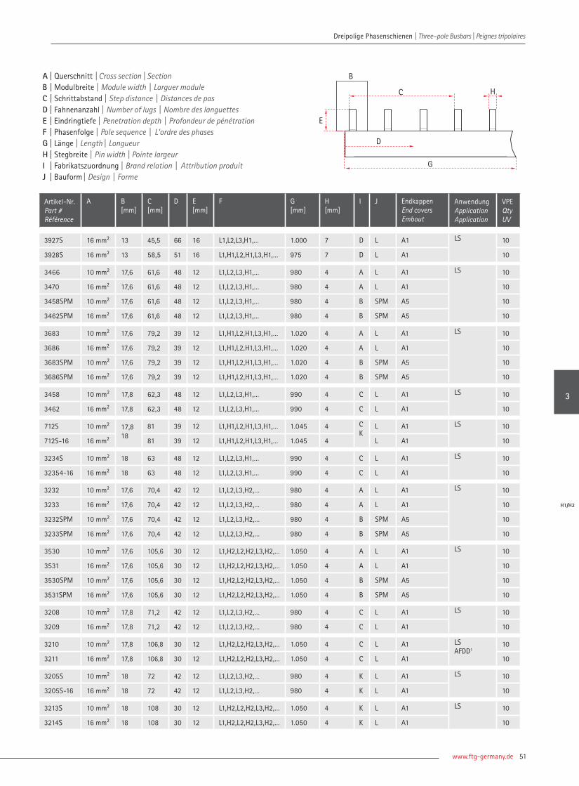
www.ftg-germany.de 51
Dreipolige Phasenschienen | Three–pole Busbars | Peignes tripolaires
Artikel-Nr. Part # Référence
A B[mm]
C [mm]
D E [mm]
F G [mm]
H [mm]
I J Endkappen End coversEmbout
AnwendungApplicationApplication
VPE Qty UV
3927S 16 mm² 13 45,5 66 16 L1,L2,L3,H1,… 1.000 7 D L A1 LS 10
3928S 16 mm² 13 58,5 51 16 L1,H1,L2,H1,L3,H1,… 975 7 D L A1 10
3466 10 mm² 17,6 61,6 48 12 L1,L2,L3,H1,… 980 4 A L A1 LS 10
3470 16 mm² 17,6 61,6 48 12 L1,L2,L3,H1,… 980 4 A L A1 10
3458SPM 10 mm² 17,6 61,6 48 12 L1,L2,L3,H1,… 980 4 B SPM A5 10
3462SPM 16 mm² 17,6 61,6 48 12 L1,L2,L3,H1,… 980 4 B SPM A5 10
3683 10 mm² 17,6 79,2 39 12 L1,H1,L2,H1,L3,H1,… 1.020 4 A L A1 LS 10
3686 16 mm² 17,6 79,2 39 12 L1,H1,L2,H1,L3,H1,… 1.020 4 A L A1 10
3683SPM 10 mm² 17,6 79,2 39 12 L1,H1,L2,H1,L3,H1,… 1.020 4 B SPM A5 10
3686SPM 16 mm² 17,6 79,2 39 12 L1,H1,L2,H1,L3,H1,… 1.020 4 B SPM A5 10
3458 10 mm² 17,8 62,3 48 12 L1,L2,L3,H1,… 990 4 C L A1 LS 10
3462 16 mm² 17,8 62,3 48 12 L1,L2,L3,H1,… 990 4 C L A1 10
712S 10 mm² 17,818
81 39 12 L1,H1,L2,H1,L3,H1,… 1.045 4 C K
L A1 LS 10
712S-16 16 mm² 81 39 12 L1,H1,L2,H1,L3,H1,… 1.045 4 L A1 10
3234S 10 mm² 18 63 48 12 L1,L2,L3,H1,… 990 4 C L A1 LS 10
32354-16 16 mm² 18 63 48 12 L1,L2,L3,H1,… 990 4 C L A1 10
3232 10 mm² 17,6 70,4 42 12 L1,L2,L3,H2,… 980 4 A L A1 LS 10
3233 16 mm² 17,6 70,4 42 12 L1,L2,L3,H2,… 980 4 A L A1 10
3232SPM 10 mm² 17,6 70,4 42 12 L1,L2,L3,H2,… 980 4 B SPM A5 10
3233SPM 16 mm² 17,6 70,4 42 12 L1,L2,L3,H2,… 980 4 B SPM A5 10
3530 10 mm² 17,6 105,6 30 12 L1,H2,L2,H2,L3,H2,… 1.050 4 A L A1 LS 10
3531 16 mm² 17,6 105,6 30 12 L1,H2,L2,H2,L3,H2,… 1.050 4 A L A1 10
3530SPM 10 mm² 17,6 105,6 30 12 L1,H2,L2,H2,L3,H2,… 1.050 4 B SPM A5 10
3531SPM 16 mm² 17,6 105,6 30 12 L1,H2,L2,H2,L3,H2,… 1.050 4 B SPM A5 10
3208 10 mm² 17,8 71,2 42 12 L1,L2,L3,H2,… 980 4 C L A1 LS 10
3209 16 mm² 17,8 71,2 42 12 L1,L2,L3,H2,… 980 4 C L A1 10
3210 10 mm² 17,8 106,8 30 12 L1,H2,L2,H2,L3,H2,… 1.050 4 C L A1 LSAFDD1
10
3211 16 mm² 17,8 106,8 30 12 L1,H2,L2,H2,L3,H2,… 1.050 4 C L A1 10
3205S 10 mm² 18 72 42 12 L1,L2,L3,H2,… 980 4 K L A1 LS 10
3205S-16 16 mm² 18 72 42 12 L1,L2,L3,H2,… 980 4 K L A1 10
3213S 10 mm² 18 108 30 12 L1,H2,L2,H2,L3,H2,… 1.050 4 K L A1 LS 10
3214S 16 mm² 18 108 30 12 L1,H2,L2,H2,L3,H2,… 1.050 4 K L A1 10
A | Querschnitt | Cross section | Section B | Modulbreite | Module width | Larguer module C | Schrittabstand | Step distance | Distances de pas D | Fahnenanzahl | Number of lugs | Nombre des languettesE | Eindringtiefe | Penetration depth | Profondeur de pénétrationF | Phasenfolge | Pole sequence | L'ordre des phases G | Länge | Length | Longueur H | Stegbreite | Pin width | Pointe largeurI | Fabrikatszuordnung | Brand relation | Attribution produitJ | Bauform | Design | Forme
H
B
E
D
G
C
3
H1/H2

| Connecting Visions52
Dreipolige Phasenschienen | Three–pole Busbars | Peignes tripolaires Dreipolige Phasenschienen | Three–pole Busbars | Peignes tripolaires
Artikel-Nr. Part # Référence
A B[mm]
C [mm]
D E[mm]
F G [mm]
H [mm]
I J AnwendungApplicationApplication
VPE Qty UV
3726 10 mm² 17,8 53,4 57 12 L1,L2,L3,… 1012 M6 G / T A1 LSabbrechbar separable
10
3729 16 mm² 17,8 53,4 57 12 L1,L2,L3,… 1012 M6 G / T A1 10
3510 16 mm² 17,8 71,2 56 12 L1,N,L2,N,… 1000 4 S / L A1 LS 10
3230 16 mm² 27 81 39 16 L1,L2,L3,… 1040 6,5 S / L A26 D0 10
3820 30 mm² 27 81 39 16 L1,L2,L3,… 1040 8,6 S / L A6 10
3922EK 10 mm² 2717,6
76,3 6 1612
L1,L2,L3,… 134 7,55
S / L inkl. D0 - LS 10
3364 10 mm² 17,6 70,4 11 12 L1,L2,L3,H2,L1,L2,L3,… 212 M6 G / T A1 FI - LS 10
3365 10 mm² 17,8 71,2 11 12 L1,L2,L3,H2,L1,L2,L3,… 212 M6 G / T A1 10
3364EK 10 mm² 17,6 70,4 11 12 L1,L2,L3,H2,L1,L2,L3,… 212 4 S / L inkl. 10
3364SPMEK 10 mm² 17,6 70,4 11 12 L1,L2,L3,H2,L1,L2,L3,… 212 4 S / SPM inkl. 10
3369-FI6LS-M5 16 mm² 17,8 71,2 9 12 L1,L2,L3,H2,L1,L2,L3,… 174 M5 G / L inkl. 10
710T-16-57-5 16 mm² 17,8 53,4 57 12 L1,L2,L3,… 1016 M5 G / T A1 LS 10
SKS 0250 16 mm² 17,8 53,4 6 13,717,7
L1,L2,L3,L1,L2,L3 108 M6M5
G / L inkl. * 10
SKS 0344-16-07TE 16 mm² 17,6 70,4 7 12 L1,L2,L3,H2,L1,L2,L3,L1 142 M5M6
G / L inkl. FI - LS 10
SKS 0717 16 mm² 18,2 17,8
71,9 11 13,711,7
L1,L2,L3,H2,L1,L2,L3,… 211 7,55
S / L inkl. 10
SKS 0742 10 mm² 8,9 36 6 13 L1,L2,L3,H2,L1,L2,L3 68 4 S / 90° inkl. ** 10
SKS 1085-08TE 16 mm² 17,8 53,4 8 14 L1,L2,L3,… 146 M5 G / L inkl. *** 10
Sonderlösungen
Special busbars | Barres spéciales
A | Querschnitt | Cross section | Section B | Modulbreite | Module width | Larguer module C | Schrittabstand | Step distance | Distances de pas D | Fahnenanzahl | Number of lugs | Nombre des languettesE | Eindringtiefe | Penetration depth | Profondeur de pénétrationF | Phasenfolge | Pole sequence | L'ordre des phases G | Länge | Length | Longueur H | Gabelöffnung | Fork width | Ouverture de fourche Stegbreite | Pin width | Pointe largeurI | Bauform | Design | FormeJ | Endkappen | End covers | Embout
* Überspannungsschutzgerät auf FI | Surge protection device on overload protection ** Schütz, 90° gebogen | Contactor, 90 ° bent*** FI - LS mit Höhenversatz | Overload protection with height offset

www.ftg-germany.de 53
Dreipolige Phasenschienen | Three–pole Busbars | Peignes tripolaires
Sonderlösungen | Special busbars | Barres spéciales
3
SO

L
T
SPM
SKN
Bauformen Design | Forme
Die Abkürzungen von den Anwendungen werden im Umschlag genauer erklärt. The abbreviations of the applications are explained in detail in the envelope.
Les abréviations des applications sont expliquées plus en détail dans l'enveloppe.
Weitere Schienen auf Anfrage erhältlich! Further busbars available on request!Plus peignes disponibles sur demande!Phone +49 (0) 7722 96 36-0 | [email protected]
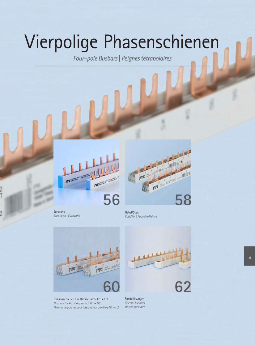
Vierpolige PhasenschienenFour–pole Busbars | Peignes tétrapolaires
Phasenschienen für Hilfsschalter H1 + H2Busbars for Auxiliary switch H1 + H2 Peignes unipolares pour Interrupteur auxiliare H1 + H2
56 58
60 62Sonderlösungen Special busbarsBarres spéciales
Eurovario Eurovario | Eurovario
Gabel/ Steg Fork/Pin | Fourche/Pointe
4

| Connecting Visions56
Vierpolige Phasenschienen | Four–pole Busbars | Peignes tétrapolaires Vierpolige Phasenschienen | Four–pole Busbars | Peignes tétrapolaires
Artikel-Nr. Part # Référence
A B[mm]
C [mm]
D E [mm]
F G [mm]
H [mm]
I J AnwendungApplicationApplication
VPE Qty UV
ES 40810 10 mm² 17,8 71,2 8 12 L1,L2,L3,N,… 142 M6 C E LS 10
ES 41210 10 mm² 17,8 71,2 12 12 L1,L2,L3,N,… 212 M6 C E 10
ES 40810N 10 mm² 17,8 106,8 12 12 L1,N,L2,N,L3,N,L1,N 142 M6 C E LS + N 10
ES 41210N 10 mm² 17,8 71,2 12 12 L1,N,L2,N,L3,N,… 212 M6 C E 10
ES 41210FI/LS 10 mm² 17,8 71,2 12 12 L1,L2,L3,N,L1,N,L2,N,L3,N,… 212 M6 C E FI - LS 10
ES 40810H1P 10 mm² 17,8 80,1 8 12 L1,L2,L3,N,H1... 152 M6 C E LS + H1 10
ES 41210H1P 10 mm² 17,8 80,1 12 12 L1,L2,L3,N,H1... 232 M6 C E 10
ES 40810H2P 10 mm² 17,8 89 8 12 L1,L2,L3,N,H2... 160 M6 C E LS + H2 10
ES 41210H2P 10 mm² 17,8 89 12 12 L1,L2,L3,N,H2... 250 M6 C E 10
ES 42708 10 mm² 17,827
108 8 12 L1,H1,L2,H1,L3,H1,N,H1,...L1,L2,L3,N,…
216 M6 C N
E LS + H1D - D0
10
ES 42712 10 mm² 108 12 12 324 M6 E 10
ES 40810H2F 10 mm² 17,8 142 8 12 L1,H2,L2,H2,L3,H2,N,H2,... 266 M6 C E LS + H2 10
ES 41210H2F 10 mm² 17,8 142 12 12 L1,H2,L2,H2,L3,H2,N,H2,... 408 M6 C E 10
ES 40816 16 mm² 17,8 71,2 8 12 L1,L2,L3,N,… 142 M6 C E LS 10
ES 41216 16 mm² 17,8 71,2 12 12 L1,L2,L3,N,… 212 M6 C E 10
ES 40816N 16 mm² 17,8 106,8 12 12 L1,N,L2,N,L3,N,L1,N 142 M6 C E LS + N 10
ES 41216N 16 mm² 17,8 106,8 12 12 L1,N,L2,N,L3,N,… 212 M6 C E 10
ES 41216FI/LS 16 mm² 17,8 71,2 12 12 L1,L2,L3,N,L1,N,L2,N,L3,N,… 212 M6 C E FI - LS 10
ES 40816H1P 16 mm² 17,8 80,1 8 12 L1,L2,L3,H1,N,H1,... 152 M6 C E LS + H1 10
ES 41216H1P 16 mm² 17,8 80,1 12 12 L1,L2,L3,H1,N,H1,... 232 M6 C E 10
ES 40816H2P 16 mm² 17,8 89 8 12 L1,L2,L3,H1,N,H1,... 160 M6 C E LS + H2 10
ES 41216H2P 16 mm² 17,8 89 12 12 L1,L2,L3,H1,N,H1,... 250 M6 C E 10
ES 42708-16 16 mm² 17,827
108 8 12 L1,H1,L2,H1,L3,H1,N,H1,...L1,L2,L3,N,…
216 M6 C N
E LS + H1D - D0
10
ES 42712-16 16 mm² 108 12 12 324 M6 E 10
ES 40816H2F 16 mm² 17,8 142 8 12 L1,H2,L2,H2,L3,H2,N,H2,... 266 M6 C E LS + H2 10
ES 41216H2F 16 mm² 17,8 142 12 12 L1,H2,L2,H2,L3,H2,N,H2,... 408 M6 C E 10
Vierpolige Eurovario Phasenschienen
Four-pole Eurovario Busbars | Eurovario peignes tétrapolaires
A | Querschnitt | Cross section | Section B | Modulbreite | Module width | Larguer module C | Schrittabstand | Step distance | Distances de pas D | Fahnenanzahl | Number of lugs | Nombre des languettesE | Eindringtiefe | Penetration depth | Profondeur de pénétrationF | Phasenfolge | Pole sequence | L'ordre des phases G | Länge | Length | Longueur H | Gabelöffnung | Fork width | Ouverture de fourcheI | Fabrikatszuordnung | Brand relation | Attribution produitJ | Bauform | Design | Forme
B
C
E
D
G
H

www.ftg-germany.de 57
Vierpolige Phasenschienen | Four–pole Busbars | Peignes tétrapolaires Vierpolige Phasenschienen | Four–pole Busbars | Peignes tétrapolaires
Artikel-Nr. Part # Référence
A B[mm]
C [mm]
D E [mm]
F G [mm]
H [mm]
I J AnwendungApplicationApplication
VPE Qty UV
ESS 40810 10 mm² 17,8 71,2 8 12 L1,L2,L3,N,… 142 4 C E LS 10
ESS 41210 10 mm² 17,8 71,2 12 12 L1,L2,L3,N,… 212 4 C E 10
ESS 40810N 10 mm² 17,8 106,8 12 12 L1,N,L2,N,L3,N,L1,N 142 4 C E LS + N 10
ESS 41210N 10 mm² 17,8 106,8 12 12 L1,N,L2,N,L3,N,… 212 4 C E 10
ESS 41210FI/LS 10 mm² 17,8 71,2 12 12 L1,L2,L3,N,L1,N,L2,N,L3,N,… 212 4 C E FI - LS 10
ESS 40810H1P 10 mm² 17,8 80,1 8 12 L1,L2,L3,H1,N,H1,... 152 4 C E LS + H1 10
ESS 41210H1P 10 mm² 17,8 80,1 12 12 L1,L2,L3,H1,N,H1,... 232 4 C E 10
ESS 40810H2P 10 mm² 17,8 89 8 12 L1,L2,L3,H1,N,H2,... 160 4 C E LS + H2 10
ESS 41210H2P 10 mm² 17,8 89 12 12 L1,L2,L3,H1,N,H2,... 250 4 C E 10
ESS 42708 10 mm² 17,827
108 8 12 L1,H1,L2,H1,L3,H1,N,H1,...L1,L2,L3,N,…
216 4 CN
E LS + H1D - D0
10
ESS 42712 10 mm² 108 12 12 324 4 E 10
ESS 40810H2F 10 mm² 17,8 142 8 12 L1,H2,L2,H2,L3,H2,N,H2,... 266 4 C E LS + H2 10
ESS 41210H2F 10 mm² 17,8 142 12 12 L1,H2,L2,H2,L3,H2,N,H2,... 408 4 C E 10
ESS 40816 16 mm² 17,8 71,2 8 12 L1,L2,L3,N,… 142 4 C E LS 10
ESS 41216 16 mm² 17,8 71,2 12 12 L1,L2,L3,N,… 212 4 C E 10
ESS 40816N 16 mm² 17,8 106,8 12 12 L1,N,L2,N,L3,N,L1,N 142 4 C E LS + N 10
ESS 41216N 16 mm² 17,8 106,8 12 12 L1,N,L2,N,L3,N,… 212 4 C E 10
ESS 41216FI/LS 16 mm² 17,8 71,2 12 12 L1,L2,L3,N,L1,N,L2,N,L3,N,… 212 4 C E FI - LS 10
ESS 40816H1P 16 mm² 17,8 80,1 8 12 L1,L2,L3,N,H1,... 152 4 C E LS + H1 10
ESS 41216H1P 16 mm² 17,8 80,1 12 12 L1,L2,L3,N,H1,... 232 4 C E 10
ESS 40816H2P 16 mm² 17,8 89 8 12 L1,L2,L3,N,H2,... 160 4 C E LS + H2 10
ESS 41216H2P 16 mm² 17,8 89 12 12 L1,L2,L3,N,H2,... 250 4 C E 10
ESS 42708-16 16 mm² 17,827
108 8 12 L1,H1,L2,H1,L3,H1,N,H1,...L1,L2,L3,N,…
216 4 CN
E LS + H1D - D0
10
ESS 42712-16 16 mm² 108 12 12 324 4 E 10
ESS 40816H2F 16 mm² 17,8 142 8 12 L1,H2,L2,H2,L3,H2,N,H2,... 266 4 C E LS + H2 10
ESS 41216H2F 16 mm² 17,8 142 12 12 L1,H2,L2,H2,L3,H2,N,H2,... 408 4 C E 10
Definierte Einspeisung durch aufgeschweißte AnschlussklemmePredefined feed-in by welded feed-in terminal | Alimentation définie par borne de raccordement soudée
ESS 41210-K25 10 mm² 17,8 71,2 12 12 L1,L2,L3,N,… 212 4 C E LS 10
ESS 41216-K25 16 mm² 17,8 71,2 12 12 L1,L2,L3,N,… 212 4 C E 10
A | Querschnitt | Cross section | Section B | Modulbreite | Module width | Larguer module C | Schrittabstand | Step distance | Distances de pas D | Fahnenanzahl | Number of lugs | Nombre des languettesE | Eindringtiefe | Penetration depth | Profondeur de pénétrationF | Phasenfolge | Pole sequence | L'ordre des phases G | Länge | Length | Longueur H | Stegbreite | Pin width | Pointe largeurI | Fabrikatszuordnung | Brand relation | Attribution produitJ | Bauform | Design | Forme
H
B
E
D
G
C
4
EV

| Connecting Visions58
Vierpolige Phasenschienen | Four–pole Busbars | Peignes tétrapolaires Vierpolige Phasenschienen | Four–pole Busbars | Peignes tétrapolaires
Artikel-Nr. Part # Référence
A B[mm]
C[mm]
D E[mm]
F G [mm]
H [mm]
I J Endkappen End coversEmbout
AnwendungApplicationApplication
VPE Qty UV
706T 10 mm² 17,8 71,2 12 12 L1,L2,L3,N,… 212 M6 C T A2 LS 50
716T 10 mm² 17,8 71,2 56 12 L1,L2,L3,N,… 1.000 M6 C T A2 10
706T-16 16 mm² 17,8 71,2 12 12 L1,L2,L3,N,… 212 M6 C T A2 50
716T-16 16 mm² 17,8 71,2 56 12 L1,L2,L3,N,… 1.000 M6 C T A2 10
3239 10 mm² 17,8 106,8 12 12 L1,N,L2,N,L3,N,… 212 M6 C T A2 50
3240 10 mm² 17,8 106,8 54 12 L1,N,L2,N,L3,N,… 965 M6 C T A2 10
3242 16 mm² 17,8 106,8 12 12 L1,N,L2,N,L3,N,… 212 M6 C T A2 50
3243 16 mm² 17,8 106,8 54 12 L1,N,L2,N,L3,N,… 965 M6 C T A2 10
3320-10 10 mm² 18 72 56 12 L1,L2,L3,N,… 1012 M6 K T A2 LS 10
3320 16 mm² 18 72 56 12 L1,L2,L3,N,… 1012 M6 K T A2 10
3870-10 10 mm² 27 108 40 14 L1,L2,L3,N,… 1070 M6 N T A2 D0 10
3870 16 mm² 27 108 40 14 L1,L2,L3,N,… 1070 M6 N T A2 50
Vierpolige Phasenschienen in Gabel/Steg
Four-pole Busbars fork/pin | Peignes tétrapolaires fourche/pointe
A | Querschnitt | Cross section | Section B | Modulbreite | Module width | Larguer module C | Schrittabstand | Step distance | Distances de pas D | Fahnenanzahl | Number of lugs | Nombre des languettesE | Eindringtiefe | Penetration depth | Profondeur de pénétrationF | Phasenfolge | Pole sequence | L'ordre des phases G | Länge | Length | Longueur H | Gabelöffnung | Fork width | Ouverture de fourcheI | Fabrikatszuordnung | Brand relation | Attribution produitJ | Bauform | Design | Forme
B
C
E
D
G
H

www.ftg-germany.de 59
Vierpolige Phasenschienen | Four–pole Busbars | Peignes tétrapolaires
Artikel-Nr. Part # Référence
A B[mm]
C[mm]
D E[mm]
F G [mm]
H [mm]
I J Endkappen End coversEmbout
AnwendungApplicationApplication
VPE Qty UV
3544 10 mm² 17,6 70,4 12 12 L1,L2,L3,N,… 212 4 A L A2 LS 50
3546 10 mm² 17,6 70,4 56 12 L1,L2,L3,N,… 1.000 4 A L A2 10
3548 16 mm² 17,6 70,4 12 12 L1,L2,L3,N,… 212 4 A L A2 50
3550 16 mm² 17,6 70,4 56 12 L1,L2,L3,N,… 1.000 4 A L A2 10
3900SPM 10 mm² 17,6 70,4 12 12 L1,L2,L3,N,… 212 4 B SPM A10 50
3901SPM 10 mm² 17,6 70,4 60 12 L1,L2,L3,N,… 1056 4 B SPM A10 10
3902SPM 16 mm² 17,6 70,4 12 12 L1,L2,L3,N,… 212 4 B SPM A10 50
3903SPM 16 mm² 17,6 70,4 60 12 L1,L2,L3,N,… 1056 4 B SPM A10 10
3592 10 mm² 17,6 105,6 12 12 L1,N,L2,N,L3,N,… 212 4 A L A2 50
3596 10 mm² 17,6 105,6 54 12 L1,N,L2,N,L3,N,… 950 4 A L A2 10
3600 16 mm² 17,6 105,6 12 12 L1,N,L2,N,L3,N,… 212 4 A L A2 50
3604 16 mm² 17,6 105,6 54 12 L1,N,L2,N,L3,N,… 950 4 A L A2 10
3904SPM 10 mm² 17,6 105,6 12 12 L1,N,L2,N,L3,N,… 212 4 B SPM A10 50
3905SPM 10 mm² 17,6 105,6 54 12 L1,N,L2,N,L3,N,… 950 4 B SPM A10 10
3906SPM 16 mm² 17,6 105,6 12 12 L1,N,L2,N,L3,N,… 212 4 B SPM A10 10
3907SPM 16 mm² 17,6 105,6 54 12 L1,N,L2,N,L3,N,… 950 4 B SPM A10 10
706S 10 mm² 17,8 71,2 12 12 L1,L2,L3,N,… 212 4 C L A2 LS 50
716S 10 mm² 17,8 71,2 56 12 L1,L2,L3,N,… 1.000 4 C L A2 10
706S-16 16 mm² 17,8 71,2 12 12 L1,L2,L3,N,… 212 4 C L A2 50
716S-16 10 mm² 17,8 71,2 56 12 L1,L2,L3,N,… 1.000 4 C L A2 10
3490 10 mm² 17,8 106,8 12 12 L1,N,L2,N,L3,N,… 212 4 C L A2 50
3494 10 mm² 17,8 106,8 54 12 L1,N,L2,N,L3,N,… 965 4 C L A2 10
3498 16 mm² 17,8 106,8 12 12 L1,N,L2,N,L3,N,… 212 4 C L A2 50
3502 16 mm² 17,8 106,8 12 12 L1,N,L2,N,L3,N,… 965 4 C L A2 10
3497 10 mm² 18 72 56 12 L1,L2,L3,N,… 1012 4 K L A2 LS 10
3497-16 16 mm² 18 72 56 12 L1,L2,L3,N,… 1012 4 K L A2 10
3876 16 mm² 27 108 36 12 L1,L2,L3,N,… 965 4 N L A2 D0 10
3870SL-30 30 mm² 27 108 40 12 L1,L2,L3,N,… 1070 6 N L A6 10
A | Querschnitt | Cross section | Section B | Modulbreite | Module width | Larguer module C | Schrittabstand | Step distance | Distances de pas D | Fahnenanzahl | Number of lugs | Nombre des languettesE | Eindringtiefe | Penetration depth | Profondeur de pénétrationF | Phasenfolge | Pole sequence | L'ordre des phases G | Länge | Length | Longueur H | Stegbreite | Pin width | Pointe largeurI | Fabrikatszuordnung | Brand relation | Attribution produitJ | Bauform | Design | Forme
H
B
E
D
G
C
4
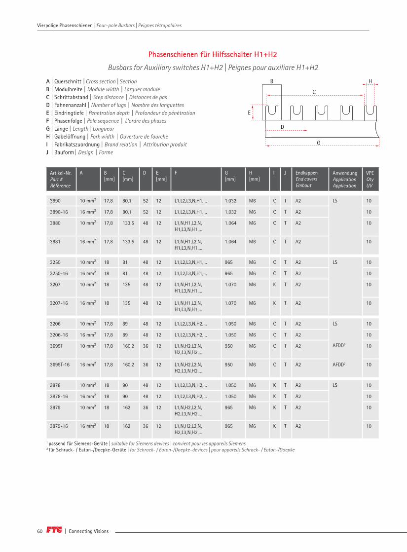
| Connecting Visions60
Vierpolige Phasenschienen | Four–pole Busbars | Peignes tétrapolaires
Artikel-Nr. Part # Référence
A B[mm]
C[mm]
D E[mm]
F G [mm]
H [mm]
I J Endkappen End coversEmbout
AnwendungApplicationApplication
VPE Qty UV
3890 10 mm² 17,8 80,1 52 12 L1,L2,L3,N,H1,… 1.032 M6 C T A2 LS 10
3890-16 16 mm² 17,8 80,1 52 12 L1,L2,L3,N,H1,… 1.032 M6 C T A2 10
3880 10 mm² 17,8 133,5 48 12 L1,N,H1,L2,N, H1,L3,N,H1,…
1.064 M6 C T A2 10
3881 16 mm² 17,8 133,5 48 12 L1,N,H1,L2,N, H1,L3,N,H1,…
1.064 M6 C T A2 10
3250 10 mm² 18 81 48 12 L1,L2,L3,N,H1,… 965 M6 C T A2 LS 10
3250-16 16 mm² 18 81 48 12 L1,L2,L3,N,H1,… 965 M6 C T A2 10
3207 10 mm² 18 135 48 12 L1,N,H1,L2,N, H1,L3,N,H1,…
1.070 M6 K T A2 10
3207-16 16 mm² 18 135 48 12 L1,N,H1,L2,N, H1,L3,N,H1,…
1.070 M6 K T A2 10
3206 10 mm² 17,8 89 48 12 L1,L2,L3,N,H2,… 1.050 M6 C T A2 LS
AFDD2
AFDD2
10
3206-16 16 mm² 17,8 89 48 12 L1,L2,L3,N,H2,… 1.050 M6 C T A2 10
3695T 10 mm² 17,8 160,2 36 12 L1,N,H2,L2,N, H2,L3,N,H2,…
950 M6 C T A2 10
3695T-16 16 mm² 17,8 160,2 36 12 L1,N,H2,L2,N, H2,L3,N,H2,…
950 M6 C T A2 10
3878 10 mm² 18 90 48 12 L1,L2,L3,N,H2,… 1.050 M6 K T A2 LS 10
3878-16 16 mm² 18 90 48 12 L1,L2,L3,N,H2,… 1.050 M6 K T A2 10
3879 10 mm² 18 162 36 12 L1,N,H2,L2,N, H2,L3,N,H2,…
965 M6 K T A2 10
3879-16 16 mm² 18 162 36 12 L1,N,H2,L2,N, H2,L3,N,H2,…
965 M6 K T A2 10
1 passend für Siemens-Geräte | suitable for Siemens devices | convient pour les appareils Siemens 2 für Schrack- / Eaton-/Doepke-Geräte | for Schrack- / Eaton-/Doepke-devices | pour appareils Schrack- / Eaton-/Doepke
Phasenschienen für Hilfsschalter H1+H2
Busbars for Auxiliary switches H1+H2 | Peignes pour auxiliare H1+H2
A | Querschnitt | Cross section | Section B | Modulbreite | Module width | Larguer module C | Schrittabstand | Step distance | Distances de pas D | Fahnenanzahl | Number of lugs | Nombre des languettesE | Eindringtiefe | Penetration depth | Profondeur de pénétrationF | Phasenfolge | Pole sequence | L'ordre des phases G | Länge | Length | Longueur H | Gabelöffnung | Fork width | Ouverture de fourcheI | Fabrikatszuordnung | Brand relation | Attribution produitJ | Bauform | Design | Forme
B
C
E
D
G
H

www.ftg-germany.de 61
Vierpolige Phasenschienen | Four–pole Busbars | Peignes tétrapolaires
Artikel-Nr. Part # Référence
A B[mm]
C[mm]
D E[mm]
F G [mm]
H [mm]
I J Endkappen End coversEmbout
AnwendungApplicationApplication
VPE Qty UV
3872 10 mm² 17,6 79,2 52 12 L1,L2,L3,N,H1,… 1020 4 A L A2 LS 10
3874 16 mm² 17,6 79,2 52 12 L1,L2,L3,N,H1,… 1020 4 A L A2 10
3872SPM 10 mm² 17,6 79,2 52 12 L1,L2,L3,N,H1,… 1020 4 B SPM A10 10
3874SPM 16 mm² 17,6 79,2 52 12 L1,L2,L3,N,H1,… 1020 4 B SPM A10 10
3877 10 mm² 17,6 79,2 48 12 L1,N,H1,L2,N, H1,L3,N,H1,…
1048 4 A L A2 10
3877-16 16 mm² 17,6 79,2 48 12 1048 4 A L A2 10
3877SPM 10 mm² 17,6 79,2 48 12 1048 4 B SPM A10 10
3877-16SPM 16 mm² 17,6 79,2 48 12 1048 4 B SPM A10 10
3892S-10 10 mm² 17,8 80,1 52 12 L1,L2,L3,N,H1,… 1032 4 C L A2 LS 10
3892S 16 mm² 17,8 80,1 52 12 L1,L2,L3,N,H1,… 1032 4 C L A2 10
3880S 10 mm² 17,8 133,5 48 12 L1,N,H1,L2,N, H1,L3,N,H1,…
1064 4 C L A2 10
3896 16 mm² 17,8 133,5 48 12 1064 4 C L A2 10
3250S 10 mm² 18 81 48 12 L1,L2,L3,N,H1,… 1020 4 K L A2 LS 10
3250S-16 16 mm² 18 81 48 12 L1,L2,L3,N,H1,… 1020 4 K L A2 10
3207S 10 mm² 18 135 48 12 L1,N,H1,L2,N, H1,L3,N,H1,…
1070 4 K L A2 10
3207S-16 16 mm² 18 135 48 12 1070 4 K L A2 10
3871SPM 10 mm² 17,6 88 48 12 L1,L2,L3,N,H2,… 1.050 4 B SPM A10 LS 10
3871-16SPM 16 mm² 17,6 88 48 12 L1,L2,L3,N,H2,… 1.050 4 B SPM A10 10
3873SPM 10 mm² 17,6 158,4 36 12 L1,N,H1,L2,N, H1,L3,N,H1,…
950 4 B SPM A10 10
3873-16SPM 16 mm² 17,6 158,4 36 12 950 4 B SPM A10 10
3206S 10 mm² 17,8 89 48 12 L1,L2,L3,N,H2,… 1.050 4 C L A2 LS
AFDD1
AFDD1
10
3206S-16 16 mm² 17,8 89 48 12 L1,L2,L3,N,H2,… 1.050 4 C L A2 10
3695S 10 mm² 17,8 160,2 36 12 L1,N,H1,L2,N, H1,L3,N,H1,…
950 4 C L A2 10
3695S-16 16 mm² 17,8 160,2 36 12 950 4 C L A2 10
3878S 10 mm² 18 90 48 12 L1,L2,L3,N,H2,… 1.050 4 K L A2 LS 10
3878S-16 16 mm² 18 90 48 12 L1,L2,L3,N,H2,… 1.050 4 K L A2 10
38795 10 mm² 18 162 36 12 L1,N,H1,L2,N, H1,L3,N,H1,…
965 4 K L A2 10
3879S-16 16 mm² 18 162 36 12 965 4 K L A2 10
3874-30 30 mm² 17,6 79,2 52 12 L1,L2,L3,N,H1,... 1.020 4 A L A6 10
A | Querschnitt | Cross section | Section B | Modulbreite | Module width | Larguer module C | Schrittabstand | Step distance | Distances de pas D | Fahnenanzahl | Number of lugs | Nombre des languettesE | Eindringtiefe | Penetration depth | Profondeur de pénétrationF | Phasenfolge | Pole sequence | L'ordre des phases G | Länge | Length | Longueur H | Stegbreite | Pin width | Pointe largeurI | Fabrikatszuordnung | Brand relation | Attribution produitJ | Bauform | Design | Forme
HB
E
D
G
C
4
H1/H2

| Connecting Visions62
Vierpolige Phasenschienen | Four–pole Busbars | Peignes tétrapolaires
Sonderlösungen
Special busbars | Barres spéciales
Artikel-Nr. Part # Référence
QuerschnittCross sectionSection
A[mm]
B[mm]
C D[mm]
E F [mm]
G [mm]
H Endkappen End coversEmbout
AnwendungApplicationApplication
VPE Qty UV
3592 10 mm² 17,6 105,6 12 12 L1,N,L2,N,L3,N,… 212 4 L A2 LS 10
3774-10 10 mm² 17,8 71,2 106,8
58 12 L1,L2,L3,N,L1,N,L2,N,L3,N,… 1.035 M6 T A2 FI - LS 10
3774 16 mm² 17,8 58 12 L1,L2,L3,N,L1,N,L2,N,L3,N,… 1.035 M6 T A2
3931 16 mm² 17,8 53,4 114 12 L1,N,L2,N,L3,N,… 1.016 3,8 L A2 1+N (Versatz 5,7) (Offset 5,7)
10
SKS 0753 16 mm² 26,5 79,5 18 12 L1,N,L2,N,L3,N,… 248 11,0 4,0
SKN A2 1+N (Versatz 18,2)(Offset 18,2)
10
SKS 0949 10 mm² 17,6 70,4 66,6 53,4
48 12 diverse | various | divers 540 11,0 4,0
SKN inkl. EK FI - 1+N 10
SKN 0015-16 16 mm² 17,8 53,4 112 12 L1,N,L2,N,L3,N,… 1.000 3,8 SKN A2 1+N (Versatz 9,2)(Offset 9,2)
10
SKN 0047-16 16 mm² 17,8 53,4 112 12 L1,N,L2,N,L3,N,… 1.000 3,8 SKN A2 1+N (Versatz 11,9)(Offset 11,9)
10
SKS 0172 16 mm² 17,8 79,5 74 12 N,L1,H1,N,L2,H1,N,L3,H1,… 992 3,4 SKN A2 1+N + H1 10
SKS 0173 16 mm² 17,8 133,8 44 12 N,L1,H3,N,L2,H3,N,L3,H3,… 972 3,4 SKN A2 1+N + H3 10
A | Querschnitt | Cross section | Section B | Modulbreite | Module width | Larguer module C | Schrittabstand | Step distance | Distances de pas D | Fahnenanzahl | Number of lugs | Nombre des languettesE | Eindringtiefe | Penetration depth | Profondeur de pénétrationF | Phasenfolge | Pole sequence | L'ordre des phases G | Länge | Length | Longueur H | Gabelöffnung | Fork width | Ouverture de fourche Stegbreite | Pin width | Pointe largeurI | Bauform | Design | Forme
Vierpolige Phasenschienen | Four–pole Busbars | Peignes tétrapolaires

www.ftg-germany.de 63
Vierpolige Phasenschienen | Four–pole Busbars | Peignes tétrapolaires
Sonderlösungen | Special busbars | Barres spéciales
4
SO
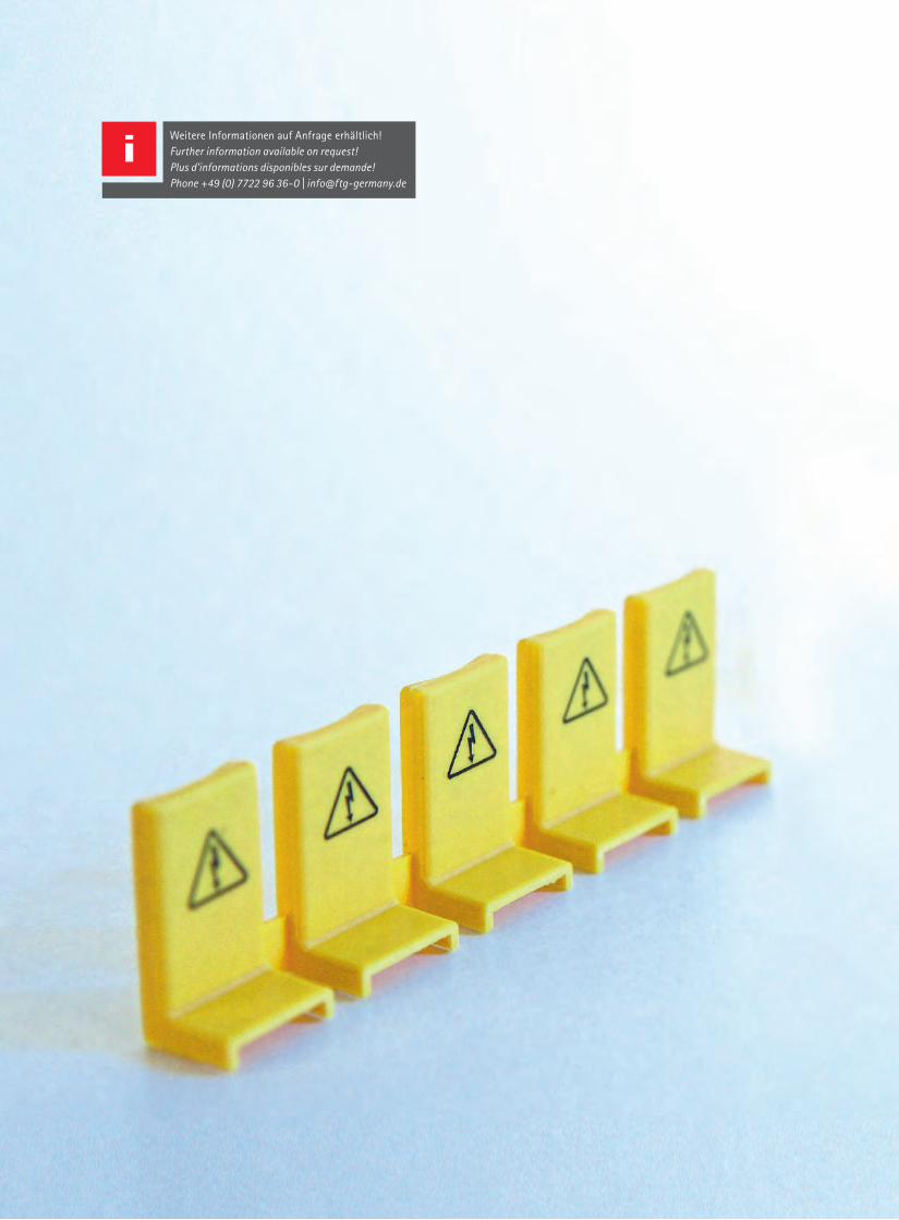
| Connecting Visions64
Weitere Informationen auf Anfrage erhältlich! Further information available on request!Plus d'informations disponibles sur demande!Phone +49 (0) 7722 96 36-0 | [email protected]
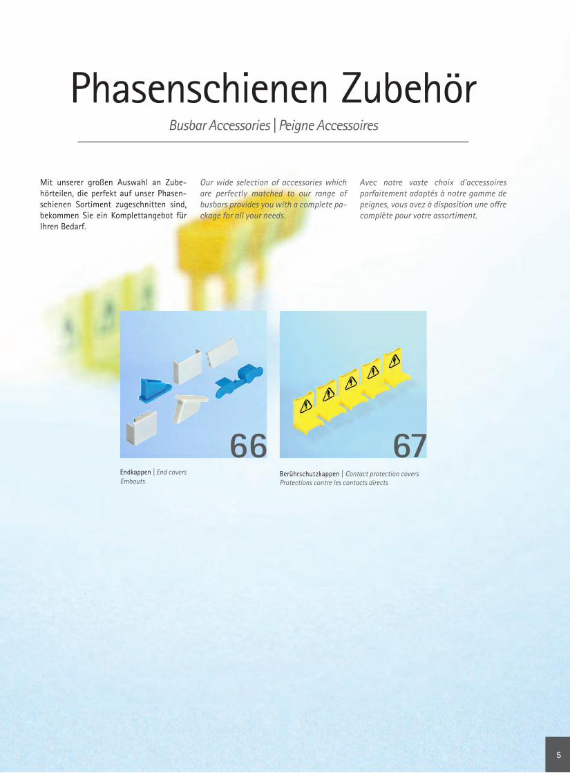
www.ftg-germany.de 65
Phasenschienen ZubehörBusbar Accessories | Peigne Accessoires
Mit unserer großen Auswahl an Zube-hörteilen, die perfekt auf unser Phasen-schienen Sortiment zugeschnitten sind, bekommen Sie ein Komplettangebot für Ihren Bedarf.
Our wide selection of accessories which are perfectly matched to our range of busbars provides you with a complete pa-ckage for all your needs.
Avec notre vaste choix d’accessoires parfaitement adaptés à notre gamme de peignes, vous avez à disposition une offre complète pour votre assortiment.
Berührschutzkappen | Contact protection coversProtections contre les contacts directs
67Endkappen | End covers Embouts
66
5

| Connecting Visions66
Phasenschienen Zubehör | Busbar Accessories | Peigne Accessoires
Zubehör
Accessories | Accessoires
Endkappen End covers | Embouts
Artikel-Nr. Part # Référence
QuerschnittCross sectionSection
BeschreibungDescriptionDescription
VPE Qty UV
A 11 10 | 16 | 20 mm² Endkappe für 1-polige PhasenschieneEnd cover for 1-pole busbar Embout pour peigne unipolaire
50
A 19 10 | 16 mm² Endkappe für 1-polige Phasenschiene mit FunktionsstegEnd cover for 1-pole busbar with function bridgeEmbout pour peigne unipolaire avec pointe fonctionnelle
25 Paare 25 Pairs 25 Paires
A 20 35 | 50 mm² Endkappe für 1-polige PhasenschieneEnd cover for 1-pole busbar Embout pour peigne unipolaire
50
A 35 10 mm² Endkappe für 1-polige PhasenschieneEnd cover for 1-pole busbarEmbout pour peigne unipolaire
25 Paare 25 Pairs 25 Paires
A 38 10 mm² Endkappe für 1-polige PhasenschieneEnd cover for 1-pole busbarEmbout pour peigne unipolaire
25 Paare 25 Pairs 25 Paires
A 39 10 | 16 | 20 mm² Endkappe für 1-polige PhasenschieneEnd cover for 1-pole busbarEmbout pour peigne unipolaire
50
A 61 35 | 50 mm² Endkappe für 1-polige PhasenschieneEnd cover for 1-pole busbar Embout pour peigne unipolaire
25 Paare 25 Pairs 25 Paires
A 69 bis 25 mm²up to 25 mm²jusqu'à 25 mm²
Endkappe für 1-polige PhasenschieneEnd cover for 1-pole busbarEmbout pour peigne unipolaire
25 Paare 25 Pairs 25 Paires
A 3 10 mm² Endkappe für 2-polige PhasenschieneEnd cover for 2-pole busbar Embout pour peigne bipolaire
50
A 1 10 | 16 mm² Endkappe für 3-polige PhasenschieneEnd cover for 3-pole busbar Embout pour peigne tripolaire
50
A 4 10 | 16 mm² Endkappe für 3-polige PhasenschieneEnd cover for 3-pole busbar Embout pour peigne tripolaire
50
A 5 10 | 16 mm² Endkappe für 3-polige Phasenschiene mit FunktionsstegEnd cover for 3-pole busbar with function bridgeEmbout pour peigne tripolaire avec pointe fonctionnelle
50
A 23 35 mm² Endkappe für 3-polige Phasenschiene, geschlossenEnd cover for 3-pole busbar, closed Embout pour peigne tripolaire, fermé
50
A 26 35 mm² Endkappe für 3-polige Phasenschiene ohne DeckelEnd cover for 3-pole busbar without coverEmbout pour peigne tripolaire sans couvercle
50
Phasenschienen Zubehör | Busbar Accessories | Peigne Accessoires
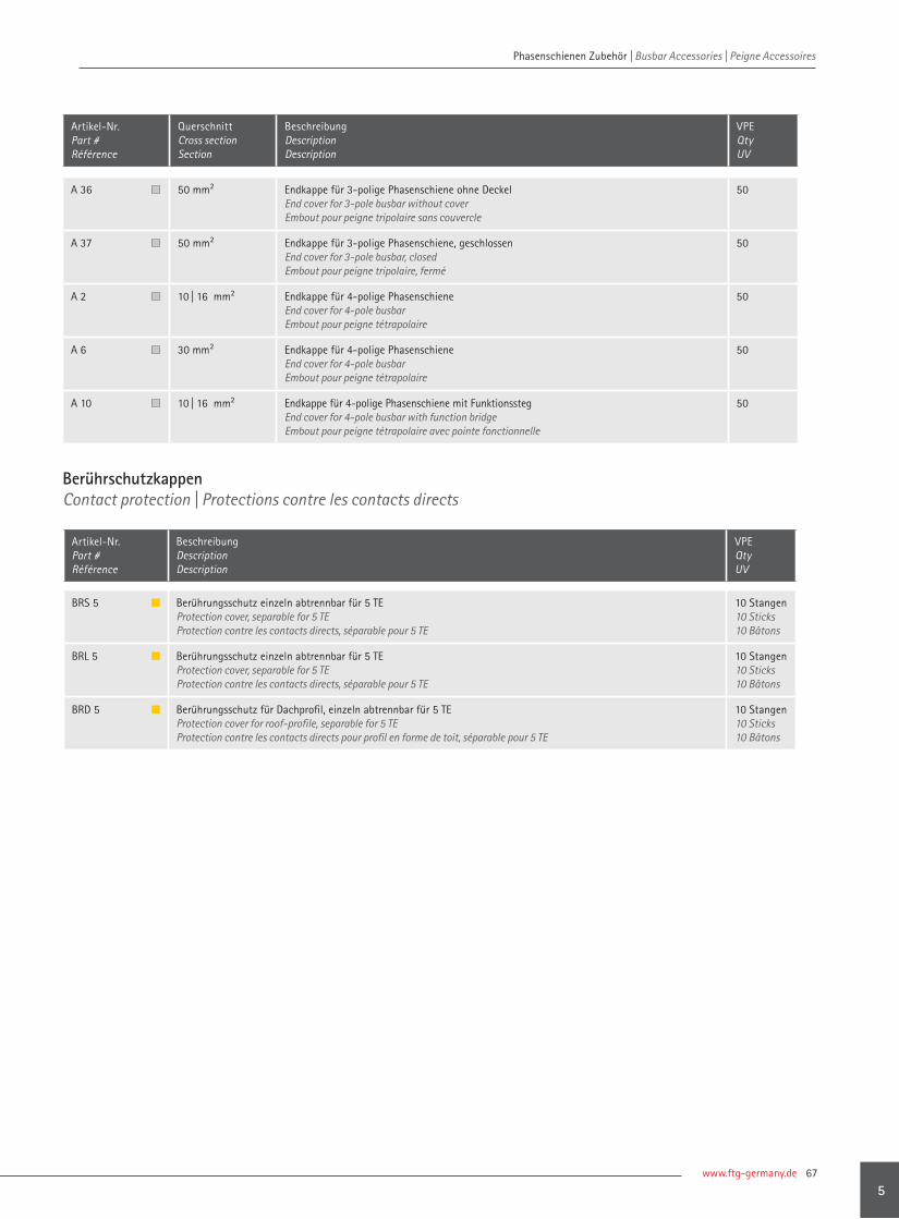
www.ftg-germany.de 67
Phasenschienen Zubehör | Busbar Accessories | Peigne Accessoires
A 36 50 mm² Endkappe für 3-polige Phasenschiene ohne DeckelEnd cover for 3-pole busbar without coverEmbout pour peigne tripolaire sans couvercle
50
A 37 50 mm² Endkappe für 3-polige Phasenschiene, geschlossenEnd cover for 3-pole busbar, closedEmbout pour peigne tripolaire, fermé
50
A 2 10 | 16 mm² Endkappe für 4-polige PhasenschieneEnd cover for 4-pole busbarEmbout pour peigne tétrapolaire
50
A 6 30 mm² Endkappe für 4-polige PhasenschieneEnd cover for 4-pole busbarEmbout pour peigne tétrapolaire
50
A 10 10 | 16 mm² Endkappe für 4-polige Phasenschiene mit FunktionsstegEnd cover for 4-pole busbar with function bridgeEmbout pour peigne tétrapolaire avec pointe fonctionnelle
50
BRS 5 Berührungsschutz einzeln abtrennbar für 5 TEProtection cover, separable for 5 TEProtection contre les contacts directs, séparable pour 5 TE
10 Stangen 10 Sticks 10 Bâtons
BRL 5 Berührungsschutz einzeln abtrennbar für 5 TEProtection cover, separable for 5 TEProtection contre les contacts directs, séparable pour 5 TE
10 Stangen 10 Sticks 10 Bâtons
BRD 5 Berührungsschutz für Dachprofil, einzeln abtrennbar für 5 TEProtection cover for roof-profile, separable for 5 TEProtection contre les contacts directs pour profil en forme de toit, séparable pour 5 TE
10 Stangen 10 Sticks 10 Bâtons
Artikel-Nr. Part # Référence
QuerschnittCross sectionSection
BeschreibungDescriptionDescription
VPE Qty UV
Berührschutzkappen Contact protection | Protections contre les contacts directs
Artikel-Nr. Part # Référence
BeschreibungDescriptionDescription
VPE Qty UV
5

| Connecting Visions68
Weitere Informationen auf Anfrage erhältlich! Further information available on request!Plus d'informations disponibles sur demande!Phone +49 (0) 7722 96 36-0 | [email protected]

www.ftg-germany.de 69
Phasenschienen für NH–TrennerBusbars for NH fuse switch disconnectors | Peignes pour interrupteurs-fusibles
FTG verfügt über Phasenschienen für NH–Sicherungslasttrennschalter der Baugrößen 00 und 000, z.B. für den Einsatz in Indus-trieanlagen und dem öffentlichen Strom-netz. Die Phasenschienen von FTG sind auf die herstellerspezifischen Eigenschaften der NH–Trenner abgestimmt. Aufgrund der Plat-zersparnisse im Vergleich zum herkömm- lichen 60 mm System ist der Verteiler-schrank mit der NH–Trennerschiene deut-lich übersichtlicher strukturiert.
FTG offers busbars for NH fuse switch disconnectors in sizes 00 and 000, e.g. for use in industrial plants and the pub-lic grid. FTG's busbars are matched to the manufacturer-specific properties of the NH disconnectors. Because of the space savings compared to traditional 60 mm system, the switch cabinet with the NH disconnector busbar is much more clearly laid out.
FTG dispose de peignes pour interrupteurs-fusibles des tailles 00 et 000, p : ex. pour l’utilisation dans les installations industriel-les et le réseau d’électricité public. Les peig-nes de FTG sont adaptés aux caractéristiques spécifiques des fabricants des interrupteurs-fusibles. En raison du gain de place par rap-port aux système conventionnel à 60 mm, l’armoire de distribution est structurée de manière nettement plus claire grâce aux peignes pour interrupteurs-fusibles.
PhasenschienenBusbars | Peignes
ZubehörAccessories | Accessoires
70 78
6

| Connecting Visions70
Phasenschienen für NH–Trenner | Busbars for NH fuse switch disconnectors | Peigne pour sectionneurs à fusibles
Phasenschienen für NH–TrennerBusbars for NH fuse switch disconnectors | Peigne pour sectionneurs à fusibles
A | Modulgröße | Module size | Taille du moduleB | Fabrikatszuordnung | Brand relation | Attribution produitC | Passende Einspeiseklemme | Suitable feed-in terminal | Borne correspondanteD | Länge | Length | Longueur E | Stegbreite | Pin width | Largeur pointeF | Eindringtiefe | Penetration depth | Profondeur de pénétration
Artikel-Nr. Part # Référence
QuerschnittCross sectionSection
Anzahl AnschlüsseNumber of lugsNombre languettes
TrennerDisconnectorsFusibles
A B C D [mm]
E [mm]
F [mm]
Endkappen End coversEmbout
VPE Qty UV
Schraubanschluss, Loch Ø 8.5 mm für Schraube M8 | Clamp screw, hole Ø 8,5 mm for M8 screw | Vis de serrage, trou Ø 8,5 mm pour vis M8
5272LD 35 mm² 6 2 NH00 1 806 | 056 210 17,5 29 inklusive included y. c.
5
5273LD 35 mm² 9 3 NH00 1 806 | 056 316 17,5 29 5
5274LD 35 mm² 12 4 NH00 1 806 | 056 422 17,5 29 5
5275LD 35 mm² 15 5 NH00 1 806 | 056 528 17,5 29 5
5270LD 35 mm² 27 pro Meter | per metre | à un mètre NH00 1 806 | 056 952 17,5 29 A23 5
7272LD 50 mm² 6 2 NH00 1 806 | 056 210 17,5 29 inklusive included y. c.
5
7273LD 50 mm² 9 3 NH00 1 806 | 056 316 17,5 29 5
7274LD 50 mm² 12 4 NH00 1 806 | 056 422 17,5 29 5
7275LD 50 mm² 15 5 NH00 1 806 | 056 528 17,5 29 5
7270LD 50 mm² 27 pro Meter | per metre | à un mètre NH00 1 806 | 056 952 17,5 29 A37 5
Käfigklemme | Cage clamp | Cage de serrage
5112SD 35 mm² 6 2 NH00 1 | 7 806 | 046 180 7,5 16 inklusive included y. c.
5
5113SD 35 mm² 9 3 NH00 1 | 7 806 | 046 267 7,5 16 5
5114SD 35 mm² 12 4 NH00 1 | 7 806 | 046 356 7,5 16 5
5115SD 35 mm² 15 5 NH00 1 | 7 806 | 046 447 7,5 16 5
5110SD 35 mm² 33 pro Meter | per metre | à un mètre NH00 1 | 7 806 | 046 978 7,5 16 A26 5
7112SD 50 mm² 6 2 NH00 1 | 7 806 | 046 180 7,5 16 inklusive included y. c.
5
7113SD 50 mm² 9 3 NH00 1 | 7 806 | 046 267 7,5 16 5
7114SD 50 mm² 12 4 NH00 1 | 7 806 | 046 356 7,5 16 5
7115SD 50 mm² 15 5 NH00 1 | 7 806 | 046 447 7,5 16 5
7110SD 50 mm² 33 pro Meter | per metre | à un mètre NH00 1 | 7 806 | 046 978 7,5 16 A36 5
1
2
2
1
16
7,5
25
89
29,3
8925
7,5
1629
,3
8,529
42
17,5
33
10610633
17,5
Ø8,5
2942
Phasenschienen für NH–Trenner | Busbars for NH fuse switch disconnectors | Peigne pour sectionneurs à fusibles

www.ftg-germany.de 71
Phasenschienen für NH–Trenner | Busbars for NH fuse switch disconnectors | Peigne pour sectionneurs à fusibles
A | Modulgröße | Module size | Taille du moduleB | Fabrikatszuordnung | Brand relation | Attribution produitC | Passende Einspeiseklemme | Suitable feed-in terminal | Borne correspondanteD | Länge | Length | Longueur E | Stegbreite | Pin width | Largeur pointeF | Eindringtiefe | Penetration depth | Profondeur de pénétration
Artikel-Nr. Part # Référence
QuerschnittCross sectionSection
Anzahl AnschlüsseNumber of lugsNombre languettes
TrennerDisconnectorsFusibles
A B C D [mm]
E [mm]
F [mm]
Endkappen End coversEmbout
VPE Qty UV
Schraubanschluss, Loch Ø 8.5 mm für Schraube M8 | Clamp screw, hole Ø 8,5 mm for M8 screw | Vis de serrage, trou Ø 8,5 mm pour vis M8
5092KD 35 mm² 6 2 NH00 2 806 | 049 214 16 21,1 inklusive included y. c.
5
5093KD 35 mm² 9 3 NH00 2 806 | 049 320 16 21,1 5
5094KD 35 mm² 12 4 NH00 2 806 | 049 426 16 21,1 5
5095KD 35 mm² 15 5 NH00 2 806 | 049 532 16 21,1 5
5090KD 35 mm² 27 pro Meter | per metre | à un mètre NH00 2 806 | 049 956 16 21,1 A23 5
7092KD 50 mm² 6 2 NH00 2 806 | 049 214 16 21,1 inklusive included y. c.
5
7093KD 50 mm² 9 3 NH00 2 806 | 049 320 16 21,1 5
7094KD 50 mm² 12 4 NH00 2 806 | 049 426 16 21,1 5
7095KD 50 mm² 15 5 NH00 2 806 | 049 532 16 21,1 5
7090KD 50 mm² 27 pro Meter | per metre | à un mètre NH00 2 806 | 049 956 16 21,1 A37 5
Schraubanschluss, Loch Ø 8.5 mm für Schraube M8 | Clamp screw, hole Ø 8,5 mm for M8 screw | Vis de serrage, trou Ø 8,5 mm pour vis M8
5172LD 35 mm² 6 2 NH000 4 806 | 047 210 17,5 22,8 inklusive included y. c.
5
5173LD 35 mm² 9 3 NH000 4 806 | 047 316 17,5 22,8 5
5174LD 35 mm² 12 4 NH000 4 806 | 047 422 17,5 22,8 5
5175LD 35 mm² 15 5 NH000 4 806 | 047 528 17,5 22,8 5
5170LD 35 mm² 27 pro Meter | per metre | à un mètre NH000 4 806 | 047 952 17,5 22,8 A23 5
7172LD 50 mm² 6 2 NH000 4 806 | 047 210 17,5 22,8 inklusive included y. c.
5
7173LD 50 mm² 9 3 NH000 4 806 | 047 316 17,5 22,8 5
7174LD 50 mm² 12 4 NH000 4 806 | 047 422 17,5 22,8 5
7175LD 50 mm² 15 5 NH000 4 806 | 047 528 17,5 22,8 5
7170LD 50 mm² 27 pro Meter | per metre | à un mètre NH000 4 806 | 047 952 17,5 22,8 A37 5
3
4
29,6
16
8,5
33
107
21,1
29,6
17,5
8,5
33
106
21,1
3
4
107
106
21,1
29,6
29,6 22,8
17,5
33
33
16
Ø8,5
Ø8,5
6

| Connecting Visions72
Phasenschienen für NH–Trenner | Busbars for NH fuse switch disconnectors | Peigne pour sectionneurs à fusibles
A | Modulgröße | Module size | Taille du moduleB | Fabrikatszuordnung | Brand relation | Attribution produitC | Passende Einspeiseklemme | Suitable feed-in terminal | Borne correspondanteD | Länge | Length | Longueur E | Stegbreite | Pin width | Largeur pointeF | Eindringtiefe | Penetration depth | Profondeur de pénétration
Artikel-Nr. Part # Référence
QuerschnittCross sectionSection
Anzahl AnschlüsseNumber of lugsNombre languettes
TrennerDisconnectorsFusibles
A B C D [mm]
E [mm]
F [mm]
Endkappen End coversEmbout
VPE Qty UV
Schraubanschluss, Loch Ø 8.5 mm für Schraube M8 | Clamp screw, hole Ø 8,5 mm for M8 screw | Vis de serrage, trou Ø 8,5 mm pour vis M8
5002LD 35 mm² 6 2 NH00 4 | 8 | 14 | 16 806 | 047 210 17,5 22,8 inklusive included y. c.
5
5003LD 35 mm² 9 3 NH00 4 | 8 | 14 | 16 806 | 047 316 17,5 22,8 5
5004LD 35 mm² 12 4 NH00 4 | 8 | 14 | 16 806 | 047 422 17,5 22,8 5
5005LD 35 mm² 15 5 NH00 4 | 8 | 14 | 16 806 | 047 528 17,5 22,8 5
5000LD 35 mm² 27 pro Meter | per metre | à un mètre NH00 4 | 8 | 14 | 16 806 | 047 952 17,5 22,8 A23 5
7002LD 50 mm² 6 2 NH00 4 | 8 | 14 | 16 806 | 047 210 17,5 22,8 inklusive included y. c.
5
7003LD 50 mm² 9 3 NH00 4 | 8 | 14 | 16 806 | 047 316 17,5 22,8 5
7004LD 50 mm² 12 4 NH00 4 | 8 | 14 | 16 806 | 047 422 17,5 22,8 5
7005LD 50 mm² 15 5 NH00 4 | 8 | 14 | 16 806 | 047 528 17,5 22,8 5
7000LD 50 mm² 27 pro Meter | per metre | à un mètre NH00 4 | 8 | 14 | 16 806 | 047 952 17,5 22,8 A37 5
Käfigklemme | Cage clamp | Cage de serrage
5152SD 35 mm² 6 2 NH000 4 | 9 | 10 | 11 806 | 046 180 8 16 inklusive included y. c.
5
5153SD 35 mm² 9 3 NH000 4 | 9 | 10 | 11 806 | 046 267 8 16 5
5154SD 35 mm² 12 4 NH000 4 | 9 | 10 | 11 806 | 046 356 8 16 5
5155SD 35 mm² 15 5 NH000 4 | 9 | 10 | 11 806 | 046 447 8 16 5
5150SD 35 mm² 33 pro Meter | per metre | à un mètre NH000 4 | 9 | 10 | 11 806 | 046 978 8 16 A26 5
7152SD 50 mm² 6 2 NH000 4 | 9 | 10 | 11 806 | 046 180 8 16 inklusive included y. c.
5
7153SD 50 mm² 9 3 NH000 4 | 9 | 10 | 11 806 | 046 267 8 16 5
7154SD 50 mm² 12 4 NH000 4 | 9 | 10 | 11 806 | 046 356 8 16 5
7155SD 50 mm² 15 5 NH000 4 | 9 | 10 | 11 806 | 046 447 8 16 5
7150SD 50 mm² 33 pro Meter | per metre | à un mètre NH000 4 | 9 | 10 | 11 806 | 046 978 8 16 A36 5
1
2
8,5
17,5
33
106
22,8
31,3
8
16
26,5
25
89
2
1
106
8925
8
1626
,5
3317,5
22,8
31,3 Ø8,5
Phasenschienen für NH–Trenner | Busbars for NH fuse switch disconnectors | Peigne pour sectionneurs à fusibles

www.ftg-germany.de 73
Phasenschienen für NH–Trenner | Busbars for NH fuse switch disconnectors | Peigne pour sectionneurs à fusibles
3
4
A | Modulgröße | Module size | Taille du moduleB | Fabrikatszuordnung | Brand relation | Attribution produitC | Passende Einspeiseklemme | Suitable feed-in terminal | Borne correspondanteD | Länge | Length | Longueur E | Stegbreite | Pin width | Largeur pointeF | Eindringtiefe | Penetration depth | Profondeur de pénétration
Artikel-Nr. Part # Référence
QuerschnittCross sectionSection
Anzahl AnschlüsseNumber of lugsNombre languettes
TrennerDisconnectorsFusibles
A B C D [mm]
E [mm]
F [mm]
Endkappen End coversEmbout
VPE Qty UV
Käfigklemme | Cage clamp | Cage de serrage
5232S 35 mm² 6 2 NH000 5 806 | 044 110 10 23,3 inklusive included y. c.
5
5233S 35 mm² 9 3 NH000 5 806 | 044 164 10 23,3 5
5234S 35 mm² 12 4 NH000 5 806 | 044 214 10 23,3 5
5235S 35 mm² 15 5 NH000 5 806 | 044 269 10 23,3 5
5230S 35 mm² 57 pro Meter | per metre | à un mètre NH000 5 806 | 044 988 10 23,3 A26 5
7232S 50 mm² 6 2 NH000 5 806 | 044 110 10 23,3 inklusive included y. c.
5
7233S 50 mm² 9 3 NH000 5 806 | 044 164 10 23,3 5
7234S 50 mm² 12 4 NH000 5 806 | 044 214 10 23,3 5
7235S 50 mm² 15 5 NH000 5 806 | 044 269 10 23,3 5
7230S 50 mm² 57 pro Meter | per metre | à un mètre NH000 5 806 | 044 988 10 23,3 A36 5
Schraubanschluss, Loch Ø 8.5 mm für Schraube M8 | Clamp screw, hole Ø 8,5 mm for M8 screw | Vis de serrage, trou Ø 8,5 mm pour vis M8
5242LD 35 mm² 6 2 NH00 5 | 10 | 11 806 | 056 212 17,5 20,3 inklusive included y. c.
5
5243LD 35 mm² 9 3 NH00 5 | 10 | 11 806 | 056 318 17,5 20,3 5
5244LD 35 mm² 12 4 NH00 5 | 10 | 11 806 | 056 424 17,5 20,3 5
5245LD 35 mm² 15 5 NH00 5 | 10 | 11 806 | 056 530 17,5 20,3 5
5240LD 35 mm² 27 pro Meter | per metre | à un mètre NH00 5 | 10 | 11 806 | 056 952 17,5 20,3 A23 5
7242LD 50 mm² 6 2 NH00 5 | 10 | 11 806 | 056 212 17,5 20,3 inklusive included y. c.
5
7243LD 50 mm² 9 3 NH00 5 | 10 | 11 806 | 056 318 17,5 20,3 5
7244LD 50 mm² 12 4 NH00 5 | 10 | 11 806 | 056 424 17,5 20,3 5
7245LD 50 mm² 15 5 NH00 5 | 10 | 11 806 | 056 530 17,5 20,3 5
7240LD 50 mm² 27 pro Meter | per metre | à un mètre NH00 5 | 10 | 11 806 | 056 952 17,5 20,3 A37 5
10
23,3
15,5
53,4
33
106
17,5
20,3
49,3
8,5
3
4
53,4
10633
17,5
20,3
49,3
15,510
23,3
Ø8,5
3
4
6
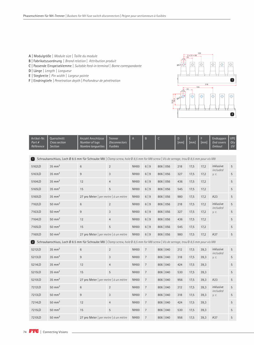
| Connecting Visions74
Phasenschienen für NH–Trenner | Busbars for NH fuse switch disconnectors | Peigne pour sectionneurs à fusibles Phasenschienen für NH–Trenner | Busbars for NH fuse switch disconnectors | Peigne pour sectionneurs à fusibles
A | Modulgröße | Module size | Taille du moduleB | Fabrikatszuordnung | Brand relation | Attribution produitC | Passende Einspeiseklemme | Suitable feed-in terminal | Borne correspondanteD | Länge | Length | Longueur E | Stegbreite | Pin width | Largeur pointeF | Eindringtiefe | Penetration depth | Profondeur de pénétration
Artikel-Nr. Part # Référence
QuerschnittCross sectionSection
Anzahl AnschlüsseNumber of lugsNombre languettes
TrennerDisconnectorsFusibles
A B C D [mm]
E [mm]
F [mm]
Endkappen End coversEmbout
VPE Qty UV
Schraubanschluss, Loch Ø 8.5 mm für Schraube M8 | Clamp screw, hole Ø 8,5 mm for M8 screw | Vis de serrage, trou Ø 8,5 mm pour vis M8
5162LD 35 mm² 6 2 NH00 6 | 9 806 | 056 218 17,5 17,2 inklusive included y. c.
5
5163LD 35 mm² 9 3 NH00 6 | 9 806 | 056 327 17,5 17,2 5
5164LD 35 mm² 12 4 NH00 6 | 9 806 | 056 436 17,5 17,2 5
5165LD 35 mm² 15 5 NH00 6 | 9 806 | 056 545 17,5 17,2 5
5160LD 35 mm² 27 pro Meter | per metre | à un mètre NH00 6 | 9 806 | 056 980 17,5 17,2 A23 5
7162LD 50 mm² 6 2 NH00 6 | 9 806 | 056 218 17,5 17,2 inklusive included y. c.
5
7163LD 50 mm² 9 3 NH00 6 | 9 806 | 056 327 17,5 17,2 5
7164LD 50 mm² 12 4 NH00 6 | 9 806 | 056 436 17,5 17,2 5
7165LD 50 mm² 15 5 NH00 6 | 9 806 | 056 545 17,5 17,2 5
7160LD 50 mm² 27 pro Meter | per metre | à un mètre NH00 6 | 9 806 | 056 980 17,5 17,2 A37 5
Schraubanschluss, Loch Ø 8.5 mm für Schraube M8 | Clamp screw, hole Ø 8,5 mm for M8 screw | Vis de serrage, trou Ø 8,5 mm pour vis M8
5212LD 35 mm² 6 2 NH00 7 806 | 040 212 17,5 39,3 inklusive included y. c.
5
5213LD 35 mm² 9 3 NH00 7 806 | 040 318 17,5 39,3 5
5214LD 35 mm² 12 4 NH00 7 806 | 040 424 17,5 39,3 5
5215LD 35 mm² 15 5 NH00 7 806 | 040 530 17,5 39,3 5
5210LD 35 mm² 27 pro Meter | per metre | à un mètre NH00 7 806 | 040 956 17,5 39,3 A23 5
7212LD 50 mm² 6 2 NH00 7 806 | 040 212 17,5 39,3 inklusive included y. c.
5
7213LD 50 mm² 9 3 NH00 7 806 | 040 318 17,5 39,3 5
7214LD 50 mm² 12 4 NH00 7 806 | 040 424 17,5 39,3 5
7215LD 50 mm² 15 5 NH00 7 806 | 040 530 17,5 39,3 5
7210LD 50 mm² 27 pro Meter | per metre | à un mètre NH00 7 806 | 040 956 17,5 39,3 A37 5
1
2
39,3
8,5
17,5
33
106
52,6
2
10633
17,5
39,3
52,6
Ø8,5
109
218
332 x 33 = 66
1
Ø8,5
17,5

www.ftg-germany.de 75
Phasenschienen für NH–Trenner | Busbars for NH fuse switch disconnectors | Peigne pour sectionneurs à fusibles
3
4
A | Modulgröße | Module size | Taille du moduleB | Fabrikatszuordnung | Brand relation | Attribution produitC | Passende Einspeiseklemme | Suitable feed-in terminal | Borne correspondanteD | Länge | Length | Longueur E | Stegbreite | Pin width | Largeur pointeF | Eindringtiefe | Penetration depth | Profondeur de pénétration
Artikel-Nr. Part # Référence
QuerschnittCross sectionSection
Anzahl AnschlüsseNumber of lugsNombre languettes
TrennerDisconnectorsFusibles
A B C D [mm]
E [mm]
F [mm]
Endkappen End coversEmbout
VPE Qty UV
Schraubanschluss, Loch Ø 8.5 mm für Schraube M8 | Clamp screw, hole Ø 8,5 mm for M8 screw | Vis de serrage, trou Ø 8,5 mm pour vis M8
5282LD 35 mm² 6 2 NH00 8 | 15 806 | 056 216 17,5 23,8 inklusive included y. c.
5
5283LD 35 mm² 9 3 NH00 8 | 15 806 | 056 318 17,5 23,8 5
5284LD 35 mm² 12 4 NH00 8 | 15 806 | 056 428 17,5 23,8 5
5285LD 35 mm² 15 5 NH00 8 | 15 806 | 056 534 17,5 23,8 5
5280LD 35 mm² 27 pro Meter | per metre | à un mètre NH00 8 | 15 806 | 056 956 17,5 23,8 A23 5
7282LD 50 mm² 6 2 NH00 8 | 15 806 | 056 216 17,5 23,8 inklusive included y. c.
5
7283LD 50 mm² 9 3 NH00 8 | 15 806 | 056 318 17,5 23,8 5
7284LD 50 mm² 12 4 NH00 8 | 15 806 | 056 428 17,5 23,8 5
7285LD 50 mm² 15 5 NH00 8 | 15 806 | 056 534 17,5 23,8 5
7280LD 50 mm² 27 pro Meter | per metre | à un mètre NH00 8 | 15 806 | 056 956 17,5 23,8 A37 5
Käfigklemme | Cage clamp | Cage de serrage
5082SD 35 mm² 6 2 NH000 11 806 | 057 212 8,5 24,4 inklusive included y. c.
5
5083SD 35 mm² 9 3 NH000 11 806 | 057 318 8,5 24,4 5
5084SD 35 mm² 12 4 NH000 11 806 | 057 424 8,5 24,4 5
5085SD 35 mm² 15 5 NH000 11 806 | 057 530 8,5 24,4 5
5080SD 35 mm² 27 pro Meter | per metre | à un mètre NH000 11 806 | 057 952 8,5 24,4 A23 5
7082SD 50 mm² 6 2 NH000 11 806 | 057 212 8,5 24,4 inklusive included y. c.
5
7083SD 50 mm² 9 3 NH000 11 806 | 057 318 8,5 24,4 5
7084SD 50 mm² 12 4 NH000 11 806 | 057 424 8,5 24,4 5
7085SD 50 mm² 15 5 NH000 11 806 | 057 530 8,5 24,4 5
7080SD 50 mm² 27 pro Meter | per metre | à un mètre NH000 11 806 | 057 952 8,5 24,4 A37 5
17,5
23,8 8,5
106
33
52,8
37,4
24,4
8,5
33
107,5
3
4
10633
17,5
23,8
52,8
Ø8,5
107,533
8,5
24,4
37,4
3
4
6

| Connecting Visions76
Phasenschienen für NH–Trenner | Busbars for NH fuse switch disconnectors | Peigne pour sectionneurs à fusibles
A | Modulgröße | Module size | Taille du moduleB | Fabrikatszuordnung | Brand relation | Attribution produitC | Passende Einspeiseklemme | Suitable feed-in terminal | Borne correspondanteD | Länge | Length | Longueur E | Stegbreite | Pin width | Largeur pointeF | Eindringtiefe | Penetration depth | Profondeur de pénétration
Artikel-Nr. Part # Référence
QuerschnittCross sectionSection
Anzahl AnschlüsseNumber of lugsNombre languettes
TrennerDisconnectorsFusibles
A B C D [mm]
E [mm]
F [mm]
Endkappen End coversEmbout
VPE Qty UV
Schraubanschluss, Loch Ø 8.5 mm für Schraube M8 | Clamp screw, hole Ø 8,5 mm for M8 screw | Vis de serrage, trou Ø 8,5 mm pour vis M8
5142K 35 mm² 6 2 NH00 12 806 | 040 212 12,4 24,2 inklusive included y. c.
5
5143K 35 mm² 9 3 NH00 12 806 | 040 318 12,4 24,2 5
5144K 35 mm² 12 4 NH00 12 806 | 040 424 12,4 24,2 5
5145K 35 mm² 15 5 NH00 12 806 | 040 530 12,4 24,2 5
5140K 35 mm² 27 pro Meter | per metre | à un mètre NH00 12 806 | 040 952 12,4 24,2 A26 5
7142K 50 mm² 6 2 NH00 12 806 | 040 212 12,4 24,2 inklusive included y. c.
5
7143K 50 mm² 9 3 NH00 12 806 | 040 318 12,4 24,2 5
7144K 50 mm² 12 4 NH00 12 806 | 040 424 12,4 24,2 5
7145K 50 mm² 15 5 NH00 12 806 | 040 530 12,4 24,2 5
7140K 50 mm² 27 pro Meter | per metre | à un mètre NH00 12 806 | 040 952 12,4 24,2 A36 5
Käfigklemme | Cage clamp | Cage de serrage
5102S 35 mm² 6 2 NH000 12 806 | 046 180 10 16,8 inklusive included y. c.
5
5103S 35 mm² 9 3 NH000 12 806 | 046 270 10 16,8 5
5104S 35 mm² 12 4 NH000 12 806 | 046 360 10 16,8 5
5105S 35 mm² 15 5 NH000 12 806 | 046 450 10 16,8 5
5100S 35 mm² 33 pro Meter | per metre | à un mètre NH000 12 806 | 046 990 10 16,8 A26 5
7102S 50 mm² 6 2 NH000 12 806 | 046 180 10 16,8 inklusive included y. c.
5
7103S 50 mm² 9 3 NH000 12 806 | 046 270 10 16,8 5
7104S 50 mm² 12 4 NH000 12 806 | 046 360 10 16,8 5
7105S 50 mm² 15 5 NH000 12 806 | 046 450 10 16,8 5
7100S 50 mm² 33 pro Meter | per metre | à un mètre NH000 12 806 | 046 990 10 16,8 A36 5
1
2
8,5
12,4
33
105
23,4
38,1
10
25
89
16,8
26,8
2
1
105
8925
10
16,8
26,8
3312,4
24,2
38,1
Ø8,5
Phasenschienen für NH–Trenner | Busbars for NH fuse switch disconnectors | Peigne pour sectionneurs à fusibles

www.ftg-germany.de 77
Phasenschienen für NH–Trenner | Busbars for NH fuse switch disconnectors | Peigne pour sectionneurs à fusibles
3
4
A | Modulgröße | Module size | Taille du moduleB | Fabrikatszuordnung | Brand relation | Attribution produitC | Passende Einspeiseklemme | Suitable feed-in terminal | Borne correspondanteD | Länge | Length | Longueur E | Stegbreite | Pin width | Largeur pointeF | Eindringtiefe | Penetration depth | Profondeur de pénétration
Artikel-Nr. Part # Référence
QuerschnittCross sectionSection
Anzahl AnschlüsseNumber of lugsNombre languettes
TrennerDisconnectorsFusibles
A B C D [mm]
E [mm]
F [mm]
Endkappen End coversEmbout
VPE Qty UV
Schraubanschluss, Loch Ø 8.5 mm für Schraube M8 | Clamp screw, hole Ø 8,5 mm for M8 screw | Vis de serrage, trou Ø 8,5 mm pour vis M8
5292LD 35 mm² 6 2 NH000 14 806 | 066 180 17,5 19,8 inklusive included y. c.
5
5293LD 35 mm² 9 3 NH000 14 806 | 066 267 17,5 19,8 5
5294LD 35 mm² 12 4 NH000 14 806 | 066 356 17,5 19,8 5
5295LD 35 mm² 15 5 NH000 14 806 | 066 447 17,5 19,8 5
5290LD 35 mm² 27 pro Meter | per metre | à un mètre NH000 14 806 | 066 800 17,5 19,8 A23 5
7292LD 50 mm² 6 2 NH000 14 806 | 066 180 17,5 19,8 inklusive included y. c.
5
7293LD 50 mm² 9 3 NH000 14 806 | 066 267 17,5 19,8 5
7294LD 50 mm² 12 4 NH000 14 806 | 066 356 17,5 19,8 5
7295LD 50 mm² 15 5 NH000 14 806 | 066 447 17,5 19,8 5
7290LD 50 mm² 27 pro Meter | per metre | à un mètre NH000 14 806 | 066 800 17,5 19,8 A37 5
Käfigklemme | Cage clamp | Cage de serrage
5152SD–OK 35 mm² 6 2 NH000 15 806 | 072 180 8 | 16 29 inklusive included y. c.
5
5153SD–OK 35 mm² 9 3 NH000 15 806 | 072 267 8 | 16 29 5
5154SD–OK 35 mm² 12 4 NH000 15 806 | 072 356 8 | 16 29 5
5155SD–OK 35 mm² 15 5 NH000 15 806 | 072 445 8 | 16 29 5
5150SD–OK 35 mm² 27 pro Meter | per metre | à un mètre NH000 15 806 | 072 800 8 | 16 29 A23 5
7152SD-OK 50 mm² 6 2 NH000 15 806 | 072 180 8 | 16 29 inklusive included y. c.
5
7153SD-OK 50 mm² 9 3 NH000 15 806 | 072 267 8 | 16 29 5
7154SD-OK 50 mm² 12 4 NH000 15 806 | 072 356 8 | 16 29 5
7155SD-OK 50 mm² 15 5 NH000 15 806 | 072 445 8 | 16 29 5
7150SD-OK 50 mm² 27 pro Meter | per metre | à un mètre NH000 15 806 | 072 800 8 | 16 29 A37 5
17,5
25
89
8,519,8
35,3
8 16
16
29,5
26,5
89
3
4
89
8926,5
168
1629
2517,5
19,8
35,3 Ø8,5
3
4
6

| Connecting Visions78
Zubehör
Accessories | Accessories
1 2 3
A | Modulgröße | Module size | Taille du module B | Anschlussart | Connection type | Type de connexion C | Breite | Width | Largeur D | Länge | Length | LongueurE | Anschlussschraube | Connection screw | Vis de connexion
250 A, AC 690 V / DC 1.000 V, Zuführung: längs | Feed in: lengthwise | Amenée: longitudinale
806/057* hoher Dom | long shield | écran long
niederer Dom | short shield | écran court
ohne Dom | without shield | sans écran
NH00 Käfigklemme Cage clamp Bornes à cage
10 23 SW6 25 – 95 mm² 25 – 70 mm² 9
806/041* NH00 10 23 SW6 25 – 95 mm² 25 – 70 mm² 9
806/044* NH000 10 23 SW6 25 – 95 mm² 25 – 70 mm² 9
806/046* NH000 8 23 SW6 25 – 95 mm² 25 – 70 mm² 9
806/047* NH00 17,5 23 SW6 25 – 95 mm² 25 – 70 mm² 9
806/072* NH000 17,5 23 SW6 25 – 95 mm² 25 – 70 mm² 9
806/056* NH00 Ø 8,5Klemmschraube Clamp screw Vis de serrage
17,5 23 SW6 25 – 95 mm² 25 – 70 mm² 9
806/040* NH00 17,5 23 SW6 25 – 95 mm² 25 – 70 mm² 9
806/066* NH000 16 23 SW6 25 – 95 mm² 25 – 70 mm² 9
806/049* NH00 16 23 SW6 25 – 95 mm² 25 – 70 mm² 9
Einspeiseklemme, für Kupfer– oder Aluminiumleiter 95 mm²Feed-in terminal, for copper or aluminium 95 mm² | Bornes de puissance, pour conducteurs cuivre ou aluminium 95 mm²
Artikel-Nr. Part # Référence
Domarten Type of shield Type de court
A B C [mm] D [mm] E ø VPE Qty UV
* Bitte fügen Sie "OD" für ohne Dom oder "ND" für niederer Dom der Artikel-Nr. an, zum Beispiel 806/040ND * Please add "OD" for without shield or "ND" for short shield to the article no., for example 806/040ND* Veuillez ajouter "ND" pour écran court ou "OD" pour sans écran au Référence, par exemple 806/040ND
1
2
3
Phasenschienen für NH–Trenner | Busbars for NH fuse switch disconnectors | Peigne pour sectionneurs à fusibles Phasenschienen für NH–Trenner | Busbars for NH fuse switch disconnectors | Peigne pour sectionneurs à fusibles
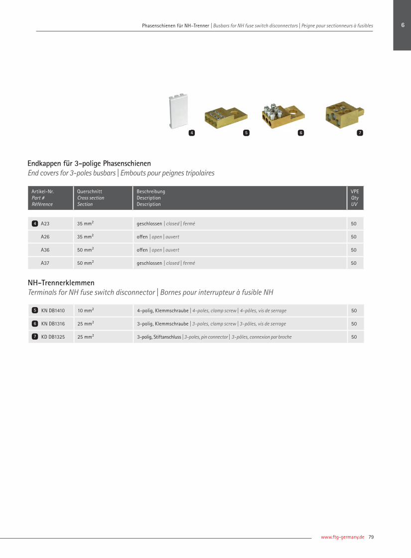
www.ftg-germany.de 79
Phasenschienen für NH–Trenner | Busbars for NH fuse switch disconnectors | Peigne pour sectionneurs à fusibles Phasenschienen für NH–Trenner | Busbars for NH fuse switch disconnectors | Peigne pour sectionneurs à fusibles
Endkappen für 3-polige PhasenschienenEnd covers for 3-poles busbars | Embouts pour peignes tripolaires
Artikel-Nr. Part # Référence
QuerschnittCross sectionSection
BeschreibungDescriptionDescription
VPE Qty UV
A23 35 mm² geschlossen | closed | fermé 50
A26 35 mm² offen | open | ouvert 50
A36 50 mm² offen | open | ouvert 50
A37 50 mm² geschlossen | closed | fermé 50
NH-TrennerklemmenTerminals for NH fuse switch disconnector | Bornes pour interrupteur à fusible NH
KN DB1410 10 mm² 4-polig, Klemmschraube | 4-poles, clamp screw | 4-pôles, vis de serrage 50
KN DB1316 25 mm² 3-polig, Klemmschraube | 3-poles, clamp screw | 3-pôles, vis de serrage 50
KD DB1325 25 mm² 3-polig, Stiftanschluss | 3-poles, pin connector | 3-pôles, connexion par broche 50
4
6
5
7
74 64 5
6
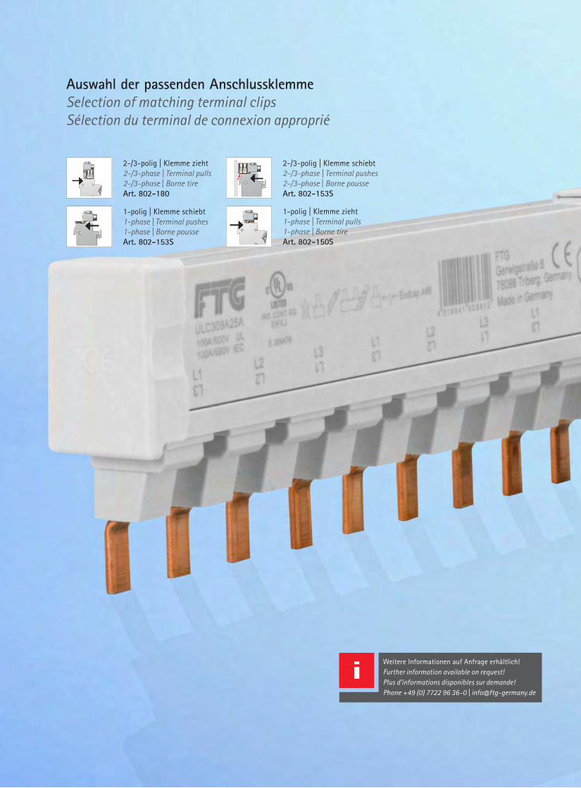
| Connecting Visions80
Weitere Informationen auf Anfrage erhältlich! Further information available on request!Plus d'informations disponibles sur demande!Phone +49 (0) 7722 96 36-0 | [email protected]
Auswahl der passenden AnschlussklemmeSelection of matching terminal clipsSélection du terminal de connexion approprié
2-/3-polig | Klemme zieht2-/3-phase | Terminal pulls2-/3-phase | Borne tireArt. 802-180
Blatt/ page
Oberflaechenbehandlungsurface treatment
Allgemeintoleranzgeneral tolerances
StandState
ÄnderungRevision
DatumDate
NameName
Werkstoffbezeichnungmaterial designation
Artikel- Nr.articel- no.
Volumen [mm³]volume [mm ³]
Oberflächen [mm²] / Querschnittsfläche (mm²)surface [mm ²] / cross section [mm²]
Gewicht [g]weight [g]
CAD errechneter Wert / CAD calculated value
-
FTG Göhringer GmbH Teile- Nr.: Part No.:
Zeichnungs- Nr.:Drawing no.:
E11.613- 003- 01
Teile- Benennung:Part name.:
MontageplanDatumDateBearb.Autor
31.08.2011A.Reis
Gepr.CheckedNormStandard
Maßstab:scale:
2 A2
1:1
D
G
F
E
1 2 3 4 5 6 7 8
D
E
F
G
H
1 5 6 7
Wei
terg
abe
sowi
e Ve
rvie
lfae
ltig
ung,
Ver
arbe
itung
und
/ode
r Be
arbe
itung
dies
es D
okum
ente
s, V
erwe
rtun
g un
d Mi
ttei
lung
sei
nes
Inha
ltes
sin
dve
rbot
en,
sowe
it ni
cht
ausd
ruec
klich
ges
tatt
et. Z
uwid
erha
ndlu
ngen
verp
flich
ten
zu S
chad
ener
satz
. Alle
Rec
hte
für
den
Fall
der
Pate
nt-,
Gebr
auch
smus
ter-
ode
r Ge
schm
acks
must
erei
ntra
gung
vor
beha
lten
.
The
pass
ing
on,
as w
ell
as t
he c
opyi
ng, d
istr
ibut
ion
and/
or a
dapt
ion
of t
his
docu
ment
, ex
ploi
tatio
n an
d co
mmun
icatio
n of
its
cont
ents
with
out
expr
esse
d au
thor
isat
ion
is p
rohi
bite
d. C
ontr
aven
tion
enta
ilslia
bilit
y fo
r th
e pa
ymen
t of
dam
ages
. All
right
s re
serv
ed in
the
eve
ntof
a p
aten
t, ut
ility
mod
el o
r or
name
ntal
des
ign
regi
stra
tion.
C
B
A
2 3 4
A
B
C
9 10 11 12
8Aus
gabe
/ Is
sue:
31.0
8.20
11 1
5:14
* Mitteneinspeisung möglich mit 802- ESB50UL
1-polig | Klemme schiebt 1-phase | Terminal pushes1-phase | Borne pousseArt. 802-153S
Blatt/ page
Oberflaechenbehandlungsurface treatment
Allgemeintoleranzgeneral tolerances
StandState
ÄnderungRevision
DatumDate
NameName
Werkstoffbezeichnungmaterial designation
Artikel- Nr.articel- no.
Volumen [mm³]volume [mm ³]
Oberflächen [mm²] / Querschnittsfläche (mm²)surface [mm ²] / cross section [mm²]
Gewicht [g]weight [g]
CAD errechneter Wert / CAD calculated value
-
FTG Göhringer GmbH Teile- Nr.: Part No.:
Zeichnungs- Nr.:Drawing no.:
E11.613- 003- 01
Teile- Benennung:Part name.:
MontageplanDatumDateBearb.Autor
31.08.2011A.Reis
Gepr.CheckedNormStandard
Maßstab:scale:
2 A2
1:1
D
G
F
E
1 2 3 4 5 6 7 8
D
E
F
G
H
1 5 6 7
Wei
terg
abe
sowi
e Ve
rvie
lfae
ltig
ung,
Ver
arbe
itung
und
/ode
r Be
arbe
itung
dies
es D
okum
ente
s, V
erwe
rtun
g un
d Mi
ttei
lung
sei
nes
Inha
ltes
sin
dve
rbot
en,
sowe
it ni
cht
ausd
ruec
klich
ges
tatt
et. Z
uwid
erha
ndlu
ngen
verp
flich
ten
zu S
chad
ener
satz
. Alle
Rec
hte
für
den
Fall
der
Pate
nt-,
Gebr
auch
smus
ter-
ode
r Ge
schm
acks
must
erei
ntra
gung
vor
beha
lten
.
The
pass
ing
on,
as w
ell
as t
he c
opyi
ng, d
istr
ibut
ion
and/
or a
dapt
ion
of t
his
docu
ment
, ex
ploi
tatio
n an
d co
mmun
icatio
n of
its
cont
ents
with
out
expr
esse
d au
thor
isat
ion
is p
rohi
bite
d. C
ontr
aven
tion
enta
ilslia
bilit
y fo
r th
e pa
ymen
t of
dam
ages
. All
right
s re
serv
ed in
the
eve
ntof
a p
aten
t, ut
ility
mod
el o
r or
name
ntal
des
ign
regi
stra
tion.
C
B
A
2 3 4
A
B
C
9 10 11 12
8Aus
gabe
/ Is
sue:
31.0
8.20
11 1
5:14
* Mitteneinspeisung möglich mit 802- ESB50UL
2-/3-polig | Klemme schiebt 2-/3-phase | Terminal pushes2-/3-phase | Borne pousseArt. 802-153S
Blatt/ page
Oberflaechenbehandlungsurface treatment
Allgemeintoleranzgeneral tolerances
StandState
ÄnderungRevision
DatumDate
NameName
Werkstoffbezeichnungmaterial designation
Artikel- Nr.articel- no.
Volumen [mm³]volume [mm ³]
Oberflächen [mm²] / Querschnittsfläche (mm²)surface [mm ²] / cross section [mm²]
Gewicht [g]weight [g]
CAD errechneter Wert / CAD calculated value
-
FTG Göhringer GmbH Teile- Nr.: Part No.:
Zeichnungs- Nr.:Drawing no.:
E11.613- 003- 01
Teile- Benennung:Part name.:
MontageplanDatumDateBearb.Autor
31.08.2011A.Reis
Gepr.CheckedNormStandard
Maßstab:scale:
2 A2
1:1
D
G
F
E
1 2 3 4 5 6 7 8
D
E
F
G
H
1 5 6 7
Wei
terg
abe
sowi
e Ve
rvie
lfae
ltig
ung,
Ver
arbe
itung
und
/ode
r Be
arbe
itung
dies
es D
okum
ente
s, V
erwe
rtun
g un
d Mi
ttei
lung
sei
nes
Inha
ltes
sin
dve
rbot
en,
sowe
it ni
cht
ausd
ruec
klich
ges
tatt
et. Z
uwid
erha
ndlu
ngen
verp
flich
ten
zu S
chad
ener
satz
. Alle
Rec
hte
für
den
Fall
der
Pate
nt-,
Gebr
auch
smus
ter-
ode
r Ge
schm
acks
must
erei
ntra
gung
vor
beha
lten
.
The
pass
ing
on,
as w
ell
as t
he c
opyi
ng, d
istr
ibut
ion
and/
or a
dapt
ion
of t
his
docu
ment
, ex
ploi
tatio
n an
d co
mmun
icatio
n of
its
cont
ents
with
out
expr
esse
d au
thor
isat
ion
is p
rohi
bite
d. C
ontr
aven
tion
enta
ilslia
bilit
y fo
r th
e pa
ymen
t of
dam
ages
. All
right
s re
serv
ed in
the
eve
ntof
a p
aten
t, ut
ility
mod
el o
r or
name
ntal
des
ign
regi
stra
tion.
C
B
A
2 3 4
A
B
C
9 10 11 12
8Aus
gabe
/ Is
sue:
31.0
8.20
11 1
5:14
* Mitteneinspeisung möglich mit 802- ESB50UL
1-polig | Klemme zieht1-phase | Terminal pulls1-phase | Borne tireArt. 802-150S
Blatt/ page
Oberflaechenbehandlungsurface treatment
Allgemeintoleranzgeneral tolerances
StandState
ÄnderungRevision
DatumDate
NameName
Werkstoffbezeichnungmaterial designation
Artikel- Nr.articel- no.
Volumen [mm³]volume [mm ³]
Oberflächen [mm²] / Querschnittsfläche (mm²)surface [mm ²] / cross section [mm²]
Gewicht [g]weight [g]
CAD errechneter Wert / CAD calculated value
-
FTG Göhringer GmbH Teile- Nr.: Part No.:
Zeichnungs- Nr.:Drawing no.:
E11.613- 003- 01
Teile- Benennung:Part name.:
MontageplanDatumDateBearb.Autor
31.08.2011A.Reis
Gepr.CheckedNormStandard
Maßstab:scale:
2 A2
1:1
D
G
F
E
1 2 3 4 5 6 7 8
D
E
F
G
H
1 5 6 7
Wei
terg
abe
sowi
e Ve
rvie
lfae
ltig
ung,
Ver
arbe
itung
und
/ode
r Be
arbe
itung
dies
es D
okum
ente
s, V
erwe
rtun
g un
d Mi
ttei
lung
sei
nes
Inha
ltes
sin
dve
rbot
en,
sowe
it ni
cht
ausd
ruec
klich
ges
tatt
et. Z
uwid
erha
ndlu
ngen
verp
flich
ten
zu S
chad
ener
satz
. Alle
Rec
hte
für
den
Fall
der
Pate
nt-,
Gebr
auch
smus
ter-
ode
r Ge
schm
acks
must
erei
ntra
gung
vor
beha
lten
.
The
pass
ing
on,
as w
ell
as t
he c
opyi
ng, d
istr
ibut
ion
and/
or a
dapt
ion
of t
his
docu
ment
, ex
ploi
tatio
n an
d co
mmun
icatio
n of
its
cont
ents
with
out
expr
esse
d au
thor
isat
ion
is p
rohi
bite
d. C
ontr
aven
tion
enta
ilslia
bilit
y fo
r th
e pa
ymen
t of
dam
ages
. All
right
s re
serv
ed in
the
eve
ntof
a p
aten
t, ut
ility
mod
el o
r or
name
ntal
des
ign
regi
stra
tion.
C
B
A
2 3 4
A
B
C
9 10 11 12
8Aus
gabe
/ Is
sue:
31.0
8.20
11 1
5:14
* Mitteneinspeisung möglich mit 802- ESB50UL

www.ftg-germany.de 81
UL PhasenschienenUL Busbars | UL Peignes
FTG bietet 1- bis 3-polige Phasenschienen in Stegausführung nach UL508 und UL489 für die verschiedenen Hersteller von Leitungs-schutzschaltern und Sicherungshaltern an. Die Schienen nach UL508 und die Serie ULcut sind für Ströme bis 200 A verfügbar und können individuell in der Länge gesägt werden. Zusätzlich gibt es das passende Sortiment an Einspeiseklemmen, Endkap-pen und Berührschütze für die einzelnen Serien.
FTG offers 1-3 pole busbars in pin design according to UL508 and UL489 for vari-ous makes of line circuit-breakers and fuse mounts. The UL508 bars and the UL-cut series are available for currents up to 200 A and can be cut individually to the required length. In addition, the matching range of feed terminals, end covers and contact protection devices is available for the individual series.
FTG propose des peignes uni- à tripolaires en version à pointe selon UL508 et UL489 pour les différents fabricants de disjon-cteurs et de porte-fusibles. Les peignes se-lon UL508 et la série UlCut sont disponibles pour des courants jusqu’à 200 A et peuvent être sciés individuellement en longueur. De plus, il y a l’assortiment adapté de bornes d’alimentation, d’embouts d’extrémité et de protection contre les contacts pour les diffé-rentes séries.
UL489 | UL489 | UL489UL508 | UL508 | UL508
Zubehör | Accessories | AccessoiresULcut | ULcut | ULcut
82 84
85 87
7
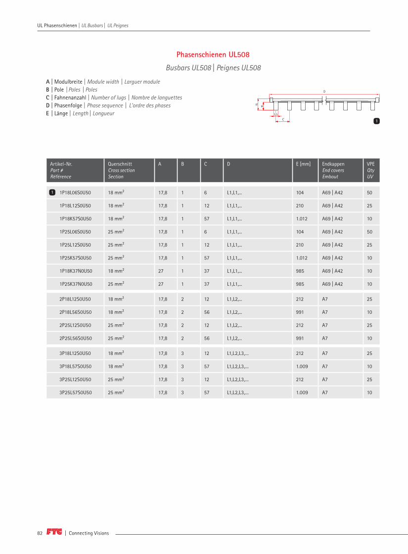
| Connecting Visions82
UL Phasenschienen | UL Busbars | UL Peignes
Phasenschienen UL508
Busbars UL508 | Peignes UL508
A | Modulbreite | Module width | Larguer module B | Pole | Poles | Poles C | Fahnenanzahl | Number of lugs | Nombre de languettesD | Phasenfolge | Phase sequence | L'ordre des phases E | Länge | Length | Longueur
Artikel-Nr. Part # Référence
QuerschnittCross sectionSection
A B C D E [mm] Endkappen End coversEmbout
VPE Qty UV
1P18L06S0U50 18 mm² 17,8 1 6 L1,L1,... 104 A69 | A42 50
1P18L12S0U50 18 mm² 17,8 1 12 L1,L1,... 210 A69 | A42 25
1P18K57S0U50 18 mm² 17,8 1 57 L1,L1,... 1.012 A69 | A42 10
1P25L06S0U50 25 mm² 17,8 1 6 L1,L1,... 104 A69 | A42 50
1P25L12S0U50 25 mm² 17,8 1 12 L1,L1,... 210 A69 | A42 25
1P25K57S0U50 25 mm² 17,8 1 57 L1,L1,... 1.012 A69 | A42 10
1P18K37N0U50 18 mm² 27 1 37 L1,L1,... 985 A69 | A42 10
1P25K37N0U50 25 mm² 27 1 37 L1,L1,... 985 A69 | A42 10
2P18L12S0U50 18 mm² 17,8 2 12 L1,L2,... 212 A7 25
2P18L56S0U50 18 mm² 17,8 2 56 L1,L2,... 991 A7 10
2P25L12S0U50 25 mm² 17,8 2 12 L1,L2,... 212 A7 25
2P25L56S0U50 25 mm² 17,8 2 56 L1,L2,... 991 A7 10
3P18L12S0U50 18 mm² 17,8 3 12 L1,L2,L3,... 212 A7 25
3P18L57S0U50 18 mm² 17,8 3 57 L1,L2,L3,... 1.009 A7 10
3P25L12S0U50 25 mm² 17,8 3 12 L1,L2,L3,... 212 A7 25
3P25L57S0U50 25 mm² 17,8 3 57 L1,L2,L3,... 1.009 A7 10
1
13,5
6
17,8
36,5
17,8
5,5
1015
1C
D

www.ftg-germany.de 83
UL Phasenschienen | UL Busbars | UL Peignes
A | Modulbreite | Module width | Larguer module B | Pole | Poles | Poles C | Fahnenanzahl | Number of lugs | Nombre de languettesD | Phasenfolge | Phase sequence | L'ordre des phases E | Länge | Length | Longueur
Artikel-Nr. Part # Référence
QuerschnittCross sectionSection
A B C D E [mm] Endkappen End coversEmbout
VPE Qty UV
H1 nach jedem Pol | H1 behind each pole | H1 après chaque phase
2P18L38S1U50 18 mm² 17,8 2 38 L1,H1,L2,H1,... 1.015 A7 10
2P25L38S1U50 25 mm² 17,8 2 38 L1,H1,L2,H1,... 1.015 A7 10
3P18L39S1U50 18 mm² 17,8 3 39 L1,H1,L2,H1,L3,H1,... 1.040 A7 10
3P25L39S1U50 25 mm² 17,8 3 39 L1,H1,L2,H1,L3,H1,... 1.040 A7 10
H1 nach jeder Sequenz | H1 behind each sequence | H1 après chaque séquence
2P18L46S2U50 18 mm² 17,8 2 46 L1,L2,H1,... 1.009 A7 10
2P25L46S2U50 25 mm² 17,8 2 46 L1,L2,H1,... 1.009 A7 10
3P18L48S2U50 18 mm² 17,8 3 48 L1,L2,L3,H1,... 984 A7 10
3P25L48S2U50 25 mm² 17,8 3 48 L1,L2,L3,H1,... 984 A7 10
1-polig1-pole | 1-pôle
2-3 polig2-3 poles | 2-3 pôles
Max. BetriebsspannungMax. operating voltageTension de service max.
1.000 V AC/DC 600 V AC/DC
Max. Schienenstrom Is/PhaseMax. current Is/Phase Courant de peigne max. ls/phase
Einspeisung am Schienenanfang bzw. -ende Feed-in at beginning / ending | Alimentation au début ou à la fin du peigne
18 mm2 = 80 A 25 mm2 = 100 A
MitteneinspeisungCenter feed-in | Alimentation centrale
18 mm2 = 160 A 25 mm2 = 200 A
BelastbarkeitLoad-bearing capacityCapacité de charge
Bei 35° Umgebungstemperatur in Abhängigkeit von EinspeisepunktAt 35° ambient temperature depending of feed-in point  une température ambiante de 35° en fonction du point d’alimentation
2
13,5
6
17,8
36,5
17,8
5,5
1015
2C
7

| Connecting Visions84
UL Phasenschienen | UL Busbars | UL Peignes
A | Modulbreite | Module width | Larguer module B | Pole | Poles | Poles C | Fahnenanzahl | Number of lugs | Nombre de languettesD | Phasenfolge | Phase sequence | L'ordre des phases E | Länge | Length | Longueur
Artikel-Nr. Part # Référence
QuerschnittCross sectionSection
A B C D E [mm] Endkappen End coversEmbout
VPE Qty UV
ULC106A16A 16 mm² 17,6 1 6 L1,L1,... 99 - 10
ULC112A16A 16 mm² 17,6 1 12 L1,L1,... 205 - 10
ULC118A16A 16 mm² 17,6 1 18 L1,L1,... 310 - 10
ULC206A16A 16 mm² 17,6 2 6 L1,L2,... 99 - 10
ULC212A16A 16 mm² 17,6 2 12 L1,L2,... 205 - 10
ULC218A16A 16 mm² 17,6 2 18 L1,L2,... 310 - 10
ULC306A16A 16 mm² 17,6 3 6 L1,L2,L3,... 99 - 10
ULC312A16A 16 mm² 17,6 3 12 L1,L2,L3,... 205 - 10
ULC318A16A 16 mm² 17,6 3 18 L1,L2,L3,... 310 - 10
1-polig1-pole | 1-pôle
2- und 3-polig 2- and 3-poles | 2- et 3-pôles
Max. Betriebsspannung Max. operating voltage | Tension de service max.
1.000 V AC/DC 600 V AC/DC
Max. Schienenstrom Is/Phase Max. current Is/Phase | Courant de peigne max. ls/phase
115 A 115 A
Phasenschienen UL489
Busbars UL489 | Peignes UL489
1
17,6 17,6
5
L
13,5
46
15,5D
C C
1

www.ftg-germany.de 85
UL Phasenschienen | UL Busbars | UL Peignes
Phasenschienen ULcut
Busbars for ULcut | Peignes pour ULcut
Artikel-Nr. Part # Référence
QuerschnittCross sectionSection
A B C D Endkappen End coversEmbout
VPE Qty UV
ULC112A18A 18 mm² 17,6 1 12 L1,L1,... A68 10
ULC112A25A 25 mm² 17,6 1 12 L1,L1,... A68 10
ULC157A18A 18 mm² 17,6 1 57 L1,L1,... A68 5
ULC157A25A 25 mm² 17,6 1 57 L1,L1,... A68 5
ULC212A18A 18 mm² 17,6 2 12 L1,L2,... A68 10
ULC212A25A 25 mm² 17,6 2 12 L1,L2,... A68 10
ULC256A18A 18 mm² 17,6 2 56 L1,L2,... A68 5
ULC256A25A 25 mm² 17,6 2 56 L1,L2,... A68 5
ULC312A18A 18 mm² 17,6 3 12 L1,L2,L3,... A68 10
ULC312A25A 25 mm² 17,6 3 12 L1,L2,L3,... A68 10
ULC357A18A 18 mm² 17,6 3 57 L1,L2,L3,... A68 5
ULC357A25A 25 mm² 17,6 3 57 L1,L2,L3,... A68 5
Belastbarkeit bei 35° Umgebungstemperatur in Abhängigkeit von EinspeisepunktCapacity at 35° ambient temperatur depending on position of feed-in | Á une température ambiante de 35° en fonction du point d’alimentation
QuerschnittCross section | Section
18 mm² 25 mm²
Einspeisung am Schienenanfang bzw. -ende | Feed-in at beginning /ending | Alimentation au début ou à la fin du peigne
Max. Schienenstrom Is/PhaseMax. current Is/Phase | Courant de peigne max. ls/phase
80 A 100 A
Anschlussquerschnitt mm2
Connection cross curent mm2 | Section de raccordementMin. 16 mm² | AWG 6 Min. 25 mm² | AWG 4
Mitteneinspeisung | Center feed-in | Alimentation centrale
Max. Schienenstrom Is/PhaseMax. current Is/Phase | Courant de peigne max. ls/phase
160 A 200 A
Anschlussquerschnitt mm²
Connection cross curent mm² | Section de connexionMin. 50 mm² | AWG 1 Min. 2 x 50 mm²
2 x AWG 1
2
A | Modulbreite | Module width | Larguer module B | Pole | Poles | Poles C | Fahnenanzahl | Number of lugs | Nombre de languettesD | Phasenfolge | Phase sequence | L'ordre des phases
13,8
17,6
5
58
1,8
22
13,8
22
58
5 1,8
217,6
7

| Connecting Visions86
UL Phasenschienen | UL Busbars | UL Peignes
Artikel-Nr. Part # Référence
QuerschnittCross sectionSection
A B C D Endkappen End coversEmbout
VPE Qty UV
H1, Abstand nach jeder Phasenfolge | H1, Space after each pole sequence | H1, avec espacement après chaque séquence de pôle
ULC137A18H1FA 18 mm² 17,6 1 37 L1,H1,... A68 5
ULC137A25H1FA 25 mm² 17,6 1 37 L1,H1,... A68 5
ULC210A18H1PA 18 mm2 17,6 2 10 L1,L2,H1,... A68 10
ULC210A25H1PA 25 mm2 17,6 2 10 L1,L2,H1,... A68 10
ULC246A18H1PA 18 mm2 17,6 2 46 L1,L2,H1,... A68 5
ULC246A25H1PA 25 mm2 17,6 2 46 L1,L2,H1,... A68 5
ULC309A18H1PA 18 mm2 17,6 3 9 L1,L2,L3,H1,... A68 10
ULC309A25H1PA 25 mm2 17,6 3 9 L1,L2,L3,H1,... A68 10
ULC348A18H1PA 18 mm2 17,6 3 48 L1,L2,L3,H1,... A68 5
ULC348A25H1PA 25 mm2 17,6 3 48 L1,L2,L3,H1,... A68 5
Phasenschienen ULcut
Busbars ULcut | Peignes ULcut
1
A | Modulbreite | Module width | Larguer module B | Pole | Poles | Poles C | Fahnenanzahl | Number of lugs | Nombre de languettesD | Phasenfolge | Phase sequence | L'ordre des phases
13,8
17,6
5
58
1,8
22
13,8
22
58
5 1,8
117,6
Belastbarkeit bei 35° Umgebungstemperatur in Abhängigkeit von EinspeisepunktCapacity at 35° ambient temperatur depending on position of feed-in | Á une température ambiante de 35° en fonction du point d’alimentation
QuerschnittCross section | Section
18 mm² 25 mm²
Einspeisung am Schienenanfang bzw. -ende | Feed-in at beginning /ending | Alimentation au début ou à la fin du peigne
Max. Schienenstrom Is/PhaseMax. current Is/Phase | Courant de peigne max. ls/phase
80 A 100 A
Anschlussquerschnitt mm2
Connection cross curent mm2 | Section de raccordementMin. 16 mm² | AWG 6 Min. 25 mm² | AWG 4
Mitteneinspeisung | Center feed-in | Alimentation centrale
Max. Schienenstrom Is/PhaseMax. current Is/Phase | Courant de peigne max. ls/phase
160 A 200 A
Anschlussquerschnitt mm²
Connection cross curent mm² | Section de connexionMin. 50 mm² | AWG 1 Min. 2 x 50 mm²
2 x AWG 1
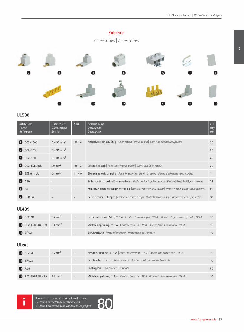
www.ftg-germany.de 87
UL Phasenschienen | UL Busbars | UL Peignes
77
Zubehör
Accessories | Accessoires
UL508
Artikel-Nr. Part # Référence
QuerschnittCross sectionSection
AWG BeschreibungDescriptionDescription
VPE Qty UV
802–150S 6 – 35 mm² 10 – 2 Anschlussklemme, Steg | Connection Terminal, pin | Borne de connexion, pointe 25
802–153S 6 – 35 mm² 25
802–180 6 – 35 mm² 25
802–ESB50UL 50 mm² 10 – 2 Einspeiseblock | Feed-in terminal block | Borne d‘alimentation 25
ESB95–3UL 95 mm² 1 – 4/0 Einspeiseblock, 3-polig | Feed-in terminal block , 3-poles | Borne d‘alimentation, 3-pôles 1
A69 – – Endkappe für 1-polige Phasenschienen | Endcover for 1–poles busbars | Embout d‘extrémité pour peignes 25
A7 – – Phasenschienen-Endkappe, mehrpolig | Busbar endcover , multipolar | Embouts pour peignes multipolaires 50
BRB5W – – Berührschutz, 5 Kappen | Protection cover, 5 caps | Protection contre les contacts directs, 5 protections 10
2
3
4
5
6
9
7
8
UL489
802–94 35 mm² - Einspeiseklemme, Stift, 115 A | Feed-in terminal, pin, 115 A, | Bornes de puissance, pointe, 115 A 10
802–ESB50UL489 50 mm² - Mitteleinspeisung, 115 A | Central feed–in, 115 A | Alimentation en milieu, 115 A 10
BRU3 - - Berührschutz | Protection cover | Protection de contact 10
ULcut
802–307 35 mm² - Einspeiseklemme, 115 A | Feed-in terminal, 115 A | Bornes de puissance, 115 A 10
BRU3V - - Berührschutz | Protection cover | Protection contre les contacts directs 10
A68 - - Endkappen | End covers | Embouts 50
802–ESB50UL489 50 mm² - Mitteleinspeisung, 115 A | Central feed–in, 115 A | Alimentation en milieu, 115 A 10
10
11
11
12
13
12
14
2 3 5 6 7 8
9
4
10 11 1412 13
Auswahl der passenden AnschlussklemmeSelection of matching terminal clipsSélection du terminal de connexion approprié 80
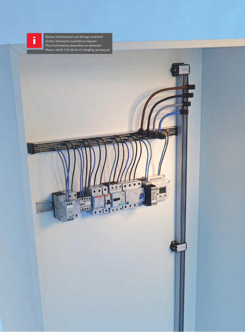
Weitere Informationen auf Anfrage erhältlich! Further information available on request!Plus d'informations disponibles sur demande!Phone +49 (0) 7722 96 36-0 | [email protected]

Flexible PhasenschienenFlexible busbars | Systèmes de busbars fl exibles
Flexible Systeme sind bei FTG Produkte zur Stromverteilung, die vor Ort durch Planer und Monteure nahezu beliebig an indivi-duelle Anforderungen angepasst werden können. So ermöglicht die StromschieneAuxigaine beliebig viele Polzahlen,wird in Schaltschrankhöhe montiert – was alle fl exiblen Systeme gemeinsamhaben – und auf äußerst einfache Weise können Zu– und Abgänge hinzugefügt oder entfernt werden.
Flexible systems are available for FTG pro-ducts for power distribution which can be adapted in almost any way to individualrequirements by planners and fi tters on site. With the Auxigaine busbar, for example, as many poles as required are possible; it is mounted at switch cabinet height – which all the fl exible system have in common – and in/outfeeds can be added or removed extremely easily.
Les systèmes fl exibles chez les produits FTG sont destinés à la distribution électrique pouvant être adaptée sur place par le con-cepteur et le technicien à des exigences indi-viduelles. Ainsi, le rail conducteur Auxigaine permet des nombres de pôles quelconques, est monté au niveau de l’armoire électrique– ce qui vaut d’ailleurs pour tous les systèmes fl exibles – et il est particulière-ment simple de rajouter ou de supprimer des entrées et des sorties.
Auxigaine | Auxigaine | Auxigaine Auxiclic | Auxiclic | Auxiclic
90 9696FCBeasy | FCBeasy | FCBeasy
98
Easyvation | Easyvation | Easyvation EasyBreak | EasyBreak | EasyBreak
102102 104104104104
8

| Connecting Visions90
Flexible Phasenschienen | Flexible busbars | Systèmes de busbars flexibles Flexible Phasenschienen | Flexible busbars | Systèmes de busbars flexibles
Auxigaine-Leiter inklusive Isolationsprofil, 1.900 mm, 152 Fahnen Auxigaine, 1.900 mm incl. insulating profile, 152 lugs Barre Auxigaine, y. c. avec profil d’isolation 1.900 mm, 152 languettes
Artikel-Nr. Part # Référence
BeschreibungDescriptionDescription
Max. A LeiterConductorConduteur
VPE Qty UV
ST1219001LBI0 Standard 32 1 Leiter Messing blank 1 conductor plain brass | 1 conducteur laiton brut
10
ST1419001LBI0 Halogenfrei | Halogen–free | Sans halogène 32 10
ST1219001CEI0 Standard 63 1 Leiter Kupfer verzinnt 1 conductor tinned copper | 1 conducteur cuivre étamé
10
ST1419001CEI0 Halogenfrei | Halogen–free | Sans halogène 63 10
ST1219001CEJ0 Standard 100 1 Leiter Kupfer verzinnt 1 conductor tinned copper | 1 conducteur cuivre étamé
10
ST1219001CEJ0SH Halogenfrei | Halogen–free | Sans halogène 100 10
ST1219001CER0 Standard 125 1 Leiter Kupfer verzinnt 1 conductor tinned copper | 1 conducteur cuivre étamé
10
ST1419001CER0 Halogenfrei | Halogen–free | Sans halogène 125 10
ST1219002LBI0 Standard 32 2 Leiter Messing blank 2 conductors plain brass | 2 conducteurs laiton brut
10
ST1419002LBI0 Halogenfrei | Halogen–free | Sans halogène 32 10
ST1219002CEI0 Standard 63 2 Leiter Kupfer verzinnt 2 conductors tinned copper | 2 conducteur cuivre étamé
10
ST1419002CEI0 Halogenfrei | Halogen–free | Sans halogène 63 10
ST1219002CEJ0 Standard 100 2 Leiter Kupfer verzinnt 2 conductor tinned copper | 2 conducteur scuivre étamé
10
ST1219002CEJ0SH Halogenfrei | Halogen–free | Sans halogène 100 10
ST1219002CER0 Standard 125 2 Leiter Kupfer verzinnt 2 conductors tinned copper | 2 conducteur cuivre étamé
10
ST1419002CER0 Halogenfrei | Halogen–free | Sans halogène 125 10
Auxigaine–Verteilerschiene Auxigaine distribution bar I Auxigaine barre de distribution
Artikel-Nr. Part # Référence
Max. A Anzahl PhasenNumber of polesNombre de pôles
Anzahl FahnenNumber of lugsNombre de languettes
Lochabstand [mm]Center hole distanceEntraxe de fixation
Länge [mm]Length Longueur
VPE Qty UV
Auf Befestigungsprofil | On mounting profil | Sur profil de fixation
ST42006/32 32 2 16 335 349 8
ST42008/32 32 2 68 935 949 8
ST42010/32 32 2 148 1.875 1.889 8
ST42006/63 63 2 16 335 349 4
ST42008/63 63 2 68 935 949 4
ST42010/63 63 2 148 1.875 1.889 4
ST42006/100 100 2 16 335 349 8
1
2
3
21
Auxigaine
Auxigaine | Auxigaine

www.ftg-germany.de 91
Flexible Phasenschienen | Flexible busbars | Systèmes de busbars flexibles
Auxigaine–Verteilerschiene Auxigaine distribution bar I Auxigaine barre de distribution
Artikel-Nr. Part # Référence
Max. A Anzahl PhasenNumber of polesNombre de pôles
Anzahl FahnenNumber of lugsNombre de languettes
Lochabstand [mm]Center hole distanceEntraxe de fixation
Länge [mm]Length Longueur
VPE Qty UV
Auf Befestigungsprofil | On mounting profil | Sur profil de fixation
ST42008/100 100 2 68 935 949 8
ST42010/100 100 2 148 1.875 1.889 8
ST42006/125 125 2 16 335 349 4
ST42008/125 125 2 68 935 949 4
ST42010/125 125 2 148 1.875 1.889 4
ST42007/32 32 4 16 335 349 8
ST42009/32 32 4 68 935 949 8
ST42011/32 32 4 148 1.875 1.889 8
ST42007/63 63 4 16 335 349 4
ST42009/63 63 4 68 935 949 4
ST42011/63 63 4 148 1.875 1.889 4
ST42007/100 100 4 16 335 349 8
ST42009/100 100 4 68 935 949 8
ST42011/100 100 4 148 1.875 1.889 8
ST42007/125 125 4 16 335 349 4
ST42009/125 125 4 68 935 949 4
ST42011/125 125 4 148 1.875 1.889 4
Auf DIN–Tragschiene vormontiert | Premounted on DIN rail | Monté sur rail DIN
ST42000/32 32 6 24 380 390 4
ST42001/32 32 6 41 580 590 4
ST42002/32 32 6 57 780 790 4
ST42003/32 32 6 73 980 990 4
ST42004/32 32 6 93 1.180 1.190 4
ST42000/63 63 6 24 380 390 4
3
3 4
4
8

| Connecting Visions92
Auf DIN–Tragschiene vormontiert | Premounted on DIN rail | Monté sur rail DIN
ST42001/63 63 6 41 580 590 4
ST42002/63 63 6 57 780 790 4
ST42003/63 63 6 73 980 990 4
ST42004/63 63 6 93 1.180 1.190 4
ST42000/100 100 6 24 380 390 4
ST42001/100 100 6 41 580 590 4
ST42002/100 100 6 57 780 790 4
ST42003/100 100 6 73 980 990 4
ST42004/100 100 6 93 1.180 1.190 4
ST42000/125 125 6 24 380 390 4
ST42001/125 125 6 41 580 590 4
ST42002/125 125 6 57 780 790 4
ST42003/125 125 6 73 980 990 4
ST42004/125 125 6 93 1.180 1.190 4
Mit Endisolieranschlägen | With end supports | Avec butées support
ST42005/32 32 2 12 188 199 8
ST42005/63 63 2 12 188 199 8
ST42005/100 100 2 12 188 199 8
ST42005/125 125 2 12 188 199 8
2
21
1
Auxigaine–Verteilerschiene Auxigaine distribution bar I Auxigaine Barre de distribution
Artikel-Nr. Part # Référence
Max. A Anzahl PhasenNumber of polesNombre de pôles
Anzahl FahnenNumber of lugsNombre de languettes
Lochabstand [mm]Center hole distanceEntraxe de fixation
Länge [mm]Length Longueur
VPE Qty UV
Flexible Phasenschienen | Flexible busbars | Systèmes de busbars flexibles Flexible Phasenschienen | Flexible busbars | Systèmes de busbars flexibles

www.ftg-germany.de 93
Flexible Phasenschienen | Flexible busbars | Systèmes de busbars flexibles
3
Mit DIN–Tragschienen Adapter | With DIN rail adapter | Avec adaptateur pour rail DIN
ST42005/32D 32 2 12 - 199 1
ST42005/63D 63 2 12 - 199 1
ST42005/100D 100 2 12 - 199 1
ST42005/125D 125 2 12 - 199 1
Auxibus, mit Abdeckung zum Einrasten von Crimp–Steckern Auxibus, with cover for snapping of crimp connectors | Auxibus, avec couvercle pour encliquetage des contacts
ST42012/32 32 2 6 335 349 4
ST42014/32 32 2 12 535 549 4
ST42016/32 32 2 24 1.875 1.889 4
ST42012/63 63 2 6 335 349 4
ST42014/63 63 2 12 535 549 4
ST42016/63 63 2 24 1.875 1.889 4
ST42013/32 32 4 6 335 349 4
ST42015/32 32 4 12 535 549 4
ST42017/32 32 4 24 1.875 1.889 4
ST42013/63 63 4 6 335 349 4
ST42015/63 63 4 12 535 549 4
ST42017/63 63 4 24 1.875 1.889 4
Auxigaine–Verteilerschiene Auxigaine distribution bar I Auxigaine Barre de distribution
Artikel-Nr. Part # Référence
Max. A Anzahl PhasenNumber of polesNombre de pôles
Anzahl FahnenNumber of lugsNombre de languettes
Lochabstand [mm]Center hole distanceEntraxe de fixation
Länge [mm]Length Longueur
VPE Qty UV
3
4
4
8

| Connecting Visions94
Flexible Phasenschienen | Flexible busbars | Systèmes de busbars flexibles Flexible Phasenschienen | Flexible busbars | Systèmes de busbars flexibles
Flexibler Stecker mit Aderendhülse | Flexible connector with sleeve | Connecteur souple avec embout
40017V2 EinspeisesteckerSupply connector | Connecteur d’alimentation
10
ST2125C Verbindungstecker 2 x 100 A Bridge connector 2 x 100 A | Connecteur 2 x 100 A
3
17BIO IsolieranschlagInsulation block | Butée isolante
50
17BS Endisolieranschlag mit Schraube M4 x 25 mm End insulation block with screw M4 x 25 mm | Butée support avec M4 x 25 mm
10
17FG1 Befestigungsbügel mit 1 Schraube M4 x 30 mm für 1 Auxigaine Bar holder with 1 screw M4 x 30 mm for 1 Auxigaine | Etrier de fixation avec 1 vis M4 x 30 mm pour 1 Auxigaine
10
19FT3V Befestigungsbügel mit 2 Schrauben M4 x 30 mm für 3 AuxigaineBar holder with 2 screws M4 x 30 for 3 Auxigaine | Etrier de fixation avec 2 vis M4 x 30 mm pour 3 Auxigaine
10
17EET Beschriftungsset für Befestigungsbügel Label and screen for bar holder | Étiquette & écran pour repérage sur étrier de fixation
50
2
3
4
5
6
32 4
Artikel-Nr. Part # Référence
QuerschnittCross sectionSection
Max. A FlachsteckerQuick disconnectConnecteur plat
AderendhülseFerrule / sleeve Embout
Länge [mm]Length Longueur
VPE Qty UV
Artikel-Nr. Part # Référence
BeschreibungDescriptionDescription
VPE Qty UV
Flexibler Stecker mit Aderendhülse | Flexible connector with sleeve | Connecteur souple avec embout
ST 25FE0120B 2,5 mm² 20 1 1 120 50
ST 25FE0120S 2,5 mm² 20 1 1 120 50
ST 25FE0200B 2,5 mm² 20 1 1 200 50
ST 25FE0200S 2,5 mm² 20 1 1 200 50
ST 60FE0120B 6 mm² 36 1 1 120 50
ST 60FE0120S 6 mm² 36 1 1 120 50
ST 60FE0200B 6 mm² 36 1 1 200 50
ST 60FE0200S 6 mm² 36 1 1 200 50
40023 2 x 4 mm² 63 2 1 120 50
40024 2 x 4 mm² 63 2 1 120 50
1
Auxigaine ZubehörAuxigaine Accessories I Auxigaine Accessoires
1
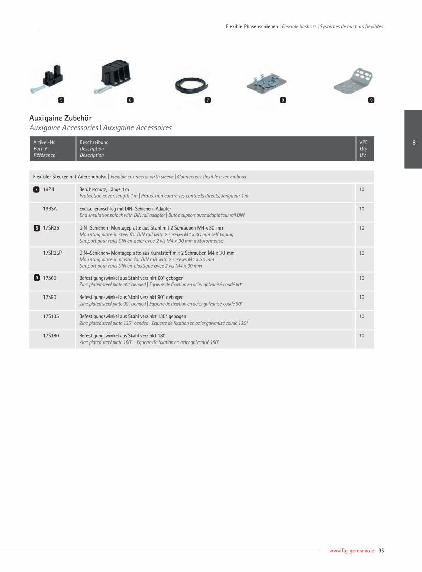
www.ftg-germany.de 95
Flexible Phasenschienen | Flexible busbars | Systèmes de busbars flexibles
Artikel-Nr. Part # Référence
BeschreibungDescriptionDescription
VPE Qty UV
Flexibler Stecker mit Aderendhülse | Flexible connector with sleeve | Connecteur flexible avec embout
19PJI Berührschutz, Länge 1m Protection cover, length 1m | Protection contre les contacts directs, longueur 1m
10
19BSA Endisolieranschlag mit DIN–Schienen–Adapter End insulationsblock with DIN rail adaptor | Butée support avec adaptateur rail DIN
10
17SR35 DIN–Schienen–Montageplatte aus Stahl mit 2 Schrauben M4 x 30 mm Mounting plate in steel for DIN rail with 2 screws M4 x 30 mm self taping Support pour rails DIN en acier avec 2 vis M4 x 30 mm autoformeuse
10
17SR35P DIN–Schienen–Montageplatte aus Kunststoff mit 2 Schrauben M4 x 30 mm Mounting plate in plastic for DIN rail with 2 screws M4 x 30 mm Support pour rails DIN en plastique avec 2 vis M4 x 30 mm
10
17S60 Befestigungswinkel aus Stahl verzinkt 60° gebogenZinc plated steel plate 60° bended | Equerre de fixation en acier galvanisé coudé 60°
10
17S90 Befestigungswinkel aus Stahl verzinkt 90° gebogenZinc plated steel plate 90° bended | Equerre de fixation en acier galvanisé coudé 90°
10
17S135 Befestigungswinkel aus Stahl verzinkt 135° gebogenZinc plated steel plate 135° bended | Equerre de fixation en acier galvanisé coudé 135°
10
17S180 Befestigungswinkel aus Stahl verzinkt 180°Zinc plated steel plate 180° | Equerre de fixation en acier galvanisé 180°
10
7
8
9
7 8 965
Auxigaine ZubehörAuxigaine Accessories I Auxigaine Accessoires
8

| Connecting Visions96
Flexible Phasenschienen | Flexible busbars | Systèmes de busbars flexibles Flexible Phasenschienen | Flexible busbars | Systèmes de busbars flexibles
21
Auxiclic, Vierpolige Phasenschiene, 250 A Auxiclic, Four-pole busbar, 250 A I Auxiclic, jeux de barres tétrapolaires, 250 A
Artikel-Nr. Part # Référence
Maße (L x B x H) [mm]Dimension (L xW x H)Dimensions (L x I x H)
BeschreibungDescriptionDescription
VPE Qty UV
AUXCL12 233 x 40 x 45 pro Phase 6 Abgänge, Neutralleiter 12 Abgänge6 outputs per phase, neutral conductor 12 outputs 6 connexions par phase, 12 pour le neutre
1
AUXCL24 422 x 40 x 45 pro Phase 12 Abgänge, Neutralleiter 24 Abgänge12 outputs per phase, neutral conductor 24 outputs 12 connexions par phase, 24 pour le neutre
1
AUXCL36 616 x 40 x 45 pro Phase 18 Abgänge, Neutralleiter 36 Abgänge18 outputs per phase, neutral conductor 36 outputs18 connexions par phase, 36 pour le neutre
1
Flexibler Verbinder Flexible connector I Connexion flexible
Artikel-Nr. Part # Référence
QuerschnittCross sectionSection
Länge [mm]Length Longueur
BeschreibungDescriptionDescription
VPE Qty UV
96505 6 mm² 120 mit Aderendhülse with sleeve | avec embout
10
96506 6 mm² 120 mit Aderendhülse with sleeve | avec embout
10
96509 6 mm² 320 ohne Aderendhülsewithout sleeve | sans embout
10
96510 6 mm² 320 ohne Aderendhülsewithout sleeve | sans embout
10
96519 6 mm² 500 ohne Aderendhülsewithout sleeve | sans embout
10
96520 6 mm² 500 ohne Aderendhülsewithout sleeve | sans embout
10
96527 6 mm² 1.000 ohne Aderendhülse without sleeve | sans embout
10
96528 6 mm² 1.000 ohne Aderendhülse without sleeve | sans embout
10
96507 10 mm² 120 mit Aderendhülse with sleeve | avec embout
10
96508 10 mm² 120 mit Aderendhülse with sleeve | avec embout
10
1
2
Auxiclic
Auxiclic | Auxiclic
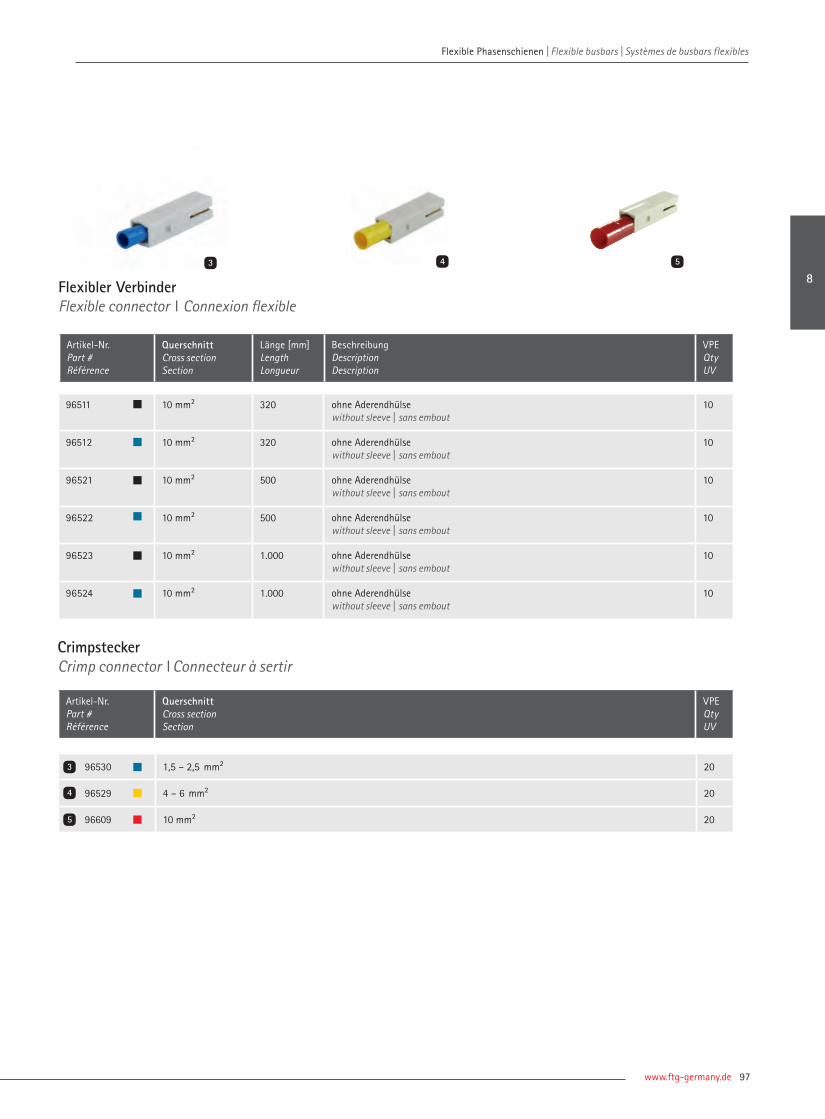
www.ftg-germany.de 97
Flexibler VerbinderFlexible connector I Connexion flexible
Artikel-Nr. Part # Référence
QuerschnittCross sectionSection
Länge [mm]Length Longueur
BeschreibungDescriptionDescription
VPE Qty UV
43 5
96511 10 mm² 320 ohne Aderendhülse without sleeve | sans embout
10
96512 10 mm² 320 ohne Aderendhülse without sleeve | sans embout
10
96521 10 mm² 500 ohne Aderendhülse without sleeve | sans embout
10
96522 10 mm² 500 ohne Aderendhülse without sleeve | sans embout
10
96523 10 mm² 1.000 ohne Aderendhülse without sleeve | sans embout
10
96524 10 mm² 1.000 ohne Aderendhülse without sleeve | sans embout
10
CrimpsteckerCrimp connector I Connecteur à sertir
Artikel-Nr. Part # Référence
QuerschnittCross sectionSection
VPE Qty UV
96530 1,5 – 2,5 mm² 20
96529 4 – 6 mm² 20
96609 10 mm² 20
4
3
5
Flexible Phasenschienen | Flexible busbars | Systèmes de busbars flexibles
8

| Connecting Visions98
21 3
Flexible StromverteilungsschieneFlexible power distribution busbar I Peigne flexible
Artikel-Nr. Part # Référence
BeschreibungDescriptionDescription
VPE Qty UV
FCB 8016 1000 Stromschiene, 80 A, 8,9 mm TE, 108 AnschlüsseBusbar, 80 A, 9 mm TE, 108 lugs | Peigne, 80 A, 9 mm TE, 108 languettes
30
FCB 8003 Isolationskörper, 3–polig, 1.000 mm langInsulation profile, 3–pole, 1.000 mm length | Isolation, 3-pôles, longueur 1.000 mm
10
FCB 8004 Isolationskörper, 4–polig, 970 mm langInsulation profile, 4–pole, 970 mm length | Isolation, 4-pôles, longueur 970 mm
10
FCB 8020G Gabelanschlussfahne, L1 + NFork terminal lug, L1 + N | Connexion à fourche, L1 + N
100
FCB 8021G Gabelanschlussfahne, L2 + L3Fork terminal lug, L2 + L3 | Connexion à fourche, L2 + L3
100
FCB 8022S Steganschlussfahne, L1 + NPin terminal lug, L1 + N | Connexion à pointe, L1 + N
100
FCB 8023S Steganschlussfahne, L2 + L3Pin terminal lug, L2 + L3 | Connexion à pointe
100
FCB A24 Endkappe 3–poligEnd cover 3–pole | Embout 3–pôles
50
FCB A30 Endkappe 4–poligEnd cover 4–pole | Embout 4–pôles
50
FCB 8010 BeschriftungsstreifenLabeling strip | Etiquette
10
Gesamtschiene inklusive Endkappen, vormontiert Complete busbar including End Covers, premounted I Peigne complet y. c. embouts, prémontés
FCB 8030 210 Stromschiene, 80 A, 3–polig, 210 mm lang, mit IsolationBusbar, 80 A, 3–pole, 210 mm length, with isolation Peigne, 80 A, 3–pôles, longueur 210 mm, avec isolation
5
FCB 8040 210 Stromschiene, 80 A, 4–polig, 210 mm lang, mit IsolationBusbar, 80 A, 4–pole, 210 mm length, with isolationPeigne, 80 A, 4–pôles, longueur 210 mm, avec isolation
5
2
1
3
FCBeasy
FCBeasy | FCBeasy
Flexible Phasenschienen | Flexible busbars | Systèmes de busbars flexibles Flexible Phasenschienen | Flexible busbars | Systèmes de busbars flexibles

www.ftg-germany.de 99
Einpoliges FCBeasy PaketOne–pole FCBeasy package I Package FCBeasy unipolaire
Artikel-Nr. Part # Référence
BeschreibungDescriptionDescription
VPE Qty UV
FCB 3PG bestehend aus | package includes | le package contient Gabel | Fork | Fourche
FCB 8016 1000 Stromschiene, 80 A, 9 mm TE, 1.000 mm, inkl. Endkappen vormontiertBusbar, 80 A, 9 mm TE, 1.000 mm, including end covers, permounted | Peigne, 80 A, 9 mm TE, 1.000 mm, embouts inclus, prémontés
9
FCB 8003 Isolationskörper, 3–polig, 1.000 mm | Insulation profile, 3–pole, 1.000 mm | Isolation, 3–pôles, 1.000 mm 3
FCB 8020G Gabelanschlussfahne, L1 + N | Fork terminal lug, L1 + N | Connexion à fourche, L1 + N 150
FCB 8021G Gabelanschlussfahne, L2 + L3 | Fork terminal lug, L2 + L3 | Connexion à fourche, L2 + L3 100
FCB A24 Endkappe 3–polig | End cover 3–pole | Embout, 3–pôles 25
FCB 8010 Beschriftungsstreifen | Labeling strip | Etiquette 5
FCB 3PS bestehend aus | package includes | le package contient Steg | Pin | Pointe
FCB 8016 1000 Stromschiene, 80 A, 9 mm TE, 1.000 mm | Busbar, 80 A, 9 mm TE, 1.000 mm | Peigne, 80 A, 9 mm TE, 1.000 mm 9
FCB 8003 Isolationskörper, 3–polig, 1.000 mm | Insulation profile, 3–pole, 1.000 mm | Isolation, 3–pôles, 1.000 mm 3
FCB 8022S Steganschlussfahne, L1 + N | Pin terminal lug, L1 + N | Connexion à pointe, L1 + N 150
FCB 8023S Steganschlussfahne, L2 + L3 | Pin terminal lug, L2 + L3 | Connexion à pointe, L2 + L3 100
FCB A24 Endkappe 3–polig | End cover 3–pole | Embout 3–pôles 25
FCB 8010 Beschriftungsstreifen | Labeling strip | Etiquette 5
Zweipoliges FCBeasy PaketTwo–pole FCBeasy package I Package FCBeasy bipolaire
FCB 4PG bestehend aus | package includes | le package contient Gabel | Fork | Fourche
FCB 8016 1000 Stromschiene, 80 A, 9 mm TE, 1.000 mm | Busbar, 80 A, 9 mm TE, 1.000 mm | Peigne, 80 A, 9 mm TE, 1.000 mm 12
FCB 8004 Isolationskörper, 4–polig, 1.000 mm | Insulation profile, 4–pole, 1.000 mm | Isolation, 4-pôles, 1.000 mm 3
FCB 8020G Gabelanschlussfahne, L1 + N | Fork terminal lug, L1 + N | Connexion à fourche, L1 + N 100
FCB 8021G Gabelanschlussfahne, L2 + L3 | Fork terminal lug, L2 + L3 | Connexion à fourche, L2 + L3 100
FCB A28 Endkappe 4–polig | End cover 4–pole | Embout 4–pôles 25
FCB 8010 Beschriftungsstreifen 200g/m² | Labeling strip 200 g/m² | Etiquette 200 g/m² 5
FCB 4PS bestehend aus | package includes | le package contient Steg | Pin | Pointe
FCB 8016 1000 Stromschiene, 80 A, 9 mm TE, 1.000 mm | Busbar, 80 A, 9 mm TE, 1.000 mm | Peigne, 80 A, 9 mm TE, 1.000 mm 9
FCB 8004 Isolationskörper, 4–polig, 1.000 mm | Insulation profile, 4–pole, 1.000 mm | Isolation, 4–pôles, 1.000 mm 3
FCB 8022S Steganschlussfahne, L1 + N | Pin terminal lug, L1 + N | Connexion à pointe, L1 + N 100
FCB 8023S Steganschlussfahne, L2 + L3 | Pin terminal lug, L2 + L3 | Connexion à pointe, L2 + L3 100
FCB A28 Endkappe 4–polig | End cover 4–pole | Embout 4–pôles 25
FCB 8010 Beschriftungsstreifen 200g/m² | Labeling strip 200 g/m² | Etiquette 200 g/m² 5
Flexible Phasenschienen | Flexible busbars | Systèmes de busbars flexibles
8

| Connecting Visions100
Flexible Phasenschienen | Flexible busbars | Systèmes de busbars flexibles Flexible Phasenschienen | Flexible busbars | Systèmes de busbars flexibles
Dreipoliges FCBeasy PaketThree–pole FCBeasy package I Package FCBeasy tripolaire
Artikel-Nr. Part # Référence
BeschreibungDescriptionDescription
VPE Qty UV
FCB 5PG bestehend aus | package includes | le package contient Gabel | Fork | Fourche
FCB 8030 210 Stromschiene 3–polig, 80 A, 210 mm | Busbar, 3–pole, 80 A, 210 mm | Peigne 3–pôles, 80 A, 210 mm 10
FCB 8020G Gabelanschlussfahne, L1 + N | Fork terminal lug, L1 + N | Connexion à fourche, L1 + N 50
FCB 8021G Gabelanschlussfahne, L2 + L3 | Fork terminal lug, L2 + L3 | Connexion à fourche, L2 + L3 50
FCB 8010 Beschriftungsstreifen 200g/m² | Labeling strip 200 g/m² | Etiquette 200 g/m² 5
FCB 5PS bestehend aus | package includes | le package contient Steg | Pin | Pointe
FCB 8016 1000 Stromschiene 3–polig, 80 A, 1.000 mm | Busbar, 3–pole, 80 A, 1.000 mm | Peigne 3–pôles, 80 A, 1.000 mm 10
FCB 8022S Steganschlussfahne, L1 + N | Pin terminal lug, L1 + N | Connexion à pointe, L1 + N 50
FCB 8023S Steganschlussfahne, L2 + L3 | Pin terminal lug, L2 + L3 | Connexion à pointe, L2 + L3 50
FCB 8010 Beschriftungsstreifen 200g/m² | Labeling strip 200 g/m² | Etiquette 200 g/m² 5
Vierpoliges FCBeasy PaketFour–pole FCBeasy package I Package FCBeasy tétrapolaire
FCB 6PG bestehend aus | package includes | le package contient Gabel | Fork | Fourche
FCB 8040 210 Stromschiene 4–polig, 80 A, 210 mm | Busbar, 4–pole, 80 A, 210 mm | Peigne 4–pôles, 80 A, 210 mm 10
FCB 8020G Gabelanschlussfahne, L1 + N | Fork terminal lug, L1 + N | Connexion à fourche, L1 + N 50
FCB 8021G Gabelanschlussfahne, L2 + L3 | Fork terminal lug, L2 + L3 | Connexion à fourche, L2 + L3 50
FCB 8010 Beschriftungsstreifen 200g/m² | Labeling strip 200 g/m² | Etiquette 200 g/m² 5
FCB 6PS bestehend aus | package includes | le package contient Steg | Pin | Pointe
FCB 8016 1000 Stromschiene 4–polig, 80 A, 1.000 mm | Busbar, 4–pole, 80 A, 1.000 mm | Peigne 4–pôles, 80 A, 1.000 mm 10
FCB 8022S Steganschlussfahne, L1 + N | Pin terminal lug, L1 + N | Connexion à pointe, L1 + N 50
FCB 8023S Steganschlussfahne, L2 + L3 | Pin terminal lug, L2 + L3 | Connexion à pointe, L2 + L3 50
FCB 8010 Beschriftungsstreifen 200g/m² | Labeling strip 200 g/m² | Etiquette 200 g/m² 5
Weitere Sets und Kombinationen auf Anfrage möglich. Further sets and combinations on request. D'autres sets et combinaisons sont possibles sur demande. Phone +49 (0) 7722 96 36-0 | [email protected]

www.ftg-germany.de 101
FCBeasy in Anwendung | FCBeasy in application | FCBeasy en application
Flexible Phasenschienen | Flexible busbars | Systèmes de busbars flexibles
8
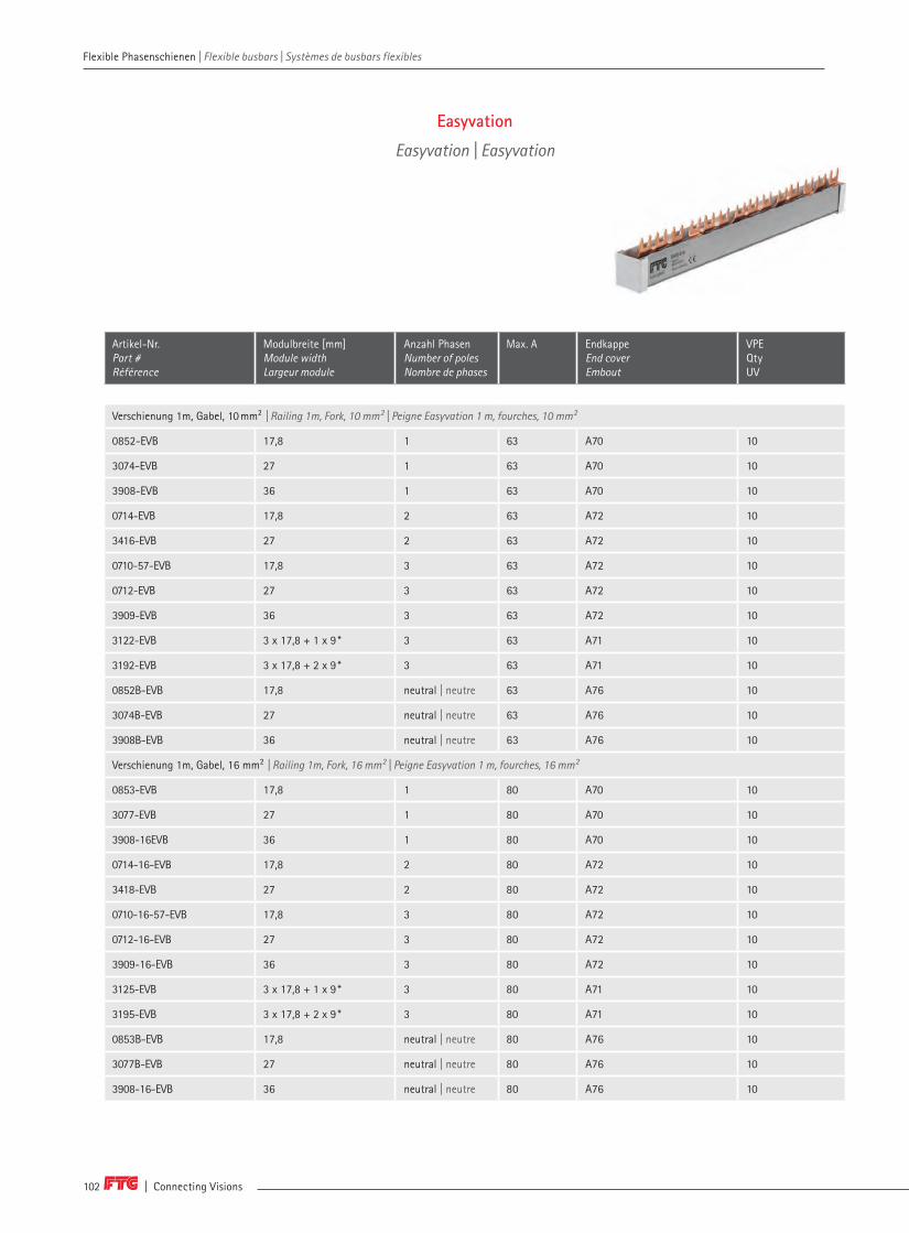
| Connecting Visions102
Artikel-Nr. Part # Référence
Modulbreite [mm] Module widthLargeur module
Anzahl PhasenNumber of poles Nombre de phases
Max. A Endkappe End coverEmbout
VPE Qty UV
Verschienung 1m, Gabel, 10mm² | Railing 1m, Fork, 10 mm² | Peigne Easyvation 1 m, fourches, 10 mm²
0852-EVB 17,8 1 63 A70 10
3074-EVB 27 1 63 A70 10
3908-EVB 36 1 63 A70 10
0714-EVB 17,8 2 63 A72 10
3416-EVB 27 2 63 A72 10
0710-57-EVB 17,8 3 63 A72 10
0712-EVB 27 3 63 A72 10
3909-EVB 36 3 63 A72 10
3122-EVB 3 x 17,8 + 1 x 9 * 3 63 A71 10
3192-EVB 3 x 17,8 + 2 x 9 * 3 63 A71 10
0852B-EVB 17,8 neutral | neutre 63 A76 10
3074B-EVB 27 neutral | neutre 63 A76 10
3908B-EVB 36 neutral | neutre 63 A76 10
Verschienung 1m, Gabel, 16 mm² | Railing 1m, Fork, 16 mm² | Peigne Easyvation 1 m, fourches, 16 mm²
0853-EVB 17,8 1 80 A70 10
3077-EVB 27 1 80 A70 10
3908-16EVB 36 1 80 A70 10
0714-16-EVB 17,8 2 80 A72 10
3418-EVB 27 2 80 A72 10
0710-16-57-EVB 17,8 3 80 A72 10
0712-16-EVB 27 3 80 A72 10
3909-16-EVB 36 3 80 A72 10
3125-EVB 3 x 17,8 + 1 x 9 * 3 80 A71 10
3195-EVB 3 x 17,8 + 2 x 9 * 3 80 A71 10
0853B-EVB 17,8 neutral | neutre 80 A76 10
3077B-EVB 27 neutral | neutre 80 A76 10
3908-16-EVB 36 neutral | neutre 80 A76 10
Easyvation
Easyvation | Easyvation
Flexible Phasenschienen | Flexible busbars | Systèmes de busbars flexibles Flexible Phasenschienen | Flexible busbars | Systèmes de busbars flexibles

www.ftg-germany.de 103
Artikel-Nr. Part # Référence
Modulbreite [mm] Module widthLargeur module
Anzahl PhasenNumber of poles Nombre de phases
Max. A Endkappe End coverEmbout
VPE Qty UV
Verschienung 1m, Steg, 10mm² | Railing 1m, Pin, 10 mm² | Peigne Easyvation 1 m, pointes, 10 mm²
854B-EVB 17,8 1 63 A70 10
3083-EVB 27 1 63 A70 10
3908S-EVB 36 1 63 A70 10
0714S-EVB 17,8 2 63 A72 10
3416S-EVB 27 2 63 A72 10
0710S-57-EVB 17,8 3 63 A72 10
0712S-EVB 27 3 63 A72 10
3909S-EVB 36 3 63 A72 10
3122S-EVB 3 x 17,8 + 1 x 9 * 3 63 A71 10
3192S-EVB 3 x 17,8 + 2 x 9 * 3 63 A71 10
854B-EVB 17,8 neutral | neutre 63 A76 10
3083B-EVB 27 neutral | neutre 63 A76 10
3908SB-EVB 36 neutral | neutre 63 A76 10
Verschienung 1m, Steg, 16 mm² | Railing 1m, Pin, 16 mm² | Peigne Easyvation 1 m, pointes, 16 mm²
854B-16-EVB 17,8 1 80 A70 10
3086-EVB 27 1 80 A70 10
3908SB-16-EVB 36 1 80 A70 10
0714S-16-EVB 17,8 2 80 A72 10
3418S-EVB 27 2 80 A72 10
0710S-16-57-EVB 17,8 3 80 A72 10
0712S-16-EVB 27 3 80 A72 10
3909S/16-EVB 36 3 80 A72 10
3125S-EVB 3 x 17,8 + 1 x 9 * 3 80 A71 10
3195S-EVB 3 x 17,8 + 2 x 9 * 3 80 A71 10
854B-16-EVB 17,8 neutral | neutre 80 A76 10
3086B-EVB 27 neutral | neutre 80 A76 10
3908SB-16-EVB 36 neutral | neutre 80 A76 10
* 3x17,8 = 3 TE = Gerät mit 53,4 mm, 1x9 = 0,5 TE = 1 x Hilfsschalter | * 3x17,8 = 3 TE = device with 53,4 mm, 1x9 = 0,5 TE = 1 x auxiliary switch | * 3x17,8 = 3 TE = appareil avec 53,4 mm, 1x9 = 0,5 TE = 1 x interrupteur auxiliaire
Zubehör | Accessories | Accessoires
0A70 Endkappe, 1-phasig | End cover, 1-pole | Embout 1-pôles 20
0A72 Endkappe, 2- + 3-phasig | End cover, 2- + 3-poles | Embout 2- + 3-pôles 40
0A71 Endkappe, 4-phasig | End cover, 4-poles | Embout 4-pôles 20
0A76 Endkappe, neutral | End cover, neutral | Embout neutre 20
0802-305 Einspeiseklemme | Feed-in terminal | Borne d'alimentation 3
994-2-0052 Klebebogen Phasenfolge | Cable pole sequence | Etiquette de pôle 5
BRL5 Berührungsschutz | Protection cover | Protection contre les contacts directs 10
Flexible Phasenschienen | Flexible busbars | Systèmes de busbars flexibles
8
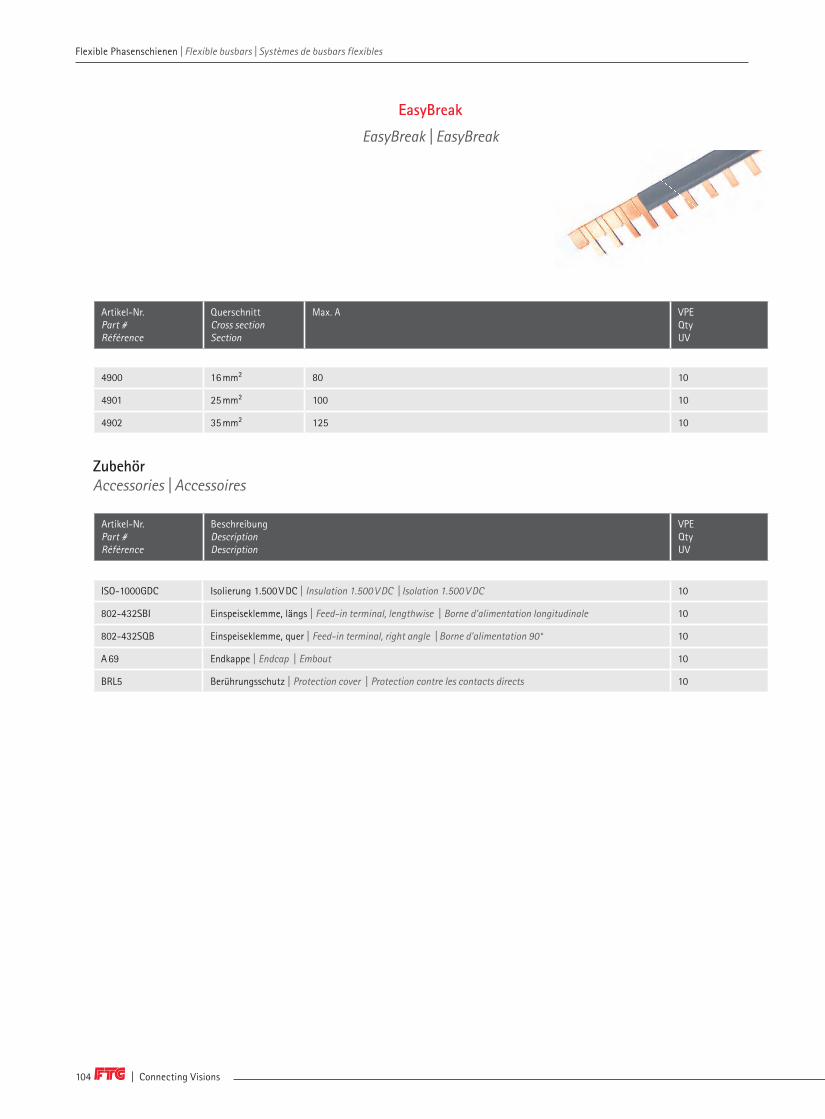
| Connecting Visions104
Flexible Phasenschienen | Flexible busbars | Systèmes de busbars flexibles Flexible Phasenschienen | Flexible busbars | Systèmes de busbars flexibles
Artikel-Nr. Part # Référence
QuerschnittCross section Section
Max. A VPEQtyUV
4900 16 mm² 80 10
4901 25 mm² 100 10
4902 35 mm² 125 10
ZubehörAccessories | Accessoires
Artikel-Nr. Part # Référence
BeschreibungDescriptionDescription
VPEQtyUV
ISO-1000GDC Isolierung 1.500 V DC | Insulation 1.500 V DC | Isolation 1.500 V DC 10
802-432SBI Einspeiseklemme, längs | Feed-in terminal, lengthwise | Borne d'alimentation longitudinale 10
802-432SQB Einspeiseklemme, quer | Feed-in terminal, right angle | Borne d'alimentation 90° 10
A 69 Endkappe | Endcap | Embout 10
BRL5 Berührungsschutz | Protection cover | Protection contre les contacts directs 10
EasyBreak
EasyBreak | EasyBreak
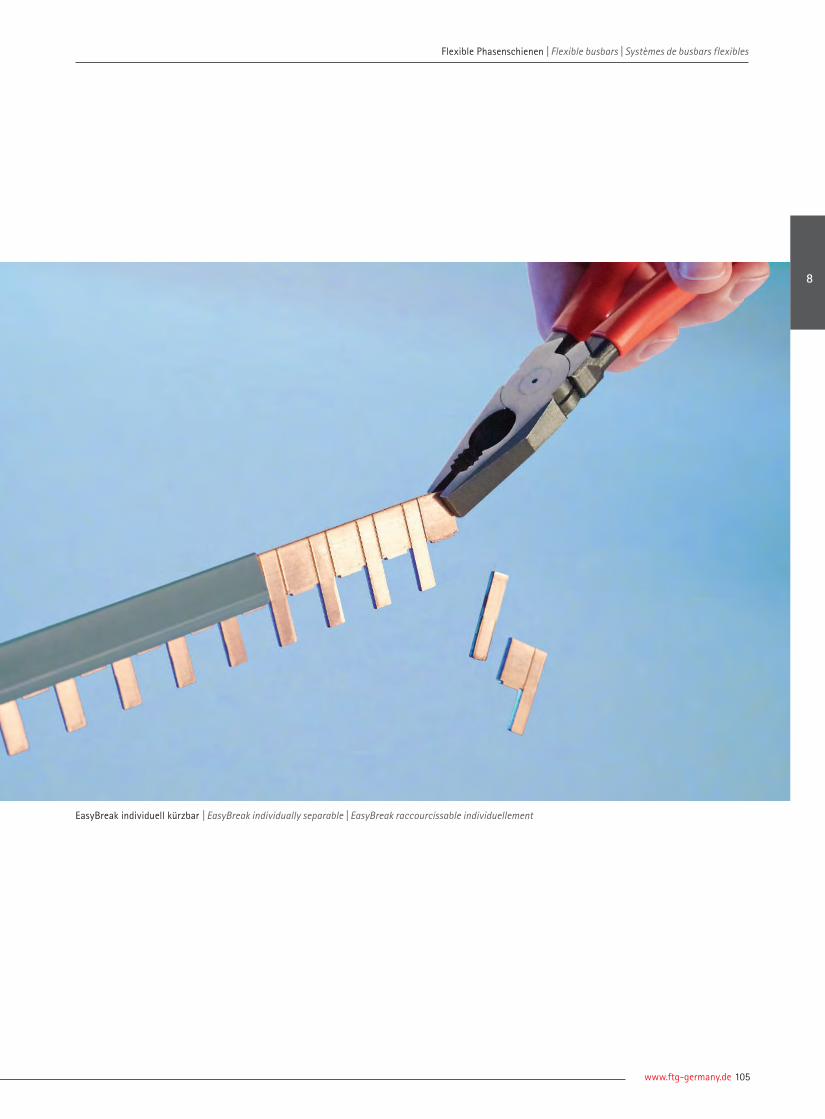
www.ftg-germany.de 105
EasyBreak individuell kürzbar | EasyBreak individually separable | EasyBreak raccourcissable individuellement
Flexible Phasenschienen | Flexible busbars | Systèmes de busbars flexibles
8
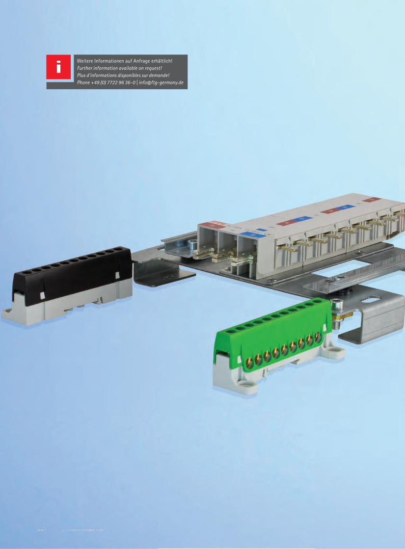
106 | Connection Visions106 | Connection Visions
Weitere Informationen auf Anfrage erhältlich! Further information available on request!Plus d'informations disponibles sur demande!Phone +49 (0) 7722 96 36-0 | [email protected]
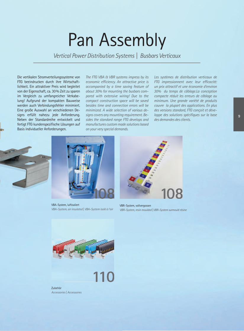
Pan AssemblyVertical Power Distribution Systems | Busbars Verticaux
Die vertikalen Stromverteilungssysteme von FTG beeindrucken durch ihre Wirtschaft-lichkeit. Ein attraktiver Preis wird begleitet von der Eigenschaft, ca. 30 % Zeit zu sparen im Vergleich zu umfangreicher Verkabe-lung! Aufgrund der kompakten Bauweise werden auch Verbindungsfehler minimiert. Eine große Auswahl an verschiedenen De-signs erfüllt nahezu jede Anforderung. Neben der Standardreihe entwickelt und fertigt FTG kundenspezifi sche Lösungen auf Basis individueller Anforderungen.
The FTG VBA & VBR systems impress by its economic effi ciency. An attractive price is accompanied by a time saving feature of about 30% for mounting the busbars com-pared with extensive wiring! Due to the compact construction space will be saved besides time and connection errors will be minimized. A wide selection of various de-signs covers any mounting requirement. Be-sides the standard range FTG develops and manufactures custom made solutions based on your very special demands.
Les systèmes de distribution verticaux de FTG impressionnent avec leur effi cacité: un prix attractif et une économie d'environ 30% du temps de câblage.La conception compacte réduit les erreurs de câblage au minimum. Une grande variété de produits couvre la plupart des applications. En plus des versions standard, FTG conçoit et déve-loppe des solutions spécifi ques sur la base des demandes des clients.
VBA–System, luftisoliertVBA–System, air insulated | VBA–System isolé à l‘air
VBR–System, vollvergossenVBR–System, resin moulded | VBR–System surmoulé résine
ZubehörAccessories | Accessoires
108108
110110
108
9
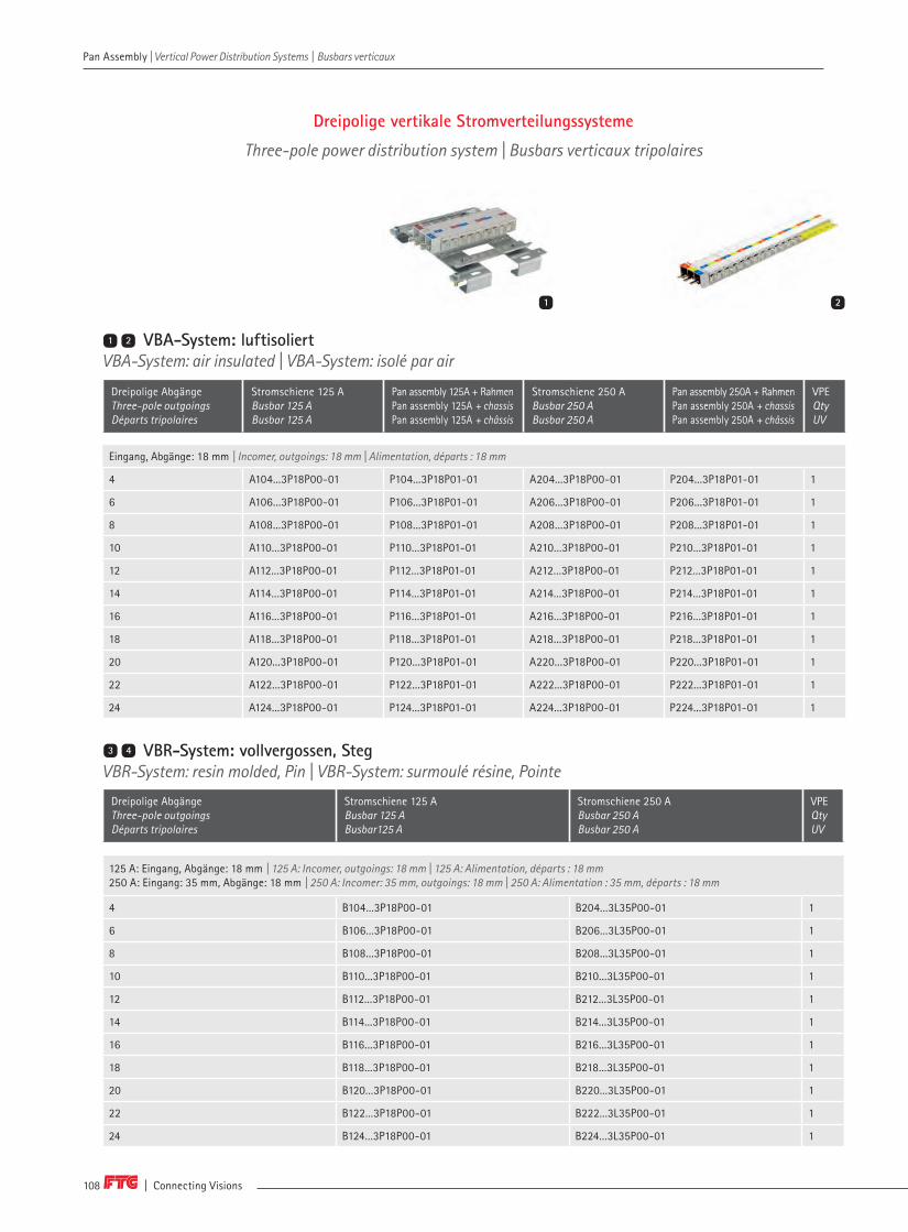
| Connecting Visions108
Pan Assembly | Vertical Power Distribution Systems | Busbars verticaux Pan Assembly | Vertical Power Distribution Systems | Busbars verticaux
Dreipolige vertikale Stromverteilungssysteme
Three-pole power distribution system | Busbars verticaux tripolaires
VBA-System: luftisoliertVBA-System: air insulated | VBA-System: isolé par air
Dreipolige AbgängeThree-pole outgoings Départs tripolaires
Stromschiene 125 A Busbar 125 A Busbar 125 A
Pan assembly 125A + Rahmen Pan assembly 125A + chassis Pan assembly 125A + châssis
Stromschiene 250 A Busbar 250 A Busbar 250 A
Pan assembly 250A + Rahmen Pan assembly 250A + chassis Pan assembly 250A + châssis
VPE Qty UV
Eingang, Abgänge: 18 mm | Incomer, outgoings: 18 mm | Alimentation, départs : 18 mm
4 A104...3P18P00-01 P104...3P18P01-01 A204...3P18P00-01 P204...3P18P01-01 1
6 A106...3P18P00-01 P106...3P18P01-01 A206...3P18P00-01 P206...3P18P01-01 1
8 A108...3P18P00-01 P108...3P18P01-01 A208...3P18P00-01 P208...3P18P01-01 1
10 A110...3P18P00-01 P110...3P18P01-01 A210...3P18P00-01 P210...3P18P01-01 1
12 A112...3P18P00-01 P112...3P18P01-01 A212...3P18P00-01 P212...3P18P01-01 1
14 A114...3P18P00-01 P114...3P18P01-01 A214...3P18P00-01 P214...3P18P01-01 1
16 A116...3P18P00-01 P116...3P18P01-01 A216...3P18P00-01 P216...3P18P01-01 1
18 A118...3P18P00-01 P118...3P18P01-01 A218...3P18P00-01 P218...3P18P01-01 1
20 A120...3P18P00-01 P120...3P18P01-01 A220...3P18P00-01 P220...3P18P01-01 1
22 A122...3P18P00-01 P122...3P18P01-01 A222...3P18P00-01 P222...3P18P01-01 1
24 A124...3P18P00-01 P124...3P18P01-01 A224...3P18P00-01 P224...3P18P01-01 1
125 A: Eingang, Abgänge: 18 mm | 125 A: Incomer, outgoings: 18 mm | 125 A: Alimentation, départs : 18 mm250 A: Eingang: 35 mm, Abgänge: 18 mm | 250 A: Incomer: 35 mm, outgoings: 18 mm | 250 A: Alimentation : 35 mm, départs : 18 mm
4 B104...3P18P00-01 B204...3L35P00-01 1
6 B106...3P18P00-01 B206...3L35P00-01 1
8 B108...3P18P00-01 B208...3L35P00-01 1
10 B110...3P18P00-01 B210...3L35P00-01 1
12 B112...3P18P00-01 B212...3L35P00-01 1
14 B114...3P18P00-01 B214...3L35P00-01 1
16 B116...3P18P00-01 B216...3L35P00-01 1
18 B118...3P18P00-01 B218...3L35P00-01 1
20 B120...3P18P00-01 B220...3L35P00-01 1
22 B122...3P18P00-01 B222...3L35P00-01 1
24 B124...3P18P00-01 B224...3L35P00-01 1
Dreipolige AbgängeThree-pole outgoings Départs tripolaires
Stromschiene 125 A Busbar 125 A Busbar125 A
Stromschiene 250 A Busbar 250 A Busbar 250 A
VPE Qty UV
1 2
1 2
VBR-System: vollvergossen, StegVBR-System: resin molded, Pin | VBR-System: surmoulé résine, Pointe3 4

www.ftg-germany.de 109
Pan Assembly | Vertical Power Distribution Systems | Busbars verticaux
VBR-System: vollvergossen, Steg und GabelVBR-System: resin molded, Pin and Fork | VBR-System: surmoulé résine, Pointe et Fourche3 4
Bitte ersetzen Sie "..." in der Tabelle mit K, M oder O, zum Beispiel: B804M3L60P20– 01Please replace "..." in the table with K, M or O, for example: B804M3L60P20– 01 | Veuillez remplacer "..." dans le tableau par K, M ou O. Par exemple: B104M3P18P00-01
Verfügbare EtikettenAvailable labels | Étiquettes disponibles
K United Kingdom
L1braunbrownbrun
L2schwarzblacknoir
L3graugreygris
Rrotredrouge
Ygelbyellowjaune
Bblaubluebleu
L1rotredrouge
L2weiswhiteblanc
L3dunkel blaudark bluebleu foncé
M Middle East O Oceania
Eingang: 52,4 mm, Abgänge: 25,4 mm | Incomer: 52,4 mm, outgoings: 25,4 mm | Alimentation : 52,4 mm, départs : 25,4 mm
4 B204...3L50P10-01 B404...3L50P10-01 B604...3L50P10-01 1
6 B206...3L50P10-01 B406...3L50P10-01 B606...3L50P10-01 1
8 B208...3L50P10-01 B408...3L50P10-01 B608...3L50P10-01 1
12 B212...3L50P10-01 B412...3L50P10-01 B612...3L50P10-01 1
Dreipolige AbgängeThree-pole way Départs tripolaires
Stromschiene 250 A, Steg Busbar 250 A, pin Busbar 250 A, pointe
Stromschiene 400 A, Steg Busbar 400 A, pin Busbar 400 A, pointe
Stromschiene 630 A, Steg Busbar 630 A, Pin Busbar 630 A, pointe
VPE Qty UV
Eingang: 63,5 mm, Abgänge: 35 mm | Incomer: 63,5 mm, outgoings: 35 mm | Alimentation : 63,5 mm, départs : 35 mm
4 B804...3L60P20-01 B804...3L60F20-01 1
6 B806...3L60P20-01 B806...3L60F20-01 1
8 B808...3L60P20-01 B808...3L60F20-01 1
10 B810...3L60P20-01 B810...3L60F20-01 1
12 B812...3L60P20-01 B812...3L60F20-01 1
14 B814...3L60P20-01 B814...3L60F20-01 1
16 B816...3L60P20-01 B816...3L60F20-01 1
18 B818...3L60P20-01 B818...3L60F20-01 1
Dreipolige AbgängeThree-pole way Départs tripolaires
Stromschiene 800 A, Steg Busbar 800 A, pin Busbar 800 A, pointe
Stromschiene 800 A, Gabel Busbar 800 A, fork Busbar 800 A, fourche
VPE Qty UV
3 4 5
L1 L2 L3
B
L3
Y
L2
R
L1
VBR-System: vollvergossen, StegVBR-System: resin molded, Pin | VBR-System: surmoulé résine, Pointe3 4
5
9
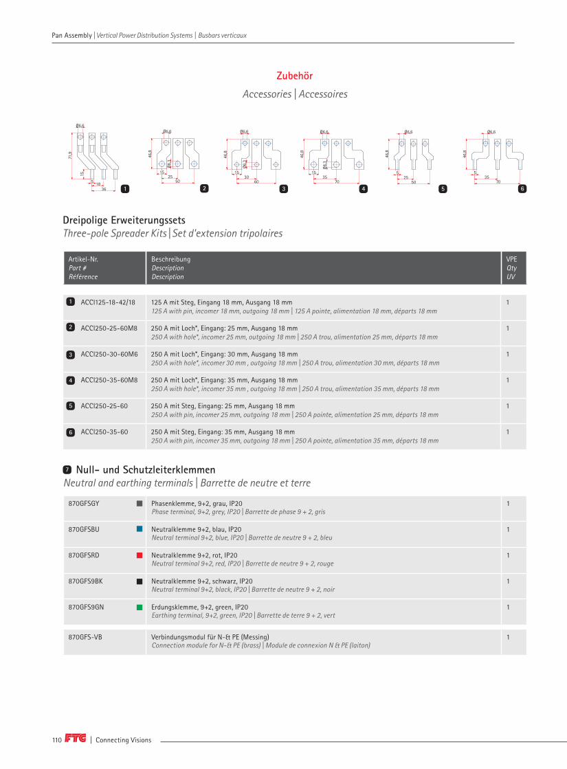
| Connecting Visions110
Zubehör
Accessories | Accessoires
ACCI125-18-42/18 125 A mit Steg, Eingang 18 mm, Ausgang 18 mm125 A with pin, incomer 18 mm, outgoing 18 mm | 125 A pointe, alimentation 18 mm, départs 18 mm
1
ACCI250-25-60M8 250 A mit Loch*, Eingang: 25 mm, Ausgang 18 mm250 A with hole*, incomer 25 mm, outgoing 18 mm | 250 A trou, alimentation 25 mm, départs 18 mm
1
ACCI250-30-60M6 250 A mit Loch*, Eingang: 30 mm, Ausgang 18 mm250 A with hole*, incomer 30 mm , outgoing 18 mm | 250 A trou, alimentation 30 mm, départs 18 mm
1
ACCI250-35-60M8 250 A mit Loch*, Eingang: 35 mm, Ausgang 18 mm250 A with hole*, incomer 35 mm , outgoing 18 mm | 250 A trou, alimentation 35 mm, départs 18 mm
1
ACCI250-25-60 250 A mit Steg, Eingang: 25 mm, Ausgang 18 mm250 A with pin, incomer 25 mm, outgoing 18 mm | 250 A pointe, alimentation 25 mm, départs 18 mm
1
ACCI250-35-60 250 A mit Steg, Eingang: 35 mm, Ausgang 18 mm250 A with pin, incomer 35 mm, outgoing 18 mm | 250 A pointe, alimentation 35 mm, départs 18 mm
1
( 1 : 2 )
A
D
C
B
1 2 3 4 5 6 7 8
A
B
C
D
E
F
1 2 3 4
Weite
rgab
e so
wie
Verv
ielfae
ltigun
g, V
erar
beitu
ng u
nd/o
der Be
arbe
itung
dies
es D
okum
ente
s, V
erwe
rtun
g un
d Mitteilung
seine
s Inha
ltes
sind
verb
oten
, sow
eit nich
t au
sdru
ecklich
ges
tattet
. Zuw
ider
hand
lung
enve
rpflich
ten
zu S
chad
ener
satz
. Alle
Rec
hte
f ür de
n Fa
ll de
r Pa
tent
-,Ge
brau
chsm
uste
r- o
der Ge
schm
acks
must
ereint
ragu
ng v
orbe
halten
.
The
pass
ing
on, a
s we
ll as
the
cop
ying
, distribut
ion
and/
or a
dapt
ion
of this
docu
ment
, exp
loita
tion
and
comm
unica
tion
of it
s co
nten
tswith
out ex
pres
sed
auth
orisat
ion
is p
rohibite
d. C
ontrav
entio
n en
tails
liabilit
y fo
r th
e pa
ymen
t of
dam
ages
. All
right
s re
serv
ed in
the
eve
ntof
a p
aten
t, ut
ility
mod
el o
r or
name
ntal d
esi gn
regist
ratio
n.Au
sgab
e /
Issu
e: 0
7.02
.201
7 13
:18
Blatt/ page
Oberflaechenbehandlungsurface treatment
Allgemeintoleranzgeneral tolerances
StandState
ÄnderungRevision
DatumDate
NameName
Werkstoffbezeichnungmaterial designation
Artikel-Nr.articel-no.
Volumen [mm³]volume [mm ³]
Oberflaechen [mm²] / Querschnittsfläche (mm ²)surface [mm ²] / cross section [mm²]
Gewicht [g]weight [g]
CAD errechneter Wert / CAD calculated value
FTG Göhringer GmbH Teile-Nr.: Part No.:
Zeichnungs-Nr.:Drawing no.:
Teile-Benennung:Part name.:
DatumDateBearb.AutorGepr.CheckedNormStandard
Maßstab:scale:
ISO 2768-1cK
Spreader kit
730-067-01.02
1:1
15.11.2016K.Knöpfle
A32
ACCI125-18-42/18
339
8715
5
71,9
6,6
38
36
18
je 3x
1 ( 1 : 2 )
A
D
C
B
1 2 3 4 5 6 7 8
A
B
C
D
E
F
1 2 3 4
Weite
rgab
e so
wie
Verv
ielfae
ltigun
g, V
erar
beitu
ng u
nd/o
der Be
arbe
itung
dies
es D
okum
ente
s, V
erwe
rtun
g un
d Mitteilung
seine
s Inha
ltes
sind
verb
oten
, sow
eit nich
t au
sdru
ecklich
ges
tattet
. Zuw
ider
hand
lung
enve
rpflich
ten
zu S
chad
ener
satz
. Alle
Rec
hte
f ür de
n Fa
ll de
r Pa
tent
-,Ge
brau
chsm
uste
r- o
der Ge
schm
acks
must
ereint
ragu
ng v
orbe
halten
.
The
pass
ing
on, a
s we
ll as
the
cop
ying
, distribut
ion
and/
or a
dapt
ion
of this
docu
ment
, exp
loita
tion
and
comm
unica
tion
of it
s co
nten
tswith
out ex
pres
sed
auth
orisat
ion
is p
rohibite
d. C
ontrav
entio
n en
tails
liabilit
y fo
r th
e pa
ymen
t of
dam
ages
. All
right
s re
serv
ed in
the
eve
ntof
a p
aten
t, ut
ility
mod
el o
r or
name
ntal d
esi gn
regist
ratio
n.Au
sgab
e /
Issu
e: 0
7.02
.201
7 13
:25
Blatt/ page
Oberflaechenbehandlungsurface treatment
Allgemeintoleranzgeneral tolerances
StandState
ÄnderungRevision
DatumDate
NameName
Werkstoffbezeichnungmaterial designation
Artikel-Nr.articel-no.
Volumen [mm³]volume [mm ³]
Oberflaechen [mm²] / Querschnittsfläche (mm ²)surface [mm ²] / cross section [mm²]
Gewicht [g]weight [g]
CAD errechneter Wert / CAD calculated value
FTG Göhringer GmbH Teile-Nr.: Part No.:
Zeichnungs-Nr.:Drawing no.:
Teile-Benennung:Part name.:
DatumDateBearb.AutorGepr.CheckedNormStandard
Maßstab:scale:
ISO 2768-1mK
Spreader kit 30/18mm
730-066-01.02
04.11.2016M.Schmid
A32
ACCI250-30-60M6
5
87
39
6,6
6,3
15
46,8
38
60
30
je 3x
3 ( 1 : 2 )
A
D
C
B
1 2 3 4 5 6 7 8
A
B
C
D
E
F
1 2 3 4
Weite
rgab
e so
wie
Verv
ielfae
ltigun
g, V
erar
beitu
ng u
nd/o
der Be
arbe
itung
dies
es D
okum
ente
s, V
erwe
rtun
g un
d Mitteilung
seine
s Inha
ltes
sind
verb
oten
, sow
eit nich
t au
sdru
ecklich
ges
tattet
. Zuw
ider
hand
lung
enve
rpflich
ten
zu S
chad
ener
satz
. Alle
Rec
hte
f ür de
n Fa
ll de
r Pa
tent
-,Ge
brau
chsm
uste
r- o
der Ge
schm
acks
must
ereint
ragu
ng v
orbe
halten
.
The
pass
ing
on, a
s we
ll as
the
cop
ying
, distribut
ion
and/
or a
dapt
ion
of this
docu
ment
, exp
loita
tion
and
comm
unica
tion
of it
s co
nten
tswith
out ex
pres
sed
auth
orisat
ion
is p
rohibite
d. C
ontrav
entio
n en
tails
liabilit
y fo
r th
e pa
ymen
t of
dam
ages
. All
right
s re
serv
ed in
the
eve
ntof
a p
aten
t, ut
ility
mod
el o
r or
name
ntal d
esi gn
regist
ratio
n.Au
sgab
e /
Issu
e: 0
7.02
.201
7 13
:13
Blatt/ page
Oberflaechenbehandlungsurface treatment
Allgemeintoleranzgeneral tolerances
StandState
ÄnderungRevision
DatumDate
NameName
Werkstoffbezeichnungmaterial designation
Artikel-Nr.articel-no.
Volumen [mm³]volume [mm ³]
Oberflaechen [mm²] / Querschnittsfläche (mm ²)surface [mm ²] / cross section [mm²]
Gewicht [g]weight [g]
CAD errechneter Wert / CAD calculated value
FTG Göhringer GmbH Teile-Nr.: Part No.:
Zeichnungs-Nr.:Drawing no.:
Teile-Benennung:Part name.:
DatumDateBearb.AutorGepr.CheckedNormStandard
Maßstab:scale:
ISO 2768-1mK
Spreader kit 35/18mm
730-063-01.02
11.07.2016K.Knöpfle
A32
ACCI250-35-60M8
Zeichnungsstand: 07.02.2017
5
87
39
6,6
8,3
15
46,8
38
70
35
je 3x
4 ( 1 : 2 )
A
D
C
B
1 2 3 4 5 6 7 8
A
B
C
D
E
F
1 2 3 4
Weite
rgab
e so
wie
Verv
ielfae
ltigun
g, V
erar
beitu
ng u
nd/o
der Be
arbe
itung
dies
es D
okum
ente
s, V
erwe
rtun
g un
d Mitteilung
seine
s Inha
ltes
sind
verb
oten
, sow
eit nich
t au
sdru
ecklich
ges
tattet
. Zuw
ider
hand
lung
enve
rpflich
ten
zu S
chad
ener
satz
. Alle
Rec
hte
f ür de
n Fa
ll de
r Pa
tent
-,Ge
brau
chsm
uste
r- o
der Ge
schm
acks
must
ereint
ragu
ng v
orbe
halten
.
The
pass
ing
on, a
s we
ll as
the
cop
ying
, distribut
ion
and/
or a
dapt
ion
of this
docu
ment
, exp
loita
tion
and
comm
unica
tion
of it
s co
nten
tswith
out ex
pres
sed
auth
orisat
ion
is p
rohibite
d. C
ontrav
entio
n en
tails
liabilit
y fo
r th
e pa
ymen
t of
dam
ages
. All
right
s re
serv
ed in
the
eve
ntof
a p
aten
t, ut
ility
mod
el o
r or
name
ntal d
esi gn
regist
ratio
n.Au
sgab
e /
Issu
e: 0
7.02
.201
7 13
:12
Blatt/ page
Oberflaechenbehandlungsurface treatment
Allgemeintoleranzgeneral tolerances
StandState
ÄnderungRevision
DatumDate
NameName
Werkstoffbezeichnungmaterial designation
Artikel-Nr.articel-no.
Volumen [mm³]volume [mm ³]
Oberflaechen [mm²] / Querschnittsfläche (mm ²)surface [mm ²] / cross section [mm²]
Gewicht [g]weight [g]
CAD errechneter Wert / CAD calculated value
FTG Göhringer GmbH Teile-Nr.: Part No.:
Zeichnungs-Nr.:Drawing no.:
Teile-Benennung:Part name.:
DatumDateBearb.AutorGepr.CheckedNormStandard
Maßstab:scale:
ISO 2768-1mK
Spreader kit 25mm
730-062-01.02
08.07.2016K.Knöpfle
A32
ACCI250-25-60
Zeichnungsstand: 07.02.2017
5
87
39
6,6
5
46,8
38
25
50
je 3x
5 ( 1 : 2 )
A
D
C
B
1 2 3 4 5 6 7 8
A
B
C
D
E
F
1 2 3 4
Weite
rgab
e so
wie
Verv
ielfae
ltigun
g, V
erar
beitu
ng u
nd/o
der Be
arbe
itung
dies
es D
okum
ente
s, V
erwe
rtun
g un
d Mitteilung
seine
s Inha
ltes
sind
verb
oten
, sow
eit nich
t au
sdru
ecklich
ges
tattet
. Zuw
ider
hand
lung
enve
rpflich
ten
zu S
chad
ener
satz
. Alle
Rec
hte
f ür de
n Fa
ll de
r Pa
tent
-,Ge
brau
chsm
uste
r- o
der Ge
schm
acks
must
ereint
ragu
ng v
orbe
halten
.
The
pass
ing
on, a
s we
ll as
the
cop
ying
, distribut
ion
and/
or a
dapt
ion
of this
docu
ment
, exp
loita
tion
and
comm
unica
tion
of it
s co
nten
tswith
out ex
pres
sed
auth
orisat
ion
is p
rohibite
d. C
ontrav
entio
n en
tails
liabilit
y fo
r th
e pa
ymen
t of
dam
ages
. All
right
s re
serv
ed in
the
eve
ntof
a p
aten
t, ut
ility
mod
el o
r or
name
ntal d
esi gn
regist
ratio
n.Au
sgab
e /
Issu
e: 0
7.02
.201
7 13
:10
Blatt/ page
Oberflaechenbehandlungsurface treatment
Allgemeintoleranzgeneral tolerances
StandState
ÄnderungRevision
DatumDate
NameName
Werkstoffbezeichnungmaterial designation
Artikel-Nr.articel-no.
Volumen [mm³]volume [mm ³]
Oberflaechen [mm²] / Querschnittsfläche (mm ²)surface [mm ²] / cross section [mm²]
Gewicht [g]weight [g]
CAD errechneter Wert / CAD calculated value
FTG Göhringer GmbH Teile-Nr.: Part No.:
Zeichnungs-Nr.:Drawing no.:
Teile-Benennung:Part name.:
DatumDateBearb.AutorGepr.CheckedNormStandard
Maßstab:scale:
ISO 2768-1mK
Spreader kit 35mm
730-061-01.02
08.07.2016K.Knöpfle
A32
ACCI250-35-60
Zeichnungsstand: 07.02.2017
je 3x
5
87
39
6,6
5
46,8
38
35
70
6 ( 1 : 2 )
A
D
C
B
1 2 3 4 5 6 7 8
A
B
C
D
E
F
1 2 3 4
Weite
rgab
e so
wie
Verv
ielfae
ltigun
g, V
erar
beitu
ng u
nd/o
der Be
arbe
itung
dies
es D
okum
ente
s, V
erwe
rtun
g un
d Mitteilung
seine
s Inha
ltes
sind
verb
oten
, sow
eit nich
t au
sdru
ecklich
ges
tattet
. Zuw
ider
hand
lung
enve
rpflich
ten
zu S
chad
ener
satz
. Alle
Rec
hte
f ür de
n Fa
ll de
r Pa
tent
-,Ge
brau
chsm
uste
r- o
der Ge
schm
acks
must
ereint
ragu
ng v
orbe
halten
.
The
pass
ing
on, a
s we
ll as
the
cop
ying
, distribut
ion
and/
or a
dapt
ion
of this
docu
ment
, exp
loita
tion
and
comm
unica
tion
of it
s co
nten
tswith
out ex
pres
sed
auth
orisat
ion
is p
rohibite
d. C
ontrav
entio
n en
tails
liabilit
y fo
r th
e pa
ymen
t of
dam
ages
. All
right
s re
serv
ed in
the
eve
ntof
a p
aten
t, ut
ility
mod
el o
r or
name
ntal d
esi gn
regist
ratio
n.Au
sgab
e /
Issu
e: 0
7.02
.201
7 13
:15
Blatt/ page
Oberflaechenbehandlungsurface treatment
Allgemeintoleranzgeneral tolerances
StandState
ÄnderungRevision
DatumDate
NameName
Werkstoffbezeichnungmaterial designation
Artikel-Nr.articel-no.
Volumen [mm³]volume [mm ³]
Oberflaechen [mm²] / Querschnittsfläche (mm ²)surface [mm ²] / cross section [mm²]
Gewicht [g]weight [g]
CAD errechneter Wert / CAD calculated value
FTG Göhringer GmbH Teile-Nr.: Part No.:
Zeichnungs-Nr.:Drawing no.:
Teile-Benennung:Part name.:
DatumDateBearb.AutorGepr.CheckedNormStandard
Maßstab:scale:
ISO 2768-1mK
Spreader kit 25/18mm
730-064-01.02
11.07.2016K.Knöpfle
A32
ACCI250-25-60M8
Zeichnungsstand: 07.02.2017
5
87
39
6,6
8,3
15
46,8
38
50
25
je 3x
2
2
3
1
4
5
6
Dreipolige ErweiterungssetsThree-pole Spreader Kits | Set d'extension tripolaires
Artikel-Nr. Part # Référence
BeschreibungDescriptionDescription
VPE Qty UV
Null- und Schutzleiterklemmen Neutral and earthing terminals | Barrette de neutre et terre
870GFSGY Phasenklemme, 9+2, grau, IP20 Phase terminal, 9+2, grey, IP20 | Barrette de phase 9 + 2, gris
1
870GFSBU Neutralklemme 9+2, blau, IP20Neutral terminal 9+2, blue, IP20 | Barrette de neutre 9 + 2, bleu
1
870GFSRD Neutralklemme 9+2, rot, IP20Neutral terminal 9+2, red, IP20 | Barrette de neutre 9 + 2, rouge
1
870GFS9BK Neutralklemme 9+2, schwarz, IP20Neutral terminal 9+2, black, IP20 | Barrette de neutre 9 + 2, noir
1
870GFS9GN Erdungsklemme, 9+2, green, IP20Earthing terminal, 9+2, green, IP20 | Barrette de terre 9 + 2, vert
1
870GFS-VB Verbindungsmodul für N-& PE (Messing)Connection module for N-& PE (brass) | Module de connexion N & PE (laiton)
1
7
71,9
Ø6,6Ø6,6 Ø6,6 Ø6,6 Ø6,6 Ø6,6
Ø8,3
Ø6,3
Ø8,3
15
5 1836
50 60 70 50 7025 30 35 25 35
5 515 15 15
46,8
46,8
46,8
46,8
46,8
Pan Assembly | Vertical Power Distribution Systems | Busbars verticaux Pan Assembly | Vertical Power Distribution Systems | Busbars verticaux

www.ftg-germany.de 111
7 8
8
9 10 11
MiniClicMiniClic | MiniClic
Artikel-Nr. Part # Référence
BeschreibungDescriptionDescription
VPEQtyUV
MC22002 1 x 95 mm², 10 x 10 mm² 1
MC22002S 1 x 95 mm², 14 x 10 mm² 1
MC122022 1 x 95 mm², 20 x 10 mm² 1
MC00001 Cube 1.5 - 10 mm² 1
MC00001N Cube 1.5 - 10 mm² 1
1261
BerührschutzProtection cover | Protection des contacts
BRL5 Berührschutz für ungenutzte Anschlüsse Protection cover for unused lugs | Protection contre des contacts directs pour les connexions inutilisées
109
EinspeiseklemmenFeed-in terminals | Bornes d'alimentation
802-215I802-215QI802-215SI
Gabel, 50 mm²Fork, 50 mm² | Fourche, 50 mm²
25
802-215SQI802-2ESB50
Steg, 50 mm²Pin, 50 mm² | Pointe, 50 mm²
25
10
11
Durchgangsklemmen KVIACFeed-throuh terminals KVIAC | Répartiteurs compacts KVIAC
KVIAC11095GKVIAC12095G
Al/Cu, 95 mm²Al/Cu, 95 mm² | Al/Cu, 95 mm²
1012
Pan Assembly | Vertical Power Distribution Systems | Busbars verticaux
9
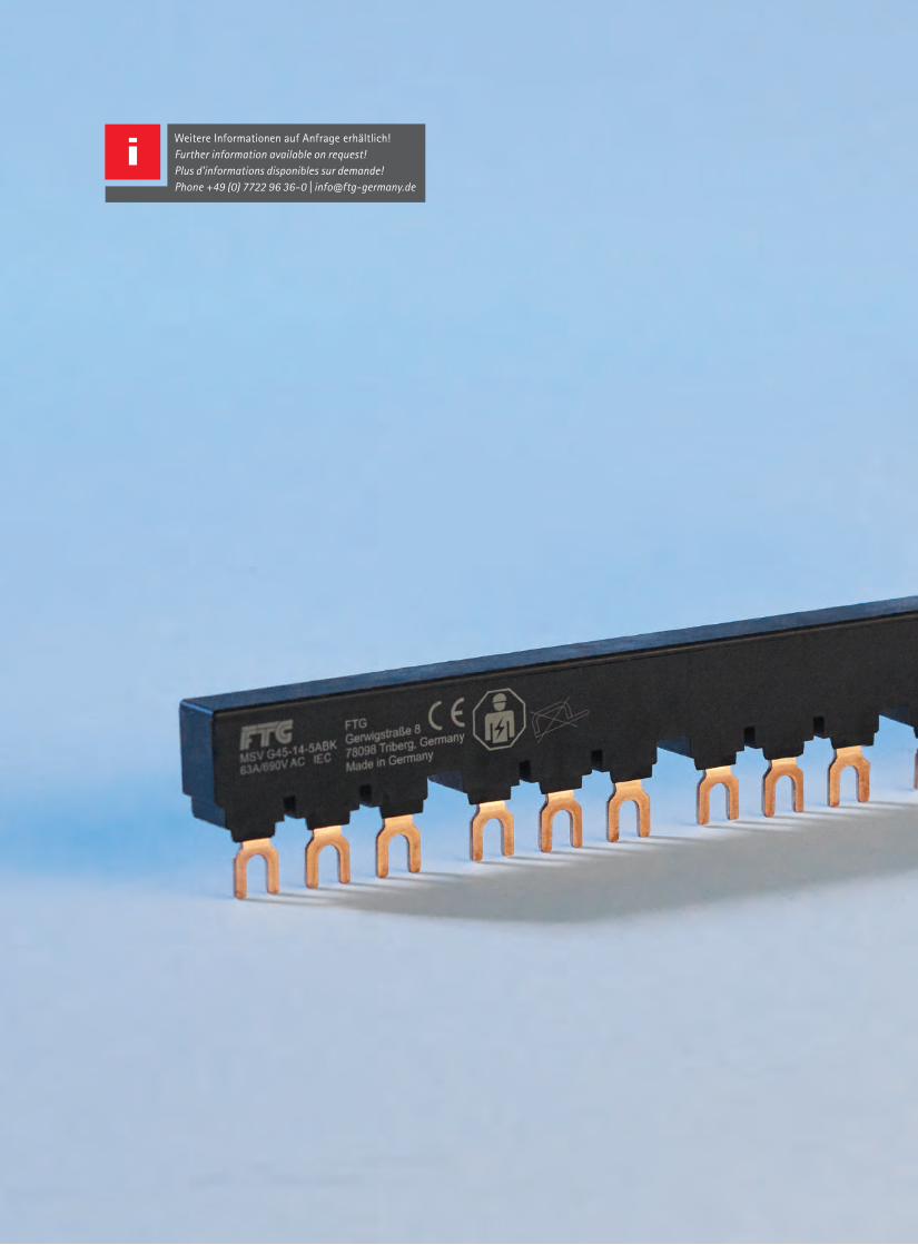
Weitere Informationen auf Anfrage erhältlich! Further information available on request!Plus d'informations disponibles sur demande!Phone +49 (0) 7722 96 36-0 | [email protected]

MSS/ VSMeasyMPS/VSMeasy | Peignes pour disjoncteur-protecteurs de moteur/VSMeasy
Schienen für Motorschutzschalter (MSS) unterschiedlicher Hersteller kommen in sämtlichen Anlagen in Verbindung mit Elektromotoren zum Einsatz. VSMeasy besticht durch eine äußerst kompakte Bauform der Schienen, die zudem sehr platzsparend in der Anwendung ist. Ein besonderes Merkmal dieser Schienen ist dievollvergossene Ausführung.
Busbars for motor protection switches (MPS) of diff erent manufacturers can be used in all systems in conjunction with electric motors for use. VSMeasy impresses with an extre-mely compact design of the rails, which is also very space-saving in the application. A special feature these rails is the fully pou-red version.
Peignes pour disjoncteur-protecteurs de moteur de diff érents fabricants sont utili-sés dans les installations pour la protection des moteurs électriques. VSMeasy off re un gain de place par sa forme très com-pacte. Une caractéristique particulière est la version surmoulée.
MotorschutzschalterschienenBusbars for Motor Protection SwitschesPeignes pour disjoncteur-protecteurs de moteur
114114Vollvergossene AusführungCompletely sealed designVersion surmoulée
116116AdapterplattenAdapter platesAdaptateurs
120120
ZubehörAccessoriesAccessoires
121121SPSeasySPSeasySPSeasy
122122
10

| Connecting Visions114
MSS / VSMeasy | Busbars for MPS / VSMeasy | Peignes pour disjoncteur-protecteurs de moteur / VSMeasy
Motorschutzschalterschienen
Busbars for MPS | Peignes pour disjoncteur-protecteurs de moteur
A | Schrittabstand | Step distance | Distances de pasB | Anzahl Phasen | Number of poles | Nombre de phasesC | Fahnenanzahl | Number of lugs | Nombre de languettesD | Modulbreite | Module width | Largeur de moduleE | Länge | Length | Longueur F | Nennstrom | Rated current | Courant nominal
Artikel-Nr. Part # Référence
QuerschnittCross section Section
A [mm] B C D [mm] E [mm] F [A] VPEQtyUV
vollisoliert | isolated | isolée
MSV G45–14–2ABK 10 mm² 45 3 6 14 87 63 10
MSV G45–14–3ABK 10 mm² 45 3 9 14 132 63 10
MSV G45–14–4ABK 10 mm² 45 3 12 14 177 63 10
MSV G45–14–5ABK 10 mm² 45 3 15 14 222 63 10
MS G45-14-3ABK 16 mm² 45 3 9 14 132 80 10
MS G45-14-4ABK 16 mm² 45 3 12 14 177 80 10
MS G45-14-5ABK 16 mm² 45 3 15 14 222 80 10
MSB G 45-14-2 35 mm² 45 3 6 14 90 100 10
MSB G 45-14-3 35 mm² 45 3 9 14 135 100 10
MSB G 45-14-4 35 mm² 45 3 12 14 180 100 10
MSB G 45-14-5 35 mm² 45 3 15 14 225 100 10
vollisoliert, 1 Hilfsschalter | isolated, 1 auxiliary switch | isolée ,1 interrupteur auxiliaire
MSV G54–14–2ABK 10 mm² 54 3 6 14 96 63 10
MSV G54–14–3ABK 10 mm² 54 3 9 14 150 63 10
MSV G54–14–4ABK 10 mm² 54 3 12 14 204 63 10
MSV G54–14–5ABK 10 mm² 54 3 15 14 258 63 10
MS G54-14-3ABK 16 mm² 54 3 9 14 150 80 10
MS G54-14-4ABK 16 mm² 54 3 12 14 204 80 10
MS G54-14-5ABK 16 mm² 54 3 15 14 258 80 10
MSB G54-14-2 35 mm² 54 3 6 14 108 100 10
MSB G54-14-3 35 mm² 54 3 9 14 162 100 10
MSB G54-14-4 35 mm² 54 3 12 14 216 100 10
MSB G54-14-5 35 mm² 54 3 15 14 270 100 10
MSS / VSMeasy | Busbars for MPS / VSMeasy | Peignes pour disjoncteur-protecteurs de moteur / VSMeasy

www.ftg-germany.de 115
MSS / VSMeasy | Busbars for MPS / VSMeasy | Peignes pour disjoncteur-protecteurs de moteur / VSMeasy MSS / VSMeasy | Busbars for MPS / VSMeasy | Peignes pour disjoncteur-protecteurs de moteur / VSMeasy
Artikel-Nr. Part # Référence
QuerschnittCross section Section
A [mm] B C D [mm] E [mm] F [A] VPE Qty UV
vollisoliert, 2 Hilfsschalter | isolated, 2 auxiliary switches | isolée, 2 interrupteurs auxiliaire
MSV G63–14–2ABK 10 mm² 63 3 6 14 105 63 10
MSV G63–14–3ABK 10 mm² 63 3 9 14 168 63 10
MSV G63–14–4ABK 10 mm² 63 3 12 14 231 63 10
MSV G63–14–5ABK 10 mm² 63 3 15 14 294 63 10
MS G63–14–3ABK 16 mm² 63 3 9 14 168 80 10
MSB G 63-14-2 35 mm² 63 3 6 14 126 100 10
MSB G 63-14-3 35 mm² 63 3 9 14 189 100 10
MSB G 63-14-4 35 mm² 63 3 12 14 252 100 10
MSB G 63-14-5 35 mm² 63 3 15 14 315 100 10
A | Schrittabstand | Step distance | Distances de pas B | Anzahl Phasen | Number of poles | Nombre de phasesC | Fahnenanzahl | Number of lugs | Nombre de languettesD | Modulbreite | Module width | Largeur de moduleE | Länge | Length | Longueur F | Nennstrom | Rated current | Courant nominal
Einspeiseblock | Feed-in terminal block | Borne d’alimentation
MSV GE1-14-25A 6 – 25 mm² 3 - - 14 - 100 10
MSV GE 2– 14 6 – 25 mm² 3 - - 14 - 100 10
MSV GE3-14-35 10 – 35 mm² 3 - - 14 - 100 10
Direkteinspeisung | Direct feed-in | Alimentation directe
MSV ESB1– 14 6 – 25 mm² 3 63 - - - - 10
MSV ESB1– 14 K 6 – 25 mm² 3 63 - - - - 100
Berührschutz für nicht benutzte Anschlussfahnen | Protection cover for unused lugs | Protection contre les contacts pour les phases inutilisées
MSV B54 - - - - - - - 50
Einspeisung MotorschutzschalterschienenFeed-in for MPS busbars | Alimentation pour barres pour disjoncteurs moteur
10

| Connecting Visions116
Vollvergossene Ausführung
Completely sealed design | Version surmoulée
A | Schützbreite | Contactor width | Longeur du contacteurB | Schützgröße | Contactor size | Taille du contacteur
Artikel-Nr. Part # Référence
A [mm] B [kW] Verwendbar z.B. fürSuitable for e.g.Adapté par ex. pour
Ue [V] Iu [A] VPE Qty UV
Wendeverdrahtung | Wiring system for reversing switch | Câblage pour inverseur
WK11A 45 2,2 – 4 – 5,5 – 7,5 Eaton DIL EEM– EM 12/DILM 7– DILM 12– DILM 15Siemens 3RT1015– 3RT1017 | Telemecanique / Schneider Electric LC1– K07– LC1– K12 | GE Power Controls LS07 | WEG CW07 / CWC07 bis CWC016
690 16 10
WK21 45 4 – 5,5 – 7,5 Eaton DIL 00M– DIL 0 AM | ABB A9– A12– A18 | Telemecanique / Schneider Electric LC1– D09 bis – LC1– D18 | WEG CWM9– CWM12–CWM18
690 25 10
WK41 45 11 – 15 – 18,5 Eaton DIL0M– DIL 00 AM | Siemens 3RT1024– 3RT1026 | Telemecanique / Schneider Electric LC1– D09 bis LC1– D38 | WEG CWM25
690 40 10
WK51 45 + 9 4 – 5,5 – 7,5 Eaton DIL 00M– DIL 00 AM | Telemecanique / Schneider Electric LC1– D09 bis LC1– D18 | WEG CWM9– CWM12– CWM18mech. Verriegelung | mechanical interlock | verrouillage mécanique
690 25 10
Stern–Dreieck–Verdrahtung | Star–Delta–Wiring | Câblage étoile–triangle
WK12A 45 2,2 – 4 – 5,5 – 7,5 Eaton DIL EEM– EM 12/DILM 7– DILM 12– DILM 15 Siemens 3RT1015– 3RT1017 | Telemecanique / Schneider Electric LC1– K07– LC1– K12 | GE Power Controls LS07 | WEG CW07 / CWC07 bis CWC016
690 16 10
WK22 45 4 – 5,5 – 7,5 Eaton DIL 00M– DIL 00 AM | ABB A9– A12– A18 | Telemecanique / Schnei-der Electric LC1– D09 bis LC1– D18 | WEG CWM9– CWM12– CWM18
690 25 10
WK42 45 11 – 15 – 18,5 Eaton DIL0M– DIL 0 AM | Siemens 3RT1024– 3RT1026 | Telemecanique / Schneider Electric LC1– D09 bis LC1– D38 | WEG CWM25
690 40 10
Parallelverdrahtung | Parallel–wiring | Câblage parallèle
WK13A 45 2,2 – 4 – 5,5 – 7,5 Eaton DIL EEM– EM 12/DILM 7– DILM 12– DILM 15 | Siemens 3RT1015– 3RT1017 | Telemecanique / Schneider Electric LC1– K07– LC1– K12 GE Power Controls LS07 | WEG CW07 / CWC07 bis CWC016
690 16 10
WK23 45 4 – 5,5 – 7,5 Eaton DIL 00M– DIL 0 AM | ABB A9– A12– A18 | Telemecanique / Schneider Electric LC1– D09 bis – LC1– D18 | WEG CWM9– CWM12– CWM18
690 25 10
WK43 45 11 – 15 – 18,5 Eaton DIL0M– DIL 0 AM | Siemens 3RT1024– 3RT1026 | Telemecanique / Schneider Electric LC1– D09 bis LC1– D38 | WEG CWM25
690 40 10
1
2
3
1 2 3
MSS / VSMeasy | Busbars for MPS / VSMeasy | Peignes pour disjoncteur-protecteurs de moteur / VSMeasy MSS / VSMeasy | Busbars for MPS / VSMeasy | Peignes pour disjoncteur-protecteurs de moteur / VSMeasy

www.ftg-germany.de 117
MSS / VSMeasy | Busbars for MPS / VSMeasy | Peignes pour disjoncteur-protecteurs de moteur / VSMeasy MSS / VSMeasy | Busbars for MPS / VSMeasy | Peignes pour disjoncteur-protecteurs de moteur / VSMeasy
10
Parallelverdrahtung 63 A, anreihbar | Parallel–Wiring 63 A, addable | Câblage parallèle 63 A, alignable
CPM 2456 A 45 2 x 3 Eaton DIL0M– DIL 0 AM Siemens 3RT1024– 3RT1026Telemecanique / Schneider Electric LC1– D09 bis LC1– D38 WEG CWM25
690 63 5
CPM 3456 A 45 3 x 3 690 63 5
CPM 4456 A 45 4 x 3 690 63 5
CPM 5456 A 45 5 x 3 690 63 5
CPM 2546 A 45 + 9 2 x 3 690 63 5
CPM 3546 A 45 + 9 3 x 3 690 63 5
CPM 4546 A 45 + 9 4 x 3 690 63 5
CPM 5546 A 45 + 9 5 x 3 690 63 5
Parallelverdrahtung im Eurovario für Klein–Schütze | Parallel–wiring in Eurovario–Design for Mini–Switches | Câblage parallèle en Eurovario pour petits contacteurs
WK 13.2 45 2 x 3 Eaton DIL EEM– EM 12 Siemens 3RT1015– 3RT1017 Telemecanique / Schneider Electric LC1– K07– LC1– K12 GE Power Controls LS07 WEG CW07 / CWC07 bis CWC016
500 63 10
WK 13.3 45 3 x 3 500 63 10
WK 13.4 45 4 x 3 500 63 10
WK 13.5 45 5 x 3 500 63 10
WK 13.6 45 6 x 3 500 63 10
WK 13.7 45 7 x 3 500 63 10
WK 13.8 45 8 x 3 500 63 10
Parallelverdrahtung 34 A für Kleinschütze, anreihbar | Parallel–wiring 34 A for Mini–Switches, addable | Câblage parallèle 34 A pour petits contacteurs, alignable
CMI 3403 45 3 x 3 Eaton DIL EEM– EM 12 | Siemens 3RT1015– 3RT1017 Telemecanique / Schneider Electric LC1– K07– LC1– K12 GE Power Controls LS07
690 34 5
CMI 4403 45 4 x 3 690 34 5
CMI 3453 45 3 x 3 Eaton DILM 7– DILM 12– DILM 15 690 34 5
CMI 4453 45 4 x 3 690 34 5
CMI 5453 45 5 x 3 690 34 5
Artikel-Nr. Part # Référence
A [mm] B [kW] Verwendbar z.B. fürSuitable for e.g.Adapté par ex. pour
Ue [V] Iu [A] VPE Qty UV
4
5
A | Schützbreite | Contactor width | Longeur du contacteurB | Schützgröße | Contactor size | Taille du contacteur
4 545
9
L1 L1L2 L2L3 L3
1215
6
6

| Connecting Visions118
Artikel-Nr. Part # Référence
A [mm] B [kW] Verwendbar z.B. fürSuitable for e.g.Adapté par ex. pour
Ue [V] Iu [A] VPE Qty UV
Phasenschienen 63 A für Motorschutzschalter IEC/EN60947, anreihbar Busbars 63 A for Motor Protection Switches IEC/EN60947, addable | Rail 63 A pour disjoncteurs moteur, alignables
CPM 3546 A 45 + 9 3 x 3 Eaton PKZM 01/PKZM 0 | Siemens 3RV1011– 3RV1021Telemecanique / Schneider Electric GV2ME | WEG MPW16– MPW25ABB MS 116/MS132 | GE Power Controls Mbs 32 | Rockwell AB 140M– C
690 63 5
CPM 4546 A 45 + 9 4 x 3 690 63 5
CPM 5546 A 45 + 9 5 x 3 690 63 5
CPM 2456 A 45 2 x 3 Eaton PKZM 01/PKZM 0 | Siemens 3RV1011– 3RV1021Telemecanique / Schneider Electric GV2ME | WEG MPW16– MPW25ABB MS 116/MS132 | GE Power Controls Mbs 32 | Rockwell AB 140M– C
690 63 5
CPM 3456 A 45 3 x 3 690 63 5
CPM 4456 A 45 4 x 3 690 63 5
CPM 5456 A 45 5 x 3 690 63 5
CPM 2546 A 45 + 9 2 x 3 690 63 5
für Motorschutzschalter IEC/EN 60947, anreihbar | for MPS according to IEC/EN 60947, addable | pour disjoncteur-protecteur de moteur IEC/EN60947, alignables
CPM 25412 54 2 x 3 Eaton PKZM 4 | Siemens 3RV1031 | ABB MS 450 | Telemecanique / Schneider Electric GV3 | GE Power Controls Mbs 63 | WEG MPW65
690 120 1
CPM 35412 54 3 x 3 690 120 1
CPM 45412 54 4 x 3 690 120 1
CPM 26312 54 + 9 2 x 3 690 120 1
CPM 36312 54 + 9 3 x 3 690 120 1
CPM 46312 54 + 9 4 x 3 690 120 1
1
1
A | Schützbreite | Contactor width | Longeur du contacteurB | Schützgröße | Contactor size | Taille du contacteur
MSS / VSMeasy | Busbars for MPS / VSMeasy | Peignes pour disjoncteur-protecteurs de moteur / VSMeasy MSS / VSMeasy | Busbars for MPS / VSMeasy | Peignes pour disjoncteur-protecteurs de moteur / VSMeasy

www.ftg-germany.de 119
MSS / VSMeasy | Busbars for MPS / VSMeasy | Peignes pour disjoncteur-protecteurs de moteur / VSMeasy MSS / VSMeasy | Busbars for MPS / VSMeasy | Peignes pour disjoncteur-protecteurs de moteur / VSMeasy
42
Artikel-Nr. Part # Référence
QuerschnittCross section Section
BeschreibungDescriptionDescription
Verwendbar z.B. fürSuitable for e.g.Adapté par ex. pour
Ue [V] Iu [A] VPE Qty UV
Einspeiseblock 63 A nach IEC/EN 60947 und UL 508E Feed-in terminal block 63 A according to IEC/EN 60947 and UL 508E | Borne d’alimentation 63 A selon IEC/EN 60947 et UL 508E
BTC 25 IC A 2,5 – 25 mm² IEC/EN60947 UL508 Anschluss mit CPM–SchieneConnection with CPM–BusbarConnexion avec CMI3403+CMI4403–Barre
Eaton PKZM 01 / PKZM 0 Siemens 3RV1011– 3RV1021 Telemecanique / Schneider Electric GV2ME WEG MPW16– MPW25 ABB MS 116/MS 132 GE Power Controls Mbs 32Rockwell AB 140M–C
690 63 5
BTC 25 EC A 2,5 – 25 mm² UL508Anschluss mit CPM–SchieneConnection with CPM–BusbarConnexion avec barre CPM
690 63 5
Einspeiseblock 34 AFeed-in terminal block 34 A | Borne d’alimentation 34 A
BMI 25 IC 1,5 – 25 mm² Anschluss mit | Connection with connexion avec CMI3403+CMI4403 Schiene | Busbar | Barre
Eaton DIL EEM– EM 12 | Siemens 3RT1015– 3RT1017 Telemecanique / Schneider Electric LC1– K07– LC1– K12 | GE Power Controls LS07 | WEG CW07 / CWC07 bis CWC016
690 34 10
BMI 25 ICM 1,5 – 25 mm² Anschluss mit | Connection with Connexion avec CMI3453, CMI4453Schiene | Busbar | Barre
Eaton DILM 7– DILM 12– DILM 15 690 34 10
Einspeiseblock 120 A nach IEC/EN 60947 und UL 508EFeed-in terminal block 120 A according to IEC/EN 60947 and UL 508E | Borne d’alimentation 120 A selon IEC/EN 60947 et UL 508E
BTC 50 E 10 – 50 mm² IEC/EN60947 UL508E Anschluss mit CPM– Schiene oder direkt am MSS Connection with CPM busbar or directly with Motor protection switch
Eaton PKZM 4 | Siemens 3RV1031 ABB MS 450 | Telemecanique / Schneider Electric GV3GE Power Controls Mbs 63 | WEG MPW65
690 120 1
2
Berührschutz für nicht benutzte AnschlussfahnenProtection cover for unused phases | Protection contre les contacts directs pour les phases inutilisées
Artikel-Nr. Part # Référence
Schützbreite [mm]Contactor width Longeur du contacteur
Verwendbar z.B. fürSuitable for e.g.Adapté par ex. pour
VPE Qty UV
TA 63 A 45 CPM…6 10
TA 120 54 CPM…12 10
5
3
4
3 5
10

| Connecting Visions120
MSS / VSMeasy | Busbars for MPS / VSMeasy | Peignes pour disjoncteur-protecteurs de moteur / VSMeasy MSS / VSMeasy | Busbars for MPS / VSMeasy | Peignes pour disjoncteur-protecteurs de moteur / VSMeasy
Adapterplatten
Adapter plates | Plaques d'adaptation
Für Motorstarter–Kombinationen zum Aufrasten auf DIN TragschienenFor motor starter combinations for snapping onto DIN railsPour les combinaisons de démarrage moteur par embrochage sur le rail
Artikel-Nr. Part # Référence
BaugrößeSize Taille
B Verwendbar z.B. fürSuitable for e.g.Adapté par ex. pour
VPE Qty UV
UMP 45A 45 mm 2 Direktstarter MSS" Leistungsschütz, 2x DIN-Schiene verschiebbar MPS " Power switch, 2 DIN-rail movableDémarreur direct MPS " interrupteur d’alimentation, 2 x rail coulissant
5
UMP 54A 54 mm 2 5
UMP 45 45 mm 2 Direktstarter MSS" Leistungsschütz,1x DIN-Schiene verschiebbar MSS"Power switch, 1 DIN-rail movableDémarreur direct MPS"interrupteur d’alimentation, 1 x rail DIN coulissant
10
UMP 90 90 mm 3 Wende-Starter-Kombination, MSS"2x Leistungsschütz, 1x DIN-Schiene verschiebbar Reversing-Starter-Combination MSS " 2x Power switches, 1x DIN-rail movableOmbinaison inverseur-démarreur MSS" 2x interrupteurs d’alimentation, 1x rail DIN coulissant
5
UMP 90E 90 mm 4 Stern-Dreieck-Kombination, MSS"3x Leistungsschütz, 1 X DIN-Schiene verschiebbar Star-Delta-Wiring MSS"3x Power switches, 1 x DIN-rail movableCombinaison étoile-triangle MSS"3x interrupteurs d’alimentation, 1 x rail DIN coulissant
5
A | Kabellänge | Cable length | Longueurs de câblesB | Anzahl Geräteplätze | Number of switch units Nombre d'emplacements de périphériquesC | Anzahl Fahnen | Number of poles | Nombre de languettes
1
1
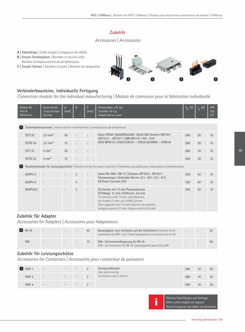
www.ftg-germany.de 121
MSS / VSMeasy | Busbars for MPS / VSMeasy | Peignes pour disjoncteur-protecteurs de moteur / VSMeasy MSS / VSMeasy | Busbars for MPS / VSMeasy | Peignes pour disjoncteur-protecteurs de moteur / VSMeasy
Weitere Kabellängen auf Anfrage.Other cable lengths on request.Autres longueurs de câbles sur demande.
A | Kabellänge | Cable length | Longueurs de câblesB | Anzahl Geräteplätze | Number of switch units Nombre d'emplacements de périphériquesC | Anzahl Fahnen | Number of poles | Nombre de languettes
Zubehör
Accessories | Accessoires
2 3
Verbinderbausteine, individuelle Fertigung Connection module for the individual manufacturing | Module de connexion pour la fabrication individuelle
Artikel-Nr. Part # Référence
QuerschnittCross sectionSection
A [mm]
B C [mm]
Verwendbar z.B. fürSuitable for e.g.Adapté par ex. pour
Ue [V] Iu [A] VPE Qty UV
Starterkombinationen | motor starter combinations | combinaisons de démarreurs
ITCF 20 2,5 mm² 50 - - Eaton PKZM | DILEM/DIL00M– DIL00 AM Siemens 3RV10113RT1015 – 3RT1017 | ABB MS116"A9 – A16 WEG MPW16 | CW07/CWC07 – CWC016/CWM9 – CWM18
690 20 10
ITCFD 20 2,5 mm² 75 - - 690 20 10
ITCF 35 4 mm² 50 - - 690 35 10
ITCFD 35 4 mm² 75 - - 690 35 10
Parallelverbinder für Leistungsschütze | Parallel wiring for power switches | Combineur parallèle pour interrupteurs d’alimentation
802PV13 - - 3 - Eaton DIL EEM– EM 12 | Siemens 3RT1015– 3RT1017 Telemecanique / Schneider Electric LC1– K07– LC1– K12 GE Power Controls LS07
500 50 10
802PV14 - - 4 - 500 50 10
802PV523 - - 3 - Für Geräte mit 13 mm Phasenabstand, Stiftlänge: 21 mm, Stiftbreite: 2,8 mmFor devices with 13 mm pole distance, pin length 21 mm, pin width 2,8 mmPour appareil avec 13 mm distance des phases, longueur pointe 21 mm, largeur pointe 2,8 mm
500 50 10
2
3
Zubehör für Adapter Accessories for Adapters | Accessoires pour Adaptateurs
RK 45 - - - 45 Kanaladapter zum Aufrasten auf die Hutschiene| Channel to be assembled on DIN– rail | Canal adaptateur à encastrer sur le rail
- - 20
ERK - - - 15 DIN– Schienenverlängerung für RK 45DIN– rail extension for RK 45 | prolongation pour rails DIN
- - 60
Zubehör für Leistungsschütze Accessories for Contactors | Accessoires pour contacteur de puissance
WKP 1 - - - 3 Sternpunktbrücke Star point wiringContacteur point neutre
690 16 20
WKP 2 - - - 3 690 16 20
WKP 4 - - - 3 690 16 20
4
5
4 5
10

| Connecting Visions122
MSS / VSMeasy | Busbars for MPS / VSMeasy | Peignes pour disjoncteur-protecteurs de moteur / VSMeasy MSS / VSMeasy | Busbars for MPS / VSMeasy | Peignes pour disjoncteur-protecteurs de moteur / VSMeasy
SystemartenSystem typesType de système
A B C D E[m]
F G VPEQtyUV
A | Bauart | Design type | ConceptionB | Anzahl Einzeladern | Number of the single wire | Nombre de fi lsC | Querschnitt | Cross section | SectionD | Kontaktart | Contact type | Type de contactE | Länge | Length | LongueurF | Farbe | Colour | CouleurG | Art der Konfektion | Manufacture type | Type de fabrication
SPS1 S7-300 SHQ
SiemensHelmholzSequenzkabelsatzSequence set of cablesSéquence de câbles
2/4/
20-polige20-pole20-pôles40-polige40-pole40-pôles
0507
0,5 mm²0,75 mm²
FK
SK
Federzugkontaktespring-loaded contactContacts à ressortSchraubkontaktescrew contactscontact vissé
1 | 2 | 3 4 | 5
BURDBNBKYGOG
1 USV (ultraschallverdichtet)USV (ultrasonically sealed)USV (compacté par ultrason)2 AE (Aderendhülse)AE (ferrule) | AE (embout)3 TA (Teilabzug)TA (partial withdrawal)TA (pré-dénudé)4 ohne Konfektionwithout confectionsans confection
1
SPS2 S7-400 SHQ
SiemensHelmholzSequenzkabelsatzSequence set of cablesSéquence de câbles
2/4/
20-polige20-pole20-pôles40-polige40-pole40-pôles
0507
0,5 mm²0,75 mm²
FK
SK
Federzugkontaktespring-loaded contactContacts à ressortSchraubkontaktescrew contactscontact vissé
1 | 2 | 3 4 | 5
BURDBNBKYGOG
1 USV (ultraschallverdichtet)USV (ultrasonically sealed)USV (compacté par ultrason) 2 AE (Aderendhülse)AE (ferrule) | AE (embout)3 TA (Teilabzug)TA (partial withdrawal)TA (pré-dénudé)4 ohne Konfektionwithout confectionsans confection
1
Nomenklatur | Nomenclature | Nomenclature
Systemarten | System types | Type de systèmeBauart | Design type | ConceptionAnzahl Einzeladern | Number of the single wire | Nombre de fi lsQuerschnitt | Cross section | SectionKontaktart | Contact type | Type de contactLänge | Length | LongueurFarbe | Colour | CouleurArt der Konfektion | Manufacture type | Type de fabrication
SPS1 S 2/ 05 FK 1 RD 1
SPSeasy
SPSeasy | SPSeasy
Auch ohne Konfektion erhältlich.Also without confection available.Sans confection disponsible. G

www.ftg-germany.de 123
SPS Stecker | SPS Plug | SPS Connecteur
MSS / VSMeasy | Busbars for MPS / VSMeasy | Peignes pour disjoncteur-protecteurs de moteur / VSMeasy MSS / VSMeasy | Busbars for MPS / VSMeasy | Peignes pour disjoncteur-protecteurs de moteur / VSMeasy
10

Weitere Informationen auf Anfrage erhältlich! Further information available on request!Plus d'informations disponibles sur demande!Phone +49 (0) 7722 96 36-0 | [email protected]
Leiterarten Types of conductors | Types de conducteurs
ein-/mehrdrähtig single/multi wire | rigide monobrins / multibrins
feindrahtig mit AE fine wire with sleeve | souple avec embout câbles fins avec embout
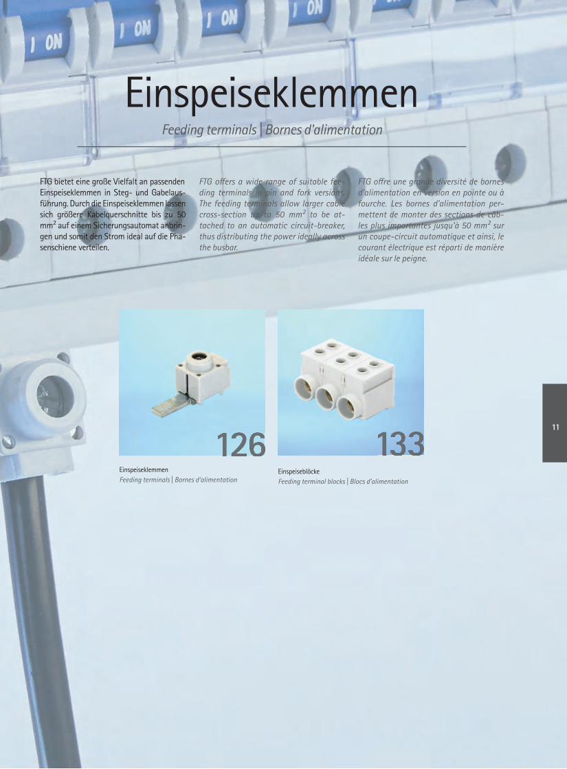
EinspeiseklemmenFeeding terminals | Bornes d'alimentation
FTG bietet eine große Vielfalt an passendenEinspeiseklemmen in Steg- und Gabelaus-führung. Durch die Einspeiseklemmen lassensich größere Kabelquerschnitte bis zu 50 mm² auf einem Sicherungsautomat anbrin-gen und somit den Strom ideal auf die Pha-senschiene verteilen.
FTG off ers a wide range of suitable fee-ding terminals in pin and fork versions. The feeding terminals allow larger cable cross-section up to 50 mm² to be at-tached to an automatic circuit-breaker, thus distributing the power ideally across the busbar.
FTG off re une grande diversité de bornes d’alimentation en version en pointe ou à fourche. Les bornes d’alimentation per-mettent de monter des sections de câb-les plus importantes jusqu’à 50 mm² sur un coupe-circuit automatique et ainsi, le courant électrique est réparti de manière idéale sur le peigne.
EinspeiseklemmenFeeding terminals | Bornes d’alimentation
EinspeiseblöckeFeeding terminal blocks | Blocs d’alimentation
13313312612611

| Connecting Visions126
Einspeiseklemmen | Feeding terminals | Bornes d'alimentation Einspeiseklemmen | Feeding terminals | Bornes d'alimentation
3
1 2
4
Einspeiseklemmen
Feeding terminals | Bornes d’alimentation
Einspeiseklemme, isoliertFeeding terminal, isolated | Bornes d'alimentation, isolées
Artikel-Nr. Part # Référence
A B [mm] C [mm] D Querschnitt | Cross section | Section Max. A|V VPE Qty UV
Zuführung: längs | Feeding: lengthwise | Alimentation: longitudinal
802/114 ¨ 11 | M6 15 PZ2 6 – 25 mm² 4 – 16 mm² 80 A | AC 690 V | DC 1.500 V 25
802/114I R 11 | M6 15 PZ2 6 – 25 mm² 4 – 16 mm² 80 A | AC 690 V | DC 1.500 V 25
802/114-blau ¨ 11 | M6 15 PZ2 6 – 25 mm² 4 – 16 mm² 80 A | AC 690 V | DC 1.500 V 25
802/114l-blau R 11 | M6 15 PZ2 6 – 25 mm² 4 – 16 mm² 80 A | AC 690 V | DC 1.500 V 25
Zuführung: quer | Feeding: across | Alimentation: transversal
802/114Q ¨ 11 | M6 15 PZ2 6 – 25 mm² 4 – 16 mm² 80 A | AC 690 V | DC 1.500 V 25
802/114QI R 11 | M6 15 PZ2 6 – 25 mm² 4 – 16 mm² 80 A | AC 690 V | DC 1.500 V 25
802/114Q-blau ¨ 11 | M6 15 PZ2 6 – 25 mm² 4 – 16 mm² 80 A | AC 690 V | DC 1.500 V 25
802/114Ql-blau R 11 | M6 15 PZ2 6 – 25 mm² 4 – 16 mm² 80 A | AC 690 V | DC 1.500 V 25
Zuführung: längs | Feeding: lengthwise | Alimentation: longitudinal
802/128 ¨ 11 | M6 28 PZ2 6 – 25 mm² 4 – 16 mm² 80 A | AC 690 V | DC 1.500 V 25
802/128I R 11 | M6 28 PZ2 6 – 25 mm² 4 – 16 mm² 80 A | AC 690 V | DC 1.500 V 25
802/128-blau ¨ 11 | M6 28 PZ2 6 – 25 mm² 4 – 16 mm² 80 A | AC 690 V | DC 1.500 V 25
802/128l-blau R 11 | M6 28 PZ2 6 – 25 mm² 4 – 16 mm² 80 A | AC 690 V | DC 1.500 V 25
Zuführung: quer | Feeding: across | Alimentation: transversal
802/128Q ¨ 11 | M6 28 PZ2 6 – 25 mm² 4 – 16 mm² 80 A | AC 690 V | DC 1.500 V 25
802/128QI R 11 | M6 28 PZ2 6 – 25 mm² 4 – 16 mm² 80 A | AC 690 V | DC 1.500 V 25
802/128Q-blau ¨ 11 | M6 28 PZ2 6 – 25 mm² 4 – 16 mm² 80 A | AC 690 V | DC 1.500 V 25
802/128Ql-blau R 11 | M6 28 PZ2 6 – 25 mm² 4 – 16 mm² 80 A | AC 690 V | DC 1.500 V 25
1
2
3
4
A | Boden isoliert | Isolated base | Sol isoléB | Gabelbreite | Fork width | Largeur fourche C | Gabellänge | Fork length | Longueur fourcheD | Anschlussschrauben | Connection screws | Vis de raccordement

www.ftg-germany.de 127
Einspeiseklemmen | Feeding terminals | Bornes d'alimentation
5 6
7 8
Einspeiseklemme, isoliertFeeding terminal, isolated | Bornes d'alimentation, isolées
Artikel-Nr. Part # Référence
A B [mm] C [mm] D Querschnitt | Cross section | Section Max. A|V VPE Qty UV
Zuführung: längs | Feeding: lengthwise | Alimentation: longitudinal
802/115S ¨ 4,3 15 PZ2 6 – 25 mm² 4 – 16 mm² 80 A | AC 690 V | DC 1.500 V 25
802/115SI R 4,3 15 PZ2 6 – 25 mm² 4 – 16 mm² 80 A | AC 690 V | DC 1.500 V 25
802/115S-bl ¨ 4,3 15 PZ2 6 – 25 mm² 4 – 16 mm² 80 A | AC 690 V | DC 1.500 V 25
802/115Sl-blau R 4,3 15 PZ2 6 – 25 mm² 4 – 16 mm² 80 A | AC 690 V | DC 1.500 V 25
Zuführung: quer | Feeding: across | Alimentation: transversal
802/115SQ ¨ 4,3 15 PZ2 6 – 25 mm² 4 – 16 mm² 80 A | AC 690 V | DC 1.500 V 25
802/115SQI R 4,3 15 PZ2 6 – 25 mm² 4 – 16 mm² 80 A | AC 690 V | DC 1.500 V 25
802/115SQ-BL ¨ 4,3 15 PZ2 6 – 25 mm² 4 – 16 mm² 80 A | AC 690 V | DC 1.500 V 25
802/115SQl-Blau R 4,3 15 PZ2 6 – 25 mm² 4 – 16 mm² 80 A | AC 690 V | DC 1.500 V 25
Zuführung: längs | Feeding: lengthwise | Alimentation: longitudinal
802/115SB ¨ 6 15 PZ2 6 – 25 mm² 4 – 16 mm² 80 A | AC 690 V | DC 1.500 V 25
802/115SBI R 6 15 PZ2 6 – 25 mm² 4 – 16 mm² 80 A | AC 690 V | DC 1.500 V 25
802/115SB-BL ¨ 6 15 PZ2 6 – 25 mm² 4 – 16 mm² 80 A | AC 690 V | DC 1.500 V 25
802/115SBl-Blau R 6 15 PZ2 6 – 25 mm² 4 – 16 mm² 80 A | AC 690 V | DC 1.500 V 25
Zuführung: quer | Feeding: across | Alimentation: transversal
802/115SQB ¨ 6 15 PZ2 6 – 25 mm² 4 – 16 mm² 80 A | AC 690 V | DC 1.500 V 25
802/115SQBI R 6 15 PZ2 6 – 25 mm² 4 – 16 mm² 80 A | AC 690 V | DC 1.500 V 25
802/115SQB-Blau ¨ 6 15 PZ2 6 – 25 mm² 4 – 16 mm² 80 A | AC 690 V | DC 1.500 V 25
802/115SQBl-Blau R 6 15 PZ2 6 – 25 mm² 4 – 16 mm² 80 A | AC 690 V | DC 1.500 V 25
5
6
7
8
A | Boden isoliert | Isolated base | Sol isoléB | Stegbreite | Pin width | Longeur pointe C | Steglänge | Pin length | Longueur pointe
D | Anschlussschrauben | Connection screws | Vis de raccordement
11
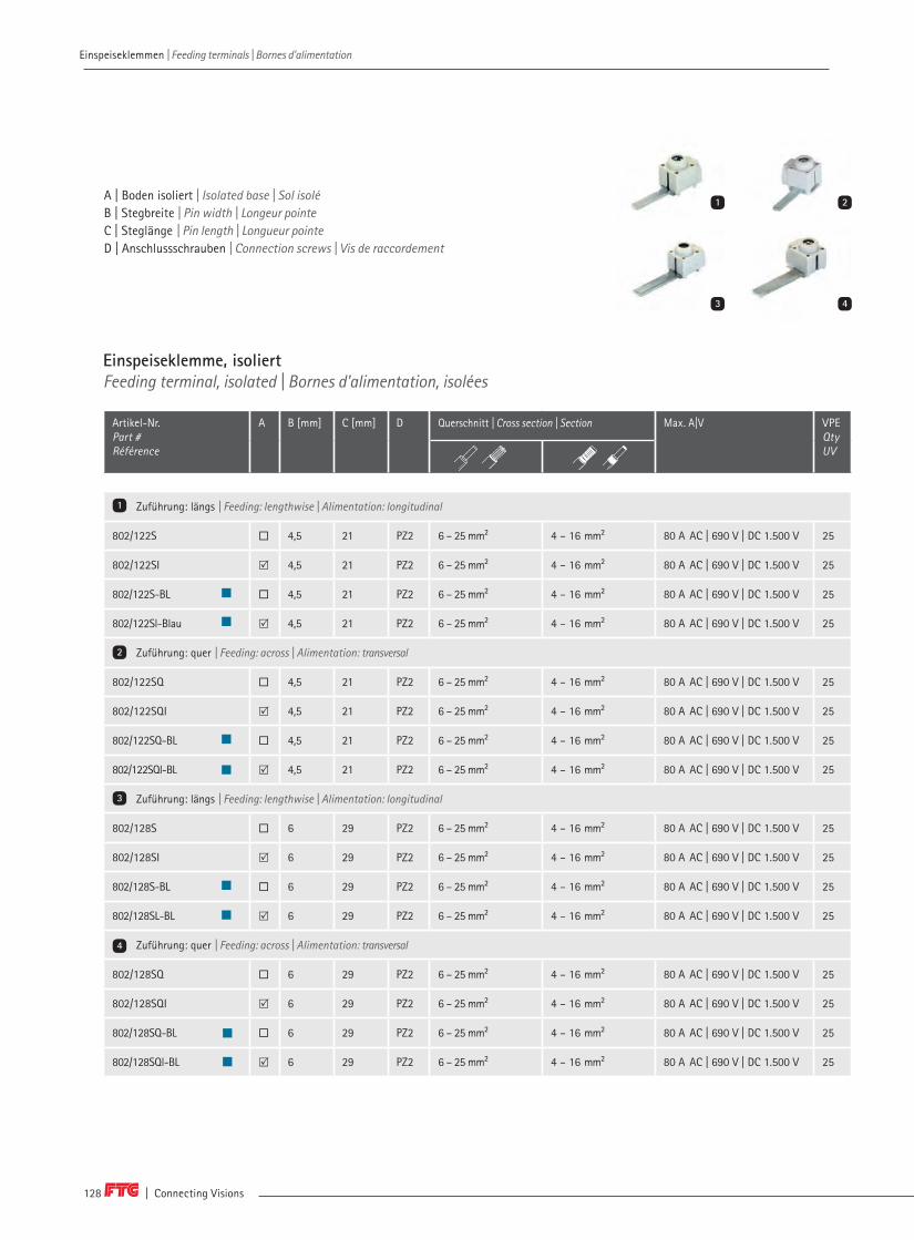
| Connecting Visions128
Einspeiseklemmen | Feeding terminals | Bornes d'alimentation Einspeiseklemmen | Feeding terminals | Bornes d'alimentation
Einspeiseklemme, isoliertFeeding terminal, isolated | Bornes d'alimentation, isolées
Artikel-Nr. Part # Référence
A B [mm] C [mm] D Querschnitt | Cross section | Section Max. A|V VPE Qty UV
Zuführung: längs | Feeding: lengthwise | Alimentation: longitudinal
802/122S ¨ 4,5 21 PZ2 6 – 25 mm² 4 – 16 mm² 80 A AC | 690 V | DC 1.500 V 25
802/122SI R 4,5 21 PZ2 6 – 25 mm² 4 – 16 mm² 80 A AC | 690 V | DC 1.500 V 25
802/122S-BL ¨ 4,5 21 PZ2 6 – 25 mm² 4 – 16 mm² 80 A AC | 690 V | DC 1.500 V 25
802/122Sl-Blau R 4,5 21 PZ2 6 – 25 mm² 4 – 16 mm² 80 A AC | 690 V | DC 1.500 V 25
Zuführung: quer | Feeding: across | Alimentation: transversal
802/122SQ ¨ 4,5 21 PZ2 6 – 25 mm² 4 – 16 mm² 80 A AC | 690 V | DC 1.500 V 25
802/122SQI R 4,5 21 PZ2 6 – 25 mm² 4 – 16 mm² 80 A AC | 690 V | DC 1.500 V 25
802/122SQ-BL ¨ 4,5 21 PZ2 6 – 25 mm² 4 – 16 mm² 80 A AC | 690 V | DC 1.500 V 25
802/122SQl-BL R 4,5 21 PZ2 6 – 25 mm² 4 – 16 mm² 80 A AC | 690 V | DC 1.500 V 25
Zuführung: längs | Feeding: lengthwise | Alimentation: longitudinal
802/128S ¨ 6 29 PZ2 6 – 25 mm² 4 – 16 mm² 80 A AC | 690 V | DC 1.500 V 25
802/128SI R 6 29 PZ2 6 – 25 mm² 4 – 16 mm² 80 A AC | 690 V | DC 1.500 V 25
802/128S-BL ¨ 6 29 PZ2 6 – 25 mm² 4 – 16 mm² 80 A AC | 690 V | DC 1.500 V 25
802/128SL-BL R 6 29 PZ2 6 – 25 mm² 4 – 16 mm² 80 A AC | 690 V | DC 1.500 V 25
Zuführung: quer | Feeding: across | Alimentation: transversal
802/128SQ ¨ 6 29 PZ2 6 – 25 mm² 4 – 16 mm² 80 A AC | 690 V | DC 1.500 V 25
802/128SQI R 6 29 PZ2 6 – 25 mm² 4 – 16 mm² 80 A AC | 690 V | DC 1.500 V 25
802/128SQ-BL ¨ 6 29 PZ2 6 – 25 mm² 4 – 16 mm² 80 A AC | 690 V | DC 1.500 V 25
802/128SQl-BL R 6 29 PZ2 6 – 25 mm² 4 – 16 mm² 80 A AC | 690 V | DC 1.500 V 25
3
1 2
4
1
2
3
4
A | Boden isoliert | Isolated base | Sol isoléB | Stegbreite | Pin width | Longeur pointe C | Steglänge | Pin length | Longueur pointe
D | Anschlussschrauben | Connection screws | Vis de raccordement

www.ftg-germany.de 129
Einspeiseklemmen | Feeding terminals | Bornes d'alimentation
Einspeiseklemme, isoliertFeeding terminal, isolated | Bornes d'alimentation, isolées
Artikel-Nr. Part # Référence
A B [mm] C [mm] D Querschnitt | Cross section | Section Max. A|V VPE Qty UV
Zuführung: längs | Feeding: lengthwise | Alimentation: longitudinal
802/130S ¨ 4 32 PZ2 6 – 25 mm² 4 – 16 mm² 80 A AC | 690 V | DC 1.500 V 25
802/130SI R 4 32 PZ2 6 – 25 mm² 4 – 16 mm² 80 A AC | 690 V | DC 1.500 V 25
802/130S-BL ¨ 4 32 PZ2 6 – 25 mm² 4 – 16 mm² 80 A AC | 690 V | DC 1.500 V 25
802/130Sl-BL R 4 32 PZ2 6 – 25 mm² 4 – 16 mm² 80 A AC | 690 V | DC 1.500 V 25
Zuführung: quer | Feeding: across | Alimentation: transversal
802/130SQ ¨ 4 32 PZ2 6 – 25 mm² 4 – 16 mm² 80 A AC | 690 V | DC 1.500 V 25
802/130SQI R 4 32 PZ2 6 – 25 mm² 4 – 16 mm² 80 A AC | 690 V | DC 1.500 V 25
802/130SQ-Blau ¨ 4 32 PZ2 6 – 25 mm² 4 – 16 mm² 80 A AC | 690 V | DC 1.500 V 25
802/130SQl-Blau R 4 32 PZ2 6 – 25 mm² 4 – 16 mm² 80 A AC | 690 V | DC 1.500 V 25
Zuführung: längs | Feeding: lengthwise | Alimentation: longitudinal
802/132S ¨ 6 32 PZ2 6 – 25 mm² 4 – 16 mm² 80 A AC | 690 V | DC 1.500 V 25
802/132SI R 6 32 PZ2 6 – 25 mm² 4 – 16 mm² 80 A AC | 690 V | DC 1.500 V 25
802/132S-Blau ¨ 6 32 PZ2 6 – 25 mm² 4 – 16 mm² 80 A AC | 690 V | DC 1.500 V 25
802/132Sl-Blau R 6 32 PZ2 6 – 25 mm² 4 – 16 mm² 80 A AC | 690 V | DC 1.500 V 25
Zuführung: quer | Feeding: across | Alimentation: transversal
802/132SQ ¨ 6 32 PZ2 6 – 25 mm² 4 – 16 mm² 80 A AC | 690 V | DC 1.500 V 25
802/132SQI R 6 32 PZ2 6 – 25 mm² 4 – 16 mm² 80 A AC | 690 V | DC 1.500 V 25
802/132SQ-Blau ¨ 6 32 PZ2 6 – 25 mm² 4 – 16 mm² 80 A AC | 690 V | DC 1.500 V 25
802/132SQl-Blau R 6 32 PZ2 6 – 25 mm² 4 – 16 mm² 80 A AC | 690 V | DC 1.500 V 25
5
6
7
8
5 6
7 8
A | Boden isoliert | Isolated base | Sol isoléB | Stegbreite | Pin width | Longeur pointe C | Steglänge | Pin length | Longueur pointe
D | Anschlussschrauben | Connection screws | Vis de raccordement
11

| Connecting Visions130
Einspeiseklemme, isoliertFeeding terminal, isolated | Bornes d'alimentation, isolées
Artikel-Nr. Part # Référence
A B [mm] C [mm] D Querschnitt | Cross section | Section Max. A|V VPE Qty UV
Zuführung: längs | Feeding: lengthwise | Alimentation: longitudinal
802/215 ¨ 11 | M6 15 PZ2 6 – 50 mm² 4 – 35 mm² 125 A AC | 690 V | DC 1.500 V 25
802/215I R 11 | M6 15 PZ2 6 – 50 mm² 4 – 35 mm² 125 A AC | 690 V | DC 1.500 V 25
802/215-BL ¨ 11 | M6 15 PZ2 6 – 50 mm² 4 – 35 mm² 125 A AC | 690 V | DC 1.500 V 25
802/215l-BL R 11 | M6 15 PZ2 6 – 50 mm² 4 – 35 mm² 125 A AC | 690 V | DC 1.500 V 25
Zuführung: quer | Feeding: across | Alimentation: transversal
802/215Q ¨ 11 | M6 15 PZ2 6 – 50 mm² 4 – 35 mm² 125 A AC | 690 V | DC 1.500 V 25
802/215QI R 11 | M6 15 PZ2 6 – 50 mm² 4 – 35 mm² 125 A AC | 690 V | DC 1.500 V 25
802/215Q-BL ¨ 11 | M6 15 PZ2 6 – 50 mm² 4 – 35 mm² 125 A AC | 690 V | DC 1.500 V 25
802/215Q l-BL R 11 | M6 15 PZ2 6 – 50 mm² 4 – 35 mm² 125 A AC | 690 V | DC 1.500 V 25
Zuführung: längs | Feeding: lengthwise | Alimentation: longitudinal
802/432 ¨ 11 | M6 32 PZ2 6 – 50 mm² 4 – 35 mm² 125 A AC | 690 V | DC 1.500 V 25
802/432I R 11 | M6 32 PZ2 6 – 50 mm² 4 – 35 mm² 125 A AC | 690 V | DC 1.500 V 25
802/432-BL ¨ 11 | M6 32 PZ2 6 – 50 mm² 4 – 35 mm² 125 A AC | 690 V | DC 1.500 V 25
802/432l-BL R 11 | M6 32 PZ2 6 – 50 mm² 4 – 35 mm² 125 A AC | 690 V | DC 1.500 V 25
Zuführung: quer | Feeding: across | Alimentation: transversal
802/432Q ¨ 11 | M6 32 PZ2 6 – 50 mm² 4 – 35 mm² 125 A AC | 690 V | DC 1.500 V 25
802/432QI R 11 | M6 32 PZ2 6 – 50 mm² 4 – 35 mm² 125 A AC | 690 V | DC 1.500 V 25
802/432Q-BL ¨ 11 | M6 32 PZ2 6 – 50 mm² 4 – 35 mm² 125 A AC | 690 V | DC 1.500 V 25
802/432Ql-Blau R 11 | M6 32 PZ2 6 – 50 mm² 4 – 35 mm² 125 A AC | 690 V | DC 1.500 V 25
3
1 2
4
1
2
3
4
A | Boden isoliert | Isolated base | Sol isoléB | Gabelbreite | Fork width | Largeur fourche C | Gabellänge | Fork length | Longueur fourcheD | Anschlussschrauben | Connection screws | Vis de raccordement
Einspeiseklemmen | Feeding terminals | Bornes d'alimentation Einspeiseklemmen | Feeding terminals | Bornes d'alimentation
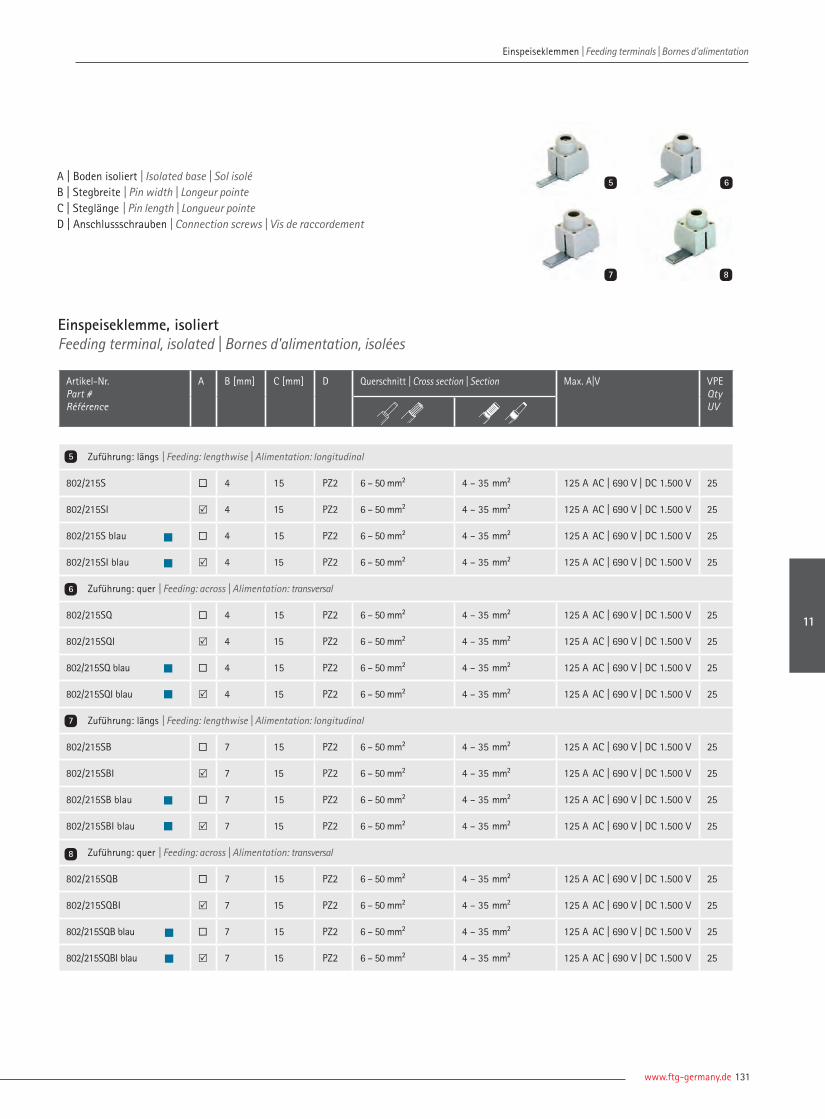
www.ftg-germany.de 131
Einspeiseklemme, isoliertFeeding terminal, isolated | Bornes d'alimentation, isolées
Artikel-Nr. Part # Référence
A B [mm] C [mm] D Querschnitt | Cross section | Section Max. A|V VPEQtyUV
Zuführung: längs | Feeding: lengthwise | Alimentation: longitudinal
802/215S ¨ 4 15 PZ2 6 – 50 mm² 4 – 35 mm² 125 A AC | 690 V | DC 1.500 V 25
802/215SI R 4 15 PZ2 6 – 50 mm² 4 – 35 mm² 125 A AC | 690 V | DC 1.500 V 25
802/215S blau ¨ 4 15 PZ2 6 – 50 mm² 4 – 35 mm² 125 A AC | 690 V | DC 1.500 V 25
802/215SI blau R 4 15 PZ2 6 – 50 mm² 4 – 35 mm² 125 A AC | 690 V | DC 1.500 V 25
Zuführung: quer | Feeding: across | Alimentation: transversal
802/215SQ ¨ 4 15 PZ2 6 – 50 mm² 4 – 35 mm² 125 A AC | 690 V | DC 1.500 V 25
802/215SQI R 4 15 PZ2 6 – 50 mm² 4 – 35 mm² 125 A AC | 690 V | DC 1.500 V 25
802/215SQ blau ¨ 4 15 PZ2 6 – 50 mm² 4 – 35 mm² 125 A AC | 690 V | DC 1.500 V 25
802/215SQI blau R 4 15 PZ2 6 – 50 mm² 4 – 35 mm² 125 A AC | 690 V | DC 1.500 V 25
Zuführung: längs | Feeding: lengthwise | Alimentation: longitudinal
802/215SB ¨ 7 15 PZ2 6 – 50 mm² 4 – 35 mm² 125 A AC | 690 V | DC 1.500 V 25
802/215SBI R 7 15 PZ2 6 – 50 mm² 4 – 35 mm² 125 A AC | 690 V | DC 1.500 V 25
802/215SB blau ¨ 7 15 PZ2 6 – 50 mm² 4 – 35 mm² 125 A AC | 690 V | DC 1.500 V 25
802/215SBI blau R 7 15 PZ2 6 – 50 mm² 4 – 35 mm² 125 A AC | 690 V | DC 1.500 V 25
Zuführung: quer | Feeding: across | Alimentation: transversal
802/215SQB ¨ 7 15 PZ2 6 – 50 mm² 4 – 35 mm² 125 A AC | 690 V | DC 1.500 V 25
802/215SQBI R 7 15 PZ2 6 – 50 mm² 4 – 35 mm² 125 A AC | 690 V | DC 1.500 V 25
802/215SQB blau ¨ 7 15 PZ2 6 – 50 mm² 4 – 35 mm² 125 A AC | 690 V | DC 1.500 V 25
802/215SQBI blau R 7 15 PZ2 6 – 50 mm² 4 – 35 mm² 125 A AC | 690 V | DC 1.500 V 25
5
6
7
8
5 6
7 8
A | Boden isoliert | Isolated base | Sol isoléB | Stegbreite | Pin width | Longeur pointeC | Steglänge | Pin length | Longueur pointe
D | Anschlussschrauben | Connection screws | Vis de raccordement
Einspeiseklemmen | Feeding terminals | Bornes d'alimentation
11

| Connecting Visions132
Einspeiseklemmen | Feeding terminals | Bornes d'alimentation Einspeiseklemmen | Feeding terminals | Bornes d'alimentation
Einspeiseklemme, isoliertFeeding terminal, isolated | Bornes d'alimentation, isolées
Artikel-Nr. Part # Référence
A B [mm] C [mm] D Querschnitt | Cross section | Section Max. A|V VPE Qty UV
Zuführung: längs | Feeding: lengthwise | Alimentation: longitudinal
802/432S ¨ 4 32 PZ2 6 – 50 mm² 4 – 35 mm² 125 A AC | 690 V | DC 1.500 V 25
802/432SI R 4 32 PZ2 6 – 50 mm² 4 – 35 mm² 125 A AC | 690 V | DC 1.500 V 25
802/432S-BL ¨ 4 32 PZ2 6 – 50 mm² 4 – 35 mm² 125 A AC | 690 V | DC 1.500 V 25
802/432Sl-BL R 4 32 PZ2 6 – 50 mm² 4 – 35 mm² 125 A AC | 690 V | DC 1.500 V 25
Zuführung: quer | Feeding: across | Alimentation: transversal
802/432SB ¨ 6 32 PZ2 6 – 50 mm² 4 – 35 mm² 125 A AC | 690 V | DC 1.500 V 25
802/432SBI R 6 32 PZ2 6 – 50 mm² 4 – 35 mm² 125 A AC | 690 V | DC 1.500 V 25
802/432SB-BL ¨ 6 32 PZ2 6 – 50 mm² 4 – 35 mm² 125 A AC | 690 V | DC 1.500 V 25
802/432SBl-Blau R 6 32 PZ2 6 – 50 mm² 4 – 35 mm² 125 A AC | 690 V | DC 1.500 V 25
Zuführung: längs | Feeding: lengthwise | Alimentation: longitudinal
802/432SQ ¨ 4 32 PZ2 6 – 50 mm² 4 – 35 mm² 125 A AC | 690 V | DC 1.500 V 25
802/432SQl R 4 32 PZ2 6 – 50 mm² 4 – 35 mm² 125 A AC | 690 V | DC 1.500 V 25
802/432SQ-Blau ¨ 4 32 PZ2 6 – 50 mm² 4 – 35 mm² 125 A AC | 690 V | DC 1.500 V 25
802/432SQl-Blau R 4 32 PZ2 6 – 50 mm² 4 – 35 mm² 125 A AC | 690 V | DC 1.500 V 25
Zuführung: quer | Feeding: across | Alimentation: transversal
802/432SQB ¨ 6 32 PZ2 6 – 50 mm² 4 – 35 mm² 125 A AC | 690 V | DC 1.500 V 25
802/432SQBl R 6 32 PZ2 6 – 50 mm² 4 – 35 mm² 125 A AC | 690 V | DC 1.500 V 25
802/432SQB-Blau ¨ 6 32 PZ2 6 – 50 mm² 4 – 35 mm² 125 A AC | 690 V | DC 1.500 V 25
802/432SQBl-Blau R 6 32 PZ2 6 – 50 mm² 4 – 35 mm² 125 A AC | 690 V | DC 1.500 V 25
1
2
3
4
1 2
3 4
A | Boden isoliert | Isolated base | Sol isoléB | Stegbreite | Pin width | Longeur pointe C | Steglänge | Pin length | Longueur pointe
D | Anschlussschrauben | Connection screws | Vis de raccordement

www.ftg-germany.de 133
A | Ausführung | Design | VersionB | Breite | Width | Largeur C | Länge | Length | Longueur D | Anschlussschrauben | Connection screws | Vis de raccordement
Einspeiseklemme, isoliertFeeding terminal, isolated | Bornes d'alimentation, isolées
Artikel-Nr. Part # Référence
A B [mm] C [mm] D Querschnitt | Cross section | Section VPE Qty UV
Vollisoliert, UL 508, Zuführung: längs, A / V max.: 115 A | 1000 V AC / DC Fully isolated, UL 508, feeding: lengthwise | Isolées, Ul 508, alimentation: longitudinal
802/080 Steg | Pin | Pointe 6,3 18,5 PZ2 6 – 50 mm² | AWG 10– 1/0 4 – 35 mm² 25
802/180 Steg | Pin | Pointe 6,3 18,5 PZ2 6 – 50 mm² | AWG 10– 1/0 4 – 35 mm² 25
802/201 Steg | Pin | Pointe 6 13 PZ2 6 – 50 mm² | AWG 10– 1/0 4 – 35 mm² 25
802/150S Steg | Pin | Pointe 6 12,4 PZ2 6 – 50 mm² | AWG 10– 1/0 4 – 35 mm² 25
802/153S Steg | Pin | Pointe 6 12,4 PZ2 6 – 50 mm² | AWG 10– 1/0 4 – 35 mm² 25
Für Aluminiumleiter, Zuführung: quer, A / V max.: 100 A | AC 690 V For alluminium conductors, feeding: across, A / V max.: 100 A | AC 690 V | Pour conducteurs aluminium, alimentation: transversal, A / V max.: 100 A | AC 690 V
802/2 N 115 Gabel | Fork | Fourche 11 | M6 15 SW5 6 – 50 mm² 4 – 35 mm 25
802/2 N 115 S Steg | Pin | Pointe 6,8 15 SW5 6 – 50 mm² 4 – 35 mm 25
5
6
7
Einspeiseblöcke, 50 mm²Feeding terminal blocks, 50 mm² | Blocs d’alimentation, 50 mm²
Anreihbar, zur Einspeisung direkt in die Phasenschiene, für Gabel und Steg Addable, direct feeding to busbar, for fork and pin | Alignable, pour alimentation directe dans la barre, pour fourche et pointe
802/2ESB50 Gabel/Steg | Fork/Pin | Fourche/Pointe – – PZ2 6 – 50 mm² 6 – 35 mm² 25
802/ESB50 UL Gabel/Steg | Fork/Pin | Fourche/Pointe – – PZ2 6 – 50 mm² 6 – 35 mm² 25
8
7 8
5 6
Einspeiseklemmen | Feeding terminals | Bornes d'alimentation
11
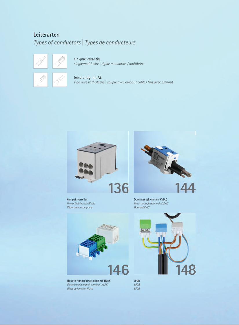
Durchgangsklemmen KVIACFeed-through terminals KVIACBornes KVIAC
KompaktverteilerPower Distribution Blocks Répartiteurs compacts
144144136136
LPDBLPDBLPDB
Hauptleitungsabzweigklemme HLAKElectric main branch terminal HLAKBlocs de jonction HLAK
148148146146
LeiterartenTypes of conductors | Types de conducteurs
ein-/mehrdrähtigsingle/multi wire | rigide monobrins / multibrins
feindrahtig mit AEfine wire with sleeve | souple avec embout câbles fins avec embout
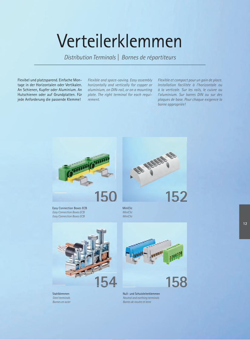
VerteilerklemmenDistribution Terminals | Bornes de répartiteurs
Flexibel und platzsparend. Einfache Mon-tage in der Horizontalen oder Vertikalen. An Schienen, Kupfer oder Aluminium. An Hutschienen oder auf Grundplatten. Für jede Anforderung die passende Klemme!
Flexible and space-saving. Easy assembly horizontally and vertically for copper or aluminium, on DIN-rail, or on a mounting plate. The right terminal for each requi-rement.
Flexible et compact pour un gain de place. Installation facilitée à l‘horizontale ou à la verticale. Sur les rails, le cuivre ou l‘aluminium. Sur barres DIN ou sur des plaques de base. Pour chaque exigence la borne appropriée!
Easy Connection Boxes ECBEasy Connection Boxes ECBEasy Connection Boxes ECB
MiniClicMiniClic MiniClic
152152150150150
Null- und SchutzleiterklemmenNeutral and earthing terminalsBarres de neutre et terre
StahlklemmenSteel terminalsBornes en acier
154154154 158158
12
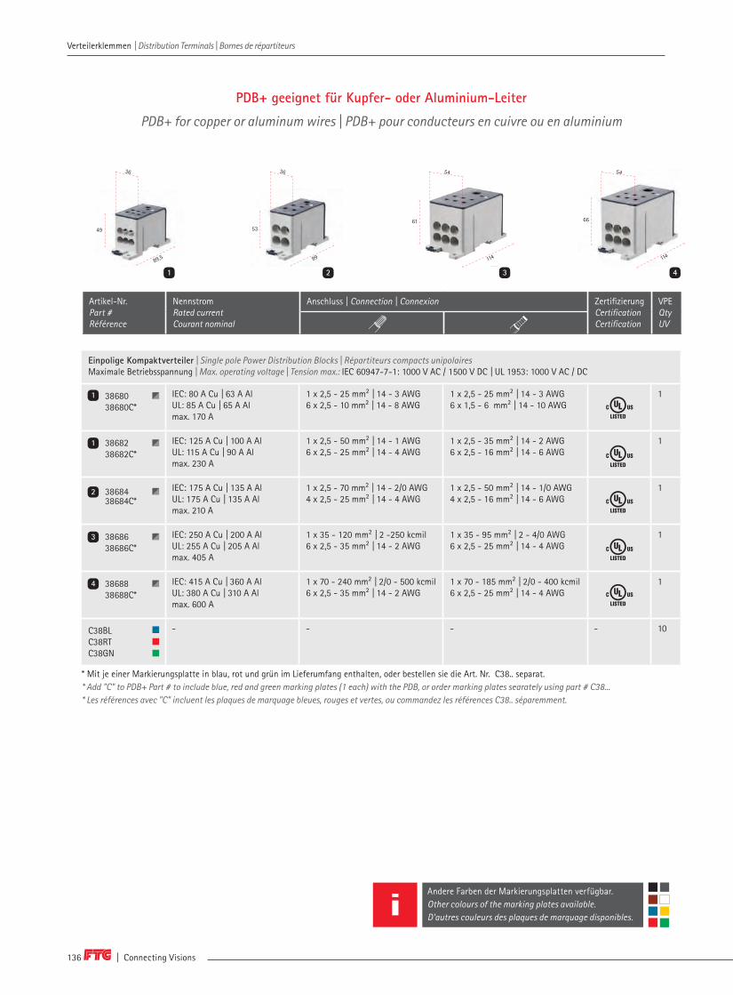
| Connecting Visions136
Verteilerklemmen | Distribution Terminals | Bornes de répartiteurs Verteilerklemmen | Distribution Terminals | Bornes de répartiteurs
PDB+ geeignet für Kupfer- oder Aluminium-Leiter
PDB+ for copper or aluminum wires | PDB+ pour conducteurs en cuivre ou en aluminium
Artikel-Nr. Part # Référence
Nennstrom Rated currentCourant nominal
Anschluss | Connection | Connexion Zertifizierung CertificationCertification
VPE Qty UV
Einpolige Kompaktverteiler | Single pole Power Distribution Blocks | Répartiteurs compacts unipolairesMaximale Betriebsspannung | Max. operating voltage | Tension max.: IEC 60947-7-1: 1000 V AC / 1500 V DC | UL 1953: 1000 V AC / DC
38680 38680C*
IEC: 80 A Cu | 63 A AlUL: 85 A Cu | 65 A Almax. 170 A
1 x 2,5 - 25 mm² | 14 - 3 AWG6 x 2,5 - 10 mm² | 14 - 8 AWG
1 x 2,5 - 25 mm² | 14 - 3 AWG6 x 1,5 - 6 mm² | 14 - 10 AWG
1
3868238682C*
IEC: 125 A Cu | 100 A AlUL: 115 A Cu | 90 A Almax. 230 A
1 x 2,5 - 50 mm² | 14 - 1 AWG6 x 2,5 - 25 mm² | 14 - 4 AWG
1 x 2,5 - 35 mm² | 14 - 2 AWG6 x 2,5 - 16 mm² | 14 - 6 AWG
1
3868438684C*
IEC: 175 A Cu | 135 A AlUL: 175 A Cu | 135 A Almax. 210 A
1 x 2,5 - 70 mm² | 14 - 2/0 AWG4 x 2,5 - 25 mm² | 14 - 4 AWG
1 x 2,5 - 50 mm² | 14 - 1/0 AWG4 x 2,5 - 16 mm² | 14 - 6 AWG
1
3868638686C*
IEC: 250 A Cu | 200 A AlUL: 255 A Cu | 205 A Almax. 405 A
1 x 35 - 120 mm² | 2 -250 kcmil6 x 2,5 - 35 mm² | 14 - 2 AWG
1 x 35 - 95 mm² | 2 - 4/0 AWG6 x 2,5 - 25 mm² | 14 - 4 AWG
1
3868838688C*
IEC: 415 A Cu | 360 A AlUL: 380 A Cu | 310 A Al max. 600 A
1 x 70 - 240 mm² | 2/0 - 500 kcmil6 x 2,5 - 35 mm² | 14 - 2 AWG
1 x 70 - 185 mm² | 2/0 - 400 kcmil6 x 2,5 - 25 mm² | 14 - 4 AWG
1
C38BL C38RT C38GN
- - - - 10
1
1
2
3
4
* Mit je einer Markierungsplatte in blau, rot und grün im Lieferumfang enthalten, oder bestellen sie die Art. Nr. C38.. separat.* Add "C" to PDB+ Part # to include blue, red and green marking plates (1 each) with the PDB, or order marking plates searately using part # C38...* Les références avec "C" incluent les plaques de marquage bleues, rouges et vertes, ou commandez les références C38.. séparemment.
66
114
42
99
53
1
36 36
89,5
49
3114
61
3
Andere Farben der Markierungsplatten verfügbar. Other colours of the marking plates available. D'autres couleurs des plaques de marquage disponibles.
54 54

www.ftg-germany.de 137
Verteilerklemmen | Distribution Terminals | Bornes de répartiteurs Verteilerklemmen | Distribution Terminals | Bornes de répartiteurs
Kompaktverteiler für Kupfer- oder Aluminium-Leiter
Power Distribution Blocks for copper or aluminum wiresRépartiteurs compacts pour conducteurs en cuivre ou en aluminium
Einpolige Kompaktverteiler | Single pole Power Distribution Blocks | Répartiteurs compacts unipolairesMaximale Betriebsspannung | Max. operating voltage | Tension max.: IEC 60947-7-1: 1000 V AC / 1500 V DC | UL1059: 600 V AC/DC
38049Al 38049AlN38049AlPE
IEC: 80 A Cu | 63 A AlUL: 80 A Cumax. 100 A
3 x 2,5 - 25 mm² | 3 x 14 - 4 AWG4 x 2,5 - 6 mm² | 4 x 14 - 10 AWG
3 x 2,5 - 16 mm² | 1 x 14 - 6 AWG4 x 2,5 - 6 mm² | 4 x 14 - 10 AWG
1
38041Al 38041AlN38041AlPE
IEC: 125 A Cu | 100 A AlUL: 115 A Cumax. 170 A
1 x 10 - 35 mm² | 1 x 8 - 2 AWG1 x 2,5 - 25 mm² | 1 x 14 - 4 AWG6 x 2,5 - 16 mm² | 6 x 14 - 4 AWG
1 x 10 - 35 mm² | 1 x 8 - 2 AWG1 x 2,5 - 16 mm² | 1 x 14 - 6 AWG6 x 2,5 - 16 mm² | 6 x 14 - 6 AWG
1
38076Al38076AlN38076AlPE
IEC: 125 A Cu | 100 A AlUL: 115 A Cumax. 170 A
1 x 10 - 35 mm² | 1 x 8 - 2 AWG10 x 2,5 - 16 mm² | 10 x 14 - 4 AWG
1 x 10 - 35 mm² | 1 x 8 - 2 AWG10 x 2,5 - 10 mm² | 10 x 14 - 6 AWG
1
38032Al38032AlN38032AlPE
IEC: 160 A Cu | 135 A AlUL: 160 Amax. 285 A
1 x 10 - 70 mm² | 1 x 8 - 2/0 AWG6 x 2,5 - 25 mm² | 6 x 14 - 4 AWG [Cu 16 x 5 mm max.]
1 x 10 - 50 mm² | 1 x 8 - 1 AWG6 x 2,5 - 16 mm² | 6 x 14 - 6 AWG [Cu 16 x 5 mm max.]
1
38074Al38074AlN38074AlPE
IEC: 175 A Cu | 135 A AlUL: 175 A Cumax. 300 A
1 x 10 - 70 mm² | 1 x 8 - 2/0 AWG10 x 2,5 - 16 mm² | 10 x 14 - 4 AWG
1 x 10 - 50 mm² | 1 x 8 - 2/0 AWG10 x 2,5 - 16 mm² | 10 x 14 - 4 AWG
1
38020Al38020AlN38020AlPE
IEC: 250 A Cu | 200 A AlUL: 230 A Cumax. 425 A
1 x 35 - 120 mm² | 1 x 2 - 4/0 AWG2 x 2,5 - 35 mm² | 2 x 14 - 2 AWG5 x 2,5 - 16 mm² | 5 x 14 - 6 AWG4 x 2,5 - 10 mm² | 4 x 14 - 8 AWG
1 x 35 - 95 mm² | 1 x 2 - 4/0 AWG2 x 2,5 - 25 mm² | 2 x 14 - 2 AWG5 x 2,5 - 16 mm² | 5 x 14 - 6 AWG4 x 2,5 - 10 mm² | 4 x 14 - 8 AWG
1
38019Al38019AlN38019AlPE
IEC: 400 A Cu | 300 A AlUL: 310 A Cumax. 500 A
1 x 95 - 185 mm² | 3/0 - 350 kcmil2 x 2,5 - 35 mm² | 2 x 14 - 2 AWG5 x 2,5 - 16 mm² | 5 x 14 - 6 AWG4 x 2,5 - 10 mm² | 4 x 14 - 8 AWG
1 x 95 - 150 mm² | 1 x 3/0 - 300 kcmil2 x 2,5 - 25 mm² | 2 x 14 - 4 AWG5 x 2,5 - 16 mm² | 5 x 14 - 6 AWG4 x 2,5 - 10 mm² | 4 x 14 - 8 AWG
1
3850138501N38501PE38501R
IEC: 400 A Cu | 350 A Almax. 600 A
4 x 20 - 10 x 25 mm | 6 x 15,5 x 1 - 6 x 24 x 1 mm | 6 x 10 - 50 mm² Für Kupferstangen For copper bars | Pour barres de cuivre
4 x 20 - 10 x 25 mm 6 x 15,5 x 1 - 6 x 24 x 1 mm 6 x 6 - 35 mm²
- 1
3850238502N38502PE38502R
IEC: 400 A Cu | 350 A Almax. 600 A
4 x 20 - 10 x 25 mm | 6 x 15,5 x 1 - 6 x 24 x 1 mm | 2 x 50 - 120 mm²Für Kupferstangen For copper bars | Pour barres de cuivre
4 x 20 - 10 x 25 mm6 x 15,5 x 1 - 6 x 24 x 1 mm 2 x 35 - 95 mm²
- 1
3850338503N38503PE38503R
IEC: 400 A Cu | 350 A Almax. 500 A
1 x 95 - 240 mm²6 x 10 - 50 mm²
1 x 70 - 185 mm²6 x 6 - 35 mm²
- 1
3850438504N38504PE38504R
IEC: 400 A Cu | 350 A Almax. 500 A
1 x 95 - 240 mm²2 x 50 - 120 mm²
1 x 70 - 185 mm²2 x 35 - 95 mm²
- 1
5
6
7
8
7
9
9
10
10
11
11
5 6 7 8
47
65,5
46
74
43
71
35
92
50
4527 27
9 10 11
49
44,5
95
50
44,5
103
44,5
103
50
Artikel-Nr. Part # Référence
Nennstrom Rated currentCourant nominal
Anschluss | Connection | Connexion Zertifizierung CertificationCertification
VPE Qty UV
12

| Connecting Visions138
Kompaktverteiler für Kupfer- oder Aluminium Leiter
Power Distribution Blocks for copper or aluminium wiresRépartiteurs compacts pour conducteurs en cuivre ou en aluminium
35
92
50
51
39
80,5
145,5
2
72
80,5
145
3
80
71
43
27
46
74
4
Einpolige Kompaktverteiler, Kupfer verzinnt | Single-pole Power Distribution Blocks, plated copper | Répartiteurs compacts unipolaires, Cuivre étamé Maximale Betriebsspannung | Max. operating voltage | Tension max.: IEC 60947-7-1: 1000 V AC / 1500 V DC | UL1059: 600 V AC/DC
38058 IEC: 400 A Cu | 300 A AlUL: 335 A Cu
1 x 16 - 185 mm² | 1 x 6 - 400 kcmil1 x 16 - 185 mm² | 1 x 6 - 400 kcmil
1 x 16 - 150 mm² | 1 x 6 - 500 kcmil1 x 16 - 150 mm² | 1 x 6 - 500 kcmil
1
38060 IEC: 800 A Cu | 630 A AlUL: 840 A Cu
2 x 25 - 240 mm² | 2 x 4 - 600 kcmil2 x 25 - 240 mm²| 2 x 4 - 600 kcmil
2 x 25 - 185 mm² | 1 x 4 - 500 kcmil2 x 25 - 185 mm² | 1 x 4 - 500 kcmil
1
Dreipolige Kompaktverteiler | Three pole Power Distribution Blocks | Répartiteurs compacts tripolaires Maximale Betriebsspannung | Max. operating voltage | Tension max.: IEC 60947-7-1: 1000 V AC / 1500 V DC | UL 1953: 1000 V AC / DC
38075Al IEC: 125 A Cu | 100 A AlUL: 115 A Cu max. 170 A
1 x 10 - 35 mm² | 1 x 8 - 2 AWG6 x 2,5 - 16 mm² | 6 x 14 - 4 AWG
1 x 10 - 35 mm² | 1 x 8 - 2 AWG6 x 2,5 - 10 mm² | 6 x 14 - 6 AWG
1
38073Al IEC: 175 A Cu | 135 A AlUL: 175 A Cumax. 300 A
1 x 10 - 70 mm² | 1 x 8 - 2/0 AWG6 x 2,5 - 16 mm² | 6 x 14 - 4 AWG
1 x 10 - 50 mm² | 1 x 8 - 1/0 AWG6 x 2,5 - 10 mm² | 6 x 14 - 6 AWG
1
Einpolige Kompaktverteiler | Single-pole Power Distribution Blocks | Répartiteurs compacts unipolaires Maximale Betriebsspannung | Max. operating voltage | Tension max.: IEC 60947-7-1: 1000 V AC / 1500 V DC | UL1059: 600 V AC/DC
3864138641N38641PE
IEC: 125 A Cu | 100 A AlUL: 115 A Cu | 90 A Al max. 170 A
1 x 10 - 35 mm² | 1 x 8 - 2 AWG1 x 2,5 - 25 mm² | 1 x 14 - 4 AWG6 x 2,5 - 16 mm² | 6 x 14 - 4 AWG
1 x 10 - 35 mm² | 1 x 8 - 2 AWG1 x 2,5 - 16 mm² | 1 x 14 - 6 AWG6 x 2,5 - 16 mm² | 6 x 14 - 6 AWG
1
3867638676N38676PE
IEC: 125 A Cu | 100 A AlUL: 115 A Cu | 90 A Al
1 x 10 - 35 mm² | 1 x 8 - 2 AWG10 x 2,5 - 16 mm² | 10 x 14 - 4 AWG
1 x 10 - 35 mm² | 1 x 8 - 2 AWG10 x 2,5 - 10 mm² | 10 x 14 - 6 AWG
1
3863238632N38632PE
IEC: 175 A Cu | 135 A AlUL: 175 A Cu | 135 A Al
1 x 10 - 70 mm² | 1 x 8 - 2/0 AWG6 x 2,5 - 25 mm² | 6 x 14/4 AWG [Cu 16 x 5 mm max.]
1 x 10 - 50 mm² | 1 x 8 - 1/0 AWG6 x 2,5 - 16 mm² | 6 x 14 - 6 AWG[Cu 16 x 5 mm max.]
1
3867438674N38674PE
IEC: 175 A Cu | 135 A AlUL: 175 A Cu | 135 A Al
1 x 10 - 70 mm² | 1 x 8 - 2/0 AWG10 x 2,5 - 16 mm² | 10 x 14 - 4 AWG
1 x 10 - 50 mm² | 1 x 8 - 1/0 AWG10 x 2,5 - 10 mm² | 10 x 14 - 6 AWG
1
38064 IEC: 175 A Cu | 135 A AlUL: 175 A Cu
1 x 2,5 - 70 mm² | 1 x 10 - 2/0 AWG1 x 2,5 - 70 mm² | 1 x 10 - 2/0 AWG
1 x 2,5 - 50 mm² | 1 x 2 - 1 AWG1 x 2,5 - 50 mm² | 1 x 2 - 1 AWG
1
3862038620N38620PE
IEC: 250 A Cu | 200 A AlUL: 255 A Cu
1 x 35 - 120 mm² | 1 x 2 - 250 kcmil2 x 2,5 - 35 mm² | 2 x 14/2 AWG5 x 2,5 - 16 mm² | 5 x 14 - 6 AWG4 x 2,5 - 10 mm² | 4 x 14 - 8 AWG
1 x 35 - 95 mm² | 1 x 2 - 4/0 AWG2 x 2,5 - 25 mm² | 2 x 14 - 4 AWG5 x 2,5 - 16 mm² | 5 x 14 - 6 AWG4 x 2,5 - 10 mm² | 4 x 14 - 8 AWG
1
Artikel-Nr. Part # Référence
Nennstrom Rated currentCourant nominal
Anschluss | Connection | Connexion Zertifizierung CertificationCertification
VPE Qty UV
3
1
2
3
4
6
5
6
7
8
Verteilerklemmen | Distribution Terminals | Bornes de répartiteurs Verteilerklemmen | Distribution Terminals | Bornes de répartiteurs

www.ftg-germany.de 139
Einpolige Kompaktverteiler | Single-pole Power Distribution Blocks | Répartiteurs compacts unipolaires Maximale Betriebsspannung | Max. operating voltage | Tension max.: IEC 60947-7-1: 1000 V AC / 1500 V DC | UL1059: 600 V AC/DC
3861938619N38619PE
IEC: 400 A Cu | 300 A Al 1 x 95 - 185 mm²2 x 2,5 - 35 mm²5 x 2,5 - 16 mm² | 5 x 14 - 6 AWG4 x 2,5 - 10 mm² | 4 x 14 - 8 AWG
95 - 150 mm²2 x 2,5 - 25 mm²5 x 2,5 - 16 mm²4 x 2,5 - 10 mm²
- 1
38057 IEC: 400 A Cu | 300 A AlUL: 335 A Cu
1 x 16 - 185 mm² | 1 x 6 - 400 kcmil1 x 16 - 185 mm² | 1 x 6 - 400 kcmil
1 x 16 - 150 mm² | 1x 6 - 3350 kcmil1 x 16 - 150 mm² | 1x 6 - 3350 kcmil
1
38061 IEC: 400 A Cu | 300 A Al 1 x 35 - 240 mm² | 9 x 4 - 20 x 10 mm1 x 35 - 240 mm² | 9 x 4 - 20 x 10 mm
1 x 16 - 185 mm²1 x 16 - 185 mm²
- 1
38059 IEC: 800 A Cu | 630 A AlUL: 840 A Cu
2 x 25 - 240 mm² | 2 x 4 - 600 kcmil2 x 25 - 240 mm² | 2 x 4 - 600 kcmil
2 x 25 - 185 mm² | 2 x 4 - 500 kcmil2 x 25 - 185 mm² | 2 x 4 - 500 kcmil
1
38062 IEC: 800 A Cu | 630 A Al 1 x 35 - 300 mm² | 9 x 4 - 50 x 10 mm2 x 35 - 300 mm² | 9 x 4 - 24 x 10 mm
1 x 25 - 240 mm²2 x 25 - 240 mm²
- 1
38063 IEC: 800 A Cu | 630 A Al 2 x 35 - 300 mm² | 9 x 4 - 24 x 10 mm2 x 35 - 300 mm² | 9 x 4 - 24 x 10 mm
2 x 25 - 240 mm²2 x 25 - 240 mm²
- 1
38650 IEC: 800 A Cu | 630 A Al 1 x 95 - 500 mm²2 x 50 - 300 mm²1 x 1,5 - 16 mm²
1 x 95- 500 mm²2 x 50 - 240 mm²1 x 1,5 - 10 mm²
- 1
Dreipolige Kompaktverteiler | Three-pole Power Distribution Blocks | Répartiteurs compacts tripolaires Maximale Betriebsspannung | Max. operating voltage | Tension max.: IEC 60947-7-1: 1000 V AC / 1500 V DC | UL1059: 600 V AC/DC
38675 IEC: 125 A Cu | 100 A AlUL: 115 A Cu | 90 A Al
1 x 10 - 35 mm² | 1 x 8 - 2 AWG6 x 2,5 - 16 mm² | 6 x 14 - 4 AWG
1 x 10 - 35 mm² | 1 x 8 - 2 AWG6 x 2,5 - 10 mm² | 6 x 14 - 6 AWG
1
38673 IEC: 175 A Cu | 135 A AlUL: 175 A Cu | 135 A Al
1 x 10 - 70 mm² | 1 x 8 - 2/0 AWG6 x 2,5 - 16 mm² | 6 x 14 - 4 AWG
1 x 10 - 50 mm² | 1 x 8 - 1/0 AWG6 x 2,5 - 10 mm² | 6 x 14 - 6 AWG
1
Artikel-Nr. Part # Référence
Nennstrom Rated currentCourant nominal
Anschluss | Connection | Connexion Zertifizierung CertificationCertification
VPE Qty UV
71
45
43
6
49
44,5
95
87
25
50
72
9
90
107
202
8
1
1
2
2
2
9
10
10
10
80
71
43
Verteilerklemmen | Distribution Terminals | Bornes de répartiteurs Verteilerklemmen | Distribution Terminals | Bornes de répartiteurs
12

| Connecting Visions140
43
71
4 5
27
51
91
27
47
65,5
1
35
45
68
3
45
46
34
2
27
Kompaktverteiler für Kupfer-Leiter
Power Distribution Blocks for copper wires Répartiteurs compacts pour conducteurs en cuivre
Artikel-Nr. Part # Référence
Nennstrom Rated currentCourant nominal
Anschluss | Connection | Connexion Zertifizierung CertificationCertification
VPE Qty UV
Einpolige Kompaktverteiler | Single pole Power Distribution Blocks | Répartiteurs compacts unipolaires Maximale Betriebsspannung | Max. operating voltage | Tension max.: IEC 60947-7-1: 1000 V AC / 1500 V DC | UL1059: 600 V AC/DC
3804938049N38049PE
IEC: 80 AUL: 80 Amax. 100 A
3 x 2,5 - 25 mm² | 3 x 14 - 4 AWG 4 x 2,5 - 6 mm² | 4 x 14 - 10 AWG
3 x 2,5 - 16 mm² | 3 x 14 - 6 AWG 4 x 2,5 - 6 mm² | 4 x 14 - 10 AWG
1
3804138041N38041PE
IEC: 125 AUL: 115 A max. 170 A
1 x 10 - 35 mm² | 1 x 8 - 2 AWG1 x 2,5 - 25 mm² | 1 x 14 - 4 AWG6 x 2,5 - 16 mm² | 6 x 14 - 4 AWG
1 x 10 - 35 mm² | 1 x 8 - 2 AWG1 x 2,5 - 16 mm² | 1 x 14 - 6 AWG6 x 2,5 - 16 mm² | 6 x 14 - 6 AWG
1
38083 IEC: 125 A 2 x 10 - 35 mm²3 x 2,5 - 25 mm²
2 x 10 - 25 mm²3 x 2,5 - 16 mm²
- 1
3807638076N38076PE
IEC: 125 AUL: 115 A max. 170 A
1 x 10 - 35 mm² | 1 x 8 - 2 AWG10 x 2,5 - 16 mm² | 10 x 14 - 4 AWG
1 x 10 - 35 mm² | 1 x 8 - 2 AWG10 x 2,5 - 10 mm² | 10 x 14 - 6 AWG
1
38811 38811N 38811PE 38811R
IEC: 125 A 2 x 10 - 35 mm²2 x 2,5 - 25 mm²6 x 1,5 - 16 mm²
2 x 6 - 25 mm²2 x 1,5 - 16 mm²6 x 1,5 - 10 mm²
- 1
38812 38812N 38812PE 38812R
IEC: 175 A 2 x 25 - 70 mm²3 x 2,5 - 25 mm²8 x 1,5 - 16 mm²
2 x 16 - 50 mm²3 x 1,5 - 16 mm²8 x 1,5 - 10 mm²
- 1
3803238032N38032PE
IEC: 160 AUL: 160 Amax. 285 A
1 x 10 - 70 mm² | 1 x 8 - 2/0 AWG6 x 2,5 - 25 mm² | 6 x 14 - 4 AWG [Cu 16 x 5 mm max.]
1 x 10 - 50 mm² | 1 x 8 - 1 AWG6 x 2,5 - 16 mm² | 6 x 14 - 6 AWG[Cu 16 x 5 mm max.]
1
3807438074N38074PE
IEC: 175 AUL: 175 A max. 300 A
1 x 10 - 70 mm² | 1 x 8 - 2/0 AWG10 x 2,5 - 16 mm² | 10 x 14 - 4 AWG
1 x 10 - 50 mm² | 1 x 8 - 1 AWG10 x 2,5 - 10 mm² | 10 x 14 - 6 AWG
1
38814 38814N 38814PE 38814R
IEC: 250 A 1 x 35 - 120 mm²1 x 1,5 - 50 mm²4 x 1,5 - 16 mm²8 x 2,5 - 25 mm²
1 x 25 - 95 mm²1 x 1,5 - 35 mm²4 x 1,5 - 10 mm²8 x 1,5 - 16 mm²
- 1
1
2
3
4
5
6
7
6
10
Verteilerklemmen | Distribution Terminals | Bornes de répartiteurs Verteilerklemmen | Distribution Terminals | Bornes de répartiteurs

www.ftg-germany.de 141
Artikel-Nr. Part # Référence
Nennstrom Rated currentCourant nominal
Anschluss | Connection | Connexion Zertifizierung CertificationCertification
VPE Qty UV
69,5
50
76
36
91
51
35
92
50
7
51
45
91
8 9 10
49
44,5
95
6
Einpolige Kompaktverteiler | Single pole Power Distribution Blocks | Répartiteurs compacts unipolaires Maximale Betriebsspannung | Max. operating voltage | Tension max.: IEC 60947-7-1: 1000 V AC / 1500 V DC | UL1059: 600 V AC/DC
38084 IEC: 250 A 1 x 20 x 10 mm 2 x 10 - 35 mm²4 x 2,5 - 25 mm²
1 x 20 x 10 mm 2 x 10 - 25 mm²4 x 2,5 - 16 mm²
- 1
3802038020N38020PE
IEC: 250 AUL: 230 Amax. 425 A
1 x 35 - 120 mm² | 1 x 2 - 4/0 AWG2 x 2,5 - 35 mm² | 2 x 14 - 2 AWG5 x 2,5 - 16 mm² | 5 x 14 - 6 AWG4 x 2,5 - 10 mm² | 4 x 14 - 8 AWG
1 x 35 - 95 mm² | 1 x 2 x 3/0 AWG2 x 2,5 - 25 mm² | 2 x 14 - 4 AWG5 x 2,5 - 16 mm² | 5 x 14 - 6 AWG4 x 2,5 - 10 mm² | 4 x 14 - 8 AWG
1
3801938019N38019PE
IEC: 400 AUL: 310 Amax. 500 A
1 x 95 - 185 mm² | 3/0 - 350 kcmil2 x 2,5 - 35 mm² | 2 x 14 - 2 AWG5 x 2,5 - 16 mm² | 5 x 14 - 6 AWG4 x 2,5 - 10 mm² | 4 x 14 - 8 AWG
1 x 95 - 150 mm² | 1 x 3/0 - 300 kcmil2 x 2,5 - 25 mm² | 2 x 14 - 4 AWG5 x 2,5 - 16 mm² | 5 x 14 - 6 AWG4 x 2,5 - 10 mm² | 4 x 14 - 8 AWG
1
9
10
10
Verteilerklemmen | Distribution Terminals | Bornes de répartiteurs Verteilerklemmen | Distribution Terminals | Bornes de répartiteurs
12

| Connecting Visions142
Artikel-Nr. Part # Référence
Nennstrom Rated currentCourant nominal
Ipk Icw Anschluss | Connection | Connexion VPE Qty UV
Kompaktverteiler für Kupfer-Leiter Power Distribution Blocks for copper wires | Répartiteurs compacts pour conducteurs en cuivre
Artikel-Nr. Part # Référence
Nennstrom Rated currentCourant nominal
Anschluss | Connection | Connexion Zertifizierung CertificationCertification
VPE Qty UV
Einpolige Kompaktverteiler | Single pole Power Distribution Blocks | Répartiteurs compacts unipolaires Maximale Betriebsspannung | Max. operating voltage | Tension max.: IEC 60947-7-1: 1000 V AC / 1500 V DC
3804438044N38044PE
IEC: 500 A max. 600 A
15 x 2 | 25 x 5 mm2 x 15,5 x 1 - 6 x 24 x 1 mm 2 x 2,5 - 35 mm²5 x 2,5 - 16 mm² 4 x 2,5 - 10 mm²
15 x 2 | 25 x 5 mm2 x 15,5 x 1 - 6 x 24 x 1 mm 2 x 2,5 - 25 mm² 5 x 2,5 - 16 mm² 4 x 2,5 - 10 mm²
- 1
3840138401N38401PE38401R
IEC: 400 Amax. 600 A
4 x 20 - 10 x 25 mm6 x 15,5 x 1 - 6 x 24 x 1 mm 6 x 10 - 50 mm²
4 x 20 - 10 x 25 mm6 x 15,5 x 1 - 6 x 24 x 1 mm 6 x 6 - 35 mm²
- 1
3840238402N38402PE38402R
IEC: 400 A max. 600 A
4 x 20 - 10 x 25 mm 6 x 15,5 x 1 - 6 x 24 x 1 mm 2 x 50 - 120 mm²
4 x 20 - 10 x 25 mm 6 x 15,5 x 1 - 6 x 24 x 1 mm 2 x 35 - 95 mm²
- 1
3840338403N38403PE38403R
IEC: 400 A max. 500 A
1 x 95 - 240 mm²6 x 10 - 50 mm²
1 x 70 - 185 mm²6 x 6 - 35 mm²
- 1
3840438404N38404PE38404R
IEC: 400 A max. 500 A
1 x 95 - 240 mm²2 x 50 - 120 mm²
1 x 70 - 185 mm²2 x 35 - 95 mm²
- 1
Dreipolige Kompaktverteiler | Three pole Power Distribution Blocks | Répartiteurs compacts tripolaires Maximale Betriebsspannung | Max. operating voltage | Tension max.: IEC 60947-7-1: 1000 V AC / 1500 V DC | UL1059: 600 V AC/DC
38075 IEC: 125 A CuUL: 115 A Cu max. 170 A
1 x 10 - 35mm² | 1 x 8 - 2 AWG6 x 2,5 - 16mm² | 6 x 14 - 4 AWG
1 x 10 - 35mm² | 1 x 8 - 2 AWG6 x 2,5 - 10mm² | 6 x 14 - 6 AWG
1
38073 IEC: 175 A CuUL: 175 A Cumax. 300 A
1 x 10 - 70mm² | 1 x 8 - 2/0 AWG6 x 2,5 - 16mm² | 6 x 14 - 4 AWG
1 x 10 - 50mm² | 1 x 8 - 1/0 AWG6 x 2,5 - 10 mm² | 6 x 14 - 6 AWG
1
1
2
2
3
3
4
4
Zweipolige Kompaktverteiler | Two pole Power Distribution Blocks | Répartiteurs compacts bipolaires Maximale Betriebsspannung | Max. operating voltage | Tension max.: IEC 60947-7-1: 690 V
38023 IEC: 80 A 21,6 k 21,6 k 2 x 2,5 - 16 mm² | 8 x 1,5 - 10 mm² 2 x 1,5 - 16 mm² | 8 x 1,5 - 10 mm² 1
38022 IEC: 125 A 29 k 29 k 2 x 10 - 35 mm² | 10 x 2,5 - 16 mm² 2 x 10 - 25 mm² | 10 x 1,5 - 16 mm² 1
38122 IEC: 125 A 25 k 25 k 2 x 6 - 35 mm² | 2 x 2,5 - 16 mm²9 x 2,5 - 16 mm²
2 x 6 - 25 mm² | 2 x 1,5 - 16 mm²9 x 1,5 - 10 mm²
1
38123 IEC: 125 A 25 k 25 k 2 x 6 - 35 mm² | 7 x 2,5 - 16 mm² 2 x 6 - 25 mm² | 7 x 1,5 - 10 mm² 1
5
5
6
6
49
44,5
95
80
71
43
38005: 86 38001: 128
48
85
50
103
44,5
103
1 4 52 3
50
44,5
Verteilerklemmen | Distribution Terminals | Bornes de répartiteurs Verteilerklemmen | Distribution Terminals | Bornes de répartiteurs

www.ftg-germany.de 143
Verteilerklemmen | Distribution Terminals | Bornes de répartiteurs Verteilerklemmen | Distribution Terminals | Bornes de répartiteurs
38101: 12638105: 88,5
93
48
98
49
74,5
50
86
160
38901: 72,2 | 38902: 127,2
38903: 175,2 | 38904: 163,2
49,723,5
38905: 69,9 | 38906: 124,9 | 38907: 155,2
6 7 8 9 10
Artikel-Nr. Part # Référence
Nennstrom Rated currentCourant nominal
Ipk Icw Anschluss | Connection | Connexion VPEQtyUV
Vierpolige Kompaktverteiler | Four pole Power Distribution Blocks | Répartiteurs compacts tétrapolairesMaximale Betriebsspannung IEC 60947-7-1: 690 V | Max. operating voltage | Tension Max.: IEC 60947-7-1: 690 V
38005 IEC: 80 A 21,6 k 3 kA 1 x 2,5 - 16 mm²8 x 1,5 - 10 mm²
1 x 1,5 - 16 mm²8 x 1,5 - 10 mm²
1
38001 IEC: 125 A 29 k 4,2 kA 2 x 10 - 35 mm²10 x 2,5 - 16 mm²
2 x 10 - 25 mm²10 x 1,5 - 16 mm²
1
38101 IEC: 125 A 25 k 4,2 kA 2 x 6 - 35 mm²2 x 2,5 - 16 mm²9 x 2,5 - 16 mm²
2 x 6 - 25 mm²2 x 1,5 - 16 mm²9 x 1,5 - 10 mm²
1
38105 IEC: 125 A 25 k 4,2 kA 2 x 6 - 35 mm²7 x 2,5 - 16 mm²
2 x 6 - 25 mm²7 x 1,5 - 10 mm²
1
38056 IEC: 125 A 25 k 4,2 kA phase1 x 6 - 35 mm²2 x 4 - 16 mm²5 x 1,5 - 6 mm²
neutral | neutre1 x 6 - 35 mm²6 x 4 - 16 mm²4 x 1,5 - 10 mm²
phase1 x 6 - 25 mm²2 x 4 - 10 mm²5 x 1,5 - 6 mm²
neutral | neutre1 x 6 - 25 mm²6 x 4 - 10 mm²4 x 1,5 - 6 mm²
1
38027 IEC: 160 A 21 k 6,2 kA 1 x 10 - 50 mm²3 x 10 - 35 mm²8 x 2,5 - 16 mm²
1 x 10 - 35 mm²3 x 10 - 25 mm²8 x 1,5 - 16 mm²
1
38901 IEC: 100 A 24 k 3 kA 2 x 2,5 - 25 mm²5 x 1,5 - 16 mm²
2 x 1,5 - 16 mm²5 x 1,5 - 10 mm²
1
38902 IEC: 125 A 26 k 4,2 kA 1 x 10 - 35 mm²7 x 2,5 - 25 mm²4 x 1,5 - 16 mm²
1 x 4 - 25 mm²7 x 1,5 - 16 mm²4 x 1,5 - 10 mm²
1
38903 IEC: 125 A 28 k 4,2 kA 1 x 10 - 35 mm²3 x 6 - 35 mm²11 x 1,5 - 16 mm²
1 x 6 - 35 mm²3 x 4 - 25 mm²11 x 1,5 - 10 mm²
1
38904 IEC: 160 A 36 k 8,4 kA 1 x 25 - 70 mm²3 x 10 - 35 mm²8 x 2,5 - 25 mm²
1 x 16 - 50 mm²3 x 4 - 25 mm²8 x 1,5 - 16 mm²
1
Zusätzliche isolierte Klemmen | Additionnal insulated terminals | Barrettes additionnelles isolées
38905 IEC: 100 A - 3 kA 2 x 2,5 - 25 mm²5 x 1,5 - 16 mm²
2 x 1,5 - 16 mm²5 x 1,5 - 10 mm²
1
38906 IEC: 125 A - 4,2 kA 1 x 10 - 35 mm²7 x 2,5 - 25 mm²4 x 1,5 - 16 mm²
1 x 4 - 25 mm²7 x 1,5 - 16 mm²4 x 1,5 - 10 mm²
1
38907 IEC: 125 A - 4,2 kA 1 x 10 - 35 mm²3 x 6 - 35 mm²11 x 1,5 - 16 mm²
1 x 6 - 35 mm²3 x 4 - 25 mm²11 x 1,5 - 10 mm²
1
6
6
7
8
9
9
9
9
5
5
10
10
10
104,5 34,5
12

| Connecting Visions144
Verteilerklemmen | Distribution Terminals | Bornes de répartiteurs Verteilerklemmen | Distribution Terminals | Bornes de répartiteurs
Artikel-Nr. Part # Référence
PolePolesPoles
Anschluss | Connection | Connexion Max. A Max. Spannung Max. VoltageTension maximale
VPE Qty UVCu Al
KVIAC 11016GKVIAC 11016BKVIAC 11016YGKVIAC 11016RKVIAC 11016S
1 1,5 – 16 mm² 1,5 – 10 mm² 82 A 75 A 1.000 AC / DC 10
KVIAC 11035G*KVIAC 11035B*KVIAC 11035YG*
1 2,5 – 35 mm² 2,5 – 25 mm² 135 A 120 A 1.000 AC / DC 10
KVIAC 12035GKVIAC 12035BKVIAC 12035YG
1 2,5 – 35 mm² 2,5 – 25 mm² 135 A 120 A 1.000 AC / DC 10
KVIAC 11050GKVIAC 11050BKVIAC 11050YGKVIAC 11050RKVIAC 11050S
1 1,5 – 50 mm² 1,5 – 35 mm² 160 A 145 A 1.000 AC / DC 10
KVIAC 12050GKVIAC 12050BKVIAC 12050YGKVIAC 12050RKVIAC 12050S
1 1,5 – 50 mm² 2,5 – 35 mm² 160 A 145 A 1.000 AC / DC 10
KVIAC 13050G*KVIAC 13050B*KVIAC 13050YG*
1 1,5 – 50 mm² 1,5 – 35 mm² 160 A 145 A 1.000 AC / DC 10
KVIAC 11095GKVIAC 11095BKVIAC 11095YG KVIAC 11095R KVIAC 11095S
1 6 – 95 mm² 6 – 70 mm² 250 A 220 A 1.000 AC / DC 10
KVIAC 12095GKVIAC 12095BKVIAC 12095YGKVIAC 12095RKVIAC 12095S
1 6 – 95 mm² 6 – 70 mm² 250 A 220 A 1.000 AC / DC 10
KVIAC 13095G*KVIAC 13095B*KVIAC 13095YG*
1 6 – 95 mm² 6 – 70 mm² 250 A 220 A 1.000 AC / DC 10
Durchgangsklemmen KVIAC für Kupfer und Aluminium
Feed-through Terminals KVIAC for Copper and Aluminium | Bornes KVIAC pour câbles en cuivre ou en aluminium
1
2
3
4
5
6
7
8
9
31 2 4 5 6 7 8 9
IEC 60947-7-1 | EN 61238-1 | Ideal als Übergangsklemme Cu / Al | Bei Aluminiumleiter muss Kontaktfett verwendet werden Sektorleiter müssen gegebenfalls rundgepresst werdenIEC 60947-7-1 | EN 61238-1 | Ideal as transitional clamp Cu / Al | Contact grease must be used for aluminum conductors Sector leaders must be rounded if necessaryIEC 60947-7-1 | EN 61238-1 | Idéal comme pince de transition Cu / Al | La graisse de contact doit être utilisée pour les conducteurs en aluminium | Les chefs de secteur doivent être arrondis si nécessaire

www.ftg-germany.de 145
Verteilerklemmen | Distribution Terminals | Bornes de répartiteurs Verteilerklemmen | Distribution Terminals | Bornes de répartiteurs
Artikel-Nr. Part # Référence
PolePolesPoles
Anschluss | Connection | Connexion Max. A Max. SpannungMax. VoltageTension maximale
VPEQtyUVCu Al
KVIAC 11150GKVIAC 11150BKVIAC 11150YG
1 25 – 150 mm² 25 – 120 mm² 320 A 290 A 1.000 AC / DC 10
KVIAC 12150GKVIAC 12150BKVIAC 12150YG
1 25 – 150 mm² 25 – 120 mm² 320 A 290 A 1.000 AC / DC 5
KVIAC 13150GKVIAC 13150BKVIAC 13150YG
1 25 – 150 mm² 25 – 120 mm² 320 A 290 A 1.000 AC / DC 5
KVIAC 11240GKVIAC 11240BKVIAC 11240YG
1 35 – 240 mm² 35 – 185 mm² 425 A 380 A 1.000 AC / DC 3
KVIAC 12240GKVIAC 12240BKVIAC 12240YG
1 35 – 240 mm² 35 – 185 mm² 425 A 380 A 1.000 AC / DC 3
KVIAC 31035G 3 á 2,5 – 35 mm² á 2,5 – 25 mm² 135 A 120 A 1.000 AC / DC 5
KVIAC51035 5 á 2,5 – 35 mm² á 2,5 – 25 mm² 135 A 120 A 1.000 AC / DC 3
10
11
12
13
14
15
16
10 11 12 13 14 15 16 17
Artikel-Nr. Part # Référence
QuerschnittCross sectionSection
BeschreibungDescriptionDescription
VPEQtyUV
KVIAC050 50 mm² BerührungsschutzProtection coverProtection contre des contacts directs
10
KVIAC095 95 mm² 10
KVIAC150 150 mm² 10
KVIAC240 240 mm² 10
ZubehörAccessories | Accessoires
17
17
17
17
*
* Unbedruckte Ware | Unprinted parts | Marchandises non imprimées
12

| Connecting Visions146
Hauptleitungsabzweigklemmen
Electric main branch terminals | Blocs de jonction
Artikel-Nr. Part # Référence
Nennstrom [A] Rated currentCourant nominal
Pole Poles Poles
Anschluss | Connection | Connexion VPE Qty UV
DIN VDE 0603-2, Ausführung C, 400 V | DIN VDE 0603-2, Version C, 400 V | DIN VDE 0603-2, Version C, 400 V
KS 251KS 251NKS 251PEKS 251RKS 251BRKS 251S
80 A 1 2 x 1,5 - 25 mm2
2 x 1,5 - 16 mm22 x 1,5 - 16 mm2
2 x 1,5 - 10 mm21
KS 252KS 252NPEKS 252NRKS 252RS
80 A 2 á 2 x 1,5 - 25 mm2
á 2 x 1,5 - 16 mm2á 2 x 1,5 - 16 mm2
á 2 x 1,5 - 10 mm21
KS 253CKS 253
80 A 3 á 1,5 - 25 mm2
á 1,5 - 16 mm2á 1,5 - 16 mm2
á 1,5 - 10 mm21
KS 254KS 254NKS 254NC
80 A 4 á 1,5 - 25 mm2
á 1,5 - 16 mm2á 1,5 - 16 mm2
á 1,5 - 10 mm21
KS 255KS 255NPEKS 255NPEC
80 A 5 á 1,5 - 25 mm2
á 1,5 - 16 mm2á 1,5 - 16 mm2
á 1,5 - 10 mm21
KS 251DKS 251PEDKS 251NDKS 251RDKS 251SDKS 251DBR
80 A 1 4 x 1,5 - 25 mm2
4 x 1,5 - 16 mm24 x 1,5 - 16 mm2
4 x 1,5 - 10 mm21
KS 252NDPEDKS 252RDSD
80 A 2 á 4 x 1,5 - 25 mm2
á 4 x 1,5 - 16 mm2á 4 x 1,5 - 16 mm2
á 4 x 1,5 - 10 mm21
KS 254NDKS 254NDC
- 4 3 x 1,5 - 25 mm2
3 x 1,5 - 16 mm2
1 x 1,5 - 25 mm2
1 x 1,5 - 16 mm2
3 x 1,5 - 16 mm2
3 x 1,5 - 10 mm2
1 x 1,5 - 16 mm2
1 x 1,5 - 10 mm2
1
KS 255NDPED 80 A 5 3 x (2 x 1,5 - 25 mm²)3 x (2 x 1,5 - 16 mm²)2 x (4 x 1,5 - 25 mm²)2 x (4 x 1,5 - 16 mm²)
3 x (2 x 1,5 - 16 mm²)3 x (2 x 1,5 - 10 mm²)2 x (4 x 1,5 - 16 mm²)2 x (4 x 1,5 - 10 mm²)
1
KS 351KS 351NKS 351PEKS 351RKS 351BRKS 351S
100 A 1 2 x 4 - 35 mm2
2 x 2,5 - 25 mm22 x 4 - 25 mm2
2 x 2,5 - 16 mm21
1
2
3
4
5
6
7
31 2 4 5 6
Verteilerklemmen | Distribution Terminals | Bornes de répartiteurs Verteilerklemmen | Distribution Terminals | Bornes de répartiteurs

www.ftg-germany.de 147
Weitere Kombinationen auf Anfrage. Further combinations on request. Autres combinaisons á la demande.
Artikel-Nr. Part # Référence
Nennstrom [A] Rated currentCourant nominal
Pole Poles Poles
Anschluss | Connection | Connexion VPE Qty UV
KS 352KS 352NPEKS 352NRKS 352RS
100 A 2 á 2 x 4 - 35 mm2
á 2 x 2,5 - 25 mm2á 2 x 4 - 25 mm2
á 2 x 2,5 - 16 mm21
KS 352KS 352NPEKS 352NRKS 352RS
100 A 2 á 2 x 4 - 35 mm2
á 2 x 2,5 - 25 mm2á 2 x 4 - 25 mm2
á 2 x 2,5 - 16 mm21
KS 353KS 353C
100 A 3 á 2 x 4 - 35 mm2
á 2 x 2,5 - 25 mm2á 2 x 4 - 25 mm2
á 2 x 2,5 - 16 mm21
KS 354KS 354N
100 A 4 á 2 x 4 - 35 mm2
á 2 x 2,5 - 25 mm2á 2 x 4 - 25 mm2
á 2 x 2,5 - 16 mm21
KS 355KS 355NPEKS 355NPEC
100 A 5 á 2 x 4 - 35 mm2
á 2 x 2,5 - 25 mm2á 2 x 4 - 25 mm2
á 2 x 2,5 - 16 mm21
KS 351DKS 351PEDKS 351NDKS 351RDKS 351SD
100 A 1 4 x 4 - 35 mm2
4 x 2,5 - 25 mm24 x 4 - 25 mm2
4 x 2,5 - 16 mm21
KS 352NDPEDKS 352RDSD
100 A 2 á 4 x 4 - 35 mm2
á 4 x 2,5 - 25 mm2á 4 x 4 - 25 mm2
á 4 x 2,5 -16 mm21
KS 354NDKS 354NDC
100 A 4 3 x 4 - 35 mm2
3 x 2,5 - 25 mm2 1 x 4 - 35 mm2 1 x 2,5 - 25 mm2
3 x 4 - 25 mm2
3 x 2,5 - 16 mm2 1 x 4 - 25 mm2 1 x 2,5 - 16 mm2
1
KS 355NDPED 100 A 5 4 x 4 - 35 mm2
4 x 2,5 - 25 mm2 1 x 4 - 35 mm2 1 x 2,5 - 25 mm2
4 x 4 - 25 mm2
4 x 2,5 - 16 mm2 1 x 4 - 25 mm2 1 x 2,5 - 16 mm2
1
KS 701KS 702KS 703KS 704KS 705
160 A 1234 5
á 2 x 6 - 70 mm2
á 2 x 6 - 50 mm2á 2 x 6 - 50 mm2
á 2 x 6 - 35 mm21
7 8 9 10 11
Verteilerklemmen | Distribution Terminals | Bornes de répartiteurs Verteilerklemmen | Distribution Terminals | Bornes de répartiteurs
12
9
10
11
8

| Connecting Visions148
1 2 3 4
Artikel-Nr. Part # Référence
Anschluss | Connection | Connexion VPEQtyUV
Federsteckklemme, I: 25 A, U: 690 V, IP33 Spring screwless terminal , I: 25 A, U: 690 V, IP33Borne enfi chable, I: 25 A, U: 690 V, IP33
KA42 2 x 0,75 - 4 mm2 Cu 2 x 0,75 - 4 mm2 Cu 10
Schraubklemmstellen, I: 160 A, 125 A Al | U: 690 V AC | 1000 V DC | IP23: 6 - 35 mm2 | IP33: 50 mm2
Screw terminal points , I: 160 A, 125 A Al | U: 690 V AC |1000 V DC | IP23: 6 - 35 mm2 | IP33: 50 mm2
Bornes à vis, I: 160 A, 125 A Al | U: 690 V AC |1000 V DC | IP23: 6 - 35 mm2 | IP33: 50 mm2
KA502 2 x 6 - 50 mm2 | 1 x 1,5 - 10 mm2 Cu/Al 2 x 6 - 35 mm2 | 1 x 1,5 - 6 mm2 Cu/Al 10
KA502N 2 x 6 - 50 mm2 | 1 x 1,5 - 10 mm2 Cu/Al 2 x 6 - 35 mm2 | 1 x 1,5 - 6 mm2 Cu/Al 10
KA502PE 2 x 6 - 50 mm2 | 1 x 1,5 - 10 mm2 Cu/Al 2 x 6 - 35 mm2 | 1 x 1,5 - 6 mm2 Cu/Al 10
KA503 3 x 6 - 50 mm2 | 2 x 1,5 - 10 mm2 Cu/Al 3 x 6 - 35 mm2 | 2 x 1,5 - 6 mm2 Cu/Al 10
KA503N 3 x 6 - 50 mm2 | 2 x 1,5 - 10 mm2 Cu/Al 3 x 6 - 35 mm2 | 2 x 1,5 - 6 mm2 Cu/Al 10
KA503PE 3 x 6 - 50 mm2 | 2 x 1,5 - 10 mm2 Cu/Al 3 x 6 - 35 mm2 | 2 x 1,5 - 6 mm2 Cu/Al 10
KA504 4 x 6 - 50 mm2 | 3 x 1,5 - 10 mm2 Cu/Al 4 x 6 - 35 mm2 | 3 x 1,5 - 6 mm2 Cu/Al 10
KA504N 4 x 6 - 50 mm2 | 3 x 1,5 - 10 mm2 Cu/Al 4 x 6 - 35 mm2 | 3 x 1,5 - 6 mm2 Cu/Al 10
KA504PE 4 x 6 - 50 mm2 | 3 x 1,5 - 10 mm2 Cu/Al 4 x 6 - 35 mm2 | 3 x 1,5 - 6 mm2 Cu/Al 10
1
2
3
4
LPDB
LPDB - PDB for street lighting | LPDB - Blocs de distribution pour éclairage public
Verteilerklemmen | Distribution Terminals | Bornes de répartiteurs Verteilerklemmen | Distribution Terminals | Bornes de répartiteurs
LPDB für Straßenleuchten, Stromversorgung von Camping-plätzen, Ladestationen von Schiffsanlegestellen, etc.
LPDB for street lights, power supply of charging stations for camping sites or quais, etc.
LPDB pour l'éclairage public, alimentation électrique de les terrains de camping, stations de recharge de quais, etc.
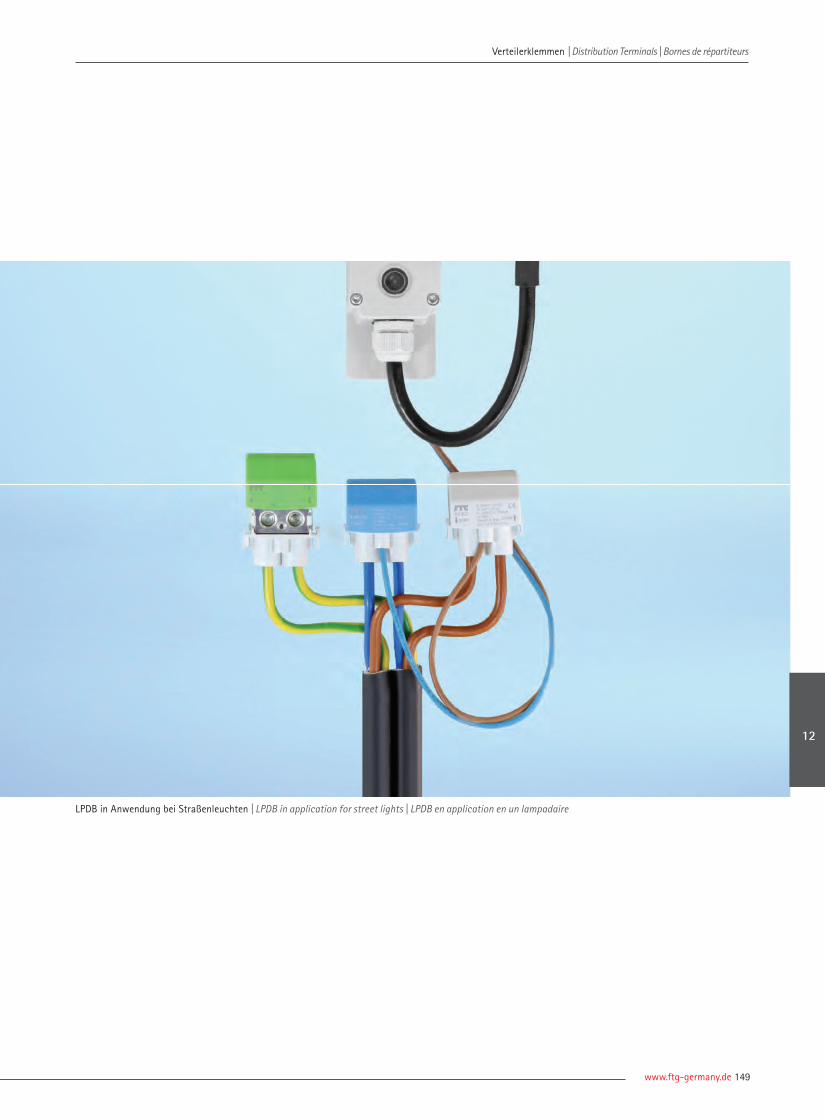
www.ftg-germany.de 149
LPDB in Anwendung bei Straßenleuchten | LPDB in application for street lights | LPDB en application en un lampadaire
Verteilerklemmen | Distribution Terminals | Bornes de répartiteurs Verteilerklemmen | Distribution Terminals | Bornes de répartiteurs
12
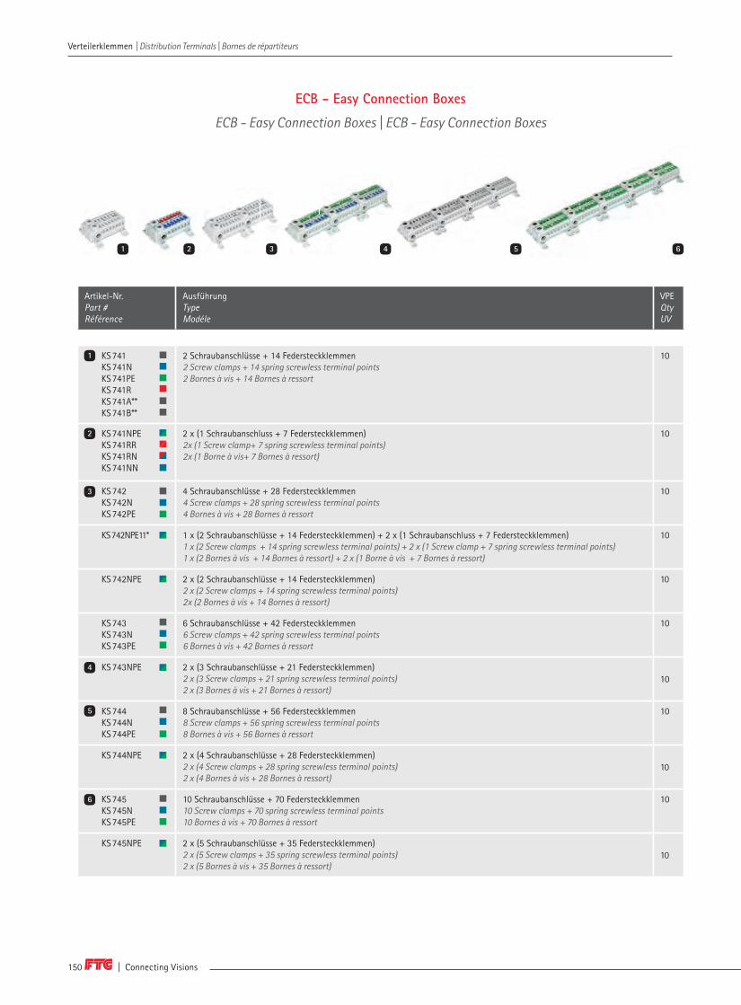
| Connecting Visions150
Verteilerklemmen | Distribution Terminals | Bornes de répartiteurs Verteilerklemmen | Distribution Terminals | Bornes de répartiteurs
Artikel-Nr. Part # Référence
AusführungTypeModéle
VPEQtyUV
KS741KS741NKS741PEKS741RKS741A**KS741B**
2 Schraubanschlüsse + 14 Federsteckklemmen2 Screw clamps + 14 spring screwless terminal points2 Bornes à vis + 14 Bornes à ressort
10
KS741NPEKS741RRKS741RNKS741NN
2 x (1 Schraubanschluss + 7 Federsteckklemmen)2x (1 Screw clamp+ 7 spring screwless terminal points)2x (1 Borne à vis+ 7 Bornes à ressort)
10
KS742KS742NKS742PE
4 Schraubanschlüsse + 28 Federsteckklemmen4 Screw clamps + 28 spring screwless terminal points4 Bornes à vis + 28 Bornes à ressort
10
KS742NPE11* 1 x (2 Schraubanschlüsse + 14 Federsteckklemmen) + 2 x (1 Schraubanschluss + 7 Federsteckklemmen)1 x (2 Screw clamps + 14 spring screwless terminal points) + 2 x (1 Screw clamp + 7 spring screwless terminal points)1 x (2 Bornes à vis + 14 Bornes à ressort) + 2 x (1 Borne à vis + 7 Bornes à ressort)
10
KS742NPE 2 x (2 Schraubanschlüsse + 14 Federsteckklemmen)2 x (2 Screw clamps + 14 spring screwless terminal points)2x (2 Bornes à vis + 14 Bornes à ressort)
10
KS743KS743NKS743PE
6 Schraubanschlüsse + 42 Federsteckklemmen6 Screw clamps + 42 spring screwless terminal points6 Bornes à vis + 42 Bornes à ressort
10
KS743NPE 2 x (3 Schraubanschlüsse + 21 Federsteckklemmen)2 x (3 Screw clamps + 21 spring screwless terminal points) 2 x (3 Bornes à vis + 21 Bornes à ressort)
10
KS744KS744NKS744PE
8 Schraubanschlüsse + 56 Federsteckklemmen8 Screw clamps + 56 spring screwless terminal points8 Bornes à vis + 56 Bornes à ressort
10
KS744NPE 2 x (4 Schraubanschlüsse + 28 Federsteckklemmen)2 x (4 Screw clamps + 28 spring screwless terminal points)2 x (4 Bornes à vis + 28 Bornes à ressort)
10
KS745KS745NKS745PE
10 Schraubanschlüsse + 70 Federsteckklemmen10 Screw clamps + 70 spring screwless terminal points10 Bornes à vis + 70 Bornes à ressort
10
KS745NPE 2 x (5 Schraubanschlüsse + 35 Federsteckklemmen)2 x (5 Screw clamps + 35 spring screwless terminal points)2 x (5 Bornes à vis + 35 Bornes à ressort)
10
1
2
3
4
5
6
31 2 4 5 6
ECB - Easy Connection Boxes
ECB - Easy Connection Boxes | ECB - Easy Connection Boxes

www.ftg-germany.de 151
Verteilerklemmen | Distribution Terminals | Bornes de répartiteurs Verteilerklemmen | Distribution Terminals | Bornes de répartiteurs
12
Artikel-Nr. Part # Référence
AusführungTypeModéle
VPEQtyUV
KS74H1KS74H1NKS74H1PEKS74H1RKS74H1S
1 Schraubanschluss + 7 Federsteckklemmen1 Screw clamp + 7 spring screwless terminal points1 Borne à vis + 7 Bornes à ressort
10
KS74H2KS74H2NKS74H2PEKS74H2RKS74H2S
2 Schraubanschlüsse + 14 Federsteckklemmen2 Screw clamps + 14 spring screwless terminal points2 Bornes à vis + 14 Bornes à ressort
10
KS74H3KS74H3NKS74H3PEKS74H3RKS74H3S
3 Schraubanschlüsse + 21 Federsteckklemmen3 Screw clamps + 21 spring screwless terminal points3 Bornes à vis + 21 Bornes à ressort
5
KS74H4KS74H4NKS74H4PEKS74H4RKS74H4S
4 Schraubanschlüsse + 28 Federsteckklemmen4 Screw clamps + 28 spring screwless terminal points4 Bornes à vis + 28 Bornes à ressort
5
KS74H5KS74H5NKS74H5PEKS74H5RKS74H5S
5 Schraubanschlüsse + 35 Federsteckklemmen5 Screw clamps + 35 spring screwless terminal points5 Bornes à vis + 35 Bornes à ressort
5
ECB Hutschienenadapter für KS74HDIN rail adapter for KS74HAdaptateur de rail DIN pour KS74H
10
7
8
9
10
11
12
* Geteiltes Potential bei Neutralleiter | Splitted potential for neutral conductors | Divisé potentiel neutre** Für DC-Anwendungen (741A-/741B+) | For DC applications (741A- / 741B +) | Pour des applications à courant continu (741A- / 741B +)
111087 9 12
SchraubklemmstellenScrew clamps | Bornes à vis
2,5 - 25 mm2 2,5 - 16 mm2
Federsteckklemmenspring screwless terminal points Bornes à ressort
0,5 - 4 mm2 0,5 - 4 mm2
I: 76 A | U: 450 V | IP20

| Connecting Visions152
Artikel-Nr. Part # Référence
BeschreibungDescriptionDescription
VPE Qty UV
MC 11001 MiniClic 4 x Basis | MiniClic 4 x basic | MiniClic 4 x base 1
MC 11001S MiniClic 4 x Basis Set mit 4 Cubes MiniClic 4 x basic with 4 cubes MiniClic 4 x base, Set avec 4 cubes
1
MC 11001SN 1
MC 11001SPE 1
MC 11001SR 1
MC 11002 MiniClic 4 x, Einspeiseklemme 95 mm² | MiniClic 4 x, Feeding terminal 95 mm² | MiniClic 4 x, Bornes d'alimentation 1
MC 11002S MiniClic 4 x Incomer 95 mm² Set mit 4 CubesMiniClic 4 x Incomer 95 mm² with 4 cubes MiniClic 4 x, Borne d'alimentation 95 mm² set avec 4 cubes
1
MC 11002SN 1
MC 11002SPE 1
MC 11002SR 1
MC 11003 MiniClic 4 x, Bolzen M8 | MiniClic 4 x, bolt M8 | MiniClic 4 x, goujon M8 1
MC 11003S MiniClic 4 x, Bolzen M8 Set mit 4 Cubes MiniClic 4 x, bolt M8 kit with 4 cubesMiniClic 4 x, goujon M8 set avec 4 cubes
1
MC 11003SN 1
MC 11003SPE 1
MC 11003SR 1
MC 22001 Basis Montage auf PhasenschienensystemenBasic mounting on busbar systems | Base montage sur jeux de barres
1
MC 22001S MiniClic Basis Set mit 4 CubesMiniClic basic Set with 4 cubesMiniClic base, Set avec 4 cubes
1
MC 22001SN 1
MC 22001SPE 1
MC 22001SR 1
Anschlussklemmen | Connection Terminals | Bornes de connexion
MC 22002 Max. 95 mm² (4/0 AWG), min. 25 mm² (3 AWG), Montage auf GrundträgerMounting on base plate | Montage sur platine
1
MC 22002S MiniClic Incomer Set mit 4 CubesMiniClic Incomer with 4 cubes MiniClic, borne raccordement 95 mm² Set avec 4 cubes
1
MC 22002SN 1
MC 22002SPE 1
MC 22002SR 1
MC 120021 Montage auf Grundträger, passend für 50 Cubes (Lieferung ohne Cubes)Mounting on base plate, suitable for 50 cubes (cubes not included)Montage sur platine, approprié pour 50 cubes (cubes non inclus)
1
1
2
3
4
5
6
31 2 4 5 6
MiniClic
MiniClic | MiniClic
Verteilerklemmen | Distribution Terminals | Bornes de répartiteurs Verteilerklemmen | Distribution Terminals | Bornes de répartiteurs

www.ftg-germany.de 153
Artikel-Nr. Part # Référence
BeschreibungDescriptionDescription
VPE Qty UV
MiniClic 4 x, mit Zubehör | MiniClic 4 x, with accessories | MiniClic 4 x, avec Accessories
MC 11004 MiniClic 4 x Basis inklusive Boden und SchraubenMiniClic 4 x basic inclusive base and screws | MiniClic 4 x base y.c. fond et vis
1
MC 11004S MiniClic 4 x Basis Set mit 4 CubesMiniClic 4 x basic with 4 cubesMiniClic 4 x kit de base avec 4 cubes
1
MC 11004SN 1
MC 11004SPE 1
MC 11004SR 1
MC 00002 DIN–Schienenadapter bestehend aus Haltern und Schrauben im Polybeutel (1 Set für MiniClic Basis)DIN rail adapter composed of holder and screws in poly bag (1 set for MiniClic base) Adaptateur pour rails DIN composé de supports et de vis fournis en sac poly (1 jeu pour la base MiniClic)
1
MC 00001 10 Cubes10 Cubes10 Cubes
1
MC 00001 N 1
MC 00001 PE 1
MC 00001 R 1
MiniClic Steg | MiniClic, Pin | MiniClic, Pointe
MC 22003 MiniClic Steg Set mit 4 Cubes MiniClic pin set with 4 cubes MiniClic pointe, goujon M8 Set avec 4 cubes
1
MC 22003S 1
MC 22003SN 1
MC 22003SPE 1
MC 22003SR 1
5 x MiniClic, Pin | 5 x MiniClic, Pin | 5 x MiniClic, Pointe
MC 120023 Mit Bolzen M8, Montage auf Grundträger, passend für 50 Cubes (Lieferung ohne Cubes)With bolt M8, mounting on base plate, suitable for 50 cubes (cubes not included)Avec goujon M8, montage sur platine, approprié pour 50 cubes (cubes non inclus)
1
8
7
9
10
1087 9
Verteilerklemmen | Distribution Terminals | Bornes de répartiteurs Verteilerklemmen | Distribution Terminals | Bornes de répartiteurs
12

| Connecting Visions154
Stahlklemmen
Steel terminals | Bornes en acier
A | Anschlussschrauben / Anzugsdrehmoment Connection screws / torque | Vis / couple de serrageB | Sektorleiter | Sector conductor | Câble sectorielC | Lammelierte Cu-Schienen | Flexible copper | Barres de cuivre souples
BKS für den Anschluss von KupferleitungenBKS for connection copper cables | BKS pour connecter des câbles en cuivre
Artikel-Nr. Part # Référence
QuerschnittCross sectionSection
A [Nm] Leiterarten Conductor types | Types de conducteurs
C [mm] Max. A | V VPE Qty UV
B
Für Cu-Sammelschienen 5/10 mm | For Cu-busbars 5/10 mm | Pour barres Cu 5/10 mm
BKS1605 BKS1610
16 mm² PZ 2/3 1,5 - 16 mm² - 1 x (8 x 6 x 0,5) 180 A1000 V AC/DC
40
BKS3505 BKS3510
35 mm² SW 13 PZ 2/10
4 - 35 mm² 35 mm² 1 x (3 x 9 x 0,8)1 x (6 x 9 x 0,8)
270 A 1000 V AC/DC
20
BKS5005 BKS5010
50 mm²
SW 13 PZ 3/10
10 - 50 mm²
35 - 50 mm² 2 x (3 x 9 x 0,8)1 x (6 x 9 x 0,8)
315 A 1000 V AC/DC
20
BKS7005 BKS7010
70 mm² SW 13PZ 3/12
16 - 70 mm² 35 - 70 mm² 2 x (3 x 9 x 0,8) 2 x (6 x 9 x 0,8) 1 x (6 x 13 x 0,5)
400 A 1000 V AC/DC
10
BKS12005 BKS12010
120 mm² SW 17PZ 3/22
16 - 120 mm² 35 - 120 mm² 1 x (10 x 15,5 x 0,8) 440 A 1000 V AC/DC
10
BKS18505 BKS18510
185 mm² SW 17PZ 3/22
50 - 185 mm² 50 - 185 mm² 1 x (6 x 20 x 1) 1 x (10 x 20 x 1)
500 A 1000 V AC/DC
10
Für Cu-Sammelschienen 3 mm, Al nur bei verzinnten Sammelschienen oder Kabeln For Cu-busbars 3 mm, Al for tinned busbars or wires only | Pour barres Cu 3 mm, Al uniquement pour barres ou câbles étamés
BKN1603 16 mm² PZ 2/3 1,5 - 16 mm² - - 180 A1000 V AC/DC
10
Für Cu Sammelschienen 5/10 mm, Al nur bei verzinnten Sammelschienen oder Kabeln For Cu busbars 5/10 mm, Al for tinned busbars or wires only | Pour barres Cu 5/10 mm, Al uniquement pour barres ou câbles en conserve
BKN1605 BKN1610
16 mm² PZ 2/3 1,5 - 16 mm² - - 180 A1000 V AC/DC
40
BKN3505 BKN3510
35 mm² SW 13 PZ 2/6
4 - 35 mm² 35 mm² 1 x (3 x 9 x 0,8)1 x (6 x 9 x 0,8)
270 A 1000 V AC/DC
40
BKN7005 BKN7010
70 mm²
SW 13PZ 3/12
16 - 70 mm²
35 - 70 mm²
2 x (3 x 9 x 0,8)1 x (6 x 9 x 0,8)2 x (6 x 9 x 0,8)1 x (6 x 13 x 0,5)
400 A 1000 V AC/DC
10
BKN12005 BKN12010
120 mm² SW 17PZ 3/22
16 - 120 mm² 35 - 120 mm² 1 x (10 x 15,5 x 0,8)1 x (6 x 20 x 1)
440 A 1000 V AC/DC
10
BKN18505 BKN18510
185 mm² SW 17PZ 3/22
50 - 185 mm² 50 - 185 mm² 1 x (6 x 20 x 1)1 x (10 x 20 x 1)
500 A 1000 V AC/DC
10
BKN für Aluminium- und Kupferleitungen mit verzinnten Kupfer-Sammelschienen oder –KabelnBKN for aluminum and copper cables with tinned copper busbars or cablesBKN pour câbles en aluminium et cuivre avec barres ou câbles en cuivre étamé
1
2
2
1
Verteilerklemmen | Distribution Terminals | Bornes de répartiteurs Verteilerklemmen | Distribution Terminals | Bornes de répartiteurs

www.ftg-germany.de 155
A | Anschlussschrauben / Anzugsdrehmoment Connection screws / torque | Vis / couple de serrageB | Sektorleiter | Sector conductor | Câble sectorielC | Lammelierte Cu-Schienen | Flexible copper | Barres de cuivre souples
BKNA für Aluminium- und Kupferleitungen geeignet ohne BearbeitungBKNA suitable for aluminum and copper cables without treatment BKNA adapté aux câbles en aluminium et cuivre sans usinage
Artikel-Nr. Part # Référence
QuerschnittCross sectionSection
A [Nm] Leiterarten Conductor types | Types de conducteurs
C [mm] Max. A | V VPE Qty UV
B
Für Cu/Al Sammelschienen 5/10 mm | For Cu/Al busbars 5/10 mm | Pour barres Cu/Al 5/10 mm
BKNA1605BKNA1610
16 mm² PZ 2/3 1,5 - 16 mm² - - 180 A1000 V AC/DC
40
BKNA3505 BKNA3510
35 mm² SW 13 PZ 2/6
4 - 35 mm² 35 mm² - 270 A1000 V AC/DC
20
BKNA7005 BKNA7010
70 mm² SW 13PZ 3/12
16 - 70 mm² 35 - 70 mm² - 400 A1000 V AC/DC
10
BKNA12005 BKNA12010
120 mm² SW 17PZ 3/22
16 - 120 mm² 35 - 120 mm² - 440 A1000 V AC/DC
10
BKNA18505 BKNA18510
185 mm² SW 17PZ 3/22
50 - 185 mm² 50 - 185 mm² - 500 A1000 V AC/DC
10
Für Cu/Al-Sammelschienen 10 mm | For Cu/Al busbars 10 mm | Pour barres Cu/Al 10 mm
BKEA30010 300 mm² SW 8 Inbus/30
Cu: 95 - 300 mm² Al: 120 - 300 mm²
- 600 A 1000 V AC/DC
3
Für Flachkupfertypen 3 x 10 mm, 6 x 6 mm | For flat copper types 3 x 10 mm, 6 x 6 mm | Pour cuivre plat 3 x 10 mm, 6 x 6 mm
BKGS0603 6 mm² PZ 21,5 - 2
1 - 6 mm² | 1 - 4 mm² - 80 A1000 V AC/DC
40
BKGS1603 16 mm² PZ 22 - 2,5
4 - 16 mm² | 4 - 10 mm² - 180 A1000 V AC/DC
40
für Flachkupfertypen 3 x 12 mm, 6 x 6 mm | for flat copper types 3 x 12 mm, 6 x 6 mm | pour cuivre plat 3 x 12 mm, 6 x 6 mm
BKGS3503 35 mm² PZ 2 2,5 - 3
4 - 35 mm² | 4 - 25 mm² - 225 A1000 V AC/DC
20
BKGS3503i 35 mm² SW 5 Inbus 2,5 - 3
4 - 35 mm² | 4 - 25 mm² - 225 A1000 V AC/DC
20
BKEABKEA | BKEA
BKGS geschlossenBKGS closed | BKGS fermé
5
3 4
3
4
5
Verteilerklemmen | Distribution Terminals | Bornes de répartiteurs Verteilerklemmen | Distribution Terminals | Bornes de répartiteurs
12

| Connecting Visions156
StahlverbindungsklemmenSteel connection terminals | Bornes de connexion en acier
Artikel-Nr. Part # Référence
QuerschnittCross sectionSection
A [Nm] Leiterarten Conductors | Types de conducteurs
Max. A | V VPE Qty UV
B
Flachkupfertypen 12 x 5 mm, 12 x 10 mm | Flat copper types 12 x 5 mm, 12 x 10 mm | Type de cuivre plat 12 x 5 mm, 12 x 10 mm
786 95 mm² SW 13 | 12 – 15Sechskantschraube mit Schlitz | Hex Screw with slotVis hexagonale avec fente
16 – 95 mm² 16 – 70 mm² 35 – 70 mm² 400 A | 690 V AC 10
Flachkupfertypen 30 x 5 mm, 30 x 10 mm | Flat copper types 30 x 5 mm, 30 x 10 mm | Type de cuivre plat 30 x 5 mm, 30 x 10 mm
793 120 mm² SW 13 | 20 – 25 Sechskantschraube mit Schlitz | Hex Screw with slotVis hexagonale avec fente
16 – 120 mm² 16 – 120 mm² 35 – 120 mm² 440 A | 690 V AC 10
Flachkupfertypen 12 x 5 mm | Flat copper types 12 x 5 mm | 2 Types de cuivre plat12 x 5 mm
757757–01
95 mm² SW 13 | 12 – 15 Sechskantschraube mit Schlitz | Hex Screw with slotVis hexagonale avec fente
16 – 95 mm² 16 – 70 mm² 35 – 70 mm² 400 A | 690 V AC 10
2 Flachkupfertypen 12 x 5 mm | 2 Flat copper types 12 x 5 mm | 2 Types de cuivre plat 12 x 5 mm
787 – SW 10 Sechskantschraube mit Schlitz | Hex Screw with slotVis hexagonale avec fente
– – – – 50
787–01 – PZ 2 | 3 – – – 690 V AC 50
787–01So – SW 3 Inbus | 3 – – – 690 V AC 50
2 Flachkupfertypen 12 x 5 mm oder 1 Flachkupfertyp 12 x 10 mm | 2 Flat copper types 12 x 5 mm or 1 flat copper typ 12 x 10 mm2 Types de cuivre plat 12 x 5 mm ou 1 type de cuivre plat 12 x 10 mm
787–17 – SW 3 Inbus | 3 – – – 690 V AC 10
2 Flachkupfertypen 12 x 10 mm | 2 Flat copper types 12 x 10 mm | 2 Types de cuivre plat 12 x 10 mm
787–19 – SW 3 Inbus | 3 – – – 690 V AC 10
2 Flachkupfertypen 12 x 5 mm oder 12 x 10 mm | 2 Flat copper types 12 x 5 mm or 12 x 10 mm | 2 Types de cuivre plat 12 x 5 mm ou 12 x 10 mm
786–18 – SW 3 Inbus | 3 – – – 600 V AC 10
2 Flachkupfertypen 12 x 5 | 2 Flat copper types 12 x 5 mm | 2 Types de cuivre plat 12 x 5 mm
789 – SW 4 Inbus | 3 – – – 690 V AC 10
Mit Druckplatte für 2 Flachkupfertypen 12 x 5 mm bzw. 1 Flachkupfertyp 12 x 5 mm oder Kabel 10 – 50 mm² With pressure plate for 2 flat copper types 12 x 5 mm or 1 flat copper type 12 x 5 mm or cable 10 - 50 mm²Avec plaque de pression pour 2 types de cuivre plat 12 x 5 mm ou 1 type de cuivre plat 12 x 5 mm ou câble 10 - 50 mm²
786–28 – SW 3 Inbus | 3 – – – 600 V AC 10
A | Anschlussschrauben / Anzugsdrehmoment Connection screws / torque | Vis / couple de serrageB | Sektorleiter | Sector conductor | Câble sectorielC | Lammelierte Cu-Schienen | Flexible copper | Barres de cuivre souples
1 2 3
6 7 8 9 10
4 5
1
2
3
4
5
6
7
8
9
10
Verteilerklemmen | Distribution Terminals | Bornes de répartiteurs Verteilerklemmen | Distribution Terminals | Bornes de répartiteurs
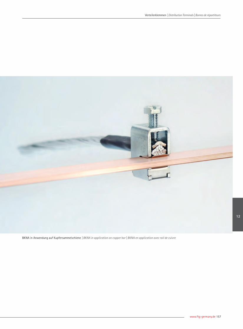
www.ftg-germany.de 157
BKNA in Anwendung auf Kupfersammelschiene | BKNA in application on copper bar | BKNA en application avec rail de cuivre
Verteilerklemmen | Distribution Terminals | Bornes de répartiteurs Verteilerklemmen | Distribution Terminals | Bornes de répartiteurs
12

| Connecting Visions158
MessingklemmleistenBrass terminal blocks | Barres de laiton
Artikel-Nr. Part # Référence
A [Nm] B Max. A | V VPE Qty UV
Blank | Plain brass | Laiton brut
870-7 PZ2 / 2 7 x 1,5 – 16 mm² 7 x 1,5 – 10 mm² 63 A | 690 V 10
870-12 PZ2 / 2 12 x 1,5 – 16 mm² 12 x 1,5 – 10 mm² 63 A | 690 V 10
870-15 PZ2 / 2 15 x 1,5 – 16 mm² 15 x 1,5 – 10 mm² 63 A | 690 V 10
870-24 PZ2 / 2 – 3,5 20 x 1,5 – 16 mm²4 x 1,5 – 25 mm²
20 x 1,5 – 10 mm²4 x 1,5 – 16 mm²
63 A | 690 V 10
870 M PZ2 / 2,5 166 x 1,5 – 16 mm² 166 x 1,5 – 10 mm² 63 A | 690 V 10
870KL Messingklemmleisten, blank | 870KL brass terminals, uncoated | Barres 870KL en laiton brut
870KL0150 PZ2 / 2 – 4 3 x 6 – 50 mm²12 x 1,5 – 25 mm²31 x 1,5 – 10 mm²
3 x 6 – 35 mm²12 x 1,5 – 16 mm²31 x 1,5 – 6 mm²
630 A 10
870KL21 PZ2 / 2 – 4 2 x 6 – 50 mm²3 x 1,5 – 25 mm²16 x 1,5 – 10 mm²
2 x 6 – 35 mm²3 x 1,5 – 16 mm²16 x 1,5 – 6 mm²
630 A 10
870KL60 PZ2 / 1,5 – 4 1 x 6 – 50 mm²1 x 1,5 – 25 mm²58 x 1,5 – 6 mm²
1 x 6 – 35 mm²1 x 1,5 – 16 mm²58 x 1,5 – 4 mm²
630 A 10
870KL Messingklemmleisten, vernickelt | 870KL brass terminals, nickel plated | Barres 870KL en laiton nickelé
870KL0150S PZ2 / 2 – 4 3 x 6 – 50 mm²12 x 1,5 – 25 mm²31 x 1,5 – 10 mm²
3 x 6 – 35 mm²12 x 1,5 – 16 mm²31 x 1,5 – 6 mm²
250 A 10
Messingklemmleisten, verzinkt | Brass terminals, zinc plated | Barres en laiton zingué
871-6 PZ2 / 2 6 x 1,5 – 16 mm² 6 x 1,5 – 10 mm² 80 A | 690 V 10
871-13 PZ2 / 2 – 3 12 x 1,5 – 16 mm² 12 x 1,5 – 10 mm² 80 A | 690 V 10
V–Ausschnitt mit Druckbügel | V–section with leaf clampDécoupure en V avec étrier de serrage, 1 x 25 – 35 mm²
871-20 PZ2 / 2 – 3 18 x 1,5 – 16 mm² 18 x 1,5 – 10 mm² 80 A | 690 V 10
V–Ausschnitt mit Druckbügel | V–section with leaf clampDécoupure en V avec étrier de serrage, 2 x 25 – 35 mm²
871-27 PZ2 / 2 - 3 24 x 1,5 - 16 mm² 24 x 1,5 - 10 mm² 80 A | 690 V 10
V–Ausschnitt mit Druckbügel | V–section with leaf clamp Découpure en V avec étrier de serrage, 3 x 25 – 35 mm²
871 / 34 PZ2 / 2 - 3 30 x 1,5 - 16 mm² 30 x 1,5 - 10 mm² 80 A | 690 V 10
V–Ausschnitt mit Druckbügel | V–section with leaf clamp Découpure en V avec étrier de serrage, 4 x 25 - 35 mm²
A | Anschlussschrauben / Anzugsdrehmoment Connection screws / torque | Vis / couple de serrageB | Leiterarten | Conductor types | Types de conducteurs
3
1 2
4
Null– und Schutzleiterklemmen
Neutral and Earthing terminals | Barres de neutre et terre
1
3
4
2
Verteilerklemmen | Distribution Terminals | Bornes de répartiteurs Verteilerklemmen | Distribution Terminals | Bornes de répartiteurs

www.ftg-germany.de 159
MessingklemmleistenBrass terminal blocks | Barres de laiton
Artikel-Nr. Part # Référence
A [Nm] B Max. A | V VPE Qty UV
A | Anschlussschrauben / Anzugsdrehmoment Connection screws / torque | Vis / couple de serrageB | Leiterarten | Conductor types | Types de conducteurs
DIN-Schienenhalter für Montage auf DIN-Tragschiene | DIN rail holder for mounting on DIN rail | Support de rail DIN pour montage sur rail DIN
870 P-7 PZ2 / 2 7 x 1,5 – 16 mm² 7 x 1,5 – 10 mm² 63 A | 690 V 10
870 N-7
870 S-7
870 P-12 12 x 1,5 – 16 mm² 12 x 1,5 – 10 mm²
870 N-12
870 S-12
870 P-15 15 x 1,5 – 16 mm² 15 x 1,5 – 10 mm²
870 N-15
870 S-15
870 P-24 20 x 1,5 – 16 mm² 4 x 1,5 – 25 mm²
20 x 1,5 – 10 mm²4 x 1,5 – 16 mm²870 N-24
870 S-24
870 P-7/16 PZ2 / 2-3 7 x 1,5 – 25 mm² 7 x 1,5 – 16 mm² 80 A | 690 V 10
870 N-7/16
870 S-7/16
870 P-12/16 12 x 1,5 – 25 mm² 12 x 1,5 – 16 mm²
870 N-12/16
870 S-12/16
870 P-15/16 15 x 1,5 – 25 mm² 15 x 1,5 – 16 mm²
870 N-15/16
870 S-15/16
Null- und SchutzleiterklemmenNeutral and earhting terminals | Barres de neutre et terre
5 6
Messingklemmleisten, verzinkt | Brass terminals, zinc plated | Barres en laiton zingué
871 M PZ2 / 2 – 3 96 x 1,5 – 16 mm² 96 x 1,5 – 10 mm² 80 A | 690 V 10
V–Ausschnitt mit Druckbügel | V–section with leaf clamp Découpure en V avec étrier de serrage, 15 x 25 – 35 mm²
Messingklemmleiste auf Stahlfederhalter montiert | Brass terminal block mounted on steel spring clip | Barre en laiton avec clip ressort en acier
871-19TS PZ2 / 2 – 3 18 x 1,5 - 16 mm² 18 x 1,5 - 10 mm² 80 A | 690 V 10
V–Ausschnitt mit Druckbügel | V–section with leaf clamp Découpure en V avec étrier de serrage, 1 x 25 - 35 mm²
870 DE-7 PZ2 / 2 7 x 1,5 - 16 mm² 7 x 1,5 - 10 mm² 63 A | 690 V 10
870 DE-12 PZ2 / 2 12 x 1,5 - 16 mm² 12 x 1,5 - 10 mm² 63 A | 690 V 10
870 DE-15 PZ2 / 2 15 x 1,5 - 16 mm² 15 x 1,5 - 10 mm² 63 A | 690 V 10
5
6
4
Verteilerklemmen | Distribution Terminals | Bornes de répartiteurs Verteilerklemmen | Distribution Terminals | Bornes de répartiteurs
12
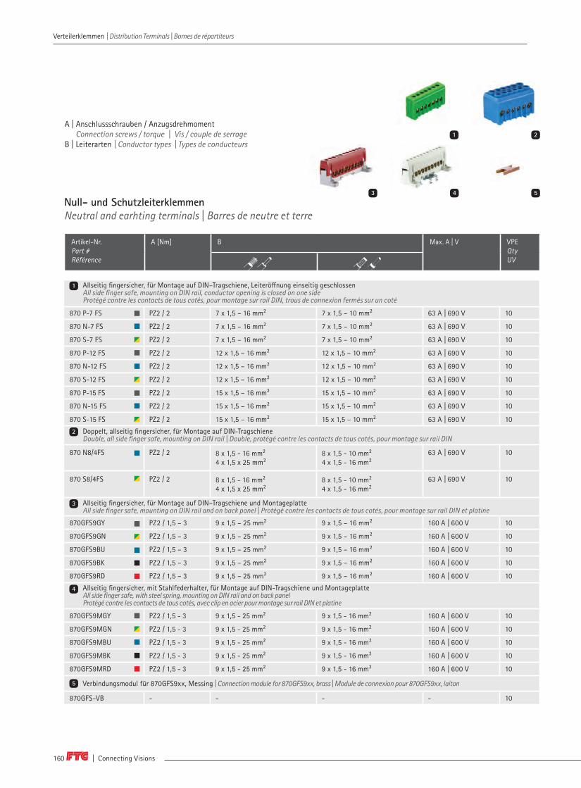
| Connecting Visions160
A | Anschlussschrauben / Anzugsdrehmoment Connection screws / torque | Vis / couple de serrageB | Leiterarten | Conductor types | Types de conducteurs
Allseitig fingersicher, für Montage auf DIN–Tragschiene, Leiteröffnung einseitig geschlossenAll side finger safe, mounting on DIN rail, conductor opening is closed on one side Protégé contre les contacts de tous cotés, pour montage sur rail DIN, trous de connexion fermés sur un coté
870 P-7 FS PZ2 / 2 7 x 1,5 – 16 mm² 7 x 1,5 – 10 mm² 63 A | 690 V 10
870 N-7 FS PZ2 / 2 7 x 1,5 – 16 mm² 7 x 1,5 – 10 mm² 63 A | 690 V 10
870 S-7 FS PZ2 / 2 7 x 1,5 – 16 mm² 7 x 1,5 – 10 mm² 63 A | 690 V 10
870 P-12 FS PZ2 / 2 12 x 1,5 – 16 mm² 12 x 1,5 – 10 mm² 63 A | 690 V 10
870 N-12 FS PZ2 / 2 12 x 1,5 – 16 mm² 12 x 1,5 – 10 mm² 63 A | 690 V 10
870 S-12 FS PZ2 / 2 12 x 1,5 – 16 mm² 12 x 1,5 – 10 mm² 63 A | 690 V 10
870 P-15 FS PZ2 / 2 15 x 1,5 – 16 mm² 15 x 1,5 – 10 mm² 63 A | 690 V 10
870 N-15 FS PZ2 / 2 15 x 1,5 – 16 mm² 15 x 1,5 – 10 mm² 63 A | 690 V 10
870 S-15 FS PZ2 / 2 15 x 1,5 – 16 mm² 15 x 1,5 – 10 mm² 63 A | 690 V 10
Doppelt, allseitig fingersicher, für Montage auf DIN-Tragschiene Double, all side finger safe, mounting on DIN rail | Double, protégé contre les contacts de tous cotés, pour montage sur rail DIN
870 N8/4FS PZ2 / 2 8 x 1,5 - 16 mm²4 x 1,5 x 25 mm²
8 x 1,5 - 10 mm²4 x 1,5 - 16 mm²
63 A | 690 V 10
870 S8/4FS PZ2 / 2 8 x 1,5 - 16 mm²4 x 1,5 x 25 mm²
8 x 1,5 - 10 mm²4 x 1,5 - 16 mm²
63 A | 690 V 10
Allseitig fingersicher, für Montage auf DIN–Tragschiene und Montageplatte All side finger safe, mounting on DIN rail and on back panel | Protégé contre les contacts de tous cotés, pour montage sur rail DIN et platine
870GFS9GY PZ2 / 1,5 – 3 9 x 1,5 – 25 mm² 9 x 1,5 – 16 mm² 160 A | 600 V 10
870GFS9GN PZ2 / 1,5 – 3 9 x 1,5 – 25 mm² 9 x 1,5 – 16 mm² 160 A | 600 V 10
870GFS9BU PZ2 / 1,5 – 3 9 x 1,5 – 25 mm² 9 x 1,5 – 16 mm² 160 A | 600 V 10
870GFS9BK PZ2 / 1,5 – 3 9 x 1,5 – 25 mm² 9 x 1,5 – 16 mm² 160 A | 600 V 10
870GFS9RD PZ2 / 1,5 – 3 9 x 1,5 – 25 mm² 9 x 1,5 – 16 mm² 160 A | 600 V 10
Allseitig fingersicher, mit Stahlfederhalter, für Montage auf DIN-Tragschiene und Montageplatte All side finger safe, with steel spring, mounting on DIN rail and on back panel Protégé contre les contacts de tous cotés, avec clip en acier pour montage sur rail DIN et platine
870GFS9MGY PZ2 / 1,5 - 3 9 x 1,5 - 25 mm² 9 x 1,5 - 16 mm² 160 A | 600 V 10
870GFS9MGN PZ2 / 1,5 - 3 9 x 1,5 - 25 mm² 9 x 1,5 - 16 mm² 160 A | 600 V 10
870GFS9MBU PZ2 / 1,5 - 3 9 x 1,5 - 25 mm² 9 x 1,5 - 16 mm² 160 A | 600 V 10
870GFS9MBK PZ2 / 1,5 - 3 9 x 1,5 - 25 mm² 9 x 1,5 - 16 mm² 160 A | 600 V 10
870GFS9MRD PZ2 / 1,5 - 3 9 x 1,5 - 25 mm² 9 x 1,5 - 16 mm² 160 A | 600 V 10
Verbindungsmodul für 870GFS9xx, Messing | Connection module for 870GFS9xx, brass | Module de connexion pour 870GFS9xx, laiton
870GFS-VB - - - - 10
Null- und SchutzleiterklemmenNeutral and earhting terminals | Barres de neutre et terre
Artikel-Nr. Part # Référence
A [Nm] B Max. A | V VPE Qty UV
3 4 5
1
2
3
4
5
1 2
Verteilerklemmen | Distribution Terminals | Bornes de répartiteurs Verteilerklemmen | Distribution Terminals | Bornes de répartiteurs

www.ftg-germany.de 161
N/PE Klemmen mit Reiterklemme montiert auf DIN-TragschienenträgerBrass terminals with steel clamp mounted on DIN rail holderBarres laiton avec bornes cavalier en acier montées sur les supports pour rail DIN
Montiert auf DIN–Tragschienenträger NPET1 | With DIN-Rail holder NPET1 | Avec support de rail DIN NPET1
870 KLS7 PZ2 / 2 2 x (7 x 1,5 – 16 mm²) 2 x (7 x 1,5 – 10 mm²) 63 A | 690 V 10
870 KLS12 PZ2 / 2 2 x (12 x 1,5 – 16 mm²) 2 x (12 x 1,5 – 10 mm²) 63 A | 690 V 10
870 KLS15 PZ2 / 2 2 x (15 x 1,5 – 16 mm²) 2 x (15 x 1,5 – 10 mm²) 63 A | 690 V 10
870 KLS30 PZ2 / 2 2 x (30 x 1,5 – 16 mm²) 2 x (30 x 1,5 – 10 mm²) 63 A | 690 V 10
Montiert auf DIN–Tragschienenträger NPET3 | With DIN-Rail holder NPET3 | Avec support de rail DIN NPET3
870 KLSE7 PZ2 / 2 2 x (7 x 1,5 – 16 mm²) 2 x (7 x 1,5 – 10 mm²) 63 A | 690 V 10
870 KLSE12 PZ2 / 2 2 x (12 x 1,5 – 16 mm²) 2 x (12 x 1,5 – 10 mm²) 63 A | 690 V 10
870 KLSE15 PZ2 / 2 2 x (15 x 1,5 – 16 mm²) 2 x (15 x 1,5 – 10 mm²) 63 A | 690 V 10
870 KLSE24 PZ2 / 2 2 x (24 x 1,5 – 16 mm²) 2 x (24 x 1,5 – 10 mm²) 63 A | 690 V 10
Klemmenleisten–SetBrass terminal strip set | Set de blocs de bornes
Artikel-Nr. Part # Référence
A [Nm] B Max. A | V VPE Qty UV
NPET1, inkl. Kupferlaschen (N / PE) und BKGS1603 | NPET1, incl. copper lugs (N / PE) and BKGS1603 | NPET1, y compris les pattes de cuivre (N / PE) et BKGS1603
KGNS120 PZ2 / 2 | PZ2 / 2 – 2,5 28 x 1,5 – 10 | 2 x 4 – 16 mm² 28 x 1,5 – 6 | 2 x 4 – 10 mm² 63 A | 690 V 10
KGNS155 PZ2 / 2 | PZ2 / 2 – 2,5 40 x 1,5 – 10 | 2 x 4 – 16 mm² 40 x 1,5 – 6 | 2 x 4 – 10 mm² 63 A | 690 V 10
KGNS195 PZ2 / 2 | PZ2 / 2 – 2,5 52 x 1,5 – 10 | 2 x 4 – 16 mm² 52 x 1,5 – 6 | 2 x 4 – 10 mm² 63 A | 690 V 10
KGNS265 PZ2 / 2 | PZ2 / 2 – 2,5 76 x 1,5 – 10 | 2 x 4 – 16 mm² 76 x 1,5 – 6 | 2 x 4 – 10 mm² 63 A | 690 V 10
KGNS375 PZ2 / 2 | PZ2 / 2 – 2,5 110 x 1,5 – 10 | 2 x 4 – 16 mm² 110 x 1,5 – 6 | 2 x 4 – 10 mm² 63 A | 690 V 10
KGNS475 PZ2 / 2 | PZ2 / 2 – 2,5 144 x 1,5 – 10 | 2 x 4 – 16 mm² 144 x 1,5 – 6 | 2 x 4 – 10 mm² 63 A | 690 V 10
NPET3, inkl. Kupferlaschen (N / PE) und BKGS1603 | NPET3, incl. copper lugs (N / PE) and BKGS1603 | NPET3, y compris les pattes de cuivre (N / PE) et BKGS1603
KGNSE120 PZ2 / 2 | PZ2 / 2 – 2,5 28 x 1,5 – 10 | 2 x 4 – 16 mm² 28 x 1,5 – 6 | 2 x 4 – 10 mm² 63 A | 690 V 10
KGNSE155 PZ2 / 2 | PZ2 / 2 – 2,5 40 x 1,5 – 10 | 2 x 4 – 16 mm² 40 x 1,5 – 6 | 2 x 4 – 10 mm² 63 A | 690 V 10
KGNSE195 PZ2 / 2 | PZ2 / 2 – 2,5 52 x 1,5 – 10 | 2 x 4 – 16 mm² 52 x 1,5 – 6 | 2 x 4 – 10 mm² 63 A | 690 V 10
KGNSE265 PZ2 / 2 | PZ2 / 2 – 2,5 76 x 1,5 – 10 | 2 x 4 – 16 mm² 76 x 1,5 – 6 | 2 x 4 – 10 mm² 63 A | 690 V 10
KGNSE375 PZ2 / 2 | PZ2 / 2 – 2,5 110 x 1,5 – 10 | 2 x 4 – 16 mm² 110 x 1,5 – 6 | 2 x 4 – 10 mm² 63 A | 690 V 10
KGNSE475 PZ2 / 2 | PZ2 / 2 – 2,5 144 x 1,5 – 10 | 2 x 4 – 16 mm² 144 x 1,5 – 6 | 2 x 4 – 10 mm² 63 A | 690 V 10
A | Anschlussschrauben / Anzugsdrehmoment Connection screws / torque | Vis / couple de serrageB | Leiterarten | Conductor types | Types de conducteurs
8
6 7
9
6
7
8
9
Verteilerklemmen | Distribution Terminals | Bornes de répartiteurs Verteilerklemmen | Distribution Terminals | Bornes de répartiteurs
12

| Connecting Visions162
A | Anschlussschrauben / Anzugsdrehmoment Connection screws / torque | Vis / couple de serrageB | Leiterarten | Conductor types | Types de conducteurs
Treppenklemmen, Messing blank | Terrace terminals, brass unocated | Barres de connexion niveaux en laiton brut
787CB8 SW3 Inbus / 2 8 x 1,5 – 16 mm² 630 A 10
787CB15 SW3 Inbus / 2 15 x 1,5 – 16 mm² 630 A 10
NPET 1 Passende Träger für DIN–TragschieneSuitable support for DIN rail adapter Support approprié pour rail DIN
50
NPET 2 50
NPET 3 passende Träger für DIN–Tragschiene & geeignet für Cu/Al 10 x 2 mm, 12 x 3 mm, 6 x 6 mmDIN rail adapter in additional use for Cu/Al 10 x 2 mm, 12 x 3 mm, 6 x 6 mmSupports pour rail DIN et utilisation Cu/Al 10 x 2, 12 x 3, 6 x 6 mm
50
CP-N Kupferplatte mit N Prägung, 3 x Anschlusslöcher ø 4,5 mm zur Adaption an Messingschienen als Nullleiterstelle Copper plate with N embossing, 3 x connection holes ø 4,5 mm for adaptation to brass rails as neutral conductor Plaque en cuivre avec marquage N, 3 x trous de raccordement ø 4,5 mm pour l'adaptation aux rails en laiton en tant que conducteur neutre
100
CP-PE Kupferplatte mit PE Prägung, 3 x Anschlusslöcher ø 4,5 mm zur Adaption an Messingschienen für Erdung Copper plate with PE embossing, 3 x connection holes ø 4,5 mm for adaptation to brass rails for earthing Plaque en cuivre avec marquage PE, 3 x trous de raccordement ø 4,5 mm pour l'adaptation aux rails en laiton pour la mise à la terre
100
MSHB65 Stahlbefestigung 3 x 12 x 65 mm, für 870KL MessingschienenSteel fixing 3 x 12 x 65 mm for brass terminals 870 KLMontage en acier 3 x 12 x 65 mm pour rails 870KL en laiton
50
MSHB110 Stahlbefestigung 3 x 12 x 110 mm, für 870KL MessingschienenSteel fixing 3 x 12 x 110 mm, for brass terminals 870KLMontage en acier 3 x 12 x 110 mm, pour rails 870KL en laiton
50
Universelle VerbindungsschienenUniversal connection bars | Barres de connexion universelles
Artikel-Nr. Part # Référence
A [Nm] B Max. A VPE Qty UV
Zubehör für MessingklemmenAccessories for brass terminals | Accessoires pour barres en laiton
Artikel-Nr. Part # Référence
BeschreibungDescriptionDescription
VPE Qty UV
1
2
2
2
3
3
1 2 3
Verteilerklemmen | Distribution Terminals | Bornes de répartiteurs Verteilerklemmen | Distribution Terminals | Bornes de répartiteurs

www.ftg-germany.de 163
Null- und Schutzleiterklemmen | Neutral and earhting terminals | Barres de neutre et terre
Verteilerklemmen | Distribution Terminals | Bornes de répartiteurs Verteilerklemmen | Distribution Terminals | Bornes de répartiteurs
12
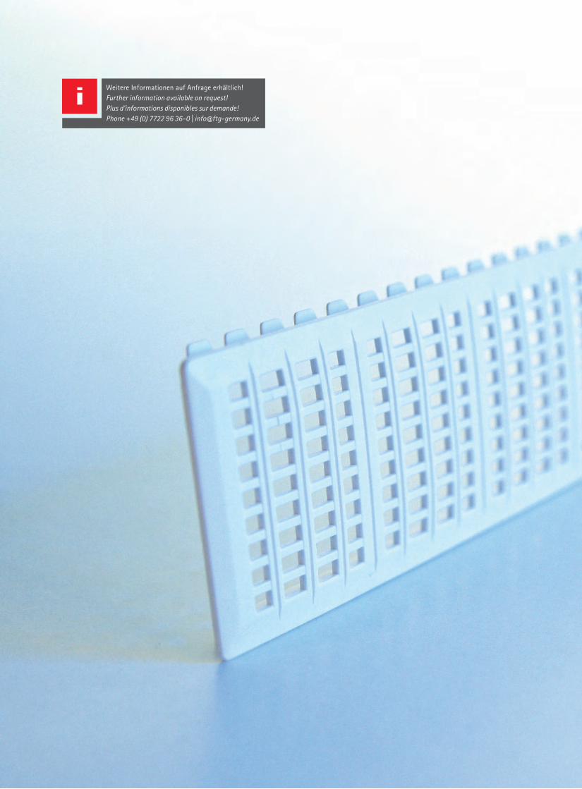
Weitere Informationen auf Anfrage erhältlich! Further information available on request!Plus d'informations disponibles sur demande!Phone +49 (0) 7722 96 36-0 | [email protected]
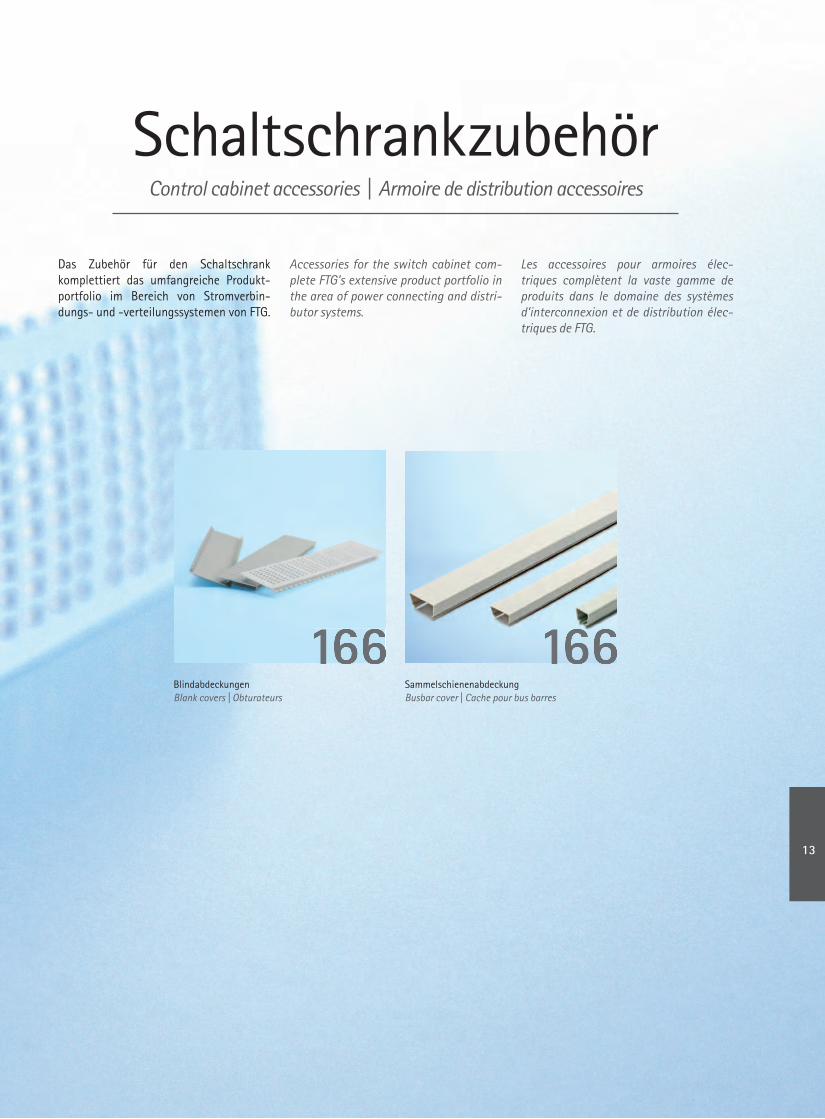
SchaltschrankzubehörControl cabinet accessories | Armoire de distribution accessoires
Accessories for the switch cabinet com-plete FTG's extensive product portfolio in the area of power connecting and distri-butor systems.
Das Zubehör für den Schaltschrank komplettiert das umfangreiche Produkt-portfolio im Bereich von Stromverbin-dungs- und -verteilungssystemen von FTG.
Les accessoires pour armoires élec-triques complètent la vaste gamme de produits dans le domaine des systèmes d’interconnexion et de distribution élec-triques de FTG.
BlindabdeckungenBlank covers | Obturateurs
SammelschienenabdeckungBusbar cover | Cache pour bus barres
166166166166
13

| Connecting Visions166
Schaltschrankzubehör | Control cabinet accessories | Armoire de distribution accessories Schaltschrankzubehör | Control cabinet accessories | Armoire de distribution accessories
SchaltschrankzubehörControl cabinet accessories | Armoire de distribution Accessories
1
Kunststoffteile rund um den Schaltschrank Plastic parts for the control cabinet | Les pièces en plastique autour de l'armoire
Artikel-Nr. Part # Référence
Passend fürSuitable forAdapte pour
Länge [mm]Length Longueur
Passende Verriegelung Matching lock Verrouillage correspondant
VPE Qty UV
Blindabdeckungen ungelocht| Blanking plates unperforated | Obturateurs non perforés
BA220W 12 TE 220 BAV1 50 | 500
BA220G 12 TE 220 BAV1 50 | 500
BA220DG 12 TE 220 BAV1 50 | 500
BA240W 13 TE 240 BAV1 50 | 500
BA240G 13 TE 240 BAV1 50 | 500
BA240DG 13 TE 240 BAV1 50 | 500
BA260W 14 TE 260 BAV1 50 | 500
BA260G 14 TE 260 BAV1 50 | 500
BA260DG 14 TE 260 BAV1 50 | 500
Blindabdeckungen gelocht | Blanking plates perforated | Obturateurs perforés
BAG220W 12 TE 220 BAV1 50 | 500
BAG220G 12 TE 220 BAV1 50 | 500
BAG220DG 12 TE 220 BAV1 50 | 500
Blindabdeckungen sägbar | Blankings plate cutable | Obturateurs sciables
BA1000W - 1.000 - 50 | 500
BA1000G - 1.000 - 50 | 500
Verriegelung Blindabdeckungen für BA220 | Interlock blanking plate for BA220 | Verrouillage Obturateurs pour BA220
BAV1 - - - 50
1
2
2 3
Sammelschienenabdeckung, sägbar für Kupfer-/Aluminium-SchienenBusbar cover, cuttable, for Cu/Al-busbars | Protection de jeux de barres Cu/Al
Sammelschienenabdeckungen | Busbar covers | Protection de jeux de barres Cu/Al
SA 12210 12 x 5 | 12 x 10 210 - 50
SA 121000 12 x 5 | 12 x 10 1.000 - 20
SA 20210 20 x 5 | 20 x 10 210 - 50
SA 201000 20 x 5 | 20 x 10 1.000 - 20
SA 30210 30 x 5 | 30 x 10 210 - 50
SA 301000 30 x 5 | 30 x 10 1.000 - 20
3
Weitere Längen bis max. 2 Meter auf Anfrage. Further lengths up to 2 meters on request.Autres longueurs jusqu‘à 2 mètres maxi sur demande.

www.ftg-germany.de 167
Schaltschrankzubehör | Control cabinet accessories | Armoire de distribution accessories Schaltschrankzubehör | Control cabinet accessories | Armoire de distribution accessories
Blindabdeckungen | Blanking plates | Obturateurs
Weitere Längen bis max. 2 Meter auf Anfrage. Further lengths up to 2 meters on request.Autres longueurs jusqu‘à 2 mètres maxi sur demande.
13
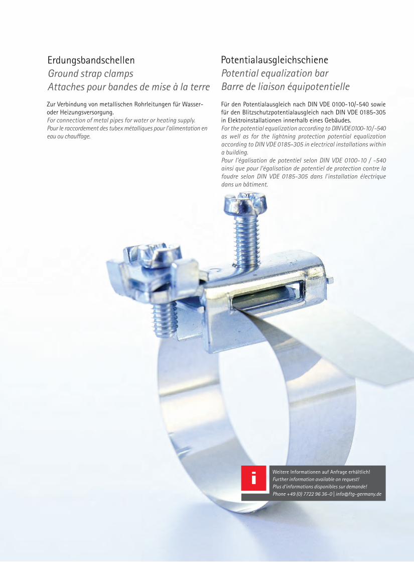
PotentialausgleichschienePotential equalization barBarre de liaison équipotentielle
Für den Potentialausgleich nach DIN VDE 0100-10/-540 sowie für den Blitzschutzpotentialausgleich nach DIN VDE 0185-305 in Elektroinstallationen innerhalb eines Gebäudes.For the potential equalization according to DIN VDE 0100-10 / -540 as well as for the lightning protection potential equalization according to DIN VDE 0185-305 in electrical installations within a building.Pour l'égalisation de potentiel selon DIN VDE 0100-10 / -540 ainsi que pour l'égalisation de potentiel de protection contre la foudre selon DIN VDE 0185-305 dans l'installation électrique dans un bâtiment.
ErdungsbandschellenGround strap clampsAttaches pour bandes de mise à la terre
Zur Verbindung von metallischen Rohrleitungen für Wasser- oder Heizungsversorgung. For connection of metal pipes for water or heating supply. Pour le raccordement des tubex métalliques pour l'alimentation en eau ou chauffage.
Weitere Informationen auf Anfrage erhältlich! Further information available on request!Plus d'informations disponibles sur demande!Phone +49 (0) 7722 96 36-0 | [email protected]
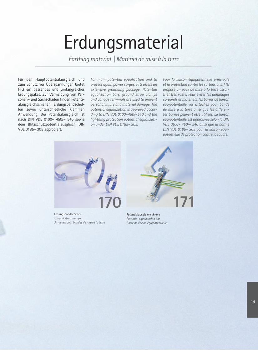
ErdungsmaterialEarthing material | Matériel de mise à la terre
Für den Hauptpotentialausgleich und zum Schutz vor Überspannungen bietet FTG ein passendes und umfangreiches Erdungspaket. Zur Vermeidung von Per-sonen– und Sachschäden fi nden Potenti-alausgleichschienen, Erdungsbandschel-len sowie unterschiedliche Klemmen Anwendung. Der Potentialausgleich ist nach DIN VDE 0100– 450/– 540 sowie dem Blitzschutzpotentialausgleich DIN VDE 0185– 305 approbiert.
For main potential equalization and to protect again power surges, FTG off ers an extensive grounding package. Potential equalization bars, ground strap clamps and various terminals are used to prevent personal injury and material damage. The potential equalization is approved accor-ding to DIN VDE 0100–450/–540 and the lightning protection potential equalizati-on under DIN VDE 0185– 305.
Pour la liaison équipotentielle principale et la protection contre les surtensions, FTG propose un pack de mise à la terre assor-ti et très vaste. Pour éviter les dommages corporels et matériels, les barres de liaison équipotentielle, les attaches pour bande de mise à la terre ainsi que les diff éren-tes bornes peuvent être utilisés. La liaison équipotentielle est approuvée selon la DIN VDE 0100– 450/– 540 ainsi que la norme DIN VDE 0185– 305 pour la liaison équi-potentielle de protection contre la foudre.
ErdungsbandschellenGround strap clampsAttaches pour bandes de mise à la terre
PotentialausgleichschienePotential equalization barBarre de liaison équipotentielle
171171170170
14
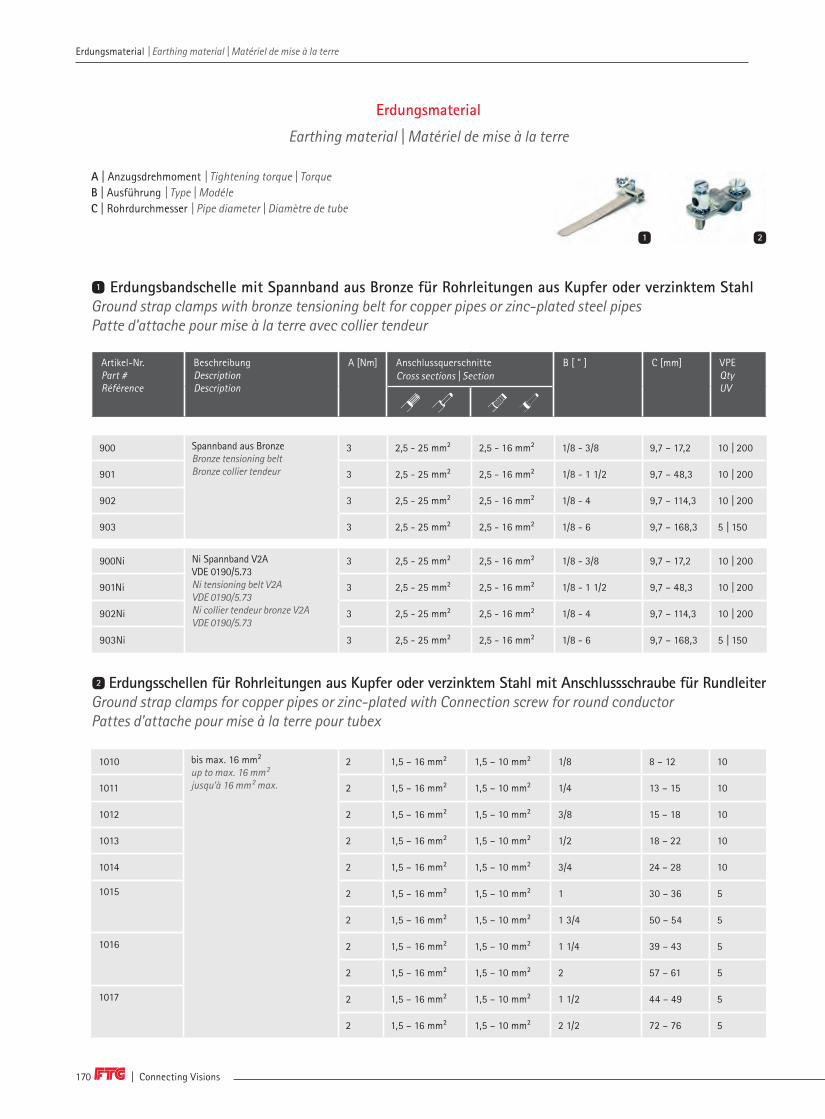
| Connecting Visions170
Erdungsmaterial | Earthing material | Matériel de mise à la terre
Erdungsmaterial
Earthing material | Matériel de mise à la terre
A | Anzugsdrehmoment | Tightening torque | TorqueB | Ausführung | Type | ModéleC | Rohrdurchmesser | Pipe diameter | Diamètre de tube
Erdungsbandschelle mit Spannband aus Bronze für Rohrleitungen aus Kupfer oder verzinktem StahlGround strap clamps with bronze tensioning belt for copper pipes or zinc-plated steel pipes Patte d'attache pour mise à la terre avec collier tendeur
Artikel-Nr. Part # Référence
BeschreibungDescriptionDescription
A [Nm] Anschlussquerschnitte Cross sections | Section
B [ " ] C [mm] VPEQtyUV
900 Spannband aus Bronze Bronze tensioning belt Bronze collier tendeur
3 2,5 - 25 mm² 2,5 - 16 mm² 1/8 - 3/8 9,7 – 17,2 10 | 200
901 3 2,5 - 25 mm² 2,5 - 16 mm² 1/8 - 1 1/2 9,7 – 48,3 10 | 200
902 3 2,5 - 25 mm² 2,5 - 16 mm² 1/8 - 4 9,7 – 114,3 10 | 200
903 3 2,5 - 25 mm² 2,5 - 16 mm² 1/8 - 6 9,7 – 168,3 5 | 150
900Ni Ni Spannband V2A VDE 0190/5.73 Ni tensioning belt V2A VDE 0190/5.73 Ni collier tendeur bronze V2A VDE 0190/5.73
3 2,5 - 25 mm² 2,5 - 16 mm² 1/8 - 3/8 9,7 – 17,2 10 | 200
901Ni 3 2,5 - 25 mm² 2,5 - 16 mm² 1/8 - 1 1/2 9,7 – 48,3 10 | 200
902Ni 3 2,5 - 25 mm² 2,5 - 16 mm² 1/8 - 4 9,7 – 114,3 10 | 200
903Ni 3 2,5 - 25 mm² 2,5 - 16 mm² 1/8 - 6 9,7 – 168,3 5 | 150
1
1 2
Erdungsschellen für Rohrleitungen aus Kupfer oder verzinktem Stahl mit Anschlussschraube für Rundleiter Ground strap clamps for copper pipes or zinc-plated with Connection screw for round conductor Pattes d'attache pour mise à la terre pour tubex
1010 bis max. 16 mm² up to max. 16 mm² jusqu'à 16 mm² max.
2 1,5 – 16 mm² 1,5 – 10 mm² 1/8 8 – 12 10
1011 2 1,5 – 16 mm² 1,5 – 10 mm² 1/4 13 – 15 10
1012 2 1,5 – 16 mm² 1,5 – 10 mm² 3/8 15 – 18 10
1013 2 1,5 – 16 mm² 1,5 – 10 mm² 1/2 18 – 22 10
1014 2 1,5 – 16 mm² 1,5 – 10 mm² 3/4 24 – 28 10
1015 2 1,5 – 16 mm² 1,5 – 10 mm² 1 30 – 36 5
2 1,5 – 16 mm² 1,5 – 10 mm² 1 3/4 50 – 54 5
1016 2 1,5 – 16 mm² 1,5 – 10 mm² 1 1/4 39 – 43 5
2 1,5 – 16 mm² 1,5 – 10 mm² 2 57 – 61 5
1017 2 1,5 – 16 mm² 1,5 – 10 mm² 1 1/2 44 – 49 5
2 1,5 – 16 mm² 1,5 – 10 mm² 2 1/2 72 – 76 5
2
Erdungsmaterial | Earthing material | Matériel de mise à la terre
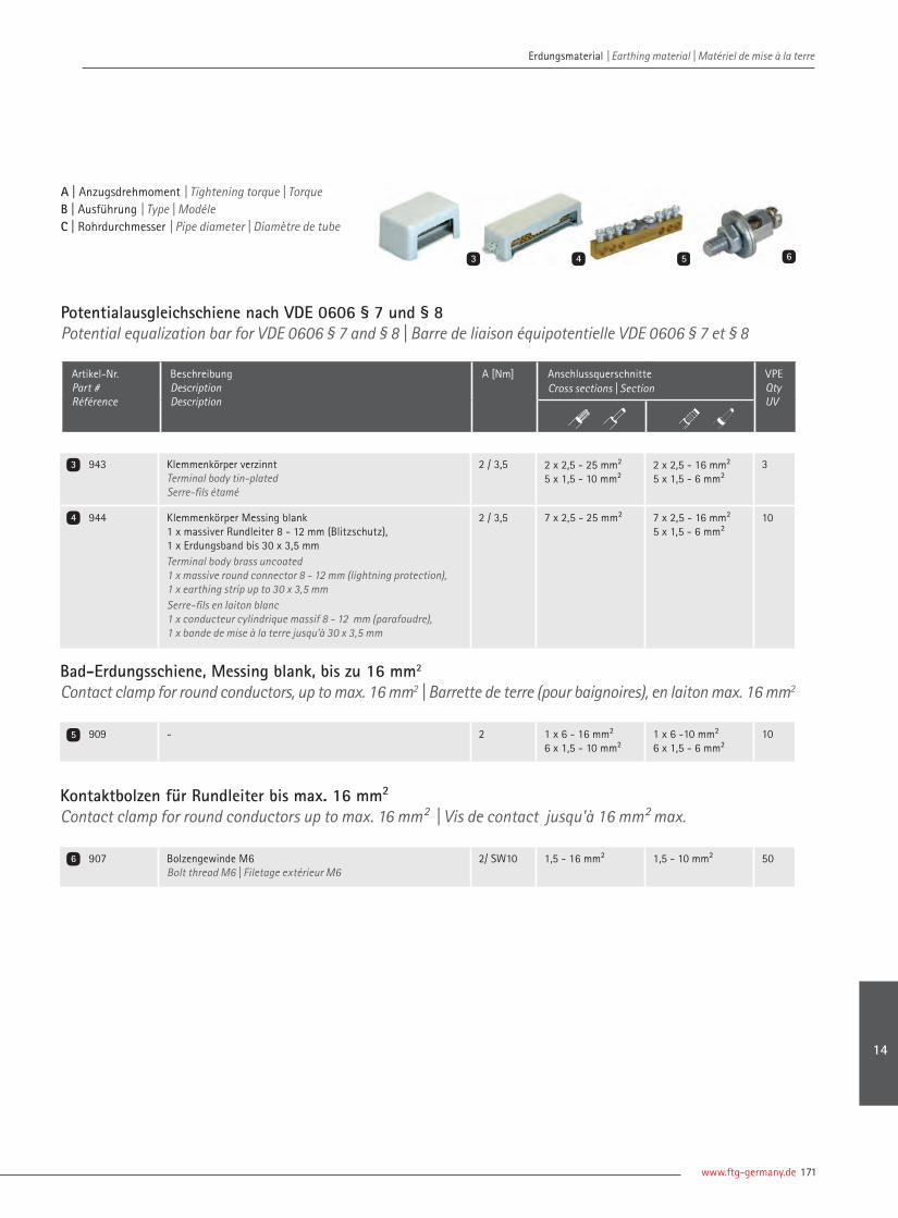
www.ftg-germany.de 171
Erdungsmaterial | Earthing material | Matériel de mise à la terre Erdungsmaterial | Earthing material | Matériel de mise à la terre
A | Anzugsdrehmoment | Tightening torque | TorqueB | Ausführung | Type | ModéleC | Rohrdurchmesser | Pipe diameter | Diamètre de tube
Potentialausgleichschiene nach VDE 0606 § 7 und § 8Potential equalization bar for VDE 0606 § 7 and § 8 | Barre de liaison équipotentielle VDE 0606 § 7 et § 8
Artikel-Nr. Part # Référence
BeschreibungDescriptionDescription
A [Nm] Anschlussquerschnitte Cross sections | Section
VPEQtyUV
943 Klemmenkörper verzinntTerminal body tin-platedSerre-fils étamé
2 / 3,5 2 x 2,5 - 25 mm²5 x 1,5 - 10 mm²
2 x 2,5 - 16 mm²5 x 1,5 - 6 mm²
3
944 Klemmenkörper Messing blank 1 x massiver Rundleiter 8 - 12 mm (Blitzschutz), 1 x Erdungsband bis 30 x 3,5 mmTerminal body brass uncoated1 x massive round connector 8 - 12 mm (lightning protection), 1 x earthing strip up to 30 x 3,5 mm Serre-fils en laiton blanc 1 x conducteur cylindrique massif 8 - 12 mm (parafoudre), 1 x bande de mise à la terre jusqu'à 30 x 3,5 mm
2 / 3,5 7 x 2,5 - 25 mm² 7 x 2,5 - 16 mm²5 x 1,5 - 6 mm²
10
Bad-Erdungsschiene, Messing blank, bis zu 16 mm2
Contact clamp for round conductors, up to max. 16 mm2 | Barrette de terre (pour baignoires), en laiton max. 16 mm2
909 - 2 1 x 6 - 16 mm²6 x 1,5 - 10 mm²
1 x 6 -10 mm²6 x 1,5 - 6 mm²
10
3
4
5
Kontaktbolzen für Rundleiter bis max. 16 mm²Contact clamp for round conductors up to max. 16 mm² | Vis de contact jusqu'à 16 mm² max.
907 Bolzengewinde M6Bolt thread M6 | Filetage extérieur M6
2/ SW10 1,5 - 16 mm² 1,5 - 10 mm² 50
3 4 5 6
6
14

| Connecting Visions172
Erdungsmaterial | Earthing material | Matériel de mise à la terre Erdungsmaterial | Earthing material | Matériel de mise à la terre
Erdungsklemme mit Zwischenplatte für Bandstahl und RundleiterEarthing terminal with intermediate plate for steel strip or round conductor Borne de terre avec plateau intermédiaire pour feuillard d’acier ou conducteur cylindrique
920 bis 35 mm Breite | up to 35 mm width | jusqu'à une Longeur de 35 mm 10
Kontaktschraube Stahl, verzinktContact screw steel, zinc-plated | Vis de contact, galvanisé
Artikel-Nr. Part # Référence
BeschreibungDescriptionDescription
VPEQtyUV
908 Bestehend aus M8 x 20 mm, Unterlagscheibe, Zahnscheibe und MutterConsisting of M8 x 20 mm, washer, toothed lock and nut | M8 x 20 mm, avec rondelles, disques dentés et écrous
50
1 2
1
2
3 4
Kreuzverbinder mit Zwischenplatte für Bandstahl und RundleiterCorssing sleeve with plate for steel strip or round connector Jonction cruciforme avec plateau intermédiaire pour feuillard d’acier et conducteur cylindrique
Anschlussklemmen für KreuzerderFeed-in terminals for earth rods | Borne d’alimentation pour fils de terre cruciformes
930 bis 35 mm Breite | up to 35 mm width | jusqu'à une Longeur de 35 mm 10
940 10 - 70 mm² 20
941 Für 1 x Rundleiter 8 - 10 mm | For 1 x round conductor 8 - 10 mm | Pour 1 conducteur cylindrique 8 - 10 mm² 25
942 Für 2 x Rundleiter 8 - 10 mm | For 2 x round conductor 8 - 10 mm | Pour 2 conducteurs cylindrique 8 - 10 mm² 25
3
4
5
6
Erdungszubehör
Accessories | Accessoires

www.ftg-germany.de 173
5
Erdungsschienen verzinnt für Flachsteckhülse 6,3 x 0,8 mmEarthing tinned bar for fast-on connector | Barrette de terre étamée pour fast on
Artikel-Nr. Part # Référence
BeschreibungDescriptionDescription
VPEQtyUV
EST002 Erdungsschiene, 2 Kontakte | Earthing bar, 2 lugs | Barrette de terre, 2 contacts 100
EST004 Erdungsschiene, 4 Kontakte | Earthing bar, 4 lugs | Barrette de terre, 4 contacts 100
EST006 Erdungsschiene, 6 Kontakte | Earthing bar, 6 lugs | Barrette de terre, 6 contacts 50
EST008 Erdungsschiene, 8 Kontakte | Earthing bar, 8 lugs | Barrette de terre, 8 contacts 50
EST010 Erdungsschiene, 10 Kontakte | Earthing bar, 10 lugs | Barrette de terre, 10 contacts 50
EST012 Erdungsschiene, 12 Kontakte | Earthing bar, 12 lugs | Barrette de terre, 12 contacts 50
EST014 Erdungsschiene, 14 Kontakte | Earthing bar, 14 lugs | Barrette de terre, 14 contacts 20
EST016 Erdungsschiene, 16 Kontakte | Earthing bar, 16 lugs | Barrette de terre, 16 contacts 20
EST020 Erdungsschiene, 20 Kontakte | Earthing bar, 20 lugs | Barrette de terre, 20 contacts 20
Erdungslitze gelb/grün, beidseitig GabelschuhEarthing wire yellow/green, with fork on both ends | Câble de terre vert/jaune avec fourche à chaque extrémité
EL-10/2500G 10 mm², Länge 2.500 mm | 10 mm², length 2500 mm | 10 mm², longueur 2.500 mm 20
EL-16/2500G 16 mm², Länge 2.500 mm | 16 mm², length 2500 mm | 16 mm², longueur 2.500 mm 20
6 7 8
7
8
Erdungsmaterial | Earthing material | Matériel de mise à la terre Erdungsmaterial | Earthing material | Matériel de mise à la terre
Auch in anderen Längen lieferbar!Weitere Erdungsklemmen im Kapitel Verteilerklemmen.
Also other lenghts available! Further earthing clamps in the chapter Distribution terminals.
D'autres longueurs sont disponibles! Autres pinces de mise à la terre dans les pinces du chapitre 12.
14

Weitere Informationen auf Anfrage erhältlich! Further information available on request!Plus d'informations disponibles sur demande!Phone +49 (0) 7722 96 36-0 | [email protected]

VerdrahtungsbrückenCable bridges | Ponts de câblage
Für mehr Ordnung im Schaltschrank sorgen individualisierte Kabelkonfektionen. Flexible Verdrahtungsbrücken, wahlwei-se mit Gabelschuh, Aderendhülsen oder beidseitig ultraschallverdichteten Enden können individuell vorkonfektioniert wer-den. Zudem liefert FTG ein– bis vierpolige Reihenverbinder.
Customized cable assemblies can be used to avoid confusion in the switch cabinet. Flexible wiring bridges, with fork termi-nal, wire end ferrules or ultrasonically welded ends on both sides if required, can be made in advance individually. In addi-tion, FTG supplies one- to four-pole row connectors.
Des confections de câbles personnalisées assurent de l’ordre dans l’armoire élec-trique. Des ponts de câblage fl exibles, au choix avec fourche, embout ou extrémi-tés comprimées par ultrason peuvent être préconfectionnés individuellement. De plus, FTG fournit des branchements en sé-rie uni- à tétrapolaires.
Flexible VerdrahtungsbrückenFlexible cable bridges | Ponts de câblage souple
ReihenverbindungenRow connectors | Pontage vertical
178178176176
15

| Connecting Visions176
Verdrahtungsbrücken | Cable bridges | Ponts de câblage
Flexible Verdrahtungsbrücken
Flexible cable bridges | Ponts de câblage souple
A
B C
Artikel-Nr. Part # Référence
QuerschnittCross sectionSection
Material MaterialMatériau
A [mm] B* C* VPEQtyUV
880 6 mm² H07V-K 125 Gabel M6 Gabel M6 50
1880 6 mm² H07V-K 125 Gabel M6 AE 50
1880U 6 mm² H07V-K 125 Gabel M6 USV 50
2880 6 mm² H07V-K 125 AE AE 50
2880B 6 mm² H07V-K 125 AE AE 50
2880U 6 mm² H07V-K 125 USV USV 50
2880UB 6 mm² H07V-K 125 USV USV 50
883 6 mm² H07V-K 260 Gabel M6 Gabel M6 50
883B 6 mm² H07V-K 260 Gabel M6 Gabel M6 50
1883 6 mm² H07V-K 260 Gabel M6 AE 50
1883B 6 mm² H07V-K 260 Gabel M6 AE 50
1883U 6 mm² H07V-K 260 Gabel M6 USV 50
1883UB 6 mm² H07V-K 260 Gabel M6 USV 50
2883 6 mm² H07V-K 260 AE AE 50
2883B 6 mm² H07V-K 260 AE AE 50
2883U 6 mm² H07V-K 260 USV USV 50
2883UB 6 mm² H07V-K 260 USV USV 50
882 6 mm² H07V-K 325 Gabel M6 Gabel M6 50
1882 6 mm² H07V-K 325 Gabel M6 AE 50
1882U 6 mm² H07V-K 325 Gabel M6 USV 50
2882 6 mm² H07V-K 325 AE AE 50
2882B 6 mm² H07V-K 325 AE AE 50
2882YG 6 mm² H07V-K 325 AE AE 50
2882U 6 mm² H07V-K 325 USV USV 50
2882UB 6 mm² H07V-K 325 USV USV 50
2882UYG 6 mm² H07V-K 325 USV USV 50
*Gabel | Fork | Fourche, AE | Ferrule | Embout, USV | Ultrasonically welded | Compactage par ultrasons
A | Länge | Length | Longueur B | Konfektion 1 | Cable end 1 | Extrémité de câble 1C | Konfektion 2 | Cable end 2 | Extrémité de câble 2
Verdrahtungsbrücken | Cable bridges | Ponts de câblage

www.ftg-germany.de 177
Verdrahtungsbrücken | Cable bridges | Ponts de câblage Verdrahtungsbrücken | Cable bridges | Ponts de câblage
*Gabel | Fork | Fourche, AE | Ferrule | Embout, USV | Ultrasonically welded | Compactage par ultrasons
Artikel-Nr. Part # Référence
QuerschnittCross sectionSection
Material MaterialMatériau
A [mm] B* C* VPEQtyUV
885 10 mm² H07V-K 125 Gabel M6 Gabel M6 25
1885 10 mm² H07V-K 125 Gabel M6 AE 25
1885U 10 mm² H07V-K 125 Gabel M6 USV 25
2885 10 mm² H07V-K 125 AE AE 25
2885B 10 mm² H07V-K 125 AE AE 25
2885U 10 mm² H07V-K 125 USV USV 25
2885UB 10 mm² H07V-K 125 USV USV 25
889 10 mm² H07V-K 260 Gabel M6 Gabel M6 25
889B 10 mm² H07V-K 260 Gabel M6 Gabel M6 25
1889 10 mm² H07V-K 260 Gabel M6 AE 25
1889B 10 mm² H07V-K 260 Gabel M6 AE 25
1889U 10 mm² H07V-K 260 Gabel M6 USV 25
1889UB 10 mm² H07V-K 260 Gabel M6 USV 25
2889 10 mm² H07V-K 260 AE AE 25
2889B 10 mm² H07V-K 260 AE AE 25
2889U 10 mm² H07V-K 260 USV USV 25
2889UB 10 mm² H07V-K 260 USV USV 25
888 10 mm² H07V-K 325 Gabel M6 Gabel M6 25
1888 10 mm² H07V-K 325 Gabel M6 AE 25
1888U 10 mm² H07V-K 325 Gabel M6 USV 25
2888 10 mm² H07V-K 325 AE AE 25
2890 10 mm² H07V-K 325 AE AE 25
2891 10 mm² H07V-K 325 AE AE 25
2888U 10 mm² H07V-K 325 USV USV 25
2890U 10 mm² H07V-K 325 USV USV 25
2891U 10 mm² H07V-K 325 USV USV 25
15

| Connecting Visions178
Verdrahtungsbrücken | Cable bridges | Ponts de câblage Verdrahtungsbrücken | Cable bridges | Ponts de câblage
Reihenverbindungen
Row Connectors | Branchement en série
21
Artikel-Nr. Part # Référence
QuerschnittCross sectionSection
Reihenabstand [mm] Row spacing Distance entre rangées
VPEQtyUV
Einpoliger Reihenverbinder | One-pole row connectors | Pontage vertical 1 pôle
RV 1125 10 mm² 125 25
RV 1125B 10 mm² 125 25
RV 1125 / 16 16 mm² 125 25
RV 1125B / 16 16 mm² 125 25
RV 1138 10 mm² 138 25
RV 1138B 10 mm² 138 25
RV 1138 / 16 16 mm² 138 25
RV 1138B / 16 16 mm² 138 25
RV 1150 10 mm² 150 25
RV 1150B 10 mm² 150 25
RV 1150 / 16 16 mm² 150 25
RV 1150B / 16 16 mm² 150 25
RV 1250 10 mm² 250 25
RV 1250B 10 mm² 250 25
RV 1250 / 16 16 mm² 250 25
RV 1250B / 16 16 mm² 250 25
Zweipoliger Reihenverbinder | Two-pole row connectors | Pontage vertical 2 pôles
RV 2125 10 mm² 125 25
RV 2125B 10 mm² 125 25
RV 2125B-S 10 mm² 125 25
RV 2125 / 16 16 mm² 125 25
RV 2125B / 16 16 mm² 125 25
RV 2138 10 mm² 138 25
RV 2138B 10 mm² 138 25
RV 2138 / 16 16 mm² 138 25
RV 2138B / 16 16 mm² 138 25
RV 2150 10 mm² 150 25
RV 2150B 10 mm² 150 25
RV 2150 / 16 16 mm² 150 25
RV 2150B / 16 16 mm² 150 25
RV 2250 10 mm² 250 25
RV 2250B 10 mm² 250 25
RV 2250 / 16 16 mm² 250 25
RV 2250B / 16 16 mm² 250 25
1
2
15

www.ftg-germany.de 179
Verdrahtungsbrücken | Cable bridges | Ponts de câblage Verdrahtungsbrücken | Cable bridges | Ponts de câblage
Artikel-Nr. Part # Référence
QuerschnittCross sectionSection
Reihenabstand [mm] Row spacing Distance entre rangées
VPEQtyUV
Dreipoliger, seitlicher Reihenverbinder | Three-pole lateral row connectors | Pontage vertical latéral, 3 pôles
RV3125-S 10 mm² 125 25
Dreipoliger Reihenverbinder | Three-pole row connectors | Pontage vertical 3 pôles
RV 3125 10 mm² 125 25
RV 3125 / 16 16 mm² 125 25
RV 3138 10 mm² 138 25
RV 3138 / 16 16 mm² 138 25
RV 3150 10 mm² 150 25
RV 3150 / 16 16 mm² 150 25
RV 3250 10 mm² 250 25
RV 3250 / 16 16 mm² 250 25
Vierpoliger, seitlicher Reihenverbinder | Four-pole lateral row connectors | Pontage vertical 4 pôles
RV4125B-S 10 mm² 125 25
Vierpoliger Reihenverbinder | Four-pole row connectors | Pontage vertical latéral, 4 pôles
RV 4125B 10 mm² 125 25
RV 4125B / 16 16 mm² 125 25
RV 4125B-LINKS 10 mm² 125 25
RV 4125B / 16-LINKS 16 mm² 125 25
RV 4138B 10 mm² 138 25
RV 4138B / 16 16 mm² 138 25
RV 4138B-LINKS 10 mm² 138 25
RV 4138B / 16-LINKS 16 mm² 138 25
RV 4150B 10 mm² 150 25
RV 4150B / 16 16 mm² 150 25
RV 4150B-LINKS 10 mm² 150 25
RV 4150B / 16-LINKS 16 mm² 150 25
RV 4200B 10 mm² 200 25
RV 4200B / 16 16 mm² 200 25
RV 4200B-LINKS 10 mm² 200 25
RV 4200B / 16-LINKS 16 mm² 200 25
RV 4250B 10 mm² 250 25
RV 4250B / 16 16 mm² 250 25
RV 4250B-LINKS 10 mm² 250 25
RV 4250B / 16-LINKS 16 mm² 250 25
3
4
5
6
5 63 4
15

| Connecting Visions180
2. Der Kunde kann nur mit unbestrittenen oder rechtskräftig festgestellten Forderungen auf-rechnen. Zahlungen oder Leistungen (z.B. Beistellungen o.ä.) kann der Kunde nur zurückbehal-ten, wenn seine fälligen Gegenforderungen unbestritten oder rechtskräftig festgestellt sind.
§ 8 Lieferung, Gefahrübergang, Teillieferungen1. Lieferungen von FTG erfolgen ab Werk (EXW Incoterms® 2010) durch Bereitstellung zur Abholung auf dem Betriebsgelände von FTG in 78098 Triberg oder einem anderen vereinbarten Ort und Mitteilung der Versandbereitschaft.2. Die Gefahr des Verlusts oder der Beschädigung der Lieferung geht gemäß EXW Incoterms® 2010 mit Lieferung im Sinne von Abs. 1 auf den Kunden über, und zwar auch dann, wenn FTG über die Bereitstellung hinaus weitere Pflichten (z.B. das Beladen oder den Transport) über-nommen hat oder die Kosten hierfür trägt.3. FTG darf Teillieferungen oder -leistungen erbringen, soweit dadurch das Kundeninteresse nicht unangemessen beeinträchtigt wird.
§ 9 Liefer- und Leistungszeit; Verzug; Lagergeld1. Vereinbarte Liefer- und Leistungsfristen oder -zeiten sind Circa-Fristen bzw. –Zeiten. 2. Liefer- und Leistungsfristen beginnen mit Zugang der Auftragsbestätigung von FTG beim Kunden, jedoch nicht vor (a) Klärung aller aus Sicht von FTG klärungsbedürftigen Einzelheiten des Auftragsinhalts (insbesondere technischer Leistungsanforderungen), (b) Erhalt aller für die Ausführung des Auftrags erforderlicher Unterlagen, Beistellung, Freigaben, Genehmigungen von Plänen und ggf. sonstiger erforderlicher Mitwirkungsleistungen des Kunden und (c) Eingang ver-einbarter oder von FTG berechtigt geforderter Vorauszahlungen. 3. Maßgebend für die Einhaltung von Fristen und Zeiten ist der Zeitpunkt des Gefahrübergangs (vgl. § 8 Abs. 2). 4. Die Einhaltung der Liefer- oder Leistungsfristen steht unter dem Vorbehalt rechtzeitiger und fehlerfreier Selbstbelieferung, es sei denn, FTG hat eine Nicht- oder Schlechtlieferung durch Vorlieferanten zu vertreten. Im Fall einer von FTG nicht zu vertretenden Nicht- oder Schlechtleistung des Vorlieferanten gerät FTG nicht in Verzug und kann sich durch Erklärung von ihrer Leistungspflicht lösen.5. Ist FTG durch höhere Gewalt, z.B. Mobilmachung, Krieg, Aufruhr, Terrorakte, Naturkatastrophen, oder andere von ihr nicht zu vertretende unvorhersehbare Umstände, z.B. Streik oder Aussperrung, unverschuldet an einer fristgerechten Lieferung gehindert, so verlängern sich Lieferfristen um den Zeitraum, in dem die Störung andauert, zzgl. einer angemessenen Anlauffrist nach Beendigung der Störung. Satz 1 gilt entsprechend, wenn Umstände in dem genannten Sinn bei Vorlieferanten von FTG eintreten. Ist die Störung nicht nur von vorübergehender Dauer, so kann FTG sich durch Erklärung von ihrer Leistungspflicht lösen; in diesem Fall bestehen beiderseits keine Ansprüche aus dem Vertrag. Im übrigen gelten die gesetzlichen Bestimmungen.6. Lieferzeiten verlängern sich ferner um den Zeitraum, in dem der Kunde seiner Verpflich-tung, bei der ordnungsgemäßen Vertragserfüllung mitzuwirken, nicht oder nur unzurei-chend nachkommt, zzgl. einer angemessenen Anlauffrist nach Vornahme der Mitwirkung.7. Gerät FTG infolge einfacher oder leichter Fahrlässigkeit in Verzug, so ist ihre Haftung für Verzögerungsschäden beschränkt auf typische und vorhersehbare Schäden, wobei FTG nur in Höhe von bis zu 0,5 Prozent des Netto-Rechnungsbetrags des vom Verzug betroffenen Teils der Lieferung pro vollendeter Woche des Verzugs haftet, insgesamt jedoch in Höhe von bis zu fünf (5) Prozent dieses Netto-Rechnungsbetrags. Im Übrigen gilt für die Haftung von FTG wegen Verzugs § 16.8. Wünscht der Kunde, dass die Lieferung oder Leistung später als vereinbart erfolgt oder führt der Annahmeverzug des Kunden zu einer verspäteten Auslieferung, so kann FTG, beginnend ab Anzeige der Versandbereitschaft Kosten für die Lagerung in Höhe von 1 % des Nettopreises der betroffenen Lieferung pro angefangenem Monat, höchstens jedoch in Höhe von insgesamt 5 % dieses Preises verlangen. FTG bleibt der Nachweis eines höheren, dem Kunden der Nachweis kei-nes oder eines wesentlich niedrigeren Schadens vorbehalten. FTG kann die Liefergegenstände auch bei einer Spedition einlagern und von dem Kunden Erstattung der dabei anfallenden Kosten verlangen. Der Gefahrübergang gemäß § 8 Abs. 2 bleibt von einer auf Wunsch des Kunden oder wegen Annahmeverzugs des Kunden erfolgen späteren Auslieferung unberührt.
§ 10 Verpackung1. FTG wird die Lieferungen auf Kosten des Kunden nach eigenem Ermessen handelsüblich verpacken.2. FTG wird Verpackungen auf Wunsch des Kunden auf ihrem Betriebsgelände (vgl. § 8 Abs. 1) zurücknehmen. Der Kunde wird in diesem Fall die Verpackung sauber, frei von Fremdstoffen und nach Verpackungsarten sortiert zurücksenden. Er trägt die Kosten der Rücksendung und der ordnungsgemäßen Entsorgung.
§ 11 Eigentumsvorbehalt1. FTG behält sich das Eigentum an Lieferungen und Leistungen („Vorbehaltsware“) bis zur Erfüllung aller Forderungen von FTG aus der Geschäftsverbindung mit dem Kunden (einschließ-lich z.B. Nebenforderungen, Schadenersatzansprüchen und Scheck- oder Wechselkosten) vor. Der Eigentumsvorbehalt bleibt auch dann bestehen, wenn einzelne Forderungen von FTG in eine laufende Rechnung aufgenommen werden und der Saldo gezogen wird. Der Eigentumsvorbehalt bezieht sich sowohl auf den tatsächlichen als auch auf den anerkannten Saldo.2. Der Kunde nimmt Ver- oder Bearbeitungen von Liefergegenständen stets für FTG als Herstel-ler im Sinne von § 950 BGB vor. Wird die Vorbehaltsware mit anderen, nicht FTG gehörenden Gegenständen verarbeitet, verbunden oder untrennbar vermischt oder vermengt, so erwirbt FTG an der neuen Sache Miteigentum nach Teilen, und zwar in dem Verhältnis, in dem der Wert der Vorbehaltsware zu dem Wert der nicht im Eigentum von FTG stehenden Ware des Kunden oder Dritter steht. Erwirbt der Kunde in den in Satz 2 genannten Fällen kraft Gesetz Alleineigentum an der unter Verwendung der Vorbehaltsware entstehenden neuen einheitlichen Sache, so überträgt der Kunde FTG entsprechend dem in Satz 2 geregelten Anteil zur Sicherung der in Abs. 1 genannten Forderungen Miteigentum und verwahrt die Sache unentgeltlich für FTG. Im Übrigen gelten für die durch Verarbeitung, Ver-bindung oder Vermischung entstehende neue Sache die Bestimmungen über die Vorbehaltsware entsprechend.
§ 1 Geltungsbereich 1. Für alle – auch künftige - Lieferungen und Leistungen (im Folgenden zusammen „Liefe-rungen“) der Friedrich Göhringer Elektrotechnik GmbH („FTG“) an Kunden gemäß Absatz 2 gelten ausschließlich diese Allgemeinen Lieferbedingungen in ihrer zum Zeitpunkt des Ver-tragsschlusses aktuellen Fassung sowie sonstige gegebenenfalls getroffene Vereinbarungen.2. Die Allgemeinen Lieferbedingungen gelten nur gegenüber Unternehmern im Sinne von § 14 BGB, juristischen Personen des öffentlichen Rechts oder öffentlich-rechtlichen Sondervermögen („Kunden“).3. Geschäftsbedingungen des Kunden gelten nicht, insbesondere auch dann nicht, auch wenn FTG der Geltung solcher Bedingungen nicht widerspricht.
§ 2 Vertragsschluss1. Angebote von FTG sind unverbindlich. 2. FTG kann Bestellungen des Kunden innerhalb von zwei (2) Wochen ab dem Bestelldatum annehmen, soweit in der Bestellung nichts Abweichendes angegeben ist.3. Verträge zwischen FTG und ihren Kunden kommen erst dadurch zustande, dass FTG eine Bestel-lung durch schriftliche Erklärung oder durch Lieferung oder Leistung annimmt.
§ 3 Leistungsinhalt; Änderungsvorbehalt1. Abbildungen oder Zeichnungen von FTG oder von FTG gemachte Maß-, Gewichts-, Konstruk-tions-, Farb-, Qualitäts-, Design-, Verarbeitungs- oder ähnliche Angaben sind nur Annäherungs-werte, soweit sie nicht ausdrücklich als verbindlich bezeichnet werden.2. Produkt- und Leistungsbeschreibungen von FTG sind keine Garantien im Rechtssinne. Nur schriftlich abgegebene und ausdrücklich als solche bezeichnete Garantien binden FTG.3. FTG kann auch nach Abschluss eines Vertrags die versprochene Lieferung oder Leistung ändern oder von ihr abweichen, wenn und soweit die Änderung oder Abweichung handelsüblich oder nur unwesentlich ist und keine von FTG garantierte Beschaffenheit betrifft. Dies gilt insbesondere für Änderungen und/oder Abweichungen in Bezug auf Maße, Gewicht, Konstruktion, Farbe, Qualität, Design, Verarbeitung und Menge.
§ 4 Werkzeuge1. Soweit die Vertragspartner keine abweichende Vereinbarung getroffen haben, wird FTG erfor-derliche Werkzeuge selbst herstellen oder beschaffen. 2. Die Werkzeuge bleiben im Eigentum von FTG. Der Kunde hat keinen Anspruch auf Übereig-nung, Herausgabe und Nutzung solcher Werkzeuge. Dies gilt, wenn die Vertragspartner keine abweichende Vereinbarung treffen, auch dann, wenn die von dem Kunden geschuldete Vergü-tung auch anteilig die entstehenden Werkzeugkosten umfasst.3. Die mit der Herstellung oder Beschaffung von Werkzeugen verbundenen Kosten und Aufwän-de sind mit der Vergütung abgegolten.
§ 5 Änderungswünsche des Kunden1. Der Kunde kann jederzeit auch nach Abschluss eines Vertrags Änderungs-wünsche im Hin-blick auf die Leistungsausführung vorbringen. Jede Abweichung von dem aufgrund eines ge-schlossenen Vertrags geschuldeten Leistungsinhalt gilt als Änderung. 2. FTG wird Änderungswünsche ausführen, wenn darüber ein gesonderter Änderungsvertrag zustande gekommen ist. Der Änderungsvertrag regelt neben dem geänderten Leistungsinhalt auch die gegebenenfalls geänderte Vergütung und angepasste Leistungszeiten.
§ 6 Preise und Zahlungsbedingungen1. Preise von FTG gelten ab Werk (EXW Incoterms® 2010) in Euro. Kosten für Verpackung, Ver-sand, gegebenenfalls Versicherung und Verzollung sowie jeweils gültige Umsatzsteuer kommen hinzu.2. Metallzuschläge werden, bemessen am Metall-Einsatzgewicht, ent-sprechend der MK-Ta-gesnotierung abzüglich 153,39 Euro pro einhundert Kilogramm zuzüglich eines Bearbeitungs-zuschlages in der Höhe von 1% am Tage des Bestelleingangs gesondert in Rechnung gestellt.3. Bei Lieferfristen von mehr als zwei (2) Monaten kann FTG die vereinbarten Preise nach billigem Ermessen angemessen erhöhen, soweit Gehalts-, Material-, Energie- und/oder Rohstoffkosten nach Vertragsschluss aus nicht von FTG zu vertretenden Gründen erheblich gestiegen sind. Die Erhöhung erfolgt durch schriftliche Erklärung durch FTG. Bei Preiserhöhungen von mehr als fünf (5) Prozent kann der Kunde sich innerhalb von zwei (2) Wochen nach Zugang der Erklärung der Preiserhöhung durch schriftliche Erklärung vom Vertrag lösen.4. Die Vergütung ist mit Vertragsschluss fällig. Der Kunde gerät nach Maß-gabe der gesetzlichen Bestimmungen auch ohne Mahnung in Zahlungsverzug, wenn er nicht spätestens innerhalb von 14 Tagen ab Rechnungszugang bezahlt, es sei denn, es ist etwas Abweichendes vereinbart. Der Kun-de darf Skonto nur abziehen, wenn dies gesondert vereinbart ist. Eine gegebenenfalls getroffene Skontoabrede bezieht sich, wenn nicht etwas Abweichendes vereinbart ist, nicht auf Metallzu-schläge und Kosten von Verpackung, Versand, Versicherung sowie gegebenenfalls sonst anfallende Kosten der Versendung.5. FTG ist berechtigt, angemessene Vorauszahlung in Rechnung zu stellen, wenn der Kunde seinen Sitz im Ausland hat oder konkrete Anhaltspunkte bestehen, die Zweifel an der Kredit-würdigkeit des Kunden rechtfertigen. Im Fall einer berechtigten Vorauskasserechnung ist FTG berechtigt, mit der Ausführung des Auftrags erst nach Zahlungseingang zu beginnen.6. Gerät der Kunde in Zahlungsverzug oder werden FTG nach Vertragsschluss Umstände be-kannt, die Zweifel an der Kreditwürdigkeit des Kunden rechtfertigen, so kann FTG noch ausste-hende, ggf. noch nicht fällige Zahlungsforderungen sofort fällig stellen und weitere Lieferungen oder Leistungen von einer Vorauszahlung abhängig machen. Weitergehende Rechte von FTG wegen Zahlungsverzugs bleiben unberührt.
§ 7 Aufrechnung und Zurückbehaltungsrecht1. FTG stehen die gesetzlichen Aufrechnungs- und Zurückbehaltungsrechte und die Einrede des nicht erfüllten Vertrags zu. FTG kann abweichend von § 273 BGB geschuldete Leistungen auch dann zurückhalten, wenn ihr ein fälliger Gegenanspruche zusteht, der nicht auf demselben recht-lichen Verhältnis wie ihre Leistungspflicht beruht.
Allgemeine Lieferbedingungender Friedrich Göhringer Elektrotechnik GmbH
www.ftg-germany.de 181
3. Der Kunde darf die Vorbehaltsware im ordentlichen Geschäftsgang veräußern. Er darf die Vorbehaltsware jedoch nicht ohne schriftliche Zustimmung von FTG verpfänden oder anderen zur Sicherheit übereignen. Im Fall einer Pfändung der Vorbehaltsware durch Dritte sowie bei Be-schlagnahmen oder sonstigen Verfügungen oder Eingriffen Dritter muss der Kunde FTG unverzüglich benachrichtigen.4. Der Kunde tritt FTG bereits mit Abschluss eines Vertrags, spätestens jedoch mit Entgegennahme des Liefergegenstands von FTG sämtliche Forderungen gegen seine Abnehmer aus dem Wei-terverkauf der Vorbehaltsware zur Sicherheit ab. FTG ermächtigt den Kunden, an FTG abge-tretene Forderungen einzuziehen. FTG bleibt jedoch trotz dieser Ermächtigung zum Einzug der Forderung berechtigt. Gerät der Kunden in Zahlungsverzug, stellt er seine Zahlungen ein, ist ein Antrag auf Eröffnung eines Insolvenzverfahrens über das Vermögen des Kunden gestellt oder liegt ein damit vergleichbarer Sachverhalt vor, kann FTG die Einzugsermächtigung widerrufen. Auf Verlangen von FTG wird der Kunde FTG im Fall des Widerrufs die zur Geltendmachung der abgetretenen Ansprüche erforderlichen Auskünfte erteilen, sämtliche dem Beweis der Forderung dienenden Unterlagen aushändigen und die Abtretung offenlegen. Auch FTG ist in diesem Fall zur Offenlegung der Abtretung berechtigt.5. Bei Zahlungsverzug des Kunden kann FTG die Vorbehaltsware herausverlangen, wenn FTG spätestens mit dem Herausgabeverlangen von dem der jeweiligen Lieferung zu Grunde lie-genden Einzelvertrag zurücktritt. Der Kunde wird in diesem Fall ggf. gegen Dritte bestehende Ansprüche auf Herausgabe der Vorbehaltsware an FTG abtreten.6. FTG wird auf Verlangen des Kunden Sicherheiten in dem Umfang freigeben, indem der realisierbare Wert der für FTG bestehenden Sicherheiten die zu sichernden Forderungen um mehr als 10% übersteigt.
§ 12 Geistiges Eigentum und Nutzungsrechte1. FTG räumt mit der Lieferung keine Nutzungsrechte an Urheberrechten, gewerblichen Schutzrechten oder sonstigem geistigen Eigentum ein, das an den Liefergegenständen, Ge-brauchsanweisungen, Produktbeschreibungen, Zeichnungen, Fotos oder dergleichen ggf. besteht.2. Im Fall einer ggf. vereinbarten Nutzungsrechtseinräumung durch FTG an Rechten im Sinne von Abs. 1 räumt FTG, soweit nichts anderes vereinbart ist, nur nicht-ausschließliche, nicht übertragbare und nicht unterlizenzierbare Rechte ein, die sachlich auf den mit der Nutzungs-rechtseinräumung verfolgten Zweck beschränkt sind.3. Beauftragt der Kunde FTG, Leistungen nach bestimmten technischen Zeichnungen, Ent-würfen oder sonstigen Vorgaben zu erbringen, so räumt er FTG mit Beauftragung sämtliche zur Erfüllung der Vorgaben nötigen Rechte an insoweit ggf. bestehenden Urheberrechten, gewerblichen Schutzrechten oder sonstigem geistigen Eigentum ein. FTG darf Erfüllungsgehil-fen und Zulieferern im erforderlichen Umfang hieran Unterlizenzen einräumen.
§ 13 Entgegennahme; Untersuchungs- und Rügepflicht1. Der Kunde darf die Entgegennahme von Lieferungen und Leistungen nicht wegen nur unerheblicher Mängel verweigern.2. Der Kunde hat, sofern er Kaufmann ist, gelieferte Ware unverzüglich gemäß § 377 HGB zu untersuchen.3. Er hat FTG bei der Untersuchung erkennbare Sachmängel unverzüglich und versteckte Sach-mängel unverzüglich nach ihrer Entdeckung anzuzeigen.4. Anzeigen nach Abs. 3 müssen schriftlich erfolgen und die Sachmängel möglichst konkret beschreiben.5. Der Kunde kann keine Ansprüche wegen Sachmängeln geltend machen, die nicht form- und fristgerecht gerügt wurden.
§ 14 Sachmängel1. FTG haftet bei Sachmängeln nach Maßgabe der gesetzlichen Bestimmungen, soweit nachfolgend nichts Abweichendes geregelt ist.2. FTG erbringt die Gewährleistung durch Nacherfüllung, und zwar nach ihrer Wahl entweder durch Beseitigung von Sachmängeln oder durch mangelfreie Neulieferung.3. Ansprüche des Bestellers wegen der zum Zweck der Nacherfüllung erforderlichen Aufwen-dungen, insbesondere Transport-, Wege-, Arbeits- und Materialkosten, sind ausgeschlossen, so-weit die Aufwendungen sich erhöhen, weil der Gegenstand der Lieferung nachträglich an einen anderen Ort als der Niederlassung des Auftraggebers verbracht worden ist, es sei denn, die Verbringung entspricht seinem bestimmungsgemäßen Gebrauch.4. Bei Fehlschlagen der Nacherfüllung kann der Kunde Herabsetzung der Vergütung verlangen oder – bei erheblichen Sachmängeln – nach seiner Wahl vom Vertrag zurücktreten. Schadensersatz wegen Sachmängeln kann der Kunde nur unter den gesetzlichen Voraussetzungen und insoweit verlangen, als eine Haftung nach § 15 gegeben ist. Andere Ansprüche wegen Sachmängeln sind ausgeschlossen.5. Rückgriffsansprüche des Kunden gegen FTG gemäß § 478 BGB bestehen nur insoweit, als der Kunde mit seinem Abnehmer keine über die gesetzlichen Mängelansprüche hinausgehenden Vereinbarungen getroffen hat. Für den Umfang des Rückgriffsanspruchs des Kunden gegen den FTG gemäß § 478 Abs. 2 BGB gilt Abs. 3 entsprechend6. Ansprüche wegen Sachmängeln verjähren nach zwölf (12) Monaten ab Gefahrübergang (vgl. § 8 Abs. 2), es sie denn, FTG hat Sachmängel arglistig verschwiegen oder vorsätzlich oder grob fahrlässig verursacht oder FTG haftet aufgrund einer Garantie oder mangelbedingt wegen Verletzung des Lebens, des Körpers oder der Gesundheit.
§ 15 Rechtsmängel1. FTG haftet bei Rechtsmängeln nach Maßgabe der gesetzlichen Bestimmungen, soweit nachfolgend nichts Abweichendes geregelt ist.2. FTG haftet nicht für Rechtsmängel, die sich daraus ergeben, dass FTG sich nach techni-schen Zeichnungen, Entwürfen oder sonstigen Angaben gerichtet hat, die der Kunde ihr zur Verfügung gestellt hat. Sollten solche Zeichnungen, Entwürfe oder Angaben Rechte Dritter verletzen, so stellt der Kunde FTG von etwaigen Ansprüchen, die Dritte deswegen gegen FTG geltend machen, frei.
3. FTG haftet für die rechtsmängelfreie Nutzung der Lieferungen außerhalb Deutschlands nur, wenn eine solche Nutzung vereinbart oder nach den Umständen bei Vertragsschluss zu erwarten war. Im Fall einer danach bestehenden Haftung für die Rechtsmängelfreiheit au-ßerhalb Deutschlands hat FTG nur dafür einzustehen, dass der Nutzung zum Zeitpunkt des Vertragsschlusses keine im Ausland bestehenden Rechte entgegenstehen, die FTG zu diesem Zeitpunkt kannte oder grob fahrlässig nicht kannte.4. Im Übrigen gelten die Bestimmungen zur Sachmängelhaftung in § 14 Abs.2 bis Abs. 6 für Rechtsmängel entsprechend.
§ 16 Haftung1. FTG haftet, gleich aus welchem Rechtsgrund, bei Vorsatz oder grober Fahrlässigkeit, bei Verletzung des Lebens, des Körpers oder der Gesundheit, nach dem Produkthaftungsgesetz und aus Garantien nach den gesetzlichen Bestimmungen.2. In sonstigen Fällen haftet FTG nur bei Verletzung einer Vertragspflicht, deren Erfüllung die ordnungsgemäße Durchführung des Vertrags überhaupt erst ermöglicht und auf deren Einhal-tung der Kunde regelmäßig vertrauen darf (sog. Kardinalpflicht), und zwar – soweit § 9 Abs. 7 für Verzögerungsschäden nicht abweichend geregelt - beschränkt auf den Ersatz des vorherseh-baren und typischen Schadens. In allen übrigen Fällen ist die Haftung von FTG ausgeschlossen.3. Schadensersatzansprüche gegen FTG gemäß § 9 Abs. 7 und Abs. 2 dieses § 16 verjähren nach zwölf (12) Monaten ab dem gesetzlichen Verjährungsbeginn.
§ 17 Geheimhaltung und Werbung1. Der Kunde verpflichtet sich, alle ihm von FTG mitgeteilten oder sonst im Zusammenhang mit der Geschäftsbeziehung zu FTG bekannt werdenden und nicht bereits offenkundigen techni-schen und kommerziellen Informationen (z.B. Kostenvoranschläge, Angebotsunterlagen, Zeichnungen, Modelle, Muster, Spezifikationen, Stückzahlen, technische Ausführung, Konditionen, Kunden, Zulieferer u.ä.) vertraulich zu behandeln und nicht ohne vorherige schriftliche Zustimmung von FTG an Dritte weitergeben.2. Der Kunde wird Unterlagen und Gegenstände im Sinne von Abs. 1 spätestens nach Be-endigung des Auftrags unaufgefordert und auf Verlangen von FTG jederzeit auf eigene Ge-fahr und Kosten an FTG herausgeben, soweit dem nicht gesetzliche Aufbewahrungspflichten entgegenstehen.3. Der Kunde darf nur nach vorheriger schriftlicher Zustimmung von FTG die Geschäftsbezeich-nung oder Marken von FTG in eine Referenzliste aufnehmen oder sonst mit der Geschäftsbezie-hung zu FTG werben sowie Werbematerialien von FTG, insbesondere Fotos und Produktdarstellun-gen und –beschreibungen, für eigene Werbezwecke nutzen.
§ 18 Einschaltung von Erfüllungsgehilfen1. FTG darf ohne vorherige Zustimmung des Kunden Erfüllungsgehilfen einschalten oder aus-tauschen.2. FTG haftet für das Verschulden von Erfüllungsgehilfen wie für eigenes Verschulden im Rah-men der in diesen Lieferbedingungen geregelten Haftungsausschlüsse und –begrenzungen.
§ 19 Erfüllungsort, Gerichtsstand und anwendbares Recht1. Erfüllungsort für alle Lieferungen und Leistungen ist 78098 Triberg, wenn die Parteien nicht etwas Abweichendes vereinbart haben.2. Die für den Sitz von FTG zuständigen Gerichte sind ausschließlich zuständig, wenn der Kunde Kaufmann, juristische Person des öffentlichen Rechts oder öffentlich-rechtliches Sondervermögen ist oder keinen allgemeinen Gerichtsstand in Deutschland hat. FTG ist berechtigt, auch vor ande-ren nach den gesetzlichen Bestimmungen zuständigen Gerichten zu klagen.3. Es gilt deutsches Recht unter Ausschluss des UN-Kaufrechts.
Stand März 2014
| Connecting Visions182
General Terms and Conditions of Supplyof Friedrich Göhringer Elektrotechnik GmbH
6. If Customer is in default with its payments or if FTG, following the contract conclusion, becomes aware of facts that justify doubts as to the creditworthiness of Customer, FTG may demand prompt payment of all outstanding amounts and make further shipments or services contingent on an advance payment. This does not affect any other claims that FTG may have based on late payment.
§ 7 Right to Offset and Withhold Supplies and/or Services1. FTG has the statutory right to offset claims and withhold Supplies and/or services, and reser-ves the defense of failure to perform the contract. Notwithstanding § 273 of the German Civil Code, FTG may also withhold Supplies due, if it has a mature counter-claim that is not based on the same legal relationship as its duty to perform. 2. Client may only offset claims against uncontested claims or claims finally adjudicated by a court. Customer may only withhold payments or supplies/services (e.g., contributed material, etc.), if its mature counter-claims are undisputed or were finally adjudicated by a court.
§ 8 Delivery, Risk of Loss, Partial Deliveries1. Delivery will be made by FTG ex works (EXW Incoterms® 2010) by providing the goods for collection at the FTG facilities in 78098 Triberg, Germany, or at any other agreed place and notice of readiness for shipment.2. The risk of loss or damage to the goods passes to Customer as defined in par. 1 upon delivery in accordance with EXW Incoterms® 2010, including in cases where FTG has assumed further obligations beyond the provision for collection (e.g., loading or transport) or bears the related cost.3. FTG may make partial shipments and/or render partial services, provided, however, that this does not significantly interfere with the interest of Customer.
§ 9 Delivery and Performance Term, Default, Storage Charges1. The agreed delivery and performance terms are approximate periods or dates. 2. Delivery and performance periods start upon receipt of the order confir-mation of FTG by Customer, however, no earlier than (a) clarification of all order details that require clarification from the perspective of FTG (in particular, technical specifications), (b) receipt of all records, documents, contributions, approvals, releases, approval of plans and, if applicable, any other necessary cooperation by Customer and (c) receipt of agreed or legitimately claimed advance payments to FTG. 3. Compliance with such periods and dates shall be determined by the date the risk of loss passes (cf. § 8 par. 2). 4. Compliance with delivery and/or performance periods is subject to timely delivery to FTG by its supplier that is free from defects, unless FTG is responsible for non-performance or defective goods or services supplied by its supplier. In the event of a mal- or non-performance of its supplier that is not attributable to FTG, FTG will not be in default and may cancel its performance obligation by giving a written declaration.5. If FTG is, with no fault on its part, unable to perform in time due to force majeure, e.g., mobilization, war, riot, terrorist activities, act of God or other unforeseeable circumstances for which it is not responsible such as strike or lock-out, the delivery periods will be extended by the period during which the event lasts, plus a reasonable period for resuming contract perfor-mance following the end of the incident of force majeure. Sentence 1 shall apply accordingly, if such circumstances arise at a supplier of FTG. If the impediment is not temporary, FTG may give a written declaration and cancel its performance obligation. In this case, the parties will not have any mutual claims out of or in connection with the contract. With regard to all other issues, the statutory provisions shall apply.6. In addition, delivery periods and/or the time for performance shall be extended by such period during which Customer fails to comply with its obligation to contribute to the proper perfor-mance of the agreement or cooperates only inadequately, plus a reasonable period to resume performance after Customer has cooperated with FTG.7. If FTG is in default due to ordinary or slight negligence, its liability for damage incurred due to the delay is limited to the typical and foreseeable damage, provided, however, that FTG is only liable up to 0.5 percent of the net invoice amount for the part of the delivery affected by the delay for each full week of default, up to a total of five (5) percent of this net invoice amount. In all other regards, § 16 shall govern the liability of FTG for default.8. If Customer wishes that the delivery or performance is to be made at a later date than agreed or if a delay in acceptance on the part of Customer results in a delayed shipment, FTG has the right to claim storage charges in the amount of 1% of the net price of the affected shipment for each partial month, starting from the notice of readiness for shipment, however, up to a maximum of 5% of this price. FTG may provide evidence that greater damages were suffered, and Customer may provide evidence that no damage or a significantly lower amount of damages was suffered. FTG may also store the deliverables with a freight forwarding business and claim reimbursement from Customer for costs incurred. The risk of loss in accordance with § 8 par. 2 remains unaffected by a later shipment at the request of Customer or due to Customer‘s failure to accept the goods.
§ 10 Packaging1. FTG shall pack the deliverables at its own discretion, as is customary in the trade, and at Customer‘s expense.2. FTG shall take back packaging material at Customer‘s request at its facilities (cf. § 8 par. 1). In this case, Customer shall return the packaging material in a clean state, free from contaminants and sorted by packaging types. Customer shall bear the costs of return shipment and proper disposal.
§ 11 Reservation of Title1. FTG reserves the ownership rights and title in the supplied goods and services (hereinafter re-ferred to as “goods supplied under reservation of title”) until all claims arising from the business relationship with Customer (including, e.g., collateral claims, claims for damages, and check and bill of exchange charges) have been settled. The reservation of title shall continue to apply if individual claims of FTG are transferred into a current account arrangement and if a balance is struck. The reservation of title applies to the actual as well as to the recognized balance.
Notice:According to Section 19 par. 3 of these General Terms and Conditions of Supply, the contracts that are subject to these terms shall be governed by German law. If the English legal meaning of a term used in this English version of the General Terms and Conditions of Supply differs from the German legal meaning of the respective term, the German meaning shall prevail.
§ 1 Scope 1. All – including future - supplies and services (hereinafter collectively referred to as „Sup-plies“) of Friedrich Göhringer Elektrotechnik GmbH („FTG“) to customers as defined in par. 2 are exclusively subject to these General Terms and Conditions of Supply as amended on the contract date and any other agreements that may have been concluded.2. The General Terms and Conditions of Supply only apply to business persons within the meaning of § 14 of the German Civil Code (BGB) or legal entities or special funds under Ger-man public law (öffentlich-rechtliches Sondervermögen) („Customer(s)“).3. Customer‘s terms and conditions shall not apply, including in cases where FTG does not object to the applicability of such terms and condi-tions.
§ 2 Conclusion of Contract1. Offers submitted by FTG are not binding. 2. FTG may accept Customer‘s orders within two (2) weeks from the order date, unless stated otherwise in the order.3. Agreements between FTG and its Customers are deemed to have been concluded if and when FTG accepts an order by way of a written declaration or by way of FTG’s supply of ordered products or the provision of ordered services.
§ 3 Supplies; Reservation of Modification1. Illustrations or drawings provided by FTG or information provided by FTG on measurements, weight, mechanical engineering, colour, quality, design, workmanship and similar information are only approximate data, unless they are expressly referred to as binding.2. Descriptions of products and/or services given by FTG are not intended to be guarantees in a legal sense. Guarantees shall only be binding on FTG, if given in writing and expressly referred to as “guarantee”.3. Upon the conclusion of a contract, FTG still has the right to modify or deviate from the pro-mised supplies or services, if and to the extent that the modification or deviation is a normal business practice or is of minor significance and does not affect a quality guaranteed by FTG. In particular, this shall apply to changes and/or deviations regarding measurements, weight, mechanical engineering, colour, quality, design, workman-ship and quantity.
§ 4 Tools1. Unless the parties have agreed otherwise, FTG shall manufacture or procure the necessary tools on its own. 2. The tools remain the property of FTG. Customer may not claim the transfer, return and use of such tools. Unless the parties agree otherwise, the same shall apply, if the compensation payable by Customer also covers a certain portion of tooling costs.3. Any costs and expenses incurred in connection with the manufacture or procurement of tools are paid and settled by the compensation.
§ 5 Customer‘s Change Requests1. Customer may state its change requests regarding the Supplies to be provided at any time following the conclusion of a contract. Any deviation from the Supplies to be provided under a contract concluded by and between the parties is considered a change request. 2. FTG will comply with change requests, provided that the parties have entered into a separate change request agreement. The change request agreement will govern the modified Supply, the changed compensation, if applicable, and the changed performance period(s).
§ 6 Prices and Terms of Payment1. Prices are indicated by FTG ex works (EXW Incoterms® 2010) and in Euro. Costs for packaging, shipment, insurance and customs duties, if applicable, and the then valid value added tax will be charged separately.2. FTG shall charge metal surcharges (“Metallzuschläge”) separately. These surcharges will be based on the weight of metal used for the respective shipment. The computation will be based on the corresponding daily MK rate on the date the order is received, provided, however, that the amount thus computed shall be reduced by EUR 153.39 per one-hundred kilograms of the weight of metal used. The computed amount will be increased by 1% of this amount as a service charge. 3. In the event of delivery terms of more than two (2) months, FTG may reasonably increase the agreed prices at its own discretion, provided that labor, material, energy and/or raw material costs significantly increased following the contract date for reasons that are not attributable to FTG. The increase requires written notification from FTG. In the event of a price increase of more than five (5) percent, Customer has the right to cancel the agreement by written notification within two (2) weeks from receipt of the notice of the price increase.4. The compensation is payable upon the conclusion of the contract. Subject to the statutory pro-visions, Customer will be automatically in default with its payment, i.e., no reminder is required, if it fails to pay within fourteen (14) days from receipt of the invoice, unless the parties have agreed otherwise. Customer shall not deduct any cash discounts, unless expressly provided. Unless agreed otherwise, in the event that the parties agree on a cash discount, this shall not apply to metal surcharges and packaging, shipping and insurance charges, and, if applicable, other delivery costs.5. FTG may claim a reasonable advance payment if Customer‘s place of business is abroad and if there is a justifiable reason to doubt the credit worthiness of Customer. In the event of a justifiable claim to advance payment, FTG has the right to start performing the order only after pay-ment has been received.
www.ftg-germany.de 183
2. Customer agrees to perform any processing and/or modifications of the deliverables on behalf of FTG as the manufacturer within the meaning of § 950 of the German Civil Code. If the goods supplied under reservation of title are processed, combined with, or inseparably mixed with other items not belonging to FTG, FTG acquires a prorated joint ownership title in such new item based on the ratio of the value of the goods supplied under reservation of title to the value of the goods of Customer or any third party not belonging to FTG. In the event that Customer becomes by virtue of law the sole owner of the new compound item created using the goods supplied under reservation of title, Customer grants FTG a prorata joint ownership right based on the ratio set forth in sentence 2 as security for the claims indicated in par. 1 and shall store the item for FTG free of charge. In addition, the provisions regarding the goods supplied under reservation of title shall apply accordingly to the new item created through the processing, combination, or mixing.3. Customer may sell or dispose of the goods supplied under reservation of title only in the ordinary course of business operations, provided, however, that Customer shall not pledge the goods supplied under reservation of title without the prior written consent of FTG or assign them as security. In the event of a seizure of the goods supplied under reservation of title by third parties or in the event of a forfeiture, attachment, garnishment or any other third party orders or interventions, Customer shall promptly notify FTG.4. At the contract date, but no later than upon receipt of the deliverable, Customer assigns to FTG as security all claims it may have against its purchasers from the reselling of the goods supplied under reservation of title. FTG authorizes Customer to collect claims that have been assigned to FTG. Notwithstanding this authorization, FTG reserves the right to collect the claims. If Cus-tomer is in default with its payments, if it suspends its payments, if insolvency proceedings are instituted against the assets of Customer or if a similar circumstance arises, FTG may revoke the authorization to collect upon claims. If authorization is revoked, Customer shall, upon request by FTG, provide FTG with any information required for the assertion of the assigned claim, surrender any documents that may serve as evidence of the claim, and disclose the assignment. In this case, FTG may also disclose the assignment.5. In the event of delayed payment on the part of Customer, FTG may claim the return of the goods supplied under reservation of title if FTG rescinds the individual contract underlying the shipment that involves the claim to return the goods. In this event, Customer will assign to FTG any claims it may have against third parties regarding the return of the goods supplied under reservation of title.6. Upon request of Customer, FTG shall release securities to the extent that the realizable value of the securities existing for the benefit of FTG exceeds the claims to be secured by more than 10%.
§ 12 Intellectual Property and Rights to Use1. Any delivery made by FTG does not imply a grant of rights to use in copyrights, industrial property rights or other intellectual property that may exist in the deliverables, product de-scriptions, drawings, photos, etc.2. In the event that the parties agree on a grant of rights to use by FTG in the rights defined in par. 1, FTG will grant, unless provided otherwise, only non-exclusive, non-transferable and non-sub-licensable rights that are restricted to the purpose intended by the rights of use granted.3. In the event that Customer commissions FTG with the provision of Supplies in accordance with certain technical drawings, drafts or other specifications, it will grant FTG at the time of commissioning all rights required for meeting the requirements in and to any copyrights, in-dustrial property rights and other intellectual property that may exist in connection here-with. FTG has the right to grant sub-licenses to vicarious agents and suppliers to the extent required.
§ 13 Receipt, Inspection and Notice of Defect1. Customer shall not refuse the receipt of Supplies and services due to insignificant defects.2. If Customer is a business person, it shall inspect the supplied goods immediately in ac-cordance with § 377 of the German Commercial Code.3. It shall notify FTG of any defects as to quality that are recognizable promptly upon inspection and of hidden defects as to quality promptly upon their discovery.4. Any notice pursuant to par. 3 shall be given in writing and contain, to the extent possible, a detailed description of the defects as to quality.5. Customer does not have the right to raise claims based on defects as to quality of which it failed to notify FTG in accordance with the require-ments as to form and time of such notifi-cation.
§ 14 Defects as to Quality1. In the event of defects as to quality, FTG will be liable in accordance with the statutory pro-visions, unless provided otherwise below.2. FTG shall discharge its warranty obligations by subsequent performance, at its option, either by the removal of the defect(s) as to quality or by supplying a replacement that is free from defects.3. Customer’s claims related to the expenses incurred in connection with subsequent per-formance, in particular, transportation, travel, labor, and material costs, are excluded, to the extent that the expenses increase due to the fact that the deliverable has been relocated to a place outside Customer’s site, unless this relocation is consistent with its contractual use.4. If the subsequent performance fails, Customer may, at its option, claim a reduction in the purchase price or - in the event of a material defect as to quality - rescind the agreement. Customer may claim damages for defects as to quality only subject to the statutory provisions and only to the extent that there is a liability claim in accordance with § 15. Any other remedies for defects as to quality are excluded.5. Recourse claims of Customer against FTG in accordance with § 478 of the German Civil Code shall only exist to the extent that Customer has not arranged with its purchaser for any provisions exceeding the statutory claims in case of defect. Paragraph 3 applies accordingly to the scope of the right to recourse of Customer against FTG in accordance with § 478 par. 2 of the German Commercial Code.6. Claims based on defects as to quality come under the Statute of Limitations upon the expiration of twelve (12) months from the passing of the risk of loss (cf. § 8 par. 2), unless FTG maliciously concealed or intentionally or grossly negligently caused defects as to quality or if FTG is liable under a guarantee or for bodily harm, personal injury or damage to health due to a defect.
§ 15 Defects in Title1. FTG will be liable for defects in title in accordance with the statutory provisions, unless provided otherwise below.2. FTG is not liable for defects in title that are due to the fact that FTG complied with technical drawings, drafts and other information provided to it by Customer. In the event that such drawings, drafts or information should infringe on third party rights, Customer shall hold FTG harmless and indemnify FTG for any claims that third parties may assert against FTG.3. FTG will be liable for the use of the deliverables without any defect in title outside the ter-ritory of Germany only in the event that the parties had agreed on such use or that it was to be expected in light of the cir-cumstances of the conclusion of the contract. In the event of a potential liability for the freedom from defects in title outside the territory of Germany, FTG will only be liable for the fact that at the contract date no rights existed abroad that conflict with the intended use that were known to FTG or about which FTG could have known in the absence of gross negligence.4. In all other regards, the provisions regarding liability for defects as to quality set forth in § 14 par. 2 to par. 6 apply accordingly to defects in title.
§ 16 Liability1. Irrespective of the legal reason, FTG will be liable for intentional wrong-doing or gross negli-gence, personal injury, bodily harm or health damage, pursuant to the product liability law and for guarantees under statutory provisions.2. In other cases FTG is only liable for a violation of a contractual duty which has to be met to allow the proper performance of the contract and that customer may generally rely on to be complied with (so-called car-dinal duty), limited to compensation for foreseeable and typical damages – unless provided for otherwise in § 9 par. 7 for damages based on default. In all other cases, liability on the part of FTG is excluded.3. Claims to damages against FTG pursuant to § 9 par. 7 and par. 2 of this § 16 will come under the Statute of Limitations within twelve (12) months from the commencement of the statutory limitations period.
§ 17 Confidentiality and Advertising1. Customer agrees to treat any technical and commercial information (e.g., cost estimates, offers and accompanying documents, drawings, models, samples, speci-fications, number of pieces, technical design, terms and conditions, customers, suppliers, etc.) that FTG discloses to Customer or of which Customer becomes aware during the course of the business relationship with FTG and that is not yet in the public domain as confidential and not to disclose the same to third parties without the prior written consent of FTG.2. Customer shall return the records, documents and items referred to in par. 1 no later than at the end of the contract, and, upon request made by FTG, any time at its own risk and cost, unless the statutory retention obligations (“Aufbewahrungspflichten”) provide otherwise.3. Customer shall not include the FTG company name or trademarks in a reference list, use the business relationship with FTG in any other manner for advertising or promotion purposes, or use FTG advertising material, in particular, photos and product illustrations and descriptions, for its own advertising purposes, unless it has obtained the prior written consent of FTG.
§ 18 Retention of Vicarious Agents1. FTG may retain or replace vicarious agents without the prior consent of Customer.2. FTG is liable for any fault of their agents in the same manner as for its own fault subject to the liability exclusions and limitations set forth in these General Terms and Conditions.
§ 19 Place of Performance, Venue and Governing Law1. The place of performance for all supplies and/or services is 78098 Triberg, Germany, unless the parties agree otherwise.2. The competent courts at the FTG place of business have sole jurisdiction if Customer is a busi-ness person, a legal entity or a special fund under German public law (“öffentlich-rechtliches Sondervermögen”) or does not have a place of general jurisdiction in Germany. FTG has the right to bring actions against Customer before other competent courts in accordance with the statutory provisions.3. The contract shall be governed by German law, and the UN Convention on the Sale of Goods shall be excluded.
Last revised: March 2014

| Connecting Visions184
Conditions générales de livraisonde la société Friedrich Göhringer Elektrotechnik GmbH
paiement immédiat des créances impayées qui, le cas échéant, ne sont pas encore échues, et de soumettre toute autre livraison et prestation au paiement anticipé. Les autres droits de FTG relatifs à un retard de paiement ne sont pas remis en cause.
Article 7 Compensation et droit de rétention1. Les droits de compensation et de rétention légaux et l‘exception d‘inexécution du contrat reviennent à FTG. En dérogation à l‘article 273 du Code civil allemand (BGB), FTG est en droit de retenir des prestations dues même si une contre-créance exigible ne reposant pas sur le même rapport juridique que son obligation lui revient.2. Le client ne peut procéder à des compensations qu‘avec des créances incontestées ou con-statées avec force de chose jugée. Le client n‘est en droit de retenir des paiements ou des prestations (par exemple des mises à disposition ou similaires) que si ses contre-prétentions échues sont incontestables ou constatées avec force de chose jugée.
Article 8 Livraison, transfert du risque, livraisons partielles1. Les livraisons de FTG sont effectuées départ usine (EXW, Incoterms® 2010) par mise à disposi-tion pour l‘enlèvement dans l‘enceinte de l‘usine de FTG à 78098 Triberg (RFA) ou en un autre lieu selon accord et par avis de disponibilité de la marchandise pour expédition.2. Selon EXW Incoterms® 2010, le risque de perte ou de détérioration de la livraison passe au client au moment de la livraison dans le sens de l‘alinéa 1, et ce même si FTG s‘est chargé d‘obligations dépassant la mise à disposition (par exemple le chargement ou le transport) et supporte les frais correspondants.3. FTG est en droit d‘effectuer des livraisons ou prestations partielles dans la mesure où l‘intérêt du client n‘en est pas affecté de manière indue.
Article 9 Délai de livraison et de prestations ; retard ; frais de stockage1. Les délais et horaires de livraison et de prestation convenus s‘entendent comme délais et horaires approximatifs.2. Les délais de livraison et de prestation commencent à courir au moment où le client reçoit la confirmation de la commande émise par FTG, cependant pas avant (a) la clarification de tous les détails du contenu de la commande que FTG estime nécessaire (en particulier les exigences tech-niques requises pour la prestation), (b) la réception de tous les documents, mises à dispositions, validations, notamment des plans ainsi que, le cas échéant, des autres contributions du client indispensables pour l‘exécution de la commande, et (c) la réception des paiements anticipés con-venus ou exigés de manière justifiée par FTG.3. Pour le respect des délais et des horaires, le moment du transfert du risque est déterminant (cf. article 8, alinéa 2).4. Le respect des délais de livraison ou de prestation est soumis à la réserve que le propre appro-visionnement préalable de FTG soit effectué par ses fournisseurs en temps voulu et de manière correcte, sauf si le défaut de livraison ou la livraison incorrecte des marchandises livrées par les propres fournisseurs est imputable à FTG. En cas de défaut de prestation ou de prestation incorrecte du fournisseur ne pouvant pas être imputé à la société FTG, cette dernière n‘est pas en retard de livraison et peut se dégager de son obligation par une déclaration.5. Si en cas de force majeure, par exemple une mobilisation, une guerre, une émeute, des actes terroristes, des catastrophes naturelles ou d‘autres circonstances imprévisibles ne pouvant lui être imputées, par exemple une grève ou un lockout, la société FTG est empêchée de livrer l’objet de la commande dans les délais impartis sans en être responsable, les délais sont prolongés de la durée de la perturbation, à laquelle s‘ajoute un délai approprié pour la remise en route après la fin de la perturbation. La phrase 1 est valable par analogie si des circonstances dans le sens évoqué ci-dessus surviennent chez des fournisseurs de FTG. Si la perturbation s‘avère ne pas être seulement passagère, FTG peut se dégager de ses obligations par une déclaration ; dans ce cas, aucune des deux parties n‘a plus aucune prétention résultant du contrat. Pour le reste, les dispositions légales sont applicables.6. De plus, les délais de livraison sont prolongés de la période pendant laquelle le client n‘assume pas ou pas suffisamment son obligation d‘apporter sa contribution pour permettre l‘exécution correcte du contrat, période à laquelle s‘ajoute un délai de remise en route ap-proprié après la prestation de la contribution.7. Si, suite à une négligence simple ou légère, FTG est en retard, sa responsabilité se limite, pour les dommages résultant du retard, aux dommages typiques et prévisibles, la responsabilité de FTG n’étant engagée que jusqu‘à concurrence de 0,5 pour cent du montant net de la facture de la partie de la livraison concernée par le retard, et ce par semaine de retard révolue, au maximum cependant pour un montant maximal de cinq (5) pour cent du montant net de cette facture. Pour le reste, les dispositions énoncées à l‘article 16 relativement à la responsabilité de FTG en cas de retard sont applicables.8. Si le client désire que la livraison ou la prestation soit exécutée au-delà de la date convenue ou si le retard de réception du client entraîne un retard de livraison, FTG est en droit, à partir de la date d‘avis de la mise à disposition de la marchandise pour expédition, d’exiger le paiement de frais de stockage d‘un montant de 1 % du prix net de la livraison concernée par mois commencé, cependant au maximum en tout 5 % de ce prix. Le droit de justifier d‘un dommage supérieur est réservé à FTG tandis que celui de prouver que le dommage est inexistant ou nettement inférieur est réservé au client. FTG est aussi en droit d‘entreposer les objets devant être livrés dans les locaux d‘une entreprise de transport et d‘exiger que le client lui rembourse les frais afférents. Le transfert du risque selon l‘article 8, alinéa 2, n‘est pas affecté par un une livraison exécutée ultérieurement sur demande du c lient ou en raison d‘un retard de réception de la part du client.
Article 10. Emballage1. FTG emballera les livraisons aux frais du client, selon son appréciation et conformément aux usages commerciaux.2. À la demande du client, FTG reprendra les emballages dans l‘enceinte de son entreprise (cf. article 8, alinéa 1). Dans ce cas, le client retournera les emballages propres, exempts de mati-ères étrangères et triés en fonction des types d‘emballage. Les frais de retour et d‘élimination conformément aux règlements en vigueur sont à la charge de ce dernier.
Article 11. Réserve de propriété1. FTG se réserve la propriété des livraisons et des prestations (« marchandise sous réserve de pro-
Remarke: Selon l‘article 19, alinéa 3 des présentes Conditions générales de livraison, les con-trats passés conformément à ces conditions sont soumis au droit allemand. Si la signification juridique d‘un terme de cette traduction en langue française diffère de la version allemande, la signification de la version allemande est déterminante.
Article 1 Domaine de validité1. Toutes les livraisons et les prestations – ceci incluant les livraisons et prestations futures – (désignées conjointement dans ce qui suit par le terme de « livraisons ») de la société Friedrich Göhringer Elektrotechnik GmbH (« FTG ») aux clients désignés dans l‘alinéa 2 sont soumises exclusivement aux présentes Conditions générales de livraison dans leur version actuelle au moment de la conclusion du contrat ainsi qu‘à tout autre accord éventuellement passé.2. Les présentes Conditions générales de livraison ne s‘appliquent qu‘à des entreprises dans le sens de l‘article 14 du Code civil allemand (Bürgerliches Gesetzbuch, BGB), des personnes morales du service public et des établissements de droit public dotés de fonds particuliers (« clients »).3. Les conditions d‘affaires du client ne s‘appliquent pas, ceci étant également valable notamment si FTG ne conteste pas la validité des conditions désignées.
Article 2 Conclusion du contrat1. Les offres de FTG sont sans engagement.2. Dans la mesure où aucune mention divergente n‘est stipulée dans la commande, FTG dis-pose d’un délai de deux (2) semaines à compter de la date de commande pour accepter des commandes du client.3. Un contrat entre FTG et un client est établi uniquement une fois que FTG a accepté une commande par déclaration écrite ou par une livraison ou une prestation.
Article 3 Contenu des prestations ; réserve de modifications1. Les reproductions ou plans de FTG ou les indications faites par FTG relativement aux dimen-sions, au poids, à la construction, la couleur, la qualité, le design, les finitions ou indications similaires ne sont que des valeurs indicatives dans la mesure où elles ne sont pas déclarées expressément contraignantes.2. Les descriptions des produits et des prestations émanant de FTG ne constituent pas des garanties dans le sens juridique du terme. Seules les garanties données par écrit et désignées expressément comme telles engagent FTG.3. Même après la passation d‘un contrat, FTG est en droit de modifier la livraison ou la prestation promise ou de fournir une livraison ou une prestation divergente si et dans la mesure où la modification ou la divergence est usuelle ou seulement mineure et ne concerne aucune des propriétés garanties par FTG. Ceci s‘applique notamment à des mo-difications et/ou des divergences relatives aux dimensions, au poids, à la construction, la couleur, la qualité, au design, aux finitions et à la quantité.
Articles 4 Outils1. Dans la mesure où les partenaires contractuels n‘ont pas conclu d‘accords divergents, la société FTG fabrique ou se procure elle-même les outils nécessaires.2. Les outils restent la propriété de FTG. Le client ne peut pas prétendre à la transmission de la propriété, la remise et l‘utilisation de ces outils. Ceci est valable quand les partenaires contrac-tuels ne concluent pas d‘accord divergent, même si le paiement dû par le client comporte les coûts liés aux outils, ne serait-ce que partiellement.3. Les coûts et charges liés à la fabrication ou à l‘acquisition d‘outils sont réglés par le paiement.
Article 5 Souhaits de modification du client1. À tout moment, même après la conclusion d‘un contrat, le client est autorisé à formuler des souhaits de modification relatifs à l‘exécution de la prestation. Toute divergence par rapport au contenu de la prestation dû en raison d’un contrat passé est considérée comme modification.2. FTG exécutera les modifications demandées si un avenant séparé a été conclu à ce sujet. Outre le contenu modifié de la prestation, l‘avenant règle aussi l‘éventuelle modification du montant ainsi que des délais de prestation.
Article 6 Prix et conditions de paiement1. Les prix de FTG s‘entendent départ usine (EXW, Incoterms® 2010) en euros. Les frais d‘emballage, d‘expédition, éventuellement d‘assurance et de dédouanement ainsi que la taxe sur la valeur ajoutée respectivement applicable s‘ajoutent à ces prix.2. Les suppléments sur les métaux, calculés sur le poids nominal du métal utilisé, sont facturés séparément en fonction de la cotation MK du jour d‘arrivée de la commande, déduction faite de 153,39 euros par tranche de cent kilogrammes, prix auquel s‘ajoute un supplément pour frais de dossier d‘un montant de 1 %.3. En cas de délais de livraison supérieurs à deux (2) mois, FTG peut augmenter les prix convenus à son appréciation équitable dans la mesure où les coûts des salaires, du matériau, de l‘énergie et/ou des matières premières ont augmenté de manière considérable après la conclusion du contrat pour des raisons qui ne sont pas imputables à FTG. L‘augmentation doit faire l‘objet d‘une déclaration écrite de la part de FTG. En cas d‘augmentations de prix supérieures à cinq (5) pour cent, le client est en droit de résilier le contrat par déclaration écrite dans un délai de deux (2) semaines après réception de la déclaration relative à l‘augmentation de prix.4. Le paiement est exigible au moment de la signature du contrat. Le client est en retard de paiement selon les dispositions légales même sans qu‘une mise en demeure préalable lui soit adressée si son paiement n‘intervient pas au plus tard dans un délai de 14 jours à compter de la date de réception de la facture, sauf accord contraire. Le client n‘est en droit de déduire une remise pour paiement comptant que si un accord à ce sujet a été conclu séparément. Sauf dis-position contraire, un accord éventuel relatif à la remise pour paiement comptant ne s‘applique pas aux suppléments sur les prix du métal, ni sur les frais d‘emballage, d‘expédition, d‘assurance, ni sur les autres coûts éventuels liés à l‘expédition.5. FTG est en droit de facturer un acompte raisonnable si le siège de l‘entreprise du client est situé à l‘étranger ou s‘il existe des indices concrets justifiant un doute sur la solvabilité du client. En cas de facturation justifiée exigeant un paiement anticipé, FTG est autorisé à ne commencer l‘exécution de la commande qu‘une fois que le montant dû lui a été crédité.6. Si le client est en retard de paiement ou si, après la conclusion du contrat, FTG découvre des circonstances justifiant des doutes sur la solvabilité du client, FTG est en droit d‘exiger le

www.ftg-germany.de 185
5. Des droits de recours du client envers FTG selon l‘article 478 du Code civil allemand (BGB) n‘existent que dans la mesure où le client n‘a pas convenu avec son propre client d‘accords dépas-sant les droits de réclamation légaux. Pour l‘étendue des droits de recours du client à l‘encontre de FTG conformément à l‘article 478, alinéa 2 du Code civil allemand (BGB), l‘alinéa 3 est applicable par analogie.6. Les droits résultant de vices matériels sont prescrits après douze (12) mois à compter du transfert du risque (cf. article 8, alinéa 2) sauf si FTG a caché dolosivement des vices matériels ou les a causés délibérément ou par négligence grave, ou bien si la responsabilité de FTG est engagée en raison d‘une garantie ou de défauts pour atteinte à la vie, à la santé ou pour des blessures corporelles.
Article 15 Vices juridiques1. En cas de vices juridiques, la responsabilité de FTG est engagée conformément aux dispositions légales dans la mesure où les clauses des présentes Conditions générales de livraison énumérées ci-dessous ne contiennent pas de dispositions divergentes.2. FTG ne saurait être tenu pour responsable de vices juridiques qui résultent du fait que FTG s‘est orienté sur des dessins techniques, des projets ou d‘autres indications que le client a mis à sa disposition. Dans le cas où de tels dessins, projets ou indications violent les droits de tiers, le client libère FTG des prétentions éventuelles que des tiers font valoir à l‘encontre de FTG pour cette raison.3. La responsabilité de FTG est engagée pour l‘utilisation exempte de vices juridiques des livraisons hors du territoire de la République fédérale d‘Allemagne seulement dans les cas où une telle utilisation était convenue ou devait être attendue en raison des circonstances existant lors de la conclusion du contrat. En cas de responsabilité existant dans ce cadre relativement à l‘exemption de vices juridiques hors des frontières de la République fédérale d‘Allemagne, FTG ne répond que du fait qu‘aucun droit existant à l‘étranger dont FTG avait connaissance ou ne connaissait pas par négligence grave au moment de la conclusion du contrat ne s‘opposent à l‘utilisation à ce moment.4. Au demeurant, les dispositions relatives à la responsabilité pour vices matériels contenues dans l‘article 14, alinéa 2 à alinéa 6 sont applicables par analogie pour les vices juridiques.
Article 16 Responsabilité1. En cas de préméditation ou de négligence grave, d’atteinte à la vie, la santé et de blessures corporelles, de responsabilité de fait des produits (Produkthaftungsgesetz) et de garanties, la responsabilité de FTG est engagée selon la loi allemande conformément aux dispositions légales, quel que soit le motif juridique.2. Dans les autres cas, la société FTG ne saurait être tenue pour responsable qu‘en cas de violation d‘une obligation contractuelle dont la satisfaction est indispensable pour permettre l‘exécution du contrat dans les règles de l‘art et au respect de laquelle le client peut se fier régulièrement (obligation appelée « obligation essentielle »), cette responsabilité étant limitée – dans la mesure où l‘article 9, alinéa 7 ne prévoit pas de règlement divergent pour les dom-mages résultant d‘un retard –au remboursement du dommage prévisible et typique. Dans tous les autres cas, la responsabilité de FTG est exclue.3. Les droits aux dommages et intérêts à l‘encontre de FTG selon l‘article 9, alinéa 7 et ali-néa 2 du présent article 16 sont prescrits après douze (12) mois à compter du début légal de prescription.
Article 17 Confidentialité et publicité1. Le client s‘engage à traiter de manière confidentielle toutes les informations techniques et commer-ciales qui lui sont communiquées par FTG ou qu’il découvre dans le cadre de la relation commerciale et qui ne sont pas déjà de notoriété publique [par exemple devis, offres, plans, modèles, échantillons, spécifications, quantités, exécutions techniques, conditions, clients, fournisseurs et autres].2. À tout moment, au plus tard après l‘exécution de la commande, le client restituera, de son propre chef ou à la demande de FTG, à ses propres risques et frais, les documents et objets dans le sens de l‘alinéa 1 à FTG dans la mesure où les obligations de conservation légales ne s‘y opposent pas.3. Le client n‘est autorisé à intégrer la dénomination sociale ou les marques de FTG dans une liste de références, à faire de la publicité en se référant à la relation commerciale avec FTG ou à utiliser du matériel publicitaire de FTG, notamment des photos et des représentations de ses produits pour sa propre publicité qu‘après avoir obtenu l‘accord écrit de FTG.
Article 18 Appel à des agents1. FTG est autorisé à faire appel ou à remplacer des agents sans l‘accord préalable du client.2. La responsabilité de FTG est engagée pour les fautes commises par des agents comme pour les propres fautes dans le cadre des exclusions et limitations de responsabilité réglementées dans le cadre des présentes Conditions de livraison.
Article 19 Lieu d’exécution, tribunal compétent et droit applicable1. Le lieu d‘exécution pour toutes les livraisons et prestations est 78098 Triberg (RFA) dans la mesure où les parties n‘ont pas conclu d‘accord contraire.2. Les tribunaux compétents pour le siège de FTG sont exclusivement compétents si le client est un commerçant, une personne morale du service public et des établissements de droit public dotés de fonds particuliers ou s‘il n‘a pas de juridiction compétente générale en Allemagne. FTG est aussi en droit de déposer des plaintes devant d‘autres tribunaux compétents selon les dispositions légales.3. Le droit de la République fédérale d‘Allemagne est applicable à l‘exclusion de la Convention des Nations unies sur les contrats de vente internationale de marchandises.
Actualisation Mars 2014
priété ») jusqu‘à la satisfaction de toutes les créances de FTG découlant de la relation commer-ciale avec le client (y compris par exemple les créances accessoires, les droits aux dommages et intérêts et les coûts liés aux chèques ou aux traites). La réserve de propriété reste valable même si certaines créances de FTG sont intégrées dans un compte courant et si le solde a été calculé. La réserve de propriété se rapporte autant au solde réel qu‘au solde reconnu.2. Quand le client procède à la transformation ou au façonnage des objets livrés, c‘est toujours pour FTG en tant que fabricant dans le sens de l‘article 950 du Code civil allemand (BGB). Si la marchandise sous réserve de propriété est transformée, combinée ou inséparablement mélangée ou incorporée avec/dans d‘autres marchandises qui ne sont pas la propriété de FTG, FTG acquiert la copropriété partielle du nouveau bien, et ce au prorata de la valeur de la marchandise sous ré-serve de propriété par rapport à la valeur des marchandises du client ou de tiers qui ne sont pas la propriété de FTG. Si, dans les cas désignés dans la phrase 2, le client devient, en vertu de la loi, le propriétaire unique du nouveau bien homogène créé en utilisant la marchandise sous ré-serve de propriété, le client reporte la copropriété sur FTG selon le prorata réglé dans la phrase 2 au titre de la garantie des exigences désignées à l‘alinéa 1 et garde le bien à titre gratuit pour FTG. Pour le reste, les dispositions relatives à la marchandise sous réserve de propriété sont valables par analogie pour le nouveau bien créé par transformation, combinaison ou mélange.3. Le client est en droit de vendre la marchandise sous réserve de propriété dans le cadre du cours normal des affaires. Cependant, sans accord écrit de FTG, il n‘est pas autorisé à donner la marchandise sous réserve de propriété en gage ou à transférer sa propriété à des tiers à titre de sûreté. En cas de saisie de la marchandise sous réserve de propriété par des tiers ainsi qu‘en cas de confiscation ou d’autres dispositions ou interventions de tiers, le client est tenu d‘en informer FTG sans délai.4. Dès la conclusion d‘un contrat, cependant au plus tard au moment de la réception de l‘objet livré par FTG, le client cède à FTG toutes les créances envers ses clients résultant de la revente de la marchandise sous réserve de propriété à titre de sûreté. FTG autorise le client à recouvrer les créances cédées à FTG. Toutefois, FTG reste en droit de recouvrer la créance malgré cette auto-risation. Si le client est en retard de paiement, arrête ses paiements, si une demande d‘ouverture d‘une procédure d‘insolvabilité se rapportant au patrimoine du client a été déposée ou en pré-sence d‘une situation comparable, FTG est en droit de révoquer l‘autorisation de recouvrement. À la demande de FTG, le client donnera à cette dernière, en cas de révocation, les renseigne-ments nécessaires pour faire valoir les prétentions cédées, lui remettra tous les documents utiles pour justifier de la créance et rendra la cession publique. Dans ce cas, la société FTG est également autorisée à rendre la cession publique.5. En cas de retard de paiement de la part du client, FTG est en droit de lui demander de lui restituer la marchandise sous réserve de propriété si FTG se désiste, au plus tard au moment de la demande de restitution, du contrat individuel sur lequel la livraison respective se base. Dans ce cas, le client cèdera à FTG les prétentions existant le cas échéant envers des tiers relatifs à la restitution de la marchandise sous réserve de propriété.6. À la demande du client, FTG débloquera des sûretés pour le montant de la valeur réalisable des sûretés existant pour FTG qui dépasse de plus de 10 % les créances devant être garanties.
Article 12 Propriété intellectuelle et droits de jouissance1. Par la livraison, FTG n‘accorde pas de droits de jouissance relatifs aux droits d‘auteur, de pro-priété industrielle ou d‘autre propriété intellectuelle existant le cas échéant sur les objets livrés, modes d‘emploi, descriptions des produits, plans, photos ou similaires.2. Dans le cas où FTG accorde des droits de jouissance éventuellement convenus relativement à des droits dans le sens de l‘alinéa 1, FTG octroie, sauf accord contraire, uniquement des droits non exclusifs, non cessibles, qui ne peuvent pas faire l‘objet de sous-licences et sont limités concrètement à l‘objectif poursuivi par l‘octroi de droits de jouissance.3. Si le client mandate FTG pour exécuter des prestations conformément à certains dessins tech-niques, projets ou autres exigences, il accorde à FTG par la commande tous les droits nécessaires pour répondre aux exigences concernant les droits d‘auteur, les droits de propriété industrielle ou autre propriété intellectuelle existant le cas échéant dans ce contexte. À ce sujet, FTG est en droit d‘accorder des sous-licences à des agents et fournisseurs dans la mesure nécessaire.
Article 13 Réception ; obligation de vérification et de réclamation1. Le client n‘est pas en droit de refuser la réception de livraisons et de prestations en raison de défauts seulement mineurs.2. Dans la mesure où il est commerçant, le client est tenu de vérifier sans délai la marchandise livrée conformément à l‘article 377 du Code de commerce allemand (Handelsgesetzbuch, HGB).3. Il est tenu de déclarer immédiatement à FTG les vices matériels reconnaissables lors de la vérification et les vices cachés immédiatement après les avoir découverts.4. Les déclarations selon l‘alinéa 3 doivent être faites par écrit et décrire aussi concrètement que possible les vices matériels.5. Le client ne peut pas faire valoir de prétentions pour des vices matériels qui n‘ont pas fait l‘objet d‘une réclamation en bonne et due forme dans les délais prévus.
Article 14 Vices matériels1. En cas de vices matériels, la responsabilité de FTG est engagée conformément aux dispositions légales dans la mesure où les clauses des présentes Conditions générales de livraison énumérées ci-dessous ne contiennent pas de dispositions divergentes.2. FTG honore la garantie (erbringt die Gewährleistung) par exécution ultérieure, et ce, à son choix, soit par l‘élimination de vices matériels, soit par la livraison d‘une marchandise exempte de défauts.3. Toute prétention du client au titre des dépenses nécessaires engagées pour permettre la répa-ration, notamment les frais de transport, de déplacement, de main-d’œuvre et de matériaux, est exclue dans la mesure où les dépenses augmentent en raison d’un transfert ultérieur de la marchandise livrée au client à un endroit différent de la succursale du client, sauf si le transfert correspond à l’utilisation de la marchandise conforme à sa destination.4. En cas d‘échec de la réparation, le client peut au choix exiger une réduction du prix, ou bien – dans le cas de vices matériels majeurs – résilier le contrat. Le client ne peut demander des dommages et intérêts pour des vices matériels que dans les conditions légales et dans la mesure où une responsabilité selon l‘article 15 est donnée. Toute autre prétention relative à des vices matériels est exclue.

SicherungshalterFuse holder
Schrittabstand Step distance
13 17,6 17,8 18 27
Standard C
ABB Pro M A
ABB Pro M Compact* B
ABL C
CBI D
Doepke C
F & G C
Mersen C N
GE/AEG C
Hager C
Kopp K
Legrand C
Merlin Gerin C
Moeller C
Neozed N
OEZ C
Schneider C
Schrack C
Siemens C
Woehner C N
Eaton C
Noark C
Chint K
Rockwell C
Anwendungen 1- bis 4-polige PhasenschienenApplications 1- to 4-pole busbars
AbkürzungAcronym
BeschreibungDescription
LS | MCB Leitungsschutzschalter | Circuit Breaker
H1 / Hi | Aux1 1 Hilfskontakt | 1 Auxiliary switch
H2 / 2 Hi | Aux2 2 Hilfskontakte | 2 Auxiliary switches
H3 / 3 Hi | Aux3 3 Hilfskontakte | 3 Auxiliary switches
D-D0 D0 Sicherungshalter | Größe: D01/D02/D03 D0 fuse bases | Size D01/D02/D03
EV Eurovario | Eurovario series
N Neutralleiter | Neutral conductor
DC Gleichstrom | Direct current
FI = RCD Fehlerstrom-Schutzschalter Residual Current Protective Device
AFDD Brandschutzschalter | Arc Fault Detection Device
L1 1 Außenleiter | 1 Outer conductor
L2 2 Außenleiter | 2 Outer conductors
L3 3 Außenleiter | 3 Outer conductors
Relais Relais | Relaise
* mit Funktionssteg | with functional pin | avec pointe fonctionnelle
NH-Trenner NH-Fuse switsch disconnectors
HerstellerserieManufacturer
Code
ABB 1
ABN Braun 2
DF 3
Efen (IN) 4
Efen (Silas) 5
Mersen 6
Hager 5
Hensel 7
Jean Mueller 8
Jung 2
M Schneider 9
Moeller 8
Rittal 10
Siemens 11
Siemens (Sentric) 13
Striebel & John 1
Schrack 9
OEZ 12
Wöhner 7
Adaptor 14
Schrack 15
ETI 16
BauformDesign
1-polig1-pole
2-polig2 -pole
3-polig3-pole
4-polig4-pole
- - -
- - -
-
-
- -
SPM
90°
L
TSKN

Member of®
Herausgeber Editor Èditeur
FTG · Friedrich Göhringer Elektrotechnik GmbH Gerwigstrasse 8 · 78098 Triberg · GermanyPhone +49 (0) 7722 96 36-0 Fax +49 (0) 7722 96 36-36www.ftg-germany.de | Ust-ID: DE143003951
Bildnachweise Photo CreditsCrédits photo
LAQUA FOTODESIGN · Peter Laqua FTG · Friedrich Göhringer Elektrotechnik GmbH
Projektteam Project team Èquipe de projet
Friedbert Brütsch, Nadine Hardy, Ulrike Stockburger, Mario Bochmann, Tino Weiß, Tobias Kreuz, Patrice Maninchedda, Jürgen Neumaier, Alisha Spiegelhalter, Gabriele Schneider, Linda Schumacher
Layout & Satz Layout & TypesettingComposition & Mise en page
FTG · Friedrich Göhringer Elektrotechnik GmbH
Geschäftsführung Chief Executive OfficersDirecteurs Gènèraux
Friedbert BrütschMarc PavyR. Adam NorwittJean-Luc Gavelle
Druck PrintImpression
Jetoprint GmbHRudolf-Diesel-Straße 1 | 78048 VS-VillingenTelefon +49 (0) 7721 9987-0 | www.jetoprint.de
ImpressumImprint | Mentions légales

FTG - Friedrich Göhringer Elektrotechnik GmbHGerwigstr. 8DE-78098 TribergGermanyPhone +49 (0) 7722 96 36 0Fax +49 (0) 7722 96 36 36www.ftg-germany.de