Fluorescence photon measurements from single quantum dots on an optical nanofiber
Upload
independentCategory
view
4download
0
Positional control of catalyst nanoparticles for the synthesis ofhigh density carbon nanofiber arrays
Scott T. Retterera,b,*, Anatoli Melechkoa,c, Dale K. Hensleya, Michael L. Simpsona,d, andMitchel J. Doktycza,ba Oak Ridge National Laboratory, Center for Nanophase Materials Sciences, 1 Bethel Valley Road,Oak Ridge, TN 37831, United Statesb Oak Ridge National Laboratory, Biosciences Division, 1 Bethel Valley Road, Oak Ridge, TN 37831,United Statesc Oak Ridge National Laboratory, Materials Science and Technology Division, 1 Bethel Valley Road,Oak Ridge, TN 37831, United Statesd Department of Materials Science and Engineering, University of Tennessee, Knoxville, TN 37996,United States
AbstractPrecise arrangement of nanoscale elements within larger systems, is essential to controlling higherorder functionality and tailoring nanophase material properties. Here, we present findings on growthconditions for vertically aligned carbon nanofibers that enable synthesis of high density arrays andindividual rows of nanofibers, which could be used to form barriers for restricting moleculartransport, that have regular spacings and few defects. Growth through plasma-enhanced chemicalvapor deposition was initiated from precisely formed nickel catalyst dots of varying diameter andspacing that were patterned through electron beam lithography. Nanofiber growth conditions,including power, precursor gas ratio, growth temperature and pressure were varied to optimize fiberuniformity and minimize defects that result from formation and migration of catalyst particles priorto growth. It was determined that both catalyst dot diameter and initial plasma power have aconsiderable influence on the number and severity of defects, while growth temperature, gas ratio(C2H2:NH3) and pressure can be varied within a considerable range to fine-tune nanofibermorphology.
1. IntroductionThe rapid development of nanostructure synthesis techniques has changed the way thatresearchers approach materials science and the construction of micro-scale systems. The abilityto probe and manipulate materials at the nanoscale has made it possible to explore the influenceof nanoscale organization and individual nanoscale element properties on bulk materialperformance [1–6]. Top-down microfabrication techniques, aimed at patterning progressivelysmaller features, and bottom-up techniques, aimed at the assembly of molecular elements intonanostructures, are converging. Still, a significant challenge exists in integrating conventionalmicrofabricated devices and nanoscale elements into systems that are functional across all ofthe relevant length scales.
*Corresponding author: Address: Oak Ridge National Laboratory, Biosciences Division, 1 Bethel Valley Road, Oak Ridge, TN 37831,United States. Fax: +1 865574 6210. E-mail address: [email protected] (S.T. Retterer).
NIH Public AccessAuthor ManuscriptCarbon N Y. Author manuscript; available in PMC 2009 May 14.
Published in final edited form as:Carbon N Y. 2008 ; 46(11): 1378–1383. doi:10.1016/j.carbon.2008.05.012.
NIH
-PA Author Manuscript
NIH
-PA Author Manuscript
NIH
-PA Author Manuscript
A significant body of work exists that describes the synthesis and material properties ofvertically aligned carbon nanofibers (VACNFs). The impact of pressure, temperature, gas ratio,choice of catalyst material, and even catalyst geometry on fiber morphology and growth ratehave been explored [7–16]. Furthermore, the integration of ensembles of individual fibers andstochastic nanofiber forests into functional devices for electrochemical and biochemicalsensing [17–26], gated-cathode field emitters [27–29], barriers to material transport [30–32]and templates for the synthesis of nanofluidic nozzles, or nanopipes [33,34], has also beendescribed. These ensembles have benefited from fiber redundancy and as such are not impactedsignificantly by isolated defects in the form of missing or migrated fibers. Here, we focusedon the patterning and synthesis of VACNFs for the creation of narrow nanofiber barriers ofdefined structure from high density ordered arrays and single rows of nanofibers. Particularemphasis was placed on elucidating the factors that contribute most significantly to thepresence of defects that impact device yield. Such defects are largely attributable to fibermigration from the intended location.
The yield of micro-scale devices whose function is dependent upon the coordinated functionof large numbers of individual nanoscale elements is severely impacted by losses of individualnanoscale elements. For example, with an element yield of 99.5%, a device requiring thecoordinated function of one hundred fibers each, would, on average, be produced successfullyin only 60% of attempts, based on the percent probability (P) of 100 events that occur 99.5%of the time occurring simultaneously (P = 100 * 0.995100). In cases such as this where a singledefect is fatal, even small increases in element yield produce large increases in device yield.In the example described, an increase of 0.1% in element yield (to 99.6%) would lead to a 10%increase in device yield (to 67%).
The synthesis of the arrays of VACNFs consists of several stages, each of which is potentiallya point of control and a source of defects. The first stage is preparation of thin film islands ofcatalyst material by means of physical vapor deposition through lithographically patternedresist masks. The second stage is pretreatment of the catalyst films that leads to their conversionto catalyst nanoparticles. This process is initiated by dewetting of the film by raising thetemperature of the film via conduction through the substrate, laser irradiation, or ion irradiation.It is believed that dewetting is facilitated by exposure to a reducing atmosphere of hydrogen(gas or plasma), which presumably removes the thin oxide film from the catalyst metal. Whenthe film is dewetted, metal droplets are mobile and can migrate from the intended position.The last stage of the process is nanofiber growth, initiated by of the introduction of acarbonaceous gas. As soon as the first carbon layers are formed under the particle, its location,and the location fiber which forms underneath, become fixed. At this stage the catalystnanoparticle is located at the tip of the growing nanofiber, and processes at its surface determinethe direction of nanofiber growth. In this work, aspects of all three stages that are necessary tomake a high density regular array of carbon nanofibers were investigated.
2. Experimental2.1. Catalyst definition
Nickel catalyst patterns were defined using electron beam lithography and conventional metallift-off techniques. Silicon <100> wafers were spin coated with 495 PMMA A4 resist(Microchem Corp., Newton, MA) having a nominal thickness of 200 nm (spun at 2500 RPMfor 1 min). Samples were then soft-baked at 170 °C for 10 min. Resist was exposed using aJeol-6300FS/E electron beam lithography system operating at a current of 1 nA and anaccelerating potential of 50 kV at doses ranging from 380 mC/cm2 to 440 mC/cm2. Patternswere developed in 1:3 MIBK:IPA NANO™PMMA and Copolymer Developer (MicrochemCorp., Newton, MA) for 1 min. A descum was performed by reactive ion etching samples inan oxygen plasma for 10 s. Deposition of 10 nm of titanium and 30 nm of nickel was performed
Retterer et al. Page 2
Carbon N Y. Author manuscript; available in PMC 2009 May 14.
NIH
-PA Author Manuscript
NIH
-PA Author Manuscript
NIH
-PA Author Manuscript
via electron beam evaporation at 2 × 10⁻⁶ torr. Lift-off was performed overnight inMicroposit® Remover 1165. Ultrasonification in the remover for 30 s was used to assist lift-off. Samples were sequentially rinsed with IPA and water, then blown dry with nitrogen.
2.2. Carbon nanofiber growthNanofiber growth was performed in a glow-discharge DC plasma consisting of an acetylene:ammonia gas mixture at 500 °C or 550 °C. Plasma pressure was 10 or 6 torr, and the gas ratioof C2H2:NH3 were varied between 0.40 and 0.75. Plasma power was adjusted by controllingcurrent from 1 to 2.5 A during growth. The actual temperature of the substrate with plasma onwas higher than the temperature of the substrate heater. The difference was estimated withinfrared pirometer to be as high as 100 °C at 2 A. Growth parameters were adjusted to producewell-aligned, high-aspect ratio fibers with a height of 10 μm.
3. Results and discussionPatterns consisted of 10-, 25- and 100 μm square cells bounded by single or staggered rows ofcatalyst dots with diameters of 250 or 350 nm at pitches of 0.8, 1, 1.2 and 1.4 μm. High densityordered arrays of 250 nm dots at a radial pitch of 0.7 and 1 μm were also created. Preliminaryexperiments using patterned dots ranging in diameter from 100 to 400 nm indicated that smallerdots (50–100 nm in diameter) did not provide sufficient catalyst to grow fibers of the desiredheight (5–10 μm), while dots with diameters larger than 350 nm were susceptible to break-upand formation of fibers with multiple tips.
Fiber morphology and growth rate are known to vary as a function of gas ratio [9]. Here, weexamined the influence of plasma power on fiber placement and growth. Initial experiments(Fig. 1) revealed a dramatic increase in the fidelity of fiber placement as the plasma currentwas increased from 1 to 2 A (Fig. 1). Based on the observation of the patterned titaniumadhesion layer where catalyst had been deposited but fibers were absent, and the relative lackof partially grown fibers, it was hypothesized that placement inaccuracy was the result of nickelparticle migration prior to the initiation of nanofiber growth. We reasoned that more accurateplacement could therefore be achieved by increasing current, and hence deposition rate, duringthe first few minutes of fiber growth in order to shorten the time between particle dewettingand initiation of fiber growth.
To verify our assumption that migration occurs during the early stages of fiber growth, shortduration growths of nanofiber arrays were conducted. We had observed that growths at 6 torrand 550 °C led to better vertical alignment than more rapid growths conducted at 10 torr and500 °C; as such the short duration growths and the remainder of experiments described wereconducted at 6 torr and 550 °C. SEM analysis was conducted on high density arrays grown atplasma currents of 1.5 A for 2 min, 2 A for 2 min, and 2.5 A for 1 min followed by 2.25 A for1 min (Fig. 2). These experiments confirmed the dependence of fiber placement on plasmapower and indicated that fiber migration occurs early in the growth process. The rapid-startapproach, in which current was decreased progressively from an initial high of 2.5 A, providedthe best result. By using both the rapid-start process to lock down the fibers and the improvedpressure/temperature combination, we were able to realize great improvement in fiber-positioning fidelity and more consistent morphology. Fig. 3 shows a single row ofdeterministically grown fibers made using the improved protocol, with Fig. 1 providing thepoint of comparison.
Improved procedures for accurate placement of nanofibers promise to expand the scope ofuseful structures and devices that can be contemplated. The accuracy achieved with the protocoldescribed is such that we have been able to construct nanofiber chambers on the scale of amammalian cell (25 μm) consisting of 250–300 fibers, as shown in Fig. 4. In these chambers,
Retterer et al. Page 3
Carbon N Y. Author manuscript; available in PMC 2009 May 14.
NIH
-PA Author Manuscript
NIH
-PA Author Manuscript
NIH
-PA Author Manuscript

staggered arrays of nanofibers create well-defined permeability barriers. For narrow barriers(consisting of just a few rows) to be effective, they must be highly regular and have few defects.Image analysis of four cell structures composed of a total of 2100 fibers for each set of growthconditions and catalyst particle sizes demonstrated fiber placement accuracies of 99.86% and100% for 250 nm and 350 nm diameter catalyst particles, respectively grown at gas ratios of100:160 (sccm acetylene:sccm ammonia). With a gas ratio of 85:160, placement accuracieswere slightly lower, at 98.14% and 99.95%. While further work is necessary to investigate theeffects of other growth parameters, it is clear that growths conducted at higher initial currentscan be used to synthesize essentially defect-free single row barriers and ordered nanofiberarrays with reasonable yields. The taper, or conical nature of the fibers, results from sidewalldeposition of silicon nitride during the deposition process as discussed by Melechko et al. [7]In Fig. 5, an ordered fiber array is shown next to a random nanofiber forest, contrasting thedifference in density and consistency of morphology of fibers grown from catalyst particlesresulting from discrete patterning (ordered array) and the break-up of a catalyst thin film(random forest).
These nanofiber containers are currently being utilized as cell mimics in studies of moleculartransport, and can be used for both the containment of large molecules and to study the diffusionof small molecules in molecularly crowded environments.
4. ConclusionsControllable integration of nanoscale components into larger multiscale systems is essentialfor taking advantage of the unique functional properties of such components and for tailoringthe properties of a derived system of components. In this work, the positional control of catalystparticles used in nanofiber growth was accomplished by first using established lithographicmethods to place catalyst particles and subsequently locking catalyst particles in place by usinghigher plasma power at the outset of nanofiber growth.
The improvement of catalyst positional control seen at high plasma current suggests that thereis a change in the dynamics of the processes involved in particle formation from a thin filmcatalyst disc. Specifically, the reduction in dwell time (the time between dewetting of thenanoparticle and its immobilization via formation of the first carbon layers) reduce theprobability of its movement from the initial location. This work represents the first step indeveloping a more complete understanding of the full host of mechanisms that impact fiberplacement, growth and migration. Ultimately a deeper understanding of these processes willbe essential to the large scale integration of carbon nanofibers into functional laboratory andcommercial devices.
AcknowledgmentsThis work was funded by National Institute of Biomedical Imaging and Bioengineering grant R01 EB000657. A.V.M.and M.L.S. acknowledge support from the Material Sciences and Engineering Division Program of the Departmentof Energy Office of Science. A portion of this research was conducted at the Center for Nanophase Materials Sciences,which is sponsored at Oak Ridge National Laboratory by the Division of Scientific User Facilities (DOE). The authorswould also like to thank David Joy, Sachin Dao, and Jihoon Kim for access to the JEOL 6300 FS/E located at theUniversity of Tennessee, Knoxville.
References1. De Stefano L, Rendina I, De Stefano M, Bismuto A, Maddalena P. Marine diatoms as optical chemical
sensors. Appl Phys Lett 2005;87(23)2. Fratzl P, Gupta HS, Paschalis EP, Roschger P. Structure and mechanical quality of the collagen-mineral
nano-composite in bone. J Mater Chem 2004;14(14):2115–23.
Retterer et al. Page 4
Carbon N Y. Author manuscript; available in PMC 2009 May 14.
NIH
-PA Author Manuscript
NIH
-PA Author Manuscript
NIH
-PA Author Manuscript
3. Fratzl P, Misof K, Zizak I, Rapp G, Amenitsch H, Bernstorff S. Fibrillar structure and mechanicalproperties of collagen. J Struct Biol 1998;122(1–2):119–22. [PubMed: 9724612]
4. Gaddis CS, Sandhage KH. Freestanding microscale 3D polymeric structures with biologically-derivedshapes and nanoscale features. J Mater Res 2004;19(9):2541–5.
5. Lakes R. Materials with structural hierarchy. Nature 1993;361(6412):511–5.6. Schadler LS, Giannaris SC, Ajayan PM. Load transfer in carbon nanotube epoxy composites. Appl
Phys Lett 1998;73(26):3842–4.7. Melechko AV, McKnight TE, Hensley DK, Guillorn MA, Borisevich AY, Merkulov VI, et al. Large-
scale synthesis of arrays of high-aspect-ratio rigid vertically aligned carbon nanofibres.Nanotechnology 2003;14(9):1029–35.
8. Melechko AV, Merkulov VI, Lowndes DH, Guillorn MA, Simpson ML. Transition between ‘base’and ‘tip’ carbon nanofiber growth modes. Chem Phys Lett 2002;356(5–6):527–33.
9. Melechko AV, Merkulov VI, McKnight TE, Guillorn MA, Klein KL, Lowndes DH, et al. Verticallyaligned carbon nanofibers and related structures: controlled synthesis and directed assembly. J ApplPhys 2005;97(4)
10. Merkulov V, Melechko AV, Guillorn MA, Lowndes DH, Simpson ML. Growth rate of plasma-synthesized vertically aligned carbon nanofibers. Chem Phys Lett 2002;361(5–6):492–8.
11. Merkulov VI, Hensley DK, Melechko AV, Guillorn MA, Lowndes DH, Simpson ML. Controlmechanisms for the growth of isolated vertically aligned carbon nanofibers. J Phys Chem B 2002;106(41):10570–7.
12. Merkulov VI, Melechko AV, Guillorn MA, Lowndes DH, Simpson ML. Alignment mechanism ofcarbon nanofibers produced by plasma-enhanced chemical-vapor deposition. Appl Phys Lett 2001;79(18):2970–2.
13. Merkulov VI, Melechko AV, Guillorn MA, Lowndes DH, Simpson ML. Effects of spatial separationon the growth of vertically aligned carbon nanofibers produced by plasma-enhanced chemical vapordeposition. Appl Phys Lett 2002;80(3):476–8.
14. Merkulov VI, Melechko AV, Guillorn MA, Simpson ML, Lowndes DH, Whealton JH, et al.Controlled alignment of carbon nanofibers in a large-scale synthesis process. Appl Phys Lett 2002;80(25):4816–8.
15. Park KH, Lee S, Koh KH, Lacerda R, Teo KBK, Milne WI. Advanced nanosphere lithography forthe areal-density variation of periodic arrays of vertically aligned carbon nanofibers. J Appl Phys2005;97(2)
16. Teo KBK, Lee SB, Chhowalla M, Semet V, Binh VT, Groening O, et al. Plasma enhanced chemicalvapour deposition carbon nanotubes/nanofibres – how uniform do they grow? Nanotechnology2003;14(2):204–11.
17. Baker S, Lee CS, Marcus MS, Yang WS, Eriksson M, Hamers RJ. Vertically-aligned carbonnanofibers as electrode materials for biosensing arrays. Abstr Papers Am Chem Soc 2005;229:U93–3.
18. Baker SE, Colavita PE, Tse KY, Hamers RJ. Functionalized vertically aligned carbon nanofibers asscaffolds for immobilization and electrochemical detection of redox-active proteins. Chem Mater2006;18(18):4415–22.
19. Hamers RJ, Baker S, Lasseter T. Biologically-modified carbon nanotubes: synthesis, biochemicalbinding, and nanoscale assembly. Abstr Papers Am Chem Soc 2003;225:U618–8.
20. McKnight TE, Melechko AV, Austin DW, Sims T, Guillorn MA, Simpson ML. Microarrays ofvertically-aligned carbon nanofiber electrodes in an open fluidic channel. J Phys Chem B 2004;108(22):7115–25.
21. McKnight TE, Melechko AV, Fletcher BL, Jones SW, Hensley DK, Peckys DB, et al. Residentneuroelectrochemical interfacing using carbon nanofiber arrays. J Phys Chem B 2006;110(31):15317–27. [PubMed: 16884251]
22. McKnight TE, Melechko AV, Griffin GD, Guillorn MA, Merkulov VI, Serna F, et al. Intracellularintegration of synthetic nanostructures with viable cells for controlled biochemical manipulation.Nanotechnology 2003;14(5):551–6.
23. McKnight TE, Melechko AV, Griffin GD, Simpson ML. Plant tissue transformation using periodicarrays of vertically aligned carbon nanofibers. In Vitro Cell Dev Biol-Animal 2006;42:17A–A.
Retterer et al. Page 5
Carbon N Y. Author manuscript; available in PMC 2009 May 14.
NIH
-PA Author Manuscript
NIH
-PA Author Manuscript
NIH
-PA Author Manuscript
24. McKnight TE, Melechko AV, Guillorn MA, Merkulov VI, Doktycz MJ, Culbertson CT, et al. Effectsof microfabrication processing on the electrochemistry of carbon nanofiber electrodes. J Phys ChemB 2003;107(39):10722–8.
25. McKnight TE, Melechko AV, Hensley DK, Mann DGJ, Griffin GD, Simpson ML. Tracking geneexpression after DNA delivery using spatially indexed nanofiber Arrays. Nano Lett 2004;4(7):1213–9.
26. McKnight TE, Peeraphatdit C, Jones SW, Fowlkes JD, Fletcher BL, Klein KL, et al. Site-specificbiochemical functionalization along the height of vertically aligned carbon nanofiber arrays. ChemMater 2006;18(14):3203–11.
27. Guillorn MA, Melechko AV, Merkulov VI, Ellis ED, Britton CL, Simpson ML, et al. Operation ofa gated field emitter using an individual carbon nanofiber cathode. Appl Phys Lett 2001;79(21):3506–8.
28. Guillorn MA, Melechko AV, Merkulov VI, Hensley DK, Simpson ML, Lowndes DH. Self-alignedgated field emission devices using single carbon nanofiber cathodes. Appl Phys Lett 2002;81(19):3660–2.
29. Guillorn MA, Yang X, Melechko AV, Hensley DK, Hale MD, Merkulov VI, et al. Vertically alignedcarbon nanofiber-based field emission electron sources with an integrated focusing electrode. J VacSci Technol B 2004;22(1):35–9.
30. Fletcher BL, Hullander ED, Melechko AV, McKnight TE, Klein KL, Hensley DK, et al. Microarraysof biomimetic cells formed by the controlled synthesis of carbon nanofiber membranes. Nano Lett2004;4(10):1809–14.
31. Fowlkes JD, Hullander ED, Fletcher BL, Retterer ST, Melechko AV, Hensley DK, et al. Moleculartransport in a crowded volume created from vertically aligned carbon nanofibres: a fluorescencerecovery after photobleaching study. Nanotechnology 2006;17(22):5659–68.
32. Zhang L, Melechko AV, Merkulov VI, Guillorn MA, Simpson ML, Lowndes DH, et al. Controlledtransport of latex beads through vertically aligned carbon nanofiber membranes. Appl Phys Lett2002;81(1):135–7.
33. Melechko AV, McKnight TE, Guillorn MA, Austin DW, Ilic B, Merkulov VI, et al. Nanopipefabrication using vertically aligned carbon nanofiber templates. J Vac Sci Technol B 2002;20(6):2730–3.
34. Melechko AV, McKnight TE, Guillorn MA, Merkulov VI, Ilic B, Doktycz MJ, et al. Vertically alignedcarbon nanofibers as sacrificial templates for nanofluidic structures. Appl Phys Lett 2003;82(6):976–8.
Retterer et al. Page 6
Carbon N Y. Author manuscript; available in PMC 2009 May 14.
NIH
-PA Author Manuscript
NIH
-PA Author Manuscript
NIH
-PA Author Manuscript

Fig. 1.Effect of plasma current on nanofiber migration during growth. SEM images of fibers grownwith plasma currents of 1.0 A (left), 1.5 A (center) and 2.0 A (right) are shown (tilt = 30°.).Other growth parameters were held constant (C2H2:NH3 = 0.75, 500 °C, 10 torr). Portions ofthe titanium adhesion layer, exposed upon catalyst migration, are visible in the left and centeras light, round spots. Accurate placement of CNFs is dependent upon the current used to controlplasma power during growth.
Retterer et al. Page 7
Carbon N Y. Author manuscript; available in PMC 2009 May 14.
NIH
-PA Author Manuscript
NIH
-PA Author Manuscript
NIH
-PA Author Manuscript

Fig. 2.Short-duration nanofiber growths at varying plasma power. SEM images of short duration (2min) growths demonstrate the strong dependence of fiber placement on initial current. Sampletilt was 30° (left) and 0° (right). Growths were performed at a controlled current of 1.5A (top),2 A (middle) and 2.5 (1 min) +2.25 A (1 min) (bottom). Other growth parameters were heldconstant. (90:160 C2H2:NH3, 550 °C, 6T).
Retterer et al. Page 8
Carbon N Y. Author manuscript; available in PMC 2009 May 14.
NIH
-PA Author Manuscript
NIH
-PA Author Manuscript
NIH
-PA Author Manuscript
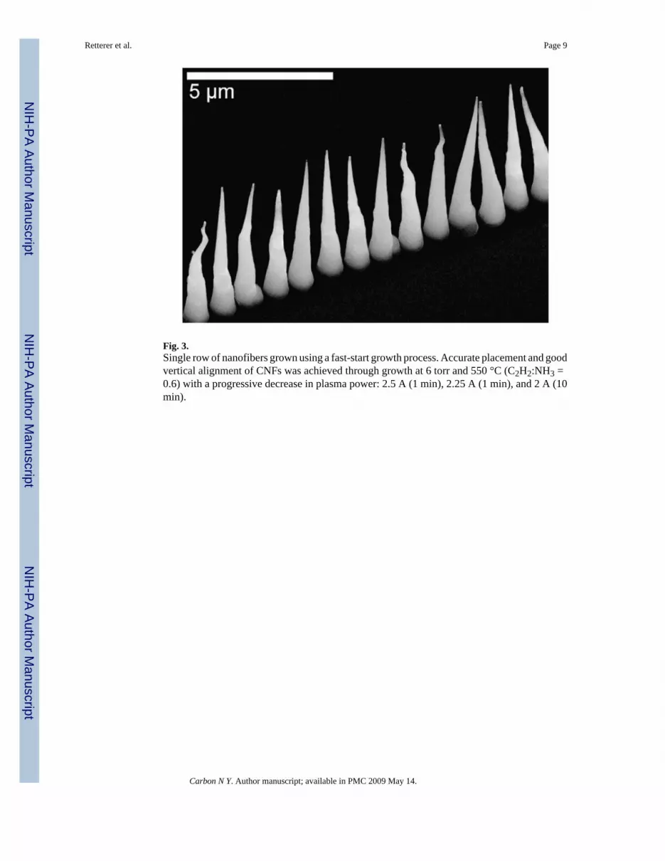
Fig. 3.Single row of nanofibers grown using a fast-start growth process. Accurate placement and goodvertical alignment of CNFs was achieved through growth at 6 torr and 550 °C (C2H2:NH3 =0.6) with a progressive decrease in plasma power: 2.5 A (1 min), 2.25 A (1 min), and 2 A (10min).
Retterer et al. Page 9
Carbon N Y. Author manuscript; available in PMC 2009 May 14.
NIH
-PA Author Manuscript
NIH
-PA Author Manuscript
NIH
-PA Author Manuscript
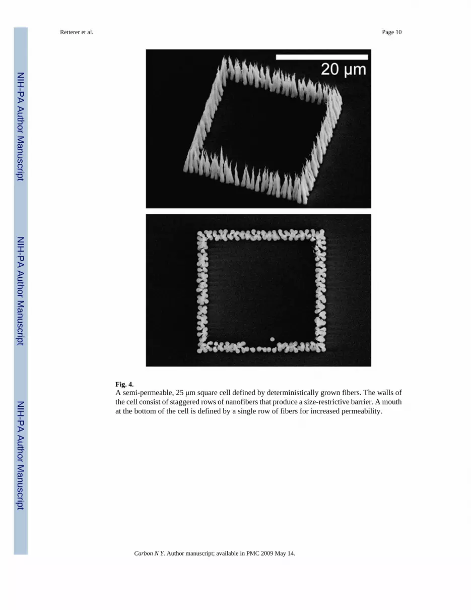
Fig. 4.A semi-permeable, 25 μm square cell defined by deterministically grown fibers. The walls ofthe cell consist of staggered rows of nanofibers that produce a size-restrictive barrier. A mouthat the bottom of the cell is defined by a single row of fibers for increased permeability.
Retterer et al. Page 10
Carbon N Y. Author manuscript; available in PMC 2009 May 14.
NIH
-PA Author Manuscript
NIH
-PA Author Manuscript
NIH
-PA Author Manuscript

Fig. 5.An ordered array of deterministically grown nanofibers shown against the backdrop of arandomly grown nanofiber forest shown at high (upper) and low (lower) magnification. Hybridnanofiber cells having a densely packed outer barrier and crowded interior can be created bycombining lithographically defined catalyst stripes that break-up into smaller particles (outerregion) with lithographically defined catalyst discs that form into ensembles of single particleshaving a deterministically controlled size and spacing (inner region).
Retterer et al. Page 11
Carbon N Y. Author manuscript; available in PMC 2009 May 14.
NIH
-PA Author Manuscript
NIH
-PA Author Manuscript
NIH
-PA Author Manuscript
Copyright © 2022 FDOKUMEN