
POSIT vs. Floating Point in Implementing IIR Notch Filter by ...
26
Citation: Esmaeel, A.A.; Abed, S.; Mohd, B.J.; Fairouz, A.A. POSIT vs. Floating Point in Implementing IIR Notch Filter by Enhancing Radix-4 Modified Booth Multiplier. Electronics 2022, 11, 163. https://doi.org/ 10.3390/electronics11010163 Academic Editors: Katarzyna Antosz, Jose Machado, Yi Ren, Rochdi El Abdi, Dariusz Mazurkiewicz, Marina Ranga, Pierluigi Rea, Vijaya Kumar Manupati, Emilia Villani and Erika Ottaviano Received: 16 November 2021 Accepted: 1 January 2022 Published: 5 January 2022 Publisher’s Note: MDPI stays neutral with regard to jurisdictional claims in published maps and institutional affil- iations. Copyright: © 2022 by the authors. Licensee MDPI, Basel, Switzerland. This article is an open access article distributed under the terms and conditions of the Creative Commons Attribution (CC BY) license (https:// creativecommons.org/licenses/by/ 4.0/). electronics Article POSIT vs. Floating Point in Implementing IIR Notch Filter by Enhancing Radix-4 Modified Booth Multiplier Anwar A. Esmaeel 1 , Sa’ed Abed 1, * , Bassam J. Mohd 2 and Abbas A. Fairouz 1 1 Computer Engineering Department, Kuwait University, P.O. Box 5969, Safat 13060, Kuwait; [email protected] (A.A.E.); [email protected] (A.A.F.) 2 Computer Engineering Department, The Hashemite University, P.O. Box 330127, Zarqa 13133, Jordan; [email protected] * Correspondence: [email protected] Abstract: The increased demand for better accuracy and precision and wider data size has strained current the floating point system and motivated the development of the POSIT system. The POSIT system supports flexible formats and tapered precision and provides equivalent accuracy with fewer bits. This paper examines the POSIT and floating point systems, comparing the performance of 32-bit POSIT and 32-bit floating point systems using IIR notch filter implementation. Given that the bulk of the calculations in the filter are multiplication operations, an Enhanced Radix-4 Modified Booth Multiplier (ERMBM) is implemented to increase the calculation speed and efficiency. ERMBM enhances area, speed, power, and energy compared to the POSIT regular multiplier by 26.80%, 51.97%, 0.54%, and 52.22%, respectively, without affecting the accuracy. Moreover, the Taylor series technique is adopted to implement the division operation along with cosine arithmetic unit for POSIT numbers. After comparing POSIT with floating point, the accuracy of POSIT is 92.31%, which is better than floating point’s accuracy of 23.08%. Moreover, POSIT reduces area by 21.77% while increasing the delay. However, when the ERMBM is utilized instead of the POSIT regular multiplier in implementing the filter, POSIT outperforms floating point in all the performance metrics including area, speed, power, and energy by 35.68%, 20.66%, 31.49%, and 45.64%, respectively. Keywords: POSIT; floating point; infinite impulse response filter; Radix-4 modified booth multiplier; taylor series 1. Introduction The discovery of deep neural networks, an increase in data size, and a high demand for better accuracy and precision mean that the standard floating point (FP) system will not be efficient enough to meet specified requirements. Therefore, modifications are required on the computer’s architecture to improve the performance. One of the modifications is upgrading the numbering system from the current floating point standard (FP IEEE-745), which has not been modified for three decades. The bit width of the three fields in FP format is fixed which results in redundant bits in both the mantissa and the exponent. In floating point format, bits are also wasted for excep- tions, including NaNs (not a number). This exception case represents illegal mathematical operations, including dividing a number by a zero [1]. Therefore, an alternative number representation system called POSIT was introduced by Gustafson in 2017 to address the drawbacks of the floating point system. Unums, which stands for universal numbers, was invented by John Gustafson as an alternative for representing real numbers using a finite number of bits. Unums latest version is called POSIT or Type III unum. It is considered to be a hardware friendly format compared to previous versions of unums. Although the Type II unum was invented to resolve the drawbacks of Type I including the complexity of hardware implementation along with the ability of representing certain values with Electronics 2022, 11, 163. https://doi.org/10.3390/electronics11010163 https://www.mdpi.com/journal/electronics
-
Upload
khangminh22 -
Category
Documents
-
view
1 -
download
0
Transcript of POSIT vs. Floating Point in Implementing IIR Notch Filter by ...

�����������������
Citation: Esmaeel, A.A.; Abed, S.;
Mohd, B.J.; Fairouz, A.A. POSIT vs.
Floating Point in Implementing IIR
Notch Filter by Enhancing Radix-4
Modified Booth Multiplier. Electronics
2022, 11, 163. https://doi.org/
10.3390/electronics11010163
Academic Editors: Katarzyna Antosz,
Jose Machado, Yi Ren, Rochdi
El Abdi, Dariusz Mazurkiewicz,
Marina Ranga, Pierluigi Rea, Vijaya
Kumar Manupati, Emilia Villani and
Erika Ottaviano
Received: 16 November 2021
Accepted: 1 January 2022
Published: 5 January 2022
Publisher’s Note: MDPI stays neutral
with regard to jurisdictional claims in
published maps and institutional affil-
iations.
Copyright: © 2022 by the authors.
Licensee MDPI, Basel, Switzerland.
This article is an open access article
distributed under the terms and
conditions of the Creative Commons
Attribution (CC BY) license (https://
creativecommons.org/licenses/by/
4.0/).
electronics
Article
POSIT vs. Floating Point in Implementing IIR Notch Filter byEnhancing Radix-4 Modified Booth MultiplierAnwar A. Esmaeel 1, Sa’ed Abed 1,* , Bassam J. Mohd 2 and Abbas A. Fairouz 1
1 Computer Engineering Department, Kuwait University, P.O. Box 5969, Safat 13060, Kuwait;[email protected] (A.A.E.); [email protected] (A.A.F.)
2 Computer Engineering Department, The Hashemite University, P.O. Box 330127, Zarqa 13133, Jordan;[email protected]
* Correspondence: [email protected]
Abstract: The increased demand for better accuracy and precision and wider data size has strainedcurrent the floating point system and motivated the development of the POSIT system. The POSITsystem supports flexible formats and tapered precision and provides equivalent accuracy with fewerbits. This paper examines the POSIT and floating point systems, comparing the performance of32-bit POSIT and 32-bit floating point systems using IIR notch filter implementation. Given that thebulk of the calculations in the filter are multiplication operations, an Enhanced Radix-4 ModifiedBooth Multiplier (ERMBM) is implemented to increase the calculation speed and efficiency. ERMBMenhances area, speed, power, and energy compared to the POSIT regular multiplier by 26.80%,51.97%, 0.54%, and 52.22%, respectively, without affecting the accuracy. Moreover, the Taylor seriestechnique is adopted to implement the division operation along with cosine arithmetic unit for POSITnumbers. After comparing POSIT with floating point, the accuracy of POSIT is 92.31%, which isbetter than floating point’s accuracy of 23.08%. Moreover, POSIT reduces area by 21.77% whileincreasing the delay. However, when the ERMBM is utilized instead of the POSIT regular multiplierin implementing the filter, POSIT outperforms floating point in all the performance metrics includingarea, speed, power, and energy by 35.68%, 20.66%, 31.49%, and 45.64%, respectively.
Keywords: POSIT; floating point; infinite impulse response filter; Radix-4 modified booth multiplier;taylor series
1. Introduction
The discovery of deep neural networks, an increase in data size, and a high demandfor better accuracy and precision mean that the standard floating point (FP) system will notbe efficient enough to meet specified requirements. Therefore, modifications are requiredon the computer’s architecture to improve the performance. One of the modifications isupgrading the numbering system from the current floating point standard (FP IEEE-745),which has not been modified for three decades.
The bit width of the three fields in FP format is fixed which results in redundant bits inboth the mantissa and the exponent. In floating point format, bits are also wasted for excep-tions, including NaNs (not a number). This exception case represents illegal mathematicaloperations, including dividing a number by a zero [1]. Therefore, an alternative numberrepresentation system called POSIT was introduced by Gustafson in 2017 to address thedrawbacks of the floating point system. Unums, which stands for universal numbers, wasinvented by John Gustafson as an alternative for representing real numbers using a finitenumber of bits. Unums latest version is called POSIT or Type III unum. It is consideredto be a hardware friendly format compared to previous versions of unums. Although theType II unum was invented to resolve the drawbacks of Type I including the complexityof hardware implementation along with the ability of representing certain values with
Electronics 2022, 11, 163. https://doi.org/10.3390/electronics11010163 https://www.mdpi.com/journal/electronics

Electronics 2022, 11, 163 2 of 26
different representations, the Type II unum depends heavily on look-up tables for most ofits operations. Moreover, implementing dot product is considered to be expensive in thisformat. That is why POSIT was invented to resolve all these drawbacks while being hard-ware friendly. POSIT systems are capable of executing complex mathematical operationsand maintaining the precision and accuracy of the result with a smaller number of bits. Theexponent in POSIT is of variable length, where the smaller exponents are assigned withfewer bits, which introduces the concept of tapered precision [2].
The idea of having an extra field called “regime” makes POSIT unique as it allowsfor the creation of tapered accuracy. The values with small exponents provide betteraccuracy compared to cumbersome or minuscule numbers, which would have less accuracy.Moreover, unlike floating point, POSIT does not have subnormal or denormalized numbersas the hidden bit of its fractional part is always set to 1. Therefore, all POSIT’s values arenormalized and only one rounding mode exists. POSIT has only two special cases reserved,namely 0 and ∞. The POSIT numbering system does not have NaN (not a number) cases [3].Furthermore, POSIT neither over- nor under-flows, and its implementation is much simplerand smaller compared to floating point [4].
The POSIT numbering system is considered a new approach and currently is notdeployed in the arithmetic architectures of existing hardware. The focus of this paperis to demonstrate that the POSIT arithmetic unit outperforms floating point in accuracy,area, speed, power, and energy. As mentioned previously, POSIT provides better accuracycompared with floating point. However, POSIT could potentially increase the executiontime. On the one hand, the fixed position of the bits representing the exponent and thefractional portion of floating point facilitates simpler and parallel decoding operations.POSIT involves serialization to determine the regime prior to the decoding operation.Hence, to boost the design speed, a special multiplier called the Enhanced Radix-4 ModifiedBooth Multiplier (ERMBM) was developed and implemented.
In this paper, the two numbering systems are employed to implement the second-order infinite impulse response notch filter. When comparing the two systems, the focusis on one of the Digital Signal Processing (DSP’s) well-known applications as its mainpurpose is to manage and manipulate information, which provides accuracy and precisionin the fundamental factors. This accuracy mainly stems from the general structure ofthe DSP. Specifically, the sampled analog signal is converted into numbers, followed byexecuting certain computations, and converting the result back to an analog signal, hencethe filter accuracy of the calculation is a critical design feature. Recent studies focus onenhancing the execution of complex algorithms and functions without increasing power,energy dissipation, or area. As optimizing all these performance metrics is significant to thefield of DSP, the paper focuses on enhancing and testing performance by implementing thePOSIT numbering system while enhancing its arithmetic units to optimize its performanceeven more.
The main contributions in our paper are:
(1) Enhancing the POSIT multiplication operation by implementing a special type ofmultiplier called ERMBM, which significantly enhances the area, speed, and energycompared with the regular multiplier proposed previously in [5].
(2) Implementing the POSIT cosine function along with the division arithmetic unitutilizing a shared hardware that is based on the Taylor series technique to reduce thedesign area.
(3) Building the second-order IIR notch filter for POSIT and floating point designs. Thefloating point adder is built as proposed by the work represented in [6], while the FPmultiplier is based on [7].
(4) Comparing the performances of POSIT when utilizing a regular multiplier withfloating point which results in better accuracy and area enhancement.
The rest of the paper is organized as follows. Section 2 includes the backgroundinformation. Section 3 reviews previous articles. Section 4 demonstrates the components
Electronics 2022, 11, 163 3 of 26
design. Section 5 summarizes the implementation results along with the discussion. Finally,Section 6 includes the conclusion of this study and recommendations for future work.
2. Background2.1. POSIT
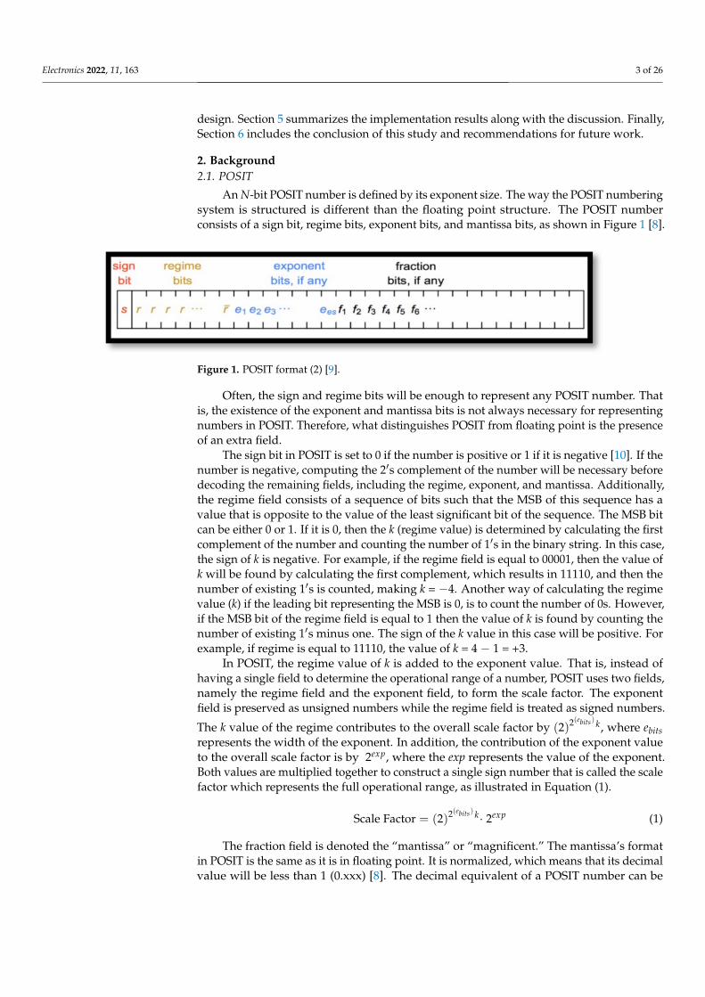
An N-bit POSIT number is defined by its exponent size. The way the POSIT numberingsystem is structured is different than the floating point structure. The POSIT numberconsists of a sign bit, regime bits, exponent bits, and mantissa bits, as shown in Figure 1 [8].
Figure 1. POSIT format (2) [9].
Often, the sign and regime bits will be enough to represent any POSIT number. Thatis, the existence of the exponent and mantissa bits is not always necessary for representingnumbers in POSIT. Therefore, what distinguishes POSIT from floating point is the presenceof an extra field.
The sign bit in POSIT is set to 0 if the number is positive or 1 if it is negative [10]. If thenumber is negative, computing the 2′s complement of the number will be necessary beforedecoding the remaining fields, including the regime, exponent, and mantissa. Additionally,the regime field consists of a sequence of bits such that the MSB of this sequence has avalue that is opposite to the value of the least significant bit of the sequence. The MSB bitcan be either 0 or 1. If it is 0, then the k (regime value) is determined by calculating the firstcomplement of the number and counting the number of 1′s in the binary string. In this case,the sign of k is negative. For example, if the regime field is equal to 00001, then the value ofk will be found by calculating the first complement, which results in 11110, and then thenumber of existing 1′s is counted, making k = −4. Another way of calculating the regimevalue (k) if the leading bit representing the MSB is 0, is to count the number of 0s. However,if the MSB bit of the regime field is equal to 1 then the value of k is found by counting thenumber of existing 1′s minus one. The sign of the k value in this case will be positive. Forexample, if regime is equal to 11110, the value of k = 4 − 1 = +3.
In POSIT, the regime value of k is added to the exponent value. That is, instead ofhaving a single field to determine the operational range of a number, POSIT uses two fields,namely the regime field and the exponent field, to form the scale factor. The exponentfield is preserved as unsigned numbers while the regime field is treated as signed numbers.
The k value of the regime contributes to the overall scale factor by (2)2(ebits) k, where ebitsrepresents the width of the exponent. In addition, the contribution of the exponent valueto the overall scale factor is by 2exp, where the exp represents the value of the exponent.Both values are multiplied together to construct a single sign number that is called the scalefactor which represents the full operational range, as illustrated in Equation (1).
Scale Factor = (2)2(ebits) k· 2exp (1)
The fraction field is denoted the “mantissa” or “magnificent.” The mantissa’s formatin POSIT is the same as it is in floating point. It is normalized, which means that its decimalvalue will be less than 1 (0.xxx) [8]. The decimal equivalent of a POSIT number can be

Electronics 2022, 11, 163 4 of 26
calculated using Equation (2), while the decimal equivalent of a floating point number canbe calculated using Equation (3) [11].
The decimal value of POSIT = (−1)s·((2)2(ebits))k·2exp·1·mantissa (2)
The decimal value of FP = (−1)s· 2(exp−bias))· 1·mantissa (3)
However, sometimes the size of the POSIT number is not enough to include all theexponent bits as per its exponent field size (ebits). This is because the width of the regimesequence can be a size up to N − 1; where N is the size of the POSIT number [5]. When thisis the case, the remaining bits of the POSIT number that are left for allocating the exponentare considered as the MSB and the rest are treated as 0. For example, when the POSITnumber (01111001) is of 8 bits, and the number of bits that are allocated for the exponent is4 (ebits = 4), then the sign bit is 0 and the regime sequence is equal to 11110. However, sinceonly 2 bits (01) of the exponent part are represented in the POSIT number, they are treatedas the MSB and the rest of the bits are set to 0. Therefore, the value of exponent is 0100 andthe mantissa is equal to (1 + 0.0).
2.2. IIR Filter
In signal processing, filters are used to eliminate some of the signal’s undesiredcomponents or to extract certain segments out of a signal. Filters are constructed usingdigital or analog circuits. In case of digital filters, mathematical operations would beapplied on a discrete signal where the analog filters operate on continuous-time analogsignals. Digital filters can be classified into two main filters: IIR filter and finite impulseresponse filter (FIR) filter. The main feature that distinguishes between the two filters is thenature of impulse response; the response of the FIR filter is of finite duration unlike theresponse of IIR which is infinite.
There are two essential signals that can assist as the input in the process of systemevaluation in control systems including the step and the impulse response. The impulseresponse, referred to as the impulse response function (IRF), is utilized to assess theresponse of a system for all the frequency elements while maintaining the same magnitude.
Filters can be categorized based on the mechanism that is used for the selection ofvarious frequency bands from a signal. For example, the notch filter is considered to bea band-stop filter with a narrow stopband where it is used in applications that requirethe exclusion of certain frequency components. It consists of different types includinga high bandwidth notch filter (FIR Filter) and a low bandwidth filter (IIR Filter). Themain difference between the two filters is the fact that the FIR filter could affect a range offrequencies unlike the IIR filter, which would only eliminate the frequency of interest. TheFIR filter attenuates the frequencies around the anticipated null. Since the IIR filter keepsthe broad band signal unchanged while eliminating the narrow band interface signal, it isconsidered to be an essential and critical block in the communication system. A detailedcomparison between FIR and IIR filter is demonstrated in Table 1.
Table 1. The difference between FIR and IIR filter.
Finite Impulse Response Filter (FIR Filter) Infinite Impulse Response Filter (IIR Filter)
Depend on current input only, no feedback isrequired (only zeros)
Depend on previous output, feedback isrequired (poles and zeros)
Uses more number of terms to achieve sameresult-more computations–slower
Uses less number of terms to achieve sameresult-less computations–faster.
Require more memory Require less memory space
Can be easily designed with a linear phase Non-linear phase
Always stable Has stability issues–Not always stable

Electronics 2022, 11, 163 5 of 26
Table 1. Cont.
Finite Impulse Response Filter (FIR Filter) Infinite Impulse Response Filter (IIR Filter)
Has constant delay at all frequencies Has unequal delays at each frequency
No analog history Derived from analog filters
Used with high order tapping (20–2000) Used with fewer order tapping type < 1/10thorder of FIR filter (4–20)
3. Related Work
The main aim of this paper is to compare POSIT and floating point numbering systemsand examine the performance of the IIR filter implementation. Consequently, the literaturereview is divided into two main categories: IIR filter and the POSIT numbering system.
3.1. IIR Filter
Numerous published articles have examined IIR implementation and addressed vari-ous aspects such as design, filter order, and fixed point representation.
Ushanandhini et al. [12] enhanced the performance of the IIR filter by proposing a newtechnique to optimize the multiplication process utilizing a Radix-4 multiplier to reducethe number of partial products from n to n/2. They also included the idea of pre-charging,aiming to reduce the delay time, increase the electrical units’ lifespan, and enhance thetrustworthiness of the system.
A new proposal was developed by Wang et al. [13] where the IIR filter is designedthrough an enhanced local search operator of the multi-objective optimization evolutionaryalgorithm (MOEA). This proposal considers the filter order, magnitude phase error, andthe linear phase response inaccuracy. The fixed point representation was applied to theLS-MOEA to establish a new form of local search operator-enhanced multi-objective evolu-tionary algorithm with floating point representation (LS-MOEA-FR), which was tested onmultiple types of IIR filter, including LP, HP, BP, and BS.
Chengliang et al. [14] implemented a 5-order IIR filter through MATLAB usingSimulink and it was tested and proven that it is possible to establish an efficient IIRfilter through MATLAB. It also concluded that as the order of the filter increases, the betterthe filtering result but with more computational time to be consumed. To overcome thisissue, the paper recommended using a low order IIR filter, which is not an issue as it ispossible to acquire same design requirement with low-order IIR filter compared to FIR filter.
In Bajwa et al. [15], the authors designed a low-pass IIR filter and proposed a newtechnique optimizing its architecture to improve precision. Unlike the coding that is seen inmost studies, Bajwa et al.’s filter parameters were encoded using a fixed point numberingsystem. In fact, it is better to go with the fixed point numbering system for real applicationsas it saves power and, therefore, cost. It will also reduce the amount of computationalresources that are being utilized. The two-state ensemble evolutionary algorithm (TEEA)was used for the optimization process. This algorithm basically is divided into two phases.The first phase includes the global shrinking phase; where it is used to reduce the searchingrange and redirect it to the most favorable area as fast as possible. The second phase on theother hand, is the local exploration phase where it is used to investigate the constrainedregion comprehensively aiming to find a better solution.
The transfer functions of one-dimensional (1-D) and two-dimensional (2-D) filters areincluded in Stavrou et al. [16]. Two of the most crucial (2-D) filters, including IIR and FIRfilters, were designed using different techniques. The IIR filter in this paper was designedusing the bilinear transformation method while the FIR filter was implemented using thewindows method. The utilized approaches to design the 2-D IIR filter were based on theappropriate 1-D functions along with the appropriate optimization methods.
A software was developed to overcome the constrained optimization challenges inStavrou et al. [17]. The software is based on the modified hybrid genetic algorithm whichincludes a series of enhanced genetic operators to maintain the viability of experimental

Electronics 2022, 11, 163 6 of 26
solutions and ceases using a stochastic stopping rule. It involves a global explorationsearch along with a local optimization process aiming for a faster recognition of globalminimum. The proposed technique was examined on multiple benchmark functions thatwere provided in the literature review and it was utilized to overcome the instability issuesthat were raised when implementing 2-D IIR filters. The software was written in ANSI C++and the results were compared with DONLP2 algorithm.
3.2. POSIT Numbering System
Numerous articles were published examining various aspects of the POSIT system,including targeted application, operations, conversion to/from FP, and the implementationof POSIT adder, subtractor, and multiplier using application-specific integrated circuit(ASIC) and field-programmable gate array (FPGA) technologies.
Langroudi et al. [18] decided to use POSIT for performing a low-precision deeplearning inference on embedded devices. According to the paper, reducing the number ofbits below 8 when implementing a deep learning inference significantly impacts accuracy.However, the accuracy of the normalized POSIT surpasses other numbering systems whenreducing the number of bits. A model was proposed for performing image classificationtasks. This model converts the weights from floating point into POSIT for all operationsinvolving memory, including read and write.
A prototype called POSGEN was developed by Podobas et al. [19], which creates anyPOSIT operation the user requests. The user specifies the operation type, width of the totalformat, and the exponent width. Although the constructed pipelined hardware covers32-bit POSIT only, their future work will be dedicated to optimizing other bit-widths. Theauthors compared the POSIT design of three different operations: addition, subtraction,and multiplication.
In Jaiswal et al. [20], the authors proposed an algorithmic flow along with an architec-ture for a POSIT adder and subtractor. The implementations of an 8-, 16-, and 32-bit addersand subtractors were realized on the FPGA and ASIC. The authors compared the POSITadders with the SP FP adders. The POSIT adders show an average value of latency andarea compared with several FP adder architectures.
The research work of Jaiswal et al. [21] included the algorithmic flow and the hardwarearchitecture of the POSIT adder, subtractor, and multiplier as well as the conversion of FPto POSIT and vice versa. The first step of converting FP to POSIT is to extract the data of FPwhile considering the zero and infinity cases and excluding the NaN (not a number) cases.Then, the POSIT fields are constructed to concatenate the sign bit with the REM [N − 1:1];where REM stands for regime, exponent, and mantissa data construction. Similarly, whenconverting POSIT to FP, the POSIT inputs should be checked for exceptions, includingzero or infinity. The sign bit is next examined to see if it is negative, and a 2′s complementis computed for the input. The equivalent FP number is created after extracting all thePOSIT data.
The software and the hardware implementation of Type I and POSIT was demon-strated by Lehoczky et al. [22]. For both types, the software implementation was constructedon a .NET platform written in C language as an open source. The authors used Hastlayer,which was run on Visual Studio 2017, for the purpose of transforming the .NET into aVHDL language that was used to configure the FPGA logic gates. The authors imple-mented Type I and POSIT through using a structure called Bitmask. This structure canhandle environments of all sizes. They performed addition, subtraction, comparison, andconversion for both numbering systems.
Hou et al. [23] examined the drawbacks of floating point along with POSIT structure.The logic circuit diagrams of the unum adder and multiplier were provided in this work.The result that was acquired by the unum adder displays only the rightmost and leftmostbit based on the value of esize and fsize, respectively. Therefore, when using unum, theauthors managed to decrease the bandwidth without affecting the accuracy of the result.
Electronics 2022, 11, 163 7 of 26
Glaser et al. created an ASIC design with a 128-bit ALU to execute unum operations,including addition and subtraction [24]. The authors also implemented two uboundand unum-specific functions—optimize and unify. The “optimize” function was usedto ensure that the intermediate results were not lost, and “unify” was used for externaldata movement.
A reconfigurable logic of a matrix multiplier was designed by Chen et al. and imple-mented on an FPGA [25]. The multiplier was constructed for matrices with 32-bit POSITnumbers with es = 2, which represents the exponent size. Chen et al. decided to create amatrix multiplier because it significantly improved memory access and tolerated havinga large bandwidth for the input and output. Having a matrix multiplier also boosts thenumber of FP operations that can be implemented.
From the previous research addressing the IIR digital filter and the POSIT numberingsystem, it is clear that POSIT implementation is attractive. However, not enough researchhas been conducted to improve POSIT performance in filter designs. Moreover, in the caseof studies showing POSIT numbers, the main focus is on enhancing either the speed, area,or both. That is, limited numbers of performance metrics have been considered. However,this paper focuses on enhancing the performance of POSIT arithmetic units includingaccuracy, area, speed, power, and energy, which are utilized to implement the second-orderIIR notch filter.
This paper focuses on the work of Podobas et al. [19] and Jaiswal et al. [20]. Podob-as et al. [19] demonstrated a hardware diagram for three arithmetic operations, includinga POSIT adder/subtractor and a POSIT multiplier. The Podobas multiplier is a regularmultiplier, while our paper creates a more efficient and faster POSIT multiplier that signif-icantly optimizes speed. Moreover, our paper includes the design of two additional POSIToperations: the division and cosine function. Our paper also implements a second-orderinfinite impulse response notch filter, which is implemented for both POSIT and floatingpoint numbering systems. Moreover, since the work presented by Jaiswal et al. [20] onlyproposes a POSIT adder/subtractor, this research builds on it by constructing additionalPOSIT arithmetic units, including ERMBM and a common block for executing divisionand cosine functions.
4. Components Design
An overview of the proposed methodology in implementing the second-order infiniteimpulse response notch filter along with the ERMBM for POSIT numbers is provided inthis section.
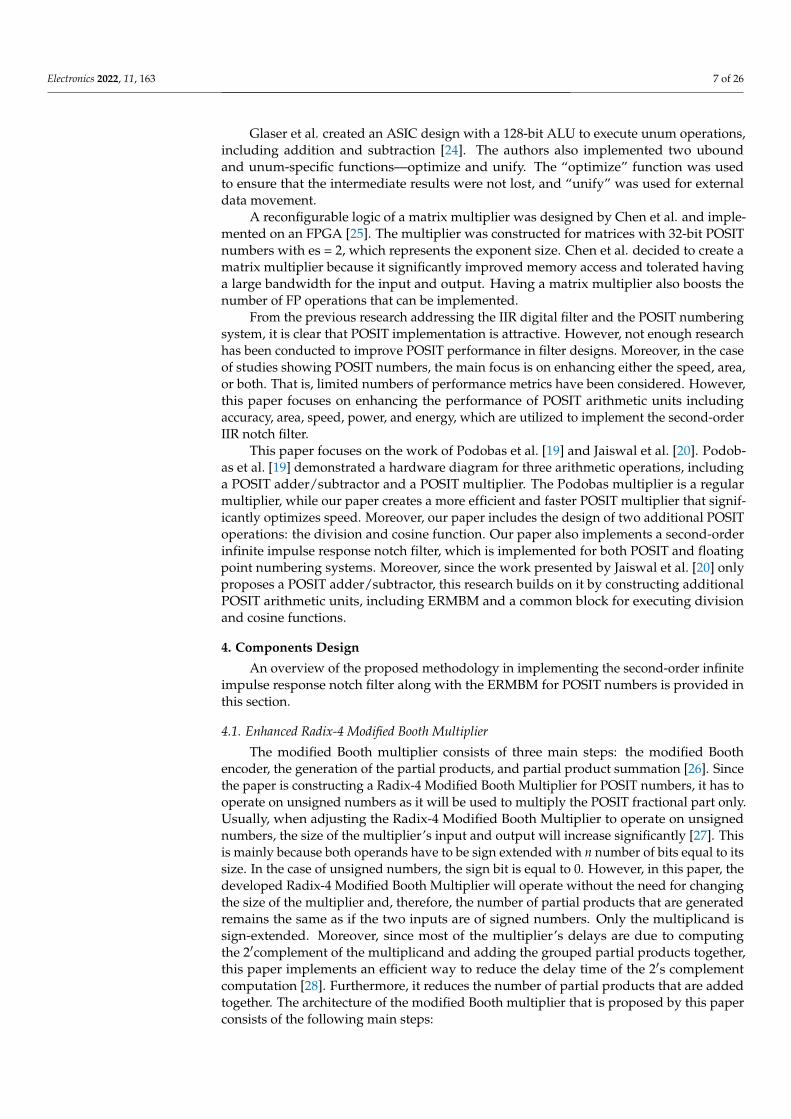
4.1. Enhanced Radix-4 Modified Booth Multiplier
The modified Booth multiplier consists of three main steps: the modified Boothencoder, the generation of the partial products, and partial product summation [26]. Sincethe paper is constructing a Radix-4 Modified Booth Multiplier for POSIT numbers, it has tooperate on unsigned numbers as it will be used to multiply the POSIT fractional part only.Usually, when adjusting the Radix-4 Modified Booth Multiplier to operate on unsignednumbers, the size of the multiplier’s input and output will increase significantly [27]. Thisis mainly because both operands have to be sign extended with n number of bits equal to itssize. In the case of unsigned numbers, the sign bit is equal to 0. However, in this paper, thedeveloped Radix-4 Modified Booth Multiplier will operate without the need for changingthe size of the multiplier and, therefore, the number of partial products that are generatedremains the same as if the two inputs are of signed numbers. Only the multiplicand issign-extended. Moreover, since most of the multiplier’s delays are due to computingthe 2′complement of the multiplicand and adding the grouped partial products together,this paper implements an efficient way to reduce the delay time of the 2′s complementcomputation [28]. Furthermore, it reduces the number of partial products that are addedtogether. The architecture of the modified Booth multiplier that is proposed by this paperconsists of the following main steps:

Electronics 2022, 11, 163 8 of 26
4.1.1. Computing 2′s Complement
The block diagram of computing 2′s complement is provided in Figure 2. The designgroups every two neighboring binary bits in one group. Since the size of the multiplier’sinput is of 29 bits as only the mantissa will be multiplier together, 29 groups will be createdonce every two neighboring bits are grouped together. This will be followed by calculatingthe conversion signal for each group. The conversion signal is found by making all thebits after the rightmost 1 equal to 1. Then, a conversion signal for a 4-bit group number isfound followed by the conversion signal for an 8-bit group number. The same approachwill be implemented until all bits after 0 are converted, as proposed by Tripathi et al. [29].The last two steps of finding the 2′s complement is to shift the final answer one bit to theleft and XOR it with the multiplicand binary number.
Figure 2. The block diagram of the 2′s complement that is utilized in the ERMBM multiplier.
4.1.2. Encoding the Multiplier
When multiplying two numbers, A and B, using a regular multiplier, as proposedin [5], the number of the partial products that are created is equal to the number of bitsof the multiplier (MR). The Booth encoder is incorporated in this design to reduce themultiplier digit number partial products and the multiplication time [30]. In general, theRadix-2i Booth reduces the number of partial products by (#of MR bits/i). To implement ann-bit multiplier when using the Radix-4 Booth encoder, a zero should be placed at position0 and then each 3 bits are grouped together in (#of MR bits)/2 groups [31]. If the MR or theMD’s total number of bits is of an odd number, then the sign bit is extended. In this paper,a 29 × 29-bit Enhanced Radix-4 Modified Booth Multiplier is implemented. Therefore, themultiplier binary number are grouped into 15 three-bit groups, as shown in Figure 3.
Figure 3. How the multiplier’s (MR) bits will be grouped.
Electronics 2022, 11, 163 9 of 26
Each group is encoded to either 0y, (±1y) or (±2y); where y represents the multiplicandas presented in Table 2. Prior to encoding, the MD is concatenated with n zeros that areequal to its size, to utilize the Booth algorithm for two unsigned numbers. When a 4-bit MRwith a value of 1111 is being multiplied with a 4-bit MD with a value 1111, the operationwill be executed differently based on number representation. If the numbers are signednumbers, then the answer will be (−1)× (−1) = +1. However, if both numbers are unsignednumbers, then the answer will be 15 × 15 = 225. The 16-bit unsigned Booth multipliercan be expressed as a 33 × 33-bit signed multiplier, resulting in a 17-partial product [27].The size of the multiplier is equal to 33 × 33 bits, as 16 bits out of those 33 bits are for theoperands, the other 16 bits are for sign extensions, and one bit is the zero that is placedat position 0 for Booth encoding. However, in this paper, a different approach has beenadapted to multiply two unsigned numbers while having several partial products that areequal to the (#of MR bits)/2. The MR’s number of bits did not change except for addingzero at position 0 and another 0 at position 30 to make the MR of an even number of bits.Therefore, the number of partial products remains the same. The conversion of each partialproduct is done based on the vector values, as shown in Table 2 [32].
Table 2. Radix-4 Modified Booth encoding table.
Yi Yi−1 Yi−2Required Operation on
the Multiplicand Acquired Output
0 0 0 0 ×MD Zero
0 0 1 +1 ×MD Value of the multiplicand
0 1 0 +1 ×MD Value of the multiplicand
0 1 1 +2 ×MD Shifting the MD 1 bit to the left
1 0 0 −2 ×MD Finding 2′s complement of the MDand then shifting 1 bit to the left
1 0 1 −1 ×MD Finding 2′s complement of MD
1 1 0 −1 ×MD Finding 2′s complement of MD
1 1 1 0 ×MD Zero
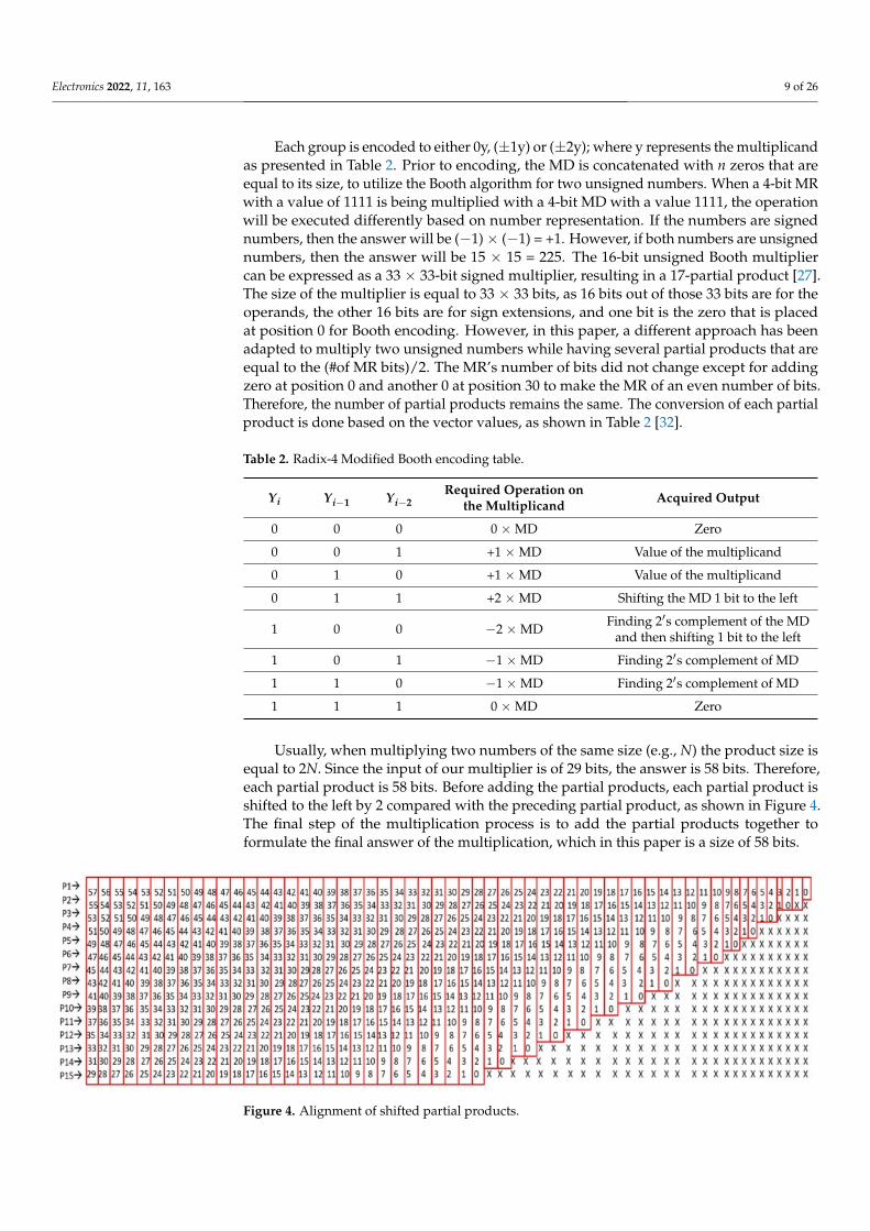
Usually, when multiplying two numbers of the same size (e.g., N) the product size isequal to 2N. Since the input of our multiplier is of 29 bits, the answer is 58 bits. Therefore,each partial product is 58 bits. Before adding the partial products, each partial product isshifted to the left by 2 compared with the preceding partial product, as shown in Figure 4.The final step of the multiplication process is to add the partial products together toformulate the final answer of the multiplication, which in this paper is a size of 58 bits.
Figure 4. Alignment of shifted partial products.

Electronics 2022, 11, 163 10 of 26
Figure 5 illustrates an example along with the steps in which the proposed ERMBMcalculates the answer of multiplying the two mantissas together, considering that the two’smantissas are of 7-bit. In this example, the first mantissa has the value of 6210, while themantissa of the second input has a value of 10210. Moreover, Figure 6 represents the generalarchitecture of the proposed Radix-4 Modified Booth Multiplier that was used to multiplythe two mantissas.
Figure 5. Multiplication of two unsigned numbers using Radix-4 modified Booth algorithm.
Figure 6. Proposed architecture for the Enhanced Radix-4 Modified Booth Multiplier.
4.2. IIR Notch Filter
As mentioned previously, one of the paper objectives is to implement the second-orderIIR notch filter. The transfer function of the second-order IIR notch filter is expressed in

Electronics 2022, 11, 163 11 of 26
Equation (4), where B1 and B2 represent the filter’s feed-forward coefficients, while A1 andA2 characterize the filter’s feed-back coefficients. Since these coefficients can be calculatedusing the formulas that are provided in Equations (5)–(11), the transfer function can berewritten as provided in Equation(13), where (ω) is the normalized polar notch frequency;(α) is the pole contraction factor, which basically defines the bandwidth of the notch; ( f0) isthe notch frequency; and ( fs) is the sampling frequency [33].
H(z) =B0 + B1z(−1) + B2 z(−2)
A0 + A1 z(−1) + A2 z(−2)(4)
B0 = 1 (5)
B1 = −2 cos(ω) (6)
B2 = 1 (7)
A0 = 1 (8)
A1 = 2·α· cos(ω) (9)
A2 = (α)2 (10)
ω = 2· π·(
f0
fs
)(11)
∴ H(z) =1− 2 cos(ω) z(−1) + z(−2)
1− 2 (α) cos(ω) z(−1) + (α)2 z(−2)(12)
Equation (13) shown in Figure 7 can be derived once the z-domain transfer functionis expressed as an input–output relation of the linear difference equations with constantcoefficients. Figure 7 represents the data flow of the second-order IIR notch filter.
∴ y[n] = x[n]− 2 cos(ω)·x[n− 1] + x[n− 2] + 2 (α) cos(ω)· y[n− 1]− (α)2·y[n− 2] (13)
Electronics 2022, 10, x FOR PEER REVIEW 12 of 27
∴ 𝑦 𝑛 = 𝑥 𝑛 − 2 cos(𝜔) ∙ 𝑥 𝑛 − 1 + 𝑥 𝑛 − 2 + 2 (𝛼) cos(𝜔) ∙ 𝑦 𝑛 − 1 − (𝛼) ∙ 𝑦 𝑛 − 2 (53)
Figure 7. Data flow of the second-order IIR notch filter.
The block diagram of the second-order IIR notch filter that is emulated using Xilinx software is provided in Figure 8. The aim of this paper is to improve the performance of the implemented filter by utilizing a Radix-4 Modified Booth multiplier as demonstrated in Figure 9. The paper also implements POSIT division operation based on the Taylor series technique. The same technique is used to implement the cosine function through utilizing a shared hardware.
As the data are represented using the 32-bit POSIT numbering system when imple-menting the IIR filter, all the arithmetic operations in the IIR filter equations are calculated in POSIT format. These operations include: (1) POSIT addition/subtraction, (2) POSIT multiplication, (3) POSIT division, (4) Cosine function for POSIT.
Figure 7. Data flow of the second-order IIR notch filter.
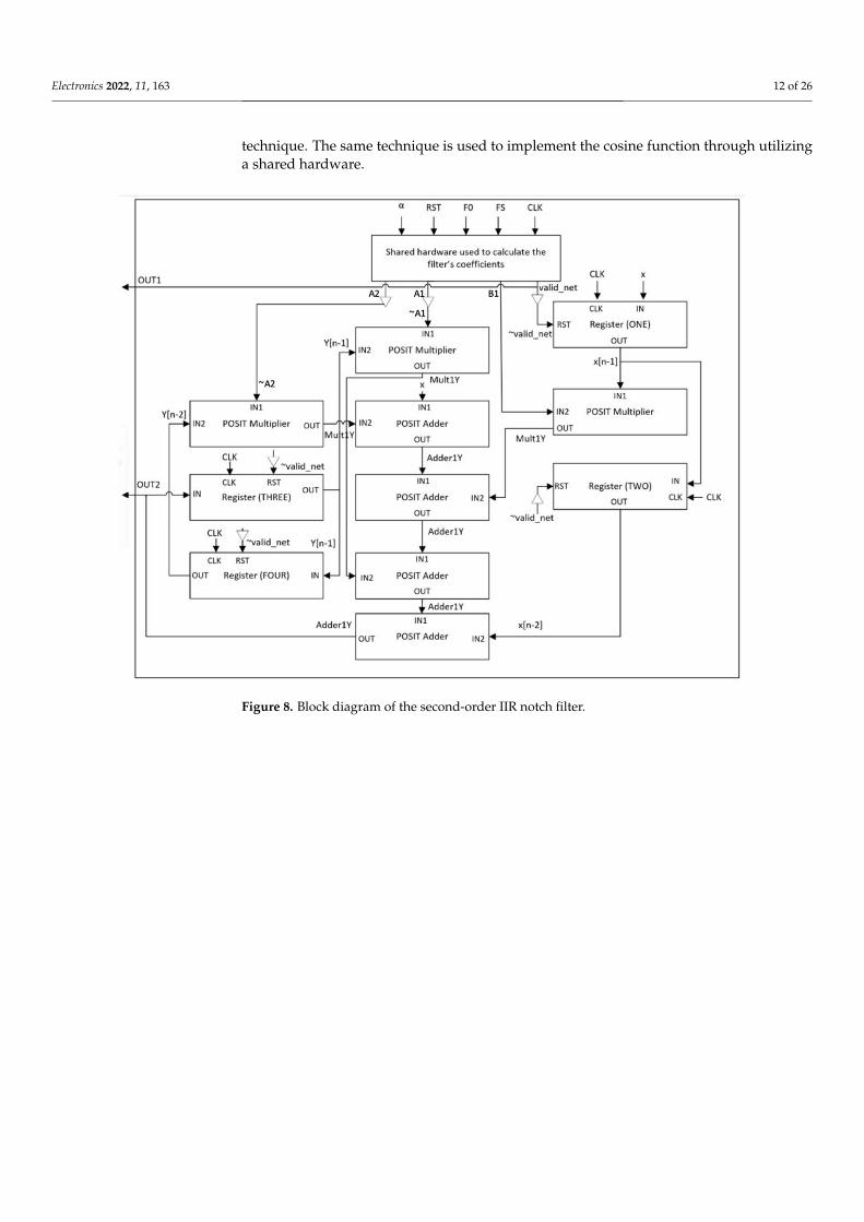
The block diagram of the second-order IIR notch filter that is emulated using Xilinxsoftware is provided in Figure 8. The aim of this paper is to improve the performance ofthe implemented filter by utilizing a Radix-4 Modified Booth multiplier as demonstrated inFigure 9. The paper also implements POSIT division operation based on the Taylor series
Electronics 2022, 11, 163 12 of 26
technique. The same technique is used to implement the cosine function through utilizinga shared hardware.
Figure 8. Block diagram of the second-order IIR notch filter.

Electronics 2022, 11, 163 13 of 26
Electronics 2022, 10, x FOR PEER REVIEW 13 of 27
Figure 8. Block diagram of the second-order IIR notch filter.
Figure 9. Block diagram of POSIT ERMBM.
Figure 9. Block diagram of POSIT ERMBM.
As the data are represented using the 32-bit POSIT numbering system when imple-menting the IIR filter, all the arithmetic operations in the IIR filter equations are calculatedin POSIT format. These operations include:
(1) POSIT addition/subtraction,(2) POSIT multiplication,(3) POSIT division,(4) Cosine function for POSIT.
4.2.1. POSIT Divider
In this paper, both the POSIT multiplication and division arithmetic units have severalsteps in common. For example, similar to the previously explained multiplication design,the division operation starts first by checking the corner cases, including 0 and ∞. Then,it decodes all the necessary fields, including sign bit (S), regime check (RC), regime (R),exponent (E), and mantissa (M) for both inputs. The 2′s complement is generated for eitherinput depending on the result of XORing the two’s input sign bit. Essentially, the divisionoperation is implemented by dividing the mantissa of the dividend over the mantissa ofthe divisor. However, the standard division operation is replaced with the multiplicationoperation as the first input will be multiplied with the second input’s reciprocal. Thisultimately generates the same output as if it were implemented using the standard divisionarithmetic unit. The reason for replacement is that division is a complex operation requiringsignificant execution time. Furthermore, standard division has a large implementationarea and consumes high power [34]. Many equations can be used to execute the divisionoperation. These equations are divided into slow and fast division equations. In this paper,the main focus will be on implementing a fast division technique including Taylor series.
Since division can be expressed as A × (1/B) instead of (A/B); where A represents thedividend and B represent the divisor, the division operation is replaced with multiplicationwith the reciprocal of the divisor. In this case, the focus will be on deriving an accurate valuefor the denominator reciprocal which can be computed using the Taylor series method.

Electronics 2022, 11, 163 14 of 26
The idea of Taylor-series expansion is to find a higher-order polynomial estimationof any continuous function at some value in its domain [35]. For example, the techniqueapproximates the continuous function along with n first derivatives by using the n degreepolynomial at a certain point. As the order of this polynomial equation increases, theaccuracy of the approximation increases dramatically. Therefore, the Taylor series replacesthe division operation with the multiplication of A and with a generated polynomialequation of B. This generated polynomial for any n of y = f (x) at any value of (x0) is shownin Equation (14). In this paper, the Taylor series technique utilizes a 5-order polynomialequation to optimize the area. As the order of the polynomial equation increases, the areawill increase dramatically and more terms must be calculated. Moreover, since the value ofthe mantissa part of (1/B) will be in a range of [1,2), the polynomial equation should becentered at 1.5. This is mainly because the minimum value of the mantissa can be 1.0, whilethe maximum value can be 1.111 . . . 1 ≈ 1.9999. However, when the error was calculated at1.5 & n = 5 using Equation (15), a different value of x0 was chosen to reduce the error andsimplify the generated equation even more. When the regime and exponent are in the rangeof 21 (100001), the range of the Taylor series will be between [2,4). Therefore, the Taylorseries equation that was used in this paper is instead centered at 3. When substituting (1/x)in Equation (14), Equation (16) is generated, and when substituting n with 5, Equation (17)is generated, which is used to calculate (1/x).
However, before substituting any number in the equation of the Taylor series, x mustbe in the range of [2,4). Therefore, some modifications must first be done on the scalefactor of the POSIT number before using the Taylor series equation, as the size of theregime in this paper is 2 bits while the size of the exponent is 4 bits. When substitutingthese values to Equation (2), Equation (18) is generated. However, because the divisionoperation involves subtracting the exponents, the exponent of the inverse scale factor needsto be a negative value. The term 16k can be a negative value by making the value ofk = −1, which is done by setting the value of the regime bits = 01. On the other hand, thenegative representation of the second exponent as displayed in Equation (18) is 1 − exp.This representation is equivalent to 17 − exp for a four-bit number, which is the case of theexponent field. Thus, the inverse of the input is calculated by concatenating 0 for the signbit with 01 for the regime bits, 17 − exp for the exponent bits, and setting the fractional bitswith zeros. This inverse is then multiplied with
(2+1·1. f
), which is calculated using the
Taylor series technique as illustrated in Equation (17), aiming to calculate the value of (1/x).
Pn(x) =f (0)(x0)
0!+
f (1)(x0)
1!(x− x0) +
f (2)(x0)
2!(x− x0)
2 + · · ·+ f (n)(x0)
n!(x− x0)
n. (14)
En(x) =1n!
∫ x
0(x− t)n f n+1(t)dt (15)
Pn(x) = ∑n≥0
(−1)n· f 3−1−n·(−3 + X)n (16)
Pn(x) =13− X− 3
9+
127
(x− 3)2 − 181
(x− 3)3 +1
243(x− 3)4 − 1
729(x− 3)5 (17)
Decimal Value o f POSIT = (−1)0·((2)2(4))k·2exp· 1. f = 216k·2exp· 1. f = 216k·2exp−1·
(2+1·1. f
)(18)
The implemented flow of the shared hardware which represents the division part isprovided in Figure 10.
4.2.2. POSIT Cosine Function
Trigonometric functions such as sine and the cosine can be computed by severalmethods such as the look-up table and the Taylor series. However, since the look-uptable technique requires memory resources compared to the Taylor series [36], the cosinefunction in this paper is designed using the Taylor series expansion method. The mainpurpose of this technique is to break down the function into an infinite sum of terms

Electronics 2022, 11, 163 15 of 26
that are introduced in terms of their function derivatives at a certain value. The functionof the Taylor series expansion is shown in Equation (19). The accuracy of the functionapproximation increases dramatically as the number of these terms increases.
f (x) = f (a) + f ′(a)(x− a) +f ′′(a)
2!(x− a)2 +
f ′ ′′(a)
3!(x− a)3 + . . .
f (n)(a)n!
(x− a)n + . . . (19)
cos(x) = 1− x2
2!+
x4
4!− x6
6!+
x8
8!− x10
10!+
x12
12!+ . . . (20)
In this paper, the cosine function that is represented in Equation (20) is implementedand the final answer is a 32-bit POSIT number. The angle of this arithmetic unit is inradians. Since the number of the finite terms in the Taylor series technique determinesthe answer’s precision, the paper considers the first three terms. Although increasing thenumber of terms will increase the accuracy of the answer, only a limited number of termshave been considered. This limitation is because only one POSIT adder and multiplier wereused to implement the cosine function; increasing the number of adders and multiplierswill occupy more area. Due to this trade-off, only three terms have been considered tocalculate the value of the cosine function. The approximated polynomial function thatwas used for the Taylor series expansion method was centered at zero with an order thatwas equal to three. The flow of the main steps that are needed to implement the secondpart of the shared hardware that represents the cosine function is represented in Figure 11.The figure also illustrates how the three main filter coefficients including B1, A1, and A2are calculated.

Electronics 2022, 11, 163 16 of 26
Figure 10. The shared hardware of the division arithmetic unit that is used to implement 1fs
.

Electronics 2022, 11, 163 17 of 26
Figure 11. Shared hardware utilized flow to calculate cos(x).

Electronics 2022, 11, 163 18 of 26
5. Results and Discussion
The result of implementing the second-order IIR notch filter, explained in Section 5,is included and discussed in this section. Xilinx Integrated Software Environment (ISE)v. 14.7 was used to implement the filter using the Verilog HDL code. The arithmetic unitsand IIR notch filter architecture are simulated by the Virtex-5 Family with an XC5VLX20Tfield-programmable gate array (FPGA) device. The floating point adder/subtractor wasbuilt based on the approach that was proposed in [6], unlike the floating point multiplierwhich was constructed based on the work that was presented in [7]. Both studies wereselected as they proposed and implemented standard floating point arithmetic units, whichis essential for this paper. Moreover, POSIT is compared with floating point before andafter enhancing POSIT arithmetic units to conduct a fair comparison between the twonumbering systems. A total of 10 different samples are passed to the filter and consideredto be the filter’s main inputs. A total of five different performance metrics are measuredand discussed including accuracy, area, speed, power, and energy. The section includes thetwo types of comparisons including:
(a) A comparison within POSIT (regular multiplier vs. radix-4 modified booth multiplier)(b) A detailed comparison between POSIT and floating point
5.1. Second-Order IIR Notch Filter5.1.1. Calculating the Filter’s Coefficients
Coefficients are one of the most fundamental aspects of any filter as they determinethe filter’s output. Therefore, it is vital to conduct a precise calculation for the coefficientsto generate the correct output. From Equation (12), which represents the equation of thesecond-order notch filter in the frequency domain, it can be concluded that there are threemain coefficients that must be calculated. These coefficients are B1, A1, and A2. For the IIRfilter, three inputs are needed to calculate the filter’s coefficients, namely ( f0), ( fs), and (α),which represent the notch frequency, sampling frequency, and the pole contraction factor,respectively. The coefficients’ values are assumed to be 60, 768, and 0.96875, respectively.
First, the reciprocal of fs is calculated and then is multiplied with f0. Basically, tenmultiplication and six addition operations are needed to calculate 1/ fs. When the reciprocalof fs is calculated, another two extra multiplication operations are needed to calculateω = 2 ∗ pi ∗ ( f0/ fs). These calculations will be executed using only one POSIT multiplierand one POSIT adder. The reciprocal of the sample frequency is calculated in 12 cycleswhile normalized polar notch frequency (ω) is calculated in cycle 14.
Moreover, six multiplications and three addition operations are needed to calculateCOS(ω), which is executed using one multiplier and one adder. In Cycle 21, the valueof the cosine function is acquired. To calculate B1 and A1, an additional multiplicationoperation is executed. The value of B1 is calculated in Cycle 22, while A1 is calculatedin Cycle 23. However, since A2 does not depend on the value of the cosine function it isexecuted once the multiplier is not occupied which is in Cycle 21. Therefore, in Cycle 23,the valid register is set to 1 to indicate that all the filter’s coefficients have been calculated.The accuracy of both numbering systems is discussed in greater detail in the next section.
5.1.2. Generating the Output of the IIR Filter
To implement Equation (13), which is the equation of the IIR filter, three additionalmultiplication and four addition operations were executed using one adder, one multiplier,and four 32-bit registers. These registers were created to construct x[n − 1], x[n − 2],y[n − 1], and y[n − 2]. If the reset is equal to 1, then these registers are equal to zero orthe registers will be updated to the value of their inputs at the rising edge of the clock. Ateach raising edge of the clock, a new sample enters the filter, updating the value of thesefour registers and, therefore, calculating the sample’s output. In this paper, 10 samples arepassed to the IIR filter. The output of the first sample will be calculated in cycle number 27as mentioned in Table 3. The corresponding result for each sample is compared with the

Electronics 2022, 11, 163 19 of 26
answers that are generated from MATLAB as a reference aiming to have a fair comparisonbetween POSIT and floating point concerning accuracy.
5.2. Comparison
The section includes a comparison within POSIT arithmetic units; as the performanceof Radix-4 Modified Booth Multiplier versus the performance of regular multiplier isdemonstrated in great detail. Moreover, the section examines the performance of the filterusing the two numbering systems. The calculations that were acquired from MATLAB areused as a reference aiming to have a fair comparison between the two systems.
5.2.1. Radix-4 Modified Booth Multiplier vs. the Regular POSIT MultiplierAccuracy
The main goal of implementing ERMBM is to speed up the calculation and conse-quently reduce the amount of occupied area. The accuracy for both multipliers has beentested for many cases, and all of these demonstrate that the two multipliers have the sameaccuracy as shown in Table 4.
Table 3. Multiplication/Addition operations and cycle number to compute filter Equation (13).
Term Multiplication Addition Cycle Number
1/ fs 10 6 12
ω 2 - 14
cos(ω) 6 3 21
A2 1 - 21
B1 1 - 22
A1 1 - 23
Equation (13) Result 3 4 27
Table 4. A total of three random cases that were tested to compare the accuracy between the arithmeticunits ERMBM and the regular multiplier.
Case One (34.3456∗434)
ERMBMOutput in POSIT =
01011011101000111001111111011000Output in decimal = 14905.99023
ERMBM error = 1.14048107× 10⁻⁶
Regular POSIT multiplier proposed by [5]Output in POSIT =
01011011101000111001111111011000Output in decimal = 14905.99023
Regular multiplier error =1.14048107× 10⁻⁶
MATLAB 14905.990399999998771818354725838
Case Two (−2.3456×10−3 ∗ 0.564)
ERMBMOutput in POSIT =
11010011010010100110100011100110Output in decimal = −1.3229184× 10⁻³
ERMBM error = 1.63910665× 10⁻¹⁴
Regular POSIT multiplier proposed by [5] 11010011010010100110100011100110Output in decimal = −1.3229184× 10⁻³
Regular multiplier error =1.63910665× 10⁻¹⁴
MATLAB −0.0013229183999999998867791450862796
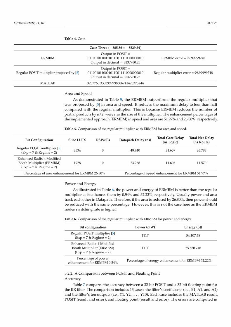
Electronics 2022, 11, 163 20 of 26
Table 4. Cont.
Case Three (−585.56 ∗ −5529.34)
ERMBMOutput in POSIT =
01100101100010110011110000000010Output in decimal = 3237760.25
ERMBM error = 99.99999748
Regular POSIT multiplier proposed by [5]Output in POSIT =
01100101100010110011110000000010Output in decimal = 3237760.25
Regular multiplier error = 99.99999748
MATLAB 3237760.3303999998606741428375244
Area and Speed
As demonstrated in Table 5, the ERMBM outperforms the regular multiplier thatwas proposed by [5] in area and speed. It reduces the maximum delay to less than halfcompared with the regular multiplier. This is because ERMBM reduces the number ofpartial products by n/2; were n is the size of the multiplier. The enhancement percentages ofthe implemented approach (ERMBM) in speed and area are 51.97% and 26.80%, respectively.
Table 5. Comparison of the regular multiplier with ERMBM for area and speed.
Bit Configuration Slice LUTS DSP48Es Datapath Delay (ns) Total Gate Delay(ns Logic)
Total Net Delay(ns Route)
Regular POSIT multiplier [5](Exp = 7 & Regime = 2) 2634 0 48.440 21.657 26.783
Enhanced Radix-4 ModifiedBooth Multiplier (ERMBM)
(Exp = 7 & Regime = 2)1928 0 23.268 11.698 11.570
Percentage of area enhancement for ERMBM 26.80% Percentage of speed enhancement for ERMBM 51.97%
Power and Energy
As illustrated in Table 6, the power and energy of ERMBM is better than the regularmultiplier as it enhances them by 0.54% and 52.22%, respectively. Usually power and areatrack each other in Datapath. Therefore, if the area is reduced by 26.80%, then power shouldbe reduced with the same percentage. However, this is not the case here as the ERMBMnodes switching rate is higher.
Table 6. Comparison of the regular multiplier with ERMBM for power and energy.
Bit configuration Power (mW) Energy (pJ)
Regular POSIT multiplier [5](Exp = 7 & Regime = 2) 1117 54,107.48
Enhanced Radix-4 ModifiedBooth Multiplier (ERMBM)
(Exp = 7 & Regime = 2)1111 25,850.748
Percentage of powerenhancement for ERMBM 0.54% Percentage of energy enhancement for ERMBM 52.22%
5.2.2. A Comparison between POSIT and Floating PointAccuracy
Table 7 compares the accuracy between a 32-bit POSIT and a 32-bit floating point forthe IIR filter. The comparison includes 13 cases: the filter’s coefficients (i.e., B1, A1, and A2)and the filter’s ten outputs (i.e., Y1, Y2, . . . , Y10). Each case includes the MATLAB result,POSIT (result and error), and floating point (result and error). The errors are computed in

Electronics 2022, 11, 163 21 of 26
reference to MATLAB. Table 7 shows that 10 cases have better accuracy for POSIT whiletwo have the same accuracy. Only one case has shown a better accuracy for the floatingpoint system. Hence, overall, POSIT provides better accuracy for the IIR filter.
Table 7. Comparison of accuracy between 32-bit POSIT and 32-bit floating point.
Calculation Source Generated Output Calculated Error
B1 (POSIT is More Accurate)
B1 from MATLAB −1.763842361931102233771193617584
B1 from POSIT 10111110011110001110100110101000→−1.763842344 POSIT error = 1.01659325× 10⁻⁶
B1 from FP proposed in [6,7] bfe1c598→−1.7638425827026367 FP error = 12.51651160× 10⁻⁶
A1 (POSIT is more accurate)
A1 from MATLAB −1.7087222881207552889658438170345
A1 from POSIT 10111110100101010010001001011011→−1.708722264 POSIT error = 1.41162526× 10⁻⁶
A1 from FP proposed in [6,7] bfdab76b→−1.708722472190857 FP error = 10.77238260× 10⁻⁶
A2 (same precision)
A2 from MATLAB 0.9384765625
A2 from POSIT 00111111110000010000000000000000→0.9384765625 POSIT error = 0
A2 from FP proposed in [6,7] 3f704000→ 0.9384765625 FP error = 0
Sample = 67 (same precision)
Y1 from MATLAB 67.0
Y1 from POSIT 0100110000011000000000000000000→67.0 POSIT error = 0
Y1 from FP proposed in [6,7] 42860000→ 67.0 FP error = 0
Sample = −456 (POSIT is more accurate)
Y2 from MATLAB −459.69304494529324530195843663682
Y2 from POSIT 10101110011010001001110100101000→−459.6930466 POSIT error = 0.35995906× 10⁻⁶
Y2 from FP proposed in [6,7] c3e5d8b6→−459.69305419921875 FP error = 2.01306624× 10⁻⁶
Sample = 19 (POSIT is more accurate)
Y3 from MATLAB 41.946435760963943178399103612273
Y3 from POSIT 01001010100111110010010010000000→41.9464111328125 POSIT error = 58.71333520× 10⁻⁶
Y3 from FP proposed in [6,7] 4227c930→ 41.94647216796875 FP error = 86.79403660× 10⁻⁶
Sample = 28 (POSIT is More Accurate)
Y4 from MATLAB 41.572953440710447008497063642695
Y4 from POSIT 01001010100110010010101010101000→41.57291412 POSIT error = 94.58243210× 10⁻⁶.
Y4 from FP proposed in [6,7] 42264ac0→ 41.572998046875 FP Error = 107.29611600× 10⁻⁶
Sample = 160 (POSIT is more accurate)
Y5 from MATLAB 161.28329915100100573765568271504
Y5 from POSIT 01001110100001010010001000001101→161.2832546 POSIT Error = 27.62282350× 10⁻⁶

Electronics 2022, 11, 163 22 of 26
Table 7. Cont.
Calculation Source Generated Output Calculated Error
Y5 from FP proposed in [6,7] 4321488a→ 161.28335571289062 FP Error = 35.06989870× 10⁻⁶
Sample = 39 (POSIT is more accurate)
Y6 from MATLAB 21.358347613975862138928193744926
Y6 from POSIT 01001000101010110111011100110000→21.35829926 POSIT Error = 226.3938050× 10⁻⁶
Y6 from FP proposed in [6,7] 41aade00→ 21.3583984375 FP Error = 237.9562550× 10⁻⁶
Sample = 142 (POSIT is more accurate)
Y7 from MATLAB 118.34503631422772995296612011743
Y7 from POSIT 01001101101100101100001010001101→118.3449955 POSIT Error = 34.48748590× 10⁻⁶
Y7 from FP Proposed in [6,7] 42ecb0ae→ 118.34507751464844 FP Error = 34.81381390× 10⁻⁶
Sample = 151 (POSIT is more accurate)
Y8 from MATLAB 121.70887719492042148245152838541
Y8 from POSIT 01001101110011011010101110111000→121.70887402 POSIT Error = 2.60861861× 10⁻⁶
Y8 from FP proposed in [6,7] 42f36af6→ 121.70890808105469 FP Error = 25.37705960× 10⁻⁶
Sample = 117 (FP is more accurate)
Y9 from MATLAB 89.562431604401888060911774239986
Y9 from POSIT 01001100110011000111111111010100→86.56241608 POSIT Error = 3349636.081× 10−6
Y9 from FP proposed in [6,7] 42b31ff8→ 89.56243896484375 FP Error = 8.21822468× 10⁻⁶
Sample = 294 (POSIT is more accurate)
Y10 from MATLAB 277.44683801916972138270230542038
Y10 from POSIT 01010000001010101110010011001000→277.4468384 POSIT Error = 0.13726243× 10⁻⁶
Y10 from FP proposed in [6,7] 43687263→ 277.4468231201172 FP Error = 5.37005671× 10⁻⁶
Area and Speed
The area and speed of the filter implementation for the two numbering systems usingthe regular multiplier is provided in Table 8. The area of the POSIT filter is reduced by21.77%, unlike its speed, which took 27.81% more time compared to floating point. Thisis because the fixed position of the fields representing floating point facilitate paralleldecoding operation unlike POSIT where some serialization is required to determine theregime first.
However, if the Enhanced Radix-4 Modified Booth Multiplier is used instead of aregular multiplier, POSIT outperforms floating point in speed as it enhanced the speed by51.97%, as mentioned in Table 5. This is the case as shown in Table 9, where the area andspeed of the whole filter are enhanced by 35.68% and 20.66% while maintaining the sameprecision for the acquired output with zero numbers of DSPE48E. This result is unlike theregular multiplier, which utilizes 8 DSPs, where each one of them adds complexity to thedesign and significantly increases the area. The DSPE48E is a digital signal processing unitthat is part of the FPGA device. Xilinx uses this element to implement several basic andcomplex operations. Sometimes it even utilizes a cascaded number of DSPs to implementcomplicated operations including advanced multiplications and N-Tap filters.
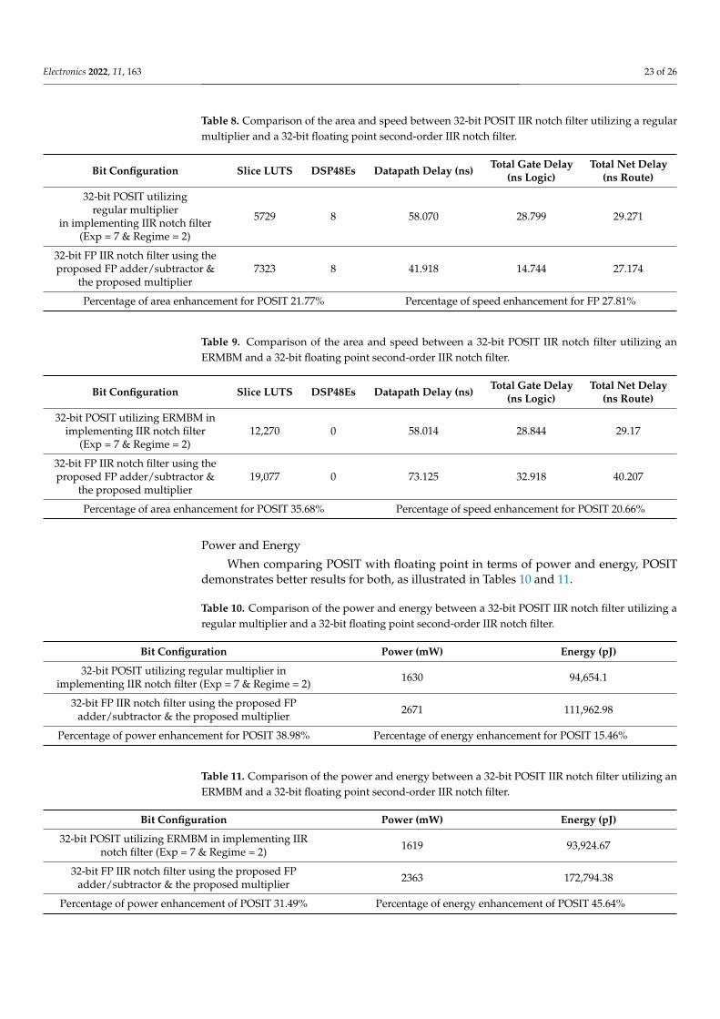
Electronics 2022, 11, 163 23 of 26
Table 8. Comparison of the area and speed between 32-bit POSIT IIR notch filter utilizing a regularmultiplier and a 32-bit floating point second-order IIR notch filter.
Bit Configuration Slice LUTS DSP48Es Datapath Delay (ns) Total Gate Delay(ns Logic)
Total Net Delay(ns Route)
32-bit POSIT utilizingregular multiplier
in implementing IIR notch filter(Exp = 7 & Regime = 2)
5729 8 58.070 28.799 29.271
32-bit FP IIR notch filter using theproposed FP adder/subtractor &
the proposed multiplier7323 8 41.918 14.744 27.174
Percentage of area enhancement for POSIT 21.77% Percentage of speed enhancement for FP 27.81%
Table 9. Comparison of the area and speed between a 32-bit POSIT IIR notch filter utilizing anERMBM and a 32-bit floating point second-order IIR notch filter.
Bit Configuration Slice LUTS DSP48Es Datapath Delay (ns) Total Gate Delay(ns Logic)
Total Net Delay(ns Route)
32-bit POSIT utilizing ERMBM inimplementing IIR notch filter
(Exp = 7 & Regime = 2)12,270 0 58.014 28.844 29.17
32-bit FP IIR notch filter using theproposed FP adder/subtractor &
the proposed multiplier19,077 0 73.125 32.918 40.207
Percentage of area enhancement for POSIT 35.68% Percentage of speed enhancement for POSIT 20.66%
Power and Energy
When comparing POSIT with floating point in terms of power and energy, POSITdemonstrates better results for both, as illustrated in Tables 10 and 11.
Table 10. Comparison of the power and energy between a 32-bit POSIT IIR notch filter utilizing aregular multiplier and a 32-bit floating point second-order IIR notch filter.
Bit Configuration Power (mW) Energy (pJ)
32-bit POSIT utilizing regular multiplier inimplementing IIR notch filter (Exp = 7 & Regime = 2) 1630 94,654.1
32-bit FP IIR notch filter using the proposed FPadder/subtractor & the proposed multiplier 2671 111,962.98
Percentage of power enhancement for POSIT 38.98% Percentage of energy enhancement for POSIT 15.46%
Table 11. Comparison of the power and energy between a 32-bit POSIT IIR notch filter utilizing anERMBM and a 32-bit floating point second-order IIR notch filter.
Bit Configuration Power (mW) Energy (pJ)
32-bit POSIT utilizing ERMBM in implementing IIRnotch filter (Exp = 7 & Regime = 2) 1619 93,924.67
32-bit FP IIR notch filter using the proposed FPadder/subtractor & the proposed multiplier 2363 172,794.38
Percentage of power enhancement of POSIT 31.49% Percentage of energy enhancement of POSIT 45.64%

Electronics 2022, 11, 163 24 of 26
5.3. Discussion
After enhancing POSIT arithmetic units and comparing the system with the floatingpoint numbering system, several recommendations result, including:
(1) Using the Enhanced Radix-4 Modified Booth Multiplier (ERMBM) instead of a regularmultiplier enhances the area, speed, power, and energy without affecting the accuracyof the output.
(2) If the accuracy, area, and power are the main concern, then it is recommended toutilize the POSIT numbering system with a regular multiplier instead of floating point.
(3) If the aim is to enhance all five performance metrics, then it is recommended to usePOSIT units along with ERMBM instead of floating point, as POSIT optimizes area,speed, power, and energy by 35.68%, 20.66%, 31.49%, and 45.64%, respectively.
6. Conclusions and Future Works
In this paper, the main goal was to implement the second-order IIR notch filter intwo numbering systems, POSIT and floating point, aiming to measure their performancemetrics for accuracy, area, speed, power, and energy.
When comparing POSIT and floating point, the regular multiplier was used firstinstead of the Radix-4 Modified Booth Multiplier with the goal of assessing the two num-bering systems without any optimization or enhancement for POSIT arithmetic units. Inthis case, POSIT shows better performance in accuracy than floating point; POSIT’s accuracywas estimated at 92.31%, as 10 out of 13 cases showed better performance for POSIT, while2 of 13 showed the same accuracy for both POSIT and FP. In comparison, the estimatedaccuracy of floating point was 23.08%, as 1 out of 13 cases showed better performance forfloating point. When implementing the entire filter, the area for POSIT is less than floatingpoint, though POSIT’s area was enhanced 21.77%. However, the longest timing path forfloating point is reduced by 27.81%, which indicates that there is a trade-off between thearea and speed. The dissipated power and energy consumption for the whole filter thatare implemented using POSIT were better compared to floating point. However, POSIToutperforms floating point in all five performance metrics when utilizing ERMBM insteadof the regular multiplier. In this case, the speed, area, power, and energy were enhanced by20.66%, 35.68%, 31.49%, and 45.64%, respectively, while utilizing zero number of DSPs.
For future work, we plan to improve the performance of POSIT arithmetic units evenmore by implementing a pipelined design aiming to enhance POSIT’s performance in re-source use, speed of execution, power, and energy consumption. It would be advantageousto compare 32-bit POSIT with a custom precision floating point to determine the number ofbits floating point would need to provide the same performance.
Author Contributions: Conceptualization, A.A.E., S.A. and B.J.M.; methodology, A.A.E., S.A. andB.J.M.; software, A.A.E. and S.A.; validation, A.A.E., S.A. and B.J.M.; formal analysis, A.A.E., S.A.and B.J.M.; investigation, A.A.E., S.A. and B.J.M.; resources, A.A.E. and S.A.; writing—original draftpreparation, A.A.E., S.A., B.J.M. and A.A.F.; writing—review and editing, A.A.E., S.A., B.J.M. andA.A.F.; visualization, A.A.E., S.A. and B.J.M.; supervision, S.A. and B.J.M.; project administration,S.A. and B.J.M. All authors have read and agreed to the published version of the manuscript.
Funding: This research received no external funding.
Data Availability Statement: The datasets used and/or analyzed during the current study areavailable from the corresponding author on reasonable request.
Conflicts of Interest: The authors declare no conflict of interest.
References1. Hauser, J.R. Handling floating-point exceptions in numeric programs. ACM Trans. Program. Lang. Syst. 1996, 18, 139–174.
[CrossRef]2. Lindstrom, P.; Lloyd, S.; Hittinger, J. Universal Coding of the Reals: Alternatives to IEEE Floating Point. In Proceedings of the
Conference for Next Generation Arithmetic, Singapore, 28 March 2018; ACM Press: New York, NY, USA, 2018; p. 5.3. Gustafson, J.L. A Radical Approach to Computation with Real Numbers. Supercomput. Front. Innov. 2016, 3, 1–16. [CrossRef]

Electronics 2022, 11, 163 25 of 26
4. Cook, J. Anatomy of a POSIT Number. 2018. Available online: https://www.johndcook.com/blog/2018/04/11/anatomy-of-a-POSIT-number/ (accessed on 3 April 2019).
5. Jaiswal, M.; So, H. PA Cogen: A Hardware POSIT Arithmetic Core Generator. IEEE Access 2019, 7, 74586–74601. [CrossRef]6. Doable, R.; Chaturvedi, S. Implementation of 32 Bit Binary Floating Point Adder Using IEEE 754 Single Precision Format. VOSR J.
VLSI Signal Processing (IOSR-JVSR-JVSP) 2015, 5, 2319–4197.7. Tejaswini, H.N.; Ravishankar, C.V. Single Precision Floating Point Numbers Multiplication using Standard IEEE 754. Int. J. Adv.
Res. Electron. Commun. Eng. (IJARECE) 2015, 4, 1–5.8. Gustafson, J.; Yosemite, I. Beating Floating Point at its Own Game: POSIT Arithmetic. Supercomput. Front. Innov. Int. J. 2017, 4,
2409–6008.9. Montero, R.M. Study of the POSIT Number System: A Practical Approach. Bachelor’s Thesis, Universidad Complutense de
Madrid, Madrid, Spain, 2019; pp. 1–78.10. Carmichael, Z.; Langroudi, H.F.; Khazanov, C.; Lillie, J.; Gustafson, J.L.; Kudithipudi, D. Deep Positron: A Deep Neural Network
Using the Posit Number System. arXiv 2018. arXiv:1812.01762.11. Dam, L. Enabling High Performance POSIT Arithmetic Applications Using Hardware Acceleration. Master’s Thesis, TU Delft
Electrical Engineering, Mathematics and Computer Science, Delft, The Netherlands, 2018; pp. 1–112.12. Ushanandhini, S.S. Designing of IIR Filter using Radix-4 Multiplier by Recharging Technique. Int. J. Trend Sci. Res. Dev. (IJTSRD)
2018, 2, 1100–1107.13. Wang, Y.; Li, B.; Li, Z. Fixed-point digital IIR filter design using multi-objective optimization evolutionary algorithm. In
Proceedings of the 2010 IEEE Youth Conference on Information, Computing and Telecommunications, Beijing, China, 28–30November 2010; pp. 174–177. [CrossRef]
14. Chengliang, Z.; Lihong, W. IIR Digital Filter Research and Simulation on MATLAB. In Proceedings of the 4th InternationalConference on Signal Processing Systems (ICSPS), Kuala Lumpur, Malaysia, 21–22 December 2012; Volume 58, pp. 138–142.
15. Bajwa, D.; Singh, K.; Chahal, N. Fixed Point digital IIR filter Design using two-stage ensemble evolutionary algorithm. Int. J. Adv.Res. Comput. Sci. Softw. Eng. (IJARCSSE) 2014, 4, 329–338.
16. Stavrou, V.; Tsoulos, I.; Mastorakis, N. Transformations for FIR and IIR Filters’ Design. Symmetry 2021, 13, 533. [CrossRef]17. Tsoulos, I.G.; Stavrou, V.; Mastorakis, N.E.; Tsalikakis, D. GenConstraint: A programming tool for constraint optimization
problems. SoftwareX 2019, 10, 100355. [CrossRef]18. Langroudi, S.H.F.; Pandit, T.; Kudithipudi, D. Deep Learning Inference on Embedded Devices: Fixed-Point vs Posit. In Proceedings
of the 2018 1st Workshop on Energy Efficient Machine Learning and Cognitive Computing for Embedded Applications (EMC2),Williamsburg, VA, USA, 25 March 2018; Volume EMC2, pp. 19–23.
19. Podobas, A.; Matsuoka, S. Hardware Implementation of POSITs and Their Application in FPGAs. In Proceedings of the 2018IEEE International Parallel and Distributed Processing Symposium Workshops (IPDPSW), Vancouver, BC, Canada, 21–25 May2018; pp. 138–145.
20. Jaiswal, M.K.; So, H.K.-H. Architecture Generator for Type-3 Unum Posit Adder/Subtractor. In Proceedings of the 2018 IEEEInternational Symposium on Circuits and Systems (ISCAS), Florence, Italy, 27–30 May 2018; pp. 1–5.
21. Jaiswal, M.K.; So, H.K.-H. Universal number posit arithmetic generator on FPGA. In Proceedings of the 2018 Design, Automation& Test in Europe Conference & Exhibition (DATE), Dresden, Germany, 19–23 March 2018; pp. 1159–1162.
22. Lehóczky, Z.; Retzler, A.; Tóth, R.; Szabó, Á.; Farkas, B.; Somogyi, K. High-level. NET software implementations of unum typeI and posit with simultaneous FPGA implementation using Hastlayer. In Proceedings of the Conference for Next GenerationArithmetic, Singapore, 28 March 2018; ACM Press: New York, NY, USA, 2018; p. 4.
23. Hou, J.; Zhu, Y.; Shen, Y.; Li, M.; Wu, H.; Song, H. Tackling Gaps in Floating Point Arithmetic: Unum Arithmetic Implementaionon FPGA. In Proceedings of the IEEE 3rd International Conference on Data Science and Systems (HPCC/SmartCity/DSS),Bangkok, Thailand, 18–20 December 2017; pp. 615–616.
24. Glaser, F.; Mach, S.; Rahimi, A.; Gurkaynak, F.K.; Huang, Q.; Benini, L. An 826 MOPS, 210uW/MHz Unum ALU in 65 nm. InProceedings of the 2018 IEEE International Symposium on Circuits and Systems (ISCAS), Florence, Italy, 27–30 May 2018; pp. 1–5.
25. Chen, J.; Al-Ars, Z.; Hofstee, H.P. A matrix-multiply unit for posits in reconfigurable logic leveraging (open) CAPI. In Proceedingsof the Conference for Next Generation Arithmetic, Singapore, 28 March 2018; ACM Press: New York, NY, USA, 2018; p. 1.
26. Fadavi-Ardekani, J. M*N Booth encoded multiplier generator using optimized Wallace trees. IEEE Trans. Very Large Scale Integr.(VLSI) Syst. 1993, 1, 120–125. [CrossRef]
27. Krushna, M.; Kumar, K. Modified Booth Encoding Multiplier for both Signed and Unsigned Radix Based Multi-ModulusMultiplier. Int. J. Mag. Eng. Technol. Manag. Res. (IJMETMR) 2015, 2, 1–6.
28. Kang, J.-Y.; Gaudiot, J.-L. A fast and well-structured multiplier. Euromicro Symposium on Digital System Design, DSD, Rennes,France, 31 August–3 September 2004; pp. 508–515. [CrossRef]
29. Tripathi, R.; Prakash, S. Comparative Design of Regular Structured Modified Booth Multiplier. Int. J. VLSI Des. Commun. Syst.(VLSICS) 2016, 7, 21–30. [CrossRef]
30. Kshirsagar, R.; Aishwarya, E.; Vishwanath, A.; Jayakrishnan, P. Implementation of pipelined Booth Encoded Wallace tree Multi-plier architecture. In Proceedings of the 2013 International Conference on Green Computing, Communication and Conservationof Energy (ICGCE), Chennai, India, 12–14 December 2013; pp. 199–204.

Electronics 2022, 11, 163 26 of 26
31. Ramteke, S.; Khandagre, Y.; Dubey, A. Implementation of Low Power Booth’s Multiplier by Utilizing Ripple Carry Adder. Int. J.Sci. Eng. Res. (IJSER) 2014, 5, 2229–5518.
32. Kaur, S.; Manna, M. Implementation of Modified Booth Algorithm (Radix-4) and its Comparison with Booth Algorithm (Radix-2).Res. India Publ. Adv. Electron. Electr. Eng. 2013, 3, 683–690.
33. Wang, C.M.; Xiao, W.C. Second-order IIR Notch Filter Design and implementation of digital signal processing system. InProceedings of the 2nd International Symposium on Computer, Communication, Control and Automation, Singapore, 1–2December 2013; Atlantis Press: Paris, France, 2013; pp. 0576–0578.
34. Lavanya, K.; Savidhan, S.; Akshatha, D. Computing Non-Restoring and Newton Raphson’s Method for Division. IOSR J. Electron.Commun. Eng. (IOSR-JECE) 2017, 12, 57–60.
35. Oberman, S.; Flynn, M. An Analysis of Division Algorithms and Implementations; Departments of Electrical Engineering andComputer Science, Stanford University: Stanford, CA, USA, 1995; Volume 46, pp. 833–854.
36. Malepati, H. Digital Media Processing DSP Algorithms Using C; Elsevier: Newnes, Australia, 2010; pp. 1–768.