Design of multidimensional finite-wordlength FIR and IIR filters by simulated annealing
22
Transcript of Design of multidimensional finite-wordlength FIR and IIR filters by simulated annealing
Design of multidimensional �nite-wordlengthFIR and IIR �lters by simulated annealingJan Radecki, Janusz Konrad and Eric [email protected]�e du Qu�ebecInstitut national de la recherche scienti�queINRS-T�el�ecommunications16 Place du Commerce, VerdunQu�ebec, Canada, H3E 1H6IEEE Transactions on Circuits and Systems {II: Analog and Digital Signal Processingvol. 42, no. 6, pp. 424{431, June 1995
Design of multidimensional �nite-wordlengthFIR and IIR �lters by simulated annealingJan Radecki, Janusz Konrad and Eric DuboisINRS-T�el�ecommunicationsInstitut National de la Recherche Scienti�que16 Place du Commerce, Verdun, Qu�ebec, H3E 1H6, CanadaAbstractThis paper describes a new approach to the design of multidimensional (M-D) �nite-wordlength digital �lters with speci�cations in the frequency and spatial domains.The approach is based on stochastic optimization and extends previous work on �niteimpulse response (FIR) �lters in two ways: by inclusion of spatial constraints andby application to the case of in�nite impulse response (IIR) �lters. The formulationproposed is based on a multiple-term objective function that, in addition to magnitudeconstraints, also includes step response, group delay and stability constraints. Ourattention to these characteristics stems from the application of such �lters to videoprocessing that we are actively pursuing. Since �lter coe�cients are of �nite precisionand since the objective function is multivariable, non-di�erentiable and likely to havemultiple minima, we use simulated annealing for optimization. We show numerousexamples of the design of practical �lters such as channel and luminance/chrominanceseparation �lters used in the NTSC system. We demonstrate the impact of coe�cientprecision as well as of group delay and step response constraints on �lter parameters.
1 IntroductionThe work presented in this paper has been motivated by our research in the area of advancedvideo systems (NTSC, HDTV) where M-D digital �ltering is often used. For example, com-ponent signals in a modern NTSC receiver are extracted using separable analog/digital 2-D�ltering, often referred to as comb �ltering. The quality of the displayed image, however,can be improved by employing fully-digital non-separable �ltering instead [12]. Since digital�ltering will play an essential role in digital transmission systems of the future (HDTV, video-conferencing, videophone), it is important to develop general and exible design methodsfor �nite-precision �lters.Usually, digital �lters are designed with respect to magnitude response only. In thispaper, we are interested in a design with respect to �lter properties in the frequency andspace-time domains. If �lter output is to be evaluated by human observers, good spatio-temporal properties, such as small ringing at sharp intensity transitions, are also important.This is due to the fact that ringing is easily perceived by the human visual system (HVS). Arelated problem is that of phase-linearity; the HVS is sensitive to phase distortions. Thus,a �lter should have linear or almost linear phase. Since the designed �lters are intendedfor �nite-precision implementation, the additional constraint is that �lter coe�cients be of�nite wordlength. Consequently, for FIR �lters, magnitude and step responses need to beconsidered; exact phase linearity can be easily achieved by constraints on �lter coe�cients.However, IIR �lters need to be additionally optimized with respect to phase response andstability.There have been numerous methods proposed for the design of M-D digital �lters. Typi-cal design methods for FIR �lters are based on windowing, spectral transformations or errorcriterion optimization [13]. M-D IIR �lters are usually designed either by spectral trans-formations of 1-D �lters [13] or by error criterion optimization. The error criterion may beestablished in space-time domain [13], frequency domain [2],[29] or state space [20]. Stabilityof an IIR �lter is usually enforced analytically [2], by spectral factorization [29] or by veri�-cation after each coe�cient update. Some of the methods optimize only magnitude responsewhile others take into account both magnitude and phase properties [10],[29]. Finally, fromthe optimization point of view, linear programming [10] or non-linear optimization proce-dures are used [29],[13]. In order to account for spatio-temporal �lter properties, in additionto the magnitude response error, also an error related to step response oscillations (ringing)has been used successfully for 1-D [24] and 2-D FIR �lters [7],[23].Implementation of a �lter in �xed-point hardware requires �nite-precision coe�cients.The simplest approach is to quantize the full-precision coe�cients1. This method, however,produces sub-optimal results since �lter response may change substantially after coe�cientquantization. Moreover, for IIR �lters such quantization may move poles close to or into theinstability region, thus making the �lter unusable. Thus, local and global design methodshave been proposed. Local methods usually start from a quantized full-precision solutionand are implemented through a univariate search, random search or branch and boundmethod. Since these methods are sub-optimal, designs assuring optimality of the solutionhave been proposed. One example is mixed integer programming [17], while another is sim-ulated annealing [11],[8],[6], a method capable of �nding the global minimum of complex,multi-variable functions with multiple minima [16]. Simulated annealing has been �rst ap-1
plied to general 1-D linear-phase FIR �lters, but later has been extended to some special1-D digital �lters such as Nyquist �lters [5] or multiplierless �lters for video applications [3].In this paper we propose a comprehensive design method for M-D �nite-precision �lters.The method is based on a multiple-term cost function that comprises magnitude, phase(group delay), stability and step response errors. In this way several requirements are com-bined. Their relative importance is controlled by suitable weights. In order to minimize thismulti-variable, non-di�erentiable function with multiple minima we use simulated annealingbased on the Metropolis algorithm.The paper is organized as follows. In Section 2 a general formulation of the �nite-precision�lter design problem is given, followed by a description of the solution method used. Then,in Sections 3 and 4 elements of the cost function are described in detail and examples ofcomputer simulations are given for FIR and IIR �lters, respectively. In Section 5 the paperis summarized and conclusions are drawn.2 General problem: formulation and solution2.1 Cost functionLet H(!) = H(!) � ej�(!) be the (complex) frequency response of an N -dimensional FIR orIIR �lter, where ! = (!1; !2; :::; !N)T is an N -dimensional frequency vector. In the specialcase of 1-D and 2-D �lters, for which examples are given in the next two sections, we have! = ! and ! = (!1; !2)T , respectively. Clearly, H(!) and �(!) are the magnitude andphase responses of the �lter. Let �i(!) be its group delay with respect to !i. We assumea general cascaded form for the �lter, which includes both the direct form and a cascade oflow order sections as special cases. We write the frequency response of such �lter as followsH(!) = QKk=1Pm2Mk ak(m) � e�j!TmQLl=1Pn2Nl bl(n) � e�j!Tn (1)where K, L denote the number of cascaded sections in the numerator and denominator,and m = (m1; :::;mN)T , n = (n1; :::; nN)T are N -dimensional vectors of coe�cient indicesfrom numerator and denominator masks M, N , respectively. Since one coe�cient in eachdenominator polynomial Bl(!) is redundant, we assume that bl(0)=1 for l = 1; :::; L. Then,for FIR �lters L=1 and b1(n)=0 for alln exceptn = 0. For the canonical �lter representationwe have K = L = 1.In this paper we assume that �lters are de�ned on a rectangular sampling lattice. Thislattice is most often used in signal processing as it allows separability as well as simpleimplementation. The formulation presented below, however, is general enough to handleother sampling lattices; �lter indices and masks would have to be suitably rede�ned. Weassume that for FIR �lters the mask M has non-causal support, i.e., full axis for 1-D caseand four quadrants for 2-D case. For the numerator and denominator masks of an IIR �lter,causal support is assumed, i.e., half axis for 1-D case and �rst quadrant for 2-D case. We donot consider non-symmetric half-plane (NSHP) denominators since they are non-separable;the need for transfer function separability is explained below.2
For IIR �lters of dimension higher than 1, assurance of �lter stability is both non-trivialand computationally expensive [1]. A recent result by Wan and Fahmy [28], however, permitsus to greatly simplify the frequency response (1). They have shown (Theorem 7 and Corollary8 in [28]) that the denominator of a transfer function possesses quadrantal symmetry andsatis�es stability constraints if and only if it is separable. This result has a signi�cantimplication since very often �lters characterized by a frequency response with quadrantalsymmetry are sought. For example, in image processing horizontal and vertical mirror imagesof a pattern should be treated in the same way as the original pattern, and thus quadrantalsymmetry is appropriate.We conclude that the desired frequency response with quadrantal symmetry can be ap-proximated by a separable denominator functionLYl=1 NYi=1 Xn2Nl;i b0l;i(n) � e�j!in: (2)With the above factorization, the N -D stability test simpli�es to (N � L) simple 1-D tests.Let � = [�1; ; :::; �P ]T be a vector that contains all P = Pk jMkj + PlPi(jNl;ij � 1)unknown coe�cients, where jMj denotes the number of coe�cients in mask M. Note thatsince b0l;i(0) = 1, each denominator polynomial has jNl;ij � 1 unknown coe�cients. Let eachcoe�cient have a �xed-point representation with b bits, and let the maximum absolute valueof each coe�cient be A. Then, the quantization step is de�ned as q = A=2b�1 and its valuebelongs to the set S = f� : � = �A+ q �m; m = 1; :::; 2bg. This could be easily extended toaccommodate di�erent A and/or b for each coe�cient.Filters designed by the algorithm proposed in this paper are intended for use in videoprocessing. Since the �nal evaluation of an image is done by the human observer, twoproperties of the HVS are critical. First, the HVS is sensitive to phase nonlinearities (i.e.,non-constant group delay) [15],[21] introduced at the processing stage. Such nonlinearitiesmanifest themselves as double contours, distortions in regular patterns, etc. Thus, �lterswith linear or almost-linear phase are required. Secondly, although a digital �lter is uniquelyspeci�ed by its magnitude and phase responses, the spatio-temporal performance of a �lteris also important to the HVS. Filters used in video processing must not produce annoying\ghosts" or multiple echoes (called ringing) around sharp intensity transitions; �lter responseto the unit step must not contain large oscillations or overshoots. Note that optimizationof frequency and spatio-temporal properties of a �lter cannot be done independently. Whatwe can hope for is to achieve a certain compromise between the di�erent requirements.Apart from the need for a sharp amplitude transition, it is not clear what spatio-temporalshape a unit step should have. For N=1 there is no ambiguity, but already for N=2 di�erentspatial shapes can be selected. We will use the corner unit step [7] since it gives moreconstraints than the diagonal step [23] and simultaneously exhibits both horizontal andvertical ringing. This is a valuable property as images are very often composed of objectswith contours in these directions.To design a digital �lter under various constraints we propose to use the followingmultiple-term cost function: E(�) = EH + ��E� + �sEs + ��E�; (3)3
where the �'s are non-negative weights and the E's are error terms (implicitly dependenton �) measuring the departure of �lter magnitude, group delay, stability and step responsefrom some desired properties.2.1.1 Magnitude errorEH is themagnitude error due to the departure of H(!) from the desired magnitude responseD(!). To obtain �lters with equiripple response we de�ne EH as follows:EH = max!2H[ H(!) � jH(!)�D(!)j]; (4)where H(!) is a weighting function and H is a set of frequencies! at which EH is evaluated.This set usually forms a uniform rectangular sampling grid in [�0:5; 0:5]N (N -fold Cartesianproduct)2. Non-uniform grids are occasionally used, especially around transition bands.In the literature, control over the transition band is often omitted ( H=0.0). We shapethe magnitude response in the transition band as well, although with a reduced emphasis( H=0.5). We do so in order to control the impact of step response optimization on thetransition band properties; experiments have shown that a relatively small change of �� maysigni�cantly a�ect the magnitude error in and close to the transition band. The weight Hcan be also used to get a very close approximation at certain frequencies, e.g., DC (! = 0),by choosing a very large weight. Note that the error (4) is evaluated only for ! 2 H , andthus the sampling grid in H must be chosen dense enough in order to provide a su�cientlyclose approximation to D(!).2.1.2 Group delay (phase) errorTo minimize phase non-linearity in IIR �lters, we chose to minimize a measure of variabilityof the group delay. We do not use the phase �(!) directly since phase unwrapping wouldhave to be carried out for each !. Thus, we calculate analytically group delay(s) �i(!), andde�ne the group delay error E� as followsE� = maxfmax!2� [ �(!)j�1(!)� ��1j]; :::;max!2� [ �(!)j�N (!)� ��N j]g: (5)� is the set of frequencies !, similar to H , at which E� is evaluated. � (!) is again afrequency-dependent weighting function. For �lters with stop-band attenuation of at least20 dB, phase linearity is irrelevant in the stop band [9] and � (!)=0 may be used. ��i is avalue of the i-th group delay to be as closely approximated by �i(!) over � as possible. Ifsuch a value is known, as sometimes may be the case, then ��i is �xed. If it is not knownand only a group delay constancy is required, then, for example, ��i may be de�ned as a � -weighted average of the i-th group delay��i = 1j� j X!2� � (!)�i(!): (6)Note that the error (5) expresses the maximum value of individual (i = 1; :::; N) groupdelay variations over � , i.e., �rst, the maximum of weighted variation for each �i(!) iscalculated, and then the largest such variation is selected.4
2.1.3 Stability errorIn order to assure IIR �lter stability, zeroes of each polynomial in (2) must be within theunit circle. The zeroes can be found using any factorization scheme, although in our designswe have used at most second-order sections. If jzjmax is the zero with the largest magnitude,then 1 � jzjmax is the �lter's stability margin.Suitable margin of stability must be assured for �lters designed in a oating-point arith-metic and implemented in a �xed-point arithmetic; after quantization the position of polesmay change. In this paper, however, we design �nite-wordlength �lters directly. A controlover �lter stability margin may be useful for two reasons. First, the stability margin of anIIR �lter has a direct impact on the settling time (rate of decay) of �lter's impulse response[1]. Consequently, it a�ects the extent of oscillations in �lter step response. Secondly, limitcycles in IIR �lters depend on the position of �lter poles with respect to the unit circle [24].In order to control the �lter's margin of stability we discourage generation of poles tooclose to the unit circle by proposing the following stability error:Es = ( minf1=((1 � �)� jzjmax); �g; for jzjmax < 1 � �,�; for jzjmax � 1 � �, (7)where 0 � � < 1 is the minimum margin of stability and � is a large positive number.Stability error (7) can be interpreted as follows. Each pole of a �lter must be located withinthe circle with radius 1� �; otherwise a high penalty is assigned to Es. Inside this circle, thestability error grows with jzjmax approaching the circle; coe�cients producing poles fartherfrom the circle are penalized less. Criterion (7) is applicable to any M-D �lter.2.1.4 Step response errorLet �(n) be the �lter response to the corner unit step. Since it is very di�cult, if not impos-sible, to propose a suitable error in a general case, we make several restricting assumptions.We assume that the �lter is low-pass (otherwise no step would appear at the output), haspositive DC gain, and that its overshoots do not exceed a fraction # of the input step re-sponse value. Let nmax and nmin be coordinates of the maximum and minimum values of�(n) over its full region of support. We also assume that the largest oscillations in the stepresponse occur around nmin and nmax. Although occasionally not true, this assumption hasheld very well for the examples given in this paper. This restriction greatly simpli�es thecalculations since only one maximum for the causal part and one minimum for the anticausalpart have to be considered.With K(n) being a neighborhood of n, we de�ne two sets as follows:W1(n) = fk 2 K(n) : �(k) � (1� #)D(0);�j� � 0; j = 1; :::; Ng;W2(n) = fk 2 K(n) : �(k) � #D(0);�j� � 0; j = 1; :::; Ng;where �j� = �(k1; k2; :::; kj +1; :::; kN)� �(k1; k2; :::; kj; :::; kN) is the �rst-order di�erence of� in the direction kj . We separately search for the causal overshoot (around nmax) and forthe anticausal overshoot (around nmin)E+� = maxk2W1(nmax) �(nmax)� �(k); E�� = maxk2W2(nmin) �(k)� �(nmin): (8)5
Note that due to the de�nitions of W1 and W2, only a search among neighbors with step re-sponse value above (1�#)D(0) (causal) and below #D(0) (anticausal) threshold is executed.Moreover, this set is further restricted by requiring that �rst-order di�erences (approxima-tion to local gradient components) be negative, i.e., that positions be not on the step rise.We de�ne the step response error as the maximum of the above overshoots:E� = max(E+� ; E�� ): (9)2.2 Minimization methodTo design a digital �lter with constraints described above we need to minimize the costfunction (3) with respect to �. The function under minimization is characterized by severalimportant properties. First, it is de�ned over discrete-valued vector �. Consequently, nogradient-type technique can be used directly, unless quantization follows each coe�cientupdate, which is a suboptimal approach. Secondly, in the general case it is multimodal,i.e., possesses multiple minima. It is also non-di�erentiable due to the way E� is de�ned; nogradient-based method can be used. Finally, it is usually de�ned over a few dozen to a fewhundred variables.A method that we propose to carry out this minimization is simulated annealing [16].This stochastic search algorithm is a computer simulation of the process of annealing of solids;the behavior of a solid is simulated by generating sample con�gurations from a probabilitydistribution with an energy function (such as the one de�ned in (3)) divided by a \tem-perature" parameter T . The sample con�gurations are produced using, e.g., the Metropolisalgorithm [22]. Initially T is chosen to be su�ciently high to generate a full range of con�g-urations, even the unlikely ones. This assures avoidance of local minima and is equivalent tomelting the solid. As the process evolves, T is very slowly reduced. It has been shown [14]that if the reduction of T is su�ciently slow, then the system attains (in a limit) the stateof minimal energy.We use the Metropolis algorithm to generate samples from a suitable discrete-timeMarkov chain. Let �s be the vector of coe�cients at (discrete) time s, and let ��s be anothervector of coe�cients that is identical to �s except the coe�cient �is. Note that only onecoe�cient is modi�ed in one trial. Let T0 and Tmin denote the initial and �nal temperatures,and let � be the number of trials for which the temperature T stays constant. Every �trials the temperature is modi�ed according to the schedule Tj+1 = �Tj. Let the energyincrement, resulting from an attempted change at time s, be �Es = E(��s) � E(�s). TheMetropolis-based simulated annealing algorithm has been implemented as follows:1) start with an initial temperature T0 and an initial state �0; j=0, s=0,2) randomly select a new state ��s in two steps:a. generate a new location is (uniformly distributed) of a coe�cient to be updated,b. generate a new value (uniformly distributed) from Sis for coe�cient �is,3) compute the energy increment �Es and make the following decision:a. if �Es � 0, accept the new state unconditionally: �s+1 = ��s,b. if �Es > 0, accept the new state with probability p = exp(��Es=Tj),6
4) s = s+ 1; if s � 0(mod �), then Tj+1 = �Tj and j = j + 1,5) if Tj � Tmin, exit; otherwise return to 2.In our implementation of simulated annealing, multiplication by � < 1 causes the reduc-tion of temperature: Tj = T0�j. T is decreased in larger steps when T is large and in smallersteps when it is small. Optimal annealing schedules, such as the logarithmic one [14], changethe temperature very little for large j (small T ). To reduce the decrements for small T weuse three di�erent values of � as followsTj+1 = 8><>: �1Tj; if 0 � j < J1,�2Tj; if J1 � j < J2,�3Tj; if J2 � j, (10)where �1 < �2 < �3 and J1, J2 indicate when a change of � occurs. These parametersas well as � have been selected experimentally during the design. Typically, we have used�1=0.97-0.99, �2=0.992-0.997, �3=0.998-0.999 switched around J1=0.01 and J2=0.005. Wehave changed the temperature every � = 10P trials.Another important parameter in simulated annealing is the initial temperature T0. Thetheoretical value of T0, in order to assure convergence to the global optimum, is usuallyimpractically high. Thus, sub-optimal values of T0 are often used. We have used initialtemperatures from 0.125 to 0.5 depending on the designed �lter. For such temperaturesthe initial acceptance ratio was typically about 15-20%. We have experimented with highervalues of T0 giving initial acceptance ratios in the 30-50% range, however we encounteredsigni�cant numerical di�culties. The very unlikely states generated at high temperaturesgave �lters with 300% magnitude ripples and group delays of the order of several hundred.For such �lters the calculation of step response error as de�ned in Section 2.1.4 fails; forexample a high-pass �lter instead of a low-pass one is generated. To improve chances oflocating the global optimum we �rst carry out the optimization several times for di�erentseeds and di�erent annealing schedules, and then use the best result as the initial state forfurther optimization with reduced T0.To speed-up the calculations at low temperatures we have modi�ed the Metropolis al-gorithm as follows. If a proposed coe�cient �is di�ers from the current coe�cient by morethan 0.5 for 1-D low-pass �lters and by 0.25 for 2-D low-pass �lters, then we consider such achange very unlikely and we proceed to the next trial. Skipping the calculation of all errorsin (3) lets us substantially reduce the computational complexity of the algorithm, and fromour experience does not impair results in any way. This is probably due to the fact thatthe modi�cation is used only at low temperatures when simulated annealing behaves sim-ilarly to the steepest descent algorithm (acceptance ratio below 1%). Other modi�cationsspeeding-up the execution are possible [6].3 Design of FIR �ltersWe have designed �nite-precision FIR �lters by minimizing EH + ��E� (��=�s=0). We haveimplemented the method for odd number of coe�cients horizontally and vertically.Since �lter coe�cients are real, H(!) is symmetric and H needs to cover only the [0; 0:5]range. For 2-D �lters, half-plane symmetry of coe�cients is su�cient for linear phase. We7
use, however, quadrantal coe�cient symmetry due to its implementation e�ciency; H isde�ned over [0; 0:5]� [0; 0:5]. We use H consisting of 128 uniformly sampled points in the1-D case and 32�32 points in the 2-D case.To describe performance of the designed �lters we calculate certain parameters over adenser grid f . For 1-D �lters f consists of 1024 uniformly sampled points, and for 2-D�lters it is a uniform 128�128 orthogonal grid. Let pf and sf be subsets of f such thatall their elements are in the pass and stop bands, respectively. For each band we identifythe frequency at which the maximum magnitude ripple occurs:!0H = arg max!2pf jH(!)�D(!)j; !00H = arg max!2sf jH(!)�D(!)j:To measure �lter performance we use the maximum pass-band ripple �p and the minimumstop-band attenuation �s de�ned as follows:�p = 20 log H(!0H)D(!0H) [dB]; �s = 20 logH(!00H) [dB]. (11)Note that �p is the maximum linear deviation of �lter response from D(!) in the pass bandexpressed in dB, and not the maximum dB ripple in this band. The two are not necessarilythe same since for the same excursion of H(!0H) above and below D(! 0H) di�erent values of�p result. Since �p is signed, the linear deviation H(!0H) �D(! 0H) can be always uniquelyrecovered using the relationship (11). Note that since the optimization is performed over Hand since H � f , �p and �s are degraded compared to their values calculated over H . Wealso compute step response overshoots E+� and E�� using (8) with #=0.5, (-3,3) neighborhoodK in the 1-D case and (-3,3)�(-3,3) neighborhood in the 2-D case. Note that for 1-D FIR�lters with linear phase we have E�� = E+� because of coe�cient symmetry.3.1 1-D FIR �ltersWe have experimented with low-pass NTSC channel �lters with the pass band from 0 to!p=0.2933 and the stop band from !s=0.3344 to 0.5 [4]. Note that the transition band isnarrow and is expected to result in signi�cant step response overshoots. We have de�ned thedesired magnitude response to be D(!) = (1; 0:5(1 + cos �(! � !p)=(!s � !p)); 0), where(a1; a2; a3) = 8><>: a1; for 0 � ! � !p,a2; for !p < ! < !s,a3; for !s � ! � 0:5. (12)We have chosen K=1, jM1j=49, A=1.0, b=6, 8 or 10, and H(!) = (1; 0:5; 1). To assurea speci�c gain at frequency ! (e.g., H(0)=1.0), we set H(!) to a high value.Table 1 shows the comparison between SA-designed �lters and �lters designed by theN -step Newton minimization [19] (��=0). The reference design is the full-precision3 imple-mentation of the N -step Newton minimization. The �nite-precision version of this methodhas been implemented by in-loop coe�cient quantization [25]. Clearly, coe�cient precisionhas a signi�cant impact on magnitude ripples of FIR �lters. As we shall see later this e�ect isless severe for IIR �lters. SA-designed �lters have the same or better pass-band ripple and/or8
increased stop-band attenuation, while step response oscillations are almost unchanged. For6-bit �lters, however, we could not obtain any improvement by using simulated annealing,which may be due to the four times smaller state space for each coe�cient (compared with8-bit design) that is easier to explore.The bottom part of Table 1 shows parameters of �lters designed with the step responseconstraint. As expected, the maximum overshoot is noticeably reduced, although at thecost of increased magnitude ripples. The compromise between the magnitude ripples andthe overshoot amplitude is due to the fact that no other degree of freedom is left (phaselinearity is enforced analytically). We will see in Section 4.1 that in the case of IIR �ltersthe compromise also involves the group delay. Magnitude and step responses of one of thedesigned �lters are shown in Fig. 1 (jointly with an IIR �lter).3.2 2-D FIR �ltersWe have designed 2-D low-pass FIR �lters with diamond-shaped pass band, that are usedin enhanced NTSC coding [12]. We have chosen K=1, jM1j=165 (15 coe�cients per line,11 lines), A=0.25, b=8 or 6. Due to the quadrantal symmetry of the �lter mask, there are48 independent coe�cients to be optimized. We chose a smaller vertical dimension of the�lter because it is intended for video processing where a line delay is much more costly thana pixel delay. The desired magnitude response of the �lter is derived from the 1-D version;values are calculated along straight lines through the origin. The 2-D weighting function H(!) is also derived from the 1-D version. As in the 1-D case, values of H are increasedat ! = 0 to assure the unit gain at DC.We have compared the proposed method with N -step Newton minimization [25] for thecase without step response constraint (��=0). Table 2 shows parameters of �lters designedby full- and �nite-precision N -step Newton minimization and by �nite-precision SA. Notea very signi�cant improvement in all parameters of SA-designed �lters in comparison withthe Newton-designed ones. Also, note a signi�cant increase in the magnitude error for 6-bitcoe�cients in comparison with the 8-bit design. As we shall see in Section 4.2 this e�ect isfar less pronounced in IIR �lters. We have also tested the impact of step response constraint(bottom of Table 2). Notice that an increase in �� causes, as expected, a reduction of stepresponse overshoots while at the same time increasing the magnitude errors. Again, a directtrade-o� between magnitude ripples and step response oscillations can be observed.Fig. 2 shows the magnitude and step responses of the 2-D 8-bit diamond-shaped FIR�lter designed with the step response constraint (��=0.5). Note the overshoot ridge at therise of the step response and its fast decay without oscillations, a typical characteristic of alow-pass �lter with a wide transition band. For more results please consult [25].4 Design of IIR �ltersTo control phase non-linearity and stability of an IIR �lter, we use the full four-term costfunction (3). No symmetry constraints are applied to the numerator or denominator coe�-cients, although, if needed, such constraints could be included.9
Since IIR coe�cients are real, H(!) possesses half-plane symmetry. Consequently, thesets H and � are as before for the 1-D case, and are de�ned over the range [�0:5; 0:5]�[0; 0:5] for the 2-D case. In all experiments with IIR �lters, the same H(!) is used as forFIR �lters (Section 3), but with a suitably extended support in the 2-D case.The same parameters as those in Section 3 are used here to describe �lter performance.Additionally, the stability margin 1� jzjmax and the i-th group delay spread ��i in the passband ��i = �i(!0�i)� �i(!00�i) (13)are used with !0�i and !00�i de�ned as follows!0�i = arg max!2pf �i(!); !00�i = arg min!2pf �i(!):4.1 1-D IIR �ltersWe have designed 1-D IIR �lters with the same frequency speci�cations as in Section 3.1.We have chosen a cascade of K=L=5 sections in both numerator and denominator withjMij=3, jNij=3 for i = 1; :::; 5 (25 coe�cients in total), and � (!) = (1; 0:52(1 + cos �(!�!p)=(!s � !p))2; 0) to insure rapid roll-o� in the transition band.In Table 3, parameters of 1-D IIR �lters designed using the proposed method are shown.As expected, magnitude response ripples increase with the reduction of coe�cient precision.Note, however, that there is only 0.07 dB increase in �p and a 0.9 dB reduction in �s when theprecision is reduced from 10 to 8 bits. For FIR �lters designed by the proposed algorithm,these numbers were 0.18 dB and 4.97 dB, respectively. Similarly, for the change from 8-to 6-bit precision, the IIR �lter looses 0.28 dB in the pass band and 2.94 dB in the stopband, while the corresponding FIR �lter loses 0.38 dB and 14.03 dB, respectively. Thisrelationship, which we have observed in other cases as well, perhaps stems from the fact thatIIR �lters have rational representation.To verify the impact of group delay and step response constraints, we have designed1-D IIR �lters with various weights �. The corresponding �lter parameters are shown inthe bottom part of Table 3. For ��=0 no control over group delay is exercised and itsmaximum spread �� is increased more than twofold in comparison with the �lter designedwith ��=0.0125. For ��=0.05, insuring better group delay constancy, �� is clearly reduced,however at the cost of increased magnitude ripples. On the other hand, if �� is set to 0, welose control over step response overshoots (an increase to 0.191).In order to verify the impact of the stability margin on the extent of step responseoscillations, we have designed �lters using di�erent values of �s (another way would beto change the minimum stability margin �). To describe the decay rate of step responseoscillations, a parameter called settling time ts is often used. This parameter gives the timeneeded for �lter output to settle to a fraction � of the unit impulse applied at the input. tsdepends on �lter stability margin: ts = int[� ln�= ln(1 + (1 � jzjmax))] [1]. Table 4 shows�lters with various stability margins designed using the proposed method for di�erent valuesof �s. Note that the smaller the weight �s, the smaller the stability margin and the largerthe settling time ts (�=0.01). t0s in Table 4 is the actual settling time evaluated from �lterimpulse response for a given �. The disparity between ts and t0s is small for large stabilitymargins. For small margins, however, there is a substantial discrepancy.10
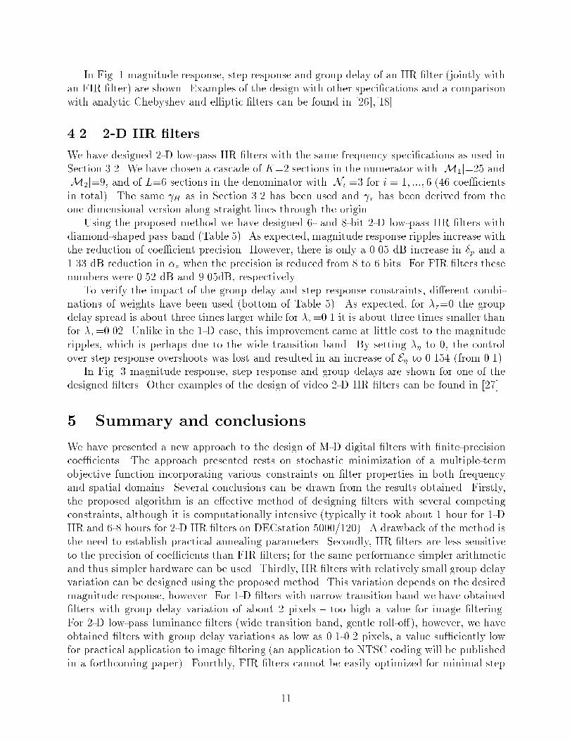
In Fig. 1 magnitude response, step response and group delay of an IIR �lter (jointly withan FIR �lter) are shown. Examples of the design with other speci�cations and a comparisonwith analytic Chebyshev and elliptic �lters can be found in [26],[18].4.2 2-D IIR �ltersWe have designed 2-D low-pass IIR �lters with the same frequency speci�cations as used inSection 3.2. We have chosen a cascade of K=2 sections in the numerator with jM1j=25 andjM2j=9, and of L=6 sections in the denominator with jNij=3 for i = 1; :::; 6 (46 coe�cientsin total). The same H as in Section 3.2 has been used and � has been derived from theone dimensional version along straight lines through the origin.Using the proposed method we have designed 6- and 8-bit 2-D low-pass IIR �lters withdiamond-shaped pass band (Table 5). As expected, magnitude response ripples increase withthe reduction of coe�cient precision. However, there is only a 0.05 dB increase in �p and a1.33 dB reduction in �s when the precision is reduced from 8 to 6 bits. For FIR �lters thesenumbers were 0.52 dB and 9.05dB, respectively.To verify the impact of the group delay and step response constraints, di�erent combi-nations of weights have been used (bottom of Table 5). As expected, for ��=0 the groupdelay spread is about three times larger while for ��=0.1 it is about three times smaller thanfor ��=0.02. Unlike in the 1-D case, this improvement came at little cost to the magnituderipples, which is perhaps due to the wide transition band. By setting �� to 0, the controlover step response overshoots was lost and resulted in an increase of E� to 0.154 (from 0.1).In Fig. 3 magnitude response, step response and group delays are shown for one of thedesigned �lters. Other examples of the design of video 2-D IIR �lters can be found in [27].5 Summary and conclusionsWe have presented a new approach to the design of M-D digital �lters with �nite-precisioncoe�cients. The approach presented rests on stochastic minimization of a multiple-termobjective function incorporating various constraints on �lter properties in both frequencyand spatial domains. Several conclusions can be drawn from the results obtained. Firstly,the proposed algorithm is an e�ective method of designing �lters with several competingconstraints, although it is computationally intensive (typically it took about 1 hour for 1-DIIR and 6-8 hours for 2-D IIR �lters on DECstation 5000/120). A drawback of the method isthe need to establish practical annealing parameters. Secondly, IIR �lters are less sensitiveto the precision of coe�cients than FIR �lters; for the same performance simpler arithmeticand thus simpler hardware can be used. Thirdly, IIR �lters with relatively small group delayvariation can be designed using the proposed method. This variation depends on the desiredmagnitude response, however. For 1-D �lters with narrow transition band we have obtained�lters with group delay variation of about 2 pixels { too high a value for image �ltering.For 2-D low-pass luminance �lters (wide transition band, gentle roll-o�), however, we haveobtained �lters with group delay variations as low as 0.1-0.2 pixels, a value su�ciently lowfor practical application to image �ltering (an application to NTSC coding will be publishedin a forthcoming paper). Fourthly, FIR �lters cannot be easily optimized for minimal step11
response overshoots; any reduction in such overshoots is re ected in dramatically increasederrors in the magnitude response. In fact, we have obtained several 1-D and 2-D FIR�lters with small overshoots (0.07 to 0.09) only to discover unacceptably high errors in themagnitude response. This trade-o� is less severe for IIR �lters since any reduction in stepresponse overshoots is re ected jointly in magnitude and group delay errors. Thus, dependingon the �lter application, a suitable use of weights � may place the unwanted error in a lesscrucial property of the �lter. Finally, the step response error used in this paper may not bethe most appropriate one if ringing visibility at sharp image transitions is a concern. Wehave tested the designed �lters on several images and we have concluded that the largestovershoot is not always the most objectionable artifact. Often the dominant role is playedby the second largest overshoot and by the extent of ringing. Thus, the step response errorneeds to be further investigated to better match properties of the HVS.References[1] P. Agathoklis, E. Jury, and M. Mansour, \The margin of stability of 2-D linear discretesystems," IEEE Trans. Acoust. Speech Signal Process., vol. ASSP-30, pp. 869{873, Dec.1982.[2] S. Aly and M. Fahmy, \Design of two-dimensional recursive digital �lters with speci�edmagnitude and group delay characteristics," IEEE Trans. Circuits Syst., vol. CAS-25,pp. 908{916, Nov. 1978.[3] L. Banzato, N. Benvenuto, and G. Cortelazzo, \A design technique for two-dimensionalmultiplierless FIR �lters for video applications," IEEE Trans. Circuits Syst. Video Tech-nol., vol. 2, pp. 273{284, Sept. 1992.[4] K. Benson, Television Engineering Handbook, ch. 21. McGraw-Hill, Inc., 1986.[5] N. Benvenuto, M. Marcesi, and A. Uncini, \Applications of simulated annealing for thedesign of special digital �lters," IEEE Trans. Signal Process., vol. 40, pp. 323{332, Feb.1992.[6] N. Benvenuto and M. Marchesi, \Digital �lter design by simulated annealing," IEEETrans. Circuits Syst., vol. CAS-36, pp. 459{460, Mar. 1989.[7] A. Biasiolo, G. Cortelazzo, and G. Mian, \Computer aided design of multidimensionalFIR �lters for video applications," IEEE Trans. Consum. Electron., vol. 35, pp. 290{295,Aug. 1989.[8] F. Catthoor and H. de Man, \Simulated-annealing-based optimization of coe�cient anddata word-lengths in digital �lters," Int. J. Circuit Theory and Appl., vol. 16, pp. 371{390, 1988.[9] J.-B. Chartier, \Traitement num�erique des signaux pour la transmission des s�equencesvid�eo: impact de la phase non-lin�eaire," Tech. Rep. 93{01, INRS-T�el�ecommunications,Jan. 1993.[10] A. Chottera and G. Jullien, \Design of two-dimensional recursive digital �lters usinglinear programming," IEEE Trans. Circuits Syst., vol. CAS-29, pp. 817{826, Dec. 1982.[11] E. Diethorn and D. Munson, \Finite word length FIR digital �lter design using simulatedannealing," in Proc. IEEE Int. Symp. Circuits and Systems, pp. 217{220, May 1986.[12] E. Dubois and W. Schreiber, \Improvements to NTSC by multidimensional �ltering,"SMPTE J., vol. 97, pp. 446{463, June 1988.[13] D. E. Dudgeon and R. M. Mersereau,Multidimensional Digital Signal Processing. Pren-tice Hall, 1984. 12
[14] S. Geman and D. Geman, \Stochastic relaxation, Gibbs distributions, and the Bayesianrestoration of images," IEEE Trans. Pattern Anal. Machine Intell., vol. PAMI-6,pp. 721{741, Nov. 1984.[15] T. Huang, J. Burnett, and A. Deczky, \The importance of phase in image processing�lters," IEEE Trans. Acoust. Speech Signal Process., vol. ASSP-23, pp. 529{542, Dec.1975.[16] S. Kirkpatrick, C. Gelatt Jr., and M. Vecchi, \Optimization by simulated annealing,"Science, vol. 220, pp. 671{680, May 1983.[17] D. Kodek, \Design of optimal �nite wordlength FIR digital �lters using integer program-ming techniques," IEEE Trans. Acoust. Speech Signal Process., vol. ASSP-28, pp. 304{308, June 1980.[18] J. Konrad, J. Radecki, and E. Dubois, \On the design of �nite wordlength IIR �ltersfor video applications," in Proc. IEEE Int. Conf. Acoustics Speech Signal Processing,pp. IV.341{IV.344, Mar. 1992.[19] G. Lampropoulos and M. Fahmy, \A new technique for the design of two-dimensionalFIR and IIR �lters," IEEE Trans. Acoust. Speech Signal Process., vol. ASSP-33,pp. 268{280, Feb. 1985.[20] T. Lin, M. Kawamata, and T. Higuchi, \Design of 2-D digital �lters with an arbitraryresponse and no over ow oscillations based on a new stability condition," IEEE Trans.Circuits Syst., vol. CAS-34, pp. 113{126, Feb. 1987.[21] M. Manry and J. Aggarwal, \The measurement of phase distortion due to �ltering indigital pictures," IEEE Trans. Acoust. Speech Signal Process., vol. ASSP-25, pp. 534{541, Dec. 1977.[22] N. Metropolis, A. Rosenbluth, M. Rosenbluth, H. Teller, and E. Teller, \Equation ofstate calculations by fast computing machines," J. Chem. Phys., vol. 21, pp. 1087{1092,June 1953.[23] V. Ouvrard and P. Siohan, \Design of two-dimensional video �lters with spatial con-straints," in Signal Process. VI: Theories and Applications (Proc. Sixth European SignalProcess. Conf.), pp. 1001{1004, Aug. 1992.[24] L. Rabiner and B. Gold, Theory and Application of Digital Signal Processing. Prentice-Hall, 1975.[25] J. Radecki, J. Konrad, and E. Dubois, \A comparison of simulated annealing and N-step Newton methods for designing 1-D and 2-D �nite wordlength FIR �lters," in Proc.Canadian Conf. Electr. Comp. Eng., pp. 53.3.1{53.3.4, Sept. 1990.[26] J. Radecki, J. Konrad, and E. Dubois, \Design of �nite wordlength IIR �lters withprescribed magnitude, group delay and stability properties using simulated annealing,"in Proc. IEEE Int. Conf. Acoustics Speech Signal Processing, pp. 1637{1640, May 1991.[27] J. Radecki, J. Konrad, and E. Dubois, \Design of �nite wordlength 2-D IIR �lters usingsimulated annealing," in Signal Process. VI: Theories and Applications (Proc. SixthEuropean Signal Process. Conf.), pp. 953{956, Aug. 1992.[28] Y. Wan and M. Fahmy, \N-dimensional symmetries and their applications in digital�lters," Signal Process., vol. 19, pp. 103{117, 1990.[29] J. Woods, J.-H. Lee, and I. Paul, \Two-dimensional IIR �lter design with magnitudeand phase error criteria," IEEE Trans. Acoust. Speech Signal Process., vol. ASSP-31,pp. 886{893, Aug. 1983. 13

Financial support:This work was supported by the Natural Sciences and Engineering Research Council ofCanada under Operating Grant OGP0121619.List of footnotes1. Coe�cients of a computer-designed �lter are always expressed by a �nite number ofbits. However, a 32- or 64-bit oating point number can be considered as a full precisionvalue when compared, for example, with its 8-bit �xed-point approximation.2. Frequency ! is considered normalized with respect to the sampling frequency.3. By a full-precision design wemean optimization using double-precision (64 bits) oating-point arithmetic.List of table captionsTable 1 1-D low-pass linear-phase FIR �lters (K=1, jMj=49) designed using SA and N -stepNewton minimization. Note that for 1-D linear-phase FIR �lters E�� = E+� .Table 2 2-D low-pass linear-phase FIR �lters with diamond-shaped pass band (K=1, jMj=165;15 coe�cients per line, 11 lines) designed using SA and N -step Newton minimization.Table 3 1-D low-pass IIR �lters (K=L=5, jMij=3, jNij=2, i = 1; :::; 5) designed using SAwith �s=0.2.Table 4 Impact of stability margin on parameters of 1-D 8-bit IIR �lter designed using SAwith ��=0.125, ��=0.25, and �=0.01.Table 5 2-D low-pass IIR �lters with diamond-shaped pass band (K=2, jM1j=25, jM2j=9;L=6, jNij=2, i = 1; :::; 6) designed using SA with �s=0.02.List of �gure captionsFig. 1 Response of SA-designed 1-D 8-bit FIR (��=0.5) and IIR �lters (��=0.125, �s=0.2,��=0.25): (a) H(!); (b) � (!); (c) �(n).Fig. 2 Response of SA-designed 2-D 8-bit low-pass FIR �lter with diamond-shaped passband (��=0.0): (a) H(!1; !2); (b) �(n1; n2).Fig. 3 Response of SA-designed 2-D 8-bit low-pass IIR �lter with diamond-shaped pass band(��=0.02, �s=0.02, ��=0.2): (a) H(!1; !2); (b) �(n1; n2); (c) �1(!1; !2); (d) �2(!1; !2).
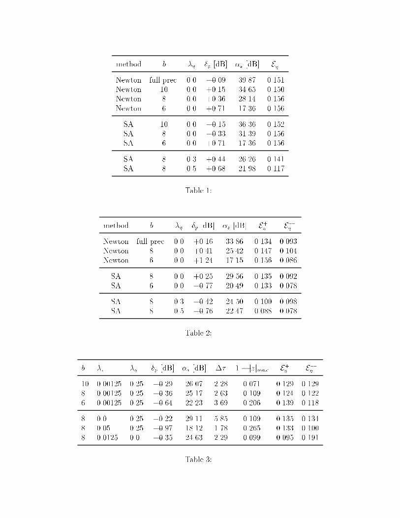
method b �� �p [dB] �s [dB] E+�Newton full prec. 0.0 �0.09 39.87 0.151Newton 10 0.0 +0.15 34.65 0.150Newton 8 0.0 +0.36 28.14 0.156Newton 6 0.0 +0.71 17.36 0.156SA 10 0.0 �0.15 36.36 0.152SA 8 0.0 �0.33 31.39 0.156SA 6 0.0 +0.71 17.36 0.156SA 8 0.3 +0.44 26.26 0.141SA 8 0.5 +0.68 21.98 0.117Table 1:method b �� �p [dB] �s [dB] E+� E��Newton full prec. 0.0 +0.16 33.86 0.134 0.093Newton 8 0.0 +0.41 25.42 0.147 0.104Newton 6 0.0 +1.24 17.15 0.156 0.086SA 8 0.0 +0.25 29.56 0.135 0.092SA 6 0.0 �0.77 20.49 0.133 0.078SA 8 0.3 �0.42 24.50 0.100 0.098SA 8 0.5 �0.76 22.47 0.088 0.078Table 2:b �� �� �p [dB] �s [dB] �� 1 � jzjmax E+� E��10 0.00125 0.25 �0.29 26.07 2.28 0.071 0.129 0.1298 0.00125 0.25 �0.36 25.17 2.63 0.109 0.124 0.1226 0.00125 0.25 �0.64 22.23 3.69 0.206 0.139 0.1188 0.0 0.25 +0.22 29.11 5.85 0.109 0.135 0.1348 0.05 0.25 �0.97 18.12 1.78 0.265 0.133 0.1008 0.0125 0.0 �0.35 24.63 2.29 0.099 0.095 0.191Table 3:
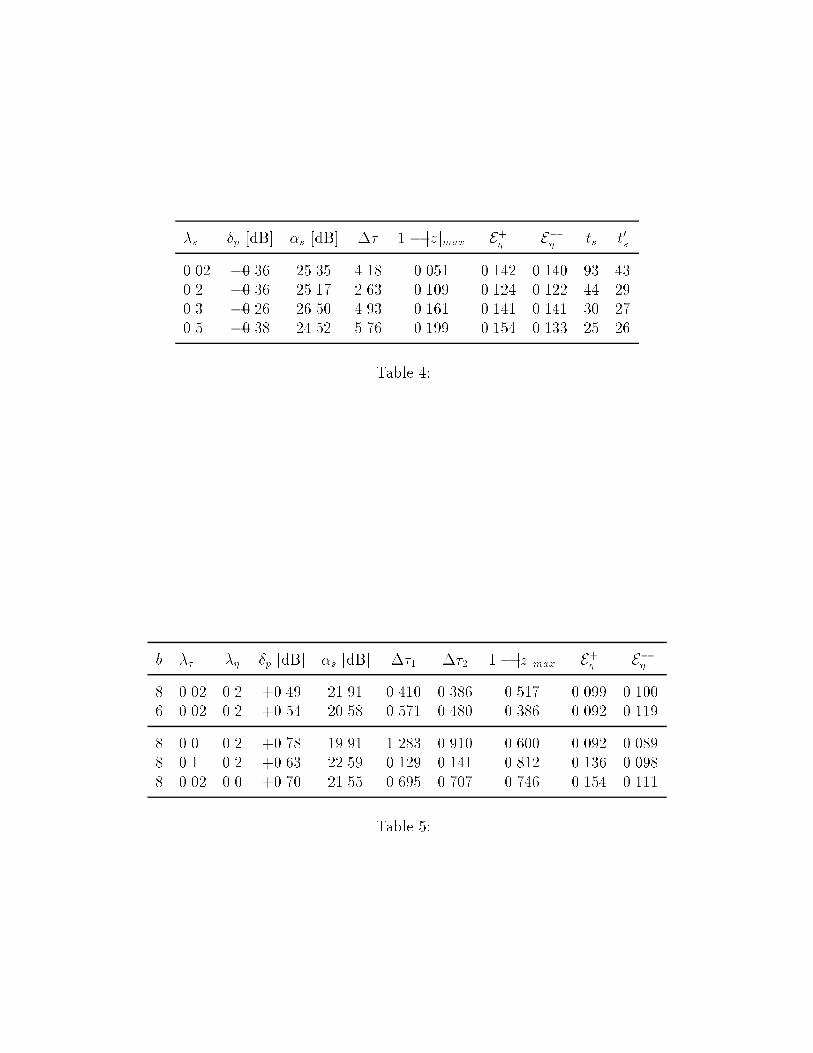
�s �p [dB] �s [dB] �� 1 � jzjmax E+� E�� ts t0s0.02 �0.36 25.35 4.18 0.051 0.142 0.140 93 430.2 �0.36 25.17 2.63 0.109 0.124 0.122 44 290.3 �0.26 26.50 4.93 0.161 0.141 0.141 30 270.5 �0.38 24.52 5.76 0.199 0.154 0.133 25 26Table 4:b �� �� �p [dB] �s [dB] ��1 ��2 1� jzjmax E+� E��8 0.02 0.2 +0.49 21.91 0.410 0.386 0.517 0.099 0.1006 0.02 0.2 +0.54 20.58 0.571 0.480 0.386 0.092 0.1198 0.0 0.2 +0.78 19.91 1.283 0.910 0.600 0.092 0.0898 0.1 0.2 +0.63 22.59 0.129 0.141 0.812 0.136 0.0988 0.02 0.0 +0.70 21.55 0.695 0.707 0.746 0.154 0.111Table 5:
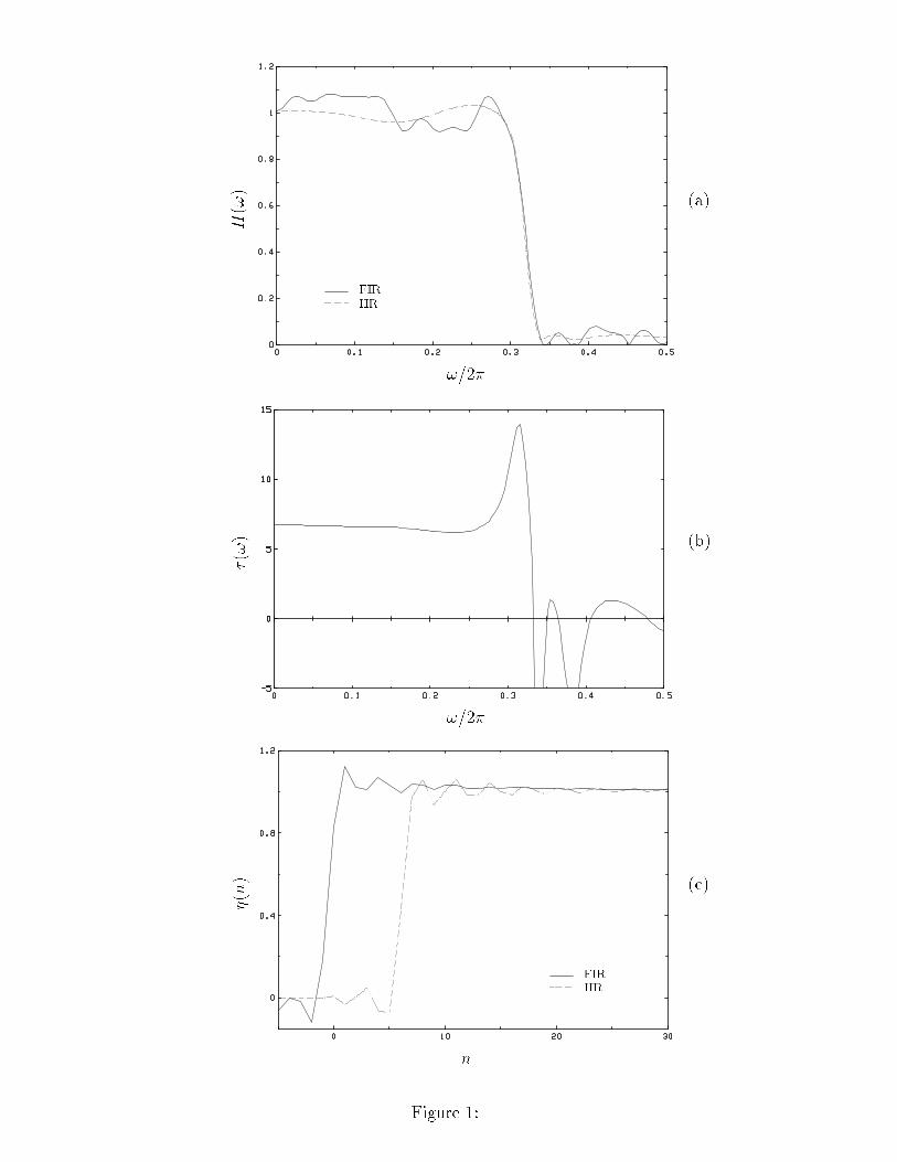
H(!) !=2�FIRIIR (a)�(!) !=2�
(b)�(n) n FIRIIR (c)
Figure 1:
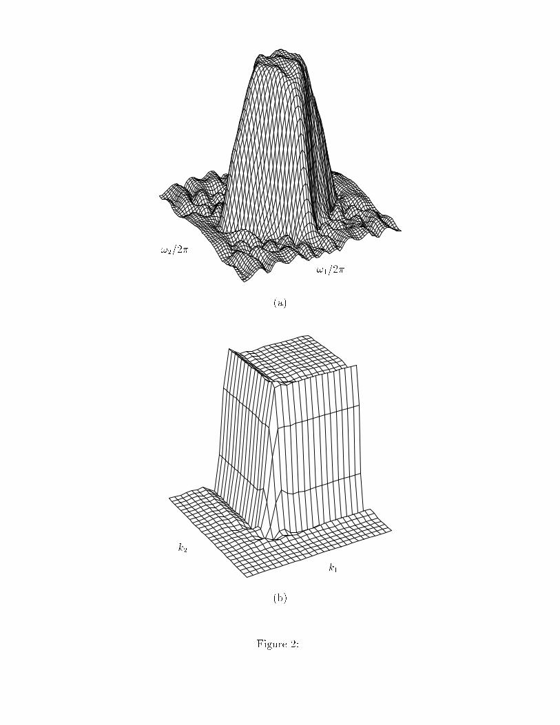
!1=2�!2=2� (a)k1k2 (b)Figure 2:
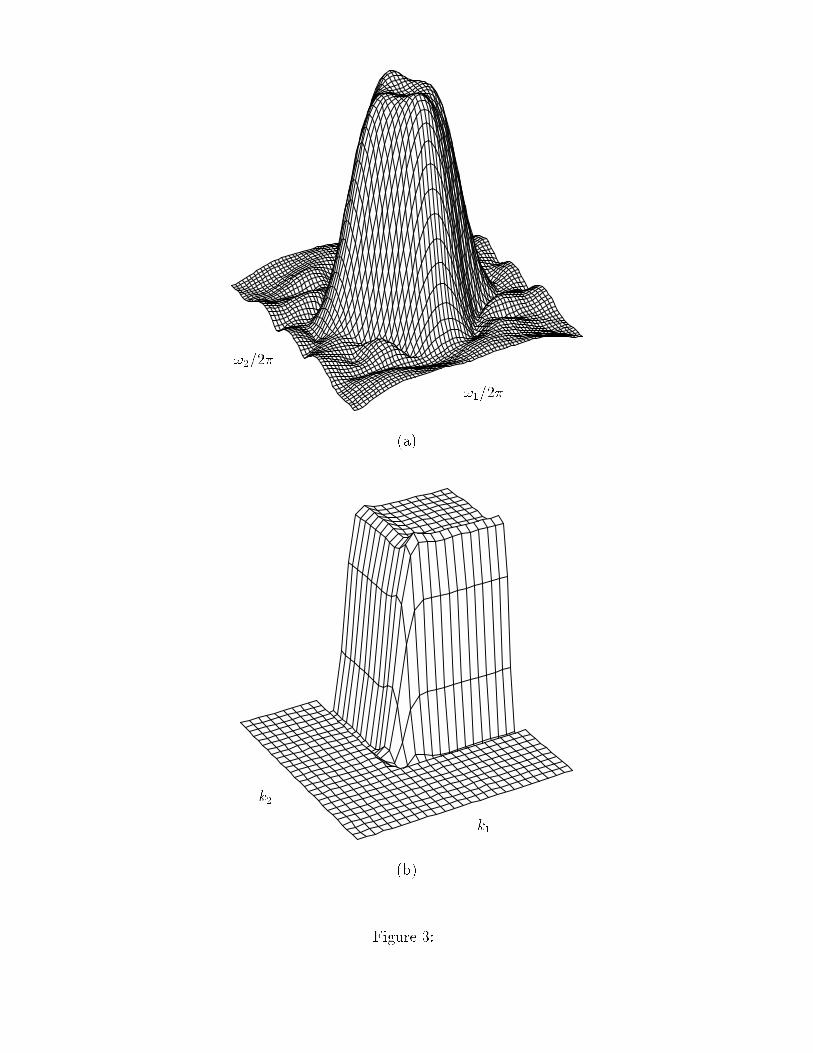
!1=2�!2=2� (a)k1k2 (b)Figure 3:
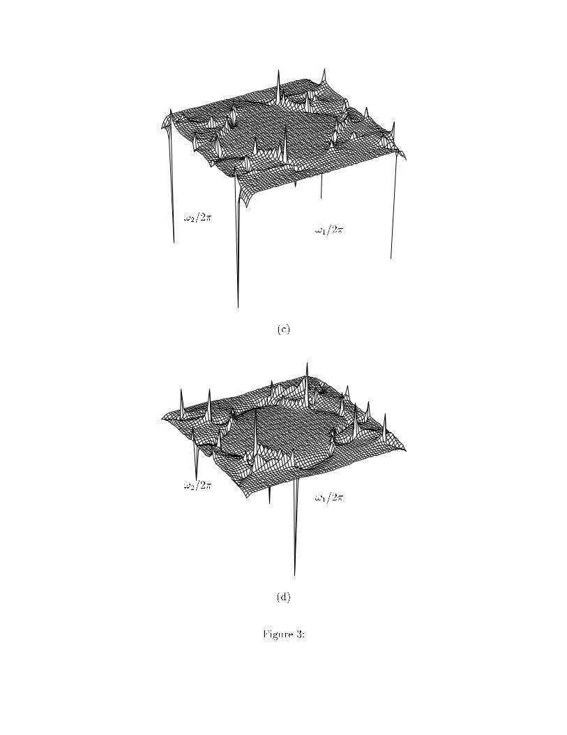
!1=2�!2=2� (c)!1=2�!2=2� (d)Figure 3: