Design of FIR filters in the complex domain
10
144 Design IEEE TRANSACTIONS ON ACOUSTICS, SPEECH, AND SIGNAL PROCESSING, VOL. ASSP-35, NO. 2, FEBRUARY 1987 of FIR Filters in the Complex Domain XIANGKUN CHEN AND THOMAS W. PARKS, FELLOW, IEEE Abstract-The design of FIR digital filters with a complex-valued de- siredfrequencyresponseusingtheChebysheverror is investigated. The complex approximation problem is converted into a real approx- imation problem which is nearly equivalent to the complex problem. A standard linear programming algorithm for the Chebyshev solution of overdetermined equations is used to solve the real approximation problem. Additional constraints are introduced which allow weighting of the phase and/or group delay of the approximation. Digital filters are designed which have nearly constant group delay in the passbands. The desired constant group delay which gives the minimum Chebyshev error is found to be smaller than that of a linear phase filter of the same length. These filters, in addition to having a smaller, approximately constant group delay, have better magnitude characteristics than exactly linear phase filters with the same length. The filters have nearly equiripple magnitude and group delay. I. INTRODUCTION T HE frequency response of an FIR digital filter is a complex-valued function of the normalized frequency f: N- 1 H(f) = h(n) e-jzTfn. n=O If the filter has symmetric real coefficients and is thus ex- actly linear phase, the frequency response can be written where the function G(f) is a real-valued function of fre- quency [I]. For an odd length N, with the symmetry h(n) = h(-n), (N - 1112 ~ ( f ) = C g(n) cos 2 r h . (1.3) The design of linear phase filters using the Chebyshev er- ror criterion may thus be formulated as a real approxi- mation problem. A real-valued desired function is ap- proximated using a weighted sum of cosine functions [I]. There is often a need to design digital filters with other than exactly linear phase. The linear phase filter has a constant group delay for all frequencies, but the delay is (N - 1)/2 samples. Filters with sharp cutoffs (short tran- sition bands) require large values of N and, therefore, large delays. Minimum phase FIR filters, which can also Manuscript received September 9, 1985; revised December 16, 1985. This work was supported by the National Science Foundation under Grant X. Chen was with the Department of Electricaland Computer Engi- neering, Rice University, Houston, TX. He is now with the Department of Engineering, University of Denver, Denver, CO 80208. T. W. Parks was with the Department of Electrical and Computer En- gineering, Rice University, Houston, TX. He is now with the School of Electrical Engineering, Cornel1 University, Ithaca, NY 14853. n=O ECS 83-14006. IEEE Log Number 861 1153. be designed using approximations of real-valued func- tions [2], cause less delay, but introduce delay distortion because the delay is not a constant for all frequencies. In order to design filters which have less delay than linear phase filters and have approximately constant delay in the filter passband, a complex approximation problem must be solved. The complex approximation problem also arises in the design of FIR equalizers [3] and in the con- trol of beam patterns for nonuniformly spaced arrays of sensors [4]. The general complex approximation problem may be stated in terms of C(Z), a normed space of complex-val- ued continuous functions on a compact subset Z of the complex plane, with the Chebyshev norm 1) Itm. With D(z) and ~&(z), i = 1, 2, * - * , n, fixed, given functions in C(2) and for any set of n complex parameters h = {hl, h2, * * 3 hll, let n H(h, z> = hi4i(z). (1.4) The linear complex approximation problem with Che- byshev norm is to determine an optimal set of parameters h* such that I)D - H(h*, z)IIco I llD - H(h, z)llrn for all h. (1.5) Several approaches have been suggested to solve this problem for FIR digital filter design. Johnson [5] indi- cated that a nonoptimal design can be calculated in the cepstrum domain. This method cannot be applied for dig- ital filters with a desired value of zero in the stopband, since then the cepstrum is infinite. Cortelazzo and Light- ner [7] applied a multiple criterion optimization technique to design both FIR and IIR digital filters to approximate the specified magnitude, phase, or group delay. They re- ported that their method is only reliable for the design of IIR digital filter with degree not higher than five and the design of FIR digital filters with length not longer than ten. Their method [7] also requires considerable comput- ing time. Separate approximation of real and imaginary parts of FIR digital filters has been proposed [3]. The problem is a 3 dB deviation from the true best approxi- mation. Moreover, the errors of magnitude and phase (or group delay) cannot be adjusted by this method. Steiglitz [3] proposed a method for designing FIR all-pass phase equalizers by linear programming. He also considered an idea of adding linear constraints for the approximation of zero magnitude. There are several papers describing the general approx- imation problem. Rivlin and Shapiro [lo], [ 141, [23] have i= 1 0096-3518/87/0200-0144$01 .OO 0 1987 IEEE
-
Upload
walsallcollege -
Category
Documents
-
view
0 -
download
0
Transcript of Design of FIR filters in the complex domain

144
Design IEEE TRANSACTIONS ON ACOUSTICS, SPEECH, AND SIGNAL PROCESSING, VOL. ASSP-35, NO. 2, FEBRUARY 1987
of FIR Filters in the Complex Domain XIANGKUN CHEN AND THOMAS W. PARKS, FELLOW, IEEE
Abstract-The design of FIR digital filters with a complex-valued de- sired frequency response using the Chebyshev error is investigated. The complex approximation problem is converted into a real approx- imation problem which is nearly equivalent to the complex problem. A standard linear programming algorithm for the Chebyshev solution of overdetermined equations is used to solve the real approximation problem. Additional constraints are introduced which allow weighting of the phase and/or group delay of the approximation.
Digital filters are designed which have nearly constant group delay in the passbands. The desired constant group delay which gives the minimum Chebyshev error is found to be smaller than that of a linear phase filter of the same length. These filters, in addition to having a smaller, approximately constant group delay, have better magnitude characteristics than exactly linear phase filters with the same length. The filters have nearly equiripple magnitude and group delay.
I. INTRODUCTION
T HE frequency response of an FIR digital filter is a complex-valued function of the normalized frequency
f: N - 1
H ( f ) = h(n) e-jzTfn. n = O
If the filter has symmetric real coefficients and is thus ex- actly linear phase, the frequency response can be written
where the function G ( f ) is a real-valued function of fre- quency [I]. For an odd length N , with the symmetry h(n) = h(-n),
(N - 1112
~ ( f ) = C g(n) cos 2 r h . (1.3)
The design of linear phase filters using the Chebyshev er- ror criterion may thus be formulated as a real approxi- mation problem. A real-valued desired function is ap- proximated using a weighted sum of cosine functions [ I ] .
There is often a need to design digital filters with other than exactly linear phase. The linear phase filter has a constant group delay for all frequencies, but the delay is ( N - 1)/2 samples. Filters with sharp cutoffs (short tran- sition bands) require large values of N and, therefore, large delays. Minimum phase FIR filters, which can also
Manuscript received September 9, 1985; revised December 16, 1985. This work was supported by the National Science Foundation under Grant
X . Chen was with the Department of Electrical and Computer Engi- neering, Rice University, Houston, TX. He is now with the Department of Engineering, University of Denver, Denver, CO 80208.
T. W. Parks was with the Department of Electrical and Computer En- gineering, Rice University, Houston, TX. He is now with the School of Electrical Engineering, Cornel1 University, Ithaca, NY 14853.
n = O
ECS 83-14006.
IEEE Log Number 861 1153.
be designed using approximations of real-valued func- tions [2], cause less delay, but introduce delay distortion because the delay is not a constant for all frequencies. In order to design filters which have less delay than linear phase filters and have approximately constant delay in the filter passband, a complex approximation problem must be solved. The complex approximation problem also arises in the design of FIR equalizers [3] and in the con- trol of beam patterns for nonuniformly spaced arrays of sensors [4].
The general complex approximation problem may be stated in terms of C(Z), a normed space of complex-val- ued continuous functions on a compact subset Z of the complex plane, with the Chebyshev norm 1 ) I t m . With D(z) and ~ & ( z ) , i = 1, 2, * - * , n, fixed, given functions in C(2) and for any set of n complex parameters h = { h l , h2, * * 3 hll, let
n
H(h, z> = hi4i(z). (1.4)
The linear complex approximation problem with Che- byshev norm is to determine an optimal set of parameters h* such that
I)D - H(h*, z)IIco I llD - H(h, z)llrn for all h. (1.5)
Several approaches have been suggested to solve this problem for FIR digital filter design. Johnson [ 5 ] indi- cated that a nonoptimal design can be calculated in the cepstrum domain. This method cannot be applied for dig- ital filters with a desired value of zero in the stopband, since then the cepstrum is infinite. Cortelazzo and Light- ner [7] applied a multiple criterion optimization technique to design both FIR and IIR digital filters to approximate the specified magnitude, phase, or group delay. They re- ported that their method is only reliable for the design of IIR digital filter with degree not higher than five and the design of FIR digital filters with length not longer than ten. Their method [7] also requires considerable comput- ing time. Separate approximation of real and imaginary parts of FIR digital filters has been proposed [3]. The problem is a 3 dB deviation from the true best approxi- mation. Moreover, the errors of magnitude and phase (or group delay) cannot be adjusted by this method. Steiglitz [3] proposed a method for designing FIR all-pass phase equalizers by linear programming. He also considered an idea of adding linear constraints for the approximation of zero magnitude.
There are several papers describing the general approx- imation problem. Rivlin and Shapiro [lo], [ 141, [23] have
i = 1
0096-3518/87/0200-0144$01 .OO 0 1987 IEEE
CHEN AND PARKS: DESIGN OF FIR FILTERS IN COMPLEX DOMAIN 145
shown that a best Chebyshev approximation is also a best least square approximation with a suitable weighting function. If the corresponding weighting function and the extremal set are known, it is easy to compute best linear complex Chebyshev approximation by I, approximation. In 1961 , Lawson proposed a fundamental algorithm for computing the best Chebyshev approximation by means of a weighted lp approximation (p < 00) [13]. The Law- son algorithm is a recursive procedure for seeking this suitable weighting function and the extremal set. It has been reported [14] that this algorithm converges very slowly. In practice, it is hard to establish a rule for ter- mination of the recursive procedure [13]. Fisher [6] ap- plied the Lawson algorithm to design FIR filters to ap- proximate arbitrary complex frequency domain spec- ifications. But this algorithm appeared not to work well
More efforts have been focused on transforming the ap- proximation problem in the complex domain into a prob- lem in the real domain. Generally, the linear Chebyshev approximation of a complex-valued function is equivalent to a nonlinear Chebyshev approximation problem in the real domain since the error in the complex domain ((Ref)' + (Ime)2)1'2 is a nonlinear function of the real and imag- inary parts of the error, Ree and Ime.
Barrodale et al. [17] proposed a method which mini- mizes the square of the Chebyshev error. By means of a Taylor expansion, the problem is linearized. Then a so- lution is found by the linear programming algorithm 495 in Barrodale et al. [lS]. The solution up to this point has a large error since the model itself is not accurate because of the Taylor expansion. A perturbation method is used to refine the solution. However, the perturbation method may fail even for a small-dimensional problem [4].
Glashoff et al. [ l l ] and Streit and Nuttall [4], [12] in- dependently proposed a discretization method to convert the approximation problem in the complex domain into a linear problem in the real domain. Glashoff-Roleff s pro- cedure uses the solution of their linear problem as an ini- tial vector for nonlinear Newton-Raphson iteration. Be- cause the initial vector may not be good, the Newton- Raphson iteration may not converge or may converge to an incorrect result. Streit-Nuttall's procedure directly finds the Chebyshev solution of a set of overdetermined linear equations by the linear programming algorithm 495 [ 181. Algorithm 495 is a stable procedure and does not require an initial guess. A drawback of this method is that the program is large and requires considerable computing time. However, we can still design reasonable length fil- ters with this method.
In this paper, the approximation method proposed by Glashoff et al. and Streit et al. will be applied to FIR filters to approximate arbitrary complex frequency do- main specifications. This method will be extended to a linear constrained approximation problem for designing FIR digital filters with very small error in the passband group delay. It is found that the optimal FIR digital filters with a linear phase requirement only in the passbands can
[61.
have both less magnitude error and a smaller, approxi- mately constant group delay than the conventional opti- mal linear phase FIR digital filters. Examples of this new kind of approximately linear phase FIR digital filter are presented.
11. PROBLEM FORMULATION, EXISTENCE, UNIQUENESS
coefficient FIR filter with a transfer function We now consider the problem of designing a complex
N - 1
H(z) = h(n) z - ~ . (2.1)
Let D(ejZTf) be the desired complex valued frequency re- sponse over the set F = U:=, Fi, Fi = [hi - &]. The design problem is to find the optimal complex coefficient FIR filter (2.1) such that the weighted Chebyshev error is minimized; i.e., the coefficient vector h E C N is to be chosen to minimize
n = O
max ~ ( f ) 1 D(ej'"f) - H(ejZTf)( (2 4
where h = (h(O), h(l), * , h(N - l ) ) T , and W(f) is a positive weighting function.
The existence and uniqueness of a solution to (2.2) has been established in [22, p. 941 and [ lo , p. 671.
A theorem characterizing the best Chebyshev approxi- mation in terms of extremal frequencies is due to Rivlin and Shapiro.
Theorem 2.2 (Rivlin and Shapiro) [lo], [14], [23]: H(z) is a best Chebyshev approximation to D(z) if and only if there are r points z l , z2 , * - , 2,. E Z, and r positive num- bers X I , Xz, - , X r , C X i = 1 , r ~ 2 N + 1 ( r r N + 1 in the real case), for which
feF
r
X k [ D ( Z k ) - H ( Z k ) l d ) i ( z k ) = 0, k= 1
i = 1 , 2 , 3 N, (2.3)
where the extremal set is denoted by
Zo = ( z : ID(z) - & ) I = IID - HIIm, z EZ) . (2.4)
This theorem indicates that the number of extremal points is, at most, 2N + 1. When the basis forms a Che- byshev system, the number of extremal points is at least N + 1 [20, p. 261. Hence, the number of extremal points for the problem in (2.2) lies between N $. 1 and 2N + 1. The exact number is unknown.
In many applications, the desired frequency response has the property
(2.5) Meinardus [9, p. 271 proved that if the desired function has the property (2.5), the optimal complex approxima- tion of the form (2.1) will have real coefficients. Streit and Nuttall [4] speculated about this property. We shall only consider the design problem (2.2) for D(z) satisfying (2.5) with coefficients h being real. All the theorems men- tioned in this section are still valid for the approximation
D(,-jZrf) = p y e j 2 " f ) .
146 IEEE TRANSACTIONS ON ACOUSTICS, SPEECH, AND SIGNAL PROCESSING, VOL. ASSP-35, NO. 2 , FEBRUARY 1987
problem (2.2) formulated only for real coefficients be- cause of our assumption of (2.5).
The design problem (2.2) is equivalent, for a desired response (2.5), to the problem minimizing 6 , subject to 6 2 0, so that
for f E F and real h. (2.6)
This form of the problem statement is converted to the standard form of the linear programming problem in the next section.
111. FROM COMPLEX TO REAL APPROXIMATION It is easy to see that the linear complex approximation
problem in the complex domain is a nonlinear optimiza- tion problem in the real domain, since for w = x + j y , Iw 1 = ( x 2 + Y ' ) " ~ . However, by introducing a simple transformation as below, it can be converted to a linear optimization problem in the real domain. For any com- plex number w = x + j y , the following equation is true [l l]:
I w I = = rnax {Re (wej2"?> tcT
where T = ( t : -0.5 5 t i 0.5). Let tj = ( j - 1)/2p,j
j y , and let = 1 , 2 , * * . , 2p, where the integer p I 2. Let w = x +
M = max (Re (wej2"'j)}. (3.1) j = I ; . . , Z p
Then [4], [12]
M s IwI I Msec ( 3 (3.2) However, A4 in (3.1) is not a norm, because it does not satisfy I a M I = 1 0 1 IM. It is a quasi-norm [ 121. M will ap- proximate the Chebyshev norm within the error indicated by (3.2). When a sufficiently large p is chosen, the error will be small.
With this transformation, substituting (2.1) into (2.6), we have the following equivalent problem for real h:
min 6 , subject to 6 L 0, so that N - 1
2 h(n) Re {eJ2x''-nf)1} I Re {D(eJ2"f)d2"z} n = O
6 +- W f ) for all (f, t ) E FxT.
Equation (3.3) leads to a linear program with a finite number of variables but an infinite number of side con- ditions. Such a problem is called a semiinfinite program, or Haar program [ 151. There are two methods to solve the problem (3.2). One, suggested in [ll], directly applies the algorithm for solving the semiinfinite problem given by Fahlander [16]. The other method [4], [ l l ] , [12] solves a discrete approximation of the semiinfinite problem by
TABLE I ERROR BOUND OF THE APPROXIMATION
P 16 4 1 8 2 sec(rd2p) 1.005 a 1.020 1.414 ________
dB no4 0.68 I 0.17 3.0
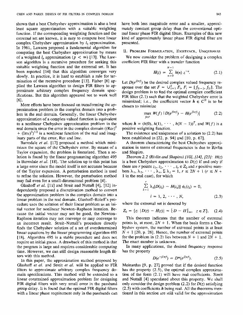
Fig. 1. Approximation of unit circle with an octagon.
linear programming. Barrodale et al. and Streit et al. pointed out that the discrete approximation problem can be solved by finding the Chebyshev solution of an over- determined system of linear equations by a standard al- gorithm using a modified simplex method [4], [ 171, [ 181.
Now we consider discretization of the problem (3.3) [4], [ 111, [ 121. Let S denote a dense discrete set of fre- quencies. We uniformly sample t in (3.3) on 2p points in the interval [ - O S , 0.51, Le.,
Let Td = { t l , t2 , * - , t2,}. With the following notation:
and
1 1 Ellps = min max max Re {Eej2gt)7 (3.4) h € R N f6S tcT
(3.2) implies
Table I shows the relation between the error bound (3.5) and the sample density oft. From this table, we know that when we choose p = 8 for the approximation, the result will have an error different from the error of the best Che- byshev approximation less than 0.17 dB. Fig. 1 shows that for p = 4, (3.4) is equivalent to approximating the circle Iw I = 1 with an octagon. The worst-case signal, which according to Table I has an error of 0.082, is also shown.
Because maxO o.5 1 Re Eej2%' I equals max-0.5 0
JRe 1 , to solve the discretized version of (3.3), we need only consider half the sample points of Td. With
Td+ = {tj/tj E Td, t j I 0},

CHEN AND PARKS: DESIGN OF FIR FILTERS IN COMPLEX DOMAIN 147
the discretized version of problem in (3.3) is to minimize over h E R",
max max IRe {Eej2?rr) 1. (3 4 f e S teT$
With D(ej2"f) = R( f ) + jZ( f ) , the discretized version of (3.3) becomes
N - 1 c h(n) {cos 2anA cos 2ntj + sin 2anA sin 27rtj) n = O
Eij W(A)
= R(A) cos 27rtj - Z(A) sin 2atj + -
for i = 1 , 2 , , m ; j = 1 , 2 , * * * , p . (3.7)
Our problem is to solve equation (3.7) such that rnaxjf 1 ,Eij 1 is minimized. This problem is exactly equivalent to the problem of solving the following overdetermined lin- ear system equations in the Chebyshev sense [4].
Ah = b (3.8)
where
A = [am1 (3.9)
hT = (h(O), h(l) , - * * , h(N - 1)) (3.10)
bT = ( b ( ~ ) , b(l), - 6 , b(mp - 1)) (3.11)
and
b(s) = W ( A ) {R(J;) cos 2atj - Z(A) sin 2x2)) (3.12)
wheres = i + ( j - l ) m - 1, i = 1 , 2, * * - , m , j = 1 , 2, I . . , P , and
as,, = W(A) cos (27rnfi - 27rG) (3.13)
where s, i, j , defined as for b(s), and n = 0, 1 , * - , N - 1.
The design procedure to best approximate the given complex frequency response is as follows.
1) Convert the complex approximation problem to a real problem, deriving the corresponding overdetermined system of linear equations (3.8)-(3.13).
2) Find a Chebyshev solution to these equations using linear programming.
Barrodale et al. [17] proved that if the rank of the coef- ficient matrix A defined by (3.8) is N , then the error of the Chebyshev solution of (3.8) attains its maximum at least N + 1 times. Streit and Nuttall [12] proved that the coefficient matrix in (3.8) is truly rank N . Therefore, the error attains its maximum at least N + 1 times.
Algorithm 495 [18], [19] finds the Chebyshev solution of a system of overdetermined linear equations by apply- ing a modified simplex method to the dual problem. It always converges and does not need an initial guess. The algorithm does not require that the coefficient matrix of the linear equations satisfy the Haar condition and it can indicate whether the Chebyshev solution of the linear equations is unique.
Iv. REDUCING THE ERRORS IN PHASE AND GROUP DELAY
A. The Error Behavior of Magnitude and Phase Responses
For complex Chebyshev approximation, the approxi- mation error in the stopband, where the desired function is zero, is exactly the magnitude error in the stopband. However, neither the error of passband magnitude re- sponse nor the error of passband phase response is rep- resented by the Chebyshev error of the complex approx- imation. We now analyze the error behavior of magnitude response and phase response in the passband. The basic assumption for the analysis is that the Chebyshev error is small.
Assume the error of the linear Chebyshev complex ap- proximation is D(eJ26) - H(ej2"f) = e ( f ) where e ( f ) is real, and I e ( f ) I 5 E, where E is the Chebyshev error of the best approximation. In the passband, the de- sired response D(ej2"f) = ejpd(f) . Denote the filter re- sponse H(eJ2"f) = AH( f ) where pH( f ) = Pd( f ) - e p ( f ) . We have
, i P d ( f ) - ~ ~ ( f ) &Pd+ ep(f)) = e ( f ) , M f )
l.e., 1 -
Since E is small, e p ( f ) is small and A H ( f ) is close to unity. Separating the real and the imaginary parts, we have
A H W = 1 - e ( f > cos ( P d ( f ) - W ) ) (4.1)
-jep(f>AH(f> = M f ) sin ( P d ( f > - (4.2) From (4. 1), we have the error of the passband magnitude response
e A f ) = e ( f ) cos ( P d W - 4(f>). (4.3) From (4.2), because of A H ( f ) = 1 forfin the passbands, we have the passband phase error
e P ( f > = - e ( f > sin ( P d ( f > - + ( f ) > . (4*4) Hence, for small Chebyshev error, the errors of both pass- band magnitude and phase are less than or equal to the Chebyshev error E. From (4.3) and (4.4), we also have
e;<f> + e % f ) = e 2 ( f ) . (4.5)
B. Reducing the Errors in Passband Phase and Group Delay
It is desirable to be able to control the error of the pass- band group delay because a constant group delay is an important characteristic to reduce transmission distortion. To reduce the errors in the phase and the group delay ap- proximation, we propose a design method which allows the designer to almost independently choose the weight- ing. functions for the error in the complex Chebyshev ap- proximation, the error in the filter passband phase, and the error in the filter passband group delay; i.e., we pro- vide a flexible design method to permit the adjustment of the errors in these three important parameters.

148 IEEE TRANSACTIONS ON ACOUSTICS, SPEECH, AND SIGNAL PROCESSING, VOL. ASSP-35, NO, 2, FEBRUARY 1987
Generally, the relation between the group delay and the transfer function is nonlinear. We can, however, derive an approximate relation which is linear.
The phase of the FIR filter (3.2) is
N- 1
C h(n) sin 27rnf
(4.6) In the passbands, because the magnitude is nearly unity, this equation can be approximately expressed as
/N - 1
Hence, the error of the passband phase is
/ N - 1 -,
Since the passband phase error is small (cos PH(f) = ZyLd h(n) cos 2nnf), we have
ep(f> sin ep( f>
= E: h(n) sin 27rnf cos P d ( f ) 1 Cr: 1 + C h(n) cos 27rnf sin P d ( f )
N- I
= C h(n) sin (2nnf + pd(f>>. (4.8)
A geometric explanation of (4.8) is given by Fig. 2. It is interesting to note that (4.8) is the same as the phase error approximation used by Steiglitz [3] for designing FIR all-pass phase equalizers. The passband phase of the FIR filter is
n=O
Hence, the group delay in the passbands is
N - 1
where r d ( f ) = - d P d ( f ) / 2 n d f . Thus, we find the linear constraint for minimizing the error of the passband group
x X+YtgB,
Fig. 2. Geometric explanation of the phase error by complex approxima- tion.
delay as N - 1
e7(f> = (n - r,(f))h(n) cos (2nn.f + P d ( f ) ) . n=O
(4.11)
For minimizing the errors in phase or group delay, we choose suitable weighting functions 'for (4.8) and (4.1 1 ) . The values of the weighting function can be estimated from the design without constraints. For example, if the unconstrained design has a Chebyshev error 0.05 for unit weighting and the group delay error is desired to be 0.5 samples, we can choose the weighting function on the group delay error as 0.1 so that the weighted delay error = (0.1)(0.5) = 0.05.
V. DESIGN EXAMPLES AND FILTER PROPERTIES Consider the problem of designing an FIR band-pass
filter with the following desired frequency response: e - j 2 ~ r d f
D(e.j2"f iff E passpands
0 iff E stopbands (5.1)
where r d is the desired group delay in the filter passbands. When the desired group delay 7d is given, the desired
filter is fully defined. When 7d is not specified, a question arises as to what is the best value of desired group delay such that the designed FIR filter will have the smallest approximation error. Since the signal is a discrete se- quence, we will prefer for the group delay to have an in- teger value. This leads to the following problem:
N - 1
min min max
for D ( e j Z T f ) defined as (5.1). Unfortunately, a closed
D ( d Z r f ) - C h(n)z -'
form solution for the best 7 d cannot be found. Fig. 3 shows typical curves of the approximation error
as the function of the desired group delay. The error curves show llEllps in (3.4) with the auxiliary discretiza- tion o f p = 2. Curve A represents the approximation error of the filter of example 1, a length 3 1 filter with the de- sired group delay varying from l to 30. The minimum Chebyshev error does not occur at 7 d = 15, which is the
7 d ~ Z h e R N f 6 F n=O
CHEN AND PARKS: DESIGN OF FIR FILTERS IN COMPLEX DOMAIN 149
0.6 I I I I I I
desired group delay 31
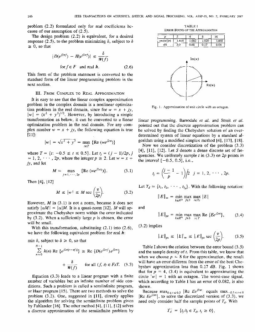
Fig. 3. Relations between the Chebyshev error and the desired group de- lay: curve A : Low-pass FIR (example l); curve E : band-pass FIR (example
2).
group delay of the linear phase FIR filter with the same length. Two minimizers of the Chebyshev error occur when the desired group delay is 12 or 18 (the curve is symmetric). The group delay of 12 is chosen as the de- sired group delay in example l , since it is the smaller delay. For a quite wide range (5-25) of desired group de- lay, the Chebyshev error does not change very quickly. The error does increase very quickly when the required group delay is beyond this range. Curve B represents the approximation error of the filter in example 2, a length 3 1 filter but with a varying group delay. A minimum error also occurs when the desired group delay is set to 12. The Chebyshev error does not change very quickly for a wide range (5-25).
Example 1 : Low-Pass Filter: This example is a low- pass filter with length N = 31, a passband [0, 0.061, and a stopband [0.12, OS]. The passband weighting is 1 and the stopband weighting is 10. We first test the nearly lin- ear phase FIR filters with different desired values of group delay with an auxiliary grid p = 2. From Fig. 3 (curve A ) , we observe that the desired group delay of 12 leads to a minimum error. Withp = 8 and Td = 12, the resulting nearly linear phase FIR filter has = 0.0436 (0.37 dB) and a2 = 0.00436 (47.21 dB). Here, 61 and 62 are the Chebyshev errors for the equations in (3.8). The maxi- mum magnitude of the complex error cannot be more than 0.17 dB greater than these values (see Table I forp = 8).
The complex Chebyshev approximation algorithm needs a large memory space and requires CPU time which increases exponentially with increasing grid density. For this example, with Td = 12, the optimal solution with p = 2 required 117 iterations and a CPU time of 2 min and 44 s, while the solution with p = 8 required 206 iterations and 18 min CPU time on a VAX 11/750. Design experi- ence shows that the best group delay observed for the de- sign based on p = 2 is also the best for p = 8. To find the best group delay, it is wise to first design filters with p = 2, then conduct the final design using p = 8 and the best group delay selected from the design results with p = 2.
The filter coefficients of the nearly linear phase FIR fil- ter are no longer symmetric. The largest value of the im- pulse response is h(12) (corresponding desired group de- lay of 12) instead of h(15) for the linear phase FIR filter. Fig. 4(a) shows the magnitude response of the filter which
is approximately equiripple. There are four passband fre- quency extremals, one more than for the linear phase FIR filter. In almost all the transition band, the phase is nearly linear. Fig. 4(b) shows that the group delay oscillates around 12 samples and has a maximum deviation of 0.97 in the passband and almost all the transition band (assum- ing we also desire the same group delay in the transition band). Fig. 4(c) and (d) shows the trace of the frequency response of the filter. It is easy to see from Fig. 4(d) that there are no zeros on the unit circle because the trace does not cross the zero point. Fig. 4(e) shows the zero pattern of the filter. One real zero is outside the unit circle, and all other zeros are inside the unit circle. Some of the zeros are so close to the unit circle that they appear to be on the unit circle in Fig. 4(e).
The linear phase FIR filter designed by the Remes ex- change method [l] , [8] with the same specification has errors of = 0.0575 (0.49 dB) and A2 = 0.00575 (44.8 dB). The nearly linear phase FIR filter has 2.4 dB im- provement of error compared to the linear phase FIR filter and has a group delay of approximately 12 while the group delay of the linear phase filter is 15. The smaller magni- tude error is paid for by an additional phase distortion. The new filter has a total of 18 extremals, one more than for the linear phase FIR filter. Fig. 4(f) and (8) shows the trace of the frequency response of the linear phase FIR filter. Notice that every circle of the trace corresponds to stopband zeros.
Example 2: Band-Pass Filter: This example is a band- pass filter of length 3 1, with two stopbands [0, 0.11 and E0.33, 0.51, and a passband [0.15, 0.281. The passband weighting is 1 and the stopband weightings are 10. The results of the test designs with p = 2 show that group delay of 12 is the best (curve B in Fig. 3). The refined design with p = 8 takes 153 iterations and about 20 min of CPU time on a VAX 11/750.
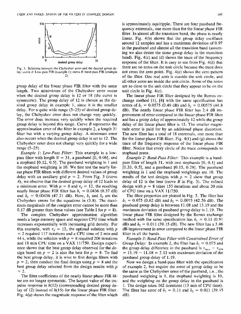
The filter properties are plotted in Fig. 5. The filter has = 0.075 (0.62 dB) and = 0.0075 (42.56 dB). The
passband group delay is between 11.08 and 13.19 and the maximum deviation of passband group delay is 1.19. The linear phase FIR filter designed by the Remes exchange method with the same specification has = 0.11 (0.91 dB) and ti2 = 0.011 (39.15 dB). The new filter has a 3.46 dB improvement in error compared to the linear phase FIR filter in all the bands.
Example 3: Band-Pass Filter with Constrained Error of Group Delay: In example 2 , the filter has 6, = 0.075 and the group delay difference in the passband is T,,, - T , ~ ~
= 13.19 - 11.08 = 2.11 with maximum deviation of the passband group delay of 1.19.
Now we design a bandypass filter with the specification of example 2, but require the error of group delay to be the same as the Chebyshev error ofthe passband, i.e., the passband weighting is 1, the stopband weighting is 10, and the weighting on the group delay in the passband is 1. The design takes 162 iterations (13 min of CPU time). The filter has error of 61 = 0.11 and a2 = 0.011 (39.15 dB).

150 IEEE TRANSACTIONS ON ACOUSTICS, SPEECH, AND SIGNAL PROCESSING, VOL. ASSP-35, NO. 2, FEBRUARY 1987
0 frequency 0.5
(a)
-1.2 real part 1.2
(c)
lS I
0 frequency 0.5
(b)
-1.2 1,,,,,,,,,,,1 -1.2 real part 1.2
0.006 7
Fig. 4. (a) Example 1: Magnitude response (dB). (b) Example 1: Group delay response. (c) Example 1: Trace of the frequency response. (d) Example 1: Trace of the frequency response for the stopband only. (e) Example 1: Zero pattern. (f) Example 1: Trace of frequency response of linear phase FIR filter. (g) Example 1: Trace of frequency response of linear phase FIR filter for the stopband only.
CHEN AND PARKS: DESIGN OF FIR FILTERS IN COMPLEX DOMAIN 151
I I I I 1 10, I I I I
0 frequency 0.5
(a)
0 frequency 0.5
(b)
Fig. 5. Example 2. (a) Magnitude, (b) group delay.
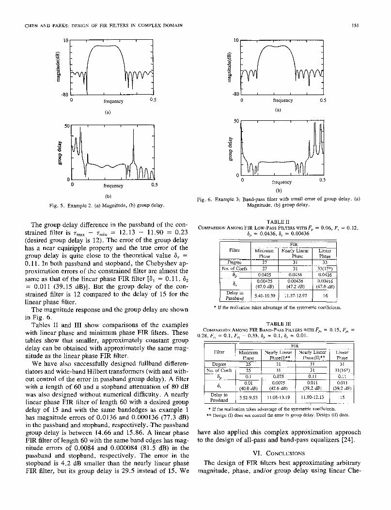
The group delay difference in the passband of the con- strained filter is T,,, - T~~~ = 12.13 - 11.90 = 0.23 (desired group delay is 12). The error of the group delay has a near equiripple property and the true error of the group delay is quite close to the theoretical value 6, = 0.11. In both passband and stopband, the Chebyshev ap- proximation errors of the constrained filter are almost the same as that of the linear phase FIR filter [al = 0.11 , d2 = 0.01 1 (39.15 dB)]. But the group delay of the con- strained filter is 12 compared to the delay of 15 for the linear phase filter.
The magnitude response and the group delay are shown in Fig. 6.
Tables I1 and I11 show comparisons of the examples with linear phase and minimum phase FIR filters. These tables show that smaller, approximately constant group delay can be obtained with approximately the same mag- nitude as the linear phase FIR filter.
We have also successfully designed fullband differen- tiators and wide-band Hilbert transformers (with and with- out control of the error in passband group delay). A filter with a length of 60 and a stopband attenuation of 80 dB was also designed without numerical difficulty. A nearly linear phase FIR filter of length 60 with a desired group
0 frequency 0.5
0 frequency 0.5
(b)
Fig. 6 . Example 3: Band-pass filter with small error of group delay. (a) Magnitude, (b) group delay.
TABLE I1 COMPARISON AMONG FIR LOWPASS FILTERS WITH Fp = 0.06, F, = 0.12,
6, = 0.0436, 6, = 0.00436
Phase Phase Phase _ _ ~ ~ _ _ Degree
33(17*) 31 27 No. of Coefs 33 31 27
6,
6,
0.04 16 0.0436 0.0425 0.00425
(47.0 dB) 0.00416 0.00436
(47.6 dB) (47.2 dl?)
Passband Delay in 16 11.37-12.97 5.41-10.30
* If the realization takes advantage of the symmetric coefficients.
TABLE 111 COMPARISON AMONG FIR BAND-PASS FILTERS WITH Fp, = 0.15, F, =
0.28, F,, = 0.1, Fa = 0.33, 6, = 0.1, 6, = 0.01.
1 Filter I Minimum I Nearly Linear I Nearly Linear I Linear I .. .
delay of 15 and with the same bandedges as example 1 * If the realization takes advantage of the symmetric coefficients.
in the passband and stopband, respectively. <The passband group delay is between 14.66 and 15.86. A linear phase have also applied this complex approximation approach FIR filter of length 60 with the same band edges has mag- to the design of all-pass and band-pass equalizers [24]. nitude errors of 0.0084 and 0.000084 (81.5 dB) in the passband and stopband, respectively. The error in the VI. CONCLUSIONS stopband is 4.2 dB smaller than the nearly linear phase The design of FIR filters best approximating arbitrary FIR filter, but its group delay is 29.5 instead of 15. We magnitude, phase, and/or group delay using linear Che-
has magnitude of 0.0136 and 0.000136 (77.3 dB) ** Design (1) does not Control the error in group delay. Design (11) does.

152 IEEE TRANSACTIONS ON ACOUSTICS, SPEECH, AND SIGNAL PROCESSING, VOL. ASSP-35, NO. 2, FEBRUARY 1987
byshev complex approximation is investigated. The typ- ical error in group delay is less than one or two samples. A method for reducing the phase and/or group delay er- rors by linear constrained approximation is proposed. The error in filter group delay designed by this method can be negligible. The filters have nearly equiripple errors in magnitude, phase, and group delay.
Examples of a class of filters having nearly linear phase only in passbands are presented. The best desired group delay corresponding to the smallest Chebyshev error is smaller than that of the linear phase FIR filter. The nearly linear phase filter can have both smaller group delay and magnitude approximation error than the linear phase filter if a small delay error can be tolerated. With the same filter specification except for group delay, the nearly linear phase FIR filter can have an improvement of several dec- ibels in both passband and stopband magnitude response compared to the linear phase FIR filter at the expense of losing the exact linear phase property and the symmetry of the filter coefficients. For some applications, for ex- ample, when realizing a linear phase FIR filter on TMS 320 microprocessor, the symmetric property of the coef- ficients does not have an advantage in computing time, only in storage [25]. The approximation error of the filters changes only a few decibels when the desired group delay varies over quite a wide range. The nearly linear phase FIR filter usually has no zeros on the unit circle.
The errors in the magnitude and phase responses of the nearly linear phase FIR filters we have designed are ap- proximately equiripple. The error in the passband group delay also appears to be nearly equiripple. The trace of the error is circular as observed by Trefethen [21]. The number of extrema1 frequencies of nearly linear phase FIR filters is equal to or larger than that of the corresponding linear phase FIR filter having the same filter length, band edges, and error weights.
With the auxiliary density p = 8, the design results are very good; with p = 4, the results are still quite good (based on the designs up to length 60); with p = 2, the filter magnitude errors at the frequencies near the band edges appear about 3 dB larger than at other frequencies. This suggests using unequal auxiliary densities, i.e., use p = 8 for the samples near the band edges, and use p = 2 for the other samples.
The complex approximation design of the filter costs CPU time and needs a large memory space. Typical time for designing a filter of length 31 with an auxiliary vari- able p = 8, which requires the Chebyshev solution of about 3000 equations, ranges from 15 to 20 min. As in- dicated in [ 181, using vector transfer ability for multipli- cation between the columns of a matrix can greatly save CPU time.
The error of the group delay in the passband of a nearly linear phase FIR filter can be reduced by a linear con- straint method. Very flat passband group delay can be achieved. The error of the group delay of the filter de-
signed by the constrained method is nearly equiripple and its value is quite close to the desired value.
REFERENCES
[I] J. H. McClellan and T. W. Parks, “A unified approach to the design of optimal FIR linear-phase digital filters,” IEEE Trans. Circuit The-
121 0. Hemnann and H. W. Schuessler, “Design of nonrecursive digital filters with minimum phase,” Electron. Lett., vol. 6, no. 11, pp. 329- 330, May 1970.
[3] K. Steiglitz, “Design of digital phase networks,” IEEE Trans. Acoust., Speech, Signal Processing, vol. ASSP-29, pp. 171-176, 1981.
[4] R. L. Streit and A. H. Nuttall, “A general Chebyshev complex func- tion approximation procedure and an application to beamforming,” J. Acoust. SOC. Amer., vol. 72, pp. 181-190, 1982.
151 A. T. Johnson, Jr., “Simultaneous magnitude and phase equalization using digital filters,” IEEE Trans. Circuits Syst., vol. CAS-25, pp. 319-321, May 1978.
161 J. D. Fisher, “Design of finite impulse response digital filters,” Ph.D. dissertation, Dep. Elec. Eng., Rice Univ., Houston, TX, May 1973.
[7] G. Cortelazzo and M. R. Lightner, “Simultaneous design in both magnitude and delay of IIR and FIR filters based on multiple criterion optimization,” IEEE Trans. Acoust., Speech, Signal Processing, vol.
[8] L. Rabiner and B. Gold, Theory and Applications of Digital Signal Processing. Englewood Cliffs, NJ: Prentice-Hall, 1975.
[9] G. Meinardus, Approximation of Functions: Theory and Numerical Methods. New York: Springer-Verldg, 1967 (translated by L. L. Schumaker).
[lo] T. J. Rivlin, The Chebyshev Polynomials. New York: Wiley, 1974. [I 11 K. Glashoff and K. Roleff, “A new method for Chebyshev approxi-
mation of complex-valued functions,” Math. Comput., vol. 36, pp.
1121 R. L. Streit and A. H. Nuttall, “A note on the semi-infinite program- ming approach to complex approximation,” Math. Comput., vol. 40,
[13] J . R. Rice, The Approximation ofFunctions. Reading, MA: Addi- son-Wesley, 1969.
[14] S. Ellacott and J . Williams, “Linear Chebyshev approximation in the complex plane using Lawson’s algorithm,” Math. Comput., vol. 30, pp. 35-44, 1976.
1151 A. Charnes, W. W. Cooper, and K. 0. Kortanek, “Duality, Haar programs and finite sequence space,” in Proc. Nut. Acad. Sci. U.S.A.,
[ 161 K. Fahlander, “Computer programs for semi-infinite optimization,” Dep. Numer. Anal., Roy. Inst. Technol., TRITA-NA-7312, S-10044, Stockholm 70, Sweden, 1973.
1171 I . Barrodale, L. M. Delves, and J . C. Mason, “Linear Chebyshev approximation of complex-valued functions,” Math. Comput., vol.
[I81 I. Barrodale and C. Phillips, “Solution of an overdetermined system of linear equations in the Chebyshev norm” (Algorithm 4 9 3 , ACM Trans. Math. Software, vol. 1, pp. 264-270, 1975.
1191 -, “An improved algorithm for discrete Chebyshev linear approx- imation,” in Proc. 4th Manitoba Conf. Numer. Math., B. L. Hartnell and H. C. Williams, Eds. (Utilitas Math.), 1975.
[20] G. G . Lorentz, Approximation of Functions. New York: Holt, Rine- hart Winston, 1966.
1211 L. N. Trefethen, “Near circularity of the error curve in complex Che- byshev approximation,” J . Approx. Theory, vol. 31, pp. 344-367, 1981.
[22] G. M. Leibowitz, Lectures on Complex Function Algebras. Glen- view, IL: Scott, Foresman, 1970.
1231 T. J. Rivlin and H. S. Shapiro, “A unified approach to certain prob- lems of approximation and minimization,” J . Soc. Indust. Appl.
[24] X. Chen and T. W. Parks, “Design of optimal FIR filters in the com- plex domain,” ECE Dept., Rice Univ., Houston, TX, Tech. Rep.
ory, V O ~ . CT-20, pp. 697-701, NOV. 1973.
ASSP-32, pp. 949-967, 1984.
233-239, 1981.
pp.599-605,1983.
V O ~ . 4 8 , 1962, pp. 783-786.
32, pp. 853-863, 1978.
Math., V O ~ . 9, pp. 670-699, 1961.
TR 8512, July 1985. 1251 TMS 32010 User’s Guide, Texas Instruments, Houston, TX, 1983.
CHEN AND PARKS: DESIGN OF FIR FILTERS IN COMPLEX DOMAIN 153
Xiangkun Chen was born in Jiangxi, China, on April 29, 1946. He graduated from the Depart- ment of Radio Electronics, University of Science and Technology of China, in 1968. He received the M.S. degree from the Chinese Academy of Sciences in 1981, and the Ph.D. degree from Rice University, Houston, TX, in 1986, both in elec- trical engineering.
From 1970 to 1977 he was with a communi- cation company in Hubei, China, where he con- ducted research and development on consumer
electronic equipment. From 1977 to 1978 he worked with an automobile company in Jiangxi, China, on control and power system design. From 1978 to 1981 he conducted research at the Institute of Automation, Chinese Academy of Sciences, in the area of digital signal processing. In 1980- 1981 he held a WIPO fellowship as a Trainee in the British Patent Office and Mewburn Ellis & Co., London, England. His research interests in- clude digital signal processing, spectrum estimation, and networks and sys- tems theory.
Thomas W. Parks (S’66-M’67-SM’79-F’82) was born in Buffalo, NY, on March 16, 1939. He received the B.E.E., M.S., and Ph.D. degrees from Cornel1 University, Ithaca, NY, in 1961, 1964, and 1967, respectively.
From 1958 through 1961 he participated in a cooperative program with the Cornell Aeronauti- cal Laboratory, Buffalo, NY. From 1961 through 1963 he was with the General Electric Company’s Advanced Electronics Center, Ithaca. He joined Rice University, Houston, TX, in 1967, where he
is a Professor of Electrical Engineering. He is currently engaged in re- search on signal theory and digital signal processing techniques. He has been a Visiting Scientist at the Lincoln Laboratory, Massachusetts Institute of Technology, Lexington, and a Senior Fulbright Fellow. From 1973 to 1974 he was a Visiting Professor at the Institut fur Nachrichtentechnik, Erlangen, Germany, as a recipient of the Alexander von Humboldt Foun- dation Senior Scientist Award. He is a coauthor of a book on the FFT and is completing work on a filter design book.
Dr. Parks has been a member of the ASSP AdCom and has been an Associate Editor for the IEEE TRANSACTIONS ON ACOWTICS, SPEECH, AND SIGNAL PROCESSING. He received the 1981 ASSP Technical Achievement Award.