
Portable Test Equipment - APPLIED PRECISION sro
122
Portable Test Equipment Models PTE 2100 PTE 2300 User’s Guide Version 6.1
-
Upload
khangminh22 -
Category
Documents
-
view
1 -
download
0
Transcript of Portable Test Equipment - APPLIED PRECISION sro

Portable Test Equipment
Models
PTE 2100 PTE 2300
User’s Guide
Version 6.1

Portable Test Equipment User’s Guide
PTE-UGFW61-EN www.appliedp.com 2
Content 1. Safety Considerations and Instructions ...................................................................................... 4
1.1 Safety Specification .................................................................................................................. 4 1.2 Safety Information ..................................................................................................................... 5
2. Introduction ................................................................................................................................... 8 2.1 Device Panel Description .......................................................................................................... 8 2.2 Connectors ............................................................................................................................... 9 2.3 Connector System of Generator .............................................................................................. 11
2.3.1 Power Characteristics of PTE (Generator) ....................................................................... 11 2.4 Connector System of Measuring Accessory ............................................................................ 12
2.4.1 Locking Mechanism ......................................................................................................... 12 2.4.2 Cable Connecting ............................................................................................................ 13 2.4.3 Cable Disconnecting ........................................................................................................ 13
2.5 Standard Package Content ..................................................................................................... 14 2.6 Description of features ............................................................................................................ 14
2.6.1 General Display Layout ................................................................................................... 15 2.6.2 Text Input ........................................................................................................................ 15
2.7 Generator ................................................................................................................................ 16
3. How to Use the Appliance .......................................................................................................... 17 3.1 Initialization ............................................................................................................................. 18 3.2 Basic Screen of Generator ...................................................................................................... 18
3.2.1 Error in generation ........................................................................................................... 20
4. Extended Generator Options ..................................................................................................... 21 4.1 Signal Shapes ......................................................................................................................... 21 4.2 DB Measurements and Tests .................................................................................................. 22
4.2.1 How to create tests .......................................................................................................... 24 4.2.2 How to create measurements .......................................................................................... 26 4.2.3 Running in Automatic Mode ............................................................................................. 27
4.3 General Generator Settings .................................................................................................... 29 4.3.1 Generator Settings .......................................................................................................... 29 4.3.2 Inputs Configuration ........................................................................................................ 31
5. Measuring Mode.......................................................................................................................... 33 5.1 Main Measurement ................................................................................................................. 33
5.1.1 Load Values .................................................................................................................... 33 5.1.2 Actual Values .................................................................................................................. 36 5.1.3 Graphical Presentation .................................................................................................... 39
5.2 Energy Measurement and Test ............................................................................................... 41 5.2.1 Energy Values ................................................................................................................. 41 5.2.2 Dial Test .......................................................................................................................... 42 5.2.3 Maximum Demand Test................................................................................................... 45
5.3 Meter Error Test ...................................................................................................................... 46 5.3.1 Test Result Details .......................................................................................................... 48 5.3.2 Optical Sensor Calibration ............................................................................................... 49
5.4 Constant Detection ................................................................................................................. 50 5.5 Meter Readout ........................................................................................................................ 51 5.6 Transformer Test .................................................................................................................... 51 5.7 Burden Measurement .............................................................................................................. 53 5.8 Menu of Measuring Mode ....................................................................................................... 54
5.8.1 Measurement Settings ..................................................................................................... 55 5.8.2 Test Settings ................................................................................................................... 60 5.8.3 System Settings .............................................................................................................. 63 5.8.4 Information ...................................................................................................................... 65

Portable Test Equipment User’s Guide
www.appliedp.com PTE-UGFW61-EN 3
5.8.5 Menu - Tests & Calibration ............................................................................................... 66 5.9 Databases ............................................................................................................................... 67
5.9.1 Database of Meters .......................................................................................................... 68 5.9.2 Database of Meter Errors ................................................................................................. 69 5.9.3 Database of Snapshots .................................................................................................... 71 5.9.4 Database of Energy tests ................................................................................................. 73 5.9.5 Database of Meter Readouts ........................................................................................... 75 5.9.6 Adding or Editing Meters .................................................................................................. 76 5.9.7 Deleting Database Items .................................................................................................. 78
5.10 Test Report ............................................................................................................................ 79
6. Remote Interface ......................................................................................................................... 81 6.1 Connection to PC .................................................................................................................... 81 6.2 Firmware Upload ..................................................................................................................... 82 6.3 Remote Communication .......................................................................................................... 83
6.3.1 Commands Description .................................................................................................... 83
7. APPENDIX .................................................................................................................................. 109 7.1 Connection Diagrams ............................................................................................................ 110
SINGLE PHASE measuring accessories ................................................................................ 113 TWO PHASE measuring accessories ..................................................................................... 113 THREE PHASE measuring accessories ................................................................................. 114
7.2 Aggregate Energy Calculation Methods ................................................................................. 117 7.3 Overvoltage Categories ......................................................................................................... 118 7.4 Accuracy Verification ............................................................................................................. 118
7.4.1 How to carry out the Accuracy Verification? ................................................................... 118 7.5 Measurement Time ................................................................................................................ 119 7.6 Measurement Error ................................................................................................................ 119 7.7 Maintenance .......................................................................................................................... 120
7.7.1 Regular Maintenance ..................................................................................................... 120 7.7.2 Clean the Product .......................................................................................................... 120 7.7.3 Fuse Replacement ......................................................................................................... 121 7.7.4 User-Replaceable Parts ................................................................................................. 121
DECLARATION OF CONFORMITY ................................................................................................ 122

Portable Test Equipment User’s Guide
PTE-UGFW61-EN www.appliedp.com 4
1. Safety Considerations and Instructions
Figure 1 - Portable Test Equipment PTE2300
1.1 Safety Specification
Input Power Voltage ............. 115 V – 230 V ±10%, 50 Hz - 60 Hz,
550 VA max.
Operating .......... IEC 61010-1:2010, IEC 61010-2-030, CAT II, Pollution Degree 2
Temperature Operating ............. -10 °C to 40 °C
Relative Humidity Operating.............. ≤95 % at Ta ≤25 °C
Altitude Operating.............. 2000m maximum
PTE must be powered only from sockets of CAT II. Manufacturer of PTE also provides (upon request) external safety equipment *** to enable secured power supply from CAT IV overvoltage conditions.
To ensure safety avoid the use of PTE in environment, where rain, excessive dust, excessive heat may occur and other environments that can compromise the safe use of the device. ©2020 Applied Precision Ltd. All rights reserved. Product specifications are subject to change without notice. All product names are trademarks of their respective companies.
Country of Origin: Slovakia

Portable Test Equipment User’s Guide
www.appliedp.com PTE-UGFW61-EN 5
1.2 Safety Information A Warning identifies conditions and procedures that are dangerous to the user. A Caution identifies conditions and procedures that can cause damage to the Product or the equipment under test.
Warnings
To prevent possible electrical shock, fire, or personal injury:
• To ensure safety only authorized and properly trained personnel may use the Product and its accessories and only for their intended purpose.
• Read all safety information before you use the Product.
• Carefully read all instructions.
• Do not use this Product around explosive gas, vapor, or in damp, wet or dusty environments.
• Do not use the Product where access to the mains power cord is blocked.
• Use only the mains power cord and connector approved for the voltage and plug configuration in your country and rated for the Product.
• Make sure the ground conductor in the mains power cord is connected to a protective earth ground. Disruption of the protective earth could put voltage on the chassis that could cause death.
• Replace the mains power cord if the insulation is damaged or if the insulation shows signs of wear.
• Examine the case before you use the Product. Look for cracks or missing plastic. Carefully look at the insulation around the terminals.
• Do not connect to live output terminals. The Product can supply voltages that can cause death. Standby mode is not sufficient to prevent electrical shock.
• Before changing the fuse, turn the Product off and remove the mains power cord. Stop for two minutes to let the power assemblies discharge before you open the fuse door.
• Do not apply more than the rated voltage, between the terminals or between each terminal and earth ground.
• Never connect the Product current output terminals to a voltage source other than the Product voltage output terminals.
• Do not touch voltages > 30 V ac rms, 42 V ac peak, or 60 V dc.
• Use only cables with correct voltage ratings.
• Use extreme caution around the output terminals. Lethal voltages may be present.
• Use special (included) plugs that make a firm, secure connection to the Product’s output binding posts. This is especially true for the current terminals, which can output 120 A and cause self-heating with loose fitting plugs.
• Inspect the output binding posts prior to use. Repair broken or loose output binding posts before use.
• Make sure the Product is in standby mode and external circuits are not energized before you connect or disconnect cables between the Product and the equipment under test.
• Do not enable voltage outputs unless the cables between the Product and equipment under test are connected or disconnected at both ends of the cable.
• Do not connect any connector or terminal, other than the mains power inlet, to line power.
• Whenever it is likely that safety protection has been impaired, the Product must be made inoperative and secured against any unintended operation. Inform qualified maintenance or repair personnel. Safety protection is likely to be impaired if, for example, the Product shows visible damage or fails to operate normally.
• Use the Product only as specified, or the protection supplied by the Product can be compromised.
• Do not use the Product if it operates incorrectly.
• Do not operate the product with covers removed or the case open. Hazardous voltage exposure is possible.

Portable Test Equipment User’s Guide
PTE-UGFW61-EN www.appliedp.com 6
Warnings
To prevent possible electrical shock, fire, or personal injury:
• Remove the input signals before you clean the product.
• Use only specified replacement parts and fuses.
• Have an approved technician repair the Product.
• Do not use the Product outside its operational temperature range.
• Do not block the vent openings located at the front panel.
• Do not use the smaller black output current terminals for currents greater than 12 A. They are intended for indirect meters only.
• If instruments to be calibrated are not connected to the Product output terminals with the original test cables, ensure that cables suitable for the calibration adjustment voltage and current are used. Maximum output voltage can reach 300 V ac and the maximum output current can reach 120 A ac.
• Do not overload the output by leaving the Product switched on with the load connected for a long time, especially on 120 A current range and 300 V voltage range.
• Do not let liquids enter the Product through the vent openings.
OPERATOR who is permitted to gain access, using a Product, to a part which in NORMAL USE may be HAZARDOUS LIVE, must ensure that the equipment must be isolated or disconnected from the HAZARDOUS LIVE voltage before access. That means that electricity meter is being connected to PTE when it is turned off.
Lithium primary battery notice
DANGER Danger of explosion if battery is incorrectly replaced.
When replacing the lithium coin-cell battery, use only the same type or equivalent type that is recommended by the manufacturer. The battery contains lithium and can explode if not properly used, handled, or disposed of. Do not:
• Throw or immerse into water • Heat to more than 100°C (212°F) • Repair or disassemble
Dispose of the battery as required by local ordinances or regulations. Disposal and recycling information
Batteries and electrical and electronic equipment marked with the symbol of a crossed-out wheeled bin may not be disposed as unsorted municipal waste. Batteries and waste of electrical and electronic equipment (WEEE) shall be treated separately using the collection
framework available to customers for the return, recycling, and treatment of batteries and WEEE. When possible, remove and isolate batteries from WEEE prior to placing WEEE in the waste collection stream. Batteries are to be collected separately using the framework available for the return, recycling, and treatment of batteries and accumulators.

Portable Test Equipment User’s Guide
www.appliedp.com PTE-UGFW61-EN 7
Symbols
Symbol Description
Hazardous voltage. Risk of electric shock.
Risk of Danger. Important information. See Manual.
Earth terminal
Conforms to European Union directives
Protective Earth (Grounding)
The Product must be operated with a protective earth/ground connection via the protective earth/grounding conductor of the mains ac cable. The protective earth/ground connects before the ac line and neutral connections when the supply plug is inserted into the ac line supply socket on the Product front panel. If the final connection to the ac line supply is made elsewhere, ensure that the protective earth/ground connection is made before ac line and neutral.
If there is a possibility the protective earth/ground connection might not be made before the ac line and neutral connections, or the output terminals are connected to a potentially hazardous live circuit, the separate protective earth/ground connection on the rear panel must be connected to a suitable protective earth/ground.
Warnings
To prevent electrical shock or personal injury, do not intentionally or unintentionally interrupt the protective ground conductor inside or outside the Product. Interrupting the protective ground conductor is likely to make the Product dangerous. Intentional interruption is prohibited.
LIMITED WARRANTY AND LIMITATION OF LIABILITY This Applied Precision product will be free from defects in material and workmanship for warranty period from the date of purchase. This warranty does not cover fuses, disposable batteries, or damage from accident, neglect, misuse, alteration, contamination, or abnormal conditions of operation or handling. To obtain service during warranty period, contact your reseller or directly the authorized service center to obtain return authorization information, then send the product to that Service Center with a description of the problem. This warranty is your only remedy. No other warranties, such as fitness for a particular purpose, are expressed or implied. Applied Precision is not liable for any special, indirect, incidental or consequential damages or losses, arising from any cause or theory. Since some states or countries do not allow the exclusion or limitation of an implied warranty or of incidental or consequential damages, this limitation of liability may not apply to you. Manufacturer address:
Applied Precision Ltd. Stavitelska 1 Bratislava 831 04 Slovakia
Technical support contact:
Service Center:
Applied Precision Ltd. Stavitelska 1 Bratislava 831 04 Slovakia

Portable Test Equipment User’s Guide
PTE-UGFW61-EN www.appliedp.com 8
2. Introduction
2.1 Device Panel Description
Figure 2 - PTE front panel
1 Display - color graphical display
10 Vents
2 Function keys - quick access to functions
11 Vents of fans - 3 pcs of fans
3 Choice keys - arrows and OK
12 Connectors for measuring accessory - two universal ones and single AUX type
4 Exp, Shift, ESC key - input of exponent of number, switching of keys functionality, termination of functions
13 Name plate - contains serial number and device type
5 Alphanumeric keypad - keys 0-9 (a-z), decimal point, insertion of plus/minus sign
14
Power connector with a switch - connector is connected to 230V (CAT II) mains network with standard cord with PE
6 PgUp, PgDn, Del keys - paging upwards and downwards - deleting
15
Voltage and Current Outputs (CAT I) – Hi and Lo terminals - red is Hi and black is Lo; It is forbidden to ground the Lo terminals in order not to damage the PTE
7 MEAS / GEN key - switching between generator and measuring mode of device
8 Generator Start / Stop - starting / stopping of signal generation
16 Communication connectors - RS232, USB
9 Metrological LED - red LED of impulse output
17 Frequency output - Fout
1
2
9
13
4
10
8
15
11
3
6
7
14
12
5 17
16

Portable Test Equipment User’s Guide
www.appliedp.com PTE-UGFW61-EN 9
Caution
• Damage caused by overheating may occur if the area around the air intake is restricted, or the intake air is too warm.
• Damage can also occur if the air intake gets some water or any other liquid.
• The PTE is cooled by variable-speed fans. To get the most reliable performance, ensure proper air flow for the Product.
• Handlebars on the front panel are not allowed for transporting the PTE. If the PTE has to be moved, it has to be turned off, all cables and accessories disconnected, closed and grabbed by the outside handlebar.
Figure 3 – Name Plate
Name plate contains following information:
- Device Brand and Model Number - Bar Code containing Serial Number - Serial Number - Country of origin - CE mark
2.2 Connectors
Caution
• Do not position the Product so that it is difficult to operate the disconnecting device.
Warnings To prevent electrical shock, personal injury, or fire:
• Connect the factory-supplied three conductor line-power cord to a properly grounded power outlet.
• Do not use a two conductor adapter or extension cord. This will break the protective ground connection.
• It is recommended to use power outlet with RCCB (Residual Current Circuit Breaker) or use an external RCCB device.

Portable Test Equipment User’s Guide
PTE-UGFW61-EN www.appliedp.com 10
Figure 4 - Mains Connector with fuses compartment
PTE includes two fuses located in the mains connector on the front panel. Use fuses specified for 250 V operation. To change the fuses, see the Maintenance instructions in Chapter 7.7.3 on page 121.
Figure 5 - Voltage and Current Output Connectors
Output connectors only for generating voltage and current up to 300V, 120A respectively. Not intended to connect to circuits with higher overvoltage categories (CAT II, CAT III and CAT IV).
Communication connectors: USB - communication connector USB RS-232 - communication connector RS-232
Connectors for voltage, current, frequency: U1, U2, U3 - they serve for connecting voltage circuit of particular phase, Lo voltage
connectors of all phases are internally connected! - PTE cannot generate testing overvoltage for electricity meters in CAT II,
CAT III, CAT IV and such voltages cannot be applied (by external devices) during tests if electricity meter is connected to PTE
I1, I2, I3 - for connection of cables of current circuits for each phase independently; red terminal is output, black ones are inputs. Bigger black output terminals work up to 120A, smaller black output terminals work up to 12A
Fout - BNC connector of impulse output (TTL) with LED indicator
Measuring connectors: In A - main signal input for current measurement In B - main signal input for voltage measurement Aux - universal (AUX) Input / Output connector
Accessories connectable into universal (AUX) Input / Output connector:
• Optical Sensor
• Impulse Input Base (for connection of Snap Switch or Impulse SO cable)
• Frequency Output cable with BNC adapter
Accessories connectable into Signal Input A or Signal Input B:
• Voltage Transducer VT 2x60 (max. voltage 500 V)
• Voltage Transducer VT 3x30 (max. voltage 500 V)
• Current Transducer CT 3x20 (max. current 20 A)
• Current Clamps CC 2x12 (max. current 120 A)
• Current Clamps CC 3x24 (max. current 240 A)
• Flexible Current Probe FCP (max. current 6000 A)

Portable Test Equipment User’s Guide
www.appliedp.com PTE-UGFW61-EN 11
2.3 Connector System of Generator
Warnings To prevent possible electrical shock, fire, or personal injury:
• Do not touch any of the connections to the output terminals when any voltage is present.
• Do not make connections to the output terminals when any voltage is present. These voltages can be lethal.
Current cables of generator (for max 120A) use plastic “push – pull” connectors. With these connectors, user simply plugs them into terminals until a click sound is heard. It means that connector is locked.
While pulling out these connectors, they should be released first. This is achieved with pressing gently and then pulling it out completely. With such a gentle push unlocking of internal mechanism happens.
Figure 6 – Current cable connector on the front panel of PTE
Each current phase is equipped with one (mutual) output terminal (red) and two input (black) terminals. The bigger one is designed for currents up to 120A, the smaller one is designed up to 12A but with different maximum power output for small currents (see pictures in next chapter).
Voltage and current connectors are compatible with standard laboratory banana types.
2.3.1 Power Characteristics of PTE (Generator)
Figure 7 - Bigger input terminal - Current
Figure 8 - Smaller input terminal - Current
From these characteristics it is obvious that the high current (“120A~ max”) input is used for direct meters which usually have lower resistivity on current terminals. On the other hand, low current (“12A max.”) input is dedicated for indirect meters which usually come with higher resistivity on current terminals.

Portable Test Equipment User’s Guide
PTE-UGFW61-EN www.appliedp.com 12
2.4 Connector System of Measuring Accessory
Warnings To prevent possible damage, use only accessories and cables supplied by manufacturer of the Product.
Device uses plastic cylindrical push-pull connectors.
Main advantages of this connector system are:
• quick and easy mating and de-mating
• definite and secure locking mechanism
Figure 9 – Receptacle (socket)
Figure 10 – Plug on the cable of the accessory
Figure 11 – Connected Plug to the socket on the panel
2.4.1 Locking Mechanism
Figure 12 - Pulling on the cable or on the back nut causes the locking fingers to grip tighter into
the groove inside receptacle (socket). A separation is virtually impossible.
Figure 13 - Pulling on the outer plug housing disengages the locking fingers from the
receptacle groove and the connector separates easily.

Portable Test Equipment User’s Guide
www.appliedp.com PTE-UGFW61-EN 13
2.4.2 Cable Connecting
Figure 14 – Connecting
Figure 15 – Connected cable
2.4.3 Cable Disconnecting
Figure 16 - Incorrect disconnecting
Figure 17 - Incorrect disconnecting
Figure 18 - Incorrect disconnecting
Figure 19 - Correct disconnecting
✓

Portable Test Equipment User’s Guide
PTE-UGFW61-EN www.appliedp.com 14
2.5 Standard Package Content Device is supplied in a carrying, which forms its casing. In addition to the regular supply of actual device users will find this accessory:
- Current cables: 6 pcs - Voltage cables: 3 pcs of red ones and 3 pcs of black ones - Power cord - Optical sensor OPTS2100 + interconnection cable - Fixing Clamp for optical sensor OPFC 1000 - Printed user guide and calibration certificate - Control software (installation CD)
2.6 Description of features Portable Test Equipment consists of two devices: source of measuring signal and Working Standard.
The source is accurate multifunctional and powerful signal generator. Working Standard is an accurate three phase reference meter of electrical quantities. The whole device is dedicated for calibration of electricity meters, and eventually can be used as supply of measuring signals or as reference meter of voltage, current, power and energy.
The device is designed to work in single-phase, two-phase and three-phase connections where signals can be generated with different shapes for various values of parameters and simultaneously measure all characteristic variables including curves and real time values of percentage errors of calibrated meter.
User can set characteristics of generated signals in a simple user interface of generator mode and in measuring mode measurement results are displayed in real time. The results are stored in an internal database, from where, using the USB bus, can be transferred into the PC. Measurement and evaluation values are implemented in all phases separately and also cumulative.
Measuring section either displays characteristics of generated signal or allows via versatile interchangeable inputs connection of different external meter accessories: current transducer for small currents up to 20 A, current clamps for currents up to 120 A or 240 A, flexible current probe for high currents up to 6000 A or voltage transducer for voltages up to 500 V (phase to neutral).
Measurement based on accurate A/D conversion and DSP technology enables high-speed evaluation of all main and descriptive variables in real time. In addition to measuring power, voltage, current and phase device also indicates the phase sequence, evaluates active, reactive and apparent energy. The apparatus measures and graphically displays distortion and shape of measured signals. For calibration purpose the device is equipped with frequency output, for which any variable and frequency constant can be set.
The appliance is equipped with integrated error processing capability, with optical sensor for capturing LED, disk or impulse contacts of verified meters and snap switch for simple manual verification.
The device is powered externally from 230V. Software for MS Windows allows transmission and presentation of measurement data in PC.

Portable Test Equipment User’s Guide
www.appliedp.com PTE-UGFW61-EN 15
2.6.1 General Display Layout
The device is equipped with color 3.5″ TFT LCD display with screens divided into 3 zones:
Figure 20 – General Display Layout
1
Header
• page name
• actual time or keypad mode indicator; signal generation status
2
Info - measured and calculated values, graphs, parameters of signal generation, signal settings, etc.
3 Functions - graphical presentation of functions of keys F1 – F5
2.6.2 Text Input
Pressing OK button on any selected input field brings device into Text Input Mode in which device shows Keypad Mode indicator instead of actual time.
Actual Keypad Mode is indicated in upper right corner of display and can be switched by repeated
pressing of SHIFT .
Available Keypad Modes:
… Numbers (0-9)
… Latin lower-case letters (a-z)
… Latin upper-case letters (A-Z)
Keypad Modes switching order (cyclical):
….
1
2
3

Portable Test Equipment User’s Guide
PTE-UGFW61-EN www.appliedp.com 16
Input characters dependence on pressed key / Keypad Mode / number of quick presses of the key:
Key
1 1 1 ( ) /
2 2 a b c 2 A B C 2
3 3 d e f 3 D E F 3
4 4 g h i4 G H I 4
5 5 j k l 5 J K L 5
6 6 m n o 6 M N O 6
7 7 p q r s 7 P Q R S 7
8 8 t u v 8 T U V 8
9 9 w x y z 9 W X Y Z 9
space /0 0 space 0
+ / - - - +
. . . , : ;
2.7 Generator
Warnings To prevent electric shock or personal injury, remove all cables from the terminals that are not used. When connections are made to a circuit that can be energized with voltages, always ensure there are no external voltages present before connecting to the Product. Voltage can be present at the loose ends of cables.
Caution
To prevent damage to the Product, do not connect mains power to any signal input or output terminal.
The basic function of the device is generating signals. The periodic sine wave is used as standard signal. Generating of Burst Fired and Phase Fired which are defined by the norm is also comprised in default configuration. In addition to these three options, the user can define own harmonic composition of signal with individual setting of amplitudes and phases of separate harmonic content of signals. Generator section in the SW uses green headers.
Starting of signal generation is achieved by red button which is located in the left bottom corner of the keypad. Start and stop mode is always active, regardless of the currently displayed screen. If generating is active, there is small colored square indication, which is located in the right top corner of the display next to the clock. Orange square is briefly displayed at the beginning and end of each generated signal and represents rise time and fall time of signal. If the square is filled with red color stable generation is in progress. Alternative indication of generation is also a beep (but it has to be enabled in generator settings).
To switch between screens of generator and meter serves the green button located in the right bottom corner of the keypad.
Generator remains active even if there is some screen of measuring section currently displayed. Or vice versa, i.e. measurement remains active even if the user switches to the generator section.

Portable Test Equipment User’s Guide
www.appliedp.com PTE-UGFW61-EN 17
3. How to Use the Appliance
Warnings
The Product can supply lethal voltages. Do not make connections to the output terminals when any voltage is present. Placing the instrument in standby may not be enough to avoid shock hazard. Disconnect the RS232 and USB cables from the Product to prevent remote commands setting unexpected outputs.
To prevent electric shock, make sure the Product is grounded as described in Chapter 2.
Caution
Product must not be left unattended when in operation. Authorized personnel must be present all the time the product is being used on site or in laboratory.
1. Prepare any electricity meter, you want to verify. 2. Connect the power cord to the device and plug into the wall socket. 3. Connect current and voltage cables to the meter (DUT), for various connection situations see
chapter 7 APPENDIX. 4. In case that measurement will be realized with external measuring accessory (e.g. voltage and
current transducer), connect this accessory before PTE being turned on. After switching on the device this accessory will be properly detected.
5. Turn on the PTE. The device after start automatically shows the initialization screens and moves into the generator section of SW, namely the Basic screen of generator. Detailed description is in chapters 3.1 and 3.2.
6. If Basic screen of generator (see Fig. on page 18) contains required parameters, you can begin
to generate a signal with button on the bottom left. If parameters change is needed, so do it. Proceed as described in chapters 3.2 to 4.3.
7. While generating your chosen signal switch to the measuring section by key in bottom right. There is a description of all measured values in chapter 5.1.
8. Before generation of signal, or even during, you can save given meter to the database referred to all its parameters. To enable this function switch to Measuring Mode - (F5) Settings - (F4) Database. Description of databases is in chapter 0.
9. To perform verification of energy dosing follow chapter 5.2. If you need to perform basic meter error test follow the description in chapter 5.3.
10. For further measurements, such as transformer check proceed with chapter 5.4. Detailed description of generator section is located in the following chapters.
* Screen identification codes (for example * P42) can be found in captions of all described software screens
DUT = Device Under Test

Portable Test Equipment User’s Guide
PTE-UGFW61-EN www.appliedp.com 18
3.1 Initialization
Device Initialization screen * P118
Date & Time Adjusting screen * P119
Device Initialization screen is shown after switch-on of the device. During initialization it detects all connected accessories (voltage and current probes have to be connected before turning on). Appliance loads parameters of sensors from their memories only during device initialization.
Note: In case when device’s date & time are incorrect (outside of limit) then Date & Time Adjusting screen is shown and user has to set correct date & time.
After initialization device switches into Generator mode and shows Basic generator screen.
3.2 Basic Screen of Generator
Warnings Do not touch the output terminals of the Product even if the display shows the presence only non-lethal voltages or currents. There can be present lethal voltages or currents due to error or connected meter.
After initialization screen device automatically displays the basic screen of generator after a short while. In this screen it is possible to easily change following parameters:
- voltage and current for each phase - phase shift of voltage and current for each phase - frequency value - type of connection (3f device only) - fixed or user-defined signal

Portable Test Equipment User’s Guide
www.appliedp.com PTE-UGFW61-EN 19
Basic generator screen 3f device * P101
Basic generator screen 1f device * P124
To move the cursor on the screen, use the keypad arrow keys and OK button changes and confirms
values. With a Shift key user can change all values in a row. Shift highlights specific row, OK enables edit mode and written number will be copied into adjacent fields. Afterwards OK key saves values.
Phase shift can be defined also by Power Factor on a special screen, which is accessible from basic generator screen by Exp button. This screen allows to set power factor value, sine or cosine, Lead or Lag. After confirmation by F5 the display will switch back to the basic generator screen and the power factor will transform into respective angles, presented in the table and will be used during load point generation.
Screen of Power Factor definition * P149
Changing of connection is immediate. Upon confirmation, for example it changes the number of displayed phases; see the examples in table below.

Portable Test Equipment User’s Guide
PTE-UGFW61-EN www.appliedp.com 20
Basic generator screen with changed connection type* P102
Basic generator screen with changed connection type* P105
When all necessary parameters are set, it is possible to initiate signal generation with a start
button . The same key serves for termination. When changing any parameter, it is highlighted in red. These changes are not stored in memory. They are saved only when the generation starts, and then the red color of changed data turns black.
For start generating, from any screen, always last saved values are used. The same applies after power on.
In case that is needed to change other parameters of generation, which are not included in the Basic screen of generator, it is possible to use the function keys:
F1 ........... it starts and ceases signal generation
F3 ........... it opens a menu of available signals – screen “Signal Shapes”
F4 ........... it opens a menu of automatic run of predefined tests – screen “DB Measurements”
F5 ........... it allows changing the settings of generator section Exp ................. it opens Power Factor screen
3.2.1 Error in generation
When error in generation occurs, device automatically skips to Standby in corresponding channel. Standby means that generation in particular channel is suspended. Once the error cause has been removed, generation update is possible, usually with F2 button. However, if voltage error occurs, it is necessary to stop and run again the generation.
Typical situation: current loop has been malfunctioned so the generation in respective channel is suspended. Error (red notification in main generator screen) in given channel occurs, i.e. no current generation in that phase, however voltage remains untouched. After current loop examination and reparation, the generation shall be restored by F2.
Conclusion: Meter remains under power (voltage) through the whole time.

Portable Test Equipment User’s Guide
www.appliedp.com PTE-UGFW61-EN 21
4. Extended Generator Options
4.1 Signal Shapes You can get into Signal shapes screen by F3 from Basic generator screen or from Generator settings, item no. 2.
Signal shapes screen * P106
There is a list of available signals at the top of screen. The first six are default and unchanging, based on standards. Other ones can be modified by user, and also can delete and add new signals. Under this list all channels are listed and highlighted are those that are used in signal at current cursor position. In the bottom half of screen is a curve which describes the signal waveform at cursor position. Signals are generated in terms of harmonic composition. User selects which harmonic item will be a part of which signal, also selects their share in percentage compared to 1st harmonic, phase and channel in which the signal will be displayed. Image on the left in the table below shows the window for editing user signal. Screen at bottom right illustrates the channel selection for a particular signal. In the editing table the cursor moves with arrows of keypad and pressing OK confirms and changes values. Applying to individual channels is determined by a square, where black means it will be generated and white it will be not generated to a particular channel.
Edit signal shape screen * P107
Fixed shape settings screen * P108

Portable Test Equipment User’s Guide
PTE-UGFW61-EN www.appliedp.com 22
Meaning of keys in mode of generated signals shapes:
F1 ..... return to previous screen
F2 ..... overview of concrete signal (in screen “Signal Shapes” opens “Signal Shape Edit” screen)
..... adding another harmonic content in “Edit Signal Shape” screen
F3 ..... addition of another new user signal to the end of list in “Signal Shapes” screen. By default, a new signal is named USERx, where X is a sequence number and this signal contains only first fundamental harmonic.
..... deletion of last harmonic in sequence in “Edit Signal Shape” screen
F4 ..... saving the current changes in screens “Signal Shape Edit” and “Fixed Shape Settings” ..... deletion of last user signal in sequence in “Signal Shapes” screen
The above mentioned deletions of harmonics and signals are realized without confirmation.
4.2 DB Measurements and Tests You can get into Database Measurements and Tests’ screen from Generator settings, item no. 4.
Measurement is a list of tests. Test is defined load point. User can define various load points and then assigned them into measurements. Once set, the whole measurement runs automatically. Such tests can be set only from PTE interface (so far). Later, it will be possible to use PC software to generate such tests and measurements using user friendly interface.
In this screen all available measurements are present.
First field Name serves as filter. User types partial name of any available measurement and after confirmation only valid ones remain visible. Valid means that filtered text string occurs in the name of particular measurements.
Table with columns NAME (measurement name) and # (number of tests contained) displays all measurements with the regard of above mentioned filter.
Screen of DB Measurements with name and number of tests per measurement * P137

Portable Test Equipment User’s Guide
www.appliedp.com PTE-UGFW61-EN 23
In this screen all available tests are present.
First fields Name and Code serve as filter. User types partial name of any available test and /or Code and after confirmation only valid ones remain visible. Valid means that filtered text string occurs in the name and /or code of particular tests.
Top table contains the list of available tests with the regard of above mentioned filters.
Bottom table contains all parameters of highlighted test (from top table).
Screen of DB Tests with table of tests and their properties * P126
All tables are scrollable. User can move between tables by arrows and between screens (Measurements and Tests) by F5 key. After pressing OK, cursor immerses into table and moves between rows of particular table. After pressing OK, particular item (row) remains selected (highlighted in yellow) and cursor skips out from the table. Meaning of keys in mode of DB Measurements and DB Tests:
or F1 ... in Measurements: performs the selection of the concerned measurement; in Tests it exits to Generator Menu
F2 ................. navigates to “Edit Measurement” or “Edit Test” screens where overview (and editing) of concrete Measurement or Test is possible
F3 .................. addition of new Measurement or Test. It will open “Add Measurement” or “Add Test” screen(s). New item after saving will appear at the end of list in “DB Measurements” or “DB Tests” screen. By default, a new Measurement or Test opens as the selected item, and so it is necessary to rename it and change its parameters. In other words, new item will not open as blank.
F4 .................. deletion (confirmed by F5) of selected Measurement or Test (or all Measurements or all Tests)
F5 .................. toggle between DB Measurements and DB Tests

Portable Test Equipment User’s Guide
PTE-UGFW61-EN www.appliedp.com 24
4.2.1 How to create tests
First when the database is empty newly defined test starts with blank parameters. After first created test next one (either new or copy) will always open for definition as the copy of currently selected.
From the screen “DB Tests” press F3 to get to the screen “Add Test 1/4”. There are four screens (toggle by F5) available to define all parameters per test. Some parameters are good as default but some has to be defined, for instance the Name. When user is done editing, F4 (from any screen) saves the Test. F1 leaves editing and discards all changes.
Add Test screen 1/4 * P127
Add Test screen 2/4 * P128
Name .........................Test name Code ..........................Code name of the test Type ...........................Test type – Automatic (error in %) or Dial Test (for future use) Shape ........................Signal shape – Pure Sine, Burst F. (IEC1036), Phase F. (IEC1036), User
def. (SCPI). For User defined see chapter 4.1 Signal Shapes Voltage ......................Selection of voltage reference – from database (Meter DB), Primary,
Secondary Value .........................This field is for VT related parameters from meters DB, otherwise %Unom is
selected Lx ...............................Percentage rate per individual voltage channels Current ......................Selection of current reference – from database (Meter DB), Primary,
Secondary Value .........................This field is for CT related parameters from meters DB, otherwise %Inom is
selected Lx ...............................Percentage rate per individual current channels Power Factor .............Power Factor – C (LEAD), L (LAG), φILx Value .........................The value of power factor for C and L option from “Power Factor” φI ...............................Angle value related to φILx option of Power Factor φU ..............................Voltage angle values (L2-L1, L3-L1) Input Type .................Mode of pulses registration, depends on meter type – LED, DISC/SO,
SNAP.S, Energy .......................Energy type registration – Active, Reactive, Apparent or Default (from
database) Constant ....................Meter constant – from database (Meter DB) or user defined (User def.) User Constant ...........User defined Constant … Usable only if Constant = “User def.”

Portable Test Equipment User’s Guide
www.appliedp.com PTE-UGFW61-EN 25
Constant Unit ........... User defined Constant Unit – i/kWh, Wh/i, Ws/i, … Usable only if Constant = “User def.”
Constant Type .......... User defined Constant Type – secondary, primary; Usable only if Constant = “User def.”
Add Test screen 3/4 * P129
Add Test screen 4/4 * P130
Sample Type ............. Sample Type - Int. Time, Impulses Integration Time ....... Integration time in seconds; Usable only if Sample Type = “Int. Time” No. of impulses ........ Pulses count; Usable only if Sample Type = “Impulses” No. of Samples ......... How many samples to calculate resulting error Energy Dose ............. How much energy to dose for Dial (Register) Test; Unit is kWh; Usable only if
Type = “Dial Test” Reg. Channels .......... Which channels to register – L1, L2, L3 Method ...................... Mode of energy registration – from database (Meter DB) or user defined
(User def.) User Method ............. User definable mode of energy registration – Algo0…Algo4 Usable only if
Method = “User def.” User Sense ............... Energy register type - Import, Export (see chapter 5.8.1 Measurement
Settings) Frequency ................. Frequency during test - Meter DB, User def. User. Freq. ................ User definable frequency; Usable only if Frequency = “User def.” Back Control ............ Enabling of BC feature – ON, OFF, No change Readout reg. ............. Register address within electricity meter, where dialer value is stored and
which will be verified during dial test. If not filled, then during dial test it is necessary to fill fields Counters #1 (at the beginning of dial test) and Counters #2 (at the end of dial test) on (blue) screen Dial test, see chapter 5.2.2, page 42
Min. (Max.) Pulses .... not implemented yet (for future use) Show message ......... not implemented yet (for future use) Tolerance .................. Accuracy class related to given test - Meter DB, User def. User Tolerance ......... User definable accuracy class; Usable only if Tolerance = “User def.” Toler. Multiplier ........ Multiplication factor of Tolerance (for easy increasing / decreasing tolerance
limits)

Portable Test Equipment User’s Guide
PTE-UGFW61-EN www.appliedp.com 26
4.2.2 How to create measurements
Navigate to the screen “DB Measurements” and press F3 to get to the “Add Measurement” screen.
In this screen any test can be assigned to one particular measurement.
Top located fields Name and Code serve as filter. User types partial name of any available test and /or Code and after confirmation only valid ones remain visible. Valid means that filtered text string occurs in the name and /or code of particular tests.
Top table contains the list of available tests with the regard of above mentioned filters.
Middle located Name is the name of New (or during editing edited) Measurement.
Bottom table displays all tests assigned to given measurement. Assignment is made by F2 key. Always the selected test from top table is assigned, even multiple times (after each key press). To change selected test go to top table and immerse with OK key and change the cursor position.
Add Measurement screen * P138 Meaning of keys in Add Measurement screen:
F1 .......... exit Add Measurement screen
F2 .......... assignment of selected test (from top table) to the given Measurement. This test will appear in the bottom table
F3 ........... deletion (without confirmation) of selected test from bottom table
F4 ........... saving the Measurement with its Name and tests composition
Tests order within the measurement can be changed using buttons “Move up” and “Move down”. These buttons can be pressed by OK key, when the cursor is placed on either of them.

Portable Test Equipment User’s Guide
www.appliedp.com PTE-UGFW61-EN 27
4.2.3 Running in Automatic Mode
To run any measurement, navigate to DB Measurements, select one item and press F1. You will get to the Measurement screen. From this screen you can run any test or all of them from selected measurement.
User can run one single test (F1) or the whole measurement - test by test (F2). System starts always with the highlighted item.
Results can be checked in the screen “Results” which is accessible by F3 key from Measurement screen.
In the top of this screen is the SN (left) and Type (right) of selected meter. Beneath these parameters is a table with the list of tests of selected measurement. Table has three columns – test sequence number, test name and error per test (will be filled after test completion).
Bold numbers in brackets are “collected pulses” / “total pulses to get one sample”. After first sample being obtained also preliminary error value (with % sign) appears.
In the bottom there are two progress bars. First one (from top) demonstrates the test duration (with test name) and number of samples done/required. Second progress bar (from top) demonstrates (with measurement name) the duration of whole measurement with test number done/required.
Automatic Mode Measurement screen * P142
Meaning of keys in Add Measurement screen:
F1 ............ when no test runs; to run one selected test from the list
F1 ............ when some test runs; to immediately stop this test
F2 ............ to run automatic tests execution (from given list) from the highlighted one till the end of list (one by one)
F2 ............ when automatic tests execution is in progress to stop this automated process, but currently running test will finish normally
F3 ............. results overview (goes to Results screen – see next chapter)
F4 ............. saving Measurement results into the (blue screens) meters’ database (icon appears after Measurement completion)
F5 ............. exit to Generator Menu
Note: To be able to run any measurement or test the database of meters (blue screens) must contain at least one properly defined meter!

Portable Test Equipment User’s Guide
PTE-UGFW61-EN www.appliedp.com 28
Test Results To get to the results, user has to navigate to Measurement screen and press F3. Results screen displays data if at least one test has been done. Results are automatically deleted when they are saved and different measurement is chosen.
In the top there is a name of currently reviewed test name, next to it is its position x within the measurement (x/y, where y is the number of all tests within this measurement). Table contains all error related parameters.
To go to the next or previous test result just press either F3 or F2 key.
Results deletion (with confirmation) is available with F4 key.
Results screen * P143
When different measurement has been chosen and the results from previous measurement was not saved user is warned about this situation.
Unsaved results from measurement * P146

Portable Test Equipment User’s Guide
www.appliedp.com PTE-UGFW61-EN 29
4.3 General Generator Settings Generator settings can be opened from Basic generator screen by F5.
Generator Menu screen* P111
Generator Settings opens the menu of generator. Detailed description is in next chapter.
Signal Shapes opens window with shapes of signals, see chapter 4.1.
Ripple Control represents entrance to sending of packets.
Database represents entrance to the Database of tests and measurements, more information in chapter 4.2 DB Measurements and Tests.
Info page displays information about the device. Details are identical to those in section 5.8.4 (page 65) with the only difference that in this case screens are shown in green background.
Selecting of Calibration makes entry to calibration menu of generator.
Inputs Configuration enables to combine the measurement of internal and external voltage and/or current along with Phantom load feature. See detailed description on page 31.
Individual items can be selected by keys F1 to F5 or 1 - 7 or arrow keys and OK.
4.3.1 Generator Settings
Generator Settings screen 1/3 * P112
Generator Settings screen 2/3 * P123
Portable Test Equipment User’s Guide
PTE-UGFW61-EN www.appliedp.com 30
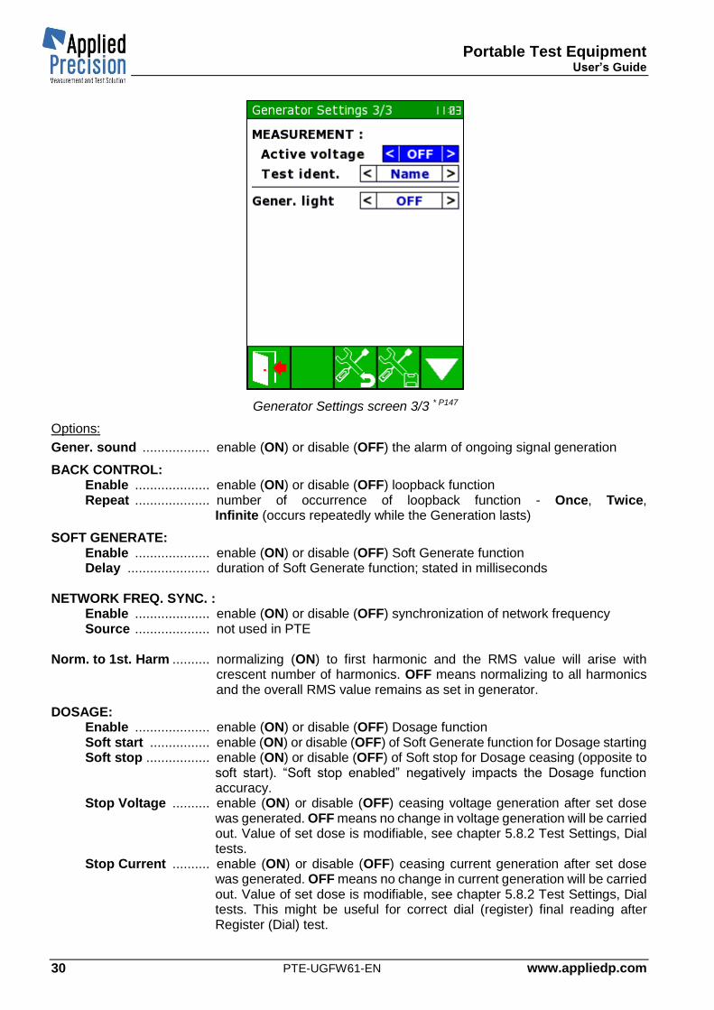
Generator Settings screen 3/3 * P147
Options:
Gener. sound .................. enable (ON) or disable (OFF) the alarm of ongoing signal generation
BACK CONTROL: Enable .................... enable (ON) or disable (OFF) loopback function Repeat .................... number of occurrence of loopback function - Once, Twice,
Infinite (occurs repeatedly while the Generation lasts)
SOFT GENERATE: Enable .................... enable (ON) or disable (OFF) Soft Generate function Delay ...................... duration of Soft Generate function; stated in milliseconds
NETWORK FREQ. SYNC. :
Enable .................... enable (ON) or disable (OFF) synchronization of network frequency Source .................... not used in PTE
Norm. to 1st. Harm .......... normalizing (ON) to first harmonic and the RMS value will arise with
crescent number of harmonics. OFF means normalizing to all harmonics and the overall RMS value remains as set in generator.
DOSAGE: Enable .................... enable (ON) or disable (OFF) Dosage function Soft start ................ enable (ON) or disable (OFF) of Soft Generate function for Dosage starting Soft stop ................. enable (ON) or disable (OFF) of Soft stop for Dosage ceasing (opposite to
soft start). “Soft stop enabled” negatively impacts the Dosage function accuracy.
Stop Voltage .......... enable (ON) or disable (OFF) ceasing voltage generation after set dose was generated. OFF means no change in voltage generation will be carried out. Value of set dose is modifiable, see chapter 5.8.2 Test Settings, Dial tests.
Stop Current .......... enable (ON) or disable (OFF) ceasing current generation after set dose was generated. OFF means no change in current generation will be carried out. Value of set dose is modifiable, see chapter 5.8.2 Test Settings, Dial tests. This might be useful for correct dial (register) final reading after Register (Dial) test.

Portable Test Equipment User’s Guide
www.appliedp.com PTE-UGFW61-EN 31
Current Standby .............. behavior of current channel when zero current should be generated. Passive means that no current is generated nor measured. However, there can be some residual current present in current loop. When current loop is disconnected, nothing happens. Active means that Generator generates zero current which it tries also to compensate this current. Actively generates zero current. When current loop is compromised error in current generation is indicated.
MEASUREMENT: Active Voltage ........ enable (ON) or disable (OFF) voltage presence between tests when
Automatic Mode is in progress Test ident. .............. test identification by NAME or CODE in table which is shown in Automatic
mode, see picture on page 27. Gener. light ……….. option for connection of semaphore light. External indication of running
measurement. Back Control timing depends on integration time of regular measurement. User has to take into account that Back control will last at least two times more than actual integration time (around 4s + 2 x integration time). Integration time is a modifiable parameter - see Time base parameter in chapter 5.8.1 Measurement Settings.
4.3.2 Inputs Configuration
Inputs Configuration Screen * P150
This screen allows switching between several measurement inputs.
1. Generator U and I This is the only option here, which allows the user to enter the basic Generator screen (like depicted in chapter 3.2) to set all possible parameters (related of generating power). After pressing OK when the cursor is located on item no. 1 the basic generator screen appears. Blue screens show load values (U, I, energy, power, meter error measurement possible, etc.)
2. Ext. [In A] & Internal U In this option external accessory connected to input A and internal voltage are selected to be measured together. User cannot change generated parameters; all changes are possible only when item no. 1 is selected in this menu. However, Generator can be in running state if it was started previously. In this option only this screen is shown to the user from all generator’s screens (green ones).
When this option is pressed main blue screen appears with regards of used accessory. If connected accessory is for voltage measurement; U+U screen is shown, otherwise it is the Load Values screen.
3. Internal I & Ext. [In B] In this option external accessory connected to input B and internal current are selected to be measured together. User cannot change generated parameters; all changes are possible only when item no. 1 is selected in this menu. However, Generator can be in running state if it was started previously. In this option only this screen is shown to the user from all generator’s screens (green ones).

Portable Test Equipment User’s Guide
PTE-UGFW61-EN www.appliedp.com 32
When this option is pressed main blue screen appears with regards of used accessory. If connected accessory is for current measurement; I+I screen is shown, otherwise it is the Load Values screen.
4. Ext. [In A] & Ext. [In B] In this option only values via external accessories are being measured regardless of generated power. User cannot change generated parameters; all changes are possible only when item no. 1 is selected in this menu. However, Generator can be in running state if it was started previously. In this option only this screen is shown to the user from all generator’s screens (green ones). When this option is pressed main blue screen appears with regards of used accessory.
5. Phantom Load This is a unique option in this menu. Principally Phantom Load enables to generate current into existing load (voltage remains intact). That’s why only current related parameters can be changed in this screen. This screen can be opened only if voltage measuring accessory is connected into input B of the device, otherwise error message appears! In the top user can set amplitudes and phase shifts for all phases of current. Phase shift is related to the voltage which is being measured by the accessory. Measured voltage and its phase shifts are visible in the bottom part of this screen. They are read only as well as the frequency in the middle. User can also change the connection type 3P4W, 1P2W, etc. and the shape of signal (see chapter 4.1 on page 21).
Phantom Load screen * P151
Function keys:
F1 ................ starts and ceases current generation
F3 ................ opens menu of available signals – screen “Signal Shapes” (see chapter 4.1)
F4 ................ opens menu of automatic run of predefined tests – screen “DB Measurements” (see chapter 4.2)
F5 ................ opens menu of Generator Settings (see chapter 4.3)

Portable Test Equipment User’s Guide
www.appliedp.com PTE-UGFW61-EN 33
5. Measuring Mode
Warnings Do not touch the output terminals of the Product even if the display shows the presence only non-lethal voltages or currents. There can be present lethal voltages or currents due to error or connected meter.
This chapter describes user interface in measuring mode. Generator’s interface is described in chapter 3. After switching into measuring mode always last used screen appears or Load Values screen if power on just happened.
5.1 Main Measurement Content of main measurement page depends on type of connected sensors:
Load Values .......................... if one voltage and one current sensor are connected Actual Values (I) .................... if one current sensor is connected Actual Values (U) .................. if one voltage sensor is connected Actual Values (I+I) ................. if two current sensors are connected Actual Values (U+U) ............. if two voltage sensors are connected
5.1.1 Load Values
Page Load Values shows actual measured and calculated values of load point when one current and one voltage measurement sensors are used.
Load Values screen LVa* P01
Load Values screen LVb* P70

Portable Test Equipment User’s Guide
PTE-UGFW61-EN www.appliedp.com 34
List of displayed quantities:
U, UPN ........ Phase to neutral voltage
UPP ............. Phase to phase voltage
I .................. Current
P ................. Active Power
Q ................ Reactive Power
S ................. Apparent Power
cos φ, sin φ ...... Power Factor (with LAG or LEAD indication in last column) *
............... Phase of UPN Voltage
PP ............ Phase of UPP Voltage
Z ................ Load Impedance
Z ............... Phase shift of Load Impedance
........... Phase of Current
........... Distortion Factor of Voltage
........... Distortion Factor of Current
............ Active Power of Harmonics (2nd-Nth) *
IP ............ Active Current
IQ ............ Reactive Current
P1ST ........ Active power of the first harmonic
f ............. Frequency
L1xx ...... Voltage Phase Seq. (L123 or L132)
LI1xx ..... Current Phase Seq. (LI123 or LI132) *
* Display of some quantities can be enabled / disabled in Measurement Settings under F5.
Control keys:
F1 .......... Energy Values
F2 ........... Meter Error Test
F3 ………. Transformer Test
F4 ........... Data Readout
F5 .......... Menu ◄ ► ....... Scroll Load Values screens: LVa <-> LVa1 <-> LVa2 <-> LVa3 <-> LVa respectively LVb <->
LVb1 <-> LVb2 <-> LVb3 <-> LVb
To scroll Load Values screens (LVa <-> LVb <-> LVc <-> LVd <-> LVa) use arrows ▼▲ or PgUP and PgDn
keys.
LVc and LVd screens show primary values which depend on CT / VT ratio defined for actual meter.

Portable Test Equipment User’s Guide
www.appliedp.com PTE-UGFW61-EN 35
Other available Load Values screens for three phase system:
Load Values screen LVc* P68
Load Values screen LVd* P74
Load Values screen LVa1* P56
Load Values screen LVa2* P57
Load Values screen LVa3* P58
Load Values screen LVb1* P71
Load Values screen LVb2* P72
Load Values screen LVb3* P73

Portable Test Equipment User’s Guide
PTE-UGFW61-EN www.appliedp.com 36
Load Values screens for single phase system:
There are only two versions of Load Values screens:
Load Values screen * P44
Load Values Primary screen * P69
Primary screen shows primary values which depend on CT and VT ratios defined for actual meter.
5.1.2 Actual Values
Actual Values screens show actual measured and calculated values of load point when other combination than one current and one voltage measurement sensors are used. Device shows measured and calculated values of Current (CT) and Voltage (VT) Transformers.
In case of connection of one measuring sensor device shows:
• basic quantities (depends on used sensor)
• Transmission Ratio rLx/L1
• Transmission Error erLx/L1
• Phase Error φLx/L1
Left values are comparison of values in phases L2 and L1 and right values in phases L3 and L1.
In case of connection of two measurement sensors device shows:
• basic quantities (depends on used sensors)
• Transmission Ratio rB/A
• Transmission Error erB/A
• Phase Error φB/A
Showed values in each phase are comparison of values in Input A and Input B.
Transmission Error is calculated as comparison of measured Transmission Ratio (rLx/L1 or rB/A) and nominal Transmission Ratio (rnom).
Content of Actual Values screens depends on connected measuring accessories.

Portable Test Equipment User’s Guide
www.appliedp.com PTE-UGFW61-EN 37
Actual Values screens for three phase measurement:
One current sensor used * P34
One voltage sensor used * P35
Two current sensors used * P36
Two voltage sensors used * P37
Control keys:
F1 ................... Graphical Presentation screens
F3 ................... Meter Readout / Swap primary vs secondary sides
F4 ................... Save
F5 ................... Menu

Portable Test Equipment User’s Guide
PTE-UGFW61-EN www.appliedp.com 38
Actual Values screens for single phase measurement:
One current sensor used * P60
One voltage sensor used * P61
Two current sensors used * P62
Two voltage sensors used * P63
Control keys:
F1 ................... Graphical Presentation screens
F3 ................... Meter Readout / Swap primary vs secondary sides
F4 ................... Save
F5 ................... Menu

Portable Test Equipment User’s Guide
www.appliedp.com PTE-UGFW61-EN 39
5.1.3 Graphical Presentation
The way of display the measurement results can be switched by pressing the F1 key repeatedly.
Graphical Presentation screens for 3f:
Vector Diagram screen * P02
Harmonics screen * P03
Curve screen * P04
Graphical Presentation screens for 1f:
Vector Diagram screen * P49
Harmonics screen * P50
Curve screen * P51
Vector diagram has two parameters which can be configured in Measurement Settings: - position of reference zero axis (vertical or horizontal) - reference unit (voltage or current) which is displayed on reference zero axis
Harmonics screen shows harmonics up to 40th harmonic. 10 harmonics are displayed on one screen. Scrolling to other harmonics can be done by ◄ ► arrow keys.
Combination of showed signals (I1+I2+I3, U1+U2+U3, U1+I1, U2+I2 or U3+I3) can be in Harmonics and Curve screens chosen by ▼▲ arrow keys.
Little back triangle in top right corner in one of the voltage or current values determines the synchronization frequency channel.

Portable Test Equipment User’s Guide
PTE-UGFW61-EN www.appliedp.com 40
Harmonics View screen shows measured values (amplitude and phase) of all harmonics.
Harmonics View screen * P65
Individual harmonic components are distributed over several screens (3 x I, 3 x U). Each screen can be scrolled up and down. Individual amplitudes represent a percentage of the first harmonic and phase shift is relative displacement of corresponding harmonic component. At the first harmonic the phase shift is given in brackets (measured against first harmonic in first voltage phase) but otherwise it is 0, which serves as a reference for determining the phase difference of other harmonics.
Control keys (for three graphical presentation pages):
F1 ........ Switch to another graphical presentation pages or back to main page
F2 .......................... Switch to Meter Error Test
F3 .................. Show Harmonics View in Harmonics screen, switch to Transformer Test
F4 .......................... Save Load Values
F5 .......................... Menu ▼▲ ........................ Choose combination of showed signals in Harmonics and Curve screens ◄ ► ........................ Scroll next/previous 10 harmonics in Harmonics screen ESC ......................... Exit (return to main measurement page)
Control keys (for Harmonics View screen):
F1, ESC .................. Exit (return back to Harmonics screen)
F2 .......................... Switch to next channel (L1<->L2<->L3<->L1)
F3 .......................... Switch to next channel (U<->I<->P<->U)
F4 .......................... Save Harmonics ▼▲◄ ► ................. Content scrolling PgDn, PgUp .............. Content paging

Portable Test Equipment User’s Guide
www.appliedp.com PTE-UGFW61-EN 41
5.2 Energy Measurement and Test
5.2.1 Energy Values
This page shows measured and calculated energy values. Page is activated by key F1 of Load Values screen.
Active, reactive and apparent energies are accumulated beside the measurement and shown on this page. Accumulation of these energies can be stopped and started again (key F3) or just restarted by F4 key.
Energy Values screen in 3f * P43
Energy Values screen in 1f * P52
List of displayed quantities:
ΣP ........... Sum of Active Powers
ΣQ........... Sum of Reactive Powers
ΣS ........... Sum of Apparent Powers
cos φ, sin φ ............ Power Factor
EP............ Active Energy
EQ ........... Reactive Energy
ES............ Apparent Energy
ΣEP ......... Sum of Active Energies
ΣEQ ......... Sum of Reactive Energies
ΣES ......... Sum of Apparent Energies
f ............. Frequency
L1xx ...... Voltage Phase Sequence (L123 or L132)
LI1xx ...... Current Phase Sequence (LI123 or LI132)
Control keys:
F1 ... Graphical Presentation screens
F2 .... Dial test
F3 .... Stop / start online energy accumulation
F4 .... Clear energy registers
F5 ... Menu
Online energy accumulation - Sum of Energies (resp. Powers) accumulate values from the beginning automatically. With F3 button it is possible to suspend/resume accumulation. When Dial test screen is accessed these registers will be cleared but only if Test Initialization has been carried out (see next chapter).

Portable Test Equipment User’s Guide
PTE-UGFW61-EN www.appliedp.com 42
5.2.2 Dial Test
This page can be accessed from Load Values screen by F1 followed by F2 or from Energy Values screen by F2 or F5 Menu, point 6 Test & Calibration, point 3 Dial Test.
Configuration of Dial tests is in Test Settings menu, where mode (Time or Energy), amount of time / energy and energy type (Active, Reactive, Apparent) is specified.
When Generator (PTE) has dosage feature enabled (see chapter 4.3.1 Generator Settings) Dial test automatically controls also start and stop of power generation. When dosage is active (energy is being accumulated with real-time generation) red highlighted “Dosage” message flashes on each screen.
Test is started with F1 key. After first press initialization occurs and dial test is prepared. At this stage #1 field (see picture below) should be filled with initial state of register of electricity meter.
After second press of F1 key testing begins. If the Generator section is enabled for Dosage, generation of current and voltage starts automatically.
After third press of F1 key the testing is aborted by user. If the Generator section is enabled for Dosage and “Stop voltage” (and /or current) is also enabled Generator will also cease generating this quantity (U and /or I). After that user can fill #2 field (see picture below). Then Error is calculated.
If the user will not interrupt the testing by third press of F1 key PTE will terminate testing automatically after reaching certain value of energy or time (depends on Test settings).
Note: Before first initialization (right after Dial test screen is opened) it is recommended to generate voltage (only) to have such meter under power. This is useful especially for static/electronic meters so user is capable of performing initial register reading. When Dosage starts (second F1 press) PTE automatically generates U and I. For activation of simultaneous measurement of P/Q/S energy testing set correct method. (F5 Menu, F1 Measurement Settings, page 3/6, ENERGY MEASUREMENT)
COUNTERS Section: This section is related to the values obtained from meter. Meter connected to the network can measure quantities via transformer. In such case meter’s parameters can be defined for transformer’s secondary side (Sec.) or calculated to the primary side (Prim.).
Operator enters initial state of meter counter #1 before test and final state of meter counter #2 after test. Device automatically calculates difference (ΔE) and evaluates test error. It is also possible to define directly the difference (ΔE).
Energy measurement Section:
This section is related to the energy measurement obtained by device. CT (Current) and VT (Voltage) ratios are acquired from database. In this window they can be changed (they turn red). By default, both Prim. / Sec. switches are set to the same value which is associated to database item.
These switches along with CT / VT ratios enable to set where the meter is placed (during measurement) and where the device measures energy.
Running in Automatic Mode (chapter 4.2.3 on page 27) uses also this mode, which means that during dial test in Automatic Mode (defined on green screen) actually this Dial test runs in the background on the blue screen and also all fields are filled. In such scenario fields #1 and #2 are filled automatically (if optical communication head with static meter is used) or manually – user must switch into this screen and fill #1 at the beginning and #2 at the end of dial test.
Dial Test runs always simultaneously with Maximum Demand Test which has to last longer than Dial Test. The reason lies in principle of Dial Test evaluation. This feature offers also evaluation of these two tests concurrently.

Portable Test Equipment User’s Guide
www.appliedp.com PTE-UGFW61-EN 43
Dial Test screen * P59
Dial Test screen * P213
Dial Test – Reactive screen * P215
Content:
COUNTERS ..... Values of meter counters (registers)
Prim. / Sec. switch ............... meter measures energy
for primary or secondary side of transformer
(if applicable). Default state is Sec.
#1 ............. Value of counter before test
#2 ............. Value of counter after test
ΔE ............ Difference between #1 and #2
CT: ................... Current Ratio
VT: ................... Voltage Ratio
Prim. / Sec. ...... on which side of transformer is the
energy measurement carried out
3P3W ............... Actual Connection Type
E ............... Energy measured during the test – two
values with regards to Prim. / Sec. switches
Error ........ Error calculated from E and ΔE
E / t .......... Mean Energy within time period of the test –
two values with regards to Prim. / Sec.
switches
t ................ Duration of the test in minutes
<Progress bar> .... Graphical interpretation of duration of the test (in time mode) or energy dosage progress (in energy mode)

Portable Test Equipment User’s Guide
PTE-UGFW61-EN www.appliedp.com 44
Control keys:
F1 ............. Initialization / Start / Stop of the test
F3 ............. Switch to Maximum Demand Test Screen (also PgDn key can be used)
F4 ............ Save results of Dial tests
F5 ............. Menu
ESC ......... Exit
Remark:
Energy (Dial) test can lose accuracy when inappropriate amount of energy over time is intended to dose. Error for the result of dial test can be expressed as (for PTE):
100. 𝑈𝑚𝑎𝑥. 𝐼𝑚𝑎𝑥
𝑈. 𝐼. 74000. 𝑡𝑖𝑚𝑒
Then, for instance with range of accessory 500V/120A and dosing only 0.1A (230V) for 60s, it causes an error of 0.059%. With higher current or with more time the error directly proportionally decreases. This behavior is caused by lower resolution for small currents disregarding other errors like device accuracy.
Conclusion: Dose more power for longer time (several minutes)!

Portable Test Equipment User’s Guide
www.appliedp.com PTE-UGFW61-EN 45
5.2.3 Maximum Demand Test
This page can be accessed from Load Values screen by pressing of F1, followed by F2 and F3.
Configuration of MD tests is in Test Settings menu, where Period, Subperiods and Window can be specified. The duration of MD test is identical with Dial test duration and it is recommended to be at least two times greater than period of MD test.
Test is started with F1 key. Then the Energy (E) is being summed and the average power (MD Act.) is being calculated. Operator must be aware of the number already stored in electricity meter’s Maximum Demand Register. It is highly advised to delete such meter’s register before and after MD test. This operation will ease the whole test procedure.
During MD test the icon above F1 depicts the sign of play. In this state the test can be prematurely stopped by F1 and the icon changes to stop sign. To evaluate the MD test, it is compulsory to wait until the test stops automatically or at least wait until the time “End” passes because only then the “MD Reg.” will obtain value different from zero. This is the value which is compared with the meter’s MD register. When the test is ceased, “Enter MD register” message flashes until any key is pressed. This warning informs the operator to submit the value of MD register from meter. Then the overall MD error is calculated.
Dial Test runs always simultaneously with Maximum Demand Test which has to last longer than Dial Test. The reason lies in principle of Dial Test evaluation. This feature offers also evaluation of these two tests concurrently.
Meter connected to the network can measure quantities via transformer. In such case meter’s parameters can be defined for transformer’s secondary side or calculated to the primary side (upper switch – Sec / Prim). By default, both Prim. / Sec. switches and CT/VT ratios are acquired from database. They can be changed (they turn red). These switches along with CT / VT ratios enable to set where the meter is placed (during measurement) and where the device measures energy.
Maximum Demand Test screen * P94
Content:
Sec. / Prim. ....... Meter measures energy for primary or
secondary side of transformer (if
applicable). Default state is Sec.
MD .................... Register value from meter after the test
CT .................... Current Ratio
VT .................... Voltage Ratio
Prim. / Sec. ...... Side of transformer on which is the
energy measurement carried out
3P3W ............... Actual Connection Type
Error ............. Error calculated from MD and MD Reg.
MD Act. ........ Actual average power
MD Reg. ....... Power value obtained after defined time
(End)
E ................... Energy measured during the test
...................... Last tri quantities show two values with
respect to Prim. / Sec. switches
Begin ............ MD test timestamp of beginning of window
End ............... Duration of the test in minutes
<Progress bar> .... Graphical interpretation of duration of the test

Portable Test Equipment User’s Guide
PTE-UGFW61-EN www.appliedp.com 46
Control keys:
F1 ............. Start / Stop of the test
F2 ............ Meter Readout
F3 ............. Switch to Dial Test Screen (also PgUp key can be used)
F4 ............ Save results of MD tests
F5 ............. Menu ESC ............. Exit
5.3 Meter Error Test This page enables to perform meter error test by samples gathering. Page is activated by F2 from Load Values screen or F1 from database (2/5 – 4/5).
Meter Error Test screen * P10
Content:
U, I ............... Load point values
Parameters... Parameters of tested meter
SN ................. Serial number of meter (asterisk behind the SN indicates that at least one from above parameters is different from meter parameters defined in database)
Error ............ Actual measured error of meter
Samples ....... Number of measured/required meter errors
Impulses / Integration time ............. number of pulses (with time) which make one sample
Average ........ Average error
Deviation ...... Standard deviation of measured samples
Parameters of tested meter:
Connection type ............. 3P4W, 3P3W, 2P3W, 1P3W or 1P2W (see Connection Diagrams) Energy type .................... Active, Reactive or Apparent Registration mode ........ LED, DISC/SO (SO = pulse output of meter), SNAP. S (=snap switch).
Switching into DISC/SO causes permanent shine of transmitter LED of OPTS 2100 sensor, so the user can easily set the position of OPTS 2100 before calibration (more information in Accessories Guide Chapter Optical Sensor)
Constant ......................... Constant of tested meter Constant Unit ................. i/kWh, i/Wh, i/Ws, i/kWs, kWh/i, Wh/i, Ws/I, kWs/i, MWh/i or i/MWh
(i = pulse or rotation) CT ................................... transformation ratio of current transformer (can be hidden in Test
settings). Changing this value influences the change of Constant value. VT ................................... transformation ratio of voltage transformer (can be hidden in Test
settings). Changing this value influences the change of Constant value.

Portable Test Equipment User’s Guide
www.appliedp.com PTE-UGFW61-EN 47
Constant type ............... Primary / Secondary – for indirect meters in the database, indicates which side of the connection view to transformer is referred the constant of electricity meter. For direct meters the default value is always Secondary and in that mode this parameter is not displayed. With parameter change the constant is automatically converted under CT VT transformation ratios stored in database for actual meter.
With changing the parameters CT Ratio, VT Ratio and Constant type the Constant parameter is automatically recalculated in the Meter Error Test screen and used in subsequent tests. When user changes the Constant type back to the value according to database item associated to that meter, Constant value is set to default for this meter type. It means CT and VT ratio parameter values are ignored in Meter Error Test screen. If CT or VT has been changed, Constant type value has to be toggled to opposite (against database) to reflect the Constant value modification.
In a case, that this mode is activated from Database, then the Parameters are set according to the selected meter. If this mode is activated from Load Values screen the Parameters are set according to the Measurement Settings.
Navigation between parameters can be done by ▼▲ arrows, parameter selection can be done by OK key and changing of parameter’s value can be done by ◄ ► arrows. If any parameter has been changed, it become red. It means that default value has been modified. These parameters remain modified until next enter to Database screen. Entering the Database will set default parameters of corresponding meter.
F4 key which is available after performing meter error test saves test result (including load point info, signal shapes and harmonics) into results database for currently selected meter.
When Registration mode parameter is switched to “Snap. S” then F2 key turns into snap switch mode (substitution of HW Snap Switch) and pulses can be registered with this F2 button.
Control keys:
F1 ................... Start / stop testing mode
F2 ................... Start / stop calibration of optical sensor
F2 ................... Snap switch button (only when registration mode is set to SNAP.S)
F3 .................... Samples page
F4 .................... Saving test results into results database
F5 ................... Menu
ESC ................ Exit (return to previous page)
Meter testing can be started or stopped by key F1. Voltage and current sensors have to be connected to tested meter and optical sensor has to be adjusted to meters emitting LED or disc or impulse SO cable has to be connected to device before start of testing.
Time between two samples (Integration time) and number of measured samples can be set in Test Settings. Integration time is described in appendix, chapter Accuracy Verification. On principle: longer integration time and higher number of measured samples brings measured results with higher accuracy and stability.
First mark is ignored after start of testing and after each following mark device shows actual value of measured error and increments counter of measured samples.
Average Error and Standard Deviation are evaluated after measuring required number of samples.

Portable Test Equipment User’s Guide
PTE-UGFW61-EN www.appliedp.com 48
5.3.1 Test Result Details
Measured samples can be seen in Test Result Details page which can be activated by key F3 from Meter Error Test page. This screen shows all measured samples with pulses or energies against time used for evaluation of these samples.
Samples screen * P66
Content: SN .................... serial number of meter
Error ................ resulting error
Deviation ......... standard deviation of last completed test
Impulses .......... number of (required) impulses
Energy ............. energy being measured by meter during last completed test
Samples: No ..................... Sequence number
Error [%] .......... Measured sample (error in %)
The last column toggles between (F5):
Exp. / Meas imp. ...... Expected impulses count / Measured impulses count or
E[kWh] / Time [s] or
E[Ws] / Time [s] ........ measured energy by WS over time (unit changes with Measurement Settings) *1
*1 Up to version 5.30 (including) of FW the quantity E[xxx] / Time [s] with different meaning „calculated energy
over time with respect to Energy and Error [%]”
Control keys:
F1, ESC ........... Exit (return to previous page)
F3 ..................... Enables to store recent test results to new meter (Add meter screen will
appear)
F4 ...................... Saves recent test results to database for currently selected meter
F5 ...................... Toggles between Exp. / Meas imp. and E[kWh] / Time [s] respectively E[Ws] / Time [s] view in third column
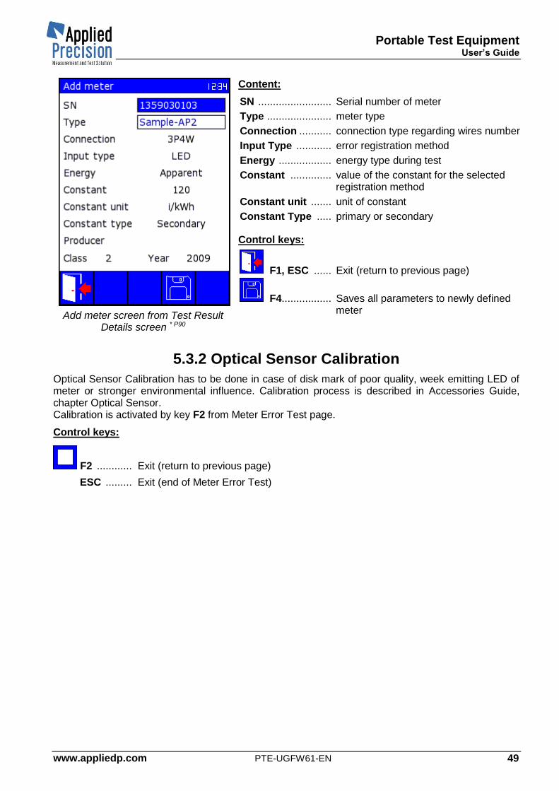
Portable Test Equipment User’s Guide
www.appliedp.com PTE-UGFW61-EN 49
Add meter screen from Test Result Details screen * P90
Content:
SN ......................... Serial number of meter
Type ...................... meter type
Connection ........... connection type regarding wires number
Input Type ............ error registration method
Energy .................. energy type during test
Constant .............. value of the constant for the selected registration method
Constant unit ....... unit of constant
Constant Type ..... primary or secondary
Control keys:
F1, ESC ...... Exit (return to previous page)
F4................. Saves all parameters to newly defined meter
5.3.2 Optical Sensor Calibration
Optical Sensor Calibration has to be done in case of disk mark of poor quality, week emitting LED of meter or stronger environmental influence. Calibration process is described in Accessories Guide, chapter Optical Sensor. Calibration is activated by key F2 from Meter Error Test page.
Control keys:
F2 ............ Exit (return to previous page)
ESC ......... Exit (end of Meter Error Test)

Portable Test Equipment User’s Guide
PTE-UGFW61-EN www.appliedp.com 50
5.4 Constant Detection This page enables to detect the constant of the meter to be verified. Page is activated by PgDn key from Meter Error Test screen. Once the constant is obtained, it is not automatically stored or used elsewhere, user must use the obtained value to enter it in the Meter Error Test screen or elsewhere.
Constant Detection screen * P205
Content:
U, I ............... Load point values
Parameters... Parameters of tested meter (see below); if one of the parameters is red it indicates difference from the stored value in the database associated with specified meter (based on SN)
SN ................. Serial number of meter
Constant ..... obtained constant with defined unit with respect to the meter’s error (cyclically renewing)
Impulses ..... number of pulses to get to calculate the constant
Time ............. counting time of one sample
Parameters of tested meter:
Connection type ............. 3P4W, 3P3W, 2P3W, 1P3W or 1P2W (see Connection Diagrams) Energy type .................... Active, Reactive or Apparent Registration mode ........ LED, DISC/SO (SO = pulse output of meter), SNAP. S (=snap switch).
Switching into DISC/SO causes permanent shine of transmitter LED of OPTS 2100 sensor, so the user can easily set the position of OPTS 2100 before calibration (more information in Accessories Guide Chapter Optical Sensor)
Constant ......................... Constant of tested meter (greyed out) Constant Unit ................. i/kWh, i/Wh, i/Ws, i/kWs, kWh/i, Wh/i, Ws/I, kWs/i, MWh/i or i/MWh
(i = pulse or rotation)
Navigation between parameters can be done by ▼▲ arrows, parameter selection can be done by OK key and changing of parameter’s value can be done by ◄ ► arrows. If any parameter has been changed, it become red. It means that default value has been modified. These parameters remain modified until next enter to Database screen. Entering the Database will set default parameters of corresponding meter.
Control keys:
F1 .................... Start / stop of testing mode
F5 ................... Menu
ESC ................ Exit (return to previous page)
Testing can be started or stopped by key F1. Voltage and current sensors have to be connected to tested meter and optical sensor has to be adjusted to meters emitting LED or disc or impulse SO cable has to be connected to device before start of testing.

Portable Test Equipment User’s Guide
www.appliedp.com PTE-UGFW61-EN 51
5.5 Meter Readout Meter Readout page enables to read content of registers of multifunctional meters with optical communication interface according to IEC 62056-21. Optical Communication head OPTH 1200 has to be connected to AUX input of the device and properly placed to meter under test before starting data readout.
Meter Readout is initiated by F4 key and result (content of registers of meter) is printed on display. Readout data can be saved into database using key F4.
Meter Readout screen * P48
Content:
(data) ............... Data from meter or error message
Control keys:
ESC ....................... Exit (return to previous page)
F3 .......... Read data from meter
F4 .......... Save data into database
F5 .......... Menu
▼▲ ........ Scrolling of readout data down and up
◄ ► ....... Scrolling of readout data left and right
PgUp, PgDn ........ Paging of readout data up
and down
5.6 Transformer Test Test of current transformers (CT) or voltage transformers (VT) can be done after connecting of suitable combination of current and voltage measuring sensors.
Testing of single phase transformer can be done using one three phase measuring accessory which is connected to transformer this way: L1 channel of accessory to secondary side and L2 (or L3) channel to primary side. Measurement screen shows result for both variants (L2/L1 and L3/L1).
Testing of three phase transformer (or also single phase transformer) can be done using two three phase current sensors (in case of current transformer testing) resp. two three phase voltage sensors (in case of voltage transformer testing). Channels of sensor connected into input A has to be connected to secondary side of transformer and channels of sensor connected into input B has to be connected to primary side of transformer.
It is possible to use any combination of current measuring accessories (CT 2x20, CC 2x12, CC 2x24, FCP 3xxx) for Current Transformer testing.
Measurement screens depend on combination of connected sensors and show: nominal and measured Transmission Ratio, Transmission Error and measured Phase Error.

Portable Test Equipment User’s Guide
PTE-UGFW61-EN www.appliedp.com 52
Transformer Test screen * P33
(one voltage sensor and one current sensor used)
One current sensor * P34
One voltage sensor * P35
Two current sensors * P36
Two voltage sensors * P37 Content:
U, I ........................... Load Point values rnom ........................... Nominal transmission ratio from meter definition rLx/L1 .......................... Measured transmission ratio, 1 probe connected (L2/L1, L3/L1) rB/A ............................ Measured transmission ratio, 2 probes connected (L1, L2 and L3) erLx/L1 ........................ Calculated transmission error,1 probe connected (L2/L1, L3/L1) er. ............................ Calculated transmission error, 2 probes connected (L1, L2 and L3) φLx/L1 ......................... Measured phase error, 1 probe connected (L2/L1, L3/L1) φB/A ........................... Measured phase error, 2 probes connected (L1, L2 and L3)
............................. Voltage Phase ............................. Current Phase
............................. Distortion Factor of Voltage
............................. Distortion Factor of Current f ................................ Frequency

Portable Test Equipment User’s Guide
www.appliedp.com PTE-UGFW61-EN 53
Control keys:
F1, ESC ......... Exit (return to previous page / skipping to next page)
F3 ................. Burden test
F3 ................ Data readout
F3 ................. Switch primary/secondary selection
F4 ................ Save Load Point values (including harmonics and shapes) into results database
F5 .................. Menu
5.7 Burden Measurement Burden Test / Measurement can be done on measuring voltage or current transformer in order to verify their function and installation. Measurement screen shows the actual load point values, nominal values from the meter label, as well as measured impedance, admittance and further calculated values.
It is initiated by pressing the F3 key twice from the Load Values page or selecting it from the Tests Menu.
Burden Measurement screen * P208
(one voltage sensor and one current sensor used)
Content:
U, I, S ........... Load point values
Snom ........... Nominal burden from meter’s label
Inom ............ Nominal current from meter’s label
Unom ........... Nominal voltage from meter’s label
Z ................... Burden (Load Impedance) = U / I
S`I ................. Measured Current burden = Inom * Inom * Z
S`bI ............... Operating Current Burden ratio = Si * 100.0 / CTSnom
Y .................. Admittance = I / U
S`U ................ Measured Voltage burden = Unom * Unom * Y
S`bU .............. Operating Voltage Burden ratio Su * 100.0 / VTSnom

Portable Test Equipment User’s Guide
PTE-UGFW61-EN www.appliedp.com 54
Control keys:
F3 .............. Transformer test
F4 ............. Save Load Point values (including harmonics and shapes) into results database
F5 ............. Menu
5.8 Menu of Measuring Mode Menu enables access to settings, database, information about device and device calibration. It can be activated by F5.
Menu screen * P11
1. Measurement settings (F1 or 1)
2. Test settings (F2 or 2)
3. System settings (F3 or 3)
4. Database of meters and results (F4 or 4)
5. Information about the device and connected
accessories (F5 or 5)
6. Tests and Calibration (6)
7. Inputs Configuration
Control keys:
F1 - F5 or 1 - 7...... Menu item selection
▼▲ ...................... Navigation on screen
OK ....................... Item selection
ESC ..................... Exit (return to previous page)

Portable Test Equipment User’s Guide
www.appliedp.com PTE-UGFW61-EN 55
5.8.1 Measurement Settings
This page, divided to more screens, contains parameters of measurement mode.
Meas. Settings screen 1/6 * P12
Meas. Settings screen 2/6 * P13
Connect. type .......................... Connection type: 3P4W, 3P3W, 2P3W, 1P3W or 1P2W (see appendix Connection Diagrams). If parameter Start-up Mode is set to Test, then this value is overwritten by value of currently selected meter from database.
ENERGY OUTPUT .................. Settings of energy (impulse) output in order to test the Working Standard by another etalon. Impulse output is realized by frequency generation of the red LED, and if AUX parameter is enabled, then even by AUX output (included BNC cabled is connectable there).
State ............................ Type of measured energy: Active, Reactive or Apparent Energy or Fixed frequency
Fixed freq. ................... Value of fixed frequency generated on red impulse LED or on connected BNC cable if parameter State has value Fixed frequency
Factor .......................... Constant of WS which determines the relation between actually measured power and frequency on Impulse output
Factor unit ................... Unit of parameter Factor: i/kWh, i/Wh, i/Ws, i/kWs, kWh/i, Wh/i, Ws/i, kWs/i, MWh/i or i/MWh
AUX output .................. Impulses in AUX output: ON (enabled) or OFF (disabled)
Channel LX .................. channel enabling (X = 1 or 2 or 3) for energy output measurement: ON (enabled) or OFF (disabled)
FREQUENCY .......................... Settings of frequency measurement
Freq. mode .................. mode of frequency measurement: Auto when Default freq. and Sync. chnl. items are enabled; or Fixed when Fixed freq. item is enabled
Default freq. ................ Default measurement frequency: 50 Hz or 60 Hz
Sync. chnl. .................. Synchronization channel used for frequency measurement: UL1, UL2, UL3, IL1, IL2, IL3 or AUTO
Fixed freq. ................... Frequency output doesn’t reflect currently measured power, frequency output generates constant frequency

Portable Test Equipment User’s Guide
PTE-UGFW61-EN www.appliedp.com 56
RANGE (Input A / Input B) ....... Settings of ranges for both measurement inputs (this part of settings is stored in SD card, but only for particular accessory. If other accessory is used, default values will be loaded. Accessory is identified by its serial number)
Auto ............................. Automatic range selection: ON (enabled) or OFF (disabled). Device chooses best suitable range depending on measured values if automatic range selection is enabled.
Value ............................ Manually selected range (valid if parameter Auto is OFF)
Meas. Settings screen 3/6 * P46
Meas. Settings screen 4/6 * P88
Start-up mode ........................ Defines initial measurement settings (Connection type, System, Energy, Constant, Unit) activated right after device power up: Meas. determines last settings used before switch-off, Test defines parameters of last used meter from database.
REACTIVE POWER MEAS ..... Setting of reactive power measurement
Method ........................ Measurement method: True, Cross, Shift or Fund. f. Remark: method Fund. f. is available only from firmware v. 5.69
Description of supported reactive power meas. methods:
True … classic calculation: 𝑄 = √𝑆2 − 𝑃2. The sign is determined by reactive power calculated from Shift method. This method’s result is considered by IEEE 1459-2010 as nonactive power. IEEE 1459-2010 defines only nonactive power and fundamental reactive power.
Cross … calculation from artificial connection:
𝑄 = 𝑄1 + 𝑄2 + 𝑄3 = (√3 ∗ 𝑈23 ∗ 𝐼1) + (√3 ∗ 𝑈31 ∗ 𝐼2) + (√3 ∗ 𝑈12 ∗ 𝐼3)
Rem: The system must be balanced for achieving correct values! This method is valid only in 3-phase connections with phase sequence L123. In 3-phase system with phase sequence L132 this method calculates results with opposite sign.
Shift … calculation from U and I where current is shifted by ¼ of period in time domain: 𝑄 = 𝑈 ∗ 𝐼′. This approach is mentioned in Annex A of IEEE 1459-2010. Rem: Method does not consider higher harmonic components correctly!

Portable Test Equipment User’s Guide
www.appliedp.com PTE-UGFW61-EN 57
Fund. f. … reactive power defined by IEC 62053-24 is reactive power of fundamental harmonic component. This type of reactive power is also defined in IEEE 1459-2010 as fundamental reactive power: 𝑄 = 𝑈𝑓𝑢𝑛𝑑 ∗ 𝐼𝑓𝑢𝑛𝑑 ∗ sin 𝜑𝑓𝑢𝑛𝑑 Rem: Method affects calculation of all units (voltage, current, active power, apparent power etc.)!
UNCONNECTED INPUT ......... Settings for unconnected voltage input checking
Check .......................... Whether to check (ON) or not (OFF) the presence of voltage on measured object
ENERGY MEASUREMENT ..... Settings of energy measurement
Unit .............................. Unit of energy: Ws or kWh
Method ......................... Way of summing energy: 4Quadrant, Algo 1 (Net Result), Algo 2 (Positive Aggregate), Algo 3 (Both Sum), Algo 4 (Anti-fraud) Rem: See details in appendix Aggregate Energy Calculation Methods
Sense ........................... Energy register displayed on the screen Energy Values (see chapter 5.2.1 Energy Values): Import for summed imported energy or Export for summed exported energy
Time base ............................... integration time of measurement, valid range is 1s – 100s
VECTOR DIAGRAM ................. Settings of vector diagram displaying
Zero axis....................... Position of reference zero axis: Vertical or Horizontal
Reference ..................... Reference unit: Voltage or Current
HARMONICS ............................ Harmonics related settings
Phase Scale ................ Phase scale with values 0-360 or 0-360/n … n= harmonic number; in second case will be phase values in these ranges: 2nd harmonic 0-180°, 3rd harmonic 0-120°, 4th harmonic 0-90° etc.
ADDITIONAL INFO ................. Settings of special measurement
Power of harm. ............ Calculation and display of Active Power of higher harmonics (for 2nd – 40th harmonic) on the Load Values screen: ON (enabled) or OFF (disabled). Sign of the number determines direction of energy flow: positive means energy consumption, negative energy delivering. If the sign of this quantity (Ph) is different than the sign of Active power (P), it means that higher harmonics are in opposite direction against the total power.
Curr. phase seq. ......... Display of Current Phase Sequence on the Load Values screen: ON (enabled) or OFF (disabled)
Lead/Lag indic. ........... Enable of Indication of leading or leading in the row cosφ on Load Values screen. Indication is presented as small red triangle at the corners of each channel L1, L2, L3, while up is LAG, down is LEAD.

Portable Test Equipment User’s Guide
PTE-UGFW61-EN www.appliedp.com 58
Meas. Settings screen 5/6 * P91
Meas. Settings screen 6/6 * P201 VOLTAGE AMPLITUDE Settings of voltage drop warnings
Check .......................... Enable (ON) or disable (OFF) checking of voltage amplitude value
Threshold ................... Value in %, relative to nominal voltage of selected meter to be tested
CURRENT AMPLITUDE .......... Settings of current drop warnings
Check .......................... Enable (ON) or disable (OFF) checking of current amplitude value
Threshold ................... Value in %, relative to nominal current of selected meter to be tested
SHOW MEAS. VALUES IN DB Settings of measured values in database
Prim. only ................... When OFF the database will contain only result values of the secondary side of measurement. Respectively the side of measurement where it was carried out. When ON the database will contain only result values of the primary side of measurement, if the measurement was carried out on the secondary side, and there are values of CT and VT not equal to 1. Result values here are values from Meter Error Test and Energy Test – voltages and currents.
PHASE PRESENTATION ........ Settings of phase presentation for the whole device
Range .......................... setting the normalization of phase values; whether it is (0 – 360 °) or (±180°)
Direction ..................... setting the sign of phase values in terms of rotation in vector diagram; values are either Clockwise or Anticlockwise.
Relation ....................... setting the relation of current phase values; either current phase is relative to voltage phase in given channel (Relative) or it is Absolute and measured against 1st voltage channel
APPARENT POWER MEAS .... Settings of the way of calculation of overall apparent power
Method ........................ there are two methods of apparent power calculation: - Scalar 𝑆𝑡𝑜𝑡𝑎𝑙 = 𝑆1 + 𝑆2 + 𝑆3
- Vector 𝑆𝑡𝑜𝑡𝑎𝑙 = √𝑃2 + 𝑄2

Portable Test Equipment User’s Guide
www.appliedp.com PTE-UGFW61-EN 59
Control keys:
F1, ESC ...... Exit (return to previous page)
F3 .............. Load default values (only for parameters in shown page!)
F4 .............. Save parameter values of all Measurement Settings screens into memory
F5 .............. Switching between screens 1/3, 2/3 and 3/3

Portable Test Equipment User’s Guide
PTE-UGFW61-EN www.appliedp.com 60
5.8.2 Test Settings
These pages contain parameters of testing mode.
Test Settings screen 1/3 * P45
Test Setting screen 2/3 * P89
METER ERROR TEST ............ Settings of meter testing
Sample type ................ determines the way of collecting samples, it’s either Impulses (Integration time item is deactivated) or Int. time (No. of impulses item is deactivated) or Time&Imp when both Impulses and Time can be defined (both must be fulfilled to obtain one sample)
Integration time .......... minimum time between two measured error values of meter [in seconds]
No. of impulses .......... Number of pulses required to calculate one sample
No. of samples ........... Number of required samples to evaluate the Error test
CT /VT ratios ................ Definition of presence of CT ratio, VT ratio and Constant type parameters in Meter Error Test screen: Show means that these parameters are showed always (even when both ratios are equal to 1). Hide means that these parameters are showed only when at least one from CT and VT ratios (defined for selected meter or edited on page) is not equal to 1 … otherwise are hidden.
TEST RESULT DETAIL
Always Show .............. ON / OFF. When enabled (ON), the Test results details screen will automatically appear after end of meter error test (after registering predefined number of impulses). It is the same like pressing F3 key after test done.

Portable Test Equipment User’s Guide
www.appliedp.com PTE-UGFW61-EN 61
SNAP SWITCH REG. MODE
Each impulse .............. ON / OFF. When enabled (ON) the required number of pulses (parameter No. of impulses in Test Settings screen) has to be registered. When disabled (OFF) only the 1st and last pulse has to be registered. Pulses registration is carried out by Snap Switch accessory or F3 key in Meter Error Test screen when registration mode is set to value SNAP.S instead of values LED or DISC/SO.
ENERGY TESTS ..................... Settings of Dial tests
Mode ............................ Mode of Dial testing: Time or Energy
Time ............................. when this time expires, the test procedure will terminate automatically
Energy ......................... when this energy amount is measured, the test procedure will terminate automatically
Energy unit .................. Definition of energy unit: kWh or MWh
Energy type ................. Definition of energy type: Active, Reactive or Apparent
AUX control ................ ON / OFF. It is the AUX output controlled by energy test. When enabled (ON) the LED is shining during the energy test and AUX output is not controlled by energy output.
All energies ................. for simultaneous P/Q/S testing. Refer Meas. Settings 3/6 parameter Energy Measurement Method value
Test Settings screen 3/3 * P202
MAXIMUM DEMAND ............... Settings of Maximum Demand Test
Period .......................... setting the duration (in minutes) of maximum demand test of tested meter
Subperiods .................. defining the number of sub-periods of Maximum Demand Test if applicable (if not, use 0)
Window ........................ setting the type of Maximum Demand Test time period. This window shall be:

Portable Test Equipment User’s Guide
PTE-UGFW61-EN www.appliedp.com 62
Sliding - continuous registering in last X minutes (defined in Period parameter) … this means that new maximum demand value is available every minute
Fixed - block registering from last full block with defined duration … this means that new maximum demand value is available after X minutes (defined in Period parameter)
AUTOMATIC SNAPSHOTS .... Setting of Automatic Snapshots routine
Period .......................... how often a snapshot will be taken (in minutes from interval <0.1; 1440>)
No. of samples ........... how many snapshots will be taken; the limit for one run is 100 (however maximum in DB is limited to 1000)
Start ............................. instant start of Snapshots routine, while the 1st is taken right away and the next after the “Period” time (Start button after pressing changes to Stop button, in order to manually prematurely cease the Snapshots acquisition)
Control keys:
F1, ESC ............... Exit (return to previous page)
F3 ....................... Load default values
F4 ....................... Save parameter values of all Test Settings screens into memory
F5 ........................ switching between pages

Portable Test Equipment User’s Guide
www.appliedp.com PTE-UGFW61-EN 63
5.8.3 System Settings
This page is divided into four screens and contains general parameters of the system.
System Settings screen 1/4 * P14
System Settings screen 3/4 * P209
System Settings screen 2/4 * P32
System Settings screen 4/4 * P207
Content:
Date .................................... Actual date (in format DD-MM-YYYY) Time ................................... Actual time (in format HH:MM:SS) Language ........................... Selection of language of user interface BAUDRATE ........................ Settings of baud rate of device communication interfaces: 300, 600, 1200,
2400, 4800, 9600, 19200, 28800, 38400, 57600 or 112000 Bd. RS-232 .................... Baud rate of RS-232 communication interface USB ......................... Baud rate of USB communication interface DISPLAY ............................ Setting of display content

Portable Test Equipment User’s Guide
PTE-UGFW61-EN www.appliedp.com 64
Resolution ............. Resolution of showed measured and calculated values in one phase screens: Standard (5 digits), High (6 digits) or Maximal (7 digits)
BACKLIGHT ....................... Settings of display’s backlight Intensity .................. Backlight intensity: 10%, 20% … 90% or 100% Auto off timeout ..... Automatic backlight switch-off time: 1-30 min or OFF (inactive) SOUNDS ............................. Settings of sounds Keypad beep ........... Acoustic indication of keys pressing: ON or OFF New sample beep ... Acoustic indication of new sample during testing: ON or OFF Last sample beep ... Acoustic indication of last sample during testing: ON or OFF Warnings ............................ Enable (ON) / disable (OFF) of showing system warnings (and errors) PRINTER ........................... Settings of printer
Type ....................... Switching between printer types (W-R341, Kyoline or P-W40)
Connection ............ Switching between printer connection (RS232 or Bluetooth)
PRINTER REPORT ............. Settings of printer report
Type ....................... Switching between printer report types (AUTO, NEW or OLD)
Vector Diag............. Enable (ON) / disable (OFF) of showing Vector Diagram Bluetooth ........................... Enable (ON) / disable (OFF) of Bluetooth feature Mode ................................ Switching between Tablet(slave) and Printer(master) mode of bluetooth
chip
Paired Printers .................. List of available/paired bluetooth printers Control keys:
F1, ESC ........... Exit (return to previous page)
F3 ................... Load default values (only for parameters in shown screen!)
F3 ................... Search for Bluetooth printers
F4 ................... Save parameter values of all System Settings screens into memory
F5 .......... Switching between screens 1/4 to 4/4

Portable Test Equipment User’s Guide
www.appliedp.com PTE-UGFW61-EN 65
5.8.4 Information
This page is divided into three screens and contains basic information about the device and connected accessories.
Calculation of MEMORY USAGE after switching to 3rd screen can take few seconds.
Information screen 1/3* P20
Information screen 2/3* P85
Information screen 3/3* P25
Content:
DEVICE .................................... Type of the device Serial No. ...................... Serial number of the device HW1 ver. ....................... Hardware version of upper (high level) part of the device HW2 ver. ....................... Hardware version of bottom (low level) part of the device FW1 ver. ....................... Firmware version of upper (high level) part of the device FW2 ver. ....................... Firmware version of bottom (low level) part of the device GUI ver. ........................ Version of user interface screens (Graphical User Interface) INPUT A ................................... Type of the accessory connected into input A Serial No. ...................... Serial number of the accessory connected into input A Ranges ......................... Ranges of the accessory connected into input A INPUT B ................................... Type of the accessory connected into input B Serial No. ...................... Serial number of the accessory connected into input B Ranges ......................... Ranges of the accessory connected into input B MEMORY: ................................ Internal memory card usage information Meters ........................... Number of meters saved in database Results ......................... Number of results saved in database Readouts ...................... Number of readouts saved in database TOTAL .......................... Total memory usage in MB BATTERY ................................. Parameters of internal battery Voltage ......................... Voltage of the battery Current ......................... Current from the battery POWER SUPPLY ..................... Auxiliary voltages (specified for diagnostic purposes) Voltage 1/2/3 ................ Power supply voltages 1/2/3
Control keys:
F1, ESC ......... Exit (return to previous page)
F5 ................. Switching between screens 1/2 and 2/2

Portable Test Equipment User’s Guide
PTE-UGFW61-EN www.appliedp.com 66
5.8.5 Menu - Tests & Calibration
This page contains all tests shortcut. Use arrows and OK or numeric keypad to select any test.
Tests Menu * P95
Item no. 1 brings you here: * P10
Item no. 2 brings you here: * P205
Item no. 3 brings you here: * P59
Item no. 4 brings you here: * P94
Item no. 5 brings you here: * P33
Item no. 6 brings you here: * P208
Item no. 7 will require the password to entry into calibration menu. If you need to calibrate the device, please refer to Applied Precision Ltd.

Portable Test Equipment User’s Guide
www.appliedp.com PTE-UGFW61-EN 67
5.9 Databases The database screens allow viewing, editing, adding and deleting of tested meters, results of tests, load points and data readouts stored in the internal databases.
Every meter (shown in DB 1/5) can have stored more measured meter errors (DB 2/5), stored load point values (DB 3/5), results of Dial tests (DB 4/5) and readouts (DB 5/5). All test results and load values are always saved together with harmonics and signal shapes.
Database of Meters * P05
DB of Meter Errors* P06
DB of Load Values* P75
DB of Energy tests* P76
DB of Meter Readouts * P15
Navigation in database screens In screens where more separate tables or components are shown in one page the selection of table is done by using arrow keys and confirming by OK. In selected table the items (rows) can be browsed by arrows and page down/up keys. Pressing OK in any table closes browsing in that table and selects whole table which enables to switch to other part of the screen. Last selected item in table of meters (DB 1/5) becomes selected meter and is used in other screens. Selected item in top table is always highlighted with yellow color. Parameters of selected item are showed in bottom table.
Searching in database of meters Searching for meter or selection of some group of meters can be done by inputting search string into one or both searching fields SN (serial number) and TYPE (type of meter) and confirming by OK.

Portable Test Equipment User’s Guide
PTE-UGFW61-EN www.appliedp.com 68
5.9.1 Database of Meters
Database of Meters contains all information (parameters) of tested meters.
Database of Meters * P05
1
Searching Fields
• SN .......... serial number
• Type ....... type of meter
2
Table of Meters
• SN .......... serial number
• TYPE ...... type of meter
• # ............ number of tests (load points)
3
Table of Parameters of selected meter
• NAME ..... name of parameter
• VALUE ... value of parameter
4 Functions
- presentation of functions of keys F1 - F5
Control keys:
F1 ... Apply meter parameters into Meter error test
F2 ... Edit selected meter parameters
F3 ... Add new meter
F4 ... Delete selected meter (all meters) and all its tests from databases
F5 ... Switch to next database screen
F1 … Make new test of selected meter
▼▲ ....... Navigation on screen or in table
PgDn ...... Page selection within selected table
PgUp ..... Page selection within selected table
OK ......... Confirmation of selected item
ESC ....... Exit screen or close browsing table
1
3
2
4

Portable Test Equipment User’s Guide
www.appliedp.com PTE-UGFW61-EN 69
Meter Parameters shown in Table of Parameters of selected meter:
SNUM serial number
TYPE type
PRODUCER manufacturer
YEAR year of manufacture
VOLTAGE voltage ratings
CURRENT current ratings
CONSTANT constant
CONST UNIT constant unit
CONST TYPE
Primary or secondary, applicable for indirect el. meters. Default is secondary
CLASS accuracy class
EN TYPE energy type
ENERMETHOD summing energy method
FREQ frequency
CON TYPE connection type
ELM TYPE measurement type
CUSTOMER customer identification
AREA area info
LOCATION location info
ADDRESS address
CT RATIO transformation ratio of current transformer
VT RATIO transformation ratio of voltage transformer
DATE date of meter input
TIME time of meter input
NOTE universal note (4x)
5.9.2 Database of Meter Errors
Database contains meter error tests saved for actual meter in Meter Error Test page.
Database of Meter Errors * P06
1
Meter Identification
• serial number
• type of meter
2
Table of Meter Error Tests
• No. ......... meter error test number
• Max ........ maximal value
• Error ..... result of meter error test
3
Table of Parameters of selected test
• Name ..... name of parameter
• Value ..... value of parameter
4 Functions
- presentation of functions of keys F1 - F5
Control keys:
F1 ... New meter error test of actual meter
F2 ... Print selected item (meter error test)
F3 ... Print all tests
F4 ... Delete selected item (meter error test)
F5 ... Switch to next database screen
▼▲ ....... Navigation on screen or in table
PgDn ...... Page selection within selected table
PgUp ..... Page selection within selected table
OK ......... Confirmation of selected item
ESC ....... Exit screen or close browsing table
1
3
2
4

Portable Test Equipment User’s Guide
PTE-UGFW61-EN www.appliedp.com 70
Meter Error Test Parameters shown in Table of Parameters of selected test:
DATE test date
TIME test time
METERERROR test result
METERSTDEV standard deviation of result
METERCONST meter constant value
METERUNIT meter constant unit
OPSINPUTTYPE input type
OPSINTTIME integration time [s]
TESTSAMPLES number of samples
MDFIXActive;
MDFIXApparent
MD power register actualized in fixed time window
MDSlidActive;
MDSlidApparent
MD power register actualized in “slided” time window
MDPeriod Size of time window (Fix/Slide) of MD test
MDSubPeriods Number of sub periods of MD Test
ENERGYTYPE energy type
CONTYPE connection type
MSINPH Sinus of phase shift between current and voltage (3x)
MACTCURR Ohmic load of current component (3x)
MREACTCURR Reactive component of current (3x)
MZ Load impedance (3x)
MPHZ Phase shift of impedance load (3x)
FREQ frequency
MCURR current (3x)
MVOLT voltage (3x)
MPHI current phase angle (3x)
MPHU voltage phase angle (3x)
MDFI current distortion (3x)
MDFU voltage distortion (3x)
MPOWER active power (3x)
MQPOWER reactive power (3x)
MSPOWER apparent power (3x)
MPOWFACT power factor (3x)
MENERGY active energy (3x)
MQENERGY reactive energy (3x)
MSENERGY apparent energy (3x)
MSPOWERSUM sum of apparent powers
MPOWERSUM sum of active powers
MQPOWERSUM sum of reactive powers
MSENERGYSUM sum of apparent energies
MENERGYSUM sum of active energies
MQENERGYSUM sum of reactive energies
MVOLT12 line voltage between L1;L2
MVOLT23 line voltage between L2;L3
MVOLT31 line voltage between L3;L1
MPHU12 phase shift between line voltage L12 and L1
MPHU23 phase shift between line voltage L23 and L2
MPHU31 phase shift between line voltage L31 and L3

Portable Test Equipment User’s Guide
www.appliedp.com PTE-UGFW61-EN 71
5.9.3 Database of Snapshots
Database contains load point values saved for actual meter in Vector Diagram, Harmonics or Curve pages.
Database of Load Values * P75
1
Meter Identification
• serial number
• type of meter
2
Table of Load Points
• No. ......... load point number
• Imax....... maximal current value
• Umax ..... maximal voltage value
3
Table of Parameters of selected load point
• Name ..... name of parameter
• Value ..... value of parameter
4 Functions
- presentation of functions of keys F1 - F5
Control keys:
F1 ........................ Make new load point saving
F2 ........................ Print selected item only
F3 ........................ Print test report of selected meter to portable printer *
F4 ........................ Delete selected item (load point)
F5 ........................ Switch to next database screen
▼▲ ...................... Navigation on screen or in table
PgDn, PgUp......... Page selection within table
OK ....................... Confirmation of selected item
ESC ...................... Exit screen or close browsing table
* Portable printer can be used as optional accessory, eventually data can be sent to any capable serial link bus, e.g. serial connection of a PC.
1
3
2
4

Portable Test Equipment User’s Guide
PTE-UGFW61-EN www.appliedp.com 72
Load Point Parameters shown in Table of Parameters of selected load point:
DATE test date
TIME test time
MCURR current (3x)
MVOLT voltage (3x)
MPHI current phase angle (3x)
MPHU voltage phase angle (3x)
MDFI current distortion (3x)
MDFU voltage distortion (3x)
FREQ frequency
MPOWER active power (3x)
MQPOWER reactive power (3x)
MSPOWER apparent power (3x)
MPOWFACT power factor (3x)
MENERGY active energy (3x)
MQENERGY reactive energy (3x)
MSENERGY apparent energy (3x)
MSPOWERSUM sum of apparent powers
MPOWERSUM sum of active powers
MQPOWERSUM sum of reactive powers
MSENERGYSUM sum of apparent energies
MENERGYSUM sum of active energies
MQENERGYSUM sum of reactive energies
CONTYPE connection type
CTRATIO21 Transformation ratio of currents I2 / I1
CTRATIO31 Transformation ratio of currents I3 / I1
CTPHASE21 Phase Error I2 - I1
CTPHASE31 Phase Error I3 - I1
VTRATIO21 Transformation ratio of voltages U2 / U1
VTRATIO31 Transformation ratio of voltages U3 / U1
VTPHASE21 Phase Error U2 - U1
VTPHASE31 Phase Error U3 - U1
CTRATIOERR21 Ratio Error I2 / I1
CTRATIOERR31 Ratio Error I3 / I1
VTRATIOERR21 Ratio Error U2 / U1
VTRATIOERR31 Ratio Error U3 / U1
MVOLTA Voltage Ua (3x)
MVOLTB Voltage Ub (3x)
MPHUA Phase Angle of Ua (3x)
MPHUB Phase Angle of Ub (3x)
CTRATIOBA Transformation ratio of currents Ib / Ia (3x)
CTPHASEBA Phase Error Ib – Ia (3x)
CTRATERRBA Ratio Error Ib / Ia (3x)
MDFIXActive;
MDFIXReactive;
MDFIXApparent
MD power register actualized in fixed time window
MDSlidActive;
MDSlidReactive;
MDSlidApparent
MD power register actualized in “slided” time window
MDPeriod Size of time window (Fix/Slide) of MD test
MDSubPeriods Number of sub periods of MD Test
MVOLT12 line voltage between L1;L2
MVOLT23 line voltage between L2;L3
MVOLT31 line voltage between L3;L1
MPHU12 phase shift between line voltage L12 and L1
MPHU23 phase shift between line voltage L23 and L2
MPHU31 phase shift between line voltage L31 and L3
MSINPH
Sinus of phase shift between current and voltage (3x)
MACTCURR Ohmic load of current component (3x)
MREACTCURR Reactive component of current (3x)
MZ Load impedance (3x)
MPHZ Phase shift of load impedance (3x)
MDFUA Voltage Distortion of Ua (3x)
MDFUB Voltage Distortion of Ub (3x)
VTRATIOBA Transformation ratio of voltages Ub / Ua (3x)
VTPHASEBA Phase Error Ub – Ua (3x)
VTRATERRBA Ratio Error Ub / Ua (3x)
MCURRA Current Ia (3x)
MCURRB Current Ib (3x)
MPHIA Phase Angle of Ia (3x)
MPHIB Phase Angle of Ib (3x)
MDFIA Current Distortion of Ia (3x)
MDFIB Current Distortion of Ib (3x)

Portable Test Equipment User’s Guide
www.appliedp.com PTE-UGFW61-EN 73
Note:
Quantities U1 ÷ U3 and I1 ÷ I3 are used when voltage and current probes are connected to the unit’s panel.
Although, quantities Ua and Ub (3x for 3 phase system) are used, when two voltage probes are connected to the device. “a” and “b” are designators of unit probe inputs A, B. See picture in chapter 2.1. Same applies when two current probes are connected to device (Ia, Ib).
5.9.4 Database of Energy tests
Database contains Dial tests results saved for actual meter in Dial test page.
Database of Dial tests * P76
1
Meter Identification
• serial number
• type of meter
2
Table of Dial tests
• No. ......... Dial test number
• E ............ energy amount
• Error ..... test result
3
Table of Parameters of selected Dial test
• Name ..... name of parameter
• Value ..... value of parameter
4 Functions
- presentation of functions of keys F1 - F5
Control keys:
F1 ........................ Make new Dial test
F2 ........................ Print selected item only
F3 ........................ Print test report of selected meter to portable printer *
F4 ........................ Delete selected item (Dial test)
F5 ........................ Switch to next database screen
▼▲ ...................... Navigation on screen or in table
PgDn, PgUp......... Page selection within table
OK ....................... Confirmation of selected item
ESC ...................... Exit screen or close browsing table
* Portable printer can be used as optional accessory, eventually data can be sent to any capable serial link bus, e.g. serial connection of a PC.
1
3
2
4

Portable Test Equipment User’s Guide
PTE-UGFW61-EN www.appliedp.com 74
Energy Test Parameters shown in Table of Parameters of selected energy test:
DATE test date
TIME test time
COUNTERBEGIN initial state of counter
COUNTEREND final state of counter
COUNTERDIFF counter difference
ENERGY energy amount
ENERGYERROR test result
AVGPOWER average power
INTTIME integration time
MDRegMUT MD register of DUT
MDReg MD register of WS/PTE
MDError error of MD test
MDWindow window type of MD test
MDPeriod Size of time window (Fix/Slide) of MD test
MDSubPeriods Number of sub periods of MD Test
ENERGYTYPE energy type
CONTYPE connection type
FREQ frequency
MCURR current (3x)
MVOLT voltage (3x)
MSINPH Sinus of phase shift between current and voltage (3x)
MACTCURR Ohmic load of current component (3x)
MREACTCURR Reactive component of current (3x)
MPHI current phase angle (3x)
MPHU voltage phase angle (3x)
MDFI current distortion (3x)
MDFU voltage distortion (3x)
MPOWER active power (3x)
MQPOWER reactive power (3x)
MSPOWER apparent power (3x)
MPOWFACT power factor (3x)
MENERGY active energy (3x)
MQENERGY reactive energy (3x)
MSENERGY apparent energy (3x)
MSPOWERSUM sum of apparent powers
MPOWERSUM sum of active powers
MQPOWERSUM sum of reactive powers
MSENERGYSUM sum of apparent energies
MENERGYSUM sum of active energies
MQENERGYSUM sum of reactive energies
MVOLT12 line voltage between L1;L2
MVOLT23 line voltage between L2;L3
MVOLT31 line voltage between L3;L1
MPHU12 phase shift between line voltage L12 and L1
MPHU23 phase shift between line voltage L23 and L2
MPHU31 phase shift between line voltage L31 and L3
MZ Load impedance (3x)
MPHZ Phase shift of impedance load (3x)

Portable Test Equipment User’s Guide
www.appliedp.com PTE-UGFW61-EN 75
5.9.5 Database of Meter Readouts
Database contains data readouts made and stored for actual meter.
Database of Meter Readouts * P15
Content:
Table of Meter Readouts with columns:
- No. ............... Readout number
- Time ........... Date and time of readout
- Length ......... Readout length in Bytes
Control keys:
F1 ........ Show selected Meter Readout
F2 ........ Print selected Meter Readout
F3 ........ Add new Meter Readout
F4 ........ Delete selected Meter Readout
F5 ........ Switch to first database screen
▼▲ ...... Navigation in table
OK ....... Confirmation of selected item
ESC ...... Exit screen or close browsing table
Content of selected Meter Readout can be shown in separate screen using F1 key:
Meter Readout View screen * P67
Content:
Meter Readout data
Control keys:
F1, ESC .... Exit (return to previous page)
▼▲ ........... Scrolling of readout data up & down
◄ ► .......... Scrolling of readout data left&right
PgDn .......... Paging of readout data downwards
PgUp .......... Paging of readout data upwards

Portable Test Equipment User’s Guide
PTE-UGFW61-EN www.appliedp.com 76
5.9.6 Adding or Editing Meters
Adding of new meter (using F3) and editing of selected meter parameters (using F2) are performed on screens with same content only the names of screens are different.
In Editing mode all actual meter parameters are shown in four screens and user can edit any of them and save the changes using F4 key.
In Adding mode all actual meter parameters are shown in four screens and after changing required parameters new meter is saved into database of meters. Newly added meter has associated no results of tests (load points).
Add / Edit meter 1/4 * P08 / P16 Add / Edit meter 2/4 * P09 / P17
Add / Edit meter 3/4 * P19 / P21 Add / Edit meter 4/4 * P22 / P23
Control keys:
F1, ESC .......... Termination without saving changes or adding new meter
F4 ................... Saving of changes or adding new meter
F5 ................... Switching between screens 1/3, 2/3 and 3/3

Portable Test Equipment User’s Guide
www.appliedp.com PTE-UGFW61-EN 77
Meter Parameters shown in Add / Edit Meter screens:
SN - serial number - delta to star conversion
Type - meter type Frequency - Frequency from meter’s label
Connection - connection type Method - method of registering bidirectional energy flow (Algo0-Algo4)
Input type - mark type PROTOCOL TEXTS
Energy - energy type Current * - current protocol text
Constant - constant Voltage * - voltage protocol text
Constant unit - constant unit Customer - customer identification
Constant type - primary or secondary for indirect meters Area - area
Producer - manufacturer Location - Location
Class - accuracy class Address - Address
Year - year of manufacture Note x - universal note (4x)
CT-ratio CT-Snom
- given CT ratio - CT nominal burden
VT-ratio VT-Snom
- given VT ratio - VT nominal burden
SECONDARY / PRIMARY
Imin - minimal current from meter’s label
Inom - nominal current from meter’s label
Imax - maximal current from meter’s label
Unom - nominal voltage
* Parameters with automatic recalculation / change when corresponding primary and secondary parameters are defined or changed

Portable Test Equipment User’s Guide
PTE-UGFW61-EN www.appliedp.com 78
5.9.7 Deleting Database Items
Any database item can be deleted using F4 key. Deleting any database item(s) requires confirmation by F5 from user on one of below screens.
In case of delete of any meter all tests and meter readouts associated with this meter are also deleted.
Deleting all meters (whole database) can be done using F3 key on screen for deleting one selected meter.
Database Items Delete screens:
Delete Meter * P07 Delete All Meters * P79 Delete Meter Errors * P38
Delete Load Values * P77 Delete All Snapshots * P203 Delete Energy Test * P78

Portable Test Equipment User’s Guide
www.appliedp.com PTE-UGFW61-EN 79
Delete Meter Readout * P18
Control keys:
F1, ESC ........... Termination without meter deleting
F3 .................... Deleting of all meters/snapshots
F5 .................... Deleting of selected meter
5.10 Test Report Test report of selected meter can be printed on connected portable printer (which supports used protocol) using F2 in Database of Tests. Printer is not included in default delivery but it is possible to order one from PTE manufacturer. Except the printer, such report might be sent to other device via serial bus. This device, for instance a PC, has to be equipped with standard serial bus.
Test report contains: - date of measurement - parameters of tested meter - results of all tests (load points) of selected meter

Portable Test Equipment User’s Guide
PTE-UGFW61-EN www.appliedp.com 80
HEADER
DATE: 15.02.2009
SNUM: 1315050166
TYPE: ET 420
YMAN: 1998
VOLTAGE: 3 x 230/400V
CURRENT: 10-40A
CONSTANT: 375r/kWh
CLASS: 2 %
CUSTOMER: Applied Precision
ADDRES: Stavitelska 1, Bratislava
NOTE1: Note 1
NOTE2: Note 2
NOTE3: Note 3
NOTE4: Note 4
LOADPOINT 1
U[V] 230.02 229.48 229.92
I[A] 120.09 120.20 120.01
P[W] 13855.27 13855.27 13855.27
Q[var] 23873.34 23816.44 23874.72
S[VA] 27599.07 27606.00 27581.49
PF 0.50 0.50 0.50
Phi 59.86 59.62 59.94
f[Hz] 50.00
Error[%] 0.327
St.Dev[%] 0.003
LOADPOINT 2
U[V] 230.15 229.71 229.99
I[A] 40.03 40.08 40.03
P[W] 4651.26 4663.75 4625.82
Q[var] 7946.83 7940.81 7962.55
S[VA] 9206.78 9208.63 9209.09
PF 0.50 0.50 0.50
Phi 59.65 59.57 59.84
f[Hz] 50.00
Error[%] -0.158
St.Dev[%] 0.004
Example of Test Report

Portable Test Equipment User’s Guide
www.appliedp.com PTE-UGFW61-EN 81
6. Remote Interface
6.1 Connection to PC USB Communication Cable type A-B is required for connection of device to PC’s USB port.
USB cable type A-B
Communication Driver required by Windows XP or higher is
FTDI Virtual COM port (VCP) driver (Not Microsoft WHQL certified)
Driver is present in CD supplied with device – typically in DRIVER_USB subdirectory. Driver can be found also in internet: Newest version of required driver is available from FTDI website:
http://www.ftdichip.com/Drivers/VCP.htm
Maybe not actual but tested version of driver is available in Applied Precision’s website from link:
http://www.appliedp.com/download/driver/ftdi-vcp.zip
Driver Installation - If windows ask for driver … navigate to driver subdirectory on supplied CD - If driver downloaded from internet … unpack the zip file and install included executable file
COM port New virtual COM port will appear in operating system after each connection of the device to PC if driver is correctly installed. Presence of this COM port can be checked in Device Manager of Windows.
Device Manager
COM port number (for example COM7) has to be chosen in all PC communication software for correct operation.

Portable Test Equipment User’s Guide
PTE-UGFW61-EN www.appliedp.com 82
6.2 Firmware Upload Firmware (=Device Software) can be upgraded using software utility Firmware Upload - USB available on supplied CD (typically in directory \PTE\SERVICER) or from internet link: http://www.appliedp.com/download/software/servicer/fwuploadusb/fwuploadusb_sw.zip
Firmware Upload - USB is single file standalone utility which doesn’t require installation.
Firmware Upload – USB utility
Firmware package is supplied as zip archive (typically with name pte_fw*.zip). Don’t unzip the file! Firmware zip file name has to be inputted (browsed) into Firmware Upload - USB utility directly.
Firmware upload process: 1. Connect PC to device and switch-on the device if not done yet 2. Start Firmware Upload - USB utility (newest available version if possible) 3. Select correct COM port in Port panel (and configure it’s settings if not same as in devices) 4. Select device type PTE in Device panel
5. Test communication with the device using read button in Device panel 6. Browse for firmware zip file into the File Name field 7. Select parts of firmware package / functions which should be uploaded / executed 8. Start firmware upload using Start button and wait until whole upload process finishes
Important remarks:
• User can be asked to restart the device before Primary device firmware (second item) upload.
• Internally stored measured results are deleted only when Format (fist item) is selected.
• Full upgrade (first item selected) is recommended if any problem with the device and on every major version upgrade (1.xx ->2.xx, 2.1x ->2.2x ...)! In this case be sure that all measured results were downloaded into PC software before full upgrade.

Portable Test Equipment User’s Guide
www.appliedp.com PTE-UGFW61-EN 83
6.3 Remote Communication
Device control, results readout and measured values collection remotely is performed using device commands compatible with SCPI standard (Standard Commands for Programmable Instruments).
Main rules of SCPI standard:
• parentheses { } restrict parameter in the command strain
• parentheses [ ] restrict optional parameters or parts of commands
• parentheses <> restrict parameter, which is due to be replaced by the value
• perpendicular line ( | ) separate options, from which exactly one has to be chosen
• character case in the command is optional (command SYST:VERS? is identical with sYsT:VeRs?)
You can use the USB interface as well as the RS232 interface to send the commands. Each command
must be ended with <CR><LF> resp. <EOL> (\r\n) signs (e.g. *IDN?<CR><LF> ), otherwise the device
does not respond! The default port setting values are following: BaudRate – 57600, DataBit – 8, Parity – None, StopBit – 1. For sending the SCPI commands you can use the AP Terminal utility, which you can find in the Servicer subdirectory of your PTE installation.(called Terminal.exe), see figure below.
Terminal utility
6.3.1 Commands Description
General Commands
*IDN? Request for the device identification string.
*RST Device reset.

Portable Test Equipment User’s Guide
PTE-UGFW61-EN www.appliedp.com 84
System Related Commands
SYST:SERN? Request for the device serial number.
SYST:VERS? Request for the device firmware version (FW1).
SYST:VFW2? Request for the device firmware version (FW2).
SYST:VGUI? Request for the device GUI version.
SYST:VHW1? Request for the device hardware version (HW1).
SYST:VHW2? Request for the device hardware version (HW2).
SYST:TIM? Request for device’s date & time.
SYST:TIM {<date&time>} Setting the date & time of the device. Parameter has to be in format “YYYY-MM-DD hh:mm:ss”. Example: "2008-09-25 11:55:20".
SYST:TIM:BEG? Request for the last switch-on (or reset) time of the device. Reply is in the format of text string “YYYY-MM-DD hh:mm:ss.xx”, while it defines date and time. Example: “1996-05-20 17:23:19.04730” Meanings of format parts:
YYYY ... year (4 digits) hh ..... hour (2 digits) xx .... fraction of second (max. 5 decimal digits) MM ....... month (2
digits) mm ... minutes (2 digits)
DD ........ day (2 digits) ss ..... seconds (2 digits)
SYST:SET:COM? Request for actual settings of active serial communication port. Reply is in format of text string “baudrate, word_length, parity, stop_bits”. Parameters range are:
- baudrate ........... 300 – 115200 - word_length ...... 5 – 8 - parity ................. N – none, O – odd, E – even, M – mark, S – space - stop bits ............ 1, 2
SYST:SET:COM {<baudrate (300-115200)>[<word_length><parity><stop_bits>]} Setting the speed (baud rate) of active serial communication port. Allowed baud rate values are: 300, 600, 1200, 2400, 4800, 9600, 14400, 19200, 28800, 38400, 57600, 115200. From FW version 1.21 is possible to specify also these optional settings: word_length (5 – 8), parity (N – none, O – odd, E – even, M – mark, S – space) and stop bits (1, 2).
SYST:SET:COM1? Request for actual settings of RS232 serial communication port. See command SYST:SET:COM?

Portable Test Equipment User’s Guide
www.appliedp.com PTE-UGFW61-EN 85
SYST:SET:COM1 {<baudrate (1200-115200)>} Setting parameters of RS232 serial communication. See command SYST:SET:COM
SYST:SET:COM2? Request for actual settings of USB serial communication port. See command SYST:SET:COM?
SYST:SET:COM2 {<baudrate (1200-115200)>} Setting parameters of USB serial communication port. See command SYST:SET:COM
SYST:CONF:SAV Save configuration.
SYST:CONF:LOAD Load user configuration.
SYST:CONF:LOAD:DEF Load default configuration (from FW version 1.21).
SYST:UIC? Request for the state of unconnected voltage input(s) check. Reply is: 0 … check is OFF = noise values enabled (values will be used in calculations) 1 … check is ON = noise cancelation (zero values are used for further calculations)
SYST:UIC {<uic_val>} Setting the state of unconnected voltage input(s) check.
SYST:STAT? Request for status of the device. Reply is: -1 … calibration or self-calibration is in progress 1 … standard measurement mode is active
Impulse Output Device’s impulse output is used for continuous energy measurement. Frequency of impulses is a product of measured absolute power value and the constant of frequency output. The impulse output can be configured to generate a constant frequency as well. The impulse output can be controlled by remote interface commands:
SYST:ENER:CHAN? Request for the setting of the individual channel selection for functions related to the energy. Reply are three (in a sequence for channels L1, L2 and L3) values 0 or 1 (0 denounce for switched-off and 1 for switched-on given channel selection, respectively) separated by a commas (e.g. “1,0,1”).
SYST:ENER:CHAN {OFF|ON},{OFF|ON},{OFF|ON} Setting of the individual channel selection for functions related to the energy. The parameters value (in a sequence for channels L1, L2 and L3) is ON or OFF for switched-on or switched-off given channel selection, respectively. This setting influences the summing up of the individual channels into the value of the generated frequency on the device impulse output if this is in the ENERGY mode.
SYST:ENER:ALG? Request for the setting of method of summing energy. Possible answers are 0 = 4Quadrant, 1 = Algo1 (Net Result), 2 = Algo2 (Positive Aggregate), 3 = Algo3 (Both Sum), 4 = Algo4 (Anti-fraud). Rem: See details in appendix Aggregate Energy Calculation Methods

Portable Test Equipment User’s Guide
PTE-UGFW61-EN www.appliedp.com 86
SYST:ENER:ALG {<algorithm>} Setting of the method of summing energy. Parameter can be 0 = 4Quadrant, 1 = Algo1 (Net Result), 2 = Algo2 (Positive Aggregate), 3 = Algo3 (Both Sum), 4 = Algo4 (Anti-fraud). Rem: See details in appendix Aggregate Energy Calculation Methods
SYST:ENER:SENS? Request for the setting of energy direction during summing energy. Only for Algorithm different from 4Quadrant (see SYST:ENER:ALG command). Possible answers are 0 = Import, 1 = Export.
SYST:ENER:SENS {<sense>} Setting of the energy direction during summing energy. Only for Algorithm different from 4Quadrant (see SYST:ENER:ALG command). Parameter can be 0 = Import, 1 = Export.
SYST:ENER:IMP? Request for the setting of the multiplication constant on the device impulse output. Reply is real number with the value of the set multiplication constant (e.g. “+2.500000E+02”). The unit of this constant is 1/Ws or 1/VAs .
SYST:ENER:IMP {<factor>} Setting of the multiplication constant of the device impulse output which generates the impulse signal proportional to the measured energy. Parameter <factor> is the multiplication constant of the impulse output in the unit of 1/Ws or 1/VAs.
SYST:ENER:IMP:K? Request for the setting of the multiplication constant on the device’s impulse output. Reply is real number with the value of the set multiplication constant (e.g. “+2.500000E+02”). The unit of this constant is 1/kWh or 1/kVAh.
SYST:ENER:IMP:K {<factor>} Setting of the multiplication constant of the device’s impulse output which generates the impulse signal proportional to the measured energy. Parameter <factor> is the multiplication constant of the impulse output in the unit of 1/kWh or 1/kVAh.
SYST:ENER:IMP:STAT? Request for the state of the device impulse output. Reply is number: 0 … state is OFF 1 … state is ACTIVE POWER 2 … state is REACTIVE POWER 3 … state is FIXED 4 … state is APPARENT POWER
SYST:ENER:IMP:STAT {0|1|2|3|4} | {OFF|ACTIVE|REACTIVE|FIXED|APPARENT} Setting of the device impulse output state. Parameter is state code (0 to 4 listed in previous command) or state name.
SYST:ENER:IMP:FIX? Request for the constant frequency value (which is generated if the impulse output is in the state FIXED). Reply is the text string containing a real number with the value of this frequency (e.g. “+1.000000E+03”). This value is in a Hz unit.
SYST:ENER:IMP:FIX {<freq>} Setting of the constant frequency value (which is generated if the impulse output is in the state FIXED). Parameter <freq> is the frequency value in Hz unit.

Portable Test Equipment User’s Guide
www.appliedp.com PTE-UGFW61-EN 87
SYST:ENER:IMP:MOD? Request for the state of the device impulse output. Reply is number: 0 … state is FIXED 1 … state is ACTIVE POWER 2 … state is REACTIVE POWER 3 … state is APPARENT POWER
SYST:ENER:IMP:MOD {<mode>} Setting the state of device’s impulse output. Parameter is number: 0 … state is FIXED 1 … state is ACTIVE POWER 2 … state is REACTIVE POWER 3 … state is APPARENT POWER
SYST:ENER:IMP:AUX? Request for the state of AUX output. The same parameter as described in Measurement Settings, page 55. Answers are 0 = OFF, 1 = ON.
SYST:ENER:IMP:AUX {<auxiliary>} Setting of the state of AUX output. The same parameter as described in Measurement Settings, page 55. Parameter can be 0 = OFF, 1 = ON.
SYST:ENER:DOS:INIT Initialization of dosage function.
SYST:ENER:DOS:STAR Start (or initialization) of dosage function.
SYST:ENER:DOS:STOP Stop (or cancel) of dosage function.
SYST:ENER:DOS? Request for general status of dosage function. If dosage function is active reply is: percentage, done energy or time and full energy or time.
SYST:ENER:DOS:STAT? Request for status of dosage function. Reply is 0 (dosage not active), 1 (dosage initialized), 2 (dosage started and running) or 3 (dosage stopped).
SYST:ENER:DOS:STAT:PERC? Request for done percentage of dosage.
SYST:ENER:DOS:STAT:VAL? Request for done value (time or energy amount) of dosage.
SYST:ENER:DOS:STAT:TIM? Request for time of “time dosage” in seconds.
SYST:ENER:DOS:STAT:ENER? Request for energy of “energy dosage” in Ws resp. VAs.
SYST:ENER:DOS:STAT:ENER:K? Request for done energy of “energy dosage” in kWh resp. kVAh.

Portable Test Equipment User’s Guide
PTE-UGFW61-EN www.appliedp.com 88
SYST:ENER:DOS:STAT:ENER:ACT? Request for sum of active energy in Ws, if is allowed measurement All type of energy PQS.
SYST:ENER:DOS:STAT:ENER:ACT:K? Request for sum of active energy in kWh, if is allowed measurement All type of energy PQS.
SYST:ENER:DOS:STAT:ENER:REACT? Request for sum of reactive energy in Ws, if is allowed measurement All type of energy PQS.
SYST:ENER:DOS:STAT:ENER:REACT:K? Request for sum of reactive energy in kWh, if is allowed measurement All type of energy PQS.
SYST:ENER:DOS:STAT:ENER:APP? Request for sum of apparent energy in Ws, if is allowed measurement All type of energy PQS.
SYST:ENER:DOS:STAT:ENER:APP:K? Request for sum of apparent energy in kWh, if is allowed measurement All type of energy PQS.
SYST:ENER:DOS:STAT:ENER:REAC:X? Request for sum of reactive energy in according Quadrant configuration in Ws.
SYST:ENER:DOS:STAT:ENER:REAC:X:K? Request for sum of reactive energy in according Quadrant configuration in kWh.
SYST:ENER:DOS:MOD {<mode>} Setting of Dosage Mode. Parameter is number (0 - 5) or code (TIME, ACTIVE …) of Dosage Mode.
SYST:ENER:DOS:MOD? Request for state of Dosage Mode. Answer is number (0 - 5) or code (TIME, ACTIVE …) of Dosage Mode.
SYST:ENER:DOS:TYP {<type>} Setting of Dosage Type. Parameter is 0 for time or 1 for energy.
SYST:ENER:DOS:TYP? Request for state of Dosage Type. Answer is 0 for time or 1 for energy.
SYST:ENER:DOS:TIM {<time>} Setting of time (in seconds) for time dosage.
SYST:ENER:DOS:TIM? Request for time for “time dosage”. Answer is time in seconds.
SYST:ENER:DOS:ENER {<energy>} Setting of energy (in Ws or VAs) for energy dosage.
SYST:ENER:DOS:ENER? Request for energy (in Ws or VAs) for energy dosage.
SYST:ENER:DOS:ENER:K {<energy>} Setting of energy (in kWh or kVAh) for energy dosage.
SYST:ENER:DOS:ENER:K? Request for energy (in kWh or kVAh) for energy dosage.

Portable Test Equipment User’s Guide
www.appliedp.com PTE-UGFW61-EN 89
SYST:ENER:DOS:ENER:TYP {< type >} Setting of energy type for Energy Dosage (Test). Parameters are 0 = Active, 1 = Reactive, 2 = Apparent.
SYST:ENER:DOS:ENER:TYP? Request for energy type for Energy Dosage (Test). Answers are 0 = Active, 1 = Reactive, 2 = Apparent.
SYST:ENER:DOS:ENER:TYP:ALL x Settings of measured type of energy. 0 = No measurement, 1 = All type of energy.
SYST:ENER:DOS:ENER:TYP:ALL? Request for measure type of energy. Answers is 0 = No measurement or 1 = All type of energy.
SYST:ENER:DOS:ENER:TYP:REAC? Request for index of settings for evaluation reactive energy.
SYST:ENER:DOS:ENER:TYP:REAC x Settings of measured type for reactive energy. Parameters are 0 = LAG(Q1+Q4), 1 = LEAD(Q2+Q4), 2 = Q1+Q2, 3 = Q3+Q4, 4 = Q1, 5 = Q2, 6 = Q3, 7 = Q4.
SYST:ENER:DOS:RES:SAV Saving the results of Dial (Dosage) test. Return values are: 0 – result available, 1 – saved result, 2 – no result available.
SYST:ENER:DOS:RES? Request for overall error of Dial (Dosage) test after finishing this test.
SYST:ENER:DOS:RES:REAC:X? Request for overall error of react energy in %.
SYST:ENER:DOS:RES:ACT? Request for overall error of active energy, if is allowed to measurement All types of energy. Answer is: If is not allowed = NAN, otherwise return value.
SYST:ENER:DOS:RES:REACT? Request for overall error of reactive energy, if is allowed to measurement All types of energy. Answer is: If is not allowed = NAN, otherwise return value.
SYST:ENER:DOS:RES:APP? Request for overall error of apparent energy, if is allowed to measurement All types of energy. Answer is: If is not allowed = NAN, otherwise return value.
SYST:ENER:DOS:DUT:ENER:K {<x>,<y>} Setting the values of Dial Test from el. meter. Parameters are: x = value type, 0 – Initial, 1 – Final, 2 – their difference. y = actual value of chosen type by x.
SYST:ENER:DOS:DUT:ENER:K? Request for all values of meter dial: Initial, Final, and differential (delta).
SYST:ENER:DOS:DUT:ENER:ACT:K {<x>,<y>} Setting the values of Dial Test from el. meter for active energy. Parameters are: x = value type, 0 – Initial, 1 – Final, 2 – their difference. y = actual value of chosen type by x.

Portable Test Equipment User’s Guide
PTE-UGFW61-EN www.appliedp.com 90
SYST:ENER:DOS:DUT:ENER:ACT:K? Request for all values of meter dial for active energy: Initial, Final, and differential (delta).
SYST:ENER:DOS:DUT:ENER:REAC:K {<x>,<y>} Setting the values of Dial Test from el. meter for reactive energy. Parameters are: x = value type, 0 – Initial, 1 – Final, 2 – their difference. y = actual value of chosen type by x.
SYST:ENER:DOS:DUT:ENER:REAC:K? Request for all values of meter dial for reactive energy: Initial, Final, and differential (delta).
SYST:ENER:DOS:DUT:ENER:APP:K {<x>,<y>} Setting the values of Dial Test from el. meter for apparent energy. Parameters are: x = value type, 0 – Initial, 1 – Final, 2 – their difference. y = actual value of chosen type by x.
SYST:ENER:DOS:DUT:ENER:APP:K? Request for all values of meter dial for apparent energy: Initial, Final, and differential (delta).
SYST:ENER:DOS:DUT:ENER:REAC:X:K? [x] Request for value of register for select type of react energy. Parameters x are: 0 = #1 register, 1 = #2 register, 2 = delta register. Answer is value.
SYST:ENER:DOS:DUT:ENER:REAC:X:K x,y Request for value of register for select type of react energy. Parameters x are: 0 = #1 register, 1 = #2 register, 2 = delta register. Parameter y is for calculation to kWh. Answer is the value in kWh.
SYST:ENER:DOS:MAXD:WIN {<window>} Setting the value of Maximum Demand Test’s window parameter. This parameters represents setting of Sliding or Fixed type of window.
SYST:ENER:DOS:MAXD:PER {<period>} Setting the value of Maximum Demand Test’s period parameter. This parameters represents time stated in minutes.
SYST:ENER:DOS:MAXD:SUBP {<subperiod>} Setting the value of Maximum Demand Test’s sub-period parameter.
SYST:ENER:DOS:DUT:MAXD:K {<register>} Setting the register value of Maximum Demand Test for DUT (Device Under Test).
SYST:ENER:DOS:RES:MAXD? Request for error of Maximum Demand Test after finishing this test.
SYST:ENER:DOS:STAT:MAXD:K? Request for state of Maximum Demand Test.
SYST:ENER:DOS:STAT:MAXD:K:TEMP? Request for the recently integrated value of power (Maximum Demand Test).
SYST:ENER:DOS:STAT:MAXD:WIN:BEG? Request for the beginning timestamp of Maximum Demand Test being in progress.
SYST:ENER:DOS:STAT:MAXD:WIN:END? Request for the ending timestamp of Maximum Demand Test being in progress.

Portable Test Equipment User’s Guide
www.appliedp.com PTE-UGFW61-EN 91
SYST:DOS? Request for state of Dosage mode. Answer is 0 (=disabled) or 1 (=enabled).
SYST:DOS:ENAB {enable(0|1) } Setting of state of Dosage mode. Parameter enable can be 0 (=disable) or 1 (=enable).
SYST:DOS:FALL? Request for Dosage fall method. Answer is 0 (=soft generate) or 1 (=immediate).
SYST:DOS:FALL { method(0|1) } Setting of Dosage fall method. Parameter can be 0 (=soft generate) or 1 (=immediate).
SYST:DOS:RISe? Request for Dosage rise method. Answer is 0 (=soft generate) or 1 (=immediate).
SYST:DOS:RIS { method(0|1) } Setting of Dosage rise method. Parameter can be 0 (=soft generate) or 1 (=immediate).
SYST:DOS:STOP:VOLT { state (0|1) } Setting of voltage Stopping feature after Dosage completion. Parameter can be 0 (disabled) or 1 (enabled).
SYST:DOS:STOP:VOLT ? Request for state of “voltage Stopping feature after Dosage completion”. Answer can be 0 (disabled) or 1 (enabled).
SYST:DOS:STOP:CURR { state (0|1) } Setting of current Stopping feature after Dosage completion. Parameter can be 0 (disabled) or 1 (enabled).
SYST:DOS:STOP:CURR ? Request for state of “current Stopping feature after Dosage completion”. Answer can be 0 (disabled) or 1 (enabled).
Meter Testing Commands
SYST:TST:STOP Stop meter testing
SYST:TST:STAR Start meter testing
SYST:TST:STAR?
SYST:TST:STAT? Both commands (same behavior) return meter testing state: 0 = not running, 1 = running
SYST:TST:STAT:COUN? Returns number of already measured samples
SYST:TST:RES? { [<count>] } If parameter is omitted (not used) then returned value is average value from all measured samples (when measurement is finished then this value is result of measurement). If parameter used then returned value is value of x-th value when x is defined in parameter.

Portable Test Equipment User’s Guide
PTE-UGFW61-EN www.appliedp.com 92
SYST:TST:RES:STD? Returns standard deviation from measured samples
SYST:TST:RES:SAV Saving the results of Meter Error Test after finishing. Return values are: 0 – result available, 1 – saved result, 2 – no result available.
SYST:TST:MAXC? Returns number of samples which have to be measured by device to automatically stop meter testing.
SYST:TST:MAXC {<maxCount>} Sets number of samples which has to be measured by device to automatically stop meter testing. Parameter has to be from interval 1 .. 999.
SYST:TST:MOD? Requests for actual value of testing mode.
SYST:TST:MOD {<mode>} Sets testing mode. Meaning of parameter: 0 = integration time defined (by command SYST:TST:TIM) 1 = number of impulses (OPS predivider) defined (by command SYST:TST:IMP)
SYST:TST:TIM? Returns integration time setting.
SYST:TST:TIM {<time>} Sets integration time in seconds. Used only when testing mode (command SYST:TST:MOD) is 0.
SYST:TST:IMP? Returns number of impulses (OPS predivider).
SYST:TST:IMP {<imp>} Sets number of impulses (OPS predivider). Used only when testing mode (command SYST:TST:MOD) is set to 1.
SYST:TST:IMP:STAT? Request for state of impulses counting. Returned value: -1 … not valid (synchronization) impulse, 0 – x … number of impulses captured.
SYST:TST:IMP:STAT:MAX? Request for number of impulses for one sample.
SYST:TST:ENER:MOD? Request for actual value of energy mode.
SYST:TST:ENER:MOD {<mode>} Sets energy mode (type of energy used for meter testing). Parameter: 0 = P (active), 1 = Q (reactive), 2 = S (apparent) energy.
SYST:TST:CONS? Requests constant of meter under test. Returns value in i/Ws or i/Vars.
SYST:TST:CONS {<const>} Sets constant of meter under test. Parameter has to be in i/Ws or i/Vars.

Portable Test Equipment User’s Guide
www.appliedp.com PTE-UGFW61-EN 93
SYST:TST:CONS:K? Requests constant of meter under test. Returns value in i/kWh or i/kVarh.
SYST:TST:CONS:K {<const>} Sets constant of meter under test. Parameter has to be in i/kWh or i/kVarh.
SYST:TST:INP? Requests type of input for meter testing. Returned value is: 0 = LED, 1 = DISC or S0, 2 = SNAP_SWITCH.
SYST:TST:INP {<input_type>} Sets type of input for meter testing. Parameter: 0 = LED, 1 = DISC or S0, 2 = SNAP_SWITCH.
SYST:TST:INP:MOD? Request for snap-switch registration mode. Returned value: 0 = each impulse is OFF, 1 = each impulse is ON.
SYST:TST:INP:MOD {<input_mode>} Sets snap–switch registration mode. Parameter: 0 = each impulse is OFF, 1 = each impulse is ON.
SYST:TST:INP:CAL:STAR? Request for OPS calibration state. Returned value: 0 = not running, 1 = running.
SYST:TST:INP:CAL:STAR Start OPS calibration.
SYST:TST:INP:CAL:STOP Stop OPS calibration.
Measuring Accessory Related Commands Commands to read out serial numbers and types of measuring accessory connected to the device.
SYST:INPA:SERN? Request for the serial number of accessory connected to Input A (In A).
SYST:INPA:TYPE? Request for the type of accessory connected to Input A (In A).
SYST:INPB:SERN? Request for the serial number of accessory connected to Input B (In B).
SYST:INPB:TYPE? Request for the type of accessory connected to Input B (In B).
SYST:INP:CONF:STAT? Request for inputs changing status. Answer is 0 when the configuration is changed (stable status), and 1 when the configuration is being changed (in progress).
SYST:INP:CONF {<x>} Setting the measuring inputs combination. Parameter can have the following values: x=0 when only internal voltage and current is being measured, regardless of connected measuring accessory x=1 when accessory connected to Input A is measured together with internal voltage x=2 when accessory connected to Input B is measured together with internal current

Portable Test Equipment User’s Guide
PTE-UGFW61-EN www.appliedp.com 94
x=3 when only accessories connected into Inputs A and B are measured, regardless of generated voltage or current These measured values are shown on blue screens and corresponding blue type screens are visible for each particular combination: Load Values when U and I are measured together, U+U screens when voltages only are available, etc.
SYST:INP:CONF? Request for inputs configuration. Answer can be 0 ÷ 3 with the same description as for previous (setting) command.
Results Reading Commands
RES:COUN:EMER? Request for number of stored meters.
RES:COUN:LP? {<emer (1-255)>} Request for number of stored load-points of defined meter.
RES:GET:EMER? {<emer (1-255)>} Request for all header data of defined meter.
RES:GET:LP? {<emer (1-255)>},{<lp (1-255)>} Request for all load-point data of defined meter and load-point.
RES:CLR Clearing of all results (stored meters’ data).
Measurement Commands Measurement commands return measured values in form of a set of three real numbers without unit. Values are in classic or exponential format (depends on value and firmware version) with max. 6 decimal places and separation of decimal part of number is made by point. Three values are separated by comma or comma followed by space (depends on firmware version). Examples of return string:
220.123456,221.234567,219.345678
+3.456789E-03, +4.567891E-03, +5.678912E-03
VOLT:AC:RANG? Request for the voltage range in connected voltage accessory (Voltage Transducer). Answer can be 0, 1 … (up to supported number of ranges).
VOLT:AC:RANG {<range>} Setting the voltage range in connected voltage accessory (Voltage Transducer). Parameter can be 0, 1 … (up to supported number of ranges).
VOLT:AC:RANG:AUTO? Request for the status of auto voltage range in connected voltage accessory (Voltage Transducer). Answer is: 0 = OFF, 1 = ON.
VOLT:AC:RANG:AUTO {<auto_range>} Setting the auto voltage range in connected voltage accessory (Voltage Transducer). Parameter is: 0 = OFF, 1 = ON.

Portable Test Equipment User’s Guide
www.appliedp.com PTE-UGFW61-EN 95
CURR:AC:RANG? Request for the current range in connected current accessory. Answer can be 0, 1 … (up to supported number of ranges).
CURR:AC:RANG {<range>} Setting the current range in connected current accessory. Parameter can be 0, 1 … (up to supported number of ranges).
CURR:AC:RANG:AUTO? Request for the status of auto current range in connected current accessory. Answer: 0 = OFF, 1 = ON.
CURR:AC:RANG:AUTO {<auto_range>} Setting the auto current range in connected current accessory. Parameter is: 0 = OFF, 1 = ON.
CHNLA:AC:RANG? Request for the measurement range in accessory connected to input A. Answer can be 0, 1 … (up to supported number of ranges).
CHNLA:AC:RANG {<range>} Setting the measurement range in accessory connected to input A. Parameter can be 0, 1 … (up to supported number of ranges).
CHNLA:AC:RANG:AUTO? Request for the status of auto range in accessory connected to input A. Answer is: 0 = OFF, 1 = ON.
CHNLA:AC:RANG:AUTO {<auto_range>} Setting the auto range in accessory connected to input A. Parameter is: 0 = OFF, 1 = ON.
CHNLB:AC:RANG? Request for the range in accessory connected to input B. Answer can be 0, 1 … (up to supported number of ranges).
CHNLB:AC:RANG {<range>} Setting the measurement range in accessory connected to input B. Parameter can be 0, 1 … (up to supported number of ranges).
CHNLB:AC:RANG:AUTO? Request for the status of auto range in accessory connected to input B. Answer is: 0 = OFF, 1 = ON.
CHNLB:AC:RANG:AUTO {<auto_range>} Setting the auto range in accessory connected to input B. Parameter is: 0 = OFF, 1 = ON.
MEAS:APP x Settings the Method for Apparent power meas. Parameter is 0 = Scalar, 1 = Vector
MEAS:APP? Request for the status of the Method for Apparent power meas. Answer is 0 = Scalar, 1 = Vector
MEAS:VOLT:AC? Request for voltage values.
MEAS:VOLT:AC:PRIM? Request for primary voltage values.

Portable Test Equipment User’s Guide
PTE-UGFW61-EN www.appliedp.com 96
MEAS:VOLT:AC:PHAS? Request for phases between voltages.
MEAS:VOLT:AC:SUM:SQ? Request for sum of square voltages.
MEAS:VOLT:AC:DIST? Request for the distortion of measured voltage.
MEAS:VOLT:AC:TR:RAT? Transformer Test: Request for the measured transmission ratio of separate voltage channels (rLx/L1).
MEAS:VOLT:AC:TR:ERR? Transformer Test: Request for the calculated transmission error of separate voltage channels (erLx/L1).
MEAS:VOLT:AC:TR:PHAS? Transformer Test: Request for the measured phase error of separate voltage channels (φLx/L1).
MEAS:VOLT:AC:TR:RNOM? Transformer Test: Request for the nominal transmission voltage ratio.
MEAS:VOLT:FREQ? Request for the measured voltage frequency value.
MEAS:CURR:AC? Request for current values.
MEAS:CURR:AC:PRIM? Request for primary current values.
MEAS:CURR:AC:PHAS? Request for phases between current and voltage in each phase.
MEAS:CURR:AC:SUM:SQ? Request for sum of square currents.
MEAS:CURR:AC:DIST? Request for the distortion of measured current.
MEAS:CURR:AC:TR:RAT Transformer Test: Request for the measured transmission ratio of separate current channels (rLx/L1).
MEAS:CURR:AC:TR:ERR Transformer Test: Request for the calculated transmission error of separate current channels (erLx/L1).
MEAS:CURR:AC:TR:PHAS Transformer Test: Request for the measured phase error of separate current channels (φLx/L1).
MEAS:CURR:AC:TR:RNOM Transformer Test: Request for the nominal transmission current ratio.
MEAS:POW:AC[:ACT]? Request for active power values.

Portable Test Equipment User’s Guide
www.appliedp.com PTE-UGFW61-EN 97
MEAS:POW:AC[:ACT]:PRIM? Request for primary active power values.
MEAS:POW:AC:REAC? Request for reactive power values.
MEAS:POW:AC:REAC:PRIM? Request for primary reactive power values.
MEAS:POW:AC:APP? Request for apparent power values.
MEAS:POW:AC:APP:PRIM? Request for primary apparent power values.
MEAS:POW:AC:FACT? Request for power factors.
MEAS:POW:AC:SUM:ACT? Request for sum of active powers.
MEAS:POW:AC:SUM:ACT:PRIM? Request for sum of primary active powers.
MEAS:POW:AC:SUM:REAC? Request for sum of reactive powers.
MEAS:POW:AC:SUM:REAC:PRIM? Request for sum of primary reactive powers.
MEAS:POW:AC:SUM:APP? Request for sum of apparent powers.
MEAS:POW:AC:SUM:APP:PRIM? Request for sum of primary apparent powers.
MEAS:POW:AC:PH? Request for active power of harmonics.
MEAS:FREQ? Request for frequency.
MEAS:FREQ:DEF{<def_freq>} Setting the default frequency. Parameter is 0 (50Hz) or 1 (60Hz).
MEAS:FREQ:DEF? Request for default frequency. Answer is: 0 (50Hz) or 1 (60Hz).
MEAS:FREQ:CHAN? Request for channel at which the frequency was measured. Answer is channel number (1 – 6).
MEAS:FREQ:MOD? Request for frequency measuring mode. Answer is either 0 (automatic) or 1 (fixed freq).

Portable Test Equipment User’s Guide
PTE-UGFW61-EN www.appliedp.com 98
MEAS:FREQ:MOD {<mode>} Setting of frequency measuring mode. Parameter is either 0 (automatic) or 1 (fixed freq).
MEAS:FREQ:MOD:VAL? Request for frequency in fixed frequency measuring mode. Answer is frequency in Hz.
MEAS:FREQ:MOD:VAL {<freq>} Setting of frequency in fixed frequency measuring mode. Parameter is frequency in Hz.
MEAS:FREQ:MOD:CHAN? Request for channel of frequency measurement. Answer is 0 (auto), 1 – 6 (channel).
MEAS:FREQ:MOD:CHAN {<mode>} Setting of channel of frequency measurement. Parameter is 0 (auto), 1 – 6 (channel).
MEAS:ENER:STAR Start of energy accumulation (if stopped).
MEAS:ENER:STOP Stop of energy accumulation (if started).
MEAS:ENER:REAC:QUAD? Request for Quadrant. Answer is 1 (Q1), 2 (Q2), 3 (Q3) or 4 (Q4).
MEAS:ENER:REAC:LAG Request for sum of Lag (Q1+Q3) energies.
MEAS:ENER:REAC:LEAD Request for sum of Lead (Q2+Q4) energies.
MEAS:ENER:RES Reset (clearing to zero) of energy accumulation values.
MEAS:ENER:STAT? Request for status of energy accumulation. Answer is 0 (stopped) or 1 (started).
MEAS:ENER:ACT? Request for active energy values in Ws.
MEAS:ENER:ACT:PRIM? Request for primary active energy values in Ws.
MEAS:ENER:ACT:K? Request for active energy values in kWh.
MEAS:ENER:ACT:PRIM:K? Request for primary active energy values in kWh.
MEAS:ENER:ACT:CHAN? {<channel (0|1|2)>} Request for active energy values in Ws in particular channel. Parameter channel can be 0=L1, 1=L2, 2=L3.
MEAS:ENER:ACT:CHAN:PRIM? {<channel (0|1|2)>} Request for primary active energy values in Ws in particular channel. Parameter channel can be 0=L1, 1=L2, 2=L3.

Portable Test Equipment User’s Guide
www.appliedp.com PTE-UGFW61-EN 99
MEAS:ENER:ACT:CHAN:K? {<channel (0|1|2)>} Request for active energy values in kWh in particular channel. Parameter channel can be 0=L1, 1=L2, 2=L3.
MEAS:ENER:ACT:CHAN:PRIM:K? {<channel (0|1|2)>} Request for primary active energy values in kWh in particular channel. Parameter channel can be 0=L1, 1=L2, 2=L3.
MEAS:ENER:REAC? Request for reactive energy values in vars.
MEAS:ENER:REAC:PRIM? Request for primary reactive energy values in vars.
MEAS:ENER:REAC:K? Request for reactive energy values in kvarh.
MEAS:ENER:REAC:PRIM:K? Request for primary reactive energy values in kvarh.
MEAS:ENER:REAC:CHAN? {<channel (0|1|2)>} Request for reactive energy values in vars in particular channel. Parameter channel can be 0=L1, 1=L2, 2=L3.
MEAS:ENER:REAC:CHAN:PRIM? {<channel (0|1|2)>} Request for primary reactive energy values in vars in particular channel. Parameter channel can be 0=L1, 1=L2, 2=L3.
MEAS:ENER:REAC:CHAN:K? {<channel (0|1|2)>} Request for reactive energy values in kvarh in particular channel. Parameter channel can be 0=L1, 1=L2, 2=L3.
MEAS:ENER:REAC:CHAN:PRIM:K? {<channel (0|1|2)>} Request for primary reactive energy values in kvarh in particular channel. Parameter channel can be 0=L1, 1=L2, 2=L3.
MEAS:ENER:APP? Request for apparent energy values in VAs.
MEAS:ENER:APP:PRIM? Request for primary apparent energy values in VAs.
MEAS:ENER:APP:K? Request for apparent energy values in kVAh.
MEAS:ENER:APP:PRIM:K? Request for primary apparent energy values in kVAh.
MEAS:ENER:APP:CHAN? {<channel (0|1|2)>} Request for apparent energy values in VAs in particular channel. Parameter channel can be 0=L1, 1=L2, 2=L3.
MEAS:ENER:APP:CHAN:PRIM? {<channel (0|1|2)>} Request for primary apparent energy values in VAs in particular channel. Parameter channel can be 0=L1, 1=L2, 2=L3.

Portable Test Equipment User’s Guide
PTE-UGFW61-EN www.appliedp.com 100
MEAS:ENER:APP:CHAN:K? {<channel (0|1|2)>} Request for apparent energy values in kVAh in particular channel. Parameter channel can be 0=L1, 1=L2, 2=L3.
MEAS:ENER:APP:CHAN:PRIM:K? {<channel (0|1|2)>} Request for primary apparent energy values in kVAh in particular channel. Parameter channel can be 0=L1, 1=L2, 2=L3.
MEAS:SIGN? {<phase (0|1|2)>},{<unit (0|1)>} ,{<harmonic (0-31)>} Request for signal’s harmonic content. Parameters: phase (0=L1, 1=L2, 2=L3), unit (0=U, 1=I) and harmonic number. Answer: amplitude and phase (two comma separated real numbers). Examples: MEASure:SIGNal? 0,0,2 … reading of content of 2nd harmonic of UL1 MEASure:SIGNal? 2,1,5 … reading of content of 5th harmonic of IL3 1.234567E-01, 9.456789E+01 … answer for MEASure:SIGNal? Command
MEAS:SIGN:SAMP? {<phase (0|1|2)>},{< unit (0|1)>} Request for measured samples of the waveform. Returns first 64 values from specific channel (phase (0=L1, 1=L2, 2=L3), unit (0=U, 1=I)). Answer: amplitude samples (64 comma separated real numbers).
MEAS:SIGN:AMPL? {<phase (0|1|2)>},{< unit (0|1)>} Request for measured amplitude values of higher harmonic content. Returns first 40 values from specific channel (phase (0=L1, 1=L2, 2=L3), unit (0=U, 1=I)). Answer: 40 comma separated real numbers.
MEAS:SIGN:PHAS? {<phase (0|1|2)>},{< unit (0|1)>} Request for measured phase shifts of higher harmonic content. Returns first 40 values from specific channel (phase (0=L1, 1=L2, 2=L3), unit (0=U, 1=I). Answer: phase shifts (40 comma separated numbers).
MEAS:OPER {<param>} Setting of Operation Mode. Parameter is Operation Mode’s number (0-7) or code (P6-K3).
MEAS:OPER? Request for setting of Operation Mode. Replay is Operation Mode’s number (0-7).
MEAS:CONN:TYP {<param>} Connection setting. Parameters: 0 - 3P4W, 1 - 3P3W, 2 - 2P3W, 3 - 1P3W, 4 - 1P2W
MEAS:CONN:TYP? Request for connection setting. Possible answers: 0 - 3P4W, 1 - 3P3W, 2 - 2P3W, 3 - 1P3W, 4 - 1P2W
MEAS:CHNLA:AC? Request for values from Input A.
MEAS:CHNLA:AC:PHAS? Request for values of phases from Input A.
MEAS:CHNLA:AC:SUM:SQ? Request for sum of square voltages or currents from Input A.
MEAS:CHNLA:AC:DIST? Request for distortion of measured voltage or current from Input A.

Portable Test Equipment User’s Guide
www.appliedp.com PTE-UGFW61-EN 101
MEAS:CHNLA:MOD? Request for accessories type connected to Input A. Answer can be: 2 … voltage, 1 … current, 0 … none.
MEAS:CHNLB:AC? Request for values from Input B.
MEAS:CHNLB:AC:PHAS? Request for values of phases from Input B.
MEAS:CHNLB:AC:SUM:SQ? Request for sum of square voltages or currents from Input B.
MEAS:CHNLB:AC:DIST? Request for the distortion of measured voltage or current from Input B.
MEAS:CHNLB:MOD? Request for accessories type connected to Input B. Answer can be: 2 … voltage, 1 … current, 0 … none.
MEAS:VAL:CONF {<xHI>},{<xLO>} This command allows to set the mask based on which MEAS:VAL? returns values. This command accepts decimal values and also hexadecimal using 0x prefix. Parameters are: xHI = higher 32bits of the word, xLO = lower 32bits of the word. Default values of configuration word when not set are (xHI, xLO): 0x00000000, 0x08FC3FFF. Possible values of parameters xHI, xLO: decimal (0 - 4294967295) or hexadecimal with prefix '0x' (0x0 - 0xFFFFFFFF).
Bit No.
Hexadecimal weight of bit
Quantity
Code Channel Name
1 0x0000000000000001 U1 L1
Voltage 2 0x0000000000000002 U2 L2
3 0x0000000000000004 U3 L3
4 0x0000000000000008 I1 L1
Current 5 0x0000000000000010 I2 L2
6 0x0000000000000020 I3 L3
7 0x0000000000000040 P1 L1
Active Power 8 0x0000000000000080 P2 L2
9 0x0000000000000100 P3 L3
10 0x0000000000000200 P123 L123
11 0x0000000000000400 Q1 L1
Reactive Power 12 0x0000000000000800 Q2 L2
13 0x0000000000001000 Q3 L3
14 0x0000000000002000 Q123 L123
15 0x0000000000004000 S1 L1
Apparent Power 16 0x0000000000008000 S2 L2
17 0x0000000000010000 S3 L3
18 0x0000000000020000 S123 L123
19 0x0000000000040000 phU1 L1
Phase Shift of voltage 20 0x0000000000080000 phU2 L2
21 0x0000000000100000 phU3 L3
22 0x0000000000200000 phI1 L1
Phase Shift of current 23 0x0000000000400000 phI2 L2
24 0x0000000000800000 phI3 L3
25 0x0000000001000000 PF1 L1 Power Factor

Portable Test Equipment User’s Guide
PTE-UGFW61-EN www.appliedp.com 102
26 0x0000000002000000 PF2 L2
27 0x0000000004000000 PF3 L3
28 0x0000000008000000 f - Frequency
29 0x0000000010000000 sync-f - Synchronization channel of frequency
30 0x0000000020000000 DFU1 L1
Voltage Distortion 31 0x0000000040000000 DFU2 L2
32 0x0000000080000000 DFU3 L3
33 0x0000000100000000 DFI1 L1
Current Distortion 34 0x0000000200000000 DFI2 L2
35 0x0000000400000000 DFI3 L3
36 0x0000000800000000 Ep1 L1
Active Energy 37 0x0000001000000000 Ep2 L2
38 0x0000002000000000 Ep3 L3
39 0x0000004000000000 Ep123 L123
40 0x0000008000000000 Eq1 L1
Reactive Energy 41 0x0000010000000000 Eq2 L2
42 0x0000020000000000 Eq3 L3
43 0x0000040000000000 Eq123 L123
44 0x0000080000000000 Es1 L1
Active Energy 45 0x0000100000000000 Es2 L2
46 0x0000200000000000 Es3 L3
47 0x0000400000000000 Es123 L123
48 0x0000800000000000 Upp12 L1-L2
Voltage between phases 49 0x0001000000000000 Upp23 L2-L3
50 0x0002000000000000 Upp31 L3-L1
51 0x0004000000000000 phUpp1223 L12-L23
Phase Shift of phase voltage 52 0x0008000000000000 phUpp2331 L23-L31
53 0x0010000000000000 phUpp3112 L31-L12
54 0x0020000000000000 psU - Phase Sequence of voltage
55 0x0040000000000000 psI - Phase Sequence of current
56 0x0080000000000000 rU1 L1
Voltage Range 57 0x0100000000000000 rU2 L2
58 0x0200000000000000 rU3 L3
59 0x0400000000000000 rI1 L1
Current Range 60 0x0800000000000000 rI2 L2
61 0x1000000000000000 rI3 L3
62 0x2000000000000000 Reserved / not used
63 0x4000000000000000 Reserved / not used
64 0x8000000000000000 Reserved / not used
MEAS:VAL:CONF? Request to get the configuration word of MEAS:VAL? command. Answer values are two comma separated numbers within range: decimal (0 - 4294967295). To understand the meaning of these numbers, converse them to hexadecimal and see previous command’s table.
MEAS:VAL:UI? Request for aggregated result of voltages and currents.
MEAS:VAL:UIP? Request for aggregated result of voltages, currents and phases.
MEAS:VAL:PUI? Request for aggregated result of active powers, voltages and currents.

Portable Test Equipment User’s Guide
www.appliedp.com PTE-UGFW61-EN 103
MEAS:VAL:PUIP? Request for aggregated result of active powers, voltages, currents and phases.
MEAS:VAL:PQS? Request for aggregated result of active, reactive and apparent powers.
MEAS:TIM? Request for “time base” value
MEAS:TIM {<time>} Setting the “time base” value. Valid range is 1s – 100s.
MEAS:MAXD:K? Request for final result of Maximum Demand Test.
MEAS:MAXD:K:TEMP? Request for actual (temporary) value of Maximum Demand Test.
MEAS:MAXD:WIN:BEG? Request for timestamp of the beginning of Maximum Demand Test window.
MEAS:MAXD:WIN:END? Request for duration of Maximum Demand Test window.
MEAS:MAXD:RES Resets Maximum Demand Test.
MEAS:MAXD:RES? Request for timestamp of last reset of Maximum Demand Test.
SYST:ASS:STAR Start of Automatic Snapshots Saving Routine with predefined periodicity.
SYST:ASS:STAR? Request for status of Automatic Snapshots Saving Routine. Answers are: 0 – not running, 1 – running.
SYST:ASS:STOP Cease of Automatic Snapshots Saving Routine.
SYST:ASS:STAT? Request for number of saved snapshots in currently running Snapshots Saving Routine.
SYST:ASS:MAXC {<x>} Setting the number (x) of snapshots to be made during Automatic Snapshot Saving Routine.
SYST:ASS:MAXC? Request for the number of snapshots to be made during Automatic Snapshot Saving Routine.
SYST:ASS:PER {<x>} Setting the period in minutes (x) of snapshots saving occurrence during Automatic Snapshot Saving Routine. Minimum value is 0.1 (6s) and maximum is 1440 (24h).
SYST:ASS:PER? Request for the time period of snapshots saving occurrence during Automatic Snapshot Saving Routine.

Portable Test Equipment User’s Guide
PTE-UGFW61-EN www.appliedp.com 104
Generator Commands Generator commands serve for generating load point on the output terminals of PTE.
GEN:STOP{ [method(0|1|2)] } Generation stop. Optional parameter method specifies transition method: 0 (=default), 1 (=immediate) or 2(=soft generate). Default transition method (parameter not used or used with value 0) is defined in menu - Soft Generate ON or OFF.
GEN:STAR? Request for the actual state of the generation. Answer is 0=off (generation not in progress), 1=transition (transition rise or fall in progress) or 2=on (stable generation in progress). While 1 is being returned, device is not able to react to new generation commands.
GEN:STAR?{ [chnl(1-6)] } Request for the actual state of generation in given channel. Answers are same as for GEN:STAR?, but 0 for current channels means that there is no current but the device can be still in transition mode. No current in particular channel will be marked as inactive channel.
GEN:STAR{ [method(0|1|2)] } Generation start. Optional parameter method specifies transition method: 0 (=default), 1 (=immediate) or 2(=soft generate). Default transition method (parameter not used or used with value 0) is defined in menu - Soft Generate ON or OFF.
GEN:STAR:BC? Request for the actual state of the Back Control feature. Answer is: 0 = off (back control not in progress or disabled) 1 = will occur after transition (transition rise or fall in progress) 2 = in progress (back control process in progress) 3 = finished (back control is successfully finished) -1 = finished with error (back control is finished but error occurred)
GEN:FREQ? Request for the generated signals basic frequency.
GEN:FREQ { freq(40-70) } Generated signals basic frequency setting (40 - 70 Hz).
GEN:EFF?{ [chnl(1-6)] } Request for the effective value of signal amplitude in given channel (or all channels if parameter omitted). Answer is 1 number or 6 comma separated numbers with the meaning of effective value of signal amplitude.
GEN:EFF{ chnl(1-6), eff_value } Setting of effective value of signal amplitude in given channel.
GEN:PHAS?{ [chnl(1-6)] } Request for the phase shift of the signal in given channel (or all channels if parameter omitted). Answer is 1 number or 6 comma separated numbers with the meaning of phase shift of signal.
GEN:PHAS{ chnl(1-6) , phase } Setting of phase shift of the signal in given channel.

Portable Test Equipment User’s Guide
www.appliedp.com PTE-UGFW61-EN 105
GEN:SHAP? Request for the used signal shape type. Answer is 0 = Sine, 1 = Burst Fire, 2 = Phase Fire 90, 3 = User Def. (SCPI), 101 = Phase Fire 45, 102 = Phase Fire 135, 6-63 = User_Def
GEN:SHAP{ x } Setting of signal shape type. Parameter type can be 0 = Sine, 1 = Burst Fire, 2 = Phase Fire 90, 3 = User Def. (SCPI), 101 = Phase Fire 45, 102 = Phase Fire 135, 6-63 = User_Def
GEN:SHAP:LIST? Request for the list of signal shapes. Answer would be the names of all signal shapes separated by comma.
GEN:SIGN?{ [chnl(1-6), harm(1-100)] } Request for the harmonic content in defined channel. The first parameter is the channel (1-6), the second one is the harmonic number (1-100). Return string is in form “act, amp, ph” (for example "1,85,60") where: act is activity (1=active, 0=not active), amp is amplitude (0-100%) and ph is phase (0-360 deg).
If both parameters omitted and no more than 5 harmonics are activated then device returns abbreviated overall harmonic content of all 6 channels in the form (max. 5 tokens): “chnl, harm, amp, ph; chnl, harm, amp, ph …" where: chnl is decimal word (0-63) with binary coding of channels (sum of set bits: U1=20, I1=21, U2=22, I2=23, U3=24, I3=25), harm is harmonic number (1-100), amp is amplitude (0-100%) and ph is phase (0-360 deg). For example answer “63,1,100,0;42,3,40,60“ means that beside first basic harmonic in all channels third harmonic with 40% amplitude and 60 deg phase shift is set in all current channels (2, 4 & 6).
GEN:SIGN{ chnl(1-6), harm(1-100), active(0|1) [,amplitude|NC [,phase|NC [,generate(ON|OFF) ]]]] } Individual channels signal values setting. The first parameter gives the channel (1-6), the second one is the harmonic number (1-100), third is activity (0|1) and the rest ones are optional: amplitude (if not used than the string NC), phase (if not used than the string NC) and last one may immediately start generation (if ON).
GEN:SIGN:DEF{ [chnl(1-6)] } Setting of harmonic content of signal in given channel (or all channels if parameter omitted) to default = only first basic harmonic is on.
GEN:EXT:RAT?{ [chnl(1-6)] } Request for value of external ratio parameter for given channel (or all 6 channels if parameter omitted). Answer is 1 number or 6 comma separated numbers with the meaning of value of external ratio.
GEN:EXT:RAT{ chnl(1-6), factor } Setting of external ratio parameter for given channel. External ratio is hidden multiplication correction factor used for correction of output amplitude every time when it is calculated. Default value (no correction) is 1. External ratio factor is hidden, that means that user don’t see it’s usage on device’s display.
For example when external ratio is 2, then every time when user sets amplitude 40A then real output will be 80A but on display (and in remote commands) will device give 40A.
GEN:CONN:TYP {<connection>} Setting the connection type of generator. Parameter can be: 0 … 3P4W, 1 … 3P3W, 2 … 2P3W, 3 … 1P3W, 4 … 1P2W (in special device versions also 5 … 1P3W_JAP)
GEN:CONN:TYP? Request for the connection type of generator.

Portable Test Equipment User’s Guide
PTE-UGFW61-EN www.appliedp.com 106
SYST:HARM{ type(0|1) } Setting of the type of harmonics normalization. Parameter type can be 0 (=“ALL HARMONICS”) or 1 (=“1st HARMONIC”).
SYST:HARM? Request for type of the harmonics normalization. Answer is 0 (=“ALL HARMONICS”) or 1 (=“1st HARMONIC”)
SYST:SOFT:ENAB? Request for Soft Generate general enable/disable parameter. Answer is 0 (=disabled) or 1 (=enabled).
SYST:SOFT:ENAB{ enable(0|1) } Setting of Soft Generate general enable/disable parameter. Parameter enable can be 0 (=disable) or 1 (=enable).
SYST:SOFT:DEL? Request for Soft Generate Delay parameter. Answer is time in milliseconds.
SYST:SOFT:DEL{ delay(0-65535) } Setting of Soft Generate Delay parameter. Parameter delay is time in milliseconds. Soft Generate Delay parameter is duration of one step of ON/OFF transitions (generation start or stop).
SYST:BC:ENAB? Request for Back Control general enable/disable parameter. Answer is 0 (=disabled) or 1 (=enabled).
SYST:BC:ENAB{ enable(0|1) } Setting of Back Control general enable/disable parameter. Parameter enable can be 0 (=disable) or 1 (=enable).
SYSTem:BC:REPeat? Request for Back Control repeat parameter. Answer repeat can be: 0 (=infinite), 1 (=once), 2 (=twice).
SYSTem:BC:REPeat { repeat(0|1|2) } Setting of Back Control repeat parameter. Parameter repeat determines how many times Back Control runs: 0 (=infinite), 1 (=once), 2 (=twice)
SYST:SYNC:ENAB? Request for state of Input Synchronization. Answer is 0 (=disabled) or 1 (=enabled).
SYST:SYNC:ENAB { enable(0|1) } Setting of state of Input Synchronization. Parameter is 0 (=disable) or 1 (=enable).
SYST:SYNC:SOUR? Valid only for Phantom Load device. Request for source of synchronization. Answer is 0 - 4 (see details in command below).
SYST:SYNC:SOUR x { x(0|1|2|3|4) } Valid only for Phantom Load device. Setting of source of synchronization. Parameter is 0 – automatic selection from some phase of measured voltage, 1 – synchronization to power supply, 2 – L1, 3 – L2, 4 – L3.
GEN:CONT:ERR? Request for actual state of current system errors and voltage systems errors. Return value is a 16-bit word holding information about errors in system.

Portable Test Equipment User’s Guide
www.appliedp.com PTE-UGFW61-EN 107
Bit # 15 14 13 12 11 10 9 8 7 6 5 4 3 2 1 0
Value 0 0 U3 I3 U2 I2 U1 I1 0 0 0 0 0 0 0 0
Bit meanings
Ix error in current system in phase Lx (indicated also on panel by deactivated Signal LED)
Ux error in voltage system in phase Lx (indicated also on panel by deactivated Signal LED)
This error is indicated while load point generation is active. If this generation is done without problems in current or voltage system then this indication disappears automatically.
GEN:CONT:CURR:STAR { [method(0-2) [, chnl(1-3)]] } Start of current generation with the value of amplitude set in the Generator menu or send by command GEN:EFF{ chnl(1-6), eff_value }. Optional parameter method specifies transition method: 0 (=default), 1 (=immediate) or 2(=soft generate). Default transition method (parameter not used or used with value 0) is defined in menu - Soft Generate ON or OFF. Optional parameter chnl specifies current channel in which generation will be started.
GEN:CONT:CURR:STOP { [method(0-2) [, chnl(1-3)]] } Stopping of current generation, while voltage remains generated. Optional parameter method specifies transition method: 0 (=default), 1 (=immediate) or 2(=soft generate). Default transition method (parameter not used or used with value 0) is defined in menu - Soft Generate ON or OFF. Optional parameter chnl specifies current channel in which generation will be stopped.
GEN:RCS:STAR Start of sending Ripple Telegram.
GEN:RCS:STAR? Request of the state of sending the Ripple Telegram. Possible answers are: -1 – Ripple Control feature not detected, 0 – transmission not active, 1 – Start bit is being transmitted, 2 – any Data bit is being transmitted, 3 – any gap between bits is being transmitted.
GEN:RCS:STOP Cease sending Ripple Telegram.
GEN:RCS:STAT? Request of the number of bits already transferred during transmission.
GEN:RCS:FREQ? Request of the modulation frequency. Answer is real number.
GEN:RCS:FREQ {<frequency>} Setting the modulation frequency. Parameter is a real number from limits: 100Hz up to 3 kHz.
GEN:RCS:CHAN? Request of the mask of voltage channels dedicated for Ripple Control (telegram transmission). Answer is a number from interval 1 – 7 with the following meaning:
1- U1 2- U2 3- U1 + U2 4- U3 5- U1 + U3 6- U2 + U3 7- U1 + U2 + U3

Portable Test Equipment User’s Guide
PTE-UGFW61-EN www.appliedp.com 108
GEN:RCS:CHAN {<channel>} Setting the mask of voltage channels dedicated for Ripple Control (telegram transmission). Parameter is a number from interval 1 – 7 with the same meaning like in requesting command.
GEN:RCS:AMP? Request of the modulation amplitude of specific voltage channel(s) stated in %. Minimum is 0.0% and maximum is 20%.
GEN:RCS:AMP {<amplitude>} Setting the modulation amplitude of specific voltage channel(s) stated in %. Parameter is from interval 0.0% < amplitude < 20%.
GEN:RCS:TIM {< param1>},{< param2>} Setting the timing of transmission, while param1 parameter defines the type of element: 0 – length of start bit, 1 – length of start pause, 2 – length of data bit, 3 – length of pause between data bits. Second parameter defines the actual time in ms from interval 1ms < param2 < 30s.
GEN:RCS:TIM? {<param3>} Request of the time of given (based on param3 parameter) element (bit/pause). Param3 can be: 0 – start bit, 1 – start pause, 2 – data bit, 3 – pause between data bits.
GEN:RCS:MESS {< param1>},{< param2>} [,{< param3>}] Setting the message of transmission. Parameters of the command are as follows: param1 – sequence number of the bit (from 1 to N) param2 – value of the bit marked by param1 (0 or 1) param3 – optional, number of bits to be set by value defined by param2 starting by param1. Example: GEN:RCS:MESS 3,1,4 - sets 4 bits starting by 3rd bit to 1; '1' - XX1111XXXX...
GEN:RCS:MESS? Returns the whole message of transmission.
GEN:RCS:MESS:LEN? Returns the length of the message, maximum is 512 bits.
GEN:RCS:MESS:LEN {<length>} Setting length of the message, maximum is 512 bits.

Portable Test Equipment User’s Guide
www.appliedp.com PTE-UGFW61-EN 109
7. APPENDIX

Portable Test Equipment User’s Guide
PTE-UGFW61-EN www.appliedp.com 110
7.1 Connection Diagrams Appropriate current input (12A or 120A) has to be used according to used meter type.
Figure 21 – 3P4W Connection with OPTS

Portable Test Equipment User’s Guide
www.appliedp.com PTE-UGFW61-EN 111
Figure 22 – 3P3W Connection with OPTS

Portable Test Equipment User’s Guide
PTE-UGFW61-EN www.appliedp.com 112
Figure 23 – 1P2W Connection with OPTS

Portable Test Equipment User’s Guide
www.appliedp.com PTE-UGFW61-EN 113
SINGLE PHASE measuring accessories
In A In B
Single-phase 2-wire (1P2W) connection
TWO PHASE measuring accessories
In A In B
Single-phase 2-wire (1P2W) connection
In A In B
Single-phase 3-wire (1P3W) or two-phase 3-wire (2P3W) connection

Portable Test Equipment User’s Guide
PTE-UGFW61-EN www.appliedp.com 114
THREE PHASE measuring accessories
In A In B
Single-phase 2-wire (1P2W) connection
In A In B
Single-phase 3-wire (1P3W) connection
In A In B
Two-phase 3-wire (2P3W) connection

Portable Test Equipment User’s Guide
www.appliedp.com PTE-UGFW61-EN 115
In A In B
Three-phase 3-wire (3P3W) connection with Current Clamps
Three-phase 3-wire (3P3W) connection with Current Transducer
In A In B

Portable Test Equipment User’s Guide
PTE-UGFW61-EN www.appliedp.com 116
In A In B
Three-phase 4-wire (3P4W) connection with Current Clamps
Three-phase 4-wire (3P4W) connection with Current Transducer
In A In B

Portable Test Equipment User’s Guide
www.appliedp.com PTE-UGFW61-EN 117
7.2 Aggregate Energy Calculation Methods

Portable Test Equipment User’s Guide
PTE-UGFW61-EN www.appliedp.com 118
7.3 Overvoltage Categories
7.4 Accuracy Verification Since the PTE is a Working Standard (Portable Reference), it offers a possibility to verify its accuracy by another reference (e.g. more precise one). For such a scenario, the PTE is equipped with BNC connector, which generates pulses according to measured energy. AUX connector can be also switched into such mode. This provides more options regarding connection capabilities to external reference.
7.4.1 How to carry out the Accuracy Verification?
Use external reference as a load and connect the PTE to the reference with regard to voltages and currents. Lastly connect BNC connector to the pulse input of the external reference. In such scenario, the reference will measure the same power as the PTE and PTE’s pulses will be measured by reference’s pulses input (acting like regular electricity meter).
Optionally a supplied cable reduction can be used to utilize the AUX connector as pulses output (AUX output in Measurements Settings has to be enabled (ON) for such functionality).
Optionally a pulses divider (supplied by Applied Precision) can be used to lower the pulses rate if the PTE’s constant modification is not enough to fulfill the possible reference’s maximum pulses limitation that may be present (e.g. with older reference standard).
Instead of BNC or AUX output connector, the metrology LED of PTE can be used in a same way as any regular electricity meter, i.e. with specific sensor.

Portable Test Equipment User’s Guide
www.appliedp.com PTE-UGFW61-EN 119
7.5 Measurement Time Measurement Time (time needed for new sample) is defined by Integration Time, which is stated in Test Settings of device.
If time between marks / impulses from the meter under test is longer than Integration Time then Measurement Time is equal to time between capturing marks from the meter.
7.6 Measurement Error Measurement Error Limits (tolerances of precision) in basic load points and temperature 23 °C are defined in technical specification. Measurement Error Limit for power measurement in other load points and temperatures is:
( ) TEMPPHASEAMPLDEV LIMITLIMITLIMITLIMIT ++22
LIMITDEV ............... overall device error [in %]
LIMITAMPL ............. amplitude error [in %] (defined in technical specification)
LIMITPHASE ............ phase error [in %]
LIMITTEMP ............. temperature error [in %]
Calculation of phase error for active power:
PHASEDEGPHASE LIMITKtgLIMIT = )(100
Calculation of phase error for reactive power:
PHASEDEGPHASE LIMITKgLIMIT = )(cot100
Calculation of temperature error:
TCTTLIMIT SPECTEMP −=
K .......................... conversion constant (to radians): 0175.0180
=
K
φ .......................... phase angle between voltage and current [°]
LIMITPHASEDEG ....... phase error [in %] (defined in technical specification)
T .......................... temperature at measurement
TSPEC .................... temperature defined in technical specification: TSPEC=23˚C
TC ........................ temperature coefficient of the device:
TC= 0.005 %/˚C ........... for PTE 2x00

Portable Test Equipment User’s Guide
PTE-UGFW61-EN www.appliedp.com 120
7.7 Maintenance The PTE is cooled by variable-speed fans. To get the most reliable performance, ensure proper air flow for the Product.
Caution
To guarantee correct operation of the PTE:
• Do not block the vent openings located at the front panel.
• Do not operate the Product in a dusty environment.
• Inspect and clean all vent openings at least once a month.
• Do not let liquids enter the Product through the vent openings.
• Do not use the Product outside its operational temperature range.
• Ensure that all cables are in good condition.
• Use special (included) plugs that make a firm, secure connection to the Product’s output binding posts. This is especially true for the current terminals, which can output 120 A and cause self-heating with loose fitting plugs.
• Inspect the output binding posts prior to use. Repair loose output binding posts before use.
• Do not overload the output by leaving the Product switched on with the load connected for a long time, especially on 120 A current range and 300 V voltage range.
• If instruments to be calibrated are not connected to the Product output terminals with the original test cables, ensure that cables suitable for the calibration adjustment voltage and current are used. Maximum output voltage can reach 300 V ac and the maximum output current can reach 120 A ac.
• Do not use the smaller black output current terminals for currents greater than 12 A. They are intended for indirect meters only
7.7.1 Regular Maintenance
The PTE does not require special maintenance of electrical or mechanical parts. Inspect the output binding posts for wear and any loose connections. The case and the display can be cleaned by a microfiber cloth rag moistened with alcohol. The PTE should be verified at the recommended two years’ interval.
7.7.2 Clean the Product
Caution
To prevent damage to the PTE, do not use aromatic hydrocarbons or chlorinated solvents for cleaning. They can damage the materials used in the PTE.
For general cleaning, first disconnect all power input and signal cables. Wipe the PTE with a soft cloth dampened with water or a non-abrasive mild cleaning solution that does not harm plastics.

Portable Test Equipment User’s Guide
www.appliedp.com PTE-UGFW61-EN 121
7.7.3 Fuse Replacement
There are two user-replaceable fuses in the PTE, the mains power cord fuses. One is for L and the other for N wire. To replace these mains fuses:
1. Switch off the PTE. 2. Remove the mains power cord from the mains connector at the front panel. 3. Insert a flat-head screwdriver into the opening that is on the mains switch and pull out the fuses holder. 4. Remove the fuses and replace them (always both) with new fuses of the correct rating (see power cord plate). 5. Replace the fuses holder. 6. Replace the mains power cord.
7.7.4 User-Replaceable Parts
The PTE contains no user-replaceable or serviceable parts.

DECLARATION OF CONFORMITY
Manufacturer’s Name: Applied Precision Ltd.
Manufacturer’s Address: Stavitelska 1 831 04 Bratislava SLOVAKIA Declares, that the product
Product Name: Portable Test Equipment
Model Number(s): PTE 2100A, PTE 2100E
PTE 2300A, PTE 2300E
Product Option(s): all options of the above product Conforms to the following EC/EU New Approach Directives:
Low Voltage Directive: 2014/35/EU
EMC Directive: 2014/30/EU Conforms to the following European harmonized standards:
EN 61010-1:2010/Cor.1 May:2011
EN 60204-1:2006/A1:2009/Cor. Feb.:2010
EN 61326-1:2013 Product is safe under conditions of standard application and carries the CE marking
1st October 2013
DATE Dr. Ladislav GRNO
Director