POLITECNICO DI TORINO Repository ISTITUZIONALE
13
02 February 2022 POLITECNICO DI TORINO Repository ISTITUZIONALE Adaptive Approximated DCT Architectures for HEVC / Masera, Maurizio; Martina, Maurizio; Masera, Guido. - In: IEEE TRANSACTIONS ON CIRCUITS AND SYSTEMS FOR VIDEO TECHNOLOGY. - ISSN 1051-8215. - STAMPA. - 27:12(2017), pp. 2714-2725. [10.1109/TCSVT.2016.2595320] Original Adaptive Approximated DCT Architectures for HEVC IEEE postprint/Author's Accepted Manuscript Publisher: Published DOI:10.1109/TCSVT.2016.2595320 Terms of use: openAccess Publisher copyright ©2017 IEEE. Personal use of this material is permitted. Permission from IEEE must be obtained for all other uses, in any current or future media, including reprinting/republishing this material for advertising or promotional purposes, creating new collecting works, for resale or lists, or reuse of any copyrighted component of this work in other works. (Article begins on next page) This article is made available under terms and conditions as specified in the corresponding bibliographic description in the repository Availability: This version is available at: 11583/2655555 since: 2017-12-13T13:29:47Z IEEE
-
Upload
khangminh22 -
Category
Documents
-
view
1 -
download
0
Transcript of POLITECNICO DI TORINO Repository ISTITUZIONALE

02 February 2022
POLITECNICO DI TORINORepository ISTITUZIONALE
Adaptive Approximated DCT Architectures for HEVC / Masera, Maurizio; Martina, Maurizio; Masera, Guido. - In: IEEETRANSACTIONS ON CIRCUITS AND SYSTEMS FOR VIDEO TECHNOLOGY. - ISSN 1051-8215. - STAMPA. -27:12(2017), pp. 2714-2725. [10.1109/TCSVT.2016.2595320]
Original
Adaptive Approximated DCT Architectures for HEVC
IEEE postprint/Author's Accepted Manuscript
Publisher:
PublishedDOI:10.1109/TCSVT.2016.2595320
Terms of use:openAccess
Publisher copyright
©2017 IEEE. Personal use of this material is permitted. Permission from IEEE must be obtained for all other uses, in anycurrent or future media, including reprinting/republishing this material for advertising or promotional purposes, creatingnew collecting works, for resale or lists, or reuse of any copyrighted component of this work in other works.
(Article begins on next page)
This article is made available under terms and conditions as specified in the corresponding bibliographic description inthe repository
Availability:This version is available at: 11583/2655555 since: 2017-12-13T13:29:47Z
IEEE

1
Adaptive Approximated DCT Architectures forHEVC
Maurizio Masera, Student Member, IEEE, Maurizio Martina, Senior Member, IEEE,and Guido Masera, Senior Member, IEEE
Abstract—This paper proposes a flexible and efficient imple-mentation of the two-dimensional N -point Discrete Cosine Trans-form (DCT) for the High Efficiency Video Coding (HEVC) stan-dard. The DCT is implemented through the Walsh-HadamardTransform (WHT) followed by Givens rotations. This scheme isexploited to derive an adaptive algorithm, which allows to com-pute four different approximations ranging from the completeDCT to the WHT, by selectively skipping some rotations. Thework shows the statistical analysis of the DCT usage and derivesa pre-computation mechanism to adaptively skip rotations. Eachapproximation, referred to as operating mode, is characterizedby a large saving of operations, at the expense of very smallquality loss. Then, two 2D-DCT architectures are proposed: thefirst one is totally unfolded while the second one is folded. Thetwo designs are finally synthesized with a 90-nm standard-celllibrary for a clock frequency of 250 MHz. Both architecturessupport real-time processing of 8K UHD video sequences at 64and 26 fps respectively and show higher throughput and lowergate count compared to state-of-art implementations. Moreover,power saving ranging from 28% to 56% can be achieved byworking within the proposed operating modes.
Index Terms—Discrete Cosine Transform (DCT), H.265, HighEfficiency Video Coding (HEVC), video coding.
I. INTRODUCTION
THE High Efficiency Video Coding (HEVC) is the latestvideo coding standard jointly developed by the ITU-
T Video Coding Experts Group (VCEG) and the ISO/IECMoving Picture Experts Group (MPEG) [1]. According to[2], the HEVC standard is able to obtain a bitrate reduc-tion of about the 50% while maintaining the same visualquality produced by the previous Advanced Video Coding(AVC) standard. In order to achieve this saving, the standardexploits a large number of new features and tools such asnew structures for recursive partitioning, new intra and interprediction modes and larger transform unit sizes. However,the resulting improvement in terms of video compression,comes at the expense of increasing the encoder complexityby about 40%-70% with respect to the AVC, due to theexploration of a large space of possible encoder decisions[3], [4]. Moreover, the challenge to design optimized area andpower-efficient hardware modules becomes more evident forsuch devices, as mobile phones and cameras, where the chiphas to incorporate a lot of functions and the battery lifetime
The authors are with the Electronics and Telecommunications Department -Politecnico di Torino, 10129 Torino, Italy (e-mail: [email protected];[email protected]; [email protected]).
Copyright 2016 IEEE. Personal use of this material is permitted. However,permission to use this material for any other purposes must be obtained fromthe IEEE by sending an email to [email protected].
is limited. In particular, one of the key features of HEVCis the variable size transform computation [5]. The standardexploits the Discrete Cosine Transform (DCT) [6], which canbe applied to blocks made of N ×N samples, where N canbe: 4, 8, 16 or 32.
Some existing works have proposed hardware architecturesfor the DCT computation in the context of image and videocompression, as the HEVC standard [7]. These works provideboth exact and approximated DCT computations, where thequality is traded for a reduction of the computational com-plexity. Among the architectures proposed in the literature forHEVC transforms, the one introduced by Shen et al. [8] usesthe multiple constant multiplication (MCM) for the four-pointand eight-point DCT while it adopts shared multipliers forDCTs of larger-size. Park et al. [9] have exploited the Chen’sfactorization [10] of the DCT implementing each butterflyoperation by means of multiplierless processing elements.Zhu et al. [11] proposed a pipelined unit, which is able tocompute the forward and inverse DCT as well as the HadamardTransform (HT) by reusing small-size transform hardware forother larger-size ones. Similarly, Budagavi et al. [12] ex-ploited symmetry properties of the forward and inverse HEVCtransform matrices to allow resources sharing in a unifiedarchitecture. Meher et al. [13] proposed a flexible architecture,which is able to compute the DCT for any of the four differentN values with the same throughput. Their work exploits thepartial butterfly approach, where the one-dimensional N -pointDCT can be calculated recursively by means of an N/2-point DCT and an N/2×N/2 matrix multiplication. Anothertype of hardware architecture is the one proposed by Ahmedet al. [14], which is inspired by the factorization proposedin [15], [16], i.e. exploiting the Walsh-Hadamard Transform(WHT) followed by a set of Givens rotations. In [17]–[19]an algebraic integer-based scheme, which exploits the Arai’sfactorization [20], is proposed for the exact computation ofthe 8×8 DCT. Among the approximated ones, Bouguezel etal. [21], [22] provided a parametric 8-point DCT matrix, whichallows to generate different transforms with low-complexity,and also defined approximated DCT matrices for N > 4 [23].Bayer et al. [24] obtained the eight-point transformation matrixby rounding-off to zero or one each entry of the originalDCT matrix. In [25] some entries of the DCT matrix in [24]have been set to zero, thus producing an approximated DCT,which requires 14 additions only. Starting from the matrix of[25], Cintra et al. [26] applied frequency-domain pruning toobtain an approximated DCT. In particular, they removed thesignal-flows related to those DCT coefficients which are likely
2
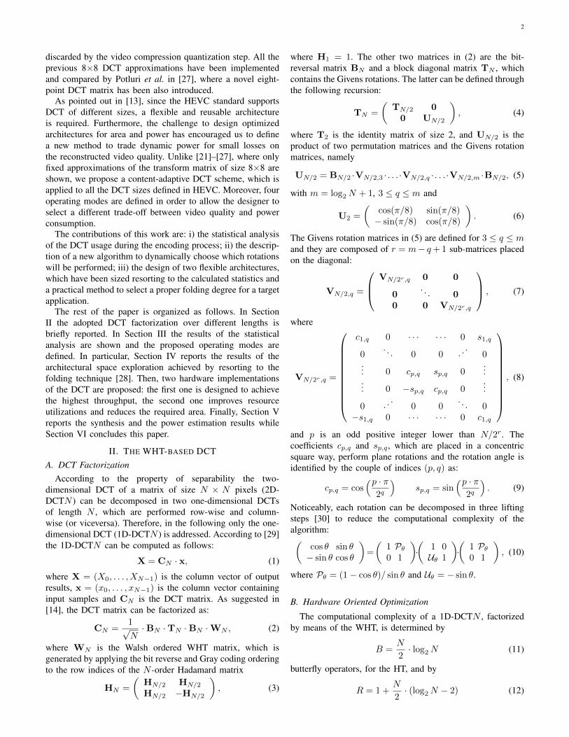
discarded by the video compression quantization step. All theprevious 8×8 DCT approximations have been implementedand compared by Potluri et al. in [27], where a novel eight-point DCT matrix has been also introduced.
As pointed out in [13], since the HEVC standard supportsDCT of different sizes, a flexible and reusable architectureis required. Furthermore, the challenge to design optimizedarchitectures for area and power has encouraged us to definea new method to trade dynamic power for small losses onthe reconstructed video quality. Unlike [21]–[27], where onlyfixed approximations of the transform matrix of size 8×8 areshown, we propose a content-adaptive DCT scheme, which isapplied to all the DCT sizes defined in HEVC. Moreover, fouroperating modes are defined in order to allow the designer toselect a different trade-off between video quality and powerconsumption.
The contributions of this work are: i) the statistical analysisof the DCT usage during the encoding process; ii) the descrip-tion of a new algorithm to dynamically choose which rotationswill be performed; iii) the design of two flexible architectures,which have been sized resorting to the calculated statistics anda practical method to select a proper folding degree for a targetapplication.
The rest of the paper is organized as follows. In SectionII the adopted DCT factorization over different lengths isbriefly reported. In Section III the results of the statisticalanalysis are shown and the proposed operating modes aredefined. In particular, Section IV reports the results of thearchitectural space exploration achieved by resorting to thefolding technique [28]. Then, two hardware implementationsof the DCT are proposed: the first one is designed to achievethe highest throughput, the second one improves resourceutilizations and reduces the required area. Finally, Section Vreports the synthesis and the power estimation results whileSection VI concludes this paper.
II. THE WHT-BASED DCTA. DCT Factorization
According to the property of separability the two-dimensional DCT of a matrix of size N × N pixels (2D-DCTN ) can be decomposed in two one-dimensional DCTsof length N , which are performed row-wise and column-wise (or viceversa). Therefore, in the following only the one-dimensional DCT (1D-DCTN ) is addressed. According to [29]the 1D-DCTN can be computed as follows:
X = CN · x, (1)
where X = (X0, . . . , XN−1) is the column vector of outputresults, x = (x0, . . . , xN−1) is the column vector containinginput samples and CN is the DCT matrix. As suggested in[14], the DCT matrix can be factorized as:
CN =1√N·BN ·TN ·BN ·WN , (2)
where WN is the Walsh ordered WHT matrix, which isgenerated by applying the bit reverse and Gray coding orderingto the row indices of the N -order Hadamard matrix
HN =
(HN/2 HN/2
HN/2 −HN/2
), (3)
where H1 = 1. The other two matrices in (2) are the bit-reversal matrix BN and a block diagonal matrix TN , whichcontains the Givens rotations. The latter can be defined throughthe following recursion:
TN =
(TN/2 00 UN/2
), (4)
where T2 is the identity matrix of size 2, and UN/2 is theproduct of two permutation matrices and the Givens rotationmatrices, namely
UN/2 = BN/2 ·VN/2,3 · . . . ·VN/2,q · . . . ·VN/2,m ·BN/2, (5)
with m = log2N + 1, 3 ≤ q ≤ m and
U2 =
(cos(π/8) sin(π/8)− sin(π/8) cos(π/8)
). (6)
The Givens rotation matrices in (5) are defined for 3 ≤ q ≤ mand they are composed of r = m− q+ 1 sub-matrices placedon the diagonal:
VN/2,q =
VN/2r,q 0 0
0. . . 0
0 0 VN/2r,q
, (7)
where
VN/2r,q =
c1,q 0 · · · · · · 0 s1,q
0. . . 0 0 . .
.0
... 0 cp,q sp,q 0...
... 0 −sp,q cp,q 0...
0 . ..
0 0. . . 0
−s1,q 0 · · · · · · 0 c1,q
, (8)
and p is an odd positive integer lower than N/2r. Thecoefficients cp,q and sp,q , which are placed in a concentricsquare way, perform plane rotations and the rotation angle isidentified by the couple of indices (p, q) as:
cp,q = cos(p · π
2q
)sp,q = sin
(p · π2q
). (9)
Noticeably, each rotation can be decomposed in three liftingsteps [30] to reduce the computational complexity of thealgorithm:(
cos θ sin θ− sin θ cos θ
)=
(1 Pθ0 1
)·(
1 0Uθ 1
)·(
1 Pθ0 1
), (10)
where Pθ = (1− cos θ)/ sin θ and Uθ = − sin θ.
B. Hardware Oriented Optimization
The computational complexity of a 1D-DCTN , factorizedby means of the WHT, is determined by
B =N
2· log2N (11)
butterfly operators, for the HT, and by
R = 1 +N
2· (log2N − 2) (12)
3
TABLE IACCURACY MEASURES AND ARITHMETIC COMPLEXITY OF 1D-DCT8 APPROXIMATIONS.
Method ε MSE (×10−2) Cg η MULT ADD SHIFTExact DCT 0.0000 0.0000 8.826 93.991 64 56 0HM [31] 0.0020 0.0009 8.829 93.825 20 28 2Proposed DCT [32] 0.0004 0.0003 8.827 93.949 15 39 0WHT 5.0494 2.5112 7.946 85.314 0 24 0BAS-2008 [21] 5.9293 2.3783 8.119 86.863 0 18 2BAS-2011 a=0 [22] 26.8642 7.1040 7.912 85.642 0 16 0BAS-2011 a=1 [22] 26.8642 7.1025 7.913 85.380 0 18 0BAS-2011 a=2 [22] 27.9224 7.8318 7.763 84.767 0 18 2CB-2011 [24] 1.7945 0.9800 8.183 87.430 0 22 0Modified CB-2011 [25] 8.6592 5.9389 7.333 80.897 0 14 0Improved Modified CB-2011 [27] 11.3128 7.8987 7.333 80.897 0 14 0
TABLE IIAPPROXIMATED VALUES OF LIFTING COEFFICIENTS.
Givens rotation a Adders Shifters b Adders Shiftersπ/8 51 2 2 98 2 3π/16 25 2 2 50 2 3
3·π/16 78 2 3 142 2 3π/32 13 2 2 25 2 2
3·π/32 38 2 3 74 2 35·π/32 64 0 1 121 2 27·π/32 92 2 3 162 2 3π/64 6 1 2 13 2 2
3·π/64 19 2 2 38 2 35·π/64 32 0 1 62 1 27·π/64 44 2 3 86 3 49·π/64 57 2 2 109 3 3
11·π/64 71 2 2 132 1 213·π/64 85 2 2 152 2 315·π/64 99 2 2 172 3 4
Givens rotations. One butterfly is composed of two adders,while one rotation is implemented by means of the liftingscheme, which is composed of three stages, as in (10), each ofwhich requires one multiplication and one addition. Accordingto the approach suggested in [33], lifting coefficients areexpressed as:
1− cos θ
sin θ≈ a
2n, sin θ ≈ b
2n. (13)
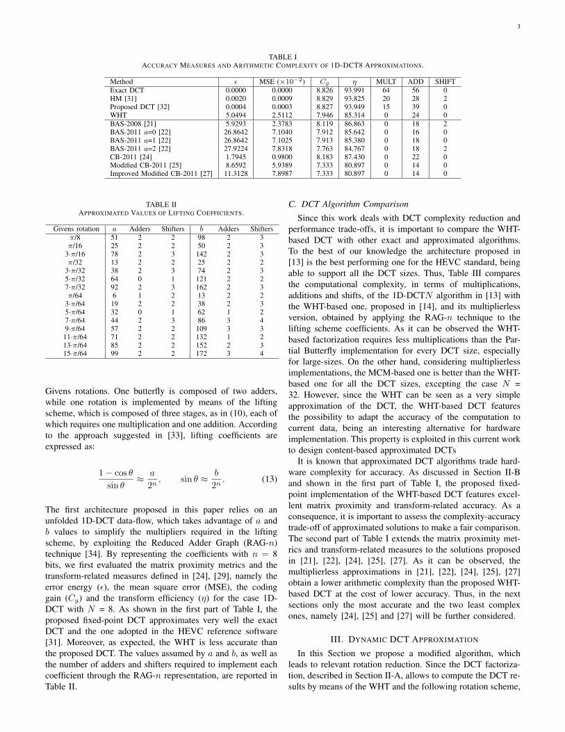
The first architecture proposed in this paper relies on anunfolded 1D-DCT data-flow, which takes advantage of a andb values to simplify the multipliers required in the liftingscheme, by exploiting the Reduced Adder Graph (RAG-n)technique [34]. By representing the coefficients with n = 8bits, we first evaluated the matrix proximity metrics and thetransform-related measures defined in [24], [29], namely theerror energy (ε), the mean square error (MSE), the codinggain (Cg) and the transform efficiency (η) for the case 1D-DCT with N = 8. As shown in the first part of Table I, theproposed fixed-point DCT approximates very well the exactDCT and the one adopted in the HEVC reference software[31]. Moreover, as expected, the WHT is less accurate thanthe proposed DCT. The values assumed by a and b, as well asthe number of adders and shifters required to implement eachcoefficient through the RAG-n representation, are reported inTable II.
C. DCT Algorithm Comparison
Since this work deals with DCT complexity reduction andperformance trade-offs, it is important to compare the WHT-based DCT with other exact and approximated algorithms.To the best of our knowledge the architecture proposed in[13] is the best performing one for the HEVC standard, beingable to support all the DCT sizes. Thus, Table III comparesthe computational complexity, in terms of multiplications,additions and shifts, of the 1D-DCTN algorithm in [13] withthe WHT-based one, proposed in [14], and its multiplierlessversion, obtained by applying the RAG-n technique to thelifting scheme coefficients. As it can be observed the WHT-based factorization requires less multiplications than the Par-tial Butterfly implementation for every DCT size, especiallyfor large-sizes. On the other hand, considering multiplierlessimplementations, the MCM-based one is better than the WHT-based one for all the DCT sizes, excepting the case N =32. However, since the WHT can be seen as a very simpleapproximation of the DCT, the WHT-based DCT featuresthe possibility to adapt the accuracy of the computation tocurrent data, being an interesting alternative for hardwareimplementation. This property is exploited in this current workto design content-based approximated DCTs
It is known that approximated DCT algorithms trade hard-ware complexity for accuracy. As discussed in Section II-Band shown in the first part of Table I, the proposed fixed-point implementation of the WHT-based DCT features excel-lent matrix proximity and transform-related accuracy. As aconsequence, it is important to assess the complexity-accuracytrade-off of approximated solutions to make a fair comparison.The second part of Table I extends the matrix proximity met-rics and transform-related measures to the solutions proposedin [21], [22], [24], [25], [27]. As it can be observed, themultiplierless approximations in [21], [22], [24], [25], [27]obtain a lower arithmetic complexity than the proposed WHT-based DCT at the cost of lower accuracy. Thus, in the nextsections only the most accurate and the two least complexones, namely [24], [25] and [27] will be further considered.
III. DYNAMIC DCT APPROXIMATION
In this Section we propose a modified algorithm, whichleads to relevant rotation reduction. Since the DCT factoriza-tion, described in Section II-A, allows to compute the DCT re-sults by means of the WHT and the following rotation scheme,

4
TABLE IIICOMPARISON OF COMPUTATIONAL COMPLEXITY OF 1D-DCTN .
Partial Butterfly [31] MCM Based [13] WHT-based [14] RAG-n BasedN MULT ADD SHIFT ADD SHIFT MULT ADD SHIFT ADD SHIFT4 4 8 2 14 10 3 11 0 17 108 20 28 2 50 30 15 39 0 69 52
16 84 100 2 186 86 49 115 2 213 17632 340 372 2 682 278 139 307 8 584 503
TABLE IVTEST SEQUENCES USED FOR SIMULATIONS.
Class Resolution Length Sequence Frame RateTraffic 30 Hz
A 2560×1600 5 s People On Street 30 HzNebuta Festival 60 Hz
Steam Locomotive 60 HzKimono 24 Hz
Park Scene 24 HzB 1920×1080 10 s Cactus 50 Hz
BQ Terrace 60 HzBasketball Drive 50 Hz
Four People 60 HzE 1280×720 10 s Johnny 60 Hz
Kristen and Sara 60 Hz
the key-idea of this modified algorithm is to explore differentapproximations of the DCT by adaptively reducing the numberof rotations to be computed. This space goes from the WHT,where all the Givens rotations are skipped, to the completeDCT where all the computation is performed. It is worthpointing out that the results obtained by removing rotations areapproximated. However, in HEVC the coefficients producedby the DCT are quantized, so the injected quantization noisepartially hides the accuracy degradation introduced at thetransform step. Therefore, if a small quality loss is consideredacceptable, then it is unnecessary to compensate the DCTapproximation.
In order to determine whether a rotation has to be applied, apre-computation mechanism is adopted. The idea is to comparethe two inputs of one rotation unit with a threshold. Then,the rotation is skipped when the magnitude of both inputs islower than the threshold or the special signal SKIP is asserted.The effectiveness of this method strongly depends on a properchoice of the thresholds. In this paper we analyse the generalapproach, which allows to identify appropriate thresholds.Then, four different trade-offs between computation savingand rate-distortion performance have been determined on thebasis of the results of such analysis.
A. Experimental Setup
All the simulations have been performed encoding twelvehigh-resolution video sequences, taken from the set of se-quences employed during the HEVC standardization processand referred to as common test conditions (CTC) [35]. Thesesequences belong to three classes, which differ in terms ofresolution, characteristics of the content and application, asreported in Table IV. According to the CTC [35], each classcan be encoded with different configurations: all intra (AI),low delay (LD) and random access (RA). AI configuration
encodes the video as a sequence of intra frames. The LDconfiguration is used for interactive applications such as video-conferencing. It is worth noting that it uses only B frames withreference to previous pictures in order to avoid delay due tothe encoding computation. The RA configuration is related toentertainment applications and it allows to start decoding fromdifferent points in the sequence. This feature is achieved byusing a hierarchical Group Of Pictures (GOP) structure madeof both I-frames and B-frames.
All the simulations shown in this paper have been performedwith the HEVC reference software HM 8.0 [31], which hasbeen modified with the introduction of our DCT and otherapproximations taken from the literature [32]. Four quantiza-tion parameters (QP) were fixed, namely 22, 27, 32 and 37as suggested in [35]. Finally, rate-distortion curves, which usethe combined peak-signal-to-noise-ratio PSNRYUV, as definedin [2], were used as quality measure. The Bjøntegaard method[36] for calculating objective differences (∆PSNR and ∆Rate)between rate-distortion curves has been used as the metric forevaluating quality loss.
B. DCT and Rotation StatisticsFrom now on, the 2D-DCTN will be referred to as DCTN
for brevity. In order to limit quality loss, a statistical analysisof which DCTN are used is required. This information iscrucial to understand which DCTs rotation mainly contributesto the quality degradation, as well as to calculate the averagethroughput of the proposed architectures. As an example TableV reports the usage statistics of each DCT and the correspond-ing percentage of rotations for three sequences, taken fromdifferent classes, encoded with the configurations specifiedin the CTC [35]. As it can be observed, simulations resultswith LD or RA configurations point out that all the sequencesexhibit similar percentage of usage: the most used DCT isthe DCT4 with almost the 70% of the total count, then theDCT8 with about the 20% and the DCT16 with the 5%. Theleast used one is the DCT32 with a percentage below the 1%.The values are slightly different when the AI configuration isemployed; in this case the count for DCT4 decreases to about58% while larger transforms increase, especially the DCT8passing from about 20% to about the 34%. The mismatchbetween statistics of AI and LD, RA configurations is due tothe different performance between intra- and inter-prediction,which can remove some TU partitioning from the exhaustivesearch set.
On the other hand, the highest number of rotations belongsto the DCTs of size 16 and 32, for which it grows more thanlinearly, as indicated in (12). Together, they cover approxi-mately the 70% of the total, the remaining 30% is due to

5
TABLE VDCT AND ROTATION STATISTICS ON SEQUENCES:
(A) TRAFFIC. (B) KIMONO. (C) FOURPEOPLE.
DCT Statistics Rotation StatisticsAI LD RA AI LD RA
DCT4 59.2% - 72.3% 4.5% - 7.5%DCT8 34.0% - 21.6% 25.9% - 22.4%DCT16 5.4% - 5.3% 27.9% - 37.5%DCT32 1.4% - 0.8% 41.7% - 32.6%
(A)
DCT Statistics Rotation StatisticsAI LD RA AI LD RA
DCT4 56.8% 72.0% 72.0% 3.9% 7.5% 7.4%DCT8 35.2% 21.9% 21.8% 24.5% 22.7% 22.5%DCT16 6.5% 5.3% 5.4% 30.7% 37.3% 37.8%DCT32 1.5% 0.8% 0.8% 40.9% 32.5% 32.3%
(B)
DCT Statistics Rotation StatisticsAI LD RA AI LD RA
DCT4 60.8% 73.4% - 4.8% 8.2% -DCT8 32.8% 20.9% - 25.7% 23.3% -DCT16 5.0% 5.0% - 26.6% 37.9% -DCT32 1.4% 0.7% - 43.0% 30.6% -
(C)
TABLE VINUMBER OF ROTATIONS PER ANGLE BREAKDOWN.
π/8 p · π/16 p · π/32 p · π/64DCT4 8 - - -DCT8 48 16 - -DCT16 224 96 32 -DCT32 960 448 192 64
the DCT4 (about 7%) and the DCT8 (about 23%). Therefore,since large-size DCTs require higher computational effort thansmall-size ones, it is likely that the most of saved operationsand quality loss, are due to DCT16 and DCT32. However,some rotations are used across more than one DCT, so theeffect on the PSNR of one Givens rotation depends on boththe DCT size and the rotation angle. Thus, Table VI showsthe number of rotations per angle to compute each DCTN ,where p is an odd integer lower than N/2.
Results in Table V and VI highlight that the contributionof each rotation to both computational complexity and qualityloss depends on the angle and DCT size. Therefore, differ-ent thresholds can be assigned to the same rotation moduledepending on the working conditions.
C. Operating Mode Definition
The proposed method relies on the values assigned to thethresholds. Since the proposed transform module supports fourDCT sizes, with many rotation angles, the threshold set (T )contains up to 26 elements, each of which is associated to arotation of an angle in a DCT. The general optimization prob-lem, which allows to determine the optimal set of thresholdscan be written as:
T ∗ =
{maximize
TΦ(T )
subject to Λ(T ) < L, (14)
-0.60
-0.50
-0.40
-0.30
-0.20
-0.10
0.00
0 2 22 23 24 25 26 27 28 29 210 211 SKIP-100
-90
-80
-70
-60
-50
-40
-30
-20
-10
0
∆PSN
R (
dB)
Φ (
%)
t
∆PSNRΦ
Fig. 1. ∆PSNR and Φ(t) curves over the threshold value, averaged on allthe sequences encoded with AI.
where T ∗ is the optimal set of thresholds, Φ(T ) and Λ(T )are functions used to model the HEVC encoding processand representing the computational saving and the qualityloss, respectively. The maximum allowable quality loss L ismeasured using the Bjøntegaard difference on the PSNRYUV.In addition, we constrain the threshold values to be powers of2, in order to simplify the hardware implementation. Sincethe exhaustive search of a solution is computationally toocomplex, we reduced the design space by using one thresholdt for all the rotation angles, i.e. T = t.
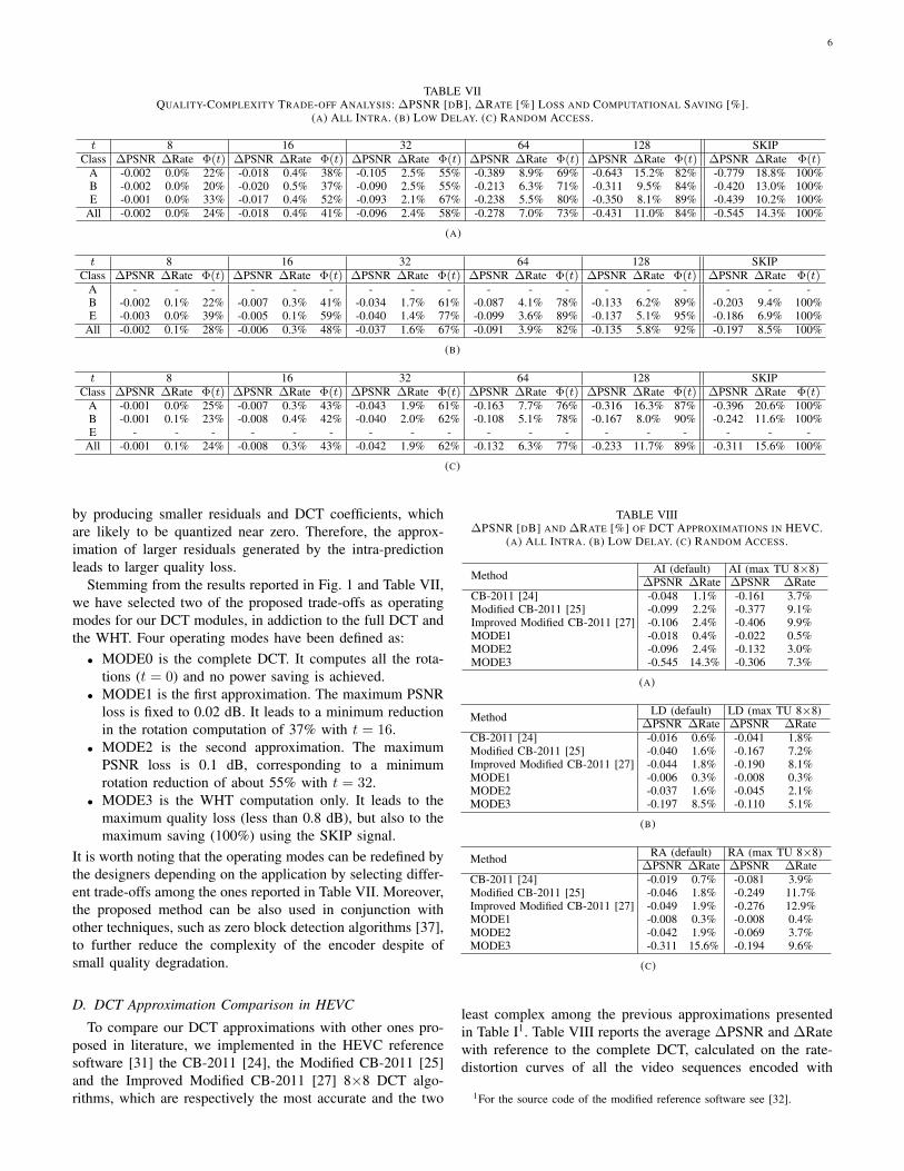
Fig. 1 shows the ∆PSNR difference and the percentageof saved rotations (Φ), averaged on all the test sequencesencoded with the AI configuration, for threshold values t inthe range from 0 to 2048 and in the case of SKIP signalassertion. As expected, both the quality loss and the rotationsaving increase with the threshold value up to the limit fixedby asserting the SKIP signal, where all the rotations areskipped and the DCT is approximated by the WHT only.As it can be observed, by choosing values smaller than 8or larger than 128, the quality loss and the rotation savingare close to either the full DCT or the WHT respectively.Therefore, only the results for thresholds within this range arereported in the left part of Table VII, which shows the qualityloss and the rotation reduction, averaged on video sequencesreported in Table IV taken from classes (A, B and E) separatelyor together (All) and encoded with the experimental setupdescribed in Section III-A. Noticeably, the approximationswith low threshold values exhibit negligible performance losswith respect to the complete DCT. Nevertheless, on average,they reduce the computational effort of the lifting schemeby more than 40%. Then, the quality loss and the rotationsaving grow up to t = 64. From that point, a further increaseof the threshold leads to large quality degradation without asignificant reduction in terms of complexity. This behaviouris observed for all the encoding configurations. Focusing onthe quality loss, the AI configuration, which employs only I-frames, is more sensitive to DCT approximation than the LDand RA configurations. This effect is due to the fact that inter-prediction provides better performance than intra-prediction,
6
TABLE VIIQUALITY-COMPLEXITY TRADE-OFF ANALYSIS: ∆PSNR [DB], ∆RATE [%] LOSS AND COMPUTATIONAL SAVING [%].
(A) ALL INTRA. (B) LOW DELAY. (C) RANDOM ACCESS.
t 8 16 32 64 128 SKIPClass ∆PSNR ∆Rate Φ(t) ∆PSNR ∆Rate Φ(t) ∆PSNR ∆Rate Φ(t) ∆PSNR ∆Rate Φ(t) ∆PSNR ∆Rate Φ(t) ∆PSNR ∆Rate Φ(t)
A -0.002 0.0% 22% -0.018 0.4% 38% -0.105 2.5% 55% -0.389 8.9% 69% -0.643 15.2% 82% -0.779 18.8% 100%B -0.002 0.0% 20% -0.020 0.5% 37% -0.090 2.5% 55% -0.213 6.3% 71% -0.311 9.5% 84% -0.420 13.0% 100%E -0.001 0.0% 33% -0.017 0.4% 52% -0.093 2.1% 67% -0.238 5.5% 80% -0.350 8.1% 89% -0.439 10.2% 100%
All -0.002 0.0% 24% -0.018 0.4% 41% -0.096 2.4% 58% -0.278 7.0% 73% -0.431 11.0% 84% -0.545 14.3% 100%
(A)
t 8 16 32 64 128 SKIPClass ∆PSNR ∆Rate Φ(t) ∆PSNR ∆Rate Φ(t) ∆PSNR ∆Rate Φ(t) ∆PSNR ∆Rate Φ(t) ∆PSNR ∆Rate Φ(t) ∆PSNR ∆Rate Φ(t)
A - - - - - - - - - - - - - - - - - -B -0.002 0.1% 22% -0.007 0.3% 41% -0.034 1.7% 61% -0.087 4.1% 78% -0.133 6.2% 89% -0.203 9.4% 100%E -0.003 0.0% 39% -0.005 0.1% 59% -0.040 1.4% 77% -0.099 3.6% 89% -0.137 5.1% 95% -0.186 6.9% 100%
All -0.002 0.1% 28% -0.006 0.3% 48% -0.037 1.6% 67% -0.091 3.9% 82% -0.135 5.8% 92% -0.197 8.5% 100%
(B)
t 8 16 32 64 128 SKIPClass ∆PSNR ∆Rate Φ(t) ∆PSNR ∆Rate Φ(t) ∆PSNR ∆Rate Φ(t) ∆PSNR ∆Rate Φ(t) ∆PSNR ∆Rate Φ(t) ∆PSNR ∆Rate Φ(t)
A -0.001 0.0% 25% -0.007 0.3% 43% -0.043 1.9% 61% -0.163 7.7% 76% -0.316 16.3% 87% -0.396 20.6% 100%B -0.001 0.1% 23% -0.008 0.4% 42% -0.040 2.0% 62% -0.108 5.1% 78% -0.167 8.0% 90% -0.242 11.6% 100%E - - - - - - - - - - - - - - - - - -
All -0.001 0.1% 24% -0.008 0.3% 43% -0.042 1.9% 62% -0.132 6.3% 77% -0.233 11.7% 89% -0.311 15.6% 100%
(C)
by producing smaller residuals and DCT coefficients, whichare likely to be quantized near zero. Therefore, the approx-imation of larger residuals generated by the intra-predictionleads to larger quality loss.
Stemming from the results reported in Fig. 1 and Table VII,we have selected two of the proposed trade-offs as operatingmodes for our DCT modules, in addiction to the full DCT andthe WHT. Four operating modes have been defined as:• MODE0 is the complete DCT. It computes all the rota-
tions (t = 0) and no power saving is achieved.• MODE1 is the first approximation. The maximum PSNR
loss is fixed to 0.02 dB. It leads to a minimum reductionin the rotation computation of 37% with t = 16.
• MODE2 is the second approximation. The maximumPSNR loss is 0.1 dB, corresponding to a minimumrotation reduction of about 55% with t = 32.
• MODE3 is the WHT computation only. It leads to themaximum quality loss (less than 0.8 dB), but also to themaximum saving (100%) using the SKIP signal.
It is worth noting that the operating modes can be redefined bythe designers depending on the application by selecting differ-ent trade-offs among the ones reported in Table VII. Moreover,the proposed method can be also used in conjunction withother techniques, such as zero block detection algorithms [37],to further reduce the complexity of the encoder despite ofsmall quality degradation.
D. DCT Approximation Comparison in HEVC
To compare our DCT approximations with other ones pro-posed in literature, we implemented in the HEVC referencesoftware [31] the CB-2011 [24], the Modified CB-2011 [25]and the Improved Modified CB-2011 [27] 8×8 DCT algo-rithms, which are respectively the most accurate and the two
TABLE VIII∆PSNR [DB] AND ∆RATE [%] OF DCT APPROXIMATIONS IN HEVC.
(A) ALL INTRA. (B) LOW DELAY. (C) RANDOM ACCESS.
Method AI (default) AI (max TU 8×8)∆PSNR ∆Rate ∆PSNR ∆Rate
CB-2011 [24] -0.048 1.1% -0.161 3.7%Modified CB-2011 [25] -0.099 2.2% -0.377 9.1%Improved Modified CB-2011 [27] -0.106 2.4% -0.406 9.9%MODE1 -0.018 0.4% -0.022 0.5%MODE2 -0.096 2.4% -0.132 3.0%MODE3 -0.545 14.3% -0.306 7.3%
(A)
Method LD (default) LD (max TU 8×8)∆PSNR ∆Rate ∆PSNR ∆Rate
CB-2011 [24] -0.016 0.6% -0.041 1.8%Modified CB-2011 [25] -0.040 1.6% -0.167 7.2%Improved Modified CB-2011 [27] -0.044 1.8% -0.190 8.1%MODE1 -0.006 0.3% -0.008 0.3%MODE2 -0.037 1.6% -0.045 2.1%MODE3 -0.197 8.5% -0.110 5.1%
(B)
Method RA (default) RA (max TU 8×8)∆PSNR ∆Rate ∆PSNR ∆Rate
CB-2011 [24] -0.019 0.7% -0.081 3.9%Modified CB-2011 [25] -0.046 1.8% -0.249 11.7%Improved Modified CB-2011 [27] -0.049 1.9% -0.276 12.9%MODE1 -0.008 0.3% -0.008 0.4%MODE2 -0.042 1.9% -0.069 3.7%MODE3 -0.311 15.6% -0.194 9.6%
(C)
least complex among the previous approximations presentedin Table I1. Table VIII reports the average ∆PSNR and ∆Ratewith reference to the complete DCT, calculated on the rate-distortion curves of all the video sequences encoded with
1For the source code of the modified reference software see [32].

7
N-point 1D-DCT
MU
X
>>log2N - 1
>>log2N + 6
rows of
2D-DCT
input
columns of
intermediate
output
rows of
intermediate
input
columns of
2D-DCT
output
C.U.
Transposition
Memory
Fig. 2. Folded 2D-DCT architecture.
two configurations. The first one is the default configuration,while the second one is derived from the default configurationby limiting the maximum transform size to 8×8. As shownin Table VIII, the rate-distortion performance with defaultconfigurations of our MODE1 approximation is the best one,whereas MODE3 is the worst one. Indeed, in this configurationthe results achieved with [24], [25] and [27] methods areaffected by DCT8 approximations only. In order to make afair comparison, we analyzed the custom configuration withmaximum TU size limited to 8×8. As it can be observed, thebehaviour of our proposed DCT is independent of the trans-form size, due to its inherent adaptivity. On the other hand, themethods taken from the literature show some degradation ofrate-distortion performance when the percentage of usage ofthe 8×8 DCT grows. In particular, the reduction of complexityprovided in [25], [27] and shown in Table I, leads to significantquality loss, much larger than the bound fixed by the proposedMODE3.
IV. PROPOSED ARCHITECTURES
In this Section we show the top-level of the proposed ar-chitectures and two possible implementations of the 1D-DCTmodule. The first one is a completely unfolded architecturederived from the one proposed in [14], where all the requiredoperations are mapped to different resources, thus achievingthe highest possible throughput for the DCT factorizationpresented in Section II. The second architecture is a foldedone, where the folding technique [28] is exploited to reusehardware resources during the computation of the differentDCTs.
A. 2D-DCT Architecture
Fig. 2 reports the proposed 2D-DCT architecture. It iscomposed of two main blocks: the 1D-DCT module and thetransposition memory, which has the role of transposing theintermediate results. Due to its flexibility, this architecture isable to concurrently perform the DCT computation on multipleblocks, depending on the DCT size. Since the number of inputsamples is fixed to 32, this module can compute 32/N DCTN ,i.e. one DCT32, two DCT16, four DCT8 or eight DCT4, thusleading to an efficient usage of the hardware resources. Forthis reason, in this work the transposition memory is designed
in the same way as presented in [13]. It is made of an arrayof 32×32 registers, required to support the DCT32, and it isable to transpose blocks of different size.
The whole system computation is scheduled as follows. Therows of the input block pixels are fed into the one-dimensionalDCT module, which computes the 1D-DCTN . Input pixelsare represented with 9 bits, this because they are the result ofthe difference between the current and the predicted frames.Then, according to the HM 8.0, the produced results arescaled to 16 bits and stored row-wise in the transpositionmemory, as shown by the log2N − 1 right shift block inthe feedback path in Fig. 2. Once all the rows have beenprocessed, the multiplexers feed the 1D-DCT with the columnsof the intermediate data, which are stored in the transpositionmemory. Finally, the results are scaled back to 16 bits forcompliance with the HM 8.0 (see the log2N + 6 shift blockin Fig. 2). All the operations are managed by a control unit(C.U.), which generates both the signals for the data selectionand storing and for the 1D-DCT block.
B. Unfolded 1D-DCT
The first proposed architecture is the unfolded one. Its dataflow is reported in Fig. 3. It is a four stage pipelined datapathcomposed of two main computational entities: the HT (leftside of Fig. 3) and the rotation scheme (right part of Fig.3). The former block receives 32 samples at each clock cycleand computes the HT by means of the butterfly stages (BUT),which perform the B butterflies indicated in (11). The HTblock is followed by a network, which implements i) bitreverse and Gray coding, to obtain Walsh-ordered data, andii) bit reverse and permutation to reorder the signals for therotation block.
According to (12), the rotation scheme contains R = 49modules, depicted as circles and ovals in Fig. 3, to supportthe worst-case, which is the DCT32. Each rotation receivesas input the threshold for the related angle and it is equippedwith some logic to implement the pre-computation mechanismintroduced in Section III. Fig. 4 reports the block schemeof a generic rotation module. Two comparators are used todetermine whether the incoming signals are smaller than thethreshold and the enable signal activates only the register bankwhich is used in the following clock cycle. If one rotation isnot calculated, then the data are sampled by register bank 1and they are not propagated to the rotation logic, thus savingdynamic power. Otherwise, the path which passes throughregister bank 2 is enabled. A final multiplexer, driven by thesame condition signal, chooses the correct output. Moreover,the special SKIP signal (which has been introduced in SectionIII) is also used to avoid rotations when the DCT size issmaller then 32 or to bypass all the rotations when the moduleworks in MODE3 (WHT only). According to (10), the rotationis computed by means of three lifting steps, each composed ofa multiplication, a shift and an addition, as illustrated in Fig.5, where x1, x2 are the input values and y1, y2 the outputresults. The values of the multiplier coefficients (a, b) are theones reported in Table II. The output of the rotation block isthen propagated to a network, which integrates permutation

8
BUT
32
BUT
16
BUT
16
BUT
8
BUT
8
BUT
8
BUT
8
BUT
4 & 2
BUT
4 & 2
BUT
4 & 2
BUT
4 & 2
BUT
4 & 2
BUT
4 & 2
BUT
4 & 2
BUT
4 & 2
NE
TW
OR
K B
it R
ever
se -
Gra
y -
Bit
Rev
erse
- P
erm
uta
tion
NE
TW
OR
K P
erm
uta
tion -
Bit
Rev
erse
16
3
16
32
32
3
32
7
32
5
64
64
3
64
5
64
7
64
9
64
11
64
13
64
15
8
Hadamard Transform Rotation Scheme
Fig. 3. Unfolded architecture for 1D-DCT.
<| · |
<| · |
threshold
rotation
inputs
rotation
outputs
angle
SKIP
MUX
bank
1
bank
2
Fig. 4. Block scheme of a rotation module.
and bit reverse reordering. The flexibility of the architectureis given by a custom set of connections, which arranges thepaths between operators as required for the DCTN .
Since different DCT types require a variable number ofrotation stages, the throughput of this architecture, definedas the number of produced results over the time required toproduce them, varies with the DCT size. The throughput ofthe complete 2D-DCT architecture employing the 1D-DCT is
T =32
N· N
2
∆, (15)
where 32/N represents the number of N×N blocks processedconcurrently, ∆ = 2 · (P + N)/fCK is the time required tocompute the results, P = log2N−1 is the number of pipelinestages required for the computation of a DCTN and fCK isthe clock frequency.
+
>> n
×
+
>> n
×
+
>> n
× a a
b
x1
x2
y1
y2
Fig. 5. Lifting scheme circuit.
C. Folded 1D-DCT
The second implementation is the folded 1D-DCT, where aset of resources is shared among DCTs of different size. Thereuse of such operators can be exploited either to support DCTcomputations of different lengths or to increase the throughputof small size DCTs. Therefore, the amount of resources andthe folding degree define a large design space. The explorationof such a space is detailed in the following paragraphs. Thetechnique is applied to both HT and rotations. Let KB , KR
be the number of butterfly and rotation resources respectively,and α, β indicate the number of cycles required to computethe WHT and the Givens rotations of 32/N 1D-DCT of sizeN .Assuming that the architecture works in pipeline and that thenumber of clock cycles required to compute one 1D-DCTN
9
0.0⋅100
2.0⋅108
4.0⋅108
6.0⋅108
8.0⋅108
1.0⋅109
1.2⋅109
1.4⋅109
0 2 4 6 8 10 12 14 16
KR = 1
KR = 2
KR = 3
KR = 4KR = 5,6
KR = 7
KR = 8,9KR = 10,11
KR = 12,13
Thr
ough
put (
sam
ples
/s)
Number of butterfly operators KB
(A)
0.0⋅100
2.0⋅108
4.0⋅108
6.0⋅108
8.0⋅108
1.0⋅109
1.2⋅109
1.4⋅109
0 2 4 6 8 10 12
KB = 1
KB = 2
KB = 3
KB = 4KB = 5KB = 6
KB = 7
KB = 8,9
KB = 10
KB = 11
KB = 12,13,14,15
KB = 16
Thr
ough
put (
sam
ples
/s)
Number of rotation operators KR
(B)
Fig. 6. Architectural space analysis: (a) throughput as function of KB (b)throughput as function of KR.
is MN , then the time to compute N2 results is
∆ =2 ·N ·MN + L
fCK, (16)
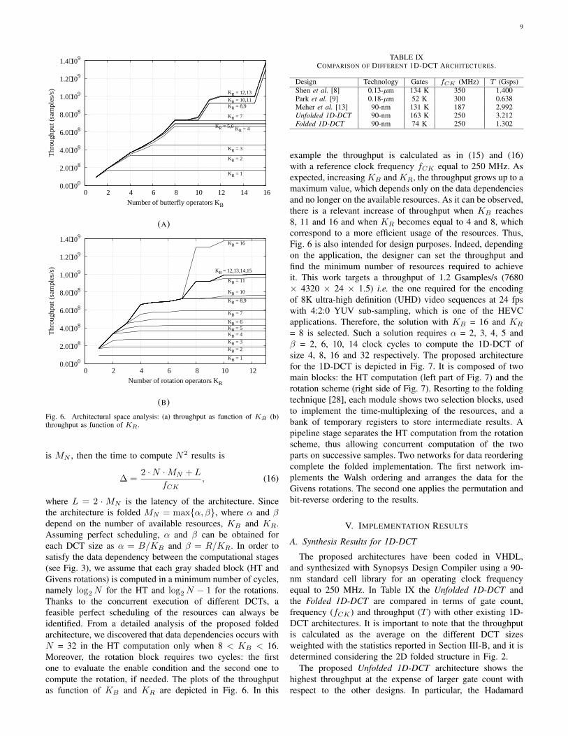
where L = 2 ·MN is the latency of the architecture. Sincethe architecture is folded MN = max{α, β}, where α and βdepend on the number of available resources, KB and KR.Assuming perfect scheduling, α and β can be obtained foreach DCT size as α = B/KB and β = R/KR. In order tosatisfy the data dependency between the computational stages(see Fig. 3), we assume that each gray shaded block (HT andGivens rotations) is computed in a minimum number of cycles,namely log2N for the HT and log2N − 1 for the rotations.Thanks to the concurrent execution of different DCTs, afeasible perfect scheduling of the resources can always beidentified. From a detailed analysis of the proposed foldedarchitecture, we discovered that data dependencies occurs withN = 32 in the HT computation only when 8 < KB < 16.Moreover, the rotation block requires two cycles: the firstone to evaluate the enable condition and the second one tocompute the rotation, if needed. The plots of the throughputas function of KB and KR are depicted in Fig. 6. In this
TABLE IXCOMPARISON OF DIFFERENT 1D-DCT ARCHITECTURES.
Design Technology Gates fCK (MHz) T (Gsps)Shen et al. [8] 0.13-µm 134 K 350 1.400Park et al. [9] 0.18-µm 52 K 300 0.638Meher et al. [13] 90-nm 131 K 187 2.992Unfolded 1D-DCT 90-nm 163 K 250 3.212Folded 1D-DCT 90-nm 74 K 250 1.302
example the throughput is calculated as in (15) and (16)with a reference clock frequency fCK equal to 250 MHz. Asexpected, increasing KB and KR, the throughput grows up to amaximum value, which depends only on the data dependenciesand no longer on the available resources. As it can be observed,there is a relevant increase of throughput when KB reaches8, 11 and 16 and when KR becomes equal to 4 and 8, whichcorrespond to a more efficient usage of the resources. Thus,Fig. 6 is also intended for design purposes. Indeed, dependingon the application, the designer can set the throughput andfind the minimum number of resources required to achieveit. This work targets a throughput of 1.2 Gsamples/s (7680× 4320 × 24 × 1.5) i.e. the one required for the encodingof 8K ultra-high definition (UHD) video sequences at 24 fpswith 4:2:0 YUV sub-sampling, which is one of the HEVCapplications. Therefore, the solution with KB = 16 and KR
= 8 is selected. Such a solution requires α = 2, 3, 4, 5 andβ = 2, 6, 10, 14 clock cycles to compute the 1D-DCT ofsize 4, 8, 16 and 32 respectively. The proposed architecturefor the 1D-DCT is depicted in Fig. 7. It is composed of twomain blocks: the HT computation (left part of Fig. 7) and therotation scheme (right side of Fig. 7). Resorting to the foldingtechnique [28], each module shows two selection blocks, usedto implement the time-multiplexing of the resources, and abank of temporary registers to store intermediate results. Apipeline stage separates the HT computation from the rotationscheme, thus allowing concurrent computation of the twoparts on successive samples. Two networks for data reorderingcomplete the folded implementation. The first network im-plements the Walsh ordering and arranges the data for theGivens rotations. The second one applies the permutation andbit-reverse ordering to the results.
V. IMPLEMENTATION RESULTS
A. Synthesis Results for 1D-DCT
The proposed architectures have been coded in VHDL,and synthesized with Synopsys Design Compiler using a 90-nm standard cell library for an operating clock frequencyequal to 250 MHz. In Table IX the Unfolded 1D-DCT andthe Folded 1D-DCT are compared in terms of gate count,frequency (fCK) and throughput (T ) with other existing 1D-DCT architectures. It is important to note that the throughputis calculated as the average on the different DCT sizesweighted with the statistics reported in Section III-B, and it isdetermined considering the 2D folded structure in Fig. 2.
The proposed Unfolded 1D-DCT architecture shows thehighest throughput at the expense of larger gate count withrespect to the other designs. In particular, the Hadamard

10
INP
UT
MU
XE
S
NE
TW
OR
K
Bit
Rev
erse
- G
ray
- B
it R
ever
se -
Per
mu
tati
on
NE
TW
OR
K
Per
mu
tati
on
- B
it R
ever
se
Hadamard Transform Rotation Scheme
OU
TP
UT
MU
XE
S
Pip
e R
egis
ters
Tem
po
rary
Reg
iste
rs
BU
TT
ER
FL
Y O
PE
RA
TO
RS
INP
UT
MU
XE
S
OU
TP
UT
MU
XE
S
Tem
po
rary
Reg
iste
rs
Rotation Scheme
Fig. 7. Proposed folded architecture for 1D-DCT.
TABLE XCOMPARISON OF DIFFERENT 2D-DCT ARCHITECTURES.
Design N Technology Gates fCK (MHz) T (Gsps) P (mW) EPS (pJ) Pd (mW/MHz)BAS-2008 [27] 8 45-nm 78 K 809 6.472 550 84.98 0.679BAS-2011 a=0 [27] 8 45-nm 74 K 763 6.104 500 81.91 0.655BAS-2011 a=1 [27] 8 45-nm 68 K 833 6.664 480 72.02 0.576BAS-2011 a=2 [27] 8 45-nm 68 K 832 6.656 480 72.11 0.576CB-2011 [27] 8 45-nm 86 K 806 6.448 600 93.05 0.744Modified CB-2011 [27] 8 45-nm 74 K 849 6.792 550 80.97 0.647Improved Modified CB-2011 [27] 8 45-nm 74 K 851 6.808 550 80.78 0.646Meher et al. Folded [13] 4, 8, 16, 32 90-nm 208 K 187 2.992 40.04 13.38 0.214Meher et al. Full-parallel [13] 4, 8, 16, 32 90-nm 347 K 187 5.984 67.57 11.29 0.361Ahmed et al. [14] 4, 8, 16, 32 90-nm 149 K 150 0.253 - - -
Architecture 1
MODE0
4, 8, 16, 32 90-nm 243 K 250 3.212
51.72 16.10 0.207MODE1 35.38 11.01 0.142MODE2 30.88 9.61 0.124MODE3 22.71 7.07 0.091
Architecture 2
MODE0
4, 8, 16, 32 90-nm 157 K 250 1.302
28.98 22.26 0.116MODE1 20.75 15.94 0.083MODE2 18.40 14.13 0.074MODE3 13.82 10.61 0.055
Transform and the Rotation Scheme block in Fig. 3 requires22 K and 135 K gates respectively. It is worth noting that theproposed architecture features some hardware overhead com-pared with the solution provided in [13]. This figure dependson the fact that [13] supports only exact DCT computation,whereas the proposed one includes some logic and registersto support the four operating modes defined in Section III.On the other hand, the proposed Folded 1D-DCT shows avery reduced gate count for the computation of the 1D-DCT,even if it supports the four operating modes as well as theunfolded one. Only 51 K gates are needed to implement theRotation Scheme, while 15 K gates are used for the HadamardTransform. When compared with [9], where only transforms
of size 16 and 32 are implemented, the proposed Folded 1D-DCT architecture shows similar gate count, but it can achievedouble throughput.
B. Synthesis Results for 2D-DCT
The two proposed 2D-DCT architectures, based on theunfolded and the folded 1D-DCT modules, have been syn-thesized as well. In the following they will be referred to asArchitecture 1 and Architecture 2 respectively. Table X lists thetechnology, gate count, operating frequency (fCK), throughput(T ), power consumption (P ), energy-per-sample (EPS) andfrequency-normalized dynamic power (Pd), which characterize

11
the two designs and other existing 2D-DCT architecturesfor HEVC. As it can be observed, all the implementationsreported in [27], address the design of DCT of size 8×8only. They provide very high throughput at the cost of veryhigh power consumption. Besides, the operating frequencyof 250 MHz allows the Architecture 1 to support 8K UHDapplications up to 64 fps with 4:2:0 YUV sub-sampling. Forsuch applications, the Full-parallel architecture proposed in[13] achieves the highest throughput with a large gate count asit relies on two 1D-DCT modules. On the contrary, the Foldedarchitecture described in [13] contains one 1D-DCT module,as the Architecture 1 we propose in this current work. As itcan be observed the proposed Architecture 1 achieves higherthroughput with respect to the folded implementation proposedin [13], but it shows slightly larger gate count and powerconsumption, when the operating mode is set to MODE0,because additional logic is required to support the proposedpower reduction algorithm.
On the other hand, Architecture 2 provides the smallestabsolute power consumption, equal to 28.98 mW showingnearly the same gate count as [14] but achieving about fivetimes larger throughput. Indeed, the proposed folded architec-ture supports 8K UHD applications with a maximum frame-rate equal to 26 fps. Moreover, the folded architecture canbe properly sized by choosing the target throughput with themethodology proposed in Section IV-C, thus optimizing areaoccupation and power consumption.
Finally, it is worth noting that both the proposed archi-tectures outperform the other ones in terms of frequency-normalized dynamic power (Pd) while they provide slightlyhigher EPS than the implementations in [13]. However, bothcan be reduced by operating in one of the low-power modesdefined in Section III-C, which allow to reduce the powerconsumption as shown in the following section.
C. Power Consumption Reduction
The power consumption of the proposed architecture can befurther reduced by using the proposed operating modes. In or-der to compute the power consumption reduction achieved byeach mode, power estimation has been performed simulatingand annotating the switching activities of each node of thegate-level netlist generated by the synthesis tool. A specifictestbench has been used to apply values of real samplesto the input ports of the designed modules. These sampleshave been extracted by annotating the DCT inputs duringencoding simulation of sequences taken from Table IV andthey comply with the DCT usage statistics. Simulations havebeen performed for each of the four operating modes definedin Section III.
The last two rows of Table X show the power consumption,energy-per-sample and frequency-normalized dynamic powerof the two proposed architectures when operating in differentmodes, while Table XI summarizes the power saving cal-culated with reference to the MODE0 (complete DCT). Asexpected, the power saving in Architecture 1 increases whenreducing the computation, namely passing from MODE1 toMODE3 (WHT only), where a power reduction of about 56%
TABLE XIPOWER SAVING OF OPERATING MODES.
Design MODE0 MODE1 MODE2 MODE3Architecture 1 ref. -31.6% -40.3% -56.1%Architecture 2 ref. -28.4% -36.5% -52.3%
can be achieved. The same trend as Architecture 1 is observedfor Architecture 2, even though the saving is slightly lower.This is due to the folding technique, which exploits a moreeffective usage of the resources than the unfolded architecture,and to the instantiation of real multipliers in the lifting scheme,instead of custom add-shift multipliers.
VI. CONCLUSION
In this paper two novel DCT architectures for the HEVCstandard have been proposed. The proposed 2D-DCTN com-putation is based on a 1D-DCTN core, where the completeDCT matrix is factorized as the cascade of the WHT andGivens rotations. In order to reduce the number of opera-tions the algorithm has been modified by introducing a pre-computation mechanism, which allows to save rotations anddynamic power at the expense of very small PSNR loss.Then, two flexible and HEVC compliant architectures, ableto support the DCT of size N equal to 4, 8, 16, 32 havebeen proposed. The first one implements the 1D-DCTN in acompletely unfolded fashion, while the second one has beenselected by identifying the proper folding degree. Moreover,the proposed architectural space exploration provides a methodto design such systems by relying on the throughput requiredby the application. From the implementation results, it is foundthat the architectures employing the unfolded and folded 1D-DCT module respectively show competitive throughput andgate count with respect to previous existing architectures. Fi-nally, power consumption results show the advantages offeredby the proposed operating modes, namely MODE1, MODE2and MODE3. In particular, MODE1 reduces roughly by 30%the power consumption with negligible quality loss. Accordingto the complexity analysis provided in [3], power saving upto 10% can be achieved for the entire HEVC encoder anddecoder by operating with the proposed approximations.
ACKNOWLEDGMENT
The authors would like to thank the HPC@POLITO, aproject of Academic Computing within the Department ofControl and Computer Engineering at the Politecnico di Torino(http://www.hpc.polito.it), which have provided the computa-tional resources.
REFERENCES
[1] G. Sullivan, J. Ohm, W.-J. Han, and T. Wiegand, “Overview of the HighEfficiency Video Coding (HEVC) Standard,” IEEE Trans. Circuits Syst.Video Technol., vol. 22, no. 12, pp. 1649–1668, Dec 2012.
[2] J. Ohm, G. Sullivan, H. Schwarz, T. K. Tan, and T. Wiegand, “Compari-son of the Coding Efficiency of Video Coding Standards–Including HighEfficiency Video Coding (HEVC),” IEEE Trans. Circuits Syst. VideoTechnol., vol. 22, no. 12, pp. 1669–1684, Dec 2012.
[3] F. Bossen, B. Bross, K. Suhring, and D. Flynn, “HEVC Complexity andImplementation Analysis,” IEEE Trans. Circuits Syst. Video Technol.,vol. 22, no. 12, pp. 1685–1696, Dec 2012.

12
[4] M. Shafique and J. Henkel, “Low power design of the next-generationHigh Efficiency Video Coding,” in Design Automation Conference (ASP-DAC), 2014 19th Asia and South Pacific, Jan 2014, pp. 274–281.
[5] M. Budagavi, A. Fuldseth, G. Bjontegaard, V. Sze, and M. Sadafale,“Core Transform Design in the High Efficiency Video Coding (HEVC)Standard,” IEEE J. Sel. Topics Signal Process., vol. 7, no. 6, pp. 1029–1041, Dec 2013.
[6] N. Ahmed, T. Natarajan, and K. Rao, “Discrete Cosine Transform,”IEEE Trans. Comput., vol. C-23, no. 1, pp. 90–93, Jan 1974.
[7] A. Madanayake, R. Cintra, V. Dimitrov, F. Bayer, K. Wahid, S. Kulasek-era, A. Edirisuriya, U. Potluri, S. Madishetty, and N. Rajapaksha, “Low-Power VLSI Architectures for DCT/DWT: Precision vs Approximationfor HD Video, Biomedical, and Smart Antenna Applications,” IEEECircuits Syst. Mag., vol. 15, no. 1, pp. 25–47, Firstquarter 2015.
[8] S. Shen, W. Shen, Y. Fan, and X. Zeng, “A Unified 4/8/16/32-PointInteger IDCT Architecture for Multiple Video Coding Standards,” inMultimedia and Expo (ICME), 2012 IEEE International Conference on,July 2012, pp. 788–793.
[9] J. Park, N. W.J., S. Han, and L. S., “2-D Large Inverse Transform(16x16, 32x32) for HEVC (High Efficiency Video Coding),” Journalof Semiconductor Technology and Science, vol. 12, no. 2, pp. 203–211,Jun 2012.
[10] W.-H. Chen, C. Smith, and S. Fralick, “A Fast Computational Algorithmfor the Discrete Cosine Transform,” IEEE Trans. Commun., vol. 25,no. 9, pp. 1004–1009, Sep 1977.
[11] J. Zhu, Z. Liu, and D. Wang, “Fully pipelined DCT/IDCT/Hadamardunified transform architecture for HEVC Codec,” in Circuits and Systems(ISCAS), 2013 IEEE International Symposium on, May 2013, pp. 677–680.
[12] M. Budagavi and V. Sze, “Unified forward+inverse transform archi-tecture for HEVC,” in Image Processing (ICIP), 2012 19th IEEEInternational Conference on, Sept 2012, pp. 209–212.
[13] P. Meher, S. Y. Park, B. Mohanty, K. S. Lim, and C. Yeo, “EfficientInteger DCT Architectures for HEVC,” IEEE Trans. Circuits Syst. VideoTechnol., vol. 24, no. 1, pp. 168–178, Jan 2014.
[14] A. Ahmed, M. U. Shahid, and A. Rehman, “N Point DCT VLSIArchitecture for Emerging HEVC Standard,” VLSI Design, vol. 2012,2012.
[15] Y.-J. Chen, S. Oraintara, and T. Nguyen, “Video compression using inte-ger DCT,” in Image Processing, 2000. Proceedings. 2000 InternationalConference on, vol. 2, Sept 2000, pp. 844–845 vol.2.
[16] S. Venkataraman, V. Kanchan, K. Rao, and M. Mohanty, “Discretetransforms via the Walsh-Hadamard transform,” Signal Processing,vol. 14, no. 4, pp. 371–382, 1988.
[17] V. Dimitrov, K. Wahid, and G. Jullien, “Multiplication-free 8 × 8 2DDCT architecture using algebraic integer encoding,” Electronics Letters,vol. 40, no. 20, pp. 1310–1311, Sept 2004.
[18] A. Madanayake, R. Cintra, D. Onen, V. Dimitrov, N. Rajapaksha,L. Bruton, and A. Edirisuriya, “A Row-Parallel 8 × 8 2-D DCTArchitecture Using Algebraic Integer-Based Exact Computation,” IEEETrans. Circuits Syst. Video Technol., vol. 22, no. 6, pp. 915–929, June2012.
[19] N. Rajapaksha, A. Edirisuriya, A. Madanayake, R. J. Cintra, D. Onen,I. Amer, and V. S. Dimitrov, “Asynchronous Realization of AlgebraicInteger-Based 2D DCT Using Achronix Speedster SPD60 FPGA,”Journal of Electrical and Computer Engineering, vol. 2013, 2013.
[20] Y. Arai, T. Agui, and N. M., “A fast DCT-SQ scheme for images,”Trans. IEICE, vol. E-71, no. 11, pp. 1095–1097, Nov 1988.
[21] S. Bouguezel, M. Ahmad, and M. Swamy, “Low-complexity 8 × 8transform for image compression,” Electronics Letters, vol. 44, no. 21,pp. 1249–1250, October 2008.
[22] ——, “A low-complexity parametric transform for image compression,”in Circuits and Systems (ISCAS), 2011 IEEE International Symposiumon, May 2011, pp. 2145–2148.
[23] ——, “A novel transform for image compression,” in Circuits andSystems (MWSCAS), 2010 53rd IEEE International Midwest Symposiumon, Aug 2010, pp. 509–512.
[24] R. Cintra and F. Bayer, “A DCT Approximation for Image Compres-sion,” IEEE Signal Process. Lett., vol. 18, no. 10, pp. 579–582, Oct2011.
[25] F. Bayer and R. Cintra, “DCT-like transform for image compressionrequires 14 additions only,” Electronics Letters, vol. 48, no. 15, pp.919–921, July 2012.
[26] R. J. Cintra, F. M. Bayer, V. A. Coutinho, S. Kulasekera,and A. Madanayake, “DCT-like Transform for Image and VideoCompression Requires 10 Additions Only,” CoRR, vol. abs/1402.5979,2014. [Online]. Available: http://arxiv.org/abs/1402.5979
[27] U. Sadhvi Potluri, A. Madanayake, R. Cintra, F. Bayer, S. Kulasekera,and A. Edirisuriya, “Improved 8-Point Approximate DCT for Image andVideo Compression Requiring Only 14 Additions,” IEEE Trans. CircuitsSyst. I, vol. 61, no. 6, pp. 1727–1740, June 2014.
[28] K. K. Parhi, VLSI Digital Signal Processing Systems: Design andImplementation. John Wiley, Jan. 1999.
[29] V. Britanak, P. C. Yip, and K. R. Rao, Discrete Cosine and Sine Trans-forms: General Properties, Fast Algorithms and Integer Approximations.Elsevier, Sep. 2006.
[30] I. Daubechies and W. Sweldens, “Factoring wavelet transforms intolifting steps,” Journal of Fourier Analysis and Applications, vol. 4, no. 3,pp. 247–269, 1998.
[31] Joint Collaborative Team on Video Coding (JCT-VC) of ITU-T SG16 WP 3 and ISO/IEC JTC 1/SC 29/WG 11, HM 8.0 ReferenceSoftware, 2012 Jul. [Online]. Available: https://hevc.hhi.fraunhofer.de/svn/svn HEVCSoftware/tags/HM-8.0/
[32] M. Masera, Adaptive Approximated DCT Architectures for HEVC, 2015Dec. [Online]. Available: http://personal.det.polito.it/maurizio.masera/material/HEVCSoftware.zip
[33] Y.-J. Chen, S. Oraintara, T. Tran, K. Amaratunga, and T. Nguyen,“Multiplierless approximation of transforms with adder constraint,”IEEE Signal Process. Lett., vol. 9, no. 11, pp. 344–347, Nov 2002.
[34] A. Dempster and M. MacLeod, “Use of minimum-adder multiplierblocks in FIR digital filters,” IEEE Trans. Circuits Syst. II, vol. 42,no. 9, pp. 569–577, Sep 1995.
[35] JCT-VC, “Common test conditions and software reference configura-tions,” JCTVC-J1100, Jul. 2012.
[36] G. Bjøntegaard, “Calculation of Average PSNR Differences BetweenRD Curves,” document VCEG-M33, ITU-T SG 16/Q 6, Apr. 2001.
[37] K. Lee, H. J. Lee, J. Kim, and Y. Choi, “A Novel Algorithm for ZeroBlock Detection in High Efficiency Video Coding,” IEEE J. Sel. TopicsSignal Process., vol. 7, no. 6, pp. 1124–1134, Dec 2013.
Maurizio Masera (S’15) received the B.S. and M.S.degrees in electronic engineering from Politecnicodi Torino, in 2012 and 2014 respectively, where heis currently working towards the Ph.D. degree. Hisresearch activities include design of digital VLSIcircuits and implementation of algorithms and ar-chitectures for multimedia applications.
Maurizio Martina (S’98-M’04-SM’15) was bornin Pinerolo, Italy, in 1975. He received the M.Sc.and Ph.D. in electrical engineering from Politecnicodi Torino, Italy, in 2000 and 2004, respectively. Heis currently an Associate Professor of the VLSI-Lab group, Politecnico di Torino. His research ac-tivities include VLSI design and implementationof architectures for digital signal processing andcommunications.
Guido Masera (SM’07) received the Dr. Ing. De-gree (summa cum laude) in 1986 and the Ph.D.degree in electronic engineering from the Politecnicodi Torino, Torino, Italy, in 1992. Since 1992, hehas been an Assistant Professor and then AssociateProfessor with the Electronic Department, where heis member of the VLSI-Lab group. His research in-terests include several aspects in the design of digitalintegrated circuits and systems, with special empha-sis on high-performance architecture developmentand on-chip interconnect modeling and optimization.
He is an associate editor of IEEE Transactions on Circuits and Systems II.