Please note that Cypress is an Infineon Technologies Company.
29
www.infineon.com Please note that Cypress is an Infineon Technologies Company. The document following this cover page is marked as “Cypress” document as this is the company that originally developed the product. Please note that Infineon will continue to offer the product to new and existing customers as part of the Infineon product portfolio. Continuity of document content The fact that Infineon offers the following product as part of the Infineon product portfolio does not lead to any changes to this document. Future revisions will occur when appropriate, and any changes will be set out on the document history page. Continuity of ordering part numbers Infineon continues to support existing part numbers. Please continue to use the ordering part numbers listed in the datasheet for ordering.
-
Upload
khangminh22 -
Category
Documents
-
view
1 -
download
0
Transcript of Please note that Cypress is an Infineon Technologies Company.

www.infineon.com
Please note that Cypress is an Infineon Technologies Company.The document following this cover page is marked as “Cypress” document as this is the company that originally developed the product. Please note that Infineon will continue to offer the product to new and existing customers as part of the Infineon product portfolio.
Continuity of document contentThe fact that Infineon offers the following product as part of the Infineon product portfolio does not lead to any changes to this document. Future revisions will occur when appropriate, and any changes will be set out on the document history page.
Continuity of ordering part numbersInfineon continues to support existing part numbers. Please continue to use the ordering part numbers listed in the datasheet for ordering.

Spec No: 001-56778 Spec Title: AN56778 - POWERPSOC(R) - MPPT SOLAR CHARGER WITH INTEGRATED LED DRIVER
Replaced by: NONE

www.cypress.com Document No. 001-56778 Rev. *J 1
AN56778
PowerPSoC® – MPPT Solar Charger with Integrated LED Driver
Author: Anshul Gulati and Srinivas NVNS
Associated Project: Yes
Associated Part Family: CY8CLED04D0x/G01
Software Version: PSoC® Designer™ 5.1
The Maximum Power Point Tracking (MPPT) algorithm is used in solar applications to track the peak power delivered by
a solar panel and maximize the energy harvested by the panels. AN56778 describes the use of PowerPSoC® for an
integrated solar charge controller based on the MPPT algorithm with LED drive functionality. It provides an overview of
the battery-charging scheme using the Cypress PowerPSoC device and describes the state machine used in the
algorithm. The associated project contains code examples that can be tested on reference boards available for purchase
from Cypress’ design partners. The project also contains complete design files for the reference design board.
Contents
Introduction ....................................................................... 2 Advantages of Cypress’s Solution ..................................... 2 MPPT Overview ................................................................ 2 What is PowerPSoC? ........................................................ 3 Design Overview ............................................................... 3 Power Train Design ........................................................... 6
MOSFETs ..................................................................... 6 Input Bulk Capacitors ................................................... 6 Blocking Diode ............................................................. 6 Sense Resistors ........................................................... 7
Power Train Scalability for Higher Wattage Designs ......... 7 LED Driver Circuit Design ................................................. 7 Load Control ...................................................................... 8 Overvoltage Protection for the Boost Channel .................. 8 Component Reference Designators ................................ 17 Battery Types Supported ................................................. 19 MPPT Battery Charging Overview................................... 19
Bulk Charge ................................................................ 19 Absorption .................................................................. 19 Float ........................................................................... 19 Equalize (Flooded Battery Only) ................................. 19
Firmware Design ............................................................. 20
Initialization State ....................................................... 20 Start State .................................................................. 20 MPPT State ................................................................ 20 Constant Current (CC) State ...................................... 21 Battery Charging Voltage Thresholds ........................ 21 Table Definitions ........................................................ 22 Trickle Charge/Constant Voltage (CV) State .............. 23 Load Enable State ...................................................... 23 Status Update State ................................................... 23 Fault State .................................................................. 23
Status Indication ............................................................. 24 MPPT Battery Charging Mode (without LED drivers) ...... 24 Wiring Details .................................................................. 24
Input Power Supply .................................................... 24 Battery ........................................................................ 24 Load ........................................................................... 25
Power-up Instructions ..................................................... 25 Summary......................................................................... 25 References ...................................................................... 25 Document History ........................................................... 26 Worldwide Sales and Design Support ............................. 27

PowerPSoC® – MPPT Solar Charger with Integrated LED Driver
www.cypress.com Document No. 001-56778 Rev. *J 2
Introduction
Solar panels consist of photovoltaic cells that use light energy from the sun to generate electricity through photovoltaic effect. Maximum Power Point Tracking, referred to as MPPT, is an electronic system that operates the photovoltaic modules in solar panels to produce maximum power. MPPT varies the electrical operating point of the modules and enables them to deliver maximum available power. MPPT can be used in conjunction with a mechanical tracking system, but the two systems are completely different.
Figure 1. Solar Street Light with High Brightness LEDs
Solar panels are being increasingly used in street lighting applications to make environment friendly designs by reducing the dependency on conventional energy. The use of High Brightness LEDs (HB-LEDs) for illumination in street lights further increases their energy efficiency. Figure 1 shows a picture of a solar panel powered street light with high brightness LEDs. These systems employ lead acid batteries that are charged by solar panels during the day, using the MPPT algorithm for optimal battery charging. The energy from the batteries is then used to drive the LEDs in the night.
Cypress’ MPPT Solar Charge Controller is designed using Cypress’ PowerPSoC device and uses its power-system-on-chip technology to implement an integrated solution for MPPT enabled battery charging and HB-LED driving.
Advantages of Cypress’s Solution
▪ Cypress’s MPPT solar charge controller solution is built on a fully flexible PowerPSoC hardware platform. It is a single chip solution for battery charging and driving LEDs.
▪ The solution implements a smart maximum peak power tracking (MPPT) algorithm that tracks the peak power point of a solar panel, irrespective of operating conditions. This ensures power gain when compared to conventional charge controllers.
▪ It charges a lead acid battery using an optimized charging method that improves battery life.
▪ It improves the life span of the battery by preventing overcharging.
▪ It implements a low battery disconnect feature to prevent the battery from discharging below a certain charge state. This helps the battery to retain its full capacity.
▪ It operates from a 40 W and 120 W rated solar panel.
▪ It provides protection from panel reverse and battery reverse conditions.
▪ It implements a floating load buck and a boost driver to drive LEDs.
MPPT Overview
Solar cells have a complex relationship between solar irradiation, temperature, and total resistance that produces a non-linear output curve known as the "I-V curve". The MPPT system samples the output of these cells and adjusts the output load to obtain maximum power for any given environmental conditions.
Figure 2 shows the typical I-V (bold trace) and P-V (dotted trace) characteristics of a 75 W solar panel at 25 °C and 1000 W/m2 of irradiance. A conventional charge controller charges a battery by placing it directly across the solar module. This causes the panel to operate at the battery voltage, thus delivering lower power than what it can actually deliver.
Figure 2. V-I and P-V Characteristics
Instead of connecting the battery directly to the photovoltaic modules, Cypress’ MPPT Solar Charge Controller modulates the battery charging current. This is done to operate the module at the voltage where it is capable of producing maximum power of 75 W. This can be done regardless of the value of battery voltage. At the maximum power point, the panel can provide about 4.5 A at 17 V. If the battery voltage is 12 V, this is an increase in battery charging current of up to 1.875 amperes. It significantly improves the ampere-hours delivered to the attached battery. The greater the difference in the module voltage at which it delivers maximum power and battery voltage, greater is the increase in the battery charging current.

PowerPSoC® – MPPT Solar Charger with Integrated LED Driver
www.cypress.com Document No. 001-56778 Rev. *J 3
What is PowerPSoC?
The PowerPSoC family incorporates Programmable System-on-Chip (PSoC) technology with the best-in-class power electronic controllers and switching devices to create easy to use power-system-on-chip solutions for lighting applications. It is an ideal platform to create lighting solutions and is designed to replace the microcontroller, system ICs and discrete components required for driving high brightness LEDs.
The PowerPSoC family of devices combines up to four independent channels of constant current drivers. These drivers feature hysteretic controllers, current sense amplifiers and dual DACs, along with configurable digital and analog peripherals, and embedded flash memory. The device operates from 7 V to 32 V and drives up to 1 A per channel of current using internal MOSFET switches. It can also used to drive more than 1 A of current using external switches and supports common power topologies such as buck and boost.
PowerPSoC features three options for hardware modulators, including the Cypress patented Precise Illumination Signal Modulation (PrISM™) scheme, which interfaces with the hysteretic controllers and modulates the LED drive signal to provide dimming.
For more information on PowerPSoC, refer to the data sheet and application notes available at http://www.cypress.com/powerpsoc.
Design Overview
Cypress’ MPPT Solar Charge Controller is a battery charger and load controller with integrated LED driver, which features a smart tracking algorithm that maximizes energy harvest from solar panels. It is designed using Cypress’ PowerPSoC and uses the device’s integrated hysteretic controllers, its dedicated modulators and PSoC core to implement the MPPT smart tracking algorithm, as well as the constant current LED driver circuit.
The following table lists the specifications of the solar charge controller described in this application note.
Table 1. Specifications
Cypress Solution CY8CLED04D01
Features MPPT Algorithm, Optimized battery charging, Buck and boost driver for LED applications
Input Solar panel open circuit voltage – 21 V
Short circuit current – 7 A
Battery Rating 12 V Lead acid
Maximum charging current – 9.5 A
Boost Driver Rating
Voltage – 40 V,
Current – 1 A
Floating Load Buck Driver Rating
Voltage – 8 V,
Current – 1 A
The block diagram of the integrated solar charger and LED driver is shown in Figure 3. Power delivered by the solar panel is converted to a voltage level that can drive charging current into the battery. PowerPSoC generates the necessary control signal to drive a synchronous buck converter that converts the solar panel power to charge the battery.
The MPPT algorithm embedded in the PowerPSoC takes voltage and current feedback from the panel and adjusts the control signals to operate the panel at its peak power. The PowerPSoC also monitors the battery charging process and provides status information based on battery condition and load switch status.
The application described in the following figure also integrates two channels of LED drivers. The first channel is configured in a floating load buck topology rated at 8 V, 1 A. The second channel is configured in a boost topology rated at 40 V, 1 A. These two LED driver channels can be used to drive LEDs with power from the batteries. The firmware in the attached code example is designed to operate one LED driver channel at a time.

PowerPSoC® – MPPT Solar Charger with Integrated LED Driver
www.cypress.com Document No. 001-56778 Rev. *J 4
Figure 3. MPPT Solar Charge Controller Block Diagram
The solar charge controller also has board-level protection features that protect the board from battery short circuits, battery open, and battery/panel reverse connections.
▪ The firmware for this design has been developed using PSoC Designer 5.1, which can be downloaded from www.cypress.com/psocdesigner. The reference design board developed for this application also features the necessary programming headers and debugger connections to enable in-system programming and debugging with PowerPSoC. The reference design board is available for purchase from Cypress’ design partners. The next few pages capture the schematics of this reference design board. The following sections describe the different blocks of the reference design, which is summarized by the block diagram in Figure 3.

PowerPSoC® – MPPT Solar Charger with Integrated LED Driver
www.cypress.com Document No. 001-56778 Rev. *J 5
Figure 4. Power Train Circuit

PowerPSoC® – MPPT Solar Charger with Integrated LED Driver
www.cypress.com Document No. 001-56778 Rev. *J 6
Power Train Design
The power train circuit is used to charge a lead acid battery using a solar panel and is shown in Figure 4. The MPPT algorithm is used during the battery charging process. The typical operating voltage at the peak power point of a panel is 14 V to 17 V and the nominal battery voltage is 12 V. This section describes the function of the key components in the power train.
The solar panel and battery terminals connect at J400 and J401 respectively. The LEDs connect to the Boost Channel at J701. Fuses F400 and F401 provide the basic over current protection for the panel and the battery side of the charge controller. CR409 and CR410 provide reverse protection for the panel and the battery. The voltage divider pairs R400/R401 and R410/R411 provide voltage feedback to the PowerPSoC from the panel and the battery. Current sense resistor pairs R402 in parallel with R406 and R405 in parallel with R407 sense the panel side and the battery side current, respectively.
MOSFETs
The synchronous buck circuit is comprised of Q400 and Q401 N-channel MOSFETs. High frequency synchronous MOSFET drivers (Figure 5) drive the MOSFETs. These MOSFETs are chosen so as to with stand the voltage of the panel and battery at their drain terminals during operation. They also have to conduct necessary output current including the ripple during normal operation. MOSFETs are also chosen so as to have very low RDSON. This ensures that heat dissipation is reduced. Enough copper area or heat sinks must also be provided to remove the heat generated by these MOSFETs. The calculation of copper areas for heat dissipation is beyond the scope of this application note. Please see AN53781 - PowerPSoC - Thermal Design Guidelines for LED Driver Circuits for more information.
The gate drivers that are required to drive the MOSFETs Q400 and Q401 should be adequately rated for the required gate charging current and dead time considerations.
Input Bulk Capacitors
The capacitor bank C405, C406, and C407 terminates the current sourced panel and buffers the synchronous buck input. This capacitor bank is designed to filter the input current ripple. If the peak to peak ripple current through the inductor is ΔiL, then the equation
Lidt
dvC = , gives the value of input capacitance required.
dv is the ripple voltage on the capacitor bank and dt is
the time where current is provided by the capacitor bank to the synchronous buck; on-time of the top MOSFET Q400.
In this design, the switching frequency is set to approximately 100 KHz, ΔiL is approximately 2.85 A (30% of maximum output current 9.5 A). For a 10 mV ripple on the capacitor bank, the total value of capacitance calculates to about 2600 µF. typically the ripple current rating of the capacitors also affects the selection of the capacitors. The capacitors chosen for this design have a ripple current rating of 1100 mA at 85 C and 120 Hz operation with a derating factor of 1.15 at frequency 10 KHz or more. This is the reason we choose to split the total capacitance into 3 capacitors of total value 3000 µF with improved ripple current support.
Power Inductor
L401 inductor is the control element for current. This inductor is part of the synchronous buck and the value of this inductor is determined by the operating parameters of the buck converter. The equation
LVdt
diL = , gives the value of inductance required, where
di is the ripple current through the inductor, dt is the
on-time of the top MOSFET Q400 and LV is the voltage
impressed on the inductor during this time. Consider a ripple current value of 2.85 A and a switching frequency of 100 KHz. The maximum value of impressed voltage on the inductor will occur when the battery is totally depleted (voltage around 9 V) and the peak maximum power point voltage (typically 19.5 V for a 12 V panel depending on I-V curve of the panel). This gives us a value of 15.85 µH for the inductor. To choose an off the shelf product, a value of 22 µH is chosen.
The other important aspect of the inductor is the rated saturation current. Since the output current can exceed 11 A including the ripple, the rated saturation current must be greater than 15 A to account for changes due to temperature increase.
Blocking Diode
CR408 is the battery blocking diode that prevents the battery from back-powering the buck circuit. This diode must be rated to greater than the peak output current to minimize the forward voltage drop. A suitable package must also be chosen for heat dissipation. An option Q403 is provided in parallel with CR408 to minimize diode losses and improve efficiency during battery charging. J404 provides the ability to connect a thermistor for battery temperature sensing.

PowerPSoC® – MPPT Solar Charger with Integrated LED Driver
www.cypress.com Document No. 001-56778 Rev. *J 7
Sense Resistors
Sense resistors R402, R405, R406, and R407 are chosen keeping in mind the current that is required to be conducted by them. For example, in the battery charging path, R406 and R407 conduct about 11 A in the worst conditions. The maximum input differential voltage on the CSA is 150 mV (please refer to PowerPSoC datasheet). This tells us that the total resistance value must be below 13.6 mΩ. The other factor that needs to be taken care is the heat dissipation. So a value of 12.5 mΩ is chosen and two 25 mΩ resistors each of 1 W are connected in parallel.
PowerPSoC Device
The PowerPSoC device used in this reference design is the CY8CLED04D01-56LTXI. If debugging options are required, the OCD (on-chip-debugger) capable device CY8CLED04DOCD1-56LTXI can be used.
PowerPSoC pin connections are shown in Figure 5 The nets Iin_CSx and BAT_CSx show current feedback from the panel and the battery from the power train circuit. Pins P0.3 and P0.5 monitor battery and panel voltages respectively.
LED600 and LED604 indicate current operating status and fault conditions that may arise during normal operating conditions. The controller can be reset using switch SW600. The load (LEDs) can be turned on or off using the switch SW601.
Power Train Scalability for Higher Wattage Designs
This reference design has been created with flexibility and scalability in mind. Although this design operates up to 120 W, it can easily be extended to operate above 200 W or more.
The following changes would be necessary in case of higher wattage operation:
▪ Power Train Circuit: This includes the MOSFETs, power inductor, input bulk capacitors, sense resistors and blocking diode. The design remains the same as given in the previous section except for suitable changes in voltage and current ratings of the components.
▪ Gate Drive Circuit of the MOSFETs: Higher wattage panels typically have an open circuit voltage of 42 V or more. When using such high voltage panels, the phase node (the node that connects the source of Q400 and drain of Q401) is at a similar voltage. This node directly connects to the gate driver IC. The phase pin of the gate driver IC must be appropriately rated for this voltage.
▪ Current Sense Amplifiers: PowerPSoC internal current sense amplifiers have an absolute common mode voltage maximum rating of 32 V. This means that panels and batteries of voltage up to 32 V can be used. For example, if a 250 W panel of maximum open circuit voltage 44 V is to be used in a 24 V
battery system, the panel side current sense has to be modified. Commercially available high voltage differential sense amplifiers can be used to convert the current sense voltage into single ended voltage. This output voltage can be directly fed to the PowerPSoC. The panel side current sense is only used for measurement. Hence this single ended voltage can be directly connected to an analog input pin on the device for ADC measurement. If the battery side current sense is also changed to an external current sense amplifier, its output can be directly fed to the hysteretic controllers by routing it through a FN0 pin.
▪ Blocking Diode: CR408 must be appropriately rated for the battery voltage and charging current required.
▪ All other ancillary devices such as fuses, protection diodes must be appropriately rated for rated current and voltage.
LED Driver Circuit Design
This solution features two integrated LED drivers: floating load buck driver for LED loads whose forward voltage is less than the battery voltage and the other, a boost driver for LED loads whose forward voltage is more than the battery voltage. Figure 7 and Figure 8 show the floating load buck and the boost LED driver. These two drivers are implemented in PowerPSoC using its hysteretic controllers, integrated current sense amplifiers and internal MOSFET switches.
The floating load buck and boost LED drivers are standard power converters for LED driving. For more information on how to design these drivers please refer to AN52699 - PowerPSoC - Configuring LED Driver Circuits in Floating Load Buck Topology and AN61668 - PowerPSoC - Configuring LED Driver Circuits in Boost Topology.
The parameters necessary to drive the buck driver are defined in file load.h in the firmware.
/* Peak current required for the Buck LED
Channel */
/* Specify the value is A */
#define I_PEAK_BUCK_CH 1.15
/* Valley current required for the Buck LED
Channel */
/* Specify the value in A */
#define I_VALLEY_BUCK_CH 0.85
/* This is the gain of the current sense
amplifier, this parameter should be same as
the value defined in the CSA settings */
#define GAIN_BUCK_CH 20
/* Define the value of the sense resistor
(units mOhms) used to sense the LED current
*/
/* Rsense is 20 mOhms */
#define RSENSE_BUCK_CH 20

PowerPSoC® – MPPT Solar Charger with Integrated LED Driver
www.cypress.com Document No. 001-56778 Rev. *J 8
/* Define the voltage resolution of the DAC
used to control the peak and valley current
limit in the hysteretic controller */
/* The resolution should be set as 5 mV if
the DAC Voltage Range is set as 1.3V */
/* It should be 10 mV if the DAC Voltage
Range is set as 2.6V */
#define DAC_RESOLUTION_BUCK_CH 10
Typically, the resolution of the DAC does not require any change. For modifying the current through the LEDs, the constants I_PEAK_BUCK_CH and I_VALLEY_BUCK_CH
have to be modified taking into consideration the ripple current required. In the present firmware, the average LED current is set to 1 A with 30% ripple. So the peak and valley limits calculate to 1.15 A and 0.85 A respectively.
The boost LED driver is a slightly modified version of the LED driver described in AN61668. Although the calculations to derive component values remain the same, the control architecture has been modified.
Please see Figure 8. R705 measure the LED current and is sampled by an ADC in the firmware. A control loop running inside the firmware modifies the current through inductor L701 to achieve energy balance and retain the LED current at set value.
The set point current for the boost LED driver is given in file global.c in the firmware.
WORD iVOUTSetpoint = 327;
To calculate the value of this variable, necessary value of LED current, value of R705 are to be known. A gain amplifier of gain 8 is used inside the PowerPSoC device before ADC sampling. For example: if the necessary value of LED current is 1 A, R705 being 200 mΩ, the value of variable iVOUTSetpoint is given by
5
28200.01intiVOUTSetpo
10xxx=
Where the numeral 5 in the denominator is the reference voltage of ADC and 210 is the bit resolution of the ADC.
Load Control
The solution features two types of load control.
▪ Automatic dusk to dawn
▪ Simultaneous battery charging and load enable
Switch SW601 shown in Figure 8 controls the load turn on/off. It is a momentary contact switch and toggles the load enable flag. The load is turned off by default on system startup. The load (Boost Channel) is turned on only if the switch is tapped momentarily. The switch is connected to Port 2_2, which generates an interrupt when it is toggled once. This sets the load enable flag; when it is pressed the second time, it generates another interrupt that resets the load enable flag.
In the automatic dusk to dawn option, the load is turned on when the solar panel voltage drops below a certain voltage if the Load on/off flag is set. The charge controller turns off the load and starts charging the battery when the panel voltage reaches a certain voltage, indicating bright and sunny conditions. This is implemented through the Load Enable state.
The load remains enabled all the time in the second case, irrespective of whether the battery is being charged or not as long as the Load on/off flag is set.
In both the cases, the battery low voltage disconnect function is active and, therefore, disconnects the load from the battery when the voltage is below 10.8 V. This helps to prevent the battery from deep discharge and improves battery life.
Firmware projects for both types of load control are attached to this application note.
Overvoltage Protection for the Boost Channel
It is desirable to prevent overvoltage at the boost channel output. An overvoltage lockout method is implemented to prevent this.
On this board, this function is implemented through the configurable hardware TRIP functionality in the PowerPSoC device. The output of a resistive voltage divider connects to one of the hardware bank comparators, whose output then connects to the TRIP inputs of the Boost hysteretic channel. Whenever the input voltage rail’s level is too high, the comparator’s output goes high and keeps the power FETs’ gate driver OFF. In each cycle of the control loop, an attempt is made to restart the hysteretic controllers. This attempt succeeds only when the TRIP inputs are low, which occurs when the comparator’s input proportional to the rail voltage is sufficiently low (below the overvoltage limit).

PowerPSoC® – MPPT Solar Charger with Integrated LED Driver
www.cypress.com Document No. 001-56778 Rev. *J 9
The other comparison value for the comparator is the output of an 8-bit hardware digital to analog converter (DAC), whose voltage is controlled by firmware. This system allows the designer to customize the lockout voltage for the desired load. In this application design, this value is set to 48 V.
The constants to set the over voltage limit are defined in the file load.h in the firmware.
/* Overvoltage shutdown */
/* These OVSD_VOLTAGE, OVSD_RES_TOP,
OVSD_RES_BOTTOM MUST be in floating-point
format */
#define OVSD_VOLTAGE 48.0
/* 220 KOhm resistance, mention the value
in KOhm */
#define OVSD_RES_TOP 220.0
/* 10 KOhm resistance, mention the value in
KOhm */
#define OVSD_RES_BOTTOM 10.0
OVSD_VOLTAGE defines the over voltage value of the LED
driver. If a value other than 48 V is desired this constant must be appropriately modified. Care also must be taken to appropriately modify the over voltage resistor divider comprising of R707 and R708 so as to keep the input voltage to the PowerPSoC device below 5 V. If any changes to the resistance values are made, the constants OVSD_RES_TOP and OVSD_RES_BOTTOM must be
modified accordingly.

PowerPSoC® – MPPT Solar Charger with Integrated LED Driver
www.cypress.com Document No. 001-56778 Rev. *J 10
Figure 5. PowerPSoC Connections

PowerPSoC® – MPPT Solar Charger with Integrated LED Driver
www.cypress.com Document No. 001-56778 Rev. *J 11
Figure 6. Gate Drive, External Vcc, and Interconnect Circuit
PowerPSoC® – MPPT Solar Charger with Integrated LED Driver
www.cypress.com Document No. 001-56778 Rev. *J 12

PowerPSoC® – MPPT Solar Charger with Integrated LED Driver
www.cypress.com Document No. 001-56778 Rev. *J 13

PowerPSoC® – MPPT Solar Charger with Integrated LED Driver
www.cypress.com Document No. 001-56778 Rev. *J 14

PowerPSoC® – MPPT Solar Charger with Integrated LED Driver
www.cypress.com Document No. 001-56778 Rev. *J 15
Figure 7. Floating Load Buck Driver for LED Driving

PowerPSoC® – MPPT Solar Charger with Integrated LED Driver
www.cypress.com Document No. 001-56778 Rev. *J 16
Figure 8. Boost Driver for LED Driving

PowerPSoC® – MPPT Solar Charger with Integrated LED Driver
www.cypress.com Document No. 001-56778 Rev. *J 17
Component Reference Designators
The following table lists the main components used on the board along with their reference designators and description.
Table 2. Main Components
Reference Part Number Description
CR400, CR403 MBRB1535CTPBF Schottky diodes 35 V 15 A
CR406, CR407 BAT54-V-GS08 Schottky diodes 30 V 200 mA
CR404, CR405, CR500, CR501, CR502, CR503
ES1A-TP Diode fast recovery 50 V 1 A
CR408 MBR2045CT Diode schottky 45 V 20 A
C405,C406,C407 UFW1 V102MHD Aluminum electrolytic capacitors 35 V 1000 µF 20% radial
F400 0225007.HXUP Fuses - axial lead, radial lead, and cartridge 125 V 7 A
F401 0225010.HXUP Fuses - axial lead, radial lead, and cartridge 125 V 10 A fast acting
L400 MSS1260-103ML Power inductor, shielded, 20% tolerance
L401 SER2817H-223KL Power inductor, high current, 10% tolerance
L701 DRA127-100-R High power density, high efficiency, shielded inductors 10 uH 11.2 A 0.017ohms
Q400,Q401 IPB039N04L G N-Channel MOSFET 40 V 80 A
Q701 STB16NF06LT4 N-Channel MOSFET 60 V 16 A
RV400 V47ZA7P Varistor 47 V 8.8J 14 MM RADIAL ZA
R400, R410 RC0603FR-07470KL Resistor 470 K Ohm 1/10 W 1%
R401, R411 RC0603FR-07100KL Resistor 100 K Ohm 1/10 W 1%
R402,R405, R406, R407 CSRN 1 0.025 1% I Resistor .025 Ohm 1 W 1%
SW600, SW601 EVQ-QXS03W Switch LT 6 mm X 3.1 mm
U400 274-2AB Heatsink
U500 TPS28225D IC synchronous MOSFET driver 4 A
U501 MIC2954-03WS TR 5 V low-dropout regulator, 250 mA, 1.0% accuracy
U600 CY8CLED04D01-56LTXI PowerPSoC intelligent LED driver

PowerPSoC® – MPPT Solar Charger with Integrated LED Driver
www.cypress.com Document No. 001-56778 Rev. *J 18
Figure 9. Rear and Front View of Board

PowerPSoC® – MPPT Solar Charger with Integrated LED Driver
www.cypress.com Document No. 001-56778 Rev. *J 19
Battery Types Supported
The application design described in this document supports four types of lead acid batteries:
▪ Flooded
▪ Absorbed Glass mat (AGM)
▪ Sealed
▪ Gel
Each of the battery has a specific requirement in terms of charging voltages and the method of charging.
Two jumpers (JP400 and JP401) are provided on the board to select one of the battery types. The jumper settings are shown in the Table 3.
Table 3. Battery Type Selection Options
JP600 JP601 Battery Type
Closed Closed Flooded
Closed Open AGM
Open Closed Sealed
Open Open Gel
MPPT Battery Charging Overview
The Cypress charge controller has a four stage battery charging regime as shown in Figure 10. These stages are:
1. Bulk charge
2. Absorption
3. Float
4. Equalize
Bulk Charge
This is the first stage. During this stage, the battery is in a low charge state, typically 10%. Therefore, 100% of the available solar power is used to charge the battery.
Absorption
At the end of bulk charge, the battery charge is around 70%, after which the charge controller changes to an absorption (constant voltage) mode. It charges at a constant voltage and the battery is allowed to take the maximum possible current. The constant voltage regulation prevents overheating and excessive battery out gassing.
Float
After the battery is fully charged, the charger reduces the battery voltage to a float charge, also called trickle charge.
Equalize (Flooded Battery Only)
Equalization is controlled over charge. Cypress recommends this only for flooded lead acid batteries. The cells in a battery are not identical; therefore, repeated charge and discharge can lead to imbalance in the specific gravity of the individual battery cells. The equalization process prevents electrolyte stratification and equalizes the individual cell voltages within the battery. If the battery is below 12.6 V at the start of charging, then the equalization phase is enabled.
Equalizing is an ‘overvoltage overcharge’ performed on flooded lead acid batteries after they are fully charged. It helps to eliminate stratification and sulfation, two of the many conditions that can reduce the overall performance and life of a flooded battery.
Table 4. Battery Charging Modes
Charging Mode
Voltage Range (Flooded)
Voltage Range (Sealed VRLA)
Voltage Range (AGM)
Voltage Range (Gel)
Current Delivered (Ibattery)
Bulk charge Up to 13.6 V Up to 13.6 V Up to 13.6 V Up to 13.6 V Current equivalent to peak power of the panel
Absorption 14.2 V – 14.8 V 14.2 V – 14.5 V 14.4 V – 15 V 14 V – 14.2 V The battery is fully charged, and the current it consumes reduces slowly to a few 100 mA ranges.
Float 13.2 V – 13.5 V 13.2 V – 13.5 V 13.2 V – 13.8 V 13.5 V – 13.8 V (Vin * Iin) / Vbat
Equalize Up to 14.8 V Not required Not required Not required Current equivalent to peak power of the panel
Overvoltage 15 V 14.8 V 15.2 V 14.5 V Indicates completion of battery charge process. Current delivered is zero.

PowerPSoC® – MPPT Solar Charger with Integrated LED Driver
www.cypress.com Document No. 001-56778 Rev. *J 20
Figure 10. Battery Charging Scheme
Firmware Design
The PowerPSoC firmware for the MPPT charge controller is developed using a state machine, described in Table 5.
The column on the extreme left shows the current state of the firmware. The row on the top shows the next state of the firmware. For a transition to occur from say S6 to S5, the condition listed in the cell where the S6 row intersects with the S5 column, must be satisfied.
After power up, PowerPSoC enters the S1-Init state of the firmware. In this state all user modules and necessary configuration parameters are set up for the state machine to continue execution. After this state is successfully completed without any faults, control is passed to relevant operating state depending on the system conditions.
The state machine operates on a two-minute update cycle. After every time out event, the control is returned to the start state. This also ensures that the system is operating at optimum values at any particular instant.
Initialization State
In this state, all user modules of the PowerPSoC are initialized.
Start State
This state ensures a steady startup. The solar panel open circuit voltage and battery voltage are monitored to identify any fault condition. If there is no fault condition, the state of the controller depends on the charging mode.
The state machine remains in this state as long as there is battery over voltage or a panel voltage low fault.
The following transitions can occur depending on the operating condition:
▪ If the panel voltage is more than a set threshold and panel voltage is more than the battery, the state machine moves to MPPT state.
▪ If the panel voltage is more than a set threshold and panel voltage is more than the battery, but the battery voltage is more than the trickle charge/acceptance voltage threshold, the state machine moves to constant voltage operation.
▪ If the panel voltage is less than the set threshold and is also less than the battery voltage; the state machine moves to load enable state provided the load switch is toggled ON.
▪ The state machine moves to fault state if a battery is not connected or if the battery voltage is low.
MPPT State
In this state, the battery is charged with a constant power. The MPPT algorithm is implemented in a three step process: test, park, and track. The maximum power point is detected through this method and the battery is charged at that point. The following are the three phases:
Test Phase: This phase tests the approximate current that the input source can supply. In this phase, the PWM duty cycle is fixed at 98% to 99% and the hysteretic controller peak and valley thresholds are varied until the source supplies the maximum power. The hysteretic controller thresholds are fixed at the end of this phase.
Park Phase: In this phase, the duty cycle is varied from 98% to 75%. Similar to the previous phase, the input power is measured at each step and the input source is parked at maximum power point (Vmp). Duty cycle is fixed at the end of this phase.
Track Phase: When the panel is parked at Vmp, the system continuously tracks the maximum power point. The panel voltage is continuously monitored. Any change in this voltage is compensated by changing the current and duty cycle to bring the voltage back to Vmp.
MPPT Algorithm
The MPPT algorithm has been designed with flexibility in mind. There will be no necessity to change this part of the firmware even with higher wattage panels. The algorithm relies on input power calculation and an effort is made to maximize it. It does so in the phase that has been described above.
The MPPT algorithm is written in file mppt.c in the firmware. The function MPPTState() defines the MPPT
operation and is called by the state machine. This function can be called at appropriate places in the intended application but has been designed to work independent of other states. The function implements the test, park and track phase as described above.
Equalization Phase
Not every battery needs an equalization phase during charging. The phase is shown in Figure 10 and is a part of the MPPT state.
The decision to charge the battery to the equalization voltage depends on the no load battery voltage at the start of charge. Only if the voltage at the start of charge is less than 12.6 V, the battery is charged to 14.8 V (on charge terminal voltage).
PowerPSoC® – MPPT Solar Charger with Integrated LED Driver
www.cypress.com Document No. 001-56778 Rev. *J 21
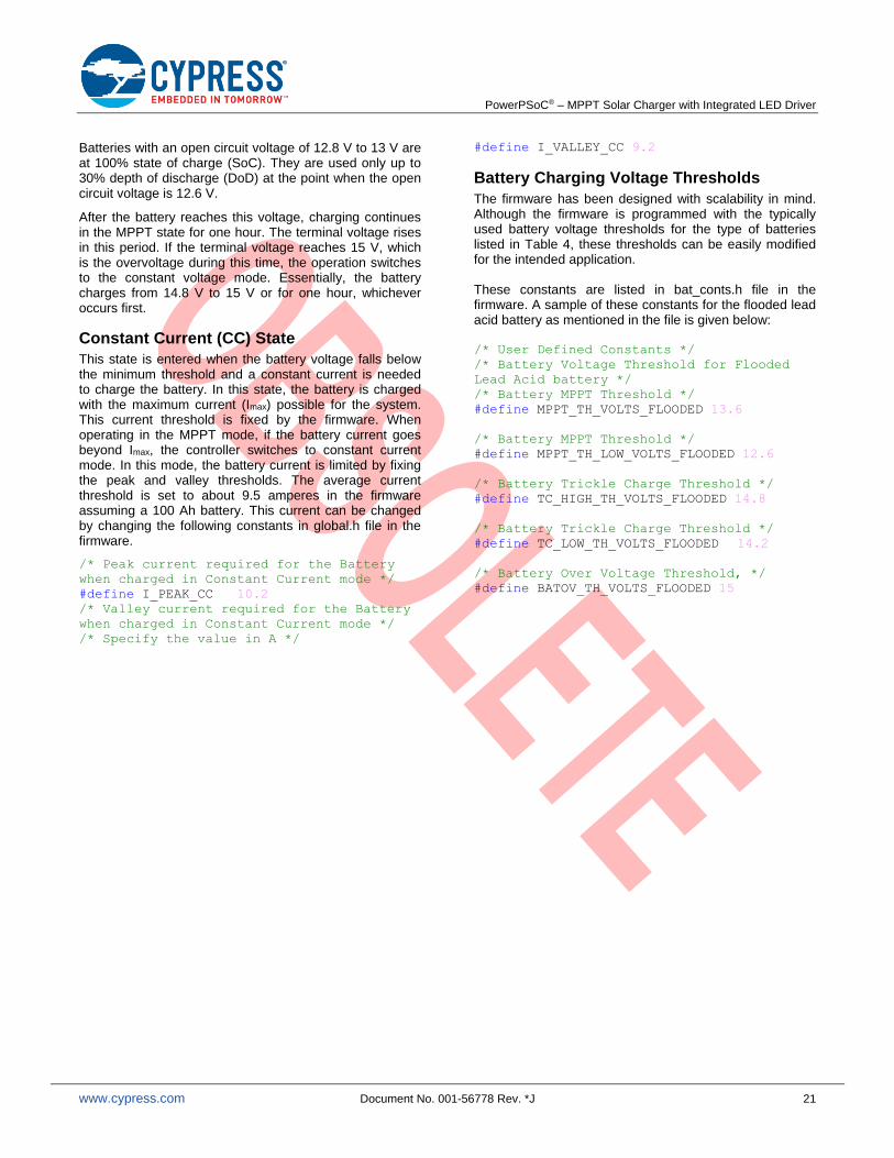
Batteries with an open circuit voltage of 12.8 V to 13 V are at 100% state of charge (SoC). They are used only up to 30% depth of discharge (DoD) at the point when the open circuit voltage is 12.6 V.
After the battery reaches this voltage, charging continues in the MPPT state for one hour. The terminal voltage rises in this period. If the terminal voltage reaches 15 V, which is the overvoltage during this time, the operation switches to the constant voltage mode. Essentially, the battery charges from 14.8 V to 15 V or for one hour, whichever occurs first.
Constant Current (CC) State
This state is entered when the battery voltage falls below the minimum threshold and a constant current is needed to charge the battery. In this state, the battery is charged with the maximum current (Imax) possible for the system. This current threshold is fixed by the firmware. When operating in the MPPT mode, if the battery current goes beyond Imax, the controller switches to constant current mode. In this mode, the battery current is limited by fixing the peak and valley thresholds. The average current threshold is set to about 9.5 amperes in the firmware assuming a 100 Ah battery. This current can be changed by changing the following constants in global.h file in the firmware.
/* Peak current required for the Battery
when charged in Constant Current mode */
#define I_PEAK_CC 10.2
/* Valley current required for the Battery
when charged in Constant Current mode */
/* Specify the value in A */
#define I_VALLEY_CC 9.2
Battery Charging Voltage Thresholds
The firmware has been designed with scalability in mind. Although the firmware is programmed with the typically used battery voltage thresholds for the type of batteries listed in Table 4, these thresholds can be easily modified for the intended application. These constants are listed in bat_conts.h file in the firmware. A sample of these constants for the flooded lead acid battery as mentioned in the file is given below: /* User Defined Constants */
/* Battery Voltage Threshold for Flooded
Lead Acid battery */
/* Battery MPPT Threshold */
#define MPPT_TH_VOLTS_FLOODED 13.6
/* Battery MPPT Threshold */
#define MPPT_TH_LOW_VOLTS_FLOODED 12.6
/* Battery Trickle Charge Threshold */
#define TC_HIGH_TH_VOLTS_FLOODED 14.8
/* Battery Trickle Charge Threshold */
#define TC_LOW_TH_VOLTS_FLOODED 14.2
/* Battery Over Voltage Threshold, */
#define BATOV_TH_VOLTS_FLOODED 15

PowerPSoC® – MPPT Solar Charger with Integrated LED Driver
www.cypress.com Document No. 001-56778 Rev. *J 22
Table 5. State Transition Matrix
Current / Next State
S1 – Init
S2 – Start S3 – MPPT S4 –
Constant Current
S5 – Trickle Charge/
Constant Voltage
S6 – Load Enable S7 –
Status Update
S8 – Fault
S1 – Init – Initialization complete
– – – – – –
S2 - Start – BOV, PVL
(Voc >Vocth) &&
(Voc > Vbat ) && (fTCFlag= =1)
–
(Voc >Vocth) &&
(Voc > Vbat )
&&
(Vbat > Vbat_TC) && (fTCFlag!=1)
(Voc < Vocth) &&
(Vbat >( Vbat_min_high +Vdiff)[ Loaddisable = =1])
||
(Voc < Vocth) &&
(Vbat > Vbat_min_high[LoadDisable == 0] )
– NBC, BUV
S3 – MPPT
(Vbat < VCC_th)
&&
(Voc > Vbat)
Vbat < VCC_th
Vbat > Vbat_max
Voc < Vbat Tupdate
S4 – Constant Current
– PVL (Voc > Vbat ) && (Vbat > VCC_th)
(Vbat < VCC_th) && (Voc > Vbat)
– – Tupdate NBC
S5 – Trickle Charge/
Constant Voltage
– PVL – – Voc > Vbat – Tupdate NBC
S6 – Load Enable
– (Voc > Vocth) || (Voc >Vbat)
– – (Voc < Vbat) && (Vbat > Vbat_min_high)
Tupdate NBC, BUV
S7 – Status Update
– If (Prevstate != LoadEnable)
– – – If (Prevstate = = Loadenable)
– –
S8 – Fault – No fault – – – – Tupdate Fault
Table Definitions
BUV Battery Under Voltage
BOV Battery Over Voltage
fTCFlag Flag to define necessary equalization state
LoadDisable Flag to check if load is disabled
NBC No Battery Connected
PVL Panel Voltage Low
Tupdate End of 2 min cycle
Vbat Battery voltage
Vbat_TC Battery voltage trickle charge threshold
Vbat_max Battery voltage trickle charge cutoff threshold
Vbat_min_high Minimum battery voltage to drive the load
Vcc Constant current battery voltage threshold
Vdiff Hysteresis for load enable
Voc Open circuit panel voltage
Vocth Open circuit panel voltage threshold

PowerPSoC® – MPPT Solar Charger with Integrated LED Driver
www.cypress.com Document No. 001-56778 Rev. *J 23
Trickle Charge/Constant Voltage (CV) State
After the battery reaches the trickle charge threshold (Vbat_max) in the MPPT state, it switches to the constant voltage state. This state compensates for the self discharge of the battery. It is divided into two phases.
Absorption: In this phase, the battery is charged at a constant voltage and is allowed to take whatever current it can. The constant voltage regulation prevents heating and excessive battery gassing. It stays in this phase until the battery is fully charged.
Float: In this phase, the battery is fully charged; the charger reduces the battery voltage to a float charge voltage. The battery takes current in the order of a few 100 mA. The charge controller continues to operate in this phase until the battery reaches the battery overvoltage threshold (Vbat_OV). Then the charging cycle is terminated.
Load Enable State
In this state, if the solar panel open circuit voltage is less than the battery voltage, it means that the panel is not capable of charging the battery. Therefore, the charging is disabled. If the battery voltage is greater than Vbat_min, then the battery is capable of driving the load. The load is turned on if the switch SW601 is on.
Status Update State
The current status of the system is recorded in the flash emulated EEPROM in this state. The execution shifts to this state after every fixed duration that is set by the firmware. It is 2 minutes by default. Battery temperature is measured enabling thermal compensation. The parameters recorded are:
1. Fault history
2. Ampere hour/Watt hour (AH/WH) meter
3. System status indicator
4. Input voltage
5. Output voltage
6. Load current
7. Battery charging current
Parameters 3 to 7 are recorded for every fixed time period (TUPDATE) and overwritten after the assigned memory is exhausted. Memory location for parameters 1 and 2 are fixed. Their values are updated every TUPDATE cycle.
Fault State
When there is a fault condition, the system operates in the fault state. Whenever there is a recovery from a fault condition, the controller transfers to the start state to ensure safe startup.
The fault conditions for the system are described as follows:
Battery Overvoltage (BOV): This fault occurs when the battery voltage exceeds the overvoltage threshold. The LED3 is turned ON (refer to Table 2).
Exit Condition: In a no load condition, the controller waits for the battery voltage to reduce below a set threshold through self discharge. When the voltage falls below the threshold, the red LED is turned off, the BOV flag is cleared, and the controller returns to the start state.
In a loaded condition, the battery continues driving the load and the controller does not enter the fault state.
No Battery Connected (NBC): This fault occurs when no battery is connected to the charge controller. The LED4 is turned ON (refer to Table 2).
Exit Condition: The controller keeps monitoring the battery voltage until the battery is detected. It then switches off the indication LED, clears the flag, and returns to the start state.
Battery Undervoltage (BUV): This fault occurs when the battery voltage is below the minimum threshold required to power the load.
Exit Condition: The controller keeps monitoring the solar panel open circuit voltage and battery voltage. It exits fault state when the solar panel open circuit voltage is sufficient to charge the battery and goes back to start state. It clears the BUV flag and switches off the green LED after the battery is sufficiently charged.
Panel Voltage Low (PVL): This fault occurs when the difference between the solar panel open circuit voltage and the battery voltage is less than Vdiff (0.5 V). This indicates that the solar panel is not capable of charging the battery.
Exit Condition: The controller keeps monitoring the solar panel open circuit voltage and battery voltage. When the solar panel open circuit voltage is greater than the battery voltage by at least Vdiff, it clears the flag and returns to the start state.

PowerPSoC® – MPPT Solar Charger with Integrated LED Driver
www.cypress.com Document No. 001-56778 Rev. *J 24
Status Indication
The PowerPSoC indicates the operation status using LEDs. The LEDs indicate the battery charging mode and the board fault status. The following table lists conditions indicated by the status LEDs. Figure 9 shows the labels of the LEDs.
Table 6. Status Indication
Status Indication Condition LED ON/OFF
Solar panel reverse indication
Solar panel terminals connected reverse LED1/LED401* Always ON
Battery reverse indication Battery terminals connected reverse LED2/LED402* Always ON
Battery over voltage Battery voltage greater than 15 V LED3/LED600* 4 seconds ON/1 second OFF
Battery under voltage Battery voltage less than 10.8 V LED3/LED600* 1 seconds ON/1 second OFF
Solar panel connected; Battery not connected
Battery is not connected LED4/LED604* 0.1 second ON/0.1 second OFF
Trickle charge mode (constant voltage)
Float voltage mode LED4/LED604* Always ON
MPPT Bulk charge mode LED4/LED604* 4 seconds ON/1 second OFF
Constant current If battery current is greater than 9.5 A, it is limited to 9.5 A. This is the constant current mode.
LED4/LED604* 1 second ON/4 seconds OFF
Solar panel open circuit voltage low
Solar panel open circuit voltage is less than battery voltage
LED4/LED604* 1 second ON/1 second OFF
* Reference designator per BOM of the board
MPPT Battery Charging Mode (without LED drivers)
The solution described in this application note uses a modular design approach for hardware and firmware design. The design can be easily modified to implement a MPPT based solar battery charger for stand-alone solar applications, without the integrated LED driver channels.
To make the solution work as a battery charger without the LED driver channels, the following lines need to be commented in the firmware file load.h.
/* To enable the Buck Channel uncomment
this line */
//#define BUCK_CH
/* To enable the Boost Channel uncomment
this line */
//#define BOOST_CH
This disables the load options present on the evaluation board. The firmware allows the state machine to operate exclusively in the battery charging mode.
If you wish to modify the hardware for battery charging application, the components listed in schematic pages ‘LED Driver Circuit’, sheet 7 of the schematic, can be completely removed. SW601 on schematic sheet 6 can either be removed or left for use for other purposes. Nevertheless the PCB needs to be modified appropriately for the intended application.
Wiring Details
Input Power Supply
▪ The power supply can be from a DC supply or a solar panel. This board can be powered from a solar panel rated between 40 W to 120 W.
▪ When using an external power supply, the voltage should be between 14 V to 17 V and current should be limited to a maximum of 7 amperes.
▪ When connecting a solar panel of 120 W or less, wires of cross section area 2.5 mm2 thicknesses or greater should be used.
▪ Wire length should be restricted to 5 m.
▪ Positive and negative terminals should be connected as shown in Figure 9.
Battery
▪ This solar charge controller is designed for a 12 V lead acid battery.
▪ When connecting the battery, a wire of cross section area 4 mm2 should be used.
▪ Wire length should be kept short; less than 1m.
▪ Positive and negative terminals should be connected as shown in Figure 9.

PowerPSoC® – MPPT Solar Charger with Integrated LED Driver
www.cypress.com Document No. 001-56778 Rev. *J 25
Load
▪ When connecting the load, a wire of cross section area 2.5 mm2 or greater should be used.
▪ Wire length should be as short as possible to minimize power losses in the wire.
▪ Positive and negative terminals should be connected as shown in Figure 9.
Power-up Instructions
Connect the panel and the battery. It is recommended to connect the battery first and then the panel. The system starts charging the battery as soon as the solar panel is connected. With just the battery connected, the solution can operate the LED loads.
The system operates in different charging modes based on the battery no load voltage. It is in a fault condition if there is any error in the system. Table 6 lists the various status indications.
Summary
AN56778 provides an overview of Cypress’ MPPT solar charger and LED driver solution implemented using PowerPSoC. Attached is a commented code example that can be tested on reference design boards available for purchase from Cypress’ design partners. Also attached are complete design files for these reference design boards.
References
CY8CLED0xx0x - PowerPSoC® Firmware Design Guidelines, Lighting Control Interfaces
CY8CLED0xx0x PowerPSoC® – Hardware Design Guidelines
CY8CLED0xx0x: Topology and Design Guide for Circuits using PowerPSoC®

PowerPSoC® – MPPT Solar Charger with Integrated LED Driver
www.cypress.com Document No. 001-56778 Rev. *J 26
Document History
Document Title: AN56778 – PowerPSoC® – MPPT Solar Charger with Integrated LED Driver
Document Number: 001-56778
Revision ECN Submission Date
Description of Change
** 2771928 10/06/09 New application note
*A 2952018 06/14/10 Updated Table 1.
Added Buck driver in the features list
Changed Input Short Circuit Current Rating to 7 A
Changed Buck LED Driver Rating to 8 V/1 A
Changed Boost LED Driver Rating to 40 V/1 A
*B 2998886 08/02/10 Corrected Figure 7
*C 3113825 12/17/2010 Added availability of evaluation hardware in the abstract section
*D 3286029 06/21/2011 Updated abstract.
Added firmware projects to the source.
*E 3352462 08/25/2011 Updated all figures.
*F 3482228 01/04/2012 Updated template
Updated project file
*G 3500464 01/20/2012 Updated project
Formula for iVoutSetPoint corrected on page 8.
In the wiring details section, the maximum current changed to 7A for the input power supply
'Background' section for SNVN removed in the 'About the authors' section
*H 4555075 10/29/2014 Updated schematic images.
Removed 'Related Application Notes' section in document header. Added 'References' section.
Removed 'About the Authors' section.
*I 5713868 04/26/2017 Updated logo and copyright.
*J 7081267 02/02/2021 Obsolete this application notes as it uses obsolete Power PSoC part.

PowerPSoC® – MPPT Solar Charger with Integrated LED Driver
www.cypress.com Document No. 001-56778 Rev. *J 27
Worldwide Sales and Design Support
Cypress maintains a worldwide network of offices, solution centers, manufacturer’s representatives, and distributors. To find the office closest to you, visit us at Cypress Locations.
Products
ARM® Cortex® Microcontrollers cypress.com/arm
Automotive cypress.com/automotive
Clocks & Buffers cypress.com/clocks
Interface cypress.com/interface
Internet of Things cypress.com/iot
Memory cypress.com/memory
Microcontrollers cypress.com/mcu
PSoC cypress.com/psoc
Power Management ICs cypress.com/pmic
Touch Sensing cypress.com/touch
USB Controllers cypress.com/usb
Wireless Connectivity cypress.com/wireless
PSoC® Solutions
PSoC 1 | PSoC 3 | PSoC 4 | PSoC 5LP | PSoC 6
Cypress Developer Community
Forums | WICED IOT Forums | Projects | Videos | Blogs | Training | Components
Technical Support
cypress.com/support
All other trademarks or registered trademarks referenced herein are the property of their respective owners.
Cypress Semiconductor 198 Champion Court San Jose, CA 95134-1709
©Cypress Semiconductor Corporation, 2009-2021. This document is the property of Cypress Semiconductor Corporation and its subsidiaries, including Spansion LLC (“Cypress”). This document, including any software or firmware included or referenced in this document (“Software”), is owned by Cypress under the intellectual property laws and treaties of the United States and other countries worldwide. Cypress reserves all rights under such laws and treaties and does not, except as specifically stated in this paragraph, grant any license under its patents, copyrights, trademarks, or other intellectual property rights. If the Software is not accompanied by a license agreement and you do not otherwise have a written agreement with Cypress governing the use of the Software, then Cypress hereby grants you a personal, non-exclusive, nontransferable license (without the right to sublicense) (1) under its copyright rights in the Software (a) for Software provided in source code form, to modify and reproduce the Software solely for use with Cypress hardware products, only internally within your organization, and (b) to distribute the Software in binary code form externally to end users (either directly or indirectly through resellers and distributors), solely for use on Cypress hardware product units, and (2) under those claims of Cypress’s patents that are infringed by the Software (as provided by Cypress, unmodified) to make, use, distribute, and import the Software solely for use with Cypress hardware products. Any other use, reproduction, modification, translation, or compilation of the Software is prohibited.
TO THE EXTENT PERMITTED BY APPLICABLE LAW, CYPRESS MAKES NO WARRANTY OF ANY KIND, EXPRESS OR IMPLIED, WITH REGARD TO THIS DOCUMENT OR ANY SOFTWARE OR ACCOMPANYING HARDWARE, INCLUDING, BUT NOT LIMITED TO, THE IMPLIED WARRANTIES OF MERCHANTABILITY AND FITNESS FOR A PARTICULAR PURPOSE. To the extent permitted by applicable law, Cypress reserves the right to make changes to this document without further notice. Cypress does not assume any liability arising out of the application or use of any product or circuit described in this document. Any information provided in this document, including any sample design information or programming code, is provided only for reference purposes. It is the responsibility of the user of this document to properly design, program, and test the functionality and safety of any application made of this information and any resulting product. Cypress products are not designed, intended, or authorized for use as critical components in systems designed or intended for the operation of weapons, weapons systems, nuclear installations, life-support devices or systems, other medical devices or systems (including resuscitation equipment and surgical implants), pollution control or hazardous substances management, or other uses where the failure of the device or system could cause personal injury, death, or property damage (“Unintended Uses”). A critical component is any component of a device or system whose failure to perform can be reasonably expected to cause the failure of the device or system, or to affect its safety or effectiveness. Cypress is not liable, in whole or in part, and you shall and hereby do release Cypress from any claim, damage, or other liability arising from or related to all Unintended Uses of Cypress products. You shall indemnify and hold Cypress harmless from and against all claims, costs, damages, and other liabilities, including claims for personal injury or death, arising from or related to any Unintended Uses of Cypress products.
Cypress, the Cypress logo, Spansion, the Spansion logo, and combinations thereof, WICED, PSoC, CapSense, EZ-USB, F-RAM, and Traveo are trademarks or registered trademarks of Cypress in the United States and other countries. For a more complete list of Cypress trademarks, visit cypress.com. Other names and brands may be claimed as property of their respective owners.