Please note that Cypress is an Infineon Technologies Company.
16
www.infineon.com Please note that Cypress is an Infineon Technologies Company. The document following this cover page is marked as “Cypress” document as this is the company that originally developed the product. Please note that Infineon will continue to offer the product to new and existing customers as part of the Infineon product portfolio. Continuity of document content The fact that Infineon offers the following product as part of the Infineon product portfolio does not lead to any changes to this document. Future revisions will occur when appropriate, and any changes will be set out on the document history page. Continuity of ordering part numbers Infineon continues to support existing part numbers. Please continue to use the ordering part numbers listed in the datasheet for ordering.
-
Upload
khangminh22 -
Category
Documents
-
view
6 -
download
0
Transcript of Please note that Cypress is an Infineon Technologies Company.
www.infineon.com
Please note that Cypress is an Infineon Technologies Company.The document following this cover page is marked as “Cypress” document as this is the company that originally developed the product. Please note that Infineon will continue to offer the product to new and existing customers as part of the Infineon product portfolio.
Continuity of document contentThe fact that Infineon offers the following product as part of the Infineon product portfolio does not lead to any changes to this document. Future revisions will occur when appropriate, and any changes will be set out on the document history page.
Continuity of ordering part numbersInfineon continues to support existing part numbers. Please continue to use the ordering part numbers listed in the datasheet for ordering.

THIS SPEC IS OBSOLETE Spec No: 002-04468 Spec Title: AN204468 - FM4 I2S USB MP3 PLAYER
APPLICATION 32-BIT MICROCONTROLLER FM4 FAMILY
Replaced by: NONE
www.cypress.com Document No. 002-04468 Rev. *C 1
AN204468
FM4 I²S USB MP3 Player Application 32-Bit Microcontroller FM4 Family
Target Products: SK-FM4-216-ETHERNET
This application note describes the general structure of the I²S USB MP3Player software example, its single modules
in detail and how it is used.
Contents
1 Introduction ............................................................... 1 1.1 About Document .............................................. 1 1.2 Supported Tool Chains .................................... 2
2 Hardware .................................................................. 2 3 Software ................................................................... 2
3.1 General Overview ............................................ 2 3.2 Software Components ..................................... 4
4 Memory Usage ....................................................... 11 4.1 ROM .............................................................. 11 4.2 RAM ............................................................... 12
5 How to Use the I²S USB MP3Player ...................... 12 Document History ............................................................ 13
1 Introduction
1.1 About Document
This application note describes the general structure of the I²S USB MP3Player software example, its single modules in detail and how it is used.
The I²S USB MP3Player software example is an easy extendable audio player application that is able to playback different types of audio files from an attached USB flash drive, while several file information (such as bitrate, MP3 ID3 Tags, etc.) are displayed for the user via LC Display and UART.
The whole project builds on top of a USB template that was generated with aid of the Cypress USB Wizard. This ready-to-use template contains an USB stack and a configured copy of Elm-Chan’s FatFs.
The current version can handle all types of mp3 files and wave files with a resolution between 0 and 32 bits.
For mp3 decoding the MPEG Audio Decoder Library (MAD) is used, which is published by Underbit Technologies under GNU General Public License (GPL).
The I²S USB MP3Player is designed to run on the hardware platform of the SK-FM4-216-ETHERNET Starter kit, which includes a SGTL5000 I²S Codec.
This document furthermore will elaborate on:
− An overview about the used hardware
− A general overview of the software and a detailed description of its single components
− ROM and RAM consumption of the presented solution
− How to use the I²S USB MP3Player.
FM4 I²S USB MP3 Player Application 32-Bit Microcontroller FM4 Family
www.cypress.com Document No. 002-04468 Rev.*C 2
1.2 Supported Tool Chains
The I²S USB MP3Player was successfully tested with the following tool chains:
− winIDEA Open Build 9.12.209 (44770) (gcc version: 4.7.4 20130613)
− Keil µVision V5.10.0.2 (tool chain: 5.10.0.0)
− IAR Embedded Workbench 7.20.5.7624 (tool chain: 7.1.2.3324)
2 Hardware
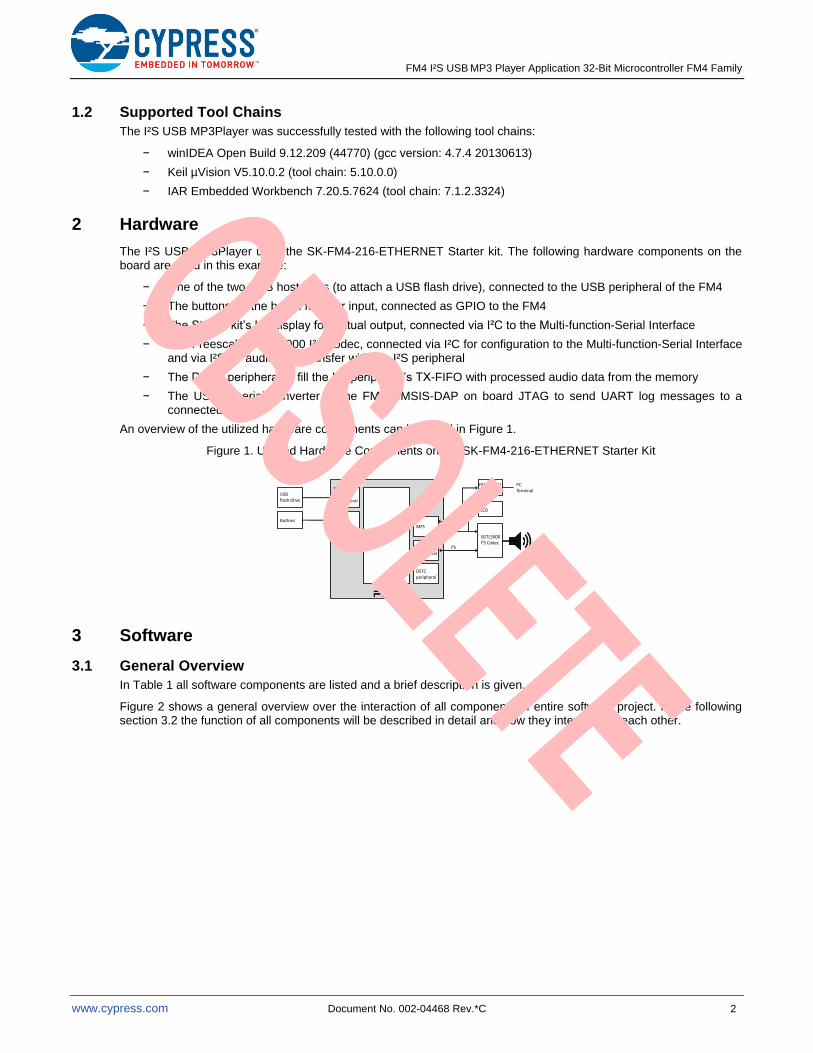
The I²S USB MP3Player uses the SK-FM4-216-ETHERNET Starter kit. The following hardware components on the board are used in this example:
− One of the two USB host ports (to attach a USB flash drive), connected to the USB peripheral of the FM4
− The buttons on the board for user input, connected as GPIO to the FM4
− The Starter kit’s LC display for textual output, connected via I²C to the Multi-function-Serial Interface
− The Freescale SGTL5000 I²S codec, connected via I²C for configuration to the Multi-function-Serial Interface and via I²S for audio data transfer with the I²S peripheral
− The DSTC peripheral to fill the I²S peripheral’s TX-FIFO with processed audio data from the memory
− The USB-to-serial converter of the FM3 CMSIS-DAP on board JTAG to send UART log messages to a connected PC.
An overview of the utilized hardware components can be found in Figure 1.
Figure 1. Utilized Hardware Components on the SK-FM4-216-ETHERNET Starter Kit
USB flash drive
DSTCperipheral
Cortex-M4
USB peripheral
I²Speripheral
MFS
SGTL5000I²S Codec
I²C
I²S
GPIO
LCD
Buttons
FM3 UART/ CSMIS-DAP
PC Terminal
UART
3 Software
3.1 General Overview
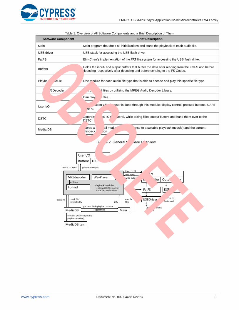
In Table 1 all software components are listed and a brief description is given.
Figure 2 shows a general overview over the interaction of all components of entire software project. In the following section 3.2 the function of all components will be described in detail and how they interact with each other.
FM4 I²S USB MP3 Player Application 32-Bit Microcontroller FM4 Family
www.cypress.com Document No. 002-04468 Rev.*C 3
Table 1. Overview of All Software Components and a Brief Description of Them
Software Component Brief Description
Main Main program that does all initializations and starts the playback of each audio file.
USB driver USB stack for accessing the USB flash drive.
FatFS Elm-Chan’s implementation of the FAT file system for accessing the USB flash drive.
Buffers Holds the input- and output buffers that buffer the data after reading from the FatFS and before decoding respectively after decoding and before sending to the I²S Codec.
Playback Module One module for each audio file type that is able to decode and play this specific file type.
MP3Decoder Can play mp3 files by utilizing the MPEG Audio Decoder Library.
WavPlayer Can play wav files.
User I/O All interaction with the user is done through this module: display control, pressed buttons, UART logging.
DSTC Controls the DSTC peripheral, while taking filled output buffers and hand them over to the DSTC.
Media DB Stores a list of all media files (a reference to a suitable playback module) and the current playback position
Figure 2. General Software Overview
MP3decoder
libmad
WavPlayer
playback modules
…
utilizes
Main
User I/O
UARTLCDButtons
MediaDB
trigger refill
read input
write output
FatFS
USBDriver
DSTC
Buffers
OutputbufferInputbuffer
USB Peripheral & USB Stick
DSTC & I2S Peripheral
MediaDBItem
contains check filecompatibility
reacts on input generates output
scan forfiles
suggest files
+ isCompatible(file): boolean+ play( file): playbackResult
contains (with compatibleplayback module)
get next file & playback module
play
FM4 I²S USB MP3 Player Application 32-Bit Microcontroller FM4 Family
www.cypress.com Document No. 002-04468 Rev.*C 4
3.2 Software Components
3.2.1 Main
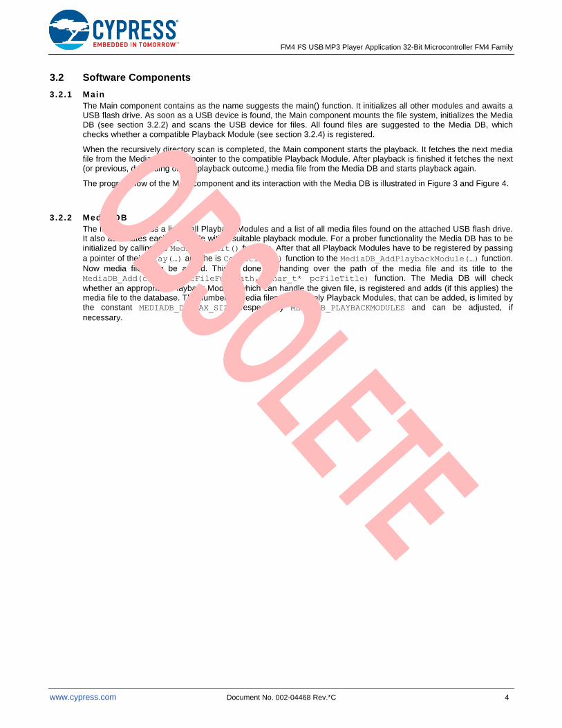
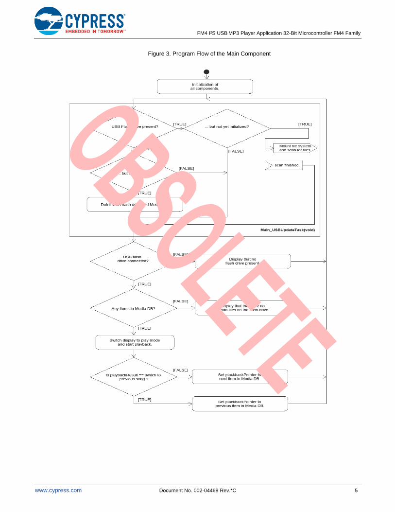
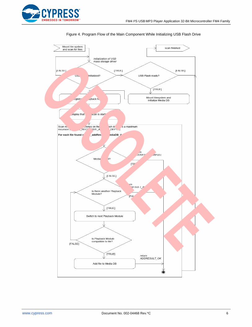
The Main component contains as the name suggests the main() function. It initializes all other modules and awaits a USB flash drive. As soon as a USB device is found, the Main component mounts the file system, initializes the Media DB (see section 3.2.2) and scans the USB device for files. All found files are suggested to the Media DB, which checks whether a compatible Playback Module (see section 3.2.4) is registered.
When the recursively directory scan is completed, the Main component starts the playback. It fetches the next media file from the Media DB and a pointer to the compatible Playback Module. After playback is finished it fetches the next (or previous, depending on the playback outcome,) media file from the Media DB and starts playback again.
The program flow of the Main component and its interaction with the Media DB is illustrated in Figure 3 and Figure 4.
3.2.2 Media DB
The Media DB holds a list of all Playback Modules and a list of all media files found on the attached USB flash drive. It also associates each media file with a suitable playback module. For a prober functionality the Media DB has to be initialized by calling the MediaDB_Init() function. After that all Playback Modules have to be registered by passing
a pointer of their play(…) and the is Compatible() function to the MediaDB_AddPlaybackModule(…) function.
Now media files can be added. This is done by handing over the path of the media file and its title to the MediaDB_Add(char_t* pcFileFullPath, char_t* pcFileTitle) function. The Media DB will check
whether an appropriate Playback Module, which can handle the given file, is registered and adds (if this applies) the media file to the database. The number of media files respectively Playback Modules, that can be added, is limited by the constant MEDIADB_DB_MAX_SIZE respectively MEDIADB_PLAYBACKMODULES and can be adjusted, if
necessary.
FM4 I²S USB MP3 Player Application 32-Bit Microcontroller FM4 Family
www.cypress.com Document No. 002-04468 Rev.*C 5
Figure 3. Program Flow of the Main Component
FM4 I²S USB MP3 Player Application 32-Bit Microcontroller FM4 Family
www.cypress.com Document No. 002-04468 Rev.*C 6
Figure 4. Program Flow of the Main Component While Initializing USB Flash Drive
FM4 I²S USB MP3 Player Application 32-Bit Microcontroller FM4 Family
www.cypress.com Document No. 002-04468 Rev.*C 7
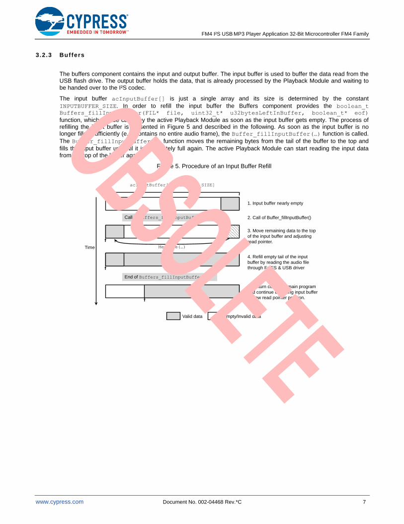
3.2.3 Buffers
The buffers component contains the input and output buffer. The input buffer is used to buffer the data read from the USB flash drive. The output buffer holds the data, that is already processed by the Playback Module and waiting to be handed over to the I²S codec.
The input buffer acInputBuffer[] is just a single array and its size is determined by the constant
INPUTBUFFER_SIZE. In order to refill the input buffer the Buffers component provides the boolean_t Buffers_fillInputBuffer(FIL* file, uint32_t* u32bytesLeftInBuffer, boolean_t* eof)
function, which can be called by the active Playback Module as soon as the input buffer gets empty. The process of refilling the input buffer is presented in Figure 5 and described in the following. As soon as the input buffer is no longer filled sufficiently (e.g. contains no entire audio frame), the Buffer_fillInputBuffer(…) function is called.
The Buffer_fillInputBuffer(…) function moves the remaining bytes from the tail of the buffer to the top and
fills the input buffer up until it is completely full again. The active Playback Module can start reading the input data from the top of the buffer again.
Figure 5. Procedure of an Input Buffer Refill
Call of Buffers_fillInputBuffer(…)
Valid data Empty/Invalid data
Time Memmove(…)
End of Buffers_fillInputBuffer(…)
1. Input buffer nearly empty
2. Call of Buffer_fillInputBuffer()
3. Move remaining data to the top
of the input buffer and adjusting
read pointer.
4. Refill empty tail of the input
buffer by reading the audio file
through FatFS & USB driver
5. Return control to main program
and continue decoding input buffer
at new read pointer position.
acInputBuffer[INPUTBUFFER_SIZE]
FM4 I²S USB MP3 Player Application 32-Bit Microcontroller FM4 Family
www.cypress.com Document No. 002-04468 Rev.*C 8
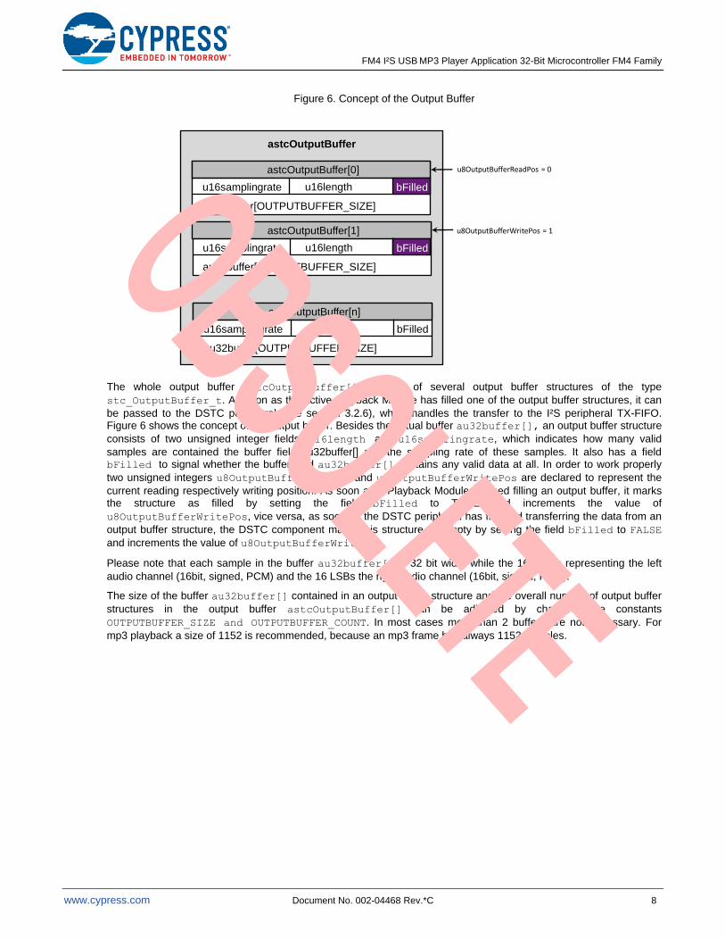
Figure 6. Concept of the Output Buffer
…
astcOutputBuffer
astcOutputBuffer[n]
bFilledu16samplingrate u16length
au32buffer[OUTPUTBUFFER_SIZE]
astcOutputBuffer[1]
bFilledu16samplingrate u16length
au32buffer[OUTPUTBUFFER_SIZE]
bFilled
astcOutputBuffer[0]
bFilledu16samplingrate u16length
au32buffer[OUTPUTBUFFER_SIZE]
bFilled
u8OutputBufferReadPos = 0
u8OutputBufferWritePos = 1
The whole output buffer astcOutputBuffer[] consists of several output buffer structures of the type
stc_OutputBuffer_t. As soon as the active Playback Module has filled one of the output buffer structures, it can
be passed to the DSTC peripheral (see section 3.2.6), which handles the transfer to the I²S peripheral TX-FIFO. Figure 6 shows the concept of the output buffer. Besides the actual buffer au32buffer[], an output buffer structure
consists of two unsigned integer fields: u16length and u16samplingrate, which indicates how many valid
samples are contained the buffer field au32buffer[] and the sampling rate of these samples. It also has a field bFilled to signal whether the buffer field au32buffer[] contains any valid data at all. In order to work properly
two unsigned integers u8OutputBufferReadPos and u8OutputBufferWritePos are declared to represent the
current reading respectively writing position. As soon as a Playback Module finished filling an output buffer, it marks the structure as filled by setting the field bFilled to TRUE and increments the value of
u8OutputBufferWritePos, vice versa, as soon as the DSTC peripheral has finished transferring the data from an
output buffer structure, the DSTC component marks this structure as empty by setting the field bFilled to FALSE
and increments the value of u8OutputBufferWritePos.
Please note that each sample in the buffer au32buffer[] is 32 bit wide, while the 16 MSBs representing the left
audio channel (16bit, signed, PCM) and the 16 LSBs the right audio channel (16bit, signed, PCM).
The size of the buffer au32buffer[] contained in an output buffer structure and the overall number of output buffer
structures in the output buffer astcOutputBuffer[] can be adjusted by changing the constants
OUTPUTBUFFER_SIZE and OUTPUTBUFFER_COUNT. In most cases more than 2 buffers are not necessary. For
mp3 playback a size of 1152 is recommended, because an mp3 frame has always 1152 samples.
FM4 I²S USB MP3 Player Application 32-Bit Microcontroller FM4 Family
www.cypress.com Document No. 002-04468 Rev.*C 9
3.2.4 Playback Modules
A Playback Module fulfills the task to play media files. It has to implement 2 functions:
− en_playbackResult_t play(char_t* pcFilePath, char_t* pcFileTitle)
− boolean_t isCompatible(char_t* pcFilePath)
The first function is utilized to play the given media file, whereby pcFilePath is the path to the file and
pcFileTitle is the file’s title that should be shown to the user. The second function isCompatible(…) is used to
determine whether the file with the given path pcFilePath can be played by the play(…) function of the Playback
Module. The returned enumeration en_playbackResult_t indicates the outcome of the playback (e.g. if it was
successful, a decoding error occurs or the user just want to skip the audio file). Each Playback Module has to be registered with its two functions at the Media DB component. It also has to report its current status (title of the media file, playback progress …) to the User I/O component and fetch and react on user inputs provided by the User I/O component. The media data, which is processed by the Playback Modules, is read from the input buffer and written into the output buffer after processing. There are 2 Playback Modules implemented in this example: MP3Decoder and WavPlayer.
MP3Decoder
The MP3Decoder playback module is used to play MP3 files. It utilizes the MPEG Audio Decoder (libmad or just MAD) (for more details see http://www.underbit.com/products/mad/) to decode the given media file. The MAD provides, besides a low-level API, a high-level API, which is used by the MP3Decoder playback module. With this API the full control is given to the MAD. The decoding process can only be influenced by a handful of callback functions (input, output, header and error function), which are handed over at the beginning of the decoding process. These callback functions are implemented in the MP3Decoder module. In Table 2 it can be seen, in which cases a callback function is called by the MAD and how they are handled by the MP3Decoder module. The MP3Decoder also contains a tiny ID3Tag Reader, which can read ID3v2.3 Tags and overrides the pcFileTitle with the Artist, Album and Title
tags, if present.
Table 2. MAD Callback Functions
Callback Function When Does MAD Call This Function? How Does MP3Decoder React?
input The Input function is called by the MAD, if the input buffer is nearly empty.
MP3Decoder fills the buffer as soon as this function is called
output The Output function is called, if a mp3 frame is decoded and can be played.
MP3Decoder waits until a new output buffer is empty, down samples the mp3 frame, transfers it to the output buffer and notifies the DSTC component. In this function also User I/Os are processed.
header The Header function is called as soon as a frame header is read.
The MP3Decoder reads the bitrate and sample rate from the mp3 header and configures the I2S codec accordingly.
error The Error function is called, if an error occurred while encoding.
The MP3Decoder propagates the error to the user via the User I/O UART functionality.
FM4 I²S USB MP3 Player Application 32-Bit Microcontroller FM4 Family
www.cypress.com Document No. 002-04468 Rev.*C 10
WavPlayer
The WavPlayer Playback Module can play PCM encoded wave files. It is able process all wave files that have a resolution between 0 and 32 bits per sample and one of the sample rates supported by the SGTL5000 I2S-Codec (8k, 10.025k, 12k, 16k, 22.05k, 24k, 32k, 44.1k, 48k and 96k). Due to performance limitations of the FatFS and USB driver only files with 1 Mbit/s data rate can be played.
After initialization the WavPlayer enters a playback loop, which mainly consists of 3 steps:
− Refill the input buffer.
− Handle new user inputs and wait until at least one output buffer array is empty.
− Process audio data in input buffer (down respectively up sampling) and transfer it to output buffer until input buffer is empty
3.2.5 User I /O
The User I/O module is used to communicate with the user. It recognizes pushed buttons, refreshes the board display and provides some UART functions. It is necessary to initialize the User I/O component by calling the UserIO_Init() function. It starts the FRT of the MFT0 for the display refresh interrupt routine and configures the
external interrupt to react on the pressed board buttons.
User Input
In order to fetch user inputs the function en_userIOInputType_t UserIO_getInput(void) has to be called.
The returned enumeration signals, if a new user input has been received since the function was called the last time. It also informs about the type of user input (e.g. which board button was pressed).
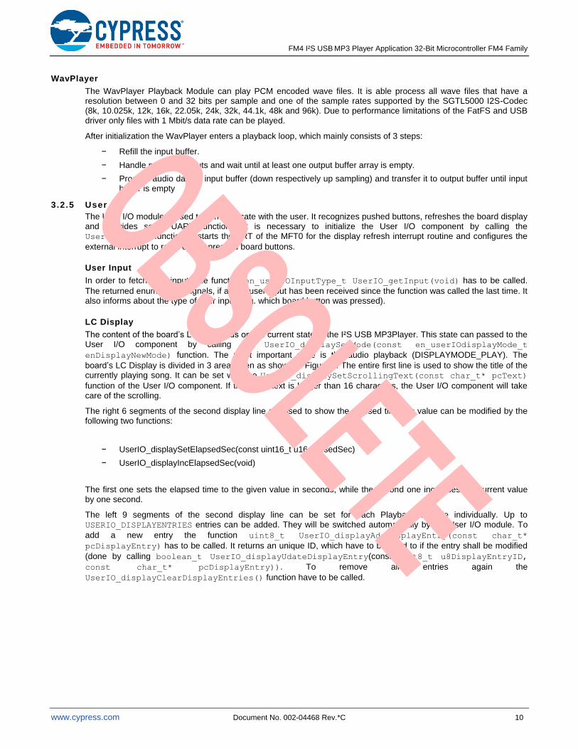
LC Display
The content of the board’s LCD depends on the current state of the I²S USB MP3Player. This state can passed to the User I/O component by calling the UserIO_displaySetMode(const en_userIOdisplayMode_t
enDisplayNewMode) function. The most important state is the audio playback (DISPLAYMODE_PLAY). The
board’s LC Display is divided in 3 areas then as shown in Figure 7. The entire first line is used to show the title of the currently playing song. It can be set with the UserIO_displaySetScrollingText(const char_t* pcText)
function of the User I/O component. If the given text is longer than 16 characters, the User I/O component will take care of the scrolling.
The right 6 segments of the second display line are used to show the elapsed time. Its value can be modified by the following two functions:
− UserIO_displaySetElapsedSec(const uint16_t u16elapsedSec)
− UserIO_displayIncElapsedSec(void)
The first one sets the elapsed time to the given value in seconds, while the second one increases the current value by one second.
The left 9 segments of the second display line can be set for each Playback Module individually. Up to USERIO_DISPLAYENTRIES entries can be added. They will be switched automatically by the User I/O module. To
add a new entry the function uint8_t UserIO_displayAddDisplayEntry(const char_t*
pcDisplayEntry) has to be called. It returns an unique ID, which have to be used to if the entry shall be modified
(done by calling boolean_t UserIO_displayUdateDisplayEntry(const uint8_t u8DisplayEntryID,
const char_t* pcDisplayEntry)). To remove all entries again the
UserIO_displayClearDisplayEntries() function have to be called.
FM4 I²S USB MP3 Player Application 32-Bit Microcontroller FM4 Family
www.cypress.com Document No. 002-04468 Rev.*C 11
Figure 7. Display Areas
scrolling title
1:23
elapsed timedisplay entries
128 kbps
AC/DC - Highway
UART Logging
To send more detailed information to the user the User I/O component provides some functionality to send UART log messages. The amount of messages can be controlled by setting a global log level (UserIO_logSetLvl(const
en_logLvl_t enLogLvl)).
3.2.6 DSTC
The DSTC component is responsible for the communication with the DSTC peripheral. The Dstc_Init() function
has to be called to initialize the DSTC Peripheral and generate one Descriptor for each output buffer structure in the output buffer array astcOutputBuffer[]. It also enables the DSTC interrupt for error logging and the DSTC
combined type interrupt, which is triggered every time a Descriptor Job is finished. As soon as the first output buffer in the output buffer array is filled by one of the Playback Modules, the Dstc_DESx_Setup(uint8_t
u8OutputBufferNo) function has to be called. It will hand over the Descriptor, corresponding to the output buffer
structure with the given output buffer number u8OutputBufferNo, to the DSTC peripheral, which will fill the I2S TX-FIFO automatically from the audio data stored in this output buffer structure. From now on the DSTC component will setup the Descriptor for the next output buffer on its own. Unless no filled output buffer can be found. Then the DSTC component will set the global variable bOutputBufferUnderrun to TRUE and the active Playback Module have
to call the Dstc_DESx_Setup(uint8_t u8OutputBufferNo) again as soon as an output buffer is filled with new
data.
4 Memory Usage
4.1 ROM
The following Table 3 shows the approximately ROM consumption of the project parts. The data was taken from the GCC linker output with the compiler optimization high (-O3).
Table 3. ROM Usage Overview
Project Part: Size:
Application 10.0 KB
MAD library 40.2 KB
FatFS file system 17.7 KB
Startup file 1.1 KB
Low level library 32.3 KB
USB 13.2 KB
SGTL5000 I²S codec driver 7.2 KB
C libraries 30.2 KB
Total ~ 132.1 KB
FM4 I²S USB MP3 Player Application 32-Bit Microcontroller FM4 Family
www.cypress.com Document No. 002-04468 Rev.*C 12
4.2 RAM
Table 4 gives an overview of the RAM usage. The data was also taken from the GCC linker output.
Note that the Common section of the Application contains the input and output buffers, which are set to 4,096 Bytes respectively 3x 4,608 Bytes (= 1152 x 32 Bit). Stack and Heap are set to 0x2000 and 0x20000, assuming the Media DB (which is located on the Heap) can contain maximally 256 entries, each with a 256 Byte field for the file path and a 256 Bytes field for the files’ title.
Table 4. RAM Usage Overview (All Values in Bytes)
Project Part: RO Data: Data: BSS: Common: Total:
Application 844 48 452 18,603 19,947
MAD library 43,127 - - - 43,127
FatFS file system 1,363 - 8 - 1,371
Low level library 456 5,208 212 437 6,313
USB 72 5,200 75 136 5,483
SGTL5000 I²S codec driver - - - - -
C libraries 456 2,235 68 4 2,763
Heap - - - - 131,072
Stack - - - - 8,192
Total 46,318 12,691 815 19,180 218,268
5 How to Use the I²S USB MP3Player
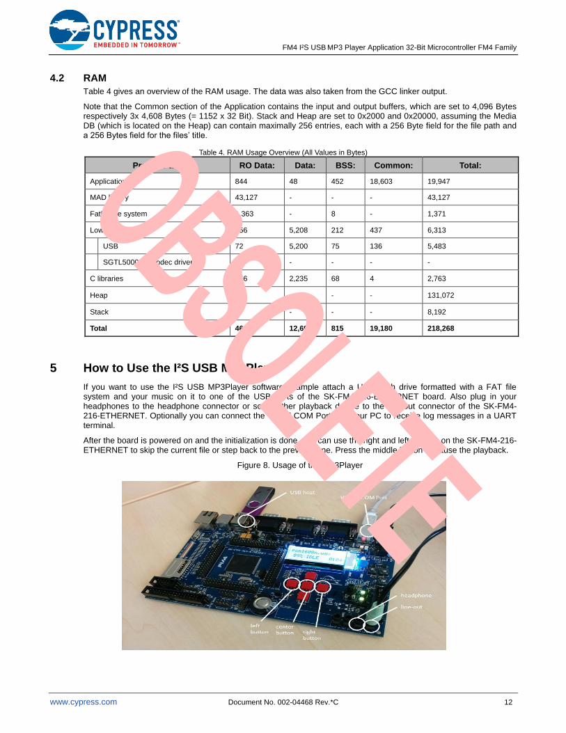
If you want to use the I²S USB MP3Player software example attach a USB flash drive formatted with a FAT file system and your music on it to one of the USB ports of the SK-FM4-216-ETHERNET board. Also plug in your headphones to the headphone connector or some other playback device to the line-out connector of the SK-FM4-216-ETHERNET. Optionally you can connect the Virtual COM Port with your PC to receive log messages in a UART terminal.
After the board is powered on and the initialization is done, you can use the right and left buttons on the SK-FM4-216-ETHERNET to skip the current file or step back to the previous one. Press the middle button to pause the playback.
Figure 8. Usage of the MP3Player
FM4 I²S USB MP3 Player Application 32-Bit Microcontroller FM4 Family
www.cypress.com Document No. 002-04468 Rev.*C 13
Document History
Document Title: AN204468 - FM4 I²S USB MP3 Player Application 32-Bit Microcontroller FM4 Family
Document Number: 002-04468
Revision ECN Orig. of Change
Submission Date
Description of Change
** – YUIS 02/16/2015 Initial Release.
*A 5028554 YUIS 12/01/2015 Updated to Cypress template.
*B 5711419 AESATP12 04/26/2017 Updated logo and copyright.
*C 6350773 WOFR 10/15/2018 Obsolete document.
Completing Sunset Review.
FM4 I²S USB MP3 Player Application 32-Bit Microcontroller FM4 Family
www.cypress.com Document No. 002-04468 Rev.*C 14
Worldwide Sales and Design Support
Cypress maintains a worldwide network of offices, solution centers, manufacturer’s representatives, and distributors. To find the office closest to you, visit us at Cypress Locations.
Products
ARM® Cortex® Microcontrollers cypress.com/arm
Automotive cypress.com/automotive
Clocks & Buffers cypress.com/clocks
Interface cypress.com/interface
Internet of Things cypress.com/iot
Memory cypress.com/memory
Microcontrollers cypress.com/mcu
PSoC cypress.com/psoc
Power Management ICs cypress.com/pmic
Touch Sensing cypress.com/touch
USB Controllers cypress.com/usb
Wireless Connectivity cypress.com/wireless
PSoC® Solutions
PSoC 1 | PSoC 3 | PSoC 4 | PSoC 5LP | PSoC 6
Cypress Developer Community
Forums | WICED IOT Forums | Projects | Videos | Blogs | Training | Components
Technical Support
cypress.com/support
All other trademarks or registered trademarks referenced herein are the property of their respective owners.
Cypress Semiconductor 198 Champion Court San Jose, CA 95134-1709
© Cypress Semiconductor Corporation, 2015-2018. This document is the property of Cypress Semiconductor Corporation and its subsidiaries, including Spansion LLC (“Cypress”). This document, including any software or firmware included or referenced in this document (“Software”), is owned by Cypress under the intellectual property laws and treaties of the United States and other countries worldwide. Cypress reserves all rights under such laws and treaties and does not, except as specifically stated in this paragraph, grant any license under its patents, copyrights, trademarks, or other intellectual property rights. If the Software is not accompanied by a license agreement and you do not otherwise have a written agreement with Cypress governing the use of the Software, then Cypress hereby grants you a personal, non-exclusive, nontransferable license (without the right to sublicense) (1) under its copyright rights in the Software (a) for Software provided in source code form, to modify and reproduce the Software solely for use with Cypress hardware products, only internally within your organization, and (b) to distribute the Software in binary code form externally to end users (either directly or indirectly through resellers and distributors), solely for use on Cypress hardware product units, and (2) under those claims of Cypress’s patents that are infringed by the Software (as provided by Cypress, unmodified) to make, use, distribute, and import the Software solely for use with Cypress hardware products. Any other use, reproduction, modification, translation, or compilation of the Software is prohibited. TO THE EXTENT PERMITTED BY APPLICABLE LAW, CYPRESS MAKES NO WARRANTY OF ANY KIND, EXPRESS OR IMPLIED, WITH REGARD TO THIS DOCUMENT OR ANY SOFTWARE OR ACCOMPANYING HARDWARE, INCLUDING, BUT NOT LIMITED TO, THE IMPLIED WARRANTIES OF MERCHANTABILITY AND FITNESS FOR A PARTICULAR PURPOSE. To the extent permitted by applicable law, Cypress reserves the right to make changes to this document without further notice. Cypress does not assume any liability arising out of the application or use of any product or circuit described in this document. Any information provided in this document, including any sample design information or programming code, is provided only for reference purposes. It is the responsibility of the user of this document to properly design, program, and test the functionality and safety of any application made of this information and any resulting product. Cypress products are not designed, intended, or authorized for use as critical components in systems designed or intended for the operation of weapons, weapons systems, nuclear installations, life-support devices or systems, other medical devices or systems (including resuscitation equipment and surgical implants), pollution control or hazardous substances management, or other uses where the failure of the device or system could cause personal injury, death, or property damage (“Unintended Uses”). A critical component is any component of a device or system whose failure to perform can be reasonably expected to cause the failure of the device or system, or to affect its safety or effectiveness. Cypress is not liable, in whole or in part, and you shall and hereby do release Cypress from any claim, damage, or other liability arising from or related to all Unintended Uses of Cypress products. You shall indemnify and hold Cypress harmless from and against all claims, costs, damages, and other liabilities, including claims for personal injury or death, arising from or related to any Unintended Uses of Cypress products. Cypress, the Cypress logo, Spansion, the Spansion logo, and combinations thereof, WICED, PSoC, CapSense, EZ-USB, F-RAM, and Traveo are trademarks or registered trademarks of Cypress in the United States and other countries. For a more complete list of Cypress trademarks, visit cypress.com. Other names and brands may be claimed as property of their respective owners.