Structural investigations on TiO 2 and Fe-doped TiO 2 nanoparticles synthesized by laser pyrolysis
Applied Catalysis B: Environmental 23 (1999) 143–157
Photocatalytic kinetics of phenol and its derivatives overUV irradiated TiO2
Dingwang Chen, Ajay K. Ray∗Department of Chemical and Environmental Engineering, National University of Singapore, 10 Kent Ridge Crescent,
Singapore 119260, Singapore
Received 8 February 1999; received in revised form 11 June 1999; accepted 11 June 1999
Abstract
In recent years, photocatalytic degradation mediated by illuminated TiO2 has received considerable attention as an alternativefor treating polluted water. In the present study, a new two-phase swirl-flow monolithic-type reactor was used to studythe kinetics of heterogeneous photocatalytic processes. Photocatalytic degradation of phenol, 4-chlorophenol (4-CP) and4-nitrophenol (4-NP) both in aqueous suspensions and over immobilized Degussa P25 TiO2 has been studied in laboratoryscale. Experiments were conducted to investigate the effects of parameters such as catalyst dosage, pollutant concentration,temperature, partial pressure of oxygen, UV light intensity, catalyst-layer thickness, circulation flowrate and catalyst annealingtemperature. Simple model for predicting the optimal catalyst dosage in aqueous suspensions for different photo-systems wasproposed. Pseudo first-order kinetics with respect to all the parent compounds was observed. Experimental data obtainedunder different conditions were fitted with kinetic equation to describe the dependency of degradation rate as a function ofthe above mentioned parameters. Consequently, kinetic parameters were experimentally determined. Adsorptive propertiesof all the organics were also experimentally measured and fitted with Langmuir equation. The extreme low surface coverageof the organics on the catalyst may be one of the main factors that result in the low efficiency of the photocatalytic process.Besides, mass transfer of organics and oxygen in the photocatalytic process has also been discussed in detail. ©1999 ElsevierScience B.V. All rights reserved.
Keywords:Photocatalytic oxidation; Photodegradation; TiO2 catalyst; Kinetic study; Phenol
1. Introduction
The efficient treatment of industrial wastewatersand contaminated drinking water sources has becomeof immediate importance in a world that is facingwith ever increasing population and decreasing energyresources. An ideal waste treatment process will com-pletely mineralize all the toxic species present in the
∗ Corresponding author. Tel.: +65-874-8049; fax: +65-779-1936E-mail address:[email protected] (A.K. Ray)
waste stream without leaving behind any hazardousresidues. It should also be cost-effective. At the currentstate of development, none of the treatment technolo-gies approach this ideal situation. Air stripping, whichis commonly employed for the removal of volatile or-ganic contaminants in wastewater, just transfers thepollutants from water phase to air phase rather thandestroying them. Thus, most air-stripping processescurrently require subsequent treatment of the off-gas.Granular activated carbon (GAC) adsorption is theother commercialized process for water purification.
0926-3373/99/$ – see front matter ©1999 Elsevier Science B.V. All rights reserved.PII: S0926-3373(99)00068-5
144 D.W. Chen, A.K. Ray / Applied Catalysis B: Environmental 23 (1999) 143–157
However, the spent carbon, on which pollutants areadsorbed, is a new waste that needs to be disposed of.Biological degradation of municipal wastes has beenpracticed, but similar biotreatment of industrial wastesare still not common because some toxic organics maykill the active micro-organisms. Heterogeneous pho-tocatalysis is one of the advanced oxidation processes(AOPs) that has proven to be a promising method forthe elimination of toxic and bio-resistant organic andinorganic compounds from wastewater by transform-ing them into innocuous species [1–3].
Many examples of complete photo-oxidation oforganic compounds have been reported. Matthewsstudied the photocatalytic degradation of 22 organicsboth in TiO2 aqueous suspensions [4,5] and over im-mobilized TiO2 thin films [6,7]. Pruden and Ollis [8]carried out the photomineralization of halogenatedorganic pollutants in TiO2 suspensions. Pelizzettiet al. [9] investigated the photo-degradation of herbi-cides and surfactants. In most of the above studies,Langmuir–Hinshelwood model was used to describethe degradation rate expressions in terms of the dis-appearance of compounds or the formation of CO2.It has been demonstrated that catalyst dosage, initialconcentration of pollutants, UV light intensity, dis-solved oxygen, temperature, circulating flowrate andpH of the solution are the main parameters affectingthe degradation rate. It is well known that kineticmodelling of the photocatalytic process is essentialto any practical applications. Several kinetic modelshave been published in literature [7,10–13], but noneof them could completely account for all possiblevariables affecting the degradation rate. Almost allthese studies investigated the effects of various pa-rameters on the initial degradation rate rather than thedegradation rate during the whole photomineraliza-tion process. The degradation kinetic rate expressionshave so far focused on the initial disappearance rateof organic compounds [12] or the initial formationrate of CO2[7,11]. Moreover, initial rate data aretedious to obtain and prone to variation, thereby re-ducing the reliability of the results. Optimal TiO2catalyst dosage in aqueous suspensions reported has awide range from 0.15 to 8 g/l for different photosys-tems, and reactor configurations, and no quantitativeexplanation was reported. Most commonly proposedmechanism is usually based on the reaction betweenthe adsorbed species. Chen et al. [14] and Cunning-
ham and Al-Sayyed [15] investigated the adsorptionproperties of dichloroethane and substituted benzoicacids, respectively over P25 TiO2. However, to ourknowledge, no adsorptive results of phenol and itsderivatives have been published. In this paper, thephotodegradation of phenol, 4-chlorophenol (4-CP)and 4-nitrophenol (4-NP) mediated by illuminatedP25 TiO2 in aqueous suspensions and over immo-bilized catalyst film has been investigated system-atically. Experiments were conducted to study theeffects of operational parameters on the degradationrate or catalyst activity. A degradation kinetic expres-sion, which can be used in the design of large-scalephotocatalytic reactor and subsequently, optimizationof experimental conditions, was proposed, which cansatisfactorily predict the photodegradation behaviourunder different conditions. A simple model that canforetell the optimal catalyst dosage for different sys-tems was proposed and has been verified for thephotodegradation of phenol, 4-CP and 4-NP. In orderto elucidate the process, the adsorptive experimentsof above compounds on TiO2 have also been stud-ied. Moreover, the mass transfer of organics and O2,which is another factor that must be taken into con-sideration in photocatalytic process, particularly forcatalyst immobilized systems, has also been discussedquantitatively.
2. Experimental details
2.1. Materials
Degussa P25 catalyst provided by Degussa Com-pany was used throughout this work without furthermodification. Its main physical data are as follows:BET surface area 55± 15 m2/g, average primaryparticle size around 30 nm, purity above 97% andwith 80 : 20 anatase to rutile. All other chemicals,4-NP (98+%) and salicylic acid (99.7%) from BDHchemicals, phenol (99.5+%), hydrochloric acid (37%)and nitric acid (65% by weight) from Merck chemi-cals, 4-CP (99+%) from Fluka chemicals, acetonitrile(for HPLC) from Fisher, sodium hydroxide (98+%)from Baker chemicals, were used as received. Waterused to make up solutions in this work was Milli-Qwater.
D.W. Chen, A.K. Ray / Applied Catalysis B: Environmental 23 (1999) 143–157 145
2.2. Apparatus and analyses
The semi-batch photoreactor consists of two circu-lar glass plates that are placed between soft paddinghoused within stainless steel and aluminium casings.The TiO2 aqueous solution, which was circulated by aperistaltic pump, was introduced tangentially betweenthe two glass plates, and exited from the center of thetop plate. Residence time distribution of this type ofreactor indicated that the tangential introduction of liq-uid made the reaction solution well mixed in the reac-tor [16]. The lamp (Philips HPR 125W high-pressuremercury vapour) was placed about 10 cm underneaththe bottom glass plate on a holder that could be movedto create a different angle of incidence of light on thebottom glass plate. Primary radiation of this lamp isemitted at 365 nm. The lamp and reactor were placedinside a wooden box painted black so that no straylight can enter the reactor. The lamp was constantlycooled by compressed air to keep the temperaturedown and protect the lamp from overheating. Provi-sion was made for placement of several metal screensof different mesh size between the lamp and bottomglass plate to vary the light intensity in the rangeof 1.5–24 mW/cm2. The detailed configuration of thephotoreactor is described elsewhere [16].
A Shimadzu TOC-5000A analyzer with anASI-5000 autosampler was used to analyze the TOCin samples. Analyses of 4-NP, 4-CP and phenol werecarried out by using a Shimadzu UV 3101 PC spec-trophotometer and a HPLC (Perkin Elmer). Aliquotsof 20 ml were injected onto a reverse-phase C-18column (Chrompack), and eluted with the mixtureof acetontrile (60%) and ultrapure water (40%) atthe total flowrate of 1.5 ml/min. Absorbance at 225and 319 nm was used to measure the concentrationof above compounds by a UV/VIS detector (PerkinElmer). All water samples were filtered by Millex-HAfilter (Millipore, 0.45mm) before analyses. The Cy-berscan 2000 pH meter and Orion 720A ion metermeasured the pH value and chloride ion concentra-tions of the reaction solution, respectively.
Adsorption experiments were carried out using50 ml of various samples with different concentra-tions in which 1g TiO2 was added in. Suspensionswere placed into 100 ml conical flasks and shakenby a laboratory shaker at 300 min−1 for 24 h at roomtemperature. After 12 h’ stationary settlement, clear
samples were obtained by filtering the solutions usingMillipore filter (0.45mm). In order to have a preciseconcentration result, samples were doubly measuredby UV spectrophotometer and HPLC.
2.3. Preparation of the immobilized catalyst
The support used in this study was 3.2 mm thickcircular Pyrex glass plate because it can cut off theUV light below 300 nm thereby eliminating the directphotolysis of the organic compounds studied. In orderto have a good adhesion for the catalyst to the glasssurface, the coated side was roughened by sand blast-ing. The glass plate was cleaned with acid followedby alkaline solution overnight to remove impurities,washed with Millipore Milli-Q water, and finally driedat 393 K for 2 h. The TiO2 suspension (5 wt.%) wasprepared in an ultrasonic cleaner bath for 1 h to obtaina milky solution that can be kept stable for weeks. Thesubstrate was then coated with catalyst by dipping itinto the suspension and pulling it out of slowly by thedip-coating technique. The catalyst coating was driedat 393 K for half-hour. Above procedure was repeatedup to 15 times depending on the desired mass of coatedcatalyst. Finally, the coated glass plate was calcinedin a furnace by raising the temperature gradually at arate of 5 K/min to final temperature of 423–873 K, fordifferent glass plates, and held there for 3 h and cooleddown using the same ramping rate until it reached theroom temperature. Gradual heating and cooling is nec-essary as otherwise the catalyst film might crack. Afterthat the coated catalyst film was brushed tenderly andflushed with water to remove the loosely bound cata-lyst particles. The total mass of catalyst deposited perunit area (or thickness) was determined by weighingthe glass plate before and after the catalyst coating.
3. Results and discussion
3.1. Photodegradation of organics
In this paper, degradation of 4-CP, 4-NP and phenolover illuminated P25 TiO2 was investigated, and theresults demonstrated that all compounds could be com-pletely degraded into CO2, water and correspondingmineral acids. Fig. 1 illustrates the degradation course
146 D.W. Chen, A.K. Ray / Applied Catalysis B: Environmental 23 (1999) 143–157
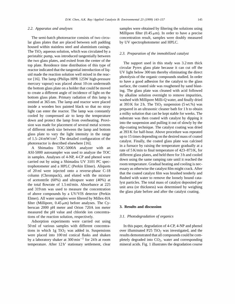
Fig. 1. Typical diagram of the degradation of 4-CP in P25 TiO2 suspensions. (Experimental conditions:I = 22 mW/cm2, C0 = 0.16 mM,(TiO2) = 2 g/l, O2 saturated).
of 4-CP, formation and subsequent degradation of in-termediates, chloride ion concentration and pH varia-tion during the photocatalyzed reaction. The decreaseof pH value in solution resulted from the formationof HCl during the degradation, which was reflectedby the increase of the chloride ion concentration. Inliterature [17] up to six intermediates have been de-tected during the degradation of 4-CP in TiO2 aque-ous slurry, and all of that could be degraded furtherto final products CO2 and HCl. Under the experimen-tal conditions in the present work, the total concen-tration of intermediates measured during the reactionwas quite low, therefore no effort has been made toidentify them. The total concentration of intermediateswas determined as the difference between the concen-trations of TOC and 4-CP under the assumption thatall formed intermediates consist of six carbon atoms.Sample concentrations of TOC and 4-CP were mea-sured by the TOC analyzer and HPLC respectively.Total chloride ion balance was carried out in the reac-tion system by measuring the concentration of 4-CP,intermediates and chloride ion in solution for eachsample drawn. The average total chloride ion concen-tration measured for nine samples with 212 mM initialchloride ion was 205.2± 7.06 mM, without consider-
ing the chloride ion present in intermediates. Aver-age total chloride ion concentration of 211.5± 6.2 mMwas obtained when it was assumed that each moleintermediates contains 1 mol chloride ion. Above re-sults indicated that no significant loss of chloride ionwas observed due to the photo-induced adsorption of4-CP onto the TiO2 particles and/or formation of highvolatility intermediates. The slight decrease of totalchloride ion concentration with reaction time was dueto the adsorption of chloride ion on the TiO2 catalyst.It should be noted that the initial concentration of chlo-ride ion concentration in Fig. 1 comes from the tracecontent of HCl present in the commercial P25 TiO2,which was reported in the manufacturer’s document.
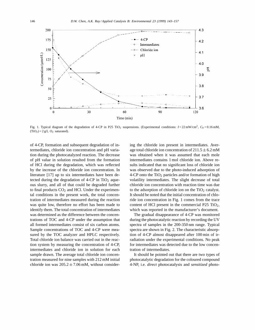
The gradual disappearance of 4-CP was monitoredduring the photocatalytic reaction by recording the UVspectra of samples in the 200-350 nm range. Typicalspectra are shown in Fig. 2. The characteristic absorp-tion of 4-CP almost disappeared after 100 min of ir-radiation under the experimental conditions. No peakfor intermediates was detected due to the low concen-tration of intermediates.
It should be pointed out that there are two types ofphotocatalytic degradation for the coloured compound4-NP, i.e.direct photocatalysis andsensitizedphoto-
D.W. Chen, A.K. Ray / Applied Catalysis B: Environmental 23 (1999) 143–157 147
Fig. 2. UV spectrum profiles during the degradation of 4-CP in P25 TiO2 suspensions. (Experimental conditions:I = 20.5 mW/cm2,C0 = 0.16 mM, (TiO2) = 2 g/l, O2 saturated).
catalysis. Thedirect photocatalysis is the one dis-cussed in this paper. Insensitizedphotocatalysis, theadsorbed coloured compound is promoted to an ex-ited state by the input ofvisibleradiation. The excited4-NP can then inject an electron into the conductionband of the semiconductor and become oxidized to acation radical. Hence, this process does not involvecharge separation in photocatalyst and formation ofhydroxyl radical, which are essential indirect photo-catalysis. Recently, Dieckmann and Gray [18] com-pared these two types of photocatalytic degradationof 4-NP in Degussa P25 suspensions. They reportedthat the pseudo-first order rate constants fordirectandsensitizedphotocatalysis were 2.02 and 0.122 h−1,respectively. Obviously,direct photocatalysis is muchmore efficient thansensitizedphotocatalysis. Mean-while, one should note that sensitized photocataly-sis for 4-NP degradation occurs mainly in alkalinesolution. In alkaline solution, 4-NP (pKa = 7.15) ispredominantly present in the deprotonated form,which strongly absorbs visible light (lmax= 399 nm;ε = 6.99× 10³ l/mol/cm), while the protonated formweakly absorbs visible light (lmax= 319 nm, extinc-tion coefficientε = 6.99× 10³ l/mol/cm) [18]. How-ever, in our experimental study for the degradation of4-NP solution pH was around 4. The primary emis-
sion of our UV lamp was at 365 nm and no radiationat wavelength of 319 nm was generated. Therefore, inour experimental studies photocatalytic degradationrate of 4-NP resulted fromsensitizedphotocatalysiswas negligible.
3.2. Catalyst dosage
In slurry photocatalytic processes, catalyst dosage isan important parameter that has been extensively stud-ied. Table 1 lists the research results reported in liter-ature. Obviously, the optimal catalyst dosage reportedwas in a wide range from 0.15 to 8 g/l for differentphotocatalyzed systems and photoreactors. Even forthe same catalyst (Degussa P25), a big difference inoptimal catalyst dosage (from 0.15 to 2.5 g/l) was re-ported. Till now no general conclusion has been made.
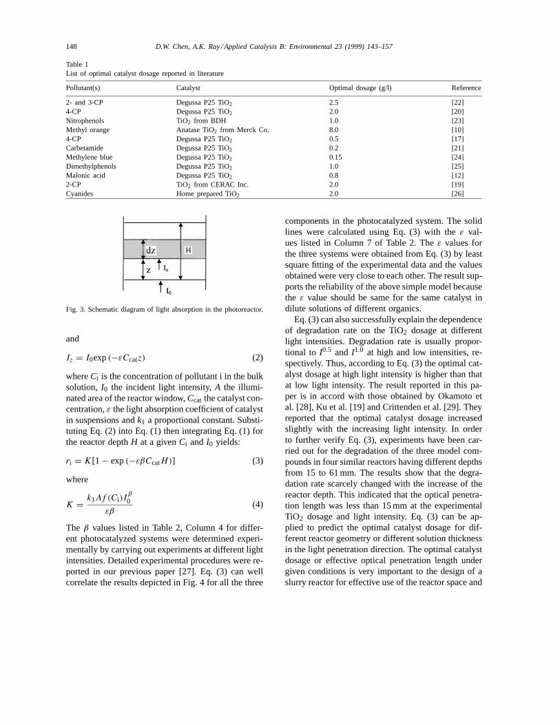
Fig. 3 is the schematic diagram of the UV light dis-tribution in the photoreactor used in this study. Be-cause the photodegradation takes place on the surfaceof catalyst, the degradation rate in a differential vol-ume is proportional to the illuminated catalyst surfacearea and can be written as:
dri = k1f (Ci)Iβz ACcatdz (1)
148 D.W. Chen, A.K. Ray / Applied Catalysis B: Environmental 23 (1999) 143–157
Table 1List of optimal catalyst dosage reported in literature
Pollutant(s) Catalyst Optimal dosage (g/l) Reference
2- and 3-CP Degussa P25 TiO2 2.5 [22]4-CP Degussa P25 TiO2 2.0 [20]Nitrophenols TiO2 from BDH 1.0 [23]Methyl orange Anatase TiO2 from Merck Co. 8.0 [10]4-CP Degussa P25 TiO2 0.5 [17]Carbetamide Degussa P25 TiO2 0.2 [21]Methylene blue Degussa P25 TiO2 0.15 [24]Dimethylphenols Degussa P25 TiO2 1.0 [25]Malonic acid Degussa P25 TiO2 0.8 [12]2-CP TiO2 from CERAC Inc. 2.0 [19]Cyanides Home prepared TiO2 2.0 [26]
Fig. 3. Schematic diagram of light absorption in the photoreactor.
and
Iz = I0exp(−εCcatz) (2)
whereCi is the concentration of pollutant i in the bulksolution, I0 the incident light intensity,A the illumi-nated area of the reactor window,Ccat the catalyst con-centration,ε the light absorption coefficient of catalystin suspensions andk1 a proportional constant. Substi-tuting Eq. (2) into Eq. (1) then integrating Eq. (1) forthe reactor depthH at a givenCi andI0 yields:
ri = K[1 − exp(−εβCcatH)] (3)
where
K = k1Af (Ci)Iβ
0
εβ(4)
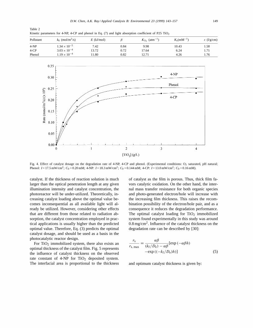
The β values listed in Table 2, Column 4 for differ-ent photocatalyzed systems were determined experi-mentally by carrying out experiments at different lightintensities. Detailed experimental procedures were re-ported in our previous paper [27]. Eq. (3) can wellcorrelate the results depicted in Fig. 4 for all the three
components in the photocatalyzed system. The solidlines were calculated using Eq. (3) with theε val-ues listed in Column 7 of Table 2. Theε values forthe three systems were obtained from Eq. (3) by leastsquare fitting of the experimental data and the valuesobtained were very close to each other. The result sup-ports the reliability of the above simple model becausethe ε value should be same for the same catalyst indilute solutions of different organics.
Eq. (3) can also successfully explain the dependenceof degradation rate on the TiO2 dosage at differentlight intensities. Degradation rate is usually propor-tional to I0.5 and I1.0 at high and low intensities, re-spectively. Thus, according to Eq. (3) the optimal cat-alyst dosage at high light intensity is higher than thatat low light intensity. The result reported in this pa-per is in accord with those obtained by Okamoto etal. [28], Ku et al. [19] and Crittenden et al. [29]. Theyreported that the optimal catalyst dosage increasedslightly with the increasing light intensity. In orderto further verify Eq. (3), experiments have been car-ried out for the degradation of the three model com-pounds in four similar reactors having different depthsfrom 15 to 61 mm. The results show that the degra-dation rate scarcely changed with the increase of thereactor depth. This indicated that the optical penetra-tion length was less than 15 mm at the experimentalTiO2 dosage and light intensity. Eq. (3) can be ap-plied to predict the optimal catalyst dosage for dif-ferent reactor geometry or different solution thicknessin the light penetration direction. The optimal catalystdosage or effective optical penetration length undergiven conditions is very important to the design of aslurry reactor for effective use of the reactor space and
D.W. Chen, A.K. Ray / Applied Catalysis B: Environmental 23 (1999) 143–157 149
Table 2Kinetic parameters for 4-NP, 4-CP and phenol in Eq. (7) and light absorption coefficient of P25 TiO2
Pollutant k0 (mol/m2/s) E (kJ/mol) β KO2 (atm−1) Ks(mM−1) ε (l/g/cm)
4-NP 1.34× 10⁻⁵ 7.42 0.84 9.98 10.43 1.584-CP 3.03× 10⁻⁴ 13.72 0.72 17.64 6.24 1.71Phenol 1.19× 10⁻⁴ 11.80 0.82 12.71 4.26 1.76
Fig. 4. Effect of catalyst dosage on the degradation rate of 4-NP, 4-CP and phenol. (Experimental conditions: O2 saturated, pH natural;Phenol:I = 17.5 mW/cm2; C0 = 0.20 mM; 4-NP:I = 18.3 mW/cm2; C0 = 0.144 mM; 4-CP:I = 13.0 mW/cm2; C0 = 0.16 mM).
catalyst. If the thickness of reaction solution is muchlarger than the optical penetration length at any givenillumination intensity and catalyst concentration, thephotoreactor will be under-utilized. Theoretically, in-creasing catalyst loading above the optimal value be-comes inconsequential as all available light will al-ready be utilized. However, considering other effectsthat are different from those related to radiation ab-sorption, the catalyst concentration employed in prac-tical applications is usually higher than the predictedoptimal value. Therefore, Eq. (3) predicts the optimalcatalyst dosage, and should be used as a basis in thephotocatalytic reactor design.
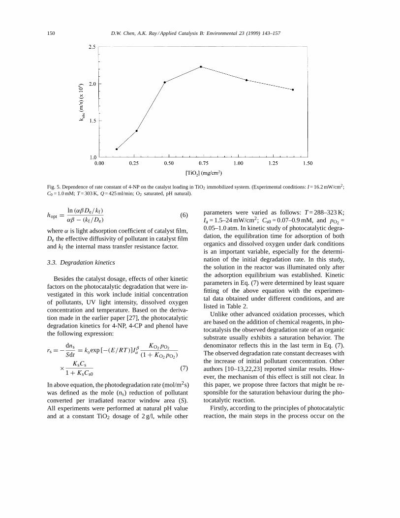
For TiO2 immobilized system, there also exists anoptimal thickness of the catalyst film. Fig. 5 representsthe influence of catalyst thickness on the observedrate constant of 4-NP for TiO2 deposited system.The interfacial area is proportional to the thickness
of catalyst as the film is porous. Thus, thick film fa-vors catalytic oxidation. On the other hand, the inter-nal mass transfer resistance for both organic speciesand photo-generated electron/hole will increase withthe increasing film thickness. This raises the recom-bination possibility of the electron/hole pair, and as aconsequence it reduces the degradation performance.The optimal catalyst loading for TiO2 immobilizedsystem found experimentally in this study was around0.8 mg/cm2. Influence of the catalyst thickness on thedegradation rate can be described by [30]:
rs
rs, max= αβ
(kf /De) − αβ[exp(−αβh)
−exp((−kf /De)h)] (5)
and optimum catalyst thickness is given by:
150 D.W. Chen, A.K. Ray / Applied Catalysis B: Environmental 23 (1999) 143–157
Fig. 5. Dependence of rate constant of 4-NP on the catalyst loading in TiO2 immobilized system. (Experimental conditions:I = 16.2 mW/cm2;C0 = 1.0 mM; T= 303 K, Q= 425 ml/min; O2 saturated, pH natural).
hopt = ln (αβDe/kf )
αβ − (kf /De)(6)
whereα is light adsorption coefficient of catalyst film,De the effective diffusivity of pollutant in catalyst filmandkf the internal mass transfer resistance factor.
3.3. Degradation kinetics
Besides the catalyst dosage, effects of other kineticfactors on the photocatalytic degradation that were in-vestigated in this work include initial concentrationof pollutants, UV light intensity, dissolved oxygenconcentration and temperature. Based on the deriva-tion made in the earlier paper [27], the photocatalyticdegradation kinetics for 4-NP, 4-CP and phenol havethe following expression:
rs = − dns
Sdt= k0exp [−(E/RT )]Iβ
a
KO2pO2
(1 + KO2pO2)
× KsCs
1 + KsCs0(7)
In above equation, the photodegradation rate (mol/m2s)was defined as the mole (ns) reduction of pollutantconverted per irradiated reactor window area (S).All experiments were performed at natural pH valueand at a constant TiO2 dosage of 2 g/l, while other
parameters were varied as follows:T= 288–323 K;Ia = 1.5–24 mW/cm2; Cs0= 0.07–0.9 mM, andpO2 =0.05–1.0 atm. In kinetic study of photocatalytic degra-dation, the equilibration time for adsorption of bothorganics and dissolved oxygen under dark conditionsis an important variable, especially for the determi-nation of the initial degradation rate. In this study,the solution in the reactor was illuminated only afterthe adsorption equilibrium was established. Kineticparameters in Eq. (7) were determined by least squarefitting of the above equation with the experimen-tal data obtained under different conditions, and arelisted in Table 2.
Unlike other advanced oxidation processes, whichare based on the addition of chemical reagents, in pho-tocatalysis the observed degradation rate of an organicsubstrate usually exhibits a saturation behavior. Thedenominator reflects this in the last term in Eq. (7).The observed degradation rate constant decreases withthe increase of initial pollutant concentration. Otherauthors [10–13,22,23] reported similar results. How-ever, the mechanism of this effect is still not clear. Inthis paper, we propose three factors that might be re-sponsible for the saturation behaviour during the pho-tocatalytic reaction.
Firstly, according to the principles of photocatalyticreaction, the main steps in the process occur on the

D.W. Chen, A.K. Ray / Applied Catalysis B: Environmental 23 (1999) 143–157 151
surface of the solid semiconductor photocatalyst [31],so the adsorption of organic compounds on the cata-lyst surface definitely affects the reaction and usuallyhigh adsorption capacity favours to the reaction. Formost organic compounds adsorption capacity on TiO2catalyst can be well described by Langmuir equation.This has been confirmed in this study. This means thatat high initial concentration all catalytic sites of thesemiconductor catalyst surface are occupied. A fur-ther increase in pollutant concentration does not affectthe actual catalyst surface concentration and therefore,this may result in the decrease of observed first orderrate constant at higher initial concentration. Secondly,the generation and migration of the photogeneratedelectron–hole pair, and the reaction between photo-generated hole (or hydroxyl radical) and organic com-pounds are two processes that occur in series. There-fore, each step may become rate determining for theoverall process. At low concentration the latter dom-inates the process and, therefore, the degradation rateincreases linearly with the concentration. On the con-trary, at high concentration the former will becomethe governing step and the degradation rate increasesslowly with concentration, and even a constant degra-dation rate may be observed at higher concentrationfor a given illuminating light intensity. Gerischer andHeller [32] and Wang et al. [33] proposed substantialevidence indicating that the interfacial electron trans-fer process involving the reduction of oxygen wasthe rate-determining step in the TiO2 sensitized pho-todegradation of organics. Lastly, intermediates gen-erated during the photocatalytic process also affect therate constant of their parent compounds. For exam-ple, two experimental runs with different initial con-centrationsC1 andC2 (C1 > C2) are performed. Whenexperiment starting withC1 decreases toC2, some in-termediates will be formed and subsequently will beadsorbed competitively on the solid catalyst surface.Whereas, for the other experimental run with the ini-tial concentrationC2, no intermediates are present atthe beginning. The presence of intermediates for thefirst run reduces the effective concentration of the par-ent compound on the catalyst surface thereby resultingin the decrease of the overall observed rate.
The overall process of photocatalytic degradationis usually not very temperature sensitive. The depen-dence of degradation rate on temperature is reflectedby the low activation energy compared with the ordi-
nary thermal reactions. This is observed by the lowactivation energies obtained in this work for the threemodel compounds and the values are comparable withthe reported values of 5–20 kJ/mol [27]. Therefore, theinfluence of temperature is quite weak. This is becauseof the low thermal energy (kT= 0.026 eV at room tem-perature) that has almost no contribution to the activa-tion of TiO2 catalyst, which has a high bandgap energy(3.2 eV). Consequently, contrary to thermal reactions,there is no need to heat the system. This absence ofheating is very attractive for photocatalytic processescarried out in aqueous media, especially for water puri-fication, because there is no need to waste energy inheating water, which has a high heat capacity. On theother hand, these activation energies are quite closeto that of a hydroxyl radical reaction [6], suggestingthat the photodegradation of the above organics weregoverned by the hydroxyl radical reaction.
Presence of electron acceptor is necessary to re-move the photo-generated electrons for continuationof the photocatalytic oxidation of organic compounds.Otherwise, the accumulated photons in the catalystparticle will recombine with holes, which are the ini-tiators of the photocatalytic reaction. The commonlyused electron acceptor is oxygen as it is easily avail-able, soluble under most conditions and non-toxic toenvironment. Wang et al. [33] observed that the photo-catalytic activity was nearly completely suppressed inthe absence of oxygen and the steady-state concentra-tion of oxygen has a profound effect on the rate ofphotocatalyzed decomposition of organic compounds.Alberici and Jardim [34] found that the decomposi-tion of phenol non-aerated solutions containing TiO2was much slower compared with aerated ones. Sabateet al. [35] did not observe photocatalytic degrada-tion of 3-chlorosalicylic acid when pure N2 was bub-bled through the solution. Hsiao et al. [36] found thatthe observed rate of disappearance of dichloro- andtrichloromethane was much faster when the solutionwas well purged with oxygen. Sclafani et al. [37]found that the concentration decay of phenol was muchfaster when oxygen was bubbled through the solutioncontaining anatase TiO2 instead of He. In the presentstudy, in order to evaluate the effects of the dissolvedoxygen concentration on the rate of the photocatalyticreaction, a series of experiments were conducted inwhich the O2/N2 ratio in the gas feed stream was var-ied while the total flowrate was kept constant. Since
152 D.W. Chen, A.K. Ray / Applied Catalysis B: Environmental 23 (1999) 143–157
Table 3Adsorption constant of dissolved oxygen on TiO2 catalyst
Pollutant Catalyst KO2 (atm−1) Reference
4-CP Degussa P25 TiO2 10.5 [38]4-CPa Degussa P25 TiO2 4.4 [11]Phenol TiO2 from Wako Chem. Co. 11.1 [28]Methyl orange Anatase TiO2 from Merck Co. 4.2 [10]4-CP Degussa P25 TiO2 17.6 This work4-NP Degussa P25 TiO2 9.98 This workPhenol Degussa P 25 TiO2 12.7 This work
a Based on the formation rate of CO2.
Henry’s Law can be applied to these gases, the varia-tions in the ratio of O2/N2 have the effect of varyingboth the gas phase partial pressure of oxygen and thedissolved oxygen concentration in the aqueous phase.It should be noted that photocatalytic degradation oforganic compounds was almost quenched in the ab-sence of dissolved oxygen (purged with pure N2). Al-though hydroquinone (HQ) was identified as the inter-mediate of 4-CP, its concentration was very low (lessthan 1 ppm) even after 1 h illumination. Above findingsuggests that transformation of 4-CP to HQ was veryslow in the absence of O2, and therefore negligible.The influence of dissolved oxygen on the observeddegradation kinetic constant can be well described byEq. (8).
kobs = kKO2pO2
1 + KO2pO2
(8)
KO2is considered as adsorption constant of dis-solved oxygen on TiO2 catalyst, butk value has noabsolute meaning because it depends on the exper-imental conditions. TheKO2 values experimentallyobtained in this study are comparable with thosereported in literature, which are listed in Table 3.
3.4. Adsorptive characteristics on P25 TiO2
The key steps of the photocatalytic degradation arethe reactions between adsorbed species. Consequently,the photocatalytic process strongly depends on theadsorptive properties of the organic compounds. Inthis study, the adsorption experiments of phenol, 4-CPand 4-NP have been investigated in TiO2 suspensionsat natural pH value and room temperature. Resultsdemonstrated that Langmuir model could well de-scribe the adsorption processes of above three com-
pounds and the adsorptive parameters are listed inTable 4. Although theKs in Eq. (7) is generally takenas the equilibrium adsorptive constants of organics onTiO2, but, the results clearly show that the adsorptionconstants obtained from the kinetic experiments aredifferent from those obtained from the dark adsorptionexperiments for the three model compounds (Table 2:Column 6, Table 4: Column 3).
Assuming that a complete monolayer of organiccompound is formed on the surface of TiO2, the max-imum surface coverage based onQmax for the abovecompounds can be calculated by the following equa-tion and are listed in Column 4 of Table 4.
θmax = QmaxNAσ0
ASP× 100% (9)
whereQmax is maximum adsorption capacity of pol-lutant over catalyst (mol/g),NA the Avogadro’s num-ber, σ0 the average cross-sectional area of organicmolecule [39] andASP the specific surface area of thecatalyst (50 m2/g). As the maximum surface coveragesfor these three compounds are extremely low, it in-dicates that most of the potential sites of the catalystare not accessible to these species. This may resultfrom the presence of high concentration of H2O and/orOH- on the surface of TiO2. It is well known thatthe surface of TiO2 is readily hydroxylated when it isin contact with water. Both dissociated and molecu-lar water are bonded to the surface of TiO2. Surfacecoverages of 7–10 OH− nm−2 at room temperaturewere reported in literature [40]. Under the experimen-tal conditions where the concentration of organics isaround 0.2 mM, the surface coverages are even muchlower (Table 4, Column 5). The reaction between hy-droxyl radical and adsorbed organics is the main stepof the photocatalytic process, and the degradation rateis proportional to the surface coverage. Therefore, one
D.W. Chen, A.K. Ray / Applied Catalysis B: Environmental 23 (1999) 143–157 153
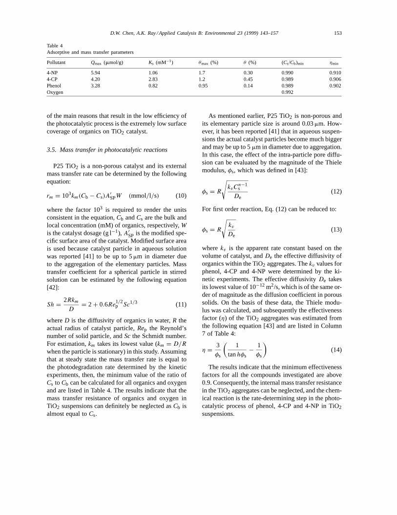
Table 4Adsorptive and mass transfer parameters
Pollutant Qmax (mmol/g) Ks (mM−1) θmax (%) θ (%) (Cs/Cb)min ηmin
4-NP 5.94 1.06 1.7 0.30 0.990 0.9104-CP 4.20 2.83 1.2 0.45 0.989 0.906Phenol 3.28 0.82 0.95 0.14 0.989 0.902Oxygen 0.992
of the main reasons that result in the low efficiency ofthe photocatalytic process is the extremely low surfacecoverage of organics on TiO2 catalyst.
3.5. Mass transfer in photocatalytic reactions
P25 TiO2 is a non-porous catalyst and its externalmass transfer rate can be determined by the followingequation:
rm = 103km(Cb − Cs)A′SPW (mmol/l/s) (10)
where the factor 103 is required to render the unitsconsistent in the equation,Cb andCs are the bulk andlocal concentration (mM) of organics, respectively,Wis the catalyst dosage (g l−1), A′
SP is the modified spe-cific surface area of the catalyst. Modified surface areais used because catalyst particle in aqueous solutionwas reported [41] to be up to 5mm in diameter dueto the aggregation of the elementary particles. Masstransfer coefficient for a spherical particle in stirredsolution can be estimated by the following equation[42]:
Sh = 2Rkm
D= 2 + 0.6Re
1/2p Sc1/3 (11)
whereD is the diffusivity of organics in water,R theactual radius of catalyst particle,Rep the Reynold’snumber of solid particle, andScthe Schmidt number.For estimation,km takes its lowest value (km = D/R
when the particle is stationary) in this study. Assumingthat at steady state the mass transfer rate is equal tothe photodegradation rate determined by the kineticexperiments, then, the minimum value of the ratio ofCs to Cb can be calculated for all organics and oxygenand are listed in Table 4. The results indicate that themass transfer resistance of organics and oxygen inTiO2 suspensions can definitely be neglected asCb isalmost equal toCs.
As mentioned earlier, P25 TiO2 is non-porous andits elementary particle size is around 0.03mm. How-ever, it has been reported [41] that in aqueous suspen-sions the actual catalyst particles become much biggerand may be up to 5mm in diameter due to aggregation.In this case, the effect of the intra-particle pore diffu-sion can be evaluated by the magnitude of the Thielemodulus,φs, which was defined in [43]:
φs = R
√kvC
n−1s
De(12)
For first order reaction, Eq. (12) can be reduced to:
φs = R
√kv
De(13)
wherekv is the apparent rate constant based on thevolume of catalyst, andDe the effective diffusivity oforganics within the TiO2 aggregates. Thekv values forphenol, 4-CP and 4-NP were determined by the ki-netic experiments. The effective diffusivityDe takesits lowest value of 10−12 m2/s, which is of the same or-der of magnitude as the diffusion coefficient in poroussolids. On the basis of these data, the Thiele modu-lus was calculated, and subsequently the effectivenessfactor (η) of the TiO2 aggregates was estimated fromthe following equation [43] and are listed in Column7 of Table 4:
η = 3
φs
(1
tanhφs− 1
φs
)(14)
The results indicate that the minimum effectivenessfactors for all the compounds investigated are above0.9. Consequently, the internal mass transfer resistancein the TiO2 aggregates can be neglected, and the chem-ical reaction is the rate-determining step in the photo-catalytic process of phenol, 4-CP and 4-NP in TiO2suspensions.
154 D.W. Chen, A.K. Ray / Applied Catalysis B: Environmental 23 (1999) 143–157
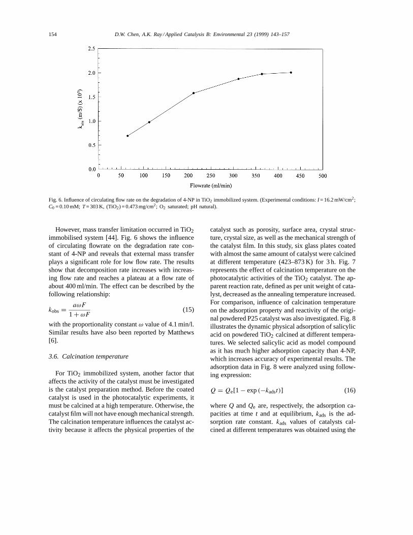
Fig. 6. Influence of circulating flow rate on the degradation of 4-NP in TiO2 immobilized system. (Experimental conditions:I = 16.2 mW/cm2;C0 = 0.10 mM; T= 303 K, (TiO2) = 0.473 mg/cm2; O2 saturated; pH natural).
However, mass transfer limitation occurred in TiO2immobilised system [44]. Fig. 6 shows the influenceof circulating flowrate on the degradation rate con-stant of 4-NP and reveals that external mass transferplays a significant role for low flow rate. The resultsshow that decomposition rate increases with increas-ing flow rate and reaches a plateau at a flow rate ofabout 400 ml/min. The effect can be described by thefollowing relationship:
kobs = aωF
1 + ωF(15)
with the proportionality constantω value of 4.1 min/l.Similar results have also been reported by Matthews[6].
3.6. Calcination temperature
For TiO2 immobilized system, another factor thataffects the activity of the catalyst must be investigatedis the catalyst preparation method. Before the coatedcatalyst is used in the photocatalytic experiments, itmust be calcined at a high temperature. Otherwise, thecatalyst film will not have enough mechanical strength.The calcination temperature influences the catalyst ac-tivity because it affects the physical properties of the
catalyst such as porosity, surface area, crystal struc-ture, crystal size, as well as the mechanical strength ofthe catalyst film. In this study, six glass plates coatedwith almost the same amount of catalyst were calcinedat different temperature (423–873 K) for 3 h. Fig. 7represents the effect of calcination temperature on thephotocatalytic activities of the TiO2 catalyst. The ap-parent reaction rate, defined as per unit weight of cata-lyst, decreased as the annealing temperature increased.For comparison, influence of calcination temperatureon the adsorption property and reactivity of the origi-nal powdered P25 catalyst was also investigated. Fig. 8illustrates the dynamic physical adsorption of salicylicacid on powdered TiO2 calcined at different tempera-tures. We selected salicylic acid as model compoundas it has much higher adsorption capacity than 4-NP,which increases accuracy of experimental results. Theadsorption data in Fig. 8 were analyzed using follow-ing expression:
Q = Qe[1 − exp(−kadst)] (16)
whereQ andQe are, respectively, the adsorption ca-pacities at timet and at equilibrium,kads is the ad-sorption rate constant.kads values of catalysts cal-cined at different temperatures was obtained using the

D.W. Chen, A.K. Ray / Applied Catalysis B: Environmental 23 (1999) 143–157 155
Fig. 7. Influence of calcination temperature on the degradation of 4-NP in TiO2 immobilized system. (Experimental conditions:I = 15.9 mW/cm2; C0 = 0.10 mM,T= 303 K; (TiO2) = 0.47–051 mg/cm2; Q= 425 ml/min; O2 saturated; pH natural).
Fig. 8. Dynamic physical adsorption of salicylic acid over powdered P25 TiO2 calcined at different temperaters. (TiO2) = 8 g/l.
linear interpolation based on Eq. (17) and are listed inTable 5.
ln (Qe − Q) = ln Qe − kadst (17)
The result indicates that adsorption rate constantdecreased with the increase of the calcination tem-perature. Mills and Morris [45] reported that no lossin catalyst surface area was observed when powdered
156 D.W. Chen, A.K. Ray / Applied Catalysis B: Environmental 23 (1999) 143–157
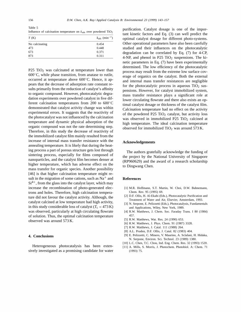
Table 5Influence of calcination temperature onkads over powdered TiO2
T (K) kads (min−1)
No calcinating 0.454473 0.448673 0.371873 0.311
P25 TiO2 was calcinated at temperature lower than600◦C, while phase transition, from anatase to rutile,occurred at temperature above 600◦C. Hence, it ap-pears that the decrease of adsorption rate constant re-sults primarily from the reduction of catalyst’s affinityto organic compound. However, photocatalytic degra-dation experiments over powdered catalyst in five dif-ferent calcination temperatures from 200 to 600◦Cdemonstrated that catalyst activity change was withinexperimental errors. It suggests that the reactivity ofthe photocatalyst was not influenced by the calcinationtemperature and dynamic physical adsorption of theorganic compound was not the rate determining step.Therefore, in this study the decrease of reactivity ofthe immobilized catalyst film mainly resulted from theincrease of internal mass transfer resistance with theannealing temperature. It is likely that during the heat-ing process a part of porous structure gets lost throughsintering process, especially for films composed ofnanoparticles, and the catalyst film becomes denser athigher temperature, which has adverse effect on themass transfer for organic species. Another possibility[46] is that higher calcination temperature might re-sult in the migration of some cations, such as Na+ andSi4+, from the glass into the catalyst layer, which mayincrease the recombination of photo-generated elec-trons and holes. Therefore, high calcination tempera-ture did not favour the catalyst activity. Although, thecatalyst calcined at low temperature had high activity,in this study considerable loss of catalyst (Tc < 473 K)was observed, particularly at high circulating flowrateof solution. Thus, the optimal calcination temperatureobserved was around 573 K.
4. Conclusions
Heterogeneous photocatalysis has been exten-sively investigated as a promising candidate for water
purification. Catalyst dosage is one of the impor-tant kinetic factors and Eq. (3) can well predict theoptimal catalyst dosage for different photo-systems.Other operational parameters have also been carefullystudied and their influences on the photocatalyticdegradation can be correlated by Eq. (7) for 4-CP,4-NP, and phenol in P25 TiO2 suspensions. The ki-netic parameters in Eq. (7) have been experimentallydetermined. The low efficiency of the photocatalyticprocess may result from the extreme low surface cov-erage of organics on the catalyst. Both the externaland internal mass transfer resistances are negligiblefor the photocatalytic process in aqueous TiO2 sus-pensions. However, for catalyst immobilized system,mass transfer resistance plays a significant role atlower circulating flowrate and there also exists an op-timal catalyst dosage or thickness of the catalyst film.Calcination temperature had no effect on the activityof the powdered P25 TiO2 catalyst, but activity losswas observed in immobilized P25 TiO2 calcined athigh temperature. The ideal calcination temperatureobserved for immobilized TiO2 was around 573 K.
Acknowledgements
The authors gratefully acknowledge the funding ofthe project by the National University of Singapore(RP960629) and the award of a research scholarshipto Dingwang Chen.
References
[1] M.R. Hoffmann, S.T. Martin, W. Choi, D.W. Bahnemann,Chem. Rev. 95 (1995) 69.
[2] D.F. Ollis, H. Al-Ekabi (Eds.), Photocatalytic Purification andTreatment of Water and Air, Elsevier, Amsterdam, 1993.
[3] N. Serpone, E. Pelizzetti (Eds.), Photocatalysis, Fundamentalsand Applications, Wiley, New York, 1989.
[4] R.W. Matthews, J. Chem. Soc. Faraday Trans. I 80 (1984)457.
[5] R.W. Matthews, Wat. Res. 24 (1990) 653.[6] R.W. Matthews, J. Phys. Chem. 91 (1987) 3328.[7] R.W. Matthews, J. Catal. 111 (1988) 264.[8] A.L. Pruden, D.F. Ollis, J. Catal. 82 (1983) 404.[9] E. Pelizzetti, C. Minero, V. Maurino, A. Sclafani, H. Hidaka,
N. Serpone, Environ. Sci. Technol. 23 (1989) 1380.[10] L.C. Chen, T.C. Chou, Ind. Eng. Chem. Res. 32 (1993) 1520.[11] A. Mills, S. Morris, J. Photochem. Photobiol. A: Chem. 71
(1993) 75.
D.W. Chen, A.K. Ray / Applied Catalysis B: Environmental 23 (1999) 143–157 157
[12] Y. Inel, A. Okte, J. Photochem. Photobiol. A: Chem. 96(1996) 175.
[13] M.C. Lu, G.D. Roam, J.N. Chen, C.P. Huang, J. Photochem.Photobiol. A: Chem. 76 (1993) 103.
[14] H.Y. Chen, O. Zahraa, M. Bouchy, F. Thomas, J.Y. Bottero,J. Photochem. Photobiol. A: Chem. 85 (1995) 179.
[15] J. Cunningham, G. Al-Sayyed, J. Chem. Soc., Faraday Trans.86 (1990) 3935.
[16] A.K. Ray, A.A.C.M. Beenackers, AIChE J. 47 (1997) 2571.[17] H. Al-Ekabi, N. Serpone, E. Pelizzetti, C. Minero, M.A. Fox,
R.B. Draper, Langmuir 5 (1989) 250.[18] M.S. Dieckmann, K.A. Gray, Wat. Res. 30 (1996) 1169.[19] Y. Ku, R.M. Leu, K.C. Lee, Wat. Res. 30 (1996) 2569.[20] G. Al-Sayyed, J.C. D’Oliveira, P. Pichat, J. Photochem.
Photobiol. A: Chem. 58 (1991) 99.[21] J.P. Percherancier, R. Chapelon, B. Pouyet, J. Photochem.
Photobiol. A: Chem. 87 (1995) 261.[22] J.C. D’Oliveira, G. Al-Sayyed, P. Pichat, Environ. Sci.
Technol. 24 (1990) 990.[23] V. Augugliaro, L. Palmisano, M. Schiavello, A. Sclafani, L.
Marchese, G. Martra, F. Miano, Appl. Catal. 69 (1991) 323.[24] S. Lakshmi, R. Renganathan, S. Fujita, J. Photochem.
Photobiol. A: Chem. 88 (1995) 163.[25] R. Terzian, N. Serpone, J. Photochem. Photobiol. A: Chem.
89 (1995) 163.[26] V. Augugliaro, V. Loddo, G. Marci, L. Palmisano, M.J.
Lopez-Munoz, J. Catal. 166 (1997) 272.[27] D.W. Chen, A.K. Ray, Wat. Res. 32 (1998) 3223.[28] K. Okamoto, Y. Yamamoto, H. Tanaka, A. Itaya, Bull. Chem.
Soc. Jpn. 58 (1985) 2023.
[29] J.C. Crittenden, J.B.D.L. Perram, J.B. Liu, D.W. Hand, Wat.Res. 31 (1997) 429.
[30] D.W. Chen, F.M. Li, A.K. Ray, Wat. Res., submitted forpublication.
[31] C. Minero, F. Catozzo, E. Pelizzetti, Langmuir 8 (1992) 481.[32] H. Gerischer, A. Heller, J. Phys. Chem. 95 (1991) 5261.[33] C.M. Wang, A. Heller, H. Gerischer, J. Am. Chem. Soc. 114
(1992) 5230.[34] R.M. Alberici, W.F. Jardim, Wat. Res. 28 (1994) 1845.[35] J. Sabate, M.A. Anderson, H. Kikkawa, M. Edwards, C.G.
Hill, J. Catal. 127 (1991) 167.[36] C.Y. Hsiao, C.L. Lee, D.F. Ollis, J. Catal. 82 (1983) 418.[37] A. Sclafani, L. Palmisano, E. Davi, New J. Chem. 14 (1990)
265.[38] A. Mills, R. Davies, J. Photochem. Photobiol. A: Chem. 85
(1995) 173.[39] J.O. Hirschfelder, C.F. Curtiss, R.B. Bird, Molecular Theory
of Gases and Liquids, Wiley, New York, 1954.[40] Y. Suda, T. Morimoto, Langmuir 3 (1987) 786.[41] H.Y. Chen, O. Zahraa, M. Bouchy, F. Thomas, J.Y. Bottero,
J. Photochem. Photobiol. A: Chem. 85 (1995) 179.[42] Y.T. Shaw, Gas–Liquid–Solid Reactor Designs, McGraw-Hill,
New York, 1979.[43] O. Levenspiel, Chemical Reaction Engineering, 2nd ed.,
Wiley, New York, 1972.[44] C.S. Turchi, D.F. Ollis, J. Phys. Chem. 92 (1988) 6853–6854.[45] A. Mills, S. Morris, J. Photochem. Photobiol. A: Chem. 71
(1993) 285.[46] A. Fernandez, G. Lassaletta, V.M. Jimenez, Appl. Catal. B:
Environmental 7 (1995) 49.
Copyright © 2022 FDOKUMEN