Synthesis and Total Phenol Content of New Resveratrol Derivative

Phenol removal from industrial wastewaters: a short review
Shohreh Mohammadia, Ali Kargaria,*, Hamidreza Sanaeepura, Khalil Abbassiana,
Atefeh Najafia, Elham Mofarrahb
aMembrane Processes Research Laboratory (MPRL), Department of Petrochemical Engineering, Amirkabir University of Technology(Tehran Polytechnic), Mahshahr Campus, PO Box 415, Mahshahr, IranTel: +98 652 23645; Fax: +98 652 41546; email: [email protected] of Chemical Engineering, Amirkabir University of Technology (Tehran Polytechnic), Tehran, Iran
Received 9 June 2013; Accepted 17 October 2013
ABSTRACT
The toxicity of phenol even at low concentrations in industrial effluents is high enough tomeet its needs for separation. In this paper, a review will be carried out on the traditionaltechniques and recent advances in the separation of phenol from its contaminated streams.The most commonly used methods classified based on the phenol concentrations (high,medium, and low), and also, their advantages and disadvantages that should be consideredin the design of industrial wastewater treatment systems will be discussed. Finally, the bestmethods will be suggested for each concentration range at the influent and, of course, thatis allowable in the final effluent. The survey results recommended that biodegradation,chemical, electrochemical, and photocatalytic oxidation, solid phase extraction, ozonation,reverse osmosis/nanofiltration, and wet air oxidation are useful methods in low phenol con-centrations, whereas liquid–liquid extraction, pervaporation, membrane-based solventextraction, adsorption, and distillation are suggested for high phenol concentrations.
Keywords: Phenol; Wastewater treatment; Persistence organic pollutants; Membranetechnologies; Emulsion liquid membrane; Adsorption; Extraction; Distillation;Ozonation; Photocatalytic oxidation; Photocatalytic membrane reactor;Concentration
1. Introduction
Phenol as a constituent of coal tar was first par-tially separated from coal tar in 1834 by Friedlieb Fer-dinand Runge, who called it “carbolic acid” or “coaloil acid.” The French chemist, Auguste Laurent, firstprepared pure phenol in 1841 and coined the name“phene” for benzene; which is the root of “phenol”and “phenyl.” In 1843, Charles Frederic Gerhardt alsoprepared phenol by heating salicylic acid with limeand gave it the name “phenol” [1].
Phenol is a basic raw material for various productssuch as herbicides, drugs, paints, cosmetics, and lubri-cants. Its largest use (35%) is as an intermediate in theproduction of phenolic resins like phenol-formalde-hyde resins. Also, its conversion to a precursor of plas-tics, such as condensation with acetone to givebisphenol-A (BPA) for the production of polycarbon-ates and epoxide resins, is from its other major useswhich together with the phenolic resins includes abouttwo thirds of its general use. Condensation productsof phenol or other phenol containing materials such asalkylphenols or diphenols with formaldehyde results
*Corresponding author.
1944-3994/1944-3986 � 2014 Balaban Desalination Publications. All rights reserved.
Desalination and Water Treatment (2014) 1–20
www.deswater.com
doi: 10.1080/19443994.2014.883327
in Bakelite, a synthetic thermo-setting phenolic resin.Other important chemicals which are produced fromphenol are cyclohexanone, as material for the produc-tion of nylon, alkylphenols such as nonylphenol or itsethoxylated product, and nonylphenyl ethoxylate, forthe production of nonionic detergents. Minor uses ofphenol and its derivatives include a versatile precur-sor for the production of some drugs such as aspirinand pharyngitis medicines, carbolic soap, one of theconstituents of industrial paint strippers in the avia-tion industry, and cosmetics including sunscreens,hair dyes, and skin lightening products. Therefore,phenol and its derivatives are usually present in theeffluents of the relevant industries such as conversionprocesses, coke ovens, petroleum refineries, fiberglassproduction, textiles, and petrochemicals [1–5].
Phenols are present in the wastewater of variousindustries, such as refineries (6–500mg/L), cokingoperations (28–3,900mg/L), coal processing (9–6,800mg/L), and petrochemical plants (2.8–1,220mg/L).Other sources containing 0.1–1,600mg/L phenols arepharmaceuticals, plastics, wood products, paint,pulp, and paper industries. Due to safety and envi-ronmental problems, it is very essential to collectand remove phenol from the wastes of various pro-duction units. Phenol is soluble in water, oil, carbondisulfide, and most organic solvents like alcohols,ethers, ketones, etc. It is rapidly absorbed throughcontact with the skin and eyes, inhalation, ingestion,and can cause skin and eye burning. In some cases,besides the corrosive effects, phenol can also causesensitization of the skin. When the skin is wettedwith phenol or phenolic solutions, it must be decon-taminated immediately. In addition, phenol canaffect the central nervous system such as collapseand loss of consciousness. Harmful effects of inhala-tion of phenolic compound vapors are dyspnea,coughing, cyanosis, and lung edema. Pouching phe-nol can cause caustic burns in the mouth and stom-ach pains. Phenol poisoning can intensely damageinner organs including kidneys, liver, spleen, lungs,and heart. When phenol poisoning is acute, neuro-psychiatric disturbances will be unavoidable. Thelimitation of phenol’s contact with the skin accord-ing to OSHA and ACGIH is less than 5mg/L, andit is considerable that the ingestion of 1 gr of phenolis deadly for humans [2–4]. The phenol concentra-tions in effluents change from 0.1 to 17 × 103 mg/L,which contribute 40–80% of the total chemicaloxygen demand (COD). In petroleum refinerywastes, the phenolic COD is less than 40%. The coalconversion process and coke oven effluents containan average of 60% phenol and 30% cresols. Ifphenol concentration exceeds from 1mg/L it can
affect aquatic life. So usually, a stringent effluentdischarge limit of less than 0.5mg/L is imposed [3].EPA determined a limit of less than 1 part per bil-lion (ppb) for surface waters. The maximum allow-able concentrations of phenol, which are adoptedfrom some water supply standards, in nonchlorinat-ed water is 0.1 mg/L (100 ppb) while that in chlori-nated water is 0.001–0.002mg/L (1–2 ppb) [1].
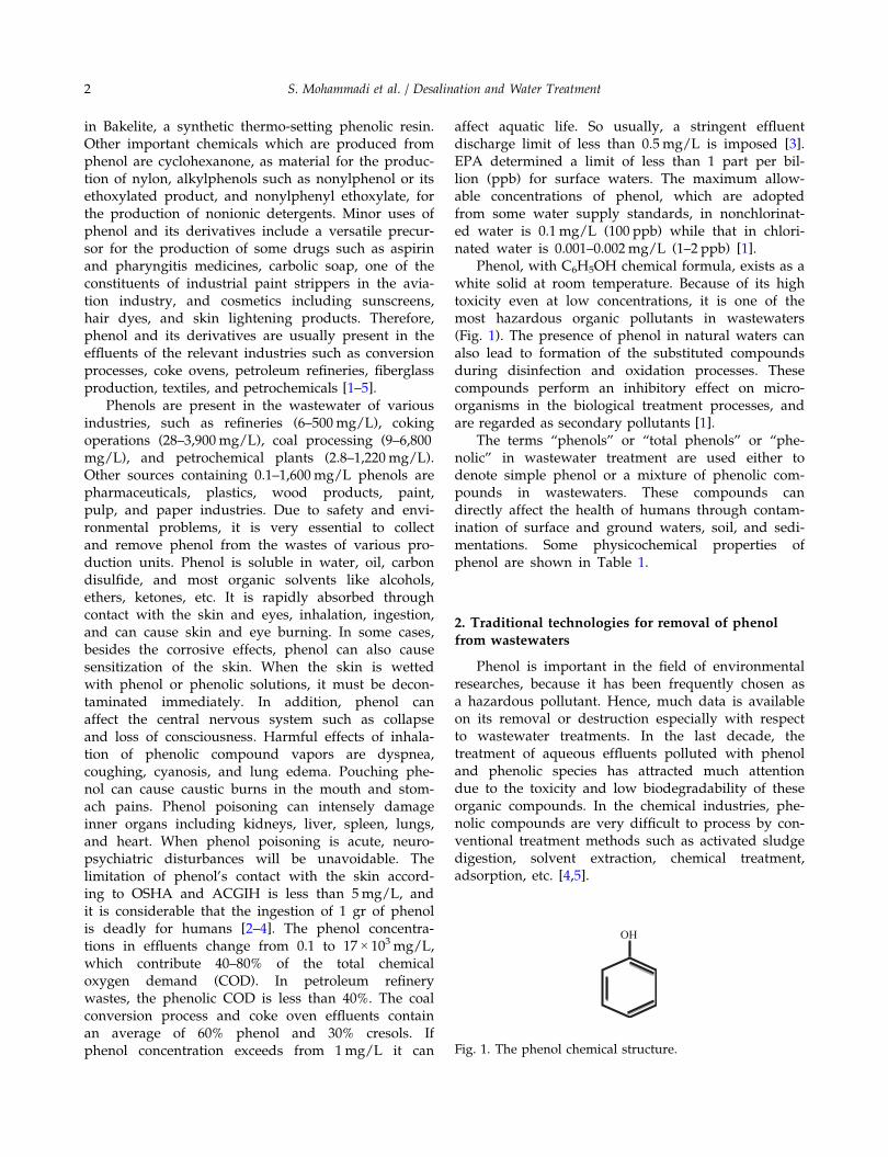
Phenol, with C6H5OH chemical formula, exists as awhite solid at room temperature. Because of its hightoxicity even at low concentrations, it is one of themost hazardous organic pollutants in wastewaters(Fig. 1). The presence of phenol in natural waters canalso lead to formation of the substituted compoundsduring disinfection and oxidation processes. Thesecompounds perform an inhibitory effect on micro-organisms in the biological treatment processes, andare regarded as secondary pollutants [1].
The terms “phenols” or “total phenols” or “phe-nolic” in wastewater treatment are used either todenote simple phenol or a mixture of phenolic com-pounds in wastewaters. These compounds candirectly affect the health of humans through contam-ination of surface and ground waters, soil, and sedi-mentations. Some physicochemical properties ofphenol are shown in Table 1.
2. Traditional technologies for removal of phenolfrom wastewaters
Phenol is important in the field of environmentalresearches, because it has been frequently chosen asa hazardous pollutant. Hence, much data is availableon its removal or destruction especially with respectto wastewater treatments. In the last decade, thetreatment of aqueous effluents polluted with phenoland phenolic species has attracted much attentiondue to the toxicity and low biodegradability of theseorganic compounds. In the chemical industries, phe-nolic compounds are very difficult to process by con-ventional treatment methods such as activated sludgedigestion, solvent extraction, chemical treatment,adsorption, etc. [4,5].
OH
Fig. 1. The phenol chemical structure.
2 S. Mohammadi et al. / Desalination and Water Treatment
In this paper, the available technologies recentlyused for separating phenol from aqueous solutions areclassified into two main groups: (1) traditional and (2)advanced methods. Based on the phenol concentra-tion, traditional methods that have been used includedistillation, extraction, adsorption, chemical oxidation,and biodegradation. The advanced methods are alsodivided into photo oxidation processes and membraneseparation technologies.
2.1. Separation methods
2.1.1. Separating by steam distillation
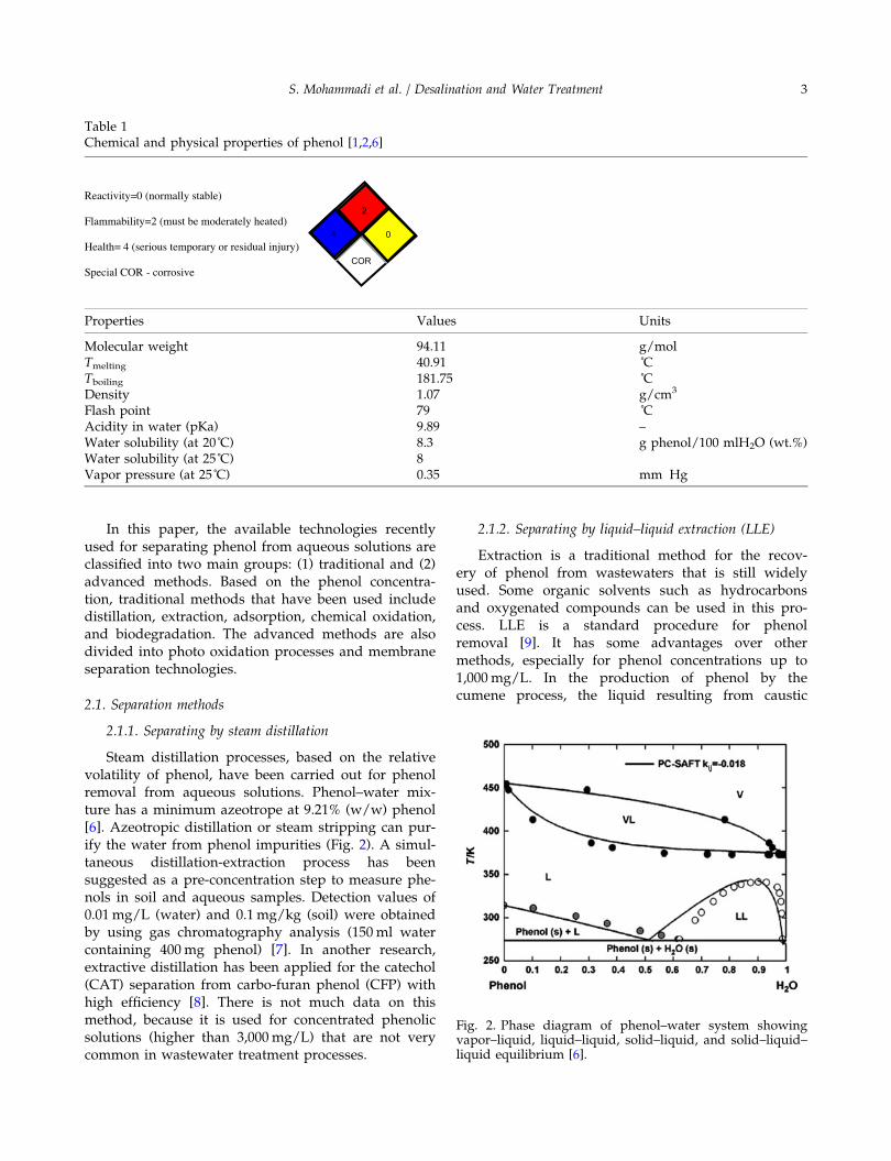
Steam distillation processes, based on the relativevolatility of phenol, have been carried out for phenolremoval from aqueous solutions. Phenol–water mix-ture has a minimum azeotrope at 9.21% (w/w) phenol[6]. Azeotropic distillation or steam stripping can pur-ify the water from phenol impurities (Fig. 2). A simul-taneous distillation-extraction process has beensuggested as a pre-concentration step to measure phe-nols in soil and aqueous samples. Detection values of0.01mg/L (water) and 0.1mg/kg (soil) were obtainedby using gas chromatography analysis (150ml watercontaining 400mg phenol) [7]. In another research,extractive distillation has been applied for the catechol(CAT) separation from carbo-furan phenol (CFP) withhigh efficiency [8]. There is not much data on thismethod, because it is used for concentrated phenolicsolutions (higher than 3,000mg/L) that are not verycommon in wastewater treatment processes.
2.1.2. Separating by liquid–liquid extraction (LLE)
Extraction is a traditional method for the recov-ery of phenol from wastewaters that is still widelyused. Some organic solvents such as hydrocarbonsand oxygenated compounds can be used in this pro-cess. LLE is a standard procedure for phenolremoval [9]. It has some advantages over othermethods, especially for phenol concentrations up to1,000mg/L. In the production of phenol by thecumene process, the liquid resulting from caustic
Table 1Chemical and physical properties of phenol [1,2,6]
Reactivity=0 (normally stable)
Flammability=2 (must be moderately heated)
Health= 4 (serious temporary or residual injury)
Special COR - corrosive
2
4
COR
0
Properties Values Units
Molecular weight 94.11 g/molTmelting 40.91 ˚CTboiling 181.75 ˚CDensity 1.07 g/cm3
Flash point 79 ˚CAcidity in water (pKa) 9.89 –Water solubility (at 20˚C) 8.3 g phenol/100 mlH2O (wt.%)Water solubility (at 25˚C) 8Vapor pressure (at 25˚C) 0.35 mm Hg
Fig. 2. Phase diagram of phenol–water system showingvapor–liquid, liquid–liquid, solid–liquid, and solid–liquid–liquid equilibrium [6].
S. Mohammadi et al. / Desalination and Water Treatment 3

washing of cumene and distillation of crude acetonecontains 1–3% phenol. This stream can be treated byextraction, and most of its phenol can be removed.In this field, the counter-current extraction is amethod that is carried out in an extraction columnwhich uses the cumene product as an extractingagent [6]. In this process, the bottom stream leavesthe column by a phenol residual concentration of20–500mg/L. The remaining phenol must beremoved in a biological purification stage in a sew-age treatment plant. All phenolic components can bealmost completely recovered except partial recoveryof dihydric phenols and neutral oils.
Extraction of phenol by various solvents such asa mixture of tributyl phosphate (TBP) and hexane,2-octanol, or kerosene has been studied. The resultsshowed that TBP has a great effect on extractionefficiency. By using TBP, phenol can be removed upto 90% with 3min of contact time to reach extrac-tion equilibrium [10]. Moreover, Jiang et al. [11]investigated the treatment of wastewaters containing6,000mg/L phenol and 5% salt in a pilot-scale LLE.They used alcohols, amines, and organic acids as ex-tractants and reached more than 99% of phenolremoval.
In a LLE work done by Hosseinzadeh et al. [12]for removal of 4-chlorophenol from water by usingkerosene as the solvent, the highest extractionefficiency was found to be 77.5% under the opti-mum condition of pH = 1, temperature of 50˚C, andinitial 4-chlorophenol concentration of 100mg/L. Ina similar work by Abbassian et al. [13] for removingphenol through the LLE method and applyingkerosene as the extracting solvent, the extractionefficiency up to 70% was obtained for 100 to500mg/L phenol concentration in the feed stream.The optimum condition in this study was pH = 6,temperature of 50˚C, and initial phenol concentrationof 100mg/L. The other solvents such as toluene thatwere used for phenol extraction are mostly moreharmful for the environment. Generally, a compara-tive study of processes for the recovery of phenolfrom aqueous effluents at concentrations higher than50mg/L shows that the LLE process is the mosteconomical nondestructive one. The LLE system hasadvantages over treating high concentrated phenolicwastewaters (over 3,000mg/L) [11].
2.1.3. Separating by adsorption
One of the separation processes that is used fortreating wastewaters, especially diluted streams, isadsorption processes. The most common adsorbentsfor water purification are activated carbons (ACs)
which are divided in two categories: granular acti-vated carbons (GACs) and powdered activated car-bons (PACs). The industrial practices with these twoforms of ACs show that GACs are normally regener-ated while PACs are discharged after use. From thispoint of view, GACs are preferred to PACs. Theadsorption by AC is currently the most favorablemethod due to its good efficiency, high adsorptioncapacity, and low operational cost [6]. Terzyk et al.[14] distinguished three stages in the mechanism ofphenol adsorption on the ACs: adsorption in theinfinite dilution, filling of micropores, and adsorp-tion in larger micropores and mesopores. The effec-tive removal of adsorbed phenols followed by anethanol wash leads to adsorbent regeneration andseparation of the aromatic species. Generally, waste-water treatment by the conventional fixed beds hastwo drawbacks: one is the low efficiency of the fixedbed due to only a just fraction of adsorbent is used.The other is a new pollution problem that is causedby waste generation [15]. Otero et al. [15] tested twopolymeric resins and an activated charcoal for evalu-ation of their adsorptive performance during thephenol removal from wastewater. The experimentswere performed at three different temperatures (293,310, and 333 K). Fixed bed and batch equilibrium
A
V
1
2
7
6
5
4
3
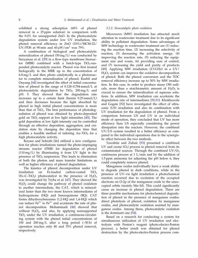
Fig. 3. Schematic view of an electrochemical system; (1) DCpower supply, (2) anode, (3) cathode, (4) reactor, (5) elec-trode gap, (6) level of solution, and (7) water bath [36].
4 S. Mohammadi et al. / Desalination and Water Treatment
experiments considered under these temperatureconditions to investigate the dependency of phenoladsorption on temperature for each of the adsor-bents. It was observed that polymeric resins aremore sensitive to temperature than ACs, and get toa high level of purification by means of thermalpumping. Among the above-mentioned traditionalmethods, adsorption similar to separation by distilla-tion is suggested for high initial phenol concentra-tion in wastewaters [8].
2.1.4. Solid-phase extraction (SPE)
SPE due to its benefits is considered as a propertechnique for extraction of phenolic compounds suchas polyphenols. Some important advantages of SPEare its simplicity, low cost, and environmentallyfriendly agents used in this technique. In a study byFerri et al. [16], five adsorbent resins were appliedwith different physical properties such as AmberliteXAD4, XAD7, XAD16, IRA96, and Isolute ENV + andshowed that the most phenol adsorption can beobtained with IRA96 polar resin in an initial phenolconcentration up to 4,000mg/L. They also tested somedesorbing agents such as water, methanol, and etha-nol. Adsorption of target compounds with a mixtureof resins and desorbing agents was compared. Theresults declared that recovery of overall phenol bynonpolar ENV + resin and ethanol as the desorbingagent was the best value of about 60%. Other poly-meric adsorbents such as poly methyl methacrylate(PMMA) can also be used as a good alternative toACs for removing phenol from aqueous solutions atlow concentrations [17]. The adsorption of phenol (10–90mg/L) is an exothermic and spontaneous process inthis case and higher ambient temperature leads toincreasing the adsorption capacity.
Onofrejova et al. [18] studied bioactive phenolicacid adsorption from freshwater alga and food prod-ucts by a new extraction technique that applies an off-line combination of pressurized liquid extraction withsolid phase extraction (PLE-SPE). Under the optimumcondition, more than 96% of phenols present in thealgae are removed.
2.2. Destruction methods
2.2.1. Total oxidation with air processes
2.2.1.1. Noncatalytic wet air oxidation. Wet air oxida-tion (WAO) (or wet oxidation, WO) is an importantwell-established technique for wastewater treatment,especially when it is too dilute to incinerate and tootoxic for bio-treating. It is a low-cost operation with a
minimal air pollution discharge [19,20]. In the WAO,aqueous solution containing the organic pollutants ispartially oxidized into biodegradable intermediates ormineralized to carbon dioxide and water in the liquidphase at high temperatures (125–320˚C) and pressures(0.5–20 MPa) by using a gaseous source of oxygen asthe oxidant. WAO has a great potential for treatmentof effluents containing a high content of organic mat-ter (about 10–100 g/L of COD) and/or toxic contami-nants for which direct biological treatment is notfeasible. Phenolic compounds were usually taken asmodel pollutants in most cases by this method oftreatment [20]. According to Luck [21], typical condi-tions for WAO are from 180˚C and 2MPa to 315˚Cand 15MPa. This coincides with the residence timesfrom 15 to 120min that leads to COD removal ofabout 75–90%.
WAO is an extremely clean process; because it nei-ther uses any harmful chemical reagents nor producesany harmful final products (carbon dioxide and waterare the products if a complete oxidation is achieved).However, high temperatures and pressures and theconsequent residence times required to achieve a highdegree of oxidation of many organic compounds areusually known as significant drawbacks of the WOprocess [19]. Furthermore, due to the presence of somelow molecular weight oxygenated compounds (espe-cially acetic and propionic acids, methanol, ethanol,and acetaldehyde) which are resistant to oxidation,WAO cannot completely mineralize the waste streams.Therefore, WAO is regarded as a pretreatment processof liquid wastes that requires additional treatments[21]. Aqueous oxidation can also operate at high pres-sure and temperature above the critical point of water(374.2˚C and 22.1MPa), which is often referred to assuper critical water oxidation (SCWO). SCWO takesadvantage of the better dissolution of both organiccompounds and oxygen in super critical water, whichcreates a single homogeneous phase for rapid oxidiza-tion of the organics [22,23].
2.2.1.2. Catalytic wet air oxidation (CWAO). CWAO isone of the most promising WAO processes. CWAOcan reduce the severity of reaction conditions anddecompose the refractory pollutants in mild operatingconditions (temperature below 200˚C and pressures inthe range 0.5–2.0MPa) which reduce both the capitaland operating costs [24]. Many recent investigationshave been searching the CWAO of phenols by a vari-ety a homogeneous/heterogeneous catalysts [19,21,25].The widely used homogeneous catalysts for CWAOare transition metal cations, such as Cu+ and Fe2+ ions.There have been industrial homogenous CWAO pro-cesses such as the Ciba-Geigy process, which work at
S. Mohammadi et al. / Desalination and Water Treatment 5
high temperatures (300˚C) and achieve high oxidationefficiencies (95–99%) [25]. To find the new catalyticmaterials with high activity and stability, different het-erogeneous catalysts including noble metals (such asRu, Rh, Rd, and Pt), metal oxides (such as Cu, Ni, Co,Fe, and Mn oxides with the rather lower activitiesthan noble metals), and mixed oxides (such as ceria–zirconia and ceria–titania mixed oxides) have beenprepared and tested for CWAO of phenolic modelcompounds and the related real wastewaters [24]. TheAC can also act as a catalyst in this case, although itmay be consumed by oxidation. Through the CWAOwith typical reaction conditions (T = 100–200˚C andPO2
= 0.3–3.5MPa, t = 1–3 h), phenol conversion of over90–95% and TOC or COD removal of over 80–90%were achieved [19]. Hamoudi et al. [26] developed oneof the most active mixed oxide catalysts in the mildoperating conditions based on the MnO2/CeO2 forCWAO of phenol in terms of TOC removal. By usingan oxygen partial pressure of 0.5MPa, this catalystachieved 80% TOC removal in 1 h at 80˚C. However,the primary goal of CWAO should be to convertorganics into products that are more amenable for bio-logical treatment but it is at a challenge of being tooexpensive.
2.2.2. Biodegradation of phenol
Due to the toxicity of phenol for most micro-organ-isms at high concentrations, most of the biodegrada-tion processes are carried out at low concentrations ofphenol. Under aerobic or anaerobic conditions, phenolcan be converted to harmless compounds by micro-organisms. Some aerobic bacteria and fungi use phe-nol as a source of carbon and energy, and degrade it[1,2]. The wastes of more industrial units contain highconcentrations of phenol, so the waste treatment bymicro-organisms is difficult. In a batch system, thedegradation of phenol at an initial concentration of250mg/L was faster. Approximately, 100% degrada-tion for phenol concentrations of 300 and 500mg/Lcould be achieved. At higher concentrations of 800and 900mg/L, the degradation decreased to about 94and 93%, respectively [6].
The activated sludge is known as a natural micro-bial consortium and due to its many advantages it iswidely used in wastewater treatment processes [6,27].This method was also used for the biodegradation of400mg/L phenol in a batch reactor and a rotatingbiological contactor (RBC) [6]. In the dual-substratebiodegradation system of phenol and m-cresol, it wasshown that low concentrations of phenol (0–500mg/L) could accelerate the m-cresol biodegradationbecause phenol can provide a carbon source as the
first-grade substrate for the synthesis and accumula-tion of new cells in the dual-substrate biodegradationsystem. In this regard, for all the phenol and m-cresolconcentrations, phenol is initially utilized and then them-cresol [28].
In the mineralization of phenol (50 mg/L), it canbiologically degrade to the concentration of 6.8 mg/L,a suitable concentration for more photocatalytic treat-ment to complete the process. The advantages of com-bined biological–photocatalytic treatment are shortermineralization time and decomposition of intermedi-ates or nonbiodegradable compounds. However, itrequires more electric cost than the biological treat-ment alone [29]. As it is taken from the abovemen-tioned, the initial concentration of phenol plays animportant role in the biodegradation process, becausesome hydrocarbon pollutants including phenol havean inhibitory effect on the activity of the biomass. Inthe case of anaerobic digestion of phenols, the up-flowanaerobic sludge blanket (UASB) process is the mostimportant operation that has been successfully used inthe chemical and petrochemical companies [30].According to the studies, it is shown that phenol andcresols are degraded with and without the dual-sub-strate biodegradation system in a UASB reactor. Thecrucial point in this case is the substrate concentrationwithin its inhibitory range in the reactor. This will bedominated by the three methods of dilution withwater, recirculation and use of co- or dual-substrates.Dilution with water, however, is not a reasonableoption. In the case of effluent recirculation, it indicatedthat at phenol concentrations of 1,260 and 3,000mg/Lwith the relevant 1:1 and 3:1 effluent recirculationratios, the UASB reactor performance is efficient(>97% removal). The co-substrate system of phenoland glucose with the respective concentrations of1,260 and 1,000mg/L can be more effective with 98%phenol removal and 92% COD removal. Moreover, itis reported that p-cresol is completely degraded at aconcentration of 650mg/L in the presence of auxiliarycarbon source such as volatile fatty acids (VFAs) as aco-substrate (p-cresol: VFA = 2:1 on COD basis). In theabsence of VFA, only 80% p-cresol is removed. Aspreviously mentioned for dual-substrate biodegrada-tion systems of o- and m-cresol and phenol, o- andm-cresol are completely degraded in the presence ofphenol [3].
3. Advanced methods for phenol separation orreduction
Several advanced methods mainly based on theoxidation processes have been widely investigated inorder to complete destruction of phenolic compounds.
6 S. Mohammadi et al. / Desalination and Water Treatment
Electrochemical oxidation, photo oxidation processes,and oxidation with chemical oxidants are in this cate-gory. Membrane separation processes such as nanofil-tration (NF) and reverse osmosis (RO) are alsoconsidered as another state of the art technology inthis context [31,32]. Phenol concentration plays a cru-cial role to perform a fast, economical, and suitableadvanced process [4,33].
3.1. Electrochemical oxidation
3.1.1. Indirect electro-oxidation
Chlorine and hypochlorite generated anodically,the electrochemically generated hydrogen peroxide(H2O2), and the metal ion mediators are used ade-quately for indirect electro-oxidation of pollutants.The indirect electro-oxidation technique using highchloride concentration can efficiently oxidize manyorganic and inorganic pollutants [34]. The electro-chemically generated H2O2 can also degrade the pol-lutants by applying a proper cathode/anode system.Adding the Fe2+ salts into the wastewater makes anelectro Fenton reaction. The advantage of the electroFenton process is to allow a better control of hydro-xyl free radical production [3]. Metal-ion mediatedelectro-oxidation is another indirect electro-oxidationprocess. Metal ions as mediators are oxidized in acathode/anode system, which in turn attack organicpollutants directly, and may also produce hydroxylfree radicals that promote destruction of the organicpollutants. This process usually needs to operate inacidic media to prevent the metal from hydroxideprecipitations. In addition, there is a secondary pol-lution due to the addition of heavy metals [34]. Aschematic view of an electrochemical system whichis used by Abdelwahab et al. is shown in Fig. 3[35].
3.1.2. Direct anodic oxidation
Direct (or anodic) oxidation is another electrochem-ical oxidation process. Oxidation of pollutants directlyoccurs on the anode by physically adsorbed (hydroxylradicals, •OH) or chemisorbed (oxygen in the oxide lat-tice, MOx + 1) “active oxygen.” Generally, chemisorbedactive oxygen is more effective than the physical one.The anodic oxidation has some advantages comparedto the other electro-oxidation processes. It does notneed the addition of many chemicals to the wastewateror feeding O2 to cathodes which in turn, no secondarypollutions are produced and the fewer accessories arerequired [34]. Boron-doped diamond (BDD) is a spe-cific electrode material that shows an increased activity
in the oxidation of aromatic compounds [36,37].Applying BDD at high anodic potentials, total mineral-ization of phenol may occur without anode deactiva-tion. The combustion efficiency of phenol on BDDelectrodes is independent of the concentration. Accord-ing to studies, BDD electrodes have better perfor-mances in mineralization of phenols with respect toothers such as SnO2, PbO2, and IrO2 [6,36,37].
3.2. Photo-oxidation processes
3.2.1. Catalytic photo-oxidation
Phenol oxidation activity under the UV irradiationmay strongly increase when photocatalysts are pres-ent. In the photocatalytic method, when the photocata-lyst immobilizes on a support, the active surface maylead to significant reduction in the photoactive capac-ity of photocatalysts; whereas using the catalyst as asuspension state has a much greater active surfacethan others [38]. Among several materials with somephotocatalytic activities, photo catalysis with TiO2 hasbeen intensively investigated for the destruction ofenvironmental toxic pollutants. Hidalgo et al. [39,40]found a complete conversion of phenol (50mg/L)with TiO2 (1 g/L) by using a medium pressure of400W mercury lamp (under the wavelength of 270nm) after a 90min illumination. Copper may alsofavor photo activity of TiO2 towards phenol degra-dation especially in conjunction with sulfate radicals[41]. Vione et al. [42] have observed that the degra-dation of phenol may depend inversely on the radi-ation that scatters from the photocatalyst, due to itsparticle size, and is increased by using surfaces fluo-rinated with TiO2. Reactors operating photo catalyti-cally use semiconductors such as TiO2 in differentways, e.g. in suspension as a fluidized bed or inter-nally supported as a fixed bed [41,42]. In the fixedbed catalytic reactors, the sol–gel procedure is usedto deposit the catalyst from its solution on the inter-nal reactor walls, and the subsequent elimination ofthe solvent [43]. Transition metal-containing meso-porous materials (MCMs) like MCM-22 and MCM-41exhibited an excellent capability in adsorbing phenolcompared to SiO2 and ZSM-5 [6]. In the work car-ried out by Sun et al. [41], MCM-22 was used as asupport for ZnO to prepare a catalyst for photocata-lytic degradation of phenol. Moreover, they usedperoxydisulphate (PDS) and peroxymonosulphate(PMS) to provide sulfate radicals in order to carryout chemical oxidation. It was found that theadsorptive property of the supports played animportant role in photochemical and photocatalyticoxidation. The MCM-22 supported ZnO catalyst
S. Mohammadi et al. / Desalination and Water Treatment 7
exhibited a strong adsorption (68% of phenolremoval in a 25 ppm solution) in comparison withthe 0.0% for unsupported ZnO. In the photocatalyticdegradation system under low UV irradiation, thephenol removal efficiency in ZnO (10%)/MCM-22/UV/PDS at 90min and 60 μW/cm2 was 79%.
A combination of biological and photocatalyticmineralization of phenol (50 mg/L) was conducted bySuryaman et al. [29] in a flow-type membrane bioreac-tor (MBR) combined with a batch-type TiO2-sus-pended photocatalytic reactor. Phenol was first treatedbiologically in the MBR up to the concentration of6.8 mg/L and then photo catalytically in a photoreac-tor to complete mineralization of phenol. Kashif andOuyang [44] investigated the effect of initial concentra-tion of phenol in the range of 0.128–0.784mmol/L atphotocatalytic degradation by TiO2: 200mg/L andpH: 5. They showed that the degradation rateincreases up to a certain limit (herein 0.25 mmol/L)and then decreases because the light absorbed byphenol in high initial phenol concentrations is morethan that of TiO2. The best performance of photodeg-radation of phenol was obtained by photo-depositedgold on TiO2 support at low light intensities [45]. Thegold deposition at low light intensity can be controlledthrough an effective deposition, aggregation, and oxi-dation state by changing the deposition time thatenables a feasible method of tailoring Au–TiO2 for ahigh photocatalytic activity.
Royaee and Sohrabi [46] utilized a new configura-tion for photo irradiations named the photo-impingingstreams reactor (PISR) for degradation of phenol(110mg/L) by illuminating it from UV light in thepresence of TiO2 suspension. This leads to eliminationof both the photon and mass transfer limitations aswell as higher efficiency of phenol degradation.
The kinetics of phenol decomposition under UVirradiation on Fe-loaded carbon-coated TiO2
(Fe–C–TiO2) photocatalyst in the presence of H2O2
was investigated by Tryba et al. [47]. They showed theH2O2 could change the pathway of phenol oxidationto another intermediate, the CAT, which is mineral-ized faster than the two more known intermediates ofhydroquinone (HQ) and benzoquinone (BQ). CATforms dihydroxybenzenes (1,2-HQ and 1,4-HQ) whichcan reduce Fe3+ to Fe2+ and accelerate the rate of phe-nol decomposition. Mohammadi [48] showed thatwithout H2O2, and also, by applying nonsupportedTiO2 under the UV irradiation, a continuous-circulat-ing system with the phenol initial concentrations of100 and 200mg/L after a long period (~50 h) ofoperation reaches only 80 and 70% phenol removal,respectively.
3.2.2. Noncatalytic photo oxidation
Microwave (MW) irradiation has attracted muchattention in wastewater treatment due to its significantability in pollutant degradation. Some advantages ofMW technology in wastewater treatment are (1) reduc-ing the reaction time, (2) increasing the selectivity ofreaction, (3) decreasing the activation energy, (4)improving the reaction rate, (5) reducing the equip-ment size and waste, (6) providing ease of control,and (7) increasing the yield and purity of products[49]. Applying MW irradiation (2.5 GHz) in a UV/H2O2 system can improve the oxidative decompositionof phenol. Both the phenol conversion and the TOCremoval efficiency increase up to 50% by MW irradia-tion. In this case, in order to produce many OH radi-cals, more than a stoichiometric amount of H2O2 iscrucial to ensure the mineralization of aqueous solu-tions. In addition, MW irradiation can accelerate thedegradation rate of intermediates [50,51]. Khokhawalaand Gogate [52] have investigated the effect of ultra-sonic (US) irradiation and also its combination withUV irradiation for the degradation of phenol. From acomparison between US and UV in an individualmode of operation, they concluded that UV has moreefficiency than US especially considering the powerdissipation into the reactors. However, the combinedUV/US system resulted in a better efficiency as com-pared to the individual operations due to the synergis-tic effect between the two methods.
Tawabini and Zubair [53] presented a combinedUV and ozone (O3) process to phenol removal from itscontaminated sources. Through the combined UV/O3
continuous process at 1 L/min and by the addition of1.5 ppm ammonia for adjusting the pH below 6, theycould completely remove phenol.
Manganese oxides individually have a weak abilityto degrade phenol in dark conditions, while in thepresence of UV–vis light irradiation a photochemicalreaction occurred due to excitation of the occupiedelectrons on O-2p of the manganese oxide to the unoc-cupied orbits (mainly Mn-3d). This could significantlycause an increase in phenol degradation. There arethree possible mechanisms for photochemical degrada-tion of phenol in the presence of manganese oxides:direct photolysis of phenol, oxidation by manganeseoxides, and photocatalytic oxidation assisted by man-ganese oxides. Among these, photocatalytic oxidationis the dominant one [54].
Based on a research for conducting a system forsimultaneous utilization of UV irradiation and elec-trolysis with Fenton’s reagent (photo-electro-Fentonprocess), a better result was obtained for phenoldestruction by the photo-electro-Fenton process com-
8 S. Mohammadi et al. / Desalination and Water Treatment

pared to that of the sonolysis assisted one, the sono-electro-Fenton process. Both of the processes havecomplete degradation of 200mg/L phenol, whereasthe photo-electro-Fenton showed a superiority in caseof its shorter required times of performance [55].
3.3. Oxidation with chemical oxidants
Different chemical oxidants have been reported tobe active in the total wet oxidation of phenol in aque-ous solutions. The most applied chemical oxidants areO3 and H2O2 [50,56–63].
3.3.1. Oxidation with O3 (ozonation)
O3 with environmentally safe oxidizer anddisinfector characteristics can oxidize organic andinorganic compounds present in wastewaters.Ozonation can effectively detoxify harmful chemicals[50]. In the presence of catalysts or in combination withUV or H2O2, the ozonation process would be moreefficient in the degradation of organic compounds.There are also some disadvantages for using O3 toremove pollutants from water, which limit its applica-tion in wastewater treatment. Some of these are high O3
generation cost, its low solubility in water, and lowoxidation rate towards stable organic compounds suchas phenols. In addition, the rate of pollutant removal isslow through the ozonation process, which requireshigh O3 dosages [50,55,64]. Using O3 and various saltsor their coupling with UV radiation or H2O2 are typicalhomogeneous catalytic oxidation [26,52,53,64–67]. Het-erogeneous catalytic ozonation dating back from the1970s [56] is now attracting attention once more. In thecase of Al2O3 supported transition metal oxide catalysts[64], the high oxidation activity in the presence of ozonehas been attributed to the high content of these agents.Dong et al. [59] synthesized ZnO particles of 200 nmthrough a hydrothermal method and applied them inthe degradation of phenols with the increase in removalefficiencies of up to 23.7%. Chang et al. [60] applied theCeO2/γ-Al2O3 catalyst as a feasible alternative to CeO2
for the catalytic wet air oxidation of phenol. After 2 h,approximately 100% phenol conversion and 80% totalorganic carbon (TOC) removals were obtained at 180˚Cin an initial phenol concentration of 1,000mg/L and3.0 g/L of catalyst. At higher phenol concentrations,both catalyst loading and O2 partial pressure should beincreased to maintain performance. In another work, adose of 4 g/L zeolite in H-form (HZSM-5 (with SiO2/Al2O3 ratio of 80)) catalyst was applied for 100mg/L ofphenol concentration and resulted in 50.5% removalafter 80min [50].
3.3.2. Noncatalytic oxidation with H2O2
H2O2 has effective oxygen content with low cost,safe storage, and operational methods, and moreimportantly, it is environmentally friendly in nature.This implies that there is a strong oxidant in both acidicand basic solutions. The reactivity of H2O2 is generallylow and largely incomplete [63] because of the kineticsbeing much enhanced by homogeneous and/or hetero-geneous catalysts, especially in acidic media.
3.3.2.1. Conventional homogeneous Fenton reaction. Inconventional Fenton reaction, H2O2 is combined withFe2+ at acidic pH to produce ferric ions and hydroxylradicals, which can oxidize organic compounds. Thezero-valent iron metal can then reduce the ferric ionsdown to ferrous (so the reaction rate increases) orindeed may interact with hydroxyl radicals resultingin oxidation of hydroxide ions, so it limits the reactionrate. Also, Fe3+ at acidic pH reacts with H2O2 in theso-called Fenton-like reaction, producing ·HO2 radicalsand causing the catalyst to be generated. This action isfrequently done that causes the process to be sustain-able. Fenton’s reaction may be recommended as a pre-treatment process to increase later microbialtransformation that lowers the operational costs. Dueto the simplicity of equipment and mild operationalconditions, Fenton reaction has been postulated as themost economic oxidation alternative. Kang et al. [67]performed a kinetic modeling of Fenton oxidation ofphenol and mono-chlorophenols. Based on Zazo et al.[68] the chemical pathway of phenol oxidation by Fen-ton’s reagent may be much more complex than whatwas expected.
3.3.2.2. Heterogeneous Fenton reaction. The applicationof conventional homogeneous Fenton reactionbecomes complicated by the typical problems ofhomogeneous catalysis, such as catalyst separation,regeneration, etc. [69,70]. Thus, Fenton-like heteroge-neous catalysts, i.e. solids containing transition metals(mostly iron ions) have been developed and tested.One of the most popular metal cations is Fe-MFI zeo-lite [69], which is very active but may suffer from dif-fusion limitation because of the relatively small size ofits pores. The mesoporous materials containing transi-tion metal, like MCM-41 type, are considered asperspective catalysts due to a larger pore size. Theyare able to increase diffusion of reagents as comparedto microporous materials which are used as catalystsfor wet phenol oxidation with H2O2 under mild reac-tion conditions (pH = 3.5, P = 1 atm, T = 353 K). Usingcopper/MCM-41 as catalyst, it was revealed that boththe phenol conversion and the final TOC removal
S. Mohammadi et al. / Desalination and Water Treatment 9
level were 90% after 10min. However, these materialssuffer from destruction of the mesopore orders, ironagglomeration, and leaching (from 6 to 100 wt.%) [65].
3.4. Membrane processes
Membrane processes are applied in differentindustries such as water and wastewater treatment toremove some organic pollutants. Recently, this tech-nology has been commonly investigated for the phe-nolic compound removals. Low energy consumption,low operating cost, and easy scale up by membranemodules are the main advantages of these technolo-gies while it the limited lifetime of the membranesmust be given attention because of membrane foulingdue to particles and colloids present in the feedstreams [71–73]. The most important membrane tech-nologies used to remove organics from wastewater aremembrane-based solvent extraction (MBSE) (known asliquid membranes), NF/RO, pervaporation (PV), andmembrane distillation (MD) [74–78]. MBRs and photo-catalytic membrane reactors (PMRs) are the otherrelated techniques that will be explained in the“hybrid systems” section.
Membrane processes are categorized based on thedriving forces. Liquid membranes are driven bymeans of the concentration difference of donor andreceiving phases. NF, RO, and PV are carried out withtransmembrane pressure difference. MD is a thermal-driven separation in which only vapor should bepassed through the membrane pores [79–95].
3.4.1. Separating by MBSE
The membrane extraction technique is a very attrac-tive alternative to conventional extraction methods forsample preparation, because the analyses can beisolated in a continuous fashion [96,97]. A MBSEprocess couples the principles of solvent extractionwith the high compactness and interfacial exchangearea that is offered by the hollow fiber membrane cont-actors. In this case, the membrane mainly acts as aphysical barrier between the aqueous feed and theorganic solvent without significant effect on the selec-tivity. It is easy to immobilize the water–solvent inter-face at the pores’ entrance of the membrane byapplying a slight transmembrane pressure difference.The extraction is driven by a concentration gradientand the transfer operation is not dependent on thetransmembrane pressure [95].
Recently, the phenol–water mixture separationsusing membrane processes have been vastly studied,most of which were interested in using hollow fiber
modules. For this purpose, Kujawski et al. [98] appliedsome organic solvents (extractants) such as methylterbutyl ether (MTBE), cumene, and a mixture ofhydrocarbons in a polypropylene (PP) membrane.They found that MTBE as an extracting agent can bemore superior to hydrocarbons, because of its higherpolarity and the possibility of constituting H-bondswith phenol. In this regard, Reis et al. [99] found thatpolydimethylsiloxane (PDMS) is more suitable for theoperations under strong base conditions. In furtherinvestigations, the experimental results showed thatthe phenol removal efficiency increased 99.9% in lessthan 10min, under the conditions of 2.0 l/d feed flowrate, phenol concentration of more than 5 g/L, andtemperature of 298 K [4].
3.4.1.1. Emulsion liquid membrane (ELM) technique. Oneof the suitable and widely used membrane methodsfor phenol removal from aqueous solution is the ELM,which has attracted more scientists and engineersbecause of its preferred advantages in comparisonwith the other methods (Fig. 4) [79]. Li [100] first pro-posed the ELM technique in 1968 for separatinghydrocarbons. All compounds, except for hydroqui-none, can be treated by the ELM process under opti-mum conditions to result in high extraction efficiency(more than 96%) [101–103]. In the ELM process, twomain operations, the extraction and stripping, occurssimultaneously in one stage. Commonly, the ELMconsists of an organic phase, an internal phase, emul-sifier, and in some cases a chemical carrier [104,105].In addition, a high interfacial area for extraction andkinetics of stripping, especially due to the small sizeof the internal droplets are favored [106,107]. Unfortu-nately, the instability of the emulsion globules againstfluid shear has limited this process. Releasing internalphase to the external phase due to rupture of emul-sion globules could cause an unsuccessful extractionprocess [104,106]. Juang et al. [108] found that conver-sion of the membrane phase from Newtonian to asuitable non-Newtonian fluid would enhance emul-sion globules stability without considerable reductionin extraction efficiency. Also an amount of stabilizingsurfactant is needed that affects mass and chemicalreaction rates at the interfaces and also decreases theswelling problem. Internal droplets get smallerbecause of low apparent viscosity which increases themass transfer area. Non-Newtonian conversion modi-fies permeability and transport through the membranephase. Park et al. [109] studied emulsion liquid mem-branes for extracted benzoic from aqueous solutionthat were stabilized by non-Newtonian conversion inthe Taylor–Couette flow. Investigation of leakage ratefor emulsion globules was done in their study which
10 S. Mohammadi et al. / Desalination and Water Treatment

is related to rotation rate. Leakage rate will beincreased by increasing the rotation rate. Mortahebet al. [110] used a new polyamine-type surfactant thatwas synthesized for emulsion phase stabilization. Byusing this new surfactant, due to the stable emulsionglobules and increasing the amount of internal phasewhich consequently enhances the driving force,removal efficiencies increased up to 98%. However,this study declared that high concentration of theinternal phase leads to swelling and increasing inhydrolysis of the emulsifier. Investigations of Ng et al.[111] and Juang et al. [112] founded that the breakageof emulsion globules increases by increasing the con-centration of surfactant.
3.4.1.2. Supported liquid membrane (SLM). In the sup-ported liquid membrane (SLM) technique a micropo-rous polymeric or inorganic film is filled with themembrane liquid and lies between two aqueoussolutions. The desired substance dissolves inmembrane pores, and transports from the feed to stripphase. SLMs are prepared in various configurationssuch as flat sheet, hollow fiber, and spiral wound(Fig. 5) [71]. One of the SLM applications is theseparation of organic compounds [113]. Some studieshave been carried out for separating phenol. In thisregard, kerosene is used as an organic solvent, NaOHas stripping agent, and TBP and tri-n-octyl phosphineoxide (TOPO) as carriers. The results showed thatSLM systems based on the TOPO are more stable thanTBP-SLM systems. It was also indicated that using thehollow-fiber SLM (HFSLM) system can be more favor-able due to the higher membrane surface area [114].Venkateswaran and Palanivelu [115] used a flat sheetSLM containing vegetable oil as the membrane’s
liquid, and poly-tetrafluoroethylene (PTFE) and PP assolid membrane supports which resulted in thephenol removal efficiency of 95%. Other carriers suchas organosiloxane dodecane and 1-n-alkyl-3-methyl-imidazolium salts have been used in the SLM struc-ture. In these systems, NaOH was utilized as thestripping agent which resulted favorable efficiencies[115–118].
3.4.2. RO and NF
Regardless of great rejecting salt levels, membraneprocesses often have low rejecting levels for manysmall organic molecules. Therefore, their use in combi-nation with adsorption processes has been developed.RO is a membrane-based demineralization techniquethat is used to separate dissolved solids, such as ions,mostly from water-based solutions. In general, mem-branes act as perm-selective barriers, allow some spe-cies such as water to selectively permeate throughthem while other dissolved species such as ions,
Emulsifier
Fresh emulsion
Settler
Mixer
Receiving phase
Feed phase
Demulsifier
Recovered membrane phaseMembrane
phase
Receiving phase with
recovered solute
Recovered feed phase
Fig. 4. Schematic view of the ELM [79].
F R
Suppor
t
RF
S S
Suppor
t
Fig. 5. Schematic view of the SLM [79].
S. Mohammadi et al. / Desalination and Water Treatment 11

retained selectively [119,121]. Bodalo et al. [121] stud-ied phenol removal from aqueous solutions by threedifferent RO membranes and obtained low rejectionpercentage in all cases (up to 40%). They concludedthat by increasing the pressure, the rejection valuesdecrease. Furthermore, they examined three NF mem-branes (NF-97, NF-99, and DSS-HR98PP) for changingthese anomaly results. A rejection percentage ofapproximately 80% was obtained by DSS-HR98PPwith the same pressure conditions used for RO mem-branes.
NF is one of the widely used techniques forremoving natural and synthetic organic pollutants,inorganic salts, color, and hardness from aqueoussolutions. Results that were recently achieved on theimprovement of membranes showed profitably andeconomically viable use of NF membranes for the sep-aration of organics, but much effort is required to fullyunderstand the roles of all the factors that affect it. Forachievement of the total elimination of such pollu-tants, the combination of advanced oxidation and ROprocesses is one of the effective procedures that areused. In addition, both NO and RO have been used asgood treatment methods for removal of organic pollu-tants in order to produce purified water [122]. Agen-son et al. [122] used five membranes for removingalkyl phenols with 0.05 mg/L initial concentration andobtained more than 90% removal. At a constant oper-ating pressure, volume flux reduced with a decreasein solute retention. Also, the volume flux increased athigher pressures while retention increased up to a lim-iting value. Solute size and functional groups alsoaffected the retention. Significant differences in theretention values of phenolic compounds in the com-monly used NF membranes, NF-270 and NF-90 wereclearly evident [123]. Arsuaga et al. [124] also used athin-film composite NF membrane (NF-90) for phenolremoval with the feed concentration of 100–500mg/L,temperature of 20–41˚C, and pH = 2.8–5.3. Theyobserved that operating pressure and organic concen-tration affect the permeate flux. The permeate fluxincreases by increasing pressure and decreasingorganic concentration. In addition, they found thattemperature had no considerable effect, but pH notice-ably affected the phenol removal. Actually, because ofthe molecular form of phenol at a low pH, its removalis more than high pH. Increasing the concentration,they also reached an increase in percentage ofremoved phenol up to 50–60%.
In case of RO for removing phenol from aqueoussolutions using different experimental conditions (phe-nol concentration, pressure, and pH) and differentmembranes, polyamide membranes have shown suit-able results [122]. Ozaki and Li used the ultra-low
pressure reverse osmosis (ULPRO) membrane forremoving phenol and some phenolic components suchas chloro- and nitrophenols [125]. They reported thatwith an initial concentration of 10mg/L, the percent-age of removal of the phenolic component increasesby increasing pH. It demonstrated that nitrophenolsare removed more than 90% while it is more than 60%for chlorophenols at pH = 9. Srinivasan et al. [126]studied separating dimethylphenol from aqueous solu-tion by using polyamide RO membranes. Theyshowed the variation in pressures between 2 to 12 atmand the feed concentrations from 85 to 750mg/Lresulting in the rejection coefficient values to increasefrom 92 to 97%.
In order to retain the intermediate products ofphenol chemical oxidation in aqueous solution Lopez-Munoz et al. [31] examined the performance of NFand RO membranes (NF-90 and TFC-HR). Theyreported that by using the TFC-HR membrane with a100mg/L initial feed concentration, 46% removal ofphenol was obtained, higher than that for the NF-90.They showed that this is in relation to the more por-ous, rough, and hydrophobic active layer of NF-90.One of the important results was about pure waterpermeability where for NF (NF-90) it was four timeshigher than RO (TFC-HR). Their results also showedthat steady relative fluxes of NF-90 are lower for sol-utes compared to the TFC-HR membrane.
3.4.3. PV
PV is a technique that recently attracted research-er’s attention for removal of low volatile organic com-pounds (VOCs) from aqueous solution. No addition ofan entertainer, no secondary contamination, minimalenergy consumption, and no regeneration needed aresome benefits of PV [127]. Generally, in this technique,water and VOCs are, respectively, separated at thefeed and permeate side of the membrane where it issimultaneous with evaporating the permeate com-pound. Some attempts have been made for removingphenol by PV. By using a polyurethane membraneHoshi et al. [128] observed a lower phenol concentra-tion in the permeate solution rather than the feedstream. With a rise in temperature, phenol fluxincreased due to enhancing the solubility of phenol inthe polyurethane membrane. Also, it was founded thatby increasing concentration of phenol in the feedphase its flux also increases, but it decreases withdownstream pressure. Kujawski et al. [129] investi-gated the application of a series of composite mem-branes based on the polyether-block-amide (PEBA),PDMS, and zeolite-filled PDMS for PV of water–ace-tone and water–phenol mixtures. The PEBA mem-
12 S. Mohammadi et al. / Desalination and Water Treatment
brane showed the best selectivity. Since the PEBAmembrane is not available on a commercial-scale, oth-ers might have a more practical use. Finally, theyclaimed that hybrid systems containing PV andadsorption could be used to obtain the higher decom-position efficiency of phenol in effluents of thecumene oxidation process. In this connection, thedense and porous hydrophobic polyurethane urea(PUU) membrane was used for PV separation of phe-nol and better results for porous PUU were observed.The separation of phenol could be carried out withseparation factors ranging from 570 to 1,760 at totalpermeate fluxes of 7.7–14.1 kg/m2 h over feed concen-trations of 1,000–4,000 ppm at 30˚C. In addition, it hasbeen reported that the phenol flux increases remark-ably by applying the porous membranes while itcould not increase the separation factor [130].
3.4.4. Hybrid systems
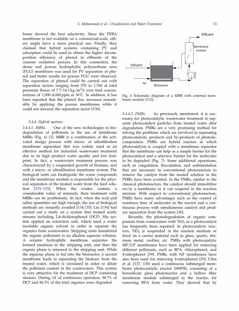
3.4.4.1. MBRs. One of the new technologies in bio-degradation of pollutants is the use of membraneMBRs (Fig. 6) [1]. MBR is a combination of the acti-vated sludge process with micro- or ultrafiltrationmembrane separation that was widely used as aneffective method for industrial wastewater treatmentdue to its high product water quality and low foot-print. In fact, a wastewater treatment process wascharacterized by a suspended growth of biomass, andwith a micro- or ultrafiltration membrane system. Thebiological units can biodegrade the waste compoundsand the membrane module is responsible for the phys-ical separation of the treated water from the feed solu-tion [131–133]. When the wastes contain aconsiderable value of minerals, their treatment withMBRs can be problematic. In fact, when the acid andsaline quantities are high enough, the use of biologicalmethods are instantly avoided [134,135]. Liu [136] hadcarried out a study on a system that treated acidicstreams including 2,4-dichlorophenol (DCP). His sys-tem applied an extraction unit, which used a waterinsoluble organic solvent in order to separate theorganics from wastewaters. Stripping units transferredthe organic pollutants to an alkaline aqueous solution.A ceramic hydrophilic membrane separates theformed emulsion in the stripping unit, and then theorganic phase is returned to the stripping unit. Whilethe aqueous phase is fed into the bioreactor, a secondmembrane leads to separating the biomass from thetreated water, which is circulated in order to dilutethe pollutant content in the wastewaters. This systemis very attractive for the treatment of DCP containingstreams. During 14 of continuous operation, 98.7% ofDCP and 86.5% of the total organics were degraded.
3.4.4.2. PMRs. As previously mentioned, it is nec-essary for photocatalytic wastewater treatment to sep-arate photocatalyst particles from treated water afterdegradation. PMRs are a very promising method forsolving the problems which are involved in separatingphotocatalysts, products and by-products of photode-composition. PMRs are hybrid reactors in whichphotocatalysis is coupled with a membrane separatorthat the membrane can help as a simple barrier for thephotocatalyst and a selective barrier for the moleculesto be degraded (Fig. 7). Some additional operations,such as coagulation, flocculation, and sedimentationthat are necessary in conventional photoreactors toremove the catalyst from the treated solution in thePMRs have been avoided. In the PMRs, similar to theclassical photoreactors, the catalyst should immobilizeon/in a membrane or it can suspend in the reactionmixture. With respect to conventional photoreactors,PMRs have many advantages such as the control ofresidence time of molecules in the reactor and a con-tinuous process with simultaneous catalyst and prod-uct separation from the system [38].
Recently, the photodegradation of organic com-pounds from wastewaters with TiO2 as a photocatalysthas frequently been reported. In photocatalytic reac-tors, TiO2 is suspended in the reaction medium orfixed on a carrier material such as glass, quartz, tita-nium metal, zeolites, etc. PMRs with photocatalyticMF/UF membranes have been applied for removingdifferent pollutants, such as BPA, chlorophenol, and4-nitrophenol [39]. PMRs with NF membranes havealso been used for removing 4-nitrophenol [39]. Chinet al. [137, 138] used a continuous submerged mem-brane photocatalytic reactor (SMPR), consisting of aborosilicate glass photoreactor and a hollow fibermembrane module submerged in the reactor, forremoving BPA from water. They showed that by
BioreactorAir
Effluent
Membrane module
Influent
Fig. 6. Schematic diagram of a MBR with external mem-brane module [132].
S. Mohammadi et al. / Desalination and Water Treatment 13

using this SMPR system, 97% of BPA (10 ppm) underphotodegradation after 90min, and more than 90% byphotomineralization after 120min of UV illuminationcould be removed. In addition, it was found that pHat low values affected degradation of BPA because ofits better adsorption on the catalyst. The efficiency ofphotocatalytic degradation was a function of aerationrate and it increased with an increase in aeration rates.Generally, they concluded that SMPR operation can beworthwhile at high feed flux and also with the lowmembrane fouling. Mohammadi [48] applied a ROmembrane separator in a PMR system using the twocommercially available nanosized TiO2 photocatalysts,the Degussa P-25 and Riedel-DeHaen. For a typicalcondition (initial phenol concentration of 100 ppm andpH = 5), it was demonstrated that this UV/TiO2/RO
Fig. 7. Schematic view of a PMR with photocatalyst in sus-pension [48].
Table 2Categorization of phenol removal methods based on the initial concentration
Influent phenol concentration
High Medium Low
TechniqueConcentration(mg/L) Technique
Concentration(mg/L) Technique
Concentration(mg/L)
Thermaldecomposition
As high as 15,000 LLE 20–500 Chemical- electrochemicaloxidation
~50
Distillation ~3,000 Adsorption 300–3,000 Photocatalytic oxidation ~50LLE Over 3,000–6,000 WAO – SPE 10–90Membrane PV Up to 10,000 ELM 300–3,000 Biodegradation Less than 50MBSE Over 5,000 CWAO – Ozonation ~50Adsorption Up to 4,000 RO/NF 0.5–750
Table 3Categorization of phenol removal methods based on the final concentration
Effluent phenol concentration
High Medium Low
TechniqueConcentration(mg/L) Technique
Concentration(mg/L) Technique
Concentration(mg/L)
Distillation – Membrane-base solventextraction
– Biologicaldegradation
Less than 10
LLE – PV ~300 Photocatalyticoxidation
Very low
CWAO – Adsorption Very lowWAO Very lowCWPO-Fentonoxidation
–
Ozonation Very low
14 S. Mohammadi et al. / Desalination and Water Treatment

hybrid system could approximately remove 50% ofphenol within one hour of continuous operation.
Finally, as a brief summary, all the traditional tech-niques and recent advances for phenol removal aregiven in Tables 2 and 3 based on the influent andeffluent phenol concentrations.
4. Conclusions
Various traditional techniques and the relevantadvances for treatment of phenolic wastewaters werereviewed. It is concluded from the investigations thattwo fundamental parameters should be considered todesign an appropriate process in this case: initial andfinal phenol concentrations. It must be noted that ineither case, the level of phenol concentration (low,medium, and high) is the key factor for appropriateselection of the methods (Tables 2 and 3).
Acknowledgments
The authors gratefully acknowledge Mr SaberSabourian from Department of Civil Engineering, Am-irkabir University of Technology (Tehran Polytechnic),Mahshahr Campus and also Mr Reza Elmafshar fromDepartment of Medicine, Jahrom University of MedicalSciences, for their valuable comments and assistances.
Nomenclature
ACGIH — American Conference of GovernmentalIndustrial Hygienists
ACs — activated carbonsAOPs — advanced oxidation processesBDD — boron-doped diamondBPA — bisphenol-ABQ — benzoquinoneCAT — catecholCFP — carbo-furan phenolCOD — chemical oxygen demandCWAO — catalytic wet air oxidationCWO — catalytic wet oxidationCWPO — catalytic wet peroxide oxidationDCP — dichlorophenolELM — emulsion liquid membraneEPA — environmental protection agencyGAC — granular activated carbonH2O2 — hydrogen peroxideHQ — hydroquinoneIRA96 — name of a special resinLLE — liquid–liquid extractionMBRs — membrane bioreactorsMBSE — membrane-based solvent extractionMF — microfiltration
MTBE — methyl-ter-butyl etherNF — nanofiltrationOSHA — Occupational Safety and Health
AdministrationP — pressure, bar or psiPAC — powdered activated carbonPCBs — polychlorinated biphenylsPDMS — polydimethylsiloxanePDS — peroxydisulphatePEBA — polyether-block-amidePISR — photo-impinging streams reactorpKa — acid dissociation constantPLE — pressurized liquid extractionPMMA — poly methyl methacrylatePMRs — photocatalytic membrane reactorsPMS — peroxymonosulphatePOPs — persistent organic pollutantsPP — polypropyleneppb — part per billionppm — part per millionPTFE — poly-tetrafluoroethylenePUU — polyurethane ureaRBC — rotating biological contactorRO — reverse osmosisSBBR — spouted bed bioreactorSCWO — super critical water oxidationSLM — supported liquid membraneSMPR — submerged membrane photocatalytic
reactorSPE — solid phase extractionT — temperature, ˚CTboiling — boiling temperature, ˚CTBP — tri butyl phosphateTmelting — melting temperature, ˚CTOC — total organic carbonTOPO — tri-n-octyl phosphine oxideUASB — up flow anaerobic sludge blanket
processUF — ultrafiltrationULPRO — ultra-low pressure reverses osmosisUS — ultrasonicVFA — volatile fatty acidVOC — volatile organic compoundWAO — wet air oxidationWater
solubility— g phenol/100 mlH2O
WPO — wet peroxide oxidation
References
[1] Z. Rappoport, The Chemistry of Phenols, John Wiley& Sons, West Sussex, 2003.
[2] S. Ahmed, M.G. Rasul, W.N. Martens, R. Brown, M.A.Hashib, Heterogeneous photocatalytic degradation ofphenols in wastewater: A review on current status anddevelopments, Desalination 261 (2010) 3–18.
S. Mohammadi et al. / Desalination and Water Treatment 15
[3] G.S. Veeresh, P. Kumar, I. Mehrotra, Treatment ofphenol and cresols in upflow anaerobic sludge blan-ket (UASB) process: A review, Water Res. 39 (2005)154–170.
[4] T.C. Zhang, R.Y. Surampalli, S. Vigneswaran, R.D.Tyagi, S.L. Ong, C.M. Kao, Membrane technologyand environmental applications, sponsored bymembrane technology task committee of the envi-ronmental council, Environmental and WaterResources Institute (EWRI) of the American Societyof Civil Engineers (ASCE), Reston, Virgina (2012)169–216.
[5] M. Takht Ravanchi, T. Kaghazchi, A. Kargari, Appli-cation of membrane separation processes in petro-chemical industry: A review, Desalination 235 (2009)199–244.
[6] G. Busca, S. Berardinelli, C. Resini, L. Arrighi, Tech-nologies for the removal of phenol from fluidstreams: a short review of recent developments,J. Hazard. Mater. 160 (2008) 265–288.
[7] P. Bartak, P. Frnkova, L. Cap, Determination of phe-nols using simultaneous steam distillation–extraction,J. Chromatogr. A 867 (2000) 281–287.
[8] J. Zhang, A. Hu, Y. Wang, X. Xiao, J. Guo, X. Luo, Theseparation of catechol from carbofuran phenol by extrac-tive distillation, Chin. J. Chem. Eng. 17 (2009) 42–46.
[9] K. Abbassian, A. Kargari, T. Kaghazchi, Phenolremoval from aqueous solutions by a novel industrialsolvent, Chem. Eng. Commun (2014), (accepted man-uscript).
[10] C. Zidi, R. Tayeb, M.B.S. Ali, M. Dhahbi, Liquid–liquid extraction and transport across supportedliquid membraneane of phenol using tributyl phos-phate, J. Membr. Sci. 360 (2010) 334–340.
[11] H. Jiang, Y. Fang, Y. Fu, Q.-X. Guo, Studies on theextraction of phenol in wastewater, J. Hazard. Mater.101 (2003) 179–190.
[12] N. Hosseinzadeh, A. Kargari, M. Soleimani, K. Abas-sian, M. Fallahi, Evaluation of 4-chlorophenol extrac-tion from aqueous solution by kerosene, The SeventhInternational Chemical Engineering Congress andExhibition, Kish Island, Iran, November 2011 21–24.
[13] K. Abbassian, A. Kargari, T. Khaghazchi, N. Hossein-zadeh, Liquid-liquid exctratction of phenol fromaqueous solution, The Seventh International ChemicalEngineering Congress and Exhibition, Kish Island,Iran, November 21–24, 2011 21–24.
[14] A.P. Terzyk, G. Rychlicki, S. Biniak, J.P. Łukaszewicz,New correlations between the composition of the sur-face layer of carbon and its physicochemical proper-ties exposed while paracetamol is adsorbed atdifferent temperatures and pH, J. Colloid Interf. Sci.257 (2003) 13–30.
[15] M. Otero, M. Zabkova, A.E. Rodrigues, Adsorptivepurification of phenol wastewaters: Experimentalbasis and operation of a parametric pumping unit,Chem. Eng. J. 110 (2005) 101–111.
[16] F. Ferri, L. Bertin, A. Scoma, L. Marchetti, F. Fava,Recovery of low molecular weight phenols throughsolid-phase extraction, Chem. Eng. J. 166 (2011)994–1001.
[17] A.H. Al-Muhtaseb, K.A. Ibrahim, A.B. Albadarin, O.Ali-khashman, G.M. Walker, M.N.M. Ahmad, Reme-diation of phenol-contaminated water by adsorption
using poly(methyl methacrylate) (PMMA), Chem.Eng. J. 168 (2011) 691–699.
[18] L. Onofrejova, J. Vasıckova, B. Klejdus, P. Stratil, L.Misurcova, S. Kracmar, J. Kopecky, J. Vacek,Bioactive phenols in algae: the application of pressur-ized-liquid and solid-phase extraction techniques, J.Pharmaceut. Biomed. 51 (2010) 464–470.
[19] S.K. Bhargava, J. Tardio, J. Prasad, K. Foger, D.B.Akolekar, S.C. Grocott, Wet oxidation and catalyticwet oxidation, Ind. Eng. Chem. Res. 45 (2006)1221–1258.
[20] V.S. Mishra, V.V. Mahajani, J.B. Joshi, Wet air oxida-tion, Ind. Eng. Chem. Res. 34 (1995) 2–48.
[21] F. Luck, Wet air oxidation: Past, present and future.Catal. Today 53 (1999) 81–91.
[22] P.J. Crooker, K.S. Ahluwalia, Z. Fan, J. Prince, Oper-ating results from supercritical water oxidationplants, Ind. Eng. Chem. Res. 39 (2000) 4865–4870.
[23] S. Gopalan, P.E. Savage, A reaction network modelfor phenol oxidation in supercritical water, Aiche J.41 (1995) 1864–1873.
[24] K.H. Kim, S.K. Ihm, Heterogeneous catalytic wet airoxidation of refractory organic pollutants in indus-trial wastewaters: A review, J. Hazard. Mater. 186(2011) 16–34.
[25] F. Luck, A review of industrial catalytic wet air oxi-dation processes, Catal. Today 27 (1996) 195–202.
[26] S. Hamoudi, A. Sayari, K. Belkacemi, L. Bonneviot,F. Larachi, Catalytic wet oxidation of phenol overPtxAg1−xMnO2/CeO2 catalysts, Catal. Today 62 (2000)379–388.
[27] J.S. Melo, S. Kholi, A.W. Patwardhan, S.F. D’Souza,Effect of oxygen transfer limitations in phenol bio-degradation, Process Biochem. 40 (2005) 625–628.
[28] Y. Jiang, X. Cai, D. Wu, N. Ren, Biodegradation ofphenol and m-cresol by mutated Candida tropicalis, J.Environ. Sci. 22 (2010) 621–626.
[29] D. Suryaman, K. Hasegawa, S. Shigehiro, Combinedbiological and photocatalytic treatment for the miner-alization of phenol in water, Chemosphere 65 (2006)2502–2506.
[30] H. Macarie, Overview of the application of anaerobictreatment to chemical and petrochemical wastewa-ters, Water Sci. Technol. 42 (2000) 201–214.
[31] M.J. Lopez-Munoz, J.M. Arsuaga, A. Sotto, Separationof phenols and their advanced oxidation intermediateproducts in aqueous solution by NF/RO membrane-anes, Sep. Purif. Technol. 71 (2010) 246–251.
[32] F. Khazaali, A. Kargari, M. Rokhsaran, Application oflow-pressure reverse osmosis for effective recovery ofbisphenol A from aqueous wastes, Desal. WaterTreat. (2013). doi:10.1080/19443994.2013.831795.
[33] M. Takht Ravanchi, A. Kargari, New advances inmembrane technology, in: K. Jayanthakumaran (Ed.),Advanced Technologies, Rijeka, InTech, Croatia,2009, pp. 369–394.
[34] G. Chen, Electrochemical technologies in wastewatertreatment, Sep. Purif. Technol. 38 (2004) 11–41.
[35] O. Abdelwahab, N.K. Amin, E.S. El-Ashtoukhy, Elec-trochemical removal of phenol from oil refinerywastewater, J. Hazard. Mater. 163 (2009) 711–716.
[36] M. Panizza, G. Cerisola, Application of diamond elec-trodes to electrochemical processes, Electrochim. Acta51 (2005) 191–199.
16 S. Mohammadi et al. / Desalination and Water Treatment

[37] M.J. Pacheco, A. Morao, A. Lopes, L. Cirıaco, I. Goncal-ves, Degradation of phenols using boron-doped dia-mond electrodes: A method for quantifying the extentof combustion, Electrochim. Acta 53 (2007) 629–636.
[38] R. Molinari, L. Palmisano, E. Drioli, M. Schiavello,Studies on various reactor configurations for couplingphotocatalysis and membrane processes in waterpurification, J. Membr. Sci. 206 (2002) 399–415.
[39] M.C. Hidalgo, M. Maicu, J.A. Navıo, G. Colon, Photo-catalytic properties of surface modified platinisedTiO2: Effects of particle size and structural composi-tion, Catal. Today 129 (2007) 43–49.
[40] G. Colon, M. Maicu, M.C. Hidalgo, J.A. Navio,Cu-doped TiO2 systems with improved photocatalyticactivity, Appl. Catal. B: Environ. 67 (2006) 41–51.
[41] H. Sun, X. Feng, S. Wang, H.M. Ang, M.O. Tade,Combination of adsorption, photochemical and pho-tocatalytic degradation of phenol solution over sup-ported zinc oxide: Effects of support and sulphateoxidant, Chem. Eng. J. 170 (2011) 270–277.
[42] D. Vione, C. Minero, V. Maurino, M.E. Carlotti,T. Picatonotto, E. Pelizzetti, Degradation of phenoland benzoic acid in the presence of a TiO2-based het-erogeneous photocatalyst, Appl. Catal. B: Environ. 58(2005) 79–88.
[43] M.P. Paschoalino, J. Kiwi, W.F. Jardim, Gas-phasephotocatalytic decontamination using polymer sup-ported TiO2, Appl. Catal. B: Environ. 68 (2006) 68–73.
[44] N. Kashif, F. Ouyang, Parameters effect on heteroge-neous photocatalysed degradation of phenol inaqueous dispersion of TiO2, J. Environ. Sci. 21 (2009)527–533.
[45] M.C. Hidalgo, J.J. Murcia, J.A. Navıo, G. Colon,Photodeposition of gold on titanium dioxide for pho-tocatalytic phenol oxidation, Appl. Catal. A: Gen. 397(2011) 112–120.
[46] S.J. Royaee, M. Sohrabi, Application of photo-imping-ing streams reactor in degradation of phenol in aque-ous phase, Desalination 253 (2010) 57–61.
[47] B. Tryba, A.W. Morawski, M. Inagaki, M. Toyoda,The kinetics of phenol decomposition under UV irra-diation with and without H2O2 on TiO2, Fe–TiO2 andFe–C–TiO2 photocatalysts, Appl. Catal. B: Environ. 63(2006) 215–221.
[48] S. Mohammadi, Phenol removal from wastewaters bya photocatalytic membrane reactor, M.Sc. thesis, Am-irkabir University of Technology, 2012.
[49] N. Remya, J.-G. Lin, Current status of microwaveapplication in wastewater treatment-A review, Chem.Eng. J. 166 (2011) 797–813.
[50] N.A.S. Amin, J. Akhtar, H.K. Rai, Screening of com-bined zeolite-ozone system for phenol and CODremoval, Chem. Eng. J. 158 (2010) 520–527.
[51] D.-H. Han, S.-Y. Cha, H.-Y. Yang, Improvement ofoxidative decomposition of aqueous phenol by micro-wave irradiation in UV/H2O2 process and kineticstudy, Water Res. 38 (2004) 2782–2790.
[52] I.M. Khokhawala, P.R. Gogate, Degradation of phenolusing a combination of ultrasonic and UV irradia-tions at pilot scale operation, Ultrason. Sonochem. 17(2010) 833–838.
[53] B. Tawabini, A. Zubair, Bromate control in phenol-contaminated water treated by UV and ozone pro-cesses, Desalination 267 (2011) 16–19.
[54] Q. Zhang, X. Cheng, C. Zheng, X. Feng, G. Qiu, W.Tan, F. Liu, Roles of manganese oxides in degrada-tion of phenol under UV-vis irradiation: Adsorption,oxidation, and photocatalysis, J. Environ. Sci. 23(2011) 1904–1910.
[55] A. Babuponnusami, K. Muthukumar, Advanced oxi-dation of phenol: a comparison between Fenton, elec-tro-Fenton, sono-electro-Fenton and photo-electro-Fenton processes, Chem. Eng. J. 183 (2012) 1–9.
[56] A. Trovarelli, A. Trovarelli, Catalysis by Ceria &Related Materials (Catalytic Science Series, Vol. 2),Imperial College Press, London, 2002, pp. 15–50.
[57] J.I. Gutierrez-Ortiz, B. de Rivas, R. Lopez-Fonseca,J.R. Gonzalez-Velasco, Combustion of aliphatic C2
chlorohydrocarbons over ceria-zirconia mixed oxidescatalysts, Appl. Catal. A: Gen. 269 (2004) 147–155.
[58] A. Trovarelli, Catalytic properties of ceria and CeO2-containing materials, Catal. Rev. 38 (1996) 439–520.
[59] Y.M. Dong, G.L. Wang, P.P. Jiang, A.M. Zhang,L. Yue, X.M. Zhang, Simple preparation and catalyticproperties of ZnO for ozonation degradation of phe-nol in water, Chinese Chem. Lett. 22 (2011) 209–212.
[60] L.Z. Chang, I.-P. Chen, S.S. Lin, An assessment of thesuitable operating conditions for the CeO2/γ-Al2O3
catalyzed wet air oxidation of phenol, Chemosphere58 (2005) 485–492.
[61] H. Chen, A. Sayari, A. Adnot, F. Larachi, Composi-tion-activity effects of Mn-Ce-O composites onphenol catalytic wet oxidation, Appl. Catal. B: Envi-ron. 32 (2001) 195–204.
[62] W. Kujawski, A. Warszawski, W. Ratajczak, T. Poreb-ski, W. Capala, I. Ostrowska, Removal of phenolfrom wastewater by different separation techniques,Desalination 163 (2004) 287–296.
[63] K.-C. Namkung, A.E. Burgess, D.H. Bremner, H.Staines, Advanced Fenton processing of aqueous phe-nol solutions: A continuous system study includingsonication effects, Ultrason. Sonochem. 15 (2008)171–176.
[64] S.-K. Kim, S.-K. Ihm, Nature of carbonaceous depos-its on the alumina supported transition metal oxidecatalysts in the wet air oxidation of phenol, Top.Catal. 33 (2005) 171–179.
[65] Q. Wu, X. Hu, P.L. Yue, X.S. Zhao, G.Q. Lu, Copper/MCM-41 as catalyst for the wet oxidation of phenol,Appl. Catal. B: Environ. 32 (2001) 151–156.
[66] S. Imamura, Catalytic and noncatalytic wet oxidation,Ind. Eng. Chem. Res. 38 (1999) 1743–1753.
[67] N. Kang, D.S. Lee, J. Yoon, Kinetic modeling of Fen-ton oxidation of phenol and monochlorophenols,Chemosphere 47 (2002) 915–924.
[68] J.A. Zazo, J.A. Casas, A.F. Mohedano, M.A. Gilarranz,J.J. Rodriguez, Chemical pathway and kinetics ofphenol oxidation by Fenton’s reagent, Environ. Sci.Technol. 39 (2005) 9295–9302.
[69] E.V. Parkhomchuk (Kuznetsova), M.P. Vanina, S.Preis, The activation of heterogeneous Fenton-typecatalyst Fe-MFI, Catal. Commun. 9 (2008) 381–385.
[70] S. Kamenev, J. Kallas, R. Munter, M. Trapido, Chemi-cal oxidation of biologically treated phenolic efflu-ents, Waste Manage. 15 (1995) 203–208.
[71] S. Mozia, Photocatalytic membrane reactors (PMRs)in water and wastewater treatment: A review, Sep.Purif. Technol. 73 (2010) 71–91.
S. Mohammadi et al. / Desalination and Water Treatment 17
[72] N.N. Li, A.G. Fane, W.S. Winston Ho, T. Matsuura,Advanced Membrane Technology and Applications,John Wiley and Sons, Hoboken, New Jersey, NJ,2008.
[73] L.S. Hager, Water Environment Federation, Mem-brane Systems for Wastewater Treatment, McGraw-Hill Professional, London, 2005.
[74] M.M.A. Shirazi, M. Tabatabaei, M.J.A. Shirazi, Y.Mansourpanah, A. Kargari, Separation of ethanol–water mixtures using sweeping gas membranedistillation: Experimental approach, The SeventhInternational Chemical Engineering Congress andExhibition, Kish Island, Iran, November 21–24, 201121–24.
[75] M.M.A. Shirazi, A. Kargari, Direct contact membranedistillation for seawater desalination, Desal. WaterTreat. 49 (2012) 368–375.
[76] M.M.A. Shirazi, D. Bastani, A. Kargari, M. Tabata-baei, Characterization of polymeric membranes formembrane distillation using atomic force microscopy,Desal. Water Treat. 51 (2013) 6003–6008.
[77] M.M.A. Shirazi, A. Kargari, D. Bastani, L. Fatehi, Pro-duction of drinking water from seawater using mem-brane distillation (MD) alternative: Direct contact MDand sweeping gas MD approaches, Desal. WaterTreat, ahead-of-print (2014). doi: 10.1080/19443994.2013.797367.
[78] M.M.A. Shirazi, Desalination of saline water usingdirect contact membrane distillation. J. Appl. Chem.Res. 17 (2011) 28–36.
[79] V.S. Kislik, Liquid Membranes: Principles and Appli-cations in Chemical Separations and WastewaterTreatment, 1st ed., Elsevier B.V, Amsterdam, 2010.
[80] A. Kargari, T. Kaghazchi, M. Sohrabi, M. Soleimani,Batch extraction of gold(III) ions from aqueous solu-tions using emulsion liquid membrane via facilitatedcarrier transport. J. Membr. Sci. 233(1) (2004) 1–10.
[81] A. Kargari, T. Kaghazchi, B. Mardangahi, M. Solei-mani, Experimental and modeling of selective separa-tion of gold(III) ions from aqueous solutions byemulsion liquid membrane system, J. Membr. Sci. 279(2006) 389–393.
[82] A. Kargari, T. Kaghazchi, M. Soleimani, Applicationof emulsion liquid membrane in the extraction ofvaluable metals from aqueous solutions, 4th Euro-pean Congress of Chemical Engineering, Granada,Spain, September 2003, 21–25.
[83] G.R. Shojaie, M.M.A. Shirazi, A. Kargari, M.J.A. Shir-azi, Supercritical carbon dioxide extraction of herbalessential oils: Study on operating conditions, J. Appl.Chem. Res. 16 (2011) 61–68.
[84] B. Nabieyan, A. Kargari, T. Kaghazchi, A. Mahmou-dian, M. Soleimani, Bench-scale pertraction of iodineusing a bulk liquid membrane system, Desalination214 (2007) 167–176.
[85] A. Kargari, T. Kaghazchi, M. Soleimani, Mathematicalmodeling of emulsion liquid membrane pertractionof gold(III) from aqueous solutions, J. Membr. Sci.279 (2006) 380–388.
[86] A. Kargari, T. Kaghazchi, M. Soleimani, Extraction ofgold(III) ions from aqueous solutions using poly-amine type surfactant liquid membrane, Can. J.Chem. Eng. 82 (2004) 1301–1306.
[87] A. Kargari, T. Kaghazchi, M. Soleimani, Mass transferinvestigation of liquid membrane transport of gold(III) by methyl isobutyl ketone mobile carrier, Chem.Eng. Technol. 27 (2004) 1014–1018.
[88] S. Mohammadi, T. Kaghazchi, A. Kargari, A modelfor metal ion pertraction through supported liquidmembrane, Desalination 219 (2008) 324–334.
[89] A. Kargari, T. Kaghazchi, M. Soleimani, Applicationof emulsion liquid membrane in the extraction ofvaluable metals from aqueous solutions, 4th Euro-pean Congress of Chemical Engineering, Granada,Spain, September 2003 21–25.
[90] A. Kargari, Extraction of gold(III) ions from aqueoussolutions using emulsion liquid membrane system,PhD Thesis, Amirkabir University of Technology,Tehran, Iran, 2004.
[91] A. Kargari, T. Kaghazchi, M. Sohrabi, M. Soleimani,Application of experimental design to emulsionliquid membrane pertraction of gold(III) ions fromaqueous solutions. Iran J. Chem. Eng. 3 (2006)76–90.
[92] T. Kaghazchi, M. Takht Ravanchi, A.A. Heydari, A.Kargari, Application of liquid membrane in separa-tion processes, J. Sep. Sci. Eng. 1 (2009) 81–89.
[93] A. Kargari, T. Kaghazchi, M. Sohrabi, M. Soleimani,Emulsion liquid membrane pertraction of gold(III)ion from aqueous solutions, 9th Iranian ChememicalEngineering Congress, Iran University of Science andTechnology, Tehran, Iran, November 2004 23–25.
[94] A. Kargari, Simultaneous extraction and stripping of4-chlorophenol from aqueous solutions by emulsionliquid membrane, Desal. Water Treat. 51 (2013)2275–2279.
[95] M. Nabavinia, M. Soleimani, A. Kargari, Vanadiumrecovery from oil refinery sludge using emulsionliquid membrane technique, Int. J. Chem. Environ.Eng. 3 (2012) 149–152.
[96] S. Bocquet, F.G. Viladomat, C.M. Nova, J. Sanchez, V.Athes, I. Souchon, Membrane-based solvent extrac-tion of aroma compounds: Choice of configurationsof hollow fiber modules based on experiments andsimulation. J. Membr. Sci. 281 (2006) 358–368.
[97] A. Najafi, A. Kargari, M. Soleimani, Influence of dilu-ent type on palladium extraction from aqueous solu-tions using DC18-Crown-6, Adv. Chem. Eng. Res. 2(2013) 35–39.
[98] W. Kujawski, A. Warszawski, W. Ratajczak, T. Por-ebski, W. Capała, I. Ostrowska, Removal of phenolfrom wastewater by different separation techniques,Desalination 163 (2004) 287–296.
[99] M.T.A. Reis, O.M.F. de Freitas, M.R.C. Ismael, J.M.R.Carvalho, Recovery of phenol from aqueous solutionsusing liquid membranes with Cyanex 923, J. Membr.Sci. 305 (2007) 313–324.
[100] N.N. Li, Separating hydrocarbons with liquid mem-branes, US Patent 3410794, 1968.
[101] A. Kargari, T. Kaghazchi, M. Soleimani, Role ofemulsifier in the extraction of gold(III) ions fromaqueous solutions using the emulsion liquid mem-brane technique, Desalination 162 (2004) 237–247.
[102] P.S. Kulkarni, S. Mukhopadhyay, M.P. Bellary, S.K.Ghosh, Studies on membrane stability and recoveryof uranium(VI) from aqueous solutions using a
18 S. Mohammadi et al. / Desalination and Water Treatment
liquid emulsion membrane process, Hydrometallurgy64 (2002) 49–58.
[103] O. Bechiri, F. Ismail, M. Abbessi, M.E.H. Samar, Sta-bility of the emulsion (W/O): Application to theextraction of a Dawson type heteropolyanion com-plex in aqueous solution, J. Hazard. Mater. 152(2008) 895–902.
[104] A. Daas, O. Hamdaoui, Extraction of bisphenol Afrom aqueous solutions by emulsion liquid mem-brane, J. Membr. Sci. 348 (2010) 360–368.
[105] J. Yan, R. Pal, Effects of aqueous-phase acidity andsalinity on isotonic swelling of W/O/W emulsionliquid membranes under agitation conditions, J.Membr. Sci. 244 (2004) 193–203.
[106] M.T.A. Reis, O.M.F. Freitas, S. Agarwal, L.M. Ferreira,M.R.C. Ismael, R. Machado, J.M.R. Carvalho, Removalof phenols from aqueous solutions by emulsion liquidmembranes, J. Hazard. Mater. 192 (2011) 986–994.
[107] A. Daneshfar, T. Khezeli, Extraction of phenolic com-pounds from environmental water samples using oil-in-water emulsions, Microchim. Acta 167 (2009)211–216.
[108] R.-S. Juang, W.-C. Huang, Y.-H. Hsu, Treatment ofphenol in synthetic saline wastewater by solventextraction and two-phase membrane biodegradation,J. Hazard. Mater. 164 (2009) 46–52.
[109] Y. Park, L.J. Forney, J.H. Kim, A.H.P. Skelland,Optimum emulsion liquid membranes stabilized bynon-Newtonian conversion in Taylor–Couette flow,Chem. Eng. Sci. 59 (2004) 5725–5734.
[110] H.R. Mortaheb, M.H. Amini, F. Sadeghian,B. Mokhtarani, H. Daneshyar, Study on a new surfac-tant for removal of phenol from wastewater by emul-sion liquid membrane, J. Hazard. Mater. 160 (2008)582–588.
[111] Y.S. Ng, N.S. Jayakumar, M.A. Hashim, Performanceevaluation of organic emulsion liquid membrane onphenol removal, J. Hazard. Mater. 184 (2010) 255–260.
[112] R.-S. Juang, H.-C. Kao, K.-J. Tseng, Kinetics of phenolremoval from saline solutions by solvent extractioncoupled with degradation in a two-phase partition-ing bioreactor, Sep. Purif. Technol. 71 (2010) 285–292.
[113] H. Zheng, B. Wang, Y. Wu, Q. Ren, Instability mech-anisms of supported liquid membrane for phenoltransport, Chinese J. Chem. Eng. 17 (2009) 750–755.
[114] C. Zidi, R. Tayeb, M. Dhahbi, Extraction of phenolfrom aqueous solutions by means of supportedliquid membrane (MLS) containing tri-n-octyl phos-phine oxide (TOPO), J. Hazard. Mater. 194 (2011)62–68.
[115] P. Venkateswaran, K. Palanivelu, Recovery of phenolfrom aqueous solution by supported liquid mem-brane using vegetable oils as liquid membrane, J.Hazard. Mater. B 131 (2006) 146–152.
[116] A.M.Y. Jaber, S.A. Ali, G.O. Yahaya, Studies on phe-nol permeation through supported liquid membranescontaining functionalized polyorganosiloxanes, J.Membr. Sci. 250 (2005) 85–94.
[117] Q.T.H. Le, D.S. Ehler, T.M. McCleskey, R.C. Dye,D.R. Pesiri, G.D. Jarvinen, N.N. Sauer, Ultra-thingates for the transport of phenol from supportedliquid membranes to permanent surface modifiedmembranes, J. Membr. Sci. 205 (2002) 213–222.
[118] S. Nosrati, N.S. Jayakumar, M.A. Hashim, Perfor-mance evaluation of supported ionic liquid mem-brane for removal of phenol, J. Hazard. Mater. 192(2011) 1283–1290.
[119] T. Kaghazchi, M. Mehri, M. Takht Ravanchi, A. Kar-gari, A mathematical modeling of two industrial sea-water desalination plants in the Persian Gulf region,Desalination 252 (2007) 135–142.
[120] U. Ipek, Phenol removal capacity of RO with andwithout pre-treatment, Filt. Sep. 41 (2004) 39–40.
[121] A. Bodalo, E. Gomez, A.M. Hidalgo, M. Gomez,M.D. Murcia, I. Lopez, Nanofiltration membranes toreduce phenol concentration in wastewater, Desalina-tion 245 (2009) 680–686.
[122] K.O. Agenson, J.-I. Oh, T. Urase, Retention of a widevariety of organic pollutants by different nanofiltra-tion/reverse osmosis membranes: controlling param-eters of process, J. Membr. Sci. 225 (2003) 91–103.
[123] J. Kucera, Reverse Osmosis: Industrial Applicationand Processes. John Wiley & Sons, Hoboken, NewJersey, NJ, 2010.
[124] J.M. Arsuaga, M.J. Lopez-Munoz, J. Aguado, A. Sot-to, Temperature, pH and concentration effects onretention and transport of organic pollutants acrossthin-film composite nanofiltration membranes, Desa-lination 221 (2008) 253–258.
[125] H. Ozaki, H. Li, Rejection of organic compounds byultra-low pressure reverse osmosis membrane, WaterRes. 36 (2002) 123–130.
[126] G. Srinivasan, S. Sundaramoorthy, D.V.R. Murthy,Separation of dimethyl phenol using a spiral-woundRO membrane - Experimental and parameter estima-tion studies, Desalination 243 (2009) 170–181.
[127] X. Hao, M. Pritzker, X. Feng, Use of pervaporationfor the separation of phenol from dilute aqueoussolutions, J. Membr. Sci. 335 (2009) 96–102.
[128] M. Hoshi, M. Kogure, T. Saitoh, T. Nakagawa, Sepa-ration of aqueous phenol through polyurethanemembranes by pervaporation, J. Appl. Polym. Sci. 65(1997) 469–479.
[129] W. Kujawski, A. Warszawski, W. Ratajczak,T. Porebski, W. Capała, I. Ostrowska, Application ofpervaporation and adsorption to the phenol removalfrom wastewater, Sep. Purif. Technol. 40 (2004)123–132.
[130] S. Dos, A.K. Banthia, B. Adhikari, Porous polyure-thane urea membranes for pervaporation separationof phenol and chlorophenols from water, Chem. Eng.J. 138 (2008) 215–223.
[131] A.N.L. Ng, A.S. Kim, A mini-review of modelingstudies on membrane bioreactor (MBR) treatment formunicipal wastewaters, Desalination 212 (2007)261–281.
[132] S. Judd, The MBR Book: Principles and Applicationsof Membrane Bioreactors in Water and WastewaterTreatment, Elsevier B.V, Amsterdam, 2006.
[133] H. Sanaeepur, O. Hosseinkhani, A. Kargari, A. EbadiAmooghin, A. Raisi, Mathematical modeling of atime-dependent extractive membrane bioreactor fordenitrification of drinking water, Desalination 289(2012) 58–65.
[134] J. Hoinkis, S.A. Deowan, V. Panten, A. Figoli, R.R.Huang, E. Drioli, Membrane bioreactor (MBR) tech-
S. Mohammadi et al. / Desalination and Water Treatment 19

nology – a promising approach for industrial waterreuse, Procedia Eng. 33 (2012) 234–241.
[135] J.G.S. Marcano, Th.T. Tsotsis, Catalytic membranesand membrane reactors, Wiley-VCH Verlag GmbH,Weinheim, 2002.
[136] W. Liu, High strength industrial wastewater treat-ment using membrane bioreactors: a novel extractivemembrane bioreactor for treating bio-refractoryorganic pollutants in the presence of high concentra-
tions of inorganics: application to acidic effluents,PhD thesis, University of Bath, 2000.
[137] S.S. Chin, T.M. Lim, K. Chiang, A.G. Fane, Factorsaffecting the performance of a low-pressure sub-merged membrane photocatalytic reactor, Chem.Eng. J. 130 (2007) 53–63.
[138] S.S. Chin, T.M. Lim, K. Chiang, A.G. Fane, Hybrid low-pressure submerged membrane photoreactor for theremoval of bisphenol A, Desalination 202 (2007) 253–261.
20 S. Mohammadi et al. / Desalination and Water Treatment
Copyright © 2022 FDOKUMEN