REMOVAL ACTION WORKPLAN FORMER NAVAL ...
439
REMOVAL ACTION WORKPLAN FORMER NAVAL INFORMATION RESEARCH FOUNDATION UNDERSEA CENTER (AKA SPACE BANK MINI STORAGE FACILITY) 3202 EAST FOOTHILL BOULEVARD PASADENA, CALIFORNIA 91107 PREPARED FOR: Pasadena Gateway, LLC 3501 Jamboree Road, Suite 230 Newport Beach, California 92660 PREPARED BY: Ninyo & Moore Geotechnical and Environmental Sciences Consultants 475 Goddard, Suite 200 Irvine, California 92618 December 11, 2017 Project No. 207220003
-
Upload
khangminh22 -
Category
Documents
-
view
0 -
download
0
Transcript of REMOVAL ACTION WORKPLAN FORMER NAVAL ...
REMOVAL ACTION WORKPLAN FORMER NAVAL INFORMATION RESEARCH
FOUNDATION UNDERSEA CENTER (AKA SPACE BANK MINI STORAGE FACILITY)
3202 EAST FOOTHILL BOULEVARD PASADENA, CALIFORNIA 91107
PREPARED FOR: Pasadena Gateway, LLC
3501 Jamboree Road, Suite 230 Newport Beach, California 92660
PREPARED BY: Ninyo & Moore
Geotechnical and Environmental Sciences Consultants 475 Goddard, Suite 200 Irvine, California 92618
December 11, 2017 Project No. 207220003
December 11, 2017 Project No. 207220003
Mr. Neal H. Holdridge Principal/Environmental Manager Pasadena Gateway, LLC 3501 Jamboree Road, Suite 230 Newport Beach, California 92660
Subject: Final Removal Action Workplan Former Naval Information Research Foundation Undersea Center (aka Space Bank Mini Storage Facility) 3202 East Foothill Boulevard Pasadena, California 91107
Dear Mr. Holdridge:
In accordance with your request, Ninyo & Moore has prepared this Removal Action Workplan for the former Naval Information Research Foundation Undersea Center, currently known as Space Bank Mini Storage Facility, at 3202 East Foothill Boulevard in Pasadena.
We appreciate the opportunity to be of service to you on this project. If you have any questions regarding this report, please contact the undersigned at your convenience.
Sincerely, NINYO & MOORE
Travis M. Coburn, PE, QSD Senior Project Engineer
Gene Berkland, PE Senior Engineer
Anthony Lizzi, PG, CHG Principal Geologist
MNC/DWF/TMC/GOB/AJL/sc/mlc
Distribution: (1) Addressee (via e-mail)

Former NIRF Undersea Center December 11, 2017 Pasadena, California Project No. 207220003
207220003 R RAW i
TABLE OF CONTENTS Page
LIST OF ACRONYMS ................................................................................................................ VI
1. INTRODUCTION ....................................................................................................................1 1.1. Site Description and Location ......................................................................................1
1.1.1. APN and Site Address .........................................................................................2 1.1.2. DTSC Identification (ID) Number ......................................................................2 1.1.3. Township, Range, Section, and Meridian ...........................................................2 1.1.4. Future Land Use ..................................................................................................2
1.2. Site Owner ....................................................................................................................2 1.3. Operational History ......................................................................................................3
1.3.1. Historical Site Use from 1928 to 1945 ................................................................3 1.3.2. Historical Site Use from 1945 to 1977 (Navy Use) ............................................3 1.3.3. Historical Site Use from 1977 to the Present (Space Bank) ...............................4
1.4. Surrounding Land Use and Sensitive Receptors ..........................................................5 1.5. Physical Setting ............................................................................................................6
1.5.1. Topography .........................................................................................................6 1.5.2. Geology ...............................................................................................................6 1.5.3. Hydrogeology ......................................................................................................7
2. PAST ENVIRONMENTAL INVESTIGATIONS ...................................................................8 2.1. Tetra Tech, Inc. (Tetra Tech), Space Bank, Ltd., Phase I Environmental Site
Assessment Final Report, dated February 10, 1994 .....................................................8 2.2. Tetra Tech, Space Bank, Ltd., Final Phase II Work Plan, dated May 1994 .................8
2.3. Maness Corporation (Maness), Underground Storage Tank (UST) Closure Report, Removal and Disposal of One 2,000-Gallon and Two 200-Gallon USTs, NIRF (Under Sea Center), 3202 East Foothill Boulevard, Pasadena, California, dated October 1998 ................................................................................................................9
2.4. United States Army Corps of Engineers (USACE), Draft Site Investigation Report, NIRF Under Sea Center Site Inspection, Pasadena, California,” Prepared by USACE, dated June 1999 ............................................................................................................9
2.5. SAIC, Draft Site Investigation Report, NIRF Under Sea Center, dated July 2002 ....11 2.6. SAIC, Non-Point Source Pollution of Storm Water Drainage System, NIRF Under
Sea Center, dated December 2003 ..............................................................................11 2.7. USACE, Draft Final Preliminary Endangerment Assessment Report, NIRF Undersea
Center, USACE, dated August 2005 ..........................................................................12 2.8. SECOR International (SECOR), Draft Expedited Phase I Environmental Site
Assessment (ESA), Space Bank Mini Storage, dated December 9, 2005 ..................13 2.9. SECOR, Expedited Phase II ESA Report, dated February 1, 2006 ............................13 2.10. SECOR, Pre-Demolition Hazardous Materials Assessment Report, Space Bank
Mini-Storage, dated February 23, 2006 ......................................................................14 2.11. Innovative Technical Solutions, Inc. (ITSI), Draft Site-Specific Work Plan Focused
Site Investigation PEA, dated March 2006.................................................................14
Former NIRF Undersea Center December 11, 2017 Pasadena, California Project No. 207220003
207220003 R RAW ii
2.12. SECOR, Workplan for Additional Soil/Soil Vapor Investigation, dated March 29, 2006 ............................................................................................................................15
2.13. SECOR, Final Expedited Phase I ESA, Space Bank Mini Storage, dated March 30, 2006 ............................................................................................................................15
2.14. ITSI, Draft Final Focused Site Investigation, PEA, dated August 2006 ....................15
2.15. ITSI, Final Focused Site Investigation, NIRF, dated November 2006 .......................15 2.16. Kennedy/Jenks Consultants (K/J), Soil Vapor Survey Report, Former NIRF
Site/Space Bank, dated April 13, 2007 .......................................................................16 2.17. K/J, Environmental Summary Report, Former NIRF Site/Space Bank, dated May 22,
2007 ............................................................................................................................16
2.18. Ninyo & Moore, Addendum to the SECOR Workplan, Space Bank Mini Storage, dated August 24, 2007 ................................................................................................17
2.19. Ninyo & Moore, Draft Final Phase I ESA, Space Bank Mini Storage Facility, dated April 17, 2008 .............................................................................................................18
2.20. Ninyo & Moore, Draft Letter Report for Mapping Hot Spots, Preliminary Human Health Risk, Space Bank Mini Storage Facility, dated September 10, 2015 .............18
2.21. Ninyo & Moore, Draft Hexavalent Chromium Evaluation Report, Space Bank Mini Storage Facility, dated March 9, 2016 ........................................................................19
2.22. Ninyo & Moore, Pesticide Sampling and Testing Report, Space Bank Mini Storage Facility, dated June 8, 2017 ........................................................................................19
3. PURPOSE OF THE RAW ......................................................................................................19
3.1. Report Organization ....................................................................................................20 3.2. Site Maps ....................................................................................................................21
4. SITE CHARACTERIZATION ..............................................................................................21 4.1. Metals .........................................................................................................................22
4.2. PAHs ...........................................................................................................................23 4.3. Petroleum Hydrocarbons ............................................................................................24 4.4. Perchlorate, NDMA, PCBs, Dioxins ..........................................................................24 4.5. Hexavalent Chromium ................................................................................................25
4.6. Storm Water Drain System .........................................................................................26 4.7. VOCs in Site Soil Gas ................................................................................................26 4.8. Hot-Spots ....................................................................................................................27
5. RAOS AND CLEANUP GOALS ..........................................................................................27 5.1. RAOs ..........................................................................................................................27
5.2. AOC1 ..........................................................................................................................28 5.3. AOC2 ..........................................................................................................................29
5.4. AOC3 ..........................................................................................................................30 5.5. AOC4 ..........................................................................................................................31 5.6. ARARs ........................................................................................................................32
5.6.1. Chemical-Specific ARARs ...............................................................................33 5.6.2. Location-Specific ARARs ................................................................................34 5.6.3. Action-Specific ARARs ....................................................................................34 5.6.4. California Environmental Quality Act ..............................................................35

Former NIRF Undersea Center December 11, 2017 Pasadena, California Project No. 207220003
207220003 R RAW iii
5.6.5. Health and Safety Plan ......................................................................................36 5.6.6. To Be Considered Regulations and Groundwater .............................................36
5.7. Site-Specific Cleanup Goals (SSCGs) ........................................................................36 5.7.1. Site-Specific Clean-Up Goals for Metals in Soil ..............................................38 5.7.2. Site-Specific Clean-Up Goals for PAHs in Soil ...............................................38
5.7.3. Site-Specific Clean-Up Goals for TPH in Soil .................................................38 5.7.4. Site-Specific Clean-Up Goals for VOCs in Soil ...............................................39 5.7.5. Site-Specific Clean-Up Goals for VOCs in Soil Vapor ....................................39
6. REMOVAL ACTION EVALUATION .................................................................................39 6.1. Process of Evaluation .................................................................................................39
6.2. Impacted Areas and Volumes .....................................................................................41 6.2.1. AOC1 ................................................................................................................41
6.2.2. AOC2 ................................................................................................................42 6.2.3. AOC3 ................................................................................................................43
6.2.4. AOC4 ................................................................................................................44 6.3. Evaluation of Removal Action Alternatives ...............................................................44
6.3.1. Alternative 1 – No Action (NA)........................................................................45 6.3.2. Alternative 2 – Soil Excavation, Off-Site Disposal, Soil Gas Survey, and
Vapor Intrusion Mitigation (if Necessary) ........................................................45
6.3.3. Alternative 3 – Soil Excavation, Off-Site Disposal, and Soil Vapor Extraction47 6.4. Evaluation of Remedial Alternatives ..........................................................................47
6.4.1. Overall Protection of Human Health and the Environment ..............................47 6.4.2. Compliance with ARARs ..................................................................................48
6.4.3. Long-Term Effectiveness ..................................................................................48 6.4.4. Reduction in Toxicity, Mobility, or Volume ....................................................49
6.4.5. Short-Term Effectiveness..................................................................................50 6.4.6. Implementability ...............................................................................................50 6.4.7. Cost ...................................................................................................................51
6.4.8. Community Acceptance ....................................................................................53
6.4.9. State Acceptance ...............................................................................................53 6.5. Selection of Preferred Remedial Alternative ..............................................................54
7. REMEDIAL ACTION IMPLEMENTATION .......................................................................55 7.1. Field Preparation .........................................................................................................56
7.1.1. Permits and Plans ..............................................................................................56
7.1.2. Utility Clearance ...............................................................................................57
7.1.3. Security Measures .............................................................................................57
7.1.4. Field Documentation .........................................................................................58 7.1.5. Photographs .......................................................................................................58
7.2. Removal Activities .....................................................................................................58 7.2.1. Trenching and Excavation.................................................................................58 7.2.2. Confined Space Entry Requirements ................................................................59 7.2.3. Temporary Stockpile Operations ......................................................................59 7.2.4. Waste Segregation Operations ..........................................................................60

Former NIRF Undersea Center December 11, 2017 Pasadena, California Project No. 207220003
207220003 R RAW iv
7.2.5. Decontamination Procedures ............................................................................61 7.2.6. Hot-Spot Markout and Geophysical Survey .....................................................62
7.3. Excavation Plan AOC1 ...............................................................................................62 7.4. Excavation Plan AOC2 and AOC3 .............................................................................62 7.5. Control Measures ........................................................................................................63
7.6. Air and Meteorological Monitoring............................................................................65 7.6.1. Air Monitoring Responsibilities ........................................................................66 7.6.2. Meteorological Monitoring ...............................................................................67 7.6.3. Dust Monitoring ................................................................................................67 7.6.4. Vapor Monitoring .............................................................................................68
7.7. Waste Disposal Characterization and Disposal ..........................................................69 7.8. Transportation Plan for Off-Site Disposal ..................................................................70
7.9. Site Restoration ...........................................................................................................70 7.10. Soil Gas Survey ..........................................................................................................70
7.11. Program Variances ......................................................................................................71
8. CONFIRMATION SOIL SAMPLING AND ANALYSIS ....................................................71
9. HEALTH AND SAFETY PLAN ...........................................................................................73
10. RAW PUBLIC PARTICIPATION ACTIVITIES..................................................................74
11. PROJECT ORGANIZATION, SCHEDULE, AND REPORTING .......................................74
11.1. Project Organization ...................................................................................................74 11.2. Project Schedule .........................................................................................................74
11.3. Reporting ....................................................................................................................75
12. REFERENCES .......................................................................................................................77
Tables Table 1 – Soil and Sediment Samples for Building 126 ................................................................10
Table 2 – Soil Hot-Spots for Metals ..............................................................................................23 Table 3 – Site-Specific Cleanup Goals - Soil .................................................................................37 Table 4 – Site-Specific Cleanup Goals – Soil Vapor .....................................................................37 Table 5 – Estimated Removal Alternative Cost .............................................................................52
Table 6 – Alternative 3 Cost Estimate (SVE) ................................................................................52 Table 7 – Anticipated RAW Schedule of Tasks .............................................................................75 Table 8 – Former Naval Information Research Foundation Undersea Center Hot-Spot and Storm Drain Excavation Total Table 9 – Former Naval Information and Research Foundation Undersea Center Hot-Spot COPCs
Former NIRF Undersea Center December 11, 2017 Pasadena, California Project No. 207220003
207220003 R RAW v
Figures Figure 1 – Site Location Figure 2 – Site Plan Figure 3 – Past Military and Current Site Use Figure 4 – Site Environmental Sample Locations Figure 5 – Storm Water Seepage Pit Diagram Figure 6 – TPHs and PAHs Figure 7 – Hot-Spots (Including Seepage Pits) Figure 8 – Hexavalent Chromium Concentrations in Soil Figure 9 – PCE Soil Gas Isoconcentration Map – 5 Feet Bgs Figure 10 – PCE Soil Gas Isoconcentration Map – 15 Feet Bgs Figure 11 – Carbon Tetrachloride Soil Gas Isoconcentration Map – 5 Feet Bgs Figure 12 – Carbon Tetrachloride Soil Gas Isoconcentration Map – 15 Feet Bgs
Appendices Appendix A – Transportation Plan Appendix B – Soil Management Plan Appendix C – Quality Assurance Project Plan Appendix D – Health and Safety Plan Appendix E – Soil Gas Survey Work Plan Appendix F – Storm Water Pollution Prevention Plan Appendix G – Detailed Design Storm Drain Slurry Cap
Former NIRF Undersea Center December 11, 2017 Pasadena, California Project No. 207220003
207220003 R RAW vi
LIST OF ACRONYMS ACMs Asbestos-Containing Materials AOC Area of Concern APN Assessor’s Parcel Number ARARs Applicable or Relevant and Appropriate Requirements B(a)P Benzo(a)pyrene BGS Below Ground Surface BTEX Benzene, Toluene, Ethylbenzene, and Xylenes CCR California Code of Regulations CEQA California Environmental Quality Act CERCLA Federal Comprehensive Environmental Response Compensation and Liability
Act CFR Code of Federal Regulations CIH Certified Industrial Hygienist COC Chain-Of-Custody COPCs CT DOD
Chemicals of Potential Concern Carbon Tetrachloride Department of Defense
DTSC EFH
Department of Toxic Substances Control Extractable Fuel Hydrocarbon
EPA United States Environmental Protection Agency ESA Environmental Site Assessment ESL Environmental Screening Level HASP Health and Safety Plan H&SC HHRA ID ITSE
California Health & Safety Code Human Health Risk Assessment Identification Innovative Technical Solutions, Inc.
K/J Kennedy/Jenks Consultants LADPW Los Angeles County Department of Public Works LBP Lead-Based Paint LUC Land Use Control mg/kg Milligrams Per Kilogram mg/m3 Milligrams Per Cubic Meter MSL MTA
Mean Sea Level Metropolitan Transit Authority
MTBE Methyl Tertiary Butyl Ether NAAQS National Ambient Air Quality Standard NCP NDAI NDMA NIRF
National Contingency Plan No Department of Defense Action Indicated N-Nitrosodimethylamine Naval Information Research Facility
NFA No Further Action NIOSH NPDES
National Institute of Occupational Safety and Health National Pollutant Discharge Elimination System

Former NIRF Undersea Center December 11, 2017 Pasadena, California Project No. 207220003
207220003 R RAW vii
O&M OCP OPP
Operation and Maintenance Organochlorine Pesticide Organophosphorus Pesticide
OSHA Occupational Safety and Health Administration OVA Organic Vapor Analyzer PAHs PCBs PCE PEA
Polycyclic Aromatic Hydrocarbons Polychlorinated Biphenyls Tetrachloroethylene Preliminary Environmental Assessment
PG PID
Pasadena Gateway, LLC Photoionization Detector
Ppm Parts per million PPE PRGi PRGr
Personal Protective Equipment Preliminary Remediation Goals for Industrial Land Use Preliminary Remediation Goals for Residential Land Use
PRGs Preliminary Remediation Goals QAPP Quality Assurance Project Plan RACR Removal Action Completion Report RAO Removal Action Objective RAW Removal Action Workplan RCRA Resource Conservation and Recovery Act RECs RI/FS rRSLs
Recognized Environmental Conditions Remedial Investigation/Feasibility Study Regional Screening Levels for Residential Land Use
RSLs Regional Screening Levels RWQCB SAIC
California Regional Water Quality Control Board, Los Angeles Region Science Application International Corporation
SCAQMD SCEA SFBRWQCB
South Coast Air Quality Management District Sustainable Communities Environmental Assessment California Regional Water Quality Control Board, San Francisco Bay Region
SHSO Site Health and Safety Officer SL Screening Level SSCG Site Specific Cleanup Goals STLC SVE SVOC
Soluble Threshold Limit Concentration Soil Vapor Extraction Semi-Volatile Organic Compound
SWPPP Storm Water Pollution Prevention Plan SWRCB TCE TCLP
State Water Resources Control Board Trichloroethylene Toxicity Characteristic Leaching Procedure
TE Toxicity Equivalent TPH Total Petroleum Hydrocarbons TPHcc Total Petroleum Hydrocarbon Carbon Chain Range TPHd Total Petroleum Hydrocarbons as Diesel Fuel TPHg Total Petroleum Hydrocarbons as Gasoline
Former NIRF Undersea Center December 11, 2017 Pasadena, California Project No. 207220003
207220003 R RAW viii
TTLC Total Threshold Limit Concentration µg/kg Micrograms Per Kilogram µg/m3 Micrograms Per Cubic Meter USA USACE
Underground Service Alert United States Army Corps of Engineers
USGS United States Geological Survey UST VMS VOA VOCs
Underground Storage Tank Vapor Mitigation System Volatile Organic Analysis Volatile Organic Compounds
WET Waste Extraction Test

Former NIRF Undersea Center December 11, 2017 Pasadena, California Project No. 207220003
207220003 R RAW 1
1. INTRODUCTION
This Removal Action Workplan (RAW) has been prepared to address environmental conditions
identified at the former Naval Information Research Foundation (NIRF) Undersea Center,
currently known as and hereinafter referred to as the Space Bank facility at 3202 East Foothill
Boulevard in the City of Pasadena, California (site; Figure 1). The facility has been known by
several other names at different times in its history including, Foothill Plant of the Pasadena
Annex, Pasadena Naval Ordnance Testing Station, U.S. Naval Ordnance Test Station, Naval
Undersea Research and Development Center, and Naval Undersea Center. The site is
approximately 9.15 acres, including the small parcel west of North Kinneloa Avenue. This RAW
is being prepared by Ninyo & Moore on behalf of the Pasadena Gateway, LLC (PG) for
submittal to the Department of Toxic Substances Control (DTSC) for the mitigation of
environmental impacts. This RAW has been prepared pursuant to the Agreement and Covenant
Not to Sue, Docket Number HSA-PPA 11/12/018, and its subsequent Amendment (date
pending), between PG and DTSC.
1.1. Site Description and Location
The site is approximately 9.15-acres, which includes the small parcel west of North
Kinneloa Avenue (former Titley Avenue), and located at 3202 East Foothill Boulevard in
Pasadena, California (Figure 1). The site is currently occupied by numerous World War II
era former United States Navy (Navy) buildings that have been divided into small storage
units and small commercial businesses (Figure 2). Most of the buildings on the site are one
or two story, primarily metal and wood framed structures typical of old buildings found on a
military facility. Building 30 is a newer style, two-story, concrete tilt-up, steel framed
structure built in the 1970s. Areas of the site outside of the building footprints are asphalt or
concrete paved with the exception of a small landscaped area surrounding Building 30 on
the north and west sides, and small areas south of Buildings 9 and 10. Kinneloa Avenue
bisects the western portion of the site from north to south. A small, roughly triangular shaped
parcel located on the west side of Kinneloa Avenue is included as part of the site. The site is
bound as shown on Figure 2.

Former NIRF Undersea Center December 11, 2017 Pasadena, California Project No. 207220003
207220003 R RAW 2
1.1.1. APN and Site Address
The Los Angeles County Assessor’s Parcel Numbers (APNs) for the site are 5752-023-
039 and 5752-023-042. The site address is 3202 E. Foothill Boulevard, Pasadena,
California, 91107 (also addressed as 3200 E. Foothill Boulevard).
1.1.2. DTSC Identification (ID) Number
Based on a review of the DTSC Envirostor Website, the site has been issued a DTSC ID
No. 19970020.
1.1.3. Township, Range, Section, and Meridian
Based on the United States Geological Survey (USGS) 7.5 Minute Series, Mount
Wilson Quadrangle, California, Topographic Quadrangle Map, dated 1966,
photorevised in 1988 (USGS, 1966), the site is in Township 1 North, Range 12 West,
San Bernardino Baseline and Meridian, in the city of Pasadena, County of Los Angeles,
California. The approximate latitude and longitude of the site are 34.149321 degrees, -
118.08539 degrees.
1.1.4. Future Land Use
The site is ultimately planned to be developed as a commercial and residential
development.
1.2. Site Owner
The site is owned by Space Bank, Ltd., a limited partnership between Mr. Robert Oltman
and Ms. Margaret Schubert.
The mailing address for the current site Owner is:
Space Bank, Ltd. 3202 E. Foothill Blvd. Pasadena, California 91107
Space Bank can be reached at (626) 449-4405.
Former NIRF Undersea Center December 11, 2017 Pasadena, California Project No. 207220003
207220003 R RAW 3
1.3. Operational History
1.3.1. Historical Site Use from 1928 to 1945
From at least 1928 to the 1950s, the western portion of the site was occupied by several
residences and a church. The remaining area of the site was developed from at least
1928 to the 1940s with a furniture factory and stone works operation, with the western
portion occupied by private residences. In 1943, the eastern portion of the site was
purchased by the California Institute of Technology (Caltech). The area west of former
Titley Avenue (currently N. Kinneloa Avenue) was primarily residential use with some
commercial use.
1.3.2. Historical Site Use from 1945 to 1977 (Navy Use)
Ownership of the site was transitioned over to the Navy in 1945. The site was
reportedly used by the Navy for testing and scientific work involving classified
materials, torpedoes, and other marine weapon systems. By 1952, the site had been
developed by the Navy with multiple buildings, which included testing laboratories,
machine shops, a foundry, storage buildings (including one for classified materials), a
transportation building, offices, and utility centers. Under the direction of the Navy,
military research and development operations were conducted at the site, primarily
involving the design and testing of underwater weapons systems. The primary focus of
the military research was anti-submarine warfare, which included technology
development, submarine-detection systems, torpedoes, fire control, and delivery
systems. The site was utilized in the development of the Mk 32 Mod 2, Mk 42, Mk 43,
Mk 44, and Mk 46 torpedoes before operations at the site were phased out in the early
1970s.
Numerous and varied laboratories were identified at the site including: combustion,
chemistry, hydro-propellants, welding, hydrodynamics, structures, metallurgy,
experimental physics, ballistics, and simulator labs. The laboratory operations were
primarily associated with research, development, and testing. The other principal use of
the site included material/metal forming and fabrication type operations such as

Former NIRF Undersea Center December 11, 2017 Pasadena, California Project No. 207220003
207220003 R RAW 4
machine shops, foundries, paint shops (including paint and chemical storage), and
assembly rooms to build and modify the various prototype devices (i.e. torpedoes)
under research and development at the site. Navy Public Works also operated out of
several buildings at the site and was charged with maintaining and upgrading the site
and equipment. Public Works type operations may have included engineering,
carpentry, vehicle maintenance, vehicle fueling, wash rack, sanitary sewer, steam
cleaning and various other operations associated with maintaining and supporting the
research and development operations being conducted at the site. Administrative
buildings including a cafeteria, library, post office and offices were also identified as
being present.
No records were identified with information concerning hazardous substances that may
have been used in the various laboratories. Possible hazardous substances that may have
been associated with the laboratories include: propellants, combustibles, explosives,
solvents, and fuels. The numerous machine shops at the facilities would likely have
used more conventional type hazardous substances such as: degreasers, solvents, cutting
oils, and petroleum products. The operations associated with running the site, including
vehicle maintenance, vehicle fueling, a wash rack, and steam cleaning, would also have
likely used more conventional hazardous substances such as degreasers, petroleum
products, and solvents. The area west of former Titley Avenue was primarily residential
use with some commercial use between the 1930s and 1950s. In the 1960s it was
developed commercial, residential, auto repair, and contractor storage. In the 1970s the
current Dewey Pest Control property located off-site, west of N. Kinneloa Avenue, was
a gas station. That gas station site was assessed in 1989 but no petroleum products were
detected in soil. The portion of the site west of N. Kinneloa Avenue does not appear to
have ever been developed for use by Caltech and/or the Navy.
1.3.3. Historical Site Use from 1977 to the Present (Space Bank)
In 1977, the site was purchased by Space Bank, Ltd., the current owner, from the
General Services Administration of United States Government. Twenty-five former
Navy buildings were converted by Space Bank for use as a mini-storage facility, office

Former NIRF Undersea Center December 11, 2017 Pasadena, California Project No. 207220003
207220003 R RAW 5
space, and small leased commercial tenant spaces. Prior to the sale to Space Bank,
several of the former Navy buildings had been demolished in the early 1970s to make
way for the new Interstate-210 freeway (I-210). Since conversion of the pre-existing
Navy buildings to public storage spaces in 1978 and later, the site buildings containing
those small leased tenant spaces have been occupied by various small commercial
businesses including; automotive repair, woodworking and assembly, welding and metal
work, and various other activities under lease agreement to Space Bank, Ltd. The small
parcel west of N. Kinneloa Avenue was apparently used for contractor storage during
this time period.
1.4. Surrounding Land Use and Sensitive Receptors
In general, the area in the vicinity of the site is occupied by commercially developed
properties (Figure 2). The site is bound to the north by East Foothill Boulevard, with
commercial retail businesses to the northeast, and Pasadena City College Foothill Campus to
the northwest. The site is bound to the south by I-210 which is separated from the site by a
retaining wall and sound wall. To the east, the site is bound by an office building. Kinneloa
Avenue bisects the site from north to south, segregating the small western portion of the
property west of N. Kinneloa Avenue from the remainder of the site. To the west of Building
30, and adjacent to the north of the N. Kinneloa Avenue parcel that is part of the subject
property is a pest control company. Further west of the pest control company is I-210
followed by a warehouse structure.
The nearest residence is approximately 200 feet north of the site on the next block north of
Foothill Boulevard. A Kaiser-Permanente medical office facility is located adjacent to the
site to the east.
The Eaton Wash is located approximately 900 feet west of the site and is a concrete lined
channel.
According to the City of Pasadena, the nearest municipal water supply wells to the site are
the following:
Former NIRF Undersea Center December 11, 2017 Pasadena, California Project No. 207220003
207220003 R RAW 6
Twombley; direction from the site, northwest approximately 1,500 feet.
Jourdan; direction from the site, southwest approximately 750 feet. The Jourdan well was taken out of service in 1997 due to perchlorate detections above the Maximum Contaminant Level (Pasadena, 2016).
Chapman; direction from site, east approximately 1,250 feet.
1.5. Physical Setting
The following sections describe the physical setting for the site.
1.5.1. Topography
The site is generally flat and is approximately 9.15 acres, including the small parcel
west of N. Kinneloa Avenue. The site and vicinity slope primarily from north to south at
an approximate 1.5 percent grade and slightly to the southeast at an approximately 1
percent grade. Based on a review of the USGS 7.5 Minute Series, Mount Wilson,
California, Topographic Quadrangle Map, dated 1966 and photorevised in 1988, the site
is situated at an approximate surface elevation of 720 feet above mean sea level (MSL).
No ridges, valleys, or streams or other significant topographic features are located on
the site.
1.5.2. Geology
The site is located within the Raymond Basin, a structural depression within the
southern margin of the Transverse Range. Raymond Basin is triangular in shape and is
bounded on the north and northeast by the San Gabriel Mountains, on the west by San
Rafael Hills, and on the south by the Raymond Hill Fault trace. The Sierra Madre Fault
trace is located approximately 1.5 miles north of the site, and the Raymond Hill Fault
trace is located approximately 5 miles south of the site. The Raymond Basin is made up
of alluvium consisting of silt, sand, and gravel which originated in the San Gabriel
Mountains to the north. Alluvium is underlain, at depth, by basement rock consisting of
Precambrian gneissic rock and Mesozoic granitic rock.
The lithology encountered in the soil borings advanced beneath the site during site
investigations consisted primarily of dry to moist, sandy silts/silty fine sands and silt,

Former NIRF Undersea Center December 11, 2017 Pasadena, California Project No. 207220003
207220003 R RAW 7
fine to coarse-grained sands with occasional granitic rock fragments and cobbles, to a
maximum depth explored of approximately 150 feet bgs. Color ranges from brownish
yellow to various shades of grayish browns, olive browns and dark grays. Groundwater
was not encountered in the soil borings.
1.5.3. Hydrogeology
The following sections discuss the site hydrology in terms of both surface waters and
groundwater.
1.5.3.1. Surface Waters
Natural surface waters are not located on the site. The closest surface water, the
Eaton Wash, a concrete-lined channel, is located approximately 0.25 miles west of
the site. Eaton Wash Reservoir is located approximately one-mile north of the site.
Storm water run-off on the site flows downhill to the south-southeast and drains
primarily into a series of catchment basins piped to on-site seepage pits and to the
county flood control storm water drainage line along the south property line.
1.5.3.2. Groundwater
The site is located within the Raymond Groundwater Basin. Existing beneficial
uses of groundwater in this sub-basin, as designated by the California Regional
Water Quality Control Board, Los Angeles Region (RWQCB), are municipal and
domestic supply, industrial service supply, industrial process supply, and
agricultural supply. No site specific groundwater information was available for the
site.
Recent groundwater information for the site was not immediately available.
Ninyo & Moore reviewed the Los Angeles County Department of Public Works
(LADPW) Groundwater Wells website for groundwater information in the site
vicinity. According to information provided the LADPW website, the nearest
groundwater well is Well No. 4115K, owned by the City of Pasadena located in the

Former NIRF Undersea Center December 11, 2017 Pasadena, California Project No. 207220003
207220003 R RAW 8
presumed cross gradient direction less than one-eighth of a mile to the southwest of
the site (Jourdan well). Depth to groundwater in this well was measured at
approximately 333 feet below ground surface (bgs), on August 27, 2014.
Groundwater flow direction in the area is undetermined, however it is estimated to
be in a southerly direction based on area topography.
2. PAST ENVIRONMENTAL INVESTIGATIONS
The followings sections are summaries of past environmental investigations conducted at the site
and reviewed by Ninyo & Moore:
2.1. Tetra Tech, Inc. (Tetra Tech), Space Bank, Ltd., Phase I Environmental Site Assessment Final Report, dated February 10, 1994
This report (Tetra Tech, 1994a) identified several areas of concern (AOCs) and
recommendations for further studies to evaluate including:
Potential for asbestos in buildings based on building age.
Potential for lead-based paint (LBP) based on building age.
Potential for contaminated soil in several areas of the property based on historical use (no sampling conducted).
Evaluate groundwater for potential contamination based on low level contaminants in City of Pasadena wells.
2.2. Tetra Tech, Space Bank, Ltd., Final Phase II Work Plan, dated May 1994
A Work Plan (Tetra Tech, 1994b) that entailed investigating potential soil contamination in
UST locations and known manufacturing and chemical storage areas, perched groundwater
(if encountered), PCB fluorescent light ballasts, LBP, and asbestos containing materials
(ACMs). The information obtained from this investigation was to be used to determine the
potential use of the site for a park and ride lot for Metropolitan Transit Authority (MTA).
Former NIRF Undersea Center December 11, 2017 Pasadena, California Project No. 207220003
207220003 R RAW 9
2.3. Maness Corporation (Maness), Underground Storage Tank (UST) Closure Report, Removal and Disposal of One 2,000-Gallon and Two 200-Gallon USTs, NIRF (Under Sea Center), 3202 East Foothill Boulevard, Pasadena, California, dated October 1998
This report (Maness, 1998) indicated that one 2,000-gallon and two 200-gallon USTs were
removed from the site under the direction of the City of Pasadena Fire Department. A total
of five soil samples were collected under each of the tanks and a dispenser island adjacent to
the 2,000-gallon tank. Some negligible levels of total petroleum hydrocarbons (TPH) and
lead were detected. However, detectable concentrations of TPH in the gasoline range
(TPHg) and diesel range (TPHd), methyl tertiary butyl ether (MTBE), or benzene, toluene,
ethylbenzene, and xylenes (BTEX) were not detected in the soil samples. The excavation
was backfilled with clean fill soil and soil generated during the UST removal. A letter of no
further action (NFA) was issued by the City of Pasadena Fire Department, dated October 13,
1999 (Pasadena, 1999).
2.4. United States Army Corps of Engineers (USACE), Draft Site Investigation Report, NIRF Under Sea Center Site Inspection, Pasadena, California,” Prepared by USACE, dated June 1999
The Draft Site Investigation (USACE, 1999) evaluated the Storm Drainage System; former
Paint and Chemical Storage in Building 18; Administration Lab and Torpedo Assembly in
Building 3; Sanitary Sewer Pumping Station in Building 103; Technology Administration
Lab and Mail Room in Building 5; and Incinerator in Building 126. The report
recommended: removal action for storm drainage dry pits (due to detections of arsenic, lead,
semi-volatile organic compounds [SVOCs], and TPHs); removal of sediment in floor drains
for Building 18 (due to detections of metals and TPH); removal of sediment in catchment
basins near Building 3 (due to detections of arsenic, lead, mercury, thallium, SVOCs, and
TPH); removal of surface water from Building 103 (due to elevated levels of cadmium,
copper, lead, and mercury); removal of sediment in catch basins of Building 5 (due to
detections of arsenic and TPH); removal of surface water from the anechoic tank located in
Building 5 (due to detections of chromium and TPH); and removal of sediment in a storm
drain catchment basin by the Building 126 incinerator (due to detections of metals, dioxins,
and furans).
Former NIRF Undersea Center December 11, 2017 Pasadena, California Project No. 207220003
207220003 R RAW 10
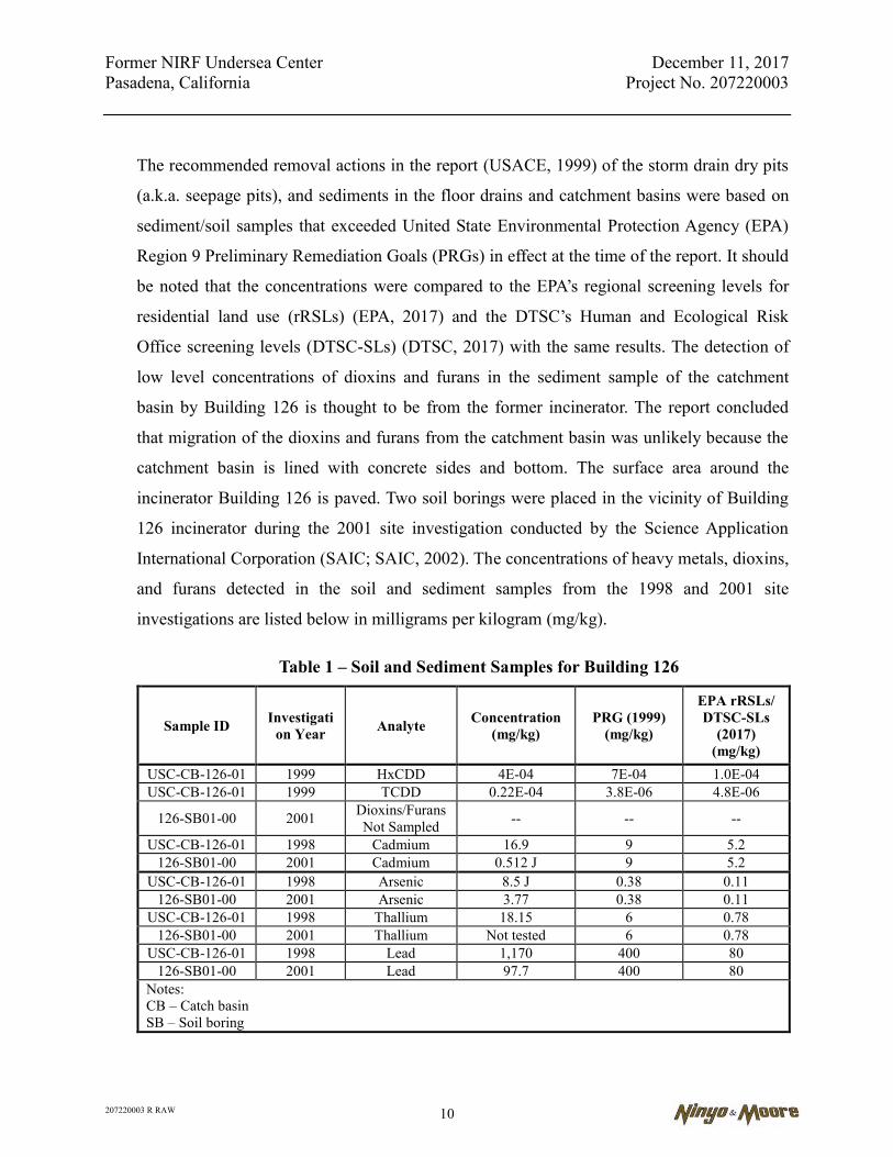
The recommended removal actions in the report (USACE, 1999) of the storm drain dry pits
(a.k.a. seepage pits), and sediments in the floor drains and catchment basins were based on
sediment/soil samples that exceeded United State Environmental Protection Agency (EPA)
Region 9 Preliminary Remediation Goals (PRGs) in effect at the time of the report. It should
be noted that the concentrations were compared to the EPA’s regional screening levels for
residential land use (rRSLs) (EPA, 2017) and the DTSC’s Human and Ecological Risk
Office screening levels (DTSC-SLs) (DTSC, 2017) with the same results. The detection of
low level concentrations of dioxins and furans in the sediment sample of the catchment
basin by Building 126 is thought to be from the former incinerator. The report concluded
that migration of the dioxins and furans from the catchment basin was unlikely because the
catchment basin is lined with concrete sides and bottom. The surface area around the
incinerator Building 126 is paved. Two soil borings were placed in the vicinity of Building
126 incinerator during the 2001 site investigation conducted by the Science Application
International Corporation (SAIC; SAIC, 2002). The concentrations of heavy metals, dioxins,
and furans detected in the soil and sediment samples from the 1998 and 2001 site
investigations are listed below in milligrams per kilogram (mg/kg).
Table 1 – Soil and Sediment Samples for Building 126
Sample ID Investigation Year Analyte Concentration
(mg/kg) PRG (1999)
(mg/kg)
EPA rRSLs/ DTSC-SLs
(2017) (mg/kg)
USC-CB-126-01 1999 HxCDD 4E-04 7E-04 1.0E-04 USC-CB-126-01 1999 TCDD 0.22E-04 3.8E-06 4.8E-06
126-SB01-00 2001 Dioxins/Furans Not Sampled -- -- --
USC-CB-126-01 1998 Cadmium 16.9 9 5.2 126-SB01-00 2001 Cadmium 0.512 J 9 5.2
USC-CB-126-01 1998 Arsenic 8.5 J 0.38 0.11 126-SB01-00 2001 Arsenic 3.77 0.38 0.11
USC-CB-126-01 1998 Thallium 18.15 6 0.78 126-SB01-00 2001 Thallium Not tested 6 0.78
USC-CB-126-01 1998 Lead 1,170 400 80 126-SB01-00 2001 Lead 97.7 400 80
Notes: CB – Catch basin SB – Soil boring
Former NIRF Undersea Center December 11, 2017 Pasadena, California Project No. 207220003
207220003 R RAW 11
Dioxins and furans were not analyzed for in the 2001 soil samples collected by Building 126
incinerator. Metals analysis of the 2001 soil samples collected by Building 126 incinerator
were substantially lower than the metals analysis of the 1998 sediment sample from inside
the catchment basin, indicating that the metals (and by inference dioxins and furans) did not
migrate from the catchment basin.
2.5. SAIC, Draft Site Investigation Report, NIRF Under Sea Center, dated July 2002
This report (SAIC, 2002) indicated sediment investigation of drains around many of the
buildings at the site, soil sampling of some areas, and a radiological survey of Building 20.
The highest cancer risk calculated was 8.3 E-03 for sediment sample collected from within
seepage pit by Building 3. Contaminants identified included:
Sediment sample in Seepage Pit at approximately 16 and 21 feet bgs had a lead concentration that exceeds its EPA Preliminary Remediation Goals (PRGs). Note the PRGs were in effect at the time of this sampling. PRGs have since been replaced with EPA RSLs and DTSC SLs to assess human health risk screening.
Several SVOCs in seepage pit/storm water conveyance system that exceed their respective PRGs for benzo(a)pyrene (B(a)P), benzo(b)fluoranthene, and indeno(1,2,3-cd) pyrene.
2.6. SAIC, Non-Point Source Pollution of Storm Water Drainage System, NIRF Under Sea Center, dated December 2003
This report (SAIC, 2003) indicated that contaminated sediment in the storm water collection
system could not be attributed to specific historic or current operations at the site.
Concentrations in sediment were compared with urban storm water runoff. Conclusions
were that concentrated metals in sediment in the storm water drainage system were
attributed to storm water runoff from the site parking lots and pavement, adjacent Foothill
Boulevard, and I-210. Storm water discharge from the site was reportedly regulated by
municipal storm water National Pollutant Discharge Elimination System (NPDES) Permit of
which the City of Pasadena is co-permittee.
Former NIRF Undersea Center December 11, 2017 Pasadena, California Project No. 207220003
207220003 R RAW 12
2.7. USACE, Draft Final Preliminary Endangerment Assessment Report, NIRF Undersea Center, USACE, dated August 2005
The Preliminary Endangerment Assessment (PEA) (USACE, 2005) was undertaken to
determine if former activities conducted by the Department of Defense (DOD) at the site
had adversely impacted the environment at the site. The PEA covered areas that had not
been identified by USACE as being beneficially used by others subsequent to DOD
ownership, including areas near Buildings 126 and 131 and in areas where buildings had
been demolished (Building 7) during the period of DOD ownership. The report indicated
that human health risk levels were acceptable for residential use for Building 131 but that
USACE would perform a focused investigation of this location. Results of sampling indicate
the following:
Building 126, Incinerator – Dioxin in storm drain catchment basin sediment sample above Preliminary Remediation Goal for residential use (PRGr) but below Preliminary Remediation Goal for industrial use (PRGi).
Building 131, Former Flammable Storage Building – Lead exceeds the PRGr, low TPH contamination, no health risk.
Building 16, Former Metals Storage Area – No contamination above PRGs; NFA recommended.
Building 20, Classified Materials – Radioactive survey did not identify radioactive readings above background levels.
Building 21, Former Public Works – No contamination above PRGs except arsenic at background levels; NFA recommended.
Building 106, Former Car Park Shed – No contamination above PRGs except arsenic at background levels; NFA recommended.
Building 107, Former Gasoline Dispensing Island – No petroleum products identified in soil; NFA recommended.
Building 129, Former Vehicle Wash Rack – No contamination above PRGs except arsenic at background levels; NFA recommended.
Building 7, Former Fabrication, Assembly – Arsenic was detected at 9.89 mg/kg at approximately 15 feet bgs and may be associated with sediments in the former seepage pit. No contamination of volatile organic compounds (VOCs), SVOCs, TPH, or metals was present above the PRGs.

Former NIRF Undersea Center December 11, 2017 Pasadena, California Project No. 207220003
207220003 R RAW 13
2.8. SECOR International (SECOR), Draft Expedited Phase I Environmental Site Assessment (ESA), Space Bank Mini Storage, dated December 9, 2005
SECOR conducted an expedited Phase I ESA for Kaiser Foundation Health Plan, Inc. of the
site. The report (SECOR, 2005) outlines the military and weapons research history of the
site. The conclusions of the report included the following:
Previous site investigations identified chemicals of potential concern at the site, including metals, VOCs, polynuclear aromatic hydrocarbons (PAHs), dioxins, and polychlorinated biphenyls (PCBs).
DTSC had recently asserted that not enough investigation was performed at the site to mitigate potential concerns.
A fourth UST may be located at the site near Building 107, but a geophysical survey of the area failed to locate the possible UST.
Groundwater in the vicinity of the site is generally of good quality, but VOCs have been detected and treated off site in various areas of the Raymond Basin, particularly in the Arroyo Seco area.
The nearest downgradient well to the site had reportedly treated groundwater for VOC contamination.
The presence of historical recognized environmental conditions (RECs) for the site, including testing of torpedoes and classified materials.
There is a possible presence of asbestos and LBP at the site.
2.9. SECOR, Expedited Phase II ESA Report, dated February 1, 2006
The Phase II ESA report (SECOR, 2006a) was conducted concurrently with a Phase I report
for Kaiser Foundation Health Plan. The purpose of the report was to evaluate RECs
identified in the Phase I report. Twelve soil borings were advanced at the following
locations:
Soil Boring B-1, near Building 18
Soil Boring B-2, between Buildings 3 and 5
Soil Boring B-3, between Buildings 3, 4, and 19
Soil Boring B-4, northeast corner of site

Former NIRF Undersea Center December 11, 2017 Pasadena, California Project No. 207220003
207220003 R RAW 14
Soil Borings B-5 and B-6, between Buildings 13 and 106
Soil Boring B-7, near Building 129
Soil Boring B-8, near Building 23
Soil Boring B-9, near Building 131
Soil Borings B-10 and B-12, near Building 30
Soil Boring B-11, near Buildings 20 and 126.
Concentrations of VOCs detected were reportedly below the PRGs. Total petroleum
hydrocarbons as carbon chain (TPHcc) was identified in borings B-10 and B-12 with
concentrations ranging between 12 and 1,100 mg/kg, heavy oil. Metals analyzed were not
detected at concentrations greater than the California Total Threshold Limit Concentrations
(TTLC) or 10 times Soluble Threshold Limit Concentration (STLC). PCB, PAH,
perchlorate, and dioxin analyses for all soil samples collected were non-detect.
2.10. SECOR, Pre-Demolition Hazardous Materials Assessment Report, Space Bank Mini-Storage, dated February 23, 2006
SECOR conducted an inspection of structures at the facility for ACM, LBP, and other
hazardous materials (SECOR, 2006b). ACM, including floor tile, roofing material, wall
texture materials, and other materials, were identified throughout the facility. LBP was
identified in some areas, primarily on exterior coatings on wood and metal surfaces. The
inspection also identified fluorescent light tubes, light ballasts, transformers, elevators, and
mercury-containing thermostats.
2.11. Innovative Technical Solutions, Inc. (ITSI), Draft Site-Specific Work Plan Focused Site Investigation PEA, dated March 2006
The purpose of the workplan (ITSI, 2006a) was to identify the vertical and lateral extent of
contamination associated with Building 131. The scope of work entailed drilling three
borings to approximately 50 feet bgs and sampling and analysis of soil for
tetrachloroethylene (PCE) and TPH at every 5 feet bgs.

Former NIRF Undersea Center December 11, 2017 Pasadena, California Project No. 207220003
207220003 R RAW 15
2.12. SECOR, Workplan for Additional Soil/Soil Vapor Investigation, dated March 29, 2006
This Sampling and Analysis Plan (SECOR, 2006c) was developed to further progress of soil
investigations required by DTSC pursuant to the Imminent and Substantial Endangerment
and Remedial Action Order. This document was approved by DTSC in 2007.
2.13. SECOR, Final Expedited Phase I ESA, Space Bank Mini Storage, dated March 30, 2006
The final Expedited Phase I ESA (SECOR, 2006d) had similar conclusions that were listed
in the Draft Expedited Phase I ESA, issued December 9, 2005.
2.14. ITSI, Draft Final Focused Site Investigation, PEA, dated August 2006
ITSI performed a focused investigation (ITSI, 2006b) on behalf of USACE for the Building
131 area by advancing three soil borings to a depth of 50 feet bgs in the building vicinity
and collecting soil samples for analysis for PCE by EPA Method 8260B, TPH C10-C32 by
EPA Method 8015M, and lead by EPA Method 6010B. The highest concentration of PCE
was 44 micrograms/kilogram (µg/kg) detected at a depth of approximately 40 feet bgs,
which is below the PRGr of 480 µg/kg. TPH was not detected in soil samples collected from
the three borings. Lead was detected at a concentration of 34 mg/kg at approximately 2 feet
bgs. The report concluded that it was ITSI’s opinion that no further investigations were
warranted at the Building 131 vicinity and No Department of Defense Action Indicated
(NDAI) based on the current industrial use of the site.
2.15. ITSI, Final Focused Site Investigation, NIRF, dated November 2006
The conclusions of the Final Focused Site Investigation of Building 131 (ITSI, 2006c) are
the same as previously indicated in the Draft Final Site Investigation Report. The report
indicated that the Building 131 site was characterized within the requirements and
limitations of the Formerly Used Defense Sites program for those contaminants for which
the USACE may be responsible and that an appropriate risk management decision
recommended by the report was NDAI for site soils near Building 131.
Former NIRF Undersea Center December 11, 2017 Pasadena, California Project No. 207220003
207220003 R RAW 16
2.16. Kennedy/Jenks Consultants (K/J), Soil Vapor Survey Report, Former NIRF Site/Space Bank, dated April 13, 2007
This report (K/J, 2007a) documents a screening level shallow soil vapor survey conducted
by K/J for Space Bank Ltd, to assess the nature and extent of VOCs at the facility. The soil
vapor survey detected primarily low levels of PCE, carbon tetrachloride (CT), and Freon
113 at the facility, with several other VOCs detected at low concentrations and in fewer
areas of the property. The highest detected concentrations of PCE were noted in the area of
the former Building 7, machine shop, former flammable storage Building 131, and near
Building 23. CT was primarily detected in the vicinity of Building 3 and near the center of
the property. The report deferred in-depth analysis and discussion of the data to an
Environmental Summary Report (K/J, 2007b) to be prepared by K/J.
2.17. K/J, Environmental Summary Report, Former NIRF Site/Space Bank, dated May 22, 2007
The report (K/J, 2007b) provided a summary of the historical site use and ownership and a
summary of the environmental investigations completed for the site. The report also
provided the results of a soil vapor survey that K/J conducted at the site. Chemical-specific
observations concerning the site included the following:
No significant gasoline-range hydrocarbon releases evident at the site.
Shallow Extractable Fuel Hydrocarbon (EFH) detections were unlikely to be fuel releases and may reflect the heavier-end hydrocarbons in the paving base material.
Otto Fuel (torpedo propellant fuel) was identified at one location at a low concentration.
Metals did not appear to be a widespread issue in the soil at the site.
SVOCs in soil appeared in soil primarily associated with seepage pits and automotive operations.
PAHs unlikely to be a concern with only two detections at site.
Perchlorate, PCBs, dioxins, and furans data was limited for the site with only four samples collected and one low detection of dioxins in catch basin CB-126.
Former NIRF Undersea Center December 11, 2017 Pasadena, California Project No. 207220003
207220003 R RAW 17
PCE and CT in soil vapor were the most widely distributed contaminants of potential concern (COPCs) at the site with the highest concentrations occurring near Buildings 3, 7, 10, and 131.
The report also addressed the potential impact to groundwater at the site indicating that
contaminants of low mobility, including metals, SVOCs, PAHs, PCBs, and heavier-end
hydrocarbons were unlikely to be a source of groundwater contamination. However, more
mobile constituents, including the lighter-end fuels and VOCs (i.e., PCE and CT), had a
greater potential for impact to groundwater.
2.18. Ninyo & Moore, Addendum to the SECOR Workplan, Space Bank Mini Storage, dated August 24, 2007
Ninyo & Moore submitted this workplan addendum to the DTSC for additional soil and soil
vapor investigation at the site. The purpose of the work was to address data gaps from
previous environmental investigations, as well as to determine the extent of contamination in
several areas of the site where previous investigations identified COPCs. The workplan is an
addendum to the SECOR Sampling and Analysis Plan (SECOR, 2006c) that is the basis for
the investigation performed for the Remedial Investigation/Feasibility Study (RI/FS). This
workplan addendum was approved by DTSC in 2007. A summary of the workplan
addendum includes the following:
Eleven shallow soil borings to 10 feet bgs; soil samples collected at approximately 1 and 5 feet bgs
Nineteen soil borings to 15 feet bgs; soil samples collected at approximately 1, 5, 10, and 15 feet bgs; vapor probes installed at 5 and 15 feet bgs
Three soil borings to 30 feet bgs; soil samples collected at approximately 1, 5, 10, 15, 20, 25, and 40 feet bgs; vapor probes installed at 20 and 30 feet bgs
In addition to these borings, Ninyo & Moore also proposed additional sampling, including:
Fifteen soil borings to approximately 15 feet; soil samples collected at approximately 5 and 15 feet bgs; vapor probes installed at 5 and 15 feet bgs
Three soil borings to approximately 150 feet bgs; soil samples collected every 10 feet (10 soil samples per boring); and vapor probes installed every 10 feet (15 probes per boring)
Former NIRF Undersea Center December 11, 2017 Pasadena, California Project No. 207220003
207220003 R RAW 18
Soil vapor samples were analyzed for VOCs. Soil samples were analyzed for a variety of
potential contaminants, including VOCs, SVOCs, TPH, Metals, hexavalent chromium,
PAHs, perchlorate, PCBs, dioxins, and N-Nitrosodimethylamine (NDMA).
2.19. Ninyo & Moore, Draft Final Phase I ESA, Space Bank Mini Storage Facility, dated April 17, 2008
Ninyo & Moore conducted a Phase I ESA at the site for PG to determine environmental
risks associated with the site as part of a potential real estate transaction. Ninyo & Moore
reviewed multiple historical records, including former environmental investigation report
under oversight by the DTSC. Numerous environmental site assessments conducted by the
USACE, site owner, and other parties had identified the presence of substances including
but not limit to SVOCs, VOCs, and metals in site soils, associated with the prior usage as a
research and development center for the Navy. The presence of these substances were
deemed RECs by Ninyo & Moore.
2.20. Ninyo & Moore, Draft Letter Report for Mapping Hot Spots, Preliminary Human Health Risk, Space Bank Mini Storage Facility, dated September 10, 2015
In Ninyo & Moore’s letter report to the Trammel Crow Company, dated September 10,
2015, analytical results of past site assessments were compared to the EPA rRSLs and the
DTSC-SLs. It was observed that analytical results for PAHs and metals exceeded the site
screening levels (SLs) in the on-site storm-drain catchment basins and seepage pits.
Hexavalent chromium was also detected at low levels throughout the site at depth up to
approximately 150 feet bgs, exceeding the rRSL of 0.3 mg/kg. Evaluation of hexavalent
chromium is discussed below in Section 2.21. A third environmental condition that exceeded
the screening criteria was VOCs in soil gas, particularly CT and PCE. Based on these three
environmental conditions, the site does not support residential development as is, but would
require some mitigation to achieve the residential use criteria.

Former NIRF Undersea Center December 11, 2017 Pasadena, California Project No. 207220003
207220003 R RAW 19
2.21. Ninyo & Moore, Draft Hexavalent Chromium Evaluation Report, Space Bank Mini Storage Facility, dated March 9, 2016
Ninyo & Moore reviewed reports from EnviroStor for the vicinity of the site to determine
whether levels of hexavalent chromium were likely to be associated with historical
operations at the site, or if they were associated with background levels typical in the area. A
review of EnviroStor records found that background levels of hexavalent chromium in a
similar site was between 0.20 mg/kg and 1.9 mg/kg. The on-site hexavalent chromium levels
were detected at an average concentration of 0.61 mg/kg, and a maximum concentration of
1.2 mg/kg. Therefore, it was concluded that hexavalent chromium concentrations detected in
soils at the Space Bank Site likely represent background concentrations that should not
require mitigation. DTSC concurred with this conclusion in comments to the RI/FS (Ninyo
& Moore, 2017).
2.22. Ninyo & Moore, Pesticide Sampling and Testing Report, Space Bank Mini Storage Facility, dated June 8, 2017
Ninyo & Moore conducted soil sampling at the small Space Bank parcel west of North
Kinneloa Avenue in Pasadena, California on May 18, 2017. Four soil borings were advanced
and soil samples were collected and analyzed for potential organochlorine pesticide (OCP)
and organophosphorus pesticide (OPP) contamination in shallow soils that may be
associated with the adjacent Dewey Pest Control property to the north. Discrete soil
samples were collected from each soil boring at depths of approximately 0.5 feet bgs and 2
feet bgs. OCPs and OPPs were not detected in each of the four 0.5-foot samples. Since
OCPs and OPPs were not detected in the 0.5-foot samples, the 2-foot depth samples were
not analyzed.
3. PURPOSE OF THE RAW
The RAW identifies and evaluates candidate removal approaches to clean up the site so that it is
suitable for future use as part of a residential and commercial use project. Using prescribed
screening criteria, a preferred removal alternative is selected for detailed discussion. The RAW
also summarizes previous field investigation results and lists site-specific cleanup levels that are
protective of human health and the environment.
Former NIRF Undersea Center December 11, 2017 Pasadena, California Project No. 207220003
207220003 R RAW 20
The RAW has been developed in accordance with applicable DTSC guidance, including criteria
specified in the California Health and Safety Code (H&SC), Section 25356.1. Once the Draft
RAW has been reviewed and approved by the DTSC, there will be an opportunity for public
review and comment, possibly including a public hearing or meeting hosted by the DTSC. The
DTSC will then consider any public comments received, prepare a response to the comments,
and the RAW will be revised, as necessary, prior to final approval and implementation.
After the removal actions described in this RAW have been completed, a Removal Action
Completion Report (RACR) will be submitted to the DTSC for review and approval. The RACR
will include the scope of work, field work activities, deviations from the approved RAW (if any),
confirmation soil sampling results, data validation memoranda, waste manifests, and other
applicable information and data for the removal areas to confirm and document the completion
of the selected remedial action.
Based on the results of the removal action confirmation sampling, and presuming that the
required removal actions have been adequately addressed in accordance with the approved RAW,
the DTSC will provide a letter to the respondent indicating that “No Further Action” (NFA) is
required.
3.1. Report Organization
The organization of the RAW is generally consistent with the format recommended by the
DTSC. An overview of the content of the RAW is provided below:
Section 1 presents an introduction to the site project, a summary of current site conditions, its history, geology and hydrogeology.
Section 2 provides a summary of previous site investigations and presents an overview of the nature, source, and extent of contamination at the site, based on the results of previous investigations at the site.
Section 3 describes the purpose of the RAW and the report organization.
Section 4 describes site characterization and COPCs.
Former NIRF Undersea Center December 11, 2017 Pasadena, California Project No. 207220003
207220003 R RAW 21
Section 5 describes the removal action objectives (RAOs). Applicable or relevant and appropriate requirements (ARARs) and site-specific removal action cleanup goals are also provided.
Section 6 identifies and describes removal action alternatives and provides a detailed evaluation of each alternative in accordance with criteria prescribed by the National Contingency Plan (NCP). The rationale for the selection of a preferred removal alternative is also included in this section.
Section 7 describes implementation of remedial action at the site.
Section 8 describes the confirmation sampling approach that will be used to determine completion of the removal action and verify that RAOs have been achieved.
Section 9 includes the health and safety procedures that will be followed during implementation of the RAW.
Section 10 describes the RAW public participation actions likely to be required by the DTSC.
Section 11 describes the project organization and roles of the DTSC and includes the project schedule and reporting requirements.
Section 12 lists the references used in preparing this RAW.
The Appendices include the Transportation Plan, Soil Management Plan, Quality Assurance Project Plan (QAPP), Health and Safety Plan (HASP), Soil Vapor Survey Work Plan, and Storm Water Pollution Prevention Plan (SWPPP) which will be followed during the implementation of the RAW. These plans are included in Appendices A, B, C, D, E, and F, respectively.
3.2. Site Maps
Illustrations pertaining to the site and site vicinity are shown on Figures 1 through 12, which
include a Site Location Map, Site Plan, Past Military Use of the Site, Hot-Spots, and various
figures showing locations of chemicals of concern.
4. SITE CHARACTERIZATION
As indicated in Section 2, numerous site investigations have been performed at the site, primarily
to gauge the impact of former military use. The data was evaluated and discussed in the RI/FS
Report (Ninyo & Moore, 2017). The RI/FS provides a summary of former military use at the site
Former NIRF Undersea Center December 11, 2017 Pasadena, California Project No. 207220003
207220003 R RAW 22
and the site investigations performed at or in the vicinity of each former military use location,
including soil borings and soil sampling, wipe samples, and soil vapor samples. Figure 3 shows
the locations of the former military uses and current use of buildings on the site. Ninyo & Moore
performed an extensive site investigation in 2007 which included soil and soil gas sampling as
described in the DTSC approved SECOR Sampling and Analysis Plan (workplan - SECOR,
2006), and Addendum to the SECOR Workplan (Ninyo & Moore, 2007). The environmental data
collected during this extensive investigation as well as the environmental data collected in the
various other investigations listed in Section 2, was evaluated for the RI/FS Report. Figure 4
shows the locations of all soil and soil gas samples collected at the site. Discussion of site
investigation results and site features associated with environmental contamination are provided
in the following sections.
4.1. Metals
In the 2007 RI completed by Ninyo & Moore, soil samples were collected at 21 boring
locations in general accordance with the RI Work Plan (SECOR, 2006) and Work Plan
Addendum (Ninyo & Moore, 2007), and analyzed for metals using EPA Method
6010B/7471A. These soil samples were generally collected in the upper 15 feet of soil with
the deepest sample collected at a depth of 60 feet bgs. Tables of the complete RI Work Plan
environmental data set of soil and soil gas samples collected in 2007, are provided in the
RI/FS.
In historic site investigations numerous sediment samples collected from the storm drain
catch basins and floor drains exceeded RSLs/SLs or assumed background concentrations for
metals including lead, arsenic, and mercury. The storm drain catch basins are concrete lined,
therefore metals contamination in the vicinity of these site features is expected to be
minimal. As part of the remedial action, the storm drain system will be removed from the
site and is discussed in other sections of this report.
Historic site investigations noted elevated metal concentrations (primarily lead, arsenic,
mercury) that exceeded RSLs/SLs or assumed background concentrations, in seepage pits
Former NIRF Undersea Center December 11, 2017 Pasadena, California Project No. 207220003
207220003 R RAW 23
associated with the storm drain system (see Figure 5). As part of the remedial action,
seepage pits will be removed from the site and are discussed in other sections of this report.
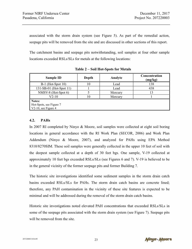
The catchment basins and seepage pits notwithstanding, soil samples at four other sample
locations exceeded RSLs/SLs for metals at the following locations:
Table 2 – Soil Hot-Spots for Metals
Sample ID Depth Analyte Concentration (mg/kg)
B-1 (Hot-Spot 10) 10 Lead 138 131-SB-01 (Hot-Spot 11) 1 Lead 438
NMSV-8 (Hot-Spot 6) 5 Mercury 13 V2-10 10 Mercury 1
Notes: Hot-Spots, see Figure 7 V2-10, see Figure 4
4.2. PAHs
In 2007 RI completed by Ninyo & Moore, soil samples were collected at eight soil boring
locations in general accordance with the RI Work Plan (SECOR, 2006) and Work Plan
Addendum (Ninyo & Moore, 2007), and analyzed for PAHs using EPA Method
8310/8270SIM. These soil samples were generally collected in the upper 10 feet of soil with
the deepest sample collected at a depth of 30 feet bgs. One sample, V-19 collected at
approximately 10 feet bgs exceeded RSLs/SLs (see Figures 6 and 7). V-19 is believed to be
in the general vicinity of the former seepage pits and former Building 7.
The historic site investigations identified some sediment samples in the storm drain catch
basins exceeded RSLs/SLs for PAHs. The storm drain catch basins are concrete lined;
therefore, any PAH contamination in the vicinity of these site features is expected to be
minimal and will be addressed during the removal of the storm drain catch basins.
Historic site investigations noted elevated PAH concentrations that exceeded RSLs/SLs in
some of the seepage pits associated with the storm drain system (see Figure 7). Seepage pits
will be removed from the site.

Former NIRF Undersea Center December 11, 2017 Pasadena, California Project No. 207220003
207220003 R RAW 24
4.3. Petroleum Hydrocarbons
In 2007 RI completed by Ninyo & Moore, soil samples were collected at 24 locations (see
Figure 6) in general accordance with the RI Work Plan (SECOR, 2006) and Work Plan
Addendum (Ninyo & Moore, 2007), and analyzed for TPH using EPA Method 8015B(M) in
the carbon ranges of C4-C12, C13-C22, C23-C32, and greater than C32. These soil samples were
generally collected in the upper 15 feet of soil with the deepest sample collected at a depth
of approximately 150 feet bgs. Due to their general acceptance by the regulatory community,
the 2013 San Francisco Bay Regional Water Quality Control Board (SFBRWQCB) residential
health-risk-based ESLs were used for screening purposes. None of the samples exceeded the
ESLs (see Figure 6).
The historic site investigations identified some sediment samples in the storm drain catch
basins exceeded ESLs for TPH. The storm drain catch basins are concrete lined; therefore,
any petroleum hydrocarbon contamination in the vicinity of these site features is expected to
be minimal and will be addressed during the removal of the storm drain catch basins.
Historic site investigations noted elevated petroleum hydrocarbons concentrations that
exceeded ESLs in some of the seepage pits associated with the storm drain system (see
Figure 7). Seepage pits will be removed from the site. TPHd (C13-C22) was detected in soil
sample 131-SB-1 at a depth of 1 foot bgs at a concentration of 640 mg/kg and will be
removed as Hot-Spot 11 (see Figure 7).
4.4. Perchlorate, NDMA, PCBs, Dioxins
In the 2007 RI completed by Ninyo & Moore, soil samples were collected at various
locations (see Figure 4) in general accordance with the RI Work Plan (SECOR, 2006) and
Work Plan Addendum (Ninyo & Moore, 2007) and analyzed for the following compounds.
Perchlorate – Sampled at 18 locations with the deepest sample collected at approximately 60 feet bgs and analyzed by EPA Method 314, with no detections of perchlorate.
NDMA – Sampled at 16 locations with the deepest sample collected at 60 feet bgs and analyzed by EPA Method 1625, with no detections of NDMA.
Former NIRF Undersea Center December 11, 2017 Pasadena, California Project No. 207220003
207220003 R RAW 25
PCBs – Sampled at 11 locations, generally from 1 to 3 feet bgs, with the deepest sample collected at 60 feet bgs and analyzed by EPA Method 8082A, with no detections of PCBs.
Dioxins – Sampled at 11 locations with the deepest sample collected at 25 feet bgs and analyzed by EPA Method 8280A, with no detections of dioxins.
In historic site investigations, no detections of perchlorates, NDMA, or PCBs in soil were
noted. Dioxins were detected in a concrete lined storm drain catch basin by Building 126
(former incinerator) but were not detected in site soils.
4.5. Hexavalent Chromium
In 2007 RI completed by Ninyo & Moore, soil samples were collected at 16 locations (see
Figure 8) in general accordance with the RI Work Plan (SECOR, 2006) and Work Plan
Addendum (Ninyo & Moore, 2007) and analyzed the samples for hexavalent chromium
using EPA Method 7199. Hexavalent chromium was detected at low concentrations in soil
throughout the Space Bank Site at concentrations that exceed the May 2016 rRSL of 0.3
mg/kg. Hexavalent chromium was evaluated due to the site’s former military use since the
military has been known to have used hexavalent chromium elsewhere as a coating for
weaponry due to its high performing anti-corrosive properties. A second possible source for
hexavalent chromium is through natural occurrence in the alluvial sediments derived from
the San Gabriel Mountains to the north. Chromium is abundant in nature and in natural
environments it is generally found in trivalent or hexavalent chromium states (EPA, 2016a).
Hexavalent chromium was detected in site soils at a mean concentration of 0.61 mg/kg and a
maximum concentration of 1.2 mg/kg detected at a depth of approximately 10 feet bgs. As
shown in Figure 8, hexavalent chromium was detected throughout the site at depths ranging
from approximately 5 feet bgs to 150 feet bgs with very little variation in concentration
throughout the site. Based on our review of the data associated with the site, we conclude
that the most likely source of hexavalent chromium at the site is due to natural occurrence.
DTSC concurred with this assessment in their review of RI/FS Report.
Former NIRF Undersea Center December 11, 2017 Pasadena, California Project No. 207220003
207220003 R RAW 26
4.6. Storm Water Drain System
The storm drain system at the site consists of approximately 1,000 to 1,200 linear feet of
concrete or clay pipe, numerous storm drain inlets and catch basins, and five seepage pits to
capture storm water from the site and potentially run-on from Foothill Boulevard, and allow
it to infiltrate into the ground (see Figure 5) The highest concentrations of PAHs and metals
detected at the site, including numerous analytes that exceeded RSLs/SLs, were detected
from the sediment samples collected from inside the storm water drain system. These storm
water drain system soil/sediment samples represent the most contaminated soils/sediments
found at the property. The storm water drain system, including catch basins and seepage pits,
at the facility will be removed during remediation of the facility. On October 7, 2015, Ninyo
& Moore performed an inspection of the storm water drain system. The storm water seepage
pits are typically about 6 feet in diameter and approximately 18 to 28 feet bgs. A diagram of
a seepage pit is shown in Figure 5. The clay and concrete storm water conveyance pipes are
typically 6 inches to 12 inches in diameter and drain into the five seepage pits. The portions
of the clay and concrete conveyance pipes that were observable (near the seepage pits and
catchment basins) appeared intact and in good condition. The catchment basins are typically
2 to 3 feet rectangular-shaped concrete basins with concrete bottoms and sides and metal
grates on the top. The catchment basins observed were in generally in good, intact condition.
4.7. VOCs in Site Soil Gas
VOCs were detected in soil gas throughout the site in all areas and at depths of
approximately 5 feet bgs to 150 feet bgs. The most likely source of the VOCs is from the
former military operations conducted on the site. The highest detection of VOCs at the site
was PCE at 342 milligram per cubic meter (mg/m3) at NMSV10-5. Soil gas samples were
collected at the site by both K/J and Ninyo & Moore in 2007. In general, soil gas sampling
performed by Ninyo & Moore occurred at more locations and depths than the K/J soil gas
survey. Based on the 2007 data collected, VOCs present at the site in soil gas represent a
vapor intrusion concern for future site occupants. Figures 9 through 12 contain PCE and CT
concentration contours at approximately 5 and 15 feet bgs at the site from the 2007 RI
Former NIRF Undersea Center December 11, 2017 Pasadena, California Project No. 207220003
207220003 R RAW 27
completed by Ninyo & Moore. As part of this RAW, additional soil gas testing will be
conducted concurrent with site remediation due to the age of the 2007 data.
4.8. Hot-Spots
Ninyo & Moore reviewed the various site investigation reports completed at the Space Bank
facility and other than soil and sediment samples associated with the storm water drain
system, recorded the maximum concentrations detected in each report in Table 5 of the
RI/FS. Locations that exceeded RSLs/SLs/ESLs from the 2007 Ninyo & Moore RI, or
historical site investigations, were noted in Figure 7, Hot-Spots. Numerous samples
collected from concrete lined storm drain catch basins noted in historical investigations
exceeded RSLs/SLs/ESLs. The storm drain system with catch basins is shown in Figure 7.
Sediment samples collected from seepage pits exceeded RSLs/SLs/ESLs and are included in
Figure 7 as hot-spots. No sample data was found for one seepage pit and one suspected
seepage pit. These two locations, lacking data, have been assumed to be hot-spots.
The storm water drain system and hot-spots shown in Figure 7 will be removed from the site
prior to redevelopment. Estimated hot-spot excavation dimensions and volumes are
presented in Figure 7. Confirmatory soil samples will be collected at the completion of hot-
spot excavation to verify that the hot-spots were successfully removed.
5. RAOS AND CLEANUP GOALS
The RAO consists of removal of the sources of contamination through which future on-site
occupants, the neighboring community, and the environment may be exposed. The following
sections describe the actions to achieve this RAO. The following sections evaluate and present
removal goals that will be protective of human health and the environment.
5.1. RAOs
RAOs are specific goals applied to media that have been identified as posing an
unacceptable baseline risk. Site-specific action levels are applied to specific COPCs within
the environmental media. Site-specific RAOs have been developed as a basis for evaluating
the removal alternatives and to achieve the goals of protecting human health and the
Former NIRF Undersea Center December 11, 2017 Pasadena, California Project No. 207220003
207220003 R RAW 28
environment. In general, RAOs are statements that identify COPCs, exposure pathways and
receptors, and acceptable contaminant levels.
VOCs such as PCE, CT, and Trichloroethylene (TCE) pose a vapor intrusion risk to fu-ture, site users.
PAHs have been detected on site and are COPCs. Animal studies have shown pyrene is toxic to the kidneys and the liver.
TPH in soil is a COPC. The compounds in different TPH fractions affect the body in different ways. Some of the compounds, particularly benzene, toluene, and xylene (which are present in gasoline), can affect the human central nervous system.
Lead is a COPC. The main target for lead toxicity is the nervous system, both in adults and children.
Demonstration that the RAOs have been met will allow the property to be used for its
intended purpose as a residential and commercial development. RAOs for the site are listed
below for each AOC. The overall RAO for the site is:
Mitigate potential on-site exposure through ingestion, inhalation, and direct contact with soil impacted by COPCs and mitigate their impact on human health or the environment in order to allow for the site’s planned residential/commercial use.
5.2. AOC1
AOC1 consists of the storm drain system. The storm drain system at the site consists of
1,000 to 1,200 linear feet of concrete or clay pipe, numerous storm drain inlets and catch
basins, and seven known and suspected seepage pits to capture storm water from the site and
potentially run-on from Foothill Boulevard, and allow it to infiltrate into the ground (see
Figure 5). The seven seepage pits will be addressed separately from the storm drain system
as AOC2. The AOCs are listed in Tables 8 and 9, and cross referenced to the hot-spots and
storm drain system at the site as shown in Figure 7. The catch basins are concrete vaults of
various sizes with the maximum size observed approximately 3 feet by 3 feet by
approximately 2.5 feet deep with concrete bottoms and sides, and a metal grate over the top.
The highest concentrations of PAHs and metals detected at the site, including numerous
analytes that exceeded rRSLs, were detected from the sediment samples collected from
Former NIRF Undersea Center December 11, 2017 Pasadena, California Project No. 207220003
207220003 R RAW 29
inside the storm water drain system catch basins. Laboratory analytical data from soil
samples collected in soil outside the storm drain system (excluding AOC2, seepage pits) do
not exceed rRSLs, indicating that the storm drain system is intact and in good condition.
Although breaks or cracks in the storm drain system have not been observed, it is possible
that they exist in below ground storm drain pipes, and may be discovered upon removal of
the storm drain system. Soil and sediment inside the storm drain system may be considered
hazardous based on past laboratory data. Soil outside the storm drain system is expected to
be non-hazardous.
The medium of concern for AOC1 is shallow soil from surface to a maximum depth of
approximately 4 feet bgs in the areas of the storm drain system. RAOs associated with
AOC1 include:
Protect site workers from exposure to metals, PCE, PAHs and TPH associated with AOC1 during remediation activities.
Mitigate elevated concentrations of PAHs, metals, TPH, and VOCs in storm drain pipes and catch basins by cleaning out soil and sediment from the storm drain system prior to excavation and removal of the storm drain system. Characterize soil and sediment removed from the storm drain system for off-site disposal.
Excavate and remove the storm drain system. Visually monitor storm drain pipes and catch basins for breaches or breaks. Over-excavate areas where breaches or breaks occurred, stockpile and characterize soil for disposal.
Perform confirmation sampling after removal of soils. Analyze for PAHs, metals, TPH, and VOCs to verify areas are remediated to below the appropriate regulatory health risk levels.
5.3. AOC2
AOC2 consists of five known and two suspected storm water seepage pits at the site, that are
associated with the storm water drain system at the facility. The storm water seepage pits are
typically about 6 feet in diameter and approximately 18 to 25 feet deep. A diagram of a
typical seepage pit is shown in Figure 5. Storm water conveyance pipes drain into the
seepage pits. Sediment samples collected from inside the known seepage pits exhibited
elevated TPH, PAHs, and metals concentrations. Soil borings located in close proximity to
Former NIRF Undersea Center December 11, 2017 Pasadena, California Project No. 207220003
207220003 R RAW 30
the seepage pits, typically within two feet of the casings, exhibited lower concentrations of
TPH, PAHs, and metals, which typically did not exceed site SLs. The two suspected seepage
pits (see Figure 7) were noted in historical reports, but have no current visual indicators of
their presence. No environmental sampling data for the suspected seepage pits have been
found in historical reports. During site remedial activities, the suspected seepage pit
locations will be excavated and the pits removed, if found. RAOs for AOC2 include the
following:
Protect site workers from exposure to metals, PAHs and TPH associated with AOC2 during remediation activities.
Soil/sediment inside the seepage pits is expected to exceed site SLs and could be characterized as Resource Conservation and Recovery Act (RCRA) or non-RCRA hazardous waste. The soil/sediment inside the seepage pits starts at approximately 15 feet bgs and is expected to continue to approximately 20-25 feet bgs. This soil/sediment will be removed, stockpiled, characterized for disposal, and disposed of at an off-site facility licensed to accept it.
The soil outside the seepage pits represents a medium concern for dermal contact exposure due to the design of the seepage pits to allow storm water to percolate out through the sidewalls into the surrounding soil (see Figure 6). After removal of the seepage pits, the soil surrounding the seepage pits within the excavations will be evaluated by collecting confirmation samples and analyzing them for TPH, PAHs, VOCs, and metals to verify that the soil has been remediated to below the appropriate regulatory health risk levels.
5.4. AOC3
AOC3 consists of four Hot-Spots, nos. 6, 10, 11, and 12 as indicated in Tables 8 and 9.
These Hot-Spots are not associated with the storm drain system or seepage pits (see Figure
7) but with soil locations that were identified to exceed site soil SLs, including metals and
PCE. Hot-Spot 3 was originally designated as a Hot-Spot but then removed as a Hot-Spot
because measured TPH concentrations at Hot-Spot 3 did not exceed the applicable screening
levels (Section 5.6.1). The medium of concern for the remaining Hot-Spots comprising
AOC3 is shallow soil from surface to a maximum depth of 10 feet bgs. RAOs for AOC3
include:
Former NIRF Undersea Center December 11, 2017 Pasadena, California Project No. 207220003
207220003 R RAW 31
Protect site workers from exposure to metals, PCE, PAHs and TPH associated with AOC3 during remediation activities.
Mitigate elevated concentrations of metals, PCE, PAHs and TPH in localized Hot-Spots to below the appropriate regulatory health risk levels.
Minimize potential migration of COPCs in shallow soil to other media (i.e., air, surface water).
5.5. AOC4
AOC4 consists of low level VOCs in soil gas detected throughout the site, which represent a
potential vapor intrusion concern for future residential/commercial structures. Hot-Spots 2,
10, and 12 have been identified to contain VOCs above site soil gas SLs, based on the soil
gas survey conducted by Ninyo & Moore in 2007. Hot-Spot 2, in particular, contained a
concentration of 342 micrograms per liter (µg/l) for PCE, significantly driving up the vapor
intrusion risk at the site. The primary VOCs that contributed significantly to the vapor
intrusion and health risk estimates are PCE, TCE, and CT; maximum concentrations in the
top 15 feet bgs for these primary VOCs were 342, 0.811, and 1.84 µg/l, respectively.
Figures 9-12 display the isoconcentrations for PCE and CT at the site. As indicated in the
figures, VOCs in soil gas were detected throughout the site but are more focused in the
southern and eastern portions. The most recent soil gas data collected at the site was in 2007;
therefore, it is expected that concentrations of VOCs in soil gas have decreased over the
intervening years to the present time.
Currently the site is capped with asphalt or covered by buildings. After removal of the
asphalt cap and buildings, removal of identified soil hot spots and performance of site
grading, including cut and fill operations that will move soils from the north to the south
side of the site, it is unknown if VOCs in soil gas will continue to present a vapor intrusion
concern. A future soil gas survey is planned for the future residential buildings after removal
of the asphalt cap, buildings, and soil hot-spots but prior to site grading occurring. Pending
the results of this post-excavation soil gas survey, a second soil gas survey may be
considered (if necessary and appropriate) to conduct after site-wide grading activities and
Former NIRF Undersea Center December 11, 2017 Pasadena, California Project No. 207220003
207220003 R RAW 32
step-out excavations (if any) have been completed, in order to adequately evaluate future
vapor intrusion risk.
RAOs for AOC4 include the following:
Protect site workers from soil gas VOCs migrating to air during remediation activities and site grading.
Perform a pre-site grading soil gas survey to evaluate if soil gas remains a vapor intrusion concern for future residential/commercial site users.
If a vapor intrusion concern remains, as indicated by the pre-site grading soil gas survey, a second soil gas survey may be considered (in necessary and appropriate) following grading activities and step-out excavation. Should the vapor survey(s) indicate the presence of an elevated vapor intrusion risk, the risk will be mitigated through installation of vapor mitigation systems beneath future slab-on-grade residential structures. Mitigation of vapor intrusion risk into residential structures will be verified through soil gas testing with results below the appropriate regulatory health risk levels.
5.6. ARARs
Removal actions selected under Federal, State, and local ARARs as required under
Section 121(d) of the Federal Comprehensive Environmental Response Compensation and
Liability Act (CERCLA) must comply with ARARs under federal environmental law or,
where more stringent than the federal requirements, state or state subdivision environmental
or facility sitting law. Where a State is delegated authority to enforce a federal statute, such
as the RCRA, the delegated portions of the statute are considered to be a federal ARAR
unless the State law is broader or more stringent than the federal requirement.
ARARs are categorized as chemical-specific, action-specific, or location-specific.
Chemical-specific ARARs are health- or risk-based cleanup standards or methodologies
that, when applied to site-specific conditions, result in the development of cleanup standards
for contaminants in environmental media. Location-specific ARARs are restrictions placed
on the concentration of hazardous substances or the conduct of activities because of the
special location of the site which have important geographical, biological, or cultural
features. Examples of special locations include wetlands, flood plains, sensitive ecosystems,
and seismically active areas. Action-specific ARARs are technology-based or activity-based
Former NIRF Undersea Center December 11, 2017 Pasadena, California Project No. 207220003
207220003 R RAW 33
requirements or limitations on actions taken to handle hazardous wastes such as
incinerators, or landfill construction. They are triggered by the particular removal activities
to accomplish a removal.
5.6.1. Chemical-Specific ARARs
Chemical-specific ARARs are health- or risk-based numerical values or methodologies
that, when applied to site-specific conditions, establish the allowable amount or
concentration of a chemical that may be found in, or discharged to, the ambient
environment. The following published SLs will be used as ARAR’s for assessing
successful mitigation of AOCs through confirmation sampling:
EPA RSLs, Target Cancer Risk 1E-06, Target Hazard Quotient 1.0, updated June 2017.
DTSC-SL for PCE, Human Health Risk Assessment (HHRA) Note 7, October 17, 2016.
SFBRWQCB Tier 1 ESLs (used for petroleum hydrocarbons [gasoline, diesel, motor oil]), February 2016
DTSC, Human and Ecological Risk Office, Human Health Risk Assessment Note Number: 3, DTSC-modified Screening Levels, updated June 2017
DTSC, Determination of a Southern California Regional Background Arsenic Concentration in Soil, G. Chernoff, W. Bosan, and D. Oudiz, March, 2008
The preferred removal action could potentially involve the generation of hazardous
waste (e.g., excavation of contaminated soil) during removal activities. The federally
authorized RCRA program implemented in the State of California requires that these
wastes be characterized (using Toxic Characteristic Leaching Potential [TCLP] method)
to determine if they are hazardous under RCRA’s definition (RCRA Hazardous Waste).
If the waste is not classified as a RCRA Hazardous Waste, under state of California
hazardous waste regulations, the waste can still be categorized as “non-RCRA” or
“California Hazardous Waste”, based on the application of laboratory test procedures
called the “total digestion” and the “Waste Extraction Test” (WET). If the results of
Former NIRF Undersea Center December 11, 2017 Pasadena, California Project No. 207220003
207220003 R RAW 34
each of these laboratory tests exceed their respective published regulatory limits, the
TTLCs and the STLCs, the waste will be classified as non-RCRA Hazardous Waste.
5.6.2. Location-Specific ARARs
Location-specific ARARs include restricted areas such as the vicinity of wetland,
endangered species, or areas of historical or cultural significance. No location-specific
ARARs were identified under regulatory agencies definition.
5.6.3. Action-Specific ARARs
Action-specific ARARs address requirements or limitations for treatment,
transportation, and disposal of hazardous waste for removal activities. These action-
specific ARARs are triggered by the particular removal activities conducted at the site.
Removal activities associated with the excavation have the potential to generate air
contaminants, particulate matter, and hazardous waste.
Hazardous waste excavation activities as regulated by RCRA, Code of Federal Regulations (CFR), Occupational Safety and Health Administration (OSHA), and California Code of Regulations (CCR), provides mandatory requirements for: eval-uation of the waste generated during excavation activities against hazardous waste criteria; management of hazardous wastes; transport of hazardous waste on high-ways and freeways; and health and safety protection for workers. The Hazardous Waste Control Act (HWCA), as administered by the DTSC, mandates the control of hazardous wastes from the point of generation through accumulation, transporta-tion, treatment, storage, and ultimate disposal. Waste generated during the implementation of the proposed alternative likely will be classified as RCRA-hazardous or non-RCRA (California Hazardous), or non-hazardous, and in each in-stance, will be handled, transported and disposed of appropriately in accordance with its determined classification.
The South Coast Air Quality Management District (SCAQMD) regulates air emissions within the Los Angeles Basin by controlling stationary and mobile sources through combined state and local programs. Air emissions from excavation or transport of soils may trigger action-specific ARARs related to air emissions. SCAQMD rules that will apply to excavation activities at the site include Rule 403 for fugitive dust emissions, Rule 1166 for emissions from VOC impacted soil, and Rule 1466 for particulate emissions from soils with toxic air contaminants. Compliance with the various SCAQMD rules is addressed in Section 7.5 and 7.6.
Former NIRF Undersea Center December 11, 2017 Pasadena, California Project No. 207220003
207220003 R RAW 35
The State Water Resources Control Board (SWRCB) regulates storm water runoff for projects disturbing more than one acre of soil. A Storm Water Pollution Prevention Plan (SWPPP) has been prepared by Ninyo & Moore in general accordance with SWRCB guidelines, and is provided as Appendix F.
5.6.4. California Environmental Quality Act
The California Environmental Quality Act (CEQA) requires that information regarding
any significant environmental effects of a proposed project be disclosed to public
agencies (DTSC) and the general public. Control measures may be included in the
design of the RAW to minimize potential impacts. The proposed remedial alternative
would not be a candidate for a Class 30 action, as described in Title 14 California Code
of Regulations 15330, and would not qualify for a categorical exemption because the
project cost could exceed $1 million. An Initial Study would be required, but under the
current scope of the project, a Negative Declaration would likely be issued by DTSC.
As a part of the CEQA process, public participation is required. The scope of the public
participation program has two phases. The first phase consists of creating a public par-
ticipation plan, which the proponent and DTSC have elected to implement a public
participation plan due to community interest in the project. The second phase consists
of specific community outreach activities associated with the planned environmental
work. These activities are being conducted by the proponent and DTSC concurrently
with the RAW preparation and approval process.
The project description in the Sustainable Communities Environmental Assessment
(SCEA), a CEQA-related profile of the overall redevelopment project (of which the
remediation described in this RAW is a part), will include and incorporate
environmental impact evaluation of the remediation efforts described in this RAW. The
SCEA will assess the potential secondary environmental effects of the implementation
of this RAW, including but not limited to: traffic, air quality, noise, and risk of
accidental release of hazardous materials.

Former NIRF Undersea Center December 11, 2017 Pasadena, California Project No. 207220003
207220003 R RAW 36
5.6.5. Health and Safety Plan
Health and Safety Code 1910.20 governs worker health and safety at environmental
remediation sites. To comply with Health and Safety Code 1910.20, a site-specific
HASP is included in Appendix D. The HASP identifies and describes potentially haz-
ardous substances that may be encountered during remedial activities. The HASP also
prescribes the appropriate personal protective equipment for site conditions and activi-
ties, and lists procedures to undertake in the event of an emergency. Field personnel
will review the HASP prior to field work. Site safety briefings will be conducted daily
prior to starting field work to identify potential physical and chemical hazards and to go
over procedures to be taken in the event of an emergency. Personnel on-site will be
briefed, given the opportunity to review the HASP, and required to sign the HASP.
5.6.6. To Be Considered Regulations and Groundwater
Groundwater conditions are generally unknown at this site. Under the Porter-Cologne
Water Quality Act, further investigation may be warranted and reportable to the Los
Angeles Regional Water Quality Control Board and to DTSC. The workplan to investi-
gate possible contamination will be submitted to DTSC (as lead agency for this project)
for review and approval concurrent with redevelopment construction.
5.7. Site-Specific Cleanup Goals (SSCGs)
The project goal is for AOCs to be remediated and/or mitigated to allow for site
development for residential and commercial use. Cleanup levels include site-specific
background and health risk-based concentrations. AOCs 1, 2, and 3 will be remediated to
below the published SLs listed in Section 5.6.1 Chemical-Specific ARARs, based on
confirmation sample results. AOC4 will be mitigated, as necessary, after the final soil gas
survey is performed at the site to evaluate current site conditions. The final soil gas survey
will be performed following site demolition and mitigation of AOCs 1, 2, and 3. AOC4 will
be mitigated (if necessary) based upon the results of the updated human health risk
assessment to evaluate the health risk associated with vapor intrusion potential which will be
completed using the final soil gas survey data. The following tables summarize the SSCGs
for soils and soil gas on site.

Former NIRF Undersea Center December 11, 2017 Pasadena, California Project No. 207220003
207220003 R RAW 37
Table 3 – Site-Specific Cleanup Goals - Soil
COPC SSCG (mg/kg) Source Lead 80 DTSC1
Arsenic 12 DTSC2 Mercury 1.0 DTSC1
Cadmium 5.2 DTSC1 Benzo(a)pyrene 0.11 EPA
Benzo(b)fluoranthene 1.1 EPA TPHg 100 SFBRWQCB TPHd 230 SFBRWQCB
TPHmo 5,100 SFBRWQCB PCE 0.59 DTSC1
Notes: COPC – contaminant of potential concern DTSC1 - Department of Toxic Substances Control, Human and Ecological Risk Office, Human Health Risk Assessment Note Number 3, DTSC-modified Screening Levels, updated June 2017 DTSC2 - Department of Toxic Substances Control, Determination of a Southern California Regional Background Arsenic Concentration in Soil, G. Chernoff, W. Bosan, and D. Oudiz, March 2008 EPA - United States Environmental Protection Agency Region 9 Screening Levels, Target Cancer Risk 1E-06, Target Hazard Quotient 1.0, updated June 2017 mg/kg – milligrams per kilogram PCE - tetrachloroethylene SFBRWQCB – San Francisco Bay Regional Water Quality Control Board Tier 1 Environmental Screening Levels, February 2016 SSCG – site-specific cleanup goal TPHd – total petroleum hydrocarbons diesel range TPHg – total petroleum hydrocarbons gasoline range TPHmo – total petroleum hydrocarbons motor oil range
Table 4 – Site-Specific Cleanup Goals – Soil Vapor
COPC Depth (ft. bgs) SSCG (µg/l)
CT 5 0.238 10 0.472 15 0.705
PCE 5 1.83 10 3.65 15 5.47
TCE 5 4.25 10 8.34 15 12.4
Notes: µg/l – micrograms per liter bgs – below ground surface COPC – contaminant of potential concern PCE - tetrachloroethylene SSCG – site-specific cleanup goal TCE – trichloroethylene
Former NIRF Undersea Center December 11, 2017 Pasadena, California Project No. 207220003
207220003 R RAW 38
5.7.1. Site-Specific Clean-Up Goals for Metals in Soil
During the investigations that have been conducted on the site, several metals have been
identified in soil samples that were associated with a human health hazard or risk. These
metals include arsenic, mercury, cadmium, and lead, and typically occur in a solid state
in the environment, such as in soils. Potential exposures could result from dermal
contact and direct ingestion of the affected soil, as well as inhalation of airborne dust
particles.
The DTSC has determined the ambient background concentration for arsenic in
Southern California is 12 mg/kg, which will be used as the SSCG for arsenic in soils
(DTSC, 2008). The SSCG for lead, cadmium, and mercury will be 80 mg/kg, 5.2, and
1.0 mg/kg, respectively, which corresponds to the DTSC - Human and Ecological Risk
Office (HERO) HHRA modified residential soil screening level (DTSC, 2017).
5.7.2. Site-Specific Clean-Up Goals for PAHs in Soil
PAHs, also known as coal tar or lamp black, have toxic properties that can affect the
skin, eyes, and liver. Certain PAHs are considered carcinogens and can have
reproductive effects, including B(a)P and benzo(b)fluoranthene, which were identified
as present in Hot-Spots 7 and 9. The EPA rRSLs are proposed as the SSCGs for PAHs
in soil matrix at the site.
5.7.3. Site-Specific Clean-Up Goals for TPH in Soil
Evaluation of health risk from petroleum hydrocarbons is typically based on the
presence of associated hydrocarbon compounds with established toxicities, such as
VOCs and PAHs. RWQCB screening level thresholds for the protection of groundwater
are often used as cleanup goals. The depth to groundwater at the site is expected to be
greater than 300 feet bgs. The SFBRWQCB Tier 1 Environmental Screening Levels
(ESLs- February 2016) for TPH as gasoline, diesel, motor oil are proposed as the
SSCGs for the site, identified as 100, 230, and 5,100 mg/kg respectively.
Former NIRF Undersea Center December 11, 2017 Pasadena, California Project No. 207220003
207220003 R RAW 39
5.7.4. Site-Specific Clean-Up Goals for VOCs in Soil
VOC-impacted soil at the site occurred at several locations, primarily due to the
presence of PCE. Removal of VOC impacted soil will be confirmed by the collection
and analysis of confirmation soil samples for VOCs. VOCs, in soil matrix will be
compared to the DTSC SLs, and RSLs, whichever is more stringent, as shown in Table
9. The DTSC residential SL for PCE in soil is 0.59 mg/kg.
5.7.5. Site-Specific Clean-Up Goals for VOCs in Soil Vapor
Historical soil boring NMSV10 exhibited elevated PCE in soil gas (Hot-Spot 2, Figure
7) at a concentration of 342 µg/l. Based on a vapor intrusion health risk posed by that
concentration, this location will be excavated to 15 feet bgs during the implementation
of the preferred remedial action. Following the removal of soil from this location and
other Hot-Spots around the site associated with AOCs 1, 2, and 3, a soil gas survey will
be conducted. The soil gas survey will be conducted in accordance with the Soil Vapor
Survey Work Plan, included as Appendix E. Concentrations of PCE, TCE, and CT
identified during the soil gas survey will be compared to the SSCGs outlined in Table 4.
Pending the results of this soil gas survey and assessment, a second soil gas survey may
be considered (if necessary and appropriate) to conduct after site-wide grading activities
and step-out excavations (if any) have been completed. Comparison of VOCs
concentrations at the site to health risk assessment values will ultimately lend to the
decision of whether implementing vapor mitigation systems (VMSs) at the site is
necessary.
6. REMOVAL ACTION EVALUATION
The following sections describe the evaluation for removal action.
6.1. Process of Evaluation
The process of development and screening of removal alternatives may be viewed
conceptually.
Identification of Impacted Areas and Volumes – Definition of areas and volumes to be removed is necessary for full evaluation of alternatives. Definition will depend on the
Former NIRF Undersea Center December 11, 2017 Pasadena, California Project No. 207220003
207220003 R RAW 40
removal objectives previously defined. Cost estimates are particularly sensitive to changes in volume estimates.
Identification and Evaluation of Technologies – Applicable technologies are identified and evaluated. Inappropriate technologies are screened out.
Assembly of Technologies into Alternatives – Removal alternatives are developed from applicable technologies
Screening of Alternatives – Alternatives are evaluated on a general basis to determine effectiveness, implementability, and cost. Those alternatives not screened-out are selected for detailed analysis.
Evaluation of Alternatives – Alternatives are evaluated on a general basis to determine effectiveness, implementability, and cost. Those alternatives not screened-out are selected for detailed analysis.
The principal purpose of the RAW is to evaluate possible removal action alternatives for
each AOC. The NCP establishes nine criteria for the evaluation and analysis of removal
alternatives and selection of the preferred alternative, as follows:
1. Overall Protection of Human Health and the Environment – This criterion evaluates overall protectiveness of the removal and provides adequate short-term and long-term protection to human health and the environment.
2. Compliance with ARARS – This criterion evaluates the alternative’s ability to comply with chemical-, action-, and location-based laws and regulations. That is, laws or regulations that address specific chemicals, apply to various sorts of actions, or define restrictions based on location.
3. Long-Term Effectiveness – This criterion addresses issues related to the management of residual risk after the removal action has been performed. Their primary focus is on long term protection of human health and the environment, including controls that may be required to manage risk posed by treatment residuals and/or untreated wastes.
4. Reduction in Toxicity, Mobility, or Volume – This criterion focuses on the degree to which a removal action reduces contaminant toxicity, mobility and volume or otherwise minimizes residual risk.
5. Short Term Effectiveness – This criterion evaluates the effects of the removal alternative during the construction and implementation phases, such as the risk of exposure of workers and the community during removal activities, and environmental impacts that result from implementing the action. It also focuses on how quickly the removal achieves environmental protection.
Former NIRF Undersea Center December 11, 2017 Pasadena, California Project No. 207220003
207220003 R RAW 41
6. Implementability – This criterion evaluates removal actions with respect to technical and administrative applicability to site conditions. Implementability includes such items as regulatory approval, ability to obtain necessary permits, and the availability of resources such as labor and equipment.
7. Cost – This criterion evaluates the relative cost of alternatives, including capital and operation and maintenance (O&M) expenses. Actual costs will be influenced by a number of factors, including true labor and material costs, competitive market conditions, final project scope, and implementation schedule.
8. Community Acceptance – This criterion considers the potential for agreement or opposition by members of the community to the removal alternative.
9. State Acceptance – This criterion considers the likelihood that the alternative will be acceptable to the regulatory agencies involved.
The first two criteria are considered threshold criteria, and alternatives that do not satisfy
these two criteria are eliminated from consideration. The next five criteria are referred to as
balancing criteria, and are used to evaluate, compare, and rank the removal alternatives.
Guidance under the CERCLA poses a series of appropriate questions to be addressed when
evaluating each alternative against balancing criteria. These questions were addressed during
the analysis process to provide consistency in evaluation of the alternatives. The final two
criteria can only be fully addressed after lead agencies and other interested parties have
reviewed and commented on the proposed alternatives.
6.2. Impacted Areas and Volumes
Based on the results of the previous investigations, a response action is necessary to remove
site contamination. Impacted areas of the site that require removal have been divided into
four AOCs to reflect differences in the nature, distribution, and types of COPCs, as
described in the following sections.
6.2.1. AOC1
AOC1 consists of the storm drain system. The storm drain system at the site consists of
1,000 to 1,200 linear feet of concrete or clay pipe, numerous storm drain inlets and
catch basins, and seepage pits to capture storm water from the site and potentially run-
on from Foothill Boulevard, and allow it to infiltrate into the ground (see Figure 5). The
Former NIRF Undersea Center December 11, 2017 Pasadena, California Project No. 207220003
207220003 R RAW 42
seepage pits will be addressed separately from the storm drain system as AOC2. The
catch basins are concrete vaults of various sizes, with the maximum size observed to be
approximately 3 feet by 3 feet and approximately 2.5 feet deep, with concrete bottoms
and sides, and a metal grate over the top. The highest concentrations of PAHs and
metals detected at the site, including numerous analytes that exceeded rRSLs, were
detected from the sediment samples collected from inside the storm water drain system
catch basins. Laboratory analytical data from soil samples collected in soil outside the
storm drain system (excluding AOC2, seepage pits) do not exceed rRSLs, indicating
that the storm drain system is intact and in good condition. Although breaks or cracks in
the storm drain system have not been observed, it is possible that they exist in below
ground storm drain pipes that may be discovered upon removal of the storm drain
system.
Soil and sediment inside the storm drain system may be considered hazardous based on
past laboratory data. Soil outside the storm drain system is expected to be non-
hazardous. As indicated in Table 8, the estimated volume of affected soil for AOC1
include the following:
Clean Overburden Soil - 5,100 cubic feet (283 tons)
Solid Non-Hazardous Waste – 5,100 cubic feet (283 tons)
Non-RCRA Hazardous Waste – 515 cubic feet (29 tons)
RCRA Hazardous Waste – 85 cubic feet (5 tons)
6.2.2. AOC2
AOC2 consists of five known and two suspected storm water seepage pits at the site
that are associated with the storm water drain system at the facility. The storm water
seepage pits are typically about 6 feet in diameter and approximately 18 to 25 feet deep.
A diagram of a typical storm water seepage pit is shown in Figure 5. Storm water
conveyance pipes drain into the seepage pits. Sediment samples collected from inside
the known seepage pits exhibited elevated TPH, PAHs, and metals. Soil borings located
Former NIRF Undersea Center December 11, 2017 Pasadena, California Project No. 207220003
207220003 R RAW 43
in close proximity to the seepage pits, typically within approximately two feet of the
casings exhibited lower concentrations of TPH, PAHs, and metals, which typically did
not exceed site screening levels. The two suspected seepage pits (see Figure 7) were
noted in historical reports, but have no current visual indicators of their presence. No
environmental sampling data for the suspected seepage pits have been found in
historical reports. During site remedial activities, the suspected seepage pit locations
will be excavated and the pits removed, if found. As indicated in Table 8, the estimated
volume of affected soil for AOC2 includes the following:
Clean Overburden Soil - 5,250 cubic feet (209 tons)
Solid Non-Hazardous Waste – 5,250 cubic feet (209 tons)
Non-RCRA Hazardous Waste – 6,300 cubic feet (350 tons)
RCRA Hazardous Waste – 700 cubic feet (40 tons)
6.2.3. AOC3
AOC3 consists of four Hot-Spots, numbered 6, 10, 11, and 12. These Hot-Spots are not
associated with the storm drain system or seepage pits (see Figure 7), but instead are
associated with soil locations that were identified to exceed site SLs, including metals
and PCE. Hot-Spot 3 was originally designated a Hot-Spot but then removed as a Hot-
Spot because measured TPH concentrations at Hot-Spot 3 do not exceed the SSCGs. As
indicated in Table 8, the estimated volume of affected soil for AOC3 includes the
following:
Clean Overburden Soil – 600 cubic feet (33 tons)
Solid Non-Hazardous Waste – 775 cubic feet (43 tons)
Non-RCRA Hazardous Waste – 1,113 cubic feet (62 tons)
RCRA Hazardous Waste – 0 cubic feet (0 tons)
Former NIRF Undersea Center December 11, 2017 Pasadena, California Project No. 207220003
207220003 R RAW 44
6.2.4. AOC4
AOC4 consists of low level VOCs in soil gas detected throughout the site. The VOCs
represent a potential vapor intrusion issue for future residential/commercial structures at
the site. The primary COPCs identified are CT and PCE (see Figures 9-12). As
indicated in the isoconcentration figures, VOCs in soil gas were detected throughout the
site but more focused on the south and east side of the site. The last soil gas data
collected at the site was in 2007, therefore, it is expected that concentrations of VOCs in
soil gas have decreased over the intervening years. Currently, the site is capped with
asphalt and/or covered by buildings. After removal of the asphalt cap and buildings,
removing identified soil hot spots, and grading the site, including cut and fill operations
that will relocate soils from the north to the south side of the site, it is unknown if soil
gas will present a vapor intrusion concern for future structures. A future soil gas survey
is planned after removal of the asphalt cap and buildings, and removal of identified Hot-
Spots, but prior to site grading occurring to reassess current soil gas levels and evaluate
if vapor intrusion remains a concern for future residential/commercial site users.
Pending the results of this post-excavation soil gas survey, a second soil gas survey may
be considered (if necessary and appropriate) to conduct after the site-wide grading
activities and step-out excavations (if any) have been completed in order to adequately
evaluate future vapor intrusion risk. Should the vapor survey(s) indicate the presence of
an elevated vapor intrusion risk, the risk (AOC4) will be mitigated through installation
of VMSs beneath slab-on-grade buildings.
6.3. Evaluation of Removal Action Alternatives
Three removal action alternatives were evaluated for the impacted soil beneath the site.
These alternatives were evaluated using the criteria listed above. The three alternatives are:
Alternative 1 – No Action
Alternative 2 – Soil Excavation, Off-Site Disposal, Soil Gas Survey, and Vapor Intrusion Mitigation (if Necessary)
Alternative 3 –Soil Excavation, Off-Site Disposal, and Soil Vapor Extraction
Each alternative is discussed in the following sections.
Former NIRF Undersea Center December 11, 2017 Pasadena, California Project No. 207220003
207220003 R RAW 45
6.3.1. Alternative 1 – No Action (NA)
The NA alternative (Alternative 1) has been included to provide a baseline for
comparison among other removal actions. This action includes no institutional controls,
no treatment of soil, and no monitoring.
The NA alternative would not require the implementation of any removal measures at
the site. Since high COPC concentrations are present at the surface, this alternative
would not reduce the health risk to exposure to soil at the site. In addition, as future
construction work is proposed for the site, workers may be exposed to impacted soil,
making this alternative unacceptable. There is no cost associated with this alternative.
6.3.2. Alternative 2 – Soil Excavation, Off-Site Disposal, Soil Gas Survey, and Vapor Intrusion Mitigation (if Necessary)
Alternative 2 includes soil excavation of selected areas of the site, including the hot-
spots shown in Figure 7 (AOC1, AOC2, AOC3) and described in this RAW, and a
limited soil vapor survey. Expected soil excavation depths are approximately 20 feet
bgs for storm drains and seepage pits. Soil excavated for this removal action alternative
will be characterized for disposal, stockpiled or loaded directly into roll-off bins or
trucks, transported off site, and disposed of at a licensed receiving facility. COPCs
addressed via this remedial method will include metals (lead and mercury), PAHs, TPH,
and VOCs identified in storm drains, seepage pits, and investigation soil samples (see
Figure 7).
Following excavation of AOCs, confirmation samples will be collected from excavation
pits in general accordance with the confirmation sampling plan described in Section 8.
The sample locations and depths will vary based on the actual excavation limits. Once
confirmation sampling has been completed and all side-wall and bottom samples meet
SSCGs, the excavations will be backfilled and graded smooth in preparation for mass
grading. If the cleanup goals for metals and PAHs are not attained after excavation to 20
feet bgs, excavation will continue to the depth the equipment will allow (e.g. 30 feet
bgs). If confirmation samples still exceed SSCGs, a slurry cap will be placed at the
Former NIRF Undersea Center December 11, 2017 Pasadena, California Project No. 207220003
207220003 R RAW 46
depth of excavation terminus. The detailed design of a typical slurry cap is provided as
Appendix G. If a slurry cap is placed on the site, a land use covenant (LUC) will be
required and will be recorded documenting the location and depth of the capped soils.
After removal of AOCs 2 and 3 and removal of the asphalt cap and buildings, a soil gas
survey will be conducted to assess the levels of subsurface VOC vapors comprising
AOC4. A Soil Gas Survey Work Plan is included in Appendix E. The soil gas survey
will consist of installing vapor probes at locations shown in Figure 1 of Appendix E, at
5 and 15 feet bgs, and collection of soil vapor samples in accordance with DTSC
guidelines. It is expected that the excavation of hot-spots will remove VOC vapor
intrusion risks from the site. If the initial soil vapor survey indicates a continued vapor
intrusion risk at the site, step-out excavations may be warranted and a second soil vapor
survey would be conducted following mass site grading, including cut and fill
operations that will move soils from the north to the south side of the site.
Based on the results of the contingent soil gas survey and corresponding Vapor Intrusion
Risk Evaluation, if a vapor intrusion concern exists for future residential/commercial
site users, VMSs will be installed beneath all slab-on-grade residential structures at the
site. VMSs installed beneath structures are commonly used in the industry as an effec-
tive means of mitigating potential vapor intrusion into buildings. If VMSs are used, a
LUC will be required, and recorded, and an Operations & Maintenance Plan (O&M)
produced for the VMS.
Several of the structures on the northern half of the site will have ventilated
subterranean garages and thus should not require installation of VMSs. The
subterranean garages will have air ventilation systems to ventilate automobile exhaust,
including carbon monoxide and fuel fumes, from these sub-grade structures. The
California Building Code requirement for ventilation of subterranean garages is 0.75
cubic feet per minute per square foot. This equates to between four and five air changes
per hour. The garage ventilation systems would also be effective in removing subsurface
soil gas vapor intruding into the parking garages from sub-grade, and therefore the
Former NIRF Undersea Center December 11, 2017 Pasadena, California Project No. 207220003
207220003 R RAW 47
structures over the parking garages would not require additional vapor mitigation
measures. VMSs for the slab-on-grade residential structures that do not have
subterranean parking garages would include a sub-slab impermeable vapor barrier with
a passive venting system. Installation of VMSs on slab-on-grade residential buildings
provides attenuation of the vapors and thus reduces the risk of vapors intruding into the
building, and lowering the health risk from this pathway.
6.3.3. Alternative 3 – Soil Excavation, Off-Site Disposal, and Soil Vapor Extraction
Alternative 3 is similar to Alternative 2, in that it includes soil excavation of selected
areas of the site shown in Figure 7 (AOC1, AOC2, AOC3). However, Alternative 3
would address remediation of AOC4, and deeper soil (greater than 25 feet bgs) if
necessary, through use of soil vapor extraction (SVE).
SVE would require installation of vapor extraction wells to a depth of approximately 30
feet throughout the site, applying a vacuum, and capturing VOCs in carbon vessels.
Such a process of removing VOCs from soil gas at the site would eliminate any
potential vapor intrusion threat to future residential site users, but would be a costly and
time-intensive process.
6.4. Evaluation of Remedial Alternatives
A comparative analysis was conducted to identify the advantages of each of the three
remedial action alternatives present in Section 6.3. The analysis was conducted using the
nine NCP evaluation criteria listed in Section 6.1.
6.4.1. Overall Protection of Human Health and the Environment
Alternative 1 would not result in any reduction in the potential risk associated with the elevated COPCs detected in soil at the site and RAOs would not be met.
Alternative 2 is overall protective of human health and the environment and would meet the RAOs for AOC1, AOC2, and AOC3. Via implementation of a post-excavation soil gas survey (with associated risk evaluation) and implementation of a VMS (if necessary) Alternative 2 also meets the RAOs for AOC4. If a VMS
Former NIRF Undersea Center December 11, 2017 Pasadena, California Project No. 207220003
207220003 R RAW 48
becomes necessary to meet the RAOs for AOC4, a LUC such as a deed restriction would be required.
Alternative 3 would meet the RAOs for AOC1, AOC2, AOC3, and AOC4, and is overall protective of human health and the environment.
Alternative 1 would not be protective of human health or the environment; Alternatives
2 and 3 would both be protective of human health and the environment through
compliance with ARARs.
6.4.2. Compliance with ARARs
Alternative 1 fails to meet ARARs, because contamination would be left in place that could potentially endanger future residents and the environment.
Alternative 2 would be conducted in accordance with all Federal and State ARARs, but may require a LUC due to installation of a slurry-cap or installation of a VMS. Alternative 2 would meet ARARs even though COPCs could remain in place at concentrations that may exceed some regulatory screening levels because VMSs installed beneath slab-on-grade buildings would limit or eliminate the exposure pathway for vapor intrusion to impact site residential and commercial receptors. It will be necessary to demonstrate through the final Human Health Risk Assessment, that implementing VMSs is protective of all the identified receptors.
Alternative 3 could be conducted in accordance with all Federal and State ARARs.
Alternative 1 is not preferred over other Alternatives with respect to compliance with
ARARs. Alternatives 2 and 3 would both be in compliance with ARARs.
6.4.3. Long-Term Effectiveness
Alternative 1 would not address the impacts due to elevated concentrations of COPCs in soil. Consequently, there would be no reduction in the potential health risks and hazards at the site and the RAOs would not be satisfied. Without a reduction in the potential health risks and hazards, the COPCs would continue to pose a threat to future occupants of the site.
Alternative 2 is designed to negate the need for future management controls and remove the elevated concentrations of COPCs in soil associated with AOC1, AOC2, and AOC3 and elevated concentrations of COPCs in soil gas associated with AOC4. The RAOs would be satisfied by Alternative 2 and it is effective long term. If the results of the soil gas survey and health risk assessment indicate that Alternative 2 does not adequately remove the elevated concentrations of COPCs in
Former NIRF Undersea Center December 11, 2017 Pasadena, California Project No. 207220003
207220003 R RAW 49
soil gas to an acceptable risk level, future management controls to effectively mitigate AOC4 long term may be required even though soil gas concentrations will continue to naturally attenuate over time, and should eventually reach levels that no longer require mitigation.
Alternative 3 would remove elevated concentrations of COPCs in soil and soil gas and would be a means of mitigating AOC4 for the long term.
Alternative 1 is not preferred over Alternatives 2 and 3 with respect to long-term
effectiveness. Alternatives 2 and 3 would both be long-term effective measures for
mitigating all of the AOCs.
6.4.4. Reduction in Toxicity, Mobility, or Volume
Alternative 1 would not result in a reduction in the toxicity, mobility, or volume of elevated levels of COPCs present in soil at the site and the RAOs would not be satisfied.
Alternative 2 would eliminate the toxicity, mobility, and volume of COPCs in AOC1, AOC2, AOC3, and AOC4 at the site, while transferring the potential hazards to an off-site location. A soil gas survey and health risk assessment will be performed to determine whether Alternative 2 was successful in eliminating the toxicity, mobility, or volume of COPCs associated with AOC4 in site soil gas. The impacted soil from these AOCs would be properly managed off-site, either by containment within an engineered, licensed landfill suitable for the placement of hazardous waste or, in the case of hazardous organic constituents, by treatment and recycling at a licensed thermal treatment facility. If necessary, the impacted soil would be treated at the off-site facility by stabilization or other approved method prior to disposal. If the soil gas surveys and health risk assessments determine that Alternative 2 did not reduce the toxicity, mobility, or volume of COPCs associated with AOC4 in site soil gas, VMSs would be installed that would eliminate the exposure pathway for vapor intrusion to impact site residential and commercial receptors. Based on site environmental investigations, soil gas COPCs are believed to be associated with historical military use of the site which ended approximately 40 years ago; therefore, current or future migration of soil gas COPCs in soil is unlikely. Soil gas concentrations will continue to naturally attenuate over time, thus reducing toxicity, and should eventually reach levels that no longer require VMSs.
Alternative 3 would eliminate the toxicity, mobility, and volume of COPCs in AOC1, AOC2, and AOC3 at the site, while transferring the potential hazards to an off-site location. Alternative 3 would reduce the volume, toxicity, and mobility of COPCs in soil gas associated with AOC4 through active remediation of concentrations of VOCs in deep soil.
Former NIRF Undersea Center December 11, 2017 Pasadena, California Project No. 207220003
207220003 R RAW 50
Alternative 1 will not reduce the toxicity, mobility, and volume of COPCs in soil gas
associated with their respective AOCs. Alternatives 2 and 3 will reduce the toxicity,
mobility, and volume of COPCs associated with their respective AOCs.
6.4.5. Short-Term Effectiveness For Alternative 1, COPCs would be left in place that could be exposed during site
development, thus Alternative 1 would not be considered short-term effective. Under implementation of Alternative 1, if the site was developed for residential and commercial use, it would be neither short-term nor long-term effective. Also during site development there would be potential short-term exposures of on-site workers to COPCs that remain in site soil during construction grading and excavation activities. These same activities would also increase the short-term risks to the surrounding community as impacted soil was released to the atmosphere during construction if construction mitigation measures are not implemented.
Alternative 2 would result in potential short-term risks to site worker as soil is excavated and handled for AOC1, AOC2, AOC3, and AOC4. These risks would be adequately mitigated through construction control measures, such as dust suppression, air monitoring, and worker health and safety protection. Soil removed from AOC1, AOC2, and AOC3 could contain VOCs (AOC4) that could be released to the atmosphere during excavation, but would be mitigated through air monitoring and compliance with SCAQMD Rules 403, 1166, and 1466 requirements. Alternative 2 would be short-term effective if construction mitigation measures are implemented and the ARARs are followed.
Alternative 3 to mitigate AOC4 would result in potential short-term risks to site workers and the community that would need to be mitigated through construction control measures such as dust suppression, air monitoring, and worker health and safety protection. Implementation of Alternative 3 would not be short-term effective in mitigating vapor intrusion to future structures based on the rapid construction schedule that will be implemented once development is approved. It is projected that implementation of Alternative 3 will take more than a year to remove soil vapors at the site to mitigate vapor intrusion potential. Future residential and commercial users could be exposed to vapor intrusion until such time that soil vapor is removed which could be more than a year.
Alternative 2 will be immediately effective given that proper construction control
measures are implemented during the development phase of the project. Alternatives 1
and 3 are not considered immediately effective in the short-term.
6.4.6. Implementability
Alternative 1 would be difficult, if not impossible, to implement administratively, because agencies would not likely issue the necessary approvals to leave COPCs in place at the site without remedial action.

Former NIRF Undersea Center December 11, 2017 Pasadena, California Project No. 207220003
207220003 R RAW 51
Alternative 2 to mitigate AOC1, AOC2, AOC3, and AOC4 is technologically feasible and easily implemented. This alternative relies on proven technology, uses readily available equipment, and requires minimal permitting. The contingency in Alternative 2 to mitigate AOC4 through VMSs if the final soil gas survey and health risk assessment indicates AOC4 has not been mitigated by soil excavation, is technologically feasible and easily implementable. VMS plans for future buildings would be developed along with building design plans and will go through the City of Pasadena building plan approval process. This alternative relies on proven technology, uses readily available equipment, and its effectiveness to mitigate vapor intrusion can be verified through environmental sampling.
Alternative 3 to mitigate AOC4 is technologically feasible but would be relatively difficult to implement given the timeframe of site development which would conflict with design, implementation, and operation of an SVE system to mitigate VOCs in soil gas that pose a vapor intrusion risk and will take up to a year to implement. Thus Alternative 3 is not practicably feasible.
Alternatives 2 is favored over Alternatives 1 and 3 in terms of ease in implementation,
especially when considering site development schedules.
6.4.7. Cost
Alternative 1 has no associated costs associated with implementation.
Alternative 2 costs are driven primarily by the excavation, transport, and off-site disposal of impacted soil and materials associated with as AOC1, AOC2, AOC3, and AOC4. The cost for soil excavation and treatment or disposal depends on the method of excavation/removal, the excavated volume, and the waste classification of the excavated soil, which in turn determines the costs of transportation and disposal. Alternative 2 costs will increase significantly depending on the results of the soil gas survey and health risk assessment, which will determine whether VMSs at site slab-on-grade buildings are required. Costs associated with VMSs are driven by the design, the type of VMS (active or passive system), and construction on future buildings. Assumptions for costs for VMSs assumes $6/square foot for 50,000 square feet of building footprint, vapor monitoring for one year and O&M for 20 years at $5,000 per year. A passive VMS is expected to cost less than an active VMS, which is provided in Table 5 as the high-end range of costs for Alternative 2. The costs provided are based on average industry costs as experienced by Ninyo & Moore on similar projects.
Alternative 3 costs are driven primarily by the excavation, transport, and off-site disposal of impacted soil and materials associated with as AOC1, AOC2, and AOC3. The costs are pushed further by the widespread low level VOC concentrations in soil at the site comprising AOC4. Although SVE is a proven
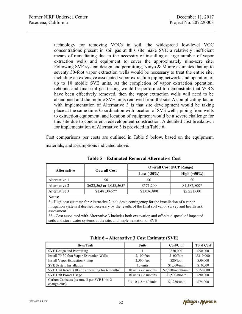
Former NIRF Undersea Center December 11, 2017 Pasadena, California Project No. 207220003
207220003 R RAW 52
technology for removing VOCs in soil, the widespread low-level VOC concentrations present in soil gas at this site make SVE a relatively inefficient means of remediating due to the necessity of installing a large number of vapor extraction wells and equipment to cover the approximately nine-acre site. Following SVE system design and permitting, Ninyo & Moore estimates that up to seventy 30-foot vapor extraction wells would be necessary to treat the entire site, including an extensive associated vapor extraction piping network, and operation of up to 10 mobile SVE units. At the completion of vapor extraction operation, rebound and final soil gas testing would be performed to demonstrate that VOCs have been effectively removed, then the vapor extraction wells will need to be abandoned and the mobile SVE units removed from the site. A complicating factor with implementation of Alternative 3 is that site development would be taking place at the same time. Coordination with location of SVE wells, piping from wells to extraction equipment, and location of equipment would be a severe challenge for this site due to concurrent redevelopment construction. A detailed cost breakdown for implementation of Alternative 3 is provided in Table 6.
Cost comparisons per costs are outlined in Table 5 below, based on the equipment,
materials, and assumptions indicated above.
Table 5 – Estimated Removal Alternative Cost
Alternative Overall Cost Overall Cost (NCP Range)
Low (-30%) High (+50%) Alternative 1 $0 $0 $0 Alternative 2 $623,565 or 1,058,565* $571,200 $1,587,800* Alternative 3 $1,481,065** $1,036,800 $2,221,600 Notes: * - High cost estimate for Alternative 2 includes a contingency for the installation of a vapor mitigation system if deemed necessary by the results of the final soil vapor survey and health risk assessment. ** - Cost associated with Alternative 3 includes both excavation and off-site disposal of impacted soils and stormwater systems at the site, and implementation of SVE
Table 6 – Alternative 3 Cost Estimate (SVE) Item/Task Units Cost/Unit Total Cost
SVE Design and Permitting 1 $50,000 $50,000 Install 70-30 foot Vapor Extraction Wells 2,100 feet $100/foot $210,000 Install Vapor Extraction Piping 2,500 feet $20/foot $50,000 SVE System Installation 10 units $1,000/unit $10,000 SVE Unit Rental (10 units operating for 6 months) 10 units x 6 months $2,500/month/unit $150,000 SVE Unit Power Usage 10 units x 6 months $1,500/month $90,000 Carbon Canisters (assume 3 per SVE Unit, 2 change-outs) 3 x 10 x 2 = 60 units $1,250/unit $75,000

Former NIRF Undersea Center December 11, 2017 Pasadena, California Project No. 207220003
207220003 R RAW 53
Table 6 – Alternative 3 Cost Estimate (SVE) Item/Task Units Cost/Unit Total Cost
Lab Analysis (assume 20 per month) 20 x 6 months = 120 tests $250/test $30,000
Mobilization/Demobilization 10 SVE units $1,500/unit $15,000 Operation and Maintenance (10 SVE units for 6 months) 60 units $1000/unit $60,000
O&M Reports 2 reports $5,000/report $10,000 Final Confirmation Soil Gas Sampling 1 soil gas survey $20,000/survey $20,000 SVE Well Abandonment 70 wells $750/well $52,500 SVE Pipe Removal 2,500 feet $10/foot $25,000 Closeout Report 1 report $10,000/report $10,000
Total $857,500
Soil Excavation and Disposal $623,565
Total Alternative 3 $1481,065
6.4.8. Community Acceptance
Alternative 1 (No Action) is unlikely to be accepted by the community because of the COPCs at the site and the unmitigated health risk those COPCs represent.
Alternative 2, Soil Excavation, Off-Site Disposal, Soil Gas Survey, and Vapor Intrusion Mitigation (if Necessary), is more likely to be perceived by the community as acceptable because it would mitigate the identified hazards and risks associated with the COPCs in soil and stormwater system via physical removal, providing greatly reduced health risks. Design and installation of VMSs for future buildings, if necessary, is likely to be perceived by the community as acceptable as long as it can be demonstrated that the COPCs that remain in soil gas are not mobile and do not pose and unacceptable health risk to receptors. An outcome that is achievable via health risk assessment.
Alternative 3, Soil Excavation, Off-Site Disposal, and Soil Vapor Extraction, is likely to be perceived by the community as acceptable because it would mitigate the identified hazards and risks associated with the COPCs in soil gas.
6.4.9. State Acceptance
Alternative 1 would not gain State acceptance because DTSC is required to ensure that the site is adequately investigated and remediated prior to use as a future project. Therefore, this alternative would preclude the project from moving forward.
Alternative 2 would be viewed favorably by regulatory agencies because it is protective of human health and the environment. It is anticipated that regulatory
Former NIRF Undersea Center December 11, 2017 Pasadena, California Project No. 207220003
207220003 R RAW 54
approval would be readily granted because this alternative makes use of common and proven technologies. Alternative 2 would not limit future development of the site or require a land use control (LUC), such as a deed restriction, depending on the results of the soil gas survey and health risk assessment. Alternative 2 can be implemented in a short time frame producing verifiable results. If the soil gas survey determines unacceptable vapor intrusion health risks to future occupants, VMSs will be installed. These would be viewed as favorable by regulatory agencies as long as it can be demonstrated that the COPCs that remain in soil gas cannot migrate to indoor air and do not pose an unacceptable health risk to receptors. Because future O&M may be required, a LUC, such as a deed restriction would be required.
Alternative 3 would be viewed favorably by regulatory agencies because it is protective of human health and the environment. It is anticipated that regulatory approval would be readily granted because this alternative makes use of common and proven technologies. Alternative 3 would be viewed as favorable by regulatory agencies as long as it can be demonstrated that the COPCs that remain in soil gas are not mobile and do not pose an unacceptable health risk to receptors. Because future O&M may be required, a LUC, such as a deed restriction would be required during and after implementation of SVE. Alternative 3 does involved delays and impediments to development and use of the property to its highest and best use.
6.5. Selection of Preferred Remedial Alternative
Based on the screening-level analysis conducted using the NCP criteria, it is clear that
Alternative 1 does not meet the RAOs for the site and does not comply with the ARARs;
therefore, this alternative was rejected from further consideration.
Alternatives 2 and 3 meet the threshold criteria for known affected media (soil and soil gas),
because they are protective of human health and the environment, would comply with the
ARARs, and would meet the RAOs for the site. However, the implementation of Alternative
3 would be problematic due to the site construction that would occur at the same time. It is
expected that SVE will take up to a year if implemented during site construction. Also,
Alternative 3 may not be short-term effective in mitigation of AOC4 because the completion
schedule of new buildings on the site is likely to occur prior to the completion of SVE
treatment at the site. In addition, the cost of implementing Alternative 3 is likely to be
approximately double the cost of implementing Alternative 2, even if 20 years of O&M is

Former NIRF Undersea Center December 11, 2017 Pasadena, California Project No. 207220003
207220003 R RAW 55
required to maintain active VMSs on site slab-on-grade buildings. Based on these factors,
Alternative 2 is recommended for remediation of AOC1, AOC2, AOC3, and AOC4.
Relating to remediating AOC4, it should be noted that there is a high likelihood for no
remediation or mitigation of AOC4 to be deemed necessary once current soil gas data is
procured via the post-removal soil gas survey, and health risk calculations are run with the
new data input. Should the new data still indicate a vapor intrusion health risk remains to
slab-on-grade building occupants, then implementation of the identified remedial alternative
(VMS) to address AOC4 will be necessary. In such a circumstance, VMSs would address
and mitigate soil vapor intrusion associated with AOC4.
Potential risks during the implementation of the preferred remedial alternative includes
exposure of on-site workers to health and safety hazards typically encountered during
construction activities and fugitive dust and VOC emissions during soil excavation
activities. These potential risks will be mitigated by adherence to health and safety
procedures and other safety controls, and compliance with SCAQMD Rules 403, 1166, and
1466.
7. REMEDIAL ACTION IMPLEMENTATION
Based on the results of the engineering evaluation and cost analysis presented in Section 6, the
preferred remediation alternative for the site is Alternative 2. The following sections present the
general procedures and methods that will be used to implement the selected alternative.
PG is responsible for the implementation of this RAW. Upon approval from the DTSC of the
final design, close of escrow on the property, and acquisition of any necessary permits by PG or
its contractors, remedial activities will commence and be performed by a California-licensed
removal contractor with a Hazardous Substance Removal Certification on their license, under the
supervision of a California registered professional engineer and/or professional geologist.
Completion of the remedial action will be demonstrated by the collection and analysis of
confirmation soil samples after the impacted soils have been removed and disposed of, and by
post-excavation soil gas data.
Former NIRF Undersea Center December 11, 2017 Pasadena, California Project No. 207220003
207220003 R RAW 56
7.1. Field Preparation
Prior to equipment mobilization, site preparation activities may include acquisition of
necessary permits, site visual inspections, boundary staking, establishment of staging areas
and construction traffic patterns, and subsurface utility clearance. The property will be fully
fenced and secure during remediation and construction activities, and will not be accessible
to non-approved personnel.
7.1.1. Permits and Plans Required regulatory permits and approvals will be obtained prior to initiation of field
activities. The following permits are expected:
SCAQMD Rule 403- Fugitive Dust requires notification to the SCAQMD prior to conducting large construction operations that disturb more than 50 acres or move more than 5,000 cubic yards of soil per day. The proposed soil removal activities do not qualify as a large operation; therefore, SCAQMD notification will not be required. However, dust suppression and air monitoring will be conducted in accordance with applicable elements of Rule 403.
General conditions of SCAQMD Rule 1166 – Volatile Organic Compound Emissions from Excavation of Soil will be followed during the excavation and handling of volatile TPH and VOC impacted soils. The Rule 1166 notification will be made at least 24 hours prior to the start of excavation. A Rule 1166 Various Locations Permit will be in hand prior to commencing excavation activities. Soil excavated during remedial activities will be monitored for the presence of VOCs, using an organic vapor analyzer (OVA). If more than 2,000-cubic yards of VOC-contaminated soil (defined as VOC concentrations greater than 50 parts per million [ppm]) as measured from a distance no more than 3 inches from the soil surface) are encountered at any time, then a site-specific VOC Contaminated Soil Mitigation Plan will be prepared and submitted to the SCAQMD for approval. Based on the compendium of soil data from the soil investigations performed at the site, the anticipated quantity of VOC impacted soil to be excavated is substantially less than the 2,000 cubic yard threshold for a site-specific plan; however, in the event that VOC impacted soil excavated quantities begin to approach the threshold quantity, work will be halted pending preparation, submittal, and approval of a site-specific VOC Contaminated Soil Mitigation Plan.
Soil excavation activities will be conducted in general accordance with the recently adopted SCAQMD Rule 1466 – Control of Particulate Emissions from Soils with Toxic Air Contaminants, which dictates the control of particulate emissions at facilities with elevated levels of arsenic, asbestos, cadmium, hexavalent chromium, lead, mercury, nickel, or polychlorinated biphenyls. At the site, it is known that
Former NIRF Undersea Center December 11, 2017 Pasadena, California Project No. 207220003
207220003 R RAW 57
elevated concentrations of arsenic, lead, and mercury exist. At least 72 hours and no more than 30 days prior to conducting earth-moving activities, SCAQMD will be notified. Permits or plans are not required for Rule 1466.
An excavation and grading plan will be developed and a grading permit will be obtained from the city of Pasadena Building & Safety Division.
PG will file a notice of intent with the SWRCB to comply with the Construction Activities Storm Water General Permit and obtain a Waste Discharger Identification number prior to beginning removal excavation. Additionally, PG’s contractor will use best-management practices in accordance with the site-specific SWPPP (Appendix F).
Soil removal activities will be conducted in accordance with applicable laws and regulations of the EPA RCRA, Federal and State OSHA, Department of Transportation, and the DTSC (CCR Title 22) regarding the characterization, excavation, and off-site transport/disposal of contaminated soil. A Transportation Plan has been prepared that provides a description of the transportation route to candidate off-site disposal facilities (Appendix A).
7.1.2. Utility Clearance Subsurface field activities will not begin without notification of the local Underground
Service Alert (USA) and the identification of utilities on the site. USA will be notified at
least 48 hours prior to the beginning of any excavation or drilling operations. A
geophysical survey will be completed in the areas of the site to be excavated. If active
utilities are present that cannot be avoided or protected during soil excavation, they will
be removed, relocated, or abandoned in coordination with the affected utility.
7.1.3. Security Measures The site will be secured by a construction fence along the perimeter. Access to the site
work areas will be through gates and restricted to authorized personnel only. During
work hours, access to the immediate work areas will be controlled by the Site Health
and Safety Officer (SHSO). After work hours, access to the site will be controlled by the
perimeter fence and locked gates.

Former NIRF Undersea Center December 11, 2017 Pasadena, California Project No. 207220003
207220003 R RAW 58
7.1.4. Field Documentation PG’s environmental consultant and removal contractor will be responsible for
maintaining field forms and logbooks that document the phases of all field work. Field
activity logs will document where, when, how, and from whom project information was
obtained. Log entries will be complete and accurate enough to permit reconstruction of
field activities. Each page will be consecutively numbered, dated, and noted with the
time of entry. Entries will be legible, written in ink, and signed by the individual making
the entries. Language will be factual, objective, and free of personal opinions or other
terminology which might prove inappropriate. If an error is made, a line will be made
through the error and the correct information will be entered. Corrections will be dated
and initialed. No entries will be obliterated or rendered unreadable.
7.1.5. Photographs Photographs will be taken at excavated locations and at other areas of interest on the
site. They will serve to complement information entered in the field activity logbooks.
When a photograph is taken, the following information will be written in the activity
logbooks, or will be recorded in a separate field photography log:
Time, date, location, direction, and if appropriate, weather conditions.
Description of the subject photographed.
Name of person taking the photograph.
7.2. Removal Activities
The following paragraphs describe the procedures during site soil removal. Soil removal
activities should be conducted in accordance with the applicable regulatory requirements
and protocols presented in the Soil Management Plan (Appendix B).
7.2.1. Trenching and Excavation Soils will be excavated to depths exceeding four feet bgs in most areas. Excavations
deeper than four feet will not be entered by personnel if graded sidewall slopes exceed
1:1, or if shoring is not present... Personnel must obtain approval from the SHSO prior
Former NIRF Undersea Center December 11, 2017 Pasadena, California Project No. 207220003
207220003 R RAW 59
to entering any excavation. On-site personnel will have received Competent Person
Training pursuant to Title 8 California Code of Regulations and Subpart P of 29 CFR
1926.650, Trenching and Excavation. Operations involving excavation or trenching will
be performed in accordance with 29 CFR 1926.650 and California Regulations for ex-
cavations (Title 8, 1539-1547). An excavation is considered to be any man-made cut,
cavity, trench, or depression in an earth surface, formed by earth removal. Daily inspec-
tions of excavations, the adjacent areas, and protective systems will be made by a
competent person to determine if a situation exists that could result in possible cave-ins,
failure of protective systems, hazardous atmospheres, or other hazardous conditions.
7.2.2. Confined Space Entry Requirements Confined space entry is not expected for the removal activities at the site. If confined
space entry is necessary permitting requirements and procedures will be included in an
addendum to the HASP.
7.2.3. Temporary Stockpile Operations Excavated suspect contaminated soil will be placed in stockpiles on heavy tarpaulins or
plastic sheeting and covered with plastic sheeting (per SCAQMD Rule 1466), or will be
placed in covered roll off bins. Per Rule 1466, soil stockpiles shall be no more than 400
cubic yards and shall not be higher than perimeter fencing. Daily inspection of the
stockpiles will be performed. Front-end loaders will remove the plastic sheeting and
stockpiled material for off-site disposal. During this process, a couple inches of soil
from underneath the stockpile will be removed along with the plastic sheeting and
stockpiled material to ensure that all potentially contaminated soils are removed. Cov-
ered roll-off bins may be used to store accumulated material instead of, or in addition to,
soil stockpiles.
Site stockpile management activities will consist of oversight and direction of stockpile
segregation into six main categories:
Construction debris for disposal or recycling;
Former NIRF Undersea Center December 11, 2017 Pasadena, California Project No. 207220003
207220003 R RAW 60
Personal protective equipment for disposal at a sanitary landfill;
Clean overburden soils (where existing) for re-use as backfill
Non-hazardous waste destined for off-site disposal or recycling;
Non-RCRA hazardous (California-hazardous) waste destined for off-site disposal or recycling; and
RCRA hazardous waste destined for off-site disposal or recycling.
Soil and materials excavated from AOC1, AOC2, and AOC3 are expected to be
transported off site as hazardous or non-hazardous waste destined for off-site disposal or
recycling. Segregation will be based initially on observed discoloration or staining of
soil, and photoionization detector (PID) readings in accordance with Rule 1166
monitoring, as well as by the previously identified COPCs known to be present at each
specific Hot Spot. Excavated soils will be segregated into separate stockpiles based
upon their anticipated COPCs, and will then be sampled and characterized for disposal
purposes according to USEPA guidance “U.S. EPA Environmental Response Team
Standard Operating Procedures SOP: 2017, 03/13/02, Waste Pile Sampling”. After soils
have been characterized, stockpiles or roll-off bins will be clearly labeled on site with
colored flags designating non-hazardous for disposal, non-RCRA hazardous (CA-HAZ)
for disposal, and RCRA hazardous for disposal.
Ninyo & Moore will obtain required waste manifest documentation prior to off-site
shipment of soils. Ninyo & Moore will maintain a copy of the manifest documentation
for each truckload of soil transported off site and will provide copies to PG, along with
weight tickets from the disposal receiving facilities. The wastes will be transported
pursuant to the Transportation Plan (see Appendix A). Stockpile areas and on-site truck
routes are presented in the Transportation Plan.
7.2.4. Waste Segregation Operations Waste segregation will be completed by excavating the soil in the AOCs in 1-foot lifts,
as necessary. Segregation will be based on observed discoloration or staining of soil,
Former NIRF Undersea Center December 11, 2017 Pasadena, California Project No. 207220003
207220003 R RAW 61
and photoionization detector (PID) readings in accordance with Rule 1166 monitoring,
as well as pre-existing knowledge of the COPCs present in any given Hot Spot area.
Excavated soils will be evaluated and characterized for disposal purposes.
7.2.5. Decontamination Procedures Vehicles and hand-held equipment will be decontaminated prior to leaving the site. A
hand-held equipment decontamination area will be prepared on site prior to impacted-
soil excavation. This area will be designed to contain liquids and residue generated
during the decontamination process. The decontamination area will be in an area easily
accessible to incoming and outgoing vehicles and equipment.
For equipment transfer to and from contaminated areas, items will be decontaminated
with a phosphate-free detergent between sampling locations and the waste water will be
accumulated into DOT-approved 55-gallon drums, pending profiling and disposal. After
decontamination, the equipment will be visually inspected for signs of residue.
Decontamination rinsate will be appropriately disposed of upon receipt of laboratory
profiling data.
In like fashion, a truck decontamination station will be established immediately inside
the ingress and egress gate to the property. Prior to departure, transport and dump trucks
will be covered with a tarp and cleaned of loose debris clinging to the sides and/or
wheels to minimize off-site tracking of contaminants. This should be achieved through
the use of a wheel-washing station, wheel shaker, or gravel pad inside the egress point.
Personnel overseeing decontamination procedures will be responsible for ensuring soil
is not tracked off site. Manual sweeping or a street sweeper will also be used to mitigate
track out during soil transport operations. Figures A-1 and A-2 of the Transportation
Plan display truck staging areas, decontamination areas, and ingress/egress points at the
site.

Former NIRF Undersea Center December 11, 2017 Pasadena, California Project No. 207220003
207220003 R RAW 62
7.2.6. Hot-Spot Markout and Geophysical Survey Locations of site hot-spots to be removed (AOC2 and AOC3) will be surveyed so that
they can be relocated after removal of the asphalt cap and buildings. A geophysical
survey will be performed in hot-spot areas to be excavated. Ground penetrating radar,
electro-magnetometer, and other geophysical instrumentation will be used in the area of
the former Building 7 to locate the former seepage pits, if possible, that were removed
when Building 7 was removed in the 1970s. Geophysical survey techniques will also
be used to survey the locations of stormwater piping and catch basins to be removed
concurrent with hot spot excavation.
7.3. Excavation Plan AOC1
Prior to excavation of AOC1, the location of the storm drain system will be marked out with
marking paint. Soil and sediment in the storm drain system, including pipes and catch
basins, will be cleaned out and stockpiled on site for characterization and disposal.
Conventional construction equipment, such as a backhoe will be used to excavate the storm
drains. A spotter will be present to note the locations of any suspected breaks in the storm
drain pipes or basins. The backhoe operator will carefully remove the hardscape asphalt and
cover soil (overburden) from over the top of the storm drain pipe. The operator will carefully
excavate along the side of the storm drain pipe until the full depth of the pipe is exposed.
The spotter will evaluate the storm drain pipe for breaks or holes. Identified locations of any
breaks or holes in the storm drain pipe will require excavation of underlying soil and
confirmation sampling to verify that any potential leaks from the storm drain pipes have not
impacted soil. Confirmation soil samples will be collected at a minimum of one sample per
20 linear feet of pipe removed and analyzed for COPCs at a state-certified laboratory.
Impacted soil, clean overburden soil, and storm drain pipe materials will be segregated,
stockpiled, and characterized for off-site disposal, or in the case of clean-overburden soil, for
re-use as backfill material.
7.4. Excavation Plan AOC2 and AOC3
Prior to excavation, the approximate horizontal extents of the impacted soil areas will be
marked using stakes or chalk to facilitate the initial excavation process. Conventional

Former NIRF Undersea Center December 11, 2017 Pasadena, California Project No. 207220003
207220003 R RAW 63
construction equipment, such as backhoes, excavators, loaders, and dozers will be used to
excavate the soil. A bucket auger may be used to remove some of the seepage pits (AOC2),
particularly those in close proximity to the I-210 Freeway retaining wall on the south side of
the site. The removal contractor will make the decision concerning the most appropriate
equipment to be used, and shoring will be installed where deemed necessary by the project
engineer. Concrete encountered in the excavation areas will be removed, stockpiled, and
disposed of as inert construction debris.
Excavation and removal of impacted soil will be performed in order to remove site soil
within AOC2 and AOC3. Lateral excavation limits will be approximately those indicated in
Figure 7, but may vary based on visual observation and/or other field or instrument
indications of potentially impacted soil. Confirmation soil samples will be collected at the
sidewalls and base of each removal excavation and analyzed for COPCs at a state-certified
laboratory. In general, confirmation soil sampling is anticipated to be conducted at a
minimum frequency of one sample per 20 linear feet of excavation sidewall and bottom and
at a minimum of one sample will per sidewall and one per bottom of each excavation,
regardless of size. The confirmation sampling procedure is described further in Section 8. At
the end of each work day, excavated areas will be secured with delineators and caution tape
to minimize the occurrence of accidents or unauthorized entry.
Following completion of the removal actions, collection and analysis of confirmation
samples, and receipt of approval from DTSC, the excavated areas will be backfilled and
graded to a smooth surface in anticipation of subsequent site mass grading activities.
7.5. Control Measures
Dust control measures will be performed at the site during removal activities in compliance
with SCAQMD Rules 403 and 1466 to reduce the potential for fugitive dust and migration
of contamination. Factors considered in providing dust control include wind speed and
direction. Generation of dust during the removal operations will be minimized, as necessary,
with the use of water as a dust suppressant. The water will be available from an on-site water

Former NIRF Undersea Center December 11, 2017 Pasadena, California Project No. 207220003
207220003 R RAW 64
service, via a water truck, or through a metered discharge from a fire hydrant located on the
site.
Dust suppression will be performed by applying a light water spray to soil stockpiles,
exposed excavation surfaces, excavator buckets, and internal roadways, as necessary, to
maintain dust concentrations below action levels. The SHSO will have the authority to stop
work in the event that on-site activities generate dust levels in excess of established action
levels or if wind conditions change creating an uncontrollable condition.
While onsite, all vehicles will maintain slow speeds (i.e., less than 5 miles per hour) for
safety purposes and to minimize dust generation. Efforts will be made to minimize the soil
drop height from excavator or loader buckets into the transport trucks. Soil stockpiles will
remain covered until load out, with only the working face uncovered during stockpiling
activities. If wind speeds exceed an amount at which engineering controls are determined to
be ineffective (e.g., sustained 25 miles per hour wind speed for 15 minutes), excavation and
loading will cease.
After soil is loaded into transport trucks, it will be covered to prevent loss of material during
transport to the disposal facility. Track-out of soil onto public roadways will be controlled by
drivers inspecting their vehicles prior to exiting the site, and cleaning tires as necessary.
Exits from the site will be swept, as necessary throughout the day and at close of operations,
to remove tracked out soil from the public street. A vacuum street sweeper will be utilized
as necessary to ensure capture of any fugitive track-out material.
Measures will also be taken to control vapors and odors emanating from the area where
VOC-impacted soil is excavated and handled as required by SCAQMD Rule 1166. If
necessary, a non-toxic, biodegradable surfactant will be added to the water used to moisten
the soil in order to suppress VOC vapors and minimize odors. VOC-impacted soil stockpiles
will be covered with plastic sheeting, with the seams and base of stockpiles secured with
sandbags or other like means. All efforts will be made to minimize the unnecessary
Former NIRF Undersea Center December 11, 2017 Pasadena, California Project No. 207220003
207220003 R RAW 65
movement or agitation of soil that could cause the uncontrolled evaporation of VOCs into
the atmosphere.
The removal contractor and subcontractors will be required to ensure that all construction
equipment is properly serviced and maintained in good operating condition. Construction
equipment idle time will be restricted to no more than 5 minutes, to the extent feasible.
During removal activities, the site perimeter fencing will be secured with a windscreen to
prevent unauthorized personnel from entering work areas and minimize the off-site
migration of windborne dust. According to SCAQMD Rule 1466, perimeter fencing should
be installed that is a minimum six feet tall and at least as tall as the highest stockpile.
Signage should be installed at intervals of at least 1,000 feet along perimeter fencing. The
signs should state the soil vapor COPCs for the site and a contact number for the community
to report dust leaving the site.
In addition to the mitigation actions listed above, the Project will also need to comply with
applicable SCAQMD and the California Air Resources Board regulations regarding
construction equipment permits to operate as well as off road equipment registration
programs.
If excavation is conducted during the rainy season, provisions will be made to prevent off-
site migration of impacted soil runoff. Best management practices will be implemented for
runoff control in accordance with regulatory requirements and the project specific SWPPP,
presented in Appendix F.
7.6. Air and Meteorological Monitoring
Air monitoring will be conducted during site removal activities to assess the effectiveness of
the various control measures. Air monitoring strategies and methodologies are designed to
achieve several goals:
Identify and measure the air contaminants generated during soil removal and decontamination activities in order to assign the appropriate personal protective equipment (PPE) to site workers and safety systems specified for those activities.
Former NIRF Undersea Center December 11, 2017 Pasadena, California Project No. 207220003
207220003 R RAW 66
Provide feedback to site operations personnel regarding potential hazards from exposure to hazardous air contaminants generated through site activities.
Identify and measure air contaminants at points outside of the soil removal and decontamination exclusion zones. Air monitoring will be conducted during work activities to measure potential exposure of sensitive receptors to site chemical constituents as a result of removal activities.
To assist in air monitoring activities, weather conditions, including wind direction and
speed, will be continuously monitored using a portable meteorological monitoring station.
7.6.1. Air Monitoring Responsibilities Air monitoring will be performed during all site activities in which soil is being
disturbed or handled. Air monitoring activities will include:
Monitoring dust levels in the exclusion zone and other locations. The SHSO will have the authority to stop work in the event that on-site activities generate dust levels that exceed site or community action levels. The SHSO will monitor on-site meteorological instrumentation and/or coordinate with off-site meteorological professionals to identify conditions that require cessation of work, such as excessive wind speeds.
Assuring that industrial hygiene air sampling equipment and media are properly calibrated and in good working condition. Real-time, data-logging aerosol monitors will be used, when required, to measure dust levels. Real-time information will be posted daily, and discussed with site workers. As analytical results for industrial hygiene samples are received, the SHSO will prepare summary sheets and discuss results with on-site management and workers.
Monitoring organic vapor concentrations using an organic vapor analyzer to establish upwind, downwind, and worker breathing zone concentrations.
Coordinating general safety activities, including all daily hazard communication, safety practices, and procedure briefings.
Oversight of personal decontamination practices.
General site safety leadership, support and recordkeeping activities.
Former NIRF Undersea Center December 11, 2017 Pasadena, California Project No. 207220003
207220003 R RAW 67
7.6.2. Meteorological Monitoring On-site meteorological monitoring will be performed concurrently with the soil removal
activities to ensure that all necessary precautions have been taken. Ambient weather
conditions (i.e. wind speed, wind direction, temperature, and relative humidity) will be
monitored by one or more of the following methods: an on-site meteorological station,
real-time internet weather for nearby locations, and/or the National Weather Service. If
off-site meteorological stations cannot provide data relevant to the site, an on-site
meteorological station will be used.
No specific regulatory wind velocity restrictions for soil excavation in the subject area
were found to exist. However, a self-imposed action level for work stoppage will be set
at a sustained wind velocity of approximately 25 mph for a duration of 15 minutes, as
recommended by the SCAQMD Rule 403.
7.6.3. Dust Monitoring Site COPCs, including PAHs, TPH, and metals have low volatility or are non-volatile,
but can adhere to soil particles and become airborne contaminants associated with dust
generated during soil handling. During periods of active removal, air monitoring for
dust will be performed at the perimeter of the site to ensure that unsafe concentrations
of dust are not migrating offsite. Air monitoring will also be conducted within the active
work zone to ensure the health and safety of construction workers. An
upwind/downwind sampling approach will be used with monitoring positions
established based on an ongoing assessment of wind speed and direction.
Dust monitoring will be conducted using continuous, real-time particulate dust monitors
equipped with data loggers. The dust monitors will be positioned at selected site
locations that may vary depending on site work and wind direction. The real-time and
time weighted average readings will be checked by on-site personnel approximately
every 15 minutes. In addition, a portable hand-held dust monitor may be used to spot-
check particulate levels at various site locations if visible dust is observed.

Former NIRF Undersea Center December 11, 2017 Pasadena, California Project No. 207220003
207220003 R RAW 68
The National Ambient Air Quality Standard (NAAQS) for dust is 50 micrograms per
cubic meter (µg/m3), based on dust particles measuring 10 micrometers or less (PM10).
The NAAQS dust standard, steady for 5 minutes, has been selected as the action level
for dust monitoring activities at the perimeter of the site (difference between upwind
and downwind readings). This is also the action level as specified in SCAQMD Rule
403. In accordance with the newly adopted SCAQMD Rule 1466, the two-hour average
PM10 concentrations from the site shall not exceed 25 µg/m3, where the PM10
concentration is the absolute difference between the upwind and downwind monitors. If
the two-hour average PM10 concentration exceeds 25 µg/m3, additional dust suppression
techniques must be implemented to reduce the potential for contaminant migration.
The action level for dust for equipment operators and workers will be set at 1 mg/m3
steady for five minutes. This action level will trigger increased dust suppression
activities to mitigate dust levels below 1 mg/m3. Respiratory protection will be worn by
the equipment operators if dust levels exceed 1 mg/m3 for greater than 5 minutes.
Additional dust suppression activities will be applied to reduce dust levels below
1 mg/m3. If dust emissions cannot be controlled within 15 minutes, all work will cease
and the SHSO will be consulted.
7.6.4. Vapor Monitoring During soil excavation, vapor monitoring will be conducted as described below and in
accordance with the general conditions of SCAQMD Rule 1166. Odors will be
monitored using worker perception. During removal activities in AOCs containing VOC
contamination, monitoring will be conducted to evaluate the potential for exposure to
airborne organic vapors. Air monitoring will be conducted in the immediate vicinity of
the contaminant source, if identified, or within the general work area. Typically, field
measurements will be collected and recorded at least every 15 minutes using a PID. If
organic vapor readings exceed the following action levels, upgrades will be made to
PPE as follows:
Background to 5 ppm – Level D PPE
Former NIRF Undersea Center December 11, 2017 Pasadena, California Project No. 207220003
207220003 R RAW 69
Greater than 5 ppm to 250 ppm – Level C PPE
Greater than 250 ppm – Level B PPE
Once the organic vapor readings are below the applicable action level for 30 minutes,
respiratory protection may be discontinued.
A PID, calibrated to hexane according to manufacturer’s specifications, will be used to
screen soils removed from AOCs containing VOC contamination in accordance with
SCAQMD Rule 1166 requirements. According to the SCAQMD definition, VOC-
contaminated soil is soil that registers a concentration of 50 ppm or greater as measured
at approximately 3 inches from the soil surface. VOC emissions from excavated
materials will be monitored in the excavator or loader bucket as it is transferred out of
the excavation area prior to temporary stockpile placement or direct loading into a
transport truck. The PID measurements will be recorded on designated field forms or in
the field logs. If PID readings of 50 ppm or greater are detected, the SCAQMD will be
notified within 24 hours of the first detection, as required by Rule 1166. If PID readings
reach 1,000 ppm or greater, the SCAQMD will be notified within one hour.
In addition to the worker health and safety monitoring described above, perimeter
monitoring will be conducted for VOC emissions that could occur during excavation
activities in AOCs containing VOC contamination. Perimeter monitoring will consist of
the measurement of VOC concentrations using a PID at locations upwind and
downwind from the excavation areas. The action level for the organic vapor perimeter
monitoring will be established as any concentration that exceeds the ambient
(background) VOC concentration, as measured at an upwind location, over a sustained
period of 5 minutes.
7.7. Waste Disposal Characterization and Disposal
Prior to off-site disposal segregated stockpiled waste will be characterized. In general, the
COPCs will be known for each excavated hot-spot. If elevated concentrations of metals are
expected in an excavation, the stockpiled waste will be profiled for Title 22 metals by the
Former NIRF Undersea Center December 11, 2017 Pasadena, California Project No. 207220003
207220003 R RAW 70
TTLC. Waste characterization samples with any TTLC results greater than 10 times the
STLC being tested using the WET. Based on the WET results, waste that exceeds the STLC
will be characterized as non-RCRA hazardous. Waste characterization samples with the
TTLC greater than 20 times the STLC will be further tested using the TCLP. Waste that
exceeds the TCLP will be characterized as RCRA-hazardous waste. A letter of acceptance
will be obtained from the waste facility(s) prior to acceptance based on the classification of
the waste.
7.8. Transportation Plan for Off-Site Disposal
A transportation plan indicating how the excavated soil will be hauled off the site, describing
truck routes for off-site disposal, proposed waste disposal facilities, and listing the frequency
of truck trips and holding areas at the site is presented in Appendix A. Prior to the start of
field work, the relevant agencies will be contacted regarding potential road construction. If
there is impact from road construction along the planned truck route, then the transportation
plan may be revised. This plan was prepared in general accordance with the DTSC’s
Transportation Plan, Preparation Guidance for Site Remediation (DTSC, 1994).
7.9. Site Restoration
Upon completion of soil removal activities and confirmation sampling, the excavations will
be graded so that sidewall slopes do not exceed a 1:1 ratio. The redevelopment of the site is
a balanced cut and fill project; therefore, excavations will be backfilled with site materials
during grading operations. The surface of the site will be graded and prepared to prevent
run-off in accordance with a site-specific SWPPP (see Appendix F). The SWPPP will be
prepared and notification made by the consultant or contractor prior to the start of field
activities.
7.10. Soil Gas Survey
The most recent soil gas survey was performed at the site in 2007, approximately 10 years
prior to the preparation of this RAW. A new soil gas survey will occur after removal of the
existing buildings and asphalt cap, and removal of hot spots, but before mass grading of the
site. The soil gas survey will consist of installing a total of fifteen (15) vapor probes
Former NIRF Undersea Center December 11, 2017 Pasadena, California Project No. 207220003
207220003 R RAW 71
throughout the site, each completed at 5 and 15 feet bgs, along with the collection of soil
vapor samples at each depth in accordance with DTSC guidelines. Pending the results of
this soil gas survey, a second soil gas survey may be appropriate to conduct after site-wide
grading activities and step-out excavations (if any) have been completed. The Soil Gas
Survey Workplan can be found in Appendix E. Results of this soil gas survey will be used to
update the Human Health Risk Assessment to evaluate if VOCs in soil gas still pose a vapor
intrusion health risk at the site. If such a result is determined, VMS plans will be prepared
for submittal to the DTSC for the planned slab-on-grade buildings. Upon receipt of DTSC
approval, the VMS plans will be incorporated into the building plans for submittal to the
City of Pasadena for approval and obtaining a building permit.
7.11. Program Variances
As conditions in the field can vary, it might be necessary to implement minor modifications
to the recommended procedures presented in this RAW. Field personnel will notify the
Project manager when deviations from the RAW are necessary. The DTSC will be notified
of the modification, and a verbal or written concurrence will be obtained from the DTSC
before implementing the modification, as appropriate. The DTSC will respond to all requests
for review and/or concurrence in a timely manner in order to minimize the potential impacts
to the project schedule. Modifications to the approved RAW will be documented in the field
logbook and in the RACR prepared at the conclusion of the removal activities.
8. CONFIRMATION SOIL SAMPLING AND ANALYSIS
Upon completion of the excavation to their planned horizontal and vertical extents, confirmation
soil samples will be collected from the exposed excavation sidewalls and bottoms. The number
of soil samples collected from each excavation will vary, depending on the dimensions of the
excavations. In general, confirmation soil sampling is anticipated to be conducted at a minimum
frequency of one sample per 20 linear feet of excavation sidewall and bottom. At a minimum,
one sample will be collected per sidewall and one per bottom from each excavation, regardless of
size. Sidewall samples will be collected equidistant between the ground surface and the
excavation bottom or between the next sample depths. Confirmation sampling of the storm drain
Former NIRF Undersea Center December 11, 2017 Pasadena, California Project No. 207220003
207220003 R RAW 72
system will be an exception to the general sampling procedure. The storm drain system will be
sampled along the excavation bottom only where the storm drain lines were observed or
suspected of being broken.
Confirmation samples will be collected using a decontaminated drive sampler, hand auger, or
similar method, wherever practicable and in conformance with the HASP. For deep samples
where it is not possible to use a drive sampler with extensions due to steep angles and at
locations where use of a drive sampler results in a safety concern, samples will be collected via
drive sampler directly from undisturbed soil within the center of the backhoe/excavator bucket to
avoid the need to enter hazardous areas. Samples to be analyzed for VOCs or TPHg will be
collected using EPA Method 5035 sampling kits and in accordance with DTSC sampling
guidelines, and placed in glass volatile organic analysis (VOA) containers preserved with
methanol and sodium bisulfate. Soil samples will be capped, labeled, placed in individual zip-
lock bags, recorded on a chain of custody (COC) document, and placed in cold storage pending
delivery to a State-certified laboratory for chemical analyses. These samples from each
excavation will be analyzed for the COPCs associated with the excavation. Depending on the
excavation, confirmation soil samples will be analyzed for the following:
Metals including arsenic, mercury, cadmium, and lead by EPA Method 6010B/7471A
PAHs by EPA Method 8310
TPHcc by EPA Method 8015M
VOCs by EPA Method 8260B/5035
The excavations will be considered completed if the confirmation sample results do not exceed
the SSCGs previously described elsewhere in the RAW. If concentrations of COPCs in
confirmation soil samples have been exceeded, an additional increment of soil (typically 6 to 12
inches) will be removed horizontally or vertically from the location represented by the
confirmation soil sample. Confirmation soil sampling, analysis, and evaluation will be repeated,
as previously described, within any expanded portions of the excavation. The excavation will be
considered complete if no confirmation samples exceed the SSCGs. If after repeated
Former NIRF Undersea Center December 11, 2017 Pasadena, California Project No. 207220003
207220003 R RAW 73
unsuccessful cycles of excavation SSCGs have not been achieved, DTSC will be consulted and
additional excavation or an alternative remedial approach may be implemented with DTSC’s
concurrence.
COC records are used to document sample collection and shipment to analytical laboratories for
analysis. Sample shipments for analyses will be accompanied by a COC record. COC form(s)
will be completed and sent with the samples for each laboratory and each shipment. If multiple
coolers are sent to a single laboratory on a single day, COC form(s) will be completed and sent
with the samples for each cooler. The COC will identify the contents of each shipment and
maintain the custodial integrity of the samples. Generally, a sample is considered to be in
someone’s custody if it is either in someone’s physical possession, in someone’s view, locked up,
or kept in a secured area that is restricted to authorized personnel. Until receipt by the laboratory,
the custody of the samples will be the responsibility of the sample collector. An example of a
COC form is provided as part of the QAPP in Appendix C. COC procedures are further discussed
in the QAPP.
9. HEALTH AND SAFETY PLAN
A site-specific HASP has been prepared for the site under the supervision of a CIH; a copy is
provided in Appendix D. The HASP was prepared in accordance with current safety standards as
defined by the EPA, OSHA, and the National Institute of Occupational Safety and Health
(NIOSH). Additionally, the HASP was prepared in accordance with guidelines set forth in Title 8
CCR Section 5192.
All contractors will be responsible for operating in accordance with the most current OSHA
regulations, including 29 CFR 1910.120, Hazardous Waste Operations and Emergency Response,
and 20 CFR 1926, Construction Industry Standards, as well as other applicable Federal, State,
and local laws and regulations. Before initiating field activities, the selected PG contractor will
be required to prepare a HASP consistent with the one included in Appendix D, or may choose to
implement the attached plan for site workers. The project SHSO will be responsible for
maintaining compliance with the HASP.
Former NIRF Undersea Center December 11, 2017 Pasadena, California Project No. 207220003
207220003 R RAW 74
10. RAW PUBLIC PARTICIPATION ACTIVITIES
The public participation activities to be completed in association with this RAW will be
determined by the DTSC. Based on similar activities for other sites, it is anticipated that the
activities may include the preparation of a mailing list, community survey, public participation
plan, a fact sheet, public notice, a 30-day comment period on the RAW document, and
distribution of a notice prior to implementation of the RAW fieldwork. These public participation
activities will be conducted by PG under supervision of the DTSC or directly by DTSC as per
standard DTSC protocol.
11. PROJECT ORGANIZATION, SCHEDULE, AND REPORTING
Parties responsible for the implementation of the RAW are identified in the following sections. A
tentative implementation schedule and reporting requirements are also discussed.
11.1. Project Organization
The contractors responsible for implementing the RAW have not been selected. In selecting
the contractors, PG will ensure that they have the proper OSHA training and qualifications,
experience, licenses, bonding, and insurance necessary to conduct the field work. PG will
oversee the implementation of the RAW.
The DTSC will review and approve the RAW prior to its implementation. The DTSC review
process will include an opportunity for public review and comment. The DTSC then will
consider any public comments received, prepare a response to the comments, and the RAW
will be revised accordingly. In addition, the DTSC will have a continued role with the
periodic inspection of field activities during implementation of the RAW, review the RACR
and certify the site with a “No Further Action” determination once the removal goals have
been met.
11.2. Project Schedule
Table 7 indicates the anticipated schedule of the RAW implementation and subsequent
reporting once the RAW has been approved by the DTSC and field activities have been
initiated.
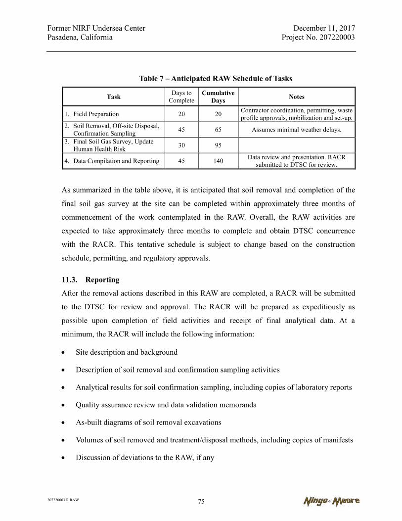
Former NIRF Undersea Center December 11, 2017 Pasadena, California Project No. 207220003
207220003 R RAW 75
Table 7 – Anticipated RAW Schedule of Tasks
Task Days to Complete
Cumulative Days Notes
1. Field Preparation 20 20 Contractor coordination, permitting, waste profile approvals, mobilization and set-up.
2. Soil Removal, Off-site Disposal, Confirmation Sampling 45 65 Assumes minimal weather delays.
3. Final Soil Gas Survey, Update Human Health Risk 30 95
4. Data Compilation and Reporting 45 140 Data review and presentation. RACR submitted to DTSC for review.
As summarized in the table above, it is anticipated that soil removal and completion of the
final soil gas survey at the site can be completed within approximately three months of
commencement of the work contemplated in the RAW. Overall, the RAW activities are
expected to take approximately three months to complete and obtain DTSC concurrence
with the RACR. This tentative schedule is subject to change based on the construction
schedule, permitting, and regulatory approvals.
11.3. Reporting
After the removal actions described in this RAW are completed, a RACR will be submitted
to the DTSC for review and approval. The RACR will be prepared as expeditiously as
possible upon completion of field activities and receipt of final analytical data. At a
minimum, the RACR will include the following information:
Site description and background
Description of soil removal and confirmation sampling activities
Analytical results for soil confirmation sampling, including copies of laboratory reports
Quality assurance review and data validation memoranda
As-built diagrams of soil removal excavations
Volumes of soil removed and treatment/disposal methods, including copies of manifests
Discussion of deviations to the RAW, if any

Former NIRF Undersea Center December 11, 2017 Pasadena, California Project No. 207220003
207220003 R RAW 76
Post-removal risk evaluation comparison of confirmation sample results to clean up goals
Summary and conclusions
Appendices and other supporting documentation
Based on the results of the removal action confirmation sampling, the DTSC will provide a
letter to PG indicating that “No Further Action” is required if the impacted areas have been
adequately addressed in accordance with the approved RAW. Upon receipt of the DTSC’s
approval of the RACR, copies of the RACR and corresponding DTSC approval letters will
be placed in one or more public repositories.
Former NIRF Undersea Center December 11, 2017 Pasadena, California Project No. 207220003
207220003 R RAW 77
12. REFERENCES
California Department of Health Services, California Code of Regulations, Title 22, Division 4, Chapter 15, Domestic Water Quality and Monitoring, Maximum Contaminant Levels.
California Department of Toxic Substance Control, 1994, Transportation Plan, Preparation Guidance for Site Remediation, dated May.
California Department of Toxic Substance Control, 1995, Remedial Action Plan Policy, dated November 16.
California, Environmental Protection Agency, Department of Toxic Substances Control (Cal-EPA), 1999, Preliminary Environmental Assessment Guidance Manual, dated June.
California Regional Water Quality Control Board, Los Angeles and Ventura Counties, Region 4, 1996, Interim Site Assessment & Cleanup Guidebook, dated May
City of Pasadena, 2016 Public Health Goals, date July, 1. Department of Toxic Substances Control (DTSC), Human and Ecological Risk Office, Human
Health Risk Assessment Note Number: 3, Cancer Value, DTSC-modified Screening Levels, updated June, 2017
DTSC, Determination of a Southern California Regional Background Arsenic Concentration in Soil, G. Chernoff, W. Bosan and D. Oudiz, March, 2008
Innovative Technical Solutions, Inc., 2006a, Draft Site-Specific Work Plan Focused Site Investigation NIRF, dated March.
Innovative Technical Solutions, Inc., 2006b, Draft Final Focused Site Investigation, NIRF, dated August.
Innovative Technical Solutions, Inc., 2006c, Final Focused Site Investigation, NIRF, dated November.
Kennedy/Jenks Consultants, 2007a, Soil Vapor Survey Report Former Naval Information Research Foundation (NIRF) Site, dated, April 13.
Kennedy/Jenks Consultants, 2007b, Environmental Summary Report, Former NIRF Site/Space Bank, dated May 22.
Maness Corporation, 1998, UST Closure Report, Removal and Disposal of 1-2000 Gal & 2-200 Gal. Underground Storage Tanks, NIRF (Under Sea Center) 3202 East Foothill Blvd., Pasadena, California, dated October.
Ninyo & Moore, 2008, Draft Final Phase I Environmental Site Assessment, Space Bank Mini Storage Facility, 3202 East Foothill Boulevard, Pasadena, California, dated April 17.
Ninyo & Moore, 2016. Draft Hexavalent Chromium Evaluation Report, Space Bank Mini Storage Facility, dated March 9.
Former NIRF Undersea Center December 11, 2017 Pasadena, California Project No. 207220003
207220003 R RAW 78
Ninyo & Moore, 2017, Draft Final Remedial Investigation Feasibility Study, Former Naval Information Research Foundation Under Sea Center (AKA Space Bank Mini Storage Facility) 3202 East Foothill Boulevard, Pasadena, California, dated May 3.
Science Application International Corporation, 2002, Draft Site Investigation Report, NIRF Under Sea Center, dated July.
Science Application International Corporation, 2003, Non-Point Source Pollution of Storm water Drainage System, NIRF Under Sea Center, dated December.
SECOR, 2006a, Expedited Phase II ESA Report, dated February 1. SECOR, 2006b, Pre-Demolition Hazardous Materials Assessment Report, Space Bank Mini-
Storage, dated February 23. United States Army Corps of Engineers, 1999, Draft Site Investigation Report, NIRF Under Sea
Center Site Inspection, Pasadena, California, dated June. United States Army Corps of Engineers, 2005, Draft Final Preliminary Endangerment
Assessment Report, Naval Information Research Facility (NIRF) Undersea Center, dated August
United States Environmental Protection Agency (EPA), 2000, Data Quality Objectives Process for Hazardous Waste Site Investigations, EPA QA/G-4HW Final, EPA Document 600/R-00/007, dated January.
United States Environmental Protection Agency (EPA) Region 9 Screening Levels, Target Cancer Risk 1E-06, Target Hazard Quotient 1.0, updated June 2017.
United States Geological Survey (USGS) 7.5 Minute Series, Mount Wilson, California, Topographic Quadrangle Map, dated 1966 and photorevised in 1988.
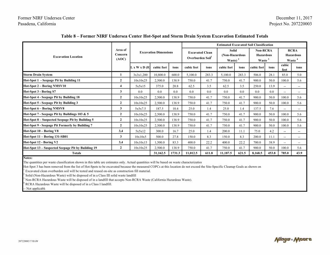
Former NIRF Undersea CenterPasadena, California
December 11, 2017Project No. 207220003
L x W x D (ft) cubic feet tons cubic feet tons cubic feet tons cubic feet tonscubicfeet
tons
Storm Drain System 1 3x3x1,200 10,800.0 600.0 5,100.0 283.3 5,100.0 283.3 506.0 28.1 85.0 5.0Hot-Spot 1 - Seepage Pit by Building 11 2 10x10x25 2,500.0 138.9 750.0 41.7 750.0 41.7 900.0 50.0 100.0 5.6Hot-Spot 2 – Boring NMSV10 4 5x5x15 375.0 20.8 62.5 3.5 62.5 3.5 250.0 13.9 -- --Hot-Spot 3 - Boring S7 3 0.0 0.0 0.0 0.0 0.0 0.0 0.0 0.0 0.0 -- --Hot-Spot 4 - Seepage Pit by Building 18 2 10x10x25 2,500.0 138.9 750.0 41.7 750.0 41.7 900.0 50.0 100.0 5.6Hot-Spot 5 - Seepage Pit by Building 3 2 10x10x25 2,500.0 138.9 750.0 41.7 750.0 41.7 900.0 50.0 100.0 5.6Hot-Spot 6 – Boring NMSV8 3 5x5x7.5 187.5 10.4 25.0 1.4 25.0 1.4 137.5 7.6 -- --Hot-Spot 7 - Seepage Pit by Buildings 103 & 5 2 10x10x25 2,500.0 138.9 750.0 41.7 750.0 41.7 900.0 50.0 100.0 5.6Hot-Spot 8 – Suspected Seepage Pit by Building 5 2 10x10x25 2,500.0 138.9 750.0 41.7 750.0 41.7 900.0 50.0 100.0 5.6Hot-Spot 9 - Seepage Pit Formerly by Building 7 2 10x10x25 2,500.0 138.9 750.0 41.7 750.0 41.7 900.0 50.0 100.0 5.6Hot-Spot 10 – Boring V8 3,4 5x5x12 300.0 16.7 25.0 1.4 200.0 11.1 75.0 4.2 -- --Hot-Spot 11 – Boring 131-SB01 3 10x10x5 500.0 27.8 150.0 8.3 150.0 8.3 200.0 11.1 -- --Hot-Spot 12 - Boring V2 3,4 10x10x15 1,500.0 83.3 400.0 22.2 400.0 22.2 700.0 38.9 -- --Hot-Spot 13 – Suspected Seepage Pit by Building 19 2 10x10x25 2,500.0 138.9 750.0 41.7 750.0 41.7 900.0 50.0 100.0 5.6
31,162.5 1731.3 11,012.5 611.8 11,187.5 621.5 8,168.5 453.8 785.0 43.9Notes:The quantities per waste classification shown in this table are estimates only. Actual quantities will be based on waste characterizationHot-Spot 3 has been removed from the list of Hot-Spots to be excavated because the measured COPCs at this location do not exceed the Site-Specific Cleanup Goals as shown on
-- Not applicable
Table 8 – Former NIRF Undersea Center Hot-Spot and Storm Drain System Excavation Estimated Totals
1 Excavated clean overburden soil will be tested and reused on-site as construction fill material.
3 Non-RCRA Hazardous Waste will be disposed of in a landfill that accepts Non-RCRA Waste (California Hazardous Waste).
2 Solid (Non-Hazardous Waste) will be disposed of in a Class III solid waste landfill
4 RCRA Hazardous Waste will be disposed of in a Class I landfill.
Excavation LocationExcavation Dimensions Solid
(Non-Hazardous Waste) 2
Non-RCRA Hazardous
Waste 3
RCRA Hazardous
Waste 4
Excavated Clean Overburden Soil 1
Estimated Excavated Soil ClassificationArea of Concern(AOC)
Totals
207220003 T RAW
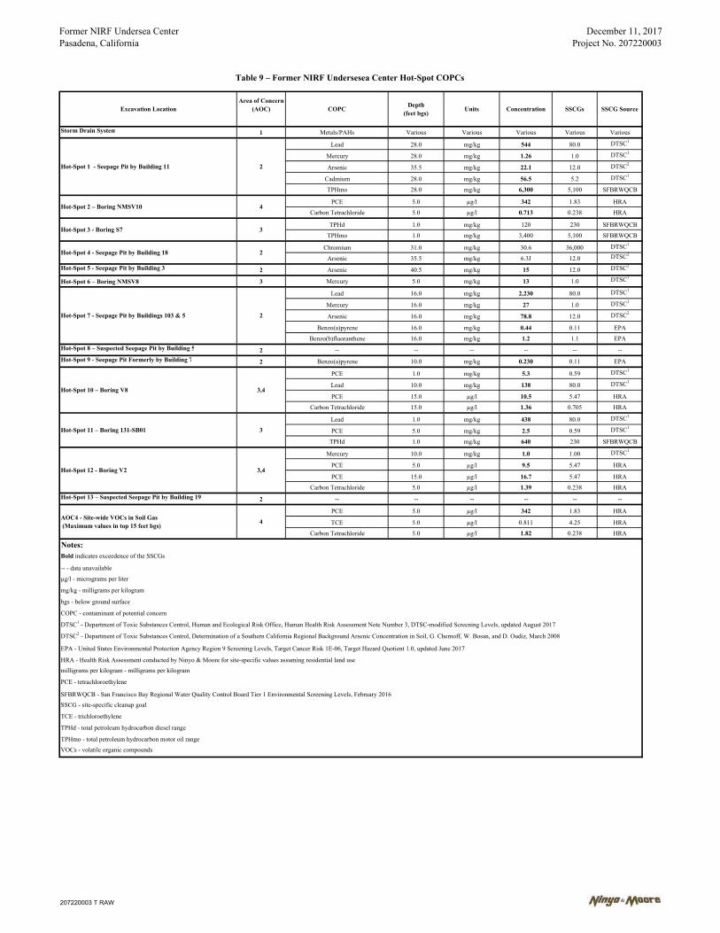
Former NIRF Undersea CenterPasadena, California
December 11, 2017Project No. 207220003
Storm Drain System 1 Metals/PAHs Various Various Various Various Various
Lead 28.0 mg/kg 544 80.0 DTSC1
Mercury 28.0 mg/kg 1.26 1.0 DTSC1
Arsenic 35.5 mg/kg 22.1 12.0 DTSC2
Cadmium 28.0 mg/kg 56.5 5.2 DTSC1
TPHmo 28.0 mg/kg 6,300 5,100 SFBRWQCB
PCE 5.0 µg/l 342 1.83 HRA
Carbon Tetrachloride 5.0 µg/l 0.713 0.238 HRA
TPHd 1.0 mg/kg 120 230 SFBRWQCB
TPHmo 1.0 mg/kg 3,400 5,100 SFBRWQCB
Chromium 31.0 mg/kg 30.6 36,000 DTSC1
Arsenic 35.5 mg/kg 6.3J 12.0 DTSC2
Hot-Spot 5 - Seepage Pit by Building 3 2 Arsenic 40.5 mg/kg 15 12.0 DTSC2
Hot-Spot 6 – Boring NMSV8 3 Mercury 5.0 mg/kg 13 1.0 DTSC1
Lead 16.0 mg/kg 2,230 80.0 DTSC1
Mercury 16.0 mg/kg 27 1.0 DTSC1
Arsenic 16.0 mg/kg 78.8 12.0 DTSC2
Benzo(a)pyrene 16.0 mg/kg 0.44 0.11 EPA
Benzo(b)fluoranthene 16.0 mg/kg 1.2 1.1 EPAHot-Spot 8 – Suspected Seepage Pit by Building 5 2 -- -- -- -- -- --Hot-Spot 9 - Seepage Pit Formerly by Building 7 2 Benzo(a)pyrene 10.0 mg/kg 0.230 0.11 EPA
PCE 1.0 mg/kg 5.3 0.59 DTSC1
Lead 10.0 mg/kg 138 80.0 DTSC1
PCE 15.0 µg/l 10.5 5.47 HRA
Carbon Tetrachloride 15.0 µg/l 1.36 0.705 HRA
Lead 1.0 mg/kg 438 80.0 DTSC1
PCE 5.0 mg/kg 2.5 0.59 DTSC1
TPHd 1.0 mg/kg 640 230 SFBRWQCB
Mercury 10.0 mg/kg 1.0 1.00 DTSC1
PCE 5.0 µg/l 9.5 5.47 HRA
PCE 15.0 µg/l 16.7 5.47 HRA
Carbon Tetrachloride 5.0 µg/l 1.39 0.238 HRAHot-Spot 13 – Suspected Seepage Pit by Building 19 2 -- -- -- -- -- --
PCE 5.0 µg/l 342 1.83 HRA
TCE 5.0 µg/l 0.811 4.25 HRA
Carbon Tetrachloride 5.0 µg/l 1.82 0.238 HRA
Notes:Bold indicates exceedence of the SSCGs
µg/l - micrograms per liter
mg/kg - milligrams per kilogram
bgs - below ground surface
COPC - contaminant of potential concern
DTSC1 - Department of Toxic Substances Control, Human and Ecological Risk Office, Human Health Risk Assessment Note Number 3, DTSC-modified Screening Levels, updated August 2017
DTSC2 - Department of Toxic Substances Control, Determination of a Southern California Regional Background Arsenic Concentration in Soil, G. Chernoff, W. Bosan, and D. Oudiz, March 2008
EPA - United States Environmental Protection Agency Region 9 Screening Levels, Target Cancer Risk 1E-06, Target Hazard Quotient 1.0, updated June 2017
HRA - Health Risk Assessment conducted by Ninyo & Moore for site-specific values assuming residential land usemilligrams per kilogram - milligrams per kilogram
PCE - tetrachloroethylene
SFBRWQCB - San Francisco Bay Regional Water Quality Control Board Tier 1 Environmental Screening Levels, February 2016SSCG - site-specific cleanup goal
TCE - trichloroethylene
TPHd - total petroleum hydrocarbon diesel range
TPHmo - total petroleum hydrocarbon motor oil rangeVOCs - volatile organic compounds
-- - data unavailable
Hot-Spot 11 – Boring 131-SB01
Table 9 – Former NIRF Undersesea Center Hot-Spot COPCs
COPC Concentration SSCGs SSCG SourceDepth(feet bgs)
Units
4
Hot-Spot 3 - Boring S7 3
Area of Concern(AOC)Excavation Location
3
AOC4 - Site-wide VOCs in Soil Gas (Maximum values in top 15 feet bgs)
3,4Hot-Spot 12 - Boring V2
4
Hot-Spot 1 - Seepage Pit by Building 11 2
Hot-Spot 10 – Boring V8
Hot-Spot 4 - Seepage Pit by Building 18 2
Hot-Spot 7 - Seepage Pit by Buildings 103 & 5 2
3,4
Hot-Spot 2 – Boring NMSV10
207220003 T RAW
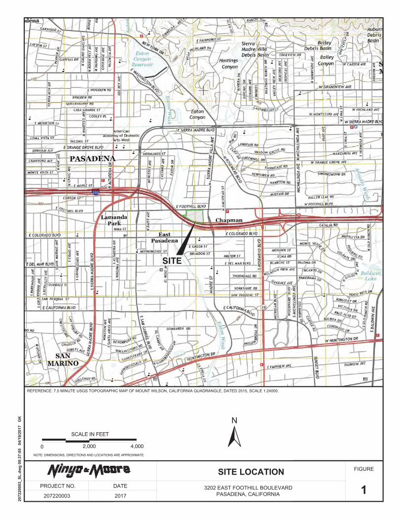
SITE
FIGURE
1PROJECT NO.
207220003
SITE LOCATIONDATE
2017
0 2,000 4,000
SCALE IN FEET
NOTE: DIMENSIONS, DIRECTIONS AND LOCATIONS ARE APPROXIMATE.
N
2072
2000
3_SL
.dw
g 09
:37:
05
04/1
9/20
17
GK
3202 EAST FOOTHILL BOULEVARDPASADENA, CALIFORNIA
REFERENCE: 7.5 MINUTE USGS TOPOGRAPHIC MAP OF MOUNT WILSON, CALIFORNIA QUADRANGLE, DATED 2015, SCALE 1:24000.

30
10101
4
19
11
68
16 23
5
3
18
17
14
12
21
120
13
103
EAST FOOTHILL BOULEVARD
INTERSTATE 2 1 0
3258
OFFICEBUILDING
3090
N. K
INN
ELO
A A
VE
NU
E
SA
NTA
PA
ULA
3135
PASADENA CITY COLLEGE
PESTICIDECOMPANY
3161
COMMERCIAL/RETAIL/BUSINESSES
3175
3183
3191
3199
3205
3209
3215
3219
3225
3229
3237
3239
3255
3100
STORAGE
3202
TRAILERS
STO
RA
GE
TRA
ILE
RS
STORAGETRAILERS
STO
RA
GE
TRA
ILE
RS
FIGURE
2SITE PLAN
3202 EAST FOOTHILL BOULEVARDPASADENA, CALIFORNIA
PROJECT NO.
207220003
DATE
2017NOTE: ALL DIMENSIONS, DIRECTIONS AND LOCATIONS ARE APPROXIMATE.
0 150 300
APPROXIMATE SCALE IN FEET
LEGEND
SITE BOUNDARY
30
3258
NAVAL INFORMATION RESEARCHFOUNDATION BUILDING DESIGNATION NUMBER
STREET ADDRESS
2072
2000
3_SP
.dw
g 09
:37:
05 1
2/07
/201
7 G
K, J
P
N
126
15
FIGURE
33202 EAST FOOTHILL BOULEVARDPASADENA, CALIFORNIA
PROJECT NO.
207220003
DATE
2017
NOT TO SCALE
NOTE: DIMENSIONS, DIRECTIONS AND LOCATIONS ARE APPROXIMATE.
N
PAST MILITARY AND
REFERENCE: SCIENCE APPLICATION INTERNATIONAL CORPORATION, DRAFT SITE INVESTIGATION REPORT, NIRF UNDER SEA CENTER, DATED JULY 2002.
2072
2000
3_SB
H.d
wg
16:5
8:28
04/
19/2
017
GK
, JP
CURRENT SITE USE

30-SV-04 NP-SV-01
120-SV-04
2-SV-01
2-SV-023-SV-11
10-SV-02
101-SV-01
107-SV-02
30-SV-05
107-SV-01
30-SV-03
30-SV-06
129-SV-01
11-SV-01
106-SV-01
106-SV-02
4-SV-01
3-SV-03
18-SV-013-SV-05
103-SV-01
5-SV-01
7-SV-03
20-SV-01
20-SV-02
30-SV-02
30-SV-07
30-SV-018-SV-01
23-SV-01
129-SV-02
NP-SV-0210-SV-01
106-SV-03
7-SV-05
23-SV-02
3-SV-06
3-SV-093-SV-04
14-SV-015-SV-03
3-SV-10
5-SV-04
3-SV-11 3-SV-02
7-SV-02
103-SV-02
S2
S6
S9
V5V8
S2
S3
S5
S7
S10
S11
V1
V4V7
V8
V10
V11
V12
V14
V15
V16
V17
V18
VD3
NMSV1NMSV2
NMSV3NMSV4
NMSV5
NMSV6
NMSV7
NMSV8
NMSV11
NMSV12
NMSV15
NMSV14
NMSD2
NMSD1
S4
NMSV9
NMSV10
NMSV13
V5
V6VD2
S1 S8
V13
V3
V2
V19
V9
FORMER BLDG 7 SEEPAGE PITSDEMOLISHED
STORM DRAINAGESYSTEM
5-SV-02
7-SV-01
NMSD3
131-SV-01
3-SV-08
3-SV-07
B7 VD1SEEPAGE PIT
SEEPAGE PIT
SEEPAGE PIT
FIGURE
4SITE ENVIRONMENTAL SAMPLE LOCATIONS
3202 EAST FOOTHILL BOULEVARDPASADENA, CALIFORNIA
PROJECT NO.
207220003
DATE
2017
NOTE: DIMENSIONS, DIRECTIONS AND LOCATIONS ARE APPROXIMATE.
0 100 200
SCALE IN FEET
LEGEND
103/SV-02 K/J Soil Vapor Samples
S4 Soil Borings (SECOR workplan)
V1, VD1 Soil/Vapor Boring (SECOR workplan)
NMSD3 150 ft Soil Borings (Ninyo & Moore)
Sample (June 1998)Sample (August 1998)
Sample (November 2001)Sample (December 2005)Sample (April 2006)
Site Boundary
Existing Building
Former Building
Naval Information Research FoundationBuilding Designation Number
Soil and Soil Vapor Borings (15 to 30 ft bgs)NMSV14
(Ninyo & Moore)
N
2072
2000
3_A
SL.d
wg
16:1
9:02
05/
02/2
017
JP
FIGURE
5PROJECT NO.
207220003
DATE
2017
NOT TO SCALE
NOTE: DIMENSIONS, DIRECTIONS AND LOCATIONS ARE APPROXIMATE.
REFERENCE: USACE, DRAFT SITE INVESTIGATION REPORT, NIRF UNDER SEA CENTER SITE INSPECTION, PASADENA, CALIFORNIA, JUNE 1999.
STORM WATER SEEPAGE PIT DIAGRAM
2072
2000
3_D
SWS.
dwg
17:0
3:28
04/
19/2
017
GK
, JP
3202 EAST FOOTHILL BOULEVARDPASADENA, CALIFORNIA
30-SV-04 NP-SV-01
120-SV-04
2-SV-01
2-SV-023-SV-11
10-SV-02
101-SV-01
107-SV-02
30-SV-05
107-SV-01
30-SV-03
30-SV-06
129-SV-01
11-SV-01
106-SV-01
106-SV-02
4-SV-01
3-SV-03
18-SV-01
103-SV-01
5-SV-01
7-SV-03
20-SV-01
20-SV-02
30-SV-02
30-SV-07
30-SV-018-SV-01
23-SV-01
129-SV-02
NP-SV-0210-SV-01
106-SV-03
7-SV-05
23-SV-02
3-SV-06
3-SV-093-SV-04
14-SV-01
5-SV-03
3-SV-10
5-SV-04
3-SV-11 3-SV-02
7-SV-02
103-SV-02
S2
S6
S9
V5 V8S2
S3
S5
S7
S10
S11
V1
V4V7
V10
V11
V12
V14
V15
V16
V17
V18
VD3
NMSV1NMSV2
NMSV3NMSV4
NMSV5
NMSV6
NMSV7
NMSV8
NMSV11
NMSV12
NMSV15
NMSV14
NMSD2
NMSD1
S4
NMSV9
NMSV10
NMSV13
V5
V6VD2
S1S8
V13
V3
V2
V19
V9
FORMER BLDG 7 SEEPAGE PITSDEMOLISHED
STORM DRAINAGESYSTEM
5-SV-02
7-SV-01
NMSD3
131-SV-01
3-SV-08
3-SV-07
B7 VD1SEEPAGE PIT
SEEPAGE PIT
SEEPAGE PIT
3-SV-05
FIGURE
6TPHs AND PAHs
3202 EAST FOOTHILL BOULEVARDPASADENA, CALIFORNIA
PROJECT NO.
207220003
DATE
2017
NOTE: DIMENSIONS, DIRECTIONS AND LOCATIONS ARE APPROXIMATE.
0 100 200
SCALE IN FEET
LEGEND
103/SV-02 K/J Soil Vapor Samples
S4 Soil Borings (SECOR workplan)
V1, VD1 Soil/Vapor Boring (SECOR workplan)
NMSD3 150 ft Soil Borings (Ninyo & Moore)
Sample (June 1998)Sample (August 1998)
Sample (November 2001)Sample (December 2005)Sample (April 2006)
Site Boundary
Existing Building
Former Building
Naval Information Research FoundationBuilding Designation Number
Soil and Soil Vapor Borings (15 to 30 ft bgs)NMSV14
(Ninyo & Moore)
N
2072
2000
3_TP
H.d
wg
12/
07/2
017
JP
Total Petroleum HydrocarbonPolynuclear Aromatic Hydrocarbon
TPHPAH
NMSD3
V6
7
20
16
3013
9
4
5
17
18
143
1
2
10
12
6 19
23
11
8
15
21
120
101
106107
128
126
103
131
129
16
S7
NMSV6
NMSV7
NMSV8
NMSV15
V10
V11
V15
V16
V18
NMSD1
VD3
VD2
USC-SP-11
USC-SB-103
103-SP01-16LAC-MH01
011-SP01
131-SB01
VD1
OIL WATER SEPARATOR
NMSD2
NMSV10
V19
V2
V8
N. K
INN
ELO
A AV
ENU
E
3202 EAST FOOTHILL BOULEVARDPASADENA, CALIFORNIA
FIGURE
7PROJECT NO.
207220003
DATE
2017
0 100 200
SCALE IN FEET
NOTE: DIMENSIONS, DIRECTIONS AND LOCATIONS ARE APPROXIMATE.
N
2072
2000
3_H
SSP.
dwg
12/0
7/17
JP
HOT-SPOTS(INCLUDING SEEPAGE PITS)
SB SOIL BORING
SP SEEPAGE PIT
SEEPAGE PIT
LEGEND
J ESTIMATED CONCENTRATION
FT BGS FEET BELOW GROUND SURFACE
HOT SPOT
RED TEXT EXCEEDS SCREENING LEVELS (EPA RSLs, DTSC SLs)
ALL SEEPAGE PITS, INCLUDING SUSPECTED SEEPAGE PITS AREASSUMED TO BE HOT-SPOTS AND WILL BE EXCAVATED.
STORM DRAIN SYSTEM WITH CATCH BASINS(APPROXIMATELY 1,200 LINEAR FEET)
NMSD3
V6
7
20
16
30 13
9
4
5
17
18
143
1
2
10
12
6 19
23
11
8
15
21
120
101
106107
128
126
103
131
129
16
S7
USC-FD-18-01
USC-FD-18-03
USC-CB-03-04
USC-CB-03-02
USC-CB-03-01
USC-CB-05-01
USC-CB-05-03
USC-SDI-02-03-02
NMSV6
NMSV7
NMSV8
NMSV15
V10
V11
V15
V16
V18
NMSD1
VD3
VD2
USC-SP-11
USC-CB-03-03
USC-SB-103
USC-CB-05-02
USC-CB-05-04
USC-CB-126-01
103-SP01-16 LAC-MH01
023-CB02
011-SP01
131-SB01
VD1
FORMER BLDG 7 SEEPAGE PITS DEMOLISHED
OIL WATER SEPARATOR
NMSD2
V19
N. K
INN
ELO
A AV
ENU
E
3202 EAST FOOTHILL BOULEVARDPASADENA, CALIFORNIA
FIGURE
8PROJECT NO.
207220002
DATE
2017
0 100 200
SCALE IN FEET
NOTE: DIMENSIONS, DIRECTIONS AND LOCATIONS ARE APPROXIMATE.
N
2072
2000
3_H
CC
T.dw
g 16
:19:
02 1
2/07
/201
7
HEXAVALENT CHROMIUMCONCENTRATIONS IN SOIL
CB CATCHMENT BASIN
FD FLOOR DRAIN
SDI STORM DRAIN INLET
SB SOIL BORING
SP SEEPAGE PIT
SEEPAGE PITCATCHMENT BASIN
LEGEND
J ESTIMATED CONCENTRATION
FT BGS FEET BELOWGROUND SURFACE
S2
S3
S5 S6
S7
S9
S10
S11
V1
V4
V7
V8
V10
V11
V12
V14
V15
V16
V17
V18
VD1
VD3
NMSV1
NMSV2
NMSV3NMSV4
NMSV5
NMSV6
NMSV7
NMSV8
NMSV11
NMSV12
NMSV15
NMSV14
NMSD2
NMSD3
NMSD1
S4
NMSV9
NMSV10
NMSV13
V5
V6
VD2
NMSD3 150' Soil Borings
LEGEND
NMSV1 5' Soil/Vapor Boring (Ninyo & Moore)
S4 Soil Borings (SECOR workplan)
V1, VD1 Soil/VaporBoring (SECOR workplan)
(Ninyo & Moore)
S1 S8
V13
V3
V2
V9
g/l
.89751.2915
g/l
.2375
.28115
g/l
5.515.28315
g/l
4.64511.615
g/l
8.32513.515
g/l
9.47516.715
g/l
28.8535.315
g/l
6.75520.515
g/l
9.172038.330
g/l
55.6513715
g/l
36.3534.115
g/l
4.047.9815
5
g/l
3.375.6330
20
g/l
.366
.171155
g/l
6.636.9515
5
g/l
3.033.2615
5
g/l
8.4813.515
5
g/l
8.8914.4215
5
g/l
30.239.110
5
g/l
6.7810.515
5
g/l
2.535.6915
5
g/l
.502
.221155
g/l
.662
.860155
g/l
3.556.5615
5
g/l
.510
.747155
g/l
.288
.309155
g/l
1.692.6415
5
g/l
3424.5815
5
g/l
1.312.7515
5
g/l
.9651.6115
5
g/l
3.784.7915
5
g/l
4.787.1315
5
g/l
7.7814.215
5
g/l
20.48.9830
20
g/l
7.569.5915
5
g/l
2.294.3115
5
g/l
.414
.170155
131 Building ID
g/l
Tetrachloroethylene
Micrograms per Liter
Below ground surface
PCE
bgs
30
30
5
Isoconcentration Contour30
V19
5
50
30
106
128129
107
9a101
10
4
10
1
2
12
3 14
17
18
120
7
20
126
13116
5
9c 9d 9e
(9a)Mini
Storage9b13n
13a
13m
13b
13s
MGR
MiniStorage
Mini
Mini
T17
T16
T15
MiniStorage
5c 5b (5a)5aa
5a-1
5d
5e
5f5h
5g
Formerly(5I)Mini
Storage
8a
8k
8-ac
8j
8c
8b
11b
8d
6e 6f 6g 6h6ib
(6i)
(6ia)
11a 11croombath
11d11e 11f 11g 11i
11h11j
sandpit
16-1bLot16 23s
23n
Lot 134
Removed Building
Currently Existing Building
11
6
8
16
23
9
13
g/l
.348
.4549263
feetbgs
1.431301.98150
g/l
22.217.9113
84
feetbgs
14.6150
g/l
4.041.4670
45
feetbgs
1.5985.88699
100
N. K
INN
ELO
A AV
ENU
E
feetbgs
feetbgs feet
bgs
feetbgs
feetbgs
feetbgs
feetbgs
feetbgs
feetbgs
feetbgs
feetbgs
feetbgs feet
bgs
feetbgs
feetbgsfeet
bgs feetbgs
feetbgs
feetbgs
feetbgs
feetbgs
feetbgs feet
bgs
feetbgs
feetbgs
feetbgs
feetbgs
feetbgs
feetbgs
feetbgs
feetbgs
feetbgs
feetbgs
feetbgs
feetbgs
feetbgs
feetbgs
FIGURE
9
PCE SOIL GAS ISOCONCENTRATION MAP -
3202 EAST FOOTHILL BOULEVARDPASADENA, CALIFORNIA
PROJECT NO.
207220003
DATE
2017
NOTE: ALL DIMENSIONS, DIRECTIONS AND LOCATIONS ARE APPROXIMATE.
0 100 200
SCALE IN FEET5 FEET BGS
N
2072
2000
3_C
TIM
3.dw
g 09
:40:
09 1
2/07
/201
7 JP

S2
S3
S5 S6
S7
S9
S10
S11
V1
V4
V7
V8
V10
V11
V12
V14
V15
V16
V17
V18
VD1
VD3
NMSV1
NMSV2
NMSV3NMSV4
NMSV5
NMSV6
NMSV7
NMSV8
NMSV11
NMSV12
NMSV15
NMSV14
NMSD2
NMSD3
NMSD1
S4
NMSV9
NMSV10
NMSV13
V5
V6
VD2
NMSD3 150' Soil Borings
LEGEND
NMSV1 5' Soil/Vapor Boring (Ninyo & Moore)
S4 Soil Borings (SECOR workplan)
V1, VD1 Soil/VaporBoring (SECOR workplan)
(Ninyo & Moore)
S1 S8
V13
V3
V2
V9
g/l
.89751.2915
g/l
.2375
.28115
g/l
5.515.28315
g/l
4.64511.615
g/l
8.32513.515
g/l
9.47516.715
g/l
28.8535.315
g/l
6.75520.515
g/l
9.172038.330
g/lfeet
55.6513715
g/l
36.3534.115
g/l
4.047.9815
5
g/l
3.375.6330
20
g/l
.366
.171155
g/l
6.636.9515
5
g/l
3.033.2615
5
g/l
8.4813.515
5
g/l
8.8914.4215
5
g/l
30.239.115
5
g/l
6.7810.515
5
g/l
2.535.6915
5
g/l
.502
.221155
g/l
.662
.860155
g/l
3.556.5615
5
g/l
.510
.747155
g/l
.288
.309155
g/l
1.692.6415
5
g/l
3424.5815
5
g/l
1.312.7515
5
g/l
.9651.6115
5
g/l
3.784.7915
5
g/l
4.787.1315
5
g/l
7.7814.215
5
g/l
20.48.9830
20
g/l
7.569.5915
5
g/l
2.294.3115
5
g/l
.414
.170155
131 Building ID
g/l
Tetrachloroethylene
Micrograms per Liter
Below ground surfacebgs
30
5
30
V19
50
30
106
128129
107
9a101
10
4
10
1
2
12
3 14
17
18
120
7
20
13116
5
9c 9d 9e
(9a)Mini
Storage9b13n
13a
13m
13b
13s
MGR
MiniStorage
Mini
Mini
T17
T16
T15
MiniStorage
5c 5b (5a)5aa
5a-1
5d
5e
5f5h
5g
Formerly(5I)Mini
Storage
8a
8k
8-ac
8j
8c
8b
11b
8d
6e 6f 6g 6h6ib
(6i)
(6ia)
11a 11croombath
11d11e 11f 11g 11i
11h11j
16-1b 16 Lot16 23s
23n
Lot 134
126
sandpit
Removed Building
Currently Existing Building
N. K
INN
ELO
A AV
ENU
E
feetbgs feet
bgsfeetbgs
feetbgs
feetbgs
feetbgs
feetbgs
feetbgs
feetbgs
feetbgs
feetbgs
feetbgs
feetbgs
feetbgsfeet
bgs
feetbgs
feetbgs
feetbgs
feetbgs
feetbgsfeet
bgs
feetbgs
feetbgs
feetbgs
feetbgs
feetbgs
feetbgs
feetbgs
feetbgs
feetbgs feet
bgs
feetbgs
feetbgs
feetbgs
feetbgs
feetbgs
FIGURE
10
PCE SOIL GAS ISOCONCENTRATION MAP -
3202 EAST FOOTHILL BOULEVARDPASADENA, CALIFORNIA
PROJECT NO.
207220003
DATE
2017
NOTE: ALL DIMENSIONS, DIRECTIONS AND LOCATIONS ARE APPROXIMATE.
0 100 200
SCALE IN FEET15 FEET BGS
N
2072
2000
3_C
TIM
4.dw
g 09
:40:
09 1
2/07
/201
7 JP

S2
S3
S5 S6
S7
S9
S10
S11
V1
V4
V7
V8
V10
V11
V12
V14
V15
V16
V17
V18
VD1
VD3
NMSV1
NMSV2
NMSV3NMSV4
NMSV5
NMSV6
NMSV7
NMSV8
NMSV11
NMSV12
NMSV15
NMSD2
NMSD3
NMSD1
S4
NMSV9
NMSV10
NMSV13
V5
V6
VD2
NMSD3 150' Soil Borings
LEGEND
NMSV1 5' Soil/Vapor Boring (Ninyo & Moore)
S4 Soil Borings (SECOR workplan)
V1, VD1 Soil/VaporBoring (SECOR workplan)
(Ninyo & Moore)
S1 S8
V13
V3
V2
V9
g/lfeet
ND5ND15
g/l
ND5ND15
g/l
ND5.21815
g/l
.1765
.23215
g/l
.5275.63615
g/l
1.395ND15
g/l
ND5.15115
g/l
ND5ND15
g/l
ND 20.47530
g/l
.2655
.35915
g/l
.69451.0915
g/l
.466ND15
5
g/l
1.451.4230
20
g/l
NDND15
g/l
1.82ND15
5
g/l
.571
.583155
g/l
.939ND15
5
g/l
.569ND15
5
g/l
.4621.36
155
155
g/l
.7891.1915
5
g/l
.044ND15
5
g/l
.220
.438155
g/l
1.38ND15
5
g/l
.210ND15
5
g/l
NDND15
g/l
.476ND15
5
g/l
.713ND15
5
g/l
ND.46415
5
g/l
NDND15
5
g/l
2.67ND15
5
g/l
.334ND15
5
g/l
.462
.775155
g/l
NDND15
5
131 Building ID
g/l Micrograms per Liter
Below ground surfacebgs
bgs feetbgs
feetbgsfeetbgs
feetbgs
feetbgs
feetbgs
feetbgs
feetbgs5
feetbgs
feetbgs
feetbgs
feetbgs
feetbgs
feetbgs
feetbgs
feetbgs
feetbgs
feetbgs
feetbgs
5
feetbgsfeet
bgs
feet
feetbgs feet
bgs.338.588
feetbgs
feetbgs
feetbgs
feetbgs
feetbgs
feetbgs
feetbgs
feetbgs
feetbgs
feetbgs
ND Not detected above laboratory detection limit
Isoconcentration Contour1.0
1.0
0.5
1.0
0.5
V19
0.5
1.0
30
106
128129
107
9a101
10
4
10
1
2
12
3 14
17
18
120
7
20
126
13116
5
9c 9d 9e
(9a)Mini
Storage9b13n
13a
13m
13b
13s
MGR
MiniStorage
Mini
Mini
T17
T16
T15
MiniStorage
5c 5b(5a)5aa
5a-1
5d
5e
5f5h
5g
Formerly(5I)Mini
Storage
8a
8k
8-ac
8j
8c
8b
11b
8d
6e 6f 6g 6h6ib
(6i)
(6ia)
11a 11croombath
11d11e 11f 11g 11i
11h11j
sandpit
16-1b 16Lot16 23s
23n
Lot 134 7Lot 134
Removed Building
Currently Existing Building
g/l
.024ND15
5
feetbgs
g/l
ND2.2730
20
feetbgs
g/l
.170ND15
5
feetbgs
NMSV14
g/l
24.328.4113
84
feetbgs
20.6150
g/l
.466ND70
45
feetbgs
7.53855.9599
g/l
2.577.292
63
feetbgs
12.913013.2150
g/lbgsN. K
INN
ELO
A AV
ENU
E
FIGURE
113202 EAST FOOTHILL BOULEVARDPASADENA, CALIFORNIA
PROJECT NO.
207220003
DATE
2017
NOTE: ALL DIMENSIONS, DIRECTIONS AND LOCATIONS ARE APPROXIMATE.
0 100 200
SCALE IN FEET
N
2072
2000
3_C
TIM
.dw
g 09
:40:
09 1
2/07
/201
7 JP
CARBON TETRACHLORIDE SOIL GASISOCONCENTRATION MAP - 5 FEET BGS
S2
S3
S5 S6
S7
S9
S10
S11
V1
V4
V7
V8
V10
V11
V12
V14
V15
V16
V17
V18
VD1
VD3
NMSV1
NMSV2
NMSV3NMSV4
NMSV5
NMSV6
NMSV7
NMSV8
NMSV11
NMSV12
NMSV15
NMSV14
NMSD2
NMSD3
NMSD1
S4
NMSV9
NMSV10
NMSV13
V5
V6
VD2NMSD3 150' Soil Borings
LEGEND
NMSV1 5' Soil/Vapor Boring (Ninyo & Moore)
S4 Soil Borings (SECOR workplan)
V1, VD1 Soil/VaporBoring (SECOR workplan)
(Ninyo & Moore)
S1 S8
V13
V3
V2
V9
g/lfeet
ND5ND15
g/l
ND5ND15
g/l
ND5.21815
g/l
.1765
.23215
g/l
.5275.63615
g/l
1.395ND15
g/l
ND5.15115
g/l
ND5ND15
g/l
ND 20.47530
g/l
.2655
.35915
g/l
.69451.0915
g/l
.466ND15
5
g/l
1.451.4230
20
g/l
NDND15
g/l
1.82ND15
5
g/l
.571
.583155
g/l
.939ND15
5
g/l
.569ND15
5
g/l
.4621.36
155
155
g/l
.7891.1915
5
g/l
.044ND15
5
g/l
.220
.438155
g/l
1.38ND15
5
g/l
.210ND15
5
g/l
NDND15
g/l
.476ND15
5
g/l
.713ND15
5
g/l
ND.46415
5
g/l
.024ND15
5
g/l
NDND15
5
g/l
NDND15
5
g/l
.334ND15
5
g/l
NDND30
20
g/l
.170ND15
5
g/l
.462
.775155
g/l
NDND15
5
131 Building ID
g/l Micrograms per Liter
Below ground surfacebgs
bgs feetbgs
feetbgsfeetbgs
feetbgs
feetbgs
feetbgs
feetbgs
feetbgs5
feetbgs
feetbgs
feetbgs
feetbgs
feetbgs
feetbgs
feetbgs
feetbgs
feetbgs
feetbgs
feetbgs
5
feetbgsfeet
bgs
feet
feetbgs feet
bgs.338.588
feetbgs
feetbgs
feetbgs
feetbgsfeet
bgs
feetbgs
feetbgs
feetbgs
feetbgs
feetbgs
feetbgs
feetbgs
feetbgs
ND Not detected above laboratory detection limit
V19
Isoconcentration Contour1.0
0.5
0.5
0.5
0.5
1.0
0.5
1.0
0.5
30
106
128129
107
9a101
10
4
10
1
2
12
3 14
17
18
120
7
20
126
13116
5
9c 9d 9e
(9a)Mini
Storage9b13n
13a
13m
13b
13s
MGR
MiniStorage
Mini
Mini
T17
T16
T15
MiniStorage
5c 5b (5a)5aa
5a-1
5d
5e
5f5h
5g
Formerly(5I)Mini
Storage
8a
8k
8-ac
8j
8c
8b
11b
8d
6e 6f 6g 6h6ib
(6i)
(6ia)
11a 11croombath
11d11e 11f 11g 11i
11h11j
sandpit
16-1b 16 Lot16 23s
23n
Lot 134
Removed Building
Currently Existing Building
g/l
2.577.292
63
feetbgs
12.913013.2150
g/l
.466ND70
45
feetbgs
7.5385
g/l
24.328.4113
84
feetbgs
20.6150
g/lbgsN. K
INN
ELO
A AV
ENU
E
FIGURE
123202 EAST FOOTHILL BOULEVARDPASADENA, CALIFORNIA
PROJECT NO.
207220003
DATE
2017
NOTE: ALL DIMENSIONS, DIRECTIONS AND LOCATIONS ARE APPROXIMATE.
0 100 200
SCALE IN FEET
2072
2000
3_C
TIM
2.dw
g 09
:40:
09 1
2/07
/201
7 JP
N
CARBON TETRACHLORIDE SOIL GAS ISOCONCENTRATION MAP - 15 FEET BGS
Former NIRF Undersea Center December 11, 2017 Pasadena, California Project No. 207220003
207220003 R RAW
APPENDIX A
TRANSPORTATION PLAN

TRANSPORTATION PLAN FORMER NAVAL INFORMATION RESEARCH
FOUNDATION UNDERSEA CENTER (AKA SPACE BANK MINI STORAGE FACILITY)
3202 EAST FOOTHILL BOULEVARD PASADENA, CALIFORNIA 91107
PREPARED FOR: Pasadena Gateway, LLC
3501 Jamboree Road, Suite 230 Newport Beach, California 92660
PREPARED BY: Ninyo & Moore
Geotechnical and Environmental Sciences Consultants 475 Goddard, Suite 200 Irvine, California 92618
December 11, 2017 Project No. 207220003

Former NIRF Undersea Center December 11, 2017 Pasadena, California Project No. 207220003
207220003 R Trans Plan i
TABLE OF CONTENTS
Page 1. INTRODUCTION ....................................................................................................................1
1.1. Background ...................................................................................................................1 1.2. Purpose and Objective ..................................................................................................2
2. WASTE CHARACTERIZATION ...........................................................................................2 2.1. Waste Profiling .............................................................................................................2
2.1.1. Hazardous Waste Management ...........................................................................3 2.1.2. Waste Quantity ....................................................................................................4
2.1.3. Special Disposal Requirements ...........................................................................4 2.2. Import Fill Material ......................................................................................................4
3. SOIL LOADING AND STAGING OPERATIONS ................................................................4 3.1. Vehicle Loading Operations .........................................................................................4 3.2. Soil Staging Operations ................................................................................................5
3.3. Working Hours and Duration .......................................................................................6
4. TRANSPORTATION CONTROL ...........................................................................................6
4.1. Dust Control..................................................................................................................6 4.2. Decontamination ...........................................................................................................6 4.3. Traffic Control Procedures ...........................................................................................7
4.4. Haul Routes ..................................................................................................................7
5. OFF-SITE DISPOSAL FACILITIES .......................................................................................9 5.1. RCRA Hazardous Waste Facility (Class I) ................................................................10 5.2. Non-RCRA (California) Hazardous Waste ................................................................10
5.3. Non-Hazardous Waste Facility (Class II or III) .........................................................11
6. SHIPPING DOCUMENTATION ..........................................................................................11
7. REQUIREMENTS OF FILL MATERIALS ..........................................................................11
8. REQUIREMENTS OF TRANSPORTERS ............................................................................12 8.1. License and Insurance .................................................................................................12 8.2. Contingency Plan ........................................................................................................12
9. RECORD KEEPING ..............................................................................................................13
10. SITE HEALTH AND SAFETY .............................................................................................14 Figures Figure A-1 – On-Site Truck Route and Stockpile Areas Figure A-2 – Off-Site Truck Route onto I-210 Appendices Appendix A – Transportation Routes Appendix B – Waste Manifest Information
Former NIRF Undersea Center December 11, 2017 Pasadena, California Project No. 207220003
207220003 R Trans Plan 1
1. INTRODUCTION
The following sections provide background information and the purpose and objective of the
transportation plan.
1.1. Background
Ninyo & Moore has prepared this Transportation Plan (TP) on behalf of the Pasadena
Gateway, LLC (PG) for the former Naval Information Research Foundation Undersea
Center, currently known as and hereinafter referred to as the Space Bank facility at 3202
East Foothill Boulevard in the City of Pasadena, California (site). The 9.15 acre site is
bounded to the north by East Foothill Boulevard, to the south by the Interstate 210 highway,
to the east by a Kaiser Permanente medical facility and to the west by North Kinneloa
Avenue. The site includes a small parcel west of North Kinneloa Avenue.
The site was previously owned by the Navy and utilized for testing and scientific testing
involving classified materials, torpedoes, and other weapons systems between 1945 and
1977. Numerous and varied laboratories were identified at the site including: combustion,
chemistry, hydro-propellants, welding, hydrodynamics, structures, metallurgy, experimental
physics, ballistics, and simulator labs. Possible hazardous substances associated with the
laboratories include: propellants, combustibles, explosives, solvents, and fuels. In 1977, the
site was purchased by Space Bank, Ltd., the current owner, and utilized as a storage facility
to the present.
Environmental Investigations were previously conducted at the site and summarized in
various reports between 1994 and 2016. Elevated levels of the chemicals of concern
(COPCs) were detected in soil and seepage pits at the site that present a potential threat to
human health and/or the environment. Based on the data collected during the historical
environmental investigations, it was determined that a Response Action (RA) is required to
address the potential threat or hazard posed by the presence of elevated levels of the COPCs
detected at the site. Therefore, a Removal Action Workplan (RAW) addressing this RA has
been prepared for approval by the California Department of Toxic Substance Control
(DTSC).

Former NIRF Undersea Center December 11, 2017 Pasadena, California Project No. 207220003
207220003 R Trans Plan 2
Based on the analytical data reported in the soil investigation reports, it is estimated that
approximately 20,138 cubic feet (approximately 746 cubic yards) of impacted soil, seepage
pits, and storm drains containing volatile organic compounds (VOCs), total petroleum
hydrocarbons (TPH), metals, and polycyclic aromatic hydrocarbons (PAHs) will be removed
from the site. Soil will be excavated by a California-licensed removal engineering contractor
under supervision of a California registered professional engineer and/or professional
geologist. A California licensed waste hauler will transport soils in covered trucks or roll-off
bins under manifests to their proper disposal facilities.
The estimated areas of removal are provided in Table 6 of the RAW and illustrated in Figure
7 of the RAW. A project summary is provided in the following table.
Project Site (Site) Space Bank Mini Storage Facility (Former NIRF Under Sea Center)
Site Address 3202 East Foothill Boulevard, Pasadena, California Project Proponent (PP) Pasadena Gateway, LLC (PG) Removal Action (RA) Contractor To Be Determined Chemicals of Concern (COCs) VOCs, TPH, PAHs, and metals Estimated Volume of Soil Removal 746 cubic yards Regulatory Status Removal Action
1.2. Purpose and Objective
This TP is included as an appendix to the RAW that has been prepared to address the
excavation and off-site disposal of the impacted material described above. The classification,
transportation, and removal of material will be conducted in accordance with the federal,
state, and local regulations, as applicable.
2. WASTE CHARACTERIZATION
The following sections provide waste profile and import fill material information.
2.1. Waste Profiling
During previous environmental investigations conducted at the site, soil sample analytical
results indicate that site screening levels (United States Environmental Protection Agency

Former NIRF Undersea Center December 11, 2017 Pasadena, California Project No. 207220003
207220003 R Trans Plan 3
[EPA] Residential Regional Screening Levels or DTSC Screening Levels for Residential
Soil) were exceeded in “hot spot” areas. These hot spot areas (13 total) are identified in
Table 6 and Figure 7 of the RAW. The storm drain system at the site also contains some of
the highest concentrations of COPCs discovered, and will be excavated and removed under
the RAW, of which approximately 409 cubic yards is clean over burden soil that will be
tested and re-used on site as construction fill material. Preliminary calculations indicate
approximately 1,155 cubic yards of soil associated with the hot spots and storm drain system
are required to be excavated under the RAW. COPCs associated with the hot spots and storm
drain system include metals such as lead, arsenic, and mercury, PAHs such as
benzo(a)pyrene and benzo(b)fluoranthene, TPH as diesel, and tetrachloroethylene. The soils
from the excavations will be profiled in four categories:
Clean Overburden Soil – Reused On-Site as Construction Fill Material
Solid (non-hazardous) Waste – Disposed of at Class III Landfill
Non-Resource, Conservation, and Recovery Act (RCRA) Hazardous Waste (California Hazardous Waste) – Disposed of at a Landfill
RCRA Hazardous Waste – Disposed of at Class I Landfill
2.1.1. Hazardous Waste Management
PG will obtain an EPA Identification number from DTSC or EPA that will be used for
generation, transportation, and off-site disposal of hazardous wastes excavated from the
site. Compliance with the DTSC requirements governing hazardous waste generation,
transportation, and disposal is required. Any container used for on-site storage will be
properly labeled with a hazardous waste label. The hazardous waste will be transported
off site for disposal within 90 days after its generation. Any shipment of hazardous
waste in California will be transported by a registered hazardous waste hauler under a
uniform hazardous waste manifest. Land ban requirements will be followed as
necessary.
Former NIRF Undersea Center December 11, 2017 Pasadena, California Project No. 207220003
207220003 R Trans Plan 4
2.1.2. Waste Quantity
As mentioned previously, approximately 746 cubic yards of VOCs, metals, PAHs, and
TPH impacted soil will be removed from the site. Based on these volumes,
approximately 55 end-dump trucks or 100 roll-off bins can be used. However,
confirmation sampling, materials testing for clean overburden soil, and field conditions
may affect the actual volume of soil to be excavated and removed from the site.
2.1.3. Special Disposal Requirements
Soil is expected to be classified as RCRA-hazardous waste (29 cubic yards), California
hazardous waste (308 cubic yards), or non-hazardous waste (409 cubic yards). Clean
overburden soil will be segregated and reused at the site as backfill after the
commencement of the RAW. There are currently no other special disposal requirements.
2.2. Import Fill Material
No backfill under the RAW is anticipated because excavations will be backfilled from site
soils during the cut and fill grading operation for future residential and commercial
construction which is planned to commence once the environmental clearance is provided
by the DTSC. However, based on site conditions, excavations will be graded so that sidewall
slopes do not exceed 1:1 if a safety hazard exists.
3. SOIL LOADING AND STAGING OPERATIONS
The following sections provide information on vehicle loading operations, soil staging
operations, and working hours and duration. Figure A-1 displays on-site truck routes, stockpile
staging areas, and ingress/egress points at the site.
3.1. Vehicle Loading Operations
Once on the site, the trucks or bins will be loaded by a front end loader. Each end-dump
truck will haul approximately 18 cubic yards (24 tons) of material; each truck carrying two
roll-off bins will haul approximately 20 cubic yards (30 tons). Based on these volumes,
approximately 55 end-dump trucks or roll-off bin carrying trucks may be used. Depending
on field activities the amount of trucks used is expected to vary daily. The selected

Former NIRF Undersea Center December 11, 2017 Pasadena, California Project No. 207220003
207220003 R Trans Plan 5
contractor will determine the actual number of trucks to be used each day. Water will be
sprayed on the material as specified in the Dust Control Plan, in the project Soil
Management Plan (SMP), to limit dust emissions during the loading process. Once loaded,
the truck will proceed to the decontamination area where the load will be covered with a
tarp, and material will be removed from the tires and flat surfaces of the trailer prior to
leaving the site. Each load will be issued a uniquely identified manifest or bill of lading for
transportation. The area outside the access gate will be swept as necessary to remove any
residual material.
3.2. Soil Staging Operations
Prior to excavation activities, areas for stockpiling impacted soil or soil requiring
classification will be established. The stockpile area(s) will have the surface wheel-rolled
prior to use and perimeter berms will be constructed to provide run-on and run-off control. If
the stockpiles area to remain on site for an extended period of time or if odors are sufficient
to cause a nuisance, the material will be covered with plastic sheeting, or another
appropriate vapor suppression technique will be used, as described in the Dust Control Plan
of the SMP. Alternatively, the soil may be loaded into 10 cubic yard covered roll-off bins
(two bins per truckload), or if characterized, direct loaded into trucks.
Soil that cannot be pre-profiled will be stockpiled and sampled for waste classification
purposes. Waste classification will be completed by collecting a minimum of two samples
for each 1,000 cubic yard (or less) stockpile. Stockpile sampling numbers for waste
classification will follow normal DTSC guidance. In the event roll-off bins are used, a four-
point field composite sample will be collected from each bin. The samples will be analyzed
for the following compounds:
VOCs in accordance with EPA Method 8260B
Title 22 Metals in accordance with EPA Method 6010B
TPH in accordance with EPA Method 8015M
PAHs in accordance with EPA Method 8270C

Former NIRF Undersea Center December 11, 2017 Pasadena, California Project No. 207220003
207220003 R Trans Plan 6
The materials will be transported off site to an approved landfill or recycling facility for
management in accordance with the results of waste classification sample results.
3.3. Working Hours and Duration
Trucks will operate from Monday through Friday during daylight hours only, subject to city
traffic restrictions. The start of field activities is to be determined and will be conducted
intermittently and completed in approximately 80 days. Restoration activities, if necessary,
will be conducted immediately after clean up goals are attained during confirmation
sampling activities.
4. TRANSPORTATION CONTROL
The following sections provide information on dust control, decontamination, traffic control
procedures, and haul routes.
4.1. Dust Control
Soil for off-site disposal will be transported in tarped end-dump trailers/trucks, drums, or
roll-off bins to an approved land disposal facility. Waste hauler vehicles will be
decontaminated prior to leaving the work area. Clean fill materials, if necessary, will be
transported in tarped trailers/trucks to the site. Street sweeping procedures, will be utilized
on the roads adjacent to the site, when necessary, to reduce the potential for fugitive dust and
migration of contamination.
4.2. Decontamination
As each truck leaves the site, it will be properly decontaminated to prevent and minimize
soil from leaving the site. A stabilized construction entrance/exit, or equivalent best
management practice, will be used to control track out. Manual sweeping, or a street
sweeper will also be used to mitigate track out.
Trucks will be inspected prior to leaving the site for the following criteria:
Proper loading of material
Proper covering/sealing
Former NIRF Undersea Center December 11, 2017 Pasadena, California Project No. 207220003
207220003 R Trans Plan 7
Proper decontamination
Proper use of placards
Proper completion of manifests
Inspections will be documented in the daily field log books.
4.3. Traffic Control Procedures
Truck Staging Area: Haul vehicles shall only be loaded in designated areas. The designated
staging area is dependent on which operating units are available and will be identified prior
to implementation of RAW activities. Figure A-1 displays on-site truck routes, stockpile
staging areas, and ingress/egress points at the site. Haul trucks may be loaded using a front-
end loader, or similar contractor approved equipment, from temporary stockpiles, or direct
loaded at the excavation by a backhoe and/or excavator. Whenever possible, haul vehicles
shall be loaded in staging areas and avoid traveling over exposed contaminated soils to
reduce the potential of cross contamination. Haul vehicles shall be loaded in accordance
with manufacturer weight limitations. Loads shall be struck level with the waterline of the
body of the vehicle to prevent spillage during transport.
Site Access Control: A flag person will be positioned at the entrance/exit to assist the truck
drivers entering and exiting the site. Waste hauling vehicles will not be allowed to cross soil
removal or staging areas.
On-Site Traffic Flow: The trucks will be dispatched on a staggered schedule to limit the
number of trucks that are staged for loading at any one time. Trucks will be staged out of
traffic lanes to the extent possible.
Speed Limit: While on site, trucks will be required to maintain slow speeds, less than 5
miles per hour for safety and dust control. While on streets and freeways, transporters will
follow the speed limit requirements and defensive driving techniques for traffic safety.
4.4. Haul Routes
Haul routes will be approved by PG.
Former NIRF Undersea Center December 11, 2017 Pasadena, California Project No. 207220003
207220003 R Trans Plan 8
Due to the amount of traffic on East Foothill Boulevard, North Kinneloa Avenue will be used for
both ingress and egress of trucks. The contractor may change the entrance and egress patterns for
haul trucks entering and leaving the site based on observations of traffic patterns throughout the
day. Trucks will enter and exit the site at the North Kinneloa Avenue entrance. Trucks leaving the
site will turn right (north) on North Kinneloa Avenue, turn left (west) on East Foothill Boulevard,
turn right on Maple Street, and merge onto the 210 Freeway westbound, proceeding to
Buttonwillow Landfill, Chiquita Landfill, or Simi Valley Landfill, or turn left (south) on North
Kinneloa Avenue with the use of a stationed flag person, turn left (east) on Frontage Road, and
merge onto the 210 Freeway eastbound, proceeding to Azusa Landfill, US Ecology Nevada, or
South Yuma County Landfill. Estimated round trips are 276 miles and approximately five hours
to the Buttonwillow Landfill, 10 miles and approximately one hour to the Azusa Landfill, 43
miles and approximately two hours to the Chiquita Canyon Landfill, 47 miles and approximately
2 hours to the Simi Valley Landfill, 281 miles and approximately five hours to the South Yuma
County Landfill, and 290 miles and approximately five hours to US Ecology Nevada. Actual trip
times depend on time of day and traffic (further detail provided in the following section). Based
on this time estimate, no more than one round trip to the Buttonwillow Landfill, six round trips
to the Azusa Landfill, three trips to the Chiquita Landfill, and three trips to the Simi Valley
Landfill can be made in one working day. Specific haul route directions and maps to each facility
are provided in Appendix A.
A hazardous materials response company will be available on an on-call basis for response to
any accidents involving the trucks utilized to transport site wastes. See Appendix A for a Map of
the proposed Haul Route and Section 5 for the list of potential off-site disposal facilities.
Local Traffic Control: Transportation of impacted soils or fill materials will be on arterial
streets and/or freeways, approved for truck traffic, to minimize any potential impact on the local
neighborhood. Moving along the proposed haul route, all street intersections are controlled by
traffic lights or stop signs. For those intersections without traffic control signs, a flag person of
the Contractor may be located to assist or direct traffic flows during heavy traffic hours.
Therefore, the number of daily truckloads during the implementation of the RAW is not expected
to disrupt local traffic.
Former NIRF Undersea Center December 11, 2017 Pasadena, California Project No. 207220003
207220003 R Trans Plan 9
Street Maintenance: A “work notice” will be given to the street maintenance authority with a
copy of the transportation route map at least three days prior to the implementation of the
proposed RAW. Street surfaces along the transportation route will be routinely inspected and, if
necessary, maintained or repaired by the contractor, during implementation of the tasks. The
Contractor is responsible for cleaning streets from spilled soils and the final cleanup after
completion of field activities. The number of daily truckloads during the implementation of the
RAW is not expected to cause damage to surface streets.
5. OFF-SITE DISPOSAL FACILITIES
Based on the analytical results provided in the site investigation reports, the majority of the
excavated soil will be classified as non-hazardous, some of the material will be classified as
California hazardous, and some material will be classified as RCRA hazardous. Waste materials
will be transported to appropriately licensed facilities. The actual disposal site(s) will be
determined during RAW implementation based on cost and schedule constraints, with PG input.
For the purposes of this transportation plan, it is assumed that waste will either be transported
Buttonwillow Landfill, Azusa Landfill, Chiquita Landfill, US Ecology Nevada, South Yuma
County Landfill, or Simi Valley Landfill. However, other lawful disposal/recycling facilities may
be used if PG grants approval in advance of off-site transportation. Specific haul route directions
and maps to each facility are provided in Appendix A. Figure A-2 displays the truck route from
the site onto the nearby I-210 Freeway.
While at the disposal facility, the truck will be weighed before off-loading the payload. Weight
tickets or bills of lading will be provided to the PG contractor after the soil has been shipped off
site. Material will be offloaded and disposed of in accordance with the landfill and regulatory
protocols.
Before leaving the site, truck drivers will be instructed to notify the PG contractor’s Site
Manager. The truck drivers will be provided with the cellular phone number for the PG
contractor’s Site Manager. It will be the responsibility of the truck drivers to contact PG
contractor’s Site Manager if problems arise after leaving the site. It will be the responsibility of
Former NIRF Undersea Center December 11, 2017 Pasadena, California Project No. 207220003
207220003 R Trans Plan 10
the Contractor’s Site Manager to notify PG of any unforeseen incidents and PG will in-turn
notify the DTSC.
5.1. RCRA Hazardous Waste Facility (Class I)
All RCRA hazardous wastes will be disposed of at a California Class I land disposal facility.
As mentioned above, other lawful disposal/recycling facilities may be used if PG grants
approval in advance of off-site transportation. The excavated soil may be transported to the
following facility:
Clean Harbor Buttonwillow Landfill 2500 West Lokern Road Buttonwillow, California 93206 Phone: (661) 762-6200
US Ecology Nevada Highway 95 Beatty, Nevada 89003 Phone: (800) 239-3943
5.2. Non-RCRA (California) Hazardous Waste
All California hazardous waste will be disposed of at one of the following land disposal
facilities:
Clean Harbor Buttonwillow Landfill 2500 West Lokern Road Buttonwillow, California 93206 Phone: (661) 762-6200
US Ecology Nevada Highway 95 Beatty, Nevada 89003 Phone: (800) 239-3943
South Yuma County Landfill 19536 South Avenue 1E Yuma, Arizona 85365 Phone: (928) 341-9300
Former NIRF Undersea Center December 11, 2017 Pasadena, California Project No. 207220003
207220003 R Trans Plan 11
5.3. Non-Hazardous Waste Facility (Class II or III)
All non-hazardous wastes will be disposed of at a California Class II or III land disposal
facility. As mentioned above, other lawful disposal/recycling facilities may be used if PG
grants approval in advance of off-site transportation. The excavated soil may be transported
to the following facilities:
Waste Management – Azusa Land Reclamation Landfill 1211 West Gladstone Street Azusa, California 91702 Phone: (626) 334-0719
Chiquita Canyon Landfill 29201 Henry Mayo Drive Castaic, California 91384 Phone: (661) 257-3655
Waste Management– Simi Valley Landfill 2801 Madera Road Simi Valley, California Phone: (818) 767-6180
6. SHIPPING DOCUMENTATION
The Uniform Hazardous Waste Manifest form or Non-hazardous Waste Manifest form shall be
utilized to track the movement of contaminated soils from the point of generation to the point of
ultimate disposition. Copies of the hazardous waste manifest form and instructions are included
as Appendix B. Prior to transporting the excavated soil off site; an authorized representative of
PG will sign each waste manifest. The waste hauler will then sign the manifest and distribute one
signed copy to the removal action contractor’s Site Manager. The removal action contractor’s
Site Manager will maintain a copy of the waste manifest for each truckload on site until
completion of the removal action.
7. REQUIREMENTS OF FILL MATERIALS
As mentioned previously, it is anticipated that imported fill materials will not be required at the
Site during the implementation of the RAW. In the event fill material is needed, the source and
fill materials will be secured with the DTSC’s approval.

Former NIRF Undersea Center December 11, 2017 Pasadena, California Project No. 207220003
207220003 R Trans Plan 12
8. REQUIREMENTS OF TRANSPORTERS
The following sections describe transporter license and insurance information and the
contingency plan.
8.1. License and Insurance
PG will utilize transporters that are properly licensed, registered, and qualified for hauling
impacted soil off site. The applicable licensing and insurance will be provided by each
transporter prior to the initiation of site activities. In addition, the transporters are required to
be registered with the DTSC to operate as a hazardous waste hauler in California.
8.2. Contingency Plan
Each contractor responsible for transporting material off site is required to provided
Contingency Plan. The Contingency Plan must be accessible during the transportation of
excavated materials from the site to the disposal facility in the event of an emergency (e.g.
waste spill, accident, vehicle breakdown, etc.). In addition, a hazardous material response
company will be available on an on-call basis for response to any accidents involving the
trucks utilized to transport site wastes.
The Contingency Plan will address the following conditions:
In the event emergency situations occur during transportation of excavated soils from the site to the designated disposal facility or during transportation of fill materials to the site;
In the event volumes of excavated soil change; or
In the event waste characteristics change.
The Contingency Plan, at a minimum, will include contaminant descriptions, a hazard
analysis, and possible methods for the containment and cleanup of an accidental release. The
Contingency Plan will contain sufficient information for the emergency service
organizations to determine if evacuation is necessary. In addition, all drivers will be
adequately trained to implement the Contingency Plan and will be given a copy of the
Transportation Plan.

Former NIRF Undersea Center December 11, 2017 Pasadena, California Project No. 207220003
207220003 R Trans Plan 13
9. RECORD KEEPING
The removal action’s contractor will be responsible for maintaining a field logbook during the
removal action activities. The field logbook will serve to document observations, on-site
personnel, equipment arrival and departure times, and other vital project information. Logbook
entries will be complete and accurate enough to permit reconstruction of field activities. Each
page will be dated and the time of entry noted. All entries will be legible, written in black ink,
and signed by the individual making the entries. Language shall be factual, objective, and free of
personal opinions or other terminology that might prove inappropriate. If an error is made,
corrections shall be made by crossing a line through the error and entering the correct
information. Corrections will be dated and initialed.
Potential transportation documents may include: bill of lading, analytical results, hazardous
waste manifests, and maps. In addition, copies of the specific transportation documents,
specifically those required by law (e.g. bill of lading and/or manifests) will be carried with the
load by the waste hauler.
The Uniform Hazardous Waste Manifest form and Non-hazardous Waste Manifest will be used
to track the movement of soil sent off site as California hazardous and nonhazardous waste from
the point of generation to the point of ultimate disposition. The hazardous waste manifests will
include information such as:
Name and address of the generator, transporter, and the destination facility.
United States Department of Transportation description of the waste being transported and any associated hazards.
Waste quantity.
Name and phone number of a contact in case of an emergency.
PG EPA Hazardous Waste Generator Number.
Other information required either by EPA and DTSC.
Before transporting the excavated soil off site, an authorized representative of PG will sign each
waste manifest. The removal action contractor’s Site manager will maintain one copy of the
Former NIRF Undersea Center December 11, 2017 Pasadena, California Project No. 207220003
207220003 R Trans Plan 14
waste manifest on site. Copies of the waste manifests, signed by the receiving facilities, will be
included in the removal action completion report.
10. SITE HEALTH AND SAFETY
A site Health and Safety Plan (HASP) is included in Appendix D of the RAW. The HASP
includes key personnel responsibilities, site contact information, an evaluation of the site
hazards, an emergency contingency plan, required personal protective equipment, and a
summary of the safety standard operating procedures. All field personnel will be familiar with
the contents of the HASP.
Former NIRF Undersea Center December 11, 2017 Pasadena, California Project No. 207220003
207220003 R Trans Plan
FIGURES
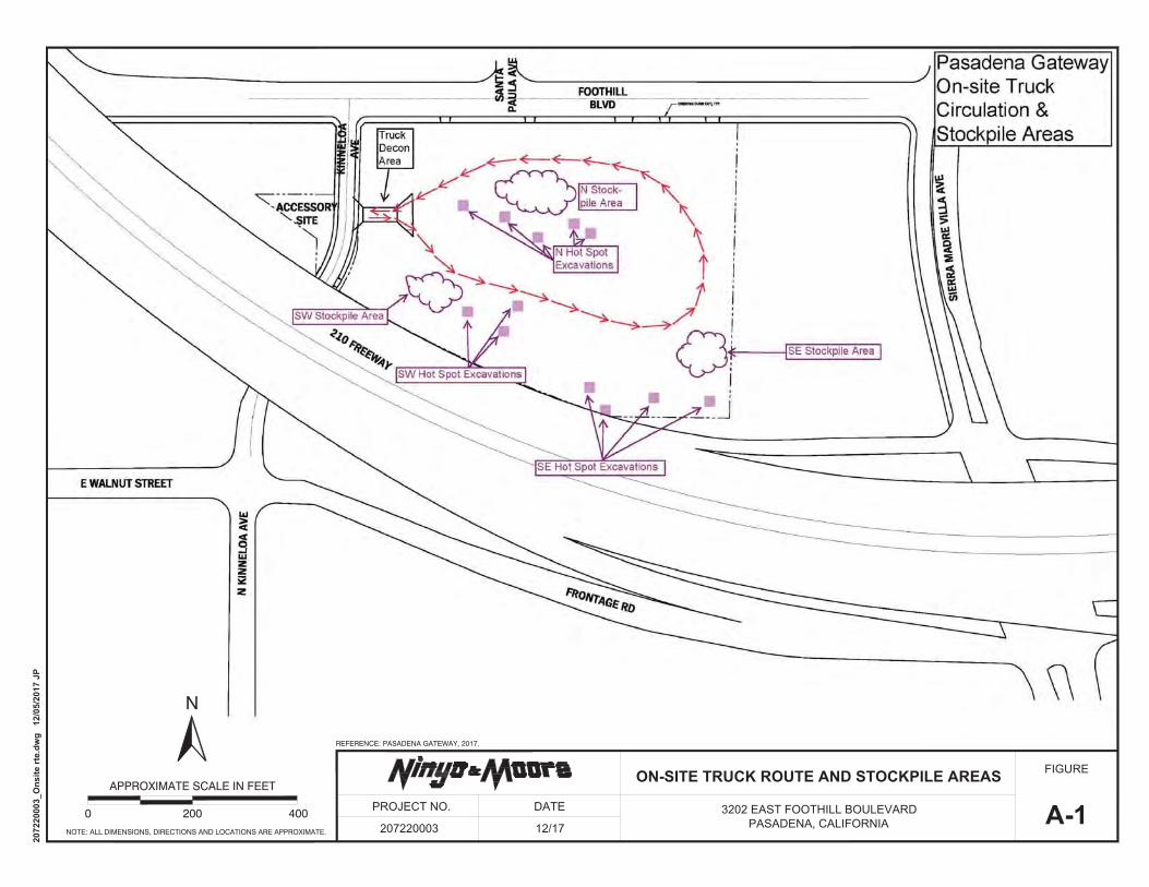
FIGURE
A-1ON-SITE TRUCK ROUTE AND STOCKPILE AREAS
3202 EAST FOOTHILL BOULEVARDPASADENA, CALIFORNIA
PROJECT NO.
207220003
DATE
12/17NOTE: ALL DIMENSIONS, DIRECTIONS AND LOCATIONS ARE APPROXIMATE.
2072
2000
3_O
nsite
rte.
dwg
12/
05/2
017
JP
N
REFERENCE: PASADENA GATEWAY, 2017.
0 200 400
APPROXIMATE SCALE IN FEET
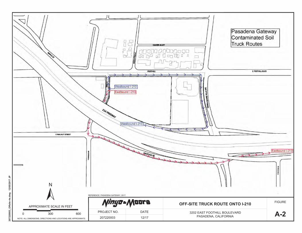
FIGURE
A-2OFF-SITE TRUCK ROUTE ONTO I-210
3202 EAST FOOTHILL BOULEVARDPASADENA, CALIFORNIA
PROJECT NO.
207220003
DATE
12/17NOTE: ALL DIMENSIONS, DIRECTIONS AND LOCATIONS ARE APPROXIMATE.
2072
2000
3_O
ffsite
rte.
dwg
12/
05/2
017
JP
REFERENCE: PASADENA GATEWAY, 2017.
N
0 300 600
APPROXIMATE SCALE IN FEET

Former NIRF Undersea Center December 11, 2017 Pasadena, California Project No. 207220003
207220003 R Trans Plan
APPENDIX A
TRANSPORTATION ROUTES
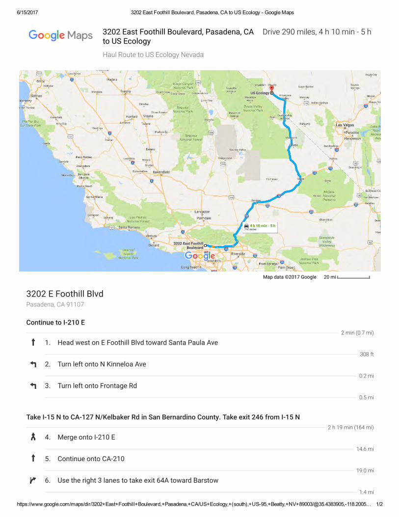
6/15/2017 3202 East Foothill Boulevard, Pasadena, CA to US Ecology - Google Maps
https://www.google.com/maps/dir/3202+East+Foothill+Boulevard,+Pasadena,+CA/US+Ecology,+(south),+US-95,+Beatty,+NV+89003/@35.4383905,-118.2005… 1/2
Map data ©2017 Google 20 mi
Pasadena, CA 911073202 E Foothill Blvd
Continue to I-210 E
1. Head west on E Foothill Blvd toward Santa Paula Ave
2. Turn left onto N Kinneloa Ave
3. Turn left onto Frontage Rd
Take I-15 N to CA-127 N/Kelbaker Rd in San Bernardino County. Take exit 246 from I-15 N
4. Merge onto I-210 E
5. Continue onto CA-210
6. Use the right 3 lanes to take exit 64A toward Barstow
2 min (0.7 mi)
308 ft
0.2 mi
0.5 mi
2 h 19 min (164 mi)
14.6 mi
19.0 mi
1.4 mi
Drive 290 miles, 4 h 10 min - 5 h3202 East Foothill Boulevard, Pasadena, CAto US Ecology
Haul Route to US Ecology Nevada

6/15/2017 3202 East Foothill Boulevard, Pasadena, CA to US Ecology - Google Maps
https://www.google.com/maps/dir/3202+East+Foothill+Boulevard,+Pasadena,+CA/US+Ecology,+(south),+US-95,+Beatty,+NV+89003/@35.4383905,-118.2005… 2/2
These directions are for planning purposes only. You may �nd that construction projects,tra�c, weather, or other events may cause conditions to differ from the map results, and youshould plan your route accordingly. You must obey all signs or notices regarding your route.
(south), US-95, Beatty, NV 89003
7. Merge onto I-15 N
8. Keep left to stay on I-15 N, follow signs for Barstow
9. Keep left at the fork to stay on I-15 N
10. Take exit 246 for CA-127/Kelbaker Rd toward Death Valley
Continue on CA-127 N. Drive to U S Ecology Rd in Nye County
11. Turn left onto CA-127 N/Kelbaker Rd Continue to follow CA-127 N Entering Nevada
12. Continue onto NV-373 N
13. Turn left onto US-95 N
14. Turn left onto U S Ecology Rd Destination will be on the right
US Ecology
7.3 mi
58.8 mi
62.1 mi
0.3 mi
2 h 2 min (126 mi)
90.8 mi
16.3 mi
18.2 mi
0.3 mi

6/15/2017 E Foothill Blvd & N Kinneloa Ave to South Yuma County Landfill - Google Maps
https://www.google.com/maps/dir/E+Foothill+Blvd+%26+N+Kinneloa+Ave,+Pasadena,+CA+91107/South+Yuma+County+Landfill,+19536+South+Avenue+1E,… 1/2
Imagery ©2017 Google, Map data ©2017 Google 1000 ft
Pasadena, CA 91107E Foothill Blvd & N Kinneloa Ave
Continue to I-210 E
1. Head south on N Kinneloa Ave toward E Foothill Blvd
2. Turn left onto Frontage Rd
Take CA-210, I-10 E, CA-86 S and I-8 E to S Avenue 3 E in Yuma County. Take exit 3 from I-8 E
3. Merge onto I-210 E
4. Continue onto CA-210
5. Use the left 2 lanes to take exit 85B for Interstate 10 E toward Indio
6. Merge onto I-10 E
2 min (0.7 mi)
0.1 mi
0.5 mi
4 h 6 min (268 mi)
14.6 mi
41.0 mi
0.9 mi
66.3 mi
Drive 281 miles, 4 h 10 min - 5 h 20 minE Foothill Blvd & N Kinneloa Ave toSouth Yuma County Land�ll
Haul Route to South Yuma County Land�ll

6/15/2017 E Foothill Blvd & N Kinneloa Ave to South Yuma County Landfill - Google Maps
https://www.google.com/maps/dir/E+Foothill+Blvd+%26+N+Kinneloa+Ave,+Pasadena,+CA+91107/South+Yuma+County+Landfill,+19536+South+Avenue+1E,… 2/2
These directions are for planning purposes only. You may �nd that construction projects,traբc, weather, or other events may cause conditions to differ from the map results, and youshould plan your route accordingly. You must obey all signs or notices regarding your route.
19536 South Avenue 1E, Yuma, AZ 85365
7. Keep right to continue on CA-86 S, follow signs for Brawley/El Centro/865 Expy
8. Turn left onto CA-78
9. Continue onto CA-111 S
10. Take the exit onto I-8 E toward Yuma Entering Arizona
11. Take exit 3 for Avenue 3 E toward AZ-280 S
Continue on S Avenue 3 E to your destination
12. Use the right 2 lanes to turn right onto S Avenue 3 E
13. Turn right onto E County 19th St
14. Turn left at S Avenue 1 E Destination will be on the right
South Yuma County Land�ll
66.6 mi
6.3 mi
14.3 mi
57.7 mi
0.3 mi
18 min (11.9 mi)
9.4 mi
2.0 mi
0.5 mi
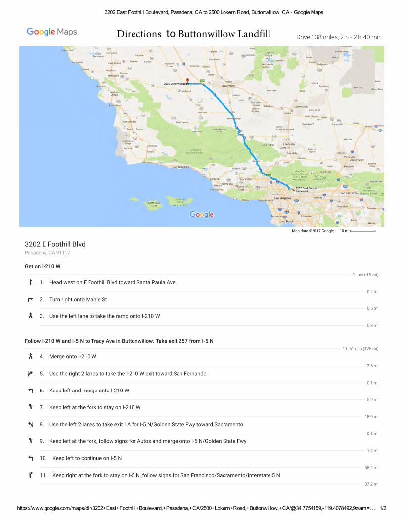
3202 East Foothill Boulevard, Pasadena, CA to 2500 Lokern Road, Buttonwillow, CA - Google Maps
https://www.google.com/maps/dir/3202+East+Foothill+Boulevard,+Pasadena,+CA/2500+Lokern+Road,+Buttonwillow,+CA/@34.7754159,-119.4078492,9z/am=… 1/2
Map data ©2017 Google 10 mi
Pasadena, CA 911073202 E Foothill Blvd
Get on I-210 W
1. Head west on E Foothill Blvd toward Santa Paula Ave
2. Turn right onto Maple St
3. Use the left lane to take the ramp onto I-210 W
Follow I-210 W and I-5 N to Tracy Ave in Buttonwillow. Take exit 257 from I-5 N
4. Merge onto I-210 W
5. Use the right 2 lanes to take the I-210 W exit toward San Fernando
6. Keep left and merge onto I-210 W
7. Keep left at the fork to stay on I-210 W
8. Use the left 2 lanes to take exit 1A for I-5 N/Golden State Fwy toward Sacramento
9. Keep left at the fork, follow signs for Autos and merge onto I-5 N/Golden State Fwy
10. Keep left to continue on I-5 N
11. Keep right at the fork to stay on I-5 N, follow signs for San Francisco/Sacramento/Interstate 5 N
2 min (0.9 mi)
0.2 mi
0.5 mi
0.3 mi
1 h 51 min (125 mi)
2.5 mi
0.1 mi
5.9 mi
18.9 mi
0.6 mi
1.2 mi
58.4 mi
37.2 mi
Drive 138 miles, 2 h - 2 h 40 minDirections to Buttonwillow Landfill

3202 East Foothill Boulevard, Pasadena, CA to 2500 Lokern Road, Buttonwillow, CA - Google Maps
https://www.google.com/maps/dir/3202+East+Foothill+Boulevard,+Pasadena,+CA/2500+Lokern+Road,+Buttonwillow,+CA/@34.7754159,-119.4078492,9z/am=… 2/2
Buttonwillow, CA 93206
12. Take exit 257 toward CA-58/Buttonwillow/McKitrick
Follow CA-58 W to Lokern Rd
13. Turn right onto Tracy Ave
14. Turn right onto CA-58 W
15. Turn right onto Lokern Rd Destination will be on the right
2500 Lokern Rd
0.2 mi
15 min (12.4 mi)
0.3 mi
8.0 mi
4.1 mi

https://www.google.com/maps/dir/3202+East+Foothill+Boulevard,+Pasadena,+CA/1211+West+Gladstone+Street,+Azusa,+CA/@34.1285153,-118.0397067,13z… 1/2
Map data ©2017 Google 1 mi
Pasadena, CA 911073202 E Foothill Blvd
Get on I-210 E
1. Head east on E Foothill Blvd toward Sierra Madre Villa Ave
2. Turn right at the 1st cross street onto Sierra Madre Villa Ave
3. Use the left 2 lanes to turn left to merge onto I-210 E
Follow I-210 E to Irwindale Ave in Irwindale. Take exit 38 from I-210 E
4. Merge onto I-210 E
5. Use the right lane to take exit 38 for Irwindale Avenue
Follow Irwindale Ave and W Gladstone St to S Mira Loma Dr in Azusa
6. Use the right 2 lanes to turn right onto Irwindale Ave (signs for Santa Fe Dam)
7. Use the left 2 lanes to turn left onto W Gladstone St
8. Turn left onto S Mira Loma Dr Partial restricted usage road Destination will be on the left
1211 W Gladstone St
2 min (0.6 mi)
0.1 mi
0.2 mi
0.2 mi
8 min (8.6 mi)
8.4 mi
0.2 mi
4 min (1.7 mi)
1.0 mi
0.6 mi
338 ft
Drive 10.8 miles, 12-20 min
3202 East Foothill Boulevard, Pasadena, CA to 1211 West Gladstone Street, Azusa, CA
Directions to Azusa Landfill
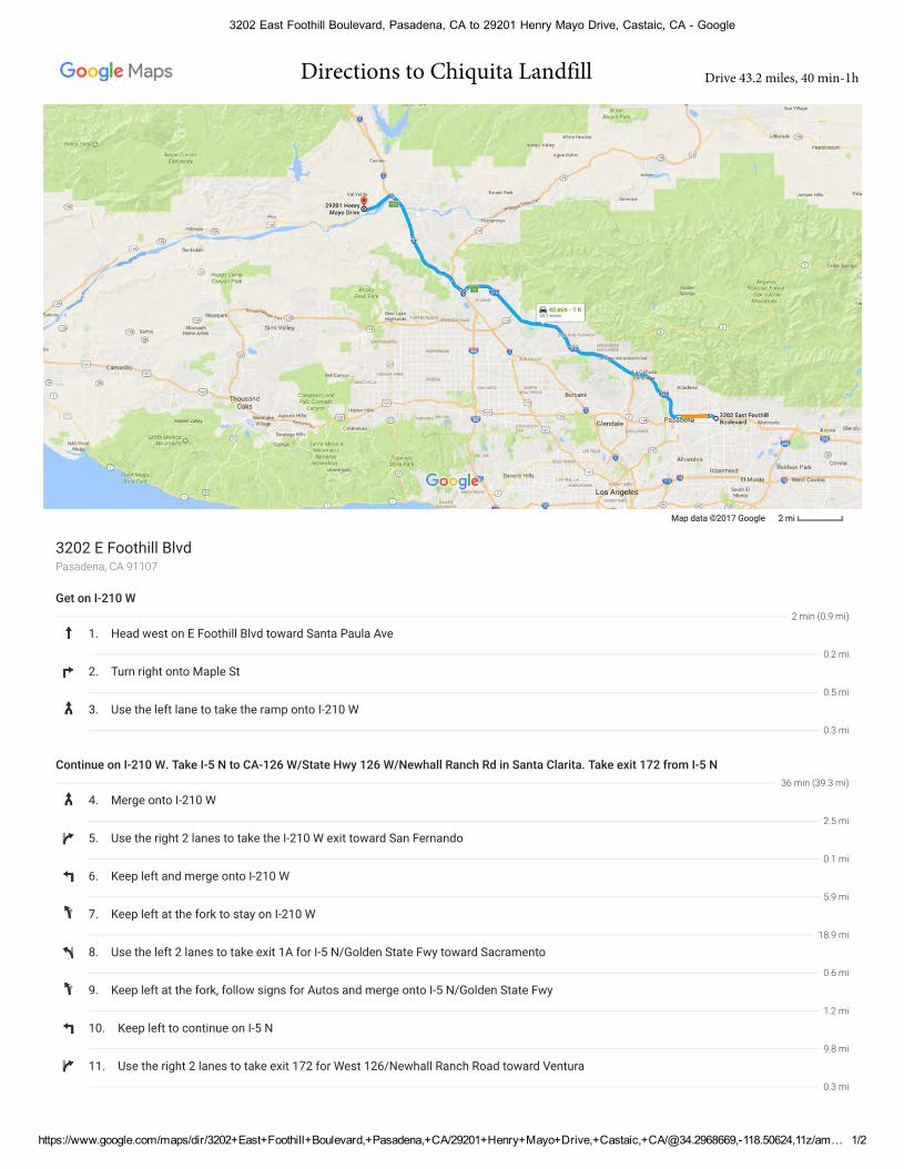
https://www.google.com/maps/dir/3202+East+Foothill+Boulevard,+Pasadena,+CA/29201+Henry+Mayo+Drive,+Castaic,+CA/@34.2968669,-118.50624,11z/am… 1/2
Map data ©2017 Google 2 mi
Pasadena, CA 911073202 E Foothill Blvd
Get on I-210 W
1. Head west on E Foothill Blvd toward Santa Paula Ave
2. Turn right onto Maple St
3. Use the left lane to take the ramp onto I-210 W
Continue on I-210 W. Take I-5 N to CA-126 W/State Hwy 126 W/Newhall Ranch Rd in Santa Clarita. Take exit 172 from I-5 N
4. Merge onto I-210 W
5. Use the right 2 lanes to take the I-210 W exit toward San Fernando
6. Keep left and merge onto I-210 W
7. Keep left at the fork to stay on I-210 W
8. Use the left 2 lanes to take exit 1A for I-5 N/Golden State Fwy toward Sacramento
9. Keep left at the fork, follow signs for Autos and merge onto I-5 N/Golden State Fwy
10. Keep left to continue on I-5 N
11. Use the right 2 lanes to take exit 172 for West 126/Newhall Ranch Road toward Ventura
2 min (0.9 mi)
0.2 mi
0.5 mi
0.3 mi
36 min (39.3 mi)
2.5 mi
0.1 mi
5.9 mi
18.9 mi
0.6 mi
1.2 mi
9.8 mi
0.3 mi
Drive 43.2 miles, 40 min-1h
3202 East Foothill Boulevard, Pasadena, CA to 29201 Henry Mayo Drive, Castaic, CA Google
Directions to Chiquita Landfill
3202 East Foothill Boulevard, Pasadena, CA to 29201 Henry Mayo Drive, Castaic, CA - Google Maps
https://www.google.com/maps/dir/3202+East+Foothill+Boulevard,+Pasadena,+CA/29201+Henry+Mayo+Drive,+Castaic,+CA/@34.2968669,-118.50624,11z/am… 2/2
Castaic, CA 91384
Follow CA-126 W/State Hwy 126 W to your destination
12. Use the left 3 lanes to turn left onto CA-126 W/State Hwy 126 W/Newhall Ranch Rd Continue to follow CA-126 W/State Hwy 126 W
13. Turn right
14. Make a U-turn Destination will be on the right
29201 Henry Mayo Dr
5 min (3.0 mi)
2.9 mi
0.1 mi
56 ft
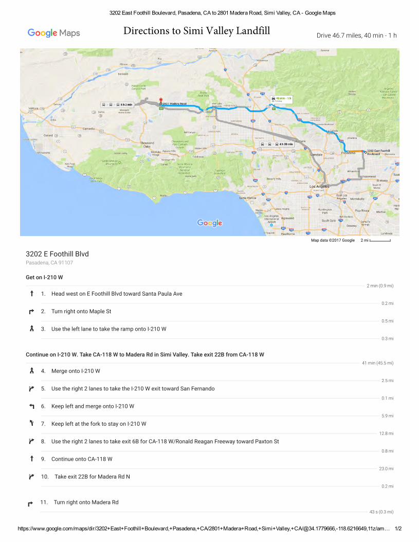
3202 East Foothill Boulevard, Pasadena, CA to 2801 Madera Road, Simi Valley, CA - Google Maps
https://www.google.com/maps/dir/3202+East+Foothill+Boulevard,+Pasadena,+CA/2801+Madera+Road,+Simi+Valley,+CA/@34.1779666,-118.6216649,11z/am… 1/2
Map data ©2017 Google 2 mi
Pasadena, CA 911073202 E Foothill Blvd
Get on I-210 W
1. Head west on E Foothill Blvd toward Santa Paula Ave
2. Turn right onto Maple St
3. Use the left lane to take the ramp onto I-210 W
Continue on I-210 W. Take CA-118 W to Madera Rd in Simi Valley. Take exit 22B from CA-118 W
4. Merge onto I-210 W
5. Use the right 2 lanes to take the I-210 W exit toward San Fernando
6. Keep left and merge onto I-210 W
7. Keep left at the fork to stay on I-210 W
8. Use the right 2 lanes to take exit 6B for CA-118 W/Ronald Reagan Freeway toward Paxton St
9. Continue onto CA-118 W
10. Take exit 22B for Madera Rd N
11. Turn right onto Madera Rd
2 min (0.9 mi)
0.2 mi
0.5 mi
0.3 mi
41 min (45.5 mi)
2.5 mi
0.1 mi
5.9 mi
12.8 mi
0.8 mi
23.0 mi
0.2 mi
43 s (0.3 mi)
Drive 46.7 miles, 40 min - 1 hDirections to Simi Valley Landfill

3202 East Foothill Boulevard, Pasadena, CA to 2801 Madera Road, Simi Valley, CA - Google Maps
https://www.google.com/maps/dir/3202+East+Foothill+Boulevard,+Pasadena,+CA/2801+Madera+Road,+Simi+Valley,+CA/@34.1779666,-118.6216649,11z/am… 2/2
Simi Valley, CA 930652801 Madera Rd

Former NIRF Undersea Center December 11, 2017 Pasadena, California Project No. 207220003
207220003 R Trans Plan
APPENDIX B
WASTE MANIFEST INFORMATION
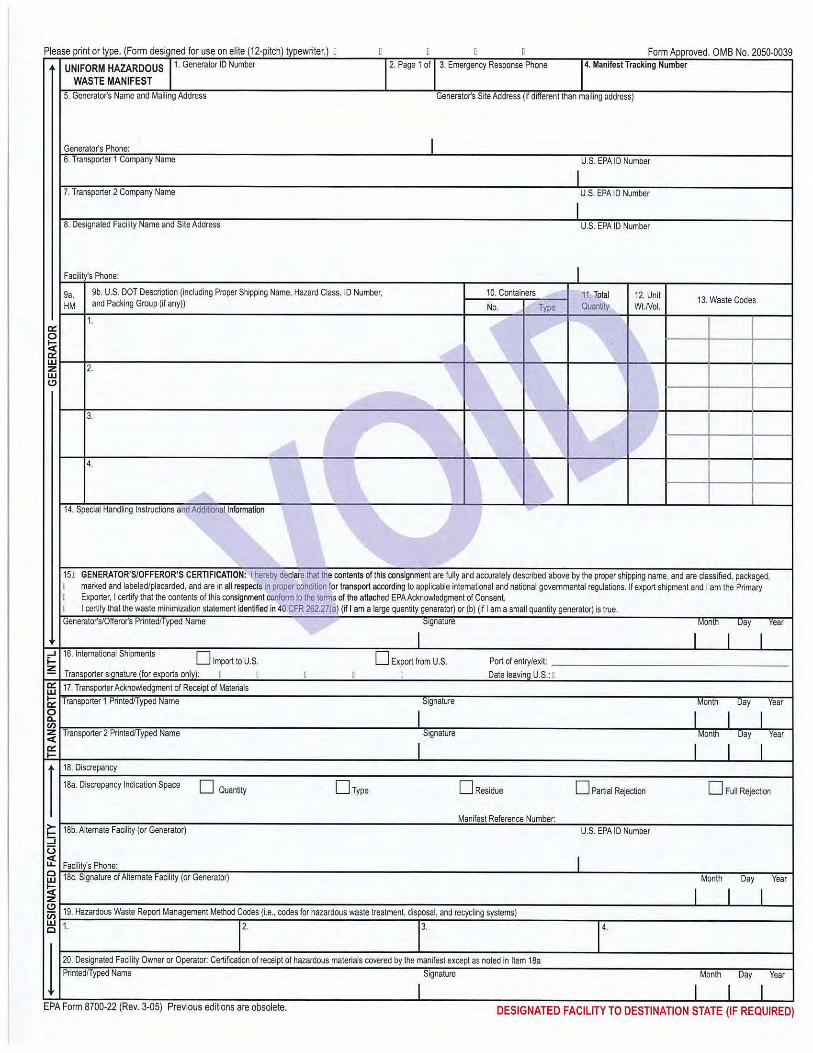


Former NIRF Undersea Center December 11, 2017 Pasadena, California Project No. 207220003
207220003 R RAW
APPENDIX B
SOIL MANAGEMENT PLAN
SOIL MANAGEMENT PLAN FORMER NAVAL INFORMATION RESEARCH
FOUNDATION UNDERSEA CENTER (AKA SPACE BANK MINI STORAGE FACILITY)
3202 EAST FOOTHILL BOULEVARD PASADENA, CALIFORNIA 91107
PREPARED FOR: Pasadena Gateway, LLC
3501 Jamboree Road, Suite 230 Newport Beach, California 92660
PREPARED BY: Ninyo & Moore
Geotechnical and Environmental Sciences Consultants 475 Goddard, Suite 200 Irvine, California 92618
December 11, 2017 Project No. 207220003
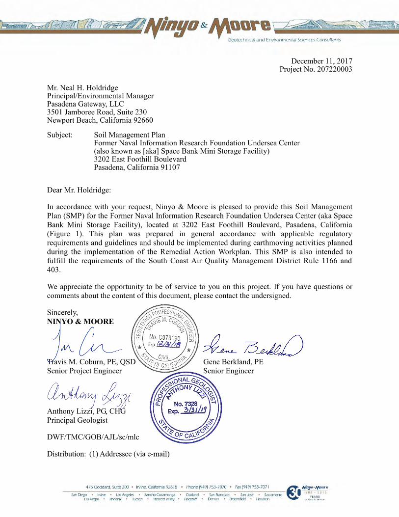
December 11, 2017 Project No. 207220003
Mr. Neal H. Holdridge Principal/Environmental Manager Pasadena Gateway, LLC 3501 Jamboree Road, Suite 230 Newport Beach, California 92660
Subject: Soil Management Plan Former Naval Information Research Foundation Undersea Center (also known as [aka] Space Bank Mini Storage Facility) 3202 East Foothill Boulevard Pasadena, California 91107
Dear Mr. Holdridge:
In accordance with your request, Ninyo & Moore is pleased to provide this Soil Management Plan (SMP) for the Former Naval Information Research Foundation Undersea Center (aka Space Bank Mini Storage Facility), located at 3202 East Foothill Boulevard, Pasadena, California (Figure 1). This plan was prepared in general accordance with applicable regulatory requirements and guidelines and should be implemented during earthmoving activities planned during the implementation of the Remedial Action Workplan. This SMP is also intended to fulfill the requirements of the South Coast Air Quality Management District Rule 1166 and 403.
We appreciate the opportunity to be of service to you on this project. If you have questions or comments about the content of this document, please contact the undersigned.
Sincerely, NINYO & MOORE
Travis M. Coburn, PE, QSD Senior Project Engineer
Gene Berkland, PE Senior Engineer
Anthony Lizzi, PG, CHG Principal Geologist
DWF/TMC/GOB/AJL/sc/mlc
Distribution: (1) Addressee (via e-mail)
Former NIRF Undersea Center December 11, 2017 Pasadena, California Project No. 207220003
207220003 R SMP i
TABLE OF CONTENTS
Page 1. INTRODUCTION ....................................................................................................................1
2. SITE DESCRIPTION ...............................................................................................................2
3. OWNERSHIP AND CONTACT INFORMATION ................................................................3
4. BACKGROUND ......................................................................................................................4 4.1. Historical Site Use from 1928 to 1945 .........................................................................4
4.2. Historical Site Use from 1945 to 1977 (Navy) .............................................................4 4.3. Historical Site Use from 1977 to the Present (Space Bank) .........................................5
5. PREVIOUS SITE ASSESSMENTS.........................................................................................6
6. DEFINITIONS .........................................................................................................................8 6.1. Materials .......................................................................................................................8 6.2. Contaminated Substance ...............................................................................................8
6.3. Hazardous Substance ....................................................................................................8 6.4. Hazardous Waste ..........................................................................................................9
6.5. Competent Person .........................................................................................................9 6.6. Construction Area .........................................................................................................9 6.7. Exclusion Zone ...........................................................................................................10
7. PROJECT TEAM ...................................................................................................................10
7.1. Remedial Contractor ...................................................................................................10
7.2. Site Health and Safety Officer ....................................................................................11 7.3. Subcontractors ............................................................................................................11
7.4. Project EP ...................................................................................................................11 7.5. SCAQMD Rule 1166 Site Monitor ............................................................................11
8. NOTIFICATIONS ..................................................................................................................12
9. HEALTH AND SAFETY PLANS .........................................................................................12
10. SOIL EXCAVATION ............................................................................................................13
11. SEGREGATION AND STOCKPILING ...............................................................................14
12. SOIL REUSE ..........................................................................................................................14
13. STOCKPILE MANAGEMENT .............................................................................................15 13.1. Best Management Practices (BMPs) ..........................................................................16 13.2. Dust Control................................................................................................................17
13.2.1. Real-Time Air Monitoring in Work Area .........................................................17 13.2.2. Site Perimeter Air Monitoring ..........................................................................18
13.3. Odor and Gas Control .................................................................................................19
14. WASTE CHARACTERIZATION .........................................................................................20
Former NIRF Undersea Center December 11, 2017 Pasadena, California Project No. 207220003
207220003 R SMP ii
15. TRANSPORT AND DISPOSAL ...........................................................................................21
16. UPSET CONDITION OR UNKNOWN CONTAMINATION .............................................22
17. DOCUMENTATION .............................................................................................................22
18. LIMITATIONS .......................................................................................................................23
19. REFERENCES .......................................................................................................................24
Tables Table 1 – Former Naval Information Research Foundation Under Sea Center Hot-Spot and
Storm Drain System Excavation Totals
Figures Figure 1 – Site Location Figure 2 – Site Plan Figure 3 – Hot-Spots (Including Seepage Pits)
Appendices Appendix B-1 – SCAQMD Rule 1166, Volatile Organic Emissions from Decontamination of Soil Appendix B-2 – SCAQMD Rule 403, Fugitive Dust Appendix B-3 – SCAQMD Rule 1466, Control of Particulate Emissions from Soils with Toxic
Air Contaminants

Former NIRF Undersea Center December 11, 2017 Pasadena, California Project No. 207220003
207220003 R SMP 1
1. INTRODUCTION
This soil management plan (SMP) has been prepared to present the protocols for excavation,
temporary stockpiling, storage, handling, and disposal of soil and debris-laden materials
generated during remediation activities within the Former Naval Information Research
Foundation Undersea Center, also known as (aka) the Space Bank Mini Storage Facility (site),
located at 3202 East Foothill Boulevard, Pasadena, California (Figure 1).
The site was formerly used by the United States Navy (Navy) for scientific research and testing.
Based on information from multiple historical environmental investigations conducted at the site,
sediments within multiple seepage pits as well as soil samples from borings were found to
contain elevated levels of various metals, volatile organic compounds (VOCs), and polycyclic
aromatic hydrocarbons (PAHs). Additionally, soil vapor beneath the site contains elevated
concentrations of VOCs such as tetrachloroethylene (PCE) and carbon tetrachloride. Special
precautions must be taken during earthmoving activities, including during the excavation and
stockpiling of contaminated soil. These precautions are detailed in this document, and include:
Site activities will be performed under a site-specific health and safety plan (HASP).
On-site workers who perform any activities that require contact with, or potential exposure to, hazardous wastes must possess current Occupational Safety and Health Administration (OSHA) 40-hour hazardous waste operations and emergency response (HAZWOPER) training in accordance with California Code of Regulations (CCR), Title 8, Section 5192 and 29 Code of Federal Regulations (CFR) 1910.120.
Site sampling data indicates that potential health risks due to exposure to contaminated materials is low for site workers and the public, however, the site will be monitored by qualified professionals to ensure that such risks are minimized.
Earthmoving activities conducted where VOCs have been identified to be present must be conducted under a South Coast Air Quality Management District (SCAQMD) Rule 1166 plan. Said Rule 1166, Volatile Organic Compounds from Soil Decontamination plan is contained in this document as Appendix A.
Earthmoving activities conducted at the site must also be conducted under SCAQMD Rules 401, 402 and 403 (Visible Emissions, Nuisance, and Fugitive Dust). Rule 403 Fugitive Dust will apply during soil handling and/or excavations in order to reduce or mitigate fugitive dust emissions. A copy of Rule 403 is contained in Appendix B.

Former NIRF Undersea Center December 11, 2017 Pasadena, California Project No. 207220003
207220003 R SMP 2
Hazardous materials disposed of off-site must be transported under a hazardous materials transportation plan in accordance with the Transportation Safety Act, Hazardous Material Transportation Act, Title 49 CFR Parts 106, 107, and 171-179.
Each company performing work on the site must possess a comprehensive site-specific HASP prepared in accordance with CCR, Title 8, Section 5192 and 29 CFR 1910.120.
Should excavations greater than 4 feet in depth require personnel entry for any reason, a Competent Person in accordance with CCR, Title 8, Section 1541 will evaluate the potential hazards associated with the entry including atmospheric hazards, prior to entry.
2. SITE DESCRIPTION
The site is approximately 9.15-acres located at 3202 East Foothill Boulevard in Pasadena,
California (Figure 1) and including the small parcel west of North Kinneloa Avenue (former
Titley Avenue). North Kinneloa Avenue bisects the western portion of the site from north to
south. The site is bound to the north by East Foothill Boulevard and to the south by the Interstate
210 (I-210) freeway which is separated from the site by a retaining wall and sound wall. Off-site
to the east, the site is bound by a Kaiser Permanente medical office building. Off-site to the west
of Building 30 and adjacent to the north of the Kinneloa parcel is a pest control company. Further
west of the pest control company is I-210 Freeway followed by a warehouse structure.
Buildings and other important features of the site are depicted in Figure 2. A small, roughly
triangular shaped parcel located on the west side of North Kinneloa Avenue is included as part of
the site (the Kinneloa parcel). The site is currently occupied by numerous World War II era
former Navy buildings that have been divided into small storage units and small commercial
businesses. Most of the buildings on site are one or two story, primarily metal and wood framed
structures typical of old buildings found on a United States military facility. Building 30 is a two-
story, concrete tilt-up, steel framed structure built in the 1970s as a replacement building for one
that was demolished to accommodate the construction of the I-210 Freeway. All areas of the site
outside of the building footprints are asphalt or concrete paved with the exception of a small
landscaped area surrounding Building 30 on the north and west sides (adjacent to city streets)
and small planter areas south of Buildings 9 and 10.
Former NIRF Undersea Center December 11, 2017 Pasadena, California Project No. 207220003
207220003 R SMP 3
3. OWNERSHIP AND CONTACT INFORMATION
The site is owned by Space Bank, Ltd. (Space Bank), a limited partnership between Mr. Robert
Oltman and Ms. Margaret Schubert. Site contact information is provided as followed:
Table 1 – Site Contact Information
Project Party Company Contact Names Address Contact #
Site Owner Space Bank, Ltd. Mr. Robert Oltman and Ms. Margaret Schubert
3202 E. Foothill Blvd. Pasadena, California 91107
(626) 449-4405
Project Proponent Pasadena Gateway, LLC Mr. Neal Holdridge
3501 Jamboree Road, Suite 230 Newport Beach, California 92660
(949) 477-4700
Environmental Consultant Ninyo & Moore
Mr. Gene Berkland and Mr. Anthony Lizzi
475 Goddard, Suite 200 Irvine, California 92618 (949) 753-7070
Certified Industrial Hygienist Ninyo & Moore Mr. Steve Waide 475 Goddard, Suite 200
Irvine, California 92618 (949) 753-7070
Lead Regulatory Agency
Department of Toxic Substances Control Cypress Office
Ms. Angela Garcia 5796 Corporate Avenue Cypress, California 90630 (714) 484-5310
General Contractor TBD TBD TBD TBD Waste Transport TBD TBD TBD TBD Disposal Site TBD TBD TBD TBD
Soil Analytical Laboratory
Enthalpy Analytical (subject to change)
Mr. Ranjit Clarke 931 W. Barkley Avenue Orange, California 92868 (714) 771-9906
Soil Vapor Analytical Laboratory
Jones Environmental (subject to change)
Ms. Carolyn Carroll 11007 Forest Pl. Santa Fe Springs, California 90670 (562) 646-1611
Other Ninyo & Moore site personnel are listed below with any of the listed individuals
potentially may perform multiple roles:
Site Health and Safety Officer (SHSO): Mr. Pedro Rodriguez-Mendez
Project Environmental Professional (EP): Mr. Travis Coburn, PE
Rule 1166 Site Monitor/Site Surveillance Technician: Ms. Kristina Hill
Former NIRF Undersea Center December 11, 2017 Pasadena, California Project No. 207220003
207220003 R SMP 4
4. BACKGROUND
The following sections describe the historical context for the site.
4.1. Historical Site Use from 1928 to 1945
From at least 1928 to the 1950s, the western portion of the site was occupied by several
residences and a church. The remaining area of the site was developed from at least 1928 to
the 1940s with a furniture factory and stone works operation, with the western portion
occupied by private residences. In 1943, the eastern portion of the site was purchased by the
California Institute of Technology. The area west of former Titley Avenue (renamed to
Kinneloa Avenue) was primarily residential use with some commercial use.
4.2. Historical Site Use from 1945 to 1977 (Navy)
Ownership of the site was transitioned over to the Navy in 1945. The site was reportedly
used by the Navy for testing and scientific research work involving classified materials,
torpedoes, and other marine weapon systems. By 1952, the site had been developed by the
Navy with multiple buildings, which included testing laboratories, machine shops, a
foundry, storage buildings (including one for classified materials), a transportation building,
offices, and utility centers. Under the direction of the Navy, military research and
development operations were conducted at the site, primarily involving the design and
testing of underwater weapons systems. The primary focus of the military research was anti-
submarine warfare which included; technology development, submarine-detection systems,
torpedoes, fire control, and delivery systems. The site was utilized in the research and
development and made substantial contributions in submarine warfare underwater weapons
including rocket assisted torpedoes (RATS) the Mk 32 Mod 2, Mk 42, Mk 43, Mk 44, and
Mk 46 torpedoes, the Polaris anti-submarine rocket (ASROC), and submarine rocket
(SUBROC) before operations at the site were phased out in the early 1970s.
Numerous and varied laboratories were identified at the site including; combustion,
chemistry, hydro-propellants, welding, hydrodynamics, structures, metallurgy, experimental
physics, ballistics, and simulator labs. The laboratory operations were primarily associated
with research, development, and testing. The other principal use of the site included

Former NIRF Undersea Center December 11, 2017 Pasadena, California Project No. 207220003
207220003 R SMP 5
material/metal forming and fabrication type operations such as machine shops, foundries,
paint shops (including paint and chemical storage), and assembly rooms to build and modify
prototypes of the various devices (i.e., torpedoes) under research and development at the
site. Navy Public Works also operated out of several buildings at the site and was charged
with maintaining and upgrading the site and equipment. Public Works operations included;
engineering, carpentry, vehicle maintenance, vehicle fueling, wash rack, sanitary sewer,
steam cleaning and various other operations associated with maintaining and supporting the
research and development operations being conducted at the site. Administrative functions
including; offices, cafeteria, library, and a post office were also identified as being present.
No records were discovered with information concerning hazardous substances that may
have been used in the various laboratories. Possible hazardous substances that may have
been associated with the laboratories include; propellants, combustibles, explosives,
solvents, and fuels. The numerous machine shops at the facilities would likely have used
more conventional type hazardous substances such as; degreasers, solvents, cutting oils, and
petroleum products. The operations associated with running the site included; vehicle
maintenance, vehicle fueling, a wash rack, and steam cleaning would also have likely used
more conventional hazardous substances such as degreasers, petroleum products, and
solvents. The area west of former Titley Avenue was primarily residential use with some
commercial use between the 1930s and 1950s. In the 1960s it was developed commercial,
residential, auto repair, and contractor storage. In the 1970s the current Dewey Pest Control
site located off-site to the north of the property was a gas station. That gas station site was
assessed in 1989 but no petroleum products were detected in soil. The portion of the site
west of the former Titley Avenue (now Kinneloa Avenue) does not appear to have ever been
developed for use by Cal Tech and/or the Navy.
4.3. Historical Site Use from 1977 to the Present (Space Bank)
In 1977, the site was purchased by Space Bank, the current owner, from the General
Services Administration of United States Government. Twenty-five former Navy buildings
were converted by Space Bank for use as a mini-storage facility, office space, and small

Former NIRF Undersea Center December 11, 2017 Pasadena, California Project No. 207220003
207220003 R SMP 6
leased commercial tenant spaces. Prior to the sale to Space Bank, several of the former Navy
buildings (primarily Building 7) had been demolished in the early 1970s to make way for the
new I-210 Freeway. Since conversion of the pre-existing Navy buildings to public storage
spaces in 1978 and later, the site buildings containing those small leased tenant spaces have
been occupied by various small commercial businesses including; automotive repair,
woodworking and assembly, welding and metal work, and various other activities under
lease agreement to Space Bank. The small parcel west of former Titley Avenue was
apparently used for contractor storage during this time period.
5. PREVIOUS SITE ASSESSMENTS
Between 1994 and the present, numerous environmental investigations have been conducted at
the site to assess potential impacts from the historical use as a Navy research and testing facility.
The presence of contaminants of potential concern such as; metals, VOCs, total petroleum
hydrocarbons (TPHs), PAHs, dioxins, and polychlorinated biphenyls (PCBs) was investigated in
soils, soil vapor, building materials, and sediment in seepage pits and storm drains. Investigations
were conducted in areas that were known to have been used by the Navy for suspect activities,
such as weapons testing, laboratories, and chemical storage. Based on the results of the
investigations, several hot-spots have been identified at the site where impacts are above
published cleanup standards and require remediation. The seepage pits and storm drains at the
site in particular contain sediment with high levels of various contaminants, primarily metals.
The following is a list of the historical environmental investigations. Detailed descriptions of the
historical environmental investigations are provided in the Remedial Investigation Feasibility
Study Report (Ninyo & Moore, 2017a).
Tetra Tech, Inc. (Tetra Tech), Space Bank, Ltd., Phase I Environmental Site Assessment Final Report, dated February 10, 1994
Tetra Tech, Space Bank, Ltd., Final Phase II Work Plan, dated May 1994
Maness Corporation (Maness), Underground Storage Tank (UST) Closure Report, Removal and Disposal of One 2,000-Gallon and Two 200-Gallon USTs, Naval Information Research Facility (NIRF) (Under Sea Center) 3202 East Foothill Boulevard, Pasadena, California, dated October 1998
Former NIRF Undersea Center December 11, 2017 Pasadena, California Project No. 207220003
207220003 R SMP 7
United States Army Corps of Engineers (USACE), Draft Site Investigation Report, NIRF Under Sea Center Site Inspection, Pasadena, California,” Prepared by United States Army Corps of Engineers, dated June 1999
Science Application International Corporation (SAIC), Draft Site Investigation Report, NIRF Under Sea Center, dated July 2002
SAIC, Non-Point Source Pollution of Storm water Drainage System, NIRF Under Sea Center, dated December 2003
USACE, Draft Final Preliminary Endangerment Assessment Report, NIRF Undersea Center, USACE, dated August 2005
SECOR International (SECOR), Draft Expedited Phase I Environmental Site Assessment, Space Bank Mini Storage, dated December 9, 2005
SECOR, Expedited Phase II ESA Report, dated February 1, 2006
SECOR, Pre-Demolition Hazardous Materials Assessment Report, Space Bank Mini-Storage, dated February 23, 2006
Innovative Technical Solutions, Inc. (ITSI), Draft Site-Specific Work Plan Focused Site Investigation Preliminary Environmental Assessment, dated March 2006
SECOR, Workplan for Additional Soil/Soil Vapor Investigation, dated March 29, 2006
SECOR, Final Expedited Phase I Environmental Site Assessment, Space Bank Mini Storage, dated March 30, 2006
ITSI, Draft Final Focused Site Investigation, Preliminary Environmental Assessment (PEA), dated August 2006
ITSI, Final Focused Site Investigation, NIRF, dated November 2006
Kennedy/Jenks Consultants (K/J), Soil Vapor Survey Report, Former NIRF Site/Space Bank, dated April 13, 2007
K/J, Environmental Summary Report, Former NIRF Site/Space Bank, dated May 22, 2007
Ninyo & Moore, Addendum to the SECOR Workplan, Space Bank Mini Storage, dated August 24, 2007
Ninyo & Moore, Draft Final Phase I Environmental Site Assessment, Space Bank Mini Storage Facility, dated April 17, 2008

Former NIRF Undersea Center December 11, 2017 Pasadena, California Project No. 207220003
207220003 R SMP 8
Ninyo & Moore, Draft Letter Report for Mapping Hot-spots, Preliminary Human Health Risk, Space Bank Mini Storage Facility, dated September 10, 2015
Ninyo & Moore, Draft Hexavalent Chromium Evaluation Report, Space Bank Mini Storage Facility, dated March 9, 2016
6. DEFINITIONS
Definitions of key terms used in this SMP are provided in the following sections.
6.1. Materials
For purposes of this plan, the term “materials” refers to soils, wastes, debris, and/or other
surficial and subsurface materials that may be encountered during the planned excavations.
6.2. Contaminated Substance
In the context of this plan, a contaminated substance is one that contains a substance, or
substances, at concentrations that would: require special training, handling, or the use of
personal protective equipment; restrict the end use to protect human health or the
environment; be subject to local, state, or federal regulatory requirements; or necessitate an
environmentally-related monetary surcharge for handling, transportation, or disposition.
Protective measures and equipment to reduce or prevent exposures from contaminated
substances that may be generated or encountered during this project will be specified in the
HASP.
6.3. Hazardous Substance
The Comprehensive Environmental Response, Compensation, and Liability Act ,(CERCLA) Section 101(14), as amended, defines "hazardous substance" by referencing other environ-mental statutes, including:
Clean Water Act (CWA) Sections 311 and 307(a); Clean Air Act (CAA) Section 112; Resource Conservation and Recovery Act (RCRA) Section 3001; and Toxic Substances Control Act (TSCA) Section 7.
There are currently about 800 CERCLA hazardous substances.

Former NIRF Undersea Center December 11, 2017 Pasadena, California Project No. 207220003
207220003 R SMP 9
6.4. Hazardous Waste
A California-hazardous waste is a contaminated substance that meets the definition of
hazardous waste as defined in the CCR, Title 22 Sections 66261.20 through 66261.24. A
Resource Conservation and Recovery Act (RCRA)-hazardous waste (federal) is a
contaminated substance that meets the definition of hazardous waste as defined in 40
CFR Part 261.
Based on the results of the past environmental investigations, it is likely that some excavated
materials will be characterized as RCRA hazardous waste and some as non-RCRA
(California) hazardous waste. Figure 3 displays hot-spot locations, including seepage pits
and storm drains, where the hazardous waste is most likely to be encountered.
6.5. Competent Person
OSHA defines a Competent Person as one who is capable of identifying existing and
predictable hazards in the surroundings or working conditions which are unsanitary,
hazardous, or dangerous to employees, and who has authorization to take prompt corrective
measures to eliminate them. The Competent Person will take specific actions to protect site
workers, Contractor personnel, persons working in the vicinity of the project area, and the
general public. The competent person will have demonstrated knowledge of, and
professional experience in the observation and documentation of environmental excavating
activities; environmental and geologic conditions in the project area; and recognition of, and
testing for, hazardous materials and conditions. The competent person will have current
OSHA training and certificates, and the authority to respond to changed conditions.
Typically, the competent person will be a state-licensed geologist, engineer, or safety and
health professional with sufficient knowledge of environmental regulations and local
conditions and, or a person working under the direct supervision of such a geologist,
engineer or safety and health professional. The Competent Person may also be the SHSO.
6.6. Construction Area
For the purpose of this SMP, the term “construction area” refers to areas in the vicinity of
earthwork activities. This SMP covers the entire site. Work performed shall be in compliance

Former NIRF Undersea Center December 11, 2017 Pasadena, California Project No. 207220003
207220003 R SMP 10
with the project specifications in this SMP and other project plans, as well as applicable
local, state, and federal regulations.
6.7. Exclusion Zone
For the purpose of this SMP, the term “exclusion zone” refers to the immediate area where
soils/materials will be disturbed during remediation-related earthwork activities within the
limits of the facility. Exclusion zones will be established at each of the hot-spot areas during
their respective excavations.
7. PROJECT TEAM
This section describes the project team relevant to the excavation and handling of wastes on the
site, and the re-use of non-contaminated materials. One person may perform multiple roles if
he/she meets the qualification requirements and project activities do not demand the attention of
more than one person.
7.1. Remedial Contractor
The Contractor shall be responsible for project construction and site health and safety in
accordance with project documents. The Contractor shall prepare an HASP for the
protection and safety of Contractor personnel. The Contractor HASP (CHASP) shall list the
various safety-related Contractor personnel and their duties and responsibilities. The
Contractor will also comply with the Project HASP prepared under direction of the
environmental consultant’s CIH, with both HASP’s being in relative conformance to one
another. The Contractor shall be responsible for assigning qualified personnel to execute the
work, and for selecting and supervising the work of other subcontractors assigned to the
project. The Contractor shall provide a site superintendent, who will be responsible for site
activities and health and safety in accordance with their CHASP. The site superintendent’s
responsibilities will include oversight of equipment, labor, materials, and resources needed
to complete the project. The Contractor and/or their subcontractors will have the required
licenses and certifications for hazardous substances removal and remedial actions, as
applicable.
Former NIRF Undersea Center December 11, 2017 Pasadena, California Project No. 207220003
207220003 R SMP 11
7.2. Site Health and Safety Officer
The SHSO, will be a CIH, or work under the direct supervision of a CIH, with the
appropriate training, certificates, and experience. The SHSO for the project may also be the
designated Competent Person. The SHSO shall implement and enforce the project HASP for
the protection of the health and safety of project personnel, and the community from
exposure to contaminated substances. The SHSO has stop-work authority and will specify
appropriate personal protective equipment (PPE) based on site conditions.
7.3. Subcontractors
The Contractor may use subcontractors retained to execute subtasks of this project. The
supervision, inspection, and approval of subcontractor work will be the responsibility of the
Contractor.
7.4. Project EP
The project EP will observe and provide opinions on the environmental aspects of the
project and Contractor’s work, and shall be a state-licensed civil engineer, geologist, or a
certified engineering geologist or work under the direct supervision of the state-licensed
professional. The project EP will demarcate the hot spot areas to be excavated, monitor the
progress of those excavations, collect confirmatory soil samples, and provide
recommendations to the Contractor on the segregation of materials, in accordance with this
SMP.
The project EP shall have the ability to suspend the Contractor’s work in areas of suspected
contaminated waste, and/or to recommend and direct action to further evaluate, delineate or
remediate such areas, and limit exposure to on-site and off-site receptors. The EP will
recommend and direct modifications to the Contractor’s work, if necessary, (e.g., increased
dust control measures) if suspected exposure to on-site and off-site receptors occurs.
7.5. SCAQMD Rule 1166 Site Monitor
A qualified SCAQMD Rule 1166 site monitor will monitor earthmoving activities as
described in the Rule 1166 Various Locations Permit.

Former NIRF Undersea Center December 11, 2017 Pasadena, California Project No. 207220003
207220003 R SMP 12
8. NOTIFICATIONS
The DTSC is the lead regulatory agency for the project and will be notified prior to the
commencement of excavation. The DTSC may conduct periodic site inspections during the
implementation of the Remedial Action Workplan (RAW) to ensure the proper management of
solid waste and the protection of human health in accordance with applicable portions of CCR
Title 27. Prior to disturbing material that may contain VOCs, or that has the potential to release
fugitive dust, the SCAQMD will be notified, as per Rule 1166 and Rule 402/403. The Contractor
will provide relevant notifications to the project EP as needed. The project EP will notify the
DTSC or SCAQMD when applicable, as well as other involved parties including the site owner
and project proponent.
9. HEALTH AND SAFETY PLANS
The project HASP will be implemented and enforced during the RAW. The project HASP has
been prepared by Ninyo & Moore, and reviewed by the DTSC. The project HASP provides
contingencies, to handle a variety of health and safety situations that may arise during remedial
activities, but also provides specific procedures for known or expected hazards to protect site
workers and reduce the level of health and safety risk. Site personnel working within exclusion
zones shall be trained, and current in their certifications, in accordance with the standards
provided by HAZWOPER (40-hour initial training with annual updates). Supervisory personnel
shall have eight-hour supervisor training. Additional training may be required for personnel
engaged in specialized tasks, as appropriate.
The Contractor will also provide their own CHASP to protect Contractor personnel during
remediation activities. Prior to site mobilization, the Contractor will provide their CHASP to the
SHSO for review and approval. The plan will provide policies, information, requirements, and
guidelines to be followed while conducting excavation activities, temporary stockpiling/storage,
and handling. The SHSO will provide notice to the Contractor if the CHASP is inconsistent with
site health and safety requirements as indicated in the project HASP. The CHASP shall be
prepared in accordance with the federal and state OSHA HAZWOPER Standards: 29 CFR
1910.120 and 8 CCR Section 5192.

Former NIRF Undersea Center December 11, 2017 Pasadena, California Project No. 207220003
207220003 R SMP 13
Contractor field personnel shall be required to review the project HASP and provide written
acknowledgement of their review and understanding of the plan and willingness to abide by its
requirements. In addition, the SHSO and Contractor will perform a daily tailgate safety meeting
held at the beginning of each workday to discuss relevant task-specific safety issues pertinent to
that day’s planned work.
10. SOIL EXCAVATION
Earth-moving activities to be conducted at the site include excavation of hot-spot areas, as well
as attendant overburden soils over or around the hot spots. These hot-spot areas are identified in
Table 8 and Figure 7 of the RAW. The seepage pits and storm drain system at the site also
contain chemicals of potential concern (COPCs) and will be excavated and removed under the
RAW. Preliminary calculations indicate approximately 31,175 cubic feet of soil associated with
the hot-spots and storm drain system are to be excavated under the RAW. Of the 30,125 cubic
feet of excavated soil approximately 8,315 cubic feet (462 tons) is estimated as non-RCRA
hazardous soil, 785 cubic feet (44 tons) is estimated as RCRA hazardous soil. The rest of the
excavated soil is expected to be clean overburden soil (11,038 cubic feet, 613 tons), and solid
non-hazardous waste (11,038 cubic feet, 613 tons). COPCs associated with the hot-spots and
storm drain system include metals such as lead, arsenic, and mercury, PAHs such as benzo(a)
pyrene, TPH in the diesel carbon chain range, and PCE. As indicated above, the soils from the
excavations will be profiled in four categories, with the following re-use or probable off-site
disposal:
Clean Overburden Soil – Reused On-Site as Construction Fill Material
Solid (non-hazardous) Waste – Disposed of at Class III Landfill
Non-RCRA Hazardous Waste (California Hazardous Waste) – Disposed of at a facility licensed to accept California Hazardous Waste
RCRA Hazardous Waste – Disposed of at Class I Landfill
The Contractor and project EP will coordinate all plans for excavation. The Contractor shall be
responsible for safety, excavation, handling, and temporary stockpiling of materials in
accordance with project requirements, the HASP, the CHASP, this plan, as well as applicable

Former NIRF Undersea Center December 11, 2017 Pasadena, California Project No. 207220003
207220003 R SMP 14
local, state, and federal statutes, regulations, and guidelines. Excavation and handling of waste
materials will be done in a manner that minimizes the exposure of contamination to site
personnel and occupants and to other on-site and off-site areas.
The project EP will observe excavation activities and use appropriate field screening procedures and
indicators to direct the Contractor in segregating the wastes.
11. SEGREGATION AND STOCKPILING
Remedial actions for potentially-contaminated materials include the excavation, segregation, and
temporary stockpiling of suspected hazardous or regulated wastes. Table 8 of the RAW outlines
the various hot-spot locations at the site, including the estimated quantity of non-hazardous and
hazardous waste to be encountered at each hot-spot. Should potentially contaminated soil and/or
waste be encountered in other areas of the project during mass grading, the Contractor shall
notify the project EP and request recommendations for assistance with segregation prior to
continuing further excavation activities in that area. The Contractor shall coordinate with the
project EP the appropriate excavation of “contaminated” and “clean” soils/materials into separate
stockpiles as follows:
“Contaminated” Soils/Materials Stockpile: Based on previous site assessments and on field observations (such as odors, discoloration, photo-ionization detector (PID) readings, and content), soils and/or materials in designated hot-spots are likely contaminated. Sediment inside seepage pits and storm drains at the site are known to have some of the highest contamination concentrations at the site, and will be segregated accordingly.
“Clean” Soil Stockpile: Soils that are not suspected of being contaminated based on the type of soil/material encountered and field indications (such as overburden soil) will be segregated apart from suspected “contaminated” soils. “Clean” stockpiles will field-screened for indicators of contamination through the use of a PID, or submission of samples to an analytical laboratory.
12. SOIL REUSE
Overburden soil that is removed to access subsurface hot-spots is intended for reuse at the site.
Soils located in, and around hot-spot areas, that has the potential for contamination will not be
reused at the site and will be stockpiled separately from overburden soil. The volume and
Former NIRF Undersea Center December 11, 2017 Pasadena, California Project No. 207220003
207220003 R SMP 15
location of overburden soil will be documented, including its removal, segregation, stockpiling,
sampling and eventual reuse during grading. Sampling and analysis of the overburden soil
stockpiles will be conducted to confirm their applicability for reuse. Waste characterization is
discussed further in Section 14.
13. STOCKPILE MANAGEMENT
The staging area and the stockpiles will be managed by the Contractor in accordance with project
specifications, this document, the HASP, the CHASP, and the Storm Water Pollution Prevention
Plan (SWPPP) in Appendix F. The contaminated soils/materials stockpile(s) shall be constructed
and managed to minimize the threat of release of contaminants or soil from the stockpile. The
stockpiling shall be performed in accordance with DTSC and SCAQMD guidelines regarding the
management of temporarily stockpiled soil.
In general, the contaminated stockpiled soil/materials will be:
placed onto a 6 mil visqueen plastic sheeting;
moistened to minimize dust emissions during stockpiling, as necessary;
no higher than the perimeter fence height;
securely covered with a 6-mil visqueen plastic sheeting, when required, to minimize vapor emissions and prevent runoff from rain. Stockpile covering is required when there is a forecast of rain or wind, or Rule 1166 monitoring indicates VOC impacted soil. Contaminated stockpiles that will remain in place overnight will be covered. The plastic will be secured at the base of the stockpile and along the seams of overlapping plastic sheeting with sandbags or equivalent means. Sandbags will be fabricated from woven, ultraviolet-resistant materials that are sufficiently close knit to prevent fines from migrating out through the bag and will weigh between 40 to 60 pounds when filled. Completed stockpiles will remain covered until removed from the site for off-site disposal or reuse;
configured in such a manner that surface water runoff from the stockpile does not carry stockpile material and/or leachate beyond the stockpile perimeter berm;
placed in an on-site staging area. The entire property will be enclosed with an installed chain link fence and entrance gates to prevent unauthorized entry. Signs at entrances will indicate emergency contact telephone numbers; and

Former NIRF Undersea Center December 11, 2017 Pasadena, California Project No. 207220003
207220003 R SMP 16
inspected daily to verify the integrity of the stockpile covers in conformance with the terms of the SCAQMD Rule 403 and Rule 1166 requirements and other applicable local, state, and federal regulations. Gaps, tears, or other deficiencies will be corrected. Emission levels will be verified by daily monitoring using a calibrated PID. Daily records will be kept of stockpile inspections and repairs made.
The “clean” soil stockpiles will be managed in accordance with the Contractors’ SWPPP and
with SCAQMD Rule 403 requirements, and if acceptable based on geotechnical parameters, may
be re-used as fill material.
13.1. Best Management Practices (BMPs)
The Contractor shall implement BMPs to protect the temporary stockpiles from erosion and
storm water run-on and runoff. The BMPs may include, but are not limited to, the following:
erosion control,
storm water drainage control,
secondary containment (as applicable),
fugitive emission control of dust and/or vapors,
wind dispersion control,
spill prevention, and
additional BMPs specified in the SWPPP.
The Contractor shall ensure that water draining from excavated soils/materials will not be
allowed to flow into any existing drainage systems or onto the ground surface unless the
surface is protected with a liner. Water draining from excavated soils/materials, and water
generated from spraying for dust suppression, will be controlled in a manner consistent with
the SWPPP. Surface water runoff will be handled according to the SWPPP and other
pertinent statutes and regulations. The Contractor shall be responsible for implementing
BMPs specified in the SWPPP.
Former NIRF Undersea Center December 11, 2017 Pasadena, California Project No. 207220003
207220003 R SMP 17
13.2. Dust Control
The Contractor will comply with SCAQMD Rules 403 and 1466, which dictate dust control
methods at contaminated sites, including measures to avoid visible dust emissions and
tracking soil to public streets (Section 7.6.3 of the RAW). The Contractor, will monitor
excavation operations for fugitive dust and take such measures, as needed, such as the
application of water or a change in operations or equipment in order to minimize the
generation of dust. Stockpiled soil will be covered with plastic sheeting, or other similar tarp
material, when rain or wind is forecast and if the stockpile will remain for more than 24
hours.
Additionally, due to suspected elevated concentrations of some metals, VOCs, and PAHs in
the soil, special precautions (dust suppression according to Rule 403 and 1466, continuous
upwind and downwind perimeter monitoring, and Rule 1166 air monitoring) will be taken to
prevent potential health risks to on-site workers and visitors, and prevent off-site migration
of dust during soil excavation activities. The air monitoring will be conducted upwind,
downwind and at the exclusion (working) zone of the soil removal activities at
approximately 15 minute intervals using a combination of hand held aerosols monitors
direct reading personal particulate monitor and stationary dust monitors with data loggers.
Daily air monitoring will also be performed at the site and at multiple locations along the
site's perimeter. If the SHSO or EP observes dust from excavations or disturbance of soil,
additional mitigation measures may be directed to be performed. As part of the dust
monitoring activities the project SHSO will conduct real-time air monitoring and site
perimeter air monitoring as needed. Daily wind fluctuations will be considered when
conducting air monitoring. The project SHSO or EP will provide recommendations to the
Contractor if unacceptable dust levels are observed or measured.
13.2.1. Real-Time Air Monitoring in Work Area
Real-time air monitoring will be conducted as needed for workers’ safety during earth-
moving activities and to minimize off-site dust emissions. The total dust action level is
1 milligram per cubic meter (mg/m3) and will be measured with real-time particulate

Former NIRF Undersea Center December 11, 2017 Pasadena, California Project No. 207220003
207220003 R SMP 18
dust monitors. Dust monitors will be used within the work area during operations that
have the potential to generate fugitive dust. Additional monitors may be needed for
workers directly in contact with “contaminated” stockpiled soil/materials, if
recommended by the SHSO or EP. If the action level is exceeded, the contractor will
take actions to suppress site dust to below this level using stockpile management and/or
wind erosion control methods as discussed in the site SWPPP and Rules 403/1466.
When total dust measurements are collected they will be documented at least every hour
in active work areas.
If engineering controls are insufficient to maintain the action level within the work area,
workers may need to wear respirators. Before respirators are used, the project SHSO
will determine if work stoppage is necessary. The use of respirators is only intended to
supplement engineering controls.
13.2.2. Site Perimeter Air Monitoring
Site perimeter air monitoring will be conducted to monitor off-site migration of dust.
Real time dust monitors will also be used for site perimeter air monitoring. The National
Ambient Air Quality Standard (NAAQS) for dust is 50 micrograms per cubic meter
(µg/m3), based on dust particles measuring 10 micrometers or less (PM10). The NAAQS
dust standard, steady for 5 minutes, has been selected as the action level for dust
monitoring activities at the perimeter of the site (difference between upwind and
downwind readings). This is also the action level as specified in SCAQMD Rule 403. In
accordance with the newly adopted SCAQMD Rule 1466, the two-hour average PM10
concentrations from the site shall not exceed 25 µg/m3, where the PM10 concentration is
the absolute difference between the upwind and downwind monitors. If the two-hour
average PM10 concentration exceeds 25 µg/m3, additional dust suppression techniques
must be implemented to reduce the potential for contaminant migration.
When site perimeter air monitoring is occurring, up to three air monitoring stations will
be established around the perimeter of the work site and daily wind fluctuations will be
considered when locating the monitoring stations. An upwind/downwind dust
Former NIRF Undersea Center December 11, 2017 Pasadena, California Project No. 207220003
207220003 R SMP 19
monitoring approach will be implemented with monitoring positions established based
on an ongoing assessment of wind speed and direction. Typically, one monitoring
station will be located upwind and either one or two monitoring stations will be located
downwind of the work area. The real-time and time-weighted average dust
measurements will be checked every 15 minutes at the perimeter monitoring stations.
Wind speed and direction will be documented at least twice daily.
13.3. Odor and Gas Control
During earthmoving activities (e.g., excavating, maintaining stockpiles, loading, and moving
of stockpiles on the site), if there is a potential to generate odors, the Contractor shall
employ odor suppression techniques to mitigate impacts to nearby sensitive receptors
(e.g., businesses, residential communities, general public). The Contractor shall implement
appropriate means and methods, including application of odor suppression techniques and
covering stockpiles and open excavations prior to leaving the site at the end of each
workday.
Because the site has VOC impacts in the subsurface, earthmoving activities will be
conducted in accordance with the Contractor’s SCAQMD Rule 1166 permit. A trained
Rule 1166 site monitor will be on site during earth-moving activities. The Rule 1166 site
monitor will conduct VOC monitoring of soils and material excavated from the active work
area using a PID calibrated to hexane in accordance with the Contractor’s SCAQMD
Rule 1166 permit (i.e., various locations or site-specific permit). The Rule 1166 site monitor
will notify the Contractor if VOCs are measured in excess of the background level of the
work area. Elevated levels of VOCs may warrant further protective action, including
establishing engineering controls to mitigate potential health risks to site workers and
visitors. The Rule 1166 site monitor will notify the Contractor if VOC detection exceeds 50
parts per million by volume (ppmv) above the background level and work will stop until
VOC mitigation action is taken that reduces VOC detection to no more than 10 ppmv above
background levels. If the PID ever detects VOCs greater than 50 ppmv during monitoring,
SCAQMD will be notified within 24 hours. If the PID ever detects VOCs greater than 1,000

Former NIRF Undersea Center December 11, 2017 Pasadena, California Project No. 207220003
207220003 R SMP 20
ppmv, SCAQMD will be notified within one hour. Engineering controls may include the use
of odor suppressing foam, keeping exposed soil damp, and covering with plastic sheeting.
The project EP will make the SCAQMD notifications in accordance with the SCAQMD
Rule 1166 permit. Affected soils will be stockpiled or removed from the site in accordance
with the permit.
14. WASTE CHARACTERIZATION
As described in Section 11, excavated soil from hot-spot locations will be segregated into
“Contaminated” and “Clean” stockpiles. The initial segregation of soils into stockpiles will be
based on historical data, as well as field observations such as staining, odors, and/or PID
measurements. Soil samples will be collected from each stockpile to profile the soil into the
following four categories:
Clean Overburden Soil – Reused On-Site as Construction Fill Material
Solid (non-hazardous) Waste – Disposed of at Class III Landfill
Non-RCRA Hazardous Waste (California Hazardous Waste) – Disposed of at a facility licensed to accept California Hazardous Waste
RCRA Hazardous Waste – Disposed of at Class I Landfill
To determine the waste characterization, soil samples will be collected and submitted to a fixed-
based laboratory for the following chemical analyses:
Metals by EPA Method 6010B/7471A
TPHs by EPA Method 8015M
VOCs by EPA Method 8260B
PAHs by EPA Method 8310
Based on the results for metals in confirmation samples, the EP may order additional analysis for
soluble threshold limit concentration and/or toxicity characteristic leaching procedure as
Former NIRF Undersea Center December 11, 2017 Pasadena, California Project No. 207220003
207220003 R SMP 21
warranted to properly characterize soil waste as non-hazardous, non-RCRA (California)
hazardous, or RCRA hazardous waste.
15. TRANSPORT AND DISPOSAL
Contaminated materials encountered and removed from the site will require transportation and
disposal off site. Transporters and disposal facilities will be appropriately licensed and/or
permitted and properly insured. The management of the transportation and disposal of wastes to
the appropriate treatment, disposal, or recycling facilities will be the responsibility of the
Contractor. The Contractor shall work in accordance with Ninyo & Moore’s Transportation Plan,
provided as Appendix A of the RAW. The Contractor shall prepare waste profiles and manifests
for review and Generator signature, and then forward the manifests to the appropriate
disposal/recycling facility for acceptance. Subsequent to landfill/recycling facility acceptance,
the Contractor shall schedule shipment of the wastes with a licensed transporter.
Vehicles entering the site for loading of wastes slated for disposal shall be tracked by the
Contractor and decontaminated prior to their departure from the site. Care shall be taken to avoid
potentially-contaminated materials being tracked off site.
Hazardous wastes transported off site for disposal or recycling shall be performed in accordance
with Department of Transportation (DOT) Hazardous Material Transportation regulations
49 CFR Parts 171 and 180, 40 CFR Part 262, Subpart B, and Title 22 CCR Section 66262, which
involve packaging, placarding, labeling, and manifesting requirements. Hazardous wastes
transported shall also have appropriate certification notices per 40 CFR Par 268 and Title 22
CCR Section 66268. Personnel having the required DOT-training shall perform DOT-related
functions, if/as required.
Wastes that have been characterized as California-hazardous, but do not exhibit the DOT hazard class
characteristics are not regulated under DOT rules for hazardous materials transportation.

Former NIRF Undersea Center December 11, 2017 Pasadena, California Project No. 207220003
207220003 R SMP 22
16. UPSET CONDITION OR UNKNOWN CONTAMINATION
In the event of a release, which causes a sudden hazard to life or the environment, the Contractor
shall immediately secure the area, call “911” to summon the emergency services, as necessary, and
notify the SHSO, and the project EP of the health and/or environmental risk. The SHSO has the
knowledge and authority to cease any activity contributing to the hazard. The SHSO will be
responsible for subsequent notifications to the appropriate emergency response agencies.
Emergency contact names and numbers to report hazards will be posted at the project site. The
project proponent and DTSC will be notified of site conditions after any emergency notifications.
If previously unknown hazardous substances or conditions are encountered that do not present an
immediate threat to human health or the environment, the Contractor shall immediately notify,
the SHSO, and the project EP. As necessary, the area surrounding the discovery of unknown
contamination will be isolated and secured by the Contractor with markings, fencing, or a
suitable barrier. The project EP and Contractor will evaluate the site condition and determine a
course of action to further assess or remediate the condition. The project EP will notify the
Project Proponent and DTSC on the discovered new site condition and with the recommended
course of action. The Contractor, with the direction and recommendations from the project EP,
will then implement the recommended action (e.g., sampling and analyses, excavation,
segregation, stockpiling, containerization, or other activities, etc.) as warranted.
17. DOCUMENTATION
Following completion of the RAW, the project EP shall prepare a Remedial Action Completion
Report (RACR) summarizing monitoring activities, site observations, locations where
“contaminated” soils/materials were encountered and excavated, and information regarding the
handling and disposal of “contaminated” soils/materials off site. The report will be signed by the
project EP.
More specifically, the report will include the following information:
the volume of material generated during hot-spot excavations,
a site plan detailing the hot-spot and stockpile locations,
Former NIRF Undersea Center December 11, 2017 Pasadena, California Project No. 207220003
207220003 R SMP 23
the results of confirmation sampling and subsequent waste characterization
the volumes of soil transported to licensed disposal facilities
health and safety monitoring records, including dust and VOC vapor monitoring data and procedures used to mitigate odors and dust.
18. LIMITATIONS
This plan has been prepared in general accordance with current regulatory guidelines and the
standard-of-care exercised in preparing similar plans in the project area. No warranty, expressed
or implied, is made regarding the professional opinions presented in this plan. Variations in site
conditions may exist and conditions not observed or described in this plan may be encountered
during subsequent activities. Please also note that this plan did not include an evaluation of
geotechnical conditions or potential geologic hazards.
The environmental interpretations and opinions contained in this plan are based on the results of
laboratory tests and analyses intended to detect the presence and concentration of specific chemical
or physical constituents in samples collected from the subject site, and on work performed by
others. The testing and analyses have been conducted by independent laboratories, which are
certified by the State of California to conduct such tests. Ninyo & Moore has no involvement in, or
control over, such testing and analysis or work performed by others. Ninyo & Moore, therefore,
disclaims responsibility for any inaccuracy in such laboratory results and work performed by
others.
This document is intended to be used only in its entirety. No portion of the document, by itself, is
designed to completely represent any aspect of the project described herein. Ninyo & Moore
should be contacted if the reader requires any additional information, or has questions regarding
content, interpretations presented, or completeness of this document.
This plan is intended exclusively for use by the client. Any use or reuse of the findings,
conclusions, and/or recommendations of this plan by parties other than the client is undertaken at
said parties’ sole risk.
Former NIRF Undersea Center December 11, 2017 Pasadena, California Project No. 207220003
207220003 R SMP 24
19. REFERENCES
Ninyo & Moore, 2017a, Draft Final Remedial Investigation Feasibility Study (RIFS) Former Naval Information Research Foundation Undersea Center, 3202 East Foothill Boulevard, Pasadena, California
Ninyo & Moore, 2017b, Draft Removal Action Workplan, Former Naval Information Research Foundation Undersea Center, 3202 East Foothill Boulevard, Pasadena, California
SITE
FIGURE
1PROJECT NO.
207220003
SITE LOCATIONDATE
2017
0 2,000 4,000
SCALE IN FEET
NOTE: DIMENSIONS, DIRECTIONS AND LOCATIONS ARE APPROXIMATE.
N
2072
2000
3_SL
.dw
g 09
:37:
05
04/1
9/20
17
GK
3202 EAST FOOTHILL BOULEVARDPASADENA, CALIFORNIA
REFERENCE: 7.5 MINUTE USGS TOPOGRAPHIC MAP OF MOUNT WILSON, CALIFORNIA QUADRANGLE, DATED 2015, SCALE 1:24000.
30
10101
4
19
11
68
16 23
5
3
18
17
14
12
21
120
13
103
EAST FOOTHILL BOULEVARD
INTERSTATE 2 1 0
3258
OFFICEBUILDING
3090
TITL
EY
AV
EN
UE
SA
NTA
PA
ULA
3135
PASADENA CITY COLLEGE
PESTICIDECOMPANY
3161
COMMERCIAL/RETAIL/BUSINESSES
3175
3183
3191
3199
3205
3209
3215
3219
3225
3229
3237
3239
3255
3100
STORAGE
3202
TRAILERS
STO
RA
GE
TRA
ILE
RS
STORAGETRAILERS
STO
RA
GE
TRA
ILE
RS
FIGURE
2SITE PLAN
3202 EAST FOOTHILL BOULEVARDPASADENA, CALIFORNIA
PROJECT NO.
207220003
DATE
2017NOTE: ALL DIMENSIONS, DIRECTIONS AND LOCATIONS ARE APPROXIMATE.
0 150 300
APPROXIMATE SCALE IN FEET
LEGEND
SITE BOUNDARY
30
3258
NAVAL INFORMATION RESEARCHFOUNDATION BUILDING DESIGNATION NUMBER
STREET ADDRESS
2072
2000
3_SP
.dw
g 09
:37:
05 0
4/19
/201
7 G
K, J
P
N

NMSD3
V6
7
20
16
3013
9
4
5
17
18
143
1
2
10
12
6 19
23
11
8
15
21
120
101
106107
128
126
103
131
129
16
S7
NMSV6
NMSV7
NMSV8
NMSV15
V10
V11
V15
V16
V18
NMSD1
VD3
VD2
USC-SP-11
USC-SB-103
103-SP01-16LAC-MH01
011-SP01
131-SB01
VD1
OIL WATER SEPARATOR
NMSD2
NMSV10
V19
VD2
V8
3202 EAST FOOTHILL BOULEVARDPASADENA, CALIFORNIA
FIGURE
3PROJECT NO.
207220003
DATE
2017
0 100 200
SCALE IN FEET
NOTE: DIMENSIONS, DIRECTIONS AND LOCATIONS ARE APPROXIMATE.
N
2072
2000
3_H
SSP.
dwg
04/1
9/17
JP
HOT-SPOTS(INCLUDING SEEPAGE PITS)
SB SOIL BORING
SP SEEPAGE PIT
SEEPAGE PIT
LEGEND
J ESTIMATED CONCENTRATION
FT BGS FEET BELOW GROUND SURFACE
HOT SPOT
RED TEXT EXCEEDS SCREENING LEVELS (EPA RSLs, DTSC SLs)
ALL SEEPAGE PITS, INCLUDING SUSPECTED SEEPAGE PITS AREASSUMED TO BE HOT-SPOTS AND WILL BE EXCAVATED.
STORM DRAIN SYSTEM WITH CATCH BASINS(APPROXIMATELY 1,200 LINEAR FEET)

Former NIRF Undersea Center December 11, 2017 Pasadena, California Project No. 207220003
207220003 R SMP
APPENDIX B-1
SCAQMD RULE 1166, VOLATILE ORGANIC EMISSIONS FROM
DECONTAMINATION OF SOIL
1166-1
(Adopted August 5, 1988)(Amended July 14, 1995)(Amended May 11, 2001)
RULE 1166. VOLATILE ORGANIC COMPOUND EMISSIONS FROM DECONTAMINATION OF SOIL
(a) Applicability This rule sets requirements to control the emission of Volatile Organic
Compounds (VOC) from excavating, grading, handling and treating VOC-contaminated soil as a result of leakage from storage or transfer operations, accidental spillage, or other deposition.
(b) Definitions (1) EXCAVATION is the process of digging out and removing materials,
including any material necessary to that process such as the digging out and removal of asphalt or concrete necessary to expose, dig out and remove known VOC contaminated soil.
(2) GRADING is the process of leveling off to produce a smooth surface including the removal of any material necessary to that process such as asphalt and concrete necessary to expose known VOC contaminated soil.
(3) SOIL DECONTAMINATION MEASURE is any process approved by the Executive Officer to remediate, destroy, remove, or encapsulate VOC and VOC-contaminated soil.
(4) UNDERGROUND STORAGE TANK means any one or combination of tanks, including pipes connected thereto, which is used for the storage of organic liquid which is more than 50% beneath the surface of the ground.
(5) VOC CONTAMINATED SOIL is a soil which registers a concentration of 50 ppm or greater of Volatile Organic Compounds as measured before suppression materials have been applied and at a distance of no more than three inches from the surface of the excavated soil with an organic vapor analyzer calibrated with hexane.
(6) VOC CONTAMINATED SOIL MITIGATION PLAN is a plan to minimize VOC emissions to the atmosphere during excavation and any subsequent handling of VOC-contaminated soil.
Rule 1166 (Cont.) (Amended May 11, 2001)
1166-2
(7) VOLATILE ORGANIC COMPOUND (VOC) is any volatile compound of carbon, excluding methane, carbon monoxide, carbon dioxide, carbonic acid, metallic carbides or carbonates, ammonium carbonate, and exempt compounds. Exempt compounds are defined in Rule 102—Definition Of Terms.
(8) VOLATILE ORGANIC MATERIALS include gasoline, diesel, crude oil, lubricant, waste oil, adhesive, paint, stain, solvent, resin, monomer, and/or any other material containing VOC.
(c) Requirements (1) A person excavating an underground storage tank and/or transfer piping
storing or previously storing VOC materials, or excavating or grading soil containing VOC materials shall:
(A) Apply for, obtain and operate pursuant to a mitigation plan approved by the Executive Officer prior to commencement of excavation or handling. The mitigation plan general requirement and application requirements are found in Attachment A to this rule. A copy of the approved plan must be on site during the entire excavation period.
(B) Notify the Executive Officer at least 24 hours prior to excavation using a form approved by the Executive Officer which is fully completed.
If the excavation does not commence on start date, renotification is required.
An alternative notification procedure may be authorized for multiple excavations within a single facility, with prior written approval from the Executive Officer.
(C) Monitor for VOC contamination pursuant to subdivision (e), at least once every 15 minutes commencing at the beginning of excavation or grading and record all VOC concentration readings in a format approved by the Executive Officer; and
(D) When VOC-contaminated soil is detected during excavation or grading:
(i) Implement the approved mitigation plan (Attachment A). (ii) Notify the Executive Officer within 24 hours of detection
of VOC-contaminated soil.

Rule 1166 (Cont.) (Amended May 11, 2001)
1166-3
(iii) Monitor and record VOC concentration readings as prescribed in the plan. Monitoring records must be kept available on site.
(iv) Keep calibration records for all monitoring instruments available on site.
(2) A person handling VOC-contaminated soil at or from an excavation or grading site shall:
(A) Segregate VOC-contaminated stockpiles from non-VOC contaminated stockpiles such that mixing of the stockpiles does not take place.
(B) Spray VOC-contaminated soil stockpiles with water and/or approved vapor suppressant and cover them with plastic sheeting for all periods of inactivity lasting more than one hour.
(C) Conduct a daily visual inspection of all covered VOC contaminated soil stockpiles to ensure the integrity of the plastic covered surfaces. A daily inspection record must be maintained on site.
(D) Comply with the provisions in subparagraph (c) (1)(A) and clause (c)(1)(D)(i).
(E) Maintain a record of the identification and business addresses of the generator, transporter and storage/treatment facilities. Such record shall be signed by each party at the time custody is transferred.
(F) Treat or remove contaminated soil from an excavation or grading site within 30 days from the time of excavation.
(3) If the VOC concentration in the excavated soil is measured at greater than 1000 ppm, spray the soil with water or vapor suppressant and:
(A) As soon as possible, but not more than 15 minutes, place the soil in sealed containers, or
(B) As soon as possible, but not more than 15 minutes, load into trucks, moisten with additional water, cover and transport off site, or
(C) Implement other alternative storage methods approved in writing by the Executive Officer.

Rule 1166 (Cont.) (Amended May 11, 2001)
1166-4
(4) A person treating VOC-contaminated soil shall: (A) Obtain a permit to construct and operate treatment equipment, as
applicable, from the Executive Officer, and (B) Implement VOC-contaminated soil decontamination measures, as
approved by the Executive Officer in writing, which result in Best Available Control Technology applied during all segments, and which include, but are not limited to, at least one of the following:
(i) Installation and operation of an underground VOC collection system and a disposal system prior to excavation.
(ii) Collection and disposal of the VOC from the excavated soil on-site using equipment approved by the Executive Officer.
(iii) Any equivalent VOC-contaminated soil control measure previously approved in writing by the Executive Officer.
(5) A person shall not engage in or allow any on-site or off-site spreading, grading or screening of VOC-contaminated soil, which results in uncontrolled evaporation of VOC to the atmosphere.
(6) Loading trucks for contaminated soil must meet the following: (A) The truck and trailer shall be adequately tarped prior to leaving
the site; no excavated materials shall extend above the sides or rear of the truck or trailer to prevent soil spillage during transport, and
(B) The exterior of the truck, trailer and tires shall be cleaned off prior to the truck leaving the site.
(d) Exemptions (1) The provisions of this rule shall not apply to the following: (A) Excavation, handling, and treating of less than one (1) cubic yard
of contaminated soil. (B) Removal of soil for sampling purposes. (C) Accidental spillage of five (5) gallons or less of VOC containing
material.
Rule 1166 (Cont.) (Amended May 11, 2001)
1166-5
(2) The provisions of paragraphs (c)(1) and (c)(2) shall not apply to soil excavation or handling as a result of an emergency as declared by an authorized health officer, agricultural commissioner, fire protection officer, or other authorized agency officer. Whenever possible, the Executive Officer shall be notified by telephone prior to commencing such excavation. The Executive Officer shall be notified in writing no later than 48 hours following such excavation. Written notification shall include written emergency declaration from the authorized officer.
(e) Test Methods (1) A person shall measure excavated soils for volatile organic compounds to
determine contamination by: (A) Using an organic vapor analyzer calibrated with hexane,
complying with 40 CFR Part 60 Appendix A, EPA Reference Method 21 Section 3 or any equivalent method with prior approval in writing by the Executive Officer. If other calibrating gases are used, then the measured readings shall be correlated to and expressed as hexane.
(B) Placing the probe inlet at a distance of no more than three inches from the surface of the excavated soil and while slowly moving the probe across the soil surface, observe the instrument readout. If an increased meter reading is observed, continue to sample the excavated soil until the maximum meter reading is obtained. Leave the probe inlet at this maximum reading location for approximately double the instrument response time. If the maximum observed meter reading is greater than the 50 ppm standard in the regulation, record and report the results.
(2) The presence of VOC in stored or spillage materials shall be determined by SCAQMD Method 313 [Determination of Presence of Volatile Organic Compounds (VOC) in Headspace] and/or Method 304 (Determination of Volatile Organic Compounds in Various Materials) contained in the SCAQMD “Laboratory Methods of Analysis for Enforcement Samples” manual.

Rule 1166 (Cont.) (Amended May 11, 2001)
1166-6
(f) Enforcement (1) Violation of any provision of this rule or the violation of the approved
mitigation plan shall be grounds for the Executive Officer to amend or revoke the mitigation plan, in addition to penalties provided by the Health & Safety Code.
(2) If the owner or operator is served with a Notice of Violation for creating a public nuisance, the owner or operator shall suspend operation until the public nuisance is mitigated to the satisfaction of the Executive Officer.
Rule 1166 (Cont.) (Amended May 11, 2001)
1166-7
ATTACHMENT A
GENERAL MITIGATION PLANS REQUIREMENTS
VOC Contaminated Soil Mitigation Plans shall be written to minimize VOC emissions to the atmosphere during excavation, grading, handling and treatment of VOC contaminated soil. VOC Contaminated Soil Mitigation Plans shall consist of three types: Various Locations, Site Specific and Facility Treatment. (1) General Requirements (A) A plan is not transferable. (B) A person responsible for the excavation, grading or handling of
VOC contaminated soil must be completely familiar with the plan and must adhere to the plan requirement. The Executive Officer may require that the plan be signed by the owner and/or operator.
(C) A plan may be amended upon renewal. (D) Permission to excavate, grade or handle VOC contaminated soil
may be withdrawn by the District upon a finding by the Executive Officer that the excavation, grading or handling of the VOC contaminated soil is causing a public nuisance or violating other AQMD rules or regulations.
(2) Various Location Plans: (A) Shall be limited to the excavation of 2000 cubic yards or less of
VOC contaminated soil in any consecutive 12 month period at the same site.
(B) Shall not be used in conjunction with any other various location plan at the same site within a consecutive 12-month period.
(C) Shall expire after one year from issuance unless renewed. (D) Shall not be issued for nor used for operations that involve
grading, soil treatment or remediation, or landfills. (3) Site Specific Plans: (A) Shall be for excavation of greater than 2000 cubic yards of VOC
contaminated soil. (B) Shall be issued for specific excavation or grading locations for a
period not to exceed two years. (C) Shall not be renewable.
Rule 1166 (Cont.) (Amended May 11, 2001)
1166-8
(4) Facility Treatment Plans: (A) Shall be issued for a treatment facility at a permanent location. (B) Shall expire after one year from issuance unless renewed. (5) Applications for Site Specific Plans shall contain as a minimum: (A) Reasons for excavation or grading. (B) Cause of VOC soil contamination and history of the site. (C) Description of tanks or piping associated with the soil
contamination. (D) An estimate of the amount of contaminated soil. (E) The operating schedule for excavation and removal. (F) Description of how the excavation or grading will be conducted. (G) Description of mitigation measures for dust, odors and VOC. (H) Details of disposal of VOC contaminated soil, including the
ultimate receptor. (I) Description of monitoring equipment and techniques. (J) A map showing the facility layout, property line, and surrounding
area up to 2500 feet away, and including any schools, residential areas or other sensitive receptors such as hospitals or locations where children or elderly people live or work.
(K) Designation of a person who can conduct a site inspection with the Executive Officer prior to issuance of the plan.
(6) Applications for Facility Treatment Plans shall at a minimum: (A) Include a list of all AQMD permits to construct or operate which
have been issued for that treatment and control equipment. (B) Provide for the implementation of VOC-contaminated soil
decontamination measures, as approved by the Executive Officer in writing, which result in Best Available Control Technology during all operations.
(C) Provide a map showing the facility layout including the location of all proposed VOC and non-VOC contaminated soil stockpiles.
(D) Specify the total amount of VOC contaminated soil proposed to be stockpiled on site.
(E) Provide for VOC contaminated soil stockpiles to be kept moist with water or suppressant and be covered to prevent fugitive emissions.

Rule 1166 (Cont.) (Amended May 11, 2001)
1166-9
(F) Provide for VOC contaminated soil stockpiles to be segregated from non-VOC contaminated soil stockpiles.
(G) Provide for maintenance of records for stockpiles according to the source name, address and dates of reception.
(H) Provide for records of the generator, transporter and storage/treatment facilities and indicate their identification and business addresses. Such records shall be signed by each party at the time custody is transferred.
(I) Provide a map showing the facility layout, property line, and surrounding area up to 2500 feet away, and including any schools, residential area or other sensitive receptors such as hospitals, or locations where children or elderly people live or work.
(J) Designation of a person who can conduct a site inspection with the Executive Officer prior to issuance of the plan.
(K) Specify the operating schedule and maximum amount of VOC-contaminated soil proposed to be remediated on a daily basis.
(7) In approving a plan, the Executive Officer require reasonable conditions deemed necessary to ensure the operations comply with the plan and AQMD rules. The conditions may include, but shall not be limited to, procedures for ensuring responsibility for the implementation of the plan, accessibility to the site for AQMD staff, notification of actions required by the plan, identification of emission receptors, monitoring and testing, suppression and covering of stockpiles, prevention of public nuisance from VOC or dust emissions, prevention of fugitive emissions of VOC contaminated soil, loading of truck trailers, and disposal and treatment.
(8) In approving a plan, the Executive Officer may require any records deemed necessary to be maintained by the operator to demonstrate compliance with the plan. Such records shall be retained for at least 2 years and be made available to the Executive officer upon request.

Former NIRF Undersea Center December 11, 2017 Pasadena, California Project No. 207220003
207220003 R SMP
APPENDIX B-2
SCAQMD RULE 403, FUGITIVE DUST


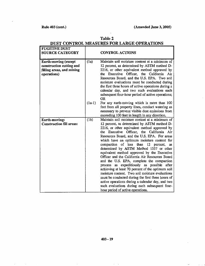

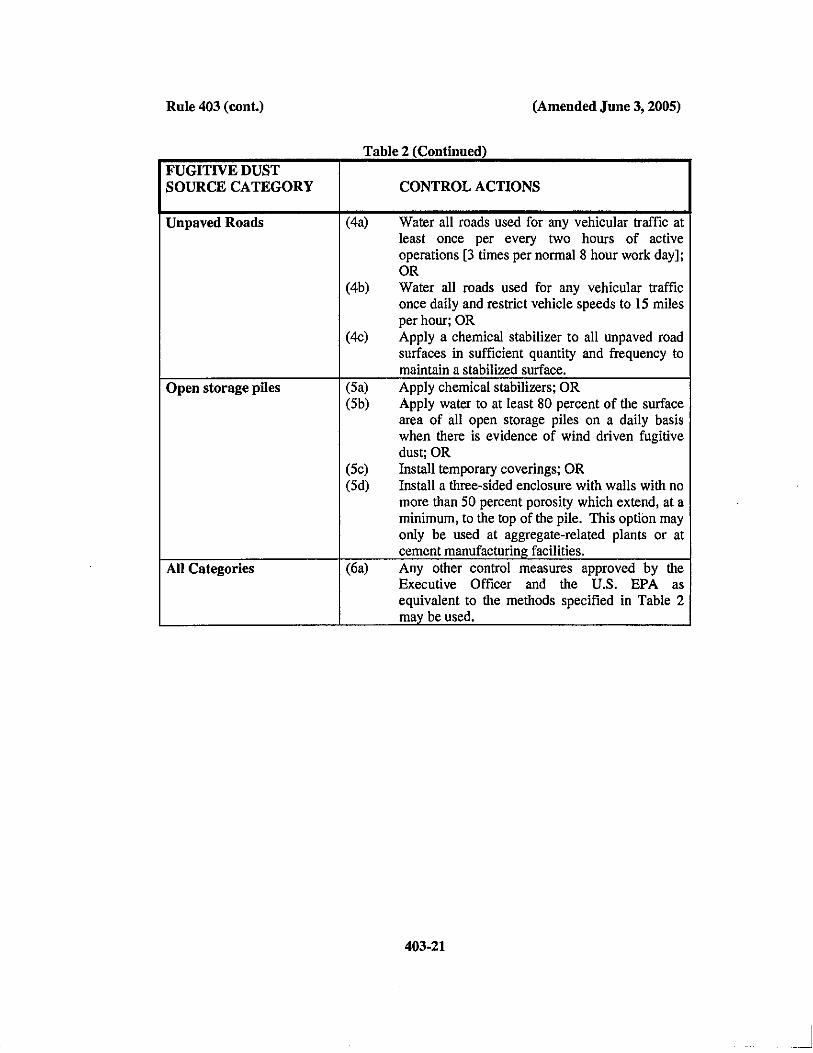
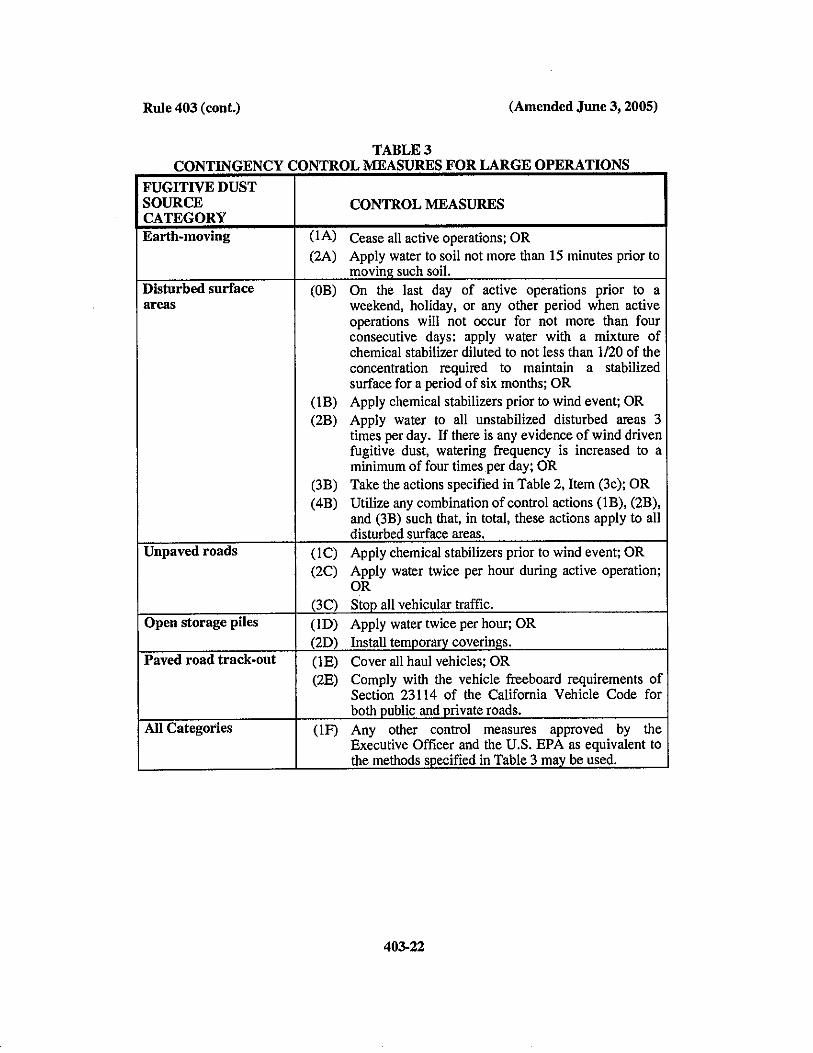
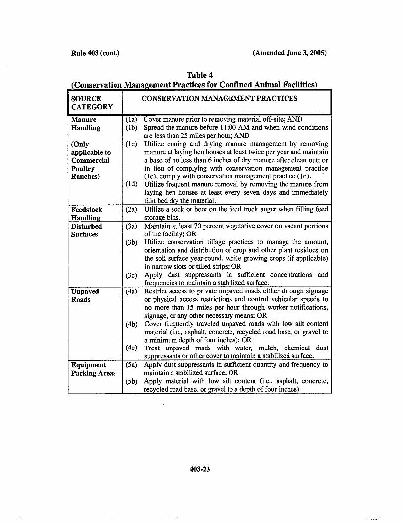
Former NIRF Undersea Center December 11, 2017 Pasadena, California Project No. 207220003
207220003 R SMP
APPENDIX B-3
SCAQMD RULE 1166, CONTROL OF PARTICULATE EMISSIONS FROM SOILS
WITH TOXIC AIR CONTAMINANTS
1466 - 1
(Adopted July 7, 2017) RULE 1466. CONTROL OF PARTICULATE EMISSIONS FROM SOILS WITH
TOXIC AIR CONTAMINANTS
(a) Purpose
The purpose of this rule is to minimize the amount of off-site fugitive dust emissions
containing toxic air contaminants by reducing particulate emissions in the ambient air as a
result of earth-moving activities, including, excavating, grading, handling, treating,
stockpiling, transferring, and removing soil that contains applicable toxic air contaminants
from sites that meet the applicability requirements of subdivision (b).
(b) Applicability
(1) Effective 30 days from adoption date, this rule shall apply to any owner or operator
conducting earth-moving activities of soil with applicable toxic air contaminants as
defined in paragraph (c)(3) that have been identified as contaminants of concern at
a site that has been designated and notified by the:
(A) U.S. Environmental Protection Agency (U.S. EPA) as a Superfund National
Priorities List site;
(B) California Department of Toxic Substances Control (DTSC) as a
Brownfield or Cleanup Program site;
(C) State Water Resources Control Board (State Water Board) or Regional
Water Quality Board (Regional Water Board) as a Site Cleanup Program
site; or
(D) Executive Officer pursuant to subdivision (i).
(2) This rule shall not apply to:
(A) Earth-moving activities of soil with applicable toxic air contaminants of less
than 50 cubic yards; or
(B) Removal of soil for sampling purposes.
(c) Definitions
(1) ADEQUATELY WET is the condition of being sufficiently mixed or penetrated
with water to prevent the release of particulates or visible emissions. The process
by which an adequately wet condition is achieved is by using a dispenser or water
hose with a nozzle that permits the use of a fine, low-pressure spray or mist.
Rule 1466 (cont.) (Adopted July 7, 2017)
1466 - 2
(2) ADJACENT ATHLETIC AREA is any outdoor athletic field or park where youth
organized sports occur that is in physical contact or separated solely by a public
roadway or other public right-of-way to a school or early education center.
(3) APPLICABLE TOXIC AIR CONTAMINANTS, for the purpose of this rule,
include arsenic, asbestos, cadmium, hexavalent chromium, lead, mercury, nickel,
and polychlorinated biphenyls.
(4) CHEMICAL STABILIZERS are any non-toxic chemical dust suppressant. The
chemical stabilizers shall meet any specifications, criteria, or tests required by any
federal, state, or local agency or any applicable law, rule, or regulation. Unless
otherwise indicated, the use of a non-toxic chemical stabilizer shall be of sufficient
concentration and application frequency to maintain a stabilized surface and no less
than what is specified by the manufacturer.
(5) DISTURBED SURFACE AREA is a portion of the earth's surface which has been
physically moved, uncovered, destabilized, or otherwise modified from its
undisturbed natural soil condition, thereby increasing the potential for fugitive dust.
This definition excludes those areas which have:
(A) Been restored to a natural state, such that the vegetative ground cover and
soil characteristics are similar to adjacent or nearby natural conditions;
(B) Been paved or otherwise covered by a permanent structure; or
(C) Sustained a vegetative ground cover of at least 70 percent of the native cover
for a particular area for at least 30 days.
(6) DUST SUPPRESSANTS are water, hygroscopic materials, or chemical stabilizers
used as a treatment material to reduce fugitive dust emissions.
(7) EARLY EDUCATION CENTER is any public or private property, used for
purposes of education as defined as an Early Learning and Developmental Program
by the U.S. Department of Education, but does not include any property in which
education is primarily conducted in private homes. Early education center includes
any building or structure, playground, athletic field, or other areas of early
education center property.
(8) EARTH-MOVING ACTIVITIES are, for the purpose of this rule, any activity on
a site that meets the applicability requirements of subdivision (b) where soil with
applicable toxic air contaminants are being moved or uncovered, and shall include,
but not be limited to the following: excavating, grading, earth cutting and filling
operations, loading or unloading, and adding to or removing from stockpiles.

Rule 1466 (cont.) (Adopted July 7, 2017)
1466 - 3
(9) FUGITIVE DUST is, for the purpose of this rule, any solid particulate matter that
is in contact with ambient air and has the potential to become airborne, other than
solid particulate matter that is emitted from an exhaust stack.
(10) JOINT USE AGREEMENT PROPERTY is a shared public facility in which a
formal agreement exists between a school or early education center and another
government entity setting forth the terms and conditions for shared use.
(11) OWNER OR OPERATOR is any firm, business establishment, association,
partnership, corporation or individual, whether acting as principal, agent,
employee, contractor, or other capacity.
(12) PAVED ROAD is a public or private improved street, highway, alley, public way,
or easement that is covered by typical roadway materials, but excluding access
roadways that connect a facility with a public paved roadway and are not open to
through traffic. Public paved roads are those open to public access and that are
owned by any federal, state, county, municipal, or any other governmental or quasi-
governmental agencies. Private paved roads are any paved roads not defined as
public.
(13) PROPERTY LINE is the boundary of an area where a person has the legal use or
possession of the property. Where such property is divided into one or more sub-
tenancies, the property line(s) shall refer to the boundaries dividing the areas of all
sub-tenancies.
(14) SCHOOL is any public or private education center, including juvenile detention
facilities and education centers serving as the students’ place of residence (e.g.,
boarding schools), used for purposes of the education of more than 12 children in
kindergarten or any grades 1 to 12, inclusive, but does not include any school in
which education is primarily conducted in private homes. School includes any
building or structure, playground, athletic field, or other areas of school property.
(15) SOIL is dirt, sand, gravel, clay, and aggregate material less than two inches in
length or diameter, and other organic or inorganic particulate matter.
(16) SOIL WITH APPLICABLE TOXIC AIR CONTAMINANT(S) means, for the
purpose of this rule, soil that has been identified by U.S. EPA, DTSC, State Water
Board, Regional Water Board, or the Executive Officer to contain one or more of
the applicable toxic air contaminants as defined in paragraph (c)(3) that exceed
action levels as specified by the designating agency.
(17) STABILIZED SURFACE is any previously disturbed surface area or stockpile,
which through the application of dust suppressants, shows visual or other evidence
of surface crusting and is resistant to wind driven fugitive dust, and is demonstrated

Rule 1466 (cont.) (Adopted July 7, 2017)
1466 - 4
to be stabilized. Stabilization can be demonstrated by one or more of the applicable
test methods contained in the SCAQMD Rule 403 Fugitive Dust Implementation
Handbook.
(18) STOCKPILE is any accumulation of soil, which is not fully enclosed, covered, or
chemically stabilized, and which attains a height of three feet or more and a total
surface area of 150 square feet or more.
(19) TRACK-OUT is any soil that adheres to and agglomerates on the exterior surface
of motor vehicles, haul trucks, and equipment (including tires) that has been
released onto a paved road.
(20) WIND-DRIVEN FUGITIVE DUST is visible emissions from any disturbed
surface area, which is generated by wind action alone.
(21) WIND GUST is the maximum instantaneous wind speed as measured by an
anemometer.
(d) Monitoring Requirements
(1) When earth-moving activities or vehicular movement occurs, the owner or operator
shall conduct continuous direct-reading near real-time ambient monitoring of PM10
concentrations pursuant to paragraph (d)(3).
(2) If the PM10 concentration averaged over two hours exceeds 25 micrograms per
cubic meter, as measured pursuant to paragraph (d)(3) and as determined pursuant
to paragraph (d)(4), the owner or operator shall cease earth-moving activities, apply
dust suppressant to fugitive dust sources, or implement other dust control measures
as necessary until the PM10 concentration is equal to or less than 25 micrograms
per cubic meter averaged over 30 minutes.
(A) The owner or operator or designating agency may request an alternative
PM10 limit from the Executive Officer provided the exposure to toxic air
contaminants from fugitive dust from earth-moving activities at the
proposed PM10 concentration level is health protective to the public. The
owner or operator or designating agency shall provide to the Executive
Officer the information specified in subparagraphs (i)(1)(A) through (G)
and substantiate its position that an alternative PM10 limit is health
protective. Use of an alternative PM10 limit must be submitted and
approved by the Executive Officer as specified in subdivision (j).
(3) The owner or operator conducting earth-moving activities shall install and conduct
ambient PM10 monitoring as follows:
Rule 1466 (cont.) (Adopted July 7, 2017)
1466 - 5
(A) In accordance with a U.S. EPA-approved equivalent method for PM10
monitoring or an alternative method approved by the Executive Officer.
The owner or operator or designating agency shall select an alternative PM10
method as specified in Appendix 1. Use of an alternative PM10 method
must be submitted and approved by the Executive Officer as specified in
subdivision (j);
(B) Using a minimum of one upwind monitor where the location of the upwind
monitor(s) are indicative of background PM10 levels and not generally
influenced by fugitive dust sources from the site;
(C) Using a minimum of one downwind monitor placed in the seasonal
prevailing wind direction downwind of each area of earth-moving activity
and as close to the property line as feasible;
(D) Operate, maintain, and calibrate ambient PM10 monitors in accordance with
appropriate U.S. EPA-published documents for U.S. EPA-approved
equivalent method(s) for PM10 or the alternative method approved by the
Executive Officer, and manufacturer’s instructions; and
(E) Collect ambient PM10 data with a data acquisition system that is capable of
logging direct-reading near real-time data providing the date, time, and
PM10 concentration in micrograms per cubic meter every 10 minutes or less.
(4) The owner or operator shall calculate the PM10 concentration based on the PM10
concentration averaged over two hours, starting at the top of each hour, where:
(A) The PM10 concentration is the absolute difference between the upwind and
downwind monitors;
(B) If there is more than one upwind monitor, the upwind result is the two hour
average of all upwind monitors;
(C) If there is more than one downwind monitor, the downwind average is the
maximum two hour average concentration of any of the downwind
monitors; and
(D) The owner or operator or designating agency may use an alternative
calculation methodology if the owner or operator or designating agency
provides information to substantiate that all or some the PM10 concentration
is the result of another source and not attributed to the earth-moving
activities of the site. Use of an alternative calculation methodology must be
submitted and approved by the Executive Officer as specified in subdivision
(j).
Rule 1466 (cont.) (Adopted July 7, 2017)
1466 - 6
(5) When earth-moving activities occur, the owner or operator shall monitor wind
direction and speed as specified in U.S. EPA Quality Assurance Handbook for Air
Pollution Measurement Systems, Volume IV: Meteorological Measurements.
(e) Requirements to Minimize Fugitive Dust Emissions
(1) The owner or operator shall not conduct earth-moving activities unless the area is
surrounded with fencing that is a minimum of 6 feet tall and at least as tall as the
height of the tallest stockpile, with a windscreen with a porosity of 50 ± 5%.
(2) An owner or operator conducting earth-moving activities shall:
(A) Adequately wet to the depth of earth-moving activity and allow time for
penetration; and
(B) Adequately wet at frequencies to prevent the generation of visible dust
plumes.
(3) An owner or operator that is moving vehicles on, within, or off a site where earth-
moving activities are occurring shall:
(A) Post signs at all entrances of the site to designate the speed limit as 15 miles
per hour;
(B) Stabilize the surface of all vehicular traffic and parking areas by applying
gravel, paving, or dust suppressant;
(C) Not allow track-out to extend beyond 25 feet of the property line. Remove
any track-out each day using a vacuum equipped with a filter(s) rated by the
manufacturer to achieve a 99.97% capture efficiency for 0.3 micron
particles;
(D) Clean the soil from the exterior of trucks, trailers, and tires prior to the truck
leaving the site; and
(E) The owner or operator shall utilize at least one of the measures listed in
clause (e)(3)(E)(i) through (e)(3)(E)(iv) at each vehicle egress from the site
to a paved public road:
(i) Install a pad consisting of washed gravel (minimum-size: one inch),
maintained in a clean condition, to a depth of at least six inches and
extending at least 30 feet wide and at least 50 feet long;
(ii) Pave the surface extending at least 100 feet from the property line
and at least 20 feet wide;
(iii) Utilize a wheel shaker/wheel spreading device consisting of raised
dividers (rails, pipes, or grates) at least 24 feet long and 10 feet wide;
or
Rule 1466 (cont.) (Adopted July 7, 2017)
1466 - 7
(iv) Install and utilize a wheel washing system to remove soil from tires
and vehicle undercarriages.
(4) An owner or operator conducting earth-moving activities that result in the
development of stockpiles of any soil with applicable toxic air contaminants shall:
(A) Segregate non-contaminated stockpiles from stockpiles with applicable
toxic air contaminants and label with “SCAQMD Rule 1466 – Control of
Particulate Emissions from Soils with Toxic Air Contaminants Applicable
Soil”;
(B) Maintain stockpiles to avoid steep sides or faces that exceed the angle of
repose;
(C) Not create a stockpile that is more than 400 cubic yards of soil and greater
in height than the perimeter fencing and windscreen;
(D) Apply dust suppressant to stockpiles;
(E) At the end of each working day, either chemically stabilize and/or
completely cover with 10 millimeter thick plastic sheeting that overlaps a
minimum of 24 inches. The plastic sheeting shall be anchored and secured
so that no portion of the soil is exposed to the atmosphere; and
(F) Daily, inspect stabilized or covered stockpiles. For a stabilized stockpile,
such inspections shall include a demonstration of stabilization by one or
more of the applicable test methods contained in SCAQMD Rule 403
Fugitive Dust Implementation Handbook. For a covered stockpile, such
inspections shall include a visual inspection of all seams and plastic cover
surfaces. Immediately re-stabilize or repair any holes, tears, or any other
potential sources of fugitive toxic air contaminant emissions.
(5) An owner or operator conducting truck loading activities of soil containing
applicable toxic air contaminants shall:
(A) Apply dust suppressant to material prior to loading;
(B) Empty the loader bucket slowly so that no dust plumes are generated;
(C) Minimize the drop height from the loader bucket;
(D) Maintain at least six inches of freeboard while transporting within a site;
and
(E) Completely tarp the truck and trailer prior to leaving the site.
(6) An owner or operator conducting truck unloading activities of soil containing
applicable toxic air contaminants shall:
(A) Apply dust suppressant to material prior to unloading; and
(B) Empty the trailer slowly so that no dust plumes are generated.
Rule 1466 (cont.) (Adopted July 7, 2017)
1466 - 8
(7) The owner or operator shall immediately remove any spilled soil containing
applicable toxic air contaminants.
(8) The owner or operator shall cease earth-moving activities if the wind speed is
greater than 15 miles per hour (mph) averaged over a 15-minute period or
instantaneous wind speeds exceed 25 mph.
(9) During earth-moving activities, the owner or operator shall have an on-site dust
control supervisor that:
(A) Is employed by or contracted with the owner or operator;
(B) Is located on the site during working hours;
(C) Is in a position to expeditiously employ sufficient dust control measures to
ensure compliance with all Rule requirements;
(D) Has completed the SCAQMD Fugitive Dust Control Class and has been
issued a valid Certificate of Completion for the class; and
(E) Has the following credentials, if asbestos is an applicable toxic air
contaminant:
(i) Successfully completed the Asbestos Abatement
Contractor/Supervisor course pursuant to the Asbestos Hazard
Emergency Response Act (AHERA), and obtained and maintained
accreditation as an AHERA Asbestos Abatement
Contractor/Supervisor; and
(ii) Trained on the provisions of 40 CFR Part 61.145, 61.146, 61.147
and 61.152 (Asbestos NESHAP provisions) and Part 763, and have
the means by which to comply with these provisions.
(10) If earth-moving activities will not occur for three (3) or more consecutive days,
apply a chemical stabilizer to potential sources of fugitive dust diluted to the
concentration required to maintain a stabilized surface for the period of inactivity;
re-stabilize as necessary.
(11) An owner or operator that is conducting earth-moving activities of soil with
applicable toxic air contaminant(s) at a school, early education center, joint use
agreement property, or adjacent athletic area shall:
(A) Only conduct earth-moving activities at a school or early education center
outside of the hours between 7:30 a.m. and 4:30 p.m. on days when the
school or early education center is in session;
(B) Not conduct earth-moving activities at a school, early education center, joint
use agreement property, or adjacent athletic area if there is a school or early
education center sponsored activity or youth organized sports at that site;
Rule 1466 (cont.) (Adopted July 7, 2017)
1466 - 9
(C) Handle excavated soils with applicable toxic air contaminants by:
(i) Immediately placing soil in a leak-tight container whereby any
contained solids or liquids are prevented from escaping or spilling
out;
(ii) Directly loading soil in trucks, applying dust suppressant, and
covering prior to transporting; or
(iii) Stockpiling pursuant to paragraph (e)(4), in a fenced area that is not
accessible to the general public, and locked when not in use; and
(D) Within five (5) days of its excavation, remove all soil with applicable toxic
air contaminants from the site.
(12) With the exception of (e)(7) and (e)(11), the owner or operator or designating
agency may use alternative dust control measures that meet the objective and
effectiveness of the dust control measure it is replacing, where the objective and
effectiveness of each category of dust control measures is stated in Appendix 2.
Use of alternative dust control measures must be submitted and approved by the
Executive Officer as specified under subdivision (j).
(f) Notification Requirements
(1) At least 72 hours and no more than 30 days prior to conducting any earth-moving
activities on any site meeting the applicability requirements of subdivision (b), the
owner or operator shall electronically notify the Executive Officer, using a format
approved by the Executive Officer, of the intent to conduct any earth-moving
activities. Notifications shall include the following requirements:
(A) Name, address, telephone number, and e-mail address of the owner or
operator;
(B) Name, telephone number, and e-mail address of the on-site dust control
supervisor;
(C) Project name and, if applicable, the project identification number from the
designating agency;
(D) Project location (address and/or coordinates);
(E) Identify whether the site is a school, early education center, joint use
agreement property, or adjacent athletic area;
(F) A map indicating the specific location(s) of each earth-moving activity and
the concentrations of the applicable toxic air contaminant(s) and location of
PM10 monitors;
Rule 1466 (cont.) (Adopted July 7, 2017)
1466 - 10
(G) A description of the earth-moving activities and a schedule that includes the
anticipated start and completion dates of earth-moving activities;
(H) Current and/or previous type of operation(s) and use(s) at the site; and
(I) Whether the notice is a revised notification.
(2) Within 72 hours of an exceedance of the PM10 emission limit specified in
subdivision (d), the owner or operator of a site meeting the applicability
requirements of subdivision (b) shall electronically notify the Executive Officer,
using a format approved by the Executive Officer, of the exceedance and shall
include the following information:
(A) Name, address, telephone number, and e-mail address of the
owner/operator;
(B) Name, telephone number, and e-mail address of the on-site dust control
supervisor;
(C) Project name and, if applicable, the project identification number from the
designating agency;
(D) Project Location (address and/or coordinates);
(E) PM10 monitoring results, including result, date and time of exceedance(s),
12 hours before first exceedance, and 12 hours after last exceedance;
(F) Earth-moving activities occurring at the date and time of exceedance(s); and
(G) Dust control measure(s) taken to mitigate fugitive dust.
(g) Signage Requirements
When conducting earth-moving activities, the owner or operator shall install and maintain
project signage.
(1) Unless otherwise approved in writing by the Executive Officer, signage shall:
(A) Be installed at all entrances and at intervals of 1,000 feet or less along the
property line or perimeter of the site, with a minimum of one along each
side;
(B) Be located between 6 and 8 feet above grade from the bottom of the sign;
(C) Display lettering at least four inches tall with text contrasting with the sign
background; and
(D) Display the following information:
(i) Local or toll-free phone number for the site contact or pre-recorded
notification center that is accessible 24 hours a day; and
(ii) Warning statement:
Rule 1466 (cont.) (Adopted July 7, 2017)
1466 - 11
“THIS SITE CONTAINS SOILS THAT CONTAIN THE
FOLLOWING CHEMICALS: [LIST APPLICABLE TOXIC AIR
CONTAMINANTS]
TO REPORT ANY DUST LEAVING THE SITE PLEASE CALL
[FACILITY CONTACT] OR THE SOUTH COAST AIR
QUALITY MANAGEMENT DISTRICT AT 1-800-CUT-SMOG”
(2) The owner or operator or designating agency may use alternative signage approved
by the Executive Officer pursuant to subdivision (j). Notwithstanding subdivision
(j), the request shall include a visual representation of the alternative sign and
proposed locations and at a minimum, the alternative signage shall:
(A) Display lettering at least four inches tall with text contrasting with the sign
background; and
(B) Display the following warning statement:
“THIS SITE CONTAINS SOILS THAT CONTAIN THE FOLLOWING
CHEMICALS: [LIST APPLICABLE TOXIC AIR CONTAMINANTS]
TO REPORT ANY DUST LEAVING THE SITE PLEASE CALL
THE SOUTH COAST AIR QUALITY MANAGEMENT DISTRICT AT
1-800-CUT-SMOG”
(h) Recordkeeping Requirements
The owner or operator shall maintain records for a period of not less than three years and
shall make such records available to the Executive Officer upon request. At a minimum,
records shall be maintained daily and shall include:
(1) Inspection of all covered stockpiles containing soils with applicable toxic air
contaminants;
(2) Results of wind and PM10 monitoring, including calibration, maintenance, operator
training, and daily instrument performance check records for all monitoring
instruments;
(3) Earth-moving activities conducted and the corresponding volume of soil with
applicable toxic air contaminant;
(4) Names and business addresses of the transporting and receiving facilities, and a
copy of the shipping manifest; and
(5) Complaints called in, including the name of complainant and contact information,
date and time, earth-moving activities occurring at the date and time, complaint,
and action taken to mitigate the source of the complaint.

Rule 1466 (cont.) (Adopted July 7, 2017)
1466 - 12
(i) Executive Officer Designated Sites
(1) The Executive Officer may designate a site if the Executive Officer has evidence
that the site contains soil with applicable toxic air contaminants, after consultation
with U.S. EPA, DTSC, the State or Regional Water Boards, and/or local or state
health agencies, and consideration of the following:
(A) Concentration(s) of applicable toxic air contaminant(s) in the soil;
(B) Background concentration(s) of applicable toxic air contaminant(s);
(C) Volume of soil with applicable toxic air contaminant(s);
(D) Distance to a residence, park, or school;
(E) Meteorological data;
(F) Health risk information or other data provided by the owner or operator, if
available; and
(G) Ambient monitoring data and other applicable data, if available.
(2) Prior to making a determination, the Executive Officer will notify the owner or
operator in writing that the site may be subject to this rule.
(A) In the event the owner or operator exercises this opportunity to demonstrate
that this rule does not apply, the owner or operator shall submit information
to the Executive Officer within 14 days of the notification substantiating
why the site should be excluded from this rule.
(B) Upon final determination, the Executive Officer will notify the owner or
operator in writing if the site is subject to this rule.
(3) During the determination period, the owner or operator shall comply with the
provisions of this rule or cease all earth-moving activities until a determination is
made.
(j) Alternative Provisions
(1) If requesting an alternative provision pursuant to subparagraphs (d)(2)(A),
(d)(3)(A), or (d)(4)(D) or paragraphs (e)(12) or (g)(2), the owner or operator or
designating agency shall submit all information to the Executive Officer to
substantiate its positon.
(A) The owner or operator or designating agency that elects to request
alternative provisions for the PM10 limit, PM10 monitoring method, or
signage shall submit the request in writing at least 30 days prior to
conducting any earth-moving activities.
(B) The owner or operator or designating agency that elects to request
alternative provisions for the PM10 calculation or dust control measures

Rule 1466 (cont.) (Adopted July 7, 2017)
1466 - 13
shall submit the request, in writing, prior to an exceedance of the PM10
concentration requirements set forth in paragraph (d)(2).
(2) The Executive Officer may request additional information from the owner or
operator or designating agency.
(3) The owner or operator or designating agency shall submit all requested information
within 14 days of the request for additional information.
(4) The Executive Officer will review the request for an alternative provision and will
approve or reject the data and notify the owner or operator or designating agency
in writing. Approved alternative provisions may not be used retroactively.
(k) Exemptions
(1) The owner or operator may be exempt from one or more provisions of this rule
provided there is written confirmation that the designating agency under
subparagraphs (b)(1)(A) through (C) has consulted with the Executive Officer and
has determined that the provision(s) are not needed based on information specified
in subparagraphs (i)(1)(A) through (G).
(2) Earth-moving activities performed within an enclosed system vented to SCAQMD
permitted air pollution control equipment shall be exempt from all requirements
except: subparagraphs (e)(3)(C) through (e)(3)(E), subparagraphs (e)(5)(D) and
(e)(5)(E), and subdivisions (g) and (h).
(3) Linear trenching for sewer projects on roadways with applicable toxic air
contaminants, directly loaded into a truck or bin for transport, shall be exempt from
all requirements except: paragraphs (e)(2) through (e)(8), paragraph (e)(11), and
subdivisions (f), (h), and (i).
(4) Earth-moving activities consisting only of excavation activities of soil with
applicable toxic air contaminants of less than 500 cubic yards, directly loaded into
a truck or bin for transport, shall be exempt from all requirements except:
paragraphs (e)(2) through (e)(8), paragraph (e)(11), and subdivisions (f), (h), and
(i).
(5) Active operations conducted during emergency life-threatening situations, or in
conjunction with any officially declared disaster or state of emergency as declared
by an authorized health officer, agricultural commissioner, fire protection officer,
or other authorized agency officer shall be exempt from all requirements. The
Executive Officer shall be notified electronically no later than 48 hours following
such earth-moving activities. Written notification shall include written emergency
declaration from the authorized officer.
Rule 1466 (cont.) (Adopted July 7, 2017)
1466 - 14
(6) Active operations conducted by essential service utilities to provide electricity,
natural gas, telephone, water, or sewer during periods of service outages and
emergency disruptions shall be exempt from all requirements. The Executive
Officer shall be notified electronically no later than 48 hours following such earth-
moving activities.
Rule 1466 (cont.) (Adopted July 7, 2017)
1466 - 15
Appendix 1 – Executive Officer Approved PM10 Monitors
The Executive Officer may approve PM10 monitors that meeting the following requirements.
1. PM10 monitors must be continuous direct-reading near-real time monitors and shall monitor
particulate matter less than 10 microns.
2. PM10 monitors must be equipped with:
a. Omni-directional heated sampler inlet with water trap;
b. Sample pump;
c. Volumetric flow controller;
d. Enclosure; and
e. Data logger capable of logging each data point with average concentration,
time/date, and data point number.
3. PM10 monitors must have the following minimum performance standards:
a. Range: 0 - 10,000 µg/m3
b. Accuracy: ±5% of reading ± precision
c. Resolution: 0.1 µg/m3
d. Measurement Cycle: User selectable (30 minute and 2 hour)
4. In order to ensure the validity of the PM10 measurements performed, there must be
appropriate Quality Assurance/Quality Control (QA/QC). It is the responsibility of the
owner or operator to adequately supplement QA/QC Plans to include the following critical
features: instrument calibration, instrument maintenance, operator training, and daily
instrument performance (span) checks.
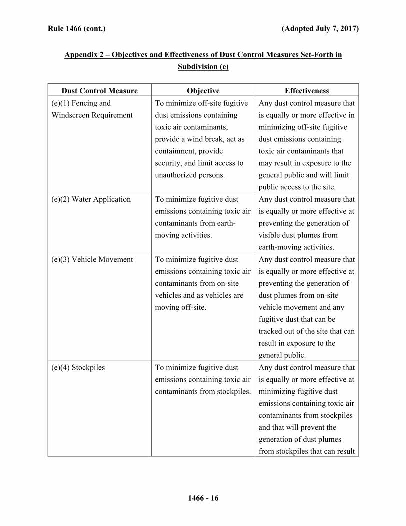
Rule 1466 (cont.) (Adopted July 7, 2017)
1466 - 16
Appendix 2 – Objectives and Effectiveness of Dust Control Measures Set-Forth in
Subdivision (e)
Dust Control Measure Objective Effectiveness
(e)(1) Fencing and
Windscreen Requirement
To minimize off-site fugitive
dust emissions containing
toxic air contaminants,
provide a wind break, act as
containment, provide
security, and limit access to
unauthorized persons.
Any dust control measure that
is equally or more effective in
minimizing off-site fugitive
dust emissions containing
toxic air contaminants that
may result in exposure to the
general public and will limit
public access to the site.
(e)(2) Water Application To minimize fugitive dust
emissions containing toxic air
contaminants from earth-
moving activities.
Any dust control measure that
is equally or more effective at
preventing the generation of
visible dust plumes from
earth-moving activities.
(e)(3) Vehicle Movement To minimize fugitive dust
emissions containing toxic air
contaminants from on-site
vehicles and as vehicles are
moving off-site.
Any dust control measure that
is equally or more effective at
preventing the generation of
dust plumes from on-site
vehicle movement and any
fugitive dust that can be
tracked out of the site that can
result in exposure to the
general public.
(e)(4) Stockpiles To minimize fugitive dust
emissions containing toxic air
contaminants from stockpiles.
Any dust control measure that
is equally or more effective at
minimizing fugitive dust
emissions containing toxic air
contaminants from stockpiles
and that will prevent the
generation of dust plumes
from stockpiles that can result
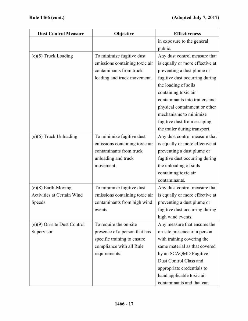
Rule 1466 (cont.) (Adopted July 7, 2017)
1466 - 17
Dust Control Measure Objective Effectiveness
in exposure to the general
public.
(e)(5) Truck Loading To minimize fugitive dust
emissions containing toxic air
contaminants from truck
loading and truck movement.
Any dust control measure that
is equally or more effective at
preventing a dust plume or
fugitive dust occurring during
the loading of soils
containing toxic air
contaminants into trailers and
physical containment or other
mechanisms to minimize
fugitive dust from escaping
the trailer during transport.
(e)(6) Truck Unloading To minimize fugitive dust
emissions containing toxic air
contaminants from truck
unloading and truck
movement.
Any dust control measure that
is equally or more effective at
preventing a dust plume or
fugitive dust occurring during
the unloading of soils
containing toxic air
contaminants.
(e)(8) Earth-Moving
Activities at Certain Wind
Speeds
To minimize fugitive dust
emissions containing toxic air
contaminants from high wind
events.
Any dust control measure that
is equally or more effective at
preventing a dust plume or
fugitive dust occurring during
high wind events.
(e)(9) On-site Dust Control
Supervisor
To require the on-site
presence of a person that has
specific training to ensure
compliance with all Rule
requirements.
Any measure that ensures the
on-site presence of a person
with training covering the
same material as that covered
by an SCAQMD Fugitive
Dust Control Class and
appropriate credentials to
hand applicable toxic air
contaminants and that can
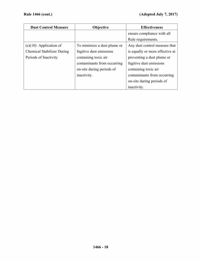
Rule 1466 (cont.) (Adopted July 7, 2017)
1466 - 18
Dust Control Measure Objective Effectiveness
ensure compliance with all
Rule requirements.
(e)(10) Application of
Chemical Stabilizer During
Periods of Inactivity
To minimize a dust plume or
fugitive dust emissions
containing toxic air
contaminants from occurring
on-site during periods of
inactivity.
Any dust control measure that
is equally or more effective at
preventing a dust plume or
fugitive dust emissions
containing toxic air
contaminants from occurring
on-site during periods of
inactivity.

Former NIRF Undersea Center December 11, 2017 Pasadena, California Project No. 207220003
207220003 R RAW
APPENDIX C
QUALITY ASSURANCE PROJECT PLAN

QUALITY ASSURANCE PROJECT PLAN
FORMER NAVAL INFORMATION RESEARCH
FOUNDATION UNDERSEA CENTER
(AKA SPACE BANK MINI STORAGE FACILITY)
3202 EAST FOOTHILL BOULEVARD
PASADENA, CALIFORNIA 91107
PREPARED FOR: Pasadena Gateway, LLC
3501 Jamboree Road, Suite 230 Newport Beach, California 92660
PREPARED BY: Ninyo & Moore
Geotechnical and Environmental Sciences Consultants 475 Goddard, Suite 200 Irvine, California 92618
December 11, 2017 Project No. 207220003
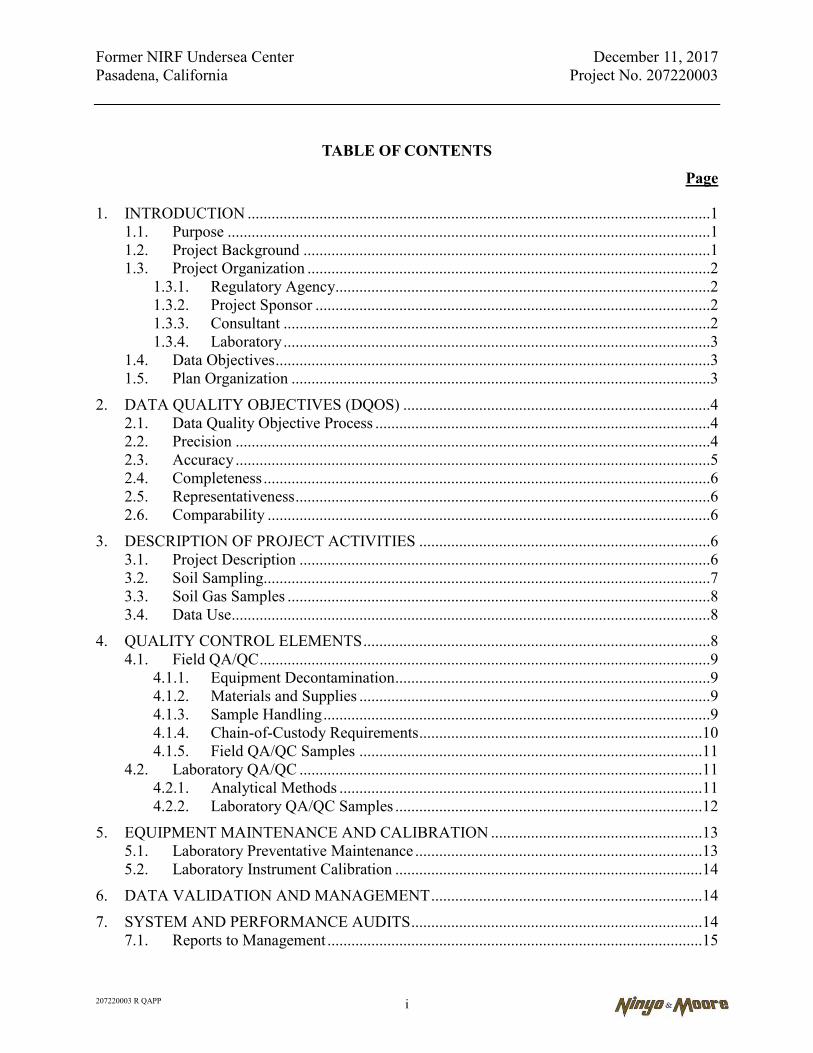
Former NIRF Undersea Center December 11, 2017 Pasadena, California Project No. 207220003
207220003 R QAPP i
TABLE OF CONTENTS
Page
1. INTRODUCTION ....................................................................................................................1 1.1. Purpose .........................................................................................................................1
1.2. Project Background ......................................................................................................1 1.3. Project Organization .....................................................................................................2
1.3.1. Regulatory Agency..............................................................................................2 1.3.2. Project Sponsor ...................................................................................................2 1.3.3. Consultant ...........................................................................................................2
1.3.4. Laboratory ...........................................................................................................3 1.4. Data Objectives .............................................................................................................3
1.5. Plan Organization .........................................................................................................3
2. DATA QUALITY OBJECTIVES (DQOS) .............................................................................4
2.1. Data Quality Objective Process ....................................................................................4 2.2. Precision .......................................................................................................................4
2.3. Accuracy .......................................................................................................................5 2.4. Completeness ................................................................................................................6 2.5. Representativeness ........................................................................................................6
2.6. Comparability ...............................................................................................................6
3. DESCRIPTION OF PROJECT ACTIVITIES .........................................................................6
3.1. Project Description .......................................................................................................6
3.2. Soil Sampling................................................................................................................7
3.3. Soil Gas Samples ..........................................................................................................8 3.4. Data Use ........................................................................................................................8
4. QUALITY CONTROL ELEMENTS .......................................................................................8 4.1. Field QA/QC .................................................................................................................9
4.1.1. Equipment Decontamination ...............................................................................9 4.1.2. Materials and Supplies ........................................................................................9
4.1.3. Sample Handling .................................................................................................9 4.1.4. Chain-of-Custody Requirements .......................................................................10 4.1.5. Field QA/QC Samples ......................................................................................11
4.2. Laboratory QA/QC .....................................................................................................11 4.2.1. Analytical Methods ...........................................................................................11
4.2.2. Laboratory QA/QC Samples .............................................................................12
5. EQUIPMENT MAINTENANCE AND CALIBRATION .....................................................13
5.1. Laboratory Preventative Maintenance ........................................................................13 5.2. Laboratory Instrument Calibration .............................................................................14
6. DATA VALIDATION AND MANAGEMENT ....................................................................14
7. SYSTEM AND PERFORMANCE AUDITS .........................................................................14 7.1. Reports to Management ..............................................................................................15

Former NIRF Undersea Center December 11, 2017 Pasadena, California Project No. 207220003
207220003 R QAPP ii
7.2. Corrective Action ........................................................................................................15
8. REFERENCES .......................................................................................................................16
Table Table C-1 – Quality Assurance Goals for Laboratory Analyses
Appendices Appendix C-1 – Example of Chain-of-Custody Appendix C-2 – Laboratory Methods and Detection Limits Appendix C-3 – Fixed-Site Laboratory Quality Assurance Manual Appendix C-4 – Mobile Laboratory Quality Assurance Manual

Former NIRF Undersea Center December 11, 2017 Pasadena, California Project No. 207220003
207220003 R QAPP 1
1. INTRODUCTION
This Quality Assurance Project Plan (QAPP) has been prepared as part of the Remedial Action
Workplan (RAW) for the former Naval Information Research Foundation (NIRF) Undersea
Center, currently the Space Bank Mini Storage facility, at 3202 east Foothill Boulevard in
Pasadena, California (site). It will be implemented in conjunction with the RAW, to which this
QAPP is an appendix.
1.1. Purpose
The purpose of the QAPP is to outline specific quality assurance/quality control (QA/QC)
procedures such that any data collected for the project meet the Data Quality Objectives
(DQOs) and are reported in a manner that is of acceptable quality to meet California
Environmental Protection Agency, Department of Toxic Substances Control (DTSC)
requirements.
1.2. Project Background
The site was previously owned by the Navy and utilized for testing and scientific testing
involving classified materials, torpedoes, and other weapons systems between 1945 and
1977. Numerous and varied laboratories were identified at the site including: combustion,
chemistry, hydro-propellants, welding, hydrodynamics, structures, metallurgy, experimental
physics, ballistics, and simulator labs. Possible hazardous substances associated with the
laboratories include: propellants, combustibles, explosives, solvents, and fuels. In 1977, the
site was purchased by Space Bank, Ltd., the current owner, and utilized as a storage facility
to the present.
Environmental Investigations were previously conducted at the site and summarized in
various reports between 1994 and 2016. Elevated levels of the chemicals of concern
(COPCs) were detected in soil, storm drain system, and seepage pits at the site that present a
potential threat to human health and/or the environment. Based on the data collected during
the historical environmental investigations, it was determined that a Response Action (RA)
is required to address the potential threat or hazard posed by the presence of elevated levels
Former NIRF Undersea Center December 11, 2017 Pasadena, California Project No. 207220003
207220003 R QAPP 2
of the COPCs detected at the site. Therefore, a RAW addressing this RA has been prepared
for approval by the DTSC.
1.3. Project Organization
This section provides a general description of the organizational structure and
responsibilities of the project personnel, including the lines of communication. Specific
individuals will be assigned to the roles described below prior to initiating the RAW.
1.3.1. Regulatory Agency
The DTSC provides regulatory oversight for this project. DTSC responsibilities include
reviewing and approving the RAW, Remedial Design Document, reports, and work
activities, as well as providing direction of DTSC policy and environmental objectives.
1.3.2. Project Sponsor
Pasadena Gateway, LLC (PG) has agreed to seek the review and approval of the DTSC
on environmental matters relating to the Space Bank facility. PG is responsible for the
directional decisions, as well as the budget, therefore, a PG representative will also
review work plans, reports, and drawings for activities associated with this project.
1.3.3. Consultant
The consultant’s designated Project Manager and Field Manager will be responsible for
the technical planning and implementation of the work in the RAW, as well as
responsibility for effective planning, review, and management of quality assurance
(QA) activities associated with the assigned project.
A Site Health and Safety Officer will also be assigned. One person may serve both
roles. The Field Manager will be responsible for the day-to-day coordination of field
activities under the direction of the Project Manager. Other responsibilities include
coordination of subcontractors and field crews so that field activities conform to the
specifications presented in the RAW. The Field Manager will also be responsible for the

Former NIRF Undersea Center December 11, 2017 Pasadena, California Project No. 207220003
207220003 R QAPP 3
QA and quality control (QC) aspects of the project. It is the responsibility of the QA
Manager to see that QA/QC protocols are met in the field and laboratory.
1.3.4. Laboratory
California state-certified laboratories will provide fixed-site laboratory analytical
services. The laboratory project manager will report to the Field Manager and Project
Manager on matters related to sample analysis and data quality. The laboratories will
conform to the QA and QC procedures outlined in their laboratory QA plan and
standard operating procedures. Currently, the planned fixed-site lab to be used is
Enthalpy Analytical, a state-certified laboratory, which is based in Orange, California.
Jones Environmental, mobile laboratory will be used for the soil gas survey.
1.4. Data Objectives
The remedial action objective consists of removal of the source of contamination through
which future on-site occupants, the neighboring community, and the environment may be
exposed.
1.5. Plan Organization
The remainder of this QAPP is organized into the following Sections:
Section 2, Data Quality Objectives, identifies and defines the measures that will be used to demonstrate that quality data has been obtained from the field program;
Section 3, Description of Project Activities, summarizes the project, and sampling strategies and methodologies;
Section 4, Quality Control Elements, outlines the procedures that will be conducted in the field and laboratories to maintain data quality for the project;
Section 5, Equipment Maintenance and Calibration, Describes laboratory and field requirements for equipment maintenance and calibration;
Section 6, Data Validation and Management, specifies specific data validation procedures and standards for data management; and
Former NIRF Undersea Center December 11, 2017 Pasadena, California Project No. 207220003
207220003 R QAPP 4
Section 7, System and Performance Audits, establishes audits, reporting, and corrective actions for QA aspects of the project.
2. DATA QUALITY OBJECTIVES (DQOS)
DQOs have been specified for each data collection activity, and the work will be conducted and
documented so that the data collected are of sufficient quality for their intended use (United
States Environmental Protection Agency [EPA], 1998). DQOs specify the data type, quality,
quantity, and uses needed to make decisions, and are the bases for designing data collection
activities. The DQOs have been used to design the data collection activities presented in the
RAP. The DQOs for the project are discussed in the following sections.
2.1. Data Quality Objective Process
The project DQOs developed specifically for the planned sampling and analysis program
have been ascertained based on the EPA's seven-step DQO process (EPA, 1994). The Project
Manager will evaluate the project DQOs to assess whether the quantitative and qualitative
needs of the sampling and analysis program have been met.
2.2. Precision
Precision is the degree of agreement between independent measurements and expressed as a
calculation of Relative Percent Difference (RPD). Analytical precision measures the
variability associated with repetitive analyses of the sample. Laboratory QC samples are
used to assess precision.
Analytical precision may be measured by the use of the same analytical instrument to make
repeated analyses on the same sample and/or the use of the same method to make repeated
measurements of the same sample within a single laboratory. Analytical precision will be
evaluated with the analysis of matrix spike (MS) and MS duplicate, laboratory control
sample, and laboratory control sample duplicates in the fixed laboratory, and if used,
primary sample and sample duplicate. The comparison will be made with the RPD given by:
Former NIRF Undersea Center December 11, 2017 Pasadena, California Project No. 207220003
207220003 R QAPP 5
RPD = [2(S1-S2)/(S1+S2)] x 100
where S1 = primary sample concentration
S2 = duplicate concentration
The goals for data precision for duplicates are summarized in Table C-1. RPD goals apply
only for samples with detected concentrations five times greater than the reporting limit.
2.3. Accuracy
Accuracy is a measurement of the correctness of the analyses. Field and laboratory activities
are subject to accuracy checks.
Laboratory accuracy can be assessed using laboratory control spikes (LCS) and MS samples.
An LCS is a blank deionized water or clean sand sample spiked with a known concentration
of the analyte of concern that is analyzed by laboratory personnel using the procedures and
methods used for the project-specific samples. An MS is an actual sample spiked with a
known concentration of the analyte of concern that is analyzed by laboratory personnel
using the procedures and methods used for the project-specific samples. The measurement is
considered accurate when the concentration measured during the analysis has a reported
value or percent recovery (R) within the laboratory’s acceptable limits. The equation for
calculating recoveries is:
R= [(A-B)/T] x 100
where A = measured concentration after spiking B= concentration prior to spiking T= known true value of spike
The laboratory will meet accuracy objectives established in accordance with their
certification and the specific analytical method. The goals for the recovery of selected target
analytes in laboratory spiked samples are presented in Table C-1. The goals may need to be
altered depending upon potential interferences associated with the matrices of samples.
Former NIRF Undersea Center December 11, 2017 Pasadena, California Project No. 207220003
207220003 R QAPP 6
2.4. Completeness
Completeness describes the content of the data set once errors, if any, have been assessed
and flagged and the data failing to meet the DQOs have been removed from the data set. The
data set will be considered acceptable if at least 90 percent of the data collected are usable
without meaningful flags or errors.
2.5. Representativeness
Representativeness describes the degree to which the data collected are an accurate
characterization of the media sampled. Careful planning of the field activities based on
known conditions and historical site usage has been undertaken to promote the RAW. The
data will be considered representative upon approval of the RAW by the DTSC.
2.6. Comparability
Comparability is a measure of the confidence with which one data set can be compared to
another. The data set will be considered comparable when the results and the field activities
meet appropriate EPA and/or DTSC Guidance methods, standards, and requirements.
3. DESCRIPTION OF PROJECT ACTIVITIES
This section presents information concerning the proposed sampling activities, selected
analytical parameters, data objectives, and the resulting project decisions. The RAW provides
specifications for field activities. In general, activities to be conducted at the sites will include
excavation and confirmation soil sampling. In addition, air monitoring will be conducted during
sampling activities in accordance with the site-specific health and safety plan (HASP) presented
in the RAW.
3.1. Project Description
The proposed sampling effort will include soil matrix sampling. The laboratory will analyze
selected samples for Title 22 metals by EPA Method 6010B, total petroleum hydrocarbons
(TPH) with carbon chain distinction by EPA Method 8015, polyaromatic hydrocarbons
(PAHs) by EPA Method 8270CM, and volatile organic compounds (VOCs) by EPA Method

Former NIRF Undersea Center December 11, 2017 Pasadena, California Project No. 207220003
207220003 R QAPP 7
8260B. A final soil gas survey will also be performed with soil gas sampling performed in
the vicinity of planned residential buildings with analysis for VOCs, by EPA Method 8260B
to be performed by a mobile laboratory.
3.2. Soil Sampling
Upon completion of the planned excavations, confirmation soil samples will be collected
from the exposed excavation sidewalls and bottoms. The number of soil samples collected
from each excavation will vary, depending on the dimensions of the excavations. For hot-
spot excavations, confirmation soil sampling is anticipated to be conducted at a frequency of
one sample per 20 linear feet of excavation sidewall and bottom. At a minimum, one sample
will be collected per sidewall and one per bottom from each excavation, regardless of size.
Sidewall samples will be collected at a single depth at a location halfway between the
ground surface and the excavation bottom. Confirmation samples for the removal of the
storm drain system piping will be collected from the excavation bottoms where breaks in the
storm drain system are observed or suspected.
Confirmation samples will be collected using a decontaminated drive sampler, hand auger,
or similar method, wherever practicable and in conformance with the HASP. For deep
samples and locations where safety is a concern, samples will be collected from the
backhoe/excavator bucket to avoid the need to enter hazardous areas. Upon retrieval, the
samples will be capped, labeled, placed in individual zip-lock bags, recorded on a chain of
custody document, and placed in storage pending delivery to a State-certified laboratory for
chemical analyses. These samples from each excavation will be analyzed only for the
COPCs associated with the excavation.
Soil samples may also be collected from segregated stockpiles, to determine waste
characterization as non-hazardous, California hazardous, or Resource, Conservation, and
Recovery Act hazardous soil. The proper disposal facilities will be determined based on the
soil stockpile samples.
Former NIRF Undersea Center December 11, 2017 Pasadena, California Project No. 207220003
207220003 R QAPP 8
At the end of each work day, excavated areas will be secured with fencing, delineators,
and/or caution tape to minimize the occurrence of accidents or unauthorized entry.
3.3. Soil Gas Samples
Direct push soil borings to 15 feet bgs will be placed in the planned areas of future
residential structures. Soil vapor probes will be installed at 5 and 15 feet bgs. Vapor wells
will be purged and sampled in accordance with DTSC Guidance (DTSC, 2015). Samples
will be analyzed by the mobile laboratory. See Appendix E (Soil Vapor Survey Work Plan)
for details.
3.4. Data Use
Decisions to be made based on the planned sampling and analysis effort will be assessed by
the laboratory analytical data compiled from the sampling and analysis program. It is
intended that data collected through implementation of this QAPP will satisfy Federal, state,
and local data quality requirements. These data may be used to characterize the nature and
extent/volume of any contamination, support risk assessment, and support the evaluation of
remedial action or additional actions.
The presence of environmental contaminants will be assessed by the extent of valid
detectable concentrations of the constituents discussed above. If the data associated with
TPHcc, PAHs, VOCs, or metals are present, the data will be used to assess risk using
accepted methods for assessing potential carcinogenic and non-carcinogenic exposures. If
results from the risk screening evaluations indicate no risks of exposure with respect to the
proposed use of the site, then PG will use the data to support No Further Action consent
from DTSC. If the evaluation indicates unacceptable risks of exposure, then the data can be
used by PG for further remedial action.
4. QUALITY CONTROL ELEMENTS
This section presents QC requirements relevant to analysis of environmental samples that will be
followed during project analytical activities. The purpose of the QC program is to produce data
Former NIRF Undersea Center December 11, 2017 Pasadena, California Project No. 207220003
207220003 R QAPP 9
of known quality that satisfy the project objectives and meet or exceed the requirements of the
standard methods of analysis. This program provides a mechanism for ongoing control and
evaluation of data quality measurements through the use of QC materials.
4.1. Field QA/QC
The RAW outlines the sampling and analysis procedures that will be implemented during
the field activities. The QA/QC procedures that apply to these field sampling activities are
presented in this section of the QAPP. These activities have been designed in order to
comply with the data use objectives presented in Section 3.3.
4.1.1. Equipment Decontamination
Soil sampling equipment will be decontaminated before and after being used each day
and between each sampling location. Non-dedicated sampling equipment will be
decontaminated before and after samples are collected. Decontamination will consist of
(in the following order): detergent (e.g., Alconox) and water wash, potable water rinse,
and distilled water rinse. Decontamination of personal protective equipment is
addressed in the HASP.
4.1.2. Materials and Supplies
Supplies and materials used either in the field or the laboratory shall be standard
industry material. The supplies and materials shall be inspected prior to use, in good
working condition, and within the expiration date requirements specified by the
manufacturer.
4.1.3. Sample Handling
In the field, each sample container will be marked with the sampling identification
location number and date and time of sample collection. Soil sample containers will be
wiped with paper towels and securely packed, in a cooler on ice, in preparation for
delivery to the laboratory. After receipt of the samples, the laboratory will immediately
notify the Field Manager if conditions or problems are assessed which need immediate

Former NIRF Undersea Center December 11, 2017 Pasadena, California Project No. 207220003
207220003 R QAPP 10
resolution. Such conditions include container breakage, missing or improper chain-of-
custody, exceeded holding times, missing or illegible sample labeling, or temperature
excursions.
4.1.4. Chain-of-Custody Requirements
Chain-of-custody records will be maintained for each sample collected to provide an
accurate written record of the possession and holding of samples from the time of
collection through data analysis and reporting. The following information will be
specified for each sample on the chain-of-custody form:
Sample identification;
Approximate volume of sample;
The name and signature of the sampler;
Date and time of sample collection for each sample;
Sample type;
Matrix;
Number and types of containers;
Tests to be performed and/or analytes requested;
Signatures of people involved in the chain of possession with dates and times of possession; and
Other notes or remarks; shipping requirements if needed.
A sample chain-of-custody document is presented in Appendix C-1.
The sampler and any other intermediate handlers of the samples (i.e., laboratory
courier) shall sign the form and record the date and time at which the samples changed
possession. The chain-of-custody form will be sealed inside of the cooler or other
sampling container. Upon receipt of samples by the laboratory, the laboratory will be
Former NIRF Undersea Center December 11, 2017 Pasadena, California Project No. 207220003
207220003 R QAPP 11
responsible for maintaining the original chain-of-custody as well as an internal chain-
of-custody of the samples.
4.1.5. Field QA/QC Samples
Field QA/QC samples that will be collected during the proposed fieldwork include
equipment blanks and split duplicate samples. The description and purpose of these
samples is discussed in this section.
4.1.5.1. Equipment Blanks
Equipment blank samples will be collected if non-dedicated sampling equipment is
used. Equipment blank samples are collected by filling decontaminated sampling
equipment with distilled water, sampling this water, and then submitting the sample
for analysis. An equipment blank will be collected at the rate of one per piece of
equipment used per day and submitted to the laboratory for analysis.
4.1.5.2. Duplicate Samples
The purpose of a duplicate sample is to evaluate the precision of both sampling
techniques and laboratory testing. A duplicate sample shall be labeled, packaged,
and stored in the same manner as any other sample. Duplicate samples will be
collected at a rate of 10 percent of the sample set.
4.2. Laboratory QA/QC
Quality control of laboratory analyses is assessed by (i) performing analytical methods
according to protocols and (ii) analyzing laboratory QA/QC samples to measure precision
and accuracy of laboratory methods and equipment, instrument calibration, and preventive
maintenance. An overview of these procedures is provided in the following sections.
4.2.1. Analytical Methods
Laboratory analyses for each parameter will be performed in accordance with EPA
protocols established in the EPA document Test Methods for Evaluating Solid Waste,
Former NIRF Undersea Center December 11, 2017 Pasadena, California Project No. 207220003
207220003 R QAPP 12
SW-846, Update III, dated June 1997. Analyses will be performed in accordance with
the EPA method procedures unless project requirements necessitate the adoption of
alternative methods. Analysis will be performed within the holding times. If an
alternative method is used, it will be documented and reported. The reporting limits
proposed for the project are considered low and achievable by the laboratory for the
methods. Laboratory methods and detection limits are presented in Appendix B-2.
4.2.2. Laboratory QA/QC Samples
A copy of the fixed-site laboratory Quality Assurance Program Plan is presented in
Appendix C-3 and the mobile laboratory Quality Assurance Program Plan is presented
in Appendix C-4.
4.2.2.1. General
Laboratory QA/QC samples that will be analyzed during the proposed assessment
include method blanks, laboratory control samples, MSs, and duplicates. Specific
acceptance limits for these types of samples will be per the respective analytical
method and at the discretion of the laboratory QA/QC manager.
4.2.2.2. Method Blanks
A method blank is a sample of deionized water or clean sand prepared by and
analyzed by the laboratory in the same manner as the samples. It is used to assess
potential contamination in the laboratory process (e.g., contaminated reagents or
improperly cleaned equipment). The laboratory will analyze one method blank
sample per batch or every 20 samples for each analytical method.
4.2.2.3. Laboratory Control Samples
A laboratory control sample is a known matrix (e.g., deionized water) that has been
spiked with a known concentration of specific target analytes. It is used to
demonstrate the precision of the analytical process. A laboratory control sample
Former NIRF Undersea Center December 11, 2017 Pasadena, California Project No. 207220003
207220003 R QAPP 13
will be analyzed at a frequency of one per preparation or analytical batch not
to exceed 20 samples.
4.2.2.4. Matrix Spikes
The MS is an actual sample matrix spiked with known concentrations of specific
target analytes. The purpose of an MS is to assess the effect of a sample matrix on
the recovery of target analytes (i.e., assess the potential for matrix interferences,
either high or low). One MS will be analyzed per batch or every 20 samples for
each analytical method.
4.2.2.5. Laboratory Duplicates
Duplicate samples are used to assess precision in the analytical method. An
additional aliquot is extracted from a sample and analyzed using the procedures.
Then the results are compared to assess the precision. Duplicates may be of three
kinds – laboratory control sample duplicates, MS duplicates, and laboratory sample
duplicates. Duplicates should be analyzed per batch or every 20 samples for
each analytical sample.
5. EQUIPMENT MAINTENANCE AND CALIBRATION
Both field and laboratory equipment involved with the collection and analysis of the samples will
be maintained and calibrated to the requirements specified below.
5.1. Laboratory Preventative Maintenance
The analytical laboratory will maintain an adequate supply of equipment and supplies to
avoid loss of data due to equipment malfunction. These include, but are not limited to,
calibration standards, reagents, glassware, and analytical equipment.

Former NIRF Undersea Center December 11, 2017 Pasadena, California Project No. 207220003
207220003 R QAPP 14
5.2. Laboratory Instrument Calibration
Instruments will be calibrated with standard solutions appropriate for the analytical method
to be performed. Laboratory personnel will calibrate equipment according to and at the
frequency by the manufacturer's directions and the requirements of the analytical methods.
Calibration procedures and frequency of calibration will be recorded in appropriate
logbooks. Initial and continuing instrument calibrations will meet applicable California
certification requirements.
6. DATA VALIDATION AND MANAGEMENT
The laboratory analytical results will be subjected to a data quality review that will include the
quality control samples used in the field (i.e., equipment blanks and split duplicate samples)
along with review of the laboratory quality control results. Aspects of the data that will be
evaluated include:
Completeness;
Accuracy;
Precision;
Sensitivity (Reporting limits/ Method Detection Limit [MDL] criteria);
Conformance with holding times; and
Chain-of-Custody Requirements.
The laboratory will need to provide a signed hardcopy of the results. QA/QC procedures will be
in place for both deliverable formats. Data Validation Memoranda will be included in the report.
7. SYSTEM AND PERFORMANCE AUDITS
Internal audits will be performed to review and evaluate the adequacy of the QAPP and to
ascertain that it has been implemented. A systems audit includes an evaluation of field and
laboratory QA/QC procedures. If the systems audit shows a significant discrepancy from the
Former NIRF Undersea Center December 11, 2017 Pasadena, California Project No. 207220003
207220003 R QAPP 15
RAW or the QAPP, the responsible party will remedy the situation before work continues. Any
major system change needs a written summary to document the change made.
A performance audit includes review of field, laboratory, and data documentation and
management procedures to assess the accuracy of the total measurement system(s) or a
component of the system. Documents that will be used to audit from will include the QAPP,
laboratory QA policies and analytical methods, and project-specific standard operating
procedures. After discovery of a significant deviation from these documents, the nature and
extent of the deviation will be recorded. Corrective action will be taken to remedy the deviation
as needed.
7.1. Reports to Management
The responsible field staff personnel will document and report the QA/QC results and the
issues (i.e., laboratory and field) to the Project Manager. The Project Manager will evaluate
the impact of the QA/QC issues and implement solutions.
7.2. Corrective Action
Results that do not meet data quality objectives will be reviewed. Additional raw analytical
data, laboratory records, or other data may be obtained and reviewed as needed. If needed,
problems will be corrected prior to laboratory re-analysis of samples within specified
holding times. If needed, a re-sampling event may be performed.

Former NIRF Undersea Center December 11, 2017 Pasadena, California Project No. 207220003
207220003 R QAPP 16
8. REFERENCES
Department of Toxic Substances Control, 2015, Advisory, Active Soil Gas Investigations, dated July.
United States Environmental Protection Agency, 1994, Guidance for the Data Quality Objectives Process, dated September.
United States Environmental Protection Agency, 1998, Guidance for Data Quality Assessment: Practical Methods for Data Analysis, dated January.
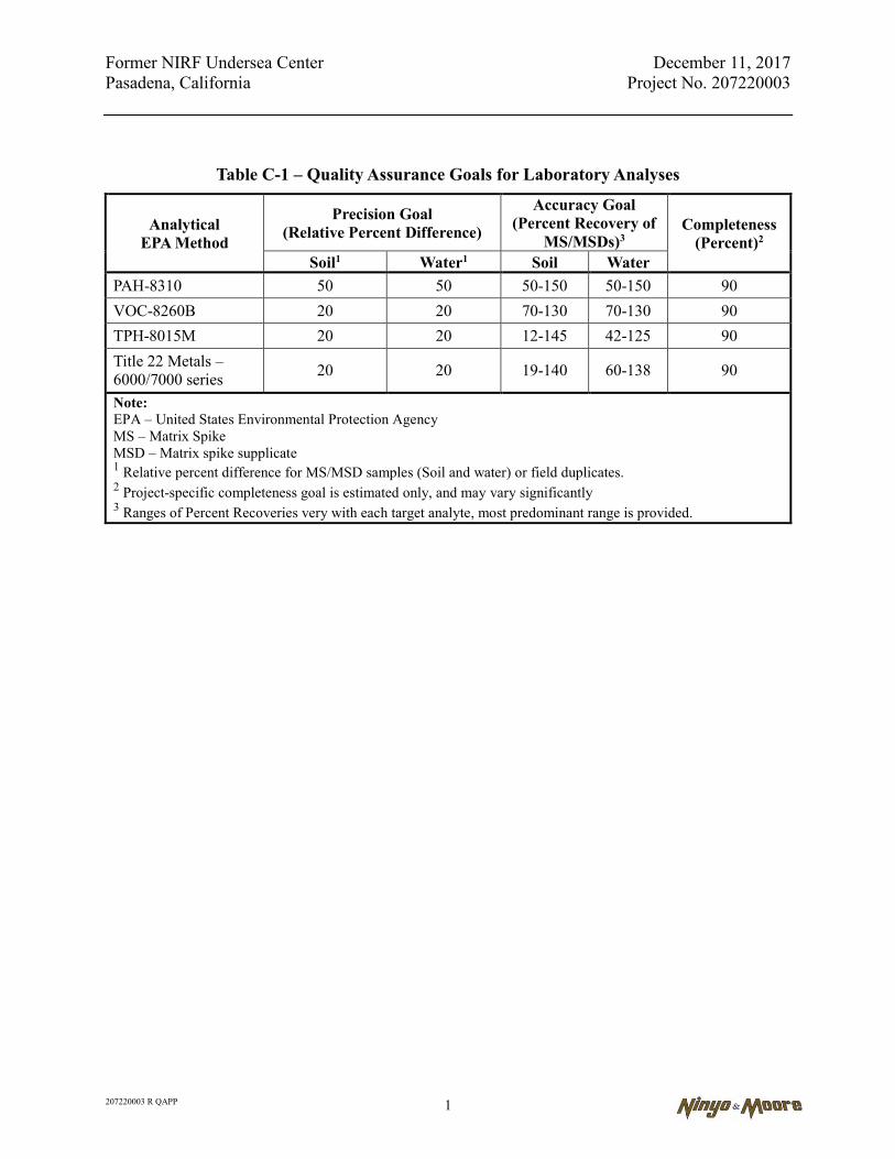
Former NIRF Undersea Center December 11, 2017 Pasadena, California Project No. 207220003
207220003 R QAPP 1
Table C-1 – Quality Assurance Goals for Laboratory Analyses
Analytical EPA Method
Precision Goal (Relative Percent Difference)
Accuracy Goal (Percent Recovery of
MS/MSDs)3 Completeness
(Percent)2 Soil1 Water1 Soil Water
PAH-8310 50 50 50-150 50-150 90 VOC-8260B 20 20 70-130 70-130 90 TPH-8015M 20 20 12-145 42-125 90 Title 22 Metals – 6000/7000 series 20 20 19-140 60-138 90
Note: EPA – United States Environmental Protection Agency MS – Matrix Spike MSD – Matrix spike supplicate 1 Relative percent difference for MS/MSD samples (Soil and water) or field duplicates. 2 Project-specific completeness goal is estimated only, and may vary significantly 3 Ranges of Percent Recoveries very with each target analyte, most predominant range is provided.
Former NIRF Undersea Center December 11, 2017 Pasadena, California Project No. 207220003
207220003 R QAPP
APPENDIX C-1
EXAMPLE OF CHAIN-OF-CUSTODY
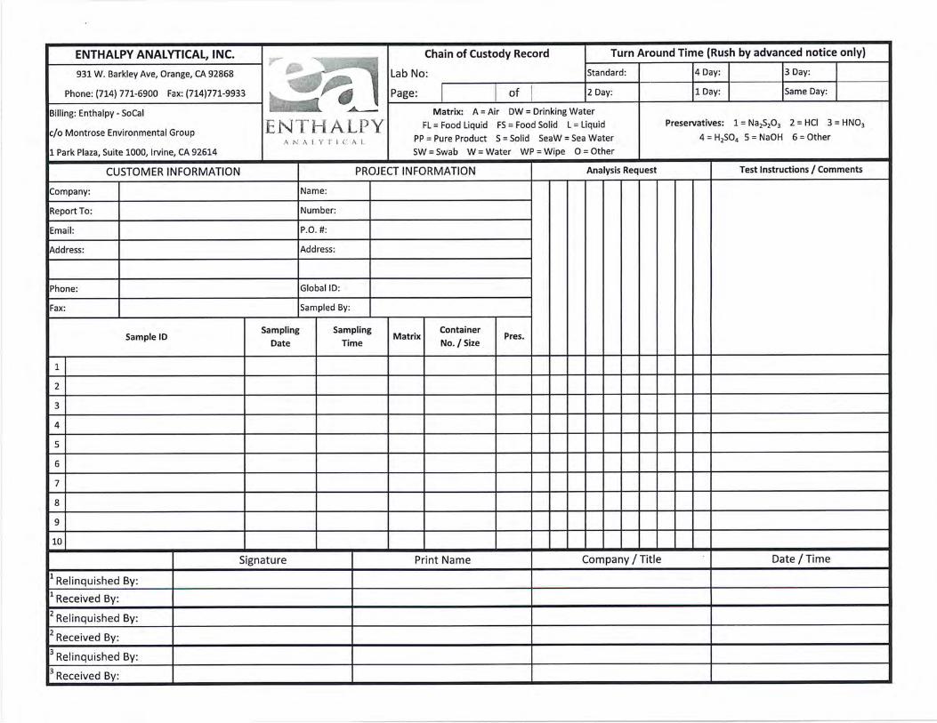

Former NIRF Undersea Center December 11, 2017 Pasadena, California Project No. 207220003
207220003 R QAPP
APPENDIX C-2
LABORATORY METHODS AND DETECTION LIMITS
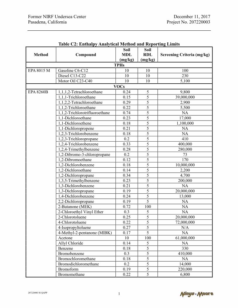
Former NIRF Undersea Center December 11, 2017 Pasadena, California Project No. 207220003
207220003 R QAPP 1
Table C2: Enthalpy Analytical Method and Reporting Limits
Method Compound Soil
MDL (mg/kg)
Soil RDL
(mg/kg) Screening Criteria (mg/kg)
TPHs EPA 8015 M Gasoline C6-C12 10 10 100
Diesel C13-C22 10 10 230 Motor Oil C23-C40 10 10 5,100
VOCs EPA 8260B 1,1,1,2-Tetrachloroethane 0.24 5 9,800
1,1,1-Trichloroethane 0.15 5 39,000,000 1,1,2,2-Tetrachloroethane 0.29 5 2,900 1,1,2-Trichloroethane 0.22 5 5,500 1,1,2-Trichlorotrifluoroethane 0.74 5 NA 1,1-Dichloroethane 0.23 5 17,000 1,1-Dichloroethene 0.18 5 1,100,000 1,1-Dichloropropene 0.21 5 NA 1,2,3-Trichlorobenzene 0.18 5 NA 1,2,3-Trichloropropane 0.2 5 410 1,2,4-Trichlorobenzene 0.33 5 400,000 1,2,4-Trimethylbenzene 0.28 5 280,000 1,2-Dibromo-3-chloropropane 0.2 5 73 1,2-Dibromoethane 0.12 5 170 1,2-Dichlorobenzene 0.18 5 10,000,000 1,2-Dichloroethane 0.14 5 2,200 1,2-Dichloropropane 0.34 5 4,700 1,3,5-Trimethylbenzene 0.23 5 200,000 1,3-Dichlorobenzene 0.21 5 NA 1,3-Dichloropropane 0.19 5 20,000,000 1,4-Dichlorobenzene 0.24 5 13,000 2,2-Dichloropropane 0.19 5 NA 2-Butanone (MEK) 0.72 100 NA 2-Chloroethyl Vinyl Ether 0.3 5 NA 2-Chlorotoluene 0.25 5 20,000,000 4-Chlorotoluene 0.22 5 72,000,000 4-Isopropyltoluene 0.27 5 N/A 4-Methyl-2-pentanone (MIBK) 0.17 5 NA Acetone 10 100 61,000,000 Allyl Chloride 0.14 5 NA Benzene 0.18 5 330 Bromobenzene 0.3 5 410,000 Bromochloromethane 0.18 5 NA Bromodichloromethane 0.2 5 14,000 Bromoform 0.19 5 220,000 Bromomethane 0.22 5 6,800

Former NIRF Undersea Center December 11, 2017 Pasadena, California Project No. 207220003
207220003 R QAPP 2
Table C2: Enthalpy Analytical Method and Reporting Limits
Method Compound Soil
MDL (mg/kg)
Soil RDL
(mg/kg) Screening Criteria (mg/kg)
EPA 8260B Carbon Tetrachloride 0.18 5 1,300 Chlorobenzene 0.18 5 1,500,000 Chlorodibromomethane 0.19 5 NA Chloroethane 0.2 5 NA Chloroform 0.17 5 1,500 Chloromethane 0.21 5 510,000 cis-1,2-Dichloroethene 0.2 5 10,000,000 cis-1,3-dichloropropene 0.2 5 8,400 cis-1,4-dichloro-2-butene 0.2 5 NA Dibromomethane 0.21 5 NA Dichlorodifluoromethane 0.23 5 780,000 Ethylbenzene 0.23 5 5,800 Hexachlorobutadiene 0.42 5 22,000 Isopropylbenzene 0.25 5 NA m and p-Xylene 0.38 5 580,000 Methyl-t-butyl Ether (MTBE) 0.17 5 NA Methylene chloride 0.21 5 54,000 N-butylbenzene 0.25 5 NA N-propylbenzene 0.22 5 NA Naphthalene 0.16 5 NA o-Xylene 0.19 5 580,000 Sec-butylbenzene 0.28 5 NA Styrene 0.13 5 38,000,000 Tert-butylbenzene 0.34 5 NA Tetrachloroethene 0.23 5 600 Toluene 0.17 5 46,000,000 trans-1,2-dichloroethene 0.19 5 500,000 trans-1,3-dichloropropene 0.18 5 NA trans-1,4-dichloro-2-butene 0.2 5 NA Trichloroethene 0.23 5 14,000 Trichlorofluoromethane 0.23 5 3,400,000 Vinyl Chloride 0.14 5 1,700 Xylenes (Total) 0.38 5 580,000
PAHs EPA 8270C 1-Methylnaphthalene 3.7 10 NA
2-Methylnaphthalene 3.8 10 NA Acenaphthene 1.4 10 3,600,000 Acenaphthylene 3.3 10 NA Anthracene 1.2 10 18,000,000 Benz(a)anthracene 1.1 10 160 Benzo(a)pyrene 1.8 10 16

Former NIRF Undersea Center December 11, 2017 Pasadena, California Project No. 207220003
207220003 R QAPP 3
Table C2: Enthalpy Analytical Method and Reporting Limits
Method Compound Soil
MDL (mg/kg)
Soil RDL
(mg/kg) Screening Criteria (mg/kg)
EPA 8270C Benzo(b)fluoranthene 1.7 10 160 Benzo(g,h,i)perylene 1.2 10 NA Benzo(k)fluoranthene 1.7 10 1,600 Chrysene 0.83 10 16,000 Dibenz(a,h)anthracene 1.4 10 16 Fluoranthene 0.84 10 2,400,000 Fluorene 1.3 10 2,400,000 Indeno(1,2,3-cd)pyrene 1.8 10 160 Naphthalene 4 10 NA Phenanthrene 1.4 10 NA Pyrene 0.78 10 1,800,000
Metals EPA 6010B Antimony 0.37 3 31
Arsenic 0.36 1 12 Barium 0.23 1 15,000 Beryllium 0.17 0.5 15 Cadmium 0.21 0.5 5.2 Chromium 0.13 1 36,000 Cobalt 0.19 0.5 23 Copper 0.31 1 3,100 Lead 0.32 0.5 80 Molybdenum 0.13 1 390 Nickel 0.2 1.5 490 Selenium 0.72 1 390 Silver 0.13 0.5 390 Thallium 0.42 1 0.78 Vanadium 0.37 0.5 390 Zinc 0.28 5 23,000
EPA 7471A Mercury 0.02 0.14 1.0 Notes: EPA - United States Environmental Protection Agency MDL - method detection limit mg/kg - milligrams per kilogram µg/kg - micrograms per kilogram NA - not available PAHs - polyaromatic hydrocarbons RDL - reporting detection limit TPHs - total petroleum hydrocarbons VOCs - volatile organic compounds

Former NIRF Undersea Center December 11, 2017 Pasadena, California Project No. 207220003
207220003 R QAPP
APPENDIX C-3
FIXED-SITE LABORATORY QUALITY ASSURANCE MANUAL

QUALITY ASSURANCE MANUAL
Revision November 2016
Effective 11/15/2016
Quality Assurance Guidelines Applicable to all Chemical and Microbiological Testing
ENTHALPY ANALYTICAL 931 W. Barkley Ave. ORANGE, CA 92868
714-771-6900

QUALITY ASSURANCE MANUAL ENTHALPY ANALYTICAL Revision: November 2016 Effective: November 15, 2016 Page: 3 of 48 TABLE OF CONTENTS
Management Quality Policy Statement ................................................................. 5 Organization and Management Structure ............................................................. 5 Job Descriptions of Key Staff ............................................................................... 6 Facilities, Major Equipment, and Services ........................................................... 6 Accreditations…………... ...................................................................................... 6 Personnel Qualifications ....................................................................................... 7 Personnel Training Program ................................................................................. 7 Document Control and Record Keeping ............................................................. 10 Review of Client Projects ................................................................................... 11 Protection of Client Confidentiality ...................................................................... 11 Conflict of Interest Statement .............................................................................. 11 Sample Receiving and Custody .......................................................................... 12 Sample Handling Practices and Chain of Custody ............................................. 12 Sample Containers, Holding Times, and Preservation ....................................... 13 Laboratory Information Management System ..................................................... 14 Standard Test Methods ....................................................................................... 15 Standard Operating Procedures ......................................................................... 16 Traceability of Measurements ............................................................................. 17 Calibration and Verification Procedures ............................................................. 18 Method Detection Limits ..................................................................................... 20 Procedures for Reporting Analytical Results ...................................................... 20 Data Review .................................................................................................... 22 Procedure for Handling Client Complaints .......................................................... 23
QUALITY ASSURANCE MANUAL ENTHALPY ANALYTICAL Revision: November 2016 Effective: November 15, 2016 Page: 4 of 48 Quality Assurance Procedures ........................................................................... 23 - Routine Quality Control Samples .................................................................. 24 - Other Essential Quality Control Procedures ................................................. 26 Quality Assurance Department Functions .......................................................... 26 - Laboratory Audits and Data Review ............................................................ 26 - External Proficiency Testing and Verification Practices ............................... 27 - Corrective Action Reports and Departures from Documented Policies ........ 27 - Laboratory Standard Operating Procedures and QA Manual ....................... 28 Management Reviews ........................................................................................ 29 Permitted Departures from Documented Policies and Procedures ................... 29 Control of Nonconforming Environmental Testing Work ..................................... 29 Preventive Actions……... .................................................................................... 29 Equipment Maintenance ..................................................................................... 30 References ......................................................................................................... 30 Quality Assurance Manual Revision History ....................................................... 31 APPENDICES Appendix A - Laboratory Job Descriptions ......................................................... 33 Appendix B - Sample Container and Preservation Guide .................................. 37 Appendix C - Equipment Inventory .................................................................... 39 Appendix D - Non-Conformance Criteria and Documentation Procedures ......... 46 Appendix E - Organization Chart ........................................................................ 48
QUALITY ASSURANCE MANUAL ENTHALPY ANALYTICAL Revision: November 2016 Effective: November 15, 2016 Page: 5 of 48 MANAGEMENT QUALITY POLICY STATEMENT It is the policy of Enthalpy Analytical to provide all Clients with test results that are accurate and legally defensible. Enthalpy Analytical Management is committed to good professional practices and quality in environmental testing as documented in the Quality Assurance Manual and all applicable NELAC standards. This policy has the full support of Management and must be accomplished with the cooperation of all employees. All personnel concerned with environmental testing within the laboratory are required to familiarize themselves with the quality documentation and implement the policies and procedures in their work. ORGANIZATION AND MANAGEMENT STRUCTURE Enthalpy Analytical is a privately-owned, independent subsidiary of Montrose Environmental Group, Inc. The Laboratory is organized into Departments as follows:
1. Sample Control (Sample Receiving, Sample Custodian, Sample Storage, and Field Services)
2. General Chemistry (CHEM) 3. Metals/IC (AAICP) 4. Volatile Organic Compounds (VOA) 5. Semi-Volatile Organic Compounds (SVOA) 6. Microbiology/Bioassay (MICRO) 7. Front Office (Project Management) 8. Quality Assurance (QA) Department
Each Department, except for the QA Department, is managed by a Department Supervisor who reports to the Technical Director, who reports to the Laboratory Director, who reports to the Vice President. Sales, IT, and Front Office Personnel report directly to the Laboratory Director. The QA Department operates independently of other Departments. The QA Director reports directly to the Vice President. An Organization Chart is attached in Appendix E. The Laboratory Director manages all operations of the laboratory. The QA Director, Laboratory Director, Technical Director, and Project Managers are the official signatories of all Laboratory Analysis Reports. The QA Director is the official signatory for Quality Assurance documents. The Laboratory Director and Technical Director are the official signatories of other official documents of the Laboratory. The signature page of this document includes all approved laboratory signatories. All personnel are employees of the Laboratory. Where contracted and additional technical and key support personnel are used, the Laboratory ensures that such personnel are supervised and competent, and that they work in accordance with the Laboratory’s quality system.
QUALITY ASSURANCE MANUAL ENTHALPY ANALYTICAL Revision: November 2016 Effective: November 15, 2016 Page: 6 of 48 JOB DESCRIPTIONS OF KEY STAFF The job descriptions of key staff are attached (Appendix A). FACILITIES, MAJOR EQUIPMENT, AND SERVICES ENTHALPY ANALYTICAL is located in two buildings: Main Office and Laboratory: 931 West Barkley Avenue, Orange, CA 92868 Annex: 1108 West Barkley Avenue, Orange, CA 92868 Telephone: 714-771-6900 Fax No: 714-538-1209 Enthalpy Analytical has been in operation for over 90 years and currently employs 40+ personnel. The main facility occupies 9,700 square feet; 2,300 square feet is laboratory space, 2,200 square feet is office space, and 5200 square feet is warehouse space. The Annex occupies 7,500 square feet and is maintained free of organic solvent vapors for analysis of volatile organic compounds. The Annex also contains the microbiology and metals/IC laboratories. Refrigerators and freezers are provided for sample storage according to method requirements. Samples are stored in refrigerators and freezers separate from analytical standards to avoid cross contamination. The Laboratory monitors, controls, and records environmental conditions, as required by the relevant specifications, methods, and procedures, where they influence the quality of the results. If environmental conditions are specified in a test method or by a regulation, the environmental conditions are documented on the sample preparation documents or separate monitoring documents. Special procedures are developed when necessary to meet such specified environmental conditions. The latest equipment inventory is attached (Appendix C). ACCREDITATIONS Enthalpy Analytical is accredited by the following agencies:
State of California, Water Boards, Environmental Laboratory Accreditation Program, Richmond, Certificate No. 1338 Oregon Environmental Laboratory Accreditation Program, Certificate No. 4038
NELAP Primary
State of Hawaii, Department of Health, Safe Drinking Water Branch
QUALITY ASSURANCE MANUAL ENTHALPY ANALYTICAL Revision: November 2016 Effective: November 15, 2016 Page: 7 of 48
U.S. Food and Drug Administration, Department of Health and Human Services, Certificate No. 2083634
U.S. Department of Agriculture, Permit to Receive Soil, Permit No. P330-16-
00027_20160126
Centers for Disease Control and Prevention, ELITE Program PERSONNEL QUALIFICATIONS The Laboratory Management shall ensure the competence of all who operate specific equipment, perform environmental tests and/or calibrations, evaluate results, and sign test reports. The Laboratory Management shall be responsible for checking the qualifications of persons before hiring based on the minimal level of qualification, experience, and skills necessary for all positions in the laboratory (see Appendix A, Laboratory Job Descriptions). In addition to education and/or experience, basic laboratory skills such as using a balance, colony counting, aseptic, or quantitative techniques shall be considered. Any falsification or inaccuracy of the employment application or educational diploma will be cause for termination of employment. Records of personnel qualifications, training, and experience are maintained in the employee training files by the QA Department. The Laboratory training program is detailed below. PERSONNEL TRAINING PROGRAM All personnel shall be responsible for complying with the quality assurance/quality control requirements that pertain to their organizational/technical function. Each technical staff member must have a combination of experience and education to adequately demonstrate specific knowledge for their particular function and a general knowledge of laboratory operations, test methods, quality assurance/quality control procedures, and records management. All current as well as new technical personnel are required to become familiar with the following documents: Laboratory Safety Manual - A formalized laboratory safety training course has been established, including a video discussion of safety and a written test. An attendance log and the test results are filed in the Employee Safety Documentation File. Each employee is required to read the Laboratory Safety Manual. Quality Assurance Manual - The Quality Assurance Manual is available in all as an electronic copy (P:\SOPs), accessible through any network computer. All employees are required to understand and follow the appropriate Quality Assurance guidelines and procedures. Standard Operating Procedures - Standard Operating Procedures (SOPs) are available to all analysts for most analytical methods. An SOP provides detailed procedures and QA acceptance limits for the method. Analysts are required to understand and follow the standard method

QUALITY ASSURANCE MANUAL ENTHALPY ANALYTICAL Revision: November 2016 Effective: November 15, 2016 Page: 8 of 48 requirements as detailed in the SOP for each analytical method. Each SOP is reviewed annually by the analysts and Department Supervisor to ensure that the SOP accurately describes the analytical procedure. All SOPs are approved by the Department Supervisor, the Technical Director, and the QA Director. The Department Supervisor is responsible for ensuring that all department personnel read and understand the Safety Manual, QA Manual, standard methods and appropriate SOP's. Completion of these requirements and other specific training is documented in the employee training records. Training records are kept in the employee training file maintained for each technical employee. Records of successful completion of training courses and other formalized training are also kept in the employee training files. In addition, the following training is conducted: Technicians are given on-the-job training for each new method or procedure by the Department Supervisor or an experienced analyst designated by the Department Supervisor. During the training period the Department Supervisor or experienced analyst continues to be responsible for all analytical results produced by the trainee. This training is documented on the employee's training record. Competence to perform each analysis is determined by the Department Supervisor’s direct evaluation and successful analysis of Lab Control Samples and/or Proficiency Testing Samples. Analysts are encouraged to attend outside classes or other relevant training to increase their job knowledge. Attendance at these courses/seminars is recorded in the training record. Training Files Training files for each employee are maintained by the QA Department. The training files contain training logs, sign-off sheets for the QA Manual and Standard Operating Procedures, Initial and Continuing Demonstration of Capability Certificates, and supporting documentation. The training files are updated on an ongoing basis. Each individual is responsible for providing documentation of training to the QA Department for inclusion in the individual’s training file. Each employee signs SOP Acknowledgement Forms to confirm that he/she has read, understood, and is using the latest version of the laboratory's in-house quality documentation, which relates to his/her job responsibilities. Demonstration of Capability For NELAP certified tests an Initial Demonstration of Capability (IDOC) must be accomplished prior to becoming certified for any test method and at any time there is a change in instrument type, personnel, or test method (TNI Standard, 2009, Volume 1, Module 4, Section 1.6). The Demonstration of Capability is updated annually, and a signed certification is placed in the employee training file for each method. When a work cell is employed, the performance of the group is linked to the training record of the individual members of the work cell. The analyst training on each method shall be considered up to date if the employee training file contains a certification that the analyst has read, understood, and agreed to perform the most recent version of the test method (the approved method or SOP as defined by the laboratory

QUALITY ASSURANCE MANUAL ENTHALPY ANALYTICAL Revision: November 2016 Effective: November 15, 2016 Page: 9 of 48 document control system) and documentation of continued proficiency by at least one of the following once per year:
a) acceptable performance of a blind sample (single blind to the analyst);
b) an ongoing demonstration of capability;
c) successful analysis of a blind performance sample on a similar test method using the same technology (e.g., GC/MS volatiles by purge and trap for Methods 524.2, 624 or 5036/8260) would only require documentation for one of the test methods;
d) at least four consecutive laboratory control samples with acceptable levels of precision
and accuracy; or
e) if a.-d. cannot be performed, analysis of authentic samples with results statistically indistinguishable from those obtained by another trained analyst
A certification statement is completed to document the completion of each demonstration of capability. This certification is signed by the Department Supervisor and the analyst. A copy of the certification statement is retained in the personnel records of each affected employee. Ethics Policy and Data Integrity Training To prevent Data Fraud/Inappropriate Practices, all technical personnel are trained in ethical and legal responsibilities. Examples of Data Fraud are identified below:
1. inappropriate use of manual integrations to meet calibration or method QC criteria would be considered fraud. For example, peak shaving or peak enhancement are considered fraudulent activities if performed to meet QC requirements;
2. time travel of analyses to meet method holding time requirements;
3. falsification of results to meet method QA requirements;
4. reporting of results without analyses to support the results;
5. selective exclusion of data to meet QC criteria (i.e. initial calibration points dropped
without technical or statistical justification);
6. misrepresentation of laboratory performance by presenting calibration data or QC data within data reports which are not linked to the data set reported;
7. notation of matrix interference as basis for exceeding acceptance limits (typically without
implementing corrective actions) in interference-free matrices (e.g. MB or LCS) The potential punishments and penalties for improper, unethical, or illegal actions include immediate dismissal and possible legal court action. All personnel are required to undergo ethics training and then sign the Ethics and Data Integrity Agreement annually. These forms are filed in the QA Office.
QUALITY ASSURANCE MANUAL ENTHALPY ANALYTICAL Revision: November 2016 Effective: November 15, 2016 Page: 10 of 48 Internal audits, which are performed periodically, monitor data integrity. Any allegations of improper reporting or manipulation of data are investigated promptly. The QA Director, the Laboratory Director, Technical Director, and Laboratory Management will keep an open door policy such that any employee who believes that they have witnessed unethical behavior may report it without fear of repercussion. DOCUMENT CONTROL AND RECORD KEEPING All documents relating to laboratory analyses and reporting are kept a minimum of five years (10 years for all documents related to analyses of metals in drinking water). After that time, the records are destroyed unless special arrangements are made. In the event that Enthalpy Analytical transfers ownership or goes out of business, all Clients shall be informed. All records shall be maintained in storage for up to two years or transferred according to the Clients’ instructions. The Laboratory maintains a tracking system for SOPs, MDL determinations, training documentations, and corrective actions. These records are kept by the QA Department. A Lab Request is created by the Laboratory Information Management System (LIMS) for each group of samples received from a Client to enable organization and tracking of the analyses and final reporting. All analytical results are reported in the LIMS database, including date of analysis and analyst initials (please refer to the LIMS section for more information). All documentation submitted with Client samples including the Chain of Custody (COC) and Sample Acceptance Checklist (Cooler Sheet) are scanned electronically at login and attached to the created Lab Request (LR), so they are available through the LIMS interface. All documentation relating to the analysis of a Client’s samples, including a copy of the final report, COC, all sample preparation worksheets, and analytical raw data may be attached to each Lab Request. Beginning in January of 2016, raw data generated by the Laboratory, and any supporting documentation for the analysis of samples, including written preparation logs, are scanned into LIMS and linked to the LIMS QC batch, allowing for the recall of the raw data when searching the LR in LIMS. The network servers where the data files are stored are regularly backed up. Prior to January 2016, raw data generated by the lab was stored in a package for each LR. Logbook entries of data and preparations are stored and maintained by the departments and the QA department. All calibration data and other relevant data such as calibration checks, which may apply to multiple LRs, are filed and retained in the individual departments. Corrections All hand-written data is recorded in permanent ink. Entries in records shall not be obliterated by erasures, overwriting, or markings. All corrections to record-keeping errors shall be made by one line marked through the error. The individual making the correction shall initial and date the correction. If the reason for the correction is not obvious, the reason must also be written next to the correction. The document control system establishes procedures to ensure that all records required under
QUALITY ASSURANCE MANUAL ENTHALPY ANALYTICAL Revision: November 2016 Effective: November 15, 2016 Page: 11 of 48 the laboratory certification are retained. Procedures for control and maintenance of documentation through a document control system ensure that all SOPs, manuals, or documents clearly indicate the time period during which the procedure or document was enforced. Document control procedures are defined in the Document Control SOP, A-0010. REVIEW OF CLIENT PROJECTS New projects and contracts are reviewed by Laboratory Management to ensure that the Laboratory has the technical capability and resources to meet the requirements. Any potential conflict of interest or other problem noted in the review is discussed with the Client prior to acceptance of the contract or samples. Refer to the Project Management SOP, J-0012. The laboratory will work to clarify the requests of Clients or their representatives, when necessary, and monitor the Laboratory’s performance in relation to the work performed. Client confidentiality is a high priority and the Laboratory will ensure confidentiality of each Client’s work while providing service to other Clients. PROTECTION OF CLIENT CONFIDENTIALITY Enthalpy Analytical recognizes the importance of Client confidentiality. The reports of Enthalpy Analytical are the confidential property of our Clients and may not be reproduced or used for publication in part or in full without our written permission. This is for the mutual protection of the public, our Clients, and ourselves. Each LR contains a statement to the above effect. Analysis results are released to third parties only with the permission of the Client. Confidentiality agreements may be signed by Laboratory Management should the Client so desire. CONFLICT OF INTEREST STATEMENT Enthalpy Analytical recognizes that certain situations may generate conflict of interest between Enthalpy Analytical and its client, and/or Enthalpy Analytical and its employees. To minimize the risk of an appearance or actual conflict of interest, Enthalpy Analytical will strive to identify relationships between itself and its clients, and its employees that may constitute a conflict. Specifically, Enthalpy Analytical employees are not allowed to 1.) work for a direct Enthalpy Analytical competitor in any capacity, 2.) accept gifts, gratuities, or awards in excess of $100 valuation in a 12 month period from any client, supplier, or in excess of $200 valuation from all clients suppliers or agencies in a 12 month period, or 3.) work directly for a client of Enthalpy Analytical in the same, or related capacities as work performed for Enthalpy Analytical. The appearance of, or actual conflict, must be corrected by terminating either the client or the employment relationship with Enthalpy Analytical."

QUALITY ASSURANCE MANUAL ENTHALPY ANALYTICAL Revision: November 2016 Effective: November 15, 2016 Page: 12 of 48 SAMPLE RECEIVING AND CUSTODY All sample receiving and login is handled by the Sample Receiving Department and proceeds as follows:
1. All samples received from a Client on the same day on the same Chain of Custody (COC) are normally grouped together under a unique LR Number. The LR Number is assigned by the LIMS.
2. All samples are assigned a unique sample (order) number during the log-in process.
This number consists of the LR number along with a number for the specific sample on the COC. Together they comprise a unique number for the sample. This number is also assigned by the LIMS.
3. All documentation submitted with Client samples (including the COC) is scanned
electronically and attached in the LIMS to the LR Number generated in step 1.
4. A Sample Acceptance Checklist (also called a Cooler Sheet) is prepared by Sample Receiving personnel and includes Client information, cooler/temperature information, sample condition, and spaces for comments regarding sample condition and notification of project management regarding such. This is also scanned electronically and attached in the LIMS to the LR number generated in step 1.
5. A Laboratory Request Summary is prepared by Sample Receiving personnel and
includes date and time sampled, Client name, Client sample ID, corresponding laboratory sample (order) numbers, all analyses to be performed, laboratory area designations, and special instructions.
Procedures for Sample Receiving and Custody are detailed in SOP J-0006. SAMPLE HANDLING PRACTICES AND CHAIN OF CUSTODY
1. After samples are logged in, they are transferred to the Warehouse for cold storage or to the laboratory if the sample hold time or turnaround time warrant quick processing.
2. All transfer of samples into and out of Sample Receiving and the Warehouse is
documented in Sample Custody Logbooks.
3. Samples are stored according to the conditions specified by preservation protocols. Samples which require thermal preservation are stored at +/- 2 °C of the specified preservation temperature unless method-specific criteria exist. For samples with a specified storage temperature of 4°C, storage at a temperature above the freezing point of water to 6°C is considered acceptable.
4. Samples are stored away from all standards, reagents, food, and other potentially-
contaminating sources. Samples are stored in such a manner as to prevent cross contamination.
QUALITY ASSURANCE MANUAL ENTHALPY ANALYTICAL Revision: November 2016 Effective: November 15, 2016 Page: 13 of 48
5. Samples for Volatiles analysis are stored separately from all other samples. The
refrigerators these samples are stored in have refrigerator blanks – a VOA vial filled with DI water – that are analyzed on a weekly basis to check for possible contamination in the refrigerators. A new refrigerator blank is put in each refrigerator when the previous week’s blank is removed for analysis. Each golf cart that is used to transport samples between buildings has a travel blank. The travel blanks are analyzed on a daily basis to check for possible contamination during the transport of the samples.
6. Sample fractions, extracts, leachates, and other sample preparation products are stored
according to #3 above or according to specifications in the test method.
7. The temperature of each refrigerator used for sample storage is monitored twice each working day and recorded on the Temperature Control Record. This record is attached to each refrigerator. When the record is completely filled in, it is filed for future reference with the Department Supervisor. If the temperature is out of control limits, the Laboratory Director, Technical Director, or Quality Assurance Director must be notified immediately. All samples in the defective refrigerator must be recorded. The results of the defective samples must be flagged. The Clients that submitted the samples in the defective refrigerator must be informed within 48 hours.
8. Unless the Client notifies the lab in writing of an alternative request, the lab will dispose
of all samples by appropriate disposal protocol thirty days from the date of the final report. Solid, liquid, and samples of unknown hazard are discarded in designated hazardous waste disposal containers. These containers are picked up periodically by a hazardous waste disposal company. Domestic and wastewater samples are disposed of down the drain.
SAMPLE CONTAINERS, HOLDING TIMES, AND PRESERVATION Most methods have recommendations regarding the containers in which samples for analysis are collected, transported, and stored until analysis. In general, the shorter the time that elapses between collection of a sample and analysis, the more reliable the analytical results will be. Chemical preservation of samples is specified in many methods. Use of the proper container and chemical preservation are confirmed by the laboratory during the sample log-in process, and the processing of samples for analysis. Clients are contacted by project management if samples are received in improper containers or are improperly chemically preserved. If the client authorizes the laboratory to proceed with the analysis of these samples, the results are reported with the appropriate data qualifier. The holding time for an analysis is the maximum time that samples may be held before preparation and/or analysis for the analysis to be considered valid. Each department is familiar with the holding times for the sample analyses that they perform. The Department Supervisor is responsible for ensuring that, if possible, these holding times are met. If holding times are not able to be met, every effort is made to notify the Client and, if necessary, send the samples to another laboratory. If the Client consents to analysis of samples by the Laboratory outside of holding times, the resulting data are reported with the appropriate data qualifier. Both extraction and analysis holding times are stored in the LIMS for each test and matrix, as well as the
QUALITY ASSURANCE MANUAL ENTHALPY ANALYTICAL Revision: November 2016 Effective: November 15, 2016 Page: 14 of 48 recommended sample preservation. The LIMS can print backlog reports that sort samples in order of their hold time or their due date. Holding times always supersede turnaround times in due date calculations by the LIMS. Appendix B contains sample container guidelines and holding times as specified by the analytical methods used. LABORATORY INFORMATION MANAGEMENT SYSTEM (LIMS) Enthalpy Analytical implements a LIMS. The laboratory information management system (LIMS) is a Client-server network of computers used to login samples, track samples during and after analysis, manage QA/QC batching and reporting, provide a means for result entry (either manually or imported), and generate a variety of reports for Clients including final results and QC summaries. In addition the LIMS software, which is database driven, is able to generate historical reports and trends, control charts, and other types of reports such as electronic deliverables. The LIMS system is also used to track and enforce such laboratory data as method detection limits (MDLs) and reporting detection limits (RDLs) for analytes in a given matrix, test specifications such as standard QC types, preservation, container type, and turnaround times. Control charts for a given analyte and test can be generated and the underlying control limits updated at any time. All reports are reviewed and electronically signed by designated managers before release to the Client. Tracking reports are generated daily from the LIMS to ensure timely analysis and reporting of all Client samples. The hardware components of the LIMS include a pool of multiple physical servers running VMware virtualization software which allows individual task-based application servers to be virtualized as virtual machines which have access to all pooled resources. There are two primary virtual servers handling the LIMS workload with other virtual servers performing various management, backup, and security duties and approximately fifty networked PC-compatible computers running Windows 2000 - Windows 7. Refer to the Data Auditing and Access Procedures SOP A-0012, and Data Backup SOP A-0013 for virtual server specifics. The LIMS Software consists of Sample Master Version 8.5 by Accelerated Technologies, Inc. using SQL Server 2008 as its backend database. Virtualizing the servers makes common maintenance tasks such as real time backups, disaster recovery, and provisioning new storage much easier. The Sample Master front end does have some in-house customization but not to any of its core functionality or calculations. Most in-house customizations are related to search functionality to make searches more efficient and also to incorporate archived data from our old LIMS, which is stored on a separate database server, to be viewed directly in Sample Master. The old LIMS still resides on a separate virtual server running Oracle 10g and contains static data and is only used for historical data-searching purposes. Physical security consists of all servers, network hardware, and server backup systems being located in locked rooms that may only be accessed by authorized personnel. Network security is maintained by a combination of a sophisticated firewall including intrusion detection with gateway antivirus/malware and network-based antivirus/malware software which keeps all servers and workstations updated daily. Access security consists of a password login system for both the LIMS itself and the network domain along with user and group permissions as defined in the Enthalpy Analytical Data SOP. Separate LIMS password security is necessary for computers that are running instruments where someone other than the logged-in network user

QUALITY ASSURANCE MANUAL ENTHALPY ANALYTICAL Revision: November 2016 Effective: November 15, 2016 Page: 15 of 48 may need to access the LIMS to perform LIMS tasks. The LIMS database and virtual machines are scheduled for a full backup daily. The database transaction log backups are performed hourly allowing the data to be restored to a specific in time. All backed up data are stored on a separate NAS device. (Please refer to the Enthalpy Analytical Data Backup SOP for complete details.) Laboratory data can be delivered to the Client in electronic data deliverable (EDD) formats such as: spreadsheet (Excel); standard database file formats (Access); delimited or fixed field formatted ASCII; industry standard formats such as COELT; or word processing formatted. Reports generated by the LIMS may also be distributed electronically as PDF files. All LIMS reports distributed as PDF shall have “PRELIMINARY” displayed prominently on the report, unless all results have been approved and the report has been signed by the designated staff. Only the final report in PDF or hard copy, signed by designated staff, is the official report. The data files can be transmitted to the Client either by standard mail, e-mail, or FTP protocols. STANDARD TEST METHODS Essentially all laboratory analyses are conducted using published standard methods. Standard method sources that are available for use are listed below. Analytical Standard Procedures for Environmental Analyses: Methods for Chemical Analysis of Water and Wastes, EPA-600/4-79- 020, 3/1983. Standard Methods for the Examination of Water and Wastewater (American Public Health Association). 40 CFR, Appendix A to part 136-Methods for Organic Chemical Analysis of Municipal and Industrial Wastewater (600-series methods). Methods for the Determination of Organic Compounds in Drinking Water, Supplement III, EPA-600/R-95/131, August 1995. (500-series methods). Methods for the Determination of Inorganic Substances in Environmental Samples, EPA/600/R-93/100, August 1993. Methods for the Determination of Metals in Environmental Samples, Supplement I EPA/600/R-94/111, May 1994. Test Methods for Evaluating Solid Waste, SW-846, 3rd Edition. Analytical Standard Procedures for Food, Feeds, Oil/Fats, and Pharmaceuticals: Association of Official Analytical Chemists (AOAC). The American Oil Chemists' Society (AOCS). Methods of the U.S. Department of Agriculture (USDA).
QUALITY ASSURANCE MANUAL ENTHALPY ANALYTICAL Revision: November 2016 Effective: November 15, 2016 Page: 16 of 48 FDA Pesticide Analytical Manual (PAM). US Pharmacopeia/National Formulary (USP/NF). Food Chemicals Codex (FCC). American Society for Testing and Materials (ASTM). Methods Not Covered by Standard Methods When it is necessary to use methods not covered by standard methods, the methods are subject to agreement with the Client. This agreement includes a clear specification of the Client’s requirements and the purpose of the environmental test and/or calibration. The method is validated appropriately before use. STANDARD OPERATING PROCEDURES Standard Operating Procedures (SOPs) are available for most methods to indicate specific procedures, instrumentation, data needs, and laboratory data quality requirements. SOPs are available to the analyst and are reviewed at least annually to ensure that method and QA requirements are being met. The original versions of the SOPs are filed in the QA Department, and controlled copies are made available to the Departments. PDFs of SOPs are also available on the network. PDFs are protected from being printed. An inventory list of all current SOPs is maintained by the QA Department. Each test method shall include or reference where applicable: 1. Identification of the test method; 2. Applicable matrix or matrices; 3. Detection limit; 4. Scope and application, including components to be analyzed; 5. Summary of the test method; 6. Definitions; 7. Interferences; 8. Safety; 9. Equipment and supplies; 10. Reagents and standards; 11. Sample collection, preservation, shipment, and storage; 12. Quality control; 13. Calibration and standardization; 14. Procedure; 15. Calculations; 16. Method performance; 17. Pollution prevention; 18. Data assessment and acceptance criteria for quality control measures; 19. Corrective actions for out-of-control data; 20. Contingencies for handling out-of-control or unacceptable data; 21. Waste management;

QUALITY ASSURANCE MANUAL ENTHALPY ANALYTICAL Revision: November 2016 Effective: November 15, 2016 Page: 17 of 48 22. References; and 23. Any tables, diagrams, flowcharts, and validation data. TRACEABILITY OF MEASUREMENTS Traceability of measurements is achieved by using standards for calibration and calibration checks which are traceable to primary National Institute of Standards and Technology (NIST) standards. Certificates of Analysis or purity are kept on file for each standard purchased, showing the traceability of the standard to a primary NIST standard. All balances are calibrated daily, prior to use, using NIST certified weights and are certified annually by a third-party contractor. Balance certifications are kept in the QA Office. The continuing calibration of every balance is monitored by each department in a logbook for that purpose dedicated to each balance. Thermometers are also calibrated at least annually using a thermometer certified against an NIST temperature standard. Thermometer calibrations are conducted and the records maintained by the QA Department. Pipettes are calibrated by each Laboratory Department at least quarterly.
When standard solutions, spiking solutions, and calibration check solutions are prepared, the following information is recorded in a Standards Traceability Notebook maintained by each Laboratory Department:
a. The identifying name of the Working Standard consists of the Working Standard identification and the date of preparation. This name must be unique and apply to only one standard solution such that the standard can be unequivocally traced back to the date of preparation, analyst, and all original standards and reagents used to prepare the standard.
b. Date of preparation and analyst’s initials;
c. The name, manufacturer, and lot number of each analytical standard and reagent used
in the solution;
d. The volume of each standard and reagent used and the final volume of the solution; and
e. The calculated concentration of all analytes in the final solution. The final standard solutions are transferred to a storage container and labeled with the Working Standard Identification, date of preparation, expiration date, concentration, and initials of the analyst who prepared the solution. All commercially-prepared standards have a maximum expiration date of one year from the date of opening or other expiration date as established and documented by the supplier. Reagents are purchased from established commercial suppliers as specified by the standard method or SOP. Reagents are stored at the appropriate temperature (refrigeration, freezing, room temperature, etc.) as specified by the supplier.

QUALITY ASSURANCE MANUAL ENTHALPY ANALYTICAL Revision: November 2016 Effective: November 15, 2016 Page: 18 of 48 Lot numbers of reagents are recorded on sample preparation log sheets or in analysis logbooks to enable traceability. CALIBRATION AND VERIFICATION PROCEDURES Initial Calibrations Criteria for Initial Calibrations are specified in the applicable method and SOP for each method. The following items are essential elements of initial instrument calibration:
a) The details of the initial instrument calibration procedures including calculations, integrations, acceptance criteria, and associated statistics included or referenced in the test method SOP;
b) Sufficient raw data records are retained to permit reconstruction of the initial instrument
calibration, e.g., calibration date, test method, instrument, analysis date, each analyte name, analyst’s initials or signature; concentration and response, calibration curve, response factor, or unique equation or coefficient used to reduce instrument responses to concentration;
c) Sample results must be quantitated from the initial instrument calibration and may not be
quantitated from any continuing instrument calibration verification unless otherwise required by regulation, method, or program;
d) All initial instrument calibrations must be verified with an Initial Calibration Verification
standard (ICV) obtained from a second manufacturer or lot number. Standards for the initial calibration are traceable to an NIST standard, when available;
e) Criteria for the acceptance of an initial instrument calibration must be established, e.g.,
correlation coefficient or relative percent difference. The criteria used must be appropriate to the calibration technique employed;
f) Results of samples outside of the concentration range established by the initial
calibration must be reported with defined qualifiers or flags or explained in the case narrative. The lowest calibration standard must be above the MDL and at or below the analyte’s Reporting Limit;
g) If the initial instrument calibration results are outside established acceptance criteria,
corrective actions must be performed before doing the initial instrument calibration again, and all associated samples should be reanalyzed. If reanalysis of the samples is not possible, data associated with an unacceptable initial instrument calibration are reported with appropriate data qualifiers;
h) Calibration standards must include concentrations at or below the regulatory
limit/decision level, if these limits/levels are known by the laboratory, unless these concentrations are below the laboratory’s demonstrated detection limits;

QUALITY ASSURANCE MANUAL ENTHALPY ANALYTICAL Revision: November 2016 Effective: November 15, 2016 Page: 19 of 48
i) The minimum number of points for establishing the initial instrument calibration is determined by the method and regulatory guidelines and stated in the SOP for each method.
Continuing Calibration Verification (CCV) When an initial instrument calibration is not performed on the day of analysis, the validity of the initial calibration is verified prior to sample analyses by continuing instrument calibration verification (CCV) with each analytical batch. The following items are essential elements of a CCV:
a. The details of the CCV, calculations, and associated statistics must be included or referenced in the test method SOP.
b. A CCV must be repeated at the beginning and end of each analytical batch, and
periodically throughout the batch, when a method requires this. If an internal standard is used, only one CCV must be analyzed per analytical batch, prior to sample analysis.
c. Sufficient raw data records must be retained to permit reconstruction of the CCV, e.g.
test method, instrument, analysis date, each analyte name, and concentration and response or calibration curve or response factor or unique equations or coefficients used to convert instrument responses into concentrations. CCV records must explicitly connect the continuing verification data to the initial instrument calibration.
d. Criteria for the acceptance of a continuing instrument calibration verification must be
established, e.g., relative percent difference.
e. If the CCV results obtained are outside established acceptance criteria, corrective actions must be performed. If routine corrective action procedures fail to produce a second consecutive (immediate) calibration verification within acceptance criteria, then either the laboratory has to demonstrate performance after corrective action with two consecutive successful calibration verifications or a new initial instrument calibration must be performed. If the laboratory has not demonstrated acceptable performance, sample analyses shall not occur until a new initial calibration curve is established and verified. If reanalysis of the samples is not possible, data associated with an unacceptable calibration verification may be reported under the following conditions:
1. When the CCV fails high: i. If the sample results are non-detect, the results can be reported without
the need for a qualifier. ii. If the sample has detections, the results must be qualified and the client
notified of the situation. 2. When a CCV fails low:
i. If sample results that exceed a maximum regulatory limit or decision level may be reported. The results still must be qualified and the situation explained to the client.
ii. If sample results are non-detect, or do not exceed a maximum regulatory limit or decision level, the results must be flagged and the client notified of the situation.
QUALITY ASSURANCE MANUAL ENTHALPY ANALYTICAL Revision: November 2016 Effective: November 15, 2016 Page: 20 of 48 METHOD DETECTION LIMITS Method Detection Limits (MDLs) are determined by taking seven or more aliquots of a sample containing the compounds of interest at a concentration 1 to 5 times the estimated detection limit and processing each sample through the entire analytical method. The MDL is calculated from the standard deviation of the replicate measurements as follows: MDL = 3.143 x Standard Deviation of the seven replicate measurements (or the appropriate student-T value if more than 7 replicates are used) MDL studies for inorganic methods are performed annually or when a major modification is made to the method or instrumentation used for analysis. MDL studies for organic methods are performed when a major modification is made to the method or instrumentation used for analysis. MDLs are updated in the LIMS and tracked by the QC Department. See the SOP for Determination and Updating of MDL/DLR/LODs (SOP A-0003). PROCEDURES FOR REPORTING ANALYTICAL RESULTS Final Reports issued to Clients contain at a minimum the following information: The report identification (Lab Request number) and page number is printed at the bottom of each page;
1. The Cover Page(s) includes the Laboratory name and address, phone number, and name
and signature of the person authorizing the report. The Cover Page(s) also includes the Client name, address, Client ID number, project identification, Client contact or project manager, date of sample receipt at the laboratory, and a cross-reference of lab identification numbers and Client sample identifications. The Cover Page includes the statement: “The reports of the Enthalpy Analytical are confidential property of our clients and may not be reproduced or used for publication in part or in full without our written permission. This is for the mutual protection of the public, our clients, and ourselves.”
2. The Lab Report pages detail the date and time of sample collection, the test results,
analysis units, methods of analysis, detection limits, dates of analyses and analyst initials. The time of preparation or analysis is reported when the holding time for preparation or analysis is 72 hours or less.
3. The original copy of the COC is attached to the final report; 4. A copy of the Sample Acceptance Checklist (Cooler Sheet) is attached to the final report.
5. A copy of other documents received with the COC from the client may be attached to the
final report, if applicable. 6. For NELAC reports and data packages, a case narrative may be attached. The case
narrative describes where the analyses were performed if they were not performed at the

QUALITY ASSURANCE MANUAL ENTHALPY ANALYTICAL Revision: November 2016 Effective: November 15, 2016 Page: 21 of 48
main address of the laboratory. Normally all analyses for volatile organic chemicals, organic volatiles in air, metals and microbiology are performed in the laboratory annex, located at 1108 West Barkley (one half block from the main laboratory building.
7. The case narrative also lists the number and identification of all discrete pages in the report
and the total number of pages in the complete report. 8. A statement is included in the case narrative that the test results meet all requirements of
NELAC. If they do not, reasons and/or justification are provided. 9. In addition to the requirements listed above, test reports shall, where necessary for the
interpretation of the test results, include the following:
a. Deviations (such as failed quality control) from, additions to, or exclusions from the test method, and information on specific test conditions, such as environmental conditions and any non-standard conditions that may have affected the quality of results, including the use and definitions of data qualifiers;
b. Where relevant, a statement of compliance/non-compliance with requirements and/or specifications, including identification of test results derived from any sample that did not meet NELAC sample acceptance requirements such as improper container, holding time, or temperature;
c. Where applicable, a statement on the estimated uncertainty of measurement. Information on uncertainty is needed in test reports when it is relevant to the validity or application of the test results, when a Client's instruction so requires, or when the uncertainty affects compliance to a specification limit.
d. Where appropriate and needed, opinions and interpretations;
e. Additional information which may be required by specific methods and Clients or groups of Clients;
f. Clear identification of numerical results with values outside of quantitation limits. 10. In addition to the requirements listed above, test reports containing the results of sampling
shall include the following, where necessary for the interpretation of test results:
a. The date and time of sampling
b. Unambiguous identification of the substance, material, or product sampled (including the name of the manufacturer, the model or type of designation and serial numbers as appropriate);
c. The location of sampling, including any diagrams, sketches or photographs;
d. A reference to the sampling plan and procedures used;
e. Details of any environmental conditions during sampling that may affect the interpretation of the test results;
QUALITY ASSURANCE MANUAL ENTHALPY ANALYTICAL Revision: November 2016 Effective: November 15, 2016 Page: 22 of 48
f. Any standard or other specification for the sampling method or procedure, and deviations, additions to or exclusions from the specification concerned.
11. Analytical results to be reported on a preliminary basis must be reviewed by one level of
review (either the analyst, Department Supervisor, or QA Department personnel) prior to release. Any change from the preliminary data in the final report must be noted and the Client notified.
DATA REVIEW All data generated from each analysis are recorded either in a bound laboratory notebook, on worksheets, and/or by analytical software. Data is scanned into LIMS using the QC batch ID to link the data with the Lab Requests in LIMS. The scanned copies of lab notebook pages, worksheets, instrument readouts, chromatograms, QC forms, and other data pertinent to the analysis are reviewed and verified by the Department Supervisor, a peer, or the QA department. In addition to the analytical results and calculations, the manufacturer and lot number of all reagents used must be documented. The assigned code numbers of all prepared reagent and standard solutions are also documented for traceability purposes. The review process includes at least three separate stages: 1. The analyst reviews all data and calculations and also checks data for completeness and
that any special requirements have been met
2. A second review, usually by the Laboratory Department Supervisor, occurs and the reviewer signifies his/her approval.
3. The QA department, the Technical Director, or the Laboratory Director perform a final review to approve the data and signifies his/her approval.
4. After all the data for a Lab Request has been approved, a Project Manager generates a final
report. The Project Manager reviews the final report for completeness and to make sure client requirements for the report have been met.
The QA Department reviews a proportionate amount of all QC data generated (at least ten percent) and also reviews all corrective action reports that are submitted by the Departments. The final report and all supporting raw data are maintained in LIMS. The LIMS facilitates these levels of data review by enforcing a status on all results and recording the user that moved results to a specific status. The specific LIMS statuses are: entered, validated, and approved. Once a result has been approved in the LIMS, it can only be changed by a director or their designee.

QUALITY ASSURANCE MANUAL ENTHALPY ANALYTICAL Revision: November 2016 Effective: November 15, 2016 Page: 23 of 48 PROCEDURE FOR HANDLING CLIENT COMPLAINTS Enthalpy Analytical encourages feedback from customers. Complaints such as improper billing or incorrect sample identification are normally handled by Project Managers, who make every effort to resolve the problem as quickly as possible. When the complaint involves problems which cannot be readily corrected, the customer’s complaints and associated paperwork (emails, letters, notes of phone conversations, and data) are submitted to the QA office with the following information:
a. Date of complaint; b. Name of company; c. Name of person submitting the complaint; d. How the complaint was submitted; e. Name of person receiving complaint; f. Nature of complaint; g. Department(s) involved.
The QA department is responsible for initializing and tracking the complaint investigation and corrective action(s). The Technical Director is responsible for ensuring that all investigative and corrective actions are performed within the timeline indicated on the Corrective Action Report (CAR). The customer is notified of the results of the investigation and resolution of the complaint by a Director or her designee in writing. All documents pertinent to the complaint, including emailed communications and corrective actions taken by the Laboratory, are filed in the Complaint File maintained by the QA Department. QUALITY ASSURANCE PROCEDURES The laboratory has established quality control procedures for monitoring the validity of environmental tests and calibrations. The resulting data are recorded in such a way that trends are detectable and, where practicable, statistical techniques can be applied to the review of the results. This monitoring includes the following:
a. regular use of certified reference materials and/or internal quality control using
secondary reference materials (Laboratory Control Samples);
b. participation in inter-laboratory comparison or proficiency-testing programs (WS, WP, and Hazardous Waste PE samples);
c. replicate tests or calibrations using the same or different methods;
d. retesting of retained samples;
e. correlation of results for different characteristics of a sample (for example, total
phosphate should be greater than or equal to orthophosphate).

QUALITY ASSURANCE MANUAL ENTHALPY ANALYTICAL Revision: November 2016 Effective: November 15, 2016 Page: 24 of 48 Routine Quality Control Samples Quality Control samples are normally analyzed with each batch of samples for each analysis. For environmental samples the Quality Control samples include a Method Blank (MB), Laboratory Control Sample (LCS), and a Matrix Spike and Matrix Spike Duplicate. These QC samples are included in each batch of samples for each matrix at a frequency required by the analytical method. If spike analyses are not feasible, a duplicate sample analysis is generally performed (e.g., for samples to be analyzed for TSS, dissolved oxygen, turbidity). 1. The Method Blank (MB; negative control sample) is used to assess the preparation batch for
possible contamination during the preparation and processing steps. The method blank is processed along with, and under the same conditions as, the associated samples and includes all steps of the analytical procedure. Procedures are included in the method to determine if a method blank is contaminated. Any affected samples associated with a contaminated method blank are reprocessed for analysis or the results reported with appropriate data qualifying codes.
2. The Laboratory Control Sample (LCS; positive control sample) is used to evaluate the
performance of the total analytical system, including all preparation and analysis steps. Results of the LCS are compared to established criteria and, if found to be outside of these criteria, indicate that the analytical system is “out of control.” Any affected samples associated with an out-of-control LCS are reprocessed for analysis or the results reported with appropriate data qualifying codes. The LCS is run at the same frequency as QC samples for each type of matrix. The LCS is obtained when possible from a source external to the laboratory. The LCS may be prepared by the laboratory using certified standards from a different source or a different lot number from the source used for calibration standards.
For NELAP accredited tests: For those methods that have extremely long lists of analytes, a representative number of analytes may be chosen using the following criteria for choosing the number of analytes to be spiked. However, the laboratory shall ensure that all targeted components are included in the spike mixture over a two-year period:
a. For methods that include one to ten targets, spike all components, except where multi-
component analytes (such as fuels, PCBs, Toxaphene, or Technical Chlordane) may interfere with quantitation of other analytes. For those methods, the requirements are spelled out in the associated SOPs;
b. For methods that include eleven to twenty targets, spike at least ten or 80% whichever is greater;
c. For methods with more than twenty targets, spike at least sixteen components.
Samples analyzed along with an LCS determined to be “out of control” shall be considered suspect and the samples reprocessed and re-analyzed or the data reported with appropriate data qualifying codes. This includes any allowable marginal exceedance (see below). If a large number of analytes are in the LCS, it becomes statistically likely that a few will be outside control limits. This may not indicate that the system is out of control, and corrective action may not be necessary. Such an occurrence is an allowable marginal exceedance (ME). The number of allowable marginal exceedances is based on the number of analytes in the LCS. If more analytes exceed the LCS control limits than are allowed, or if any one
QUALITY ASSURANCE MANUAL ENTHALPY ANALYTICAL Revision: November 2016 Effective: November 15, 2016 Page: 25 of 48
analyte exceeds the ME limits, the LCS fails, and corrective action is necessary. This ME approach is relevant for methods with long lists of analytes. It does not apply to target analyte lists with fewer than eleven analytes. The number of allowable MEs is as follows:
a. >90 analytes in LCS, 5 analytes allowed in ME of LCS control limit; b. 71-90 analytes in LCS, 4 analytes allowed in ME of LCS control limit; c. 51-70 analytes in LCS, 3 analytes allowed in ME of LCS control limit; d. 31-50 analytes in LCS, 2 analytes allowed in ME of LCS control limit; e. 11-30 analytes in LCS, 1 analytes allowed in ME of LCS control limit; f. < 11 analytes in LCS, 0 analytes allowed in ME of LCS control limit. If the same analyte keeps exceeding the LCS control limit, it is an indication of a systemic problem. The source of the error shall be located and corrective action taken.
3. Matrix Spike (MS) and Matrix Spike Duplicate (MSD) samples (replicate samples) are
normally analyzed with each batch of samples. Matrix spikes are duplicate aliquots of a sample which are spiked with the analytes of interest and taken through the same analytical procedures as the sample. The analyte concentration is calculated and indicates the accuracy of the analysis in the sample matrix. The relative percent difference between the MS and MSD samples provides a measure of precision of the analysis in the sample matrix. For NELAP-accredited tests, all analytes are included in the matrix spike mixture over a two year period.
4. Surrogate spike analyses are performed for all organic analyses when required by the
method. Surrogates are used most often in organic chromatography test methods and are chosen to reflect the chemistries of the targeted components of the method. Added prior to sample preparation/extraction, they provide a measure of recovery for every sample matrix. The surrogate spike solution is added to all samples, standards, and blanks. The results are compared to the laboratory-generated acceptance criteria or acceptance criteria as published in the mandated test method. Results reported from analyses with surrogate recoveries outside the acceptance criteria must include appropriate data qualifiers.
5. All other QC requirements (tuning, multiple point calibrations, daily calibration checks, etc.)
are performed as specified in each method. 6. All QC data are to be recorded on the appropriate forms and kept on file by each
Department. Copies of these forms must be attached to the Lab Requests for all samples associated with that particular QC sample. Accuracy and precision data may be used to generate control charts.
7. Acceptance limits for QC samples are detailed in the SOP for each method and may be
established by the original reference source or statistical analysis of the historical data for each type of QC sample, method, and matrix using control charts.
8. When QC acceptance criteria are exceeded, corrective actions are to be taken as specified
in the method or as instructed by the Department Supervisor.

QUALITY ASSURANCE MANUAL ENTHALPY ANALYTICAL Revision: November 2016 Effective: November 15, 2016 Page: 26 of 48 9. Non-conformances such as QC limit failures which cannot be corrected by re-analyses,
Client requirements which cannot be met, or standard method modifications are documented by initiating a Non-Conformance Document (NCD). Appendix D describes the use of the NCD Form.
Other Essential Quality Control Procedures 1. Method capabilities are measured by determination of detection limits and quantitation
limits. This is done on an annual basis or as needed.
2. Selection of appropriate formulae to reduce raw data to final results such as regression analyses, comparison to internal/external standard calculations, and statistical analyses is detailed in the SOP for each method.
3. Selection and use of reagents and standards of appropriate quality is included in the method
SOP. 4. Measures to ensure the selectivity of the test for its intended purpose are assessed on a
continuing basis by analysis of QC samples as detailed above. 5. Measures are taken to monitor test conditions [both instrumental and environmental
(temperature, humidity, light)] when required by the test method. 6. All quality control measures are assessed and evaluated on an on-going basis and quality
control acceptance criteria are used to determine the usability of the data. 7. The Laboratory will develop quality control acceptance/rejection criteria where no method or
regulatory criteria exist. 8. The quality control protocols specified by the laboratory’s SOP for each method are to be
followed. The Laboratory shall ensure that the essential standards outlined in NELAC, Quality Systems, or the mandated methods or regulations (whichever are more stringent) are incorporated into its SOPs. When it is not apparent which is more stringent, the QC in the mandated method or regulation is to be followed.
QUALITY ASSURANCE DEPARTMENT FUNCTIONS Laboratory Audits and Data Review Various types of internal audits are performed on Laboratory activities on a routine basis. These audits should reflect, as closely as possible, the Laboratory performance under normal operating conditions. Performance Audits: All technical, clerical, and administrative aspects of the data reports generated by the Laboratory are reviewed. Errors observed during these ongoing audits are categorized as they relate to the technical accuracy and legal defensibility of data. Procedures to reduce the errors are introduced to the appropriate Department(s).
QUALITY ASSURANCE MANUAL ENTHALPY ANALYTICAL Revision: November 2016 Effective: November 15, 2016 Page: 27 of 48 Internal Audits: Formal internal evaluations of procedures and methods in each Department are conducted at least annually by the QA Department. Routine quality control checks, for example checking laboratory notebooks, daily calibrations, and quality control sample frequency are also done on a random basis. Results of internal audits (including the completed checklist, deficiencies, responses, and corrective actions) are documented in the internal audit file maintained in the QA office. Internal audit procedures are detailed in the Internal Quality Program SOP A-0008. System Audits: Physical inspections and reviews of the entire Laboratory operation to verify compliance with the QA Program objectives as stated in the Laboratory's QA Manual are conducted periodically by external auditors, such as state regulatory agencies, commercial Clients, or independent auditors representing these agencies or Clients. In response to deficiencies or recommendations from auditing activities, corrective action reports are required to document the corrective actions taken to correct deficiencies noted at inspections and reviews. The QA Department oversees audit activities and tracks corrective actions where necessary. When audit findings cast doubt on the effectiveness of the operations or on the correctness or validity of the Laboratory’s environmental test or calibration results, the Laboratory will conduct an investigation to see if the pertinent results were affected. If it is determined that such results may have been affected, all potentially-affected Clients will be notified in writing. The Laboratory will notify Clients promptly, in writing, of any event such as the identification of defective measuring or test equipment that casts doubt on the validity of results given in any calibration certificate, test report, or test certificate or amendment to a report or certificate. External Proficiency Testing and Verification Practices The QA Department is responsible for organizing Proficiency Testing (PT) Programs, including drinking water (WS) and waste water (WP) studies as well as other studies as required by accrediting agencies. PT samples are obtained from NELAP-approved external sources on a semi-annual basis. Results must be satisfactory (within acceptance limits) or a corrective action report is initiated. . PT samples for California-ELAP-accredited tests may be analyzed annually or semiannually. To demonstrate proficiency under NELAP guidelines, the Laboratory must pass two of the three of the most recent PT samples for each accredited test. The Laboratory Management and all analysts shall ensure that all PT samples are handled (i.e., managed, analyzed, and reported) in the same manner as real environmental samples utilizing the same staff, methods as used for routine analysis of that analyte, procedures, equipment, facilities, and frequency of analysis. Refer to the Analysis Procedures for PT Samples SOP A-0014. Corrective Action Reports and Departures from Documented Policies A Non-Conformance Document (NCD) may be required when certain Quality Control criteria are not met in a sample analysis batch.

QUALITY ASSURANCE MANUAL ENTHALPY ANALYTICAL Revision: November 2016 Effective: November 15, 2016 Page: 28 of 48 Non-conformances such as some instances of a sample exceeding holding time, QC limit failures which cannot be corrected by re-analyses, Client requirements which cannot be met, or standard method modifications are documented by filling out a numbered NCD. Non-Conformance criteria and documentation procedures are included in Appendix D. An NCD is initiated by Sample Receiving or the analyst in the event of a sample exceeding holding time. An NCD is initiated by the analyst in the event of QC sample results outside control limits or other known non-conformance to the analytical method or Client requirements. An NCD may also be initiated by Project Management, a Department Supervisor, the QA Department, the Technical Director, or the Laboratory Director in the event Client requirements are not met or other analytical problems are encountered. After the NCD is initiated, the corrective action, if any, must be agreed upon by the Department Supervisor and the QA Department. If appropriate, the procedure for corrective actions starts with an investigation of the root cause(s) of the problem. The potential corrective actions shall be identified, selected, and implemented to eliminate the problem and to prevent recurrence. Corrective actions shall be to a degree appropriate to the magnitude and risk of the problem. This is documented and signed by the Department Supervisor in the second part of the NCD Form. The form is then forwarded to the QA Department. The QA Department completes and signs the final part of the form. Verification of the corrective action may be documented in this section. If necessary, future pertinent results will be monitored to ensure that the corrective actions taken have been effective. All follow-ups shall be completed and documented by the QA Department. The event documented by the NCD is added to the NCD Tracking List to ensure that all events are followed-up. The Client is notified when Quality Control criteria are not met. If an NCD is developed, it is filed in the Non Conformance File, which is maintained in the QA office. When there are deviations from the requirements by the specific method, such as receipt of a sample out of hold time, insufficient sample volume, or improper preservation, the Client will be notified as soon as possible. If the Client agrees to analysis despite the deviation, then a statement of the deviation or non-compliance is required in the data package/final report. Laboratory Standard Operating Procedures and QA Manual The QA Department is responsible for ensuring that all Laboratory SOPs and the QA Manual are current. A tracking system is in place to ensure that copies of SOPs are controlled such that only currently-approved versions are in use in the Laboratory. The QA department maintains a tracking list of copies of SOPs that are issued to clients. Procedures for tracking SOPs are detailed in the SOP for Control, Update, and Organization of SOPs A-0002.
QUALITY ASSURANCE MANUAL ENTHALPY ANALYTICAL Revision: November 2016 Effective: November 15, 2016 Page: 29 of 48 MANAGEMENT REVIEWS In accordance with a predetermined schedule and procedure, the Laboratory’s Executive Management will periodically and at least annually conduct a review of the Laboratory's quality system and environmental testing and/or calibration activities to ensure their continuing suitability and effectiveness and to introduce necessary changes or improvements. Refer to the SOP for Management Review A-0016. PERMITTED DEPARTURES FROM DOCUMENTED POLICIES AND PROCEDURES Any departures from documented policies and procedures or changes in standard methods must be approved by the Technical Director and QA Director. The deviation from standard methodology must be explained in the final report. CONTROL OF NONCONFORMING ENVIRONMENTAL TESTING WORK When any aspect of the environmental testing work or the results of this work do not conform to the procedures or the agreed requirements of the Client, the QA Director shall be informed and the actions below taken:
a. As necessary, the work shall be halted and the test report(s) withheld; b. An evaluation of the significance of the nonconforming work shall be made by the QA
Department; c. Corrective actions shall be taken immediately together with any decision on the
acceptability of the nonconforming work; d. When the data quality is or may be impacted, the Client shall be notified; e. An NCD may be used to record events; any required changes resulting from corrective
action investigations shall be implemented and documented; f. The QA Director shall authorize the resumption of work; g. As necessary, the investigation results, corrective actions, and follow-ups for the non-
conforming work shall be reviewed by the QA Department. PREVENTIVE ACTIONS Identifying and taking a preventive action is a process used to identify an area for improvement instead of reacting to a problem or complaint. Needed improvements and potential sources of nonconformance, either technical or concerning the quality system, are identified in the preventive action process. If preventive action is required, an action plan is developed, implemented, and monitored to reduce the likelihood of the occurrence of nonconforming events and to take advantage of opportunities for improvement. Procedures for preventive actions include the initiation of such actions and application of controls to ensure that they are effective.

QUALITY ASSURANCE MANUAL ENTHALPY ANALYTICAL Revision: November 2016 Effective: November 15, 2016 Page: 30 of 48 EQUIPMENT MAINTENANCE Written records are kept for each analytical instrument to document inspections, maintenance, troubleshooting, or modifications. A Maintenance Logbook must be kept for each individual instrument, and the records shall include at least the following:
a. The identity of the item of equipment and its software; b. The manufacturer's name, type of equipment, identification of equipment, and serial
number or other unique identification; c. Checks that equipment complies with the specifications; d. The current location; e. The manufacturer's instructions, if available, or reference to their location; f. Dates, results, and copies of reports and certificates of all calibrations, adjustments,
acceptance criteria, and the due date of next calibration; g. The maintenance plan, where appropriate, and maintenance carried out to date;
documentation on all routine and non-routine maintenance activities and reference material verifications;
h. Any damage, malfunction, modification, or repair to the equipment, and notation as to whether maintenance or repair activities were successful in returning the instrument to operation;
i. Date received and date placed in service (if available); j. Condition when received e.g., new, used, reconditioned (if available).
Operational performance of analytical instrumentation is monitored by daily, documented performance checks and calibration verifications in accordance with the SOP for each type of instrumentation. Support equipment such as analytical balances, ovens, refrigerators, and water baths are checked daily for performance within acceptance limits. This information is recorded in a Logbook maintained for each piece of equipment. Weights used to check the balances are traceable to NIST standards. In addition, all balances are inspected and certified by an accredited service provider at least annually. REFERENCES 40 CFR, Chapter 1, Part 136, Appendix B (7-1-86 Ed.) for MDL determination NELAC Quality Systems, effective July 1, 2003. NELAC Quality Systems Checklist, Revision Ch5 Rev d. TNI Standard, EL-V1-2009

QUALITY ASSURANCE MANUAL ENTHALPY ANALYTICAL Revision: November 2016 Effective: November 15, 2016 Page: 31 of 48 QUALITY ASSURANCE MANUAL REVISION HISTORY Revision 09/2004: QA Manual all sections re-written to incorporate NELAC guidelines. Added sections for: Demonstration of Capability Review of New Projects
Protection of Client Confidentiality Calibration and Verification Procedures
Updated Appendix A, Laboratory Job Descriptions Updated Appendix B, Standard Operation Procedures for Sample
Receiving Updated Appendix D, Equipment Inventory Revision 05/2005: QA Manual re-written to incorporate more NELAC requirements.
Added Appendix G, Organization Chart Added Appendix H, Listing of CA Accredited Methods
Added references to SOPs for Document Control Revision 10/2005: Sections added in response to NELAC Audit. Added section for personnel qualifications, pg. 8. Added training program requirements, pg. 8. Rewrote Demonstration of Capability, pg.10. Rewrote procedures for reporting analytical results, pgs. 19-21. Added section for ensuring the validity of environmental tests, pg.22. Added section for essential Quality Control Procedures, pg. 24. Edited section for Internal Audits, pg. 25. Added section for management review, pg. 27. Rewrote sample handling practices and chain of custody, pg. 13. Revision 7/2008: Sections added or re-written in response to NELAC Audit: Added current ELAP and NELAP certificate test lists. Added to the section for Handling Customer Complaints, pg. 22. Added to the section for Corrective Action Reports, pg. 26. Added to the section for Management Review, pg. 27. Added Section for Control of Nonconforming Testing Work, pg. 28. Revision 7/2009: Added Hongling Cao, Manager of Quality Assurance to signature page to
replace James McCall. Added provision for “instant read” thermometer, pg. 36, B.2.e. Updated Inventory List, Organization Chart, Sample Acceptance
Checklist and Sample Containers and Preservation Guide. Revision 7/2010: Updated the Equipment Inventory, Organization Chart and FOT. Revision 9/2012: Updated the Equipment Inventory, Organization Chart and FOT. Added
details.

QUALITY ASSURANCE MANUAL ENTHALPY ANALYTICAL Revision: November 2016 Effective: November 15, 2016 Page: 32 of 48 Revision 9/2012: Updated the Equipment Inventory, SOP list, Organization Chart and FOT. Updated “PROCEDURE FOR HANDLING CUSTOMER’S COMPLAINTS” Revision 9/2014: Added Dat Phan, Manager of Quality Assurance to signature page to
replace Hongling Cao. Changed “Lab director, technical” to “Vice President” Changed “Lab Manager” to “District Manager” Updated the Equipment Inventory, Organization Chart and FOT. Revision 4/2015 Added Steve Eckard, Vice President to signature page Changed “District Manager” to “Technical Director/District Manager” Changed “Vice President, Technical” to “Director, Quality Assurance” Removed Dat Phan from signature page Various changes to prose for clarity Revision 4/2016
Changed the Signatories and job titles of some signatories. Various edits that can be found in the “Draft” version via the Track Changes feature. Removed several appendices. The Samples Receiving and Detection Limit procedure
appendices were moved to SOPs Revision 11/2016
Changed the main facility address to 931 W. Barkley Ave.
QUALITY ASSURANCE MANUAL ENTHALPY ANALYTICAL Revision: November 2016 Effective: November 15, 2016 Page: 33 of 48 APPENDIX A LABORATORY JOB DESCRIPTIONS Laboratory Director Enthalpy Analytical’s Laboratory Director, reporting directly to the Vice President, is responsible for all aspects of the laboratory including quality, customer service, safety, technical training, financial, and human resources. Responsibilities include, but are not limited to the following:
Provides the necessary resources to implement and maintain an effective QA and Data Integrity /Ethics Program;
Put proper measures in place to ensure that the lab adheres to the Quality System as described in the QA Manual;
Works with the QA Director to assess the effectiveness of the Quality System annually and ensures that proper resources and proper training are provided to the Managers and their analysts to carry out the required duties;
Ensures that there are no undue pressures and influences to adversely affect the lab personnel’s quality of work;
Maintains qualified staff to adequately manage and perform the analyses. Ensures that any non-conformance procedures are properly identified and they are
addressed with timely corrective actions; Have signature authority for the QAM, SOPs, contracts and laboratory policies.
Technical Director Education: Bachelor’s degree or equivalent in the chemical, environmental, biological sciences, physical sciences, or engineering, with at least 24 college semester credit hours in chemistry Experience: At least two years of experience in the environmental analysis of representative inorganic and organic analytes for which the laboratory seeks or maintains accreditation. A masters or doctoral degree in one of the above disciplines may be substituted for one year of experience. Job Description:
A full-time member of the staff; Exercises day-to-day supervision of laboratory operations for the appropriate fields of
accreditation and reporting of results; Monitors standards of performance in quality control and quality assurance; Monitors the validity of the analyses performed and data generated in the laboratory to
assure reliable data. Responsibilities: Overall responsibility for management of all laboratory operations Delegation of Authority: In the event that the Technical Director is absent for a period of time in excess of 15 consecutive calendar days, the Technical Director’s responsibilities will be covered by the Laboratory Director and the Quality Assurance Director.

QUALITY ASSURANCE MANUAL ENTHALPY ANALYTICAL Revision: November 2016 Effective: November 15, 2016 Page: 34 of 48 Quality Assurance Director Education: Bachelor’s degree in chemistry or other scientific/engineering discipline Experience: Three or more years of experience in a chemistry laboratory. Job Description: The Quality Assurance Director (and/or his/her designees) shall:
Maintain a Quality Assurance Program that includes a Quality Assurance Manual (QAM) and Standard Operating Procedures (SOPs) for significant aspects of the program as detailed in the QAP;
Have documented training and/or experience in QA/QC procedures and be knowledgeable in the quality system as defined under NELAC;
Overall development and management of the laboratory quality assurance system as defined by California Water Boards/ELAP and NELAP requirements;
Review or oversee the review of data generated as a result of the analysis of Clients’ samples to ensure their compliance with the requirements of the Laboratory’s Clients, the quality system, and applicable reference methods;
Direct the activities of the Quality Assurance Unit; Maintain quality and technical records for the time frame prescribed by the Laboratory’s
Clients and accrediting bodies; Perform internal audits to ensure compliance with the Laboratory’s QAP; Maintain the Laboratory’s current accreditations to perform testing with national and
international accrediting bodies; Answer QA questions from Laboratory staff as needed; Answer client questions concerning reports; Oversee annual balance and thermometer studies and quarterly pipette studies; Maintain employee training records; Record errors in data reports and inform staff to reduce errors in future; Communicate with auditors and accrediting bodies as needed; Provide audit sample results to the appropriate agencies and track results for internal
use; Other duties as assigned by V.P., Montrose Environmental Laboratory Services.
Quality Assurance Scientist Education: Bachelor’s degree in chemistry or other scientific/engineering discipline or equivalent experience Experience: Three or more years of experience in a chemistry laboratory. Job Description: The QA scientist shall:
Support the QA Director in the QA functions of the laboratory; Have functions independent from laboratory operations for which they have quality
assurance oversight; Be able to evaluate data objectively and perform assessments without outside (e.g.,
managerial) influence;
QUALITY ASSURANCE MANUAL ENTHALPY ANALYTICAL Revision: November 2016 Effective: November 15, 2016 Page: 35 of 48
Have a general knowledge of the analytical test methods for which data review is performed;
Notify laboratory management of deficiencies in the quality system and monitor corrective action.
Laboratory Department Supervisor Education: Bachelor’s degree in chemistry or other scientific/engineering discipline or equivalent experience Experience: Three or more years experience in a chemistry laboratory Job Description: Responsible for the overall technical and personnel management of a laboratory area or work group, including:
Interacting with and taking direction from the Laboratory Director and Technical Director; Proper training of personnel in analytical techniques, reporting, quality assurance, and
lab safety; Maintaining the orderly flow of work and the timely analysis of samples; Organizing and assigning work duties of the group supervised; Checking QA/QC records for completeness and proper frequency; Providing for technical expertise as required in the group or department; Evaluating and working to constantly improve the quality of data that is being generated
(including QA data).
Responsibilities:
The accuracy, completeness, and integrity of all analyses completed by his/her group or department;
Safe practices of his/her employees; Maintaining effective communication with his/her employees and upper management of
the laboratory; Complete documentation of all analyses and related QA/QC; Any deviation from standard methods or laboratory standard operating procedures.
Analyst Education: Requires minimum of Bachelor’s degree in chemistry or any scientific/engineering discipline or equivalent experience. Experience: One or more years of experience in a chemistry laboratory operating and maintaining analytical instrumentation such as AA, ICP, GC, HPLC, etc or a degree in Chemistry, Biology, or a related field. Job Description:
Conduct analyses in laboratory using specialized analytical equipment;
QUALITY ASSURANCE MANUAL ENTHALPY ANALYTICAL Revision: November 2016 Effective: November 15, 2016 Page: 36 of 48
Uses standard protocols such as EPA, EPA/CLP, SM, AOAC, USP, ASTM, or in-house methods;
Must understand the theory, use, and maintenance of specialized analytical equipment; Must be able to follow written procedures and SOPs; Must be able to calculate final results, including QC results; Must understand the importance of good lab practices and QA/QC, and be able to
evaluate the quality of data that is being generated; Are responsible for the accuracy, completeness, and integrity of all work that they have
been assigned; Must communicate any questions or problems to their immediate supervisor; Will not deviate from standard methods unless permitted by the Laboratory Department
Supervisor and the Quality Assurance Director. Lab Technician Education: Requires high school diploma with one year of chemistry course work or one year of experience in a laboratory. Experience: No experience in a laboratory is required. Job Description:
Conduct analyses in laboratory using standard methods (EPA, EPA/CLP, SM, AOAC, USP, ASTM, or in-house methods);
Must understand lab nomenclature ; Must be proficient in the use of standard lab equipment such as pipettes, balances,
separatory funnels, burettes, etc.; Must be able to follow written procedures and SOPs; Must be able to calculate final results; Must understand the importance of good lab practices and QA/QC; Must be responsible for the accuracy, completeness, and integrity of all work that they
have been assigned; Must communicate any questions or problems to their immediate supervisor; Will not deviate from standard methods unless permitted by the Laboratory Department
Supervisor and the Quality Assurance Director.

QUALITY ASSURANCE MANUAL ENTHALPY ANALYTICAL Revision: November 2016 Effective: November 15, 2016 Page: 37 of 48 APPENDIX B
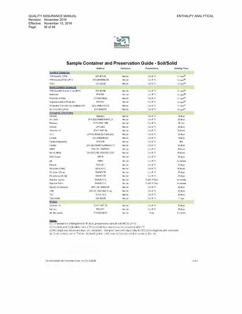
QUALITY ASSURANCE MANUAL ENTHALPY ANALYTICAL Revision: November 2016 Effective: November 15, 2016 Page: 38 of 48

QUALITY ASSURANCE MANUAL ENTHALPY ANALYTICAL Revision: November 2016 Effective: November 15, 2016 Page: 39 of 48 APPENDIX C
Enthalpy Analytical Equipment Inventory Updated: April 2016
Department Equipment Make Model Serial Number Quant
AAICP ICP/MS Instrument PerkinElmer ELAN DRC II AI01170606 1
AAICP Autosampler Ctac Technologies ADX 500 Autosampler 010001ADX 1
AAICP ICP-OES instrument PerkinElmer Optima 8300 078S1485081 1 AAICP Autosampler PerkinElmer S10 Autosampler 102514020837 1 AAICP ICP-OES instrument PerkinElmer Optima 4300 DV 077N1091901 1 AAICP Autosampler PerkinElmer AS93 Plus 1
AAICP Mercury Atomic Absoption instrument PerkinElmer FIMS 400 4545 1
AAICP Autosampler PerkinElmer AS-90 3670 1
AAICP Ion Chromatography instrument Dionex ICS-2000 4040830 1
AAICP Autosampler Dionex AS-40 95120063 1 AAICP Autosampler Dionex AS-40 99110460 1 AAICP IC Suppressor Dionex ASRS 300 110907009 1
AAICP Ion Chromatography instrument Dionex ICS-1100 1201147 1
AAICP Autosampler Dionex AS-DV 12020112 1 AAICP UV/Vis Detector Dionex VWD 12011568 1 AAICP Pneumatic controller Dionex PC10 N/A 2
AAICP Ion Chromatography instrument Dionex ICS-3000 DC 8110673 1
AAICP Autosampler Dionex AS 8110408 1
AAICP Conductivity detector Dionex Dionex Conductivity Detector
8110417 1
AAICP UV/Vis Detector Dionex VWD 8110537 1 AAICP Eluent generator Dionex ICS-3000 EG 8110325 1 AAICP Dual pump Dionex ICS-3000 DP 8110200 1 AAICP Supressor Dionex AERS 500 151216021 1
AAICP Hotblock (50 mL, 36 positions)
Environmental Express SC100 145CEC0423 1
AAICP Hotblock (50 mL, 36 positions)
Environmental Express SC100 N/A 1
AAICP Hotblock (100 mL, 33 positions) CPI International Modblock N/A 1

QUALITY ASSURANCE MANUAL ENTHALPY ANALYTICAL Revision: November 2016 Effective: November 15, 2016 Page: 40 of 48
AAICP Magnetic Stir Base Environmental Express N/A 1
AAICP Fume Hood N/A N/A 2 AAICP Fume Hood N/A N/A
AAICP TCLP Rotating Agitator N/A No. 753 1
AAICP STLC Agitator Eberbach Eberbach 6000 90615 1 AAICP Balance Mettler AE 100-S 38699 1 AAICP Balance Mettler AE 200-S J79480 1 AAICP pH Meter Acumet AB150 AB92347025 1 AAICP pH Meter Hama Hama HI 2210 8576153 1 AAICP Stir Plate/Hot Plate Thermolyne Nuova II 102719 1
AAICP Air Compressor (165 PSI) Craftsman 921.16272 U3A1654C 1
AAICP Refrigerated Argon Tank Cart Industries Perma-Cyl 450 MP CJXS08G105 1
AAICP PC Workstations HP/Dell Various Various 7 MICRO Waterbath Thermo 2868 205906-287 1 MICRO Waterbath Thermo 2862 200946-62 1 MICRO UV Lamp Spectroline ENF-2606 1326493 1 MICRO Incubator Shel Lab 1925 600101 1 MICRO Incubator VWR Scientific 1555 1 MICRO Incubator VWR Scientific 0500301 2475T 1 MICRO Incubator VWR Scientific 0500301 2475B 1 MICRO Incubator Fisher 307 1519051121558 1 MICRO Incubator Fisher 307 1 MICRO Incubator Fisher 1 MICRO Incubator Barnstead DB104115 1041050456251 1 MICRO Refrigerator Kenmore 106.8696410 E91110578 1 MICRO Refrigerator Electrolux FRT18L4JWS BA93400403 1 MICRO Refrigerator Frigifaire FFTR1821QW1 BA93400403 1 MICRO Refrigerator Summit S-23-C 950801412 1 MICRO Autoclave Eagle 3000 1 MICRO Microwave GE JES2US1DN2WW HD201715L 1 MICRO Hot Plate Corning PC-260D 013806298328 1 MICRO Hot Plate Corning PC-260D 013806244122 1 MICRO BOD Analyzer Skalar 1 MICRO Colony Counter Quebec 3325 11001-0 1 MICRO Colony Counter Quebec 3330 1 MICRO Quanti-Tray Sealer IDEXX Model 2X 02934 1
MICRO Filamatic National Instrument AB 022168 1
MICRO Vortex Mixer Baxter SP-Vortex Mixer 036700 1
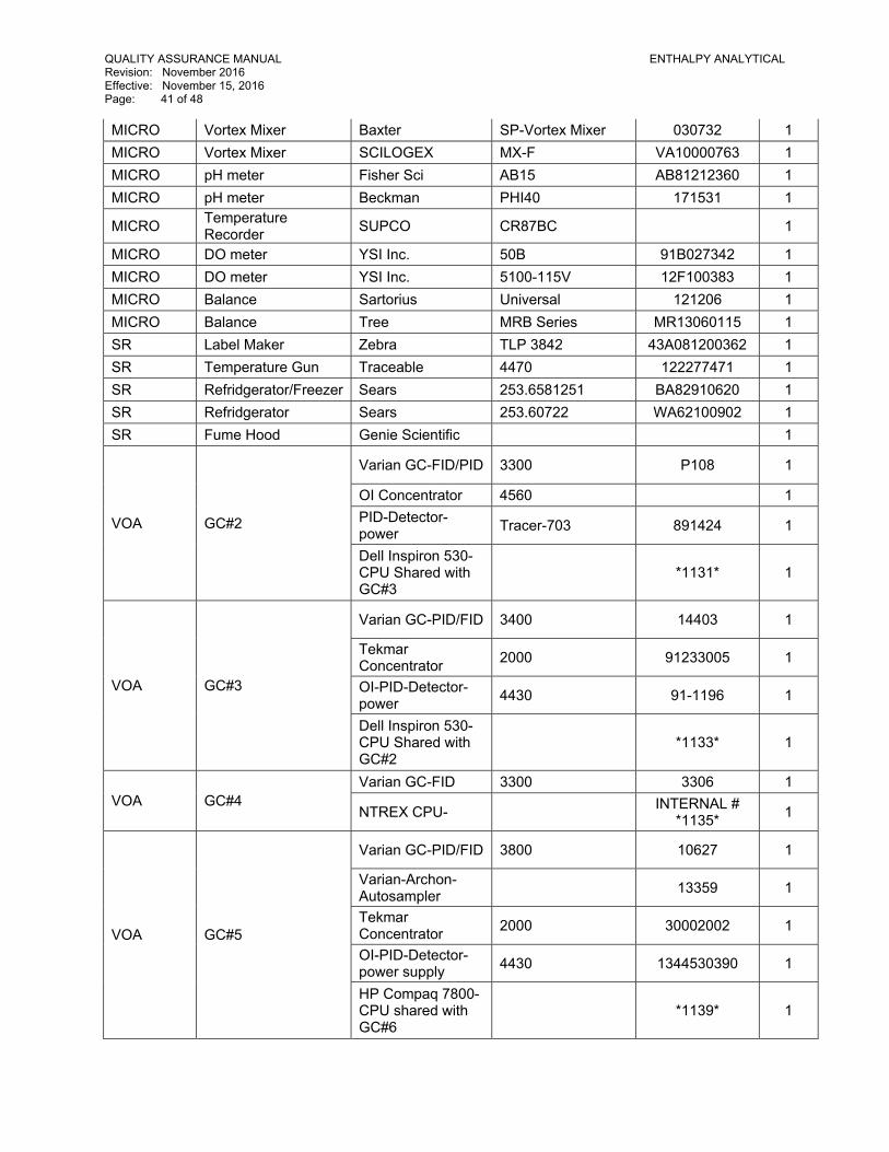
QUALITY ASSURANCE MANUAL ENTHALPY ANALYTICAL Revision: November 2016 Effective: November 15, 2016 Page: 41 of 48 MICRO Vortex Mixer Baxter SP-Vortex Mixer 030732 1 MICRO Vortex Mixer SCILOGEX MX-F VA10000763 1 MICRO pH meter Fisher Sci AB15 AB81212360 1 MICRO pH meter Beckman PHI40 171531 1
MICRO Temperature Recorder SUPCO CR87BC 1
MICRO DO meter YSI Inc. 50B 91B027342 1 MICRO DO meter YSI Inc. 5100-115V 12F100383 1 MICRO Balance Sartorius Universal 121206 1 MICRO Balance Tree MRB Series MR13060115 1 SR Label Maker Zebra TLP 3842 43A081200362 1 SR Temperature Gun Traceable 4470 122277471 1 SR Refridgerator/Freezer Sears 253.6581251 BA82910620 1 SR Refridgerator Sears 253.60722 WA62100902 1 SR Fume Hood Genie Scientific 1
VOA GC#2
Varian GC-FID/PID 3300 P108 1
OI Concentrator 4560 1 PID-Detector-power Tracer-703 891424 1
Dell Inspiron 530-CPU Shared with GC#3
*1131* 1
VOA GC#3
Varian GC-PID/FID 3400 14403 1
Tekmar Concentrator 2000 91233005 1
OI-PID-Detector-power 4430 91-1196 1
Dell Inspiron 530-CPU Shared with GC#2
*1133* 1
VOA GC#4 Varian GC-FID 3300 3306 1
NTREX CPU- INTERNAL # *1135* 1
VOA GC#5
Varian GC-PID/FID 3800 10627 1
Varian-Archon-Autosampler 13359 1
Tekmar Concentrator 2000 30002002 1
OI-PID-Detector-power supply 4430 1344530390 1
HP Compaq 7800-CPU shared with GC#6
*1139* 1
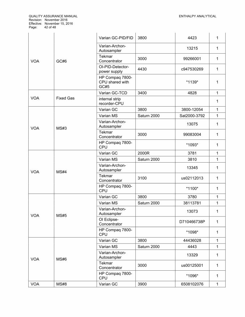
QUALITY ASSURANCE MANUAL ENTHALPY ANALYTICAL Revision: November 2016 Effective: November 15, 2016 Page: 42 of 48
VOA GC#6
Varian GC-PID/FID 3800 4423 1
Varian-Archon-Autosampler 13215 1
Tekmar Concentrator 3000 99266001 1
OI-PID-Detector-power supply 4430 c947530269 1
HP Compaq 7800-CPU shared with GC#5
*1139* 1
VOA Fixed Gas Varian GC-TCD 3400 4828 1 internal strip recorder-CPU 1
VOA MS#3
Varian GC 3800 3800-12054 1 Varian MS Saturn 2000 Sat2000-3792 1 Varian-Archon-Autosampler 13075 1
Tekmar Concentrator 3000 99083004 1
HP Compaq 7800-CPU *1093* 1
VOA MS#4
Varian GC 2000R 3781 1 Varian MS Saturn 2000 3810 1 Varian-Archon-Autosampler 13345 1
Tekmar Concentrator 3100 us02112013 1
HP Compaq 7800-CPU *1100* 1
VOA MS#5
Varian GC 3800 3780 1 Varian MS Saturn 2000 38113781 1 Varian-Archon-Autosampler 13073 1
OI Eclipse-Concentrator D710466738P 1
HP Compaq 7800-CPU *1098* 1
VOA MS#6
Varian GC 3800 44436028 1 Varian MS Saturn 2000 4443 1 Varian-Archon-Autosampler 13329 1
Tekmar Concentrator 3000 us00125001 1
HP Compaq 7800-CPU *1096* 1
VOA MS#8 Varian GC 3900 6508102076 1
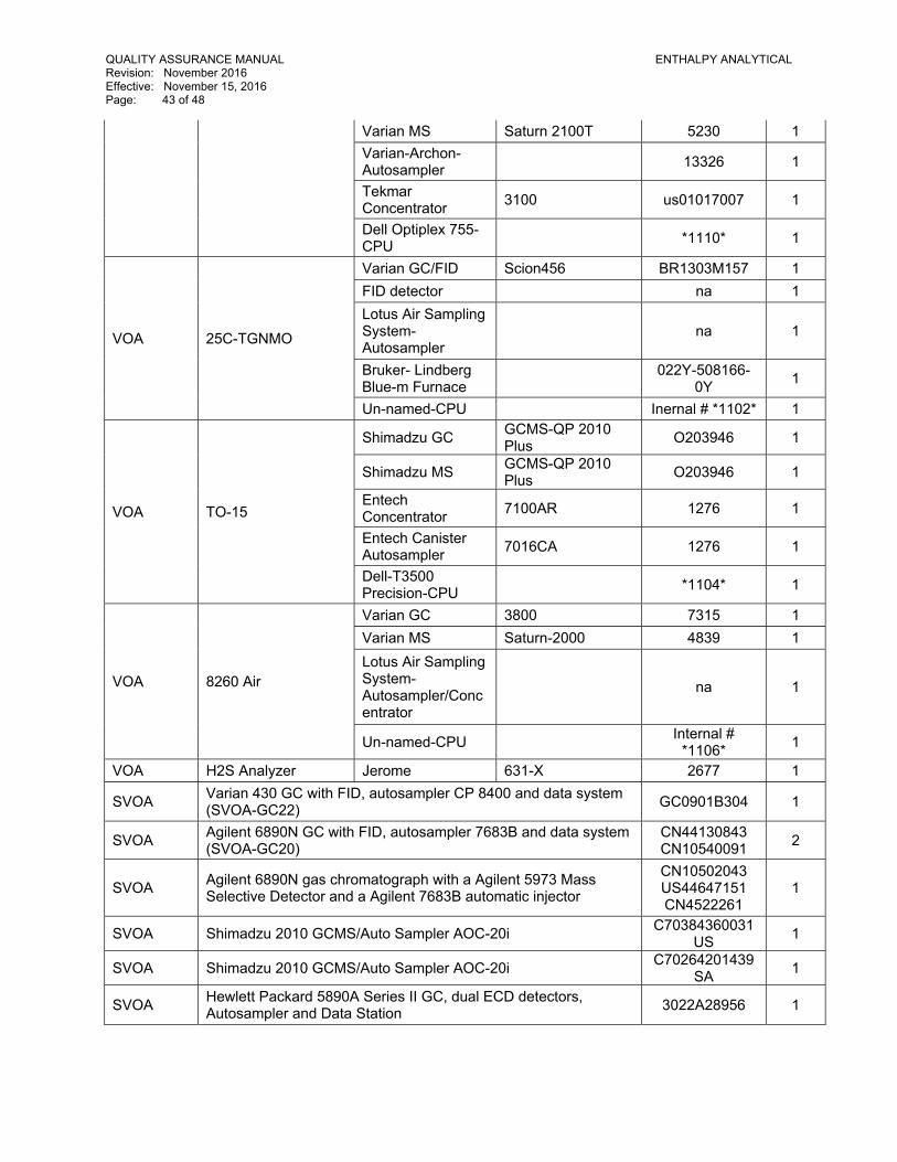
QUALITY ASSURANCE MANUAL ENTHALPY ANALYTICAL Revision: November 2016 Effective: November 15, 2016 Page: 43 of 48
Varian MS Saturn 2100T 5230 1 Varian-Archon-Autosampler 13326 1
Tekmar Concentrator 3100 us01017007 1
Dell Optiplex 755-CPU *1110* 1
VOA 25C-TGNMO
Varian GC/FID Scion456 BR1303M157 1 FID detector na 1 Lotus Air Sampling System-Autosampler
na 1
Bruker- Lindberg Blue-m Furnace 022Y-508166-
0Y 1
Un-named-CPU Inernal # *1102* 1
VOA TO-15
Shimadzu GC GCMS-QP 2010 Plus O203946 1
Shimadzu MS GCMS-QP 2010 Plus O203946 1
Entech Concentrator 7100AR 1276 1
Entech Canister Autosampler 7016CA 1276 1
Dell-T3500 Precision-CPU *1104* 1
VOA 8260 Air
Varian GC 3800 7315 1 Varian MS Saturn-2000 4839 1 Lotus Air Sampling System-Autosampler/Concentrator
na 1
Un-named-CPU Internal # *1106* 1
VOA H2S Analyzer Jerome 631-X 2677 1
SVOA Varian 430 GC with FID, autosampler CP 8400 and data system (SVOA-GC22) GC0901B304 1
SVOA Agilent 6890N GC with FID, autosampler 7683B and data system (SVOA-GC20)
CN44130843 CN10540091 2
SVOA Agilent 6890N gas chromatograph with a Agilent 5973 Mass Selective Detector and a Agilent 7683B automatic injector
CN10502043 US44647151 CN4522261
1
SVOA Shimadzu 2010 GCMS/Auto Sampler AOC-20i C70384360031US 1
SVOA Shimadzu 2010 GCMS/Auto Sampler AOC-20i C70264201439SA 1
SVOA Hewlett Packard 5890A Series II GC, dual ECD detectors, Autosampler and Data Station 3022A28956 1
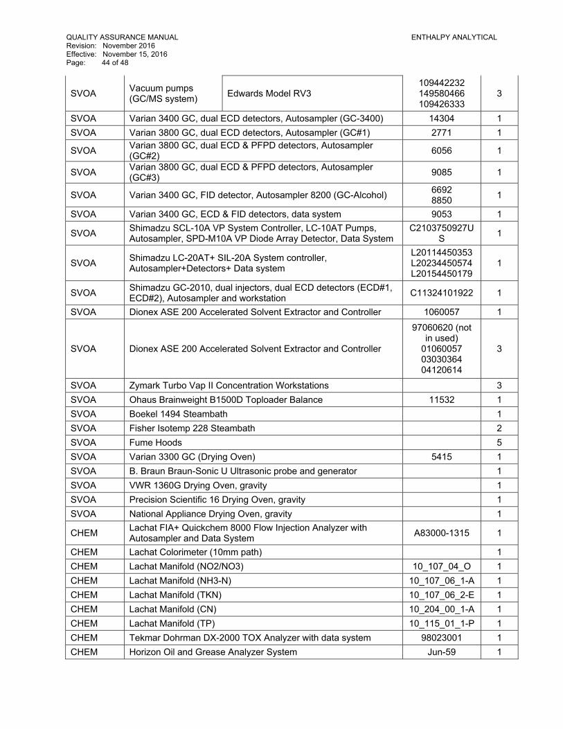
QUALITY ASSURANCE MANUAL ENTHALPY ANALYTICAL Revision: November 2016 Effective: November 15, 2016 Page: 44 of 48
SVOA Vacuum pumps (GC/MS system) Edwards Model RV3
109442232 149580466 109426333
3
SVOA Varian 3400 GC, dual ECD detectors, Autosampler (GC-3400) 14304 1 SVOA Varian 3800 GC, dual ECD detectors, Autosampler (GC#1) 2771 1
SVOA Varian 3800 GC, dual ECD & PFPD detectors, Autosampler (GC#2) 6056 1
SVOA Varian 3800 GC, dual ECD & PFPD detectors, Autosampler (GC#3) 9085 1
SVOA Varian 3400 GC, FID detector, Autosampler 8200 (GC-Alcohol) 6692 8850 1
SVOA Varian 3400 GC, ECD & FID detectors, data system 9053 1
SVOA Shimadzu SCL-10A VP System Controller, LC-10AT Pumps, Autosampler, SPD-M10A VP Diode Array Detector, Data System
C2103750927US 1
SVOA Shimadzu LC-20AT+ SIL-20A System controller, Autosampler+Detectors+ Data system
L20114450353L20234450574L20154450179
1
SVOA Shimadzu GC-2010, dual injectors, dual ECD detectors (ECD#1, ECD#2), Autosampler and workstation C11324101922 1
SVOA Dionex ASE 200 Accelerated Solvent Extractor and Controller 1060057 1
SVOA Dionex ASE 200 Accelerated Solvent Extractor and Controller
97060620 (not in used)
01060057 03030364 04120614
3
SVOA Zymark Turbo Vap II Concentration Workstations 3 SVOA Ohaus Brainweight B1500D Toploader Balance 11532 1 SVOA Boekel 1494 Steambath 1 SVOA Fisher Isotemp 228 Steambath 2 SVOA Fume Hoods 5 SVOA Varian 3300 GC (Drying Oven) 5415 1 SVOA B. Braun Braun-Sonic U Ultrasonic probe and generator 1 SVOA VWR 1360G Drying Oven, gravity 1 SVOA Precision Scientific 16 Drying Oven, gravity 1 SVOA National Appliance Drying Oven, gravity 1
CHEM Lachat FIA+ Quickchem 8000 Flow Injection Analyzer with Autosampler and Data System A83000-1315 1
CHEM Lachat Colorimeter (10mm path) 1 CHEM Lachat Manifold (NO2/NO3) 10_107_04_O 1 CHEM Lachat Manifold (NH3-N) 10_107_06_1-A 1 CHEM Lachat Manifold (TKN) 10_107_06_2-E 1 CHEM Lachat Manifold (CN) 10_204_00_1-A 1 CHEM Lachat Manifold (TP) 10_115_01_1-P 1 CHEM Tekmar Dohrman DX-2000 TOX Analyzer with data system 98023001 1 CHEM Horizon Oil and Grease Analyzer System Jun-59 1
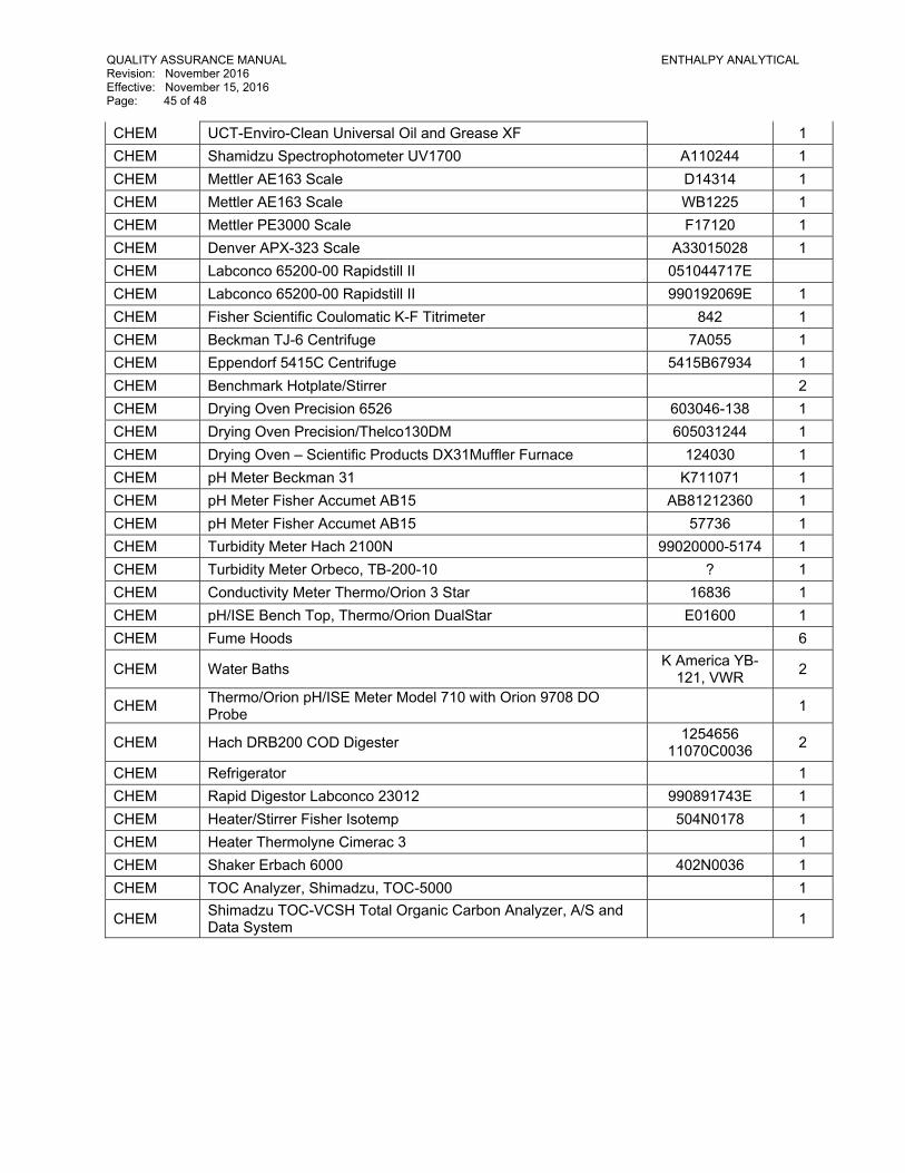
QUALITY ASSURANCE MANUAL ENTHALPY ANALYTICAL Revision: November 2016 Effective: November 15, 2016 Page: 45 of 48 CHEM UCT-Enviro-Clean Universal Oil and Grease XF 1 CHEM Shamidzu Spectrophotometer UV1700 A110244 1 CHEM Mettler AE163 Scale D14314 1 CHEM Mettler AE163 Scale WB1225 1 CHEM Mettler PE3000 Scale F17120 1 CHEM Denver APX-323 Scale A33015028 1 CHEM Labconco 65200-00 Rapidstill II 051044717E CHEM Labconco 65200-00 Rapidstill II 990192069E 1 CHEM Fisher Scientific Coulomatic K-F Titrimeter 842 1 CHEM Beckman TJ-6 Centrifuge 7A055 1 CHEM Eppendorf 5415C Centrifuge 5415B67934 1 CHEM Benchmark Hotplate/Stirrer 2 CHEM Drying Oven Precision 6526 603046-138 1 CHEM Drying Oven Precision/Thelco130DM 605031244 1 CHEM Drying Oven – Scientific Products DX31Muffler Furnace 124030 1 CHEM pH Meter Beckman 31 K711071 1 CHEM pH Meter Fisher Accumet AB15 AB81212360 1 CHEM pH Meter Fisher Accumet AB15 57736 1 CHEM Turbidity Meter Hach 2100N 99020000-5174 1 CHEM Turbidity Meter Orbeco, TB-200-10 ? 1 CHEM Conductivity Meter Thermo/Orion 3 Star 16836 1 CHEM pH/ISE Bench Top, Thermo/Orion DualStar E01600 1 CHEM Fume Hoods 6
CHEM Water Baths K America YB-121, VWR 2
CHEM Thermo/Orion pH/ISE Meter Model 710 with Orion 9708 DO Probe 1
CHEM Hach DRB200 COD Digester 1254656 11070C0036 2
CHEM Refrigerator 1 CHEM Rapid Digestor Labconco 23012 990891743E 1 CHEM Heater/Stirrer Fisher Isotemp 504N0178 1 CHEM Heater Thermolyne Cimerac 3 1 CHEM Shaker Erbach 6000 402N0036 1 CHEM TOC Analyzer, Shimadzu, TOC-5000 1
CHEM Shimadzu TOC-VCSH Total Organic Carbon Analyzer, A/S and Data System 1
QUALITY ASSURANCE MANUAL ENTHALPY ANALYTICAL Revision: November 2016 Effective: November 15, 2016 Page: 46 of 48 APPENDIX D
NON-CONFORMANCE CRITERIA AND DOCUMENTATION PROCEDURES
QC Samples - Corrective Actions:
1. Lab Control Sample: the acceptance criteria for the LCS are defined by the analytical method or by control charts of recoveries in the LIMS. If the acceptance criteria are not met, or the number of allowable marginal exceedances is exceeded, all samples in the batch must be re-prepared and re-analyzed. If re-preparation and re-analysis are not possible, data may be reported with the L qualifier.
2. Method Blank: the result must be less than the reporting limit for each analyte or less than 1/10 the lowest sample in the batch. If not, all samples in the batch must be re-prepared and re-analyzed. If re-preparation and re-analysis are not possible, data may be reported with the B qualifier.
3. Matrix Spike Sample (MS): acceptance criteria are defined by the analytical method or by control charts in the LIMS. If the acceptance criteria are not met, the sample result should be flagged for potential matrix interference for each analyte showing poor recovery (M qualifier). (For metals analyses, a post-digestion spike should be done for any element with poor matrix spike recovery when the poor recovery is on a new or unfamiliar matrix.)
4. Matrix Spike Duplicate (MSD): the MSD is evaluated for both recovery and relative percent difference between the MS and MSD and these criteria are defined by the analytical method. If recovery criteria is not met, the affected analyte(s) will be flagged (M qualifier). If the relative percent difference is not met, the analysis should be repeated or the result flagged for precision out of limits (D qualifier).
5. Surrogate Recovery: the surrogate recoveries should be within the current control limits for all methods where surrogate recoveries apply. If the surrogate recoveries are outside control limits, the results should be flagged for potential matrix interference for each analyte showing recovery outside the control limits (S qualifier). If the surrogate was diluted out of the sample because of a high dilution factor, the surrogate should be flagged with the S2 qualifier. If the surrogate recoveries for the LCS or Method Blank are outside control limits, all samples in the batch must be re-prepared/re-analyzed, unless it can be determined that the poor recovery was due to a problem specific to that sample only.
Other Corrective Actions
1. Holding Time: Samples must be analyzed within the hold time that is defined in the analytical method or other regulatory guidelines. There are certain instances when a missed holding time requires an NCD from the laboratory. Those situations are outlined

QUALITY ASSURANCE MANUAL ENTHALPY ANALYTICAL Revision: November 2016 Effective: November 15, 2016 Page: 47 of 48
below:
a. If the sample was received within holding time and there was sufficient time remaining on the hold time for analysis to be started
b. If the sample needed reanalysis because of failing batch or sequence QC. In this situation, the sample was originally analyzed within hold time, but the reanalysis was outside of hold time.
2. Broken Sample containers: Containers received broken or broken within the laboratory need to have an NCD filed.
3. Situations where method or client requirements were missed or not met need to have an NCD documenting the situation and communication to the client regarding the situation.
Non-conformance Documentation Form (NCD):
1. Non-conformances such as QC limit failures that cannot be corrected by re-analysis, sample analysis exceeding hold time, Client requirements which cannot be met, or standard method modifications are documented by initiating a Non-Conformance Document (NCD).
2. An NCD is initiated by the analyst in the event of a QC sample exceeding control limits or other known non-conformance to the analytical method or Client requirements. An NCD may also be initiated by the QA Department, Project Manager, or Department Supervisor in the event method or Client requirements are not met or other analytical problems are discovered.
3. The root cause of the non-conformance must be investigated and documented on the NCD form. The determination of the root cause is necessary in order to have an effective corrective action.
4. After the NCD is initiated, the corrective action must be determined and agreed upon by the Department Supervisor and the QA Department. This is documented and signed by the Department Supervisor in the second part of the NCD Form. The form is then forwarded to the QA Department.
5. The QA Department then completes and signs the final part of the form. If necessary, verification of the corrective action is documented in this section.
6. The Client is notified of the nonconformance as appropriate. The NCD is filed in the Corrective Actions File which is maintained in the QA Office.
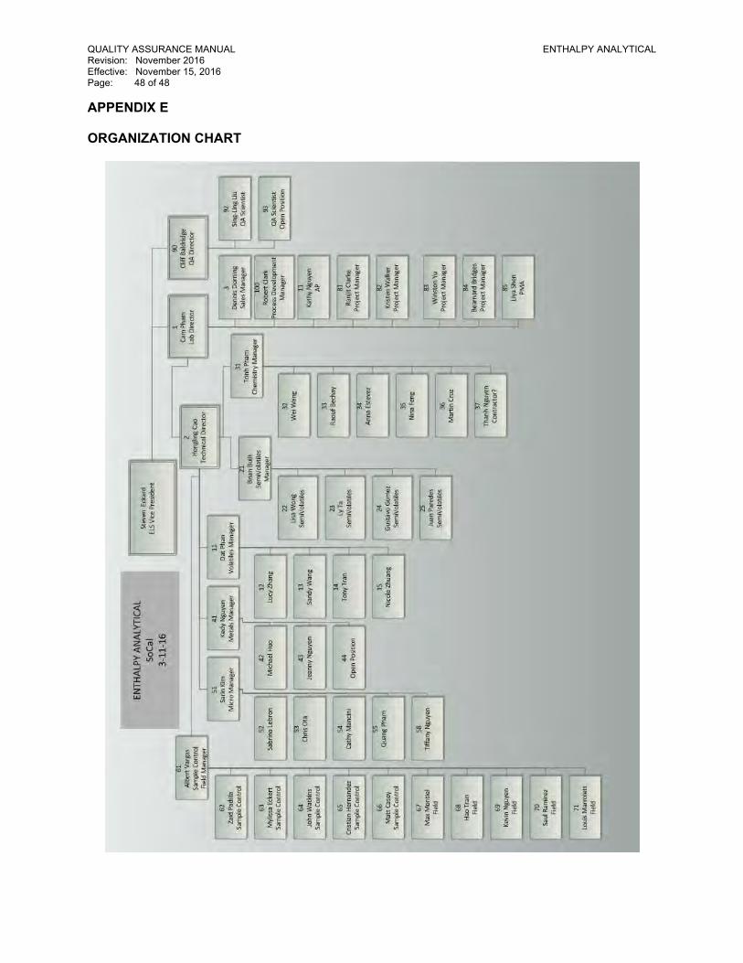
QUALITY ASSURANCE MANUAL ENTHALPY ANALYTICAL Revision: November 2016 Effective: November 15, 2016 Page: 48 of 48 APPENDIX E ORGANIZATION CHART

Former NIRF Undersea Center December 11, 2017 Pasadena, California Project No. 207220003
207220003 R QAPP
APPENDIX C-4
MOBILE LABORATORY QUALITY ASSURANCE MANUAL
Page | 1 QAQC Manual
Updated 3/9/2016 Rev. 19
QUALITY ASSURANCE/QUALITY CONTROL
MANUAL
March 2016
Revision 19
______________________ ______________________
Carolyn Carroll Steve Jones
____________________ ____________________
Marshall Chaffee Colby Wakeman
Page | 2 QAQC Manual
Updated 3/9/2016 Rev. 19
TABLE OF CONTENTS
1.0 Purpose
2.0 Scope
3.0 Introduction
4.0 Definitions
5.0 Laboratory Structure
6.0 QA/QC Objectives for Data Measurement
7.0 Sampling Procedures
8.0 Sample Custody
9.0 Calibration Procedures and Frequency
10.0 Analytical Procedures
11.0 Data Management
12.0 Internal Quality Control Checks
13.0 Intra-laboratory Audits
14.0 Preventative Maintenance
15.0 Data Assessment
16.0 Corrective Action
17.0 Quality Assurance Reports
18.0 Staff Training
APPENDIX:
A - Chain-Of-Custody Record
B - Laboratory Worksheets
C - List of SOPs
Page | 3 QAQC Manual
Updated 3/9/2016 Rev. 19
Quality Assurance/Quality Control Manual
1.0 PURPOSE
The purpose of this manual is to formally document the principles and procedures by which the
laboratory produces its data. The objective of this Quality Assurance/Quality Control (QA/QC) program
is to provide a system of checks and controls which enables the laboratory to reliably and consistently
provide data that is performed according to established EPA methodologies, of known precision and
accuracy, and defensible in court, if necessary.
To meet this commitment, a comprehensive QA/QC program has been established. Jones
Environmental, Inc. (JEL) adheres to the principles and procedures outlined in this manual.
2.0 SCOPE
This manual presents an overview of the QA/QC program that governs all data which is produced by JEL.
The essential components of JEL's QA/QC program are outlined in the following sections. Detailed
information regarding specific methods/procedures should be directed to documented Standard
Operating Procedures (SOP's) or to laboratory management.
JEL has modeled its program after guidelines as outlined in "Interim Guidelines and Specifications for
Preparing Quality Assurance Program Plans", QAMS-004/80, December 29, 1980 and "Interim Guidelines
and Specifications for Preparing Quality Assurance Project Plans", QAMS-00G5/80, February, 1983, both
of which have been issued by the Office of Monitoring Systems and Quality Assurance, Office of
Research and Development, US EPA. All routine QA/QC practices follow EPA "Minimum Guidelines for
the Evaluation of Laboratory Data" as reported in the February 8, 1990, issue of the Federal Register.
This document contains all information required by Title 22, Division 4, Chapter 19, Article 8, Section
64815.
3.0 INTRODUCTION
JEL, a California corporation, is an independently owned and operated analytical laboratory offering a
broad range of environmental testing services. The laboratory has expertise in the analysis of organic
and inorganic compounds in support of various environmental activities including investigations,
remediation, monitoring services, underground tank (UST) programs, risk assessments and other related
events.
The laboratory routinely provides analyses in full compliance with the following agencies:
Environmental Protection agency (USEPA)
California Department of Health Services (CA DHS)
American Society for Materials and Testing (ASTM)
National Institute of Occupational Safety and Health (NIOSH)
American Public Health Association (APHA)
Page | 4 QAQC Manual
Updated 3/9/2016 Rev. 19
The laboratory conducts client specific studies through its mobile laboratory facilities. Outside
laboratories are audited for Quality Control procedures for all analyses not performed by JEL. JEL
utilizes the services of Orange and L.A. County laboratories as its stationary laboratory affiliates and a
major source for duplicate analyses, overflow work and confirmations.
4.0 DEFINITIONS
Analytical Batch- An analytical batch is defined as a group of samples of the same matrix that behave
similarly with respect to the procedures being employed and which are processed as a unit. If
the number of samples in a group is greater than 20, then each group of 20 samples or less will
all be handled as a separate batch. All conditions such as method sequence and the same lot of
reagents and with all the manipulations common to each sample within the same time period or
in continuous sequential time periods including calibrations, columns, temperature program,
blanks, and laboratory control samples are considered a single batch.
Detection Limit – A statistically derived number specific to each instrument, each instrument detector,
and in some instances each different analyte the amount of which is distinctively detectable
(99% confidence level).
Environmental sample (or field sample) – A representative portion of any material collected from any
source for which determination of composition or portions thereof is requested.
Initiate Analyses – The point in time that the sample, extract or digestate is introduced into an
instrument or process for analysis of the parameter of interest.
Initiate Preparation – The point in time that the process of separating the parameters of interest from
the sample is begun.
Method Blank – This is an analytical analysis involving all of the reagents or chemical solutions common
to a given analysis using the matrix of the samples to be analyzed in the proceeding batch. The
method blank will be prepared in the same manner of the samples.
QA/QC Program – This is the complete plan of policies and procedures incorporated by the laboratory in
order to produce acceptable data.
Reagent Grade – This is a reagent which conforms to the current specifications of the committee on
Analytical reagents of the American Chemical Society. The burden of verification of this is
generally left to the chemical manufacturer. Certificates of reagent quality/concentrations are
maintained in JELs office.
Replicate Sample – These are considered to be two samples taken at different times from the same
location. They can be taken sequentially, or at completely different times.

Page | 5 QAQC Manual
Updated 3/9/2016 Rev. 19
Duplicate Sample – A sample prepared by dividing a sample into two or more separate aliquots, or are
collected simultaneously (i.e. soil gas).
Standard Curve/Calibration Curve – A plot of instrument response to an analyte versus the known
concentration of a standard analyte and processed by linear regression to determine slope.
Water – reagent, analyte-free, or laboratory pure water which is either distilled and/or deionized and is
free of contaminants that may interfere with the analytical test in question. Method blanks are
analyzed in each batch to verify purity of reagent water.
5.0 LABORATORY STRUCTURE
The current structure of JEL consists of maintenance/courier, stationary laboratory operators, mobile
laboratory operators, laboratory manager, office manager, office assistant, and an
Accountant/Bookkeeper. As the laboratory grows additional personnel will be added and the laboratory
will be structured into distinct departments.
The maintenance/courier personnel is responsible for general maintenance of the building and mobile
laboratories. They are also responsible for picking up samples from clients and transporting any
necessary items to clients and/or mobile laboratory operators out in the field when needed.
The stationary laboratory operators are responsible for the daily operation of the stationary laboratory
instruments, preparation of samples, production of data, preparation of laboratory reports, and
calculation of laboratory results and quality control information.
The mobile laboratory operators are responsible for the daily operation of the four mobile laboratories,
production of data, preparation of laboratory reports, and calculation of laboratory results and quality
control information.
The laboratory manager also operates the mobile laboratory on occasion in the field and will operate
the mobile laboratory at its stationary location to finish jobs in progress. In addition to the operation of
the mobile laboratory, the laboratory manager performs but is not limited to the following activities:
Approves/Signs final laboratory reports
Approves changes in the QA/QC program
Coordinates all laboratory certifications
Directs the implementation of company QA/QC plan
Reviews, approves, and implements all SOP's
Approves and monitors the JEL Health and Safety Plan
The office manager is responsible for the preparation of all laboratory reports to be reviewed by the
laboratory director. In addition, they are responsible for organizing all jobs, answering the telephone,
Page | 6 QAQC Manual
Updated 3/9/2016 Rev. 19
preparing bids, issuing invoices, ordering supplies, organizing sample pickups, and scheduling
deliveries/pick-ups to outside laboratories or to the mobile laboratory operators.
The office assistant is responsible for performing any task that the office manager has delegated to
them. This mostly consists of, but is not limited to, preparing laboratory reports to be reviewed by the
laboratory director, answering the telephone, and preparing EDD reports.
6.0 QA/QC OBJECTIVES FOR DATA MEASUREMENT
The Quality Assurance/ Quality Control program is an essential part of the analytical protocol. It has
been integrated into all facets of the laboratory operation. Its purpose is to detect and correct problems
in the measurement process, to ensure that all data is valid, of known precision and accuracy, and
defensible. It is designed to monitor and control the quality of data generated by the laboratory. The
conscientious execution of the QA/QC procedures described herein ensures that the results will meet or
exceed the minimum requirements for data acceptability as established by the EPA and California DHS.
It assures that proper sample collection, preservation, labeling and storage procedures are applied to
maintain sample integrity and identification. The specific procedures implemented to obtain valid data
are described in the following sections:
QA/QC program objectives include:
Demonstration of the ability of the laboratory to perform analyses accurately, reproducibly
and reliably.
Reduction of measurement errors to acceptable minimum levels.
Evaluation and control of data generation.
Documentation of the laboratory's performance on a daily basis.
An essential part of the formally documented QA/QC program is the sound judgment of the technical
staff. It is the technical staff that interprets events that may have caused an out-of-control condition. A
function of the QA/QC program is to alert the staff that a nonconformity may exist. This ensures that
corrective action can be administered without delay. Samples analyzed under conditions that are found
to be out of control are reanalyzed utilizing a properly operating system.
7.0 SAMPLING PROCEDURES
In an attempt to minimize sample preservation effects, samples should be analyzed as soon as possible
after receipt into the laboratory. Since it is not always possible to perform analyses immediately,
samples must be maintained in an unaltered state. Samples are always preserved with consideration for
the desired analyte(s). Aqueous and soil samples are always kept in refrigerators that are monitored
daily at a temperature of 4°C, plus or minus 2°C.
Sample collection technique, preservation conditions and storage conditions may have a significant
impact on chemical/physical analysis. JEL has a policy of providing pre-cleaned sampling containers to

Page | 7 QAQC Manual
Updated 3/9/2016 Rev. 19
clients so that container integrity is not an issue. The use of proper sampling containers, protocols and
performance of analysis within the established holding time limit are criteria for data acceptance that
are not compromised at JEL. The following items demand attention to ensure sample integrity:
Samples must be collected and stored in contaminant free containers
Samples must consist of an adequate volume
Samples must be clearly and completely labeled corresponding to the client chain of
custody record
Samples must be properly preserved immediately after collection, if necessary
Aqueous samples should be preserved with HCL or Sodium Thiosulfate as appropriate
No preservative should be added to aqueous grab samples collected in the field and given directly to the mobile lab to analyze. If sediment is visible in the sample, no preservative should be added since the reaction of soil carbonates and preservatives will generate bubbles.
Aqueous samples for volatile analysis should have no headspace in the container(s).
When sample containers and labels are provided to clients, JEL adheres to the EPA's established
guidelines for sample preservation, storage and holding times. For the analyses of water and waste
water, the laboratory follows the guidelines found in table 1060:1, page 1-22 in "Standard Methods for
the Examination of Water and Waste water", 2004, 20th edition, APHA, AWWA, WPCE and table 2-16 in
SW-846, December 1996, 4th edition, Volume III.
Samples received by the laboratory are placed in appropriate storage or sent directly to the test area.
The storage areas are located in the warehouse and consist of refrigerators at 4°C and designate storage
cabinets for sample types. Once the analysis is completed, the remaining sample is kept for a minimum
of 9 days in storage, and then discarded. If a contracting officer should request return of a sample prior
to the expiration interval, it will be returned in a manner that meets the required criteria.
For proper containers, holding times, preservation techniques, and volumes required, see the
appropriate method SOP.
8.0 SAMPLE CUSTODY
The chain of custody procedure employed by JEL follows procedures established by the EPA and is
applied to all samples whether they are analyzed immediately in the field by the mobile laboratory,
analyzed by the stationary laboratory, sent to an outside laboratory locally or shipped to an outside
laboratory by courier. The objective of the chain of custody procedure is to establish legal
documentation describing the transfer of samples. The procedure records the custody of the samples
from the sampling event, through shipment, and receipt by the laboratory. The samples may be
considered legal evidence and it is the intention of JEL to treat them accordingly.
The chain of custody procedure is outlined below:

Page | 8 QAQC Manual
Updated 3/9/2016 Rev. 19
1. All samples received by the mobile laboratory or stationary laboratory are assigned an
unambiguous, project specific identification number at the time of the sampling event.
2. The sample containers are fully identified with this number. Sample labels are completed
and are permanently fixed to the sample container. The time and date of the sampling
event, the identity of the sampler and the preservative, if any, is documented on the chain
of custody record.
3. The chain of custody record is completed simultaneously with the labeling of the sample
container. Information noted on the chain of custody record includes: project name and
location, sampler's signature, sample identification, analysis requested, number of
containers per sample, description of sample matrix, date and time of the sampling event,
laboratory's name and the laboratory sample number.
4. Each transfer of sample custody is recorded on the form; the relinquishing party and the
receiving party accepting the samples must sign the chain of custody record and document
the time and date of the transfer.
5. For Soil Gas samples, the purge volume and the number of purges used is recorded. In
addition, any tracer gas used and the purge rate is checked under the remarks section of the
COC. The Soil Gas collection device is recorded.
A sample of the JEL chain of custody record is located in Appendix B.
9.0 CALIBRATION PROCEDURES AND FREQUENCY
The accuracy of calibration is dependent on the purity of the standard solutions and reagents used in
the analytical operation. JEL continually monitors the quality of its reagents and standard solutions
through blank analyses runs and comparison of one standard to another standard obtained from an
independent source. When possible, standards acquired have traceability to the USEPA or the National
Institute of Standards and Technology (NIST). Permanent records are maintained to document standard
traceability. This information is maintained and documented in each of the standards log books.
The generation of valid data is dependent on the accurate and reliable calibration of each instrument.
Although calibration and standardization procedures vary depending on the type of system and
analytical method employed, the principles of calibration are universal. Proper calibration ensures that
the analytical system is operating correctly and functioning at the proper sensitivity to meet established
method detection limits. Before a system is used for analyses, the calibration range is defined,
detection limits are determined and potential interferences are identified and eliminated where
possible. The calibration status is checked periodically to ensure that the system is functioning properly.
Each instrument is calibrated with standards appropriate to the type of analysis and the calibration
range established for the method employed. The calibration program at JEL is instrument/method
specific. The calibration procedures for selected instruments are given in the following sections. Once a
calibration curve has been generated, the date of calibration will be recorded on the curve page of the

Page | 9 QAQC Manual
Updated 3/9/2016 Rev. 19
calibration. The raw data, graph and computer calculations will be stored in the calibration file of the
laboratory in which the instrument being calibrated resides.
Instrument Calibration Frequency
Today’s complex instrumentation and calibration frequencies are extremely varied; therefore, a
maintenance log is assigned to each instrument to log the following:
All maintenance performed
All daily sensitivity checks and/or calibration results where applicable according to
methodology found in SOP
All manufacturer’s maintenance and repairs
Each log entry will contain the date, operator’s name, and operation performed (i.e., maintenance,
sensitivity check, calibration, etc.).
Calibration is performed whenever the instrument calibration checks do not pass or if the system has
had major maintenance performed (i.e., new column, new trap, etc.) for the following instruments:
GC/MS – EPA 8260B, 8270, TO-15, TO-17
GC/FID – EPA 8015, 8015M, ASTM D2887
GC/ECD – EPA 8081, 8082
GC/TCD – ASTM D1946
Calibrations are performed on a daily basis or whenever the following instruments are used:
CVAA – EPA 7471/7470A
ICP-OES – EPA 6010
Other instruments may require weekly, monthly, quarterly, or semiannual calibration (i.e., balances,
ovens, thermometers, hoods etc.). Once a standard calibration range has been established, at least
three standards are normally used in daily standardization where applicable. Please refer to the
Appendix to reference specific SOPs for each analytical method performed to get more information
about particular calibration procedures. If a problem arises which cannot be corrected by the instrument
operator, then the laboratory QA Officer is notified. The officer will coordinate the necessary diagnostic
and corrective measures to be implemented.
Calibration Standards/Reagents Preparation
A critical area in the generation of quality data is the quality, purity, and traceability of the standards
and reagents used in analytical calibration procedures. All primary reference standards and standard
solutions used by JEL are obtained from commercial manufacturers. All standards, standard solutions,
and reagents are accompanied by a certificate of analysis.
Page | 10 QAQC Manual
Updated 3/9/2016 Rev. 19
Preparation of working standards is kept track of in a bound log book for each analytical method. This
logbook is kept in the stationary laboratory in a central location. The logbook contains the following
information for each intermediate and working standard:
Name of supplier
Lot number
Date of preparation for intermediate standards (dilution from the stock or concentrated
solution from supplier)
ID number traceable to calibration standard logbook
Name of person who performed the dilution
Volume of concentrated solution taken for dilution
Final volume after dilution
Calculated concentration after dilution
10.0 ANALYTICAL PROCEDURES
The laboratory routinely provides analyses of organic and inorganic parameters in conformity with US
EPA and CA DHS methodologies. Appropriate analytical techniques are incorporated into methods and
procedures as prescribed by the EPA, ASTM, and APHA.
Each analytical method employed is documented in the form of a Standard Operating Procedure (SOP).
The purpose of establishing these procedures is to standardize the methods so that all samples are
analyzed consistently, correctly and without bias. In addition, the SOP's provide a good starting point
for the training of new analysts. The SOP is constructed so that it contains detailed instructions
describing the use and performance of the method. All pertinent QA/QC program procedures are
integrated into the SOP.
Before an analytical method is used to generate data, the method is validated. Method validation
includes definition of detection limits, the determination of the calibration range, accuracy and precision
measurements, and methods for the analysis of specific parameters to be used in this laboratory and in
outside laboratories.
11.0 DATA MANAGEMENT
Data Reduction
Data reduction is the process by which raw data are transformed into final results. The analyst who
generates the analytical data has the primary responsibility for its quality. All data is generated and
reduced following procedures specified by the laboratory SOP's. Each analyst reviews the quality of
his/her work based on these established QA/QC procedures, his/her technical knowledge, and
experience. The analyst reviews the data package to ensure that:
Page | 11 QAQC Manual
Updated 3/9/2016 Rev. 19
Raw data generated from the analysis is correct and complete
- Surrogate Standards as appropriate are all within laboratory established guidelines
- CCV and LCS are within method specified guidelines
- Appropriate SOP's have been followed
- Analytical results are correct and defensible
- Method blank test results are within control limits
- Matrix spike/spike duplicate results are within established limits
- Documentation is complete
Data Validation
After the data reduction package is reviewed and dated by the analyst, it is then forwarded to the
laboratory manager/technical director or senior staff member for final validation, completeness, and
accuracy review. This review also includes verification of calculations and raw data to provide a
complete independent audit of the data package. The final review is based on the following criteria:
Calibration data reviewed
Appropriate method used
QC samples within established guidelines
Comparison of historical data when available
Correlation checks reviewed when applicable
Evaluation of data in general by comparability, assessment, and reasonableness of sample types
Ensures completion of all analytical work requested
When no errors are found, the reviewed data are then approved for release and the final report is
prepared. If errors are reported, the report is sent back to the primary reviewer for correction.
Report Documentation
The purpose of the Laboratory Report is to provide a concise and complete description of the analytical
results generated for a specific sample. The Laboratory Report consists of three parts: general client
and lab information, Quality Assurance/Quality Control summary and the laboratory results. Laboratory
worksheets are used to document lab information about samples being analyzed. Examples of lab
worksheets found on Excel forms on the computers in each lab are given in Appendix C.
General information issued in the laboratory report consists of the client identification and address,
project identification and address, date of the report, laboratory job number and client job number, the
date the sample(s) was collected, date received by the laboratory, date analyzed and the physical state
of the sample.

Page | 12 QAQC Manual
Updated 3/9/2016 Rev. 19
The QA/QC summary issued in the laboratory report consists of a description of the parameter
investigated, the method used, the QC type (Matrix Spike/Spike Duplicate or QC Reference sample, etc.),
the % recovery, the acceptable range for % recovery and the reproducibility.
The laboratory results section of the laboratory report identifies the test performed, the sample on
which the test was performed, the parameters investigated, the level determined for each parameter
investigated with the appropriate units and the reporting limit for each parameter.
Additional information issued in the laboratory report includes a statement as to the condition of the
sample(s) on receipt. In addition, any qualifications about the sample analysis such as fuel type, method
alterations, etc. will be placed in the laboratory report summaries.
12.0 INTERNAL QUALITY CONTROL CHECKS
Data quality is monitored with internal QC checks. The checks are used to determine whether the
laboratory is operating within acceptable limits. Sample matrix effects are also evaluated by the use of
QC checks.
Blanks
Field Blanks – are check samples which monitor contamination originating from the collection,
transport, and storage of environmental samples. Laboratory prepared blank water is supplied to field
personnel for processing in the same manner as samples; this includes field filtration and addition of
preservatives.
Method Blanks – are analyzed to assess the level of background interference or contamination in the
analytical system. A method blank is analyzed each time a batch is processed. When compounds are
found in the blank, their value is evaluated to determine their effect on the analysis of environmental
samples.
Calibration Standards
Calibration standards are routinely run with every sample set. Calibration standards must fall within
established QC limits before any sample results can be accepted. These limits are found in the particular
analytical method SOP being used. If the calibration standards are unacceptable, then sample results are
rejected, corrective action taken, and the samples reanalyzed.
Check Standards
The check standard is usually a midrange calibration standard used to monitor the analytical method.
The check standard is analyzed according to the particular analytical method SOP being used. As long as
check standard results fall within established control limits, the analysis can continue. If check standards
results fall outside the control limits, the data are suspect and the procedure is stopped. The analytical

Page | 13 QAQC Manual
Updated 3/9/2016 Rev. 19
procedure is checked for error step by step by the analyst. Once the procedure is again acceptable,
reanalysis of samples begins with the last check standards
Laboratory Control Sample
JEL routinely analyzes a laboratory control sample (LCS). It is used to verify the analytical method is in
control and to also serve as second source verification for the calibration standards of all routine
analyses. The concentration of the LCS must be within the working range of the analytical method.
Before any data can be accepted, the analytes of interest in the LCS must fall within their expected
control limits.
Internal Standards
Internal standards are added to samples to evaluate the measurement of the sample throughout the
entire time of analysis. The internal standards help determine the individual response factors used to
calculate the concentrations of the analytes of interest.
The monitoring of the internal standards area counts is also used as a continuing check on instrument
system performance. An average area count is established for each internal standard and any analytical
run in which the internal standard area count falls outside the established criteria, the cause is
determined, corrected, and the sample is reanalyzed.
NOTE: Not all analyses require the use of internal standards.
Surrogate Compounds
Surrogate compounds are used to monitor the analytical performance of the method and
extraction/digestion process. A known amount of surrogate is added to samples, standards, and blanks.
The results of the surrogate compounds must fall within the established QC criteria for the analytical
method. Samples that are outside the QC limits are reanalyzed.
NOTE: Not all analyses require the use of surrogates.
Sample Duplicates
Duplicates are environmental samples divided into two separate aliquots analyzed independently to
determine the repeatability and precision of the analytical method. This difference in the duplicate
results must be within established control limits to ensure the generated data meet the quality
assurance objectives for the particular analytical method.
Matrix Spike/Matrix Spike Duplicates
Matrix spike/matrix spike duplicates are environmental samples into which a known concentration of
analyte(s) has been added. The matrix spike sample is analyzed with environmental samples of the
Page | 14 QAQC Manual
Updated 3/9/2016 Rev. 19
same matrix type in each batch and the results are used to evaluate sample matrix effects on method
accuracy. The percent recovery and relative percent difference are calculated and the results must fall
within established control limits to ensure the generated data meets the QA objectives for the particular
analytical method used.
For times when it is not appropriate or there is not enough sample to spike an environmental sample, a
clean blank sample will be spiked (i.e. clean soil, clean water, or ambient air). This will be done at the
discretion of the analyst preparing the samples and QC batch unless otherwise requested by the client.
Performance Evaluation Samples
Performance evaluation (PE) samples are analyzed on an annual basis for each analytical method. The
results are reviewed by both the Laboratory QA officer and senior staff.
13.0 INTRALBAORATORY AUDITS
Audits are an integral part of the QA/QC program. Audits conducted at JEL are of two types: system
audits which qualitatively evaluate the operational details of the QA/QC program, and performance
audits which quantitatively evaluate the accuracy of analytical data generated. It is the responsibility of
the laboratory manager or an outside auditing entity such as CA DHS personnel to conduct these audits.
System Audits
System audits consist of checks of critical operations in randomly selected test records that are reviewed
to assure that all required documentation is retrievable. Data are examined in detail to determine the
quality as well as the completeness of the information. This detailed examination also ensures that all
steps of the QA/QC program are performed. The frequency of system audits depends on the critical
nature of the data output, the importance of different certifications/recertification’s, and the number of
system changes.
Performance Audits
Performance audits evaluate test methods. The laboratory manager conducts these audits by
introducing reference samples into the analysis stream without the knowledge of the analyst when
possible. The audit is completed upon evaluation of the analytical results of reference samples by the
laboratory manager.
14.0 PREVENTATIVE MAINTENANCE
A preventive maintenance schedule exists for each instrument, mobile lab and genset which enables
consistent production of quality data. Routine instrument maintenance is conducted by designated
laboratory personnel in accordance with the manufacturer's specifications and/or the experience of the
operator. Instrument repairs are performed by trained staff or instrument manufacturer
Page | 15 QAQC Manual
Updated 3/9/2016 Rev. 19
representatives. JEL maintains logbooks and files documenting the preventive maintenance and repairs
performed on each instrument.
Analysts are responsible for the routine daily maintenance of their instruments per the manufacturer’s
recommendations and for documenting repairs in the equipment maintenance logbooks. Designated
laboratory personnel are trained and responsible for more complex maintenance procedures. All
necessary repairs are performed by trained staff or factory service engineers.
Equipment Log Books
Equipment log books are maintained for all analytical instruments and equipment in the laboratory.
Each entry in the log includes the date, the nature of the entry, and the name of the individual
responsible for the entry. The following information at a minimum is recorded:
All scheduled maintenance performance
Any major or minor problem encountered, a brief description, corrective action required, and a
list of any parts replaced
Verification of equipment operation after any maintenance is performed
The equipment log books are periodically reviewed by the laboratory QA officer for compliance and
problem areas in the equipment.
15.0 DATA ASSESSMENT
The effectiveness of a QA/QC program is measured by the quality of data generated by the laboratory.
Data generated by the laboratory is assessed in terms of the measure of its precision, accuracy,
representativeness, completeness and comparability. The quantification procedure for each of these
terms is detailed in the following sections
Precision
Precision is the degree to which a measurement can be reproduced without assumption of any prior
knowledge as to the true result. Precision is assessed by means of duplicate/replicate sample analysis.
The acceptability of replicate analyses at JEL is the evaluation of the relative percent difference (RPD) of
control sample values. The RPD is calculated in all cases where matrix spike and matrix spike duplicate
determinations are made. Its definition is given below:
RPD = [(X1 − X2)
(X1 + X2)2
] ∗ 100
Where: X1 and X2 are measurements of the sample parameter of duplicate/replicate sample analysis.
Accuracy
Page | 16 QAQC Manual
Updated 3/9/2016 Rev. 19
Accuracy is the determination of how close a measurement is to the actual value. It can be assessed by
means of laboratory control samples (LCS), standard reference materials or spiked samples and percent
recoveries. The determination of the accuracy of a measurement requires a knowledge of the known
value for the parameter being measured.
Representativeness
Representativeness expresses the degree to which data accurately and precisely represents a
characteristic of a given set of samples or data sets. The use of appropriate methods and sound
judgment in the field will ensure that samples are representative. To maximize representativeness of
results, sampling procedures should follow established protocols and sample locations should be chosen
based on sound judgment and knowledge of the particular site. Mobile laboratory personnel will be
able to advise the client on these matters based on their experience. Some samples may require
analysis of multiple phases to obtain representative results. The client is always consulted as to which
phase of a multi-phase sample is to be analyzed.
16.0 CORRECTIVE ACTION
Regardless of the cause, any activity in the laboratory which adversely affects the quality of the data is
considered a nonconformance. Nonconformances are defined as errors, deficiencies or out-of-control
situations. These situations can arise due to method procedural problems, equipment malfunctions,
improper data reduction or nonsystematic errors. The QA/QC program provides systematic procedures
called corrective actions to resolve these nonconformances and restore the system to its proper
condition. Corrective action procedures are most often handled by the analyst, who performs the initial
review of the situation and the initial diagnosis of the nonconformance. If the problem persists or
cannot be identified, the matter is referred to laboratory management for further investigation. Once a
nonconformance has been confirmed, the analysis must be stopped and the integrity of the results
determined. When the analyses are adversely affected, the samples in question must be reanalyzed
utilizing a system that is functioning properly. Once resolved, full documentation of the corrective
action procedure is filed with management, placed into the maintenance logbook, and all reanalyzed
samples noted in the instrument logbook.
17.0 QUALITY ASSURANCE REPORTS
Laboratory management reviews QA/QC issues that have relevance to the previous week's
performance. The purpose of this continuous review is to provide a monitoring and review of the data
produced by the laboratory. A continual effort is made through SOP's and QA/QC documents to
upgrade the quality of data being produced by the laboratory.
18.0 STAFF TRAINING

Page | 17 QAQC Manual
Updated 3/9/2016 Rev. 19
Appropriately and adequately trained staff is one of the most important elements necessary to meet
data quality objectives. An appropriately trained analyst has achieved an acceptable level of skills and
understanding, sufficient to generate data of documented and acceptable precision and accuracy as
defined in the applicable method. A trained employee is able to competently carry out the defined
duties of his/her job. Competence is based on adequate and sound educational background, specific
training to perform assigned duties, and experience in the use of techniques and methodologies
employed. A trained employee is able to apply a method and/or technique with sound judgment,
demonstrate effective problem solving, perform at an acceptable level of independence, and meet or
exceed minimum standards for productivity and data quality. A trained employee understands the basic
principles of quality control and quality assurance and their application to the task at hand.
Training should be conducted in a two-fold manner.
First the trainer demonstrates the procedure to the employee.
Second, the employee conducts the procedure while the trainer observes and discusses the
procedure with the employee.

Page | 18 QAQC Manual
Updated 3/9/2016 Rev. 19
APPENDIX A: Chain of Custody Record

Page | 19 QAQC Manual
Updated 3/9/2016 Rev. 19
APPENDIX B: Laboratory Worksheets
Page | 20 QAQC Manual
Updated 3/9/2016 Rev. 19
Page | 21 QAQC Manual
Updated 3/9/2016 Rev. 19
Page | 22 QAQC Manual
Updated 3/9/2016 Rev. 19
APPENDIX C: LIST OF SOPs
A - Mobile Lab 8260 – Soil/Water SOP
B - Mobile Lab 8260 Soil Gas SOP
C - Mobile Lab 8015 SOP
D - Stationary Lab 8260 Soil/Water SOP
E - Stationary LAB 8260 Soil Gas SOP
F - TO-15 SOP
G - ASTM D2887 SOP
H - 8015M/D1946 SOP
I - 7471/7470A SOP
J - 6010 SOP
K - 8081/8082 SOP
L - 8270 SOP
M - Sample Receiving SOP
N - Waste SOP
O - 3620C SOP
P - 3660B SOP
Q - 9045B SOP
R - 9040B SOP
S - Tedlar Bag Sampling SOP
T - Summa Sampling SOP
Updates By Version:
1. Version 7.2 – 7/2002 2. Version 9.2 – 8/2006 3. Version 9.2 – 8/2007 4. Version 11 – 6/2009 5. Version 12 – 10/2010 6. Version 13 – 11/2010 7. Version 14 – 10/2011 8. Version 16 – 12/26/2013
a. New formatting b. Generalized more c. Included new fields of testing
9. Version 17 – 12/15/2014 10. Version 18 – 7/7/2015
a. Added Section 18.0 – Staff Training b. Edited all sections c. Updated list of SOPs
11. Version 19 – 3/9/2016 a.

Page | 23 QAQC Manual
Updated 3/9/2016 Rev. 19
Page | 1 12/18/2014
EPA Method 8260 Compound List with Reporting Limits – SOIL GAS
Compound Name Reporting Limits
Commercial µg/L µg/m3
Residential µg/L µg/m3
Benzene 0.020 20.0 0.008 8.0 Bromobenzene 0.020 20.0 0.008 8.0 Bromodichloromethane 0.020 20.0 0.008 8.0 Bromoform 0.020 20.0 0.008 8.0 n-Butylbenzene 0.020 20.0 0.008 8.0 sec-Butylbenzene 0.020 20.0 0.008 8.0 tert-Butylbenzene 0.020 20.0 0.008 8.0 Carbon tetrachloride 0.020 20.0 0.008 8.0 Chlorobenzene 0.020 20.0 0.008 8.0 Chloroform 0.020 20.0 0.008 8.0 2-Chlorotoluene 0.020 20.0 0.008 8.0 4-Chlorotoluene 0.020 20.0 0.008 8.0 Dibromochloromethane 0.020 20.0 0.008 8.0 1,2-Dibromo-3-chloropropane 0.020 20.0 0.008 8.0 1,2-Dibromoethane (EDB) 0.020 20.0 0.008 8.0 Dibromomethane 0.020 20.0 0.008 8.0 1,2- Dichlorobenzene 0.020 20.0 0.008 8.0 1,3-Dichlorobenzene 0.020 20.0 0.008 8.0 1,4-Dichlorobenzene 0.020 20.0 0.008 8.0 Dichlorodifluoromethane 0.020 20.0 0.008 8.0 1,1-Dichloroethane 0.020 20.0 0.008 8.0 1,2-Dichloroethane 0.020 20.0 0.008 8.0 1,1-Dichloroethene 0.020 20.0 0.008 8.0 cis-1,2-Dichloroethene 0.020 20.0 0.008 8.0 trans-1,2-Dichloroethene 0.020 20.0 0.008 8.0 1,2-Dichloropropane 0.020 20.0 0.008 8.0 1,3-Dichloropropane 0.020 20.0 0.008 8.0 2,2-Dichloropropane 0.020 20.0 0.008 8.0 1,1-Dichloropropene 0.020 20.0 0.008 8.0 cis-1,3-Dichloropropene 0.020 20.0 0.008 8.0 trans-1,3-Dichloropropene 0.020 20.0 0.008 8.0 Ethylbenzene 0.020 20.0 0.008 8.0 Freon 113 0.100 100 0.040 40.0
Page | 2 12/18/2014
EPA Method 8260 Compound List with Reporting Limits – SOIL GAS (cont.)
Compound Name Reporting Limits
Commercial µg/L µg/m3
Residential µg/L µg/m3
Hexachlorobutadiene 0.020 20.0 0.008 8.0 Isopropylbenzene 0.020 20.0 0.008 8.0 4-Isopropyltoluene 0.020 20.0 0.008 8.0 Methylene chloride 0.020 20.0 0.008 8.0 Naphthalene 0.020 20.0 0.008 8.0 n-Propylbenzene 0.020 20.0 0.008 8.0 Styrene 0.020 20.0 0.008 8.0 1,1,1,2-Tetrachloroethane 0.020 20.0 0.008 8.0 1,1,2,2-Tetrachloroethane 0.020 20.0 0.008 8.0 Tetrachloroethylene 0.020 20.0 0.008 8.0 Toluene 0.020 20.0 0.008 8.0 1,2,3-Trichlorobenzene 0.020 20.0 0.008 8.0 1,2,4-Trichlorobenzene 0.020 20.0 0.008 8.0 1,1,1-Trichloroethane 0.020 20.0 0.008 8.0 1,1,2-Trichloroethane 0.020 20.0 0.008 8.0 Trichloroethylene 0.020 20.0 0.008 8.0 Trichlorofluoromethane 0.020 20.0 0.008 8.0 1,2,3-Trichloropropane 0.020 20.0 0.008 8.0 1,2,4-Trimethylbenzene 0.020 20.0 0.008 8.0 1,3,5-Trimethylbenzene 0.020 20.0 0.008 8.0 Vinyl chloride 0.020 20.0 0.008 8.0 Xylenes 0.020 20.0 0.008 8.0 MTBE 0.100 100 0.040 40.0 Ethyl-tert-butylether 0.100 100 0.040 40.0 Di-isopropylether 0.100 100 0.040 40.0 tert-amylmethylether 0.100 100 0.040 40.0 tert-Butylalcohol 1.000 1000 0.400 400 TPH Gasoline Range 0.200 200 0.080 80.0 TIC
n-propanol 0.200 200 0.080 80.0 n-pentane 0.020 20.0 0.008 8.0

Former NIRF Undersea Center December 11, 2017 Pasadena, California Project No. 207220003
207220003 R RAW
APPENDIX D
HEALTH AND SAFETY PLAN
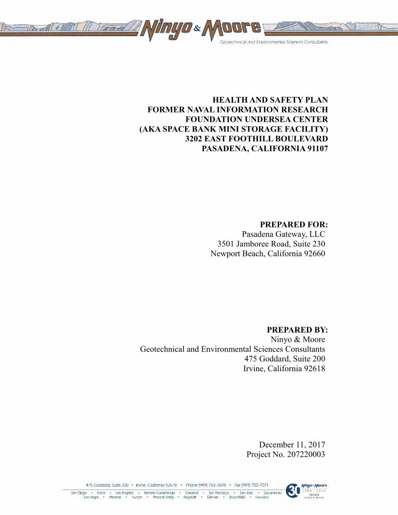
HEALTH AND SAFETY PLAN FORMER NAVAL INFORMATION RESEARCH
FOUNDATION UNDERSEA CENTER (AKA SPACE BANK MINI STORAGE FACILITY)
3202 EAST FOOTHILL BOULEVARD PASADENA, CALIFORNIA 91107
PREPARED FOR: Pasadena Gateway, LLC
3501 Jamboree Road, Suite 230 Newport Beach, California 92660
PREPARED BY: Ninyo & Moore
Geotechnical and Environmental Sciences Consultants 475 Goddard, Suite 200 Irvine, California 92618
December 11, 2017 Project No. 207220003
Former NIRF Undersea Center December 11, 2017 Pasadena, California Project No. 207220003
207220003 R HSP i
TABLE OF CONTENTS
Page 1. SITE DESCRIPTION ...............................................................................................................1
2. SCOPE OF WORK...................................................................................................................1
3. ORGANIZATION AND RESPONSIBILITIES ......................................................................1
4. HAZARD ANALYSIS .............................................................................................................2 4.1. Chemical Hazards .........................................................................................................2
4.1.1. Semi-Volatile Organic Compounds ....................................................................2 4.1.2. Volatile Organic Compounds (VOCs) ................................................................3
4.1.3. Total Petroleum Hydrocarbons (TPHs) ..............................................................4
4.1.4. Lead .....................................................................................................................4 4.1.5. Mercury ...............................................................................................................5 4.1.6. Hexavalent Chromium ........................................................................................5
4.1.7. Arsenic ................................................................................................................5 4.1.8. Organochlorine pesticides (OCPs)/ Organophosphorus Pesticides (OPPs) ........6
4.2. Physical Hazards ...........................................................................................................6 4.2.1. Walking/Working Near/Under Heavy Loads......................................................7 4.2.2. Vehicle and Heavy Equipment Operation...........................................................7
4.2.3. Strains and Sprains From Material Handling ......................................................8 4.2.4. Slip/Trip/Fall Hazards .........................................................................................8
4.2.5. Noise Hazards .....................................................................................................8 4.2.6. Underground Utilities..........................................................................................8
4.2.7. Thermal Stress/Heat Stress .................................................................................9 4.3. Biological Hazards ........................................................................................................9
4.3.1. Insect Bites and Stings ........................................................................................9
4.3.2. Poisonous Plants ...............................................................................................10
5. SITE CONTROL ....................................................................................................................11
6. DECONTAMINATION .........................................................................................................11 6.1. Personnel Decontamination ........................................................................................11 6.2. Vehicle and Equipment Decontamination ..................................................................11
7. MEDICAL SURVEILLANCE REQUIREMENTS ...............................................................12
7.1. Medical Surveillance Requirements for Ninyo & Moore Personnel ..........................12 7.2. Medical Surveillance Requirements for Subcontractors ............................................12
8. HAZARD MONITORING .....................................................................................................12
9. PERSONAL PROTECTIVE EQUIPMENT ..........................................................................14
10. EMPLOYEE TRAINING ASSIGNMENTS ..........................................................................15 10.1. Requirements for Ninyo & Moore Personnel .............................................................15 10.2. Requirements for Subcontractors ...............................................................................16

Former NIRF Undersea Center December 11, 2017 Pasadena, California Project No. 207220003
207220003 R HSP ii
10.3. General Training Requirements ..................................................................................16
11. CONFINED SPACE ENTRY ................................................................................................17
12. EMERGENCY RESPONSE ..................................................................................................17 12.1. Emergency Route to Hospital .....................................................................................18
13. SPILL CONTAINMENT PROGRAM...................................................................................18
13.1. Record Keeping and Notifications ..............................................................................19
14. SIGNATURES .......................................................................................................................20
15. CERTIFIED INDUSTRIAL HYGIENIST REVIEW ............................................................21
Tables Table 1 – Responsible Personnel for the Site ...................................................................................2 Table 2 – Chemical/Physical Agent Monitoring Requirements.........................................................13
Table 3 – Monitoring Methods and Action Levels for Petroleum Hydrocarbon1 Sites Using Screening Survey Instruments ............................................................................13
Table 4 – Personal Protective Equipment (potential or actual chemical exposure) .......................14
Table 5 – Training Assignment Matrix ..........................................................................................16 Table 6 – Emergency Phone Numbers (to be kept by Site Health and Safety Officer) .................17
Figure Figure 1 – Hospital Location

Former NIRF Undersea Center December 11, 2017 Pasadena, California Project No. 207220003
207220003 R HSP 1
1. SITE DESCRIPTION
The former Naval Information Research Foundation (NIRF) Undersea Center (currently Space
Bank Mini-Storage Facility) is located in Pasadena, California at 3202 East Foothill Boulevard.
Historically, the site was once used for military testing purposes, and has been impacted by
chemicals associated with its historical use. The project site is currently used as a storage facility,
and contains approximately 30 buildings of various size and use. The site is bordered by East
Foothill Boulevard to the north, the 210 Freeway to the south, and various commercial buildings
to the east and west.
Site work will involve the excavation and proper disposal of soils in known “hot-spot” areas,
including seepage pits and storm drains, and collection of confirmation soil samples. The
chemicals of potential concern (COPC) for the site consist of metals (lead, arsenic, hexavalent
chromium, and mercury), polynucleararomatic hydrocarbons (PAHs), volatile organic
compounds (VOCs), total petroleum hydrocarbons (TPHs), and potentially organochlorine
pesticides (OCPs) and organophosphorus pesticides (OPP).
2. SCOPE OF WORK
Ninyo & Moore’s current scope of work is described below. Ninyo & Moore personnel at the site
will conduct the following activities:
Oversee soil excavation to remove known hot spots of impacted soil, seepage pits, and storm drain system;
Collect confirmation soil samples of segregated stockpiles and excavation limits
Designate proper disposal of contaminated soils depending on results of confirmation sampling
Collection of confirmation soil samples at hot-spot locations, and OCPs and OPPs in the portion of the site west of Kinneloa Avenue.
3. ORGANIZATION AND RESPONSIBILITIES
Personnel responsible for fieldwork are identified in Table 1.
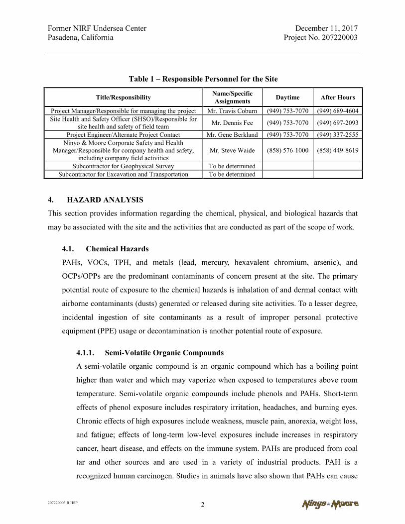
Former NIRF Undersea Center December 11, 2017 Pasadena, California Project No. 207220003
207220003 R HSP 2
Table 1 – Responsible Personnel for the Site
Title/Responsibility Name/Specific Assignments Daytime After Hours
Project Manager/Responsible for managing the project Mr. Travis Coburn (949) 753-7070 (949) 689-4604 Site Health and Safety Officer (SHSO)/Responsible for
site health and safety of field team Mr. Dennis Fee (949) 753-7070 (949) 697-2093
Project Engineer/Alternate Project Contact Mr. Gene Berkland (949) 753-7070 (949) 337-2555 Ninyo & Moore Corporate Safety and Health
Manager/Responsible for company health and safety, including company field activities
Mr. Steve Waide (858) 576-1000 (858) 449-8619
Subcontractor for Geophysical Survey To be determined Subcontractor for Excavation and Transportation To be determined
4. HAZARD ANALYSIS
This section provides information regarding the chemical, physical, and biological hazards that
may be associated with the site and the activities that are conducted as part of the scope of work.
4.1. Chemical Hazards
PAHs, VOCs, TPH, and metals (lead, mercury, hexavalent chromium, arsenic), and
OCPs/OPPs are the predominant contaminants of concern present at the site. The primary
potential route of exposure to the chemical hazards is inhalation of and dermal contact with
airborne contaminants (dusts) generated or released during site activities. To a lesser degree,
incidental ingestion of site contaminants as a result of improper personal protective
equipment (PPE) usage or decontamination is another potential route of exposure.
4.1.1. Semi-Volatile Organic Compounds
A semi-volatile organic compound is an organic compound which has a boiling point
higher than water and which may vaporize when exposed to temperatures above room
temperature. Semi-volatile organic compounds include phenols and PAHs. Short-term
effects of phenol exposure includes respiratory irritation, headaches, and burning eyes.
Chronic effects of high exposures include weakness, muscle pain, anorexia, weight loss,
and fatigue; effects of long-term low-level exposures include increases in respiratory
cancer, heart disease, and effects on the immune system. PAHs are produced from coal
tar and other sources and are used in a variety of industrial products. PAH is a
recognized human carcinogen. Studies in animals have also shown that PAHs can cause
Former NIRF Undersea Center December 11, 2017 Pasadena, California Project No. 207220003
207220003 R HSP 3
harmful effects on skin, body fluids, and the body’s system for fighting disease after
both short- and long-term exposure; however, these effects have not been reported in
people. The current Occupational Safety and Health Administration (OSHA)
permissible exposure limit (PEL) is 0.2 milligrams per cubic meter (mg/m3); however,
exposure by any route to PAH and other recognized human carcinogens will be
maintained at the absolute practicable minimum level.
4.1.2. Volatile Organic Compounds (VOCs)
VOCs are emitted as gases from certain solids or liquids. VOCs include a variety of
chemicals, some of which may have short- and long-term adverse health effects. Health
effects may include eye, nose, and throat irritation; headaches, loss of coordination,
nausea; damage to liver, kidney, and central nervous system. Some organics can cause
cancer in animals; some are suspected or known to cause cancer in humans. Key signs
or symptoms associated with exposure to VOCs include conjunctival irritation, nose and
throat discomfort, headache, allergic skin reaction, dyspnea, declines in serum
cholinesterase levels, nausea, emesis, epistaxis, fatigue, dizziness.
The ability of organic chemicals to cause health effects varies greatly from those that
are highly toxic, to those with no known health effect. As with other pollutants, the
extent and nature of the health effect will depend on many factors including level of
exposure and length of time exposed. Eye and respiratory tract irritation, headaches,
dizziness, visual disorders, and memory impairment are among the immediate
symptoms that some people have experienced soon after exposure to some organics.
Many organic compounds are known to cause cancer in animals; some are suspected of
causing, or are known to cause, cancer in humans. As with TPH above, benzene is
usually the principal concern and the basis for establishing action levels for continuous
monitoring equipment in the presence of VOCs. The current OSHA PEL for benzene is
1 part per million (ppm).
Former NIRF Undersea Center December 11, 2017 Pasadena, California Project No. 207220003
207220003 R HSP 4
4.1.3. Total Petroleum Hydrocarbons (TPHs)
TPHs is a term used to describe a large family of several hundred chemical compounds
that originally come from crude oil. TPH is a mixture of chemicals, but they are all
made mainly from hydrocarbons. Some chemicals that may be found in TPH are
hexane, jet fuels, mineral oils, benzene, toluene, xylenes, naphthalene, and fluorene, as
well as other petroleum products and gasoline components. Some of the TPH
compounds can affect your central nervous system. One compound can cause headaches
and dizziness at high levels in the air. Another compound can cause a nerve disorder
called “peripheral neuropathy,” consisting of numbness in the feet and legs. Other TPH
compounds can cause effects on the blood, immune system, lungs, skin, and eyes.
Animal studies have shown effects on the lungs, central nervous system, liver, and
kidney from exposure to TPH compounds. Some TPH compounds have also been
shown to affect reproduction and the developing fetus in animals. The International
Agency for Research on Cancer (IARC) has determined that one TPH compound
(benzene) is carcinogenic to humans. IARC has determined that other TPH compounds
(benzo[a]pyrene and gasoline) are probably and possibly carcinogenic to humans. Most
of the other TPH compounds are considered not to be classifiable by IARC. OSHA has
set PELs for many of the compounds listed above however benzene, a known human
carcinogen, is typically the principal concern and the basis for establishing the action
levels for continuous monitoring equipment in the vicinity of gasoline and other light
distillate products. The current OSHA PEL for benzene is 1 ppm.
4.1.4. Lead
Lead may be encountered as a contaminant of soil in locations near tanks and other
process equipment as a result of painting operations. Lead may also be encountered as a
result of spills or leakage of lead additives to motor fuels. Lead is a toxic heavy metal
and a suspected carcinogen that may be encountered in inorganic or organic forms.
Where lead is identified as present in sufficiently high concentrations, work will be
conducted in accordance with the applicable OSHA standards.
Former NIRF Undersea Center December 11, 2017 Pasadena, California Project No. 207220003
207220003 R HSP 5
4.1.5. Mercury
Mercury may be encountered as a contaminant of soil in locations near process
equipment, tanks, and lines. Mercury was extensively used as a gauge fluid. Breakage
of gauges may have resulted in spillage of mercury and soil contamination. Mercury is a
toxic heavy metal.
Mercury is volatile at room temperature and may present an inhalation hazard even if no
soil disturbance is occurring. Areas suspected of mercury contamination will be
screened before work begins, either by chemical sampling or with a mercury vapor
meter. Respiratory protection appropriate for the level of mercury present will be
utilized.
4.1.6. Hexavalent Chromium
Hexavalent chromium, or chromium VI, is both naturally occurring in nature, and a
man-made chromium compound which is used in steel manufacturing and welding,
chromate pigments, chemicals and thermal cutting. Hexavalent chromium has been
detected at low concentrations in soil at the site and is thought to be naturally occurring.
Hexavalent chromium is a confirmed human carcinogen that can be absorbed through
the skin. Prolonged or repeated exposure of hexavalent chromium to the skin or eyes
can cause irritations, such as discolorations and rashes. Symptoms will progressively
get worse with repeated exposure. Hexavalent chromium would travel offsite only in
visible dust. Visible dust levels will be monitored and engineering controls implemented
should ongoing visible airborne dust be generated from site work activity.
4.1.7. Arsenic
Inorganic arsenic may be found in areas where certain industrial residue may have
contaminated soils. Arsenic may also be found in areas where arsenic was used as an
herbicide. Some arsenic compounds may release a toxic gas when in an acidic
environment. Arsenic is a toxic heavy metal. Inorganic arsenic is regulated by OSHA as
a carcinogen.
Former NIRF Undersea Center December 11, 2017 Pasadena, California Project No. 207220003
207220003 R HSP 6
4.1.8. Organochlorine pesticides (OCPs)/ Organophosphorus Pesticides (OPPs)
Organochlorine pesticides range from relativity low-toxicity products to highly
poisonous compounds. Exposure to extremely small quantities of some of these
pesticides may result in serious bodily harm, even death. Central nervous system
excitation and depression, typically abrupt in onset, are the primary clinical effects of
acute organochlorine toxicity. Symptoms may include euphoria with auditory or visual
hallucinations, perceptual disturbances, seizures, agitation, lethargy, or
unconsciousness.
OPPs are typically not known carcinogens, however they can have toxic effects on
humans including the central nervous system, respiratory system, cardiovascular system
and many target organs. Routes of exposure include inhalation, ingestion, and skin
contact.
Identification of pesticide containers during field activity requires evaluation by the Site
Health and Safety Officer (SHSO) before work can proceed. Pesticide dumping at a site
requires that protective clothing protocols be implemented during all intrusive activity.
Presence of only residue following normal application may permit a reduced level of
PPE. There are a wide variety of organochlorine pesticides but the commonly cited
compounds are chlordane and dichlorodiphenyltrichloroethane (DDT). Chlordane has a
current OSHA PEL of 0.5 mg/m3 while DDT has a current PEL of 1 mg/m3.
4.2. Physical Hazards
In addition to the chemical hazards discussed above, the following physical hazards may be
present during Site activities.
Excavation
Before the start of excavation activities, a “competent person” in accordance with 29 Code
of Federal Regulations (CFR) 1926.650 (a person who has the knowledge and training to
identify hazards and the authority to correct the hazards) will ensure that the following
activities are completed:
Former NIRF Undersea Center December 11, 2017 Pasadena, California Project No. 207220003
207220003 R HSP 7
Contact utility companies and the property owner to ensure underground installations and utilities are located. Make sure underground installations and utilities are located, protected, supported or removed as necessary to safeguard employees.
Remove or secure any surface obstacles, such as trees, rocks and sidewalks, that may create a hazard.
Classify the type of soil and rock deposits at the site. One visual and at least one analytical classification should be made.
The following safety rules must be implemented during excavation activities when
personnel are to enter the excavation:
In excavations greater than four feet, and where hazardous atmospheres exist, or could reasonably be expected to exist, the competent person will test the air before entering the excavation. The competent person will use a photo-ionization detector (PID) to test for VOCs and a combustible gas indicator (CGI) to test for the presence of oxygen, carbon monoxide, hydrogen sulfide, and explosive concentrations of gases or vapors.
Keep materials or equipment that might fall or roll into an excavation at least two feet from the edge.
Adequate protection from falling rock, soil or other materials and equipment will be provided in the form of benching, sloping or shoring.
Do not work in excavations where water has accumulated, or is accumulating, unless adequate precautions have been taken.
Do not cross over an excavation unless walkways are provided. Guardrails must be provided if the walkway is six feet or more above the bottom of the excavation.
4.2.1. Walking/Working Near/Under Heavy Loads
Project personnel are prohibited from standing or walking under heavy loads (piping,
beams, etc.) They must stay at safe distance from the hoists, slings, etc.
4.2.2. Vehicle and Heavy Equipment Operation
Vehicles will only be operated in authorized areas. When moving equipment, caution
should be exercised in order not to damage equipment or cause injury. When backing up
heavy vehicles (larger than pickup trucks), passenger vehicles, or pickups with obscured
rear vision, a guide will be used to direct the vehicle. Extra caution will be exercised

Former NIRF Undersea Center December 11, 2017 Pasadena, California Project No. 207220003
207220003 R HSP 8
during vehicle operation on dike roads, industrial areas, and other close spaces.
Personnel directing traffic will wear orange vests. Each vehicle will be equipped with a
minimum of one fire extinguisher rated 3A:40B:40C.
4.2.3. Strains and Sprains From Material Handling
Workers should use good body positioning and check posture when lifting, carrying,
and handling heavy or bulky materials. Get additional assistance for carrying excessive
loads.
4.2.4. Slip/Trip/Fall Hazards
Workers should exercise caution when walking around the site to avoid slip, trip, and
fall hazards. If holes or uneven terrain are located in the work area, they must be
covered, flagged, or marked to warn workers. If conditions become slippery, workers
should take small steps with their feet pointed outward to decrease the possibility of
slipping. Workers should watch where they are walking and plan to walk in areas of
good stability (designated walkways).
4.2.5. Noise Hazards
Excavation equipment may produce continuous or impact noise at or above the OSHA
and California OSHA (Cal/OSHA) action level of 85 A-weighted decibels (dBA).
Exposure to excessive noise levels can result in temporary or permanent hearing loss.
Personnel stationed within 15 feet of operating equipment or near an operation that
creates noise levels high enough to impair conversation will wear hearing protection
(i.e., ear plugs or muffs). Personnel will wash their hands with soap and water prior to
inserting earplugs to avoid ear infections. Ninyo & Moore personnel participate in the
Ninyo & Moore hearing conservation program.
4.2.6. Underground Utilities
The Project Manager is responsible for identifying underground utility locations prior to
commencement of subsurface activities. Resources include site plans, utility companies,
and third party utility locating services. The proper utility company personnel will
certify utility de-activation and the certification retained in the permanent log.
Former NIRF Undersea Center December 11, 2017 Pasadena, California Project No. 207220003
207220003 R HSP 9
4.2.7. Thermal Stress/Heat Stress
If work is conducted during warm or hot weather, heat stress is a recognized health and
safety hazard. Cool drinking water will be made available to personnel and its use will
be encouraged and monitored. The ambient air temperature will be monitored with a
digital thermometer, and general weather conditions will be recorded in the project field
log-book daily when the temperature is expected to be above 70 degrees Fahrenheit (F).
Generally, heat stress can be reduced by:
Acclimating the body slowly. A period of adjustment will be allowed to make further heat exposure endurable. Acclimation can be lost if a worker is away from the heat for two weeks or more;
Drinking more liquids (water or diluted electrolyte drinks) to replace body water lost through sweating;
Resting frequently;
Get out of the sun;
Drink water before going out in the field; and
Avoid alcohol and caffeine and do not smoke.
4.3. Biological Hazards
During field activities, site personnel may encounter various natural hazards. These hazards
include, but are not limited to, the following:
Insect bites and stings;
Vector-transmitted illnesses (e.g., ticks and mosquitoes); and
Poisonous plants (e.g., poison oak, sumac, ivy).
In order to minimize or eliminate these hazards, the following control measures will be
enacted where possible.
4.3.1. Insect Bites and Stings
In an effort to minimize this hazard, the following control measures will be initiated
where possible.
Former NIRF Undersea Center December 11, 2017 Pasadena, California Project No. 207220003
207220003 R HSP 10
Loose-fitting clothing with long sleeves, where possible (given heat stress considerations), should be worn to provide a barrier between the field person and the insects. Commercially available insect repellents can be used if necessary. Products containing DEET should not be applied directly to the skin due to potential irritation. This product should be applied over clothing articles. For mosquito-infested areas, mosquito nets may also be used.
The SHSO will preview access routes and work areas in an effort to identify physical hazards including nesting areas in and around the work sites. These areas will be communicated to site personnel.
Personnel will be directed in the administration of antidotes for personnel who suffer allergic reactions to bee stings. Dermal applications for the bite areas will be maintained as part of the first-aid kit.
Note: It is important that allergies be reported on the medical data sheets and to the
SHSO. Additionally, specific procedure for administering treatment as directed by your
physician must also be communicated to ensure the quickest and most effective
response possible.
4.3.2. Poisonous Plants
Various plants that can cause an allergic reaction may be encountered during site work.
These include, but are not limited to, poison ivy, poison oak, and poison sumac. Contact
may occur when clearing vegetation to gain access to work areas. Oils from the plant
are transferred to exposed skin or clothing.
Protective measures to control and minimize the effects of poisonous plants include the
following:
Identify plants for field personnel. These are as follows:
Poison Ivy – Suspect plants are characterized as climbing shrubbery, three-leaf configuration ovate to elliptical in shape, greenish flowers, and white berries that produce irritating oils.
Poison Sumac – Suspect plants are characterized as a tall bush of the sumac family bearing compound leaves (7 to 13 entire leaflets), branched from a central axis, drooping, with axillary clusters of white fruit producing irritating oils.
Former NIRF Undersea Center December 11, 2017 Pasadena, California Project No. 207220003
207220003 R HSP 11
Poison Oak – Suspect plants are characterized as similar to poison ivy consisting of a shrub, stems erect, 1 to 6 feet tall, leaflets consisting of broad thick lobes with coarsely serrated configuration, denser at the base, less so than the top. Protective measures may include the use of disposable garments such as Tyvek when clearing brush. After use, carefully remove and properly dispose of disposable PPE that may be contaminated with plant oils/resins, and do not reuse.
5. SITE CONTROL
For intrusive field activities such as excavation operations, precautions shall be taken to assure
that only authorized personnel with the proper training and PPE enter work areas associated with
the operation of heavy equipment and/or the potential for exposure to hazardous
conditions/materials. In these areas, access may be controlled with caution tape and/or
barricades.
6. DECONTAMINATION
The following sections describe the decontamination procedures.
6.1. Personnel Decontamination
A minimal decontamination procedure (consisting of washing exposed skin with soap and
water) is required at soil sampling locations, such as during pesticide sampling via hand
auger, and confirmation sampling of soil stockpiles.
6.2. Vehicle and Equipment Decontamination
The primary focus of the decontamination program is to minimize the spread of
contaminated material beyond a given site. During field activities, a variety of heavy
equipment, vehicles, and small equipment is anticipated. The level of potential
contamination for vehicles and equipment at this site is low for the sampling equipment and
support vehicles used. For equipment coming from contaminated areas, items will be
decontaminated with Alconox detergent between sampling locations and the waste water
will be disposed of within approved 55-gallon drums. Prior to departure, transport and dump
trucks will be covered with a tarp and cleaned of loose debris clinging to the sides and/or
Former NIRF Undersea Center December 11, 2017 Pasadena, California Project No. 207220003
207220003 R HSP 12
wheels to minimize off-site tracking of contaminants. This should be achieved through the
use of a wheel-washing station, wheel shaker, or gravel pad near the egress point.
7. MEDICAL SURVEILLANCE REQUIREMENTS
The following sections describe training medical surveillance requirements.
7.1. Medical Surveillance Requirements for Ninyo & Moore Personnel
Ninyo & Moore personnel participating in project field activities must have a physical
examination meeting the requirements of Ninyo & Moore medical surveillance program and
will be medically qualified to perform hazardous waste operations work using respiratory
protection.
Documentation for medical clearances is maintained at the Ninyo & Moore Irvine,
California, office and is available, as necessary.
7.2. Medical Surveillance Requirements for Subcontractors
Subcontractors are required to obtain a certificate of their ability to perform hazardous waste
operations work and to wear respiratory protection. Documentation for medical clearances
must be forwarded to the SHSO prior to beginning work on site. This documentation is
maintained in the Ninyo & Moore Irvine, California, office.
8. HAZARD MONITORING
During field activities, the following monitoring requirements will be mandated:
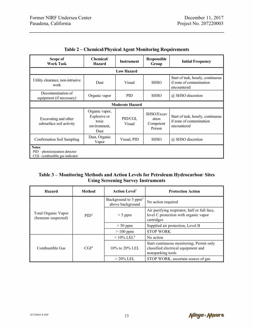
Former NIRF Undersea Center December 11, 2017 Pasadena, California Project No. 207220003
207220003 R HSP 13
Table 2 – Chemical/Physical Agent Monitoring Requirements
Scope of Work Task
Chemical/ Hazard Instrument Responsible
Group Initial Frequency
Low Hazard
Utility clearance, non-intrusive work Dust Visual SHSO
Start of task, hourly, continuous if zone of contamination encountered
Decontamination of equipment (if necessary) Organic vapor PID SHSO @ SHSO discretion
Moderate Hazard
Excavating and other subsurface soil activity
Organic vapor, Explosive or
toxic environment,
Dust
PID/CGI, Visual
SHSO/Excavation
Competent Person
Start of task, hourly, continuous if zone of contamination encountered
Confirmation Soil Sampling Dust, Organic Vapor Visual, PID SHSO @ SHSO discretion
Notes: PID – photoionization detector CGI– combustible gas indicator
Table 3 – Monitoring Methods and Action Levels for Petroleum Hydrocarbon1 Sites Using Screening Survey Instruments
Hazard Method Action Level2 Protection Action
Total Organic Vapor (benzene suspected) PID3
Background to 5 ppm5 above background No action required
> 5 ppm Air purifying respirator, half or full face, level C protection with organic vapor cartridges
> 50 ppm Supplied air protection, Level B > 100 ppm STOP WORK
Combustible Gas CGI4
< 10% LEL6 No action
10% to 20% LEL Start continuous monitoring; Permit only classified electrical equipment and nonsparking tools
> 20% LEL STOP WORK, ascertain source of gas

Former NIRF Undersea Center December 11, 2017 Pasadena, California Project No. 207220003
207220003 R HSP 14
Table 3 – Monitoring Methods and Action Levels for Petroleum Hydrocarbon1 Sites Using Screening Survey Instruments
Hazard Method Action Level2 Protection Action
Oxygen Concentration CGI4
< 19.5% O2 Leave area, evaluate reason for deficiency, monitor again remotely or with IDLH8 entry program
19.5 to 20.5% O2 Slight deficiency, continue continuous monitoring
20.5 - 21.0% O2 Normal range
> 22.0% O2 Elevated reading, check calibration, investigate cause, STOP any potential spark-producing activity
Carbon Monoxide Combustible gas indicator
> 10 ppm CO Perform continuous monitoring, evaluate reason for elevated reading, consider engineering controls
> 25 ppm CO Stop work until engineering controls can be implemented, remove personnel from excavation
Hydrogen Sulfide Combustible gas indicator > 10 ppm H2S
Leave area, evaluate reason for elevated reading, monitor again remotely or with IDLH8 entry program
Notes: 1 Action levels based on gasoline, aviation gasoline, and diesel contaminants only. A conservative 20% benzene is assumed
where benzene is not verified absent from atmosphere. Action levels should be reestablished based on periodic analysis of atmosphere.
2 All action levels are readings observed above background 3 photoionization detector 4 Combustible Gas Indicator 5 parts per million
9. PERSONAL PROTECTIVE EQUIPMENT
For each task, the hazards, control measures, and PPE requirements have been identified. The
types and levels of PPE anticipated to be worn for the performance of various tasks at the site are
as follows:
Table 4 – Personal Protective Equipment (potential or actual chemical exposure)
Task Hazard Level Body Respirator Skin Other
Non-intrusive activities
Minimal chemical exposure,
noise, solar radiation
D*
Normal work
clothes, long pants, long-sleeve shirt, safety vest
N/A Nitrile gloves
Hard hat, safety glasses,
hearing protection, steel-
toed boots
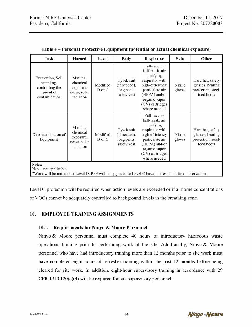
Former NIRF Undersea Center December 11, 2017 Pasadena, California Project No. 207220003
207220003 R HSP 15
Table 4 – Personal Protective Equipment (potential or actual chemical exposure)
Task Hazard Level Body Respirator Skin Other
Excavation, Soil sampling,
controlling the spread of
contamination
Minimal chemical exposure,
noise, solar radiation
Modified D or C
Tyvek suit (if needed), long pants, safety vest
Full-face or half-mask, air
purifying respirator with high-efficiency particulate air
(HEPA) and/or organic vapor
(OV) cartridges where needed
Nitrile gloves
Hard hat, safety glasses, hearing protection, steel-
toed boots
Decontamination of Equipment
Minimal chemical exposure,
noise, solar radiation
Modified D or C
Tyvek suit (if needed), long pants, safety vest
Full-face or half-mask, air
purifying respirator with high-efficiency particulate air
(HEPA) and/or organic vapor
(OV) cartridges where needed
Nitrile gloves
Hard hat, safety glasses, hearing protection, steel-
toed boots
Notes: N/A – not applicable *Work will be initiated at Level D. PPE will be upgraded to Level C based on results of field observations.
Level C protection will be required when action levels are exceeded or if airborne concentrations
of VOCs cannot be adequately controlled to background levels in the breathing zone.
10. EMPLOYEE TRAINING ASSIGNMENTS
10.1. Requirements for Ninyo & Moore Personnel
Ninyo & Moore personnel must complete 40 hours of introductory hazardous waste
operations training prior to performing work at the site. Additionally, Ninyo & Moore
personnel who have had introductory training more than 12 months prior to site work must
have completed eight hours of refresher training within the past 12 months before being
cleared for site work. In addition, eight-hour supervisory training in accordance with 29
CFR 1910.120(e)(4) will be required for site supervisory personnel.

Former NIRF Undersea Center December 11, 2017 Pasadena, California Project No. 207220003
207220003 R HSP 16
Documentation of Ninyo & Moore introductory, supervisory, and refresher training, as well
as site-specific training, are maintained at the Ninyo & Moore Irvine, California, office.
Copies of certificates or other official documentation will be used to fulfill this requirement.
Ninyo & Moore will also conduct a brief daily meeting to discuss operations planned for
that day. When appropriate, a short meeting will be held to discuss the operations completed
and any problems encountered.
10.2. Requirements for Subcontractors
Ninyo & Moore subcontractor personnel must have completed introductory hazardous waste
operations training or equivalent work experience as defined in OSHA Standard 29 CFR
1910.120(e) and eight hours of refresher training meeting the requirements of 29 CFR
1910.120(e)(8) prior to performing field work at the site. Subcontractor personnel serving as
supervisors must also provide documentation of Supervisory training as per 29 CFR
1910.120(e)(4). Ninyo & Moore subcontractors must certify that each employee has had
such training by providing copies of certificates for subcontractor personnel participating in
site activities.
10.3. General Training Requirements
A matrix summarizing training requirements for Ninyo & Moore supervisors and personnel,
subcontract personnel, visitors, and vendors is presented in Table 5.
Table 5 – Training Assignment Matrix
Category 40-
Hour Basic
8-Hour Refresher
24 Hours Supervised Experience
8-Hour Supervisor
Site- Specific
Miller Safety
Orientation
Excavation Competent
Person
First Aid/CPR
Ninyo & Moore Employee
X X X X X
Ninyo & Moore Supervisor/SHSO
X X X X X X X
Subcontractor Supervisor X X X X X X X
Subcontractor Personnel X X X X X
Visitor X X X X Vendor X X X X
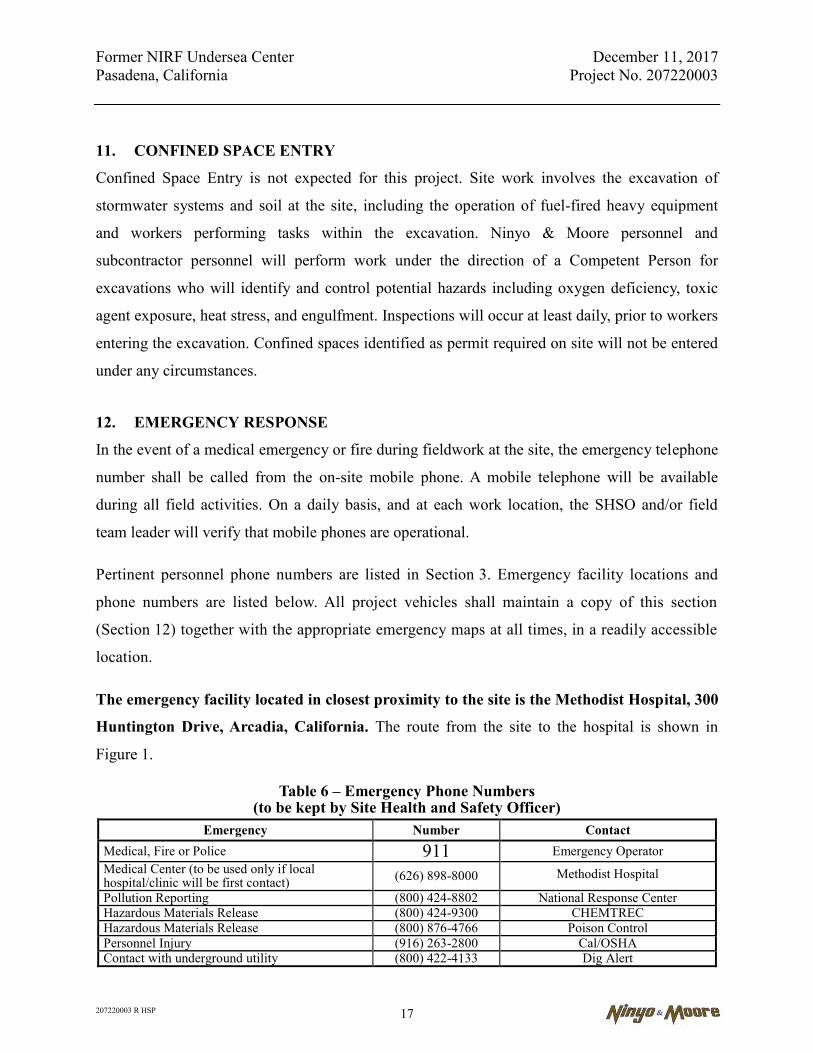
Former NIRF Undersea Center December 11, 2017 Pasadena, California Project No. 207220003
207220003 R HSP 17
11. CONFINED SPACE ENTRY
Confined Space Entry is not expected for this project. Site work involves the excavation of
stormwater systems and soil at the site, including the operation of fuel-fired heavy equipment
and workers performing tasks within the excavation. Ninyo & Moore personnel and
subcontractor personnel will perform work under the direction of a Competent Person for
excavations who will identify and control potential hazards including oxygen deficiency, toxic
agent exposure, heat stress, and engulfment. Inspections will occur at least daily, prior to workers
entering the excavation. Confined spaces identified as permit required on site will not be entered
under any circumstances.
12. EMERGENCY RESPONSE
In the event of a medical emergency or fire during fieldwork at the site, the emergency telephone
number shall be called from the on-site mobile phone. A mobile telephone will be available
during all field activities. On a daily basis, and at each work location, the SHSO and/or field
team leader will verify that mobile phones are operational.
Pertinent personnel phone numbers are listed in Section 3. Emergency facility locations and
phone numbers are listed below. All project vehicles shall maintain a copy of this section
(Section 12) together with the appropriate emergency maps at all times, in a readily accessible
location.
The emergency facility located in closest proximity to the site is the Methodist Hospital, 300
Huntington Drive, Arcadia, California. The route from the site to the hospital is shown in
Figure 1.
Table 6 – Emergency Phone Numbers (to be kept by Site Health and Safety Officer)
Emergency Number Contact Medical, Fire or Police 911 Emergency Operator Medical Center (to be used only if local hospital/clinic will be first contact) (626) 898-8000 Methodist Hospital
Pollution Reporting (800) 424-8802 National Response Center Hazardous Materials Release (800) 424-9300 CHEMTREC Hazardous Materials Release (800) 876-4766 Poison Control Personnel Injury (916) 263-2800 Cal/OSHA Contact with underground utility (800) 422-4133 Dig Alert
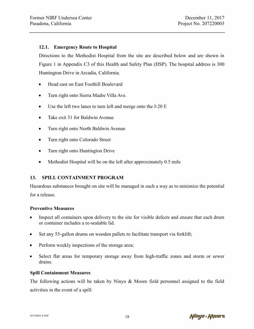
Former NIRF Undersea Center December 11, 2017 Pasadena, California Project No. 207220003
207220003 R HSP 18
12.1. Emergency Route to Hospital
Directions to the Methodist Hospital from the site are described below and are shown in
Figure 1 in Appendix C3 of this Health and Safety Plan (HSP). The hospital address is 300
Huntington Drive in Arcadia, California.
Head east on East Foothill Boulevard
Turn right onto Sierra Madre Villa Ave.
Use the left two lanes to turn left and merge onto the I-20 E
Take exit 31 for Baldwin Avenue
Turn right onto North Baldwin Avenue
Turn right onto Colorado Street
Turn right onto Huntington Drive
Methodist Hospital will be on the left after approximately 0.5 mile
13. SPILL CONTAINMENT PROGRAM
Hazardous substances brought on site will be managed in such a way as to minimize the potential
for a release.
Preventive Measures
Inspect all containers upon delivery to the site for visible defects and ensure that each drum or container includes a re-sealable lid.
Set any 55-gallon drums on wooden pallets to facilitate transport via forklift;
Perform weekly inspections of the storage area;
Select flat areas for temporary storage away from high-traffic zones and storm or sewer drains.
Spill Containment Measures
The following actions will be taken by Ninyo & Moore field personnel assigned to the field
activities in the event of a spill:
Former NIRF Undersea Center December 11, 2017 Pasadena, California Project No. 207220003
207220003 R HSP 19
the Site Coordinator (field team leader) and SHSO are to be notified immediately;
workers not involved in spill containment and/or cleanup shall evacuate the immediate area and designated emergency response personnel attired in appropriate PPE (see Section 4.2), shall proceed to the spill area with a spill cleanup and control kit, including absorbent materials;
attempts shall be made to stop the source(s) of spillage immediately;
the SHSO shall monitor for exposure to chemicals or hazardous substances during spill cleanup work and shall stay at the spill area until the area has been cleared, inspected, and readied for reentry. A spill incident report shall be prepared by the SHSO;
13.1. Record Keeping and Notifications
The SHSO shall thoroughly document the spill in an Incident Report which will be
forwarded to the Corporate Safety Manager and Project Manager. Records of all hazardous
materials releases shall be maintained with the project files and the facility operating record.
The Project Manager will make any necessary notifications to off-site authorities and he and
the Safety Manager will approve the reentry to the site for routine use and will issue a final
release report pertaining to cleanup of the area.
Former NIRF Undersea Center December 11, 2017 Pasadena, California Project No. 207220003
207220003 R HSP 20
14. SIGNATURES
All site personnel are required to read the above plan and by signing below, acknowledge that
they are familiar with its provisions.
Print Name Signature/Date
Ninyo & Moore Personnel
Field Team Leader/SHSO
Field Team Members
Field Team Members
Field Team Members
Field Team Members
Field Team Members
Contractors
Client/Agency Personnel

Former NIRF Undersea Center December 11, 2017 Pasadena, California Project No. 207220003
207220003 R HSP 21
15. CERTIFIED INDUSTRIAL HYGIENIST REVIEW
The above Site Specific HSP has been reviewed and approved by the certified industrial
hygienist (CIH) indicated below.
Stephen J. Waide, CIH, CSP Certified Industrial Hygienist No. CP 7005 Expires 6/1/22
Former NIRF Undersea Center December 11, 2017 Pasadena, California Project No. 207220003
207220003 R HSP
FIGURE 1
ROUTE FROM SITE TO HOSPITAL

SITE
METHODIST HOSPITAL300 HUNTINGTON DRIVE
ARCADIA, CALIFORNIA 91007PH: (626) 898-8000
FIGURE
1PROJECT NO.
207220003
HOSPITAL LOCATIONDATE
2017
0 2,000 4,000
SCALE IN FEET
NOTE: DIMENSIONS, DIRECTIONS AND LOCATIONS ARE APPROXIMATE.
N
2072
2000
3_H
L.dw
g 09
:37:
05
04/1
9/20
17
GK
3202 EAST FOOTHILL BOULEVARDPASADENA, CALIFORNIA
REFERENCE: 7.5 MINUTE USGS TOPOGRAPHIC MAP OF MOUNT WILSON, CALIFORNIA QUADRANGLE, DATED 2015, SCALE 1:24000.
Former NIRF Undersea Center December 11, 2017 Pasadena, California Project No. 207220003
207220003 R RAW
APPENDIX E
SOIL GAS SURVEY WORK PLAN
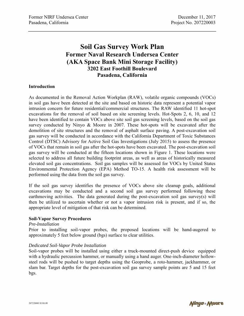
Former NIRF Undersea Center December 11, 2017 Pasadena, California Project No. 207220003
207220003 R RAW
Soil Gas Survey Work Plan Former Naval Research Undersea Center (AKA Space Bank Mini Storage Facility)
3202 East Foothill Boulevard Pasadena, California
Introduction As documented in the Removal Action Workplan (RAW), volatile organic compounds (VOCs) in soil gas have been detected at the site and based on historic data represent a potential vapor intrusion concern for future residential/commercial structures. The RAW identified 11 hot-spot excavations for the removal of soil based on site screening levels. Hot-Spots 2, 6, 10, and 12 have been identified to contain VOCs above site soil gas screening levels, based on the soil gas survey conducted by Ninyo & Moore in 2007. These hot-spots will be excavated after the demolition of site structures and the removal of asphalt surface paving. A post-excavation soil gas survey will be conducted in accordance with the California Department of Toxic Substances Control (DTSC) Advisory for Active Soil Gas Investigations (July 2015) to assess the presence of VOCs that remain in soil gas after the hot-spots have been excavated. The post-excavation soil gas survey will be conducted at the fifteen locations shown in Figure 1. These locations were selected to address all future building footprint areas, as well as areas of historically measured elevated soil gas concentrations. Soil gas samples will be assessed for VOCs by United States Environmental Protection Agency (EPA) Method TO-15. A health risk assessment will be performed using the data from the soil gas survey. If the soil gas survey identifies the presence of VOCs above site cleanup goals, additional excavations may be conducted and a second soil gas survey performed following these earthmoving activities. The data generated during the post-excavation soil gas survey(s) will then be utilized to ascertain whether or not a vapor intrusion risk is present, and if so, the appropriate level of mitigation of that risk can be determined. Soil-Vapor Survey Procedures Pre-Installation
Prior to installing soil-vapor probes, the proposed locations will be hand-augered to approximately 5 feet below ground (bgs) surface to clear utilities.
Dedicated Soil-Vapor Probe Installation
Soil-vapor probes will be installed using either a truck-mounted direct-push device equipped with a hydraulic percussion hammer, or manually using a hand auger. One-inch-diameter hollow-steel rods will be pushed to target depths using the Geoprobe, a roto-hammer, jackhammer, or slam bar. Target depths for the post-excavation soil gas survey sample points are 5 and 15 feet bgs.

Former NIRF Undersea Center December 11, 2017 Pasadena, California Project No. 207220003
207220003 R RAW
An expendable drive point/anchor is attached to the bottom-most probe rod prior to insertion. Once the target depth is reached, the probe is withdrawn approximately 6 inches to 1 foot, disengaging the drive point. A ¼-inch-diameter Nylaflow tube, with perforations along the bottom 4 inches, is inserted to the bottom of the hole inside the steel pipe. Alternatively, the tubing can be connected to a vapor sampling implant prior to lowering down hole. The rods are then retrieved leaving the tubing in the hole. Fine-grained sand is poured around the tube openings to at least 6 inches above the perforations. The annulus is then grouted with granular bentonite hydrated in place to form a tight seal around the tube and reduce the chance of sampling ambient air. The tubing is then labeled with the probe designation and total depth. Vapor sampling is conducted after a period of at least two hours to allow for recovery of the subsurface vapor regime.
Soil-Vapor Sampling
Soil-vapor sampling in non-paved areas will not be conducted within two days following a significant rain event (e.g., ½-inch or greater) due to possible effects of rainwater infiltration on the subsurface vapor regime. Each sampling point’s Nylaflow tubing is connected to a glass-sampling bulb fitted with Teflon stopcocks and a Viton rubber sampling port. The bulb is connected in turn to a vacuum gauge, a flowmeter, and portable sampling pump in series. The entire sampling train is tested for leakage to avoid sampling ambient air or diluting the desired soil gas sample. The glass-sampling bulb is wrapped in aluminum foil to minimize photoreactions with captured chemicals. Alternatively, soil-vapor samples can be collected using a syringe by inserting the needle into a silicon tubing attaching the top of the probe to the sampling pump. Prior to sample collection, approximately three purge volumes (using a purge rate of 100 to 200 milliliters per minute [ml/min]) of air will be removed using a calibrated air pump or graduated syringe. If the air pump is used, the purge volume will be monitored by volume and time. The purge begin time and end time will be recorded on the soil gas sampling field forms. The purge rates during the purge-volume test and during the sample purging will be kept at approximately 100 to 200 ml/min. All purge volumes and methods will be recorded in the field logs.
When purging procedures are completed, first the pump-end and then the probe-end sample cocks are closed in sequence. Once collected, the sample is labeled, injected with isotopically labeled surrogate compounds, recorded on a chain-of-custody, and immediately transferred to an on-site mobile laboratory for chemical analysis.
If no-flow or low-flow conditions are caused by wet soils, the soil-vapor sampling will cease until conditions dry (at least two days after a significant rain event or after on-site watering has ceased). If low-flow conditions are related to a specific lithology, a new probe will be installed at a greater depth, a new lateral location selected after evaluation of the site lithologic logs or in consultation with the oversight agency. Soil-vapor probes will be removed after sampling. Quality Assurance/Quality Control Evaluation The purpose for the quality assurance (QA) procedures and collecting quality control (QC) samples is to acquire data to assess and document the effectiveness of probe-installation, field

Former NIRF Undersea Center December 11, 2017 Pasadena, California Project No. 207220003
207220003 R RAW
sampling and laboratory-analysis procedures in producing accurate and precise analytical data. A description of the field QA procedures, QC sample types, and an evaluation of the analytical results of these samples for this project are presented in the following sections.
Field QA Procedures Sample-Train Leakage Test
Prior to sampling, the entire sampling train is tested for leakage to prevent sampling ambient air. Initially, both stopcocks in the sample train are closed. The absence of flow and the presence of a slight vacuum demonstrate that the pump-end side of the sampling train has no leaks. Then the first stopcock (pump end) is opened. The absence of flow demonstrates that the sampling bulb itself does not leak.
Annular-Seal Leakage Test
To ensure proper probe installation and sealing, a leakage test is performed during sampling procedures. The leakage test consists of applying a 1:1 mixture of n-pentane and n-propanol (tracer gases) to a rag set and placing it on the probe tubing on the ground surface and at the sample system port within a few minutes prior to sampling. If the tracer is detected at 10 times its respective detection limit, the probe will be replaced and resampled.
Decontamination
Equipment blanks shall be collected at the beginning of sampling and at least once each day after decontamination. An Equipment blank is sampled by pouring distilled water over a recently de-contaminated piece of equipment and collect the water in an appropriate container for analysis of site constituents. Drill rods contacting contaminated soil will be decontaminated before reuse and blank tested as appropriate. The equipment blanks demonstrate there is no residual contaminant carryover from other sites or sampling points.
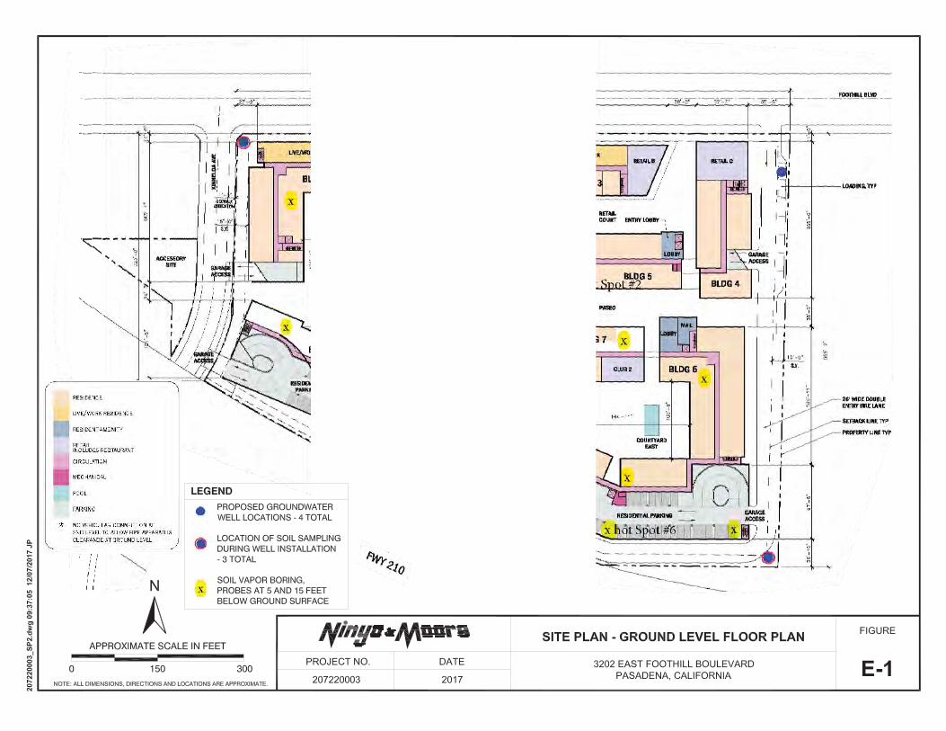

Former NIRF Undersea Center December 11, 2017 Pasadena, California Project No. 207220003
207220003 R RAW
APPENDIX F
STORMWATER POLLUTION PREVENTION PLAN
WASTE DISCHARGE IDENTIFICATION (WDID) NUMBER: TBD
STORM WATER POLLUTION PREVENTION PLAN for
Pasadena Gateway Removal Action Project
RISK LEVEL: 1
Prepared for: RWQCB, Los Angeles Region
320 West Fourth Street, Suite 200 Los Angeles, CA 90013
Submitted by: Ninyo & Moore 475 Goddard
Irvine, California 92618
Project Site Address 3202 East Foothill Blvd., Pasadena, California
Contractor’s Qualified SWPPP Developer (QSD) TBD
Water Pollution Control (WPC) Manager _
TBD
SWPPP Developed by: Ninyo & Moore 475 Goddard
Irvine, CA
Storm Water Pollution Prevention Plan (SWPPP) Pasadena Gateway Project
Riverside County Transportation Commission Page i 207220003 R SWPPP December 11, 2017
ABBREVIATIONS AC – Asphalt Concrete ATS – Active Treatment System BAT/BCT – Best Available Technology/ Best Conventional Technology BGS – below ground surface BMP – Best Management Practice BMPSWD – Best Management Practice and Storm Water Discharge Sample Locations BOD – Biological Oxygen Demand CASQA – California Storm Water Quality Association CCR – California Code of Regulations CFR – Code of Federal Regulations CGP – Construction General Permit CSMP – Construction Site Monitoring Program DOT – Department of Transportation DSA – Disturbed Soil Area DTSC – Department of Toxic Substances Control DWQ – Division of Water Quality EMAP – Environmental Monitoring and Assessment Program EPA – Environmental Protection Agency HDPE – High Density Polyethylene HVAC – heating, ventilating, and air conditioning Liston – Liston Aluminum Brick Company LRP – Legally Responsible Person ml – Milliliter mph – miles per hour NAL – Numeric Action Level NEL – Numeric Effluent Limitation NPDES – National Pollutant Discharge Elimination System OUs – Operable Units PCC – Portland Cement Concrete QSD – Qualified Storm Water Pollution Prevention Plan Developer QSP – Qualified Storm Water Pollution Prevention Plan Practitioner REAP – Rain Event Action Plan RWQCB – Regional Water Quality Control Board SCAQMD – South Coast Air Quality Management District SWPPP – Storm Water Pollution Prevention Plan SWRCB – State Water Resources Control Board TPH – Total Petroleum Hydrocarbons USEPA – United States Environmental Protection Agency VOCs – volatile organic compounds WDID – Waste Discharge Identification Number WPCD – Water Pollution Control Drawings WPCP – Water Pollution Control Program

Storm Water Pollution Prevention Plan (SWPPP) Pasadena Gateway Project
Pasadena Gateway, LLC Page i 207220003 R SWPPP December 11, 2017
Contents ABBREVIATIONS………………………………………………………………………………………………………… i SECTION 100 Storm Water Pollution Prevention Plan (SWPPP) Certifications and Approval ....................1
100.1 Legally Responsible Person (LRP) Certification Approval...................................................... 1 100.2 Qualified Storm Water Pollution Prevention Plan Developer (QSD) SWPPP Certification ..... 2 100.3 Amendments .......................................................................................................................... 2
100.3.1 SWPPP Amendments Certification and Approval ................................................... 2 100.3.2 Amendment Log ...................................................................................................... 3
SECTION 200 OBJECTIVES ...............................................................................................................................4 SECTION 300 PROJECT AND CONTRACTOR INFORMATION ........................................................................6
300.1 Project Description ................................................................................................................. 6 300.2 Project Risk Level .................................................................................................................. 6 300.3 Construction Sites Estimates ................................................................................................. 6 300.4 Vicinity and Site Map .............................................................................................................. 7 300.5 Unique Site Features ............................................................................................................. 7 300.6 Contact Information for Responsible Parties .......................................................................... 7 300.7 List of Subcontractor and Materials Suppliers ........................................................................ 8 300.8 Training .................................................................................................................................. 8
SECTION 400 REFERENCES, OTHER PLANS, PERMITS AND AGREEMENTS ........................................... 10 SECTION 500 DETERMINATION OF CONSTRUCTION SITE BEST MANAGEMENT PRACTICES .............. 11
500.1 Pollutant Sources ................................................................................................................. 11 500.1.1 Inventory of Materials and Activities that May Pollute Storm Water ...................... 11 500.1.2 Potential Pollutants from Site Features or Known Contaminates .......................... 15 500.1.3 Risk Level Determination ...................................................................................... 15
500.2 Pre-Construction Existing Storm Water Control Measures................................................... 16 500.3 BMP Selection for Erosion and Sediment Control ................................................................ 16
500.3.1 Temporary Run-on Control BMPs ......................................................................... 17 500.3.2 Soil Stabilization (Erosion Control) ........................................................................ 18 500.3.3 Sediment Control .................................................................................................. 20 500.3.4 Tracking Control .................................................................................................... 22 500.3.5 Wind Erosion Control ............................................................................................ 22
500.4 BMP Selection for Construction Site Management .............................................................. 23 500.4.1 Non-Storm Water Site Management ..................................................................... 23 500.4.2 Waste Management and Materials Pollution Control ............................................ 25
500.5 Best Management Practices List .......................................................................................... 28

Storm Water Pollution Prevention Plan (SWPPP) Pasadena Gateway Project
Pasadena Gateway, LLC Page ii 207220003 R SWPPP December 11, 2017
500.6 Best Management Plan Drawings ........................................................................................ 28 SECTION 600 PROJECT SITE IMPLEMENTATION PROGRAM ..................................................................... 30
600.1 QSD/QSP Responsibilities ................................................................................................... 30 600.2 Site Inspections .................................................................................................................... 31 600.3 Weather Forecast Monitoring ............................................................................................... 31 600.4 Weather Monitoring .............................................................................................................. 32 600.5 Best Management Practices Status Report.......................................................................... 33 600.6 Rain Event Action Plans ....................................................................................................... 33
SECTION 700 CONSTRUCTION SITE MONITORING PROGRAM-RISK LEVEL 1 SITES .............................. 34 700.1 Objectives ............................................................................................................................ 34 700.2 Visual Monitoring, Sampling, and Sample Analytical - Requirements for Qualifying Rain Events 34 700.2 Non-Storm Water Discharge Monitoring Requirements ....................................................... 35 700.3 Non-Visible Pollutant Monitoring Requirements ................................................................... 36 700.4 Sample Analytical Laboratory Contacts and Analytical Methods .......................................... 36 700.5 Records ................................................................................................................................ 37 700.6 Exceedance Report .............................................................................................................. 37
SECTION 800 POST CONSTRUCTION CONTROL PRACTICES .................................................................... 39 800.1 Post-Construction Control Practices .................................................................................... 39 800.2 Post Construction Operation/Maintenance ........................................................................... 39
SECTION 900 SWPPP REPORTING REQUIREMENTS ................................................................................... 40 900.1 Record Keeping ................................................................................................................... 40 900.2 Storm Water Annual Report ................................................................................................. 41 900.3 Discharge Reporting ............................................................................................................ 41 900.4 Regulatory Agency Notice or Order Reporting ..................................................................... 42 900.5 Illicit Connection/Illegal Discharge Reporting ....................................................................... 42
Figures Figure 1 ..................................................................................................................................Site Location Figure 2 ......................................................................................................................................... Site Plan
SWPPP Attachments Attachment A ................................................................................................................... SWPPP Amendment Log Attachment B .................................................................................................................... Risk Level Determination Attachment C ...........................................................................................................Runoff Coefficient Calculations Attachment D ........................................................................................................ Water Pollution Control Drawing
Storm Water Pollution Prevention Plan (SWPPP) Pasadena Gateway Project
Pasadena Gateway, LLC Page iii 207220003 R SWPPP December 11, 2017
Attachment E ............................................................................ QSD Training and Professional Engineer License Attachment F ............................................................................................................................................. Not Used Attachment G ............................................................................................................................................ Not Used Attachment H ............................................................................................................................................. Not Used Attachment I .................................................................................................... Storm Water Site Inspection Forms Attachment J .............................................................................................................................................. Not Used Attachment K .............................................................................................................................................. Not Used Attachment L ................................................................. Storm Water Best Management Practices Status Report Attachment M ............................................................................................................................................. Not Used Attachment N ................................................... Sample Information, Identification, and Chain of Custody Form Attachment O ................................................................................................................. Notice of Discharge Form

Storm Water Pollution Prevention Plan (SWPPP) Pasadena Gateway Project
Pasadena Gateway, LLC Page 1 207220003 R SWPPP December 11, 2017
SECTION 100 Storm Water Pollution Prevention Plan (SWPPP) Certifications and Approval 100.1 Legally Responsible Person (LRP) Certification Approval The Contractor and Pasadena Gateway, LLC are responsible and liable at all times for compliance with applicable requirements of the CGP (CAS******, Order No. 2009-0009-Division of Water Quality [DWQ]) for which compliance is ultimately determined by the Regional Water Quality Control Board (RWQCB), the State Water Resources Control Board (SWRCB), and/or the United States Environmental Protection Agency (USEPA).
Local Agency Legally Responsible Person Certification of the Storm Water Pollution Prevention Plan
Project Name: Pasadena Gateway, LLC Removal Action Project
Local Agency Name DEPARTMENT OF TOXICS SUBSTANCES CONTROL
“I certify under a penalty of law that this document and all attachments were prepared under my direction or supervision in accordance with a system designed to assure that qualified personnel properly gather and evaluate the information submitted. Based on my inquiry of the person or persons who manage the system or those persons directly responsible for gathering the information, to the best of my knowledge and belief, the information submitted is true, accurate, and complete. I am aware that there are significant penalties for submitting false information, including the possibility of fine and imprisonment for knowing violations.”
Legally Responsible Person’s Signature Date
Storm Water Pollution Prevention Plan (SWPPP) Pasadena Gateway Project
Pasadena Gateway, LLC Page 2 207220003 R SWPPP December 11, 2017
100.2 Qualified Storm Water Pollution Prevention Plan Developer (QSD) SWPPP Certification Project Name: Pasadena Gateway, LLC Removal Action Project
“I certify under a penalty of law that I relied upon available project and site information, current watershed and basin plan maps and available soil data to develop this SWPPP so that Best Management Practices (BMPs) were designed and placed in accordance with industry standards and best professional judgment to reduce pollutants from leaving the job site. All other sources relied upon to gain information for this project’s SWPPP were appropriate and dependable based on my best professional judgment. To the best of my knowledge and belief, the information submitted in this SWPPP is in compliance with all requirements of the Construction General Permit (CGP) (CAS000002, Order No. 2009-0009-DWQ).”
Date
100.3 Amendments
100.3.1 SWPPP Amendments Certification and Approval
This SWPPP shall be amended annually and when:
≠ There is a change in construction or operations which may affect the discharge of pollutants to surface waters, groundwater(s), or a municipal separate storm sewer system (MS4);
≠ Water pollution control practices are added by contract change order;
≠ Objectives of reducing or eliminating pollutants in storm water discharges has not been achieved;
≠ There is a Permit violation. If the RWQCB determines that a Permit violation has occurred, the SWPPP shall be amended and implemented within 14 calendar days after notification by the RWQCB; and
≠ Deemed necessary by the QSD or LRP.
The following items shall be included in each amendment:
≠ Who requested the amendment;
≠ The location of proposed change;
≠ The reason for change;
≠ The original BMP proposed, if any; and

Storm Water Pollution Prevention Plan (SWPPP) Pasadena Gateway Project
Pasadena Gateway, LLC Page 3 207220003 R SWPPP December 11, 2017
≠ The new BMP proposed.
Approved and certified amendments shall be inserted into the appropriate section of the SWPPP or attachment and a copy inserted into Attachment A. All SWPPP amendments are listed in the SWPPP Amendment Log in Attachment A.
All SWPPP amendments prepared by the QSD shall be approved by the LRP or Approved Signatory.
100.3.2 Amendment Log
The amendment log shall include:
≠ Amendment number;
≠ Date;
≠ Brief description of the amendment;
≠ Requested by; and
≠ Approval date.

Storm Water Pollution Prevention Plan (SWPPP) Pasadena Gateway Project
Pasadena Gateway, LLC Page 4 207220003 R SWPPP December 11, 2017
SECTION 200 OBJECTIVES This SWPPP has five (5) main objectives:
1. Ensure that all pollutants and their sources, including sources of sediment associated with construction, construction site erosion, and all other activities associated with construction activity are controlled;
2. Where not otherwise required to be under a RWQCB Permit, all non-storm water discharges are identified and either eliminated, controlled, or treated;
3. Site BMPs are effective and result in the reduction or elimination of pollutants in storm water discharges and authorized non- storm water discharges from the construction activity to the Best Available Technology/ Best Conventional Technology (BAT/BCT) standard;
4. Calculations and design details as well as BMP controls for site run-on are complete and correct; and
5. Stabilization BMPs designed to eliminate or reduce pollutants after construction is complete have been installed.
This SWPPP was developed to conform to the required elements of the CGP (CAS******, Order No. 2009-0009-DWQ) issued by the SWRCB.
This SWPPP is designed to be a useful document for those who must implement the SWPPP on a daily basis in the field. Most of the information necessary for the daily implementation of the SWPPP is contained in the attachments and appendices.
This SWPPP shall be regarded as a “living document” as it is updated and additional information is added to the SWPPP file categories as the project progresses, including:
≠ Storm Water Site Inspection Reports;
≠ Storm Water Site Inspections Report Corrections Summary;
≠ Rain Event Action Plans (REAPs);
≠ Contractor Personnel Training Documentation;
≠ Storm Water Sampling Test Results;
≠ Notice of Discharges; and
≠ Contact information for additional subcontractors and material suppliers.
Updates to the SWPPP that do require an amendment of the SWPPP include:
≠ Location change of a BMP shown on the Water Pollution Control Drawings (Attachment E) to meet field conditions; and
≠ Additional BMPs required by a REAP.
Storm Water Pollution Prevention Plan (SWPPP) Pasadena Gateway Project
Pasadena Gateway, LLC Page 5 207220003 R SWPPP December 11, 2017
The SWPPP will be modified and amended when:
≠ There are any amendments to the Permits;
≠ There are any changes in construction or operations that may affect the discharge of pollutants from the construction site to surface waters, groundwater, or the municipal separate storm sewer system (MS4);
≠ The general objective of reducing pollutants in storm water discharges is not achieved.
The SWPPP will be completely revised if either the number of amendments and amount of information contained in the amendments makes implementation of the SWPPP confusing, as determined by the Construction Site Manager or the Contractor requests to revise the SWPPP based on planned changes in activities that would require a major SWPPP amendment.
The SWPPP shall be readily available on site for the duration of the project.
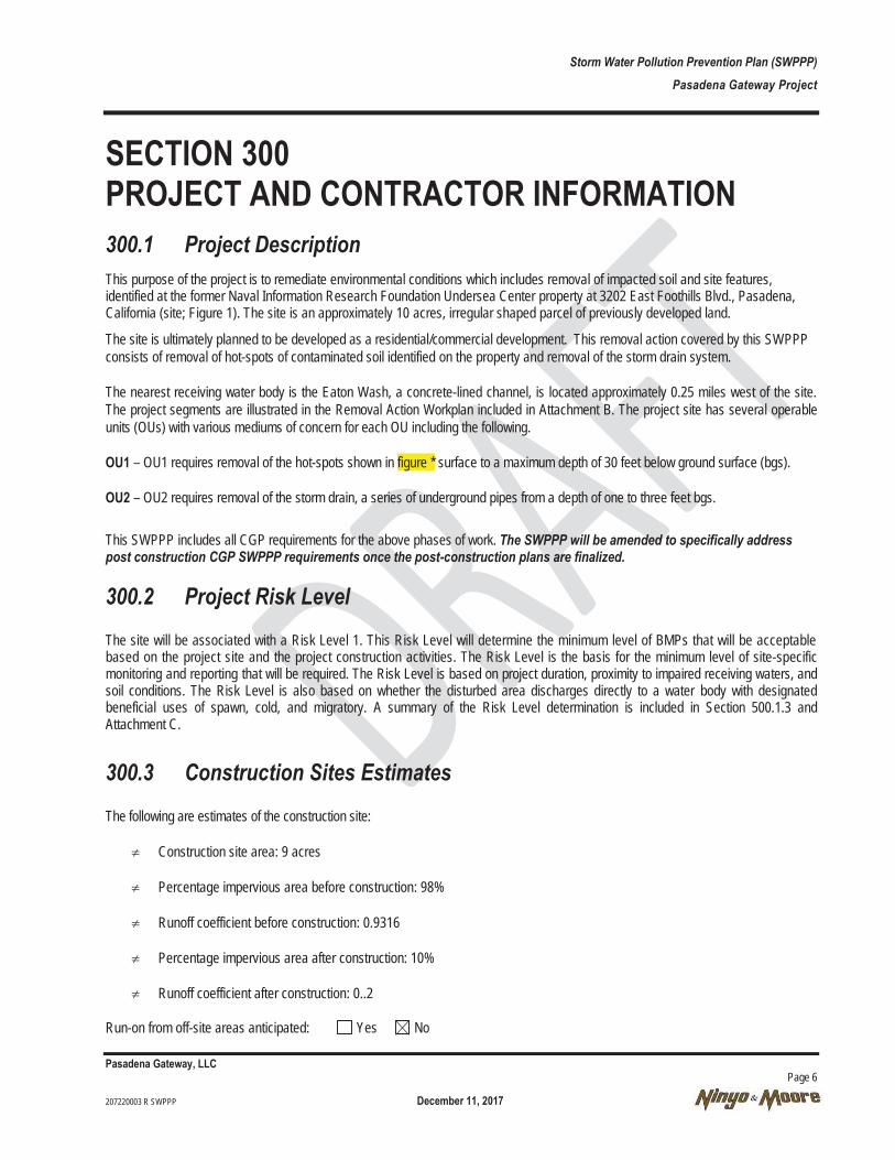
Storm Water Pollution Prevention Plan (SWPPP) Pasadena Gateway Project
Pasadena Gateway, LLC Page 6 207220003 R SWPPP December 11, 2017
SECTION 300 PROJECT AND CONTRACTOR INFORMATION 300.1 Project Description This purpose of the project is to remediate environmental conditions which includes removal of impacted soil and site features, identified at the former Naval Information Research Foundation Undersea Center property at 3202 East Foothills Blvd., Pasadena, California (site; Figure 1). The site is an approximately 10 acres, irregular shaped parcel of previously developed land.
The site is ultimately planned to be developed as a residential/commercial development. This removal action covered by this SWPPP consists of removal of hot-spots of contaminated soil identified on the property and removal of the storm drain system.
The nearest receiving water body is the Eaton Wash, a concrete-lined channel, is located approximately 0.25 miles west of the site. The project segments are illustrated in the Removal Action Workplan included in Attachment B. The project site has several operable units (OUs) with various mediums of concern for each OU including the following.
OU1 – OU1 requires removal of the hot-spots shown in figure * surface to a maximum depth of 30 feet below ground surface (bgs).
OU2 – OU2 requires removal of the storm drain, a series of underground pipes from a depth of one to three feet bgs.
This SWPPP includes all CGP requirements for the above phases of work. The SWPPP will be amended to specifically address post construction CGP SWPPP requirements once the post-construction plans are finalized.
300.2 Project Risk Level The site will be associated with a Risk Level 1. This Risk Level will determine the minimum level of BMPs that will be acceptable based on the project site and the project construction activities. The Risk Level is the basis for the minimum level of site-specific monitoring and reporting that will be required. The Risk Level is based on project duration, proximity to impaired receiving waters, and soil conditions. The Risk Level is also based on whether the disturbed area discharges directly to a water body with designated beneficial uses of spawn, cold, and migratory. A summary of the Risk Level determination is included in Section 500.1.3 and Attachment C.
300.3 Construction Sites Estimates The following are estimates of the construction site:
≠ Construction site area: 9 acres
≠ Percentage impervious area before construction: 98%
≠ Runoff coefficient before construction: 0.9316
≠ Percentage impervious area after construction: 10%
≠ Runoff coefficient after construction: 0..2
Run-on from off-site areas anticipated: Yes No
Storm Water Pollution Prevention Plan (SWPPP) Pasadena Gateway Project
Pasadena Gateway, LLC Page 7 207220003 R SWPPP December 11, 2017
Runoff coefficient calculations are presented in Attachment D. Current and anticipated drainage patterns following the completion of grading activities are shown along with the BMPs and storm water sample locations in Attachment E.
300.4 Vicinity and Site Map The construction project vicinity map is shown on Figure 1. A map showing the project location, and all current buildings is shown on Figure 2.
This project involves removal of environmentally impacted soil from various locations on the site. This construction project is located in Los Angeles County, in the City of Pasadena, California. The nearest receiving water body is the Eaton Wash. The project site is developed land with primarily World War II era wooden structures with one exception; Building 30, a brick structure built in the 1970s. Features including storage connexes, asphalt pavement, and discharge locations from site storm water discharges are located on the Best Management Practice and Storm Water Discharge Sample Locations (BMPSWD) map in Attachment E.
300.5 Unique Site Features Project has Fill Material: Yes No
Project has Native Material: Yes No
Hydrologic Soil Group: A (high infiltration rate) B (moderate infiltration rate)
C (slow infiltration rate) D (very slow infiltration rate
Soil Erodibility: Slight Moderate Severe
Unique Features On Site: Water Bodies Wetlands Endangered or Protected Species
Environmentally Sensitive Areas Other None
300.6 Contact Information for Responsible Parties The following parties are responsible for this SWPPP:
Qualified SWPPP Developer (QSD) Name: Travis CoburnTitle: Engineer Company: NINYO & Moore Address: 475 Goddard Irvine, CA 92727
Phone Number: 949-752-7070 Emergency Phone Number (24/7):
PASADENA GATEWAY Project Manager Name: Neal Holdridge Title: Environmental Manager Agency: EASI / Trammell Crow Company

Storm Water Pollution Prevention Plan (SWPPP) Pasadena Gateway Project
Pasadena Gateway, LLC Page 8 207220003 R SWPPP December 11, 2017
Address: 3501 Jamboree Road, Suite 230 Newport Beach, CA 92660
Phone Number: 949-477-4719 Contractor Name: TBD Title: Company: Address: Phone Number:
Construction Site Manager Name: TBD Title: Company: Address: Phone Number:
Water Pollution Control Manager Name: Travis Coburn Title:: Engineer Company: Ninyo & Moore Address: 475 Goddard Irvine, CA 92727
300.7 List of Subcontractor and Materials Suppliers At the time of preparation of this SWPPP, the following subcontractors have been determined.
Designer of Record – TBD
Excavation Contractor – TBD
All material suppliers shall be notified that the removal project is covered by the following permit issued by the SWRCB:
≠ SWRCB Order No. 2009-0009-DWQ, National Pollutant Discharge Elimination System (NPDES) General Permit No. CAS000002, NPDES General Permit for Storm Water Discharges Associated with Construction and Land Disturbance Activities, September 02. 2009 (CGP).
300.8 Training The Contractor’s SWPPP Developer (QSD), * meets the qualifications and certification requirements of Section VII, Training Qualifications and Certification Requirements, of the CGP based on:
The QSD has received the following training and certifications:

Storm Water Pollution Prevention Plan (SWPPP) Pasadena Gateway Project
Pasadena Gateway, LLC Page 9 207220003 R SWPPP December 11, 2017
≠ Project staff will be trained and overseen by the QSD to ensure that all required BMPs are implemented and perform non-storm water and storm water visual observations, sampling and analysis.
Informal employee training shall include tailgate site meetings to be conducted as needed to address the following topics: o Water pollution control BMP deficiencies and corrective actions;
o BMPs that are required for work activities during the week;
o Spill prevention and control;
o Material delivery, storage, use, and disposal;
o Waste management; and
o Non-storm water management procedures.
Certificates and training documents of QSD are included in Attachment F.
Training information shall be provided in the Storm Water Annual Report consisting of: ≠ Documentation of training for individuals responsible for activities associated with compliance with the CGP;
≠ Documentation of training for individuals responsible for BMP inspection; and
≠ Documentation of training for individuals responsible for overseeing, revising, and amending the SWPPP.
Storm Water Pollution Prevention Plan (SWPPP) Pasadena Gateway Project
Pasadena Gateway, LLC Page 10 207220003 R SWPPP December 11, 2017
SECTION 400 REFERENCES, OTHER PLANS, PERMITS AND AGREEMENTS PASADENA GATEWAY shall be responsible for obtaining the following Permits and documents for the benefit of the Contractor:
≠ CASQA, Construction BMP Guidance Handbook ****;
≠ SWRCB Order No. 2009-0009-DWQ, NPDES General Permit No. CAS*******, NPDES General Permit for Storm Water Discharges Associated with Construction and Land Disturbance Activities, September 02, 2009.

Storm Water Pollution Prevention Plan (SWPPP) Pasadena Gateway Project
Pasadena Gateway, LLC Page 11 207220003 R SWPPP December 11, 2017
SECTION 500 DETERMINATION OF CONSTRUCTION SITE BEST MANAGEMENT PRACTICES 500.1 Pollutant Sources
500.1.1 Inventory of Materials and Activities that May Pollute Storm Water
The QSD has conducted an assessment of materials and equipment expected to be used on site with the potential to contaminate storm water runoff and prepare a Materials Management Plan. The QSD shall consider the following as part of the Materials Management Plan:
≠ the quantity, physical characteristics (e.g., liquid, powder, solid), and locations of each potential pollutant source handled, produced, stored, recycled, or disposed of at the site,
≠ the degree to which pollutants associated with those materials may be exposed to and mobilized by contact with storm water,
≠ the direct and indirect pathways that pollutants may be exposed to storm water or authorized non-storm water discharges, and
≠ the effectiveness of BMPs to reduce or prevent pollutants in storm water discharges and authorized non-storm water discharges.
From this assessment, the QSD has determined the best strategy for protecting potential pollutants during delivery, staging, usage, storage, and waste management is to minimize contact with storm water. The Potential Pollutant Inventory must include all non-visible pollutants that are known or should be known to occur on the construction site including, but not limited to, materials that:
≠ are being used in construction activities,
≠ are stored on the construction site,
≠ were spilled during construction operations and not cleaned up,
≠ were stored (or used) in a manner that created the potential for a release of the materials during past land use activities,
≠ were spilled during previous land use activities and not cleaned up, or
≠ were applied to the soil as part of past land use activities.
As discussed in Section 300.1.1, the project involves excavation and stockpiling of impacted soils from the hot-spots shown in Figure *. The following is a list of materials or substances commonly associated with construction activities. This list is not all-inclusive and the Materials Management Plan shall be modified to address any materials used or produced at the site that are not designed to be outdoors and exposed to environmental conditions.
≠ waste materials associated with demolition activities (e.g., concrete; asphalt; pre-cast concrete block rubble)

Storm Water Pollution Prevention Plan (SWPPP) Pasadena Gateway Project
Pasadena Gateway, LLC Page 12 207220003 R SWPPP December 11, 2017
≠ contaminated soil (e.g.VOCS, metals, and PAHs),
≠ vehicle and equipment fluids (e.g. TPHs and fuels, oils and grease, coolants/antifreeze, solvents, sealers, acids, benzene and derivatives, lubricants, and discharge from batteries),
≠ portable toilet waste products (e.g. bacteria, Biological Oxygen Demand [BOD], pathogens, and sanitary wastes), and
≠ general litter (e.g. plastic, paper, cigarettes, other dry garbage, and packaging.
The QSD shall update the list of potential pollutants in accordance with on-site conditions, documenting all materials or equipment that have been received or produced on site that are not designed to be outdoors and are potential sources of storm water contamination. An inventory form has been included as part of the Construction Site Monitoring Program (CSMP) to document any additional potential pollutants.
Some construction activities have the potential to generate pollutants in storm water discharges if no BMPs are implemented. Construction activities can be grouped into categories for purpose of identifying likely pollutants. Activities and areas include excavation and stockpiling of hot-spots (contaminated soil), removal of storm drains, and building and hardscape removal.
The following table contains a list of construction activities that have the potential to contribute pollutants, including sediment, to storm water discharges. Details for controlling erosion and potential pollutant transport are discussed in Sections 500.3.1 through 500.3.5. Potential non-storm water and waste management related discharges are further described in Sections 500.4.1 and 500.4.2, respectively.
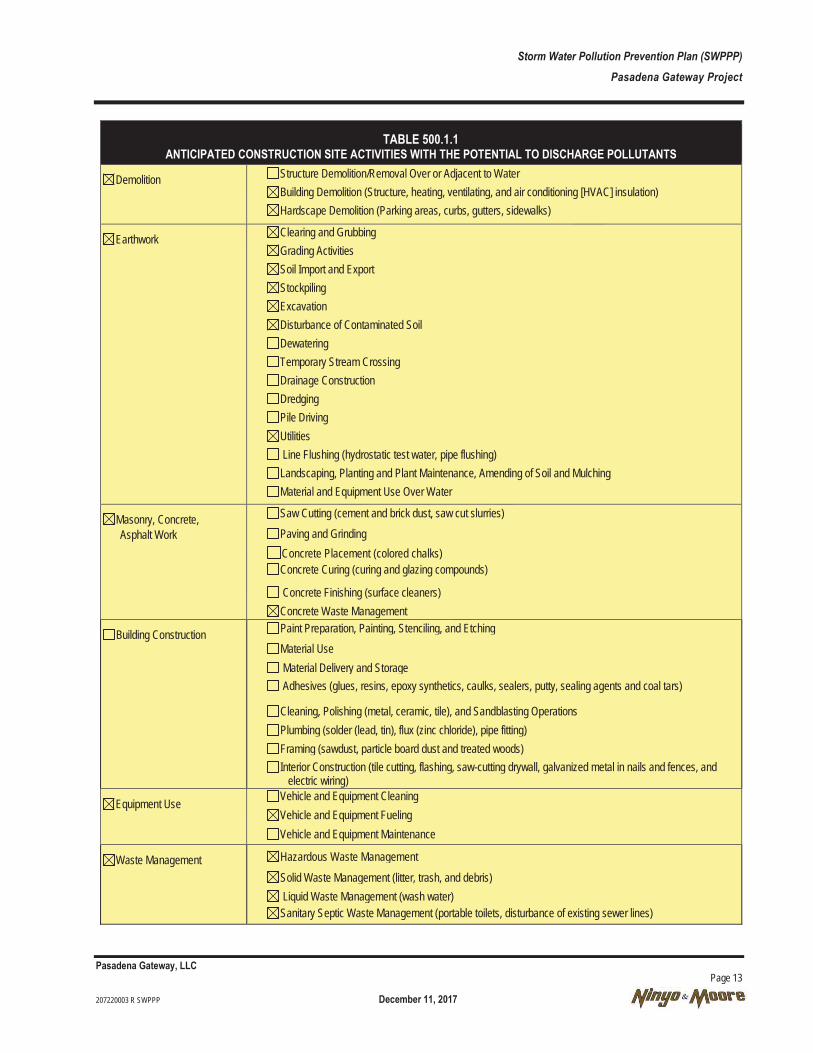
Storm Water Pollution Prevention Plan (SWPPP) Pasadena Gateway Project
Pasadena Gateway, LLC Page 13 207220003 R SWPPP December 11, 2017
TABLE 500.1.1 ANTICIPATED CONSTRUCTION SITE ACTIVITIES WITH THE POTENTIAL TO DISCHARGE POLLUTANTS
Demolition Structure Demolition/Removal Over or Adjacent to Water Building Demolition (Structure, heating, ventilating, and air conditioning [HVAC] insulation) Hardscape Demolition (Parking areas, curbs, gutters, sidewalks)
Earthwork Clearing and Grubbing Grading Activities Soil Import and Export Stockpiling Excavation Disturbance of Contaminated Soil Dewatering Temporary Stream Crossing Drainage Construction Dredging Pile Driving Utilities Line Flushing (hydrostatic test water, pipe flushing) Landscaping, Planting and Plant Maintenance, Amending of Soil and Mulching Material and Equipment Use Over Water
Masonry, Concrete, Asphalt Work
Saw Cutting (cement and brick dust, saw cut slurries) Paving and Grinding Concrete Placement (colored chalks) Concrete Curing (curing and glazing compounds)
Concrete Finishing (surface cleaners) Concrete Waste Management
Building Construction Paint Preparation, Painting, Stenciling, and Etching Material Use Material Delivery and Storage Adhesives (glues, resins, epoxy synthetics, caulks, sealers, putty, sealing agents and coal tars)
Cleaning, Polishing (metal, ceramic, tile), and Sandblasting Operations Plumbing (solder (lead, tin), flux (zinc chloride), pipe fitting) Framing (sawdust, particle board dust and treated woods) Interior Construction (tile cutting, flashing, saw-cutting drywall, galvanized metal in nails and fences, and
electric wiring)
Equipment Use Vehicle and Equipment Cleaning Vehicle and Equipment Fueling Vehicle and Equipment Maintenance
Waste Management Hazardous Waste Management
Solid Waste Management (litter, trash, and debris) Liquid Waste Management (wash water) Sanitary Septic Waste Management (portable toilets, disturbance of existing sewer lines)
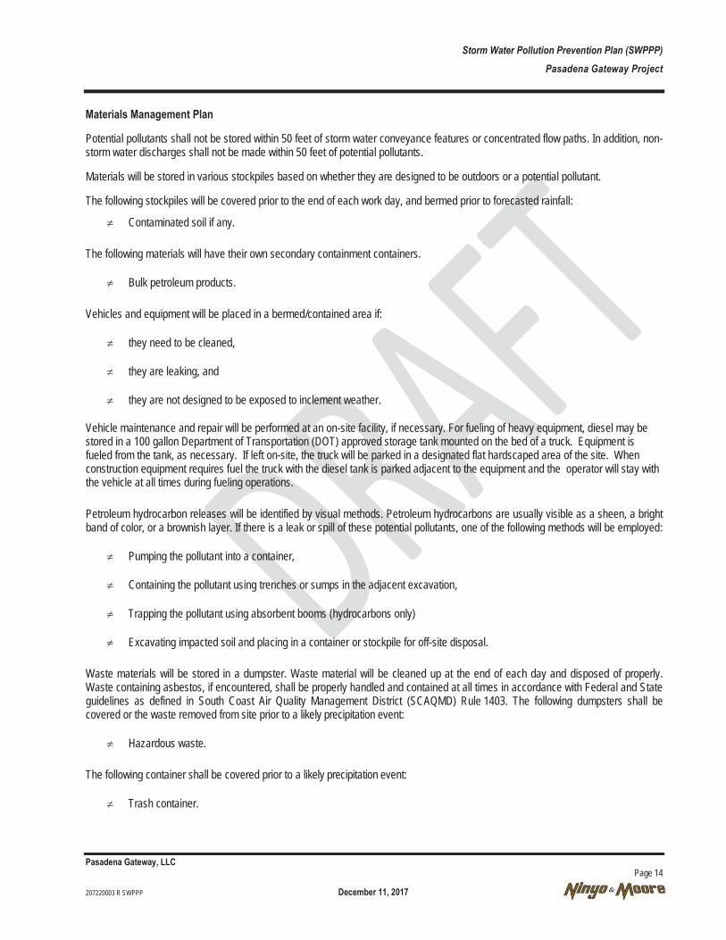
Storm Water Pollution Prevention Plan (SWPPP) Pasadena Gateway Project
Pasadena Gateway, LLC Page 14 207220003 R SWPPP December 11, 2017
Materials Management Plan
Potential pollutants shall not be stored within 50 feet of storm water conveyance features or concentrated flow paths. In addition, non-storm water discharges shall not be made within 50 feet of potential pollutants.
Materials will be stored in various stockpiles based on whether they are designed to be outdoors or a potential pollutant.
The following stockpiles will be covered prior to the end of each work day, and bermed prior to forecasted rainfall:
≠ Contaminated soil if any.
The following materials will have their own secondary containment containers.
≠ Bulk petroleum products.
Vehicles and equipment will be placed in a bermed/contained area if:
≠ they need to be cleaned,
≠ they are leaking, and
≠ they are not designed to be exposed to inclement weather.
Vehicle maintenance and repair will be performed at an on-site facility, if necessary. For fueling of heavy equipment, diesel may be stored in a 100 gallon Department of Transportation (DOT) approved storage tank mounted on the bed of a truck. Equipment is fueled from the tank, as necessary. If left on-site, the truck will be parked in a designated flat hardscaped area of the site. When construction equipment requires fuel the truck with the diesel tank is parked adjacent to the equipment and the operator will stay with the vehicle at all times during fueling operations.
Petroleum hydrocarbon releases will be identified by visual methods. Petroleum hydrocarbons are usually visible as a sheen, a bright band of color, or a brownish layer. If there is a leak or spill of these potential pollutants, one of the following methods will be employed:
≠ Pumping the pollutant into a container,
≠ Containing the pollutant using trenches or sumps in the adjacent excavation,
≠ Trapping the pollutant using absorbent booms (hydrocarbons only)
≠ Excavating impacted soil and placing in a container or stockpile for off-site disposal.
Waste materials will be stored in a dumpster. Waste material will be cleaned up at the end of each day and disposed of properly. Waste containing asbestos, if encountered, shall be properly handled and contained at all times in accordance with Federal and State guidelines as defined in South Coast Air Quality Management District (SCAQMD) Rule 1403. The following dumpsters shall be covered or the waste removed from site prior to a likely precipitation event:
≠ Hazardous waste.
The following container shall be covered prior to a likely precipitation event:
≠ Trash container.
Storm Water Pollution Prevention Plan (SWPPP) Pasadena Gateway Project
Pasadena Gateway, LLC Page 15 207220003 R SWPPP December 11, 2017
The following areas will be inspected for leaks or spills prior to a likely precipitation event:
≠ Vehicle and equipment storage and maintenance area, and
≠ Portable toilet.
500.1.2 Potential Pollutants from Site Features or Known Contaminates
Based on soil samples collected at the site, VOCs, PAHs, metals and petroleum hydrocarbon contamination exists in soil at some areas of the site, as a result of past usage, which may contribute pollutants to storm water (e.g., toxic materials that are known to have been treated, stored, disposed, spilled, or leaked on or in close proximity to the construction site).
Documents within the RWQCB and Department of Toxic Substances Control’s (DTSC’s) Envirostor online database listings for soil and/or groundwater contamination were reviewed for locations in the vicinity of the site. No listings were found that are likely to cause impact to the construction site.
500.1.3 Risk Level Determination
Overview The following memorandum documents the Risk Level determination for the Pasadena Gateway Removal Action Project per the NPDES General Permit for Storm Water Discharges Associated with Construction and Land Disturbance Activities (Order No. 2009-0009-DWQ NPDES No. CAS000002) issued by the SWRCB. The supporting documentation and worksheets for all factors are provided in Attachment C.
Sediment Risk Factor The Sediment Risk Factor is a combination of three factors that estimate the watershed erosion. The three factors are rainfall erosivity (R-Factor), soil erodibility (K-Factor), and the effect of the topography (LS-Factor). Multiplying these factors together produces the Sediment Risk Factor.
The rainfall erosivity or R-Factor is calculated based on the project location and amount of anticipated rainfall during the period of construction. The project is located in the County of Lod Angeles, California. A period of construction from December 12, 2014 to January 30, 2015 was used. The R-Factor is computed using the Rainfall Erosivity Calculator for Small Construction Sites provided in the USEPA website. Inputting the site location (latitude and longitude coordinates) and period of construction, the calculated R-Factor was 10.2. The soil erodibility or K-Factor represents the susceptibility of the soil to erosion, transportability of the sediment, and the amount and rate of runoff given for a particular rainfall event. The effect of the topography or the LS-Factor is based on the effect of hill slope-length and hill slope gradient. The product of the K-Factor and the LS-Factor was determined using the USEPA Environmental Monitoring and Assessment Program (EMAP) Risk Categories figure provided in Appendix 1 of the General Permit. Based on the project location in Pasadena, California, the product of K-Factor times LS-Factor for this project is 0.14.
To determine the Site Sediment Risk Factor, the R, K, and LS-Factors were entered into the SWRCB Sediment Risk Factor Worksheet. This project’s Watershed Erosion Estimate is 1.428 tons per acre. The Sediment Risk Factor for this project is Low.
Receiving Water Risk Factor The Receiving Water Risk Factor is based on the characteristics of the receiving watershed. Specifically, does the disturbed area discharge directly or indirectly to either a 303(d)-listed water body impaired by sediment or a water body designated by the University of California Davis Geo Waterbody System as having beneficial uses of spawn, cold, and migratory.
The disturbed area for this project does not discharge directly into a waterbody.
To determine the Receiving Water Risk Factor, the watershed characteristics were entered into the Receiving Water Risk Factor Worksheet. The Receiving Water Risk Factor for this project is Low.

Storm Water Pollution Prevention Plan (SWPPP) Pasadena Gateway Project
Pasadena Gateway, LLC Page 16 207220003 R SWPPP December 11, 2017
Combined SWPPP Risk Level To establish the Combined Risk Level for the project, both the Site Sediment Risk Factor (Low) and the Receiving Water Risk Factor (Low) were entered into the Combined Risk Level Matrix. In accordance with the procedures in the Risk Determination Worksheet, the Pasadena Gateway Project is classified as a Risk Level 1 project. Risk Level 1 is low risk with a low probability sediment run-off.
500.2 Pre-Construction Existing Storm Water Control Measures No pre-construction control measures exist on site.
500.3 BMP Selection for Erosion and Sediment Control The Contractor shall control construction site erosion through the implementation of effective erosion and sediment control measures in accordance with the CGP. The Contractor shall develop a schedule that includes the sequencing of construction activities and the implementation of effective erosion control BMPs while taking local climate (rainfall, wind, etc.) into consideration, thereby reducing the amount and duration of soil exposed to erosion by wind, rain, runoff, and vehicle tracking. The project schedule will be updated periodically as and when approved by PASADENA GATEWAY as the project progresses. The schedule shall: describe when work activities will be performed that could cause the discharge of pollutants to storm water; describe when the water pollution control practices associated with each construction phase will be installed; and identify the soil stabilization and sediment control practices for all disturbed soil areas (DSAs). Effective soil cover as discussed in the following sections shall be provided for:
≠ Exposed soil within the interior of the site construction area, and
≠ Soil stockpiles.
The Contractor may need additional erosion and sediment control BMPs in other locations on the project site as work progresses, to keep sediment from leaving the construction site. These measures shall be determined by the QSD and the contractor in the field. As long as the water pollution control measures are in addition to the BMPs already selected in the approved SWPPP, then these additional measures do not require a SWPPP amendment and the QSD shall simply show the additional measures on the BMPSWDs. If erosion control or sediment control BMPs must be changed because of field conditions or because they are determined to be ineffective, the SWPPP must be amended. Once deemed necessary, corrective actions/design changes to the SWPPP shall be reviewed and signed by the QSD, implemented within 72 hours of identification, and completed as soon as possible. Immediate corrective action is required for numeric action level (NAL) exceedances. Routine BMP maintenance or the implementation of an additional quantity of a BMP included in the SWPPP as recommended by the QSD does not require an amendment to the SWPPP.
The project shall implement and maintain an effective combination of erosion (soil stabilization) and sediment control BMPs. The following principals shall be followed to the maximum extent practicable to control erosion and sedimentation in disturbed areas at the site:
≠ Minimization of disturbance,
≠ Protection of the land surface from wind and rainfall erosion,
≠ Management of runoff and reduction of flow velocity,
≠ On-site sediment capture,
≠ Integration of controls with construction, and
≠ Monitoring and maintenance of all control practices.
A more concise listing of the BMP control measures to be implemented and maintained at the project site are included in the BMP selection tables in the following sub-sections, and CASQA BMP specifications (which may be modified depending on site features) are located in the Appendix.

Storm Water Pollution Prevention Plan (SWPPP) Pasadena Gateway Project
Pasadena Gateway, LLC Page 17 207220003 R SWPPP December 11, 2017
500.3.1 Temporary Run-on Control BMPs
Implementation of Temporary Run-on Controls BMPs
BMPs will be deployed in a sequence to follow the progress of grading and construction. As the locations of soil disturbance change, temporary diversion controls will be adjusted accordingly to prevent run-on from impacting disturbed soil.
This project will implement the following practices in Table 500.3.1 for effective temporary DSA protection during construction.
TABLE 500.3.1 TEMPORARY RUN-ON CONTROL BMPs
CONSTRUCTION BMP ID NO. BMP NAME
BMP USED COMMENTS
YES NO
SS-1 Scheduling
SS-2 Preservation of Property/ Preservation of Existing Vegetation
SS-9 Earth Dikes / Drainage Swales & Lined Swales
SS-10 Outlet Protection / Velocity Dissipation Devices as needed
SS-11 Slope Drains
SS-12 Stream bank Stabilization
SC-4 Temporary Check Dam
SC-5 Fiber Rolls
SC-6 Temporary Gravel Bag Berm as needed
SC-8 Temporary Sandbag Barrier as needed Notes: Use of alternative BMPs will require written approval by the QSD.
A further description of the BMPs is listed below.
SS-1 Scheduling The Contractor will schedule as much soil disturbing activities as possible during the dry season, leaving as much soil undisturbed as possible.
SC-5 Fiber Rolls Fiber rolls will be used to protect staged materials and stockpiles from run-on. Materials, stockpiles, and waste will not be stored near concentrated flow paths. Fiber roll shall be stored in the staging area for mobilization prior to a storm event.
SC-6 Temporary Gravel Bag Berm Gravel bags berms will control flows generated from run-on flows from storm water or surrounding existing conditions flows (landscape water). SC-8 Temporary Sandbag Barrier A sandbag barrier is a temporary linear sediment barrier consisting of stacked sandbags, designed to intercept and slow the flow of sediment-laden sheet flow runoff. Sandbag barriers allow sediment to settle from runoff before water leaves the construction site.
Storm Water Pollution Prevention Plan (SWPPP) Pasadena Gateway Project
Pasadena Gateway, LLC Page 18 207220003 R SWPPP December 11, 2017
Once installed, run-on control BMPs may remain in place, except where they interfere with construction activities or access to and from the site.
500.3.2 Soil Stabilization (Erosion Control)
Implementation of Temporary Soil Stabilization BMPs Soil stabilization, also referred to as erosion control, consists of source control measures that are designed to prevent soil particles from detaching and becoming transported in storm water runoff. Soil stabilization BMPs protects the soil surface by covering and/or binding soil particles. This project will incorporate CGP soil stabilization measures, contract specifications, and other measures selected by the contractor.
BMPs shall be deployed in a sequence to follow the progress of grading and construction. As the locations of soil disturbance change, soil stabilization and erosion control BMPs shall be adjusted accordingly to control storm water runoff throughout the disturbed areas. This project shall implement the following practices for effective temporary and final soil stabilization during and after construction.
≠ The project schedule shall sequence construction activities with the installation of both soil stabilization and sediment control measures. The construction schedule shall be arranged as much as practicable to leave soil undisturbed until immediately prior to clearing/grading.
≠ Preserve existing vegetation where indicated on the BMPSWDs.
≠ The Contractor shall monitor weather using National Weather Service reports to track conditions and alert crews with regard to likely precipitation events (http://www.srh.noaa.gov/forecast).
≠ Prior to likely precipitation events (50 percent or greater chance of rain), all DSAs and temporary soil stabilization BMPs shall be inspected, and maintenance performed or additional BMPs deployed if necessary.
≠ Sufficient soil stabilization materials shall be maintained on site to allow implementation in conformance with this SWPPP. This includes implementation requirements for active and non-active areas that require BMP deployment before the onset of rain.
≠ Soil stabilization involves covering disturbed soils with mulch, soil binders, geotextiles, or vegetation.
o Accurate cut berms will be cut perpendicular to the length of slope to slow runoff..
o Apply temporary soil stabilization (erosion control) to active and non-active areas as required. Reapply as necessary to maintain effectiveness.
o Discontinue the application of any erodible landscape material within 2 days before a forecasted rain event or during periods of precipitation.
≠ DSAs that are substantially complete shall be stabilized with temporary soil stabilization (erosion control) until hardscaping or landscaping can be completed.
≠ The Contractor must provide temporary stabilization, or initiate permanent stabilization, of disturbed areas within 14 calendar days of the most recent land disturbance in areas where construction support activities have been temporarily suspended or have permanently ceased, except as follows:
o When the site is using vegetative stabilization, but is located in an arid area during dry or drought conditions, vegetative stabilization measures shall be initiated as soon as practicable, when growing conditions are best for planting or seeding.
o Where disturbed areas are awaiting vegetative stabilization for periods greater than 14 calendar days after the most recent disturbance, non-vegetative methods of stabilization shall be employed.

Storm Water Pollution Prevention Plan (SWPPP) Pasadena Gateway Project
Pasadena Gateway, LLC Page 19 207220003 R SWPPP December 11, 2017
≠ BMPs using plastic materials shall be replaced by more sustainable, environmentally friendly alternatives where feasible. Where plastic materials are deemed necessary, the Contractor shall use plastic materials resistant to solar degradation.
≠ Prior to completion of construction, apply temporary erosion control measures to all remaining DSAs until final construction plans are prepared and approved.
≠ Temporary erosion control BMPs shall be removed after the protected areas are finally stabilized.
The following soil stabilization BMP selection discussed in Table 500.3.2 indicates the BMPs that shall be implemented to control erosion on the construction site.
TABLE 500.3.2 TEMPORARY EROSION CONTROL BMPs
CONSTRUCTION BMP ID NO BMP NAME
BMP USED COMMENTS
YES NO
SS-1 Scheduling
SS-2 Preservation of Property/ Preservation of Existing Vegetation
EC-4 Hydroseeding
SS-3 Temporary Hydraulic Mulch (Bonded Stabilized Fiber Matrix)
Temporary Hydraulic Mulch (Polymer Stabilized Fiber Matrix)
SS-4 Temporary Erosion Control (With Temporary Seeding)
SS-5 Temporary Soil Stabilizer
SS-6 Temporary Erosion Control (Straw Mulch with Stabilizing Emulsion)
SS-7
Temporary Erosion Control Blanket (On Slope)
Temporary Erosion Control Blanket (In swale or ditch)
Temporary Cover (Geotextiles and Mats)
SS-8 Temporary Mulch (Wood)
SS-9 Earth Dikes / Drainage Swales & Lined Swales
SS-10 Outlet Protection / Velocity Dissipation Devices as needed
SS-11 Slope Drains
SS-12 Stream bank Stabilization
SS-13 Polyacrylamide Notes: Use of alternative BMPs will require written approval by the QSD.
The following list of BMPs and narrative explain how the selected BMPs will be incorporated into the project:
SS-1 Scheduling The Contractor/QSD will schedule as much soil disturbing activities as possible during the dry season, leaving as much soil undisturbed as possible.
SS-2 Preservation of Existing Vegetation The slopes will be protected in place. Only BMPs needed to divert run-on away from the site will disturb the slopes. No vehicle or foot traffic will be allowed on the slopes.
Storm Water Pollution Prevention Plan (SWPPP) Pasadena Gateway Project
Pasadena Gateway, LLC Page 20 207220003 R SWPPP December 11, 2017
SS-5 Temporary Soil Stabilizer Temporary erosion control prior to a rain event will occur with Rhino Snot a soil binder that will bond particles and bind them in place.
SS-6 Temporary Erosion Control Straw Mulch with Stabilizing Emulsion will only be used on exposed surfaces prior to a rain event.
SS-10 Outlet Protection / Velocity Dissipation Devices Outlet protection and velocity dissipation devices will be used if outlet protection is required prior to a rain event.
500.3.3 Sediment Control Sediment controls are structural measures that are intended to complement and enhance the selected soil stabilization (erosion control) measures and reduce sediment discharges from construction areas. Sediment controls are designed to intercept and settle out soil particles that have been detached and transported by the force of water. This project will incorporate SWPPP/ Water Pollution Control Program (WPCP) Preparation Manual minimum temporary sediment control requirements, temporary sediment control measures required by the contract documents, and other measures selected by the contractor.
Sediment control BMPs will be installed at all appropriate locations along the site perimeter and at all operational internal inlets to storm drain systems at all times.
Temporary sediment control materials, enough to implement stabilization of active areas plus 10 percent, will be maintained on site throughout the duration of the project for implementation in event of predicted rain, rapid response to failures or emergencies as described in the SWPPP. This includes implementation requirements for active areas and non-active areas before the onset of rain.
The following sediment control BMP selection in Table 500.3.3 indicates the BMPs that shall be implemented to control sediment on the construction site. Temporary sediment control BMPs are shown in the BMPSWD in Attachment E.
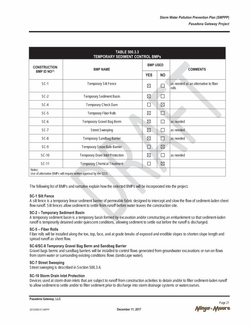
Storm Water Pollution Prevention Plan (SWPPP) Pasadena Gateway Project
Pasadena Gateway, LLC Page 21 207220003 R SWPPP December 11, 2017
TABLE 500.3.3 TEMPORARY SEDIMENT CONTROL BMPs
CONSTRUCTION BMP ID NO(1) BMP NAME
BMP USED COMMENTS
YES NO
SC-1 Temporary Silt Fence as needed as an alternative to fiber rolls
SC-2 Temporary Sediment Basin
SC-4 Temporary Check Dam
SC-5 Temporary Fiber Rolls
SC-6 Temporary Gravel Bag Berm as needed
SC-7 Street Sweeping as needed
SC-8 Temporary Sandbag Barrier as needed
SC-9 Temporary Straw Bale Barrier
SC-10 Temporary Drain Inlet Protection as needed
SC-11 Temporary Chemical Treatment Notes: Use of alternative BMPs will require written approval by the QSD.
The following list of BMPs and narrative explain how the selected BMPs will be incorporated into the project.
SC-1 Silt Fence A silt fence is a temporary linear sediment barrier of permeable fabric designed to intercept and slow the flow of sediment-laden sheet flow runoff. Silt fences allow sediment to settle from runoff before water leaves the construction site. SC-2 – Temporary Sediment Basin A temporary sediment basin is a temporary basin formed by excavation and/or constructing an embankment so that sediment-laden runoff is temporarily detained under quiescent conditions, allowing sediment to settle out before the runoff is discharged.
SC-5 – Fiber Rolls Fiber rolls will be installed along the toe, top, face, and at grade breaks of exposed and erodible slopes to shorten slope length and spread runoff as sheet flow.
SC-6/SC-8 Temporary Gravel Bag Berm and Sandbag Barrier Gravel bags berms and sandbag barriers will be installed to control flows generated from groundwater excavations or run-on flows from storm water or surrounding existing conditions flows (landscape water).
SC-7 Street Sweeping Street sweeping is described in Section 500.3.4.
SC-10 Storm Drain Inlet Protection Devices used at storm drain inlets that are subject to runoff from construction activities to detain and/or to filter sediment-laden runoff to allow sediment to settle and/or to filter sediment prior to discharge into storm drainage systems or watercourses.

Storm Water Pollution Prevention Plan (SWPPP) Pasadena Gateway Project
Pasadena Gateway, LLC Page 22 207220003 R SWPPP December 11, 2017
500.3.4 Tracking Control
Tracking control BMPs are be implemented to reduce sediment tracking from the construction site onto private or public roads. This project will incorporate SWPPP minimum temporary tracking control requirements, temporary tracking control measures required by the contract documents, and other measures selected by the contractor. A description of the BMPs are listed in Table 500.3.4 below.
TABLE 500.3.4 TEMPORARY TRACKING CONTROL BMPs
CONSTRUCTION BMP ID NO BMP NAME
BMP USED COMMENTS
YES NO
SC-7 Street Sweeping As needed
TC-1 Temporary Construction Entrance/exit
TC-2 Stabilized Construction Roadway
TC-3 Temporary Entrance / Outlet Tire Wash Notes: Use of alternative BMPs will require written approval by the QSD.
A narrative explaining how the selected BMPs will be incorporated into the project follows.
SC-7 Street Sweeping
Road sweeping and vacuuming will occur as necessary to keep streets clear of tracked material and debris. Washing of sediment tracked onto streets into storm drains will not occur.
TC-1 Stabilized Construction Entrance
A stabilized construction access is defined by a point of entrance/exit to a construction site that is stabilized to reduce the tracking of mud and dirt into public roads by construction vehicles. The site entrances and exits are shown on the figures in Attachment E. Due to site conditions and the construction schedule, rumble plates will be placed at designated exit points in lieu of rock. TC-3 will be implemented in conjunction with SC-7 if rumble plates are ineffective.
TC-2 Stabilized Construction Roadway
The on-site roadway will be stabilized including a truck decon station if necessary.
500.3.5 Wind Erosion Control
Wind erosion control BMPs are be implemented to reduce sediment form leaving the construction site. This project will incorporate SWPPP/WPCP Preparation Manual minimum temporary wind erosion control requirements, temporary wind erosion control measures required by the contract documents, and other measures selected by the contractor.
The following temporary wind erosion control BMP selection table (Table 500.3.5) indicates the BMPs that shall be implemented to reduce wind erosion at the construction site.
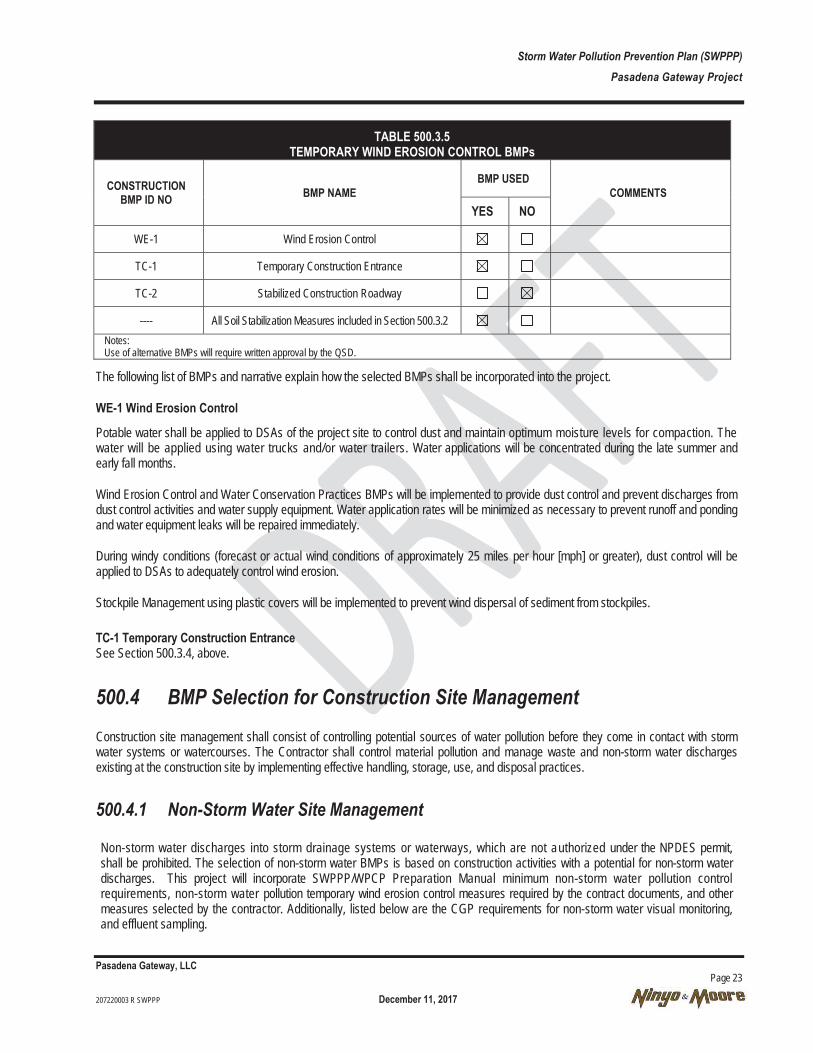
Storm Water Pollution Prevention Plan (SWPPP) Pasadena Gateway Project
Pasadena Gateway, LLC Page 23 207220003 R SWPPP December 11, 2017
TABLE 500.3.5 TEMPORARY WIND EROSION CONTROL BMPs
CONSTRUCTION BMP ID NO BMP NAME
BMP USED COMMENTS
YES NO
WE-1 Wind Erosion Control
TC-1 Temporary Construction Entrance
TC-2 Stabilized Construction Roadway
---- All Soil Stabilization Measures included in Section 500.3.2 Notes: Use of alternative BMPs will require written approval by the QSD.
The following list of BMPs and narrative explain how the selected BMPs shall be incorporated into the project.
WE-1 Wind Erosion Control
Potable water shall be applied to DSAs of the project site to control dust and maintain optimum moisture levels for compaction. The water will be applied using water trucks and/or water trailers. Water applications will be concentrated during the late summer and early fall months.
Wind Erosion Control and Water Conservation Practices BMPs will be implemented to provide dust control and prevent discharges from dust control activities and water supply equipment. Water application rates will be minimized as necessary to prevent runoff and ponding and water equipment leaks will be repaired immediately.
During windy conditions (forecast or actual wind conditions of approximately 25 miles per hour [mph] or greater), dust control will be applied to DSAs to adequately control wind erosion.
Stockpile Management using plastic covers will be implemented to prevent wind dispersal of sediment from stockpiles.
TC-1 Temporary Construction Entrance See Section 500.3.4, above.
500.4 BMP Selection for Construction Site Management Construction site management shall consist of controlling potential sources of water pollution before they come in contact with storm water systems or watercourses. The Contractor shall control material pollution and manage waste and non-storm water discharges existing at the construction site by implementing effective handling, storage, use, and disposal practices.
500.4.1 Non-Storm Water Site Management
Non-storm water discharges into storm drainage systems or waterways, which are not authorized under the NPDES permit, shall be prohibited. The selection of non-storm water BMPs is based on construction activities with a potential for non-storm water discharges. This project will incorporate SWPPP/WPCP Preparation Manual minimum non-storm water pollution control requirements, non-storm water pollution temporary wind erosion control measures required by the contract documents, and other measures selected by the contractor. Additionally, listed below are the CGP requirements for non-storm water visual monitoring, and effluent sampling.
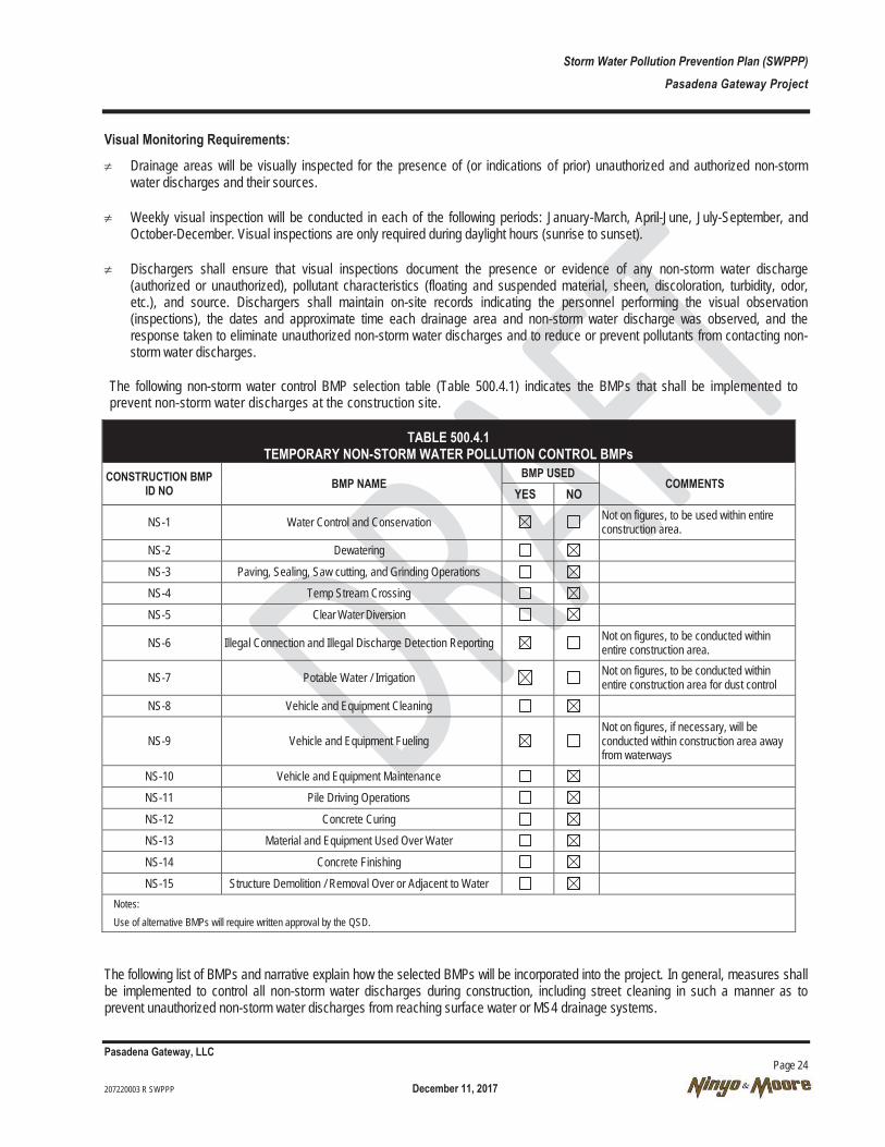
Storm Water Pollution Prevention Plan (SWPPP) Pasadena Gateway Project
Pasadena Gateway, LLC Page 24 207220003 R SWPPP December 11, 2017
Visual Monitoring Requirements:
≠ Drainage areas will be visually inspected for the presence of (or indications of prior) unauthorized and authorized non-storm water discharges and their sources.
≠ Weekly visual inspection will be conducted in each of the following periods: January-March, April-June, July-September, and October-December. Visual inspections are only required during daylight hours (sunrise to sunset).
≠ Dischargers shall ensure that visual inspections document the presence or evidence of any non-storm water discharge (authorized or unauthorized), pollutant characteristics (floating and suspended material, sheen, discoloration, turbidity, odor, etc.), and source. Dischargers shall maintain on-site records indicating the personnel performing the visual observation (inspections), the dates and approximate time each drainage area and non-storm water discharge was observed, and the response taken to eliminate unauthorized non-storm water discharges and to reduce or prevent pollutants from contacting non-storm water discharges.
The following non-storm water control BMP selection table (Table 500.4.1) indicates the BMPs that shall be implemented to prevent non-storm water discharges at the construction site.
TABLE 500.4.1 TEMPORARY NON-STORM WATER POLLUTION CONTROL BMPs
CONSTRUCTION BMP ID NO BMP NAME
BMP USED COMMENTS
YES NO
NS-1 Water Control and Conservation Not on figures, to be used within entire construction area.
NS-2 Dewatering
NS-3 Paving, Sealing, Saw cutting, and Grinding Operations NS-4 Temp Stream Crossing
NS-5 Clear Water Diversion
NS-6 Illegal Connection and Illegal Discharge Detection Reporting Not on figures, to be conducted within entire construction area.
NS-7 Potable Water / Irrigation Not on figures, to be conducted within entire construction area for dust control
NS-8 Vehicle and Equipment Cleaning
NS-9 Vehicle and Equipment Fueling Not on figures, if necessary, will be conducted within construction area away from waterways
NS-10 Vehicle and Equipment Maintenance NS-11 Pile Driving Operations
NS-12 Concrete Curing NS-13 Material and Equipment Used Over Water
NS-14 Concrete Finishing NS-15 Structure Demolition / Removal Over or Adjacent to Water
Notes: Use of alternative BMPs will require written approval by the QSD.
The following list of BMPs and narrative explain how the selected BMPs will be incorporated into the project. In general, measures shall be implemented to control all non-storm water discharges during construction, including street cleaning in such a manner as to prevent unauthorized non-storm water discharges from reaching surface water or MS4 drainage systems.
Storm Water Pollution Prevention Plan (SWPPP) Pasadena Gateway Project
Pasadena Gateway, LLC Page 25 207220003 R SWPPP December 11, 2017
NS-1 Water Control and Conservation / Potable Water and Irrigation
Water application rates will be minimized as necessary to prevent runoff and ponding and water equipment leaks will be repaired immediately. A construction meter will be attached to a fire hydrant and utilized for water on site..
Minimize exposure of construction materials to precipitation. This does not include materials and equipment that are designed to be outdoors and exposed to environmental conditions (i.e. poles, equipment pads, bricks, etc.).
NS-6 Illegal Connection and Illegal Discharge Detection Reporting
The contractor will implement the Illegal Connection/Illegal Discharge Detection Reporting BMP throughout the duration of the project.
Store chemicals in watertight containers (with appropriate secondary containment to prevent any spillage or leakage) or in a storage shed (completely enclosed).
NS-7 Potable Water/Irrigation Potable Water/Irrigation management consists of practices and procedures to manage the discharge of potential pollutants generated during discharges from irrigation water lines, landscape irrigation, lawn or garden watering, planned and unplanned discharges from potable water sources, water line flushing, and hydrant flushing.
NS-9 Vehicle and Equipment Operations
Several types of vehicles and equipment may be used on site throughout the project, including graders, scrapers, excavators, loaders, rollers, trucks and trailers, backhoes, forklifts, generators, compressors, and traffic control equipment.
Vehicle and Equipment Fueling, and Vehicle and Equipment Maintenance BMPs will be utilized to prevent discharges of fuel and other vehicle fluids, and will not be fueled or maintained in the vicinity of receiving waters.
Fuel trucks that shall be used for on-site fueling shall be equipped with absorbent spill clean-up materials, whether at a temporary fueling area or for mobile fueling elsewhere on the site. Drip pans shall be used during all mobile fueling. Fuel trucks will not be stored on site.
Vehicle and equipment repair and maintenance will typically occur at an off-site facility. Drip pans or absorbent pads shall be used during any emergency vehicle and equipment repair and maintenance activities that involve grease, oil, solvents, or other vehicle fluids.
500.4.2 Waste Management and Materials Pollution Control
An inventory of construction activities, materials, and waste is provided in Section 500.1.1. The following BMP consideration checklist indicates the BMPs that have been selected to control construction site wastes and materials. The steps outlined in the instructions for this section for identifying waste management and materials pollution control BMPs to be included in the SWPPP have been followed. The Removal Action Plan is provided in Attachment B. In the narrative description, a list of waste disposal facilities and the type of waste to be disposed at each facility is also provided. The following list of BMPs included in Table 500.4.2 and narrative explain how the selected BMPs will be incorporated into the project.
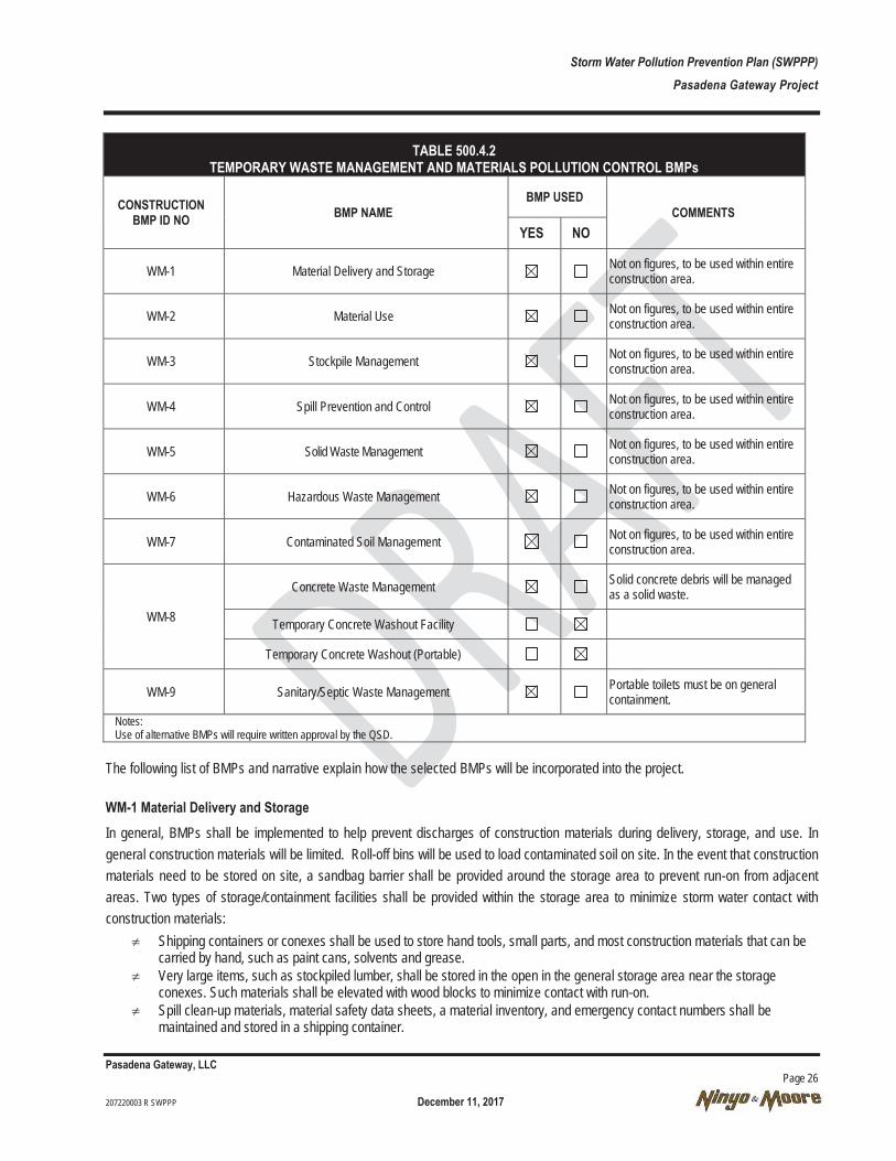
Storm Water Pollution Prevention Plan (SWPPP) Pasadena Gateway Project
Pasadena Gateway, LLC Page 26 207220003 R SWPPP December 11, 2017
TABLE 500.4.2 TEMPORARY WASTE MANAGEMENT AND MATERIALS POLLUTION CONTROL BMPs
CONSTRUCTION BMP ID NO BMP NAME
BMP USED COMMENTS
YES NO
WM-1 Material Delivery and Storage Not on figures, to be used within entire construction area.
WM-2 Material Use Not on figures, to be used within entire construction area.
WM-3 Stockpile Management Not on figures, to be used within entire construction area.
WM-4 Spill Prevention and Control Not on figures, to be used within entire construction area.
WM-5 Solid Waste Management Not on figures, to be used within entire construction area.
WM-6 Hazardous Waste Management Not on figures, to be used within entire construction area.
WM-7 Contaminated Soil Management Not on figures, to be used within entire construction area.
WM-8
Concrete Waste Management Solid concrete debris will be managed as a solid waste.
Temporary Concrete Washout Facility
Temporary Concrete Washout (Portable)
WM-9 Sanitary/Septic Waste Management Portable toilets must be on general containment.
Notes: Use of alternative BMPs will require written approval by the QSD.
The following list of BMPs and narrative explain how the selected BMPs will be incorporated into the project.
WM-1 Material Delivery and Storage In general, BMPs shall be implemented to help prevent discharges of construction materials during delivery, storage, and use. In general construction materials will be limited. Roll-off bins will be used to load contaminated soil on site. In the event that construction materials need to be stored on site, a sandbag barrier shall be provided around the storage area to prevent run-on from adjacent areas. Two types of storage/containment facilities shall be provided within the storage area to minimize storm water contact with construction materials:
≠ Shipping containers or conexes shall be used to store hand tools, small parts, and most construction materials that can be carried by hand, such as paint cans, solvents and grease.
≠ Very large items, such as stockpiled lumber, shall be stored in the open in the general storage area near the storage conexes. Such materials shall be elevated with wood blocks to minimize contact with run-on.
≠ Spill clean-up materials, material safety data sheets, a material inventory, and emergency contact numbers shall be maintained and stored in a shipping container.
Storm Water Pollution Prevention Plan (SWPPP) Pasadena Gateway Project
Pasadena Gateway, LLC Page 27 207220003 R SWPPP December 11, 2017
WM-2 Material Use WM-2 shall be implemented to prevent or reduce the discharge of pollutants to the storm drain system or watercourses from material use by using alternative products, minimizing hazardous material use on site, and training employees and subcontractors. WM-3 Stockpile Management
BMP WM-3, Stockpile Management shall be implemented to reduce or eliminate pollution of storm water from stockpiles of soil and paving materials such as Portland Cement Concrete (PCC) rubble, AC, AC rubble, aggregate base, aggregate subbase, premixed aggregate and asphalt binder (so called “cold mix” asphalt). Where practical roll-off bins will be used to store excavated contaminated soil. Where stockpiles are used, they shall be surrounded with sediment controls (BMP SC-5, Fiber rolls or SC-8, sandbag barriers). Plastic covers, or SS-5, Soil Binders, shall also be used. Asphalt must be stored on plastic sheeting and covered with plastic sheeting at all times.
WM-4 Spill Prevention and Control
BMP WM-4, Spill Prevention and Control shall be implemented to contain and clean-up spills and prevent material discharges to the storm drain system. A primary way to contain spills is through secondary containment mechanisms. A secondary containment system provides protection in the event of failure of bulk storage containers, portable containers, pipes or flowlines, or other oil-filled operational equipment. In general, secondary containment requirements include general and specific requirements. General containment requirements are more applicable to the site because they address site equipment that may create potential spill hazards, including portable bulk oil and fuel containers, work vehicles and equipment. A variety of general containment methods are available, and include sorbent filled booms, barriers (spill mats, storm drain covers, and check dams), sorbent materials, and drip pans. Most of these methods can be used as spill prevention measures, however all can be used for spill control. Construction personnel will be involved in daily tailgate meetings to discuss various site hazards including spill prevention and control. Site construction vehicles and equipment will have spill control equipment during construction activities.
WM-5/WM-6, Solid Waste and Hazardous Waste Management
BMP WM-5 and WM-6, Solid Waste and Hazardous Waste Management shall be implemented to minimize storm water contact with waste materials and prevent waste discharges. Solid wastes shall be either loaded directly onto trucks for off-site disposal, or, when on-site storage is necessary, stored in watertight dumpsters in the locations shown on the figure in Attachment B. Waste disposal services will be provided by a licensed waste disposal facility. Wastes shall be stored in sealed containers constructed of a suitable material and shall be labeled as required by Title 22 California Code of Regulations (CCR), Division 4.5 and 49 Code of Federal Regulations (CFR) Parts 172, 173, 178, and 179. All hazardous waste shall be stored, transported, and disposed as required in Title 22 CCR, Division 4.5 and 49 CFR 261-263. Non-hazardous waste can be transported to several Class II Landfills within the immediate Los Angeles area.
WM-7 Contaminated Soil Management
When contaminated soils are encountered that are in hot-spot locations, the Construction Site Manager shall be notified, the contaminated soils shall be contained, placed on plastic and covered with plastic, if stockpiled, and disposed of per the Contract Documents. Employees shall be instructed to recognize evidence of contaminated soil, such as buried debris, discolored soil, and unusual odors, and an approved Soil Management Plan is in place governing this process.
WM-9 Sanitary and Septic Wastes
Storm Water Pollution Prevention Plan (SWPPP) Pasadena Gateway Project
Pasadena Gateway, LLC Page 28 207220003 R SWPPP December 11, 2017
The contractor shall implement Sanitary and Septic Waste Management BMPs. Portable toilets elevated off the ground on wood blocks shall be located and maintained at the employee parking area and at active work areas for the duration of the project. Toilets must be placed on general containment. Weekly maintenance shall be conducted and wastes shall be disposed off site. The toilets shall be located away from concentrated flow paths and traffic flow.
500.5 Best Management Practices List Construction site BMPs include the following:
≠ Temporary soil stabilization and temporary sediment control BMPs that will be used during construction. Include temporary on-site drainage(s) to carry concentrated flows;
≠ BMPs to mitigate or eliminate non-storm water discharges;
≠ BMPs for waste management and materials pollution control, including, but not limited to storage of soil or waste; construction material loading, unloading, storage and access areas; and areas designated for waste handling and disposal;
≠ BMPs for vehicle and equipment storage, fueling, and emergency maintenance; and
500.6 Best Management Plan Drawings The WPCDs are the component of the project SWPPP that show the necessary BMPs for the project to be in compliance with the CGP. For this project, the WPCD drawings are represented by the Plans in Attachment E. The construction activity phases used in this SWPPP are the Preliminary Phase, Excavation Phase, and Post Excavation Erosion Control Phase. These phases are defined below.
Preliminary Phase – Requires mapping out contaminated soil areas of the site and placement of BMPs prior to the start of excavation activities to minimize runoff of pollutants.
Excavation Phase – Requires breaking and removal of concrete, stockpiling, and removal of contaminated soil.
Post Excavation Erosion Control Phase – Requires grading and shaping of pervious areas that remain after excavation and removal of contaminated soil to increase settling and percolation and minimize runoff. Best management plan drawings show;
≠ Drainage patterns across the project area (show using flow arrows);
≠ Drainage patterns to off-site discharge points including receiving waters and storm drains;
≠ Outline of all areas of existing vegetation, soil cover, or native vegetation that will remain undisturbed during the project; and
The BMPSWDs show proposed locations of construction site BMPs. Additional detail drawings will be provided if necessary to convey site-specific BMP configurations. The BMPSWDs show construction site BMPs including the following:
≠ Construction entrances used for site ingress and egress points and any proposed temporary construction roads;
≠ BMPs to control sediment discharges due to storm water flow;

Storm Water Pollution Prevention Plan (SWPPP) Pasadena Gateway Project
Pasadena Gateway, LLC Page 29 207220003 R SWPPP December 11, 2017
≠ BMPs for waste management and materials pollution control, including, but not limited to storage of soil or waste; storage containers, portable toilets and access areas.
Storm Water Pollution Prevention Plan (SWPPP) Pasadena Gateway Project
Pasadena Gateway, LLC Page 30 207220003 R SWPPP December 11, 2017
SECTION 600 PROJECT SITE IMPLEMENTATION PROGRAM 600.1 QSD/QSP Responsibilities The QSP shall have primary responsibility and authority to implement the SWPPP and ensure the project is in compliance with the CGP. The QSD is responsible for SWPPP implementation and amending the SWPPP when any of the conditions specified in Section 100 are met. The QSP will mobilize crews as necessary for SWPPP and CGP compliance. The QSP will be available at all times throughout duration of the project.
Duties of the QSP include but are not limited to the following items.
≠ Ensuring full compliance with the SWPPP and the CGP.
≠ Implementing all elements of the SWPPP, including but not limited to:
o Implementing prompt and effective erosion and sediment control measures; and
o Implementing all non-storm water management, and materials and waste management activities such as: monitoring discharges, general site clean-up; vehicle and equipment cleaning, fueling and maintenance; spill control; ensuring that no materials other than storm water are discharged in quantities, which will have an adverse effect on receiving waters or storm drain systems, etc.
≠ Conducting routine weekly storm water site BMP inspections.
≠ Conducting quarterly non-storm water site inspections.
≠ Conducting pre-storm inspections for likely precipitation events.
≠ Conducting daily inspections during storm events.
≠ Conducting post-storm inspections for qualifying rain events.
≠ Mobilizing crews to repair, replace, and/or implement additional BMPs due to deficiencies, failures or other shortcomings identified during inspections, to begin implementation within 72 hours of identification (the Contractor’s QSP shall be assigned authority by the Contractor to mobilize crews).
≠ Coordinating with the Construction Manager to assure that if design changes to BMPs are required due to deficiencies, failures or other shortcomings identified during inspections, the changes are completed as soon as possible and the SWPPP is revised accordingly.
≠ Monitoring National Weather Service Forecast Office forecasts for both likely precipitation events and qualifying rain events.
o A likely precipitation event is defined as a 50 percent or greater chance of precipitation in the project area.
o A qualifying rain event is defined as a rain event that has produced ½ inch or more of precipitation at the time of discharge.
≠ Monitoring Weather at the Project Site.
≠ Preparing and implementing REAPs for likely precipitation events.
Storm Water Pollution Prevention Plan (SWPPP) Pasadena Gateway Project
Pasadena Gateway, LLC Page 31 207220003 R SWPPP December 11, 2017
≠ Preparing amendments to the SWPPP when required.
≠ Preparing Contractor’s SWPPP Annual Compliance Certification.
≠ Preparing the Storm Water Annual Report (QSD).
≠ Ensuring elimination of all unauthorized discharges.
≠ Preparing and submitting Notice of Discharge reports to the Construction Site Manager. And,
≠ Preparing and submitting reports of Illicit Connections or Illegal Discharges to the Construction Site Manager.
600.2 Site Inspections Storm water site inspections and visual monitoring are necessary to ensure that the project is in compliance with the requirements of the CGP. Project site visual monitoring requirements are covered in Section 700 of the CSMP. Project site inspections of storm water BMPs are conducted to identify and record:
≠ that BMPs are properly installed;
≠ what BMPs need maintenance to operate effectively;
≠ what BMPs have failed; or
≠ what BMPs could fail to operate as intended.
The frequencies for conducting storm water site inspections required for visual monitoring are shown in Section 700.1.2, Visual Monitoring Schedule. Routine storm water site inspections shall be conducted by the QSD or other QSPs at the following minimum frequencies:
≠ weekly; and
≠ at least once each 24-hour period during extended storm events.
Storm water site inspections will be documented on the Storm Water Site Inspection Report, available in Attachment J. Other periodic storm water BMPs monitoring and inspection forms are also included in Attachment J. Completed inspection reports shall be submitted to the Construction Site Manager within 24 hours of inspection.
Corrective actions documented in site inspection reports shall be reviewed by the QSD and if deemed necessary, implemented within 72 hours of identification and completed as soon as possible. Immediate corrective action is required for NAL exceedances. Corrective Action Summary forms shall be submitted to the Construction Site Manager when corrections are completed but must be submitted within five (5) days of a site inspection.
600.3 Weather Forecast Monitoring The QSD shall have primary responsibility to monitor the National Weather Service Forecast Office for forecasted precipitation based on project site location. Precipitation forecast information shall be obtained from the National Weather service Forecast Office available at: http://www.srh.noaa.gov/.
Storm Water Pollution Prevention Plan (SWPPP) Pasadena Gateway Project
Pasadena Gateway, LLC Page 32 207220003 R SWPPP December 11, 2017
The project site location to be used for obtaining forecast from National Weather Service Forecast Office website is TBD, in Pasadena, California.
When the forecast for precipitation is 50 percent or greater, the QSD or authorized delegate under the supervision of the QSD shall perform a pre-storm site inspection and ensure that the site is prepared for the likely precipitation event. Site preparation shall include, but is not limited to, the installation of soil stabilization and sediment BMPs on active DSAs and stockpiles.
600.4 Weather Monitoring The QSD shall have primary responsibility to monitor weather at the project site. A weather monitoring unit shall be installed on the project site. The QSD on a daily basis shall monitor the weather on the National Weather Service website. Weather forecast reports for the project site location will be printed daily and documented.
When there is precipitation, the QSD shall ensure that storm precipitation data is obtained from the project site weather unit. Precipitation monitoring will be performed at least every two hours during normal working hours and will include recording the time, amount of precipitation measured in the project site rain gauge and calculating the amount of precipitation within 24 hour period and the total cumulative amount of precipitation for the storm event. In addition, printouts of precipitation data from the website shall be attached to the storm-event documentation.

Storm Water Pollution Prevention Plan (SWPPP) Pasadena Gateway Project
Pasadena Gateway, LLC Page 33 207220003 R SWPPP December 11, 2017
600.5 Best Management Practices Status Report The QSD shall include future SWPPP activity, including BMPs, in a three week “Look Ahead Schedule”. Additionally, a map listing water pollution control BMP practices on site will be included in the weekly inspection or BMP status report. The weekly BMP status report will be based on the progress of the work for the project with any additional BMPs the QSP has determined are necessary based on the stage of construction and construction activities. The weekly status report will be used by storm water inspectors and contractor personnel to ensure SWPPP compliance.
The Look Ahead Schedule will be used to cover upcoming changes or additions to BMPs that are required for work activities and will be provided to regulatory agency staff who visit the project site to indicate which BMPs should be in place and which are scheduled to be implemented.
Storm water BMPs weekly status will be documented on the Storm Water BMPs Status Report, in Attachment M. Completed weekly status reports shall be submitted to the Construction Site Manager 48 hours prior to beginning the work week.
600.6 Rain Event Action Plans A REAP is not required for a Risk Level 1 site.
Storm Water Pollution Prevention Plan (SWPPP) Pasadena Gateway Project
Pasadena Gateway, LLC Page 34 207220003 R SWPPP December 11, 2017
SECTION 700 CONSTRUCTION SITE MONITORING PROGRAM-RISK LEVEL 1 SITES 700.1 Objectives The CSMP shall be developed and implemented to address the following objectives for the site:
≠ To demonstrate that the site is in compliance with the Discharge Prohibitions and applicable NALs/Numeric Effluent Limitation (NELs) of this CGP.
≠ To determine whether non-visible pollutants are present at the construction site and are causing or contributing to exceedances of water quality objectives.
≠ To determine whether immediate corrective actions, additional BMP implementation, or SWPPP revisions are necessary to reduce pollutants in storm water discharges and authorized non-storm water discharges. And,
≠ To determine whether BMPs included in the SWPPP are effective in preventing or reducing pollutants in storm water discharges and authorized non-storm water discharges.
700.2 Visual Monitoring, Sampling, and Sample Analytical - Requirements for Qualifying Rain Events
Site visual monitoring inspections shall be conducted by a Certified QSD or the QSDs trained and qualified representative.
The name(s) and contact number(s) of the site visual monitoring inspection personnel are listed below and their training qualifications are provided in Attachment F:
≠ Assigned QSD: TBD Contact Phone: ≠ Assigned representative: TBD Contact Phone:
Visual Monitoring
≠ Visual inspections will be conducted at all discharge locations within two business days (48 hours) after each qualifying rain event.
≠ Visual inspections will be conducted of stored or contained storm water that is derived from and discharged subsequent to a qualifying rain event producing precipitation of ½ inch or more at the time of discharge. Stored or contained storm water that will likely discharge after operating hours due to anticipated precipitation shall be observed prior to the discharge during operating hours.
≠ Visual inspections will be conducted during business hours only.
≠ The time, date and rain gauge reading of all qualifying rain events will be recorded on a Weather Monitoring Form included in Attachment K.

Storm Water Pollution Prevention Plan (SWPPP) Pasadena Gateway Project
Pasadena Gateway, LLC Page 35 207220003 R SWPPP December 11, 2017
≠ Within two business days (48 hours) prior to each qualifying rain event, a visual inspection will occur relating to:
o all storm water drainage areas to identify any spills, leaks, or uncontrolled pollutant sources. If needed, the discharger shall implement appropriate corrective actions.
o all BMPs to identify whether they have been properly implemented in accordance with the SWPPP/REAP. If needed, the discharger shall implement appropriate corrective actions.
o any storm water storage and containment areas to detect leaks and ensure maintenance of adequate freeboard.
≠ For the visual inspections described above, observations will be made relating to the presence or absence of floating and suspended materials, a sheen on the surface, discolorations, turbidity, odors, and source(s) of any observed pollutants.
≠ Within two business days (48 hours) after each qualifying rain event, post rain event visual inspections will be conducted to (1) identify whether BMPs were adequately designed, implemented, and effective, and (2) identify additional BMPs and revise the SWPPP accordingly.
≠ On-site records will be maintained of all visual inspections, personnel performing the observations, observation dates, weather conditions, locations observed, and corrective actions taken in response to the observations.
≠ Visual inspections are not required under the following conditions:
o During dangerous weather conditions such as flooding and electrical storms, and/or
o Outside of scheduled site business hours.
≠ If no visual inspections are conducted due to these exceptions, an explanation shall be included in the SWPPP and in the Annual Report documenting why the visual inspections were not conducted.
Storm Water Discharge Water Quality Sampling Locations The project site is a Risk Level 1 and does not require water quality sampling.
Monitoring Methods
≠ The following monitoring methods shall be included in the CSMP:
o Visual observation locations, visual observation procedures, and visual observation follow-up and tracking procedures.
700.2 Non-Storm Water Discharge Monitoring Requirements
Visual Monitoring Requirements:
≠ Drainage areas will be visually inspected for the presence of (or indications of prior) unauthorized and authorized non-storm water discharges and their sources.
≠ One visual inspection will be conducted quarterly in each of the following periods: January-March, April-June, July-September, and October-December. Visual inspections are only required during daylight hours (sunrise to sunset).
≠ Dischargers shall ensure that visual inspections document the presence or evidence of any non-storm water discharge (authorized or unauthorized), pollutant characteristics (floating and suspended material, sheen, discoloration, turbidity, odor,
Storm Water Pollution Prevention Plan (SWPPP) Pasadena Gateway Project
Pasadena Gateway, LLC Page 36 207220003 R SWPPP December 11, 2017
etc.), and source. Dischargers shall maintain on-site records indicating the personnel performing the visual observation (inspections), the dates and approximate time each drainage area and non-storm water discharge was observed, and the response taken to eliminate unauthorized non-storm water discharges and to reduce or prevent pollutants from contacting non-storm water discharges.
Effluent Sampling Locations:
≠ Samples shall be collected from effluent at all discharge points where non-storm water and/or authorized non-storm water is discharged off-site.
≠ All non-storm water samples shall be sent to a laboratory certified for the required analyses by the State Department of Health Services.
≠ The site shall be monitored, and run-on(s) shall be reported from surrounding areas if there is reason to believe run-on may contribute to an exceedance of NALs.
700.3 Non-Visible Pollutant Monitoring Requirements ≠ One or more samples will be collected during any breach, malfunction, leakage, or spill observed during an inspection which
could result in the discharge of pollutants to surface waters that would not be visually detectable in storm water. Samples will be collected at discharge locations that can be safely accessed. Non-visible pollutants may include concrete products, curing compounds, and products containing solvents, pesticides or herbicides, acids or bases, heavy metals. Additionally, several areas along the alignment contain soils with elevated concentrations of metals, including soluble lead.
≠ Samples will be collected during the first two hours of discharge from rain events that occur during business hours and which generate runoff.
≠ Samples will be analyzed for all non-visible pollutant parameters (if applicable) - parameters indicating the presence of pollutants identified in the pollutant source assessment required (Risk Level 2 dischargers shall modify their CSMPs to address these additional parameters in accordance with any updated SWPPP pollutant source assessment).
≠ A sample of storm water that has not come in contact with the disturbed soil or the materials stored or used on-site (Uncontaminated sample) will be collected for comparison with the discharge sample. The uncontaminated sample will be compared to the samples of discharge using field analysis or through laboratory analysis.
≠ All field /or analytical data will be stored in the SWPPP document.
700.4 Sample Analytical Laboratory Contacts and Analytical Methods Sample analytical laboratories to be used for analyzing all samples will include laboratories that are California State certified. The laboratories include:
TBD Phone: Contact:
Samples are to be stored in a cooler with ice subsequent to sample collection and analyzed by a state certified laboratory. The samples will be properly labeled with a sample identification number, date and time of sampling, location of sample, sampler’s initials,

Storm Water Pollution Prevention Plan (SWPPP) Pasadena Gateway Project
Pasadena Gateway, LLC Page 37 207220003 R SWPPP December 11, 2017
and analytical method requested. Completed chain of custody documentation will be prepared and sent with the samples via courier to the analytical laboratory. A copy of the Sample Information, Identification, and Chain of Custody Form is included in Attachment O.
The following is a list of sampling methods/sample containers/holding times pertaining to potential constituents encountered during storm water, and non-storm water sampling events: ≠ pH using United States Environmental Protection Agency (EPA) Method 9040B/SM 4500H+B/250 milliliter (ml) plastic/15
minutes,
≠ TPH as diesel and motor oil using EPA Method 8015B/1 liter glass/14 days,
≠ TPH as gasoline using EPA Method 8015B/40 ml volatile organic compounds (VOCs) with HCL/14 days,
≠ Semi-volatile organic compounds using EPA Method 8270C/1 liter glass/7 days,
≠ VOCs using EPA Method 8260B/40 ml VOCs with HCL/14 days,
700.5 Records All storm water monitoring information records and copies of all reports (including Annual Reports) will be retained for a period of at least three years, and all records will be retained on-site while construction is ongoing. These records include:
≠ The date, place, time of facility inspections, sampling, visual observation (inspections), and/or measurements, including precipitation.
≠ The individual(s) who performed the facility inspections, sampling, visual observation (inspections), and or measurements.
≠ The date and approximate time of analyses.
≠ The individual(s) who performed the analyses.
≠ A summary of all analytical results from the last three years, the method detection limits and reporting units, the analytical techniques or methods used, and the chain of custody forms.
≠ Rain gauge readings from site inspections;
≠ Quality assurance/quality control records and results.
≠ Non-storm water discharge inspections and visual observation (inspections) and storm water discharge visual observation records (see Sections I.3 and I.10 above).
≠ Visual observation and sample collection exception records (see Section I.6 above).
≠ The records of any corrective actions and follow-up activities that resulted from analytical results, visual observation (inspections), or inspections.
700.6 Exceedance Report ≠ In the event that any effluent sample collected during a qualifying rain event exceeds an applicable NAL, all storm event
sampling results shall be electronically submitted to the State Water Board no later than 10 days after the conclusion of the storm event. The Regional Boards have the authority to require the submittal of an NAL Exceedance Report.
≠ Each NAL Exceedance Report shall be certified in accordance with the Special Provisions for Construction Activity.

Storm Water Pollution Prevention Plan (SWPPP) Pasadena Gateway Project
Pasadena Gateway, LLC Page 38 207220003 R SWPPP December 11, 2017
≠ An electronic or paper copy of each NAL Exceedance Report shall be retained for a minimum of three years after the date the annual report is filed.
≠ The NAL Exceedance Report shall include:
o The analytical method(s), method reporting unit(s), and method detection limit(s) of each analytical parameter (analytical results that are less than the method detection limit shall be reported as “less than the method detection limit”).
o The date, place, time of sampling, visual observation (inspections), and/or measurements, including precipitation.
o A description of the current BMPs associated with the effluent sample that exceeded the NAL and the proposed corrective actions taken.
Storm Water Pollution Prevention Plan (SWPPP) Pasadena Gateway Project
Pasadena Gateway, LLC Page 39 207220003 R SWPPP December 11, 2017
SECTION 800 POST CONSTRUCTION CONTROL PRACTICES 800.1 Post-Construction Control Practices
The site will be graded in preparation for site construction. All BMPs will remain in place during construction.
800.2 Post Construction Operation/Maintenance
≠ Post Construction Operations and Maintenance will be conducted by PASADENA GATEWAY and will be developed under separate documentation.

Storm Water Pollution Prevention Plan (SWPPP) Pasadena Gateway Project
Pasadena Gateway, LLC Page 40 207220003 R SWPPP December 11, 2017
SECTION 900 SWPPP REPORTING REQUIREMENTS 900.1 Record Keeping To manage the various documents required to by the SWPPP the following documents will be included in a SWPPP file:
≠ SWPPP
≠ SWPPP Amendments
≠ Water Pollution Control Schedule Updates
≠ Notice of Construction or Notice of Intent
≠ LRP Authorization of Approved Signatory
≠ Correspondence
≠ Material Supplier Contact Information and Notification Letters
≠ Contractor Personnel Training Documentation
≠ Contractor Storm Water Site Inspection Reports
≠ Site Visual Monitoring Inspection Reports
≠ BMPs Weekly Status Reports
≠ Corrective Actions Summary
≠ Weather Monitoring Logs
≠ Storm/Rain Event Action, Sampling and Analysis Plans
≠ Non-Visible Pollutant Sampling and Test Results
≠ Turbidity, pH and Analytical Test Results
≠ Required Regional Water Board Monitoring Sampling and Test Results
≠ Active Treatment System (ATS) Monitoring Sampling and Test Results
≠ Field Testing Equipment Maintenance and Calibration Records
≠ Notice of Discharge Reports
≠ Numeric Action Level Exceedance Reports
≠ Annual Certification Compliance
≠ Storm Water Annual Reports
≠ Notice of Termination
Records shall be retained for a minimum of three years for the following items:
≠ approved SWPPP document and amendments;
≠ Storm Water Site Inspection Reports;

Storm Water Pollution Prevention Plan (SWPPP) Pasadena Gateway Project
Pasadena Gateway, LLC Page 41 207220003 R SWPPP December 11, 2017
≠ Site Inspection Report Corrections Summary;
≠ REAPs;
≠ Notice of Discharge Reports;
≠ Numeric Action Limit Exceedance Reports;
≠ NEL Violation Reports;
≠ Sampling records and analysis reports;
≠ Annual Compliance Certifications; and
≠ copies of all applicable permits.
900.2 Storm Water Annual Report A Storm Water Annual Report will be prepared for this project to document the storm water monitoring information and training information.
The following storm water monitoring information shall be included in the Storm Water Annual Report:
≠ A summary and evaluation of all sampling and analysis results, including copies of laboratory reports,
≠ The analytical method(s), method reporting unit(s), and method detection limit(s) of each analytical parameter,
≠ A summary of all corrective actions taken during the compliance year,
≠ Identification of any compliance activities or corrective actions that were not implemented,
≠ A summary of all violations of the CGP,
≠ The names of individual(s) who performed site inspections, sampling, site visual monitoring inspections and/or measurements,
≠ The date, place, time of site inspections, sampling, site visual monitoring inspections, and/or measurements, including precipitation (rain gauge), and
≠ Any site visual monitoring inspection and sample collection exception records.
The following storm water training information shall be included in the Storm Water Annual Report:
≠ Documentation of all training for individuals responsible for all activities associated with compliance with the CGP,
≠ Documentation of all training for individuals responsible for BMP installation, inspection, maintenance, and repair, and
≠ Documentation of all training individuals responsible for overseeing, revising and amending the SWPPP.
900.3 Discharge Reporting If a discharge or evidence of a prior discharge is discovered by the contractor, the QSD shall notify the Construction Site Manager within 6 hours of the discharge event or discovery, and will file a written report to the Construction Site Manager within 48 hours of the
Storm Water Pollution Prevention Plan (SWPPP) Pasadena Gateway Project
Pasadena Gateway, LLC Page 42 207220003 R SWPPP December 11, 2017
discharge event or discovery of evidence of a prior discharge. The written report to the Construction Site Manager will contain the following items:
≠ The date, time, location, and type of unauthorized discharge;
≠ Nature of operation that caused the discharge;
≠ Initial assessment of any impacts caused by the discharge;
≠ The BMPs deployed before the discharge event;
≠ The date of deployment and type of BMPs deployed after the discharge event, including additional measures installed or planned to reduce or prevent re-occurrence; and
≠ Steps taken or planned to reduce, eliminate and/or prevent recurrence of the discharge.
Reporting of discharges shall be documented on the Notice of Discharge form, available in Attachment P. Completed Notice of Discharge forms shall be submitted to the Construction Site Manager within 24 hours of discharge event or discovery of evidence of a prior discharge.
900.4 Regulatory Agency Notice or Order Reporting If the project receives a written notice or order from any regulatory agency, the QSD will notify the Construction Site Manager and the PASADENA GATEWAY Project Manager within 6 hours of receiving the notice or order and will file a written report to the Construction Site Manager within 48 hours of receiving the notice, or order. Corrective measures will be implemented immediately following the notice or order.
The report to the Construction Site Manager will contain the following items:
≠ The date, time, location, and cause or nature of the notice or order,
≠ The BMPs deployed prior to receiving notice or order,
≠ The date of deployment and type of BMPs deployed after receiving the notice or order, including additional BMPs installed or planned to reduce or prevent re-occurrence, and
≠ An implementation and maintenance schedule for any affected BMPs.
900.5 Illicit Connection/Illegal Discharge Reporting If the contractor discovers an illicit connection to a storm drain system or any pipe discharging on to the project site not shown on the project plans, the QSD shall notify the Construction Site Manager within 6 hours of the discovery and will file a written report to the Construction Site Manager within 48 hours of the discovery.
If the contractor discovers any illegal discharge including illegal dumping of material on the project site, the contractor shall immediately notify the Construction Site Manager and will file a written report to the Construction Site Manager within 3 days of discovery.
The report to the Construction Site Manager will contain the following items:
≠ The date, time, and location of the discovery,
Storm Water Pollution Prevention Plan (SWPPP) Pasadena Gateway Project
Pasadena Gateway, LLC Page 43 207220003 R SWPPP December 11, 2017
≠ The details for the illicit connection or illegal discharge, including any photographs taken, and
≠ Any actions taken to contain illegal discharge or sampling and testing to determine material dumped or discharged.

Storm Water Pollution Prevention Plan (SWPPP) Pasadena Gateway Project
Riverside County Transportation Commission 207220003 R SWPPP December 11, 2014
ATTACHMENT A
SWPPP AMENDMENT LOG

Storm Water Pollution Prevention Plan (SWPPP) Pasadena Gateway Project
Riverside County Transportation Commission 207220003 R SWPPP December 11, 2014
ATTACHMENT B
RISK LEVEL DETERMINATION

Low Medium High
Low Level 1
High Level 3
Project Sediment Risk: Low 1
Project RW Risk: Low 1
Project Combined Risk: Level 1
Combined Risk Level Matrix
Sediment Risk
Rec
eivi
ng W
ater
R
isk Level 2
Level 2

Storm Water Pollution Prevention Plan (SWPPP) Pasadena Gateway Project
Riverside County Transportation Commission 207220003 R SWPPP December 11, 2014
ATTACHMENT C
RUNOFF COEFFICIENT CALCULATIONS
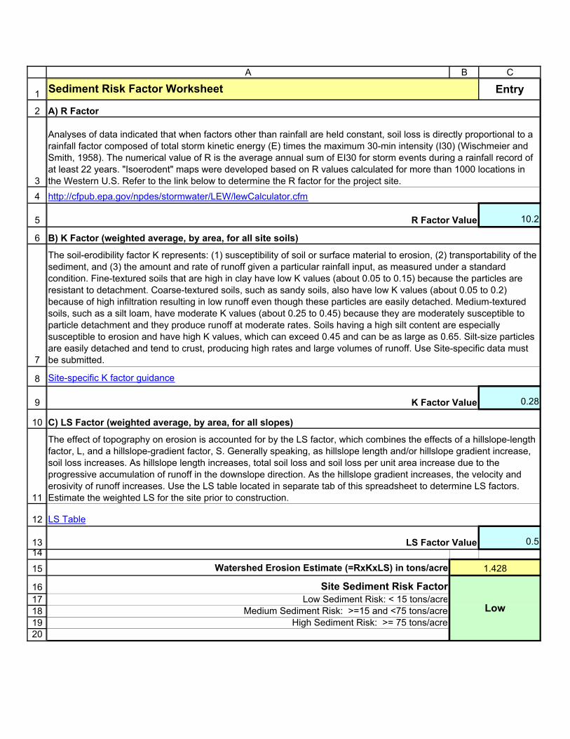
1
2
34
5
6
7
8
9
10
11
12
1314
15
1617181920
A B C
Entry
10.2
0.28
0.5
Watershed Erosion Estimate (=RxKxLS) in tons/acre
Site Sediment Risk FactorLow Sediment Risk: < 15 tons/acre
Medium Sediment Risk: >=15 and <75 tons/acreHigh Sediment Risk: >= 75 tons/acre
Sediment Risk Factor Worksheet
A) R Factor
R Factor Value
B) K Factor (weighted average, by area, for all site soils)
Analyses of data indicated that when factors other than rainfall are held constant, soil loss is directly proportional to a rainfall factor composed of total storm kinetic energy (E) times the maximum 30-min intensity (I30) (Wischmeier and Smith, 1958). The numerical value of R is the average annual sum of EI30 for storm events during a rainfall record of at least 22 years. "Isoerodent" maps were developed based on R values calculated for more than 1000 locations in the Western U.S. Refer to the link below to determine the R factor for the project site.http://cfpub.epa.gov/npdes/stormwater/LEW/lewCalculator.cfm
K Factor Value
LS Factor Value
Low
C) LS Factor (weighted average, by area, for all slopes)
The soil-erodibility factor K represents: (1) susceptibility of soil or surface material to erosion, (2) transportability of the sediment, and (3) the amount and rate of runoff given a particular rainfall input, as measured under a standard condition. Fine-textured soils that are high in clay have low K values (about 0.05 to 0.15) because the particles are resistant to detachment. Coarse-textured soils, such as sandy soils, also have low K values (about 0.05 to 0.2) because of high infiltration resulting in low runoff even though these particles are easily detached. Medium-textured soils, such as a silt loam, have moderate K values (about 0.25 to 0.45) because they are moderately susceptible to particle detachment and they produce runoff at moderate rates. Soils having a high silt content are especially susceptible to erosion and have high K values, which can exceed 0.45 and can be as large as 0.65. Silt-size particles are easily detached and tend to crust, producing high rates and large volumes of runoff. Use Site-specific data must be submitted.
The effect of topography on erosion is accounted for by the LS factor, which combines the effects of a hillslope-length factor, L, and a hillslope-gradient factor, S. Generally speaking, as hillslope length and/or hillslope gradient increase, soil loss increases. As hillslope length increases, total soil loss and soil loss per unit area increase due to the progressive accumulation of runoff in the downslope direction. As the hillslope gradient increases, the velocity and erosivity of runoff increases. Use the LS table located in separate tab of this spreadsheet to determine LS factors. Estimate the weighted LS for the site prior to construction.
1.428
Site-specific K factor guidance
LS Table

Receiving Water (RW) Risk Factor Worksheet Entry Score
A. Watershed Characteristics yes/noA.1. Does the disturbed area discharge (either directly or indirectly) to a 303(d)-listed waterbody impaired by sediment (For help with impaired waterbodies please visit the link below) or has a USEPA approved TMDL implementation plan for sediment?:http://www.waterboards.ca.gov/water_issues/programs/tmdl/integrated2010.shtml
ORA.2. Does the disturbed area discharge to a waterbody with designated beneficial uses of SPAWN & COLD & MIGRATORY? (For help please review the appropriate Regional Board Basin Plan)
http://www.waterboards.ca.gov/waterboards_map.shtml
Region 1 Basin Plan
Region 2 Basin Plan
Region 3 Basin Plan
Region 4 Basin Plan
Region 5 Basin Plan
Region 6 Basin Plan
Region 7 Basin Plan
Region 8 Basin Plan
Region 9 Basin Plan
no Low

Storm Water Pollution Prevention Plan (SWPPP) Pasadena Gateway Project
Riverside County Transportation Commission 207220003 R SWPPP December 11, 2014
ATTACHMENT D
WATER POLLUTION CONTROL DRAWING
Storm Water Pollution Prevention Plan (SWPPP) Pasadena Gateway Project
Riverside County Transportation Commission 207220003 R SWPPP December 11, 2014
ATTACHMENT E
QSD TRAINING AND PROFESSIONAL ENGINEER LICENSE
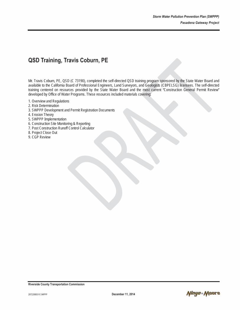
Storm Water Pollution Prevention Plan (SWPPP) Pasadena Gateway Project
Riverside County Transportation Commission 207220003 R SWPPP December 11, 2014
QSD Training, Travis Coburn, PE
Mr. Travis Coburn, PE, QSD (C 73190), completed the self-directed QSD training program sponsored by the State Water Board and available to the California Board of Professional Engineers, Land Surveyors, and Geologists (CBPELSG) licensees. The self-directed training centered on resources provided by the State Water Board and the most current “Construction General Permit Review” developed by Office of Water Programs. These resources included materials covering:
1. Overview and Regulations 2. Risk Determination 3. SWPPP Development and Permit Registration Documents 4. Erosion Theory 5. SWPPP Implementation 6. Construction Site Monitoring & Reporting 7. Post Construction Runoff Control Calculator 8. Project Close Out 9. CGP Review

Storm Water Pollution Prevention Plan (SWPPP) Pasadena Gateway Project
Riverside County Transportation Commission 207220003 R SWPPP December 11, 2014
ATTACHMENT F
NOT USED

Storm Water Pollution Prevention Plan (SWPPP) Pasadena Gateway Project
Riverside County Transportation Commission 207220003 R SWPPP December 11, 2014
ATTACHMENT G
NOT USED

Storm Water Pollution Prevention Plan (SWPPP) Pasadena Gateway Project
Riverside County Transportation Commission 207220003 R SWPPP December 11, 2014
ATTACHMENT I
NOT USED

Storm Water Pollution Prevention Plan (SWPPP) Pasadena Gateway Project
Riverside County Transportation Commission 207220003 R SWPPP December 11, 2014
ATTACHMENT I
STORM WATER SITE INSPECTION FORMS
Storm Water Pollution Prevention Plan (SWPPP) Pasadena Gateway Project
Riverside County Transportation Commission 207220003 R SWPPP December 11, 2014
ATTACHMENT J
NOT USED

Storm Water Pollution Prevention Plan (SWPPP) Pasadena Gateway Project
Riverside County Transportation Commission 207220003 R SWPPP December 11, 2014
ATTACHMENT K
NOT USED

Storm Water Pollution Prevention Plan (SWPPP) Pasadena Gateway Project
Riverside County Transportation Commission 207220003 R SWPPP December 11, 2014
ATTACHMENT L
STORM WATER BEST MANAGEMENT PRACTICES STATUS REPORT

Storm Water Pollution Prevention Plan (SWPPP) Pasadena Gateway Project
Riverside County Transportation Commission 207220003 R SWPPP December 11, 2014
ATTACHMENT M
NOT USED
Storm Water Pollution Prevention Plan (SWPPP) Pasadena Gateway Project
Riverside County Transportation Commission 207220003 R SWPPP December 11, 2014
ATTACHMENT N
SAMPLE INFORMATION, IDENTIFICATION, AND CHAIN OF CUSTODY FORM
Storm Water Pollution Prevention Plan (SWPPP) Pasadena Gateway Project
Riverside County Transportation Commission 207220003 R SWPPP December 11, 2014
ATTACHMENT O
NOTICE OF DISCHARGE FORM
Storm Water Pollution Prevention Plan (SWPPP) Pasadena Gateway Project
Riverside County Transportation Commission 207220003 R SWPPP December 11, 2014

Former NIRF Undersea Center December 11, 2017 Pasadena, California Project No. 207220003
207220003 R RAW
APPENDIX G
DETAILED DESIGN STORM DRAIN SLURRY CAP

Former NIRF Undersea Center December 11, 2017 Pasadena, California Project No. 207220003
207220003 R RAW
Detailed Design Storm Drain Slurry Cap Former Naval Research Undersea Center (AKA Space Bank Mini Storage Facility)
3202 East Foothill Boulevard Pasadena, California
The storm drain system at the site consists of more than 1,000 to 1,200 linear feet of concrete or
clay pipe, numerous storm drain inlets and catch basins, and five seepage pits to capture storm
water from the site and potentially run-on from Foothill Boulevard, and allow it to infiltrate into
the ground. A diagram of a typical on-site storm drain seepage pit is shown on Figure 1. The
highest concentrations of PAHs and metals detected at the site, including numerous analytes that
exceeded site-specific cleanup goals (SSCGs), were detected from the sediment samples collect-
ed from inside the storm water drain system. The storm drain seepage pits will be excavated as
hot-spots. Confirmation samples will be collected in sidewalls and the bottom of excavation pit
according to the Confirmation Sampling section of the RAW. If bottom samples exceed SSCGs
they will be slurry capped. An approximately 4 to 6-inch layer of concrete slurry will be poured
over the bottom of the excavation (see Figure 2). The mixture will consist of water and the fol-
lowing:
2 Parts Portland Cement
1 Part bentonite Slurry
3 Parts Sand
3 Parts Aggregate
A typical slurry filled excavation is shown on Figure 2. After concrete slurry has hardened (ap-
proximately one day), the excavation will be backfilled with soil in one foot increments and
compacted to 95 percent compaction. The excavation coordinates will be surveyed.
FIGURE
1PROJECT NO.
207220003
DATE
2017
NOT TO SCALE
NOTE: DIMENSIONS, DIRECTIONS AND LOCATIONS ARE APPROXIMATE.
REFERENCE: USACE, DRAFT SITE INVESTIGATION REPORT, NIRF UNDER SEA CENTER SITE INSPECTION, PASADENA, CALIFORNIA, JUNE 1999.
STORM WATER SEEPAGE PIT DIAGRAM
2072
2000
3_D
SWS2
.dw
g 17
:03:
28 0
4/19
/201
7 G
K, J
P
3202 EAST FOOTHILL BOULEVARDPASADENA, CALIFORNIA
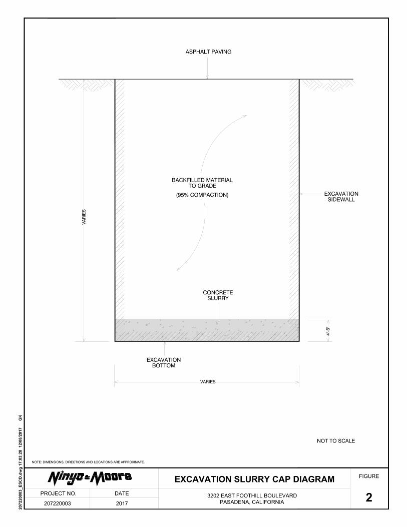
VA
RIE
S
VARIES
4"-6
"
CONCRETESLURRY
EXCAVATIONSIDEWALL
EXCAVATIONBOTTOM
BACKFILLED MATERIALTO GRADE
(95% COMPACTION)
ASPHALT PAVING
FIGURE
2PROJECT NO.
207220003
DATE
2017
NOT TO SCALE
NOTE: DIMENSIONS, DIRECTIONS AND LOCATIONS ARE APPROXIMATE.
EXCAVATION SLURRY CAP DIAGRAM
2072
2000
3_ES
CD
.dw
g 17
:03:
28 1
2/08
/201
7
GK
3202 EAST FOOTHILL BOULEVARDPASADENA, CALIFORNIA