Phoenix User Manual 2014 - Digital Vision World
546
UM-2014.1-07 2014
-
Upload
khangminh22 -
Category
Documents
-
view
0 -
download
0
Transcript of Phoenix User Manual 2014 - Digital Vision World

UM-2014.1-07
2014

Phoenix User Manual 2014
© 2014 Digital Vision
This publication, or parts thereof, may not be reproduced in any form, by any method, for anypurpose.
The software described in this document is furnished under a license agreement. This license isavailable in the docs/licenses folder once the software is installed. See the appendix for licenseand legal notification.
DIGITAL VISION MAKES NO WARRANTY, EITHER EXPRESSED OR IMPLIED, INCLUDING BUTNOT LIMITED TO ANY IMPLIED WARRANTIES, OF MERCHANTABILITY OR FITNESS FOR APARTICULAR PURPOSE, REGARDING THESE MATERIALS AND MAKES SUCH MATERIALSAVAILABLE SOLELY ON AN “AS-IS” BASIS. IN NO EVENT SHALL DIGITAL VISION BE LIABLETO ANYONE FOR SPECIAL, COLLATERAL, INCIDENTAL, OR CONSEQUENTIAL DAMAGES INCONNECTION WITH OR ARISING OUT OF PURCHASE OR USE OF THESE MATERIALS. THESOLE AND EXCLUSIVE LIABILITY TO DIGITAL VISION, REGARDLESS OF THE FORM OFACTION, SHALL NOT EXCEED THE PURCHASE PRICE OF THE MATERIALS DESCRIBEDHEREIN.
DIGITAL VISION reserves the right to revise and improve its products as it sees fit. Thispublication describes the state of this product at the time of its publication, and may not reflectthe product at all times in the future.
The following are trademarks of DIGITAL VISION :
Nucoda, Nucoda Look, Phoenix Finish, Phoenix Refine, Phoenix Video, Phoenix Touch, Loki, LokiControl, DVO, Clarity, Twister and Valhall.
All other brand names, product names, or trademarks belong to their respective holders.
Front cover shows Les Enfants du Paradis, directed by Marcel Carné, 1945. Courtesy of Pathéand Laboratoires Éclair.
Title :
Document Revision :
Date :
Phoenix User Manual 2014
UM-2014.1-07
13/05/2014
Software Revision : 2014.1

1Contents
UM-2014.1-07
Table of Contents
Welcome . . . . . . . . . . . . . . . . . . . . . . . . . . . . . . . . . . . . . . . . . . . . . . . . . . . . . . . . . . 8
Overview . . . . . . . . . . . . . . . . . . . . . . . . . . . . . . . . . . . . . . . . . . . . . . . . . . . . . . . . . . 11
Documentation . . . . . . . . . . . . . . . . . . . . . . . . . . . . . . . . . . . . . . . . . . . . . . . . . . . . . . . . 11
New in This Release . . . . . . . . . . . . . . . . . . . . . . . . . . . . . . . . . . . . . . . . . . . . . . . . . . . . . . . . 12
Product Support . . . . . . . . . . . . . . . . . . . . . . . . . . . . . . . . . . . . . . . . . . . . . . . . . . . . . . . . 13
Contacts . . . . . . . . . . . . . . . . . . . . . . . . . . . . . . . . . . . . . . . . . . . . . . . . . . . . . . . . 13
The User Interface. . . . . . . . . . . . . . . . . . . . . . . . . . . . . . . . . . . . . . . . . . . . . . . . . . . . . . . . . . 16
Interface Conventions . . . . . . . . . . . . . . . . . . . . . . . . . . . . . . . . . . . . . . . . . . . . . . . . . . . . . . . . 16
Main Screens . . . . . . . . . . . . . . . . . . . . . . . . . . . . . . . . . . . . . . . . . . . . . . . . . . . . . . . . 18
Project Screen . . . . . . . . . . . . . . . . . . . . . . . . . . . . . . . . . . . . . . . . . . . . . . . . . . . . . . . . 18
Project Desktop . . . . . . . . . . . . . . . . . . . . . . . . . . . . . . . . . . . . . . . . . . . . . . . . . . . . . . . . 19
Project Library . . . . . . . . . . . . . . . . . . . . . . . . . . . . . . . . . . . . . . . . . . . . . . . . . . . . . . . . 20
File Browser . . . . . . . . . . . . . . . . . . . . . . . . . . . . . . . . . . . . . . . . . . . . . . . . . . . . . . . . 20
Network and Drives . . . . . . . . . . . . . . . . . . . . . . . . . . . . . . . . . . . . . . . . . . . . . . . . . . . . . . . . 21
Folder Navigation . . . . . . . . . . . . . . . . . . . . . . . . . . . . . . . . . . . . . . . . . . . . . . . . . . . . . . . . 23
Folder Bookmarks . . . . . . . . . . . . . . . . . . . . . . . . . . . . . . . . . . . . . . . . . . . . . . . . . . . . . . . . 26
Folder Management . . . . . . . . . . . . . . . . . . . . . . . . . . . . . . . . . . . . . . . . . . . . . . . . . . . . . . . . 28
File Type Filter . . . . . . . . . . . . . . . . . . . . . . . . . . . . . . . . . . . . . . . . . . . . . . . . . . . . . . . . 28
Tables . . . . . . . . . . . . . . . . . . . . . . . . . . . . . . . . . . . . . . . . . . . . . . . . . . . . . . . . 29
Projects . . . . . . . . . . . . . . . . . . . . . . . . . . . . . . . . . . . . . . . . . . . . . . . . . . . . . . . . . . 33
Project List . . . . . . . . . . . . . . . . . . . . . . . . . . . . . . . . . . . . . . . . . . . . . . . . . . . . . . . . 33
Creating Projects . . . . . . . . . . . . . . . . . . . . . . . . . . . . . . . . . . . . . . . . . . . . . . . . . . . . . . . . 34
Output Formats . . . . . . . . . . . . . . . . . . . . . . . . . . . . . . . . . . . . . . . . . . . . . . . . . . . . . . . . 35
Output Format Attributes . . . . . . . . . . . . . . . . . . . . . . . . . . . . . . . . . . . . . . . . . . . . . . . . . . . . . . . . 38
Project Sources and Proxies . . . . . . . . . . . . . . . . . . . . . . . . . . . . . . . . . . . . . . . . . . . . . . . . . . . . . . . . 42
Project Colour Scaling . . . . . . . . . . . . . . . . . . . . . . . . . . . . . . . . . . . . . . . . . . . . . . . . . . . . . . . . 44
Attach/Detach Project . . . . . . . . . . . . . . . . . . . . . . . . . . . . . . . . . . . . . . . . . . . . . . . . . . . . . . . . 44
Opening Projects . . . . . . . . . . . . . . . . . . . . . . . . . . . . . . . . . . . . . . . . . . . . . . . . . . . . . . . . 45
Delete Project . . . . . . . . . . . . . . . . . . . . . . . . . . . . . . . . . . . . . . . . . . . . . . . . . . . . . . . . 47
Recovering a Project . . . . . . . . . . . . . . . . . . . . . . . . . . . . . . . . . . . . . . . . . . . . . . . . . . . . . . . . 47
Location and Configuration . . . . . . . . . . . . . . . . . . . . . . . . . . . . . . . . . . . . . . . . . . . . . . . . . . . . . . . . 49
The Project Library. . . . . . . . . . . . . . . . . . . . . . . . . . . . . . . . . . . . . . . . . . . . . . . . . . . . . . . . . . 51
Folders . . . . . . . . . . . . . . . . . . . . . . . . . . . . . . . . . . . . . . . . . . . . . . . . . . . . . . . . 51
Library Contents . . . . . . . . . . . . . . . . . . . . . . . . . . . . . . . . . . . . . . . . . . . . . . . . . . . . . . . . 53
Properties and Metadata . . . . . . . . . . . . . . . . . . . . . . . . . . . . . . . . . . . . . . . . . . . . . . . . . . . . . . . . 55
Library Filters . . . . . . . . . . . . . . . . . . . . . . . . . . . . . . . . . . . . . . . . . . . . . . . . . . . . . . . . 59
Cache Management . . . . . . . . . . . . . . . . . . . . . . . . . . . . . . . . . . . . . . . . . . . . . . . . . . . . . . . . 60
Composition Save and Load . . . . . . . . . . . . . . . . . . . . . . . . . . . . . . . . . . . . . . . . . . . . . . . . . . . . . . . . 62

Phoenix User Manual2
© 2014 Digital Vision
Importing Material. . . . . . . . . . . . . . . . . . . . . . . . . . . . . . . . . . . . . . . . . . . . . . . . . . . . . . . . . . 66
Importing Media . . . . . . . . . . . . . . . . . . . . . . . . . . . . . . . . . . . . . . . . . . . . . . . . . . . . . . . . 67
Import Options . . . . . . . . . . . . . . . . . . . . . . . . . . . . . . . . . . . . . . . . . . . . . . . . . . . . . . . . 68
Folder Import . . . . . . . . . . . . . . . . . . . . . . . . . . . . . . . . . . . . . . . . . . . . . . . . . . . . . . . . 70
Library Folders . . . . . . . . . . . . . . . . . . . . . . . . . . . . . . . . . . . . . . . . . . . . . . . . . . . . . . . . 71
Importing Audio . . . . . . . . . . . . . . . . . . . . . . . . . . . . . . . . . . . . . . . . . . . . . . . . . . . . . . . . 71
Importing List Files . . . . . . . . . . . . . . . . . . . . . . . . . . . . . . . . . . . . . . . . . . . . . . . . . . . . . . . . 72
List Capture . . . . . . . . . . . . . . . . . . . . . . . . . . . . . . . . . . . . . . . . . . . . . . . . . . . . . . . . 78
Capturing Media . . . . . . . . . . . . . . . . . . . . . . . . . . . . . . . . . . . . . . . . . . . . . . . . . . . . . . . . 80
Conforming the List . . . . . . . . . . . . . . . . . . . . . . . . . . . . . . . . . . . . . . . . . . . . . . . . . . . . . . . . 84
Compositions . . . . . . . . . . . . . . . . . . . . . . . . . . . . . . . . . . . . . . . . . . . . . . . . . . . . . . . . . . 86
Creating Compositions . . . . . . . . . . . . . . . . . . . . . . . . . . . . . . . . . . . . . . . . . . . . . . . . . . . . . . . . 86
Composition Elements . . . . . . . . . . . . . . . . . . . . . . . . . . . . . . . . . . . . . . . . . . . . . . . . . . . . . . . . 88
Video and Audio Tracks . . . . . . . . . . . . . . . . . . . . . . . . . . . . . . . . . . . . . . . . . . . . . . . . . . . . . . . . 88
Media Segments . . . . . . . . . . . . . . . . . . . . . . . . . . . . . . . . . . . . . . . . . . . . . . . . . . . . . . . . 91
Audio Segments . . . . . . . . . . . . . . . . . . . . . . . . . . . . . . . . . . . . . . . . . . . . . . . . . . . . . . . . 92
Positions and Lengths . . . . . . . . . . . . . . . . . . . . . . . . . . . . . . . . . . . . . . . . . . . . . . . . . . . . . . . . 96
Play Heads . . . . . . . . . . . . . . . . . . . . . . . . . . . . . . . . . . . . . . . . . . . . . . . . . . . . . . . . 97
Timeline Marks . . . . . . . . . . . . . . . . . . . . . . . . . . . . . . . . . . . . . . . . . . . . . . . . . . . . . . . . 97
Bookmarks . . . . . . . . . . . . . . . . . . . . . . . . . . . . . . . . . . . . . . . . . . . . . . . . . . . . . . . . 98
Adjustment Segments . . . . . . . . . . . . . . . . . . . . . . . . . . . . . . . . . . . . . . . . . . . . . . . . . . . . . . . . 101
Segment Status Colours . . . . . . . . . . . . . . . . . . . . . . . . . . . . . . . . . . . . . . . . . . . . . . . . . . . . . . . . 102
BL and AUX Segments . . . . . . . . . . . . . . . . . . . . . . . . . . . . . . . . . . . . . . . . . . . . . . . . . . . . . . . . 104
Grouped Shots . . . . . . . . . . . . . . . . . . . . . . . . . . . . . . . . . . . . . . . . . . . . . . . . . . . . . . . . 105
Manipulating Compositions . . . . . . . . . . . . . . . . . . . . . . . . . . . . . . . . . . . . . . . . . . . . . . . . . . . . . . . . 105
Adding Media . . . . . . . . . . . . . . . . . . . . . . . . . . . . . . . . . . . . . . . . . . . . . . . . . . . . . . . . 106
Editing and Selection . . . . . . . . . . . . . . . . . . . . . . . . . . . . . . . . . . . . . . . . . . . . . . . . . . . . . . . . 108
Marking Regions . . . . . . . . . . . . . . . . . . . . . . . . . . . . . . . . . . . . . . . . . . . . . . . . . . . . . . . . 111
Deleting Media . . . . . . . . . . . . . . . . . . . . . . . . . . . . . . . . . . . . . . . . . . . . . . . . . . . . . . . . 112
Ripple Mode . . . . . . . . . . . . . . . . . . . . . . . . . . . . . . . . . . . . . . . . . . . . . . . . . . . . . . . . 113
Trim Modes . . . . . . . . . . . . . . . . . . . . . . . . . . . . . . . . . . . . . . . . . . . . . . . . . . . . . . . . 114
Cuts . . . . . . . . . . . . . . . . . . . . . . . . . . . . . . . . . . . . . . . . . . . . . . . . . . . . . . . . 118
Shots View . . . . . . . . . . . . . . . . . . . . . . . . . . . . . . . . . . . . . . . . . . . . . . . . . . . . . . . . 120
Handy Hotkeys . . . . . . . . . . . . . . . . . . . . . . . . . . . . . . . . . . . . . . . . . . . . . . . . . . . . . . . . 123
Versions . . . . . . . . . . . . . . . . . . . . . . . . . . . . . . . . . . . . . . . . . . . . . . . . . . . . . . . . . . 127
Adding Versions . . . . . . . . . . . . . . . . . . . . . . . . . . . . . . . . . . . . . . . . . . . . . . . . . . . . . . . . 128
Managing Versions . . . . . . . . . . . . . . . . . . . . . . . . . . . . . . . . . . . . . . . . . . . . . . . . . . . . . . . . 129
Rendering . . . . . . . . . . . . . . . . . . . . . . . . . . . . . . . . . . . . . . . . . . . . . . . . . . . . . . . . . . 133
Automatic Render Controls . . . . . . . . . . . . . . . . . . . . . . . . . . . . . . . . . . . . . . . . . . . . . . . . . . . . . . . . 134
Manual Render Controls . . . . . . . . . . . . . . . . . . . . . . . . . . . . . . . . . . . . . . . . . . . . . . . . . . . . . . . . 136
Task Queue . . . . . . . . . . . . . . . . . . . . . . . . . . . . . . . . . . . . . . . . . . . . . . . . . . . . . . . . 136
Exporting . . . . . . . . . . . . . . . . . . . . . . . . . . . . . . . . . . . . . . . . . . . . . . . . . . . . . . . . . . 139
Export Media . . . . . . . . . . . . . . . . . . . . . . . . . . . . . . . . . . . . . . . . . . . . . . . . . . . . . . . . 139
The Export Browser . . . . . . . . . . . . . . . . . . . . . . . . . . . . . . . . . . . . . . . . . . . . . . . . . . . . . . . . 140
File Format and Options . . . . . . . . . . . . . . . . . . . . . . . . . . . . . . . . . . . . . . . . . . . . . . . . . . . . . . . . 141
Filename and Number . . . . . . . . . . . . . . . . . . . . . . . . . . . . . . . . . . . . . . . . . . . . . . . . . . . . . . . . 141

3Contents
UM-2014.1-07
Global Options . . . . . . . . . . . . . . . . . . . . . . . . . . . . . . . . . . . . . . . . . . . . . . . . . . . . . . . . 143
Export Modes . . . . . . . . . . . . . . . . . . . . . . . . . . . . . . . . . . . . . . . . . . . . . . . . . . . . . . . . 145
Mixdow n Rec TC . . . . . . . . . . . . . . . . . . . . . . . . . . . . . . . . . . . . . . . . . . . . . . . . . . . . . . . . 145
Visible Multi Rec TC . . . . . . . . . . . . . . . . . . . . . . . . . . . . . . . . . . . . . . . . . . . . . . . . . . . . . . . . 145
Tracks Multi Rec TC . . . . . . . . . . . . . . . . . . . . . . . . . . . . . . . . . . . . . . . . . . . . . . . . . . . . . . . . 145
Visible Multi Src TC . . . . . . . . . . . . . . . . . . . . . . . . . . . . . . . . . . . . . . . . . . . . . . . . . . . . . . . . 145
Tracks Multi Src TC . . . . . . . . . . . . . . . . . . . . . . . . . . . . . . . . . . . . . . . . . . . . . . . . . . . . . . . . 145
Folder Hierarchy, Presets and Variables . . . . . . . . . . . . . . . . . . . . . . . . . . . . . . . . . . . . . . . . . . . . . . . . . . . . . . . . 152
Export File Formats . . . . . . . . . . . . . . . . . . . . . . . . . . . . . . . . . . . . . . . . . . . . . . . . . . . . . . . . 155
Export Composition . . . . . . . . . . . . . . . . . . . . . . . . . . . . . . . . . . . . . . . . . . . . . . . . . . . . . . . . 155
Scene Detection . . . . . . . . . . . . . . . . . . . . . . . . . . . . . . . . . . . . . . . . . . . . . . . . . . . . . . . . . . 160
Viewer Tools . . . . . . . . . . . . . . . . . . . . . . . . . . . . . . . . . . . . . . . . . . . . . . . . . . . . . . . . . . 163
Head-up Display (HUD) . . . . . . . . . . . . . . . . . . . . . . . . . . . . . . . . . . . . . . . . . . . . . . . . . . . . . . . . 164
Grids . . . . . . . . . . . . . . . . . . . . . . . . . . . . . . . . . . . . . . . . . . . . . . . . . . . . . . . . 166
Masks . . . . . . . . . . . . . . . . . . . . . . . . . . . . . . . . . . . . . . . . . . . . . . . . . . . . . . . . 168
Graphs . . . . . . . . . . . . . . . . . . . . . . . . . . . . . . . . . . . . . . . . . . . . . . . . . . . . . . . . 170
Histogram . . . . . . . . . . . . . . . . . . . . . . . . . . . . . . . . . . . . . . . . . . . . . . . . . . . . . . . . 172
Audio Waveform . . . . . . . . . . . . . . . . . . . . . . . . . . . . . . . . . . . . . . . . . . . . . . . . . . . . . . . . 175
Handy Hotkeys . . . . . . . . . . . . . . . . . . . . . . . . . . . . . . . . . . . . . . . . . . . . . . . . . . . . . . . . 176
Comparison Mode. . . . . . . . . . . . . . . . . . . . . . . . . . . . . . . . . . . . . . . . . . . . . . . . . . . . . . . . . . 179
Stereo Multitrack . . . . . . . . . . . . . . . . . . . . . . . . . . . . . . . . . . . . . . . . . . . . . . . . . . . . . . . . . . 184
Setting Up Stereo . . . . . . . . . . . . . . . . . . . . . . . . . . . . . . . . . . . . . . . . . . . . . . . . . . . . . . . . 184
Using Stereo . . . . . . . . . . . . . . . . . . . . . . . . . . . . . . . . . . . . . . . . . . . . . . . . . . . . . . . . 185
Colour Management. . . . . . . . . . . . . . . . . . . . . . . . . . . . . . . . . . . . . . . . . . . . . . . . . . . . . . . . . . 190
Effects . . . . . . . . . . . . . . . . . . . . . . . . . . . . . . . . . . . . . . . . . . . . . . . . . . . . . . . . . . 192
Colour Correction Layers . . . . . . . . . . . . . . . . . . . . . . . . . . . . . . . . . . . . . . . . . . . . . . . . . . . . . . . . 193
Managing Layers and Effects . . . . . . . . . . . . . . . . . . . . . . . . . . . . . . . . . . . . . . . . . . . . . . . . . . . . . . . . 196
Applying and Editing Effects . . . . . . . . . . . . . . . . . . . . . . . . . . . . . . . . . . . . . . . . . . . . . . . . . . . . . . . . 198
Split Panel View . . . . . . . . . . . . . . . . . . . . . . . . . . . . . . . . . . . . . . . . . . . . . . . . . . . . . . . . 200
Adding User and Layer Effects . . . . . . . . . . . . . . . . . . . . . . . . . . . . . . . . . . . . . . . . . . . . . . . . . . . . . . . . 201
Transition Effects . . . . . . . . . . . . . . . . . . . . . . . . . . . . . . . . . . . . . . . . . . . . . . . . . . . . . . . . 205
Retime . . . . . . . . . . . . . . . . . . . . . . . . . . . . . . . . . . . . . . . . . . . . . . . . . . . . . . . . 208
Brightness Regions . . . . . . . . . . . . . . . . . . . . . . . . . . . . . . . . . . . . . . . . . . . . . . . . . . . . . . . . 210
Printer Lights . . . . . . . . . . . . . . . . . . . . . . . . . . . . . . . . . . . . . . . . . . . . . . . . . . . . . . . . 211
Gamma Matrix . . . . . . . . . . . . . . . . . . . . . . . . . . . . . . . . . . . . . . . . . . . . . . . . . . . . . . . . 212
Gamma . . . . . . . . . . . . . . . . . . . . . . . . . . . . . . . . . . . . . . . . . . . . . . . . . . . . . . . . 212
Matrix . . . . . . . . . . . . . . . . . . . . . . . . . . . . . . . . . . . . . . . . . . . . . . . . . . . . . . . . 214
Presets . . . . . . . . . . . . . . . . . . . . . . . . . . . . . . . . . . . . . . . . . . . . . . . . . . . . . . . . 216
Preset Definition . . . . . . . . . . . . . . . . . . . . . . . . . . . . . . . . . . . . . . . . . . . . . . . . . . . . . . . . 216
Preset Layout . . . . . . . . . . . . . . . . . . . . . . . . . . . . . . . . . . . . . . . . . . . . . . . . . . . . . . . . 216
Hue Curves . . . . . . . . . . . . . . . . . . . . . . . . . . . . . . . . . . . . . . . . . . . . . . . . . . . . . . . . 220
Soft Clip . . . . . . . . . . . . . . . . . . . . . . . . . . . . . . . . . . . . . . . . . . . . . . . . . . . . . . . . 222

Phoenix User Manual4
© 2014 Digital Vision
Effect Notes . . . . . . . . . . . . . . . . . . . . . . . . . . . . . . . . . . . . . . . . . . . . . . . . . . . . . . . . 223
Lens Distort . . . . . . . . . . . . . . . . . . . . . . . . . . . . . . . . . . . . . . . . . . . . . . . . . . . . . . . . 225
Warper . . . . . . . . . . . . . . . . . . . . . . . . . . . . . . . . . . . . . . . . . . . . . . . . . . . . . . . . . . 229
Warper Introduction . . . . . . . . . . . . . . . . . . . . . . . . . . . . . . . . . . . . . . . . . . . . . . . . . . . . . . . . 229
Warper Basics . . . . . . . . . . . . . . . . . . . . . . . . . . . . . . . . . . . . . . . . . . . . . . . . . . . . . . . . 230
DVO Effects . . . . . . . . . . . . . . . . . . . . . . . . . . . . . . . . . . . . . . . . . . . . . . . . . . . . . . . . . . 236
Introduction . . . . . . . . . . . . . . . . . . . . . . . . . . . . . . . . . . . . . . . . . . . . . . . . . . . . . . . . 236
DVO Stereo Fix . . . . . . . . . . . . . . . . . . . . . . . . . . . . . . . . . . . . . . . . . . . . . . . . . . . . . . . . 240
DVO Dust . . . . . . . . . . . . . . . . . . . . . . . . . . . . . . . . . . . . . . . . . . . . . . . . . . . . . . . . 249
DVO Fix . . . . . . . . . . . . . . . . . . . . . . . . . . . . . . . . . . . . . . . . . . . . . . . . . . . . . . . . 266
DVO Flicker . . . . . . . . . . . . . . . . . . . . . . . . . . . . . . . . . . . . . . . . . . . . . . . . . . . . . . . . 270
DVO Print Align . . . . . . . . . . . . . . . . . . . . . . . . . . . . . . . . . . . . . . . . . . . . . . . . . . . . . . . . 273
DVO Scratch . . . . . . . . . . . . . . . . . . . . . . . . . . . . . . . . . . . . . . . . . . . . . . . . . . . . . . . . 275
DVO Steady . . . . . . . . . . . . . . . . . . . . . . . . . . . . . . . . . . . . . . . . . . . . . . . . . . . . . . . . 279
DVO Alias . . . . . . . . . . . . . . . . . . . . . . . . . . . . . . . . . . . . . . . . . . . . . . . . . . . . . . . . 288
DVO Aperture . . . . . . . . . . . . . . . . . . . . . . . . . . . . . . . . . . . . . . . . . . . . . . . . . . . . . . . . 289
DVO Brickwall . . . . . . . . . . . . . . . . . . . . . . . . . . . . . . . . . . . . . . . . . . . . . . . . . . . . . . . . 290
DVO Clarity . . . . . . . . . . . . . . . . . . . . . . . . . . . . . . . . . . . . . . . . . . . . . . . . . . . . . . . . 292
DVO Grain . . . . . . . . . . . . . . . . . . . . . . . . . . . . . . . . . . . . . . . . . . . . . . . . . . . . . . . . 296
DVO Regrain . . . . . . . . . . . . . . . . . . . . . . . . . . . . . . . . . . . . . . . . . . . . . . . . . . . . . . . . 311
DVO Sharpen . . . . . . . . . . . . . . . . . . . . . . . . . . . . . . . . . . . . . . . . . . . . . . . . . . . . . . . . 314
DVO Cross Colour . . . . . . . . . . . . . . . . . . . . . . . . . . . . . . . . . . . . . . . . . . . . . . . . . . . . . . . . 317
DVO Line Sync . . . . . . . . . . . . . . . . . . . . . . . . . . . . . . . . . . . . . . . . . . . . . . . . . . . . . . . . 318
DVO Deinterlace . . . . . . . . . . . . . . . . . . . . . . . . . . . . . . . . . . . . . . . . . . . . . . . . . . . . . . . . 320
DVO Twister . . . . . . . . . . . . . . . . . . . . . . . . . . . . . . . . . . . . . . . . . . . . . . . . . . . . . . . . 322
DVO Upscale . . . . . . . . . . . . . . . . . . . . . . . . . . . . . . . . . . . . . . . . . . . . . . . . . . . . . . . . 325
Shapes . . . . . . . . . . . . . . . . . . . . . . . . . . . . . . . . . . . . . . . . . . . . . . . . . . . . . . . . . . 332
Available Shapes . . . . . . . . . . . . . . . . . . . . . . . . . . . . . . . . . . . . . . . . . . . . . . . . . . . . . . . . 332
Transforming Shapes . . . . . . . . . . . . . . . . . . . . . . . . . . . . . . . . . . . . . . . . . . . . . . . . . . . . . . . . 333
Manipulating Shapes . . . . . . . . . . . . . . . . . . . . . . . . . . . . . . . . . . . . . . . . . . . . . . . . . . . . . . . . 335
Shape Softness . . . . . . . . . . . . . . . . . . . . . . . . . . . . . . . . . . . . . . . . . . . . . . . . . . . . . . . . 337
Shape Overlay Colour . . . . . . . . . . . . . . . . . . . . . . . . . . . . . . . . . . . . . . . . . . . . . . . . . . . . . . . . 339
Tracking Shapes . . . . . . . . . . . . . . . . . . . . . . . . . . . . . . . . . . . . . . . . . . . . . . . . . . . . . . . . 340
DVO Tracker . . . . . . . . . . . . . . . . . . . . . . . . . . . . . . . . . . . . . . . . . . . . . . . . . . . . . . . . . . 342
Tracking Basics . . . . . . . . . . . . . . . . . . . . . . . . . . . . . . . . . . . . . . . . . . . . . . . . . . . . . . . . 342
Using Other Tracks . . . . . . . . . . . . . . . . . . . . . . . . . . . . . . . . . . . . . . . . . . . . . . . . . . . . . . . . 345
Offset Tracking . . . . . . . . . . . . . . . . . . . . . . . . . . . . . . . . . . . . . . . . . . . . . . . . . . . . . . . . 346
Predictive Tracking . . . . . . . . . . . . . . . . . . . . . . . . . . . . . . . . . . . . . . . . . . . . . . . . . . . . . . . . 347
Reference . . . . . . . . . . . . . . . . . . . . . . . . . . . . . . . . . . . . . . . . . . . . . . . . . . . . . . . . 348

5Contents
UM-2014.1-07
Valhall Keys . . . . . . . . . . . . . . . . . . . . . . . . . . . . . . . . . . . . . . . . . . . . . . . . . . . . . . . . 353
Video I/O . . . . . . . . . . . . . . . . . . . . . . . . . . . . . . . . . . . . . . . . . . . . . . . . . . . . . . . . . . 356
VTR Settings . . . . . . . . . . . . . . . . . . . . . . . . . . . . . . . . . . . . . . . . . . . . . . . . . . . . . . . . 357
Video Capture . . . . . . . . . . . . . . . . . . . . . . . . . . . . . . . . . . . . . . . . . . . . . . . . . . . . . . . . 362
Capture Live . . . . . . . . . . . . . . . . . . . . . . . . . . . . . . . . . . . . . . . . . . . . . . . . . . . . . . . . 364
Capture Marked . . . . . . . . . . . . . . . . . . . . . . . . . . . . . . . . . . . . . . . . . . . . . . . . . . . . . . . . 365
Capture List . . . . . . . . . . . . . . . . . . . . . . . . . . . . . . . . . . . . . . . . . . . . . . . . . . . . . . . . 366
Video Layoff . . . . . . . . . . . . . . . . . . . . . . . . . . . . . . . . . . . . . . . . . . . . . . . . . . . . . . . . 371
Output Controls . . . . . . . . . . . . . . . . . . . . . . . . . . . . . . . . . . . . . . . . . . . . . . . . . . . . . . . . 374
Output List . . . . . . . . . . . . . . . . . . . . . . . . . . . . . . . . . . . . . . . . . . . . . . . . . . . . . . . . 378
Output Single . . . . . . . . . . . . . . . . . . . . . . . . . . . . . . . . . . . . . . . . . . . . . . . . . . . . . . . . 379
Command Line . . . . . . . . . . . . . . . . . . . . . . . . . . . . . . . . . . . . . . . . . . . . . . . . . . . . . . . . . . 381
User Login . . . . . . . . . . . . . . . . . . . . . . . . . . . . . . . . . . . . . . . . . . . . . . . . . . . . . . . . 383
Creating a Project . . . . . . . . . . . . . . . . . . . . . . . . . . . . . . . . . . . . . . . . . . . . . . . . . . . . . . . . 383
Project Format Specification . . . . . . . . . . . . . . . . . . . . . . . . . . . . . . . . . . . . . . . . . . . . . . . . . . . . . . . . 384
Attach and Detach Project . . . . . . . . . . . . . . . . . . . . . . . . . . . . . . . . . . . . . . . . . . . . . . . . . . . . . . . . 389
Creating a Composition . . . . . . . . . . . . . . . . . . . . . . . . . . . . . . . . . . . . . . . . . . . . . . . . . . . . . . . . 390
Importing Clips . . . . . . . . . . . . . . . . . . . . . . . . . . . . . . . . . . . . . . . . . . . . . . . . . . . . . . . . 391
Importing Movies . . . . . . . . . . . . . . . . . . . . . . . . . . . . . . . . . . . . . . . . . . . . . . . . . . . . . . . . 393
Importing Folders . . . . . . . . . . . . . . . . . . . . . . . . . . . . . . . . . . . . . . . . . . . . . . . . . . . . . . . . 394
Adding a Version . . . . . . . . . . . . . . . . . . . . . . . . . . . . . . . . . . . . . . . . . . . . . . . . . . . . . . . . 397
Replacing a Source . . . . . . . . . . . . . . . . . . . . . . . . . . . . . . . . . . . . . . . . . . . . . . . . . . . . . . . . 398
Splice and Overwrite Clips . . . . . . . . . . . . . . . . . . . . . . . . . . . . . . . . . . . . . . . . . . . . . . . . . . . . . . . . 399
Applying a Note to a Shot . . . . . . . . . . . . . . . . . . . . . . . . . . . . . . . . . . . . . . . . . . . . . . . . . . . . . . . . 404
EDL Import and Conform . . . . . . . . . . . . . . . . . . . . . . . . . . . . . . . . . . . . . . . . . . . . . . . . . . . . . . . . 405
Capturing and Conforming . . . . . . . . . . . . . . . . . . . . . . . . . . . . . . . . . . . . . . . . . . . . . . . . . . . . . . . . 412
Generating Local Proxies . . . . . . . . . . . . . . . . . . . . . . . . . . . . . . . . . . . . . . . . . . . . . . . . . . . . . . . . 416
Exporting Shots . . . . . . . . . . . . . . . . . . . . . . . . . . . . . . . . . . . . . . . . . . . . . . . . . . . . . . . . 418
Exporting an EDL . . . . . . . . . . . . . . . . . . . . . . . . . . . . . . . . . . . . . . . . . . . . . . . . . . . . . . . . 421
Saving and Loading Compositions . . . . . . . . . . . . . . . . . . . . . . . . . . . . . . . . . . . . . . . . . . . . . . . . . . . . . . . . 422
Rendering a Composition Cache . . . . . . . . . . . . . . . . . . . . . . . . . . . . . . . . . . . . . . . . . . . . . . . . . . . . . . . . 423
Running Batch Operations . . . . . . . . . . . . . . . . . . . . . . . . . . . . . . . . . . . . . . . . . . . . . . . . . . . . . . . . 424
Interactive Mode . . . . . . . . . . . . . . . . . . . . . . . . . . . . . . . . . . . . . . . . . . . . . . . . . . . . . . . . 426
Listing Information . . . . . . . . . . . . . . . . . . . . . . . . . . . . . . . . . . . . . . . . . . . . . . . . . . . . . . . . 426
Removing Items . . . . . . . . . . . . . . . . . . . . . . . . . . . . . . . . . . . . . . . . . . . . . . . . . . . . . . . . 428
Counting and Adding Tracks . . . . . . . . . . . . . . . . . . . . . . . . . . . . . . . . . . . . . . . . . . . . . . . . . . . . . . . . 430
Testing for a GUI Lock . . . . . . . . . . . . . . . . . . . . . . . . . . . . . . . . . . . . . . . . . . . . . . . . . . . . . . . . 431
Appendices . . . . . . . . . . . . . . . . . . . . . . . . . . . . . . . . . . . . . . . . . . . . . . . . . . . . . . . . . . 434
Application Preferences . . . . . . . . . . . . . . . . . . . . . . . . . . . . . . . . . . . . . . . . . . . . . . . . . . . . . . . . 435
General . . . . . . . . . . . . . . . . . . . . . . . . . . . . . . . . . . . . . . . . . . . . . . . . . . . . . . . . 436
Capture/Conform . . . . . . . . . . . . . . . . . . . . . . . . . . . . . . . . . . . . . . . . . . . . . . . . . . . . . . . . 439
Rendering . . . . . . . . . . . . . . . . . . . . . . . . . . . . . . . . . . . . . . . . . . . . . . . . . . . . . . . . 444
Memories . . . . . . . . . . . . . . . . . . . . . . . . . . . . . . . . . . . . . . . . . . . . . . . . . . . . . . . . 447

Phoenix User Manual6
© 2014 Digital Vision
Control Panel . . . . . . . . . . . . . . . . . . . . . . . . . . . . . . . . . . . . . . . . . . . . . . . . . . . . . . . . 448
Colour . . . . . . . . . . . . . . . . . . . . . . . . . . . . . . . . . . . . . . . . . . . . . . . . . . . . . . . . 453
Monitoring / Video IO . . . . . . . . . . . . . . . . . . . . . . . . . . . . . . . . . . . . . . . . . . . . . . . . . . . . . . . . 457
Preferences Assistant . . . . . . . . . . . . . . . . . . . . . . . . . . . . . . . . . . . . . . . . . . . . . . . . . . . . . . . . 464
Keycode . . . . . . . . . . . . . . . . . . . . . . . . . . . . . . . . . . . . . . . . . . . . . . . . . . . . . . . . 469
Automatic Naming . . . . . . . . . . . . . . . . . . . . . . . . . . . . . . . . . . . . . . . . . . . . . . . . . . . . . . . . 470
Effect Identifiers . . . . . . . . . . . . . . . . . . . . . . . . . . . . . . . . . . . . . . . . . . . . . . . . . . . . . . . . 474
Effect Selector Configuration . . . . . . . . . . . . . . . . . . . . . . . . . . . . . . . . . . . . . . . . . . . . . . . . . . . . . . . . 476
Output Format Confguration . . . . . . . . . . . . . . . . . . . . . . . . . . . . . . . . . . . . . . . . . . . . . . . . . . . . . . . . 480
Colour Tool Order . . . . . . . . . . . . . . . . . . . . . . . . . . . . . . . . . . . . . . . . . . . . . . . . . . . . . . . . 485
3D LUT File Format . . . . . . . . . . . . . . . . . . . . . . . . . . . . . . . . . . . . . . . . . . . . . . . . . . . . . . . . 487
Icon Tools Reference . . . . . . . . . . . . . . . . . . . . . . . . . . . . . . . . . . . . . . . . . . . . . . . . . . . . . . . . 492
Format Support . . . . . . . . . . . . . . . . . . . . . . . . . . . . . . . . . . . . . . . . . . . . . . . . . . . . . . . . 494
Image Formats . . . . . . . . . . . . . . . . . . . . . . . . . . . . . . . . . . . . . . . . . . . . . . . . . . . . . . . . 494
DPX . . . . . . . . . . . . . . . . . . . . . . . . . . . . . . . . . . . . . . . . . . . . . . . . . . . . . . . . 494
Cineon . . . . . . . . . . . . . . . . . . . . . . . . . . . . . . . . . . . . . . . . . . . . . . . . . . . . . . . . 494
TIFF . . . . . . . . . . . . . . . . . . . . . . . . . . . . . . . . . . . . . . . . . . . . . . . . . . . . . . . . 494
SGI . . . . . . . . . . . . . . . . . . . . . . . . . . . . . . . . . . . . . . . . . . . . . . . . . . . . . . . . 494
JPEG . . . . . . . . . . . . . . . . . . . . . . . . . . . . . . . . . . . . . . . . . . . . . . . . . . . . . . . . 494
PIC . . . . . . . . . . . . . . . . . . . . . . . . . . . . . . . . . . . . . . . . . . . . . . . . . . . . . . . . 494
MPEG . . . . . . . . . . . . . . . . . . . . . . . . . . . . . . . . . . . . . . . . . . . . . . . . . . . . . . . . 494
MXF . . . . . . . . . . . . . . . . . . . . . . . . . . . . . . . . . . . . . . . . . . . . . . . . . . . . . . . . 494
EXR . . . . . . . . . . . . . . . . . . . . . . . . . . . . . . . . . . . . . . . . . . . . . . . . . . . . . . . . 494
Quicktime . . . . . . . . . . . . . . . . . . . . . . . . . . . . . . . . . . . . . . . . . . . . . . . . . . . . . . . . 494
List Formats . . . . . . . . . . . . . . . . . . . . . . . . . . . . . . . . . . . . . . . . . . . . . . . . . . . . . . . . 499
EDL . . . . . . . . . . . . . . . . . . . . . . . . . . . . . . . . . . . . . . . . . . . . . . . . . . . . . . . . 499
AAF . . . . . . . . . . . . . . . . . . . . . . . . . . . . . . . . . . . . . . . . . . . . . . . . . . . . . . . . 499
CUT . . . . . . . . . . . . . . . . . . . . . . . . . . . . . . . . . . . . . . . . . . . . . . . . . . . . . . . . 499
ALE . . . . . . . . . . . . . . . . . . . . . . . . . . . . . . . . . . . . . . . . . . . . . . . . . . . . . . . . 499
MXF Formats . . . . . . . . . . . . . . . . . . . . . . . . . . . . . . . . . . . . . . . . . . . . . . . . . . . . . . . . 504
Camera Formats . . . . . . . . . . . . . . . . . . . . . . . . . . . . . . . . . . . . . . . . . . . . . . . . . . . . . . . . 506
Red . . . . . . . . . . . . . . . . . . . . . . . . . . . . . . . . . . . . . . . . . . . . . . . . . . . . . . . . 506
ARRI D-21 . . . . . . . . . . . . . . . . . . . . . . . . . . . . . . . . . . . . . . . . . . . . . . . . . . . . . . . . 506
Silicon Imaging SI-2K . . . . . . . . . . . . . . . . . . . . . . . . . . . . . . . . . . . . . . . . . . . . . . . . . . . . . . . . 506
Vision Research Phantom. . . . . . . . . . . . . . . . . . . . . . . . . . . . . . . . . . . . . . . . . . . . . . . . . . . . . . . . 506
Audio Formats . . . . . . . . . . . . . . . . . . . . . . . . . . . . . . . . . . . . . . . . . . . . . . . . . . . . . . . . 514
WAV Audio . . . . . . . . . . . . . . . . . . . . . . . . . . . . . . . . . . . . . . . . . . . . . . . . . . . . . . . . 514
Audio Interchange Format. . . . . . . . . . . . . . . . . . . . . . . . . . . . . . . . . . . . . . . . . . . . . . . . . . . . . . . . 514
OFX Plugins . . . . . . . . . . . . . . . . . . . . . . . . . . . . . . . . . . . . . . . . . . . . . . . . . . . . . . . . 516
Configurable Viewer Tools . . . . . . . . . . . . . . . . . . . . . . . . . . . . . . . . . . . . . . . . . . . . . . . . . . . . . . . . 517
Grids Specification . . . . . . . . . . . . . . . . . . . . . . . . . . . . . . . . . . . . . . . . . . . . . . . . . . . . . . . . 519
HUDs Specification . . . . . . . . . . . . . . . . . . . . . . . . . . . . . . . . . . . . . . . . . . . . . . . . . . . . . . . . 528
Masks Specification . . . . . . . . . . . . . . . . . . . . . . . . . . . . . . . . . . . . . . . . . . . . . . . . . . . . . . . . 528
Graphs Specification . . . . . . . . . . . . . . . . . . . . . . . . . . . . . . . . . . . . . . . . . . . . . . . . . . . . . . . . 531
Legal Notices . . . . . . . . . . . . . . . . . . . . . . . . . . . . . . . . . . . . . . . . . . . . . . . . . . . . . . . . 536
Index 0

Welcome 1

Welcome8
© 2014 Digital Vision UM-2014.1-07
Phoenix User Manual 2014
Phoenix Finish - Phoenix RefinePhoenix Touch - Phoenix Video
Welcome to the Phoenix Restoration Environment from Digital Vision!
The Phoenix platform is the perfect solution for film/video archives andcontent owners who require the best in content restoration, re-mastering andre-purposing. This manual will help you get the most out of the system.
Product : Phoenix
Version : 2014
Document Revision : UM-2014.1-07
Date : 13/05/2014

9
© 2014 Digital Vision UM-2014.1-07

Overview 2

11
© 2014 Digital Vision UM-2014.1-07
Phoenix Finish
Phoenix Refine
Phoenix Touch
Phoenix Video
Welcome to the Phoenix Restoration Environment from Digital Vision.
The Documentation section lists the documentation included with theapplication and where to locate it.
First Time Users
The User Interface chapter gives an overview of the application environmentand GUI, but those who want to jump straight into creating projects may wantto skip ahead to the Projects chapter and return to the User Interface sectionat a later date, after having acquired a feel for the product.
Documentation
Several items of documentation are included, all of which can be accessedvia the "Phoenix Docs 2014.1" shortcut that is placed on your desktop by theinstallation program. You can also access the index page directly from :
C:\Phoenix\2014_1\docs\index.html
Install and Setup Manual
The Setup Manual describes how to install and configure the application. Italso details installation and configuration of graphics and video hardware andimportant considerations for use of the software.
User Manual
This is the user guide that you are currently reading.
Release Notes
The release notes list all the new features, bug fixes and known bugs.

Overview12
© 2014 Digital Vision UM-2014.1-07
Precision Control PanelDocumentation
The Precision Panel documentation includes an User Guide and a HardwareInstallation Guide.
Valhall Control Panel Documentation
The Valhall Panel documentation includes an installation guide (givinginformation on the Valhall environment variables and setup), a user guide, anda quick reference labelled diagram of all the Valhall panel controls.
Hotkeys Reference Guide
The Phoenix hotkeys guide is a labelled keyboard diagram and summary pageof all the Hotkeys available in the application. A shortcut to this PDF documentis also placed on your desktop by the installation program.
Note that the application itself includes tool-tip labels on buttons anduser-interface elements. These will pop up when you hover yourmouse over a button and display some explanatory text.
New in This Release
Please see the Features and Benefits document for a description on newfeatures.

New in This Release 13
© 2014 Digital Vision UM-2014.1-07
Product SupportProduct Support is available to all clients with a valid maintenance contract.To contact support, see the Contacts section.
User Forum
Digital Vision runs a web-based user forum at the following address :
http://forum.digitalvision.se
Please consider joining the forum and taking part in wide-ranging discussionswith our growing community of users.
Contacts
Stockholm
Digital VisionTelefonv. 30126 26 HägerstenSweden
t: +46 (0)8 546 182 00f: +46 (0)8 546 182 09
Linköping
Digital VisionÅgatan 40582 22 LinköpingSweden
t: +46 (0)13 200 100f: +46 (0)13 200 150
London
Digital Vision11 Wardour MewsLondon W1F 8ANUnited Kingdom
t: +44 (0)207 734 8282f: +44 (0)207 292 6969
Los Angeles
DV Sales and Support6464 Sunset BlvdSuite 830HollywoodCA 90028USA
t: +1 818 769 8111f: +1 818 769 1888
Email Contacts

Overview14
© 2014 Digital Vision UM-2014.1-07

The User Interface 3
The User Interface16
© 2014 Digital Vision UM-2014.1-07
This chapter will give you an overview of the user interface and some basiccomponents of the application.
Interface ConventionsThe following interface conventions are used for various elements.
Functional
A function button performs a single action only.
Active and availablefunction button.
Inactive function button.If a button is not available for selection, it isgreyed out.
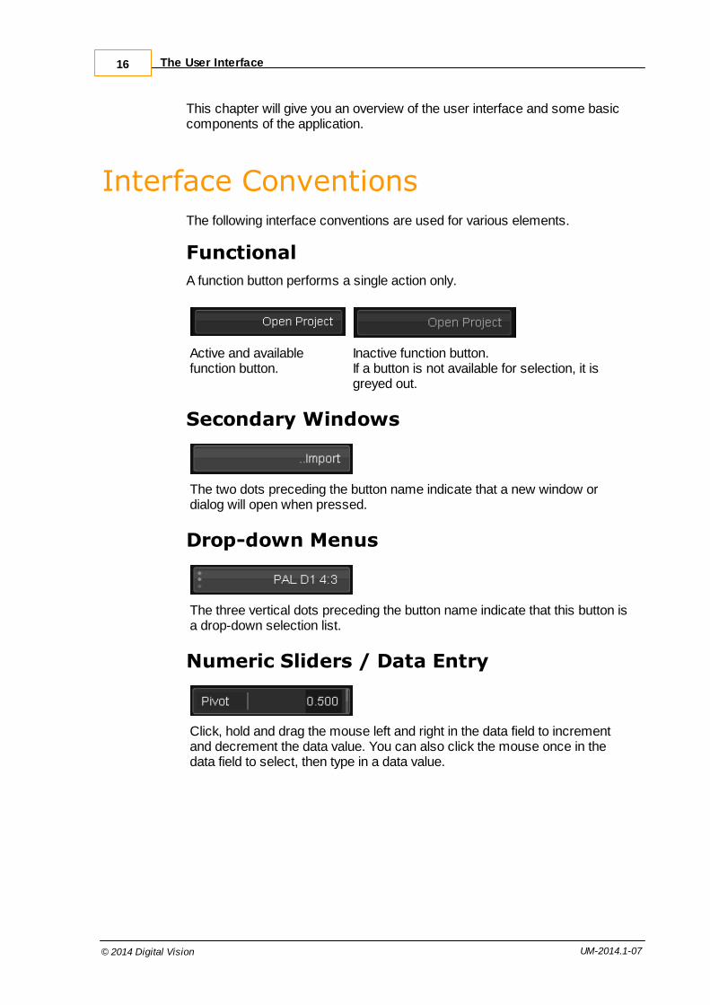
Secondary Windows
The two dots preceding the button name indicate that a new window ordialog will open when pressed.
Drop-down Menus
The three vertical dots preceding the button name indicate that this button isa drop-down selection list.
Numeric Sliders / Data Entry
Click, hold and drag the mouse left and right in the data field to incrementand decrement the data value. You can also click the mouse once in thedata field to select, then type in a data value.

Interface Conventions 17
© 2014 Digital Vision UM-2014.1-07
Toggle Buttons
Toggle button off. Toggle button on.
A group of three toggle buttons, with one enabled.
Radio Buttons
A group of two radio buttons. In a group, only one option can be selected atone time.
Option Buttons
Option button off. Option button on.
Information Dialogs
InformationalInformationalmessages, no userinteraction required.
QueryRequest for userinput.
Warning/ErrorWarning or error alert.Sometimes including arequest for user intervention.

The User Interface18
© 2014 Digital Vision UM-2014.1-07
Main ScreensThe application environment is composed of a number of components withinwhich you do the majority of your work. These include the main ProjectScreen, the Project Desktop and the Project Library.
Project ScreenThe Project Screen is the first screen visible when we launch the application.This is where we create and manage our projects and access our globalpreferences.
Main Project Screen
See the Creating a Project and Project Management sections of this manual.
The active component screen will be high-lighted orange.
To access the component, press the corresponding button on the mainscreen :
For the Preferences component, see the appendix Application Preferences.

Main Screens 19
© 2014 Digital Vision UM-2014.1-07
Project DesktopThe Project Desktop is the main working environment inside your project.
The Project Desktop showing the viewer area and the composition timeline below.
The desktop is composed of three main views :
The Monitor - in dual monitor mode, this will be displayed on yoursecond monitorThe Composition Timeline and GUI controls
The Memories view - for notes, memories and grouped shots
In single-screen mode, the Monitor panel can display the Monitor,the Library or the Memories panel.
Project Desktop showing M emories view

The User Interface20
© 2014 Digital Vision UM-2014.1-07
Project LibraryThe Project Library is where we import and export media, createcompositions and manage our project assets.
See the Project Library section of this manual.
File BrowserA sophisticated file browser is used throughout the application. It is used tonavigate both local and remote filesystems. You will use the file browsercomponent in many places, including :
Import and export of media, list files and LUT files.
Attaching and detaching projects.
Capturing material from lists.
This section describes the file browser and its various components.

File Browser 21
© 2014 Digital Vision UM-2014.1-07
File Browser (Import Media version) showing main functional areas
1. Network and Drives2. Navigation and Folder hierarchy3. Folder Bookmarks4. Folder Management5. File Type Filter
Network and DrivesTo the left of the main file browser panels are the panels that allow :
Network folder and local folder browsing
Local drive selection or
Network share selection

The User Interface22
© 2014 Digital Vision UM-2014.1-07
Local Drives
When browsing Local drives, the available drive letters will be shown in thepanel below :
Local drives displaying available drive letters.
You can double-click a drive letter to jump to the root of the drive.
Network
When browsing the Network, the panel will show other systems available onthe local network :
Network displays available network systems
The top-level folder list will display the available Network Shares on theselected system :

File Browser 23
© 2014 Digital Vision UM-2014.1-07
System Magners has a shared folder "S on Magners".
If the target system (Magners above) requires authentication, youwill need to do this before starting the application.
Folder NavigationOnce we have selected a local drive or network share, we navigate thefilesystem folders via the central panels.

The User Interface24
© 2014 Digital Vision UM-2014.1-07
Full Current Location
The file browser always shows you the full current location to your currentfolder in the box at the top :
Full current location
Folder Navigation
The button to the right of the location display lets you quickly go up one folderlevel :
Button to move up one folder level
You can navigate up and down both local and remote folders using the panelsin the centre of the window. These panels have two modes of display -Cascade Mode (multi-pane) and Single Mode (single pane).
These central panels display folders only, never files.
Cascade Mode
In Cascade Mode, the central area will show up to three panels. Each panelwill display the folders that exist :
In folder above us (left pane)
In current folder (middle pane)
In folder below us (right-hand pane)
The current folder is always high-lighted in orange. Click anyfolder to make it current.
Enable Cascade Mode via the button :

File Browser 25
© 2014 Digital Vision UM-2014.1-07
Cascade Mode showing three folders (above and below current)
In Cascade Mode, you can jump backwards (up) and forwards (down) inyour location history using the arrow buttons below the panels :
Single Pane Mode
In Single Pane Mode, the central area shows a single pane and the foldersinside (below) the current folder only.
Single Pane Mode. Display folders below current folder location only.
Folder File Contents
The files within the current folder are displayed in the bottom pane.

The User Interface26
© 2014 Digital Vision UM-2014.1-07
Files that exist within the current folder are displayed in a tabular format (seethe Tables section for a discussion of table use).
The files displayed can be filtered by file type.
Contiguous file sequences (i.e. no gaps) are compressed to display only thestart and end frames i.e.
export097738.dpx, export097739.dpx, ..., export097812.dpx
is displayed as :
export[97738-97812].dpx
Use CTRL+R to refresh the file browser.
Folder BookmarksFolder Bookmarks let you store a folder location and jump to it via a drop-down list.
Using Bookmarks
To jump to a previously bookmarked folder, select the bookmark from thebookmarks drop-down list :

File Browser 27
© 2014 Digital Vision UM-2014.1-07
Adding Bookmarks
To add a bookmark for the current folder, or manage bookmarks, press theBookm arks button. A dialog window will open. To add a bookmark for thecurrent folder, press the Add button :
Bookmark dialog
The bookmark will be added to the list and available for use :
New bookmark in the list
Delete and rename Bookmarks
To delete or rename a bookmark, select and jump to it and use theappropriate button.

The User Interface28
© 2014 Digital Vision UM-2014.1-07
Folder ManagementAt the top-right, the file browser displays the name of the current folder.
To the right of the current folder name are the two buttons :
Rename Current folder
Create New folder
Rename Current Folder
Type a new name for the folder and press the Rename Folder button.
Create New Folder
Type a new name for the folder and press the Create New Folder button.
The new folder is created within the current folder.
File Type Filter
The File Type Filter drop-down list lets you limit the display of files in thecurrent folder to the specified file type only.

File Browser 29
© 2014 Digital Vision UM-2014.1-07
Use the drop-down list and select the desired filter :
TablesMany areas of the application display information in a tabular format, includingthe library, video I/O screens, capture lists, project list and file browser.
Tabular display of assets in library
Tables behave in a similar manner throughout the application.
Selection
Select items by left-clicking with the mouse. Selected items are shown inorange.
Multiple non-continuous items selected

The User Interface30
© 2014 Digital Vision UM-2014.1-07
Multiple Selection
To select multiple items :
SHIFT + select to select a continuous range
CTRL + select to select non-continuous items (as shown in imageabove)
Deselection
To deselect an item, select it with CTRL + select again.
Column Order
To re-order the columns, click and drag a column title :
Repositioning a column.
Column Sort
To sort the table display on a column, click the column title. Clicking again,reverses the sorting :
Ordering on M aterial Name (title changes to italic).
Column titles change to italics when sorted on the column.
Remove Sort
To remove the sorting, click on another column (or in the library, click onthe the Thumbnail column title).

Tables 31
© 2014 Digital Vision UM-2014.1-07
Show and Hide Columns
You can show (insert) or hide (remove) a column by using your mouse and aright-click :
Remove Column
Right-click the mouse over the column you want to remove and choose Remove Column :
Insert Column
Right-click the mouse in the contents title area where you want to insertthe new column and choose the column you want to insert :
Column Sizing
You can adjust the width of columns by clicking and dragging the columnboundary with your mouse :
Click and drag to stretch Material Name column width out.

Projects 4

33
© 2014 Digital Vision UM-2014.1-07
Projects are used to store and organise your work. This includes the projectlibrary containing all your compositions and source material, all your edits andgrades specific to each composition, definitions of all the project outputformats and all other project state (such as play heads, cached renders,window positions, undo stack etc.).
The Project Screen is the first screen displayed when you launch theapplication. This is where you create and manage your projects.
Below the project list is an area that displays configuration settings for thecurrently selected project. To the right of these settings in a group of buttonsthat let us create, open and perform various other actions with projects.
Whenever you select a project from the project list, the projectsettings panel will refresh to show you the current settings for theselected project.
Project List
The top panel lists all available projects:

Projects34
© 2014 Digital Vision UM-2014.1-07
Project properties displayed are :
Project Name
Status (e.g. Offline, Available)
Project Location
Creation Date
Modification Date
The Project List is displayed a standard table. For more detail ontables and their use, see the Tables section.
Project Status
The Status field can have two values :
Available : the project is available for use and exists at the specifiedlocationMissing : the project folder cannot be located at the specified location
If a needed project is listed as Missing, you will need to locate theproject folder or retrieve from backup. Then you can :
A. Move project folder back to original location orB. Detach the missing project from the list and then attach it from its
new location.
Creating Projects
Creating a project consists of defining :
One or more output (target) formats. Required.
One or more source definitions (e.g. proxies). Optional.
The project screen has 3 main panels. At the top, a list of all availableprojects, along the bottom the project configuration settings, and to the rightthe project options:

Creating Projects 35
© 2014 Digital Vision UM-2014.1-07
To create a new project :
Type the name of the new project in the project name text field.
Press the New Project button.
Usually, a new project will take its initial settings from the last projectselected. To create a completely fresh project (with all settings asdefault), see below.
Now configure the project settings (e.g. output formats, sources, colour spaceetc.). Once done, press the Apply Settings button or just Open Project.
If project settings have been changed, Open Project will promptyou to apply them before opening.
Creating a Fresh Project
Currently, a new project is always created using settings defined fromthe currently selected project (except for the very first project created).To create a new fresh project, follow this procedure :
Create a dummy project (e.g. called "delete me")
Open this dummy project
Exit project
Delete the dummy project
Exit application
On application restart, no project will be current and the default settingswill be used for a Untitled Project.
Output FormatsIn addition to naming your project, the project configuration settings panelalong the bottom of the project screen allows you to specify your intended output format(s) and any additional sources you may want to create:

Projects36
© 2014 Digital Vision UM-2014.1-07
Defined project output formats are displayed on the left. The project masterformat is the first in the list.The settings for the selected output format is displayed to the right.
Each output format has independent settings.
The output formats defined determine the available display, playback, renderand output formats for the project. You can modify the output formats definedfor the project anytime.
Master Output Format
The master format is always shown at the top of the output format list andcannot be deleted.
It is recommended that the master format be defined to match themost common format of the source material you will be using insidethe project.
Some common formats have been provided for use as quick defaults (e.g.PAL, HD 1080) and these are listed in the Setup drop-down menu. Selectingone of these formats will automatically update the frame rate, image size andaspect ratio attributes to the corresponding values for that format.
If you change any of these default values, the setup format will automaticallychange to being a Custom Setup.

Creating Projects 37
© 2014 Digital Vision UM-2014.1-07
Additional Output Formats
All additional output formats are listed below the master format and arecompletely independent of it. To create a new output format :
Press the New button located below the Output Formats list box. Anew format will be created.Then configure the output via the Setup drop-down list or edit theindividual parameters.
To delete an output format, just select it from the output formats list and pressthe Delete button.
Editing the Output Formats
To modify an output format :
Highlight it in the output formats list. The settings displayed on theright switch to the selected format. Alter any of the output format attributes.
Press the Apply Settings button to apply any changes made.
You will be warned if you try and move away from the main projectscreen if any settings have been changed.

Projects38
© 2014 Digital Vision UM-2014.1-07
Output Format AttributesEach output format has a set of attributes defined, including :
Format Presets
Frame Rate
Colour Channels
Colour Depth
Render Resolution
Viewing Aspect Ratio
Render Options
Conversion and Filter settings
Colour Management System (CMS)
When setting the attributes for your output formats you are definingthe different ways that you wish to render material. It does not affectthe source material that you will import, which has its own sourceformat.
Format Presets
There are a variety of predefined formats available in the preset drop-downlist. Selecting a preset will configure the other settings appropriately.
Format Setup
You can configure the format settings independently of the the preset chosen.
Frame Rate
Use the frame rate drop-down list to select the frame rate for thecomposition timelines created in the project
If you selected a default setup, it will automatically set its own framerate, but you can change this. If you do change it, the default setup willchange to Custom Setup.
You will be able to see the frame rate of each of your compositions and

Creating Projects 39
© 2014 Digital Vision UM-2014.1-07
media in the project library.
It is possible to create compositions with different frame rateswithin a single project. The Library/New Composition buttonalways creates a timeline at the frame rate set on the currentlyselected output format. You can create a composition at adifferent frame rate by changing the rate of the output format(at the project screen), creating the New Composition, thenreverting the output format rate again.
Colour Channels
Default : RGB
Use this drop-down to select the colour channels to use. This definesthe components used in any cache generated.This is an advanced setting. In general, do not change this.
Component Bit Depth
Default : 10 bit
Use this drop-down to select the bits per component (colour accuracy)that you want the output format to render.
Component Bit Depth is an advanced setting and usuallyshould be left at the default.
Render Resolution
The image width and height, in pixels, are set automatically when youchoose one of the preset formats from the setup menu. If you want todefine a different image size for your output format then simply enterthe values into the appropriate text boxes; in doing so, the default formatwill automatically change itself to Custom Setup.
Viewing Aspect Ratio
The aspect ratio for viewing images is set automatically when youchoose one of the default formats from the setup menu. If you want todefine a different aspect ratio for your output format then simply enterthe value into the appropriate text box; in doing so, the default format willautomatically change itself to Custom Setup. You will be able to togglethe aspect ratio correction on/off when viewing images.
Render Options
Cache Output
Default : OFF
Enabling Cache Output will cause output caches to be generated (in the

Projects40
© 2014 Digital Vision UM-2014.1-07
output format) if the source format differs from the output. If the sourceformat matches the output, an output cache is generated if any Masterlayer effects are added. Cache Output can be set independently on anyproject output format.
Enable this :
To ensure everything is rendered and ready to lay-off to video.
On a 10 bit secondary output format when your master format(and sources) are half-float or 16 bit. Cache Output will ensurethat the secondary format caches are 10 bit which can improverealtime performance.
This cache is in addition to the standard (source-format)cache.
frame / field rendering
Full support for interlaced video formats is included.
Options :
framesProgressive format, no fields.fields (f1:f2)
Fields, with field order f1:f2 [PAL]fields (f2:f1)
Fields with field order f1:f2 [NTSC]
Field settings will enable field edits/cuts in the composition, field viewing,playback and rendering.
Conversion Settings
If your source images are a different resolution to your defined output, you canchoose if and how they are scaled and/or cropped for output.
None
Displays the source image in its original size. This may result in a cropped or blanked image, depending on the difference between thesource and output resolution and aspect ratio.
Auto Fit
Scales the source image to the size of the output format.
Auto Crop
Crops the source image and scales it to the size of the output format.
Center
The center of the source image is mapped to the center of the output

Creating Projects 41
© 2014 Digital Vision UM-2014.1-07
format maintaining the source image aspect ratio. This may result in acropped or blanked image, depending on the difference between thesource and output resolution and aspect ratio.
Filtering
The filter type selects the mechanism used to transform the pixels in thesource image to the new output. This mechanism involves calculating thevalue of an output pixel as an aggregation of contributing source pixels. Howthe various pixel contributions are weighed defines the filter.
In order of worst to best (or increasing accuracy) :
No Filtering
Only the source pixel at the center of the projected boundary issampled. This method is very prone to visible artefacts such as jaggedimage edges.
Bilinear Filtering
The four pixels in the source image that are closest to the center of theprojected boundary are sampled. Their weighting is based on therelative proximity to the center of the projected pixel boundary. Thisproduces an accurate colour result but doesn't cut down aliasing as wellas Gaussian does. Box and bilinear will produce very similar results forsmall scale reductions, but due to the nature of the software codingbilinear is generally the fastest of these two options.
Box Filtering
All pixels falling within the projected pixel boundary are sampled andtheir weight is proportional to their area that lies within the projected pixelboundary. Box and bilinear filtering will produce very similar results forsmall scale reductions, but box can produce better results for largerscale reductions.
Gaussian Filtering
All pixels falling within the projected pixel boundary are sampled andweighted using a gaussian filter kernel. This produces better resultsthan the box or bilinear filters in so far as it results in less aliasing, but isslower.
ZOM Filtering
Uses a sinc filter and is the best general filter for up and down-scaling,providing a sharp result without artefacts. This is the default setting.
Lanczos Filtering
A windowed form of the sinc filter which may give better results in somecases.

Projects42
© 2014 Digital Vision UM-2014.1-07
Colour Management System (CMS)
Each defined output format can have an independent colour Look Up Tableapplied (LUT) as part of your Colour Management System (CMS).
A variety of LUT formats and CMS systems are supported, including the Nucoda CMS, THX Cinespace and Kodak.
The LUT can be used in two ways :
As a viewing only LUT. The LUT is not rendered on the final output.The LUT can be selected and toggled on/off inside the project.As a rendered LUT on the output. Pressing the Apply CMS buttonmarks the selected output format with CMS and burns in the LUT onthis format.
Sample CMS LUT files are provided in the folder :
C:\Phoenix\2014_1\root\cms
Project Sources and Proxies
Project Sources refer to source material available inside a project and howthe source media is presented.
The "1:1 Source Clip" source is always present and refers to your pristine,original source material (imported or captured), at whatever original resolution.
Optionally, you can add one or more proxy sources via the New button.
A proxy source will act as a substitute source in the project.
You may decide to add a proxy source if :
Your original sources are located on a slower storage device (e.g.network). In this case, you may wish to add a "1:1 Clone" source toensure fast access to (local) fast storage.Your original sources are large, you may wish to add a "2:1" proxy to

Creating Projects 43
© 2014 Digital Vision UM-2014.1-07
improve rendering speeds and realtime performance.
To add a new source, press the New button below the Sources list.
Format
The format and filter type of the selected proxy is shown to the right of theSources list.
The format allows you to change the proxy scale and bits per component.
Scale
Set the scale compared to the source media :
1:1
2:1
3.1 etc.
Bits Per Component
Set the colour component depth.
Same Same bit depth as original source media
8 Bit Set proxy to 8 bits per component
10 Bit Set proxy to 10 bits per component
16 Bit Set proxy to 16 bits per component
Half Set proxy to half-float bits per component.
Proxies are created in the DPX file format except Half format, whichare created as EXR files.
This is an advanced setting.In general, do not change the bits per component but leave as"Same".
Filter
For non-1:1 proxy sources, you can apply a filter to improve the proxy imagequality.
The Filter options are described in the Filtering section in Output FormatAttributes.

Projects44
© 2014 Digital Vision UM-2014.1-07
Project Colour Scaling
The default colour scaling is a per project setting and is defined via a drop-down list below the proxy setup.
These scaling modes (defined below) affect :
Video capture and layoff
Timeline monitoring via SDI – including : Timeline filler, Transitions ,Pan/Scan blanking, Fade to ColourColour tool behaviour (black/white pivot points etc.)
Scene detection
Be very careful with this setting. If you change the scaling on an existing project, a warning dialog willrequest confirmation before application of the change. The changewill affect SDI monitoring, capture and layoff settings and the modeused in new colour tools. It may also cause a re-render of colouradaptive tools on your timelines.
See the Colour Scaling section in the Install and Setup Manual.
Attach/Detach Project
Attach Project
We can only open and edit projects once they appear in our main project list.
The Attach Project button lets you insert an existing project (projectfolder) into our project list.
Clicking the Attach Project button brings up the file browser so that youcan select the location of the project (folder) you want to add to the list. Selectthe project folder and click the OK button, or browse inside it and click OK.
The project will then appear in your project list and you can select it to open.

Attach/Detach Project 45
© 2014 Digital Vision UM-2014.1-07
You should only import projects that were created on the sameversion of the application software, e.g. v2013.3 projects should notbe imported into v2014.1
Detach Project
The Detach Project option removes a project from your project list.
It does not delete the project.
If you want to open the project again at a later date you need to re-attach itusing the Attach Project button.
You will not be asked to confirm project detachment.
This is a useful tool for moving a project from one computer toanother, or removing a shared project from your project list withoutaffecting users elsewhere.
Opening Projects
To open a project, double-click the project on the main project screen, orselect it and press the Open Project button.On opening the project you will betaken to the project desktop.
When you open a project, if any of the project configuration settingsfor that project have been changed but have not been applied withthe Apply Settings button you will be asked if you want to applythe new settings at this point. If the changes were unintentional youcan say no and they will be discarded.
The open project button will be disabled if there is no project selected or if theselected project has a status of Offline. An Offline project means that theunderlying project data folder is not located in the expected location.
Warnings
You may sometimes see a warning when opening a project. This may relate

Projects46
© 2014 Digital Vision UM-2014.1-07
to a version mismatch or to missing cache renders.
Version Mismatch Warning
If you open a project that was created with an earlier application version, youwill receive a warning dialog alerting you to this fact.
It is usually safe to open a project created with the same Major.Minorversion as used currently (i.e. 3.6r1 to 3.6r2). However, projectscreated in earlier Major.Minor versions may not be safe (e.g. 3.5r7 to3.6r1).
Missing Caches
If some (or all) of the rendered cache files cannot be located on disk, you willreceive a warning alerting you to this fact.
This may occur if :
1. The cache (cacheRootDir) volume is unavailable2. The project has been moved and attached on a different machine3. After a crash etc.
For case (1), you may wish to press Cancel and investigate. For otherpossibilities, pressing Yes will delete the cache references before openingthe project (your timelines will need rendering).
If you remove cache references your project will require re-rendering.

Delete Project 47
© 2014 Digital Vision UM-2014.1-07
Delete Project
Press the Delete Project Button to delete the selected project. Thispermanently deletes the project and all its contents. You will be asked toconfirm the deletion and also asked if you wish to delete the project notes.
To keep the project notes, untick the tickbox before clicking the OK button.
The project notes folder will be left untouched in the notes folder on yourmedia root directory e.g.
C:\Phoenix\2014_1\root\notes\<project name>\
You can continue to view and use these notes in other projects.
Project deletion cannot be undone.
Recovering a Project
Using the ..Recover Project button, you can revert to a previous versionof a project. Select the project you want to roll back in time and press the ..Recover Project button.
This can be useful if you want to revert to a previous project statebeyond your undo stack, or if you are unhappy with the past twohours of work you have done. It can also be used to recover aprevious version of a project if the current one has a problem.
A project snapshot is taken every few minutes (every time the projectis saved) and then these are rolled up and merged as the day goeson.
On pressing the button, a dialog window will open and allow you to select thedesired version to revert back to :

Projects48
© 2014 Digital Vision UM-2014.1-07
Recover Project dialog window
Using the From drop-down list, select a previous project revision :
Then press the Recover button to do the recovery. The selected project iscopied to a backup folder (timestamped as per the Backup Folder box, seebelow) and then replaced with the chosen project version.
The selected project will now be as it was at the stated date and time chosenfrom the drop-down list.
If you are reverting to a previous revision because your currentproject has a problem, it is best to revert in stages (one by one,newest to oldest) until you find a suitable version.
Backup Project
When you press the Recover button, the current project is backed up (copied)to a folder as named here. The backup is given a timestamp as a suffix. Thisbackup folder is placed beside the current project :
Each backed up project is the entire state of the project.
In the example illustration above, we have :

Recovering a Project 49
© 2014 Digital Vision UM-2014.1-07
Grandstand EP 01 - This is the current project - the project thatopens. This project is actually a revision we have recovered.Grandstand EP 01_2009_04_28_11_46 - This is a backup of theproject created when we pressed Recover at 11:46 on 2009-04-28.
Note that recovery can only go back in time. Once you recover aprevious version of a project, you cannot use this method to revert toa later version again. To do this, you can rename the appropriateproject backup folder to the project name.
Location and ConfigurationProjects are stored in folders located using the projectRootDir setting givenin the main preference file :
C:\Phoenix\2014_1\root\general.prefs
The project folder will default to a subfolder :
C:\Phoenix\2014_1\rootprojects\
Each project consists on a single folder which can be copied,moved or otherwise archived once a project is complete.
Project folders contain the complete project except for the sourcemedia, renders/caches, any proxies or thumbnails. With the sourcematerial placed in the expected location (as per project library), or re-conformed/linked elsewhere, all other media can be regenerated.

The Project Library 5

51
© 2014 Digital Vision UM-2014.1-07
Keyboard Shortcut : F1
The Project Library is used for a wide variety of tasks, including :
Importing and exporting media
Creating composition timelines
Organising media and timelines
Viewing and modifying metadata
Managing render tasks
Creating proxy sources
In single-screen mode, the Library window replaces the viewer. Indual-screen mode, the Library (and F1) button toggles display ofthe Memories window.
Library Components
The Library is organised around a central tabular display of your mediaassets, a list of folders on the left and a row of function and view filter buttonsbelow.
The main areas are shown below :
Main library components
FoldersTo the left of the Library is the folder list. This is a tree view of all foldersexisting in the library. Folders are created underneath the project root folder.

The Project Library52
© 2014 Digital Vision UM-2014.1-07
The Caches folder contains the renders for all project compositions.It cannot be deleted.
Create New Folder
This button creates a new folder. New folders are always created as childrenof the selected folder. The selected folder is highlighted in orange (e.g. folder"02" above).
Naming Folders
By default, folders are named new folder. To rename a folder :
Select the folder
Press the F2 hot key
Type the folder name

Folders 53
© 2014 Digital Vision UM-2014.1-07
Delete Folder
To delete a folder, select it and press the delete folder button.
Recurse
The library only displays the contents of the currently selected folder bydefault. To display the contents of the current folder and all sub-folders,enable the Recurse button.
With the Recurse button off, we only see the contents of the scans folder.
With the Recurse button on, we see the contents of the scans folder andfolders 001, 002, 003 etc.
Library ContentsThe main library view is located to the right of the folder list and shows thecontents of the active (orange) folder.
The contents list is tabular, with each row being a single item (shot, timeline,audio file etc.) and each column being a property of the item.
Library content rows

The Project Library54
© 2014 Digital Vision UM-2014.1-07
For more detail on tables and their use, see the Tables section.
Item Types
Each library item has a type.
CLIP
A CLIP is the label for both image and audio media. For image media,this is source media composed of individual file based frames e.g. DPXor TIFF sequences.
An audio CLIP will have an icon :
COMP
A composition timeline.
The active composition is shown with a Status property set as CurrentEdit and a COMP icon :
Active composition shown as Current Edit.
Editing a Composition
You can set the selected composition active as Current Edit by :
Double-clicking it or
Pressing the Edit button
The active composition displayed in your timeline will update.
Copying the Composition
You can make a copy of the selected (in orange) composition bypressing the Copy button :

Library Contents 55
© 2014 Digital Vision UM-2014.1-07
The copy will be named using a prefix "Copy of .." and is completelyindependent of the original (but caches will be shared).
MOVIE
This is source media composed of a movie sequence e.g. Quicktime orRed.
PROXY
A proxy source (or clone).
A proxy source is grouped with its corresponding source media. Anarrow to the left can be expanded to show the proxy or clone.
The proxy scale is shown in the Scale property.
Item Deletion
You can delete on or more selected library items by :
Pressing the delete key on your keyboard or
Pressing the Delete button :
Properties and MetadataPress the Properties button to bring up a property editor for the selectedlibrary items.
The Properties available depend on the selected item.
Most image sequence types have basic properties, but many movie formats(such as Red, SI-2K etc.) have extended format properties and extramiscellaneous metadata associated with them. Audio clips have their ownspecific audio properties (including channel routing).

The Project Library56
© 2014 Digital Vision UM-2014.1-07
The layout of the Property dialog
Property Editor Layout
As can be seen in the illustration above, the Property Editor is composed of anumber of panels that descrive different aspects of the metadata.
Not all library items will include all metadata and all the panels.
Basic Properties
Basic Properties are those common to all library types, and include itemname, tape name, description, timecode and duration, components andcolour space.

Properties and Metadata 57
© 2014 Digital Vision UM-2014.1-07
Format Properties
Some items have format specific properties we can edit and these are shownin the Format Properties panel. The image below shows the extra propertiesavailable for a Red R3D shot.
Format Properties panel showing extra properties for a Red Camera shot.
Miscellaneous Metadata
The Miscellaneous Metadata panel shows the extra metadata available. Thiswill be the complete display of all item metadata, some of which will overlapwith the Format Properties panel.
A portion of the displayed miscellaneous metadata for a Red shot.
This metadata is shown as a more raw form as found in the originalitem.

The Project Library58
© 2014 Digital Vision UM-2014.1-07
Nucoda Properties
The Nucoda Properties are an extra set of metadata fields that can be set onlibrary items.
Nucoda properties (part).
Available properties include : SourceId, Take, Scene, Camroll, Slate,Soundroll, Director, ProjectName, DoP, Cameraman, DailiesColorist,DateOfShoot
These Nucoda Properties will be included in any ALE List export andfacilitate interoperability in a dailies environment with products fromAvid etc.
Relinking Clips
The Relink Clips dialog allows you to change the source path (location ondisk) for a clip stored in the library. This can be useful if a clip is moved ondisk and needs to be re-linked to the composition.
Open the clip Properties dialog and select the ..Change button to the right ofthe clip Source Path property :
The Relink Clips dialog opens and displays the Before path (current locationused) and the After path, the new location we can set. Initially they will be thesame.

Properties and Metadata 59
© 2014 Digital Vision UM-2014.1-07
Open the File Browser and navigate to the new path required and select theclip located in the new location. The After path will update.
The Status indicator will display Online if the selected (After) path isgood and the clip is located. If we cannot locate the new path, wedisplay Offline.
Once complete, press the Apply button :
If you want to undo your change and revert to the original After path, press theRevert button :
Library FiltersYou can filter the main contents display to show only items matching chosencriteria.
Note that all filters will apply to the contents of the selected libraryfolder (and sub-folders if Recurse is enabled).
All
Display all items.

The Project Library60
© 2014 Digital Vision UM-2014.1-07
Current
Display the library item that corresponds to the segment under the active play-head.
Marked
Display the library items that correspond to the marked segments.
Unused
Display the library items that are not in use in the composition or markedregion.
Comp / Clip / Proxy
Display compositions / clips / proxies.
Cache ManagementThe Clean Up button lets you selectively purge unused or unwanted cachesand proxies.
Clean Up dialog
You can choose to delete any combination of caches, proxies, thumbnailsand/or paint mattes.
Proxies include any source caches (e.g. from MXF). Paint mattesare temporary mattes created using the Paint effect or DVO Fixpaint.

Cache Management 61
© 2014 Digital Vision UM-2014.1-07
Filters
Select a filter via the drop-down menu :
The filter will operate on all library item types selected via the toggle buttons :
Available Filters
unused only
Caches and proxies are deleted if they are not used in any composition.
all in project
All caches and proxies in project are deleted.
all in current composition
Caches and proxies are deleted if they are used in active composition.
all exclusively in current composition
Caches and proxies are deleted if they are only used in activecomposition.
all not in current composition
Caches and proxies are deleted if they are not used in activecomposition.
Age Filter
To perform a clean up based on selected item age, use the age boxes :
Items older than the set age will be deleted.

The Project Library62
© 2014 Digital Vision UM-2014.1-07
Composition Save and Load
You can use the Save and Load buttons (and also Store and Recall, seebelow) to easily copy compositions and clips between projects. We cancopy image clips, audio clips and compositions.
The projects can even be on separate computers as long as any selectedsequences have the same file paths on each.
If the paths differ, you can change it by editing the clip Properties andpressing the ..Change button to open the Relink Clips dialog.
The Save operation (and Store, see below) will save all selected clips andcompositions. If you select a composition, we will also save all clips itreferences.
Save will stored selected library items:
Composition "review 10:30" (and everything it references),
plus clips "clip 2" and "clip 3" explicitly.
Any items we Save (or Store) are copied and the original items areuntouched. We Load (or Recall) the copy.
These copies will have the same metadata (properties) as theoriginal items and, because these are copies, we can safely changeany metadata without affecting the original.

Composition Save and Load 63
© 2014 Digital Vision UM-2014.1-07
Save / Load
Save
Pressing the Save button will open a File Browser dialog and let you choose apath and filename for the saved information. This file will have a .contentextension added automatically and stores metadata only.
The .content file is a text file.
Load
Pressing the Load button will open a File Browser dialog and let you select apreviously saved content file for loading.
You can load this saved content into any project (including the current one)and the result is that a copy of every included clip and composition will beloaded and made available immediately. No conform or re-linking isnecessary.
Only metadata is written out to the content file, no actual imagesequence data itself. This metadata includes the full path to anysequences stored and these paths can be checked and (ifnecessary) modified before load in any text editor.

The Project Library64
© 2014 Digital Vision UM-2014.1-07
If sequences are deleted or moved after the paths are stored, thenwe will fail to locate this media when we load the content.
Store / Recall
Store and Recall work exactly like Load and Save except no content file isused (so no File Browser prompt).
A Store will save the selected compositions and/or clips. A Recall operationwill recall whatever this stored "snapshot" contains.
The stored content persists until the next Store operation, evenbetween application restarts.
Store and Recall will only work when used with the same version ofthe application software.
Also see : Command Line Interface chapter.

Importing Material 6

Importing Material66
© 2014 Digital Vision UM-2014.1-07
This chapter describes :
How to get media (both video and audio) into the project library for use
How to recursively import entire folders automatically
How to import and conform from list files (e.g. an EDL)
How to make sure each piece of media we import has the propermetadata attachedHow to manage our media library
We import material into our project via the Library. Switch to the Librarymodule via :
F1 hotkey or
L ibrary button
Although we talk about importing in this chapter, the application doesnot move or copy media around. Unlike some applications thatmake you import to a proprietary storage volume, we create library references to the original media files. Importing large sequences isalmost instant in most cases.
The Library Module will appear over the top part of our desktop :
Project desktop with Library View in upper part.
For a complete description of the Library see the Library chapter.
We can get material into the project library in three ways :

67
© 2014 Digital Vision UM-2014.1-07
Directly importing media (image or audio)
Importing material via a list (and then doing a List Capture)
Capturing media from a tape source - this is covered separately inthe VTR section
In the first two cases, you start off by clicking on the ..Im port button in thelibrary :
This will launch the file browser and let us browse and load an imagesequence or movie, audio or list file.
For supported file formats, see File Format Support.
Importing Media
To import material into the project library :
Press the Library ..Im port button
Browse to and select the media to import
Check your import options
Press browser ..Im port button to do the import
Pressing ..Im port in the library opens the f ile browser and allows usto locate and import our source material.
See the File Browser section for detailed instructions on using thebrowser component.
The file browser collapses contiguous sequences into single rows and showsthe start and end frames in square brackets :
Select a sequence and press the browser Im port button to import theselection into the library as a shot.

Importing Material68
© 2014 Digital Vision UM-2014.1-07
As shown in the screenshot above, you can import multiple items atonce by selecting more than one item (e.g. SHIFT+Click orCTRL+Click) and pressing the ..Im port button.
Before doing the import, check your import options (see below).
Once you have finished importing your media, click the Close button to closethe file browser.
Import Options
For image media, the Import Options dialog lets us select the method used toextract the Timecode and the Tapename from the media imported.
The browser ..Options button will open the import Properties dialog :
Set the default settings in the Application Preferences Capture/Conform tab.
It is very important that we ensure (where we can) that we have a proper tapename and timecode associated with our source media.
Timecode

Importing Media 69
© 2014 Digital Vision UM-2014.1-07
We can extract the timecode from the file header (e.g. a DPX formatsequence) or from the sequence filename (i.e. sequence numbers are thetimecodes).
For header timecode, you will always use 1st tc header unless youhave a Red R3D sequence and wish to use the second R3Dtimecode (2nd tc header).
The timecode extracted will be placed in the Library In column, and will alsocause the assignment of the Out and Duration values.
Tape Name
We can extract the tapename from the file :
Header - Some file header metadata contains the tapename (e.g.DPX)Filename - A string component of the file path e.g. file name orcontaining folder name
Tape Dir Level
The Tape Dir Level sets the folder level from which we take extract thetapename when extracting the tapename from the filename.
Level 0 is the file name
Level 1 is the containing folder
Level 2 is one folder up etc.
See the appendix chapter Automatic Naming.

Importing Material70
© 2014 Digital Vision UM-2014.1-07
Folder ImportIf you select a folder and press the ..Im port button, the folder contents andall sub-folders are imported recursively. We search for image sequences andmovies and import those we find automatically.
The Import Folder Options dialog allows us to set some import options, suchas filters on image format and resolution, material naming convention andautomatic sequence timeline splicing.
Options
Filter file format
Select to import only files of specified file format.
Filter image size
Select to import only files of specified pixel width and height.
Auto create library folders
Select to automatically create library folders for the imported media.Folders are created as per the auto folder settings.
Import and splice
Select this to splice the imported media to the current compositiontimeline automatically. Choose the desired splice order from the drop-down menu :
File order is the order the file sequences are found.
Timecode order is the order as per the extracted shottimecodes.

Importing Media 71
© 2014 Digital Vision UM-2014.1-07
Import as background task
Select to import as a background task. After pressing Im port, you canclose the file browser and the importing will continue in the background.
Library Folders
Media you import is placed inside the currently selected library folder (shownhighlighted in orange).
The import process can also create library folders automatically, placingeach piece of media inside a folder named from the filename, file path ortapename extracted. To configure this, see Automatic Naming in theappendices.
Importing Audio
Import audio material into the library in the same way as image media. In the Library module, press the ..Im port button, browse to the audio medialocation and select and import.
The audio formats supported are :
Wave Audio (.wav) - either 44.1 KHz or 48 KHz 16bit stereo
Broadcast Wave (.bwf)
Audio Interchange File Format (.aiff, .aif, .aifc)
The default sample rate is 48KHz.
The audio sample rate is configured in the main preference filegeneral.prefs using the audioSampleRate parameter. It cannot beconfigured through the GUI currently.

Importing Material72
© 2014 Digital Vision UM-2014.1-07
Importing List Files
Import a list into the library in the same way as image media.
In the Library module, press the ..Im port button, browse to the list filelocation, select and import.
In the case of a list file, you are creating a Composition, notimporting shots. Initially, the list created composition will have nomedia linked to it. To link media to the composition created, see thenext section List Capture.
A list file is a formatted text file that defines the basic layout of a compositionand relates the source media "events" (defining shots) to the record timelinelocations. The source media is defined by a tapename (or reel) and sourcetimecode.
The supported list file formats are:
EDL - CMX 3600 format
AAF
Cut Lists (.ctl, .cut)
For Cut Lists, the supported formats are as per the example files infolder : C:\Phoenix\2014_1\example_files\
Once the list itself is imported, we will have a new composition. We will thenhave to capture any required media and conform. See List Capture.s
Conforming will "attach" media to the empty composition shots.

Importing List Files 73
© 2014 Digital Vision UM-2014.1-07
List Import Options
When we import a list file, a new dialog opens and lets us set various importoptions. We can decide whether to import the list creating a new composition,merge it into an existing composition, how to merge any existing grades etc.
Always take a backup copy of your composition before modifying it(e.g. by importing a list "into current composition").
List Import options dialog. The dialog title is the list filename.
Each option is described below.
Import Mode

Importing Material74
© 2014 Digital Vision UM-2014.1-07
All events as new composition
A new composition is created from the list file.
If the list has a "TITLE:" field, this will become the name (Material Name in the Library) of the new composition.
All events into current composition
The list file is added to the active composition on a new video track.
You can also set the imported list events to overwrite a current track byselecting Overwrite existing track and selecting the track to overwritefrom the drop-down list :
Record events only to mark currentcomposition
The list record events are used to add cuts only to the currently activecomposition.
Use the track selector to the right of Overwrite existing track to choosewhich video track to mark :
Note that the cuts will be scene cuts. See the Compositionschapter.
Import as audio
This imports the EDL (a normal video EDL) but creates audio events on anaudio track, not video.

Importing List Files 75
© 2014 Digital Vision UM-2014.1-07
Overwrite existing track
With an active composition, this will cause the new list events to overwrite theselected video track.
The new events from the list will completely replace the selectedtrack.
Merge existing grades from
If you have a graded composition, you can choose to merge these grades intothe new imported list. You can create a new composition result (All events asnew composition) or merge the grades into the existing composition (Allevents into current composition).
The grades are taken from the selected video track.
The Match options let us choose the criteria used to match each graded shotwith the new shot imported with the list.
Match source TC
Use the source timecode when determining the matched shots whenmerging grades.
Match record TC
Use the record timecode when determining the matched shots whenmerging grades.
You can select both Match source TC and Match record TC to haveboth tried consecutively.
Import material from file paths
Select this to automatically import media specified in the EDL list file.
The EDL should contain media paths per event in the following format :
* FROM FILE: <path>

Importing Material76
© 2014 Digital Vision UM-2014.1-07
e.g.
001 OE5012E V C 19:08:57:15 19:08:58:15 01:00:01:0001:00:02:00* FROM FILE: S:\media\annotated\4\tc\1723400.dpx
Conform to material
If the media is available in the library (perhaps pulled in via Import materialfrom file paths), Conform to material will try and conform (i.e. link) the listevents to it.
Create ASC CDL layers
If the EDL list we import includes ASC Color Decision List information,selecting this option will create effect layers for the shots.
The ASC CDL information includes :
ASC SOP - Slope Offset Power values. Encoded as :ASC_SOP (SlopeR SlopeG SlopeB) (OffsetR OffsetG OffsetB)(PowerR PowerG PowerB)
ASC SAT - Saturation value. Encodes as :ASC_SAT Saturation
e.g.
002 A049_C013_0706DS V C 11:14:16:22 11:14:24:1501:00:07:22 01:00:15:15* FROM CLIP NAME: * FROM FILE: S:\tests\Day-1\A049_C013_0706DS.RDC\A049_C013_0706DS_001.R3D* ASC_SOP (1.1029 1.1223 1.1110) (-0.1162 -0.1061 -0.1046)(0.6293 0.6277 0.6179)* ASC_SAT 1.2000
Application version 2010.0r1 and before contains a bug such that theASC lines must not contain a space after the "*" i.e. you must usethe syntax *ASC_SOP (no space between '*' and 'ASC'). This issuehas since been fixed.

Importing List Files 77
© 2014 Digital Vision UM-2014.1-07
Conform to record TC
Selecting Conform to record TC changes the default conforming behaviourand looks to conform (link) our the available media with the list recordtimecodes.
Normally we conform (i.e. link) our media to the event sourcetimecode. Conforming to the list event record timecode is often required when our media has already been edited (such that mediatimecodes are now those for the record timeline). This media willusually have a start timecode the same as the first EDL recordtimecode event.
TC Offset
Set the offset (if any) between the list record timecodes and media weare conforming.
Set positive or negative offsets via the "+" and "-" buttons.
Tape name
Technically, only the source events are associated with a tape. You canassociate the record events with a tape by entering it here. It is goodpractice to always set a tapename here.
Fill record event gaps
If the record events are not all contiguous (timecode) but contain gaps,fill the gaps with filler.
Match name
When using Conform to material ,ensure we take account of thetapename we have entered in the Tape name field.
Keep playhead positions
Make sure we do not reset or change the play-head positions.

Importing Material78
© 2014 Digital Vision UM-2014.1-07
List Capture
Once you have imported your list file, we have a composition timeline that hasno media linked to the shots.
A shot without media linked to it will display the offline slate in themonitor :
To connect the composition shots to media, we need to :
a) capture - find the referenced media and import it to the library.b) conform - link the matching media to the shots.
We do this via a batch operation called List Capture. With the compositionactive (currently edited) click on the ..L ist Capture option in the library:
This will bring up the List Capture window :

Importing List Files 79
© 2014 Digital Vision UM-2014.1-07
The List Capture window displays an alternative view of the compositiontimeline, showing each shot as a separate row in a table. Each shot will havea Status.
You will only see the events listed on enabled video tracks.
After initial import, the list will not be linked to any media and each list eventwill have a Needed status.
Each event has a Needed status after list import.
Media Event Status
The shot Status field can take the following values :
Status Meaning
Needed The media specific to this event is not in the library,or has not been matched to media on disk aftersearching (Capture).
Found The media specific to this event is in the library andhas been matched exactly (given capture controlcriteria).
Found Multiple The media for this event is in the library but multiplematches have been found (given capture controlcriteria). By default, we select the latest for use butyou can choose to change this selection.
Disabled (Needed) As the Needed status, but the event has beendisabled (so no attempt will be made to find ormatch it).
Disabled (Found) As the Found status, but the event has beendisabled (so no attempt will be made to conform/linkthe event to the media found).
Conformed The media for this event is found, is in the library andhas been linked (conformed) to the event.

Importing Material80
© 2014 Digital Vision UM-2014.1-07
Capturing Media
After importing our list, we can proceed to Capture media into our Library viathe ..Capture button.
The capture process will examine on-disk file media and compare it withevents in our list. Those that match will be loaded into our library and have astatus set to Found. Matching can be performed on timecode alone, or ontimecode and tapename.
Because capture list events are always matched (linked) to materialin the project library, if the library contains matching material whenthe list is imported, the match will be shown immediately in the Status field. In this case, the list event Status will say Found forthose events we can match.
Capture opens a file browser and we choose a starting folder from which tosearch for media matching our event list. Each piece of media we find has its timecode and tapename extracted as per the settings we have in the CaptureControls. For a discussion of this metadata extraction process, see theCapture/Conform chapter in the appendices.
Capture Controls
The Capture Controls set the mechanisms we use for extracting the timecodeand tapename information from material we find on disk.
As we recursively search from the chosen starting folder, the extractedtimecode and tapename is compared to each list event and if we find amatch, we change the matched event status from Needed to Found.

Importing List Files 81
© 2014 Digital Vision UM-2014.1-07
Any matching material is loaded into the library, but not yet linked (conformed)to the event.
Match Name
If Match Name is enabled, the tapename is used when testing for amatch. With Match Name disabled, only timecode will be used.
Multiple Matches
Sometimes, we find more than one item of media on disk that matches a shotin the capture list.
When this happens, the Status is displayed as Found Multiple and an arrow isdisplayed to the left of the list item. You can select the arrow to open up therows and view all the matches.
The most recent event is selected by default.
Both shot index 000 and 001 have been matched to multiple media items.
Opening shot 001 to see what media we have matched. Note we matched 5 media items
and have selected the latest.
If you want to change the selected match, highlight your choice in the list andpress the Enable Event button in the Event Controls (see below) :

Importing Material82
© 2014 Digital Vision UM-2014.1-07
Event Controls
Use the Event Controls to :
Switch the selected event when multiple matches occur.
Disable events to prevent them being conformed or found.
Disable/Enable Event
When you Disable an event, you prevent it changing status such that :
A Found event will not conform (link) to material when pressingConform (it will stay Found)A Needed event will not be found (it will stay Needed)
The Disabled state of an event is reset if you close and re-enter theList Capture module.
Enable Event will reverse the disabled state and allow the event to take part incapture and conform operations once again.

Importing List Files 83
© 2014 Digital Vision UM-2014.1-07
Detach Event Material
Detach Event Material will unlink the selected events from their conformedmedia and change their status from Conformed to Found. The media itselfremains loaded in the library but the affected events (shots) will go offlinebecause the link to their media has been broken (they become un-conformed).
Match Open Folder
If Match open library folder only is selected, we will restrict the media we tryand conform (link) to that inside the currently open library folder.
Consolidation
Default : Consolidate on tape
Consolidation is the grouping together of overlapping events (generally bytimecode) into a single "event" which can be processed (captured) as one.This can minimise the amount of work required to capture the same amountof material. Consolidation reduces the total number of events to capture.
Don't consolidate Ignore potential consolidation and show every event inthe list.
Consolidate ontape
Consolidate overlapping timecodes within the sametape.
Consolidate onclip
Consolidate overlapping timecodes within the same clip.
Without consolidation, a composition that uses the same mediamore than once, each time using a different set of frames, willappear in the composition capture list multiple times.

Importing Material84
© 2014 Digital Vision UM-2014.1-07
Conforming the List
Conforming will link the Found events in your capture list to specific mediamatched and loaded into the project library. Once conformed, the status of theevent changes to Conformed and can be considered locked (to the specifiedmaterial).
The event can be considered locked because a re-conform(pressing the Conform button in the List Capture module) will neverdetach or attach different media. To un-lock the event, and break thelink between the event and its media, use the Detach Event Materialbutton (the event will revert to the Found state).
Once conformed, you can close the List Capture module and return to theproject desktop.

Compositions 7

Compositions86
© 2014 Digital Vision UM-2014.1-07
A composition can be considered a container within which you compose yourwork. A project can contain an unlimited number of compositions, each ofwhich can contain any number of video and audio tracks and their mediasegments.
Compositions consists of :
Video and audio tracks to arrange your media
Bookmarks
Edits and transitions
Shot versions
Any grading and effects on the shots of tracks
Play-heads and marks
The composition is the basic building block of any creative work you do.
Composition item in library selected and composition timeline below
Creating CompositionsYou can create a composition manually, or by importing a supported list file(e.g. EDL) or an AAF file.

Creating Compositions 87
© 2014 Digital Vision UM-2014.1-07
Manual Creation
To manually create a composition, press the New Composition button in theLibrary screen :
This will close any open composition, create and open a new one. The newcomposition will be named Untitled by default but you can name it via the ..Properties dialog window or by double-clicking the Material Name field andtyping a new name :
Renaming a composition manually by typing in new M aterial Name
The currently viewed (edited) composition has status Current Edit in thelibrary.
The frame rate of the composition is set on creation to the projectmaster format rate.
List Import and Capture
Importing an EDL, AAF or other supported list format will create a newcomposition with video and audio tracks, media segments and supportedeffects (e.g. retimes) as per the imported list.
With an EDL, the composition will be named as per the "TITLE" field. Mediasegments will need to be conformed to the timeline.
A composition will also be automatically created when you capture mediafrom a VTR device.

Compositions88
© 2014 Digital Vision UM-2014.1-07
Composition ElementsThe main element of a composition is the tim eline.
This view is where you can arrange your m edia segm ents, editsegments, add effects and control what is displayed in the monitor.This is the default view for a composition and shows you :
Video and audio tracks
Media segments
Play-heads and position indicators
Timeline marks
Bookmarks
Video and Audio TracksVideo and audio tracks are laid out in horizontal strips in the classic way. An empty composition defaults to one video and one audio track. The monitor willdisplay a mixed-down view of your timeline.
A mixed-down view is the view you see as if viewing the compositionfrom above, taking track output visibility into account.
A composition is composed of one or more media tracks (image or audio)stacked on top of each other in rows.
Each track has :
Per track, independent controls on the left and
Global track controls above these

Composition Elements 89
© 2014 Digital Vision UM-2014.1-07
Per Track Controls
Per track, a set of track indicators on the left :
Enabling a Track
The track enable button allows you to select one or more tracks tooperate on i.e.
Delete
Splice or overwrite media
Push up or down etc.
Disabled tracks are still exported (to file or tape).
Locking a Track
Locking a track will prevent any edit changes i.e.
Edits/cuts
Trimming
Moving segments
Track or segment insertion or deletion etc.
A locked track can still have the grade changed.

Compositions90
© 2014 Digital Vision UM-2014.1-07
Track Picture and Sound Output
Toggle the timeline monitor picture and audio output via the togglebuttons.
Tracks with output turned off are not exported (to tape or file).
Global Track Controls
Globally, you can also set the display of track thumbnails, play-heads, audiowaveform and set the active play-head position to centred during play-back :
Icon Description
Centre active play head when playing composition.
Toggle display of composition segment thumbnails.
Toggle display of non-active play heads.
Toggle display of audio waveform inside audio segments. See AudioSegments.
In Shots View mode, the centre active play-head button is removedand the audio waveform button replaced with a button to toggledisplay of effects layers. See the section Shots View.
Creating and Deleting Tracks
Use the toolbar buttons to add or delete video and audio tracks.

Composition Elements 91
© 2014 Digital Vision UM-2014.1-07
Icon Description
Create a new video track
Create a new audio track
Push selected tracks up a level
Push selected tracks down a level
Delete selected tracks
You cannot delete a locked track.
Media SegmentsMedia segments are displayed on the timeline with head and tail thumbnails.
You can toggle the display of thumbnails using the button. Seeprevious section above.
Each media segment on a video track displays the tape name, material nameand any source offset (head handles). The source offset is given as atimecode.
The segment in the diagram above has four seconds and twelve frames ofhandles at the front of the segment.
Composition segments are colour-coded.
Normal Segment
Segments are displayed in grey.

Compositions92
© 2014 Digital Vision UM-2014.1-07
Active Segment
The active segment lies under the currently active play-head and isdisplayed in blue. Grades, effects, versions etc. are applied to the activesegment unless some other segment is selected.
Selected Segment
A selected segment will be displayed in orange. Any selected segmentswill take priority over the active segment.
When one or more segments are selected, your composition timeline scroll-bar will also turn orange to indicate this. This isvisible even if the selected segment is off-screen.
Segment Showing Handles
Head and tail handles are shown as yellow bars, indicating the amountof handles available.
Audio SegmentsAudio segments are displayed on the timeline on audio tracks A1, A2 etc. Thelibrary will display the metadata for each audio segment :

Composition Elements 93
© 2014 Digital Vision UM-2014.1-07
Components : Number of audio channels in file e.g. 2 chan
Depth : Sample bit depth e.g. 16 bits
Rate : Sample rate in Hz e.g. 48000
If the audio file has extra metadata available, it will be displayed in theDescription column :
Audio Waveforms
The audio display button toggles the display of the audio waveform. Thewaveform is overlaid on the audio segments and the output display monitor.
On the timeline segment, the audio channels are shown stacked on top ofeach other, as shown below.
Audio track w ith 5 channels as segment waveform

Compositions94
© 2014 Digital Vision UM-2014.1-07
Audio Properties
To view and modify the audio metadata and properties, select the audio clip
in the Library and press the Properties button. The audio clip propertieswindow will open. This lets you view and modify metadata such as the audioclip name and description.
Audio clip property dialog, including audio
patching interface
Audio Channel Patching
Patching describes the method of switching (and/or affecting) audio signalrouting between input and output audio channels. For example, you may wantto mute an audio channel, or route the signal in channel 2 to output channel 1.
There are two places in the application that allow audio patching :
1. On an audio clip (file)2. On a composition timeline
Adjusting the audio patching on an audio clip is specific to this cliponly. Adjusting the audio patching on a composition is global, andaffects the entire composition.
Audio Clip Patching
The properties dialog for an audio clip includes an audio patch panel section.

Composition Elements 95
© 2014 Digital Vision UM-2014.1-07
Audio clip properties dialog and patch panel.
The audio clip channels (In) are labelled C1, C2, C3 etc., up to a maximum ofeight channels. On import, available audio channels are un-muted by defaultand routed (patched) to the corresponding Out channel (i.e. In(C1) to Out(C1)etc.).
Modify the patching of each channel via the In channel drop-down menus :
Composition Audio Patching
You can view and change the audio patching for the entire timeline via thecomposition Properties button in the Library.
The audio patching interface is similar to the interface used for an audio clip(detailed above). However, extra selectors are available for choosing channelsfrom any particular audio track on the composition.
Audio patching in the properties for a composition

Compositions96
© 2014 Digital Vision UM-2014.1-07
The available audio channels for the composition are in the In column andlabelled :
Track : Channel
e.g. "A1:C2" is Audio Track A1, Channel 2.
The menu selector drop-down lists allow patching the available input track andchannel to an output channel :
Composition audio patching - input
selection.
Positions and LengthsFour position position and length indicators are displayed to the right of adisplay format specification button :
In pointThis will be the location of any Mark In point, or the composition startif no mark in is set.Out pointThis will be the location of any Mark Out point, or the composition endif no mark out is set.Duration In to OutThis will be the composition duration if no marks are set.Active play-head positionPlay-head selector and indicator buttons are shown below the locationof the active play-head. The active play-head is shown in orange, thesecondary in yellow.

Composition Elements 97
© 2014 Digital Vision UM-2014.1-07
Timecode versus Frames
You can choose to display fields as timecodes or frames via the drop-downbutton to the left of the indicator boxes :
Play Heads
Every composition includes four independent play-heads labelled A, B, C andD. There is an active play-head, a secondary (last-active) play-head and twoauxiliary play-heads. Multiple play-heads can be used for shot comparisonoperations.
Icon Description
The A play-head.Yellow means it is the secondary head (last active).
The B play-head.Orange means it is the current active head.
The C play-head.
The D play-head.
You can switch between play-heads using the play-head selectors :
The selected play-head will become active (orange) and the timeline willcentre itself on the active play-head. The colour of the indicator buttons updateto reflect the play-head status.
Timeline Marks
You can add marks to a composition timeline in order to operate on specificregions only :
Delete only a marked region

Compositions98
© 2014 Digital Vision UM-2014.1-07
Limit clip insertion to a marked region
Playback only a marked region etc.
Starting marks are called In marks, ending marks are called Out marks. Thetimeline position indicators will reflect any marks set on the timeline.
Mark In and Out set w ith dotted line indicators.
Icon
Hotkey
Description
i Set mark in
o Set mark out
p Set mark in to out (mark segment)
CTRL+i
Clear mark in
CTRL+o
Clear mark out
CTRL+p
Clear mark in to out (un-mark segment)
BookmarksBookmarks are tags you attach to either an absolute timeline position or toindividual segments. These bookmarks are useful for taking notes for futurereference.
Creating a Bookmark
There are two types of bookmarks - timeline and segment. To create abookmark of either type at the active play-head position, open the bookmarkdialog :
Keyboard : CTRL + m
Panel : CTRL + Book M

Composition Elements 99
© 2014 Digital Vision UM-2014.1-07
Mouse :You can also use the mouse Right-Click on the timeline timecoderow at the top of the composition :
Right Click to open Add Bookmark dialog
The bookmark dialog window opens :
Add Bookmark dialog
The Type drop-down list lets you select a segment or timelinebookmark (see below).Add your descriptive text to the Note field.
Choose a colour for t he bookmark.
Then press the Create button to create the bookmark.
Valhall Control Panel
If you are using the panel you can use ENTER to add a bookmarkor use the the QUICKNOTES buttons 1-8 to add bookmarks ofdiffering colours.
The panel also allows the addition of bookmarks on the fly duringplay out. They will update on the timeline once you stop playback.However, note that you cannot change between Timeline andSegment bookmarks while playing back.

Compositions100
© 2014 Digital Vision UM-2014.1-07
Timeline Bookmark
A timeline bookmark is attached to a specific timecode on thecomposition timeline itself and stays in the same place on the timeline.A timeline bookmark is displayed above the timeline.
Segment Bookmark
A segment bookmark is attached to a specific segment and moves withthe segment. A segment bookmark is displayed within the segment.
Listing and Editing Bookmarks
To list your bookmarks, press :
Keyboard : m
Panel : Book M
A window opens and displays all bookmarks created on the currentcomposition with their types.
You can select a bookmark and edit it, delete or cue to the bookmark location.

Composition Elements 101
© 2014 Digital Vision UM-2014.1-07
Valhall Control Panel
Use the UP/DOWN arrows to navigate and ENTER to cue to theselected bookmark.
Exporting Bookmarks
You can export timeline bookmarks (not segment) using a utility tool calledBookmarks Assistant supplied with the distribution. This is documented inthe Bookmarks Assistant appendix.
Adjustment SegmentsAn adjustment segment is a special kind of segment we can create that hasno associated material. This type of segment is "transparent" and any effectswe apply to it will be applied to the material we cover on (visible) tracks below.
An adjustment segment is narrower than a normal segment and by defaultdrawn in a grey-green colour :
The adjustment segment (middle) is narrow and a different colour. If active, it w ill be
shown in the usual blue colour.
Effects you apply are only applied to covered segments on tracks below.
An adjustment track and the material it can affect on the track below. Note that an
adjustment segment has no thumbnails.
Adjustment segments are useful for adjusting a group of shots the same way.You can apply any number of effects to the segment in the normal way.

Compositions102
© 2014 Digital Vision UM-2014.1-07
Creating an Adjustment Segment
To create an adjustment segment, use marks to select the timeline area forthe segment and then use splice or overwrite with no library materialselected :
Set a Mark In mark
Set a Mark Out mark
Press SHIFT + v (splice) or SHIFT + b (overwrite)
Segment Status ColoursVarious colour codes are used to identify the cache and render status oftimeline segments.
The colours shown below are the defaults. They can be changed byediting the preference file colour.prefs in the folder :
C:\Phoenix\2014_1\root
Cached and Rendered
We mention two types of frames below : cached frames and renderedframes.
Cached
A cache (also known as source cache) is a source sequence that hasbeen cached to our internal format (currently DPX except for float/halffloat sources). It may be a full size clone (e.g. 1:1 Source Clone, or fromR3D, Quicktime or MXF) or a source proxy at 2:1, 3:1 etc.These caches have no effects applied.
Rendered
A rendered cache is a sequence that has one or more effects appliedand has to be rendered.
Colour Coding
Normal
N/A

Composition Elements 103
© 2014 Digital Vision UM-2014.1-07
No processing required.
No timeline colour means the segment requires no rendering e.g. noapplied effects or no source caching/generation needed.
Cached
The first segment above has been cached (and note it has no appliedeffects). This segment may be a cached MXF source (or some othercacheable media) or a generated proxy (2:1, 3:1 etc.) and is shown indark green.
Rendered
The second segment has been rendered (i.e. it has an applied effect)and is shown in lighter-green.
Note also that the second segment has a lighter colourindicative of an applied effect.
Uncached
The first segment needs caching.
This segment may be an MXF source (or other cacheable media) or anungenerated proxy and is shown in dark red. It has no applied effects.

Compositions104
© 2014 Digital Vision UM-2014.1-07
Unrendered
The second segment needs rendering.
This segment has an applied effect and requires rendering. It is shownin a lighter red.
Caches Missing
Segment has missing caches.
Missing caches are shown in yellow. You will be prompted to fix these(which will render them).
Caches Fragmented
Segment has fragmented caches.
Fragmented caches are shown in bright red. You will be prompted to fixthese (which will re-render them).
BL and AUX Segments
BL and AUX segments will conform automatically via an EDL. You can also

Composition Elements 105
© 2014 Digital Vision UM-2014.1-07
manually splice BL or AUX segments using the keyboard :
BL
SHIFT + CTRL + b (or v)AUX
CTRL + ALT + b (or v)
The actual black-level value used by BL will be taken from the project setting.
The AUX colour will be taken from the general.prefs preference file and will beset once on project creation.
The general.prefs setting for AUX colour is auxColour and defaultsto black. Parameters are given for red, green and blue where valuesare 0.0 to 1.0.
BL and AUX segments are never active (blue). As a result of this,you cannot start a colour dynamic on these segments, only end onone.
Grouped ShotsYou can group segments together and apply your grade to the group ratherthan to each shot individually. A shot that is part of a group (and when thatgroup is current) is shown with a green triangle at the end of the segment.
Segment is part of a group
If segment thumbnails are enabled, the thumbnail will cover part of thetriangle.
Manipulating CompositionsTimeline editing tools are found on the tim eline toolbar at thebottom of the main screen :

Compositions106
© 2014 Digital Vision UM-2014.1-07
You may need to change from the effects to the editing toolbar usingthe switch button :
The following sections relate to both video and audio material.
Adding MediaYou can manually add shots to the composition timeline by using drag anddrop from the library or by using the splice or overwrite tools (from thekeyboard or GUI buttons).
Clip insertion will obey the current ripple mode and will be inserted at either :
a) The active play-head position orb) Any Mark In location set.
Splice
Hotkey : v
The splice operation is non-destructive, and any clip segments thatalready exist on the timeline will be shifted along by the length of themedia you insert.
The overall length of time used on that track will therefore change by thelength of the new media clip that has been added.

Manipulating Compositions 107
© 2014 Digital Vision UM-2014.1-07
Overwrite
Hotkey : b
This operation will not move existing clip segments out of the way so theoverall length of time used on that track will not change. Any existing clipsegments will be overwritten.
Once a media clip has been added to the timeline we refer to itas a media segment. The source clip remains the same but asegment can be edited.
Drag and Drop
You can select one or more library clips and drag them to thecomposition timeline.
The shots will be placed onto the video track they are dropped on andthis is indicated by the track enabled light being active.
Drag and Drop : track indicator light matches cursor position

Compositions108
© 2014 Digital Vision UM-2014.1-07
Editing and Selection
An edit mode defines the behaviour of the timeline manipulation tools,including editing, moving, slipping, sliding and selection. There are fourmodes, the default being a direct selection tool.
Icon Description
Direct Select mode
Region Zoom mode
Move segments mode (segment editing)
Trim mode
Direct Select
This is the default mode. Use the mouse to left-click a segment to select it (itturns orange).
To select multiple segments :
Drag a selection box with the mouse (see diagram below)
Use the SHIFT key to SHIFT-click multiple segments and allsegments in betweenUse the CTRL key to CTRL-click multiple non-contiguous segments.
Using the mouse to drag a selection region

Manipulating Compositions 109
© 2014 Digital Vision UM-2014.1-07
Region Zoom
You can use the mouse to drag a selection box around a section of thetimeline. On mouse release, the timeline will zoom to fit the selectedsegments.
Drag select a box and timeline w ill zoom to display segments.
Segment Editing
This mode lets you move or copy one or more segments on the timeline.
Select one or more segments as per the direct select mode described above.To move the selected segment(s), we drag with the mouse and to copy weuse the keyboard short-cut keys.
Moving Segments
To move segments, select them, press with the left mouse button and dragthem to the new location on your timeline. Dragging will obey ripple mode.
If you are not in ripple mode, dragging one or more segments on topof other segments will replace the segments below. In ripple mode,the segments below are pushed out of the way.
The default move mode is snap to cut. The start and end of the draggedsegments will snap to any cut points they cross, and allow positioning flush toany other segment (beside, above or below).

Compositions110
© 2014 Digital Vision UM-2014.1-07
Before : two segments selected
During : segments being moved by dragging. A vertical bar and arrow
shows the dragged segments snapping to any cuts they cross.
After : segments moved to new position.
To position segments freely, with no snapping to cuts, hold downthe CTRL key while dragging.
Copying Segments
Use the keyboard to copy the selected segments to a different location onyour timeline.
Copy : c
Splice : v
Overwrite : b
Splice will ripple the timeline and ignore ripple mode.
The segments will be inserted at :
The active play-head location or
The Mark In point if it exists
If a Mark In and a Mark Out point exists, the segments will be inserted to fit

Manipulating Compositions 111
© 2014 Digital Vision UM-2014.1-07
between them, and clipped if longer.
Trim Mode
For discussion of trim mode, see Trim Modes below.
Marking Regions
When adding clips to the composition timeline, we take account of anytimeline marks set (see Timeline Marks).
No Marks
With no marks, a clip is inserted full length at the active play-headposition.
No marks - splice to active play-head
Mark In
With a Mark In only, a clip is inserted full length at the Mark In position.
Mark In - splice to it
Mark Out
With a Mark Out only, a clip is inserted at the active play-head position.If the clip extends beyond the Mark Out point, it is truncated.
Mark Out - splice at play-head to mark

Compositions112
© 2014 Digital Vision UM-2014.1-07
Mark In and Mark Out
With both a Mark In and a Mark Out, the clip is inserted at the Mark Inposition. If the clip extends beyond the Mark Out point, it is truncated.
Mark In and Out - splice from in to out
Deleting MediaTo delete one or more segments from your timeline, select the segment(s)then :
Press your keyboard Delete key or
Press the lift/remove toolbar button
The track does not need to be enabled but must be unlocked :
If you have ripple mode on, you may see timeline segments move tofill the space created. See below.
Removing Marked Regions
To delete a marked region :
a) Set your Mark In and Mark Out points
b) Enable and unlock the track you want to affect :
c) Press the Lift Marked button .
All media will be removed between the Mark In and Out points on the selectedtrack.

Manipulating Compositions 113
© 2014 Digital Vision UM-2014.1-07
Ripple Mode
Ripple mode is a state that affects the behavior of all delete, move and trimoperations, it can be toggled on/off via the button on the timeline toolbar :
Any operations performed while ripple mode is on are rippled throughout therest of the timeline so that any gaps created by the operation are closed. Ifripple mode is turned off then a gap/filler will be left on the track in place ofany segments that have been removed or trimmed down. See below.
Ripple mode does not apply to splice and overwrite operationsbecause these operations are inherently rippled (splice) or not(overwrite).
The following example shows the effect of deleting the middle of threesegments, with and without ripple mode on.
Select the middle segment and press the delete key on keyboard :
Ripple Mode Off
With ripple mode off, the gap remains.

Compositions114
© 2014 Digital Vision UM-2014.1-07
Ripple Off - gap remains
Ripple Mode On
With ripple mode on, the segment to the right is shifted left and closesthe gap.
Ripple On - segments collapse and fill gap
Trim Modes
A timeline segment can be considered a "window" on the sequence as itexists on disk and there may be frames both before and after those we cansee in the monitor window.
Using the trim toolset, we can adjust the portion of the shot we see, includingthe visible start and end frames.
The start and end portions of a shot we do not see are known as head and tail handles.

Manipulating Compositions 115
© 2014 Digital Vision UM-2014.1-07
Trim Mode
You can enable trim mode via a shortcut key or a GUI button :
CTRL + u (this toggles trim mode)
.
To enter Trim Mode, the timeline area of the GUI has to be in focus.You can focus it by left-clicking once with the mouse.
In trim mode, if a segment has head or tail handles, these will be indicatedvisually in yellow. Any available shot handles will be shown inside the shotitself :
Centre shot has both head (left) and tail (right) handles, shown in yellow.
Trimming
In trim mode, handle drag bars will be visible when you move the mouseover them :
Hover over shot w ith mouse and handle
drag bar appears
Click drag bar to select
You should select the drag bar by left-clicking once (drag bar turns orange) before attempting to trim.

Compositions116
© 2014 Digital Vision UM-2014.1-07
With a drag bar selected, you can trim a shot by :
Dragging with the mouse
Using the keyboard shortcut keys (see below)
Typing in a trim value
The keyboard shortcuts are as follows :
Key Description
< Trim left one frame
> Trim right one frame
M Trim left 10 frames
/ Trim right 10 frames
See the Hotkeys guide distributed with the software. Note that thesekeys refer to the Digital Vision application keyboard and the keynames may be different on a normal keyboard.
You can enter a value directly by typing it into a numeric text entry box thatappears above the edit mode buttons. Use a negative value to trim backwards:
Number entry box for trim mode
If a shot has head handles, the offset (as a timecode) of the first visible frameof the segment is shown on the segment. This is the Source Offset :
Source offset displays current number of frames to first frame visible
If you trim the head of a shot, the source offset will update.
You will not be able to trim a shot beyond the available handles and no changeto the shots on the timeline will occur if you type such a value into the trim editbox.

Manipulating Compositions 117
© 2014 Digital Vision UM-2014.1-07
Slip Mode
Slipping allows you to change the range of source frames that are used in asegment, changing the start and end frames, without changing the position ofthe segment within the timeline or its overall length. This is useful forsynchronizing video segments to audio.
Slip Mode : Segment stays fixed on timeline but start and end frames change.
To activate slip mode, select the head and tail trim handles of the samesegment. You can do this via the short-cut key :
CTRL + t
Slip Mode handles inside segment
You can slip the shot by typing a value into the trim edit box or using thekeyboard short-cut keys, as described above.
Slide Mode
Sliding allows you to adjust the position of a segment within the timeline bysliding it left or right. The tail of the previous clip and the head of thesubsequent clip are trimmed automatically to match the repositioned segmentand the overall length of the composition stays the same.
Slide Mode : Segment moves along timeline, start and end frames stay fixed.
To activate slide mode, select the trim handles on the segments adjacent tothe segment you want to slide i.e. the tail of the preceding segment and thehead of the next segment. You can do this via the short-cut key :

Compositions118
© 2014 Digital Vision UM-2014.1-07
CTRL + y
Slide Mode handles outside segment
You can slide the shot by typing a value into the trim edit box or using thekeyboard short-cut keys, as described above.
CutsA cut (or edit point) splits a timeline segment up into two parts. There are twotypes of timeline cuts defined, a scene cut and a normal cut.
Scene Cut
Short-cut : c
GUI :
A scene cut is a cut inserted manually inside the application via :
The cut button (or keyboard shortcut)
The scene detect module
An EDL used to "cut up" pre-loaded and spliced timeline media.
You cannot trim scene edits.
Normal Cut
Short-cut : N/A
GUI : N/A
A normal cut is an editorial decision and will be created via :
An EDL
An AAF file
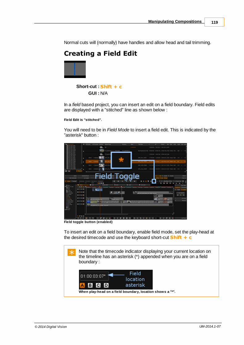
Manipulating Compositions 119
© 2014 Digital Vision UM-2014.1-07
Normal cuts will (normally) have handles and allow head and tail trimming.
Creating a Field Edit
Short-cut : Shift + c
GUI : N/A
In a field based project, you can insert an edit on a field boundary. Field editsare displayed with a "stitched" line as shown below :
Field Edit is "stitched".
You will need to be in Field Mode to insert a field edit. This is indicated by the"asterisk" button :
Field toggle button (enabled)
To insert an edit on a field boundary, enable field mode, set the play-head atthe desired timecode and use the keyboard short-cut Shift + c
Note that the timecode indicator displaying your current location onthe timeline has an asterisk (*) appended when you are on a fieldboundary :
When play-head on a field boundary, location shows a "*".

Compositions120
© 2014 Digital Vision UM-2014.1-07
Toggle Scene Cut to Normal Cut
Short-cut : N/A
GUI :
You can toggle a scene cut to a normal cut (and vice-versa) by pressing thetoggle edit button.
Joining Contiguous Segments
Short-cut : N/A
GUI :
You can join two contiguous segments together by selecting them both andpressing the Remove Matched Edit button :
The segments you are joining have to be from the same media source,adjacent to each other in the timeline, and in increasing source time order.Trimmed out frames from either of the segments is allowed, as the underlyingmaterial will still exist and the join operation can put the segment backtogether.
Shots View
The second view we have of the timeline is Shots view. To select Shots view,click the Shots tab or press the F3 short-cut key.
The Shots view shows a video mix-down of the shots in your compositionsuch that we only see the segments that are topmost in the timeline view. Weshow :
We show a single frame of each timeline segment.
An indication of any applied effect layers are placed on top (optionally).
Gaps in the timeline are shown as black shots.

Shots View 121
© 2014 Digital Vision UM-2014.1-07
The two illustrations below show the timeline view and its associated Shotsview.
Timeline view.
Shots view of timeline above.
The frame displayed is from the middle of the segment. This is notconfigurable currently.
Shots View Switches
To the left of the shots themselves are some buttons that affect the displayand ordering of the shots.
Thumbnails
This toggles the size of the displayed thumbnails.
Play-heads
Toggles the display of all play-heads or only the active play-head.

Compositions122
© 2014 Digital Vision UM-2014.1-07
Effect Bars
Toggles the display of the effects bars above the shot.
Src / Rec Switch
Toggles the display of the shots in record timecode order (default) or sourcetimecode order.
This will affect VTR layoff and is linked to Tapename Sort (below).Set to SRC for a Source Order (C) VTR layoff.
Handles Mode
Toggles handles mode.
Normally, we can only play the visible (non-handle) portion of a segment. Inhandles mode, we can step through and play entire shots, including playingthrough head and tail handles. The play-head position will update to show usour position within the shot and accounting for handles.
This requires us to be in SRC order view.
Tapename Sort
This will sort the shots to be in tapename order (then source timecode order).You must be in SRC timecode order (SRC switch enabled).
This will affect VTR layoff and is linked to Src/Rec Switch (above).Enabling this results in a Source Order Tape (C) VTR layoff.

Shots View 123
© 2014 Digital Vision UM-2014.1-07
Effect Indicators
Any applied effects are indicated above the shot using coloured bars : Baselayer, CC/FX layer, Master layer and Pan/Scan. If multiple FX or CC layersare present, these are indicated by small boxes in the LY bar :
In the illustration on the right, theshot on the left is the active shot(blue outline).
All effect layers have an appliedeffect (coloured bars) and thereare two CC/FX layers indicated(two boxes on LY bar).
Active shot on left, w ith effect indicator bars
You can toggle the display of the effect indicator bars using the
Marks
Timeline Mark In and Out points will be shown with dotted lines :
Handy Hotkeys
icon hotkey function
TAB Toggle full-screen mode, i.e. hiding the GUI
ESC Exit full-screen mode, back to GUI mode
G Zoom into the active region of the timeline

Compositions124
© 2014 Digital Vision UM-2014.1-07
F Fit the whole timeline into the viewing area
none + / - Zoom timeline in/out
none mouse wheel Zoom timeline in/out
noneCtrl + dragmouse left/right
Pan the timeline left/right
noneCtrl + Shift +drag mouseup/down
Zoom tracks in/out, showing bigger/smallerthumbnails
none Ctrl + F2 Toggle between standard timeline view andlarge panel view
none Ctrl + HOMESwitch to the next play-head making it theactive play-head
none HOMEJump play-head to the start of thecomposition
none ENDJump play-head to the end of thecomposition
none[ or DownArrow
Jump play-head to the start of the previousedit
none ] or Up Arrow Jump play-head to the start of the next edit
noneCtrl+[ orCtrl+Down
Jump play-head to end of the previoussegment
noneCtrl+] orCtrl+Up
Jump play-head to the end of the segment
I Set mark-in point at the play-head position
O Set mark-out point at the play-head position
P Set mark in and out points around selection
Ctrl + I Clear the mark-in point
Ctrl + O Clear the mark-out point
Ctrl + P Clear the both mark-in and mark-out points
none Shift + I Jump play-head to the mark-in point
none Shift + O Jump play-head to the mark-out point
V Splice a clip onto the active track
BInsert a clip onto the active track overwritingsegments if necessary
DELETERemove selected segments from thetimeline

Handy Hotkeys 125
© 2014 Digital Vision UM-2014.1-07
Remove marked region from the timeline
C Insert an edit/cut
none Shift + C Insert a field edit/cut
Ctrl + CRemove an edit/cut, rejoining two adjacentsegments
Ctrl + UToggles between Direct Select Mode andTrim Mode
none Ctrl + TToggles slip mode on/off, when in TrimMode, and activates the segment trimhandles
none Ctrl + YToggles slide mode on/off, when in TrimMode, and activates the segment trimhandles
none M Trims the active handle back 10 frames.
none < Trims the active handle back one frame.
none > Trims the active handle forward one frame.
none / Trims the active handle forward 10 frames.
none F3 Switch to Shot List View
none Ctrl+F3 Toggle large shots view / standard view
Versions 8

127
© 2014 Digital Vision UM-2014.1-07
When adding a media clip to a composition timeline it is possible to add it asa version of an existing clip segment instead of as a new segment.
By adding a version you preserve the underlying clip segment in thecomposition along with all the changes you have made to it (e.g. trimming oreffects). Versions therefore allow you to experiment with different clips, or tomake gradual changes to a clip segment and save each one as a separateversion until you decide which version you want to keep.
A segment containing a version is denoted on the timeline by a triangle in thecentre:
Grey triangles denote the presence of underlying versions in that segment,and a green triangle identifies the approved version. Approving a version issimply a mechanism that allows you to differentiate your preferred versionfrom all the others. You can change the approved version at any time.
Version Controls
The buttons for adding, approving, and deleting versions are on the timelinetoolbar:
Add a source (duplicate) version (for active shot).Hotkey : CTRL + N
Add a grade version (for active shot).
Approve current version.

Versions128
© 2014 Digital Vision UM-2014.1-07
Delete current version.Hotkey : SHIFT + N
Adding VersionsTo add a version you have to first determine which segment on the timelineyou want to version.
A single selected segment (orange) takes precedence
Otherwise, the active segment is versioned
When you're versioning it is not necessary to activate the trackbecause we are explicitly selecting a segment to version. However, ifthe track that the selected segment is on is locked, then versioningwill not work.
Once you have selected the timeline segment that you want to add a versionto you have two choices, you can either:
add a shot from the library as a new ungraded version (sourceversion), or add a duplicate version of the existing timeline segment (gradeversion)
Add New Source Version
Hotkey : CTRL + N
A new shot version is a different shot to the one that is already present in theselected segment of the timeline. It can be the same source media clip, but itis different from the shot on the timeline in that it will not have any gradingapplied.
To add a new shot version :
1. Select the media clip to add from the library

Adding Versions 129
© 2014 Digital Vision UM-2014.1-07
2. Select the timeline segment to add the version to
3. Press the Add Version button :
The media clip that you select to add as a version has to be at leastas long as the timeline segment used. You cannot add a media clipto a segment if the clip is shorter than the segment.
Once the new version has been added a triangle will appear in the centre ofthe segment to denote the presence of underlying versions, and the newversion will be the one that appears on top and visible in the viewer.
Add Duplicate (Grade) Version
To add a new duplicate grade version :
Select the desired timeline segment
Press the Add Grade Version button :
This will add another version of the same shot, retaining any grading andtrimming carried out up to that point. Any selected library clips will be ignored.
As with adding a new version, a triangle will appear in the centre of thesegment to denote the presence of underlying versions, and the new versionwill be the one that appears on top.
Handy Hotkeys
icon hotkey function
Ctrl + N Adds a selected clip from the library as anew version
none Adds a duplicate graded version of the shotselected on the timeline
Managing Versions
Viewing Versions
To view the different versions underlying a segment simply click on thetriangle in the middle of the segment. This will open up a drop-down list of allthe versions in that segment:

Versions130
© 2014 Digital Vision UM-2014.1-07
Two versions visible in dropped-down view.
You can change the active version by selecting any other version from thelist.
Versions are numbered Version 1 (original), Version 2 etc. To the right of theversion number is the Material Name.
Approving Versions
If you want to mark a version to denote that it is the preferred version, you cando so by approving it. To do this:
1. Select the version that you want to approve from the versions list sothat it is the active version, visible on the timeline
2. Select the segment on the timeline so that it turns orange 3. Press the Approve Version button on the timeline toolbar
The version indicator will change from grey to green to indicate that you arenow viewing the approved version:
Green triangle signifies the approved version.
If you later select a non-approved version to view, the indicator will turn backto grey.
You can change the approved version at any time, simply by selecting adifferent version as the active version and approving it following the stepsabove. This will set the previously approved version back to unapproved andset the new selection to approved.

Managing Versions 131
© 2014 Digital Vision UM-2014.1-07
Deleting Versions
Hotkey : SHIFT + N
To delete a version at any time:
1. select the version to be deleted so that it is the active version on thetimeline 2. select the segment on the timeline so that it turns orange
3. press the Delete Version button on the timeline toolbar :
The active version will be removed from the list and the next version in the listwill become the active version. At this point the version numbers will reshuffleto close the number gap created by the deleted version.
If on deleting a version there is only one version left, the triangular versionindicator will disappear from the segment and the segment will return to beinga regular segment without versions.
Version operations are always applied to the active or selectedsegment on the timeline, so the active/selected segment must beappropriate for the operation being carried out otherwise no actionwill be performed.

Rendering 9

133
© 2014 Digital Vision UM-2014.1-07
Adding effects to segments, or transforming sources for output, willrequire CPU processing: rendering. This rendering normally happenstransparently in the background as you work, and in mostcircumstances requires no explicit intervention.
Master layer effects are rendered in realtime on the graphics cardGPU and do not require system CPU processing.
You will have to render your composition if you :
Add effect layers or
Add adjustment segments
Create and use proxy sources (1:1 Clone, 2:1 etc.)
Create source caches (for example, from MXF, Quicktime or Red rawfiles)
Proxy Source vs Source Cache
A proxy source and a source cache are technically the same thingbut we differentiate them because :
a) A source cache is always 1:1 (equivalent to 1:1 Clone proxy) andb) A source cache requires no explicit proxy format created on the
project. The cache proxy is created automatically andtransparently.
Note that (b) is only true if you leave the createClone parametertrue (for the relevant file format) in the preference file :
C:\Phoenix\2014_1\root\Clip.prefs

Rendering134
© 2014 Digital Vision UM-2014.1-07
The following buttons control the rendering process in your project:
Render Controls
The automatic render controls toggle between different rendering behaviour,and the manual render controls let you set off specific rendering tasks.
Automatic Render Controls
These controls are automatic in that they are toggled on or off, and affect therender processing from then on.
Render BG
Default : On
With The Render BG button enabled, some resources are devoted torendering the active composition in the background while you work. Thisbackground rendering will only occur if the application is otherwise idle and willpause when a more important workload surfaces (e.g. if you play the timeline,or need interactive response during grading adjustments).
By default, all new projects have the Render BG button enabled.

Automatic Render Controls 135
© 2014 Digital Vision UM-2014.1-07
Render BG can greatly reduce rendering requirements with littleimpact on your interactive work. It is generally a good idea to leave itenabled.
Render FG
Default : On
This will cause unrendered portions of the timeline to be rendered for displaywhen playing timeline. If this button is disabled, playback of unrenderedtimeline areas will display grey "not generated" frames :
Cache
Default : Off
The Cache button is relevant to composition playback only. During timelineplayback, any unrendered frames are rendered on-the-fly dynamically fordisplay (if Render FG is enabled) but are not normally saved to disk. Enablingthe Cache button causes any unrendered frames encountered duringplayback to be saved to disk.
This rendering is identical to that done with Render BG enabled orwhen doing a Render Output operation, except it occurs only duringtimeline playback (of unrendered frames).
Enabling the Cache button may affect timeline playback due to theextra work required to save out rendered frames to disk.

Rendering136
© 2014 Digital Vision UM-2014.1-07
Transition
Default : On
The Transition button enables the rendering of transition effects (e.g.dissolves).
Manual Render Controls
These controls are in the project library and let you set off specific rendertasks, such as rendering a specific portion of the timeline, or rendering andexporting media.
Render Output
Pressing the Render Output button will start (or queue) a render task for thecurrently active composition.
Only visible video tracks are rendered (we render a "mix-down").
If you have marked an in-point, we will render from this position until we reachan out-point, or the end of the composition. If there is no in-point, we exportthe entire composition. If there is a Mark In and Mark Out set, we render anyunrendered material lying between them.
Export Media
For a discussion of the Export Media options, see the Exporting section.
Task Queue
Render tasks and their status will appear in the Task Manager. This isaccessible via the Library/Tasks button. Tasks are displayed in the Taskmanager window, with their progress and status :

Task Queue 137
© 2014 Digital Vision UM-2014.1-07
Task Manager
Render tasks include both Render Output, Render BG and Export Mediatasks.
Suspend Tasks
The Suspend button will suspend all running tasks.
Delete Tasks
You can delete one or more tasks by selecting them and pressing the Deletebutton.

Exporting 10

139
© 2014 Digital Vision UM-2014.1-07
There are two export options available from the Library :
Library / Export buttons
Export Media renders and exports a composition to a chosen file format(DPX, TIFF, MXF etc.). Export Composition exports the active composition as a list file e.g. an EDL
Version 2014.1 also lets you export to an AAF composition via ..Export Media. This requires the composition you export as AAF tohave been created from an AAF.
Export Media
The Export Media button will let you export the active composition to a file (orsequence of files) in your chosen location and in your chosen format.
If not already rendered, an export will render all applied effects.
If you have marked an in-point, we will export media from this position until wereach an out-point, or the end of the composition. If there is no in-point, weexport the composition from the start until we reach an out-point or the end ofthe composition.
See File Format Support for supported file formats.
From the library, press the ..Export Media button, this will launch the exportbrowser and let you navigate to the desired export location.

Exporting140
© 2014 Digital Vision UM-2014.1-07
The Export BrowserThe Export Browser consists of a number of separate elements that let you :
Navigate to the base folder you wish to write the exported frames to
Choose the desired file format and format options
Choose the export mode (default is record timecode order, as asingle clip)Choose any global options to set (some depend on export modechosen)Choose the filename (if any - default to numeric names only)
The various component parts of the Export Browser are shown below.
Navigate to the desired folder using the standard file browser controls. Set thedesired file format, format options (if any), export mode and global optionsusing the controls at the bottom of the browser.

Export Media 141
© 2014 Digital Vision UM-2014.1-07
Export Path Preview
A preview of the path and filename we will create using the current settings isdisplayed at the bottom on the browser window.
The following settings :
Current folder : Z:\projects\SH_77TH\exports\van3d\
Filename typed : $c_outputcc..
Folder Hierarchy set : $c_$o\$r
will preview as shown below :
File Format and OptionsUse the drop-down list to select a file format for your export. Options availablefor the selected format will be displayed in the Format Options panel below :
See File Format Support for supported file formats.
Switching to a different file format will reset the Global Options totheir default settings.
Filename and Number
Name your exported sequence(s) by typing in a name in the text box. This will

Exporting142
© 2014 Digital Vision UM-2014.1-07
be the base name for every exported shot (even when multiple shots arecreated on export).
If you do not type in a base name, file names will be numeric only e.g. 007845.dpxNumbers are added automatically to exported sequences andcorrespond to the frame timecodes. The numbers thus depend on theselected export mode (and may be record or source timecodes)File extensions are added automatically
Number Handling
Frame numbers will be added automatically on export, zero-padded to thespecified width (Frame Padding). The frame numbers correspond to therecord (Rec) or source (Src) timecode as per the chosen export mode.
Because numbers are added automatically, some care has to be taken if youchoose to type in numbers as part of the base file name.
If you type in numbers as part of the base file name :
Rec TC modes use the numbers as the starting timecode/numberfor every shot created. If shots are exported to multiple folders, everyshot in every folder will start at the given number.
Src TC modes ignore any numbers and always use the sourcetimecode for shots created.
A filename entered as test will usually result in a file calledtest090000.dpx (or similar). To put another "." before the numerics, enter a filename test..(note the two dots).This results in a file called test.090000.dpx.
Using Variables in File Names
You can also use variables in the file entry box e.g.
$t_graded_
might expand to a base filename :
newrtt1_graded_
See the Folder Hierarchy and Variables for a list of variables available.

Export Media 143
© 2014 Digital Vision UM-2014.1-07
Examples
Filename Pad Sample File Created Note
(nothing typed) 6 078456.dpx
4883 7 0004883.dpx A Rec TC exportmode
4883 7 0000096.dpx A Src TC exportmode
testexport 7 testexport0006734.dpx Frame Padding = 7
$c_graded.. 0 shot677_graded.89345.dpx
Global OptionsThe Global Options panel displays options available to all file formats.
Export Mode
The export mode determines how a composition is exported. See ExportModes below.
Frame Padding
Use this slider to choose the width of frame numbers added to exportedsequences. Numbers are zero-padded.

Exporting144
© 2014 Digital Vision UM-2014.1-07
Number FramePadding
Result
789 0 789
789 6 000789
456789 4 456789
Target
Export graded material or source (ungraded) only.
Target: Output Output graded material (as per timelinePlay Output view)
Target: Source Output source (ungraded) material (asper timeline Play Source view).
Handle Size
This sets how many head and tail handles frames are exported with eachshot.
You can only set handles when using a Multi mode export (seebelow).
Caching
The Cache option lets us choose whether to save (internally) any cacherenders or proxies created as part of a render export process.
Cache : Description
None No internal caches or required proxies are saved in theapplication data store.
Proxies Save any required proxies.
All Save both caches and proxies created (if any).

Export Media 145
© 2014 Digital Vision UM-2014.1-07
SMPTE Level Clip
The SMPTE Level Clip toggle button will clip the exported frame colour datato a SMPTE legal range (64-940 for 10 bit data).
This is only available inside a Linear (SMPTE) colour space project.
See the Colour Scaling section of the Setup Manual for a discussionon colour space and scaling.
Export Modes
The export mode determines which shots we export, what timecodes we use,how we order the shots and (usually) whether to create any folder structure.
There are five modes :
Mixdown Rec TC
Visible Multi Rec TC
Tracks Multi Rec TC
Visible Multi Src TC
Tracks Multi Src TC
The default is Mixdown Rec TC i.e. a single mixed downsequence using record timecodes.
Each mode consists of important keywords that describe how the modeworks :
Mixdown A single clip is created on export.
Multi Multiple clips are created on export
Visible A shot is only exported if any part of it is visible.

Exporting146
© 2014 Digital Vision UM-2014.1-07
Tracks Shots are exported per track. In this mode, clips are exportedeven when fully hidden by other clips.
Src / Rec Clips are exported in source or record timecode order. Thisalso affects the timecodes used (header and filename).
Track MonitoringEvery mode obeys track monitoring.
An un-monitored track never takes part in any export mode.
Multi-Mode Exporting
Care needs to be taken when using multi-mode export.
Multi-mode exports can cause shots to be overwritten on export.
Due to the fact that some shot metadata can overlap (e.g. timecodes,tapenames etc.), it is possible to export in such a way that shots getoverwritten.
For this reason, multi-mode exports will warn you if you do not use an eventfolder output structure when exporting :
If you know that your output clips do not overlap, you can press the OK buttonto continue.
See Folder Hierarchy and Variables.
Mark In/Out Points
Every mode will take account of any in or out points marked.
Begin an export from an In point.End the export at any Out point (or the end of the composition).

Export Media 147
© 2014 Digital Vision UM-2014.1-07
Mixdown Rec TC
Exports as :
Single clip - a flattened, mixed-down contiguous sequence into onefolder.BL, AUX and filler included in export
No handles allowed
Record order and timecodes
Filler will be exported as black frames at the level defined by projectcolour space.
Example
No folder hierarchy or variables required.

Exporting148
© 2014 Digital Vision UM-2014.1-07
Visible Multi Rec TC
Exports as :
Multiple clips created
No BL, AUX or filler
Handles allowed. Adjust via Handle size slider :
Record order and timecodes
Clips are only exported if they are visible (even partly)
Example
Here, we use event folders (see Folder Hierarchy and Variables) to ensureexported shots do not overlap.
See Multi-Mode Exporting for a description of why multi-mode mightcause exports shots to be overwritten sometimes.

Export Media 149
© 2014 Digital Vision UM-2014.1-07
Tracks Multi Rec TC
Exports as :
Multiple clips created
No BL, AUX or filler
Handles allowed. Adjust via Handle size slider :
Record order and timecodes
Clips are exported even if hidden by other clips.
Example
Here, we use event folders (see Folder Hierarchy and Variables) to ensureexported shots do not overlap.
See Multi-Mode Exporting for a description of why multi-mode mightcause exports shots to be overwritten sometimes.

Exporting150
© 2014 Digital Vision UM-2014.1-07
Visible Multi Src TC
Exports as :
Multiple clips created
No BL, AUX or filler
Handles allowed. Adjust via Handle size slider :
Source order and timecodes
Clips are only exported if they are visible (even partly)
Example
Here, we use event folders (see Folder Hierarchy and Variables) to ensureexported shots do not overlap.
See Multi-Mode Exporting for a description of why multi-mode mightcause exports shots to be overwritten sometimes.

Export Media 151
© 2014 Digital Vision UM-2014.1-07
Tracks Multi Src TC
Exports as :
Multiple clips created
No BL, AUX or filler
Handles allowed. Adjust via Handle size slider :
Source order and timecodes
Clips are exported even if hidden by other clips.
Example
Here, we use event folders (see Folder Hierarchy and Variables) to ensureexported shots do not overlap.
See Multi-Mode Exporting for a description of why multi-mode mightcause exports shots to be overwritten sometimes.

Exporting152
© 2014 Digital Vision UM-2014.1-07
Folder Hierarchy, Presets andVariables
The Folder Hierarchy panel lets you create a folder structure as part of anexport process.
The Folder Hierarchy panel does not create filenames, only folders.See the Filenaming section for naming exported files.
Folders are created automatically below the current file browser folder (the"base" folder) and can include shot names, tapenames, project name andmany other metadata elements (see the Variables section below).
You can create a folder hierarchy on export by :
Choose a preset from the drop-down listorEnter a hierarchy definition in the text box (including variables)
You should consider using a folder hierarchy when doing any multi-mode export (e.g. Visible Multi or Tracks Multi). A multi-mode exportmay cause exported frames to be over-written. See Export Modes.

Export Media 153
© 2014 Digital Vision UM-2014.1-07
Presets
Presets are pre-defined folder structures available in a drop-down list for easeof selection and re-use. When selected, the preset will also be written into thetext box and can be edited as required.
A back-slash character ("\") delimits folders.
Manual Entry or Edit
You can create your own folder structure by typing in preset variables andother text strings in the Folder Hierarchy text box.
You can create a folder structure by separating the elements witha back-slash character "\".
Saving a Preset
Pressing the Save button will add your folder hierarchy definition to thedrop-down list.
Deleting a Preset
Presets are stored in a plain text file in the application root folder :
C:\Phoenix\2014_1\root\ExportFolder.prefs
ExportFolderPresets[ Preset "$e" Preset "$t\$c\$e" Preset "$o$e" Preset "$o\$c_$n\$r"]
To delete a preset, remove it from this file, save the file and restartthe application.

Exporting154
© 2014 Digital Vision UM-2014.1-07
Variables
The following variables are available :
Var Description Note
$n Material name NONAME used if material nameempty.
$e Event number See below for the event numberformat.
$o Composition name NOCOMP used if composition nameempty.
$p Project name
$r Resolution. This will be represented asWidthxHeight in pixels e.g. 2048x1556
$t Tape name NOTAPE used if tape name empty.
$c Clip name NOCLIP used if clip name empty.
$O Original material name NOORIG used if original materialname is empty.
$f Frame number Replaced with a numeric framenumber zero-padded to specified Frame Padding.
Event Padding
By default, event folders start at 1 and are zero-padded to 4 digits i.e. folderswill be named :
0001/0002/..
You can adjust the start number and default event number padding by editingthe export section in the main preference file general.prefs found in the folderC:\Phoenix\2014_1\root :
C:\Phoenix\2014_1\rootgeneral.prefs
export{ eventStart 1 eventPadding 4}

Export Media 155
© 2014 Digital Vision UM-2014.1-07
Export File Formats
Choose a file format to export to, via the format drop-down list at the bottom ofthe window.
Each available format will offerits own independent set ofoptions via the Options button.
Drop-down format list
For a full list of supported formats see the appendix Format Support.
Export Composition
This exports the entire composition as a list file (i.e. metadata, not media).
In the Library, press the ..Export Com position button to open the ExportComposition dialog.
Then :
Use the file browser to navigate to the desired location for the list file
Choose the list format
Set list options
Type a list file name
Press the Export button

Exporting156
© 2014 Digital Vision UM-2014.1-07
Export Composition dialog
Note that the export ignores :
Marks
Track enable
Track visibility
If you want to export some shots, not the entire composition :
copy the composition (Library/Copy)
delete unwanted shots (with ripple mode off)
export the copy.
You can export a mixdown of all tracks, or a specific track only via the optionsdialog.
File extensions are added automatically.
List Format
Choose the export format from the format selector drop-down list :
The supported export list formats are:
EDL (.edl)
Cut List (.ctl)
ALE (.ale)

Export Composition 157
© 2014 Digital Vision UM-2014.1-07
See the appendix for a description of the list formats.
EDL/CTL Options
The ..Options button is available for the EDL and CTL formats.
This will open a new dialog window and let you set various options for thechosen output list format.
EDL Options
Video Mix Down
Selecting Video Mix Down will export shots from all tracks with "mixed" downview i.e. shots/cuts as seen from the top track downwards.
Solo Video Track
If you have more than one video track, use this drop-down list to select thetrack to export.
Clip Details
Add extra metadata to each exported shot (e.g. clip name, file name) e.g.
* FROM CLIP NAME: A005* FROM FILE: T:\media\images\tc.00000.dpx* FROM COMMENT: Check this is OK later
The comment is taken from the shot description column in theLibrary.
Cuts Only
This option will only export cuts, no retimes or dissolves.
CMX Legal
The CMX Legal option will disallow the creation of illegal CMX EDL files. Theis particularly important with regards to the tapename.

Exporting158
© 2014 Digital Vision UM-2014.1-07
A legal CMX tapename will have :
no spaces
eight characters or less.
If you disable the CMX Legal option, you will be limited to 36character tapenames. However, the tapename must still contain nospaces.
When you have adjusted the export properties, close the options dialog andpress the Export button on the bottom right of the file browser window.
The export progress report will be shown in the main Library screenor via the library T asks window.
Output Timecodes
The source and record event timecodes can be output as a timecode or aframe count.
CTL Options
The CTL format has a restricted set of options available (Video Mixdown andSolo Video Track) with the same meanings as for EDL export above.

Scene Detection 11

Scene Detection160
© 2014 Digital Vision UM-2014.1-07
The Scene Detect module can perform an automatic detection of scenechanges in a contiguous segment, adding scene edits where found. Whenenabled, the detection will begin from the current location of the active play-head.
Setup
To configure scene detection, switch to the Scene Detect tab.
Parameters
Sensitivity
This numeric slider is for adjusting the sensitivity towards detectingscene changes. The lower the value the less sensitive scene detectionis going to be, so changes have to be very obvious to trigger a scenechange, whilst the higher the value the more sensitive to changes thescene detector is going to be and smaller amounts of changes willtrigger an edit. If this value is too high then edits will be inserted in themiddle of a scene, whilst if the value is too low scene changes may bemissed.
Lead In
This numeric slider is for specifying the minimum number of frames toleave in a segment before the next edit is inserted, with the default set to5 frames. So at its highest sensitivity setting, the scene detector might bedetecting scene changes every frame, but it will only insert an edit every5 frames.
Field Boundaries
If enabled, edits can also be inserted at field boundaries on interlacedmaterial.
When working with interlaced material scene changes sometimesoccur between fields as opposed to between frames, so by turning on

161
© 2014 Digital Vision UM-2014.1-07
this option you allow the scene detector to insert edits where the scenechange actually occurs. If this options is turned off, then the edits will beinserted on the frame boundary rather than where the scene changeactually takes place.
Colour
Scene detection is dependent on the material colour format andespecially whether the input is linear or logarithmic. The default settingwill be taken from the project colour scaling setting. Setting the incorrectvalue here may result in incorrect scene change detection.
See The Setup Manual for a discussion of colour scaling.
Panel Audio Notify
Enabling this will cause an audible notification when a scene change isdetected. The sound is produced via the control panel.
Usage
Once you have adjusted the settings, switch back to the T im eline tab andmove the active playhead to the start of the segment you want to divide up.
The video track needs to be enabled for scene detection to work.
Turn on the Scene Detect button to start the scene detection process :
You will see the edits appearing on the timeline and a progress report will beshown in the Library screen :
To stop scene detection at any point just toggle off the scene detect button.
Viewer Tools 12

163
© 2014 Digital Vision UM-2014.1-07
The viewer tools menu is opened from the project desktop by :
Pressing the F12 hot key or
Clicking the up-arrow button on the bottom-right of the viewer panel asshown below.
viewer toolbox menu
The viewer tools pop-up menu contains setup for the following functions:
compare mode
head-up display (HUD)
grids
masks
graphs
histogram
colour management system (cms)
These functions can be turned on/off from within the menu pop-up window, orfrom the corresponding icons on the desktop once the settings for eachfunction have been selected via the pop-up menu.

Viewer Tools164
© 2014 Digital Vision UM-2014.1-07
Tool Configuration
The available options are user configurable for the following tools :
HUD
Grids
Masks
Graphs
Head-up Display (HUD)
Hot key : F7
The head up display (HUD) overlays information about the frame/shot beingviewed on top of the displayed frame. The information that is displayed is userconfigurable (content and position).
The display of the HUD can be toggled on/off using the H UD button in theviewer options menu or the hot key S.
This is display only and is not rendered into any final output.

Head-up Display (HUD) 165
© 2014 Digital Vision UM-2014.1-07
Options
This drop-down list defines what HUD information to display over the image.
Sample HUD definitions available are:
location - source and timeline (record) information, in both frames andtimecodefull info all - full information available
full info BI - full information available inside image area (burnt intoimage)
full info all location
logo
Hud Specifications
For the HUD format and specification, see Appendix HUDs Specification.

Viewer Tools166
© 2014 Digital Vision UM-2014.1-07
Grids
Hot key : F8
The grids functionality allows you to apply preset grid overlays to your image.Grids are displayed over the viewed image and are useful for displaying lines,borders and layout information.
This is display only and is not rendered into any final output.
Options
This drop-down list defines the grids available to display over the image.

Grids 167
© 2014 Digital Vision UM-2014.1-07
Sample grids included are:
full border
16:9 grid
16:9 blank
1.85 grid
2.35 grid
Grid Specifications
For the Grid format and specification, see Appendix Grids Specification.

Viewer Tools168
© 2014 Digital Vision UM-2014.1-07
Masks
Hot key : F9
Masks crop (black out) rectangular areas of the displayed image.
Press the masks button to activate the picture mask function and then selectthe mask that you want to apply from the drop-down menu.
This is display only and is not rendered into any final output.
Options
This drop-down list defines which mask to apply to the image.
Sample masks included are:
user
4:3
16:9
1.85
2.35

Masks 169
© 2014 Digital Vision UM-2014.1-07
2.35 mask set
User mask
The user mask allows you to interactively draw your own mask over theimage.
In User mask mode, press the mask edit button :
A rectangular overlay will appear over the image with handles on each corner.You can interactively resize the rectangle to create your mask by draggingeach of the corners.
Edit User Mask
Use mouse to drag rectangle corners to resize mask.
Move mask by picking and dragging center point.

Viewer Tools170
© 2014 Digital Vision UM-2014.1-07
Disable Edit Mode
Turn off edit mode to see mask applied to image.
Mask Specifications
For the Mask format and specification, see Appendix Masks Specification.
Graphs
Hot key : F10
The graph tool serves three purposes :
It shows the RGB response curves of your shots
It shows the value ranges using dotted lines on the graph (includingimportant value levels)It defines how and where the histogram graph will be displayed whenenabled

Graphs 171
© 2014 Digital Vision UM-2014.1-07
This is display only and is not rendered into any final output.
Options
This drop-down list defines available graphs and histograms.
Note that graphs ignore the "hist" and "parade" settings, using onlythe location (e.g. center), size (e.g. PAL) and scaling information(e.g. cineon).
These options are configured via plain text files (*.graphs) located inside thefolder specified inside the general.prefs file (variable monitorGraphDir).
Named sections inside these files specify the listed options above.
Example graph locations are :
SW - south-west in image
Center - center of image
Scaling refers to the dotted-lines overlaid on the graph to indicate importantgraph data points i.e.
Cineon - dotted lines at default cineon black and white points (95/685)
Video - dotted lines at YCrCb SMPTE levels (64/940)
cineon sw With a grade

Viewer Tools172
© 2014 Digital Vision UM-2014.1-07
Graph Specifications
For the Graph format and specification, see Appendix Graphs Specification.
Histogram
Hot key : F11
The histogram tool displays a graph of RGB colour information :
For the entire image or
A selected area of the image
This can be useful in helping identify how much colour correction is needed.
The button on the left activates the histogram, which will be displayed in themanner and location defined by the current graphs setting.
This is display only and is not rendered into any final output.

Histogram 173
© 2014 Digital Vision UM-2014.1-07
Options
The available graph positions and types are as per the graphs.
Unlike the Graphs settings, the Histogram settings can be set in ahistogram mode (RGB values overlaid) or a parade mode (RGBvalues separated in columns).
Setup
Graph Setup
Toggle display of graph.
Reset graph active area to default (whole image)
Set the scale to use for the reported graph values.Values : 8,10,16 bit or 0-1.Default : 10bit

Viewer Tools174
© 2014 Digital Vision UM-2014.1-07
Area Selection
By default, the histogram will display RGB values related to the entire image.
You can select a region of interest with the mouse interactively.
You can also click anywhere on the image to display information about asingle pixel.
Display Modes
Histogram Parade
Note that you can display graphs (colour curves) and histograms (orparades) simultaneously.

Histogram 175
© 2014 Digital Vision UM-2014.1-07
Audio Waveform
The Audio Waveform button displays the audio segment waveform overlaidon your monitor output. The waveform will update dynamically as thesegment plays.

Viewer Tools176
© 2014 Digital Vision UM-2014.1-07
Audio segment waveform shown overlaid on monitor
Handy Hotkeys
icon hotkey function
F12
Toggles the viewer options panel on/off.
none Ctrl + 5Saves a snapshot of the current imageas a reference image
none 5Toggles the compare source, betweendynamic selection and the referenceimage
F6 Turns compare mode on/off
none Shift + F6Changes the compare mode (wipe/dual/cut)
none Ctrl + F6Changes to the next dynamic comparesource
F7 Turns the Head Up Display (HUD) on/off
none Ctrl + F7 Changes to the next HUD definition
F8 Turns Grids on/off
none Ctrl + F8 Changes to the next Grid definition
F9 Turns Masks on/off
none Ctrl + F9 Changes to the next Mask definition
F10 Turns Graph Curves on/off
F11 Turns Histogram on/off
Shift + F11 Resets Histogram
none Ctrl + F12Changes to the next Histogram/Graphdefinition
Ctrl + F12 Turns CMS on/off

Handy Hotkeys 177
© 2014 Digital Vision UM-2014.1-07

Comparison Mode 13

179
© 2014 Digital Vision UM-2014.1-07
Hot key : F6
The compare function allows you to compare the frame you are viewingagainst other instances in your timeline, against a reference frame, or againstdifferent versions of the frame itself.
Compare Modes
The Compare options are selected via the drop-down list on the right-handmenu. Show this menu using the F12 hot key. The options listed inside aproject may be a subset of the total available because you may want to limitthose you can cycle through. The options available in this list is configured inthe Control Panel preference section.

Comparison Mode180
© 2014 Digital Vision UM-2014.1-07
Split mode. You can interactively change the
split using the mouse or panel.
Dual mode. Comparison side-by-side.
Split
Selecting split mode will allow you to wipe between the currently active framein the viewer and your comparison image.An overlay control will appear in the viewer, separating the two frames. Thiscontrol can then be manipulated interactively by dragging it in any arbitrarydirection, to make comparisons between the two images. It is also possibleadjust the overlay during playback.
Dual
Selecting dual mode will display two images in the viewer. The currentlyactive frame will appear on the left, and next to it on the right will be yourchoice of comparison image.
Cut
Selecting the cut mode will allow you to toggle between the current frame andyour comparison image in full size. Only one image will be displayed at a time,determined by pressing the compare button on/off. When the compare buttonis off you will see the current frame, as normal, and when the compare buttonis on you will see the comparison image.
A full screen compare can be achieved by taking a snapshot of thecurrent image and moving to a new frame for comparison. Press CTRL + 5 to grab the current image. Holding down the 5 key at anyfuture time will display the snapshot frame in place of the currentimage in the monitor.

181
© 2014 Digital Vision UM-2014.1-07
Difference Modes
There are 3 difference modes:
Diff red
Diff luma
Diff monochrome
Each one will show you the difference between the current frame and thecomparison frame in the specified colour.
Comparison Image
Once you have selected your compare mode, you can close the viewer toolsmenu (F12) and bring up the Memories screen to select what we willcompare against.
Select the ..Mem ories button :
Select the Shot button :
Choose a Comparison Target from the drop-down list below Shot :

Comparison Mode182
© 2014 Digital Vision UM-2014.1-07
You can compare against targets :
Track - the track below
Head - the secondary play-head
Event - a selected event
Revert - the previous grade on the shot
Source - the segment source
Groups - a selected group member

Stereo Multitrack 14

Stereo Multitrack184
© 2014 Digital Vision UM-2014.1-07
A Stereoscopic mode can be enabled on a per project basis. This allows boththe display and the grading of stereo left and right channels.
Setting Up StereoFor stereo support, you need to :
1. Enable a project setting and 2. Choose your stereo mode (if using an interlaced DVI device).
DVS Centaurus II Licensing
You will need the DVS Centaurus II license option Multidevice touse stereo multitrack mode SDI output. See the DVS Centaurus IIVideo section of the Setup Manual for more information.
Project Setting
Stereo is enabled independently per project. To enable stereo on a project,select the project on the main project screen and select the StereoscopicOutput tick-box :
Application Preferences
Two modes of stereo channel output are supported, SDI video andinterlaced DVI.
SDI
Output of left and right stereo on SDI channels A and B through a DVSCentaurus II video board.
You will need to enable your SDI I/O card via :

Setting Up Stereo 185
© 2014 Digital Vision UM-2014.1-07
Preferences / Monitoring/VideoIO : Enable SDI I/O Card
Interlaced DVI
Output of interlaced stereo through DVI to a supported display device.
If your stereo display device uses an interlaced DVI signal, enable thisvia :
Preferences / Monitoring/VideoIO : Interlace Stereo DVI Output
Interlaced Stereo mode is incompatible with OpenGL read-back and will be hidden if read-back is enabled.
Using StereoIf Stereoscopic Output is enabled for a project, stereo display output will besent to the configured stereo display device (SDI or DVI) automatically.
Composition tracks V1 and V2 will both be sent to the display device as theleft and right stereo channel.
Stereo channel SDI output order :

Stereo Multitrack186
© 2014 Digital Vision UM-2014.1-07
Track Stereo SDI Output
V1 Left A
V2 Right B
You can reverse this order via the toolbar button :
or by changing the general.prefs parameter :
reverseStereoOutput
This parameter is inside the IOCard section of the preference file.
Viewing
You can view and compare the two stereo channels by choosing a comparemode between the two tracks. Compare modes are described in theComparison Mode section.
Multitrack Grading
You can grade both stereo channels at the same time (and apply notes toboth channels) by enabling Multitrack Grading.
Switch to Memories mode :
Then, switch to Shots mode and enable Multitrack Grading using the buttonshown below :

Using Stereo 187
© 2014 Digital Vision UM-2014.1-07
Shots that are grouped into multitrack mode are shown with green triangleson their right-hand edge :
Multitrack shots shown in group
Note that multitrack mode will only enable (on both tracks) if the twotracks are the same length.
The render indicator bar also shows the render status of each trackseparately :
Each track now has an independent render status bar
Grades will now be applied to both the top and bottom tracks.
A grade will only be applied to a monitored track :

Stereo Multitrack188
© 2014 Digital Vision UM-2014.1-07
Stereoscopic Depth Grading
The Stereoscopic Depth Grading button will cause Pan, Tilt and Rotate Pan/Scan transforms to be applied normally on the top track but in reverse on thetrack below.
This can easily be seen in the track thumbnails as shown below :
Track thumbnails show that top track has positive pan. This is reversed on the bottom
track.

Colour Management 15

Colour Management190
© 2014 Digital Vision UM-2014.1-07
Hot key : CTRL + F12
The Colour Management System (CMS) lets you apply colourtransformations to your shots. These transformations are user configurableand defined in a 3D colour cube file which is loaded into the application ondemand, or specified as part of an project output format.
To use a CMS Look Up Table (LUT), you need to define the project LUT typeon the main project setup screen.
Some samples colour cubes have been provided.
If CMS was not selected for the output format that you are viewing then theCMS option will appear disabled in the viewer tools menu. To activate theCMS option you can simply exit your project, add CMS to your projectconfiguration, then re-open your project.
Once you have activated the CMS option, you can apply the CMS by pressingthe CMS toggle button in the viewer tools menu:
Alternatively, you may have chosen to 'burn-in' the CMS to your output format(via the project configuration options) in which case the CMS will bepermanently applied and you will not be able to toggle it on/off.
If you want to change the colour cube that you are using, you can use the ..CMS Setup button to select a different LUT file.

Effects 16

Effects192
© 2014 Digital Vision UM-2014.1-07
A variety of colour correction tools and effects are available, each of whichcan be applied independently to individual segments on the timeline.
Since each segment can have a different set of effects, the effects tree to theleft of the composition editor will always show all the colour correction layersand effects that can be applied to the active segment on the timeline:
As the active segment changes, the effects tree will change to show only theeffects corresponding to that segment.
A selected segment is orange, but this does not override the activesegment with regards to the effects tree.
By default, only the basic colour correction layers appear in the effects tree.These are the Base layer and the Master layer. Additional colour correctionlayers and effects can be added using the effects toolbar, which runs alongthe bottom of the composition editor.
Segments that have had grading/effects applied are differentiated on thetimeline from those that haven't by having a lighter segment colour; i.e.segments with effects are whiter than the grey segments without effects.
In addition, if you have thumbnails enabled, the thumbnails in each timelinesegment will show the first and last frames of the segment with the effectsthat have been applied.

193
© 2014 Digital Vision UM-2014.1-07
The following effects operations will be covered in the next sections:
colour correction layers
editing effects
managing effects layers
adding user effects
transition effects
Colour Correction LayersEvery segment has two colour correction layers available by default, the Baseand Master layers.
The Base layer is a fixed colour adjustment layer at the beginning ofprocessingThe Master layer is a fixed colour adjustment layer at the end ofprocessing.
The Base layer also contains isolation effects, whilst the master layer doesnot.
These layers are displayed in the effects tree, and as the active playheadchanges segment the effects tree updates to list the effects available for the active segment on the timeline. To expand an effects layer, click on the arrowtoggle button next to the layer name:
You can control the effects that are available in the base and master layersand the order that they appear in the effects tree (which is the order they areprocessed in) by editing the following lines in the main preference file general.prefs (See Appendix Application Preferences) :
defaultRealTimeEffectIDs - effects available in Master layer
defaultSecondaryCCEffectIDs - effects available in Base andCC Layers
Not all effects are necessarily available by default, and you can add/remove

Effects194
© 2014 Digital Vision UM-2014.1-07
effects from either layer by adding/removing the appropriate IDs from thepreferences file.
See appendix Effect Identifiers for a list of available effect you canuse in these preference settings.
Effects Layer
The Effects layer, at the top of the effects tree, contains no effects by default.When you add user effects to a segment they will be listed here.
Additional Secondary ColourCorrection Layers
Additional colour correction layers can be added to the active segment bypressing the Add Layer button on the effects toolbar. This will add thelayers to the effects tree. The layers are numbered from 1 according to theirposition within the effects tree:
These additional layers will have the same set of effects available as the baselayer.
You can add an unlimited number of secondary colour correction layers andeach contains shapes, keys and mattes :

Colour Correction Layers 195
© 2014 Digital Vision UM-2014.1-07
Layers are always added to the active segment only, they are notadded to selected segments or any other segments.
Rename a CC Layer by selecting it and pressing the F2 key.
Layer Router
It is possible to use the layer router (at bottom of every layer) to set variouslayer specific parameters, including how layers are composited (blended) ontop of each other.
The Router has an effect tab containing the parameters available.
It is possible to change the layer opacity, or bypass the layer completely.
Blend Mode
The layer router includes a Blend Mode that controls how the layer iscomposited over layers below. It has the following settings :
Over
Add
Subtract
Dodge
Burn

Effects196
© 2014 Digital Vision UM-2014.1-07
Lighten
Darken
Hardlight
Softlight
Screen
Overlay
These modes will be familiar to Adobe Photoshop users.
Managing Layers and Effects
Re-ordering Layers
You can re-arrange any layers and effects that you have added to the effectstree, not including the default 'effects', 'base', or 'master' layers.
Effects are processed top-down as they appear in the effects tree,so by re-ordering effects you are changing the order that they areprocessed in.
By default, any user effects that you add are placed above the colourcorrection layers in the 'effects' layer. If you want to be able to place usereffects in-between the colour correction layers, you just need to add them as layer effects instead. These two options are covered in the adding effectssection.
To re-order a layer :
1. Select the layer (it is highlighted)2. Hold down the mouse left button and drag the layer up/down the
effects tree (an orange guideline appears)3. Release the mouse button when repositioned correctly.
4. When you've reached the place where you want to place the layersimply let go of it with the mouse. All the other layers will

Managing Layers and Effects 197
© 2014 Digital Vision UM-2014.1-07
automatically shuffle down and be renumbered accordingly.
You cannot place any effects after the 'master' layer. The masterlayer is always the last layer in the pipeline.
Renaming Layers
To rename a CC layer :
1. Select the layer (it is highlighted)2. Press the F2 hot key to edit the layer name3. Rename the layer and press ENTER when done.
You cannot rename the Base or Master layers.
Deleting Layers
To delete a layer :
1. Select the layer (it is highlighted)2. Press the Remove Layer button or the keyboard DELETE key
The effect/layer selected is removed from the active segment, so make surethat your active playhead is positioned over the correct segment whencarrying out this operation.
You cannot delete the Effects layer or the Master layer.
You can delete the Base (CC layer) but the first CC layer createdafterwards will become the new Base layer. If you use CC layers, thefirst will always be the Base.

Effects198
© 2014 Digital Vision UM-2014.1-07
You can use the control panel Undo button, or press CTRL+Z on yourkeyboard to revert mistakes.
If you have multiple colour correction layers, numbered 1 - N, andyou remove one of them, the remaining layers will be renumbered toreflect their position within the effects tree.
Applying and Editing EffectsThe colour correction layers in the effects tree are by default inactive and willnot be applied to the corresponding segment until you edit the parameters ofone of the effects within the layer.
User effects and layer effects on the other hand, are often active by defaultand are applied to the corresponding segment from the moment that they areadded.
You can adjust the parameters of any effect, whether active or inactive.
To edit an effect, double-click on the effect name in the effects tree to edit it.The composition editor panel will automatically switch to the Effects tab toshow the parameters for the chosen effect
The currently edited Effect will be orange.
View Output
Hot key : w
In addition, the view mode will automatically switch to Play Output. In thismode, any changes to the effect parameters are rendered automatically andthe resulting output image is displayed in the viewer. This output image is thecumulative result of all the effects that have been applied to that segment, i.e.the full effects tree.
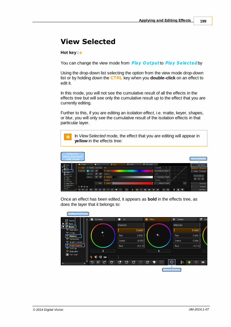
Applying and Editing Effects 199
© 2014 Digital Vision UM-2014.1-07
View Selected
Hot key : e
You can change the view mode from Play Output to Play Selected by
Using the drop-down list selecting the option from the view mode drop-downlist or by holding down the CTRL key when you double-click on an effect toedit it.
In this mode, you will not see the cumulative result of all the effects in theeffects tree but will see only the cumulative result up to the effect that you arecurrently editing.
Further to this, if you are editing an isolation effect, i.e. matte, keyer, shapes,or blur, you will only see the cumulative result of the isolation effects in thatparticular layer.
In View Selected mode, the effect that you are editing will appear inyellow in the effects tree:
Once an effect has been edited, it appears as bold in the effects tree, asdoes the layer that it belongs to:

Effects200
© 2014 Digital Vision UM-2014.1-07
The bold indicator in the effects tree signals that the effect has beenedited, not that the effect is active. User effects can be active bydefault and will not appear bold unless the effect parameters areedited.
You can reset an effect back to its original parameters by selecting the effect,so that it's highlighted, and pressing the Reset Effect button on the effectstoolbar. You can also reset an entire layer, which will recursively reset all theeffects within the layer.
Split Panel ViewHot key : CTRL + F4
When editing effects it can be useful to view the timeline, or the shot list, atthe same time as you're editing the effect parameters. You can do this usingthe split panel view.
This will switch the composition editor display to an extended panel mode andwill split the tabs so that you have the 'timeline' and 'list' tabs available acrossthe top and the 'effects', 'tracker' and 'scene detect' tabs along the bottom:
You can then click on the tabs as normal to change the combination, e.g. toview the shot list and effect parameters:

Applying and Editing Effects 201
© 2014 Digital Vision UM-2014.1-07
Adding User and Layer Effects
You can add individual effects to any segment in your composition in additionto the existing colour correction layers. These effects can be added in twoways, as user effects or as layer effects:
User effects are added to the Effects layer at the top of the effects tree.
Except Composite effects which are added at the bottom of theeffect tree (below the Master layer).
Layer effects are added as new layers in the effects tree. These may beColour Correction layers (CC Layer/Base) or Effect Layers (FX Layers).
The benefit of layer effects is that you can change the position of the layerwithin the effects tree and therefore the order that it will be processed in, sinceeffects are processed top-down based on their order in the effects tree. Usereffects can only be ordered within the effects layer and the position of theeffects layer cannot be changed.
As when adding colour correction layers, layer effects are only added to the

Effects202
© 2014 Digital Vision UM-2014.1-07
active segment. This is because the effects tree of each segment can bedifferent, i.e. have a different number of layers and effects, and layers areadded at a specific position within the tree, i.e. under the currently selectedlayer.
However, User Effects on the other hand are added to all selectedsegments, and only when no segments are selected is the effectadded to the active segment.
The effects available are accessed via the effects list drop-down menu buttonon the right of the work area panel:
To add an effect you need to select the effect from this list. The selectedeffect will be shown as the button label once the list is closed. Valid effectaddition buttons will be enabled on the effects toolbar.
Next, select the segment(s) that you want to add the effect to.

Adding User and Layer Effects 203
© 2014 Digital Vision UM-2014.1-07
To select multiple effects, hold down the CTRL key on the keyboardwhile clicking them (refer to the section on selecting timelinesegments for alternative methods).
By selecting segments you are overriding the active segment, so if you wantto also add the effect to the active segment you have to select it. Selectedsegments are in orange.
If any segment is selected on your composition, the scrollbar is also shownas orange.
Changing the scrollbar colour to orange means that you can see if asegment is selected even if it is not visible. This can preventaccidental effect application to the wrong segment.
At the bottom of the main screen are the buttons that control effect addition,deleting and parameter reset.
Icon Action
Add CC Layer
Add FX Layer
Add Inverted CC layer
Add Composite LayerNote that this is active only if a composite effect is chosen

Effects204
© 2014 Digital Vision UM-2014.1-07
Add User Effect (to Effect layer at top)
Add Restoration Effect. This is a DVO Dust+Fix Effect layer
Delete Effect or CC/FX Layer
Reset Effect or CC/FX Layer parameters
User Effects
Adding the effect as a user effect will add the effect to all the selectedsegments. The effect will appear in the Effects layer of the effects tree:
Layer Effects
Adding the effect as a layer effect will add the effect only to the activesegment, ignoring other selected segments. The effect will appear as a newlayer in the effects tree:
The effect layer will have the applied effect, as well as all the isolation effects('matte', 'keyer', 'shapes', 'blur') and 'router' which are present in all layers.

Adding User and Layer Effects 205
© 2014 Digital Vision UM-2014.1-07
Composite Effects
Like an normal Effect, a Composite effect is added to all the selectedsegments. It appears at the bottom of the effect tree.
Transition EffectsTransition effects can be added manually between two adjacent segments onthe timeline. An imported EDL may also include transitions between shots.
Enable the T ransition button - transitions will not be rendered and displayedunless the T ransition button is enabled.
Select two adjacent segments on the timeline (hold down the CTRL keywhilst clicking on the segments) and press the Insert Transition button on thetimeline toolbar:

Effects206
© 2014 Digital Vision UM-2014.1-07
Valid Transition
A valid transition will be shown in white, as a diagonal line between the twosegments, with a vertical line on the start and end frames.
Invalid Transition
If there is not enough material for the transition as set (insufficient handles),then that part of the transition will be displayed as red :
You can fix an invalid transition by going into trim mode and either :
Trimming the shot that requires the extra handles for the transition.Once valid, the transition changes from red to white.Adjusting the transition itself

Transition Effects 207
© 2014 Digital Vision UM-2014.1-07
Selected Transition
A selected transition is displayed as orange.
If the transition is fully valid, i.e. there are sufficient handles in the tail of thefirst segment and head of the second segment to carry out the transition, thenthe line denoting the transition will be white, as in the image above. If there areinsufficient head or tail overlap frames then the line be red, instead of white,over those frames which have insufficient underlying material.
To make the transition valid, you can either adjust the transition handles, i.e.the start/end frames of the transition, or you can trim the underlying segmentsto create the necessary handles. For either operation you need to switch to 'Trim Mode', via the button on the shared toolbar, shown in the image above.
Once in trim mode, you can click on the transition handles and drag them withthe mouse to increase or decrease the length/duration of the transition.
For trimming. refer to the Trim Modes section.
Editing the Effect on a Transition
To edit the parameters of the transition effect you first need to make thetransition the active selection.
To do this, place the active playhead in the first segment, positioning it overany of the frames the make up the transition. This will set the underlyingsegment as the active segment.
Then press the keyboard Page Down key to switch the active selection fromthe segment to the transition.
Note that the play head flag will change (drop down) to show that you are

Effects208
© 2014 Digital Vision UM-2014.1-07
editing the dissolve now :
A blue box will now appear around the transition to show that it is the activeselection, and the effects tree panel will change to display the transition effect:
To edit the parameters of the transition effect you simply have to double-clickon the effect in the effects tree panel, as when editing any effect.
Retime
The retime effect allows you to change the duration of a shot, either adding ordiscarding frames as necessary. A retime effect, being time-based, is treatedslightly differently to other effects.
A retime effect should added as a plain Effect node at the top of thetree.

Retime 209
© 2014 Digital Vision UM-2014.1-07
Parameters
Mode
The retime Mode determines the accuracy of the retime calculation for thefinal output sequence. It can be set as :
Nearest Neighbour
Bilinear Interpolate - more accurate
Scale
The Scale determines a percentage retime speed.
Note that setting a scale to zero (0) lets you adjust a clip durationmanually by stretching it using the cursor.
Frame Pin
The Frame Pin determines which frame in the source stays constant for theoutput sequence.

Effects210
© 2014 Digital Vision UM-2014.1-07
Brightness RegionsThe Brightness Regions effect allows separate adjustness of the shadows,midtones and highlights.
It is available as a CC Layer, an Effect Layer or a User Effect.
From the Control Panel, the trackballs adjust black, mid and highlightBrightness Regions when the Color panel is set to Brightness Regions.
The thresholds for black, mid and white can be altered from the top menus bypressing B.M or W respectively. The RGB values for black, mid and white canalso be adjusted from the top menus by pressing B.M or W a second time.These buttons are on the right of the top menu when Brightness Regionsmode is selected.
If you need finer control over the areas affected, you can also use luminance keys.

Brightness Regions 211
© 2014 Digital Vision UM-2014.1-07
Printer Lights
Printer Lights are named after the laboratory process of filtering light duringthe film printing process, to control the colour of the film.
The numeric values displayed in the GUI and on the panels can be calibratedin the Preferences pages, so that they match a local film lab. The number ofpoints per f-stop can also be calibrated.
On the panel, the top menu knobs adjust red green and blue Printer Lightswhen the Color panel is set to Balance, Color Curves or Brightness Regionsand the right hand menu selection is button 1, labeled All.
Printer Lights affect all pixels and produce a very clean correction.They are ideal for balancing raw images, log files or flat transfers.They are also a good way to remove color casts and adjust colortemperature offsets.
Density
Density is Printer Lights ganged together and a density reset makes each ofthe RGB Printer Light values neutral. Density works the same as the Brightness tool in Brightness/ Contrast and is also known as offset in someother systems.
Although Density and Brightness behave the same, they are in factdifferent controls and occur at different stages of the processing pathwithin a layer. They can be used independently of each other,although Brightness is used less frequently because it does notappear on the control panels. See S Gamma to learn more aboutContrast.
This control affects all pixels equally, regardless of luminance, color orposition. Its affect is similar to camera exposure and it is useful for adjustingthe source image dynamic range to a pleasing level. Since it does notsqueeze or stretch the dynamic range it causes no artifacts and is a greatcontrol to start grading raw or flat scanned images.
Some use Density to set black levels and others to use it to assign the midrange. Both methods are correct.

Effects212
© 2014 Digital Vision UM-2014.1-07
Use Density with a dynamic to grade a fade to black.
Gamma Matrix
The Gamma Matrix tool applies a matrix colour transformation to your imagesequence. A gamma correction factor can also be set before and after thistransformation is applied. You can define and apply presets for both thegamma correction and the colour matrix.
The gamma function applied here is based on a standard power lawmathematical expression.
Compared to a 3D Lookup Table, the Gamma Matrix tool allows fora more precise and efficient way to convert between various colourdomains e.g. RGB to/from XYZ or RGB Rec709 to/from RGB DCI-P3 etc.
This tool is not designed to convert between video and film colourdomains (e.g. film look or negative density).
Enable
The Enable toggle button enables/disables application of the effect. Togglingthis off will cause the effect to take no part in the processing chain.
Gamma

Gamma Matrix 213
© 2014 Digital Vision UM-2014.1-07
Switch to the Gamma settings using the Gamma button.
Pre/Post Gamma
A gamma correction can be applied to the sequence before (pre) and/orafter (post) any colour matrix is applied.
Pre Gamma
The Pre Gamma slider applies the specified gamma to the image before thecolour matrix is applied.
Post Gamma
The Post Gamma slider applies the specified gamma to the image after thecolour matrix is applied.
Pre/Post Gamma Presets
Below each gamma slider are gamma preset buttons. Press each button toquickly set the specific gamma.
See the Presets section for details on configuring and positioningpreset buttons.
Negative Mode
The Negative Mode (-ve mode) button lets you choose how to processnegative values.

Effects214
© 2014 Digital Vision UM-2014.1-07
preserve
The preserve setting leaves negative values as they are.
The processing chain is :
-val -> process -> result
clamp
The clamp setting clamps negative values to zero (0).
The processing chain is :
-val -> 0 -> process -> result
process
The process setting causes negative values to be processed as ifpositive.
The processing chain is :
-val -> +val -> process -> -result
Clamp at 1.0
The Clamp at 1.0 button causes values greater than 1.0 to be clamped to 1.0.
Preserve Denormals
The Preserve Denormals button enables the use of very small floating pointnumbers in the processing chain.
This setting is not needed for most reasonable gamma values.When enabled, the Gamma Matrix tool will take longer to processthe sequence.
Matrix

Gamma Matrix 215
© 2014 Digital Vision UM-2014.1-07
Switch to the Matrix settings using the Matrix button.
The Matrix page consists of three sections :
Presets on the left
Matrix settings
Matrix configuration on the right
Matrix Presets
Any matrix presets you have defined will be listed in the first column. Pressingany preset button will load the preset values into the matrix.
See the Presets section for details on configuring and positioningpreset buttons.
Matrix Settings
The Red, Green, Blue and Alpha matrix component values are listed in thecentral section. You can enter these values manually using the value sliders,or activate a preset button to load predefined values.
Pressing a preset button (e.g. Identity Matrix) will set the matrix values to thepreset values.
Matrix Configuration
The Matrix Configuration column contains utility functions that modify the waythe colour matrix is interpreted.
Preserve Luma
Setting Preserve Luma will adjust the resultant matrix such that the scale of

Effects216
© 2014 Digital Vision UM-2014.1-07
each component value stays the same relative to the others, thus keeping theoutput luminance the same.
Transpose
Setting Transpose causes the matrix to be transposed before beingprocessed.
Note that the matrix settings will not change when Transpose isenabled. However, it is transposed internally before use.
Presets
You can define presets for both the gamma settings (pre and post) and thecolour matrix settings. These can be made available inside the GammaMatrix tool as preset buttons.
To create and use a preset, you need to do two things :
1. Define the preset and the values it sets.2. Lay out the preset button in the tool interface.
These operations require the modification of two text files in the application root folder.
Preset Definition
Location : C:\Phoenix\2014_1\root\ParamPresets.prefs
File Format
All presets are defined in the ParamPresets.prefs text file, wrappedinside the ParamPresets tag. The Gamma Matrix effect is defined in asection wrapped with the tag GammaMatrix.
Within the GammaMatrix section, define one or more preset sections asshown below.

Gamma Matrix 217
© 2014 Digital Vision UM-2014.1-07
ParamPresets{ ... GammaMatrix { PresetID1 { ... } PresetID2 { ... } ... }}
Each preset has a unique identifier, shown above as PresetID1,PresetID2 etc.
These unique names are used to reference the preset when placing it as abutton in the tool interface (see the Preset Layout section).
By convention, these preset identifiers are named in a style thatidentifies their usage i.e.
preGamma16postGamma20matrixIdentitymatrixRGBtoXYZetc.
Pre/Post Gamma Presets
Set pre-gamma and post-gamma using the preGamma and postGammadeclarations within a section :
preGammaID1{ preGamma <FLOAT>}
postGammaID2{ postGamma <FLOAT>}
Where <FLOAT> defines a floating point value for the gamma applied e.g.
preGamma188{ preGamma 1.88}
The above pre-gamma section would be referenced inside the Layout filethrough the identifier "preGamma188".

Effects218
© 2014 Digital Vision UM-2014.1-07
Matrix Presets
A matrix preset specifies each red, green, blue and alpha column value asfollows :
matrixID{ red { red <FLOAT> green <FLOAT> blue <FLOAT> alpha <FLOAT> } green { red <FLOAT> green <FLOAT> blue <FLOAT> alpha <FLOAT> } blue { red <FLOAT> green <FLOAT> blue <FLOAT> alpha <FLOAT> } alpha { red <FLOAT> green <FLOAT> blue <FLOAT> alpha <FLOAT> } transpose <BOOLEAN>}
Where <FLOAT> defines a floating point value e.g.
matrixTestSample{ red { red 0.782000 green 0.366000 blue 0.455000 alpha 0.000000 } ... ... etc. ... transpose true}
transpose is a <BOOLEAN> and can be set to true or false. If not present,transpose is assumed true.
The above matrix would be referenced inside the Layout file through theidentifier "matrixTestSample".

Gamma Matrix 219
© 2014 Digital Vision UM-2014.1-07
Preset Layout
Location : C:\Phoenix\2014_1\root\ParamLayout.configs
The ParamLayout.configs file arranges various tool interface elements -parameters, pages, buttons etc.
File Format
All layouts are wrapped inside the paramConfigurations tag. The GammaMatrix effect layout is defined in a section wrapped with the tagGammaMatrix.
Note that each tool (e.g. GammaMatrix, HLS, DvoRegrain etc.) hasparameters delimited by square brackets ([,]).
Within the GammaMatrix layout section, specify preset buttons use thesyntax :
presetButton "<BUTTON NAME>" "<IDENTIFIER>"
Where <BUTTON NAME> will be the button title (text on button) and<IDENTIFIER> identifies the button action to use from the preset definitionfile.
For the GammaMatrix tool, the <IDENTIFIER> key has a format :
GammaMatrix.<PresetIdentifier>
The <PresetIdentifier> is the unique name given to the preset (see thePreset Definition section).
Examples
paramConfigurations{ ... ... GammaMatrix [ ... presetButton "Test Matrix" "GammaMatrix.matrixTestSample" presetButton "1.88" "GammaMatrix.preGamma188" ... ] ...}
The above produce the following interface buttons :

Effects220
© 2014 Digital Vision UM-2014.1-07
Hue Curves
Hue Curves is a powerful effect that allows you to modify the hue, lightness orsaturation (HLS) of a shot using an interactive graph.
Parameters
Hue / Lightness / Saturation
The Hue, Lightness and Saturation toggle buttons on the left of the graphselect how the graph affects the image.
Hist
The Hist button shows or hides the histogram display in the graph window.
You can select (pick) areas of colour from the image using your mouse, andthese areas will be displayed on the graph as an aid to graph manpulation.

Hue Curves 221
© 2014 Digital Vision UM-2014.1-07
Add Point / Delete Point
You can Add or Delete points from the graph by toggling these buttons on, andthen clicking on the graph. This allows finer manipulation of the area of theimage affected by the effect.
Scale
The Scale slider adjusts the scale of the graph shown.
Discussion
Hue Curves is the only tool that utilizes the top menu of both the Color andthe Image panels.
The top buttons on the Image panel select one of six preset points on aspectrum. These presets assign the menu controls of the Color panel to red,yellow, green, cyan, blue, or magenta. When the Color panel is set to [Menu2], labeled Positive, the knobs adjust hue, luminance and saturation of theselected color. This tool can isolate and adjust several colors in the samelayer.
If Color panel [Menu 3], labeled Inverse, is active the selected coloris left unchanged and the other 5 points are adjusted.
[Menu 3] Inverse makes it very easy to create black and white images with

Effects222
© 2014 Digital Vision UM-2014.1-07
one color retained.Color panel [Menu 1], labeled All, selects all six points andconfigures the Hue Curves to work the same as the HLS tool. This mightseem redundant but the default processing path puts Hue Curves first in alayer and HLS as last. Hue Curves All is useful for creating duotone and splittone effects in one layer, whilst HLS modifies the layer correction as well asthe natural color.
Soft ClipThe Soft Clip effect allows full control over black and white point clipping, andthreshold values. Each RGB channel can be independently controlled.
Parameters
The Soft Clip effect has separate white and black modes, chosen via thetoggle buttons to the left.
The white mode includes Threshold White settings.
The black mode includes Threshold Black settings.
Clip
This setting controls the level of clipping done per RGB channel.
Softness
This setting controls the fall-off (softness) in the clipping performed.
Threshold White / Threshold Black
These settings control the cut-off values for white/black clipping.
Discussion
On the control panel, the black and white trackballs adjust soft clips when theColor panel is set to Clip. The outer rings adjust a neutral clip and the ballsclip the RGB channels separately to cause colour in the peak whites orblacks.

Soft Clip 223
© 2014 Digital Vision UM-2014.1-07
The clips are useful for removing colors introduced by clip settings ina telecine or camera as well as creating color offsets in thehighlights and shadows.
Effect NotesYou can store all, or a chosen subset, of the effects on a segment (includingany keyframes) using effect Notes.
This is available via the ..Memories button (at the bottom right of mainscreen).
Storing and Recalling a Note
In Memories/Notes view, store a note for the current shot by pressing theStore button.
To recall a note, press the Recall button. The effects contained within the notewill be applied to the current shot.

Effects224
© 2014 Digital Vision UM-2014.1-07
Notes are placed in the the notes library and display a thumbnail.
Hovering your mouse cursor over a note will display the note contents :
Selecting a note will display the note effects in the note effect tree (top-right).

Effect Notes 225
© 2014 Digital Vision UM-2014.1-07
Lens Distort
The Lens Distort tool can fix and undo camera lens distortion.
A number of presets are included for various GoPro cameras.
Presets
Presets are predefined settings organised as easy to apply button actions. Apreset exists for some commonly used GoPro camera formats e.g. GoProHero at 1280x960 etc.
Each preset will set up the Distort parameters described below.
Unity
This removes all correction and disables Lens Distort.
The Distort parameter is changed from Remove Distortion to Off.

Effects226
© 2014 Digital Vision UM-2014.1-07
GoPro Hero 1920x1080
This preset is the tool default.
This means that when we reset the tool, it resets to the default valueas per the GoPro Hero 1920x1080 preset.
Distort Parameters
Application
Choose to disable tool, add or remove distortion. The default is RemoveDistortion.
The Off setting (tool disabled) is equivalent to the Unity preset.
Amount
The amount of correction to apply (strength).

Lens Distort 227
© 2014 Digital Vision UM-2014.1-07
Radius
The Radius determines the distance before we see distortion.
Scale
This scales the source image from its center.
Center X/ Center Y
The center point of the distortion. Default to image center point.
A1 A2 A3 / B1 B2
These define the lens distortion coefficents.
A1 deals with the major "fish-eye" style distortion while A2 and A3 aremore distant, edge distortion. B1 and B2 deal with distortionconsidered as pans in Z space (or up and down).
Channels
Values : RGB , R , G , B
Default : RGB
Correct distortion in a single RGB channel or (by default) all three.

Warper 17

229
© 2014 Digital Vision UM-2014.1-07
Warp 4 and Warp 9 are sophisticated image warping tools. They can be usedto fix geometric issues and distortion within image sequences.
Both have a broad application but are of particular use when working with Stereoscopic 3D sequences.
The two Warp tools are :
Warp 4 The Warp 4 warper is a classic four point warper and allowswarping through the manipulation of the four image corner points.
Warp 9 The Warp 9 warper extends the Warp 4 warper with extra controlpoints on each side mid-point and the center point.
Both warpers allow warping of all three RGB channels simultaneously, oreach channel separately.
Warper IntroductionBoth warper tools are designed to be useful in a wide variety of situations.
The Warp 9 tool should be particularly useful in two important areas describedbelow. Both areas of specifically relevant to stereoscopic work.
For most Stereoscopic work, you would use a warp tool directly afterthe DVO Stereo Fix tool.
Geometric Correction
The Warp 9 tool makes geometric correction straightforward. This issuearises due to distortion between the camera lenses or the mirror fromthe stereo rig and creates a non-uniform vertical mismatch between theleft and right eye images.
By correcting to the center of the image, Warp 9 can then adjust eachquadrant of the image, adjusting the points in Y whilst leaving the centerpoint unchanged. This provides a much more accurate geometricmatch as a result.
Frame Violation

Warper230
© 2014 Digital Vision UM-2014.1-07
The Warp 9 warper makes it very easy to bend the image forward orbackwards in depth. This is done by moving the control points in X only.By moving selected areas you can minimise frame violation (whereobjects are too far forward in space), thus limiting the effect on the restof the image.
Warper BasicsBoth Warp 4 and Warp 9 warpers share common features.
A warp is created by selecting and moving one or more control points. Thesecan be manipulated and controlled interactively using the mouse or the GUIcontrols.
Owners of a Precision Panel can also use it to control the warpertools.
Control Points
Control points are placed around the edges of the source image.
Warp 4 : four warper control points. Warp 9 : nine warper control points,including the central control point.

Warper Basics 231
© 2014 Digital Vision UM-2014.1-07
Control points change their look when used :
An unselected controlpoint.
A selected control point A control point with amouse cursor proximityindication.
Mouse Control
A control point is indicated in red when your mouse cursor is within range.
To select points :
Select one control point :Click it with the left mouse button
Select multiple control points :Hold down the SHIFT key while click selecting points with the leftmouse button
Hold down left mouse button and drag to warp image
Marquee Select
You can marquee select multiple control points by drag selecting them :
Drag select multiple points using the mouse.
GUI Controls
Once selected, you can manipulate control points via the GUI controls, usingthe mouse or keyboard to enter value.

Warper232
© 2014 Digital Vision UM-2014.1-07
The Warp 4 GUI controls
The Warp 4 GUI controls are shown above, and include separate sliders forthe X/Y movement of each Warp 4 control point. Four points leading to eightsliders.
The Warp 9 GUI controls are similar but have eighteen sliders correspondingto X/Y for all nine control points.
Warp 9-as-4
You can make the Warp 9 tool warp in a similar mode to Warp 4 by selectinga corner point and dragging whilst holding down the ALT key :
Mouse drag top-right point :
Normal Warp 9 single point drag and warp
behaviour.
+ ALT :
Warp 9 warp behaviour w ith ALT held
down.
Note that the warper behaves in asimilar way to Warp 4 and as if themid-points do not exist. The centralpoint stays locked in place however.

Warper Basics 233
© 2014 Digital Vision UM-2014.1-07
The Precision Panel has a 4 Points toggle to enable this mode. Ineffect, the Warp 9 tool changes to a Warp 4 :
Frame Violation
For frame violation issues, the Precision Panel has mode that lets you modifyall left points in X, all right points in X, all top points in X etc.
Use the Left, Top, Right, Bottom buttons to select the row of affectedcontrol pointsThen move all the selected points in the X or Y axes using the All LeftX or All Left Y, or All Top X, All Top Y etc.
Using Left / All Left X to select andmove only one side of the image inthe X axis.
Basic Controls
Scale
Values : 0 - >100000 (slider)
Default : 1.000
The Scale slider lets you scale the image from image center.

Warper234
© 2014 Digital Vision UM-2014.1-07
You may want to hide warper boundary artifacts in somecircumstances and the Scale control can push these outside thevisible frame.
Channels
Values : RGB , R , G , B
Default : RGB
You can choose to warp only a single RGB channel or (by default) all three.
This can be useful for cases (e.g. stereoscopic sequences) thathave distortion that differs in one or more colour channels.
Reset Selected Points
This button will reset any selected control points.
This also removes any keyframes associated with the control points.
Warp 9 Extended Controls
Interpolation
Values : Linear , Bicubic
Default : Linear
Linear interpolation is faster but less accurate than Bicubic.
Center Pinning
Pinning the central control point stops it moving when manipulating othercontrol points and so protects the central part of the image.
Use the Pin Radius to hold a proportion of the central image area steady asyou move other control points around.

DVO Effects 18

DVO Effects236
© 2014 Digital Vision UM-2014.1-07
DVO stands for Digital Vision Optics, a collection of imageprocessing tools running in software on generic computerplatforms. DVO effects are optimised to make use of the latestmultithreading, CPU and GPU computer technology.
With the DVO toolset, Digital Vision brings twenty years of experience indeveloping high performance image processing algorithms to the world ofdata-centric restoration, digital intermediate and commercial work.
Many DVO effects are available and will be described in this chapter.
DVO tools are shot based and require the presence of sceneinformation. Always scene detect pre-conformed media oradjustment tracks that span more than one shot.
IntroductionMany DVO tools are available and each can be applied independently toindividual timeline segments. A timeline segment can have multiple differenteffects applied, stacked in various configurations (layers).
Selecting a DVO Effect
The individual DVO tools are logically grouped into packages :
DVO Restore - repair and renovate media
DVO Enhance - improve detail and add clarity
DVO Video - tools to process and fix video content
DVO Convert - standards conversion, upscaling and de-interlacing
DVO Camera - tools to process digital camera related content
Each package contains a set of DVO tools available. Choose via the EffectToolbox to the left of the timeline :

Introduction 237
© 2014 Digital Vision UM-2014.1-07
The selector displays the groups and effects as a drop-down list :
Applying a DVO Effect
Once you select the DVO effect, you can add it to the active timeline sectionas :
Part of the Input FX group or
A new FX Layer
Adding the DVO effect inserts the selected DVO tool at the appropriate placein the Effects Tree to the left of the timeline.
Input FX
Press the Input Fx button to add the selected effect to the Input FX group :

DVO Effects238
© 2014 Digital Vision UM-2014.1-07
In the example below, the selected effect (here DVO Flicker) is added at thetop of the effects stack in the Input FX group.
Action : Effects Tree Result :
FX Layer
Press the FX Layer button to add the selected effect to the FX Layer group :
In the example below, the selected effect (here DVO Flicker) is added to theFX Layer group. An FX Layer gives you extra layer tools such as a Keyer andShapes.
Action : Effects Tree Result :
In Phoenix Finish and Phoenix Video, only the basic colourcorrection layer (Master Layer) will appear in the Effects Tree bydefault.
The Effects Tree will display all effects applied to the current timelinesegment (segment under play-head). The tree will dynamically update if thecurrent segment changes (such as during play-back).

Introduction 239
© 2014 Digital Vision UM-2014.1-07
Additionally, a segment with effects applied is displayed in a different colour toa segment with no effects applied. See the Compositions section.

DVO Effects240
© 2014 Digital Vision UM-2014.1-07
DVO Stereo FixDVO Stereo Fix is an advanced stereo enhancement tool designed to resolvecolour matching and geometry alignment issues with stereo sequences. Thetool can address problem areas when they appear over the entire imageframe (global correction) or in different areas inside a frame (localcorrection).
The tool will be able to correct most problems automatically but where this isnot possible, controls are available that allow straightforward manualcorrection.
Enabling Stereo Work
Some basic setup is required to use the DVO Stereo Fix tool.
Project
Your project should be enabled for Stereoscopic Output :
Composition
You should have Multi-track Grading enabled inside the project :

DVO Stereo Fix 241
© 2014 Digital Vision UM-2014.1-07
A clip with Multi-track enabled will display edge markers as shownbelow :
Adding the Tool
DVO Stereo Fix must be added as an Input FX tool :
Overview
The tool has the following basic control layout, with the two primary tool areasbeing :
Colour matching controls
Alignment (geometry) controls

DVO Effects242
© 2014 Digital Vision UM-2014.1-07
View Controls
Mute
Mutes both the colour match and the align match, as well as any associatedborder/blanking modes.
The parameters in this section regarding view and orientation remain active i.e. SwapEyes/ViewMode/Mirror/Flip.
This can be used to compare before and after while correcting anynecessary mirror/flip.
Swap Eyes
Swaps left and right eye on output.
All parameters referring to either left or right are associated with the sourceleft and right tracks. As such, the actual processing is not affected byswapping eyes on the output.
View Mode
Values : Normal , Blended , Side-By-Side
Default : Normal
This control allows different view modes to be applied on the output and isused mainly for visualisation purposes.
Normal Separate left and right outputs.
Blended Blends left and right image, which could be used to verifyalignment processing.
Side-By-Side Displays left and right images side-by-side with halvedhorizontal resolution.
If this mode is used to verify colour matchingsimultaneously, please note that many monitors mighthave colour reproduction which varies spatially or byviewing angle.

DVO Stereo Fix 243
© 2014 Digital Vision UM-2014.1-07
Mirror Controls
The Mirror Controls will automatically determine and correct for a mirrored leftor right eye. If required, manual correction can also be set here.
Auto Mirror
Values : Disable , Left , Right
Default : Right
Automatically determines mirror and flip between left and right eye. If wedetect a requirement to mirror or flip, it is applied to the specified eye.
This automatic correction will follow any manual mirror or flipsettings applied to the other eye.
Mirror Left
Manually set left eye to be mirrored.
Mirror Right
Manually set right eye to be mirrored.
Flip Left
Manually set left eye to be flipped (vertically).
Flip Right
Manually set right eye to be flipped (vertically).

DVO Effects244
© 2014 Digital Vision UM-2014.1-07
Colour Matching
These controls allow us to correct the colour match between the left and righteyes.
Colour Match
Values : to Left , to Right
Default : to Left
Sets colour processing to match the specified eye.
Setting this to "to Left" will process the right eye to match the left.
Scene Mode
Values : Disable , Uniform , Non-Uniform
Default : Non-Uniform
Sets the colour matching mode for a scene such that the scene is analysedand processed equally throughout (all frames). The different modes relate tohow colour matching may vary spatially over the image.
This is unrelated to any spectrum transformation being uniform ornon-uniform.
Disable No colour match processing is performed (on scene basis).
Uniform Colour matching is assumed to be spatially uniform.
Non-Uniform Colour matching is allowed to be spatially non-uniform.This mode typically works just as well when the colourdifferences are spatially uniform.

DVO Stereo Fix 245
© 2014 Digital Vision UM-2014.1-07
Scene Mode requires proper scene edits as normally one scene willbehave very differently to another.
Frame Mode
Values : Disable , Uniform , Non-Uniform
Default : Disable
Sets the colour matching mode which is applied per frame individually.
The processing and modes are the same as described above for SceneMode.
This option can be used as an alternative to Scene Mode processingif it appears that colour differences change on a frame by framebasis. It is recommended that Scene Mode processing be Disabledwhen used.
Local Mode
Values : Disable , Normal
Default : Normal
This option allows for more localised colour match processing than found inScene or Frame Modes. The Area Size and Sensitivity controls are linked toLocal Mode processing.
Area Size
Values : X-Small , Small , Medium , Large , X-Large
Default : Medium
The smaller the Area Size is the more locally aggressive it can beconsidered to be.
Sensitivity
Values : 0 - 1023
Default : 64
The Sensitivity parameter is used to control the allowed differenceranges. The values we set correspond to 10 bit levels. The effect ofSensitivity is as a safety measure rather than a processing amount.
To speed up the processing of complete scenes/material, LocalMode processing can be disabled.

DVO Effects246
© 2014 Digital Vision UM-2014.1-07
Colour Match Safety
Values : 0.0 - 1.0
Default : 0.5
This parameter sets a general safety level for the Scene and Frame Modecolour matching.
Colour Match Safety applies to black levels as well as the analysis andvariability of the spectrum transform applied.
This does not include Local Mode, which uses Area Size andSensitivity.
Alignment
These controls allow us to correct the alignment (or geometry) between theleft and right eyes.
Align Match
Values : to Left , to Right
Default : to Left
Sets alignment processing to match the specified eye.
Setting this to "to Left" will process the right eye to match the left.
Align Mode
Values : Disable , Manual , Global , Morph
Default : Morph
The alignment processing is based on scene analysis and frames areprocessed equally throughout the scene. The alignment can also be setmanually or adjusted with a global offset (Manual V-Offset).
Disable No alignment processing.
Manual Set manual global vertical offset (using Manual V-Offset).
Global Automatic and global adjustment.

DVO Stereo Fix 247
© 2014 Digital Vision UM-2014.1-07
Morph Spatially variable adjustment with linear variability over the image.
Like Scene Mode colour matching, Align Mode requires properscene edits as normally one scene will behave very differently toanother.
Manual V-Offset
Values : 0 - 128
Default : 0
Manual adjustment of the alignment.
Borders
The Borders controls let us correct any effect alignment has on frameborders.
Border correction also depends on the Blanking configuration (seebelow).
Borders
Values : Disable , Blank , Zoom Source , Zoom Fill
Default : Zoom Source
Disable Disable border processing.
Blank Automatically applies necessary blanking to borders.
ZoomSource
Automatically zooms the output to the source frame andoriginal blanking. As per the Blanking Mode, this mode takes into accountwhat needs to be excluded regarding the borders andalignment.
Zoom Fill Automatically zooms the output to fill the full framedisregarding any original blanking of the source.
Centre
Values : On , Off
Default : On
Centre the result in the frame. This may be necessary for some Bordermodes.

DVO Effects248
© 2014 Digital Vision UM-2014.1-07
Blanking
Blanking is closely linked to the Borders control and allows us to control howthe frame borders are blanked.
Blank Setup
Values : Auto , Source , Output
Default : Auto
Blank Setup lets us choose if blanking is setup by automatic analysis ormanually in relation to the source or the output.
Blanking affects the border processing and and its effect will dependon the Borders mode.
Auto Use automatic analysis to define the blanking amount.
Source Allow manual blanking setup.
Output Manually specify blanking completely based on the output alone.This requires you to regard frame effects from the alignmentprocessing manually, as well as the original source frameblanking. This is an Advanced Mode.
Blank Top / Left / Right / Bottom
Manual blanking adjustment to the top, left, right and bottom of the frame.Specified in pixels.

DVO Stereo Fix 249
© 2014 Digital Vision UM-2014.1-07
DVO DustDVO Dust is a fully automatic and highly accurate film dirt, dust and randomscratch concealment and video drop-out removal system. It can removearound 90% of visible imperfections without introducing unwelcome artifacts.
DVO Dust utilises a pioneering set of processing algorithms and new filterswith the Digital Vision Emmy award-winning PHAME motion compensationtechnology. With manual "dust busting" being very time consuming andexpensive, the automation in DVO Dust can typically reduce the amount ofoperator time required by an order of magnitude. This saves enormousamounts of time and money without any compromise in terms of picturequality.
This effect has three groups of parameters:
The Enable toggle button allows the complete effectto be turned on or off.
Presets - preset selections for quick dirtremovalProcessing - specific processing options
Setup - additional settings for variousprocessing selections
Basic Settings and Presets
The DVO Dust effect provides a number of presets, ranging from Extra Lightto Extra Heavy removal. These work as a very good starting point beforemoving on to the more advanced controls in the Processing and Setup tabs.You may not need to use any of the advanced parameters.

DVO Effects250
© 2014 Digital Vision UM-2014.1-07
Enable Basic
The Enable Basic toggle button allows you to enable/disable basic mode.This mode uses presets to automate and hide much of the effect complexity.
When you edit any of the settings in the processing or setup tabs thebasic mode becomes automatically disabled. Similarly, when youselect a mode from the basic modes, all settings will beautomatically adjusted to fit the selected mode and basic mode willbe automatically enabled.
Presets
This is a collection of preset settings (e.g. Extra Light, Heavy etc.) that setupthe effect for a predefined level of dust/dirt.
Values : Extra Light, Light, Medium, Heavy, Extra Heavy
Default : Medium
Strength
This slider allows the adjustment of the strength of dust reduction processingto use. It is only available in basic mode.
Range : -5 to +5
Default : 0
Enable White / Enable Black
White/black dirt removal is enabled via the corresponding Enable White/Enable Black toggle buttons.

DVO Dust 251
© 2014 Digital Vision UM-2014.1-07
Enable Black - for black/dark spots
Enable White - for white/light spots
Both can also be enabled at the same time.
Default : On
These options also appear in the Processing tab and they are linked(changing one location affects the other).
Note that if neither button is enabled then DVO Dust will not filterat all!
Processing Filters
The filters used by the process are very important in determining the finalprocessed quality. DVO Dust includes a variety of filter algorithms that caneffectively process a wide range of input footage.
Drop-down Filter list

DVO Effects252
© 2014 Digital Vision UM-2014.1-07
Spatial / Temporal / Mixed Filters
Values : Spatial, Mixed 1, Mixed 2, Mixed 3, Mixed 4, Temporal 1,Temporal 2, Copy Prev, Copy Next, Bypass
Default : Mixed 3
The following generic filter groups are defined.
Spatial
All filters named Spatial are filters that work only within the currentframe (or field if the material is interlaced), i.e. it has taps only in thecurrent frame. These filters are intended for very small spots.
Mixed
All filters named Mixed have taps in both the current frame and theframe previous to and following the current frame. That is, it has bothspatial and temporal taps. All these filters however have more taps inthe current frame than in the previous and following frames together(more spatial taps than temporal). These filters are intended fornormal spots.
The different Mixed types (Mixed 1,2,3 etc.) change the ratio betweenspatial and temporal. The larger the number, the more temporalfiltering.

DVO Dust 253
© 2014 Digital Vision UM-2014.1-07
Temporal
Filters named Temporal have both spatial and temporal taps but withmore temporal than spatial. This will enable the DVO Dust to removeany size of spots. These filters may need more careful use, to notgive unwanted artefacts.
The filter called 'Temporal 2' is a special temporal filter thatuses minimum amount of information from the current frame.This means that the processed signal will not vary as much asthe normal temporal filter in terms of luminance/intensity.
Copy
Copy Next Copy Prev
The 'Copy Next' and 'Copy Prev' filters should be used for one framein combination with a key area and Global mode to replace a bigchunk of dirt, a big hole, or a flash frame with information from thenext or previous frame.
Bypass
Setting the filter to Bypass will leave dirt unprocessed.
Use Adaptive Size
When the Use Adaptive S ize button is enabled, the filter sizeautomatically adjusts during processing according to the size of the dirt found.
Default : On

DVO Effects254
© 2014 Digital Vision UM-2014.1-07
Filter Size
This sets the size of the filter on the current frame, so it is only required forspatial and temporal filters.
Use the numeric slider to define the filter size when adaptive filter sizing is notenabled. The larger the size of the dirt the larger this value should be.
Range : 0 to 15
Default : 7
Adaptation
The Adaptation toggle button allows you to turn the adaptation processingon/off.
When this button is off, DVO Dust works in global mode, filtering the wholeimage with the same fixed filter selected in the Filter menu.
Note that if the Adaptation button is off then none of theadaptation controls above will have an effect.
Motion
This numeric slider configures the degree of motion sensitivity.
Initially you can set it to 0 (most safety), for maximum motion sensitivity, andthen increase it in steps if there isn't enough filtering in moving parts of thepicture.
A value of 256 corresponds to no motion adaptation at all, which means thattemporal filtering can be applied fully to moving parts of the image.
Range : 0 to 256
Default : 30
MDC
The MDC (Motion Detection Current) toggle button determines whether tolook at just the previous and next field/frame, or to look at all of the previous,

DVO Dust 255
© 2014 Digital Vision UM-2014.1-07
current, and next field/frame.
Default : On
Having this option on ensures higher sensitivity and reduces artefacts down toa minimum.For maximum filtering, the control may be set to off.
MDC filter configuration is done inside the Setup section.
Edge
This controls material edge protection.
Edge protection acts as a safety measure and reduces the possibility of falsescratch detection. Some material may require this protection e.g. houses at adistance, a forest or material with a slight weave. By turning edge protection on, the built in edge detector will affect were DVO Dust filters and it will reducefiltering where it finds edges.
Default : On
Edge protection should normally be left on.
Further controls for defining thresholds for edges are available in the Setuptab.
Edge parameter configuration is done inside the Setup section.
Temporal Adaptation
Temporal Adaptation acts to exclude falsely detected dust/dirt from beingprocessed. It does this by comparing dirt detected on the current frame withdirt detected on the previous frame (within a sizable window).
This toggle button turns temporal adaptation on/off.
Default : Off
The temporal adaptation settings can be found in the Setup tab.
Black / White
There are two separate and independent parameter groups controlling theprocessing for Black (dark) and White (light) areas of dust/dirt.

DVO Effects256
© 2014 Digital Vision UM-2014.1-07
Enable Black / Enable White
White/black dirt removal can be enabled via the corresponding togglebutton.
Enable Black - to remove black/dark spots
Enable White - to remove white/light spots
Both can also be enabled at the same time.
Default : On
Note that if neither button is enabled then DVO Dust will notfilter at all!
Use Adaptive
If on, sets white/black contrast to be adaptive.
Default : On
This will result in the algorithm determining which contrast setting isneeded on a pixel-by-pixel basis.When enabled the contrast controls change to give more, or less, effectof the adaptive contrast.
Adptv Threshold
Only applicable if Use Adaptive is on.
Range : -32 to 31
Default : 0
Fixed Threshold
Only applicable if Use Adaptive is off.
Range : 0 to 63
Default : 30
You should lower the thresholds if you have very low contrast whitespots on light background, or black spots on dark background, andincrease the thresholds if the luminance difference between the spotsand the background is less:

DVO Dust 257
© 2014 Digital Vision UM-2014.1-07
or set the contrast threshold to a low value
or set the contrast threshold to a high value
Contrast Adaptation Limits
The contrast adaptation low and high limit controls only work in the adaptivemode and are used to specify the range of contrast settings that theadaptation is allowed to work in.
The upper limit is normally set to the non-adaptive contrast setting younormally use. If both limits are set to the same value the result is exactly thesame as when using non-adaptive contrast.
Low
Range : 0 to 63
Default : 5
High
Range : 0 to 63
Default : 30

DVO Effects258
© 2014 Digital Vision UM-2014.1-07
Other Settings
Signal
This selects the signal (channel) within which scratches/dirt will bedetected.
Values : Y,U,V,R,G,B,Y+U+V
Default : Y
The adaptation works on one channel only, normally 'Y'. By setting thesignal to 'R', for example, when only red scratches are visible, the DVODust will more precisely detect the dirt, minimizing the risk of affectingactual picture content.
Motion Estimation
This drop-down button allows you to choose the motion estimation.
Values : off, normal, best
Default : normal
When enabled, the motion estimation module gives a performanceboost, both in dirt detection and concealment. This means that muchmore aggressive settings can be used without introducing smearing.
Scene Change
This drop-down button gives options for how to process the framessurrounding an edit/cut point:
Inside - processes the frame before a cut using only the current andprevious frame, and processes the frame after a cut using only thecurrent and next frame. Stays inside the shot.Across - ignores cuts, use the previous, current, and next frame.Goes across shots.Bypass - doesn't process the frames before or after a cut.

DVO Dust 259
© 2014 Digital Vision UM-2014.1-07
Values : Inside, Across, Bypass
Default : inside
Channels
This control is for selecting the channels from which dirt will beremoved.
Normally the processing should be set to all channels, but in somecases, especially with small dirt, better results can be achieved byprocessing only one or two of the channels.
Values : Any combination of R,G and B.
Default : R,G,B
Setup
View
Turning on the View toggle button will provide an overlay/preview showingdetected dirt. The type of overlay can be selected via the View Mode drop-down list:
Default : Off
View Mode

DVO Effects260
© 2014 Digital Vision UM-2014.1-07
Values : Dirt On Luma, Dirt On Red Input, Dirt On Red Output,Difference
Default : Dirt On Luma
Where :
Dirt On Luma - The detected scratches/dirt are high-lighted on amonochrome input picture with lowered luminance.Dirt On Red Input - The detected scratches/dirt are shown with redon the unprocessed input signal.
Dirt On Red Output - The detected scratches/dirt are shown withred on the processed output signal.
Difference - The difference between the unprocessed input and theprocessed output is displayed.
Colour
The drop-down list will default to the project setting for the input format. Youneed to set this control according to the material that you are working with. Ifthe footage was shot with a video camera, select a linear format. If thiscontrol is not set correctly the material may not be processed properly.
Default : From Project
History Required
The DVO Dust effect is recursive.
Recursive means the result for any given frame depends on theresult of the previous frame(s).
For best results a certain amount of frame history needs to be built up, andthis numeric slider is used to specify how many frames of history to use.
Range : 0 to 15
Default : 5 frames
Use Handles
The Use Handles button controls whether the history includes available

DVO Dust 261
© 2014 Digital Vision UM-2014.1-07
handles of a scene/shot. Normally, the history frames accumulated willterminate on a shot edit/event (start/end edit). There may be extra framesavailable (handles) before or after the start and end edit points of a shothowever and these will be included as history if Use Handles is set.
If handles exist, full and precise processing will be available from thefirst frame of a clip.
Default : On
The remaining controls on the Setup page are used to optimize theprocessing further. These controls should only be used by experiencedoperators with a good understanding of the dirt and scratch concealmentprocess.
Max Filter
Enable
In addition to the filter selected in the Processing tab, a separate max filtercan be enabled.
The Max Filter will only be used when Use Adaptive is enabled in theProcessing tab.
This is very useful when you have material with mostly small dirt andthe occasional bigger stains.
Default : Off
Filter
Use this drop-down button to select the max filter with which to process largestains.

DVO Effects262
© 2014 Digital Vision UM-2014.1-07
Values : Spatial, Mixed 1, Mixed 2, Mixed 3, Mixed 4, Temporal 1,Temporal 2, Copy Prev, Copy Next, Bypass
Default : Temporal 1
When the Max Filter is enabled, the normal filter used for the adaptive filtersizing will take care of the small dirt. When the upper size limit is reached itwill automatically switch over to the filter selected here.
The filter used here would typically be a larger temporal filter.
The Max Filter can also be set to Bypass, which will leave big stainsunprocessed. These can be processed later by a de-blotcher or 3rd partysoftware.
Size
This specifies the size of the spatial part of the filter (for spatial and mixedfilter types).
Use a large value when processing large bits of dirt.
Range : 0 to 15
Default : 3
Motion
Width
Motion W idth is used in combination with the Motion control in theProcessing section and defines the motion adaptation behaviour. Whenmotion width is set to 0, the motion setting will be used as a thresholddiscriminating between moving and non-moving parts. When motion width isset to a non-zero value, the classification will change gradually from “nomotion” to “full motion”. Motion width then specifies the size of the transitionregion.
Range : 0 to 255
Default : 30

DVO Dust 263
© 2014 Digital Vision UM-2014.1-07
MDC Scale
The MDC (Motion Detection Current) toggle button in the Processing sectiondetermines whether to look at just the previous and next field/frame, or to lookat all of the previous, current, and next field/frame.
Only used if MDC (Motion Detection Current) control enabled in the Processing section.
The higher the scale setting, the more filtering (less impact of the MDCalgorithm).
Range : 0 to 15
Default : 8
Edge
The Edge settings apply only if Edge protection has been enabled inthe Processing tab.
Offset
The edge offset acts like a threshold, determining how well-defined edgeshave to be before the edge control has any effect. The smaller the offset valuethe sooner the edge control will have an effect.
Range : 0 to 255
Default : 45
Scale
Edge scale sets the sensitivity of the edge control. The higher the setting themore pronounced the effect of the edge control.
Range : 0 to 255
Default : 192

DVO Effects264
© 2014 Digital Vision UM-2014.1-07
Temporal
The temporal settings apply only if Temporal Adaptation has beenenabled in the Processing tab.
The purpose of temporal adaptation is to exclude falsely detected dirt fromprocessing by comparing it with the previous frame's detected dirt within asizable window.
Strength
The strength level determines the amount of influence that the previousframe's detected dirt will have on exclusion of dirt detection in the currentframe. A higher value will result in more dirt being excluded and lessprocessing carried out.
Range : 0 to 255
Default : 80
Trim Size
The trim size corresponds to a "window" in the previous frame which issearched for dirt to compare against the current frame. The smaller thewindow (trim size) the more filtering that will be achieved.
Range : 0 to 7
Default : 5
Hit Growth
The Hit Growth control is useful when the dirt in the image does not have verywell-defined edges.

DVO Dust 265
© 2014 Digital Vision UM-2014.1-07
By increasing the hit growth the processor is told that the dirt is bigger than itactually appears. The result is that the soft edges also are processed.
Mode
Absolute
Use Relative button off.
The hit mask for all sizes of scratches are grown by the same amount asspecified with the strength control
Range : 0 to 4
Default : 4
Relative
Use Relative button on (default)
In relative mode large scratches cause a larger growth.
Range : 0 to 15
Default : 10
The Absolute and Relative sliders control the amount of hit mask growth foreach mode. The higher the value, the larger the area around the scratch thatwill be processed.

DVO Effects266
© 2014 Digital Vision UM-2014.1-07
DVO Fix
DVO Fix facilitates the repair of specific areas and imperfections in a singleframe, such as scratches, hairs and blotches. It also works for repairinglarger damage such as punch holes, film tears and full frame reconstruction.
Using a brush or shape tool to select the damage, DVO Fix automaticallyrepairs the selected area by comparing it to adjacent frames and applyingmotion compensation to recreate missing detail plus grain compensation toblend-in the recreated information. In addition to Auto Fix and manual Clone,an Auto Clone mode will automatically reposition and perform a best matchof surrounding frames as an alternative to complete regeneration of content.
DVO Fix is not enabled by default. It is only enabled once an area to fix hasbeen selected via the Brush or the Rectangle tool.
Brush Menu
The brush tool appears in the viewer as an oval shape. Use this tool to fix anarea by either clicking or clicking and dragging the brush.
Size
The size tool allows you to resize the brush in order to fix smaller/largerareas.
You can also resize the brush by holding down the SHIFT key (on either thekeyboard or control panel), the left mouse button and dragging. The brushsize will
Range : 0.1 to 5000
Default : 20 pixels

DVO Fix 267
© 2014 Digital Vision UM-2014.1-07
Rate
The rate tool applies to when you drag the brush, affecting how many brush'stamps' are performed during the dragging motion.
Range : 2 to 1000
Default : 10
Rect Menu
The rectangle tool displays a cross-hair in the viewer, allowing you to draw arectangle around the area that you want to fix. As soon as the rectangle hasbeen drawn the DVO Fix effect will start processing.
Softness
The softness setting applies to the border outside of the rectangle and allowsyou to adjust how the outline blends into the surrounding area. This numericslider takes values between 0-1.
Range : 0 to 1
Default : 0.2
Common Menu
The Use H andles button controls whether the tool uses source handleswhen rebuilding the frame. This is important at scene boundaries (edits)because the tool rebuilds using frames before and after the current frame.
Default : On
If this button is on, and we are at a scene boundary (start or end of shot), if wehave handles we will use them as part of the rebuilding process.
If there are no handles, or this button is off, no before (or after) frames will (orcan) be used at the scene start (or end), and this impacts the DVO Fix result.
Note that a scene detected timeline can have no shot handles, so
Use H andles should be turned off.

DVO Effects268
© 2014 Digital Vision UM-2014.1-07
Erase
The Erase button becomes enabled as soon as a fix is made to the currentlayer.
Default : Off
Turning on the Erase button will turn the brush into an eraser and applyingthis to the fixed area of your image will 'undo' previous fixes.
You cannot erase changes to a mixed-down layer.
Mixdown
The Mix Down button becomes enabled as soon as a fix is made to thecurrent layer.
Pressing Mix Down will make the changes to the current layer permanent,"burning" them into the image.
This tool allows you to apply fixes with different settings to the samearea.
Enable Grain

DVO Fix 269
© 2014 Digital Vision UM-2014.1-07
Enable Grain will turn on the grain compensation. This adds grain to the 'fixed'area as appropriate, blending the changes into the scene.
Default : Off
The parameters are the same as for the DVO Regrain effect.
Colour
The drop-down list will default to the project setting for the input format. Youneed to set this control according to the material that you are working with. Ifthe footage was shot with a video camera, select a linear format. If thiscontrol is not set correctly the material may not be processed properly.`
Default : From Project

DVO Effects270
© 2014 Digital Vision UM-2014.1-07
DVO FlickerDVO Flicker analyses the image sequence to remove brightness andchrominance fluctuations. These may be caused by varying exposure time,unsynchronised light sources, telecine tranfer, aging film stock and/or filmchemical related issues.
Chrominance flucuations are often termed chroma breathing.
The effect is enabled and the colour mode of the input set via the basic setupoptions :
Setup
The main configuration options are described below.
Mode
This parameter describes the general nature of the flickering. There is onesetting curernt, Location Invariant. This is a flicker that occurs globally on aframe and is not isolated to portions within a frame.
Future releases will include more Mode options.
Temporal Window
Values : 5, 7, 9 , 11
Default : 11
The Temporal Window specifies how many frames to use for the analysis.
You should usually leave this at the default value.

DVO Flicker 271
© 2014 Digital Vision UM-2014.1-07
Variation Control
Numeric slider, value range 0-1.
Range : 0 to 1
Default : 0.5
The Variation Control parameter sets how precise and controlled we arewhen we make adjustments for flicker. The higher the value we use, the morecare is taken. Lower values allow for larger adjustments (less control).
Lower values (allowing larger adjustments) are best for simplescenes. Larger settings may be required to take better account ofmore complex and dynamic scenes with more real-world intensitychanges (e.g. high-speed pans etc.).
Enhanced Adjust
Values : Off, Low, Medium, High
Default : Medium
This will apply further processing enhancements to deal with small scalevariations (both local and global).
The High setting will apply a specialised noise filter and noticeablyaffect processing speed.
Max Adjust Limitation
Range : 0 to 10
Default : 4
This sets an adjustment limit to the general processing mode. The settingcorresponds to a percentage (%) of the full signal.

DVO Effects272
© 2014 Digital Vision UM-2014.1-07
Black Level Save
Black Level Save lets us enable specific processing to preserve black levelsin the sequence.
If enabled, the Low and High parameters are used to assign the level ofprocessing performed at the lower (blackest) end of the input sequence. Both Low and High are 10 bit numbers and limited to values between 0 and 100(out of the full 10 bit range, 1024).
Low
Range : 0 to 100
Default : 0
If the input level is less than or equal to the setting for Low, no flickeradjustment is performed and the input signal is untouched.
High
Range : 0 to 100
Default : 1
If the input level is greater than or equal to the setting for High, full flickeradjustment is performed.
In between these values, there is a soft transition between none andfull processing.
Chroma
The Chroma button enables the removal of chrominance flicker (i.e."colourbreathing").
The Chroma toggle removes luminance flicker as well (if present).However, for best performance, leave Chroma off unless you havechrominance flickering to remove.

DVO Flicker 273
© 2014 Digital Vision UM-2014.1-07
DVO Print AlignDVO Print Align uses a fully automatic process to align RGB separationprints, even if the offset varies over time.
Basic Setup
Enable
This toggle button allows you to enable/disable the effect. By default, as soonas the effect is added it is applied/enabled.
Colour
The drop-down list will default to the project setting for the input format. Youneed to set this control according to the material that you are working with. Ifthe footage was shot with a video camera, select a linear format. If thiscontrol is not set correctly the material may not be processed properly.
Default : From Project
Controls
Reference Colour
Select the component (Red, Green or Blue) that should be used as the reference.
Values : Red, Green, Blue
Default : Green

DVO Effects274
© 2014 Digital Vision UM-2014.1-07
This is normally set to Green as more luminance (detail) is availablein the component.
Fixed Colour
Select the component (Red, Green or Blue) to which all other should belocked.
Values : Red, Green, Blue
Default : Green
Normally select the component that is most aligned/stable.
Max Offset
Set the maximum adjustment that can be done in pixels.
Range : 0 - 1000
Default : 100 pixels
Analyze Mode
Determines how extensive an analysis is performed.
Values : Normal, Extended
Default : Normal
Normal - Works for most types of material
Extended - For more difficult material and highest safety. Slower.
Picture Noise
Values : Low, Normal, High
Default : Normal
Describes the noise level of the image.
ROI Margins
Sets the region for analysis. For best results in some cases, the frameborders can be included in the analysis. However if picture content is notlocked to frame borders, it might be necessary to exclude frame bordersusing the Region Of Interest control. Individual control for Left/Top/Right/Bottom in pixels (starting from the image edge).
Range : 0 TO 1000
Default : 0

DVO Print Align 275
© 2014 Digital Vision UM-2014.1-07
DVO ScratchDVO Scratch processes vertical/continuous scratches.
These are typically those not being detected by dust/dirt removers, which arelooking for random defects in the picture. The process is fully automatic andhas an advanced detection algorithm with a fill-in result far superior to thenormal process of hiding the defect using information from both sides of thescratch.
Basic Settings
Enable
This toggle button allows you to enable/disable the effect. By default, as soonas the effect is added it is applied/enabled.
Colour
The drop-down list will default to the project setting for the input format. Youneed to set this control according to the material that you are working with. Ifthe footage was shot with a video camera, select a linear format. If thiscontrol is not set correctly the material may not be processed properly.
Default : From Project
Scratch Detection Parameters
Colour Mode
This determines the image channels detection is undertaken in.
Values : Y, R+G+B, R,G,B
Default : Y
where :

DVO Effects276
© 2014 Digital Vision UM-2014.1-07
Y
Luminance detection only (fastest).
R+G+B
Separate detection in R, G and B channels.
Processing of each channel is based on the combined result from thedetection.
R,G,B
Separate detection in R, G and B channels.
Each detection channel affects the corresponding processing channel.
Column Aggressiveness
First stage detector aggressiveness, which determines what columns (andpixels) are selected as scratch candidates to be processed. The higher thesetting, the more aggressive.
Range : 0.0 - 1.0
Default : 0.5
Pixel Aggressiveness
Second stage detector aggressiveness, which is a modifier for pixel selectionwithin the selected columns (from the first stage). The higher the setting, themore aggressive.
Range : 0.0 - 1.0
Default : 0.5
Scratch Type
Used to describe scratch characteristics. For moderate scratches, typicallychoose the specific scratch type evident in the material. In case of very heavyscratches, with emphasised edges, it can be advantageous to select W+B.
Values : White, Black, W+ B
Default : White
White - for white (brighter) scratches.
Black - for black (darker) scratches
W+ B - for a mixture of black and white scratches
Do not use W+B as a default setting as it will sometimes processtoo much in the picture.

DVO Scratch 277
© 2014 Digital Vision UM-2014.1-07
Scratch Width
Sets the width-profile for scratches.
Values : Thin, Normal, Wide
Default : Normal
If detection/processing is insufficient in areas which have manyscratches close by, a Wide setting is recommended.
Image Noise Level
Characterises the level of noise in the image. Image noise will affect theaccuracy of detection.
Range : 0.0 - 1.0
Default : 0.3
Processing Parameters
Colour Mode
This determines the colour mode of scratches we detect and process.
Values : RGB, YUV
Default : RGB
where :
YUV - for monochrome scratches
RGB - for colour scratches
YUV colour mode can not be used in detector mode R,G,B.

DVO Effects278
© 2014 Digital Vision UM-2014.1-07
Base Strength
Determines base strength of the processing. This affects properties such as smoothness (as might be noticed in wide scratches).
Range : -3 to +3
Default : 0
Residual Strength
Determines the strength of processing the "residuals" e.g. very jaggedscratch may need additional processing.
Range : 0.0 - 1.0
Default : 0.5

DVO Scratch 279
© 2014 Digital Vision UM-2014.1-07
DVO SteadyDVO Steady is used to reduce unsteadiness due to film weave duringscanning or camera shakes during capture of footage. A two pass solution,including advanced motion estimation, provides better separation of randominstability and pan/tilt movements.
DVO Steady can be used for both film and progressive video material.
The two passes are :
Analyze - data collection
Processor - actual processing
Analysis
The first pass collects analysis data from the pictures. This is used in theprocessing stage.
The default settings work with most types of material, so just enable the Analyze control and let the shots be analyzed before processing takes over.
A key frame is added for every analyzed frame containing theanalysis data. Complete analysis of the selected clip(s) should bedone before looking at the result and adjusting the processingparameters.

DVO Effects280
© 2014 Digital Vision UM-2014.1-07
Mode, Size and Density
Mode
The analysis looks at the complete frame with selectable focus instead oflocking to a single point. This has several advantages, especially in archiving/restoration applications with time constraints and problems like camera shakeand film stretching.
The Mode control determines where the analyzer focuses within the frame.
Values : Full, Centre Weighted, Border Weighted, Frame Only
Default : Full
Full - Complete frame
Centre Weighted - Complete frame with priority towards centre
Border Weighted - Complete frame with priority towards borders
Frame Only - Only analyzes film frame edge (i.e. requires completeframe edges). This is further specified by the "Frame Only Border Enable" controls.
Frame Only mode is fastest.
Size
Sets analyzer size, which should be related to image size and motion.
Values : Small, Medium, Large
Default : Medium
Size affects processing time. The larger the size, the moreprocessing required.

DVO Steady 281
© 2014 Digital Vision UM-2014.1-07
Size Setting Suitable For
Small SD - low/normal motionHD/2K - low motionFrame Only mode (any format)
Medium SD - normal/high motionHD/2K - normal motionDefault
Large HD/2K - high motion4K - low/normal motion
Density
Determines the amount of analysis within the frame.
Values : Small, Medium, High
Default : Medium
Low - Lowest safety margin - less accurate
Medium - Normal safety
High - Increased safety margin, more accurate
Processing time increases with the density.
Region of Interest
Set or find active area of picture - the region of interest to be analysed.
Values : Disabled, Specific
Default : Specific
Disabled - use complete frame
Specific - set region of interest via additional parameters below

DVO Effects282
© 2014 Digital Vision UM-2014.1-07
ROI Size
This is the number of pixels from each edge where the frame (active area)starts.
Range : 0 to 2048
Default : 0 pixels
Only borders which have visible “non-clipped" film frame edges must(can) be used and Region of Interest must be set to include those.
Processing
Processing parameters are applied to the pictures in accordance with theresult from the analyze pass.
Basic Setup
Enable
This toggle button allows you to enable/disable the effect. By default, as soonas the effect is added it is applied/enabled
Colour
The drop-down list will default to the project setting for the input format. Youneed to set this control according to the material that you are working with. If

DVO Steady 283
© 2014 Digital Vision UM-2014.1-07
the footage was shot with a video camera, select a linear format. If thiscontrol is not set correctly the material may not be processed properly.
Default : From Project
Analyze
This toggle button enables the analysis function.
Currently, once analysis is complete, it should be turned off to enablerendering.
After analysis, if you change any of the processing parameters youwill need to re-run the analyse step.
Peak / XOffs / YOffs
Once analysis is complete, these display some statistical results.
Aggressiveness
This parameter determines how aggressive the effect should be in attackingunsteadiness.
Range : 1 - 10
Default : 5
Low values are used for fine errors (small and quick) e.g. introduced by ascanner/telecine and does not try correct for slower and larger movements.
High values does not only take care of fine errors but also handles coarseerrors (large and slow) like very old material or handheld/shaky cameras.
Reduction

DVO Effects284
© 2014 Digital Vision UM-2014.1-07
Used to set how much the unsteadiness should be decreased, with separatecontrols for horizontal (X) and vertical (Y) reduction.
Range : 0 - 100
Default : 100 %
Reduction is typically set to 100% to achieve maximum correction.
A bit of residual unsteadiness might be necessary to create a morenatural result sometimes e.g. a camera shaking during framecapture resulting in motion blur.
Max Adjust
Sets a maximum limit (in pixels) for how much the process is allowed toadjust the stabilized frames, with separate horizontal (X) and vertical (Y)controls.
Range : 0 - 100
Default : 20 pixels
Motion Safety
Adaptively reduces the unsteadiness correction based on motion.
Range : 0 - 10
Default : 5
In high motion sequences, errors are more likely to occur. A high MotionSafety setting limits the allowed unsteadiness correction so that any errorswill become less obvious.
A low setting ignores almost all motion.

DVO Steady 285
© 2014 Digital Vision UM-2014.1-07
Quality Safety
Adaptively reduces the unsteadiness correction in accordance with ananalyze quality measure recorded during the analyse pass.
Range : 0 - 10
Default : 3
Under certain circumstances, the analysis may be complex and more difficult.This is signaled by a quality value.
When the analysis quality is low, errors are more likely to occur. In this case ahigh setting of the Quality Safety control limits the allowed unsteadinesscorrection in such parts of the material, so that any errors will become lessobvious.
A low setting generally ignores the analysis quality.
Mask
Mode
Determines if and how the (shaking) borders should be masked.
Values : Disable, Follow Max Adjust, Specific
Default : Follow Max Adjust
where :
Disable - Less safety. Less accurate.
Follow Max Adjust - Use settings as per Max Adjust parameter

DVO Effects286
© 2014 Digital Vision UM-2014.1-07
Specific - use settings as per Max Size parameter
Size
Sets the mask size for Specific mode.
Range : 0 - 100
Default : 20
Soft Border
When Enabled (default), creates a soft border where the picture has beenclipped.
A soft border can give a more natural look.
Zoom
Enlarges the picture according to selected mode.
Values : Disable, To Blanking, Fill Screen (Letter/PillarBoxed), Fill SCreen (Full)
Default : Disable
Disable - No zoom - Default
To Blanking - Enlarges to specified blanking (see below)
Fill Screen (Letter/Pillar Boxed) - Enlarges picture until either fullvertical or full horizontal size is reached.Fill Screen (Full) - If necessary, makes a cutout to fill the completeframe (i.e. no black borders/blanking)
All modes keep the correct aspect ratio
Blanking

DVO Steady 287
© 2014 Digital Vision UM-2014.1-07
The Blanking Mode determines whether to use a masked or a full image.
Set blanking mode to Specific and specify Blanking Size if blanking (mattes)should be added to the processed pictures.
Disable - Use complete image
Specific - Apply blanking (mattes) according to Blanking Size controls- Default
Border Size
Range : 0 - 2048
Default : 0 pixels
This specifies the number of pixels from the each edge of the picture.
Scene Cut
Determines if the first/last frame of a scene/shot should be adjusted (Low/Medium/High Safety) or not (Fixed). Start and End mode are set separately.
Under certain circumstances (typically for very unsteady material), a Fixed setting might look wrong.

DVO Effects288
© 2014 Digital Vision UM-2014.1-07
DVO AliasDVO Alias takes care of the negative side effects of out-of-band verticalfrequencies that show up on-screen as line flicker or “twitter”.
This is commonly seen in footage containing venetian blinds or cargrills.
Parameters
Enable
This toggle button allows you to enable/disable the DVO Alias effect. Bydefault, as soon as the effect is added it is applied/enabled.
Cutoff Frequency
This controls the amount of filtering and selects for the maximum verticalbandwidth to keep
A setting of 100% equals a full bypass.
You should start at a high value and lower until the flickering has beenremoved.
Range : 0 to 100
Default : 70%
Colour
The drop-down list will default to the project setting for the input format. Youneed to set this control according to the material that you are working with. Ifthe footage was shot with a video camera, select a linear format. If thiscontrol is not set correctly the material may not be processed properly.
Default : From Project

DVO Alias 289
© 2014 Digital Vision UM-2014.1-07
DVO ApertureThe DVO Aperture tool is a high quality frame-based spatial filter thatincreases the apparent sharpness of the picture.
This is a critical function when dealing with film scans and compensates forthe loss of high frequency information generated in the film scanner.Problems requiring aperture correction arise in a scanning system when thefrequency response falls off as the effective wavelength of the detail to beresolved in the image approaches the dimension of the scanning aperture.
The aperture processor normally increases response to high frequencycontent in the signal, thus adding subjective sharpness to the picture.
Aperture correction should therefore be employed as the lastprocess in the chain.
Parameters
Enable
This toggle button allows you to enable/disable the DVO Aperture effect. Bydefault, as soon as the effect is added it is applied/enabled.
Horizontal / Vertical
Separate controls for the amount of horizontal and vertical aperturecorrection. Allowed values are from 0 to 100% in increements of 10%.
Values : 0 - 100% (in 10% increments)
Default : 0 %
Colour
The drop-down list will default to the project setting for the input format. Youneed to set this control according to the material that you are working with. Ifthe footage was shot with a video camera, select a linear format. If thiscontrol is not set correctly the material may not be processed properly.
Default : From Project

DVO Effects290
© 2014 Digital Vision UM-2014.1-07
DVO BrickwallDVO Brickwall helps reduce signal entropy making compression easier. Itprovides an extremely sharp cut-off beyond a user defined frequency,enabling you to create an accurately defined spectral content of material forvarious types of compression pre-processing.
This means that compression artefacts can be reduced and the quality of thecompressed image can usually be greatly improved.
Enable
This toggle button allows you to enable/disable the DVO Brickwall effect. Bydefault, as soon as the effect is added it is applied/enabled.
Colour
The drop-down list will default to the project setting for the input format. Youneed to set this control according to the material that you are working with. Ifthe footage was shot with a video camera, select a linear format. If thiscontrol is not set correctly the material may not be processed properly.
Default : From Project
Parameters
Filter
Type
Values : Rect Sharp Film, Rectangular, Circular, Diagonal
Default : Rect Sharp Film

DVO Brickwall 291
© 2014 Digital Vision UM-2014.1-07
Size
Values : Small, Normal, Large
Default : Normal
Cutoff
This numeric slider allows you to precisely control the horizontal filtering of theluminance, as a percentage of the maximum bandwidth. A setting of 100%equals a full bypass.
Horizontal
Range : 10 to 100
Default : 70
Vertical
Range : 10 to 100
Default : 70
Sharpness
Range : 0 to 15
Default : 0

DVO Effects292
© 2014 Digital Vision UM-2014.1-07
DVO ClarityDVO Clarity is the fifth generation noise and grain reducer from Digital Visionand is designed to automate as much configuration as possible while stillproducing the highest quality output. The new DVO Clarity algorithms aredesigned to preserve detail and keep the original image sharpness, whilebeing artifact free.
DVO Clarity includes :
Automated grain characteristic analysis
An enhanced motion estimation engine
Detail enhancement
A new spatio-temporal filter
Unprocessed Processed
Enable
The Enable toggle button allows you to enable/disable the effect. By default,as soon as the effect is added it is applied/enabled.
Colour
The drop-down list will default to the project setting for the input format. Youneed to set this control according to the material that you are working with. Ifthe footage was shot with a video camera, select a linear format. If thiscontrol is not set correctly the material may not be processed properly.
Default : From Project

DVO Clarity 293
© 2014 Digital Vision UM-2014.1-07
Process
The Process group sets the basic processing parameters for the DVO Clarityalgorithms.
Amount
Range : 0 to 100
Default : 75
The Amount parameter sets the overall level of noise/grain reduction.
Aggressiveness
Range : 0 to 100
Default : 50
Aggressiveness sets how far and how strongly we attempt to reduce noise/grain taking motion into account. The higher the value the more motion weignore.
Care should be taken because at higher settings there is anincreased risk of introducing motion artifacts.
Details
The Details group controls the level of detail preservation versus noise/grainreduction performed.
Base Level
Range : More, Less, Auto
Default : Auto
The Base Level sets the overall bias used for preserving detail. When set toAuto (the default), the algorithm will adapt automatically. Setting this to Lessor More will change the overall detail preservation bias such that :

DVO Effects294
© 2014 Digital Vision UM-2014.1-07
Less - try and preserve less detail
More - try and preserve more detail
Preservation
Range : 0 to 100
Default : 75
Given the Base Level, the Preservation parameter will fine-tune detailpreservation. Higher settings preserve more detail.
Detail Preservation WorkflowAnalyse the shot and note the amount and size of any noise artifacts(e.g. grain size). Based on this and the level of detail in the shot, wecan choose settings for the Details parameters.
Detail Level Example Settings
Low detailNo detail below average noise/grain size
Base Level : LessPreservation : 0
Higher detailDetail observable belowaverage size of noise/grain
Base Level : MorePreservation : 100
Speed and Quality
Range : Highest Speed, Highest Quality, Balanced
Default : Balanced
By default, we try to balance the quality of our output with the amount ofprocessing time we use to produce it. The Speed vs Quality setting lets youadjust this trade-off between quality and processing time used.

DVO Clarity 295
© 2014 Digital Vision UM-2014.1-07
Intensity per Channel
The intensity of noise and grain might be very different in the low, mid andhigh-lights of the picture. As part of the automatic analysis undertaken foreach shot, DVO Clarity calculates the intensity distribution of noise/grain ineach component (red, green and blue). The calculated distribution isdisplayed as a graph.
The graph is calculated per shot.

DVO Effects296
© 2014 Digital Vision UM-2014.1-07
DVO GrainDigital Vision DVO Grain algorithm is specifically designed to manage the lookof film grain and to reduce unwanted electronic noise in film or videooriginated material. Uses include restoration, compression pre-processing,and image processing of new feature film, television and commercialmaterial.
The Grain algorithm incorporates the Digital Vision Emmy award-winningPHAME advanced motion estimation technology along with edge-preserving3-D spatio-temporal filters and temporal (recursive) filters to allow artists toproduce clean, sharp pictures and to match the look of film grain from shot-to-shot (including grain matching for underexposed film). The process ofadaptively selecting the best mix of spatial and recursive filtering for each pixelis unique to the DVO Grain algorithm.
This effect has four groups of parameters:
The Enable toggle button allows the complete effectto be turned on or off.
Basic mode - basic settings for a quick de-grainProcessing - specific processing options
Key - keyed settings for chroma adaptation
Setup - settings for various processingselections
Basic Settings and Presets
The DVO Grain Basic mode provides simple control of the grain/noisereduction without sacrificing performance. Basic mode is a good startingpoint before using the more advanced settings in the Processing and Setuptabs (if necessary).

DVO Grain 297
© 2014 Digital Vision UM-2014.1-07
Enable Basic
The Enable Basic toggle button allows you to enable/disable DVO Grainbasic mode.
When you edit any of the settings in the Processing or Setup tabsbasic mode becomes disabled automatically. Similarly, when youselect a Mode from the basic modes, all settings in the Processingor Setup tabs will be adjusted automatically to fit the selected modeand basic mode will be automatically enabled.
Presets
The Mode sets a basic preset level of grain reduction :
Values : Default, Film fine (or video), Film medium, Film coarse
Default : Default
Default is roughly equivalent to Film medium
Strength
The amount of grain/noise reduction is automatically set up in the basic mode.This slider control allows you to tune this, and increase or decrease theamount of grain reduction done.
Range : -2 to 2
Default : 0
Out Mix
The Out Mix control determines the mix between the processed image (withgrain removed) and the input image to give the final output image.

DVO Effects298
© 2014 Digital Vision UM-2014.1-07
This makes it possible to mix in some of the original grain into theprocessed picture for a better film look.
Range : 0 to 100
Default : 100%
The default value of 100% results in an output with full grain removal, whilst asetting of 0% results in an output equal to the input image.
This control is also available in the Processing section and changes here aremirrored there.
Processing Filters
Temporal and spatial filters are available on the Processing screen.
DVO Grain utilizes a process that adaptively selects the best mix of spatialand temporal (recursive) filtering for each pixel.
Start with the basic mode enabled, selecting the most appropriatesetting. If necessary, adjust the processing by disabling basic modeand continuing to the more advanced settings. In many cases,advanced mode will not be necessary.

DVO Grain 299
© 2014 Digital Vision UM-2014.1-07
Temporal Filtering
The temporal or recursive filtering is the most effective filter in terms ofreducing grain/noise.
Temporal Strength
Use the numeric sliders to set the amount/level of temporal recursive filteringin each channel.
Range : 0 to 15
Default : 7
Do not use higher settings than 11-12 except in extreme situations.Also note that both Chroma trim and Pos/Neg trim (see below) willadd their values to these set strengths.
Temporal Global
Use this toggle button to turn Temporal Global on/off.
Default : Off
The DVO Grain is an adaptive grain and noise reducer. This means itdisables the temporal/recursive processing of all moving edges within theimage to assist in the reduction of motion artifacts.
T em poral Global enables filtering of the whole picture regardless ofmotion for maximum temporal filtering.
Temporal global should normally be set to Off and only used inextreme situations, or to create a motion smearing effect.
Enabling Temporal Global might cause excessive smearing in thepicture.

DVO Effects300
© 2014 Digital Vision UM-2014.1-07
In addition to the above controls, the motion sensitivity control on the Setupsection adapts the temporal filtering in respect to grain size and intensity
Spatial Filtering
Edge-preserving spatial filtering complements the adaptive temporal filters byprocessing grain and noise in portions of the image that are detected as beingin motion, while leaving non-moving areas unaffected. The spatial filtering isdone before application of the temporal filters and works in unison with DVOGrain’s motion processing.
Spatial Strength
This is the overall level of spatial filtering applied in each channel. Normally,they should match the temporal strength.
Range : 0 to 15
Default : 7
Spatial Size
The Spatial S ize drop-down lists adjust the spatial size of the grain/noise,in pixels, for each channel.
Values : 1,3,5,7,9
Default : 7
Setting R, G, B spatial size equally will give best performance
Spatial Threshold
The spatial threshold determines when to filter, depending on the intensity ofthe surrounding pixels.
Range : 0 to 100
Default : 7

DVO Grain 301
© 2014 Digital Vision UM-2014.1-07
Use the spatial threshold sliders to adjust the setting for each channel.
If there is a high enough intensity/contrast (e.g. an edge) between the grain/noise and surrounding pixels, filtering will not occur.
A low setting will only affect low intensity pixels (flat areas). A highsetting will start to affect high intensity pixels (edges)
Spatial Global
This enables filtering of the whole picture by switching off the motionadaptation.
Use this toggle button to enable/disable global spatial filtering.
Default : Off
A moderate level of global spatial filtering can be used as a basic level of grainand noise reduction before using the temporal filtering (also see GlobalBalance).
This may cause excessive softening of the picture if the spatial filteris not set up correctly.
Temporal filtering works in areas with no or little motion.Spatial filtering works in areas of motion.Global enable the filters to work on the entire picture.
The R, G, B Strength controls should normally be ganged andadjusted together. They typically need to be adjusted by the sameamount.
Optimising the Spatial Filter
1. Set Spatial Strength, Size and Threshold to their maximum2. Turn Spatial Global on3. Adapt the spatial filter to the grain/noise size by decreasing the spatial size
settings to as low as possible whilst still resulting in grain/noise beingremoved
4. Decrease spatial threshold until edges are not affected (a typical setting is between 8-20%)
5. Decrease spatial strength until the desired level of spatial filtering isachieved
6. Decide whether Spatial Global should be left on (filtering of the wholepicture), or turned off (filtering only in areas with motion).

DVO Effects302
© 2014 Digital Vision UM-2014.1-07
Starting with enabling Basic mode and selecting one of the availablepreset modes will automatically set up spatial threshold/size
Chroma Trim
The Chroma Trim controls are used to adjust the grain/noise reduction oneach selected colour. This allows for the boosting or cutting of both the spatialand temporal filter settings within the selected colour.
Range : -8 to 7
Default : 0
The colours 1, 2, 3, are selected via the key tab, as described in the ChromaAdaptation section below.
Having a temporal strength of 7, setting up chroma adaptation for ared colour and corresponding trim to +2, will set the temporalstrength to 7+2=9 for areas in the picture that contain the selectedred colour.
Other
Pos/Neg Trim
The Pos/Neg Trim control works in conjunction with the Pos/Neg modecontrols in the Setup section. Having selected the mode and luma thresholds

DVO Grain 303
© 2014 Digital Vision UM-2014.1-07
in the Setup section, use the Pos/Neg Trim control to adjust the noisereduction levels equally for all RGB channels in highlights (Neg) or lowlights(Pos).
Range : 0 to 7
Default : 0
Having a temporal strength of 7, setting up neg mode to neg and thepos/neg trim to +2, will set the temporal strength to 7+2=9 for highlights.
Processing is slower using trims. Even if Temporal/Spatial strengthsare at 0, Pos/Neg Trim will still add to this and result in processingwithin highlights or lowlights.
Out Mix
This control is the same as the Out Mix control available in the basic modetab, and changes here are mirrored there.
Range : 0 to 7
Default : 0
Global Balance
Global Balance allows a combination of the basic level of spatial filtering andmotion adaptive spatial filtering.
Maximum filtering according to spatial strength is achieved in areas withmotion.
The Global Balance slider allows you to to set a minimum level of spatialfiltering, rather than having the level set entirely based on motion detection. Ifthe slider is set to 0, then parts of the image with no motion will receive nospatial filtering. Increasing the slider increases the spatial filtering of areaswith little or no motion.
Range : 0 to 100
Default : 50
Motion Estimation
DVO Grain is a fully motion compensated noise/grain reducer. This meansthat much more aggressive settings can be used without introducingsmearing.

DVO Effects304
© 2014 Digital Vision UM-2014.1-07
The motion estimation drop-down button allows you to set the motionestimation to :
Range : Off, Normal, Best
Default : Normal
The Best setting is good for fast motion but is slower than Normal. Inalmost all cases, Normal or Best should be used.
Key (Chroma Trim)
The Key (chroma adaptation) function can be used to adjust the levels ofgrain/noise reduction in user selectable colour regions.
For example, this feature can be used for greater grain/noisereduction in sensitive areas such as a blue sky, or less noisereduction in skin tones.
Three independent channels of chroma adaptation allows adjustment of noisereduction levels (both spatial and temporal) in the regions of the selectedcolour.
These selectable colours are labelled 1, 2 and 3.
Only colours with a saturation higher than approximately 5% will bedetected.
Use the Key screen to adjust the hues and widths to isolate the colours ineach channel:

DVO Grain 305
© 2014 Digital Vision UM-2014.1-07
Click a colour picker toggle button to enable/disable colour picking from thedisplayed monitor image :
Enable picker
Pick area of colour fromimage using the mouse
You can also select the selected hue by clicking on the hue bar with the leftmouse button and dragging the hue bar left and right :
Drag on hue bar and/or orange box indicators to alter hue selection.
After selecting the colours using the key tab, the corresponding Chroma Trimcontrol in the Processing tab may be used to adjust the grain/noise reductionfor each selected colour. Chroma Trim allows for the boosting or cutting ofboth the spatial and temporal filter settings within the selected colour.
Even if Temporal/Spatial strengths are at 0, Chroma Trim will stilladd to that number and resulting in processing within selectedcolour.

DVO Effects306
© 2014 Digital Vision UM-2014.1-07
Setup
The Setup screen allows various other effect parameters to be configured.
Colour
The drop-down list will default to the project setting for the input format. Youneed to set this control according to the material that you are working with. Ifthe footage was shot with a video camera, select a linear format. If thiscontrol is not set correctly the material may not be processed properly.
Default : From Project
History Required
The DVO Grain effect is recursive.
Recursive means the result for any given frame depends on theresult of the previous frame(s).
For best results a certain amount of frame history needs to be built up, andthis numeric slider is used to specify how many frames of history to use.
Range : 0 to 15
Default : 5 frames

DVO Grain 307
© 2014 Digital Vision UM-2014.1-07
Use Handles
The Use Handles button controls whether the history includes availablehandles of a scene/shot. Normally, the history frames accumulated willterminate on a shot edit/event (start/end edit). There may be extra framesavailable (handles) before or after the start and end edit points of a shothowever and these will be included as history if Use Handles is set.
If handles exist, full and precise processing will be available from thefirst frame of a clip.
Default : On
The remaining controls on the Setup page are used to optimise theprocessing further. These controls should only be used by experiencedoperators with a good understanding of the dirt and scratch concealmentprocess
Motion Sensitivity
This drop-down allows you to set the level of sensitivity.
Values : Low, Medium, High
Default : Medium
Motion sensitivity adapts the temporal filtering with respect to grain size andintensity.
Motion sensitivity has great impact on processing and the type offilter (spatial/temporal) being used.
It may be better to set Motion Sensitivity to Low rather than justincreasing filter strengths.

DVO Effects308
© 2014 Digital Vision UM-2014.1-07
Spatial Filter
Spatio - Temporal
Enabling this extends the spatial filter to become a 3D spatio-temporal filter,by including the use of temporal taps. This can enhance the noise reductionachieved.
Default : On
Temporal Mix
The temporal mix controls the balance between the spatial and temporal tapsof the spatio-temporal filter.
Values : Low, Medium, High,Full
Default : High
This setting affects the noise reduction achieved by the spatio-temporal filter,with more noise reduction for the higher settings.
For fast motion material and a higher than default spatial filter thresholdsetting, a high temporal mix setting may increase the probability of artifacts. Insuch cases, this setting may be lowered. For a lower than default spatial filterthreshold setting, the Full setting may be used.
The default setting High should be safe in most circumstances.
Spike
This setting enhances the spatial filter performance by incorporating a spikeadaptation.
Values : Off,Narrow,Medium,Wide
Default : Medium
The setting relates to the grain/noise characteristics. A low setting (e.g. Narrow) is suitable for smaller grain and noise sizes and/or less pronouncedvariations in amplitudes.

DVO Grain 309
© 2014 Digital Vision UM-2014.1-07
A high setting (e.g. Wide) is suitable for larger grain/noise and/or morepronounced variations in amplitudes.
Setting spike to Narrow in conjunction with setting Motion Sensitivityto High and Motion Estimation (in the Processing screen) to Bestcan help avoid motion estimation errors caused by noisy / grainymaterial.
Pos/Neg Profile
The Pos/Neg profile allows the user to select the amount of noise reduction(both spatial and temporal) applied to the highlights or lowlights within theimage.
This function is important when dealing with grainy images in positiveor negative film stock.Positive film will generally show more grain inthe lowlights whilst Negative film will generally show more noise inthe highlights.
Neg
Values : Positive,Negative
Default : Positive
Parameters :
Positive - more grain reduction in lowlights
Negative - more grain reduction in highlights (Film mode)
Having selected the mode, you need to set the Pos/Neg Trim level on theProcessing screen. This will adjust the noise reduction levels equally for allRGB channels in highlights (Neg) or lowlights (Pos).

DVO Effects310
© 2014 Digital Vision UM-2014.1-07
Luma Thresholds
The range of luminance values affected by the Pos/Neg Trim can be set bytwo luma thresholds.
Luma Threshold Low
Range : 0 to 50
Default : 0% Luma
Luma Threshold High
Range : 50 to 100
Default : 100% Luma
These two thresholds determine the point in highlights and lowlights where thePos or Neg trim is at its maximum.
The effect of the Trim will gradually decrease between these two points.
Trimming the Grain/Noise Reduction level for Positive film
Trimming the Grain/Noise Reduction level for Positive film

DVO Grain 311
© 2014 Digital Vision UM-2014.1-07
DVO RegrainDVO Regrain allows you to quickly set up and generate natural looking filmgrain. The intuitive controls enable you to match almost any type of film stockby setting the grain size and sharpness as well as matching thecharacteristics of highlight and lowlight intensity behaviour.
Before After
Enable
This toggle button allows you to enable/disable the effect. By default, as soonas the effect is added it is applied/enabled.
Colour
The drop-down list will default to the project setting for the input format. Youneed to set this control according to the material that you are working with. Ifthe footage was shot with a video camera, select a linear format. If thiscontrol is not set correctly the material may not be processed properly.
Default : From Project

DVO Effects312
© 2014 Digital Vision UM-2014.1-07
Parameters
Size
Desired pixel size of the grain.
Range : 0 to 3
Default : 1 pixel
Sharpness
Determines the sharpness of the edges of the grain.
Range : 0 to 100
Default : 50%
Saturation
Determines the colour saturation of the grain.
Range : 0 to 100
Default : 50%
Overall
Overall amount of grain added.
Range : 0 to 400
Default : 100%
Low
Specifies the amount of film grain to be added in low light (dark) areas. Thefilm grain added is in addition to the overall film grain, as specified in OverallAmount (above).
Range : 0 to 400
Default : 100%

DVO Regrain 313
© 2014 Digital Vision UM-2014.1-07
High
Specifies the amount of film grain to be added in high light (light) areas. Thefilm grain added is in addition to the overall film grain, as specified in OverallAmount (above).
Range : 0 to 400
Default : 100%
Midpoint
Midpoint Balance controls the amount of the frequency range considered tobe high light and low light, and thus affects how the low light and high lightamounts are applied.
Range : 0 - 20
Default : 10
To treat more of the spectrum as high light, enter a low number. Totreat more of the spectrum as low light, enter a positive number. If"10" is entered, the gradual change between low and high lights iscompletely linear.

DVO Effects314
© 2014 Digital Vision UM-2014.1-07
DVO SharpenDVO Sharpen is an advanced sharpening tool that greatly enhances out-of-focus shots. It uses adaptive picture analysis and processing to yieldexcellent results without the common side effects associated with standardalgorithms (such as amplified grain, noise, or halos around areas that werealready sharp).
Before After
Enable
This toggle button allows you to enable/disable the DVO Sharpen effect. Bydefault, as soon as the effect is added it is applied/enabled.
Colour
The drop-down list gives two choices of input colour format, log or video. Youneed to set this control according to the material that you are working with. Ifthe footage was shot with a video camera, select video. If this control is notset correctly the material may not be processed properly.
Default : From Project

DVO Sharpen 315
© 2014 Digital Vision UM-2014.1-07
Parameters
Overall Strength
Numeric slider, value range 0-200.
Range : 0 to 200
Default : 100
Spatial Strength
Numeric slider, value range 0-200.
Range : 0 to 200
Default : 100
Crispness
Numeric slider, value range 0-200.
Range : 0 to 200
Default : 150
Low Detail Sharpening
Numeric slider, value range 0-200.
Range : 0 to 200
Default : 100
High Detail Sharpening
Numeric slider, value range 0-200.
Range : 0 to 200
Default : 100
Image Noise Level
Numeric slider, value range 0-2.

DVO Effects316
© 2014 Digital Vision UM-2014.1-07
Range : 0 to 2
Default : 1
Low Light Trim
Numeric slider, value range -25 - 0.
Range : -25 to 0
Default : 0
High Light Trim
Numeric slider, value range -25 - 0.
Range : -25 to 0
Default : 0

DVO Sharpen 317
© 2014 Digital Vision UM-2014.1-07
DVO Cross Colour
Cross Colour (also known as Chroma Crawling) is a defect that results fromcrosstalk between the chrominance and luminance components of acomposite video signal (PAL or NTSC). Once a video signal has been in thecomposite domain, this defect is not easily removed.
Parameters
Enable
When enabled, DVO Cross Colour will process the input as per the settingsdescribed below.
Aggressiveness
Allows the tuning of the degree of removal.
If we increase these parameters too much we increase thepossibility of introducing artifacts.
Spatial
When the Temporal setting is decreased, The Spatial control may beincreased instead to remove cross-colour at the expense of slight spatialchroma bleeding.
Temporal
Increase for maximum cross-colour removal. Reduce if temporal chromableeding becomes too intrusive.

DVO Effects318
© 2014 Digital Vision UM-2014.1-07
DVO Line Sync
Line sync or line jitter is a very common problem with archived analog videotape.
It is typically caused by the lack of (or disturbances with) line synchronizationpulses which prevents the the video tape recorder from locating the actualstart and end of each line. This causes random line displacement (jitter).
The most visible effect is that vertical edges appear to be jagged. The jittercan range from +/-1 pixel to more than +/-5 pixels in severe cases. DVO LineSync automatically detects and corrects these line displacements as well asany stretching it causes.
Parameters
Enable
When enabled, DVO Line Sync will process the input as per the settingsdescribed below.
Detection Strength
Detection Strength controls the degree of jitter detection with a higher numbermeaning a higher degree of detection.
If the Strength parameter is pushed too high, we may correct linesunnecessarily and introduce jitter. Analyse the resulting output beforecommitting to a long render.
Note that the processing time is dependent on detected (andprocessed) lines. The more line sync issues we find, the longer it willtake to process.

DVO Line Sync 319
© 2014 Digital Vision UM-2014.1-07
Processing
Shift
Enables correction of pixel shifting (left/right)
Stretch
Enables correction of stretched/shrunken lines.
Noise Reduction
This is Adaptive Noise Reduction with non-recursive spatio-temporal filteringso ghosting will not occur.
Note that processing time will be considerably higher when activesince all lines have to be processed.
NR Enable
Enables Noise Reduction, independent of shift/stretch detection andcorrection.
NR Strength
Sets the amount of Noise Reduction to perform.

DVO Effects320
© 2014 Digital Vision UM-2014.1-07
DVO Deinterlace
DVO Deinterlace accurately creates progressive frames from interlaced videooriginated material. The de-interlacer can maintain the fluid motion present invideo (e.g. 50p delivery from a 50i source) or create a film look (e.g. 25pdelivery from a 50i source). DVO Deinterlace uses advanced motion adaptation techniques to preservesharpness while also avoiding jaggedness typically associated with similarprocesses.
Parameters
Enable
When enabled, DVO Deinterlace will process the input as per the settingsdescribed below.
Mode
Values : align to f1 , align to f2 , double rate f1 + f2 , double ratef2 + f1
Default : align to f1
The Mode control sets which field(s) the progressive frame is aligned to interms of motion and content.

DVO Deinterlace 321
© 2014 Digital Vision UM-2014.1-07
align to f1 Keep field 1 and align the missing information in the newframe to the contents of the original field 1
align to f2 Keep field 2 and align the missing information in the newframe to the contents of the original field 2
double rate f1+ f2
Make a complete progressive frame using every singlefield using the above methods. This doubles the number offrames.Top (f1) field first.
double rate f2+ f1
Make a complete progressive frame using every singlefield using the above methods. This doubles the number offrames.Bottom (f2) field first.
Half Line Fix
In an analog video signal there may be a visible half lines (unless removedwhen captured) i.e. half the line is blanked and the rest of the line containsimage information. Including the half line when de-interlacing is usuallyunwanted.
To remove the blanked part, enable Half Line Fix and select the line(s) toaddress for top (Top Fix Lines) and bottom (Bottom Fix Lines). This willensure that the blanked part of the line is not visible in the final image.
Data
Values : Linear , Log
Default : From Project
Process using the selected the data format.

DVO Effects322
© 2014 Digital Vision UM-2014.1-07
DVO TwisterDVO Twister is an advanced software standards conversion tool.
To use DVO Twister, you should set up a project and composition configuredfor your target format.
Parameters
Enable
This toggle button allows you to enable/disable the DVO Twister effect. Bydefault, as soon as the effect is added it is applied/enabled.
Mode
The mode option lets you choose the source and target format for theconversion. Available modes include :

DVO Twister 323
© 2014 Digital Vision UM-2014.1-07
50i to 23.98p50i to 24.00p50i to 29.97p
50i to 59.94i50i to 60.00p
59.94i to 23.98p59.94i to 24.00p59.94i to 25.00p59.94i to 50i59.94i to 50p
50p to 60p60p to 50p
23.98p to 29.97p23.98p to 50.00i
29.97p to 23.98p29.97p to 50.00i
16.00p to 24.00p16.00p to 25.00p
18.00p to 24.00p18.00p to 25.00p
20.00p to 24.00p20.00p to 25.00p
Processing Mode
Values : Narrow, Medium, Wide, Auto
Default : Narrow
The Processing Mode affects how motion is detected and selects betweenthree main modes. The Auto mode automatically selects the most appropriatesetting based on the source and target mode chosen.
Only has an effect when Motion Mode is set to Motion Comp.
Motion Mode
Values : Motion Comp, Interpolated, Nearest Frame
Default : Motion Comp
This determines how the images are recreated in the target format.
Motion Comp
This uses motion compensation and is the default. This allows theaccurate recreation of fields and frames using the Digital Vision Phamemotion vector algorithms.
Interpolated
This is a simple method that recreates correct target fields and framesby careful mixing of the input source. This method will often produce alower quality result than the motion compensated approach (blurs, jerky

DVO Effects324
© 2014 Digital Vision UM-2014.1-07
motion). Try if Motion Comp fails.
Nearest Frame
This uses no processing other than skipping or repeating frames tooutput the same clip duration.
Cut Mode
Values : Across Scene, Inside Scene, Inside Scene Frame Aligned
Default : Inside Scene
DVO Twister has an internal scene detector and the Cut Mode determineshow images adjacent to a scene cut are aligned.
Across Scene
This ignores the cut and blends the images. This will not provide in aclean cut but is sometimes preferred as it is the most accuraterepresentation in terms of alignment in time.
Inside Scene
This aligns the cut to the nearest video field.
Inside Scene Frame Aligned
This aligns the cut to the nearest output video/film frame and so resultsin the cleanest cut.

DVO Twister 325
© 2014 Digital Vision UM-2014.1-07
DVO UpscaleDVO Upscale provides optimised up-scaling of material and is of specificvalue when converting from SD to HD.
The algorithm maintains the high quality of edges, including diagonals, and isespecially useful for graphics.
Basic Parameters
Enable
The Enable button must be on to enable processing.
Optimisation
Values : Fast , Advanced
Default : Advanced
Optimisation determines the balance between speed and quality. In Advancedmode a special algorithm is used for the high frequency parts of the image toreduce scaling artifacts. In Fast mode this algorithm is disabled to gain speedat the expense of quality.
Mode
Values : P -> P , i -> P , i -> i
Default : P -> P
DVO Upscale has an internal de-interlace function in order to deal withmultiple formats.
P is Progressive
i is interlaced

DVO Effects326
© 2014 Digital Vision UM-2014.1-07
The setting of progressive or interlaced here is not the same asvideo/image format (e.g. HD 1080i 50). It only describes howpictures were captured and whether to maintain this.
The project must set up to render frames even if the output mode isinterlaced. Internally, the effect needs to use a progressive (framebased) format for optimal results when both input and output areinterlaced.
Fill
Values : Auto , Vertical , Horizontal , Both
Default : Auto
Controls how the input picture is mapped (scaled) to the output picture.
Auto Scales input picture until vertical or horizontal limit of theoutput picture is reached, without changing aspect ratio.
Vertical Fills the output picture vertically without changing aspect ratio.E.g. scaling a SD 4:3 picture to an HD 16:9 output format willresult in a pillar-box format.
Horizontal Fills the output picture horizontally without changing aspectratio. E.g. scaling an HD 16:9 picture to a 2k 4:3 picture willresult in a letter-box format.
Both Fills the output picture both vertically and horizontally. Doesnot keep the original aspect. Overrides the “Keep InputAspect” E.g. scaling an SD 16:9 anamorphic to HD 16:9 willresult in a full 16:9 format.
Keep Input Aspect
Reads clip properties and keeps the input aspect ratio and will alsoautomatically compensate for non-square pixels.
This should normally be enabled, especially when up-converting fromstandard definition sources (525 or 625).
If the clip has an incorrect aspect ratio you will have to change theclip properties in the library (Library/Properties).

DVO Upscale 327
© 2014 Digital Vision UM-2014.1-07
Data
Values : Linear , Log
Default : From project
Set the clip data format.
Other Parameters
Repos
X and Y repositioning after Fill mode is chosen.
Centre
Values : On , Off
Default : On
This centres the scaled image on the output picture. If disabled it maps thescaled image on the output picture from the lower left corner.
Field Order
Values : Follow Clip , f1:f2 , f2:f1
Default : Follow Clip
The Field Order parameter sets the input field order in time for interlacedinput.
Follow Clip Uses the clip properties (assumed correct).
f1:f2 Assumes top field first.
f2:f1 Assumes bottom field first.
This setting is independent of the output field order as set in theproject properties.

DVO Effects328
© 2014 Digital Vision UM-2014.1-07
Resize
X and Y scaling after Fill mode is chosen
Sharpen
Adjusts post-scale crispness.
The controls differ between Advanced and Fast modes.
Size
Values : 0.5 - 2.0
Default : 1.5
Adjusts the sharpening radius.
Amount
Values : 0 - 100
Default : 50
In Fast mode, this is the overall sharpness amount. In Advanced mode, theflat area sharpness amount.
Edge
Values : 0 - 100
Default : 50

DVO Upscale 329
© 2014 Digital Vision UM-2014.1-07
Advanced mode only
Edge sharpening amount
Texture
Values : 0 - 100
Default : 100
Advanced mode only
Balances flat area texture and sharpening noise.
Recommended settings are 100 for normal images and 0 for graphics. If flatarea noise is intrusive a setting lower than 100 will give less noise at theexpense of texture definition.
Deinterlace Control
In an analogue video signal there may be a visible half lines (unless removedwhen captured) i.e. half the line is blanked and the rest of the line containsimage information. The last half line is usually unwanted when de-interlacing.
To remove the blanked part, enable Half Line Fix and select the line(s) toaddress for top (Top Fix Lines) and bottom (Bottom Fix Lines). This willensure that the blanked part of the line is not visible in the final image.
Blanking
Blanking controls can be used to cover up soft image edges or any other edgerelated problem.

DVO Effects330
© 2014 Digital Vision UM-2014.1-07

Shapes 19

Shapes332
© 2014 Digital Vision UM-2014.1-07
You can use an unlimited number of editable shapes for isolation(mattes) or as an effect themselves.
Shapes are available as separate (user) effects, as part of an Effect Layerand as part of any Colour Correction Layer (CC Layer).
Available Shapes
There are four basic shapes available :
Four points define rectangle. User clicks and drags toset dimensions. Points are not bezier spline style.
Four points define ellipse. User clicks and drags toset dimensions. Points are bezier spline style.
User clicks to add points (minimum three) and defineshape. Straight edges define shape. Points are not bezier spline style.

Available Shapes 333
© 2014 Digital Vision UM-2014.1-07
User clicks to add points (minimum three) and defineshape. Points are bezier spline style.
Valhall Control Panel
You can add a shape using the Control Panel using the ImagePanel {Iso} menu, and pressing the corresponding shape buttone.g. {Ellip} :
You can also use the Image Panel Quick Shape buttons above thetrackball (mouse) :
Image Panel
The ESC key on the keyboard closes a polygon and bezier shape.
Transforming Shapes
You can move, scale and rotate a shape via the Transform button.
When the Transform button is enabled, the shape is displayed with transform

Shapes334
© 2014 Digital Vision UM-2014.1-07
controls :
Transform controls on shape.
You can use your mouse to scale, move or rotate the shape by dragging anoverlay element on-screen interactively.
You can perform the same transformations by using your mouse to modifythe Position, Scale and Rotation parameters directly via their sliders :
Pivot Points
The Pivot X/Y points define the center of the shape for scaling and rotation.Initially, the pivot points are placed in the exact center of the shape :
You can move the pivot location using the GUI sliders or dragging with themouse. The shape will rotate around the pivot :

Transforming Shapes 335
© 2014 Digital Vision UM-2014.1-07
Valhall Control Panel
On the Valhall Panel, you can manipulate and transform shapes(move, rotate, scale etc.) using the Image panel {ISO} menu onbutton {2} and {3} e.g.
Manipulating ShapesShapes are defined by control points. A point is selected when it filled(white) i.e.
To select multiple points, use CTRL + Click
To de-select a point, CTRL + Click it again
To de-select all points, click outside the shape
You should be in Shape mode (not Transform mode).

Shapes336
© 2014 Digital Vision UM-2014.1-07
Adding Points
To add a point to a shape, enable the Add Point button and click on the shapeedge.
Points added behave as bezier points for all base shape types.
Bezier Control
A bezier shape is a spline and is defined by a number of bezier control points.
Each control point has tangent handles on each side of the point that allowfine control of the curve of the shape at the point.
Shape showing bezier-style controlpoint and tangent handles.
One tangent handle "broken" (notmirror of other) using SHIFT+CTRLdrag handle.
The basic ellipse and bezier shapes are defined by bezier style pointswhereas the basic rectangle and polygon shapes are defined by standardnon-bezier points. Any points manually added to any shape will be a beziertype.
You can access and pull out the tangent handles on a sharpcornered bezier shape by dragging the corner point while holdingdown the keyboard z key :
Keyboard : z + drag (mouse)

Manipulating Shapes 337
© 2014 Digital Vision UM-2014.1-07
Breaking a Shape
You can break a corner of a shape by holding down the keyboard SHIFT +CTRL keys while dragging the point.
To re-join the two points, hold down SHIFT+CTRL and drag onepoint on top of the other. The two points should snap togetherwhen close.
Shape Softness
Shape softness controls are as follows :
Outer Softness sets the amount of softness to create inside theshape boundary edge.Inner Softness sets the amount of softness to create outside theshape boundary edge.The Variable Softness button lets you vary the amount of softnesscreated for different parts of the shape.
Basic bezier shape Increase Inner Softness

Shapes338
© 2014 Digital Vision UM-2014.1-07
Increase Inner and Outer Softness Enable Variable Softness
Vary the softness by manipulating the
variable softness controls
If viewing shape is difficult - Press the
keyboard "p" key to change the shape
colour
You may get unwanted artifacts if points and/or handles overlap orcross.
Del Outer / Del Inner
Del Outer will reset any outside/outer softness variation change
Del Inner resets any inside/inner softness variation change

Shape Softness 339
© 2014 Digital Vision UM-2014.1-07
Valhall Control Panel
On the Valhall Panel, you can manipulate Inner and OuterSoftness using the Image panel {ISO} menu on button {3} e.g.
Shape Overlay ColourThe shape overlay colours are defined in the Shapes section of the file :
C:\Phoenix\2014_1\root\colour.prefs
Two sets of colours are defined : a normal and an alternative set of colours.
The alternative set are tagged with Alt. You can switch between thenormal and alternative colours dynamically by pressing the keyboard p key.
Example
Shapes{ Outline 255 255 255 255 Outer 155 155 155 155 Inner 100 100 100 100 VariableLink 185 185 185 185 OutlineAlt 0 0 0 255 OuterAlt 255 0 0 255 InnerAlt 255 0 255 255 VariableLinkAlt 0 0 255 255}
Be careful editing this file and always create a backup first.

Shapes340
© 2014 Digital Vision UM-2014.1-07
Tracking Shapes
You can attach tracking information to shapes via the ..T rack Pointsbutton.

DVO Tracker 20

DVO Tracker342
© 2014 Digital Vision UM-2014.1-07
Version 2009 introduces a sophisticated new tracker called the DVO Tracker.The tracker automates the selection of optimal tracking points within a userspecified area of a shot.
The DVO Tracking controls are available inside every Shapes layer andbecome active when a shape is selected.
DVO Tracker controls inside a Shapes control pane.
Tracking BasicsAny Shapes layer inside a CC Layer (including Base) or FX Layer canbe used to create a track for a shot.
Before starting, familiarise yourself with the shot you wish to use. Play theshot through and identify the area you wish to track and its behaviour. Payattention to how the chosen feature moves (including any scaling or rotation),whether it is ever obscured (or partly obscured), whether it stays inside theframe and how other parts of the shot move relative to it.
The tracking process is straightforward :
Draw a shape around the area you want to track (and affect)
Press the track control to track forwards or backwards
With the play-head at the required starting frame, we will draw a shape aroundthe feature we wish to track.
In the Shapes/Shape menu :

Tracking Basics 343
© 2014 Digital Vision UM-2014.1-07
We draw our shape around the feature we wish to track :
Ellipse shape drawn around our car "feature" we will track
Shape Tips
It is often possible to keep the shape simple (rectangle, ellipse). Anymatte/mask the track creates will usually be softened such that itproperly merges into our shot and does not stand out in an artificial way.
Create the shape to cover the entire feature area of interest with somehead-room. Try and extend the shape a bit beyond the feature area.
Once the shape is drawn, the DVO Tracking controls are enabled.
To track the feature forwards to the end of the shot, press the track forwardsbutton (as shown above).
If the Feature Points button is enabled, two or more feature points will appearinside the shape as we start playing the shot, tracking as we go.
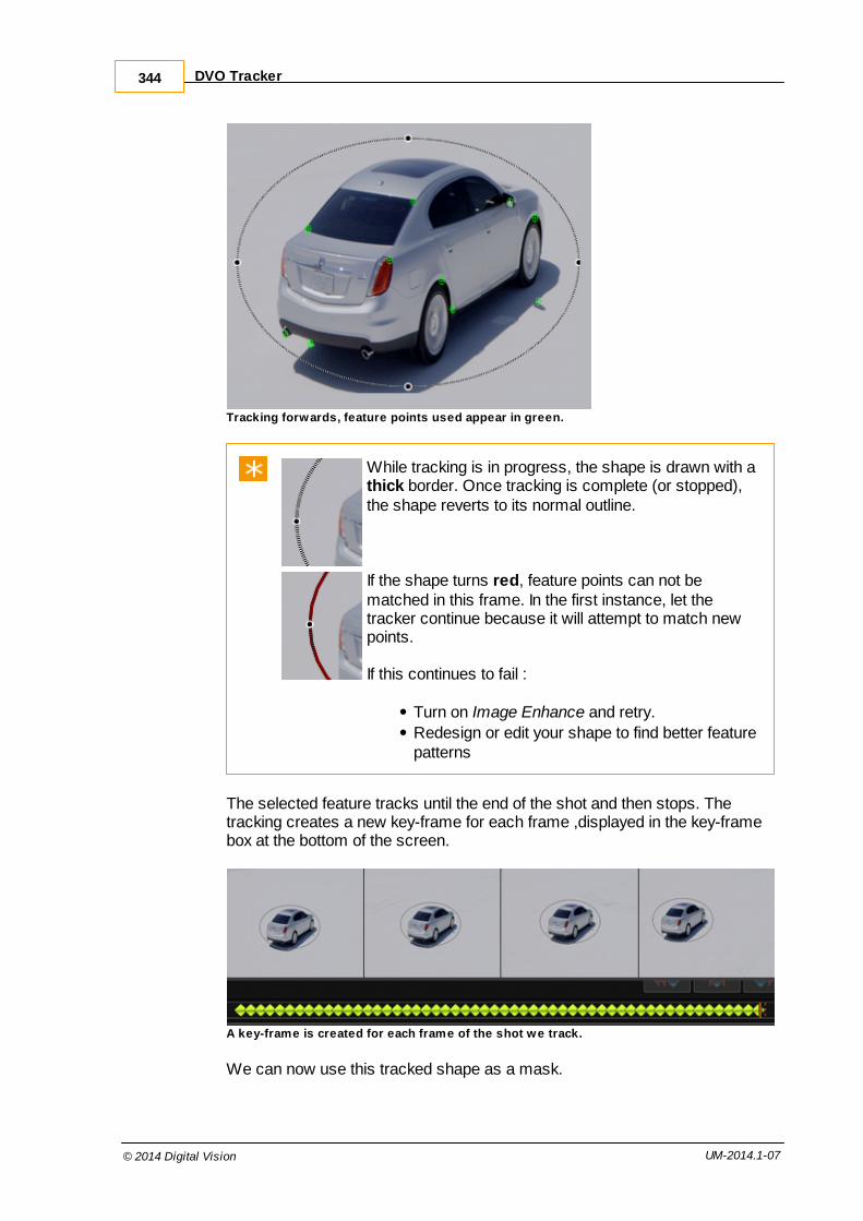
DVO Tracker344
© 2014 Digital Vision UM-2014.1-07
Tracking forwards, feature points used appear in green.
While tracking is in progress, the shape is drawn with a thick border. Once tracking is complete (or stopped),the shape reverts to its normal outline.
If the shape turns red, feature points can not bematched in this frame. In the first instance, let thetracker continue because it will attempt to match newpoints.
If this continues to fail :
Turn on Image Enhance and retry.
Redesign or edit your shape to find better featurepatterns
The selected feature tracks until the end of the shot and then stops. Thetracking creates a new key-frame for each frame ,displayed in the key-framebox at the bottom of the screen.
A key-frame is created for each frame of the shot we track.
We can now use this tracked shape as a mask.

Using Other Tracks 345
© 2014 Digital Vision UM-2014.1-07
Using Other TracksOne shot may have any number of effect layers, each including a Shapeslayer.
CC Layers 1-2 all contain tracked shapes. Layer 3 (rear w indow) is new.
The tracking data from any previously tracked shape can be selected andapplied to any other shape via the Other Tracked Shapes drop-down list :
Having created a new shape, select Other Tracked Shapes and choose thetracking data you want to apply :
Once chosen, click the Apply button to apply the tracking data to your shape.
The tracking data is applied and track/shape key-frames appear inthe key-frame bar at the bottom of the screen. If the shape had anyprevious tracking data, it will be overwritten.

DVO Tracker346
© 2014 Digital Vision UM-2014.1-07
Offset Tracking
Offset Tracking lets you use a different area of a shot for generating the trackcompared to the position of the shape itself. If a different area of the shotbecomes the best candidate for generating the actual tracking data, we canuse it by creating an offset shape and positioning it over this better area.
Enabling the Offset button will activate a copy of the tracking shape :
Normal shape tracking Offset enabled - shape copied (green)
The copy is green. Initially, it is placed on top of the original shape.
We can switch to the Transform menu :
Then move the offset shape to our new preferred position :

Offset Tracking 347
© 2014 Digital Vision UM-2014.1-07
Once in place, we can switch back to the Shape menu :
and continue our tracking.
The tracking data is calculated from the offset shape and applied to the original.
When the Offset button is enabled, the offset shape is used to generate thetrack. You can set the offset shape to any suitable position in the frame. If abetter position becomes apparent, you can re-position it again.
For an offset shape track calculation to work properly, both theoriginal and the offset shape need to share the same type of motion.
Predictive Tracking
Normally, if the tracking calculation fails at some point in a shot, trackingstops. In some cases, it is apparent that the track path could simply carry onas before, the path being extrapolated based on its previous history.

DVO Tracker348
© 2014 Digital Vision UM-2014.1-07
If tracking fails because our tracked feature loses definition or goes out ofcamera, we can enable Predict Tracking at this point.
When we resume tracking, the track path is calculated such that it smoothlycontinues along the same path as calculated previously.
1: Tracking ... 2: Feature reaches edge of frame. Turn Predict
Tracking ON.
3: Feature off camera but track path is
extrapolated.
Track path extrapolation continues.
ReferenceThe DVO Tracker is available to use everywhere we have a Shapes layeravailable. As such, we can draw a shape to define the feature we wish totrack and use the result as a Region of Interest matte.

Reference 349
© 2014 Digital Vision UM-2014.1-07
Every Shapes parameter pane includes the new DVO Tracker controlparameters as shown in the figures below. The DVO Tracker controlsbecome available once a shape is drawn.
Shape controls and new DVO Tracker controls highlighted
Track Buttons
These buttons start the tracking process. You can track forwards orbackwards in a shot, to the shot end or start (respectively) or a frame at atime.
From left to right we have :
Track backwards from current frame tostart of shot.

DVO Tracker350
© 2014 Digital Vision UM-2014.1-07
Track backwards one frame from currentframe.
Track forwards one frame from currentframe.
Track forwards from current frame to end ofshot.
Feature Points
The Feature Points button toggles display of the feature points used by theDVO Tracker at each frame.
Feature Points are points inside our shape that are calculated to be goodpatterns to use when tracking. They are chosen automatically and appearinside the shape we have defined.
Feature Points in green, found inside the defined shape.
Feature Points are chosen dynamically on a frame by frame basis.They are not user selectable or editable.
Transform Buttons
These buttons control what transformations are applied to the shape as wetrack. If the button is off (white), the selected transformation is not applied.
If no transform buttons are enabled, the defined shape will not moveor change at all because no transformations will be applied.
From left to right we have :
Pan X/YEnable to calculate X/Y (up/down/left/right)

Reference 351
© 2014 Digital Vision UM-2014.1-07
pans.
RotationEnable to calculate feature rotation.
Scale XEnable to calculate scale changes in the X-axis.
Scale YEnable to calculate scale changes in the Y-axis.
Offset Button
The Offset button creates an offset shape from the currently selected shape.
This offset shape can be moved (offset) to a new position in the shot fromwhere new feature points are calculated. The feature points calculated usingthe offset shape are applied to the original shape. You can re-position anoffset shape any number of times in the same shot if required, with anytracking data calculated applied to the original shape. See Offset Tracking.
Smooth Button
Normally, the DVO Tracker will position the transformed shape (x/y,rotation,scale) in single pixel increments. The Smooth button will enable sub-pixelpositioning, and cause the track to be re-computed.
This smoothing effect will be visible by switching to the Keyframe Editor taband viewing the resultant animation graph.
If you turn the Smooth button off before completion, the smoothprocess will stop and any smoothing done will be reset to itsprevious state. Once complete, an undo operation will also reset theentire track path to its pre-smoothed state.
Reset Track Points
These buttons allow you to reset all or some of the key-frames created by thetracking process.

DVO Tracker352
© 2014 Digital Vision UM-2014.1-07
From left to right we have :
Reset all track key-frames from currentposition to start of shot.
Reset all track key-frames.
Reset all track key-frames from currentposition to end of shot.
The tracker key-frames are shown below the Shapes panel as greendiamonds :
Key-frames shown in green, and current key-frame in blue.
Pressing the reset all left button will result in all key-frames to to theleft of the play-head being reset (inclusively). This results in the following key-frame status :
Key-frames after reset all left button pressed.
Image Enhance
Image Enhance will do some image processing on the shot to increase thecontrast such that tracking is optimised and a more accurate track calculated.This enhancement is transparent and done in the background (with no visibleimage changes).
Enabling Image Enhance may be necessary for certain type of media,particularly those with lower contrast or high contrast changes.
Image Enhance will default to on for Log projects.
Other Shapes
This drop-down list lets you apply the tracking data from a previously trackedshape in the shot (in another layer) to the current shape. See Using OtherTracks.

Reference 353
© 2014 Digital Vision UM-2014.1-07
Predict Tracking
The Predict Tracking toggle button lets you carry on the track even if alltracked feature points have moved outside the image frame and tracking hasterminated. Turning Predict Tracking on will extrapolate the track to the end(or start) of the shot such that the track is contiguous and smoothly extended.See Predictive Tracking.
Valhall Keys
Mod Key function
Track forwards to end of shot
Track backwards to start of shot
Track forwards one frame
Track backwards one frame
Scroll up/down "Other Tracked Shapes" menu
Apply tracking from selected "Other" shape tocurrent shape.
Creates or toggles the Offset Shape
Resets tracking from current frame to end of shot(inclusive)
Resets tracking from current frame to start of shot(inclusive)
Resets all tracking on current shot

DVO Tracker354
© 2014 Digital Vision UM-2014.1-07

Video I/O 21

Video I/O356
© 2014 Digital Vision UM-2014.1-07
You can capture and lay off video via the Library modules :
Capture video
Layoff video
These options will only be enabled when your system has a video I/O boardinstalled.
Audio I/O
Support for 8 channel audio capture and layoff with the following video cards :
Bluefish Lust - AES/EBU audio
DVS Centaurus2 - AES/EBU and embedded audio
Video I/O
Capture and layoff modules have similar layouts :
The monitor and transport controls are situated on the top left
The settings and control tabs sit below the monitor and transportcontrolsThe event list and event controls are on the right hand side
Playback/Transport Controls
The playback controls on a VTR deck are more commonly referred to as transport controls. These controls are the same on both the capture and layoffscreens:

357
© 2014 Digital Vision UM-2014.1-07
Timecode Box / Cue
This field displays the current tape position.
If you enter a timecode in the box and press the Cue button, the tape will cueto this location.
VTR SettingsThe VT R/Video Capture Settings tab contains a variety ofconfiguration settings - including VTR status, video format used, and audiochannels active. The available settings are similar between the capture andlayoff modules.
Always check these settings carefully before proceeding with anyvideo I/O.

Video I/O358
© 2014 Digital Vision UM-2014.1-07
VTR Deck Status Feedback
The four deck status fields are read-only display fields and provide feedbackon :
Model of VTR attached (e.g. HDW-F500)
Status of the VTR (still,stop,play etc.)
Reported VTR frame rate
Record inhibit status (REC Lock).
Note - if the deck and project frame rates do not match you will get a warningmessage.
This message can be turned off by setting the general.prefsframeRateWarning parameter to false.
Refresh Button
The status fields should update automatically but you can perform a manualupdate by pressing the Refresh button.
Video Signal Feedback
The three 'SDI' fields are read-only display fields, providing feedback from thevideo card.
SDI Input
This shows the video format (resolution and frequency) of the video inputsignal.
SDI Sync
This shows the reported sync signal seen by the video card.

VTR Settings 359
© 2014 Digital Vision UM-2014.1-07
SDI Output
This shows the video format (resolution and frequency) of the video outputsignal
Video Format settings
capture output
Colour Space control
The first drop-down button allows you to set the colour space mode for yourmaterial.
YCrCb 422
RGB 444
RGB Scaling control
The second drop-down allows you to set the video scaling mode that theapplication should apply to the material:
Linear (SMPTE) - no scaling
Linear (CGR) - signal is scaled
This setting is very important in order to ensure that what you see onyour monitor is what you will get on output. For a discussion ofColour Scaling modes, see the Setup Manual.
FPS control
VTR Capture only.
For certain bandwidth intensive formats we need to specify an optimal capturerate to use.
Default FPS - the default is the composition frame rate
Use 14.98 FPS (2K)
Use 15.00 FPS (2K)

Video I/O360
© 2014 Digital Vision UM-2014.1-07
Use 5.00 FPS (4K)
Blanking
VTR Output only
This setting will blank out the top and bottom video lines.
This may be useful to hide any edge artifacts pushed into the videoactive area by certain effects (e.g. blurs).
Audio I/O
Note - the audio settings on the right are only available in the Capture module.
The audio channel buttons give feedback and also act as controls. They willautomatically default to show how many audio channels are available(highlighting them in green), after which you can enable/disable them forcapture/layoff.
2014.1 currently supports eight (8) channels of audio. The buttonsfor channels 9-16 are visible but disabled (and not used).
Capture Only
Interface
Options : AES-EBU or Embedded SDI
This sets the source of the captured audio data.
We support AES/EBU audio with the Bluefish Lust card (AES audio cables)We support AES/EBU and embedded audio on the DVS Centaurus2 card.
The audio capture path is set separately in the capture Controls tab.
File Storage
Options : Broadcast WAV
Bit Depth
Options : 16 or 32
Number of bits per sample to capture.

VTR Settings 361
© 2014 Digital Vision UM-2014.1-07
Roll and Trim controls
Pre-roll
How many seconds the deck should allow the tape to roll before capture/layoffstarts.
When capturing or laying off the deck will cue to the VTR in point minus thevalue set in the pre-roll field. No actual capture/layoff takes place during apost-roll.
Post-roll
How many seconds the deck should allow the tape to roll for after capture/layoff ends. No actual capture/layoff takes place during a post-roll.
Video Trim
This numeric entry field / slider allows you to correct timecode offset errorsthat might occur when capturing or laying off video.
The Video Trim controls which frame of video is recorded at the edit (in) pointand can be used to help fix video routing or system delays.
Edit Trim
VTR Output module only.
Similar to video trim, it allows you to correct any timecode errors causing therecorded material on tape to be starting at the wrong timecode.
The difference between video trim and edit trim is that the video trim settingwill make adjustments to the time when the frames start being sent from diskto tape, i.e. when layoff starts, whilst the edit trim setting makes adjustmentsto when the deck actually starts recording.
The point at which the deck actually starts recording prior to receiving thevideo is what can be adjusted using the edit trim control, should you find thatthe layoff is not ending up at the correct timecode.

Video I/O362
© 2014 Digital Vision UM-2014.1-07
Project Settings for Video Output
If you intend to lay off video from your project, make sure you enable the VideoOutput setting on the project output format. See Cache Output.
Video Capture
The VTR Capture screen is accessible from the library screen via the ..L istCapture button.
This brings up the list capture screen, with two options on the bottom left:
Data Capture - this is the mode used for batch capturing digital media. VTR Capture - this is the mode for capturing media from tape.
For capturing from a VTR deck, press the VT R Capture button.
The Control tab is where the interactive controls for carrying out a videocapture are located.

Video Capture 363
© 2014 Digital Vision UM-2014.1-07
Prior to attempting any capture you should always review and adjustall the values in the settings tab as appropriate for your material andcomposition.
Capture Locations
Defaults : As per general.prefs preference file.
Use the tick boxes to choose which data streams to capture - video, audio orboth.
The capture paths are shown and can be edited in place, or set via the file
browser (click the icon).
If you change a path here, the new location will be saved to the general.prefs preference file.
For optimal performance, the audio and video capture locationsshould be set to separate disk volumes in order to optimiseconcurrent disk-writes (and minimise interference). For example,capture video to the S:\ volume and audio to the W:\ volume.
Deck Status
The deck status is displayed in a summary line at the bottom of the controlstab.
Information displayed is :
VTR/deck model,
Frame rate
Control status.
If the VTR deck is record inhibited, this will be shown as REC Lock.

Video I/O364
© 2014 Digital Vision UM-2014.1-07
Capture Methods
There are three main methods for performing a video capture:
Capture Marked - specify an in and an out point, then capture thismarked region.Capture Live - start recording as the VTR plays
Capture List - import and then capture from a list (e.g. an EDL).
The Capture Single operation is discussed as part of the Capture List section.
Capture Live
This is the simplest capture method and involves pressing the CaptureL ive button at an appropriate time as the video tape is playing.
Pre-roll and post-roll settings do not apply during live capture.
When Capture L ive is pressed, it turns red and the Stop Capture buttonis highlighted. To stop capturing, press the Stop Capture button.

Video Capture 365
© 2014 Digital Vision UM-2014.1-07
If you do a 'Capture Live' without having pressed play, i.e. with nofootage being displayed in the viewer, you will capture blank (black)frames for the duration of the capture.
Once capture has stopped, the captured footage will automatically be addedto your project library.
Capture Marked
This capture method will capture the footage defined between the marked inand marked out timecodes.
Specify the Mark In and Out points by :
Manually typing in the in and out timecode into the appropriate in/outtimecode box orCueing the VTR deck to the In timecode and pressing the Mark Inbutton, then Cueing the VTR deck to the Out timecode and pressing the Mark Outbutton
For accurate marking of the In/Out points you can use the jog framebuttons to locate the exact frame positions.
Once marked, the duration display field will show the total duration of themarked region, and pressing Capture Marked will begin the capture.

Video I/O366
© 2014 Digital Vision UM-2014.1-07
During capture, the Capture marked button will turn red and the VTR deck willcue to the pre-roll point before the marked timecode in-point.
Once the mark-in position is reached the capture will commence and at thispoint the Stop Capture button will become enabled.
Once complete, the capture will stop automatically. You can interrupt thecapture at any time by pressing the Stop Capture button.
Once capture has stopped, the captured footage will automatically be addedto your project library.
Capture List
The Capture L ist method requires an existing event list.
This list is usually created by importing a list file (such as an EDL) and thencapturing and conforming the events. Refer to the section on importing listfiles for detailed instructions on creating a composition based on a list file.
Once you have imported the list file, the corresponding composition willappear in the Library and the events that need to be captured will appear onthe timeline.
No media will exist in the library until it is captured and conformed tothis empty timeline.
Inside the capture module, the list events are shown on the right.

Video Capture 367
© 2014 Digital Vision UM-2014.1-07
Event List
The event list table is composed of a number of fields per event.
The Event List is displayed a standard table. For more detail ontables and their use, see the Tables section.
Each event listed has a status assigned to it. This status will update as thecapture proceeds.
Event Status
The status fields are :
Needed - the media for this event has not yet been captured and theevent is enabled for capture.Disabled (Needed) - the media has not yet been captured but youhave disabled the capture of this event.Disabled (Found) - the media has already been captured and youhave disabled the event to avoid recapturing it.Capturing - the media for this event is in the process of beingcaptured.Partial Capture - part of the media for this event has been capturedbut not in its entirety.Found - all the media for this event has been found and captured.

Video I/O368
© 2014 Digital Vision UM-2014.1-07
Material
Once an event has been captured (Found), the path to the stored media willbe shown in the Material column for that event.
Tape Name
Events in the list may need to be captured from different tapes, as indicatedby the Tape Name column. You will be prompted to insert each tape (or toskip it).
This will continue until all the media from the different tapes has beencaptured.
If you press Skip T ape , no media will be captured for this tape andcapture will proceed to the next tape (prompt for insert), if there isone. You can capture any skipped tapes later.
Event Controls
The event controls, located beneath the event list, allow you to refine your listand select specific events prior to capturing:
Enable / Disable Event
To selectively choose to capture events (or not), select single or multipleevents from the list and use the Enable Event and Disable Eventbuttons prior to pressing Capture L ist.
A disabled event will have a status that displays Disabled e.g. Disabled(Needed) or Disabled (Found).
You can capture events in "groups", perhaps using a differentnumber of handles for each.
Reset Event
This option will reset the selected event(s) to the status of Needed, whether ornot the media had already been captured. This allows a re-capture of apreviously captured event.

Video Capture 369
© 2014 Digital Vision UM-2014.1-07
Event Handles
This numeric slider specifies whether to capture more frames than the eventsrequire i.e. handles. Setting the Event Handles to 5, will capture 5 frames ofhead and 5 frames of tail for each enabled event.
The addition of handles might be applied in order to capture as muchof each media clip as might be later needed and to allow latertrimming of the media clip within the composition. Adding handlescan also be used to lengthen events in the composition list so thattheir timecodes overlap with others and various events can beconsolidated and captured as a single media clip using the'Consolidate Events and Tapes' function.
Consolidation
Default : Consolidate on tape
Consolidation is the grouping together of overlapping events (generally bytimecode) into a single "event" which can be processed (captured) as one.This can minimise the amount of work required to capture the same amountof material. Consolidation reduces the total number of events to capture.
Don't consolidate Ignore potential consolidation and show every event inthe list.
Consolidate ontape
Consolidate overlapping timecodes within the sametape.
Consolidate onclip
Consolidate overlapping timecodes within the same clip.
You can also use consolidate in conjunction with the handlesfunction to increase the length of media required by events that areclose in their timecodes but not overlapping. By making them overlapon purpose, the source material can be captured in one go as asingle clip.
Capturing the List
When ready, press Capture L ist to start the capture.
Once capture starts, the Capture L ist button turns red.

Video I/O370
© 2014 Digital Vision UM-2014.1-07
Buttons Skip Event, Skip T ape and Stop Capture are also enablednow.
In-between capturing each event, whilst the deck scans to find thecorrect position, these interactive buttons will become disabled.
Once capture is complete (or stopped), you should look at the status of eachevent in your list to check that it was captured correctly and that the Materiallocation is given.
Press Conform to complete the capture process and link the capturedmedia in the library to your composition.
Capturing a Single Event
To capture a single event, select it in the event list and press CaptureS ingle.
This button is only enabled when a single event is selected.
As before, the button will turn red once capture is underway, and the 'StopCapture' button will become enabled:
The event list will show the individual event being captured:
Exporting the Events List
Press Export L ist to export all, or a subset, of the event list.

Video Capture 371
© 2014 Digital Vision UM-2014.1-07
You can export as a CMX3600 EDL or a CUT style list.
There are three options for export :
Export all - This will export the full list of events as displayed on-screen. You may want to do this if you've altered the original list insome way, e.g. by adding handles or using the consolidate eventsfunction. Export found - This will export a list containing only the events that youcaptured.Export not found - This will export a list of all the events that were notcaptured. This could serve as an easy way to identify which eventshave yet to be captured.
The list export option is only available in the List Capture screen.
Video Layoff
The VTR Layoff screen is accessible from the library screen via the ..L istOutput button. The layoff module is called List Output and will output thecurrent composition events to video.
There are two tabs - VTR Output Control and VTR/Video Output Settings.The Settings tab has been detailed in the VTR Settings section.
The monitor will switch between displaying the footage on tapeduring tape playback, and displaying your composition footage duringthe actual layoff process.
The Control tab is where the interactive controls for carrying out a video layoffare located.

Video I/O372
© 2014 Digital Vision UM-2014.1-07
Event List
The events to be output are shown on the right-hand side and correspond tothe events on your timeline. The number of events in the list matches thenumber of events on your timeline. Gaps in the timeline are ignored.
Though gaps in the timeline do not show up in the event list, they willin fact be laid off to tape as black frames for the duration that theyoccur on the timeline.
Status
Before output, each event is checked and rendered if necessary. This is anautomatic process.
Processing - This means the event is still being checked or rendered.
Rendered & Found - This means the event is ready for layoff.
Rec In / Rec Out
The Record In time of the first event matches the start time of thecomposition on the timeline, and the Record Out time of the last eventmatches the end time of the composition.
These two columns show the Record In and Record Out timecodes of theevent as it appears on the composition timeline. These values are used whenlaying events off in Record Order.
Src In / Src Out
These two columns show the Source In and Source Out timecodes of thesource material for that event. These values are used when laying events off

Video Layoff 373
© 2014 Digital Vision UM-2014.1-07
in Source Order.
Material
This column shows the location of the rendered material on disk. This may ormay not correspond to the location of the source material shown in the libraryscreen.
Tape Name
This column shows the tape name corresponding to the source material forthat event.
Event Handles
If a source order mode (e.g. Source Order Tape) is selected, the EventHandles option is enabled.
This numeric slider is located directly below the event list, and allows theoption of laying-off more frames than each event requires (i.e. adding'handles'). The handles are added on either side of the event on tape.
The addition of handles might be applied in order to layoff as much ofeach media clip as might be later needed when re-importing themedia as source material for a composition, and to allow latertrimming of the media clip within the composition.
Laying off Sections
With no marks set, the Output module will select all events for layoff.
To layoff a section of your timeline only, use the timeline Mark In and Mark
Out buttons to mark the desired range before pressing ..L ist Output.
The output module will only display and output the marked events.

Video I/O374
© 2014 Digital Vision UM-2014.1-07
Output ControlsThe VTR Output Controls are shown below.
The Actions buttons in the centre perform the specified output operation e.g.Output L ist, Stop Output etc.
Status Fields
VTR
VTR Deck status is shown in the VTR row.
If the tape is record inhibited, it will show REC Lock.
List
During processing or output, this row will show the list status and outputprogress.
Buffer
The Buffer row will display how many frames are buffered and ready foroutput.
Output Channels
Use the tick boxes to choose which data streams to output - video, audio orboth.

Video Layoff 375
© 2014 Digital Vision UM-2014.1-07
Record Edit Mode
This drop-down list allows you to select the edit mode, which determines howmaterial is written to tape. The following modes are available.
Insert Edit Each event is recorded at the record in-point timecode.This mode requires a tape pre-striped with the right recordtimecodes.
AssembleEdit
This locates the record in-point timecode of the first eventand starts recording. From here, timecodes are generated(assembled) as the output proceeds. Only the initial in-point timecode is required (hence only a partially stripedtape is necessary).
Crash Record This method starts recording at the current tape position,with no pre-roll or post-roll used, and writes out timecodesas it records. This mode will therefore work on a blanktape (no pre-striping required) and is only suitable forlaying off contiguous material.
The Pad Events option is available here.
Preview BVB This mode previews the output. It does not write anythingto tape. The preview shows : Black - Output Video - Black.
Preview VVV This mode previews the output. It does not write anythingto tape. The preview shows : Video - Output Video - Video.
Review This mode reviews the output on tape. It does not writeanything to the tape.
Pre-striped tapes must be striped at the same frame rate as yourcomposition.
The Actions buttons will change depending on record mode selected.

Video I/O376
© 2014 Digital Vision UM-2014.1-07
Timecode Output Order
This drop-down list allows you to select which timecode order is to be usedwhen writing the events to the tape:
Source Order TC (C) Record each event to tape at its original location (i.e. its source timecode), ignoring its location onthe composition timeline (record timecode).Event handles : enabled.
Source Order Tape(C)
This is the same as Source Order TC except thelist is sorted by tape first, then source timecode.Event handles : enabled.
Record Order (A) Record each event to tape at its composition(record) timecode location i.e. the samesequential order as your composition timeline andat the same timecodes (unless "Use mark as inpoint" is set, see below).Event handles : disabled.
Event Handles are enabled for Source Order mode layoffs :
Note that Source Order layoffs will not render transition effects.
When Source Order is selected, the Mark-In/Out values in the EventList will change to show the source timecodes matching the startand end timecodes of the list events. When Record Order isselected the record timecodes are shown instead.
Pad Events In / Out
Crash Record only.

Video Layoff 377
© 2014 Digital Vision UM-2014.1-07
Pad Events controls whether padding is to be applied during output. Paddingconsists of black frames with contiguous timecode being written before andafter the events being laid off.
How much padding is written is controlled by the In and Out timecode fields.
The timecode given to the padding will always precede the timecodeof the 1st event being laid off, and if a Mark-In Timecode has beensupplied the timecode of the padding will precede the Mark-In TC.
Padding can only be carried out in Crash Record mode.
In / Out Markers
The In, Out and Duration boxes relate to the in, out and duration times of yourevent list. Record timecodes or source timecodes are used according to theTimecode Output Order selected.
You can set the In point timecode by :
Pressing the Set In button (Cue In). This sets the In timecode to thecurrent deck position.Erasing and typing in a new timecode via your keyboard.
Use mark as in point
Ticking this box will set your layoff in-point to the In timecode set. Your listwill be recorded starting at this In timecode
Output List
This button is enabled when there are events in the event list. Pressing it willstart off the layoff to tape of all the events in the list.
Unlike the VTR Capture module, you cannot select a group of eventsfor layoff from the event list. All items in the list will be output. Toselect a sub-section for layoff, see Laying Off Sections.

Video I/O378
© 2014 Digital Vision UM-2014.1-07
Output Single
This button is enabled whenever a single event is selected/highlighted in the event list. Pressing it will layoff that specific event only.
Stop Output
This button is only enabled when there a layoff is in progress. Pressing it willhalt the layoff.
Output ListOutput L ist will layoff the entire event list.
Checking the List
Before the list is output to video, the events are first checked to ensure theyare fully rendered and available.
Validate Output
Default : On
If Validate Output is enabled, a final output validity check is performed afterany rendering is complete.
Once layoff starts, the button will turn red and the Stop Output button willbecome enabled and turn green.
The tape will be scanned for the correct timecode in-point and recording willcommence. For a crash record, recording will commence at the tape position.
All the events shown in the event list will be written to tape.
The layoff can be halted at any time by pressing the Stop Output button.

Video Layoff 379
© 2014 Digital Vision UM-2014.1-07
Output SingleOutput Single will layoff a single selected event only.
The Output Single button is only enabled when a single event isselected in the event list.
Before the layoff starts, the event is rendered (if required) and a final outputvalidation check is performed (if Validate Output is enabled - see ValidateOutput).
Once layoff starts, the button will turn red and the Stop Output button willbecome enabled and turn green.
The tape will be scanned for the correct timecode in-point and recording willcommence. For a crash record, recording will commence at the tape position.
Only the selected event will be output to tape.
The layoff can be halted at any time by pressing the Stop Output button.

Command Line 22

381
© 2014 Digital Vision UM-2014.1-07
The Command Line Interface (CLI) lets you run application commandswithout starting up the application interface (GUI). The CLI is therefore usefulfor automating tasks that do not require an operator to be present.
The CLI supports many of the operations that can be performed interactivelyusing the GUI interface:
Project Definition and Creation
Composition Definition and Creation
Importing Clips to the Library
Adding a Version
Splicing or Overwriting Clips to a Composition
EDL Import and Conform
Capturing and Conforming Material
Generating Local Proxies
Rendering a Composition via Export
Rendering a Composition Cache
Running Multiple Operations from a File
Listing Project and Composition Information
Counting and Adding Tracks to Existing Compositions
Testing for a GUI Lock
Project Format Specification
Be careful to quote any strings or paths you use on the commandline. In particular, pay attention to any spaces in strings or paths oryou will see syntax errors i.e.
The argument :
--format-spec C:\data files\specs\test.spec
Will give an error due to the space in the "data files" folder. Quotethis to prevent the error :
--format-spec "C:\data files\specs\test.spec"

Command Line382
© 2014 Digital Vision UM-2014.1-07
Conventions
Required parameters are given in angled brackets <> i.e.
--format-spec <path>
Optional parameters are given in square brackets [] i.e.
--timecode-header [1|2]
Possible values are separated with a vertical bar (| as above).
Splitting Long Lines
This document sometimes splits long command lines over multiple lines tomake the command easier to read. The split if delimited by a line-continuationcharacter "\" i.e.
--export S:\exp\$o\$c..dpx \ --export-mode single
In reality, you would type the above command on a single line only withoutthe continuation character :
--export S:\exp\$o\$c..dpx --export-mode single

383
© 2014 Digital Vision UM-2014.1-07
User Login--user <username> Log in as named user
To use the command line interface as a specific user, use the --user optionand specify the username to login to the application as.
Command :
$ nucoda_film_master --user steven --listProjects:
1: test1 - C:\Nucoda\...
2: Check Danger 002 - C:\Nucoda\...
3: Check Danger 003 - C:\Nucoda\...
Without the --user option, the last user we logged in as is used. If we have never logged in, the Default user is used.
Creating a Project--project <name> Create a new project with the specified name
--format-spec <path> Use the specified project format specificationtemplate
Create a New Project
--project <name>--format-spec <path>
To create a new project from the command line, create a project formatspecification file that describes the project. This is the equivalent of setting upthe project configuration settings in the GUI.
Specify the name of the project and its format specification file using thecommand:
Command :
$ film_master --project PROJ1 --format-spec H:\specs\hd-1.txtINFO Creating new project "PROJ1".
The above command creates a new project "PROJ1" using the definitionstored in the file "hd-1.txt".
Project Format Specification
--format-spec <path>
This "format spec" is a text file that defines the elements of the project,

Command Line384
© 2014 Digital Vision UM-2014.1-07
including both outputs and sources. The output and source sections arespecified using the section tags:
[output]
[source]
The basic format is as follows :
<Global Parameters>[output]<output sections>[source]<source sections>
Some global parameters are requiredThere must be one or more output sections.The first output section will be the master format for the project.There are zero or more source sections (a "1:1 source" will alwaysbe created).The '#' symbol starts a comment
See : Format Specification definition section
A minimal format specification file would look like:
# A minimum basic format specificationcolourScaling=cgr
[output]width=1920height=1080fps=25aspectRatio=16/9
A "#" symbol starts a comment.
See the next section for the complete file format definition.
Example format specification files can be found in the folder :
C:\Phoenix\2014_1example_files\format_specs\
Project Format SpecificationA project is defined using a project format specification file. This file is of thefollowing format :

Creating a Project 385
© 2014 Digital Vision UM-2014.1-07
<Global Parameters># one or more output sections[output]key=value...# zero or more source sections[source]key=value...

Command Line386
© 2014 Digital Vision UM-2014.1-07
Data Types
The various data types we can use in the specification are as shown in thetable below.
Data Type Description Examples
<bool> A boolean true/false true, false
<int> Integer number 1556
<float> Floating point number 29.97
Global Parameters
These parameters appear outside an output or source section, at the start ofthe file. We underline required options.
colourScaling
Required
Values : SMPTE CGR FilmLog VideoLog
Default :
Project colour scaling mode.
outputClip
Values : <bool>
Default : false
Project output clipping.
Output Section Parameters
These parameters appear inside an output section.
width
Required
Values : <int>
Default :
The width (x resolution)of the output format in pixels.

Creating a Project 387
© 2014 Digital Vision UM-2014.1-07
height
Required
Values : <int>
Default :
The height (y resolution)of the output format in pixels.
fps
Required
Values : <float>
Default :
The frames per second. If no decimal point set, we add a .0automatically e.g. 29.97, 25
aspectRatio
Required
Values : <int>/<int>
Default :
The output format image aspect ratio. Specify as M/N e.g. 1316/1000
dropFrame
Values : <bool>
Default : false
Set if output format is drop-frame.
videoOutput
Values : <bool>
Default : false
Specifies if Video Output is enabled on output format.
fields
Values : f2:f1 f1:f2 frames
Default : frames
Specifies if output format is field based and gives field order.

Command Line388
© 2014 Digital Vision UM-2014.1-07
channels
Values : RGB RGBA
Default : RGB
Colour channels
bitDepth
Values : 8,10,16,half
Default : 10
Output colour depth per colour channel, in bits per pixel.
convertMode
Values : none fit crop center
Default : none
Output format conversion from source.
convertFilter
Values : none box bilinear gaussian zom lanczos
Default : zom
What conversion filter to use on the source (if convertMode not "none")
applyCms
Values : <bool>
Default : false
Specifies if the Apply CMS toggle is on or off.
Source Section Parameters
These parameters appear inside an input section.
scale
Required
Values : <int>
Default :
Sets the scale of the source/proxy. This integer will divide the width andheight to set the proxy size. A scale N gives an "N:1" proxy.

Creating a Project 389
© 2014 Digital Vision UM-2014.1-07
bitDepth
As output section above.
convertFilter
As output section above.Only applicable if scale > 1.
Notes
The key values are case-sensitive.
Values are case-insensitive (e.g. use "rgb" or "RGB").
Attach and Detach Project--attach-project <path> Attach project found at specified path
--detach-project <name> Detach named project
--remove-cache delete project caches when attaching
Attaching a project makes it available for use by the application and adds it tothe list of available projects on the project screen.
Attaching a Project
--attach-project <path>
This command attaches the specified project. The named project is the fullpath to the project folder.
Command :
$ nucoda_film_master \ --attach-project D:\archived\project-xINFO Imported "D:\archived\project-x" (project name is "project-x").
Attach multiple projects by separating them with a space e.g.
--attach-project D:\project1 "G:\blue sky"
Detaching a Project
--detach-project <name>
This command detaches the named project.

Command Line390
© 2014 Digital Vision UM-2014.1-07
Command :
$ nucoda_film_master --detach-project project-xINFO Detached project "project-x".
Removing Project Caches
--remove-cache
When attaching projects, specify this argument to have their caches removedafter attachment.
Command :
$ nucoda_film_master \ --attach-project D:\archived\project-x \ --remove-cacheINFO Imported "D:\archived\project-x" \
(project name is "project-x") and removed cache.
Creating a Composition--composition <name> Name and create a new composition
--num-tracks <N> Create a composition with N video tracks
Create a New Composition
--composition <name>
The following command creates a new composition named "COMP1" insideproject "PROJ1".
Command :
$ film_master --project PROJ1 --composition COMP1INFO Opening project "PROJ1".INFO Creating new composition "COMP1".
If the project does not exist, it will be created. This will require a formatspecification option.
Create a New Project and NewComposition
The following command creates a new project "PROJ2" according to theformat specification file "FORMAT". It will then create a new compositionnamed "COMP2" inside the newly created project.

Creating a Composition 391
© 2014 Digital Vision UM-2014.1-07
Command :
$ film_master --project PROJ2 --format-spec FORMAT \--composition COMP2INFO Creating new project "PROJ2".INFO Creating new composition "COMP2".
Create a New Composition withMultiple Video Tracks
--num-tracks <N>
The following command creates a new composition "COMP3" containing 3video tracks (V1,V2 and V3) inside project "PROJ1".
Command :
$ film_master --project PROJ1 --composition COMP3 \--num-tracks 3INFO Opening project "PROJ1".INFO Creating new composition "COMP3".
Video tracks can be selected using the --track ID option on thecommand line, where ID is "V1", "V2" etc.
Importing Clips--import-clip <path> Import clip from specified path
--name <name> Give the clip a library name on import
--description <descr>--clip-description <descr>
Give the clip a library description onimport
Importing a Clip
--import-clip <path>
The following command imports a clip from the specified path into the libraryof project "PROJ1":
Command :
$ film_master --project PROJ1 --import-clip \ M:\images\train\300001.dpxINFO Opening project "PROJ1".INFO Found range (300000, 300164).
The clip imported above will be given a default name in this case because thefilename is numeric only.

Command Line392
© 2014 Digital Vision UM-2014.1-07
The default name will be taken from the two containing directories i.e. "imagestrain". See below.
Command :
$ film_master --project PROJ1 \ --import-clip Z:\shots\056\056_001.001.dpxINFO Opening project "PROJ1".INFO Found range (1, 15).
The clip will be given a name taken from the filename, i.e. "056_001". Seebelow.
This command only imports one clip. To import multiple clips, see Importing Folders.
If you perform the same import operation twice, the clip will beimported again. This differs from previous behaviour that expectedthe option --force-import to be used (this option has beenremoved).
Specifying a Clip Name on Import
--name <name>
To specify a clip name in the library on import, use the --name option.
Command :
$ film_master --project PROJ1 \ --import-clip Z:\shots\002\shot1002.001.dpx \ --name "clip name"INFO Opening project "PROJ1".INFO Found range (1, 99).INFO Set clip name to "clip name".
You can only set the name of an imported clip when you import it, notafterwards.
Clip Naming Convention
Unless specified with the --name option, the imported clip is named asper the settings in the application preferences Auto Assign Name.
Specifying a Clip Description onImport
--description <description>

Importing Clips 393
© 2014 Digital Vision UM-2014.1-07
To specify a clip description in the library on import, use the --descriptionoption.
Command :
$ film_master --project PROJ1 --import-clip \ Z:\shots\1002\shot1002.001.dpx \ --description "clip desc"INFO Opening project "PROJ1".INFO Found range (1, 99).INFO Set clip description to "clip desc".
The description can only be set on import, not afterwards.
Importing Movies--import-movie <path> Import a movie clip from specified path
Importing a Movie
--import-movie <path>
This command imports a movie into the named project from the specifiedpath.
Any supported movie format can be imported using this command,including :
Red R3D
Quicktime
MXF wrapped media
ARRI D21
Silicon Imaging SI-2K
Vision Research Phantom
Command :
$ film_master --project PROJ1 --composition comp1 \ --import-movie C:\media\qt\sample.movINFO Opening project "PROJ1".INFO Opening composition "comp1".

Command Line394
© 2014 Digital Vision UM-2014.1-07
Importing Folders--import-folder <path> Import clips found in named
folder (and all sub-folders)
--filter-format <fmt> Filter clips we import by fileformat
--filter-res <w> <h> Filter clips we import by imageresolution
--splice-order <file|timecode> Splice clips found tocomposition in specified order
--timecode-header [1|2] Take timecodes from fileheaders
--timecode-filename Take timecodes from filenames/paths
--tapename-header Take tapenames from fileheaders
--tapename-filename <level> Take tapenames from filenames/paths
These options control the import of supported image sequences recursivelyfrom a specified folder path.
Importing a Folder
--import-folder <start folder path>
This command imports all supported image files found in the specifiedfolder and any sub-folders (recursively).
Command :
$ film_master --project code2 \ --import-folder Z:\scans\reel4\INFO Opening project "code2" from ...INFO Batch ... importing directory 0 of 1 (0)INFO Batch ... importing directory 1 of 5 (20)...INFO Batch Import (completed) ... 6 of 6 (100)
The command shown above has imported the given folder into the specifiedproject "code2". This is a total of six folders searched, the specified folderitself and five sub-folders :
z:\scans\reel4\
z:\scans\reel4\0008H\
z:\scans\reel4\0006\
z:\scans\reel4\0005\
z:\scans\reel4\0002\
z:\scans\reel4\0002\high\

Importing Folders 395
© 2014 Digital Vision UM-2014.1-07
Filtering
We can filter the sequences the command selects to import on imageresolution (e.g. choose only HD sequences) and image format (e.g. chooseonly TIFF sequences).
Filter on Resolution
--filter-res <width> <height>
This option will select only images that match the given resolution (width xheight) in pixels.
Command :
$ film_master --project code2 \ --import-folder z:\scans\reel4\ \ --filter-res 2048 1556INFO Opening project "code2" from ...INFO Batch ... importing directory 0 of 1 (0)INFO Batch ... importing directory 1 of 5 (20)......INFO Batch Import (completed) ... 6 of 6 (100)
Shots that match the resolution specified will be loaded into the project library.
Filter on Image Format
--filter-format <extension>
This option will select only image sequences that match the specified fileformat, given as the common format extension.
Command :
$ film_master --project code2 \ --import-folder z:\scans\reel4\ \ --filter-format dpx
For a list of supported formats and recognised extensions, see FileFormat Support.
Tapename
--tapename-header--tapename-filename <level>
These options override the source of the tapename field we extract whenimporting each sequence found.

Command Line396
© 2014 Digital Vision UM-2014.1-07
If you do not specify these options, the default settings will be usedas set up in your preferences.
Command :
$ film_master --project code2 \ --import-folder z:\scans\reel4\ \ --filter-format tif --tapename-filename 1INFO Opening project "code2" from ...INFO Batch ... importing directory 0 of 1 (0)INFO Batch ... importing directory 1 of 5 (20)......INFO Batch Import (completed) ... 6 of 6 (100)
Timecode
--timecode-header [1|2]--timecode-filename
These options override the source of the timecode we extract when importingeach sequence found.
Using --timecode-header will attempt to extract the sequence timecodefrom the file header. If this does not exist (e.g. the format does not supportheader timecode), then the filename numerics are used to calculate thetimecode.
If you do not specify these options, the default settings will be usedas set up in your preferences.
First and Second Timecode
This is a Red R3D file specific option argument.
The --timecode-header option takes an optional argument 1 or 2.This allows us to specify whether to use the first or second timecodefrom an R3D file. With no argument, we default to 1.
Command :
$ film_master --project code2 \ --import-folder z:\scans\episode5\ \ --filter-format r3d --timecode-header 2INFO Opening project "code2" from ...INFO Batch ... importing directory 0 of 1 (0)INFO Batch ... importing directory 1 of 5 (20)......INFO Batch Import (completed) ... 6 of 6 (100)
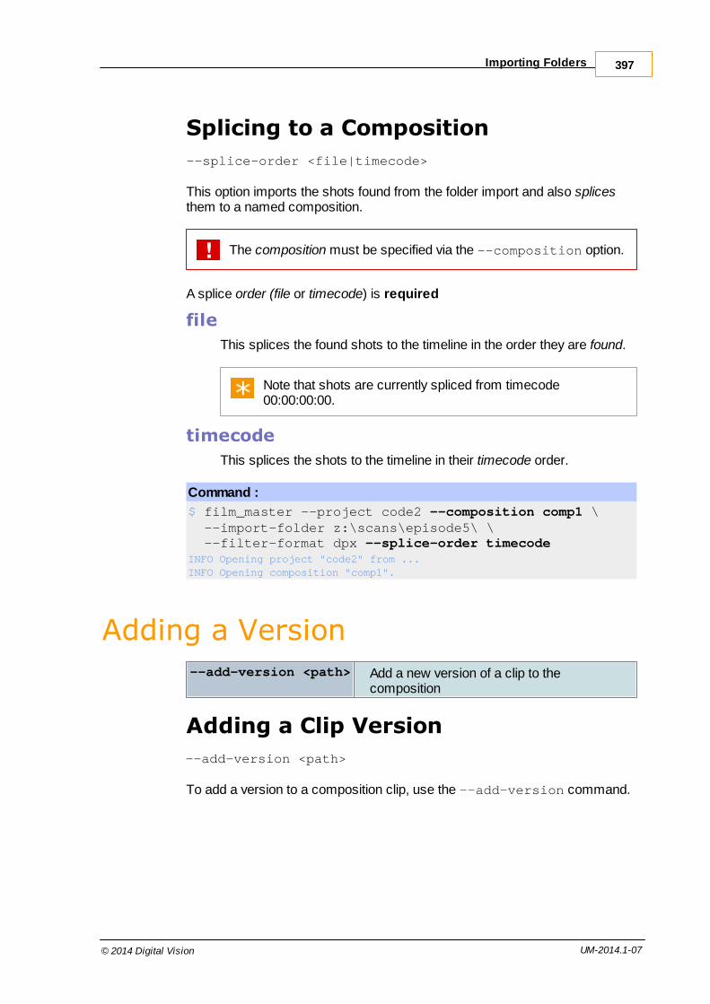
Importing Folders 397
© 2014 Digital Vision UM-2014.1-07
Splicing to a Composition
--splice-order <file|timecode>
This option imports the shots found from the folder import and also splicesthem to a named composition.
The composition must be specified via the --composition option.
A splice order (file or timecode) is required
file
This splices the found shots to the timeline in the order they are found.
Note that shots are currently spliced from timecode00:00:00:00.
timecode
This splices the shots to the timeline in their timecode order.
Command :
$ film_master --project code2 --composition comp1 \ --import-folder z:\scans\episode5\ \ --filter-format dpx --splice-order timecodeINFO Opening project "code2" from ...INFO Opening composition "comp1".
Adding a Version--add-version <path> Add a new version of a clip to the
composition
Adding a Clip Version
--add-version <path>
To add a version to a composition clip, use the --add-version command.

Command Line398
© 2014 Digital Vision UM-2014.1-07
Command :
$ film_master --project PROJ1 --composition COMP1 \ --add-version M:\images\shots\009\056_009.001.dpx \ --clip-name VERSION2 --record-in 100
INFO Opening project "PROJ1".
INFO Opening composition "COMP1".INFO Found range (1, 54).INFO Set clip name to "VERSION2".INFO Clip added to composition.
This will import the clip at the specified path (giving it a name "VERSION2"),setting it as a version of the clip at the record position 100.
You need to have at least the same amount of source material in thenew version as the old or an error will occur.
Replacing a Source--replace-source <path> Replace source of shot (at frame count)
specified by new source
Replacing a Clip Source
--replace-source <path>
To replace the source of the shot (at specified record-in count) with the newsource as specified in the given path.

Replacing a Source 399
© 2014 Digital Vision UM-2014.1-07
Command :
$ film_master --project PROJ1 --composition COMP1 \ --replace-source M:\images\shots\009\056_009.001.dpx \ --record-in 100
INFO Opening project "PROJ1".
INFO Opening composition "COMP1".INFO Found range (1, 54).INFO Set clip name to "VERSION2".INFO Clip added to composition.
The source will be replaced.
Grades will be retained on the shot.
You need to have at least the same amount of source material in thenew version as the old or an error will occur.
Splice and Overwrite Clips--splice [path] Splice a clip to the composition timeline
If clip path not given, clip name must be.
--overwrite [path] Overwrite a clip to the composition timeline.If clip path not given, clip name must be.
--record-in <N> Composition timeline record position
--source-in <N> Input clip source position offset
--name <name> Select name of library clip to operate on
--length <N> Consider only this number of input frames
--track <Vn> Select video track to operate on
Splice versus Overwrite
A splice operation will push any existing clip frames up the timelinefrom the splice location.An overwrite operation will overwrite any existing clip frames fromthe splice location.
If a clip file path is not supplied, it is required to supply a clip name (--name). If you only supply a clip name, it must exist in the projectlibrary.

Command Line400
© 2014 Digital Vision UM-2014.1-07
Note that the timeline is assumed to start at 00:00:00:00.Clips will be placed at the end of the timeline (or 00:00:00:00 iftimeline empty) unless a record-in point is set with the --record-inoption.
Original "alex one" clip (splice to empty composition)
Command :
$ nucoda_fuse --project PROJ1 --composition COMP1 \ --name "alex one" \ --splice
Result:
If we now :
Splice Clip
Command :
$ nucoda_fuse --project PROJ1 --composition COMP1 \ --name "train" \ --splice --record-in 0
We end up with :
Overwrite Clip
Command :
$ nucoda_fuse --project PROJ1 --composition COMP1 \ --name "train" \ --overwrite --record-in 0
We end up with :
It is best to always set the explicit in point for an overwrite operationusing the --record-in option.

Splice and Overwrite Clips 401
© 2014 Digital Vision UM-2014.1-07
Splice/Overwrite By Clip Name
Command :
$ nucoda_fuse --project PROJ1 --composition COMP1 \ --name "train" --spliceINFO Opening project "PROJ1".INFO Opening composition "COMP1".INFO Clip added to composition.
Splice/Overwrite By Clip Path
This will do an import to library followed by a splice.
Command :
$ nucoda_fuse --project PROJ1 --composition COMP1 \ --splice M:\shots\004\300000.dpxINFO Opening project "PROJ1".INFO Opening composition "COMP1".INFO Found range (300000, 300164).INFO Clip added to composition.
You might want to give the imported clip a library name and description(possible on first import only).
Command :
$ nucoda_fuse --project PROJ1 --composition COMP1 \ --splice Z:\images\300000.dpx --name "train" \ --description "this is a train clip"INFO Opening project "PROJ1".INFO Opening composition "COMP1".INFO Found range (300000, 300164).INFO Set clip name to "train".INFO Set clip description to "this is a train clip".INFO Clip added to composition.
Splice/Overwrite to a Different VideoTrack
If the composition has more than one video track, we can select the targettrack using the --track option.
Command :
$ nucoda_fuse --project PROJ1 --composition COMP1 \ --splice --name "train" --track V2INFO Opening project "PROJ1".INFO Opening composition "COMP1".INFO Clip added to composition.

Command Line402
© 2014 Digital Vision UM-2014.1-07
Splice/Overwrite to a SpecificRecord Position
We can splice or overwrite to a specific position on the composition timelineusing the option --record-in.
Original timeline video track with clip "alex one":
Command :
$ nucoda_fuse --project PROJ1 --composition COMP1 \ --overwrite --name "train" --record-in 100INFO Opening project "PROJ1".INFO Opening composition "COMP1".INFO Clip added to composition.
After overwrite to frame 100 of clip "train"
Splice/Overwrite from a SpecificSource Position
There are two methods to splice or overwrite a clip from a specific sourceposition. Explicitly using the --source-in option or implicitly using thetimecode of the frame of the clip we pass in.
The second implicit method needs the full path of the clip frame to beused not the clip name.
Source-In
We can splice/overwrite from a specific source position by using the option--source-in :

Splice and Overwrite Clips 403
© 2014 Digital Vision UM-2014.1-07
Command :
$ nucoda_fuse --project PROJ1 --composition COMP1 \ --overwrite --name "slate" \ --record-in 100 --source-in 10INFO Opening project "PROJ1".INFO Opening composition "COMP1".INFO Clip added to composition.
Clip Frame
Instead of using the --source-in option to select the first frame of the sourceto splice, we splice the source clip from the frame we pass in.
If we have a clip :
008[200-300].dpx
The following command :
Command :
$ nucoda_fuse --project PROJ1 --composition COMP1 \ --splice Z:\images\008220.dpx --record-in 100INFO Opening project "PROJ1".INFO Opening composition "COMP1".INFO Clip added to composition.
will splice the clip from frame 008220.dpx i.e. splicing frames 008[220-300].dpx.
This is equivalent to using the option --source-in 8220.
Splice/Overwrite of ParticularMaterial Lengths
We can choose to splice or overwrite a particular length of clip using the --length. The following command will splice in the first 10 frames (--length) of clip "slate" onto the timeline at frame 100 (--record-in).

Command Line404
© 2014 Digital Vision UM-2014.1-07
Command :
$ nucoda_fuse --project PROJ1 --composition COMP1 \ --splice --name "slate" \ --record-in 100 --length 10INFO Opening project "PROJ1".INFO Opening composition "COMP1".INFO Clip added to composition.
Applying a Note to a Shot--set-note <name|path> Apply note to shot we splice (or overwrite).
Note can be specified by name or path.
Apply Note
Use the --set-note command to apply a note to a shot.
The note can only be applied when the shot is spliced or overwrittento the composition. See : Splice and Overwrite Clips
By Name
--set-note NAME
Apply the named note to the shot. The note must exist in the project notesfolder :
The named note must exist in the specified project.
Command :
$ film_master --project PROJ1 \ --composition comp --name SHOT \ --splice --record-in 90673 \ --set-note lowerlevelsINFO Opening project "PROJ1".INFO Opening project "PROJ1" from "D:\Nucoda\2013_1\projects\PROJ1".INFO Opening composition "comp".Successfully applied note lowerlevels.INFO Clip added to composition.
By Path
--set-note PATH

Applying a Note to a Shot 405
© 2014 Digital Vision UM-2014.1-07
Apply the note found at the given path to the shot.
Command :
$ film_master --project PROJ1 \ --composition comp --name SHOT \ --overwrite --record-in 90673 \ --set-note S:\Temp\lowerlevels.noteINFO Opening project "PROJ1".INFO Opening project "PROJ1" from "D:\Nucoda\2013_1\projects\PROJ1".INFO Opening composition "comp".Successfully applied note s:\Temp\lowerlevels.note.INFO Clip added to composition.
EDL Import and Conform--import-edl <path> Import EDL or AAF from given path
--new--add--mark
Required (one of)
--new : Create a new composition--add : Operate on existing composition--mark : Mark existing composition
Additional Options :
--track-type <v|a|l|r|m>
Specify video, audio, left, right or monotrackDefault : v
--merge-from N After import, merge grades from tracknumber NRequires : --match
--match<source|record|clip>
When merging grades using --merge-from, specify what to match whenmerging : source timecode, recordtimecode or clip name
--track-target N Specify target track number N
--import-material Import EDL or AAF referenced material
--conform-material Conform material to composition
--autoconform Import and conform EDL or AAFreferenced material in one step
--conform-record-tc Conform to record timecode (default issource timecode)
--no-translate Do not use any EDL tapename translationtable
--strip-extension Strip clip name extensions (e.g. .mov etc.)
--lut-layers Import ASC LUT's and create a CDL base

Command Line406
© 2014 Digital Vision UM-2014.1-07
layer
--cdl-layers Create an ASC CDL and CDL base layer
Note : track numbers are indexed from 1.
Use the --help-import option to the application to see some basicusage for the EDL import functionality.
Importing
--import-edl <path> < --new | --add | --mark >
To import an EDL or AAF list, use the --import-edl option with the path tothe file.
Requirements :
One of the options --new, --add or --mark is required to fully specifythe operation. See below.
You can use --import-edl with AAF files but most other options inthis chapter relate to EDL import only.
Creating a New Composition
--import-edl <path> --new
This imports the file and creates a new composition in the library with trackscreated as required.
No media is imported or linked to a composition automatically. Seethe --import-material and conform options below.
Command :
$ nucoda_film_master --project "PROJ1" \ --import-edl S:\edl\ttt.edl --newINFO Opening project "PROJ1" from "D:\Nucoda\2014_1\projects\PROJ1".INFO ttt.edl imported.
Naming the Composition
By default, the composition name (material name) is taken from the EDL"TITLE:" line.
Use the --name option to name the composition created explicitly.

EDL Import and Conform 407
© 2014 Digital Vision UM-2014.1-07
Command :
$ nucoda_film_master --project "PROJ1" \ --import-edl S:\edl\ttt.edl --new \ --name compnameINFO Opening project "PROJ1" from "D:\Nucoda\2014_1\projects\PROJ1".INFO ttt.edl imported.
Adding to an Existing Composition
--import-edl <path> --add
The --add option will import the named EDL and add it to the namedcomposition.
Requirements :
Name the composition we are operating on using the --compositionoption.
Command :
$ nucoda_film_master --project "PROJ1" --composition "compname" \ --import-edl S:\edl\ttt-extra.edl --addINFO Opening project "PROJ1" from "D:\Nucoda\2014_1\projects\PROJ1".INFO Opening composition "compname".INFO ttt-extra.edl imported.
Target Track
--track-target N
Use this option to add the imported EDL to the specified track. If this option isnot given, the EDL is added to the next available track (which will be created).
The imported EDL will overwrite the target track.
Marking an Existing Composition
--import-edl <path> --mark --track-target N
The --mark option imports the named EDL and places "marks" (scene edits)on the track specified. We place the edits on the target track as per the EDLIn/Out record timecode (for each EDL event).
Requirements :
The --composition option is required
The --track-target option is required to specify the target track wemark

Command Line408
© 2014 Digital Vision UM-2014.1-07
Command :
$ nucoda_film_master --project "PROJ1" --composition "compname" \ --import-edl S:\edl\ttt-mark.edl \ --mark --track-target 1INFO Opening project "PROJ1" from "D:\Nucoda\2014_1\projects\PROJ1".INFO Opening composition "compname".INFO ttt-mark.edl marked.
The target track must exist.
Importing Media and Conforming
--import-material--conform-material--autoconform--conform-record-tc
Importing an EDL creates the basic composition but does not import or linkmedia to the composition. The options described here import actual media tothe project library and conform (link) it to the imported EDL.
These options work on --import-edl only and assume acommand-line that includes :
--import-edl <path> < --new | --add | --mark >
Importing Media
--import-material
Imports any material referenced when importing the EDL.
Command :
$ nucoda_film_master --project "PROJ1" \ --import-edl S:\edl\ttt.edl --new \ --import-materialINFO Opening project "PROJ1" from "D:\Nucoda\2014_1\projects\PROJ1".INFO ttt.edl imported.
Material paths are specified per EDL event using a "FROM FILE" syntax asshown below :
TITLE: comptest001 tape-1 V C 05:04:46:13 05:04:56:03 01:03:16:04 01:03:25:19* FROM FILE: S:\media\images\mazda-2k\OE5012A\438877.dpx
Each referenced clip is imported into the project library from the specified filepath.

EDL Import and Conform 409
© 2014 Digital Vision UM-2014.1-07
Conforming
--conform-material
Conform (link) any material referenced when importing the EDL. The materialis assumed to be in the project library unless the option --import-materialis also used.
Command :
$ nucoda_film_master --project "PROJ1" \ --import-edl S:\edl\ttt.edl --new \ --import-material --conform-materialINFO Opening project "PROJ1" from "D:\Nucoda\2014_1\projects\PROJ1".INFO ttt.edl imported.
Import and Conform in One Step
--autoconform
This will import EDL referenced material into the library and conform (link) it tothe composition at the same time.
Command :
$ nucoda_film_master --project "PROJ1" \ --import-edl S:\edl\ttt.edl --new \ --autoconformINFO Opening project "PROJ1" from "D:\Nucoda\2014_1\projects\PROJ1".INFO ttt.edl imported.
The - - aut oconf or m option is equivalent to :
--import-material --conform-material
Conforming to Record Timecode
--conform-record-tc
When conforming composition events, use the record timecode when doingthe match.
Merging Grades
--merge-from < N | mixdown >--match < source | record | clip >
Use these options to import and add a new EDL to an existing composition,preserving existing grades where shots match. You must specify the trackyou take the grades from and also how to match the shots (thus selecting thecorrect grades to merge over).

Command Line410
© 2014 Digital Vision UM-2014.1-07
To ensure that any EDL referenced material is imported andconformed, you will also need to use some combination of theconform options above e.g. - - aut oconf or m
Requirements :
The --composition option is required to specify the current compositionwe merge from.The --match option is required to specify how to match the shots.
Use a conform option (e.g. - - aut oconf or m) to link referenced material.
Choosing Source Track
--merge-from < N | mixdown >
This selects the source track containing the grades to merge or "mixdown" toselect the mixed down grades (the "sum" of the grades over all sourcetracks).
Match Method
--match < source | record | clip >
Required when using --merge-from.
This selects the method to use when matching shots when merging over thegrades.
Name Method
source Match via source timecode
record Match via record timecode
clip Match using clip name
Command :
$ nucoda_film_master --project "PROJ1" \ --composition compname \ --import-edl S:\edl\ttt-merge.edl --add \ --autoconform \ --merge-from 1 \ --match recordINFO Opening project "PROJ1" from "D:\Nucoda\2014_1\projects\PROJ1".INFO Opening composition "compname".INFO ttt-merge.edl imported.

EDL Import and Conform 411
© 2014 Digital Vision UM-2014.1-07
Other Options
Tapename Translation
--no-translate
This option disables the automatic tapename translation on import.
Some EDL files contain a tapename translation table. This table can be usedto translate illegal tapenames (e.g. containing spaces) to legal ones (e.g.spaces replaced with underscores). Normally we use this translation table tocreate correct tapenames once imported.
We support two types of translation table : Avid and Final Cut Pro style.
Translation TableType
EDL Line Pattern
Avid style : >>> SOURCE
Final Cut pro style : FINAL CUT PRO REEL:
Example
TITLE: comptest001 tape_daily_10 V C 05:04:46:13 05:04:56:03 01:03:16:04 01:03:25:19* FROM FILE: S:\media\images\mazda-2k\OE5012A\438877.dpxFINAL CUT PRO REEL: tape daily 10 REPLACED BY: tape_daily_10
Stripping Clipname Extensions
--strip-extensions
Remove file extensions on any EDL clipnames (e.g. .mov) before processingEDL.
LUT Layers
--lut-layers
If the EDL contains any ASC LUT definitions, this option will enableprocessing and creation of a CDL base layer.
CDL Layers
--cdl-layers
If the EDL contains any CDL (Color Decision List) definitions, this option willenable processing and creation of a CDL base layer.

Command Line412
© 2014 Digital Vision UM-2014.1-07
Capturing and Conforming--capture <path> Capture material from top-level path specified
--capture-list Print out the internal capture list created.
--match-name <0|1> Whether to use tapename, clipname orfilmname when conforming.
--exact-timecode When capturing, expect source clips to matchthe EDL timecode exactly.
--conform Link timeline to "Found" library clips
--handle-length <N> Capture N handles
Capture versus Conform
Capture
Searches for source material in specified locations (recursively), trying tomatch items referenced in the EDL/AAF composition and pulling them into thelibrary. In general, whole clips are captured if present (not just the eventduration).
Conform
Links library items with the composition timeline (you may wish to use an EDLmerely to load material into the library (capture only)).
A conform will always attempt to link the latest library material to thetimeline. This means if a later version of a clip is imported orcaptured, the conform will link to this new version.
Loading the List
--import <path>
When we perform a capture operation on a list file created composition, weattempt to match the composition timeline (which reflect the list "events") toactual source material.
Consider the following EDL:
TITLE: Test EDL001 721A V C 01:51:25:07 01:51:25:22 01:05:00:00 01:05:00:15002 722A V C 02:37:04:21 02:37:06:12 01:05:00:15 01:05:02:06003 721A V C 01:52:27:09 01:52:28:13 01:05:02:06 01:05:03:10004 722A V C 02:38:05:16 02:38:06:19 01:05:03:10 01:05:04:13
Load an EDL using the following command :

Capturing and Conforming 413
© 2014 Digital Vision UM-2014.1-07
Command :
$ film_master --project PROJ1 \ --import C:\edls\test.edlINFO Opening project "PROJ1".INFO /edl/test.edl imported.
Results in the composition title "Test EDL" from the EDL "TITLE" parameter.
At this point, we will have a composition called "Test EDL" in the library.Making it active would show us a timeline consisting of four clips (as per EDL)on a single video track. These clips will be Offline if we view them using the application monitor.
Displaying the Capture List
--capture-list
With an EDL loaded, we can view its status using the --capture-listoption :
Command :
$ film_master --project PROJ1 --composition "Test EDL" \ --capture-listINFO Opening project "PROJ1".INFO Opening composition "Test EDL".Clip | Start | End | Tape | Status------------------------+-------------+-------------+------------+---- 721A.[160447-160462] | 01:51:25:07 | 01:51:25:22 | 721A | Ready 722A.[226197-226236] | 02:37:04:21 | 02:37:06:12 | 722A | Ready 721A.[161937-161965] | 01:52:27:09 | 01:52:28:13 | 721A | Ready 722A.[227656-227683] | 02:38:05:16 | 02:38:06:19 | 722A | Ready
This is our internal representation of the EDL and its current status "Ready".
Capturing
--capture <path>--match-name <0|1>--handle-length <N>

Command Line414
© 2014 Digital Vision UM-2014.1-07
To perform the capture, use the --capture option, with an argument of a filepath to search :
Command :
$ film_master --project PROJ1 --composition "Test EDL" \ --capture Z:\server\shotsINFO Opening project "PROJ1".INFO Opening composition "Test EDL".Clip | Start | End | Tape | Status------------------------+-------------+-------------+------------+---- 721A.[160447-160462] | 01:51:25:07 | 01:51:25:22 | 721A | Found 722A.[226197-226236] | 02:37:04:21 | 02:37:06:12 | 722A | Found 721A.[161937-161965] | 01:52:27:09 | 01:52:28:13 | 721A | Found 722A.[227656-227683] | 02:38:05:16 | 02:38:06:19 | 722A | Found
Our status changes to "Found" and we will have clips (four in this case)loaded into the library. These clips are still offline in the monitor however.
Normally, when searching for source material, we will look at both a cliptimecode and its tapename field when attempting to identify a match to theEDL/composition.
Matching Names
--match-name <0|1>
The --match-name option lets you specify whether to take a "name" intoaccount when searching for material to conform.
The "name" we use is as set in the preferences - and might be clipname, tape name or film name. If we do not specify this option, thesettings are taken from the preferences.
Our capture operation would then look like:

Capturing and Conforming 415
© 2014 Digital Vision UM-2014.1-07
Command :
$ film_master --project PROJ1 --composition "Test EDL" \ --capture Z:\server\shots \ --match-name 0INFO Opening project "PROJ1".INFO Opening composition "Test EDL".Clip | Start | End | Tape | Status------------------------+-------------+-------------+------------+---- 721A.[160447-160462] | 01:51:25:07 | 01:51:25:22 | 721A | Found 722A.[226197-226236] | 02:37:04:21 | 02:37:06:12 | 722A | Found 721A.[161937-161965] | 01:52:27:09 | 01:52:28:13 | 721A | Found 722A.[227656-227683] | 02:38:05:16 | 02:38:06:19 | 722A | Found
Handles
--handle-length <N>
Use this option to specify how many head and tail handles to capture.
Capturing with Exact Timecode
--exact-timecode
If our EDL looks like the following:
TITLE: Test EDL001 721A V C T1 T2 ....
where
T1 is the source in timecode
T2 is the source out timecode
And our source clip looks like :
where
TS is the clip first frame timecode
TE is the clip last frame timecode
Then :
Normally, a capture operation would find a match for this source clipbecause our EDL source in/out timecode is completely enclosedwithin the clip.Using --exact-timecode will only match during a capture if theEDL source in/out timecode exactly matches the source clip i.e.T1 == TS AND T2 == TE

Command Line416
© 2014 Digital Vision UM-2014.1-07
Command :
$ film_master --project PROJ1 --composition "Test EDL" \ --capture Z:\server\shots \ --exact-timecode
Conform
--conform
After the capture stage, we can do a conform. This will link captured materialto the composition timeline where the capture status is Found.
Command :
$ film_master --project PROJ1 --composition "Test EDL" \ --conformINFO Opening project "PROJ1".INFO Opening composition "Test EDL".INFO Conforming material...
Generating Local Proxies--generate-proxies Generate proxies
--range <M> <N> Specify a range of proxies to generate
Generating Proxies for a Composition
--generate-proxies
Generate all the proxies for specified composition :
Command :
$ film_master --project PROJ1 --composition COMP1 \ --generate-proxiesINFO Opening project "PROJ1".INFO Opening composition "COMP1".INFO Generating proxies for composition...INFO gen ... 0 frames of 98 (0%)INFO gen ... 1 frames of 98 (1%)INFO gen ... 2 frames of 98 (2%)...INFO gen ... 98 frames of 98 (100%)

Generating Local Proxies 417
© 2014 Digital Vision UM-2014.1-07
Generating Proxies for a Clip
--clip-name N --generate-proxies
To generate proxies for a specific clip in a composition, give the clip name:
Command :
$ film_master --project PROJ1 --clip-name CLIP2 \ --generate-proxiesINFO Opening project "PROJ1".INFO Generating proxies for clip...INFO Creating new composition "CLIP2".INFO gen ... generated 0 frames of 15 (0%)INFO gen ... generated 1 frames of 15 (6%)INFO gen ... generated 2 frames of 15 (13%)...INFO gen ... generated 15 frames of 15 (100%)
Generating Proxies on a Range
--range A B
You can generate proxies for a range of frames using the --range option.This will work on a range of frames within a clip or on a range within a wholecomposition, depending on usage.
Within a clip:
Command :
$ film_master --project PROJ1 --clip-name CLIP1 \ --range 10 20 --generate-proxiesINFO Opening project "PROJ1".INFO Found clip. Origin is 1.INFO Generating proxies for clip...INFO Creating new composition "CLIP1".INFO gen ... generated 0 frames of 10 (0%)INFO gen ... generated 1 frames of 10 (10%)...INFO gen ... generated 10 frames of 10 (100%)
If you only give a start frame for the range (e.g. --range 30), thenthe proxies will be generated from this frame (in the clip) to the endof the clip.
Within a composition:

Command Line418
© 2014 Digital Vision UM-2014.1-07
Command :
$ film_master --project PROJ1 --composition COMP1 \ --range 30 50 --generate-proxiesINFO Opening project "PROJ1".INFO Opening composition "COMP1".INFO Generating proxies for composition...INFO gen ... generated 0 frames of 21 (0%)INFO gen ... generated 1 frames of 21 (4%)...INFO gen ... generated 21 frames of 21 (100%)
If you only give a start frame for the range (e.g. --range 60), thenthe proxies will be generated from this frame to the end of thecomposition.
Exporting Shots--export <path> Export/render supplied
composition to specified path
--export-mode <single|multi> Choose mode of export (singleor multi). Required.
--multi-mode <visible-src|tracks-src|visible-rec|tracks-rec>
Set export mode. Required when using multimode export.
--frame-padding <N> Set with of numeric padding onfilenames on export. This will bezero-padded.
--export-handles <N> Export each shot with specifiedhandlesRequired when using multimode export.
--smpte-level-clip <true|false> Clip the exported shotcolourspace to SMPTE videolevels
Exporting a Composition
--export <path>--export-mode <single|multi> REQUIRED
This command will render and export the specified composition (given by the--composition parameter) to the specified path.

Exporting Shots 419
© 2014 Digital Vision UM-2014.1-07
The <path> argument should be the full path, including the driveletter, filename and extension.
The export mode option is required.
Command :
$ film_master --project PROJ1 --composition COMP1 \ --export-mode single \ --export Z:\jobs\001\graded_m.dpxINFO Opening project "PROJ1".INFO Opening composition "COMP1".INFO export ... exported 0 frames of 60 (0%)...INFO export ... exported 60 frames of 60 (100%)
Exporting shots on the command line will not generate caches. Thisis different behaviour to the GUI where you have a choice of cachingbehaviour when exporting media.
Export Variables
The export path specified with - - expor t can contain export variables such as$o, $f etc.
See section Export Variables for a description of available variables.
Example
--export S:\exports\$o\$c_graded..dpx \ --export-mode single
Producing a single file sequence named from the clip name, in a foldernamed from composition :
GRADED_MASTER\approved.090000.dpx ... approved.092421.dpx
Exporting Numeric Files
To export files with numeric filenames only, use the $f (frame number)variable :
--export S:\exports\$e\$f.tiff
Produces numeric files in event folders e.g.
0045\008331.tiff
Export Modes
--export-mode <single|multi> REQUIRED

Command Line420
© 2014 Digital Vision UM-2014.1-07
--multi-mode <visible-src|visible-rec|tracks-src|tracks-rec>--export-handles <N>
You can export your composition as a single contiguous clip (single), inmultiple shot chunks (multi), using source timecode (src) or using recordtimecode (rec).
There is one single mode and four types of multi mode, each multi modelaying out the exported shots slightly differently. The four multi modes are :
--multi-mode visible-src
--multi-mode visible-rec
--multi-mode tracks-src
--multi-mode tracks-rec
Because shots might be overwritten if they have overlappingtimecodes, you should consider the use of an event folder variable($e) when exporting.
See the Exporting chapter for a fuller description of Export Modes.
Example
The following examples are split over two lines using a linecontinuation character. In reality, the command would be on asingle line only.
--export S:\export\$e\$c..dpx --export-mode multi \ --multi-mode visible-rec --export-handles 20
Producing multiple event folders, each containing one shot with recordorder timecodes :
0001/NOCLIP.090000.dpx ...0002/fixed.0090078.dpx ...etc.
Frame Number Padding
--frame-padding <N>
This sets the numeric padding on exported filenames.
Numbers are zero padded i.e. 008999.dpx is frame padding of six.
Shot Handles

Exporting Shots 421
© 2014 Digital Vision UM-2014.1-07
--export-handles <N>
In multi-mode export, set how many handles to export per shot. This isrequired in multi-mode.
SMPTE Level Clip
--smpte-level-clip <true|false>
This setting will clip the exported shot to a SMPTE video level (i.e. 64-940 for10 bit data).
This is only applicable to SMPTE colourspace projects.
Exporting an EDL--export-edl <edl file> Export supplied composition to specified
EDL file
--use-frame-numbers Use frame numbers in EDL instead oftimecode
Exporting an EDL
--export-edl <edl file>
This command will export the the specified composition (given by the --composition parameter) to the specified EDL file.
The <edl file> argument should be the full path, including the driveletter, filename and extension.
Command :
$ nucoda_film_master --project project-x --composition comptest \ --export-edl S:\edl1.edlINFO Opening project "project-x" from "D:\Nucoda\2014_1\projects\project-x".INFO Opening composition "comptest".
Result
The output EDL will be standard EDL (CMX) format with timecodes e.g.

Command Line422
© 2014 Digital Vision UM-2014.1-07
TITLE: comptestFCM: PAL001 tape-1 V C 05:04:46:13 05:04:56:03 01:03:16:04 01:03:25:19* FROM CLIP NAME: * FROM FILE: S:\media\images\mazda-2k\OE5012A\438877.dpx* FROM COMMENT:
Exporting with Frame Numbers
--use-frame-numbers
When exporting an EDL, use --use-frame-numbers to include framenumbers instead of timecodes in the output EDL.
Command :
$ nucoda_film_master --project project-x --composition comptest \ --export-edl S:\edl1.edl --use-frame-numbersINFO Opening project "project-x" from "D:\Nucoda\2014_1\projects\project-x".INFO Opening composition "comptest".
Result
The output EDL will be standard EDL (CMX) format with frame numbers e.g.
TITLE: comptestFCM: PAL001 tape-1 V C 457163 457403 94904 95144* FROM CLIP NAME: * FROM FILE: S:\media\images\mazda-2k\OE5012A\438877.dpx* FROM COMMENT:
Saving and LoadingCompositions
--save-composition <file path> Save given composition and allreferenced source clips to givenfile.
--load-composition <file path> Load composition and allreferenced source clips to givenfile.
Save Composition
--save-composition <file path>
This command will save the the specified composition (given by the --composition parameter) to the specified file.

Saving and Loading Compositions 423
© 2014 Digital Vision UM-2014.1-07
The <file path> argument should be the full path, including thedrive letter, filename and extension.Composition content files saved through the GUI are given anextension .content.
Command :
$ nucoda_film_master --project project-x --composition comptest \ --save-composition S:\output\comp1.contentINFO Opening project "project-x" from "D:\Nucoda\2014_1\projects\project-x".INFO Opening composition "comptest".
Load Composition
--load-composition <file path>
Load the composition from given composition file into the specified project.
Command :
$ nucoda_film_master --project project-x \ --load-composition S:\new\day\day011.contentINFO Opening project "project-x" from "D:\Nucoda\2014_1\projects\project-x".
The composition file will be loaded and create a composition with thesame name and contents as the original (saved) composition.
Rendering a Composition Cache--render-output Render caches for supplied composition
--render-output
This command will render the caches for the specified composition.
Command :
$ film_master --project PROJ1 --composition COMP1 \ --render-outputINFO Opening project "PROJ1".INFO Opening composition "COMP1".INFO Rendering output for composition...INFO render output ... 226 still to render (0)INFO render output ... 224 still to render (0)...INFO render output ... 0 still to render (100)

Command Line424
© 2014 Digital Vision UM-2014.1-07
Running Batch Operations--batch-mode <file> Run CLI commands from file
--ops-file <file> Run some commands from file
Both these options run application commands from the given text file. Theadvantage of this is that the commands complete much more quickly than ifrun separately on the command line because the application only needs tostartup, initialise and open projects or compositions once.
The "ops-file" command is left for backwards compatibility. The"batch-mode" option is new and much more flexible and powerful. Italso supports all CLI commands.
Batch Mode
--batch-mode <file>
Run the command-line commands from the given text file. Each commandline should be placed on a separate line of the file and any valid command lineis allowed. The application will load the file and run each line as if you weretyping them interactively.
You do not need to include the application executable on each batchfile line i.e. write batch file lines like :
-p TestProject -c Compname --splice <path>
Example Batch File
--project P --composition C --splice Z:\shots\dpx\056_004.001.dpx
-p P -c Compname --splice Z:\shots\dpx\078_021.001.dpx --record-in 8992
--project ProjectX --import-folder S:\images\testfiles
Ops File
--ops-file <file>
This options allows you to take commands to run from a specified text file butis more limited in the commands it supports.

Running Batch Operations 425
© 2014 Digital Vision UM-2014.1-07
Command :
$ nucoda_film_master --project PROJ1 \ --composition COMP1 \ --ops-file ops.txtINFO Opening project "PROJ1".INFO Opening composition "COMP1".INFO Found range (1, 5).INFO Clip added to composition.INFO SPLICE : /server/shots/shot1/clip.00001.dpx (0.03 secs)INFO Found range (1, 5).INFO Clip added to composition.INFO SPLICE : /server/shots/shot2/clip.00001.dpx (0.01 secs)INFO Found range (1, 3).INFO Clip added to composition....
Commands are read from the file and then run, the project and compositionare opening only once. The project will be saved every now and then.
Supported Commands
Currently supported commands are:
splice
overwrite
add-version
replace-source
Command Format
Each operation will be on a separate line and have the following format :
<operation> <path> [record in] [source in] [track]
e.g.
splice Z:\shots\dpx\056_004.001.dpx 100overwrite Z:\shots\test\011_v1.0001.cin 10 1 V2replace-source Z:\server\ttt\ttt.0001.cin 95662 - V1splice \images\test\ttt\ttt.0001.cin 1002 - V2add-version Z:\server\scene4\78818.cin 67711 211 V3
A dash "-" acts as a place-holder.

Command Line426
© 2014 Digital Vision UM-2014.1-07
Interactive Mode--interactive-mode
Interactive Mode lets you type command-line commands to the applicationfrom the Windows CMD prompt interactively. This mode only needs to startthe application once and is therefore faster.
Interactive Mode is useful for testing out the command-line.
Command :
$ nucoda_film_master --interactive-modeINFO Set current user to "Default".Interactive mode. Type --quit to exit.>>--list
Projects: 1: PROJ1 - D:\Nucoda\2014_1\projects\PROJ1 2: PROJ1.export - D:\Nucoda\2014_1\projects\PROJ1.export 3: PROJC - D:\Nucoda\2014_1\projects\PROJC>-p PROJ1 --import-folder S:\media\images\testsequences\timeline_tests\CLIP-A-DIR
INFO Opening project "PROJ1" from "D:\Nucoda\2014_1\projects\PROJ1".INFO Batch Import (running) : "Importing" - importing directory 0 of 1 (0)INFO Batch Import (running) : "Importing" - importing directory 1 of 1 (100)INFO Batch Import (completed) : "Importing" - importing directory 1 of 1 (100)>--quit
At the interactive mode prompt (>), you can type any valid command-linecommand and see the result immediately.
Use --quit to exit interactive mode.
Listing Information--list List projects, or compositions within projects.
--capture-list List details to list captured material
--clip-list [s] List details of clips in composition
Any item listed includes an index. You can use this index whenperforming remove operations.
Listing Projects
--list
To list projects available, use the command --list :

Listing Information 427
© 2014 Digital Vision UM-2014.1-07
Command :
$ film_master --listProjects:
1: test1 - C:\Nucoda\...
2: Check Danger 002 - C:\Nucoda\...
3: Check Danger 003 - C:\Nucoda\...
4: Road Less Travelled Part 1 - C:\Nucoda\...
5: Who Goes Here - C:\Nucoda\...
6: Mist Snow Fog and Rain 1 - C:\Nucoda\...
7: Mist Snow Fog and Rain 2 - C:\Nucoda\....
8: Road Story 002 - C:\Nucoda\2009_1\....
9: et - C:\Nucoda\2009_1\....
10: et2 - C:\Nucoda\2009_1\....
Listing Compositions
To list compositions available within a project, use the command:
Command :
$ film_master --project PROJ1 --listINFO Opening project "et2" from "C:\Phoenix\2014_1\root\projects\et2".
Compositions in project "et2" of "C:\Phoenix\2014_1\root\projects\et2":
1: Comp - imported from C:\Temp\et.edl ...
2: Graded 001 - Tue 16 Feb 2010 16:22:13
3: Check - Tue 16 Feb 2010 16:22:14
List Captured Material
--capture-list
This option lists the status of captured material from the specifiedcomposition. It is only relevant if the composition contains list capturedmaterial.
Command :
$ film_master --project et2 --composition Comp \ --capture-listINFO Opening project "et2" from "C:\Phoenix\2014_1\root\projects\et2".
INFO Opening composition "Comp".
Clip(s) from composition "Comp" in project "et2" of ..
|Clip | Start | End | Tape | Status
----+------------------------+-------------+-------------+----------+--------
1| blue.[27-127] | 00:00:01:02 | 00:00:05:02 | blue | Ready
2| green.[203-272] | 00:00:08:03 | 00:00:10:22 | green | Ready
3| purple.[1085-1185] | 00:00:43:10 | 00:00:47:10 | purple | Ready
4| yellow.[39-88] | 00:00:01:14 | 00:00:03:13 | yellow | Ready
INFO Opening composition "Comp".
Once captured the shot Status field will change to Found.
List Clips and Associated Material
--clip-list [s]

Command Line428
© 2014 Digital Vision UM-2014.1-07
This option lists details of all clips in specified composition, including :
The clip material name
The clip date and time of import
If you include the argument "s", the clip .Material GUID is also displayed.
Command :
$ film_master --project et2 --composition Comp \ --clip-listINFO Opening project "et2" from "C:\Phoenix\2014_1\root\projects\et2".
INFO Opening composition "Comp".
Clips in project "et2" of "C:\Phoenix\2014_1\root\projects\et2":
1: blueframe export-tests - Tue 16 Feb 2010 16:07:32
2: cyanframe export-tests - Tue 16 Feb 2010 16:07:32
3: greenframe export-tests - Tue 16 Feb 2010 16:07:33
4: purpleframe export-tests - Tue 16 Feb 2010 16:07:33
5: yellowframe export-tests - Tue 16 Feb 2010 16:07:33
Removing Items--remove-project <name> Remove named
project
--remove-indexed-project <index> Remove project withindex
--remove-composition <name> Remove namedcomposition
--remove-indexed-composition <index> Remove compositionwith index
--remove-clip <name> Remove named clip
--remove-indexed-clip <index> Remove clip with index
Removal operations cannot be undone. You may wish to backup(copy) your project folder before using them.
Each removal operation can work on the name of an item, or its index. The item index is as returned from a list operation e.g.
Command :
$ film_master --project et --listINFO Opening project "et2" from "C:\Phoenix\2014_1\root\projects\et2".
Compositions in project "et2" of "C:\Phoenix\2014_1\root\projects\et2":
1: Comp - imported from C:\Temp\et.edl ...
2: Graded 001 - Tue 16 Feb 2010 16:22:13
3: Check - Tue 16 Feb 2010 16:22:14
To remove the Graded 001 composition, use the command :

Removing Items 429
© 2014 Digital Vision UM-2014.1-07
Command :
$ film_master.exe --project et --remove-indexed-composition 2INFO Opening project "et" from "C:\Phoenix\2014_1\root\projects\et".
INFO Deleting composition indexed 2 "Graded 002" from \
project "et" of "C:\Phoenix\2014_1\root\projects\et".
Removing Projects
--remove-project <name>--remove-indexed-project <index>
To remove a project by :
Name :
Command :
$ film_master.exe --remove-project "Check Danger 003"INFO Deleting project "Check Danger 003" from \
"C:\Phoenix\2014_1\root\projects\Check Danger 003".
Index :
Command :
$ film_master.exe --project et --remove-indexed-project 2INFO Deleting project indexed 2 - "Check Danger 002" of \
"C:\Phoenix\2014_1\root\projects\Check Danger 002".
Removing Compositions
--remove-composition <name>--remove-indexed-composition <index>
You must specify the project name.
Example :
Command :
$ film_master.exe --project et2 --remove-composition CheckINFO Opening project "et2" from "C:\Phoenix\2014_1\root\projects\et2".
INFO Deleting composition "Check" from project "et2" \
of "C:\Phoenix\2014_1\root\projects\et2".
Removing Clips
--remove-clip <name>--remove-indexed-clip <index>
You must specify the project and the composition.
Example :

Command Line430
© 2014 Digital Vision UM-2014.1-07
Command :
$ film_master.exe --project et2 --composition Comp \ --remove-clip "tc first"INFO Opening project "et2" from "C:\Phoenix\2014_1\root\projects\et2".
INFO Opening composition "Comp".
INFO Deleting clip "tc first" from project "et2" of "C:\Phoenix\2014_1
\root\projects\et2".
Counting and Adding Tracks--count-tracks <video|audio> Count how many tracks of
specified type are in composition
--add-track <video|audio> Add a new track of specified typeto existing composition
Count Tracks
--count-tracks <video|audio>
This command will count how many tracks of the type specified exist in thenamed composition.
Command :
$ film_master --project PROJ1 --composition COMP1 \ --count-tracks videoINFO Opening project "ttt".INFO Opening composition "COMP1".INFO Total video tracks : 3
Command :
$ film_master --project PROJ1 --composition COMP1 \ --count-tracks audioINFO Opening project "ttt".INFO Opening composition "COMP1".INFO Total audio tracks : 2
Add a Track
--add-track <video|audio>
This command will add a track of the type specified to the namedcomposition. The number of the new track added is returned.

Counting and Adding Tracks 431
© 2014 Digital Vision UM-2014.1-07
Command :
$ film_master --project PROJ1 --composition COMP1 \ --add-track videoINFO Opening project "ttt".INFO Opening composition "COMP1".INFO New video track added number : 4
We will now have a new track "V4" in the composition "COMP1" above.
Testing for a GUI Lock--testlock Test if the GUI has a lock (and therefore GUI is
open)
Testing if the GUI is Running
--testlock
This command will test if the GUI is open (and the application is holding a lockfile).
Command :
$ film_master --testlock$ echo $?0
Return :
0 : GUI is not running (no lock)
1 : GUI is running (lock held)
This must be the first argument on the command-line.

Command Line432
© 2014 Digital Vision UM-2014.1-07

Appendices 23

Appendices434
© 2014 Digital Vision UM-2014.1-07

435
© 2014 Digital Vision UM-2014.1-07
Application Preferences
To access the application preferences, from the main project screen, clickthe Preferences button.
Here you can adjust the default system-wide preferences.
Changes will apply to all new and existing projects.
Note that many of these settings can be overridden within a project.
The Preferences screen has a subset of screens, selectable via the tabsacross the top:
General preferences
Capture/Conform preferences
Colour preferences
Video/VTR preferences
Rendering preferences
Control Panel preferences
Preference File
The location of the main preference file is displayed at the bottom of the General tab section.
Most preferences are stored in a text file called general.prefs, located in theapplication ROOT folder.

Appendices436
© 2014 Digital Vision UM-2014.1-07
The ROOT folder is set in the environment variable :
PHOENIX_ROOT_V2014_1
Some application preferences can only be changed by editing the general.prefs file.
General
The general preferences screen specifies global configuration settings.
Location display
Select whether you want the default location display across your project toshow frame numbers or timecodes. Changing the display style will affect thefollowing:
the timeline timebar
the current position and in/out duration displays on the GUI and controlpanelthe in / out values in the library
the render progress report
This setting can also be changed from within your project.
Reference mode

Application Preferences 437
© 2014 Digital Vision UM-2014.1-07
Values : Still store, Live memory
Default : Still store
Select whether comparisons against the reference frame should be carriedout in still store or live memory mode.
Keycode
A keycode allows the unique identification of any frame on a reel of film.For a film reel, these settings define :
Perfs per frame - how many perforations in one film frame
Perf per count - how many perforations make up one keycode countincrement
See Appendix Keycode.
SAFE mode
Normally, opening a project automatically selects to edit (and display) yourcurrent composition. Selecting Safe Mode will not do this, and open a projectwith no composition selected.
This may be useful if a composition causes errors or problems whenopening a project.
This should be left off in normal use.
Other Settings

Appendices438
© 2014 Digital Vision UM-2014.1-07
Warn when playback sync is lost
This controls the display of a warning indicator (red arrow) on your monitorwhen playback drops below realtime (as defined for currently selected outputformat). If off, this warning will not be shown, even if playback is less thanrealtime.
Changing this setting requires an application restart.
Ripple Mode on
Whether ripple mode should default to off or on in new projects.
Reset Recall Selection
Whether the source of a Recall action (effects/layers recalled) shouldreset afterwards, or persist.
Audio notify default
This enables an audio notification (sound event) on event/shot change. Control panel only.
Auto Keyframe persist on shot change
This enables the persistence of the Auto Keyframe button on shotchange.
Preference File Location
The location of the main preference file is displayed at the bottom of the General tab section. Most preferences are stored in a text file called general.prefs, located in the application ROOT folder.
The ROOT folder is set in the environment variablePHOENIX_ROOT_V2014_1.

Application Preferences 439
© 2014 Digital Vision UM-2014.1-07
Capture/Conform
The Capture/Conform preferences screen specifies global configurationsettings and conventions used when naming and conforming imported andcaptured material.
See Appendix Extracting Names for more detail on how we extract namesfrom files and folders.
Auto Assign Name
Defines what library Material Name we give imported files/sequences. Thisname is extracted from the file name and/or folder structure according to rulesdefined here.
Example folder/file sequence on disk :
three / two / one / clip.0000.dpx
Naming Options
The drop-down choice here modifies the basic name string we calculate viathe Folder Up/Adding parameters (see appendix Extracting Names for detailson calculating the basic name string).
replace with filename
Uses filename only.This ignores any file/folder calculations (i.e. folder up/additions).
Material Name : clip
prepend filename
Place filename before the concatenated folders we use.

Appendices440
© 2014 Digital Vision UM-2014.1-07
Material Name : clip two one
append filename
Place filename after the concatenated folders we use.
Material Name : two one clip
ignore filename
Just use the concatenated folders, no filename.
Material Name : two one
See : Appendix Extracting Names for details on the naming rules for theconcatenated folder.
Folder Up
Which folder we start counting from. The folder containing the imported file/sequence is index 0.
Adding folders
How many file/folder levels do we "add" as a name string, to create the finalname.
Auto Create Library Folder
Defines if we create named folders in the project library automatically onmaterial import.
The names created are extracted from the file name and/or folder structureaccording to rules defined here.
See : Appendix Extracting Names from File Folders
Example folder/file sequence on disk :
three / two / one / clip.0000.dpx
Naming Options
The drop-down choice here modifies the basic name string we calculate viathe Folder Up/Adding parameters (see Appendix Extracting Names for detailson calculating the basic name string).

Application Preferences 441
© 2014 Digital Vision UM-2014.1-07
no auto folder
Do not create library folders automatically. Material is imported into currentlibrary folder.
Folder : none created
tape name
Name the folder from the tapename extracted on import.The tapename is extracted as per the Conform tape name settings below.This ignores any basic name file/folder calculations (folder up/additions).If the tapename cannot be determined, the folder is named "NOTAPE".
Folder : one (if we take tape name from filename, 1 folder up)
filename
Name the folder from the file structure on disk.
Folder : three two
filename hierarchical
Name the folder from the file structure on disk.Unlike the filename option, this creates folders/subfolders recursively(whereas filename is flat).
Folder : three / two (folder one is inside two)
See Appendix Extracting Names for an explanation of the rules.
Folder Up
Which folder we start counting from. The folder containing the imported file/sequence is index 0.
Adding folders
How many file/folder levels do we "add" to create the final name.

Appendices442
© 2014 Digital Vision UM-2014.1-07
Start from Selected
This sets whether we create the folders under our currently selected libraryfolder. If off, the folders are created under the library root folder.
Capture and Conform
Here we are configuring how we assign and set some other importantinformation when importing/capturing material into our library.
Timecode / Keycode
The Capture tim ecode/Capture keycode drop-down list specifieswhere we extract the timecode information from.
The "timecode" can be an actual timecode or a film keycode , and both canuniquely identify a frame in a sequence.
Timecode
A timecode can be extracted from :
file header (if available)The DPX file format has a timecode field. The RED R3D file format containstwo timecodes.filename (numerics) e.g.clip.090000.dpx is timecode 01:00:00:00 @ 25 fps.
1st and 2nd Timecodes
The 2nd timecode is only used for the RED R3D file format (whichcontain two timecode fields). In all other circumstances, use 1st TCFile header.

Application Preferences 443
© 2014 Digital Vision UM-2014.1-07
Keycode
A keycode can only be extracted from a DPX file header. A keycode will giveus both the keycode field in the project library and the timecode field.
See Appendix Keycode.
Assigning Tapename and Conforming
A tapename can be automatically assigned to a shot :
When importing a shot manually via the Library file browser
As part of an EDL capture/conform process
We can also choose if we use an EDL tape name, film name or clip name inaddition to the timecode for differentiating events during conform.
Tapename
The tape name field in the project library is set via the preference parametersto the right of the Conform .. drop-down list.
When importing image sequences, it does not matter how the drop-down list to the left is set (whether Conform clip name, Conform filmname or Conform tape name). The high-lighted areas in thediagram above set the tape name in the library.
The tape name can be extracted from :
file header (if available)This is supported in the DPX file format.If the file format does not support this header field, the library tapename field is blank.file nameThis will be a single folder name at the specified level.A level of 0 (zero) selects the name of the file (e.g. clip).See Appendix Extracting Names.
For the DPX format, we use field 38, input device name, as a tapename/clip name/film name field.
Conforming
A basic conform process will compare events/shots on a timecode basisonly. This method can sometimes result in multiple matches, where we havemore than one candidate shot for the same timeline event.

Appendices444
© 2014 Digital Vision UM-2014.1-07
To differentiate these multiple shot matches, we can extend our comparisonto include tape name (or film name, or clip name).
The extra level of conform differentiation is performed if MatchNam e is enabled.
A drop-down list assigns the method used to differentiate multiple event/shotmatches in a conform.
Conform tape name
Conform film name
Conform clip name
We take the associated names from the list (EDL,CTL etc.).
Rendering
The Rendering preference tab configures global settings used as defaults forvarious render parameters.
DPX Export Style

Application Preferences 445
© 2014 Digital Vision UM-2014.1-07
The default DPX image format used for DPX exports.
Values : Big endian, Little endian
Default : Big endian
Big endian ("cineon" format)
Little endian ("OpenGL" format)
A big endian DPX file has header magic SDPX (ascii). A little endianDPX file has header magic XPDS (ascii). This specifies the byte-order used in the file and has an impact on DPX compatibility. Thedefault should be most compatible.
DPX Export Colour Depth
This specifies the default bit depth and colour data format for exported DPXimage files.
Current colour depth RGB - default. This sets the export bit-depth perchannel as per the current output format, and uses RGB colourspace.12 bit RGB - use 12 bits per channel, RGB.
10 bit YUV - use 10 bits per channel, YUV.
Leave this at the default setting unless you are sure you need tochange it.
Render Tile/Frame Threads
These settings control how many frames we try to render in parallel, and howeach frame may be split for further concurrency in the render process.
Render tile threads - this defines how each individual frame is split(tiled) for rendering in parallel across multiple CPU coresRender frame threads - this defines how many whole frames arerendered in parallel.

Appendices446
© 2014 Digital Vision UM-2014.1-07
These settings are dependent on the system type. See the Installand Configuration Guide for configuration settings for varioussupported systems.
Image Memory
This setting defines a "pool" of memory the application will allocate for storingand rendering image sequences.
Leave this at the default setting unless instructed to change it by aDigital Vision engineer.
Cache Rendering Setup
These parameters setup some options on how cache renders are generated.
Cache preallocation frames
Values : text entry
Default : 20
This defines how many frames are preallocated for caches before the cachesthemselves are written to disk. This will help prevent caches gettingfragmented.
To disable cache preallocation, set to 0 (zero).
Cache fragmentation test
Default : on
This test is for Windows NTFS only. Do not enable on SANfilesystems (e.g. Stornext SNFS).
If turned off, caches will not be tested for fragmentation and no fragmentationstatus will be displayed on the timeline.

Application Preferences 447
© 2014 Digital Vision UM-2014.1-07
Fragmented cache files are displayed in bright-red on the timeline :
Memories
Display Ungraded as Greyscale
Default : Off
If on, ungraded shots are shown in greyscale in the Memories Window.
Ungraded Graded
Generate Thumbnails
Default : First frame
Values : First frame, Middle frame, Last frame
This option selects the default thumbnail displayed for each event in the Memories view.

Appendices448
© 2014 Digital Vision UM-2014.1-07
Cue Method
Default : Timecode
Values : First frame, Middle frame, Last frame, Timecode
This option sets which frame we will cue to in a shot using CTRL+Cue on the Media Panel.
CTRL + Cue :
First frame : cues to the first frame of the shot
Middle frame : cues to the middle frame of the shot
Last frame : cues to the last frame of the shot
Timecode : cues to the event thumbnail timecode for the shot i.e. thetimecode shown below the Memories/Event itself. This can be set viathe Manual update method described in Update Method below.
Update Method
Default : Manual
Values : Auto, Manual
This option chooses how the Memories event thumbnail is updated :
Auto : Memories thumbnail updates automatically when you grade ashotManual : Press Enter on panel to update Memories thumbnail
When your Cue Method is set to Timecode, cueing (CTRL+Cue) will cue tothe timecode
Control Panel

Application Preferences 449
© 2014 Digital Vision UM-2014.1-07
The Control Panel tab configures global settings used as defaults for variouscontrol panel parameters.
Trackball Orientation
See : Colour Preferences
Modifier Timeout
Default : 3 seconds
This specifies how long a modifier key will stay active ("locked") before timingout when no other key is pressed.
The modifier keys affected by this setting are :
Ctrl
Shift
Delete
Event
Dyn
All
Clear
Setting this to 0 (zero) will disable locking the modifier key, andrequire both the modifier key and the (action) key to be pressedtogether.
Shape Scale Control
This controls how shapes are scaled using the control panel, and whetherscaling happens in X and Y independently or together, with separate aspectratio control.

Appendices450
© 2014 Digital Vision UM-2014.1-07
The choices relate to the control panel menus visible under Shapes on theImage panel.
Values : Aspect - Scale, Scale X - Scale Y
Default : Aspect - Scale
Aspect - ScaleThis is the default. On the control panel Shapes menu, we have an Aspectparameter and a Scale parameter.Scale X - Scale YOn the control panel Shapes menu, we have Scale X and Scale Yparameters.
Layer Focus on Shot Change
Default : Remember per shot
This option defines the layer focused policy when we jump between shots.
Remember per shotThe focused layer is persisted on a shot by shot basis. Returning toa shot will focus the same layer as focused previously on this shot. Ifnavigating to a shot for the first time, focus is put to the Layer FocusDefault (see below).Match between shotsThe focused layer is persisted between shots such that we keep thesame layer focused on our new shot as was focused on the previousshot.
Layer Focus Default
Values : Effect, Base, Master
Default : Base
This option defines which layer we focus after a Master Reset on the controlpanel or the first time we visit a shot.
Press-hold Timeout

Application Preferences 451
© 2014 Digital Vision UM-2014.1-07
Default : 1 second
This refers to the length of time, in seconds, that you need to hold a buttondown before it goes into repeat keystroke mode.
Display Timeout
Values : User Set
Default : 15 minutes
How many minutes of inactivity before the panel displays are turned off.
Display Brightness
Values : User Set (0 - 255)
Default : 255 (brightest)
The brightness of the LED display screens on the panel.
Key Brightness
Values : User Set (0 - 255)
Default : 255 (brightest)
The brightness of the lights on the panel keys.
Trackball Timeout
Default : 200
This setting controls how fast the trackball "stops".This parameter is deprecated and should not be changed.
Trackball Trigger

Appendices452
© 2014 Digital Vision UM-2014.1-07
Default : 5
This setting controls how fast the trackball "starts".This parameter is deprecated and should not be changed.
Ring Timeout
Default : 200
This setting controls how fast the rings "stop".This parameter is deprecated and should not be changed.
Ring Trigger
Default : 1
This setting controls how fast the rings "start".This parameter is deprecated and should not be changed.
Speed Settings
These speed settings control the overall sensitivity of the panel controls.
Trackball Speed - the three trackballs on the Colour panel.
Ring Speed - the three rings on the outside of each trackball on the Colour panel.Knob Speed - the parameter control knobs on the Colour and Imagepanels.Wheel Speed - the navigation wheel on the Media panel and thecomparison wheel on the Image panel.

Application Preferences 453
© 2014 Digital Vision UM-2014.1-07
Higher values give more sensitivity.
Fine Sensitivity
Ticking this box will make the rings and trackballs sensitive to very smallchanges, without affecting the sensitivity for larger changes. This means tinychanges can be applied via tiny movements of controls.
Compare Modes
These parameters are on the next page of the Control Panel settings. Go tothe next page by pressing the More button.
Enabled (ticked) items are available as compare modes inside the application.
Colour
The Colour preferences screen specifies global configuration settingscontrolling colour related controls and display.
Trackball Orientation
This specifies the orientation used for the colour-correction trackballs, both on

Appendices454
© 2014 Digital Vision UM-2014.1-07
the control panel and the GUI interface.This configures the colourarrangement on the trackball.
Values : Vector. Offset, Offset 30, Offset 330
Default : Vector
Offset corresponds to the old Rank system
As you change this setting the trackball image next to the drop-down willupdate, indicating the current colour orientation :
The Trackball Orientation setting also appears in the Control Panelpreferences screen.
Printer Points Per F-Stop
Range : User set
Default : 8
This setting specifies the number of printer points used to represent an f-stopfor the printer lights tool.
Positive
With the Positive setting enabled, the number you enter will add colour.Uncheck Positive to remove colour.
Printer Neutral
Range : User set
Default : 25
This value represents no change in the printer lights settings.

Application Preferences 455
© 2014 Digital Vision UM-2014.1-07
Default Layer Show Mode
Values : Red,Green,Blue,Cyan,Magenta,Yellow,White,Black,Grey,Saturated
Default : Grey
Values : Inside Area, Outside Area
Default : Outside Area
These settings correspond to :
Show As
Show Area (In/Out)
in the Router settings for each CC/Effect layer.
Default Keyer Input
Values : Previous, Base, Start
Default : Start
This configures which layer a Keyer effect will use as input and correspondsto the layer Router setting Key Input.
Start - use input of Base Layer as input
Base - use output of Base Layer as input
Previous - use previous layer as input
Compare Diff Threshold
This is the threshold below which compare mode differences will not beregistered. A higher value means we are less sensitive to difference.
Range : User set
Default : 5 units
Default Colour Scaling

Appendices456
© 2014 Digital Vision UM-2014.1-07
This parameter controls the default scaling mode used on a new project. SeeProject Colour Scaling.
For a discussion of colour scaling modes, see the Colour Scalingsection in the Setup Manual.

Application Preferences 457
© 2014 Digital Vision UM-2014.1-07
Monitoring / Video IO
The Monitoring/Video IO preference tab configures global settings for displaymodes, timeline monitoring and video and audio I/O.
Note that changing many of these settings requires an applicationrestart.
Enable Dual Display
If Enable Dual Display is on, the application assumes a two displayconfiguration and configures its screen layout appropriately.
The Enable Dual Display checkbox should be on when usingNVIDIA SDI direct output

Appendices458
© 2014 Digital Vision UM-2014.1-07
DVI Order
Values : UI(1) - Monitor(2), Monitor(1) - UI(2)
Default : UI(1) - Monitor(2)
Use : All dual-display configurations.
This setting controls the orientation of the displays, where :
UI - the graphical user interface (menus, buttons etc.)
Monitor - the player, image display
If the dual screen mode you configure is invalid and causesproblems, you can always set the general.prefs preference fileparameter dualScreenMode to false before restarting.
Monitor Anchor
Values : Centre, Top left
Default : Centre
Use : NVIDIA SDI in extended desktop mode
This setting is only relevant to the extended desktop mode NVIDIA SDIconfiguration i.e. SDI configured via the NVIDIA control panel. It is used todefine the positioning of the NVIDIA SDI output in relation to the primary (UI)output, when the SDI output is a different size to the UI output i.e.
UI output is HD (1920x1080 pixels)
SDI output is PAL (720x576 pixels)
NVIDIA Display Settings
SDI output is ID #2Use : Top left
SDI output is ID #2Use : Centre
Enable NVIDIA SDI Direct Output
These settings relate to the NVIDIA direct SDI monitoring output.
Use : Monitoring via NVIDIA direct SDI

Application Preferences 459
© 2014 Digital Vision UM-2014.1-07
The Enable Dual Display checkbox should be on when usingNVIDIA SDI direct output
NVIDIA direct SDI is our term for the application taking direct controlof the NVIDIA card SDI monitoring signal. This means that noconfiguration is needed in the NVIDIA display control panel.
SDI Link
This specifies the default NVIDIA SDI colourspace and format.
Values : YCrCb 422, RGB 444, YCrCb 444, Dual YCrCb422, 12 bit YCrCb 422, 12 bit YCrCb 444
Default : YCrCb 422
Default Format
This specifies the default NVIDIA SDI video format to use.
Values : PAL, NTSC, 720p, HD 1080i, HD 1080psf, HD1080p, 2k p, 2k i
Default : HD 1080i

Appendices460
© 2014 Digital Vision UM-2014.1-07
Always use default format for monitoring
When enabled, the monitor is locked to the format set above and will not tryand switch to a new format, even if its input changes.
This is useful if your output monitoring device does not support someoutput formats and you wish to lock it to a supported format.
Enable OpenGL readback to Video
This setting enables the OpenGL graphics on your display monitor to be sentto the video board output for display in realtime. This includes the colourgrading as well as any HUD or graphs displayed.
This setting is only supported for NVIDIA FX4600 graphics cards (orbetter) and DVS Centaurus2 video boards.
OpenGL read-back is not compatible with the Interlaced Stereo DVIsetting below. When enabled, the Interlaced Stereo DVI setting willbe hidden.
Interlaced Stereo DVI Output
When enabled, Interlaced Stereo DVI Output will convert the DVI signal to aleft and right stereo channel mode.
This stereo mode is supported on display devices like the ZalmanZM-M220W 3D LCD monitor.
Interlaced Stereo mode is incompatible with OpenGL read-backand will be hidden if read-back is enabled.
Enable SDI I/O Card
Use : Video I/O and Monitoring via video I/O card
These settings relate to your SDI video card (e.g. Centaurus2, Bluefish Lust).

Application Preferences 461
© 2014 Digital Vision UM-2014.1-07
SDI Link
This specifies the default video card SDI colourspace and format.
Values : YCrCb 422, RGB 444, YCrCb 444, Dual YCrCb422, 12 bit YCrCb 422, 12 bit YCrCb 444
Default : YCrCb 422
Default Format
This specifies the default video card SDI video format to use.
Values : PAL, NTSC, 720p, HD 1080i, HD 1080psf, HD1080p, 2k p, 2k i
Default : HD 1080i
Always use default format for monitoring
When enabled, the monitor is locked to the format set above and will not tryand switch to a new format, even if its input changes.
This is useful if your output monitoring device does not support someoutput formats and you wish to lock it to something supported.
Priority Format
Use : Frame based project output formats
This setting is only relevant if we are using a progressive (frame) based (non-interlaced) project output format.
If we have a progressive output format (e.g. HD 1080p), this specifies whetherwe set our video I/O card to output a progressive signal ("p", Match p format)or a progressive segmented fields signal ("psf", Match psf format).

Appendices462
© 2014 Digital Vision UM-2014.1-07
Values : Match p format
Default : Match psf format
RS422 COM Port
Default : 1
This sets the workstation serial (COM) port to use for VTR control.
On a DVW workstation with built-in RS422 ports, this setting is notused if the environment variable USE_DVS_VTR_IF is set.
Output Sync
This setting specifies the sync signal the video I/O card uses.
Values : Internal Sync, External Sync, Bi Level Sync, Tri Level Sync,Bi Level Sync (SD Source), Tri Level Sync (SD Source)
Default : External Sync
where :
Internal Sync - sync is generated internally and is free-running onlayoffExternal Sync - sync on input signal
Bi Level Sync - used for SD (BB -0.3V)
Tri Level Sync - used for HD (-0.3V to +0.3V)
Bi Level Sync (SD Source) - use Bi level sync on HD project
Tri Level Sync (SD Source) - use Tri level sync on SD project
Audio Settings
Default Audio Capture Bitrate
This setting specifies the sample size for VTR audio capture.
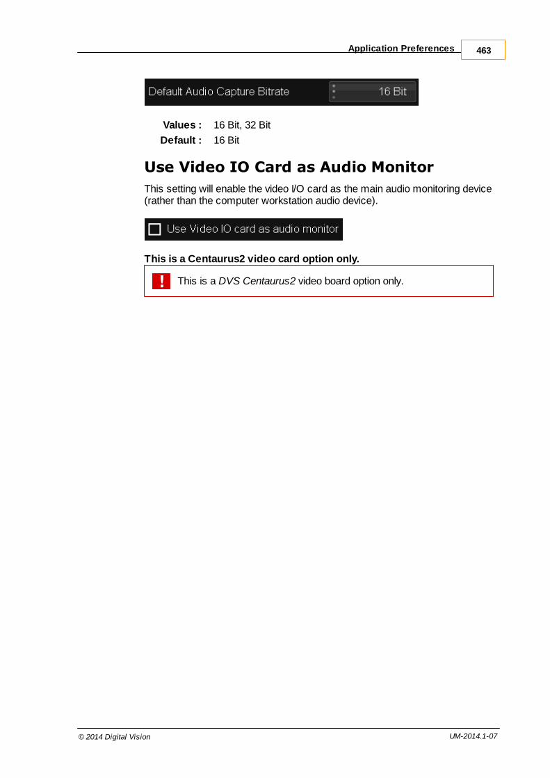
Application Preferences 463
© 2014 Digital Vision UM-2014.1-07
Values : 16 Bit, 32 Bit
Default : 16 Bit
Use Video IO Card as Audio Monitor
This setting will enable the video I/O card as the main audio monitoring device(rather than the computer workstation audio device).
This is a Centaurus2 video card option only.
This is a DVS Centaurus2 video board option only.

Appendices464
© 2014 Digital Vision UM-2014.1-07
Preferences AssistantThe Preference Assistant is a utility tool for display and edit of the general.prefs file.
Run the main application at least once before using this tool.
Hitting the UPDATE button on any tab will update your general.prefsfile at that time. If you want to create multiple preferences, first go tothe Users section and create a Default general.prefs file and thenadditional user files to update. Also note that the in applicationpreferences will be applied to the current active user preference file.
Welcome Screen
On this tab you have the option to look at some system information such asoperating system version, MAC Address, Cards and Drivers.

Preferences Assistant 465
© 2014 Digital Vision UM-2014.1-07
Re-order Master Layer Tools
Re-order or remove colour tools available on your Master layer.
The inactive tools can not be changed and have to remain in thegiven order.
Re-order CC Layer Tools
As the Master layer tab but operating on the CC Layers.

Appendices466
© 2014 Digital Vision UM-2014.1-07
Re-Order Panel Tools
Re-order or remove tools available on your Control Panel.
Using None will leave a gap.
Media Locations
Show and set the various media folder locations.
Avid Mediafiles locations should still be set in general.prefs

Preferences Assistant 467
© 2014 Digital Vision UM-2014.1-07
Monitoring and Video I/O
Monitor setup with presets for often used configurations. This is a mirror ofwhat is in the Application Preferences.
License
View and update your license file.
Copy the new license string into the text box and press the Update button.

Appendices468
© 2014 Digital Vision UM-2014.1-07
If the string entered starts with "Panel", the rest of the string is takenas the Control Panel "welcome" string e.g.
Panel Grading System
Sets the Control Panel welcome string to Grading System. This isthe general.prefs option panel.welcomeString.
Users
The Users tab lets you create separate preference files for multiple users andeasily switch between them.
Recommendation :Once you have set the basic configuration files, use this tool to savethe current preference as Default.
Once you have done this you can change the preferences for a newuser, update and save as as "User-01" "User-02" etc.
A list of user preferences will be displayed in the Available user box.
To switch to a different user, select the user and press the Install button.
These preference files are saved separately from the application, allowing youto re-install safely without losing preferences.

Preferences Assistant 469
© 2014 Digital Vision UM-2014.1-07
KeycodeKeycodes sre numbers appearing on the edge of film, incrementing once perfoot, used to uniquely identify frames for negative cutting. Also known asedgecodes, they are the film equivalent of timecode. The key numbers identifycertain traits of the film, including the manufacturer, the stock type, a prefixidentifying the roll and a footage count.
A keycode has a format : KZ 12 8506 2190 +05
where :
KZ Manufacturer code - KZ is Kodak
12 8506 Prefix identifies film roll
2190 The count is 4 digits that increment once per foot (35mm film,4 perf = 16 x 4 perfs per frame)
+05 Offset - how many perforations the frame is from the keycodemark
Using the count and offset values we can calculate the frame location, as longas we know how many perforations there are per frame and per count.
The DPX file format includes keycode in the file header.

Appendices470
© 2014 Digital Vision UM-2014.1-07
Automatic NamingSome parts of the application assign names to items such as library materialor folders based on a set of predefined rules. These rules are defined in theapplication preferences Capture/Conform tab.
These rules are used for :
Auto assign name
Auto create library folder
Library tape name
Both Auto assign Name and Auto create library folder use the followinginterface convention when building a filename/folder structure :
i.e. M folders up, adding N folders
The settings here control the creation of a name string based on thefilename/folder structure on disk. The resulting string can be used as aname, or part of a name, of an item in a project library.
Basic Name String
Consider the example file and folder structure :
five / four / three / two / one / clip.0001.dpx
The filename is "clip" inside folder "one".
Note that the application considers the filename as "clip", ignoring thefile numbers (0001) and extension (.dpx).
We start by going :
M folders up :
five / four / three / two / one / clip.0001.dpx| | | | | |5 up 4 up 3 up 2 up 1 up 0 up
Where we end up, we then:
add N folders (such that we try and end up with N folders) :

Automatic Naming 471
© 2014 Digital Vision UM-2014.1-07
Calculation Basic Name String Note
4 up, adding 2 four three
2 up, adding 1 two
2 up, adding 3 two one no more folders
1 up, adding 2 one no more folders
0 up, adding 2 empty (no folders)
The result here can be used as a name, or as part of a name.
How we use this resulting basic name, and whether we use it at all, dependson other parameters.
Auto Assign Name
The Auto Assign Name parameter in the Capture/Conform preference tab,defines what Material Name we give imported files/sequences inside theproject library.This name is extracted from the file name and/or folderstructure according to rules defined here.
Once we have our basic name string described above, we determine its usevia a drop-down selector of :
replace with filename - this setting does not use the basic string wecalculated aboveprepend filename
append filename
ignore filename
These settings control whether we combine our basic string with the actualfilename when creating the library material name (apart from the replace withfilename setting).
For our first resultant basic string calculated above :
Calculation Basic Name String Note
4 up, adding 2 four three
We end up with :

Appendices472
© 2014 Digital Vision UM-2014.1-07
Choice Material Nameresult
Note
replace with filename clip Use filename only,ignore above calculation
prepend filename clip four three
append filename four three clip
ignore filename four three throw filename away
Auto Assign Library Folder
This setting defines whether we create named library folders automatically onmaterial import. The folder names are created according to rules definedhere.
Once we have our basic name string described above, we determine its usevia a drop-down selector of :
no auto folder
tape name
filename
filename hierarchical
Note that if we choose no auto folder, the name calculations detailedbelow are not used and any imported material is imported into the current folder.
The folder string constructed is only used for the settings filename andfilename hierarchical .
See the chapter on Capture/Conform preferences for details.
If tape name is selected, a library folder is created and named as per the tapename extracted from the file or its path.

Automatic Naming 473
© 2014 Digital Vision UM-2014.1-07
Tape Name
The tape name field in the library can be assigned from both the file headerand the file path.
If we take the tape name from the file path, our choice is a single valueextracted from the filename/filepath :
M folders up e.g.
Example :
five / four / three / two / one / clip.0001.dpx| | | | | |5 up 4 up 3 up 2 up 1 up 0 up
Result :
Folders Up Tape Name Result Note
0 clip Use filename at level 0
1 one
2 two

Appendices474
© 2014 Digital Vision UM-2014.1-07
Effect IdentifiersEffect Identifiers are unique names for application effects and are used touniquely specify an effect in the general.prefs preference file.
Master layer
The following table lists the effects available for the master layer and theircorresponding IDs in the general.prefs file:
Effect Tree Name Effect ID
saturation Saturation
printer PrinterLights
lift gamma gain LiftGammaGain
balance Balance
col curves DifferentialColorCorrect
bright contrast BrightnessContrast
bright regions BrightnessRegions
soft clip SoftClip
saturation Saturation
pan scan n/a, always available
Base layer
The following table lists the effects available for the base layer and theircorresponding IDs in the general.prefs file:
Effect Tree Name Effect ID
matte n/a, isolation always available
keyer n/a, isolation always available
shapes n/a, isolation always available
matte blur n/a, isolation always available
hue curves HueCurves
printer PrinterLights
lift gamma gain LiftGammaGain
balance Balance
col curves DifferentialColorCorrect
bright contrast BrightnessContrast
bright regions BrightnessRegions

Effect Identifiers 475
© 2014 Digital Vision UM-2014.1-07
soft clip SoftClip
HLS HLSColorCorrect
blur Blur

Appendices476
© 2014 Digital Vision UM-2014.1-07
Effect Selector ConfigurationThe Effect Selector is the drop-down list that displays all available effects.These can be selected and added to a segment on the current composition.
The Effect Selector drop-down list.
Interacting w ith the Effect Selector drop-
down list and choosing an effect to add to
the current composition.
Effects are placed within Effect Groups. Above, we see the group Colourcontaining the effects Channel Mixer, Saturation, SOP and other tools.
The order of the top-level effect groups, the effects within each group and theorder the effects appear inside a group are controlled by configuration files.
Configuration Files
There are two possible configuration files.
One is the default configuration and exists in the application C:\Phoenix\2014_1\root. The other user file will override the defaults if youcreate it and place it in the same folder. By default, this user configuration filedoes not exist.
Default Configuration File
Name : defaultEffectList.prefs
Location : C:\Phoenix\2014_1\root
This is the main configuration file for the drop-down list and defines the effectgroups and the effects that appear in each group by default.
Do not edit or modify this file. It will be over-written every applicationinstall. If you want to modify the effect selector, edit the userEffectList.prefs file.
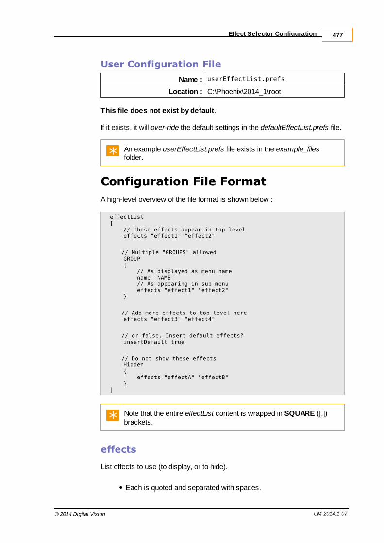
Effect Selector Configuration 477
© 2014 Digital Vision UM-2014.1-07
User Configuration File
Name : userEffectList.prefs
Location : C:\Phoenix\2014_1\root
This file does not exist by default.
If it exists, it will over-ride the default settings in the defaultEffectList.prefs file.
An example userEffectList.prefs file exists in the example_filesfolder.
Configuration File Format
A high-level overview of the file format is shown below :
effectList[ // These effects appear in top-level effects "effect1" "effect2"
// Multiple "GROUPS" allowed GROUP { // As displayed as menu name name "NAME" // As appearing in sub-menu effects "effect1" "effect2" }
// Add more effects to top-level here effects "effect3" "effect4"
// or false. Insert default effects? insertDefault true
// Do not show these effects Hidden { effects "effectA" "effectB" }]
Note that the entire effectList content is wrapped in SQUARE ([,])brackets.
effects
List effects to use (to display, or to hide).
Each is quoted and separated with spaces.

Appendices478
© 2014 Digital Vision UM-2014.1-07
The effect names used are the "effect id". You can list all the "effectid"'s by running the application with the argument --effect-ids e.g.
cd \Program Files\Nucoda\2014_1\nucoda_fuse.exe --effect-ids
You can have multiple "effects" lines.
You can use multiple "effects" tags.
An "effects" tag at the top-level is displayed at the top-level of theEffect Selector. An "effects" tag in a GROUP is displayed within thenamed ("name") GROUP.
Example :
effects "Blur" "ChannelExtract" "Saturation"
GROUP
A GROUP groups a set of effects together as a unit with a "name".
The "name" will be displayed in the GUI.
The listed effects are given inside the "effects" tag within the GROUP.
You can have multiple GROUP sections.
Example :
MainEffects{ effects "Blur" "ChannelExtract" "Saturation"}
insertDefault
This tag will insert the default effects list (in its entirety) where this tag isplaced.
true - Insert the default effects list. The list inserted is as per the defaultEffectList.prefs file and inserted where this tag is placed.false - Do not insert the default list of effects. This may have the effectof minimising and simplifying the effects list.
If "insertDefault" is omitted, this is equivalent of "insertDefault true" beingadded at the end.
Example :
insertDefault true

Effect Selector Configuration 479
© 2014 Digital Vision UM-2014.1-07
Hidden
Hide the effects set in the "effects" list given.
This means they do not appear anywhere in the Effect Selector, evenif placed in a GROUP or a top-level "effects" list.This means they cannot be added.
Example :
Hidden{ effects "FieldSwap" "LiftGammaGain"}
Example Configuration
The example shown below will result in an Effect Selector drop-down thatlooks like :
Channel Extract Saturation My Favourites > DVO Clarity DVO Grain DVO Regrain Balance Bob's favourites > DVO Dust+Fix DVO Fix DVO Flicker
effectList[ effects "ChannelExtract" "Saturation"
MyFavorites // This is a comment { name "My Favourites" effects "DvoClarity" "AGR4" "DvoRegrain" }
effects "Balance" "Saturation"
BobsFavorites { name "Bob's Favourites" effects "Dust+Fix" "Deblotch" "DvoDeflicker" }
insertDefault false
Hidden { effects "FieldDomCorrect" "FieldRemove" "FieldSwap" }]

Appendices480
© 2014 Digital Vision UM-2014.1-07
Output Format ConfgurationEvery project a main output format defined and may also have one or moresecondary formats configured. Available formats appear as a drop-down liston the project screen with a name Setup.
The Output Format Selector drop-down list. Interacting w ith the Output Format Selector
drop-down list and choosing a format.
The output formats available can be defined through the use of textconfiguration files.
Configuration Files
The default configuration file exists in the application C:\Phoenix\2014_1\root.
If a user configuration file exists in the same folder it will override the defaults.This user configuration file does not exists unless you create it.
Default Configuration File
Name : defaultOutputFormats.prefs
Location : C:\Phoenix\2014_1\root
This is the main configuration file for the drop-down list and defines the standard output formats available.
You should not edit or modify this file. It will be over-written by everyapplication install. If you want to modify the format list, edit the userOutputFormats.prefs file.

Output Format Confguration 481
© 2014 Digital Vision UM-2014.1-07
User Configuration File
Name : userOutputFormats.prefs
Location : C:\Phoenix\2014_1\root
This file does not exist by default.
If it exists, it will over-ride the default settings in the defaultOutputFormats.prefs file.
An example userOutputFormats.prefs file exists in the example_filesfolder.
Configuration File Format
A high-level overview of the file format is shown below :
outputFormats[
// Multiple formats allowed FORMATNAME // Must be unique { name "<Format Name>" // as displayed size N N // X Y pixels aspect W H // Rational aspect fps N N // Rational FPS fieldOrder <FIELD ORDER> // See below dropFrame <Boolean> initial <Boolean> // Optional - see below }
FORMATNAME2 // Must be unique { name "<Format Name>" // as displayed size N N // X Y pixels aspect W H // Rational aspect fps N N // Rational FPS fieldOrder <FIELD ORDER> // See below dropFrame <Boolean> initial <Boolean> // Optional - see below }
insertDefault <Boolean> // insert default list?
]
Note that the entire outputFormats content is wrapped in SQUARE([,]) brackets.

Appendices482
© 2014 Digital Vision UM-2014.1-07
Definitions
Some configuration file parameters are of a specific type :
Rational : A Rational number is a fraction and is composed ofa numerator (top) and a denominator (bottom).
Rather than using a floating point number (anddecimal places), a rational number can moreaccurate reflect a parameter such as aspect ratio,or frames per second.
Boolean : A Boolean value is either true or false.
Sections
FORMATNAME
Type : Identifier
Each output format definition is grouped (using curly braces), and named. These names :
Must be unique
Must not contain spaces (Only : a-z,A-Z,0-9,_,-)
These names are not related to the user visible name field usedinside the format definition and can be different.
Example :
Main_Feature_2800x1800_Test{
}
name S
Type : String
This is the user visible display name for the format. It is a stringwrapped in double-quotes ("") and can contain spaces.
Example :
name "2800 x 1800 Test"

Output Format Confguration 483
© 2014 Digital Vision UM-2014.1-07
size W H
Type : Rational
The size parameter specifies the pixel width and height as a rationalnumber.
Example :
size 2800 1800
aspect N M
Type : Rational
The aspect parameter specifies the aspect ratio as a rational number(fraction with a numerator and a denominator).
A 1:1 aspect can always be chosen by setting the aspectvalues the same as the size values.
Example :
aspect 37 20 // 1.85
fps N M
Type : Rational
The fps parameter specifies the frames per second as a rationalnumber.
Example :
fps 2997 100 // i.e. "29.97"
fieldOrder S
Type : String
The fieldOrder parameter specifies how to interpret a frame in theformat. It is a string wrapped in double-quotes ("") and can take values :
InterlacedUpper Format uses interlaced frames (fields) with upperfield dominant.
InterlacedLower Format uses interlaced frames (fields) with lowerfield dominant.
Progressive Format is not fielld based.

Appendices484
© 2014 Digital Vision UM-2014.1-07
Example :
fieldOrder "Progressive"
dropFrame B
Type : Boolean
The dropFrame parameter specifies if the format uses drop-frametimecode (true) or not (false).
Example :
dropFrame false
initial B
Type : Boolean
This parameter is optional.
The initial parameter specifies that the format it appears in will beselected on application start (for a completely fresh installation).
Example :
initial true
insertDefault B
Type : Boolean
The insertDefault parameter can be used in a user configuration file(userOutputFormats.prefs) to load in the default output formats (aspecified in the defaultOutputFormats.prefs file) at the location thedirective appears.
This parameter must be placed outside any actual formatdefinition section.
Example :
insertDefault true

Output Format Confguration 485
© 2014 Digital Vision UM-2014.1-07
Colour Tool Order
Colour tools are effects such as Keyer, Channel Mixer, RGB Curves andSOP. They exist inside the Master and CC Layers.
The default order of the tools can be changed in both the GUI and the ControlPanel by editing the main application preference file general.prefs :
C:\Phoenix\2014_1\root\general.prefs
The recommended way to change the tool order is via the utilityprogram Preferences Assistant. Always make a backup if youchoose to edit the general.prefs directly.
GUI Tool Order
Two preference file options set the tool order :
defaultRealTimeEffectIDs - Master Layer tool order
defaultSecondaryCCEffectIDs - Base and CC Layer tool order
Format
Note that each option should be on a single line in the preference file.
Some tools must stay in the default position in the layer. Theseare identified in red.
defaultRealTimeEffectIDs "ChannelMixer" "Saturation" "SlopeOffsetPower" "PrinterLights" "LiftGammaGain" "Balance" "RGBMLevels" "DifferentialColorCorrect" "BrightnessContrast" "BrightnessRegions" "RGBMCurves" "SoftClip" "Saturation"
defaultSecondaryCCEffectIDs "ChannelMixer" "Saturation" "SlopeOffsetPower" "PrinterLights" "LiftGammaGain" "Balance" "RGBMLevels" "DifferentialColorCorrect" "BrightnessContrast" "BrightnessRegions" "RGBMCurves" "SoftClip" "HueCurves" "HLSColorCorrect" "Blur"

Appendices486
© 2014 Digital Vision UM-2014.1-07
Control Panel Tool Order
Two preference file options are in the "panel" section :
defaultMasterFX - Master Layer tool order
defaultLayerFX - Base and CC Layer tool order
Format
Note that each option should be on a single line in the preference file.
defaultMasterFX "CMix" "Bal" "ColC" "BReg" "Clip" "SOP" "Lev" "RGB"defaultLayerFX "CMix" "Bal" "ColC" "BReg" "HCurv" "Clip" "SOP" "Lev" "RGB" "None" "HCurv" "HLS"
The Valhall Control Panel has space for six options on the display atonce. Use the string "None" to designate a space on the paneldisplay.

Colour Tool Order 487
© 2014 Digital Vision UM-2014.1-07
3D LUT File FormatLUT format v3 extends support to High Dynamic Range (HDR) images (e.g.OpenEXR) and allows the transformation of extended range inputs. Thismeans LUT data values can exist outside the range 0.0 to 1.0.
Example LUT files are distributed in the folder :
C:\Phoenix\2014_1\root\cms\
In addition, example C programs are included to generate sampleLUT files. These are found in the Example Code folder alongsidesome sample program outputs.
v2 format code example : Example Code\Lut3D.cpp
v3 format code example :Example Code\Lut3Dv3.cpp
The Nucoda 3D LUT file format is ASCII text with a .cms file extension.
The file is composed of :
1D x 3 floating point LUT and a
3D x 3 floating point LUT
The LUT file can contain a 1D LUT, a 3D LUT or both. If both, the 1DLUT definition should be before the 3D LUT definition.
Setup
The following parameters are used in the LUT file before the LUT data isdefined :
TITLE
Format : STRING
LUT title. Use quotes if the title contains spaces.
Example :
TITLE "Title of LUT"

Appendices488
© 2014 Digital Vision UM-2014.1-07
NUCODA_3D_CUBE
Format : INT
Integer format version of LUT file.
Example :
NUCODA_3D_CUBE 3
LUT_1D_SIZE
Format : INT
Size of 1D LUT.
Example :
LUT_1D_SIZE 1024
LUT_1D_INPUT_RANGE
Format : FLOAT FLOAT
Minimum and maximum 1D input values allowed: min1D max1DOptional (defaults to 0.0 1.0).LUT Format v3 Only
Example :
LUT_1D_INPUT_RANGE 0.0 1.0
LUT_3D_SIZE
Format : INT
Size of 3D LUT.
Example :
LUT_3D_SIZE 17

3D LUT File Format 489
© 2014 Digital Vision UM-2014.1-07
LUT_3D_INPUT_RANGE
Format : FLOAT FLOAT
Minimum and maximum 3D input values allowed: min3D max3DOptional (defaults to 0.0 1.0).LUT Format v3 Only
Example :
LUT_3D_INPUT_RANGE -1.000 4.000
Note that min1D and max1D are the minimum and maximum inputvalues that can be transformed by the 1D LUT. Similarly for the 3DLUT and min3D and max3D input values.
Input values outside these ranges are clipped to these ranges beforelookup. There is no constraint on the LUT outputs.
The LUT data is specified after the header setup.
1D LUTS
A single 1D array per R,G and B component.
The LUT values will range between min3D and max3D.
Earlier LUT versions use a different range : v1 is between 0 and M,v2 is normalised between 0 and 1.
In the file this is expanded into a single list of r,g,b triples ....
3D LUTS
The 3D LUT is an MxMxM array.
In the file this is expanded into a single list of r,g,b triples with red the fastestmoving axis, then green, then blue.

Appendices490
© 2014 Digital Vision UM-2014.1-07
An example of the RGB values in an EXR pipeline is shown in the diagrambelow :
Example EXR RGB values pipeline.
File Format
From a sample file included : lut3d_2xN_noinvert_1D_only.cms
# Lut3D.exe <1D-size> <3D-size> <invert-green> <1d-3d-test># see Lut3D.cpp for details on optional arguments
NUCODA_3D_CUBE 2
TITLE "Identity Lut, 1D Only, Version 2 format"
LUT_1D_SIZE 2
0.000000 0.000000 0.0000001.000000 1.000000 1.000000
Comments start a line with '//' or '#' characters.

3D LUT File Format 491
© 2014 Digital Vision UM-2014.1-07
Format Description
// version, title and sizes of LUTs:
NUCODA_3D_CUBE version-number:int // version number
TITLE "colour-conversion-title:string" // optional title (in quotes)
LUT_1D_SIZE size-of-1D-LUTs:int // call this NLUT_1D_INPUT_RANGE min1D:float max1D:float // optional
LUT_3D_SIZE number-of-levels-per-axis-in-3D-LUT:int // call this MLUT_3D_INPUT_RANGE min3D:float max3D:float // optional
// specify 1D LUT: comes directly after the header specificationsred[0]:float green[0]:float blue[0]:floatred[1]:float green[1]:float blue[1]:floatred[2]:float green[2]:float blue[2]:float......red[N-1]:float green[N-1]:float blue[N-1]:float
// specify 3D LUT: comes directly after 1D LUT specification// R lvl 0, G lvl 0, B lvl 0red[0,0,0]:float green[0,0,0]:float blue[0,0,0]:float// R lvl 1, G lvl 0, B lvl 0red[0,0,1]:float green[0,0,1]:float blue[0,0,1]:float// R lvl 2, G lvl 0, B lvl 0red[0,0,2]:float green[0,0,2]:float blue[0,0,2]:float ......// red level M-1, green level 0, blue level 0red[0,0,M-1]:float green[0,0,M-1]:float blue[0,0,M-1]:float// R lvl 0, G lvl 1, B lvl 0red[0,1,0]:float green[0,1,0]:float blue[0,1,0]:float// R lvl 1, G lvl 1, B lvl 0red[0,1,1]:float green[0,1,1]:float blue[0,1,1]:float// R lvl 2, G lvl 1, B lvl 0red[0,1,2]:float green[0,1,2]:float blue[0,1,2]:float......// red level M-1, green level 1, blue level 0red[0,1,M-1]:float green[0,1,M-1]:float blue[0,1,M-1]:float// R lvl 0, g lvl 2, B lvl 0red[0,2,0]:float green[0,2,0]:float blue[0,2,0]:float// R lvl 1, G lvl 2, B lvl 0red[0,2,1]:float green[0,2,1]:float blue[0,2,1]:float// R lvl 2, G lvl 2, B lvl 0red[0,2,2]:float green[0,2,2]:float blue[0,2,2]:float......// red level M-1, green level M-1, blue level 0red[0,M-1,M-1]:float green[0,M-1,M-1]:float blue[0,M-1,M-1]:float// R lvl 0, G lvl 0, B lvl 1red[1,0,0]:float green[1,0,0]:float blue[1,0,0]:float// R lvl 1, G lvl 0, B lvl 1red[1,0,1]:float green[1,0,1]:float blue[1,0,1]:float// R lvl 2, G lvl 0, B lvl 1red[1,0,2]:float green[1,0,2]:float blue[1,0,2]:float......// red level M-2, green level M-1, blue level M-1red[M-1,M-1,M-2]:float green[M-1,M-1,M-2]:float blue[M-1,M-1,M-2]:float// red level M-2, green level M-1, blue level M-1red[M-1,M-1,M-2]:float green[M-1,M-1,M-2]:float blue[M-1,M-1,M-2]:float

Appendices492
© 2014 Digital Vision UM-2014.1-07
Icon Tools Reference
File Browser Navigation
icon function
User preset directories - Opens the preset directories configurationpanel
Back to previous directory - Navigate backwards by one folder level
Directory rename - Renames the selected folder
Add folder - Adds a new folder as a sub directory of the current one
Open / Close Panels - Opens/closes the multiple panel display
Move panels right - Navigates forwards through multiple panels
Move panels left - Navigates backwards through multiple panels
Library Folders
icon function
Add Folder - Creates a new folder in the Library
Remove Folder - Removes the selected folder from the library
Folder - Depicts a Library folder
Caches Folder - Depicts the Caches folder in the library
Tree Expand - Expands the Tree branch being viewed
Tree Close - Closes the Tree branch being viewed
Playback Tools
icon functionStep Back a frame
Jump to previous edit point
Play backwards - Toggle, plays backwards, then stops
Play forwards - Toggle, plays forwards, then stops
Jump to next edit point

Icon Tools Reference 493
© 2014 Digital Vision UM-2014.1-07
Step Forward a frame
Scene Detect - Applies scene detection on next playback
Viewer Tools
icon function
Apply monitor Aspect Ratio correction
Show Video Fields - Shows individual video fields of interlacedfootage
Show monitor Overlay tools
View Full Screen
Reference Lock
Compare Mode
Show HUD (Head Up Display)
Show Grid
Show Mask
Edit Mask
Show Graph Curves
Show Histogram
Reset Histogram
Apply CMS
Show monitor output
Show video output
Shape Transform Tools
icon function
Translate
Rotate
Scale

Appendices494
© 2014 Digital Vision UM-2014.1-07
Invert
Tracker Tools
icon function
Track Forward - Plays through the shot tracking as it goes
Track Backwards - Plays backwards through the shot tracking as itgoes
Track Step Forward - Tracks forward one frame
Track Step Backwards - Tracks backward one frame
Format SupportThe following sections describe media formats supported by themain application.
Image Formats
DPXDigital Moving Picture Exchange (SMPTE 268M)Extensions : dpx
Read / WriteOptimised for realtime playback
Options :
Mode Big-endian (default) / Little-endian
Depth 10 bit RGB / 12 bit RGB / 10 bit YUV
The DPX format is optimised for realtime playback and includessupport for alpha channels. It is the native format for cache rendersand source proxies in 10 bit projects (default).

Format Support 495
© 2014 Digital Vision UM-2014.1-07
CineonCineon File FormatExtensions : cin
Read / Write
Options : None

Appendices496
© 2014 Digital Vision UM-2014.1-07
TIFFTagged Image File FormatExtensions : tiff tif
Read / Write
Options :
Bit Depth 8 / 16 bit
SGISGI Image FormatExtensions : sgi rgb
Read / Write
Options :
Compression None / RLE
Bit Depth 8 / 16 bit
JPEGJPEG Image FormatExtensions : jpg jpeg
Read / Write
Options :
Quality 0-100% (default : 75)

Format Support 497
© 2014 Digital Vision UM-2014.1-07
PICSoftimage PIC FormatExtensions : pic
Read / Write
Options :
Compression None / RLE
MPEGMPEG-1 VideoExtensions : mpg mpeg
Read / Write
Options :
Width/Height Slider
I-FrameInterval
0-10 (default : 8)
Bitrate (Kb/s) Slider (default : 400 Kbps)
Tolerance (%) Slider
See the MXF Formats section.
MXFMaterial Exchange FormatExtensions : mxf
Read / Write
Options :
Codec Availability is output format dependant
Avid ProjectName
From MXF File / From DV Project / User Set
See MXF Formats section.

Appendices498
© 2014 Digital Vision UM-2014.1-07
EXROpenEXR High Dynamic Range FormatExtensions : exr
Read / Write
Options :
Compression None / RLE / ZIPS / ZIP / PIZ / PXR24 / B44 / B44A
The EXR format is based on the industry standard OpenEXR format[1]. It is the default cache format for half-float projects.
For optimal performance reading and writing EXR files to/from diskon the Windows NTFS filesystem, EXR frames should be padded toan NTFS volume sector size. This is usually 512 bytes but may bedifferent on some systems (e.g. padding to 4096 or 16384 bytes).
[1] For details on OpenEXR, see the web site at http://www.openexr.com. OpenEXR is trademarked by Lucasfilm Ltd.
QuicktimeApple Quicktime FormatExtensions : mov
Read / Write
Supported as per installed and configured codecs.
Support includes Avid DNxHD.

Format Support 499
© 2014 Digital Vision UM-2014.1-07
List Formats
EDLThis is the Edit Decision List.
CMX3600 Standard Format
Support :
Dissolves
Retimes
Black (BL) and AUX (AX) events
EDL export (Export Composition) supports both standard CMX3600format and an extended EDL format that includes :
Long tapenames
Clipname detail
File path detail per event.
Comment fields are parsed for clipname and event material (file path)information.
Clip Names
If an event followed by a clip-name specifier e.g.
* FROM CLIP NAME: test_gh56
Then the event is loaded and the clip is created with a clip-name asspecified.
File Load
If an event is followed with a file path e.g.
* FROM FILE: C:\media\film_cc_scans.007882.dpx
Then the event material will be loaded into the library if we enable thefollowing on EDL import :
Import material from file paths

Appendices500
© 2014 Digital Vision UM-2014.1-07
See the Export Composition chapter for details of EDL export options.
AAFThis is the Advanced Authoring Format.Extensions : aaf
Read / Write (see note below)
Options :
Format See MXF Formats section.
Export toInterplay
Off / On (default : off)
Exporting an AAF requires the composition to have been createdfrom an imported AAF.
CUTThis is a film cut list file.
Extension : .cut
Format
We expect a line :
The cut list in construction order
We expect a line after this (skipping empty lines and comments) that startswith the word :
Shot
We skip :

Format Support 501
© 2014 Digital Vision UM-2014.1-07
lines that start with a string of asterisks (*).
blank lines.
A Title line becomes the title of the created composition.
This is a fixed format text file with the following fields (index from 0 (zero)) :
Field Start Length
Shot 0 5
Footage (Rec Start) 5 7
Length (Rec Length) 14 7
Keycode 24 10
In Frame (Src In) 36 7
Out Frame (Src Out) 46 7
Roll 57 10
Example CUT File
This is taken from the release distribution and the examples folder :
C:\Phoenix\2014_1\example_files\cut\
Title: Cutlist test**************************************************************The cut list in construction order:Shot Footage Length Keycode In Frame Out Frame Roll 001 0000+00 0000+08 KM 16 1825 4582+08 4582+12 002 002 0000+08 0000+06 KM 41 2976 3884+00 3884+06 004 003 0000+14 0000+05 KU 25 1490 2105+02 2105+07 007 004 0001+03 0000+10 KM 18 0863 0044+00 0044+10 025 005 0001+13 0000+10 KU 09 8386 2901+07 2902+01 030 006 0002+07 0007+12 KM 46 9745 0513+00 0520+12 050 **************************************************************
ALEThis is the Avid Log Exchange format. Extensions : ale
The ALE format is export only.
The ALE format is an ascii text format used by Avid editing systems formetadata interchange.
Generate an ALE file for the current composition via the ..ExportCom position button. Choose ale as your export format.

Appendices502
© 2014 Digital Vision UM-2014.1-07
The ALE format is ascii text and usually tab-delimited (delimiters are specifiedin the header). It consists of :
A header containing various global settings (e.g. project format, fpsetc.)A column specification
One or more lines encoding metadata for a shot
Header
HeadingFIELD_DELIM<TAB>TABSVIDEO_FORMAT<TAB>PALFPS<TAB>25
Column Specification
ColumnName<TAB>FPS<TAB>Project<TAB>Tape<TAB>Start<TAB> ... <TAB>ASC_SOP
Fields :
NameFPSProjectTapeStartEndDurationTracksSourceIdTakeSceneSlateCamrollDirectorSoundRollProjectNameDoPCameramanDailiesColoristDateOfShootASC_SATASC_SOP

Format Support 503
© 2014 Digital Vision UM-2014.1-07
Content
Data<shot1><shot2>...
Each shot includes and encodes the fields as shown above. Each field ineach shot is delimited as per the header specification (e.g. usually a TAB).

Appendices504
© 2014 Digital Vision UM-2014.1-07
MXF Formats
Read Support
Codec On Avid Format Bits Notes
DV25 DV 25 MXF 720x576 50i720x486 59.94i
8 [1]
DV50 DV 50 MXF 720x576 50i720x486 59.94i
8 [1]
DVCPRO100 DVCPRO HD MXF 720p 59.941080i 50
8 [2]
MPEG IMX30 MPEG 30 MXF 720x576 50i720x486 59.94i
8 [3]
MPEG IMX 40 MPEG 40 MXF 720x576 50i720x486 59.94i
8 [3]
MPEG IMX 50 MPEG 50 MXF 720x576 50i720x486 59.94i
8 [3]
DNxHD 40 DNxHD 36 MXF 1080p25 8 [5]
DNxHD 36 DNxHD 36 MXF 1080p 23.981080p 24
8
DNxHD 115 DNxHD 115 MXF 1080p 23.981080p 24
8
DNxHD 120 DNxHD 120 MXF 1080i 50 8
DNxHD 145 DNxHD 145 MXF 1080i 59.94720p 59.94
8
DNxHD 175 DNxHD 175 MXF 1080p 23.981080p 24
8
DNxHD 175X DNxHD 175 X MXF 1080p 23.981080p 24
10
DNxHD 185 DNxHD 185 MXF 1080i 50 8
DNxHD 185X DNxHD 185 X MXF 1080i 50 10
DNxHD 220 DNxHD 220 MXF 1080i 59.941080p 29.97720p 59.94
8
DNxHD 220X DNxHD 220 X MXF 1080i 59.941080p 29.97720p 59.94
10
2:1 / 3:1Compressed
2:1i / 3:1i PAL / NTSC 8
Uncompressed 1:1 1:1 MXF1:1 10b MXF
720x486720x576HD 1920x1080
8/10 [4]

Format Support 505
© 2014 Digital Vision UM-2014.1-07
[1] DV25/DV50. For NTSC DV, sample height is actually 480.These formats are DVPRO, not consumer DV (4:2:0).
[2] DVPRO100. The 1080 i50 format is actually sampled 1440x1080.
[3] IMX. Samples are actually 16 lines greater (vertical blanking), makingthe formats 720x608 and 720x512.
[4] Actually a YUV 4:2:2 format. Will offer a 10 bit version if using 10 bitoutput depth.
[5] Avid will treat and label DNxHD 40 as DNxHD 36.
Sony XDCAM
Format Codec
XDCAM SD DVCAM 4:1:1/4:2:2 25 Mbps
XDCAM SD MPEG IMX 30/40/50 Mbps 4:2:2

Appendices506
© 2014 Digital Vision UM-2014.1-07
Camera Formats
RedThe Red digital camera format.Read only
Extension : .R3D
See the Red chapter for details.
ARRI D-21The ARRI D-21 camera is an advanced digital camera from ARRI. Thecamera has a 3K sensor and generates ARRIRAW data (an uncompresssed12 bit RAW format) as well as a variety of HD output formats.
Read only.
Extension : .ari
We support the .ari (ARRIRAW) file format only.
Timecode
The timecode can be retrieved from :
The file header or
The filename.
Tapename
The tapename is from filename only.
Care needs to be taken when using a standard EDL due totapename length and character restrictions.
Resolution
Frames are 2880x2160 pixels native.

Format Support 507
© 2014 Digital Vision UM-2014.1-07
LUT
A LUT is important in an ARRI D-21 workflow.
We include a standard set of ARRI LUT files in our cms folder :
C:\Phoenix\2014_1\root\cms\ArriD21-LUTS\
You can also download LUT files directly from ARRI by going tothe URL :
http://www.arridigital.com/technical/luts/
Properties
The application exposes the following shot properties via the Library/Properties dialog.
Scale
Set the resolution we decode to.
Options
1/1
1/2
1/4
1/8
Decode Quality
Set the RAW camera data decode mechanism.
Options
Low
Medium

Appendices508
© 2014 Digital Vision UM-2014.1-07
High
Brightness
Slider : -100 to 100
Contrast
Slider : -100 to 100
Gamma
Gamma correction used to transform the camera data for display.
Slider : -0.1 to 10
Saturation
Slider : 0 to 2
Extra Metadata
All available metadata is also displayed in a raw format :
Silicon Imaging SI-2KThe Silicon Imaging SI-2K camera is an advanced 2K digital cinemacompliant camera from Silicon Imaging Inc. The camera records directly tothe CineForm RAW™ format.
Read only.
Extension : .mov
We support the SI-2K .mov file format only.

Format Support 509
© 2014 Digital Vision UM-2014.1-07
Timecode
The timecode can be retrieved from :
The file header or
The filename.
Tapename
The tapename is from filename only.
Properties
The application exposes the following shot properties via the Library/Properties dialog.
Look File
The Look File option lets you select and enable an SI-2K CineForm RAW™LUT file.
SI-2K Look Files have a .look extension.
To select a LUT, click on the file browser icon, navigate to your LUT filelocation and press OK. To apply the LUT, enable it via the Look File toggle :

Appendices510
© 2014 Digital Vision UM-2014.1-07
SI-2K Look File LUTs have to be installed before use. See below.
Decode Resolution
Set the resolution we decode to.
Options
1/1
1/2
1/4
Decode Quality
Set the RAW camera data decode mechanism.
Options
Automatic
Advanced Bilinear
Advanced Matrix5x5
Advanced Smooth
Advanced Detail 1
Advanced Detail 2
Advanced Detail 3
Gamma Curve
Gamma correction used to transform the camera data for display.
Options
Log 90
Gamma 2.2
Cineon 1.7
Cine985 1.7
Cineon 1.0
Linear
Saturation
Slider : 0 to 4

Format Support 511
© 2014 Digital Vision UM-2014.1-07
Extra Metadata
All available metadata is also displayed in a raw format :
Installing Look File LUTs
SI-2K CineForm RAW™ Look File LUTs have to be compiled andinstalled before they can be used by the application.
If you do not install the .look files before trying to use them, you willget an error "Could not find .cflook file for selected look file."
The Look Files have a .look extension and are installed by aprogram called LookInstaller.exe.
To install :
Open a Windows CMD shell : Start / Run / Cm d
Type : LookInstaller <file.look>
Where <file.look> is your chosen .look file.
On success, a dialog box opens and displays information e.g.
You can now use the installed LUT by selecting it in the Look File file selectorin the shot Properties.

Appendices512
© 2014 Digital Vision UM-2014.1-07
The LookInstaller program compiles the .look file and installs it as a .cflook file to the folder :
C:\Program Files\Common Files\CineForm\LUTs
To use the LUT, you can select either the original .look file orthe installed .look file (in above folder).
Because the files are installed to the same location, the nameshave to be unique.
Vision Research PhantomThe Vision Research Phantom camera is an advanced digital camerasupporting both RAW data and various HD output formats.
Read only
Extension : .cine
Timecode
The timecode is from file header only.
Timecode is calculated based on .cine file Trigger Time andthe frame rate.
Tapename
The tapename is created based on :
<Camera Serial Number> + "CINE" + <6 Digit Date>
This facilitates an easier conform/re-conform in a tape-less work-flow.
Properties
The application exposes the following properties specific to each Phantomshot via the Library/Properties dialog.

Format Support 513
© 2014 Digital Vision UM-2014.1-07
CINE Properties
Options
CINE
Custom
Scale
Set the resolution we decode to.
Options
1/1
1/2
1/4
1/8
Decode Quality
Set the RAW camera data decode mechanism.
Options
Low
Medium
High
WB Red Gain
Slider : 0 to 2
WB Blue Gain
Slider : 0 to 2
Brightness
Slider : -100 to 100

Appendices514
© 2014 Digital Vision UM-2014.1-07
Contrast
Slider : -100 to 100
Gamma
Gamma correction used to transform the camera data for display.
Slider : -100 to 100
Saturation
Slider : -100 to 100
Extra Metadata
All available metadata is also displayed in a raw format :
Audio Formats
WAV AudioUncompressed WAV audio files.Extension : .wav
Broadcast WAV Audio
An extension to the WAV file format to include extra metadata.Extension : .wav .bwf

Format Support 515
© 2014 Digital Vision UM-2014.1-07
Audio Interchange FormatThe audio interchange format.Extension : .aiff .aif .aifc
Compressed and uncompressed variants.

Appendices516
© 2014 Digital Vision UM-2014.1-07
OFX PluginsOFX is an Open Source standard for visual-effect plugins.
We support the full OFX API (Application Programming Interface) and avariety of plugins. Plugin support includes :
The Foundry - Tinder, Furnace and Keylight
GenArts - Sapphire (New)
IMAGICA Corp. of America - Primatte
The OFX API and documentation can be found online :
http://openfx.sourceforge.net/

OFX Plugins 517
© 2014 Digital Vision UM-2014.1-07
Configurable Viewer ToolsViewer tools let you display various pieces of information and guide elementson top of your monitor image. This includes various metadata items, grids/shapes, logos, masks and colour information graphs.
The following viewer tools are user configurable :
Grids
Overlay lines, rectangles and layout information.
HUD (head Up Display)
Overlay text or graphics inside monitor area or image.
Masks
Mask/Blank areas of the image.

Appendices518
© 2014 Digital Vision UM-2014.1-07
Graphs
Display a graph or histogram of image colour map.
The displayed information and its position can be customised via one or more specification files. The search path for the specification files is given in themain preference file general.prefs.
Configuration
Grids, HUDs, Masks and Graphs are configured via plain text files searchedfor in folders specified in the main configuration file general.prefs.
Parameter Default File Extension
monitorMaskDir monitorMasks/ .masks
monitorGridDir monitorGrids/ .grids
monitorGraphDir monitorGraphs/ .graphs
monitorHeadUpDisplayDir monitorHUDs/ .grids
Each specific parameter specifies a folder from which correspondingspecification files will be loaded.
Multiple specification files per folder will be loaded and aggregated
Only files with the specified extensions are loaded
Parameters can be repeated, specifying multiple folders to search
Specification files located are global and available to all projects
Example
An example general.prefs line that specifies three folders to be searched :
monitorGrids "monitorGrids\" "\\server\testgrids\" "C:\Grids\"
Global Versus Project Specific
Specification files located inside folders described in the general.prefs file willbe global and available to all projects.
Specification files can be kept private to a project by placing them inside acorresponding default named folder inside the project folder i.e.

Configurable Viewer Tools 519
© 2014 Digital Vision UM-2014.1-07
ProjectName/monitorGraphs/private.graphs
Grids SpecificationOverlay lines, rectangles and layout information.
The HUD specification also use Grid files (.grids) but with alocation set as per the general.prefs monitorHeadUpDisplayDirparameter.
File Specification
A grids file must end in the extension '.grids', e.g. test.grids
It should be a plain text file
Each specification file specifies one or more grids, each identified by uniquename (a name parameter).
Format
The grid file format is as follows :
monitorGrids 1.0 -1{ monitorGrid 1.0 -1 { <grid specification> } monitorGrid 1.0 -1 { <grid specification> } ...}
The grid specification section is described below.

Appendices520
© 2014 Digital Vision UM-2014.1-07
NOTE
Grid specification lines must end with a semi-colon ";" character.
A '#' character at line start delimits a comment. Rest of line isignored.Strings should be quoted i.e. "string".
There should be a space between each identifier and before theterminating semi-colon.
Grid Specification
The following identifiers are used.
name
name "<STRING>" ;
This is the name of the grid as shown in the GUI drop-down list.Grid names should be unique.
units
units "<UNITS>" ;
where UNITS are :
pixels By default the coordinate system is absolute image pixels,lower left to top right. Elements are drawn relative to the lower left corner of apixel.
normalised Normalised coordinates map the range 0.0..1.0 to themonitor source full image pixel size in x and y.
unitsImageAspect
unitsImageAspect <FLOAT> ;
The normalised region may be mapped to an image aspect extraction of themonitor source full image (pre or post monitor mask).
This is achieved by specifying the target image aspect. Given the monitorsource image and aspect ratio, the normalised region will automatically beadjusted for 'letterbox' or 'pillarbox' display of the target aspect ratio.
unitsObeyMask
unitsObeyMask <INT> ;
where INT can be 0 or 1.
The normalised region may be mapped to the visible (post monitor mask)image pixel size in x and y.

Configurable Viewer Tools 521
© 2014 Digital Vision UM-2014.1-07
line
line <FLOAT x0> <FLOAT y0> <FLOAT x1> <FLOAT y1>;
Draws a line from coordinates x0,y0 to coordinates x1,y1 using the currentcoordinate system and draw style.
lineWeight
lineWeight <FLOAT> ;
How wide to draw lines, in pixels.
ellipse
ellipse <INT x0> <INT y0> <INT Rx> <INT Ry> ;
where Rx is X radius and Ry is Y radius.
Draws an ellipse with centre at coordinates (x0,y0) and size 2*Rx by 2*Ry,using the current coordinate system and draw style.
polygon
polygon <INT x0> <INT y0> .. <INT xN> <INT yN> ;
Draws a multi-point polygon from (x0,y0) to (x1,y1) to .. (xN,yN), using thecurrent coordinate system and draw style. If the draw style is filled and thepolygon is convex, it will be filled on the inside.
rectExtraction
rectExtraction <INT x0> <INT y0> <INT x1> <INT y1> ;
Draws a rectangle from (x0,y0) to (x1,y1) using the current coordinate systemand draw style.
If the draw style is filled the rectangle will be filled on the outside, up to theouter limit of the monitor source image. This element is intended for use whena solid or semi-transparent 'masking' or 'blanking' region is required.
If the draw style is not filled, an open rectangle will be drawn with the currentline style.
text
text <INT x> <INT y> "<STRING>" ;
Draws the specified string at (x,y) using the current coordinate system anddraw style.
Note that you can use text macros, which will be expanded on display. Seebelow.

Appendices522
© 2014 Digital Vision UM-2014.1-07
textSize
textSize <FLOAT> ;
Set the size of text drawn.
color
color <FLOAT R> <FLOAT G> <FLOAT B> <FLOAT A> ;
Set the color (Red Green Blue Alpha) for drawing.
fill
fill "<FILL>" ;
where FILL is solid or open.
Set the fill mode.
anchor
anchor "<VERT>" "<HORIZ>" ;
where :
String ValuesVERT bottom, middle , topHORIZ left, center , right
This defines the horizontal and vertical positioning for :
text elements
image elements
image
image <INT x> <INT y> "<PATH>" ;
where PATH is full path to image file.
Draw specified image at (x,y) using the current coordinate system and drawstyle.
Images should be in PNG format. The image path can be relative (tospecification file) or given as an absolute path.

Configurable Viewer Tools 523
© 2014 Digital Vision UM-2014.1-07
origin
origin "<VERT>" "<HORIZ>" ;
where :
String ValuesVERT bottom , topHORIZ left , right
Define the coordinate origin for all drawing operations.
Macro Expansion
Macros are available for use with the text operator and will be expanded to theassociated information.
Macro Format
To specify a macro, use a text element e.g.
text 20 50 "Name: ##srcName" ;text 220 80 "Frame: ##recTimeFrames" ;
Available Macros
Macro Text Meaning
Source Information
##srcTime Source time (auto-set from project)
##srcTimeFrames Source time in frames
##srcTimeTimecode Source time as timecode
##srcKeycode Source time as keycode (if available)
##srcTape Tape name
##srcFilm Film name
##srcClip Clip name
##srcScene Scene name
##srcName Material Name
##srcDescription Description
##srcLocation Location (path on disk)
Record Information
##recTime Record time (auto-set from project)
##recTimeFrames Record time in frames
##recTimeTimecode Record time as timecode

Appendices524
© 2014 Digital Vision UM-2014.1-07
##segmentVersion Version number of segment
Audio Information
##audioName Audio material name
##audioOriginator Audio originator/creator (e.g. Pro Tools)
##audioTimecode Audio timecode
##audioTimeFrames Audio timecode as frames
##audioReference Audio reference as per originator
##audioChannels Number of audio channels
##audioSampleRate Sample rate of audio
Miscellaneous
##headLength Length of segment head in frames
##tailLength Length of segment tail in frames
##clipLength Length of visible segment in frames
Example Grids
For further examples, see the grids file in folder :
C:\Phoenix\2014_1\root\monitorGrids\
and HUD's in folder :
C:\Phoenix\2014_1\root\monitorHUDs\
monitorGrid 1.0 -1{ name "DV Logo" ; units "normalised" ; textSize 64.0 ; color 1.0 0.0 0.0 0.8 ; text 0.1 0.05 "Digital Vision" ;}

Configurable Viewer Tools 525
© 2014 Digital Vision UM-2014.1-07
monitorGrid 1.0 -1{ name "Poly" ; units "normalised" ; fill "solid" ; color 1.0 0.0 0.0 0.33 ; lineWeight 3.0 ; polygon 0.5 0.0 1.0 0.5 0.5 0.5 ;}
monitorGrid 1.0 -1{ name "Poly2" ; units "normalised" ; fill "open" ; color 0.0 0.0 1.0 1.0 ; lineWeight 3.0 ; polygon 0.5 0.0 1.0 0.5 0.5 0.5 ;}
monitorGrid 1.0 -1{ name "AS Rect" ; units "normalised" ; fill "solid" ; color 1.0 0.0 0.0 0.33 ; rectExtraction 0.25 0.25 0.75 0.75 ;}

Appendices526
© 2014 Digital Vision UM-2014.1-07
monitorGrid 1.0 -1{ name "Center Cross" ; lineWeight 3.0 ; units "normalised" ; color 1.0 1.0 1.0 1.0 ; polygon 0.0 0.0 0.0 1.0 1.0 1.0 1.0 0.0 ; polygon 0.0 0.0 0.0 0.5 1.0 0.5 1.0 0.0 ; polygon 0.0 0.0 0.0 1.0 0.5 1.0 0.5 0.0 ;}
monitorGrid 1.0 -1{ name "Safe Areas" ; lineWeight 2.0 ; units "normalised" ; color 1.0 1.0 1.0 1.0 ; polygon 0.05 0.05 0.05 0.95 0.95 0.95 0.95 0.05 ; polygon 0.1 0.1 0.1 0.9 0.9 0.9 0.9 0.1 ; polygon 0.0 0.0 0.0 1.0 1.0 1.0 1.0 0.0 ; lineWeight 3.0 ; line 0.45 0.5 0.55 0.5 ; line 0.5 0.45 0.5 0.55 ; anchor "top" "left" ; origin "top" "left" ; textSize 20.0 ; color 0.9 0.9 0.9 0.9 ; text 0.056 0.06 "PICTURE SAFE" ; text 0.106 0.11 "TITLE SAFE" ;}

Configurable Viewer Tools 527
© 2014 Digital Vision UM-2014.1-07
monitorGrid 1.0 -1{ name "Greyscale" ; units "pixels" ; color 1.0 1.0 1.0 1.0 ; anchor "bottom" "left" ; origin "bottom" "left" ; image 0 0 "greyscale2.png" ;}
monitorGrid 1.0 -1{ name "full info all" ; units "pixelsFullWindow" ;
anchor "top" "left" ; origin "top" "left" ; textSize 14.0 ; text 20 20 "##segmentVersion" ; text 20 50 "Name: ##srcName" ; text 20 80 "Description: ##srcDescription" ; text 20 110 "Tape Name: ##srcTape" ; text 20 140 "Keycode: ##srcKeycode" ;
anchor "bottom" "left" ; origin "bottom" "left" ; textSize 14.0 ; ... ...
anchor "top" "right" ; origin "top" "right" ; textSize 14.0 ; text 20 20 "audio: ##audioName" ; text 20 50 "originator: ##audioOriginator" ; ...}

Appendices528
© 2014 Digital Vision UM-2014.1-07
HUDs SpecificationThe Head Up Display (HUD) configuration is the same as for the Grids.
Masks SpecificationMask/Blank areas of the image. This is a view only mode and is not exportedor rendered.
2.35 extraction. User defined.
File Specification
A masks file must end in the extension '.masks', e.g. test.masks
It should be a plain text file
Each specification file specifies one or more masks, each identified byunique name (a name parameter).
Format
The mask file format is as follows :
monitorMasks 1.0 -1{ monitorMask 1.0 -1 { <mask specification> } monitorMask 1.0 -1 { <mask specification> } ...}
The mask specification section is described below.

Configurable Viewer Tools 529
© 2014 Digital Vision UM-2014.1-07
NOTE
Mask specification lines must end with a semi-colon ";" character.
A '#' character at line start delimits a comment. Rest of line isignored.Strings should be quoted i.e. "string".
There should be a space between each identifier and before theterminating semi-colon.
Mask Specification
name
name "<STRING>" ;
This is the name of the mask as shown in the GUI drop-down list.Mask names should be unique.
units
units "<UNITS>" ;
where UNITS are :
pixels By default the coordinate system is absolute image pixels,lower left to top right. Elements are drawn relative to the lower left corner of a pixel.
normalised
Normalised coordinates map the range 0.0..1.0 to the monitorsource full image pixel size in x and y.
unitsImageAspect
unitsImageAspect <FLOAT> ;
The normalised region may be mapped to an image aspect extraction of themonitor source full image (pre or post monitor mask).
This is achieved by specifying the target image aspect. Given the monitorsource image and aspect ratio, the normalised region will automatically beadjusted for 'letterbox' or 'pillarbox' display of the target aspect ratio.
rect
rect <INT x0> <INT y0> <INT x1> <INT y1> ;
Where :
(x0,y0) is rectangle bottom-left.(x1,y1) is rectangle top-right.
Mask rectangle defined from x0,y0 to x1,y1 using the current coordinate

Appendices530
© 2014 Digital Vision UM-2014.1-07
system. The area outside this rectangle will be blanked.
User Masks
A special mask named "User" will also appear in the GUI list. This allows us toset the mask size and position interactively.
Example Mask Specifications
monitorMask 1.0 -1{ name "1920x1080" ; units "pixels" ; rect 0 0 1920 1080 ;}
monitorMask 1.0 -1{ name "10% in" ; units "normalised" ; rect 0.1 0.1 0.9 0.9 ;}monitorMask 1.0 -1{ name "4:3" ; units "normalised" ; unitsImageAspect 1.333 ; rect 0.0 0.0 1.0 1.0 ;}

Configurable Viewer Tools 531
© 2014 Digital Vision UM-2014.1-07
Graphs SpecificationDisplay a graph or histogram of image colour map.
Parade style centred. Fill style south-west.
File Specification
A graphs file must end in the extension '.graphs', e.g. test.graphs
It should be a plain text file
The format used for a Graph file is simpler than that used for Grids andMasks.
Each specification file specifies one or more graphs, each identified byunique name (a GraphID string) and containing a list of drawing instructions.
Graph File Format
// This is a comment and ignored<GraphID 1>{ <Graph Specification>}
<GraphID 2>{ <Graph Specification>}
Graph files :
Do not use semi-colons to terminate lines
Use C++ style comments (two characters "//" at line start)
Overview
The main elements of the graph are shown below :

Appendices532
© 2014 Digital Vision UM-2014.1-07
Main Parameters
GraphID
The unique identifier for the graph e.g.
NameOfGraph{ ....}
This identifier is not displayed.
This identifier must not contain any spaces.
name
name "<STRING>"
This is the name displayed in the GUI Graph drop-down list e.g.

Configurable Viewer Tools 533
© 2014 Digital Vision UM-2014.1-07
Graph name in drop-down list
intervals
intervals <INT>
The intervals parameter defines the total number of solid lines drawn to markintervals on the graph. See overview diagram above.
black
black <FLOAT>
The black parameter specifies the position of the dashed line representingthe black point. See overview diagram above.
It is given in normalised coordinates (0.0 to 1.0).
white
white <FLOAT>
The white parameter specifies the position of the dashed line representing thewhite point. See overview diagram above.
It is given in normalised coordinates (0.0 to 1.0).
Current Section
The current section is optional.
current{ origin "bottom" "left" offset 0 0 size 800 600 style "parade"}
origin
origin "<STRING V>" "<STRING H>"
This defines the vertical and horizontal positioning of the graph.

Appendices534
© 2014 Digital Vision UM-2014.1-07
Where :
STRING V Vertical alignment.Values : bottom center (or centre) top
STRING H Horizontal alignmentValues : left center (or centre) right
offset
offset <INT x> <INT y>
This is the (x,y) position of the graph inside the monitor display area.
(0,0) is bottom-left.
size
size <INT w> <INT h>
This is the (width,height) in pixels of the graph.
style
style "<STRING S>"
Where :
STRING S Style chosenValues : parade fill line
This defines the type of graph to display.
parade fill line
Compare Section
The compare section is optional.
compare{ origin "bottom" "left"}
If present, this defines the location of the second comparison graph when incompare mode. The origin parameter is as per the current section but refersto the location of the second comparison graph.

Configurable Viewer Tools 535
© 2014 Digital Vision UM-2014.1-07
Example :
current{ origin "bottom" "left" ....}
compare{ origin "top" "right"}
Dual Comparison Mode with Graphs

Appendices536
© 2014 Digital Vision UM-2014.1-07
Legal NoticesThe software described in this document is furnished under a licenseagreement.
This license is available in the docs/licenses folder once the software isinstalled.
The software may not be reverse assembled and may be used or copied onlyin accordance with the terms of the license agreement. It is against the law tocopy the software on any medium except as specifically allowed in the licenseagreement.
This product includes software that is copyright 2009, Avid Technology, Inc.,its licensors and its licensees. All rights reserved.
This product is manufactured by Digital Vision AB under license to patentpending applications and issued (U.S. and other) patents :U.S. Patent Application 10/817,209, published as U.S. patent publication2004/0196903U.S. Patent Application 10/817,217, published as U.S. patent publication2004/0196911Canadian Patent Application 2521467European Patent Application 04749684.0, published as European patentpublication 1629675.
This product includes software that is copyright 2008 RED Digital Cinema.
Digital Vision applications incorporate and are based in part on the work of :
Name URL Notes
FLTK http://www.fltk.org [1] [2]
FFmpeg http://www.ffmpeg.org [1]
Freetype http://www.freetype.org [17]
FTGL http://ftgl.wiki.sourceforge.net [3]
libtiff http://www.libtiff.org [4]
libjpeg http://www.ijg.org/files/README [5]
winpcap http://www.winpcap.org/ [6]
GLEW http://glew.sourceforge.net/ [7] [8] [9]
OpenFX http://openfx.sourceforge.net/ [10]
mxflib http://sourceforge.net/projects/mxflib/ [11]

Legal Notices 537
© 2014 Digital Vision UM-2014.1-07
AAF http://aaf.sourceforge.net/ [12]
OpenEXR http://www.openexr.com/ [13]
libsigc http://libsigc.sourceforge.net/ [1]
libsndfile http://www.mega-nerd.com/libsndfile/ [1]
libpng http://www.libpng.org/pub/png/libpng.html
[14]
zlib http://www.zlib.net/ [15]
Boost http://www.boost.org/ [16]
ProtocolBuffers
http://code.google.com/apis/protocolbuffers
[18]
ACES http://github.com/ampas/aces-dev [19]
Notes
[1] http://www.gnu.org/licenses/old-licenses/lgpl-2.1.html.
Included with product distribution in folder docs/licenses/.
[2] http://www.fltk.org/COPYING.php - FLTK exceptions to [1]
[3] The MIT License
Copyright (c) <year> <copyright holders>
Permission is hereby granted, free of charge, to any person obtaining a copy of this softwareand associated documentation files (the "Software"), to deal in the Software withoutrestriction, including without limitation the rights to use, copy, modify, merge, publish,distribute, sublicense, and/or sell copies of the Software, and to permit persons to whom theSoftware is furnished to do so, subject to the following conditions:
The above copyright notice and this permission notice shall be included inall copies or substantial portions of the Software.
THE SOFTWARE IS PROVIDED "AS IS", WITHOUT WARRANTY OF ANY KIND, EXPRESS ORIMPLIED, INCLUDING BUT NOT LIMITED TO THE WARRANTIES OF MERCHANTABILITY,FITNESS FOR A PARTICULAR PURPOSE AND NONINFRINGEMENT. IN NO EVENT SHALLTHE AUTHORS OR COPYRIGHT HOLDERS BE LIABLE FOR ANY CLAIM, DAMAGES OROTHER LIABILITY, WHETHER IN AN ACTION OF CONTRACT, TORT OR OTHERWISE,ARISING FROM, OUT OF OR IN CONNECTION WITH THE SOFTWARE OR THE USE OROTHER DEALINGS IN THE SOFTWARE.
[4] Libtiff license
Copyright (c) 1988-1997 Sam LefflerCopyright (c) 1991-1997 Silicon Graphics, Inc.
Permission to use, copy, modify, distribute, and sell this software and its documentation forany purpose is hereby granted without fee, provided that (i) the above copyright notices andthis permission notice appear in all copies of the software and related documentation, and(ii) the names of Sam Leffler and Silicon Graphics may not be used in any advertising orpublicity relating to the software without the specific, prior written permission of Sam Lefflerand Silicon Graphics.

Appendices538
© 2014 Digital Vision UM-2014.1-07
THE SOFTWARE IS PROVIDED "AS-IS" AND WITHOUT WARRANTY OF ANY KIND,EXPRESS, IMPLIED OR OTHERWISE, INCLUDING WITHOUT LIMITATION, ANY WARRANTYOF MERCHANTABILITY OR FITNESS FOR A PARTICULAR PURPOSE.
IN NO EVENT SHALL SAM LEFFLER OR SILICON GRAPHICS BE LIABLE FOR ANYSPECIAL, INCIDENTAL, INDIRECT OR CONSEQUENTIAL DAMAGES OF ANY KIND, OR ANYDAMAGES WHATSOEVER RESULTING FROM LOSS OF USE, DATA OR PROFITS,WHETHER OR NOT ADVISED OF THE POSSIBILITY OF DAMAGE, AND ON ANY THEORY OFLIABILITY, ARISING OUT OF OR IN CONNECTION WITH THE USE OR PERFORMANCE OFTHIS SOFTWARE.
[5] libjpeg
See : http://www.ijg.org/files/README
We are releasing this software for both noncommercial and commercial use. Companiesare welcome to use it as the basis for JPEG-related products. We do not ask a royalty,although we do ask for an acknowledgement in product literature (see the README file inthe distribution for details). We hope to make this software industrial-quality --- although, aswith anything that's free, we offer no warranty and accept no liability.
[6] winpcap
See : http://www.winpcap.org/misc/copyright.htm
Copyright (c) 1999 - 2005 NetGroup, Politecnico di Torino (Italy).Copyright (c) 2005 - 2009 CACE Technologies, Davis (California).All rights reserved.
Portions Copyright (c) 1990, 1991, 1992, 1993, 1994, 1995, 1996, 1997 The Regents of theUniversity of California. All rights reserved.Portions Copyright (c) 1995, 1996, 1997 Kungliga Tekniska Högskolan (Royal Institute ofTechnology, Stockholm, Sweden). All rights reserved.Portions Copyright (c) 1997 Yen Yen Lim and North Dakota State University. All rightsreserved.Portions Copyright (c) 1993 by Digital Equipment Corporation.Portions Copyright (C) 1995, 1996, 1997, 1998, and 1999 WIDE Project. All rights reserved.Portions Copyright (c) 1996 Juniper Networks, Inc. All rights reserved.Portions Copyright (c) 2001 Daniel Hartmeier All rights reserved.Portions Copyright 1989 by Carnegie Mellon.
License included with product distribution in folder docs/licenses/.
[7] GLEW
The OpenGL Extension Wrangler LibraryCopyright (C) 2002-2008, Milan Ikits <milan ikits[]ieee org>Copyright (C) 2002-2008, Marcelo E. Magallon <mmagallo[]debian org>Copyright (C) 2002, Lev PovalahevAll rights reserved.
Redistribution and use in source and binary forms, with or without modification, are permitted provided that the following conditions are met:
* Redistributions of source code must retain the above copyright notice, this list ofconditions and the following disclaimer.* Redistributions in binary form must reproduce the above copyright notice, this list ofconditions and the following disclaimer in the documentation and/or other materialsprovided with the distribution.* The name of the author may be used to endorse or promote products derived from thissoftware without specific prior written permission.

Legal Notices 539
© 2014 Digital Vision UM-2014.1-07
THIS SOFTWARE IS PROVIDED BY THE COPYRIGHT HOLDERS AND CONTRIBUTORS "ASIS" AND ANY EXPRESS OR IMPLIED WARRANTIES, INCLUDING, BUT NOT LIMITED TO,THE IMPLIED WARRANTIES OF MERCHANTABILITY AND FITNESS FOR A PARTICULARPURPOSE ARE DISCLAIMED. IN NO EVENT SHALL THE COPYRIGHT OWNER ORCONTRIBUTORS BE LIABLE FOR ANY DIRECT, INDIRECT, INCIDENTAL, SPECIAL,EXEMPLARY, OR CONSEQUENTIAL DAMAGES (INCLUDING, BUT NOT LIMITED TO,PROCUREMENT OF SUBSTITUTE GOODS OR SERVICES; LOSS OF USE, DATA, ORPROFITS; OR BUSINESS INTERRUPTION) HOWEVER CAUSED AND ON ANY THEORY OFLIABILITY, WHETHER IN CONTRACT, STRICT LIABILITY, OR TORT (INCLUDINGNEGLIGENCE OR OTHERWISE) ARISING IN ANY WAY OUT OF THE USE OF THISSOFTWARE, EVEN IF ADVISED OF THE POSSIBILITY OF SUCH DAMAGE.
[8] Mesa
Mesa 3-D graphics libraryVersion: 7.0
Copyright (C) 1999-2007 Brian Paul All Rights Reserved.
Permission is hereby granted, free of charge, to any person obtaining a copy of this softwareand associated documentation files (the "Software"), to deal in the Software withoutrestriction, including without limitation the rights to use, copy, modify, merge, publish,distribute, sublicense, and/or sell copies of the Software, and to permit persons to whom theSoftware is furnished to do so, subject to the following conditions:
The above copyright notice and this permission notice shall be included in all copies orsubstantial portions of the Software.
THE SOFTWARE IS PROVIDED "AS IS", WITHOUT WARRANTY OF ANY KIND, EXPRESS ORIMPLIED, INCLUDING BUT NOT LIMITED TO THE WARRANTIES OF MERCHANTABILITY,FITNESS FOR A PARTICULAR PURPOSE AND NON INFRINGEMENT. IN NO EVENT SHALLBRIAN PAUL BE LIABLE FOR ANY CLAIM, DAMAGES OR OTHER LIABILITY, WHETHER INAN ACTION OF CONTRACT, TORT OR OTHERWISE, ARISING FROM, OUT OF OR INCONNECTION WITH THE SOFTWARE OR THE US
[9] Khronos
Copyright (c) 2007 The Khronos Group Inc.
Permission is hereby granted, free of charge, to any person obtaining a copy of this softwareand/or associated documentation files (the "Materials"), to deal in the Materials withoutrestriction, including without limitation the rights to use, copy, modify, merge, publish,distribute, sublicense, and/or sell copies of the Materials, and to permit persons to whomthe Materials are furnished to do so, subject to the following conditions:
The above copyright notice and this permission notice shall be included in all copies orsubstantial portions of the Materials.
THE MATERIALS ARE PROVIDED "AS IS", WITHOUT WARRANTY OF ANY KIND, EXPRESSOR IMPLIED, INCLUDING BUT NOT LIMITED TO THE WARRANTIES OFMERCHANTABILITY, FITNESS FOR A PARTICULAR PURPOSE AND NONINFRINGEMENT.IN NO EVENT SHALL THE AUTHORS OR COPYRIGHT HOLDERS BE LIABLE FOR ANYCLAIM, DAMAGES OR OTHER LIABILITY, WHETHER IN AN ACTION OF CONTRACT, TORTOR OTHERWISE, ARISING FROM, OUT OF OR IN CONNECTION WITH THE MATERIALS ORTHE USE OR OTHER DEALINGS IN THE MATERIALS.
[10] OFX
From : http://openfx.sourceforge.net/Documentation/Doxygen/ofxCore_8h-source.html

Appendices540
© 2014 Digital Vision UM-2014.1-07
Copyright (c) 2003-2004, The Foundry Visionmongers Ltd. All rights reserved.
Redistribution and use in source and binary forms, with or without modification, arepermitted provided that the following conditions are met:
* Redistributions of source code must retain the above copyright notice, this list of conditionsand the following disclaimer.* Redistributions in binary form must reproduce the above copyright notice, this list ofconditions and the following disclaimer in the documentation and/or other materialsprovided with the distribution.* Neither the name The Foundry Visionmongers Ltd, nor the names of its contributors maybe used to endorse or promote products derived from this software without specific priorwritten permission.
THIS SOFTWARE IS PROVIDED BY THE COPYRIGHT HOLDERS AND CONTRIBUTORS "ASIS" AND ANY EXPRESS OR IMPLIED WARRANTIES, INCLUDING, BUT NOT LIMITED TO,THE IMPLIED WARRANTIES OF MERCHANTABILITY AND FITNESS FOR A PARTICULARPURPOSE ARE DISCLAIMED. IN NO EVENT SHALL THE COPYRIGHT OWNER ORCONTRIBUTORS BE LIABLE FOR ANY DIRECT, INDIRECT, INCIDENTAL, SPECIAL,EXEMPLARY, OR CONSEQUENTIAL DAMAGES (INCLUDING, BUT NOT LIMITED TO,PROCUREMENT OF SUBSTITUTE GOODS OR SERVICES; LOSS OF USE, DATA, ORPROFITS; OR BUSINESS INTERRUPTION) HOWEVER CAUSED AND ON ANY THEORY OFLIABILITY, WHETHER IN CONTRACT, STRICT LIABILITY, OR TORT (INCLUDINGNEGLIGENCE OR OTHERWISE) ARISING IN ANY WAY OUT OF THE USE OF THISSOFTWARE, EVEN IF ADVISED OF THE POSSIBILITY OF SUCH DAMAGE.
[11] mxflib
Copyright (c) 2002-2007, Matt Beard, BBC R&D and Metaglue Corporation
See : http://mxflib.cvs.sourceforge.net/viewvc/mxflib/mxflib/COPYING?revision=1.5&view=markup
[12] AAF Public Source License
See : http://aaf.cvs.sourceforge.net/aaf/AAF/LEGAL/AAFSDKPSL.TXT?view=markup
Included with product distribution in folder docs/licenses/.
[13] OpenEXR
See : http://www.ilm.com/opensource/ilm-bsd-lic.html
Copyright (c) 2002, Industrial Light & Magic, a division of Lucas Digital Ltd. LLC All rightsreserved.
Redistribution and use in source and binary forms, with or without modification, arepermitted provided that the following conditions are met:
* Redistributions of source code must retain the above copyright notice, this list of conditionsand the following disclaimer.* Redistributions in binary form must reproduce the above copyright notice, this list ofconditions and the following disclaimer in the documentation and/or other materialsprovided with the distribution.* Neither the name of Industrial Light & Magic nor the names of its contributors may be usedto endorse or promote products derived from this software without specific prior writtenpermission.
THIS SOFTWARE IS PROVIDED BY THE COPYRIGHT HOLDERS AND CONTRIBUTORS "ASIS" AND ANY EXPRESS OR IMPLIED WARRANTIES, INCLUDING, BUT NOT LIMITED TO,THE IMPLIED WARRANTIES OF MERCHANTABILITY AND FITNESS FOR A PARTICULAR

Legal Notices 541
© 2014 Digital Vision UM-2014.1-07
PURPOSE ARE DISCLAIMED. IN NO EVENT SHALL THE COPYRIGHT OWNER ORCONTRIBUTORS BE LIABLE FOR ANY DIRECT, INDIRECT, INCIDENTAL, SPECIAL,EXEMPLARY, OR CONSEQUENTIAL DAMAGES (INCLUDING, BUT NOT LIMITED TO,PROCUREMENT OF SUBSTITUTE GOODS OR SERVICES; LOSS OF USE, DATA, ORPROFITS; OR BUSINESS INTERRUPTION) HOWEVER CAUSED AND ON ANY THEORY OFLIABILITY, WHETHER IN CONTRACT, STRICT LIABILITY, OR TORT (INCLUDINGNEGLIGENCE OR OTHERWISE) ARISING IN ANY WAY OUT OF THE USE OF THISSOFTWARE, EVEN IF ADVISED OF THE POSSIBILITY OF SUCH DAMAGE.
[14] libpng
See : http://www.libpng.org/pub/png/src/libpng-LICENSE.txt
[15] zlib
See : http://www.zlib.net/zlib_license.html
[16] Boost Software License
See : http://www.boost.org/LICENSE_1_0.txt
Boost Software License - Version 1.0 - August 17th, 2003
Permission is hereby granted, free of charge, to any person or organization obtaining a copyof the software and accompanying documentation covered by this license (the "Software") touse, reproduce, display, distribute, execute, and transmit the Software, and to preparederivative works of the Software, and to permit third-parties to whom the Software isfurnished to do so, all subject to the following:
The copyright notices in the Software and this entire statement, including the above licensegrant, this restriction and the following disclaimer, must be included in all copies of theSoftware, in whole or in part, and all derivative works of the Software, unless such copies orderivative works are solely in the form of machine-executable object code generated by asource language processor.
THE SOFTWARE IS PROVIDED "AS IS", WITHOUT WARRANTY OF ANY KIND, EXPRESS ORIMPLIED, INCLUDING BUT NOT LIMITED TO THE WARRANTIES OF MERCHANTABILITY,FITNESS FOR A PARTICULAR PURPOSE, TITLE AND NON-INFRINGEMENT. IN NO EVENTSHALL THE COPYRIGHT HOLDERS OR ANYONE DISTRIBUTING THE SOFTWARE BELIABLE FOR ANY DAMAGES OR OTHER LIABILITY, WHETHER IN CONTRACT, TORT OROTHERWISE, ARISING FROM, OUT OF OR IN CONNECTION WITH THE SOFTWARE ORTHE USE OR OTHER DEALINGS IN THE SOFTWARE.
[17] Freetype
See : http://www.freetype.org/FTL.TXT
Portions of this software are copyright copyright (c) 2006 The FreeType Project (www.freetype.org). All rights reserved.
[18] Protocol Buffers (Google)
Copyright 2008, Google Inc.All rights reserved.
Redistribution and use in source and binary forms, with or withoutmodification, are permitted provided that the following conditions aremet:
* Redistributions of source code must retain the above copyrightnotice, this list of conditions and the following disclaimer. * Redistributions in binary form must reproduce the above
Appendices542
© 2014 Digital Vision UM-2014.1-07
copyright notice, this list of conditions and the following disclaimerin the documentation and/or other materials provided with thedistribution. * Neither the name of Google Inc. nor the names of itscontributors may be used to endorse or promote products derived fromthis software without specific prior written permission.
THIS SOFTWARE IS PROVIDED BY THE COPYRIGHT HOLDERS AND CONTRIBUTORS"AS IS" AND ANY EXPRESS OR IMPLIED WARRANTIES, INCLUDING, BUT NOTLIMITED TO, THE IMPLIED WARRANTIES OF MERCHANTABILITY AND FITNESS FORA PARTICULAR PURPOSE ARE DISCLAIMED. IN NO EVENT SHALL THE COPYRIGHTOWNER OR CONTRIBUTORS BE LIABLE FOR ANY DIRECT, INDIRECT, INCIDENTAL,SPECIAL, EXEMPLARY, OR CONSEQUENTIAL DAMAGES (INCLUDING, BUT NOTLIMITED TO, PROCUREMENT OF SUBSTITUTE GOODS OR SERVICES; LOSS OF USE,DATA, OR PROFITS; OR BUSINESS INTERRUPTION) HOWEVER CAUSED AND ON ANYTHEORY OF LIABILITY, WHETHER IN CONTRACT, STRICT LIABILITY, OR TORT(INCLUDING NEGLIGENCE OR OTHERWISE) ARISING IN ANY WAY OUT OF THE USEOF THIS SOFTWARE, EVEN IF ADVISED OF THE POSSIBILITY OF SUCH DAMAGE.
Code generated by the Protocol Buffer compiler is owned by the ownerof the input file used when generating it. This code is notstandalone and requires a support library to be linked with it. Thissupport library is itself covered by the above license.
[19] ACES
License Terms for Academy Color Encoding System Components
Academy Color Encoding System (ACES) software and tools are provided by theAcademy under the following terms and conditions: A worldwide, royalty-free,non-exclusive right to copy, modify, create derivatives, and use, in source andbinary forms, is hereby granted, subject to acceptance of this license.Performance of any of the aforementioned acts indicates acceptance to be boundby the following terms and conditions:
Copies of source code, in whole or in part, must retain the above copyrightnotice, this list of conditions and the Disclaimer of Warranty.
Use in binary form must retain the copyright notice (below), this list ofconditions and the Disclaimer of Warranty in the documentation and/or othermaterials provided with the distribution.
* Nothing in this license shall be deemed to grant any rights to trademarks,copyrights, patents, trade secrets or any other intellectual property ofA.M.P.A.S. or any contributors, except as expressly stated herein.
* Neither the name "A.M.P.A.S." nor the name of any other contributors to thissoftware may be used to endorse or promote products derivative of or based onthis software without express prior written permission of A.M.P.A.S. or thecontributors, as appropriate.
* This license shall be construed pursuant to the laws of the State ofCalifornia, and any disputes related thereto shall be subject to thejurisdiction of the courts therein.
Copyright © 2012 Academy of Motion Picture Arts and Sciences (A.M.P.A.S.).Portions contributed by others as indicated. All rights reserved.
Disclaimer of Warranty: THIS SOFTWARE IS PROVIDED BY A.M.P.A.S. ANDCONTRIBUTORS

Legal Notices 543
© 2014 Digital Vision UM-2014.1-07
"AS IS" AND ANY EXPRESS OR IMPLIED WARRANTIES, INCLUDING, BUT NOT LIMITED TO,THE IMPLIED WARRANTIES OF MERCHANTABILITY, FITNESS FOR A PARTICULARPURPOSE, ANDNON-INFRINGEMENT ARE DISCLAIMED. IN NO EVENT SHALL A.M.P.A.S., OR ANYCONTRIBUTORS OR DISTRIBUTORS, BE LIABLE FOR ANY DIRECT, INDIRECT,INCIDENTAL,SPECIAL, EXEMPLARY, RESITUTIONARY, OR CONSEQUENTIAL DAMAGES (INCLUDING,BUT NOTLIMITED TO, PROCUREMENT OF SUBSTITUTE GOODS OR SERVICES; LOSS OF USE,DATA, ORPROFITS; OR BUSINESS INTERRUPTION) HOWEVER CAUSED AND ON ANY THEORY OFLIABILITY, WHETHER IN CONTRACT, STRICT LIABILITY, OR TORT (INCLUDINGNEGLIGENCEOR OTHERWISE) ARISING IN ANY WAY OUT OF THE USE OF THIS SOFTWARE, EVEN IFADVISED OF THE POSSIBILITY OF SUCH DAMAGE.
WITHOUT LIMITING THE GENERALITY OF THE FOREGOING, THE ACADEMYSPECIFICALLYDISCLAIMS ANY REPRESENTATIONS OR WARRANTIES WHATSOEVER RELATED TOPATENT OROTHER INTELLECTUAL PROPERTY RIGHTS IN THE ACADEMY COLOR ENCODINGSYSTEM, ORAPPLICATIONS THEREOF, HELD BY PARTIES OTHER THAN A.M.P.A.S.,WHETHERDISCLOSED ORUNDISCLOSED.