APSolute Vision - USER GUIDE - Check Point Software
775
APSolute Vision User Guide APSolute Vision USER GUIDE Software Version 4.0.0 Document ID: RDWR-APSV-V04000_UG1809 September 2018
-
Upload
khangminh22 -
Category
Documents
-
view
0 -
download
0
Transcript of APSolute Vision - USER GUIDE - Check Point Software

APSolute Vision User Guide
APSolute VisionUSER GUIDE
Software Version 4.0.0Document ID: RDWR-APSV-V04000_UG1809 September 2018

APSolute Vision User Guide
2 Document ID: RDWR-APSV-V04000_UG1809

APSolute Vision User Guide
Document ID: RDWR-APSV-V04000_UG1809 3
Important NoticesThe following important notices are presented in English, French, and German.
Important NoticesThis guide is delivered subject to the following conditions and restrictions:Copyright Radware Ltd. 2018. All rights reserved.The copyright and all other intellectual property rights and trade secrets included in this guide are owned by Radware Ltd.The guide is provided to Radware customers for the sole purpose of obtaining information with respect to the installation and use of the Radware products described in this document, and may not be used for any other purpose.The information contained in this guide is proprietary to Radware and must be kept in strict confidence.It is strictly forbidden to copy, duplicate, reproduce or disclose this guide or any part thereof without the prior written consent of Radware.
Notice importanteCe guide est sujet aux conditions et restrictions suivantes:Copyright Radware Ltd. 2018. Tous droits réservés.Le copyright ainsi que tout autre droit lié à la propriété intellectuelle et aux secrets industriels contenus dans ce guide sont la propriété de Radware Ltd.Ce guide d’informations est fourni à nos clients dans le cadre de l’installation et de l’usage des produits de Radware décrits dans ce document et ne pourra être utilisé dans un but autre que celui pour lequel il a été conçu.Les informations répertoriées dans ce document restent la propriété de Radware et doivent être conservées de manière confidentielle.Il est strictement interdit de copier, reproduire ou divulguer des informations contenues dans ce manuel sans avoir obtenu le consentement préalable écrit de Radware.
Wichtige AnmerkungDieses Handbuch wird vorbehaltlich folgender Bedingungen und Einschränkungen ausgeliefert:Copyright Radware Ltd. 2018. Alle Rechte vorbehalten.Das Urheberrecht und alle anderen in diesem Handbuch enthaltenen Eigentumsrechte und Geschäftsgeheimnisse sind Eigentum von Radware Ltd.Dieses Handbuch wird Kunden von Radware mit dem ausschließlichen Zweck ausgehändigt, Informationen zu Montage und Benutzung der in diesem Dokument beschriebene Produkte von Radware bereitzustellen. Es darf für keinen anderen Zweck verwendet werden.Die in diesem Handbuch enthaltenen Informationen sind Eigentum von Radware und müssen streng vertraulich behandelt werden.Es ist streng verboten, dieses Handbuch oder Teile daraus ohne vorherige schriftliche Zustimmung von Radware zu kopieren, vervielfältigen, reproduzieren oder offen zu legen.

APSolute Vision User Guide
4 Document ID: RDWR-APSV-V04000_UG1809
Copyright NoticesThe following copyright notices are presented in English, French, and German.
Copyright NoticesThe programs included in this product are subject to a restricted use license and can only be used in conjunction with this application.The OpenSSL toolkit stays under a dual license, i.e. both the conditions of the OpenSSL License and the original SSLeay license apply to the toolkit. See below for the actual license texts. Actually both licenses are BSD-style Open Source licenses. In case of any license issues related to OpenSSL, please contact [email protected] LicenseCopyright (c) 1998-2011 The OpenSSL Project. All rights reserved.Redistribution and use in source and binary forms, with or without modification, are permitted provided that the following conditions are met:
1. Redistributions of source code must retain the above copyright notice, this list of conditions and the following disclaimer.
2. Redistributions in binary form must reproduce the above copyright notice, this list of conditions and the following disclaimer in the documentation and/or other materials provided with the distribution.
3. All advertising materials mentioning features or use of this software must display the following acknowledgement:
This product includes software developed by the OpenSSL Project for use in the OpenSSL Toolkit. (http://www.openssl.org/)
4. The names “OpenSSL Toolkit” and “OpenSSL Project” must not be used to endorse or promote products derived from this software without prior written permission. For written permission, please contact [email protected].
5. Products derived from this software may not be called “OpenSSL” nor may “OpenSSL” appear in their names without prior written permission of the OpenSSL Project.
6. Redistributions of any form whatsoever must retain the following acknowledgment:
“This product includes software developed by the OpenSSL Project for use in the OpenSSL Toolkit (http://www.openssl.org/)”
THIS SOFTWARE IS PROVIDED BY THE OpenSSL PROJECT “AS IS'' AND ANY EXPRESSED OR IMPLIED WARRANTIES, INCLUDING, BUT NOT LIMITED TO, THE IMPLIED WARRANTIES OF MERCHANTABILITY AND FITNESS FOR A PARTICULAR PURPOSE ARE DISCLAIMED. IN NO EVENT SHALL THE OpenSSL PROJECT OR ITS CONTRIBUTORS BE LIABLE FOR ANY DIRECT, INDIRECT, INCIDENTAL, SPECIAL, EXEMPLARY, OR CONSEQUENTIAL DAMAGES (INCLUDING, BUT NOT LIMITED TO, PROCUREMENT OF SUBSTITUTE GOODS OR SERVICES; LOSS OF USE, DATA, OR PROFITS; OR BUSINESS INTERRUPTION) HOWEVER CAUSED AND ON ANY THEORY OF LIABILITY, WHETHER IN CONTRACT, STRICT LIABILITY, OR TORT (INCLUDING NEGLIGENCE OR OTHERWISE) ARISING IN ANY WAY OUT OF THE USE OF THIS SOFTWARE, EVEN IF ADVISED OF THE POSSIBILITY OF SUCH DAMAGE.This product includes cryptographic software written by Eric Young ([email protected]). This product includes software written by Tim Hudson ([email protected]).Original SSLeay LicenseCopyright (C) 1995-1998 Eric Young ([email protected])All rights reserved.This package is an SSL implementation written by Eric Young ([email protected]).The implementation was written so as to conform with Netscapes SSL.

APSolute Vision User Guide
Document ID: RDWR-APSV-V04000_UG1809 5
This library is free for commercial and non-commercial use as long as the following conditions are aheared to. The following conditions apply to all code found in this distribution, be it the RC4, RSA, lhash, DES, etc., code; not just the SSL code. The SSL documentation included with this distribution is covered by the same copyright terms except that the holder is Tim Hudson ([email protected]).Copyright remains Eric Young's, and as such any Copyright notices in the code are not to be removed.If this package is used in a product, Eric Young should be given attribution as the author of the parts of the library used.This can be in the form of a textual message at program startup or in documentation (online or textual) provided with the package.Redistribution and use in source and binary forms, with or without modification, are permitted provided that the following conditions are met:
1. Redistributions of source code must retain the copyright notice, this list of conditions and the following disclaimer.
2. Redistributions in binary form must reproduce the above copyright notice, this list of conditions and the following disclaimer in the documentation and/or other materials provided with the distribution.
3. All advertising materials mentioning features or use of this software must display the following acknowledgement:
"This product includes cryptographic software written by Eric Young ([email protected])" The word 'cryptographic' can be left out if the rouines from the library being used are not cryptographic related :-).
4. If you include any Windows specific code (or a derivative thereof) from the apps directory (application code) you must include an acknowledgment:
"This product includes software written by Tim Hudson ([email protected])"THIS SOFTWARE IS PROVIDED BY ERIC YOUNG “AS IS”' AND ANY EXPRESS OR IMPLIED WARRANTIES, INCLUDING, BUT NOT LIMITED TO, THE IMPLIED WARRANTIES OF MERCHANTABILITY AND FITNESS FOR A PARTICULAR PURPOSE ARE DISCLAIMED. IN NO EVENT SHALL THE AUTHOR OR CONTRIBUTORS BE LIABLE FOR ANY DIRECT, INDIRECT, INCIDENTAL, SPECIAL, EXEMPLARY, OR CONSEQUENTIAL DAMAGES (INCLUDING, BUT NOT LIMITED TO, PROCUREMENT OF SUBSTITUTE GOODS OR SERVICES; LOSS OF USE, DATA, OR PROFITS; OR BUSINESS INTERRUPTION) HOWEVER CAUSED AND ON ANY THEORY OF LIABILITY, WHETHER IN CONTRACT, STRICT LIABILITY, OR TORT (INCLUDING NEGLIGENCE OR OTHERWISE) ARISING IN ANY WAY OUT OF THE USE OF THIS SOFTWARE, EVEN IF ADVISED OF THE POSSIBILITY OF SUCH DAMAGE.The licence and distribution terms for any publically available version or derivative of this code cannot be changed. i.e. this code cannot simply be copied and put under another distribution licence [including the GNU Public Licence.]This product contains the Rijndael cipher The Rijndael implementation by Vincent Rijmen, Antoon Bosselaers and Paulo Barreto is in the public domain and distributed with the following license: @version 3.0 (December 2000)Optimized ANSI C code for the Rijndael cipher (now AES)@author Vincent Rijmen <[email protected]>@author Antoon Bosselaers <[email protected]>@author Paulo Barreto <[email protected]>The OnDemand Switch may use software components licensed under the GNU General Public License Agreement Version 2 (GPL v.2) including LinuxBios and Filo open source projects. The source code of the LinuxBios and Filo is available from Radware upon request. A copy of the license can be viewed at: http://www.gnu.org/licenses/old-licenses/gpl-2.0.html.This code is hereby placed in the public domain.

APSolute Vision User Guide
6 Document ID: RDWR-APSV-V04000_UG1809
This product contains code developed by the OpenBSD ProjectCopyright ©1983, 1990, 1992, 1993, 1995The Regents of the University of California. All rights reserved.Redistribution and use in source and binary forms, with or without modification, are permitted provided that the following conditions are met:
1. Redistributions of source code must retain the above copyright notice, this list of conditions and the following disclaimer.
2. Redistributions in binary form must reproduce the above copyright notice, this list of conditions and the following disclaimer in the documentation and/or other materials provided with the distribution.
3. Neither the name of the University nor the names of its contributors may be used to endorse or promote products derived from this software without specific prior written permission.
This product includes software developed by Markus Friedl.This product includes software developed by Theo de Raadt.This product includes software developed by Niels ProvosThis product includes software developed by Dug SongThis product includes software developed by Aaron CampbellThis product includes software developed by Damien MillerThis product includes software developed by Kevin StevesThis product includes software developed by Daniel KourilThis product includes software developed by Wesley GriffinThis product includes software developed by Per AllanssonThis product includes software developed by Nils NordmanThis product includes software developed by Simon WilkinsonRedistribution and use in source and binary forms, with or without modification, are permitted provided that the following conditions are met:
1. Redistributions of source code must retain the above copyright notice, this list of conditions and the following disclaimer.
2. Redistributions in binary form must reproduce the above copyright notice, this list of conditions and the following disclaimer in the documentation and/or other materials provided with the distribution.
This product contains work derived from the RSA Data Security, Inc. MD5 Message-Digest Algorithm. RSA Data Security, Inc. makes no representations concerning either the merchantability of the MD5 Message - Digest Algorithm or the suitability of the MD5 Message - Digest Algorithm for any particular purpose. It is provided “as is” without express or implied warranty of any kind.This product includes the DB2 Express-C database, the copyrights of which are owned IBM.
Notice traitant du copyrightLes programmes intégrés dans ce produit sont soumis à une licence d’utilisation limitée et ne peuvent être utilisés qu’en lien avec cette application.L’implémentation de Rijindael par Vincent Rijmen, Antoon Bosselaers et Paulo Barreto est du domaine public et distribuée sous les termes de la licence suivante:@version 3.0 (Décembre 2000)Code ANSI C code pour Rijndael (actuellement AES)@author Vincent Rijmen <[email protected]>@author Antoon Bosselaers <[email protected]>@author Paulo Barreto <[email protected]>.

APSolute Vision User Guide
Document ID: RDWR-APSV-V04000_UG1809 7
Le commutateur OnDemand peut utiliser les composants logiciels sous licence, en vertu des termes de la licence GNU General Public License Agreement Version 2 (GPL v.2), y compris les projets à source ouverte LinuxBios et Filo. Le code source de LinuxBios et Filo est disponible sur demande auprès de Radware. Une copie de la licence est répertoriée sur: http://www.gnu.org/licenses/old-licenses/gpl-2.0.html.Ce code est également placé dans le domaine public.Ce produit renferme des codes développés dans le cadre du projet OpenSSL.Copyright ©1983, 1990, 1992, 1993, 1995Les membres du conseil de l’Université de Californie. Tous droits réservés.La distribution et l’usage sous une forme source et binaire, avec ou sans modifications, est autorisée pour autant que les conditions suivantes soient remplies:
1. La distribution d’un code source doit inclure la notice de copyright mentionnée ci-dessus, cette liste de conditions et l’avis de non-responsabilité suivant.
2. La distribution, sous une forme binaire, doit reproduire dans la documentation et/ou dans tout autre matériel fourni la notice de copyright mentionnée ci-dessus, cette liste de conditions et l’avis de non-responsabilité suivant.
3. Le nom de l’université, ainsi que le nom des contributeurs ne seront en aucun cas utilisés pour approuver ou promouvoir un produit dérivé de ce programme sans l’obtention préalable d’une autorisation écrite.
Ce produit inclut un logiciel développé par Markus Friedl.Ce produit inclut un logiciel développé par Theo de Raadt.Ce produit inclut un logiciel développé par Niels Provos.Ce produit inclut un logiciel développé par Dug Song.Ce produit inclut un logiciel développé par Aaron Campbell.Ce produit inclut un logiciel développé par Damien Miller.Ce produit inclut un logiciel développé par Kevin Steves.Ce produit inclut un logiciel développé par Daniel Kouril.Ce produit inclut un logiciel développé par Wesley Griffin.Ce produit inclut un logiciel développé par Per Allansson.Ce produit inclut un logiciel développé par Nils Nordman.Ce produit inclut un logiciel développé par Simon Wilkinson.La distribution et l’usage sous une forme source et binaire, avec ou sans modifications, est autorisée pour autant que les conditions suivantes soient remplies:
1. La distribution d’un code source doit inclure la notice de copyright mentionnée ci-dessus, cette liste de conditions et l’avis de non-responsabilité suivant.
2. La distribution, sous une forme binaire, doit reproduire dans la documentation et/ou dans tout autre matériel fourni la notice de copyright mentionnée ci-dessus, cette liste de conditions et l’avis de non-responsabilité suivant.
LE LOGICIEL MENTIONNÉ CI-DESSUS EST FOURNI TEL QUEL PAR LE DÉVELOPPEUR ET TOUTE GARANTIE, EXPLICITE OU IMPLICITE, Y COMPRIS, MAIS SANS S’Y LIMITER, TOUTE GARANTIE IMPLICITE DE QUALITÉ MARCHANDE ET D’ADÉQUATION À UN USAGE PARTICULIER EST EXCLUE.EN AUCUN CAS L’AUTEUR NE POURRA ÊTRE TENU RESPONSABLE DES DOMMAGES DIRECTS, INDIRECTS, ACCESSOIRES, SPÉCIAUX, EXEMPLAIRES OU CONSÉCUTIFS (Y COMPRIS, MAIS SANS S’Y LIMITER, L’ACQUISITION DE BIENS OU DE SERVICES DE REMPLACEMENT, LA PERTE D’USAGE, DE DONNÉES OU DE PROFITS OU L’INTERRUPTION DES AFFAIRES), QUELLE QU’EN SOIT LA CAUSE ET LA THÉORIE DE RESPONSABILITÉ, QU’IL S’AGISSE D’UN CONTRAT, DE RESPONSABILITÉ STRICTE OU D’UN ACTE DOMMAGEABLE (Y COMPRIS LA NÉGLIGENCE OU AUTRE), DÉCOULANT DE QUELLE QUE FAÇON QUE CE SOIT DE L’USAGE DE CE LOGICIEL, MÊME S’IL A ÉTÉ AVERTI DE LA POSSIBILITÉ D’UN TEL DOMMAGE.

APSolute Vision User Guide
8 Document ID: RDWR-APSV-V04000_UG1809
CopyrightvermerkeDie in diesem Produkt enthalten Programme unterliegen einer eingeschränkten Nutzungslizenz und können nur in Verbindung mit dieser Anwendung benutzt werden.Die Rijndael-Implementierung von Vincent Rijndael, Anton Bosselaers und Paulo Barreto ist öffentlich zugänglich und wird unter folgender Lizenz vertrieben:@version 3.0 (December 2000)Optimierter ANSI C Code für den Rijndael cipher (jetzt AES)@author Vincent Rijmen <[email protected]>@author Antoon Bosselaers <[email protected]>@author Paulo Barreto <[email protected]>Der OnDemand Switch verwendet möglicherweise Software, die im Rahmen der DNU Allgemeine Öffentliche Lizenzvereinbarung Version 2 (GPL v.2) lizensiert sind, einschließlich LinuxBios und Filo Open Source-Projekte. Der Quellcode von LinuxBios und Filo ist bei Radware auf Anfrage erhältlich. Eine Kopie dieser Lizenz kann eingesehen werden unter http://www.gnu.org/licenses/old-licenses/gpl-2.0.html.Dieser Code wird hiermit allgemein zugänglich gemacht.Dieses Produkt enthält einen vom OpenBSD-Projekt entwickelten CodeCopyright ©1983, 1990, 1992, 1993, 1995The Regents of the University of California. Alle Rechte vorbehalten.Die Verbreitung und Verwendung in Quell- und binärem Format, mit oder ohne Veränderungen, sind unter folgenden Bedingungen erlaubt:
1. Die Verbreitung von Quellcodes muss den voranstehenden Copyrightvermerk, diese Liste von Bedingungen und den folgenden Haftungsausschluss beibehalten.
2. Die Verbreitung in binärem Format muss den voranstehenden Copyrightvermerk, diese Liste von Bedingungen und den folgenden Haftungsausschluss in der Dokumentation und/oder andere Materialien, die mit verteilt werden, reproduzieren.
3. Weder der Name der Universität noch die Namen der Beitragenden dürfen ohne ausdrückliche vorherige schriftliche Genehmigung verwendet werden, um von dieser Software abgeleitete Produkte zu empfehlen oder zu bewerben.
Dieses Produkt enthält von Markus Friedl entwickelte Software.Dieses Produkt enthält von Theo de Raadt entwickelte Software. Dieses Produkt enthält von Niels Provos entwickelte Software.Dieses Produkt enthält von Dug Song entwickelte Software.Dieses Produkt enthält von Aaron Campbell entwickelte Software.Dieses Produkt enthält von Damien Miller entwickelte Software.Dieses Produkt enthält von Kevin Steves entwickelte Software.Dieses Produkt enthält von Daniel Kouril entwickelte Software.Dieses Produkt enthält von Wesley Griffin entwickelte Software.Dieses Produkt enthält von Per Allansson entwickelte Software.Dieses Produkt enthält von Nils Nordman entwickelte Software.Dieses Produkt enthält von Simon Wilkinson entwickelte Software.Die Verbreitung und Verwendung in Quell- und binärem Format, mit oder ohne Veränderungen, sind unter folgenden Bedingungen erlaubt:
1. Die Verbreitung von Quellcodes muss den voranstehenden Copyrightvermerk, diese Liste von Bedingungen und den folgenden Haftungsausschluss beibehalten.
2. Die Verbreitung in binärem Format muss den voranstehenden Copyrightvermerk, diese Liste von Bedingungen und den folgenden Haftungsausschluss in der Dokumentation und/oder andere Materialien, die mit verteilt werden, reproduzieren.

APSolute Vision User Guide
Document ID: RDWR-APSV-V04000_UG1809 9
SÄMTLICHE VORGENANNTE SOFTWARE WIRD VOM AUTOR IM IST-ZUSTAND (“AS IS”) BEREITGESTELLT. JEGLICHE AUSDRÜCKLICHEN ODER IMPLIZITEN GARANTIEN, EINSCHLIESSLICH, DOCH NICHT BESCHRÄNKT AUF DIE IMPLIZIERTEN GARANTIEN DER MARKTGÄNGIGKEIT UND DER ANWENDBARKEIT FÜR EINEN BESTIMMTEN ZWECK, SIND AUSGESCHLOSSEN.UNTER KEINEN UMSTÄNDEN HAFTET DER AUTOR FÜR DIREKTE ODER INDIREKTE SCHÄDEN, FÜR BEI VERTRAGSERFÜLLUNG ENTSTANDENE SCHÄDEN, FÜR BESONDERE SCHÄDEN, FÜR SCHADENSERSATZ MIT STRAFCHARAKTER, ODER FÜR FOLGESCHÄDEN EINSCHLIESSLICH, DOCH NICHT BESCHRÄNKT AUF, ERWERB VON ERSATZGÜTERN ODER ERSATZLEISTUNGEN; VERLUST AN NUTZUNG, DATEN ODER GEWINN; ODER GESCHÄFTSUNTERBRECHUNGEN) GLEICH, WIE SIE ENTSTANDEN SIND, UND FÜR JEGLICHE ART VON HAFTUNG, SEI ES VERTRÄGE, GEFÄHRDUNGSHAFTUNG, ODER DELIKTISCHE HAFTUNG (EINSCHLIESSLICH FAHRLÄSSIGKEIT ODER ANDERE), DIE IN JEGLICHER FORM FOLGE DER BENUTZUNG DIESER SOFTWARE IST, SELBST WENN AUF DIE MÖGLICHKEIT EINES SOLCHEN SCHADENS HINGEWIESEN WURDE.
Standard WarrantyThe following standard warranty is presented in English, French, and German.
Standard WarrantyRadware offers a limited warranty for all its products (“Products”). Radware hardware products are warranted against defects in material and workmanship for a period of one year from date of shipment. Radware software carries a standard warranty that provides bug fixes for up to 90 days after date of purchase. Should a Product unit fail anytime during the said period(s), Radware will, at its discretion, repair or replace the Product.For hardware warranty service or repair, the product must be returned to a service facility designated by Radware. Customer shall pay the shipping charges to Radware and Radware shall pay the shipping charges in returning the product to the customer. Please see specific details outlined in the Standard Warranty section of the customer’s purchase order.Radware shall be released from all obligations under its Standard Warranty in the event that the Product and/or the defective component has been subjected to misuse, neglect, accident or improper installation, or if repairs or modifications were made by persons other than Radware authorized service personnel, unless such repairs by others were made with the written consent of Radware.EXCEPT AS SET FORTH ABOVE, ALL RADWARE PRODUCTS (HARDWARE AND SOFTWARE) ARE PROVIDED BY “AS IS” AND ANY EXPRESS OR IMPLIED WARRANTIES, INCLUDING, BUT NOT LIMITED TO, THE IMPLIED WARRANTIES OF MERCHANTABILITY AND FITNESS FOR A PARTICULAR PURPOSE ARE DISCLAIMED.
Garantie standardRadware octroie une garantie limitée pour l’ensemble de ses produits (“Produits”). Le matériel informatique (hardware) Radware est garanti contre tout défaut matériel et de fabrication pendant une durée d’un an à compter de la date d’expédition. Les logiciels (software) Radware sont fournis avec une garantie standard consistant en la fourniture de correctifs des dysfonctionnements du logiciels (bugs) pendant une durée maximum de 90 jours à compter de la date d’achat. Dans l’hypothèse où un Produit présenterait un défaut pendant ladite (lesdites) période(s), Radware procédera, à sa discrétion, à la réparation ou à l’échange du Produit.S’agissant de la garantie d’échange ou de réparation du matériel informatique, le Produit doit être retourné chez un réparateur désigné par Radware. Le Client aura à sa charge les frais d’envoi du Produit à Radware et Radware supportera les frais de retour du Produit au client. Veuillez consulter les conditions spécifiques décrites dans la partie “Garantie Standard” du bon de commande client.

APSolute Vision User Guide
10 Document ID: RDWR-APSV-V04000_UG1809
Radware est libérée de toutes obligations liées à la Garantie Standard dans l’hypothèse où le Produit et/ou le composant défectueux a fait l’objet d’un mauvais usage, d’une négligence, d’un accident ou d’une installation non conforme, ou si les réparations ou les modifications qu’il a subi ont été effectuées par d’autres personnes que le personnel de maintenance autorisé par Radware, sauf si Radware a donné son consentement écrit à ce que de telles réparations soient effectuées par ces personnes.SAUF DANS LES CAS PREVUS CI-DESSUS, L’ENSEMBLE DES PRODUITS RADWARE (MATERIELS ET LOGICIELS) SONT FOURNIS “TELS QUELS” ET TOUTES GARANTIES EXPRESSES OU IMPLICITES SONT EXCLUES, EN CE COMPRIS, MAIS SANS S’Y RESTREINDRE, LES GARANTIES IMPLICITES DE QUALITE MARCHANDE ET D’ADÉQUATION À UNE UTILISATION PARTICULIÈRE.
Standard GarantieRadware bietet eine begrenzte Garantie für alle seine Produkte (“Produkte”) an. Hardware Produkte von Radware haben eine Garantie gegen Material- und Verarbeitungsfehler für einen Zeitraum von einem Jahr ab Lieferdatum. Radware Software verfügt über eine Standard Garantie zur Fehlerbereinigung für einen Zeitraum von bis zu 90 Tagen nach Erwerbsdatum. Sollte ein Produkt innerhalb des angegebenen Garantiezeitraumes einen Defekt aufweisen, wird Radware das Produkt nach eigenem Ermessen entweder reparieren oder ersetzen.Für den Hardware Garantieservice oder die Reparatur ist das Produkt an eine von Radware bezeichnete Serviceeinrichtung zurückzugeben. Der Kunde hat die Versandkosten für den Transport des Produktes zu Radware zu tragen, Radware übernimmt die Kosten der Rückversendung des Produktes an den Kunden. Genauere Angaben entnehmen Sie bitte dem Abschnitt zur Standard Garantie im Bestellformular für Kunden.Radware ist von sämtlichen Verpflichtungen unter seiner Standard Garantie befreit, sofern das Produkt oder der fehlerhafte Teil zweckentfremdet genutzt, in der Pflege vernachlässigt, einem Unfall ausgesetzt oder unsachgemäß installiert wurde oder sofern Reparaturen oder Modifikationen von anderen Personen als durch Radware autorisierten Kundendienstmitarbeitern vorgenommen wurden, es sei denn, diese Reparatur durch besagte andere Personen wurden mit schriftlicher Genehmigung seitens Radware durchgeführt.MIT AUSNAHME DES OBEN DARGESTELLTEN, SIND ALLE RADWARE PRODUKTE (HARDWARE UND SOFTWARE) GELIEFERT “WIE GESEHEN” UND JEGLICHE AUSDRÜCKLICHEN ODER STILLSCHWEIGENDEN GARANTIEN, EINSCHLIESSLICH ABER NICHT BEGRENZT AUF STILLSCHWEIGENDE GEWÄHRLEISTUNG DER MARKTFÄHIGKEIT UND EIGNUNG FÜR EINEN BESTIMMTEN ZWECK AUSGESCHLOSSEN.
Limitations on Warranty and LiabilityThe following limitations on warranty and liability are presented in English, French, and German.
Limitations on Warranty and LiabilityIN NO EVENT SHALL RADWARE LTD. OR ANY OF ITS AFFILIATED ENTITIES BE LIABLE FOR ANY DAMAGES INCURRED BY THE USE OF THE PRODUCTS (INCLUDING BOTH HARDWARE AND SOFTWARE) DESCRIBED IN THIS USER GUIDE, OR BY ANY DEFECT OR INACCURACY IN THIS USER GUIDE ITSELF. THIS INCLUDES BUT IS NOT LIMITED TO ANY DIRECT, INDIRECT, INCIDENTAL, SPECIAL, EXEMPLARY, OR CONSEQUENTIAL DAMAGES (INCLUDING, BUT NOT LIMITED TO, PROCUREMENT OF SUBSTITUTE GOODS OR SERVICES; LOSS OF USE, DATA, OR PROFITS; OR BUSINESS INTERRUPTION). THE ABOVE LIMITATIONS WILL APPLY EVEN IF RADWARE HAS BEEN ADVISED OF THE POSSIBILITY OF SUCH DAMAGES. SOME JURISDICTIONS DO NOT ALLOW THE EXCLUSION OR LIMITATION OF IMPLIED WARRANTIES OR LIABILITY FOR INCIDENTAL OR CONSEQUENTIAL DAMAGES, SO THE ABOVE LIMITATION OR EXCLUSION MAY NOT APPLY TO YOU.

APSolute Vision User Guide
Document ID: RDWR-APSV-V04000_UG1809 11
Limitations de la Garantie et ResponsabilitéRADWARE LTD. OU SES ENTITIES AFFILIES NE POURRONT EN AUCUN CAS ETRE TENUES RESPONSABLES DES DOMMAGES SUBIS DU FAIT DE L’UTILISATION DES PRODUITS (EN CE COMPRIS LES MATERIELS ET LES LOGICIELS) DECRITS DANS CE MANUEL D’UTILISATION, OU DU FAIT DE DEFAUT OU D’IMPRECISIONS DANS CE MANUEL D’UTILISATION, EN CE COMPRIS, SANS TOUTEFOIS QUE CETTE ENUMERATION SOIT CONSIDEREE COMME LIMITATIVE, TOUS DOMMAGES DIRECTS, INDIRECTS, ACCIDENTELS, SPECIAUX, EXEMPLAIRES, OU ACCESSOIRES (INCLUANT, MAIS SANS S’Y RESTREINDRE, LA FOURNITURE DE PRODUITS OU DE SERVICES DE REMPLACEMENT; LA PERTE D’UTILISATION, DE DONNEES OU DE PROFITS; OU L’INTERRUPTION DES AFFAIRES). LES LIMITATIONS CI-DESSUS S’APPLIQUERONT QUAND BIEN MEME RADWARE A ETE INFORMEE DE LA POSSIBLE EXISTENCE DE CES DOMMAGES. CERTAINES JURIDICTIONS N’ADMETTANT PAS LES EXCLUSIONS OU LIMITATIONS DE GARANTIES IMPLICITES OU DE RESPONSABILITE EN CAS DE DOMMAGES ACCESSOIRES OU INDIRECTS, LESDITES LIMITATIONS OU EXCLUSIONS POURRAIENT NE PAS ETRE APPLICABLE DANS VOTRE CAS.
Haftungs- und GewährleistungsausschlussIN KEINEM FALL IST RADWARE LTD. ODER EIN IHR VERBUNDENES UNTERNEHMEN HAFTBAR FÜR SCHÄDEN, WELCHE BEIM GEBRAUCH DES PRODUKTES (HARDWARE UND SOFTWARE) WIE IM BENUTZERHANDBUCH BESCHRIEBEN, ODER AUFGRUND EINES FEHLERS ODER EINER UNGENAUIGKEIT IN DIESEM BENUTZERHANDBUCH SELBST ENTSTANDEN SIND. DAZU GEHÖREN UNTER ANDEREM (OHNE DARAUF BEGRENZT ZU SEIN) JEGLICHE DIREKTEN; IDIREKTEN; NEBEN; SPEZIELLEN, BELEGTEN ODER FOLGESCHÄDEN (EINSCHLIESSLICH ABER NICHT BEGRENZT AUF BESCHAFFUNG ODER ERSATZ VON WAREN ODER DIENSTEN, NUTZUNGSAUSFALL, DATEN- ODER GEWINNVERLUST ODER BETRIEBSUNTERBRECHUNGEN). DIE OBEN GENANNTEN BEGRENZUNGEN GREIFEN AUCH, SOFERN RADWARE AUF DIE MÖGLICHKEIT EINES SOLCHEN SCHADENS HINGEWIESEN WORDEN SEIN SOLLTE. EINIGE RECHTSORDNUNGEN LASSEN EINEN AUSSCHLUSS ODER EINE BEGRENZUNG STILLSCHWEIGENDER GARANTIEN ODER HAFTUNGEN BEZÜGLICH NEBEN- ODER FOLGESCHÄDEN NICHT ZU, SO DASS DIE OBEN DARGESTELLTE BEGRENZUNG ODER DER AUSSCHLUSS SIE UNTER UMSTÄNDEN NICHT BETREFFEN WIRD.
Safety InstructionsThe following safety instructions are presented in English, French, and German.
Safety InstructionsCAUTION A readily accessible disconnect device shall be incorporated in the building installation wiring. Due to the risks of electrical shock, and energy, mechanical, and fire hazards, any procedures that involve opening panels or changing components must be performed by qualified service personnel only.To reduce the risk of fire and electrical shock, disconnect the device from the power line before removing cover or panels. The following figure shows the caution label that is attached to Radware platforms with dual power supplies.

APSolute Vision User Guide
12 Document ID: RDWR-APSV-V04000_UG1809
Figure 1: Electrical Shock Hazard Label
DUAL-POWER-SUPPLY-SYSTEM SAFETY WARNING IN CHINESEThe following figure is the warning for Radware platforms with dual power supplies.
Figure 2: Dual-Power-Supply-System Safety Warning in Chinese
Translation of Dual-Power-Supply-System Safety Warning in Chinese:This unit has more than one power supply. Disconnect all power supplies before maintenance to avoid electric shock. SERVICING Do not perform any servicing other than that contained in the operating instructions unless you are qualified to do so. There are no serviceable parts inside the unit. HIGH VOLTAGEAny adjustment, maintenance, and repair of the opened instrument under voltage must be avoided as much as possible and, when inevitable, must be carried out only by a skilled person who is aware of the hazard involved. Capacitors inside the instrument may still be charged even if the instrument has been disconnected from its source of supply.GROUNDINGBefore connecting this device to the power line, the protective earth terminal screws of this device must be connected to the protective earth in the building installation.LASERThis equipment is a Class 1 Laser Product in accordance with IEC60825 - 1: 1993 + A1:1997 + A2:2001 Standard.FUSESMake sure that only fuses with the required rated current and of the specified type are used for replacement. The use of repaired fuses and the short-circuiting of fuse holders must be avoided. Whenever it is likely that the protection offered by fuses has been impaired, the instrument must be made inoperative and be secured against any unintended operation. LINE VOLTAGE Before connecting this instrument to the power line, make sure the voltage of the power source matches the requirements of the instrument. Refer to the Specifications for information about the correct power rating for the device. 48V DC-powered platforms have an input tolerance of 36-72V DC.

APSolute Vision User Guide
Document ID: RDWR-APSV-V04000_UG1809 13
SPECIFICATION CHANGES Specifications are subject to change without notice.
Note: This equipment has been tested and found to comply with the limits for a Class A digital device pursuant to Part 15B of the FCC Rules and EN55022 Class A, EN 55024; EN 61000-3-2; EN 61000-3-3; IEC 61000 4-2 to 4-6, IEC 61000 4-8 and IEC 61000-4-11For CE MARK Compliance. These limits are designed to provide reasonable protection against harmful interference when the equipment is operated in a commercial environment. This equipment generates, uses and can radiate radio frequency energy and, if not installed and used in accordance with the instruction manual, may cause harmful interference to radio communications. Operation of this equipment in a residential area is likely to cause harmful interference in which case the user is required to correct the interference at his own expense.SPECIAL NOTICE FOR NORTH AMERICAN USERSFor North American power connection, select a power supply cord that is UL Listed and CSA Certified 3 - conductor, [18 AWG], terminated in a molded on plug cap rated 125 V, [10 A], with a minimum length of 1.5m [six feet] but no longer than 4.5m...For European connection, select a power supply cord that is internationally harmonized and marked “<HAR>”, 3 - conductor, 0,75 mm2 minimum mm2 wire, rated 300 V, with a PVC insulated jacket. The cord must have a molded on plug cap rated 250 V, 3 A.RESTRICT AREA ACCESSThe DC powered equipment should only be installed in a Restricted Access Area. INSTALLATION CODESThis device must be installed according to country national electrical codes. For North America, equipment must be installed in accordance with the US National Electrical Code, Articles 110 - 16, 110 -17, and 110 -18 and the Canadian Electrical Code, Section 12.INTERCONNECTION OF UNITS Cables for connecting to the unit RS232 and Ethernet Interfaces must be UL certified type DP-1 or DP-2. (Note- when residing in non LPS circuit)OVERCURRENT PROTECTION A readily accessible listed branch-circuit over current protective device rated 15 A must be incorporated in the building wiring for each power input.REPLACEABLE BATTERIESIf equipment is provided with a replaceable battery, and is replaced by an incorrect battery type, then an explosion may occur. This is the case for some Lithium batteries and the following is applicable:• If the battery is placed in an Operator Access Area, there is a marking close to the battery or
a statement in both the operating and service instructions.• If the battery is placed elsewhere in the equipment, there is a marking close to the battery or a
statement in the service instructions.
This marking or statement includes the following text warning:CAUTIONRISK OF EXPLOSION IF BATTERY IS REPLACED BY AN INCORRECT BATTERY TYPE. DISPOSE OF USED BATTERIES ACCORDING TO THE INSTRUCTIONS.Caution – To Reduce the Risk of Electrical Shock and Fire
1. This equipment is designed to permit connection between the earthed conductor of the DC supply circuit and the earthing conductor equipment. See Installation Instructions.
2. All servicing must be undertaken only by qualified service personnel. There are not user serviceable parts inside the unit.
3. DO NOT plug in, turn on or attempt to operate an obviously damaged unit.
APSolute Vision User Guide
14 Document ID: RDWR-APSV-V04000_UG1809
4. Ensure that the chassis ventilation openings in the unit are NOT BLOCKED.
5. Replace a blown fuse ONLY with the same type and rating as is marked on the safety label adjacent to the power inlet, housing the fuse.
6. Do not operate the device in a location where the maximum ambient temperature exceeds 40°C/104°F.
7. Be sure to unplug the power supply cord from the wall socket BEFORE attempting to remove and/or check the main power fuse. CLASS 1 LASER PRODUCT AND REFERENCE TO THE MOST RECENT LASER STANDARDS IEC 60 825-1:1993 + A1:1997 + A2:2001 AND EN 60825-1:1994+A1:1996+ A2:2001
AC units for Denmark, Finland, Norway, Sweden (marked on product):• Denmark - “Unit is class I - unit to be used with an AC cord set suitable with Denmark
deviations. The cord includes an earthing conductor. The Unit is to be plugged into a wall socket outlet which is connected to a protective earth. Socket outlets which are not connected to earth are not to be used!”
• Finland - (Marking label and in manual) - “Laite on liitettävä suojamaadoituskoskettimilla varustettuun pistorasiaan”
• Norway (Marking label and in manual) - “Apparatet må tilkoples jordet stikkontakt”• Unit is intended for connection to IT power systems for Norway only.• Sweden (Marking label and in manual) - “Apparaten skall anslutas till jordat uttag.”
To connect the power connection:
1. Connect the power cable to the main socket, located on the rear panel of the device.2. Connect the power cable to the grounded AC outlet.
CAUTIONRisk of electric shock and energy hazard. Disconnecting one power supply disconnects only one power supply module. To isolate the unit completely, disconnect all power supplies.
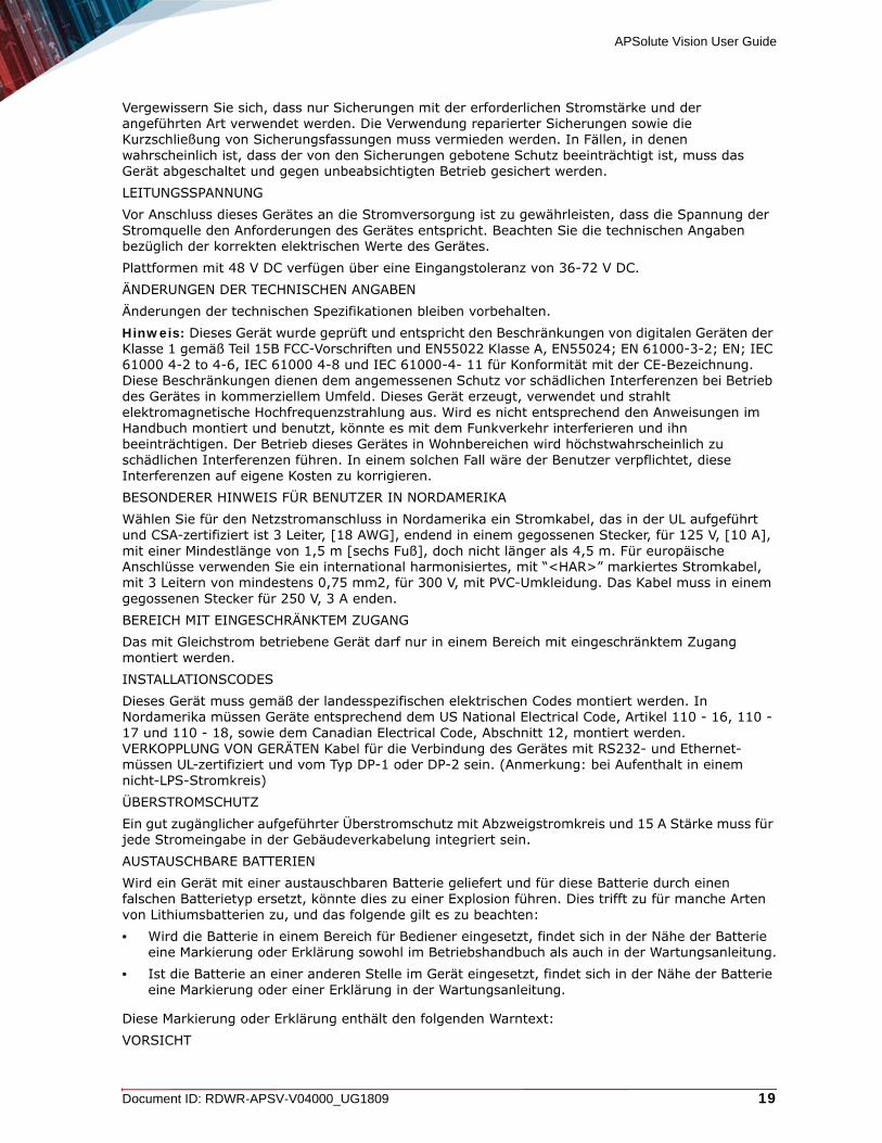
Instructions de sécuritéAVERTISSEMENTUn dispositif de déconnexion facilement accessible sera incorporé au câblage du bâtiment.En raison des risques de chocs électriques et des dangers énergétiques, mécaniques et d’incendie, chaque procédure impliquant l’ouverture des panneaux ou le remplacement de composants sera exécutée par du personnel qualifié.Pour réduire les risques d’incendie et de chocs électriques, déconnectez le dispositif du bloc d’alimentation avant de retirer le couvercle ou les panneaux.La figure suivante montre l’étiquette d’avertissement apposée sur les plateformes Radware dotées de plus d’une source d’alimentation électrique.
Figure 3: Étiquette d’avertissement de danger de chocs électriques

APSolute Vision User Guide
Document ID: RDWR-APSV-V04000_UG1809 15
AVERTISSEMENT DE SÉCURITÉ POUR LES SYSTÈMES DOTÉS DE DEUX SOURCES D’ALIMENTATION ÉLECTRIQUE (EN CHINOIS)La figure suivante représente l’étiquette d’avertissement pour les plateformes Radware dotées de deux sources d’alimentation électrique.
Figure 4: Avertissement de sécurité pour les systèmes dotes de deux sources d’alimentation électrique (en chinois)
Traduction de la Avertissement de sécurité pour les systèmes dotes de deux sources d’alimentation électrique (en chinois):Cette unité est dotée de plus d’une source d’alimentation électrique. Déconnectez toutes les sources d’alimentation électrique avant d’entretenir l’appareil ceci pour éviter tout choc électrique.ENTRETIENN’effectuez aucun entretien autre que ceux répertoriés dans le manuel d’instructions, à moins d’être qualifié en la matière. Aucune pièce à l’intérieur de l’unité ne peut être remplacée ou réparée.HAUTE TENSIONTout réglage, opération d’entretien et réparation de l’instrument ouvert sous tension doit être évité. Si cela s’avère indispensable, confiez cette opération à une personne qualifiée et consciente des dangers impliqués.Les condensateurs au sein de l’unité risquent d’être chargés même si l’unité a été déconnectée de la source d’alimentation électrique.MISE A LA TERREAvant de connecter ce dispositif à la ligne électrique, les vis de protection de la borne de terre de cette unité doivent être reliées au système de mise à la terre du bâtiment.LASERCet équipement est un produit laser de classe 1, conforme à la norme IEC60825 - 1: 1993 + A1: 1997 + A2: 2001.FUSIBLESAssurez-vous que, seuls les fusibles à courant nominal requis et de type spécifié sont utilisés en remplacement. L’usage de fusibles réparés et le court-circuitage des porte-fusibles doivent être évités. Lorsqu’il est pratiquement certain que la protection offerte par les fusibles a été détériorée, l’instrument doit être désactivé et sécurisé contre toute opération involontaire.TENSION DE LIGNEAvant de connecter cet instrument à la ligne électrique, vérifiez que la tension de la source d’alimentation correspond aux exigences de l’instrument. Consultez les spécifications propres à l’alimentation nominale correcte du dispositif.Les plateformes alimentées en 48 CC ont une tolérance d’entrée comprise entre 36 et 72 V CC. MODIFICATIONS DES SPÉCIFICATIONSLes spécifications sont sujettes à changement sans notice préalable.

APSolute Vision User Guide
16 Document ID: RDWR-APSV-V04000_UG1809
Remarque: Cet équipement a été testé et déclaré conforme aux limites définies pour un appareil numérique de classe A, conformément au paragraphe 15B de la réglementation FCC et EN55022 Classe A, EN 55024, EN 61000-3-2; EN 61000-3-3; IEC 61000 4-2 to 4-6, IEC 61000 4-8, et IEC 61000-4-11, pour la marque de conformité de la CE. Ces limites sont fixées pour fournir une protection raisonnable contre les interférences nuisibles, lorsque l’équipement est utilisé dans un environnement commercial. Cet équipement génère, utilise et peut émettre des fréquences radio et, s’il n’est pas installé et utilisé conformément au manuel d’instructions, peut entraîner des interférences nuisibles aux communications radio. Le fonctionnement de cet équipement dans une zone résidentielle est susceptible de provoquer des interférences nuisibles, auquel cas l’utilisateur devra corriger le problème à ses propres frais.NOTICE SPÉCIALE POUR LES UTILISATEURS NORD-AMÉRICAINSPour un raccordement électrique en Amérique du Nord, sélectionnez un cordon d’alimentation homologué UL et certifié CSA 3 - conducteur, [18 AWG], muni d’une prise moulée à son extrémité, de 125 V, [10 A], d’une longueur minimale de 1,5 m [six pieds] et maximale de 4,5m...Pour la connexion européenne, choisissez un cordon d’alimentation mondialement homologué et marqué “<HAR>”, 3 - conducteur, câble de 0,75 mm2 minimum, de 300 V, avec une gaine en PVC isolée. La prise à l’extrémité du cordon, sera dotée d’un sceau moulé indiquant: 250 V, 3 A.ZONE A ACCÈS RESTREINTL’équipement alimenté en CC ne pourra être installé que dans une zone à accès restreint.CODES D’INSTALLATIONCe dispositif doit être installé en conformité avec les codes électriques nationaux. En Amérique du Nord, l’équipement sera installé en conformité avec le code électrique national américain, articles 110-16, 110 -17, et 110 -18 et le code électrique canadien, Section 12.INTERCONNEXION DES UNÎTESLes câbles de connexion à l’unité RS232 et aux interfaces Ethernet seront certifiés UL, type DP-1 ou DP-2. (Remarque- s’ils ne résident pas dans un circuit LPS).PROTECTION CONTRE LES SURCHARGESUn circuit de dérivation, facilement accessible, sur le dispositif de protection du courant de 15 A doit être intégré au câblage du bâtiment pour chaque puissance consommée.BATTERIES REMPLAÇABLESSi l’équipement est fourni avec une batterie, et qu’elle est remplacée par un type de batterie incorrect, elle est susceptible d’exploser. C’est le cas pour certaines batteries au lithium, les éléments suivants sont donc applicables:• Si la batterie est placée dans une zone d’accès opérateur, une marque est indiquée sur la
batterie ou une remarque est insérée, aussi bien dans les instructions d’exploitation que d’entretien.
• Si la batterie est placée ailleurs dans l’équipement, une marque est indiquée sur la batterie ou une remarque est insérée dans les instructions d’entretien.
Cette marque ou remarque inclut l’avertissement textuel suivant: AVERTISSEMENTRISQUE D’EXPLOSION SI LA BATTERIE EST REMPLACÉE PAR UN MODÈLE INCORRECT. METTRE AU REBUT LES BATTERIES CONFORMÉMENT AUX INSTRUCTIONS.Attention - Pour réduire les risques de chocs électriques et d’incendie
1. Cet équipement est conçu pour permettre la connexion entre le conducteur de mise à la terre du circuit électrique CC et l’équipement de mise à la terre. Voir les instructions d’installation.
2. Tout entretien sera entrepris par du personnel qualifié. Aucune pièce à l’intérieur de l’unité ne peut être remplacée ou réparée.
3. NE branchez pas, n’allumez pas ou n’essayez pas d’utiliser une unité manifestement endommagée.
4. Vérifiez que l’orifice de ventilation du châssis dans l’unité n’est PAS OBSTRUE.

APSolute Vision User Guide
Document ID: RDWR-APSV-V04000_UG1809 17
5. Remplacez le fusible endommagé par un modèle similaire de même puissance, tel qu’indiqué sur l’étiquette de sécurité adjacente à l’arrivée électrique hébergeant le fusible.
6. Ne faites pas fonctionner l’appareil dans un endroit, où la température ambiante dépasse la valeur maximale autorisée. 40°C/104°F.
7. Débranchez le cordon électrique de la prise murale AVANT d’essayer de retirer et/ou de vérifier le fusible d’alimentation principal.
PRODUIT LASER DE CLASSE 1 ET RÉFÉRENCE AUX NORMES LASER LES PLUS RÉCENTES: IEC 60825-1: 1993 + A1: 1997 + A2: 2001 ET EN 60825-1: 1994+A1: 1996+ A2: 2001Unités à CA pour le Danemark, la Finlande, la Norvège, la Suède (indiqué sur le produit):• Danemark - Unité de classe 1 - qui doit être utilisée avec un cordon CA compatible avec les
déviations du Danemark. Le cordon inclut un conducteur de mise à la terre. L’unité sera branchée à une prise murale, mise à la terre. Les prises non-mises à la terre ne seront pas utilisées!
• Finlande (Étiquette et inscription dans le manuel) - Laite on liitettävä suojamaadoituskoskettimilla varustettuun pistorasiaan
• Norvège (Étiquette et inscription dans le manuel) - Apparatet må tilkoples jordet stikkontakt• L’unité peut être connectée à un système électrique IT (en Norvège uniquement).• Suède (Étiquette et inscription dans le manuel) - Apparaten skall anslutas till jordat uttag.
Pour brancher à l’alimentation électrique:
1. Branchez le câble d’alimentation à la prise principale, située sur le panneau arrière de l’unité.2. Connectez le câble d’alimentation à la prise CA mise à la terre.
AVERTISSEMENTRisque de choc électrique et danger énergétique. La déconnexion d’une source d’alimentation électrique ne débranche qu’un seul module électrique. Pour isoler complètement l’unité, débranchez toutes les sources d’alimentation électrique.ATTENTIONRisque de choc et de danger électriques. Le débranchement d’une seule alimentation stabilisée ne débranche qu’un module “Alimentation Stabilisée”. Pour Isoler complètement le module en cause, il faut débrancher toutes les alimentations stabilisées.Attention: Pour Réduire Les Risques d’Électrocution et d’Incendie
1. Toutes les opérations d’entretien seront effectuées UNIQUEMENT par du personnel d’entretien qualifié. Aucun composant ne peut être entretenu ou remplacée par l’utilisateur.
2. NE PAS connecter, mettre sous tension ou essayer d’utiliser une unité visiblement défectueuse.
3. Assurez-vous que les ouvertures de ventilation du châssis NE SONT PAS OBSTRUÉES.
4. Remplacez un fusible qui a sauté SEULEMENT par un fusible du même type et de même capacité, comme indiqué sur l’étiquette de sécurité proche de l’entrée de l’alimentation qui contient le fusible.
5. NE PAS UTILISER l’équipement dans des locaux dont la température maximale dépasse 40 degrés Centigrades.
6. Assurez vous que le cordon d’alimentation a été déconnecté AVANT d’essayer de l’enlever et/ou vérifier le fusible de l’alimentation générale.
SicherheitsanweisungenVORSICHTDie Elektroinstallation des Gebäudes muss ein unverzüglich zugängliches Stromunterbrechungsgerät integrieren.

APSolute Vision User Guide
18 Document ID: RDWR-APSV-V04000_UG1809
Aufgrund des Stromschlagrisikos und der Energie-, mechanische und Feuergefahr dürfen Vorgänge, in deren Verlauf Abdeckungen entfernt oder Elemente ausgetauscht werden, ausschließlich von qualifiziertem Servicepersonal durchgeführt werden.Zur Reduzierung der Feuer- und Stromschlaggefahr muss das Gerät vor der Entfernung der Abdeckung oder der Paneele von der Stromversorgung getrennt werden.Folgende Abbildung zeigt das VORSICHT-Etikett, das auf die Radware-Plattformen mit Doppelspeisung angebracht ist.
Figure 5: Warnetikett Stromschlaggefahr
SICHERHEITSHINWEIS IN CHINESISCHER SPRACHE FÜR SYSTEME MIT DOPPELSPEISUNGDie folgende Abbildung ist die Warnung für Radware-Plattformen mit Doppelspeisung.
Figure 6: Sicherheitshinweis in chinesischer Sprache für Systeme mit Doppelspeisung
Übersetzung von Sicherheitshinweis in chinesischer Sprache für Systeme mit Doppelspeisung:Die Einheit verfügt über mehr als eine Stromversorgungsquelle. Ziehen Sie zur Verhinderung von Stromschlag vor Wartungsarbeiten sämtliche Stromversorgungsleitungen ab.WARTUNGFühren Sie keinerlei Wartungsarbeiten aus, die nicht in der Betriebsanleitung angeführt sind, es sei denn, Sie sind dafür qualifiziert. Es gibt innerhalb des Gerätes keine wartungsfähigen Teile.HOCHSPANNUNGJegliche Einstellungs-, Instandhaltungs- und Reparaturarbeiten am geöffneten Gerät unter Spannung müssen so weit wie möglich vermieden werden. Sind sie nicht vermeidbar, dürfen sie ausschließlich von qualifizierten Personen ausgeführt werden, die sich der Gefahr bewusst sind.Innerhalb des Gerätes befindliche Kondensatoren können auch dann noch Ladung enthalten, wenn das Gerät von der Stromversorgung abgeschnitten wurde.ERDUNGBevor das Gerät an die Stromversorgung angeschlossen wird, müssen die Schrauben der Erdungsleitung des Gerätes an die Erdung der Gebäudeverkabelung angeschlossen werden.LASERDieses Gerät ist ein Laser-Produkt der Klasse 1 in Übereinstimmung mit IEC60825 - 1: 1993 + A1:1997 + A2:2001 Standard.SICHERUNGEN
APSolute Vision User Guide
Document ID: RDWR-APSV-V04000_UG1809 19
Vergewissern Sie sich, dass nur Sicherungen mit der erforderlichen Stromstärke und der angeführten Art verwendet werden. Die Verwendung reparierter Sicherungen sowie die Kurzschließung von Sicherungsfassungen muss vermieden werden. In Fällen, in denen wahrscheinlich ist, dass der von den Sicherungen gebotene Schutz beeinträchtigt ist, muss das Gerät abgeschaltet und gegen unbeabsichtigten Betrieb gesichert werden.LEITUNGSSPANNUNGVor Anschluss dieses Gerätes an die Stromversorgung ist zu gewährleisten, dass die Spannung der Stromquelle den Anforderungen des Gerätes entspricht. Beachten Sie die technischen Angaben bezüglich der korrekten elektrischen Werte des Gerätes.Plattformen mit 48 V DC verfügen über eine Eingangstoleranz von 36-72 V DC.ÄNDERUNGEN DER TECHNISCHEN ANGABENÄnderungen der technischen Spezifikationen bleiben vorbehalten.Hinweis: Dieses Gerät wurde geprüft und entspricht den Beschränkungen von digitalen Geräten der Klasse 1 gemäß Teil 15B FCC-Vorschriften und EN55022 Klasse A, EN55024; EN 61000-3-2; EN; IEC 61000 4-2 to 4-6, IEC 61000 4-8 und IEC 61000-4- 11 für Konformität mit der CE-Bezeichnung. Diese Beschränkungen dienen dem angemessenen Schutz vor schädlichen Interferenzen bei Betrieb des Gerätes in kommerziellem Umfeld. Dieses Gerät erzeugt, verwendet und strahlt elektromagnetische Hochfrequenzstrahlung aus. Wird es nicht entsprechend den Anweisungen im Handbuch montiert und benutzt, könnte es mit dem Funkverkehr interferieren und ihn beeinträchtigen. Der Betrieb dieses Gerätes in Wohnbereichen wird höchstwahrscheinlich zu schädlichen Interferenzen führen. In einem solchen Fall wäre der Benutzer verpflichtet, diese Interferenzen auf eigene Kosten zu korrigieren.BESONDERER HINWEIS FÜR BENUTZER IN NORDAMERIKAWählen Sie für den Netzstromanschluss in Nordamerika ein Stromkabel, das in der UL aufgeführt und CSA-zertifiziert ist 3 Leiter, [18 AWG], endend in einem gegossenen Stecker, für 125 V, [10 A], mit einer Mindestlänge von 1,5 m [sechs Fuß], doch nicht länger als 4,5 m. Für europäische Anschlüsse verwenden Sie ein international harmonisiertes, mit “<HAR>” markiertes Stromkabel, mit 3 Leitern von mindestens 0,75 mm2, für 300 V, mit PVC-Umkleidung. Das Kabel muss in einem gegossenen Stecker für 250 V, 3 A enden.BEREICH MIT EINGESCHRÄNKTEM ZUGANGDas mit Gleichstrom betriebene Gerät darf nur in einem Bereich mit eingeschränktem Zugang montiert werden.INSTALLATIONSCODESDieses Gerät muss gemäß der landesspezifischen elektrischen Codes montiert werden. In Nordamerika müssen Geräte entsprechend dem US National Electrical Code, Artikel 110 - 16, 110 - 17 und 110 - 18, sowie dem Canadian Electrical Code, Abschnitt 12, montiert werden. VERKOPPLUNG VON GERÄTEN Kabel für die Verbindung des Gerätes mit RS232- und Ethernet-müssen UL-zertifiziert und vom Typ DP-1 oder DP-2 sein. (Anmerkung: bei Aufenthalt in einem nicht-LPS-Stromkreis)ÜBERSTROMSCHUTZEin gut zugänglicher aufgeführter Überstromschutz mit Abzweigstromkreis und 15 A Stärke muss für jede Stromeingabe in der Gebäudeverkabelung integriert sein.AUSTAUSCHBARE BATTERIENWird ein Gerät mit einer austauschbaren Batterie geliefert und für diese Batterie durch einen falschen Batterietyp ersetzt, könnte dies zu einer Explosion führen. Dies trifft zu für manche Arten von Lithiumsbatterien zu, und das folgende gilt es zu beachten:• Wird die Batterie in einem Bereich für Bediener eingesetzt, findet sich in der Nähe der Batterie
eine Markierung oder Erklärung sowohl im Betriebshandbuch als auch in der Wartungsanleitung.• Ist die Batterie an einer anderen Stelle im Gerät eingesetzt, findet sich in der Nähe der Batterie
eine Markierung oder einer Erklärung in der Wartungsanleitung.
Diese Markierung oder Erklärung enthält den folgenden Warntext:VORSICHT
APSolute Vision User Guide
20 Document ID: RDWR-APSV-V04000_UG1809
EXPLOSIONSGEFAHR, FALLS BATTERIE DURCH EINEN FALSCHEN BATTERIETYP ERSETZT WIRD. GEBRAUCHTE BATTERIEN DEN ANWEISUNGEN ENTSPRECHEND ENTSORGEN.• Denmark - “Unit is class I - mit Wechselstromkabel benutzen, dass für die Abweichungen in
Dänemark eingestellt ist. Das Kabel ist mit einem Erdungsdraht versehen. Das Kabel wird in eine geerdete Wandsteckdose angeschlossen. Keine Steckdosen ohne Erdungsleitung verwenden!”
• Finland - (Markierungsetikett und im Handbuch) - Laite on liitettävä suojamaadoituskoskettimilla varustettuun pistorasiaan
• Norway - (Markierungsetikett und im Handbuch) - Apparatet må tilkoples jordet stikkontakt Ausschließlich für Anschluss an IT-Netzstromsysteme in Norwegen vorgesehen
• Sweden - (Markierungsetikett und im Handbuch) - Apparaten skall anslutas till jordat uttag.
Anschluss des Stromkabels:
1. Schließen Sie das Stromkabel an den Hauptanschluss auf der Rückseite des Gerätes an.2. Schließen Sie das Stromkabel an den geerdeten Wechselstromanschluss an.
VORSICHTStromschlag- und Energiegefahr Die Trennung einer Stromquelle trennt nur ein Stromversorgungsmodul von der Stromversorgung. Um das Gerät komplett zu isolieren, muss es von der gesamten Stromversorgung getrennt werden. Vorsicht - Zur Reduzierung der Stromschlag- und Feuergefahr
1. Dieses Gerät ist dazu ausgelegt, die Verbindung zwischen der geerdeten Leitung des Gleichstromkreises und dem Erdungsleiter des Gerätes zu ermöglichen. Siehe Montageanleitung.
2. Wartungsarbeiten jeglicher Art dürfen nur von qualifiziertem Servicepersonal ausgeführt werden. Es gibt innerhalb des Gerätes keine vom Benutzer zu wartenden Teile.
3. Versuchen Sie nicht, ein offensichtlich beschädigtes Gerät an den Stromkreis anzuschließen, einzuschalten oder zu betreiben.
4. Vergewissern Sie sich, dass sie Lüftungsöffnungen im Gehäuse des Gerätes NICHT BLOCKIERT SIND.
5. Ersetzen Sie eine durchgebrannte Sicherung ausschließlich mit dem selben Typ und von der selben Stärke, die auf dem Sicherheitsetikett angeführt sind, das sich neben dem Stromkabelanschluss, am Sicherungsgehäuse.
6. Betreiben Sie das Gerät nicht an einem Standort, an dem die Höchsttemperatur der Umgebung 40°C überschreitet.
7. Vergewissern Sie sich, das Stromkabel aus dem Wandstecker zu ziehen, BEVOR Sie die Hauptsicherung entfernen und/oder prüfen.
Electromagnetic-Interference StatementsThe following statements are presented in English, French, and German.
Electromagnetic-Interference StatementsSPECIFICATION CHANGES Specifications are subject to change without notice.

APSolute Vision User Guide
Document ID: RDWR-APSV-V04000_UG1809 21
Note: This equipment has been tested and found to comply with the limits for a Class A digital device pursuant to Part 15B of the FCC Rules and EN55022 Class A, EN 55024; EN 61000-3-2; EN 61000-3-3; IEC 61000 4-2 to 4-6, IEC 61000 4-8 and IEC 61000-4-11For CE MARK Compliance. These limits are designed to provide reasonable protection against harmful interference when the equipment is operated in a commercial environment. This equipment generates, uses and can radiate radio frequency energy and, if not installed and used in accordance with the instruction manual, may cause harmful interference to radio communications. Operation of this equipment in a residential area is likely to cause harmful interference in which case the user is required to correct the interference at his own expense.VCCI ELECTROMAGNETIC-INTERFERENCE STATEMENTS
Figure 7: Statement for Class A VCCI-certified Equipment
Translation of Statement for Class A VCCI-certified Equipment:This is a Class A product based on the standard of the Voluntary Control Council for Interference by Information Technology Equipment (VCCI). If this equipment is used in a domestic environment, radio disturbance may occur, in which case, the user may be required to take corrective actions.KCC KOREA
Figure 8: KCC—Korea Communications Commission Certificate of Broadcasting and Communication Equipment
Figure 9: Statement For Class A KCC-certified Equipment in Korean
Translation of Statement For Class A KCC-certified Equipment in Korean:This equipment is Industrial (Class A) electromagnetic wave suitability equipment and seller or user should take notice of it, and this equipment is to be used in the places except for home.BSMI
Figure 10: Statement for Class A BSMI-certified Equipment
這是甲類的資訊產品,在居住的環境使用中時,可能會造成射頻
干擾,在這種情況下,使用者會被要求採取某些適當的對策。

APSolute Vision User Guide
22 Document ID: RDWR-APSV-V04000_UG1809
Translation of Statement for Class A BSMI-certified Equipment:This is a Class A product, in use in a residential environment, it may cause radio interference in which case the user will be required to take adequate measures.
Déclarations sur les Interférences ÉlectromagnétiquesMODIFICATIONS DES SPÉCIFICATIONSLes spécifications sont sujettes à changement sans notice préalable.Remarque: Cet équipement a été testé et déclaré conforme aux limites définies pour un appareil numérique de classe A, conformément au paragraphe 15B de la réglementation FCC et EN55022 Classe A, EN 55024, EN 61000-3-2; EN 61000-3-3; IEC 61000 4-2 to 4-6, IEC 61000 4-8, et IEC 61000-4-11, pour la marque de conformité de la CE. Ces limites sont fixées pour fournir une protection raisonnable contre les interférences nuisibles, lorsque l’équipement est utilisé dans un environnement commercial. Cet équipement génère, utilise et peut émettre des fréquences radio et, s’il n’est pas installé et utilisé conformément au manuel d’instructions, peut entraîner des interférences nuisibles aux communications radio. Le fonctionnement de cet équipement dans une zone résidentielle est susceptible de provoquer des interférences nuisibles, auquel cas l’utilisateur devra corriger le problème à ses propres frais.DÉCLARATIONS SUR LES INTERFÉRENCES ÉLECTROMAGNÉTIQUES VCCI
Figure 11: Déclaration pour l’équipement de classe A certifié VCCI
Traduction de la Déclaration pour l’équipement de classe A certifié VCCI:Il s’agit d’un produit de classe A, basé sur la norme du Voluntary Control Council for Interference by Information Technology Equipment (VCCI). Si cet équipement est utilisé dans un environnement domestique, des perturbations radioélectriques sont susceptibles d’apparaître. Si tel est le cas, l’utilisateur sera tenu de prendre des mesures correctives.KCC Corée
Figure 12: KCC—Certificat de la commission des communications de Corée pour les equipements de radiodiffusion et communication.
Figure 13: Déclaration pour l’équipement de classe A certifié KCC en langue coréenne
Translation de la Déclaration pour l’équipement de classe A certifié KCC en langue coréenne:
APSolute Vision User Guide
Document ID: RDWR-APSV-V04000_UG1809 23
Cet équipement est un matériel (classe A) en adéquation aux ondes électromagnétiques et le vendeur ou l’utilisateur doit prendre cela en compte. Ce matériel est donc fait pour être utilisé ailleurs qu’ á la maison.BSMI
Figure 14: Déclaration pour l’équipement de classe A certifié BSMI
Translation de la Déclaration pour l’équipement de classe A certifié BSMI:Il s’agit d’un produit de Classe A; utilisé dans un environnement résidentiel il peut provoquer des interférences, l’utilisateur devra alors prendre les mesures adéquates.
Erklärungen zu Elektromagnetischer InterferenzÄNDERUNGEN DER TECHNISCHEN ANGABENÄnderungen der technischen Spezifikationen bleiben vorbehalten.Hinweis: Dieses Gerät wurde geprüft und entspricht den Beschränkungen von digitalen Geräten der Klasse 1 gemäß Teil 15B FCC-Vorschriften und EN55022 Klasse A, EN55024; EN 61000-3-2; EN; IEC 61000 4-2 to 4-6, IEC 61000 4-8 und IEC 61000-4- 11 für Konformität mit der CE-Bezeichnung. Diese Beschränkungen dienen dem angemessenen Schutz vor schädlichen Interferenzen bei Betrieb des Gerätes in kommerziellem Umfeld. Dieses Gerät erzeugt, verwendet und strahlt elektromagnetische Hochfrequenzstrahlung aus. Wird es nicht entsprechend den Anweisungen im Handbuch montiert und benutzt, könnte es mit dem Funkverkehr interferieren und ihn beeinträchtigen. Der Betrieb dieses Gerätes in Wohnbereichen wird höchstwahrscheinlich zu schädlichen Interferenzen führen. In einem solchen Fall wäre der Benutzer verpflichtet, diese Interferenzen auf eigene Kosten zu korrigieren.ERKLÄRUNG DER VCCI ZU ELEKTROMAGNETISCHER INTERFERENZ
Figure 15: Erklärung zu VCCI-zertifizierten Geräten der Klasse A
Übersetzung von Erklärung zu VCCI-zertifizierten Geräten der Klasse A:Dies ist ein Produkt der Klasse A gemäß den Normen des Voluntary Control Council for Interference by Information Technology Equipment (VCCI). Wird dieses Gerät in einem Wohnbereich benutzt, können elektromagnetische Störungen auftreten. In einem solchen Fall wäre der Benutzer verpflichtet, korrigierend einzugreifen.KCC KOREA
Figure 16: KCC—Korea Communications Commission Zertifikat für Rundfunk-und Nachrichtentechnik
這是甲類的資訊產品,在居住的環境使用中時,可能會造成射頻
干擾,在這種情況下,使用者會被要求採取某些適當的對策。

APSolute Vision User Guide
24 Document ID: RDWR-APSV-V04000_UG1809
Figure 17: Erklärung zu KCC-zertifizierten Geräten der Klasse A
Übersetzung von Erklärung zu KCC-zertifizierten Geräten der Klasse A:Verkäufer oder Nutzer sollten davon Kenntnis nehmen, daß dieses Gerät der Klasse A für industriell elektromagnetische Wellen geeignete Geräten angehört und dass diese Geräte nicht für den heimischen Gebrauch bestimmt sind.BSMI
Figure 18: Erklärung zu BSMI-zertifizierten Geräten der Klasse A
Übersetzung von Erklärung zu BSMI-zertifizierten Geräten der Klasse A:Dies ist ein Class A Produkt, bei Gebrauch in einer Wohnumgebung kann es zu Funkstörungen kommen, in diesem Fall ist der Benutzer verpflichtet, angemessene Maßnahmen zu ergreifen.
Altitude and Climate WarningThis warning only applies to The People’s Republic of China.
1. 对于在非热带气候条件下运行的设备而言,Tma:为制造商规范允许的最大环境温度,或者为 25°C,采用两者中的较大者。
2. 关于在海拔不超过 2000m或者在非热带气候地区使用的设备,附加警告要求如下:
关于在海拔不超过 2000m的地区使用的设备,必须在随时可见的位置处粘贴包含如下内容或者类似用语的警告标记、或者附件DD中的符号。
“只可在海拔不超过 2000m的位置使用。”
关于在非热带气候地区使用的设备,必须在随时可见的位置处粘贴包含如下内容的警告标记:
附件DD:有关新安全警告标记的说明。
DD.1 海拔警告标记
這是甲類的資訊產品,在居住的環境使用中時,可能會造成射頻
干擾,在這種情況下,使用者會被要求採取某些適當的對策。

APSolute Vision User Guide
Document ID: RDWR-APSV-V04000_UG1809 25
标记含义:设备的评估仅基于 2000m以下的海拔高度,因此设备只适用于该运行条件。如果在海拔超过 2000m的位置使用设备,可能会存在某些安全隐患。
DD.2 气候警告标记
标记含义:设备的评估仅基于温带气候条件,因此设备只适用于该运行条件。如果在热带气候地区使用设备,可能会存在某些安全隐患。
Document ConventionsThe following describes the conventions and symbols that this guide uses:
Item Description Description Beschreibung
Example
An example scenario Un scénario d’exemple Ein Beispielszenarium
Caution:
Possible damage to equipment, software, or data
Endommagement possible de l’équipement, des données ou du logiciel
Mögliche Schäden an Gerät, Software oder Daten
Note:
Additional information Informations complémentaires
Zusätzliche Informationen
To
A statement and instructions
Références et instructions
Eine Erklärung und Anweisungen
Tip:
A suggestion or workaround
Une suggestion ou solution
Ein Vorschlag oder eine Umgehung
Warning:
Possible physical harm to the operator
Blessure possible de l’opérateur
Verletzungsgefahr des Bedieners

APSolute Vision User Guide
26 Document ID: RDWR-APSV-V04000_UG1809

APSolute Vision User Guide
Table of Contents
Document ID: RDWR-APSV-V04000_UG1809 27
TABLE OF CONTENTS
Important Notices .......................................................................................................... 3
Copyright Notices .......................................................................................................... 4
Standard Warranty ........................................................................................................ 9
Limitations on Warranty and Liability ........................................................................... 10
Safety Instructions ....................................................................................................... 11
Electromagnetic-Interference Statements ................................................................... 20
Altitude and Climate Warning ...................................................................................... 24
Document Conventions ............................................................................................... 25
CHAPTER 1 – INTRODUCTION TO APSOLUTE VISION ...................................... 41
What is APSolute Vision? ............................................................................................ 41
APSolute Vision Three-Tier Architecture ..................................................................... 43
APSolute Vision Features—Overview ........................................................................ 43APSolute Vision Platform Management ............................................................................... 44User Management and Role-based Access Control (RBAC) .............................................. 44APSolute Vision Platform Security ....................................................................................... 44Auditing and Alerts ............................................................................................................... 45Device-Configuration Features ............................................................................................ 45DefenseFlow Access ........................................................................................................... 48Radware Cloud DDoS Portal Access .................................................................................. 48Device- and Service-Monitoring Features ........................................................................... 49Application Performance Monitor—for Radware ADC Devices .......................................... 50Security-Reporting Features ................................................................................................ 51APSolute Vision Online Help ............................................................................................... 53Language Support (Localization) ......................................................................................... 53
APSolute Vision Interface Navigation .......................................................................... 53APSolute Vision Toolbar ...................................................................................................... 54APSolute Vision Settings View ............................................................................................ 55Device Pane ........................................................................................................................ 57Device-Properties Pane ....................................................................................................... 59Configuration Perspective .................................................................................................... 60Monitoring Perspective ........................................................................................................ 63Security Monitoring Perspective .......................................................................................... 64
CHAPTER 2 – MANAGING APSOLUTE VISION USERS....................................... 67
Logging In as the Default Administrator User—radware User .................................... 67
Viewing Details About the Current User ...................................................................... 68
Role-Based Access Control (RBAC) ........................................................................... 68APSolute Vision RBAC—General Information .................................................................... 69Roles and Scopes ................................................................................................................ 69

APSolute Vision User Guide
Table of Contents
28 Document ID: RDWR-APSV-V04000_UG1809
GUI Display Is According to Role ........................................................................................ 70IDM Strings for Predefined Roles ........................................................................................ 71Predefined Roles Described ................................................................................................ 72Roles per Radware Product ............................................................................................... 74Feature-Accessibility per Role ............................................................................................. 75Rules for RBAC Permission Conflicts with Logical Groups ................................................. 77
Configuring General User-Management Settings ....................................................... 79
Configuring Local Users for APSolute Vision ............................................................. 82Adding and Editing Users .................................................................................................... 84Deleting Users ..................................................................................................................... 87Releasing User Lockout ...................................................................................................... 87Resetting User Passwords to the Default ............................................................................ 88Revoking and Enabling Users ............................................................................................. 88
Viewing the Predefined Roles .................................................................................... 89
Managing LDAP Object Class Permissions ............................................................... 89
Viewing User Statistics ............................................................................................... 90
APSolute Vision Password Requirements .................................................................. 91
CHAPTER 3 – GETTING STARTED WITH APSOLUTE VISION............................ 93
Initializing the APSolute Vision Server ....................................................................... 93
Recommended Basic Security Procedures ................................................................ 95Restricting Root Access ...................................................................................................... 95Restricting APSolute Vision CLI Access ............................................................................. 95Restricting Web Access to the APSolute Vision Server ...................................................... 95Restricting Web Access by Radware Technical Support .................................................... 96
APSolute Vision WBM Requirements ......................................................................... 96APSolute Vision WBM Requirements ................................................................................. 96Application Performance Monitoring Requirements ............................................................ 97APSolute Vision Reporter Requirements ............................................................................ 97Device Performance Monitor Requirements ....................................................................... 97
Logging In to and Out of APSolute Vision .................................................................. 97
Changing Passwords for Local Users ........................................................................ 99
Selecting Your Landing Page ................................................................................... 100
After Initial Configuration of APSolute Vision ........................................................... 100
Using Common GUI Elements in APSolute Vision ................................................... 101Icons/Buttons and Commands for Managing Table Entries .............................................. 101Filtering Table Rows .......................................................................................................... 102
CHAPTER 4 – MANAGING AND MONITORING THE APSOLUTE VISION SYSTEM 103
Monitoring APSolute Vision—Overview ................................................................... 104
Managing APSolute Vision Basic Information and Properties .................................. 104

APSolute Vision User Guide
Table of Contents
Document ID: RDWR-APSV-V04000_UG1809 29
Configuring Connectivity Parameters for Server Connections ................................. 109
Configuring Settings for Alerts .................................................................................. 112Configuring Settings for the Alerts Pane ........................................................................... 112Selecting Parameters to Include in Security Alerts ........................................................... 124
Managing APSolute Vision Analytics Settings .......................................................... 125Managing the Email Reporting Configuration for APSolute Vision Analytics .................... 125
Configuring Monitoring Settings ............................................................................... 126
Configuring APSolute Vision Server Alarm Thresholds ............................................ 127
Configuring Connections to Authentication Servers ................................................. 128Configuring RADIUS Server Connections ........................................................................ 128Configuring TACACS+ Server Connections ..................................................................... 132Configuring LDAP Server Connections ............................................................................ 137
Managing Device Drivers ......................................................................................... 139
Configuring APSolute Vision Reporter Parameters .................................................. 143
Managing APSolute Vision Licenses and Viewing Capacity Utilization .................... 143
Managing APM in APSolute Vision .......................................................................... 147Viewing Information on the APM-Enabled Devices .......................................................... 150
Configuring the Radware Cloud DDoS Protection Setting ....................................... 151
Configuring APSolute Vision Server Advanced Parameters .................................... 151
Configuring APSolute Vision Display Parameters .................................................... 153
Managing APSolute Vision Maintenance Files ......................................................... 155
Managing Operator Toolbox Settings ....................................................................... 156
Managing Stored Device Configuration/Backup Files .............................................. 156
Viewing Device Subscriptions .................................................................................. 158
Controlling APSolute Vision Operations ................................................................... 160
CHAPTER 5 – MANAGING DEVICES, SITES, AND LOGICAL GROUPS........... 161
Using the Device Pane ............................................................................................. 161Device Pane Trees ........................................................................................................... 162Icons for High Availability .................................................................................................. 162Configuring Sites .............................................................................................................. 162Tree Nodes ....................................................................................................................... 164Exporting a CSV File with the Devices in the Sites and Devices Tree ............................ 164Filtering Entities in the Device Pane ................................................................................. 164
Managing Individual Devices ................................................................................... 164
APSolute Vision Server Registered for Device Events—Alteon and LinkProof NG . 178
APSolute Vision Server Registered for Device Events—DefensePro ..................... 178
APSolute Vision Server Registered for Device Events—AppWall ........................... 179
Locking and Unlocking Devices ................................................................................ 179

APSolute Vision User Guide
Table of Contents
30 Document ID: RDWR-APSV-V04000_UG1809
Managing DefensePro Clusters for High Availability ................................................ 181High-Availability in DefensePro—Overview ...................................................................... 181Configuring DefensePro High-Availability Clusters ........................................................... 184Monitoring DefensePro Clusters ....................................................................................... 185Synchronizing High-Availability Devices and Switching the Device States ....................... 186
Using the Multi-Device View and the Multiple Devices Summary ............................ 187
Using Logical Groups of Devices ............................................................................. 190Logical Groups—General Information .............................................................................. 190Logical Group User Interface ............................................................................................ 191Managing Logical Groups ................................................................................................. 192
After You Set Up Your Managed Devices ................................................................ 194
CHAPTER 6 – MANAGING DEVICE OPERATIONS AND MAINTENANCE........ 195
Rebooting and Shutting Down Managed Devices .................................................... 195
Configuring Multiple Devices .................................................................................... 196
Using the Diff Feature ............................................................................................... 198
Device-Configuration Management (Global Commands) for Alteon and LinkProof NG ... 199
Upgrading DefensePro Device Software .................................................................. 202
Downloading a DefensePro Log File to the APSolute Vision Client ......................... 203
Managing a Radware Signature File or Fraud Signature File in DefensePro Devices ..... 204
Downloading a DefensePro Technical Support File ................................................. 206
Managing DefensePro Configurations ...................................................................... 206DefensePro Configuration File Content ............................................................................. 206Downloading a Device-Configuration File ......................................................................... 207Restoring a Device Configuration ...................................................................................... 208
Updating DefensePro Policy Configurations ............................................................ 209
CHAPTER 7 – USING THE TOOLBOX ................................................................. 211
Using and Managing Toolbox Scripts ....................................................................... 211Managing and Customizing Panels in the Toolbox Dashboard ......................................... 214User Roles and Toolbox Scripts ........................................................................................ 216vDirect and vDirect Access to Devices .............................................................................. 216Prerequisites for Target Devices of Toolbox Scripts ......................................................... 216Predefined Toolbox Scripts ............................................................................................... 217Device Locking and Toolbox Scripts ................................................................................. 227Running Scripts ................................................................................................................. 227Managing Toolbox Scripts ................................................................................................. 233Writing and Editing Toolbox Scripts .................................................................................. 237
Using DefensePro Templates ................................................................................... 240

APSolute Vision User Guide
Table of Contents
Document ID: RDWR-APSV-V04000_UG1809 31
Using AppShape Templates and Instances ............................................................. 248Configuring a Common Web Application AppShape Instance ......................................... 251Configuring a Citrix XenDesktop AppShape Instance ...................................................... 253Configuring a DefenseSSL AppShape Instance ............................................................... 256Configuring a Microsoft Exchange 2010 AppShape Instance .......................................... 258Configuring a Microsoft Exchange 2013 AppShape Instance .......................................... 262Configuring a Microsoft Lync External AppShape Instance .............................................. 266Configuring a Microsoft Lync Internal AppShape Instance ............................................... 269Configuring an Oracle E-Business AppShape Instance ................................................... 272Configuring an Oracle SOA Suite 11g AppShape Instance .............................................. 274Configuring an Oracle WebLogic 12c AppShape Instance ............................................... 276Configuring a SharePoint 2010 AppShape Instance ........................................................ 278Configuring a SharePoint 2013 AppShape Instance ........................................................ 280Configuring an VMware View 5.1 AppShape Instance ..................................................... 282Configuring a Zimbra AppShape Instance ........................................................................ 284
CHAPTER 8 – SCHEDULING APSOLUTE VISION AND DEVICE TASKS.......... 287
Overview of Scheduling ............................................................................................ 287
Managing Tasks in the Scheduler ............................................................................ 288
Task Parameters ...................................................................................................... 290APSolute Vision Configuration Backup—Parameters ...................................................... 290APSolute Vision Reporter Backup—Parameters ............................................................. 293Update Security Signature Files—Parameters ................................................................ 295Update Fraud Security Signatures—Parameters ............................................................. 296Update Attack Description File—Parameters ................................................................... 297Device Configuration Backup—Parameters ..................................................................... 299Device Reboot Task—Parameters ................................................................................... 301Operator Toolbox Task—Parameters .............................................................................. 302ERT Active Attackers Feed for DefensePro—Parameters ............................................... 305ERT IP Reputation Feed for Alteon—Parameters ........................................................... 307
CHAPTER 9 – MANAGING AUDITING AND ALERTS ......................................... 309
APSolute Vision Auditing .......................................................................................... 309
Enabling Configuration Auditing for Managed Devices ............................................ 310
Managing Alerts ....................................................................................................... 310Events Handled in the Alerts Table Pane ......................................................................... 310Alert Information ............................................................................................................... 312Displaying Alert Information .............................................................................................. 314Filtering Alerts ................................................................................................................... 316Configuring Preferences for the Alerts Pane .................................................................... 318

APSolute Vision User Guide
Table of Contents
32 Document ID: RDWR-APSV-V04000_UG1809
CHAPTER 10 – MONITORING ALTEON WITH THE DASHBOARD AND SERVICE STATUS VIEW ....................................................................................................... 319
Monitoring Alteon with the Dashboard ...................................................................... 319System View Dashboard of the Alteon Standalone and Alteon VA Platforms .................. 320System View Dashboard of the vADC Platform ................................................................ 322System View Dashboard for the ADC-VX Platform ........................................................... 323vADCs View Dashboard for ADC-VX ................................................................................ 325
Monitoring Alteon with the Application Delivery View ............................................... 326
Monitoring Alteon with the Service Status View ....................................................... 327
CHAPTER 11 – MONITORING THE ALTEON SYSTEM ...................................... 331
Monitoring General Information ................................................................................ 331
CPU Utilization and Memory Statistics ..................................................................... 333
Monitoring Capacity .................................................................................................. 334Monitoring System Capacity .............................................................................................. 335Monitoring Network Capacity ............................................................................................ 335Monitoring Application Delivery Capacity .......................................................................... 337
Unlocking Users ...................................................................................................... 339
Maintenance ............................................................................................................. 339
Azure ....................................................................................................................... 344
CHAPTER 12 – MONITORING THE ALTEON NETWORK................................... 345
Monitoring and Controlling Physical Ports ................................................................ 345
Monitoring Layer 2 .................................................................................................... 346Monitoring FDB ................................................................................................................. 346Monitoring STG ................................................................................................................. 348
Monitoring Layer 3 .................................................................................................... 348Monitoring Gateways ........................................................................................................ 349Monitoring Routes ............................................................................................................. 349Monitoring Learned MACs (or IP FDB) ............................................................................. 350Monitoring VRRP Virtual Routers in Alteon Version 30.0 and Earlier ............................... 353Monitoring Interfaces ......................................................................................................... 354
Monitoring High Availability ...................................................................................... 355Monitoring High Availability in Alteon Version 30.1 ........................................................... 355Monitoring High Availability for Alteon Version 30.2 and Later ......................................... 358
CHAPTER 13 – MONITORING ALTEON APPLICATION DELIVERY.................. 363
Clearing Non-operating SLB Statistics ..................................................................... 363
Clearing SLB Statistics from the HA Peer ................................................................ 364
Monitoring and Controlling Virtual Servers ............................................................... 364
Monitoring and Managing Filters .............................................................................. 369

APSolute Vision User Guide
Table of Contents
Document ID: RDWR-APSV-V04000_UG1809 33
Monitoring and Controlling Server Resources .......................................................... 372Monitoring and Controlling Real Servers .......................................................................... 373Monitoring and Controlling Server Groups ....................................................................... 375
View a FastView Web Application ............................................................................ 377
Monitoring and Controlling APM ............................................................................... 378
Monitoring and Controlling SSL ................................................................................ 379Monitoring SSL Client Authentication and the OCSP /CDP Cache .................................. 379Monitoring SSL Inspection ............................................................................................... 380Monitoring Security Device Groups ................................................................................. 380Monitoring Security Devices ............................................................................................ 380Monitoring CDP Group Status ......................................................................................... 381
Monitoring Traffic Match Criteria .............................................................................. 382Monitoring URL Filtering .................................................................................................. 382
Monitoring and Controlling Application Services ...................................................... 383Monitoring and Controlling HTTP .................................................................................... 383
Monitoring LinkProof ................................................................................................. 389Monitoring WAN Links ..................................................................................................... 389Monitoring WAN Link Groups ........................................................................................... 390Monitoring Proximity ......................................................................................................... 391Monitoring Smart NAT ...................................................................................................... 391
Monitoring Global Traffic Redirection Statistics ........................................................ 392Monitoring Global DNS and HTTP Redirection Statistics ................................................. 392Monitoring Remote Real And Virtual Server Statistics ..................................................... 393Monitoring Client Network Rule Statistics ......................................................................... 394Monitoring DNS Redirection Rule Statistics ..................................................................... 394Monitoring DNS Zone Statistics ........................................................................................ 395
Monitoring AppShape++ Statistics ........................................................................... 396
CHAPTER 14 – MONITORING AND CONTROLLING VADC............................... 397
CHAPTER 15 – MONITORING ALTEON IP REPUTATION SECURITY............... 399Monitoring the IP Reputation Activity Log ......................................................................... 400
CHAPTER 16 – USING THE DEVICE PERFORMANCE MONITOR..................... 403
DPM Overview .......................................................................................................... 403
Opening the Device Performance Monitor ............................................................... 404
Device Performance Monitor Main Interface ............................................................ 404
Displaying and Filtering Sites and Devices .............................................................. 406
Viewing and Managing Reports ................................................................................ 406Viewing Reports ................................................................................................................ 406Opening the Filter Window ............................................................................................... 407
Exporting Reports ..................................................................................................... 407
APSolute Vision User Guide
Table of Contents
34 Document ID: RDWR-APSV-V04000_UG1809
Supported Report Categories ................................................................................... 408ADC/vADC Reports ........................................................................................................... 408Application Reports ........................................................................................................... 413Real Server Reports .......................................................................................................... 417Port Reports ...................................................................................................................... 419VX Reports ........................................................................................................................ 421
Viewing Dashboards for Single Standalone and vADC Devices .............................. 423Displaying the Dashboard and Managing the Display ....................................................... 424
Dashboard Components for Single Standalone and vADC Devices ........................ 424
Viewing the Dashboard for ADC-VX Devices ........................................................... 426Displaying the VX Dashboard and Managing the Display ................................................. 426
Dashboard Components for VX Devices .................................................................. 427
Viewing Dashboards for Multiple Standalone and vADC Devices ............................ 428Displaying the Multi-Device Dashboard and Managing the Display .................................. 428
Multi-Device Dashboard Components ...................................................................... 429
CHAPTER 17 – MONITORING AND CONTROLLING THE DEFENSEPRO OPERATIONAL STATUS ...................................................................................... 431
Monitoring the General DefensePro Device Information .......................................... 431
Monitoring and Controlling DefensePro Device Ports and Trunks ........................... 433
Monitoring DefensePro High Availability .................................................................. 435
Monitoring DefensePro Resource Utilization ............................................................ 436Monitoring DefensePro CPU Utilization ............................................................................ 436Monitoring and Clearing DefensePro Authentication Tables ............................................. 439Monitoring DME Utilization According to Configured Policies ........................................... 440Monitoring DefensePro Syslog Information ....................................................................... 441
Monitoring Cisco Security Group Tags (SGTs) ........................................................ 441
CHAPTER 18 – MONITORING DEFENSEPRO STATISTICS .............................. 443
Monitoring DefensePro SNMP Statistics .................................................................. 443
Monitoring DefensePro Bandwidth Management Statistics ...................................... 444Displaying the Last-Second BWM Statistics for a Selected DefensePro Device .............. 444Displaying the Last-Period BWM Statistics for a Selected DefensePro Device ................ 445
Monitoring DefensePro IP Statistics ......................................................................... 446
CHAPTER 19 – MONITORING AND MANAGING DEFENSEPRO DIAGNOSTICS.... 449
Configuring the Diagnostic Tool Parameters ............................................................ 449
Configuring Diagnostics Policies .............................................................................. 453
Managing Capture Files ........................................................................................... 454

APSolute Vision User Guide
Table of Contents
Document ID: RDWR-APSV-V04000_UG1809 35
CHAPTER 20 – MONITORING AND CONTROLLING DEFENSEPRO NETWORKING 459
Monitoring and Controlling the DefensePro Session Table ...................................... 459Monitoring Session Table Information .............................................................................. 459Configuring DefensePro Session Table Filters ................................................................. 461
Monitoring Routing Table Information ...................................................................... 461
Monitoring DefensePro ARP Table Information ....................................................... 462
Monitoring MPLS RD Information ............................................................................. 463
Monitoring the DefensePro Suspend Table .............................................................. 464
Monitoring Tunnel Interfaces .................................................................................... 465
Monitoring BGP Peers .............................................................................................. 465
CHAPTER 21 – MONITORING AND CONTROLLING DEFENSEFLOW OPERATION 469
Operation .................................................................................................................. 469Attack Mitigation Operations ............................................................................................. 469Pending Actions ................................................................................................................ 475Mitigation Devices ............................................................................................................. 482Protected Objects ............................................................................................................. 483Ongoing Protections ......................................................................................................... 491BGP .................................................................................................................................. 496
System ..................................................................................................................... 503General Information .......................................................................................................... 503System Utilization ............................................................................................................. 504Background Processes ..................................................................................................... 504High Availability ................................................................................................................ 504
CHAPTER 22 – USING REAL-TIME SECURITY MONITORING .......................... 507
Using Real-Time Security Monitoring with AppWall and Alteon ............................... 508Monitoring Security Events ............................................................................................... 508Monitoring Attack Distribution ........................................................................................... 512Monitoring Outbound SSL Inspection ............................................................................... 513
Using Real-Time Security Monitoring with DefensePro and DefenseFlow ............... 520Risk Levels ....................................................................................................................... 521Using the Dashboard Views for Real-Time Security Monitoring ....................................... 521Viewing Real-Time Traffic Reports ................................................................................... 549Protection Monitoring ........................................................................................................ 560HTTP Reports ................................................................................................................... 568
CHAPTER 23 – USING THE APSOLUTE VISION DASHBOARDS...................... 573
Using the Application SLA Dashboard ..................................................................... 573
Using the Security Control Center ............................................................................ 576DefensePro Information in the Security Control Center .................................................... 577

APSolute Vision User Guide
Table of Contents
36 Document ID: RDWR-APSV-V04000_UG1809
DefenseFlow Information in the Security Control Center .................................................. 578AppWall Information in the Security Control Center .......................................................... 578APSolute Vision Reporter Information in the Security Control Center .............................. 578APSolute Vision Analytics Information in the Security Control Center .............................. 579Emergency Response Team Information in the Security Control Center .......................... 579Radware Cloud DDoS Protection Information in the Security Control Center ................... 579Radware Signature-Update-Service (SUS) Information in the Security Control Center .... 579Fraud Security Signatures Information in the Security Control Center .............................. 580ERT Active Attackers Feed Information in the Security Control Center ............................ 581
Using the Service Status Dashboard ........................................................................ 582
CHAPTER 24 – APSOLUTE VISION CLI COMMANDS ....................................... 589
Accessing APSolute Vision CLI ................................................................................ 589
Command Syntax Conventions ................................................................................ 590
Main CLI Menu ......................................................................................................... 591
General CLI Commands ........................................................................................... 591exit ..................................................................................................................................... 591help ................................................................................................................................... 592history ................................................................................................................................ 592ping ................................................................................................................................... 592reboot ................................................................................................................................ 592shutdown ........................................................................................................................... 593grep ................................................................................................................................... 593more .................................................................................................................................. 593
Network Configuration Commands ........................................................................... 593Network DNS Commands ................................................................................................. 593Net Firewall Commands .................................................................................................... 595Network IP Interface Commands ...................................................................................... 596Network NAT Commands .................................................................................................. 597Network Physical Interface Commands ............................................................................ 598Network Routing Commands ............................................................................................ 599
System Commands .................................................................................................. 602System APM Commands .................................................................................................. 603system audit-log export ..................................................................................................... 603System APSolute Vision Server Commands ..................................................................... 604System Backup Commands .............................................................................................. 604system cleanup ................................................................................................................. 620System Configuration-Synchronization Commands .......................................................... 620System Database Commands ........................................................................................... 624System Date Commands .................................................................................................. 625System DF Commands ..................................................................................................... 626System DPM Commands .................................................................................................. 628System Exporter Commands (Event Exporter) ................................................................. 632system hardware status get .............................................................................................. 637System Hostname Commands .......................................................................................... 637

APSolute Vision User Guide
Table of Contents
Document ID: RDWR-APSV-V04000_UG1809 37
System Java Security Commands .................................................................................... 637System NTP Commands .................................................................................................. 638system rpm list .................................................................................................................. 640System SNMP Commands ............................................................................................... 640System SSL Commands ................................................................................................... 642system statistics ................................................................................................................ 645System Storage Commands ............................................................................................. 645System TCP Capture Commands .................................................................................... 646System Terminal Commands ........................................................................................... 648System Timezone Commands .......................................................................................... 649System Upgrade Commands ............................................................................................ 650System User Authentication-Mode Commands ................................................................ 651System User Password Commands ................................................................................. 652system version .................................................................................................................. 654System VRM Commands ................................................................................................. 654
Migrating APSolute Vision from the OnDemand Switch VL Platform to the OnDemand Switch VL2 Platform .............................................................................................. 655
Managing the Protection for the Meltdown and Spectre Exploit Vulnerabilities in APSolute Vision ..................................................................................................................... 656
CHAPTER 25 – USING VDIRECT WITH APSOLUTE VISION.............................. 657
vDirect-APSolute Vision Integration—Overview ...................................................... 657
Accessing the vDirect Configuration Interface of the APSolute Vision Server ......... 657
Managing Devices in APSolute Vision with vDirect .................................................. 658APSolute Vision and vDirect Terminology ........................................................................ 658APSolute Vision vDirect Sites ........................................................................................... 659APSolute-Vision–vDirect Limitations ................................................................................ 659APSolute-Vision–vDirect Prerequisites and Recommendations ....................................... 659Configuring a Container in vDirect .................................................................................... 660Managing DefensePro Instances in APSolute Vision vDirect ........................................... 664
APPENDIX A – MANAGING THE ONLINE-HELP PACKAGE ON THE SERVER 669
APPENDIX B – APSOLUTE VISION LOG MESSAGES AND ALERTS............... 671
Global Parameters .................................................................................................... 672
Advanced Parameters .............................................................................................. 672
Alert Browser Settings .............................................................................................. 673
Connection Settings ................................................................................................. 674
Monitoring Settings ................................................................................................... 675
RADIUS Configuration .............................................................................................. 676
Security Alert Settings .............................................................................................. 677
TACACS+ Configuration Settings ............................................................................ 678
Warning Threshold Settings ..................................................................................... 678

APSolute Vision User Guide
Table of Contents
38 Document ID: RDWR-APSV-V04000_UG1809
SharePath Settings ................................................................................................... 679
APSolute Vision License Settings ............................................................................ 679
Upload Logo Settings ............................................................................................... 680
Security Group Settings ............................................................................................ 680
Device Operation Alerts ............................................................................................ 680
Audit Message Type Enum ...................................................................................... 683
HTTPS Communication Check ................................................................................. 684
Anti-Fraud Update on the Device ............................................................................. 684
SUS Updates ............................................................................................................ 685
ERT Active Attackers Feed ...................................................................................... 685
Operation Constant .................................................................................................. 686
Audit Messages ........................................................................................................ 686
Alert Mail Notifier ...................................................................................................... 687
Scheduled Task Alerts .............................................................................................. 688
General ..................................................................................................................... 690
Alerts from CLI .......................................................................................................... 690
Device Configuration Audit Messages ...................................................................... 692
Hardware Alerts ........................................................................................................ 692
APPENDIX C – MIBS FOR MONITORING APSOLUTE VISION ......................... 693
RFC1213 MIB Objects for Monitoring APSolute Vision ............................................ 694
Host Resources MIB Objects for Monitoring APSolute Vision .................................. 696
UCD-SNMP-MIB MIB Objects for Monitoring APSolute Vision ................................ 696
Trap Objects for Monitoring APSolute Vision ........................................................... 697
Trap Objects for APSolute Vision Alerts ................................................................... 698
APPENDIX D – APPSHAPE-GENERATED CONFIGURATIONS......................... 701
Common Web Application—AppShape-generated Configuration ........................... 701
Citrix XenDesktop—AppShape-generated Configuration ........................................ 703
DefenseSSL—AppShape-generated Configuration ................................................. 705
Microsoft Exchange 2010—AppShape-generated Configuration ............................ 706
Microsoft Exchange 2013—AppShape-generated Configuration ............................ 709
Microsoft Link External—AppShape-generated Configuration ................................ 711
Microsoft Link Internal—AppShape-generated Configuration .................................. 714
Oracle E-Business—AppShape-generated Configuration ....................................... 723
Oracle SOA Suite 11g—AppShape-generated Configuration ................................. 724
Oracle WebLogic 12c—AppShape-generated Configuration .................................. 726
SharePoint 2010—AppShape-generated Configuration .......................................... 727
SharePoint 2013—AppShape-generated Configuration .......................................... 729

APSolute Vision User Guide
Table of Contents
Document ID: RDWR-APSV-V04000_UG1809 39
VMware View 5.1—AppShape-generated Configuration ......................................... 731
Zimbra—AppShape-generated Configuration .......................................................... 732
APPENDIX E – USING THE EVENT EXPORTER................................................. 737
Event-Record Structure and Content ....................................................................... 737
DFBdosBaseline (DefenseFlow BDoS Baseline) Records ...................................... 737
DFSecurityAttack (DefenseFlow Security Attack) Records ...................................... 739
DFTrafficUtilization (DefenseFlow Traffic Utilization) Records ................................. 742
DPSecurityAttack (DefensePro Security Attack) Records ........................................ 744
DPTrafficUtilization (DefensePro Traffic Utilization) Records ................................... 749
APPENDIX F – DEFENSEPRO ATTACK-PROTECTION IDS .............................. 751
APPENDIX G – APSOLUTE VISION SPECIFICATIONS AND REQUIREMENTS 765
UDP/TCP Ports and IP Protocols ............................................................................. 765
APSolute Vision Web Based Management Interface Requirements ........................ 768APSolute Vision WBM Supported Operating Systems ..................................................... 768APSolute Vision WBM Supported Browsers ..................................................................... 768
Application Performance Monitoring Requirements ................................................. 768
Device Performance Monitoring Requirements ........................................................ 769
APSolute Vision Reporter Requirements ................................................................. 769
RADWARE LTD. END USER LICENSE AGREEMENT ........................................ 771

APSolute Vision User Guide
Table of Contents
40 Document ID: RDWR-APSV-V04000_UG1809

Document ID: RDWR-APSV-V04000_UG1809 41
CHAPTER 1 – INTRODUCTION TO APSOLUTE VISION
This guide is intended for users and administrators of APSolute Vision™. The guide describes the relevant aspects of APSolute Vision and how to use it.The following topics introduce APSolute Vision:• What is APSolute Vision?, page 41• APSolute Vision Three-Tier Architecture, page 43• APSolute Vision Features—Overview, page 43• APSolute Vision Interface Navigation, page 53
For information about installing the APSolute Vision server and initial settings on the APSolute Vision platform, see the APSolute Vision Installation and Maintenance Guide.
What is APSolute Vision?APSolute Vision manages, monitors, controls, and enhances Radware application-delivery-control (ADC) and security products, modules, and services—including the following:
• Alteon®—Alteon is an application delivery controller (ADC) and load balancer that guarantees application SLA. For information about the required workflows for configuring application delivery with Alteon, see the Alteon Application Switch Operating System Application Guide.
• AppWall®—AppWall is a Web Application Firewall (WAF) that ensures fast, reliable, and secure delivery of mission-critical Web applications. For more information on AppWall, see the AppWall User Guide.
• DefenseFlow®—DefenseFlow is a network-wide attack detection and cyber command and control application designed to protect networks against known and emerging network attacks that threaten network resources availability. For more information on DefenseFlow, see the DefenseFlow User Guide.
• DefensePro®—DefensePro is a real-time attack-mitigation device that protects organizations against emerging network and application cyber-attacks. For information about the required workflows for configuring network security with DefensePro, see the DefensePro User Guide.APSolute Vision supports the following products, which are related to DefensePro:— Check Point DDoS Protector™—Unless stated otherwise in the APSolute Vision
documentation or the Check Point DDoS Protector Release Notes, the term DefensePro refers also to the Check Point DDoS Protector product. For more information on Check Point DDoS Protector, including limitations and different behavior, see the Check Point DDoS Protector Release Notes, Check Point DDoS Protector User Guide, and the related Check Point documentation.
— Radware DefensePro DDoS Mitigation for Cisco Firepower™—Unless described otherwise in the APSolute Vision documentation, the term DefensePro refers also to the Radware DefensePro DDoS Mitigation for Cisco Firepower service. For more information on Radware DefensePro DDoS Mitigation for Cisco Firepower, including limitations and different behavior, see the relevant release notes and the related Cisco documentation.
• LinkProof® NG—LinkProof NG provides link load-balancing. For information about the basic and advanced link load balancing and configuration of LinkProof NG, see the LinkProof NG User Guide.

APSolute Vision User Guide
Introduction to APSolute Vision
42 Document ID: RDWR-APSV-V04000_UG1809
APSolute Vision provides:• A Role-Based Access Control (RBAC) system—APSolute Vision’s RBAC provides granular
control and monitoring of various aspects for different users.• Online configuration per device and multiple-device configuration and tools—These
include the following:— Support for Toolbox scripts, which automate and streamline common configuration and
management actions on Alteon, DefensePro, or LinkProof NG devices— Support for AppShape™ templates, which automate and streamlines device configuration for
common applications— Support for DefensePro Configuration Templates, which automate and streamline
configuration in various applications• Management capabilities—These include the following:
— Scheduling device control and maintenance tasks— Auditing— Viewing alerts and configuration messages (Alerts pane)— Device software management— Management of DefensePro templates for Network Protection policies and Server Protection
policies• Monitoring and control of logical groups of devices—You can use a Logical Group to help
you define the scope of APSolute Vision users, configure and monitor multiple devices in a single view, and more. When you change the set of devices in a Logical Group, the features that use the group reflect the change dynamically.
• Monitoring and control of multiple devices—This includes enabling and disabling entities within a device. APSolute Vision can configure and monitor multiple devices in a single view.
• Application Performance Monitoring (APM)—On HTTP/HTTPS traffic flowing through Alteon or LinkProof NG devices.
• Device Performance Monitoring (DPM)—On Alteon and LinkProof NG devices. When DPM is enabled, the device listens for requests for its performance data and sends the data to APSolute Vision. APSolute Vision processes the data and can display the information in the Device Performance Monitoring Web interface. The DPM Web interface includes alerts, dashboards with current monitoring data, and reports with historical data.
• Security reporting and statistics—At the device level, and on logical entities within a device. For real-time and historical security reporting, APSolute Vision can also provide device and multi-device reports for immediate problem isolation, convenient attack and status visibility, and information drill-down.
• vDirect® support—Radware’s vDirect is a software-based plug-in that integrates Radware’s ADC and security products with networking virtualization and automation solutions.
• REST API support—APSolute Vision exposes a REST API for all functionality supported by the APSolute Vision WBM, including configuration, monitoring, and security reporting.

APSolute Vision User Guide
Introduction to APSolute Vision
Document ID: RDWR-APSV-V04000_UG1809 43
APSolute Vision Three-Tier ArchitectureAPSolute Vision is a three-tier management system with Web-client, server, and device tiers. APSolute Vision server can run as a standalone physical appliance or as a virtual appliance (VA). The client tier does not connect to devices directly.The client tier does the following:• Runs as a Web application on a PC browser and provides a graphical user interface with separate
perspectives for configuration, monitoring and control, and security monitoring. • Transmits user requests to the server tier and displays the results in the APSolute Vision
interface in an intuitive and easy-to-read format.
The server tier does the following:• Runs on the APSolute Vision platform• Processes user commands• Transmits and stores data from other tiers• Makes logical decisions and performs calculations• Performs user authentication and authorization• Communicates with the managed devices• Collects statistics and generates reports• Collects alerts and messages from managed devices
The network physical or virtual device tier enables management of the collection of network elements connected to APSolute Vision, which includes the following:• Alteon • AppWall • DefensePro• LinkProof NG
APSolute Vision Features—OverviewThis section provides an overview of APSolute Vision’s main features:• APSolute Vision Platform Management, page 44• User Management and Role-based Access Control (RBAC), page 44• APSolute Vision Platform Security, page 44• Auditing and Alerts, page 45• Device-Configuration Features, page 45:
— Online Device Configuration, page 45— Operation Control and Maintenance, page 46— vDirect with APSolute Vision, page 46— Supported Form Factors—for Alteon and LinkProof NG, page 47— Device Drivers, page 47— Scheduled Tasks, page 48
• DefenseFlow Access, page 48• Radware Cloud DDoS Portal Access, page 48• Device- and Service-Monitoring Features, page 49
APSolute Vision User Guide
Introduction to APSolute Vision
44 Document ID: RDWR-APSV-V04000_UG1809
— Monitoring General Information About Managed Devices and Services, page 49— Application SLA Dashboard—for Radware ADC Devices, page 49— Service Status Dashboard—for Radware ADC Devices, page 49— Device Performance Monitoring—for Radware ADC Devices, page 50— Security Control Center—for Radware Security Devices and Services, page 50
• Application Performance Monitor—for Radware ADC Devices, page 50• Security-Reporting Features, page 51:
— Real-Time Security Reporting, page 51— Historical Security Reporting—for DefensePro and AppWall—APSolute Vision Reporter
(AVR), page 52— APSolute Vision Analytics, page 52
• APSolute Vision Online Help, page 53• Language Support (Localization), page 53
APSolute Vision Platform ManagementAPSolute Vision supports the following management interfaces:• CLI shell commands—For installation, first-time configuration, and special maintenance
activities• APSolute Vision Web Based Management—For APSolute Vision server options, such as,
timeouts, connectivity, event forwarding, and so on, and for server monitoring
User Management and Role-based Access Control (RBAC)APSolute Vision supports multi-user access and role-based access control (RBAC).APSolute Vision RBAC provides the following:• Predefined basic roles and permissions• Customized permissions per role and device• Access-control configuration and management in a local user table or using an external
authentication server (TACACS+ or RADIUS—using custom attributes defined to provide the APSolute Vision RBAC definitions)
Note: For more information, see Managing APSolute Vision Users, page 67.
APSolute Vision Platform SecurityAPSolute Vision supports user security with user-account options for the following parameters:• Password expiration—Specified in days• Inactivity timeout—Automatic logout• Forbidding use of old passwords• Password challenge configuration• Password constraints
• Administrative actions—To create users, reset user passwords (except for the radware user), and locking out users
• Tracking user statistics—For successful logins, failed logins, account locks, and so on

APSolute Vision User Guide
Introduction to APSolute Vision
Document ID: RDWR-APSV-V04000_UG1809 45
Auditing and AlertsAPSolute Vision logs all alerts and actions for APSolute Vision and for the managed devices. You can view auditing information and other alerts in the APSolute Vision Alerts pane. Alerts are created with the time at which the APSolute Vision server processed them, but the time displayed in the Alerts pane is the time of the APSolute Vision client with the proper time offset.APSolute Vision provides the audit trail for system messages and modifications to the configuration of managed devices.APSolute Vision can forward alarms and notifications. System Alarms can be forwarded via APSolute Vision. Security service alarms can be forwarded via APSolute Vision Reporter. E-mail notifications can be sent via SMTP. Notifications can be sent to a syslog server.The Alerts tab in the Alerts pane provides fault management by supporting the following system and audit alarms:• APSolute Vision server alarms• General device alarms (fan, CPU, and so on)• Alteon device configuration and operation messages• DefensePro security alerts• Audit trail messages
Note: For more information, see Managing Auditing and Alerts, page 309 and APSolute Vision Log Messages and Alerts, page 671.
Device-Configuration FeaturesAPSolute Vision supports the following features for configuring Radware devices:• Online Device Configuration, page 45• Operation Control and Maintenance, page 46• vDirect with APSolute Vision, page 46• Supported Form Factors—for Alteon and LinkProof NG, page 47• Device Drivers, page 47• Scheduled Tasks, page 48
Online Device ConfigurationOnline configuration of devices using APSolute Vision supports the following:• Easy access for all device configuration topics• Simultaneous configuration of multiple managed devices• Hierarchical grouping of logical elements• Graphical change notation• Drill-down configuration topics• Inline filtering• Online configuration per device• Toolbox scripts to automate and streamline common configuration and management actions on
Alteon, DefensePro, or LinkProof NG devices.

APSolute Vision User Guide
Introduction to APSolute Vision
46 Document ID: RDWR-APSV-V04000_UG1809
• AppShape™ templates and AppShape instances for Alteon ADC or LinkProof NG devices. AppShape automates and streamlines ADC configuration for common applications, such as SAP Portal and Microsoft SharePoint Server.
• DefensePro configuration templates to export and import Network Protection policies and Server Protection policies along with associated profiles, configuration objects, and baselines.
Notes
• You can access Toolbox scripts, AppShape templates, and DefensePro configuration templates
from the APSolute Vision toolbar ( ).
• For more information on Toolbox scripts, AppShape templates, and DefensePro configuration templates, Using the Toolbox, page 211.
Operation Control and MaintenanceControl and maintenance operations include the following:• Managing pairs of devices for high availability (HA)• Enabling and disabling all relevant entities on a device• Performing file transfers• Managing configuration backups• Rebooting devices
vDirect with APSolute VisionThe APSolute Vision installation includes vDirect.Users with a proper role can use vDirect with APSolute Vision to do the following:• Add Alteon, DefensePro, and LinkProof NG devices to the APSolute Vision configuration• Delete Alteon, DefensePro, and LinkProof NG devices from the APSolute Vision configuration• Modify Alteon, DefensePro, and LinkProof NG devices that APSolute Vision manages• Use the Toolbox scripts feature
You can open the vDirect interface from the APSolute Vision toolbar ( > ).vDirect, a component within the Radware Virtual Application Delivery Infrastructure (VADI), is a software-based plug-in that integrates Radware’s ADC and security products with networking virtualization and automation solutions. With vDirect, enterprise and cloud IT personnel can provision, decommission, configure, and monitor complex ADC and security services, both physical and virtual, in matter of hours and even minutes, thus maintaining maximum business agility and IT efficiency.vDirect exposes the following APIs:• SSH/HTTPS APIs for CLI or Web integration• SOAP APIs for use with the vDirect Java SDK• REST APIs for easy scripting integration
Key benefits of the vDirect plug-in include:• Full business agility and resource elasticity—Improved business agility by ensuring the
application delivery layer is constantly aligned with the changes in the virtual infrastructure.• Drives IT efficiency through workflow automation—Full integration of Radware’s ADC and
security products into the data center workflow automation, driving greater levels of IT efficiency and extracting more value from Radware solutions.

APSolute Vision User Guide
Introduction to APSolute Vision
Document ID: RDWR-APSV-V04000_UG1809 47
Note: For more information, see Using vDirect with APSolute Vision, page 657.
Supported Form Factors—for Alteon and LinkProof NGAPSolute Vision supports the following form factors (or modes) for Alteon and LinkProof NG:• Standalone—The traditional hardware Application Delivery Controller (ADC)• Alteon VA—A software-based ADC supporting AlteonOS functionality and running on the
VMware virtual infrastructure• ADC-VX—A specialized ADC hypervisor that runs multiple virtual ADC instances on dedicated
ADC hardware, Radware’s OnDemand Switch platforms• vADC—A virtualized instance of the Alteon operating system (AlteonOS)
Notes
• For more information, see the Alteon Application Switch Operating System Application Guide.
• The Alerts tab in the Alerts pane displays Alteon and LinkProof NG configuration messages. A message is displayed in the Alerts pane after each Alteon or LinkProof NG configuration-management action (Apply, Save, Diff, Diff Flash, Revert, Revert Apply, and Dump). When you double-click a message, APSolute Vision opens a separate pane that contains the full message text, which you can copy to the clipboard.
• If the new configuration is different from the current one, to indicate that the Apply command is required, the message “Apply is required” is displayed under the Apply button in the device toolbar and a fiery background displays behind the button.
• During the Apply operation, the device icon may momentarily change from “locked” to
“maintenance” , and the value of the Status parameter in the Properties pane may momentarily change from Up to Maintenance.
Device DriversAPSolute Vision device drivers enable you to install or upgrade Radware devices without the need to upgrade your APSolute Vision server. A device driver in APSolute Vision defines the graphical user interface and configuration for the software version of a managed device. The software version of a managed device defines the baseline driver version. You can install a newer version of the device driver, and you can revert to the baseline version.You can have only one device-driver version in use on any single APSolute Vision server. Typically, subsequent versions of device drivers for a particular software version of a managed device only includes very minor changes and/or bug fixes.
Notes
• There are cases where upgrading the Radware device software requires upgrading the APSolute Vision server software. Check the release notes of the new Radware device version to determine the minimum APSolute Vision version required.
• When you upgrade device software, you need to reboot the device. However, when you install a new version of a device driver or revert to the baseline version, you do not need to reboot the device.
APSolute Vision User Guide
Introduction to APSolute Vision
48 Document ID: RDWR-APSV-V04000_UG1809
• Device drivers do not include the online help. If the APSolute Vision server is configure so that the clients get help from the server (the default option), the APSolute Vision administrator should make sure that the APSolute Vision server has the latest version of the online-help package.
• The Properties pane that is displayed for a device includes the name of the device driver.
Scheduled TasksYou can configure scheduled tasks for various operations for the APSolute Vision server and managed devices.When you create a task and specify the time to run it, the time is according to your local OS. APSolute Vision then stores the time, translated to the timezone of the of the APSolute Vision server, and then runs it accordingly. That is, once you configure a task, it runs according to the APSolute Vision time settings, disregarding any changes made to the local OS time settings.
You can open the scheduler from the APSolute Vision toolbar ( ).
Note: For more information, see Scheduling APSolute Vision and Device Tasks, page 287.
DefenseFlow AccessWhen the DefenseFlow IP address is configured, you can open the DefenseFlow interface from the
APSolute Vision toolbar ( ). The DefenseFlow button is active only when the DefenseFlow IP address is configured in the APSolute Vision CLI. The DefenseFlow button is inactive if the DefenseFlow IP address is not configured.
Note: For more information on DefenseFlow, see the DefenseFlow User Guide.
Radware Cloud DDoS Portal AccessYou can connect to the associated Radware Cloud DDoS Protection service interface from the
APSolute Vision toolbar ( > ).
Note: For more information on Radware Cloud DDoS Protection services, see the Cloud DDoS Protection Services User Guide.

APSolute Vision User Guide
Introduction to APSolute Vision
Document ID: RDWR-APSV-V04000_UG1809 49
Device- and Service-Monitoring FeaturesAPSolute Vision supports the following features for monitoring Radware devices and services:• Monitoring General Information About Managed Devices and Services, page 49• Application SLA Dashboard—for Radware ADC Devices, page 49• Service Status Dashboard—for Radware ADC Devices, page 49• Device Performance Monitoring—for Radware ADC Devices, page 50• Security Control Center—for Radware Security Devices and Services, page 50
Monitoring General Information About Managed Devices and ServicesAPSolute Vision supports the following for monitoring general information about managed devices and services:• Easy access for device monitoring topics• Logical-element grouping• Hierarchical browsing• Properties—status, management IP address, software version, device-driver version, hardware
platform, license information, and the time of the last configuration change• Routing table• IP statistics—received and discarded• Information on ports, VLANs, and trunks, such as:
— General status— Statistics— Device statistics tables for the device level and logical level
Application SLA Dashboard—for Radware ADC DevicesThe Application SLA Dashboard enables you to view all major application SLA issues for Alteon and LinkProof NG.
Note: For more information, see Using the Application SLA Dashboard, page 573.
Service Status Dashboard—for Radware ADC DevicesThe Service Status Dashboard enables you to view configuration and status information about the following ADC objects of up to 10 managed ADC devices: • Virtual services• AppShape++ scripts• Content rules• Server groups• Real servers• WAN links
Note: For more information, see Using the Service Status Dashboard, page 582.

APSolute Vision User Guide
Introduction to APSolute Vision
50 Document ID: RDWR-APSV-V04000_UG1809
Device Performance Monitoring—for Radware ADC DevicesDevice Performance Monitoring (DPM) enables you to view current and historical device-performance data from Alteon and LinkProof NG devices.
You can open DPM from the APSolute Vision toolbar ( > ).
Note: For more information, see Using the Device Performance Monitor, page 403.
Security Control Center—for Radware Security Devices and ServicesThe Security Control Center, which is component of the APSolute Vision dashboards, enables you to view and monitor the following:• Radware security products and modules:
— DefensePro— DefenseFlow— AppWall (WAF)— APSolute Vision Reporter (AVR)— APSolute Vision Analytics
• Radware subscription, security services:— Emergency Response Team (ERT)— Radware Cloud DDoS Protection— Radware security signature files / Signature Update Service (SUS)— Fraud Security signatures— ERT Active Attackers Feed subscription
You can open the Security Control Center from the APSolute Vision toolbar ( > ).
Note: For more information, see Using the Security Control Center, page 576.
Application Performance Monitor—for Radware ADC DevicesApplication Performance Monitoring (APM) enables you to view real application-performance statistics from Alteon and LinkProof NG devices.
You can open APM from the APSolute Vision toolbar ( > ).
Note: For more information, see the Application Performance Monitor User Guide.

APSolute Vision User Guide
Introduction to APSolute Vision
Document ID: RDWR-APSV-V04000_UG1809 51
Security-Reporting FeaturesAPSolute Vision supports the following features for security reporting:• Real-Time Security Reporting, page 51• Historical Security Reporting—for DefensePro and AppWall—APSolute Vision Reporter (AVR),
page 52• APSolute Vision Analytics, page 52
Real-Time Security ReportingAPSolute Vision provides the Security Monitoring perspective to view and analyze real-time security information of managed devices, which include the following platform types:• Alteon with embedded AppWall module• AppWall standalone• DefenseFlow mitigation devices• DefensePro
Real-time security reporting for Alteon with embedded AppWall module or AppWall standalone includes the following:• Security-event monitoring• Attack-distribution monitoring• SSL Inspection monitoring
Note: SSL Inspection monitoring utilizes the infrastructure of APSolute Vision Analytics.Real-time security reporting for DefenseFlow and DefensePro device includes the following:• Dashboard views• Real-time traffic reports• Protection monitoring• HTTP reports
Note: For more information, see Using Real-Time Security Monitoring, page 507.Using the APSolute Vision CLI, you can configure APSolute Vision to export security-event records from managed DefensePro and/or DefenseFlow devices to a specified syslog server. The event exporter lets you integrate with a Security Information Event Management (SIEM) system, which you may be using as your main analytics-and-reporting system. For more information, see System Exporter Commands (Event Exporter), page 632.

APSolute Vision User Guide
Introduction to APSolute Vision
52 Document ID: RDWR-APSV-V04000_UG1809
Historical Security Reporting—for DefensePro and AppWall—APSolute Vision Reporter (AVR)APSolute Vision Reporter (AVR) is a historical security-reporting engine, which provides the following:• Customizable dashboards, reports, and notifications• Advanced incident handling for security operating centers (SOCs) and network operating centers
(NOCs)• Standard security reports• In-depth forensics capabilities• Ticket workflow management
You can open AVR from the APSolute Vision toolbar ( > ).
Notes
• For information on the products and versions that APSolute Vision Reporter supports, see the APSolute Vision Release Notes.
• For information about APSolute Vision Reporter and how to use it, see its online help and the APSolute Vision Reporter User Guide.
APSolute Vision AnalyticsAPSolute Vision Analytics is a real-time and historical security-reporting engine for DefensePro version-8.x devices.APSolute Vision Analytics provides the following:• Dashboards for DefensePro security monitoring and analytics. The dashboards organize and
present complex information in a way that is easy to comprehend. The dashboards display monitoring and reporting metrics so that you can track the state of security throughout the network. The dashboards summarize the existing network infrastructure in widgets (panels) with graphs or tables. You can perform a deep analysis by drilling down and altering rules as conditions change.
• Customizable reports• In-depth forensics capabilities
You can open APSolute Vision Analytics from the APSolute Vision toolbar ( ).
Note: For information about APSolute Vision Analytics and how to use it, see the APSolute Vision Analytics User Guide.

APSolute Vision User Guide
Introduction to APSolute Vision
Document ID: RDWR-APSV-V04000_UG1809 53
APSolute Vision Online Help
APSolute Vision supports context-sensitive online help, which opens when you click the (Help) button.By default, APSolute Vision clients get online help from the APSolute Vision server. The default installation of the APSolute Vision server includes online-help files.Depending on the configuration of the APSolute Vision server (see Configuring APSolute Vision Server Advanced Parameters, page 151), APSolute Vision clients get online help from one of the following locations:• A hard-coded location on the APSolute Vision server—Installation of the APSolute Vision
server includes online-help files. However, the online-help files on the server should be updated with a new online-help package if managed devices are upgraded later (with a new device, new device version, new device driver, or new AppShape template type). It is the responsibility of the APSolute Vision administrator to make sure that the help files on the server are updated as necessary. For more information, see Appendix A - Managing the Online-Help Package on the Server, page 669.
• radware.com—The online help files at radware.com are always the most up-to-date.
Language Support (Localization)APSolute Vision supports a graphical user interfaces and online help in the following languages:• Chinese• English• Japanese• Korean
Additionally, APSolute Vision supports the following:• A Chinese graphical user interface and online help for Alteon version 30.2 and later• A Japanese graphical user interface and online help for Alteon version 30.5 and later• A Korean graphical user interface and online help for Alteon version 30.5 and later
Administrators can change the default language for new users and per new user. Individual users can change their language when logging in or through the APSolute Vision toolbar (see APSolute Vision Toolbar, page 54).
APSolute Vision Interface NavigationThis section contains the following topics:• APSolute Vision Toolbar, page 54• APSolute Vision Settings View, page 55• Device Pane, page 57• Configuration Perspective, page 60• Monitoring Perspective, page 63• Security Monitoring Perspective, page 64
The APSolute Vision interface follows a consistent hierarchical structure, organized functionally to enable easy access to options. You start at a high functional level and drill down to a specific module, function, or object.

APSolute Vision User Guide
Introduction to APSolute Vision
54 Document ID: RDWR-APSV-V04000_UG1809
Note: Access to and privileges in APSolute Vision interface elements is determined by Role-Based Access Control (RBAC). For more information, see Role-Based Access Control (RBAC), page 68 and Configuring Local Users for APSolute Vision, page 82.
APSolute Vision ToolbarThe following figure shows the APSolute Vision toolbar.
Figure 19: APSolute Vision Toolbar
The the APSolute Vision toolbar contains the following items:• DefenseFlow button—Opens the DefenseFlow interface (when the DefenseFlow IP address is
configured in the APSolute Vision CLI).• Scheduler button—Opens the Scheduler to schedule various operations for the APSolute
Vision server and managed devices. For more information, see Scheduling APSolute Vision and Device Tasks, page 287.
• Toolbox button—Opens the Toolbox pane, which includes the Toolbox tab and the Advanced tab. By default, the Toolbox tab displays predefined Toolbox scripts. From the Advanced tab, you can manage Toolbox scripts, use AppShape templates, and manage DefensePro configuration templates. For more information, see Using the Toolbox, page 211.
• APSolute Vision Settings button—Opens the APSolute Vision Settings view. For more information, see APSolute Vision Settings View, page 55.
• Alerts icon/button—Orange indicates that you have new alerts. Click the button to open the Alerts Table pane. The Alerts Table displays APSolute Vision alerts, device alerts, DefensePro security alerts, and device-configuration messages.
• Apps Launcher—Opens a pop-up box, with buttons to open or connect to the following apps and services: — AVR—APSolute Vision Reporter, which is historical security reporting for DefensePro and
AppWall.— APM—Application Performance Monitoring for Alteon and LinkProof NG.— DPM—Device Performance Monitoring for Alteon and LinkProof NG.— Cloud DDoS Portal button—Connects you to the to the associated Radware Cloud DDoS
Protection service interface. For more information on Radware Cloud DDoS Protection services, see the Cloud DDoS Protection Services User Guide.
User ribbon.
Alerts icon/button. Orange indicates that you have new alerts. Click the button to open the Alerts Table pane. The Alerts Table displays APSolute Vision alerts, device alerts, DefensePro security alerts, and device-configuration messages.
Apps Launcher button, to open the following:• AVR• APM• DPM• Cloud DDoS Portal• vDirect• Security Control Center
Refresh button and last refresh time.

APSolute Vision User Guide
Introduction to APSolute Vision
Document ID: RDWR-APSV-V04000_UG1809 55
— vDirect—Opens the vDirect interface in the APSolute Vision server.— Security Control Center—Opens the Security Control Center.
• Refresh button and last refresh time.
• User ribbon—Clicking the arrow ( )in the User ribbon opens the User drop-down dialog box.Use the User dialog box to do the following:— View the user name, RBAC role, and previous login time.— Change the UI language by selecting another value from the Language drop-down list.— Log out of the session and log in as another user.
Figure 20: User Dialog Box
APSolute Vision Settings View
Click in the APSolute Vision toolbar APSolute Vision Settings view.The APSolute Vision Settings view includes the following perspectives:• System—For more information, see Settings View—System Perspective, page 56. Access to the
APSolute Vision Settings view System perspective is restricted to administrators.• Dashboards—For more information, see Settings View—Dashboards Perspective, page 57.• Preferences—For more information, see Settings View—Preferences Perspective, page 57.
Click the relevant button (System, Dashboards, or Preferences) to display the perspective that you require.At the upper-left of the APSolute Vision Settings view, APSolute Vision displays the APSolute Vision device-properties pane. For more information, see Device-Properties Pane, page 59.When you hover over a device node in the device pane, a popup displays. For more information, see Device-Properties Hover Popup, page 59.
Clicking the arrow opens the User drop-down dialog box.

APSolute Vision User Guide
Introduction to APSolute Vision
56 Document ID: RDWR-APSV-V04000_UG1809
Figure 21: Settings View (Showing the System Perspective)
Settings View—System PerspectiveAdministrators can use the APSolute Vision Settings view System perspective to do the following:• Monitor or manage the general settings of the APSolute Vision server—Monitoring and
managing the general settings of the APSolute Vision server include the following:— General properties, details, and statistics of the APSolute Vision server— Statistics of the APSolute Vision server— Connectivity— Alert browser and security alerts— Monitoring parameters— Server alarm thresholds— Authentication protocols— Device drivers— APSolute Vision Reporter for DefensePro— Licenses — Application Performance Monitoring (APM)— Radware Cloud DDoS Protection URL— Advanced general parameters
The System perspective in the APSolute Vision Settings view is being displayed.
Content area.
Settings button—Switches to and from the APSolute Vision Settings view.
Dashboards button—Displays the Dashboards perspective in the APSolute Vision Settings view.
Displays the device pane.
APSolute Vision device-properties pane.
Preferences button—Displays the Preferences perspective in the APSolute Vision Settings view.

APSolute Vision User Guide
Introduction to APSolute Vision
Document ID: RDWR-APSV-V04000_UG1809 57
— Display formats— Maintenance files— Operator Toolbox settings
• Manage and monitor users—Users can, in turn, manage multiple devices concurrently. Using APSolute Vision RBAC, administrators can allow the users various access control levels on devices. RBAC provides a set of predefined roles, which you can assign per user and per working scope (device or group of devices). RBAC definition is supported both internally (in APSolute Vision) and through remote authentication (with RADIUS or TACACS+).
• Manage device resources —For device backup files and device subscriptions.
Note: For more information on operations that are exposed in the APSolute Vision Settings view System perspective, see Managing and Monitoring the APSolute Vision System, page 103.
Settings View—Dashboards PerspectiveUsers with a proper role can use the APSolute Vision Settings view Dashboards perspective to access the following:• Application SLA Dashboard—For more information, see Using the Application SLA Dashboard,
page 573.• Security Control Center—For more information, see Using the Security Control Center,
page 576.• Service Status Dashboard—For more information, see Using the Service Status Dashboard,
page 582.
Settings View—Preferences PerspectiveUse the Preferences perspective to change your password or select the landing page (that is, the page that APSolute Vision displays when you open APSolute Vision WBM).
Device PaneUsers with a proper role can use the device pane to add or delete the Radware devices that the APSolute Vision server manages.If the device pane is not being displayed, to display it, click the little downward-pointing arrow
( ) close to the upper-left corner of the APSolute Vision main screen (see Figure 21 - Settings View (Showing the System Perspective), page 56).To organize and manage devices, the device pane includes the following three different trees: • Sites and Devices—The Sites and Devices tree can contain devices (except for ADC- VX),
user-defined Sites, and DefensePro high-availability clusters.• Physical Containers—The Physical Containers tree can contain ADC-VX instances and Sites
with ADC-VX instances.• Logical Groups—The Logical Groups tree contains user-defined Logical Groups. A Logical
Group is a group of devices of the same type, which you manage as a single entity.

APSolute Vision User Guide
Introduction to APSolute Vision
58 Document ID: RDWR-APSV-V04000_UG1809
Figure 22: Device Pane (Not Docked)—Showing the Sites and Devices Tree
Notes
• For information on how to add or delete the Radware devices that the APSolute Vision server manages, see Managing Devices, Sites, and Logical Groups, page 161.
• For more information on the device pane, see Using the Device Pane, page 161.
• When you double-click a device in the Sites and Devices tree or in the Physical Containers tree, APSolute Vision displays the device-properties pane and the last perspective that you viewed on the device along with the corresponding content area.
• In the context of role-based access control (RBAC) RBAC, Sites and Logical Groups enable administrators to define the scope of each user. For more information on RBAC, see Role-Based Access Control (RBAC), page 68.
• For more information on Logical Groups, see Using Logical Groups of Devices, page 190.
Docks the device pane.
Minimizes the docked device pane.
Displays the UI for the selected device or devices.
Controls for filtering the devices that the pane displays.
APSolute Vision appends the number of devices matching the filter at that level according to your RBAC permissions.
The button that selects the device-pane tree (Sites and Devices, Physical Containers, or Logical Groups) and the name of the tree that is displayed now.

APSolute Vision User Guide
Introduction to APSolute Vision
Document ID: RDWR-APSV-V04000_UG1809 59
Device-Properties Hover PopupWhen you hover over a device node in the device pane, a popup displays the following parameters:• Device Name—The user-defined device name.• Status—The device general status: Up, Down, or Maintenance—and for vADCs in the
Physical Containers tab: Managed or Not Managed.• Locked By—If the device is locked, the user who locked it.• Management IP Address—The host or IP address of the device.• Device Type—That is, Alteon, AppWall, DefensePro, or LinkProof NG.• Version—The device version.• MAC—The MAC address.• License (displayed only for Alteon, and LinkProof NG devices)—The license for the device.• APM License (displayed only for Alteon devices)—The license for the device.• Form Factor (displayed only for Alteon, DefensePro version 8.x devices, Radware DefensePro
DDoS Mitigation for Cisco Firepower, and LinkProof NG devices)—The form factor, for example, Standalone.
• Platform—The platform type.• HA Status (displayed only for Alteon, DefensePro, and LinkProof NG devices)—The high-
availability status of the device. For Alteon and LinkProof NG: Active, Standby, or DISABLED. For DefensePro: N/A, Standalone, Primary, or Secondary.
• Init (displayed only for AppWall devices)—The init status, for example Ended with Successfully or Ended with Errors.
• Device Driver—The device driver name.• RTU License—The status of the Right to Use license: Valid or Invalid—and for vADCs in the
Physical Containers tab: N/A.
Note: If the status of the Right to Use license is Invalid, the device icon in the device pane
has a red slash through it— for Alteon and LinkProof NG, for ADC-VX, for AppWall, and
for DefensePro.
Logical-Group–Properties Hover PopupWhen you hover over a Logical Group in the device pane Logical Groups tree, a popup opens. For more information, see Logical Group User Interface, page 191.
Device-Properties PaneWhen you select a single device in the device pane, all APSolute Vision perspectives display the device-properties pane (see Figure 21 - Settings View (Showing the System Perspective), page 56, Figure 23 - Configuration Perspective—Alteon and LinkProof NG, page 61, Figure 27 - Monitoring Perspective—Alteon and LinkProof NG, page 63, Figure 28 - Monitoring Perspective—DefensePro, page 64, Figure 29 - DefensePro Security Monitoring Perspective—Showing the Security Dashboard, page 65). When you select multiple devices in the device pane, APSolute Vision displays the multi-device view. For more information, see Using the Multi-Device View and the Multiple Devices Summary, page 187.

APSolute Vision User Guide
Introduction to APSolute Vision
60 Document ID: RDWR-APSV-V04000_UG1809
When you select a single device in the device pane, the device-properties pane displays the following parameters:• The device type (Alteon, AppWall, DefensePro, or LinkProof NG) and the user-defined device
name.• An icon showing whether the device is locked.
• A picture of the device front panel. When the device is locked, you can click the button to reset or shut down the device.
• Status—The device general status: Up, Down, or Maintenance.• Locked By—If the device is locked, the user who locked it.• Type (displayed only for Alteon, AppWall, DefensePro version 8.x devices, Radware DefensePro
DDoS Mitigation for Cisco Firepower, and LinkProof NG devices)—This field displays the platform and form factor.
• Platform (displayed only for DefensePro devices)—The platform type, for example x420.• Mngt IP—The host or IP address of the devices.• Version—The device version.• MAC—The MAC address.• License (displayed only for Alteon, AppWall, and LinkProof NG devices)—The license for the
device.• APM License (displayed only for Alteon)—The pages-per-minute limit of the APM license.• HA Status (displayed only for Alteon, Radware DefensePro DDoS Mitigation for Cisco Firepower,
and LinkProof NG devices)—The high-availability status of the device. For Alteon and LinkProof NG: Active, Standby, or DISABLED. For DefensePro: Standalone, Primary, or Secondary.
• Init (displayed only for AppWall devices)—The init status, for example Ended with Successfully or Ended with Errors.
• Device Driver—The device driver name.• User Role—The RBAC role that the user has for the selected device. The User Role parameter
clarifies situations where the configuration of a user includes multiple devices (scopes) and differing roles. For more information on RBAC users and role-scope pairs, see Managing APSolute Vision Users, page 67.
Configuration PerspectiveUse the Configuration perspective to configure Radware devices. Choose the device to configure in the device pane. You can view and modify device configurations in the content area.When APSolute Vision manages Alteon or LinkProof NG:• You choose the standalone, VA, or vADC device to configure in the device pane Sites and
Devices tree. • You manage ADC-VXs and the hosted vADCs in the device pane Physical Containers tree.
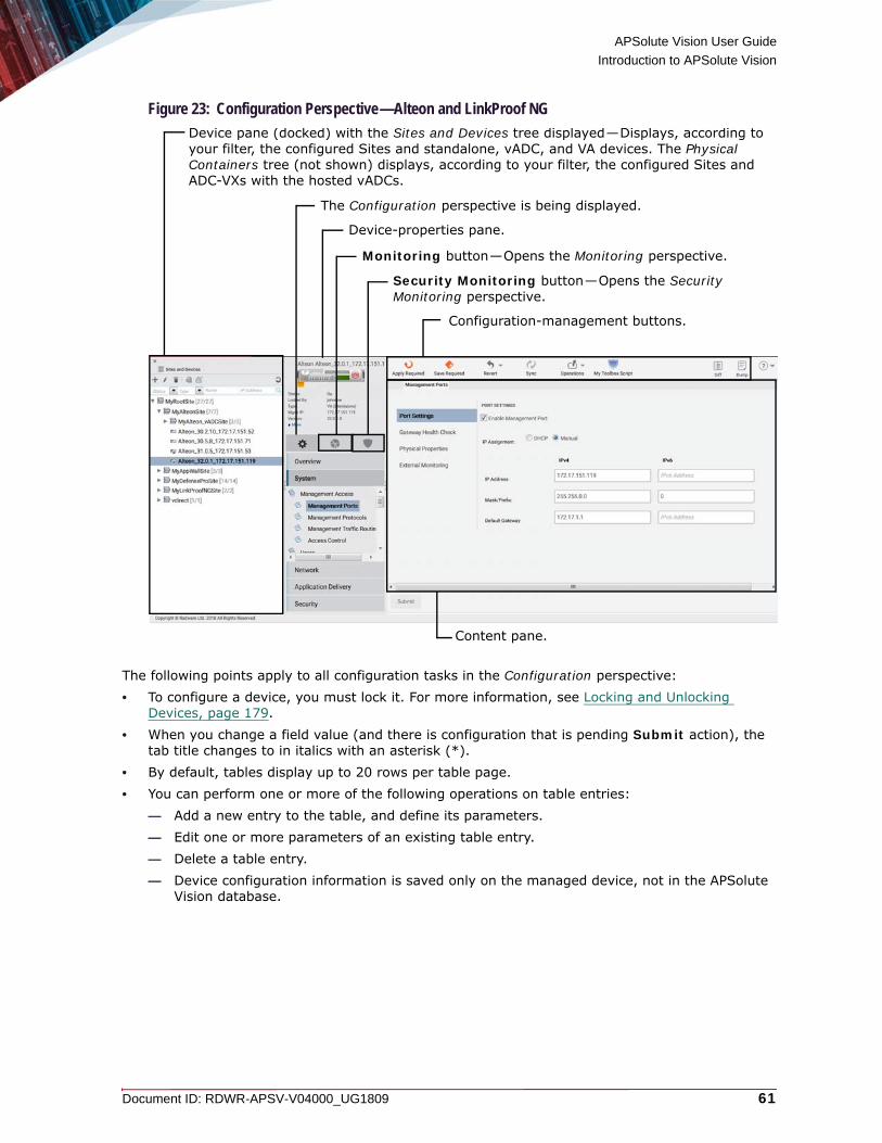
APSolute Vision User Guide
Introduction to APSolute Vision
Document ID: RDWR-APSV-V04000_UG1809 61
Figure 23: Configuration Perspective—Alteon and LinkProof NG
The following points apply to all configuration tasks in the Configuration perspective:• To configure a device, you must lock it. For more information, see Locking and Unlocking
Devices, page 179.• When you change a field value (and there is configuration that is pending Submit action), the
tab title changes to in italics with an asterisk (*).• By default, tables display up to 20 rows per table page.• You can perform one or more of the following operations on table entries:
— Add a new entry to the table, and define its parameters.— Edit one or more parameters of an existing table entry.— Delete a table entry.— Device configuration information is saved only on the managed device, not in the APSolute
Vision database.
Monitoring button—Opens the Monitoring perspective.
Content pane.
Device-properties pane.
Device pane (docked) with the Sites and Devices tree displayed—Displays, according to your filter, the configured Sites and standalone, vADC, and VA devices. The Physical Containers tree (not shown) displays, according to your filter, the configured Sites and ADC-VXs with the hosted vADCs.
Configuration-management buttons.
The Configuration perspective is being displayed.
Security Monitoring button—Opens the Security Monitoring perspective.

APSolute Vision User Guide
Introduction to APSolute Vision
62 Document ID: RDWR-APSV-V04000_UG1809
To commit information to the device, you must click Submit when you modify settings in a configuration dialog box or configuration page.Some configuration changes require an immediate device reboot. When you submit the configuration change the device will reboot immediately.Some configuration changes require a device reboot to take effect, but you can save the change without an immediate reboot. When you submit a change without a reboot, the Properties pane displays a “Reboot Required” notification until you reboot the device.
For Alteon and LinkProof NG, APSolute Vision supports the configuration-management (global-command) options: Apply, Save, Diff, Diff Flash, Revert, Revert Apply, and Dump. If the new configuration requires an Apply or Save operation to take effect, the button is displayed with an orange icon.
Figure 24: Apply (Required) and Save (Required) Buttons
For AppWall, APSolute Vision supports the Apply button to perform the AppWall Apply operation. If the configuration requires an Apply operation to take effect, the button is displayed with an orange icon.For DefensePro, click Update Policies to implement policy-configuration changes if necessary. Policy-configuration changes for a device are saved on the device, but the device does not apply the changes until you perform a device-configuration update. For DefensePro 7.x versions 7.32 and later, if the new configuration requires an Update Policies operation to take effect, the button is displayed with an orange icon.
Figure 25: Update Policies Button
Figure 26: Update Policies Required Button
Example Device selection in the Configuration perspectiveThe following example shows the selections you would make to view or change configuration parameters for a Radware device:
1. Select the required device in the device pane by drilling down through the Sites and child Sites.
2. Lock the device by clicking the icon in the device-properties pane. The icon changes to
(a picture of a locked padlock).
3. Click Configuration ( ) to open the Configuration perspective.
4. Navigate to the configuration objects in the content pane.

APSolute Vision User Guide
Introduction to APSolute Vision
Document ID: RDWR-APSV-V04000_UG1809 63
Monitoring PerspectiveIn the Monitoring perspective, you can monitor physical devices and interfaces, and logical objects.
Figure 27: Monitoring Perspective—Alteon and LinkProof NG
The Monitoring perspective is being displayed.
Device-properties pane.
Configuration-management buttons.
Device pane (docked) with the Sites and Devices tree displayed—Displays, according to your filter, the configured Sites and standalone, vADC, and VA devices. The Physical Containers tree (not shown) displays, according to your filter, the configured Sites and ADC-VXs with the hosted vADCs.
Content pane.

APSolute Vision User Guide
Introduction to APSolute Vision
64 Document ID: RDWR-APSV-V04000_UG1809
Figure 28: Monitoring Perspective—DefensePro
Security Monitoring PerspectiveAPSolute Vision displays the Security Monitoring perspective to view and analyze real-time security information of managed devices, which include the following platform types:• AppWall standalone• Alteon with embedded AppWall module• DefenseFlow mitigation devices• DefensePro
The Security Monitoring perspective is available for single devices and also for multiple devices. Security monitoring for multiple devices supports two report categories: the Dashboard View and Traffic Monitoring. Security monitoring for single devices supports two additional report categories: Protection Monitoring and HTTP Reports.You can filter the Sites and devices that APSolute Vision displays. The filter does not change the contents of the tree, only how APSolute Vision displays the tree to you.
The Monitoring perspective is being displayed.
Content pane.
Device pane (docked) with the Sites and Devices tree displayed—Displays, according to your filter, the configured Sites and DefensePro devices. The Physical Containers tree (not shown) is not relevant for DefensePro.
Device-properties pane.
DefensePro configuration-management buttons.

APSolute Vision User Guide
Introduction to APSolute Vision
Document ID: RDWR-APSV-V04000_UG1809 65
For DefenseFlow and DefensePro, the Security Monitoring perspective includes the following tabs:• Dashboard View—Comprises the following:
— Security Dashboard—A graphical summary view of all current active attacks in the network with color-coded attack-category identification, graphical threat-level indication, and instant drill-down to attack details.
— Current Attacks—A view of the current attacks in a tabular format with graphical notations of attack categories, threat-level indication, drill-down to attack details, and easy access to the protecting policies for immediate fine-tuning.
• Traffic Monitoring—A real-time graph and table displaying network information, with the attack traffic and legitimate traffic filtered according to specified traffic direction and protocol.
• Protection Monitoring—Real-time graphs and tables with statistics on policies, protections according to specified traffic direction and protocol, along with learned traffic baselines.
• HTTP Reports—Real-time graphs and tables with statistics on policies, protections according to specified traffic direction and protocol, along with learned traffic baselines.
Figure 29: DefensePro Security Monitoring Perspective—Showing the Security Dashboard
Note: For more information on the Security Monitoring perspective, see Using Real-Time Security Monitoring, page 507.
Device-properties pane.

APSolute Vision User Guide
Introduction to APSolute Vision
66 Document ID: RDWR-APSV-V04000_UG1809

Document ID: RDWR-APSV-V04000_UG1809 67
CHAPTER 2 – MANAGING APSOLUTE VISION USERS
APSolute Vision supports concurrent access to up to 50 users.Each user has individual credentials and privileges. APSolute Vision supports role-based access control (RBAC) to manage user privileges. RBAC users can be defined and managed in the local APSolute Vision user database (the Local Users table) or through an external authentication server. All user credentials for local users are encrypted and stored in the APSolute Vision database.All all actions by all users (local or non-local) are stored in the audit log.Users with the appropriate privileges can lock a device on an APSolute Vision server and modify its configuration. Locking the device prevents other users from performing configuration tasks on that device at the same time.The following topics describe role-based access control, and how to configure and monitor local APSolute Vision users:• Logging In as the Default Administrator User—radware User, page 67• Viewing Details About the Current User, page 68• Role-Based Access Control (RBAC), page 68• Configuring Local Users for APSolute Vision, page 82• Managing LDAP Object Class Permissions, page 89• Viewing User Statistics, page 90• Configuring General User-Management Settings, page 79• APSolute Vision Password Requirements, page 91
Logging In as the Default Administrator User—radware UserA new APSolute Vision server (one that no one has yet logged into) contains a single predefined Administrator user, which is called radware, defined with the Administrator role.
Caution: Radware recommends that the radware user be used by customers for disaster recovery and kept secret from all other administrators.
The radware user can create and manage additional local users and their individual and global user settings.The radware user cannot be deleted.The radware user is authenticated only in the Local Users table, regardless of whether the system is configured to use a different authentication method. That is, the radware user cannot be overridden by the configuration of an authentication server (see Configuring Connections to Authentication Servers, page 128).
Caution: You are not required to change the password for the radware user during the initial configuration, but Radware recommends you do so.

APSolute Vision User Guide
Managing APSolute Vision Users
68 Document ID: RDWR-APSV-V04000_UG1809
The radware user can change the password of the radware user in the CLI or in the login dialog box. For more information, see the APSolute Vision User Guide.
To log in to APSolute Vision for the first time as the radware user
1. In your Web browser, enter the hostname or IP address of the APSolute Vision server.2. In the login dialog box, specify the following:
— Username—The name of the user, radware.— Password—The password for the radware user.
3. Click Log In.
Viewing Details About the Current UserYou can view the following details about the current user: • The user name• The user’s RBAC role or roles• The previous login time• The UI language (which you can change by selecting another value from the drop-down list)
Figure 30: Viewing Details About the Current User
To view details about the current user
> In the APSolute Vision toolbar, in the User ribbon at the at the far right, click the arrow.
Role-Based Access Control (RBAC)This section contains the following main topics: • APSolute Vision RBAC—General Information, page 69• Roles and Scopes, page 69• GUI Display Is According to Role, page 70• IDM Strings for Predefined Roles, page 71
APSolute Vision User Guide
Managing APSolute Vision Users
Document ID: RDWR-APSV-V04000_UG1809 69
• Predefined Roles Described, page 72• Roles per Radware Product, page 74• Feature-Accessibility per Role, page 75• Rules for RBAC Permission Conflicts with Logical Groups, page 77
APSolute Vision RBAC—General InformationYou can determine the functionality and managed devices available to each user in APSolute Vision by using RBAC to associate users with roles and scopes of devices.All users can also be defined and managed through an authentication server—except for the users radware, defenseflow, msspportal, and reporter.
Notes
• The APSolute Vision installation includes the radware, defenseflow, msspportal, and reporter users.
• You cannot delete the radware, defenseflow, msspportal, and reporter users. They are defined, managed, and authenticated only in the Local Users table, regardless of whether the system is configured to manage other users through an authentication server.
• The reporter user is used by APSolute Vision Analytics.
• If you require a DefenseFlow or MSSP Portal platform to be authenticated remotely—for connections from a DefenseFlow or MSSP Portal platform to APSolute Vision, you can create a SYSTEM_USER on the remote authentication server, and configure DefenseFlow or MSSP Portal to use that user rather than the built-in defenseflow or msspportal user.
• For information about how to configure DefenseFlow, see the DefenseFlow User Guide.
• For information about how to configure MSSP Portal, see the MSSP Portal Deployment and Operator Guide.
Caution: You are not required to change the password for the radware user during the initial configuration, but Radware recommends you do so.
A user with the Administrator or User Administrator role can create, edit, and manage local APSolute Vision users.
Roles and ScopesUser management includes assigning roles and scopes. A scope defines the devices that the user can access. A role defines the set of permissions for the corresponding scope. A user definition can contain multiple role-scope pairs.APSolute Vision contains a set of predefined roles, which you cannot delete or modify. Each role defines a set of privileges. The relevance and descriptions for the predefined roles may depend on the device type.The scopes of devices are organized according to the Sites and Devices tree and Physical Containers tree in the device pane. A scope can contain one of the following:• An individual device.• [All]—The All scope contains all devices and the APSolute Vision server.

APSolute Vision User Guide
Managing APSolute Vision Users
70 Document ID: RDWR-APSV-V04000_UG1809
• A Site—With all of its devices.
Note: For more information, see Configuring Sites, page 162.• A Logical Group—The user’s scope dynamically updates, according to the devices in the
Logical Group. That is, when the device-set of a Logical Group changes, the user’s scope changes accordingly.
Notes
— For more information on Logical Groups, see Using Logical Groups of Devices, page 190. — For information on permission conflicts, see Rules for RBAC Permission Conflicts with Logical
Groups, page 77.
Caution: If the name of an APSolute Vision Site or Logical Group changes and an authentication server authenticates users, you must reconfigure the user scopes on the authentication server.
If the name of an APSolute Vision Site or Logical Group changes and APSolute Vision authenticates the users locally, APSolute Vision updates the relevant scopes for the users.Every role must be assigned a scope—except for the following roles, which APSolute Vision always configures with the All scope: • Administrator• System User• User Administrator• Vision Administrator
Caution: When defined through an authentication server, users with the Administrator, User Administrator, System User, or Vision Administrator role must be configured with the scope [ALL] (including the square brackets).
GUI Display Is According to RoleAPSolute Vision displays the graphical user interface according to the user’s role, for example:• When a user has full read and write permissions, all Add, Edit, and Delete buttons are
displayed.• When a user has update permissions only, Add buttons are not displayed.• When a user does not have any configuration permissions, Add, Delete, and Submit buttons
are not displayed.• A user with the User Administrator role can manage all user settings: the Local Users table, the
Authentication Method, and so on. A user with the User Administrator role cannot view other elements in the APSolute Vision Settings view System perspective.
• The tree in device pane displays only those devices that belong to scope associated with the user.
• The Security Monitoring perspective displays information only for the devices that belong to the user’s device scope. For DefensePro devices, you can limit the Network Protection policies accessible to users in the perspective. This applies also to the information that APSolute Vision Reporter displays.

APSolute Vision User Guide
Managing APSolute Vision Users
Document ID: RDWR-APSV-V04000_UG1809 71
Users with a proper role can access the APSolute Vision GUI and can see the Alerts Table pane, but APSolute Vision limits the alert-display according to device permissions.
IDM Strings for Predefined RolesEach role has an associated identity-management (IDM) string. You use the IDM strings in an authentication-server configuration, for example. If the user is authenticated, the APSolute Vision server grants access according to the user’s IDM string and scope. The authentication server Access-Accept response must include an IDM-string–scope combination.
Note: APSolute Vision RBAC functionality is separate from the functionality of user accounts on the devices themselves. The following table lists the predefined roles and the corresponding IDM strings. The relevance and descriptions for the predefined roles may depend on the device type.
Table 1: Predefined Roles and IDM Strings
Role IDM StringADC + Certificate Administrator
ADC_AND_CERTIF_ADMIN
ADC Administrator ADC_ADMIN
ADC Operator ADC_OPERATOR
Administrator SYS_ADMIN
Certificate Administrator CERTIF_ADMIN
Device Administrator DEV_ADMIN
Device Configurator CONFIG
Device Operator DEVICE_OPERATOR
Device Viewer VIEWER
Real Server Operator REAL_SERVER_OPERATOR
Security Administrator SEC_ADMIN
Security Monitor SEC_MON
System User SYSTEM_USER
User Administrator USR_ADMIN
Vision Administrator VISION_ADMIN
Vision Reporter REPORTER

APSolute Vision User Guide
Managing APSolute Vision Users
72 Document ID: RDWR-APSV-V04000_UG1809
Predefined Roles DescribedThe following table describes the predefined roles in APSolute Vision. The relevance and descriptions for the predefined roles may depend on the device type.
Table 2: Predefined Roles
Role DescriptionADC + Certificate Administrator
The union of ADC Administrator and Certificate Administrator roles.Has full control over ADC configuration and AppShapes, can configure and manage servers, services, traffic redirection, and health checks.Can perform all functions of the devices for which the user has credentials.Has control over the Certificate Repository and the Client Authentication Policy in the Configuration perspective.Can perform all functions related to Alteon and LinkProof NG.Can launch the Device Performance Monitor Web interface and view the Application SLA Dashboard.Can view the Alerts Table.Can access Security Monitoring perspective.
ADC Administrator Has full control over ADC configuration and AppShapes, can configure and manage servers, services, traffic redirection, and health checks.Can perform all functions of the devices for which the user has credentials.Can launch the Device Performance Monitor Web interface and view the Application SLA Dashboard.Can view the Alerts Table.Can access Security Monitoring perspective.
ADC Operator Has read-only permission on the configuration of ADC devices and general device control.Can launch the Device Performance Monitor Web interface and view the Application SLA Dashboard.Can view the Alerts Table.
Administrator Can access the CLI and can perform all actions and access all functionality.
Certificate Administrator
Has control over the Certificate Repository and the Client Authentication Policy in the Configuration perspective.Can view the Alerts Table.Can access the Monitoring perspective.Can perform all functions related to Alteon and LinkProof NG, but some functions are read-only.Can view the Application SLA Dashboard.
Device Administrator
Has full control over devices for which the user has credentials.Can launch the Device Performance Monitor Web interface and view the Application SLA Dashboard.Can view the Alerts Table.Can export a policy file from the Network Protection Policies table and Server Protection Policies table. Can access the Templates tab.

APSolute Vision User Guide
Managing APSolute Vision Users
Document ID: RDWR-APSV-V04000_UG1809 73
Device Configurator
Can access all Configuration-perspective panes and Monitoring-perspective panes, and has full control over the Setup, Networking, Device Security and Advanced parameter tabs of the Configuration perspective of the devices for which the user has credentials.Can perform all Configuration and Monitoring pane perspective functions of the devices for which the user has credentials, excluding AppShapes. Can launch the Device Performance Monitor Web interface and view the Application SLA Dashboard.Can view the Alerts Table.
Device Operator Has full control over all Monitoring perspective panes and can access the Configuration perspective. Can perform all functions related to Alteon and LinkProof NG, including AppShapes, but some functions are read-only.Can launch the Device Performance Monitor Web interface and view the Application SLA Dashboard.Can view the Alerts Table.
Device Viewer Can access all devices for which the user has credentials.Can launch the Device Performance Monitor Web interface and view the Application SLA Dashboard.
Real Server Operator
Can lock and unlock an Alteon device for which the user has credentials. Can access the Monitoring perspective with the following permissions with read-write access to the following nodes (all other nodes are hidden):• Application Delivery > Virtual Service > Real Servers• Application Delivery > Virtual Service > Server GroupsCan view the Alerts Table.Can view the Application SLA Dashboard.
Security Administrator
Can configure and manage network and server security, ACL policies, and so on.Can export a policy file from the Network Protection Policies table and Server Protection Policies table. Furthermore, can open the Advanced Toolbox tab, and can see and use the DefensePro Configuration Templates node.Can view the Alerts Table.
Security Monitor Has full control over Security Monitoring and APSolute Vision Reporter.
System User Can access APSolute Vision through the REST interface (only) and can perform all actions and access all functionality.
User Administrator Can access the APSolute Vision Settings view System perspective, and in it, can create and manage users. Cannot view other elements in the APSolute Vision Settings view System perspective.
Vision Administrator
Can access the CLI except for system snmp community and system snmp trap target—and can perform all actions and access all functionality, except for user management and authentication protocols (RADIUS Settings and TACACS+ Settings).Can use DefenseFlow.Can view the Alerts Table.
Vision Reporter Has full control over APSolute Vision reporting capabilities (APM, AVR, and DPM).
Table 2: Predefined Roles (cont.)
Role Description

APSolute Vision User Guide
Managing APSolute Vision Users
74 Document ID: RDWR-APSV-V04000_UG1809
Roles per Radware Product The following table lists the predefined roles and corresponding functionalities.
Table 3: Role per Radware Product
Role Can Add New Device
Manages Application Delivery Devices (Alteon and LinkProof NG)
Manages Security Devices (AppWall and DefensePro)
Can Use DefenseFlow
ADC + Certificate Administrator
No Yes No No
ADC Administrator No Yes No No
ADC Operator No Yes No No
Administrator Yes Yes Yes Yes
Certificate Administrator No Yes No No
Device Administrator Yes Yes Yes No
Device Configurator No Yes Yes No
Device Operator No Yes No No
Device Viewer No Yes Yes No
Real Server Operator No Yes No No
Security Administrator No No Yes No
Security Monitor No Yes Yes No
System User Yes1
1 – Yes, but only using the REST interface. This role does not allow access to the APSolute Vision GUI (that is, Web Based Management).
Yes1 Yes1 Yes1
User Administrator No N/A N/A N/A
Vision Administrator Yes Yes Yes Yes
Vision Reporter No Yes Yes No
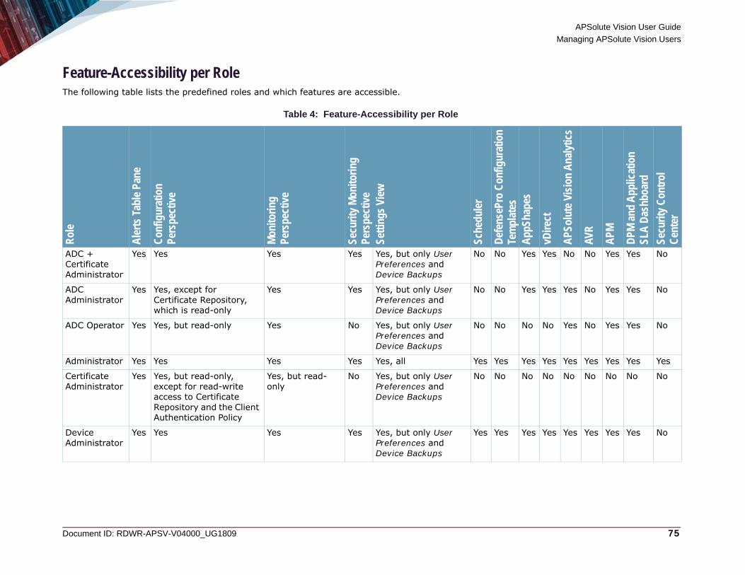
APSolute Vision User Guide
Managing APSolute Vision Users
Document ID: RDWR-APSV-V04000_UG1809 75
Feature-Accessibility per RoleThe following table lists the predefined roles and which features are accessible.
Table 4: Feature-Accessibility per Role
Rol
e
Ale
rts
Tabl
e Pa
ne
Con
figur
atio
nPe
rspe
ctiv
e
Mon
itorin
g Pe
rspe
ctiv
e
Secu
rity
Mon
itorin
gPe
rspe
ctiv
e Se
tting
s Vi
ew
Sche
dule
r
Def
ense
Pro
Con
figur
atio
nTe
mpl
ates
App
Shap
es
vDire
ct
APS
olut
e Vi
sion
Ana
lytic
s
AVR
APM
DPM
and
App
licat
ion
SLA
Das
hboa
rd
Secu
rity
Con
trol
C
ente
r
ADC + Certificate Administrator
Yes Yes Yes Yes Yes, but only User Preferences and Device Backups
No No Yes Yes No No Yes Yes No
ADC Administrator
Yes Yes, except for Certificate Repository, which is read-only
Yes Yes Yes, but only User Preferences and Device Backups
No No Yes Yes Yes No Yes Yes No
ADC Operator Yes Yes, but read-only Yes No Yes, but only User Preferences and Device Backups
No No No No Yes No Yes Yes No
Administrator Yes Yes Yes Yes Yes, all Yes Yes Yes Yes Yes Yes Yes Yes Yes
Certificate Administrator
Yes Yes, but read-only, except for read-write access to Certificate Repository and the Client Authentication Policy
Yes, but read-only
No Yes, but only User Preferences and Device Backups
No No No No No No No No No
Device Administrator
Yes Yes Yes Yes Yes, but only User Preferences and Device Backups
Yes Yes Yes Yes Yes Yes Yes Yes No
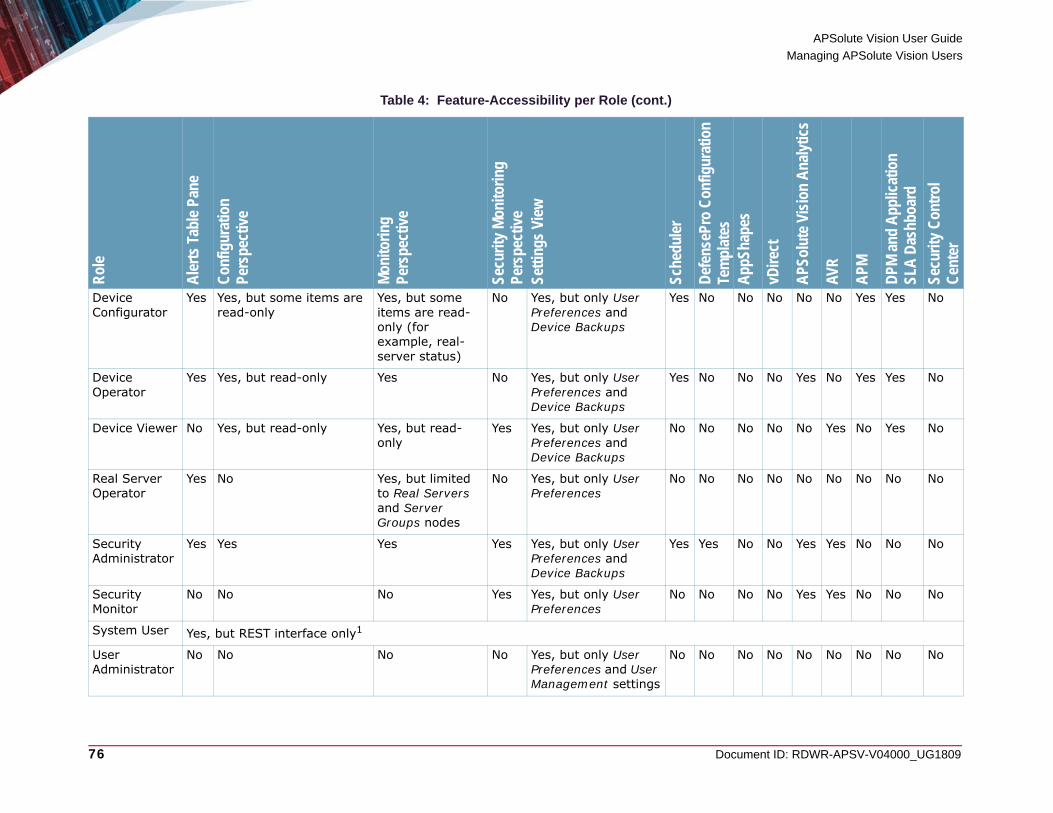
APSolute Vision User Guide
Managing APSolute Vision Users
76 Document ID: RDWR-APSV-V04000_UG1809
Device Configurator
Yes Yes, but some items are read-only
Yes, but some items are read-only (for example, real- server status)
No Yes, but only User Preferences and Device Backups
Yes No No No No No Yes Yes No
Device Operator
Yes Yes, but read-only Yes No Yes, but only User Preferences and Device Backups
Yes No No No Yes No Yes Yes No
Device Viewer No Yes, but read-only Yes, but read-only
Yes Yes, but only User Preferences and Device Backups
No No No No No Yes No Yes No
Real Server Operator
Yes No Yes, but limited to Real Servers and Server Groups nodes
No Yes, but only User Preferences
No No No No No No No No No
Security Administrator
Yes Yes Yes Yes Yes, but only User Preferences and Device Backups
Yes Yes No No Yes Yes No No No
Security Monitor
No No No Yes Yes, but only User Preferences
No No No No Yes Yes No No No
System User Yes, but REST interface only1
User Administrator
No No No No Yes, but only User Preferences and User Management settings
No No No No No No No No No
Table 4: Feature-Accessibility per Role (cont.)R
ole
Ale
rts
Tabl
e Pa
ne
Con
figur
atio
nPe
rspe
ctiv
e
Mon
itorin
g Pe
rspe
ctiv
e
Secu
rity
Mon
itorin
gPe
rspe
ctiv
e Se
tting
s Vi
ew
Sche
dule
r
Def
ense
Pro
Con
figur
atio
nTe
mpl
ates
App
Shap
es
vDire
ct
APS
olut
e Vi
sion
Ana
lytic
s
AVR
APM
DPM
and
App
licat
ion
SLA
Das
hboa
rd
Secu
rity
Con
trol
C
ente
r

APSolute Vision User Guide
Managing APSolute Vision Users
Document ID: RDWR-APSV-V04000_UG1809 77
Rules for RBAC Permission Conflicts with Logical GroupsAPSolute Vision users can include multiple role-scope pairs, and a device can be a member of multiple Logical Groups. These factors make permission conflicts possible.
Vision Administrator
Yes Yes Yes Yes All, but excluding User Management settings and authentication protocols2
Yes Yes Yes Yes Yes Yes Yes Yes
Vision Reporter
No No No No Yes, but only User Preferences
No No No No Yes Yes Yes Yes No
1 – Users with the System User role can perform all actions and access all functionality but can access APSolute Vision only using the REST interface. The System User role does not allow access to the APSolute Vision GUI (Web Based Management).
2 – That is, RADIUS Settings, TACACS+ Settings, and LDAP Settings.
Table 4: Feature-Accessibility per Role (cont.)R
ole
Ale
rts
Tabl
e Pa
ne
Con
figur
atio
nPe
rspe
ctiv
e
Mon
itorin
g Pe
rspe
ctiv
e
Secu
rity
Mon
itorin
gPe
rspe
ctiv
e Se
tting
s Vi
ew
Sche
dule
r
Def
ense
Pro
Con
figur
atio
nTe
mpl
ates
App
Shap
es
vDire
ct
APS
olut
e Vi
sion
Ana
lytic
s
AVR
APM
DPM
and
App
licat
ion
SLA
Das
hboa
rd
Secu
rity
Con
trol
C
ente
r

APSolute Vision User Guide
Managing APSolute Vision Users
78 Document ID: RDWR-APSV-V04000_UG1809
APSolute Vision handles conflicting permissions as follows:• The role with an individual device overrides the user’s role with a Logical Group—That
is, if the configuration of user includes one role with a Logical-Group scope, and another role with a individual-device scope, and that individual device is a member of the same Logical Group, the role with the individual-device scope takes precedence.
• The role with a Site overrides the user’s role with a Logical Group—That is, if the configuration of user includes one role with a Logical-Group scope, and another role with a Site scope, and that Site contains a device that is a member of the same Logical Group, the role with the Site scope takes precedence.
• The role with the highest level takes precedence when a device is a member of multiple Logical Groups used in a user configuration—That is, if the configuration of a user includes one role with one Logical-Group scope, and another role with another Logical-Group scope, and the Logical Groups include a common member, the role with highest level of access takes precedence. For the list of access levels, see Table 5 - Access Levels for Determining a User’s RBAC Role for a Device, when the Device Is a Common Member of Multiple Logical Groups, page 78.
Example An APSolute Vision server includes a user named User-A, a device named Device-1, and a Logical Group named MyLG. Device-1 is a member of MyLG. The configuration of User-A contains two role-scope pairs. One role-scope pair is Configurator–Device-1. The other role-scope pair is Operator–MyLG. APSolute Vision grants User-A the role of Configurator on Device-1.
Example An APSolute Vision server includes a user named User-A, a device named Device-1, a Site named MySite, and a Logical Group named MyLG. Device-1 is a member of MySite and MyLG. The configuration of User-A contains two role-scope pairs. One role-scope pair is Configurator–MySite. The other role-scope pair is Operator–MyLG. APSolute Vision grants User-A the role of Configurator on Device-1.
Example An APSolute Vision server includes a user named User-A, a device named Device-1, a Logical Group named MyLG-X and a Logical Group named MyLG-Y. Device-1 is a member of MyLG-X and MyLG-Y. The configuration of User-A contains two role-scope pairs. One role-scope pair is ADC-Administrator–MyLG-X. The other role-scope pair is Device-Viewer–MyLG-Y. APSolute Vision grants User-A the role of ADC Administrator on Device-1.The following table lists the access levels that APSolute Vision uses to determine a user’s RBAC role for a device, when the device is a common member of multiple Logical Groups. The role with the highest level takes precedence.
Table 5: Access Levels for Determining a User’s RBAC Role for a Device, when the Device Is a Common Member of Multiple Logical Groups
Level Role1 Administrator
2 Vision Administrator
3 System User
4 User Administrator

APSolute Vision User Guide
Managing APSolute Vision Users
Document ID: RDWR-APSV-V04000_UG1809 79
Configuring General User-Management SettingsThe Administrator or User Administrator user can specify the user-authentication method for all APSolute Vision interfaces.
To configure general user-management settings
1. In the APSolute Vision Settings view System perspective, select User Management > User Management Settings.
2. Configure the parameters, and click Submit.
5 Device Administrator
6 Security Administrator
7 ADC + Certificate Administrator
8 ADC Administrator
9 Certificate Administrator
10 Device Configurator
11 Device Operator
12 ADC Operator
13 Real Server Operator
14 Device Viewer
15 Security Monitor
16 Vision Reporter
Table 5: Access Levels for Determining a User’s RBAC Role for a Device, when the Device Is a Common Member of Multiple Logical Groups (cont.)
Level Role

APSolute Vision User Guide
Managing APSolute Vision Users
80 Document ID: RDWR-APSV-V04000_UG1809
Table 6: User Management Settings
Parameter DescriptionAuthentication Mode The user-authentication method that APSolute Vision uses.
The Administrator or User Administrator user can specify the user-authentication method for all APSolute Vision interfaces.The setting is retained after reboot of the APSolute Vision server, and it is included in the APSolute Vision configuration backup and restore operations.Values:• LDAP—An LDAP server stores the credentials of and
authenticates the APSolute Vision users (see Configuring LDAP Server Connections, page 138). If the primary LDAP server and, if defined, secondary LDAP server is down, user authentication fails over to the Local Users table (see Configuring Local Users for APSolute Vision, page 82).
• Local—The Local Users table stores the credentials of and authenticates the APSolute Vision users (see Configuring Local Users for APSolute Vision, page 82).
• RADIUS—A RADIUS server stores the credentials of and authenticates the APSolute Vision users (see Configuring RADIUS Server Connections, page 128). If the primary RADIUS server and, if defined, secondary RADIUS server is down, user authentication fails over to the Local Users table (see Configuring Local Users for APSolute Vision, page 82).
• TACACS+—A TACACS+ server stores the credentials of and authenticates the APSolute Vision users (see Configuring TACACS+ Server Connections, page 132). If the primary TACACS+ server and, if defined, secondary TACACS+ server is down, user authentication fails over to the Local Users table (see Configuring Local Users for APSolute Vision, page 82).
Default: Local
Maximum Password Challenges The number of consecutive unsuccessful password entries before a user is locked out.Values: 3–10Default: 3

APSolute Vision User Guide
Managing APSolute Vision Users
Document ID: RDWR-APSV-V04000_UG1809 81
Default Password for Other Users The default password that new users enter on initial login or after password reset—except for the following users: radware, defenseflow, msspportal, and reporter.
Notes: • You can configure the initial password for an individual
user. For more information, see Table 11 - User: Password Parameters, page 86.
• The radware user can change the password at any time or on expiration.
• The defenseflow user has a special password. For DefenseFlow version 2.5 and later, the password for both APSolute Vision and DefenseFlow must match.
• The reporter user (which APSolute Vision Analytics uses) has a special password.
Confirm Default Password for Other Users
The value for confirmation of Default Password for Other Users.
Password Validity Period The number of days from password creation until that password expires. When you change this value, the new value is applied to any subsequently created passwords; current passwords are not affected by the change.Values: 1–3670Default: 30
User Statistics Storage Period The number of days the user statistics information is stored before being deleted.Values: 1–3670Default: 30
Inactivity Timeout Period for CLI Access of Non-Local Users
The time, in days—following the initial login, that APSolute Vision allows CLI access to users who are defined in an external authentication server (RADIUS, TACACS+, or LDAP). Any subsequent login to APSolute Vision (either CLI or WBM) resets the timer. A user who has timed out can reactivate CLI access by logging in to APSolute Vision WBM.Values: 30–3650Default: 365
Note: To activate CLI access, all users defined in an external authentication server must log in to APSolute Vision WBM at least once.
Last Passwords Saved The number of passwords that APSolute Vision saves for a user to prevent the user from reusing a recently expired password.Values: 2–100Default: 3
Table 6: User Management Settings (cont.)
Parameter Description

APSolute Vision User Guide
Managing APSolute Vision Users
82 Document ID: RDWR-APSV-V04000_UG1809
Configuring Local Users for APSolute VisionThe Local Users table contain individual local APSolute Vision user configurations.A user with the Administrator or User Administrator role can set and change the following individual local APSolute Vision user configurations:• Add, edit, and delete users• Revoke and enable users• Release user lockout and reset user passwords
Caution: Users with the name admin (case insensitive) cannot be created in the APSolute Vision local user table. If users with the name admin (case insensitive) are defined in an external, RADIUS or TACACS+ authentication server, or were created in the local user table prior to APSolute Vision version 3.30, they can log in to APSolute Vision, but they will not be able to log in to the AVR.
Note: The APSolute Vision installation includes the radware, defenseflow, msspportal, and reporter users. You cannot delete them or modify their role and/or scope assignment.For information about setting global user configurations, see Configuring General User-Management Settings, page 79.Besides the Local Users table, APSolute Vision users can be authenticated through an authentication server (see Configuring Connections to Authentication Servers, page 128). When the authentication server is down, user authentication fails over to the Local Users table.
Tip: If an authentication server is specified to authenticate the APSolute Vision users, Radware recommends that administrator users be defined also in the Local Users table. Having users defined also in the Local Users table is for fall-back access to APSolute Vision in case the authentication server is not available.
Use the Local Users tab for the following operations:• Adding and Editing Users, page 84• Deleting Users, page 87• Releasing User Lockout, page 87• Resetting User Passwords to the Default, page 88• Revoking and Enabling Users, page 88
User Must Change Password at First Login
Specifies whether all users must change their password when logging in for the first time to the APSolute Vision server.Default: Disabled
Note: The value for this parameter applies to when the user is created, and does not change. For example, if the value for this parameter is enabled when the user is created, and then the value changes to disabled—but the user has not yet logged in, the user will be required to change his/her password when he/she first logs in.
Table 6: User Management Settings (cont.)
Parameter Description

APSolute Vision User Guide
Managing APSolute Vision Users
Document ID: RDWR-APSV-V04000_UG1809 83
To open the Local Users tab
> In the APSolute Vision Settings view System perspective, select User Management > Local Users.
The Local Users tab displays information for all currently defined users. Additional information for users is available when editing specific rows in the Local Users table.
Table 7: Local User Table Parameters
Parameter DescriptionUser Name The username used for login.
User Full Name The user’s full name.
Language The default display language for the user.
Notes: • The Default Display Language parameter (see Configuring
APSolute Vision Display Parameters, page 153) determines the default value.
• A user can change his/her own display language, by opening the User drop-down dialog box (from the APSolute Vision toolbar, in the User ribbon at the at the far right) and selecting
the language from the drop-down list next to the (globe) icon.
Scope The scopes of devices, which are organized according to the Sites and Devices tree and Physical Containers tree in the device pane. A scope can be one of the following:• An individual device.• A Site, with all of its devices. • A Logical Group—The user’s scope dynamically updates,
according to the devices in the Logical Group. That is, when the device-set of a Logical Group changes, the user’s scope changes accordingly. For more information, see Rules for RBAC Permission Conflicts with Logical Groups, page 77 and Using Logical Groups of Devices, page 190.
• [All]—The All scope contains all devices and the APSolute Vision server.
The displayed scopes for each user represent the devices that the user can access. Each scope in the list is associated with a corresponding role that defines the permissions for the user on those devices.Users defined through an authentication server with the Administrator, User Administrator, or Vision Administrator role must be configured with the scope [ALL] (including the square brackets).
Role The roles with which the user is associated. Each role defines a set of actions the user can perform through APSolute Vision. Each role in the list applies to its corresponding scope of devices.
Contact Info The user’s contact information—organization, address, and phone number.
Password Expiration Date The date on which the current password expires.

APSolute Vision User Guide
Managing APSolute Vision Users
84 Document ID: RDWR-APSV-V04000_UG1809
Adding and Editing UsersWhen you add a user, you associate the user with one or more role-and-scope pairs to define the user’s privileges and the managed devices to which the privileges apply. Scopes represent the devices for which the user has credentials. The corresponding role for each scope in the list defines the permissions for the user on those devices.When you modify the role and/or scope assignment for a user who is logged into APSolute Vision, the user must log out and log in again for the changes to take effect.
Note: You cannot modify the role and/or scope assignment of the radware, defenseflow, msspportal, and reporter users.By default, a new user is not associated with any scope or role.You can only add a scope once for each user. You cannot add a scope that contains devices that are already in a scope associated with the user.For DefensePro devices, after you configure the role-scope pair, you can configure the security-monitoring access for the user. Security-monitoring access defines what security data the user sees in the Security Monitoring perspective and APSolute Vision Reporter according to specified DefensePro Network Protection policies.
Caution: Do not configure more than 300 explicit device-policy pairs for DefensePro security-monitoring access—for any user. If there are more than 300 explicit device-policy pairs for a user, the Security Monitoring Dashboard View might not function properly for the user.
Note: The terms Network Protection policy and network policy may be used interchangeably in APSolute Vision and in the documentation.
To add or edit a user
1. In the APSolute Vision Settings view System perspective, select User Management > Local Users.
2. Do one of the following:
— To add a user, click the (Add) button in the tab toolbar.— To edit a user, double-click the username.
Active User Specifies whether the user is currently enabled.Values: • Yes—The user is currently enabled.• No—The user is currently suspended and cannot log in.
Currently Locked Out Specifies whether the user is currently locked out.
Created On The date on which the user was created.
Last Password Change The date on which the user password was last changed.
Last Lockout The date on which the user was last locked out.
Table 7: Local User Table Parameters (cont.)
Parameter Description

APSolute Vision User Guide
Managing APSolute Vision Users
Document ID: RDWR-APSV-V04000_UG1809 85
3. In the Permissions tab User Roles and Scopes table, do one of the following:
— To add a new role-scope pair, click the (Add) button in the tab toolbar.
— To edit a role-scope pair, click (Edit) in the tab toolbar.4. Do the following:
— From the Role drop-down list, select the role for the selected scope.— From the Scope drop-down list, select the scope containing the devices that the user can
access.Note: For information, see Role and Scope in Table 7 - Local User Table Parameters, page 83, and Role-Based Access Control (RBAC), page 68.
5. Click Submit.
6. Configure the rest of the user parameters, and click Submit.
Tip: Select a row and click the (Duplicate...) button to open a new “add row” tab, which is populated with the values from the selected row, except for the indexes.
Note: At the initial login, a new user enters the password and is then prompted to create a new password. Users can always change their own passwords at login. For more information, see Changing Passwords for Local Users, page 99. The initial password can be a default password (see Table 6 - User Management Settings, page 80) or a personal password configured for the specific user (see Table 11 - User: Password Parameters, page 86).
Table 8: User: General Parameters
Parameter DescriptionUser Name The username used for login. This field is mandatory.
The name should start with a letter or an underscore.The remaining characters can be letters, numbers, underscores, hyphens, or periods (dots).APSolute Vision usernames are not case sensitive when logging in to APSolute Vision WBM. APSolute Vision usernames are case sensitive when logging in to the APSolute Vision CLI. APSolute Vision user passwords are case sensitive.
User Full Name The user’s full name. This field is optional.
Language The default display language for the user.
Notes: • The Default Display Language parameter (see Configuring
APSolute Vision Display Parameters, page 153) determines the default value.
• The user can change his/her own display language, by using the
(globe) icon at the upper-right corner of the main screen.

APSolute Vision User Guide
Managing APSolute Vision Users
86 Document ID: RDWR-APSV-V04000_UG1809
To configure the DefensePro Network Protection policies whose security data the user can access in the Security Monitoring perspective and APSolute Vision Reporter
1. In the APSolute Vision Settings view System perspective, select User Management > Local Users.
2. In the Permissions tab, under the title Authorized Network Policies for Security Monitoring, configure the Selected table with the Network Protection policies whose security data the user can access in the Security Monitoring perspective and APSolute Vision Reporter.
Table 9: User: Permissions Parameters
Parameter DescriptionUser Roles and Scopes The specified role for the user on the specified device or devices for
which the user has credentials.
Note: For information, see Role and Scope in Table 7 - Local User Table Parameters, page 83, and Role-Based Access Control (RBAC), page 68.
Authorized Network Policies for Security Monitoring
The DefensePro Network Protection policies that the user is authorized to monitor in the Security Monitoring perspective.
Note: For more information, see the procedure below, To configure the DefensePro Network Protection policies whose security data the user can access in the Security Monitoring perspective and APSolute Vision Reporter, page 86.
Table 10: User: Contact Info Parameters
Parameter DescriptionThese fields are optional.
Organization The user’s organization.
Address The user’s address.
Phone Number The user’s phone number.
Table 11: User: Password Parameters
Parameter DescriptionThese fields are optional.If you specify no password, APSolute Vision uses the default password for new users.
Note: For more information, see Default Password for Other Users in Table 6 - User Management Settings, page 80.Password The initial password for the new user.
Confirm Password The value for confirmation of Password, when you specify the initial password for the new user.

APSolute Vision User Guide
Managing APSolute Vision Users
Document ID: RDWR-APSV-V04000_UG1809 87
Notes
• By default, users have access to all policies of all devices in their scope.
• When you create a user, the Selected table displays [ALL] in the Device column and [ALL] in the Policy Name column. This signifies that the user can access all policies for each permitted device. A user must be authorized for all network policies of a device ([ALL]) or for selected network policies of a device. When you move a policy from the Available table to the Selected table, [ALL] values move automatically from the Selected table to the Available table.
• A change to Authorized Network Policies for Security Monitoring takes effect the next time the user logs in, and does not affect current ongoing sessions.
Deleting UsersDeleting a user removes the user from the Local Users table.
Notes
• The radware, defenseflow, msspportal, and reporter users cannot be deleted.
• You can suspend a user without removing the user from the table. For more information, see Revoking and Enabling Users, page 88.
To delete a user
1. In the APSolute Vision Settings view System perspective, select User Management > Local Users.
2. In the Local Users table, select the username, and click the (Delete) button in the tab toolbar.
3. Click Yes in the confirmation box.
Releasing User LockoutWhen a user performs more than the permitted number of unsuccessful logins (User Management > User Management Settings > Maximum Password Challenges), the user is locked out and cannot log in again until the user administrator releases the lock and resets the password.
To release a user lockout
1. In the APSolute Vision Settings view System perspective, select User Management > Local Users.
2. In the Local Users table, select the usernames that you want to unlock, and click (Unlock Selected Users).
3. Reset the user password to the default, see Resetting User Passwords to the Default, page 88.
APSolute Vision User Guide
Managing APSolute Vision Users
88 Document ID: RDWR-APSV-V04000_UG1809
Resetting User Passwords to the DefaultFollowing a user lockout, a user administrator can reset a local user’s password to the default user password. When the user next logs into APSolute Vision, that user will be prompted to change the default password according to APSolute Vision Password Requirements, page 91.
Notes
• You cannot reset the password of the radware user. If the radware user is locked out for any reason, contact Radware Technical Support.
• You cannot reset the password of the reporter user.
To reset a user’s password to the default
1. In the APSolute Vision Settings view System perspective, select User Management > Local Users.
2. In the Local Users table, select the usernames whose password you want to reset, and click (Reset Selected User Password).
Revoking and Enabling UsersRevoking a user suspends the user, but does not delete the user from the Users table.
Caution: If you revoke the defenseflow user, DefenseFlow version 2.5 and later cannot communicate with APSolute Vision.
Note: For information on how to delete a user from the Users table, see Deleting Users, page 87.
To revoke a user
1. In the APSolute Vision Settings view System perspective, select User Management > Local Users.
2. In the Local Users table, select the usernames, and click (Revoke Selected Users). The value in the Active User column of the user in the Local Users table changes from Yes to No.
To enable a revoked user
1. In the APSolute Vision Settings view System perspective, select User Management > Local Users.
2. In the Users table, select the usernames, and click (Enable Selected Users). The value in the Active User column of the user in the Local Users table changes from No to Yes.

APSolute Vision User Guide
Managing APSolute Vision Users
Document ID: RDWR-APSV-V04000_UG1809 89
Viewing the Predefined RolesAPSolute Vision provides predefined roles, which you cannot delete or modify.
Note: For the list of predefined roles, see Table 2 - Predefined Roles, page 72.
To view the table of predefined roles
> In the APSolute Vision Settings view System perspective, select User Management > Roles.
Managing LDAP Object Class PermissionsUse the LDAP Object Class Permissions tab to manage APSolute Vision permissions for LDAP object classes.
To add or edit an LDAP Object Class Permission
1. In the APSolute Vision Settings view System perspective, select User Management > LDAP Object Class Permission.
2. Do one of the following:
— To add a permission, click the (Add) button in the tab toolbar.— To edit a permission, double-click the entry.
3. Configure the following parameters:
— Object Class Name—The name of the object class in the LDAP server that includes the Attribute and Value for the permission. In most cases, the name of the object class is user.Example: user
— Attribute—The Attribute field to match for the permission in the LDAP server.Example: memberof
— Value—The value of the Attribute.Example: CN=financeTeam,OU=finance,DC=company,DC=com
4. In the Permissions section, do one of the following:
— To add a new role-scope pair, click the (Add) button in the tab toolbar.
— To edit a role-scope pair, click (Edit) in the tab toolbar.5. Do the following:
— From the Role drop-down list, select the role for the selected scope.— From the Scope drop-down list, select the scope containing the devices that the user can
access.Note: For information on roles, see Role-Based Access Control (RBAC), page 68.
6. Click Submit.
7. Repeat step 4 through step 6 to configure all the role-scope pairs for the permission.
APSolute Vision User Guide
Managing APSolute Vision Users
90 Document ID: RDWR-APSV-V04000_UG1809
8. (Optional) If you are using DefensePro, under the title Authorized Network Policies for Security Monitoring, configure the Selected table with the Network Protection policies whose security data the user can access in the Security Monitoring perspective and APSolute Vision Reporter.
Note: A change to Authorized Network Policies for Security Monitoring takes effect the next time the user logs in, and does not affect current ongoing sessions.
9. Click Submit.
Tip: Select a row and click the (Duplicate...) button to open a new “add row” tab, which is populated with the values from the selected row, except for the indexes.
Example Using the examples in step 3 in the procedure above, if some user who is a member of the financeTeam group successfully logs in to the LDAP server, that user is assigned the role-scope pair as described in step 4 and step 5.
Viewing User StatisticsUse the User Statistics tab to view user statistics.The User Statistics tab includes the following tables:• Currently Connected Users—The users who are currently connected to APSolute Vision
through the local user table or an authentication server. The table contains the following columns:— Name— Login Date and Time—The date and time of last login. The date/time format is configurable
according to your preferences (APSolute Vision Settings view Settings perspective, General Settings > Display).
• User Statistics—A table, which you can filter, and which contains the following columns:— User Name— Date— Successful Logins— Failed Authentication Attempts— Password Changes— Lock-Outs
To display user statistics
> In the APSolute Vision Settings view System perspective, select User Management > User Statistics.

APSolute Vision User Guide
Managing APSolute Vision Users
Document ID: RDWR-APSV-V04000_UG1809 91
APSolute Vision Password RequirementsAll personal and default passwords required by the Administrator user and other local users must conform to the following rules:• A password must be at least eight (8) characters in length.• A password must include characters from at least two (2) of the following character types: text
character, number, special character—except for characters that may have command functions.• A password must not be the same as the username with which they are associated.• A new password must not contain a sequence of three (3) or more characters from the previous
password.
For information about changing individual and default passwords, see the following:• Changing Passwords for Local Users, page 99• Configuring General User-Management Settings, page 79

APSolute Vision User Guide
Managing APSolute Vision Users
92 Document ID: RDWR-APSV-V04000_UG1809

Document ID: RDWR-APSV-V04000_UG1809 93
CHAPTER 3 – GETTING STARTED WITH APSOLUTE VISION
The following topics describe how to get started and set up APSolute Vision before configuring and monitoring your Radware devices:• Initializing the APSolute Vision Server, page 93• Recommended Basic Security Procedures, page 95• APSolute Vision WBM Requirements, page 96• Logging In to and Out of APSolute Vision, page 97• Changing Passwords for Local Users, page 99• Selecting Your Landing Page, page 100• After Initial Configuration of APSolute Vision, page 100• Using Common GUI Elements in APSolute Vision, page 101
Notes
• For information about installing the APSolute Vision server, see the APSolute Vision Installation and Maintenance Guide.
• For information on managing APSolute Vision users, see Managing APSolute Vision Users, page 67.
Initializing the APSolute Vision ServerOn a physical appliance, access the APSolute Vision CLI using a serial cable and terminal emulation application, or from an SSH client.
Note: APSolute Vision CLI uses Control-? (127) for the Backspace key. Terminal settings for the APSolute Vision server are as follows:• Bits per second: 19200 for the ODS-VL platform, 9600 for the ODS-VL2 platform• Data bits: 8• Parity: None• Stop bits: 1• Flow control: None
Note: When connecting from an SSH client, APSolute Vision CLI has a default timeout of five minutes for idle connections. If an SSH connection is idle for more than five minutes, APSolute Vision terminates the session.

APSolute Vision User Guide
Getting Started with APSolute Vision
94 Document ID: RDWR-APSV-V04000_UG1809
To initialize the APSolute Vision server
1. Ensure that an ASCII console is connected to the device through the RJ-45–to–DE-9 cable and that console computer is turned on.
2. Power on the device. The PWR and SYS or SYS OK LED indicators on the front panel light up.
3. Wait for the login prompt, vision login:.
4. Type the default username radware, and then, press Enter.
5. Type the default password radware, and then, press Enter.
6. Type the IP address for the APSolute Vision server, and then, press Enter.
7. Type the value for the network mask for the APSolute Vision server, and then, press Enter.
8. Type the value for the default gateway for the APSolute Vision server, and then, press Enter.
9. Type the value for the primary DNS server for the APSolute Vision server, and then, press Enter.
10. If applicable, type the value for the secondary DNS server for the APSolute Vision server, and then, press Enter.
Note: Configuring a secondary DNS server is not mandatory. That is, if you press Enter without typing anything, the installation will proceed.
11. Type the interface identifier—for example, G1 or G2 (case sensitive)—that is, the interface that the APSolute Vision clients access, and then, press Enter.
Notes
— When APSolute Vision is running on the OnDemand Switch VL2 (ODS-VL2) platform, the relevant identifiers are G3 and G5 (case sensitive).
— The installation program checks whether there are connected interfaces, and it displays their identifiers. If there are no connected interfaces, a “No link detected” message is displayed.
— The interface identifiers that are supported depend on the APSolute Vision form factor. 12. Review the values.
13. Type one of the following values:
— y—yes, that is, you accept the values.
— N—no, that is, you need to go back and change one or more values.
The initialization script asks whether you want to change the root user password.14. Change the root user password if required.
Note: For information on how to change the default passwords, see Using vDirect with APSolute Vision, page 657.

APSolute Vision User Guide
Getting Started with APSolute Vision
Document ID: RDWR-APSV-V04000_UG1809 95
Recommended Basic Security ProceduresThis section describes the basic procedures that Radware recommends for the security of the APSolute Vision system.
Restricting Root AccessThe APSolute Vision server runs on a Linux shell.The APSolute Vision server supports root access to the operating system. The default password is radware, which can be modified during the initial setup of the APSolute Vision server. Additionally, user radware can modify the password using the CLI command system user password root.
Radware recommends that the root user password be kept secret from other administrators, and retained for troubleshooting by Radware Technical Support.If you require recovery of the root password, contact Radware Technical Support.
Note: For more information on the APSolute Vision CLI, see Using vDirect with APSolute Vision, page 657.
Restricting APSolute Vision CLI AccessThe default username/password for the APSolute Vision CLI is radware/radware.As soon as you complete the APSolute Vision installation, initialize the server, and verify that it is operating properly, Radware recommends that you change the default password of the radware user, using the CLI command system user password change radware.
Change the password with the relevant CLI command.Access to the APSolute Vision CLI is available only to users with the Administrator or Vision Administrator role.
Note: For more information on the APSolute Vision CLI, see Using vDirect with APSolute Vision, page 657.
Restricting Web Access to the APSolute Vision ServerYou install of APSolute Vision client software by accessing an APSolute Vision appliance using a Web browser.The APSolute Vision installation includes one default user, radware, with the password radware. The radware user has access to all APSolute Vision interfaces. Radware recommends that you change the password of the radware user. Change the password with the relevant CLI command.As soon as you complete the APSolute Vision installation, initialize the server, and verify that it is operating properly.
Note: For more information on the APSolute Vision CLI, see Using vDirect with APSolute Vision, page 657.

APSolute Vision User Guide
Getting Started with APSolute Vision
96 Document ID: RDWR-APSV-V04000_UG1809
Restricting Web Access by Radware Technical SupportRadware Technical Support can access an APSolute Vision appliance using a Web browser.As soon as you complete the APSolute Vision installation, initialize the server, and verify that it is operating properly, Radware recommends that you change the default password.Change the password with the relevant CLI command.
Note: For more information on the APSolute Vision CLI, see Using vDirect with APSolute Vision, page 657.
APSolute Vision WBM RequirementsAPSolute Vision supports a Web-based management interface, which is called Web Based Management (WBM). This section describes the basic requirements with the following topics:• APSolute Vision WBM Requirements, page 96• Application Performance Monitoring Requirements, page 97• APSolute Vision Reporter Requirements, page 97• Device Performance Monitor Requirements, page 97
Notes
• For more information, see APSolute Vision Specifications and Requirements, page 765.
• For the list of required UDP/TCP ports, see UDP/TCP Ports and IP Protocols, page 765.
APSolute Vision WBM RequirementsThis section includes the following topics:• APSolute Vision Client Supported Operating Systems, page 96• APSolute Vision WBM Supported Browsers, page 96
APSolute Vision Client Supported Operating SystemsThe following operating systems support APSolute Vision WBM:• Windows Server 2008 R2 64-bit• Windows 8 64-bit• Windows 7 SP1 32-bit and 64-bit• Windows Server 2012 R2 64-bit• Linux Ubuntu (Desktop)• Mac OS X
APSolute Vision WBM Supported BrowsersYou can access APSolute Vision Web-based management (and APSolute Vision Reporter, Device Performance Monitor, and the APM server Web interface) using a Web browser. For the list of supported browsers, please refer to the release notes.

APSolute Vision User Guide
Getting Started with APSolute Vision
Document ID: RDWR-APSV-V04000_UG1809 97
Caution: When you use Internet Explorer 11 (IE11) on Windows OS to access APSolute Vision WBM, there is sometimes a problem when downloading files. You can fix the problem by updating the Windows registry. The update tells IE to open JSON documents in the browser. In the update, the value 25336920-03F9-11cf-8FD0-00AA00686F13 is the CLSID for the “Browse in place” action. To fix the problem, Radware recommends that you use Windows Registry Editor version 5.00 and update the Windows registry with the following:
[HKEY_CLASSES_ROOT\MIME\Database\Content Type\application/json]
"CLSID"="{25336920-03F9-11cf-8FD0-00AA00686F13}"
"Encoding"=hex:08,00,00,00
[HKEY_CLASSES_ROOT\MIME\Database\Content Type\text/json]
"CLSID"="{25336920-03F9-11cf-8FD0-00AA00686F13}"
"Encoding"=hex:08,00,00,00
Application Performance Monitoring RequirementsAPSolute Vision WBM can connect to the APSolute Vision Application Performance Monitor (APM). The APM is a process that runs on the APSolute Vision server with APM server VA offering. APSolute Vision WBM includes an option to open the APM Web interface. You access the APM via a browser on your PC. APSolute Vision WBM includes an option to open the APM Web interface.For the APM server requirements, see the relevant chapter in the APSolute Vision Installation and Maintenance Guide.
APSolute Vision Reporter RequirementsAPSolute Vision WBM can connect to the APSolute Vision Reporter (AVR). APSolute Vision WBM includes a button that opens the AVR in a separate browser tab.Java client version 1.6.0_22 or later must be installed to run the APSolute Vision Reporter.The Java client must be 32-bit.
Device Performance Monitor RequirementsAPSolute Vision WBM can connect to the APSolute Vision Device Performance Monitor (DPM) for Alteon devices. APSolute Vision WBM includes a button that opens the DPM in a separate browser tab.
Logging In to and Out of APSolute VisionTo start working with APSolute Vision, you log in to the APSolute Vision Web application, which is referred to as Web Based Management (WBM).The first login to APSolute Vision WBM requires an APSolute Vision Activation License (which has a vision-activation prefix). When APSolute Vision is running as a virtual appliance (VA), the license is based on the MAC address of the APSolute Vision G1 or G2 port. When APSolute Vision is running on an OnDemand Switch VL2 (ODS-VL2) platform, the license is based on the MAC address of the APSolute Vision G3 or G5 port.

APSolute Vision User Guide
Getting Started with APSolute Vision
98 Document ID: RDWR-APSV-V04000_UG1809
Note: The CLI command net ip get displays the ports and the MAC addresses.
You can request the license from Radware Technical Support. The license is also available using the license generator at radware.com. Up to 50 users can access the APSolute Vision server concurrently.
Note: Users with the Administrator role can manage APSolute Vision users. For information on managing APSolute Vision users, see Managing APSolute Vision Users, page 67.APSolute Vision supports role-based access control (RBAC) to manage user privileges. Your credentials and privileges may be managed through an authentication server or through the local APSolute Vision user database.After successful authentication, the user’s role is assigned. The role determines the devices that the user is authorized to manage. Furthermore, the role determines which content panes, menus, and operations the user can access. The assigned role remains fixed throughout the user session. If a user enters the credentials incorrectly, the user is prompted to re-enter the information. After a globally defined number of consecutive failures, the user is locked out of the system. If the user uses local user credentials, an administrator can release the lockout by resetting the password to the global default password (see Releasing User Lockout, page 87). If the user uses credentials from an authentication server (for example, a RADIUS server), you must contact the administrator of that authentication server.There are special properties and procedures for the user who first logs into the APSolute Vision server. For more information, see Managing APSolute Vision Users, page 67.
To log in to APSolute Vision as an existing user
1. In a Web browser, enter the hostname or IP address of the APSolute Vision server.2. In the login dialog box, specify the following:
— User Name—Your user name.— Password—Your user password. Depending on the configuration of the server, you may be
required to change your password immediately. Default: radware.
— The language of the APSolute Vision graphical user interface. Click the (globe) icon to set the value.
3. Click Log In.
Caution: For DefensePro 7.x and 8.x versions and in networks with high latency, Radware recommends increasing the SNMP Timeout to 180 seconds (APSolute Vision Settings view System perspective, General Settings > Connectivity > Timeout).

APSolute Vision User Guide
Getting Started with APSolute Vision
Document ID: RDWR-APSV-V04000_UG1809 99
To log out of APSolute Vision
1. In the APSolute Vision toolbar, in the User ribbon at the at the far right, click the arrow. A drop-down dialog box opens.
2. Click Log Out.
Changing Passwords for Local UsersIf your user credentials are managed through the APSolute Vision Local Users table (not through an authentication server, such as RADIUS or TACACS+), you can change your user password at the login or in the APSolute Vision Settings view Preferences perspective. If your password has expired, you must change it in the APSolute Vision Login dialog box.
Notes
• For information about password requirements, see APSolute Vision Password Requirements, page 91.
• For more information on managing APSolute Vision users, see Managing APSolute Vision Users, page 67.
To change a password for a local user
1. In the APSolute Vision Settings view Preferences perspective, select User Preferences > User Password Settings.
2. Configure the parameters, and click Update Password.
Table 12: User Password Settings Parameters
Parameter DescriptionCurrent Username (Read-only) The current username.
Current Password Your current password.
New Password Your new password.
Confirm New Password Your new password.

APSolute Vision User Guide
Getting Started with APSolute Vision
100 Document ID: RDWR-APSV-V04000_UG1809
Selecting Your Landing PageYou can select the page that APSolute Vision displays when you open APSolute Vision WBM.
To select your landing page
1. In the APSolute Vision Settings view Preferences perspective, select User Preferences > Display.
2. Configure the parameter, and click Submit.
After Initial Configuration of APSolute VisionAfter initial configuration of the APSolute Vision server, continue with the following (as permitted by your RBAC role):• If required, configure local APSolute Vision users and global user settings in the APSolute Vision
Settings view System perspective, under User Management. For more information, see Managing APSolute Vision Users, page 67.
• Add the devices that you want to manage using APSolute Vision. For more information, see Managing Devices, Sites, and Logical Groups, page 161. To add Alteon or DefensePro devices, you can also use vDirect with APSolute Vision. For more information, see Using vDirect with APSolute Vision, page 657.
Table 13: Display Parameter
Parameter DescriptionDefault Landing Page The page that APSolute Vision displays when you open APSolute
Vision WBM.Values: • None—When you open APSolute Vision WBM, you land in the
default page configured on the APSolute Vision server (see Configuring APSolute Vision Display Parameters, page 153).
• Application SLA Dashboard—When you open APSolute Vision WBM, you land on the Application SLA Dashboard (see Using the Application SLA Dashboard, page 573).
• Security Control Center—When you open APSolute Vision WBM, you land on the Security Control Center (see Using the Security Control Center, page 576).
• Operator Toolbox—When you open APSolute Vision WBM, you land on the Toolbox (see Using the Toolbox, page 211).
• Service Status Dashboard—When you open APSolute Vision WBM, you land on the Service Status Dashboard (see Using the Service Status Dashboard, page 582).
Default: None
Note: Your user role and scope determines the available options. If you do not have permission to view the default page configured on the APSolute Vision server, you land in the first permitted tab of the APSolute Vision Settings view. For information on user roles and scopes, see Managing APSolute Vision Users, page 67.
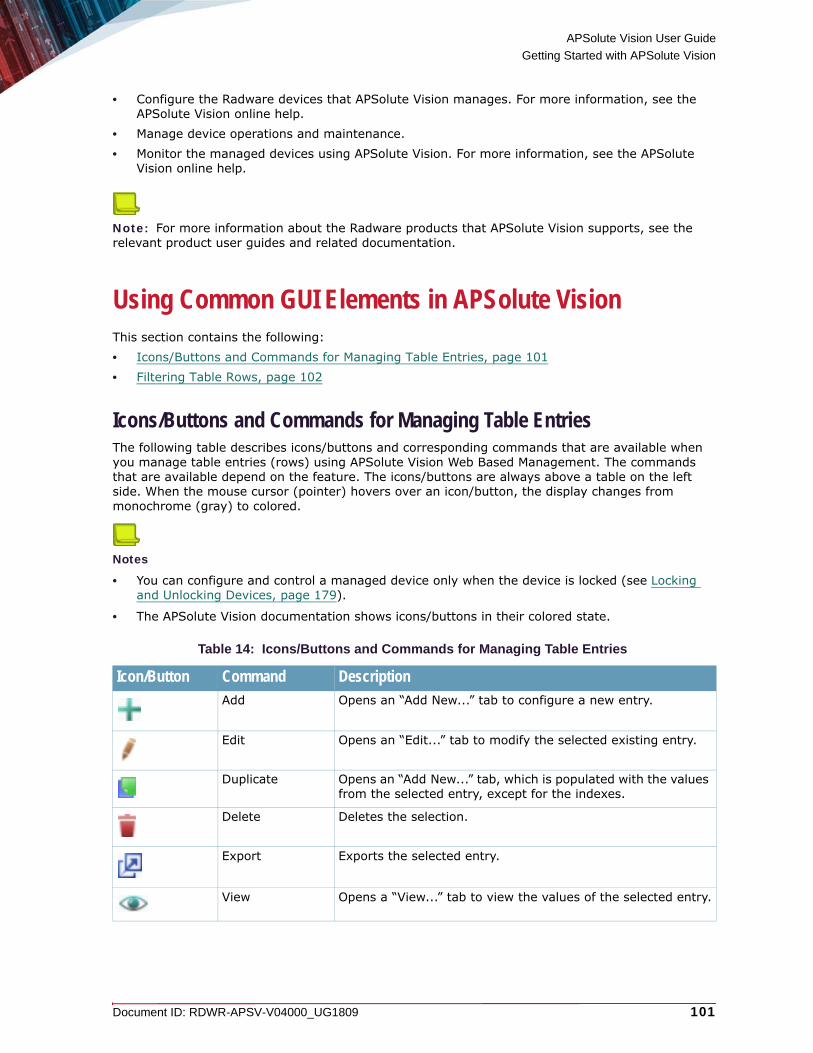
APSolute Vision User Guide
Getting Started with APSolute Vision
Document ID: RDWR-APSV-V04000_UG1809 101
• Configure the Radware devices that APSolute Vision manages. For more information, see the APSolute Vision online help.
• Manage device operations and maintenance.• Monitor the managed devices using APSolute Vision. For more information, see the APSolute
Vision online help.
Note: For more information about the Radware products that APSolute Vision supports, see the relevant product user guides and related documentation.
Using Common GUI Elements in APSolute VisionThis section contains the following:• Icons/Buttons and Commands for Managing Table Entries, page 101• Filtering Table Rows, page 102
Icons/Buttons and Commands for Managing Table EntriesThe following table describes icons/buttons and corresponding commands that are available when you manage table entries (rows) using APSolute Vision Web Based Management. The commands that are available depend on the feature. The icons/buttons are always above a table on the left side. When the mouse cursor (pointer) hovers over an icon/button, the display changes from monochrome (gray) to colored.
Notes
• You can configure and control a managed device only when the device is locked (see Locking and Unlocking Devices, page 179).
• The APSolute Vision documentation shows icons/buttons in their colored state.
Table 14: Icons/Buttons and Commands for Managing Table Entries
Icon/Button Command DescriptionAdd Opens an “Add New...” tab to configure a new entry.
Edit Opens an “Edit...” tab to modify the selected existing entry.
Duplicate Opens an “Add New...” tab, which is populated with the values from the selected entry, except for the indexes.
Delete Deletes the selection.
Export Exports the selected entry.
View Opens a “View...” tab to view the values of the selected entry.
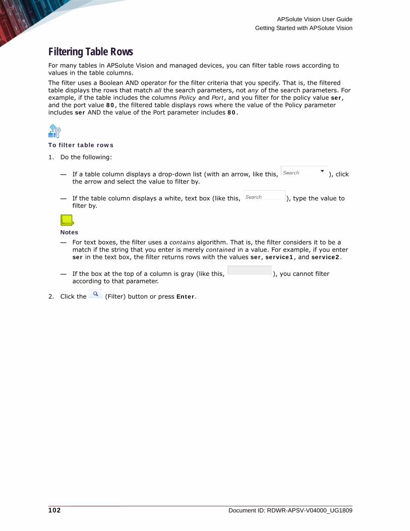
APSolute Vision User Guide
Getting Started with APSolute Vision
102 Document ID: RDWR-APSV-V04000_UG1809
Filtering Table RowsFor many tables in APSolute Vision and managed devices, you can filter table rows according to values in the table columns.The filter uses a Boolean AND operator for the filter criteria that you specify. That is, the filtered table displays the rows that match all the search parameters, not any of the search parameters. For example, if the table includes the columns Policy and Port, and you filter for the policy value ser, and the port value 80, the filtered table displays rows where the value of the Policy parameter includes ser AND the value of the Port parameter includes 80.
To filter table rows
1. Do the following:
— If a table column displays a drop-down list (with an arrow, like this, ), click the arrow and select the value to filter by.
— If the table column displays a white, text box (like this, ), type the value to filter by.
Notes
— For text boxes, the filter uses a contains algorithm. That is, the filter considers it to be a match if the string that you enter is merely contained in a value. For example, if you enter ser in the text box, the filter returns rows with the values ser, service1, and service2.
— If the box at the top of a column is gray (like this, ), you cannot filter according to that parameter.
2. Click the (Filter) button or press Enter.

Document ID: RDWR-APSV-V04000_UG1809 103
CHAPTER 4 – MANAGING AND MONITORING THE APSOLUTE VISION SYSTEM
APSolute Vision monitors and controls the APSolute Vision server and platform, and the associated database.This chapter contains the following main sections:• Monitoring APSolute Vision—Overview, page 104• Managing APSolute Vision Basic Information and Properties, page 104• Configuring Connectivity Parameters for Server Connections, page 109• Configuring Settings for the Alerts Pane, page 112• Managing APSolute Vision Analytics Settings, page 125• Configuring Monitoring Settings, page 126• Configuring APSolute Vision Server Alarm Thresholds, page 127• Configuring Connections to Authentication Servers, page 128• Managing Device Drivers, page 139• Configuring APSolute Vision Reporter Parameters, page 143• Managing APSolute Vision Licenses and Viewing Capacity Utilization, page 143• Managing APM in APSolute Vision, page 147• Configuring the Radware Cloud DDoS Protection Setting, page 151• Configuring APSolute Vision Server Advanced Parameters, page 151• Configuring APSolute Vision Display Parameters, page 153• Managing APSolute Vision Maintenance Files, page 155• Managing Operator Toolbox Settings, page 156• Managing Stored Device Configuration/Backup Files, page 156• Viewing Device Subscriptions, page 158• Controlling APSolute Vision Operations, page 160
Notes
• The labels of mandatory APSolute Vision parameters are bold.
• When the value of a parameter has changed, before the value is submitted, the label is in italics.
• In the English language display, when a value of a parameter has changed, before the value is submitted, the tab label is in italics and has an asterisk (*).
• In the Chinese language display, when a value of a parameter has changed, before the value is submitted, the tab label has a dashed underline.

APSolute Vision User Guide
Managing and Monitoring the APSolute Vision System
104 Document ID: RDWR-APSV-V04000_UG1809
Monitoring APSolute Vision—OverviewAPSolute Vision monitors the APSolute Vision server and platform, and the associated database. The system monitors performance and operational status, and stores the processed monitoring information in the APSolute Vision database. When a problem is identified, an alert is issued, and displayed in the Alerts pane.
Managing APSolute Vision Basic Information and PropertiesThis section contains the following topics:• Displaying Basic Information About the APSolute Vision Server, page 104• Managing APSolute Vision Server Software, page 106• Displaying APSolute Vision Server Hardware Information, page 107• Managing and Updating the Attack Descriptions File for DefensePro, page 108
Displaying Basic Information About the APSolute Vision ServerYou can view the basic information about the APSolute Vision server. You can also verify that the date and time on the APSolute Vision server is synchronized with the date and time on the client PC.
To display the basic information about the APSolute Vision server
> In the APSolute Vision Settings view System perspective, select General Settings > Basic Parameters.
Table 15: Basic Parameters: General Parameters—When Running as a VA or on an OnDemand Switch VL (ODS-VL) Platform
Parameter DescriptionManagement IP Address The IP address of the of the APSolute Vision server used for
management.
Hardware Platform The type of hardware platform of the APSolute Vision server.
Vision Server Uptime The up time of the APSolute Vision server, in days, hours, minutes, and seconds.
APSolute Vision Server Time The current date, time, and timezone in the APSolute Vision server.
Note: APSolute Vision requires that the date and time settings of the server be configured correctly, relative to the real time—taking into consideration their defined timezones. Upon logging into APSolute Vision from your browser, an alert is generated if a discrepancy of more than 5 minutes is found between the date and time settings of the server and local host.
MAC Address of Port G1 The MAC address of the APSolute Vision server G1 port.
MAC Address of Port G2 The MAC address of the APSolute Vision server G2 port.

APSolute Vision User Guide
Managing and Monitoring the APSolute Vision System
Document ID: RDWR-APSV-V04000_UG1809 105
To verify the date and time settings
1. In the APSolute Vision Settings view System perspective, select General Settings > Basic Parameters.
2. Click Verify Time Settings.
MAC Address of Port G3 The MAC address of the APSolute Vision server G3 port.
Note: If the port is not supported, the field displays the value Unsupported.
MAC Address of Port G4 The MAC address of the APSolute Vision server G4 port.
Note: If the port is not supported, the field displays the value Unsupported.
Table 16: Basic Parameters: General Parameters—When Running on an OnDemand Switch VL2 (ODS-VL2) Platform
Parameter DescriptionManagement IP Address The IP address of the of the APSolute Vision server used for
management.
Hardware Platform The type of hardware platform of the APSolute Vision server: ODS-VL2 for OnDemand Switch VL2.
Vision Server Uptime The up time of the APSolute Vision server, in days, hours, minutes, and seconds.
APSolute Vision Server Time The current date, time, and timezone in the APSolute Vision server.
Note: APSolute Vision requires that the date and time settings of the server be configured correctly, relative to the real time—taking into consideration their defined timezones. Upon logging into APSolute Vision from your browser, an alert is generated if a discrepancy of more than 5 minutes is found between the date and time settings of the server and local host.
MAC Address of Port G3 The MAC address of the APSolute Vision server G3 port.
MAC Address of Port G4 This port is not supported, and the field displays the value Unsupported.
MAC Address of Port G5 The MAC address of the APSolute Vision server G5 port.
MAC Address of Port G7 The MAC address of the APSolute Vision server G7 port.
Table 15: Basic Parameters: General Parameters—When Running as a VA or on an OnDemand Switch VL (ODS-VL) Platform (cont.)
Parameter Description
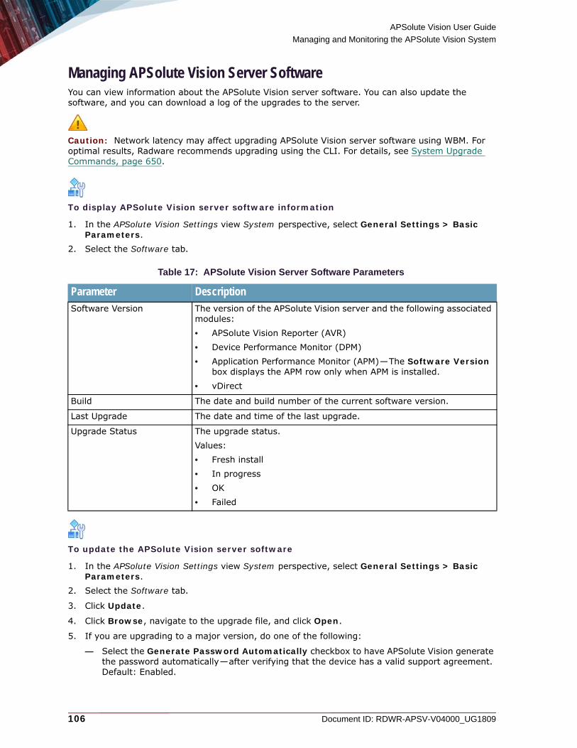
APSolute Vision User Guide
Managing and Monitoring the APSolute Vision System
106 Document ID: RDWR-APSV-V04000_UG1809
Managing APSolute Vision Server SoftwareYou can view information about the APSolute Vision server software. You can also update the software, and you can download a log of the upgrades to the server.
Caution: Network latency may affect upgrading APSolute Vision server software using WBM. For optimal results, Radware recommends upgrading using the CLI. For details, see System Upgrade Commands, page 650.
To display APSolute Vision server software information
1. In the APSolute Vision Settings view System perspective, select General Settings > Basic Parameters.
2. Select the Software tab.
To update the APSolute Vision server software
1. In the APSolute Vision Settings view System perspective, select General Settings > Basic Parameters.
2. Select the Software tab.
3. Click Update.
4. Click Browse, navigate to the upgrade file, and click Open.
5. If you are upgrading to a major version, do one of the following:
— Select the Generate Password Automatically checkbox to have APSolute Vision generate the password automatically—after verifying that the device has a valid support agreement. Default: Enabled.
Table 17: APSolute Vision Server Software Parameters
Parameter DescriptionSoftware Version The version of the APSolute Vision server and the following associated
modules:• APSolute Vision Reporter (AVR)• Device Performance Monitor (DPM)• Application Performance Monitor (APM)—The Software Version
box displays the APM row only when APM is installed.• vDirect
Build The date and build number of the current software version.
Last Upgrade The date and time of the last upgrade.
Upgrade Status The upgrade status.Values:• Fresh install• In progress• OK• Failed

APSolute Vision User Guide
Managing and Monitoring the APSolute Vision System
Document ID: RDWR-APSV-V04000_UG1809 107
Caution: The functionality of the Generate Password Automatically button requires connectivity to radware.com or the proxy server that is configured in the APSolute Vision settings (APSolute Vision Settings view System perspective, General Settings > Connectivity > Proxy Server Parameters).
— In the Password text box, enter the password.
Notes
— A password is required for upgrade to all major versions. Upgrade without a password is allowed when upgrading to minor versions.
— When APSolute Vision is running as a virtual appliance (VA) or on an OnDemand Switch VL (ODS-VL) platform, the password is based on the size of the upgrade file and the MAC address of the APSolute Vision G1 or G2 port, which the Basic Parameters pane displays.
— When APSolute Vision is running on an OnDemand Switch VL2 (ODS-VL2) platform, the password is based on the size of the upgrade file and the MAC address of the APSolute Vision G3 or G5 port, which the Basic Parameters pane displays.
— Migrating APSolute Vision on the OnDemand Switch VL (ODS-VL) platform to the OnDemand Switch VL2 (ODS-VL2) platform uses a special procedure, which requires the Administrator or the Vision Administrator role and root access to the ODS-VL2 operating system. For information about the migration procedure, see Migrating APSolute Vision from the OnDemand Switch VL Platform to the OnDemand Switch VL2 Platform, page 655.
— You can request the password from Radware Technical Support. The password is also available using the password generator at radware.com.
6. Click Upload.
To download the upgrade log of the APSolute Vision server
1. In the APSolute Vision Settings view System perspective, select General Settings > Basic Parameters.
2. Select the Software tab.
3. Click Download Upgrade Log. You can open the file with a selected application, or you can save the file to a specified location.
Displaying APSolute Vision Server Hardware InformationYou can view information about the APSolute Vision server hardware.
To display APSolute Vision server hardware information
1. In the APSolute Vision Settings view System perspective, select General Settings > Basic Parameters.
2. Select the Hardware tab.
Table 18: APSolute Vision Server Hardware Parameters
Parameter DescriptionRAM Size The amount of RAM, in gigabytes.

APSolute Vision User Guide
Managing and Monitoring the APSolute Vision System
108 Document ID: RDWR-APSV-V04000_UG1809
Managing and Updating the Attack Descriptions File for DefenseProYou can view the time of the latest update of the Attack Description file on the APSolute Vision server, and you can update the file.The Attack Description file contains descriptions of all the different attacks that DefensePro can handle. You can view a specific description by entering the attack name. When you first configure APSolute Vision, you should download the latest Attack Description file to the APSolute Vision server. The file is used for real-time and historical reports to show attack descriptions for attacks coming from DefensePro devices. The file versions on APSolute Vision and on the DefensePro devices should be identical. Radware recommends synchronizing regular updates of the file at regular intervals on APSolute Vision and on the individual devices.
Note: Radware also recommends updating the Attack Description file each time you update the Signature files on DefensePro devices. When you update the Attack Description file, APSolute Vision downloads the file directly from Radware.com or from the enabled proxy file server.
To view the date and time of the last update of the Attack Description file
1. In the APSolute Vision Settings view System perspective, select General Settings > Basic Parameters.
2. Select the Attack Descriptions File tab. The Attack Descriptions Last Update text box displays the time of the latest update of the Attack Description file on the APSolute Vision server.
To update the Attack Description file
1. In the APSolute Vision Settings view System perspective, select General Settings > Basic Parameters.
2. Do one of the following:
— To update the Attack Description file from Radware, select the Radware.com radio button.— To update the files from the APSolute Vision client host:
a. Select the Client radio button.b. In the File Name text box, enter the file path of the Attack Description file or click
Browse to navigate to and select the file.3. Click Update. The Alerts pane displays a success or failure notification and whether the
operation was performed using a proxy server.

APSolute Vision User Guide
Managing and Monitoring the APSolute Vision System
Document ID: RDWR-APSV-V04000_UG1809 109
Configuring Connectivity Parameters for Server ConnectionsThese settings define how the APSolute Vision server communicates with the APSolute Vision clients, external servers, and Radware devices.
To configure the connections to and from the APSolute Vision server
1. In the APSolute Vision Settings view System perspective, select General Settings > Connectivity.
2. Configure the parameters, and click Submit.
Table 19: Connectivity: SNMP Parameters Toward Devices Parameters
Parameter DescriptionTimeout The time, in seconds, that APSolute Vision waits for a reply before
retrying to connect to other Radware devices. If the device does not respond after the configured number of retries, APSolute Vision notifies the user that the connection failed. Values: 1–180Default: 3
Caution: For DefensePro 7.x versions and in networks with high latency, Radware recommends increasing the SNMP Timeout to 180 seconds (APSolute Vision Settings view System perspective, General Settings > Connectivity > Timeout).
Retries The number of connection retries to another Radware device, when the device does not respond.Values: 1–100Default: 3
Port The port used to communicate with Radware devices.Values: 1–65,535Default: 161
Table 20: APSolute Vision Connectivity HTTP/S Parameters Toward Devices
Parameter DescriptionDefault HTTP Port The default HTTP port that APSolute Vision uses to communicate
with Radware devices. This value is displayed in the HTTP Port text box in the Device Properties dialog box. Values: 1–65,535Default: 80
Default HTTPS Port The default HTTPS port that APSolute Vision uses to communicate with Radware devices. This value is displayed in the HTTPS Port text box in the Device Properties dialog box.Values: 1–65,535Default: 443

APSolute Vision User Guide
Managing and Monitoring the APSolute Vision System
110 Document ID: RDWR-APSV-V04000_UG1809
Connection Timeout The time, in seconds, that the HTTP client waits for a response from the remote host—during the handshake for device configuration— before disconnecting the socket and returning an exception. Values: 1–60Default: 20
Socket Timeout The time, in seconds, that the HTTP client waits for a response from the remote host—during the data transfer for device configuration—before disconnecting the socket and returning an exception. Values: 1–60Default: 20
Long Operation Connection Timeout
The time, in seconds, that the HTTP client waits for a response from the remote host—during the handshake for certain long file operations—before disconnecting the socket and returning an exception.1
Values: 1–1200Default: 180
Long Operation Socket Timeout
The time, in seconds, that the HTTP client waits for a response from the remote host—during the data transfer for certain long file operations—before disconnecting the socket and returning an exception.Values: 1–1200Default: 180
1 – This parameter applies to the following operations: • Import/export configuration file operations.• Export of the quarantined-addresses file (for DefensePro).• DefensePro-template import/export operations.• Import/export of Radware-devices log files.• Import/export of certificate files.• Import/export of DNSSEC files.• Import/export AppShape script files (for Alteon or LinkProof NG).• fraud signature update (for DefensePro).• Attack signatures updates (for DefensePro).• Download of the Attack Description file (for DefensePro).
Table 21: APSolute Vision Connectivity Event Notification Parameters
Parameter DescriptionVision Management Port Specifies the management port on the APSolute Vision server to
which the managed Radware devices send events. Any change of this parameter takes effect only when you click Register This APSolute Vision Server for Device Events button. Clicking Submit in this pane has no effect on this parameter.
Caution: This parameter overwrites the Register APSolute Vision Server IP parameter.
Table 20: APSolute Vision Connectivity HTTP/S Parameters Toward Devices (cont.)
Parameter Description

APSolute Vision User Guide
Managing and Monitoring the APSolute Vision System
Document ID: RDWR-APSV-V04000_UG1809 111
Remove All Other Targets of Device Events
Specifies whether—when you click Register This APSolute Vision Server for Device Events—the APSolute Vision server removes (from all the managed devices) all recipients of device events except for its own address.Default: Disabled
Note: For related information, see APSolute Vision Server Registered for Device Events—Alteon and LinkProof NG, page 178 and APSolute Vision Server Registered for Device Events—DefensePro, page 178.
Register This APSolute Vision Server for Device Events(button)
Registers the APSolute Vision server as a target of the device events (for example, traps, alerts, IRP messages, and packet-reporting data) on all the managed devices.In Alteon or LinkProof NG, when you click the button and run the Apply command, APSolute Vision configures itself as a target of the device events and ensures that the device also sends traps for authentication-failure events. Alteon or LinkProof NG, by default, does not send traps for authentication-failure events.When multiple APSolute Vision servers manage the same DefensePro device, the device sends the following:• Traps to all the APSolute Vision servers that manage it. The
Target Address table and the Target Parameters table contain entries for all APSolute Vision servers.
• Packet-reporting data only to the last APSolute Vision server that registered on the device.
Note: For related information, see APSolute Vision Server Registered for Device Events—Alteon and LinkProof NG, page 178 and APSolute Vision Server Registered for Device Events—DefensePro, page 178.
Table 22: Connectivity: Proxy Server Parameters
Parameter DescriptionThese connection settings are for the proxy server that the APSolute Vision server uses to download files from Radware.com. The Alerts pane displays a success or failure notification and whether the operation was performed using a proxy server.
Enable Proxy Server Specifies whether the APSolute Vision server uses a proxy server to download files from Radware.com.
IP Address The IP address of the proxy server.
Port The port of the proxy server.
Use Authentication Specifies whether authentication is required for a successful connection between the APSolute Vision server and the proxy server.
Username The username for the proxy server.
Password The password for the proxy-server user.
Verify Password The password for the proxy-server user.
Table 21: APSolute Vision Connectivity Event Notification Parameters (cont.)
Parameter Description
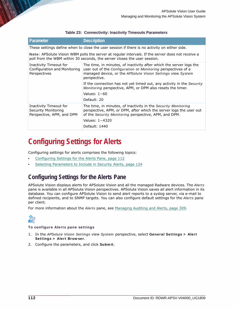
APSolute Vision User Guide
Managing and Monitoring the APSolute Vision System
112 Document ID: RDWR-APSV-V04000_UG1809
Configuring Settings for AlertsConfiguring settings for alerts comprises the following topics:• Configuring Settings for the Alerts Pane, page 112• Selecting Parameters to Include in Security Alerts, page 124
Configuring Settings for the Alerts PaneAPSolute Vision displays alerts for APSolute Vision and all the managed Radware devices. The Alerts pane is available in all APSolute Vision perspectives. APSolute Vision saves all alert information in its database. You can configure APSolute Vision to send alert reports to a syslog server, via e-mail to defined recipients, and to SNMP targets. You can also configure default settings for the Alerts pane per client.For more information about the Alerts pane, see Managing Auditing and Alerts, page 309.
To configure Alerts pane settings
1. In the APSolute Vision Settings view System perspective, select General Settings > Alert Settings > Alert Browser.
2. Configure the parameters, and click Submit.
Table 23: Connectivity: Inactivity Timeouts Parameters
Parameter DescriptionThese settings define when to close the user session if there is no activity on either side.
Note: APSolute Vision WBM polls the server at regular intervals. If the server does not receive a poll from the WBM within 30 seconds, the server closes the user session.
Inactivity Timeout for Configuration and Monitoring Perspectives
The time, in minutes, of inactivity after which the server logs the user out of the Configuration or Monitoring perspectives of a managed device, or the APSolute Vision Settings view System perspective.If the connection has not yet timed out, any activity in the Security Monitoring perspective, APM, or DPM also resets the timer.Values: 1–60Default: 20
Inactivity Timeout for Security Monitoring Perspective, APM, and DPM
The time, in minutes, of inactivity in the Security Monitoring perspective, APM, or DPM, after which the server logs the user out of the Security Monitoring perspective, APM, and DPM.Values: 1–4320Default: 1440

APSolute Vision User Guide
Managing and Monitoring the APSolute Vision System
Document ID: RDWR-APSV-V04000_UG1809 113
Table 24: Alert Browser: Auditing Settings Parameters
Parameter DescriptionEnable Detailed Auditing of APSolute Vision Activity
Specifies whether the messages that APSolute Vision issues regarding APSolute Vision activity include additional information, such as the new value for a parameter. For example: • When an administrator changes a value for a parameter (such as
Device Lock Timeout):— When the option is disabled, the message gives the name of
the parameter and says that the value was changed. — When the option is enabled, the message gives the name of
the parameter and the new value. • When a user administrator changes the contact information of
another user:— When the option is disabled, the message gives the name of
the user and says that the user’s properties were changed. — When the option is enabled, the message gives the name of
the user, says that the user’s properties were changed, and gives the new contact information.
Default: Disabled
Notes: • When a message refers to a change that a user initiated, the
message includes the username (even when the option is disabled).
• For a list of log messages corresponding to when this option is disabled, see Appendix B - APSolute Vision Log Messages and Alerts, page 671.

APSolute Vision User Guide
Managing and Monitoring the APSolute Vision System
114 Document ID: RDWR-APSV-V04000_UG1809
Enable Detailed Auditing of Device Configuration Changes
Specifies whether the messages that APSolute Vision issues regarding configuration changes made on managed devices—from APSolute Vision—include additional information. When a user changes a value for a scalar parameter:• When the option is disabled, the message gives the name of the
scalar and says that the value was changed. • When the option is enabled, the message gives the name of the
scalar and the new value. When a user adds or edits an entry to a table:• When the option is disabled, the message gives the name of the
table and says that a row was added or edited. • When the option is enabled, the message gives the name of the
table, the table parameters, and the value for each parameter. When a user deletes an entry in a table:• When the option is disabled, the message gives the name of the
table and says that a row was deleted. • When the option is enabled, the message gives the name of the
table and the indexes of the deleted row. Default: Disabled
Notes: • When a message refers to a change that a user initiated, the
message includes the username (even when the option is disabled).
• This parameter does not affect audit messages that the managed device generates, which APSolute Vision displays in the Alerts pane. This parameter only affects alerts that APSolute Vision generates itself.
Table 25: Alert Browser: Syslog Reporting Parameters
Parameter DescriptionThese settings determine how APSolute Vision forwards the events in the Alerts table to the configured syslog servers. For more information, see Configuring Syslog Servers for Alerts from APSolute Vision, page 118.
Enable Syslog Reporting Specifies whether APSolute Vision sends reports and logs to the configured syslog servers.Default: Disabled
Enable Encryption Specifies whether APSolute Vision sends the syslog messages encrypted over TLS.1
Default: Disabled
Table 24: Alert Browser: Auditing Settings Parameters (cont.)
Parameter Description

APSolute Vision User Guide
Managing and Monitoring the APSolute Vision System
Document ID: RDWR-APSV-V04000_UG1809 115
CA Certificate(This parameter is available only when the Enable Encryption checkbox is selected.)
The filepath of the CA certificate.1
To update the certificate1. Click the Update button next to this text field. A file browser
dialog box opens.2. Browse to the certificate file, and click Open. The field displays
Pending. 3. Click Submit. If successful, the field displays Installed.
Enable Authentication (This parameter is available only when the Enable Encryption checkbox is selected.)
Specifies whether the certificate must be authenticated with a private key and a public key.1
Default: Disabled
Authentication Type (This parameter is available only when the Enable Encryption checkbox is selected.)
Values:1
• Certificate Validation (certvalid)—APSolute Vision checks with the syslog server that the certificate is valid.
• Name—APSolute Vision checks with the syslog server that the certificate is valid and includes the specified Permitted Peer in the certificate subject.
Permitted Peer (This parameter is available only when the Authentication Type is Name.)
The string that the certificate subject must include for authentication.1
Private Key (This parameter is available only when the Enable Authentication checkbox is selected.)
The filepath of the private key.1
To update the certificate1. Click the Update button next to this text field. A file browser
dialog box opens. 2. Browse to the certificate file, and click Open. The field displays
Pending. 3. Click Submit. If successful, the field displays Installed.
Public Key (This parameter is available only when the Enable Authentication checkbox is selected.)
The filepath of the public key.1
To update the certificate1. Click the Update button next to this text field. A file browser
dialog box opens. 2. Browse to the certificate file, and click Open. The field displays
Pending. 3. Click Submit. If successful, the field displays Installed.
The configured syslog servers.For more information, see Configuring Syslog Servers for Alerts from APSolute Vision, page 118.
1 – This parameter applies to all the configured servers (see Configuring Syslog Servers for Alerts from APSolute Vision, page 118).
Table 25: Alert Browser: Syslog Reporting Parameters (cont.)
Parameter Description

APSolute Vision User Guide
Managing and Monitoring the APSolute Vision System
116 Document ID: RDWR-APSV-V04000_UG1809
Table 26: Alert Browser: Email Reporting Configuration Parameters
Parameter DescriptionThese settings determine how APSolute Vision forwards the events in the Alerts pane via e-mail to the defined recipients.
Enable Specifies whether APSolute Vision sends reports and logs via e-mail.Default: Disabled
Note: This parameter relates to reports and logs from the Alerts pane. This parameter is independent of the APSolute Vision Analytics settings.
SMTP Server Address The name or IP address of the SMTP e-mail server.This value of this parameter is shared with the SMTP Server Address parameter under General Settings > APSolute Vision Analytics Settings > Email Reporting Configuration.
Caution: If you change this value and click Submit, the SMTP Server Address under General Settings > APSolute Vision Analytics Settings > Email Reporting Configuration changes accordingly.
SMTP User Name The account name used to send e-mail notifications—for example, [email protected].
Note: This value of this parameter is not shared with the SMTP User Name parameter under General Settings > APSolute Vision Analytics Settings > Email Reporting Configuration.
Subject Header The text that appears in the Subject header of the e-mail.Default: Alert Notification Message.
From Header The text that appears in the From header of the e-mail. Default: APSolute Vision
Recipient Email Address The e-mail addresses of the intended recipients. When there are multiple e-mail addresses, use comma (,), or semi-colon (;) separators.
Email Sending Interval The interval, in seconds, between successive e-mail messages.Values: 30–3600Default: 30
Alerts per Email The maximum number of alerts to include in an e-mail message. When there are more than the maximum number of alerts, multiple e-mail messages are sent.Values: 1–60Default: 30
DevicesClick to select a subset of managed devices for which to send alerts. If no devices are specified, APSolute Vision forwards alerts from all the devices to the defined recipients.Move the required devices from the Available list to the Selected list.
Severity
Critical Specifies whether to include alerts of this severity in e-mail messages.
Major Specifies whether to include alerts of this severity in e-mail messages.

APSolute Vision User Guide
Managing and Monitoring the APSolute Vision System
Document ID: RDWR-APSV-V04000_UG1809 117
Minor Specifies whether to include alerts of this severity in e-mail messages.
Warning Specifies whether to include alerts of this severity in e-mail messages.
Information Specifies whether to include alerts of this severity in e-mail messages.
Module
Device Security Specifies whether to include alerts regarding this module in e-mail messages.
Device General Specifies whether to include alerts regarding this module in e-mail messages.
Vision General Specifies whether to include alerts regarding this module in e-mail messages.
Vision Configuration Specifies whether to include alerts regarding this module in e-mail messages.
Vision Control Specifies whether to include alerts regarding this module in e-mail messages.
Security Reporting Specifies whether to include alerts regarding this module in e-mail messages.
Trouble Ticket Specifies whether to include alerts regarding this module in e-mail messages.
Operator Toolbox Specifies whether to include alerts regarding this module in e-mail messages.
Table 27: Alert Browser: SNMP Reporting Configuration
Parameter DescriptionThe SNMP Reporting Configuration comprises the following:• A name• An Alert Profile (see Configuring SNMP Alert Rules, page 120)• An Alert Target (see Configuring SNMP Alert Targets, page 121)—that is, an SNMP listener• Specifying whether the rule is enabled
Table 28: Alert Browser: Alert Profiles
Parameter DescriptionThese settings determine which events in the in the Alerts table APSolute Vision forwards to the configured SNMP listeners (targets). For more information, see Managing Alert Profiles, page 122.
Table 26: Alert Browser: Email Reporting Configuration Parameters (cont.)
Parameter Description

APSolute Vision User Guide
Managing and Monitoring the APSolute Vision System
118 Document ID: RDWR-APSV-V04000_UG1809
Configuring Syslog Servers for Alerts from APSolute VisionYou can configure up to ten syslog servers that receive alerts from APSolute Vision and selected managed devices.
To configure a syslog server that receive alerts from APSolute Vision
1. In the APSolute Vision Settings view System perspective, select General Settings > Alert Settings > Alert Browser.
2. In the Syslog Reporting tab, do one of the following:
— To add an entry, click the (Add) button.— To edit an entry, double-click the row.
3. Configure the parameters, and click Submit.
Table 29: Alert Browser: Display Parameter
Parameter DescriptionRefresh Interval The interval, in seconds, that APSolute Vision refreshes the Alerts
Table with the latest messages.Values: 5–300Default: 5
Table 30: Syslog Server Parameters
Parameter DescriptionEnable Server Specifies whether the server is enabled.
Default: Disabled
Report(This parameter is available only when the Enable Server checkbox is selected.)
Specifies whether APSolute Vision reports all messages received by the Alerts pane or only audit messages.Values: All Messages, Audit MessagesDefault: All Messages
Syslog Server Address(This parameter is available only when the Enable Server checkbox is selected.)
The IP address of the device running the syslog service.
L4 Destination Port(This parameter is available only when the Enable Server checkbox is selected.)
Values: 1–65,535Default: 514

APSolute Vision User Guide
Managing and Monitoring the APSolute Vision System
Document ID: RDWR-APSV-V04000_UG1809 119
Syslog Facility(This parameter is available only when the Enable Server checkbox is selected.)
The facility for all APSolute Vision syslog reporting. The list includes facilities as defined in RFC 3164.Values:• Local Use 0• Local Use 1• Local Use 2• Local Use 3• Local Use 4• Local Use 5• Local Use 6• Local Use 6• Local Use 7• Log Audit• User-Level MessagesDefault: Log Audit
Note: Change the default if the syslog server uses this facility for reports from another system.
DevicesClick to select a subset of managed devices for which to send alerts. If no devices are specified, APSolute Vision forwards alerts from all the devices to the syslog server.Move the required devices from the Available list to the Selected list.
SeverityBy default, all the checkboxes are selected.
Critical Specifies whether to include alerts of this severity in syslog messages.
Major Specifies whether to include alerts of this severity in syslog messages.
Minor Specifies whether to include alerts of this severity in syslog messages.
Warning Specifies whether to include alerts of this severity in syslog messages.
Information Specifies whether to include alerts of this severity in syslog messages.
ModuleBy default, all the checkboxes are selected.
Device Security Specifies whether to include alerts regarding this module in syslog messages.
Device General Specifies whether to include alerts regarding this module in syslog messages.
Vision General Specifies whether to include alerts regarding this module in syslog messages.
Vision Configuration Specifies whether to include alerts regarding this module in syslog messages.
Table 30: Syslog Server Parameters (cont.)
Parameter Description

APSolute Vision User Guide
Managing and Monitoring the APSolute Vision System
120 Document ID: RDWR-APSV-V04000_UG1809
Managing the SNMP Reporting ConfigurationUse the SNMP Reporting Configuration tab to doing the following:• Configuring SNMP Alert Rules, page 120• Configuring SNMP Alert Targets, page 121
Configuring SNMP Alert RulesYou can configure APSolute Vision to send SNMP alerts (traps) to external NMS systems. NMS systems may be referred to as SNMP servers. In the context of the APSolute Vision alert configuration, an SNMP server is referred to as an SNMP Alert Target. The APSolute Vision server can contain multiple SNMP Alert Rules. The configuration of an SNMP Alert Rule includes one Alert Profile and one SNMP Alert Target. So, before you can configure a rule, there must be at least one Alert Profile and one SNMP Target. For more information, see Managing Alert Profiles, page 122 and Configuring SNMP Alert Targets, page 121.
To configure an SNMP Alert Rule
1. In the APSolute Vision Settings view System perspective, select General Settings > Alert Settings > Alert Browser.
2. In the SNMP Reporting Configuration tab, do one of the following:
— To add an entry, click the (Add) button.— To edit an entry, double-click the row.
3. Configure the parameters, and click Submit.
Vision Control Specifies whether to include alerts regarding this module in syslog messages.
Security Reporting Specifies whether to include alerts regarding this module in syslog messages.
Trouble Ticket Specifies whether to include alerts regarding this module in syslog messages.
Operator Toolbox Specifies whether to include alerts regarding this module in syslog messages.
Table 31: SNMP Alert Rule Parameters
Parameter DescriptionName The name of the Alert Rule.
Maximum characters: 32
Profile The Alert Profile of the Alert Rule. (See the procedure To configure an Alert Profile, page 122.)
Targets The SNMP Target of the Alert Rule. (See the procedure To configure an SNMP Alert Target, page 121.)
Enabled Specifies whether the Alert Rule is enabled.Default: Disabled
Table 30: Syslog Server Parameters (cont.)
Parameter Description

APSolute Vision User Guide
Managing and Monitoring the APSolute Vision System
Document ID: RDWR-APSV-V04000_UG1809 121
Configuring SNMP Alert TargetsUse the SNMP Reporting Configuration tab to configure SNMP Alert Targets for alerts from APSolute Vision. An SNMP Alert Target, which is a parameter of an SNMP Alert Rule, (see Managing the SNMP Reporting Configuration, page 120) can determine the destination of each alert.
To configure an SNMP Alert Target
1. In the APSolute Vision Settings view System perspective, select General Settings > Alert Settings > Alert Browser.
2. In the SNMP Reporting Configuration tab, at the top of the SNMP Alert Targets table, do one of the following:
— To add an entry, click the (Add) button.— To edit an entry, double-click the row.
3. Configure the parameters, and click Submit.
Table 32: SNMP Alert Target Parameters
Parameter DescriptionName The name of the Alert Rule.
Maximum characters: 32
SNMP Server IP Address The IP address of the SNMP server.
Port The Layer 4 port on the SNMP server.Values: 1–65535Default: 162
SNMP Version The SNMP version that APSolute Vision uses for the connection.Values: SNMPv2c, SNMPv3Default: SNMPv3
SNMP Community(This parameter is displayed only when SNMP Version is SNMPv2c.)
The SNMP community name.
User Name(This parameter is displayed only when SNMP Version is SNMPv3.)
The username for the SNMP connection.Maximum characters: 32
Use Authentication(This parameter is displayed only when SNMP Version is SNMPv3.)
Specifies whether APSolute Vision authenticates the user for a successful connection.Values: Enabled, DisabledDefault: Disabled
Authentication Protocol(This parameter is available only when the Use Authentication value is Enabled.)
The protocol that APSolute Vision uses for authentication.Values: MD5, SHADefault: SHA

APSolute Vision User Guide
Managing and Monitoring the APSolute Vision System
122 Document ID: RDWR-APSV-V04000_UG1809
Managing Alert ProfilesYou can configure Alert Profiles for alerts from APSolute Vision. An Alert Profile, which is a parameter of an SNMP Alert Rule, (see Managing the SNMP Reporting Configuration, page 120) determines the content filtering of each alert.
To configure an Alert Profile
1. In the APSolute Vision Settings view System perspective, select General Settings > Alert Settings > Alert Browser.
2. In the Alert Profiles tab, do one of the following:
— To add an entry, click the (Add) button.— To edit an entry, double-click the row.
3. Configure the parameters, and click Submit.
Authentication Password(This parameter is available only when the Use Authentication value is Enabled.)
The password that APSolute Vision uses for authentication.
Caution: The password should be at least eight characters. vDirect requires that password be at least eight characters.
Confirm Authentication Password(This parameter is available only when the Use Authentication value is Enabled.)
The password that APSolute Vision uses for authentication.
Caution: The password should be at least eight characters. vDirect requires that password be at least eight characters.
Use Privacy(This parameter is displayed only when SNMP Version is SNMPv3.)
Specifies whether APSolute Vision encrypts SNMPv3 traffic for additional security.Default: Disabled
Privacy Protocol(This parameter is available only when and the Use Privacy checkbox is selected.)
The privacy protocol that APSolute Vision uses for the Privacy facility.Value: DES, AES128Default: DES
Privacy Password(This parameter is available only when the Use Privacy checkbox is selected.)
The password used for the Privacy facility.
Caution: The password should be at least eight characters. vDirect requires that password be at least eight characters.
Confirm Privacy Password(This parameter is available only when the Use Privacy checkbox is selected.)
The password used for the Privacy facility.
Caution: The password should be at least eight characters. vDirect requires that password be at least eight characters.
Table 32: SNMP Alert Target Parameters (cont.)
Parameter Description

APSolute Vision User Guide
Managing and Monitoring the APSolute Vision System
Document ID: RDWR-APSV-V04000_UG1809 123
Table 33: Alert Profiles Parameters
Parameter DescriptionName The name of the Alert Profile.
Maximum characters: 255
DevicesThe Available lists and the Selected lists of devices and Logical Groups (of devices of the appropriate type). The Available lists display the available devices and available Logical Groups. The Selected device list displays the managed devices for which to send alerts. The Selected Logical Group list displays the Logical Groups with the devices for which to send alerts.Select entries from the Available lists and the Selected lists of devices and Logical Groups (of devices). Use the arrows to move the entries to the other lists as required.If no devices are specified, APSolute Vision forwards alerts from all the devices to the SNMP targets (see Configuring SNMP Alert Targets, page 121).
Note: When a Logical Group is selected, the effective Selected device list dynamically updates—according to the devices in the Logical Group. That is, when the device-set of a Logical Group changes, the effective Selected device list changes accordingly. For more information, see Using Logical Groups of Devices, page 190.
SeverityBy default, all the checkboxes are selected.
Critical Specifies whether to include alerts of this severity in SNMP traps.
Major Specifies whether to include alerts of this severity in SNMP traps.
Minor Specifies whether to include alerts of this severity in SNMP traps.
Warning Specifies whether to include alerts of this severity in SNMP traps.
Information Specifies whether to include alerts of this severity in SNMP traps.
ModuleBy default, all the checkboxes are selected.
Device Security Specifies whether to include alerts regarding this module in SNMP traps.
Device General Specifies whether to include alerts regarding this module in SNMP traps.
Vision General Specifies whether to include alerts regarding this module in SNMP traps.
Vision Configuration Specifies whether to include alerts regarding this module in SNMP traps.
Vision Control Specifies whether to include alerts regarding this module in SNMP traps.
Security Reporting Specifies whether to include alerts regarding this module in SNMP traps.
Trouble Ticket Specifies whether to include alerts regarding this module in SNMP traps.
Operator Toolbox Specifies whether to include alerts regarding this module in SNMP traps.
Attack CategoryBy default, all the checkboxes are selected.
ACL Specifies whether to include alerts regarding this Attack Category in SNMP traps.
Anti-Scanning Specifies whether to include alerts regarding this Attack Category in SNMP traps.
Behavioral DoS Specifies whether to include alerts regarding this Attack Category in SNMP traps.
DoS Specifies whether to include alerts regarding this Attack Category in SNMP traps.

APSolute Vision User Guide
Managing and Monitoring the APSolute Vision System
124 Document ID: RDWR-APSV-V04000_UG1809
Selecting Parameters to Include in Security AlertsYou can limit the parameters that are included in security alerts. This option enables you to customize the alerts to provide the relevant information according to your administrative requirements.
To select parameters to include in security alerts
1. In the APSolute Vision Settings view System perspective, select General Settings > Alert Settings > Security Alerts.
2. Select the check box next to each parameter you want to include in the alerts.
You can choose any combination of the following parameters:— Policy Name— Attack Name— Source IP Address— Destination IP Address— Destination Port— ActionBy default, all the checkboxes are selected.
3. Click Submit.
Note: Changes to the settings take effect on alerts generated from the time of the change and onward.
HTTP Flood Specifies whether to include alerts regarding this Attack Category in SNMP traps.
Intrusions Specifies whether to include alerts regarding this Attack Category in SNMP traps.
Server Cracking Specifies whether to include alerts regarding this Attack Category in SNMP traps.
SYN Flood Specifies whether to include alerts regarding this Attack Category in SNMP traps.
Anomalies Specifies whether to include alerts regarding this Attack Category in SNMP traps.
Stateful ACL Specifies whether to include alerts regarding this Attack Category in SNMP traps.
DNS Flood Specifies whether to include alerts regarding this Attack Category in SNMP traps.
Bandwidth Management Specifies whether to include alerts regarding this Attack Category in SNMP traps.
Table 33: Alert Profiles Parameters (cont.)
Parameter Description

APSolute Vision User Guide
Managing and Monitoring the APSolute Vision System
Document ID: RDWR-APSV-V04000_UG1809 125
Managing APSolute Vision Analytics SettingsAPSolute Vision Analytics supports real-time and historical reporting in APSolute Vision. Managing APSolute Vision Analytics settings includes one sub-topic: Managing the Email Reporting Configuration for APSolute Vision Analytics, page 125.
Managing the Email Reporting Configuration for APSolute Vision AnalyticsUse the Email Reporting Configuration pane to configure the general, e-mail settings for the APSolute Vision Analytics.
Note: APSolute Vision Analytics in APSolute Vision version 4.0 supports APSolute Vision Analytics for DefensePro version-8.x devices and Alteon SSL Inspection Monitoring. For more information, see the APSolute Vision Analytics User Guide and Monitoring Outbound SSL Inspection, page 513, respectively.
To configure APSolute Vision Analytics Reporting Settings
1. In the APSolute Vision Settings view System perspective, select General Settings > APSolute Vision Analytics Settings > Email Reporting Configuration.
2. Configure the parameters, and click Submit.
Table 34: Email Reporting Configuration Parameters
Parameter DescriptionEnable Specifies whether APSolute Vision sends reports via e-mail.
Default: Disabled
Note: This parameter relates to APSolute Vision Analytics reports only. This parameter is independent of the reports from the Alerts pane.
SMTP Server Address The name or IP address of the SMTP e-mail server.This value of this parameter is shared with the SMTP Server Address parameter under General Settings > Alert Settings > Alert Browser > Email Reporting Configuration.
Caution: If you change this value and click Submit, the SMTP Server Address under General Settings > Alert Settings > Alert Browser > Email Reporting Configuration changes accordingly.
SMTP User Name The account name used to send e-mail notifications—for example, [email protected].
Note: This value of this parameter is not shared with the SMTP User Name parameter under General Settings > Alert Settings > Alert Browser > Email Reporting Configuration.
Password The password of the SMTP e-mail server.
Confirm Password The password of the SMTP e-mail server.

APSolute Vision User Guide
Managing and Monitoring the APSolute Vision System
126 Document ID: RDWR-APSV-V04000_UG1809
Configuring Monitoring SettingsAPSolute Vision can perform online monitoring of all the managed Radware devices. It also collects information for online security reports for DefensePro. You can configure general global settings about how APSolute Vision obtains data for online monitoring and reports.
To configure APSolute Vision monitoring parameters
1. In the APSolute Vision Settings view System perspective, select General Settings > Monitoring.
2. Configure the parameters, and click Submit.
Table 35: Monitoring Parameters
Parameter DescriptionThese settings configure APSolute Vision online monitoring for all managed devices.
Polling Interval for On-line Monitoring
The interval, in seconds, between data collections for online monitoring of a managed device. A shorter interval provides more up-to-date data, but uses more network and device resources.Values: 15–3600Default: 15
Polling Interval for Device Status
The number of seconds between polls of a device to determine the up or down status of the device and its elements.Values: 10–3600Default: 15
Timeout for Device Status Poll The time, in milliseconds, that the APSolute Vision server waits for a response of a device-status poll before considering a device to be down.Default: 300
Note: If the network has latency longer than the Timeout for Device Status Poll, devices will appear up and down or always down, and therefore unmanageable. If you encounter such behavior, increase the value accordingly.
ReportsThis setting configures APSolute Vision monitoring for real-time reports for DefensePro.
Polling Interval for Reports The time, in seconds, between data collections for reports. A smaller interval provides more up-to-date information at the expense of network resources.Values: 15–3600Default: 15

APSolute Vision User Guide
Managing and Monitoring the APSolute Vision System
Document ID: RDWR-APSV-V04000_UG1809 127
Configuring APSolute Vision Server Alarm ThresholdsYou can configure the following server-alarm thresholds for specific alarms:• Two threshold values for rising alarms to issue warning and error alerts respectively—
The rising server-alarm threshold value must always be lower than the rising error threshold. When the parameter value exceeds the rising server-alarm threshold value but is less than the error threshold value, a warning alert is issued. When the parameter value exceeds the rising error threshold, an error alert is issued.
• Two threshold values for falling alarms to clear warning and error alerts respectively—The falling alarm values must be less than their respective rising alarm values.
Note: For the CPU alert, since CPU measurements vary rapidly, APSolute Vision determines threshold limits based on a moving average calculation.
To configure APSolute Vision server-alarm thresholds
1. In the APSolute Vision Settings view System perspective, select General Settings > Server Alarm.
2. To edit the thresholds for a specific parameter, double-click the parameter name.
3. Configure the parameters, and click Submit.
Table 36: Server-Alarm Threshold Parameters
Parameter DescriptionParameter (Read-only) The parameter name.
Enabled Specifies whether the threshold parameter is used for the corresponding alarm. Default: Enabled
RisingConfigure rising alarms to issue warning and error alerts respectively.
Warning The rising threshold value must always be lower than the rising error threshold. When the parameter value exceeds the rising threshold value but is less than the error threshold value, a warning alert is issued.
Error The rising error threshold value must always be greater than the rising threshold value. When the parameter value exceeds the rising error threshold, an error alert is issued.
FallingConfigure falling alarms to clear warning and error alerts respectively.
Warning The falling warning alarm value must be less than the rising warning alarm value.
Error The falling error alarm value must be less than the rising error alarm value.

APSolute Vision User Guide
Managing and Monitoring the APSolute Vision System
128 Document ID: RDWR-APSV-V04000_UG1809
Configuring Connections to Authentication ServersBesides the Local Users table (see Configuring Local Users for APSolute Vision, page 82), APSolute Vision users can be authenticated through LDAP, RADIUS, or TACACS+.This section contains the following topics:• Configuring RADIUS Server Connections, page 128• Configuring TACACS+ Server Connections, page 132• Configuring LDAP Server Connections, page 138
Configuring RADIUS Server ConnectionsAPSolute Vision can authenticate users using its role-based access control (RBAC) through a Remote Authentication Dial In User Service (RADIUS) server connection.
Caution: Users defined through a RADIUS server with the Administrator, User Administrator, or Vision Administrator roles must be configured with the scope [ALL] (including the square brackets).
Caution: If the name of an APSolute Vision site or device changes and a RADIUS server authenticates users, the user scopes on the RADIUS server must be reconfigured manually.
Caution: When users defined through a RADIUS server must access DefensePro devices, those passwords must not exceed 15 characters. Using RADIUS, when a password exceeds 15 characters, APSolute Vision cannot log in to DefensePro devices over HTTP, HTTPS, or SSH.
Caution: Do not configure more than 300 explicit device-policy pairs for DefensePro security-monitoring access—for any user. If there are more than 300 explicit device-policy pairs for a user, the Security Monitoring Dashboard View might not function properly for the user.
Note: For more information on RBAC and RBAC roles and scopes, see Role-Based Access Control (RBAC), page 68.
Authentication Process with RADIUSIf the APSolute Vision server is configured to use RADIUS for authentication, the user-authentication process is as follows:
1. The user connects to APSolute Vision WBM, and enters the username and password given by the RADIUS administrator.
2. The APSolute Vision server sends the authentication request to the specified port of the RADIUS server.
3. If the RADIUS server recognizes and authorizes the APSolute Vision server, the RADIUS server processes the request for the user and password.
Note: If a RADIUS server does not recognize a request source (in this case, the APSolute Vision server), the RADIUS server ignores the request.

APSolute Vision User Guide
Managing and Monitoring the APSolute Vision System
Document ID: RDWR-APSV-V04000_UG1809 129
4. If the RADIUS server authenticates the user, the RADIUS server returns an Access-Accept message with the username and its associated IDM-string–scope combination to the APSolute Vision server. The Access-Accept message contains the SecurityMonitoringScope-ProtectionPolicy combination for the Radware-Policy attribute (for more information, see Each RADIUS server (primary and secondary) for APSolute Vision user authentication requires the following:, page 129). If the RADIUS server does not authenticate the user, the RADIUS server sends an Access-Reject message.
Note: The identity-management (IDM) string defines the role of user. For more information on roles, IDM strings, and scopes, see Role-Based Access Control (RBAC), page 68.
5. If the user is authenticated, the APSolute Vision server grants access according to the user’s IDM string and scope. If the user is rejected, the APSolute Vision server does not grant access.
Each RADIUS server (primary and secondary) for APSolute Vision user authentication requires the following:• The RADIUS server must use the port specified on the APSolute Vision server.• The RADIUS server must authorize the APSolute Vision server.• The RADIUS server must use the authentication type (for example, PAP) that is specified in the
APSolute Vision server.• Your RADIUS server and/or RADIUS Authentication system and your dictionary file must include
the following: — Attribute ID 26—To specify a Vendor-Specific Attribute (VSA).
— Vendor ID 89—To specify Radware (as assigned by Internet Assigned Numbers Authority, IANA). Vendor ID 89 will need to be configured on the RADIUS server.
— Vendor Attribute ID 100—To specify the Radware-Role attribute. The RADIUS server can use this attribute to return the IDM-string–scope combination to the APSolute Vision serer.
— Vendor Attribute ID 101—To specify the Radware-Policy attribute. The Radware-Policy attribute is used to limit what DefensePro security data the user sees in the Security Monitoring perspective and APSolute Vision Reporter according to specified DefensePro Network Protection policies.
• The RADIUS server Access-Accept response must include an IDM-string–scope combination, for the Radware-Role attribute, in the following format:
<IDM string>:<Scope>
where:
— <IDM string> is the identity-management (IDM) string, which defines the role of user. For more information on roles, IDM strings, and scopes, see Role-Based Access Control (RBAC), page 68. The list of the available RADIUS attribute IDs and corresponding attribute names is available at http://www.iana.org/assignments/radius-types/radius-types.xhtml.
— <Scope> is the scope of the user. The scope [ALL] (including the square brackets) specifies all sites and managed devices. You define a limited scope using one or more rows specifying a site or managed-device name.
Examples:
ADMINISTRATOR:[ALL]ADC_OPERATOR:MyADCSiteADC_OPERATOR:MyADCSiteADC_OPERATOR:MyDevice1ADC_OPERATOR:MyDevice2
Caution: Users defined through a RADIUS server with the Administrator, User Administrator, or Vision Administrator roles role must be configured with the scope [ALL] (including the square brackets).

APSolute Vision User Guide
Managing and Monitoring the APSolute Vision System
130 Document ID: RDWR-APSV-V04000_UG1809
• If the Radware-Policy attribute is used, the RADIUS server Access-Accept response must include a SecurityMonitoringScope-ProtectionPolicy combination for the Radware-Policy attribute, in the following format:
<SecurityMonitoringScope>:<ProtectionPolicyName>
where:
— <SecurityMonitoringScope> is the scope of the user in the context of DefensePro security monitoring. The scope [ALL] (including the square brackets) specifies all supported DefensePro devices under the corresponding role. If the value for SecurityMonitoringScope is [ALL], the value for ProtectionPolicy must be [ALL]. You define a limited scope using one or more rows specifying an IP address of a supported DefensePro device.
— <ProtectionPolicy> is a DefensePro Network Protection Policy for the scope. The value [ALL] (including the square brackets) specifies all Network Protection policies for the corresponding SecurityMonitoringScope. You define Network Protection policies for the SecurityMonitoringScope using one or more rows.
Examples:
— [ALL]:[ALL]—The user has security-monitoring access to all the supported DefensePro devices for the corresponding scope and all the associated Network Protection policies.
— 10.202.199.36:[ALL]—The user has security-monitoring access to all the Network Protection Policies for the DefensePro device with the IP address 10.202.199.36.
— 10.202.199.36:MyNetProtPolicy—The user has security-monitoring access to data related to the Network Protection Policy named MyNetProtPolicy that is configured in the DefensePro device with the IP address 10.202.199.36.
— 10.202.199.36:MyNetProtPolicy110.202.199.36:MyNetProtPolicy210.202.199.36:MyNetProtPolicy3—The user has security-monitoring access to data related to the Network Protection policies named MyNetProtPolicy1, MyNetProtPolicy2, and MyNetProtPolicy3, that are configured in the DefensePro device with the IP address 10.202.199.36.
Caution: If the value for <SecurityMonitoringScope> is [ALL], the value for <ProtectionPolicy> must be [ALL].
Configuring the RADIUS Server ConnectionsUse the following procedure to configure your RADIUS server connections.
To configure a RADIUS-server connection
1. In the APSolute Vision Settings view System perspective, select General Settings > Authentication Protocols > RADIUS Settings.
2. Configure the parameters, and click Submit.
Table 37: RADIUS Settings
Parameter DescriptionPrimary RADIUS Configuration Parameters
IP Address The IP address of the primary RADIUS server for authentication.

APSolute Vision User Guide
Managing and Monitoring the APSolute Vision System
Document ID: RDWR-APSV-V04000_UG1809 131
Port The Layer 4 port on the primary RADIUS server.Values: 1812, 1645Default: 1812
Shared Secret The RADIUS shared secret used for communication between the primary RADIUS server and APSolute Vision. Maximum characters: 64
Verify Shared Secret The RADIUS shared secret used for communication between the primary RADIUS server and APSolute Vision. Maximum characters: 64
Secondary RADIUS Configuration Parameters
IP The IP address of the secondary RADIUS server for authentication.
Authenticate Port The Layer 4 port on the secondary RADIUS server.Values: 1812, 1645Default: 1812
Shared Secret The shared secret used for communication between the secondary RADIUS server and APSolute Vision. Maximum characters: 64
Verify Shared Secret The shared secret used for communication between the secondary RADIUS server and APSolute Vision.Maximum characters: 64
Shared RADIUS Configuration Parameters
Timeout The time, in seconds, between retransmissions to the RADIUS servers.Values: 1–100Default: 5
Note: If connectivity is too slow, increase the value.
Retries The number of authentication retries before a second RADIUS server (if configured) is contacted.Values: 1–10Default: 3
Note: If connectivity is too slow, increase the value.
Attribute ID The RADIUS attribute used in the RADIUS profile.Values: 1–255Default: 26—that is, Vendor Specific Attribute
Vendor ID(This parameter is displayed only if the specified Attribute ID is 26.)
The vendor ID for the vendor-specific attribute (VSAs).Default: 89—Specifies Radware (as assigned by IANA)
Table 37: RADIUS Settings (cont.)
Parameter Description

APSolute Vision User Guide
Managing and Monitoring the APSolute Vision System
132 Document ID: RDWR-APSV-V04000_UG1809
Configuring TACACS+ Server ConnectionsAPSolute Vision can authenticate users using its role-based access control (RBAC) through a Terminal Access Controller Access-Control System Plus (TACACS+) server connection.
Caution: Users defined through a TACACS+ server with the Administrator, User Administrator, or Vision Administrator roles must be configured with the scope [ALL] (including the square brackets).
Caution: If the name of an APSolute Vision site or device changes and a TACACS+ server authenticates users, the user scopes on the TACACS+ server must be reconfigured manually.
Caution: Do not configure more than 300 explicit device-policy pairs for DefensePro security-monitoring access—for any user. If there are more than 300 explicit device-policy pairs for a user, the Security Monitoring Dashboard View might not function properly for the user.
Note: For more information on RBAC and RBAC roles and scopes, see Role-Based Access Control (RBAC), page 68.
Authentication Process with TACACS+If the APSolute Vision server is configured to use TACACS+ for authentication, the user-authentication process is as follows:
1. The user connects to APSolute Vision WBM, and enters the username and password given by the TACACS+ administrator.
2. The APSolute Vision server sends the authentication request to the specified port of the TACACS+ server.
Vendor Attribute ID(This parameter is displayed only if the specified Attribute ID is 26.)
The vendor-specific-attribute ID to hold the <IDM string>:<Scope> values.Default: 100—Specifies the Radware Radware-Role.
Note: Names of vendor-specific attributes are decided on by the vendor.
Authentication Type The method of authentication to be used.Values: • PAP• CHAP• EAP-MD5• EAP-MSCHAP v1• MSCHAP v1• MSCHAP v2Default: PAP
Table 37: RADIUS Settings (cont.)
Parameter Description

APSolute Vision User Guide
Managing and Monitoring the APSolute Vision System
Document ID: RDWR-APSV-V04000_UG1809 133
3. If the TACACS+ server recognizes and authorizes the APSolute Vision server, the TACACS+ server processes the request for the user and password.
Note: If a TACACS+ server does not recognize a request source (in this case, the APSolute Vision server), the TACACS+ server ignores the request.
4. If the TACACS+ server authenticates the user, the TACACS+ server returns an Access-Accept message with the username and its associated IDM-string–scope combination to the APSolute Vision server. The Access-Accept message contains the SecurityMonitoringScope-ProtectionPolicy combination for the Radware-Policy attribute (for more information, see TACACS+ Server Requirements, page 133). If the TACACS+ server does not authenticate the user, the TACACS+ server sends an Access-Reject message.
Note: The identity-management (IDM) string defines the role of user. For more information on roles, IDM strings, and scopes, see Role-Based Access Control (RBAC), page 68.
5. If the user is authenticated, the APSolute Vision server grants access according to the user’s IDM string and scope. If the user is rejected, the APSolute Vision server does not grant access.
TACACS+ Server RequirementsThe TACACS+ implementation in APSolute Vision supports standard ASCII inbound login to the device. PAP, CHAP, ARAP, and MSCHAP login methods are not supported. TACACS+ change password requests are not supported. One-time password authentication is not supported. APSolute Vision performs encryption of body packets by concatenating a series of MD-5 hashes. Setting the TAC_PLUS_UNENCRYPTED_FLAG, which allows the exchange of clear text TACACS+ packets, is not allowed. Each TACACS+ server (primary and secondary) for APSolute Vision user authentication requires the following:• The TACACS+ server must use the port specified on the APSolute Vision server.• The TACACS+ server must authorize the APSolute Vision server.• The TACACS+ server configuration file must use the following structure, which is also case-
sensitive:
user = <user> {
login = <login>
member = <user group>
}
group = <user group>{
service = <service> {
radware-role = <IDM string>:<Scope>
radware-policy = <SecurityMonitoringScope>:<ProtectionPolicyName>
priv-lvl = <privilege level>
}
}

APSolute Vision User Guide
Managing and Monitoring the APSolute Vision System
134 Document ID: RDWR-APSV-V04000_UG1809
where:
— <user> is the user’s name.
— <login> is the login type and the user’s password. The login type can be cleartext, where the user’s password is exposed in the configuration file, or may use encryption such as des. If the password includes a space, the password must be enclosed in quotation marks (").
Examples:
• cleartext mypassword
• cleartext "my password"
• des l5c2fHiF21uZ6
— <user group> is the group of which the user is a member.
— <service> is the Service Name configured for the TACACS+ connection in APSolute Vision.
— <IDM string> is the identity-management (IDM) string, which defines the role of user. For more information on roles, IDM strings, and scopes, see Role-Based Access Control (RBAC), page 68.
— <Scope> is the scope of the user. The scope [ALL] (including the square brackets) specifies all sites and managed devices. You define a limited scope using one or more entries specifying a site or managed-device name—delimited by plus signs (+).
Caution: Users defined through a TACACS+ server with the Administrator, User Administrator, or Vision Administrator role must be configured with the scope [ALL] (including the square brackets).
— The radware-policy row defines DefensePro security monitoring.
The radware-policy row is optional if the managed device does not support DefensePro security monitoring.
— <SecurityMonitoringScope> is the scope of the user in the context of DefensePro security monitoring. The scope [ALL] (including the square brackets) specifies all supported DefensePro devices under the corresponding role. If the value for SecurityMonitoringScope is [ALL], the value for ProtectionPolicy must be [ALL]. You define a limited scope using one or more entries specifying a DefensePro-device name or APSolute Vision site name—delimited by plus signs (+).
and
— <ProtectionPolicy> is a DefensePro Network Protection Policy for the scope. The value [ALL] (including the square brackets) specifies all Network Protection policies for the corresponding SecurityMonitoringScope. You define Network Protection policies for the SecurityMonitoringScope using one or more entries—delimited by plus signs (+).
Examples:
• [ALL]:[ALL]—The user has security-monitoring access to all the supported DefensePro devices for the corresponding scope and all the associated Network Protection policies.
• dp1:[ALL]—The user has security-monitoring access to all the Network Protection policies for the DefensePro device named dp1.
• dp2:Syn_ACK_V21_Policy—The user has security-monitoring access to data related to the Network Protection Policy named Syn_ACK_V21_Policy that is configured in the DefensePro device named dp2.
• dp3:MyNetProtPolicy1+dp3:MyNetProtPolicy2+dp3:MyNetProtPolicy3—The user has security-monitoring access to data related to the Network Protection policies named MyNetProtPolicy1, MyNetProtPolicy2, and MyNetProtPolicy3, that are configured in the DefensePro device named dp3.

APSolute Vision User Guide
Managing and Monitoring the APSolute Vision System
Document ID: RDWR-APSV-V04000_UG1809 135
Caution: If the value for <SecurityMonitoringScope> is [ALL], the value for <ProtectionPolicy> must be [ALL].
— <privilege level> is the Minimal Required Privilege Level configured for the TACACS+ connection in APSolute Vision. TACACS+ indicates the privilege level at which the user is authenticating.
Note: Privilege levels are ordered values from 0 to 15 with each level representing a privilege level that is a superset of the next lower value. If a NAS client uses a different privilege level scheme, mapping must be provided.
The predefined values are as follows:
— TAC_PLUS_PRIV_LVL_MAX := 0x0f
— TAC_PLUS_PRIV_LVL_ROOT := 0x0f
— TAC_PLUS_PRIV_LVL_USER := 0x01
— TAC_PLUS_PRIV_LVL_MIN := 0x00
Example The following is an example of a TACACS+ configuration file.The file includes definitions of the user testuser who belongs to the group testgroup.
dp1, dp2, and dp3 are DefensePro devices that are managed by the APSolute Vision server.
The user is defined to have multiple roles: Security Monitor on dp3 and dp4, and Viewer on dp1.
RBAC by DefensePro Network Protection policies is also defined. For dp1 and dp4, access to all policies is allowed. For dp3, access is limited to the policy: Syn_ACK_V21_Policy.
user = testuser {
login = cleartext "radware"
member = testgroup
}
group = testgroup {
service = connection {
radware-role=VIEWER:dp1+SEC_MON:dp3+SEC_MON:dp4
radware-policy=dp1:[ALL]+dp3:Syn_ACK_V21_Policy+dp4:[ALL]
priv-lvl = 2
}
}
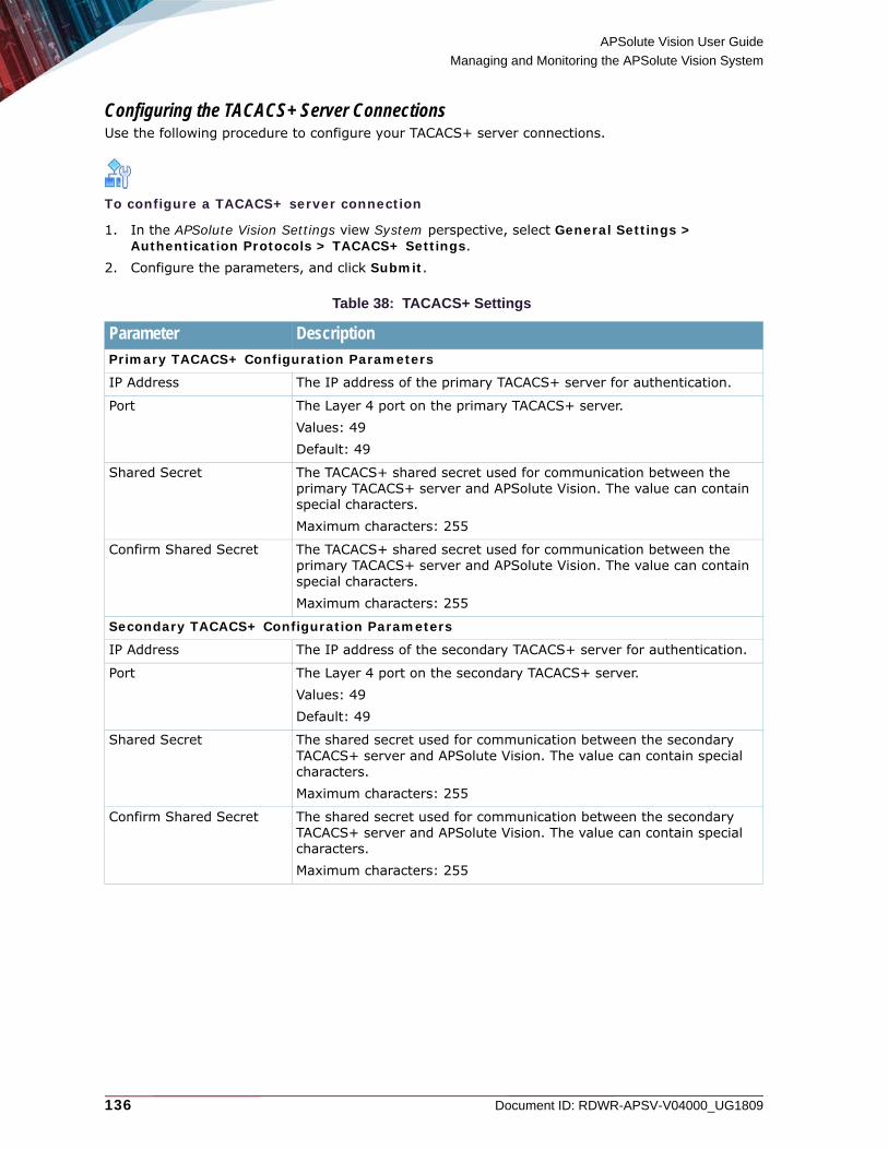
APSolute Vision User Guide
Managing and Monitoring the APSolute Vision System
136 Document ID: RDWR-APSV-V04000_UG1809
Configuring the TACACS+ Server ConnectionsUse the following procedure to configure your TACACS+ server connections.
To configure a TACACS+ server connection
1. In the APSolute Vision Settings view System perspective, select General Settings > Authentication Protocols > TACACS+ Settings.
2. Configure the parameters, and click Submit.
Table 38: TACACS+ Settings
Parameter DescriptionPrimary TACACS+ Configuration Parameters
IP Address The IP address of the primary TACACS+ server for authentication.
Port The Layer 4 port on the primary TACACS+ server.Values: 49 Default: 49
Shared Secret The TACACS+ shared secret used for communication between the primary TACACS+ server and APSolute Vision. The value can contain special characters. Maximum characters: 255
Confirm Shared Secret The TACACS+ shared secret used for communication between the primary TACACS+ server and APSolute Vision. The value can contain special characters.Maximum characters: 255
Secondary TACACS+ Configuration Parameters
IP Address The IP address of the secondary TACACS+ server for authentication.
Port The Layer 4 port on the secondary TACACS+ server.Values: 49Default: 49
Shared Secret The shared secret used for communication between the secondary TACACS+ server and APSolute Vision. The value can contain special characters. Maximum characters: 255
Confirm Shared Secret The shared secret used for communication between the secondary TACACS+ server and APSolute Vision. The value can contain special characters. Maximum characters: 255

APSolute Vision User Guide
Managing and Monitoring the APSolute Vision System
Document ID: RDWR-APSV-V04000_UG1809 137
Configuring LDAP Server ConnectionsAPSolute Vision can authenticate users using its role-based access control (RBAC) through a Lightweight Directory Access Protocol (LDAP) server connection. APSolute Vision is tested to work with Microsoft Active Directory; APSolute Vision is not tested with other LDAP implementations.
Caution: Users defined through a LDAP server with the Administrator, User Administrator, or Vision Administrator roles must be configured with the scope [ALL].
Caution: Do not configure more than 300 explicit device-policy pairs for DefensePro security-monitoring access—for any user. If there are more than 300 explicit device-policy pairs for a user, the Security Monitoring Dashboard View might not function properly for the user.
Note: For more information on RBAC and RBAC roles and scopes, see Role-Based Access Control (RBAC), page 68.
Authentication with LDAPIf the APSolute Vision server is configured to use LDAP for authentication, the user-authentication process is as follows:
1. The user connects to APSolute Vision WBM, and enters the username and password given by the LDAP administrator.
2. The APSolute Vision server sends the authentication request (that is, the bind request) to the LDAP server (see Configuring LDAP Server Connections, page 138).
Note: If the Fully Qualified Domain Name (FQDN) parameter is specified, the user name in the bind request includes the FQDN (that is, <username>@<FQDN>).
3. If the authentication with the LDAP server fails, the user receives an appropriate message.
Shared TACACS+ Configuration Parameters
Minimal Required Privilege Level
The minimum TACACS+ privilege level specified for a user that will allow access to APSolute Vision. A user can successfully be authorized by the TACACS+ server but have a privilege level that is too low to access APSolute Vision. 0 (zero) is the lowest privilege level, meaning: all users can access APSolute Vision. 15 is the highest level. For example, if the Minimal Required Privilege Level is defined as 1, all users with access level of 1 or higher can access APSolute Vision; and users with level 0 (zero) will not have access to APSolute Vision.Values: 0–15Default: 0
Service Name The name of the service as defined in the TACACS+ server configuration file.
Table 38: TACACS+ Settings (cont.)
Parameter Description

APSolute Vision User Guide
Managing and Monitoring the APSolute Vision System
138 Document ID: RDWR-APSV-V04000_UG1809
4. If the authentication with the LDAP server succeeds:
a. APSolute Vision sends a search request to the LDAP server for the user whose sAMAccountName value matches the login name, using a specified distinguished name as the root for the search.
b. If the LDAP server finds the requested user, APSolute Vision gives permissions to the authenticated user according to the matching LDAP object-class–permission entry that is configured on the APSolute Vision server (see Managing LDAP Object Class Permissions, page 89).Note: If the LDAP server does not find the requested user, APSolute Vision displays an appropriate message and does not grant the user access.
Radware recommends the following for each LDAP server (primary and secondary) for APSolute Vision user authentication:• Specify the Fully Qualified Domain Name (FQDN) parameter.
Note: If the Fully Qualified Domain Name (FQDN) parameter is specified, the user name in the bind request includes the FQDN (that is, <username>@<FQDN>).
• For optimal login time, configure distinguished names using the most specific values that you can.
Configuring LDAP Server ConnectionsUse the following procedure to configure your LDAP server connections.
To configure a LDAP-server connection
1. In the APSolute Vision Settings view System perspective, select General Settings > Authentication Protocols > LDAP Settings.
2. Configure the parameters, and click Submit.
Table 39: LDAP Settings
Parameter DescriptionGeneral LDAP Settings
Warning The rising threshold value must always be lower than the rising error threshold. When the parameter value exceeds the rising threshold value but is less than the error threshold value, a warning alert is issued.
Fully Qualified Domain Name The Fully Qualified Domain Name of the LDAP server.
Primary LDAP Configuration Parameters
IP Address / Host The IP address of the primary LDAP server for authentication.
Port The Layer 4 port on the primary LDAP server.Values: 1–65535Default: 636
Note: If the Encrypted checkbox is not selected, the (port) value is typically 389.
Encrypted Specifies whether authentication communication between APSolute Vision and the primary LDAP server is encrypted using SSL.Default: Enabled

APSolute Vision User Guide
Managing and Monitoring the APSolute Vision System
Document ID: RDWR-APSV-V04000_UG1809 139
Managing Device DriversA device driver in APSolute Vision defines the GUI and configuration of the software version of a managed device. The software version of a managed device defines the baseline driver version. There may be multiple device-driver versions for a single software version of a device, but there can be only one device-driver version in use on any single APSolute Vision server. That is, each device driver applies to all devices in the system that use the same device-software version. Typically, subsequent versions of device drivers include only fixes for GUI and configuration bugs. You can install a newer version of the device driver, and you can revert to the baseline version.When you upgrade device software, you need to reboot the device. However, when you install a new version of a device driver or revert to the baseline version, you do not need to reboot the device.
Secondary LDAP Configuration Parameter
IP Address / Host The IP address of the secondary LDAP server for authentication.
Authenticate Port The Layer 4 port on the secondary LDAP server.Values: 1–65535Default: 636
Note: If the Encrypted checkbox is not selected, the (port) value is typically 389.
Encrypted Specifies whether authentication communication between APSolute Vision and the secondary LDAP server is encrypted using SSL.Default: Enabled
Distinguished Names for SearchesThe list of each distinguished name (DN) on the LDAP server that may include the APSolute Vision user accounts.To add a name to the list
1. Click the (Add) button.2. In the Name box, type the DN.3. Click Submit. To edit a name in the list1. Double-click the entry.2. In the Name box, type the DN.3. Click Submit. To delete a name from the list1. Select the entry.
2. Click the (Delete) button and confirm your action.
Table 39: LDAP Settings (cont.)
Parameter Description

APSolute Vision User Guide
Managing and Monitoring the APSolute Vision System
140 Document ID: RDWR-APSV-V04000_UG1809
Caution: Device drivers do not include changes to the online help. Depending on the configuration of the APSolute Vision server, the APSolute Vision clients get online help either from the APSolute Vision server (the default option) or radware.com. The online-help files at radware.com are always the most up-to-date; but clients may encounter latency or connectivity problems. If the APSolute Vision clients get online help from the APSolute Vision server, after updating a device driver, the online-help files on the server should be updated. It is the responsibility of the APSolute Vision administrator to make sure that the help files on the server are updated as necessary. For more information, see Appendix A - Managing the Online-Help Package on the Server, page 669.
Note: The device driver includes the minimum APSolute Vision version.When an APSolute Vision server detects that a new device has been installed or that a new device software version has been installed on an existing device, the server retrieves the driver version from the device. The server checks whether it already has a driver version that corresponds to the device software version, and uses the newest device driver. If the driver version on the device is newer than the device version on the server, the server downloads the new driver from the device, but does not apply it. The table in the Device Drivers node (in the APSolute Vision Settings view System perspective) displays the device-version row shaded gray. If the device driver is incompatible or not found, APSolute Vision behaves as follows:• Issues an appropriate error message, but displays the device in the tree of the device pane with
a special icon (?) on top of it.• When you click the device in the tree, no screen is displayed, but the following information is
displayed in the device-properties pane: Device Name (from Vision), Device Type (if known), Status: Unsupported, and Software Version: <SW_version>
The device-properties pane includes the name of the device driver.You can do the following:• Update the drivers of the devices of a particular software version. • Update all the device drivers that are not updated in the APSolute Vision server.• Revert the driver to the baseline driver version.
If one or more of the relevant devices is locked, APSolute Vision prompts you whether to continue or not. If you change the driver version when a device is locked by other users, you may lose the changes for those users.
Table 40: Driver Parameters
Column DescriptionProduct Name The device type.
Values: • Alteon• AppWall• DefensePro• LinkProof NG
Product Version The device software version.
Instances The number of devices that use the same device software version.
Driver Baseline The baseline version of the driver used for this device software version.

APSolute Vision User Guide
Managing and Monitoring the APSolute Vision System
Document ID: RDWR-APSV-V04000_UG1809 141
To update a device driver
1. In the APSolute Vision Settings view System perspective, select General Settings > Device Drivers.
2. Select the row with the relevant device and device version.
3. Click the (Update Device Driver) button.
4. Click Browse, navigate to the driver, and click Open.
5. Click Update. APSolute Vision verifies that the device driver version is relevant for the device software.
6. Read the confirmation message, and then, accept or abort the action.
The version of the driver that you install cannot be the same version or an older version of the driver baseline version. If the driver version that you install is newer than the baseline version but older than the driver version in use, APSolute Vision prompts you for confirmation to change the current driver. If the driver version that you install is newer than the baseline version and newer than the driver version in use, APSolute Vision prompts you for confirmation to upgrade the current driver.
To apply a driver version to a specific device when there is a newer version in the server
1. In the APSolute Vision Settings view System perspective, select General Settings > Device Drivers.
2. Select the row with the relevant device and device version.
3. Select the (Update to Latest Driver) button.
To revert to baseline driver version that resides on the APSolute Vision server
1. In the APSolute Vision Settings view System perspective, select General Settings > Device Drivers.
2. Select the row with the relevant device and device version.
3. Select (Revert to Baseline Driver) button.
Note: This option is displayed only when the driver version in use is different from the baseline driver release.
Driver in Use The driver version in use for this device software version.
Latest Driver The latest driver version for this device software version that is stored in the APSolute Vision server.
Supported Languages The languages that the device driver supports.
Table 40: Driver Parameters (cont.)
Column Description
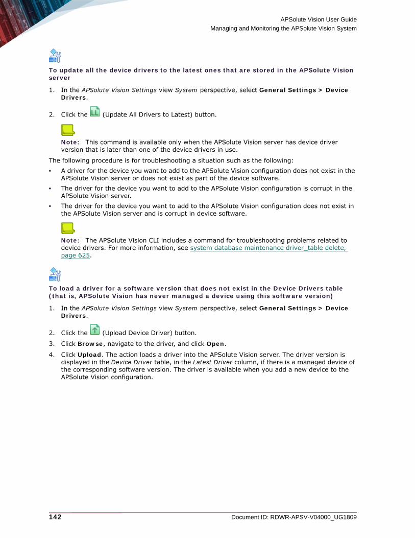
APSolute Vision User Guide
Managing and Monitoring the APSolute Vision System
142 Document ID: RDWR-APSV-V04000_UG1809
To update all the device drivers to the latest ones that are stored in the APSolute Vision server
1. In the APSolute Vision Settings view System perspective, select General Settings > Device Drivers.
2. Click the (Update All Drivers to Latest) button.
Note: This command is available only when the APSolute Vision server has device driver version that is later than one of the device drivers in use.
The following procedure is for troubleshooting a situation such as the following: • A driver for the device you want to add to the APSolute Vision configuration does not exist in the
APSolute Vision server or does not exist as part of the device software.• The driver for the device you want to add to the APSolute Vision configuration is corrupt in the
APSolute Vision server.• The driver for the device you want to add to the APSolute Vision configuration does not exist in
the APSolute Vision server and is corrupt in device software.
Note: The APSolute Vision CLI includes a command for troubleshooting problems related to device drivers. For more information, see system database maintenance driver_table delete, page 625.
To load a driver for a software version that does not exist in the Device Drivers table (that is, APSolute Vision has never managed a device using this software version)
1. In the APSolute Vision Settings view System perspective, select General Settings > Device Drivers.
2. Click the (Upload Device Driver) button.
3. Click Browse, navigate to the driver, and click Open.
4. Click Upload. The action loads a driver into the APSolute Vision server. The driver version is displayed in the Device Driver table, in the Latest Driver column, if there is a managed device of the corresponding software version. The driver is available when you add a new device to the APSolute Vision configuration.

APSolute Vision User Guide
Managing and Monitoring the APSolute Vision System
Document ID: RDWR-APSV-V04000_UG1809 143
Configuring APSolute Vision Reporter ParametersYou can view historical security reports in the APSolute Vision Reporter (AVR).The AVR client supports only a single timezone, which is the timezone configured on the APSolute Vision server.
Notes
• To open AVR, click > in the APSolute Vision toolbar.
• AVR does not support Alteon or LinkProof NG.
To configure APSolute Vision Reporter settings
1. In the APSolute Vision Settings view System perspective, select General Settings > APSolute Vision Reporter.
2. Configure the parameters, and click Submit.
Managing APSolute Vision Licenses and Viewing Capacity UtilizationUse the License Management pane for doing the following:• Managing Licenses for APSolute Vision, page 144• Viewing Details of the RTU Licenses, page 146• Viewing Details on the Current Utilization of the APSolute Vision Server, page 146
To open the License Management pane
> In the APSolute Vision Settings view System perspective, select General Settings > License Management.
Table 41: APSolute Vision Reporter Parameters
Parameter DescriptionAttack Polling Interval (Read-only) The interval for polling security attack data, which is 5
minutes.
Data Retention Interval The time, in months, that APSolute Vision retains AVR data.Values: • 1–48• UnlimitedDefault: 12
Note: After upgrade from an APSolute Vision version prior to 2.30, the value is Unlimited. You can modify this value if you require.
Upload Logo(button)
You can upload a logo to display on reports. Click the button and enter the name of the file to upload.

APSolute Vision User Guide
Managing and Monitoring the APSolute Vision System
144 Document ID: RDWR-APSV-V04000_UG1809
Note: For your convenience, the License Management pane includes a link to the Device Subscriptions pane (see Viewing Device Subscriptions, page 158).
Managing Licenses for APSolute VisionIn addition to the existing perpetual licenses, APSolute Vision accepts and enforces time-based right-to-use (RTU) licenses and time-based licenses for various features, such as AVR, APM, and DPM. APSolute Vision denies access to a feature if the license is not installed or the license has expired.When APSolute Vision is running as a virtual appliance (VA) or on an OnDemand Switch VL (ODS-VL) platform, licenses for APSolute Vision are generated based on the MAC address of the APSolute Vision port G1 or G2. APSolute Vision displays the MAC address of port G1 in the License Management pane above the License table.When APSolute Vision is running on an OnDemand Switch VL2 (ODS-VL2) platform, licenses for APSolute Vision are generated based on the MAC address of the APSolute Vision port G3 or G5. APSolute Vision displays the MAC address of port G3 in the License Management pane above the License table.APSolute Vision has capacity limitations and limitations based on the RTU license. The total number of licenses is called the RTU license pool. The RTU license pool determines the maximum number of supported physical and virtual devices that the APSolute Vision server can manage.When a system is in violation of the RTU license:• APSolute Vision allows you to manage only the number of devices corresponding to the RTU
license pool. • The RTU License status of the devices that are not covered by the RTU license pool is Invalid.• APSolute Vision randomly selects which managed devices have the Invalid status. • You cannot configure devices whose RTU License status is Invalid. In this context, configure
includes: Scheduler tasks, Operator Toolbox scripts, multi-device configuration, and multi-device configuration with Logical Groups.
Notes
• When you install a new license over a license (of the same type) that has already expired, the new license automatically overwrites the expired one. APSolute Vision enforces licenses according to the start date to the expiration date. You can replace an existing valid license with a new license if the starting day is before the installation date.
• If you try to install a new license over a valid active license, and the starting date of the new license is after the day of installation, APSolute Vision does not allow the action and displays an appropriate message.
• If there is no active license and you try to install a license with a future start date, APSolute Vision allows the action but displays an appropriate message.
• When removing a device from APSolute Vision that is covered by the RTU license pool, the license portion returns to the pool. If there are managed devices that are not covered by the pool, APSolute Vision randomly selects one of those devices, and allocates the license portion to that device.
APSolute Vision starts generating license-expiration alerts 90 days before the expiration date.

APSolute Vision User Guide
Managing and Monitoring the APSolute Vision System
Document ID: RDWR-APSV-V04000_UG1809 145
When APSolute Vision generates an license-expiration alert:• The APSolute Vision toolbar displays the License Alert button. The button displays only to users
with the Administrator or Vision Administrator roles. If a license expires within 90 days up to 30 days, the button background is blue. If a license expires within 29 days up to one day, the button background is amber. The last day before the license expires and after the license is expired, the button background is red. When there are multiple license alerts, the button displays the lowest number of remaining days. Hovering on the button opens a tooltip with additional information. When there are multiple alerts, the bell shows the number of alerts. Clicking the License Alert button opens the License Management pane.
Figure 31: License Alert Button and Tooltip
• A pop-up notification is displayed to users with the Administrator or Vision Administrator roles.• The alert is displayed in the Alerts Table.• The alert is included in the technical-support (tech-support) package. For information on tech-
support packages, see System Backup Technical-Support Commands, page 616.
Caution: After upgrading from APSolute Vision versions earlier than 3.80, if there is an RTU-license alert, there will be a grace period of 30 days. This grace period is intended to grant you time to contact Radware Technical Support and purchase additional RTU licenses, as required. After the grace period, APSolute Vision will support only the number of devices covered by the RTU license pool.
To add a license for APSolute Vision
1. In the APSolute Vision Settings view System perspective, select General Settings > License Management.
2. In the License table, click the (Add) button.
3. In the License String text box, enter the license string.
4. Click Submit.
Use the Licenses table to view information on the installed licenses. If a license is expired or is soon to expire, the text in the corresponding row is red. If a license is going to be active in the future, text in the row is blue. When you click on a license in the License Management table, the View License tab opens. If the license is expired or about to expire, the View License tab includes a link to the Radware portal, which provides purchasing options.
Table 42: License Table Parameters
Parameter DescriptionItem The license type.
License String The license string that Radware supplied.

APSolute Vision User Guide
Managing and Monitoring the APSolute Vision System
146 Document ID: RDWR-APSV-V04000_UG1809
Viewing Details of the RTU LicensesUse the RTU Licenses table to help determine whether you exceed scale/capacity specifications and whether you need to purchase additional RTU licenses.
Note: For more information on capacity limitations, see the APSolute Vision Release Notes for the relevant APSolute Vision version.
Viewing Details on the Current Utilization of the APSolute Vision ServerThe Current Utilization table displays various Item parameters and the number of each item.
Note: For more information on capacity limitations, see the APSolute Vision Release Notes for the relevant APSolute Vision version.
Expiration Date The date that the license expires.
Note: The date format is according to the configuration of the APSolute Vision server (see Configuring APSolute Vision Display Parameters, page 153).
Days to Expiration The number of days before the license expires.
Activation Date The date that the license was activated.
Note: The date format is according to the configuration of the APSolute Vision server (see Configuring APSolute Vision Display Parameters, page 153).
Table 43: RTU Licenses Table Parameters
Parameter DescriptionType Values:
• Managed Physical Devices—The number of physical devices (of any supported device type) that the APSolute Vision is managing. DefenseFlow is not counted.
• Managed Virtual Devices—The number of virtual devices (of any supported device type) that the APSolute Vision is managing. DefenseFlow is not counted.
Number of Devices The number of devices of the specific type that APSolute Vision is managing.
Devices with No License The number of devices of the specific type that have no RTU license.
Allocated Licenses The number of devices of the specific type from the license pool that are allocated (used).
License Pool The total number of licenses in the pool.
Table 42: License Table Parameters (cont.)
Parameter Description

APSolute Vision User Guide
Managing and Monitoring the APSolute Vision System
Document ID: RDWR-APSV-V04000_UG1809 147
Managing APM in APSolute VisionApplication Performance Monitoring (APM) monitors traffic through Alteon and LinkProof NG devices. APM can continuously monitor all transactions and provide visibility into the true end-user experience in the data center, network, or online application.The APM server is part of the APSolute Vision server with APM server VA offering. One APM server per APSolute Vision server supports the APM functionality. The APM server is an OVA installation in a VMware vSphere environment. You specify the connection details of the APM server in the APSolute Vision Settings view System perspective, under General Settings > APM Settings.From the APM Settings node, you can view information related to the virtual services of the managed devices that have APM enabled. There, you can also directly access the service in APM Web interface.
Notes
• The term “APM server” may also be referred to as “SharePath server”.
• APM requires a proper license, which you can manage in the License Management tab (APSolute Vision Settings view System perspective, General Settings > License Management).
• For information on the installation of the APM server, see the APSolute Vision Installation and Maintenance Guide.
• For information on how to configure Alteon or LinkProof NG with APM, see the sections “Configuring the Application Performance Monitoring (APM) Server in Alteon” and “Managing Virtual Services Settings” in the online help.
• For information on using APM, see the Application Performance Monitoring User Guide.
• For information on how to use the APM Web interface, click the (Help) button in the APM Web interface.
Table 44: Current Utilization Table Parameters
Parameter DescriptionItem Values:
• Managed DefensePro Devices—The number of DefensePro devices of any deployment type (virtual or physical appliance) that the APSolute Vision is managing.
• Unavailable Devices—The number of devices that the APSolute Vision is managing whose status is not Up. That is, devices whose status is Down, Maintenance, Unknown, and so on.
• Total Enabled DefensePro Policies—The sum of enabled Network Protection policies and Server Protection policies on the DefensePro devices that the APSolute Vision is managing.
• Total Profiles Assigned to Enabled Policies—The number of profiles in both the Network Protection policies and Server Protection policies on the DefensePro devices that the APSolute Vision is managing. If a profile is associated with multiple policies, it is counted multiple times.
Quantity The number of the specific item.

APSolute Vision User Guide
Managing and Monitoring the APSolute Vision System
148 Document ID: RDWR-APSV-V04000_UG1809
To open the APM Web interface
> Do one of the following:
— In the APSolute Vision toolbar, click > .— Do the following:
a. In the APSolute Vision Settings view System perspective, select General Settings > APM Settings.
b. In the table, in the APM Server column, click the hyperlink.
Considerations and Constraints Using APM with Alteon Version 29.5The following lists describes the considerations and constraints using APM with Alteon version 29.5: • The Alteon must be managed by the same APSolute Vision that hosts the APM server.• If the instance of the APM server is replaced without restoring the previous database, the
system administrator must reapply the APM configuration on each virtual service.
Managing the APM ServerThis section describes how to manage the APM server.Use the APM-Enabled Services table to view information related to the virtual services of the managed Alteon or LinkProof NG devices that have APM enabled. There, you can also directly access the service in the APM Web interface.
To manage the APM server
1. In the APSolute Vision Settings view System perspective, select General Settings > APM Settings. The APM Settings tab displays the APM Server State field and a table with information about the APM server. The APM Server State field can display the following values:— Initializing—The APM server is initializing.— Running—The APM server is running.— Down—The APM server is down. Typically, this is because the APM server is not yet
configured in the table or the APM license is not yet installed.2. Do one of the following:
— To add an entry, click the (Add) button.— To edit an entry, double-click the row.
3. Configure the parameters, and then, click Submit.

APSolute Vision User Guide
Managing and Monitoring the APSolute Vision System
Document ID: RDWR-APSV-V04000_UG1809 149
Table 45: APM Server Parameters
Parameter DescriptionUse the APM Server Installed on this APSolute Vision Server(This parameter is available only with the APSolute Vision server with APM server VA offering.)
Specifies whether APSolute Vision uses the APM server associated with the APSolute Vision server with APM server VA installation. Values:• Disabled—APSolute Vision uses an external APM server.• Enabled—APSolute Vision uses the APM server associated
with the APSolute Vision installation, and populates the following fields with read-only values:— Management IP Address—The IP address of the APSolute
Vision management port (G1 or G2), which is the management port for both APM and APSolute Vision server.
— Data IP Address—The IP address of the G4 port.— Backup IP Address—The IP address of the G3 port. This
value is not mandatory.Default: Disabled
Notes: • For information on configuring the IP address for each port,
see Network IP Interface Commands, page 596.• For information on configuring the routing for each port, see
Network Routing Commands, page 599.
Management IP Address The IP address of the port on the SharePath/APM server that APSolute Vision uses for APM management traffic.In the APSolute Vision server with APM server VA offering, this address is typically the management IP address of the APSolute Vision server too. By default, this is the IP address of the G1 port on the APSolute Vision server VA.
Port The management interface TCP port. Values: 1–65535Default: 443
Caution: Specifying a non-default port involves modifying the APM server configuration. For more information, in the Application Performance Monitoring Troubleshooting and Technical Guide, see the appendix “Configuring a Non-Default APM Port for APM Reports.”
Note: You can specify the port only when you add a new APM server to the APSolute Vision configuration. You cannot modify the port on an APM server that is already configured in APSolute Vision. To modify the port, you need to remove the APM server from the APSolute Vision configuration, and then, add the APM server with the required port to the APSolute Vision configuration again.

APSolute Vision User Guide
Managing and Monitoring the APSolute Vision System
150 Document ID: RDWR-APSV-V04000_UG1809
Viewing Information on the APM-Enabled DevicesUse the APM Enabled-Devices pane to view information on the devices managed by the APSolute Vision server that have at least one virtual service with APM enabled.
To view information on the APM-enabled devices
> In the APSolute Vision Settings view System perspective, select General Settings > APM Settings > APM-Enabled Devices.
Data IP Address The IP address of the port on the SharePath/APM server that APSolute Vision uses for APM data traffic. In the APSolute Vision server with APM server VA offering, this address is typically the IP address of the APSolute Vision G4 port. This field is significant only for older Alteon versions 29.5, 30.0.0, 30.0.1, 30.0.2, 30.0.3, and 30.1. New versions use the configuration on the device and ignore the Data IP Address field. The default is set to G4, assuming that APM must support the device sending beacons from the Alteon data interface.
Backup IP Address The IP address of the port on the SharePath/APM server that APSolute Vision uses for APM backup traffic.
Note: This value is not mandatory.
Performance Limit The maximum events (performance reports for an HTML page) per second that the APM server can process.Values: 10–1000Default: 500
Table 46: APM-Enabled Services Table
Parameter DescriptionDevice Name The name of the device with the APM-enabled service.
Virtual Server Index The index of the APM-enabled service.
Virtual Server IP The IP address of the APM-enabled service.
Port The port of the APM-enabled service.
Description The description of the APM-enabled service.
APM Application Link A hyperlink to the APM-enabled service in the APM interface.
Table 47: APM-Enabled Devices Table
Parameter DescriptionDevice Name The name of the device with an APM-enabled service.
Device Management IP The IP address of the device.
Software Version The software version of the device.
APM License (PgPM) The APM license currently installed on the device.
Form Factor The form factor of the device.
Table 45: APM Server Parameters (cont.)
Parameter Description
APSolute Vision User Guide
Managing and Monitoring the APSolute Vision System
Document ID: RDWR-APSV-V04000_UG1809 151
Configuring the Radware Cloud DDoS Protection SettingUse the Radware Cloud DDoS Protection pane to specify the Radware Cloud DDoS Protection URL. APSolute Vision uses the URL to connect to the Radware Cloud DDoS Protection service when you
click > in the APSolute Vision menu bar.
Note: For more information on Radware Cloud DDoS Protection services, see the Cloud DDoS Protection Services User Guide.
To specify the Radware Cloud DDoS Protection URL
1. In the APSolute Vision Settings view System perspective, select General Settings > Radware Cloud DDoS Protection.
2. In the Radware Cloud DDoS Protection URL text box, type the URL, and click Submit.
Configuring APSolute Vision Server Advanced ParametersUse the following procedure to configure additional advanced parameters and online-help parameters for the APSolute Vision server.
To configure advanced parameters for the APSolute Vision server
1. In the APSolute Vision Settings view System perspective, select General Settings > Advanced.
2. Configure the parameters, and click Submit.
Hardware Platform The platform of the device.
APM Server Management IP The IP address of the management port of the APM server. For the APSolute Vision server with APM server VA offering, this is the IP address of the management port of the APSolute Vision server.
Table 47: APM-Enabled Devices Table (cont.)
Parameter Description

APSolute Vision User Guide
Managing and Monitoring the APSolute Vision System
152 Document ID: RDWR-APSV-V04000_UG1809
Table 48: APSolute Vision Advanced: General Parameters
Parameter DescriptionMaximum Configuration Files for Device
The maximum number of configuration files per managed device that you can store on the APSolute Vision server for backup. When the limit is reached, you are prompted to delete the oldest file.Values: 1–10Default: 5
Note: If you change the maximum value to less than the number of existing configuration files, none of the existing files will be deleted. For example, the configured maximum value is 10 and there are 8 configuration files, if you then change the configured maximum value to 4, no files are deleted.
Minimal Log Level The lowest severity of messages that will be logged for debugging purposes. Values:• Fatal• Error• Warning• Info • Debug• TraceDefault: Error
Caution: Lowering the value of the Minimal Log Level parameter may negatively affect the performance of the APSolute Vision server. Radware recommends using the default value, Error, except when there are specific troubleshooting requirements.
Device Lock Timeout The time, in minutes, that a device remains locked. If you have the appropriate permissions to configure a device, you can lock the device so that other user cannot configure the device at the same time.Values: 5–180Default: 10
Results per Page The number of rows that are displayed per table page.Values: 10–100Default: 50
APSolute Vision User Guide
Managing and Monitoring the APSolute Vision System
Document ID: RDWR-APSV-V04000_UG1809 153
Configuring APSolute Vision Display ParametersYou can configure display parameters for APSolute Vision clients, which also affect certain other APSolute Vision functionalities.
To configure APSolute Vision display parameters
1. In the APSolute Vision Settings view System perspective, select General Settings > Display.2. Configure the parameters, and click Submit.
Table 49: APSolute Vision Advanced: Online Help Parameters
Parameter DescriptionNote: For changes to existing online help content to display properly, you may need to refresh your browser display or clear the browser cache.
Online Help URL The source of the online help that clients request.Values:• APSolute Vision Server—The server provides the client with
online-help files stored on the server. Installation of the APSolute Vision server includes online-help files, but if managed devices are somehow upgraded later (with a new device, new device version, or new device driver), the online-help files on the server should be updated. It is the responsibility of the APSolute Vision administrator to make sure that the help files on the server are updated as necessary. For more information, see Appendix A - Managing the Online-Help Package on the Server, page 669.
• Radware.com—The client sends online-help requests to the radware.com Web site and receives files from there. The online-help files at radware.com are always the most up-to-date, but you may encounter latency or connectivity problems.
Default: APSolute Vision Server
Update(button)
Opens the dialog box to update the online-help package that resides in the APSolute Vision server.
Note: For more information, see Appendix A - Managing the Online-Help Package on the Server, page 669.
Revert to Default Help(button)
The online help currently on the server reverts to the online help package that was included with the installation of the APSolute Vision server.
Note: For more information, see Appendix A - Managing the Online-Help Package on the Server, page 669.

APSolute Vision User Guide
Managing and Monitoring the APSolute Vision System
154 Document ID: RDWR-APSV-V04000_UG1809
Table 50: Display: General Parameters
Parameter DescriptionDefault Display Language The default display language for new users in the APSolute Vision
system.
Notes: • If you change the value, the change affects only users created
after the change.• Each user can change his/her own display language, by opening
the User drop-down dialog box (from the APSolute Vision toolbar, in the User ribbon at the at the far right) and selecting
the language from the drop-down list next to the (globe) icon.
• An Administrator can specify the default language for each specific user (see Configuring Local Users for APSolute Vision, page 82).
Default Landing Page The page that APSolute Vision displays by default for new users in the APSolute Vision system.Values: • First Device in the Tree—New users land on the Device pane
with the first available device selected, and the Configuration perspective.
• Application SLA Dashboard—New users land on the Application SLA Dashboard (see Using the Application SLA Dashboard, page 573).
• Security Control Center—New users land on the Security Control Center (see Using the Security Control Center, page 576).
• Operator Toolbox—New users land on the Toolbox (see Using the Toolbox, page 211).
• Service Status Dashboard—New users land on the Service Status Dashboard (see Using the Service Status Dashboard, page 582).
Default: First Device in the Tree
Notes: • User roles and scopes determine whether the selected option is
relevant. If a user does not have permission to view the selected option, he/she lands on the first permitted tab in the APSolute Vision Settings view. For information on user roles and scopes, see Managing APSolute Vision Users, page 67.
• Each user can change his/her own landing page (APSolute Vision Settings view Preferences perspective, User Preferences > Display).
• If you change the value, the change affects only users created after the change.

APSolute Vision User Guide
Managing and Monitoring the APSolute Vision System
Document ID: RDWR-APSV-V04000_UG1809 155
Managing APSolute Vision Maintenance FilesYou can open and save the maintenance files and upgrade log files of the APSolute Vision server.
To open or save a maintenance file or upgrade log file
1. In the APSolute Vision Settings view System perspective, select General Settings > Maintenance Files.
2. Double-click the row with the relevant file.
3. Use the dialog box to open the file with a selected application or save the file to a selected location.
Table 51: Display: Date and Time Format Parameters
Parameter DescriptionDate Format The date format for information that includes date and time
displayed in the APSolute Vision Web client.Values:• dd.MM.yyyy• MM.dd.yyyy• dd/MM/yyyy• MM/dd/yyyyDefault: dd.MM.yyyy
Time Format The time format for information that includes date and time displayed in the APSolute Vision Web client.Values:• HH:mm:ss• HH:mm:ss z• h:mm:ss aa• h:mm:ss aa zDefault: HH:mm:ss

APSolute Vision User Guide
Managing and Monitoring the APSolute Vision System
156 Document ID: RDWR-APSV-V04000_UG1809
Managing Operator Toolbox SettingsUse the Operator Toolbox Settings tab to manage the graphic files for the Toolbox dashboard (see Using and Managing Toolbox Scripts, page 211).The file must have the PNG, SVG, or JPG extension and be no larger than 200 KB.The table in the Operator Toolbox Settings tab comprises the following columns: • File Name—The filename of the graphic file.• Used by Script—The filename of the script that is associated with this graphic file (Toolbox >
Advanced > Operator Toolbox > Assign to Dashboard).• Icon Preview—The image that the Operator Toolbox dashboard uses—or can use—to run a
script.• Upload Date—The date the file was uploaded to APSolute Vision.• Uploaded By—The username who uploaded the file to APSolute Vision.
Note: To replace a file with the same name, you must first delete the old file.
To upload an image file for the Toolbox dashboard
1. In the APSolute Vision Settings view System perspective, select General Settings > Operator Toolbox Settings.
2. Click the (Add) button.
3. Click Browse and browse to the file.
4. Click Upload.
Related Topics • Using and Managing Toolbox Scripts, page 211• Managing Toolbox Scripts, page 233
Managing Stored Device Configuration/Backup FilesYou can manage configuration files of managed devices that are stored on the APSolute Vision server. You can do the following:• View details of the configuration files of managed devices • Save configuration files from the server to your PC• Delete configuration files from the server• Edit configuration file descriptions
For information about configuring the maximum number of configuration files per device that can be stored, see Configuring APSolute Vision Server Advanced Parameters, page 151.

APSolute Vision User Guide
Managing and Monitoring the APSolute Vision System
Document ID: RDWR-APSV-V04000_UG1809 157
To access the device backups
> In the APSolute Vision Settings view System perspective, select Device Resources > Device Backups.
To edit the description of a configuration file
1. In the APSolute Vision Settings view System perspective, select Device Resources > Device Backups.
2. Double-click the relevant entry.
3. In the Description text box, add or edit the text, up to 50 characters.
To delete a configuration file from the server
1. In the APSolute Vision Settings view System perspective, select Device Resources > Device Backups.
2. Select the relevant entry.
3. Click the (Delete) button.
To get the configuration file of the device from the APSolute Vision server and download the file to the local PC
1. In the APSolute Vision Settings view System perspective, select Device Resources > Device Backups.
2. Select the relevant entry.
3. Click the (Download Selected File) button.
4. Open or save the file as you require.
Table 52: Device Configuration File Parameters
Parameter DescriptionFile Name The name of the stored configuration file.
File Type This field always displays Regular.
SW Version The software version of the device.
Backup Date The date and time that the file was saved on the APSolute Vision server.
Description A description of the file. You can enter and edit text in this field.

APSolute Vision User Guide
Managing and Monitoring the APSolute Vision System
158 Document ID: RDWR-APSV-V04000_UG1809
To compare a device-backup file—of an Alteon, DefensePro, or LinkProof NG device—from the APSolute Vision server to another object
1. In the APSolute Vision Settings view System perspective, select Device Resources > Device Backups.
2. Select the relevant entry.
3. Click the (Compare Backup File) button.
4. From the Compare... With drop-down list, select one of the following:
— Other Device Running Configuration— Backup File from System— Backup File from Local File System
5. Select the device, configuration, or file.
6. Click OK.
Viewing Device SubscriptionsUse the Device Subscriptions pane to view information on the devices that APSolute Vision manages, the associated support agreements, and the associated subscriptions. The table in the Device Subscriptions tab displays all managed devices of most device types—including Alteon VX devices. The table retrieves information on the devices from Radware, and displays the information even when a device is unavailable to APSolute Vision. You can sort and filter the table according to your needs. You can also export the contents of the table in the pane to a CSV file—according to any filter that is applied.
Caution: The functionality of the Device Subscriptions pane requires connectivity to radware.com or the proxy server that is configured in the APSolute Vision settings (APSolute Vision Settings view System perspective, General Settings > Connectivity > Proxy Server Parameters).

APSolute Vision User Guide
Managing and Monitoring the APSolute Vision System
Document ID: RDWR-APSV-V04000_UG1809 159
Notes
• Columns in the Device Subscriptions table display N/A when there is no connectivity to radware.com or the proxy server that is configured in the APSolute Vision settings.
• Radware’s Security Update Service (SUS) is a subscription service for security advisories and signature updates, which delivers rapid and continuous updates.
• The Fraud Signature Protection subscription provides protection against fraud and phishing attacks using the DefensePro Fraud Protection module.
• The ERT Active Attackers Feed is a subscription service that updates DefensePro devices with IP addresses of known attackers that were recently active. The feed is generated by Radware’s Threat Research Center.
• The Device Subscriptions table does not display DefenseFlow devices.
• The Device Subscriptions table does not display vADC devices that APSolute Vision does not manage.
• Except for AppWall devices, all of the subscriptions are based on the device MAC address.
• For your convenience, the Device Subscriptions pane includes a link to the APSolute Vision License Management tab (see Managing APSolute Vision Licenses and Viewing Capacity Utilization, page 143).
You can use the Device Subscriptions to help you manage your device repository, and make sure you have all of the required subscriptions, prior to updating your devices. For example, when you want to upgrade device software, you can first check the Device Subscriptions table, and verify that all devices have a support agreement. You can filter the table for Support Agreement: No and locate devices that do not have a support agreement. If there are no such devices, you can continue and upgrade the devices. If there are devices that do not have a valid support agreement, you can export the table to a CSV file and use the file to send Radware the list of MAC addresses lacking a support agreement. Radware will check whether there’s is an error in the database or the device MAC addresses are not registered. After handling errors and purchases and refreshing the Device Subscriptions table, all relevant rows will show Support Agreement: Yes. You can then continue with the device upgrade.
To open the Device Subscriptions pane
> In the APSolute Vision Settings view System perspective, select Device Resources > Device Subscriptions.
The following table describes the Device Subscriptions table.
Table 53: Device Subscriptions Table Parameters
Parameter DescriptionDevice Name The name of the device.
Device Type The type of the device.
MAC Address The MAC address of the device.
Note: AppWall devices do not use the MAC address for to register agreements. Instead, AppWall devices use the host ID to register agreements.
Software Version The software version of the device.
Valid Support Agreement
Specifies whether there is a valid Support Agreement for the device.Values: N/A, Yes, No
APSolute Vision User Guide
Managing and Monitoring the APSolute Vision System
160 Document ID: RDWR-APSV-V04000_UG1809
To export a CSV file with the information in the Device Subscriptions table
1. In the APSolute Vision Settings view System perspective, select Device Resources > Device Subscriptions.
2. Click (Export Table to CSV File).
3. View the file or specify the location and file name, and then, click Save.
Controlling APSolute Vision OperationsYou can perform the following operations on APSolute Vision:• Back up the APSolute Vision data—You can back up the configuration tables and other APSolute
Vision data. To back up the database including real-time and historical reports, you must use CLI commands. For more information, see Using vDirect with APSolute Vision, page 657.
• Update the Attack Description file.
You can perform the following operations using APSolute Vision CLI:• Restoring the appliance configuration.• Restoring the server configuration.• Restarting the APSolute Vision server.
For more information about APSolute Vision CLI commands, see Using vDirect with APSolute Vision, page 657.
Support Agreement Expiration Date
The expiration date of the Support agreement.
Valid SUS Agreement Specifies whether there is a valid SUS agreement for the device.Values: N/A, Yes, No
SUS Expiration Date The expiration date of the SUS agreement.
Valid Fraud Updates Agreement
Specifies whether there is a valid Fraud Updates agreement for the device.Values: N/A, Yes, No
Fraud Expiration Date The expiration date of the Fraud agreement.
ERT Active Attackers Feed Subscription
Specifies whether there is a valid ERT Active Attackers Feed subscription for the device.Values: N/A, Yes, No
ERT Active Attackers Feed Expiration Date
The expiration date of the ERT Active Attackers Feed subscription.
Table 53: Device Subscriptions Table Parameters (cont.)
Parameter Description

Document ID: RDWR-APSV-V04000_UG1809 161
CHAPTER 5 – MANAGING DEVICES, SITES, AND LOGICAL GROUPS
Before you can configure Radware devices through APSolute Vision, you add devices to the APSolute Vision server configuration. You can group devices into Sites and/or Logical Groups.The following topics describe how to set up your network of APSolute Vision Sites and Radware devices:• Using the Device Pane, page 161• Configuring Sites, page 162• Managing Individual Devices, page 164• Locking and Unlocking Devices, page 179• Managing DefensePro Clusters for High Availability, page 181• Using the Multi-Device View and the Multiple Devices Summary, page 187• Using Logical Groups of Devices, page 190• After You Set Up Your Managed Devices, page 194
Note: To add Alteon or DefensePro devices, you can also use vDirect with APSolute Vision. For more information, see Using vDirect with APSolute Vision, page 657.
Using the Device PaneYou organize the devices that APSolute Vision manages in the device pane.The following topics describe using the device pane: • Device Pane Trees, page 162• Icons for High Availability, page 162• Configuring Sites, page 162• Tree Nodes, page 164• Exporting a CSV File with the Devices in the Sites and Devices Tree, page 164• Filtering Entities in the Device Pane, page 164
Note: For a picture of the device pane, see Figure 22 - Device Pane (Not Docked)—Showing the Sites and Devices Tree, page 58.

APSolute Vision User Guide
Managing Devices, Sites, and Logical Groups
162 Document ID: RDWR-APSV-V04000_UG1809
Device Pane TreesTo organize and manage devices, the device pane includes the following three different trees: • Sites and Devices—The Sites and Devices tree can contain:
— Alteon standalone, VA, and vADC devices and clusters of Alteon devices for high availability — AppWall devices and clusters of AppWall devices for high availability— DefensePro devices and clusters of DefensePro devices for high availability
Note: You can configure DefensePro high-availability clusters only on DefensePro version 6.x and 7.x devices.
— LinkProof NG devices• Physical Containers—The Physical Containers tree can contain the managed ADC-VX
instances, and Sites with ADC-VX instances. After you add an ADC-VX to the Physical Containers tree, you can configure the vADCs that the ADC-VX hosts. The vADCs that the ADC-VX is hosting are displayed as child nodes of the ADC-VX. Once a vADC is managed in the Physical Containers tree, you can only configure the corresponding vADC entity in the Sites and Devices tree.
• Logical Groups—The Logical Groups tree contains user-defined Logical Groups. A Logical Group is a group of devices of the same type, which you manage as a single entity. For more information on Logical Groups, see Using Logical Groups of Devices, page 190.
To display another tree, click the button, and select the name of the tree that you require.
Icons for High AvailabilityIn the Sites and Devices tree, you can create clusters of devices for high availability. APSolute Vision displays DefensePro primary devices and AppWall cluster managers with a green border.
Figure 32: Icon for a Primary Device in a DefensePro Cluster
Figure 33: Icon for an AppWall Cluster Manager
Configuring SitesYou can configure Sites in the Sites and Devices tree and in the Physical Containers tree. You may configure Sites according to a geographical location, administrative function, or device type. You can nest Sites; that is, each Site can contain child Sites and devices. By default, the root Site is called Default. You can rename this Site, and add nested Sites and devices. You can add, rename, and delete Sites. When you delete a Site, you must first remove all its child Sites and devices.When you manage a vADC hosted by an ADC-VX in the Physical Containers tree, you specify the Site under which that vADC is displayed in the Sites and Devices tree.You can also display real-time security monitoring for multiple devices. You can select a Site or select multiple devices (using standard, mouse click/keyboard combinations) even if the devices are in the same Site.

APSolute Vision User Guide
Managing Devices, Sites, and Logical Groups
Document ID: RDWR-APSV-V04000_UG1809 163
Notes
• To move a device between Sites, you must first delete the device from the tree and then add the device in the required Site.
• A Site cannot have the same name as a device, and Sites nested under different parent Sites cannot have the same name.
• You cannot delete the Default Site, but you can rename it.
To add a new Site
1. In the device pane, click the icon, and select Sites and Devices or Physical Containers.2. In the device pane Sites and Devices tree or Physical Containers tree, select the Site node in
which you want to create the new Site.
3. Click the (Add) button in the tab toolbar.
4. From the Type drop-down list, select Site.
5. In the Name text box, type the name of the Site.
6. Click Submit.
Caution: With RADIUS or TACACS+ authentication, if a user definition explicitly mentions the name of a Site and the Site name changes, the user definition in the RADIUS or TACACS+ server must be updated accordingly.
If the name of an APSolute Vision Site changes and APSolute Vision authenticates the users locally, APSolute Vision updates the relevant scopes for the users.
To rename a Site
1. In the device pane, click the icon, and select Sites and Devices or Physical Containers.2. Select the Site.
3. Click the (Edit) button.
4. In the Name text box, type the name of the Site.
5. Click Submit.
To delete a Site
1. In the device pane, click the icon, and select Sites and Devices or Physical Containers.2. Select the Site.
3. Click the (Delete) button and confirm your action.

APSolute Vision User Guide
Managing Devices, Sites, and Logical Groups
164 Document ID: RDWR-APSV-V04000_UG1809
Tree NodesTree nodes are arranged alphabetically in the tree within each level. For example, a Site called Alteon_Site appears before a Site at the same level called DefensePro_Site.All nested Sites appear before devices at the same level, regardless of their alphanumerical order.All node names in a tree must be unique. For example, you cannot give a Site and a device the same name, and you cannot give devices in different Sites the same name.Node names are case-sensitive.
Exporting a CSV File with the Devices in the Sites and Devices Tree You can export a CSV file with the devices in the Sites and Devices tree. The CSV file includes information on each device. The file does not include information regarding associated Sites. For more information, see the procedure To export a CSV file with the devices in the Sites and Devices tree, page 177.
Filtering Entities in the Device PaneYou can filter the Sites, devices, and Logical Groups that APSolute Vision displays. The filter applies to all the Sites, devices, and Logical Groups in the tree. The filter does not change the contents of the tree, only how APSolute Vision displays the tree to you. By default, APSolute Vision displays all the Sites, devices, and Logical Groups that you have permission to view. To each node in the tree, APSolute Vision appends the number of devices matching the filter at that level according to your RBAC permissions.You can filter the Sites, devices, and Logical Groups that APSolute Vision displays according to the following criteria:• Status—Up, Down, Maintenance, or Unknown. The Logical Groups tab includes the criteria
Valid and Invalid.• Type—Alteon, AppWall, DefensePro, or LinkProof NG. The Physical Containers tab does
not display this field.• Name—The name of a device, Site, Logical Group, or string contained in the name (for
example, the value aRy matches an element named Primary1 and SecondaryABC). • IP Address—The IP address or portion of the IP address.
After you configure the filter criteria, to apply the filter, click the button to apply the filter.
Click the button to cancel the filter.
Managing Individual Devices Before you can manage a Radware device in APSolute Vision, you need to add the device to the appropriate Site tree in the device pane.The number of Radware devices that APSolute Vision can manage depends on the Right to Use (RTU) license. For information on managing licenses in APSolute Vision, see Managing APSolute Vision Licenses and Viewing Capacity Utilization, page 143.When you add a device, you can define a name for it. You also provide the device-connection information, including authentication parameters (credentials) for communication between the device and the APSolute Vision server.After APSolute Vision connects to the device, basic device information is displayed in the content pane, and device properties information is displayed in the device-properties pane.
APSolute Vision User Guide
Managing Devices, Sites, and Logical Groups
Document ID: RDWR-APSV-V04000_UG1809 165
After submitting device-connection information, the APSolute Vision server verifies that it can connect to the device. APSolute Vision then retrieves and stores the device information and licensing information.After the connection has been established, you can modify some of the connection information and configure the device.When you add a device or modify device properties, you can specify whether the APSolute Vision server configures itself as a target of the device events and whether the APSolute Vision server removes from the device all recipients of device events except for its own address. For more, important information, see APSolute Vision Server Registered for Device Events—Alteon and LinkProof NG, page 178, APSolute Vision Server Registered for Device Events—DefensePro, page 178, or APSolute Vision Server Registered for Device Events—AppWall, page 179.After adding devices, you can create clusters of the main and backup devices, or the primary and secondary devices (according to the device type).
Notes
• A device cannot have the same name as a Site.
• Devices in different Sites cannot have the same name.
• You can change the name of a device after you have added it to the APSolute Vision configuration.
• To move a device between Sites, you must first delete the device from the tree and then add it to the required target Site.
• If you replace a device with a new device to which you want to assign the same management IP address, you must delete the device from the Site and then recreate it for the replacement.
• When you delete a device, you can no longer view historical reports for that device.
• When you delete a device, the device alarms and security monitoring information are removed also.
• You can export a CSV file with the devices in the Sites and Devices tab. The CSV file includes information on each device. The file does not include information regarding associated Sites. For more information, see the procedure To export a CSV file with the devices in the Sites and Devices tree, page 177.
• HTTPS is used for downloading/uploading various files from/to managed devices, including: configuration files, certificate and key files, attack-signature files, device-software files, and so on. APSolute Vision uses Transport Layer Security (TLS) protocol version 1.1 or later for DefensePro 6.x versions 6.14.05 and later, 7.x versions 7.42.07 and later, and 8.x versions 8.13 and later.
• You can configure APSolute Vision to manage multiple Alteon vADCs hosted by an ADC-VX managed by the same APSolute Vision server.
Caution: If a DefensePro device was added to APSolute Vision using vDirect (that is, registered on APSolute Vision), and the device Web (HTTPS) credentials are different from the CLI (SSH) credentials, you must update the Web credentials of the device in the APSolute Vision Device Properties dialog box. For the procedure, see To add a new device or edit device-connection information, page 166. For more information on vDirect, see Using vDirect with APSolute Vision, page 657 and Registering a DefensePro Instance, page 665.
This section includes the procedures to do the following:• To add a new device or edit device-connection information, page 166—Relevant for the
following device types:— Alteon standalone— Alteon VA

APSolute Vision User Guide
Managing Devices, Sites, and Logical Groups
166 Document ID: RDWR-APSV-V04000_UG1809
— Alteon vADC not hosted by an ADC-VX managed by the same APSolute Vision server— AppWall— DefensePro— LinkProof NG
• To add an ADC-VX or edit ADC-VX connection information, page 170• To configure APSolute Vision to manage one or more vADCs hosted by an ADC-VX managed by
the same APSolute Vision server, page 173• To delete a device, page 177—Relevant for the following device types:
— Alteon standalone— Alteon VA— Alteon vADC displayed in the Sites and Devices tree— AppWall— DefensePro— LinkProof NG
• To delete an ADC-VX, page 177
To add a new device or edit device-connection information
1. In the device pane, click the icon, and select Sites and Devices.2. In the device pane Sites and Devices tree, do one of the following:
— To add a new device:a. Navigate to and select the Site name to which you want to add the device.
b. Click the (Add) button in the tab toolbar.c. From the Type drop-down list, select the device type that you require.
— To edit device-connection information:a. Select the device name.
b. Click the (Edit) button.3. Configure the parameters, and click Submit.
After APSolute Vision connects to the device, basic device information is displayed in the content pane, and device properties information is displayed in the device-properties pane.
Table 54: Device Properties: General Parameters
Parameter DescriptionType The type of the object.
Values: • Site• Alteon• AppWall• DefensePro• LinkProof NG

APSolute Vision User Guide
Managing Devices, Sites, and Logical Groups
Document ID: RDWR-APSV-V04000_UG1809 167
Name The name of the device.
Notes: • There are some reserved words (for example,
DefenseFlow) that APSolute Vision does not allow as names.
• You can change the name of a device after you have added it to the APSolute Vision configuration.
Table 55: Device Properties: SNMP Parameters
Parameter Description(This tab is available only for Alteon, DefensePro, and LinkProof NG devices.)
Management IP The management IP address as it is defined on the managed device.
Note: Once you add the device to the APSolute Vision configuration, you cannot change its IP address.
SNMP Version The SNMP version used for the connection.
SNMP Read Community(This parameter is displayed only when SNMP Version is SNMPv1 or SNMPv2.)
The SNMP read community name.
SNMP Write Community(This parameter is displayed only when SNMP Version is SNMPv1 or SNMPv2.)
The SNMP write community name.
User Name(This parameter is displayed only when SNMP Version is SNMPv3.)
The username for the SNMP connection.Maximum characters: 18
Use Authentication(This parameter is displayed only when SNMP Version is SNMPv3.)
Specifies whether the device authenticates the user for a successful connection.Default: Disabled
Authentication Protocol(This parameter is available only when the Use Authentication checkbox is selected.)
The protocol used for authentication.Values: MD5, SHADefault: SHA
Authentication Password(This parameter is available only when the Use Authentication checkbox is selected.)
The password used for authentication.
Caution: The password should be at least eight characters. vDirect requires that password be at least eight characters.
Use Privacy(This parameter is available only when and the Use Authentication checkbox is selected.)
Specifies whether the device encrypts SNMPv3 traffic for additional security.Default: Disabled
Table 54: Device Properties: General Parameters (cont.)
Parameter Description

APSolute Vision User Guide
Managing Devices, Sites, and Logical Groups
168 Document ID: RDWR-APSV-V04000_UG1809
Privacy Protocol(This parameter is available only when and the Use Privacy checkbox is selected.)
Value: DES, AES128Default: DES
Caution: AES128 is supported only in Alteon version 30.5 and later, and in DefensePro 7.x versions 7.42.06 and later. If you select AES128 and the device software version does not support AES128, APSolute Vision will fail to connect to the device.
Privacy Password(This parameter is available only when the Use Privacy checkbox is selected.)
The password used for the Privacy facility.
Caution: The password should be at least eight characters. vDirect requires that password be at least eight characters.
Table 56: Device Properties: HTTP/S Access Parameters
Parameter DescriptionVerify HTTP Access(This option is not available for AppWall.)
Specifies whether APSolute Vision verifies HTTP access to the managed device.Default: Enabled
Note: This option is not used for Alteon versions 29.5 and later.
Verify HTTPS Access(This option is not available for AppWall.)
Specifies whether APSolute Vision verifies HTTPS access to the managed device.Default: Enabled
Management IP (This option is available only for AppWall.)
The management IP address as it is defined on the managed device.
Note: Once you add the device to the APSolute Vision configuration, you cannot change its IP address.
User Name The username for HTTP and HTTPS communication. Maximum characters: 18
Password The password used for HTTP and HTTPS communication.
HTTP Port The port for HTTP communication with the device. Default: 80
HTTPS Port The port for HTTPS communication with the device. Default: 443
Table 57: Device Properties: SSH Access Parameters
Parameter Description(This tab is available only for Alteon, DefensePro, LinkProof NG devices.)
Note: To configure and apply certain features, APSolute Vision requires SSH access to run CLI commands on the Alteon device.
User Name The username for SSH access to the device.Maximum characters: 32Default: admin
Table 55: Device Properties: SNMP Parameters (cont.)
Parameter Description

APSolute Vision User Guide
Managing Devices, Sites, and Logical Groups
Document ID: RDWR-APSV-V04000_UG1809 169
Password The password for SSH access to the device.Maximum characters: 32 Default: admin
SSH Port The port for SSH communication with the device.Default: 22
Note: This value should be the same as the value for the SSH port configured in the device (Configuration perspective, System> Management Access > Management Protocols > SSH).
Table 58: Device Properties: Event Notification Parameters
Parameter DescriptionRegister This APSolute Vision Server for Device Events
Specifies whether the APSolute Vision server configures itself as a target of the device events.Values:• Enabled—The APSolute Vision server configures itself as
a target of the device events (for example, traps, alerts, IRP messages, and packet-reporting data).
• Disabled—For a new device, the APSolute Vision server adds the device without registering itself as a target for events.For an existing device, the APSolute Vision removes itself as a target of the device events.
Default: Enabled
Notes: • APSolute Vision runs this action each time you click
Submit in the dialog box. • For more, important information, see the following
relevant section:— APSolute Vision Server Registered for Device
Events—Alteon and LinkProof NG, page 178— APSolute Vision Server Registered for Device
Events—DefensePro, page 178— APSolute Vision Server Registered for Device
Events—AppWall, page 179
Register APSolute Vision Server IP(This parameter is available only when the Register This APSolute Vision Server for Device Events checkbox is selected.)
The port and IP address of the APSolute Vision server to which the managed device sends events.Select an APSolute Vision server interface that is used as the APSolute Vision server data port, and is configured to have a route to the managed devices.
Table 57: Device Properties: SSH Access Parameters (cont.)
Parameter Description

APSolute Vision User Guide
Managing Devices, Sites, and Logical Groups
170 Document ID: RDWR-APSV-V04000_UG1809
To add an ADC-VX or edit ADC-VX connection information
1. In the device pane, click the icon, and select Physical Containers.2. Do one of the following:
— To add a new device:a. Navigate to and select the Site name to which you want to add the ADC-VX.
b. Click the (Add) button in the tab toolbar.c. From the Type drop-down list, select Alteon.
— To edit device-connection information:a. Select the device name.
b. Click the (Edit) button.3. Configure the parameters, and click Submit.
After APSolute Vision connects to the device, basic device information is displayed in the content pane, and device properties information is displayed in the device-properties pane. The vADCs that the ADC-VX is hosting are displayed as child nodes of the ADC-VX. The name format in the vADC child nodes is <ADC-VX Name>_vADC-<vADC ID>.
Remove All Other Targets of Device Events(This parameter is available only when the Register This APSolute Vision Server for Device Events checkbox is selected.)
Specifies whether the APSolute Vision server removes from the device all recipients of device events (for example, traps, and IRP messages) except for its own address.Default: Disabled
Note: APSolute Vision runs this action each time you click Submit in the dialog box. For example, if you select the checkbox and click Submit—and later, a trap target is added to the trap target-address table—APSolute Vision removes the additional address the next time you click Submit in the dialog box.
Table 59: ADC-VX Device Properties: General Parameters
Parameter DescriptionType The type of the object.
Values: Site, Alteon
Name The name of the device.
Notes: • There are some reserved words (for example,
DefenseFlow) that APSolute Vision does not allow as names.
• You can change the name of a device after you have added it to the APSolute Vision configuration.
Table 58: Device Properties: Event Notification Parameters (cont.)
Parameter Description

APSolute Vision User Guide
Managing Devices, Sites, and Logical Groups
Document ID: RDWR-APSV-V04000_UG1809 171
Table 60: ADC-VX Device: SNMP Properties
Parameter DescriptionManagement IP The management IP address as it is defined on the managed
device.
Note: Once you add the device to the APSolute Vision configuration, you cannot change its IP address.
SNMP Version The SNMP version used for the connection.
SNMP Community(This parameter is displayed only when SNMP Version is SNMPv1 or SNMPv2.)
The SNMP community name.
User Name(This parameter is displayed only when SNMP Version is SNMPv3.)
The username for the SNMP connection.Maximum characters: 18
Use Authentication(This parameter is displayed only when SNMP Version is SNMPv3.)
Specifies whether the device authenticates the user for a successful connection.Default: disabled
Authentication Protocol(This parameter is available only when the Use Authentication checkbox is selected.)
The protocol used for authentication.Values: MD5, SHADefault: SHA
Authentication Password(This parameter is available only when the Use Authentication checkbox is selected.)
The password used for authentication.
Use Privacy(This parameter is available only when and the Use Authentication checkbox is selected.)
Specifies whether the device encrypts SNMPv3 traffic for additional security.Default: Disabled
Privacy Protocol(This parameter is available only when and the Use Privacy checkbox is selected.)
Values: DES, AES128Default: DES
Note: AES128 is supported in Alteon only on version 30.5 and later. If the device software version does not support AES128, APSolute Vision will fail to connect to the device.
Privacy Password(This parameter is available only when the Use Privacy checkbox is selected.)
The password used for the Privacy facility.

APSolute Vision User Guide
Managing Devices, Sites, and Logical Groups
172 Document ID: RDWR-APSV-V04000_UG1809
Table 61: ADC-VX Device: HTTP/S Access Properties
Parameter DescriptionVerify HTTP Access Specifies whether APSolute Vision verifies HTTP access to the
managed device.Default: Enabled
Note: This option is not used for Alteon versions 29.5 and later.
Verify HTTPS Access Specifies whether APSolute Vision verifies HTTPS access to the managed device.Default: Enabled
User Name The username for HTTP and HTTPS communication.Default: adminMaximum characters: 18
Password The password used for HTTP and HTTPS communication.Default: admin
HTTP Port The port for HTTP communication with the device.Default: 80
HTTPS Port The port for HTTPS communication with the device.Default: 443
Table 62: ADC-VX Device: Event Notification Properties
Parameter DescriptionRegister This APSolute Vision Server for Device Events
Specifies whether the APSolute Vision server configures itself as a target of the device events.Values:• Enabled—The APSolute Vision server configures itself as a
target of the device events (for example, traps, alerts, IRP messages, and packet-reporting data).
• Disabled—For a new device, the APSolute Vision server adds the device without registering itself as a target for events.For an existing device, the APSolute Vision removes itself as a target of the device events.
Default: Enabled
Notes: • APSolute Vision runs this action each time you click
Submit in the dialog box. • For more, important information, see APSolute Vision
Server Registered for Device Events—Alteon and LinkProof NG, page 178.
Register APSolute Vision Server IP(This parameter is available only when the Register This APSolute Vision Server for Device Events checkbox is selected.)
The port and IP address of the APSolute Vision server to which the managed device sends events.

APSolute Vision User Guide
Managing Devices, Sites, and Logical Groups
Document ID: RDWR-APSV-V04000_UG1809 173
To configure APSolute Vision to manage one or more vADCs hosted by an ADC-VX managed by the same APSolute Vision server
1. In the device pane, click the icon, and select Physical Containers.2. Expand the node of the ADC-VX that hosts the vADC.
3. Select the vADCs and click the (Manage vADC) button.
4. In the Device Properties dialog box, configure the parameters, and click Submit.
After APSolute Vision connects to the vADC, the vADC is displayed in the device pane Sites and Devices tree. The device information is displayed in the content pane, and device properties information is displayed in the device-properties pane. Once you add the vADC to the device pane Sites and Devices tree, you cannot change its location or configure any of its properties from the Physical Containers tree.
Remove All Other Targets of Device Events(This parameter is available only when the Register This APSolute Vision Server for Device Events checkbox is selected.)
Specifies whether the APSolute Vision server removes from the device all recipients of device events (for example, traps, and IRP messages) except for its own address.Default: DisabledAPSolute Vision runs this action each time you click Submit in the dialog box. For example, if you select the checkbox and click Submit—and later, a trap target is added to the trap target-address table—APSolute Vision removes the additional address the next time you click Submit in the dialog box.
Table 63: vADC Device Properties: General Parameters
Parameter DescriptionName(This parameter is not available when configuring APSolute Vision to manage multiple vADCs.)
The name of the device. You can change the default.
Notes: • There are some reserved words (for example,
DefenseFlow) that APSolute Vision does not allow as names.
• You can change the name of a device after you have added it to the APSolute Vision configuration.
Location The Site in the device pane Sites and Devices tree where APSolute Vision locates the vADC.
Table 64: vADC Device Properties: SNMP Parameters
Parameter DescriptionManagement IP The management IP address as it is defined on the
managed device.
Note: Once you add the device to the APSolute Vision configuration, you cannot change its IP address.
SNMP Version The SNMP version used for the connection.
Table 62: ADC-VX Device: Event Notification Properties (cont.)
Parameter Description

APSolute Vision User Guide
Managing Devices, Sites, and Logical Groups
174 Document ID: RDWR-APSV-V04000_UG1809
SNMP Community(This parameter is displayed only when SNMP Version is SNMPv1 or SNMPv2.)
The SNMP community name.
User Name(This parameter is displayed only when SNMP Version is SNMPv3.)
The username for the SNMP connection.Maximum characters: 18
Use Authentication(This parameter is displayed only when SNMP Version is SNMPv3.)
Specifies whether the device authenticates the user for a successful connection.Default: disabled
Authentication Protocol(This parameter is displayed only when the Use Authentication checkbox is selected.)
The protocol used for authentication.Values: MD5, SHADefault: SHA
Authentication Password(This parameter is displayed only when the Use Authentication checkbox is selected.)
The password used for authentication.
Use Privacy(This parameter is displayed only when and the Use Authentication checkbox is selected.)
Specifies whether the device encrypts SNMPv3 traffic for additional security.Default: disabled
Privacy Protocol(This parameter is available only when and the Use Privacy checkbox is selected.)
Values: DES, AES128Default: DES
Note: AES128 is supported only on Alteon version 30.5 and later, and on a future Defense version. If the device software version does not support AES128, APSolute Vision will fail to connect to the device.
Privacy Password(This parameter is displayed only when the Use Privacy checkbox is selected.)
The password used for the Privacy facility.
Table 65: vADC Device Properties: HTTP/S Access Parameters
Parameter DescriptionVerify HTTP Access Specifies whether APSolute Vision verifies HTTP access to
the managed device.Default: Enabled
Note: This option is not used for Alteon versions 29.5 and later.
Verify HTTPS Access Specifies whether APSolute Vision verifies HTTPS access to the managed device.Default: Enabled
Table 64: vADC Device Properties: SNMP Parameters (cont.)
Parameter Description

APSolute Vision User Guide
Managing Devices, Sites, and Logical Groups
Document ID: RDWR-APSV-V04000_UG1809 175
User Name The username for HTTP and HTTPS communication. Default: adminMaximum characters: 18
Password The password used for HTTP and HTTPS communication.Default: admin
HTTP Port The port for HTTP communication with the device. Default: 80
HTTPS Port The port for HTTPS communication with the device. Default: 443
Table 66: vADC Device Properties: SSH Access Parameters
Parameter DescriptionNote: To configure and apply certain features, APSolute Vision requires SSH access to run CLI commands on the Alteon device.
User Name The username for SSH access to the device.Maximum characters: 32Default: admin
Password The username for SSH access to the device.Maximum characters: 32Default: admin
SSH Port The port for SSH communication with the device.Default: 22
Note: This value should be the same as the value for the SSH port configured in the device (Configuration perspective, System > Management Access > Management Protocols > SSH).
Table 65: vADC Device Properties: HTTP/S Access Parameters (cont.)
Parameter Description

APSolute Vision User Guide
Managing Devices, Sites, and Logical Groups
176 Document ID: RDWR-APSV-V04000_UG1809
Table 67: vADC Device Properties: Event Notification Parameters
Parameter DescriptionRegister This APSolute Vision Server for Device Events
Specifies whether the APSolute Vision server configures itself as a target of the device events.Values:• Enabled—The APSolute Vision server configures itself
as a target of the device events (for example, traps, alerts, IRP messages, and packet-reporting data).
• Disabled—For a new device, the APSolute Vision server adds the device without registering itself as a target for events.For an existing device, the APSolute Vision removes itself as a target of the device events.
Default: Enabled
Notes: • APSolute Vision runs this action each time you click
Submit in the dialog box. • For more, important information, see APSolute Vision
Server Registered for Device Events—Alteon and LinkProof NG, page 178.
Register APSolute Vision Server IP(This parameter is available only when the Register This APSolute Vision Server for Device Events checkbox is selected.)
The port and IP address of the APSolute Vision server to which the managed device sends events.
Remove All Other Targets of Device Events(This parameter is available only when the Register This APSolute Vision Server for Device Events checkbox is selected.)
Specifies whether the APSolute Vision server removes from the device all recipients of device events (for example, traps, and IRP messages) except for its own address.Default: Disabled
Notes: • APSolute Vision runs this action each time you click
Submit in the dialog box. For example, if you select the checkbox and click Submit and later, a trap target is added to the trap target-address table—APSolute Vision removes the additional address the next time you click Submit in the dialog box.
• For more, important information, see APSolute Vision Server Registered for Device Events—Alteon and LinkProof NG, page 178.

APSolute Vision User Guide
Managing Devices, Sites, and Logical Groups
Document ID: RDWR-APSV-V04000_UG1809 177
The following procedure, To delete a device, page 177, is relevant for the following device types:• Alteon standalone• Alteon VA• Alteon vADC displayed in the Sites and Devices tree • AppWall• DefensePro• LinkProof NG
To delete a device
1. In the device pane, click the icon, and select Sites and Devices.
2. Select the device name, and click the (Delete) button.
3. Click Yes in the confirmation box. The device is deleted from the list of managed devices.
To delete an ADC-VX
1. In the device pane Physical Containers tree, select the device name and click the (Delete) button.
2. Click Yes in the confirmation box. The device is deleted from the list.
To export a CSV file with the devices in the Sites and Devices tree
1. In the device pane, click the icon, and select Sites and Devices.
2. Click (Export Device List to CSV).
3. View the file or specify the location and file name, and then, click Save.
The CSV file includes the following columns: — Device Name— Device Type— Status— Management IP Address— Software Version— MAC Address— License— Platform— Form Factor— HA Status— Device Driver
Note: The file does not include information regarding Sites or Logical Groups.

APSolute Vision User Guide
Managing Devices, Sites, and Logical Groups
178 Document ID: RDWR-APSV-V04000_UG1809
APSolute Vision Server Registered for Device Events—Alteon and LinkProof NGIn the Device Properties dialog box, you can specify the following actions—which APSolute Vision runs each time you click Submit in the dialog box:• Whether the APSolute Vision server configures itself as a target of the device events (Register
This APSolute Vision Server for Device Events checkbox)• Whether the APSolute Vision server removes from the device all recipients of device events
except for its own address (Remove All Other Targets of Device Events checkbox)
In Alteon, when you select the Remove All Other Targets of Device Events checkbox and run the Apply command, APSolute Vision configures itself as a target of the device events and ensures that the device also sends traps for authentication-failure events.Alteon, by default, does not send traps for authentication-failure events.Use the following CLI command to enabling sending traps for these events:/cfg/sys/ssnmp/auth
You can view the APSolute Vision address target with the following CLI commands:
• /cfg/sys/ssnmp/trap1
• /cfg/sys/ssnmp/trap2
APSolute Vision Server Registered for Device Events—DefenseProIn the Device Properties dialog box, you can specify the following actions—which APSolute Vision runs each time you click Submit in the dialog box:• Whether the APSolute Vision server configures itself as a target of the device events (Register
This APSolute Vision Server for Device Events checkbox)• Whether the APSolute Vision server removes from the device all recipients of device events
except for its own address (Remove All Other Targets of Device Events checkbox)
Caution: If the Register This APSolute Vision Server for Device Events checkbox is cleared, the Alert browser, security reporting, and APSolute Vision Reporter (AVR) might not collect and display information about the device.
DefensePro supports a device being managed by multiple APSolute Vision servers.When multiple APSolute Vision servers manage the same DefensePro device, the device sends the following:• Traps to all the APSolute Vision servers that manage it. The Target Address table and the Target
Parameters table contain entries for all APSolute Vision servers.• Packet-reporting data only to the last APSolute Vision server that registered on the device.

APSolute Vision User Guide
Managing Devices, Sites, and Logical Groups
Document ID: RDWR-APSV-V04000_UG1809 179
APSolute Vision Server Registered for Device Events—AppWallIn the Device Properties dialog box, you can specify the following actions—which APSolute Vision runs each time you click Submit in the dialog box:• Whether the APSolute Vision server configures itself as a target of the device events (Register
This APSolute Vision Server for Device Events checkbox)• Whether the APSolute Vision server removes from the device all recipients of device events
except for its own address (Remove All Other Targets of Device Events checkbox)
Caution: If the Register This APSolute Vision Server for Device Events checkbox is cleared, the Alert browser, security reporting, and APSolute Vision Reporter (AVR) might not collect and display information about the device. If the checkbox is cleared, and you want AppWall to send security events to APSolute Vision and/or AVR, you need to manually configure AppWall to send security events to APSolute Vision and/or AVR.
With AppWall version 6.6.1 and later, and for Alteon version 30.5 with embedded AppWall—or a future version of AppWall for Alteon, when APSolute Vision server configures itself as a target of the device events (Register This APSolute Vision Server for Device Events checkbox):• AppWall sends the device events (that is, the syslog security events) to port 2215 on the
APSolute Vision server.• APSolute Vision displays the events in the Security Monitoring perspective.• APSolute Vision forwards the events to AVR for historical security reporting.
With AppWall versions earlier than 6.6.1—or AppWall for Alteon earlier than version 30.5, APSolute Vision server cannot configure itself as a target of the device events. Rather, in the configuration of the AppWall or AppWall for Alteon device, you must manually configure the APSolute Vision management IP address as a syslog server. If you specify port 2214 for the syslog server, AppWall security events are displayed (only) in AVR. If you specify port 2215 for the syslog server, AppWall security events are displayed in AVR and in the Security Monitoring perspective.
Locking and Unlocking DevicesWhen you have permission to perform device configuration on a specific device, you must lock the device before you can configure it. Locking the device ensures that other users cannot make configuration changes at the same time. The device remains locked until you unlock the device, you disconnect, until the Device Lock Timeout elapses, or an Administrator unlocks it. Locking a device does not apply to the same device that is configured on another APSolute Vision server, using Web Based Management, or using the CLI.
Note: Only one APSolute Vision server should manage any one Radware device.
APSolute Vision User Guide
Managing Devices, Sites, and Logical Groups
180 Document ID: RDWR-APSV-V04000_UG1809
While the device is locked:
• The device icon in the device pane includes a small lock symbol— for Alteon and
LinkProof NG, for AppWall, and for DefensePro.• Configuration panes are displayed in read-only mode to other users with configuration
permissions for the device.• If applicable, the Submit button is available.
• If applicable, the (Add) button is displayed.
To lock a single device
1. In the device pane, click the icon, and select Sites and Devices or Physical Containers.2. Select the device.
3. In the device-properties pane, click (the drawing of the unlocked padlock at the lower-left
corner of the device drawing). The drawing changes to (a picture of a locked padlock).
To unlock a single device
1. In the device pane, click the icon, and select Sites and Devices or Physical Containers.2. Select the device.
3. In the device-properties pane, click (the drawing of the locked padlock at the lower-left
corner of the device drawing). The drawing changes to (a picture of an unlocked padlock).
To lock multiple devices
1. In the device pane, click the icon, and select Sites and Devices or Physical Containers.2. Select the devices to lock. You can select a Site or select multiple devices (using standard,
mouse click/keyboard combinations) whether or not the devices are in the same Site.
3. Click the (View) button.
4. In the device-properties pane, click (the drawing of the unlocked padlock at the lower-left
corner of the device drawing). The drawing changes to (a picture of a locked padlock).

APSolute Vision User Guide
Managing Devices, Sites, and Logical Groups
Document ID: RDWR-APSV-V04000_UG1809 181
To unlock multiple devices
1. In the device pane, click the icon, and select Sites and Devices or Physical Containers.2. Select the devices to unlock. You can select a Site or select multiple devices (using standard,
mouse click/keyboard combinations) whether or not the devices are in the same Site.
3. Click the (View) button.
4. In the device-properties pane, click (the drawing of the locked padlock at the lower-left
corner of the device drawing). The drawing changes to (a picture of an unlocked padlock).
Tip: If you APSolute Vision setup uses Logical Groups, you can select a Logical Group to lock or unlock the devices in it.
Managing DefensePro Clusters for High AvailabilityRadware recommends installing DefensePro devices in pairs to provide high availability (HA)—that is, fault tolerance in the case of a single device failure.
Note: DefensePro does not support this feature when the Device Operation Mode is IP (see Configuring the Device Operation Mode for DefensePro, page 224).This section contains the following topics:• High-Availability in DefensePro—Overview, page 181• Configuring DefensePro High-Availability Clusters, page 184• Monitoring DefensePro Clusters, page 185• Synchronizing High-Availability Devices and Switching the Device States, page 186
High-Availability in DefensePro—OverviewTo support high availability (HA), you can configure two compatible DefensePro devices to operate in a two-node cluster. One member of the cluster is configured as the primary; the other member of the cluster assumes the role of secondary. Both cluster members must meet the following requirements:• Must use the same:
— Platform— Software version— Software license— Throughput license— Radware signature file
• Must be on the same network. • Must use the same management port (that is, MNG-1 on both devices, MNG-2 on both devices,
or both MNG-1 and MNG-2 on both devices).

APSolute Vision User Guide
Managing Devices, Sites, and Logical Groups
182 Document ID: RDWR-APSV-V04000_UG1809
When you configure a cluster and submit the configuration, the newly designated primary device configures the required parameters on the designated secondary device.You can configure a DefensePro high-availability cluster in the following ways:• To configure the primary device of the cluster, the failover parameters, and the advanced
parameters, you can use the High Availability pane (Configuration perspective, Setup > High Availability). When you specify the primary device, you specify the peer device, which becomes the secondary member of the cluster.
• To configure only the basic parameters of a cluster (Cluster Name, Primary Device, and Associated Management Ports), you can use the Create Cluster pane. The following graphic shows the Create Cluster pane and the device pane.
Figure 34: Create Cluster Pane
The members of a cluster work in an active-passive architecture.When a cluster is created:• The primary device becomes the active member.• The secondary device becomes the passive member.• The primary device transfers the relevant configuration objects to the secondary device.
A secondary device maintains its own configuration for the device users, IP interfaces, routing, and the port-pair Failure Mode. A primary device immediately transfers each relevant change to its secondary device. For example, after you make a change to a Network Protection policy, the primary device immediately transfers the change to the secondary device. However, if you change the list of device users on the primary device, the primary device transfers nothing (because the secondary device maintains its own list of device users).The passive device periodically updates the baselines for BDoS and HTTP Mitigator protections with the values from the active device.

APSolute Vision User Guide
Managing Devices, Sites, and Logical Groups
Document ID: RDWR-APSV-V04000_UG1809 183
The following situations trigger the active device and the passive device to switch states (active to passive and passive to active):• The passive device does not detect the active device according to the specified Heartbeat
Timeout. • All links are identified as down on the active device according to the specified Link Down
Timeout.• Optionally, the traffic to the active device falls below the specified Idle Line Threshold for the
specified Idle Line Timeout.• You issue the Switch Over command. To switch the device states, select the cluster node, and
then select Switch Over.
The actions that you can perform on a secondary device is limited.You can perform only the following actions on a secondary device:• Switch the device state (that is, switch over active to passive and passive to active).• Break the cluster if the primary device is unavailable.• Configure management IP addresses and routing.• Configure the port-pair Failure Mode. • Manage device users.• Download a device configuration.• Upload a signature file.• Download the device log file.• Download the support log file.• Reboot.• Shut down.• Change the device name.• Change the device time.• Initiate a baseline synchronization if the device is passive, using the CLI or Web Based
Management.
Notes
• To create a cluster, the devices must not be locked by another user.
• By design, an active device does not fail over during a user-initiated reboot. Before you reboot an active device, you can manually switch to the other device in the cluster.
• You can initiate a baseline synchronization if a cluster member is passive, using the CLI or Web Based Management.
• When you upgrade the device software, you need to break the cluster (that is, ungroup the two devices). Then, you can upgrade the software and reconfigure the cluster as you require.
• In an existing cluster, you cannot change the role of a device (primary to secondary or vice versa). To change the role of a device, you need to break the cluster (that is, ungroup the two devices), and then, reconfigure the cluster as you require.
• If the devices of a cluster belong to different Sites, APSolute Vision creates the cluster node under the Site where the primary device resides; and APSolute Vision removes the secondary device from the Site where it was configured.
• APSolute Vision issues an alert if the state of the cluster members is ambiguous—for example, if there has been no trigger for switchover and both cluster members detect traffic. However, during the initial synchronization process, the state of the cluster members is momentarily ambiguous, and this situation is normal.

APSolute Vision User Guide
Managing Devices, Sites, and Logical Groups
184 Document ID: RDWR-APSV-V04000_UG1809
• When a passive device becomes active, any grace time resets to 0 (for example, the time of the Graceful Startup Mode Startup Timer).
• You can monitor high-availability operation in the High Availability pane of the Monitoring perspective (Monitoring perspective, Operational Status > High Availability).
• The Properties pane displays the high-availability information of the selected device.
Configuring DefensePro High-Availability ClustersYou can configure DefensePro high-availability clusters from the APSolute Vision device pane Sites and Devices tree.
To create a DefensePro high-availability cluster
1. In the device pane Sites and Devices tree, select the two DefensePro devices for the cluster (select one device and press Ctrl and click the other device).
2. Click the (Create Cluster) button.
3. Configure the parameters, and then, click Submit.
To break a DefensePro high-availability cluster
1. In the device pane Sites and Devices tree, select the cluster node.
2. Click the (Break Cluster) button.
After your confirmation, the cluster node is removed from the tree, and the DefensePro devices are displayed under the parent node.
To rename a DefensePro high-availability cluster
1. In the device pane Sites and Devices tree, select the cluster node.
2. Click the (Edit) button.
Table 68: Cluster Setup Parameters
Parameter DescriptionCluster Name The name for the cluster (up to 32 characters).
Primary Device Specifies which of the cluster members is the primary device.
Associated Management Ports Specifies the management (MNG) port or ports through which the primary and secondary devices communicate.Values: MNG1, MNG2, MNG1+2
Note: You cannot change the value if the currently specified management port is being used by the cluster. For example, if the cluster is configured with MNG1+2, and MNG1 is in use, you cannot change the value to MNG2.

APSolute Vision User Guide
Managing Devices, Sites, and Logical Groups
Document ID: RDWR-APSV-V04000_UG1809 185
3. In the Cluster Name text box, type the new name (up to 32 characters).
4. Click Submit.
To change the associated management ports of a DefensePro high-availability cluster
1. In the device pane Sites and Devices tree, select the cluster node.
2. Click the (Edit) button.
3. Configure the parameters, and then click Submit.
Note: You cannot change the value if the currently specified management port is being used by the cluster. For example, if the cluster is configured with MNG1+2, and MNG1 is in use, you cannot change the value to MNG2.
Monitoring DefensePro ClustersIn the device pane, APSolute Vision identifies the high-availability cluster elements, roles, modes, and states using various combinations of icons and icon elements.The following table describes the icons that APSolute Vision displays in the device pane for DefensePro high-availability clusters.
The following table describes the icon elements that APSolute Vision displays in the device pane for DefensePro high-availability clusters.
The following table describes some icons that APSolute Vision can display in the device pane for DefensePro high-availability clusters.
Table 69: Icons for DefensePro High-Availability Clusters
Icon DescriptionCluster
Primary device
Secondary device
Table 70: Icons Elements for DefensePro High-Availability Clusters
Icon Element DescriptionActive device
Synchronizing
Unavailable
Table 71: Icons for DefensePro High-Availability Clusters—Examples
Icon DescriptionThe cluster is operating normally.

APSolute Vision User Guide
Managing Devices, Sites, and Logical Groups
186 Document ID: RDWR-APSV-V04000_UG1809
Synchronizing High-Availability Devices and Switching the Device StatesUse the Synchronize button to synchronize the members of a high-availability cluster. Use the Switch Over button to switch the state of the members of a high-availability cluster.
To synchronize the members of a high-availability cluster
1. In the device pane, select the cluster node.2. Lock the devices.
3. Click Synchronize ( ).
To switch the state of the members of a high-availability cluster
1. In the device pane, select the cluster node.2. Lock the devices.
3. Click Switch Over ( ).
The primary device is active, unlocked, and operating normally.
The primary device is passive, unlocked, and operating normally.
The secondary device is active, locked, and operating normally.
The secondary device is passive, unlocked, and operating normally.
The device is unavailable.
Table 71: Icons for DefensePro High-Availability Clusters—Examples (cont.)
Icon Description

APSolute Vision User Guide
Managing Devices, Sites, and Logical Groups
Document ID: RDWR-APSV-V04000_UG1809 187
Using the Multi-Device View and the Multiple Devices SummaryAPSolute Vision displays the multi-device view when you do one of the following:• Select a Logical Group in the Logical Groups tree in the device pane. For information about
managing and configuring Logical Groups, see Using Logical Groups of Devices, page 190.• Select multiple devices in the Sites and Devices tree or the Physical Containers tree in the device
pane and then click the (View) button.
Use the multi-device view to do the following: • Lock multiple devices to configure them.• View the Multiple Devices Summary table. The table contains all the relevant devices and
comprises the following columns: Lock State, Device Type, Device Name, IP Address, Locked by User, and Status.
• Run configuration-management actions for the relevant devices—You can run the Apply or Revert actions on Alteon or LinkProof NG devices. You can run the Update Policies action on multiple DefensePro devices.
• Use a Logical Group to configure the devices in it—For more about configuring multiple devices simultaneously, see Configuring Multiple Devices, page 196.
• Open the Multi-Device Configuration dialog box to configure simultaneously multiple devices of the same type and major version—For more about configuring multiple devices simultaneously, see Configuring Multiple Devices, page 196.
• Open the Security Monitoring perspective—In the multi-device view, the Security Monitoring perspective displays the Dashboard View and Traffic Utilization tabs—with the data aggregated for all the selected devices. For more information, see Using Real-Time Security Monitoring, page 507.

APSolute Vision User Guide
Managing Devices, Sites, and Logical Groups
188 Document ID: RDWR-APSV-V04000_UG1809
Figure 35: Multi-Device View from the Site and Devices Tree
The relevant configuration-management buttons display for the selected devices.
Multiple Devices Summary pane.
Multiple devices are selected. You can select a site or select multiple devices (using standard, mouse click/keyboard combinations) whether or not the devices are in the same site.
View button.
Configuration button—Opens the Multi-Device Configuration dialog box.
Security Monitoring button—Opens the Security Monitoring perspective.
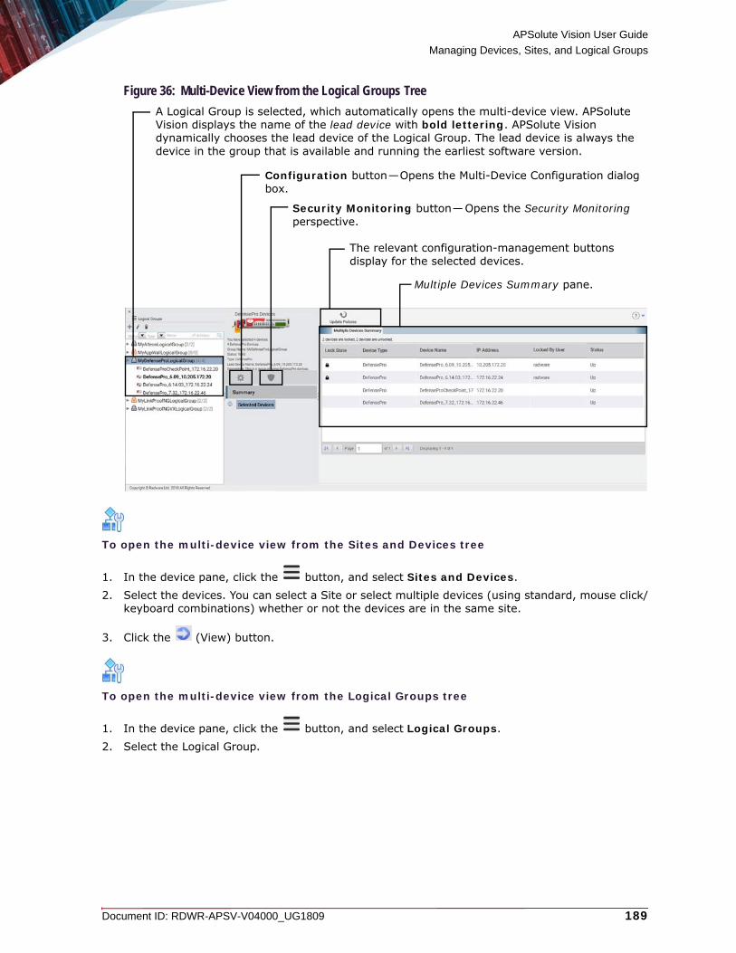
APSolute Vision User Guide
Managing Devices, Sites, and Logical Groups
Document ID: RDWR-APSV-V04000_UG1809 189
Figure 36: Multi-Device View from the Logical Groups Tree
To open the multi-device view from the Sites and Devices tree
1. In the device pane, click the button, and select Sites and Devices.2. Select the devices. You can select a Site or select multiple devices (using standard, mouse click/
keyboard combinations) whether or not the devices are in the same site.
3. Click the (View) button.
To open the multi-device view from the Logical Groups tree
1. In the device pane, click the button, and select Logical Groups.2. Select the Logical Group.
Multiple Devices Summary pane.
Configuration button—Opens the Multi-Device Configuration dialog box.
Security Monitoring button—Opens the Security Monitoring perspective.
The relevant configuration-management buttons display for the selected devices.
A Logical Group is selected, which automatically opens the multi-device view. APSolute Vision displays the name of the lead device with bold lettering. APSolute Vision dynamically chooses the lead device of the Logical Group. The lead device is always the device in the group that is available and running the earliest software version.

APSolute Vision User Guide
Managing Devices, Sites, and Logical Groups
190 Document ID: RDWR-APSV-V04000_UG1809
Using Logical Groups of DevicesThis section contains the following main topics: • Logical Groups—General Information, page 190• Logical Group User Interface, page 191• Managing Logical Groups, page 192
Logical Groups—General InformationA Logical Group is a user-defined group of one or more devices of the same device type.To be valid, a Logical Device group must contain at least one accessible device, and all the devices in the group must be the same device type.The devices in a Logical Group do not need to be running the same software version.The same device can exist in more than one Logical Group.You can use a Logical Group to help you perform the following:• Define the scope of APSolute Vision users—The Scope value of a user’s RBAC role/scope
pair can be a Logical Group. The user’s scope dynamically updates, according to the devices in the Logical Group. That is, when the device-set of a Logical Group changes, the user’s scope changes accordingly. For more information, see Role-Based Access Control (RBAC), page 68 and Rules for RBAC Permission Conflicts with Logical Groups, page 77.
• Manage multiple devices simultaneously—When you configure the devices in a Logical Group, you use the multi-device view (see Using the Multi-Device View and the Multiple Devices Summary, page 187) to do the following:— View the Multiple Devices Summary table. The table contains all the relevant devices
and comprises the following columns: Lock State, Device Type, Device Name, IP Address, Locked by User, and Status.
— Lock multiple devices to configure them.— Make configuration changes to the lead device and apply the changes to the other
devices in the Logical Group—APSolute Vision dynamically chooses the lead device of the Logical Group. The lead device is always the device in the group that is available, and running the earliest software version. APSolute Vision displays the name of the lead device with bold lettering. After you make a valid change and click Submit All, APSolute Vision attempts to change the value for the submitted parameters on the lead device and all the other devices in the Logical Group. APSolute Vision submits only modified values; APSolute Vision does not submit values that were not modified. For more information, see Configuring Multiple Devices, page 196.
— Run configuration-management actions for the relevant devices—You can run the Apply or Revert actions on Alteon or LinkProof NG devices. You can run the Update Policies action on multiple DefensePro devices.
— Open the Security Monitoring perspective—In the multi-device view, the Security Monitoring perspective displays the Dashboard View and Traffic Utilization tabs—with the data aggregated for all the selected devices.
• Specify devices for scheduled tasks—In addition to selecting individual devices, you can specify one or more relevant Logical Groups. For more information on scheduled tasks, see Scheduling APSolute Vision and Device Tasks, page 287.
• Specify devices for Operator Toolbox scripts—In addition to selecting individual devices, you can specify one or more relevant Logical Groups. For more information, see Using and Managing Toolbox Scripts, page 211.
• Specify devices for sending or deleting DefensePro configuration templates—In addition to selecting individual devices, you can specify one or more Logical Groups of DefensePro devices. For more information on DefensePro configuration templates, see Using DefensePro Templates, page 240.

APSolute Vision User Guide
Managing Devices, Sites, and Logical Groups
Document ID: RDWR-APSV-V04000_UG1809 191
• Specify devices for Alert Profile—In addition to selecting individual devices, you can specify one or more relevant Logical Groups. For more information on the Alert Profiles, see Managing Alert Profiles, page 122.
• Specify devices for the Alerts Table Filter—In addition to selecting individual devices, you can specify one or more relevant Logical Groups. For more information on the Alerts Filter, see Filtering Alerts, page 316.
• Specify devices for REST API operations—For information on the REST API, see the APSolute Vision REST API documentation.
Logical Group User InterfaceThe user interface for existing Logical Groups comprises the following: • The Logical Groups tree in the device pane and the popup displays information for each Logical
Group node.• The multi-device view, which is displayed when you click a Logical Group node in the Logical
Groups tree. For more information, see Using the Multi-Device View and the Multiple Devices Summary, page 187.
Figure 37: Device Pane (Not Docked)—Showing the Logical Groups Tree
Note: For information on filtering the display of the tree, see Filtering Entities in the Device Pane, page 7.
Docks the device pane.
Minimizes the docked device pane.
APSolute Vision displays the name of the lead device with bold lettering. APSolute Vision dynamically chooses the lead device of the Logical Group. The lead device is always the device in the group that is available and running the earliest software version.
Controls for filtering the devices that the pane displays. APSolute Vision appends the number of devices matching the filter.
The button that selects the device-pane tree (Sites and Devices, Physical Containers, or Logical Groups) and the name of the tree that is displayed now.
Identifies an invalid Logical Group.
Identifies a valid Logical Group.

APSolute Vision User Guide
Managing Devices, Sites, and Logical Groups
192 Document ID: RDWR-APSV-V04000_UG1809
When you hover over a Logical Group node in the device pane, a popup displays the following parameters:• Group Name—The user-defined name of the Logical Group.• Status—The status of the group: Valid or Invalid. • Invalid Reason (displayed only when Status is Invalid)—The reason that the Logical Group is
invalid.• Type—The device type of the group, that is: Alteon, AppWall, DefensePro, or LinkProof
NG.• Lead Device Name—The name of the lead device of the Logical Group, select the lead device—
that is, the device whose configuration changes will be applied to the select devices.• Description—The user-defined description of the Logical Group.
Figure 38: Popup for Logical Group Node in the Device Pane
Managing Logical GroupsOnly users with a proper RBAC roles can manage Logical Groups (Administrator, Vision Administrator, and System User).To be valid, a Logical Device group must contain at least one accessible device, and all the devices in the group must be the same device type.You can create a new Logical Group in any of the three trees that the device pane can display. However, you cannot modify Logical Groups in the device pane Sites and Devices tree or Physical Containers tree.
Caution: With RADIUS or TACACS+ authentication, if a user definition explicitly mentions the name of a Logical Group and the Logical Group name changes, the user definition in the RADIUS or TACACS+ server must be updated accordingly.
If the name of Logical Group changes and APSolute Vision authenticates the users locally, APSolute Vision updates the relevant scopes for the users.In the device pane Logical Groups tree, you can configure and modify Logical Groups.
To configure a Logical Group from the Logical Groups tree
1. In the device pane, click the button, and select Logical Groups.2. Do one of the following:
— To create a new Logical Group, click the (Add) button.
— To edit a Logical Group, select the Logical Group node and click the (Edit) button.3. Configure the parameters, and click Submit.

APSolute Vision User Guide
Managing Devices, Sites, and Logical Groups
Document ID: RDWR-APSV-V04000_UG1809 193
In the device pane Sites and Devices tree and Physical Containers tree, you can select devices and create a new Logical Group.
To create a new Logical Group from the Sites and Devices tree or Physical Containers tree
1. In the device pane, click the button, and select Sites and Devices or Physical Containers.
2. In the Sites and Devices or Physical Containers tree, select the devices, which must be of the same type. You can select multiple devices (using standard, mouse click/keyboard combinations) whether or not the devices are in the same Site.
3. Click the (Add Group) button.
4. Configure the parameters, and click Submit.
Table 72: Logical Groups Parameters
Parameter DescriptionType The device type. When you are creating a new Logical Group, the Type value
determines the devices that the Device lists display. When you are editing a Logical Group, the Type value is read-only.Values: • Alteon• AppWall• DefensePro• LinkProof NGDefault: Alteon
Name The name of the Logical Group.Maximum characters: 255
Devices The Available list and the Selected list. The Available list displays the available devices. The Selected list displays the devices in the Logical Group.
Description The description of the Logical Group.Maximum characters: 255
Table 73: Logical Groups Parameters
Parameter DescriptionType (Read-only) The device type.
Name The name of the Logical Group.Maximum characters: 255
Devices The Available list and the Selected list. The Available list displays the available devices. The Selected list displays the devices in the Logical Group.
Description The description of the Logical Group.Maximum characters: 255
APSolute Vision User Guide
Managing Devices, Sites, and Logical Groups
194 Document ID: RDWR-APSV-V04000_UG1809
You cannot delete a Logical Group if it is the used in a user role-scope pair.
To delete a Logical Group
1. In the device pane, click the button, and select Logical Groups.
2. In the device pane Logical Groups tree, click the Logical Group node, and click the (Delete) button.
3. Click Yes in the confirmation box. The Logical Group is deleted from the Logical Groups tree.
After You Set Up Your Managed DevicesAfter you set up your network of managed devices, and establish a connection to the devices, APSolute Vision obtains the network configuration and displays the settings in the device configuration tabs.You can then do the following:• Set and change the device configuration through APSolute Vision.• Perform administration and maintenance tasks on managed devices such as scheduling tasks,
making backups, and so on.• Monitor managed devices through APSolute Vision.
Note: For information about configuring Radware devices through APSolute Vision, see the APSolute Vision online help.

Document ID: RDWR-APSV-V04000_UG1809 195
CHAPTER 6 – MANAGING DEVICE OPERATIONS AND MAINTENANCE
This section describes the following: • Rebooting and Shutting Down Managed Devices, page 195• Configuring Multiple Devices, page 196• Using the Diff Feature, page 198• Device-Configuration Management (Global Commands) for Alteon and LinkProof NG, page 199• Upgrading DefensePro Device Software, page 202• Downloading a DefensePro Log File to the APSolute Vision Client, page 203• Managing a Radware Signature File or Fraud Signature File in DefensePro Devices, page 204• Downloading a DefensePro Technical Support File, page 206• Managing DefensePro Configurations, page 206• Updating DefensePro Policy Configurations, page 209
Note: For information about other topics that are related to managing device operations, see the chapter Using the Toolbox, page 211, which contains the following:• Using and Managing Toolbox Scripts, page 211• Using DefensePro Templates, page 240• Using AppShape Templates and Instances, page 248
Rebooting and Shutting Down Managed DevicesYou can activate a device reboot (reset) or device shutdown from APSolute Vision.Some configuration changes on the device require a device reboot for the configuration to take effect. You can activate the device reboot from APSolute Vision.
Caution: For Alteon and LinkProof NG:
• Reset causes failover of the ADC, which might cause an interruption in network service.• If possible, synchronize the configuration before you reset the system.
• Configuration changes that have not been applied will be lost. Run the Diff command to view the changes that have not been applied, and then, run the Apply command as needed.
• Configuration changes that have not been saved will be lost. Run the Diff Flash command to view the changes that have not been saved, and then, run the Save command as needed.
• The spanning tree will be restarted, which will likely cause an interruption in network service.
Note: You can schedule device reboots in the APSolute Vision scheduler. For more information, see Managing Tasks in the Scheduler, page 288.

APSolute Vision User Guide
Managing Device Operations and Maintenance
196 Document ID: RDWR-APSV-V04000_UG1809
To reboot a device
1. Lock the device.
2. In the Properties pane, click the (On-Off) button, which is part of the device picture.
3. Select Reset.
To shut down a device
1. Lock the device.
2. In the Properties pane, click the (On-Off) button, which is part of the device picture.
3. Select Shut Down.
Configuring Multiple DevicesUse the Multi-Device Configuration feature to make changes to multiple devices.You can use the Multi-Device Configuration feature in the following ways:• Using a Logical Group. The devices in Logical Group are of the same type, but may run different
software versions. For more information on Logical Groups, see Using Logical Groups of Devices, page 190.
• Selecting a site or multiple devices from the Sites and Clusters tree or the Physical Containers tree. The devices must be of the same type and same major version. You can select devices from different Sites. For more information, see Configuring Sites, page 162.
To configure multiple devices using a Logical Group
1. In the device pane, open the Logical Groups tree, and click the Logical Group. The Multi-Device View opens.
Note: For more information, see Using the Multi-Device View and the Multiple Devices Summary, page 187.
2. Click the (Configuration) button. The configuration GUI of the lead device opens.
Notes
— The tabs of the configuration GUI include the Summary tab, which comprises the Multi-Device View.
— The lead device is the device whose configuration changes will be applied to the selected additional devices. For more information on the lead device of a Logical Group, see Using Logical Groups of Devices, page 190.
3. Lock the devices if necessary.

APSolute Vision User Guide
Managing Device Operations and Maintenance
Document ID: RDWR-APSV-V04000_UG1809 197
4. Make a required change in the GUI of the lead device.
5. After you make a valid change, click Submit All. APSolute Vision attempts to change the value for the submitted parameter on the lead device and all the other devices in the Logical Group.
Notes
— APSolute Vision submits only modified values. APSolute Vision does not submit values that were not modified.
— APSolute Vision issues detailed message for unsuccessful attempts to change the value of a parameter on other devices in the Logical Group.
6. Repeat step 4 and step 5 as necessary.
To configure the multiple devices by selecting a site or multiple devices
1. In the device pane, open the Sites and Clusters tree or the Physical Containers tree, and select the devices. You can select a site or select multiple devices (using standard, mouse click/keyboard combinations) whether or not the devices are in the same site.
2. Click the (View) button.
3. Click the (Configuration) button. The Multi-Device Configuration dialog box opens.
Note: The top table, which you can filter, contains all the selected devices and comprises the following columns: Device Type, Device Name, IP Address, and Version.
4. From the top table, select the lead device—that is, the device whose configuration changes will be applied to the selected additional devices. The bottom table, which you can filter, displays the selected devices of the same type and major version.
5. From the bottom table, select the checkbox next to each device that the lead device will try to change.
6. Click Go. The GUI of the lead device opens. The device pane shows the lead device and the selected additional devices as selected.
7. Lock the devices if necessary.
8. Make a required change in the GUI of the lead device.
9. After you make a valid change, click Submit All. APSolute Vision attempts to change the value for the submitted parameter on the lead device and all the selected additional devices.
Notes
— APSolute Vision submits only modified values. APSolute Vision does not submit values that were not modified.
— APSolute Vision issues detailed message for unsuccessful attempts to change the value of a parameter on selected additional devices.
10. Repeat step 8 and step 9 as necessary.

APSolute Vision User Guide
Managing Device Operations and Maintenance
198 Document ID: RDWR-APSV-V04000_UG1809
Using the Diff Feature
Click the (Diff) button to run the following commands on a single selected device:• Compare (Alteon, DefensePro, and LinkProof NG only)—Compares the configuration of the
selected device with one of the following: — Other Device Running Configuration—That is, another device of the same type and
major version— Backup File from System—That is, a device-configuration backup file stored on the
APSolute Vision server— Backup File from Local File System—That is, a device-configuration backup file stored on
the local file systemThe Compare action displays differences in the configurations using a green background for the configuration of the first device and red background for the configuration of the other device.
• Diff (Alteon and LinkProof NG only)—Collects the pending configuration changes.• Diff Flash (Alteon and LinkProof NG only)—Collects the pending configuration changes and the
affected configuration stored in flash memory on the device.
Figure 39: Diff Feature (Displaying Options for Alteon)
Click the (Save to File) button to save the results to a specified location.
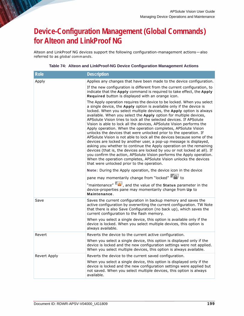
APSolute Vision User Guide
Managing Device Operations and Maintenance
Document ID: RDWR-APSV-V04000_UG1809 199
Device-Configuration Management (Global Commands) for Alteon and LinkProof NGAlteon and LinkProof NG devices support the following configuration-management actions—also referred to as global commands.
Table 74: Alteon and LinkProof-NG Device Configuration Management Actions
Role DescriptionApply Applies any changes that have been made to the device configuration.
If the new configuration is different from the current configuration, to indicate that the Apply command is required to take effect, the Apply Required button is displayed with an orange icon.The Apply operation requires the device to be locked. When you select a single device, the Apply option is available only if the device is locked. When you select multiple devices, the Apply option is always available. When you select the Apply option for multiple devices, APSolute Vision tries to lock all the selected devices. If APSolute Vision is able to lock all the devices, APSolute Vision performs the Apply operation. When the operation completes, APSolute Vision unlocks the devices that were unlocked prior to the operation. If APSolute Vision is not able to lock all the devices because some of the devices are locked by another user, a pop-up message is displayed, asking you whether to continue the Apply operation on the remaining devices (that is, the devices are locked by you or not locked at all). If you confirm the action, APSolute Vision performs the Apply operation. When the operation completes, APSolute Vision unlocks the devices that were unlocked prior to the operation.
Note: During the Apply operation, the device icon in the device
pane may momentarily change from “locked” to
“maintenance” , and the value of the Status parameter in the device-properties pane may momentarily change from Up to Maintenance.
Save Saves the current configuration in backup memory and saves the active configuration by overwriting the current configuration. TW Note that there is also Save Configuration (no back up), which saves the current configuration to the flash memory.When you select a single device, this option is available only if the device is locked. When you select multiple devices, this option is always available.
Revert Reverts the device to the current active configuration.When you select a single device, this option is displayed only if the device is locked and the new configuration settings were not applied. When you select multiple devices, this option is always available.
Revert Apply Reverts the device to the current saved configuration.When you select a single device, this option is displayed only if the device is locked and the new configuration settings were applied but not saved. When you select multiple devices, this option is always available.

APSolute Vision User Guide
Managing Device Operations and Maintenance
200 Document ID: RDWR-APSV-V04000_UG1809
To perform a configuration-management action on a single device
1. From the device pane, select the device name.2. Click the required button. The Diff Flash option is available when you click the Diff button. The
Revert Apply option is available when you click the arrow next to the Revert icon.
Figure 40: Apply (Required) and Save (Required) Buttons
Figure 41: Revert Button—Arrow Clicked Shows Revert and Revert Apply Options
Diff Collects the pending configuration changes. You can view, save, and copy the text when you double-click the associated message in the Alerts tab in the Alerts pane.When you select multiple devices, this option is not supported.
Note: For more information, see Using the Diff Feature, page 198.
Diff Flash Collects the pending configuration changes and the affected configuration stored in flash memory on the device. You can view, save, and copy the text when you double-click the associated message in the Alerts tab in the Alerts pane. When you select multiple devices, this option is not supported.
Note: For more information, see Using the Diff Feature, page 198.
Dump Collects a dump of the current device configuration. You can view, save, and copy the text when you double-click the associated message in the Alerts tab in the Alerts pane.When you select multiple devices, this option is not supported.
Table 74: Alteon and LinkProof-NG Device Configuration Management Actions (cont.)
Role Description

APSolute Vision User Guide
Managing Device Operations and Maintenance
Document ID: RDWR-APSV-V04000_UG1809 201
Figure 42: Diff Button—Clicked Displays Compare, Diff, and Diff Flash Options
Figure 43: Dump Button—Clicked

APSolute Vision User Guide
Managing Device Operations and Maintenance
202 Document ID: RDWR-APSV-V04000_UG1809
Upgrading DefensePro Device SoftwareYou can upgrade the software version on DefensePro devices from APSolute Vision.A device upgrade enables the new features and functions on the device without altering the existing configuration. In exceptional circumstances, new software versions are incompatible with legacy configuration files from earlier software versions. This most often occurs when attempting to upgrade from a very old version to the most recently available version.The software version file must be located on the APSolute Vision client system. APSolute Vision transfers the file, over HTTPS, to the APSolute Vision server and uploads it to the device.For a maintenance-only upgrade, a password is not required.New software versions require a password. APSolute Vision can generate a new password automatically, if the device has a valid support agreement. Alternatively, you can obtain the password from the Radware corporate Web site and enter the password manually.After the device upgrade is complete, you must reboot the device.
Caution: Before upgrading to a newer software version, do the following:
• Back up the existing configuration file. For more information, see Downloading a Device-Configuration File, page 627.
• Ensure that you have configured on the device the authentication details for the protocol used to upload the file.
Note: If the DefensePro platform is very far away from the machine with the upgrade file, software upgrade may take a very long time. Besides distance, the line quality may further increase the upgrade time. Long upgrade time may be more common in DefensePro version-8.x platforms, because of the significantly larger size of the upgrade file.
To update the device software version
1. In the device pane, select the device.
2. Click the arrow next to the Operations icon ( ).
3. Select Update Software Versions.
4. Configure software upgrade parameters, and click Update.
5. When the device upgrade is complete, reboot the device.
Table 75: Software Upgrade Parameters
Parameter DescriptionBrowse for File The name of the file to upload.
Software Version The software version number as specified in the new software documentation.

APSolute Vision User Guide
Managing Device Operations and Maintenance
Document ID: RDWR-APSV-V04000_UG1809 203
Downloading a DefensePro Log File to the APSolute Vision ClientYou can download a log file to the APSolute Vision system. DefensePro automatically generates a log file, which contains a report of configuration errors.
To download a device log file
1. In the device pane, select the device.
2. Click the arrow next to the Operations icon ( ).
3. Click Export Configuration Log File.
4. Configure the download parameters, and click Submit.
Generate Password Automatically Specifies whether APSolute Vision generates the password automatically—after verifying that the device has a valid support agreement.Default: Enabled
Caution: The functionality of the Generate Password Automatically button requires connectivity to radware.com or the proxy server that is configured in the APSolute Vision settings (APSolute Vision Settings view System perspective, General Settings > Connectivity > Proxy Server Parameters).
Password(This parameter is available only when the Generate Password Automatically checkbox is cleared.)
The password received with the new software version. The password is case sensitive.
Confirm Password(This parameter is available only when the Generate Password Automatically checkbox is cleared.)
The password received with the new software version. The password is case sensitive.
Browse for File The name of the file to upload.
Caution: You must use the original filename.
Table 75: Software Upgrade Parameters (cont.)
Parameter Description

APSolute Vision User Guide
Managing Device Operations and Maintenance
204 Document ID: RDWR-APSV-V04000_UG1809
Managing a Radware Signature File or Fraud Signature File in DefensePro DevicesYou can upload an updated Radware signature file or fraud signature file to a DefensePro device.Uploading an updated fraud signature file is relevant only for DefensePro 6.x versions and 7.x versions 7.42.09 and later.In DefensePro 6.x versions 6.14.07 and later and 7.x versions 7.42.08 and later, you can also roll the signature file back to the previous version that was loaded on the device.
Note: A signature file on a DefensePro device may also be referred to as the attack database.You can upload an updated Radware signature file to a DefensePro device from the following sources:• Radware.com or the proxy file server that is configured in the APSolute Vision
settings—The Alerts pane displays a success or failure notification and whether the operation was performed using a proxy server. The configuration of the proxy server in the APSolute Vision Settings view System perspective, under General Settings > Connectivity > Proxy Server Parameters.
• APSolute Vision client system—The name of the signature file must be one of the following:
— <Device-MAC-address>.sig—For DefensePro physical platforms.
— <Device-IP-address>.sig—For DefensePro virtual platforms.
Caution: Updating the signature file consumes large amounts of resources, which may cause the device to go temporarily into an overload state. Radware recommends updating the signature file during hours of low activity.
Tip: You can schedule signature-file updates in the APSolute Vision scheduler. For more information, see Managing Tasks in the Scheduler, page 288.
To update the signature file of a device
1. In the device pane, select the device.
2. Click the arrow next to the Operations icon ( ).
3. Select Update Security Signatures.
4. Configure the parameters, and click Update.

APSolute Vision User Guide
Managing Device Operations and Maintenance
Document ID: RDWR-APSV-V04000_UG1809 205
Rolling Back the Signature FileThis feature is supported only in DefensePro 6.x versions 6.14.07 and later and 7.x versions 7.42.08 and later.When the signature file on a DefensePro device gets updated, DefensePro stores the previous version. Use the Roll Back command to roll the signature file back to the previous version that was loaded on the device. You may require this command if you encounter an error after a signature-file update, a corrupted signature file, and so on.
Note: A signature file on a DefensePro device may also be referred to as the attack database.
To roll the signature file on the device back to the previous version
1. In the device pane, select the device.
2. Click the arrow next to the Operations icon ( ).
3. Select Update Security Signatures.
4. Click Roll Back.
Table 76: Update Device Signature File Parameters for DefensePro
Parameter DescriptionSignature Type The type of the signature file to upload to the device.
Values:• Radware Signatures• Fraud Signatures
Note: You can select Fraud Signatures only on DefensePro version-6.x devices that have Fraud Protection enabled, and version-7.x devices with version 7.42.09 and later that have Fraud Protection enabled.
Update From The location of the signature file to upload.Values:• Radware.com—APSolute Vision uploads the signature file directly
from Radware.com or from the proxy server that is configured in the Vision Server Connection configuration.
• Client—APSolute Vision uploads the signature file from the APSolute Vision client system. This option is only available for Radware signatures.
File Name (This parameter is displayed only when Update From Client is selected)
Name of the signature file on the client system.

APSolute Vision User Guide
Managing Device Operations and Maintenance
206 Document ID: RDWR-APSV-V04000_UG1809
Downloading a DefensePro Technical Support FileFor debugging purposes, a DefensePro device can generate a TAR file containing the technical information that Radware Technical Support requires. The file includes output of various CLI commands, for example, a printout of the Client table.You can download a DefensePro technical support file and send it to Radware Technical Support.
Note: You can also download a DefensePro technical support file using the DefensePro CLI. For more information, see the DefensePro User Guide.Use the following procedure to download a technical support file using APSolute Vision.
To download a technical support file using APSolute Vision
1. In the device pane, select the device.
2. Click the arrow next to the Operations icon ( ).
3. Select Export Technical Support File.
4. Configure the download parameters, and click Submit.
Managing DefensePro ConfigurationsThis section describes how to manage configurations of the DefensePro devices that are managed on the APSolute Vision server.
DefensePro Configuration File ContentThe configuration file content is divided into two sections:• Commands that require rebooting the device—These include BWM Application
Classification Mode, Application Security status, Operation Mode, tuning parameters, and so on. Copying and pasting a command from this section takes effect only after the device is rebooted. The section has the heading: The following commands will take effect only once the device has been rebooted!
• Commands that do not require rebooting the device—Copying and pasting a command from this section takes effect immediately after pasting. The commands in the section are not bound to SNMP. The section has the heading: The following commands take effect immediately upon execution!
The commands are printed within each section—in the order of implementation.
Table 77: Device Technical Support File Download Parameters
Parameter DescriptionDownload Via (Read-only) The protocol used to download the technical support file.
Value: HTTPS
Save As Save the downloaded technical support file as a text file on the APSolute Vision system. Enter or browse to the location of the saved file, and select or enter a file name.

APSolute Vision User Guide
Managing Device Operations and Maintenance
Document ID: RDWR-APSV-V04000_UG1809 207
At the end of the file, the device prints the signature of the configuration file. This signature is used to verify the authenticity of the file and that it has not been corrupted. The signature is validated each time the configuration file is uploaded to the device. If the validity check fails, the device accepts the configuration, but a notification is sent to the user that the configuration file has been tampered with and there is no guarantee that it works. The signature looks like File Signature: 063390ed2ce0e9dfc98c78266a90a7e4.
Downloading a Device-Configuration FileYou can download a configuration file from a managed device to APSolute Vision, for backup. If you choose to download to the APSolute Vision server, a copy is always saved in the APSolute Vision database.By default, you can save up to five (5) configuration files per device on the APSolute Vision server. You can change this number in the APSolute Vision Setup page—up to a maximum of 10. When the limit is reached, you are prompted to delete the oldest file. For more information, see Configuring APSolute Vision Server Advanced Parameters, page 151.
Note: You can schedule configuration file backups in the APSolute Vision scheduler. For more information, see Managing Tasks in the Scheduler, page 288.
To download a device-configuration file
1. In the device pane, select the device.
2. Click the arrow next to the Operations icon ( ).
3. Select Export Configuration File.
4. Configure the download parameters, and then, click OK.
Table 78: Device Configuration File Download Parameters
Parameter DescriptionDestination The destination of the device configuration file.
Values: Client, Server
Include Private Keys Specifies whether the certificate private key information is included in the downloaded file.Default: Disabled
Passphrase(This parameter is available only in DefensePro 8.x versions 8.14 and later and only when the Include Private Keys checkbox is selected.)
The user-defined passphrase for the encryption of the private keys.Minimum characters: 4Maximum characters: 64

APSolute Vision User Guide
Managing Device Operations and Maintenance
208 Document ID: RDWR-APSV-V04000_UG1809
Restoring a Device ConfigurationYou can restore a DefensePro or DefenseFlow configuration from a backup configuration file on the APSolute Vision server or client system to the DefensePro or DefenseFlow device. When you upload the configuration file to the device, it overwrites the existing device configuration.After the restore operation is complete, you must reboot the device.
Caution: Importing a configuration file that has been edited is not supported.
Caution: Importing a configuration file from a different version is not supported.
To restore a device’s configuration
1. In the device pane, select the device.
2. Click the arrow next to the Operations icon ( ).
3. Click Import Configuration File.
4. Configure upload parameters, and then, do one of the following:
— If you select Upload From Client, click Import.— If you select Upload From Server, click Update.
5. When the upload completes, reboot the device.
Confirm Passphrase(This parameter is available only in DefensePro 8.x versions 8.14 and later and only when the Include Private Keys checkbox is selected.)
The user-defined passphrase for the encryption of the private keys.Minimum characters: 4Maximum characters: 64
Save As(This parameter is displayed only when Destination is Server.)
On the server, the default name is a combination of the device name and backup date and time. You can change the default name.
Table 79: Device Configuration File Upload Parameters
Parameter DescriptionUpload From The location of the backup device-configuration file to send.
Values: Client, Server
Table 78: Device Configuration File Download Parameters (cont.)
Parameter Description

APSolute Vision User Guide
Managing Device Operations and Maintenance
Document ID: RDWR-APSV-V04000_UG1809 209
Updating DefensePro Policy ConfigurationsYou can apply the following configuration changes to a DefensePro device in a single operation:• Network Protection policy• Server Protection policy • ACL policy• White list• Black list• Classes
To update policy configurations on a DefensePro device
> In the device pane, select the device, and then, click Update Policies ( ).
File Name (This parameter is available only when Upload From is Client.)
When uploading from the computer running the APSolute Vision client— that is, the browser, enter or browse to the name of the configuration file to upload.
File for Upload(This parameter is available only when Upload From is Server.)
When uploading from the APSolute Vision server, select the configuration to upload.
Passphrase(This parameter is available only in DefensePro 8.x versions 8.14 and later.)
The passphrase for the decryption of the private keys—if a passphrase was used to encrypt the file when it was exported (see Downloading a Device-Configuration File, page 207).Minimum characters: 4Maximum characters: 64
Table 79: Device Configuration File Upload Parameters (cont.)
Parameter Description

APSolute Vision User Guide
Managing Device Operations and Maintenance
210 Document ID: RDWR-APSV-V04000_UG1809

Document ID: RDWR-APSV-V04000_UG1809 211
CHAPTER 7 – USING THE TOOLBOX
This chapter contains the following main sections:• Using and Managing Toolbox Scripts, page 211• Using DefensePro Templates, page 240• Using AppShape Templates and Instances, page 248
Using and Managing Toolbox ScriptsThe following sections describe using and managing Toolbox scripts:• Toolbox Scripts—Basics, page 211• Managing and Customizing Panels in the Toolbox Dashboard, page 214• User Roles and Toolbox Scripts, page 216• vDirect and vDirect Access to Devices, page 216• Prerequisites for Target Devices of Toolbox Scripts, page 216• Predefined Toolbox Scripts, page 217• Device Locking and Toolbox Scripts, page 227• Running Scripts, page 227• Managing Toolbox Scripts, page 233• Writing and Editing Toolbox Scripts, page 237
Toolbox Scripts—BasicsUse Toolbox scripts to automate common tasks on managed Alteon, DefensePro, and LinkProof NG devices.When you run a script, you configure the target devices and, if required, configure parameters.When you specify the target devices for a script—that is, configure the Target Device List, you can select individual devices or Logical Groups of devices. When you select a Logical Group, the effective Target Device List dynamically updates, according to the devices in the Logical Group. That is, when the device-set of a Logical Group changes, the effective Target Device List changes accordingly. For more information, see Using Logical Groups of Devices, page 190.You can run a Toolbox script in the following ways:• From the Toolbox dashboard• From a device toolbar• From the Operator Toolbox pane from the Advanced Toolbox tree• Using an Operator Toolbox scheduled task.
The APSolute Vision installation includes many predefined Toolbox scripts, which are for routine tasks on managed devices. By default, the Toolbox dashboard contains most of the predefined Toolbox scripts and displays the scripts that are relevant to your role. For more information, see Predefined Toolbox Scripts, page 217.The configuration of each script includes the RBAC roles that are permitted to run the script. For more information, see User Roles and Toolbox Scripts, page 216.
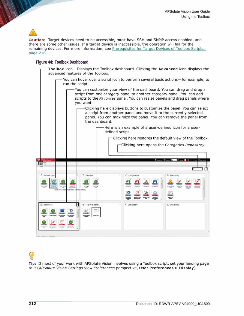
APSolute Vision User Guide
Using the Toolbox
212 Document ID: RDWR-APSV-V04000_UG1809
Caution: Target devices need to be accessible, must have SSH and SNMP access enabled, and there are some other issues. If a target device is inaccessible, the operation will fail for the remaining devices. For more information, see Prerequisites for Target Devices of Toolbox Scripts, page 216.
Figure 44: Toolbox Dashboard
Tip: If most of your work with APSolute Vision involves using a Toolbox script, set your landing page to it (APSolute Vision Settings view Preferences perspective, User Preferences > Display).
You can hover over a script icon to perform several basic actions—for example, to run the script.
Clicking here displays buttons to customize the panel. You can select a script from another panel and move it to the currently selected panel. You can maximize the panel. You can remove the panel from the dashboard.
Here is an example of a user-defined icon for a user-defined script.
You can customize your view of the dashboard. You can drag and drop a script from one category panel to another category panel. You can add scripts to the Favorites panel. You can resize panels and drag panels where you want.
Toolbox icon—Displays the Toolbox dashboard. Clicking the Advanced icon displays the advanced features of the Toolbox.
Clicking here restores the default view of the Toolbox.
Clicking here opens the Categories Repository.

APSolute Vision User Guide
Using the Toolbox
Document ID: RDWR-APSV-V04000_UG1809 213
Hovering over a script icon displays buttons to do the following:• Configure a scheduled task to run the script. For more information, see the procedure To
configure a scheduled task for a script from the Toolbox dashboard, page 231.• Remove the script from your view of the dashboard.• Run the script. For more information, see the procedure To run a Toolbox script from the
Toolbox dashboard, page 228.• Run the script the last configuration.
Figure 45: Hovering Over a Script Icon
Clicking the button in the top-right corner of a category panel displays buttons to do the following:• Select a script in another panel and move it to the currently selected panel• Maximize the panel• Remove the panel from the dashboard
Note: You can return the category panel to the dashboard display using the Categories Repository. Clicking Restore Default View restores all the panels and removes all other modifications to the dashboard.
Figure 46: Category-Panel-Display Buttons
In the Categories Repository, you can select which category panels the Toolbox dashboard displays.
Figure 47: Categories Repository
APSolute Vision User Guide
Using the Toolbox
214 Document ID: RDWR-APSV-V04000_UG1809
Managing and Customizing Panels in the Toolbox DashboardYou can manage and customize contents of the panels in the Toolbox dashboard.The Toolbox dashboard displays the following panels:• Recently Used• Favorites • The following category panels:
— Configuration— Data Export— Emergency— High Availability— Monitoring— Operations
The Recently Used panel contains up to six scripts that you have used most recently. APSolute Vision populates the panel on a first-in-first-out basis but with weight on the number of uses. For example, if you used a script, Script_A, 10 times and other scripts fewer times, Script_A will be the last one that APSolute Vision removes, even if Script_A was the first one that APSolute Vision added to the panel.The Favorites panel contains your favorite scripts. You can drag and drop a script from a category panel to the Favorites panel. You can add one or multiple scripts from category panels to the Favorites panel. You can delete scripts from the Favorites panel as you wish.The contents of the Recently Used and Favorites panels in the Toolbox dashboard are per user, per browser, and per machine.
Caution: If you delete the data from the browser, the contents of the Recently Used and Favorites panels revert to the default display.
You can manage the contents of the category panels, but there are some logical restrictions. You can drag and drop a script from one category panel to another category panel or to the Favorites panel. You can also select a script in another category panel, or an Unassigned script, and move it to the currently selected panel (see the procedure To add one or multiple scripts to a panel in the Toolbox dashboard, page 215). A Toolbox script can exist in only one category panel. The Toolbox dashboard can, however, display a script in a category panel and also in the Recently Used and/or Favorites panels.
Caution: The contents of the category panels in the Toolbox dashboard are stored on the APSolute Vision server. If you move a script to another category panel, the Category field changes accordingly (see Category in Configuring a Toolbox Script in APSolute Vision, page 235), and other users will see that script in the panel to which you moved that script. If you delete a script from a category panel, the Category field changes to Unassigned, and users will not see that script in the Toolbox dashboard anymore. However, it is possible to return the script to the Toolbox dashboard using the Add Script dialog box.
Use the Add Scripts dialog box to add one or multiple scripts to a panel in the Toolbox dashboard.

APSolute Vision User Guide
Using the Toolbox
Document ID: RDWR-APSV-V04000_UG1809 215
Figure 48: Add Scripts Dialog Box
To add one or multiple scripts to a panel in the Toolbox dashboard
1. Click Toolbox ( ). The Toolbox dashboard opens.
2. In the top-right corner of a panel to which you want to add scripts, click the button and then
the button. The Add Scripts dialog box opens.
3. Do the following as convenient:
— Expand or collapse the category headings.— Type a string in text box to show only the matching script names.
4. Select the required scripts (using standard Windows key combinations), and click Select.
To delete a script from the Toolbox dashboard
1. Click Toolbox ( ). The Toolbox dashboard opens.
2. Hover over the required script and click the button.
The Unassigned category contains the scripts in the APSolute Vision server with the Category value Unassigned. Here, the category list is expanded, and it contains an example of a user-defined icon for a user-defined script.
Type a string in this box to show only the matching script names.
The Add Scripts dialog box displays only the categories that are populated. Here, the category lists are collapsed.

APSolute Vision User Guide
Using the Toolbox
216 Document ID: RDWR-APSV-V04000_UG1809
User Roles and Toolbox ScriptsThe configuration of each script includes the RBAC roles that are permitted to run the script. Users may run a script from the Toolbox dashboard or a device toolbar. The Operator Toolbox node in the Advanced Toolbox tree (for managing scripts) is available only to users with the Administrator or Vision Administrator roles. For more information, see Role-Based Access Control (RBAC), page 68.Users with the Administrator, Vision Administrator, or System User roles can run and manage Toolbox scripts in APSolute Vision. This includes adding scripts to the APSolute Vision server, modifying script properties, exporting scripts, and deleting scripts from the APSolute Vision server. For example, an administrator can upload a script, specify the roles that can run a script, expose a script in the Toolbox dashboard, and display an icon for a script in the toolbar of the managed devices. For more information, see Managing Toolbox Scripts, page 233.
vDirect and vDirect Access to DevicesToolbox scripts use the vDirect infrastructure. Toolbox scripts are text files with the .vm extension, which use vDirect syntax. There is a vDirect repository in the APSolute Vision server for Toolbox scripts, which is called Configuration Templates. Users with the Administrator or Vision Administrator, roles can access vDirect to add and edit scripts. For more information, see Writing and Editing Toolbox Scripts, page 237 and Using vDirect with APSolute Vision, page 657.
Prerequisites for Target Devices of Toolbox ScriptsThis section contains the following topics:• Device Connectivity for Target Devices of Toolbox Scripts, page 216• DefensePro Traps that Must Be Disabled for Target Devices of Toolbox Scripts, page 216
Device Connectivity for Target Devices of Toolbox ScriptsTarget Alteon and LinkProof NG devices must have SSH enabled and SNMP access enabled on the management interface (/c/sys/mmgmt/snmp mgmt, /c/sys/access/snmp w, and /c/sys/access/sshd/on).
Target DefensePro devices must have SSH and SNMP access enabled (manage ssh status set enable and manage snmp status set enable).
DefensePro Traps that Must Be Disabled for Target Devices of Toolbox ScriptsCertain traps that DefensePro can generate can damage the behavior of Toolbox scripts. These traps must be disabled before you run a Toolbox script on a DefensePro device. These traps are disabled by default, and they are used primarily only for troubleshooting. When these traps are disabled, traps can still, however, go to the syslog and to APSolute Vision.
To check whether the traps are disabled, as required
> In the DefensePro CLI, run the following commands:
— services auditing status—Required result: Auditing Status: Disabled
— manage terminal trap-echo—Required result: Traps Echo Disabled
— manage terminal traps-output get—Required result: Trap output: off
Perform the following procedure for each trap type that is not disabled as required.

APSolute Vision User Guide
Using the Toolbox
Document ID: RDWR-APSV-V04000_UG1809 217
To disable the traps, as required
> In the DefensePro CLI, run the following commands:
— services auditing status set 2
— manage terminal trap-echo set 2
— manage terminal traps-output set 3
Predefined Toolbox ScriptsThe following tables describe the default configuration of predefined Toolbox scripts that are exposed in theAPSolute Vision Operator Toolbox tab:• Table 80 - ADC and Alteon Predefined Toolbox Scripts, page 218• Table 81 - DefensePro Predefined Toolbox Scripts, page 221• Table 82 - Miscellaneous Predefined Toolbox Scripts, page 226
Caution: If you intend to run a predefined script often, you may want to modify its default configuration. However, an upgrade of APSolute Vision may include changes to predefined scripts, which overwrite any script modifications that you have made to the predefined scripts. If you modify a predefined script, Radware recommends downloading the file, renaming it, and uploading it to APSolute Vision as a new script with your modifications.
Notes
• Almost all the predefined Toolbox scripts that are exposed in the Operator Toolbox tab are displayed with an icon (a .svg file) in the Toolbox dashboard. In the following tables, if the Icon column in contains a value, the Toolbox scripts is displayed in the Toolbox dashboard.
• The vDirect repository (Configuration Templates) includes some predefined scripts, which, by default, are not exposed in the Toolbox dashboard or Operator Toolbox tab. The predefined scripts that are not exposed in the Operator Toolbox tab are mostly for internal use.

APSolute Vision User Guide
Using the Toolbox
218 Document ID: RDWR-APSV-V04000_UG1809
Table 80: ADC and Alteon Predefined Toolbox Scripts
Action Title Description/Remark Permitted Roles vDirect Filename (.vm) Icon Filename (.svg)ADC Check Certificate Validity
Finds Alteon and LinkProof NG devices that have a certificate that expires within a specified number of days.
• Administrator• Vision Administrator• System User• Certificate Administrator• ADC + Certificate
Administrator• Device Administrator
Alteon_Check_Certificate_Validity
certificate_alteon
ADC Check Policy Compliance
Finds SSL policies in Alteon and LinkProof NG devices whose selected parameters do not match specified values.
• Administrator• Vision Administrator• System User• Device Viewer• ADC Administrator• ADC + Certificate
Administrator• Device Administrator
Alteon_Check_Policy_Compliance
check_policy_alteon
ADC Create Users Creates a user in ADC devices. • Administrator• Vision Administrator• System User• Device Administrator
ADC_Create_Users add_user_alteon
ADC Delete Users Deletes a user from ADC devices. • Administrator• Vision Administrator• System User• Device Administrator
ADC_Delete_Users delete_user_alteon

APSolute Vision User Guide
Using the Toolbox
Document ID: RDWR-APSV-V04000_UG1809 219
ADC Find Apply Pending Finds Alteon and LinkProof NG devices that have a configuration that has not been applied yet.
• Administrator• Vision Administrator• System User• Device Viewer• ADC Operator• ADC Administrator• ADC + Certificate
Administrator• Device Administrator
Alteon_Find_Apply_Pending
find_apply_pending_alteon
ADC Find Save Pending Finds Alteon and LinkProof NG devices that have a configuration that has not been saved yet.
• Administrator• Vision Administrator• System User• Device Viewer• ADC Operator• ADC Administrator• ADC + Certificate
Administrator• Device Administrator
Alteon_Find_Save_Pending
find_save_pending_alteon
ADC Setup Device Implements a basic configuration on Alteon and LinkProof NG devices (including NTP, syslog, SSH, and SMTP settings).
• Administrator• Vision Administrator• System User• Device Administrator
Alteon_Setup_Device
setup_alteon
ADC Update Users Updates user credentials in ADC devices.
• Administrator• Vision Administrator• System User• Device Administrator
ADC_Update_Users edit_user_alteon
Table 80: ADC and Alteon Predefined Toolbox Scripts (cont.)
Action Title Description/Remark Permitted Roles vDirect Filename (.vm) Icon Filename (.svg)
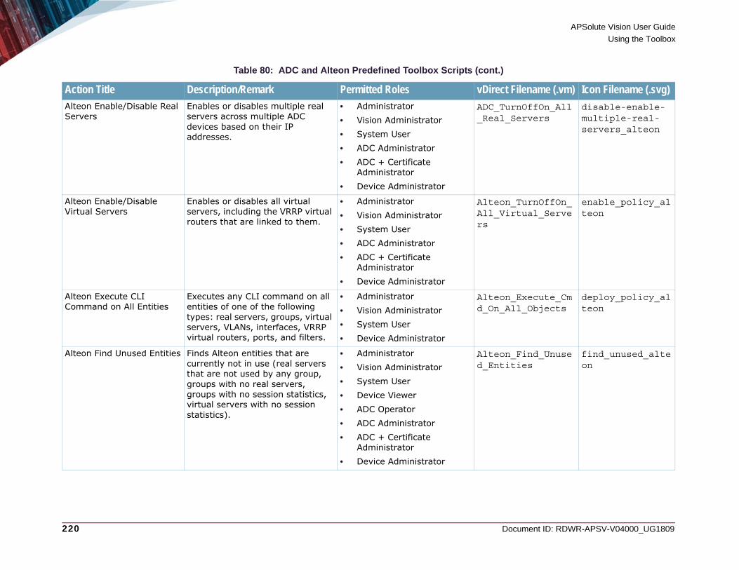
APSolute Vision User Guide
Using the Toolbox
220 Document ID: RDWR-APSV-V04000_UG1809
Alteon Enable/Disable Real Servers
Enables or disables multiple real servers across multiple ADC devices based on their IP addresses.
• Administrator• Vision Administrator• System User• ADC Administrator• ADC + Certificate
Administrator• Device Administrator
ADC_TurnOffOn_All_Real_Servers
disable-enable-multiple-real-servers_alteon
Alteon Enable/Disable Virtual Servers
Enables or disables all virtual servers, including the VRRP virtual routers that are linked to them.
• Administrator• Vision Administrator• System User• ADC Administrator• ADC + Certificate
Administrator• Device Administrator
Alteon_TurnOffOn_All_Virtual_Servers
enable_policy_alteon
Alteon Execute CLI Command on All Entities
Executes any CLI command on all entities of one of the following types: real servers, groups, virtual servers, VLANs, interfaces, VRRP virtual routers, ports, and filters.
• Administrator• Vision Administrator• System User• Device Administrator
Alteon_Execute_Cmd_On_All_Objects
deploy_policy_alteon
Alteon Find Unused Entities Finds Alteon entities that are currently not in use (real servers that are not used by any group, groups with no real servers, groups with no session statistics, virtual servers with no session statistics).
• Administrator• Vision Administrator• System User• Device Viewer• ADC Operator• ADC Administrator• ADC + Certificate
Administrator• Device Administrator
Alteon_Find_Unused_Entities
find_unused_alteon
Table 80: ADC and Alteon Predefined Toolbox Scripts (cont.)
Action Title Description/Remark Permitted Roles vDirect Filename (.vm) Icon Filename (.svg)

APSolute Vision User Guide
Using the Toolbox
Document ID: RDWR-APSV-V04000_UG1809 221
Alteon High-Availability Configuration
Configures a High Availability service/switch on Alteon devices.
• Administrator• Vision Administrator• System User• ADC Operator• ADC Administrator• ADC + Certificate
Administrator• Device Administrator
Alteon_HA_Configuration
high_availability_alteon
Alteon Specify ERT IP Reputation Feed Source
Configures Alteon devices to fetch the ERT IP Reputation Feed via a specified source.
• Administrator• Vision Administrator• System User
Alteon_Set_TOR_Feed
N/A
Table 81: DefensePro Predefined Toolbox Scripts
Action Title Description/Remark Permitted Roles vDirect Filename (.vm) Icon Filename (.svg)DefensePro 6.x Deploy Network Protection Policy for Enterprise
Deploys a new Network Protection policy on DefensePro version-6.x devices. The operator needs to enter the full range for the network to protect and the bandwidth. Then, the operator can add services from a predefined list.
• Administrator• Vision Administrator• System User• Security Administrator• Device Administrator
DefensePro_Deploy_Network_Policy_6_x
deploy_policy_dp
DefensePro 6.x Setup Device
Implements a basic configuration on DefensePro version-6.x devices (including NTP, syslog, SSH, and SMTP settings).
• Administrator• Vision Administrator• System User• Device Administrator
DefensePro_6_x_Setup_Device
setup_dp
Table 80: ADC and Alteon Predefined Toolbox Scripts (cont.)
Action Title Description/Remark Permitted Roles vDirect Filename (.vm) Icon Filename (.svg)

APSolute Vision User Guide
Using the Toolbox
222 Document ID: RDWR-APSV-V04000_UG1809
DefensePro Add Network Classes by Mask
Creates a DefensePro Network Class object using a subnet mask.
• Administrator• Vision Administrator• System User• Security Administrator• Device Administrator
DefensePro_Add_Network_Classes_by_Mask
add_network_dp
DefensePro Add Network Classes by Range
Creates a DefensePro Network Class object using an IP range.
• Administrator• Vision Administrator• System User• Security Administrator• Device Administrator
DefensePro_Add_Network_Classes_by_Range
add_network_dp
DefensePro Add Network Classes with Common Mask
Creates a DefensePro Network Class object with a subnet mask and multiple IP addresses (for quick updates).
• Administrator• Vision Administrator• System User• Security Administrator• Device Administrator
DefensePro_Add_Network_Classes_with_Common_Mask
add_network_dp
DefensePro Check Network Policy Compliance
Finds the DefensePro Network Protection policies that differ from one specified policy.
• Administrator• Vision Administrator• System User• Security Administrator• Device Administrator
DefensePro_Check_Network_Policy_Compliance
check_policy_dp
DefensePro Create Users Creates a user in DefensePro devices.
• Administrator• Vision Administrator• System User• Device Administrator
DefensePro_Create_Users
add_user_dp
Table 81: DefensePro Predefined Toolbox Scripts (cont.)
Action Title Description/Remark Permitted Roles vDirect Filename (.vm) Icon Filename (.svg)

APSolute Vision User Guide
Using the Toolbox
Document ID: RDWR-APSV-V04000_UG1809 223
DefensePro Delete Active Attackers Feed Entries from Blacklist Rules
Deletes the Black List rules from the ERT Active Attackers Feed from DefensePro devices.
• Administrator• Vision Administrator• System User• Security Administrator• Device Administrator
DefensePro_Delete_ERTActiveDDoSFeed_ACLRules
N/A
DefensePro Delete Users Deletes a user from DefensePro devices.
• Administrator• Vision Administrator• System User• Device Administrator
DefensePro_Delete_Users
delete_user_dp
DefensePro Deploy Network Protection Policy for MSSP
Deploys a new Network Protection policy. It deploys the policies per service for an MSSP environment.
• Administrator• Vision Administrator• System User• Security Administrator• Device Administrator
DefensePro_Deploy_Policies_for_MSSP
edit_policy_dp
DefensePro Enable/Disable Policies
Toggles the state (enabled/disabled) of a specified Network Protection policy on selected DefensePro devices. The policy name can be specified using a regular expression.
• Administrator• Vision Administrator• System User• Security Administrator• Device Administrator
DefensePro_Toggle_Policy_State_Based_On_Policy-regex
enable_policy_dp
DefensePro Export/Import Policies
Exports policies from a selected DefensePro device and imports the policies to one or more target devices.For more information on the feature, see Using DefensePro Templates, page 240.
• Administrator• Vision Administrator• System User• Device Administrator
DefensePro_Export_And_Import_Policy
check_policy_dp
Table 81: DefensePro Predefined Toolbox Scripts (cont.)
Action Title Description/Remark Permitted Roles vDirect Filename (.vm) Icon Filename (.svg)

APSolute Vision User Guide
Using the Toolbox
224 Document ID: RDWR-APSV-V04000_UG1809
DefensePro Find Update Policy Pending
Finds DefensePro devices that have a configuration that is pending an Update Policies action.
• Administrator• Vision Administrator• System User• Security Administrator• Device Administrator
DefensePro_Find_Update_Policy_Pending
find_upsate_policy_pending_dp
DefensePro Locate Policies and Profiles with Specified Signature
Finds the policies and profiles that use a specified Signature ID.
• Administrator• Device Administrator• Security Monitor• Security Administrator
DefensePro_Search_Signature
tune_BDoS_profiles_DP
DefensePro Reset BDoS Policy Baselines
Resets the BDoS baselines of specified policies on DefensePro devices.
• Administrator• Vision Administrator• System User• Security Administrator• Device Administrator
DefensePro_Reset_BDoS_Policy_Baselines
reset_policy_bdos
DefensePro Reset DNS Policy Baselines
Resets the DNS baselines of specified policies on DefensePro devices.
• Administrator• Vision Administrator• System User• Security Administrator• Device Administrator
DefensePro_Reset_DNS_Policy_Baselines
reset_policy_dns
DefensePro Tune BDoS Profiles
Provides options for tuning existing BDoS profiles.
• Administrator• Vision Administrator• System User• Security Administrator• Device Administrator
DefensePro_Tune_BDos_Profile
tune_BDoS_profiles_DP
Table 81: DefensePro Predefined Toolbox Scripts (cont.)
Action Title Description/Remark Permitted Roles vDirect Filename (.vm) Icon Filename (.svg)

APSolute Vision User Guide
Using the Toolbox
Document ID: RDWR-APSV-V04000_UG1809 225
DefensePro Update Users Updates user credentials in DefensePro devices.
• Administrator• Vision Administrator• System User• Device Administrator
DefensePro_Update_Users
edit_user_dp
Table 81: DefensePro Predefined Toolbox Scripts (cont.)
Action Title Description/Remark Permitted Roles vDirect Filename (.vm) Icon Filename (.svg)

APSolute Vision User Guide
Using the Toolbox
226 Document ID: RDWR-APSV-V04000_UG1809
Table 82: Miscellaneous Predefined Toolbox Scripts
Action Title Description/Remark Permitted Roles vDirect Filename (.vm)
Icon Filename (.svg)
DefenseSSL Quick Setup
Configures a DefensePro version-8.x device with SYN Flood Protection and SSL Mitigation, and configures an Alteon device that acts as the SSL Decryption Unit.The Alteon device that acts as the SSL Decryption Unit must be an Alteon standalone or VA platform of version 30.0 and later.In DefensePro versions 8.14 and later, before you can run the script, you must select the option Enabled, Using an External Device.
Notes: • For information on the SSL Mitigation feature, see
the relevant sections in the DefensePro User Guide or the APSolute Vision online help.
• After the Toolbox script configures the DefensePro and Alteon devices, you can modify the configuration on the devices. Be aware, however, that modifying the configuration of the DefensePro device may require modifying the configuration of the Alteon device or vice versa.
• Administrator• Vision Administrator• System User• Security Administrator• Device Administrator
DefenseSSL_DPv8_Alteon_Quick_Setup
N/A
Validate All APM Services
Validates the APM configuration for all APM-enabled services.For more information on APM, see the Application Performance Monitoring User Guide and other related documentation.
• Administrator• Vision Administrator• System User• ADC Administrator• ADC + Certificate
Administrator• Device Configurator• Device Administrator
Validate_All_Apm_Services
apm_alteon.svg

APSolute Vision User Guide
Using the Toolbox
Document ID: RDWR-APSV-V04000_UG1809 227
Device Locking and Toolbox ScriptsThe Toolbox script determines whether the target devices must be locked for the script to run.If the script does not require device locking, any Toolbox mechanism can run the script (whether or not the device is locked by any user).If the script requires device locking:• When an Operator Toolbox scheduled task runs the script, APSolute Vision tries to lock the
device. If the locking action is successful, the script runs, and then, APSolute Vision unlocks the device. If the locking action fails, the Operator Toolbox scheduled task fails.
• When a user runs the script, and the device is already locked by the user, the script runs.• When a user runs the script, and the device is not locked by the user, the APSolute Vision tries to
lock the device for the user. If the locking action is successful, the script runs, and then, APSolute Vision unlocks the device. If the locking action fails, APSolute Vision issues an error message and stops trying to run the script.
The following predefined scripts do not require device locking:• DefensePro Check Network Policy Compliance• DefensePro Find Update Policy Pending• ADC Check Certificate Validity• ADC Check SSL Policy Compliance• ADC Find Apply Pending• ADC Find Save Pending
Running ScriptsYou can run a script in the following ways:• From the Toolbox dashboard• From a device toolbar• From the Operator Toolbox tab in the Advanced tree
Caution: Before you try running a script, see Prerequisites for Target Devices of Toolbox Scripts, page 216.
Note: You cannot specify a high-availability cluster as a target device of a Toolbox script.
Tip: If you select devices in the device pane Sites and Devices tree or Physical Containers tree and then run a Toolbox script, the Selected list of target devices is populated automatically.
Tip: Once you have run a Toolbox script from the Toolbox dashboard, you can run the script again using the same configuration as the last time. All you need to do is hover over the required script and click the button.

APSolute Vision User Guide
Using the Toolbox
228 Document ID: RDWR-APSV-V04000_UG1809
Figure 49: Button to Run a Script Using the Last Configuration
To run a Toolbox script from the Toolbox dashboard
1. Click Toolbox ( ). The Toolbox dashboard opens.
2. Hover over the required script and click the button. The Run Script: <script name> tab opens.
3. Do the following:
— In the Target Device List tab, specify the target devices. That is, select entries from the lists and use the arrows to move the entries to the other lists as required. The Target Device List tab contains the Available lists and the Selected lists of devices and Logical Groups (of devices). The Available lists display the available devices and available Logical Groups. The Selected device list displays the devices that the script runs on. The Selected Logical Group list displays the Logical Groups with the devices that the script runs on.
— In the Parameters tab, configure the script-specific parameters.Note: When a Logical Group is selected, the effective Target Device List dynamically updates, according to the devices in the Logical Group. That is, when the device-set of a Logical Group changes, the effective Target Device List changes accordingly. For more information, see Using Logical Groups of Devices, page 190.
4. Click Submit. The Output Script: <script name> tab opens.
The Output Script: <script name> tab contains the following three fields: — Status—The short status of the script, for example, Operation Completed.— Output—The output that the script returned after a successful run. — CLI Output—The full CLI output of the script.
Notes
— You can leave the Output Script: <script name> tab open and rerun the script. Having multiple instances of the Output Script: <script name> tab enables you to compare the results of multiple runs.
— The Run Script: <script name> tab open after a run, so you can go back and look at the script parameters and compare them to the output. You can also rerun the same script, or change parameters and then rerun it.
— Only one Run Script: <script name> tab can be open concurrently. If you want to run another script, you need to close the Run Script: <script name> tab.

APSolute Vision User Guide
Using the Toolbox
Document ID: RDWR-APSV-V04000_UG1809 229
A device toolbar may display one or more icons that enable a device user to run a script. For more information, see Configuring a Toolbox Script in APSolute Vision, page 235.
To run a script from a device toolbar
1. Open the device and click the relevant icon in the device toolbar. The Run Script: <script name> tab opens.
2. Do the following:
— In the Target Device List tab, specify the target devices. That is, select entries from the lists and use the arrows to move the entries to the other lists as required. The Target Device List tab contains the Available lists and the Selected lists of devices and Logical Groups (of devices). The Available lists display the available devices and available Logical Groups. The Selected device list displays the devices that the script runs on. The Selected Logical Group list displays the Logical Groups with the devices that the script runs on.
— In the Parameters tab, configure the script-specific parameters.Note: When a Logical Group is selected, the effective Target Device List dynamically updates, according to the devices in the Logical Group. That is, when the device-set of a Logical Group changes, the effective Target Device List changes accordingly. For more information, see Using Logical Groups of Devices, page 190.
3. Click Submit. The Output Script: <script name> tab opens.
The Output Script: <script name> tab contains the following three fields: — Status—The short status of the script, for example, Operation Completed.— Output—The output that the script returned after a successful run. — CLI Output—The full CLI output of the script.
Notes
— You can leave the Output Script: <script name> tab open and rerun the script. Having multiple instances of the Output Script: <script name> tab enables you to compare the results of multiple runs.
— The Run Script: <script name> tab open after a run, so you can go back and look at the script parameters and compare them to the output. You can also rerun the same script, or change parameters and then rerun it.
— Only one Run Script: <script name> tab can be open at any one time. If you want to run another script, you need to close the Run Script: <script name> tab.
To run a Toolbox script from the Operator Toolbox tab in the Advanced tree
1. Click Toolbox ( ) and select Advanced > Operator Toolbox.
2. Select the script, and click the (Run Script) button. The Run Script: <script name> tab opens.

APSolute Vision User Guide
Using the Toolbox
230 Document ID: RDWR-APSV-V04000_UG1809
3. Do the following:
— In the Target Device List tab, specify the target devices. That is, select entries from the lists and use the arrows to move the entries to the other lists as required. The Target Device List tab contains the Available lists and the Selected lists of devices and Logical Groups (of devices). The Available lists display the available devices and available Logical Groups. The Selected device list displays the devices that the script runs on. The Selected Logical Group list displays the Logical Groups with the devices that the script runs on.
— In the Parameters tab, configure the script-specific parameters.Note: When a Logical Group is selected, the effective Target Device List dynamically updates, according to the devices in the Logical Group. That is, when the device-set of a Logical Group changes, the effective Target Device List changes accordingly. For more information, see Using Logical Groups of Devices, page 190.
4. Click Submit. The Output Script: <script name> tab opens.
The Output Script: <script name> tab contains the following three fields: — Status—The short status of the script, for example, Operation Completed.— Output—The output that the script returned after a successful run. — CLI Output—The full CLI output of the script.
Notes
— You can leave the Output Script: <script name> tab open and rerun the script. Having multiple instances of the Output Script: <script name> tab enables you to compare the results of multiple runs.
— The Run Script: <script name> tab open after a run, so you can go back and look at the script parameters and compare them to the output. You can also rerun the same script, or change parameters and then rerun it.
— Only one Run Script: <script name> tab can be open at any one time. If you want to run another script, you need to close the Run Script: <script name> tab.
Configuring a Scheduled Task for a Script in the Toolbox DashboardYou can configure a new scheduled task for a script from the Toolbox dashboard. The task type is Operator Toolbox. If your configuration is successful, the Scheduler’s Task List table displays your new task.
Notes
• For more information on scheduled tasks, including modifying Operator Toolbox tasks, see Scheduling APSolute Vision and Device Tasks, page 287.
• APSolute Vision issues a failure message if any task action is not successful. The failure message includes the result of each action—that is, whether the action succeeded or failed for each target device.
• The configuration of the Toolbox script determines whether the target device must be locked for the script to run. If the script requires device locking, when an Operator Toolbox task runs the script, APSolute Vision tries to lock the device. If the locking action is successful, the script runs, and then, APSolute Vision unlocks the device. If the locking action fails, the Operator Toolbox task fails.
• If a device in the Target Device List is deleted from APSolute Vision, APSolute Vision deletes the device from the Target Device List and continues running the task.
• If all the devices in the Target Device List are deleted from APSolute Vision, APSolute Vision disables the task.

APSolute Vision User Guide
Using the Toolbox
Document ID: RDWR-APSV-V04000_UG1809 231
To configure a scheduled task for a script from the Toolbox dashboard
1. Click Toolbox ( ). The Toolbox dashboard opens.
2. Hover over the required script and click the button. The Add Toolbox Script tab opens. The Task Type value is Operator Toolbox, and in the Configuration Template tab, the Selected Script text box displays the filename of the selected script.
3. Configure the remaining parameters, which are described in Operator Toolbox Task—Parameters, page 302, and click Submit.
Table 83: Operator Toolbox: General Parameters
Parameter DescriptionName The name of the task.
Description A user-defined description of the task.
Enabled When selected, the task runs according to the defined schedule. Disabled tasks are not activated, but the task configuration is saved in the database.
Table 84: Operator Toolbox: Schedule Parameters
Parameter DescriptionRun The frequency at which the task runs.
Select a frequency, then configure the related time and day/date parameters. Values:• Once—The task runs one time only at the specified date and time.• Minutes—The task runs at intervals of the specified number of
minutes between task starts.• Daily—The task runs daily at the specified time.• Weekly—The task runs every week on the specified day or days, at
the specified time.
Note: Tasks run according to the time as configured on the APSolute Vision client.
Time1 The time at which the task runs.
Date2 The date on which the task runs.
Minutes3 The interval, in minutes, at which the task runs.
Run Always4 Specifies whether the task always runs or only during the defined period.Values:• Enabled—The task is activated immediately and runs indefinitely, with
no start or end time. It runs at the first Time configured with the Frequency in the Schedule tab.
• Disabled—The task runs (at the time and frequency specified in the Schedule tab) from the specified Start Date at the Start Time until the End Date at the End Time.
Default: Enabled

APSolute Vision User Guide
Using the Toolbox
232 Document ID: RDWR-APSV-V04000_UG1809
Start Date5 The date and time at which the task is activated.
Start Time
End Date The date and time after which the task no longer runs.
End Time
1 – This parameter is available only when the specified Run value is Once, Daily, or Weekly.
2 – This parameter is available only when the specified Run value is Once.3 – This parameter is available only when the specified Run value is Minutes.4 – This parameter is available only when the specified Run value is Minutes, Daily, or
Weekly.5 – This parameter is available only when the Run Always checkbox is cleared.
Table 85: Operator Toolbox: Configuration Template
Parameter DescriptionSelected Script (Read-only) The script that is selected in the table—with the file name.
To select the script, click the script from the Action Title column.The table contains all the Toolbox scripts that you have permission to run. The table comprises the following columns: Action Title, File Name, and Category.
Note: When you change a selection, the parameters in the Parameters tab change accordingly.
Table 86: Operator Toolbox: Parameters Parameters
Parameter DescriptionNote: This tab is available only when the script that is selected in the Configuration Template tab includes configuration parameters.
The parameters for the selected script.
Table 87: Operator Toolbox: Target Device List
Parameter DescriptionNote: This tab is available only when the script that is selected in the Configuration Template tab includes configuration parameters.
The Available lists and the Selected lists of devices and Logical Groups (of devices of the appropriate type). The Available lists display the available devices and available Logical Groups. The Selected device list displays the devices that the Toolbox script runs on. The Selected Logical Group list displays the Logical Groups that the Toolbox script runs on.Select entries from the lists and use the arrows to move the entries to the other lists as required.
Note: When a Logical Group is selected, the effective Target Device List dynamically updates— according to the devices in the Logical Group. That is, when the device-set of a Logical Group changes, the effective Target Device List changes accordingly. For more information, see Using Logical Groups of Devices, page 190.
Table 84: Operator Toolbox: Schedule Parameters (cont.)
Parameter Description

APSolute Vision User Guide
Using the Toolbox
Document ID: RDWR-APSV-V04000_UG1809 233
Managing Toolbox ScriptsUsers with the Administrator or Vision Administrator roles can access the Operator Toolbox pane from the Advanced Toolbox tree and manage Toolbox scripts.Managing Toolbox scripts comprises the following:• Using the Operator Toolbox Pane, page 233• Configuring a Toolbox Script in APSolute Vision, page 235• Deleting a Toolbox Script from APSolute Vision, page 237• Downloading a Toolbox Script, page 237
Using the Operator Toolbox Pane Use the Operator Toolbox pane from the Advanced Toolbox tree to manage Toolbox scripts.
To open the Operator Toolbox pane
> Click Toolbox ( ) and select Advanced > Operator Toolbox.
Figure 50: Operator Toolbox Pane in the Advanced Toolbox Tree
Buttons for managing a script: Add, Edit (that is, its properties not the script itself), Delete, and Download.
Run button—Runs the selected script and opens the Run Script tab, where you specify the target devices and script-specific values.
Categories—You can define a category for each script, organizing your scripts into meaningful groups, to make it easier to locate relevant scripts. When you click on a category node, the Operator Toolbox tab displays only the scripts belonging to that category.
Advanced icon—Displays the advanced features of the toolbox.

APSolute Vision User Guide
Using the Toolbox
234 Document ID: RDWR-APSV-V04000_UG1809
The table in the Operator Toolbox tab, which contains most of the default scripts configured in the APSolute Vision server, comprises the following columns:• Action Title—The title for the script.• File Name—The file name of the script, which is a hyperlink to the script in the vDirect module.
You can edit the script in the user interface of the vDirect module.• Description—The user-defined description of the script.• Category—The category assigned to sort the script. When you click on the category node, the
Operator Toolbox tab displays only the scripts belonging to the category.• Toolbar Icon—The icon that runs the script from the toolbar of a managed device. This is
relevant only when the Assign to Toolbar parameter is set in the script configuration.• Device Toolbar—The device types whose toolbar displays an icon to run the script.• Uploaded By—The username who uploaded the script to APSolute Vision.• Upload Date—The date the script was uploaded to APSolute Vision.
In the Operator Toolbox tab, you can load the scripts from APSolute Vision or from vDirect. You can run scripts from the Toolbox or from vDirect. Any change you to make to a script is reflected in both locations. The vDirect module in APSolute Vision validates the scripts and hosts them in the vDirect Configuration Templates tab. You can use vDirect to write new Toolbox scripts and then configure them in APSolute Vision. If a script is already configured in APSolute Vision, you can click on its link, which opens the script in vDirect—for you to view or modify as you require.
Note: For more information on vDirect, see vDirect with APSolute Vision, page 46, Using vDirect with APSolute Vision, page 657, and the Radware vDirect documentation that corresponds to the vDirect version in the APSolute Vision server. To find out the vDirect version, in the APSolute Vision Settings view System perspective, select General Settings > Basic Parameters and look in the Software tab.
Caution: See before you try running a script, see Prerequisites for Target Devices of Toolbox Scripts, page 216.
To run a Toolbox script from the Operator Toolbox tab
1. Click Toolbox ( ) and select Advanced > Operator Toolbox.
2. Select the script, and click the (Run Script) button. The Run Script: <script name> tab opens.
3. Do the following:
— In the Target Device List tab, specify the target devices. That is, select entries from the lists and use the arrows to move the entries to the other lists as required. The Target Device List tab contains the Available lists and the Selected lists of devices and Logical Groups (of devices). The Available lists display the available devices and available Logical Groups. The Selected device list displays the devices that the script runs on. The Selected Logical Group list displays the Logical Groups with the devices that the script runs on.
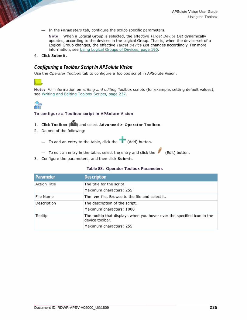
APSolute Vision User Guide
Using the Toolbox
Document ID: RDWR-APSV-V04000_UG1809 235
— In the Parameters tab, configure the script-specific parameters.Note: When a Logical Group is selected, the effective Target Device List dynamically updates, according to the devices in the Logical Group. That is, when the device-set of a Logical Group changes, the effective Target Device List changes accordingly. For more information, see Using Logical Groups of Devices, page 190.
4. Click Submit.
Configuring a Toolbox Script in APSolute VisionUse the Operator Toolbox tab to configure a Toolbox script in APSolute Vision.
Note: For information on writing and editing Toolbox scripts (for example, setting default values), see Writing and Editing Toolbox Scripts, page 237.
To configure a Toolbox script in APSolute Vision
1. Click Toolbox ( ) and select Advanced > Operator Toolbox.2. Do one of the following:
— To add an entry to the table, click the (Add) button.
— To edit an entry in the table, select the entry and click the (Edit) button.3. Configure the parameters, and then click Submit.
Table 88: Operator Toolbox Parameters
Parameter DescriptionAction Title The title for the script.
Maximum characters: 255
File Name The .vm file. Browse to the file and select it.
Description The description of the script.Maximum characters: 1000
Tooltip The tooltip that displays when you hover over the specified icon in the device toolbar.Maximum characters: 255

APSolute Vision User Guide
Using the Toolbox
236 Document ID: RDWR-APSV-V04000_UG1809
Category The category that determines which node (under the parent Operator Toolbox node) contains the script. Specify a category for a script to organize the script into a meaningful group, and make it easier to locate. When you click on a category node, the Operator Toolbox tab displays only the scripts belonging to that category. Values: • Configuration• Data Export• Emergency• High Availability• Monitoring• Operations• UnassignedDefault: Unassigned
Assign to Toolbar Specifies whether you can run the script from the toolbar of a managed device.Default: Disabled
Toolbar Icon(This button is available only when the Assign to Toolbar checkbox is selected.)
The icon that you click to run the script from the toolbar of a managed device.
Device Toolbar The device type whose toolbar displays the icon to click to run the script.Values: Alteon, LinkProof NG, DefensePro, AllDefault: All
Assign to Dashboard Specifies whether you can run the script from the Toolbox dashboard.Default: Disabled
Dashboard Icon(This parameter is available only when the Assign to Dashboard checkbox is selected.)
The icon that you click to run the script from the Toolbar dashboard.
Note: The table in the Operator Toolbox Settings tab manages the icons for the Toolbox dashboard (APSolute Vision Settings view System perspective, General Settings > Operator Toolbox Settings). For more information, see Managing Operator Toolbox Settings, page 156.
RolesConfigure the Selected list with the RBAC roles that are allowed to run the script.The Selected list always includes the roles Administrator, Vision Administrator, and System User, and you cannot remove them.
Notes: • The predefined roles are configured with the appropriate RBAC roles, by default. • For more information on RBAC roles, see Role-Based Access Control (RBAC), page 68.
Table 88: Operator Toolbox Parameters (cont.)
Parameter Description

APSolute Vision User Guide
Using the Toolbox
Document ID: RDWR-APSV-V04000_UG1809 237
Deleting a Toolbox Script from APSolute VisionUse the Operator Toolbox tab to delete a Toolbox script from APSolute Vision.
To delete a Toolbox script from APSolute Vision
1. Click Toolbox ( ) and select Advanced > Operator Toolbox.
2. Select the script, and click the (Delete) button.
Downloading a Toolbox ScriptUse the Operator Toolbox tab to download or view a Toolbox script in APSolute Vision.
To download or view a Toolbox script
1. Click Toolbox ( ) and select Advanced > Operator Toolbox.2. Configure the filter as necessary (see the procedure To filter the display of the template list,
page 244).
3. Select the rows with the required scripts (using standard Windows key combinations).
4. Click the (Download Selected File) button.
5. In the Save As text box, type the path to the target directory or click Browse to browse to the directory.
6. Click Save.
Writing and Editing Toolbox ScriptsThis section contains the following topics:• Allowing a Script To Run on an Unlocked Device, page 238• Guidelines for Setting a Default Value for a Parameter, page 238• Recommended vDirect Elements to Include in Scripts, page 238
Toolbox scripts are text files with the .vm extension, which use vDirect syntax. You can write new scripts, and you can edit existing scripts according to your requirements. For example, if you need to run a script repeatedly with the same values, you can edit the script and define default values for parameters.
Caution: If you intend to run a predefined script often, you may want to modify its default configuration. However, an upgrade of APSolute Vision may include changes to predefined scripts, which overwrite any script modifications that you have made to the predefined scripts. If you modify a predefined script, Radware recommends downloading the file, renaming it, and uploading it to APSolute Vision as a new script.
APSolute Vision User Guide
Using the Toolbox
238 Document ID: RDWR-APSV-V04000_UG1809
Notes
• The predefined scripts incorporate the guidelines as appropriate. For example, using #haltOnDeviceError is not incorporated in a script that uses a GET command, and #require_device_lock=false is included in script that makes no change to a device configuration.
• For more information on vDirect, see vDirect with APSolute Vision, page 46, Using vDirect with APSolute Vision, page 657, and the Radware vDirect documentation that corresponds to the vDirect version in the APSolute Vision server. (To identify the vDirect version, in the APSolute Vision Settings view System perspective, select General Settings > Basic Parameters and look in the Software tab.)
Allowing a Script To Run on an Unlocked DeviceBy default, Toolbox scripts cannot run on an unlocked device. For more information, see Device Locking and Toolbox Scripts, page 227.To allow a script to run on unlocked devices, include the following row in the script:
#param($require_device_lock, 'bool', 'out', 'defaultValue=false')
Guidelines for Setting a Default Value for a ParameterYou can set a default value for a script parameter.Here are some snippets showing how to set a default value for a parameter:
• #param($activate, 'type=string', 'prompt=Enable User', 'values=Enable,Disable', 'defaultValue=Enable')
• #param($crtmng, 'type=string', 'prompt=Certificate Management', 'values=Enable,Disable', 'defaultValue=Disable')
• #param($name, 'type=string', 'prompt=Server Name', 'properties={"maxCharLength" : "24"}', 'defaultValue="My Server"')
• #param($privsrc, 'type=ip', 'prompt=Primary Source Address', 'required=false', 'defaultValue=0.0.0.0')
Recommended vDirect Elements to Include in ScriptsWhen you write a vDirect script to use as a Toolbox script in APSolute Vision, Radware recommends using the following elements:
• #haltOnDeviceError(true|false) ... #end—This block directive surrounds a block of commands.When you use the true argument, every command is automatically tested for errors and, if an error response is detected, the script is halted with an exception. The drawback to this is that when you run a Toolbox script on multiple devices, the first exception causes the script to halt.When you use the false argument, no command is tested for errors, and the script is not halted.
• An output parameter, so that the APSolute Vision alert message displays the output of the script formatted well and clearly.

APSolute Vision User Guide
Using the Toolbox
Document ID: RDWR-APSV-V04000_UG1809 239
Figure 51: Example Output that Is Not Formatted Well
Figure 52: Example Output that Is Formatted Well
The following is an excerpt of a script that includes an output parameter, so that the APSolute Vision alert message displays the output of the script formatted well and clearly.
#device($alteons, 'type=alteon[]', 'prompt=Alteon/LinkProof NG')
#param($output, 'type=string','out')
#set($output = 'The following devices are pending apply:<br>')
#set($negOutput = 'There are no devices pending apply.')
#set($tempOutput = '')
#foreach($alteon in $alteons)
#select($alteon)
#set($applyTable = $alteon.readAllBeans("AgApply"))
#foreach($applyRow in $applyTable)
#if($applyRow.agApplyPending == 'APPLYNEEDED')
#set($tempOutput = $tempOutput + $alteon.ip + '<br>')
#end
#end
#end
#if($tempOutput.isEmpty())
#set($output = $negOutput)
#else
#set($output = $output + $tempOutput)
#end

APSolute Vision User Guide
Using the Toolbox
240 Document ID: RDWR-APSV-V04000_UG1809
Using DefensePro TemplatesThis feature is available only in DefensePro 6.x versions 6.11 and later, 7.x versions, and 8.x versions 8.10 and later.You can export and import DefensePro configuration templates.A DefensePro configuration template can include the configuration (the definitions and security settings) and/or baselines of a Network Protection policy and/or Server Protection policy.A template from a Network Protection policy can include the baselines from the associated DNS and/or BDoS profiles.A template from a Server Protection policy can include learned baselines from the associated HTTP Flood profiles.DefensePro configuration templates do not include the following information:• DefensePro setup and network configuration—For example, device time, physical ports,
and so on.• DefensePro security settings—The protections that a policy template uses must be
supported and enabled globally in the target DefensePro device (that is, the target DefensePro device into which you are importing the policy template). For example, if you export a Network Protection policy that includes a BDoS Protection profile, the DefensePro device into which you are importing the policy template must have BDoS Protection enabled globally (Configuration perspective, Setup > Security Settings > BDoS Protection > Enable BDoS Protection).
• User-defined signatures.• SYN Protection profiles with a user-defined SYN Protection.• User-defined/custom Signature Protection profiles in certain earlier DefensePro
versions—The following versions can include the user-defined/custom Signature Protection profile: 6.x versions 6.13 and later, 7.x versions 7.42.03 and later, and 8.x versions 8.10 and later.
Caution: If the imported BDoS baseline or DNS baseline is below the minimum value in the configuration of the corresponding profile, after an Update Policies action, DefensePro recalculates the baseline or baselines according to the configuration of the profile. (For information on the configuration of profiles, see Configuring BDoS Profiles, page 32 and Configuring DNS Protection Profiles, page 48.)
Notes
• The terms Network Protection policy, and network policy may be used interchangeably in APSolute Vision and in the documentation.
• You can import Network Protection policies from DefensePro platforms running supported 6.x versions into platforms running supported 6.x or 7.x versions.
• You can import Network Protection policies from DefensePro platforms running supported 7.x versions only into other platforms running supported 7.x versions.
• You can import Network Protection policies from DefensePro platforms running supported 8.x versions only into other platforms running supported 8.x versions.
• You can import Server Protection policies from DefensePro platforms running supported 6.x versions into platforms running supported 6.x versions.

APSolute Vision User Guide
Using the Toolbox
Document ID: RDWR-APSV-V04000_UG1809 241
• You can import Server Protection policies from DefensePro platforms running supported 7.x versions into platforms running supported 7.x versions.
• APSolute Vision provides a predefined Toolbox script for exporting and importing DefensePro configurations, DefensePro Export/Import Policies. For more information, see Using and Managing Toolbox Scripts, page 211.
Exporting a Network Protection Policy as a TemplateUse the following procedure to export a Network Protection policy as a template.
To export a Network Protection policy as a template
1. In the Configuration perspective, select Network Protection > Network Protection Policies.
2. Select the Network Protection policy that you want to export, and click (Export).
3. Configure the parameters, and then click Submit.
Table 89: Export Network Protection Parameters
Parameter DescriptionDownload To Values:
• Client—DefensePro exports the template to the location specified in the filepath or by browsing to the location with the Browse button.
• Server—DefensePro exports the template to the APSolute Vision database.
Default: Server
Download Via (Read-only) The transport method.Value: HTTPS
Configuration Specifies whether DefensePro exports the template with the configuration of the policy. Default: Enabled
DNS Baseline Specifies whether DefensePro exports the template with the current DNS baseline of the policy. Default: Enabled
BDoS Baseline Specifies whether DefensePro exports the template with the current BDoS baseline of the policy. Default: Enabled
Custom Signature Profile
Specifies whether DefensePro exports the template with the current custom (user-defined) Signature Protection profile of the policy.Default: Enabled
Traffic Filters Profile Specifies whether DefensePro exports the template with the current Traffic Filters profile of the policy.Default: Enabled
Anti-Scanning Whitelisted Objects
Specifies whether DefensePro exports the template with the current whitelisted objects of the Anti-Scanning profile of the policy.Default: Enabled
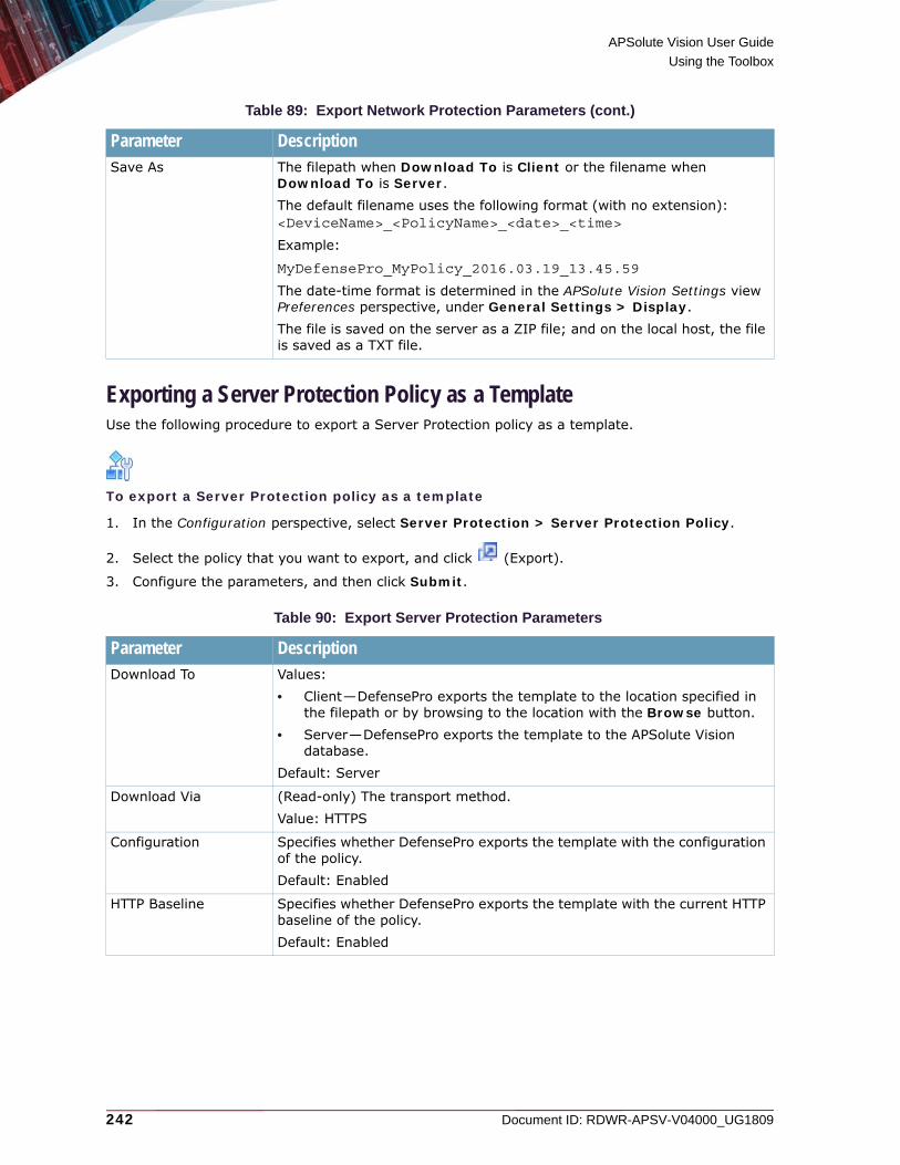
APSolute Vision User Guide
Using the Toolbox
242 Document ID: RDWR-APSV-V04000_UG1809
Exporting a Server Protection Policy as a TemplateUse the following procedure to export a Server Protection policy as a template.
To export a Server Protection policy as a template
1. In the Configuration perspective, select Server Protection > Server Protection Policy.
2. Select the policy that you want to export, and click (Export).
3. Configure the parameters, and then click Submit.
Save As The filepath when Download To is Client or the filename when Download To is Server.The default filename uses the following format (with no extension):<DeviceName>_<PolicyName>_<date>_<time>
Example:
MyDefensePro_MyPolicy_2016.03.19_13.45.59
The date-time format is determined in the APSolute Vision Settings view Preferences perspective, under General Settings > Display.The file is saved on the server as a ZIP file; and on the local host, the file is saved as a TXT file.
Table 90: Export Server Protection Parameters
Parameter DescriptionDownload To Values:
• Client—DefensePro exports the template to the location specified in the filepath or by browsing to the location with the Browse button.
• Server—DefensePro exports the template to the APSolute Vision database.
Default: Server
Download Via (Read-only) The transport method.Value: HTTPS
Configuration Specifies whether DefensePro exports the template with the configuration of the policy.Default: Enabled
HTTP Baseline Specifies whether DefensePro exports the template with the current HTTP baseline of the policy.Default: Enabled
Table 89: Export Network Protection Parameters (cont.)
Parameter Description
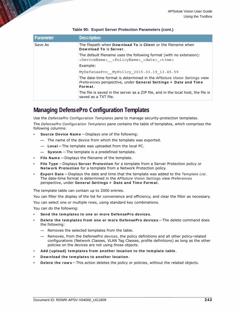
APSolute Vision User Guide
Using the Toolbox
Document ID: RDWR-APSV-V04000_UG1809 243
Managing DefensePro Configuration TemplatesUse the DefensePro Configuration Templates pane to manage security-protection templates.The DefensePro Configuration Templates pane contains the table of templates, which comprises the following columns:• Source Device Name—Displays one of the following:
— The name of the device from which the template was exported.— Local—The template was uploaded from the local PC.— System—The template is a predefined template.
• File Name—Displays the filename of the template.• File Type—Displays Server Protection for a template from a Server Protection policy or
Network Protection for a template from a Network Protection policy.• Export Date—Displays the date and time that the template was added to the Template List.
The date-time format is determined in the APSolute Vision Settings view Preferences perspective, under General Settings > Date and Time Format.
The template table can contain up to 2000 entries.You can filter the display of the list for convenience and efficiency, and clear the filter as necessary.You can select one or multiple rows, using standard key combinations.You can do the following:• Send the templates to one or more DefensePro devices.• Delete the templates from one or more DefensePro devices—The delete command does
the following:— Removes the selected templates from the table. — Removes, from the DefensePro devices, the policy definitions and all other policy-related
configurations (Network Classes, VLAN Tag Classes, profile definitions) as long as the other policies on the devices are not using those objects.
• Add (upload) templates from another location to the template table.• Download the templates to another location.• Delete the rows—This action deletes the policy or policies, without the related objects.
Save As The filepath when Download To is Client or the filename when Download To is Server.The default filename uses the following format (with no extension):<DeviceName>__<PolicyName>_<date>_<time>
Example:
MyDefensePro__MyPolicy_2015.03.19_13.45.59
The date-time format is determined in the APSolute Vision Settings view Preferences perspective, under General Settings > Date and Time Format.The file is saved in the server as a ZIP file, and in the local host, the file is saved as a TXT file.
Table 90: Export Server Protection Parameters (cont.)
Parameter Description

APSolute Vision User Guide
Using the Toolbox
244 Document ID: RDWR-APSV-V04000_UG1809
To filter the display of the template list
1. Click the Toolbox ( ) button.
2. Click the Advanced ( ) button to open the DefensePro Configuration Templates pane.
3. Configure the parameters, and then, click the (Search) button.
To clear the template-list filter and show all of the stored templates
1. Click the Toolbox ( ) button.
2. Click the Advanced ( ) button to open the DefensePro Configuration Templates pane.
3. Click Clear.
To send templates to DefensePro devices
1. Click the Toolbox ( ) button.
2. Click the Advanced ( ) button to open the DefensePro Configuration Templates pane.
3. Configure the filter as necessary (see the procedure To filter the display of the template list, page 244).
Table 91: Template-List Filter Parameters
Parameter DescriptionSource Device Name Values:
• Device name—Shows only the templates downloaded from the selected device.
• Local—Shows only the templates uploaded from the local PC.• System—Shows only the predefined templates.Default: All
File Type Values:• Server Protection (not relevant for DefensePro 8.x versions)—
Shows the templates from Server Protection policies.• Network Protection—Shows the templates from Network Protection
policies.
File Name The filename that the filter uses. The value supports one or two wildcards (*).Examples:
• *pol*—Shows any filename containing the string pol.
• *pol—Shows any filename ending with the string pol.
• pol*—Shows any filename starting with the string pol.

APSolute Vision User Guide
Using the Toolbox
Document ID: RDWR-APSV-V04000_UG1809 245
4. Select the rows with the required templates (using standard Windows key combinations).
5. Select Send to Devices.
6. Configure the parameters, and then click Submit.
Table 92: Send to Devices: Select Devices to Update Parameters
Parameter DescriptionThe Available lists and the Selected lists of DefensePro devices and Logical Groups (of DefensePro devices). The Available lists display the available devices and available Logical Groups. The Selected device list displays the devices to update. The Selected Logical Group list displays the Logical Groups with the devices to update.Select entries from the lists and use the arrows to move the entries to the other lists as required.
Notes: • The Available device list can contain only the devices that support the templates features.• When a Logical Group is selected, the effective Target Device List dynamically updates,
according to the devices in the Logical Group. That is, when the device-set of a Logical Group changes, the effective Target Device List changes accordingly. For more information, see Using Logical Groups of Devices, page 190.
Update Method Values:• Append to Existing Configuration—The template adds the policy
and profile configurations, and any baselines, to the devices in the Selected lists. The template does not overwrite any existing configuration. For example, if a policy name exists in a target device, the policy on the target device does not get changed.
• Overwrite Existing Configuration—The template adds the policy and profile configurations, and any baselines, to the devices in the Selected lists. If a policy or profile with the same name exists in a target device, the template overwrites it.
Default: Overwrite Existing Configuration
Caution: For the update behavior when the policy template includes a user-defined profile (User-Defined Signature Protection Profile, Custom Signature Profile, or Traffic Filters Profile), see Update Behavior Using DefensePro Configuration Templates with User-Defined Profiles, page 246.
Install on Instance(This parameter is relevant only for DefensePro x420 platforms.)
The identifier or the DefensePro hardware instance onto which to add the template. Values: 0, 1Default: 0
Update Policies After Sending Configuration
Values: • Enabled—After successfully uploading a template to a device, an
Update Policies (activate latest changes) action is automatically initiated.
• Disabled—After successfully uploading a template to a device, an Update Policies (activate latest changes) action is required for the configuration to take effect.
Default: Disabled

APSolute Vision User Guide
Using the Toolbox
246 Document ID: RDWR-APSV-V04000_UG1809
Update Behavior Using DefensePro Configuration Templates with User-Defined ProfilesThis section describes the update behavior when one of the following Export options was enabled when a security-protection policy template was created:• Custom Signature Profile—Available only in DefensePro 8.x versions• User-Defined Signature Protection Profile—Available only in DefensePro 6.x versions 6.13
and later, and 7.x versions 7.42.03 and later• Traffic Filters Profile—Available only in DefensePro 8.x versions 8.15 and later
• When the Update Method is Append to Existing Configuration and the policy does not exist, but a user-defined profile name exists in the target device, the policy is created in the target device using the existing profile.
• When the Update Method is Overwrite Existing Configuration and the user-defined profile name exists in the target device, the policy is created or modified (if it exists already), but the template does not modify the rules or attributes of the existing profile—the template only extends the profile with new rules and attributes on the target device.
To delete templates and associated configuration objects from DefensePro devices
1. Click the Toolbox ( ) button.
2. Click the Advanced ( ) button to open the DefensePro Configuration Templates pane.
3. Configure the filter as necessary (see the procedure To filter the display of the template list, page 244).
4. Select the rows with the required templates (using standard Windows key combinations).
5. Select Delete from Devices.
6. Configure the parameters, and then click Submit.
Table 93: Delete from Devices: Select Devices to Update Parameters
Parameter DescriptionThe Available lists and the Selected lists of DefensePro devices and Logical Groups (of DefensePro devices). The Available lists display the available devices and available Logical Groups. The Selected device list displays the devices to update. The Selected Logical Group list displays the Logical Groups with the devices to update.Select entries from the lists and use the arrows to move the entries to the other lists as required.
Notes: • The Available device list can contain only the devices that support the templates features.• The Selected device list can contain only DefensePro devices running 6.x versions 6.14 and
later, 7.x versions 7.41.02 and later, or 8.x versions 8.10 and later.• When a Logical Group is selected, the effective Target Device List dynamically updates,
according to the devices in the Logical Group. That is, when the device-set of a Logical Group changes, the effective Target Device List changes accordingly. For more information, see Using Logical Groups of Devices, page 190.

APSolute Vision User Guide
Using the Toolbox
Document ID: RDWR-APSV-V04000_UG1809 247
To add (upload) templates from another location to the template list
1. Click the Toolbox ( ) button.
2. Click the Advanced ( ) button to open the DefensePro Configuration Templates pane.
3. Click the (Add) button.
4. Configure the parameters, and then click Submit.
To download templates to another location
1. Click the Toolbox ( ) button.
2. Click the Advanced ( ) button to open the DefensePro Configuration Templates pane.
3. Configure the filter as necessary (see the procedure To filter the display of the template list, page 244).
4. Select the rows with the required templates (using standard Windows key combinations).
5. Click the (Download Selected File) button.
6. In the Save As text box, type the path to the target directory or click Browse to browse to the directory.
7. Click Save.
Update Policies After Sending Configuration
Values:• Enabled—After successfully deleting the templates and associated
configuration objects from a device, an Update Policies (activate latest changes) action is automatically initiated.
• Disabled—After successfully deleting the templates and associated configuration objects from the devices, an Update Policies (activate latest changes) action is required for the configuration to take effect.
Default: Disabled
Table 94: Upload File to Server Parameters
Parameter DescriptionFile Type Values:
• Server Protection—The template defines a Server Protection policy.• Network Protection—The template defines a Network Protection policy.
Upload From The filepath of the template. Click Browse to browse to the directory and select the file.
Table 93: Delete from Devices: Select Devices to Update Parameters (cont.)
Parameter Description

APSolute Vision User Guide
Using the Toolbox
248 Document ID: RDWR-APSV-V04000_UG1809
To delete stored templates
1. Click the Toolbox ( ) button.
2. Click the Advanced ( ) button to open the DefensePro Configuration Templates pane.
3. Configure the filter as necessary (see the procedure To filter the display of the template list, page 244).
4. Select the rows with the required templates (using standard Windows key combinations).
5. Click the (Delete) button in the pane.
Using AppShape Templates and InstancesUse AppShape™ templates to accelerate, simplify, and optimize the configuration of Alteon ADC devices for deployments of the following applications:• Common Web Applications• Citrix XenDesktop• DefenseSSL• Microsoft Exchange 2010• Microsoft Exchange 2013• Microsoft Lync External• Microsoft Lync Internal• Oracle E Business• Oracle SOA Suite 11g• Oracle WebLogic 12c• SharePoint 2010• SharePoint 2013• VMware View 5.1• Zimbra
AppShape templates configure all the required ADC options tailored and optimized for the selected business application. With APSolute Vision, you can create instances of AppShape templates from one single configuration pane with a small set of parameters.AppShape configures the full, optimal Server Load Balancing (SLB) configuration for the selected business application, which comprises:• Real servers• Server groups• Virtual servers• Virtual services• Application services—such as (depending on the selected business application) health check,
FastView optimized caching, compression, connection management, or acceleration

APSolute Vision User Guide
Using the Toolbox
Document ID: RDWR-APSV-V04000_UG1809 249
Users with the Administrator role can manage the AppShape templates.Users with following roles can create AppShape instances on Alteon devices:• Administrator• ADC + Certificate Administrator• ADC Administrator• Device Administrator• System User• Vision Administrator
To create AppShape instances of most AppShape types, APSolute Vision requires SSH access to run CLI commands on the Alteon device. Therefore, SSH must be enabled and properly configured. SSH must be enabled in the Management Protocols pane (Configuration perspective, System > Management Access > Management Protocols). And, the SSH port configured in the Management Protocols pane must be the same as the value in the SSH Port text box in the Device Properties pane. (The Device Properties pane opens from the Sites and Devices tree when you add a new device or edit device properties.)
To view the basic parameters of AppShape instances that the APSolute Vision server is managing
> Click the Toolbox ( ) button, and then, select Advanced ( ) and AppShapes.
You can filter the display of the AppShapes Service table according to the values in any column. The filter is either a drop-down list or a text box. If the filter is a text box, the result is a case-insensitive match of a string that the specified string in the value. After you configure the filter criteria, to apply
the filter, click the button to apply the filter. Click Clear to cancel the filter.The nodes under the AppShapes node display, by default, the instances of the corresponding AppShape type.
Tip: If you intend to configure the AppShape instance with SSL Acceleration enabled (which is the default of most AppShape types), configure the SSL certificate before you configure the AppShape instance (Configuration perspective, Application Delivery > Application Services > SSL > Certificate Repository).
Table 95: Basic Parameters of AppShape Instances in APSolute Vision
Parameter DescriptionAppShape Type The AppShape type.
Name The name of the AppShape instance.
Note: You can change the name in the configuration of the instance on the device.
Device Name The name of the device on which the AppShape instance is deployed.
Virtual Address The virtual IP address of the service.
Valid Configuration The latest-known status that specifies whether the AppShape instance is synchronized with the AppShape template.
Last Validation The last time that the configuration of the device was synchronized with the AppShape template.

APSolute Vision User Guide
Using the Toolbox
250 Document ID: RDWR-APSV-V04000_UG1809
To create an AppShape instance on a device
1. Lock the Alteon device on which you intend to configure the AppShape instance.
2. Click the Toolbox ( ) button, and then, select Advanced ( ) and AppShapes.
3. Click the (Add) button in the AppShape Service pane.
4. Do the following:
— From the AppShape Type drop-down list, select the AppShape type that you require. — From the Device Name drop-down list, select the Alteon instance on which to configure the
AppShape instance. 5. Configure the mandatory parameters, make changes to non-mandatory parameters as required,
and click Submit.
For information on the various AppShape types and associated parameters, see the relevant section:— Configuring a Common Web Application AppShape Instance, page 251— Configuring a Citrix XenDesktop AppShape Instance, page 253— Configuring a DefenseSSL AppShape Instance, page 256— Configuring a Microsoft Exchange 2010 AppShape Instance, page 258— Configuring a Microsoft Exchange 2013 AppShape Instance, page 262— Configuring a Microsoft Lync External AppShape Instance, page 266— Configuring a Microsoft Lync Internal AppShape Instance, page 269— Configuring an Oracle E-Business AppShape Instance, page 272 — Configuring an Oracle SOA Suite 11g AppShape Instance, page 274— Configuring an Oracle WebLogic 12c AppShape Instance, page 276 — Configuring a SharePoint 2010 AppShape Instance, page 278— Configuring a SharePoint 2013 AppShape Instance, page 280— Configuring an VMware View 5.1 AppShape Instance, page 282 — Configuring a Zimbra AppShape Instance, page 284
To validate an AppShape instance
> Select the row with the AppShape instance and click (Validate AppShape Instance).
To view or modify the configuration of an existing AppShape instance on a specific device
1. Click the Toolbox ( ) button, and then, select Advanced ( ) and AppShapes.2. Select the row with the instance whose configuration you want to view or modify, and then, click
the (Edit) button.
3. View or modify the configuration as required.
APSolute Vision User Guide
Using the Toolbox
Document ID: RDWR-APSV-V04000_UG1809 251
Uploading a New AppShape Template Type to the APSolute Vision ServerYou can upload a new AppShape template type to the APSolute Vision server. When you upload a new AppShape template type to the APSolute Vision server, you do not need to change or even restart the APSolute Vision server. All you need is the AppShape-template ZIP file, that you receive from Radware.
Caution: If you upload an AppShape template type that already exists in the APSolute Vision server, before proceeding, and overwriting the existing template, Radware strongly recommends that you remove existing instances of the template. If you overwrite the existing template and there are existing instances of this template, unexpected results may occur.
Note: The online help that includes the description of the new AppShape template type will be in the online-help files at radware.com and the latest online-help package. The APSolute Vision administrator can configure whether the online help comes from the APSolute Vision server or from radware.com. It is the responsibility of the APSolute Vision administrator to make sure that the help files on the server are updated as necessary with the latest online-help package.
To upload a new AppShape template type to the APSolute Vision server
1. Click the Toolbox ( ) button, and then, select Advanced ( ) and AppShapes.
2. Click the (Upload AppShape) button at the top-left of the pane.
3. Navigate to the AppShape-template ZIP file, and then, click Open.
Configuring a Common Web Application AppShape InstanceUse the Common Web Application AppShape to configure an Alteon ADC device to work in a network architecture with a generic HTTP-based application.
Notes
• For the CLI configuration that AppShape generates as the result of the hard-coded AppShape pattern or as the result of a value that you specify in the AppShape Instance tab, see Common Web Application—AppShape-generated Configuration, page 701.
• The template configures some parameters automatically, which the template GUI does not expose. After you finish the following procedure, you can use the Diff command to view the entire configuration.
To configure a Common Web Application AppShape instance on a device
1. Lock the Alteon device on which you intend to configure the AppShape instance.
2. Click the Toolbox ( ) button, and then, select Advanced ( ) and AppShapes.
3. Select Common Web Application.

APSolute Vision User Guide
Using the Toolbox
252 Document ID: RDWR-APSV-V04000_UG1809
4. Do one of the following:
— To add an entry to the table, click the (Add) button.
— To edit an entry in the table, select the entry and click the (Edit) button.5. Configure the parameters, and click Submit.
Table 96: Common Web Application: General Parameters
Parameter DescriptionAppShape Type The specified AppShape type.
Device Name The name of the device on which the AppShape instance is deployed.
Table 97: Common Web Application: Web Application Instance Parameters
Parameter DescriptionLast Validation (Read-only) The last time, in yyyy-MM-dd hh:mm:ss.f format, that
the configuration device was synchronized with the AppShape template.
Valid Configuration (Read-only) Specifies whether the configuration is valid.
Instance Name The name of the AppShape instance. Maximum characters: 100
Virtual Address The virtual IP address of the service.
Table 98: Common Web Application: Application Servers Parameters
Parameter DescriptionAddress/Port table Contains the addresses and ports of each real server configured for the
service.
To add an entry to the table, click the (Add) button.
To edit an entry in the table, select the entry and click the (Edit) button.
Table 99: Common Web Application: Load Balancing Settings Parameters
Parameter DescriptionSLB Metric The SLB metric used to select next server in the group.
Default: Round Robin
Note: If you choose a value other than the default, the AppShape always uses the default value for any additional, specifically related parameter. For example, if the value of SLB Metric is Min Misses, the specifically related Minmiss Hash is always the default 24 Bits.
Health Check The type of content that is examined during health checks. The content depends on the type of health check.Default: http

APSolute Vision User Guide
Using the Toolbox
Document ID: RDWR-APSV-V04000_UG1809 253
Configuring a Citrix XenDesktop AppShape InstanceUse the Citrix XenDesktop AppShape to configure an Alteon ADC device to work in a network architecture with Citrix XenDesktop.
Notes
• For the CLI configuration that AppShape generates as the result of the hard-coded AppShape pattern or as the result of a value that you specify in the AppShape Instance tab, see Citrix XenDesktop—AppShape-generated Configuration, page 703.
• The template configures some parameters automatically, which the template GUI does not expose. After you finish the following procedure, you can use the Diff command to view the entire configuration.
To configure a Citrix XenDesktop AppShape instance on a device
1. Lock the Alteon device on which you intend to configure the AppShape instance.
2. Click the Toolbox ( ) button, and then, select Advanced ( ) and AppShapes.
3. Select Citrix XenDesktop.
Table 100: Common Web Application: HTTP Parameters
Parameter DescriptionCaching Specifies whether the HTTP profile uses caching.
Default: Enabled
Compression Specifies whether the HTTP profile uses compression.Default: Enabled
Connection Management Specifies whether the HTTP profile uses connection management.If enabled, you must configure the proxy IP address. Default: Enabled
Proxy IP(This button is displayed only when the Connection Management checkbox is selected.)
Opens the Proxy IP pane.
Table 101: Common Web Application: SSL Parameters
Parameter DescriptionSSL Acceleration Specifies whether SSL offloading is enabled for acceleration.
Default: Enabled
Server Certificate(This parameter is displayed only when the SSL Acceleration checkbox is selected.)
The name of the SSL certificate, selected from the drop-down list.To edit the selected SSL certificate, click Server Certificate.
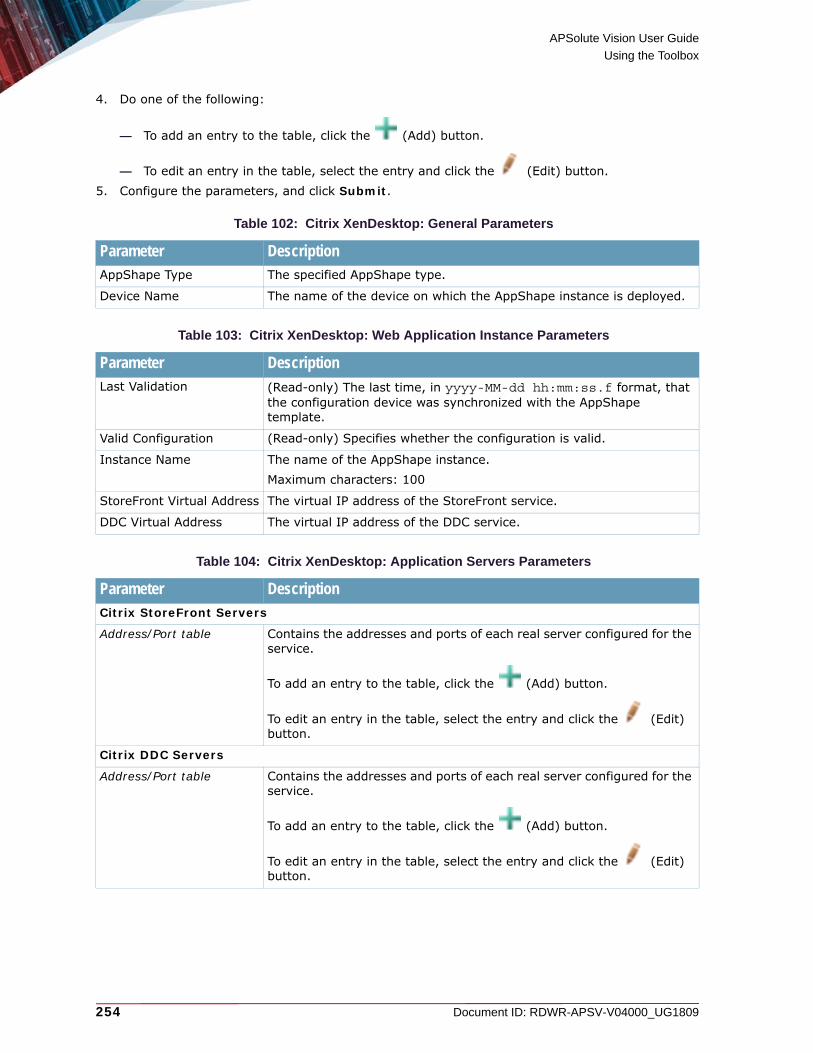
APSolute Vision User Guide
Using the Toolbox
254 Document ID: RDWR-APSV-V04000_UG1809
4. Do one of the following:
— To add an entry to the table, click the (Add) button.
— To edit an entry in the table, select the entry and click the (Edit) button.5. Configure the parameters, and click Submit.
Table 102: Citrix XenDesktop: General Parameters
Parameter DescriptionAppShape Type The specified AppShape type.
Device Name The name of the device on which the AppShape instance is deployed.
Table 103: Citrix XenDesktop: Web Application Instance Parameters
Parameter DescriptionLast Validation (Read-only) The last time, in yyyy-MM-dd hh:mm:ss.f format, that
the configuration device was synchronized with the AppShape template.
Valid Configuration (Read-only) Specifies whether the configuration is valid.
Instance Name The name of the AppShape instance. Maximum characters: 100
StoreFront Virtual Address The virtual IP address of the StoreFront service.
DDC Virtual Address The virtual IP address of the DDC service.
Table 104: Citrix XenDesktop: Application Servers Parameters
Parameter DescriptionCitrix StoreFront Servers
Address/Port table Contains the addresses and ports of each real server configured for the service.
To add an entry to the table, click the (Add) button.
To edit an entry in the table, select the entry and click the (Edit) button.
Citrix DDC Servers
Address/Port table Contains the addresses and ports of each real server configured for the service.
To add an entry to the table, click the (Add) button.
To edit an entry in the table, select the entry and click the (Edit) button.

APSolute Vision User Guide
Using the Toolbox
Document ID: RDWR-APSV-V04000_UG1809 255
Table 105: Citrix XenDesktop: Load Balancing Settings Parameters
Parameter DescriptionStoreFront
SLB Metric The SLB metric used to select next server in the group.Default: Round Robin
Note: If you choose a value other than the default, the AppShape always uses the default value for any additional, specifically related parameter. For example, if the value of SLB Metric is Min Misses, the specifically related Minmiss Hash is always the default 24 Bits.
Health Check The type of content that is examined during health checks. The content depends on the type of health check.Default: tcp
DDC
SLB Metric The SLB metric used to select next server in the group.Default: Round Robin
Note: If you choose a value other than the default, the AppShape always uses the default value for any additional, specifically related parameter. For example, if the value of SLB Metric is Min Misses, the specifically related Minmiss Hash is always the default 24 Bits.
Health Check The type of content that is examined during health checks. The content depends on the type of health check.Default: tcp
Table 106: Citrix XenDesktop: HTTP Parameters
Parameter DescriptionCompression Specifies whether the HTTP profile uses compression.
Default: Enabled
Connection Management Specifies whether the HTTP profile uses connection management.If enabled, you must configure the proxy IP address.Default: Disabled
PIP Table(This button is displayed only when the Connection Management checkbox is selected.)
Opens the Proxy IP pane.
Table 107: Citrix XenDesktop: SSL Parameters
Parameter DescriptionSSL Acceleration Specifies whether SSL offloading is enabled for acceleration.
Default: Enabled

APSolute Vision User Guide
Using the Toolbox
256 Document ID: RDWR-APSV-V04000_UG1809
Configuring a DefenseSSL AppShape InstanceUse the DefenseSSL AppShape to configure an Alteon ADC device to work in a network architecture with DefenseSSL. DefenseSSL mitigates SSL encrypted flood attacks at the network perimeter.
Tip: If you are using DefensePro version 8.x, use the DefenseSSL Quick Setup Operator Toolbox script. For more information, see Using and Managing Toolbox Scripts, page 211.
Notes
• For the CLI configuration that AppShape generates as the result of the hard-coded AppShape pattern or as the result of a value that you specify in the AppShape Instance tab, see DefenseSSL—AppShape-generated Configuration, page 705.
• The template configures some parameters automatically, which the template GUI does not expose. After you finish the following procedure, you can use the Diff command to view the entire configuration.
To configure a DefenseSSL AppShape instance on a device
1. Lock the Alteon device on which you intend to configure the AppShape instance.
2. Click the Toolbox ( ) button, and then, select Advanced ( ) and AppShapes.
3. Select DefenseSSL.
4. Do one of the following:
— To add an entry to the table, click the (Add) button.
— To edit an entry in the table, select the entry and click the (Edit) button.5. Configure the parameters, and click Submit.
Server Certificate(This parameter is displayed only when the SSL Acceleration checkbox is selected.)
The name of the SSL certificate, selected from the drop-down list.To edit the selected SSL certificate, click Server Certificate.
Table 108: DefenseSSL: General Parameters
Parameter DescriptionAppShape Type The specified AppShape type.
Device Name The name of the device on which the AppShape instance is deployed.
Table 107: Citrix XenDesktop: SSL Parameters (cont.)
Parameter Description

APSolute Vision User Guide
Using the Toolbox
Document ID: RDWR-APSV-V04000_UG1809 257
Table 109: DefenseSSL: DefenseSSL Instance Parameters
Parameter DescriptionLast Validation (Read-only) The last time, in yyyy-MM-dd hh:mm:ss.f format, that
the configuration device was synchronized with the AppShape template.
Valid Configuration (Read-only) Specifies whether the configuration is valid.
Instance Name The name of the AppShape instance. Maximum characters: 100
Virtual Address The virtual IP address of the service.
Table 110: DefenseSSL: Application Servers Parameters
Parameter DescriptionAddress/Port table Contains the addresses and ports of each real server configured for the
service.
To add an entry to the table, click the (Add) button.
To edit an entry in the table, select the entry and click the (Edit) button.
Table 111: DefenseSSL: SSL Parameters
Parameter DescriptionSSL Acceleration Specifies whether SSL offloading is enabled for acceleration.
Default: Enabled
Server Certificate(This parameter is displayed only when the SSL Acceleration checkbox is selected.)
The name of the SSL certificate, selected from the drop-down list.To edit the selected SSL certificate, click Server Certificate.
Table 112: DefenseSSL: Static ARP Parameters
Parameter DescriptionAddress The IP address for the ARP entry.
MAC Address The MAC address for the ARP entry.
VLAN The VLAN for the ARP entry.Values: 1–4090
Port The port for the ARP entry.The range of valid values depends on the device on which you are deploying the AppShape instance.

APSolute Vision User Guide
Using the Toolbox
258 Document ID: RDWR-APSV-V04000_UG1809
Configuring a Microsoft Exchange 2010 AppShape InstanceUse the Microsoft Exchange 2010 AppShape to configure an Alteon ADC device to work in a network architecture with MS Exchange 2010. Microsoft Exchange provides business-class email, calendar and contacts. The Alteon and Microsoft Exchange 2010 joint solution provides a highly scalable and highly available unified messaging and communication infrastructure, with fast response time. Using advanced health monitoring of each of the client access servers (CASs), Alteon can validate the availability and response time of those resources, as well as deliver seamless load-balancing, redundancy, and persistency features. Furthermore, Alteon provides service acceleration through compression, caching, and SSL termination to the Exchange users, offloading critical resources from the client access servers, enabling smaller CAS arrays, and thus, lower CAPEX and OPEX in the organization.
Note: With Exchange Server 2010, Outlook clients connect using native MAPI to the RPC Client Access Service (CAS), which runs on Client Access servers. Because the RPC CAS requires the traffic to be passed to the Client Access servers on a large number of ports, Radware recommends that you use a firewall to permit only internal networks to access the RPC Client Access virtual server IP address.
Figure 53: Alteon and Microsoft Exchange 2010 Architecture
Eth
ern
et
Ethernet
Ethernet
Exchange CAS application servers(client access servers)
Mail Box Servers DAG(not part of the AppShape configuration )
Exchange SMTP application servers (HUB transport)
FirewallInternal Clients
External Clients
192.168.1.81 192.168.1.82 192.168.1.33 192.168.1.34 192.168.1.35
RST
Alteon 4416
PWR
USB MNG 2
MNG 1
CONSOLE
PWR
FAN
SYS OK
1000
10/100
1
13 14 15 16
3 5 7 9 11
2 4 6 8 10 12
ACT LINKACT LINK
ACT LINK ACT LINK ACT LINK ACT LINK
ACT LINKACT LINK
RST
Alteon 4416
PWR
USB MNG 2
MNG 1
CONSOLE
PWR
FAN
SYS OK
1000
10/100
1
13 14 15 16
3 5 7 9 11
2 4 6 8 10 12
ACT LINKACT LINK
ACT LINK ACT LINK ACT LINK ACT LINK
ACT LINKACT LINK
Alteon.active.device
192.168.1.1/24
Alteon.backup.device
192.168.1.2/24
DMZ
192.168.2.254/24
192.168.1.254/24
192.168.1.36
Active Directory(not part of the AppShape configuration )
192.168.1.10
Edge Transport Server

APSolute Vision User Guide
Using the Toolbox
Document ID: RDWR-APSV-V04000_UG1809 259
Notes
• For the CLI configuration that AppShape generates as the result of the hard-coded AppShape pattern or as the result of a value that you specify in the AppShape Instance tab, see Microsoft Exchange 2010—AppShape-generated Configuration, page 706.
• The template configures some parameters automatically, which the template GUI does not expose. After you finish the following procedure, you can use the Diff command to view the entire configuration.
To configure a Microsoft Exchange 2010 AppShape instance on a device
1. Lock the Alteon device on which you intend to configure the AppShape instance.
2. Click the Toolbox ( ) button, and then, select Advanced ( ) and AppShapes.
3. Select Microsoft Exchange 2010.
4. Do one of the following:
— To add an entry to the table, click the (Add) button.
— To edit an entry in the table, select the entry and click the (Edit) button.5. Configure the parameters, and click Submit.
Table 113: Microsoft Exchange 2010: General Parameters
Parameter DescriptionAppShape Type The specified AppShape type.
Device Name The name of the device on which the AppShape instance is deployed.
Table 114: Microsoft Exchange 2010: Microsoft Exchange 2010 Instance Parameters
Parameter DescriptionLast Validation (Read-only) The last time, in yyyy-MM-dd hh:mm:ss.f format, that
the configuration device was synchronized with the AppShape template.
Valid Configuration (Read-only) Specifies whether the configuration is valid.
Instance Name The name of the AppShape instance. Maximum characters: 100
Virtual Address The virtual IP address of the service.
Table 115: Microsoft Exchange 2010: Protocols Parameters
Parameter DescriptionRPC Client Access The static port for the RPC Client Access Service.
Values: 10–65535Default: 135

APSolute Vision User Guide
Using the Toolbox
260 Document ID: RDWR-APSV-V04000_UG1809
RPC Endpoint Mapper The port for the RPC Endpoint Mapper.Values: 10–65535Default: 59532
Exchange Address Book The port for the Exchange Address Book.Values: 10–65535Default: 59533
POP3 The port for the associated POP3 server. This parameter is optional.Values: 10–65535Default with the Secured checkbox selected: 993Default with the Secured checkbox cleared: 110
Secured Specifies whether the POP3 server uses a secured port.Default: Enabled
IMAP4 (Optional) The port for the associated IMAP4 server.This parameter is optional.Values: 10–65535Default with the Secured checkbox selected: 993Default with the Secured checkbox cleared: 143
Secured Specifies whether the IMAP4 server uses a secured port.Default: Enabled
Table 116: Microsoft Exchange 2010: Application Servers Parameters
Parameter DescriptionExchange CAS Application Servers
Address/Port table Contains the addresses and ports of each real server configured for the service.
To add an entry to the table, click the (Add) button.
To edit an entry in the table, select the entry and click the (Edit) button.
Exchange SMTP Application Servers
Address/Port table Contains the addresses and ports of each real server configured for the service.
To add an entry to the table, click the (Add) button.
To edit an entry in the table, select the entry and click the (Edit) button.
Table 115: Microsoft Exchange 2010: Protocols Parameters (cont.)
Parameter Description

APSolute Vision User Guide
Using the Toolbox
Document ID: RDWR-APSV-V04000_UG1809 261
Table 117: Microsoft Exchange 2010: Load Balancing Settings Parameters
Parameter DescriptionCAS
SLB Metric The SLB metric used to select next server in the group.1
Default: Least Connections
1 – If you choose a value other than the default, the AppShape always uses the default value for any additional, specifically related parameter. For example, if the value of SLB Metric is Min Misses, the specifically related Minmiss Hash is always the default 24 Bits.
Health Check The type of content that is examined during health checks. The content depends on the type of health check.Default: http
SMTP Settings
SLB Metric The SLB metric used to select next server in the group.1
Default: Least Connections
Health Check The type of content that is examined during health checks. The content depends on the type of health check.Default: smtp
Table 118: Microsoft Exchange 2010: HTTP Parameters
Parameter DescriptionCaching Specifies whether the HTTP profile uses caching.
Default: Enabled
Compression Specifies whether the HTTP profile uses compression.Default: Enabled
Connection Management Specifies whether the HTTP profile uses connection management.If enabled, you must configure the proxy IP address. Default: Disabled
Proxy IP(This button is displayed only when the Connection Management checkbox is selected.)
Opens the Proxy IP pane.
Table 119: Microsoft Exchange 2010: SSL Parameters
Parameter DescriptionSSL Acceleration Specifies whether SSL offloading is enabled for acceleration.
Default: Enabled
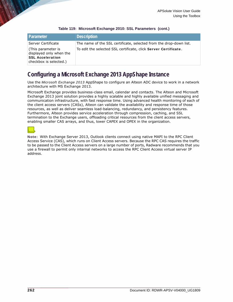
APSolute Vision User Guide
Using the Toolbox
262 Document ID: RDWR-APSV-V04000_UG1809
Configuring a Microsoft Exchange 2013 AppShape InstanceUse the Microsoft Exchange 2013 AppShape to configure an Alteon ADC device to work in a network architecture with MS Exchange 2013. Microsoft Exchange provides business-class email, calendar and contacts. The Alteon and Microsoft Exchange 2013 joint solution provides a highly scalable and highly available unified messaging and communication infrastructure, with fast response time. Using advanced health monitoring of each of the client access servers (CASs), Alteon can validate the availability and response time of those resources, as well as deliver seamless load-balancing, redundancy, and persistency features. Furthermore, Alteon provides service acceleration through compression, caching, and SSL termination to the Exchange users, offloading critical resources from the client access servers, enabling smaller CAS arrays, and thus, lower CAPEX and OPEX in the organization.
Note: With Exchange Server 2013, Outlook clients connect using native MAPI to the RPC Client Access Service (CAS), which runs on Client Access servers. Because the RPC CAS requires the traffic to be passed to the Client Access servers on a large number of ports, Radware recommends that you use a firewall to permit only internal networks to access the RPC Client Access virtual server IP address.
Server Certificate(This parameter is displayed only when the SSL Acceleration checkbox is selected.)
The name of the SSL certificate, selected from the drop-down list.To edit the selected SSL certificate, click Server Certificate.
Table 119: Microsoft Exchange 2010: SSL Parameters (cont.)
Parameter Description

APSolute Vision User Guide
Using the Toolbox
Document ID: RDWR-APSV-V04000_UG1809 263
Figure 54: Alteon and Microsoft Exchange 2013 Architecture
Notes
• For the CLI configuration that AppShape generates as the result of the hard-coded AppShape pattern or as the result of a value that you specify in the AppShape Instance tab, see Microsoft Exchange 2013—AppShape-generated Configuration, page 709.
• The template configures some parameters automatically, which the template GUI does not expose. After you finish the following procedure, you can use the Diff command to view the entire configuration.
To configure a Microsoft Exchange 2013 AppShape instance on a device
1. Lock the Alteon device on which you intend to configure the AppShape instance.
2. Click the Toolbox ( ) button, and then, select Advanced ( ) and AppShapes.
3. Select Microsoft Exchange 2013.
4. Do one of the following:
— To add an entry to the table, click the (Add) button.
— To edit an entry in the table, select the entry and click the (Edit) button.5. Configure the parameters, and click Submit.
Eth
ern
et
Ethernet
Ethernet
Exchange CAS application servers(client access servers)
Mail Box Servers DAG(not part of the AppShape configuration )
Exchange POP3 application servers
FirewallInternal Clients
External Clients
192.168.1.81 192.168.1.82 192.168.1.33 192.168.1.34 192.168.1.37
RST
Alteon 4416
PWR
USB MNG 2
MNG 1
CONSOLE
PWR
FAN
SYS OK
1000
10/100
1
13 14 15 16
3 5 7 9 11
2 4 6 8 10 12
ACT LINKACT LINK
ACT LINK ACT LINK ACT LINK ACT LINK
ACT LINKACT LINK
RST
Alteon 4416
PWR
USB MNG 2
MNG 1
CONSOLE
PWR
FAN
SYS OK
1000
10/100
1
13 14 15 16
3 5 7 9 11
2 4 6 8 10 12
ACT LINKACT LINK
ACT LINK ACT LINK ACT LINK ACT LINK
ACT LINKACT LINK
Alteon.active.device
192.168.1.1/24
Alteon.backup.device
192.168.1.2/24
DMZ
192.168.2.254/24
192.168.1.254/24
192.168.1.38
Active Directory(not part of the AppShape configuration )
192.168.1.10
Edge Transport Server
Exchange IMAP application servers
192.168.1.35 192.168.1.36

APSolute Vision User Guide
Using the Toolbox
264 Document ID: RDWR-APSV-V04000_UG1809
Table 120: Microsoft Exchange 2013: General Parameters
Parameter DescriptionAppShape Type The specified AppShape type.
Device Name The name of the device on which the AppShape instance is deployed.
Table 121: Microsoft Exchange 2013: Microsoft Exchange 2013 Instance Parameters
Parameter DescriptionLast Validation (Read-only) The last time, in yyyy-MM-dd hh:mm:ss.f format, that
the configuration device was synchronized with the AppShape template.
Valid Configuration (Read-only) Specifies whether the configuration is valid.
Instance Name The name of the AppShape instance. Maximum characters: 100
Virtual Address The virtual IP address of the service.
Table 122: Microsoft Exchange 2013: Application Servers Parameters
Parameter DescriptionExchange CAS Application Servers
Address/Port table Contains the addresses and ports of each real server configured for the service.
To add an entry to the table, click the (Add) button.
To edit an entry in the table, select the entry and click the (Edit) button.
Exchange IMAP Application Servers
Address/Port table Contains the addresses and ports of each real server configured for the service.
To add an entry to the table, click the (Add) button.
To edit an entry in the table, select the entry and click the (Edit) button.
Exchange POP3 Application Servers
Address/Port table Contains the addresses and ports of each real server configured for the service.
To add an entry to the table, click the (Add) button.
To edit an entry in the table, select the entry and click the (Edit) button.

APSolute Vision User Guide
Using the Toolbox
Document ID: RDWR-APSV-V04000_UG1809 265
Table 123: Microsoft Exchange 2013: Load Balancing Settings Parameters
Parameter DescriptionCAS
SLB Metric The SLB metric used to select next server in the group.Default: Round Robin
Note: If you choose a value other than the default, the AppShape always uses the default value for any additional, specifically related parameter. For example, if the value of SLB Metric is Min Misses, the specifically related Minmiss Hash is always the default 24 Bits.
Health Check The type of content that is examined during health checks. The content depends on the type of health check.Default: http
IMAP Settings
SLB Metric The SLB metric used to select next server in the group.1
Default: Round Robin
1 – If you choose a value other than the default, the AppShape always uses the default value for any additional, specifically related parameter. For example, if the value of SLB Metric is Min Misses, the specifically related Minmiss Hash is always the default 24 Bits.
Health Check The type of content that is examined during health checks. The content depends on the type of health check.Default: imap
POP3 Settings
SLB Metric The SLB metric used to select next server in the group.1
Default: Round Robin
Health Check The type of content that is examined during health checks. The content depends on the type of health check.Default: pop3
Table 124: Microsoft Exchange 2013: HTTP Parameter
Parameter DescriptionCompression Specifies whether the HTTP profile uses compression.
Default: Enabled
Table 125: Microsoft Exchange 2013: SSL Parameters
Parameter DescriptionSSL Acceleration Specifies whether SSL offloading is enabled for acceleration.
Default: Enabled
Server Certificate(This parameter is displayed only when the SSL Acceleration checkbox is selected.)
The name of the SSL certificate, selected from the drop-down list.To edit the selected SSL certificate, click Server Certificate.

APSolute Vision User Guide
Using the Toolbox
266 Document ID: RDWR-APSV-V04000_UG1809
Configuring a Microsoft Lync External AppShape InstanceUse the Microsoft Lync External AppShape to configure an Alteon ADC device to work in a network architecture with Microsoft Lync External.
Notes
• For the CLI configuration that AppShape generates as the result of the hard-coded AppShape pattern or as the result of a value that you specify in the AppShape Instance tab, see Microsoft Link External—AppShape-generated Configuration, page 711.
• The template configures some parameters automatically, which the template GUI does not expose. After you finish the following procedure, you can use the Diff command to view the entire configuration.
To configure a Microsoft Lync External AppShape instance on a device
1. Lock the Alteon device on which you intend to configure the AppShape instance.
2. Click the Toolbox ( ) button, and then, select Advanced ( ) and AppShapes.
3. Select Microsoft Lync External.
4. Do one of the following:
— To add an entry to the table, click the (Add) button.
— To edit an entry in the table, select the entry and click the (Edit) button.5. Configure the parameters, and click Submit.
Table 126: Microsoft Lync External: General Parameters
Parameter DescriptionAppShape Type The specified AppShape type.
Device Name The name of the device on which the AppShape instance is deployed.
Table 127: Microsoft Lync External: Microsoft Lync External Instance Parameters
Parameter DescriptionLast Validation (Read-only) The last time, in yyyy-MM-dd hh:mm:ss.f
format, that the configuration device was synchronized with the AppShape template.
Valid Configuration (Read-only) Specifies whether the configuration is valid.
Instance Name The name of the AppShape instance.Maximum characters: 100
Edge AV HTTPS Virtual Address The text box contains the virtual IP address of the edge audio-visual service, and the checkbox specifies whether the service is enabled.
Edge Meeting HTTPS Virtual Address The text box contains the virtual IP address of the edge Meeting service, and the checkbox specifies whether the service is enabled.

APSolute Vision User Guide
Using the Toolbox
Document ID: RDWR-APSV-V04000_UG1809 267
Edge IM HTTPS Virtual Address The text box contains the virtual IP address of the edge instant-messaging service, and the checkbox specifies whether the service is enabled.
Edge SIP HTTPS Virtual Address The text box contains the virtual IP address of the edge SIP service, and the checkbox specifies whether the service is enabled.
CWA Virtual Address The text box contains the virtual IP address of the Communicator Web Access (CWA) server, and the checkbox specifies whether the service is enabled.
Table 128: Microsoft Lync External: Application Servers Parameters
Parameter DescriptionSIP Servers
Address/Port table Contains the addresses and ports of each real server configured for the service.
To add an entry to the table, click the (Add) button.
To edit an entry in the table, select the entry and click the (Edit) button.
IM Servers
Address/Port table Contains the addresses and ports of each real server configured for the service.
To add an entry to the table, click the (Add) button.
To edit an entry in the table, select the entry and click the (Edit) button.
CWA Servers
Address/Port table Contains the addresses and ports of each real server configured for the service.
To add an entry to the table, click the (Add) button.
To edit an entry in the table, select the entry and click the (Edit) button.
Meeting Servers
Address/Port table Contains the addresses and ports of each real server configured for the service.
To add an entry to the table, click the (Add) button.
To edit an entry in the table, select the entry and click the (Edit) button.
Table 127: Microsoft Lync External: Microsoft Lync External Instance Parameters (cont.)
Parameter Description

APSolute Vision User Guide
Using the Toolbox
268 Document ID: RDWR-APSV-V04000_UG1809
AV Servers
Address/Port table Contains the addresses and ports of each real server configured for the service.
To add an entry to the table, click the (Add) button.
To edit an entry in the table, select the entry and click the (Edit) button.
Table 129: Microsoft Lync External: Load Balancing Settings Parameters
Parameter DescriptionEach pair of load-balancing parameters (the SLB Metric and the Health Check) is available only when the corresponding checkbox is selected in the Microsoft Lync External: Microsoft Lync External Instance Parameters, page 266 table.
Edge HTTPS SIP (443) Settings
SLB Metric The SLB metric used to select next server in the group.1
Default: Least Connections
Health Check The type of content that is examined during health checks. The content depends on the type of health check.Default: TCP
Edge IM (443) Settings
SLB Metric The SLB metric used to select next server in the group.1
Default: Least Connections
Health Check The type of content that is examined during health checks. The content depends on the type of health check.Default: TCP
Edge Meeting (443) Settings
SLB Metric The SLB metric used to select next server in the group.1
Default: Least Connections
Health Check The type of content that is examined during health checks. The content depends on the type of health check.Default: TCP
Edge CWA Settings
SLB Metric The SLB metric used to select next server in the group.1
Default: Least Connections
Health Check The type of content that is examined during health checks. The content depends on the type of health check.Default: TCP
Edge AV (443) Settings
SLB Metric The SLB metric used to select next server in the group.1
Default: Least Connections
Table 128: Microsoft Lync External: Application Servers Parameters (cont.)
Parameter Description

APSolute Vision User Guide
Using the Toolbox
Document ID: RDWR-APSV-V04000_UG1809 269
Configuring a Microsoft Lync Internal AppShape InstanceUse the Microsoft Lync Internal AppShape to configure an Alteon ADC device to work in a network architecture with Microsoft Lync Internal.
Notes
• For the CLI configuration that AppShape generates as the result of the hard-coded AppShape pattern or as the result of a value that you specify in the AppShape Instance tab, see Microsoft Link Internal—AppShape-generated Configuration, page 714.
• The template configures some parameters automatically, which the template GUI does not expose. After you finish the following procedure, you can use the Diff command to view the entire configuration.
To configure a Microsoft Lync Internal AppShape instance on a device
1. Lock the Alteon device on which you intend to configure the AppShape instance.
2. Click the Toolbox ( ) button, and then, select Advanced ( ) and AppShapes.
3. Select Microsoft Lync Internal.
4. Do one of the following:
— To add an entry to the table, click the (Add) button.
— To edit an entry in the table, select the entry and click the (Edit) button.5. Configure the parameters, and click Submit.
Health Check The type of content that is examined during health checks. The content depends on the type of health check.Default: TCP
1 – If you choose a value other than the default, the AppShape always uses the default value for any additional, specifically related parameter. For example, if the value of SLB Metric is Min Misses, the specifically related Minmiss Hash is always the default 24 Bits.
Table 130: Microsoft Lync Internal: General Parameters
Parameter DescriptionAppShape Type The specified AppShape type.
Device Name The name of the device on which the AppShape instance is deployed.
Table 129: Microsoft Lync External: Load Balancing Settings Parameters (cont.)
Parameter Description
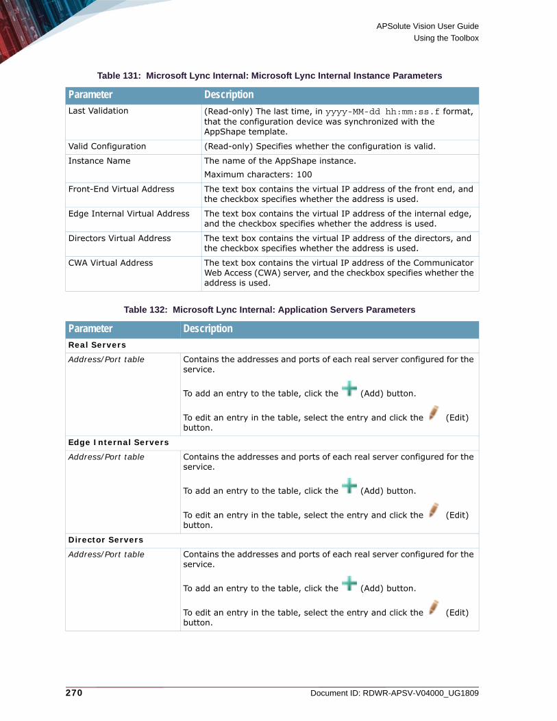
APSolute Vision User Guide
Using the Toolbox
270 Document ID: RDWR-APSV-V04000_UG1809
Table 131: Microsoft Lync Internal: Microsoft Lync Internal Instance Parameters
Parameter DescriptionLast Validation (Read-only) The last time, in yyyy-MM-dd hh:mm:ss.f format,
that the configuration device was synchronized with the AppShape template.
Valid Configuration (Read-only) Specifies whether the configuration is valid.
Instance Name The name of the AppShape instance. Maximum characters: 100
Front-End Virtual Address The text box contains the virtual IP address of the front end, and the checkbox specifies whether the address is used.
Edge Internal Virtual Address The text box contains the virtual IP address of the internal edge, and the checkbox specifies whether the address is used.
Directors Virtual Address The text box contains the virtual IP address of the directors, and the checkbox specifies whether the address is used.
CWA Virtual Address The text box contains the virtual IP address of the Communicator Web Access (CWA) server, and the checkbox specifies whether the address is used.
Table 132: Microsoft Lync Internal: Application Servers Parameters
Parameter DescriptionReal Servers
Address/Port table Contains the addresses and ports of each real server configured for the service.
To add an entry to the table, click the (Add) button.
To edit an entry in the table, select the entry and click the (Edit) button.
Edge Internal Servers
Address/Port table Contains the addresses and ports of each real server configured for the service.
To add an entry to the table, click the (Add) button.
To edit an entry in the table, select the entry and click the (Edit) button.
Director Servers
Address/Port table Contains the addresses and ports of each real server configured for the service.
To add an entry to the table, click the (Add) button.
To edit an entry in the table, select the entry and click the (Edit) button.

APSolute Vision User Guide
Using the Toolbox
Document ID: RDWR-APSV-V04000_UG1809 271
CWA Servers
Address/Port table Contains the addresses and ports of each real server configured for the service.
To add an entry to the table, click the (Add) button.
To edit an entry in the table, select the entry and click the (Edit) button.
Table 133: Microsoft Lync Internal: Load Balancing Settings Parameters
Parameter DescriptionEach pair of load-balancing parameters (the SLB Metric and the Health Check) is available only when the corresponding checkbox is selected in the Microsoft Lync Internal: Microsoft Lync Internal Instance Parameters, page 270 table.
Front-End Settings
SLB Metric The SLB metric used to select next server in the group.1
Default: Least Connections
1 – If you choose a value other than the default, the AppShape always uses the default value for any additional, specifically related parameter. For example, if the value of SLB Metric is Min Misses, the specifically related Minmiss Hash is always the default 24 Bits.
Health Check The type of content that is examined during health checks. The content depends on the type of health check.Default: TCP
Edge Settings
SLB Metric The SLB metric used to select next server in the group.1
Default: Least Connections
Health Check The type of content that is examined during health checks. The content depends on the type of health check.Default: TCP
Directors Settings
SLB Metric The SLB metric used to select next server in the group.1
Default: Least Connections
Health Check The type of content that is examined during health checks. The content depends on the type of health check.Default: TCP
Edge CWA Settings
SLB Metric The SLB metric used to select next server in the group.1
Default: Least Connections
Health Check The type of content that is examined during health checks. The content depends on the type of health check.Default: TCP
Table 132: Microsoft Lync Internal: Application Servers Parameters (cont.)
Parameter Description

APSolute Vision User Guide
Using the Toolbox
272 Document ID: RDWR-APSV-V04000_UG1809
Configuring an Oracle E-Business AppShape InstanceUse the Oracle E-Business AppShape to configure an Alteon ADC device to work in a network architecture with Oracle E-Business.
Notes
• For the CLI configuration that AppShape generates as the result of the hard-coded AppShape pattern or as the result of a value that you specify in the AppShape Instance tab, see Oracle E-Business—AppShape-generated Configuration, page 723.
• The template configures some parameters automatically, which the template GUI does not expose. After you finish the following procedure, you can use the Diff command to view the entire configuration.
To configure an Oracle E-Business instance on a device
1. Lock the Alteon device on which you intend to configure the AppShape instance.
2. Click the Toolbox ( ) button, and then, select Advanced ( ) and AppShapes.
3. Select Oracle E-Business.
Table 134: Microsoft Lync Internal: CWA HTTP Configuration Parameters
Parameter DescriptionCompression Specifies whether compression is enabled on the Communicator Web
Access (CWA) servers.Default: Enabled
Domain Name The CWA domain name.Example: https://cwa.lyncmycompany.com
Note: Internally, APSolute Vision forces the prefix of the domain name to be https. For example, if you enter http://cwa.lyncmycompany.com or just cwa.lyncmycompany.com, APSolute Vision configures the value in Alteon as https://cwa.lyncmycompany.com.
Table 135: Microsoft Lync Internal: SSL Parameters
Parameter DescriptionSSL Acceleration Specifies whether SSL offloading is enabled for acceleration.
Default: Enabled
Server Certificate(This parameter is displayed only when the SSL Acceleration checkbox is selected.)
The name of the SSL certificate, selected from the drop-down list.To edit the selected SSL certificate, click Server Certificate.

APSolute Vision User Guide
Using the Toolbox
Document ID: RDWR-APSV-V04000_UG1809 273
4. Do one of the following:
— To add an entry to the table, click the (Add) button.
— To edit an entry in the table, select the entry and click the (Edit) button.5. Configure the parameters, and click Submit.
Table 136: Oracle E-Business: General Parameters
Parameter DescriptionAppShape Type The specified AppShape type.
Device Name The name of the device on which the AppShape instance is deployed.
Table 137: Oracle E-Business: Oracle E-Business Instance Parameters
Parameter DescriptionLast Validation (Read-only) The last time, in yyyy-MM-dd hh:mm:ss.f format, that
the configuration device was synchronized with the AppShape template.
Valid Configuration (Read-only) Specifies whether the configuration is valid.
Instance Name The name of the AppShape instance.Maximum characters: 100
Virtual Address The virtual IP address of the service.
Table 138: Oracle E-Business: Application Servers Parameters
Parameter DescriptionAddress/Port table Contains the addresses and ports of each real server configured for the
Oracle E-Business server.
To add an entry to the table, click the (Add) button.
To edit an entry in the table, select the entry and click the (Edit) button.
Table 139: Oracle E-Business: Load Balancing Settings Parameters
Parameter DescriptionSLB Metric The SLB metric used to select next server in the group.
Default: Least Connections
Note: If you choose a value other than the default, the AppShape always uses the default value for any additional, specifically related parameter. For example, if the value of SLB Metric is Min Misses, the specifically related Minmiss Hash is always the default 24 Bits.
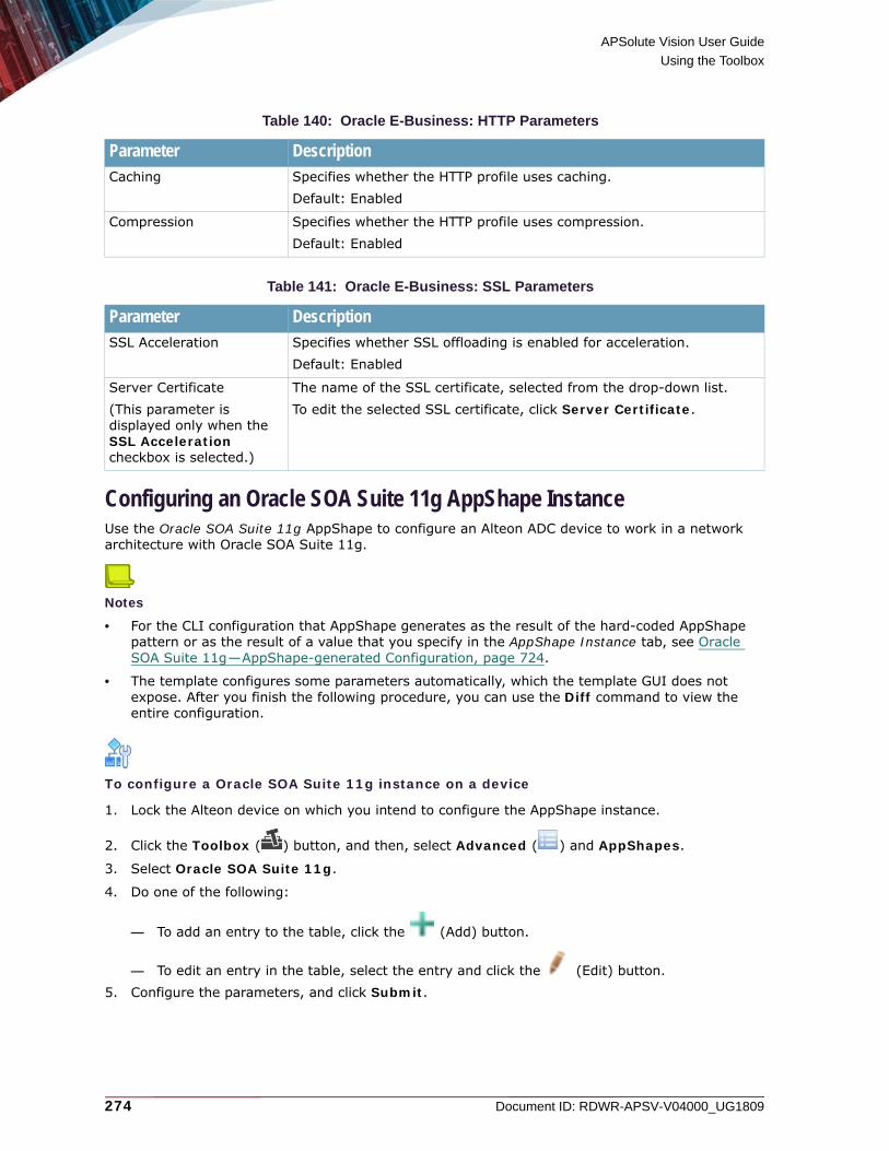
APSolute Vision User Guide
Using the Toolbox
274 Document ID: RDWR-APSV-V04000_UG1809
Configuring an Oracle SOA Suite 11g AppShape InstanceUse the Oracle SOA Suite 11g AppShape to configure an Alteon ADC device to work in a network architecture with Oracle SOA Suite 11g.
Notes
• For the CLI configuration that AppShape generates as the result of the hard-coded AppShape pattern or as the result of a value that you specify in the AppShape Instance tab, see Oracle SOA Suite 11g—AppShape-generated Configuration, page 724.
• The template configures some parameters automatically, which the template GUI does not expose. After you finish the following procedure, you can use the Diff command to view the entire configuration.
To configure a Oracle SOA Suite 11g instance on a device
1. Lock the Alteon device on which you intend to configure the AppShape instance.
2. Click the Toolbox ( ) button, and then, select Advanced ( ) and AppShapes.
3. Select Oracle SOA Suite 11g.
4. Do one of the following:
— To add an entry to the table, click the (Add) button.
— To edit an entry in the table, select the entry and click the (Edit) button.5. Configure the parameters, and click Submit.
Table 140: Oracle E-Business: HTTP Parameters
Parameter DescriptionCaching Specifies whether the HTTP profile uses caching.
Default: Enabled
Compression Specifies whether the HTTP profile uses compression.Default: Enabled
Table 141: Oracle E-Business: SSL Parameters
Parameter DescriptionSSL Acceleration Specifies whether SSL offloading is enabled for acceleration.
Default: Enabled
Server Certificate(This parameter is displayed only when the SSL Acceleration checkbox is selected.)
The name of the SSL certificate, selected from the drop-down list.To edit the selected SSL certificate, click Server Certificate.
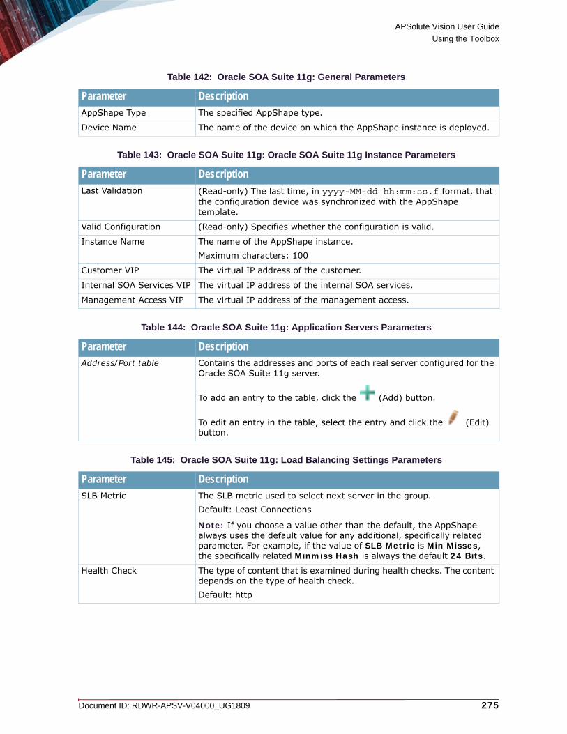
APSolute Vision User Guide
Using the Toolbox
Document ID: RDWR-APSV-V04000_UG1809 275
Table 142: Oracle SOA Suite 11g: General Parameters
Parameter DescriptionAppShape Type The specified AppShape type.
Device Name The name of the device on which the AppShape instance is deployed.
Table 143: Oracle SOA Suite 11g: Oracle SOA Suite 11g Instance Parameters
Parameter DescriptionLast Validation (Read-only) The last time, in yyyy-MM-dd hh:mm:ss.f format, that
the configuration device was synchronized with the AppShape template.
Valid Configuration (Read-only) Specifies whether the configuration is valid.
Instance Name The name of the AppShape instance.Maximum characters: 100
Customer VIP The virtual IP address of the customer.
Internal SOA Services VIP The virtual IP address of the internal SOA services.
Management Access VIP The virtual IP address of the management access.
Table 144: Oracle SOA Suite 11g: Application Servers Parameters
Parameter DescriptionAddress/Port table Contains the addresses and ports of each real server configured for the
Oracle SOA Suite 11g server.
To add an entry to the table, click the (Add) button.
To edit an entry in the table, select the entry and click the (Edit) button.
Table 145: Oracle SOA Suite 11g: Load Balancing Settings Parameters
Parameter DescriptionSLB Metric The SLB metric used to select next server in the group.
Default: Least Connections
Note: If you choose a value other than the default, the AppShape always uses the default value for any additional, specifically related parameter. For example, if the value of SLB Metric is Min Misses, the specifically related Minmiss Hash is always the default 24 Bits.
Health Check The type of content that is examined during health checks. The content depends on the type of health check.Default: http

APSolute Vision User Guide
Using the Toolbox
276 Document ID: RDWR-APSV-V04000_UG1809
Configuring an Oracle WebLogic 12c AppShape InstanceUse the Oracle WebLogic 12c AppShape to configure an Alteon ADC device to work in a network architecture with Oracle WebLogic 12c.
Notes
• For the CLI configuration that AppShape generates as the result of the hard-coded AppShape pattern or as the result of a value that you specify in the AppShape Instance tab, see Oracle WebLogic 12c—AppShape-generated Configuration, page 726.
• The template configures some parameters automatically, which the template GUI does not expose. After you finish the following procedure, you can use the Diff command to view the entire configuration.
To configure a Oracle WebLogic 12c instance on a device
1. Lock the Alteon device on which you intend to configure the AppShape instance.
2. Click the Toolbox ( ) button, and then, select Advanced ( ) and AppShapes.
3. Select Oracle WebLogic 12c.
4. Do one of the following:
— To add an entry to the table, click the (Add) button.
— To edit an entry in the table, select the entry and click the (Edit) button.
Table 146: Oracle SOA Suite 11g: HTTP Parameters
Parameter DescriptionCaching Specifies whether the HTTP profile uses caching.
Default: Enabled
Compression Specifies whether the HTTP profile uses compression.Default: Enabled
Connection Management Specifies whether the HTTP profile uses connection management.If enabled, you must configure the proxy IP address. Default: Enabled
Table 147: Oracle SOA Suite 11g: SSL Parameters
Parameter DescriptionSSL Acceleration Specifies whether SSL offloading is enabled for acceleration.
Default: Enabled
Server Certificate(This parameter is displayed only when the SSL Acceleration checkbox is selected.)
The name of the SSL certificate, selected from the drop-down list.To edit the selected SSL certificate, click Server Certificate.

APSolute Vision User Guide
Using the Toolbox
Document ID: RDWR-APSV-V04000_UG1809 277
5. Configure the parameters, and click Submit.
Table 148: Oracle WebLogic 12c: General Parameters
Parameter DescriptionAppShape Type The specified AppShape type.
Device Name The name of the device on which the AppShape instance is deployed.
Table 149: Oracle WebLogic 12c: Oracle WebLogic 12c Instance Parameters
Parameter DescriptionLast Validation (Read-only) The last time, in yyyy-MM-dd hh:mm:ss.f format, that
the configuration device was synchronized with the AppShape template.
Valid Configuration (Read-only) Specifies whether the configuration is valid.
Instance Name The name of the AppShape instance.Maximum characters: 100
Virtual Address The virtual IP address of the service.
Table 150: Oracle WebLogic 12c: Application Servers Parameters
Parameter DescriptionAddress/Port table Contains the addresses and ports of each real server configured for the
Oracle WebLogic 12c server.
To add an entry to the table, click the (Add) button.
To edit an entry in the table, select the entry and click the (Edit) button.
Table 151: Oracle WebLogic 12c: Load Balancing Settings Parameters
Parameter DescriptionSLB Metric The SLB metric used to select next server in the group.
Default: Round Robin
Note: If you choose a value other than the default, the AppShape always uses the default value for any additional, specifically related parameter. For example, if the value of SLB Metric is Min Misses, the specifically related Minmiss Hash is always the default 24 Bits.
Table 152: Oracle WebLogic 12c: HTTP Parameters
Parameter DescriptionCompression Specifies whether the HTTP profile uses compression.
Default: Enabled

APSolute Vision User Guide
Using the Toolbox
278 Document ID: RDWR-APSV-V04000_UG1809
Configuring a SharePoint 2010 AppShape InstanceUse the SharePoint 2010 AppShape to configure an Alteon ADC device to work in a network architecture with SharePoint 2010.
Notes
• For the CLI configuration that AppShape generates as the result of the hard-coded AppShape pattern or as the result of a value that you specify in the AppShape Instance tab, see SharePoint 2010—AppShape-generated Configuration, page 727.
• The template configures some parameters automatically, which the template GUI does not expose. After you finish the following procedure, you can use the Diff command to view the entire configuration.
To configure a SharePoint 2010 AppShape instance on a device
1. Lock the Alteon device on which you intend to configure the AppShape instance.
2. Click the Toolbox ( ) button, and then, select Advanced ( ) and AppShapes.
3. Select SharePoint 2010.
4. Do one of the following:
— To add an entry to the table, click the (Add) button.
— To edit an entry in the table, select the entry and click the (Edit) button.5. Configure the parameters, and click Submit.
Table 153: Oracle WebLogic 12c: SSL Parameters
Parameter DescriptionSSL Acceleration Specifies whether SSL offloading is enabled for acceleration.
Default: Enabled
Server Certificate(This parameter is displayed only when the SSL Acceleration checkbox is selected.)
The name of the SSL certificate, selected from the drop-down list.To edit the selected SSL certificate, click Server Certificate.
Table 154: SharePoint 2010: General Parameters
Parameter DescriptionAppShape Type The specified AppShape type.
Device Name The name of the device on which the AppShape instance is deployed.

APSolute Vision User Guide
Using the Toolbox
Document ID: RDWR-APSV-V04000_UG1809 279
Table 155: SharePoint 2010: SharePoint 2010 Instance Parameters
Parameter DescriptionLast Validation (Read-only) The last time, in yyyy-MM-dd hh:mm:ss.f format, that
the configuration device was synchronized with the AppShape template.
Valid Configuration (Read-only) Specifies whether the configuration is valid.
Instance Name The name of the AppShape instance.Maximum characters: 100
Virtual Address The virtual IP address of the service.
Table 156: SharePoint 2010: Application Servers Parameters
Parameter DescriptionAddress/Port table Contains the addresses and ports of each real server configured for the
SharePoint 2010 server.
To add an entry to the table, click the (Add) button.
To edit an entry in the table, select the entry and click the (Edit) button.
Table 157: SharePoint 2010: Load Balancing Settings Parameters
Parameter DescriptionSLB Metric The SLB metric used to select next server in the group.
Default: Round Robin
Note: If you choose a value other than the default, the AppShape always uses the default value for any additional, specifically related parameter. For example, if the value of SLB Metric is Min Misses, the specifically related Minmiss Hash is always the default 24 Bits.
Health Check The type of content that is examined during health checks. The content depends on the type of health check.Default: http
Table 158: SharePoint 2010: HTTP Parameters
Parameter DescriptionCaching Specifies whether the HTTP profile uses caching.
Default: Enabled
Compression Specifies whether the HTTP profile uses compression.Default: Enabled
Connection Management Specifies whether the HTTP profile uses connection management.If enabled, you must configure the proxy IP address. Default: Enabled
Domain Name The domain for of the SharePoint 2010 server. Maximum characters: 34

APSolute Vision User Guide
Using the Toolbox
280 Document ID: RDWR-APSV-V04000_UG1809
Configuring a SharePoint 2013 AppShape InstanceUse the SharePoint 2013 AppShape to configure an Alteon ADC device to work in a network architecture with SharePoint 2013.
Notes
• For the CLI configuration that AppShape generates as the result of the hard-coded AppShape pattern or as the result of a value that you specify in the AppShape Instance tab, see SharePoint 2013—AppShape-generated Configuration, page 729.
• The template configures some parameters automatically, which the template GUI does not expose. After you finish the following procedure, you can use the Diff command to view the entire configuration.
To configure a SharePoint 2013 AppShape instance on a device
1. Lock the Alteon device on which you intend to configure the AppShape instance.
2. Click the Toolbox ( ) button, and then, select Advanced ( ) and AppShapes.
3. Select SharePoint 2013.
4. Do one of the following:
— To add an entry to the table, click the (Add) button.
— To edit an entry in the table, select the entry and click the (Edit) button.5. Configure the parameters, and click Submit.
Proxy IP(This button is displayed only when the Connection Management checkbox is selected.)
Opens the Proxy IP pane.
Table 159: SharePoint 2010: SSL Parameters
Parameter DescriptionSSL Acceleration Specifies whether SSL offloading is enabled for acceleration.
Default: Enabled
Server Certificate(This parameter is displayed only when the SSL Acceleration checkbox is selected.)
The name of the SSL certificate, selected from the drop-down list.To edit the selected SSL certificate, click Server Certificate.
Table 158: SharePoint 2010: HTTP Parameters (cont.)
Parameter Description

APSolute Vision User Guide
Using the Toolbox
Document ID: RDWR-APSV-V04000_UG1809 281
Table 160: SharePoint 2013: General Parameters
Parameter DescriptionAppShape Type The specified AppShape type.
Device Name The name of the device on which the AppShape instance is deployed.
Table 161: SharePoint 2013: SharePoint 2013 Instance Parameters
Parameter DescriptionLast Validation (Read-only) The last time, in yyyy-MM-dd hh:mm:ss.f format, that
the configuration device was synchronized with the AppShape template.
Valid Configuration (Read-only) Specifies whether the configuration is valid.
Instance Name The name of the AppShape instance.Maximum characters: 100
Virtual Address The virtual IP address of the service.
Table 162: SharePoint 2013: Application Servers Parameters
Parameter DescriptionAddress/Port table Contains the addresses and ports of each real server configured for the
SharePoint 2013 server.
To add an entry to the table, click the (Add) button.
To edit an entry in the table, select the entry and click the (Edit) button.
Table 163: SharePoint 2013: Load Balancing Settings Parameters
Parameter DescriptionSLB Metric The SLB metric used to select next server in the group.
Default: Round Robin
Note: If you choose a value other than the default, the AppShape always uses the default value for any additional, specifically related parameter. For example, if the value of SLB Metric is Min Misses, the specifically related Minmiss Hash is always the default 24 Bits.
Table 164: SharePoint 2013: HTTP Parameters
Parameter DescriptionCompression Specifies whether the HTTP profile uses compression.
Default: Enabled
Domain Name The domain for of the SharePoint 2013 server. Maximum characters: 34

APSolute Vision User Guide
Using the Toolbox
282 Document ID: RDWR-APSV-V04000_UG1809
Configuring an VMware View 5.1 AppShape InstanceUse the VMware View 5.1 AppShape to configure an Alteon ADC device to work in a network architecture with VMware View 5.1.
Notes
• For the CLI configuration that AppShape generates as the result of the hard-coded AppShape pattern or as the result of a value that you specify in the AppShape Instance tab, see VMware View 5.1—AppShape-generated Configuration, page 731.
• The template configures some parameters automatically, which the template GUI does not expose. After you finish the following procedure, you can use the Diff command to view the entire configuration.
To configure a VMware View 5.1 instance on a device
1. Lock the Alteon device on which you intend to configure the AppShape instance.
2. Click the Toolbox ( ) button, and then, select Advanced ( ) and AppShapes.
3. Select VMware View 5.1.
4. Do one of the following:
— To add an entry to the table, click the (Add) button.
— To edit an entry in the table, select the entry and click the (Edit) button.5. Configure the parameters, and click Submit.
Table 165: SharePoint 2013: SSL Parameters
Parameter DescriptionSSL Acceleration Specifies whether SSL offloading is enabled for acceleration.
Default: Enabled
Server Certificate(This parameter is displayed only when the SSL Acceleration checkbox is selected.)
The name of the SSL certificate, selected from the drop-down list.To edit the selected SSL certificate, click Server Certificate.
Table 166: VMware View 5.1: General Parameters
Parameter DescriptionAppShape Type The specified AppShape type.
Device Name The name of the device on which the AppShape instance is deployed.

APSolute Vision User Guide
Using the Toolbox
Document ID: RDWR-APSV-V04000_UG1809 283
Table 167: VMware View 5.1: VMware View 5.1 Instance Parameters
Parameter DescriptionLast Validation (Read-only) The last time, in yyyy-MM-dd hh:mm:ss.f format, that
the configuration device was synchronized with the AppShape template.
Valid Configuration (Read-only) Specifies whether the configuration is valid.
Instance Name The name of the AppShape instance.Maximum characters: 100
Virtual Address The virtual IP address of the service.
Table 168: VMware View 5.1: Application Servers Parameters
Parameter DescriptionAddress/Port table Contains the addresses and ports of each real server configured for the
VMware View 5.1 server.
To add an entry to the table, click the (Add) button.
To edit an entry in the table, select the entry and click the (Edit) button.
Table 169: VMware View 5.1: Load Balancing Settings Parameters
Parameter DescriptionSLB Metric The SLB metric used to select next server in the group.
Default: Persistent Hash
Note: If you choose a value other than the default, the AppShape always uses the default value for any additional, specifically related parameter. For example, if the value of SLB Metric is Min Misses, the specifically related Minmiss Hash is always the default 24 Bits.
Table 170: VMware View 5.1: HTTP Parameters
Parameter DescriptionCompression Specifies whether the HTTP profile uses compression.
Default: Enabled
Table 171: VMware View 5.1: SSL Parameters
Parameter DescriptionSSL Acceleration Specifies whether SSL offloading is enabled for acceleration.
Default: Enabled
Server Certificate(This parameter is displayed only when the SSL Acceleration checkbox is selected.)
The name of the SSL certificate, selected from the drop-down list.To edit the selected SSL certificate, click Server Certificate.

APSolute Vision User Guide
Using the Toolbox
284 Document ID: RDWR-APSV-V04000_UG1809
Configuring a Zimbra AppShape InstanceUse the Zimbra AppShape to configure an Alteon ADC device to work in a network architecture with Zimbra.
Notes
• For the CLI configuration that AppShape generates as the result of the hard-coded AppShape pattern or as the result of a value that you specify in the AppShape Instance tab, see Zimbra—AppShape-generated Configuration, page 732.
• The template configures some parameters automatically, which the template GUI does not expose. After you finish the following procedure, you can use the Diff command to view the entire configuration.
To configure a Zimbra instance on a device
1. Lock the Alteon device on which you intend to configure the AppShape instance.
2. Click the Toolbox ( ) button, and then, select Advanced ( ) and AppShapes.
3. Select Zimbra.
4. Do one of the following:
— To add an entry to the table, click the (Add) button.
— To edit an entry in the table, select the entry and click the (Edit) button.5. Configure the parameters, and click Submit.
Table 172: Zimbra: General Parameters
Parameter DescriptionAppShape Type The specified AppShape type.
Device Name The name of the device on which the AppShape instance is deployed.
Table 173: Zimbra: Zimbra Instance Parameters
Parameter DescriptionLast Validation (Read-only) The last time, in yyyy-MM-dd hh:mm:ss.f format, that
the configuration device was synchronized with the AppShape template.
Valid Configuration (Read-only) Specifies whether the configuration is valid.
Instance Name The name of the AppShape instance.Maximum characters: 100
Virtual Address The virtual IP address of the service.

APSolute Vision User Guide
Using the Toolbox
Document ID: RDWR-APSV-V04000_UG1809 285
Table 174: Zimbra: Application Servers Parameters
Parameter DescriptionAddress/Port table Contains the addresses and ports of each real server configured for the
Zimbra server.
To add an entry to the table, click the (Add) button.
To edit an entry in the table, select the entry and click the (Edit) button.
Table 175: Zimbra: Load Balancing Settings Parameters
Parameter DescriptionSLB Metric The SLB metric used to select next server in the group.
Default: Persistent Hash
Note: If you choose a value other than the default, the AppShape always uses the default value for any additional, specifically related parameter. For example, if the value of SLB Metric is Min Misses, the specifically related Minmiss Hash is always the default 24 Bits.
Table 176: Zimbra: HTTP Parameters
Parameter DescriptionCompression Specifies whether the HTTP profile uses compression.
Default: Enabled
Table 177: Zimbra: SSL Parameters
Parameter DescriptionSSL Acceleration Specifies whether SSL offloading is enabled for acceleration.
Default: Enabled
Server Certificate(This parameter is displayed only when the SSL Acceleration checkbox is selected.)
The name of the SSL certificate, selected from the drop-down list.To edit the selected SSL certificate, click Server Certificate.

APSolute Vision User Guide
Using the Toolbox
286 Document ID: RDWR-APSV-V04000_UG1809

Document ID: RDWR-APSV-V04000_UG1809 287
CHAPTER 8 – SCHEDULING APSOLUTE VISION AND DEVICE TASKS
The following topics describe how to schedule APSolute Vision and device operations in the APSolute Vision Scheduler:• Overview of Scheduling, page 287• Managing Tasks in the Scheduler, page 288• Task Parameters, page 290
Overview of SchedulingYou can schedule various operations for the APSolute Vision server and managed devices. Scheduled operations are called tasks.The APSolute Vision scheduler tracks when tasks were last performed and when they are due to be performed next. When you configure a task for multiple devices, the task runs on each device sequentially. After the task completes on one device, it begins on the next. If the task fails to complete on a device, the Scheduler will activate the task on the next listed device.When you create a task and specify the time to run it, the time is according to your local OS. APSolute Vision then stores the time, translated to the timezone of the of the APSolute Vision server, and then runs it accordingly. That is, once you configure a task, it runs according to the APSolute Vision time settings, disregarding any changes made to the local OS time settings.
Caution: If the APSolute Vision client timezone differs from the timezone of the APSolute Vision server or the managed device, take the time offset into consideration.
When you define a task, you can choose whether to enable or disable the task. All configured tasks are stored in the APSolute Vision database.You can define the following types of scheduled tasks:• Back up the APSolute Vision server configuration• Back up a device configuration• Back up the APSolute Vision Reporter data• Reboot a device• Update the Radware security signature file onto a DefensePro device from Radware.com or the
proxy server• Update the fraud signature file onto a DefensePro device from Radware.com or the proxy server• Update the APSolute Vision Attack Description file from Radware.com or the proxy server• Run an Operator Toolbox script• Retrieve the ERT IP Reputation Feed file for Alteon from the Radware domain• Retrieve the ERT Active Attackers Feed file for DefensePro from the Radware domain

APSolute Vision User Guide
Scheduling APSolute Vision and Device Tasks
288 Document ID: RDWR-APSV-V04000_UG1809
Note: You can perform some of the operations manually, for example, from the APSolute Vision Settings view System perspective, or from the Operations options
( ).
Managing Tasks in the SchedulerThe Task List table is the starting point for viewing and configuring tasks, which are scheduled operations. The table displays the information for each configured task. You can sort and filter the table rows according to your needs. You can also drag the bottom of Task List pane to lengthen the table.
Figure 55: Sorting Rows in the Task List
Note: For more information on filtering table rows, see Filtering Table Rows, page 102.
Table 178: Tasks Table Parameters
Parameter DescriptionTask Type The type of task to be performed.
Name The name of the configured task.
Description The user-defined description of the task.
Current Status The current status of the task.Values: Waiting, In progress
Enabled When selected, the task runs according to the defined schedule. Disabled tasks are not activated, but the task is saved in the database.
Last Execution Status Whether the last task run was successful. When the task is disabled or has not yet started, the status is Never Executed.Values:• Failure• Never Executed• Success• Warning
Last Execution Time The date and time of the last task run. When the task is disabled or has not yet started, this field is empty.
Next Execution Time The date and time of the next task run. When the task is disabled, this field is empty.
Click the far-right side of the title of the column with the values to sort by. Then, select the option that you require, for example, Sort Ascending or Sort Descending.

APSolute Vision User Guide
Scheduling APSolute Vision and Device Tasks
Document ID: RDWR-APSV-V04000_UG1809 289
To configure a scheduled task
1. In the APSolute Vision toolbar, click the (Scheduler) button. The Tasks table displays information for each scheduled task.
2. Do one of the following:
— To add an entry to the table, click the (Add) button. Then, select the type of task, and click Submit. The dialog box for the selected task type is displayed.
— To edit an entry in the table, select the entry and click the (Edit) button.3. Configure task parameters, and click Submit. All task configurations include basic parameters
and scheduling parameters. Other parameters depend on the task type that you select. Some tasks that APSolute Vision exposes are non-operational/irrelevant for certain products and/or versions. For more information, see the description of the relevant task parameters in Task Parameters, page 290
To run an existing task
1. In the APSolute Vision toolbar, click the (Scheduler) button. The Tasks table displays information for each scheduled task.
2. Select the required task, and click the (Run Now) button.
Run The frequency at which the task runs; for example, daily or weekly. The schedule start date is displayed, if it has been defined.Values:• Daily • Minutes• Once• Weekly
Table 178: Tasks Table Parameters (cont.)
Parameter Description

APSolute Vision User Guide
Scheduling APSolute Vision and Device Tasks
290 Document ID: RDWR-APSV-V04000_UG1809
Task ParametersThe following sections describe the parameters for Scheduler tasks:• APSolute Vision Configuration Backup—Parameters, page 290• APSolute Vision Reporter Backup—Parameters, page 293• Update Security Signature Files—Parameters, page 295• Update Fraud Security Signatures—Parameters, page 296• Update Attack Description File—Parameters, page 297• Device Configuration Backup—Parameters, page 299• Device Reboot Task—Parameters, page 301• Operator Toolbox Task—Parameters, page 302• ERT Active Attackers Feed for DefensePro—Parameters, page 305• ERT IP Reputation Feed for Alteon—Parameters, page 307
Note: Some tasks that APSolute Vision exposes are non-operational and/or irrelevant for certain DefensePro versions.
APSolute Vision Configuration Backup—ParametersThe APSolute Vision Configuration Backup task creates a backup of the APSolute Vision configuration in the storage location and exports the backup to a specified destination.Each backup includes the following:• The APSolute Vision system configuration• The local users• The managed devices• The host IP addresses in the database-viewer list
The task does not back up the following:
• The password of the radware user of the APSolute Vision server appliance
• The IP address(es) of the APSolute Vision server• The DNS address(es) of the APSolute Vision server • The network routes of the APSolute Vision server • Attack data
Notes
• The storage location is, by default, a hard-coded location in the APSolute Vision server.
• For information on managing the backups using the CLI, see System Commands, page 602.
• Restoring the configuration is performed using the CLI. For more information, see system backup config restore, page 608.
• APSolute Vision stores up to five configuration-backup iterations in the storage location. After the fifth configuration-backup, APSolute Vision deletes the oldest one.

APSolute Vision User Guide
Scheduling APSolute Vision and Device Tasks
Document ID: RDWR-APSV-V04000_UG1809 291
• The backup filenames in the storage location are the first five characters of the specified filename plus a 10-character timestamp. When the task exports the backup file, the filename is as specified in the task configuration.
• The backup file in the storage location includes the hard-coded description Scheduler-generated.
Table 179: APSolute Vision Configuration Backup: General Parameters
Parameter DescriptionName A name for the task.
Description A user-defined description of the task.
Enabled When selected, the task runs according to the defined schedule. Disabled tasks are not activated, but the task configuration is saved in the database.
Current Status (Read-only) The current status of the task.Values: Waiting, In progress
Table 180: APSolute Vision Configuration Backup: Schedule Parameters
Parameter DescriptionRun The frequency at which the task runs.
Select a frequency, then configure the related time and day/date parameters. Values:• Once—The task runs one time only at the specified date and time.• Minutes—The task runs at intervals of the specified number of
minutes between task starts. • Daily—The task runs daily at the specified time.• Weekly—The task runs every week on the specified day or days, at
the specified time.
Note: Tasks run according to the time as configured on the APSolute Vision client.
Time1 The time at which the task runs.
Date2 The date on which the task runs.
Minutes3 The interval, in minutes, at which the task runs.
Run Always4 Specifies whether the task always runs or only during the defined period.Values:• Enabled—The task is activated immediately and runs indefinitely, with
no start or end time. It runs at the first Time configured with the Frequency in the Schedule tab.
• Disabled—The task runs (at the time and frequency specified in the Schedule tab) from the specified Start Date at the Start Time until the End Date at the End Time.
Default: Enabled
Start Date5 The date and time at which the task is activated.
Start Time

APSolute Vision User Guide
Scheduling APSolute Vision and Device Tasks
292 Document ID: RDWR-APSV-V04000_UG1809
End Date The date and time after which the task no longer runs.
End Time
1 – This parameter is available only when the specified Run value is Once, Daily, or Weekly.
2 – This parameter is available only when the specified Run value is Once.3 – This parameter is available only when the specified Run value is Minutes.4 – This parameter is available only when the specified Run value is Minutes, Daily, or
Weekly.5 – This parameter is available only when the Run Always checkbox is cleared.
Table 181: APSolute Vision Configuration Backup: Destination Parameters
Parameter DescriptionBackup Configuration To The destination of the backup configuration files.
Values:• APSolute Vision Server• APSolute Vision and External Location Default: APSolute Vision Server
Protocol1
1 – This parameter is available only when Backup Configuration To is APSolute Vision Server and External Location.
The protocol that APSolute Vision uses for this task.Values:• FTP• SCP• SFTP• SSH
IP Address The IP address of the external location.
Directory The path to the export directory with no spaces. Only alphanumeric characters and underscores (_) are allowed.
Backup File Name The name of the backup, up to 15 characters, with no spaces. Only alphanumeric characters and underscores (_) are allowed.
User The username.
Password The user password.
Confirm Password The user password.
Table 180: APSolute Vision Configuration Backup: Schedule Parameters (cont.)
Parameter Description

APSolute Vision User Guide
Scheduling APSolute Vision and Device Tasks
Document ID: RDWR-APSV-V04000_UG1809 293
APSolute Vision Reporter Backup—ParametersThe APSolute Vision Reporter Backup task creates a backup of the APSolute Vision Reporter data in the storage location and exports the date to a specified destination. The backup includes all the APSolute Vision Reporter data.
Notes
• For information on managing the backups using the CLI, see System Commands, page 602.
• Restoring the data is performed using the CLI. For more information, see system backup config restore, page 608.
• APSolute Vision stores up to three iterations of the APSolute Vision Reporter data in the storage location. After the third reporter-backup, the system deletes the oldest one.
• The backup filenames in the storage location are the first five characters of the specified filename plus a 10-character timestamp. When the task exports the backup file, the filename is as specified in the task configuration.
• The backup file in the storage location includes the hard-coded description Scheduler-generated.
Table 182: APSolute Vision Reporter Backup: General Parameters
Parameter DescriptionName A name for the task.
Description A user-defined description of the task.
Enabled When selected, the task runs according to the defined schedule. Disabled tasks are not activated, but the task configuration is saved in the database.
Table 183: APSolute Vision Reporter Backup: Schedule Parameters
Parameter DescriptionRun The frequency at which the task runs.
Select a frequency, then configure the related time and day/date parameters. Values:• Once—The task runs one time only at the specified date and time.• Minutes—The task runs at intervals of the specified number of
minutes between task starts.• Daily—The task runs daily at the specified time.• Weekly—The task runs every week on the specified day or days, at
the specified time.
Note: Tasks run according to the time as configured on the APSolute Vision client.
Time1 The time at which the task runs.
Date2 The date on which the task runs.
Minutes3 The interval, in minutes, at which the task runs.

APSolute Vision User Guide
Scheduling APSolute Vision and Device Tasks
294 Document ID: RDWR-APSV-V04000_UG1809
Run Always4 Specifies whether the task always runs or only during the defined period.Values:• Enabled—The task is activated immediately and runs indefinitely, with
no start or end time. It runs at the first Time configured with the Frequency in the Schedule tab.
• Disabled—The task runs (at the time and frequency specified in the Schedule tab) from the specified Start Date at the Start Time until the End Date at the End Time.
Default: Enabled
Start Date5 The date and time at which the task is activated.
Start Time
End Date The date and time after which the task no longer runs.
End Time
1 – This parameter is available only when the specified Run value is Once, Daily, or Weekly.
2 – This parameter is available only when the specified Run value is Once.3 – This parameter is available only when the specified Run value is Minutes.4 – This parameter is available only when the specified Run value is Minutes, Daily, or
Weekly.5 – This parameter is available only when the Run Always checkbox is cleared.
Table 184: APSolute Vision Reporter Backup: Destination Parameters
Parameter DescriptionBackup Configuration To The destination of the backup configuration files.
Values:• APSolute Vision Server• APSolute Vision and External LocationDefault: APSolute Vision Server
Protocol1 The protocol that APSolute Vision uses for this task.Values:• FTP• SCP• SFTP• SSH
IP Address The IP address of the external location.
Directory The path to the export directory with no spaces. Only alphanumeric characters and underscores (_) are allowed.
Backup File Name The name of the backup, up to 15 characters, with no spaces. Only alphanumeric characters and underscores (_) are allowed.
User The username.
Password The user password.
Confirm Password The user password.
Table 183: APSolute Vision Reporter Backup: Schedule Parameters (cont.)
Parameter Description
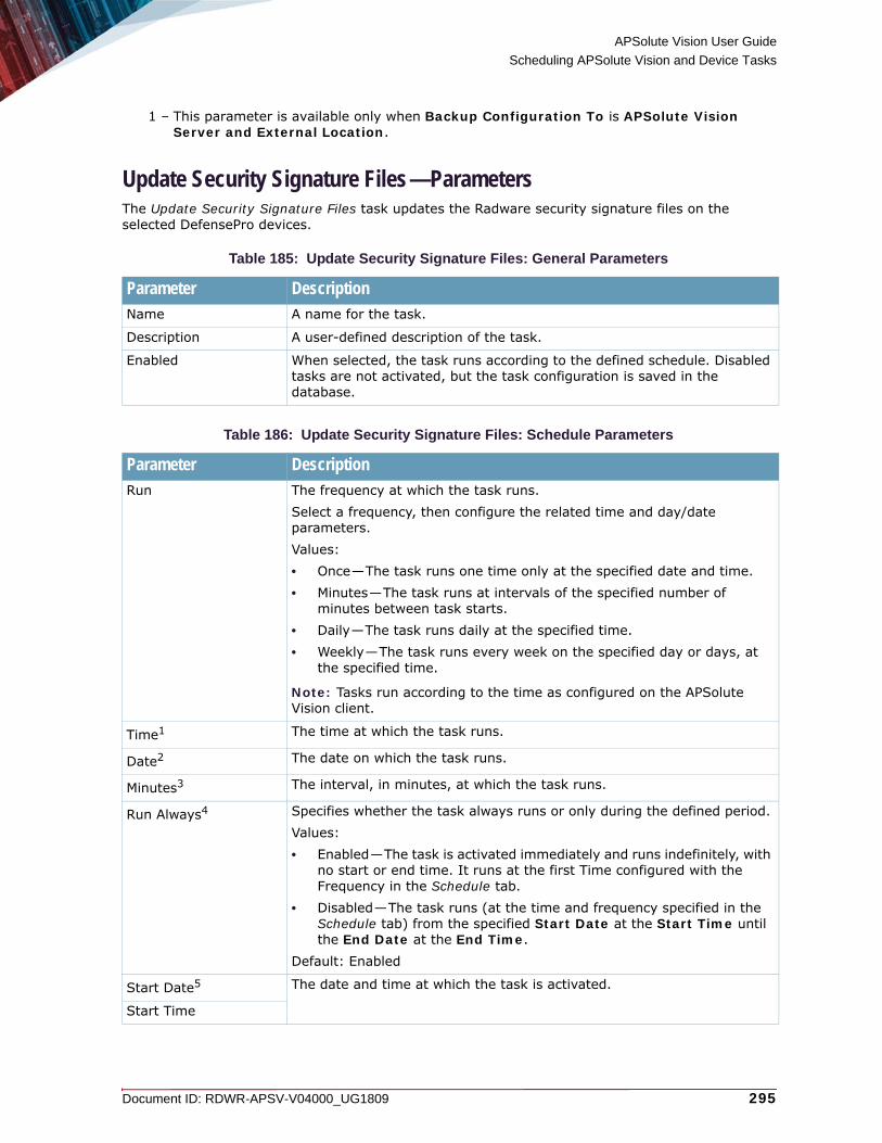
APSolute Vision User Guide
Scheduling APSolute Vision and Device Tasks
Document ID: RDWR-APSV-V04000_UG1809 295
Update Security Signature Files—ParametersThe Update Security Signature Files task updates the Radware security signature files on the selected DefensePro devices.
1 – This parameter is available only when Backup Configuration To is APSolute Vision Server and External Location.
Table 185: Update Security Signature Files: General Parameters
Parameter DescriptionName A name for the task.
Description A user-defined description of the task.
Enabled When selected, the task runs according to the defined schedule. Disabled tasks are not activated, but the task configuration is saved in the database.
Table 186: Update Security Signature Files: Schedule Parameters
Parameter DescriptionRun The frequency at which the task runs.
Select a frequency, then configure the related time and day/date parameters. Values:• Once—The task runs one time only at the specified date and time.• Minutes—The task runs at intervals of the specified number of
minutes between task starts. • Daily—The task runs daily at the specified time.• Weekly—The task runs every week on the specified day or days, at
the specified time.
Note: Tasks run according to the time as configured on the APSolute Vision client.
Time1 The time at which the task runs.
Date2 The date on which the task runs.
Minutes3 The interval, in minutes, at which the task runs.
Run Always4 Specifies whether the task always runs or only during the defined period.Values:• Enabled—The task is activated immediately and runs indefinitely, with
no start or end time. It runs at the first Time configured with the Frequency in the Schedule tab.
• Disabled—The task runs (at the time and frequency specified in the Schedule tab) from the specified Start Date at the Start Time until the End Date at the End Time.
Default: Enabled
Start Date5 The date and time at which the task is activated.
Start Time

APSolute Vision User Guide
Scheduling APSolute Vision and Device Tasks
296 Document ID: RDWR-APSV-V04000_UG1809
Update Fraud Security Signatures—ParametersThe Update Fraud Security Signatures task updates the fraud security signatures on the selected DefensePro devices.
Caution: This feature is operational only in DefensePro 6.x versions and 7.x versions 7.42.09 and later.
Note: The frequency range for the Update Fraud Security Signatures task is 10–60 minutes. The default interval is 60 minutes.
End Date The date and time after which the task no longer runs.
End Time
1 – This parameter is available only when the specified Run value is Once, Daily, or Weekly.
2 – This parameter is available only when the specified Run value is Once.3 – This parameter is available only when the specified Run value is Minutes.4 – This parameter is available only when the specified Run value is Minutes, Daily, or
Weekly.5 – This parameter is available only when the Run Always checkbox is cleared.
Table 187: Update Security Signature Files: Target Device List
Parameter DescriptionThe Available lists and the Selected lists of DefensePro devices and Logical Groups (of DefensePro devices). The Available lists display the available devices and available Logical Groups. The Selected device list displays the devices whose Radware signature files this task updates. The Selected Logical Group list displays the Logical Groups with the devices whose Radware signature files this task updates.Select entries from the lists and use the arrows to move the entries to the other lists as required.
Note: When a Logical Group is selected, the effective Target Device List dynamically updates— according to the devices in the Logical Group. That is, when the device-set of a Logical Group changes, the effective Target Device List changes accordingly. For more information, see Using Logical Groups of Devices, page 190.
Table 188: Update Fraud Security Signatures: General Parameters
Parameter DescriptionName A name for the task.
Description A user-defined description of the task.
Enabled When selected, the task runs according to the defined schedule. Disabled tasks are not activated, but the task configuration is saved in the database.
Table 186: Update Security Signature Files: Schedule Parameters (cont.)
Parameter Description

APSolute Vision User Guide
Scheduling APSolute Vision and Device Tasks
Document ID: RDWR-APSV-V04000_UG1809 297
Update Attack Description File—ParametersThe Update Attack Description File task updates the attack description file on the APSolute Vision server.
Caution: In Radware DefensePro DDoS Mitigation for Cisco Firepower, this feature is non-operational.
Table 189: Update Fraud Security Signatures: Schedule Parameters
Parameter DescriptionRun (Read-only) The frequency unit at which the task runs.
Value: Minutes
Note: Tasks run according to the time as configured on the APSolute Vision client.
Minutes The frequency, in minutes, at which the task runs.Values: 10–60Default: 60
Note: Tasks run according to the time as configured on the APSolute Vision client.
Run Always Specifies whether the task always runs or only during the defined period.Values:• Enabled—The task is activated immediately and runs indefinitely,
with no start or end time. It runs at the first Time configured with the Frequency in the Schedule tab.
• Disabled—The task runs (at the time and frequency specified in the Schedule tab) from the specified Start Date at the Start Time until the End Date at the End Time.
Default: Enabled
Table 190: Update Fraud Security Signatures: Target Device List
Parameter DescriptionThe Available lists and the Selected lists of DefensePro devices and Logical Groups (of DefensePro devices). The Available lists display the available devices and available Logical Groups. The Selected device list displays the devices whose fraud signature files this task updates. The Selected Logical Group list displays the Logical Groups with the devices whose fraud signature files this task updates.Select entries from the lists and use the arrows to move the entries to the other lists as required.
Note: When a Logical Group is selected, the effective Target Device List dynamically updates— according to the devices in the Logical Group. That is, when the device-set of a Logical Group changes, the effective Target Device List changes accordingly. For more information, see Using Logical Groups of Devices, page 190.
Table 191: Update Attack Description File: General Parameters
Parameter DescriptionName A name for the task.

APSolute Vision User Guide
Scheduling APSolute Vision and Device Tasks
298 Document ID: RDWR-APSV-V04000_UG1809
Description A user-defined description of the task.
Enabled When selected, the task runs according to the defined schedule. Disabled tasks are not activated, but the task configuration is saved in the database.
Table 192: Update Vision's Attack Description File: Schedule Parameters
Parameter DescriptionRun The frequency at which the task runs.
Select a frequency, then configure the related time and day/date parameters.Values:• Once—The task runs one time only at the specified date and time.• Minutes—The task runs at intervals of the specified number of
minutes between task starts. • Daily—The task runs daily at the specified time.• Weekly—The task runs every week on the specified day or days, at
the specified time.
Note: Tasks run according to the time as configured on the APSolute Vision client.
Time1
1 – This parameter is available only when the specified Run value is Once, Daily, or Weekly.
The time at which the task runs.
Date2
2 – This parameter is available only when the specified Run value is Once.
The date on which the task runs.
Minutes3
3 – This parameter is available only when the specified Run value is Minutes.
The interval, in minutes, at which the task runs.
Run Always4
4 – This parameter is available only when the specified Run value is Minutes, Daily, or Weekly.
Specifies whether the task always runs or only during the defined period.Values:• Enabled—The task is activated immediately and runs indefinitely, with
no start or end time. It runs at the first Time configured with the Frequency in the Schedule tab.
• Disabled—The task runs (at the time and frequency specified in the Schedule tab) from the specified Start Date at the Start Time until the End Date at the End Time.
Default: Enabled
Start Date5
5 – This parameter is available only when the Run Always checkbox is cleared.
The date and time at which the task is activated.
Start Time
End Date The date and time after which the task no longer runs.
End Time
Table 191: Update Attack Description File: General Parameters (cont.)
Parameter Description

APSolute Vision User Guide
Scheduling APSolute Vision and Device Tasks
Document ID: RDWR-APSV-V04000_UG1809 299
Device Configuration Backup—ParametersThe Device Configuration Backup task saves a configuration backup of the specified devices.
Note: By default, you can save up to five (5) configuration files per device on the APSolute Vision server. You can change this parameter in the APSolute Vision Setup tab.
Table 193: Device Configuration Backup: General Parameters
Parameter DescriptionName A name for the task.
Description A user-defined description of the task.
Enabled When selected, the task runs according to the defined schedule. Disabled tasks are not activated, but the task configuration is saved in the database.
Table 194: Device Configuration Backup: Schedule Parameters
Parameter DescriptionRun The frequency at which the task runs.
Select a frequency, then configure the related time and day/date parameters. Values:• Once—The task runs one time only at the specified date and time.• Minutes—The task runs at intervals of the specified number of
minutes between task starts. • Daily—The task runs daily at the specified time.• Weekly—The task runs every week on the specified day or days, at
the specified time.
Note: Tasks run according to the time as configured on the APSolute Vision client.
Time1 The time at which the task runs.
Date2 The date on which the task runs.
Minutes3 The interval, in minutes, at which the task runs.
Run Always4 Specifies whether the task always runs or only during the defined period.Values:• Enabled—The task is activated immediately and runs indefinitely, with
no start or end time. It runs at the first Time configured with the Frequency in the Schedule tab.
• Disabled—The task runs (at the time and frequency specified in the Schedule tab) from the specified Start Date at the Start Time until the End Date at the End Time.
Default: Enabled
Start Date5 The date and time at which the task is activated.
Start Time

APSolute Vision User Guide
Scheduling APSolute Vision and Device Tasks
300 Document ID: RDWR-APSV-V04000_UG1809
End Date The date and time after which the task no longer runs.
End Time
1 – This parameter is available only when the specified Run value is Once, Daily, or Weekly.
2 – This parameter is available only when the specified Run value is Once.3 – This parameter is available only when the specified Run value is Minutes.4 – This parameter is available only when the specified Run value is Minutes, Daily, or
Weekly.5 – This parameter is available only when the Run Always checkbox is cleared.
Table 195: Device Configuration Backup: Parameters Parameters
Parameter DescriptionInclude Private Keys Specifies whether to include the certificate private key information in the
configuration file in devices that support private keys.Default: Disabled
Table 196: Device Configuration Backup: Destination Parameters
Parameter DescriptionBackup Configuration To
The destination of the backup configuration files.Values:• APSolute Vision Server• External Location Default: APSolute Vision Server
Protocol1
1 – This parameter is available only when Backup Configuration To is External Location.
The protocol that APSolute Vision uses for this task.Values:• FTP• SCP• SFTP• SSH
IP Address The IP address of the external location.
Directory The path to the export directory with no spaces. Only alphanumeric characters and underscores (_) are allowed.
Backup File Name The name of the backup, up to 15 characters, with no spaces. Only alphanumeric characters and underscores (_) are allowed.
User The username.
Password The user password.
Confirm Password The user password.
Table 194: Device Configuration Backup: Schedule Parameters (cont.)
Parameter Description

APSolute Vision User Guide
Scheduling APSolute Vision and Device Tasks
Document ID: RDWR-APSV-V04000_UG1809 301
Device Reboot Task—ParametersThe Device Reboot task reboots the specified devices.
Table 197: Device Configuration Backup: Target Device List
Parameter DescriptionThe Available lists and the Selected lists of devices and Logical Groups (of devices). The Available lists display the available devices and available Logical Groups. The Selected device list displays the devices whose configurations this task backs up. The Selected Logical Group list displays the Logical Groups with the devices whose configurations this task backs up.Select entries from the lists and use the arrows to move the entries to the other lists as required.
Note: When a Logical Group is selected, the effective Target Device List dynamically updates— according to the devices in the Logical Group. That is, when the device-set of a Logical Group changes, the effective Target Device List changes accordingly. For more information, see Using Logical Groups of Devices, page 190.
Table 198: Device Reboot: General Parameters
Parameter DescriptionName A name for the task.
Description A user-defined description of the task.
Enabled When selected, the task runs according to the defined schedule. Disabled tasks are not activated, but the task configuration is saved in the database.
Table 199: Device Reboot: Schedule Parameters
Parameter DescriptionRun The frequency at which the task runs.
Select a frequency, then configure the related time and day/date parameters. Values:• Once—The task runs one time only at the specified date and time.• Minutes—The task runs at intervals of the specified number of
minutes between task starts. • Daily—The task runs daily at the specified time.• Weekly—The task runs every week on the specified day or days, at
the specified time.
Note: Tasks run according to the time as configured on the APSolute Vision client.
Time1 The time at which the task runs.
Date2 The date on which the task runs.
Minutes3 The interval, in minutes, at which the task runs.

APSolute Vision User Guide
Scheduling APSolute Vision and Device Tasks
302 Document ID: RDWR-APSV-V04000_UG1809
Operator Toolbox Task—ParametersThe Operator Toolbox task can run a Toolbox script on selected devices.
Notes
• For more information on Toolbox scripts, see Using and Managing Toolbox Scripts, page 211.
• The scope configured for an APSolute Vision user determines the managed devices that the Operator Toolbox task displays. (For more information, see Managing APSolute Vision Users, page 67.)
• APSolute Vision issues a failure message if any task action is not successful. The failure message includes the result of each action—that is, whether the action succeeded or failed for each target device.
Run Always4 Specifies whether the task always runs or only during the defined period.Values:• Enabled—The task is activated immediately and runs indefinitely, with
no start or end time. It runs at the first Time configured with the Frequency in the Schedule tab.
• Disabled—The task runs (at the time and frequency specified in the Schedule tab) from the specified Start Date at the Start Time until the End Date at the End Time.
Default: Enabled
Start Date5 The date and time at which the task is activated.
Start Time
End Date The date and time after which the task no longer runs.
End Time
1 – This parameter is available only when the specified Run value is Once, Daily, or Weekly.
2 – This parameter is available only when the specified Run value is Once.3 – This parameter is available only when the specified Run value is Minutes.4 – This parameter is available only when the specified Run value is Minutes, Daily, or
Weekly.5 – This parameter is available only when the Run Always checkbox is cleared.
Table 200: Device Reboot: Target Device List
Parameter DescriptionThe Available lists and the Selected lists of devices and Logical Groups (of devices). The Available lists display the available devices and available Logical Groups. The Selected device list displays the devices that this task reboots. The Selected Logical Group list displays the Logical Groups with the devices that this task reboots.Select entries from the lists and use the arrows to move the entries to the other lists as required.
Note: When a Logical Group is selected, the effective Target Device List dynamically updates— according to the devices in the Logical Group. That is, when the device-set of a Logical Group changes, the effective Target Device List changes accordingly. For more information, see Using Logical Groups of Devices, page 190.
Table 199: Device Reboot: Schedule Parameters (cont.)
Parameter Description

APSolute Vision User Guide
Scheduling APSolute Vision and Device Tasks
Document ID: RDWR-APSV-V04000_UG1809 303
• The configuration of the Toolbox script determines whether the target device must be locked for the script to run. If the script requires device locking, when an Operator Toolbox task runs the script, APSolute Vision tries to lock the device. If the locking action is successful, the script runs, and then, APSolute Vision unlocks the device. If the locking action fails, the Operator Toolbox task fails.
• If a device in the Target Device List is deleted from APSolute Vision, APSolute Vision deletes the device from the Target Device List and continues running the task.
• If all the devices in the Target Device List are deleted from APSolute Vision, APSolute Vision disables the task.
Table 201: Operator Toolbox: General Parameters
Parameter DescriptionName The name of the task.
Description A user-defined description of the task.
Enabled When selected, the task runs according to the defined schedule. Disabled tasks are not activated, but the task configuration is saved in the database.
Table 202: Operator Toolbox: Schedule Parameters
Parameter DescriptionRun The frequency at which the task runs.
Select a frequency, then configure the related time and day/date parameters. Values:• Once—The task runs one time only at the specified date and time.• Minutes—The task runs at intervals of the specified number of
minutes between task starts.• Daily—The task runs daily at the specified time.• Weekly—The task runs every week on the specified day or days, at
the specified time.
Note: Tasks run according to the time as configured on the APSolute Vision client.
Time1 The time at which the task runs.
Date2 The date on which the task runs.
Minutes3 The interval, in minutes, at which the task runs.
Run Always4 Specifies whether the task always runs or only during the defined period.Values:• Enabled—The task is activated immediately and runs indefinitely, with
no start or end time. It runs at the first Time configured with the Frequency in the Schedule tab.
• Disabled—The task runs (at the time and frequency specified in the Schedule tab) from the specified Start Date at the Start Time until the End Date at the End Time.
Default: Enabled
Start Date5 The date and time at which the task is activated.
Start Time

APSolute Vision User Guide
Scheduling APSolute Vision and Device Tasks
304 Document ID: RDWR-APSV-V04000_UG1809
End Date The date and time after which the task no longer runs.
End Time
1 – This parameter is available only when the specified Run value is Once, Daily, or Weekly.
2 – This parameter is available only when the specified Run value is Once.3 – This parameter is available only when the specified Run value is Minutes.4 – This parameter is available only when the specified Run value is Minutes, Daily, or
Weekly.5 – This parameter is available only when the Run Always checkbox is cleared.
Table 203: Operator Toolbox: Configuration Template
Parameter DescriptionSelected Script (Read-only) The script that is selected in the table—with the file name.
To select the script, click the script from the Action Title column.The table contains all the Toolbox scripts that you have permission to run. The table comprises the following columns: Action Title, File Name, and Category.
Note: When you change a selection, the parameters in the Parameters tab change accordingly.
Table 204: Operator Toolbox: Parameters Parameters
Parameter DescriptionNote: This tab is available only when the script that is selected in the Configuration Template tab includes configuration parameters.
The parameters for the selected script.
Table 205: Operator Toolbox: Target Device List
Parameter DescriptionNote: This tab is available only when the script that is selected in the Configuration Template tab includes configuration parameters.
The Available lists and the Selected lists of devices and Logical Groups (of devices of the appropriate type). The Available lists display the available devices and available Logical Groups. The Selected device list displays the devices that the Toolbox script runs on. The Selected Logical Group list displays the Logical Groups that the Toolbox script runs on.Select entries from the lists and use the arrows to move the entries to the other lists as required.
Note: When a Logical Group is selected, the effective Target Device List dynamically updates— according to the devices in the Logical Group. That is, when the device-set of a Logical Group changes, the effective Target Device List changes accordingly. For more information, see Using Logical Groups of Devices, page 190.
Table 202: Operator Toolbox: Schedule Parameters (cont.)
Parameter Description

APSolute Vision User Guide
Scheduling APSolute Vision and Device Tasks
Document ID: RDWR-APSV-V04000_UG1809 305
ERT Active Attackers Feed for DefensePro—ParametersThe ERT Active Attackers Feed for DefensePro task updates the entries in the Black List module in the selected DefensePro devices with the ERT Active Attackers Feed.
Caution: SSH must be enabled on the selected DefensePro devices for the ERT Active Attackers Feed for DefensePro task to run. (You can enable SSH on DefensePro in the Configuration perspective, under Setup > Device Security > Access Protocols> SSH Parameters > Enable SSH.)
Caution: The task updates the entries in the Black List module in each selected DefensePro device sequentially, and if the task fails on one device, the task-run does not continue. For example, suppose the task is configured with three selected DefensePro devices, A, B, and C. The task succeeds on device A. The task fails on device B, and stops. The task does not try to update device C.
Note: DefensePro parses only the first IP addresses from the feed—according to current available capacity on the device. The current available capacity is the platform capacity minus the number of manual entries.
Caution: ] On DefensePro devices running 6.x and 7.x versions and version 8.16, the task fails if there is not enough space in the Black List module for the IP address in the feed.
Caution: If a device on which the task is running is near maximum capacity (for example, more than 90% capacity for Black List rules) and an Update Policies action is initiated, the task does not complete the update.
Table 206: ERT Active Attackers Feed for DefensePro: General Parameters
Parameter DescriptionName A name for the task.
Description A user-defined description of the task.
Enabled When selected, the task runs according to the defined schedule. Disabled tasks are not activated, but the task configuration is saved in the database.
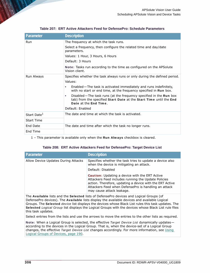
APSolute Vision User Guide
Scheduling APSolute Vision and Device Tasks
306 Document ID: RDWR-APSV-V04000_UG1809
Table 207: ERT Active Attackers Feed for DefensePro: Schedule Parameters
Parameter DescriptionRun The frequency at which the task runs.
Select a frequency, then configure the related time and day/date parameters. Values: 1 Hour, 3 Hours, 6 HoursDefault: 3 Hours
Note: Tasks run according to the time as configured on the APSolute Vision client.
Run Always Specifies whether the task always runs or only during the defined period.Values:• Enabled—The task is activated immediately and runs indefinitely,
with no start or end time, at the frequency specified in Run box.• Disabled—The task runs (at the frequency specified in the Run box
tab) from the specified Start Date at the Start Time until the End Date at the End Time.
Default: Enabled
Start Date1
1 – This parameter is available only when the Run Always checkbox is cleared.
The date and time at which the task is activated.
Start Time
End Date The date and time after which the task no longer runs.
End Time
Table 208: ERT Active Attackers Feed for DefensePro: Target Device List
Parameter DescriptionAllow Device Updates During Attacks Specifies whether the task tries to update a device also
when the device is mitigating an attack.Default: Disabled
Caution: Updating a device with the ERT Active Attackers Feed includes running the Update Policies action. Therefore, updating a device with the ERT Active Attackers Feed when DefensePro is handling an attack may cause attack leakage.
The Available lists and the Selected lists of DefensePro devices and Logical Groups (of DefensePro devices). The Available lists display the available devices and available Logical Groups. The Selected device list displays the devices whose Black List rules this task updates. The Selected Logical Group list displays the Logical Groups with the devices whose Black List rule files this task updates.Select entries from the lists and use the arrows to move the entries to the other lists as required.
Note: When a Logical Group is selected, the effective Target Device List dynamically updates— according to the devices in the Logical Group. That is, when the device-set of a Logical Group changes, the effective Target Device List changes accordingly. For more information, see Using Logical Groups of Devices, page 190.

APSolute Vision User Guide
Scheduling APSolute Vision and Device Tasks
Document ID: RDWR-APSV-V04000_UG1809 307
ERT IP Reputation Feed for Alteon—ParametersThe ERT IP Reputation Feed for Alteon task makes the ERT IP Reputation Feed service to be available for the Alteon devices that the APSolute Vision manages.
Caution: Port 443 must be open on the APSolute Vision server and Alteon devices for this task to run successfully.
Table 209: ERT IP Reputation Feed for Alteon: General Parameters
Parameter DescriptionName A name for the task.
Description A user-defined description of the task.
Enabled When selected, the task runs every five minutes after the first request by an Alteon for the ERT IP Reputation Feed. Disabled tasks are not activated, but the task configuration is saved in the database.

APSolute Vision User Guide
Scheduling APSolute Vision and Device Tasks
308 Document ID: RDWR-APSV-V04000_UG1809

Document ID: RDWR-APSV-V04000_UG1809 309
CHAPTER 9 – MANAGING AUDITING AND ALERTS
APSolute Vision logs all alerts and actions for APSolute Vision and, optionally, for the managed devices. You can view auditing information and other alerts in the Alerts Table pane.The following topics describe APSolute Vision auditing and the Alerts Table pane:• APSolute Vision Auditing, page 309• Enabling Configuration Auditing for Managed Devices, page 310• Managing Alerts, page 310
Note: APSolute Vision server alerts are added to the Alerts Table, and added to the audit table and forwarded to syslog, with one exception. The exception is that when the APSolute Vision process on the underlying operating system is down, alerts triggered by the operating system are sent to the Alerts Table only.
APSolute Vision AuditingAPSolute Vision auditing meets compliance requirements by automatically logging the following:• All APSolute Vision alerts and user actions• All configuration changes made to managed devices via APSolute Vision
This meets Sarbanes-Oxley requirements to audit any configuration change that might affect the network. In APSolute Vision, you can also configure the managed devices to log all configuration changes on the device.The Auditing log is stored in the APSolute Vision database. All audit logs are sent to the Alerts Table, and can be displayed in the Alerts Table pane depending on the alerts filter configuration. APSolute Vision allows read-only access to the Auditing log. You can extract the data and store it remotely, as you require. The Auditing log can hold a maximum two million entries. APSolute Vision ages the oldest entries after the maximum number of entries is reached and also ages entries that are older than six months.The following information is logged to the audit log:• All user management events and user activities—for example, access attempts, successful
login, password change by user, password reset by admin, and so on.• Actions performed on the device—for example, uploading or downloading a file to a device,
device reboot and shutdown, log file retrieval, and so on.• APSolute Vision activities, including:
— APSolute Vision upgrade— User management events (for example, creating or deleting a user, activating or
deactivating a user, and so on)• Device changes through CLI or WBM (if device auditing is enabled).• Alarms received from the device (if device auditing is enabled).• Device configuration activities (if device auditing is enabled). The audit log records all
configuration changes applied to the managed devices.• Device addition and deletion.

APSolute Vision User Guide
Managing Auditing and Alerts
310 Document ID: RDWR-APSV-V04000_UG1809
To manage APSolute Vision auditing
1. Enable or disable configuration auditing for devices. For more information, see Enabling Configuration Auditing for Managed Devices, page 310.
2. Enable and configure syslog and e-mail settings for sending audit information from the Alerts Table pane. For more information, see Configuring Settings for the Alerts Pane, page 112.
Enabling Configuration Auditing for Managed DevicesWhen configuration auditing for devices is enabled on the APSolute Vision server and on the device, any configuration change on a device using APSolute Vision creates two records in the Audit database, one from the APSolute Vision server, and one from the device audit message.
Note: To prevent overloading the managed device and prevent degraded performance, the feature is disabled by default.
To enable configuration auditing for a managed device
1. In the Configuration perspective, select Setup > Advanced Parameters > Configuration Audit.
2. Select the Enable Configuration Auditing checkbox, and click Submit.
Managing AlertsThe Alerts Table pane stores and displays alerts.The alerts are based on events that are received from:• SNMP traps sent by managed Radware devices.• Auditing messages from all APSolute Vision modules.• APSolute Vision server events.• Configuration auditing messages for managed devices, if enabled on the device.
All alert information is stored in the APSolute Vision database in a table separate from the audit information. Alert information can be sent to a central audit repository via syslog, and to a configured recipient via e-mail.
Figure 56: Alert Displayed on the APSolute Vision Main Screen
Events Handled in the Alerts Table PaneThe following types of events are handled in the Alerts Table pane: • SNMP Traps, page 311• Auditing Messages, page 311

APSolute Vision User Guide
Managing Auditing and Alerts
Document ID: RDWR-APSV-V04000_UG1809 311
• APSolute Vision Server Events, page 311• Alerts for New Security Attacks, page 311
SNMP TrapsThe Alerts Table handles all traps generated by APSolute Vision and the managed devices, including: • Generic traps, such as, Cold Start, Link Down, Link Up, Authentication Failure, and so on.• Radware traps common to all Radware devices.• Device-specific Radware traps.
Auditing MessagesAPSolute Vision forwards all logged audit events from all APSolute Vision modules and managed devices to the Alerts Table pane, including:• Successful and failed login attempts• Backup and restore operations• Configuration changes to APSolute Vision and the managed devices• Monitoring and control changes• Successful and failed task scheduling changes• User management configuration changes
APSolute Vision Server Events APSolute Vision server events include events from:• Server and database monitoring processes• The APSolute Vision appliance• The watchdog process, which monitors APSolute Vision server processes
Alerts for New Security AttacksAPSolute Vision triggers an alert when a new attack is displayed in the Current Attacks table (which is part of the Security Monitoring perspective).The value in the Module column in the Alerts Table pane is Security Reporting.Each DefensePro device triggers separate security alerts. The security alerts are either for a single security event (that is, a single attack event) or aggregated from multiple security events. The format is similar for alerts for single attacks and multiple attacks.
Table 210: Information in Security Alerts
String in a Security Alert for a Single Attack String in a Security Alert Aggregated Attack Information
An attack of type: <attack category>1 started. <quantity of attacks> attacks of type: <attack category>1 started between <start time of first attack> and <start time of last attack>.2
Detected by policy: <policy>; Detected by policy: <policy>;3
Attack name: <attack name>; Attack name: <attack name>;
Source IP: <attacker IP address>; Source IP: <attacker IP address>;4
Destination IP: <attacked IP address>; Destination IP: <attacked IP address>;
Destination port: <attacked port>; Destination port: <attacked port>;

APSolute Vision User Guide
Managing Auditing and Alerts
312 Document ID: RDWR-APSV-V04000_UG1809
Alert InformationAll alert information is stored in the APSolute Vision database. Double-click on an alert in the Alerts Table tab to open the Alert Details dialog box, which displays all the information with the expanded alert message. The following table describes the fields of the APSolute Vision alerts.
Action: <action>5 . Action: <action>.
1 – Attack categories: ACL, Anti-Scanning, Behavioral DoS, DoS, HTTP Flood, Intrusions, Server Cracking, SYN Flood, Anomalies, Stateful ACL, DNS, BWM
2 – Times are in the format dd.MM.yy hh:mm.3 – When there are differences in the field values for the attacks, the values are comma-
separated.4 – When there are differences in the field values for the attacks, the value is multiple.5 – Action values: forward, proxy, drop, source-reset, dest-reset, source-dest-reset,
bypass, challenge, quarantine, drop-and-quarantine
Table 211: APSolute Vision Alert Fields
Alert Information Description Displayed in Alerts Table Pane?
Ack A check box indicating whether the alert has been acknowledged. Alerts of Info severity are acknowledged automatically when raised. Alerts of severity higher than Info require user acknowledgment. Acknowledging an alert indicates that it has been seen by the user and remains in the Alerts Table pane display. You can select or clear the check box to acknowledge or un-acknowledge alerts.
Yes, by default
Severity The APSolute Vision severity of the event: Critical, Major, Minor, Warning, Info. SNMP trap severities are mapped as shown in SNMP Trap Severity Mapped to APSolute Vision Severity, page 313 and APSolute Vision Alerts Mapped to Syslog Severity, page 314.
Yes, by default
Date and Time The date and GMT time at which the event occurred.In the Alert Details dialog box, this value is displayed with the label Raised Time.
Yes, by default
Device Name The values differ according to the alert type, as follows: • SNMP traps—The value is the name of the device
that generated them.• APSolute Vision auditing events, which have device
context (configuration, monitoring). The value is the name of the device to which the event relates.
When the alert is generated by the APSolute Vision server, no device name is displayed.
Yes, by default
Table 210: Information in Security Alerts (cont.)
String in a Security Alert for a Single Attack String in a Security Alert Aggregated Attack Information
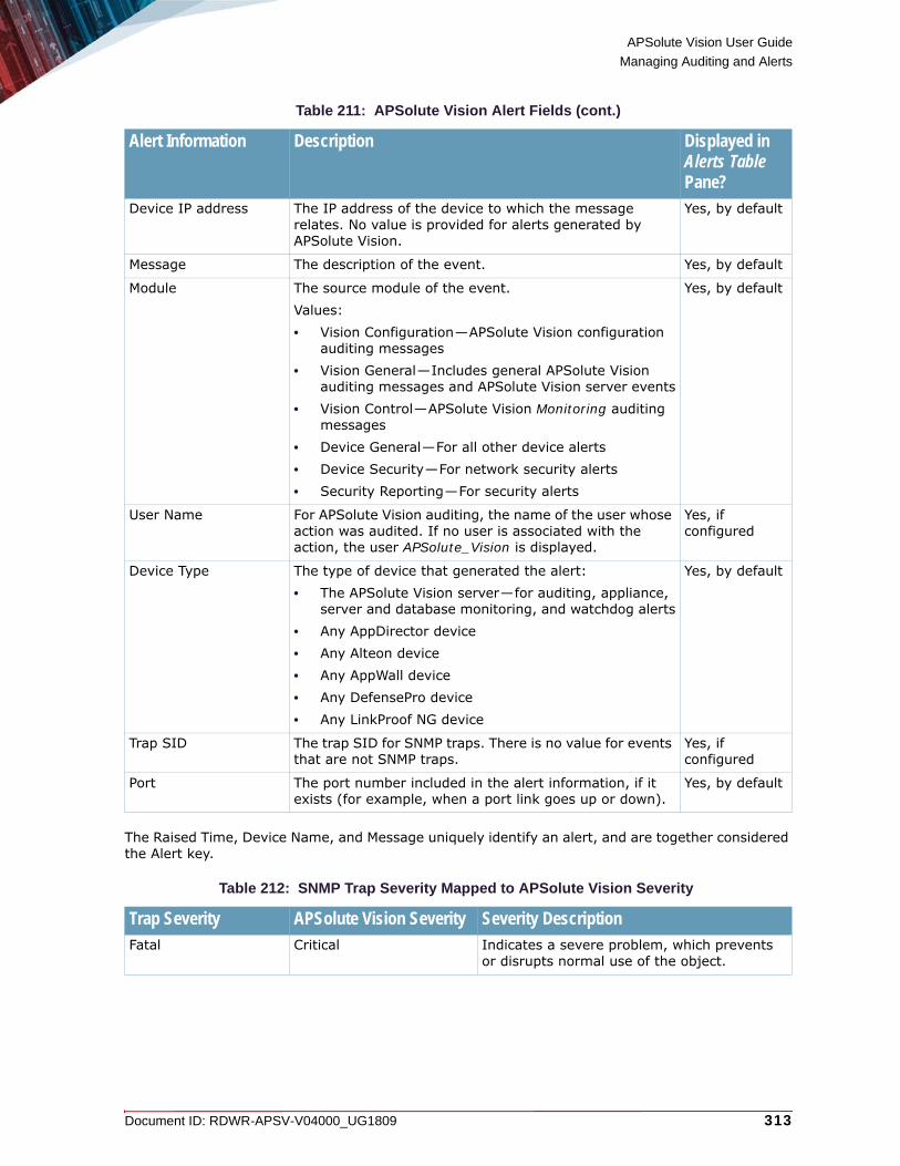
APSolute Vision User Guide
Managing Auditing and Alerts
Document ID: RDWR-APSV-V04000_UG1809 313
The Raised Time, Device Name, and Message uniquely identify an alert, and are together considered the Alert key.
Device IP address The IP address of the device to which the message relates. No value is provided for alerts generated by APSolute Vision.
Yes, by default
Message The description of the event. Yes, by default
Module The source module of the event. Values:• Vision Configuration—APSolute Vision configuration
auditing messages• Vision General—Includes general APSolute Vision
auditing messages and APSolute Vision server events• Vision Control—APSolute Vision Monitoring auditing
messages• Device General—For all other device alerts• Device Security—For network security alerts• Security Reporting—For security alerts
Yes, by default
User Name For APSolute Vision auditing, the name of the user whose action was audited. If no user is associated with the action, the user APSolute_Vision is displayed.
Yes, if configured
Device Type The type of device that generated the alert:• The APSolute Vision server—for auditing, appliance,
server and database monitoring, and watchdog alerts• Any AppDirector device• Any Alteon device• Any AppWall device• Any DefensePro device• Any LinkProof NG device
Yes, by default
Trap SID The trap SID for SNMP traps. There is no value for events that are not SNMP traps.
Yes, if configured
Port The port number included in the alert information, if it exists (for example, when a port link goes up or down).
Yes, by default
Table 212: SNMP Trap Severity Mapped to APSolute Vision Severity
Trap Severity APSolute Vision Severity Severity DescriptionFatal Critical Indicates a severe problem, which prevents
or disrupts normal use of the object.
Table 211: APSolute Vision Alert Fields (cont.)
Alert Information Description Displayed in Alerts Table Pane?

APSolute Vision User Guide
Managing Auditing and Alerts
314 Document ID: RDWR-APSV-V04000_UG1809
Displaying Alert InformationAPSolute Vision displays alert information in the Alerts Table pane. The Alerts Table table displays APSolute Vision alerts, device alerts, DefensePro security alerts, and device-configuration messages.
Figure 57: Alerts icon/button
For more information about the information displayed, see Alert Information, page 312.By default, alert information is displayed for one hour after the alert is raised. The information is then cleared from the display, but remains in the Alerts database. You can change the default in the Filtering dialog box. For more information, see Filtering Alerts, page 316.
Caution: The Alerts Table can display up to 10,000 entries. Refine your filter settings to get better results.
To view the Alert Table pane
> Click the (alert bell) button.
Error(APSolute Vision uses predefined criteria to assign Major or Minor severity.)
Major Indicates a problem of relatively high severity, which is likely to prevent normal use of the object.
Minor Indicates a problem of relatively low severity, which should not prevent normal use of the object.
Warning Warning While the managed object is functioning as it is intended to function, conditions exist that could potentially cause a problem.
Info Information Information only. There are no problems and the object is functioning normally.
Table 213: APSolute Vision Alerts Mapped to Syslog Severity
Severity in APSolute Vision Alerts Table Pane Level in Syslog1 - CRITICAL 3 - CRITICAL
2 - MAJOR 4 - ERROR
3 - MINOR 5 - WARNING
4 - WARNING 6 - NOTICE
5 - INFO 7 - INFORMATIONAL
Table 212: SNMP Trap Severity Mapped to APSolute Vision Severity (cont.)
Trap Severity APSolute Vision Severity Severity Description
Alerts icon/button. Orange indicates that you have new alerts. Click the button to open the Alerts Table pane.

APSolute Vision User Guide
Managing Auditing and Alerts
Document ID: RDWR-APSV-V04000_UG1809 315
For more information about Alerts Table pane navigation features, see APSolute Vision Interface Navigation, page 53. The information in the alert table is refreshed according to your configured preferences.In the Alerts Table pane, you can:• Show and hide columns.• Acknowledge and unacknowledge displayed alerts. Alerts of severity higher than Info require
user acknowledgment to indicate that they have been seen by the user. The alert remains in the Alerts pane display.
• Filter the alerts in the alert table to display a subset of alerts. For more information, see Filtering Alerts, page 316.
• Clear individual alerts from the alert table display.• Clear all the alerts in APSolute Vision database that match the current filter, whether or not the
alerts are visible in the Alerts pane.• Turn off automatic refresh of alert information.
To view details of an alert
> Double-click the alert row that you want to view. The alert details are displayed in the Alert Details dialog box.For more information about the information displayed, see Alert Information, page 312.
To clear all the alerts in APSolute Vision database that match the current filter, whether or not the alerts are visible in the Alerts pane
> Click the (Clear All Alerts) button.
To acknowledge alerts
> Do one of the following:— To acknowledge one or more alerts, select the alert row in the table, and click the
(Acknowledge Selected Alerts) button.
— To acknowledge all alerts in the alert table, click the (Acknowledge All Alerts) button.
To unacknowledge alerts
> Select the alert rows in the table and select click the (Unacknowledge Selected Alerts) button.
APSolute Vision User Guide
Managing Auditing and Alerts
316 Document ID: RDWR-APSV-V04000_UG1809
To clear alerts from the display
> To clear alerts, select the alert rows in the table and select the (Clear Selected Alerts) button.
Notes
• Cleared alerts remain in the database, but cannot be viewed.
• Clearing an unacknowledged alert automatically acknowledges the alert.
Automatic refresh is indicated by the selected (Pause) button.
To pause automatic refresh of alert information
> Click the (Pause) button.
To resume automatic refresh of alert information
> Click the (Resume) button.
Note: Radware recommends pausing automatic refresh while you are analyzing alert information—to prevent alerts disappearing from the display.
To close the Alert Table pane
> At the bottom of the Alerts Table pane, click Minimize.
Filtering AlertsYou can display a subset of the currently displayed alerts by filtering the alerts according to various alert information criteria.The criteria are organized according to categories, for example, alert severity, device module, and so on. Criteria from the same category are combined with a logical OR. Criteria from different categories are combined with a logical AND.The default filter settings include all criteria in all categories, meaning, by default, all alerts raised in the last hour are displayed.Use the filtering criteria to define how long an alert is displayed in the Alerts Browser.
Note: Regardless of the filter defined, the configured number of most recent critical alerts are always displayed at the top of the table on a colored background. This means that critical alerts that match the filter criteria are displayed twice.

APSolute Vision User Guide
Managing Auditing and Alerts
Document ID: RDWR-APSV-V04000_UG1809 317
To filter alerts in the alert table
1. Click the (alert bell) button to display the Alerts Table.
2. Click the (Alert Filter) button.
3. Configure the filtering criteria, and click Submit. The table is updated at the next automatic refresh.
Note: To restore the default filtering criteria, click Restore Defaults, then click Submit.
For more information about the filtering criteria, see Alert Information, page 312.
Table 214: Filtering Criteria Parameters
Parameter DescriptionThe Available lists and the Selected lists of devices and Logical Groups (of devices). The Available lists display the available devices and available Logical Groups. The Selected device list displays the devices whose alerts the Alerts Browser displays. The Selected Logical Group list displays the Logical Groups with the devices whose alerts the Alerts Browser displays.Select entries from the lists and use the arrows to move the entries to the other lists as required.
Note: When a Logical Group is selected, the devices whose alerts the Alerts Browser displays dynamically updates, according to the devices in the Logical Group. That is, when the device-set of a Logical Group changes, the set of devices whose alerts the Alerts Browser displays changes accordingly. For more information, see Using Logical Groups of Devices, page 190.
Select All Devices Specifies whether matching alerts for all devices are displayed.Default: Enabled
Raised Time The time period that includes the alerts’ raised-time that the Alerts Browser displays. For example, if you define 1 hour, alerts raised in the last hour are displayed. After the defined time, alerts are cleared from the display (not from the Alerts database).Values: 1 minute–24 hours Default: 1 hour
Severity The severities that the Alerts Browser displays.
Module The modules that the Alerts Browser displays.
Device Type The device types that the Alerts Browser displays.
Acknowledgment Specifies whether the Alerts Browser displays acknowledged alerts, unacknowledged alerts, or both.

APSolute Vision User Guide
Managing Auditing and Alerts
318 Document ID: RDWR-APSV-V04000_UG1809
Configuring Preferences for the Alerts PaneYou can configure the following preferences for the Alerts pane:• Client preferences—Define how many critical alerts to display and how often the client polls
the server for alert information. For more information, see Configuring Settings for the Alerts Pane, page 112.
• Server preferences—Define how the APSolute Vision server handles alerts. You can enable and configure reporting and logging events from the Alerts pane to a syslog server. You can configure sending alert information via e-mail to a defined recipient. For more information, see Configuring Settings for the Alerts Pane, page 112.

Document ID: RDWR-APSV-V04000_UG1809 319
CHAPTER 10 – MONITORING ALTEON WITH THE DASHBOARD AND SERVICE STATUS VIEW
This chapter describes the monitoring Alteon using the Dashboard and Service Status View.This feature is available only in Alteon version 30.0 and later.
Note: For information on monitoring Alteon device performance using the Device Performance Monitor, see Using the Device Performance Monitor, page 403.This chapter contains the following main topics:• Monitoring Alteon with the Dashboard, page 319• Monitoring Alteon with the Application Delivery View, page 326• Monitoring Alteon with the Service Status View, page 327
Monitoring Alteon with the DashboardEvery 15 seconds, Alteon polls the following information for the dashboard: • CPU utilization• System usage• License capacity utilization• License capacity• Temperature and fans (physical platforms only)
The top row of the dashboard includes the following:• The device IP address or device name if configured• The current date and time on the client• The role of the user who opened the dashboard• The name of the user who opened the dashboard• Log Out to log out of the session
The parameters that the dashboard displays depend on the Alteon form factor (standalone, VA, vADC, or ADC-VX).
Dashboard Features and UsageThe following dashboard features and usage are common to all form factors:• The dashboard opens in a new browser tab. Each click on the Dashboard opens a new browser
tab, which does not affect the display of any other opened browser tabs. • To change the display in the frame from a chart/graph to a table and from a table to a chart/
graph, click the icon in the upper right of any frame.

APSolute Vision User Guide
Monitoring Alteon with the Dashboard and Service Status View
320 Document ID: RDWR-APSV-V04000_UG1809
• To change the sorting from ascending to descending and descending to ascending, click in a table heading.
• When the dashboard is visible, it displays runtime information.• To pause or resume the display, click the icon in the upper right of any frame. When you pause
the display, the timestamp is displayed. The timestamp is according to the timezone of the client.
• To pause or resume the display of all the displays in the current dashboard, click the Pause button or Resume button the top of the dashboard.
In a some charts, hovering over a point opens a box with details of the specific point.
To view the dashboard
> In the Configuration perspective or Monitoring perspective, select Overview > Dashboard.
System View Dashboard of the Alteon Standalone and Alteon VA PlatformsThe following table describes the frames in the System View dashboard for the Alteon standalone and VA platforms.
Table 215: System View Dashboard for Alteon Standalone and VA
Component DescriptionCPU Utilization The chart view displays a line graph showing the average SP CPU
utilization (%) and MP CPU utilization (%) on the platform over time. The X-axis displays the time (hh:mm:ss). The Y-axis displays the utilization percentage.The table view displays the current MP CPU utilization (%) on the platform and the CPU utilization (%) for each SP.

APSolute Vision User Guide
Monitoring Alteon with the Dashboard and Service Status View
Document ID: RDWR-APSV-V04000_UG1809 321
Temperature and Fans (The dashboard displays this frame only for physical standalone platforms.)
This frame contains two sections: the temperature and status of the critical fans.The chart view for temperature displays the following: • A thermometer, per sensor, with a color indicator for
temperature status: green—for nominal, and red—for not operating/not operating properly.
• A table with the sensor number and the temperature status (for example: Normal).
The table view for temperature displays a table with the following columns: • Sensor ID.• State—For example, Normal.• Temperature—In Celsius and Fahrenheit.The chart view for fans displays the following: • A fan with a color indicator for the current temperature status:
green—for nominal, and red—for not operating/not operating properly.
• A table with the number of fans and the current operational status (for example: Up).
The table view for fans displays a table with the following columns: • Fan ID—Only the critical fans.• State—For example, Up.
System Usage The chart view contains bar graphs—Session Table, Hard Disk (displayed only for physical standalone platforms), and Caching—showing the current utilization value (percentage). The Y-axis displays the current utilization percentage.The table view displays a table with the following columns:• Name—Hard Disk (displayed only for physical standalone
platforms), Capacity Units, and ADC Allocation.• Utilization—The current utilization value (percentage).• Current—The current utilization absolute value—for example,
in KB.• Maximum—The maximum available absolute value—for
example, in KB.
License Capacity Utilization The chart view contains bar graphs—one bar for each license type showing the current utilization value (percentage) of each capacity license. The Y-axis displays the current utilization percentage.The table view displays a table with the following columns:• Name—The name of the license type and the units (for
example, Mbps).• Utilization—The current utilization value (percentage).• License—The license capacity.• Current—The current utilization absolute value.• Peak—The peak utilization absolute value.
Table 215: System View Dashboard for Alteon Standalone and VA (cont.)
Component Description

APSolute Vision User Guide
Monitoring Alteon with the Dashboard and Service Status View
322 Document ID: RDWR-APSV-V04000_UG1809
System View Dashboard of the vADC PlatformThe following table describes the frames in the System View dashboard for the vADC platform.
License Capacity The chart view for this frame contains two tabs:• Throughput—A solid line for the Alteon, displaying the
throughput usage (Mbps) over time. A dotted line indicates the maximum throughput that the license allows. The scale of the Y-axis is logarithmic.
• SSL—A line for each selected vADC displaying the SSL usage (CPS) over time. A dotted line indicates the maximum throughput that the license allows.
To reset the peak values for the chart, click Reset All Peak Values.
Table 216: System View Dashboard for vADC
Component DescriptionCPU Utilization The chart view displays a line graph showing the average SP CPU
utilization (%) and MP CPU utilization (%) on the platform over time. The X-axis displays the time (hh:mm:ss). The Y-axis displays the utilization percentage.The table view displays the current MP CPU utilization (%) on the platform and the CPU utilization (%) for each SP.
System Usage The chart view contains bar graphs—Session Table, Hard Disk (relating to the physical ADC-VX), and Caching—showing the current utilization value (percentage). The Y-axis displays the current utilization percentage.The table view displays a table with the following columns:• Name—Hard Disk (relating to the physical ADC-VX), Capacity
Units, and ADC Allocation.• Utilization—The current utilization value (percentage).• Current—The current utilization absolute value—for example,
in KB.• Maximum—The maximum available absolute value—for
example, in KB.
License Capacity Utilization The chart view contains bar graphs—one bar for each license type showing the current utilization value (percentage) of each capacity license. The Y-axis displays the current utilization percentage.The table view displays a table with the following columns:• Name—The name of the license type and the units (for
example, Mbps).• Utilization—The current utilization value (percentage).• License—The license capacity.• Current—The current utilization absolute value.• Peak—The peak utilization absolute value.
Table 215: System View Dashboard for Alteon Standalone and VA (cont.)
Component Description

APSolute Vision User Guide
Monitoring Alteon with the Dashboard and Service Status View
Document ID: RDWR-APSV-V04000_UG1809 323
System View Dashboard for the ADC-VX PlatformThe following table describes the frames in the System View dashboard for the ADC-VX platform.
License Capacity The chart view for this frame contains two tabs:• Throughput—A solid colored line for the Alteon, displaying the
throughput usage (Mbps) over time. A solid gray line for the Alteon, displaying the latest peak throughput usage (Mbps) over time. A dotted line indicates the maximum throughput that the license allows. The scale of the Y-axis is logarithmic.
• SSL—A line for each selected vADC displaying the SSL usage (CPS) over time. A dotted line indicates the maximum throughput that the license allows.
To reset the peak values for the chart, click Reset All Peak Values.
Table 217: System View Dashboard for Dashboard for ADC-VX
Component DescriptionCPU Utilization The chart view displays a line graph showing the MP CPU utilization
(%) on the platform over time. The X-axis displays the time (hh:mm:ss). The Y-axis displays the utilization percentage.The table view displays the current MP CPU utilization (%) on the platform.
Table 216: System View Dashboard for vADC (cont.)
Component Description

APSolute Vision User Guide
Monitoring Alteon with the Dashboard and Service Status View
324 Document ID: RDWR-APSV-V04000_UG1809
Temperature and Fans This frame contains two sections: the temperature and status of the critical fans.The chart view for temperature displays the following: • A thermometer, per sensor, with a color indicator for
temperature status: green—for nominal, and red—for not operating/not operating properly.
• A table with the sensor number and the temperature status (for example: Normal).
The table view for temperature displays a table with the following columns: • Sensor ID.• State—For example, Normal.• Temperature—In Celsius and Fahrenheit.The chart view for fans displays the following: • A fan with a color indicator for the current temperature status:
green—for nominal, and red—for not operating/not operating properly.
• A table with the number of fans and the current operational status (for example: Up).
The table view for fans displays a table with the following columns: • Fan ID—Only the critical fans.• State—For example, Up.
System Usage The chart view contains three bar graphs—Hard Disk, Capacity Units, and ADC Allocation—showing the current utilization value (percentage). The Y-axis displays the current utilization percentage. The table view displays a table with the following columns: • Name—Hard Disk, Capacity Units, and ADC Allocation.• Utilization—The current utilization value (percentage).• Current—The current utilization absolute value (for Hard disk,
in gigabytes, for Capacity Units and ADC Allocation, the number).
• Maximum—The maximum available absolute value (for Hard disk, in gigabytes, for Capacity Units and ADC Allocation, the number).
Table 217: System View Dashboard for Dashboard for ADC-VX (cont.)
Component Description

APSolute Vision User Guide
Monitoring Alteon with the Dashboard and Service Status View
Document ID: RDWR-APSV-V04000_UG1809 325
vADCs View Dashboard for ADC-VXYou can select up to five vADCs to monitor.The following table describes the frames in the vADCs View dashboard for the ADC-VX platform.
Table 218: vADCs View Dashboard for ADC-VX
Component DescriptionvADC Summary and Selection This frame contains two sections: vADC Utilization Summary and
vADC Selection.There is no table view for this frame.vADC Utilization Summary shows a status indicator (High, Medium, Low) for SP CPU Utilization and Throughput Utilization.Use the vADC Selection table to select the vADC to monitor in the dashboard (up to five). The table contains the following columns: ID, Name, and CU (which displays the number of allocated CUs).
CPU Utilization The chart view displays two bar graphs for each selected vADC. One bar shows the current MP CPU utilization (%). One bar shows the current SP CPU utilization (%). The Y-axis displays the utilization percentage. If more than one vADC is operating at the same utilization, only the top line is displayed.The table view displays a table with the following columns: • vADC—The vADC ID.• Name—The vADC name, if configured.• MP utilization (%).• SP CPU (%).
License Capacity Utilization The chart view for this frame contains two tabs:• Throughput—A line for each selected vADC displaying the
throughput utilization percentage over time. If more than one vADC is operating at the same utilization, only the top line is displayed.
• SSL—A line for each selected vADC displaying the SSL utilization percentage over time. If more than one vADC is operating at the same utilization, only the top line is displayed.
The table view displays a table with the following columns:• vADC—The vADC ID.• Name—The vADC name, if configured.• Throughput (%).• SSL (%).

APSolute Vision User Guide
Monitoring Alteon with the Dashboard and Service Status View
326 Document ID: RDWR-APSV-V04000_UG1809
Monitoring Alteon with the Application Delivery ViewThe Application Delivery View is available for Alteon standalone and vADC.This feature is available only in Alteon version 30.2 and later. The following table describes the frames in the Application Delivery View dashboard for the Alteon standalone and vADC platforms.
Note: You must globally enable virtual service statistics reporting to display information in the Application Delivery View.
To configure virtual service statistics settings
1. Select Configuration > Application Delivery > Virtual Services > Settings.2. Select the Statistics tab.
3. In the Statistics Measuring Period field, type a value in seconds in the range 1–3600.
4. Set the Per Service Statistics option to Enable.
5. Click Submit.
Table 219: Application Delivery View Dashboard for Alteon Standalone and vADC
Component DescriptionVirtual Service Selection The table view displays a table with the following columns:
• Status—The operational status of the virtual service.• Virtual Server—The identifier of the virtual server for the
virtual service.• Application—Values: http, ftp, dns• Port—The virtual service port.• Protocol—The virtual service protocol. Values: tcp, udp
Virtual Service Performance The chart view displays the following for each entry selected in the Virtual Service Selection frame: • Throughput (Mbps)• Connections per Second• Concurrent ConnectionsThe chart contains tool tips displaying a timestamp, a colored virtual service identifier, and virtual service performance statistics.The table view displays a table with the following columns: • Virtual Server• Port• Throughput (Mbps)• Connections per Second• Concurrent Connections
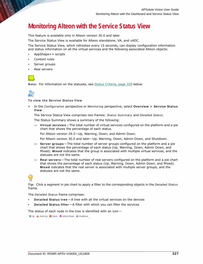
APSolute Vision User Guide
Monitoring Alteon with the Dashboard and Service Status View
Document ID: RDWR-APSV-V04000_UG1809 327
Monitoring Alteon with the Service Status ViewThis feature is available only in Alteon version 30.0 and later. The Service Status View is available for Alteon standalone, VA, and vADC.The Service Status View, which refreshes every 15 seconds, can display configuration information and status information on all the virtual services and the following associated Alteon objects: • AppShape++ scripts• Content rules• Server groups• Real servers
Note: For information on the statuses, see Status Criteria, page 329 below.
To view the Service Status View
> In the Configuration perspective or Monitoring perspective, select Overview > Service Status View.The Service Status View comprises two frames: Status Summary and Detailed Status.The Status Summary shows a summary of the following:— Virtual services—The total number of virtual services configured on the platform and a pie
chart that shows the percentage of each status.For Alteon version 29.5—Up, Warning, Down, and Admin Down.For Alteon version 30.0 and later—Up, Warning, Down, Admin Down, and Shutdown.
— Server groups—The total number of server groups configured on the platform and a pie chart that shows the percentage of each status (Up, Warning, Down, Admin Down, and Mixed). Mixed indicates that the group is associated with multiple virtual services, and the statuses are not the same.
— Real servers—The total number of real servers configured on the platform and a pie chart that shows the percentage of each status (Up, Warning, Down, Admin Down, and Mixed). Mixed indicates that the real server is associated with multiple server groups, and the statuses are not the same.
Tip: Click a segment in pie chart to apply a filter to the corresponding objects in the Detailed Status frame.
The Detailed Status frame comprises:• Detailed Status tree—A tree with all the virtual services on the devices• Detailed Status filter—A filter with which you can filter the services
The status of each node in the tree is identified with an icon—
.
APSolute Vision User Guide
Monitoring Alteon with the Dashboard and Service Status View
328 Document ID: RDWR-APSV-V04000_UG1809
By default, all the parent nodes in the tree—the Virtual Service nodes—are collapsed. Each Virtual Service node is in the following format:
Virtual Service ID: <ID>, (<Port> <TCP|UDP>), Action: < Action>
where:
• <ID> is the specified ID of the virtual service.
• <Port> is the specified port number of the of the virtual service.
• <TCP|UDP> is the relevant protocol of the virtual service.
• < Action> is either the specified Action when the Application is HTTP or HTTPS (Group, Redirect, or Discard) or Group for all other Application values.
Example Virtual Service ID: MyDNSVirt, (53 TCP), Action: Group
Expanding a Virtual Service node displays the following:
• AppShape++ Script(s) Associated—The Service Status View displays this node only if the virtual service is configured with one or more AppShape++ scripts.
• Content Rules—This node is displayed only if the virtual service is configured with one or more content rules. The Service Status View displays content rules numerically, each in the following format:
<Rule ID>, Action: <Action>, Group: <Group name>
• Group ID: <ID>—The ID of the server group, and includes the following node(s) sorted alphanumerically, each in the following format:
<Real server ID>: <IP address>
Note: Backup real servers and backup groups appear in the tree only when they are active.
Detailed Status FilterApplying a filter refreshes the tree view and shows the updated statuses and objects based on the filter criteria. The filter uses a Boolean AND operator on the data.By default, the child objects of each virtual service node are collapsed. After you run the filter, the tree view displays the relevant object expanded.
To filter the Detailed Status tree
> Configure the filter parameters and click GO.

APSolute Vision User Guide
Monitoring Alteon with the Dashboard and Service Status View
Document ID: RDWR-APSV-V04000_UG1809 329
Status CriteriaThis section describes the following status options:• Real Server Status, page 329• Server Group status, page 330• Content Rules per Virtual Service Status, page 330• Virtual Service Status, page 330
Real Server StatusThe real server status is calculated according to the following order:• Admin Down—Configuration disabled (either globally or in the group).• Shutdown—Operationally disabled (either globally or in the group).• Down—The real server health check failed.• Warning—The real server is in the No-new-sessions state or the Recovery state.• Up—The real server health check state is UP.
Table 220: System View Dashboard for Alteon Standalone and VA
Parameter DescriptionStatus Values:
• All—Show the specified object types with all statuses.• Up—Show only the specified object types with the Up status.• Warning—Show only the specified object types with the Warning status.• Down—Show only the specified object types with the Down status.• Warning + Down—Show the specified object types with the Down status and
the Warning status.• Admin Down—Show only the specified object types with the Down status.• Shutdown—Show only the specified object types with the Shutdown status.
Available in Alteon version 30.2.3 and later.Default: All
Note: For more status information, see Status Criteria, page 329.
Type Values:• All—Show all object types.• Virtual Service—Show only the virtual services that match the other criteria.• Server Group—Show only the server groups that match the other criteria.• Real Server—Show only the real servers that match the other criteria.• Content Rule—Show only the content rules that match the other criteria.Default: All
Free Text Free text that filters the results according to ID or other identifier.For example:• You can filter for a real server by entering its IP address. • You can filter for a group by entering the suffix of its ID.

APSolute Vision User Guide
Monitoring Alteon with the Dashboard and Service Status View
330 Document ID: RDWR-APSV-V04000_UG1809
Server Group statusThe server group status is calculated according to the status of its real servers.
Note: A group is considered to be in the Warning state if:• At least one real server is in the Warning state, or • Some of the real servers in the group are in Down and some are in the UP state.
Content Rules per Virtual Service StatusThe content rule status is defined as follows:• If the content rule is disabled, its status is Admin Down.• For a group action, the content rule status is the group status.• For a redirect or discard action, the content rule is considered to be up.
Virtual Service StatusThe virtual service status is calculated according to the following statuses:• The content rule status.• If at least one enabled AppShape++ script is associated to this service.• The service-action status, as follows:
— For an HTTP or HTTPS service, you can specify Group, Redirect, or Discard actions. — For a non-HTTP/S services, the action is always (implicitly) Group.
Note: When the action is Group, the service-action status is the Group status. When the Action is Redirect or Discard, the service-action status is always Up.

Document ID: RDWR-APSV-V04000_UG1809 331
CHAPTER 11 – MONITORING THE ALTEON SYSTEM
This chapter describes monitoring Alteon system operations.
Note: For information on monitoring Alteon device performance using the Device Performance Monitor, see Using the Device Performance Monitor, page 403.The Alteon operations that you can monitor depend on the Alteon form factor and/or platform: standalone, VA, vADC, or ADC-VX.This chapter contains the following main topics:• Monitoring General Information, page 331• CPU Utilization and Memory Statistics, page 333• Monitoring Capacity, page 334• Unlocking Users, page 339• Maintenance, page 339• Azure, page 344
Monitoring General InformationThe Alteon parameters that Alteon displays depend on the Alteon form factor and/or platform: standalone, VA, vADC, or ADC-VX.
To monitor general system information
> In the Monitoring perspective, select System > General Information.
Table 221: General Information: General Parameters
Table 222: General Information: System Memory Parameters
Parameter DescriptionSwitch Name The name of the switch.
System Time The system time.
System Date The system date.
Last Apply The time and date of the last Apply action.
Last Save The time and date of the last Save action.
Last Boot The time and date of the last boot.
Switch Uptime The amount of time the switch has been up.
Parameter DescriptionThis group box is displayed only in standalone mode and ADC-VX mode.
Free The memory resources (in bytes) currently free in the system.

APSolute Vision User Guide
Monitoring the Alteon System
332 Document ID: RDWR-APSV-V04000_UG1809
Table 223: General Information: System Hardware Parameters
Total The total memory resources (in bytes) in the system.
Parameter DescriptionMAC Address The MAC address.
Serial Number(Alteon VX and standalone only)
The serial number.
Mainboard Hardware No(Alteon VX and standalone only)
The mainboard hardware number.
Mainboard Hardware Rev The mainboard hardware revision.
Ethernet Board Hardware No
The Ethernet board hardware number.
Ethernet Board Hardware Rev
The Ethernet board hardware revision.
Temperature Sensors(Alteon VX and standalone only)
The number of temperature sensors.
Hard Disk The capacity, in GBs, of the hard disk.
Used Disk Space The used space, in GBs, of the hard disk.
Total RAM The capacity, in GBs, of RAM.
Power Supply(Alteon VX and standalone only)
The number of power supplies.
Fan Status(Alteon VX and standalone only)
The fan status.
SSL Chip Displays the following parameters regarding the SSL chips:• SSL Chip Status—Values: Active Initialized, and so on. • Type—For example:
Cavium HSM; Model NITROX XL CN16XX-NFBE;
• Amount—The quantity of HSM card on the platform, which is typically 1.
HSM State The state of the HSM card. Values: trusted, and so on.
Note: Initialization of the HSM card is done using the Alteon CLI. For more information, see the Alteon Web Based Management Application Guide and Alteon Command Line Interface Reference Guide.
Current capacity units (Alteon VX only)
The current capacity units configured on the platform.
Parameter Description
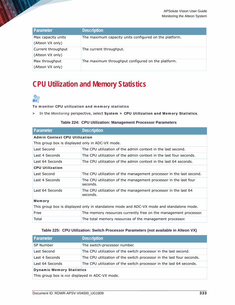
APSolute Vision User Guide
Monitoring the Alteon System
Document ID: RDWR-APSV-V04000_UG1809 333
CPU Utilization and Memory Statistics
To monitor CPU utilization and memory statistics
> In the Monitoring perspective, select System > CPU Utilization and Memory Statistics.
Max capacity units (Alteon VX only)
The maximum capacity units configured on the platform.
Current throughput (Alteon VX only)
The current throughput.
Max throughput (Alteon VX only)
The maximum throughput configured on the platform.
Table 224: CPU Utilization: Management Processor Parameters
Parameter DescriptionAdmin Context CPU UtilizationThis group box is displayed only in ADC-VX mode.
Last Second The CPU utilization of the admin context in the last second.
Last 4 Seconds The CPU utilization of the admin context in the last four seconds.
Last 64 Seconds The CPU utilization of the admin context in the last 64 seconds.
CPU Utilization
Last Second The CPU utilization of the management processor in the last second.
Last 4 Seconds The CPU utilization of the management processor in the last four seconds.
Last 64 Seconds The CPU utilization of the management processor in the last 64 seconds.
MemoryThis group box is displayed only in standalone mode and ADC-VX mode and standalone mode.
Free The memory resources currently free on the management processor.
Total The total memory resources of the management processor.
Table 225: CPU Utilization: Switch Processor Parameters (not available in Alteon VX)
Parameter DescriptionSP Number The switch-processor number.
Last Second The CPU utilization of the switch processor in the last second.
Last 4 Seconds The CPU utilization of the switch processor in the last four seconds.
Last 64 Seconds The CPU utilization of the switch processor in the last 64 seconds.
Dynamic Memory StatisticsThis group box is not displayed in ADC-VX mode.
Parameter Description

APSolute Vision User Guide
Monitoring the Alteon System
334 Document ID: RDWR-APSV-V04000_UG1809
Monitoring CapacityThis feature is available only in Alteon standalone, VA, and ADC-VX. Monitoring capacity comprises the following:• Monitoring System Capacity, page 335• Monitoring Network Capacity, page 335• Monitoring Application Delivery Capacity, page 337
SP Number The switch-processor number.
Total Memory The total memory resources of the switch processor.
Current Memory The memory resources, in KB, currently used on the switch processor.
Hi water mark The peak memory resources, in KB, used on the switch processor.
Allowed Max The allowed maximum memory usage, in KB.
Table 226: Memory Statistics: Memory Statistics Parameters
Parameter DescriptionThis tab is available only in Alteon versions 30.5.2.0 and later.This tab is not displayed in ADC-VX mode.
Total RAM The total RAM memory resources of the switch processor in MB.
Initial Configured Memory The initial configured memory of the switch processor in MB.
Safety Margin 1st Watermark
The percentage of memory allocated to the first watermark.
Safety Margin 2nd Watermark
The percentage of memory allocated to the second watermark.
SP Number The switch-processor number.
Initial Size: 1st Watermark
The amount of memory given until pressure starts (in MB): Initial configured memory / Number of SPs x 75%.
Initial Size: 2nd Watermark
The amount of memory given to the growing phase (in MB): Initial configured memory / Number of SPs x 90%.
Current Process Size The size of the current process (in MB).
Memory Pressure The memory pressure.Values: On, Off
Memory Pressure Active Time
The memory pressure active time (in seconds).
Memory used from 1st Watermark
The percentage of memory used from the first watermark.
Table 225: CPU Utilization: Switch Processor Parameters (not available in Alteon VX) (cont.)
Parameter Description

APSolute Vision User Guide
Monitoring the Alteon System
Document ID: RDWR-APSV-V04000_UG1809 335
Monitoring System CapacityThis feature is available only in version 30.0 and later.
To monitor system capacity
> In the Monitoring perspective, select System > Capacity > System.
Monitoring Network CapacityThis feature is available only in version 30.0 and later.
To monitor network capacity
> In the Monitoring perspective, select System > Capacity > Network.
Table 227: System Capacity Parameters in Alteon Standalone, VA, and vADC
Parameter DescriptionCache Usage (MB) Comprises the following two values:
• Maximum—The maximum cache usage, in MB, that the device can support.
• Current—The current cache usage, in MB.
Hard Disk (GB) Comprises the following two values:• Maximum—The hard-disk size, in GB, that the device can support. • Current—The current hard-disk usage, in GB. • In Use—The amount of hard-disk space in use, in MB.
RAM (GB) Comprises the following two values:• Maximum—The maximum RAM, in GB, that the device can
support.
Table 228: System Capacity Parameters in ADC-VX
Parameter DescriptionvADCs Comprises the following two values:
• Maximum—The maximum number of vADCs that the device can support.
• Current—The current number of vADCs configured on the device and, in parentheses, the number of enabled vADCs on the device.
Capacity Units Comprises the following two values:• Maximum—The maximum number of capacity units that the device
can support. • Current—The current number of capacity units configured on the
device.
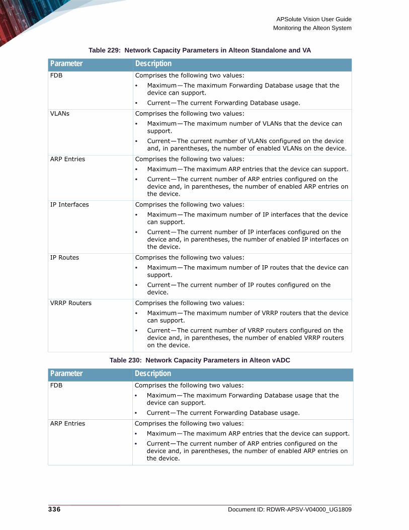
APSolute Vision User Guide
Monitoring the Alteon System
336 Document ID: RDWR-APSV-V04000_UG1809
Table 229: Network Capacity Parameters in Alteon Standalone and VA
Table 230: Network Capacity Parameters in Alteon vADC
Parameter DescriptionFDB Comprises the following two values:
• Maximum—The maximum Forwarding Database usage that the device can support.
• Current—The current Forwarding Database usage.
VLANs Comprises the following two values:• Maximum—The maximum number of VLANs that the device can
support. • Current—The current number of VLANs configured on the device
and, in parentheses, the number of enabled VLANs on the device.
ARP Entries Comprises the following two values:• Maximum—The maximum ARP entries that the device can support. • Current—The current number of ARP entries configured on the
device and, in parentheses, the number of enabled ARP entries on the device.
IP Interfaces Comprises the following two values:• Maximum—The maximum number of IP interfaces that the device
can support. • Current—The current number of IP interfaces configured on the
device and, in parentheses, the number of enabled IP interfaces on the device.
IP Routes Comprises the following two values:• Maximum—The maximum number of IP routes that the device can
support. • Current—The current number of IP routes configured on the
device.
VRRP Routers Comprises the following two values:• Maximum—The maximum number of VRRP routers that the device
can support. • Current—The current number of VRRP routers configured on the
device and, in parentheses, the number of enabled VRRP routers on the device.
Parameter DescriptionFDB Comprises the following two values:
• Maximum—The maximum Forwarding Database usage that the device can support.
• Current—The current Forwarding Database usage.
ARP Entries Comprises the following two values:• Maximum—The maximum ARP entries that the device can support. • Current—The current number of ARP entries configured on the
device and, in parentheses, the number of enabled ARP entries on the device.

APSolute Vision User Guide
Monitoring the Alteon System
Document ID: RDWR-APSV-V04000_UG1809 337
Table 231: Network Capacity Parameters in ADC-VX
Monitoring Application Delivery CapacityThis feature is available only in Alteon standalone, VA, and vADC.
To monitor application delivery capacity
> In the Monitoring perspective, select System > Capacity > Application Delivery.
IP Interfaces Comprises the following two values:• Maximum—The maximum number of IP interfaces that the device
can support. • Current—The current number of IP interfaces configured on the
device and, in parentheses, the number of enabled IP interfaces on the device.
IP Routes Comprises the following two values:• Maximum—The maximum number of IP routes that the device can
support. • Current—The current number of IP routes configured on the device.
VRRP Routers Comprises the following two values:• Maximum—The maximum number of VRRP routers that the device
can support. • Current—The current number of VRRP routers configured on the
device and, in parentheses, the number of enabled VRRP routers on the device.
Parameter DescriptionVLANs Comprises the following two values:
• Maximum—The maximum number of VLANs that the device can support.
• Current—The current number of VLANs configured on the device and, in parentheses, the number of enabled VLANs on the device.
Table 232: Application Delivery Capacity Parameters
Parameter DescriptionReal Servers Comprises the following two values:
• Maximum—The maximum number of real servers that the device can support.
• Current—The current number of real servers configured on the device and, in parentheses, the number of enabled real servers on the device.
Parameter Description

APSolute Vision User Guide
Monitoring the Alteon System
338 Document ID: RDWR-APSV-V04000_UG1809
Server Groups Comprises the following two values:• Maximum—The maximum number of server groups that
the device can support. • Current—The current number of server groups configured
on the device.
Virtual Servers Comprises the following two values:• Maximum—The maximum number of virtual servers that
the device can support. • Current—The current number of virtual servers configured
on the device and, in parentheses, the number of enabled virtual servers on the device.
Virtual Services The maximum number of virtual services that the device can support.
Real Services The maximum number of real services that the device can support.
Filters(This parameter is available only in version 30.0 and later.)
Comprises the following two values:• Maximum—The maximum number of filters that the device
can support. • Current—The current number of filters currently used and,
in parentheses, the number of enabled filters on the device.
Session Table Entries (This parameter is available only in version 30.0 and later.)
Comprises the following two values:• Maximum—The maximum number of Session table entries
that the device can support. • Current—The current number of Session table entries
currently used and, in parentheses, the number of enabled Session table entries on the device.
Dynamic Data Store Comprises the following two values:• Maximum—The maximum number of 512-byte blocks that
the device can support in the dynamic data store. • Current—The current number of 512-byte blocks currently
used in the dynamic data store. Note that each persistence and user-defined entry can occupy one or more 512 byte blocks.
Keys (This parameter is available only in version 30.0 and later.)
Comprises the following two values:• Maximum—The maximum number of keys that the device
can support. • Current—The current number of keys configured on the
device.
Certificate Signing Requests (This parameter is available only in version 30.0 and later.)
Comprises the following two values:• Maximum—The maximum number of certificate signing
requests that the device can support. • Current—The current number of certificate signing requests
configured on the device.
Table 232: Application Delivery Capacity Parameters (cont.)
Parameter Description

APSolute Vision User Guide
Monitoring the Alteon System
Document ID: RDWR-APSV-V04000_UG1809 339
Unlocking Users The administrator can monitor all currently locked-out users, viewing the remaining lockout time, and can unlock any locked-out user. For more details regarding the user lockout feature, see the relevant Alteon section in the APSolute Vision online help.
To unlock users
1. In the Monitoring perspective, select System > Locked Users.The table lists all currently locked-out users, detailing the User ID, User Name and User Role. The table shows the date and time the user was locked out and the amount of remaining lockout time (in minutes).
2. Select the row detailing the specific locked-out user and click Unlock.
3. Click OK to confirm.
MaintenanceUse the Maintenance tab to manage technical support data, packet capture, and trace logging of application services.
Technical Support DataThis procedure describes how manage technical support data.
Note: The Technical Support File (tsdump) is a text file containing Alteon statistics, information and configuration output. The Tech Data Log File is a zipped archive that includes, in addition to the tsdump file, other log files (for example, core dump files) to help R&D with debugging. All passwords in the technical support files are encrypted.
Server Certificates (This parameter is available only in version 30.0 and later.)
Comprises the following two values:• Maximum—The maximum number of server certificates
that the device can support. • Current—The current number of server certificates
configured on the device.
Table 232: Application Delivery Capacity Parameters (cont.)
Parameter Description

APSolute Vision User Guide
Monitoring the Alteon System
340 Document ID: RDWR-APSV-V04000_UG1809
To manage technical support data
1. In the Monitoring perspective, select System > Maintenance.2. In the Technical Support Data tab, select the technical support data to be included, and click
Generate to generate the technical support file.
3. Click Export to export the technical support file.
4. To export the full technical support data, click Export Tech Data Log to export the Tech Data log file.
Note: Generating the technical support data file may take up to a few minutes. Only after you receive the note stating that the file generation has ended, can you operate the export option.
Core File Management This feature is available only in Alteon standalone, VA, and VX.Alteon allows you to export the core dump files in a compressed .tgz file to your local disk. You can select to export all the core dump files in a single zipped file, or you can select a single core dump file to be exported.You can also delete all core dump files.
Note: The core files compress and export operation will take few minutes. During this time, the WEB GUI will be blocked. The files will be available when the operation ends.
Table 233: Technical Support Data Parameters
Parameter DescriptionInclude Private Keys Specifies whether to include private keys in the technical support file.
Passphrase(Available when Include Private Keys is selected.)
The passphrase, which must be at least four characters long.
Confirm Passphrase(Available when Include Private Keys is selected.)
The passphrase, which must be at least four characters long.
Include DNSSEC information(This parameter is available only in version 31.0 and later.)
Specifies whether to include DNSSEC information in the technical support file.
Include Persistency Entries(This parameter is available only in version 31.0 and later.)
Specifies whether to include persistency entries in the technical support file.
Include UDP Listen Ports(This parameter is available only in version 31.0 and later.)
Specifies whether to include UDP listening ports in the technical support file.

APSolute Vision User Guide
Monitoring the Alteon System
Document ID: RDWR-APSV-V04000_UG1809 341
To export core files
1. In the Monitoring perspective, select System > Maintenance.2. In the Core File Management tab, do one the following:
— Select Export All Core Files (enabled by default).— Select Export Selected Core File, and enter the core ID to be exported. The Core Files are listed in a table, detailing the Core ID, File Name, Time and date, and file size.
3. Click Export to export the (selected) Core File(s).
4. Click Delete to delete all Core Files.
Packet Capture
Notes
• Live capture is not enabled when you are connected using a serial connection.
• For Alteon standalone and ADC-VX platforms: The capture file size is limited to 500 MB. For Alteon VA platforms, the capture file size is limited to 50 MB.
• The output displays GMT time and not the local time.
• If you transform the back-end flow to port 80, you will see clear text in the capture file.
Note: Alteon VA translates the MAC address for virtual servers and interfaces assigned by VMware to its own internal MAC address for internal processing. It switches the Alteon VA MAC address back to the VMware MAC address when it sends the packet back to the VMware switch. Therefore, the internal Alteon VA MAC address is displayed in some of the tables and dumps displayed on the console.
Note: Service interruptions may occur when using packet capture in certain situations; for example, with high traffic volume and only one CU allocated for the vADC. Radware recommends that you use packet capture sparingly (for troubleshooting purposes), during a maintenance window, or only in periods of low traffic volume.
To manage packet capture
1. In the Monitoring perspective, select System > Maintenance.2. In the Packet Capture tab, configure the parameters, and do one the following:
— Click Start to start the packet capture.— Click Stop to stop the packet capture.— Click Export to export the packet capture.— Click Clear Capture File to clear the packet capture file.

APSolute Vision User Guide
Monitoring the Alteon System
342 Document ID: RDWR-APSV-V04000_UG1809
Application Services Trace LogThis feature is available only in Alteon standalone, VA, and vADC.If a service is specified, messages generated by that service are enabled for logging and routed to the syslog server.Enabling Application Services Trace Logging may impact performance on Alteon traffic processing capabilities. Make sure that you disable trace logging when you are done.
To manage application services trace log
1. In the Monitoring perspective, select System > Maintenance.2. In the Application Services Trace Log tab, configure the parameters, and do one the following:
3. Click Clear to clear the trace log.
4. Click Export to export the trace log.
5. Click Submit to submit the configuration.
Table 234: Packet Capture Parameters
Parameter DescriptionPacket Count The maximum number of captured packets.
Range: 0-1000000000
Packet Length The length of packets to capture, in bytes. Range: 0-9100
Port Range The port range.The valid range depends on the Alteon platform. Refer to the Alteon Installation and Maintenance Guide for details of the port range for each supported platform.
VLAN The VLAN range. Range: 1-4090
Packet Filter String The packet capture filter string field is used to set the capture filter parameters. It accepts the same filter criteria (syntax) as the tcpdump format. The following parameters can be set with an “and” or an “or” operator between them, or using parentheses: • dst host <host>—Filters the output on the specified destination host IP.• src host <host>—Filters the output on the specified source host IP
address.• dst port <port>—Filters the output on the specified destination port.• src port <port>—Filters the output on the specified source port.• port—Filters the output on the specified port.• tcp—Filters the output for TCP traffic only.• udp—Filters the output for UDP traffic only• icmp—Filters the output for ICMP traffic only.• ip multicast—Filters the output for multicast traffic only.• ip broadcast—Filters the output for broadcast traffic only.Example: (dst host 6.6.6.6 or src host 6.6.3.3) and port 80Maximum characters: 1024

APSolute Vision User Guide
Monitoring the Alteon System
Document ID: RDWR-APSV-V04000_UG1809 343
FastView LogsThis procedure describes how access the FastView log files.
To manage technical support data
1. In the Monitoring perspective, select System > Maintenance.2. In the FastView Logs tab, select one of the following FastView log files to display:
— SMF Hub— Configuration Manager— Compiler
View the FastView logs for SMF Hub, Config Manager, and the Compiler. Each button launches a new pane for you to see the details in the log.
Table 235: Application Services Trace Log Parameters
Parameter DescriptionAppShape++ Specifies whether to enable logging of AppShape++ activities.
Default: Disabled
Caching Specifies whether to enable logging of caching activities.Default: Disabled
Compression Specifies whether to enable logging of compression activities.Default: Disabled
Content Class Specifies whether to enable logging of Content Class activities.Default: Disabled
HTTP Specifies whether to enable logging of HTTP activities.Default: Disabled
HTTP Modification Specifies whether to enable logging of HTTP Modification activities. Default: Disabled
SSL Specifies whether to enable logging of SSL activities. Default: Disabled
TCP Specifies whether to enable logging of TCP activities. Default: Disabled
Data Table Specifies whether to enable logging of data table activities. Default: Disabled
Memory Specifies whether to enable logging of memory activities. Default: Disabled
FastView Specifies whether to enable logging of FastView activities. Default: Disabled
FastView SMF Specifies whether to enable logging of FastView SMF activities. Default: Disabled
Fetcher Specifies whether to enable logging of Fetcher activities. Default: Disabled
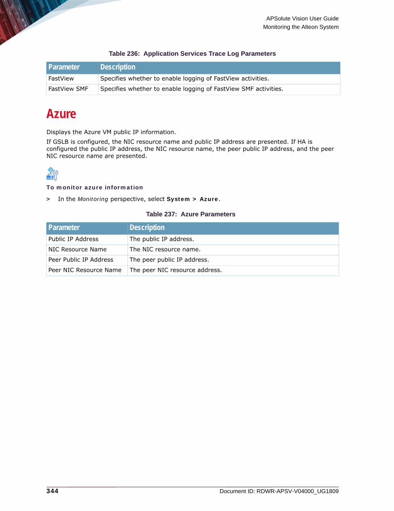
APSolute Vision User Guide
Monitoring the Alteon System
344 Document ID: RDWR-APSV-V04000_UG1809
Azure Displays the Azure VM public IP information. If GSLB is configured, the NIC resource name and public IP address are presented. If HA is configured the public IP address, the NIC resource name, the peer public IP address, and the peer NIC resource name are presented.
To monitor azure information
> In the Monitoring perspective, select System > Azure.
Table 236: Application Services Trace Log Parameters
Parameter DescriptionFastView Specifies whether to enable logging of FastView activities.
FastView SMF Specifies whether to enable logging of FastView SMF activities.
Table 237: Azure Parameters
Parameter DescriptionPublic IP Address The public IP address.
NIC Resource Name The NIC resource name.
Peer Public IP Address The peer public IP address.
Peer NIC Resource Name The peer NIC resource address.

Document ID: RDWR-APSV-V04000_UG1809 345
CHAPTER 12 – MONITORING THE ALTEON NETWORK
This chapter describes monitoring Alteon network operations.
Note: For information on monitoring Alteon device performance using the Device Performance Monitor, see Using the Device Performance Monitor, page 403.The Alteon operations that you can monitor depend on the Alteon form factor and/or platform: standalone, VA, vADC, or ADC-VX.This chapter contains the following main topics:• Monitoring and Controlling Physical Ports, page 345• Monitoring Layer 2, page 346• Monitoring Layer 3, page 348• Monitoring High Availability, page 355
Monitoring and Controlling Physical PortsThis feature is available only in Alteon standalone, VA, and ADC-VX.
To monitor physical ports
> In the Monitoring perspective, select Network > Physical Ports.
Table 238: Physical Port Parameters
Parameter DescriptionPort ID The port identifier.
Status Specifies whether the port is enabled or disabled.Values: Enable, Disable
Operational Status Specifies whether the port is online or offline.Values: Online, Offline
Octets
In The number of inbound octets.
Out The number of outbound octets.
Unicast Packets
In The number of inbound unicast packets.
Out The number of outbound unicast packets.
Broadcast Packets
In The number of inbound broadcast packets.
Out The number of outbound broadcast packets.

APSolute Vision User Guide
Monitoring the Alteon Network
346 Document ID: RDWR-APSV-V04000_UG1809
To enable physical ports
1. In the Monitoring perspective, select Network > Physical Ports.2. Select the row in the table for the required port.
3. Click Enable.
To disable physical ports
1. In the Monitoring perspective, select Network > Physical Ports.2. Select the row in the table for the required port.
3. Click Disable.
To clear statistics for physical ports
1. In the Monitoring perspective, select Network > Physical Ports.2. Select the row in the table for the required port.
3. Click Clear Statistics.
Monitoring Layer 2This feature is available only in version 30.0 and later.Monitoring Layer 2 comprises the following topics:• Monitoring FDB, page 346• Monitoring STG, page 348
Monitoring FDBThis feature is available only in Alteon standalone, VA, and vADC.
Multicast Packets
In The number of inbound multicast packets.
Out The number of outbound multicast packets.
Discards
In The number of inbound discarded packets.
Out The number of outbound discarded packets.
Errors
In The number of inbound errored packets.
Out The number of outbound errored packets.
Table 238: Physical Port Parameters (cont.)
Parameter Description

APSolute Vision User Guide
Monitoring the Alteon Network
Document ID: RDWR-APSV-V04000_UG1809 347
The forwarding database (FDB) contains information that maps the media access control (MAC) address to the port from which the Alteon address was learned.
Note: The forwarding database supports up to 16K MAC address entries on the MP per Alteon. Each SP supports up to 8K entries.
To display FDB monitoring parameters
> In the Monitoring perspective, select Network > Layer 2 > FDB.
To clear the entire FDB
1. In the Monitoring perspective, select Network > Layer 2 > FDB.2. Click Clear Entire FDB.
Table 239: FDB Monitoring Parameters
Parameter Description MAC Address The MAC address in the FDB.
VLAN The VLAN. Values: 1–4090
Port The port number. 0 specifies unknown.
Trunk The trunk-group number. The FDB entries on a single trunk. Values: 1–4090
State Values:• Forward—The address has been learned by Alteon.• Trunk—The Port field represents the trunk group number. • Unknown—The MAC address has not yet been learned by Alteon,
but has only been seen as a destination address. When an address is in the Unknown state, no outbound port is indicated, although ports which reference the address as a destination are listed under reference ports.
• Vir—The MAC address is for a standard VRRP virtual router.• Virtual server (VIP)—The MAC address is for a virtual server
router, a virtual router with the same IP address as a virtual server.
Referenced SPs The SP number.
Learned Port The learned port number.
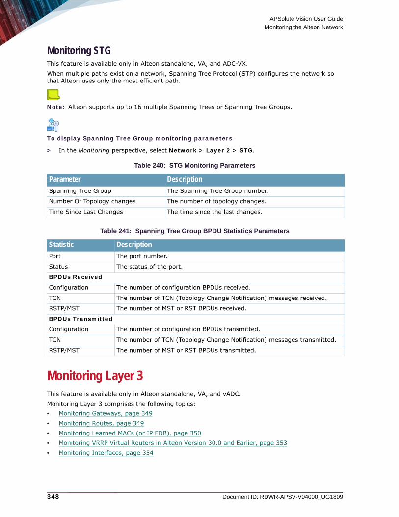
APSolute Vision User Guide
Monitoring the Alteon Network
348 Document ID: RDWR-APSV-V04000_UG1809
Monitoring STGThis feature is available only in Alteon standalone, VA, and ADC-VX.When multiple paths exist on a network, Spanning Tree Protocol (STP) configures the network so that Alteon uses only the most efficient path.
Note: Alteon supports up to 16 multiple Spanning Trees or Spanning Tree Groups.
To display Spanning Tree Group monitoring parameters
> In the Monitoring perspective, select Network > Layer 2 > STG.
Monitoring Layer 3This feature is available only in Alteon standalone, VA, and vADC.Monitoring Layer 3 comprises the following topics:• Monitoring Gateways, page 349• Monitoring Routes, page 349• Monitoring Learned MACs (or IP FDB), page 350• Monitoring VRRP Virtual Routers in Alteon Version 30.0 and Earlier, page 353• Monitoring Interfaces, page 354
Table 240: STG Monitoring Parameters
Parameter Description Spanning Tree Group The Spanning Tree Group number.
Number Of Topology changes The number of topology changes.
Time Since Last Changes The time since the last changes.
Table 241: Spanning Tree Group BPDU Statistics Parameters
Statistic DescriptionPort The port number.
Status The status of the port.
BPDUs Received
Configuration The number of configuration BPDUs received.
TCN The number of TCN (Topology Change Notification) messages received.
RSTP/MST The number of MST or RST BPDUs received.
BPDUs Transmitted
Configuration The number of configuration BPDUs transmitted.
TCN The number of TCN (Topology Change Notification) messages transmitted.
RSTP/MST The number of MST or RST BPDUs transmitted.

APSolute Vision User Guide
Monitoring the Alteon Network
Document ID: RDWR-APSV-V04000_UG1809 349
Monitoring GatewaysThis feature is available only in version 30.0 and later.Alteon can be configured with up to 255 gateways. Gateways 1 to 4 are reserved for default gateway load balancing. Gateways 5 to 259 are used for load-balancing of VLAN-based gateways.Alteon needs an IP interface for each default gateway to which it is connected. Each interface needs to be placed in the appropriate VLAN. These interfaces are used as the primary and secondary default gateways for Alteon.
To monitor gateways
> In the Monitoring perspective, select Network > Layer 3 > Gateways.
Monitoring RoutesThis feature is available only in version 30.0 and later.Alteon uses a combination of configurable IP interfaces and IP routing options. Alteon IP routing capabilities provide the following benefits:• Connects the server IP subnets to the rest of the backbone network.• Performs Server Load Balancing (using both Layer 3 and Layer 4 in combination) to server
subnets that are separate from backbone subnets.• Introduces Jumbo frame technology into the server-switched network by fragmenting UDP
Jumbo frames when routing to non-Jumbo frame VLANs or subnets.• Routing IP traffic between multiple Virtual Local Area Networks (VLANs) configured on Alteon.
To monitor routes
> In the Monitoring perspective, select Network > Layer 3 > Routes.
Table 243: IPv4 Routes Monitoring Parameters
Table 242: Gateway Monitoring Parameters
Parameter Description Status The status of the gateway.
Gateway ID The gateway number to which the information is related.Values: 1–259
IP Address The IP address of the default gateway.
VLAN The VLAN identifier of the gateway.
Parameter DescriptionEntry The entry number of the route in the routing table.
Destination The destination IP address of this route.
Mask The subnet mask of this route.
Gateway The IP address of the destination gateway for this route.

APSolute Vision User Guide
Monitoring the Alteon Network
350 Document ID: RDWR-APSV-V04000_UG1809
The IPv6 Routers table shows all of the IPv6 routes maintained. Since each link-local interface is shown with an entry prefix of /128, the link-local network (such as FE80::/10) is not shown for each interface to avoid too many network entries in the table.
Table 244: IPv6 Routes Monitoring Parameters
Monitoring Learned MACs (or IP FDB)This feature is available only in Alteon standalone, VA, and vADC. The name of this node in Alteon version 30.1 and earlier is IP FDB. The name of this node in Alteon version 30.2 and later is Learned MACs.
Type The route type.Values:• Indirect—The next hop to the host or subnet destination are forwarded
through a router at the gateway address.• Direct—Packets are delivered to a destination host or subnet attached to
Alteon.• Local—Indicates a route to one of the Alteon IP interfaces.• Broadcast—Indicates a broadcast route.• Martian—The destination belongs to a host or subnet that is filtered out.
Packets to this destination are discarded.
Tag The tag that indicates the origin of the route.Values:• Fixed—The address belongs to a host or subnet attached to Alteon.• Static—The address is a static route which has been configured on Alteon.• Addr—The address belongs to one of the Alteon IP interfaces.• RIP—The address was learned by the Routing Information Protocol (RIP).• OSPF—The address was learned by Open Shortest Path First (OSPF).• BGP—The address was learned via the Border Gateway Protocol (BGP)• Broadcast—Indicates a broadcast address.• Martian—The address belongs to a filtered group.• Multicast—Indicates a multicast address.• VIP—Indicates a route destination that is a virtual server IP address. VIP
routes are needed to advertise virtual server IP addresses via BGP.
Metric The metric for RIP tagged routes, specifying the number of hops to the destination (1 through 15 hops, or 16 for infinite hops).
Interface The IP interface that the route uses.
Parameter DescriptionEntry The entry number of the route in the routing table.
Destination The destination IP address of this route.
VLAN The VLAN of the route.
Next Hop The next hop of the route.
Protocol The route protocol.Values: Local, Static
Parameter Description

APSolute Vision User Guide
Monitoring the Alteon Network
Document ID: RDWR-APSV-V04000_UG1809 351
Monitoring learned MACs (or IP FDB) comprises the following topics:• ARP, page 351—Displaying ARP monitoring parameters and clearing the ARP cache• Neighbor Cache, page 352—Includes displaying Neighbor Cache monitoring parameters and
summary information and clearing the Neighbor Cache
ARPThis procedure describes how to display the ARP monitoring parameters.Static ARP entries reside permanently in the ARP cache and do not age out like the ARP entries that are learned dynamically. Static ARP entries enable Alteon to reach hosts without sending an ARP broadcast request to the network. Static ARPs are also useful in communicating with devices that do not respond to ARP requests. Static ARPs can also be configured on some gateways as protection against malicious ARP cache corruption and possible DoS attacks.
Note: Alteon allows the static ARP configuration to be retained over reboots.
To display ARP monitoring parameters
> In the Monitoring perspective, select Network > Layer 3 > Learned MACs (or IP FDB).
To clear the ARP cache
1. In the Monitoring perspective, select Network > Layer 3 > Learned MACs (or IP FDB).2. Select the relevant row in the table.
3. Click Clear ARP Cache.
Table 245: ARP Monitoring Parameters
Parameter Description IP Address The IP address for the ARP entry.
Flags The flag associated with the entry.Examples:• clear• permanent—Not obtained via an ARP request (for example, IP interface and
VIP) • R—Indirect ARP (cache) entry for IP address reachable via indirect routes
(static/dynamic)• layer4—Layer 4 IP address (VIP) • u—Unresolved ARP entry. The MAC address has not been learned.
MAC Address The MAC address for the ARP entry.
VLAN The VLAN for the ARP entry.Values: 1–4090
Port The physical port where the IP address owner for this ARP entry is connected.
Referenced SPs The number of SPs on which this ARP entry is present.

APSolute Vision User Guide
Monitoring the Alteon Network
352 Document ID: RDWR-APSV-V04000_UG1809
Neighbor CacheIPv6 uses the Neighbor Discovery (ND) protocol to discover its neighbors’ link layer addresses and reachability. ND can also auto-configure addresses and detect duplicate addresses. ND enables routers to advertise their presence and address prefixes, and to inform hosts of a better next hop address to forward packets.
Note: Once the Neighbor Cache table reaches 2000 entries, table entries are replaced by adding the new entry and dropping the 2000th entry off the list. Table entries are kept until the entry is replaced by a new one. During this period, no new entries are used to sort for display.The information collected from ND is stored in the Neighbor Cache. The Neighbor Cache maintains information about each neighbor. Neighbor Cache entries are added in the following situations:• Entries are added when an IPv6 interface or virtual IP is operational.• Reception of ND messages from neighbor.• A device sends ND packets to resolve a link layer address to which it is attempting to send
packets.
To display Neighbor Cache monitoring parameters and summary information
> In the Monitoring perspective, select Network > Layer 3 > Learned MACs (or IP FDB).
Table 246: Neighbor Cache Monitoring Parameters
Parameter DescriptionIPv6 Address The IPv6 address for the Neighbor Cache entry.
MAC Address The MAC address for the Neighbor Cache entry.
VLAN The VLAN for the Neighbor Cache entry.Values: 1–4090
Port The physical port for the Neighbor Cache entry.
State The the reachability state of the Neighbor Cache entry. Values:• INCPM—Incomplete. The link-layer address of the neighbor has not yet been
determined.• REACH—Reachable. The neighbor is known to have been reachable recently.• Stale—The neighbor is no longer known to be reachable, but until traffic is
sent to the neighbor, no attempt should be made to verify its reachability.• Delay—The neighbor is no longer known to be reachable, and traffic has
recently been sent to the neighbor.• Probe—The neighbor is no longer known to be reachable, and ND messages
are sent to the neighbor to verify reachability.
Type The type of the Neighbor Cache entry.Values:• LOCAL—The entry is a predefined address on Alteon.• DYNAMIC—The entry is a neighbor address learned from ND.
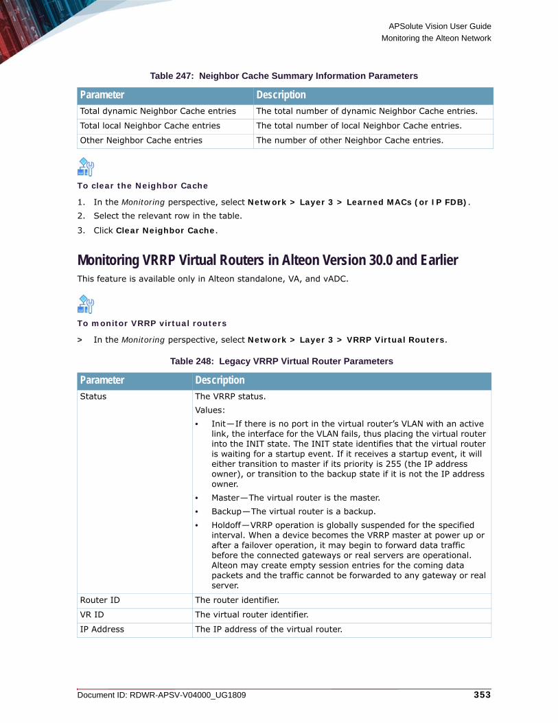
APSolute Vision User Guide
Monitoring the Alteon Network
Document ID: RDWR-APSV-V04000_UG1809 353
To clear the Neighbor Cache
1. In the Monitoring perspective, select Network > Layer 3 > Learned MACs (or IP FDB).2. Select the relevant row in the table.
3. Click Clear Neighbor Cache.
Monitoring VRRP Virtual Routers in Alteon Version 30.0 and EarlierThis feature is available only in Alteon standalone, VA, and vADC.
To monitor VRRP virtual routers
> In the Monitoring perspective, select Network > Layer 3 > VRRP Virtual Routers.
Table 247: Neighbor Cache Summary Information Parameters
Parameter DescriptionTotal dynamic Neighbor Cache entries The total number of dynamic Neighbor Cache entries.
Total local Neighbor Cache entries The total number of local Neighbor Cache entries.
Other Neighbor Cache entries The number of other Neighbor Cache entries.
Table 248: Legacy VRRP Virtual Router Parameters
Parameter DescriptionStatus The VRRP status.
Values: • Init—If there is no port in the virtual router’s VLAN with an active
link, the interface for the VLAN fails, thus placing the virtual router into the INIT state. The INIT state identifies that the virtual router is waiting for a startup event. If it receives a startup event, it will either transition to master if its priority is 255 (the IP address owner), or transition to the backup state if it is not the IP address owner.
• Master—The virtual router is the master.• Backup—The virtual router is a backup.• Holdoff—VRRP operation is globally suspended for the specified
interval. When a device becomes the VRRP master at power up or after a failover operation, it may begin to forward data traffic before the connected gateways or real servers are operational. Alteon may create empty session entries for the coming data packets and the traffic cannot be forwarded to any gateway or real server.
Router ID The router identifier.
VR ID The virtual router identifier.
IP Address The IP address of the virtual router.

APSolute Vision User Guide
Monitoring the Alteon Network
354 Document ID: RDWR-APSV-V04000_UG1809
To switch over a VRRP virtual router
1. In the Monitoring perspective, select Network > Layer 3 > VRRP Virtual Routers.2. Select an entry and click Backup.
Monitoring InterfacesAlteon needs an IP interface for each subnet to which it is connected so it can communicate with the real servers and other devices attached to it that receive switching services. Alteon can be configured with up to 256 IP interfaces. Each IP interface represents Alteon on an IP subnet on your network. The interface option is disabled by default.This feature is available only in version 30.0 and later.
To monitor interfaces
> In the Monitoring perspective, select Network > Layer 3 > Interfaces.
Interface The IP interface of the device. If the IP interface has the same IP address as the IP address, this device is considered the owner of the defined virtual router.
Priority The election priority bias for this virtual server.During the master router election process, the routing device with the highest virtual router priority number wins. If there is a tie, the device with the highest IP interface address wins. If this virtual router’s IP address (addr) is the same as the one used by the IP interface, the priority for this virtual router is set to 255 (highest).When priority tracking is used, this base priority value can be modified according to a number of performance and operational criteria.Values: 1–254Default: 100
Note: When you enable hot-standby for a vrgroup, the currently set priority for the vrgroup is increased by 2.
Ownership The owner of the VRRP IP address.Values:• Owner—If the IP interface has the same IP address as the virtual
address IP, this device is considered the owner of the defined virtual router. An owner has a special priority of 255 (highest) and always assumes the role of the master router, even if it must preempt another virtual router that has assumed master routing authority.
• Renter—The virtual router that is not owned by the device.
Table 248: Legacy VRRP Virtual Router Parameters (cont.)
Parameter Description

APSolute Vision User Guide
Monitoring the Alteon Network
Document ID: RDWR-APSV-V04000_UG1809 355
Monitoring High AvailabilityThis section comprises the following topics:• Monitoring High Availability in Alteon Version 30.1, page 355• Monitoring High Availability for Alteon Version 30.2 and Later, page 358
Monitoring High Availability in Alteon Version 30.1This feature is available only in Alteon standalone, VA, and vADC.
Note: You can configure the values for the High Availability feature in the Configuration perspective, under Network > High Availability.For Alteon version 30.1 and later, use the High Availability tab in the Monitoring perspective to do the following:• When the High Availability Mode on the device is Switch HA (or Extended HA in Alteon
version 30.5.4 and later, and version 31.0.1 and later), switch an active device to backup mode. Typically, you do this when you need to perform maintenance on the active Alteon and not affect the service.
• When the High Availability Mode on the device is Service HA: — Monitor high-availability information.— Switch an active service group to backup mode. Typically, you select all the services and
switch to backup mode when you need to perform maintenance on the active Alteon and not affect the services.
• When the High Availability Mode on the device is Legacy VRRP:— Monitor high-availability information.— Switch an active device to backup mode when the High Availability Mode on the device is
Legacy VRRP. Typically, you do this when you need to perform maintenance on the active Alteon and not affect the services or for passing master control back to a primary Alteon after it has been returned to service after a failure.
Table 249: Interface Monitoring Parameters
Parameter Description State The state of the interface.
Interface ID The identifier of the interface.
IP Address The IP address of the interface.
Mask The mask of the interface if the interface is IPv4. If the interface is IPv6, the fields displays 0.0.0.0.
Prefix The prefix of the interface if the interface is IPv6. If the interface is IPv4, the fields displays 0.
VLAN The VLAN identifier of the interface.
BFD The status of the Bidirectional Forwarding Detection (BFD) peer on this interface.Values: Disabled, Enabled

APSolute Vision User Guide
Monitoring the Alteon Network
356 Document ID: RDWR-APSV-V04000_UG1809
To view High Availability mode and state
> In the Monitoring perspective, select Network > High Availability.The High Availability Mode field displays one of the following: Disabled, Switch HA, Service HA, Extended HA, Legacy VRRPThe Status field displays master or backup.
To monitor Service HA information in Alteon version 30.1
> In the Monitoring perspective, select Network > Layer 3 > High Availability.
To monitor Switch HA information in Alteon version 30.1
> In the Monitoring perspective, select Network > Layer 3 > High Availability
To monitor legacy VRRP virtual routers in Alteon version 30.1
> In the Monitoring perspective, select Network > Layer 3 > High Availability.
Table 250:
Parameter DescriptionStatus The Service HA status.
HA Group ID The HA Group identifier.
Table 251: Switch HA Monitoring Parameters
Parameter DescriptionPeer Switch ID The identifier of the peer.
Peer Switch Address The IP address of the advertisement IP interface associated with the peer.
Last Sync The type (manual or automatic), status, timestamp, and failure reason of the last configuration synchronization attempt.
Last Successful Sync The type (manual or automatic) and timestamp of the last successful configuration synchronization.

APSolute Vision User Guide
Monitoring the Alteon Network
Document ID: RDWR-APSV-V04000_UG1809 357
Table 252: Legacy VRRP Virtual Router Parameters
Parameter DescriptionStatus The VRRP status.
Values: • Init—If there is no port in the virtual router’s VLAN with an active
link, the interface for the VLAN fails, thus placing the virtual router into the INIT state. The INIT state identifies that the virtual router is waiting for a startup event. If it receives a startup event, it will either transition to master if its priority is 255 (the IP address owner), or transition to the backup state if it is not the IP address owner.
• Master—The virtual router is the master.• Backup—The virtual router is a backup.• Holdoff—VRRP operation is globally suspended for the specified
interval. When a device becomes the VRRP master at power up or after a failover operation, it may begin to forward data traffic before the connected gateways or real servers are operational. Alteon may create empty session entries for the coming data packets and the traffic cannot be forwarded to any gateway or real server.
Router ID The router identifier.
VR ID The virtual router identifier.
IP Address The IP address of the virtual router.
Interface The IP interface of the device. If the IP interface has the same IP address as the IP address, this device is considered the owner of the defined virtual router.
Priority The election priority bias for this virtual server.During the master router election process, the routing device with the highest virtual router priority number wins. If there is a tie, the device with the highest IP interface address wins. If this virtual router’s IP address (addr) is the same as the one used by the IP interface, the priority for this virtual router is set to 255 (highest).When priority tracking is used, this base priority value can be modified according to a number of performance and operational criteria.Values: 1–254Default: 100
Note: When you enable hot-standby for a vrgroup, the currently set priority for the vrgroup is increased by 2.
Ownership The owner of the VRRP IP address.Values:• Owner—If the IP interface has the same IP address as the virtual
address IP, this device is considered the owner of the defined virtual router. An owner has a special priority of 255 (highest) and always assumes the role of the master router, even if it must preempt another virtual router that has assumed master routing authority.
• Renter—The virtual router that is not owned by the device.
APSolute Vision User Guide
Monitoring the Alteon Network
358 Document ID: RDWR-APSV-V04000_UG1809
Forcing FailoverYou can force a specified master Alteon, or a specified master service group, into backup mode. This is generally used for passing master control back to a preferred Alteon (or service group) once the preferred Alteon (or service group) has been returned to service after a failure.If failback mode is Always when you force failover, the Alteon with preferred state Active (the “preferred master”) briefly becomes the backup and then reverts to the master.
To force a master Alteon into backup mode
1. In the Monitoring perspective, select Network > Layer 3 > High Availability.2. Click Backup.
To force a master service group into backup mode
1. In the Monitoring perspective, select Network > Layer 3 > High Availability.2. Select the required service group or service groups.
3. Click Backup.
Monitoring High Availability for Alteon Version 30.2 and LaterThis feature is available only in Alteon standalone, VA, and vADC.
Note: You can configure the values for the High Availability feature in the Configuration perspective, under Network > High Availability.• When the High Availability Mode on the device is Switch HA (or Extended HA in Alteon
version 30.5.4 and later, and version 31.0.1 and later), switch an active device to backup mode. Typically, you do this when you need to perform maintenance on the active Alteon and not affect the service.
• When the High Availability Mode on the device is Service HA: — Monitor high-availability information.— Switch an active service group to backup mode. Typically, you select all the services and
switch to backup mode when you need to perform maintenance on the active Alteon and not affect the services.
• When the High Availability Mode on the device is Legacy VRRP:— Monitor high-availability information.— Switch an active device to backup mode when the High Availability Mode on the device is
Legacy VRRP. Typically, you do this when you need to perform maintenance on the active Alteon and not affect the services or for passing master control back to a primary Alteon after it has been returned to service after a failure.
To view High Availability mode and state
> In the Monitoring perspective, select Network > High Availability.The High Availability Mode field displays one of the following: Disabled, Switch HA, Service HA, Extended HA, Legacy VRRP

APSolute Vision User Guide
Monitoring the Alteon Network
Document ID: RDWR-APSV-V04000_UG1809 359
The Status field displays master or backup.
To monitor Service HA information
> In the Monitoring perspective, select Network > High Availability > Sync Status.
To monitor Switch HA information
> In the Monitoring perspective, select Network > High Availability > Sync Status.
To monitor Extended HA information
This option is available only in Alteon version 30.5.4 and later, and in version 31.0.1 and later.> In the Monitoring perspective, select Network > High Availability > Sync Status.
Table 253: Service HA Monitoring Parameters
Parameter DescriptionStatus The Service HA status.
HA Group ID The HA Group identifier.
Table 254:
Parameter DescriptionPeer Switch ID The identifier of the peer.
Peer Switch Address The IP address of the advertisement IP interface associated with the peer.
Last Sync The type (manual or automatic), status, timestamp, and failure reason of the last configuration synchronization attempt.
Last Successful Sync The type (manual or automatic) and timestamp of the last successful configuration synchronization.
Table 255: Extended HA Monitoring Parameters
Parameter DescriptionState The Extended HA status.
Values: • Init—If there is no port in the virtual router’s VLAN with an active
link, the interface for the VLAN fails, thus placing the virtual router into the INIT state. The INIT state identifies that the virtual router is waiting for a startup event. If it receives a startup event, it will either transition to master if its priority is 255 (the IP address owner), or transition to the backup state if it is not the IP address owner.
• Master—The virtual router is the master.• Backup—The virtual router is a backup.

APSolute Vision User Guide
Monitoring the Alteon Network
360 Document ID: RDWR-APSV-V04000_UG1809
To monitor legacy VRRP virtual routers
> In the Monitoring perspective, select Network > High Availability > Sync Status.
Table 256: Legacy VRRP Virtual Router Parameters
Parameter DescriptionStatus The VRRP status.
Values: • Init—If there is no port in the virtual router’s VLAN with an active
link, the interface for the VLAN fails, thus placing the virtual router into the INIT state. The INIT state identifies that the virtual router is waiting for a startup event. If it receives a startup event, it will either transition to master if its priority is 255 (the IP address owner), or transition to the backup state if it is not the IP address owner.
• Master—The virtual router is the master.• Backup—The virtual router is a backup.• Holdoff—VRRP operation is globally suspended for the specified
interval. When a device becomes the VRRP master at power up or after a failover operation, it may begin to forward data traffic before the connected gateways or real servers are operational. Alteon may create empty session entries for the coming data packets and the traffic cannot be forwarded to any gateway or real server.
Router ID The router identifier.
VR ID The virtual router identifier.
IP Address The IP address of the virtual router.
Interface The IP interface of the device. If the IP interface has the same IP address as the IP address, this device is considered the owner of the defined virtual router.
Priority The election priority bias for this virtual server.During the master router election process, the routing device with the highest virtual router priority number wins. If there is a tie, the device with the highest IP interface address wins. If this virtual router’s IP address (addr) is the same as the one used by the IP interface, the priority for this virtual router is set to 255 (highest).When priority tracking is used, this base priority value can be modified according to a number of performance and operational criteria.Values: 1–254Default: 100
Note: When you enable hot-standby for a vrgroup, the currently set priority for the vrgroup is increased by 2.

APSolute Vision User Guide
Monitoring the Alteon Network
Document ID: RDWR-APSV-V04000_UG1809 361
Forcing FailoverYou can force a specified master Alteon, or a specified master service group, into backup mode. This is generally used for passing master control back to a preferred Alteon (or service group) once the preferred Alteon (or service group) has been returned to service after a failure.If failback mode is Always when you force failover, the Alteon with preferred state Active (the “preferred master”) briefly becomes the backup and then reverts to the master.
To force a master Alteon into backup mode
1. In the Monitoring perspective, select Network > High Availability.2. Click Backup.
To force a master service group into backup mode
1. In the Monitoring perspective, select Network > High Availability.2. Select the required service group or service groups.
3. Click Backup.
Ownership The owner of the VRRP IP address.Values:• Owner—If the IP interface has the same IP address as the virtual
address IP, this device is considered the owner of the defined virtual router. An owner has a special priority of 255 (highest) and always assumes the role of the master router, even if it must preempt another virtual router that has assumed master routing authority.
• Renter—The virtual router that is not owned by the device.
Table 256: Legacy VRRP Virtual Router Parameters (cont.)
Parameter Description

APSolute Vision User Guide
Monitoring the Alteon Network
362 Document ID: RDWR-APSV-V04000_UG1809

Document ID: RDWR-APSV-V04000_UG1809 363
CHAPTER 13 – MONITORING ALTEON APPLICATION DELIVERY
This chapter describes monitoring Alteon application delivery operations.
Note: For information on monitoring Alteon device performance using the Device Performance Monitor, see Using the Device Performance Monitor, page 403.This section contains the following main topics:• Clearing Non-operating SLB Statistics, page 363• Clearing SLB Statistics from the HA Peer, page 364• Monitoring and Controlling Virtual Servers, page 364• Monitoring and Managing Filters, page 369• Monitoring and Controlling Server Resources, page 372• View a FastView Web Application, page 377• Monitoring and Controlling APM, page 378• Monitoring and Controlling SSL, page 379• Monitoring Traffic Match Criteria, page 382• Monitoring and Controlling Application Services, page 383• Monitoring LinkProof, page 389• Monitoring Global Traffic Redirection Statistics, page 392• Monitoring AppShape++ Statistics, page 396
Clearing Non-operating SLB StatisticsIn Alteon version 30.1 and later, you can clear all non-operating SLB statistics, resetting them to zero. The action, Clear All SLB Statistics, does not reset Alteon and does not affect the following counters:• Counters required for Layer 4 and Layer 7 operations (such as current real server sessions)• All related SNMP counters
To clear all non-operating SLB statistics
1. (In Alteon version 30.1 and later, and 30.2 and later) In the Monitoring perspective, select Application Delivery > Virtual Service.
2. (In Alteon version 30.5 and later, version 31.0 and later, and version 32.0 and later) In the Monitoring perspective, select Application Delivery > Server Resources.
3. Click Clear All SLB Statistics.
APSolute Vision User Guide
Monitoring Alteon Application Delivery
364 Document ID: RDWR-APSV-V04000_UG1809
Clearing SLB Statistics from the HA PeerIn Alteon version 31.0.6.0 and later, and version 32.1.0.0 and later, you can clear all SLB statistics from the HA peer when both the following conditions are met:When both the following conditions are met, you can clear all SLB statistics from the HA peer:• The Configuration > Network > High Availability > High Availability Mode parameter is
set to Service HA.• Session mirroring is enabled for at least one service.
To clear all SLB statistics from the HA peer
1. In the Monitoring perspective, select Application Delivery > Server Resources.2. Select Also clear SLB statistics on peer.
3. Click Clear All SLB Statistics.
Monitoring and Controlling Virtual ServersThis feature is available only in Alteon standalone, VA, and vADC.
To monitor virtual servers, virtual services, and content-based rules
> In the Monitoring perspective, select Application Delivery > Virtual Service > Virtual Servers.The following parameters display in the Virtual Servers table:
To monitor virtual servers, virtual services, and content-based rules
> In the Monitoring perspective, select Application Delivery > Server Resources > Virtual Servers.The following parameters display in the Virtual Servers table:
To monitor virtual servers, virtual services, and content-based rules
> In the Monitoring perspective, select Application Delivery > Virtual Servers.The following parameters display in the Virtual Servers table:
Table 257: Virtual Servers Statistics
Parameter DescriptionStatus The status of the virtual server.
Virtual Server ID The ID of the virtual server.

APSolute Vision User Guide
Monitoring Alteon Application Delivery
Document ID: RDWR-APSV-V04000_UG1809 365
Click on an entry in the Virtual Services of Selected Virtual Server table to view the following detailed virtual service statistics:
Description(This parameter is available only in version 31.0 and later, and 32.0 and later.)
The description of the virtual server.
Name(This parameter is available only in version 29.5.x, 30.0.x, 30.1.x, 30.2.x, and 30.5.x.)
A name for the virtual server
IP Address(This parameter is available only in version 31.0 and later, and 32.0 and later.)
The IP address of the virtual server.
Connection per Second(This parameter is available only in version 30.5.x and later, 31.0.2 and later, and 32.0 and later.)
The number of connections per second for the virtual server.
Throughput per Second(This parameter is available only in version 30.5.x and later, 31.0.2 and later, and 32.0 and later.)
The throughput, in Mbps, for the virtual server.
Current Sessions The number of sessions currently open on the virtual server.
Total Sessions The total number of sessions handled by the virtual server.
Highest Sessions The highest number of concurrent sessions recorded on the virtual server.
Total Octets The total number of octets sent and received by the virtual server.
Table 258: Virtual Services: General Statistics (Alteon Version 31.0 and Later)
Parameter DescriptionVirtual Server ID The ID of the virtual server associated with the selected virtual service.
Application The name of the application associated with the virtual service.
Service Port The service port associated with the selected virtual service.
Protocol The Layer 4 protocol for the specified application.
Action The action of the virtual service.
Group ID The identifier of the server group to which this virtual service redirects the traffic.
Table 257: Virtual Servers Statistics (cont.)
Parameter Description

APSolute Vision User Guide
Monitoring Alteon Application Delivery
366 Document ID: RDWR-APSV-V04000_UG1809
Total Octets(This parameter is available only in version 31.0.2 and later, and version 32.0 and later.)
The total number of octets sent and received by the virtual service.
Connections per Second(This parameter is available only in version 31.0.2 and later, and version 32.0 and later.)
The number of connections per second for the virtual service.
Throughput per Second(This parameter is available only in version 31.0.2 and later, and version 32.0 and later.)
The throughput, in bytes per second, for the virtual service.
Current Sessions(This parameter is available only in version 31.0.2 and later, and version 32.0 and later.)
The number of sessions currently open on the virtual service.
Total Sessions(This parameter is available only in version 31.0.2 and later, and version 32.0 and later.)
The total number of sessions handled by the virtual service.
Highest Sessions(This parameter is available only in version 31.0.2 and later, and version 32.0 and later.)
The highest number of concurrent sessions recorded on the virtual service.
Table 259: Virtual Service: Traffic Statistics per Real Server (Alteon Version 30.1 and Later)
Parameter DescriptionRuntime Status(Available only in Alteon version 31.0 and later, and version 32.0 and later.)
The run-time status of the real server per service based on the configuration, operational status, health check status, and traffic of the real server.Available statuses: Up, Down, Admin-Down, Warning, or Shutdown.
Real ID The identifier of a real server associated with the virtual service.
Current Sessions The number of current sessions to the virtual service on the real server.
Total Sessions The total number of sessions to the virtual service on the real server.
Highest Sessions The highest number of concurrent sessions to the virtual service on the real server.
Table 258: Virtual Services: General Statistics (Alteon Version 31.0 and Later) (cont.)
Parameter Description

APSolute Vision User Guide
Monitoring Alteon Application Delivery
Document ID: RDWR-APSV-V04000_UG1809 367
Failure Reason(This parameter is available only in version 31.0.3 and later, and version 32.0 and later)
Displays the reason for which the real server associated with the virtual service is considered Down. The failure reason displays when the runtime status of the server is Down, otherwise the failure reason is empty.
Time since last device reset / clear statistics
The time since the device was last reset and traffic statistics were cleared.
Table 260: Virtual Service: HTTP Statistics (Alteon Version 30.2 and Later)
Parameter DescriptionHTTP 2.0 Displays the following statistics for HTTP 2.0 traffic:
• Connection Count—Number of connections within the statistics measuring period.
• Connection Peak—The peak number of concurrent connections within the statistics measuring period.
• Requests Count—Number of requests within the statistics measuring period.
HTTP 1.1 Displays the following statistics for HTTP 1.1 traffic:• Connection Count—Number of connections within the statistics
measuring period.• Connection Peak—The peak number of concurrent connections
within the statistics measuring period.• Requests Count—Number of requests within the statistics
measuring period.
HTTP 1.0 Displays the following statistics for HTTP 1.0 traffic:• Connection Count—Number of connections within the statistics
measuring period.• Connection Peak—The peak number of concurrent connections
within the statistics measuring period.• Requests Count—Number of requests within the statistics
measuring period.
HTTP/2 Connection Statistics(These statistics are displayed only when an HTTP/2 policy is associated with the selected virtual service)
Displays the value for the last measuring period (Current) and the highest value recorded in a measuring period (Peak) for each of the following statistics:• Backend Connections used by HTTP/2 Proxy• Client Streams—Average number of client streams per connection.• PUSH Streams—Average number of PUSH stream connections sent
by Alteon to clients.• Canceled PUSH Requests—Average number of cancel PUSH
requests received from a client per connection.
• Session Duration Average—In mm:ss format.
Table 259: Virtual Service: Traffic Statistics per Real Server (Alteon Version 30.1 and Later)
Parameter Description

APSolute Vision User Guide
Monitoring Alteon Application Delivery
368 Document ID: RDWR-APSV-V04000_UG1809
HTTP/2 Header Compression Statistics(These statistics are displayed only when an HTTP/2 policy is associated with the selected virtual service)
Displays the value for the last measuring period (Current) and the highest value recorded in a measuring period (Peak) for each of the following header compression statistics:• Requests—Average Compression Ratio (%)• Responses—Average Compression Ratio (%)• Average de facto HPACK Table Size—Average size of the dynamic
HPACK table.• Big Headers Count—The number of Big Headers handled. A Big
Header is a header whose size is more than half of the maximum dynamic table size. Such headers usually cause eviction of older headers from the table.
• Average Evicted Bytes Per Connection
Statistics Measuring Period
Period, in seconds, for which statistics are measured and displayed.You configure this parameter in the Statistics tab at Configuration > Application Delivery > Virtual Services.
Time since last device reset / clear statistics
The time since the device was last reset and traffic statistics were cleared.
Table 261: Virtual Services Monitoring: Caching and Compression Statistics (Alteon Version 30.2 and Later)
Parameter DescriptionObjects Served from Cache
The number of objects served from cache.
Cache Hits Percentage of cache hits.
Cache Requests Number of cache requests per second.
Total Cached Objects Total number of cached objects.
New Cached Objects Number of new cached objects per second.
Peak New Cached Objects Number of peak new cached objects per second.
Compression Statistics Compression-specific statistics:• Throughput (KB)—Amount of compressed and uncompressed
throughput, and compression ratio.• Average Object Size (KB)—Average compressed and
uncompressed object size, and compression ratio.• Total Bytes Saved—Since last reboot or statistics clear.• Bytes Saved—Bytes saved per second.• Peak Bytes Saved—Highest number of bytes saved per second
since last reboot or statistics clear.
Statistics Measuring Period
Period, in seconds, for which statistics are measured and displayed.You configure this parameter in the Statistics tab at Configuration > Application Delivery > Virtual Services.
Time since last device reset / clear statistics
The time since the device was last reset and traffic statistics were cleared.
Table 260: Virtual Service: HTTP Statistics (Alteon Version 30.2 and Later) (cont.)
Parameter Description

APSolute Vision User Guide
Monitoring Alteon Application Delivery
Document ID: RDWR-APSV-V04000_UG1809 369
Monitoring and Managing Filters
To monitor filters
1. In the Monitoring perspective, select Application Delivery > Filters.
2. In the Filters table, select the required row(s) and click the button to view the filter details.
Table 262: Virtual Services: FastView Statistics (Alteon Version 30.2 and Later)
Parameter DescriptionTransactions Number of current, total, and peak transactions.
HTML Pages Number of current, total, and peak HTML pages.
Optimized Pages Number of current, total, and peak optimized pages.
Tokens Rewritten Number of current, total, and peak tokens rewritten.
Compiled Pages Number of current, total, and peak compiled pages.
Bytes Saved with Image Reduction
Number of bytes saved with image reduction for current traffic, and for traffic since the last clear of statistics.
% Bytes Saved with Image Reduction
Percentage of bytes saved with image reduction for current traffic, and for traffic since the last clear of statistics.
Responses with Expiry Modified
Number of responses with expiry modified for current traffic, and for traffic since the last clear of statistics.
% Responses with Expiry Modified
Percentage of responses with expiry modified for current traffic, and for traffic since the last clear of statistics.
Statistics Measuring Period
Period, in seconds, for which statistics are measured and displayed.You configure this parameter in the Statistics tab at Configuration > Application Delivery > Virtual Services.
Time since last device reset / clear statistics
The time since the device was last reset and traffic statistics were cleared.
Table 263: Content-Based Rules Statistics
Parameter DescriptionVirtual Server ID The ID of the virtual server associated with the selected content-based
rule.
Service ID The ID of the virtual service associated with the selected content-based rule.
Content Rule ID The ID of the content-based rule.
Action The action of the content-based rule.
Current Sessions The number of current sessions that match the content-based rule.
Total Sessions The total number of sessions that match the content-based rule.
Highest Sessions The highest number of concurrent sessions that matched the content-based rule.
Total Octets The total number of bytes/octets that matched the content-based rule.

APSolute Vision User Guide
Monitoring Alteon Application Delivery
370 Document ID: RDWR-APSV-V04000_UG1809
The statistics in the following tabs are relevant for redirect filters. They displays the statistics of the real servers that participate in this redirect group.
Note: The counters display accumulative data from all filters that redirect to each real server.
Table 264: Filter Parameters
Parameter DescriptionStatus The configurational status of the filter.
Filter ID The filter ID of the filter.
Name The name of the filter.
Action The configurational action of the filter.
Table 265: Statistics Parameters
Parameter DescriptionThis tab is available only in version 32.0 and later
Connections per Second The number of connections per second currently processed by this filter.Special cases:• For HTTP Layer 7 filters, the match is request-based, and therefore
the session counter is incremented per request.• For non-cached filters and Layer 2 filters with non-IP traffic, the
match is packets based, and therefore the session counter is not incremented.
Current Sessions The current number of sessions processed by this filter.Special cases:• For HTTP Layer 7 filters, the match is request-based, and therefore
the session counter is incremented per request.• For non-cached filters and Layer 2 filters with non-IP traffic, the
match is packets-based, and therefore the session counter is not incremented.
Highest Sessions The highest number of sessions processed by this filter since the last reboot of reset statistics.Special cases:• For HTTP Layer 7 filters, the match is request-based, and therefore
the session counter is incremented per request.• For non-cached filters and Layer 2 filters with non-IP traffic, the
match is packets-based, and therefore the session counter is not incremented.
Total Sessions The total number of sessions processed by this filter since the last reboot of reset statistics.Special cases:• For HTTP Layer 7 filters, the match is request-based, and therefore
the session counter is incremented per request.• For non-cached filters and Layer 2 filters with non-IP traffic, the
match is packets-based, and therefore the session counter is not incremented.

APSolute Vision User Guide
Monitoring Alteon Application Delivery
Document ID: RDWR-APSV-V04000_UG1809 371
Current Throughput The current throughput, in Kbps, processed by this filter.
Highest Throughput The highest throughput, in Kbps, processed by this filter.
Total Bandwidth The total bandwidth, in Mb, processed by this filter.
Total Hits The number of total hits, in packets, connections, or Requests, depending on the type of filter.Special cases:• For HTTP Layer 7 filters, the match is request based, and therefore
the session counter is incremented per request.• For non-cached filters and Layer 2 filters with non-IP traffic, the
match is packets based, and therefore the session counter is not incremented.
Table 266: Real Server Traffic Parameters
Parameter DescriptionThis tab is available only in version 32.0 and later
Runtime Status The runtime status of the real server.Values: Disabled, Failed, Running
Real IDs The real server ID.
Current Sessions The current number of sessions processed by the real server connected to this filter.Special cases:• For HTTP Layer 7 filters, the match is request-based, and therefore
the session counter is incremented per request.• For non-cached filters and Layer 2 filters with non-IP traffic, the
match is packets-based, and therefore the session counter is not incremented.
Highest Sessions The highest number of sessions processed by this real server since the last reboot of reset statistics. Special cases:• For HTTP Layer 7 filters, the match is request-based, and therefore
the session counter is incremented per request.• For non-cached filters and Layer 2 filters with non-IP traffic, the
match is packets-based, and therefore the session counter is not incremented.
Total Sessions The total number of sessions processed by this real server since the last reboot of reset statistics. Special cases:• For HTTP Layer 7 filters, the match is request-based, and therefore
the session counter is incremented per request.• For non-cached filters and Layer 2 filters with non-IP traffic, the
match is packets-based, and therefore the session counter is not incremented.
Current Throughput [Kbps]
The current throughput, in Kbps, processed by this real server.
Table 265: Statistics Parameters (cont.)
Parameter Description

APSolute Vision User Guide
Monitoring Alteon Application Delivery
372 Document ID: RDWR-APSV-V04000_UG1809
Monitoring and Controlling Server ResourcesAlteon displays the following connections per second (CPS) statistics for the entire Alteon platform: current connections per second, current throughput (in Mbps), and current SSL connections per second.Monitoring and controlling virtual services comprises the following: • Monitoring and Controlling Real Servers, page 373• Monitoring and Controlling Server Groups, page 375• Monitoring and Controlling Virtual Servers, page 364• Monitoring and Controlling APM, page 378
Highest Throughput [Kbps]
The highest throughput, in Kbps, processed by this real server.
Total BW [Mb] The total bandwidth, in Mb, processed by this real server.
CPS The number of connections per second currently processed by this real server.Special cases:• For HTTP Layer 7 filters, the match is request-based, and therefore
the session counter is incremented per request.• For non-cached filters and Layer 2 filters with non-IP traffic, the
match is packets-based, and therefore the session counter is not incremented.
Table 267: SSL Parameters
Parameter DescriptionNew SSL handshakes The number of new SSL handshakes per second.
Reused SSL handshakes The number of reused SSL handshakes per second.
Reuse rate The reuse rate in percentage.
Rejected SSL handshakes The number of rejected SSL handshakes per second.
SSL v3 handshakes The percentage of SSL v3 handshakes.
TLS 1.0 handshakes The percentage of TLS 1.0 handshakes.
TLS 1.1 handshakes The percentage of TLS 1.1 handshakes.
TLS 1.2 handshakes The percentage of TLS 1.2 handshakes.
TLS 1.3 handshakes The percentage of TLS 1.3 handshakes.
HTTP to HTTPS redirections
The number of HTTP to HTTPS redirections.
Statistics Measuring Period
Period, in seconds, for which statistics are measured and displayed.You configure this parameter in the Statistics tab at Configuration > Application Delivery > Virtual Services.
Time since last device reset / clear statistics
The time since the device was last reset and traffic statistics were cleared.
Table 266: Real Server Traffic Parameters (cont.)
Parameter Description

APSolute Vision User Guide
Monitoring Alteon Application Delivery
Document ID: RDWR-APSV-V04000_UG1809 373
To monitor device summary statistics
> In the Monitoring perspective, select Application Delivery > Server Resources. The device statistics table displays the following statistics:
Related Topics • Clearing Non-operating SLB Statistics, page 363• Clearing SLB Statistics from the HA Peer, page 364
Monitoring and Controlling Real ServersThis feature is available only in Alteon standalone, VA, and vADC.You can view monitoring information of the real servers and change their operational status.
Note: Changing the operational status of a real server is typically performed for maintenance purposes. If you execute a change to the operational status of a real server, the change takes effect without an Apply or Save command. When the Alteon resets, the real server reverts to its configuration status (that is, enabled or disabled).
To change the operation status or one or more real servers
1. In the Monitoring perspective, select Application Delivery > Virtual Service Server Resources > Real Servers.
2. In the table, select the rows of the real server whose operational statue you want to change.
3. From the Real Server Operations drop-down list, select the required option, and then click Execute.
Default: Disable.
Table 268: Device Summary Statistics
Parameter DescriptionCurrent Connection Per Second
The number of current connections per second.
Current Throughput The amount of current throughput (in Mbps).
Current SSL CPS The number of current SSL connections per second.
Table 269: Real Server Operations—Options
Parameter DescriptionDisable Disables the selected real server(s) immediately and close existing
connections.
Disable & Fastage Existing Gracefully disables the real server, having the server do the following:1. Does not accept new connections.2. Fast-ages existing sessions.3. Disables the real server when there are no connections on it.

APSolute Vision User Guide
Monitoring Alteon Application Delivery
374 Document ID: RDWR-APSV-V04000_UG1809
To view monitoring information for the real servers
1. In the Monitoring perspective, select Application Delivery > Virtual Service > Real Servers. The table in the Real Servers tab displays information for all the real servers.
Note: Users with CoS type User can see the statistics and status of all real servers, but they can only perform operations on the real servers that are assigned to them.
2. To view the monitoring information for one specific real server, click the button.
Disable & Keep Persistency
Gracefully disables the real server, having the server do the following:1. Does not accept new connections.2. Keeps persistent data until session expiration.3. Disables the real server when there are no connections including
the persistent data for the real server.
Disable & Keep Persistency and Fastage
Gracefully disables the real server, having the server do the following:1. Does not accept new connections.2. Keeps persistent data until session expiration.3. Fast-ages existing sessions.4. Disables the real server when there are no connections including
the persistent data for the real server.
Enable Enables the selected real server(s).
Table 270: Real Server Monitoring: Status Information
Parameter DescriptionStatus The administrative status of the real server.
Values (Alteon version 30.2.7 and later, version 30.5.6 and later, and version 31.0.3 and later):• Disable—Disables the server and removes the existing sessions
using disabled-with-fastage option.• Enable—Enables the server.• Connections Shutdown—Continues sending to the server traffic
belonging to active connections but denies any new connections.• Sessions Shutdown—Continues sending to the server traffic
belonging to active connections and accepts new connections if they belong to persistent session entry.
Values (all other versions): • Enabled—The real server is enabled.• Disabled—The real server is disabled.• Disable-with-fastage—The real server was disabled and fastaged
the existing sessions.
Table 269: Real Server Operations—Options (cont.)
Parameter Description

APSolute Vision User Guide
Monitoring Alteon Application Delivery
Document ID: RDWR-APSV-V04000_UG1809 375
Monitoring and Controlling Server GroupsThis feature is available only in Alteon standalone, VA, and vADC.
Server State The run-time state of the real server (which is, the result of the real-server health check).Values: Disabled, Failed, Running
Operational Status The operational status of the real server. For more information, see Real Server Operations—Options, page 373.
Real Server ID The identifier of the real server.
Description The description of the real server.
IP Address The IP address of the real server.
MAC Address The MAC address of the real server.
Table 271: Real Server Monitoring: Sessions Statistics
Parameter DescriptionCurrent Sessions The number of sessions currently open on the real server.
Total Sessions The total number of sessions the real server handled.
Highest Sessions The highest number of concurrent sessions handled by the real server.
Table 272: Real Server Monitoring: Octets Statistics
Parameter DescriptionTotal Bytes The total number of bytes handled by the real server (transmit and
receive).
Table 273: Real Server Monitoring: Failures Statistics
Parameter DescriptionServer Failures The number of times the real server has failed since the last reboot.
Table 274: Real Server Monitoring: Health Check Information
Parameter Description(These parameters are displayed only when monitoring a specific real server.)
Last Failure The time of the last failure.
Up Time The time that the server has been up.
Down Time The time that the server has been down
Table 270: Real Server Monitoring: Status Information (cont.)
Parameter Description

APSolute Vision User Guide
Monitoring Alteon Application Delivery
376 Document ID: RDWR-APSV-V04000_UG1809
To monitor basic information of the server groups
> In the Monitoring perspective, select Application Delivery > Virtual Service Server Resources > Server Groups.The Server Groups table shows the following statistics:
To operationally enable selected servers in a group
1. In the Monitoring perspective, select Application Delivery > Virtual Service > Server Groups.
2. In the Real Servers per Group table, select the required row(s) and click the (Edit) button.
3. From the Real Server per Group Operation drop-down list, select Enable.
4. Click Enable.
To operationally disable selected servers in a group
1. In the Monitoring perspective, select Application Delivery > Virtual Service > Server Groups.
2. In the Server Groups table, select the required server group and click the (Edit) button.
3. In the Real Servers per Group table, select the required row(s).
4. (In Alteon version 30.0.12 and earlier, version 30.2.7 and earlier, version 30.5.5 and earlier, and version 31.0.2 and earlier) From the Real Server per Group Operation drop-down list, select Disable.
5. (In Alteon version 30.2.8 and later, version 30.5.6 and later, and version 31.0.3 and later) From the Real Server per Group Operation drop-down list, select from the following options how to shut down the selected real servers in the server group:
— Disable—Disables the server and removes the existing sessions using disabled-with-fastage option.
Table 275: Server Groups Statistics
Parameter DescriptionServer Group ID The identifier of the server group.
Description The description of the server group.
SLB Metric The load balancing metric for the server group.
Health Check The health check used to monitor the server group.
Current Sessions The current number of sessions that the server group is handling.
Total Sessions The total number of sessions that the server group has handled.
Highest Sessions The highest number of concurrent sessions that the server group has handled.
Total Octets The total number of octets that the server group has handled.

APSolute Vision User Guide
Monitoring Alteon Application Delivery
Document ID: RDWR-APSV-V04000_UG1809 377
— Connections Shutdown—Continues sending to the server traffic belonging to active connections but denies any new connections.
— Sessions Shutdown—Continues sending to the server traffic belonging to active connections and accepts new connections if they belong to persistent session entry.
6. Click the button next to the Real Server per Group Operation drop-down list.
To monitor information of the real servers in a server group
1. In the Monitoring perspective, select Application Delivery > Virtual Service > Server Groups.
2. Double-click the relevant server group.
The Real Servers per Group table shows the following statistics:
View a FastView Web ApplicationYou can view details about any FastView Web applications from the Monitoring section.
To access monitoring details for FastView Web applications
1. Navigate to Monitoring > Application Delivery > Virtual Service > Virtual Servers.
Note: You can also access this information directly from the Content Rule pane or the FastView Web Application pane.
Table 276: Real Servers per Group Statistics
Parameter DescriptionStatus The real server configuration status in the group.
Values: Enable, Disable, Connection Shutdown, Sessions Shutdown
Server State The run-time state of the real server in the group. Values: Running, Failed, Overloaded.(The Overloaded status is available only in version 30.2.10.0 and later, version 30.5.8.0 and later, version 31.0.5.0 and later, and version 32.0.1.0 and later.)
Operational Status The operational status of the server.Values: Enable, Disable, Connection Shutdown, Sessions Shutdown
Real Server ID The ID of the real server.
IP Address The IP address of the real server.
Description The description of the real server.
Current (Sessions) The current number of sessions that the real server is handling.
Total (Sessions) The total number of sessions that the real server has handled.
Highest (Sessions) The highest number of concurrent sessions that the real server has handled.
Bytes The total number of bytes that the real server has handled.
APSolute Vision User Guide
Monitoring Alteon Application Delivery
378 Document ID: RDWR-APSV-V04000_UG1809
2. Select the Web application you want to view in the Virtual Services of Selected Virtual Server pane.
3. Select the FastView tab on the View Virtual Service pane.
4. View the information available for each virtual service:
Monitoring and Controlling APMThis feature is available only in version 30.0 and later on Alteon standalone, VA, and vADC.
To monitor APM
> In the Monitoring perspective, select (depending on the Alteon version) Application Delivery > Virtual Service > APM or Application Delivery > Server Resources > APM or Application Delivery > Virtual Servers > APM.
Table 277: Virtual Service
Parameter DescriptionTransactions The counter of HTTP GET requests served by FastView for this virtual
service within the measured period.
HTML Pages The number of HTML pages served by FastView. Some of them may not be optimized, for example if they are excluded in the configuration.
Optimized Pages The number of HTML pages optimized and rewritten by FastView.
Tokens Rewritten The number of substitution performed by FastView.
Compiled Pages The number of compiled or learned pages.
Bytes Saved with Image Reduction
Displays the number of bytes saved by the image reduction treatments on a resource.
% Bytes Saved with Image Reduction
Displays the percentage of bytes saved by the image reductions treatments on a resource.
Responses with Expiry Modified
Displays the number of responses that have a modified expiry.
% Responses with Expiry Modified
Displays the percentage of responses with a modified expiry.
Statistics Measuring Period
Period, in seconds, for which statistics are measured and displayed.You configure this parameter in the Statistics tab at Configuration > Application Delivery > Virtual Services.
Time since last device reset / clear statistics
The time since the device was last reset and traffic statistics were cleared.
Table 278: Virtual Servers Monitoring Parameters
Parameter DescriptionVirtual Server ID The ID of the virtual server.
Service The service identifier.

APSolute Vision User Guide
Monitoring Alteon Application Delivery
Document ID: RDWR-APSV-V04000_UG1809 379
Monitoring and Controlling SSLYou can view and monitor the SSL filter parameters (read only).
To monitor SSL filters
> In the Monitoring perspective, select Application Delivery > SSL.
Monitoring SSL Client Authentication and the OCSP /CDP CacheThis feature is available only in Alteon standalone, VA, and vADC.When the OCSP or CDP cache is filled with stale responses, you may want to purge the cache.
To monitor SSL client authentication and purge the OCSP/CDP cache
> In the Monitoring perspective, select Application Delivery > SSL > SSL Client Authentication.
Table 279: SSL Filter Parameters
Parameter DescriptionNew SSL handshakes The number of new SSL handshakes per second.
Reused SSL handshakes The number of reused SSL handshakes per second.
Reuse rate The reuse rate in percentage.
Rejected SSL handshakes The number of rejected SSL handshakes per second.
SSL v3 handshakes The percentage of SSL v3 handshakes.
TLS 1.0 handshakes The percentage of TLS 1.0 handshakes.
TLS 1.1 handshakes The percentage of TLS 1.1 handshakes.
TLS 1.2 handshakes The percentage of TLS 1.2 handshakes.
TLS 1.3 handshakes The percentage of TLS 1.3 handshakes.
HTTP to HTTPS redirections
The number of HTTP to HTTPS redirections.
Statistics Measuring Period
Period, in seconds, for which statistics are measured and displayed.You configure this parameter in the Statistics tab at Configuration > Application Delivery > Virtual Services.
Time since last device reset / clear statistics
The time since the device was last reset and traffic statistics were cleared.
Table 280: SSL Client Authentication Parameters
Parameter DescriptionClient Authentication Policy ID The Client Authentication Policy ID.
OCSP Cache Purge Purges the cached content of the relevant OCSP responses.
CDP Cache Purge Purges the cached content of the relevant CDP responses.

APSolute Vision User Guide
Monitoring Alteon Application Delivery
380 Document ID: RDWR-APSV-V04000_UG1809
Monitoring SSL Inspection You can purge the SSL Certificate Cache.
To purge the SSL certificate cache
1. In the Monitoring perspective, select Application Delivery > SSL> SSL Inspection.2. Click Certificate Cache Purge.
Monitoring Security Device Groups You can view the security device group parameters.
To monitor Security Device Group parameters
> In the Monitoring perspective, select Application Delivery > SSL > SSL Inspection > Security Device Groups
Security device parameters include:• Group Name• Security Device Type• Health Check• Current Sessions• Total Sessions• Highest Sessions• Total Bytes
Monitoring Security Devices You can set the real server operation and monitor and view the security device parameters.
To set the real server operation
1. In the Monitoring perspective, select Application Delivery > SSL > SSL Inspection > Security Devices
2. For the Real Server Operation parameter, select an option from the drop-down list and click Enable/Disable (as applicable)
Table 281: Real Server Operations—Options
Parameter DescriptionEnable Enables the selected real server(s).
Disable Disables the selected real server(s) immediately and close existing connections.
APSolute Vision User Guide
Monitoring Alteon Application Delivery
Document ID: RDWR-APSV-V04000_UG1809 381
To monitor Security Device parameters
> In the Monitoring perspective, select Application Delivery > SSL > SSL Inspection > Security Devices
Security device parameters include:• Status• Server State• Operational State• Real server ID• security Device Type• Description• IP Address• MAC Address• Current Sessions• Total Sessions• Highest Sessions• Total Bytes • Server Failures
Monitoring CDP Group Status You can view (read-only) the status of the latest successful or failed CRL downloads.
Disable & Keep Persistency
Gracefully disables the real server, having the server do the following:1. Does not accept new connections.2. Keeps persistent data until session expiration.3. Disables the real server when there are no connections including
the persistent data for the real server.
Disable & Fastage Existing Gracefully disables the real server, having the server do the following:1. Does not accept new connections.2. Fastages existing sessions.3. Disables the real server when there are no connections on it.
Disable & Keep Persistency and Fastage
Gracefully disables the real server, having the server do the following:1. Does not accept new connections.2. Keeps persistent data until session expiration.3. Fastages existing sessions.4. Disables the real server when there are no connections including
the persistent data for the real server.
Table 281: Real Server Operations—Options (cont.)
Parameter Description

APSolute Vision User Guide
Monitoring Alteon Application Delivery
382 Document ID: RDWR-APSV-V04000_UG1809
To view the CRL download status
> In the Monitoring perspective, select Application Delivery > SSL > SSL Inspection > CDP Group
Monitoring Traffic Match CriteriaTraffic Match Criteria comprises the following topic:• Monitoring URL Filtering, page 382
Monitoring URL Filtering This feature lets you view the URL filtering information for a selected URL filter.This feature is available only in version 30.5 and later.
To monitor URL filtering
1. In the Monitoring perspective, select Application Delivery > Traffic Match Criteria > URL Filtering.
2. Select a row and click the button to view the URL filtering information for the selected URL filter.
3. If you want to clear the URL filtering statistics, click Clear Statistics.
4. If you want to purge the URL filtering cache, click URLF Cache Purge.
Table 282: CDP Group up Monitoring Parameters
Parameter DescriptionID The CDP group identifier.
Last Successful Download Shows the day, date, and time of the last successful CRL download per CDP group.
Last Failed Download Shows the day, date, and time of the last failed CRL download per CDP group.
Table 283: URL Filtering Parameters
Parameter DescriptionSubcategory The URL filter subcategory hits status.
Category The URL filter category hits status.
Count The URL filter count statistics.

APSolute Vision User Guide
Monitoring Alteon Application Delivery
Document ID: RDWR-APSV-V04000_UG1809 383
Monitoring and Controlling Application ServicesMonitoring and controlling application services comprises:• Monitoring and Controlling HTTP, page 383
Monitoring and Controlling HTTP Monitoring and controlling HTTP includes the following features on the HTTP Services pane:• In Alteon version 30.2 and later, HTTP Statistics• Cache Purge of HTTP Content• Flushing Learned FastView Optimizations
HTTP ServicesThis feature is available only in Alteon standalone, VA, and vADC.HTTP services include:• Viewing HTTP Statistics, page 383• Purging Cached Content of HTTP Responses, page 384• Flushing Learned FastView Optimizations, page 384
Viewing HTTP StatisticsThis feature is available only in Alteon version 30.2 and later.You can view statistics for supported versions of HTTP.
To view HTTP statistics
1. In the Monitoring perspective, select Application Delivery > Application Services > HTTP.2. Select the HTTP tab.
Table 284: HTTP Statistics Parameters
Parameter DescriptionHTTP 2.0 Displays the following statistics for HTTP 2.0 traffic:
• Connection Count—Number of connections within the statistics measuring period.
• Connection Peak—The peak number of concurrent connections within the statistics measuring period.
• Requests Count—Number of requests within the statistics measuring period.
HTTP 1.1 Displays the following statistics for HTTP 1.1 traffic:• Connection Count—Number of connections within the statistics
measuring period.• Connection Peak—The peak number of concurrent connections
within the statistics measuring period.• Requests Count—Number of requests within the statistics
measuring period.

APSolute Vision User Guide
Monitoring Alteon Application Delivery
384 Document ID: RDWR-APSV-V04000_UG1809
Purging Cached Content of HTTP ResponsesWhen the caching criteria or the server content has changed, you may want to purge the cached content of HTTP responses.
To purge cached content of HTTP responses
1. In the Monitoring perspective, select Application Delivery > Application Services > HTTP.2. Select the Cache Purge tab.
3. Configure the following parameters, and then, click Purge.
Flushing Learned FastView OptimizationsIf you are using FastView, you can flush learned FastView optimizations.This feature is available only in Alteon version 30.2 and later.
To flush learned FastView optimizations
1. In the Monitoring perspective, select Application Delivery > Application Services > HTTP.2. Select the FastView tab.
3. Do one of the following:
— To flush selected learned FastView Web applications, filter the FastView Web Applications table by Web Application ID or State, select the required entries, and then click the
button.
HTTP 1.0 Displays the following statistics for HTTP 1.0 traffic:• Connection Count—Number of connections within the statistics
measuring period.• Connection Peak—The peak number of concurrent connections
within the statistics measuring period.• Requests Count—Number of requests within the statistics
measuring period.
Statistics Measuring Period
Period, in seconds, for which statistics are measured and displayed.You configure this parameter in the Statistics tab at Configuration > Application Delivery > Virtual Services.
Time since last device reset / clear statistics
The time since the device was last reset and traffic statistics were cleared.
Table 285: HTTP Cache Parameters
Parameter DescriptionVirtual Server The virtual server or all virtual servers.
Service Port The port of the virtual service or all virtual-service ports.
Object URL The specific object URL or a URL with wildcard (*) in it.
Table 284: HTTP Statistics Parameters (cont.)
Parameter Description

APSolute Vision User Guide
Monitoring Alteon Application Delivery
Document ID: RDWR-APSV-V04000_UG1809 385
— In Alteon version 30.2 and later, this option is no longer available. To flush all the learned
FastView Web applications, click the button.
Viewing FastView DiagnosticsThis feature is available only in Alteon version 30.1 and later.Diagnostics provide runtime information on your selected Web application, providing you a better understanding of the internal optimization process and its outputs, including instructions sets and resources. There are a few actions that you can perform in response, but primarily the diagnostics provide a summary of the selected Web application’s configuration and where this information is stored.You can view various diagnostics for your FastView Web applications including:• Optimization Status• Workload Monitor• Resource Library• Instruction List
To view diagnostics for FastView Web applications.
1. Navigate to Monitoring > Application Delivery > Application Services > HTTP.2. Select the appropriate Web application.
3. Select Diagnostics.
Note: The FastView Web Applications tab stays active once you launch it. If you want to view diagnostics for another Web application, you can navigate from the FastView Web Applications tab or close the tab and reopen from the HTTP page, with another Web application selected.
Resource LibraryThe Resource Library tab displays a list of all modified resources for a Web application.By selecting any resource on the list, you can find out more details about it, including its treated name, if it is in a preload list, and so on.The following information is listed for each resource.• ID• Name• Size• Created (date is displayed)• Accessed (date is displayed)
Note: It can be very difficult to find individual treated resources using the Resource Library, as the list is not sorted by treated or untreated name, and has no indication of what page it is on. Radware recommends that you use the ?printcompileinfo parameter, which specifically displays information about treated resources for a specific page.

APSolute Vision User Guide
Monitoring Alteon Application Delivery
386 Document ID: RDWR-APSV-V04000_UG1809
Instruction ListsEach time a page is optimized for a client browser, it is called an instruction. Instructions are a representation of a treated HTML document and the manner in which it is rewritten to call treated resources. It does not represent the treated resources themselves, except when those resources have been inlined into the page as part of a treatment.This section includes the following topics:• Working with Instruction Lists, page 386• Instruction Details, page 386• Substitution Lists, page 386• Treatment Information, page 386
Working with Instruction ListsUse the following procedure to access the instruction lists.
To access the instruction list
1. Navigate to Monitoring > Application Delivery > Application Services > HTTP.2. Select the Web application for which you want the instruction list.
3. Select Diagnostics.
4. Select the Instruction List tab.
The instruction list contains a list of all the compiled pages for the Web Application, including which page URL it is for, which Client Group it is part of, and if it is a landing page. Each of these individual values create a unique page instruction. FiltersUse the following procedure to filter the instruction set.
To filter the instruction set
1. Select the filter options: URL contents, client groups, landing page, rows per page.2. Click Refresh Instruction List.
Instruction DetailsYou can drill down into each instruction to get more details about it.Parameters that indicate the health of the instruction include: Recompiling?, Requires Compile?, and At Threshold?.Substitution ListsThe details page also includes both primary and secondary substitution lists. These display what was the original text on a compiled text or HTML page, and what is now being provided to a user.Treatment InformationSome types of treatment information is also provided on this page. The details of these vary between treatments, however the common information includes:• Is the treatment enabled?• Has the treatment reached its threshold?

APSolute Vision User Guide
Monitoring Alteon Application Delivery
Document ID: RDWR-APSV-V04000_UG1809 387
• Does it require compilation?
Note: The treatment information here does not necessarily align with the actual FastView for Alteon NG treatments. These are representative of the processes that are applied to a page when they undergo acceleration treatment.
Dashboard TabThe Dashboard tab includes details on:• Optimization Status, page 387• Workload Monitor, page 388
From the Dashboard tab, you can: • Navigate to different Web applications using the Selected WebApp drop-down.• Refresh the results with the Refresh icon in the top right corner of the Dashboard tab.
Optimization StatusThe Optimization Status displays the following information:• Optimization by Instruction, page 387• Optimization by Page View, page 387• Settings, page 388
Optimization by InstructionThis displays the various instructions that are being treated by FastView. An instruction is a unique view of a Web page (based on Web browser client and page compile type). For example, /home.aspx is viewed as a non-landing page by Internet Explorer 7 browsers creates a single instruction.Each instruction can be in one of the following states:• Queued—The instruction is being served as untreated. FastView is ready to process the
instruction for treating, but it is currently in a queue.• First Compile—The instruction has been served as treated, but FastView has only viewed the
page once. FastView still needs to process the page to learn how to provide instructions.• Learning—The instruction is being served as treated, but FastView is still learning how to treat
the instruction. The next time FastView serves the page, it may be treated differently depending on how the next few unique browsers request the instruction. This continues until the Compiled threshold (number of same unique views) occurs.
• Compiled—The instruction has been requested enough times (defined by unique page views that are the same) to consider the page as Compiled. FastView does not continue to process the page until it goes through a touch-up or recompile.
• Touchup—The percentage of instructions that are in the Touchup state. This indicates that the instruction will still be served, but FastView will examine the next request to the instruction to ensure that everything is still valid.
• Recompile—Instructions in the Recompile state have expired. A request to the instruction causes it to go into a Learning state again.
The graph indicates, by percentage, where the instructions are located in the system. For detailed information on a specific instruction, see Instruction Lists, page 386.Optimization by Page View

APSolute Vision User Guide
Monitoring Alteon Application Delivery
388 Document ID: RDWR-APSV-V04000_UG1809
This displays the status of unique views rather than instruction states. It contains the following:• Unaccelerated—The viewed page was unaccelerated.• Learning—The viewed page displayed to the client as accelerated, but FastView is still learning
the best way to treat the page.• Accelerated—The page served to the client was accelerated by FastView.
The Optimization by Page View is a cumulative view of each unique request to a page. The following workflow illustrates how values display in this section:
1. Person A browses to home.aspx. 100% of page views display in the Unaccelerated state.2. Person B and Person C now browse to the same page. Each of these users add to the Learning
state. This results in 33% Unaccelerated and 66% Learning.
3. Person D now browses to the same page. The page has a compile threshold set to three unique views which has been reached by Persons A, B and C. Because of this, the request is set to the Accelerated state. This results in 25% Unaccelerated, 50% Learning, and 25% Accelerated.
SettingsThis section displays the current FastView settings. These values are generally not configurable:• Compile Threshold—The number of unique page views that must be requested of an
instruction before it can go into the Compiled state. The default unique views is three. • Touch-Up Interval—The number of minutes that FastView waits per compiled instruction
before it re-examines it for the next request. This value is the starting value for the Touch-Up Interval and is on a sliding scale. The more static the instruction, the longer the next touch-up interval takes. The default Touch-Up Interval is five minutes.
• Recompile Interval—The number of minutes that FastView waits per compiled instruction before it discards the instruction and performs full recompile. The default recompile time is 1440 minutes or one day.
The Touch-Up Interval, Recompile Interval, and Invalidation framework help to FastView recognize changing data on your Web server after the initial instruction compilation has occurred.
Workload MonitorThe Workload Monitor displays the amount of processing FastView is currently performing.The Peak, Current, Average, and Total values for the following rates are displayed with the following values:• Request Rate—The number of unique pages requested through FastView. This provides a
Pages Per Second (PPS) view of your traffic.• Parse Rate—The amount of information that FastView has looked at for potential replacement
in a page. Any rewriting (such as replacement tokens, URL renaming) is considered and displayed in tokens per second/minute (tkps/tkpm).
• Rewrite Rate—The amount of information that FastView actually acts upon when replacing data in Web content that is served. This is also displayed in number of tokens per second/minute (tkps/tkpm).
• Compile Rate—The number of instructions compiled by FastView. As pages eventually stop being compiled after they pass the Learning state, this number should increase greatly when your site is first started or modified, and slowly as FastView learns how to provide the treated pages.

APSolute Vision User Guide
Monitoring Alteon Application Delivery
Document ID: RDWR-APSV-V04000_UG1809 389
Monitoring LinkProofMonitoring LinkProof services comprises:• Monitoring WAN Links, page 389• Monitoring WAN Link Groups, page 390• Monitoring Proximity, page 391• Monitoring Smart NAT, page 391
Monitoring WAN Links This feature is available only in Alteon version 30.2 and later.
To monitor WAN link statistics
1. In the Monitoring perspective, select Application Delivery > LinkProof > WAN Links.2. Select the tab to view WAN Link data Per WAN Link IP or Per WAN Link ID.
3. If you want to clear all WAN link data, click Clear All.
Table 286: WAN Link Parameters
Parameter DescriptionStatus (Per WAN Link ID)
The WAN link status, per WAN link ID.
ID(Per WAN Link ID)
The WAN link ID
IP Address The WAN link IP address.
Download Bandwidth - Current [Mbps]
The current download bandwidth, in Mbps, of the WAN link.
Download Bandwidth - Utilization
The utilization of the download bandwidth, of the WAN link.
Upload Bandwidth - Current [Mbps]
The current download upload, in Mbps, of the WAN link.
Upload Bandwidth - Utilization
The utilization of the upload bandwidth, of the WAN link.
Total Bandwidth - Current [Mbps]
The current total (download and upload) bandwidth, in Mbps, of the WAN link.
Total Bandwidth - Utilization
The utilization of the total (download and upload) bandwidth, of the WAN link.
Concurrent Connections The number of concurrent connections of the WAN link.

APSolute Vision User Guide
Monitoring Alteon Application Delivery
390 Document ID: RDWR-APSV-V04000_UG1809
Viewing Statistics of a WAN LinkThis feature is available only in Alteon version 30.2 and later.
To view statistics of a WAN link
1. In the Monitoring perspective, select Application Delivery > LinkProof > WAN Links.2. Select the tab to view WAN Link data Per WAN Link IP or Per WAN Link ID.
3. Select a row and click the button to view the WAN Link measurements for the selected WAN link.
Monitoring WAN Link GroupsThis feature is available only in Alteon version 30.2 and later.
To monitor WAN link group statistics
1. In the Monitoring perspective, select Application Delivery > LinkProof > WAN Link Groups.
2. Select a row and click the button to view the WAN Link Group measurements for the selected WAN link group.
3. If you want to clear all WAN Link Group data, click Clear All.
Table 287: Statistics of a WAN Link Parameters
Parameter DescriptionWAN Link Status The WAN link status, per WAN link ID.
WAN Link ID The WAN link ID
IP Address The WAN link IP address.
Connections The number of concurrent connections of the WAN link.
Time Since Device Reset/Statistics Clear
The time and date of last device reset or clearing the statistics
Current Bandwidth Mbps The current download, upload, and total bandwidth, in Mbps, of the WAN link.
Peak Bandwidth Mbps The peak download, upload, and total bandwidth, in Mbps, of the WAN link.
Utilization The utilization of the download, upload, and total bandwidth, of the WAN link.
Timestamp The timestamp of the download, upload, and total bandwidth, of the WAN link.
Byte Transfered MB The number of bytes transfered, in MB, of the download, upload, and total bandwidth, of the WAN link.
Table 288: WAN Link Group Parameters
Parameter DescriptionWAN Link Group ID The WAN link group ID.
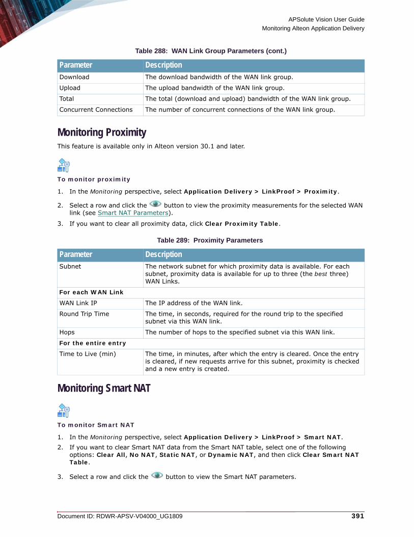
APSolute Vision User Guide
Monitoring Alteon Application Delivery
Document ID: RDWR-APSV-V04000_UG1809 391
Monitoring ProximityThis feature is available only in Alteon version 30.1 and later.
To monitor proximity
1. In the Monitoring perspective, select Application Delivery > LinkProof > Proximity.
2. Select a row and click the button to view the proximity measurements for the selected WAN link (see Smart NAT Parameters).
3. If you want to clear all proximity data, click Clear Proximity Table.
Monitoring Smart NAT
To monitor Smart NAT
1. In the Monitoring perspective, select Application Delivery > LinkProof > Smart NAT.2. If you want to clear Smart NAT data from the Smart NAT table, select one of the following
options: Clear All, No NAT, Static NAT, or Dynamic NAT, and then click Clear Smart NAT Table.
3. Select a row and click the button to view the Smart NAT parameters.
Download The download bandwidth of the WAN link group.
Upload The upload bandwidth of the WAN link group.
Total The total (download and upload) bandwidth of the WAN link group.
Concurrent Connections The number of concurrent connections of the WAN link group.
Table 289: Proximity Parameters
Parameter DescriptionSubnet The network subnet for which proximity data is available. For each
subnet, proximity data is available for up to three (the best three) WAN Links.
For each WAN Link
WAN Link IP The IP address of the WAN link.
Round Trip Time The time, in seconds, required for the round trip to the specified subnet via this WAN link.
Hops The number of hops to the specified subnet via this WAN link.
For the entire entry
Time to Live (min) The time, in minutes, after which the entry is cleared. Once the entry is cleared, if new requests arrive for this subnet, proximity is checked and a new entry is created.
Table 288: WAN Link Group Parameters (cont.)
Parameter Description

APSolute Vision User Guide
Monitoring Alteon Application Delivery
392 Document ID: RDWR-APSV-V04000_UG1809
Monitoring Global Traffic Redirection StatisticsIn Alteon version 30.2.3.0 and later, you can view statistics for the traffic that was globally redirected. The following data is available:• Monitoring Global DNS and HTTP Redirection Statistics, page 392• Monitoring Remote Real And Virtual Server Statistics, page 393• Monitoring Client Network Rule Statistics, page 394• Monitoring DNS Redirection Rule Statistics, page 394• Monitoring DNS Zone Statistics, page 395
Monitoring Global DNS and HTTP Redirection Statistics
To view global DNS and HTTP traffic redirection statistics
> In the Monitoring perspective, select Application Delivery > Global Traffic Redirection.
Table 290: Smart NAT Parameters
Parameter DescriptionSmart NAT ID Specifies the identifier for this NAT address.
Current Sessions The number of current NAT sessions.
Total Sessions The number of total NAT sessions
Table 291: Global Traffic Redirection: DNS Statistics
Parameter DescriptionTotal DNS requests The total number of DNS queries received.
Total DNSSEC requests The total number of DNSSEC requests received.
Current DNS requests The number of DNS requests currently being processed.
Current DNSSEC requests The number of DNSSEC requests currently being processed.
Current DNS requests per second The number of DNS requests received per second.
Current DNSSEC requests per second The number of DNSSEC requests received per second.
Total DNS responses The total number of DNS responses sent by Alteon (includes DNS records and DNS error responses).
Total NSEC record answers The number of NSEC records answered since boot time.
Total UDP DNS requests The total number of DNS queries received over UDP transport.
DNSSEC requests percentage The number of DNSSEC requests received per second.
Total TCP DNS requests The total number of DNS queries received over TCP transport.
Total invalid DNS requests The total number of malformed DNS queries received.

APSolute Vision User Guide
Monitoring Alteon Application Delivery
Document ID: RDWR-APSV-V04000_UG1809 393
Monitoring Remote Real And Virtual Server StatisticsIn Alteon version 30.2.3.0 and later, you can view statistics for remote real servers and local virtual servers that participate in a global solution.
To view remote real and virtual server statistics
> In the Monitoring perspective, select Application Delivery > Global Traffic Redirection > Remote Real And Virtual Servers.
Total domain parse errors The total number of DNS queries with short or invalid domain names received.
No matching domain occurrences The number of times the DNS queries received did not match the hostname or configured domain name.
Threshold exceeded occurrences The number of times the threshold was exceeded.
Last source IP The source IP address of the last DNS query or HTTP request received.
Last no result domain The last domain received that did not match the hostname, domain name, or the network domain configured.
Table 292: Global Traffic Redirection: HTTP Statistics
Parameter DescriptionTotal HTTP Requests The total number of HTTP requests received.
Total HTTP Responses The total number of HTTP responses sent by Alteon that redirects traffic to a different site.
Bad HTTP Requests The number of bad/dropped client HTTP requests. Client HTTP GET request packets that do not contain the entire URL are considered bad and are dropped.
Table 293: Global Traffic Redirection: DNS Persistence Cache Statistics
Parameter DescriptionCurrent The number of persistent DNS entries currently active.
Highwater The highest number of persistent DNS entries ever recorded.
Maximum The maximum number of entries in the persistent DNS cache.
Table 294: Remote Real Server Statistics
Parameter DescriptionReal Server ID The remote real server ID.
Server IP Address The IP address of the virtual server.
Table 291: Global Traffic Redirection: DNS Statistics (cont.)
Parameter Description

APSolute Vision User Guide
Monitoring Alteon Application Delivery
394 Document ID: RDWR-APSV-V04000_UG1809
Monitoring Client Network Rule StatisticsIn Alteon version 30.2.3.0 and later, you can view statistics per client network.
To view client network rule statistics
> In the Monitoring perspective, select Application Delivery > Global Traffic Redirection > Network Preference.
Monitoring DNS Redirection Rule StatisticsIn Alteon version 30.2.3.0 and later, you can view statistics per DNS redirection rule. When a different DNS rule is configured for each domain, these statistics provide a view per domain.
To view DNS rule statistics
> In the Monitoring perspective, select Application Delivery > Global Traffic Redirection > Rules.
Threshold Exceeded Hits The number of times the threshold was exceeded.
DNS Redirects The number of DNS responses that return the IP address of this server.
HTTP Redirects The number of HTTP requests redirected to this server.
Table 295: Virtual Server Statistics
Parameter DescriptionVirtual Server ID The local virtual server ID.
IP Version The IP version of the virtual server.
Server IP Address The IP address of the virtual server.
Threshold Exceeded Hits The number of times the threshold was exceeded.
DNS Redirects The number of DNS responses that return the IP address of this server.
Table 296: Client Network Rule Statistics
Parameter DescriptionNetwork ID The client network ID.
IP Address The client network IP address.
Hits The number of times DNS queries were received from clients belonging to this network.
Table 294: Remote Real Server Statistics (cont.)
Parameter Description

APSolute Vision User Guide
Monitoring Alteon Application Delivery
Document ID: RDWR-APSV-V04000_UG1809 395
Monitoring DNS Zone StatisticsIn Alteon version 30.2.3.0 and later, you can view statistics for the DNS zones defined under DNSSEC capability.
To view DNZ zone statistics
> In the Monitoring perspective, select Application Delivery > Global Traffic Redirection > DNS Zones.
Table 297: DNS Rule Statistics
Parameter DescriptionRule ID The DNS rule ID.
Total Hits The number of times the DNS queries received matched the specific DNS redirection rule ID.
Table 298: DNS Zones: DNS Zone Statistics
Parameter DescriptionDNS Zone ID The DNS zone ID.
Total DNS Requests The total number of DNS queries received.
UDP DNS Requests The total number of DNS queries received over UDP transport.
TCP DNS Requests The total number of DNS queries received over TCP transport.
Total DNSSEC Requests The total number of DNSSEC requests received.
Table 299: DNS Zones: View Detailed Zone Statistics
Parameter DescriptionTotal DNS requests The total number of DNS queries received.
Total DNSSEC requests The total number of DNSSEC requests received.
DNSSEC requests percentage The number of DNSSEC requests received per second.
Current DNS requests per second The number of DNS requests received per second.
Total UDP DNS requests The total number of DNS queries received over UDP transport.
Total TCP DNS requests The total number of DNS queries received over TCP transport.
Total invalid DNS requests The total number of malformed DNS queries received.
Total NSEC record answers The number of NSEC records answered since boot time.

APSolute Vision User Guide
Monitoring Alteon Application Delivery
396 Document ID: RDWR-APSV-V04000_UG1809
Monitoring AppShape++ Statistics
To monitor AppShape++ statistics
1. In the Monitoring perspective, select Application Delivery > AppShape++.2. Select the required row, and click Edit Row.
3. View the parameters, and click OK.
AppShape++ statistics are described in the following table:
Table 300: AppShape++ Statistics
Statistic DescriptionScript ID The identifier for the AppShape++ script.
Event The event name that appears in the AppShape++ script ID.
Activation The number of times that the AppShape++ script or script event was activated.
Failures The number of times that the AppShape++ script failed, and the failure distribution between the script events (how many of the failures occurred during treatment of each event).
Aborts The number of times that the AppShape++ script was aborted, and the abort distribution between the script events (how many of the aborts occurred during treatment of each event).

Document ID: RDWR-APSV-V04000_UG1809 397
CHAPTER 14 – MONITORING AND CONTROLLING VADC
This chapter describes monitoring vADC operations.This feature is available only in ADC-VX mode.
Notes
• For information on monitoring Alteon device performance using the Device Performance Monitor, see Using the Device Performance Monitor, page 403.
• For more information on this feature, see the Alteon Web Based Management Application Guide.
Monitoring and Rebooting vADCsFor more information on this feature, see the Alteon Web Based Management Application Guide.
To monitor vADCs
> In the Monitoring perspective, select vADC > vADC.
To reboot a vADC
1. In the Monitoring perspective, select vADC > vADC. 2. Select the row with the relevant vADC and click Reset vADC.
Table 301: vADC Parameters
Parameter DescriptionStatus The status of the vADC.
vADC ID The vADC ID.
Boot Action The boot action.
vADC Name The vADC name.
Capacity Units The number of capacity units associated with this vADC.
SP Utilization The percentage of SP utilization.
vMP Utilization The percentage of vMP utilization.
Throughput Utilization The percentage of throughput utilization.
Up Time The length of time this vADC has been running (in <days>D<hours>H<minutes>M<seconds>S format) since its last reboot.

APSolute Vision User Guide
Monitoring and Controlling vADC
398 Document ID: RDWR-APSV-V04000_UG1809
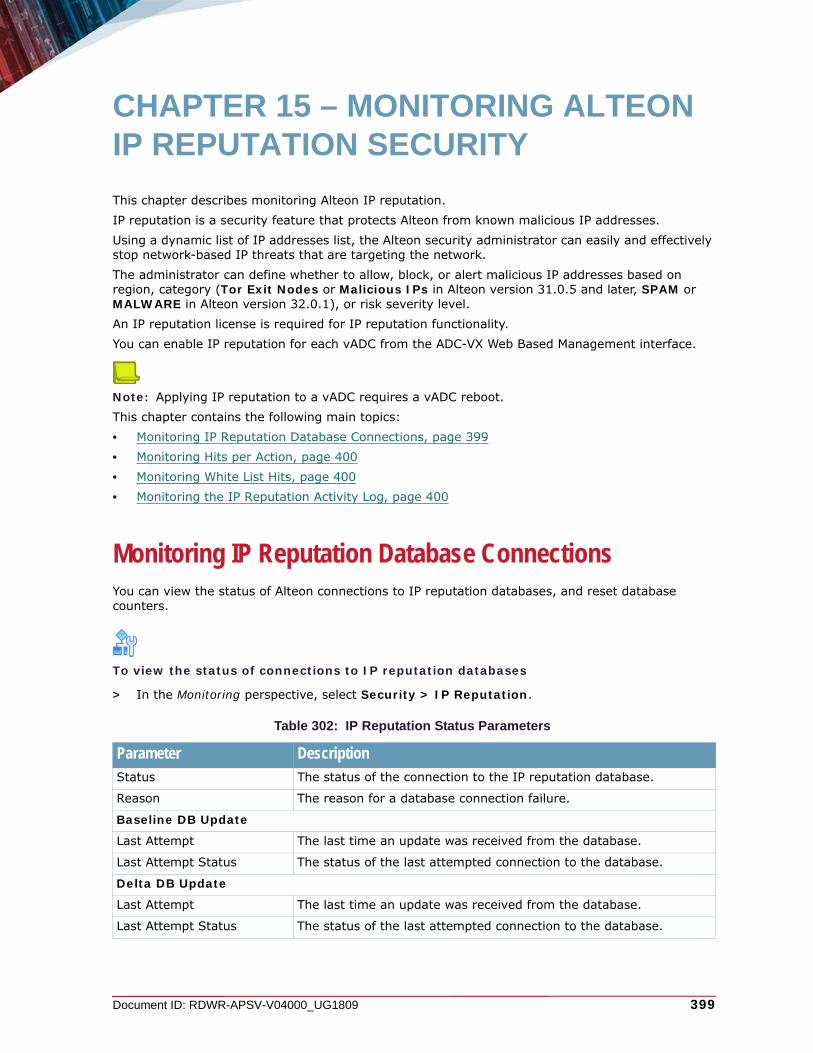
Document ID: RDWR-APSV-V04000_UG1809 399
CHAPTER 15 – MONITORING ALTEON IP REPUTATION SECURITY
This chapter describes monitoring Alteon IP reputation.IP reputation is a security feature that protects Alteon from known malicious IP addresses. Using a dynamic list of IP addresses list, the Alteon security administrator can easily and effectively stop network-based IP threats that are targeting the network.The administrator can define whether to allow, block, or alert malicious IP addresses based on region, category (Tor Exit Nodes or Malicious IPs in Alteon version 31.0.5 and later, SPAM or MALWARE in Alteon version 32.0.1), or risk severity level.An IP reputation license is required for IP reputation functionality. You can enable IP reputation for each vADC from the ADC-VX Web Based Management interface.
Note: Applying IP reputation to a vADC requires a vADC reboot.This chapter contains the following main topics:• Monitoring IP Reputation Database Connections, page 399• Monitoring Hits per Action, page 400• Monitoring White List Hits, page 400• Monitoring the IP Reputation Activity Log, page 400
Monitoring IP Reputation Database ConnectionsYou can view the status of Alteon connections to IP reputation databases, and reset database counters.
To view the status of connections to IP reputation databases
> In the Monitoring perspective, select Security > IP Reputation.
Table 302: IP Reputation Status Parameters
Parameter DescriptionStatus The status of the connection to the IP reputation database.
Reason The reason for a database connection failure.
Baseline DB Update
Last Attempt The last time an update was received from the database.
Last Attempt Status The status of the last attempted connection to the database.
Delta DB Update
Last Attempt The last time an update was received from the database.
Last Attempt Status The status of the last attempted connection to the database.

APSolute Vision User Guide
Monitoring Alteon IP Reputation Security
400 Document ID: RDWR-APSV-V04000_UG1809
To clear IP reputation counters
1. In the Monitoring perspective, select Security > IP Reputation.2. Click Clear All Counters.
Monitoring Hits per ActionYou can view the number of IP reputation activities for traffic from blocked, reported, and allowed IP addresses based on the category (Tor Exit Nodes or Malicious IPs in Alteon version 31.0.5 and later, SPAM or MALWARE in Alteon version 32.0.1), and risk severity level (High, Medium, or Low) of the traffic.
To view the hits per action
1. In the Monitoring perspective, select Security > IP Reputation.2. Select the Hits per Action tab.
Monitoring White List HitsYou can view the total number of hits on the IP addresses added to the IP reputation white list.
To view total white list hits
1. In the Monitoring perspective, select Security > IP Reputation.2. Select the White List hits tab.
Monitoring the IP Reputation Activity LogAlteon logs the activities of the IP reputation module. The IP reputation activity log displays the last 1000 activities.
To view the IP reputation activity log
1. In the Monitoring perspective, select Security > IP Reputation > Activity Log.
2. To view an entry in the table, select the entry and click the (View) button.
Table 303: IP Reputation Activity Log Parameters
Parameter DescriptionSource IP Source IP address of logged traffic.
Country Source country of logged traffic.
Destination IP Destination IP address of logged traffic.
Source Port Source port of logged traffic.
Destination Port Destination port of logged traffic.

APSolute Vision User Guide
Monitoring Alteon IP Reputation Security
Document ID: RDWR-APSV-V04000_UG1809 401
Direction Direction of logged traffic—Inbound or Outbound.
Category Category of logged traffic—Spam or Malware.
Risk Risk severity level of logged traffic—High, Medium, or Low.
Action Alteon processing of logged traffic—Alarm, Allow, or Block.
Table 303: IP Reputation Activity Log Parameters (cont.)
Parameter Description

APSolute Vision User Guide
Monitoring Alteon IP Reputation Security
402 Document ID: RDWR-APSV-V04000_UG1809
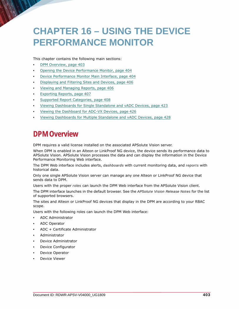
Document ID: RDWR-APSV-V04000_UG1809 403
CHAPTER 16 – USING THE DEVICE PERFORMANCE MONITOR
This chapter contains the following main sections:• DPM Overview, page 403• Opening the Device Performance Monitor, page 404• Device Performance Monitor Main Interface, page 404• Displaying and Filtering Sites and Devices, page 406• Viewing and Managing Reports, page 406• Exporting Reports, page 407• Supported Report Categories, page 408• Viewing Dashboards for Single Standalone and vADC Devices, page 423• Viewing the Dashboard for ADC-VX Devices, page 426• Viewing Dashboards for Multiple Standalone and vADC Devices, page 428
DPM OverviewDPM requires a valid license installed on the associated APSolute Vision server.When DPM is enabled in an Alteon or LinkProof NG device, the device sends its performance data to APSolute Vision. APSolute Vision processes the data and can display the information in the Device Performance Monitoring Web interface.The DPM Web interface includes alerts, dashboards with current monitoring data, and reports with historical data.Only one single APSolute Vision server can manage any one Alteon or LinkProof NG device that sends data to DPM.Users with the proper roles can launch the DPM Web interface from the APSolute Vision client.The DPM interface launches in the default browser. See the APSolute Vision Release Notes for the list of supported browsers.The sites and Alteon or LinkProof NG devices that display in the DPM are according to your RBAC scope.Users with the following roles can launch the DPM Web interface:• ADC Administrator• ADC Operator• ADC + Certificate Administrator• Administrator• Device Administrator• Device Configurator• Device Operator• Device Viewer

APSolute Vision User Guide
Using the Device Performance Monitor
404 Document ID: RDWR-APSV-V04000_UG1809
Notes
• For requirements, limitations, and information on configuring DPM parameters in the Alteon or LinkProof NG device, see the section “Configuring Device Performance Monitoring” in the APSolute Vision online help.
• For information on roles, see Role-Based Access Control (RBAC), page 68.
• One Alteon or LinkProof NG ADC with a large configuration consumes about 210 MB hard-disk space in the course of a year.
• For information on managing the DPM database and DPM technical-support files, see Using vDirect with APSolute Vision, page 657.
Opening the Device Performance MonitorThe following procedure describes how to open the DPM Web interface.
To open the DPM Web interface
> In the APSolute Vision toolbar, click the icon.
Device Performance Monitor Main InterfaceThe following figure describes the Device Performance Monitor screen.

APSolute Vision User Guide
Using the Device Performance Monitor
Document ID: RDWR-APSV-V04000_UG1809 405
Figure 58: Device Performance Monitor Screen
Content area—Contains the Report and Dashboard tabs. The Server Time Difference value (near the Modify Filter button) displays the timezone difference between the PC and the APSolute Vision server.
Devices pane Organization tab—Displays, according to your filter, the configured sites and or LinkProof NG, Alteon standalone, vADC, and VA devices. The Deleted Devices node shows deleted devices on which DPM can show historical reports.
Devices pane Physical tab—Displays, according to your filter, configured sites and Alteon ADC-VXs.
Report tab—Displays a report according to report category and type.
Dashboard tab—Displays current alerts and the System, Network, and Application dashboards for one selected device in the Devices pane Organization tab.
Devices pane
VX Dashboard tab—Displays the current alerts and status of various parameters of one selected VX device in the Devices pane Physical tab.
Multi-Device Dashboard tab—Displays current alerts and the status of multiple devices selected in the Devices pane Organization tab.
Properties pane—Displays, according to the configuration in the Devices pane, and the properties of devices.

APSolute Vision User Guide
Using the Device Performance Monitor
406 Document ID: RDWR-APSV-V04000_UG1809
Displaying and Filtering Sites and DevicesThe Devices pane displays the all sites and Alteon or LinkProof NG devices of the APSolute Vision (according to your RBAC scope).You can filter the sites and devices that the DPM displays. The filter does not change the contents of the tree, only how the DPM displays the tree to you.The Properties pane displays information about the currently selected devices.
Viewing and Managing ReportsUse the Report tab in the content area to view reports. Reports display static, historical Alteon-device or LinkProof-NG-device data in various formats (line graph, bar graph, pie-chart, or table).In addition, you can export reports in many different file formats, for example, PDF, Excel, and so on.DPM aggregates historical statistics data to bigger time frames as the time passes, up to one year back.
Viewing ReportsThe tab that you select in the Devices pane (Organization or Physical) determines which reports you can view in the Report tab of the content area. You specify the Report Category and Report Type and configure a filter. Some Report Types are available for more than one Report Category. A Report Category with the same name displays the same report. For more information on the reports, see Supported Report Categories, page 408.
To view a report
1. In the Devices pane, select the required tab (Organization or Physical).2. In the Report tab, from the Report Category drop-down list, select the category, and then,
from the Report Type drop-down list, select the required type. The category determines the available report types.
3. Configure the filter or filters. The set of filters that you can configure depends on the selected Report Category.
4. Click Display Report.
Table 304: Aggregation of Historical Data
Sampling Period Time Number of Samples15 seconds 15 minutes 60
2 minute 1 hour 30
15 minutes 24 hours 96
1 hour 72 hours 72
1 day 3 months 93
1 week 1 year 52

APSolute Vision User Guide
Using the Device Performance Monitor
Document ID: RDWR-APSV-V04000_UG1809 407
To modify a filter when the DPM is displaying a report
1. Click Modify Filter.2. Configure the filter or filters.
The set of filters that you can configure depends on the selected Report Category, which may include:— Filter Time Period—Includes last hour, day, week, month, year, and Custom, with start date/
time and end date/time.— Filter Scope—In the filter, you can select the object on which to perform the report,
depending on the report type. — Group By—In the filter configuration, you can specify to display the data per selected object
or grouped by ADC.3. Click Display Report.
Opening the Filter WindowUse the Filter window to configure Boolean expressions and apply them to selected report components.
To open the Filter window
> In the content area, click the Filter button ( ).
Exporting ReportsYou can export a report in any of the following formats:• PDF• HTML• Excel• Text• RTF• XML• PostScript
To export a report
1. In the content area, click the Export button ( ), and then, click OK.2. Do the following:
— From the Export File Format drop-down list, select the required format.— Select the checkboxes next to the name or each report component to include in the report.— If you require, in the File Name text box, modify the file name.

APSolute Vision User Guide
Using the Device Performance Monitor
408 Document ID: RDWR-APSV-V04000_UG1809
Supported Report CategoriesThe DPM supports the following report categories:• ADC/vADC Reports, page 408• Application Reports, page 413• Real Server Reports, page 417• Port Reports, page 419• VX Reports, page 421
ADC/vADC ReportsThe following tables describe the DPM reports for LinkProof NG, Alteon Standalone, VA, or vADC with Report Category ADC/vADC:• Table 305 - ADC CPU Capacity Utilization Report, page 408• Table 306 - ADC Memory Utilization Report, page 409• Table 307 - ADC Throughput License Utilization Report, page 410• Table 308 - ADC System Resources Utilization Report, page 411• Table 309 - Total Network Statistics per Port Report, page 412• Table 310 - Network Performance per ADC Report, page 413
The ADC names in the reports correspond to the selected objects in the Devices pane.
Table 305: ADC CPU Capacity Utilization Report
Supported Filter Type/s Component Component DescriptionThis report supports the following filter type: Filter Time Period—Includes last hour, day, week, month, year, and Custom, with start date/time and end date/time.
MP CPU Utilization graph Displays the MP CPU utilization (%) according to time. For vADCs, DPM bases the values on the allocated CUs.
MP CPU Utilization Peak Usage graph
Displays the peak MP CPU utilization (%) in the selected time period. For vADCs, DPM bases the values on the allocated CUs.
Maximum SP CPU Utilization graph
Displays, according to time, the maximum SP CPU utilization (%) from all SPs. For vADCs, DPM bases the values on the allocated CUs.
Maximum SP CPU Utilization Peak Usage graph
Displays the peak SP CPU utilization (%) from all the SPs in the selected time period. For vADCs, DPM bases the values on the allocated CUs.
ADC CPU Capacity Utilization table
Columns:• ADC Name• Type—MP and SPs• CPU Utilization (%)
• Time—In dd/MMM/yyyy hh:mm:ss T format (for example: 31/Jan/2012 03:10 PM)
To sort or filter the table, right-click in a row and select the option that you require.

APSolute Vision User Guide
Using the Device Performance Monitor
Document ID: RDWR-APSV-V04000_UG1809 409
Table 306: ADC Memory Utilization Report
Supported Filter Type/s Component Component DescriptionThis report supports the following filter type: Filter Time Period—Includes last hour, day, week, month, year, and Custom, with start date/time and end date/time.
MP Memory Utilization graph
Displays, according to time, the MP-memory utilization (%). For vADCs, DPM bases the values on the allocated CUs.
MP Memory Utilization Peak Usage graph
Displays the peak MP-memory utilization (%) in the selected time period. For vADCs, DPM bases the values on the allocated CUs.
Maximum SP Memory Utilization graph
Displays, according to time, the maximum SP-memory utilization (%) from all the SPs. For vADCs, DPM bases the values on the allocated CUs.
Maximum SP Memory Utilization Peak Usage graph
Displays the peak SP-memory utilization (%) from all the SPs in the selected time period. For vADCs, DPM bases the values on the allocated CUs.
ADC Memory Capacity Utilization table
Columns:• ADC Name• Type—MP and SPs• Memory Utilization (%)
• Time—In dd/MMM/yyyy hh:mm:ss T format (for example: 31/Jan/2012 03:10 PM)
To sort or filter the table, select a row and select the option that you require.

APSolute Vision User Guide
Using the Device Performance Monitor
410 Document ID: RDWR-APSV-V04000_UG1809
Table 307: ADC Throughput License Utilization Report
Supported Filter Type/s Component Component DescriptionThis report supports the following filter type: Filter Time Period—Includes last hour, day, week, month, year, and Custom, with start date/time and end date/time.
Throughput License Utilization graph
Displays the device throughput utilization according to time. DPM measures the traffic entering all the data ports, and calculates the values based on the installed throughput license (for ADC) or allocated throughput limit (for vADC).
Throughput License Peak Usage graph
Displays the peak throughput utilization (%) in the selected time period. DPM measures the traffic entering all the data ports, and calculates the values based on the installed throughput license (for ADC) or allocated throughput limit (for vADC).
License ADC/vADC table Columns:• ADC Name• Throughput License (Mb)• Throughput Peak utilization (%)To sort or filter the table, select a row and select the option that you require.
ADC Throughput License Utilization table
Columns:• ADC Name• Throughput Utilization (%)
• Time—In dd/MMM/yyyy hh:mm:ss T format (for example: 31/Jan/2012 03:10 PM)
To sort or filter the table, select a row and select the option that you require.

APSolute Vision User Guide
Using the Device Performance Monitor
Document ID: RDWR-APSV-V04000_UG1809 411
Table 308: ADC System Resources Utilization Report
Supported Filter Type/s Component Component DescriptionThis report supports the following filter type: Filter Time Period—Includes last hour, day, week, month, year, and Custom, with start date/time and end date/time.
Session Utilization graph Displays the session utilization (%) according to time. DPM calculates the values based on the maximum session-table size available on the ADC/vADC.
Session Utilization Peak Usage graph
Displays the peak session utilization (%) in the selected time period. DPM calculates the values based on the maximum session-table size available on the ADC/vADC.
Cache Memory Utilization graph
Displays the memory utilization (%) according to time. DPM calculates the values based on the memory allocated for caching on the ADC/vADC.
Cache Memory Utilization Peak Usage graph
Displays the peak memory utilization (%) in the selected time period. DPM calculates the values based on the memory allocated for caching on the ADC/vADC.
Hard Disk Utilization graph
Displays hard-disk utilization (%) according to time. DPM calculates the values based on the installed/allocated hard disk on the ADC/vADC.
Hard Disk Utilization Peak Usage graph
Displays the peak utilization (%) in the selected time period. DPM calculates the values based on the installed/allocated hard disk on the ADC/vADC.
PIP Allocation graph Displays utilization according to time. DPM calculates the values based on the maximum PIP addresses available on the ADC/vADC.
PIP Allocation Peak Usage graph
Displays the peak utilization (%) in the selected time period. DPM calculates the values based on the maximum PIP addresses available on the ADC/vADC.
ADC System Resources Utilization table
Columns:• ADC Name• Session (%)• Cache Memory (%)• Hard Disk (%)• PIP Allocation (%)
• Time—In dd/MMM/yyyy hh:mm:ss T format (for example: 31/Jan/2012 03:10 PM)
The last row is Average for Session (%), Cache Memory (%), Hard Disk (%), and PIP Allocation (%).To sort or filter the table, select a row and select the option that you require.
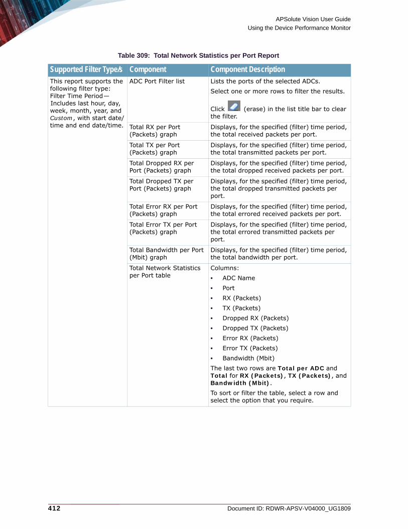
APSolute Vision User Guide
Using the Device Performance Monitor
412 Document ID: RDWR-APSV-V04000_UG1809
Table 309: Total Network Statistics per Port Report
Supported Filter Type/s Component Component DescriptionThis report supports the following filter type: Filter Time Period—Includes last hour, day, week, month, year, and Custom, with start date/time and end date/time.
ADC Port Filter list Lists the ports of the selected ADCs.Select one or more rows to filter the results.
Click (erase) in the list title bar to clear the filter.
Total RX per Port (Packets) graph
Displays, for the specified (filter) time period, the total received packets per port.
Total TX per Port (Packets) graph
Displays, for the specified (filter) time period, the total transmitted packets per port.
Total Dropped RX per Port (Packets) graph
Displays, for the specified (filter) time period, the total dropped received packets per port.
Total Dropped TX per Port (Packets) graph
Displays, for the specified (filter) time period, the total dropped transmitted packets per port.
Total Error RX per Port (Packets) graph
Displays, for the specified (filter) time period, the total errored received packets per port.
Total Error TX per Port (Packets) graph
Displays, for the specified (filter) time period, the total errored transmitted packets per port.
Total Bandwidth per Port (Mbit) graph
Displays, for the specified (filter) time period, the total bandwidth per port.
Total Network Statistics per Port table
Columns: • ADC Name• Port• RX (Packets)• TX (Packets)• Dropped RX (Packets)• Dropped TX (Packets)• Error RX (Packets)• Error TX (Packets)• Bandwidth (Mbit)The last two rows are Total per ADC and Total for RX (Packets), TX (Packets), and Bandwidth (Mbit).To sort or filter the table, select a row and select the option that you require.
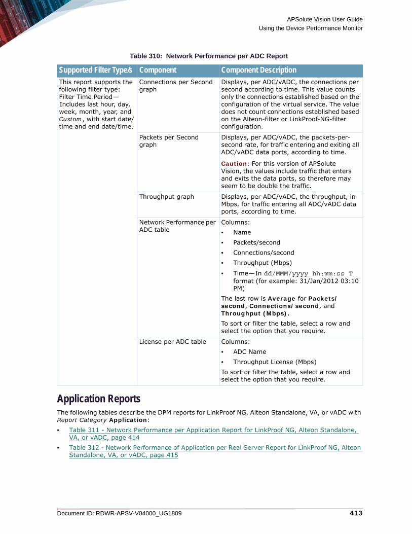
APSolute Vision User Guide
Using the Device Performance Monitor
Document ID: RDWR-APSV-V04000_UG1809 413
Application ReportsThe following tables describe the DPM reports for LinkProof NG, Alteon Standalone, VA, or vADC with Report Category Application:• Table 311 - Network Performance per Application Report for LinkProof NG, Alteon Standalone,
VA, or vADC, page 414• Table 312 - Network Performance of Application per Real Server Report for LinkProof NG, Alteon
Standalone, VA, or vADC, page 415
Table 310: Network Performance per ADC Report
Supported Filter Type/s Component Component DescriptionThis report supports the following filter type: Filter Time Period—Includes last hour, day, week, month, year, and Custom, with start date/time and end date/time.
Connections per Second graph
Displays, per ADC/vADC, the connections per second according to time. This value counts only the connections established based on the configuration of the virtual service. The value does not count connections established based on the Alteon-filter or LinkProof-NG-filter configuration.
Packets per Second graph
Displays, per ADC/vADC, the packets-per- second rate, for traffic entering and exiting all ADC/vADC data ports, according to time.
Caution: For this version of APSolute Vision, the values include traffic that enters and exits the data ports, so therefore may seem to be double the traffic.
Throughput graph Displays, per ADC/vADC, the throughput, in Mbps, for traffic entering all ADC/vADC data ports, according to time.
Network Performance per ADC table
Columns: • Name • Packets/second• Connections/second• Throughput (Mbps)
• Time—In dd/MMM/yyyy hh:mm:ss T format (for example: 31/Jan/2012 03:10 PM)
The last row is Average for Packets/second, Connections/second, and Throughput (Mbps).To sort or filter the table, select a row and select the option that you require.
License per ADC table Columns:• ADC Name• Throughput License (Mbps)To sort or filter the table, select a row and select the option that you require.

APSolute Vision User Guide
Using the Device Performance Monitor
414 Document ID: RDWR-APSV-V04000_UG1809
• Table 313 - Total Usage of Resources per Application per Network Class Report for Alteon Standalone, VA, or vADC, page 416
• Table 314 - Total Usage of Resources per Network Class per Application Report for LinkProof NG, Alteon Standalone, VA, or vADC, page 416
An application is a virtual service, which is identified in one of the following ways:• The specified virtual-service Description is set in the configuration (Configuration perspective
Application Delivery tab navigation pane > Virtual Services > Virtual Servers > Virtual Services > Description/Virtual Service Name).
• The virtual-service identifier in the following format:<VirtualServerAddress>:<protocol>:<port>[:NetworkClass].
Table 311: Network Performance per Application Report for LinkProof NG, Alteon Standalone, VA, or vADC
Supported Filter Type/s Component Component DescriptionThis report supports the following filter types:• Filter Time Period—
Includes last hour, day, week, month, year, and Custom, with start date/time and end date/time.
• Filter Scope—In the filter, you can select up to 10 applications.
• Group By—In the filter configuration, you can specify to group the data by application or ADC.
Filter by Application Name list Select one or more applications names to filter the results.
Click (erase) in the list title bar to clear the filter.
Connections per Second graph Displays the connections per second per application according to time.
Packets per Second graph Displays the packets per second per application according to time.
Throughput graph Displays the throughput, in Mbps, per application according to time.
Throughput License/Limit per ADC/vADC table
Columns:• ADC Name• Throughput License Limit (Mbps)To sort or filter the table, select a row and select the option that you require.
Network Performance per Application table
Columns: • App Name • ADC Name • Connections/second• Packets/second • Throughput (Mbps)
• Time—In dd/MMM/yyyy hh:mm:ss T format (for example: 31/Jan/2012 03:10 PM
The last two rows are Average per ADC, and Average for Connections/second, Packets/second, and Throughput (Mbps).To sort or filter the table, select a row and select the option that you require.

APSolute Vision User Guide
Using the Device Performance Monitor
Document ID: RDWR-APSV-V04000_UG1809 415
Table 312: Network Performance of Application per Real Server Report for LinkProof NG, Alteon Standalone, VA, or vADC
Notes and Supported Filter Type/s
Component Component Description
You can view this report this report only on services where the granularity level is set to Real Server.This report supports only a single selected device.This report supports the following filter types:• Filter Time Period—
Includes last hour, day, week, month, year, and Custom, with start date/time and end date/time.
• Filter Scope—In the filter, you can select up to 10 real servers.
Filter by Application Name:Real Server list
Select one or more real servers to filter the results.
Click (erase) in the list title bar to clear the filter.
Connections per Second graph Displays the connections per second per application per real server according to time.
Packets per Second graph Displays the packets per second per application per real server according to time.
Throughput graph Displays the throughput, in Mbps, per application per real server according to time.
Network Performance of Application per Real Server table
Columns: • ADC Name • APP Name • Real Identifier• Real Name • Connections/second• Packets/second • Throughput (Mbps)
• Time—In dd/MMM/yyyy hh:mm:ss T format (for example: 31/Jan/2012 03:10 PM
The last two rows are Average/Real and Average for Connections/second, Packets/second, and Throughput (Mbps).To sort or filter the table, select a row and select the option that you require.

APSolute Vision User Guide
Using the Device Performance Monitor
416 Document ID: RDWR-APSV-V04000_UG1809
Table 313: Total Usage of Resources per Application per Network Class Report for Alteon Standalone, VA, or vADC
Note and Supported Filter Type/s
Component Component Description
Note: This report supports only a single selected device. This report supports the following filter types:• Filter Time Period—
Includes last hour, day, week, month, year, and Custom, with start date/time and end date/time.
• Filter Scope—In the filter, you can select up to 10 applications.
Total Bandwidth (Mbits) Usage of Application per Network graph
Displays the total bandwidth usage, in Mbits, per network class per application.
Total Connections (K) of Application per Network graph
Displays the total connections, in 1000s, per network class per application.
Total Usage of Resources per Application table
Columns: • Application • Network Class• Bandwidth (Mbits)• Total Connections (K)The last two rows are Total per Application and Grand Total for Bandwidth (Mbits) and Total Connections (K).To sort or filter the table, select a row and select the option that you require.
Table 314: Total Usage of Resources per Network Class per Application Report for LinkProof NG, Alteon Standalone, VA, or vADC
Supported Filter Type/s Component Component DescriptionThis report supports the following filter types:• Filter Time Period—
Includes last hour, day, week, month, year, and Custom, with start date/time and end date/time.
• Filter Scope—In the filter, you can select up to 10 network classes.
Total Bandwidth (Mbits) Usage of Network per Applications graph
Displays the total bandwidth, in Mbits, per applications per network class.
Total Connections (K) Usage of Network per Applications graph
Displays the total usage of connections, in 1000s, per network class per application.
Total Usage of Resources per Network Class per Application table
Columns: • Network Class• Application • Bandwidth (Mbits)• Total Connections (K)The last two rows are Total per Client Subnet and Grand Total for Bandwidth (Mbits) and Total Connections (K).To sort or filter the table, select a row and select the option that you require.

APSolute Vision User Guide
Using the Device Performance Monitor
Document ID: RDWR-APSV-V04000_UG1809 417
Real Server ReportsThe following tables describe the DPM Reports for LinkProof NG, Alteon Standalone, VA, or vADC with Report Category Real Server:• Table 315 - Network Performance per Real Server Report for LinkProof NG, Alteon Standalone,
VA, or vADC, page 417• Table 316 - Network Performance of Application per Real Server Report for LinkProof NG, Alteon
Standalone, VA, or vADC, page 418• Table 317 - Total Usage of Resources per Real Server Report for LinkProof NG, Alteon
Standalone, VA, or vADC, page 419
Table 315: Network Performance per Real Server Report for LinkProof NG, Alteon Standalone, VA, or vADC
Supported Filter Type/s
Component Component Description
This report supports the following filter types:• Filter Time Period—
Includes last hour, day, week, month, year, and Custom, with start date/time and end date/time.
• Filter Scope—In the filter, you can select up to 10 real servers.
Filter by ADC Name:Real Server list Lists the real servers.Select one or more rows to filter the results.
Click (erase) in the list title bar to clear the filter.
Connections per Second graph Displays the connections per second per real server according to time.
Packets per Second graph Displays the packets per second per real server according to time.
Throughput graph Displays the throughput, in Mbps, per real server according to time.
Network Performance per Real Server table
Columns: • ADC Name • Real Identifier• Real Name • Connections/second• Packets/second • Throughput (Mbps)
• Time—In dd/MMM/yyyy hh:mm:ss T format (for example: 31/Jan/2012 03:10 PM)
The last two rows are Average per ADC and Average for Connections/second, Packets/second, and Throughput (Mbps).To sort or filter the table, select a row and select the option that you require.

APSolute Vision User Guide
Using the Device Performance Monitor
418 Document ID: RDWR-APSV-V04000_UG1809
Table 316: Network Performance of Application per Real Server Report for LinkProof NG, Alteon Standalone, VA, or vADC
Notes and Supported Filter Type/s
Component Component Description
You can view this report this report only on services where the granularity level is set to Real Server.This report supports only a single selected device.This report supports the following filter types:• Filter Time Period—
Includes last hour, day, week, month, year, and Custom, with start date/time and end date/time.
• Filter Scope—In the filter, you can select up to 10 real servers.
Filter by Application Name:Real Server list
Lists the real servers.Select one or more rows to filter the results.
Click (erase) in the list title bar to clear the filter.
Connections per Second graph Displays the connections per second per real server according to time.
Packets per Second graph Displays the packets per second per real server according to time.
Throughput graph Displays the throughput, in Mbps, per real server according to time.
Network Performance per Real Server table
Columns: • ADC Name • APP Name • Real Identifier• Real Name • Connections/second• Packets/second • Throughput (Mbps)
• Time—In dd/MMM/yyyy hh:mm:ss T format (for example: 31/Jan/2012 03:10 PM)
The last row is Average for Connections/second, Packets/second, and Throughput (Mbps).To sort or filter the table, right-click in a row and select the option that you require.

APSolute Vision User Guide
Using the Device Performance Monitor
Document ID: RDWR-APSV-V04000_UG1809 419
Port ReportsThe following tables describe the DPM Reports for LinkProof NG,. Alteon Standalone, VA, or vADC with Report Category Port:• Table 318 - Total Network Statistics per Port Report for LinkProof NG, Alteon Standalone, VA, or
vADC, page 420• Table 319 - Network Performance per Port Report for LinkProof NG, Alteon Standalone, VA, or
vADC, page 421
Table 317: Total Usage of Resources per Real Server Report for LinkProof NG, Alteon Standalone, VA, or vADC
Supported Filter Type/s
Component Component Description
This report supports the following filter types:• Filter Time Period—
Includes last hour, day, week, month, year, and Custom, with start date/time and end date/time.
• Filter Scope—In the filter, you can select up to 10 real servers.
Filter by ADC Name:Real Server list Lists the real servers.Select one or more rows to filter the results.
Click (erase) in the list title bar to clear the filter.
Total Connections graph Displays the total connections per real server.
Total Bandwidth graph Displays the total bandwidth, in Mbits, per real server.
Total Usage of Resources per Real Server table
Columns: • ADC Name • Real Identifier• Real Name • Connections • Bandwidth (Mbit)The last row is Total for Connections and Bandwidth (Mbit).To sort or filter the table, select a row and select the option that you require.

APSolute Vision User Guide
Using the Device Performance Monitor
420 Document ID: RDWR-APSV-V04000_UG1809
Table 318: Total Network Statistics per Port Report for LinkProof NG, Alteon Standalone, VA, or vADC
Supported Filter Type/s
Component Component Description
This report supports the following filter type: Filter Time Period—Includes last hour, day, week, month, year, and Custom, with start date/time and end date/time.
Filter by ADC Name:Port list Lists the ports of the selected ADCs.Select rows to filter the results.
Click (erase) in the list title bar to clear the filter.
Total RX per Port (Packets) graph
Displays the total received packets per port.
Total TX per Port (Packets) graph
Displays the total transmitted packets per port.
Total Dropped RX per Port (Packets) graph
Displays the total received dropped packets per port.
Total Dropped TX per Port (Packets) graph
Displays the total transmitted dropped packets per port.
Total Error RX per Port (Packets) graph
Displays the total received errored packets per port.
Total Error TX per Port (Packets) graph
Displays the total transmitted errored packets per port.
Total Bandwidth per Port (Mbit) graph
Displays the total bandwidth, in Mbits, per port.
Total Network Statistics per Port table
Columns:• ADC Name• Port• RX (Packets)• TX (Packets)• Dropped RX (Packets)• Dropped TX (Packets)• Error RX (Packets)• Error TX (Packets)• Bandwidth (Mbit)The last rows are Total per ADC and Total for RX (Packets), TX (Packets), and Bandwidth (Mbit).To sort or filter the table, select a row and select the option that you require.

APSolute Vision User Guide
Using the Device Performance Monitor
Document ID: RDWR-APSV-V04000_UG1809 421
VX ReportsThe following tables describe the DPM Report for Alteon VX with Report Category VX:• Table 320 - CPU Utilization per vADC Report for Alteon VX, page 422• Table 321 - Throughput Limit Utilization per vADC Report for Alteon VX, page 423
Table 319: Network Performance per Port Report for LinkProof NG, Alteon Standalone, VA, or vADC
Supported Filter Type/s
Component Component Description
This report supports the following filter type: Filter Time Period—Includes last hour, day, week, month, year, and Custom, with start date/time and end date/time.
Filter by ADC Name:Port list Lists the ports of the selected ADCs.Select rows to filter the results.
Click (erase) in the list title bar to clear the filter.
RX Port Rate graph Displays the rates, in Mbps, of received traffic per port according to time.
TX Port Rate graph Displays the rates, in Mbps, of transmitted traffic per port according to time.
Packets per Second per Port graph
Displays the packets per second per port according to time.
Throughput per Port graph Displays the throughput, in Mbps, per port according to time.
Network Performance per Port table
Columns: • ADC Name• Port• RX (bps)• TX (bps)• Packets/second• Throughput (Mbps)The last rows are Average per ADC and Average for RX (bps), TX (bps), and Packets/second. To sort or filter the table, select a row and select the option that you require.

APSolute Vision User Guide
Using the Device Performance Monitor
422 Document ID: RDWR-APSV-V04000_UG1809
Table 320: CPU Utilization per vADC Report for Alteon VX
Supported Filter Type/s
Component Component Description
This report supports the following filter type: Filter Time Period—Includes last hour, day, week, month, year, and Custom, with start date/time and end date/time.
Filter by vADC list Lists the vADCs of the selected VXs.Select rows to filter the results.
Click (erase) in the list title bar to clear the filter.
vMP CPU Utilization graph Displays the CPU utilization (%) per vADC vMP according to time.
Peak vMP CPU Utilization graph
Displays the peak CPU utilization (%) per vADC vMP in the selected time period.
vSP CPU Utilization graph Displays the CPU utilization (%) per vADC vSP according to time.
Peak vSP CPU Utilization graph
Displays the peak CPU utilization (%) er vADC vSP in the selected time period.
CPU Utilization per vADC table
Columns:• vADC Name• CPU Type—vSP, vMP or the SPs (for
example, SP # 1)• CPU Utilization (%)
• Time—In dd/MMM/yyyy hh:mm:ss T format (for example: 31/Jan/2012 03:10 PM)
The last rows are Total per ADC and Total for RX (Packets), TX (Packets), and Bandwidth (Mbit).To sort or filter the table, select a row and select the option that you require.

APSolute Vision User Guide
Using the Device Performance Monitor
Document ID: RDWR-APSV-V04000_UG1809 423
Viewing Dashboards for Single Standalone and vADC DevicesUse the Dashboard tab in the content area to view the dashboards with the current data for one selected device in the Devices pane Organization tab. The contents of the dashboards differ according to whether the selected device is a standalone or vADC. For example, the dashboard tab for a vADC does not display temperature.You will always see the alerts for all the devices you have in the Organization and Physical trees—according to your role and scope.This section contains the following topics:• Displaying the Dashboard and Managing the Display, page 424• Dashboard Components for Single Standalone and vADC Devices, page 424
Table 321: Throughput Limit Utilization per vADC Report for Alteon VX
Supported Filter Type/s
Component Component Description
This report supports the following filter type: Filter Time Period—Includes last hour, day, week, month, year, and Custom, with start date/time and end date/time.
Filter by vADC list Lists the vADCs of the selected VXs.Select rows to filter the results.
Click (erase) in the list title bar to clear the filter.
vADC Throughput Limit Utilization graph
Displays the vADC throughput-limit utilization (%) according to time. DPM measures the vADC throughput of the traffic entering all the data ports, and calculates the values based on the allocated throughput limit of each vADC.
Peak vADC Throughput Limit Utilization graph
Displays the peak vADC throughput-limit utilization (%) in the selected time period. DPM measures the vADC throughput of the traffic entering all the data ports, and calculates the values based on the allocated throughput limit of each vADC.
Throughput Limit Utilization per vADC table
Columns:• vADC • Throughput Limit Utilization (%)
• Time—In dd/MMM/yyyy hh:mm:ss T format (for example: 31/Jan/2012 03:10 PM)
The last two rows Grand Total Average Throughput and Grand Total Maximum Throughput for Throughput Limit Utilization (%). To sort or filter the table, select a row and select the option that you require.

APSolute Vision User Guide
Using the Device Performance Monitor
424 Document ID: RDWR-APSV-V04000_UG1809
Displaying the Dashboard and Managing the DisplayThe following procedure describes how to display the dashboard.
To display the dashboard
1. In the Devices pane, select the Organization tab.2. In the Organization tab, select one device.
3. In the content area (on the right, by default), select the Dashboard tab.
Use the buttons, which are described in the following table, to manage the dashboard display.
Dashboard Components for Single Standalone and vADC DevicesThe following table describes the dashboard components for single standalone and vADC devices.
Table 322: Dashboard-Display Buttons
Button DescriptionOpens the dialog box to select the temperature scale (Celsius or Fahrenheit) for monitoring the temperature sensors on physical devices.
Note: This setting applies to all DPM interfaces.
Refreshes the dashboard display.
Maximizes and floats the currently displayed dashboard tab.
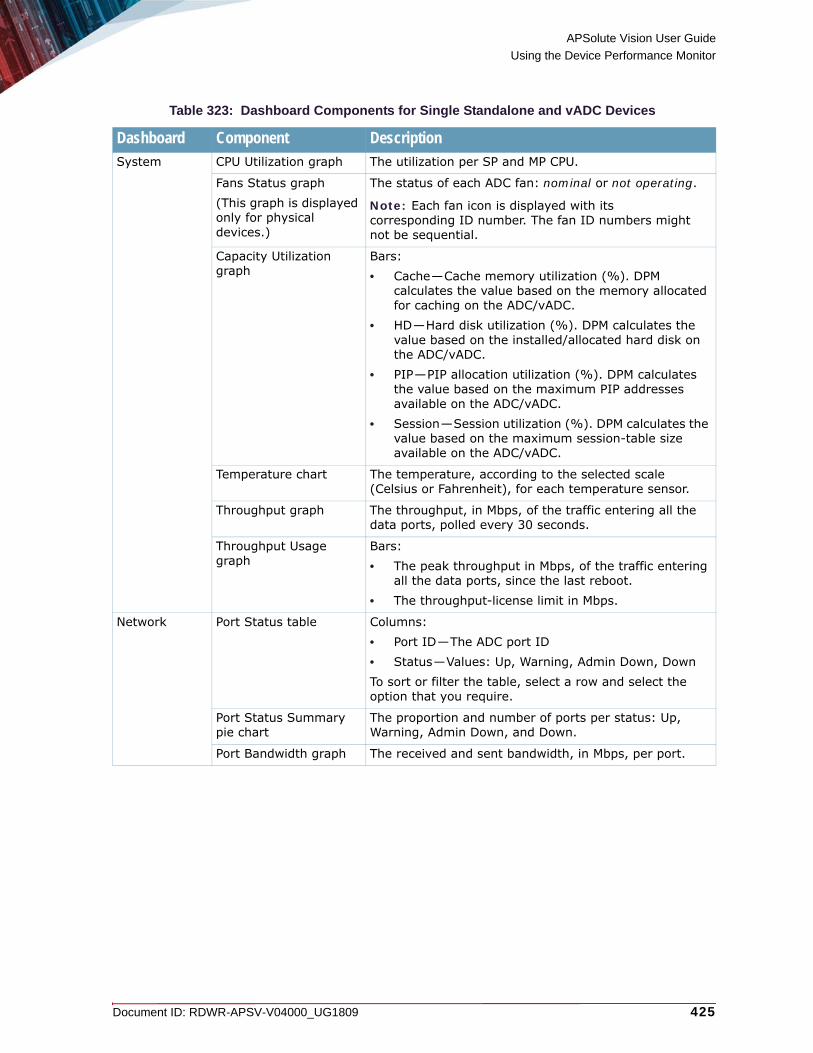
APSolute Vision User Guide
Using the Device Performance Monitor
Document ID: RDWR-APSV-V04000_UG1809 425
Table 323: Dashboard Components for Single Standalone and vADC Devices
Dashboard Component DescriptionSystem CPU Utilization graph The utilization per SP and MP CPU.
Fans Status graph(This graph is displayed only for physical devices.)
The status of each ADC fan: nominal or not operating.
Note: Each fan icon is displayed with its corresponding ID number. The fan ID numbers might not be sequential.
Capacity Utilization graph
Bars: • Cache—Cache memory utilization (%). DPM
calculates the value based on the memory allocated for caching on the ADC/vADC.
• HD—Hard disk utilization (%). DPM calculates the value based on the installed/allocated hard disk on the ADC/vADC.
• PIP—PIP allocation utilization (%). DPM calculates the value based on the maximum PIP addresses available on the ADC/vADC.
• Session—Session utilization (%). DPM calculates the value based on the maximum session-table size available on the ADC/vADC.
Temperature chart The temperature, according to the selected scale (Celsius or Fahrenheit), for each temperature sensor.
Throughput graph The throughput, in Mbps, of the traffic entering all the data ports, polled every 30 seconds.
Throughput Usage graph
Bars:• The peak throughput in Mbps, of the traffic entering
all the data ports, since the last reboot.• The throughput-license limit in Mbps.
Network Port Status table Columns:• Port ID—The ADC port ID• Status—Values: Up, Warning, Admin Down, DownTo sort or filter the table, select a row and select the option that you require.
Port Status Summary pie chart
The proportion and number of ports per status: Up, Warning, Admin Down, and Down.
Port Bandwidth graph The received and sent bandwidth, in Mbps, per port.
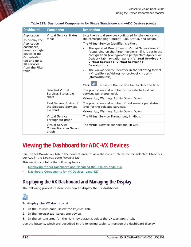
APSolute Vision User Guide
Using the Device Performance Monitor
426 Document ID: RDWR-APSV-V04000_UG1809
Viewing the Dashboard for ADC-VX DevicesUse the VX Dashboard tab in the content area to view the current alerts for the selected Alteon VX devices in the Devices pane Physical tab. This section contains the following topics:• Displaying the VX Dashboard and Managing the Display, page 426• Dashboard Components for VX Devices, page 427
Displaying the VX Dashboard and Managing the DisplayThe following procedure describes how to display the VX dashboard.
To display the VX dashboard
1. In the Devices pane, select the Physical tab.2. In the Physical tab, select one device.
3. In the content area (on the right, by default), select the VX Dashboard tab.
Use the buttons, which are described in the following table, to manage the dashboard display.
ApplicationTo display the Application dashboard, select a single device in the Organization tab and up to 10 services from the Filter table.
Virtual Service Status table
Lists the virtual services configured for the device with the corresponding Content Rule, Status, and Action. The Virtual Service Identifier is either:• The specified Description or Virtual Service Name
(depending on the Alteon version)—if it is set in the configuration (Configuration perspective Application Delivery tab navigation pane > Virtual Services > Virtual Servers > Virtual Services > Description).
• The virtual-service identifier in the following format:<VirtualServerAddress>:<protocol>:<port>[:NetworkClass].
Click (erase) in the list title bar to clear the filter.
Selected Virtual Services Status pie chart
The proportion and number of the selected virtual services per status level.Values: Up, Warning, Admin Down, Down
Real Servers Status of the Selected Services pie chart
The proportion and number of real servers per status level for the selected services. Values: Up, Warning, Admin Down, Down
Virtual Service Throughput graph
The Virtual Service Throughput, in Mbps.
Virtual Service Connections per Second graph
The Virtual Service connections, in CPS.
Table 323: Dashboard Components for Single Standalone and vADC Devices (cont.)
Dashboard Component Description

APSolute Vision User Guide
Using the Device Performance Monitor
Document ID: RDWR-APSV-V04000_UG1809 427
Dashboard Components for VX DevicesThe following table describes the dashboard components for VX devices.
Table 324: VX Dashboard-Display Buttons
Button DescriptionOpens the dialog box to select the temperature scale (Celsius or Fahrenheit) for monitoring the temperature sensors on physical devices.
Note: This setting applies to all DPM interfaces.
Refreshes the dashboard display.
Maximizes and floats the VX Dashboard tab.
Table 325: Dashboard Components for VX Devices
Component DescriptionTemperature chart The temperature, according to the selected scale (Celsius or
Fahrenheit), for each temperature sensor in the VX device.When relating to an Alteon 10000 platform, the temperatures that the monitor displays show the average temperature of the blade sensors. The ID numbers represent the slot numbers. Slot 1 supports the Switch Blade. Slot 2 supports the Switch Extension Blade. Slots 3–6 support Payload Blades. Slot 7–8 support Shelf Managers. Some blades are optional.
Fan Status indicators The status of each fan: nominal or not operating. Green—for nominal. Red—for not operating/not operating properly.Each fan icon is displayed with its corresponding ID number. The fan ID numbers might not be sequential and might be repeated.When relating to an Alteon 10000 non-NEBS platform, the ID number represents the fan blade. If all fans in the blade are working properly, the status is green. If one or more fans in the blade are not working properly, the status is red.
vADC CPU Distribution graph The proportion and number of vADCs per maximum utilization level of vSP and vMP.Values: • Low• Medium• High
vADC Throughput Limit Utilization Distribution graph
The proportion and number of vADCs per maximum throughput-limit utilization.Values: • Low• Medium• High
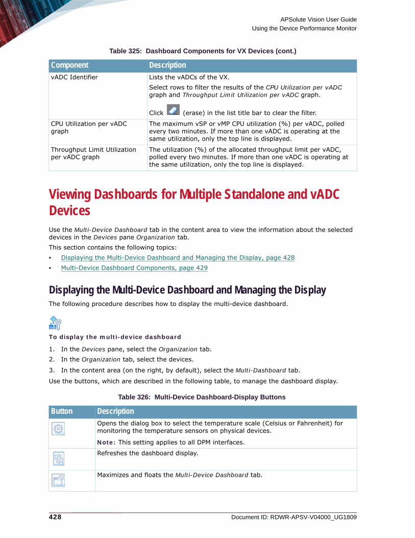
APSolute Vision User Guide
Using the Device Performance Monitor
428 Document ID: RDWR-APSV-V04000_UG1809
Viewing Dashboards for Multiple Standalone and vADC DevicesUse the Multi-Device Dashboard tab in the content area to view the information about the selected devices in the Devices pane Organization tab. This section contains the following topics:• Displaying the Multi-Device Dashboard and Managing the Display, page 428• Multi-Device Dashboard Components, page 429
Displaying the Multi-Device Dashboard and Managing the DisplayThe following procedure describes how to display the multi-device dashboard.
To display the multi-device dashboard
1. In the Devices pane, select the Organization tab.2. In the Organization tab, select the devices.
3. In the content area (on the right, by default), select the Multi-Dashboard tab.
Use the buttons, which are described in the following table, to manage the dashboard display.
vADC Identifier Lists the vADCs of the VX. Select rows to filter the results of the CPU Utilization per vADC graph and Throughput Limit Utilization per vADC graph.
Click (erase) in the list title bar to clear the filter.
CPU Utilization per vADC graph
The maximum vSP or vMP CPU utilization (%) per vADC, polled every two minutes. If more than one vADC is operating at the same utilization, only the top line is displayed.
Throughput Limit Utilization per vADC graph
The utilization (%) of the allocated throughput limit per vADC, polled every two minutes. If more than one vADC is operating at the same utilization, only the top line is displayed.
Table 326: Multi-Device Dashboard-Display Buttons
Button DescriptionOpens the dialog box to select the temperature scale (Celsius or Fahrenheit) for monitoring the temperature sensors on physical devices.
Note: This setting applies to all DPM interfaces.
Refreshes the dashboard display.
Maximizes and floats the Multi-Device Dashboard tab.
Table 325: Dashboard Components for VX Devices (cont.)
Component Description

APSolute Vision User Guide
Using the Device Performance Monitor
Document ID: RDWR-APSV-V04000_UG1809 429
Multi-Device Dashboard ComponentsThe following table describes the multi-device dashboard components.
Table 327: Multi-Device Dashboard Components
Component DescriptionOverall Status pie chart The proportion and number of devices per highest-severity status
level.Values: OK, Warning, Error
Throughput Utilization Distribution pie chart
The proportion and number of devices per throughput-utilization level.Values: Low, Medium, High
Max. CPU Utilization Distribution pie chart
The proportion and number of devices per maximum-CPU-utilization level. Values: Low, Medium, High
Session Table Utilization Distribution pie chart
The proportion and number of devices per session-table-utilization level. Values: Low, Medium, High
Max. Temperature Distribution pie chart
The proportion and number of devices per maximum-temperature level. Values: Low, Medium, High, NA (vADC)
Monitoring Parameters per Device
Columns:• Device—Displays the device name.• Overall Status—Displays the highest-severity status level on
the device except for Virtual Services Down. Values: OK, Warning, Error.
• Virtual Services Down—Displays the number of virtual services that are down on the device.
• Throughput Util. (%)—Displays the utilization (%) of the throughput license (for standalone devices) or the allocated throughput limit (for vADCs).
• Max. CPU Util. (%)—Displays the highest current CPU utilization (%) of all the SP/MPs.
• Session Table Util. (%)—Displays the current Session-table utilization (%) of all the SP/MPs.
• Max. Temperature—Displays the highest current temperature of the sensors on the device. This value is not applicable for virtual devices. For a vADC, NA (vADC) is displayed.

APSolute Vision User Guide
Using the Device Performance Monitor
430 Document ID: RDWR-APSV-V04000_UG1809

Document ID: RDWR-APSV-V04000_UG1809 431
CHAPTER 17 – MONITORING AND CONTROLLING THE DEFENSEPRO OPERATIONAL STATUS
APSolute Vision’s online monitoring for DefensePro can serve as part of a Network Operating Center (NOC) that monitors and analyzes the network and connected devices for changes in conditions that may impact network performance.This section contains the following topics:• Monitoring the General DefensePro Device Information, page 431• Monitoring and Controlling DefensePro Device Ports and Trunks, page 433• Monitoring DefensePro High Availability, page 435• Monitoring DefensePro Resource Utilization, page 436• Monitoring Cisco Security Group Tags (SGTs), page 441
Monitoring the General DefensePro Device InformationThe Overview tab displays general device information, including the information about the software version on the device and the hardware version of the device.
To display general device information for a selected device
> In the Monitoring perspective, select Operational Status > Overview.
Table 328: Overview: Basic Parameters
Parameter DescriptionHardware Platform The type of hardware platform for this device.
Uptime The system up time in days, hours, minutes, and seconds.
Base MAC Address The MAC address of the first port on the device.
Device Serial Number(This parameter is exposed only in 6.x versions 6.12 and later, 7.x versions, and 8.x versions.)
The serial number of the device.Virtual devices do not have a serial number. For virtual devices, the field displays 0000000000.
Table 329: Overview: Signature Update Parameters
Parameter DescriptionRadware Signature File Version
The version of the Radware Signature File installed on the device.

APSolute Vision User Guide
Monitoring and Controlling the DefensePro Operational Status
432 Document ID: RDWR-APSV-V04000_UG1809
Fraud Signatures Last Update(This parameter is available only in 6.x versions and 7.x versions 7.42.09 and later.)
When Fraud Protection is enabled, this parameter can display the timestamp of the last update of fraud signatures, received from Radware.com and downloaded to the DefensePro device.Values:
• The timestamp, in DDD MMM DD hh:mm:ss yyyy z format—displayed according to the timezone of your APSolute Vision client.
• No Feeds Received Since Device Boot
Table 330: Overview: Software Parameters
Parameter DescriptionSoftware Version The version of the product software installed on the device.
APSolute OS Version The version of the APSolute OS installed on the device—for example, 10.31-03.01:2.06.08.
Build The build number of the current software version.
Version Status The state of this software version.Values:• Open—Not yet released• Final—Released version
Throughput License(This parameter displays only in 8.x versions.)
Values:• The maximum throughput that the license allows.• Unlimited
Table 331: Overview: Hardware Parameters
Parameter DescriptionHardware Version(This parameter displays only in 6.x and 7.x versions.)
The hardware version; for example, B.5.
RAM Size The amount of RAM, in megabytes.
Flash Size The size of flash (permanent) memory, in megabytes.
Cores(This parameter is available only in 8.x versions.)
The number of CPUs/cores that the device uses for processing traffic. That is, the value does not include the CPUs/cores for DefensePro management.
Note: On virtual DefensePro platforms—but not Radware DefensePro DDoS Mitigation for Cisco Firepower, you can specify the number of virtual cores in the initial setup of the virtual instance.
CPU Speed (This parameter is available only in 8.x versions.)
The CPU speed, in GHz.
Table 329: Overview: Signature Update Parameters (cont.)
Parameter Description

APSolute Vision User Guide
Monitoring and Controlling the DefensePro Operational Status
Document ID: RDWR-APSV-V04000_UG1809 433
Monitoring and Controlling DefensePro Device Ports and TrunksA Layer 2 interface is defined as any interface that has its own MAC address, physical port, trunk, and VLAN. You can monitor status and interface statistics for ports and trunks on DefensePro version 6.x–8.x platforms.You can also change the administrative status of a port, from Up to Down or vice versa.
Caution: If the administrative status of a QSFP+ 40-Gigabit Ethernet (40GbE) port is Down, the port does not issue traps or alerts, and does not show information for system hardware transceiver-info commands.
To change the administrative status of a port or trunk
1. In the Monitoring perspective, select Operational Status > Ports and Trunks.
2. Select the rows with the relevant ports, and click the (Disable Selected Ports) button (for a port currently Up) or the (Enable Selected Ports) button (for a port that is currently Down).
To display L2 interface statistics for a selected device
1. In the Monitoring perspective, select Operational Status > Ports and Trunks.2. To view the statistics for a specific port all in one dialog box, double-click the row.
Table 332: L2 Interface Statistics Basic Parameters
Parameter DescriptionPort Name The interface name or index number.
Port Family (This parameter displays only in DefensePro 7.x and 8.x versions.)
A hard-coded description of the interface.
Port Description For 6.x versions—A hard-coded description of the interface.For DefensePro 7.x and 8.x versions—A user-defined description of the interface. Maximum characters: 64.
Port Speed The current bandwidth of the interface. On DefensePro 6, 20, 60, 200, 400, x420, and x4420 platforms, the value is in megabits per second. On all platforms except for DefensePro 6, 20, 60, 200, 400, x420, and x4420, the value is in bits per second.
MAC Address The MAC address of the interface.
Admin Status The administrative status of the interface, Up or Down.
Operational Status The operational status of the interface, Up or Down.
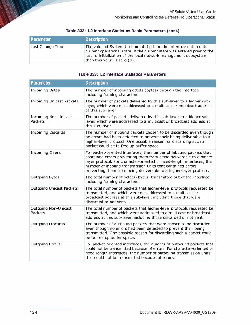
APSolute Vision User Guide
Monitoring and Controlling the DefensePro Operational Status
434 Document ID: RDWR-APSV-V04000_UG1809
Last Change Time The value of System Up time at the time the interface entered its current operational state. If the current state was entered prior to the last re-initialization of the local network management subsystem, then this value is zero (0).
Table 333: L2 Interface Statistics Parameters
Parameter DescriptionIncoming Bytes The number of incoming octets (bytes) through the interface
including framing characters.
Incoming Unicast Packets The number of packets delivered by this sub-layer to a higher sub-layer, which were not addressed to a multicast or broadcast address at this sub-layer.
Incoming Non-Unicast Packets
The number of packets delivered by this sub-layer to a higher sub-layer, which were addressed to a multicast or broadcast address at this sub-layer.
Incoming Discards The number of inbound packets chosen to be discarded even though no errors had been detected to prevent their being deliverable to a higher-layer protocol. One possible reason for discarding such a packet could be to free up buffer space.
Incoming Errors For packet-oriented interfaces, the number of inbound packets that contained errors preventing them from being deliverable to a higher-layer protocol. For character-oriented or fixed-length interfaces, the number of inbound transmission units that contained errors preventing them from being deliverable to a higher-layer protocol.
Outgoing Bytes The total number of octets (bytes) transmitted out of the interface, including framing characters.
Outgoing Unicast Packets The total number of packets that higher-level protocols requested be transmitted, and which were not addressed to a multicast or broadcast address at this sub-layer, including those that were discarded or not sent.
Outgoing Non-Unicast Packets
The total number of packets that higher-level protocols requested be transmitted, and which were addressed to a multicast or broadcast address at this sub-layer, including those discarded or not sent.
Outgoing Discards The number of outbound packets that were chosen to be discarded even though no errors had been detected to prevent their being transmitted. One possible reason for discarding such a packet could be to free up buffer space.
Outgoing Errors For packet-oriented interfaces, the number of outbound packets that could not be transmitted because of errors. For character-oriented or fixed-length interfaces, the number of outbound transmission units that could not be transmitted because of errors.
Table 332: L2 Interface Statistics Basic Parameters (cont.)
Parameter Description

APSolute Vision User Guide
Monitoring and Controlling the DefensePro Operational Status
Document ID: RDWR-APSV-V04000_UG1809 435
Monitoring DefensePro High AvailabilityYou can view the status of parameters related to the high availability of a selected DefensePro device.
Note: When you issue the Switch Over command on the cluster node, the active device switches over. To switch modes, select the cluster node, and then select Switch Over.)
To view the parameters related to the high availability of a selected DefensePro device
> In the Monitoring perspective, select Operational Status > High Availability.
Table 334: DefensePro High-Availability Monitoring Parameters
Parameter DescriptionDevice Role Values:
• Stand Alone—The device is not configured as a member of a high-availability cluster.
• Primary—The device is configured as the primary member of a high-availability cluster.
• Secondary—This device is configured as the secondary member of a high-availability cluster.
Device State Values: • Active—The device is in the active state. The device may be a
standalone device (not part of a high-availability cluster) or the active member of a high-availability cluster.
• Passive—The device is the passive member of a high-availability cluster.
Last Baseline Sync. Values:• Base-Line still not synched on this device—Either high availability is
not enabled on the device or high availability is enabled on the device but the baselines for security protections are still not synchronized.
• The timestamp, in DDD MMM DD hh:mm:ss yyyy format, of the last synchronization of the baseline between the active and passive device.
Cluster State Values:• Pair not defined—The device is not configured as a member of a high-
availability cluster.• Disconnected—The device is disconnected from the other member of
the high-availability cluster. • Negotiate—The device is negotiating with the other member of the
high-availability cluster.• Synchronizing—The device is synchronizing with the other member of
the high-availability cluster.• In Sync—The members of the high-availability cluster are
synchronized. • Hold on—The device is waiting for information from the other member
of the high-availability cluster.

APSolute Vision User Guide
Monitoring and Controlling the DefensePro Operational Status
436 Document ID: RDWR-APSV-V04000_UG1809
Monitoring DefensePro Resource UtilizationThis section contains the following topics:• Monitoring DefensePro CPU Utilization, page 436• Monitoring and Clearing DefensePro Authentication Tables, page 439• Monitoring DME Utilization According to Configured Policies, page 440• Monitoring DefensePro Syslog Information, page 441
Monitoring DefensePro CPU UtilizationYou can view statistics for the device’s average resource utilization and the utilization for each accelerator.
To monitor device utilization for a selected DefensePro device in 8.x versions
> In the Monitoring perspective, select Operational Status > Resource Utilization > CPU Utilization.
Cluster Node in Use The IP address of the selected device.
Peer Clustered Node in Use
The IP address of the other cluster member.
Table 335: CPU Utilization: Controller Utilization Parameters—Versions 8.14 and Later
Parameter DescriptionController Utilization The percentage of the controller’s resources currently utilized.
Average Controller Utilization - Last 5 Seconds
The average utilization of controller’s resources in the last 5 seconds.
Average Controller Utilization - Last 60 Seconds
The average utilization of controller’s resources in the last 60 seconds.
Table 336: CPU Utilization: Engines Utilization Parameters—Versions 8.14 and Later
Parameter DescriptionEngine ID The name of the flow engine.
Forwarding Task The percentage of CPU cycles used for traffic processing.
Other Tasks The percentage of CPU resources used for other tasks such as aging and so on.
Idle Task The percentage of free CPU resources.
Table 334: DefensePro High-Availability Monitoring Parameters (cont.)
Parameter Description

APSolute Vision User Guide
Monitoring and Controlling the DefensePro Operational Status
Document ID: RDWR-APSV-V04000_UG1809 437
To monitor device utilization for a selected DefensePro device in 7.x versions
> In the Monitoring perspective, select Operational Status > Resource Utilization > CPU Utilization.
Table 337: CPU Utilization: General Parameters—8.x Versions Earlier than 8.14
Parameter DescriptionResource Utilization The percentage of the device’s CPU currently utilized.
Last 5 sec. Average Utilization
The average utilization of resources in the last 5 seconds.
Last 60 sec. Average Utilization
The average utilization of resources in the last 60 seconds.
Table 338: CPU Utilization: Engine Utilization Parameters—8.x Versions Earlier than 8.14
Parameter DescriptionEngine ID The name of the flow engine.
Forwarding Task The percentage of CPU cycles used for traffic processing.
Other Tasks The percentage of CPU resources used for other tasks such as aging and so on.
Idle Task The percentage of free CPU resources.
Table 339: CPU-Utilization: General Parameters
Parameter DescriptionNote: DefensePro 7.x versions running on the x420 platform contains internal logic of two DefensePro software instances—using the DoS Mitigation Engine (DME) and physical ports as shared resources. For more information, see the DefensePro User Guide.
Resource Utilization Instance 0 The percentage of the device’s instance-0 CPU currently utilized.
Resource Utilization Instance 1 The percentage of the device’s instance-1 CPU currently utilized.
RS Resource Utilization Instance 0
The percentage of the device’s instance-0 routing services (RS) resource currently utilized.
RS Resource Utilization Instance 1
The percentage of the device’s instance-1 routing services (RS) resource currently utilized.
RE Resource Utilization Instance 0
The percentage of the device’s instance-0 routing engine (RE) resource currently utilized.
RE Resource Utilization Instance 1
The percentage of the device’s instance-1 routing engine (RE) resource currently utilized.
Last 5 sec. Average Utilization Instance 0
The average utilization of instance-0 resources in the last 5 seconds.
Last 5 sec. Average Utilization Instance 1
The average utilization of instance-1 resources in the last 5 seconds.
Last 60 sec. Average Utilization Instance 0
The average utilization of instance-0 resources in the last 60 seconds.
Last 60 sec. Average Utilization Instance 1
The average utilization of instance-1 resources in the last 60 seconds.

APSolute Vision User Guide
Monitoring and Controlling the DefensePro Operational Status
438 Document ID: RDWR-APSV-V04000_UG1809
To monitor device utilization for a selected DefensePro device in 6.x versions
> In the Monitoring perspective, select Operational Status > Resource Utilization > CPU Utilization.
Table 340: CPU Utilization: Accelerator Utilization Parameters
Parameter DescriptionInstance The internal hardware instance of the device.
Accelerator Type The name of the accelerator. The accelerator named Flow_Accelerator_0 is one logical accelerator that uses several CPU cores. The accelerator named HW Classifier is the string-matching engine (SME).
CPU ID The CPU number for the accelerator.
Forwarding Task The percentage of CPU cycles used for traffic processing.
Other Tasks The percentage of CPU resources used for other tasks such as aging and so on.
Idle Task The percentage of free CPU resources.
Table 341: CPU Utilization: General Parameters
Parameter DescriptionResource Utilization The percentage of the device’s CPU currently utilized.
RS Resource Utilization The percentage of the device’s routing services (RS) resource currently utilized.
RE Resource Utilization The percentage of the device’s routing engine (RE) resource currently utilized.
Last 5 sec. Average Utilization
The average utilization of resources in the last 5 seconds.
Last 60 sec. Average Utilization
The average utilization of resources in the last 60 seconds.
Table 342: CPU-Utilization: Accelerator Utilization Parameters
Parameter DescriptionAccelerator Type The name of the accelerator. The accelerator named Flow_Accelerator_0
is one logical accelerator that uses several CPU cores. The accelerator named HW Classifier is the string-matching engine (SME). OnDemand Switch 3 S1 has no SME.
CPU ID The CPU number for the accelerator. OnDemand Switch 2 and OnDemand Switch 3 S2 have two CPU cores. OnDemand Switch 3 S1 has three CPU cores.
Forwarding Task The percentage of CPU cycles used for traffic processing.
Other Tasks The percentage of CPU resources used for other tasks such as aging and so on.
Idle Task The percentage of free CPU resources.
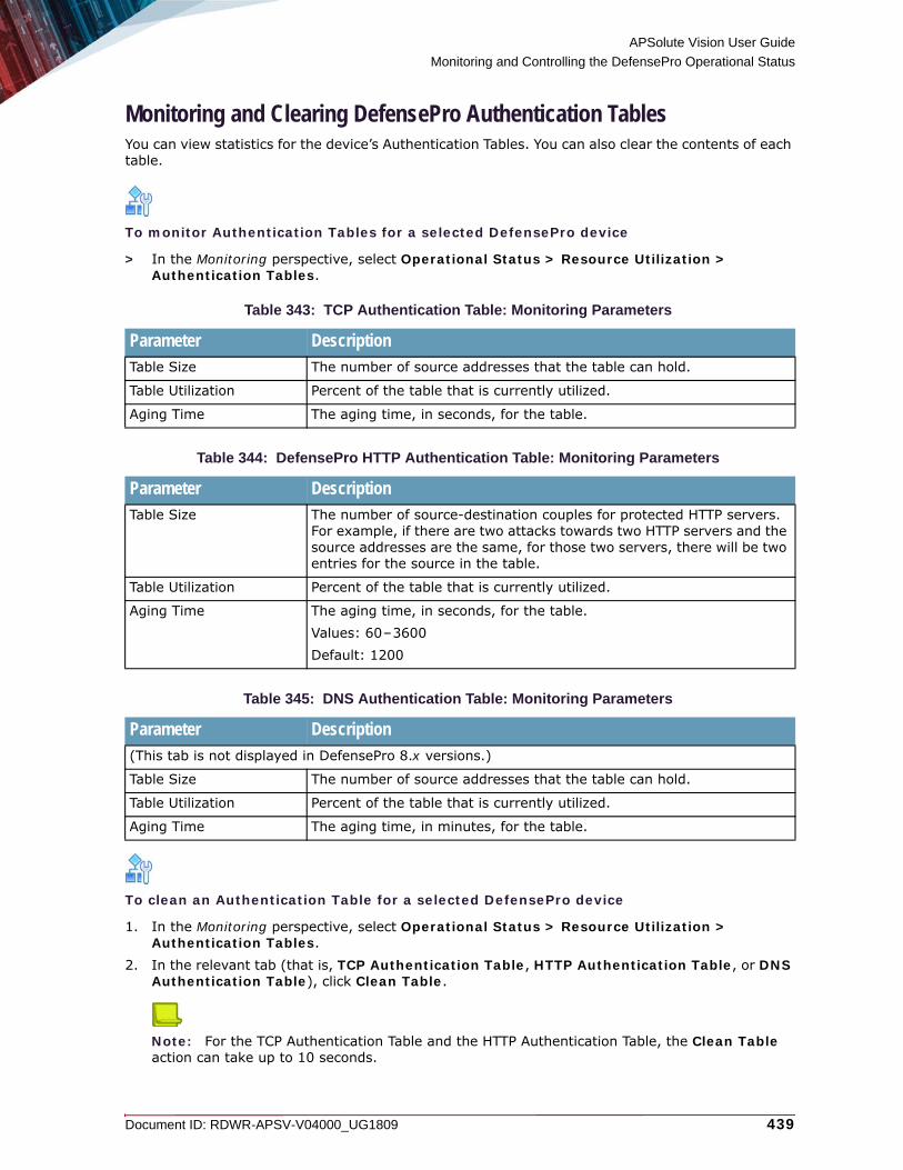
APSolute Vision User Guide
Monitoring and Controlling the DefensePro Operational Status
Document ID: RDWR-APSV-V04000_UG1809 439
Monitoring and Clearing DefensePro Authentication TablesYou can view statistics for the device’s Authentication Tables. You can also clear the contents of each table.
To monitor Authentication Tables for a selected DefensePro device
> In the Monitoring perspective, select Operational Status > Resource Utilization > Authentication Tables.
To clean an Authentication Table for a selected DefensePro device
1. In the Monitoring perspective, select Operational Status > Resource Utilization > Authentication Tables.
2. In the relevant tab (that is, TCP Authentication Table, HTTP Authentication Table, or DNS Authentication Table), click Clean Table.
Note: For the TCP Authentication Table and the HTTP Authentication Table, the Clean Table action can take up to 10 seconds.
Table 343: TCP Authentication Table: Monitoring Parameters
Parameter DescriptionTable Size The number of source addresses that the table can hold.
Table Utilization Percent of the table that is currently utilized.
Aging Time The aging time, in seconds, for the table.
Table 344: DefensePro HTTP Authentication Table: Monitoring Parameters
Parameter DescriptionTable Size The number of source-destination couples for protected HTTP servers.
For example, if there are two attacks towards two HTTP servers and the source addresses are the same, for those two servers, there will be two entries for the source in the table.
Table Utilization Percent of the table that is currently utilized.
Aging Time The aging time, in seconds, for the table.Values: 60–3600Default: 1200
Table 345: DNS Authentication Table: Monitoring Parameters
Parameter Description(This tab is not displayed in DefensePro 8.x versions.)
Table Size The number of source addresses that the table can hold.
Table Utilization Percent of the table that is currently utilized.
Aging Time The aging time, in minutes, for the table.

APSolute Vision User Guide
Monitoring and Controlling the DefensePro Operational Status
440 Document ID: RDWR-APSV-V04000_UG1809
Monitoring DME Utilization According to Configured PoliciesThe contents of this tab are irrelevant for Radware DefensePro DDoS Mitigation for Cisco Firepower. This tab is functional only on DefensePro 20, 60, 200, 400, x420, and x4420 devices, and x412 devices with the DME.You can view statistics relating the user-defined policies to the utilization of the DoS Mitigation Engine (DME).The values that the device exposes are the calculated according to the configured values—even before running the Update Policies command.
Note: If the device is not equipped with the DME, 0 (zero) values are displayed.
To monitor DME utilization according to configured policies
> In the Monitoring perspective, select Operational Status > Resource Utilization > Policies.
Table 346: Policies: General Resource Utilization Monitoring Parameters
Parameter DescriptionNote: If a value in this tab is close to the maximum, the resources for the device are exhausted.
Total Policies The total number of policies in the context of the DME, which is double the number of network policies configured in the device. OnDemand Switch 3 S2 supports 50 configured network policies. x420 supports 50 configured network policies.
HW Entries Utilization The percentage of resource utilization from the HW entries in the context of the DME.
Sub-Policies Utilization The percentage of DME resource utilization from the entries of sub-policies.In the context of the DME, a sub-policy is a combination of the following:• Source-IP-address range• Destination-IP-address range• VLAN-tag range
Concurrent Active BDoS Attacks (This parameter is available only in 7.x versions.)
The number of concurrent active BDoS attacks.
Table 347: Policies: Per-Policy Resource Utilization Monitoring Parameters
Parameter DescriptionPolicy Name The name of the policy.
Direction The direction of the policy.Values:• Inbound• Outbound
HW Entries The number of DME hardware entries that the policy uses.

APSolute Vision User Guide
Monitoring and Controlling the DefensePro Operational Status
Document ID: RDWR-APSV-V04000_UG1809 441
Monitoring DefensePro Syslog InformationYou can view information relating to the syslog mechanism.
To monitor DefensePro syslog information
> In the Monitoring perspective, select Operational Status > Resource Utilization > Syslog Monitor.
Monitoring Cisco Security Group Tags (SGTs)You can monitor the name and value of the enabled SGT, if one exists.
Note: For more information on SGTs in DefensePro, see Managing SGT Classes, page 29.
To monitor SGTs
> In the Monitoring perspective, select Operational Status > SGT.
Sub-Policies The number of DME sub-policy entries that the policy uses.
Table 348: DefensePro Syslog Monitoring Parameters
Parameter DescriptionSyslog Server The name of the syslog server.
Status The status of the syslog server.Values: • Reachable—The server is reachable.• Unreachable—The server is unreachable.• N/R—Specifies not relevant, because traffic towards the
Syslog server is over UDP—as specified (Configuration perspective, Setup > Syslog Server > Protocol > UDP).
Messages in Backlog The number of messages in the backlog to the syslog server.
Table 349: SGT Monitoring Parameters
Parameter DescriptionName The name of the SGT.
Value The value of the SGT.
Table 347: Policies: Per-Policy Resource Utilization Monitoring Parameters (cont.)
Parameter Description

APSolute Vision User Guide
Monitoring and Controlling the DefensePro Operational Status
442 Document ID: RDWR-APSV-V04000_UG1809
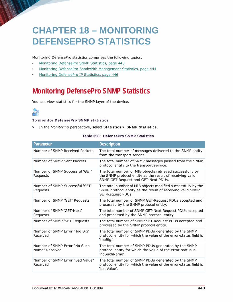
Document ID: RDWR-APSV-V04000_UG1809 443
CHAPTER 18 – MONITORING DEFENSEPRO STATISTICS
Monitoring DefensePro statistics comprises the following topics:• Monitoring DefensePro SNMP Statistics, page 443• Monitoring DefensePro Bandwidth Management Statistics, page 444• Monitoring DefensePro IP Statistics, page 446
Monitoring DefensePro SNMP StatisticsYou can view statistics for the SNMP layer of the device.
To monitor DefensePro SNMP statistics
> In the Monitoring perspective, select Statistics > SNMP Statistics.
Table 350: DefensePro SNMP Statistics
Parameter DescriptionNumber of SNMP Received Packets The total number of messages delivered to the SNMP entity
from the transport service.
Number of SNMP Sent Packets The total number of SNMP messages passed from the SNMP protocol entity to the transport service.
Number of SNMP Successful 'GET' Requests
The total number of MIB objects retrieved successfully by the SNMP protocol entity as the result of receiving valid SNMP GET-Request and GET-Next PDUs.
Number of SNMP Successful 'SET' Requests
The total number of MIB objects modified successfully by the SNMP protocol entity as the result of receiving valid SNMP SET-Request PDUs.
Number of SNMP 'GET' Requests The total number of SNMP GET-Request PDUs accepted and processed by the SNMP protocol entity.
Number of SNMP 'GET-Next' Requests
The total number of SNMP GET-Next Request PDUs accepted and processed by the SNMP protocol entity.
Number of SNMP 'SET' Requests The total number of SNMP SET-Request PDUs accepted and processed by the SNMP protocol entity.
Number of SNMP Error “Too Big” Received
The total number of SNMP PDUs generated by the SNMP protocol entity for which the value of the error-status field is ‘tooBig.’
Number of SNMP Error “No Such Name” Received
The total number of SNMP PDUs generated by the SNMP protocol entity for which the value of the error-status is ‘noSuchName’.
Number of SNMP Error “Bad Value” Received
The total number of SNMP PDUs generated by the SNMP protocol entity for which the value of the error-status field is ‘badValue’.

APSolute Vision User Guide
Monitoring DefensePro Statistics
444 Document ID: RDWR-APSV-V04000_UG1809
Monitoring DefensePro Bandwidth Management StatisticsThis feature is available only in DefensePro 6.x versions. You can monitor the Bandwidth Management (BWM) statistics for a DefensePro device.
Displaying the Last-Second BWM Statistics for a Selected DefensePro DeviceThis feature is available only in DefensePro 6.x versions. To display the last-second BWM statistics for a selected DefensePro device, the Enable Policy Statistics Monitoring checkbox must be selected (Configuration perspective, BWM > Global Settings > Enable Policy Statistics Monitoring).
To display the last-second BWM statistics for a selected DefensePro device
1. In the Monitoring perspective, select Statistics > BWM Statistics > Policy Statistics (Last Second). The Policy Statistics (Last Second) table is displayed.
2. To view all the parameters of a policy, double-click the row of the policy. The Edit Statistics Entry dialog box is displayed with all the BWM statistics.
Number of SNMP Error “Generic Error” Received
The total number of SNMP PDUs generated by the SNMP protocol entity for which the value of the error-status field is ‘genErr’.
Number of SNMP 'GET' Responses Sent
The total number of SNMP Get-Response PDUs generated by the SNMP protocol entity.
Number of SNMP Traps Sent The total number of SNMP Trap PDUs generated by the SNMP protocol entity.
Table 351: DefensePro BWM Last-Second Statistics Parameters
Parameter DescriptionPolicy Name The name of the displayed policy.
Matched Packets The number of packets matching the policy during the last second.
Matched Bandwidth The traffic bandwidth, in Kbits, matching the policy during the last second.
Sent Bandwidth The volume of sent traffic, in Kbits, in any direction, in the last second.
Guaranteed Bandwidth Reached Specifies whether the guaranteed bandwidth was reached during the last second.
Maximum Bandwidth Reached Specifies whether the maximum bandwidth was reached during the last second.
New TCP Sessions The number of new TCP sessions the device detected in the last second.
Table 350: DefensePro SNMP Statistics (cont.)
Parameter Description

APSolute Vision User Guide
Monitoring DefensePro Statistics
Document ID: RDWR-APSV-V04000_UG1809 445
Displaying the Last-Period BWM Statistics for a Selected DefensePro DeviceThis feature is available only in DefensePro 6.x versions.To display the last-second BWM statistics for a selected DefensePro device, the Enable Policy Statistics Monitoring checkbox must be selected (Configuration perspective, BWM > Global Settings > Enable Policy Statistics Monitoring). The Policy Statistics Reporting Period parameter determines the period (Configuration perspective, BWM > Global Settings > Policy Statistics Reporting Period).
To display the last-period BWM statistics for a selected DefensePro device
1. In the Monitoring perspective, select Statistics > BWM Statistics > Policy Statistics (Last Period). The Policy Statistics (Last Period) table is displayed.
2. To view all the parameters of a policy, double-click the row of the policy. The Edit Statistics Entry dialog box is displayed with all the BWM statistics.
New UDP Sessions The number of new UDP sessions the device detected in the last second.
Queued Bandwidth The bandwidth, in Kilobits, during the last second.
Full Queue Bandwidth The bandwidth, in Kilobits, discarded during the last second, due to a full queue.
Aged Packets Bandwidth The amount of discarded bandwidth, in Kilobits, during the last second, due to the aging of packets in the queue.
Inbound Packets The number of inbound packets in the last second.
Inbound Matched Bandwidth The volume of inbound traffic, in Kilobits, in the last second that matched the policy.
Inbound Sent Bandwidth The volume of inbound sent traffic, in Kilobits, in the last second.
Outbound Packets The number of outbound packets in the last second.
Outbound Matched Bandwidth The volume of outbound traffic, in Kilobits, in the last second that matched the policy.
Outbound Sent Bandwidth The volume of outbound sent traffic, in Kilobits, in the last second.
Table 352: DefensePro BWM Last-Period Statistics Parameters
Parameter DescriptionPolicy Name The name of the displayed policy.
Matched Packets The number of packets matching the policy during the last specified period.
Matched Bandwidth The traffic bandwidth, in Kilobits, matching the policy during the last specified period.
Sent Bandwidth The volume of sent traffic, in Kilobits, in any direction, in the last specified period.
Table 351: DefensePro BWM Last-Second Statistics Parameters (cont.)
Parameter Description
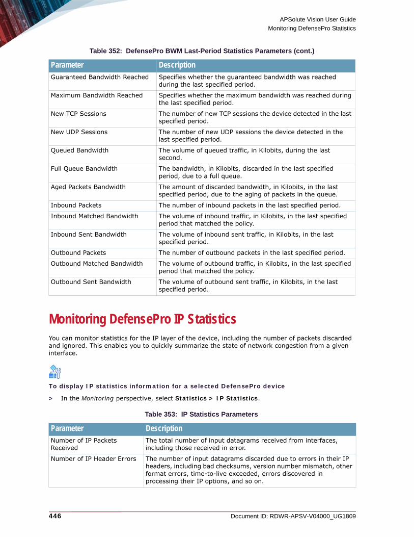
APSolute Vision User Guide
Monitoring DefensePro Statistics
446 Document ID: RDWR-APSV-V04000_UG1809
Monitoring DefensePro IP StatisticsYou can monitor statistics for the IP layer of the device, including the number of packets discarded and ignored. This enables you to quickly summarize the state of network congestion from a given interface.
To display IP statistics information for a selected DefensePro device
> In the Monitoring perspective, select Statistics > IP Statistics.
Guaranteed Bandwidth Reached Specifies whether the guaranteed bandwidth was reached during the last specified period.
Maximum Bandwidth Reached Specifies whether the maximum bandwidth was reached during the last specified period.
New TCP Sessions The number of new TCP sessions the device detected in the last specified period.
New UDP Sessions The number of new UDP sessions the device detected in the last specified period.
Queued Bandwidth The volume of queued traffic, in Kilobits, during the last second.
Full Queue Bandwidth The bandwidth, in Kilobits, discarded in the last specified period, due to a full queue.
Aged Packets Bandwidth The amount of discarded bandwidth, in Kilobits, in the last specified period, due to the aging of packets in the queue.
Inbound Packets The number of inbound packets in the last specified period.
Inbound Matched Bandwidth The volume of inbound traffic, in Kilobits, in the last specified period that matched the policy.
Inbound Sent Bandwidth The volume of inbound sent traffic, in Kilobits, in the last specified period.
Outbound Packets The number of outbound packets in the last specified period.
Outbound Matched Bandwidth The volume of outbound traffic, in Kilobits, in the last specified period that matched the policy.
Outbound Sent Bandwidth The volume of outbound sent traffic, in Kilobits, in the last specified period.
Table 353: IP Statistics Parameters
Parameter DescriptionNumber of IP Packets Received
The total number of input datagrams received from interfaces, including those received in error.
Number of IP Header Errors The number of input datagrams discarded due to errors in their IP headers, including bad checksums, version number mismatch, other format errors, time-to-live exceeded, errors discovered in processing their IP options, and so on.
Table 352: DefensePro BWM Last-Period Statistics Parameters (cont.)
Parameter Description

APSolute Vision User Guide
Monitoring DefensePro Statistics
Document ID: RDWR-APSV-V04000_UG1809 447
Number of Discarded IP Packets
The total number of input datagrams for management that were discarded. This counter does not include any datagrams discarded while awaiting re-assembly.
Number of Valid IP Packets Received
The total number of input datagrams successfully delivered to IP user-protocols (including ICMP).
Number of Transmitted Packets (Inc. Discards)
The total number of IP datagrams which local IP user-protocols, including ICMP supplied to IP in requests for transmission. This counter does not include any datagrams counted in the Number of IP Packets Forwarded.
Number of Discarded Packets on TX
The number of output IP datagrams for which no problem was encountered to prevent their transmission to their destination, but which were discarded, for example, the lack of buffer space. This counter includes any datagrams counted in the Number of IP Packets Forwarded if those packets meet this (discretionary) discard criterion.
Table 354: Router Statistics Parameters
Parameter DescriptionNumber of IP Packets Forwarded
The number of input datagrams for which this entity was not their final IP destination, as a result of which an attempt was made to find a route to forward them to that final destination. In entities that do not act as IP Gateways, this counter includes only those packets which were Source - Routed via this entity, and the Source - Route option processing was successful.
Number of IP Packets Discarded Due to ‘Unknown Protocol’
The number of locally addressed datagrams received successfully but discarded because of an unknown or unsupported protocol.
Number of IP Packets Discarded Due to ‘No Route’
The number of IP datagrams discarded because no route could be found to transmit them to their destination.
Note: This counter includes any packets counted in the Number of IP Packets Forwarded that meet the no-route criterion. This includes any datagrams which a host cannot route because all of its default gateways are down.
Number of IP Fragments Received
The number of IP fragments received which needed to be reassembled at this entity.
Number of IP Fragments Successfully Reassembled
The number of IP datagrams successfully re-assembled.
Number of IP Fragments Failed Reassembly
The number of failures detected by the IP re-assembly algorithm, such as timed out, errors, and so on. Note: This is not necessarily a count of discarded IP fragments since some algorithms (notably the algorithm in RFC 815) can lose track of the number of fragments by combining them as they are received.
Number of IP Datagrams Successfully Reassembled
The number of IP datagrams that have been successfully re-assembled at this entity.
Table 353: IP Statistics Parameters (cont.)
Parameter Description

APSolute Vision User Guide
Monitoring DefensePro Statistics
448 Document ID: RDWR-APSV-V04000_UG1809
Number of IP Datagrams Discarded Due to Fragmentation Failure
The number of IP datagrams that have been discarded because they needed to be fragmented at this entity but could not be, for example, because their Don’t Fragment flag was set.
Number of IP Datagrams Fragments Generated
The number of IP datagram fragments that have been generated as a result of fragmentation at this entity.
Valid Routing Entries Discarded
Number of valid routing entries discarded.
Table 354: Router Statistics Parameters (cont.)
Parameter Description

Document ID: RDWR-APSV-V04000_UG1809 449
CHAPTER 19 – MONITORING AND MANAGING DEFENSEPRO DIAGNOSTICS
Monitoring and managing DefensePro diagnostics comprises the following topics:• Configuring the Diagnostic Tool Parameters• Configuring Diagnostics Policies• Managing Capture Files
You can monitor and manage DefensePro diagnostics using in APSolute Vision in DefensePro 6.x versions 6.12 and later, 7.x versions, and 8.x versions 8.10 and later. The feature described in Configuring Diagnostics Policies is relevant only to DefensePro 6.x and 7.x versions.
Note: In DefensePro 6.x versions earlier than 6.12, you can monitor and manage DefensePro diagnostics using DefensePro CLI or WBM.
Configuring the Diagnostic Tool ParametersThis feature is available in APSolute Vision only in DefensePro 6.x versions 6.12 and later, 7.x versions, and 8.x versions 8.10 and later.The diagnostic packet-capture tool can capture packets that enter the device, leave the device, or both. The captured traffic is stored in CAP files. You can download the files with the captured packets using the Capture Files pane (Monitoring perspective, Diagnostics > Capture Files). You can analyze the traffic Unix snoop, or various other tools.
Caution: Enabling this feature may cause severe performance degradation.
Notes
• For information on managing the files that diagnostic packet-capture tool generates, see Managing Capture Files.
• To see the actual timestamp of the packets in the files that the diagnostic packet-capture tool produces, in the packet analyzer (for example, Wireshark), you may need to modify the format of the time display. The timestamp in the packets in the files that the diagnostic packet-capture tool produces is always UTC.
• The diagnostic packet-capture tool does not capture packets that pass through the device as the result of Traffic Exclusion. Traffic Exclusion is when DefensePro passes through all traffic that matches no network policy configured on the device.
• The diagnostic packet-capture tool does not capture GRE-encapsulated packets.

APSolute Vision User Guide
Monitoring and Managing DefensePro Diagnostics
450 Document ID: RDWR-APSV-V04000_UG1809
• In DefensePro 6.x versions, the diagnostic packet-capture tool truncates packets longer than 1619 bytes (regardless of the configuration for jumbo frames).
• In DefensePro 7.x and 8.x versions, the diagnostic packet-capture tool does not handle jumbo frames. DefensePro 7.x and 8.x versions either pass through jumbo-frame traffic or drop jumbo-frame traffic.
To configure diagnostic packet-capture tool in DefensePro 8.x versions
1. In the Monitoring perspective, select Diagnostics > Diagnostic Tool Parameters.2. Configure the parameters, and then, click Submit.
Table 355: Diagnostic Tool Parameters in DefensePro 8.x Versions
Parameter DescriptionStatus Specifies whether the diagnostic packet-capture tool is enabled.
Values: Enabled, DisabledDefault: Disabled
Note: When the device reboots, the status of the diagnostic packet-capture tool reverts to Disabled.
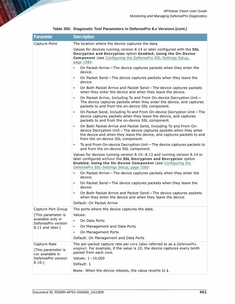
APSolute Vision User Guide
Monitoring and Managing DefensePro Diagnostics
Document ID: RDWR-APSV-V04000_UG1809 451
Capture Point The location where the device captures the data.Values for devices running version 8.14 or later configured with the SSL Decryption and Encryption option Enabled, Using the On-Device Component (see Configuring the DefensePro SSL-Settings Setup, page 108):• On Packet Arrive—The device captures packets when they enter the
device.• On Packet Send—The device captures packets when they leave the
device.• On Both Packet Arrive and Packet Send—The device captures packets
when they enter the device and when they leave the device.• On Packet Arrive, Including To and From On-device Decryption Unit—
The device captures packets when they enter the device, and captures packets to and from the on-device SSL component.
• On Packet Send, Including To and From On-device Decryption Unit—The device captures packets when they leave the device, and captures packets to and from the on-device SSL component.
• On Both Packet Arrive and Packet Send, Including To and From On-device Decryption Unit—The device captures packets when they enter the device and when they leave the device, and captures packets to and from the on-device SSL component.
• To and From On-device Decryption Unit—The device captures packets to and from the on-device SSL component.
Values for devices running version 8.10–8.13 and running version 8.14 or later configured without the SSL Decryption and Encryption option Enabled, Using the On-Device Component (see Configuring the DefensePro SSL-Settings Setup, page 108):• On Packet Arrive—The device captures packets when they enter the
device.• On Packet Send—The device captures packets when they leave the
device.• On Both Packet Arrive and Packet Send—The device captures packets
when they enter the device and when they leave the device.Default: On Packet Arrive
Capture Port Group(This parameter is available only in DefensePro version 8.11 and later.)
The ports where the device captures the data.Values:• On Data Ports• On Management and Data Ports• On Management PortsDefault: On Management and Data Ports
Capture Rate(This parameter is not available in DefensePro version 8.10.)
The per-packet capture rate per core (also referred to as a DefensePro engine). For example, if the value is 10, the device captures every tenth packet from each core.Values: 1–10,000Default: 1
Note: When the device reboots, the value reverts to 1.
Table 355: Diagnostic Tool Parameters in DefensePro 8.x Versions (cont.)
Parameter Description

APSolute Vision User Guide
Monitoring and Managing DefensePro Diagnostics
452 Document ID: RDWR-APSV-V04000_UG1809
To configure diagnostic packet-capture tool in DefensePro 6.x and 7.x versions
1. In the Monitoring perspective, select Diagnostics > Diagnostic Tool Parameters.2. Configure the parameters, and then, click Submit.
Table 356: Diagnostic Tool Parameters in DefensePro 6.x and 7.x Versions
Parameter DescriptionStatus Specifies whether the diagnostic packet-capture tool is enabled.
Values: Enabled, DisabledDefault: Disabled
Note: When the device reboots, the status of the diagnostic packet-capture tool reverts to Disabled.
Output to File The location of the stored captured data.Values:• RAM Drive and Flash—The device stores the data in RAM and appends
the data to the file on the CompactFlash drive. Due to limits on CompactFlash size, DefensePro uses two files. When the first file becomes full, the device switches to the second, until it is full, and then it overwrites the first file, and so on.
• RAM Drive—The device stores the data in RAM.• None—The device does not store the data in RAM or flash, but you can
view the data using a terminal.
Output to Terminal Specifies whether the device sends captured data to a terminal.Values: Enabled, DisabledDefault: Disabled
Capture Point The location where the device captures the data.Values:• On Packet Arrive—The device captures packets when they enter the
device.• On Packet Send—The device captures packets when they leave the
device.• Both—The device captures packets when they enter the device and
when they leave the device.Default: On Packet Arrive
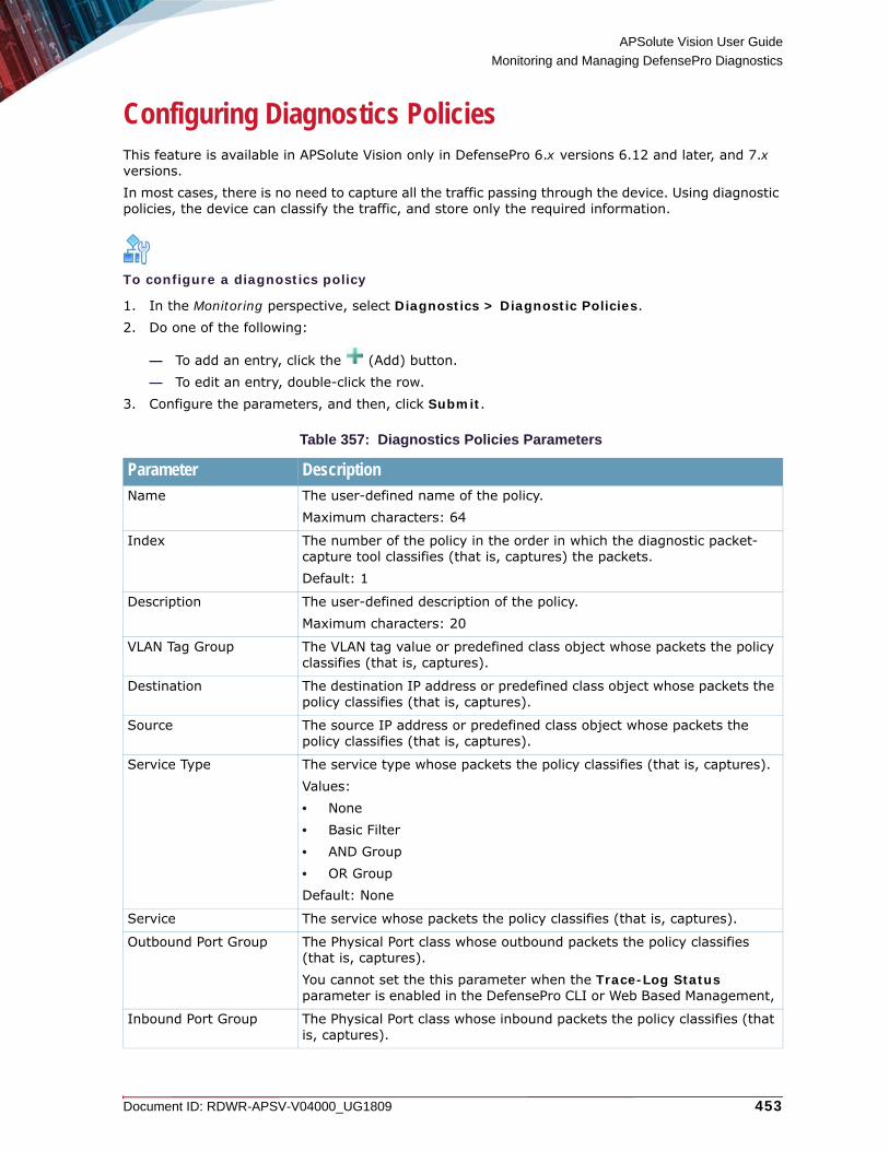
APSolute Vision User Guide
Monitoring and Managing DefensePro Diagnostics
Document ID: RDWR-APSV-V04000_UG1809 453
Configuring Diagnostics PoliciesThis feature is available in APSolute Vision only in DefensePro 6.x versions 6.12 and later, and 7.x versions.In most cases, there is no need to capture all the traffic passing through the device. Using diagnostic policies, the device can classify the traffic, and store only the required information.
To configure a diagnostics policy
1. In the Monitoring perspective, select Diagnostics > Diagnostic Policies. 2. Do one of the following:
— To add an entry, click the (Add) button.— To edit an entry, double-click the row.
3. Configure the parameters, and then, click Submit.
Table 357: Diagnostics Policies Parameters
Parameter DescriptionName The user-defined name of the policy.
Maximum characters: 64
Index The number of the policy in the order in which the diagnostic packet-capture tool classifies (that is, captures) the packets.Default: 1
Description The user-defined description of the policy.Maximum characters: 20
VLAN Tag Group The VLAN tag value or predefined class object whose packets the policy classifies (that is, captures).
Destination The destination IP address or predefined class object whose packets the policy classifies (that is, captures).
Source The source IP address or predefined class object whose packets the policy classifies (that is, captures).
Service Type The service type whose packets the policy classifies (that is, captures).Values:• None• Basic Filter• AND Group• OR GroupDefault: None
Service The service whose packets the policy classifies (that is, captures).
Outbound Port Group The Physical Port class whose outbound packets the policy classifies (that is, captures). You cannot set the this parameter when the Trace-Log Status parameter is enabled in the DefensePro CLI or Web Based Management,
Inbound Port Group The Physical Port class whose inbound packets the policy classifies (that is, captures).
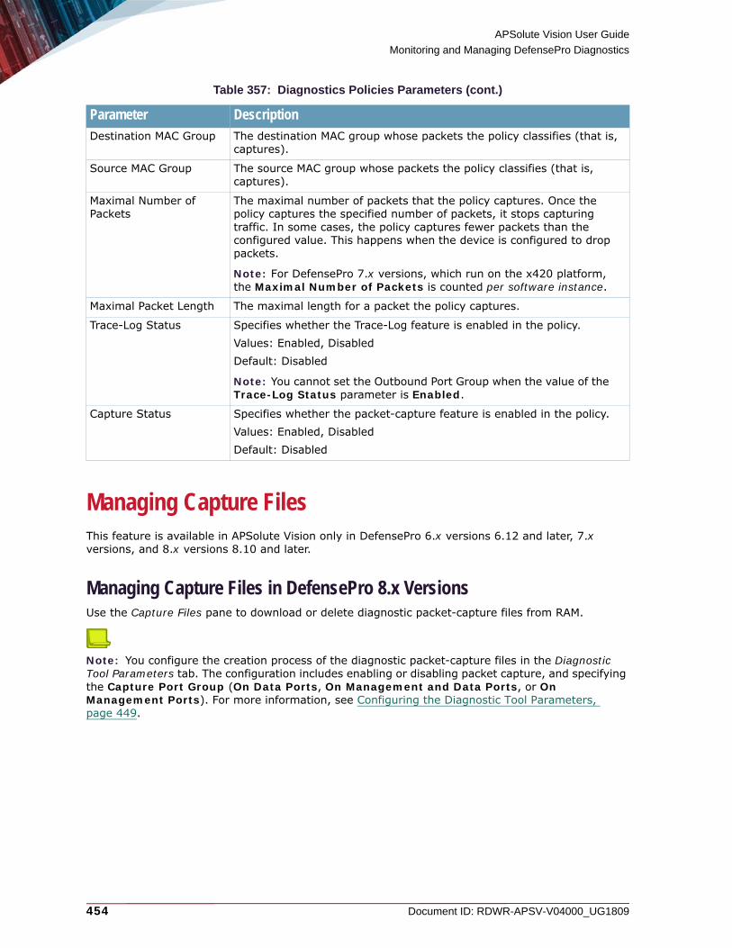
APSolute Vision User Guide
Monitoring and Managing DefensePro Diagnostics
454 Document ID: RDWR-APSV-V04000_UG1809
Managing Capture FilesThis feature is available in APSolute Vision only in DefensePro 6.x versions 6.12 and later, 7.x versions, and 8.x versions 8.10 and later.
Managing Capture Files in DefensePro 8.x VersionsUse the Capture Files pane to download or delete diagnostic packet-capture files from RAM.
Note: You configure the creation process of the diagnostic packet-capture files in the Diagnostic Tool Parameters tab. The configuration includes enabling or disabling packet capture, and specifying the Capture Port Group (On Data Ports, On Management and Data Ports, or On Management Ports). For more information, see Configuring the Diagnostic Tool Parameters, page 449.
Destination MAC Group The destination MAC group whose packets the policy classifies (that is, captures).
Source MAC Group The source MAC group whose packets the policy classifies (that is, captures).
Maximal Number of Packets
The maximal number of packets that the policy captures. Once the policy captures the specified number of packets, it stops capturing traffic. In some cases, the policy captures fewer packets than the configured value. This happens when the device is configured to drop packets.
Note: For DefensePro 7.x versions, which run on the x420 platform, the Maximal Number of Packets is counted per software instance.
Maximal Packet Length The maximal length for a packet the policy captures.
Trace-Log Status Specifies whether the Trace-Log feature is enabled in the policy.Values: Enabled, DisabledDefault: Disabled
Note: You cannot set the Outbound Port Group when the value of the Trace-Log Status parameter is Enabled.
Capture Status Specifies whether the packet-capture feature is enabled in the policy.Values: Enabled, DisabledDefault: Disabled
Table 357: Diagnostics Policies Parameters (cont.)
Parameter Description

APSolute Vision User Guide
Monitoring and Managing DefensePro Diagnostics
Document ID: RDWR-APSV-V04000_UG1809 455
In DefensePro 8.x version 8.17 and later, the diagnostic packet-capture tool does the following—according to the value of the of the Capture Port Group parameter:• When the Status of the diagnostic packet-capture tool is Enabled (Monitoring perspective,
Diagnostics > Diagnostic Tool Parameters > Status), the diagnostic packet-capture tool writes the following: — Files from the data (traffic) ports per core (also referred to as a “DefensePro
engine”)—Compressed, in the following format: CapturedOnEngine_<engine ID>.cap.bz2.
DefensePro limits the size of each CapturedOnEngine_<engine ID>.cap.bz2 file (per core)—before compression—to 300 MB. When a diagnostic packet-capture file exceeds the maximum size, packet-capture on the specific core stops (but the tool will remain enabled to allow other cores to continue capturing). To resume packet capture on the specific core, you must delete the file.Note: When packet capture is disabled and re-enabled, the tool appends data to the existing files from the data (traffic) ports.
— Files from management ports 1 and 2—Compressed, in the following format:CapturedOnManagement_<1|2>.cap.bz2.
DefensePro limits the size of each CapturedOnManagement_<1|2>.cap.bz2 file (per management interface)—before compression—to 300 MB. When a diagnostic packet-capture file exceeds the maximum size, packet-capture on the specific interface, the file rolls over, restarting with an empty file. To resume packet capture on the specific core, you must delete the file.Note: When packet capture is disabled and re-enabled, the tool starts a new file for the management ports.
• When the Status of the diagnostic packet-capture tool changes from Enabled to Disabled (Monitoring perspective, Diagnostics > Diagnostic Tool Parameters > Status), the diagnostic packet-capture tool writes the following: — A merged file of the data (traffic) ports, interleaved from all the
CapturedOnEngine_<engine ID>.cap.bz2 files (per core)—Compressed, in the following format:AllEnginesCombined.cap.bz2.
DefensePro limits the size of each AllEnginesCombined.cap.bz2 file—before compression—to 300 MB.DefensePro merges the first 300 MB of data—starting from the earliest packet.
— A merged file, interleaved from the CapturedOnManagement_<1|2>.cap.bz2 files (per management interface)—Compressed, in the following format:AllManagementCombined.cap.bz2.
DefensePro limits the size of each AllManagementCombined.cap.bz2 file—before compression—to 300 MB.DefensePro merges the first 300 MB of data—starting from the earliest packet.
In DefensePro versions 8.11–8.16, the diagnostic packet-capture tool does the following:• Writes the files per core (also referred to as a DefensePro engine), compressed, in the following
format:CapturedOnEngine_<engine ID>.cap.bz2
• Limits the size of each file (per core)—before compression—to 300 MB. When a diagnostic packet-capture file exceeds the maximum size, packet-capture on the specific core stops (but the tool will remain enabled to allow other cores to continue capturing). To resume packet capture on the specific core, you must delete the file.

APSolute Vision User Guide
Monitoring and Managing DefensePro Diagnostics
456 Document ID: RDWR-APSV-V04000_UG1809
In DefensePro version 8.10, the diagnostic packet-capture tool does the following:• Writes the files per core (also referred to as a DefensePro engine) in the following format:
CapturedOnEngine_<engine ID>.cap
• Limits the size of each file (per core) to 300 MB. When a diagnostic packet-capture file exceeds the maximum size, packet-capture on the specific core stops (but the tool will remain enabled to allow other cores to continue capturing). To resume packet capture on the specific core, you must delete the file.
To download or delete capture files in DefensePro 8.x versions
1. In the Monitoring perspective, select Diagnostics > Capture Files.The table comprises the following columns:— File Name—The name of the file.— Uncompressed File Size—The size of the file, in bytes, before compression.
2. Select the required row.
3. Click one of the following:
— (Delete Row)—Deletes the selected file.— Download—Starts the download process of the selected data. Follow the on-screen
instructions.Note: The download may take a several minutes.
Managing Capture Files in DefensePro 6.x and 7.x VersionsUse the Capture Files pane to download or delete diagnostic packet-capture files from the RAM or CompactFlash.In DefensePro 6.x and 7.x versions, the capture tool names the files using the following format:capture_<Device Name>_<ddMMyyyy>_<hhmmss>_<file number>.cap
If the device is configured to store the output in the CompactFlash, when the data size in RAM reaches its limit, the device appends the data chunk from RAM to the file on the CompactFlash drive. For each enabled diagnostic tool, DefensePro uses two temporary files. When one temporary file reaches the limit (1 MB), DefensePro stores the information in the second temporary file. When the second temporary file reaches the limit (1 MB), DefensePro overwrites the first file, and so on. When you download a CompactFlash file, the file contains both temporary files.
To download or delete capture files in DefensePro 6.x and 7.x versions
1. In the Monitoring perspective, select Diagnostics > Capture Files.The pane contains two tables, Files On RAM Drive and Files On Main Flash.Each table comprises the following columns:— File Name—The name of the file.— File Size—The file size, in bytes.
2. Select the required row.

APSolute Vision User Guide
Monitoring and Managing DefensePro Diagnostics
Document ID: RDWR-APSV-V04000_UG1809 457
3. Click one of the following:
— (Delete Row)—Deletes the selected file.— Download—Starts the download process of the selected data. Follow the on-screen
instructions.

APSolute Vision User Guide
Monitoring and Managing DefensePro Diagnostics
458 Document ID: RDWR-APSV-V04000_UG1809

Document ID: RDWR-APSV-V04000_UG1809 459
CHAPTER 20 – MONITORING AND CONTROLLING DEFENSEPRO NETWORKING
Monitoring and controlling DefensePro networking comprises the following topics:• Monitoring and Controlling the DefensePro Session Table, page 459• Monitoring Routing Table Information, page 461• Monitoring DefensePro ARP Table Information, page 462• Monitoring MPLS RD Information, page 463• Monitoring the DefensePro Suspend Table, page 464• Monitoring Tunnel Interfaces, page 465• Monitoring BGP Peers, page 465
Monitoring and Controlling the DefensePro Session TableMonitoring and controlling DefensePro Session table comprises the following topics:• Monitoring Session Table Information, page 459• Configuring DefensePro Session Table Filters, page 461
Monitoring Session Table InformationEach DefensePro device includes a Session table to keep track of sessions bridged and forwarded by the device. In DefensePro 6.x and 7.x versions, the Session table is enabled by default. In DefensePro 8.x versions, the Session table is always enabled.The size of the table makes it difficult to view. To generate reliable and useful reports and prevent system failures, in DefensePro 6.x and 7.x versions, you can use filters to define the Session table information to display. The Session Table pane displays information that matches any enabled Session table filter.
Notes
• The filtered Session table does not automatically refresh. The information loads when you display the Session Table pane and when you manually refresh the display.
• DefensePro issues alerts for high utilization alerts of the Session table. DefensePro sends alerts to APSolute Vision when table utilization reaches 90% and 100%.
To view Session table information
> In the Monitoring perspective, select Networking > Session Table > Session Table.

APSolute Vision User Guide
Monitoring and Controlling DefensePro Networking
460 Document ID: RDWR-APSV-V04000_UG1809
Table 358: Session-Table Monitoring Parameters
Parameter DescriptionSource IP The source IP address within the defined subnet.
Destination IP The destination IP address within the defined subnet.
Source L4 Port The session source port.
Destination L4 Port The session destination port.
Context Group Tag(This parameter is available only in DefensePro 8.x versions.)
The Tag value of the Context Group class associated with the entry.
Protocol The session protocol.
Physical Interface(This parameter is available only in DefensePro 6.x and 7.x versions.)
The physical port on the device at which the request arrives from the client.
Lifetime (Sec.) The time, in seconds, following the arrival of the last packet, that the entry remains in the table before it is deleted.
Aging Type(This parameter is available only in DefensePro 6.x and 7.x versions.)
The reason for the Lifetime value. Values:• Default—A lifetime per protocol. The default value is 100 seconds.• End—Session end. A FIN/RST arrived, and the session ended. The
value depends on the protocol defaults. The default value is 5 seconds.
• SYN—SYN Protection. The Lifetime was set after DefensePro received a SYN that may be an attack. The default value is 10 seconds.
• App—An application changed the lifetime for an application-specific reason. Note that the host table can change this lifetime only to the Lifetime type End (for example, ACL rules).
• Initial—The initial lifetime of the session, which later (probably after the arrival of the second packet) will be modified to the Lifetime type Default. The default value is 5 seconds.
• Unknown—If none of the above options are used.
SYN Flood Status(This parameter is available only in DefensePro 6.x and 7.x versions.)
Indicates whether the entry is currently protected against SYN attacks.Values:• Not Protected—The SYN Flood Protection module is disabled.• Protected (No Attack)—No trigger is found for the protected server,
thus there is no attack.• Protected (Under Attack)—There is an ongoing attack on the
protected server, and DefensePro is mitigating the attack
Policy Name(This parameter is available only in DefensePro 7.x versions 7.42 and later.)
The name of the Network Protection policy.
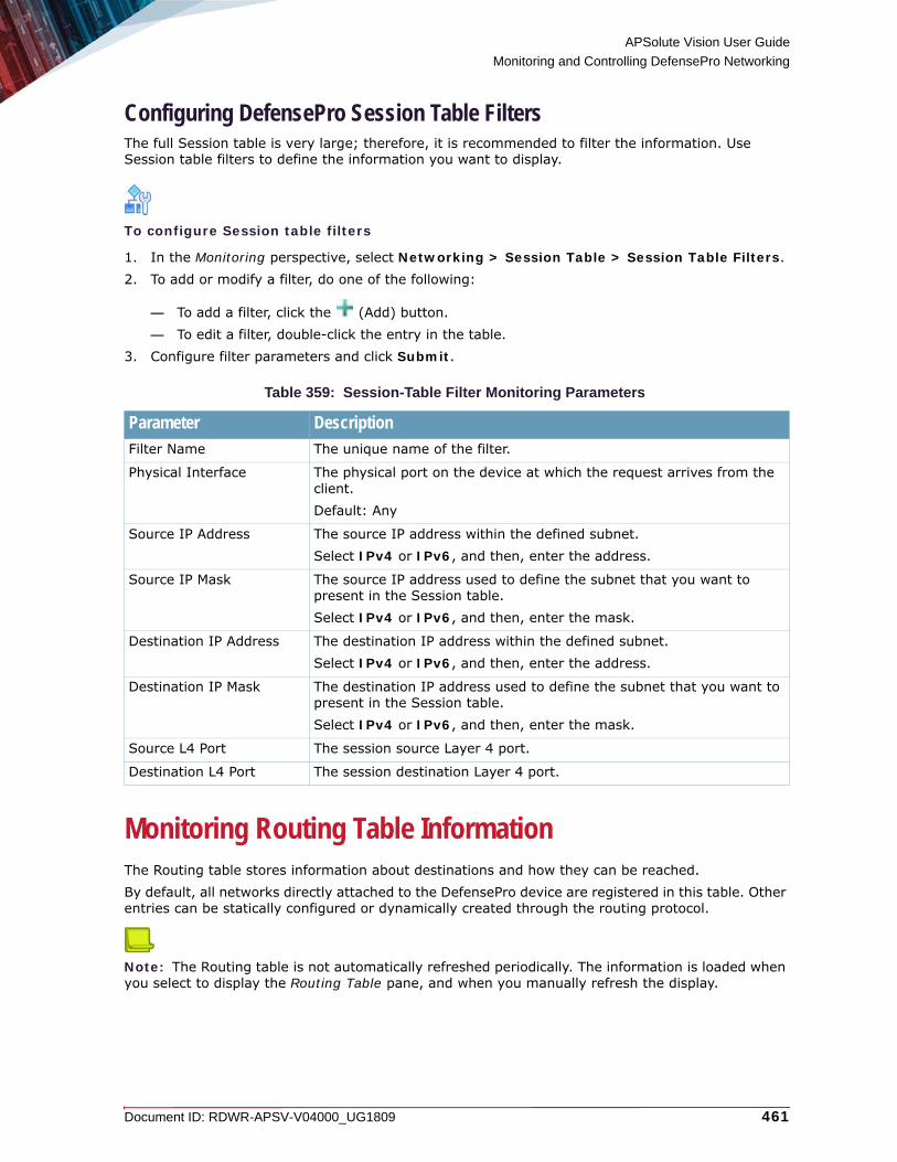
APSolute Vision User Guide
Monitoring and Controlling DefensePro Networking
Document ID: RDWR-APSV-V04000_UG1809 461
Configuring DefensePro Session Table FiltersThe full Session table is very large; therefore, it is recommended to filter the information. Use Session table filters to define the information you want to display.
To configure Session table filters
1. In the Monitoring perspective, select Networking > Session Table > Session Table Filters.2. To add or modify a filter, do one of the following:
— To add a filter, click the (Add) button.— To edit a filter, double-click the entry in the table.
3. Configure filter parameters and click Submit.
Monitoring Routing Table InformationThe Routing table stores information about destinations and how they can be reached.By default, all networks directly attached to the DefensePro device are registered in this table. Other entries can be statically configured or dynamically created through the routing protocol.
Note: The Routing table is not automatically refreshed periodically. The information is loaded when you select to display the Routing Table pane, and when you manually refresh the display.
Table 359: Session-Table Filter Monitoring Parameters
Parameter DescriptionFilter Name The unique name of the filter.
Physical Interface The physical port on the device at which the request arrives from the client. Default: Any
Source IP Address The source IP address within the defined subnet.Select IPv4 or IPv6, and then, enter the address.
Source IP Mask The source IP address used to define the subnet that you want to present in the Session table.Select IPv4 or IPv6, and then, enter the mask.
Destination IP Address The destination IP address within the defined subnet.Select IPv4 or IPv6, and then, enter the address.
Destination IP Mask The destination IP address used to define the subnet that you want to present in the Session table.Select IPv4 or IPv6, and then, enter the mask.
Source L4 Port The session source Layer 4 port.
Destination L4 Port The session destination Layer 4 port.

APSolute Vision User Guide
Monitoring and Controlling DefensePro Networking
462 Document ID: RDWR-APSV-V04000_UG1809
To display Routing Table information for a selected device
> In the Monitoring perspective, select Networking > Routing.
Monitoring DefensePro ARP Table InformationYou can view the device’s ARP table, which contains both static and dynamic entries. You can change an entry type from dynamic to static.
Note: The ARP table is not automatically refreshed periodically. The information is loaded when you select to display the ARP Table pane, and when you manually refresh the display.
To display ARP Table information for a selected DefensePro device
> In the Monitoring perspective, select Networking > ARP.
Table 360: Routing-Table Monitoring Parameters
Parameter DescriptionDestination Network The destination network to which the route is defined.
Netmask The network mask of the destination subnet.
Next Hop The IP address of the next hop toward the Destination subnet. (The next hop always resides on the subnet local to the device.)
Via Interface In DefensePro 6.x–8.x versions, this is the local interface or VLAN through which the next hop of this route is reached. This can be the port name, trunk name, or VLAN ID.In Radware DefensePro DDoS Mitigation for Cisco Firepower, the value is MNG-1 (read-only), which is the value of the management interface.
Type This field is displayed only in the Static Routes table.The type of routing.Values:• Local—The subnet is directly reachable from the device.• Remote—The subnet is not directly reachable from the device.
Metric The metric value defined or calculated for this route.
Table 361: DefensePro ARP-Table Monitoring Parameters
Parameter HeadingPort The interface number where the station resides.
IP Address The station’s IP address.
MAC Address The station’s MAC address.

APSolute Vision User Guide
Monitoring and Controlling DefensePro Networking
Document ID: RDWR-APSV-V04000_UG1809 463
To change an entry type from dynamic to static
1. In the Monitoring perspective, select Networking > ARP.2. Select the entry, and select Change Entry to Static.
Monitoring MPLS RD InformationThis feature is supported only in DefensePro 6.x versions and 7.x versions prior to 7.40.You can monitor MPLS RD information and configure an MPLS RD. Each MPLS RD is assigned two tags for the link on which the device is installed, an upper tag and a lower tag. On a different link, the same MPLS RD can be assigned with different tags.
To display MPLS RD information for a selected DefensePro device
1. In the Monitoring perspective, select Networking > MPLS RD.The MPLS RD table displays current MPLS RD information.
2. To add an MPLS RD, click the (Add) button.
3. Configure the parameters, and then, click Submit.
Type The entry type.Values:• Other—Not Dynamic or Static.• Dynamic—Entry is learned from ARP protocol. If the entry is not active
for a predetermined time, the node is deleted from the table.• Static—Entry has been configured by the network management station
and is permanent.
Table 362: MPLS RD Parameters
Parameter DescriptionMPLS RD The MPLS RD name.
Type Describes the MPLS RD format.Values:• 2 Bytes : 4 Bytes—AS (16 bit): Number (32 bit)• 4 Bytes : 2 Bytes—AS (32 bit): Number (16 bit)• IP Address : 2 Bytes—IP: Number (16 bit)
Upper Tag The upper tag for the link on which the device is installed.
Lower Tag The lower tag for the link on which the device is installed.
Table 361: DefensePro ARP-Table Monitoring Parameters (cont.)
Parameter Heading
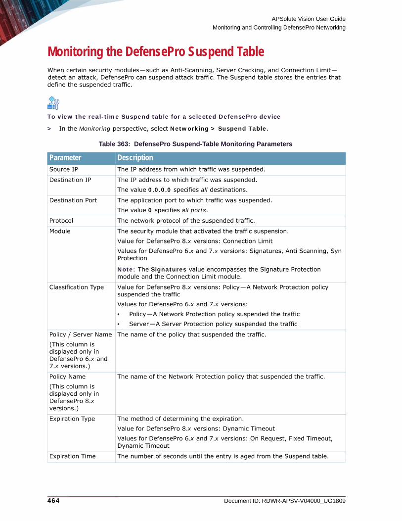
APSolute Vision User Guide
Monitoring and Controlling DefensePro Networking
464 Document ID: RDWR-APSV-V04000_UG1809
Monitoring the DefensePro Suspend TableWhen certain security modules—such as Anti-Scanning, Server Cracking, and Connection Limit—detect an attack, DefensePro can suspend attack traffic. The Suspend table stores the entries that define the suspended traffic.
To view the real-time Suspend table for a selected DefensePro device
> In the Monitoring perspective, select Networking > Suspend Table.
Table 363: DefensePro Suspend-Table Monitoring Parameters
Parameter DescriptionSource IP The IP address from which traffic was suspended.
Destination IP The IP address to which traffic was suspended. The value 0.0.0.0 specifies all destinations.
Destination Port The application port to which traffic was suspended. The value 0 specifies all ports.
Protocol The network protocol of the suspended traffic.
Module The security module that activated the traffic suspension.Value for DefensePro 8.x versions: Connection LimitValues for DefensePro 6.x and 7.x versions: Signatures, Anti Scanning, Syn Protection
Note: The Signatures value encompasses the Signature Protection module and the Connection Limit module.
Classification Type Value for DefensePro 8.x versions: Policy—A Network Protection policy suspended the trafficValues for DefensePro 6.x and 7.x versions: • Policy—A Network Protection policy suspended the traffic• Server—A Server Protection policy suspended the traffic
Policy / Server Name(This column is displayed only in DefensePro 6.x and 7.x versions.)
The name of the policy that suspended the traffic.
Policy Name(This column is displayed only in DefensePro 8.x versions.)
The name of the Network Protection policy that suspended the traffic.
Expiration Type The method of determining the expiration. Value for DefensePro 8.x versions: Dynamic TimeoutValues for DefensePro 6.x and 7.x versions: On Request, Fixed Timeout, Dynamic Timeout
Expiration Time The number of seconds until the entry is aged from the Suspend table.

APSolute Vision User Guide
Monitoring and Controlling DefensePro Networking
Document ID: RDWR-APSV-V04000_UG1809 465
Monitoring Tunnel InterfacesThis feature is available only in DefensePro 7.x versions.You can monitor tunnel interfaces that are configured in the Tunnel Interfaces pane (Configuration perspective, Setup > Networking > IP Management > Tunnel Interfaces).
Notes
• For more information on the Device Operation Mode, see Configuring the Device Operation Mode for DefensePro, page 224).
• For more information on the tunnels in the context of the IP Device Operation Mode, see Managing Tunnel Interfaces, page 64.
To display tunnel interface information for a selected DefensePro device
> In the Monitoring perspective, select Networking > Tunnel Interfaces.
Monitoring BGP PeersThis feature is available only in DefensePro 7.x versions.You can monitor statistics regarding the BGP peers configured on the device.
Note: The routing tables managed by a Border Gateway Protocol (BGP) implementation are adjusted continually to reflect changes in the network, such as links breaking and being restored, or routers going down and coming back up. In the network as a whole, these changes happen almost continuously, but for any particular router or link, changes should be relatively infrequent.
To display BGP information for a selected DefensePro device
> In the Monitoring perspective, select Networking > BGP Peers.
Table 364: Tunnel Interfaces: Table Parameters
Parameter DescriptionTunnel IP Address The IP address of the tunnel.
Primary Tunnel Status The status of the primary tunnel.
Secondary Tunnel Status The status of the secondary tunnel.
Table 365: Tunnel Interfaces: Total Tunnel Status Parameter
Parameter DescriptionTotal Tunnels Status The number of reachable tunnels of the total configured tunnels,
using a slash (/) as the separator. For example, the value 10/11 signifies that there are 10 reachable tunnels of the 11 total configured tunnels.

APSolute Vision User Guide
Monitoring and Controlling DefensePro Networking
466 Document ID: RDWR-APSV-V04000_UG1809
Table 366: BGP Information for DefensePro
Parameter DescriptionPeer IP Address The IP address of the remote peer.
Admin Status Indicates whether the peer is enabled.
Connection State The state of the connection. Values: • Idle—The peer is stopped.• Connect—DefensePro initiated a TCP connection to remote
peer.• Active—The peer is waiting during a connect retry interval,
after failing to establish TCP connection to a remote peer. In this state, DefensePro also listens on port 179 for potential incoming connections from the remote peer.
• OpenSent—A TCP connection is established with the remote peer. DefensePro sent a BGP OPEN message to the remote peer and expects to receive an OPEN message from it.
• OpenConfirm—DefensePro received an OPEN message from the remote peer. DefensePro responds with a KEEPALIVE message and expects a KEEPALIVE message from the remote peer.
• Established—A BGP connection is established with a remote peer. DefensePro can now exchange UPDATE messages with it.
Remote AS The remote autonomous system number.
Peer Identifier The IP address that identifies the remote peer for the current BGP connection.
Local Address The DefensePro IP interface address used as the source IP address for a BGP connection.
Local Port (Source) The TCP source port number used by DefensePro for a BGP connection to the remote peer.
Remote Port (Destination) The TCP destination port number used by DefensePro for a BGP connection to the remote peer.
In Updates The number of BGP UPDATE messages transmitted on the connection.
Out Updates The number of BGP UPDATE messages transmitted on the connection.
In Total Messages The total number of messages received from to the remote peer on the connection.
Out Total Messages The total number of messages transmitted to the remote peer on the connection.
Last Error The last error code and subcode seen by the peer on the connection. If no error has occurred, the value for this field is zero (0). Otherwise, the first byte of this two-byte OCTET STRING contains the error code, and the second byte contains the subcode.
FSM Established Time How long, in seconds, the peer has been in the established state, or how long since the peer was last in the established state. It is set to zero when a new peer is configured or the router is booted.
FSM Established Transitions The total number of times the BGP FSM transitioned into the established state.

APSolute Vision User Guide
Monitoring and Controlling DefensePro Networking
Document ID: RDWR-APSV-V04000_UG1809 467
Connect Retry Interval The Connect Retry Interval value specified in the configuration of the peer.
Hold Time The time, in seconds, the Hold Timer established with the peer. The value of this object is calculated by the BGP speaker by using the smaller of the value by the specified Hold Time and the Hold Time received in the OPEN message. The value zero (0) indicates that the Hold Timer has not been established with the peer, or, the specified Hold Time is zero (0).
Keep Alive Time The interval, in seconds, for the keepalive timer established with the peer. The value of this object is calculated by the BGP speaker. The value zero (0) indicates that the keepalive timer has not been established with the peer, or, the specified Keep-Alive Time is zero (0).
Hold Time Configured The Hold Time value specified in the configuration of the peer.
Keep Alive Configured The Keep-Alive Time value specified in the configuration of the peer.
In Update Elapsed Time The elapsed time, in seconds, since the last BGP UPDATE message was received from the peer.
Table 366: BGP Information for DefensePro (cont.)
Parameter Description

APSolute Vision User Guide
Monitoring and Controlling DefensePro Networking
468 Document ID: RDWR-APSV-V04000_UG1809

Document ID: RDWR-APSV-V04000_UG1809 469
CHAPTER 21 – MONITORING AND CONTROLLING DEFENSEFLOW OPERATION
The Monitoring pane lets you view system information and statistics and the operation of protected objects in real-time, including protected objects for:• Operation, page 469• System, page 503
Note: In DefenseFlow version 2.1, the order of the Operation and System tabs are switched.
OperationThe Operation pane lets you manage protected objects and manually activate them using the Protected Objects pane, including:• Attack Mitigation Operations, page 469• Pending Actions, page 475• Mitigation Devices, page 482• Protected Objects, page 483• Ongoing Protections, page 491• BGP, page 496
Attack Mitigation OperationsThis feature is only available starting with version 3.0.The Attack Mitigation Operations dashboard graphically displays all the ongoing attacks and their associated protections, and displays a log of all the history attacks.
To view and modify attack mitigation operations from the Attack Mitigation Operations dashboard
1. To access the Attack Mitigation Operations dashboard, do one of the following:— From APSolute Vision,
a. In the Monitoring perspective, select Operation > Attack Mitigation Operations.b. To open the Attack Mitigation Operations dashboard, click Click here to access Attack
Mitigation Operations. A separate browser page opens with the DefenseFlow login prompt.
— To directly access the DefenseFlow dashboard, go to the following URL: https://DefenseFlow-IP/login

APSolute Vision User Guide
Monitoring and Controlling DefenseFlow Operation
470 Document ID: RDWR-APSV-V04000_UG1809
2. At the DefenseFlow login prompt, log in to the DefenseFlow device using the DefenseFlow username and password. The Attack Mitigation Operations dashboard displays all the ongoing attacks and their associated protections, and displays a log of all the history attacks.
Notes
— To return to the main DefenseFlow UI in APSolute Vision, switch to that browser page.— To log out from the Attack Mitigation Operations dashboard, at the top-right in the title bar,
click the username icon, then click Logout.— If you do not log out of the Attack Mitigation Operations dashboard and you close the
browser page, you will still be logged into the dashboard. The login session times out after one hour.
3. By default, the attack table is sorted in the following order:
— Unprotected attacks sorted by volume bytes per second (BPS) in descending order— Protected attacks sorted by volume bytes per second (BPS) in descending order— Historical attacks sorted by attack end-time in descending order
Historical attack data is saved. You can delete an historical attack record after the attack has
ended by highlighting the attack and clicking .Note: Up to 3000 historical attacks are saved for three months. Any attacks older than three months are deleted. Any attacks beyond the 3000 attacks limit are deleted, starting with the oldest attack.
— You can sort the attack table by any of the columns in the table in ascending or descending order by clicking on the relevant column header.
— You can search for records in the Search field above the Attack Operations table based on strings in the Attack ID, PO Name, Source Network, Destination Network, Protocol, Attack Start, and Attack End parameters. Begin the search by entering characters, one at a time, until you find the records that include the string you entered. If no records include the string you entered, the table will display with no records.
— You can start protections for all unprotected attacks by clicking the Protect All button at the top right corner of the Attack Mitigation Operations dashboard pane.
—4. Highlight the attack and review and/or set the attack operation parameters as required:

APSolute Vision User Guide
Monitoring and Controlling DefenseFlow Operation
Document ID: RDWR-APSV-V04000_UG1809 471
Table 367: Attack Operations Parameters
Parameter DescriptionOverall Attack Operation Status
A colored indicator to the left of the Attack ID that indicates the overall attack operation status. It is related to the protection Status, as described here and as described later in this table.Overall Status Indicators:• Red—Displays under one the following conditions:
— The status icon is (Protection is not activated), where none of the protections are activated.
— The status icon is (Protection is activated on some of the networks), where only some of the protections are activated.
— The status icon is (Protection activation has failed), where the protection was not activated.
• Green—Displays under of the following conditions:
— The status icon is (Protection activated successfully), where all the protections have been activated automatically but the attack has not yet ended.
• Orange—Displays under one of the following conditions:
— The status icon is (Protection activated successfully), where all the protections have been activated manually, but no attack has been detected.
— This status icon is (In progress), where is the protections are either being activated or deactivated.
— The status icon is (Attack has terminated), where the unprotected attack has terminated.
• Gray—Displays under one of the following conditions:
— The status icon is (Protection has terminated), where all protections have been activated automatically and the attack has ended.
Attack ID The unique attack ID for the attack operation. This ID remains with the attack record for the record’s entire lifetime. This attack ID is internal to DefenseFlow and not related to any external IDs associated with the attack.
PO Name The protected object associated with the attack.

APSolute Vision User Guide
Monitoring and Controlling DefenseFlow Operation
472 Document ID: RDWR-APSV-V04000_UG1809
Source Network The attack operation source network IP addresses and ranges (CIDRs).Up to three CIDRs are displayed. If there are more than three CIDRs for an attack, the total number of CIDRs is displayed within parentheses (round brackets).
To view the list of source CIDRs, click the (Edit) icon to the right of the displayed CIDRs. From the Networks dialog box, you can:• View the full list of source CIDRs.
• Click the (Destination Networks) icon and
— Change the protection statuses of any of the destination CIDRs.— Add a new network to protect in the Protect New Network field.
After making any changes, click Submit.
Destination Network
The attack operation destination network IP addresses and ranges (CIDRs).Up to three CIDRs are displayed. If there are more than three CIDRs for an attack, the total number of CIDRs is displayed within parentheses (round brackets).
To view the list of destination CIDRs, click the (Edit) icon to the right of the displayed CIDRs. From the Networks dialog box, you can:• Change the protection statuses of any of the destination CIDRs.• Add a new network to protect in the Protect New Network field.
• Click the (Source Networks) icon and view the full list of the source CIDRs.
After making any changes, click Submit.
Table 367: Attack Operations Parameters (cont.)
Parameter Description
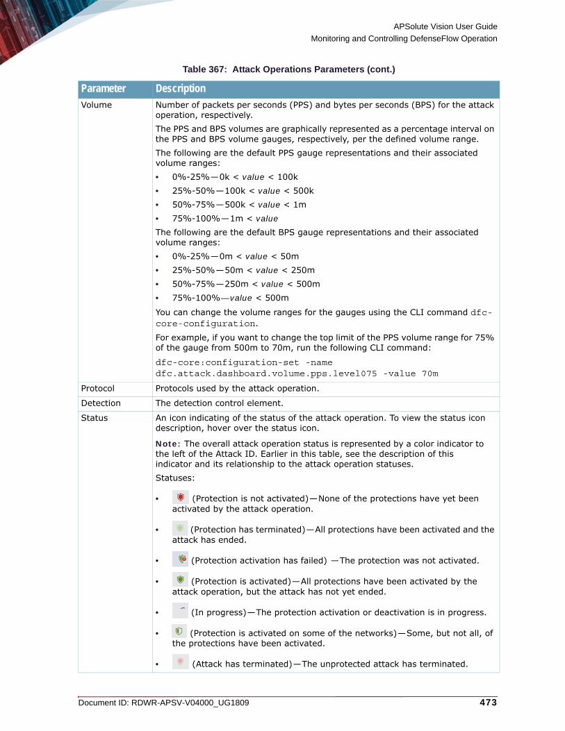
APSolute Vision User Guide
Monitoring and Controlling DefenseFlow Operation
Document ID: RDWR-APSV-V04000_UG1809 473
Volume Number of packets per seconds (PPS) and bytes per seconds (BPS) for the attack operation, respectively.The PPS and BPS volumes are graphically represented as a percentage interval on the PPS and BPS volume gauges, respectively, per the defined volume range.The following are the default PPS gauge representations and their associated volume ranges:• 0%-25%—0k < value < 100k• 25%-50%—100k < value < 500k• 50%-75%—500k < value < 1m• 75%-100%—1m < valueThe following are the default BPS gauge representations and their associated volume ranges:• 0%-25%—0m < value < 50m• 25%-50%—50m < value < 250m• 50%-75%—250m < value < 500m• 75%-100%—value < 500m
You can change the volume ranges for the gauges using the CLI command dfc-core-configuration.
For example, if you want to change the top limit of the PPS volume range for 75% of the gauge from 500m to 70m, run the following CLI command:
dfc-core:configuration-set -name dfc.attack.dashboard.volume.pps.level075 -value 70m
Protocol Protocols used by the attack operation.
Detection The detection control element.
Status An icon indicating of the status of the attack operation. To view the status icon description, hover over the status icon.
Note: The overall attack operation status is represented by a color indicator to the left of the Attack ID. Earlier in this table, see the description of this indicator and its relationship to the attack operation statuses. Statuses:
• (Protection is not activated)—None of the protections have yet been activated by the attack operation.
• (Protection has terminated)—All protections have been activated and the attack has ended.
• (Protection activation has failed) —The protection was not activated.
• (Protection is activated)—All protections have been activated by the attack operation, but the attack has not yet ended.
• (In progress)—The protection activation or deactivation is in progress.
• (Protection is activated on some of the networks)—Some, but not all, of the protections have been activated.
• (Attack has terminated)—The unprotected attack has terminated.
Table 367: Attack Operations Parameters (cont.)
Parameter Description

APSolute Vision User Guide
Monitoring and Controlling DefenseFlow Operation
474 Document ID: RDWR-APSV-V04000_UG1809
To view the attack operation background processes
You can view the all attack background operation details.
1. To view the Operation Background Processes pane, at the far top-right in the title bar, click the
icon.
2. On the menu, click Operation Background Processes. The Operation Background Processes table includes the following parameters:
Protection Manually start or stop a protection operation for the attack based on the current status of the protection.Click one of the following buttons as relevant:• CONFIRM ALL—Confirm starting or stopping multiple protection operations
for a given attack ID.• CONFIRM START—Confirm starting a single protection operation for a given
attack ID.• CONFIRM STOP—Confirm stopping a single protection operation for a given
attack ID.• START—Start a single protection operation for a given attack ID.• STOP—Stop a single protection operation for a given attack ID.• STOP ALL—Stop all protections for multiple operations for a given attack ID.
Notes: • You can start protections for all unprotected attacks by clicking the Protect
All button at the top right corner of the Attack Mitigation Operations dashboard pane.
• While a protection operation is in process, you can hover over the Protection button to view the protection status and to see more details of the operation by clicking the Details link.
Attack Start Attack operation start time and end time of the attack or the protection.
Attack End Attack operation end time of the attack or the protection.
Table 368: Operation Background Processes Parameters
Parameter DescriptionPROCESS DESCRIPTION
Description of the operation background process, including the associated PO name where relevant.
DATE STARTED Date and time the process started.
DATE MODIFIED Last date and time the process was modified.
Table 367: Attack Operations Parameters (cont.)
Parameter Description
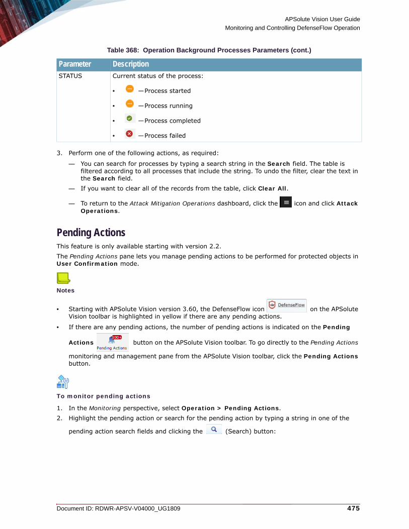
APSolute Vision User Guide
Monitoring and Controlling DefenseFlow Operation
Document ID: RDWR-APSV-V04000_UG1809 475
3. Perform one of the following actions, as required:
— You can search for processes by typing a search string in the Search field. The table is filtered according to all processes that include the string. To undo the filter, clear the text in the Search field.
— If you want to clear all of the records from the table, click Clear All.
— To return to the Attack Mitigation Operations dashboard, click the icon and click Attack Operations.
Pending ActionsThis feature is only available starting with version 2.2.The Pending Actions pane lets you manage pending actions to be performed for protected objects in User Confirmation mode.
Notes
• Starting with APSolute Vision version 3.60, the DefenseFlow icon on the APSolute Vision toolbar is highlighted in yellow if there are any pending actions.
• If there are any pending actions, the number of pending actions is indicated on the Pending
Actions button on the APSolute Vision toolbar. To go directly to the Pending Actions
monitoring and management pane from the APSolute Vision toolbar, click the Pending Actions button.
To monitor pending actions
1. In the Monitoring perspective, select Operation > Pending Actions.2. Highlight the pending action or search for the pending action by typing a string in one of the
pending action search fields and clicking the (Search) button:
STATUS Current status of the process:
• —Process started
• —Process running
• —Process completed
• —Process failed
Table 368: Operation Background Processes Parameters (cont.)
Parameter Description

APSolute Vision User Guide
Monitoring and Controlling DefenseFlow Operation
476 Document ID: RDWR-APSV-V04000_UG1809
Table 369: Pending Actions View/Search Parameters
Parameter DescriptionName(From versions 2.3 through 2.6, the Name and IP Address parameters were together in one column. In versions earlier than 2.7, Name was PO Name)
The name of the protected object awaiting action confirmation.Starting with version 2.7, to view and/or edit a protected object associated with a pending action, select the link in the Name column, and the Edit Protected Object pane for that protected object displays. For more information on protected objects, see the DefenseFlow Installation and User Guide.
Note: If the protected object is under protection, and you modify an attribute that conflicts with the ongoing protection, the change is performed only at the next activation of the protected object.Starting with version 2.8.1, if you want a modification that affects an ongoing protection to take effect immediately, you can make this modification from Operation > Ongoing Protections > Edit Protection. For more information, see To edit ongoing protections, page 495.
IP Address(In versions earlier than 2.3, IP Address was Detected IP Address)
The IP address of the attacked destination as detected by the selected detection device.
Operation(This parameter is only available starting with version 2.3. In versions earlier than 2.4, it displays in the last column)
String within the operation name.Starting with version 2.7, to view and/or edit an operation associated with a pending action, select the link in the Operation column, and the Edit Operation pane for that operation displays. For more information on operations, see the DefenseFlow Installation and User Guide.
Note: If the protected object is under protection, and you modify an attribute that conflicts with the ongoing protection, the change is performed only at the next activation of the protected object.Starting with version 2.8.1, if you want a modification that affects an ongoing protection to take effect immediately, you can make this modification from Operation > Ongoing Protections > Edit Protection. For more information, see To edit ongoing protections, page 495.
Attack ID The ID of the detected attack as reported by the detection device.
Pending Action The pending action waiting for confirmation.Values:• Start—An attack was detected for the protected object. The user can confirm
activation of the configured actions.• End—The attack was terminated. The user can confirm deactivation of the
active actions.
Configured Action(This parameter is only available in versions prior to 2.8.1)
The configured action for the protected object.

APSolute Vision User Guide
Monitoring and Controlling DefenseFlow Operation
Document ID: RDWR-APSV-V04000_UG1809 477
To clear the filter and perform a new search, click Clear next to the (Search) button.
To confirm or ignore a pending action
1. In the Monitoring perspective, select Operation > Pending Actions.
2. Click the (Edit) button.
The following parameters display:— IP Address (starting with version 2.7; read-only)—The IP address of the attacked
destination as detected by the selected detection device.— Configured Action (starting with version 2.7; read-only)—The configured action for the
protected object.— Workflow (starting with version 2.7; read-only)—Workflow associated with the protected
object— Action—Action to take on the pending action: Ignore, Confirm Start, Confirm End
3. Do one of the following:
— To ignore a pending action and remove it from the pending actions table, select Ignore.— To confirm start of a pending action, for the Action, select Confirm Start. The Action
parameters display and can be modified:• Attack Destination (this option is only available in versions earlier than 2.3)— Select
Activate Entire PO to protect the entire protected object or select Activate Specific IP to protect a specific IP address or set of addresses within the protected object.
Workflow(This parameter is only available starting with version 2.7)
Workflow associated with the protected object.Starting with version 2.8.1, to view and/or edit a workflow associated with a pending action, select the link in the Workflow column, and the Edit Workflow pane for that operation displays. For more information on operations, see the DefenseFlow Installation and User Guide.
Criteria(This parameter is only available starting with version 2.7)
The criteria associated with the pending action.
External Attack URI(This parameter is only available starting with version 2.7)
Link to the third-party detector management system that handles the external attack associated with the pending action.
External PO URI(This parameter is only available starting with version 2.7)
Link to the third-party detector management system that handles the external protected object associated with the pending action.
Table 369: Pending Actions View/Search Parameters (cont.)
Parameter Description

APSolute Vision User Guide
Monitoring and Controlling DefenseFlow Operation
478 Document ID: RDWR-APSV-V04000_UG1809
• Protected IP Address (in versions earlier than 2.3, Protected IP)—Starting with version 2.3, select one of the following options:—Activate (in versions earlier than 2.4, Divert) Entire Networks—This activates (in versions earlier than 2.4, diverts) the entire protected object.—Activate (in versions earlier than 2.4, Divert) Specific IP Address—This activates (in versions earlier than 2.4, diverts) only a specified IP address, which you change to any IP address or subnet as required.Starting with version 2.3, this option displays the Attack Destination IP Address parameter is the specific IP address attack target to be protected (this displays only if you selected Activate Specific IP). This must be within the network classification of the protected object.In versions earlier than 2.3, this option (Protected IP) is the specific IP address attack target to be protected (this displays only if you selected Activate Specific IP). This must be within the network classification of the protected object.
• Attack Destination IP Address (starting with version 2.3)—The IP address of the attack destination. This field only displays if the Activate Specific IP Address option is selected.
• Operation—The operation to use for diversion and mitigation groups preferences. Starting with version 2.3, select from the list of configured operations. The fields related to the operation type display. In versions earlier than 2.3, only the Attack Bandwidth and Ignore mitigation devices capacity units parameters are available.• If the operation you selected is a Mitigation operation, the mitigation and BGP
parameters (starting in version 2.4) display:
Table 370: Mitigation Parameters
Parameter DescriptionAttack Bandwidth
In versions earlier than 2.3, the peak attack level to use as a basis for configuring the DefensePro device if the information is missing from the detection signals.Starting with version 2.3, specify the attack bandwidth (bits per second). You can also specify units (for example, 100M). This is used for verifying that the mitigation devices can handle the related attack bandwidth. This is also used to set the DefensePro policy bandwidth if there is not any BDoS bandwidth ready yet.
Use busy mitigation devices(In versions earlier than 2.3, Ignore mitigation devices capacity units)
If checked, DefenseFlow uses the selected DefensePro devices regardless of their monitored capacity.
BGP
Operation BGP Community(In versions earlier than 2.4, BGP Community.)
The BGP community values to be sent to the diversion groups that should receive them per the operation. Multiple communities can be configured separated by a space. In addition, well-known communities can be also defined, including: NO_EXPORT, NO_ADVERTISE, NO_EXPORT_SUBCONFED, NOPEER
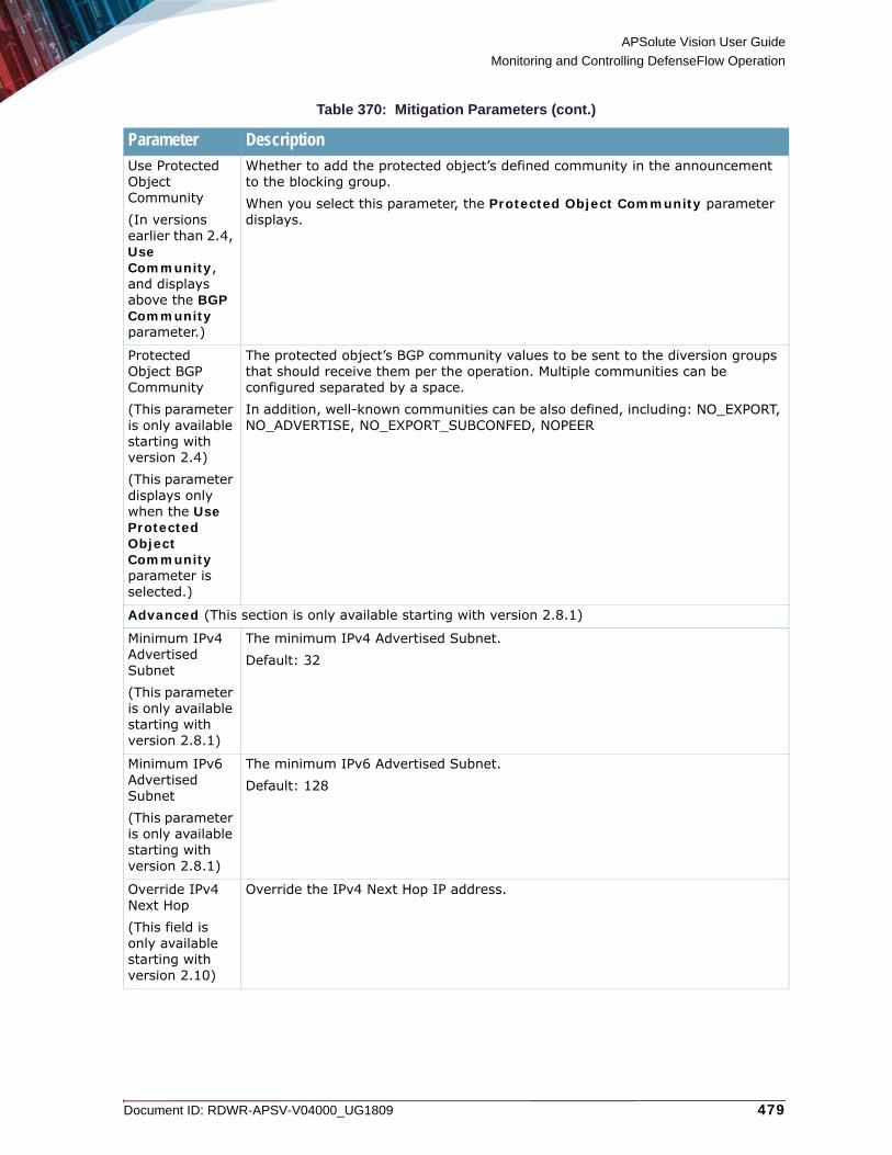
APSolute Vision User Guide
Monitoring and Controlling DefenseFlow Operation
Document ID: RDWR-APSV-V04000_UG1809 479
Use Protected Object Community(In versions earlier than 2.4, Use Community, and displays above the BGP Community parameter.)
Whether to add the protected object’s defined community in the announcement to the blocking group.When you select this parameter, the Protected Object Community parameter displays.
Protected Object BGP Community(This parameter is only available starting with version 2.4)(This parameter displays only when the Use Protected Object Community parameter is selected.)
The protected object’s BGP community values to be sent to the diversion groups that should receive them per the operation. Multiple communities can be configured separated by a space. In addition, well-known communities can be also defined, including: NO_EXPORT, NO_ADVERTISE, NO_EXPORT_SUBCONFED, NOPEER
Advanced (This section is only available starting with version 2.8.1)
Minimum IPv4 Advertised Subnet(This parameter is only available starting with version 2.8.1)
The minimum IPv4 Advertised Subnet. Default: 32
Minimum IPv6 Advertised Subnet(This parameter is only available starting with version 2.8.1)
The minimum IPv6 Advertised Subnet. Default: 128
Override IPv4 Next Hop(This field is only available starting with version 2.10)
Override the IPv4 Next Hop IP address.
Table 370: Mitigation Parameters (cont.)
Parameter Description

APSolute Vision User Guide
Monitoring and Controlling DefenseFlow Operation
480 Document ID: RDWR-APSV-V04000_UG1809
• If the operation you selected is a FlowSpec (in versions earlier than 2.4, Traffic Blocking) operation, the FlowSpec parameters display (for more information on defining FlowSpec operations, see the DefenseFlow Installation and User Guide):
Override IPv6 Next Hop(This field is only available starting with version 2.10)
Override the IPv6 Next Hop IP address.
Mitigation Route Name(This field is only available starting with version 2.10)
The route name for this mitigation. Select one of the routes that you defined for mitigation devices. For more information on configuring routes, see the DefenseFlow Installation and User Guide.
Table 371: FlowSpec (in versions earlier than 2.4, Traffic Blocking) Parameters
Parameter DescriptionDestination Prefix
The destination prefix to block as defined in the Flow rule.Values:• Attacked IP—The actual destination IP addresses are inherited from the
protected object’s networks or IP addresses under attack or manually activated.
• Entire Networks—The actual destination IP addresses are inherited from the protected object that uses this rule for its various operations or manual actions.
• Specific prefix—The Prefix to Block field displays, letting you define a set of IP prefixes for the destination prefix.
Default: Attacked IP
Prefix to Block(This field is only available starting with version 2.4)(This field displays only if you have selected Specific prefix as the Destination Prefix.)
Defines one or more IPv4 destination prefixes, each IP prefix separated by a space.Values: IPv4 address in the format n1.n2.n3.n4/5Maximum number of networks: 100
Source Prefix The source prefix to block as defined in the Flow rule.
Port The port to block as defined in the Flow rule.
Destination Port The destination port to block as defined in the Flow rule.
Protocol The protocol to block as defined in the Flow rule.
Source Port The source port to block as defined in the Flow rule.
Table 370: Mitigation Parameters (cont.)
Parameter Description

APSolute Vision User Guide
Monitoring and Controlling DefenseFlow Operation
Document ID: RDWR-APSV-V04000_UG1809 481
ICMP Type The ICMP type to block as defined in the Flow rule.
ICMP Code The ICMP code to block as defined in the Flow rule.
TCP Flag The TCP flag to block as defined in the Flow rule.
Packet Length The packet length to block as defined in the Flow rule.
DSCP The DSCP to block as defined in the Flow rule.
Fragment The fragment to block as defined in the Flow rule.
Redirect to VRF(This field is only available starting with version 2.4)
The route tag (VPN in versions earlier than 2.8.1) to which to redirect traffic. Select from a list of route tags (VPNs in versions earlier than 2.8.1) for which you have defined a route target. For more information, see the DefenseFlow Installation and User Guide.
Redirect to Mitigation(This field is only available starting with version 2.4)
Enables or disables redirection to the operation’s mitigation group. The next hop IP addresses are inherited from the mitigation group of the protected object that uses this rule for its various operations or manual actions.
Block(This parameter is only available starting with version 2.4. In version 2.3, this was an Action option.)
Enables or disables traffic blocking (drop all matching packets).
Rate Limit(This parameter is only available starting with version 2.4. In version 2.3, this was an Action option.)
The rate limit in MB/s or GB/s.Values:• Example for MB/s: 103M• Example for GB/s: 1G
Set DSCP(This parameter is only available starting with version 2.4. In version 2.3, this was an Action option.)
Defines how to update the DSCP header of the matching packets.Values: 0–63
Table 371: FlowSpec (in versions earlier than 2.4, Traffic Blocking) Parameters (cont.)
Parameter Description

APSolute Vision User Guide
Monitoring and Controlling DefenseFlow Operation
482 Document ID: RDWR-APSV-V04000_UG1809
— To confirm ending a protection, for the Action, select Confirm End. Do this if after you have started an action with Confirm Start by clicking Submit and the exit criteria for the action has been met (usually after an attack has ended). A confirmation message displays. Click OK to confirm.
4. Click Submit.
Mitigation DevicesThis feature is only available starting with version 2.2.The Mitigation Devices pane lets you monitor the status of mitigation devices.
To monitor mitigation devices
1. In the Monitoring perspective, select Operation > Mitigation Devices.2. Highlight the mitigation device or search for the mitigation device by typing a string in one of the
mitigation device search fields and clicking the (Search) button:
Action(This parameter is only available in version 2.3. Starting with version 2.4, the options are now separate parameters.)
The FlowSpec action to perform.Available actions:• Block—Drop all matching packets.• Rate Limit—Drop all matching packets above this rate (see the Rate
parameter in this table).• Set DSCP—Update the DSCP header of the matching packets.
Rate(This parameter is only available in version 2.3.)
This field displays when you select the Action as Rate Limit. Set the rate limit to block in bytes per second.
Table 372: Mitigation Devices View/Search Parameters
Parameter DescriptionName The name of the mitigation device.
Starting with version 2.7, to view and/or edit a mitigation device, select the link in the Name column, and the Edit Mitigation Device pane for that mitigation device displays. For more information on mitigation devices, see the DefenseFlow Installation and User Guide.
Note: Any modification you make is deployed immediately on the mitigation device.
Instance(This parameter is only available starting with version 2.9)
For DefensePro version 7.x mitigation devices, the DefensePro internal hardware instance that handles BDoS attacks in the DME when there are more than 32 such attacks. Values: 0, 1
Table 371: FlowSpec (in versions earlier than 2.4, Traffic Blocking) Parameters (cont.)
Parameter Description

APSolute Vision User Guide
Monitoring and Controlling DefenseFlow Operation
Document ID: RDWR-APSV-V04000_UG1809 483
To clear the filter and perform a new search, click Clear next to the (Search) button.
Protected ObjectsThe Protected Objects pane lets you monitor protected objects and manually activate them.
To monitor protected objects
1. In the Monitoring perspective, select Operation > Protected Objects.2. Highlight the protected object or search for the protected object by typing a string in one of the
protected object search fields and clicking the (Search) button:
Operational Status
The operational status of the mitigation device.
CPU Utilization CPU utilization of the mitigation device.
BW Utilization (Gbps)
Bandwidth utilization of the mitigation device.
Policies Utilization
The policies table utilization of the mitigation device.
Filter List Utilization(This parameter is only available starting with version 2.8.1)
The filter list utilization of the mitigation device.
Managed(This parameter is only available starting with version 2.4.1)
Whether the mitigation device is managed.Values: true, false
Update Time Last monitored update time.
Last Error(This parameter is only available starting with version 2.4.1)
The last device access error that was issued.
Examples A Authentication error
B Unable to connect to the mitigation device
Table 372: Mitigation Devices View/Search Parameters (cont.)
Parameter Description

APSolute Vision User Guide
Monitoring and Controlling DefenseFlow Operation
484 Document ID: RDWR-APSV-V04000_UG1809
Table 373: Protected Object View/Search Parameters
Parameter DescriptionName The name of the protected object.
Starting with version 2.7, to view and/or edit a protected object, select the link in the Name column, and the Edit Protected Object pane for that protected object displays. For more information on protected objects, see the DefenseFlow Installation and User Guide.
Note: If the protected object is under protection, and you modify an attribute that conflicts with the ongoing protection, the change is performed only at the next activation of the protected object.Starting with version 2.8.1, if you want a modification that affects an ongoing protection to take effect immediately, you can make this modification from Operation > Ongoing Protections > Edit Protection. For more information, see To edit ongoing protections, page 495.
Detection Status
The detection status of the protected object.Values:• Learning—DefenseFlow learns protected object baselines.• Normal—No attack is currently detected for the protected object.• Attacked—The protected object is under attack.
Action Status The action status of the protected object.Values:• Active—The configured actions are active. This means that the action
specified for the protected object is now enabled. The action can be enabled automatically or manually.
• Not Active—The configured actions are currently not active.
Mitigation Device/ Mitigation Group(This parameter is only available in version 2.1)
The list of mitigation devices that are currently performing mitigation for the protected object.
Action Mode(This parameter is only available in versions earlier than 2.7. Starting with version 2.7, it is now configured as one of the Workflow Rules parameters.)
The action mode configured for the protected object.Values:• Automatic—Configured actions are automatically activated upon detection of
an attack.• Manual—Configured actions can only be activated manually.• User confirmation—The user is prompted to confirm activation of the
configured actions upon attack.
Pending Action The pending action waiting for confirmation for a protected object that is in User Confirmation mode.Values:• Activate —An attack was detected for the protected object. The user can
confirm activation of the configured actions.• Deactivate—The attack was terminated. The user can confirm deactivation of
the active actions.
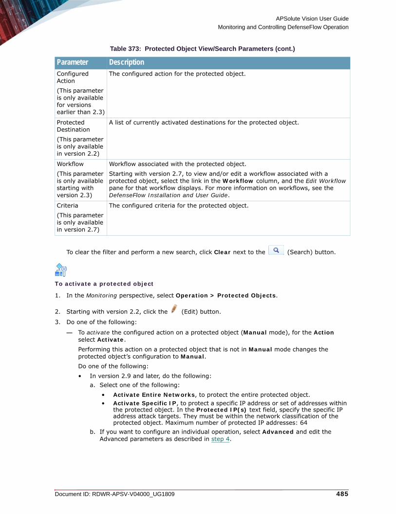
APSolute Vision User Guide
Monitoring and Controlling DefenseFlow Operation
Document ID: RDWR-APSV-V04000_UG1809 485
To clear the filter and perform a new search, click Clear next to the (Search) button.
To activate a protected object
1. In the Monitoring perspective, select Operation > Protected Objects.
2. Starting with version 2.2, click the (Edit) button.
3. Do one of the following:
— To activate the configured action on a protected object (Manual mode), for the Action select Activate.Performing this action on a protected object that is not in Manual mode changes the protected object’s configuration to Manual.Do one of the following:• In version 2.9 and later, do the following:
a. Select one of the following:• Activate Entire Networks, to protect the entire protected object.• Activate Specific IP, to protect a specific IP address or set of addresses within
the protected object. In the Protected IP(s) text field, specify the specific IP address attack targets. They must be within the network classification of the protected object. Maximum number of protected IP addresses: 64
b. If you want to configure an individual operation, select Advanced and edit the Advanced parameters as described in step 4.
Configured Action(This parameter is only available for versions earlier than 2.3)
The configured action for the protected object.
Protected Destination(This parameter is only available in version 2.2)
A list of currently activated destinations for the protected object.
Workflow(This parameter is only available starting with version 2.3)
Workflow associated with the protected object.Starting with version 2.7, to view and/or edit a workflow associated with a protected object, select the link in the Workflow column, and the Edit Workflow pane for that workflow displays. For more information on workflows, see the DefenseFlow Installation and User Guide.
Criteria(This parameter is only available in version 2.7)
The configured criteria for the protected object.
Table 373: Protected Object View/Search Parameters (cont.)
Parameter Description
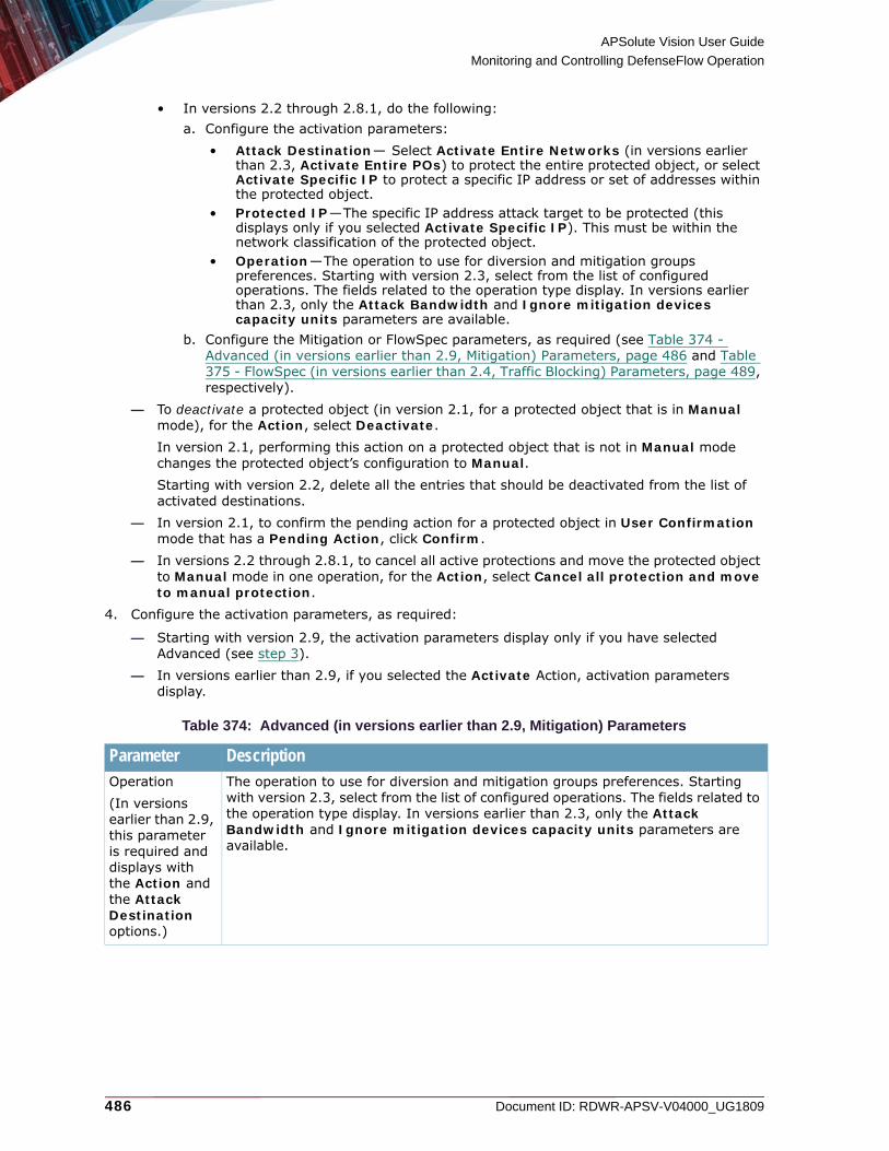
APSolute Vision User Guide
Monitoring and Controlling DefenseFlow Operation
486 Document ID: RDWR-APSV-V04000_UG1809
• In versions 2.2 through 2.8.1, do the following:a. Configure the activation parameters:
• Attack Destination— Select Activate Entire Networks (in versions earlier than 2.3, Activate Entire POs) to protect the entire protected object, or select Activate Specific IP to protect a specific IP address or set of addresses within the protected object.
• Protected IP—The specific IP address attack target to be protected (this displays only if you selected Activate Specific IP). This must be within the network classification of the protected object.
• Operation—The operation to use for diversion and mitigation groups preferences. Starting with version 2.3, select from the list of configured operations. The fields related to the operation type display. In versions earlier than 2.3, only the Attack Bandwidth and Ignore mitigation devices capacity units parameters are available.
b. Configure the Mitigation or FlowSpec parameters, as required (see Table 374 - Advanced (in versions earlier than 2.9, Mitigation) Parameters, page 486 and Table 375 - FlowSpec (in versions earlier than 2.4, Traffic Blocking) Parameters, page 489, respectively).
— To deactivate a protected object (in version 2.1, for a protected object that is in Manual mode), for the Action, select Deactivate.In version 2.1, performing this action on a protected object that is not in Manual mode changes the protected object’s configuration to Manual.Starting with version 2.2, delete all the entries that should be deactivated from the list of activated destinations.
— In version 2.1, to confirm the pending action for a protected object in User Confirmation mode that has a Pending Action, click Confirm.
— In versions 2.2 through 2.8.1, to cancel all active protections and move the protected object to Manual mode in one operation, for the Action, select Cancel all protection and move to manual protection.
4. Configure the activation parameters, as required:
— Starting with version 2.9, the activation parameters display only if you have selected Advanced (see step 3).
— In versions earlier than 2.9, if you selected the Activate Action, activation parameters display.
Table 374: Advanced (in versions earlier than 2.9, Mitigation) Parameters
Parameter DescriptionOperation(In versions earlier than 2.9, this parameter is required and displays with the Action and the Attack Destination options.)
The operation to use for diversion and mitigation groups preferences. Starting with version 2.3, select from the list of configured operations. The fields related to the operation type display. In versions earlier than 2.3, only the Attack Bandwidth and Ignore mitigation devices capacity units parameters are available.

APSolute Vision User Guide
Monitoring and Controlling DefenseFlow Operation
Document ID: RDWR-APSV-V04000_UG1809 487
Attack Source IP
This displays only if you selected a Mitigation operation. This is the specific IP address attack target to be protected. This must be within the network classification of the protected object.The operation to use for diversion and mitigation groups preferences. Starting with version 2.3, select from the list of configured operations. The fields related to the operation type display. In versions earlier than 2.3, only the Attack Bandwidth and Ignore mitigation devices capacity units parameters are available.
Attack Bandwidth
In versions earlier than 2.3, the peak attack level to use as a basis for configuring the DefensePro device if the information is missing from the detection signals. Starting with version 2.3, specify the attack bandwidth (bits per second) (this displays only if you selected a Mitigation operation). You can also specify units (for example, 100M). This is used for verifying that the mitigation devices can handle the related attack bandwidth. This is also used to set the DefensePro policy bandwidth if there is not any BDoS bandwidth ready yet.
Use busy mitigation devices(In versions earlier than 2.3, Ignore mitigation devices capacity units)
This displays only if you selected a Mitigation operation. If selected, DefenseFlow uses the selected DefensePro devices regardless of their monitored capacity.
BGP Communities
Operation BGP Community(In versions earlier than 2.4, BGP Community.)
The BGP community values to be sent to the diversion groups that should receive them per the operation. Multiple communities can be configured separated by a space. In addition, well-known communities can be also defined, including: NO_EXPORT, NO_ADVERTISE, NO_EXPORT_SUBCONFED, NOPEER
Use Protected Object Community(In versions earlier than 2.4, Use Community, and displays above the BGP Community parameter.)
Whether to add the protected object’s defined community in the announcement to the blocking group.When you select this parameter, the Protected Object Community parameter displays.
Table 374: Advanced (in versions earlier than 2.9, Mitigation) Parameters (cont.)
Parameter Description

APSolute Vision User Guide
Monitoring and Controlling DefenseFlow Operation
488 Document ID: RDWR-APSV-V04000_UG1809
— If the operation you selected is a FlowSpec (in versions earlier than 2.4, Traffic Blocking) operation, the FlowSpec parameters display (for more information on defining FlowSpec operations, and starting with version 2.4, for mitigation with BGP FlowSpec rules, see the DefenseFlow Installation and User Guide):
Protected Object BGP Community(This parameter is only available starting with version 2.4)(This parameter displays only when the Use Protected Object Community parameter is selected.)
The protected object’s BGP community values to be sent to the diversion groups that should receive them per the operation. Multiple communities can be configured separated by a space. In addition, well-known communities can be also defined, including: NO_EXPORT, NO_ADVERTISE, NO_EXPORT_SUBCONFED, NOPEER
Advanced (In version 2.9, this section is no longer referred to as Advanced.)Starting with version 2.7, the following parameters let you advertise BGP announcements following a predefined operation prefix size. This is useful for an advertisement over the WAN or any other network where the router restricts the advertisement for certain classes.For example, if DefenseFlow receives an attack alert for IP address 204.1.1.3/32 and the network allows only an advertisement of /24 or lower, you can set the DefenseFlow prefix size to 24.
Minimum IPv4 Advertised Subnet
Minimum IPv4 advertised BGP announcement subnet.Default: 32
Minimum IPv6 Advertised Subnet
Minimum IPv6 advertised BGP announcement subnet.Default: 128
Override IPv4 Next Hop(This field is only available starting with version 2.10)
Override the IPv4 Next Hop IP address.
Override IPv6 Next Hop(This field is only available starting with version 2.10)
Override the IPv6 Next Hop IP address.
Mitigation Route Name(This field is only available starting with version 2.10)
The route name for this mitigation. Select one of the routes that you defined for mitigation devices. For more information on configuring routes, see the DefenseFlow Installation and User Guide.
Table 374: Advanced (in versions earlier than 2.9, Mitigation) Parameters (cont.)
Parameter Description

APSolute Vision User Guide
Monitoring and Controlling DefenseFlow Operation
Document ID: RDWR-APSV-V04000_UG1809 489
Table 375: FlowSpec (in versions earlier than 2.4, Traffic Blocking) Parameters
Parameter DescriptionFlow Rules(Starting in version 2.4, the FlowSpec rules display only if you have selected a BGP FlowSpec operation to activate the protected object).
Destination Prefix
The destination prefix to block as defined in the Flow rule.Values:• Attacked IP—The actual destination IP addresses are inherited from the
protected object’s networks or IP addresses under attack or manually activated.
• Entire Networks—The actual destination IP addresses are inherited from the protected object that uses this rule for its various operations or manual actions.
• Specific prefix—The Prefix to Block field displays, letting you define a set of IP prefixes for the destination prefix.
Default: Attacked IP
Prefix to Block(This field is only available starting with version 2.4)(This field displays only if you have selected Specific prefix as the Destination Prefix.)
Defines one or more IP destination prefixes, each IP prefix separated by a space.Values: IP addressMaximum number of networks: 100
Source Prefix The source prefix to block as defined in the Flow rule.
Port The port to block as defined in the Flow rule.
Destination Port The destination port to block as defined in the Flow rule.
Protocol The protocol to block as defined in the Flow rule.
Source Port The source port to block as defined in the Flow rule.
ICMP Type The ICMP type to block as defined in the Flow rule.
ICMP Code The ICMP code to block as defined in the Flow rule.
TCP Flag The TCP flag to block as defined in the Flow rule.
Packet Length The packet length to block as defined in the Flow rule.
DSCP The DSCP to block as defined in the Flow rule.
Fragment The fragment to block as defined in the Flow rule.
Redirect to VRF(This parameter is only available starting with version 2.4)
The route tag (VPN in versions earlier than 2.8.1) to which to redirect traffic. Select from a list of route tags (VPNs in versions earlier than 2.8.1) for which you have defined a route target. For more information, see the DefenseFlow Installation and User Guide.
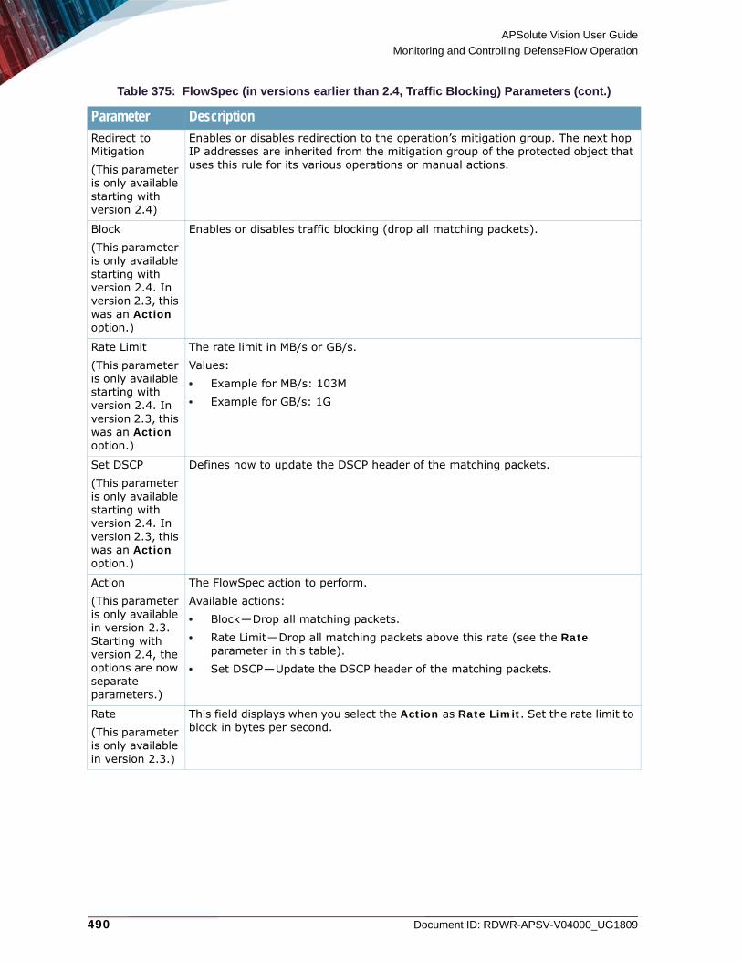
APSolute Vision User Guide
Monitoring and Controlling DefenseFlow Operation
490 Document ID: RDWR-APSV-V04000_UG1809
Redirect to Mitigation(This parameter is only available starting with version 2.4)
Enables or disables redirection to the operation’s mitigation group. The next hop IP addresses are inherited from the mitigation group of the protected object that uses this rule for its various operations or manual actions.
Block(This parameter is only available starting with version 2.4. In version 2.3, this was an Action option.)
Enables or disables traffic blocking (drop all matching packets).
Rate Limit(This parameter is only available starting with version 2.4. In version 2.3, this was an Action option.)
The rate limit in MB/s or GB/s.Values:• Example for MB/s: 103M• Example for GB/s: 1G
Set DSCP(This parameter is only available starting with version 2.4. In version 2.3, this was an Action option.)
Defines how to update the DSCP header of the matching packets.
Action(This parameter is only available in version 2.3. Starting with version 2.4, the options are now separate parameters.)
The FlowSpec action to perform.Available actions:• Block—Drop all matching packets.• Rate Limit—Drop all matching packets above this rate (see the Rate
parameter in this table).• Set DSCP—Update the DSCP header of the matching packets.
Rate(This parameter is only available in version 2.3.)
This field displays when you select the Action as Rate Limit. Set the rate limit to block in bytes per second.
Table 375: FlowSpec (in versions earlier than 2.4, Traffic Blocking) Parameters (cont.)
Parameter Description

APSolute Vision User Guide
Monitoring and Controlling DefenseFlow Operation
Document ID: RDWR-APSV-V04000_UG1809 491
5. In version 2.1, a confirmation message displays; click Yes to perform the action. In version 2.2, click Submit.
Ongoing ProtectionsThis feature is only available starting with version 2.2.The Ongoing Protections pane lets you monitor the status of currently active protections.
To monitor ongoing protections
1. In the Monitoring perspective, select Operation > Ongoing Protections.2. Select the ongoing protection to edit and by typing a string in one of the ongoing protection
search fields and clicking the (Search) button.
Use busy mitigation devices(In versions earlier than 2.3, Ignore mitigation devices capacity units.)
If checked, DefenseFlow uses the selected DefensePro devices regardless of their monitored capacity.
Table 376: Ongoing Protections View/Search Parameters
Parameter DescriptionNote: In version 2.8.1, the placement of many of the parameters was shifted. This table reflects the order of the parameters in version 2.8.1.
ID(This parameter is only available in version 2.8.1)
The ID of the protected object.
Protected Object(In versions earlier than 2.4.1, this parameter is named Name. From version 2.4.1 through version 2.7, this parameter is named PO Name.)
The name of the protected object.Starting with version 2.7, to view and/or edit a protected object associated with an ongoing protection, select the link in the Name column, and the Edit Protected Object pane for that protected object displays. For more information on protected objects, see the DefenseFlow Installation and User Guide.
Note: If the protected object is under protection, and you modify an attribute that conflicts with the ongoing protection, the change is performed only at the next activation of the protected object.Starting with version 2.8.1, if you want a modification that affects an ongoing protection to take effect immediately, you can make this modification from Operation > Ongoing Protections > Edit Protection. For more information, see To edit ongoing protections, page 495.
Table 375: FlowSpec (in versions earlier than 2.4, Traffic Blocking) Parameters (cont.)
Parameter Description

APSolute Vision User Guide
Monitoring and Controlling DefenseFlow Operation
492 Document ID: RDWR-APSV-V04000_UG1809
IP Address(This parameter does not display in version 2.8.1)In versions earlier than 2.7, PO Name and IP Address are in the same column, In versions earlier than 2.3, the IP Address parameter displays after the Origin parameter.)
The Destination IP address that was activated.
Networks(This parameter is only available starting with version 2.8.1. In version 2.8.1, it was named Network.)
The destination networks that were activated.
Operation(In versions earlier than 2.3, this is named the Strategy parameter)
The operation used for the protection.Starting with version 2.7, to view and/or edit an operation associated with an ongoing protection, select the link in the Operation column, and the Edit Operation pane for that operation displays. For more information on operations, see the DefenseFlow Installation and User Guide.
Note: If the protected object is under protection, and you modify an attribute that conflicts with the ongoing protection, the change is performed only at the next activation of the protected object.Starting with version 2.8.1, if you want a modification that affects an ongoing protection to take effect immediately, you can make this modification from Operation > Ongoing Protections > Edit Protection. For more information, see To edit ongoing protections, page 495.
Policy Name(This parameter is only available starting with version 2.4.1)
The policy name for this protection activation.
Table 376: Ongoing Protections View/Search Parameters (cont.)
Parameter Description

APSolute Vision User Guide
Monitoring and Controlling DefenseFlow Operation
Document ID: RDWR-APSV-V04000_UG1809 493
Activated Black List(This parameter is only available from version 2.7 through 2.8.1. In version 2.7 it is named Black List.)
Black list associated with the protection activation.
Activated White List(This parameter is only available from version 2.7 through 2.8.1. In version 2.7 it is named White List.)
White list associated with the protection activation.
Origin Origin of the detection for this protection activation.
Workflow(This parameter is only available starting with version 2.7)
The configured workflow for the protection activation.
Criteria(This parameter is only available starting with version 2.7)
The configured criteria for the protection activation.
Mitigation Devices, Instance(In versions earlier than 2.6 and starting with version 2.4.1, this is named the Mitigation Device parameter. In versions earlier than 2.4.1, this is named the Mitigation Device/Mitigation Group parameter)
The list of mitigation devices that are currently performing mitigation for this protection, and (starting with version 2.9) the DefensePro 7.x instance.
Table 376: Ongoing Protections View/Search Parameters (cont.)
Parameter Description

APSolute Vision User Guide
Monitoring and Controlling DefenseFlow Operation
494 Document ID: RDWR-APSV-V04000_UG1809
Mitigation Status(This parameter is only available starting with version 2.4.1)
The mitigation status for this protection.A BGP announcement is not sent if the mitigation status is not SUCCESS.Values: RUNNING, SUCCESS, FAILED
Signature Source IP Addresses(This parameter is only available starting with version 2.8.1)
The protected object’s signature source IP addresses.
Network Elements(In versions 2.3 and 2.4, this is named the Diversion Blocking/Network Elements parameter. In versions earlier than 2.3, this is named the Diversion Group parameter)
The network elements for the protection.In versions 2.3 and 2.4, the diversion and blocking network elements for the protection. In versions earlier than 2.3, the diversion group for this protection.
Attack ID Attack ID as received from the detection origin.
Start Time The time that the protection has started.
Configured Type(This parameter does not display in version 2.8.1)(In versions earlier than 2.3, this is named the Configured Action parameter)
The configured operation type (in versions earlier than 2.3, the action) for the protected object.
External Attack URI(This parameter is only available starting with version 2.7)
Link to the third-party detector management system that handles the external attack associated with the ongoing protection.
Table 376: Ongoing Protections View/Search Parameters (cont.)
Parameter Description

APSolute Vision User Guide
Monitoring and Controlling DefenseFlow Operation
Document ID: RDWR-APSV-V04000_UG1809 495
To clear the filter and perform a new search, click Clear next to the (Search) button.
To edit ongoing protections
This feature is only available starting with version 2.8.1.
1. In the Monitoring perspective, select Operation > Ongoing Protections.
2. Select the ongoing protection to edit and click the (Edit) button.
External PO URI(This parameter is only available starting with version 2.7)
Link to the third-party detector management system that handles the external protected object associated with the ongoing protection.
Table 377: Ongoing Protections Edit Parameters
Parameter DescriptionID (read-only) The ID of the protected object.
Protected Object
(read-only) The name of the protected object.
Operation (read-only) The operation used for the protection.
Networks Tab(This tab is only available starting with version 2.9)
The networks to be activated in the mitigation group (scrubbing center DefensePro devices):• Protected Networks Policy—The networks that are diverted to the scrubbing
center (mitigation group).You can resize the text box as required by dragging the icon at the bottom right-hand corner of the scroll bar.
• Diverted Networks (read-only)—The diversion networks for this ongoing protection.
• Clean Traffic Injection Networks (read-only)—The injection networks from the scrubbing center going to the protected object.
Policy Tab The policy text for this protection activation.You can resize the text box as required by dragging the icon at the bottom right-hand corner of the scroll bar.
Filters Tab Filter lists associated with this ongoing protection:• Blacklist—Select a black list to associate with the protection activation.• Whitelist—Select a white list to associate with the protection activation.
Table 376: Ongoing Protections View/Search Parameters (cont.)
Parameter Description

APSolute Vision User Guide
Monitoring and Controlling DefenseFlow Operation
496 Document ID: RDWR-APSV-V04000_UG1809
To terminate an ongoing protection
1. In the Monitoring perspective, select Operation > Ongoing Protections.
2. To terminate an ongoing protection, click the (Edit) button.
The following parameters display:— Operation (starting with version 2.7; read-only)—The operation used by the ongoing
protection.— Workflow (starting with version 2.7; read-only)—Workflow associated with the ongoing
protection.3. At the prompt Do you want to terminate the activation?, click Yes to terminate the ongoing
protection, or No not to terminate the ongoing protection.
4. Click Submit.
BGPThis feature is only available starting with version 2.2.The BGP pane lets you monitor the status of BGP peers and announcements, including:• Peers, page 496• Announcements, page 498• FlowSpecs, page 499
PeersThe Peers pane lets you monitor the status of BGP peers.
To monitor the status of BGP peers
1. In the Monitoring perspective, select Operation > BGP > Peers.2. Highlight the BGP peer or search for the BGP peer by typing a string in one of the BGP peer
search fields and clicking the (Search) button:
Advanced Filters Tab
Black list and white list IP addresses associated with this ongoing protection:• Blacklist Addresses—Add, delete, modify individual IP addresses in the
associated black list.• Auto-generated Blacklist Addresses—These addresses are automatically
generated upon detection of an attacker’s source address.• Whitelist Addresses—Add, delete, modify individual IP addresses in the
associated white list.You can resize the text boxes as required by dragging the icon at the bottom right-hand corner of the text box scroll bar.Maximum number of characters: 50,000,000
Table 377: Ongoing Protections Edit Parameters (cont.)
Parameter Description
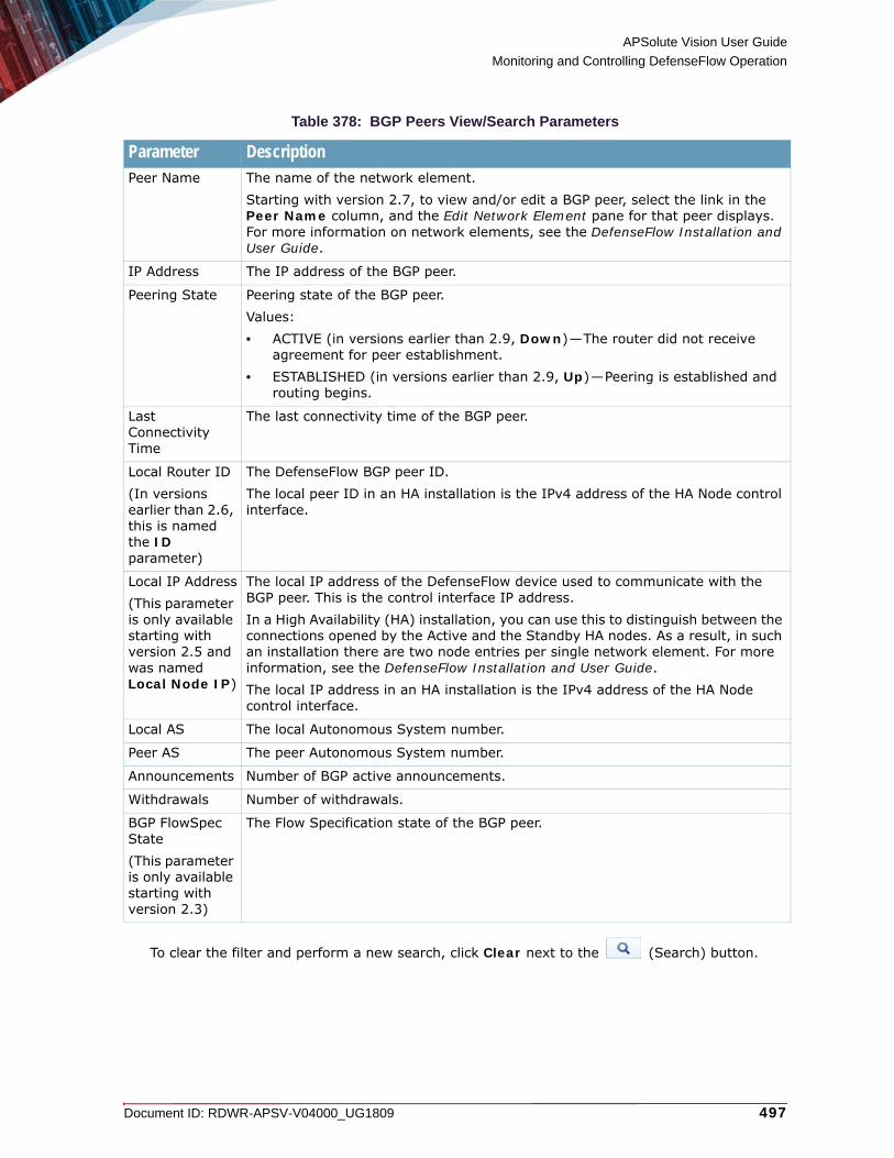
APSolute Vision User Guide
Monitoring and Controlling DefenseFlow Operation
Document ID: RDWR-APSV-V04000_UG1809 497
To clear the filter and perform a new search, click Clear next to the (Search) button.
Table 378: BGP Peers View/Search Parameters
Parameter DescriptionPeer Name The name of the network element.
Starting with version 2.7, to view and/or edit a BGP peer, select the link in the Peer Name column, and the Edit Network Element pane for that peer displays. For more information on network elements, see the DefenseFlow Installation and User Guide.
IP Address The IP address of the BGP peer.
Peering State Peering state of the BGP peer.Values:• ACTIVE (in versions earlier than 2.9, Down)—The router did not receive
agreement for peer establishment.• ESTABLISHED (in versions earlier than 2.9, Up)—Peering is established and
routing begins.
Last Connectivity Time
The last connectivity time of the BGP peer.
Local Router ID(In versions earlier than 2.6, this is named the ID parameter)
The DefenseFlow BGP peer ID.The local peer ID in an HA installation is the IPv4 address of the HA Node control interface.
Local IP Address(This parameter is only available starting with version 2.5 and was named Local Node IP)
The local IP address of the DefenseFlow device used to communicate with the BGP peer. This is the control interface IP address.In a High Availability (HA) installation, you can use this to distinguish between the connections opened by the Active and the Standby HA nodes. As a result, in such an installation there are two node entries per single network element. For more information, see the DefenseFlow Installation and User Guide.The local IP address in an HA installation is the IPv4 address of the HA Node control interface.
Local AS The local Autonomous System number.
Peer AS The peer Autonomous System number.
Announcements Number of BGP active announcements.
Withdrawals Number of withdrawals.
BGP FlowSpec State(This parameter is only available starting with version 2.3)
The Flow Specification state of the BGP peer.

APSolute Vision User Guide
Monitoring and Controlling DefenseFlow Operation
498 Document ID: RDWR-APSV-V04000_UG1809
AnnouncementsThe Announcements pane lets you monitor the status of currently active BGP announcements.
Note: In a High Availability (HA) installation, per announcement, there are two entries representing the two HA nodes.
To monitor the status of BGP announcements
1. In the Monitoring perspective, select Operation > BGP > Announcements.2. Highlight the BGP announcement or search for the BGP announcement by typing a string in one
of the BGP announcement search fields and clicking the (Search) button:
Table 379: BGP Announcements View/Search Parameters
Parameter DescriptionProtected Object
The name of the protected object for which that the announcement was sent.Starting with version 2.7, to view and/or edit a protected object associated with a BGP announcement, select the link in the Name column, and the Edit Protected Object pane for that protected object displays. For more information on protected objects, see the DefenseFlow Installation and User Guide.
Note: If the protected object is under protection, and you modify an attribute that conflicts with the ongoing protection, the change is performed only at the next activation of the protected object.Starting with version 2.8.1, if you want a modification that affects an ongoing protection to take effect immediately, you can make this modification from Operation > Ongoing Protections > Edit Protection. For more information, see To edit ongoing protections, page 495.
Operation(This parameter is only available starting with version 2.6)
The operation of the protected object for which that the announcement was sent.Starting with version 2.7, to view and/or edit an operation associated with a BGP announcement, select the link in the Operation column, and the Edit Operation pane for that operation displays. For more information on operations, see the DefenseFlow Installation and User Guide.
Note: If the protected object is under protection, and you modify an attribute that conflicts with the ongoing protection, the change is performed only at the next activation of the protected object.Starting with version 2.8.1, if you want a modification that affects an ongoing protection to take effect immediately, you can make this modification from Operation > Ongoing Protections > Edit Protection. For more information, see To edit ongoing protections, page 495.
Local IP Address(This parameter is only available starting with version 2.6)
The local IP address of the protected object for which that the announcement was sent.
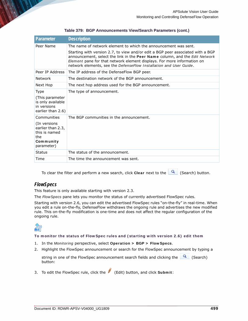
APSolute Vision User Guide
Monitoring and Controlling DefenseFlow Operation
Document ID: RDWR-APSV-V04000_UG1809 499
To clear the filter and perform a new search, click Clear next to the (Search) button.
FlowSpecsThis feature is only available starting with version 2.3.The FlowSpecs pane lets you monitor the status of currently advertised FlowSpec rules.Starting with version 2.6, you can edit the advertised FlowSpec rules “on-the-fly” in real-time. When you edit a rule on-the-fly, DefenseFlow withdraws the ongoing rule and advertises the new modified rule. This on-the-fly modification is one-time and does not affect the regular configuration of the ongoing rule.
To monitor the status of FlowSpec rules and (starting with version 2.6) edit them
1. In the Monitoring perspective, select Operation > BGP > FlowSpecs.2. Highlight the FlowSpec announcement or search for the FlowSpec announcement by typing a
string in one of the FlowSpec announcement search fields and clicking the (Search) button:
3. To edit the FlowSpec rule, click the (Edit) button, and click Submit:
Peer Name The name of network element to which the announcement was sent.Starting with version 2.7, to view and/or edit a BGP peer associated with a BGP announcement, select the link in the Peer Name column, and the Edit Network Element pane for that network element displays. For more information on network elements, see the DefenseFlow Installation and User Guide.
Peer IP Address The IP address of the DefenseFlow BGP peer.
Network The destination network of the BGP announcement.
Next Hop The next hop address used for the BGP announcement.
Type(This parameter is only available in versions earlier than 2.6)
The type of announcement.
Communities(In versions earlier than 2.3, this is named the Community parameter)
The BGP communities in the announcement.
Status The status of the announcement.
Time The time the announcement was sent.
Table 379: BGP Announcements View/Search Parameters (cont.)
Parameter Description

APSolute Vision User Guide
Monitoring and Controlling DefenseFlow Operation
500 Document ID: RDWR-APSV-V04000_UG1809
Table 380: FlowSpec View/Search and Edit Parameters
Parameter DescriptionID(This parameter is only available starting with version 2.6)
(Starting with version 2.6, in the Edit pane, read-only) The ID to block as defined in the FlowSpec rule.
Protected Object(This parameter is only available starting with version 2.6)
(Starting with version 2.6, in the Edit pane, read-only) The protected object to block as defined in the FlowSpec rule.Starting with version 2.7, to view and/or edit a protected object associated with a FlowSpec rule, select the link in the Name column, and the Edit Protected Object pane for that protected object displays. For more information on protected objects, see the DefenseFlow Installation and User Guide.
Note: If the protected object is under protection, and you modify an attribute that conflicts with the ongoing protection, the change is performed only at the next activation of the protected object.Starting with version 2.8.1, if you want a modification that affects an ongoing protection to take effect immediately, you can make this modification from Operation > Ongoing Protections > Edit Protection. For more information, see To edit ongoing protections, page 495.
Operation(This parameter is only available starting with version 2.6)
(Starting with version 2.6, in the Edit pane, read-only) The operation to block as defined in the FlowSpec rule.Starting with version 2.7, to view and/or edit an operation associated with a FlowSpec rule, select the link in the Operation column, and the Edit Operation pane for that operation displays. For more information on operations, see the DefenseFlow Installation and User Guide.
Note: If the protected object is under protection, and you modify an attribute that conflicts with the ongoing protection, the change is performed only at the next activation of the protected object.Starting with version 2.8.1, if you want a modification that affects an ongoing protection to take effect immediately, you can make this modification from Operation > Ongoing Protections > Edit Protection. For more information, see To edit ongoing protections, page 495.
Activated Rule Name(This parameter is only available starting with version 2.6)
The activated rule name to block as defined in the FlowSpec rule.Starting with version 2.7, to view and/or edit a FlowSpec rule, select the link in the Activated Rule Name column, and the Edit GP FlowSpec pane for that rule displays. For more information on BGP FlowSpec rules, see the DefenseFlow Installation and User Guide.
Note: If the protected object is under protection, and you modify an attribute that conflicts with the ongoing protection, the change is performed only at the next activation of the protected object.Starting with version 2.8.1, if you want a modification that affects an ongoing protection to take effect immediately, you can make this modification from Operation > Ongoing Protections > Edit Protection. For more information, see To edit ongoing protections, page 495.

APSolute Vision User Guide
Monitoring and Controlling DefenseFlow Operation
Document ID: RDWR-APSV-V04000_UG1809 501
Peer IP Address(Starting with version 2.6, this parameter is not available in the in the Edit pane)
The IP address to block as defined in the FlowSpec rule.
Community(This parameter is only available starting with version 2.4)
(Starting with version 2.6, in the Edit pane, read-only) The community to block as defined in the FlowSpec rule.
Destination (Starting with version 2.6, in the Edit pane, read-only) The destination prefix to block as defined in the FlowSpec rule.
Source The source prefix to block as defined in the FlowSpec rule.
Port The port to block as defined in the FlowSpec rule.
Destination Port The destination port to block as defined in the FlowSpec rule.
Source Port The source port to block as defined in the FlowSpec rule.
Protocol The protocol to block as defined in the FlowSpec rule.
ICMP Type The ICMP type to block as defined in the FlowSpec rule.
ICMP Code The ICMP code to block as defined in the FlowSpec rule.
TCP Flag The TCP flag to block as defined in the FlowSpec rule.
Packet Length The packet length to block as defined in the FlowSpec rule.
DSCP The DSCP to block as defined in the FlowSpec rule.
Fragment The fragment to block as defined in the FlowSpec rule.
Route Tag Name(This parameter is only available starting with version 2.4. In versions 2.6 and 2.7, it is named VPN Name. Before version 2.6, it is named Redirect VPN.)
The name of the route tag (VPN prior to version 2.8.1) to which to redirect as defined in the FlowSpec rule.
Table 380: FlowSpec View/Search and Edit Parameters (cont.)
Parameter Description

APSolute Vision User Guide
Monitoring and Controlling DefenseFlow Operation
502 Document ID: RDWR-APSV-V04000_UG1809
Route Tag Route(This parameter is only available starting with version 2.6. In versions 2.6 and 2.7, it is named VPN Route.))(Starting with version 2.6, this parameter is not available in the in the Edit pane)
The route tag route (VPN prior to version 2.8.1) to which to redirect as defined in the FlowSpec rule.
Redirect Mitigation Enabled(This parameter is only available starting with version 2.4. Before version 2.6, it is named Redirect Mitigation.)
The mitigation redirection status (enabled or disabled) for the FlowSpec rule.
Redirect Mitigation NextHop(This parameter is only available starting with version 2.6)(Starting with version 2.6, this parameter is not available in the in the Edit pane)
The device to which to redirect for mitigation as defined in the FlowSpec rule.
Block(This parameter is only available starting with version 2.4)
The blocking status (enabled or disabled) for the FlowSpec rule.
Action(This parameter is only available in versions earlier than 2.3)
The FlowSpec action to perform as defined in the Flow rule.
Table 380: FlowSpec View/Search and Edit Parameters (cont.)
Parameter Description

APSolute Vision User Guide
Monitoring and Controlling DefenseFlow Operation
Document ID: RDWR-APSV-V04000_UG1809 503
SystemThe System pane lets you view system information and utilization statistics, including:• General Information, page 503• System Utilization, page 504• Background Processes, page 504• High Availability, page 504
General InformationThe General Information pane lets you view DefenseFlow general system information.
To view DefenseFlow general information
> In the Monitoring perspective, select System > General Information.
Rate Limit (bytes per second)(In versions earlier than 2.9, it is named Rate Limit)
The rate limit to block as defined in the Flow rule.
Set DSCP(This parameter is only available starting with version 2.4)
The update setting for DSCP header in the FlowSpec rule.
Table 381: General Information Parameters
Parameter DescriptionUptime Time since the last reboot of the system in the format hh:mm:ss (hours:
minutes, seconds).
Software Version
Currently installed DefenseFlow software version.
Build Currently installed DefenseFlow software build.
Table 380: FlowSpec View/Search and Edit Parameters (cont.)
Parameter Description

APSolute Vision User Guide
Monitoring and Controlling DefenseFlow Operation
504 Document ID: RDWR-APSV-V04000_UG1809
System UtilizationThe System Utilization pane lets you view the current DefenseFlow utilization statistics and set alert levels.
To view DefenseFlow general information and set alert levels
> In the Monitoring perspective, select System > System Utilization.
Background ProcessesThe Background Process pane lets you view the status of background processes running in DefenseFlow to determine if an unsynchronized task is completed or still running.
To view the status DefenseFlow background processes
1. In the Monitoring perspective, select System > Background Processes.2. Highlight the background process or search for the background process by typing a string in one
of the background process search fields and clicking the (Search) button:
To clear the filter and perform a new search, click Clear next to the (Search) button.
High AvailabilityThis feature is only available starting with version 2.5.The High Availability pane lets you monitor the status of High Availability nodes.
Table 382: System Utilization Parameters
Parameter DescriptionCPU Utilization Percent of CPU currently being utilized.
Alert Level Set the CPU utilization percentage when an alert is issued.
Memory Utilization
Memory Utilization
Memory percentage currently being utilized.
Free Amount of free memory in kilobytes.
Total Total memory in kilobytes
Alert Level Set the memory utilization percentage when an alert is issued.
Table 383: Background Processes Parameters
Parameter DescriptionDescription Description of the background process.
Status Status of the background process.
Update Time Date and time of the status update for the background process.
Error Message Error message related to the status update.
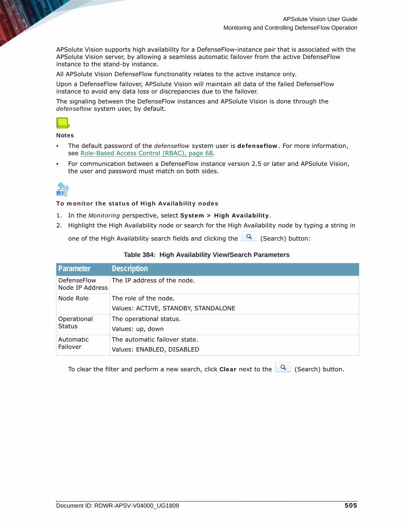
APSolute Vision User Guide
Monitoring and Controlling DefenseFlow Operation
Document ID: RDWR-APSV-V04000_UG1809 505
APSolute Vision supports high availability for a DefenseFlow-instance pair that is associated with the APSolute Vision server, by allowing a seamless automatic failover from the active DefenseFlow instance to the stand-by instance.All APSolute Vision DefenseFlow functionality relates to the active instance only.Upon a DefenseFlow failover, APSolute Vision will maintain all data of the failed DefenseFlow instance to avoid any data loss or discrepancies due to the failover.The signaling between the DefenseFlow instances and APSolute Vision is done through the defenseflow system user, by default.
Notes
• The default password of the defenseflow system user is defenseflow. For more information, see Role-Based Access Control (RBAC), page 68.
• For communication between a DefenseFlow instance version 2.5 or later and APSolute Vision, the user and password must match on both sides.
To monitor the status of High Availability nodes
1. In the Monitoring perspective, select System > High Availability.2. Highlight the High Availability node or search for the High Availability node by typing a string in
one of the High Availability search fields and clicking the (Search) button:
To clear the filter and perform a new search, click Clear next to the (Search) button.
Table 384: High Availability View/Search Parameters
Parameter DescriptionDefenseFlow Node IP Address
The IP address of the node.
Node Role The role of the node.Values: ACTIVE, STANDBY, STANDALONE
Operational Status
The operational status.Values: up, down
Automatic Failover
The automatic failover state.Values: ENABLED, DISABLED

APSolute Vision User Guide
Monitoring and Controlling DefenseFlow Operation
506 Document ID: RDWR-APSV-V04000_UG1809

Document ID: RDWR-APSV-V04000_UG1809 507
CHAPTER 22 – USING REAL-TIME SECURITY MONITORING
Use the Security Monitoring perspective to view and analyze real-time security information of managed devices, which include the following platform types:• Alteon with embedded AppWall module• AppWall standalone• DefenseFlow mitigation devices• DefensePro
The following main topics describe security monitoring in APSolute Vision:• Using Real-Time Security Monitoring with AppWall and Alteon, page 508• Using Real-Time Security Monitoring with DefensePro and DefenseFlow, page 520
Notes
• The contents of the Security Monitoring perspective are customized for the specific monitored device. The reporting information for DefensePro and DefenseFlow mitigation devices is different from the reporting information for AppWall and Alteon devices.
• When selecting multiple devices, the Security Monitoring perspective display reports that are relevant across devices, with the same reporting information. When selecting multiple devices including DefensePro and other device types (AppWall or Alteon), the Security Monitoring perspective shows reports only for the DefensePro devices.
• You can use APSolute Vision Analytics to view and analyze real-time and historical security information from DefensePro version-8.x devices. APSolute Vision Analytics includes dashboards for DefensePro security monitoring and analytics, customizable reports, and in-depth forensics capabilities. Full functionality of APSolute Vision Analytics requires a license. For more information, see the online help or the APSolute Vision Analytics User Guide.
• You can use APSolute Vision Reporter (AVR) to view and analyze historical security information. For information on the products and versions that APSolute Vision Reporter supports, see the APSolute Vision Release Notes. For information about APSolute Vision Reporter and how to use it, see its online help and the APSolute Vision Reporter User Guide.
• Using the APSolute Vision CLI, you can configure APSolute Vision to export security-event records from managed DefensePro and/or DefenseFlow devices to a specified syslog server. The event exporter lets you integrate with a Security Information Event Management (SIEM) system, which you may be using as your main analytics-and-reporting system. For more information, see System Exporter Commands (Event Exporter), page 632.

APSolute Vision User Guide
Using Real-Time Security Monitoring
508 Document ID: RDWR-APSV-V04000_UG1809
Using Real-Time Security Monitoring with AppWall and AlteonWhen an attack is detected, Alteon creates and reports a security event that includes the information relevant to the specific attack. The Security Monitoring perspective displays information relevant to the specific attack along with real-time network traffic and statistical parameters. Use the Security Monitoring perspective to observe and analyze the attacks that the device detected and the countermeasures that the device implemented.This section describes using real-time security monitoring with AppWall and Alteon.• Monitoring Security Events, page 508• Monitoring Attack Distribution, page 512• Monitoring Outbound SSL Inspection, page 513
Monitoring Security EventsUse the Dashboard View in the Security Monitoring perspective to analyze security events in the network, identify security trends, and analyze risks.You can view information for individual devices, all devices in a site, or all devices in the network. The dashboard monitoring display automatically refreshes providing ongoing real-time analysis of the system.
To view the security event list
1. In the Security Monitoring perspective, select Dashboard View > Security Events.2. Click on a line to expand the security event to show all the parameter values for the selected
event.
3. If you want to set which parameters are shown in the Security Events table (eight parameters are show as default, as listed it the Security Events Parameters (Default) table below), click the
Columns icon, , and select or clear any parameter to be shown or removed from the Security Events table. (All the non-default Security Events parameters are listed in the Create Filter: Basic or Advanced Parameters table below.)
4. If you want to define a filter to display the security events in the table according to selected
parameter values, click the Create Filter icon, , and enter the required parameters (listed in the Create Filter: Basic or Advanced Parameters table below), and click Submit.
5. Click the Enable Auto-Refresh icon, , to enable auto-refresh of the Security Events table.
Table 385: Security Events Parameters (Default)
Parameter DescriptionSeverity The severity of the security event.
Values: • Critical• High• Low• Info• Warning

APSolute Vision User Guide
Using Real-Time Security Monitoring
Document ID: RDWR-APSV-V04000_UG1809 509
Time The date and time that the security event occurred.
Source IP The source IP address of the security event.
Source Port The source port number of the security event.
Action The action taken regarding the security event.Values: • Blocked• Modified• Reported
Device IP The device IP address of the security event.
Server Name The server name of the security event.
Transaction ID The transaction ID number of the security event.
Table 386: Security Events: Create Filter: Display Period Parameters
Parameter DescriptionDisplay Last Select Display Last to filter the Security Event table to only list
the events that occurred during the last specified amount of time.Values:• 10 Minutes• 20 Minutes• 30 Minutes• 1 Hour• 2 Hours• 6 Hours• 12 Hours• 24 HoursDefault: 10 Minutes
Date and Time Range Select Date and Time Range to filter the Security Event table to only list the events that occurred during the specified date and time range.
Note: The default time is 12:00:00 on each date selected. The time can be changed manually within the field.
Table 387: Security Events: Create Filter: Basic Parameters
Parameter DescriptionTime The time that the security event occurred, in HH:mm:ss format.
Table 385: Security Events Parameters (Default) (cont.)
Parameter Description

APSolute Vision User Guide
Using Real-Time Security Monitoring
510 Document ID: RDWR-APSV-V04000_UG1809
Severity The severity of the security event.Values (Equals or Not Equals):• Critical• High• Low• Info• Warning
Web Application The Web application of the security event.Values: Contains or Not Contains the entered value
External IP The external IP address of the security event.Values: Contains or Not Contains the entered value
Action The action taken regarding the security event.Values (Equals or Not Equals): • Blocked• Modified• Reported
Violation Type The violation type of the security event.Values: Equals or Not Equals the violation type from the drop-down list
Source IP The source IP address of the security event. Values: Contains or Not Contains the entered value
Table 388: Security Events: Create Filter: Advanced Parameters
Parameter DescriptionUser The user of the security event.
Values: Contains or Not Contains the entered value
AppWall Version The AppWall version of the security event. Values: Contains or Not Contains the entered value
Target Module The target module of the security event. Values: Contains or Not Contains the entered value
Host The host of the security event. Values: Contains or Not Contains the entered value
Tunnel The tunnel of the security event. Values: Contains or Not Contains the entered value
Tunnel Listen Port The tunnel listening port of the security event. Values: Contains or Not Contains the entered value
Table 387: Security Events: Create Filter: Basic Parameters (cont.)
Parameter Description

APSolute Vision User Guide
Using Real-Time Security Monitoring
Document ID: RDWR-APSV-V04000_UG1809 511
Device Type The device type of the security event. Values (Equals or Not Equals): • Stand-Alone Gateway• Stand-Alone Monitor• Cluster Manager• Cluster Gateway Node• Cluster Monitor Mode
vHost The virtual host of the security event. Values: Contains or Not Contains the entered value
Source Port The source port of the security event. Values: Contains or Not Contains the entered value
Destination Port The destination port of the security event. Values: Contains or Not Contains the entered value
Protocol The protocol of the security event. Values (Equals or Not Equals): • TCP• HTTP• HTTPS
Parameter Name The parameter name of the security event. Values: Contains or Not Contains the entered value
Transaction ID The transaction ID number of the security event. Values: Contains or Not Contains the entered value
Request The request of the security event. Values: Contains or Not Contains the entered value
Role The role of the security event. Values: Contains or Not Contains the entered value
Module The module of the security event. Values: Contains or Not Contains the entered value
Event Type The event type of the security event. Values: Contains or Not Contains the entered value
Directory The directory of the security event. Values: Contains or Not Contains the entered value
Tunnel Listen IP The tunnel listening IP address of the security event. Values: Contains or Not Contains the entered value
URI The URI of the security event. Values: Contains or Not Contains the entered value
Violation Category The violation category of the security event. Values: Equals or Not Equals the violation category from the drop-down list
Table 388: Security Events: Create Filter: Advanced Parameters (cont.)
Parameter Description

APSolute Vision User Guide
Using Real-Time Security Monitoring
512 Document ID: RDWR-APSV-V04000_UG1809
Monitoring Attack DistributionYou can monitor the attacks, listed by various distribution parameters. This section contains the following main topics:• Monitoring Top Attacks by Violation Type, page 512• Monitoring Top Attacks by Source IP Address, page 513
Monitoring Top Attacks by Violation TypeYou can monitor the top attacks, graphically presented by their violation type.
To view the top attacks by violation type
1. In the Security Monitoring perspective, select Dashboard View > Attack Distribution > Top Attacks by Violation Type.
2. In the Display Last option, you can filter the display to only show the events that occurred during the last specified amount of time: 10 minutes (default), 20 minutes, 30 minutes, or 1 hour.
appPath The application path of the security event. Values: Contains or Not Contains the entered value
Destination IP The destination IP address of the security event. Values: Contains or Not Contains the entered value
Refine CRC The refine CRC of the security event. Values: Contains or Not Contains the entered value
Method The method of the security event. Values (Equals or Not Equals): • GET• POST
Parameter Type The parameter type of the security event. Values: Contains or Not Contains the entered value
Rule ID The rule ID of the security event. Values: Contains or Not Contains the entered value
Title The title of the security event. Values: Contains or Not Contains the entered value
Table 388: Security Events: Create Filter: Advanced Parameters (cont.)
Parameter Description

APSolute Vision User Guide
Using Real-Time Security Monitoring
Document ID: RDWR-APSV-V04000_UG1809 513
Monitoring Top Attacks by Source IP AddressYou can monitor the top attacks, graphically presented by the source IP address of the attack.
To view the top attacks by source IP address
1. In the Security Monitoring perspective, select Dashboard View > Attack Distribution > Top Attacks by Source.
2. In the Display Last option, you can filter the display to only show the events that occurred during the last specified amount of time: 10 minutes (default), 20 minutes, 30 minutes, or 1 hour.
Monitoring Outbound SSL InspectionYou can monitor statistics of SSL Inspection from Alteon version 32.0 and later. The SSL Inspection node in the Security Monitoring perspective Dashboard View uses the APSolute Vision Analytics infrastructure.The SSL Inspection node displays a widget-based dashboard that can show outbound SSL-inspection data information for bypassed and inspected HTTP/S traffic. Using the APSolute Vision Analytics infrastructure, you can configure e-mail reports.The SSL inspection statistics are collected on the front-end and back-end filters participating in the solution, and sent to APSolute Vision Analytics upon request (at one-minute intervals). To collect statistics for sending to APSolute Vision Analytics, the filter must first be tagged according to its purpose, application, direction, and location.For information about configuring SSL inspection in Alteon, see Viewing the APSolute Vision Analytics Identifier, page 93 and Table 370 - Filter: Logging and Reporting Parameters in Alteon Version 32.0 and Later, page 377.For information about general e-mail settings for APSolute Vision Analytics, see Managing the Email Reporting Configuration for APSolute Vision Analytics, page 125.
Caution: To view the SSL Inspection statistics in the Security Monitoring perspective, the relevant services must be enabled on the APSolute Vision server, using the CLI. By default, the services are disabled. Users with the Administrator or the Vision Administrator role can use the APSolute Vision CLI. For more information, see System VRM Commands, page 654.
To enable the services for monitoring outbound SSL Inspection
> In the APSolute Vision CLI, run the following command:
system vrm ssl-inspection state enable
To view the SSL Inspection statistics
1. In the Sites and Devices panel, select the Alteon device(s) or logical group of Alteons that you
require, and click .
2. In the Security Monitoring perspective, select Dashboard View > SSL Inspection > Dashboard.
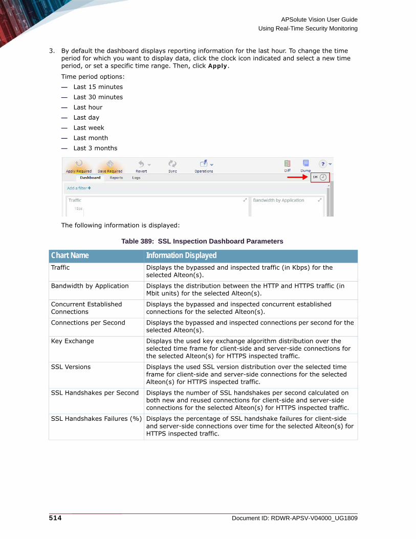
APSolute Vision User Guide
Using Real-Time Security Monitoring
514 Document ID: RDWR-APSV-V04000_UG1809
3. By default the dashboard displays reporting information for the last hour. To change the time period for which you want to display data, click the clock icon indicated and select a new time period, or set a specific time range. Then, click Apply.
Time period options:— Last 15 minutes— Last 30 minutes— Last hour— Last day— Last week— Last month— Last 3 months
The following information is displayed:
Table 389: SSL Inspection Dashboard Parameters
Chart Name Information DisplayedTraffic Displays the bypassed and inspected traffic (in Kbps) for the
selected Alteon(s).
Bandwidth by Application Displays the distribution between the HTTP and HTTPS traffic (in Mbit units) for the selected Alteon(s).
Concurrent Established Connections
Displays the bypassed and inspected concurrent established connections for the selected Alteon(s).
Connections per Second Displays the bypassed and inspected connections per second for the selected Alteon(s).
Key Exchange Displays the used key exchange algorithm distribution over the selected time frame for client-side and server-side connections for the selected Alteon(s) for HTTPS inspected traffic.
SSL Versions Displays the used SSL version distribution over the selected time frame for client-side and server-side connections for the selected Alteon(s) for HTTPS inspected traffic.
SSL Handshakes per Second Displays the number of SSL handshakes per second calculated on both new and reused connections for client-side and server-side connections for the selected Alteon(s) for HTTPS inspected traffic.
SSL Handshakes Failures (%) Displays the percentage of SSL handshake failures for client-side and server-side connections over time for the selected Alteon(s) for HTTPS inspected traffic.
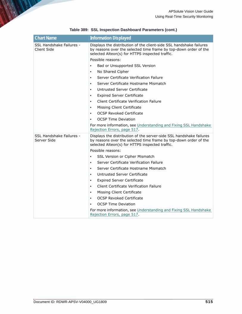
APSolute Vision User Guide
Using Real-Time Security Monitoring
Document ID: RDWR-APSV-V04000_UG1809 515
SSL Handshake Failures - Client Side
Displays the distribution of the client-side SSL handshake failures by reasons over the selected time frame by top-down order of the selected Alteon(s) for HTTPS inspected traffic.Possible reasons:• Bad or Unsupported SSL Version• No Shared Cipher• Server Certificate Verification Failure• Server Certificate Hostname Mismatch• Untrusted Server Certificate • Expired Server Certificate• Client Certificate Verification Failure• Missing Client Certificate• OCSP Revoked Certificate• OCSP Time DeviationFor more information, see Understanding and Fixing SSL Handshake Rejection Errors, page 517.
SSL Handshake Failures - Server Side
Displays the distribution of the server-side SSL handshake failures by reasons over the selected time frame by top-down order of the selected Alteon(s) for HTTPS inspected traffic.Possible reasons:• SSL Version or Cipher Mismatch• Server Certificate Verification Failure• Server Certificate Hostname Mismatch• Untrusted Server Certificate • Expired Server Certificate• Client Certificate Verification Failure• Missing Client Certificate• OCSP Revoked Certificate• OCSP Time DeviationFor more information, see Understanding and Fixing SSL Handshake Rejection Errors, page 517.
Table 389: SSL Inspection Dashboard Parameters (cont.)
Chart Name Information Displayed

APSolute Vision User Guide
Using Real-Time Security Monitoring
516 Document ID: RDWR-APSV-V04000_UG1809
Top Bypassed Categories Displays the bypassed domains/URLs sorted by URL categories.URL categorization is performed for all traffic that was bypassed by either URL filtering or content class classification.
Notes: • This chart requires a URL filtering license, and URL filtering
configuration on at least one of the filters.• Bypassed actions based on URL filtering are performed only on
the filters that are configured with a URL filtering policy.• A specific URL category may appear in both the Top Bypassed
Categories and Top Inspected Categories charts. For example:Office365 URLs can be marked for bypass based on content class configuration. These connections will be listed in the Top Bypassed Categories chart under the “Computer and Technology” category. All other domains/URLs that are not marked for bypass, but still categorized by Cyren under “Computer and Technology” will appear in the Top Inspected Categories chart.
Top Inspected Categories Displays the inspected domains/URLs sorted by URL categories.URL categorization is performed for all traffic that was inspected.
Notes: • This chart requires a URL filtering license, and URL filtering
configuration on at least one of the filters.• A specific URL category may appear in both the Top Bypassed
Categories and Top Inspected Categories charts. For example:Office365 URLs can be marked for bypass based on content class configuration. These connections will be listed in the Top Bypassed Categories chart under the “Computer and Technology” category. All other domains/URLs that are not marked for bypass, but still categorized by Cyren under “Computer and Technology” will appear in the Top Inspected Categories chart.
Dynamic Certificate Storage Displays dynamic certificate store usage over time. When multiple devices are selected, the maximum usage is displayed.Radware recommends that the table capacity does not exceed 80 percent.
CPU Utilization Displays the average SP CPU usage over time for the selected devices.
Memory Utilization Displays the average SP memory usage over time for the selected devices.
Table 389: SSL Inspection Dashboard Parameters (cont.)
Chart Name Information Displayed

APSolute Vision User Guide
Using Real-Time Security Monitoring
Document ID: RDWR-APSV-V04000_UG1809 517
Understanding and Fixing SSL Handshake Rejection ErrorsThis section describes the reasons for SSL handshake rejections and how to fix them, when possible.
Table 390: Rejected Handshake Reason Descriptions
# Alteon Error Message
Reason for Error/Flow
Solution Front-end/Back-end
1 Bad or unsupported SSL version
Client sends SSLv2 handshake.Client sends SSLv3/TLSv1.0/TLSv1.1/TLSv1.2 handshake while it is disabled in Alteon.Alteon sends SSLv3/TLSv1.0/TLSv1.1/TLSv1.2 handshake while it is not supported by the server.Server expects TLSv1.0/TLSv1.1/TLSv1.2 handshake while it is disabled in Alteon.The client version in the Client hello message is lower than the minimal version in the client hello.
• Verify client handshake version.• Verify the front-end and back-end
enabled versions in Alteon configuration using:
/cfg/slb/ssl/sslpol/frver
/cfg/slb/ssl/sslpol/backend/ver
• Verify server supported versions.
Note: This error message may also occur when Alteon sends a handshake with a cipher not supported by the server, since the server may be obscuring the real reason.
Both
2 No shared ciphers found
Client sends handshake with unsupported cipher in Alteon.
Verify that Alteon and client have at least one shared supported cipher in front-end policy using:
• /cfg/slb/ssl/sslpol/cipher
• /info/slb/ssl/ciphpol
Front-end connection
3 Server Certificate Verification Failure
Alteon as client is missing CA in the certificate chain.
Reconfigure intermediate/CA certificates in Alteon to match with server cert using:
/cfg/slb/ssl/authpol/trustca
Back-end connection
4 Server Certificate Hostname Mismatch
Alteon receives a certificate with hostname mismatch from the server.
Verify SNI sent by client and compare to CN of server certificate.Can ignore by using:
/cfg/slb/ssl/authpol/seract/mismatch
Back-end connection

APSolute Vision User Guide
Using Real-Time Security Monitoring
518 Document ID: RDWR-APSV-V04000_UG1809
Adding FiltersFor each chart, you can perform advanced filtering over the displayed data.
5 Untrusted Server Certificate
Alteon receives an untrusted certificate from the server.
• Add signer of server certificate to configuration of back-end authorization policy in Alteon using:
/cfg/slb/ssl/authpol/trustca
• Can ignore by using:
/cfg/slb/ssl/authpol/seract/untrust
Back-end connection
6 Expired Server Certificate
Alteon receives an expired certificate from the server.
• Renew server certificate.• Can ignore by using:
/cfg/slb/ssl/authpol/seract/expired
Back-end connection
7 Client Certificate Verification Failure
Alteon as server dynamically signs a certificate with a configured root CA which does not exist in the client.Alteon requests the client to send a certificate signed by a CA which is not supported by the client.
• Either—Update Radware as a CA on the client,
• Or—Configure on Alteon a trustCA known to the client by using
/cfg/slb/ssl/authpol/trustca
• Or—Disable the front-end authorization policy in Alteon by using:
/cfg/slb/ssl/authpol/
Front-end connection
8 Missing Client Certificate
The client authorization policy is configured on Alteon, but no certificate is returned by the client.
• Either—Install a certificate on the client, • Or—Disable the front-end authorization
policy in Alteon by using:
/cfg/slb/ssl/authpol/
Front-end connection
9 OCSP Revoked Certificate
OCSP failure due to revoked or unsupported algorithm.
• Use another server.• Can ignore by disabling OCSP using
/cfg/slb/ssl/authpol/validity/method none
Back-end connection
10 OCSP Time Deviation
Alteon sends OCSP a certificate with a future date.Alteon sends OCSP a certificate with an old date.
• Verify that the date and time are updated on Alteon and the server.
• Consider using NTP.
Back-end connection
Table 390: Rejected Handshake Reason Descriptions (cont.)
# Alteon Error Message
Reason for Error/Flow
Solution Front-end/Back-end

APSolute Vision User Guide
Using Real-Time Security Monitoring
Document ID: RDWR-APSV-V04000_UG1809 519
Configuring ReportsThis section describes how to configure the SSL Inspection monitoring module to send e-mail reports for selected managed devices. Reports are included in the e-mail as PDF files.
To configure APSolute Vision Analytics e-mail reports
1. In the Security Monitoring perspective, select Dashboard View > SSL Inspection > Report Settings.
2. Click .
3. Configure the following parameters, then click Save.
Viewing ReportsYou can view or download a list of the reports sent as follows:
To view a list of e-mail reports sent
1. In the Security Monitoring perspective, select Dashboard View > SSL Inspection > Reports.2. Click the clock icon indicated to set the time period for which you want to display reporting
information.
Options:— Last 15 minutes— Last 30 minutes— Last hour
Table 391: SSL Inspection Report Settings Parameters
Parameter DescriptionReport Title Specifies a name for the report.
Sender Specifies the name or e-mail address of the sender.
Recipients Specifies the recipients of the e-mail containing the report.
Subject Specifies the subject line of the e-mail containing the report.
Message Body (Optional) Specifies the body of the e-mail containing the report.
Report Period Specifies the period covered by the report.Options:• Last 1 Day• Last 1 Week• Last 1 Month• Last 3 Months• Last 6 Months• Last 1 YearDefault: Last 3 Months
Send Every Specifies the frequency, in hours, with which APSolute Vision Analytics sends the e-mail containing the report.

APSolute Vision User Guide
Using Real-Time Security Monitoring
520 Document ID: RDWR-APSV-V04000_UG1809
— Last day— Last week— Last month— Last 3 months
3. From the list of reports, select the report you require.
An image of the report displays on the right of the screen.You can print the report or download it as a PDF file.
Using Real-Time Security Monitoring with DefensePro and DefenseFlowThis section describes using real-time security monitoring with DefensePro and DefenseFlow.When an attack is detected, the DefensePro device or DefenseFlow mitigation device creates and reports a security event, which includes the information relevant to the specific attack.The Security Monitoring perspective displays information relevant to the specific attack along with real-time network traffic and statistical parameters. Use the Security Monitoring perspective to observe and analyze the attacks that the device detected and the countermeasures that the device implemented.The following main topics describe security monitoring in APSolute Vision:• Risk Levels, page 521• Using the Dashboard Views for Real-Time Security Monitoring, page 521• Viewing Real-Time Traffic Reports, page 549• Protection Monitoring, page 560• HTTP Reports, page 568
Notes
• Your user permissions (your RBAC user definition) determine the DefensePro devices and policies, or DefenseFlow protected objects, that the Security Monitoring perspective displays to you. You can view and monitor only the attacks blocked by the DefensePro devices and policies, or DefenseFlow mitigation devices and protected objects that are available to you.
• APSolute Vision also manages and issues alerts for new security attacks.
• DefensePro calculates traffic baselines, and uses the baselines to identify abnormalities in traffic levels.
• When calculating the real-time network traffic and statistical parameters, DefensePro or DefenseFlow version 2.1 do not include traffic that exceeded the throughput license.
APSolute Vision User Guide
Using Real-Time Security Monitoring
Document ID: RDWR-APSV-V04000_UG1809 521
• You can use APSolute Vision Analytics to view and analyze real-time and historical security information from DefensePro version-8.x devices. APSolute Vision Analytics includes dashboards for DefensePro security monitoring and analytics, customizable reports, and in-depth forensics capabilities. Full functionality of APSolute Vision Analytics requires a license. For more information, see the online help or the APSolute Vision Analytics User Guide.
• You can use the APSolute Vision REST API to view security events from DefenseFlow mitigation devices or DefensePro devices. For more information, see the APSolute Vision REST API documentation.
• You can use the APSolute Vision CLI to export security events from DefenseFlow mitigation devices or DefensePro devices. For more information, see System Exporter Commands (Event Exporter), page 632.
Risk LevelsThe following table describes the risk levels that DefensePro supports to classify security events.
Note: For some protections, the user can specify the risk level for an event. For these protections, the descriptions in the following table are recommendations, and specifying the risk level is the user’s responsibility.
Using the Dashboard Views for Real-Time Security MonitoringThis section is relevant to both DefensePro and DefenseFlow.This section includes the following topics:• Configuring the Display Parameters of a Dashboard View, page 522• Using the Current Attacks Table, page 524• Using the Ongoing Attacks Monitor, page 530• Attack Details, page 531• Sampled Data Tab, page 547• Viewing Real-Time Traffic Reports, page 549• Viewing the Traffic Utilization Report, page 549
Use a Dashboard View in the Security Monitoring perspective to analyze activity and security events in the network, identify security trends, and analyze risks.You can view information for individual devices, all devices in a Site, all devices in a Logical Group, or all devices in the network. The dashboard monitoring display automatically refreshes providing ongoing real-time analysis of the system.
Table 392: Risk Levels
Risk Level DescriptionInfo The risk does not pose a threat to normal service operation.
Low The risk does not pose a threat to normal service operation, but may be part of a preliminary action for malicious behavior.
Medium The risk may pose a threat to normal service operation, but is not likely to cause complete service outage, remote code execution, or unauthorized access.
High The risk is very likely to pose a threat to normal service availability, and may cause complete service outage, remote code execution, or unauthorized access.

APSolute Vision User Guide
Using Real-Time Security Monitoring
522 Document ID: RDWR-APSV-V04000_UG1809
The Dashboard View node comprises the following tabs, which display the same summary information:• Current Attacks Table—which is a table display (see Figure 59 - Current Attacks Table—
DefensePro, page 525).• Ongoing Attacks Monitor—which includes a graphical, chart display (see Figure 60 - Ongoing
Attacks Monitor, page 530).
The Scope and other display parameters that you configure apply to the Current Attacks Table and to the Ongoing Attacks Monitor. For more information, see Configuring the Display Parameters of a Dashboard View, page 522.When you double-click an attack in the Current Attacks Table or Ongoing Attacks Monitor, APSolute Vision displays the details in an Attack Details tab. There, you can display the Sampled Data dialog box for the all attack types that support sampled data.By default, the display of the Dashboard View refreshes every 15 seconds. Administrators can configure the refresh rate (APSolute Vision Settings view System perspective, General Settings > Monitoring > Polling Interval for Reports).
Configuring the Display Parameters of a Dashboard ViewThe following table describes the display parameters of the Dashboard View in the Security Monitoring perspective. The Scope and Display Last parameters that you configure in the Current Attacks Table applies to the Ongoing Attacks Monitor and vice versa.
Table 393: Security Monitor Dashboard View—Display Parameters
Parameter DescriptionScope The Scope depends on whether you are monitoring using DefensePro or
DefenseFlow. Using DefensePro, this parameter defines the physical ports and the Network Protection policies that the dashboard displays. Using DefenseFlow, this parameter defines the Protected Object, ports, and policies that the dashboard displays.Using DefensePro, by default, the Scope is Any Port; Any Policy. That is, by default, the dashboard displays all the information.Using DefenseFlow, by default, the Scope is Any Protected Object; Any Port; Any Policy. That is, by default, the dashboard displays all the information.To control the scope of the information that the dashboard displays in DefensePro, see the procedure To control the scope of the information that the Dashboard View displays for DefensePro, page 523.To control the scope of the information that the dashboard displays in DefenseFlow, see the procedure To control the scope of the information that the Dashboard View displays for DefenseFlow, page 524.

APSolute Vision User Guide
Using Real-Time Security Monitoring
Document ID: RDWR-APSV-V04000_UG1809 523
To control the scope of the information that the Dashboard View displays for DefensePro
1. Click . Two tables open. One table has the Device Name and Port columns, and the other table has the Device Name and Policy columns.
2. Do one of the following:
— To limit the physical ports or Network Protection policies that the dashboard displays, select the corresponding checkboxes.
— To display the information for all the currently relevant physical ports or Network Protection policies, click in the top-left table cell, and then, select Select All.
— To display all the information in the database, even information that is not associated with a specific port or specific Network Protection policy, click in the top-left table cell, and then, select Select None.
Display Last How long the dashboard displays attacks after the attack terminates. That is, the dashboard displays all attacks that are currently ongoing or that terminated within the selected period.Values:• 10 Minutes• 20 Minutes• 30 Minutes• 1 Hour• 2 Hours• 6 Hours• 12 Hours• 24 HoursDefault: 10 Minutes
Top Attacks to Display(This parameter is available only in the Ongoing Attacks Monitor.)
The number of attacks that the Ongoing Attacks Monitor displays.Values: 1–50Default: 20
Sort By(This parameter is available only in the Ongoing Attacks Monitor.)
Values:• Top Total Packet Count—The Ongoing Attacks Monitor displays the
attacks with the highest number of packets.• Top Volume—The Ongoing Attacks Monitor displays the attacks with
the highest volume. • Most Recent—The Ongoing Attacks Monitor displays the most recent
attacks. • Attack Risk—The Ongoing Attacks Monitor displays the attacks
according to attack risk. Default: Top Packet Count
Table 393: Security Monitor Dashboard View—Display Parameters (cont.)
Parameter Description

APSolute Vision User Guide
Using Real-Time Security Monitoring
524 Document ID: RDWR-APSV-V04000_UG1809
To control the scope of the information that the Dashboard View displays for DefenseFlow
1. Click . Three tables open. One table has the Protected Object, one table has the Device Name and Port columns, and the third table has the Device Name and Policy columns.
2. To toggle the sort order of the information in any of the columns, hover over the column heading until you see an arrow, and then, click the arrow.
Using the Current Attacks TableThe Current Attacks Table displays information on current and recent attacks. The configuration of the display parameters determine the information that the Current Attacks Table displays (see Configuring the Display Parameters of a Dashboard View, page 522).
Note: Once DefensePro reports a Packet Anomaly attack of a certain Radware ID, the Status value Occurred and the Start Time value remain indefinitely. For example, suppose a new DefensePro device starts identifying and handling a Packet Anomaly attack with Radware ID 105 with the start time 20.02.2017 15:19:09. The attack subsides. One month later, the DefensePro device starts identifying and handling another Packet Anomaly attack with Radware ID 105. The Start Time value 20.02.2017 15:19:09 is reported. (For more information on Packet Anomaly protection, see Configuring Global Packet Anomaly Protection, page 183.)
To display the Current Attacks Table
1. In the Security Monitoring perspective, select the DefensePro device, Site, or Logical Group for which to display data.
2. Select Dashboard View > Current Attacks Table.
You can do the following in the Current Attacks Table: • Filter the rows—You can filter table rows according to values in the table columns. For more
information on filtering table rows, see Filtering Table Rows, page 102.• Sort the rows—You can change the row order from ascending to descending or vice versa. To
do this, hover the mouse over the column to display the arrow and change the order.• View additional information for a specific attack—To do this, select the relevant row, and
click (View Attack Details). For more information, see Attack Details, page 531.
• Go to the policy that handled attack—To do this, click (Go to Policy).
• Export the information in the table to a CSV file—To do this, click (CSV). Then, you can view the file or specify the location and file name.
• Pause the refresh of the table display—To do this, click (Pause). When the table display is not paused, it refreshes approximately every 15 seconds.

APSolute Vision User Guide
Using Real-Time Security Monitoring
Document ID: RDWR-APSV-V04000_UG1809 525
Figure 59: Current Attacks Table—DefensePro
Table 394: Current Attacks Table Parameters
Parameter DescriptionSource Type(This parameter is available only in DefenseFlow.)
The source of the signal entry.Values:• DP—DefensePro• DF—DefenseFlow
Start Time The date and time that the attack started.1
The Scope summary.
Scope—Displays the tables to select the physical ports and Network Protection policies that the Dashboard View displays.
Function buttons:● View Attack Details● Go to Policy● Export Table to CSV● Pause
Arrow for sorting ascending or descending.

APSolute Vision User Guide
Using Real-Time Security Monitoring
526 Document ID: RDWR-APSV-V04000_UG1809
Attack Category The threat type to which this attack belongs.Values:• ACL (not in DefenseFlow)
• Anomalies1 (in DefenseFlow, detection was performed by an external detector)
• Anti-Scanning (not in DefenseFlow)• Bandwidth Management (not in DefenseFlow)• Behavioral DoS (in DefenseFlow, detection was performed by
DefenseFlow BDoS)• DNS Flood (not in DefenseFlow)• DoS (not in DefenseFlow)• HTTP Flood (not in DefenseFlow)• Intrusions (not in DefenseFlow)• Server Cracking (not in DefenseFlow)• Stateful ACL (not in DefenseFlow)• SYN Flood (not in DefenseFlow)• Traffic Filters
Status The last-reported status of the attack.Values:• Started—An attack containing more than one security event has been
detected. (Some attacks contain multiple security events, such as DoS, Scans, and so on.)
• Occurred (Signature-based attacks)—Each packet matched with signatures was reported as an attack and dropped.•
• Sampled (available only in DefenseFlow)—The last reading for each protocol and the totals for all protocols, for a single device. This information is only available when viewing a single device.
• Ongoing—The attack is currently taking place, that is, the time between Started and Terminated (for attacks that contain multiple security events, such as DoS, Scans, and so on).
• Terminated—There are no more packets matching the characteristics of the attack, and the device reports that the attack has ended.
Risk The predefined attack severity level (see Risk Levels, page 521).Values:
• —High
• —Medium
• —Low
• —Info
Attack Name The name of the detected attack.
Table 394: Current Attacks Table Parameters (cont.)
Parameter Description

APSolute Vision User Guide
Using Real-Time Security Monitoring
Document ID: RDWR-APSV-V04000_UG1809 527
Source Address The source IP address of the attack. If there are multiple IP sources for an attack, this field displays Multiple. The multiple IP addresses are displayed in the Attack Details window. Multiple may also refer to cases when DefensePro or DefenseFlow cannot report a specific value.The Search string can be any legal IPv4 or IPv6 address, and can include a wildcard (*).
Destination Address The destination IP address of the attack. If there are multiple IP sources for an attack, this field displays Multiple. The multiple IP addresses are displayed in the Attack Details window. Multiple may also refer to cases when DefensePro or DefenseFlow cannot report a specific value.
Policy In DefensePro, the name of the configured Network Protection policy or Server Protection policy that was violated by this attack.To view or edit the policy for a specific attack, select the attack entry and click the (Go to Policy) button.In DefenseFlow, the name of the configured Security Policy that was set to mitigate this attack. The default policy name is the name of the protected object. Policies in DefenseFlow cannot be edited.
Radware ID The DefensePro Attack-Protection identifier issued by the device. For more information, see DefensePro Attack-Protection IDs, page 751. For more information, see DefensePro Attack-Protection IDs, page 801.
Direction The direction of the attack, inbound or outbound. Values: in, out
Table 394: Current Attacks Table Parameters (cont.)
Parameter Description

APSolute Vision User Guide
Using Real-Time Security Monitoring
528 Document ID: RDWR-APSV-V04000_UG1809
Action Type(This parameter is available only in DefensePro.)
The reported action against the attack. The actions are specified in the protection profile, which may or may not be available or relevant for your system.Values:• Bypass—DefensePro does not protect against this attack, but rather,
sends its data out of the device, and may report it. • Challenge—DefensePro challenges the packet.• Destination Reset—DefensePro sends a TCP-Reset packet to the
destination IP address and port.• Drop—DefensePro discards the packet.• Drop & Quarantine—DefensePro discards the traffic and adds the
destination to the Web quarantine.• Forward—DefensePro continues to process the traffic and eventually
forwards the packet to its destination.• Proxy• Quarantine—DefensePro adds the destination to the Web quarantine.• Source Destination Reset—DefensePro sends a TCP-Reset packet to
both the packet source IP and the packet destination IP address.• Source Reset—DefensePro sends a TCP-Reset packet to the packet
source IP address.• Http 200 Ok—DefensePro sends a 200 OK response using a predefined
page and leaves the server-side connection open.• Http 200 Ok Reset Dest—DefensePro sends a 200 OK response using a
predefined page and sends a TCP-Reset packet to the server side to close the connection.
• Http 403 Forbidden—DefensePro sends a 403 Forbidden response using a predefined page and leaves the server-side connection open.
• Http 403 Forbidden Reset Dest—DefensePro sends a 403 Forbidden response using a predefined page and sends a TCP-Reset packet to the server side to close the connection.
Total Packet Count The number of identified attack packets from the beginning of the attack.
Volume For most protections, this value is the volume of the attack, in kilobits, from when the attack started.In DefensePro, for SYN protection (SYN cookies), this value is the number of SYN packets dropped, multiplied by 60 bytes (the SYN packet size).
Device IP(This parameter is available only in DefensePro.)
The IP address of the attacked device.
Protected Object(This parameter is available only in DefenseFlow.)
The name of the protected object that was attacked.
Table 394: Current Attacks Table Parameters (cont.)
Parameter Description

APSolute Vision User Guide
Using Real-Time Security Monitoring
Document ID: RDWR-APSV-V04000_UG1809 529
Application Protocol The transmission protocol used to send the attack:Values:• TCP• UDP• ICMP• IP
MPLS RD The Multi-protocol Label Switching Route Distinguisher in the policy that handled the attack. The value N/A or 0 (zero) in this field indicates that the MPLS RD is not available.
VLAN Tag / Context The VLAN tag value or Context Group in the policy that handled the attack. The value N/A or 0 (zero) in this field indicates that the VLAN tag or Context Group is not available.
Note: The VLAN tag or Context Group identifies similar information in this field. DefensePro 6.x and 7.x versions support VLAN tags. DefensePro 8.x versions support Context Groups.
Source Port2 The Layer 4 source port of the attack.
Destination Port The Layer 4 destination port of the attack. If there are multiple destination L4 ports, this field displays Multiple. In cases when DefensePro cannot report a specific value, the field displays 0 (zero).
Physical Port The port on the device at which the attack packets arrived. In cases when DefensePro cannot report a specific value, the field displays 0 (zero) or Multiple.
Source MSISDN The MSISDN Resolution feature is not supported in APSolute Vision version 3.0 and later.
Destination MSISDN The MSISDN Resolution feature is not supported in APSolute Vision version 3.0 and later.
1 – Once DefensePro reports a Packet Anomaly attack of a certain Radware ID, the Status value Occurred and the Start Time value remain indefinitely. For example, suppose a new DefensePro device starts identifying and handling a Packet Anomaly attack with Radware ID 105 with the start time 20.02.2017 15:19:09. The attack subsides. One month later, the DefensePro device starts identifying and handling another Packet Anomaly attack with Radware ID 105. The Start Time value 20.02.2017 15:19:09 is reported. (For more information on Packet Anomaly protection, see Configuring Global Packet Anomaly Protection, page 183.)
2 – This column is not displayed by default in the Current Attacks tab.
To display the column, click the (Table Settings) button and then select the relevant checkbox. Click the button again to close the Table Settings list.
Table 394: Current Attacks Table Parameters (cont.)
Parameter Description

APSolute Vision User Guide
Using Real-Time Security Monitoring
530 Document ID: RDWR-APSV-V04000_UG1809
Using the Ongoing Attacks MonitorThe Ongoing Attacks Monitor comprises two charts: the Ongoing Attacks Monitor and Drop Intensity gauges. The information that the charts display is according to the configuration of the display parameters (see Configuring the Display Parameters of a Dashboard View, page 522).
To display the Ongoing Attacks Monitor
1. In the Security Monitoring perspective, select the DefensePro device, Site, or Logical Group for which to display data.
2. Select Dashboard View > Ongoing Attacks Monitor.
The Ongoing Attacks Monitor is a graphical representation of current and recent attacks. Each icon in the monitor represents a separate attack. The icon type (see the legend) represents the type of protection that the attack violates. A flashing icon represents an ongoing attack. The horizontal position of each icon in the chart indicates the attack risk (see Risk Levels, page 521). The vertical position of the icon in the chart indicates the attack duration; the higher in the chart, the longer the attack has existed. Attacks that have started recently are lower in the monitor. The icon size indicates the amount of dropped data for the attack type relative to other attacks of the same type. Hover the mouse over an icon to display summary information for the attack. Double-click an icon to display detailed information for the attack. For more information, see Attack Details, page 531.There are two Drop Intensity gauges: Packets and Bandwidth. The Packets gauge indicates the proportion of dropped packets relative to the total packets. The Bandwidth gauge indicates the proportion of dropped bandwidth relative to the total bandwidth (according to the license). The gauges show the calculated ranges Low (up to 30% dropped), Medium (up to 70% dropped), and High (more than 70% dropped).
Figure 60: Ongoing Attacks Monitor
The Scope summary. Hover the mouse over an icon to display summary information for the attack.
Scope—Displays the tables to select the physical ports and Network Protection policies that the dashboard displays.

APSolute Vision User Guide
Using Real-Time Security Monitoring
Document ID: RDWR-APSV-V04000_UG1809 531
Attack DetailsAPSolute Vision displays an Attack Details tab when you double-click an attack in a Security Monitoring Dashboard View. APSolute Vision displays attack details for the following attacks:• ACL (Black List) Details, page 532• Anti-Scanning Details, page 532• Bandwidth Management Details, page 535• BDoS Attack Details, page 535• DNS Flood Attack Details, page 538• DoS Attack Details, page 540• HTTP Flood Attack Details, page 540• Intrusions Attack Details, page 543• Packet Anomalies Attack Details, page 543• Server Cracking Attack Details, page 544• Stateful ACL Details, page 545• SYN Flood Attack Details, page 545• Traffic Filters Attack Details, page 546
For DefenseFlow Attack Details, only the Attack Details tab displays.Each Attack Details tab includes two or more sub-tabs, which provide details on the attack. All Attack Details tabs include the sub-tabs Attack Characteristics and the Attack Description. The Attack Characteristics tab displays information that is also available in the hidden columns of the Current Attacks Table. The Attack Description tab displays the information from the Attack Descriptions file. An attack description is displayed only if the Attacks Description file has been uploaded on the APSolute Vision server.
Notes
• To display hidden columns of the Current Attacks Table, click the (Table Settings) button and then select the relevant checkbox. Click the button again to close the Table Settings list.
• For information about uploading the Attack Description file, see Managing and Updating the Attack Descriptions File for DefensePro, page 108.
In addition to viewing the details of the attack, in each Attack Details tab, you can do the following:
• View sampled data from the attack—To do this, click the (View Sampled Data) button. For more information, see Sampled Data Tab, page 547.
• Go to the policy that handled attack— To do this, click the (Go to Policy) button.• Export the information in the in the Attack Details tab to a CSV file—To do this, click
the (CSV) button. Then, you can view the file or specify the location and file name.• In DefensePro 8.x versions 8.13 and later, for DNS recursive attacks, view the list of
relevant whitelisted subdomains—To do this, click the (View Subdomains Whitelist) button.
• Export the capture files related to the selected attack to a ZIP file—To do this, click
the (Export Attack Capture Files) button, and enter a file name in the file selection dialog box.

APSolute Vision User Guide
Using Real-Time Security Monitoring
532 Document ID: RDWR-APSV-V04000_UG1809
Notes
— You can send the CAP file to a packet analyzer.— Up to 255 bytes of packet information is saved in the CAP file. That is, DefensePro and/or
DefenseFlow export full packets but APSolute Vision trims them to 255 bytes.— The file is available only as long as it is displayed in the Current Attacks table.— The file is created only if packet reporting is enabled in the protection configuration for the
profile that was violated.— DefensePro exports only the last packet in a sequence that matches the filter. Furthermore,
if traffic matches a signature that consists of more than one packet, the reported packet will not include the whole expression in the filter.
— For DoS attacks of very short duration, there might be no sampling or ongoing traps. Consequently, for such attacks, there might be no sampled data or capture files. (For more information, see DoS Attack Details, page 540.)
ACL (Black List) Details
Anti-Scanning DetailsThe set of Anti-Scanning Attack Details parameters and their location differs slightly depending on the DefensePro version.
Anti-Scanning Attack Details in DefensePro 8.x Versions
Table 395: ACL Attack Details: Characteristics Parameters
Parameter DescriptionProtocol The protocol that the attack uses or used.
Physical Port1
1 – This parameter is not resolved, and the value Multiple is always displayed.
The physical port that the attack uses or used.
Packet Count The packet count of the attack.
VLAN The VLAN that the attack uses or used.
MPLS RD The MPLS RD that the attack uses or used.
Device IP The device IP address that the attack uses or used.
Table 396: ACL Attack Details: Attack Description
Parameter DescriptionThe description of the attack from the Attack Descriptions file, if it is uploaded on the APSolute Vision server.
Table 397: Anti-Scanning Attack Details: Characteristics Parameters
Parameter DescriptionSource L4 Port The source L4 port that the attack uses or used.
Protocol The protocol that the attack uses or used.
Physical Port The physical port that the attack uses or used.
Total Packet Count The packet count that the attack uses or used.

APSolute Vision User Guide
Using Real-Time Security Monitoring
Document ID: RDWR-APSV-V04000_UG1809 533
VLAN Tag / Context The Context Group that the attack uses or used.
MPLS RD N/A
Device IP Address The device IP address that the attack uses or used.
Avg. Time Between Probes The average time, in seconds, between scan events.
Number of Probes The number of scan events from the time the attack started.
Volume (Kbits) The volume, in Kbits, that the attack uses or used.
Table 398: Anti-Scanning Attack Details: Info Parameters
Parameter DescriptionAction The protection Action taken.
Action Reason Values:• Configuration—The action is (or was) according to the
value in the Action field in the Anti-Scanning profile. • Footprint-accuracy-level—There is (or was) insufficient
data for a footprint, because the Include in the Footprint More than Source IP Address and Protocol option is enabled in the Anti-Scanning profile.
• Multiple-probed-ports—Port scans are (or were) monitored only (not blocked), because the Monitor but Do Not Block Port Scans option is enabled in the Anti-Scanning profile.
Blocking Duration The blocking duration, in seconds, of the attacker source IP address.
Estimated Release Time (Local) The estimated release time of attacker in local time.
Table 399: Anti-Scanning Attack Details: Scan Details Parameters
Parameter DescriptionDST IP The destination IP address of the scan.
DST L4 Port The destination port of the scan.
TCP Flag / Protocol Values: • The TCP flag, for example, “ACK”—Displayed for TCP
scans.• UDP—Displayed for UDP scans.• ICMP—Displayed for ICMP scans.
Table 400: Anti-Scanning Attack Details: Footprint
Parameter DescriptionThe footprint blocking rule generated by the Anti-Scanning protection, which provides the narrowest effective blocking rule against the scanning attack.
Table 397: Anti-Scanning Attack Details: Characteristics Parameters (cont.)
Parameter Description

APSolute Vision User Guide
Using Real-Time Security Monitoring
534 Document ID: RDWR-APSV-V04000_UG1809
Anti-Scanning Attack Details in DefensePro 6.x and 7.x Versions
Table 401: Anti-Scanning Attack Details: Attack Description
Parameter DescriptionThe description of the attack from the Attack Descriptions file, if it is uploaded on the APSolute Vision server.
Table 402: Anti-Scanning Attack Details: Characteristics Parameters
Parameter DescriptionSource L4 Port The source L4 port that the attack uses or used.
Protocol The protocol that the attack uses or used.
Physical Port The physical port that the attack uses or used.
Total Packet Count The packet count that the attack uses or used.
Volume (Kbits) The volume, in Kbits, that the attack uses or used.
VLAN Tag / Context The VLAN Tag class that the attack uses or used.
MPLS RD The MPLS RD that the attack uses or used.
Device IP Address The device IP address that the attack uses or used.
Table 403: Anti-Scanning Attack Details: Info Parameters
Parameter DescriptionAction The protection Action taken.
Action Reason Describes the difference between the configured action and the actual action.
Blocking Duration The blocking duration, in seconds, of the attacker source IP address.
Estimated Release Time (Local) The estimated release time of attacker in local time.
Avg. Time Between Probes The average time, in seconds, between scan events.
Number of Probes The number of scan events from the time the attack started.
Table 404: Anti-Scanning Attack Details: Scan Details Parameters
Parameter DescriptionDST IP The destination IP address of the scan.
DST L4 Port The destination port of the scan.
TCP Flag / Protocol Values:• The TCP flag, for example, “ACK”—Displayed for TCP
scans.• UDP—Displayed for UDP scans.• ICMP—Displayed for ICMP scans.

APSolute Vision User Guide
Using Real-Time Security Monitoring
Document ID: RDWR-APSV-V04000_UG1809 535
Bandwidth Management Details
BDoS Attack Details
Table 405: Anti-Scanning Attack Details: Footprint
Parameter DescriptionThe footprint blocking rule generated by the Anti-Scanning protection, which provides the narrowest effective blocking rule against the scanning attack.
Table 406: Anti-Scanning Attack Details: Attack Description
Parameter DescriptionThe description of the attack from the Attack Descriptions file, if it is uploaded on the APSolute Vision server.
Table 407: Bandwidth Management Attack Details: Characteristics Parameters
Parameter DescriptionProtocol The protocol that the attack uses or used.
Physical Port1
1 – This parameter is not resolved, and the value Multiple is always displayed.
The physical port that the attack uses or used.
Packet Count The packet count of the attack.
Volume (Kbits) The volume, in Kbits, that the attack uses or used.
VLAN The VLAN that the attack uses or used.
MPLS RD The MPLS RD that the attack uses or used.
Device IP The device IP address that the attack uses or used.
Table 408: Bandwidth Management Attack Details: Attack Description
Parameter DescriptionThe description of the attack from the Attack Descriptions file, if it is uploaded on the APSolute Vision server.
Table 409: BDoS Attack Details: Characteristics Parameters
Parameter DescriptionNote: Some fields can display multiple values, when relevant and available. The values that these field display depend on the current stage of the attack. If a field is part of the dynamic signature (that is, a specific value or values appear in all the attack traffic), the field displays the relevant value or values.
Protocol The protocol that the attack uses or used.
Source L4 Port The source L4 port that the attack uses or used.
Physical Port The physical port that the attack uses or used.
Packet Count The packet count of the attack.
Volume (Kbits) The volume, in Kbits, that the attack uses or used.

APSolute Vision User Guide
Using Real-Time Security Monitoring
536 Document ID: RDWR-APSV-V04000_UG1809
VLAN Tag / Context The VLAN tag value or Context Group in the policy that handled the attack.
Note: The VLAN tag or Context Group identifies similar information in this field. DefensePro 6.x and 7.x versions support VLAN tags. DefensePro 8.x versions support Context Groups.
MPLS RD The MPLS RD that the attack uses or used.
Device IP The device IP address that the attack uses or used.
TTL The TTL that the attack uses or used.
L4 Checksum The L4 checksum that the attack uses or used.
TCP Sequence Number The TCP sequence number that the attack uses or used.
IP ID Number The IP ID number that the attack uses or used.
Fragmentation Offset The fragmentation offset that the attack uses or used.
Fragmentation Flag The fragmentation flag that the attack uses or used. 0 indicates that fragmentation is allowed. 1 indicates that fragmentation is not allowed.
Flow Label (IPv6 only) The flow label that the attack uses or used.
ToS The ToS that the attack uses or used.
Packet Size The packet size that the attack uses or used.
ICMP Message Type(This is displayed only if the protocol is ICMP.)
The ICMP message type that the attack uses or used.
Source IP The source IP address that the attack uses or used.
Destination IP The destination IP address that the attack uses or used.
Source Ports The source ports that the attack uses or used.
Destination Ports The destination port that the attack uses or used.
DNS ID The DNS ID that the attack uses or used.
DNS Query The DNS query that the attack uses or used.
DNS Query Count The DNS query count that the attack uses or used.
Table 410: BDoS Attack Details: Info Parameters
Parameter DescriptionPacket Size Anomaly Region
The statistical region of the attack packets. The formula for the packet-size baseline for a policy is as follows:
{(AnomalyBandwidth/AnomalyPPS)/(NormalBandwidth/NormalPPS)}
Values:• Large Packets—The attack packets are approximately 15% larger
than the normal packet-size baseline for the policy.• Normal Packets—The attack packets are within approximately 15%
either side of the normal packet-size baseline for the policy.• Small Packets—The attack packets are approximately 15% smaller
than the normal packet-size baseline for the policy.
Table 409: BDoS Attack Details: Characteristics Parameters (cont.)
Parameter Description

APSolute Vision User Guide
Using Real-Time Security Monitoring
Document ID: RDWR-APSV-V04000_UG1809 537
State The state of the protection process.Values:• footprint analysis—BDoS protection has detected an attack and is
currently generating an attack footprint.• footprint-applied—BDoS protection is blocking the attack based on
the generated footprint. Through a closed-feedback loop operation, BDoS protection optimizes the footprint rule, achieving the narrowest effective mitigation rule.
• burst-footprint blocking (available only in 8.x versions 8.15 and later)—BDoS protection is blocking the burst attack based on the footprint generated by the previous states. This state remains until the burst attack terminates or the specified Maximum Burst-Attack Period is reached.
• non-attack—Nothing was blocked because the traffic was not an attack. That is, no footprint was detected or the blocking strictness level was not met.
Table 411: BDoS Attack Details: Footprint Parameters
Parameter DescriptionThe footprint blocking rule generated by the Behavioral DoS Protection, which provides the narrowest effective blocking rule against the flood attack.
Table 412: BDoS Attack Details: Attack-Identification Statistics Table
Parameter DescriptionThis table displays attack traffic (Anomaly) and normal traffic information. Red indicates real-time values identified as suspicious in the 15 seconds prior to when the attack was triggered. Black indicates the learned normal traffic baselines. Table columns are displayed according to the protocols: TCP (includes all flags), UDP, or ICMP.
Table 413: BDoS Attack Details: Attack-Identification Statistics Graph
Parameter DescriptionThe graph displays a snapshot of the relevant traffic type for the 15-second period during which the attack was triggered. For example, during a UDP flood, just UDP traffic is represented. The blue line represents the normal adapted traffic baseline.
Table 414: BDoS Attack Details: Burst Attack Statistics
Parameter DescriptionThis tab displays data only for DefensePro 8.x versions 8.15 and later, and only when the value of the State parameter in the Info tab (see above) is burst-footprint blocking.
Note: For information on burst-attacks protection, see the DefensePro documentation.
Burst Occurring Now Values: Yes, No
Current Burst Number The number of bursts since start of the attack.
Average Burst Duration The average duration, in hh:mm:ss format, of the bursts.
Table 410: BDoS Attack Details: Info Parameters (cont.)
Parameter Description

APSolute Vision User Guide
Using Real-Time Security Monitoring
538 Document ID: RDWR-APSV-V04000_UG1809
DNS Flood Attack Details
Note: In DefensePro 8.x versions 8.13 and later, the Attack Details tab includes the (View Subdomains Whitelist) button. When the attack is a recursive attack, clicking the button opens a table with the subdomains that match the attack footprint but DefensePro identifies as legitimate. DefensePro can identify a subdomain as legitimate through automatic learning and by using manual entries in the Subdomains Whitelist. For more information, see the section “Configuring DNS Protection Profiles for Network Protection” in the APSolute Vision online help.
Average Time Between Bursts The average time, in hh:mm:ss format, between separate bursts.
Average Burst Rate The average rate, in Kbps, of the bursts.
Max. Burst Rate The rate, in Kbps, of the biggest burst in this attack.
Table 415: BDoS Attack Details: Attack Description
Parameter DescriptionThe description of the attack from the Attack Descriptions file, if it is uploaded on the APSolute Vision server.
Table 416: DNS Flood Attack Details: Characteristics Parameters
Parameter DescriptionNote: Some fields can display multiple values, when relevant and available. The values that these field display depend on the current stage of the attack. If a field is part of the dynamic signature (that is, a specific value or values appear in all the attack traffic), the field displays the relevant value or values.
Protocol The protocol that the attack uses or used.
Source L4 Port The source L4 port that the attack uses or used.
Physical Port The physical port that the attack uses or used.
Packet Count The packet count of the attack.
Volume (Kbits) The volume, in Kbits, that the attack uses or used.
VLAN Tag / Context The VLAN tag value or Context Group in the policy that handled the attack.
Note: The VLAN tag or Context Group identifies similar information in this field. DefensePro 6.x and 7.x versions support VLAN tags. DefensePro 8.x versions support Context Groups.
MPLS RD The MPLS RD that the attack uses or used.
Device IP The device IP address that the attack uses or used.
TTL The TTL that the attack uses or used.
L4 Checksum The L4 checksum that the attack uses or used.
IP ID Number The IP ID number that the attack uses or used.
Packet Size The packet size that the attack uses or used.
Table 414: BDoS Attack Details: Burst Attack Statistics (cont.)
Parameter Description

APSolute Vision User Guide
Using Real-Time Security Monitoring
Document ID: RDWR-APSV-V04000_UG1809 539
Destination IP The destination IP address that the attack uses or used.
Destination Ports The destination ports that the attack uses or used.
DNS ID The DNS ID that the attack uses or used.
DNS Query The DNS query that the attack uses or used.
DNS Query Count The DNS query count that the attack uses or used.
DNS An Query Count The DNS An query count that the attack uses or used.
Table 417: DNS Flood Attack Details: Info Parameters
Parameter DescriptionState The state of the protection process.
Mitigation Action The mitigation action. Values:• Signature Challenge• Signature Rate Limit• Collective Challenge • Collective Rate Limit
Table 418: DNS Flood Attack: Footprint
Parameter DescriptionThe footprint blocking rule that the Behavioral DoS Protection generated. The footprint blocking rule provides the narrowest effective blocking rule against the flood attack.
Table 419: DNS Flood Attack Details: Attack-Identification Statistics Table
Parameter DescriptionThis table displays attack traffic (Anomaly) and normal traffic information. Red indicates real-time values identified as suspicious in the 15 seconds prior to when the attack was triggered. Black indicates the learned normal traffic baselines. Table columns are displayed according to the DNS query types: A, MX, PTR, AAAA, Text, SOA, NAPTR, SRV, Other.
Table 420: DNS Flood Attack Details: Attack-Identification Statistics Graph
Parameter DescriptionThe graph displays a snapshot of the relevant traffic type for the 15-second period during which the attack was triggered. For example, during a UDP flood, just UDP traffic is represented. The blue line represents the normal adapted traffic baseline.
Table 421: DNS Flood Attack Details: Attack Description
Parameter DescriptionThe description of the attack from the Attack Descriptions file, if it is uploaded on the APSolute Vision server.
Table 416: DNS Flood Attack Details: Characteristics Parameters (cont.)
Parameter Description

APSolute Vision User Guide
Using Real-Time Security Monitoring
540 Document ID: RDWR-APSV-V04000_UG1809
DoS Attack Details
Note: For DoS attacks of very short duration, there might be no sampling or ongoing traps. Consequently, for such attacks, there might be no sampled data or capture files.
HTTP Flood Attack Details
Table 422: DoS Attack Details: Characteristics Parameters
Parameter DescriptionProtocol The protocol that the attack uses or used.
Physical Port The physical port that the attack uses or used.
Packet Count The packet count of the attack.
VLAN Tag / Context The VLAN tag value or Context Group in the policy that handled the attack.
Note: The VLAN tag or Context Group identifies similar information in this field. DefensePro 6.x and 7.x versions support VLAN tags. DefensePro 8.x versions support Context Groups.
MPLS RD The MPLS RD that the attack uses or used.
Device IP The device IP address that the attack uses or used.
Table 423: DoS Attack Details: Info Parameters
Parameter DescriptionAction The Action that the protection took for the attack traffic, for example:
Drop.
Attacker IP The IP address of the attacker.
Protected Host The protected host.
Protected Port The protected port.
Attack Duration The duration of the attack.
Current Packet Rate The current packet rate.
Average Packet Rate The average packet rate.
Table 424: DoS Attack Details: Attack Description
Parameter DescriptionThe description of the attack from the Attack Descriptions file, if it is uploaded on the APSolute Vision server.
Table 425: HTTP Flood Attack Details: Characteristics Parameters
Parameter DescriptionNote: Some fields can display multiple values, when relevant and available. The values that these field display depend on the current stage of the attack. If a field is part of the dynamic signature (that is, a specific value or values appear in all the attack traffic), the field displays the relevant value or values.
Protocol The protocol that the attack uses or used.

APSolute Vision User Guide
Using Real-Time Security Monitoring
Document ID: RDWR-APSV-V04000_UG1809 541
Source L4 Port The source L4 port that the attack uses or used.
Physical Port The physical port that the attack uses or used.
Packet Count The dropped packet count of the attack.
Volume (Kbits) The volume, in Kbits, that the attack uses or used.
VLAN The VLAN that the attack uses or used.
MPLS RD The MPLS RD that the attack uses or used.
Device IP The device IP address that the attack uses or used.
Table 426: HTTP Flood Attack Details: Info Parameters
Parameter DescriptionProtection State The state of the protection process.
Values:• Characterization—The protection module is analyzing the
attack footprint.• Mitigation—The protection module is mitigating the attack
according to the profile configuration.• Suspicious Activities—The protection module identified the
attack but cannot mitigate it.
Mitigation Flow The configuration of the mitigation flow for the profile.Values:• Default—The mitigation flow for the profile is configured to
use all three mitigation actions, which are selected by default: 1-Challenge Suspects, 2-Challenge All, 3-Block Suspects.
• Customized—The mitigation flow for the profile is not configured to use all three mitigation actions.
Action The current action that protection module is using to mitigate the attack.Values: • Challenge Suspected Attackers—The protection module is
challenging HTTP sources that match the real-time signature.• Challenge All Sources—The protection module is challenging
all HTTP traffic toward the protected server.• Block Suspected Attackers—The protection module is
blocking all HTTP traffic from the suspect sources (that is, sources that match the signature).
• No Mitigation—The protection module is in the Suspicious Activities state and is not mitigating the attack.
Challenge Method The user-specified Challenge Mode: 302 Redirect or JavaScript.
Suspicious Sources The number of sources that the protection module suspects as being malicious.
Challenged Sources The number of sources that the protection module has identified as being attackers and is now challenging them.
Table 425: HTTP Flood Attack Details: Characteristics Parameters (cont.)
Parameter Description

APSolute Vision User Guide
Using Real-Time Security Monitoring
542 Document ID: RDWR-APSV-V04000_UG1809
Blocked Sources The number of sources that the protection module has identified as being attackers and is now blocking them.
HTTP Authentication Table Utilization [%]
The percentage of HTTP Authentication Table that is full.
Table 427: HTTP Flood Attack Details: Blocked Users Parameters
Parameter DescriptionSource IP address The source IP addresses mitigated as attackers. Up to 40
different IP addresses can be viewed.
Note: When the HTTP flood attack is widely distributed, meaning more than 1000 source IP addresses, the system does not use any source IP addresses in the blocking rule. This mitigation occurs only if the URI Only blocking mode option is enabled.
Request URI The HTTP request URIs that took part in the HTTP flood attack and were mitigated.
Bypassed / Blocked Usually, the value that is displayed is Blocked. Only when one of HTTP request URIs was configured to be bypassed, is the value Bypassed.
Table 428: HTTP Flood Attack Details: Attack-Identification Statistics Table
Parameter DescriptionThis table displays attack traffic (Anomaly) and normal traffic information. Red indicates real-time values identified as suspicious in the 15 seconds prior to when the attack was triggered. Black indicates the learned normal traffic baselines. Table columns:• Statistic Type—Anomaly or Normal• Get and Post Requests/sec • Other HTTP Requests/sec • Outbound Kbps• GET and POST per source/sec • GET and POST per connection
Table 429: HTTP Flood Attack Details: Attack-Identification Statistics Graph
Parameter DescriptionThe graph displays the HTTP request URI size distribution. The y-axis shows the number of HTTP requests per second that refers to GET and POST request methods, and the x-axis shows the Request URI size in bytes. The blue line represents the normal expected HTTP request rates and the orange line represents the real-time rate values identified when the attack was triggered.
Table 426: HTTP Flood Attack Details: Info Parameters (cont.)
Parameter Description

APSolute Vision User Guide
Using Real-Time Security Monitoring
Document ID: RDWR-APSV-V04000_UG1809 543
Intrusions Attack Details
Packet Anomalies Attack Details
Table 430: HTTP Flood Attack Details: Attack Description
Parameter DescriptionThe description of the attack from the Attack Descriptions file, if it is uploaded on the APSolute Vision server.
Table 431: Intrusions Attack Details: Characteristics Parameters
Parameter DescriptionProtocol The protocol that the attack uses or used.
Physical Port1
1 – This parameter is not resolved, and the value Multiple is always displayed.
The physical port that the attack uses or used.
Packet Count The packet count of the attack.
Volume (Kbits) The volume, in Kbits, that the attack uses or used.
VLAN The VLAN that the attack uses or used.
MPLS RD The MPLS RD that the attack uses or used.
Device IP The device IP address that the attack uses or used.
Table 432: Intrusions Attack Details: Attack Description
Parameter DescriptionThe description of the attack from the Attack Descriptions file, if it is uploaded on the APSolute Vision server.
Table 433: Packet Anomalies Attack Details: Characteristics Parameters
Parameter DescriptionProtocol The protocol that the attack uses or used.
Physical Port1
1 – This parameter is not resolved, and the value Multiple is always displayed.
The physical port that the attack uses or used.
Packet Count The packet count of the attack.
VLAN Tag / Context The VLAN tag value or Context Group in the policy that handled the attack.
Note: The VLAN tag or Context Group identifies similar information in this field. DefensePro 6.x and 7.x versions support VLAN tags. DefensePro 8.x versions support Context Groups.
MPLS RD The MPLS RD that the attack uses or used.
Device IP The device IP address that the attack uses or used.
Attack DescriptionThe description of the attack from the Attack Descriptions file, if it is uploaded on the APSolute Vision server.

APSolute Vision User Guide
Using Real-Time Security Monitoring
544 Document ID: RDWR-APSV-V04000_UG1809
Server Cracking Attack Details
Caution: Server Cracking attack details do not include information for DNS brute-force attacks.
Table 434: Packet Anomalies Attack Details: Attack Description
Parameter DescriptionThe description of the attack from the Attack Descriptions file, if it is uploaded on the APSolute Vision server.
Table 435: Server Cracking Attack Details: Characteristics Parameters
Parameter DescriptionProtocol The protocol that the attack uses or used.
Source L4 Port The Source L4 Port that the attack uses or used.
Physical Port The Physical Port that the attack uses or used.
Packet Count The Packet Count that the attack uses or used.
Volume (Kbits) The volume, in Kbits, that the attack uses or used.
VLAN The VLAN that the attack uses or used.
MPLS RD The MPLS RD that the attack uses or used.
Device IP The Device IP that the attack uses or used.
Table 436: Server Cracking Attack Details: Info Parameters
Parameter DescriptionBlocking Duration The blocking duration, in seconds, of the attacker source IP
address.
Estimated Release Time The estimated release time of attacker in local time.
Avg. Time Between Probes The average time between scan events in seconds.
Number of Probes The number of scan events from the time the attack started.
Table 437: Server Cracking Attack Details: Scan Details Parameters
Parameter DescriptionRequests Details When a server-cracking attack is detected, DefensePro sends, to
the management system, sample suspicious “attacker” requests in order to provide more information on the nature of the attack.The sample requests are sent for the protocols or attacks.Values:• Web Scan—Sample HTTP requests.• Web Cracking—Username and Password.• SIP—SIP user (SIP URI).• FTP—Username (if sent in the same request) and Password.• POP3—Username (if sent in the same request) and Password.

APSolute Vision User Guide
Using Real-Time Security Monitoring
Document ID: RDWR-APSV-V04000_UG1809 545
Stateful ACL Details
SYN Flood Attack Details
Table 438: Server Cracking Attack Details: Attack Description
Parameter DescriptionThe description of the attack from the Attack Descriptions file, if it is uploaded on the APSolute Vision server.
Table 439: Stateful ACL Attack Details: Characteristics Parameters
Parameter DescriptionProtocol The protocol that the attack uses or used.
Physical Port1
1 – This parameter is not resolved, and the value Multiple is always displayed.
The physical port that the attack uses or used.
Packet Count The packet count of the attack.
VLAN The VLAN that the attack uses or used.
MPLS RD The MPLS RD that the attack uses or used.
Device IP The device IP address that the attack uses or used.
Table 440: Stateful ACL Attack Details: Attack Description
Parameter DescriptionThe description of the attack from the Attack Descriptions file, if it is uploaded on the APSolute Vision server.
Table 441: SYN Flood Attack Details: Characteristics Parameters
Parameter DescriptionProtocol The protocol that the attack uses or used.
Physical Port The physical port that the attack uses or used. If the configuration of the Network Protection policy includes no value for Port Group, the field displays Multiple.
Packet Count The packet count of the attack.
Volume (Kbits) The volume, in Kbits, that the attack uses or used.
VLAN Tag / Context The VLAN tag value or Context Group in the policy that handled the attack.
Note: The VLAN tag or Context Group identifies similar information in this field. DefensePro 6.x and 7.x versions support VLAN tags. DefensePro 8.x versions support Context Groups.
MPLS RD The MPLS RD that the attack uses or used.
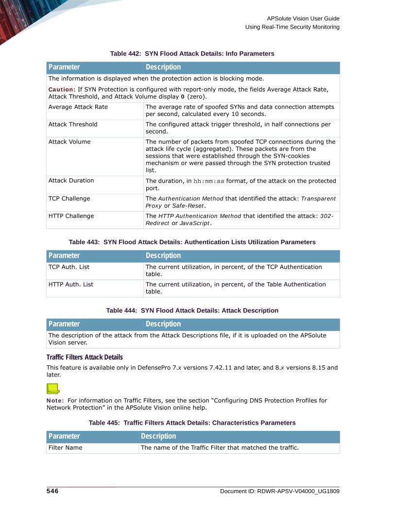
APSolute Vision User Guide
Using Real-Time Security Monitoring
546 Document ID: RDWR-APSV-V04000_UG1809
Traffic Filters Attack DetailsThis feature is available only in DefensePro 7.x versions 7.42.11 and later, and 8.x versions 8.15 and later.
Note: For information on Traffic Filters, see the section “Configuring DNS Protection Profiles for Network Protection” in the APSolute Vision online help.
Table 442: SYN Flood Attack Details: Info Parameters
Parameter DescriptionThe information is displayed when the protection action is blocking mode.
Caution: If SYN Protection is configured with report-only mode, the fields Average Attack Rate, Attack Threshold, and Attack Volume display 0 (zero).
Average Attack Rate The average rate of spoofed SYNs and data connection attempts per second, calculated every 10 seconds.
Attack Threshold The configured attack trigger threshold, in half connections per second.
Attack Volume The number of packets from spoofed TCP connections during the attack life cycle (aggregated). These packets are from the sessions that were established through the SYN-cookies mechanism or were passed through the SYN protection trusted list.
Attack Duration The duration, in hh:mm:ss format, of the attack on the protected port.
TCP Challenge The Authentication Method that identified the attack: Transparent Proxy or Safe-Reset.
HTTP Challenge The HTTP Authentication Method that identified the attack: 302-Redirect or JavaScript.
Table 443: SYN Flood Attack Details: Authentication Lists Utilization Parameters
Parameter DescriptionTCP Auth. List The current utilization, in percent, of the TCP Authentication
table.
HTTP Auth. List The current utilization, in percent, of the Table Authentication table.
Table 444: SYN Flood Attack Details: Attack Description
Parameter DescriptionThe description of the attack from the Attack Descriptions file, if it is uploaded on the APSolute Vision server.
Table 445: Traffic Filters Attack Details: Characteristics Parameters
Parameter DescriptionFilter Name The name of the Traffic Filter that matched the traffic.

APSolute Vision User Guide
Using Real-Time Security Monitoring
Document ID: RDWR-APSV-V04000_UG1809 547
Sampled Data TabYou can display the Sampled Data dialog box for the all attack types that support sampled data.The Sampled Data tab contains a table with data on sampled attack packets. Each row in the table displays the data for one sampled attack packet. The title bar includes the category of the data—for example, Behavioral DoS.
Notes
• This feature is not supported on OnDemand Switch 2 S2 (DefensePro 1016 IPS & Behavioral Protection - DME).
• APSolute Vision stores sampled attack data, which includes the source and destination addresses of the sampled packets. This information reflects a sampling of the attack packets; it does not reflect the full attack data. For example, it is possible that the source IP addresses of the sampled data do not include all of the source addresses of the attack.
Filter ID The Radware ID of the Traffic Filter that matched the traffic.
Note: The ID is a hyperlink to the configuration of the Traffic Filter.
Protocol The protocol of the traffic that the Traffic Filter matched.
Source Network The source network of the traffic that the Traffic Filter matched.
Source Port The source port of the traffic that the Traffic Filter matched.
Destination Network The destination network of the traffic that the Traffic Filter matched.
Destination Port The destination port of the traffic that the Traffic Filter matched.
Device IP The IP address of the DefensePro device with the Traffic Filter that matched the traffic.
Table 446: Traffic Filters Attack Details: Info Parameters
Parameter DescriptionTotal Attack Packets The total number of packets that match or matched the Traffic
Filter.
Attack Packets Rate (pps) The rate, in packets/second, of packets that match or matched the Traffic Filter.
Total Attack Data (Kbits) The total volume, in Kbits, of traffic that matches or matched the Traffic Filter.
Attack Bandwidth (Kbps) The bandwidth, in Kbits/second, of traffic that matches or matched the Traffic Filter.
Table 447: Traffic Filters Attack Details: Attack Description
Parameter DescriptionThe description of the attack from the Attack Descriptions file, if it is uploaded on the APSolute Vision server.
Table 445: Traffic Filters Attack Details: Characteristics Parameters (cont.)
Parameter Description

APSolute Vision User Guide
Using Real-Time Security Monitoring
548 Document ID: RDWR-APSV-V04000_UG1809
The table in the Sampled Data tab comprises the following columns:• Time• Source Address• Source L4 Port• Destination Address• Destination L4 Port• Protocol• VLAN / Context• MPLS RD• Physical Port
To display the Sampled Data tab
1. In the Security Monitoring perspective, select the DefensePro device, Site, or Logical Group for which to display data.
2. Select Dashboard View.
3. Do one of the following to open the Attack Details tab:
— Select Current Attacks Table, and then, double-click the relevant row.— Select Ongoing Attacks Monitor, and then, double-click the icon.
4. Click the (View Sampled Data) button.
You can export some rows of the table in the Sampled Data dialog box to a CSV file.
To save sampled data to a CSV file
1. In the Security Monitoring perspective, select the DefensePro device, Site, or Logical Group for which to display data.
2. Select Dashboard View.
3. Do one of the following to open the Attack Details tab:
— Select Current Attacks Table, and then, double-click the relevant row.— Select Ongoing Attacks Monitor, and then, double-click the icon.
4. Click the (View Sampled Data) button.
5. Select the row with which you want the data rows in the file to start.
6. Click the (CSV) button.
7. View the file or specify the location and file name.

APSolute Vision User Guide
Using Real-Time Security Monitoring
Document ID: RDWR-APSV-V04000_UG1809 549
Viewing Real-Time Traffic ReportsYou can view real-time traffic reports over time for the IP traffic passing through the DefensePro devices. The information includes data on overall IP traffic, protocol mix, and packet discards. You can display the data in graph or table format.
Notes
• On DefensePro devices that do not support the Device Operation Mode feature, the traffic is calculated according to the selected port pairs.
• For DefensePro devices that support the Device Operation Mode feature:
— When Device Operation Mode is Transparent, the traffic is calculated according to the selected port pairs.
— When Device Operation Mode is IP, the traffic is calculated according to the selected ports.
— When you are viewing multiple DefensePro devices in the Security Monitoring perspective, the table displays both port pairs and single ports as appropriate.
You can also view graphs of connection rates and concurrent connections based on data from the Session table.By default, all traffic is presented in these graphs and tables. In each graph, you can filter the display by protocol or traffic direction, but not for concurrent connections.The Connection Statistics are displayed only when the device is operating in Full Layer 4 Session Table Lookup mode (relevant only for 6.x and 7.x versions).You can monitor the following traffic information in the Traffic Monitoring tab:• Viewing the Traffic Utilization Report, page 549• Viewing the Connection Rate Report, page 556• Viewing the Concurrent Connections Report, page 558• Viewing the Top Queried Domain Names Report, page 558
Viewing the Traffic Utilization ReportThe Traffic Utilization Report displays statistics for the following:• Traffic Statistics—Displays information for the selected port pairs in DefensePro, and
protected object in DefenseFlow, as a graph. The graph contains information for a selected protocol or the total for all protocols over a period of time. There is a curve on the graph for each the following:— Inbound IP traffic in DefensePro, Inbound traffic in DefenseFlow— Dropped inbound traffic (DefenseFlow only)— Diverted inbound traffic (DefenseFlow only)— Outbound IP traffic— Discarded inbound traffic— Discarded outbound traffic— Excluded inbound traffic (DefensePro only)— Clean inbound traffic (DefenseFlow only)— Excluded outbound trafficTo hide or show a curve for a particular traffic type, click the corresponding colored square in the legend.
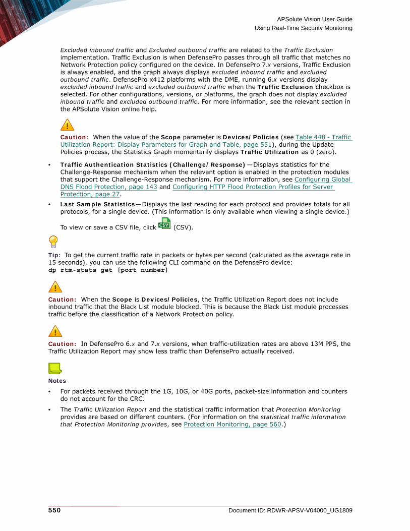
APSolute Vision User Guide
Using Real-Time Security Monitoring
550 Document ID: RDWR-APSV-V04000_UG1809
Excluded inbound traffic and Excluded outbound traffic are related to the Traffic Exclusion implementation. Traffic Exclusion is when DefensePro passes through all traffic that matches no Network Protection policy configured on the device. In DefensePro 7.x versions, Traffic Exclusion is always enabled, and the graph always displays excluded inbound traffic and excluded outbound traffic. DefensePro x412 platforms with the DME, running 6.x versions display excluded inbound traffic and excluded outbound traffic when the Traffic Exclusion checkbox is selected. For other configurations, versions, or platforms, the graph does not display excluded inbound traffic and excluded outbound traffic. For more information, see the relevant section in the APSolute Vision online help.
Caution: When the value of the Scope parameter is Devices/Policies (see Table 448 - Traffic Utilization Report: Display Parameters for Graph and Table, page 551), during the Update Policies process, the Statistics Graph momentarily displays Traffic Utilization as 0 (zero).
• Traffic Authentication Statistics (Challenge/Response)—Displays statistics for the Challenge-Response mechanism when the relevant option is enabled in the protection modules that support the Challenge-Response mechanism. For more information, see Configuring Global DNS Flood Protection, page 143 and Configuring HTTP Flood Protection Profiles for Server Protection, page 27.
• Last Sample Statistics—Displays the last reading for each protocol and provides totals for all protocols, for a single device. (This information is only available when viewing a single device.)
To view or save a CSV file, click (CSV).
Tip: To get the current traffic rate in packets or bytes per second (calculated as the average rate in 15 seconds), you can use the following CLI command on the DefensePro device:dp rtm-stats get [port number]
Caution: When the Scope is Devices/Policies, the Traffic Utilization Report does not include inbound traffic that the Black List module blocked. This is because the Black List module processes traffic before the classification of a Network Protection policy.
Caution: In DefensePro 6.x and 7.x versions, when traffic-utilization rates are above 13M PPS, the Traffic Utilization Report may show less traffic than DefensePro actually received.
Notes
• For packets received through the 1G, 10G, or 40G ports, packet-size information and counters do not account for the CRC.
• The Traffic Utilization Report and the statistical traffic information that Protection Monitoring provides are based on different counters. (For information on the statistical traffic information that Protection Monitoring provides, see Protection Monitoring, page 560.)
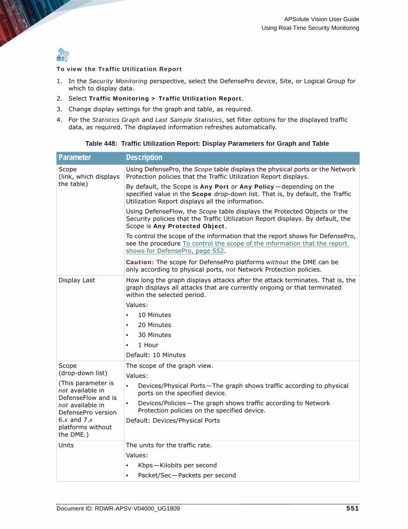
APSolute Vision User Guide
Using Real-Time Security Monitoring
Document ID: RDWR-APSV-V04000_UG1809 551
To view the Traffic Utilization Report
1. In the Security Monitoring perspective, select the DefensePro device, Site, or Logical Group for which to display data.
2. Select Traffic Monitoring > Traffic Utilization Report.
3. Change display settings for the graph and table, as required.
4. For the Statistics Graph and Last Sample Statistics, set filter options for the displayed traffic data, as required. The displayed information refreshes automatically.
Table 448: Traffic Utilization Report: Display Parameters for Graph and Table
Parameter DescriptionScope(link, which displays the table)
Using DefensePro, the Scope table displays the physical ports or the Network Protection policies that the Traffic Utilization Report displays. By default, the Scope is Any Port or Any Policy—depending on the specified value in the Scope drop-down list. That is, by default, the Traffic Utilization Report displays all the information.Using DefenseFlow, the Scope table displays the Protected Objects or the Security policies that the Traffic Utilization Report displays. By default, the Scope is Any Protected Object.To control the scope of the information that the report shows for DefensePro, see the procedure To control the scope of the information that the report shows for DefensePro, page 552.
Caution: The scope for DefensePro platforms without the DME can be only according to physical ports, not Network Protection policies.
Display Last How long the graph displays attacks after the attack terminates. That is, the graph displays all attacks that are currently ongoing or that terminated within the selected period.Values:• 10 Minutes• 20 Minutes• 30 Minutes• 1 HourDefault: 10 Minutes
Scope(drop-down list)(This parameter is not available in DefenseFlow and is not available in DefensePro version 6.x and 7.x platforms without the DME.)
The scope of the graph view.Values:• Devices/Physical Ports—The graph shows traffic according to physical
ports on the specified device.• Devices/Policies—The graph shows traffic according to Network
Protection policies on the specified device.Default: Devices/Physical Ports
Units The units for the traffic rate.Values:• Kbps—Kilobits per second• Packet/Sec—Packets per second
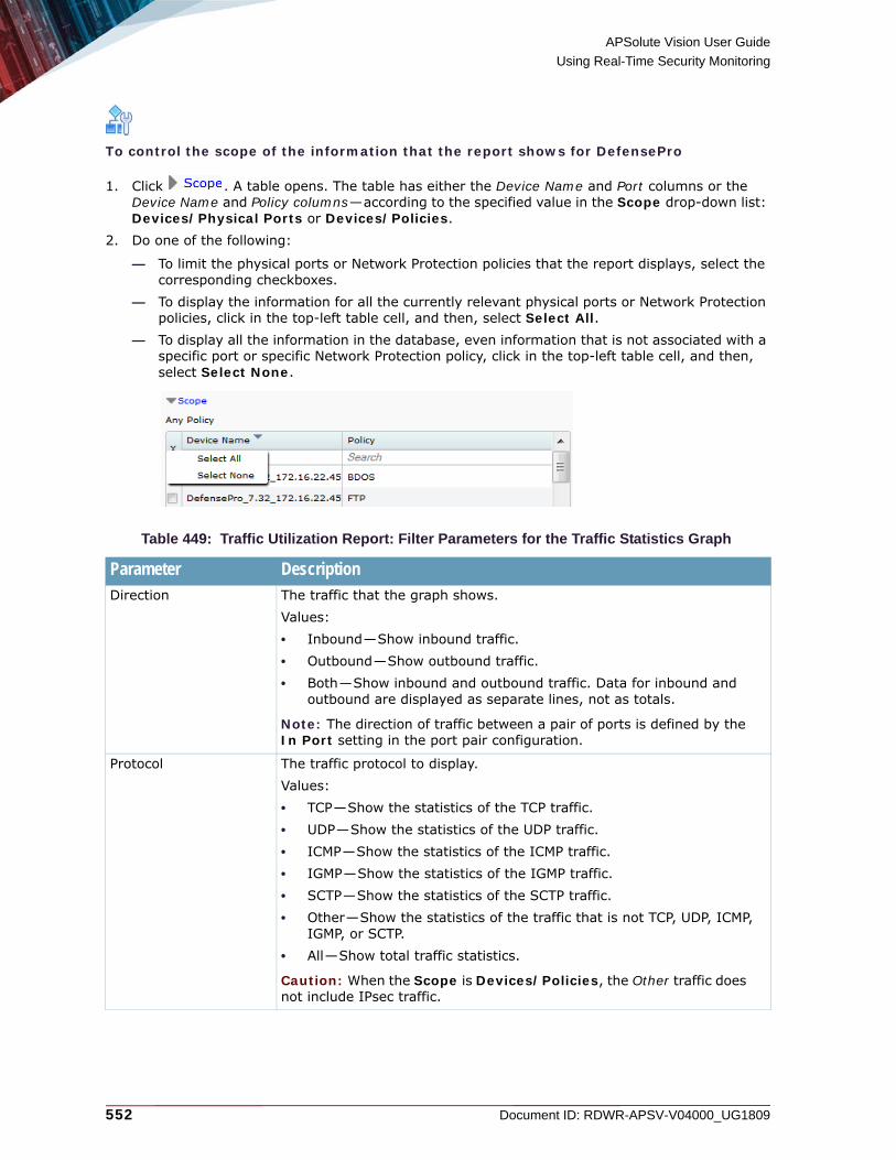
APSolute Vision User Guide
Using Real-Time Security Monitoring
552 Document ID: RDWR-APSV-V04000_UG1809
To control the scope of the information that the report shows for DefensePro
1. Click . A table opens. The table has either the Device Name and Port columns or the Device Name and Policy columns—according to the specified value in the Scope drop-down list: Devices/Physical Ports or Devices/Policies.
2. Do one of the following:
— To limit the physical ports or Network Protection policies that the report displays, select the corresponding checkboxes.
— To display the information for all the currently relevant physical ports or Network Protection policies, click in the top-left table cell, and then, select Select All.
— To display all the information in the database, even information that is not associated with a specific port or specific Network Protection policy, click in the top-left table cell, and then, select Select None.
Table 449: Traffic Utilization Report: Filter Parameters for the Traffic Statistics Graph
Parameter DescriptionDirection The traffic that the graph shows.
Values:• Inbound—Show inbound traffic.• Outbound—Show outbound traffic.• Both—Show inbound and outbound traffic. Data for inbound and
outbound are displayed as separate lines, not as totals.
Note: The direction of traffic between a pair of ports is defined by the In Port setting in the port pair configuration.
Protocol The traffic protocol to display.Values:• TCP—Show the statistics of the TCP traffic.• UDP—Show the statistics of the UDP traffic.• ICMP—Show the statistics of the ICMP traffic.• IGMP—Show the statistics of the IGMP traffic.• SCTP—Show the statistics of the SCTP traffic.• Other—Show the statistics of the traffic that is not TCP, UDP, ICMP,
IGMP, or SCTP.• All—Show total traffic statistics.
Caution: When the Scope is Devices/Policies, the Other traffic does not include IPsec traffic.

APSolute Vision User Guide
Using Real-Time Security Monitoring
Document ID: RDWR-APSV-V04000_UG1809 553
Table 450: Traffic Utilization Report: Traffic Authentication Statistics (Challenge/Response) Parameters
Parameter DescriptionProtocol The protocol of the statistics displayed in the row.
Values: HTTP, TCP, DNS
Note: The HTTP row is not relevant for DefensePro 8.x versions earlier than 8.10.
Current Attacks The number of attacks currently in the device.
Authentication Table Utilization % The percentage of the Authentication Table that is full.
Challenges Rate The rate, in PPS, that the device is sending challenges.
Table 451: Traffic Utilization Report: Last Sample Statistics Parameters
Parameter DescriptionProtocol The traffic protocol.
Values:• TCP• UDP• ICMP• IGMP• SCTP• Other—The statistics of the traffic that is not TCP, UDP, ICMP, IGMP, or
SCTP.• All—Total traffic statistics.
Caution: When the Scope is Devices/Policies, the Other traffic does not include IPsec traffic.
Inbound The amount of inbound traffic for the protocol identified in the row.
Outbound(This parameter is available only in DefensePro.)
The amount of outbound traffic for the protocol identified in the row.
Discarded Inbound The amount of discarded inbound traffic for the protocol identified in the row.
Discarded Outbound(This parameter is available only in DefensePro.)
The amount of discarded outbound traffic for the protocol identified in the row.
Clean(This parameter is available only in DefenseFlow.)
The amount of clean traffic for the protocol identified in the row.
Dropped(This parameter is available only in DefenseFlow.)
The amount of traffic dropped traffic for the protocol identified in the row.
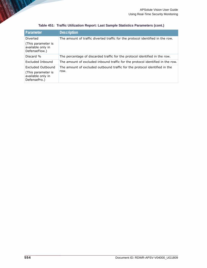
APSolute Vision User Guide
Using Real-Time Security Monitoring
554 Document ID: RDWR-APSV-V04000_UG1809
Diverted(This parameter is available only in DefenseFlow.)
The amount of traffic diverted traffic for the protocol identified in the row.
Discard % The percentage of discarded traffic for the protocol identified in the row.
Excluded Inbound The amount of excluded inbound traffic for the protocol identified in the row.
Excluded Outbound(This parameter is available only in DefensePro.)
The amount of excluded outbound traffic for the protocol identified in the row.
Table 451: Traffic Utilization Report: Last Sample Statistics Parameters (cont.)
Parameter Description

APSolute Vision User Guide
Using Real-Time Security Monitoring
Document ID: RDWR-APSV-V04000_UG1809 555
MIB Support for Traffic-Monitoring DataThis feature is available on DefensePro 7.x versions and 6.x versions with the DME. When the device configuration includes a Network Protection policy, DefensePro exposes MIBs with traffic-monitoring data for the policies. In addition to APSolute Vision, you can use third-party SNMP readers to access the MIB data. DefensePro issues the data at 15-second intervals.
Table 452: Network-Protection-policy Monitoring OIDs and Corresponding MIBs
OID MIB Comment1.3.6.1.4.1.89.35.1.65.188.4 rsTrafficUtilizationPerPolicy
1.3.6.1.4.1.89.35.1.65.188.4.1 rsTrafficUtilizationPerPolicyTableUDP Index for the UDP statistics table.
1.3.6.1.4.1.89.35.1.65.188.4.2 rsTrafficUtilizationPerPolicyTableTCP Index for the TCP statistics table.
1.3.6.1.4.1.89.35.1.65.188.4.3 rsTrafficUtilizationPerPolicyTableICMP Index for the ICMP statistics table.
1.3.6.1.4.1.89.35.1.65.188.4.4 rsTrafficUtilizationPerPolicyTableOTHER Index for the statistics table for other protocols.
1.3.6.1.4.1.89.35.1.65.188.4.5 rsTrafficUtilizationPerPolicyTableSCTP Index for the SCTP statistics table.
1.3.6.1.4.1.89.35.1.65.188.4.6 rsTrafficUtilizationPerPolicyTableIGMP Index for the IGMP statistics table.
1.3.6.1.4.1.89.35.1.65.188.4.<X>.1 rsPolicyNamePerPolicy<Y> <X> refers to one of the indexing tables detailed above. <Y> refers to the protocol according to the <X> value. 1.3.6.1.4.1.89.35.1.65.188.4.<X>.2 rsNewConnectionsPerPolicy<Y>
1.3.6.1.4.1.89.35.1.65.188.4.<X>.3 rsConcurConnections<Y>1
1 – A placeholder (zeros) is displayed here.
1.3.6.1.4.1.89.35.1.65.188.4.<X>.4 rsDroppedPacketsPerPolicy<Y>
1.3.6.1.4.1.89.35.1.65.188.4.<X>.5 rsDroppedBytesPerPolicy<Y>
1.3.6.1.4.1.89.35.1.65.188.4.<X>.6 rsReceivedPacketsPerPolicy<Y>
1.3.6.1.4.1.89.35.1.65.188.4.<X>.7 rsReceivedBytesPerPolicy<Y>

APSolute Vision User Guide
Using Real-Time Security Monitoring
556 Document ID: RDWR-APSV-V04000_UG1809
Viewing the Connection Rate ReportThis feature is functional only in DefensePro 6.x and 7.x versions, and 8.x versions 8.10 and later.The Connection Rate Report displays a graph showing connection rate statistics of inbound and outbound traffic.
To view the Connection Rate Report
1. In the Security Monitoring perspective, select the DefensePro device, Site, or Logical Group for which to display data.
2. Select Traffic Monitoring > Connections Rate Report.
3. Change display settings for the graph, as required.
Table 453: Connection Rate Report: Display Parameters
Parameter DescriptionScope(link, which displays the table)
The physical ports and the Network Protection policies that the Connection Rate Report shows. By default, the Scope is Any Port or Any Policy (depending on the specified value in the Scope drop-down list). That is, by default, the Connection Rate Report displays all the information.To control the scope of the information that the report shows, see the procedure To control the scope of the information that the report shows, page 557.
Caution: The scope for DefensePro platforms without the DME can be only according to physical ports, not Network Protection policies.
Display Last How long the graph displays attacks after the attack terminates. That is, the graph displays all attacks that are currently ongoing or that terminated within the selected period.Values:• 10 Minutes• 20 Minutes• 30 Minutes• 1 HourDefault: 10 Minutes
Scope(link, which displays the table)
The scope of the graph view.Values:• Devices/Physical Ports—The graph shows traffic according to physical
ports on the specified device.• Devices/Network Policies—The graph shows traffic according to Network
Protection policies on the specified device. This graph is available only on DefensePro 20, 60, 200, 400, x420, and x4420 devices, and x412 devices with the DME.
Default: Devices/Physical Ports
Caution: In 8.x versions, the Connection Rate Report works only when the Scope is Devices/Network Policies.

APSolute Vision User Guide
Using Real-Time Security Monitoring
Document ID: RDWR-APSV-V04000_UG1809 557
To control the scope of the information that the report shows
1. Click . A table opens. The table has either the Device Name and Port columns or the Device Name and Policy columns—according to the specified value in the Scope drop-down list: Devices/Physical Ports or Devices/Policies.
2. Do one of the following:
— To limit the physical ports or Network Protection policies that the report displays, select the corresponding checkboxes.
— To display the information for all the currently relevant physical ports or Network Protection policies, click in the top-left table cell, and then, select Select All.
— To display all the information in the database, even information that is not associated with a specific port or specific Network Protection policy, click in the top-left table cell, and then, select Select None.
Direction Values:• Both—Show both inbound traffic and outbound traffic. Data for inbound
and outbound are displayed as separate lines, not as totals.• Inbound—Show only inbound traffic.• Outbound—Show only outbound traffic.
Note: The direction of traffic between a pair of ports is defined by the In Port setting in the port pair configuration.
Protocol The traffic protocol to display.When you select All, total traffic statistics are displayed.
Select Port Pair(button)(This button is displayed only when the Scope is Devices/Physical Ports.)
Opens the Select Port Pairs dialog box. Select the port pairs relevant for the network topology by moving the required port pairs to the Selected Port Pairs list. All other port pairs should be in the Available Port Pairs list.
Note: You can select port pairs for each direction; however, Radware recommends that you select a port pair in one direction only, and display traffic for both directions, if required. If you select port pairs in both directions, and traffic for both directions, the graph will display the same traffic twice.
Select Policies(This button is displayed only when the Scope is Devices/Policies.)
Opens the Select Policies dialog box. Select the Network Protection policies relevant for the network topology by moving the required policies the Selected Policies list.
Table 453: Connection Rate Report: Display Parameters (cont.)
Parameter Description
APSolute Vision User Guide
Using Real-Time Security Monitoring
558 Document ID: RDWR-APSV-V04000_UG1809
Viewing the Concurrent Connections ReportThis feature is functional only in DefensePro 6.x and 7.x versions, and 8.x versions 8.10 and later.The Concurrent Connections Report displays a graph showing the rate of current connections for selected port pairs. You can display the information for a selected protocol or the total for all protocols over the last 10, 20, 30, or 60 minutes.
Note: For packets received through the 1G, 10G, or 40G ports, packet-size information and counters do not account for the CRC.
To view the Concurrent Connections Report
1. In the Security Monitoring perspective, select the device, Site, or Logical Group for which to display data.
2. Select Traffic Monitoring > Concurrent Connections Report.
3. Change display settings for the graph, as required.
Viewing the Top Queried Domain Names ReportThis feature is available only when viewing a single device running DefensePro 8.x versions 8.13 and later.The Top Queried Domain Names Report displays content only when the selected Scope value is a Network Protection policy with a DNS profile that is configured with a Query Name Monitoring Sensitivity value other than None.
Note: For more information, see the section “Configuring DNS Protection Profiles for Network Protection” in the APSolute Vision online help.Every 10 minutes, DefensePro sends APSolute Vision data about sampled DNS packets, and APSolute Vision recalculates the values and the display of the Top Queried Domain Names Report.
Table 454: Concurrent Connections Report: Display Parameters
Parameter DescriptionDisplay Last How long the graph displays attacks after the attack terminates. That is, the
graph displays all attacks that are currently ongoing or that terminated within the selected period.Values:• 10 Minutes• 20 Minutes• 30 Minutes• 1 HourDefault: 10 Minutes
Protocol The traffic protocol to display. When you select All, total traffic statistics are displayed.

APSolute Vision User Guide
Using Real-Time Security Monitoring
Document ID: RDWR-APSV-V04000_UG1809 559
The Top Queried Domain Names Report shows the following:• The 10 most-queried DNS domain names under the specified Network Protection
policy—The list is in descending order; that is, the most-queried domain name is at the top of the list.
• A colored bar beneath each domain name—The width of the colored bar represents the ranking of the domain name. The most-queried domain name is at the top of the list and the colored bar always fills the box. The sequence of the colors of the bars is static; that is, the actual colors have no significance. Inside each colored bar, a number displays the approximate total number of queries from the samples, for the specified period (according to the selected Display Last option). The displayed value is based on a sampling of up to 1000 DNS queries per second.
• A line graph for a selected domain—The graph shows the number of queries—and trend—for the specified period (according to the selected Display Last option). Hovering the mouse on the line opens a popup that shows the sample time (hh:mm:ss) and a Score with the number of queries for that domain name, for that sample.
Figure 61: Top Queried Domain Names Report
To view the Top Queried Domain Names Report
1. In the Security Monitoring perspective, select the device for which to display data.2. Select Traffic Monitoring > Top Queried Domain Names Report.
3. Change display settings, as required.
Table 455: Top Queried Domain Names Report: Display Parameters
Parameter DescriptionScope(drop-down list)
The Network Protection policy whose 10 most-queried DNS domain names the tab displays.
APSolute Vision User Guide
Using Real-Time Security Monitoring
560 Document ID: RDWR-APSV-V04000_UG1809
Protection MonitoringProtection Monitoring provides the real-time traffic monitoring per network policy, either for the network as a whole—if BDoS Protection is configured, or for DNS traffic—if DNS Flood Protection is configured. The statistical traffic information that Protection Monitoring provides can help you better understand the traffic that flows through the protected network, how the configured protection is working, and, most importantly, how anomalous traffic is detected.For information about displaying protection information for a selected device, see the following:• Displaying Attack Status Information, page 560• Monitoring the Traffic Under BDoS Protection, page 561• Monitoring the Traffic Under DNS Flood Protection, page 564
Note: The statistical traffic information that Protection Monitoring provides and Traffic Utilization Report are based on different counters. (For information on the Traffic Utilization Report, see Viewing the Traffic Utilization Report, page 549.)
Displaying Attack Status InformationYou can display summary status information for attacks for each configured and enabled protection policy. When there is an attack that violates a Network Protection policy, the table displays an icon indicating the status of the attack in the corresponding row for the relevant attack traffic.
To display attack status information
1. In the Security Monitoring perspective, select the DefensePro device to monitor.2. Select Protection Monitoring > Attack Status Report.
The table comprises the following columns:— Policy Name— IPv4-TCP— IPv4-UDP— IPv4-ICMP— IPv4-DNS
Display Last Determines the following: • The period for the calculation of the 10 most-queried DNS domain
names (the bar graphs and the displayed values)• The time range of the x-axis in the line graph (for a selected domain)Values:• 10 Minutes• 1 Hour• 12 Hours• 24 HourDefault: 10 Minutes
Table 455: Top Queried Domain Names Report: Display Parameters (cont.)
Parameter Description

APSolute Vision User Guide
Using Real-Time Security Monitoring
Document ID: RDWR-APSV-V04000_UG1809 561
— IPv6-TCP— IPv6-UDP— IPv6-ICMP— IPv6-DNS
3. When an attack icon is displayed in the table, click the icon to display the corresponding attack traffic information.
Monitoring the Traffic Under BDoS ProtectionYou can monitor the traffic for a Network Protection policy that includes BDoS protection.Traffic information is displayed in the following tabs: • BDoS Traffic Statistics, page 562• Last Sample Statistics, page 563
Caution: When traffic matches multiple Network Protection policies with Out-of-State protection, the value that APSolute Vision displays for the total dropped traffic represents the sum of all dropped traffic for all relevant Network Protection policies. This is because when traffic matches multiple Network Protection policies with Out-of-State protection, all those Network Protection policies count the same dropped traffic.
Note: APSolute Vision displays the Protection Monitoring graphs using averaged values, and therefore, points on the curves might diverge from the exact values.
To display traffic information for a Network Policy that includes BDoS protection
1. In the Security Monitoring perspective, select the device to monitor.2. Select Protection Monitoring > BDoS Traffic Monitoring Reports.
3. Configure the general parameters for the display of the BDoS Traffic Statistics graph and Last Sample Statistics table.
Table 456: BDoS Traffic Monitoring Reports: General Parameters
Parameter DescriptionScope The Network Protection policy. The list only displays policies that are
configured with a BDoS profile.
Display Last How long the graph displays attacks after the attack terminates. That is, the graph displays all attacks that are currently ongoing or that terminated within the selected period.Values:• 10 Minutes• 20 Minutes• 30 Minutes• 1 HourDefault: 10 Minutes

APSolute Vision User Guide
Using Real-Time Security Monitoring
562 Document ID: RDWR-APSV-V04000_UG1809
BDoS Traffic StatisticsThe graph displays the traffic rates for the selected Network Protection policy according to the specified parameters.
Direction The direction of the traffic that the Statistics Graph and Last Sample Statistics table display.Values: Inbound, Outbound
Units The unit according to which the Statistics Graph and Last Sample Statistics table display the traffic. Values: • Kbps—Kilobits per second• Packets/Sec—Packets per second
Table 457: BDoS Traffic Statistics Parameters
Parameter DescriptionIP Version The IP version of the traffic that the graph displays.
Values: IPv4, IPv6
Protection Type The protection type to monitor.Values:
• TCP ACK FIN• TCP FRAG• TCP RST• TCP SYN• TCP SYN ACK• UDP• ICMP• IGMP• UDP FRAG• TCP
• TCP SYN• SYN ACK• TCP FRAG• TCP RST• TCP ACK FIN• UDP• UDP FRAG• ICMP• Other IP
For DefenseFlow, only the following protection types are available:• UDP• ICMP• TCP• Other
Scale The scale for the presentation of the information along the Y-axis.Values: Linear, Logarithmic
Attack Status (Read-only) The status of the attack.
Table 456: BDoS Traffic Monitoring Reports: General Parameters (cont.)
Parameter Description

APSolute Vision User Guide
Using Real-Time Security Monitoring
Document ID: RDWR-APSV-V04000_UG1809 563
Last Sample StatisticsUse the Last Sample Statistics table to view information about last relevant sample.
Table 458: Statistics Graph Legend
Line DescriptionTotal Traffic( dark blue)
The total traffic that the device sees for the specific protection type and direction.
Legitimate Traffic( light blue)
The actual forwarded traffic rate, after DefensePro managed to block the attack. When there is no attack, the Total Traffic and Legitimate Traffic are equal.
Normal Edge( dashed green)
The statistically calculated baseline traffic rate.
Suspected Edge( dashed orange)
The traffic rate that indicates a change in traffic that might be an attack.
Caution: DefensePro reports the Suspected Edge in Kbps only. The graph displays the Suspected Edge only when the Scope parameter Units is Kbps (see Table 460 - DNS Traffic Monitoring Reports: General Parameters, page 564). When the Scope parameter Units is Packets/Sec, the graph does not display the Suspected Edge.
Attack Edge( dashed red)
The traffic rate that indicates an attack.
Caution: DefensePro reports the Attack Edge in Kbps only. The graph displays the Attack Edge only when the Scope parameter Units is Kbps (see Table 460 - DNS Traffic Monitoring Reports: General Parameters, page 564). When the Scope parameter Units is Packets/Sec, the graph does not display the Attack Edge.
Table 459: Last Sample Statistics Parameters
Parameter DescriptionTraffic Type The protection type. Each specific traffic type and direction has a baseline
that the device learns automatically.
Baseline The normal traffic rate expected by the device.
Total Traffic The total traffic rate that the DefensePro device sees for the specific traffic type and direction.
Baseline Portion % An indication for the rate invariant baseline—that is, the normal percentage of the specific traffic type to all other traffic in the same direction.
RT Portion % The actual percentage of the specific traffic type relative to all other traffic in the same direction.
Legitimate Traffic (This parameter is not available in DefenseFlow.)
The actual forwarded traffic rate, after the device blocked the attack.When there is no attack, the RT Rate and Legitimate Rate are equal.
Legitimate Portion %(This parameter is not available in DefenseFlow.)
The actual percentage of the forwarded traffic rate of the specified type relative to other types of traffic, after the device blocked the attack.

APSolute Vision User Guide
Using Real-Time Security Monitoring
564 Document ID: RDWR-APSV-V04000_UG1809
Monitoring the Traffic Under DNS Flood ProtectionYou can monitor the traffic for a Network Protection policy that includes DNS Flood protection.APSolute Vision displays traffic information in the following tabs: • DNS Traffic Statistics, page 565• Last Sample Statistics, page 565
Note: APSolute Vision displays the Protection Monitoring graphs using averaged values, and therefore, points on the curves might diverge from the exact values.
To display traffic information for a Network Protection policy that includes DNS protection
1. In the Security Monitoring perspective, select the device to monitor.2. Select Protection Monitoring > DNS Traffic Monitoring Reports.
3. Configure the general parameters for the display of the Statistics Graph and Last Sample Statistics table.
Traffic Peak(This parameter is available only in DefenseFlow.)
Peak traffic value, in bps, to use in case of a manual action without attack volume information available.
Degree of Attack A numeric value that evaluates the current level of attack. A value of 8 or greater signifies an attack.
Table 460: DNS Traffic Monitoring Reports: General Parameters
Parameter DescriptionScope The Network Protection policy. The list only displays rules configured with a
DNS profile.
Direction (Read-only) The direction of the traffic that the Statistics Graph and Last Sample Statistics table display. Values: Inbound
Units (Read-only) The unit according to which the Statistics Graph and Last Sample Statistics table display the traffic.Value: QPS—Queries per second
Table 459: Last Sample Statistics Parameters (cont.)
Parameter Description

APSolute Vision User Guide
Using Real-Time Security Monitoring
Document ID: RDWR-APSV-V04000_UG1809 565
DNS Traffic StatisticsThe graph displays the traffic rates for the selected Network Protection policy according to the specified parameters.
Last Sample StatisticsUse the Last Sample Statistics tab to view information about the last relevant sample of DNS query statistics. The DefensePro version determines the contents and display of the Last Sample Statistics tab.
Table 461: DNS Traffic Statistics Graph Parameters
Parameter DescriptionIP Version The IP version of the traffic that the graph displays.
Values: IPv4, IPv6
Protection Type The DNS query type to monitor.Values:• Other• Text• A• AAAA• MX• NAPTR• PTR• SOA• SRV
Scale The scale for the presentation of the information along the Y-axis.Values: Linear, Logarithmic
Attack Status (Read-only) The status of the attack.
Table 462: Statistics Graph Legend
Line DescriptionTotal Traffic( dark blue)
The total traffic that the device sees for the specific protection type and direction.
Legitimate Traffic( light blue)
The actual forwarded traffic rate, after DefensePro managed to block the attack. When there is no attack, the Total Traffic and Legitimate Traffic are equal.
Normal Edge1
( dashed green)
1 – This line is not displayed if the protection is configured to use a footprint bypass or manual triggers.
The statistically calculated baseline traffic rate.
Suspected Edge( dashed orange)
The traffic rate that indicates a change in traffic that might be an attack.
Attack Edge( dashed red)
The traffic rate that indicates an attack.

APSolute Vision User Guide
Using Real-Time Security Monitoring
566 Document ID: RDWR-APSV-V04000_UG1809
DNS Last Sample Statistics—for DefensePro 8.x Versions 8.13 and LaterThe Last Sample Statistics tab for DefensePro 8.x versions 8.13 and later is divided into panels for each of the DNS query types.
Note: For more information, see the section “Configuring DNS Protection Profiles for Network Protection” in the APSolute Vision online help.
Figure 62: DNS Last Sample Statistics—for DefensePro 8.x Versions 8.13 and Later—Example Showing the “A” Panel
Table 463: Last Sample Statistics Parameters for DefensePro 8.x Versions 8.13 and Later
Parameter DescriptionQuery Type The DNS query type.
Values: • A• AAAA• MX• NAPTR• Other• PTR• SOA• SRV• Text
Degree of Attack(gauge)
A gauge with a color representation of the DefensePro Degree of Attack (DoA) value for the specific query type. Green represents the Normal status. Orange represents the Suspect status. Red represents the Attack status.
General rate statistics
Total Traffic The total rate of traffic, in QPS, that the DefensePro device sees for the specific query type.
The Degree of Attack gauge displays a color representation for the DefensePro Degree of Attack value.
The query type whose information the panel shows.
General rate statistics.
Rate-invariant statistics showing the FQDN-randomization level in the DNS queries.
Rate-invariant statistics showing the query-type distribution.

APSolute Vision User Guide
Using Real-Time Security Monitoring
Document ID: RDWR-APSV-V04000_UG1809 567
DNS Last Sample Statistics—for all Versions Other than 8.x Versions 8.13 and LaterThe following table describes the parameters of the Last Sample Statistics tab for all DefensePro versions other than DefensePro 8.x versions 8.13 and later.
Legitimate Traffic The actual forwarded traffic rate, in QPS, for the specific query type, after the device blocked the attack.
Note: When there is no attack, the Total Traffic and Legitimate Traffic values are equal.
Baseline The normal rate of traffic, in QPS, expected by the DefensePro device for the specific query type. Each query type has a baseline that the device learns automatically.
Rate-invariant statistics—query-type distribution (on the left side of the panel)
Baseline Portion % An indication of the rate-invariant baseline—that is, the normal percentage of the specific query type out of all other DNS traffic in the same direction.
Current Portion % The actual percentage of the specific traffic type relative to all other DNS traffic in the same direction.
Legitimate Portion % The actual percentage of the forwarded traffic rate of the specified query type relative to other types of queries, after the device blocked the attack.
Rate-invariant statistics—FQDN Randomization Level (on the right side of the panel)
Baseline Portion % An indication of the FQDN Randomization Level baseline—that is, the normal randomness level, in percent, of FQDNs i the DNS queries of the specific query type.
Current Portion % The actual percentage, representing the FQDN Randomization Level within the DNS queries of the specific query type.
Legitimate Portion % The actual FQDN Randomization Level, in the forwarded traffic after the device blocked the attack.
Table 464: Last Sample Statistics Parameters for All DefensePro Versions Other than DefensePro 8.x Versions 8.13 and Later
Parameter DescriptionTraffic Type The query type. Each specific query type and direction has a baseline that
the device learns automatically.
Baseline The normal traffic rate expected by the device.
Total Traffic The total traffic rate that the DefensePro device sees for the specific query type and direction.
Baseline Portion % An indication for the rate-invariant baseline—that is, the normal percentage of the specific query type out of all other traffic in the same direction.
RT Portion % The actual percentage of the specific query type relative to all other traffic in the same direction.
Legitimate Traffic The actual forwarded traffic rate, after the device blocked the attack. When there is no attack, the RT Rate and Legitimate Rate are equal.
Legitimate Portion % The actual percentage of the forwarded traffic rate of the specified type relative to other types of queries, after the device blocked the attack.
Degree of Attack A numeric value that evaluates the current level of attack. A value of 8 or greater signifies an attack.
Table 463: Last Sample Statistics Parameters for DefensePro 8.x Versions 8.13 and Later (cont.)
Parameter Description

APSolute Vision User Guide
Using Real-Time Security Monitoring
568 Document ID: RDWR-APSV-V04000_UG1809
HTTP ReportsThis feature is functional only in DefensePro 6.x and 7.x versions.This feature is not functional in DefensePro 8.x versions.HTTP Mitigator protection monitors rate-based and rate-invariant HTTP traffic parameters, learns them, and generates normal behavior baselines accordingly.
Note: DefensePro examines the number and rate of HTTP requests. Thus, when HTTP pipelining is used, the detection mechanism remains accurate.You can monitor real-time and historical (normal baseline) values, and analyze HTTP traffic anomalies using the following reports:• Monitoring Continuous Learning Statistics, page 568• Monitoring Hour-Specific Learning Statistics, page 569• HTTP Request Size Distribution, page 570
Monitoring Continuous Learning StatisticsThis feature is functional only in DefensePro 6.x and 7.x versions.This feature is not functional in DefensePro 8.x versions.You can generate and display normal HTTP traffic baselines based on continuous traffic statistics. Continuous learning statistics are based on recent traffic, irrespective of time of day, or day of the week. The learning response period (that is, the exponential sliding-window period on which statistics measurements are based) is set based on the HTTP Mitigator learning sensitivity settings (default: 1 week).To build a comprehensive picture of the traffic of a protected site, the device monitors various HTTP attack statistics. Continuous learning reports display normal HTTP traffic baselines (blue) and real-time HTTP traffic statistics (orange) over the specified recent time period.
Table 465: Continuous Learning Statistics Reports
Channel DescriptionGET & POST Requests Rate The rate of HTTP GET and POST requests sent per second to the
protected server.
Other Requests Rate The rate of HTTP requests that are not POST or GET sent per second to the protected server. Other HTTP request methods can be used, but are used less frequently.
Requests Rate per Source The maximum rate of HTTP GET and POST requests per second per source IP address.This parameter characterizes the site users’ behavior, enabling you to recognize abnormal activities, such as scanning or bots. Legitimate users may generate many requests per second, but automatic devices such as bots or scanners generate many more.

APSolute Vision User Guide
Using Real-Time Security Monitoring
Document ID: RDWR-APSV-V04000_UG1809 569
Note: Normal Requests per Source and Requests per Connection baseline parameters show the highest number of HTTP requests generated by a single source IP address and TCP connection respectively. This number fades out, unless a higher value is observed, within about 30 seconds.
To display continuous learning HTTP reports
1. In the Security Monitoring perspective, select the device to monitor.2. Select HTTP Reports > Continuous Learning Statistics.
3. Select a report:
— GET and POST Request Rate— Other Requests Rate— Requests Rate per Source— Requests Rate per Connection— Outbound Bandwidth
4. Configure the filter parameters for the graph.
Monitoring Hour-Specific Learning StatisticsThis feature is functional only in DefensePro 6.x and 7.x versions.This feature is not functional in DefensePro 8.x versions.
Requests per Connection The maximum number of HTTP GET and POST requests per TCP connection.This parameter characterizes the site users’ behavior, enabling you to recognize abnormal activities, such as scanning or bots.Many requests over a single TCP connection may indicate bot or scanner activity.
Outbound Bandwidth The bandwidth, in megabits per second, of the HTTP servers sending the responses.
Table 466: HTTP Report Filter Parameters
Parameter DescriptionServer The name of the protected Web server for which to display HTTP traffic
statistics.
Display Last The last number of hours for which the graph displays information.Values: 1, 2, 3, 6, 12, 24Default: 1
Table 465: Continuous Learning Statistics Reports (cont.)
Channel Description

APSolute Vision User Guide
Using Real-Time Security Monitoring
570 Document ID: RDWR-APSV-V04000_UG1809
The Hour-Specific Learning Statistics reports display normal traffic baselines for the last week. You can view the hourly distribution of the site requests and outbound HTTP traffic for each day in the past week and for each hour in a day.The normal baseline for each hour in the week is calculated based on historical information for the specific hour in the day and the specific day of the week over the past 12 weeks. The graph is updated every hour.The HTTP Mitigator learns the baseline traffic, and, based on these statistics, reports attacks based on abnormal traffic.
To display hour-specific learning HTTP reports
1. In the Security Monitoring perspective, select the DefensePro device to monitor.2. Select HTTP Reports > Hour-Specific Learning Statistics.
3. Select a report:
— GET and POST Request Rate— Other Requests Rate— Outbound Bandwidth
4. In the Server list, select the protected Web server for which to display information.
HTTP Request Size DistributionThis feature is functional only in DefensePro 6.x and 7.x versions.This feature is not functional in DefensePro 8.x versions.The HTTP Request Size Distribution graph displays the URI size distribution, which shows how server resources are used, and helps you to analyze resource distribution. A large deviation from the normal probability distribution of one or more HTTP request sizes indicates that relative usage of these server resources has increased. The HTTP Request Size Distribution graph x-axis values are request sizes in 10-byte increments. The y-axis values are percentages of requests. The probability reflects the level of usage of each Request size for the protected Web server. In the graph, the blue bars represent normal probability distribution, and the orange bars represent real-time probability (short-term probability) as calculated in intervals of a few seconds.
To display the HTTP request size distribution
1. In the Security Monitoring perspective, select the DefensePro device to monitor.2. Select HTTP Reports > HTTP Request Size Distribution.
3. Change display settings for the graph, as required.
Table 467: Hour-Specific Learning Statistics Reports
Channel DescriptionGET & POST Requests Rate The rate of HTTP GET and POST requests sent per second to the
protected server.
Other Requests Rate The rate of HTTP requests that are not POST or GET sent per second to the protected server. Other HTTP request methods can be used, but are used less frequently.
Outbound Bandwidth The bandwidth, in megabits per second, of the HTTP pages sent as responses.

APSolute Vision User Guide
Using Real-Time Security Monitoring
Document ID: RDWR-APSV-V04000_UG1809 571
Table 468: HTTP Request Size Distribution Settings
Parameter DescriptionServer The protected server for which to display information.
Scale The scale for the presentation of the information along the Y-axis.Values: Linear, Logarithmic

APSolute Vision User Guide
Using Real-Time Security Monitoring
572 Document ID: RDWR-APSV-V04000_UG1809
Document ID: RDWR-APSV-V04000_UG1809 573
CHAPTER 23 – USING THE APSOLUTE VISION DASHBOARDS
The following topics describe the APSolute Vision dashboards and how to use them:• Using the Application SLA Dashboard, page 573• Using the Security Control Center, page 576• Using the Service Status Dashboard, page 582
Tip: You can select one of the APSolute Vision dashboards as your landing page. APSolute Vision administrators can select one of the APSolute Vision dashboards as the landing page for new users. For more information, see Selecting Your Landing Page, page 100 or Configuring APSolute Vision Display Parameters, page 153.
Using the Application SLA DashboardThis feature requires an APM license.Users whose RBAC role supports Alteon and LinkProof NG can access the Application SLA Dashboard.Use the Application SLA Dashboard to do the following:• View the high-level status of each APM-enabled ADC (Alteon or LinkProof NG) service, which use
the following indicators:
— OK—The status is OK according to the corresponding module.
— Warning—The status is Warning according to the corresponding module is nominal.
— Critical—The status is Critical according to the corresponding module is nominal.
— Not Available—The Application SLA Dashboard cannot display the status because the feature is not supported on the Alteon platform or the required license is not installed.
— No Data—The Application SLA Dashboard cannot display the status because no traffic transactions were generated in the collection interval.
— Communication Error—The Application SLA Dashboard cannot display the status because of a problem with the Alteon or server.
• Hover over an icon in the dashboard to view additional information.• Click an icon on the dashboard to go to the related APM dashboard, Alteon dashboard, or
Application Delivery View dashboard. For more information on APM, see the Application Performance Monitor User Guide.

APSolute Vision User Guide
Using the APSolute Vision Dashboards
574 Document ID: RDWR-APSV-V04000_UG1809
Figure 63: Application SLA Dashboard
To view the Application SLA Dashboard
> In the APSolute Vision Settings view Dashboards perspective, select Application SLA Dashboard.
Table 469: Application SLA Dashboard Parameters
Name Display Hover Display (Tooltip) Click ActionApplication Name The application
name in APM. None None
User Experience SLA The User Experience (UE) SLA status—green (acceptable), orange (warning), and red (critical alert)—during the last 15 minutes.1
Parameters:• UE SLA %• Avg UE Time• Rendering Time• Network Time
Opens APM and goes to the related User Experience Application Dashboard.
Data Center SLA The Data Center (DC) Experience SLA status—green (acceptable), orange (warning), and red (critical alert)—during the last 15 minutes.
Parameters: DC SLA %, Avg DC Time
Opens APM and goes to the related Data Center Application Dashboard.

APSolute Vision User Guide
Using the APSolute Vision Dashboards
Document ID: RDWR-APSV-V04000_UG1809 575
Service Availability(The Application SLA Dashboard resolves this parameter only for Alteon version 30.0 and later.)
The indicator for the availability of the application —green (acceptable), orange (warning), and red (critical alert)—during the last 15 minutes.2
Parameters:• Status• Successful/Total
Opens the Service Status View dashboard of the Alteon that manages the service.
Service Throughput (Mbps)(The Application SLA Dashboard resolves this parameter only for Alteon version 30.2 and later.)
The throughput, in Mbps, for the application.
The throughput, in Mbps, for the application.
Opens the Application Delivery View dashboard of the Alteon that manages the service.
Infrastructure The indicator for the health of the Alteon hardware and software resources.
Parameters:• Device Name• Management IP• Device Status• CPU SP (Avg)• CPU MP• Cache• Hard drive• Session• Throughput License• SSL LicenseAdditional parameters for physical devices:• Fan Info (curr/max)• Temperature (Critical
/ High / Normal)
Opens the System View dashboard of the Alteon that manages the service.
1 – The status is the same as that in APM. The dashboard displays the status only if the service has generated transactions and APM data is available.
2 – This is based on one poll per minute for the last 15 minutes—Green (OK): 0 (zero) service-down records. Amber (Warning): 1–2 service-down records. Red (Critical): 3 or more service-down records.
Table 469: Application SLA Dashboard Parameters (cont.)
Name Display Hover Display (Tooltip) Click Action

APSolute Vision User Guide
Using the APSolute Vision Dashboards
576 Document ID: RDWR-APSV-V04000_UG1809
Using the Security Control CenterThe Security Control Center enables users with the proper roles (see Role-Based Access Control (RBAC), page 68) to view and monitor the following:• Radware security products and modules:
— DefensePro®—DefensePro is a real-time attack-mitigation device that protects organizations against emerging network and application cyber-attacks. For Security Control Center information, see DefensePro Information in the Security Control Center, page 577.
— DefenseFlow®—DefenseFlow is a network-wide attack detection and cyber command and control application designed to protect networks against known and emerging network attacks that threaten network resources availability. For Security Control Center information, see DefenseFlow Information in the Security Control Center, page 578.
— AppWall®—AppWall is a Web Application Firewall (WAF) that ensures fast, reliable, and secure delivery of mission-critical Web applications. For Security Control Center information, see AppWall Information in the Security Control Center, page 578.
— APSolute Vision Reporter—APSolute Vision Reporter (AVR) provides historical reporting of security information. For Security Control Center information, see APSolute Vision Reporter Information in the Security Control Center, page 578.
— APSolute Vision Analytics—APSolute Vision Analytics provides real-time and historical reports of information from DefensePro version-8.x devices. For Security Control Center information, see APSolute Vision Analytics Information in the Security Control Center, page 579.
• Radware subscription security services:— Emergency Response Team—Radware’s ERT premium service is an extended set of
services that includes 24/7 monitoring and blocking of DDoS attacks, provided by a group of dedicated security experts. For Security Control Center information, see Emergency Response Team Information in the Security Control Center, page 579.
— Radware Cloud DDoS Protection—Radware Cloud DDoS Protection is a cloud-based DDoS scrubbing service that provides volumetric DDoS attack mitigation and Internet pipe saturation defense measures. For Security Control Center information, see Radware Cloud DDoS Protection Information in the Security Control Center, page 579.
— Radware Security Signatures (SUS)—Radware’s Security Update Service (SUS) is a subscription service for security advisories and signature updates, which delivers rapid and continuous updates. For Security Control Center information, see Radware Signature-Update-Service (SUS) Information in the Security Control Center, page 579.
— Fraud Security Signatures—The Fraud Signature Protection subscription provides protection against fraud and phishing attacks using the DefensePro Fraud Protection module. For Security Control Center information, see Fraud Security Signatures Information in the Security Control Center, page 580.
— ERT Active Attackers Feed—The ERT Active Attackers Feed is a subscription service that updates DefensePro devices with IP addresses of known attackers that were recently active. The feed is generated by Radware’s Threat Research Center. For Security Control Center information, see ERT Active Attackers Feed Information in the Security Control Center, page 581.

APSolute Vision User Guide
Using the APSolute Vision Dashboards
Document ID: RDWR-APSV-V04000_UG1809 577
Each tab displays one of the following global-status indicators, in addition to the label (for example, DefensePro):
• —OK.
• —Mixed results.
• —Warning or Fail.
• —Not enough data, polling data, or the Security Control Center cannot determine the status.
To open the Security Control Center
> Do one of the following:— In the APSolute Vision Settings view Dashboards perspective, select Security Control
Center.
— Click the (Security Control Center) button in the APSolute Vision toolbar.
DefensePro Information in the Security Control CenterThe DefensePro node of the Security Control Center can show the following global-status indicators:
• —The APSolute Vision server is managing one or more DefensePro devices with enabled policies.
• —The APSolute Vision server is managing one or more DefensePro devices, but none have any enabled policy.
• —The APSolute Vision server is managing no DefensePro devices.
• —The Security Control Center has not yet determined the status.
When the global status is OK or mixed-results, the DefensePro node of the Security Control Center displays the parameters described in the following table.
Table 470: Security Control Center: DefensePro Parameters
Parameter DescriptionTotal managed DefensePro devices The number of DefensePro device that the APSolute Vision
server is managing.
Total Policies The number of DefensePro Network Protection policies and Server Protection policies.
Enabled Policies The number of enabled DefensePro Network Protection policies and Server Protection policies.
Disabled Policies The number of disabled DefensePro Network Protection policies and Server Protection policies.

APSolute Vision User Guide
Using the APSolute Vision Dashboards
578 Document ID: RDWR-APSV-V04000_UG1809
DefenseFlow Information in the Security Control CenterThe DefenseFlow node of the Security Control Center can show the following global-status indicators:
• —DefenseFlow is available.
• —DefenseFlow is not available.
• —The Security Control Center cannot determine the status.
AppWall Information in the Security Control CenterThe AppWall node of the Security Control Center can show the following global-status indicators:
• —The APSolute Vision server is managing one or more AppWall devices, which is reporting to the associated APSolute Vision Reporter.
• —The APSolute Vision server is managing s or more AppWall devices, but one or more of the AppWall devices is not reporting to the APSolute Vision Reporter that is associated with this APSolute Vision server.
• —The APSolute Vision server is managing no AppWall devices.
• —The Security Control Center cannot determine the status.
When the global status is OK or mixed-results, the AppWall node of the Security Control Center displays the parameters described in the following table.
Table 471: Security Control Center: AppWall Parameters
APSolute Vision Reporter Information in the Security Control CenterThe APSolute Vision Reporter node of the Security Control Center can show the following global-status indicators:
• —The APSolute Vision server has a license for AVR, and AVR is available.
• —The APSolute Vision server has no license for AVR, or AVR is unavailable.
• —The Security Control Center cannot determine the AVR status.
Parameter DescriptionAppWall devices Managed by APSolute Vision
The number of AppWall devices that the APSolute Vision server is managing.
AppWall devices Monitored by APSolute Vision Reporter
The number of AppWall devices that APSolute Vision Reporter is monitoring.

APSolute Vision User Guide
Using the APSolute Vision Dashboards
Document ID: RDWR-APSV-V04000_UG1809 579
APSolute Vision Analytics Information in the Security Control CenterThe APSolute Vision Analytics node of the Security Control Center can show the following global-status indicators:
• —The APSolute Vision server has a license for the APSolute Vision Analytics, and APSolute Vision Analytics is available.
• —The APSolute Vision server has no license for APSolute Vision Analytics, or APSolute Vision Analytics is unavailable.
• —The Security Control Center cannot determine the APSolute Vision Analytics status.
Emergency Response Team Information in the Security Control CenterThe Emergency Response Team (ERT) node of the Security Control Center shows whether you have the Radware ERT Premium service.
Radware Cloud DDoS Protection Information in the Security Control CenterThe Radware Cloud DDoS Protection node of the Security Control Center can show the following global-status indicators:
• —The Radware Cloud DDoS Protection service is configured in the system.
• —The Radware Cloud DDoS Protection service is not configured in the system.
• —The Security Control Center cannot determine the status.
Tip: Users with a proper role can click the (Settings) icon to specify the Radware Cloud DDoS Protection URL (see Configuring the Radware Cloud DDoS Protection Setting, page 151).
Radware Signature-Update-Service (SUS) Information in the Security Control CenterThe Radware Security Signatures (SUS) node of the Security Control Center can show the following global-status indicators:
• —All the DefensePro devices are using the latest signature file.
• —Only some of the DefensePro devices are using the latest signature file version.
• —No DefensePro devices are using the latest signature file (whether or not they have a subscription).
• —The Security Control Center cannot determine the status.

APSolute Vision User Guide
Using the APSolute Vision Dashboards
580 Document ID: RDWR-APSV-V04000_UG1809
Tip: Users with a proper role can click the (Scheduler) button to open the Scheduler and configure an Update Security Signature Files task (see Update Security Signature Files—Parameters, page 295).
When the global status is OK or mixed-results, the Radware Security Signatures (SUS) node of the Security Control Center displays the parameters described in the following table.
Table 472: Security Control Center: Radware Security Signatures (SUS) Parameters
Fraud Security Signatures Information in the Security Control CenterThe Fraud Security Signatures node of the Security Control Center can show the following global-status indicators:
• —All of the DefensePro devices were updated with fraud signatures in the last hour.
• —Only some of the DefensePro devices were updated with fraud signatures in the last hour.
• —No DefensePro devices were updated with fraud signatures in the last hour.
• —The Security Control Center cannot determine the status.
Tip: Users with a proper role can click the (Scheduler) button to open the Scheduler and configure an Update Security Signature Files task (see Update Fraud Security Signatures—Parameters, page 296).
When the global status is OK or mixed-results, the Fraud Security Signatures node of the Security Control Center displays the parameters described in the following table.
Table 473: Security Control Center: Fraud Security Signatures Parameters
Parameter DescriptionLatest Signature Release The identifier or the Signature file.
Total DefensePro Devices The number of DefensePro devices that the APSolute Vision server is managing.
DefensePro Devices Using Latest Signature File Release
The number of DefensePro devices using the latest signature-file release.
DefensePro Devices Requiring Signature File Update
The number of DefensePro devices not using the latest signature-file release.
DefensePro Devices Without Signature File Update Subscription
The number of DefensePro devices that do not have a subscription for Signature File updates.
Parameter DescriptionDefensePro Devices Updated in Last Hour
The number of DefensePro devices (managed by the APSolute Vision server) that were updated in the last hour.
DefensePro Devices Not Updated in Last Hour
The number of DefensePro devices (managed by the APSolute Vision server) that were not updated in the last hour.

APSolute Vision User Guide
Using the APSolute Vision Dashboards
Document ID: RDWR-APSV-V04000_UG1809 581
ERT Active Attackers Feed Information in the Security Control CenterThe ERT Active Attackers Feed node of the Security Control Center can show the following global-status indicators:
• —All of the DefensePro devices were updated with the ERT Active Attackers Feed in the last run of the ERT Active Attackers Feed for DefensePro scheduled task.
• —Only some of the DefensePro devices were updated with the ERT Active Attackers Feed in the last run of the ERT Active Attackers Feed for DefensePro scheduled task.
• —No DefensePro devices were updated with the ERT Active Attackers Feed in the last run of the ERT Active Attackers Feed for DefensePro scheduled task.
• —The Security Control Center cannot determine the status.
Note: For information on the ERT Active Attackers Feed for DefensePro scheduled task, see ERT Active Attackers Feed for DefensePro—Parameters, page 305.
Tip: Users with a proper role can click the (Scheduler) button to open the Scheduler and configure an ERT Active Attackers Feed for DefensePro task.
When the global status is OK or mixed-results, the ERT Active Attackers Feed node of the Security Control Center displays the parameters described in the following table.
Table 474: Security Control Center: ERT Active Attackers Feed Parameters
DefensePro Devices Not Using fraud Subscription
The number of DefensePro devices (managed by the APSolute Vision server) without a Fraud Signature Protection subscription.
Parameter DescriptionLast ERT Active Attackers Feed The time that APSolute Vision received the last feed.
Note: The time format is according to the configuration (see Configuring APSolute Vision Display Parameters, page 153).
Last Run The time that APSolute Vision last ran an ERT Active Attackers Feed for DefensePro task.
Note: The time format is according to the configuration (see Configuring APSolute Vision Display Parameters, page 153).
DefensePro Devices Updated in Last Run
The number of DefensePro devices (managed by the APSolute Vision server) that were updated in the last run of the ERT Active Attackers Feed for DefensePro scheduled task.
DefensePro Devices Not Updated in Last Run
The number of DefensePro devices (managed by the APSolute Vision server) that were not updated in the last run of the ERT Active Attackers Feed for DefensePro scheduled task.
Parameter Description

APSolute Vision User Guide
Using the APSolute Vision Dashboards
582 Document ID: RDWR-APSV-V04000_UG1809
Using the Service Status DashboardThis feature is operational only in standalone, VA, and vADC. This feature is available only with Alteon and LinkProof NG version 30.0 and later.The Service Status Dashboard enables users with the proper roles to view configuration and status information about the following ADC objects of up to 10 managed ADC devices:• Virtual services• AppShape++ scripts• Content rules• Server groups• Real servers• WAN links
The Service Status Dashboard includes doughnut charts that show summary information and a tree view with more detailed information. For information on the different statuses, see Status Criteria, page 586.You can manage the set of devices that the Service Status Dashboard shows and filter objects in the tree view using the filter dialog box. For more information, see Managing Set of Devices that the Service Status Dashboard Shows and the Objects in the Tree View, page 584.
Figure 64: Filter Dialog Box
You can pause and resume the refresh of Service Status Dashboard display.
Figure 65: Use the Slider to Pause or Refresh the Display of the Service Status Dashboard
DefensePro Devices Not Using ERT Active Attackers Feed Subscription
The number of DefensePro devices (managed by the APSolute Vision server) without an ERT Active Attackers Feed subscription.
Parameter Description

APSolute Vision User Guide
Using the APSolute Vision Dashboards
Document ID: RDWR-APSV-V04000_UG1809 583
Notes
• For information about roles in APSolute Vision, see Role-Based Access Control (RBAC), page 68.
• By default, the information in the Service Status Dashboard refreshes every 15 seconds. You can modify the rate by modifying the value for the APSolute Vision Polling Interval for Reports parameter (see Configuring Monitoring Settings, page 126).
• The Service Status Dashboard may not be able to fetch data from the ADC for several reasons, for example:
— The ADC statistics are not ready.— The ADC is unavailable.— There is some exception on the APSolute Vision side or the ADC side.
To view the Service Status Dashboard
> In the APSolute Vision Settings view Dashboards perspective, select Service Status Dashboard.
Service Status Dashboard Doughnut ChartsThe Service Status Dashboard shows the following doughnut charts:• Virtual services—The total number of virtual services configured on the managed devices and
the percentage in each status (Up, Warning, Down, Admin Down, and Shutdown). • Server groups—The total number of server groups configured on the managed devices and the
percentage in each status (Up, Warning, Down, and Admin Down). • Real servers—The total number of real servers configured on the managed devices and the
percentage in each status (Up, Warning, Down, Admin Down, and Mixed). The Mixed status indicates that the real server is associated with multiple server groups, and the statuses are not the same.
Tip: Click a segment in a doughnut chart to apply a filter to the corresponding objects in the status tree.
Tip: Hover over a segment in a doughnut chart to display more exact values.
Service Status Dashboard-Status TreeThe status tree displays detailed status information for up to 10 Alteon and LinkProof NG devices that the APSolute Vision server manages.The status of each node in the tree is identified with an icon. For information on the different statuses, see Status Criteria, page 586.
Figure 66: Service Status Legend

APSolute Vision User Guide
Using the APSolute Vision Dashboards
584 Document ID: RDWR-APSV-V04000_UG1809
Under each device node, all the second-level nodes in the tree—the virtual-service nodes—are collapsed.Expanding a device node displays the following:• Virtual Service ID: <ID>, <Application> (<port> <tcp|udp>), Action: <action>
where: — <ID> is the specified ID of the virtual service.
— <Application> is the specified Application of the virtual service, for example: basic-slb, http, or https. For information on the Application parameter, see the APSolute Vision online help.
— <Port> is the specified port number of the of the virtual service.— <tcp|udp> is the relevant protocol of the virtual service.— <action> is either the specified Action (Group, Redirect, or Discard) when the
Application is HTTP or HTTPS (group, redirect, discard) or group for all other Application values.
• AppShape++ Script (Always Up)—Specifies that a virtual service is always be available, even if all servers are down, when an AppShape++ script is attached to the service.The Service Status Dashboard displays this node only under the following conditions: — In version 30.2.5 and later, version 30.5.3 and later, and version 31.0 and later—
The virtual service is configured with one or more AppShape++ scripts and the Service Always Up options is Enable. For more information on the Service Always Up parameter, see the APSolute Vision online help.
— In versions earlier than 30.2.5, earlier than 30.5.3, and earlier than 31.0—The virtual service is configured with one or more AppShape++ scripts.
• Content Rules—This node is displayed only if the virtual service is configured with one or more content rules. The Service Status Dashboard displays content rules numerically, each in the format <Rule ID>, Action: <Action>, Group: <Group name>.
• Group ID: <ID>—The ID of the server group, and includes the following nodes sorted alphanumerically, each in the format <Real server ID>,<IP address>.
• WAN Link ID: <ID>, <WAN Link Router IP address>—This node is displayed only if the virtual service is configured with a WAN link.
Note: Backup real servers and backup groups appear in the tree only when they are active.
Managing Set of Devices that the Service Status Dashboard Shows and the Objects in the Tree ViewUse the following procedure to modify the set of managed ADC devices that the Service Status Dashboard shows. The Service Status Dashboard can show up to 10 managed ADC devices. If there are more than 10 managed ADC devices, by default, the Service Status Dashboard shows the first 10 devices.

APSolute Vision User Guide
Using the APSolute Vision Dashboards
Document ID: RDWR-APSV-V04000_UG1809 585
Applying a filter refreshes the tree view (not the doughnut charts) and shows the updated statuses and objects based on the filter criteria.
To manage the set of devices that the Service Status Dashboard Shows and the objects in the tree view
1. In the APSolute Vision Settings view Dashboards perspective, select Service Status Dashboard.
2. Click the filter funnel icon ( ) at the top-left of the Service Status Dashboard.
3. Configure the filter parameters and click APPLY.
Table 475: Filter Parameters of the Service Status Dashboard
Filter Category DescriptionFREE TEXT Free text that filters the results according to ID or other identifier.
For example:• You can filter for a real server by entering its IP address.• You can filter for a group by entering the suffix of its ID.Default: Empty
STATUS Values:• Up—Shows the selected object types with the Up status.• Down—Shows the selected object types with the Down status.• Admin Down—Shows the selected object types with the Down status.• Warning—Shows the selected object types with the Warning status.• Shutdown—Shows the specified object types with the Shutdown status. This
value is available only in version 30.2.3 and later.• Mixed—Shows the selected object types with the Down status and the
Warning status.Default: All items are selected.
Note: For more status information, see Status Criteria, page 586.
TYPE Values:• Virtual Service—Shows the virtual services that match the other criteria.• Server Group—Shows the server groups that match the other criteria.• Real Server—Shows the real servers that match the other criteria.• Content Rule—Shows the content rules that match the other criteria.• WAN Link—Shows the WAN links that match the other criteria.Default: All items are selected.
DEVICES The ADC devices that are configured on the APSolute Vision server. The selected lines indicate the devices that Service Status Dashboard can shows. The Service Status Dashboard can show only 10 devices.Click in a highlighted line to remove the device from the set of devices that the Service Status Dashboard shows. Click in a unlighted line to add the device to the set of devices that the Service Status Dashboard shows. Default: The first 10 devices are selected.

APSolute Vision User Guide
Using the APSolute Vision Dashboards
586 Document ID: RDWR-APSV-V04000_UG1809
To cancel the filter application of the status tree, but retain the filter configuration
1. In the APSolute Vision Settings view Dashboards perspective, select Service Status Dashboard.
2. Click the filter funnel icon ( ) at the top-left of the Service Status Dashboard.
3. Configure the filter parameters and click CANCEL.
To cancel the filter application of the status tree and revert the filter configuration to the default
1. In the APSolute Vision Settings view Dashboards perspective, select Service Status Dashboard.
2. Click the filter funnel icon ( ) at the top-left of the Service Status Dashboard.
3. Configure the filter parameters and click CLEAR.
Status CriteriaThis section describes the status criteria for the items in the Service Status Dashboard, and contains the following:• Device Status Criteria, page 586• Real Server Status, page 586• Server Group Status, page 587• Content Rules per Virtual Service Status, page 587• Virtual Service Status, page 587• WAN Link Status, page 587
Device Status CriteriaThe status of a device that is shown in the Service Status Dashboard can be one of the following:• Down—One or more virtual services on the device has the status Down, Admin Down or
Shutdown.• Up—The device and its services are up.
Real Server StatusThe status of a real server that is shown in the Service Status Dashboard can be one of the following:• Admin Down—Configuration disabled (either globally or in the group).• Shutdown—Operationally disabled (either globally or in the group).• Down—The real server health check failed.• Warning—The real server is in the No-new-sessions state or the Recovery state.• Up—The real server health check state is UP.

APSolute Vision User Guide
Using the APSolute Vision Dashboards
Document ID: RDWR-APSV-V04000_UG1809 587
Server Group StatusThe the Service Status Dashboard determines the status of a server group status according to the status of its real servers.A group is considered to be in the Warning state in the following conditions:• At least one real server is in the Warning state.• Some of the real servers in the group are in Down and some are in the UP state.
Content Rules per Virtual Service StatusThe status of a content rule that is shown in the Service Status Dashboard can be one of the following:• Admin Down—The content rule is disabled.• Up—For a redirect or discard action.• The status of the group—For a group action.
Virtual Service StatusThe Service Status Dashboard calculates the status of a virtual service according to the following:• The content rule status.• If at least one enabled AppShape++ script is associated to the service.• The service-action status, as follows:
— For an HTTP or HTTPS service, you can specify Group, Redirect, or Discard actions. — For a non-HTTP/S services, the action is always (implicitly) Group.
Note: When the specified Action is Group, the service-action status is the Group status. When the Action is Redirect or Discard, the service-action status is always Up.
WAN Link StatusThe status of a WAN link service that is shown in the Service Status Dashboard can be one of the following:• Admin Down—Configuration disabled (either globally or in the group).• Shutdown—Operationally disabled (either globally or in the group).• Down—The WAN link health check failed.• Warning—The WAN link is in the No-new-sessions state or the Recovery state.• Up—The WAN link health-check state is Up.

APSolute Vision User Guide
Using the APSolute Vision Dashboards
588 Document ID: RDWR-APSV-V04000_UG1809

Document ID: RDWR-APSV-V04000_UG1809 589
CHAPTER 24 – APSOLUTE VISION CLI COMMANDS
Users with the Administrator or the Vision Administrator role can use APSolute Vision CLI commands to manage the APSolute Vision server.
Caution: Radware strongly recommends that the system administrator follow the recommended basic security procedures. The basic security procedure use the APSolute Vision CLI and affect access to the APSolute Vision CLI. For more information, see Recommended Basic Security Procedures, page 95 and System User Password Commands, page 652.
APSolute Vision CLI includes the following capabilities:• Consistent, logically structured and intuitive command syntax• Command completion using the TAB key • Paging and selection commands.• Command history• Short and long help for every menu and command
All configuration changes that are made using CLI commands are sent to the APSolute Vision server audit log.This chapter contains the following sections:• Accessing APSolute Vision CLI, page 589• Command Syntax Conventions, page 590• Main CLI Menu, page 591• General CLI Commands, page 591• Network Configuration Commands, page 593• System Commands, page 602• Migrating APSolute Vision from the OnDemand Switch VL Platform to the OnDemand Switch VL2
Platform, page 655• Managing the Protection for the Meltdown and Spectre Exploit Vulnerabilities in APSolute Vision,
page 656
Accessing APSolute Vision CLIAccess to the APSolute Vision CLI is available only to users with the Administrator or Vision Administrator role. If your user account is defined through an external authentication server:• To access the CLI, you need to first log in to the APSolute Vision WBM.• There is a 60-day inactivity timeout. That is, if you have not logged in to APSolute Vision server
for 60 days, you must again log in to the APSolute Vision WBM before you can log in to the APSolute Vision CLI.
The CLI login username and password is case sensitive.APSolute Vision supports up to 15 concurrent CLI users.

APSolute Vision User Guide
APSolute Vision CLI Commands
590 Document ID: RDWR-APSV-V04000_UG1809
You can access the APSolute Vision CLI using a serial cable and terminal emulation application, or from an SSH client. Terminal settings for the APSolute Vision server are as follows:• Bits per second: 19200 for the ODS-VL platform, 9600 for the ODS-VL2 platform• Data bits: 8• Parity: None• Stop bits: 1• Flow control: None• APSolute Vision CLI uses Control-? (127) for the Backspace key.• When connecting from an SSH client, APSolute Vision CLI has a default timeout of five minutes
for idle connections. If an SSH connection is idle for five minutes, APSolute Vision terminates the session.
• Accessing APSolute Vision using GSSAPI authentication is not supported. Make sure that your SSH client does not attempt GSSAPI authentication.
Command Syntax ConventionsThe following table describes the command syntax conventions used in this chapter.
Syntax Convention Description Example Bold Bold text designates information that must be
entered on the command line exactly as shown. This applies to command names and non-variable options.
net dns get
Angle Brackets (<>) The information enclosed in brackets (<>) is variable and must be replaced by whatever it represents. In the example shown, you must replace <filename> with the name of the specific file.
<filename>
Brackets ([ ]) The information enclosed in square brackets ([ ]) is optional. Anything not enclosed in brackets must be specified.
[-s <size>]
Curly brackets containing vertical bar or bars({ | })
Curly brackets ({ }), also called braces, identify a set of mutually exclusive options, which are separated by a pipe ( | ). You can enter only one of the options in a single use of the command. Each option within the braces can be optional or required, and variable or non-variable.In the example shown, you can specify a value for the variable <host_ip>, or use the non-variable option, default.
{<host_ip>|default}

APSolute Vision User Guide
APSolute Vision CLI Commands
Document ID: RDWR-APSV-V04000_UG1809 591
Main CLI MenuThe following table describes the main CLI menu commands:
General CLI CommandsThis section describes the following APSolute Vision CLI commands:• exit• help• history• ping• reboot• shutdown• grep• more
exitLogs out of the APSolute Vision CLI session.Syntax
exit
Command Description
exit Logs out of the APSolute Vision CLI session. For more information, see exit, page 591.
help Displays help for menus and commands. You can also use the ? key. For more information, see help, page 592.
history Displays a history of previously run commands. For more information, see history, page 592.
net Commands to display and configure network interface settings and IP routing. For more information, see Network Configuration Commands, page 593.
ping Pings a host on the network to test its availability. For more information, see ping, page 592.
reboot Stops all processes and then reboots the APSolute Vision server. For more information, see reboot, page 592.
shutdown Stops all processes and then shuts down the APSolute Vision server. For more information, see shutdown, page 593.
system System commands for the APSolute Vision server. For more information, see System Commands, page 602.
grep Selects lines containing a match for the specified regular expression. For more information, see grep, page 593.
more Paginates command output. For more information, see more, page 593.

APSolute Vision User Guide
APSolute Vision CLI Commands
592 Document ID: RDWR-APSV-V04000_UG1809
helpDisplays help for a command or menu. You can also use the ? key.
Examples A net? displays help for the net menu.
B net management-ip? displays help for the net management-ip command.
Tip: To display the list of commands for a menu, enter the menu name and press Enter.
historyDisplays a history of the previously run commands.Syntax
history [-<num>]
Tip: To paginate results, use history | more.To view command history for specific commands or menus, use |grep.
Example history | grep sys
Displays the history of commands containing the string sys.
pingPings a host on the network to test its availability.Syntax
ping <IP_address> <N>
rebootStops all processes and then reboots the APSolute Vision server.Syntax
reboot
<num> The number of previous commands to display, starting from the current command. The default is the last 50 commands.
Optional
<IP_address> IP address of the host to ping. Required
<N> Number of packets to send.If N is 0, the device will ping indefinitely. Use Ctrl-C to stop.
Required

APSolute Vision User Guide
APSolute Vision CLI Commands
Document ID: RDWR-APSV-V04000_UG1809 593
shutdownStops all processes and then shuts down the APSolute Vision server.Syntax
shutdown
grepSelects lines containing a match for the specified regular expression. You can use this command only concatenated to other commands that produce output.Syntax
| grep <regexp>
Tip: Use this command with history and timezone list commands to filter output.
morePaginates command output. You can use this command only concatenated to other commands that produce output.Syntax
| more
Tip: Use this command with history and timezone list commands to paginate output.
Network Configuration CommandsThe net menu includes the following command types to display and configure network interface settings and IP routing:• Network DNS Commands, page 593• Net Firewall Commands, page 595• Network IP Interface Commands, page 596• Network NAT Commands, page 597• Network Physical Interface Commands, page 598• Network Routing Commands, page 599
Network DNS CommandsUse net dns commands to display and configure DNS server settings.
The net dns commands comprise the following:
• net dns get• net dns set primary
<regexp> The regular expression string to match. Required

APSolute Vision User Guide
APSolute Vision CLI Commands
594 Document ID: RDWR-APSV-V04000_UG1809
• net dns set secondary• net dns set tertiary• net dns delete primary• net dns delete secondary• net dns delete tertiary
net dns getDisplays the IP address for each configured DNS server.Syntax
net dns get
net dns set primaryAdds a primary DNS server to the DNS server table. If a primary DNS server already exists, the new configuration overwrite the old one.Syntax
net dns set primary <IP_address>
net dns set secondaryAdds a secondary DNS server to the DNS server table if there is an existing configuration of a primary DNS server. If there is no primary DNS server, APSolute Vision defines the secondary server as the primary. If a secondary DNS server already exists, the new configuration overwrite the old one.Syntax
net dns set secondary <IP_address>
net dns set tertiaryAdds a tertiary DNS server to the DNS server table if there is an existing configuration of a primary and secondary DNS server. If there is no primary and secondary DNS server, APSolute Vision defines the tertiary server as the next-higher-level server (primary or secondary). If a tertiary DNS server already exists, the new configuration overwrite the old one.Syntax
net dns set tertiary <IP_address>
net dns delete primaryDeletes the primary DNS server.Syntax
net dns delete primary
<IP_address> The IP address of the primary DNS server. Required
<IP_address> The IP address of the secondary DNS server. Required
<IP_address> The IP address of the tertiary DNS server. Required

APSolute Vision User Guide
APSolute Vision CLI Commands
Document ID: RDWR-APSV-V04000_UG1809 595
net dns delete secondaryDeletes the secondary DNS server.Syntax
net dns delete secondary
net dns delete tertiaryDeletes the tertiary DNS server.Syntax
net dns delete tertiary
Net Firewall CommandsUse net firewall commands to manage L4 ports other than the ports that are opened by the APSolute Vision installation.
Note: For information on the ports opened by the APSolute Vision installation, see UDP/TCP Ports and IP Protocols, page 765.
The net firewall commands comprise the following:
• net firewall open-port set• net firewall open-port list
net firewall open-port set Opens or closes a specified port in the firewall other than a port opened by the APSolute Vision installation (see UDP/TCP Ports and IP Protocols, page 765). Syntax
net firewall open-port set <port_number> {open|close}
net firewall open-port list Lists the currently open ports in the firewall that were opened using the net firewall open-port set <port_number> open command.
Syntax
net firewall open-port list
<port_number> The L4 TCP port in the firewall. Required
{open|close} The open argument in the command opens the port in the firewall.
The close argument in the command closes a port that was opened with the net firewall open-port set <port_number> open command.
Required

APSolute Vision User Guide
APSolute Vision CLI Commands
596 Document ID: RDWR-APSV-V04000_UG1809
Network IP Interface CommandsUse net ip commands to display and configure APSolute Vision server network-interface settings and define the following ports on the APSolute Vision server:• G1, G2, G3, and G4—When running as a virtual appliance (VA)• G1 and G2—When running on an OnDemand Switch VL (ODS-VL) platform• G3, G5, and G7—When running on an OnDemand Switch VL2 (ODS-VL2) platform
Note: After changing the configuration of a management port, G1 or G2—or G3 or G5, you must restart the APSolute Vision server.
The net ip commands comprise the following:
• net ip set• net ip delete• net ip get• net ip management set
net ip setConfigures an IP address for APSolute Vision server network interfaces.
Notes
• APSolute Vision running as a virtual appliance (VA) supports ports G1, G2, G3, and G4.
• APSolute Vision running on an OnDemand Switch VL (ODS-VL) platform supports ports G1 and G2.
• APSolute Vision running on an OnDemand Switch VL2 (ODS-VL2) platform supports ports G3, G5, and G7.
Syntax
net ip set <IP_address> <netmask> {G1|G2|G3|G4|G5|G7}
net ip deleteDeletes an IP address from a port on the APSolute Vision server.
Notes
• APSolute Vision running as a virtual appliance (VA) supports ports G1, G2, G3, and G4.
• APSolute Vision running on an OnDemand Switch VL (ODS-VL) platform supports ports G1 and G2.
• APSolute Vision running on an OnDemand Switch VL2 (ODS-VL2) platform supports ports G3, G5, and G7.
<IP_address> The IP address of the network interface. Required
<netmask> The subnet for the network interface. Required
{G1|G2|G3|G4|G5|G7} Specifies whether the interface is on port G1, G2, G3, G4, G5, or G7.
Required

APSolute Vision User Guide
APSolute Vision CLI Commands
Document ID: RDWR-APSV-V04000_UG1809 597
Syntax
net ip delete {G1|G2|G3|G4|G5|G7}
net ip getDisplays the MAC addresses and other information about the configured network interfaces. Syntax
net ip get
net ip management setSets the network interface on which APSolute Vision listens for incoming traps and messages from managed devices. Managed devices must be able to reach the APSolute Vision management IP address. When APSolute Vision is running as a virtual appliance (VA) or on an OnDemand Switch VL (ODS-VL) platform, the management port can be either G1 or G2, but not both simultaneously. When APSolute Vision is running on an OnDemand Switch VL2 (ODS-VL2) platform, the management port can be either G3 or G5, but not both simultaneously.This is the interface that APSolute Vision registers in the event-target table on managed devices.
Notes
• When APSolute Vision is running as a virtual appliance (VA), you can connect to the APSolute Vision server (with the client, SSH/Telnet, and so on) through ports G1, G2, and G3.
• When APSolute Vision is running on an OnDemand Switch VL (ODS-VL) platform, you can connect to the APSolute Vision server (with the client, SSH/Telnet, and so on) through ports G1 and G2.
• When APSolute Vision is running on an OnDemand Switch VL2 (ODS-VL2) platform, you can connect to the APSolute Vision server (with the client, SSH/Telnet, and so on) through ports G3, G5, and G7.
Syntax
net ip management set {G1|G2|G3|G5}
Network NAT CommandsTo access APM or DPM from an APSolute Vision server that is deployed behind a network address translation (NAT), use the net nat commands described in this section.
The net nat commands comprise the following:
• net nat get• net nat set hostname• net nat set ip• net nat set none
net nat getGets the NAT-host configuration for the server.
{G1|G2|G3|G4|G5|G7} The port on the APSolute Vision server whose IP address will be deleted.
Required
{G1|G2|G3|G5} The port on the APSolute Vision server. Required

APSolute Vision User Guide
APSolute Vision CLI Commands
598 Document ID: RDWR-APSV-V04000_UG1809
Syntax
net nat get
net nat set hostnameSets a hostname for the APSolute Vision server. Use this option when the APSolute Vision server is deployed behind a NAT to enable APSolute Vision clients to access the server both from the internal and external network. With this option, all clients must be configured to resolve the specified hostname—for example, using a DNS server or modifying the hosts file. Clients behind the NAT of the APSolute Vision server local IP address must be configured to resolve the hostname to the external NAT IP address. Clients inside the local subnet of the APSolute Vision server must be configured to resolve the hostname to the internal IP address.Syntax
net nat set hostname <hostname>
net nat set ipSets the external NAT IP address of the APSolute Vision server. Use this option when access is required only from an external IP address.
Caution: The specified IP address must be routable from the client machine.
Syntax
net nat set ip <IP address>
net nat set noneRemoves the server-NAT configuration. The APSolute Vision server will be accessible to clients only using the internal Management IP address.Syntax
net nat set none
Network Physical Interface CommandsUse net physical-interface commands to display and configure network physical interface settings on the APSolute Vision server.
The net physical commands comprise the following:
• net physical-interface get• net physical-interface set
<hostname> The hostname used for APSolute Vision server-client communication when NAT is used. The hostname must conform to RFC 952.
A period (.) is allowed only if the specified nat hostname is the same as the system hostname. To set the system hostname (see System Hostname Commands, page 637).
Required
<IP address> The IP address of the APSolute Vision server from an external network.
Required

APSolute Vision User Guide
APSolute Vision CLI Commands
Document ID: RDWR-APSV-V04000_UG1809 599
net physical-interface getDisplays speed and duplex mode for each accessible network physical interface on the APSolute Vision server. Displays whether a physical interface is down, and whether auto-negotiation mode is set.Syntax
net physical-interface get
net physical-interface setConfigures the speed and duplex mode for a network physical interface using manual settings or by setting auto-negotiation. The speed and duplex arguments take precedence over the auto-negotiation setting. That is, if you change the speed and/or duplex setting, APSolute Vision sets auto-negotiation to OFF automatically.On APSolute Vision VA platforms, this command is not supported. The values, which apply to the virtual NIC card, are static—with auto-negotiation OFF, the speed 10,000 Mbps (10 Gbps), and full duplex mode ON. Syntax
net physical-interface set {G1|G2|G3|G5} autoneg {on|off} speed {10|100|1000} duplex {half|full}
Examples A net physical-interface set G1 autoneg on
B net physical-interface set G2 speed 1000 autoneg off
C net physical-interface set G1 duplex half speed 10 autoneg off
Network Routing CommandsUse net route commands to display and configure IP routing settings. APSolute Vision saves configured routes by retrieving them directly from the kernel’s active routing table. Routes are be deleted when deleting an IP address from a specific device interface.
{G1|G2|G3|G5} The physical interface to configure.Values:
• G1 or G2—When running on an OnDemand Switch VL (ODS-VL) platform
• G3 or G5—When running on an OnDemand Switch VL2 (ODS-VL2) platform
Required
{on|off} The auto-negotiation mode. Enter autoneg on to set speed and duplex mode by auto-negotiation.
Optional
{10|100|1000} The speed setting, in Mbps. Optional
{half|full} The duplex-mode setting. Optional

APSolute Vision User Guide
APSolute Vision CLI Commands
600 Document ID: RDWR-APSV-V04000_UG1809
The net route commands comprise the following:
• net route set host• net route set net• net route set default• net route delete• net route get
net route set hostSets a route to a destination host.
Notes
• APSolute Vision running as a virtual appliance (VA) supports ports G1, G2, G3, and G4.
• APSolute Vision running on an OnDemand Switch VL (ODS-VL) platform supports ports G1 and G2.
• APSolute Vision running on an OnDemand Switch VL2 (ODS-VL2) platform supports ports G3, G5, and G7.
Syntax
net route set host <host_ip> <gateway_ip> [dev {G1|G2|G3|G4|G5|G7}]
net route set netSets a route to a destination network or subnet.Syntax
net route set net <net_ip> <netmask> <gateway_ip> [dev {G1|G2|G3|G4|G5|G7}]
<host_ip> The IP address of the destination host to which the route is defined.
Required
<gateway_ip> The IP address of the next hop toward the destination host.
Required
{G1|G2|G3|G4|G5|G7} The port on the APSolute Vision server. Required for G4 (relevant only for APSolute Vision VA). Optional for all ports except G4.
<net_ip> The IP address of the destination network to which the route is defined.
Required
<netmask> The destination subnet. Required
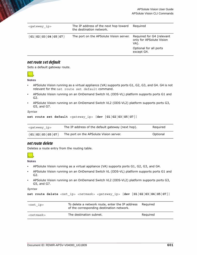
APSolute Vision User Guide
APSolute Vision CLI Commands
Document ID: RDWR-APSV-V04000_UG1809 601
net route set defaultSets a default gateway route.
Notes
• APSolute Vision running as a virtual appliance (VA) supports ports G1, G2, G3, and G4. G4 is not relevant for the net route set default command.
• APSolute Vision running on an OnDemand Switch VL (ODS-VL) platform supports ports G1 and G2.
• APSolute Vision running on an OnDemand Switch VL2 (ODS-VL2) platform supports ports G3, G5, and G7.
Syntax
net route set default <gateway_ip> [dev {G1|G2|G3|G5|G7}]
net route deleteDeletes a route entry from the routing table.
Notes
• APSolute Vision running as a virtual appliance (VA) supports ports G1, G2, G3, and G4.
• APSolute Vision running on an OnDemand Switch VL (ODS-VL) platform supports ports G1 and G2.
• APSolute Vision running on an OnDemand Switch VL2 (ODS-VL2) platform supports ports G3, G5, and G7.
Syntax
net route delete <net_ip> <netmask> <gateway_ip> [dev {G1|G2|G3|G4|G5|G7}]
<gateway_ip> The IP address of the next hop toward the destination network.
Required
{G1|G2|G3|G4|G5|G7} The port on the APSolute Vision server. Required for G4 (relevant only for APSolute Vision VA). Optional for all ports except G4.
<gateway_ip> The IP address of the default gateway (next hop). Required
{G1|G2|G3|G5|G7} The port on the APSolute Vision server. Optional
<net_ip> To delete a network route, enter the IP address of the corresponding destination network.
Required
<netmask> The destination subnet. Required

APSolute Vision User Guide
APSolute Vision CLI Commands
602 Document ID: RDWR-APSV-V04000_UG1809
net route getDisplays routing information for active routes and statically-configured host routes, network routes, and default routes.Syntax
net route get
System CommandsThe system menu includes the following system commands and command types for the APSolute Vision server:• System APM Commands, page 603• system audit-log export, page 603• System APSolute Vision Server Commands, page 604• System Backup Commands, page 604• system cleanup, page 620• System Configuration-Synchronization Commands, page 620• System Database Commands, page 624• System Date Commands, page 625• System DF Commands, page 626• System DPM Commands, page 628• System Exporter Commands (Event Exporter), page 632• system hardware status get, page 637• System Hostname Commands, page 637• System NTP Commands, page 638• system rpm list, page 640• System SNMP Commands, page 640• System SSL Commands, page 642• system statistics, page 645• System Storage Commands, page 645• System TCP Capture Commands, page 646• System Backup Technical-Support Commands, page 616• System Terminal Commands, page 648• System Timezone Commands, page 649• System Upgrade Commands, page 650• System User Authentication-Mode Commands, page 651
<gateway_ip> The IP address of the default gateway (next hop).
Required
{G1|G2|G3|G4|G5|G7} The physical port on the APSolute Vision server. Required for G4 (relevant only for APSolute Vision VA). Optional for all ports except G4.

APSolute Vision User Guide
APSolute Vision CLI Commands
Document ID: RDWR-APSV-V04000_UG1809 603
• System User Password Commands, page 652• system version, page 654
System APM CommandsUse system apm commands to manage aspects of an APSolute Vision server with APM server VA.
Note: For more information on APSolute Vision server with APM server VA, see the APSolute Vision Installation and Maintenance Guide and the Application Performance Monitoring Troubleshooting and Technical Guide.
The system apm commands comprise the following:
• system apm clear, page 603• system apm shell, page 603
system apm clearDeletes all APM data files, including raw data.Syntax
system apm clear
system apm shellLaunches the APM shell in an APSolute Vision server with APM server VA.
Note: From the APM shell, the exit command returns the CLI session to the APSolute Vision shell.
Syntax
system apm shell
system audit-log exportExports the audit-log to the location specified in the command.Syntax
system audit-log export <protocol>://<user>@<server>:/<path/to/directory>/<filename> {all|<yyyy-MM-dd>}
<protocol> Values: • ssh• sftp• ftp• scp
Required
<user> The username.
Note: If a password is required, you are prompted for it after the connection is initiated.
Required
<server> The IP address or DNS name of the server. Required

APSolute Vision User Guide
APSolute Vision CLI Commands
604 Document ID: RDWR-APSV-V04000_UG1809
System APSolute Vision Server CommandsUse system vision-server commands to manage the APSolute Vision server.
The system vision-server commands comprise the following:
• system vision-server start, page 604• system vision-server status, page 604• system vision-server stop, page 604
system vision-server startStarts the APSolute Vision server.Syntax
system vision-server start
system vision-server statusShows the status of the APSolute Vision server, Server running or Server stopped.
Syntax
system vision-server status
system vision-server stopStops the APSolute Vision server.Syntax
system vision-server stop
System Backup CommandsUse system backup commands to manage APSolute Vision system backups.
The system backup commands comprise the following:
• System Backup Configuration Commands, page 605• System Backup Full Commands, page 608• System Backup SecurityReporter Commands, page 612• System Backup Technical-Support Commands, page 616
<path/to/directory> The path to the export directory. Required
<filename> The filename of the audit-log in the export directory. Required
{all|<yyyy-MM-dd>} Specify all to export all entries, or specify the start date of records to export. The start date must be in yyyy-MM-dd format.
Required

APSolute Vision User Guide
APSolute Vision CLI Commands
Document ID: RDWR-APSV-V04000_UG1809 605
System Backup Configuration CommandsUse system backup config commands to manage APSolute Vision system-configuration backups.
The system backup config commands comprise the following:
• system backup config create, page 605• system backup config delete, page 605• system backup config export, page 606• system backup config import, page 607• system backup config info, page 607• system backup config list, page 608• system backup config restore, page 608
system backup config createCreates a backup of the system configuration in the storage location.
Note: For information on the storage location, see System Storage Commands, page 645.Each backup includes the following:• The APSolute Vision system configuration• The local users• The managed devices• The host IP addresses in the database-viewer list• The vDirect database file
The backup config create command does not back up the following:
• The password of the radware user of the APSolute Vision server appliance • The IP address/es of the APSolute Vision server appliance• The DNS address/es of the APSolute Vision server appliance• The network routes of the APSolute Vision server appliance• Attack data
The system stores up to five configuration-backup iterations. After the fifth configuration-backup, the system deletes the oldest one.Syntax
system backup config create <configName> [description]
system backup config deleteDeletes the specified system-configuration backup from the storage location.
Note: For information on the storage location, see System Storage Commands, page 645.
<configName> The name of the system-configuration backup, up to 15 characters, with no spaces. Only alphanumeric characters and underscores (_) are allowed.
Required
[description] The description of the system-configuration backup. Optional

APSolute Vision User Guide
APSolute Vision CLI Commands
606 Document ID: RDWR-APSV-V04000_UG1809
Syntax
system backup config delete <configName>
system backup config exportExports the specified system-configuration backup.
Note: For information on the storage location, see System Storage Commands, page 645.Syntax
system backup config export <configName> <protocol>://<user>@<server>:/<path/to/directory>/<filename>
<configName> The name of the system-configuration backup. Required
<configName> The name of the system-configuration backup. Required
<protocol> Values:• ssh• sftp• ftp• scp• file—This option exports the backup locally to the
location specified in the command.
Caution: Only root users have access to the local directory and can delete the file. You can, however, use the system backup config import command on the same machine with the file parameter to retrieve the exported backup. If you use the file option, Radware recommends that you place the file in the Maintenance Files folder, which you can access from the APSolute Vision server Web interface. For example:
system backup config export MyBackupName file:///opt/radware/storage/maintenance/MyBackupTargetName
Required
<user>@ The username.
Note: If a password is required, you are prompted for it after the connection is initiated.
Required
<server> The IP address or DNS name of the server. Required
<path/to/directory> The path to the export directory. Required
<filename> The filename of the system-configuration backup in the export directory, which may be different from the configName.
Required

APSolute Vision User Guide
APSolute Vision CLI Commands
Document ID: RDWR-APSV-V04000_UG1809 607
system backup config importImports the specified system-configuration backup from the specified location to the storage location.
Note: For information on the storage location, see System Storage Commands, page 645.Syntax
system backup config import <protocol>://<user>@<server>:/<path/to/directory><filename>
system backup config infoDisplays the following information about the specified system-configuration backup:• Name—The name of the system-configuration backup.• Disk Size—The size of the system-configuration backup on the disk.• Date—The time and date that the system-configuration backup was created.• Version—The APSolute Vision version and build number.• Description—The user-defined description of the system-configuration backup.
Syntax
system backup config info <configName>
<protocol> Values: • ssh• sftp• ftp• scp• file—Uses the backup file on the local machine, which
was made using the system backup config export command with the file option.
Required
<user>@ The username.
Note: If a password is required, you are prompted for it after the connection is initiated.
Required
<server> The IP address or DNS name of the server. Required
<path/to/directory> The path to the remote directory. Required
<filename> The name of the system-configuration backup in the remote directory, which may be different from the configName.
When the file is imported, the filename reverts to the configName, that is, the name that was used when the system-configuration backup was created.
Required
<configName> The name of the system-configuration backup. Required

APSolute Vision User Guide
APSolute Vision CLI Commands
608 Document ID: RDWR-APSV-V04000_UG1809
system backup config listLists the system-configuration backups in the storage location in a table with the following columns:• Name—The name of the system-configuration backup.• Size(K)—The size of the system-configuration backup on the disk.• Date—The time and date that the system-configuration backup was created.• Version—The APSolute Vision version and build number.• Description—The user-defined description of the system-configuration backup, which is
truncated as necessary to fit the table.
Note: For information on the storage location, see System Storage Commands, page 645.Syntax
system backup config list
system backup config restoreRestores the system using the specified system-configuration backup. The version and build number of the current system and the version and build number of the system that created the system-configuration backup must be the same.
Note: The restore process stops APSolute Vision and its associated services, and when it finishes, restarts them. Syntax
system backup config restore <configName> [-retainlicenses]
System Backup Full CommandsThe system backup full commands comprise the following:
• system backup full create, page 608• system backup full delete, page 609• system backup full export, page 609• system backup full import, page 610• system backup full info, page 611• system backup full list, page 611• system backup full restore, page 612
system backup full createCreates a system backup in the storage location. Each system backup includes all the data necessary to restore the entire system—but not the data of APSolute Vision Reporter (AVR) or the Device Performance Monitor (DPM).
<configName> The name of the system-configuration backup. Required
-retainlicenses Retains the currently installed licenses. Otherwise, the restore process overwrites existing licenses with the licenses from the backup file.
Optional

APSolute Vision User Guide
APSolute Vision CLI Commands
Document ID: RDWR-APSV-V04000_UG1809 609
Note: For information on the storage location, see System Storage Commands, page 645.The system stores up to five system backups. After the fifth system backup, the system deletes the oldest one.
Caution: The system backup does not include AVR or DPM data.
Syntax
system backup full create <backupName> [description]
system backup full deleteDeletes the specified system backup from the storage location.
Note: For information on the storage location, see System Storage Commands, page 645.Syntax
system backup full delete <backupName>
system backup full exportExports the specified system backup from the storage location to the location specified in the command.
Note: For information on the storage location, see System Storage Commands, page 645.Syntax
system backup full export <backupName> <protocol>://<user>@<server>:/<path/to/directory>/<filename>
<backupName> The name of the backup, up to 15 characters with no spaces. Only alphanumeric characters and underscores (_) are allowed.
Required
[description] The description of the backup. Optional
<backupName> The name of the backup. Required

APSolute Vision User Guide
APSolute Vision CLI Commands
610 Document ID: RDWR-APSV-V04000_UG1809
system backup full importImports the specified system backup from the specified location to the storage location.
Note: For information on the storage location, see System Storage Commands, page 645.The system stores up to five system backups. After the fifth system backup, the system deletes the oldest one. Syntax
system full backup import <protocol>://<user>@<server>:/<path/to/directory><filename>
<backupName> The name of the backup. Required
<protocol> Values: • ssh• sftp• ftp• scp• file—This option exports the backup locally to the
location specified in the command.
Caution: Only root users have access to the local directory and can delete the file. You can, however, use the system backup import command on the same machine with the file parameter to retrieve the exported backup.If you use the file option, Radware recommends that you place the file in the Maintenance Files folder, which you can access from the APSolute Vision server Web interface.For example:
system backup full export MyBackupName file:///opt/radware/storage/maintenance/MyBackupTargetName
Required
<user>@ The username.
Note: If a password is required, you are prompted for it after the connection is initiated.
Required
<server> The IP address or DNS name of the server. Required
<path/to/directory> The path to the export directory. Required
<filename> The filename of the backup in the export directory, which may be different from the backupName.
Required

APSolute Vision User Guide
APSolute Vision CLI Commands
Document ID: RDWR-APSV-V04000_UG1809 611
system backup full infoDisplays the following information about the specified system backup:• Name—The name of the backup.• Disk Size—The size of the backup on the disk.• Date—The time and date that the backup was created.• Version—The APSolute Vision version and build number.• Description—The user-defined description of the backup.
Syntax
system backup full info <backupName>
system backup full listLists the system backups in the storage location in a table with the following columns:• Name—The name of the backup.• Size(K)—The size of the backup on the disk.• Date—The time and date that the backup was created.• Version—The APSolute Vision version and build number.• Description—The user-defined description of the backup, which is truncated as necessary to fit
the table.
Note: For information on the storage location, see System Storage Commands, page 645.
<protocol> Values: • ssh• sftp• ftp• scp• file—Uses the backup file on the local machine, which
was made using the system backup full export command with the file option.
Required
<user>@ The username.
Note: If a password is required, you are prompted for it after the connection is initiated.
Required
<server> The IP address or DNS name of the server. Required
<path/to/directory> The path to the export directory. Required
<filename> The name of the backup in the export directory, which may be different from the backupName.
When the file is imported, the filename reverts to the backupName, that is, the name that was used when the backup was created.
Required
<backupName> The name of the backup. Required

APSolute Vision User Guide
APSolute Vision CLI Commands
612 Document ID: RDWR-APSV-V04000_UG1809
Syntax
system backup full list
system backup full restoreRestores the system using the specified system backup. The version and build number of the current system and the version and build number of the system that created the backup must be the same.
Caution: The system backup does not include the data of APSolute Vision Reporter (AVR) or the Device Performance Monitor (DPM). If you use AVR or DPM, you must restore the system before you restore the AVR and/or DPM data.
Caution: If the password of the reporter user (used for the Vision Reporting Module) changed after running system backup full create, before you run the system backup full restore command, you must update the password on the APSolute Vision server
Note: The restore process stops APSolute Vision and its associated services, and when it finishes, restarts them.Syntax
system backup full restore <backupName> [-retainlicenses]
System Backup SecurityReporter CommandsUse system backup securityReporter commands to manage backups of APSolute Vision Reporter data.
The system backup securityReporter commands comprise the following:
• system backup securityReporter create, page 613• system backup securityReporter delete, page 613• system backup securityReporter export, page 613• system backup securityReporter import, page 614• system backup securityReporter info, page 615• system backup securityReporter list, page 615• system backup securityReporter restore, page 616
<backupName> The name of the backup. Required
-retainlicenses Retains the currently installed licenses. Otherwise, the restore process overwrites existing licenses with the licenses from the backup file.
Optional

APSolute Vision User Guide
APSolute Vision CLI Commands
Document ID: RDWR-APSV-V04000_UG1809 613
system backup securityReporter createCreates a APSolute Vision Reporter data backup in the storage location. The system stores up to three reporter-backup iterations backups. After the third reporter-backup, the system deletes the oldest one.The backup includes all the APSolute Vision Reporter data.
Note: For information on the storage location, see System Storage Commands, page 645.Syntax
system backup securityReporter create <securityReporterName> <description>
system backup securityReporter deleteDeletes the specified reporter-backup from the storage location.
Note: For information on the storage location, see System Storage Commands, page 645.Syntax
system backup securityReporter delete <securityReporterName>
system backup securityReporter exportExports the specified reporter-backup from the storage location to a specified location.
Note: For information on the storage location, see System Storage Commands, page 645.Syntax
system backup securityReporter export <securityReporterName> <protocol>://<user>@<server>:/<path/to/directory>/<filename>
<securityReporterName> The name of the reporter-backup, up to 15 characters, with no spaces. Only alphanumeric characters and underscores (_) are allowed.
Required
<description> The description of the reporter-backup. Optional
<securityReporterName> The name of the reporter-backup. Required

APSolute Vision User Guide
APSolute Vision CLI Commands
614 Document ID: RDWR-APSV-V04000_UG1809
system backup securityReporter importImports the specified reporter-backup from the specified location to the storage location.
Note: For information on the storage location, see System Storage Commands, page 645.Syntax
system backup securityReporter import <protocol>://<user>@<server>:/<path/to/directory><filename>
<securityReporterName> The name of the reporter-backup. Required
<protocol> Values: • ssh• sftp• ftp• scp• file—This option exports the backup locally to the
location specified in the command.
Caution: Only root users have access to the local directory and can delete the file. You can, however, use the system backup securityReporter import command on the same machine with the file parameter to retrieve the exported backup. If you use the file option, Radware recommends that you place the file in the Maintenance Files folder, which you can access from the APSolute Vision server Web interface. For example:
system backup securityReporter export MyBackupName file:///opt/radware/storage/maintenance/MyBackupTargetName
Required
<user>@ The username.
Note: If a password is required, you are prompted for it after the connection is initiated.
Required
<server> The IP address or DNS name of the server. Required
<path/to/directory> The path to the export directory. Required
<filename> The filename of the reporter-backup in the export directory, which may be different from the securityReporterName.
Required
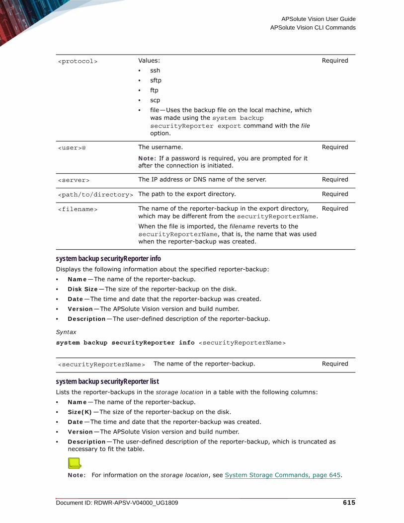
APSolute Vision User Guide
APSolute Vision CLI Commands
Document ID: RDWR-APSV-V04000_UG1809 615
system backup securityReporter infoDisplays the following information about the specified reporter-backup:• Name—The name of the reporter-backup.• Disk Size—The size of the reporter-backup on the disk.• Date—The time and date that the reporter-backup was created.• Version—The APSolute Vision version and build number.• Description—The user-defined description of the reporter-backup.
Syntax
system backup securityReporter info <securityReporterName>
system backup securityReporter listLists the reporter-backups in the storage location in a table with the following columns:• Name—The name of the reporter-backup.• Size(K)—The size of the reporter-backup on the disk.• Date—The time and date that the reporter-backup was created.• Version—The APSolute Vision version and build number.• Description—The user-defined description of the reporter-backup, which is truncated as
necessary to fit the table.
Note: For information on the storage location, see System Storage Commands, page 645.
<protocol> Values: • ssh• sftp• ftp• scp• file—Uses the backup file on the local machine, which
was made using the system backup securityReporter export command with the file option.
Required
<user>@ The username.
Note: If a password is required, you are prompted for it after the connection is initiated.
Required
<server> The IP address or DNS name of the server. Required
<path/to/directory> The path to the export directory. Required
<filename> The name of the reporter-backup in the export directory, which may be different from the securityReporterName.
When the file is imported, the filename reverts to the securityReporterName, that is, the name that was used when the reporter-backup was created.
Required
<securityReporterName> The name of the reporter-backup. Required

APSolute Vision User Guide
APSolute Vision CLI Commands
616 Document ID: RDWR-APSV-V04000_UG1809
Syntax
system backup securityReporter list
system backup securityReporter restoreRestores the APSolute Vision Reporter (AVR) data using the specified reporter-backup. The version and build number of the current system and the version and build number of the system that created the reporter-backup must be the same.
Caution: When you are restoring the system backup also, you must restore the system before you restore AVR data.
Caution: After the restore process is complete, verify that AVR is successfully collecting data for new attacks and traffic events. To do this, in AVR, select Setup > Admin Messages.
Note: The restore process stops APSolute Vision and its associated services, and when it finishes, restarts them. Syntax
system backup securityReporter restore <securityReporterName>
System Backup Technical-Support CommandsIf you encounter problems with APSolute Vision, you can create a technical-support package and send it to Radware Technical Support for assistance.
Use system backup techSupport commands to manage technical-support packages for the APSolute Vision server.
The system backup techSupport commands comprise the following:
• system backup techSupport local, page 616• system backup techSupport create, page 617• system backup techSupport export, page 618• system backup techSupport info, page 619• system backup techSupport list, page 619• system backup techSupport delete, page 619
system backup techSupport local Creates a tech-support package that you can access in the APSolute Vision Web interface (APSolute Vision Settings mode System perspective, General Settings > Maintenance Files). When the process finishes, the CLI message includes the hard-coded filepath and name of the package, which is a .tar file.
<securityReporterName> The name of the reporter-backup. Required

APSolute Vision User Guide
APSolute Vision CLI Commands
Document ID: RDWR-APSV-V04000_UG1809 617
Notes
• This command is an alternative to using the two separate commands, system backup techSupport create and system backup techSupport export.
• You can delete the .tar file using system backup techSupport delete (without the .tar extension).
APSolute Vision generates each package in a .tar file using the following format:
vision_support_<IPAddress>_<MM-dd-yy-hhmm>.tar
where:
• <IPAddress> is the IP address of the APSolute Vision server.
• <MM-dd-yy-hhmm> is the date and time.
Each tech-support package includes the following:• The current system time in millis (from Unix epoch)• The APSolute Vision version and build number• APSolute Vision system configuration, which includes the network IP addresses, DNS address,
routes, and so on• Running processes• The status of each APSolute Vision service• APSolute Vision system logs• APSolute Vision Reporter logs• APSolute Vision debug logs• Disk usage• Additional internal-resource information
Syntax
system backup techSupport local
system backup techSupport createCreates a tech-support package.The system stores up to three tech-support packages in the storage location. After the third tech-support package, the system deletes the oldest one.
Note: For information on the storage location, see System Storage Commands, page 645.Each tech-support package includes the following:• The current system time in millis• The APSolute Vision version and build number• APSolute Vision system configuration, which includes the network IP addresses, DNS address,
routes, and so on• Running processes• The status of each APSolute Vision service• APSolute Vision system logs• APSolute Vision Reporter logs• APSolute Vision debug logs

APSolute Vision User Guide
APSolute Vision CLI Commands
618 Document ID: RDWR-APSV-V04000_UG1809
• Disk usage• Additional internal-resource information
Syntax
system backup techSupport create <techSupportName> [<description>]
system backup techSupport exportExports the specified tech-support package from the storage location to the specified location.
Note: For information on the storage location, see System Storage Commands, page 645.Syntax
system backup techSupport export <techSupportName> <protocol>://<user>@<server>:/<path/to/directory>/<filename>
<techSupportName> The name of the tech-support package, up to 15 characters, with no spaces. Only alphanumeric characters and underscores (_) are allowed.
Required
<description> The description of the tech-support package. Optional
<techSupportName> The name of the tech-support package. Required
<protocol> Values:• ssh• sftp• ftp• scp• file—This option exports the backup locally to the
location specified in the command.
Caution: Only root users have access to the local directory and can delete the file. If you use the file option, Radware recommends that you place the file in the Maintenance Files folder, which you can access from the APSolute Vision server Web interface. For example:
system backup techSupport export MyTechSupportName file:///opt/radware/storage/maintenance/MyBackupTargetName
Required
<user>@ The username.
Note: If a password is required, you are prompted for it after the connection is initiated.
Required
<server> The IP address or DNS name of the server. Required

APSolute Vision User Guide
APSolute Vision CLI Commands
Document ID: RDWR-APSV-V04000_UG1809 619
system backup techSupport infoDisplays the following information about the specified tech-support package:• Name—The name of the tech-support package.• Disk Size—The size of the tech-support package on the disk.• Date—The time and date that the tech-support package was created. • Version—The APSolute Vision version and build number. • Description—The user-defined description of the tech-support package.
Syntax
system backup techSupport info <techSupportName>
system backup techSupport listLists the tech-support packages in the storage location in a table with the following columns:• Name—The name of the tech-support package.• Size(K)—The size of the tech-support package on the disk.• Date—The time and date that the tech-support package was created.• Version—The APSolute Vision version and build number.• Description—The user-defined description of the tech-support package, which is truncated as
necessary to fit the table.
Note: For information on the storage location, see System Storage Commands, page 645.Syntax
system backup techSupport list
system backup techSupport delete
Deletes the specified tech-support package. For a package that system techSupport create created, system backup techSupport delete deletes the package in the storage location. For a package that system backup techSupport local created, system backup techSupport delete deletes the package in the hard-coded local location.
Notes
• For information on the storage location, see System Storage Commands, page 645.
• For information on system backup techSupport local, see system backup techSupport local, page 616.
Syntax
system backup techSupport delete <techSupportName>
<path/to/directory> The path to the export directory. Required
<filename> The filename of the tech-support package in the export directory, which may be different from the techSupportName.
Required
<techSupportName> The name of the tech-support package. Required

APSolute Vision User Guide
APSolute Vision CLI Commands
620 Document ID: RDWR-APSV-V04000_UG1809
system cleanupCleans all the data on the APSolute Vision server, or cleans all the data on the APSolute Vision server except for the following:• APSolute Vision server management IP addresses and routes• Installed licenses
Syntax
system cleanup {full|without-server-ip}
System Configuration-Synchronization CommandsUse system config-sync commands to deploy and manage a configuration-synchronization pair of APSolute Vision server instances in an active/standby topology, so that all the configuration on the active instance is automatically synched to the standby instance. The system config-sync commands are part of the APSolute Vision configuration-synchronization feature. When the configuration-synchronization mode of an APSolute Vision server is active, at the specified interval, that server notifies the standby server (the configured peer) to fetch the configuration.
Caution: It is the responsibility of the APSolute Vision administrator to register the APSolute Vision servers as a target of the device events (for example, traps, alerts, IRP messages, and packet-reporting data) on the managed devices. For related information, see APSolute Vision Server Registered for Device Events—Alteon and LinkProof NG, page 178, APSolute Vision Server Registered for Device Events—DefensePro, page 178, and APSolute Vision Server Registered for Device Events—AppWall, page 179.
<techSupportName> The name of the tech-support package. Required
{full|without-server-ip} The command with the full argument restores the APSolute Vision server to the factory defaults. After you run the command with the full argument, the initial configuration script launches automatically.
The command with the without-server-ip argument cleans all the data on the APSolute Vision server but retains the APSolute Vision server management IP addresses and routes.
Required

APSolute Vision User Guide
APSolute Vision CLI Commands
Document ID: RDWR-APSV-V04000_UG1809 621
Requirements of the configuration-synchronization feature:• The APSolute Vision version and build number must be the same for both members of a
configuration-synchronization setup.• The DefensePro devices that the members of a configuration-synchronization setup manage
must be configured with the same connectivity settings.• Ports 443 and 5672 on both members of a configuration-synchronization setup must be
accessible and not blocked by your firewall—in both directions.
Limitations of the configuration-synchronization feature:• The APSolute Vision server instance in the configuration-synchronization setup are not aware of
one another. It is possible—but not recommended—that both peers of a configuration-synchronization setup are in the active mode.
• There is no detection and/or alert in the event of a failure of an APSolute Vision server.• There is no automatic failover mechanism. It is the responsibility of the APSolute Vision
administrator to change the role of the standby server to active, when required.• The configuration-synchronization is encrypted, but the connection is not.• The configuration-synchronization feature does not support APM, DPM, or vDirect.• APSolute Vision Reporter (AVR) limitations:
— Configuration-synchronization for historical reports covers downtime up to one hour for Traffic Utilization and Baselines data, and up to 24 hours of Attack data. A longer downtime requires manual backup and restore.
— If the AVR is down, there is a 20-minute window for the AVR to synchronize the database before APSolute Vision cleans it up and the data is lost.
The system config-sync commands comprise the following:
• system config-sync mode Commands, page 621• system config-sync peer Commands, page 622• system config-sync interval Commands, page 623• system config-sync status, page 623• system config-sync manual, page 624
system config-sync mode CommandsUse system config-sync mode commands to manage the configuration-synchronization mode of the APSolute Vision server.
The system config-sync mode commands comprise the following:
• system config-sync mode set, page 621• system config-sync mode get, page 622
system config-sync mode setManages the status of the configuration-sync feature on the APSolute Vision server.Syntax
system config-sync mode set {active|disabled|standby}

APSolute Vision User Guide
APSolute Vision CLI Commands
622 Document ID: RDWR-APSV-V04000_UG1809
system config-sync mode getDisplays the configuration-synchronization mode of the APSolute Vision server: active, disabled, or standby.Syntax
system config-sync mode get
system config-sync peer CommandsUse system config-sync peer commands to manage the peer IP address or hostname.
The system config-sync peer commands comprise the following:
• system config-sync peer set, page 622• system config-sync peer get, page 623
system config-sync peer setSets the IP address or hostname for the peer APSolute Vision server.Syntax
system config-sync peer set <IP address or hostname>
{active|disabled|standby} Values:
• active—Sets the server as the active instance of a configuration-synchronization pair.
• disabled—Disables the configuration-synchronization feature.
• standby—Sets the server as the standby instance of a configuration-synchronization pair.
Default: disabled
Notes: • Setting the mode to standby stops the
configuration service on the APSolute Vision server.
• An APSolute Vision server in the standby mode cannot lock or configure devices, or execute scheduled tasks or scripts.
• An APSolute Vision server in the standby mode is not accessible through Web or REST interfaces.
• If the mode was standby, setting the mode to active or disabled starts the configuration service on the APSolute Vision server.
Required
<IP address or hostname> The IP address or hostname for the peer APSolute Vision server.
Required

APSolute Vision User Guide
APSolute Vision CLI Commands
Document ID: RDWR-APSV-V04000_UG1809 623
system config-sync peer getDisplays the peer IP address or hostname.Syntax
system config-sync peer get
system config-sync interval CommandsUse system config-sync interval commands to manage the interval at which the APSolute Vision server with the active role notifies the server with the standby role to fetch the configuration.
The system config-sync interval commands comprise the following:
• system config-sync interval set, page 623• system config-sync interval get, page 623
system config-sync interval setSets the interval, in minutes, at which the APSolute Vision server with the active role notifies the server with the standby role to fetch the configuration.Syntax
system config-sync interval set <interval>
system config-sync interval getDisplays the configuration-synchronization interval, in minutes.Syntax
system config-sync interval get
system config-sync statusDisplays the following configuration-synchronization information:
• Mode—The configuration-synchronization mode of the APSolute Vision server instance: active or disabled.
• Interval—The configuration-synchronization interval, in minutes, that is configured on the APSolute Vision server instance.
Note: The configuration-synchronization actions are according to the interval that is configured on the active server.
• Peer Address—Displays the IP address or hostname of the peer.• Last Configuration Sync Date—Displays the date of the last configuration-synchronization
action in the format MM/dd/yyyy hh:mm:ss.
• Last Configuration Sync Timestamp—Displays the time of the last configuration-synchronization action in millis (from Unix epoch).
Syntax
system config-sync status
<interval> Values: 1–1440 (24 hours)Default: 5
Required

APSolute Vision User Guide
APSolute Vision CLI Commands
624 Document ID: RDWR-APSV-V04000_UG1809
system config-sync manualManually starts a configuration-synchronization action. Invoking a manual configuration-synchronization action is possible only on the server with the active role.Syntax
system config-sync manual
System Database CommandsUse system database commands to manage the APSolute Vision database.
The system database commands comprise the following:
• system database clear, page 624• system database start, page 624• system database status, page 624• system database stop, page 624
system database clearClears and initializes the APSolute Vision database.Syntax
system database clear
system database startRestarts the APSolute Vision database, making it available for access.Syntax
system database start
system database statusShows the database status. For example, the output:MySQL running (2688) [OK]shows the database is up and running with process ID 2688.Syntax
system database status
system database stopStops the APSolute Vision database, making it unavailable for access.Syntax
system database stop
system database maintenance CommandsThe system database maintenance commands comprise the following:
• system database maintenance optimize, page 625• system database maintenance check, page 625• system database maintenance driver_table delete, page 625

APSolute Vision User Guide
APSolute Vision CLI Commands
Document ID: RDWR-APSV-V04000_UG1809 625
system database maintenance optimizeOptimizes the relevant tables.Syntax
system database maintenance optimize
system database maintenance checkChecks whether the database needs optimization.Syntax
system database maintenance check
system database maintenance driver_table deleteStops the APSolute Vision server, deletes all device drivers from the Device Drivers table, and starts the server. This command permanently deletes all device drivers that were manually uploaded to the Device Drivers table (Asset Management perspective > General Settings > Device Drivers).When APSolute Vision restarts:• For managed devices of product versions created before the introduction of the
device-driver feature—APSolute Vision reloads the device drivers from the APSolute Vision file system. (APSolute Vision persistently maintains the device drivers of product versions created before the introduction of the device-driver feature.)
• For managed devices of product versions created with the device-driver feature—APSolute Vision retrieves and loads the device driver from each managed device.
Caution: If you require functionality that relies on a manually uploaded device driver (for example, as is the case with configuration templates), you must upload the relevant device driver again.
Note: For more information on device drivers, see Managing Device Drivers, page 139. Syntax
system database maintenance driver_table delete
System Date CommandsUse system date commands to display and set date and time on the APSolute Vision server.
The system date commands comprise the following:
• system date get, page 625• system date set, page 626
system date getDisplays the APSolute Vision server date and time.Syntax
system date get

APSolute Vision User Guide
APSolute Vision CLI Commands
626 Document ID: RDWR-APSV-V04000_UG1809
system date setSets the date and time on the APSolute Vision server.
Caution: For APSolute Vision VA—The time on the APSolute Vision VA must be the same as—or within several minutes of—the time on the VMware host. Otherwise, an APSolute Vision reboot may hang (even when, in the VMware Tools, the synchronize guest time with host checkbox is cleared). If the reboot hangs, reboot the APSolute Vision VA server, which should solve the problem. For more information on this issue, refer to the VMware knowledge article Timekeeping best practices for Linux guests (1006427) at http://kb.vmware.com/selfservice/microsites/search.do?language=en_US&cmd=displayKC&externalId=1006427).
Notes
• Setting the system date stops the NTP service.
• Setting the system date requires restarting the APSolute Vision server, the APSolute Vision Reporter, and MySQL.
• The APSolute Vision Reporter client supports only a single timezone, which is the timezone configured in APSolute Vision server.
Syntax
system date set <date_and_time>
Example system date set 2010/05/23 13:56:00 sets date and time to 23/05/2010 13:56.
System DF CommandsUse df commands to manage the DefenseFlow device associated with the APSolute Vision server.
Note: APSolute Vision allows only one DefenseFlow device to be associated with it.
The system df commands comprise the following:
• system df management-ip get, page 626• system df management-ip set, page 627• system df management-ip delete, page 627• system df shell, page 627
system df management-ip getDisplays the IP address of the DefenseFlow associated with the APSolute Vision server.Syntax
system df management-ip get
<date_and_time> The date and time in yyyy/MM/dd hh:mm:ss format. Required

APSolute Vision User Guide
APSolute Vision CLI Commands
Document ID: RDWR-APSV-V04000_UG1809 627
system df management-ip setSets the IP address of an external DefenseFlow device to be associated with the APSolute Vision server.
Caution: APSolute Vision automatically restarts after running this command.
Notes
• If the APSolute Vision server includes an embedded DefenseFlow device, this command is not required.
• If the APSolute Vision server includes an embedded DefenseFlow device, you can set a different (external) DefenseFlow device to be associated with the APSolute Vision server.
Syntax
system df management-ip set <IP_address>
system df management-ip deleteUnregisters the specified IP address of the external DefenseFlow device associated with the APSolute Vision server.
Caution: APSolute Vision automatically restarts after running this command.
Syntax
system df management-ip delete <IP_address>
system df shellLaunches the DefenseFlow shell.Syntax
system df shell
IP_address The IP address of the DefenseFlow associated with the APSolute Vision server.
Required
IP_address The IP address of the DefenseFlow associated with the APSolute Vision server to be unregistered.
Required

APSolute Vision User Guide
APSolute Vision CLI Commands
628 Document ID: RDWR-APSV-V04000_UG1809
System DPM CommandsUse dpm commands to manage the Device Performance Monitor (DPM).
The system dpm commands comprise the following:
• system dpm database clear, page 628• system backup dpm create, page 628• system dpm backup delete, page 628• system dpm backup export, page 629• system dpm backup import, page 629• system dpm backup list, page 629• system dpm backup restore, page 630• system dpm techSupport Commands, page 630• system dpm debug Commands, page 631
system dpm database clearClears the Device Performance Monitor database.
Caution: This command deletes all the data for the Device Performance Monitor.
Syntax
system dpm database clear
system backup dpm createCreates a Device Performance Monitor backup in the storage location.
Note: For information on the storage location, see System Storage Commands, page 645.The system stores up to three DPM backups. After the third tech-support package, the system deletes the oldest one.Syntax
system dpm backup create <dpm_bu_name>
system dpm backup deleteDeletes the specified Device Performance Monitor backup.Syntax
system dpm backup delete <dpm_bu_name>
<dpm_bu_name> The name of the DPM backup, up to 15 characters, with no spaces. Only alphanumeric characters and underscores (_) are allowed.
Required
<dpm_bu_name> The name of the DPM backup, up to 15 characters, with no spaces. Only alphanumeric characters and underscores (_) are allowed.
Required

APSolute Vision User Guide
APSolute Vision CLI Commands
Document ID: RDWR-APSV-V04000_UG1809 629
system dpm backup exportExports the specified Device Performance Monitor backup from the storage location to the specified target.
Note: For information on the storage location, see System Storage Commands, page 645.Syntax
system dpm backup export <dpm_bu_name> <protocol>://<user>@<ip>://<path/to/directory><RemoteFolder>
system dpm backup importImports the specified Device Performance Monitor backup to the storage location.
Note: For information on the storage location, see System Storage Commands, page 645.Syntax
system dpm backup import <protocol>://<user>@<ip>://<path/to/directory><BackupFilename>
system dpm backup listLists the available Device Performance Monitor backups.Syntax
system dpm backup list
<dpm_bu_name> The name of the DPM backup. Required
<protocol> Value: ftp Required
<user>@ The username.
Note: If a password is required, you are prompted for it after the connection is initiated.
Required
<server> The IP address or DNS name of the server. Required
<path/to/directory> The path to the export directory. Required
<RemoteFolder> The remote folder for the file in the export directory. Required
<protocol> Value: ftp Required
<user>@ The username.
Note: If a password is required, you are prompted for it after the connection is initiated.
Required
<server> The IP address or DNS name of the server. Required
<path/to/directory> The path to the remote directory. Required
<BackupFilename> The filename of the backup in the remote directory. Required

APSolute Vision User Guide
APSolute Vision CLI Commands
630 Document ID: RDWR-APSV-V04000_UG1809
system dpm backup restoreRestores the Device Performance Monitor with the data of the specified backup.
Caution: When you are restoring the system backup also, you must restore the system before you restore DPM data. Otherwise, the devices in DPM will be marked as deleted.
Note: This action also stops and restarts the Device Performance Monitor process.Syntax
system dpm backup restore <dpm_bu_name>
system dpm techSupport CommandsAPSolute Vision supports commands for to help Radware Technical Support solve problems with the Device Performance Monitor. Use the commands under the instructions of Radware Technical Support.
The system dpm techSupport commands comprise the following:
• system dpm techSupport create, page 630• system dpm techSupport export, page 630• system dpm techSupport list, page 631• system dpm techSupport delete, page 631
system dpm techSupport createCreates a DPM tech-support package in the storage location.
Note: For information on the storage location, see System Storage Commands, page 645.The system stores up to three DPM tech-support packages. After the third tech-support package, the system deletes the oldest one.Syntax
system dpm techSupport create <techSupportName> [description]
system dpm techSupport exportExports the specified Device Performance Monitor tech-support file to the specified target.Syntax
system dpm techSupport export <dpm_techsupport_name> <protocol>://<user>@<ip>://<path/to/directory><RemoteFolder>
<dpm_bu_name> The name of the DPM backup, up to 15 characters, with no spaces. Only alphanumeric characters and underscores (_) are allowed.
Required
<techSupportName> The name of the tech-support package, up to 15 characters, with no spaces. Only alphanumeric characters and underscores (_) are allowed.
Required
[description] The description of the tech-support package. Optional

APSolute Vision User Guide
APSolute Vision CLI Commands
Document ID: RDWR-APSV-V04000_UG1809 631
system dpm techSupport listLists the DPM tech-support packages in the storage location.
Note: For information on the storage location, see System Storage Commands, page 645.Syntax
system dpm techSupport list
system dpm techSupport deleteDeletes the specified DPM tech-support package in the storage location.
Note: For information on the storage location, see System Storage Commands, page 645.Syntax
system dpm techSupport delete <techSupportName>
system dpm debug CommandsAPSolute Vision supports commands for debugging the Device Performance Monitor. Use the commands under the instructions of Radware Technical Support.
system dpm debug commands:
• system dpm debug start
• system dpm debug stop
• system dpm debug status
• system dpm debug version
• system dpm debug database
• system dpm debug database count
• system dpm debug database devices
• system dpm debug database connections
• system dpm debug database query
• system dpm debug sample
<dpm_techsupport_name> The name of the tech-support file. Required
<protocol> Value: ftp Required
<user>@ The username.
Note: If a password is required, you are prompted for it after the connection is initiated.
Required
<server> The IP address or DNS name of the server. Required
<path/to/directory> The path to the export directory. Required
<RemoteFolder> The remote folder for the file in the export directory. Required
<techSupportName> The name of the tech-support package. Required

APSolute Vision User Guide
APSolute Vision CLI Commands
632 Document ID: RDWR-APSV-V04000_UG1809
• system dpm debug sample create
• system dpm debug sample delete
• system dpm debug sample list
• system dpm debug sample export
• system dpm debug install
Caution: The system dpm debug install command performs a fresh installation of the DPM service, and all existing DPM data is deleted.
System Exporter Commands (Event Exporter)Use the system exporter commands to configure the APSolute Vision event exporter. The event exporter can export security-event records from managed DefensePro and/or DefenseFlow devices to a specified syslog server. The event exporter lets you integrate with a Security Information Event Management (SIEM) system, which you may be using as your main analytics-and-reporting system.
Notes
• For information about the records from the event exporter, see Appendix E - Using the Event Exporter, page 737.
• When you use the event exporter within an active/standby topology, only the active instance exports the security-event information. (For more information, see System Configuration-Synchronization Commands, page 620.)
• The event exporter can export to the specified syslog server only over UDP.
The system exporter commands comprise the following:
• system exporter configuration get, page 632• System Exporter Event-Type Commands, page 633• System Exporter History Commands, page 634• System Exporter State Commands, page 635• System Exporter Syslog-Host Commands, page 636• System Exporter Syslog-Port Commands, page 636
system exporter configuration getDisplays the full configuration of the event exporter.Syntax
system exporter configuration get

APSolute Vision User Guide
APSolute Vision CLI Commands
Document ID: RDWR-APSV-V04000_UG1809 633
Example output Exporter disabled
type: syslog
syslogHost:
syslogPort: 514
rabbitHost: rabbit-rabbitPort: 5672-rabbitUserName: radware-rabbitPassword: radware-rabbitQueueName: event.exporter
DPTrafficUtilization: true
DPSecurityAttack: true
DFSecurityAttack: true
DFTrafficUtilization: true
DFBdosBaseline: true
System Exporter Event-Type CommandsUse system exporter event-type commands to manage the event types that the event exporter exports.
The system exporter event-type commands comprise the following:
• system exporter event-type disable, page 633• system exporter event-type enable, page 634• system exporter event-type get, page 634
system exporter event-type disableDisables exporting events per event type. full configuration of the event exporter.Syntax
system exporter event-type disable <event-type>
<event-type> The type of the event to disable export.Values:
• all—Disables all event-types exporting.
• DFBdosBaseline—Disables DefenseFlow BDoS Baseline exporting.
• DFSecurityAttack—Disables DefenseFlow Security Attack exporting.
• DFTrafficUtilization—Disables DefenseFlow Traffic Utilization exporting.
• DPSecurityAttack—Disables DefensePro Security Attack exporting.
• DPTrafficUtilization—Disables DefensePro Traffic Utilization exporting.
Required

APSolute Vision User Guide
APSolute Vision CLI Commands
634 Document ID: RDWR-APSV-V04000_UG1809
system exporter event-type enableEnables exporting events per event type. Syntax
system exporter event-type enable <event-type>
system exporter event-type getDisplays the configuration of exporting events per event type.Syntax
system exporter event-type get <event-type>
System Exporter History CommandsUse system exporter history commands to export previous records, which are stored on APSolute Vision.
The system exporter event-type commands comprise the following:
• system exporter history last, page 635• system exporter history period, page 635
<event-type> The type of the event to enable export.Values:
• all—Enables all event-types exporting.
• DFBdosBaseline—Enables DefenseFlow BDoS Baseline exporting.
• DFSecurityAttack—Enables DefenseFlow Security Attack exporting.
• DFTrafficUtilization—Enables DefenseFlow Traffic Utilization exporting.
• DPSecurityAttack—Enables DefensePro Security Attack exporting.
• DPTrafficUtilization—Enables DefensePro Traffic Utilization exporting.
Required
<event-type> The type of the event to enable export.Values:
• all—Displays the configuration of all event-types exporting.
• DFBdosBaseline—Displays the configuration of DefenseFlow BDoS Baseline exporting.
• DFSecurityAttack—Displays the configuration of DefenseFlow Security Attack exporting.
• DFTrafficUtilization—Displays the configuration of DefenseFlow Traffic Utilization exporting.
• DPSecurityAttack—Displays the configuration of DefensePro Security Attack exporting.
• DPTrafficUtilization—Displays the configuration of the configuration of DefensePro Traffic Utilization exporting.
Required

APSolute Vision User Guide
APSolute Vision CLI Commands
Document ID: RDWR-APSV-V04000_UG1809 635
system exporter history lastExports all the export events of the last 30 days. Syntax
ssystem exporter history last
system exporter history periodExports all the event-exporter records, which are stored on APSolute Vision, for any specified period, which can be up to thirty days long.Syntax
system exporter history period <from> <to>
System Exporter State CommandsUse system exporter state commands to manage the state of the exporter.
The system exporter state commands comprise the following:
• system exporter configuration state disable, page 635• system exporter configuration state enable, page 635• system exporter configuration state get, page 636
system exporter configuration state disableDisables the event exporter.Syntax
system exporter state disable
system exporter configuration state enableEnables the event exporter and displays the current configuration, which includes the following parameters:• syslogHost—For more information, see System Exporter Syslog-Host Commands, page 636.• syslogPort—For more information, see System Exporter Syslog-Port Commands, page 636.• DPTrafficUtilization—true or false; that is, enabled or disabled. For more information, see
System Exporter Event-Type Commands, page 633.• DPSecurityAttack—true or false; that is, enabled or disabled. For more information, see
System Exporter Event-Type Commands, page 633.• DFSecurityAttack—true or false; that is, enabled or disabled. For more information, see
System Exporter Event-Type Commands, page 633.• DFTrafficUtilization—true or false; that is, enabled or disabled. For more information, see
System Exporter Event-Type Commands, page 633.• DFBdosBaseline—true or false; that is, enabled or disabled. For more information, see System
Exporter Event-Type Commands, page 633.
Note: Some values are for future use.
<from> The start day and time, in yyyy/MM/dd:HH:mm:ss format. Required
<to> The end day and time, in yyyy/MM/dd:HH:mm:ss format. Required

APSolute Vision User Guide
APSolute Vision CLI Commands
636 Document ID: RDWR-APSV-V04000_UG1809
Syntax
system exporter state get
system exporter configuration state getDisplays the state of the event exporter: enabled, or disabled.Syntax
system exporter state get
System Exporter Syslog-Host CommandsThe system exporter syslog-host commands comprise the following:
• System exporter syslog-host get, page 636• system exporter syslog-host set, page 636
System exporter syslog-host getDisplays the host name or IP address of the syslog server, which is the target of the event exporter.Syntax
system exporter syslog-host get
system exporter syslog-host setSets the host name or IP address of the syslog server, which is the target of the event exporter.Syntax
system exporter syslog-host set <host>
System Exporter Syslog-Port Commands The system exporter syslog-port commands comprise the following:
• System exporter syslog-port get, page 636• system exporter syslog-port set, page 636
System exporter syslog-port getDisplays the port number of the syslog server, which is the target of the event exporter.Syntax
system system exporter syslog-port get
system exporter syslog-port setSets the port number syslog server, which is the target of the event exporter.Syntax
system system exporter syslog-port set <port>
<host> The host name or IP address. Required
<port> The port number. Default: 514
Required

APSolute Vision User Guide
APSolute Vision CLI Commands
Document ID: RDWR-APSV-V04000_UG1809 637
system hardware status getReturns a table showing each of the APSolute Vision physical server fans and its status: OK/Failed and the device temperature. The temperature is displayed in Celsius and Fahrenheit.Syntax
system hardware status get
System Hostname CommandsThe system hostname commands comprise the following:
• system hostname get, page 637• system hostname set, page 637
system hostname getDisplays the hostname of the APSolute Vision server.Syntax
system hostname get
system hostname set Sets the system hostname. The hostname will be included in the system backup, configuration backup, and restored following system restore. The hostname reverts to the default (vision.radware) in system cleanup.
Following a hostname update, the system prompts you whether to allow or deny regenerating the certificate, which will use the new hostname. It does not matter whether the system is using a default self-signed certificate or a non-default certificate.Syntax
system hostname set <hostname>
System Java Security CommandsUse system java security commands to control the allowed certificate algorithm that APSolute Vision uses to communicate with managed devices.
The system java security commands comprise the following:
• system java certificate-algorithm set, page 638• system java certificate-algorithm get, page 638
<hostname> The hostname. The hostname must conform to RFC 952.
If a nat hostname is configured (see net nat set hostname, page 598), and the nat hostname is the same as the system hostname before running system hostname set, this command overwrites the nat hostname.
Maximum characters: 63
Note: A period (.) is expected to delimit components (for example, vision.radware.com), however, APSolute Vision does not enforce fully qualified domain names.
Optional

APSolute Vision User Guide
APSolute Vision CLI Commands
638 Document ID: RDWR-APSV-V04000_UG1809
system java certificate-algorithm setSpecifies the security level for certificates that APSolute Vision allows to be used to communicate with managed devices.Syntax
system java certificate-algorithm set {tolerant|strict}
system java certificate-algorithm getDisplays the security level for certificates that APSolute Vision allows to be used to communicate with managed devices.Syntax
system java certificate-algorithm get
System NTP CommandsUse system ntp commands to manage Network Time Protocol (NTP) settings to synchronize time and date across the network.
The system ntp commands comprise the following:
• system ntp servers add, page 638• system ntp servers del, page 639• system ntp servers get, page 639• system ntp service, page 639
system ntp servers addAdds an NTP server to the list of NTP servers.Syntax
system ntp servers add <server> [minpoll <minpoll>] [maxpoll <maxpoll>] [prefer]
tolerant Default. APSolute Vision allows the use of certificates signed with an MD5 signature.
Required
strict APSolute Vision prohibits the use of certificates signed with an MD5 signature within X.509 certificates used by SSL/TLS and code-signing. This option prevents APSolute Vision from communicating with devices using MD5 signatures.
Required
<server> The URL or IP address of the NTP server. Required
<minpoll> The minimum poll interval for NTP messages, as a power of 2 in seconds.Minimum: 4—That is, 16 seconds.Default: 6—That is, 64 seconds.
Optional
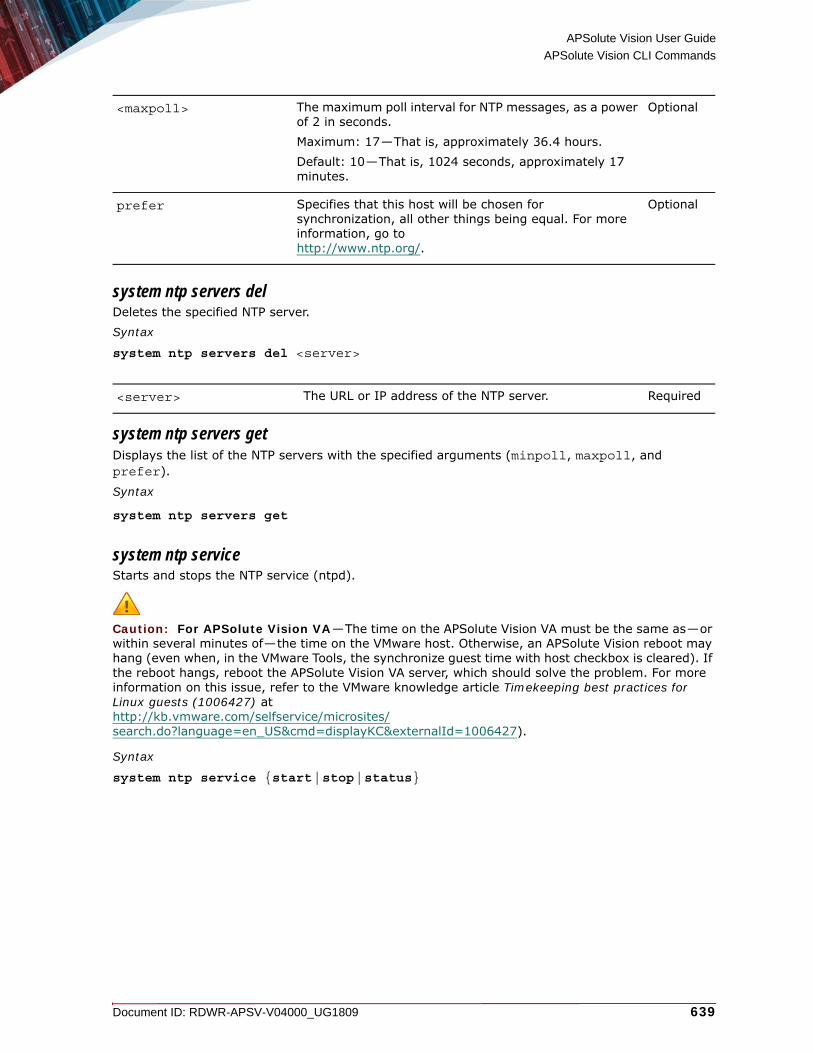
APSolute Vision User Guide
APSolute Vision CLI Commands
Document ID: RDWR-APSV-V04000_UG1809 639
system ntp servers delDeletes the specified NTP server.Syntax
system ntp servers del <server>
system ntp servers getDisplays the list of the NTP servers with the specified arguments (minpoll, maxpoll, and prefer).
Syntax
system ntp servers get
system ntp serviceStarts and stops the NTP service (ntpd).
Caution: For APSolute Vision VA—The time on the APSolute Vision VA must be the same as—or within several minutes of—the time on the VMware host. Otherwise, an APSolute Vision reboot may hang (even when, in the VMware Tools, the synchronize guest time with host checkbox is cleared). If the reboot hangs, reboot the APSolute Vision VA server, which should solve the problem. For more information on this issue, refer to the VMware knowledge article Timekeeping best practices for Linux guests (1006427) at http://kb.vmware.com/selfservice/microsites/search.do?language=en_US&cmd=displayKC&externalId=1006427).
Syntax
system ntp service {start|stop|status}
<maxpoll> The maximum poll interval for NTP messages, as a power of 2 in seconds.Maximum: 17—That is, approximately 36.4 hours.Default: 10—That is, 1024 seconds, approximately 17 minutes.
Optional
prefer Specifies that this host will be chosen for synchronization, all other things being equal. For more information, go tohttp://www.ntp.org/.
Optional
<server> The URL or IP address of the NTP server. Required

APSolute Vision User Guide
APSolute Vision CLI Commands
640 Document ID: RDWR-APSV-V04000_UG1809
system rpm listLists the RPM Package Manager (RPM) packages used by the APSolute Vision server. Syntax
system rpm list
System SNMP CommandsUse system snmp commands to manage the settings of the Simple Network Management Protocol (SNMP) interface for APSolute Vision monitoring. By default, the SNMP service in APSolute Vision is not started.
Access to the system snmp service commands is available to users with the Administrator and the Vision Administrator role.
Access to the system snmp community commands and to the system snmp trap target commands is available only to users with the Administrator role.
Note: For information on the MIBs that the SNMP interface exposes, see Appendix C - MIBs for Monitoring APSolute Vision, page 693.
{start|stop|status} Use one of the following commands:
• start—Starts the NTP service, which starts to send query messages to the external NTP servers to synchronize time and date.
• stop—Stops the NTP service.
• status—Displays the status of the NTP service (running or stopped) and the following additional information in table form when the service is running:
— remote—Server name or IP address— refid—Association ID— st—Server stratum level— t—Type:
• u—Unicast or manycast client• b—Broadcast or multicast client• l—Local (reference clock)• s—Symmetric (peer)• A—Manycast server• B—Broadcast server• M—Multicast server
— when—Sec/min/hr since last received packet— poll—Poll interval (log2(sec))— reach—Reach shift register (octal)— delay—Round-trip delay— offset—Offset of server relative to this host— jitter—Jitter
Required
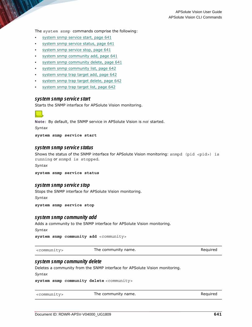
APSolute Vision User Guide
APSolute Vision CLI Commands
Document ID: RDWR-APSV-V04000_UG1809 641
The system snmp commands comprise the following:
• system snmp service start, page 641• system snmp service status, page 641• system snmp service stop, page 641• system snmp community add, page 641• system snmp community delete, page 641• system snmp community list, page 642• system snmp trap target add, page 642• system snmp trap target delete, page 642• system snmp trap target list, page 642
system snmp service startStarts the SNMP interface for APSolute Vision monitoring.
Note: By default, the SNMP service in APSolute Vision is not started.Syntax
system snmp service start
system snmp service statusShows the status of the SNMP interface for APSolute Vision monitoring: snmpd (pid <pid>) is running or snmpd is stopped.
Syntax
system snmp service status
system snmp service stopStops the SNMP interface for APSolute Vision monitoring.Syntax
system snmp service stop
system snmp community addAdds a community to the SNMP interface for APSolute Vision monitoring.Syntax
system snmp community add <community>
system snmp community deleteDeletes a community from the SNMP interface for APSolute Vision monitoring.Syntax
system snmp community delete <community>
<community> The community name. Required
<community> The community name. Required

APSolute Vision User Guide
APSolute Vision CLI Commands
642 Document ID: RDWR-APSV-V04000_UG1809
system snmp community listLists the communities of the SNMP interface for APSolute Vision monitoring, with the columns: Security Name, Source, and Community. Syntax
system snmp community list
system snmp trap target addAdds a trap target to the SNMP interface for APSolute Vision monitoring.Syntax
system snmp trap target add <host> <community> [port]
system snmp trap target deleteDeletes a trap target from the SNMP interface for APSolute Vision monitoring.Syntax
system snmp target delete <host> <community>
system snmp trap target listLists the trap targets of the of SNMP interface for APSolute Vision monitoring, with the columns Destination and Community.Syntax
system snmp target list
System SSL CommandsUse system ssl commands to create, import, and show SSL certificates.
The system ssl commands comprise the following:
• system ssl create, page 642• system ssl import, page 643• system ssl show, page 645
system ssl createCreates a new self-signed certificate, according to SHA-2 (SHA-256), with the information you provide.The system stores one SSL certificate.The system asks you for information that will be incorporated into the certificate request. The default value is APSolute Vision Server. To leave a field blank, press ENTER.
<host> The host name or IP address. Required
<community> The community name. Required
[port] The port number. Optional
<host> The host name or IP address. Required
<community> The community name. Required

APSolute Vision User Guide
APSolute Vision CLI Commands
Document ID: RDWR-APSV-V04000_UG1809 643
The system asks you for the following information: • Common Name—The server hostname or the IP address. Default: APSolute Vision Server.• Country Name—The two-letter code. Default: NA.• State or Province Name—Default: NA.• Locality Name—For example, the city. Default: NA.• Organization Name—For example, the company name. Default: NA.• Organizational Unit Name—For example, the company department. Default: NA.• Email Address—Default: NA.
Caution: Every certificate includes a validity period, which is defined by a start date and an end date. To prevent certificate-validity conflicts, before creating certificates, make sure that the correct time is configured on the APSolute Vision server—either manually or using an NTP server.
Note: Replacing the SSL certificate reboots the AVR Web server. You will need to log in again to AVR.Syntax
system ssl create
system ssl importImports a private key and certificate in PEM or PKCS #12 format.
system ssl import pemImports a private key and certificate in PEM format.Syntax
system ssl import pem <protocol>://<user>@<server>:/<path/to/directory> -key <key_filename> -cert <certificate_filename>[-pass <key_passphrase>] [-interm <intermediate_certifcate_filename>]
<protocol> Values:• sftp• scp
Required
<user>@ The username.
Note: If a password is required, you are prompted for it after the connection is initiated.
Required
<server> The IP address or DNS name of the server. Required
<path/to/directory> The path to the directory. Required
<key_filename> The name of the key in the remote directory. Required
<certificate_filename> The name of the certificate in the remote directory. Required

APSolute Vision User Guide
APSolute Vision CLI Commands
644 Document ID: RDWR-APSV-V04000_UG1809
Example sftp://[email protected]:/tmp -key key.pem -cert cert.pem -pass 12345
system ssl import pkcs12Imports a private key and certificate in PKCS #12 format.Syntax
system ssl import pkcs12 <protocol>://<user>@<server>:/<path/to/directory>/<PKCS12_filename> -pass <pkcs12_passphrase> [<intermediate_certifcate_filename>]
Example sftp://[email protected]:/tmp/file.p12 -pass 12345
<key_passphrase> The passphrase of the key file in the remote directory.For PEM, the key passphrase is optional. Supply the key passphrase if the private key is encrypted with a passphrase.
Optional
<intermediate_certifcate_filename>
The name of the intermediate certificate in the remote directory.
Optional
<protocol> Values:• sftp• scp
Required
<user>@ The username.
Note: If a password is required, you are prompted for it after the connection is initiated.
Required
<server> The IP address or DNS name of the server. Required
<path/to/directory> The path to the directory. Required
<PKCS12_filename> The name of the PKCS #12 file in the remote directory. Required
<pkcs12_passphrase> The name of the passphrase in the remote directory. Required
<intermediate_certifcate_filename>
The name of the intermediate certificate in the remote directory.
Optional
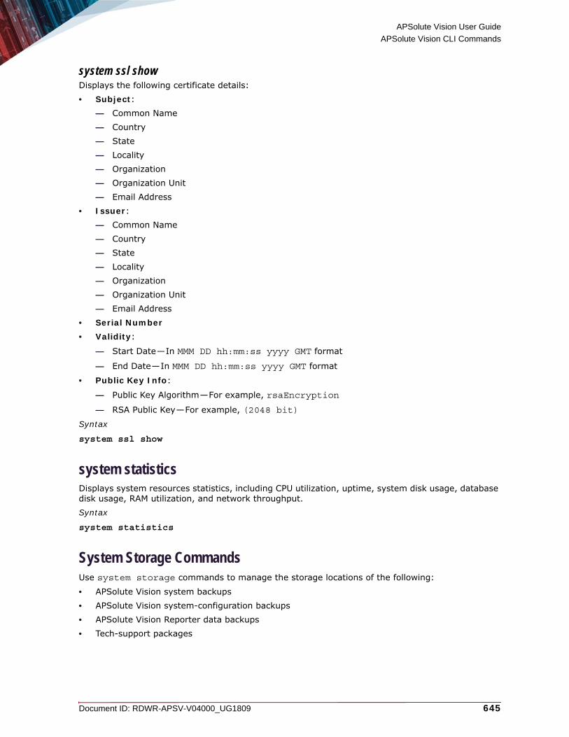
APSolute Vision User Guide
APSolute Vision CLI Commands
Document ID: RDWR-APSV-V04000_UG1809 645
system ssl showDisplays the following certificate details:• Subject:
— Common Name— Country— State— Locality— Organization— Organization Unit— Email Address
• Issuer:— Common Name— Country— State— Locality— Organization— Organization Unit— Email Address
• Serial Number• Validity:
— Start Date—In MMM DD hh:mm:ss yyyy GMT format
— End Date—In MMM DD hh:mm:ss yyyy GMT format
• Public Key Info:
— Public Key Algorithm—For example, rsaEncryption
— RSA Public Key—For example, (2048 bit)
Syntax
system ssl show
system statisticsDisplays system resources statistics, including CPU utilization, uptime, system disk usage, database disk usage, RAM utilization, and network throughput.Syntax
system statistics
System Storage CommandsUse system storage commands to manage the storage locations of the following:
• APSolute Vision system backups• APSolute Vision system-configuration backups• APSolute Vision Reporter data backups• Tech-support packages

APSolute Vision User Guide
APSolute Vision CLI Commands
646 Document ID: RDWR-APSV-V04000_UG1809
The system storage commands comprise the following:
• system storage backup local, page 646• system storage backup remote, page 646• system storage backup info, page 646
system storage backup local Sets the storage location to the hard-coded local directory.
Note: Only root users can manually manage files in the hard-coded local directory. Syntax
system storage backup local
system storage backup remote Sets the storage location to a remote directory using either NFS or CIFS (Samba).Syntax
system storage backup remote <protocol>://<server>:/<path/to/store>
system storage backup infoLists the storage location.Syntax
system storage backup info
System TCP Capture CommandsUse system tcpdump commands to dump a TCP capture for debugging.
The system tcpdump commands comprise the following:
• system tcpdump export, page 646• system tcpdump print, page 647
system tcpdump exportExports the TCP capture file by SSH. The capture file, dump.cap, is created locally, on the server. When the TCP capture ends, you are prompted to download the capture file from the APSolute Vision Web interface. (For the procedure, see Managing APSolute Vision Maintenance Files, page 155.)
The file is overwritten each time you run the tcpdump export command.
After entering the system tcpdump export command, you are prompted to enter a filter. You can enter a filter expression to select which packets to include in the dump. Alternatively, you can press Enter to dump all the packets.
<protocol> Values: nfs, cifs Required
<server> The IP address or DNS name of the server. Required
<path/to/store> The path to the storage directory. Required
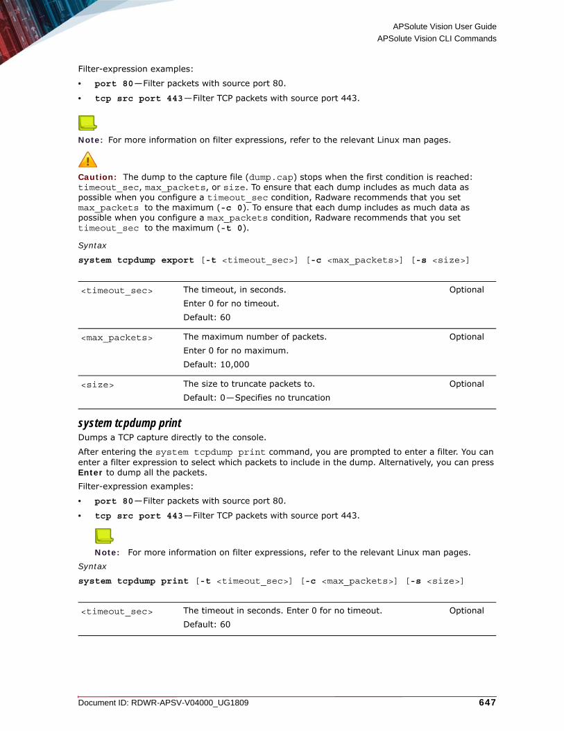
APSolute Vision User Guide
APSolute Vision CLI Commands
Document ID: RDWR-APSV-V04000_UG1809 647
Filter-expression examples:
• port 80—Filter packets with source port 80.
• tcp src port 443—Filter TCP packets with source port 443.
Note: For more information on filter expressions, refer to the relevant Linux man pages.
Caution: The dump to the capture file (dump.cap) stops when the first condition is reached: timeout_sec, max_packets, or size. To ensure that each dump includes as much data as possible when you configure a timeout_sec condition, Radware recommends that you set max_packets to the maximum (-c 0). To ensure that each dump includes as much data as possible when you configure a max_packets condition, Radware recommends that you set timeout_sec to the maximum (-t 0).
Syntax
system tcpdump export [-t <timeout_sec>] [-c <max_packets>] [-s <size>]
system tcpdump printDumps a TCP capture directly to the console.
After entering the system tcpdump print command, you are prompted to enter a filter. You can enter a filter expression to select which packets to include in the dump. Alternatively, you can press Enter to dump all the packets.Filter-expression examples:
• port 80—Filter packets with source port 80.
• tcp src port 443—Filter TCP packets with source port 443.
Note: For more information on filter expressions, refer to the relevant Linux man pages.Syntax
system tcpdump print [-t <timeout_sec>] [-c <max_packets>] [-s <size>]
<timeout_sec> The timeout, in seconds.Enter 0 for no timeout.Default: 60
Optional
<max_packets> The maximum number of packets.Enter 0 for no maximum.Default: 10,000
Optional
<size> The size to truncate packets to.Default: 0—Specifies no truncation
Optional
<timeout_sec> The timeout in seconds. Enter 0 for no timeout.Default: 60
Optional

APSolute Vision User Guide
APSolute Vision CLI Commands
648 Document ID: RDWR-APSV-V04000_UG1809
System Terminal CommandsUse CLI system terminal commands to manage the terminal prompt and banner displayed in the APSolute Vision console. The settings are global settings common to all users who access the APSolute Vision CLI shell.
Note: The settings are persistent and are included in the APSolute Vision configuration backup and restore operations.
The system terminal commands comprise the following:
• System Terminal Prompt Commands, page 648• System Terminal Banner Commands, page 648
System Terminal Prompt CommandsThe system terminal prompt commands comprise the following:
• system terminal prompt set, page 648• system terminal prompt get, page 648
system terminal prompt setSpecifies the string to be used as the terminal prompt.Syntax
system terminal prompt set
system terminal prompt getRetrieves the string currently used as the terminal prompt.Syntax
system terminal prompt get
System Terminal Banner CommandsBy default there is an empty banner—that is, no banner.At startup, the following is printed to the console:
1. The banner, if defined.2. The system version information.
3. The MAC addresses of the available ports.
The system terminal banner commands comprise the following:
• system terminal banner update, page 649• system terminal banner get, page 649
<max_packets> The maximum number of packets. Enter 0 for no maximum.Default: 10000
Optional
<size> The size to truncate packets to. Default: 0—Specifies no truncation
Optional

APSolute Vision User Guide
APSolute Vision CLI Commands
Document ID: RDWR-APSV-V04000_UG1809 649
system terminal banner updateLaunches a vi shell to edit the string to be used as start-up banner.Syntax
system terminal banner update
system terminal banner getRetrieves the string currently used as start-up banner.Syntax
system terminal banner get
System Timezone CommandsUse system timezone commands to display and set the timezone, with or without daylight saving time, on the APSolute Vision server.
The system timezone commands comprise the following:
• system timezone get, page 649• system timezone list, page 649• system timezone set, page 649
system timezone getDisplays the timezone set on the APSolute Vision server.Syntax
system timezone get
system timezone listLists the timezones that are supported on the APSolute Vision server.Syntax
system timezone list
Tip: To paginate output, use system timezone list | more. To find a specific timezone, use |grep. For example, to find the timezone for London, use system timezone list | grep Lon to display all time-zone names containing Lon.
system timezone setSets the timezone on the APSolute Vision server, and implements daylight saving time, if required. You can use any timezone from the list of supported timezones.
Note: In an APSolute Vision server with APM server VA installation, this command affects the APSolute Vision server and the APM module. That is, in an APSolute Vision server with APM server VA installation, changing the timezone in the APM Linux shell, has no effect. Timezones for named locations, for example, Europe/London, set the GMT value and daylight saving time parameters for those areas. To set a timezone without daylight saving time adjustments, use a generic GMT timezone, for example, Etc/GMT+2.
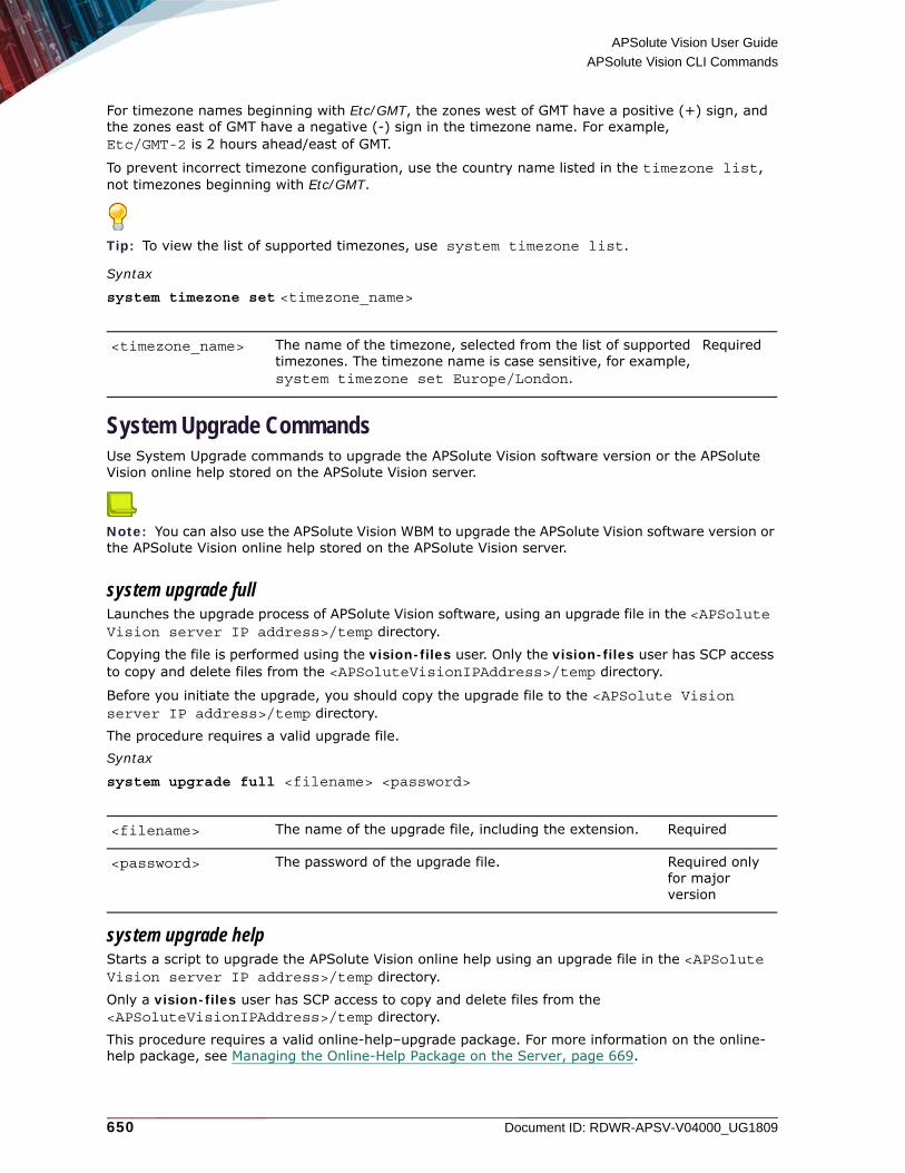
APSolute Vision User Guide
APSolute Vision CLI Commands
650 Document ID: RDWR-APSV-V04000_UG1809
For timezone names beginning with Etc/GMT, the zones west of GMT have a positive (+) sign, and the zones east of GMT have a negative (-) sign in the timezone name. For example, Etc/GMT-2 is 2 hours ahead/east of GMT.
To prevent incorrect timezone configuration, use the country name listed in the timezone list, not timezones beginning with Etc/GMT.
Tip: To view the list of supported timezones, use system timezone list.
Syntax
system timezone set <timezone_name>
System Upgrade CommandsUse System Upgrade commands to upgrade the APSolute Vision software version or the APSolute Vision online help stored on the APSolute Vision server.
Note: You can also use the APSolute Vision WBM to upgrade the APSolute Vision software version or the APSolute Vision online help stored on the APSolute Vision server.
system upgrade fullLaunches the upgrade process of APSolute Vision software, using an upgrade file in the <APSolute Vision server IP address>/temp directory.
Copying the file is performed using the vision-files user. Only the vision-files user has SCP access to copy and delete files from the <APSoluteVisionIPAddress>/temp directory.
Before you initiate the upgrade, you should copy the upgrade file to the <APSolute Vision server IP address>/temp directory.
The procedure requires a valid upgrade file. Syntax
system upgrade full <filename> <password>
system upgrade helpStarts a script to upgrade the APSolute Vision online help using an upgrade file in the <APSolute Vision server IP address>/temp directory.
Only a vision-files user has SCP access to copy and delete files from the <APSoluteVisionIPAddress>/temp directory.
This procedure requires a valid online-help–upgrade package. For more information on the online-help package, see Managing the Online-Help Package on the Server, page 669.
<timezone_name> The name of the timezone, selected from the list of supported timezones. The timezone name is case sensitive, for example, system timezone set Europe/London.
Required
<filename> The name of the upgrade file, including the extension. Required
<password> The password of the upgrade file. Required only for major version

APSolute Vision User Guide
APSolute Vision CLI Commands
Document ID: RDWR-APSV-V04000_UG1809 651
Syntax
system upgrade help <filename>
System User Authentication-Mode CommandsThe system user authentication-mode commands comprise the following:
• system user authentication-mode set, page 651• system user authentication-mode get, page 652
system user authentication-mode setSets the user-authentication method for all access to APSolute Vision (CLI, Web interface, or client).
Note: The setting is retained after reboot of the APSolute Vision server, and it is included in the APSolute Vision configuration backup and restore operations.Syntax
system user authentication-mode set {Local|RADIUS|TACACS+|LDAP}
<filename> The name of the upgrade file, including the extension. Required

APSolute Vision User Guide
APSolute Vision CLI Commands
652 Document ID: RDWR-APSV-V04000_UG1809
system user authentication-mode getThis command is available only to users with the Administrator role.Gets the user-authentication method for all access to APSolute Vision (CLI, Web interface, or client).Syntax
system user authentication-mode get
System User Password CommandsUse system user password commands to reset or set passwords.
The system user password commands comprise the following:
• system user password change, page 653• system user password root, page 653
{Local|RADIUS|TACACS+|LDAP} The user-authentication method APSolute Vision client users.Values:
• Local—The Local Users table stores the credentials of and authenticates the APSolute Vision users (see Configuring Local Users for APSolute Vision, page 82).
• RADIUS—A RADIUS server stores the credentials of and authenticates the APSolute Vision users (see Configuring RADIUS Server Connections, page 128). If the RADIUS server and, if defined, secondary RADIUS server is down, user authentication fails over to the Local Users table (see Configuring Local Users for APSolute Vision, page 82).
• TACACS+—A TACACS+ server stores the credentials of and authenticates the APSolute Vision users (see Configuring TACACS+ Server Connections, page 132). If the TACACS+ server and, if defined, secondary TACACS+ server is down, user authentication fails over to the Local Users table (see Configuring Local Users for APSolute Vision, page 82).
• LDAP—An LDAP server stores the credentials of and authenticates the APSolute Vision users (see Configuring LDAP Server Connections, page 138). If the primary LDAP server and, if defined, secondary LDAP server is down, user authentication fails over to the Local Users table (see Configuring Local Users for APSolute Vision, page 82).
Default: Local
Required

APSolute Vision User Guide
APSolute Vision CLI Commands
Document ID: RDWR-APSV-V04000_UG1809 653
• system user password vision-files, page 653• system user password vision-tech, page 654
system user password change Changes the password of the radware user or an Administrator user of the same account. That is, this command is available only to the radware user or an Administrator user to change his/her own password.
Caution: Radware recommends using the radware only for disaster recovery, and keeping the details of the radware user secret from all except special administrators.
Notes
• The default password is radware.
• This command is not available to Vision Administrator users.
When you use this command, you will be prompted to enter a new password at the New UNIX Password prompt; then, retype the password for verification.
Syntax
system user password change <user>
system user password rootChanges the root user password for access to the APSolute Vision operating system. This command is available only to the radware user and the root user.
Note: The default password for username root is radware.
When you use this command, you will be prompted to enter a new password at the New UNIX Password prompt; then, retype the password for verification.
Syntax
system user password root
system user password vision-filesRuns a script to set a new password for SCP access by vision-files users. The script prompts you for the new password. For security reasons, the characters of the password are not displayed. The default password is radware.The vision-files user has SCP access only to copy and delete files from the <APSoluteVisionIPAddress>\temp directory.
The vision-files users are authenticated locally by APSolute Vision server, regardless of whether the system is configured to use a different authentication method. That is, vision-files users cannot be overridden by the configuration of an authentication server.This command is available only to the radware user and Administrator users.Syntax
system user password vision-files
<user> The username. Required

APSolute Vision User Guide
APSolute Vision CLI Commands
654 Document ID: RDWR-APSV-V04000_UG1809
system user password vision-techRuns a script to set a new password for Web access by Radware Technical Support. The script prompts you for the new password. For security reasons, the characters of the password are not displayed. The default password is radware. This command is available only to the radware user and Administrator users.Syntax
system user password vision-tech
system versionDisplays the current APSolute Vision version and the versions of its components.Syntax
system version
System VRM CommandsUse system vrm commands to manage the state of the services for VRM outbound SSL-inspection monitoring.
The system vrm commands comprise the following:
• system vrm outbound-ssl-inspection state enable, page 654• system vrm outbound-ssl-inspection state disable, page 654• system vrm outbound-ssl-inspection state get, page 654
Note: For more information on outbound SSL-inspection monitoring, see Monitoring Outbound SSL Inspection, page 8.
system vrm outbound-ssl-inspection state enableEnables the services for monitoring outbound SSL Inspection.Syntax
system vrm ssl-inspection state enable
system vrm outbound-ssl-inspection state disableDisables the services for monitoring outbound SSL Inspection.Syntax
system vrm ssl-inspection state disable
system vrm outbound-ssl-inspection state getGets the state of the services for monitoring outbound SSL Inspection.Syntax
system vrm ssl-inspection state get

APSolute Vision User Guide
APSolute Vision CLI Commands
Document ID: RDWR-APSV-V04000_UG1809 655
Migrating APSolute Vision from the OnDemand Switch VL Platform to the OnDemand Switch VL2 PlatformThis section describes the procedure required for migrating APSolute Vision on the OnDemand Switch VL (ODS-VL) platform to the OnDemand Switch VL2 (ODS-VL2) platform.The procedure requires root access to the ODS-VL2 operating system.You can migrate to the ODS-VL2 platform with only the system-configuration backup of the ODS-VL platform or with the full system backup of the ODS-VL platform. For information on what each backup includes, see System Backup Configuration Commands, page 605 and System Backup Full Commands, page 608.
To migrate APSolute Vision from the ODS-VL platform to the ODS-VL2 platform with only the system-configuration backup
1. Install APSolute Vision on the ODS-VL2 platform.
Note: For information about installing APSolute Vision on the ODS-VL2 platform, see the APSolute Vision Installation and Maintenance Guide.
2. Upgrade APSolute Vision on the ODS-VL platform to the same version and build number as on the ODS-VL2 platform that you installed in the previous step. For more information, see Managing APSolute Vision Basic Information and Properties, page 104.
3. Create a system-configuration backup of the APSolute Vision on the ODS-VL platform. For more information, see system backup config create, page 605.
4. Export the system-configuration backup from the storage location on the ODS-VL platform to a specified location (for example, your computer). For more information, see system backup config export, page 606.
5. Import the system-configuration backup from the specified location to the storage location on the ODS-VL2 platform. For more information, see system backup config import, page 607.
6. Restore the system on the ODS-VL2 platform using the specified system-configuration backup. For more information, see system backup config restore, page 608.
7. On the ODS-VL2 platform, from the root/opt/radware/box/bin directory, run the following command:system_post_restore.sh
8. Run the following command to restart APSolute Vision:reboot
To migrate APSolute Vision from the ODS-VL platform to the ODS-VL2 platform with the full system backup
1. Install APSolute Vision on the ODS-VL2 platform.
Note: For information about installing APSolute Vision on the ODS-VL2 platform, see the APSolute Vision Installation and Maintenance Guide.
2. Upgrade APSolute Vision on the ODS-VL platform to the same version and build number as on the ODS-VL2 platform that you installed in the previous step. For more information, see Managing APSolute Vision Basic Information and Properties, page 104.

APSolute Vision User Guide
APSolute Vision CLI Commands
656 Document ID: RDWR-APSV-V04000_UG1809
3. Create a full system backup of the APSolute Vision on the ODS-VL platform. For more information, see system backup full create, page 608.
4. Export the full system backup from the storage location on the ODS-VL platform to a specified location (for example, your computer). For more information, see system backup full export, page 609.
5. Import the full system backup from the specified location to the storage location on the ODS-VL2 platform. For more information, see system backup full import, page 610.
6. Restore the system on the ODS-VL2 platform using the specified full system backup. For more information, see system backup full restore, page 612.
7. On the ODS-VL2 platform, from the root/opt/radware/box/bin directory, run the following command:system_post_restore.sh
8. Run the following command to restart APSolute Vision:reboot
Managing the Protection for the Meltdown and Spectre Exploit Vulnerabilities in APSolute VisionProtection against the Meltdown and Spectre exploit vulnerabilities in APSolute Vision is enabled by default. If you are sure that your system does not require the protection, you can disable the protection, and APSolute Vision may benefit from improved performance. You can re-enable the protection later.The following procedures require root access to the operating system.
To disable protection against the Meltdown and Spectre exploit vulnerabilities
1. As a root user, from the opt/radware/box/bin directory, run the following command:disable_meltdown.sh
2. Run the following command to restart APSolute Vision:reboot
To enable protection against the Meltdown and Spectre exploit vulnerabilities
1. As a root user, from the opt/radware/box/bin directory, run the following command:enable_meltdown.sh
2. Run the following command to restart APSolute Vision:reboot

Document ID: RDWR-APSV-V04000_UG1809 657
CHAPTER 25 – USING VDIRECT WITH APSOLUTE VISION
The following topics describe using vDirect with APSolute Vision:• vDirect-APSolute Vision Integration—Overview, page 657• Accessing the vDirect Configuration Interface of the APSolute Vision Server, page 657• Managing Devices in APSolute Vision with vDirect, page 658
Note: If you need to refer to the Radware vDirect documentation, use the documentation that corresponds to the vDirect version in the APSolute Vision server. To find out the vDirect version, in the APSolute Vision Settings view System perspective, select General Settings > Basic Parameters and look in the Software tab.
vDirect-APSolute Vision Integration—OverviewThe APSolute Vision installation includes vDirect.Users with a proper role can use vDirect with APSolute Vision to do the following:• Add Alteon, DefensePro, and LinkProof NG devices to the APSolute Vision configuration• Delete Alteon, DefensePro, and LinkProof NG devices from the APSolute Vision configuration• Modify Alteon, DefensePro, and LinkProof NG devices that APSolute Vision manages• Use the Toolbox scripts feature
Caution: An upgrade of APSolute Vision may include changes to vDirect objects included in the APSolute Vision installation—that is, system scripts. Examples of system scripts are predefined Toolbox scripts (see Predefined Toolbox Scripts, page 217) and some AppShape templates. If you modify a system script, Radware recommends downloading the file, renaming it, and uploading it to APSolute Vision as a new script with your modifications.
Accessing the vDirect Configuration Interface of the APSolute Vision ServerThe role-based access control (RBAC) configurations of both the APSolute Vision server and APSolute Vision vDirect manage the access to the APSolute Vision vDirect configuration interface. Users defined only in vDirect cannot log in to APSolute Vision. APSolute Vision users who are defined with the Administrator or Vision Administrator role can access vDirect. vDirect uses the identity-management (IDM) strings of the Administrator and Vision Administrator roles to map to an Administrator role in vDirect. The IDM string for the APSolute Vision Administrator role is SYS_ADMIN. The IDM string for the APSolute Vision Vision Administrator role is VISION_ADMIN.

APSolute Vision User Guide
Using vDirect with APSolute Vision
658 Document ID: RDWR-APSV-V04000_UG1809
Other than Administrator and Vision Administrator, no other APSolute Vision roles can access vDirect. vDirect maps all other APSolute Vision roles to a vDirect role called defaultRole. The defaultRole role has no permissions in vDirect, including viewing vDirect.vDirect supports the following special users: admin, root, and vDirect, which are all mapped to the vDirect Administrator role.It is possible that the same username is defined both in APSolute Vision RBAC and vDirect access control.
You can access vDirect from the main APSolute Vision menu, by clicking vDirect (You can access vDirect explicitly through the APSolute Vision RBAC by entering vision: before the username—for example, vision:john for a user named john.You can access vDirect explicitly through the vDirect access control by entering pam: before the username—for example, pam:john for a user named john.
Note: For more information on APSolute Vision RBAC, see Role-Based Access Control (RBAC), page 68.
To log in to the vDirect configuration interface of the APSolute Vision server
1. From the main APSolute Vision menu, click vDirect ( )2. In the login dialog box, enter you user name and password.
3. Click Login.
Managing Devices in APSolute Vision with vDirectThis section contains the following topics:• APSolute Vision and vDirect Terminology, page 658• APSolute Vision vDirect Sites, page 659• APSolute-Vision–vDirect Limitations, page 659• APSolute-Vision–vDirect Prerequisites and Recommendations, page 659• Configuring a Container in vDirect, page 660• Managing DefensePro Instances in APSolute Vision vDirect, page 664
APSolute Vision and vDirect TerminologyThe terminology for managing Radware devices differs for APSolute Vision and vDirect as follows:• In APSolute Vision, you add a device; whereas in vDirect, you register a device.• A device that you added to APSolute Vision is referred to as a managed device; whereas in
vDirect, the device is referred to as registered.• APSolute Vision categorizes Alteon devices by form factor (standalone, VX, or vADC) and
platform (platform model, VA, or hosting VX-platform model).

APSolute Vision User Guide
Using vDirect with APSolute Vision
Document ID: RDWR-APSV-V04000_UG1809 659
• vDirect calls all Alteon and LinkProof NG devices containers. vDirect calls standalone/VA and vADC devices dedicated containers. vDirect calls VX devices partitioned containers.
Note: vDirect recognizes LinkProof NG devices as Alteon devices.
APSolute Vision vDirect SitesWhen you register an Alteon or DefensePro device, adding the device to the associated APSolute Vision server, vDirect adds the device under a Site in the APSolute Vision device pane called vDirect. A vDirect Site in the Sites and Devices tree displays the Alteon standalone, vADC, and VA devices and DefensePro devices. A vDirect Site in the Physical Containers tab displays ADC-VXs.
Caution: If you change the name of a vDirect Site in the APSolute Vision device pane, vDirect does not recognize it later. That is, if you change the name of a vDirect Site in the APSolute Vision device pane, and you register a new Radware device with APSolute Vision, vDirect will create a new a vDirect Site.
APSolute-Vision–vDirect LimitationsvDirect in APSolute Vision includes the following limitations:• For Radware devices that are added to APSolute Vision using APSolute Vision WBM, vDirect
displays IP address of each device, not the specified name.• You cannot register multiple vADCs from multiple VXs in the same operation.• vDirect recognizes LinkProof NG devices as Alteon devices.• DefensePro high-availability (HA) clusters defined in APSolute Vision are not supported with
vDirect.• Alteon HA clusters defined in APSolute Vision are not synchronized with vDirect.• ADC Services (a type of HA cluster of Alteon devices) defined in vDirect are not supported with
APSolute Vision.• There are differences in the set of device-access parameters that vDirect and APSolute Vision
expose. For example, APSolute Vision exposes the HTTP and HTTPS parameters, and event- notification parameters. If a DefensePro device is registered on APSolute Vision using vDirect, and the device Web (HTTPS) credentials are different from the CLI (SSH) credentials, you must update the Web credentials of the device in the APSolute Vision Device Properties dialog box (see the procedure To add a new device or edit device-connection information, page 166).
• If a device managed by APSolute Vision is in Maintenance status, device-synchronization messages from vDirect do not update APSolute Vision.
• The APSolute Vision Lock operation on a device is not enforced on vDirect. That is, the APSolute Vision and APSolute Vision vDirect can modify a device configuration in parallel. This may cause conflicting configurations.
APSolute-Vision–vDirect Prerequisites and RecommendationsThis section describes the prerequisites and recommendations for managing Radware devices in APSolute Vision with vDirect.Target Alteon and LinkProof NG devices must have SSH enabled and SNMP access enabled on the management interface (/c/sys/mmgmt/snmp mgmt, /c/sys/access/snmp w, and /c/sys/access/sshd/on).

APSolute Vision User Guide
Using vDirect with APSolute Vision
660 Document ID: RDWR-APSV-V04000_UG1809
Target DefensePro devices must have SSH and SNMP access enabled (manage ssh status set enable and manage snmp status set enable).
Certain traps that DefensePro can generate can damage the behavior of Toolbox scripts. These traps must be disabled before you run a Toolbox script on a DefensePro device. These traps are disabled by default, and they are used primarily only for troubleshooting. When these traps are disabled, traps can still, however, go to the syslog and to APSolute Vision.
To check whether the traps are disabled, as required
> In the DefensePro CLI, run the following commands:
— services auditing status—Required result: Auditing Status: Disabled
— manage terminal trap-echo—Required result: Traps Echo Disabled
— manage terminal traps-output get—Required result: Trap output: off
Perform the following procedure for each trap type that is not disabled as required.
To disable the traps, as required
> In the DefensePro CLI, run the following commands:
— services auditing status set 2
— manage terminal trap-echo set 2
— manage terminal traps-output set 3
Configuring a Container in vDirectThis section comprises the following:• Registering an Alteon Dedicated or Alteon VX Partitioned Container, page 660• Viewing the Resources Related to a Container, page 662• Viewing the vADCs Related to a Partitioned Container (VX), page 663• Registering an ADC of a Partitioned Container, page 663• Modifying a Registered Container, page 664• Unregistering a Container, page 664
Registering an Alteon Dedicated or Alteon VX Partitioned ContainerThis section describes how to register an Alteon dedicated or Alteon partitioned container.When you register an Alteon dedicated container, vDirect / APSolute Vision adds the Alteon in the vDirect Site of the Sites and Devices tree in the APSolute Vision device pane.When you register an Alteon partitioned container, vDirect / APSolute Vision adds the Alteon VX in the vDirect Site of the Physical Containers tree of the in the APSolute Vision device pane.
To configure an Alteon Dedicated or Alteon VX Partitioned container
1. Log in to the vDirect configuration interface of the APSolute Vision server (see Accessing the vDirect Configuration Interface of the APSolute Vision Server, page 657).
2. From the upper menu options, select Configuration.

APSolute Vision User Guide
Using vDirect with APSolute Vision
Document ID: RDWR-APSV-V04000_UG1809 661
3. Select Containers.
4. Click Register.
5. Select Alteon Dedicated or Alteon VX Partitioned.
6. Configure the parameters, and then, do the following:
a. Click Validate to check that your settings are valid.b. Click Register to complete the registration process.
Table 476: Alteon Dedicated or Alteon VX Partitioned Parameters
Parameter DescriptionName The container name.
Note: There are some reserved words (for example, DefenseFlow) that APSolute Vision does not allow as names.
Tenants Assigns the container to one or more tenants. For more information, see the vDirect documentation.
Address The IP address where the dedicated ADC container resides. This is the management IP address as it is defined on the managed device.
CLI User Name The username for CLI and HTTPS access to the device.Maximum characters: 32Default: admin
CLI Password The password for CLI and HTTPS access to the device.Maximum characters: 32Default: admin
CLI Use SSH Specifies whether the device uses SSH.Default: Enabled
CLI Port The port for SSH communication with the device.Default: 22
Note: This value should be the same as the value for the SSH port configured in the device (Configuration perspective System tab > Management Access > Management Protocols > SSH).
SNMP Version The SNMP version used for the connection.
SNMP Port The SNMP port.Default: 161
User Name(This parameter is displayed only when SNMP Version is VersionThree.)
The username for the SNMP connection.Maximum characters: 18
Authentication Protocol(This parameter is displayed only when SNMP Version is VersionThree.)
The protocol used for authentication.Values: MD5, SHA, NoneDefault: SHA

APSolute Vision User Guide
Using vDirect with APSolute Vision
662 Document ID: RDWR-APSV-V04000_UG1809
Viewing the Resources Related to a ContainervDirect displays a list of the resources that are related to the vDirect object you are configuring. You access the list of related resources as follows:
To view resources related to a container
1. Log in to the vDirect configuration interface of the APSolute Vision server (see Accessing the vDirect Configuration Interface of the APSolute Vision Server, page 657).
2. From the upper menu options, select Configuration.
3. Select Containers.
4. In the Name column, click the link to the relevant container. The Resources Referencing box displays the list of resources related to the container.
5. In the Name column, click the link to a resource to view configuration details for that resource.
Authentication Password(This parameter is displayed only when SNMP Version is VersionThree.)
The password used for authentication.
Privacy Password(This parameter is displayed only when SNMP Version is VersionThree.)
The password used for the Privacy facility.
Privacy Protocol(This parameter is displayed only when SNMP Version is VersionThree.)
The SNMPv3 privacy protocol to use.Values: DES, NoneDefault: DES
SNMP Read Community(This parameter is displayed only when SNMP Version is VersionOne or VersionTwo.)
The SNMP read community name authorized to access the dedicated ADC.
SNMP Write Community(This parameter is displayed only when SNMP Version is VersionOne or VersionTwo.)
The SNMP write community name authorized to access the dedicated ADC.
Table 476: Alteon Dedicated or Alteon VX Partitioned Parameters
Parameter Description

APSolute Vision User Guide
Using vDirect with APSolute Vision
Document ID: RDWR-APSV-V04000_UG1809 663
Viewing the vADCs Related to a Partitioned Container (VX)You can view a list of all vADCs in a container that vDirect / APSolute Vision manages. Managed vADCs are called registered ADCs. You can also view a list of all vADCs in a container that are not managed by vDirect. These are called unregistered ADCs.
To view registered vADCs in a container
1. Log in to the vDirect configuration interface of the APSolute Vision server (see Accessing the vDirect Configuration Interface of the APSolute Vision Server, page 657).
2. From the upper menu options, select Configuration.
3. Select Containers.
4. In the Name column, click the link to the relevant container.
The Registered ADCs box displays the list of vADCs in the container.
To view unregistered ADCs in a container
1. Log in to the vDirect configuration interface of the APSolute Vision server (see Accessing the vDirect Configuration Interface of the APSolute Vision Server, page 657).
2. From the upper menu options, select Configuration.
3. Select Containers.
4. In the Name column, click the link to the relevant container.
5. In the Unregistered ADCs box, click Query Unregistered ADCs.
Registering an ADC of a Partitioned ContainerWhen you register an ADC of a partitioned container, vDirect / APSolute Vision adds an Alteon vADC in the vDirect Site of the Sites and Devices tree in the APSolute Vision device pane.Registering an ADC of a partitioned container is similar to configuring APSolute Vision to manage a vADC hosted by an ADC-VX managed by the same APSolute Vision server (see To configure APSolute Vision to manage one or more vADCs hosted by an ADC-VX managed by the same APSolute Vision server, page 173).
To register an ADC of a partitioned container
1. Log in to the vDirect configuration interface of the APSolute Vision server (see Accessing the vDirect Configuration Interface of the APSolute Vision Server, page 657).
2. From the upper menu options, select Configuration.
3. Select Containers.
4. In the Name column, click the link to the relevant container.
5. In the Unregistered ADCs box, click Query Unregistered ADCs.
6. Select an ADC from the list, and click Register Selected.

APSolute Vision User Guide
Using vDirect with APSolute Vision
664 Document ID: RDWR-APSV-V04000_UG1809
Modifying a Registered Container This section describes how to modify a container already defined in the vDirect system.
To modify a registered container instance
1. Log in to the vDirect configuration interface of the APSolute Vision server (see Accessing the vDirect Configuration Interface of the APSolute Vision Server, page 657).
2. From the upper menu options, select Configuration.
3. Select Containers.
4. In the Name column, click the link to the container you want to modify.
5. Make your changes.
6. Click Validate to check that your settings are valid.
7. Click Save to complete the process.
Unregistering a ContainerThis section describes how to remove a container from the vDirect system.
To unregister a container
1. Log in to the vDirect configuration interface of the APSolute Vision server (see Accessing the vDirect Configuration Interface of the APSolute Vision Server, page 657).
2. From the upper menu options, select Configuration.
3. Select Containers.
4. Click the box to the left of the name of the container you want to unregister.
5. Click Unregister.
6. Click Unregister again to confirm the removal.
Managing DefensePro Instances in APSolute Vision vDirectThis section comprises the following:• Registering a DefensePro Instance, page 665• Modifying a Registered DefensePro Instance, page 667• Unregistering a DefensePro Instance, page 667
Certain traps that DefensePro can generate can damage the behavior of Toolbox scripts. These traps must be disabled before you run a Toolbox script on a DefensePro device. These traps are disabled by default, and they are used primarily only for troubleshooting. When these traps are disabled, traps can still, however, go to the syslog and to APSolute Vision.
To check whether the traps are disabled, as required
> In the DefensePro CLI, run the following commands:
— services auditing status—Required result: Auditing Status: Disabled
— manage terminal trap-echo—Required result: Traps Echo Disabled

APSolute Vision User Guide
Using vDirect with APSolute Vision
Document ID: RDWR-APSV-V04000_UG1809 665
— manage terminal traps-output get—Required result: Trap output: off
Perform the following procedure for each trap type that is not disabled as required.
To disable the traps, as required
> In the DefensePro CLI, run the following commands:
— services auditing status set 2
— manage terminal trap-echo set 2
— manage terminal traps-output set 3
Registering a DefensePro InstanceWhen you register an DefensePro instance in the vDirect / APSolute Vision system, vDirect / APSolute Vision adds the DefensePro device in the vDirect Site of the Sites and Devices tree in the APSolute Vision device pane.
Caution: If you use vDirect to register a DefensePro device, and the device Web (HTTPS) credentials are different from the CLI (SSH) credentials, you must update the Web credentials of the device in the APSolute Vision Device Properties dialog box (see the procedure To add a new device or edit device-connection information, page 166).
To register a DefensePro instance
1. Log in to the vDirect configuration interface of the APSolute Vision server (see Accessing the vDirect Configuration Interface of the APSolute Vision Server, page 657).
2. From the upper menu options, select Configuration.
3. Select DefensePro.
4. Click Register.
5. Configure the parameters, and then, do the following:
a. Click Validate to check that your settings are valid.b. Click Register to complete the registration process.
Table 477: DefensePro Instance Parameters
Parameter DescriptionName The name of the DefensePro instance.
Note: There are some reserved words (for example, DefenseFlow) that APSolute Vision does not allow as names.
Tenants Configures and adds new tenants to the DefensePro instance. For more information, see the vDirect documentation.
Address The management IP address of the DefensePro instance.
CLI User Name The username for CLI, HTTP, and HTTPS access to the device.Maximum characters: 32Default: radware

APSolute Vision User Guide
Using vDirect with APSolute Vision
666 Document ID: RDWR-APSV-V04000_UG1809
CLI Password The password for CLI, HTTP, and HTTPS access to the device.Maximum characters: 32Default: radware
CLI Use SSH Specifies whether the device uses SSH.Default: Enabled
CLI Port The port for SSH or telnet communication with the device.When SSH is enabled, the default SSH port is 22.When SSH is disabled, the default Telnet port is 23.
Note: This value should be the same as the value for the SSH port configured in the device (Configuration perspective System tab > Management Access > Management Protocols > SSH).
SNMP Version The SNMP version used for the connection.Default: VersionThree
SNMP Port The SNMP port.
User Name(This parameter is displayed only when SNMP Version is VersionThree.)
The username for the SNMP connection.Maximum characters: 18
Authentication Protocol(This parameter is displayed only when SNMP Version is VersionThree.)
The protocol used for authentication.Values: MD5, SHA, NoneDefault: SHA
Authentication Password(This parameter is displayed only when SNMP Version is VersionThree.)
The password used for authentication.
Privacy Password(This parameter is displayed only when SNMP Version is VersionThree.)
The password used for the Privacy facility.
Privacy Protocol(This parameter is displayed only when SNMP Version is VersionThree.)
The SNMPv3 privacy protocol to use.Values: DES, NoneDefault: DES
SNMP Read Community(This parameter is displayed only when SNMP Version is VersionOne or VersionTwo.)
The SNMP read community name authorized to access the DefensePro.
Table 477: DefensePro Instance Parameters
Parameter Description

APSolute Vision User Guide
Using vDirect with APSolute Vision
Document ID: RDWR-APSV-V04000_UG1809 667
Modifying a Registered DefensePro Instance This section describes how to modify a DefensePro instance already defined in the vDirect system.
To modify a registered DefensePro instance
1. Log in to the vDirect configuration interface of the APSolute Vision server (see Accessing the vDirect Configuration Interface of the APSolute Vision Server, page 657).
2. From the upper menu options, select Configuration.
3. Select DefensePro.
4. In the Name column, click the link to the DefensePro instance you want to modify.
5. Make your changes.
6. Click Validate to check that your settings are valid.
7. Click Save to complete the process.
Unregistering a DefensePro InstanceThis section describes how to remove a DefensePro instance from the vDirect system.
To unregister a DefensePro instance
1. Log in to the vDirect configuration interface of the APSolute Vision server (see Accessing the vDirect Configuration Interface of the APSolute Vision Server, page 657).
2. From the upper menu options, select Configuration.
3. Select DefensePro.
4. Click the box to the left of the name of the DefensePro instance you want to unregister.
5. Click Unregister.
6. Click Unregister again to confirm the removal.
SNMP Write Community(This parameter is displayed only when SNMP Version is VersionOne or VersionTwo.)
The SNMP write community name authorized to access the DefensePro.
Table 477: DefensePro Instance Parameters
Parameter Description

APSolute Vision User Guide
Using vDirect with APSolute Vision
668 Document ID: RDWR-APSV-V04000_UG1809
Document ID: RDWR-APSV-V04000_UG1809 669
APPENDIX A – MANAGING THE ONLINE-HELP PACKAGE ON THE SERVERThis appendix describes managing the online-help package on the APSolute Vision server.Managing the online-help package is available only to users with the Administrator or Vision Administrator role.Managing the online-help package comprises the following:• Upgrading the online-help package that resides in the APSolute Vision server.• Reverting the online help to the original version—that is, the online help that came with the
installation of the APSolute Vision server.
You can upgrade the online-help package that resides in the APSolute Vision server using the procedure below (To update the APSolute Vision help on the server, page 670) or using the CLI. For information on the CLI command, see System Upgrade Commands, page 650.
Note: Depending on the configuration of the APSolute Vision server (see Configuring APSolute Vision Server Advanced Parameters, page 151), APSolute Vision clients access online-help pages from the server itself or from radware.com. The online help at radware.com is always the latest, but the files on your APSolute Vision server might be out-of-date if a managed device was upgraded or a new device driver is used.The help-upgrade procedure requires a valid online-help–upgrade package.You can download the software upgrade file from the Radware customer portal. The online-help–upgrade package may also be included in the product CD.The name format of the online-help package is as follows:APSoluteVisionHelp_<VisionVersion>_<BuildNumber>_<yyyyMMdd>.upgrade
To download the software upgrade file from the Radware customer portal
1. Open your browser and go to www.radware.com.2. At the top right of the window, click My Account, and log in.
3. At the upper right of the window, click Customer.

APSolute Vision User Guide
Managing the Online-Help Package on the Server
670 Document ID: RDWR-APSV-V04000_UG1809
4. Hover over Products, navigate to the relevant product type, and click the relevant product—as shown in the following example.
5. In the Software Releases tab, click (Download Software) for the relevant item.
6. In the Help Software Upgrade row, click .
7. Save the UPGRADE file to the appropriate location.
To update the APSolute Vision help on the server
1. In the APSolute Vision Settings mode System perspective, select General Settings > Advanced.
2. In the Online Help section, click the Update. The Upgrade APSolute Vision Help Version dialog box opens.
3. Click Browse and navigate to the online-help–upgrade package, and then, click Open.
4. Click Send. The upgrade utility uploads the package and places the online-help files in the location in the APSolute Vision server.
To revert the online help to the original version on the APSolute Vision server
1. In the APSolute Vision Settings mode System perspective, select General Settings > Advanced.
2. In the Online Help section, click Revert to Default Help.

Document ID: RDWR-APSV-V04000_UG1809 671
APPENDIX B – APSOLUTE VISION LOG MESSAGES AND ALERTSThis appendix lists log messages and alerts that APSolute Vision may issue.Many of the log messages and alerts also include a unique numeric ID. The tables in the following sections display the ID when available.When APSolute Vision receives a log message or alert that a managed device issues, APSolute Vision displays the log message or alert with the ID 20000 or 30000.Some messages or alerts comprise two versions, depending on whether the detailed auditing is enabled (Enable Detailed Auditing of APSolute Vision Activity and Enable Detailed Auditing of Device Configuration Changes). For more information, see Configuring Settings for the Alerts Pane, page 112.This appendix comprises the following sections:• Global Parameters, page 672• Advanced Parameters, page 672• Alert Browser Settings, page 673• Connection Settings, page 674• Monitoring Settings, page 675• RADIUS Configuration, page 676• Security Alert Settings, page 677• TACACS+ Configuration Settings, page 678• Warning Threshold Settings, page 678• SharePath Settings, page 679• APSolute Vision License Settings, page 679• Upload Logo Settings, page 680• Device Operation Alerts, page 680• Audit Message Type Enum, page 683• HTTPS Communication Check, page 684• Anti-Fraud Update on the Device, page 684• SUS Updates, page 685• ERT Active Attackers Feed, page 685• Operation Constant, page 686• Audit Messages, page 686• Alert Mail Notifier, page 687• Scheduled Task Alerts, page 688• General, page 690• Alerts from CLI, page 690• Device Configuration Audit Messages, page 692

APSolute Vision User Guide
APSolute Vision Log Messages and Alerts
672 Document ID: RDWR-APSV-V04000_UG1809
Global ParametersThe following table lists the messages that are triggered by actions performed on global parameters. The value in the Type column identifies whether the message is regular (R), or detailed (D) when detailed auditing is enabled (see Configuring Settings for the Alerts Pane, page 112).
Advanced ParametersThe following table lists the messages that are triggered by actions performed on advanced parameters. The value in the Type column identifies whether the message is regular (R), or detailed (D) when detailed auditing is enabled (see Configuring Settings for the Alerts Pane, page 112).
Table 478: Global Parameters
ID Type Message- R User <username> has changed the default password for other users.
- R User <username> has changed the default Password for the user radware.
- R User <username> has changed the User Statistics Storage
- D User <username> has changed the User Statistics Storage to <value>.
- R User <username> has changed the Number of Password Challenges.
- D User <username> has changed the Number of Password Challenges to <value>.
- R User <username> has changed the Number of Last Passwords Saved.
- D User <username> has changed the Number of Last Passwords Saved to value <value>.
- R User <username> has changed the Password Validity Period
- R User <username> changed the setting that users must change their password at first login.
- D User <username> changed the setting that users must change their password at first login to <value>.
Table 479: Advanced Parameters
ID Type Message- R User <username> has changed the Online Help URL.
- D User <username> has changed the Online Help URL to APSolute Vision Server.
- D User <username> has changed the Online Help URL to Radware.com.
- R User <username> has changed the Results per Page.
- D User <username> has changed the Results per Page to <value>.
- R User <username> has changed the Device Lock Timeout.
- D User <username> has changed the Device Lock Timeout to <value>.
- R User <username> User <username> User <username> has changed the Minimal Log Level.
- D User <username> has changed the Minimal Log Level to <value>.

APSolute Vision User Guide
APSolute Vision Log Messages and Alerts
Document ID: RDWR-APSV-V04000_UG1809 673
Alert Browser SettingsThe following table lists the messages that are triggered by actions performed on Alert Browser settings. The value in the Type column identifies whether the message is regular (R), or detailed (D) when detailed auditing is enabled (see Configuring Settings for the Alerts Pane, page 112).
- R User <username> has changed the Max. Number of Configuration Files per Device.
- D User <username> has changed the Max. Number of Configuration Files per Device to <value>.
Table 480: Alert Browser Settings
ID Type Message- R User <username> has changed the Syslog Facility.
- D User <username> has changed the Syslog Facility to <value>.
- R User <username> has changed the L4 Destination Port for Syslog Reporting.
- D User <username> has changed the L4 Destination Port for Syslog Reporting to Port <value>.
- R User <username> changed the Syslog server address.
- D User <username> changed the Syslog server address to <value>.
- R User <username> has changed the Syslog Reporting report (scope).
- D User <username> has changed the Syslog Reporting report (scope) to <value>.
- R User <username> changed the Syslog reporting status.
- D User <username> changed the Syslog reporting status to <value>.
- R User <username> changed the Syslog reporting encryption status.
- D User <username> changed the Syslog reporting encryption status to <value>.
- R User <username> changed the Syslog reporting encryption certificate.
- D User <username> changed the Syslog reporting encryption certificate to <value>.
- R User <username> changed the Syslog reporting authentication status.
- D User <username> changed the Syslog reporting authentication status to <value>.
- R User <username> changed the Syslog reporting authentication type.
- D User <username> changed the Syslog reporting authentication type to <value>.
- R User <username> changed the Syslog reporting encryption authentication permitted peer was changed.
- D User <username> changed the Syslog reporting encryption authentication permitted peer was changed to <value>.
- R User <username> changed the Syslog reporting encryption authentication private key was changed.
- D User <username> changed the Syslog reporting encryption authentication private key was changed to <value>.
Table 479: Advanced Parameters (cont.)
ID Type Message

APSolute Vision User Guide
APSolute Vision Log Messages and Alerts
674 Document ID: RDWR-APSV-V04000_UG1809
Connection SettingsThe following table lists the messages that are triggered by actions performed on connection settings. The value in the Type column identifies whether the message is regular (R), or detailed (D) when detailed auditing is enabled (see Configuring Settings for the Alerts Pane, page 112).
- R User <username> changed the Syslog reporting encryption authentication public key was changed.
- D User <username> changed the Syslog reporting encryption authentication public key was changed to value>.
- R User <username> changed the detailed APSolute Vision activity auditing alerts feature to <value>
- D User <username> changed the detailed APSolute Vision activity auditing alerts feature.
- R User <username> changed the detailed Device Configuration auditing alerts feature.
- D User <username> changed the detailed Device Configuration auditing alerts feature to <value>.
Table 481: Connection Settings
ID Type Message00986 R User <username> has changed the password for authentication with the proxy
server.
00987 R User <username> has changed the user name for authentication with the proxy server.
00988 R User <username> changed the proxy-server authentication status.
00988 D User <username> changed the proxy-server authentication status to <value>.
00989 R User <username> has changed the port of the proxy server.
00989 D User <username> has changed the port of the proxy server to port <value>.
00990 R User <username> has changed the IP address of the proxy server.
00991 R User <username> changed the proxy-server status.
00991 D User <username> changed the proxy-server status to <value>.
00992 R User <username> has changed the timeout for connecting to a device using SNMP.
00992 D User <username> has changed the timeout for connecting to a device using SNMP to <value>.
00993 R User <username> has changed the number of retries for connecting to a device using SNMP.
00993 D User <username> has changed the number of retries for connecting to a device using SNMP to <value>.
00994 R User <username> has changed the port for accessing a device using SNMP.
00994 D User <username> has changed the port for accessing a device using SNMP to port <value>.
Table 480: Alert Browser Settings (cont.)
ID Type Message

APSolute Vision User Guide
APSolute Vision Log Messages and Alerts
Document ID: RDWR-APSV-V04000_UG1809 675
Monitoring SettingsThe following table lists the messages that are triggered by actions performed on monitoring settings. The value in the Type column identifies whether the message is regular (R), or detailed (D) when detailed auditing is enabled (see Configuring Settings for the Alerts Pane, page 112).
00995 R User <username> has changed the value of the 'Session Inactivity Timeout' parameter.
00995 D User <username> has changed the value of the 'Session Inactivity Timeout' parameter to <value>.
00996 R User <username> has changed the default HTTPS port toward devices.
00996 D User <username> has changed the default HTTPS port toward devices to port <value>.
00997 R User <username> has changed the default HTTP port toward devices.
00997 D User <username> has changed the default HTTP port toward devices to port <value>.
00998 D User <username> has changed the IP address of the proxy server to IP Address <value>.
00999 D User <username> has changed the user name for authentication with the proxy server to proxy-username <value>.
Table 482: Monitoring Settings
ID Type Message01000 R User <username> has changed the Polling Interval for Reports.
01000 D User <username> has changed the Polling Interval for Reports to <value>.
01001 R User <username> has changed the Timeout for Device Status Poll.
01001 D User <username> has changed the Timeout for Device Status Poll to <value>.
01002 R User <username> has changed the polling interval for device status.
01002 D User <username> has changed the polling interval for device status to <value>.
01003 R User <username> has changed the Polling Interval for System Configuration.
01003 D User <username> has changed the Polling Interval for System Configuration to <value>.
01004 R User <username> has changed the Polling Interval for On-line Monitoring.
01004 D User <username> has changed the Polling Interval for On-line Monitoring to <value>.
01005 R User <username> changed the status of the MSISDN resolution feature.1
01006 D User <username> changed the status of the MSISDN resolution feature to <value>.1
01007 R User <username> changed the MSISDN IP address.1
01007 D User <username> changed the MSISDN IP address to <value>.1
01008 R User <username> changed the MSISDN Port address.1
Table 481: Connection Settings (cont.)
ID Type Message

APSolute Vision User Guide
APSolute Vision Log Messages and Alerts
676 Document ID: RDWR-APSV-V04000_UG1809
RADIUS ConfigurationThe following table lists the messages that are triggered by actions performed on the RADIUS configuration. The value in the Type column identifies whether the message is regular (R), or detailed (D) when detailed auditing is enabled (see Configuring Settings for the Alerts Pane, page 112).
01008 D User <username> changed the MSISDN Port address to <value>.1
01009 R User <username> changed the MSISDN user name.1
01009 D User <username> changed the MSISDN user name to <value>.1
01010 R User <username> changed the MSISDN password.1
1 – The MSISDN Resolution feature is not supported in APSolute Vision version 3.0 and later.
Table 483: RADIUS Configuration
ID Type Message- R User <username> has changed the Timeout for the RADIUS servers.
- D User <username> has changed the Timeout for the RADIUS servers to <value>.
- R User <username> has changed the Retries for the RADIUS servers.
- D User <username> has changed the Retries for the RADIUS servers to <value>.
- R User <username> has changed the Authentication Type for the RADIUS servers.
- D User <username> has changed the Authentication Type for the RADIUS servers to <value>.
- R User <username> has changed the Attribute ID for the RADIUS servers.
- D User <username> has changed the Attribute ID for the RADIUS servers to <value>.
- R User <username> has changed the Vendor ID for the RADIUS servers.
- D User <username> has changed the Vendor ID for the RADIUS servers to <value>.
- R User <username> has changed the Vendor Role Attribute ID for the RADIUS servers.
- D User <username> has changed the Vendor Role Attribute ID for the RADIUS servers to <value>.
- R User <username> has changed the Vendor Policy Attribute ID for the RADIUS servers.
- D User <username> has changed the Vendor Policy Attribute ID for the RADIUS servers to <value>.
- R User <username> has changed the Shared Secret for the Secondary RADIUS server.
- R User <username> has changed the Shared Secret for the Primary RADIUS server.
Table 482: Monitoring Settings (cont.)
ID Type Message

APSolute Vision User Guide
APSolute Vision Log Messages and Alerts
Document ID: RDWR-APSV-V04000_UG1809 677
Security Alert SettingsThe following table lists the messages that are triggered by actions performed on the security alert settings.
- R User <username> has changed the Port for the Secondary RADIUS server.
- D User <username> has changed the Port for the Secondary RADIUS server to <value>.
- R User <username> has changed the Port for the Primary RADIUS server.
- D User <username> has changed the Port for the Primary RADIUS server to <value>.
- R User <username> has changed the IP Address for the Secondary RADIUS server.
- D User <username> has changed the IP Address for the Secondary RADIUS server to <value>.
- R User <username> has changed the IP Address for the Primary RADIUS server.
- D User <username> has changed the IP Address for the Primary RADIUS server to <value>.
Table 484: Security Alert Settings
ID Type Message01012 R Security alert fields were modified: Rule Name was enabled.
01013 R Security alert fields were modified: Rule Name was disabled.
01014 R Security alert fields were modified: Source IP was enabled.
01015 R Security alert fields were modified: Source IP was disabled.
01016 R Security alert fields were modified: Destination port was enabled.
01017 R Security alert fields were modified: Destination port was disabled.
01018 R Security alert fields were modified: Attack Name was enabled.
01019 R Security alert fields were modified: Attack Name was disabled.
01020 R Security alert fields were modified: Action was enabled.
01021 R Security alert fields were modified: Action was disabled.
01022 R Security alert fields were modified: Destination IP was enabled.
01023 R Security alert fields were modified: Destination IP was disabled.
Table 483: RADIUS Configuration (cont.)
ID Type Message

APSolute Vision User Guide
APSolute Vision Log Messages and Alerts
678 Document ID: RDWR-APSV-V04000_UG1809
TACACS+ Configuration SettingsThe following table lists the messages that are triggered by actions performed on the TACACS+ configuration settings. The value in the Type column identifies whether the message is regular (R), or detailed (D) when detailed auditing is enabled (see Configuring Settings for the Alerts Pane, page 112).
Warning Threshold SettingsThe following table lists the messages that are triggered by actions performed on warning threshold settings. The value in the Type column identifies whether the message is regular (R), or detailed (D) when detailed auditing is enabled (see Configuring Settings for the Alerts Pane, page 112).
Table 485: TACACS+ Configuration Settings
ID Type Message- R User <username> changed TACACS+ service name.
- D User <username> changed TACACS+ service name to <value>.
- R User <username> changed TACACS+ timeout.
- D User <username> changed TACACS+ timeout to <value>.
- R User <username> changed TACACS+ retries.
- D User <username> changed TACACS+ retries to <value>.
- R User <username> changed TACACS+ minimal required privilege level.
- D User <username> changed TACACS+ minimal required privilege level to <value>.
- R The Authentication Type for the TACACS+ servers was changed.
- R User <username> changed TACACS+ secondary server shared secret.
- R User <username> changed TACACS+ primary server shared secret.
- R User <username> changed TACACS+ secondary server port.
- D User <username> changed TACACS+ secondary server port to <value>.
- R User <username> changed TACACS+ primary server port.
- D User <username> changed TACACS+ primary server port to <value>.
- R User <username> changed TACACS+ secondary server IP address.
- D User <username> changed TACACS+ secondary server IP address to <value>.
- R User <username> changed TACACS+ primary server IP address.
- D User <username> changed TACACS+ primary server IP address to <value>.
Table 486: Warning Threshold Settings
ID Type Message00980 R User <username> has changed the threshold for Warning Falling CPU
Utilization.
00980 D User <username> has changed the threshold for Warning Falling CPU Utilization to <value>.
00982 R User <username> has changed the threshold for Error Falling CPU Utilization.

APSolute Vision User Guide
APSolute Vision Log Messages and Alerts
Document ID: RDWR-APSV-V04000_UG1809 679
SharePath SettingsThe following table lists the messages that are triggered by actions performed on SharePath settings.
APSolute Vision License SettingsThe following table lists the messages that are triggered by actions performed APSolute Vision license settings.
00982 D User <username> has changed the threshold for Error Falling CPU Utilization to <value>.
00983 R User <username> has changed the threshold for Error Rising CPU Utilization.
00983 D User <username> has changed the threshold for Error Rising CPU Utilization to <value>.
00981 R User <username> has changed the threshold for Warning Rising CPU Utilization.
00981 D User <username> has changed the threshold for Warning Rising CPU Utilization to <value>.
00984 R User <username> disabled alarms for server CPU utilization.
00985 R User <username> enabled alarms for server CPU utilization.
Table 487: SharePath Settings
ID Type Message- R The management IP of a SharePath server instance was updated.
- R The data IP of a SharePath server instance was updated.
- R The backup server IP of a SharePath server instance was updated.
- R The Performance Limit of a SharePath server instance was updated.
00585 R A SharePath server instance was added to the configuration of the APSolute Vision server.
00586 R A SharePath server instance was removed from the configuration of the APSolute Vision server.
Table 488: Upload Logo Settings
ID Type Message- R A license of type <feature Name> was deleted from APSolute Vision.
00852 R A new license of type <license type> was provided for APSolute Vision.
Table 486: Warning Threshold Settings (cont.)
ID Type Message

APSolute Vision User Guide
APSolute Vision Log Messages and Alerts
680 Document ID: RDWR-APSV-V04000_UG1809
Upload Logo SettingsThe following table lists the message that is triggered by actions performed on APSolute Vision Reporter logo settings.
Security Group SettingsThe following table lists the messages that are triggered by actions performed on Security Group settings.
Device Operation AlertsThe following table lists the messages that are device operation alerts.
Table 489: Upload Logo Settings
ID Type Message- R A new logo for Vision Reporter uploaded, filename: <file name>.
Table 490: Security Group Settings
ID Type Message- R A DefensePro Security Group's senders list was updated.
- R A DefensePro Security Group's receivers list was updated.
- R Blocking Rule parameters of a DefensePro Security Group were updated.
- R Security modules of a DefensePro Security Group were updated.
- R A DefensePro Security Group was disabled.
- R A DefensePro Security Group was enabled.
- R A DefensePro Security Group's blocking period was updated.
- R A new DefensePro Security Group was created.
Table 491: Device Operation Alerts
ID Type Message- R User <username> backed up a configuration file for device <device name> -
<Device IP>.
- R User <username> restored a configuration file to device <device name> - <device IP>.
- R User <username> uploaded an attack signatures file to device <device name> - <device IP>.
- R User <username> updated the attack signatures file to device <device name>.
- R User <username> failed uploading the attack signatures file to device <device name>.
- R <device name>, <device IP> is locked by other user.
- R User <username> failed to unlock <device name>, <device IP>.

APSolute Vision User Guide
APSolute Vision Log Messages and Alerts
Document ID: RDWR-APSV-V04000_UG1809 681
- R <device name>, <device IP> cannot be unlocked by user <username> because it already locked by user <username>
- R <Operation Name> action finished successfully for device <device name>. <Operation Output>
- R <Operation Name> action failed for device <device name> due to: <reason>
- R Send Signature File From Website To Device
- R Send File To Device
- R Send Attack Signatures File To Device
- R For more information, see the Messages tab.
- R The device type or version is not compatible with DefensePro Configuration Template feature.
00699, 00971
R Devices <device name> and <device name> have identical SNMP engine IDs. To prevent connection problems, change the engine ID on one of the devices.
00723 R Failed to retrieve the Device Driver from <device name>. Please enable HTTPS or HTTP communication on the device.
00908 R <Operation Name> action failed for device <device name>. <Operation Output>
00910, 00952
R User <username> failed uploading a quarantine file to device <device name> - <device IP>.
00912 R User <username> failed downloading a quarantine file from device <device name> - <device IP>.
00915 R User <username> uploaded a configuration file to device <device name> - <device IP> successfully.
00915, 00944
R User <username> uploaded a configuration file to device <device name> - <device IP> successfully.
00916, 00945
R User <username> failed uploading a configuration file to device <device name> - <device IP>.
00920 R User <username> upgraded the software for device <device name> - <device IP> successfully.
00921 R The signature file is up-to-date. No download is required.
00926 R <device name>, <device IP> unlocked due to inactivity.
00927, 00938, 01098
R <device name>, <device IP> unlocked by user <username>.
00933 R User <username> rebooted device <device name> - <device IP>.
00934 R User <username> shutdown device <device name> - <device IP>.
00935 R <device name>, <device IP> locked by user <username>.
00936 R <device name>, <device IP> is already locked.
00937 R <device name>, <device IP> forcibly locked by user <username>.
00939 R <device name>, <device IP> is already unlocked.
00941 R User <username> failed to update Anti-Fraud signatures for device <device name>.
00942, 01047
R User <username> uploaded file <file name> to device <device name> - <device IP> successfully.
Table 491: Device Operation Alerts (cont.)
ID Type Message
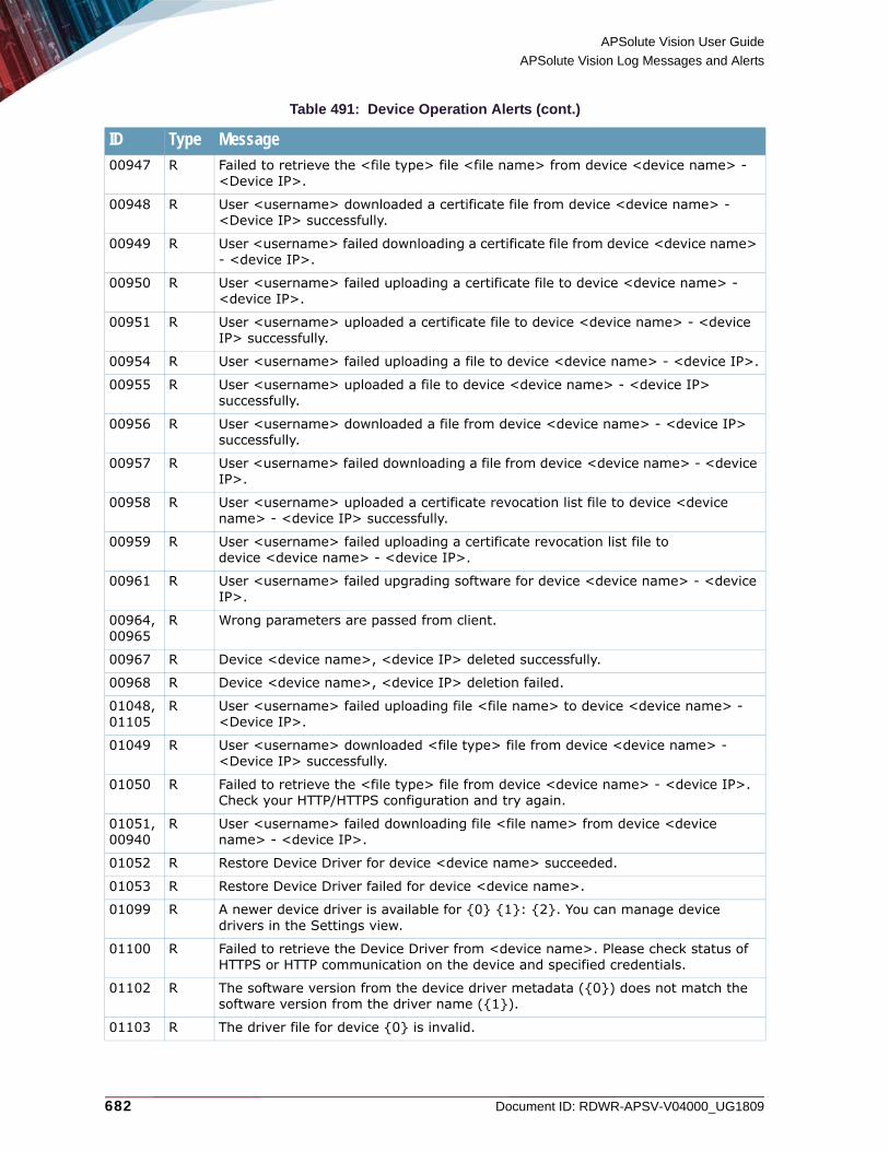
APSolute Vision User Guide
APSolute Vision Log Messages and Alerts
682 Document ID: RDWR-APSV-V04000_UG1809
00947 R Failed to retrieve the <file type> file <file name> from device <device name> - <Device IP>.
00948 R User <username> downloaded a certificate file from device <device name> - <Device IP> successfully.
00949 R User <username> failed downloading a certificate file from device <device name> - <device IP>.
00950 R User <username> failed uploading a certificate file to device <device name> - <device IP>.
00951 R User <username> uploaded a certificate file to device <device name> - <device IP> successfully.
00954 R User <username> failed uploading a file to device <device name> - <device IP>.
00955 R User <username> uploaded a file to device <device name> - <device IP> successfully.
00956 R User <username> downloaded a file from device <device name> - <device IP> successfully.
00957 R User <username> failed downloading a file from device <device name> - <device IP>.
00958 R User <username> uploaded a certificate revocation list file to device <device name> - <device IP> successfully.
00959 R User <username> failed uploading a certificate revocation list file to device <device name> - <device IP>.
00961 R User <username> failed upgrading software for device <device name> - <device IP>.
00964, 00965
R Wrong parameters are passed from client.
00967 R Device <device name>, <device IP> deleted successfully.
00968 R Device <device name>, <device IP> deletion failed.
01048, 01105
R User <username> failed uploading file <file name> to device <device name> - <Device IP>.
01049 R User <username> downloaded <file type> file from device <device name> - <Device IP> successfully.
01050 R Failed to retrieve the <file type> file from device <device name> - <device IP>. Check your HTTP/HTTPS configuration and try again.
01051, 00940
R User <username> failed downloading file <file name> from device <device name> - <device IP>.
01052 R Restore Device Driver for device <device name> succeeded.
01053 R Restore Device Driver failed for device <device name>.
01099 R A newer device driver is available for {0} {1}: {2}. You can manage device drivers in the Settings view.
01100 R Failed to retrieve the Device Driver from <device name>. Please check status of HTTPS or HTTP communication on the device and specified credentials.
01102 R The software version from the device driver metadata ({0}) does not match the software version from the driver name ({1}).
01103 R The driver file for device {0} is invalid.
Table 491: Device Operation Alerts (cont.)
ID Type Message

APSolute Vision User Guide
APSolute Vision Log Messages and Alerts
Document ID: RDWR-APSV-V04000_UG1809 683
Audit Message Type EnumThe following table lists the enum audit messages.
01106 R Failed <file type> file verification on device <device name> - <device IP>.
01107 R An operation was performed using a proxy server.
01110 R User <username> failed to lock <device name>, <device IP>.
Table 492: Audit Message Type Enum
ID Type Message- R Added user <username>.
- R User <username> changed password.
- R Deleted user <username>.
- R Enabled user <username>.
- R Disabled user <username>.
- R User <username> was locked.
- R User <username> was unlocked.
- R User <username> successfully logged in.
- R User <username> failed to log in.
- R Password for user <username> was reset.
- R Changed properties for user <username>.
- R User <username> logged out.
- R Updating Configuration template <template> failed because <reason>.
- R Updated role-scope pair for user <username>.
- R Removed role-scope pair for user <username>.
- R User <username> changed the scheduled task name.
00855 R Changed password expiration date for user <username>.
00866 R Changed name for user <username> to <username>.
00873 R User <username> has credentials error.
00874 R The configuration template <template> was added to the APSolute Vision server.
00875 R The configuration template <template> was updated to the APSolute Vision server.
00876 R The configuration template <template> was deleted to sic the APSolute Vision server.
00877 R Propagated Configuration template <template>.
00878 R Failed to propagate Configuration template <template>.
Table 491: Device Operation Alerts (cont.)
ID Type Message
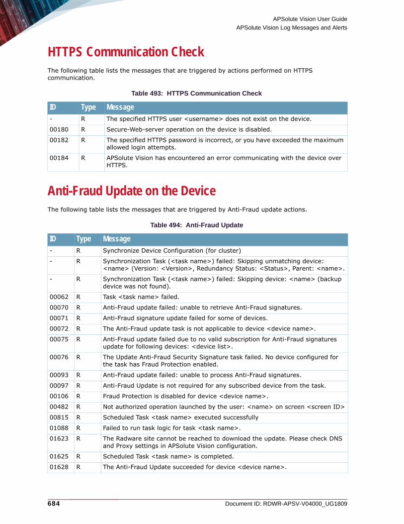
APSolute Vision User Guide
APSolute Vision Log Messages and Alerts
684 Document ID: RDWR-APSV-V04000_UG1809
HTTPS Communication CheckThe following table lists the messages that are triggered by actions performed on HTTPS communication.
Anti-Fraud Update on the DeviceThe following table lists the messages that are triggered by Anti-Fraud update actions.
Table 493: HTTPS Communication Check
ID Type Message- R The specified HTTPS user <username> does not exist on the device.
00180 R Secure-Web-server operation on the device is disabled.
00182 R The specified HTTPS password is incorrect, or you have exceeded the maximum allowed login attempts.
00184 R APSolute Vision has encountered an error communicating with the device over HTTPS.
Table 494: Anti-Fraud Update
ID Type Message- R Synchronize Device Configuration (for cluster)
- R Synchronization Task (<task name>) failed: Skipping unmatching device: <name> (Version: <Version>, Redundancy Status: <Status>, Parent: <name>.
- R Synchronization Task (<task name>) failed: Skipping device: <name> (backup device was not found).
00062 R Task <task name> failed.
00070 R Anti-Fraud update failed: unable to retrieve Anti-Fraud signatures.
00071 R Anti-Fraud signature update failed for some of devices.
00072 R The Anti-Fraud update task is not applicable to device <device name>.
00075 R Anti-Fraud update failed due to no valid subscription for Anti-Fraud signatures update for following devices: <device list>.
00076 R The Update Anti-Fraud Security Signature task failed. No device configured for the task has Fraud Protection enabled.
00093 R Anti-Fraud update failed: unable to process Anti-Fraud signatures.
00097 R Anti-Fraud Update is not required for any subscribed device from the task.
00106 R Fraud Protection is disabled for device <device name>.
00482 R Not authorized operation launched by the user: <name> on screen <screen ID>
00815 R Scheduled Task <task name> executed successfully
01088 R Failed to run task logic for task <task name>.
01623 R The Radware site cannot be reached to download the update. Please check DNS and Proxy settings in APSolute Vision configuration.
01625 R Scheduled Task <task name> is completed.
01628 R The Anti-Fraud Update succeeded for device <device name>.
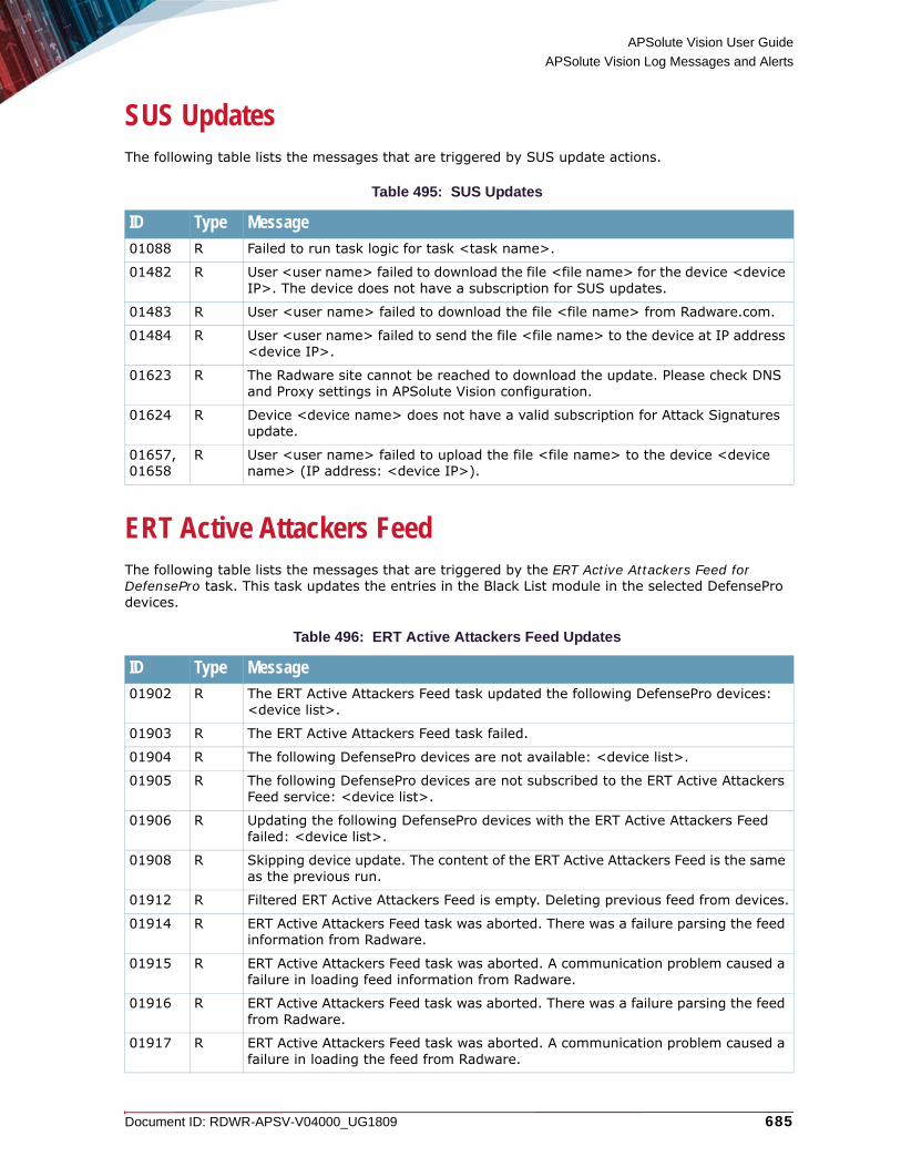
APSolute Vision User Guide
APSolute Vision Log Messages and Alerts
Document ID: RDWR-APSV-V04000_UG1809 685
SUS UpdatesThe following table lists the messages that are triggered by SUS update actions.
ERT Active Attackers FeedThe following table lists the messages that are triggered by the ERT Active Attackers Feed for DefensePro task. This task updates the entries in the Black List module in the selected DefensePro devices.
Table 495: SUS Updates
ID Type Message01088 R Failed to run task logic for task <task name>.
01482 R User <user name> failed to download the file <file name> for the device <device IP>. The device does not have a subscription for SUS updates.
01483 R User <user name> failed to download the file <file name> from Radware.com.
01484 R User <user name> failed to send the file <file name> to the device at IP address <device IP>.
01623 R The Radware site cannot be reached to download the update. Please check DNS and Proxy settings in APSolute Vision configuration.
01624 R Device <device name> does not have a valid subscription for Attack Signatures update.
01657, 01658
R User <user name> failed to upload the file <file name> to the device <device name> (IP address: <device IP>).
Table 496: ERT Active Attackers Feed Updates
ID Type Message01902 R The ERT Active Attackers Feed task updated the following DefensePro devices:
<device list>.
01903 R The ERT Active Attackers Feed task failed.
01904 R The following DefensePro devices are not available: <device list>.
01905 R The following DefensePro devices are not subscribed to the ERT Active Attackers Feed service: <device list>.
01906 R Updating the following DefensePro devices with the ERT Active Attackers Feed failed: <device list>.
01908 R Skipping device update. The content of the ERT Active Attackers Feed is the same as the previous run.
01912 R Filtered ERT Active Attackers Feed is empty. Deleting previous feed from devices.
01914 R ERT Active Attackers Feed task was aborted. There was a failure parsing the feed information from Radware.
01915 R ERT Active Attackers Feed task was aborted. A communication problem caused a failure in loading feed information from Radware.
01916 R ERT Active Attackers Feed task was aborted. There was a failure parsing the feed from Radware.
01917 R ERT Active Attackers Feed task was aborted. A communication problem caused a failure in loading the feed from Radware.

APSolute Vision User Guide
APSolute Vision Log Messages and Alerts
686 Document ID: RDWR-APSV-V04000_UG1809
Operation ConstantThe following table lists the messages that are triggered by operation constants.
Audit MessagesThe following table lists the audit messages.
01918 R ERT Active Attackers Feed task was aborted. There are no devices with a valid subscription.
01919 R Update failed with the following error on the device <device>: <error>
01920 R ERT Active Attackers Feed task failed to update the device <device>. No specific error.
Table 497: Operation Constant
ID Type Message- R Anti-Fraud Security Signature Update from Radware Site failed.
- R Anti-Fraud Security Signature Update from Radware Site succeeded.
- R Anti-Fraud Security Signature Update was downloaded from Radware Site
- R Anti-Fraud Security Signature Update is not required.
00917 R Backup Vision DB failed.
00918 R Backup Vision DB succeeded.
01041 R Updating the Attack Description file from Radware site succeeded.
01042 R Updating the Attack Description file from Radware site failed.
01043 R Updating the Attack Description file from Remote Server succeeded.
01044 R Update the Attack Description file from Remote Server failed.
01045 R Updating the Attack Description file from client succeeded.
01046 R Updating the Attack Description file from client failed.
Table 498: Audit Messages
ID Type Message- R User <username> added account <account> ,with Scope <scope>, Role <role>
and Network Policy <policy>
- R User <username> changed password expiration Date for user <user name>, to expiration Date <date>
00857 R User <username> changed his/her password.
00858 R User <username> deleted account <account>
00859 R User <username> enabled account <account>
00860 R User <username> disabled the account <account>
Table 496: ERT Active Attackers Feed Updates (cont.)
ID Type Message

APSolute Vision User Guide
APSolute Vision Log Messages and Alerts
Document ID: RDWR-APSV-V04000_UG1809 687
Alert Mail NotifierThe following table lists the messages that are triggered by actions performed on alert mail settings. The value in the Type column identifies whether the message is regular (R), or detailed (D) when detailed auditing is enabled (see Configuring Settings for the Alerts Pane, page 112).
00861 R Account <account> was locked
00862 R User <username> has unlocked account <account>
00863 R Account <account> successfully logged in
00864 R Account <account> failed to log in
00865 R User <username> reset password for account <account>
00866 R User <username> changed name for user <name>, to <name>
00868 R User <username> update the Full Name of account <account>, to Full Name: <value>
00870 R User <username> update the Contact Information of account <account>, to Contact Information: <value>.
00872 R Account <account> logged out.
00874 R The configuration template <template> was added to the APSolute Vision server
00875 R The configuration template <template> was updated to the APSolute Vision server
00876 R The configuration template <template> was deleted to the APSolute Vision server
00877 R Propagated Configuration template <template>
00878 R Failed to propagate Configuration template <value>
- R Updating Configuration template <value> failed because <reason>
00880 R User <username> added or modified the Role-scope pair for account <account> , to Role-scope pair <pair>
00882 R User <username> removed the Role-scope pair <pair> of account <account>
00883 R User <username> changed his/her password on the APSolute Vision server machine.
00884 R User <username> deleted device backup file <file name>
Table 499: Alert Mail Notifier
ID Type Message- D User <username> has changed the Subject Header in the Email Reporting
Configuration to <value>.
01026 R Email reporting settings were changed.
01028 R User <username> has changed the Email Sending Interval.
01028 D User <username> has changed the Email Sending Interval to <value>.
01029 R User <user name> has changed the From Header in the Email Reporting Configuration.
Table 498: Audit Messages (cont.)
ID Type Message

APSolute Vision User Guide
APSolute Vision Log Messages and Alerts
688 Document ID: RDWR-APSV-V04000_UG1809
Scheduled Task AlertsThe following table lists the messages that are triggered by actions performed on scheduled tasks. The value in the Type column identifies whether the message is regular (R), or detailed (D) when detailed auditing is enabled (see Configuring Settings for the Alerts Pane, page 112).
01029 D User <user name> has changed the From Header in the Email Reporting Configuration to <value>.
01030 R User <username> has changed the Number of Alerts per Email.
01030 D User <username> has changed the Number of Alerts per Email to <value>.
01031 R User <username> has changed the Recipient Email Address.
01032 R User <username> has changed the SMTP Server Address.
01032 D User <username> has changed the SMTP Server Address to IP Address <value>.
01033 R User <username> has changed the SMTP User Name.
01034 R User <username> has changed the Subject Header in the Email Reporting Configuration.
01024 D User <username> has changed the Recipient Email Address to email-address <value>.
01025 D User <username> has changed the SMTP User Name to smtp-username <value>.
Table 500: Scheduled Task Alerts
ID Type Message- R User <username> changed the scheduled task backup file name.
- D User <username> changed the scheduled task backup file name to <value>.
- R User <username> changed the scheduled task destination IP address.
- D User <username> changed the scheduled task destination IP address to <value>.
- R User <username> has changed the password for authentication with the backup device during a scheduled task.
- D User <username> has changed the password for authentication with the backup device during a scheduled task.
- R User <username> changed the scheduled task backup directory.
- D User <username> changed the scheduled task backup directory to <value>.
- R User <username> changed the protocol to communicate with the backup device during a scheduled task.
- D User <username> changed the protocol to communicate with the backup device during a scheduled task to protocol <value>.
- R User <username> has changed the user name for authentication with the backup device during a scheduled task.
- D User <username> has changed the user name for authentication with the backup device during a scheduled task to username <value>.
Table 499: Alert Mail Notifier (cont.)
ID Type Message

APSolute Vision User Guide
APSolute Vision Log Messages and Alerts
Document ID: RDWR-APSV-V04000_UG1809 689
- R User <username> added Devices to a scheduled task's list of devices.
- D User <username> changed scheduled task name to <value>.
- R User <username> updated the date (day) of a scheduled task.
- D User <username> updated the date (day) of a scheduled task to <value>.
- R User <username> updated the date (month) of a scheduled task.
- D User <username> updated the date (month) of a scheduled task to <value>.
- R User <username> updated the date (year) of a scheduled task.
- D User <username> updated the date (year) of a scheduled task to <value>.
- R User <username> updated the time (hour) of a scheduled task.
- D User <username> updated the time (hour) of a scheduled task to <value>.
- R User <username> updated the time (minutes) of a scheduled task.
- D User <username> updated the time (minutes) of a scheduled task to <value>.
- R User <username> updated the time (seconds) of a scheduled task.
- D User <username> updated the time (seconds) of a scheduled task to <value>.
- R User <username> updated the frequency of a scheduled task.
- D User <username> updated the frequency of a scheduled task to <value>.
- R User <username> updated the quantity of minutes between two executions of a scheduled task.
- D User <username> updated the quantity of minutes between two executions of a scheduled task to <value>.
- R User <username> set run always to a scheduled task.
- R User <username> updated the start date of the scheduled period of a scheduled task.
- D User <username> updated the start date of the scheduled period of a scheduled task to <value>.
- R User <username> updated the end date of the scheduled period of a scheduled task.
- D User <username> updated the end date of the scheduled period of a scheduled task to <value>.
- R User <username> removed Devices from a scheduled task's list of devices.
- R User <username> changed scheduled task name.
00072 R The Anti-Fraud update task is not applicable to device <device name>.
00075 R Anti-Fraud update failed due to no valid subscription for Anti-Fraud signatures update for following devices: <device list>.
00093 R Anti-Fraud update failed: unable to process Anti-Fraud signatures.
00097 R Anti-Fraud Update is not required for any subscribed device from the task.
00106 R Fraud Protection is disabled for device <device name>.
00972 R User <username> changed scheduled task to enabled.
00973 R User <username> changed scheduled task to disabled.
00976 R User <username> changed scheduled task file type.
00976 D User <username> changed scheduled task file type to <value>.
Table 500: Scheduled Task Alerts (cont.)
ID Type Message
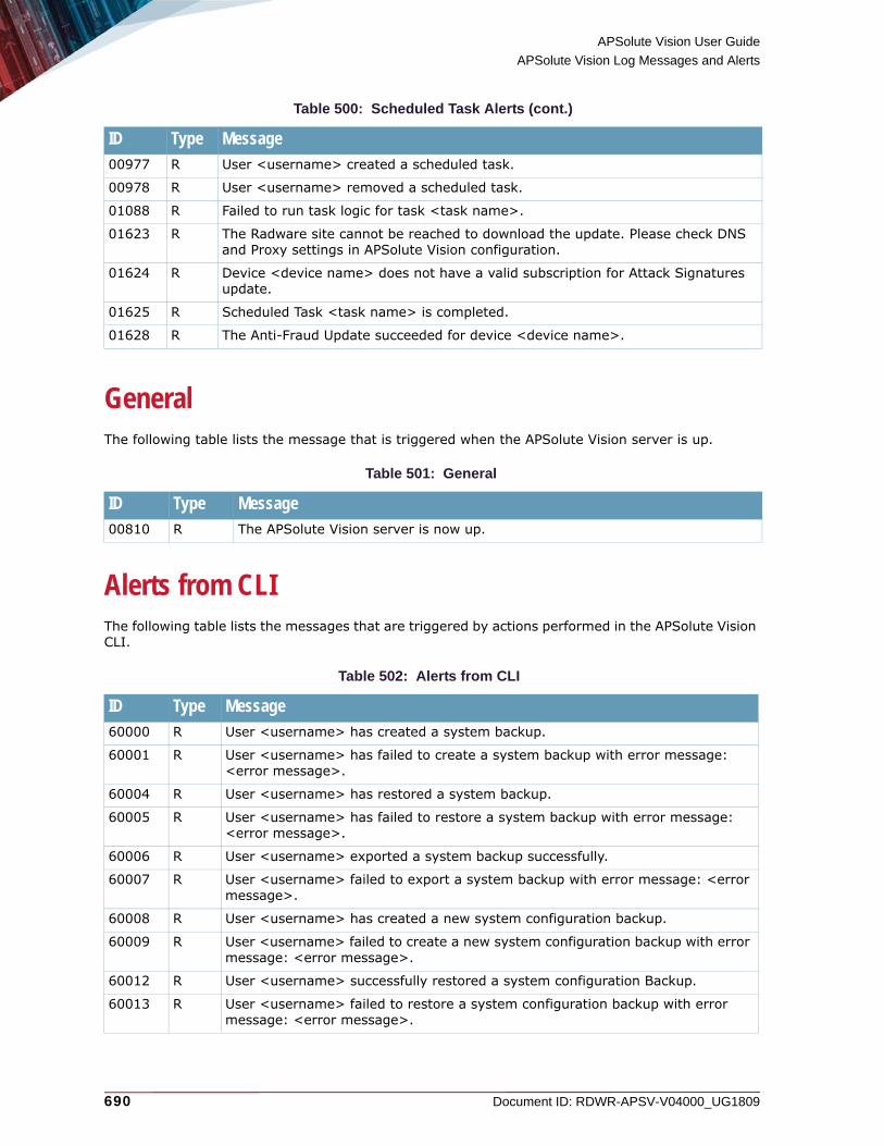
APSolute Vision User Guide
APSolute Vision Log Messages and Alerts
690 Document ID: RDWR-APSV-V04000_UG1809
GeneralThe following table lists the message that is triggered when the APSolute Vision server is up.
Alerts from CLIThe following table lists the messages that are triggered by actions performed in the APSolute Vision CLI.
00977 R User <username> created a scheduled task.
00978 R User <username> removed a scheduled task.
01088 R Failed to run task logic for task <task name>.
01623 R The Radware site cannot be reached to download the update. Please check DNS and Proxy settings in APSolute Vision configuration.
01624 R Device <device name> does not have a valid subscription for Attack Signatures update.
01625 R Scheduled Task <task name> is completed.
01628 R The Anti-Fraud Update succeeded for device <device name>.
Table 501: General
ID Type Message00810 R The APSolute Vision server is now up.
Table 502: Alerts from CLI
ID Type Message60000 R User <username> has created a system backup.
60001 R User <username> has failed to create a system backup with error message: <error message>.
60004 R User <username> has restored a system backup.
60005 R User <username> has failed to restore a system backup with error message: <error message>.
60006 R User <username> exported a system backup successfully.
60007 R User <username> failed to export a system backup with error message: <error message>.
60008 R User <username> has created a new system configuration backup.
60009 R User <username> failed to create a new system configuration backup with error message: <error message>.
60012 R User <username> successfully restored a system configuration Backup.
60013 R User <username> failed to restore a system configuration backup with error message: <error message>.
Table 500: Scheduled Task Alerts (cont.)
ID Type Message

APSolute Vision User Guide
APSolute Vision Log Messages and Alerts
Document ID: RDWR-APSV-V04000_UG1809 691
60014 R User <username> successfully exported a system configuration backup.
60015 R User <username> failed to export a system configuration backup with error message: <error message>.
60016 R User <username> has created a new Vision Reporter backup.
60017 R User <username> failed to create a new Vision Reporter backup with error message: <error message>.
60020 R User <username> successfully restore a Vision Reporter Backup.
60021 R User <username> failed to restore a Vision Reporter backup with error message: <error message>.
60022 R User <username> successfully exported a Vision Reporter Backup.
60023 R User <username> failed to export a Vision Reporter backup with error message: <error message>.
60024 R User <username> created a tech-support file.
60025 R User <username> failed to create a tech-support file with error message: <error message>.
60028 R User <username> successfully restore a tech-support file.
60029 R User <username> failed to restore a tech-support file with error message: <error message>.
60030 R User <username> successfully exported a tech-support file.
60031 R User <username> failed to export a tech-support file with error message: <error message>.
60032 R User <username> changed the date and time on the APSolute Vision server to Date and Time <value>.
60033 R User <username> changed the timezone of the APSolute Vision server to Timezone <value>.
60034 R User <username> started the Vision server.
60035 R User <username> failed to started the Vision server.
60036 R User <username> stopped the Vision server.
60037 R User <username> failed to stop the Vision server.
60038 R User <username> changed the IP address for the <value> port of the APSolute Vision server to IP Address <value>.
60039 R User <username> changed the tech-support password of the APSolute Vision server.
60040 R User <username> changed the web-access password of the APSolute Vision server.
60041 R The <username> user password of the APSolute Vision system was changed.
60042 R User <username> changed the root user password of the APSolute Vision system.
60043 R User <username> changed the vision-files user password of the APSolute Vision system.
60044 R User <username> started the database server.
60045 R User <username> stopped the database server.
60046 R User <username> failed to stop the database server.
Table 502: Alerts from CLI (cont.)
ID Type Message
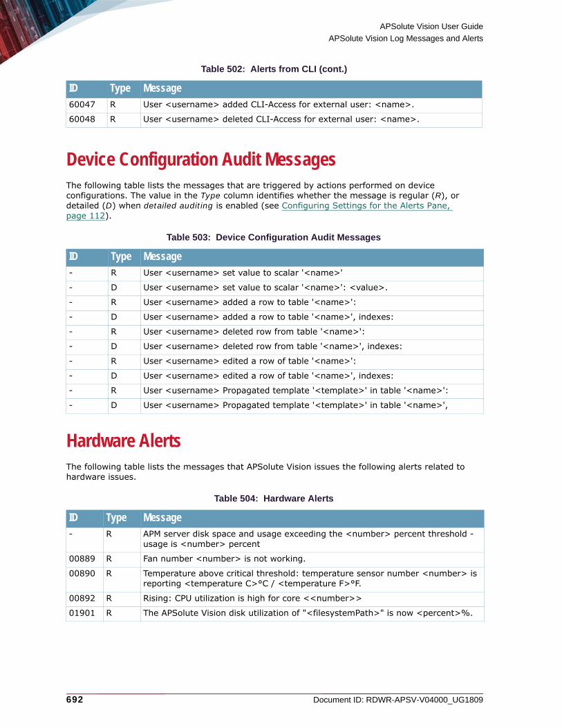
APSolute Vision User Guide
APSolute Vision Log Messages and Alerts
692 Document ID: RDWR-APSV-V04000_UG1809
Device Configuration Audit MessagesThe following table lists the messages that are triggered by actions performed on device configurations. The value in the Type column identifies whether the message is regular (R), or detailed (D) when detailed auditing is enabled (see Configuring Settings for the Alerts Pane, page 112).
Hardware AlertsThe following table lists the messages that APSolute Vision issues the following alerts related to hardware issues.
60047 R User <username> added CLI-Access for external user: <name>.
60048 R User <username> deleted CLI-Access for external user: <name>.
Table 503: Device Configuration Audit Messages
ID Type Message- R User <username> set value to scalar '<name>'
- D User <username> set value to scalar '<name>': <value>.
- R User <username> added a row to table '<name>':
- D User <username> added a row to table '<name>', indexes:
- R User <username> deleted row from table '<name>':
- D User <username> deleted row from table '<name>', indexes:
- R User <username> edited a row of table '<name>':
- D User <username> edited a row of table '<name>', indexes:
- R User <username> Propagated template '<template>' in table '<name>':
- D User <username> Propagated template '<template>' in table '<name>',
Table 504: Hardware Alerts
ID Type Message- R APM server disk space and usage exceeding the <number> percent threshold -
usage is <number> percent
00889 R Fan number <number> is not working.
00890 R Temperature above critical threshold: temperature sensor number <number> is reporting <temperature C>°C / <temperature F>°F.
00892 R Rising: CPU utilization is high for core <<number>>
01901 R The APSolute Vision disk utilization of "<filesystemPath>" is now <percent>%.
Table 502: Alerts from CLI (cont.)
ID Type Message

Document ID: RDWR-APSV-V04000_UG1809 693
APPENDIX C – MIBS FOR MONITORING APSOLUTE VISION This appendix contains the following sections, which describe the MIBs that APSolute Vision exposes for monitoring APSolute Vision:• RFC1213 MIB Objects for Monitoring APSolute Vision, page 694• Host Resources MIB Objects for Monitoring APSolute Vision, page 696• UCD-SNMP-MIB MIB Objects for Monitoring APSolute Vision, page 696• Trap Objects for Monitoring APSolute Vision, page 697• Trap Objects for APSolute Vision Alerts, page 698
Note: For information on managing the settings of the SNMP interface, see System SNMP Commands, page 640.
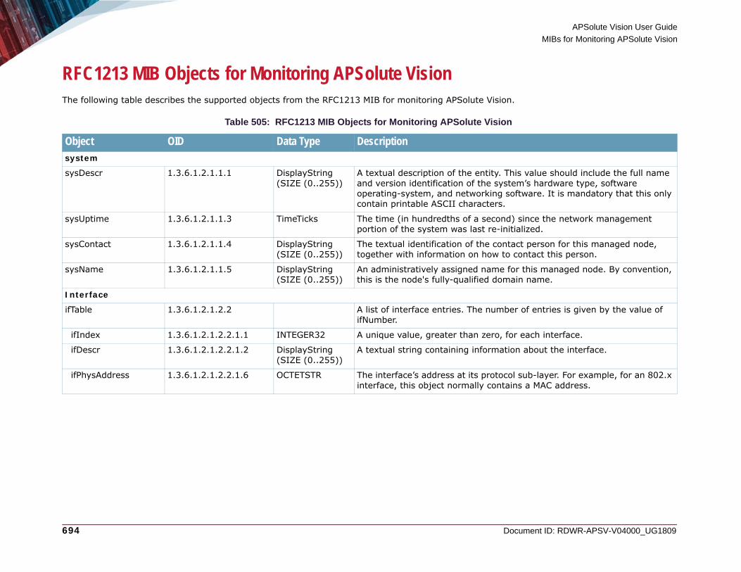
APSolute Vision User Guide
MIBs for Monitoring APSolute Vision
694 Document ID: RDWR-APSV-V04000_UG1809
RFC1213 MIB Objects for Monitoring APSolute VisionThe following table describes the supported objects from the RFC1213 MIB for monitoring APSolute Vision.
Table 505: RFC1213 MIB Objects for Monitoring APSolute Vision
Object OID Data Type Descriptionsystem
sysDescr 1.3.6.1.2.1.1.1 DisplayString (SIZE (0..255))
A textual description of the entity. This value should include the full name and version identification of the system’s hardware type, software operating-system, and networking software. It is mandatory that this only contain printable ASCII characters.
sysUptime 1.3.6.1.2.1.1.3 TimeTicks The time (in hundredths of a second) since the network management portion of the system was last re-initialized.
sysContact 1.3.6.1.2.1.1.4 DisplayString (SIZE (0..255))
The textual identification of the contact person for this managed node, together with information on how to contact this person.
sysName 1.3.6.1.2.1.1.5 DisplayString (SIZE (0..255))
An administratively assigned name for this managed node. By convention, this is the node's fully-qualified domain name.
Interface
ifTable 1.3.6.1.2.1.2.2 A list of interface entries. The number of entries is given by the value of ifNumber.
ifIndex 1.3.6.1.2.1.2.2.1.1 INTEGER32 A unique value, greater than zero, for each interface.
ifDescr 1.3.6.1.2.1.2.2.1.2 DisplayString (SIZE (0..255))
A textual string containing information about the interface.
ifPhysAddress 1.3.6.1.2.1.2.2.1.6 OCTETSTR The interface’s address at its protocol sub-layer. For example, for an 802.x interface, this object normally contains a MAC address.
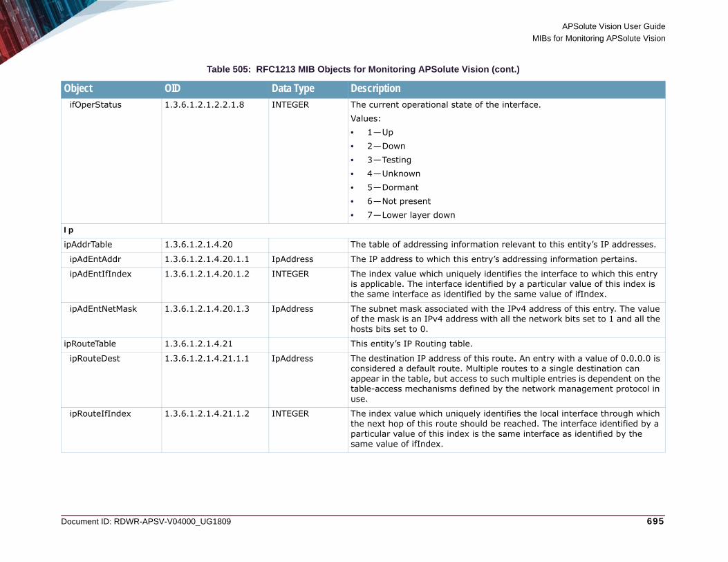
APSolute Vision User Guide
MIBs for Monitoring APSolute Vision
Document ID: RDWR-APSV-V04000_UG1809 695
ifOperStatus 1.3.6.1.2.1.2.2.1.8 INTEGER The current operational state of the interface.Values: • 1—Up• 2—Down• 3—Testing• 4—Unknown• 5—Dormant• 6—Not present• 7—Lower layer down
Ip
ipAddrTable 1.3.6.1.2.1.4.20 The table of addressing information relevant to this entity’s IP addresses.
ipAdEntAddr 1.3.6.1.2.1.4.20.1.1 IpAddress The IP address to which this entry’s addressing information pertains.
ipAdEntIfIndex 1.3.6.1.2.1.4.20.1.2 INTEGER The index value which uniquely identifies the interface to which this entry is applicable. The interface identified by a particular value of this index is the same interface as identified by the same value of ifIndex.
ipAdEntNetMask 1.3.6.1.2.1.4.20.1.3 IpAddress The subnet mask associated with the IPv4 address of this entry. The value of the mask is an IPv4 address with all the network bits set to 1 and all the hosts bits set to 0.
ipRouteTable 1.3.6.1.2.1.4.21 This entity’s IP Routing table.
ipRouteDest 1.3.6.1.2.1.4.21.1.1 IpAddress The destination IP address of this route. An entry with a value of 0.0.0.0 is considered a default route. Multiple routes to a single destination can appear in the table, but access to such multiple entries is dependent on the table-access mechanisms defined by the network management protocol in use.
ipRouteIfIndex 1.3.6.1.2.1.4.21.1.2 INTEGER The index value which uniquely identifies the local interface through which the next hop of this route should be reached. The interface identified by a particular value of this index is the same interface as identified by the same value of ifIndex.
Table 505: RFC1213 MIB Objects for Monitoring APSolute Vision (cont.)
Object OID Data Type Description

APSolute Vision User Guide
MIBs for Monitoring APSolute Vision
696 Document ID: RDWR-APSV-V04000_UG1809
Host Resources MIB Objects for Monitoring APSolute VisionThe following table describes the supported objects from the Host Resources MIB for monitoring APSolute Vision.
UCD-SNMP-MIB MIB Objects for Monitoring APSolute VisionThe following table describes the supported objects from the UCD-SNMP-MIB MIB for monitoring APSolute Vision.
ipRouteNextHop 1.3.6.1.2.1.4.21.1.7 IpAddress The IP address of the next hop of this route. (In the case of a route bound to an interface which is realized via a broadcast media, the value of this field is the agent’s IP address on that interface.)
ipRouteMask 1.3.6.1.2.1.4.21.1.11 IpAddress Indicate the mask to be logical-ANDed with the destination address before being compared to the value in the ipRouteDest field.
Table 506: Host Resources MIB Objects for Monitoring APSolute Vision
Object OID Data Type DescriptionhrSystem
hrSystemDate 1.3.6.1.2.1.25.1.2 DateAndTime The host’s notion of the local date and time of day.
hrSystemUptime 1.3.6.1.2.1.25.1.1 TimeTicks The amount of time since this host was last initialized. Note that this is different from sysUpTime in the SNMPv2-MIB [RFC 1907] because sysUpTime is the uptime of the network management portion of the system.
Table 507: UCD-SNMP-MIB MIB Objects for Monitoring APSolute Vision
Object OID Data Type DescriptionMemory
memTotalSwap 1.3.6.1.4.1.2021.4.3 INTEGER32 The total amount of swap space configured for this host.
Table 505: RFC1213 MIB Objects for Monitoring APSolute Vision (cont.)
Object OID Data Type Description

APSolute Vision User Guide
MIBs for Monitoring APSolute Vision
Document ID: RDWR-APSV-V04000_UG1809 697
Trap Objects for Monitoring APSolute VisionThe following table describes the supported trap objects for monitoring APSolute Vision.
memAvailSwap 1.3.6.1.4.1.2021.4.4 INTEGER32 The amount of swap space currently unused or available.
memTotalReal 1.3.6.1.4.1.2021.4.5 INTEGER32 The total amount of real/physical memory installed on this host.
memAvailReal 1.3.6.1.4.1.2021.4.6 INTEGER32 The amount of real/physical memory currently unused or available.
memTotalFree 1.3.6.1.4.1.2021.4.11 INTEGER32 The total amount of memory free or available for use on this host. This value typically covers both real memory and swap space or virtual memory.
Table 508: Trap Objects for Monitoring APSolute Vision
Object OID Type DescriptioncoldStart 1.3.6.1.6.3.1.1.5.1 Trap A coldStart trap signifies that the SNMP entity, supporting a notification
originator application, is reinitializing itself and that its configuration may have been altered. This trap, in SNMPv2-MIB, is generated at the following times:• At APSolute Vision machine startup (which starts the SNMP service).• At APSolute Vision application startup (for example, after running the CLI
command system vision-server start). This occurs after the shutdown trap.
nsNotifyShutdown 1.3.6.1.4.1.8072.4.0.2 Trap An indication that the agent is in the process of being shut down. This trap, in NET-SNMP-AGENT-MIB, is generated at the following times:• At APSolute Vision machine shutdown (which stops the SNMP service).• At APSolute Vision startup (for example, after running the CLI command
system vision-server start). This occurs before the startup trap.
Table 507: UCD-SNMP-MIB MIB Objects for Monitoring APSolute Vision (cont.)
Object OID Data Type Description

APSolute Vision User Guide
MIBs for Monitoring APSolute Vision
698 Document ID: RDWR-APSV-V04000_UG1809
Trap Objects for APSolute Vision AlertsThe following table describes the supported trap objects for SNMP alerts from APSolute Vision. For information on configuring APSolute Vision to send SNMP alerts, see Managing the SNMP Reporting Configuration, page 120 and Managing Alert Profiles, page 122.
Table 509: Trap Objects for Monitoring APSolute Vision
Object OID Type DescriptionSNMPv1 TRAPs
alertTrap 1.3.6.1.4.1.89.35.10.1.0.200 The attributes in the alerts from APSolute Vision.
alerts
alertId 1.3.6.1.4.1.89.35.10.1.1 INTEGER The alert identifier. There is no value for events that are not SNMP traps.
alertMessage 1.3.6.1.4.1.89.35.10.1.2 DisplayString The description of the event.
alertUser 1.3.6.1.4.1.89.35.10.1.3 DisplayString The user who triggered the event. If no user is associated with the action, the user APSolute_Vision is displayed.
alertSeverity 1.3.6.1.4.1.89.35.10.1.4 DisplayString The severity of the alert.
alertModule 1.3.6.1.4.1.89.35.10.1.5 DisplayString The source module of the event. Values: • Vision Configuration• Vision General• Vision Control• Device General• Device Security• Security Reporting.
alertCategory 1.3.6.1.4.1.89.35.10.1.6 DisplayString The attack category of the event.
alertTimeString 1.3.6.1.4.1.89.35.10.1.7 DisplayString The time that event was triggered. The time format is according to the configuration on the APSolute Vision server.
alertTimeMillis 1.3.6.1.4.1.89.35.10.1.8 Counter64 The time that event was issued, in milliseconds since Epoch.

APSolute Vision User Guide
MIBs for Monitoring APSolute Vision
Document ID: RDWR-APSV-V04000_UG1809 699
alertSourceDeviceName 1.3.6.1.4.1.89.35.10.1.9 DisplayString The values differ according to the alert type. For SNMP traps, the value is the name of the device that generated them. For APSolute Vision auditing events, which have device context (configuration, monitoring), the value is the name of the device to which the event relates. When the alert is generated by the APSolute Vision server, no device name is displayed.
alertSourceDeviceIp 1.3.6.1.4.1.89.35.10.1.10 DisplayString The IP address of the device to which the message relates. No value is provided for alerts generated by APSolute Vision.
Table 509: Trap Objects for Monitoring APSolute Vision (cont.)
Object OID Type Description

APSolute Vision User Guide
MIBs for Monitoring APSolute Vision
700 Document ID: RDWR-APSV-V04000_UG1809

Document ID: RDWR-APSV-V04000_UG1809 701
APPENDIX D – APPSHAPE-GENERATED CONFIGURATIONSThis appendix contains the configurations that the various AppShape templates generate. The sections include values that the templates explicitly configure—as the result of the hard-coded AppShape pattern or as the result of a value that you specify in the AppShape Instance tab.This appendix contains the following sections:• Common Web Application—AppShape-generated Configuration, page 701• Citrix XenDesktop—AppShape-generated Configuration, page 703• DefenseSSL—AppShape-generated Configuration, page 705• Microsoft Exchange 2010—AppShape-generated Configuration, page 706• Microsoft Exchange 2013—AppShape-generated Configuration, page 709• Microsoft Link External—AppShape-generated Configuration, page 711• Oracle E-Business—AppShape-generated Configuration, page 723• Oracle SOA Suite 11g—AppShape-generated Configuration, page 724• Oracle WebLogic 12c—AppShape-generated Configuration, page 726• Microsoft Link Internal—AppShape-generated Configuration, page 714• SharePoint 2010—AppShape-generated Configuration, page 727• SharePoint 2013—AppShape-generated Configuration, page 729• VMware View 5.1—AppShape-generated Configuration, page 731• Zimbra—AppShape-generated Configuration, page 732
Common Web Application—AppShape-generated ConfigurationThe following is the Alteon CLI configuration that the Common Web Application AppShape generates.
Note: For more information on the Common Web Application AppShape type, see Configuring a Common Web Application AppShape Instance, page 251.
/c/slb/accel/compress/comppol <generated index number>
name "WebApplication.<generated index number>"
minsize 1024
ena
/c/slb/ssl/sslpol <generated index number>
name "WebApplication.<generated index number>"
ena
/c/slb/accel/caching/cachepol <generated index number>
name "WebApplication.<generated index number>"

APSolute Vision User Guide
AppShape-Generated Configurations
702 Document ID: RDWR-APSV-V04000_UG1809
ena
/c/slb/real <user-specified virtual-server name>_<generated suffix>
ena
ipver v4
rip <user-specified IP address>
name "CommonWebApp.<user-specified IP address>"
/c/slb/real <user-specified virtual-server name>_<generated suffix>
ena
ipver v4
rip <user-specified IP address>
name "CommonWebApp.<user-specified IP address>"
/c/slb/group <user-specified virtual-server name>_grp
ipver v4
metric <user-specified metric>
health <user-specified type>
add <user-specified virtual-server name>_<generated suffix>
add <user-specified virtual-server name>_<generated suffix>
name "WebApplication.servers"
/c/slb/virt <user-specified virtual-server name>
ena
ipver v4
vip <user-specified IP address>
vname "WebApp.<user-specified virtual-server name>"
/c/slb/virt <user-specified virtual-server name>/service 80 http
group <user-specified virtual-server name>_grp
rport 0
dbind forceproxy
report real
/c/slb/virt <user-specified virtual-server name>/service 80 http/http
comppol <generated index number>
cachepol <generated index number>
connmgt ena 10
/c/slb/virt <user-specified virtual-server name>/service 443 https
group <user-specified virtual-server name>_grp
rport 0
dbind forceproxy
report real
/c/slb/virt <user-specified virtual-server name>/service 443 https/http
comppol <generated index number>

APSolute Vision User Guide
AppShape-Generated Configurations
Document ID: RDWR-APSV-V04000_UG1809 703
Citrix XenDesktop—AppShape-generated ConfigurationThe following is the Alteon CLI configuration that the Citrix XenDesktop AppShape generates.
Note: For more information on the Citrix XenDesktop AppShape type, see Configuring a Citrix XenDesktop AppShape Instance, page 253.
cachepol <generated index number>
connmgt ena 10 [disabled by default]
/c/slb/virt <user-specified virtual-server name>/service 443 https/ssl
srvrcert cert <user-specified certificate>
sslpol <generated index number>
/c/slb/accel/compress/comppol <user-specified instance name>Citrix
minsize 1
ena
/c/slb/ssl/certs/key <user-specified certificate ID>
/c/slb/ssl/certs/import key "<user-specified certificate ID>" text
<RSA PRIVATE KEY>
/c/slb/ssl/certs/key <user-specified certificate name>
/c/slb/ssl/certs/import key "<user-specified certificate name>" text
<RSA PRIVATE KEY>
/c/slb/ssl/certs/request <user-specified certificate ID>
/c/slb/ssl/certs/import request "<user-specified certificate ID>" text
<CERTIFICATE REQUEST>
/c/slb/ssl/certs/request <user-specified certificate name>
/c/slb/ssl/certs/import request "<user-specified certificate name>" text
<CERTIFICATE REQUEST>
/c/slb/ssl/certs/cert <user-specified certificate ID>
/c/slb/ssl/certs/import cert "<user-specified certificate ID>" text
<CERTIFICATE>
/c/slb/ssl/certs/cert <user-specified certificate name>
/c/slb/ssl/certs/import cert "<user-specified certificate name>" text
<CERTIFICATE>
/c/slb/ssl/sslpol <user-specified instance name>Citrix
name "SSL.Citrix"
ena
/c/slb/group <user-specified instance name>_grpDDC
ipver v4

APSolute Vision User Guide
AppShape-Generated Configurations
704 Document ID: RDWR-APSV-V04000_UG1809
metric roundrobin
name "Citrix_DDC.group"
/c/slb/virt <user-specified instance name>DDC
ena
ipver v4
vip <user-specified IP address>
vname "Citrix.<user-specified instance name>DDC"
/c/slb/virt <user-specified instance name>DDC/service <user-specified port and service>p
group <user-specified instance name>_grpDDC
rport <user-specified port>
pbind clientip norport
dbind forceproxy
tmout 20
ptmout 20
/c/slb/virt <user-specified instance name>StoreFront
ena
ipver v4
vip <user-specified IP address>
/c/slb/virt <user-specified instance name>StoreFront/service <user-specified IP address and service>
group <generated index number>
rport <user-specified port>
dbind forceproxy
tmout 20
ptmout 20
/c/slb/virt <user-specified instance name>StoreFront/service <user-specified port and service>
comppol <user-specified instance name>Citrix
xforward ena
/c/slb/virt <user-specified instance name>StoreFront/service <user-specified port and service>/ssl
srvrcert cert MyCertID
sslpol <user-specified instance name>Citrix

APSolute Vision User Guide
AppShape-Generated Configurations
Document ID: RDWR-APSV-V04000_UG1809 705
DefenseSSL—AppShape-generated ConfigurationThe following is the Alteon CLI configuration that the DefenseSSL AppShape generates.
Note: For more information on the DefenseSSL AppShape type, see Configuring a DefenseSSL AppShape Instance, page 256.
c/slb/ssl/certs/key <user-specified certificate>
/c/slb/ssl/certs/request <user-specified certificate>
/c/slb/ssl/certs/srvrcert <user-specified certificate>
/c/slb/ssl/sslpol <generated index number>
name "DefSSL. <generated index number>"
ena
/c/slb/real <user-specified instance name>_<generated index number>
ena
ipver v4
rip <user-specified IP address>
maxcon 0 physical
name "defenseSsl. <user-specified IP address>"
addport <user-specified port>
/c/slb/real <user-specified instance name>_<generated index number>
ena
ipver v4
rip <user-specified IP address>
maxcon 0 physical
name "defenseSsl. <user-specified IP address>"
addport <user-specified port>
/c/slb/group <user-specified instance name>_grp
ipver v4
health link
add <user-specified instance name>_<generated index number>
add <user-specified instance name>_<generated index number>
name "DefenseSSL.srv"
/c/slb/virt <user-specified instance name>
ena
ipver v4
vip <user-specified IP address>
vname "secureservice.<user-specified instance name>"
/c/slb/virt <user-specified instance name>/service 80 http
group <user-specified instance name>_grp

APSolute Vision User Guide
AppShape-Generated Configurations
706 Document ID: RDWR-APSV-V04000_UG1809
Microsoft Exchange 2010—AppShape-generated ConfigurationThe following is the Alteon CLI configuration that the Microsoft Exchange 2010 AppShape generates.
Note: For more information on the Microsoft Exchange AppShape type, see Configuring a Microsoft Exchange 2010 AppShape Instance, page 258.
rport <user-specified port>
/c/slb/virt <user-specified instance name>/service 443 https
group <user-specified instance name>_grp
rport <user-specified port>
dbind ena
/c/slb/virt <user-specified instance name>/service 443 https/ssl
srvrcert cert <user-specified certificate>
sslpol 1
/c/l3/arp/static
add <user-specified IP address> <user-specified MAC address> <user-specified VLAN> <user-specified port>
/c/slb/accel/compress/comppol <generated index number>
name "MicrosoftExchange.<generated index number>"
ena
/c/slb/ssl/sslpol <generated index number>
name "SSL.Exchange.2010"
ena
/c/slb/accel/caching/cachepol <generated index number>
name "Exchange.<generated index number>"
ena
/c/slb/real <user-specified virtual-server name>_<generated index number>
ena
ipver v4
rip <user-specified IP address>
name "Exchange. <user-specified IP address>"
/c/slb/real <user-specified virtual-server name>_<generated index number>
ena
ipver v4
rip <user-specified IP address>
name "Exchange. <user-specified IP address>"

APSolute Vision User Guide
AppShape-Generated Configurations
Document ID: RDWR-APSV-V04000_UG1809 707
/c/slb/real <user-specified virtual-server name>_<generated index number>
ena
ipver v4
rip <user-specified IP address>
name "Exchange. <user-specified IP address>"
/c/slb/real <user-specified virtual-server name>_<generated index number>
ena
ipver v4
rip <user-specified IP address>
name "Exchange. <user-specified IP address>"
/c/slb/group <user-specified virtual-server name>_grpCAS
ipver v4
health http
add <user-specified virtual-server name>_<generated index number>
add <user-specified virtual-server name>_<generated index number>
name "Exchange_CAS.group"
/c/slb/group <user-specified virtual-server name>_grpSMTP
ipver v4
health smtp
add <user-specified virtual-server name>_<generated index number>
add <user-specified virtual-server name>_<generated index number>
name "Exchange_SMTP.group"
/c/slb/pip/type vlan [Specified by user because connection management was enabled]
/c/slb/pip/type port [Specified by user because connection management was enabled]
/c/slb/pip/add <user-specified IP address> <user-specified port> [Specified by user because connection management was enabled]
/c/slb/virt <user-specified virtual-server name>
ena
ipver v4
vip <user-specified IP address>
/c/slb/virt <user-specified virtual-server name>/service 80 http
group <user-specified virtual-server name>_grpCAS
rport 80
pbind clientip norport
dbind ena
tmout 60
/c/slb/virt <user-specified virtual-server name>/service 80 http/http
comppol <generated index number>
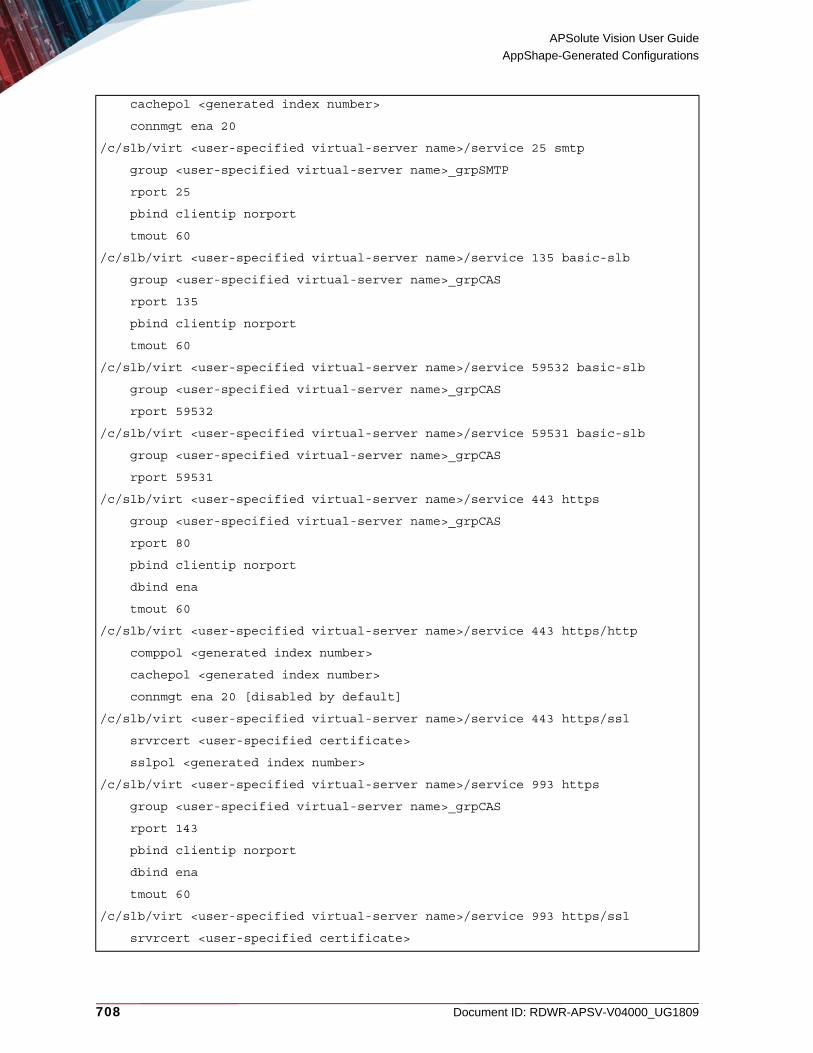
APSolute Vision User Guide
AppShape-Generated Configurations
708 Document ID: RDWR-APSV-V04000_UG1809
cachepol <generated index number>
connmgt ena 20
/c/slb/virt <user-specified virtual-server name>/service 25 smtp
group <user-specified virtual-server name>_grpSMTP
rport 25
pbind clientip norport
tmout 60
/c/slb/virt <user-specified virtual-server name>/service 135 basic-slb
group <user-specified virtual-server name>_grpCAS
rport 135
pbind clientip norport
tmout 60
/c/slb/virt <user-specified virtual-server name>/service 59532 basic-slb
group <user-specified virtual-server name>_grpCAS
rport 59532
/c/slb/virt <user-specified virtual-server name>/service 59531 basic-slb
group <user-specified virtual-server name>_grpCAS
rport 59531
/c/slb/virt <user-specified virtual-server name>/service 443 https
group <user-specified virtual-server name>_grpCAS
rport 80
pbind clientip norport
dbind ena
tmout 60
/c/slb/virt <user-specified virtual-server name>/service 443 https/http
comppol <generated index number>
cachepol <generated index number>
connmgt ena 20 [disabled by default]
/c/slb/virt <user-specified virtual-server name>/service 443 https/ssl
srvrcert <user-specified certificate>
sslpol <generated index number>
/c/slb/virt <user-specified virtual-server name>/service 993 https
group <user-specified virtual-server name>_grpCAS
rport 143
pbind clientip norport
dbind ena
tmout 60
/c/slb/virt <user-specified virtual-server name>/service 993 https/ssl
srvrcert <user-specified certificate>

APSolute Vision User Guide
AppShape-Generated Configurations
Document ID: RDWR-APSV-V04000_UG1809 709
Microsoft Exchange 2013—AppShape-generated ConfigurationThe following is the Alteon CLI configuration that the Microsoft Exchange 2013 AppShape generates.
Note: For more information on the Microsoft Exchange AppShape type, see Configuring a Microsoft Exchange 2013 AppShape Instance, page 262.
sslpol <generated index number>
/c/slb/virt <user-specified virtual-server name>/service 995 https
group <user-specified virtual-server name>_grpCAS
rport 110
pbind clientip norport
dbind ena
tmout 60
/c/slb/virt <user-specified virtual-server name>/service 995 https/ssl
srvrcert <user-specified certificate>
sslpol <generated index number>
/c/slb/accel/compress/comppol <generated index number>
name "WebApplication. <generated index number>"
minsize 1
ena
/c/slb/ssl/certs/key <user-specified certificate>
/c/slb/ssl/certs/request <user-specified certificate>
/c/slb/ssl/certs/cert <user-specified certificate>
/c/slb/ssl/sslpol <generated index number>
name "Exchange_2013. <generated index number>"
cipher "all"
convert disabled
ena
/c/slb/ssl/sslpol <generated index number>/backend
ssl enabled
/c/slb/real <user-specified instance name>_<generated index number>
ena
ipver v4
rip <user-specified IP address>
name "Exchange2013.<user-specified IP address>"
addport <user-specified port>
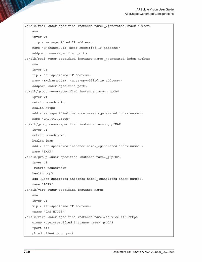
APSolute Vision User Guide
AppShape-Generated Configurations
710 Document ID: RDWR-APSV-V04000_UG1809
/c/slb/real <user-specified instance name>_<generated index number>
ena
ipver v4
rip <user-specified IP address>
name "Exchange2013.<user-specified IP address>"
addport <user-specified port>
/c/slb/real <user-specified instance name>_<generated index number>
ena
ipver v4
rip <user-specified IP address>
name "Exchange2013. <user-specified IP address>"
addport <user-specified port>
/c/slb/group <user-specified instance name>_grpCAS
ipver v4
metric roundrobin
health https
add <user-specified instance name>_<generated index number>
name "CAS.443.Group"
/c/slb/group <user-specified instance name>_grpIMAP
ipver v4
metric roundrobin
health imap
add <user-specified instance name>_<generated index number>
name "IMAP"
/c/slb/group <user-specified instance name>_grpPOP3
ipver v4
metric roundrobin
health pop3
add <user-specified instance name>_<generated index number>
name "POP3"
/c/slb/virt <user-specified instance name>
ena
ipver v4
vip <user-specified IP address>
vname "CAS.HTTPS"
/c/slb/virt <user-specified instance name>/service 443 https
group <user-specified instance name>_grpCAS
rport 443
pbind clientip norport

APSolute Vision User Guide
AppShape-Generated Configurations
Document ID: RDWR-APSV-V04000_UG1809 711
Microsoft Link External—AppShape-generated ConfigurationThe following is the Alteon CLI configuration that the Microsoft Link External AppShape generates.
Note: For more information on the Microsoft Exchange AppShape type, see Configuring a Microsoft Lync External AppShape Instance, page 266.
dbind forceproxy
/c/slb/virt <user-specified instance name>/service 443 https/http
comppol 1
/c/slb/virt <user-specified instance name>/service 443 https/ssl
srvrcert cert <user-specified certificate>
sslpol 1
/c/slb/virt <user-specified instance name>/service 110 pop3
group <user-specified instance name>_grpPOP3
rport 110
pbind clientip norport
/c/slb/virt <user-specified instance name>/service 143 imap
group <user-specified instance name>_grpIMAP
rport 143
pbind clientip norport
/c/slb/virt <user-specified instance name>/service 993 basic-slb
group <user-specified instance name>_grpIMAP
rport 993
pbind clientip norport
/c/slb/virt <user-specified instance name>/service 995 basic-slb
group <user-specified instance name>_grpPOP3
rport 995
pbind clientip norport
/c/slb/virt <user-specified instance name>/service 25 smtp
group <user-specified instance name>_grpCAS
rport 25
pbind clientip norport
/c/slb/real <user-specified instance name>_AV_<generated index number>
ena
ipver v4
rip <user-specified IP address>

APSolute Vision User Guide
AppShape-Generated Configurations
712 Document ID: RDWR-APSV-V04000_UG1809
addport <user-specified port>
/c/slb/real <user-specified instance name>_CWA_<generated index number>
ena
ipver v4
rip <user-specified IP address>
addport <user-specified port>
/c/slb/real <user-specified instance name>_SIP_<generated index number>
ena
ipver v4
rip <user-specified IP address>
addport <user-specified port>
/c/slb/group <user-specified instance name>_AV
ipver v4
add <user-specified instance name>_AV_<generated index number>
name "Lync.edge.av.443"
/c/slb/group <user-specified instance name>_CWA
ipver v4
add <user-specified instance name>_CWA_<generated index number>
name "CWA.Service.group"
/c/slb/group <user-specified instance name>_IM
ipver v4
name "Lync.edge.im.443"
/c/slb/group <user-specified instance name>_MEETING
ipver v4
name "Lync.edge.meeting.HTTPS.443"
/c/slb/group <user-specified instance name>_SIP
ipver v4
add <user-specified instance name>_SIP_<generated index number>
name "Lync.edge.HTTPS.SIP.443"
/c/slb/virt <user-specified instance name>_AV
ena
ipver v4
vip <user-specified IP address>
/c/slb/virt <user-specified instance name>_AV/service 443 https
group <user-specified instance name>_AV
rport 443
pbind clientip norport
tmout 30
/c/slb/virt <user-specified instance name>_CWA

APSolute Vision User Guide
AppShape-Generated Configurations
Document ID: RDWR-APSV-V04000_UG1809 713
ena
ipver v4
vip <user-specified IP address>
/c/slb/virt <user-specified instance name>_CWA/service 443 https
group <user-specified instance name>_CWA
rport 443
pbind clientip norport
tmout 30
/c/slb/virt <user-specified instance name>_MEETING
ena
ipver v4
vip <user-specified IP address>
/c/slb/virt <user-specified instance name>_MEETING/service 443 https
group <user-specified instance name>_MEETING
rport 443
pbind clientip norport
tmout 30
/c/slb/virt <user-specified instance name>_PROXY
ena
ipver v4
vip <user-specified IP address>
vname "lm.Proxy_<user-specified instance name>_PROXY"
/c/slb/virt <user-specified instance name>_PROXY/service 443 https
group <user-specified instance name>_IM
rport 4443
pbind clientip norport
tmout 30
/c/slb/virt <user-specified instance name>_SIP
ena
ipver v4
vip <user-specified IP address>
/c/slb/virt <user-specified instance name>_SIP/service 443 https
group <user-specified instance name>_SIP
rport 443
pbind clientip norport
tmout 30
/c/slb/virt <user-specified instance name>_STUN
ena
ipver v4
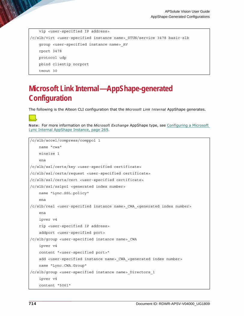
APSolute Vision User Guide
AppShape-Generated Configurations
714 Document ID: RDWR-APSV-V04000_UG1809
Microsoft Link Internal—AppShape-generated ConfigurationThe following is the Alteon CLI configuration that the Microsoft Link Internal AppShape generates.
Note: For more information on the Microsoft Exchange AppShape type, see Configuring a Microsoft Lync Internal AppShape Instance, page 269.
vip <user-specified IP address>
/c/slb/virt <user-specified instance name>_STUN/service 3478 basic-slb
group <user-specified instance name>_AV
rport 3478
protocol udp
pbind clientip norport
tmout 30
/c/slb/accel/compress/comppol 1
name "cwa"
minsize 1
ena
/c/slb/ssl/certs/key <user-specified certificate>
/c/slb/ssl/certs/request <user-specified certificate>
/c/slb/ssl/certs/cert <user-specified certificate>
/c/slb/ssl/sslpol <generated index number>
name "Lync.SSL.policy"
ena
/c/slb/real <user-specified instance name>_CWA_<generated index number>
ena
ipver v4
rip <user-specified IP address>
addport <user-specified port>
/c/slb/group <user-specified instance name>_CWA
ipver v4
content "<user-specified port>"
add <user-specified instance name>_CWA_<generated index number>
name "Lync.CWA.Group"
/c/slb/group <user-specified instance name>_Directors_1
ipver v4
content "5061"

APSolute Vision User Guide
AppShape-Generated Configurations
Document ID: RDWR-APSV-V04000_UG1809 715
name "Lync.Directors"
/c/slb/group <user-specified instance name>_Directors_2
ipver v4
name "Lync.Director.5060"
/c/slb/group <user-specified instance name>_EDGE_1
ipver v4
name "EDGE.Replication.4443"
/c/slb/group <user-specified instance name>_EDGE_2
ipver v4
name "EDGE.INT.443"
/c/slb/group <user-specified instance name>_EDGE_3
ipver v4
name "EDGE.INT.5061"
/c/slb/group <user-specified instance name>_EDGE_4
ipver v4
name "EDGE.INT.5062"
/c/slb/group <user-specified instance name>_EDGE_5
ipver v4
name "GE.INT.UDP.STUN.3478"
/c/slb/group <user-specified instance name>_EDGE_6
ipver v4
name "EDGE.INT.8057"
/c/slb/group <user-specified instance name>_Fronted_1 TBD 3.40, Nir is fixing all to “Frontend_x”.
ipver v4
content "5060"
name "Lync.frontend.SIP.5060"
/c/slb/group <user-specified instance name>_Fronted_2
ipver v4
content "444"
name "Lync.frontend.HTTPS.conf.444"
/c/slb/group <user-specified instance name>_Fronted_3
ipver v4
content "443"
name "Lync.frontend.HTTPS.443"
/c/slb/group <user-specified instance name>_Fronted_4
ipver v4
content "5061"
name "Lync.frontend.MTLS.5061"
/c/slb/group <user-specified instance name>_Fronted_5

APSolute Vision User Guide
AppShape-Generated Configurations
716 Document ID: RDWR-APSV-V04000_UG1809
ipver v4
content "135"
name "Lync.frontend.DCOM.135"
/c/slb/group <user-specified instance name>_Fronted_6
ipver v4
name "Proxy.to.FE.4443"
/c/slb/group <user-specified instance name>_Fronted_7
ipver v4
name "FE.IM.REQ.8057"
/c/slb/group <user-specified instance name>_Fronted_8
ipver v4
name "fe.web.service.8080"
/c/slb/group <user-specified instance name>_Fronted_9
ipver v4
name "FE.CALL.ADM.448"
/c/slb/group <user-specified instance name>_Fronted_10
ipver v4
name "FE.App.Share.5065"
/c/slb/group <user-specified instance name>_Fronted_11
ipver v4
name "FE.monitoring.5069"
/c/slb/group <user-specified instance name>_Fronted_12
ipver v4
name "FE.RES.GROUP.5071"
/c/slb/group <user-specified instance name>_Fronted_13
ipver v4
name "FE.SIP.REQ.5072"
/c/slb/group <user-specified instance name>_Fronted_14
ipver v4
name "FE.CONF.ANOUN.5073"
/c/slb/group <user-specified instance name>_Fronted_15
ipver v4
name "FE.SIP.REQ.CALL.PRK.5075"
/c/slb/group <user-specified instance name>_Fronted_16
ipver v4
name "FE.AUDIO.TEST.5076"
/c/slb/group <user-specified instance name>_Fronted_17
ipver v4
name "FE.AV.AGE.TURN.TRAFF.5080"

APSolute Vision User Guide
AppShape-Generated Configurations
Document ID: RDWR-APSV-V04000_UG1809 717
/c/slb/virt <user-specified instance name>_CWA
ena
ipver v4
vip <user-specified IP address>
/c/slb/virt <user-specified instance name>_CWA/service 443 https
group <user-specified instance name>_CWA
rport <user-specified port>
dbind ena
/c/slb/virt <user-specified instance name>_CWA/service 443 https/http
comppol 1
httpmod 1
/c/slb/virt <user-specified instance name>_CWA/service 443 https/ssl
srvrcert cert cer
sslpol 1
/c/slb/virt <user-specified instance name>_Directors
ena
ipver v4
vip <user-specified IP address>
/c/slb/virt <user-specified instance name>_Directors/service 5061 basic-slb
group <user-specified instance name>_Directors_1
rport 5061
pbind clientip norport
tmout 20
/c/slb/virt <user-specified instance name>_Directors/service 5060 sip
group <user-specified instance name>_Directors_2
rport 5060
pbind clientip norport
tmout 20
/c/slb/virt <user-specified instance name>_EDGE_1
ena
ipver v4
vip <user-specified IP address>
/c/slb/virt <user-specified instance name>_EDGE_1/service 3478 basic-slb
group <user-specified instance name>_EDGE_5
rport 3478
protocol udp
pbind clientip norport
tmout 30
/c/slb/virt <user-specified instance name>_EDGE_2

APSolute Vision User Guide
AppShape-Generated Configurations
718 Document ID: RDWR-APSV-V04000_UG1809
ena
ipver v4
vip <user-specified IP address>
/c/slb/virt <user-specified instance name>_EDGE_2/service 443 https
group <user-specified instance name>_EDGE_2
rport 443
pbind clientip norport
tmout 30
/c/slb/virt <user-specified instance name>_EDGE_3
ena
ipver v4
vip <user-specified IP address>
/c/slb/virt <user-specified instance name>_EDGE_3/service 5062 basic-slb
group <user-specified instance name>_EDGE_4
rport 5062
pbind clientip norport
tmout 30
/c/slb/virt <user-specified instance name>_EDGE_4
ena
ipver v4
vip <user-specified IP address>
/c/slb/virt <user-specified instance name>_EDGE_4/service 8057 basic-slb
group <user-specified instance name>_EDGE_6
rport 8057
pbind clientip norport
tmout 30
/c/slb/virt <user-specified instance name>_EDGE_5
ena
ipver v4
vip <user-specified IP address>
/c/slb/virt <user-specified instance name>_EDGE_5/service 5061 basic-slb
group <user-specified instance name>_EDGE_3
rport 5061
pbind clientip norport
tmout 30
/c/slb/virt <user-specified instance name>_EDGE_6
ena
ipver v4
vip <user-specified IP address>

APSolute Vision User Guide
AppShape-Generated Configurations
Document ID: RDWR-APSV-V04000_UG1809 719
/c/slb/virt <user-specified instance name>_EDGE_6/service 4443 basic-slb
group <user-specified instance name>_EDGE_1
rport 4443
pbind clientip norport
/c/slb/virt <user-specified instance name>_Fronted_1
ena
ipver v4
vip <user-specified IP address>
/c/slb/virt <user-specified instance name>_Fronted_1/service 135 basic-slb
group <user-specified instance name>_Fronted_5
rport 135
pbind clientip norport
tmout 30
/c/slb/virt <user-specified instance name>_Fronted_2
ena
ipver v4
vip <user-specified IP address>
/c/slb/virt <user-specified instance name>_Fronted_2/service 443 https
group <user-specified instance name>_Fronted_3
rport 443
pbind clientip norport
tmout 30
direct dis
/c/slb/virt <user-specified instance name>_Fronted_3
ena
ipver v4
vip <user-specified IP address>
/c/slb/virt <user-specified instance name>_Fronted_3/service 444 basic-slb
group <user-specified instance name>_Fronted_2
rport 444
pbind clientip norport
tmout 30
/c/slb/virt <user-specified instance name>_Fronted_4
ena
ipver v4
vip <user-specified IP address>
/c/slb/virt <user-specified instance name>_Fronted_4/service 5060 sip
group <user-specified instance name>_Fronted_1
rport 5060

APSolute Vision User Guide
AppShape-Generated Configurations
720 Document ID: RDWR-APSV-V04000_UG1809
pbind clientip norport
tmout 30
/c/slb/virt <user-specified instance name>_Fronted_5
ena
ipver v4
vip <user-specified IP address>
/c/slb/virt <user-specified instance name>_Fronted_5/service 5061 basic-slb
group <user-specified instance name>_Fronted_4
rport 5061
pbind clientip norport
tmout 30
/c/slb/virt <user-specified instance name>_Fronted_6
ena
ipver v4
vip <user-specified IP address>
/c/slb/virt <user-specified instance name>_Fronted_6/service 5065 basic-slb
group <user-specified instance name>_Fronted_10
rport 5065
pbind clientip norport
tmout 30
/c/slb/virt <user-specified instance name>_Fronted_7
ena
ipver v4
vip <user-specified IP address>
/c/slb/virt <user-specified instance name>_Fronted_7/service 4443 basic-slb
group <user-specified instance name>_Fronted_6
rport 4443
pbind clientip norport
/c/slb/virt <user-specified instance name>_Fronted_8
ena
ipver v4
vip <user-specified IP address>
/c/slb/virt <user-specified instance name>_Fronted_8/service 5069 basic-slb
group <user-specified instance name>_Fronted_11
rport 5069
pbind clientip norport
/c/slb/virt <user-specified instance name>_Fronted_9
ena
ipver v4

APSolute Vision User Guide
AppShape-Generated Configurations
Document ID: RDWR-APSV-V04000_UG1809 721
vip <user-specified IP address>
/c/slb/virt <user-specified instance name>_Fronted_9/service 8057 basic-slb
group <user-specified instance name>_Fronted_7
rport 8057
pbind clientip norport
tmout 30
/c/slb/virt <user-specified instance name>_Fronted_10
ena
ipver v4
vip <user-specified IP address>
/c/slb/virt <user-specified instance name>_Fronted_10/service 448 basic-slb
group <user-specified instance name>_Fronted_9
rport 448
pbind clientip norport
tmout 30
/c/slb/virt <user-specified instance name>_Fronted_11
ena
ipver v4
vip <user-specified IP address>
/c/slb/virt <user-specified instance name>_Fronted_11/service 5071 basic-slb
group <user-specified instance name>_Fronted_12
rport 5071
pbind clientip norport
/c/slb/virt <user-specified instance name>_Fronted_12
ena
ipver v4
vip <user-specified IP address>
/c/slb/virt <user-specified instance name>_Fronted_12/service 5072 basic-slb
group <user-specified instance name>_Fronted_13
rport 5072
pbind clientip norport
/c/slb/virt <user-specified instance name>_Fronted_13
ena
ipver v4
vip <user-specified IP address>
/c/slb/virt <user-specified instance name>_Fronted_13/service 5073 basic-slb
group <user-specified instance name>_Fronted_14
rport 5073
pbind clientip norport

APSolute Vision User Guide
AppShape-Generated Configurations
722 Document ID: RDWR-APSV-V04000_UG1809
tmout 30
/c/slb/virt <user-specified instance name>_Fronted_14
ena
ipver v4
vip <user-specified IP address>
/c/slb/virt <user-specified instance name>_Fronted_14/service 5075 basic-slb
group <user-specified instance name>_Fronted_15
rport 5075
pbind clientip norport
/c/slb/virt <user-specified instance name>_Fronted_15
ena
ipver v4
vip <user-specified IP address>
/c/slb/virt <user-specified instance name>_Fronted_15/service 5076 basic-slb
group <user-specified instance name>_Fronted_16
rport 5076
pbind clientip norport
/c/slb/virt <user-specified instance name>_Fronted_16
ena
ipver v4
vip <user-specified IP address>
/c/slb/virt <user-specified instance name>_Fronted_16/service 5080 basic-slb
group <user-specified instance name>_Fronted_17
rport 5080
pbind clientip norport
/c/slb/virt <user-specified instance name>_Fronted_17
ena
ipver v4
vip <user-specified IP address>
/c/slb/virt <user-specified instance name>_Fronted_17/service 8080 http
group <user-specified instance name>_Fronted_8
rport 8080
pbind clientip norport
/c/slb/layer7/httpmod <generated index number>
ena
name "htto.to.https.lync.cwa"
/c/slb/layer7/httpmod <generated index number>/rule <generated index number> text
name "htto.to.https.cwa"
directn resp

APSolute Vision User Guide
AppShape-Generated Configurations
Document ID: RDWR-APSV-V04000_UG1809 723
Oracle E-Business—AppShape-generated ConfigurationThe following is the Alteon CLI configuration that the Oracle E-Business AppShape generates.
Note: For more information on the Oracle E-Business AppShape type, see Configuring an Oracle E-Business AppShape Instance, page 272.
body include
action replace "FROMTEXT=http:// <user-specified domain>" "TOTEXT=https:// <user-specified domain>"
/c/slb/accel/compress/comppol <generated index number>
name "oracle.<generated index number>"
minsize 1024
ena
/c/slb/ssl/certs/key <user-specified certificate ID>
/c/slb/ssl/certs/request <user-specified certificate ID>
/c/slb/ssl/certs/cert <user-specified certificate ID>
/c/slb/ssl/sslpol <generated index number>
name "Oracle.SSL.offloading.<generated index number>"
ena
/c/slb/accel/caching/cachepol <generated index number>
name "oracle.cache.<generated index number>"
ena
/c/slb/real <user-specified instance name>_<generated index number>
ena
ipver v4
rip <user-specified IP address>
name "Oracle.app<user-specified IP address>"
addport <user-specified port>
/c/slb/group <user-specified instance name>_grp
ipver v4
add <user-specified instance name>_<generated index number>
name "oracle.app"
/c/slb/virt <user-specified instance name>
ena
ipver v4
vip <user-specified IP address>
vname "Oracle.e-buiss.<user-specified instance name>"
/c/slb/virt <user-specified instance name>/service 80 http
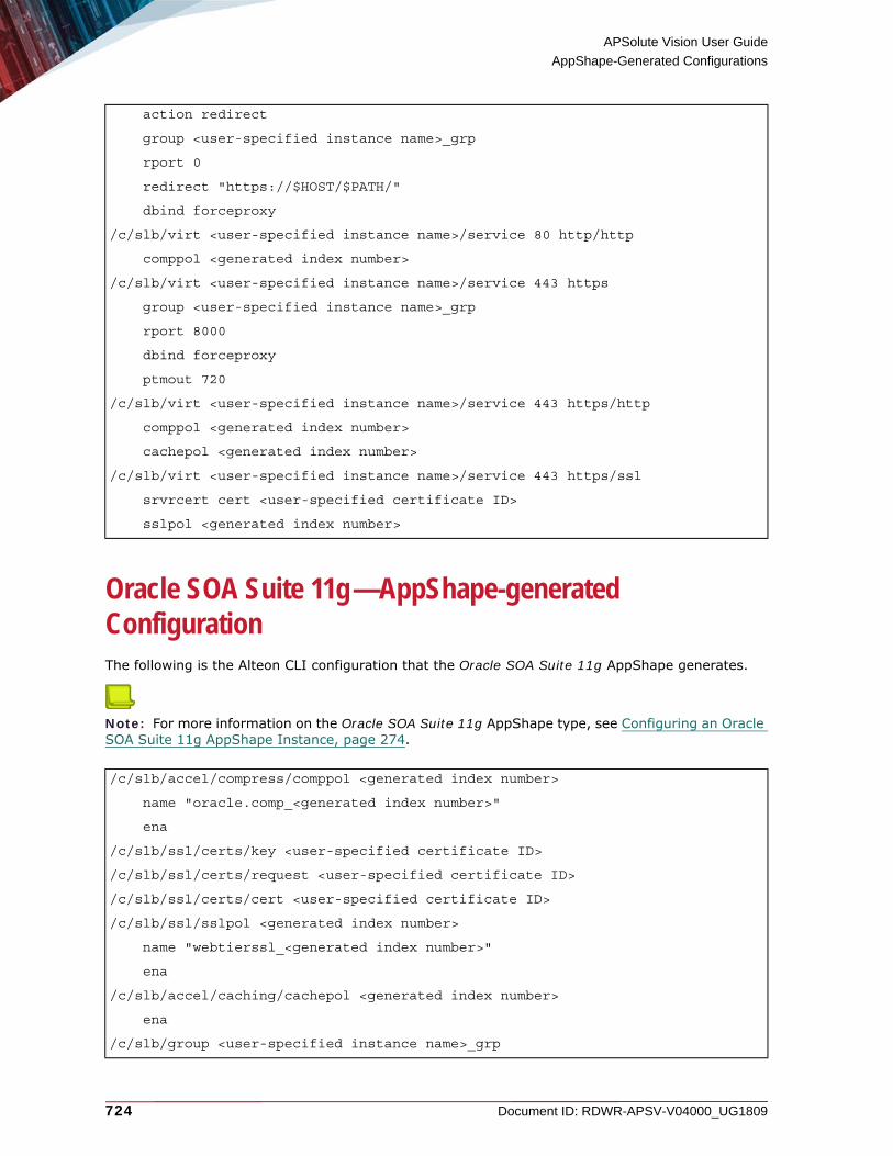
APSolute Vision User Guide
AppShape-Generated Configurations
724 Document ID: RDWR-APSV-V04000_UG1809
Oracle SOA Suite 11g—AppShape-generated ConfigurationThe following is the Alteon CLI configuration that the Oracle SOA Suite 11g AppShape generates.
Note: For more information on the Oracle SOA Suite 11g AppShape type, see Configuring an Oracle SOA Suite 11g AppShape Instance, page 274.
action redirect
group <user-specified instance name>_grp
rport 0
redirect "https://$HOST/$PATH/"
dbind forceproxy
/c/slb/virt <user-specified instance name>/service 80 http/http
comppol <generated index number>
/c/slb/virt <user-specified instance name>/service 443 https
group <user-specified instance name>_grp
rport 8000
dbind forceproxy
ptmout 720
/c/slb/virt <user-specified instance name>/service 443 https/http
comppol <generated index number>
cachepol <generated index number>
/c/slb/virt <user-specified instance name>/service 443 https/ssl
srvrcert cert <user-specified certificate ID>
sslpol <generated index number>
/c/slb/accel/compress/comppol <generated index number>
name "oracle.comp_<generated index number>"
ena
/c/slb/ssl/certs/key <user-specified certificate ID>
/c/slb/ssl/certs/request <user-specified certificate ID>
/c/slb/ssl/certs/cert <user-specified certificate ID>
/c/slb/ssl/sslpol <generated index number>
name "webtierssl_<generated index number>"
ena
/c/slb/accel/caching/cachepol <generated index number>
ena
/c/slb/group <user-specified instance name>_grp

APSolute Vision User Guide
AppShape-Generated Configurations
Document ID: RDWR-APSV-V04000_UG1809 725
ipver v4
health http
slowstr 180
name "webtier"
/c/slb/virt <user-specified instance name>_<generated index number>
ena
ipver v4
vip <user-specified IP address>
/c/slb/virt <user-specified instance name>_<generated index number>/service 80 http
group <user-specified instance name>_grp
rport 7777
dbind ena
/c/slb/virt <user-specified instance name>_<generated index number>/service 80 http/http
cachepol 1
/c/slb/virt <user-specified instance name>_<generated index number>/service 443 https
group <user-specified instance name>_grp
rport 7777
pbind clientip
dbind ena
/c/slb/virt <user-specified instance name>_<generated index number>/service 443 https/http
comppol <generated index number>
cachepol <generated index number>
/c/slb/virt <user-specified instance name>_<generated index number>/service 443 https/ssl
srvrcert cert <user-specified certificate ID>
sslpol <generated index number>
/c/slb/virt <user-specified instance name>_<generated index number>
ena
ipver v4
vip <user-specified IP address>
/c/slb/virt <user-specified instance name>_<generated index number>/service 80 http
group <user-specified instance name>_grp
rport 7777
dbind forceproxy
/c/slb/virt <user-specified instance name>_<generated index number>/service 80 http/http

APSolute Vision User Guide
AppShape-Generated Configurations
726 Document ID: RDWR-APSV-V04000_UG1809
Oracle WebLogic 12c—AppShape-generated ConfigurationThe following is the Alteon CLI configuration that the Oracle WebLogic 12c AppShape generates.
Note: For more information on the Oracle WebLogic 12c AppShape type, see Configuring an Oracle WebLogic 12c AppShape Instance, page 276.
cachepol <generated index number>
/c/slb/virt <user-specified instance name>_<generated index number>
ena
ipver v4
vip <user-specified IP address>
/c/slb/virt <user-specified instance name>_<generated index number>/service 80 http
group MyOracleSOASuite11gIn_grp
rport 7777
dbind forceproxy
/c/slb/virt <user-specified instance name>_<generated index number>/service 80 http/http
cachepol <generated index number>
/c/slb/accel/compress/comppol <generated index number>
name "compression.<generated index number>"
minsize 1024
ena
/c/slb/ssl/certs/key <user-specified certificate ID>
/c/slb/ssl/certs/request <user-specified certificate ID>
/c/slb/ssl/certs/cert <user-specified certificate ID>
/c/slb/ssl/sslpol<generated index number>
name "SSL.<generated index number>"
ena
/c/slb/real <user-specified instance name>_<generated index number>
ena
ipver v4
rip <user-specified IP address>
name "Weblogic.<user-specified IP address>"
addport <user-specified port>
/c/slb/group <user-specified instance name>_grp

APSolute Vision User Guide
AppShape-Generated Configurations
Document ID: RDWR-APSV-V04000_UG1809 727
SharePoint 2010—AppShape-generated ConfigurationThe following is the Alteon CLI configuration that the SharePoint 2010 AppShape generates.
Note: For more information on the SharePoint 2010 AppShape type, see Configuring a SharePoint 2010 AppShape Instance, page 278.
ipver v4
metric roundrobin
add <user-specified instance name>_<generated index number>
name "weblogic.group"
/c/slb/virt <user-specified instance name>
ena
ipver v4
vip <user-specified IP address>
vname "Weblogic.<user-specified instance name>"
/c/slb/virt <user-specified instance name>/service 80 http
action redirect
group <user-specified instance name>_grp
rport 0
redirect "https://$HOST/$PATH/"
dbind ena
/c/slb/virt <user-specified instance name>/service 443 https
group <user-specified instance name>_grp
rport 7001
dbind forceproxy
/c/slb/virt <user-specified instance name>/service 443 https/http
comppol <generated index number>
/c/slb/virt <user-specified instance name>/service 443 https/ssl
srvrcert cert <user-specified certificate ID>
sslpol <generated index number>
User specified enable disable.
/c/slb/accel/compress/comppol <generated index number>
name "SharePoint.<index number>"
ena
User specified enable disable
/c/slb/ssl/sslpol <index number>
name "SharePoint. < generated index number>"

APSolute Vision User Guide
AppShape-Generated Configurations
728 Document ID: RDWR-APSV-V04000_UG1809
ena
/c/slb/ssl/sslpol < generated index number>/passinfo
frontend enabled
User specified enable disable
/c/slb/accel/caching/cachepol <generated index number>
name "SharePoint. <generated index number>"
minsize 1024
ena
/c/slb/real <user-specified virtual-server name>_<generated suffix>
ena
ipver v4
rip <user-specified IP address>
name "SharePoint. <user-specified IP address>"
/c/slb/real <user-specified virtual-server name>_<generated suffix>
ena
ipver v4
rip <user-specified IP address>
name "SharePoint.<user-specified IP address>"
/c/slb/group <user-specified virtual-server name>_grp
ipver v4
metric <user-specified metric>
health <user-specified type>
add <user-specified virtual-server name>_<generated suffix first>
add <user-specified virtual-server name>_<generated suffix next>
name "SharePoint.group"
/c/slb/pip/type vlan [Specified by user because connection management was enabled]
/c/slb/pip/type port [Specified by user because connection management was enabled]
/c/slb/pip/add <user-specified IP address> <user-specified port> [Specified by user because connection management was enabled.]
/c/slb/virt <user-specified virtual-server name>
ena
ipver v4
vip <user-specified IP address>
vname "SharePoint.<user-specified virtual-server name>"
/c/slb/virt <user-specified virtual-server name>/service 80 http
group .<user-specified virtual-server name>_grp
rport 80
pbind clientip norport

APSolute Vision User Guide
AppShape-Generated Configurations
Document ID: RDWR-APSV-V04000_UG1809 729
SharePoint 2013—AppShape-generated ConfigurationThe following is the Alteon CLI configuration that the SharePoint 2013 AppShape generates.
Note: For more information on the SharePoint 2013 AppShape type, see Configuring a SharePoint 2013 AppShape Instance, page 280.
dbind forceproxy
report real
/c/slb/virt <user-specified virtual-server name>/service 80 http/http
comppol <generated index number>
cachepol <generated index number>
connmgt ena 20 [disabled by default]
/c/slb/virt <user-specified virtual-server name>/service 443 https
group <user-specified virtual-server name>_grp
rport 80
dbind forceproxy
report real
/c/slb/virt <user-specified virtual-server name>/service 443 https/http
comppol <generated index number>
cachepol <generated index number>
connmgt ena 10
httpmod <generated index number>
/c/slb/virt <user-specified virtual-server name>/service 443 https/<generated index number>
srvrcert cert <user-specified certificate>
sslpol <generated index number>
/c/slb/layer7/httpmod <generated index number>
ena
name "http.to.https.sharepoint"
/c/slb/layer7/httpmod <generated index number>/rule 1 text
ena
name "http.to.https.sharepoint"
directn resp
body include
action replace "FROMTEXT=http://<user-specified domain>" "TOTEXT=https:// <user-specified domain>"
/c/slb/accel/compress/comppol <generated index number>
name "comp<generated index number>"
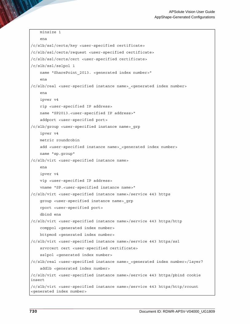
APSolute Vision User Guide
AppShape-Generated Configurations
730 Document ID: RDWR-APSV-V04000_UG1809
minsize 1
ena
/c/slb/ssl/certs/key <user-specified certificate>
/c/slb/ssl/certs/request <user-specified certificate>
/c/slb/ssl/certs/cert <user-specified certificate>
/c/slb/ssl/sslpol 1
name "SharePoint_2013. <generated index number>"
ena
/c/slb/real <user-specified instance name>_<generated index number>
ena
ipver v4
rip <user-specified IP address>
name "SP2013.<user-specified IP address>"
addport <user-specified port>
/c/slb/group <user-specified instance name>_grp
ipver v4
metric roundrobin
add <user-specified instance name>_<generated index number>
name "sp.group"
/c/slb/virt <user-specified instance name>
ena
ipver v4
vip <user-specified IP address>
vname "SP.<user-specified instance name>"
/c/slb/virt <user-specified instance name>/service 443 https
group <user-specified instance name>_grp
rport <user-specified port>
dbind ena
/c/slb/virt <user-specified instance name>/service 443 https/http
comppol <generated index number>
httpmod <generated index number>
/c/slb/virt <user-specified instance name>/service 443 https/ssl
srvrcert cert <user-specified certificate>
sslpol <generated index number>
/c/slb/real <user-specified instance name>_<generated index number>/layer7
addlb <generated index number>
/c/slb/virt <user-specified instance name>/service 443 https/pbind cookie insert
/c/slb/virt <user-specified instance name>/service 443 https/http/rcount <generated index number>
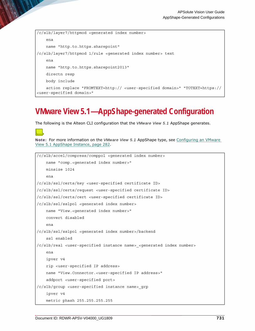
APSolute Vision User Guide
AppShape-Generated Configurations
Document ID: RDWR-APSV-V04000_UG1809 731
VMware View 5.1—AppShape-generated ConfigurationThe following is the Alteon CLI configuration that the VMware View 5.1 AppShape generates.
Note: For more information on the VMware View 5.1 AppShape type, see Configuring an VMware View 5.1 AppShape Instance, page 282.
/c/slb/layer7/httpmod <generated index number>
ena
name "http.to.https.sharepoint"
/c/slb/layer7/httpmod 1/rule <generated index number> text
ena
name "http.to.https.sharepoint2013"
directn resp
body include
action replace "FROMTEXT=http:// <user-specified domain>" "TOTEXT=https:// <user-specified domain>"
/c/slb/accel/compress/comppol <generated index number>
name "comp.<generated index number>"
minsize 1024
ena
/c/slb/ssl/certs/key <user-specified certificate ID>
/c/slb/ssl/certs/request <user-specified certificate ID>
/c/slb/ssl/certs/cert <user-specified certificate ID>
/c/slb/ssl/sslpol <generated index number>
name "View.<generated index number>"
convert disabled
ena
/c/slb/ssl/sslpol <generated index number>/backend
ssl enabled
/c/slb/real <user-specified instance name>_<generated index number>
ena
ipver v4
rip <user-specified IP address>
name "View.Connector.<user-specified IP address>"
addport <user-specified port>
/c/slb/group <user-specified instance name>_grp
ipver v4
metric phash 255.255.255.255

APSolute Vision User Guide
AppShape-Generated Configurations
732 Document ID: RDWR-APSV-V04000_UG1809
Zimbra—AppShape-generated ConfigurationThe following is the Alteon CLI configuration that the Zimbra AppShape generates.
Note: For more information on the Zimbra AppShape type, see Configuring a Zimbra AppShape Instance, page 284.
add <user-specified instance name>_<generated index number>
name "View.connectors"
/c/slb/virt <user-specified instance name>
ena
ipver v4
vip <user-specified IP address>
vname "View.<user-specified instance name>"
/c/slb/virt <user-specified instance name>/service 443 https
group <user-specified instance name>_grp
rport 443
dbind forceproxy
/c/slb/virt <user-specified instance name>/service 443 https/http
comppol <generated index number>
/c/slb/virt <user-specified instance name>/service 443 https/ssl
srvrcert cert <user-specified certificate ID>
sslpol <generated index number>
/c/slb/accel/compress/comppol <generated index number>
name "Zimbra.<generated index number>"
minsize 1024
ena
/c/slb/ssl/certs/key <user-specified certificate>
/c/slb/ssl/certs/key <user-specified certificate ID>
/c/slb/ssl/certs/request <user-specified certificate >
/c/slb/ssl/certs/request <user-specified certificate ID>
/c/slb/ssl/certs/cert <user-specified certificate >
/c/slb/ssl/certs/cert <user-specified certificate ID>
/c/slb/ssl/sslpol <user-specified instance name>_ssl<generated index number>
name "Zimbra.<user-specified instance name>_ssl<generated index number>"
ena
/c/slb/ssl/sslpol <user-specified instance name>_ssl<generated index number>
cipher "all"

APSolute Vision User Guide
AppShape-Generated Configurations
Document ID: RDWR-APSV-V04000_UG1809 733
convert disabled
ena
/c/slb/real <user-specified instance name>_<generated index number>
ena
ipver v4
rip <user-specified IP address>
name "Zimbra.<user-specified IP address>"
addport <user-specified port>
/c/slb/group <user-specified instance name>_grp<generated index number>
ipver v4
metric phash 255.255.255.255
add <user-specified instance name>_<generated index number>
name "zimbra.HTTP.servers"
/c/slb/group <user-specified instance name>_grp<generated index number>
ipver v4
metric phash 255.255.255.255
add <user-specified instance name>_<generated index number>
name "zimbra.pop3.servers"
/c/slb/group <user-specified instance name>_grp<generated index number>
ipver v4
metric phash 255.255.255.255
add <user-specified instance name>_<generated index number>
name "zimbra.ldap.servers"
/c/slb/group MyZimbraInstance_grp<generated index number>
ipver v4
metric phash 255.255.255.255
add <user-specified instance name>_<generated index number>
name "zimbra.imap.servers"
/c/slb/group <user-specified instance name>_grp<generated index number>
ipver v4
metric phash 255.255.255.255
add <user-specified instance name>_<generated index number>
name "zimbra.smtp.servers"
/c/slb/virt <user-specified instance name>
ena
ipver v4
vip <user-specified IP address>
vname "zimbra.servers.MyZimbraInstance"
/c/slb/virt <user-specified instance name>/service 443 https
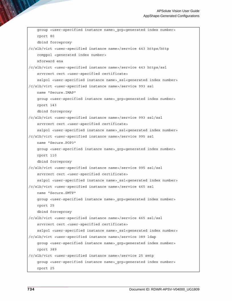
APSolute Vision User Guide
AppShape-Generated Configurations
734 Document ID: RDWR-APSV-V04000_UG1809
group <user-specified instance name>_grp<generated index number>
rport 80
dbind forceproxy
/c/slb/virt <user-specified instance name>/service 443 https/http
comppol <generated index number>
xforward ena
/c/slb/virt <user-specified instance name>/service 443 https/ssl
srvrcert cert <user-specified certificate>
sslpol <user-specified instance name>_ssl<generated index number>
/c/slb/virt <user-specified instance name>/service 993 ssl
name "Secure.IMAP"
group <user-specified instance name>_grp<generated index number>
rport 143
dbind forceproxy
/c/slb/virt <user-specified instance name>/service 993 ssl/ssl
srvrcert cert <user-specified certificate>
sslpol <user-specified instance name>_ssl<generated index number>
/c/slb/virt <user-specified instance name>/service 995 ssl
name "Secure.POP3"
group <user-specified instance name>_grp<generated index number>
rport 110
dbind forceproxy
/c/slb/virt <user-specified instance name>/service 995 ssl/ssl
srvrcert cert <user-specified certificate>
sslpol <user-specified instance name>_ssl<generated index number>
/c/slb/virt <user-specified instance name>/service 465 ssl
name "Secure.SMTP"
group <user-specified instance name>_grp<generated index number>
rport 25
dbind forceproxy
/c/slb/virt <user-specified instance name>/service 465 ssl/ssl
srvrcert cert <user-specified certificate>
sslpol <user-specified instance name>_ssl<generated index number>
/c/slb/virt <user-specified instance name>/service 389 ldap
group <user-specified instance name>_grp<generated index number>
rport 389
/c/slb/virt <user-specified instance name>/service 25 smtp
group <user-specified instance name>_grp<generated index number>
rport 25

APSolute Vision User Guide
AppShape-Generated Configurations
Document ID: RDWR-APSV-V04000_UG1809 735
pbind clientip norport
/c/slb/virt <user-specified instance name>/service 110 pop3
group <user-specified instance name>_grp<generated index number>
rport 110
/c/slb/virt <user-specified instance name>/service 143 imap
group <user-specified instance name>_grp<generated index number>
rport 143

APSolute Vision User Guide
AppShape-Generated Configurations
736 Document ID: RDWR-APSV-V04000_UG1809

Document ID: RDWR-APSV-V04000_UG1809 737
APPENDIX E – USING THE EVENT EXPORTERThis appendix contains the following sections, which describe the output of the event exporter:• Event-Record Structure and Content, page 737• DFBdosBaseline (DefenseFlow BDoS Baseline) Records, page 737• DFSecurityAttack (DefenseFlow Security Attack) Records, page 739• DFTrafficUtilization (DefenseFlow Traffic Utilization) Records, page 742• DPSecurityAttack (DefensePro Security Attack) Records, page 744• DPTrafficUtilization (DefensePro Traffic Utilization) Records, page 749
Note: For information on managing the event exporter, see System Exporter Commands (Event Exporter), page 632.
Event-Record Structure and ContentThe records from the event exporter are structured to provide all available information on occurring security events. Each field is separated by a single space character. Fields that may contain spaces are enclosed between double quotation marks.Security events can last from seconds to hours, and even days. Many of the DefensePro protection modules can identify continuous ongoing events, and generate a series of records for the events. In such cases, DefensePro uses the same unique ID for all the events.
DFBdosBaseline (DefenseFlow BDoS Baseline) Records The following table describes the fields of the DFBdosBaseline (DefenseFlow BDoS Baseline) records from the event exporter.
Table 510: DFBdosBaseline (DefenseFlow BDoS Baseline) Fields
Field Description Example or Static ValuesDFBDosRealTimeEdgeEntity
The entity type of the record. There is no value attached to this field.
DFBDosRealTimeEdgeEntity
tcp Specifies whether the protected object includes TCP in the BDoS Protection Settings.
false
normal The legitimate traffic. 0.8
normalEdge The statistically calculated baseline traffic rate.
792.0064

APSolute Vision User Guide
Using the Event Exporter
738 Document ID: RDWR-APSV-V04000_UG1809
policyName The name of the configured Security Policy that was set to mitigate the attack. The default policy name is the name of the protected object. Policies in DefenseFlow cannot be edited.
PO_John
enrichmentContainer This field is for internal use.
{}
protection The traffic type of the attack.
icmp
units The unit of measurement for the traffic rate.
bps
totalTraffic The total traffic that the device sees for the specific protection type and direction.
4800.2705
timeStamp The time, in 13-digit Unix format, that the DefenseFlow device record was generated.
1504185750104
suspectedAttack The traffic rate that indicates a change in traffic that might be an attack.
3200.0017
legitimateTraffic The actual forwarded traffic rate, after the mitigation device managed to block the attack. When there is no attack, the totalTraffic and legitimateTraffic are equal.
885.60565
ipVersion The IP version of the traffic on which the record reports.
IPv6
doa Degree of Attack. A numeric value that evaluates the current level of attack. A value of 8 or greater signifies an attack.
5
partial The legitimate traffic. 0.13
protectedObjectName
The name of the protected object that was attacked.
PO_John
direction The direction of the attack, inbound or outbound.
Values: In, Out
Table 510: DFBdosBaseline (DefenseFlow BDoS Baseline) Fields (cont.)
Field Description Example or Static Values

APSolute Vision User Guide
Using the Event Exporter
Document ID: RDWR-APSV-V04000_UG1809 739
DFSecurityAttack (DefenseFlow Security Attack) RecordsThe following table describes the fields of the DFSecurityAttack (DefenseFlow Security Attack) records from the event exporter.
suspectedEdge The traffic rate that indicates a change in traffic that might be an attack.
1600.0065
full The actual overall traffic. 0.19
Table 511: DFSecurityAttack (DefenseFlow Security Attack) Fields
Field Description Example or Static ValuesDFAttackEntity The entity type of the
record. There is no value attached to this field.
DFAttackEntity
sourcePort The source L4 port that the attack uses or used.
29100
vlanTag The VLAN tag value or Context Group in the policy that handled the attack. The VLAN tag or Context Group identifies similar information in this field. DefensePro 6.x and 7.x versions support VLAN tags. DefensePro 8.x versions support Context Groups.
172
packetCount The packet count of the attack.
2000
destMsisdn The MSISDN Resolution feature is not supported currently.
Unknown
protocol The protocol that the attack uses or used.
NonIP
destPort The destination port that the attack uses or used.
443
threatGroup This field is for internal use.
DDoSGroup
destAddress The destination IP address that the attack uses or used.
10.0.0.2
ruleName The name of the user-defined protected object.
PO_John_1
Table 510: DFBdosBaseline (DefenseFlow BDoS Baseline) Fields (cont.)
Field Description Example or Static Values

APSolute Vision User Guide
Using the Event Exporter
740 Document ID: RDWR-APSV-V04000_UG1809
startTime The time, in 13-digit Unix notation, that the attack started.
1504186486428
radwareId The Radware DefensePro Attack-Protection identifier issued by the device. For more information, see DefensePro Attack-Protection IDs, page 751.
-1
Note: The value -1 signifies N⁄A.
direction The direction of the attack, inbound or outbound. Values: In, Out
In
mplsRd The Multi-protocol Label Switching Route Distinguisher in the policy that handled the attack.
211
attackIpsId The unique identifier of the attack, issued from the mitigation device.
2455492_10.0.0.2/32_null_null_EXTERNAL_DETECTOR
sourceAddress The source IP address of the attack. If there are multiple IP sources for an attack, this field displays Multiple. The multiple IP addresses are displayed in the Attack Details window. Multiple may also refer to cases when DefensePro cannot report a specific value.
192.168.172.1
srcMsisdn The MSISDN Resolution feature is not supported currently.
Unknown
enrichmentContainer This field is for internal use.
{}
physicalPort The port on the device to which the attack packets arrived.
0
Note: The value -1 signifies N⁄A.
Table 511: DFSecurityAttack (DefenseFlow Security Attack) Fields (cont.)
Field Description Example or Static Values

APSolute Vision User Guide
Using the Event Exporter
Document ID: RDWR-APSV-V04000_UG1809 741
actionType The reported action against the attack. The actions are specified in the protection profile, which may or may not be available or relevant for your system.
Values:• Bypass—DefensePro does not protect
against this attack, but rather, sends its data out of the device, and may report it.
• Challenge—DefensePro challenges the packet.
• Destination Reset—DefensePro sends a TCP-Reset packet to the destination IP address and port.
• Drop—DefensePro discards the packet.• Drop & Quarantine—DefensePro discards
the traffic and adds the destination to the Web quarantine.
• Forward—DefensePro continues to process the traffic and eventually forwards the packet to its destination.
• Proxy• Quarantine—DefensePro adds the
destination to the Web quarantine.• Source Destination Reset—DefensePro
sends a TCP-Reset packet to both the packet source IP and the packet destination IP address.
• Source Reset—DefensePro sends a TCP-Reset packet to the packet source IP address.
• Http 200 Ok—DefensePro sends a 200 OK response using a predefined page and leaves the server-side connection open.
• Http 200 Ok Reset Dest—DefensePro sends a 200 OK response using a predefined page and sends a TCP-Reset packet to the server side to close the connection.
• Http 403 Forbidden—DefensePro sends a 403 Forbidden response using a predefined page and leaves the server-side connection open.
packetBandwidth The attack bandwidth in kbit⁄s.
256
name The attack name. Unknown
Table 511: DFSecurityAttack (DefenseFlow Security Attack) Fields (cont.)
Field Description Example or Static Values

APSolute Vision User Guide
Using the Event Exporter
742 Document ID: RDWR-APSV-V04000_UG1809
DFTrafficUtilization (DefenseFlow Traffic Utilization) RecordsThe following table describes the fields of the DFTrafficUtilization (DefenseFlow Traffic Utilization) records from the event exporter.
risk The risk level that DefensePro classifies the security event.
Values:• Info—The risk does not pose a threat to
normal service operation.• Low—The risk does not pose a threat to
normal service operation, but may be part of a preliminary action for malicious behavior.
• Medium—The risk may pose a threat to normal service operation, but is not likely to cause complete service outage, remote code execution, or unauthorized access.High—The risk is very likely to pose a threat to normal service availability, and may cause complete service outage, remote code execution, or unauthorized access.
endTime The time, in 13-digit Unix notation, that the attack ended.
1504185481240
category The threat type to which this attack belongs.
Values:
• Anomalies1 (in DefenseFlow, detection was performed by an external detector)
• BehavioralDoS (in DefenseFlow, detection was performed by DefenseFlow BDoS)
status The attack status. Terminated
protectedObjectName
The name of the protected object.
PO_John
1 – Once DefensePro reports a Packet Anomaly attack of a certain radwareId, the status value Occurred and the startTime value remain indefinitely. For example, suppose a new DefensePro device starts identifying and handling a Packet Anomaly attack with radwareId 105 with the start time 20.02.2017 15:19:09. The attack subsides. One month later, the DefensePro device starts identifying and handling another Packet Anomaly attack with radwareId 105. The startTime value 20.02.2017 15:19:09 is reported. (For more information on Packet Anomaly protection, see the APSolute Vision online help or the DefensePro User Guide.)
Table 512: DFTrafficUtilization (DefenseFlow Traffic Utilization) Fields
Field Description Example or Static ValuesDFTrafficUtilizationRawEntity
The entity type of the record. There is no value attached to this field.
DFTrafficUtilizationRawEntity
Table 511: DFSecurityAttack (DefenseFlow Security Attack) Fields (cont.)
Field Description Example or Static Values

APSolute Vision User Guide
Using the Event Exporter
Document ID: RDWR-APSV-V04000_UG1809 743
discarded The discarded traffic for the specified protocol.
0.0
monitoringProtocol The traffic protocol. Values:• tcp• udp• icmp• igmp• sctp• other—The statistics of the traffic that is
not TCP, UDP, ICMP, IGMP, or SCTP• all—Total traffic statistics
policyName The name of the configured Security Policy.
PO_John_1
inbound The rate of inbound traffic for the protocol identified in the record.
933.0
dropped The rate of traffic dropped for the protocol identified in the record.
0.0
enrichmentContainer This field is for internal use. {}
cleanAmount This field is for future use. 27990.0
clean This field is for future use. 933.0
discardedAmount This field is for future use. 0.0
physicalPort The physical port of the mitigation device.
-1
Note: The value -1 signifies N⁄A.
timeStamp The time, in 13-digit Unix notation, that the DefenseFlow device sent the record.
1504186700069
diverted The rate of diverted traffic for the protocol identified in the record.
0.0
droppedAmount This field is for future use. 0.0
unit The unit of measurement for the traffic rate.
Values:• Kbps—Kilobits per second• pps—Packets per second
divertedAmount This field is for future use. 0.0
id N⁄A null
inboundAmount This field is for future use. 27990.0
protectedObjectName
The name of the protected object.
PO_John
Table 512: DFTrafficUtilization (DefenseFlow Traffic Utilization) Fields (cont.)
Field Description Example or Static Values
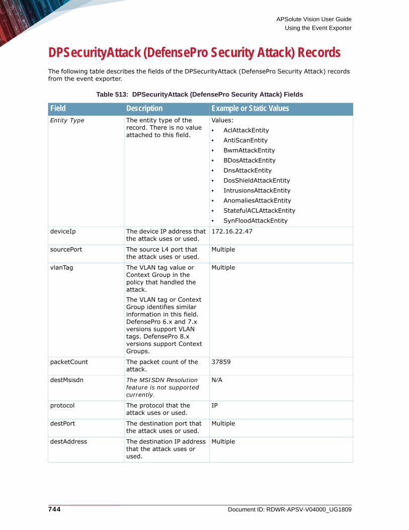
APSolute Vision User Guide
Using the Event Exporter
744 Document ID: RDWR-APSV-V04000_UG1809
DPSecurityAttack (DefensePro Security Attack) RecordsThe following table describes the fields of the DPSecurityAttack (DefensePro Security Attack) records from the event exporter.
Table 513: DPSecurityAttack (DefensePro Security Attack) Fields
Field Description Example or Static ValuesEntity Type The entity type of the
record. There is no value attached to this field.
Values: • AclAttackEntity• AntiScanEntity• BwmAttackEntity• BDosAttackEntity• DnsAttackEntity• DosShieldAttackEntity• IntrusionsAttackEntity• AnomaliesAttackEntity• StatefulACLAttackEntity• SynFloodAttackEntity
deviceIp The device IP address that the attack uses or used.
172.16.22.47
sourcePort The source L4 port that the attack uses or used.
Multiple
vlanTag The VLAN tag value or Context Group in the policy that handled the attack. The VLAN tag or Context Group identifies similar information in this field. DefensePro 6.x and 7.x versions support VLAN tags. DefensePro 8.x versions support Context Groups.
Multiple
packetCount The packet count of the attack.
37859
destMsisdn The MSISDN Resolution feature is not supported currently.
N⁄A
protocol The protocol that the attack uses or used.
IP
destPort The destination port that the attack uses or used.
Multiple
destAddress The destination IP address that the attack uses or used.
Multiple

APSolute Vision User Guide
Using the Event Exporter
Document ID: RDWR-APSV-V04000_UG1809 745
ruleName The name of the Network Protection policy or the Server Protection policy associated with the record.
Black List
radwareId The unique attack identifier issued by the device.
8
startTime The time, in millis, that the attack started.
1504181689804
direction The direction of the attack, inbound or outbound. Values: In, Out
In
mplsRd The Multi-protocol Label Switching Route Distinguisher in the policy that handled the attack.
Multiple
attackIpsId The unique ID of the attack from DefensePro.
3383-1402580209
sourceAddress The source IP address of the attack. If there are multiple IP sources for an attack, this field displays Multiple. The multiple IP addresses are displayed in the Attack Details window. Multiple may also refer to cases when DefensePro cannot report a specific value.
Multiple
srcMsisdn The MSISDN Resolution feature is not supported currently.
N⁄A
physicalPort The port on the device to which the attack packets arrived.
Multiple
Note: The value -1 signifies N⁄A.
Table 513: DPSecurityAttack (DefensePro Security Attack) Fields (cont.)
Field Description Example or Static Values

APSolute Vision User Guide
Using the Event Exporter
746 Document ID: RDWR-APSV-V04000_UG1809
actionType The reported action against the attack. The actions are specified in the protection profile, which may or may not be available or relevant for your system.
Values:• Bypass—DefensePro does not protect
against this attack, but rather, sends its data out of the device, and may report it.
• Challenge—DefensePro challenges the packet.
• Destination Reset—DefensePro sends a TCP-Reset packet to the destination IP address and port.
• Drop—DefensePro discards the packet.• Drop & Quarantine—DefensePro discards
the traffic and adds the destination to the Web quarantine.
• Forward—DefensePro continues to process the traffic and eventually forwards the packet to its destination.
• Proxy• Quarantine—DefensePro adds the
destination to the Web quarantine.• Source Destination Reset—DefensePro
sends a TCP-Reset packet to both the packet source IP and the packet destination IP address.
• Source Reset—DefensePro sends a TCP-Reset packet to the packet source IP address.
• Http 200 Ok—DefensePro sends a 200 OK response using a predefined page and leaves the server-side connection open.
• Http 200 Ok Reset Dest—DefensePro sends a 200 OK response using a predefined page and sends a TCP-Reset packet to the server side to close the connection.
• Http 403 Forbidden—DefensePro sends a 403 Forbidden response using a predefined page and leaves the server-side connection open.
• Http 403 Forbidden Reset Dest—DefensePro sends a 403 Forbidden response using a predefined page and sends a TCP-Reset packet to the server side to close the connection.
packetBandwidth The attack bandwidth in kbit⁄s.
0
name The attack name. BL
Table 513: DPSecurityAttack (DefensePro Security Attack) Fields (cont.)
Field Description Example or Static Values
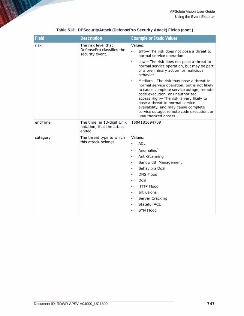
APSolute Vision User Guide
Using the Event Exporter
Document ID: RDWR-APSV-V04000_UG1809 747
risk The risk level that DefensePro classifies the security event.
Values:• Info—The risk does not pose a threat to
normal service operation.• Low—The risk does not pose a threat to
normal service operation, but may be part of a preliminary action for malicious behavior.
• Medium—The risk may pose a threat to normal service operation, but is not likely to cause complete service outage, remote code execution, or unauthorized access.High—The risk is very likely to pose a threat to normal service availability, and may cause complete service outage, remote code execution, or unauthorized access.
endTime The time, in 13-digit Unix notation, that the attack ended.
1504181694709
category The threat type to which this attack belongs.
Values:• ACL
• Anomalies1
• Anti-Scanning • Bandwidth Management• BehavioralDoS• DNS Flood • DoS• HTTP Flood• Intrusions• Server Cracking• Stateful ACL• SYN Flood
Table 513: DPSecurityAttack (DefensePro Security Attack) Fields (cont.)
Field Description Example or Static Values

APSolute Vision User Guide
Using the Event Exporter
748 Document ID: RDWR-APSV-V04000_UG1809
status The last-reported status of the attack.
Values:• Started—An attack containing more than
one security event has been detected. (Some attacks contain multiple security events, such as DoS, Scans, and so on.)
• Occurred—Only for signature-based attacks. Each packet matched with signatures was reported as an attack and dropped.
• Ongoing—The attack is currently taking place, that is, the time between Started and Terminated (for attacks that contain multiple security events, such as DoS, Scans, and so on).
• Terminated—There are no more packets matching the characteristics of the attack, and the device reports that the attack has ended.
• sampled—Along with messages that have the status value Ongoing, some DefensePro protection modules can send additional records with the status value Sampled. These records provide Layer 4 parameters of specific packets that were classified as part of the security event. Each of these records includes the same unique ID that is used for other messages (Started/Ongoing/Terminated). The packetBandwidth value in these records may contain the value for bandwidth or packet size. DefensePro normalizes the measured bandwidth or packet size. The normalization function always rounds down the value. For example, in such records, DefensePro reports values of 1–127 as 0, values of 128–255 as 1, and so on.
1 – Once DefensePro reports a Packet Anomaly attack of a certain Radware ID, the status value Occurred and the startTime value remain indefinitely. For example, suppose a new DefensePro device starts identifying and handling a Packet Anomaly attack with radwareId 105 with the start time 20.02.2017 15:19:09. The attack subsides. One month later, the DefensePro device starts identifying and handling another Packet Anomaly attack with radwareId 105. The Start Time value 20.02.2017 15:19:09 is reported. (For more information on Packet Anomaly protection, see the APSolute Vision online help or the DefensePro User Guide.)
Table 513: DPSecurityAttack (DefensePro Security Attack) Fields (cont.)
Field Description Example or Static Values
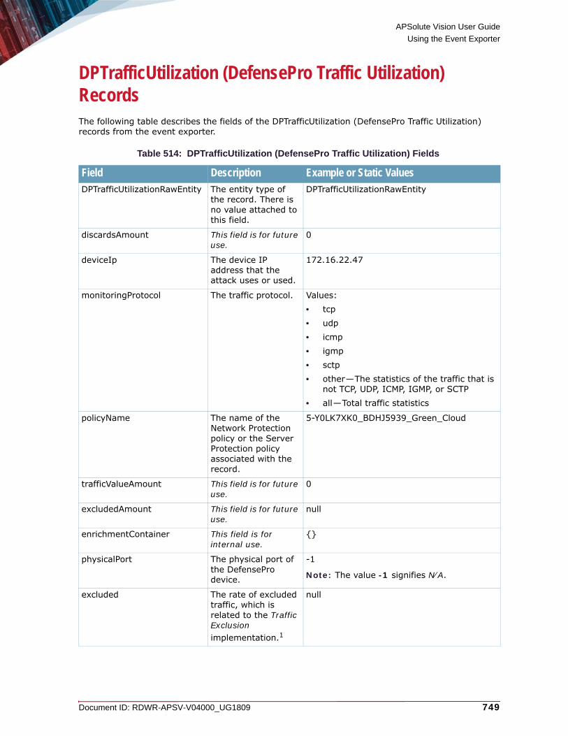
APSolute Vision User Guide
Using the Event Exporter
Document ID: RDWR-APSV-V04000_UG1809 749
DPTrafficUtilization (DefensePro Traffic Utilization) RecordsThe following table describes the fields of the DPTrafficUtilization (DefensePro Traffic Utilization) records from the event exporter.
Table 514: DPTrafficUtilization (DefensePro Traffic Utilization) Fields
Field Description Example or Static ValuesDPTrafficUtilizationRawEntity The entity type of
the record. There is no value attached to this field.
DPTrafficUtilizationRawEntity
discardsAmount This field is for future use.
0
deviceIp The device IP address that the attack uses or used.
172.16.22.47
monitoringProtocol The traffic protocol. Values:• tcp• udp• icmp• igmp• sctp• other—The statistics of the traffic that is
not TCP, UDP, ICMP, IGMP, or SCTP• all—Total traffic statistics
policyName The name of the Network Protection policy or the Server Protection policy associated with the record.
5-Y0LK7XK0_BDHJ5939_Green_Cloud
trafficValueAmount This field is for future use.
0
excludedAmount This field is for future use.
null
enrichmentContainer This field is for internal use.
{}
physicalPort The physical port of the DefensePro device.
-1
Note: The value -1 signifies N⁄A.
excluded The rate of excluded traffic, which is related to the Traffic Exclusion implementation.1
null
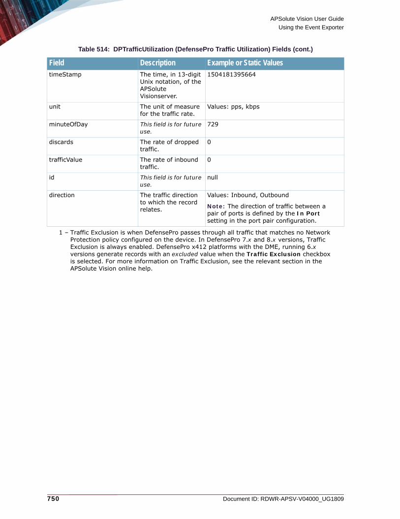
APSolute Vision User Guide
Using the Event Exporter
750 Document ID: RDWR-APSV-V04000_UG1809
timeStamp The time, in 13-digit Unix notation, of the APSolute Visionserver.
1504181395664
unit The unit of measure for the traffic rate.
Values: pps, kbps
minuteOfDay This field is for future use.
729
discards The rate of dropped traffic.
0
trafficValue The rate of inbound traffic.
0
id This field is for future use.
null
direction The traffic direction to which the record relates.
Values: Inbound, Outbound
Note: The direction of traffic between a pair of ports is defined by the In Port setting in the port pair configuration.
1 – Traffic Exclusion is when DefensePro passes through all traffic that matches no Network Protection policy configured on the device. In DefensePro 7.x and 8.x versions, Traffic Exclusion is always enabled. DefensePro x412 platforms with the DME, running 6.x versions generate records with an excluded value when the Traffic Exclusion checkbox is selected. For more information on Traffic Exclusion, see the relevant section in the APSolute Vision online help.
Table 514: DPTrafficUtilization (DefensePro Traffic Utilization) Fields (cont.)
Field Description Example or Static Values

Document ID: RDWR-APSV-V04000_UG1809 751
APPENDIX F – DEFENSEPRO ATTACK-PROTECTION IDSThis appendix describes the DefensePro Attack-Protection IDs.
Note: Some DefensePro versions do not support all the attack-protections listed in the following table.

APSolute Vision User Guide
DefensePro Attack-Protection IDs
752 Document ID: RDWR-APSV-V04000_UG1809
Table 515: DefensePro Attack-Protection IDs
ID Number or Range
Attack-Protection Name Category(for Reporting)
Default Risk
Default Action
Report Action
Description
8 White List N/A White-list encounters are not reported as security events.
9 Black List Access Black-list access violation.
70 Network flood IPv4 UDP Behavioral-DoS Network flood IPv4 UDP.
71 Network flood IPv4 ICMP Behavioral-DoS Network flood IPv4 ICMP.
72 Network flood IPv4 IGMP Behavioral-DoS Network flood IPv4 IGMP.
73 Network flood IPv4 TCP-SYN
Behavioral-DoS Network flood IPv4 TCP with SYN flag.
74 Network flood IPv4 TCP-RST
Behavioral-DoS Network flood IPv4 TCP with RST flag.
75 Network flood IPv4 TCP-ACK
Behavioral-DoS Network flood IPv4 TCP with ACK flag.
76 Network flood IPv4 TCP-PSH
Behavioral-DoS Network flood IPv4 TCP with PSH flag.
77 Network flood IPv4 TCP-FIN
Behavioral-DoS Network flood IPv4 TCP with FIN flag.
78 Network flood IPv4 TCP-SYN-ACK
Behavioral-DoS Network flood IPv4 TCP with SYN and ACK flags
79 Network flood IPv4 TCP-FRAG
Behavioral-DoS Network flood IPv4 TCP with FRAG flag.
80 Network flood IPv6 UDP Behavioral-DoS Network flood IPv6 UDP.
81 Network flood IPv6 ICMP Behavioral-DoS Network flood IPv6 ICMP.
82 Network flood IPv6 IGMP Behavioral-DoS Network flood IPv6 IGMP.
83 Network flood IPv6 TCP-SYN
Behavioral-DoS Network flood IPv6 TCP with SYN flag.
84 Network flood IPv6 TCP-RST
Behavioral-DoS Network flood IPv6 TCP with RST flag.

APSolute Vision User Guide
DefensePro Attack-Protection IDs
Document ID: RDWR-APSV-V04000_UG1809 753
85 Network flood IPv6 TCP-ACK
Behavioral-DoS Network flood IPv6 TCP with ACK flag.
86 Network flood IPv6 TCP-PSH
Behavioral-DoS Network flood IPv6 TCP with PSH flag.
87 Network flood IPv6 TCP-FIN
Behavioral-DoS Network flood IPv6 TCP with FIN flag.
88 Network flood IPv6 TCP-SYN-ACK
Behavioral-DoS Network flood IPv6 TCP with SYN and ACK flags.
89 Network flood IPv6 TCP-FRAG
Behavioral-DoS Network flood IPv6 TCP with FRAG flag.
100 Unrecognized L2 Format Anomalies Low No-report Process Unrecognized L2 format.
103 Incorrect IPv4 checksum Anomalies Low Block Bypass Incorrect IPv4 checksum.
104 Invalid IPv4 Header or Total Length
Anomalies Low Block Bypass Invalid IPv4 header or total length.
105 TTL Less Than or Equal to 1 Anomalies Low Report Process TTL less than or equal to 1.
107 Inconsistent IPv6 Headers Anomalies Low Block Bypass Inconsistent IPv6 headers.
108 IPv6 Hop Limit Reached Anomalies Low Report Process IPv6 hop limit reached.
110 Unsupported L4 Protocol Anomalies Low No-report Process Unsupported L4 protocol.
112 Invalid TCP Header Length Anomalies (This anomaly protection is available only in DefensePro 5.11 and 5.12.) Invalid TCP header length.
113 Invalid TCP Flags Anomalies Low Block Bypass Invalid TCP flags.
116 Invalid UDP Header Length Anomalies Invalid UDP header length.
119 Source or Dest Address same as Local Host
Anomalies Low Block Bypass Source or destination IP address same as local host.
Table 515: DefensePro Attack-Protection IDs (cont.)
ID Number or Range
Attack-Protection Name Category(for Reporting)
Default Risk
Default Action
Report Action
Description
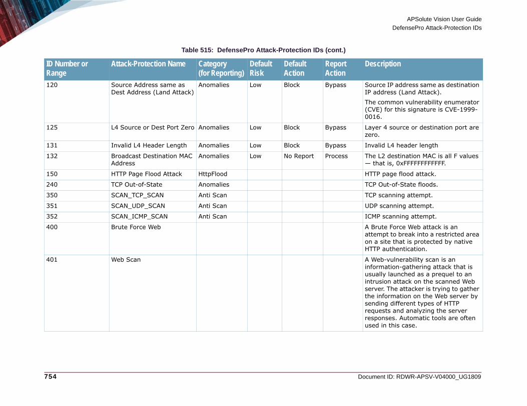
APSolute Vision User Guide
DefensePro Attack-Protection IDs
754 Document ID: RDWR-APSV-V04000_UG1809
120 Source Address same as Dest Address (Land Attack)
Anomalies Low Block Bypass Source IP address same as destination IP address (Land Attack).The common vulnerability enumerator (CVE) for this signature is CVE-1999-0016.
125 L4 Source or Dest Port Zero Anomalies Low Block Bypass Layer 4 source or destination port are zero.
131 Invalid L4 Header Length Anomalies Low Block Bypass Invalid L4 header length
132 Broadcast Destination MAC Address
Anomalies Low No Report Process The L2 destination MAC is all F values — that is, 0xFFFFFFFFFFFF.
150 HTTP Page Flood Attack HttpFlood HTTP page flood attack.
240 TCP Out-of-State Anomalies TCP Out-of-State floods.
350 SCAN_TCP_SCAN Anti Scan TCP scanning attempt.
351 SCAN_UDP_SCAN Anti Scan UDP scanning attempt.
352 SCAN_ICMP_SCAN Anti Scan ICMP scanning attempt.
400 Brute Force Web A Brute Force Web attack is an attempt to break into a restricted area on a site that is protected by native HTTP authentication.
401 Web Scan A Web-vulnerability scan is an information-gathering attack that is usually launched as a prequel to an intrusion attack on the scanned Web server. The attacker is trying to gather the information on the Web server by sending different types of HTTP requests and analyzing the server responses. Automatic tools are often used in this case.
Table 515: DefensePro Attack-Protection IDs (cont.)
ID Number or Range
Attack-Protection Name Category(for Reporting)
Default Risk
Default Action
Report Action
Description

APSolute Vision User Guide
DefensePro Attack-Protection IDs
Document ID: RDWR-APSV-V04000_UG1809 755
402 Brute Force SMTP A Brute Force SMTP attack is an attempt to break into restricted accounts on the SMTP mail server that is protected by username and password authentication.
403 Brute Force FTP A Brute Force FTP attack is an attempt to break into a restricted account on the FTP server that is protected by username and password authentication.
404 Brute Force POP3 A Brute Force POP3 attack is an attempt to break into restricted accounts on the POP3 mail server that is protected by username and password authentication.
405 Brute Force SIP (UDP) A Brute Force SIP (UDP) attack is an attempt to break into restricted accounts on the SIP server, over UDP, which is protected by username and password authentication. This type of attack can also cause a Register flood on the SIP server.
406 Brute Force SIP (TCP) A Brute Force SIP (TCP) attack is an attempt to break into restricted accounts on the SIP server, over TCP, which is protected by username and password authentication. This type of attack can also cause a Register flood on the SIP server.
Table 515: DefensePro Attack-Protection IDs (cont.)
ID Number or Range
Attack-Protection Name Category(for Reporting)
Default Risk
Default Action
Report Action
Description

APSolute Vision User Guide
DefensePro Attack-Protection IDs
756 Document ID: RDWR-APSV-V04000_UG1809
407 Brute Force MySQL A Brute Force MySQL attack is an attempt to break into restricted Database accounts on the MySQL database server that is protected by username and password authentication.
408 Brute Force MSSQL A Brute Force MSSQL attack is an attempt to break into a restricted database accounts on the MSSQL database server that is protected by username and password authentication.
409 SIP Scan (UDP) SIP scan attacks intend to identify the SIP server in order to find vulnerabilities or to harvest the server for existing subscriber phone numbers (also known as SIP users or SIP URI). The phone numbers can be used later to launch a SPIT (SPAM over IP Telephony) attack.
410 SIP Scan (TCP) SIP scan attacks intend to identify the SIP server in order to find vulnerabilities or to harvest the server for existing subscriber phone numbers (also known as SIP users or SIP URI). The phone numbers can be used later to launch a SPIT (SPAM over IP Telephony) attack.
Table 515: DefensePro Attack-Protection IDs (cont.)
ID Number or Range
Attack-Protection Name Category(for Reporting)
Default Risk
Default Action
Report Action
Description

APSolute Vision User Guide
DefensePro Attack-Protection IDs
Document ID: RDWR-APSV-V04000_UG1809 757
414 SIP Scan DST (TCP) SIP scan attacks intend to identify the SIP server in order to find vulnerabilities or to harvest the server for existing subscriber phone numbers (also known as SIP users or SIP URI). The phone numbers can be used later to launch a SPIT (SPAM over IP Telephony) attack.
416 Brute Force SIP DST (TCP) A Brute Force SIP DST (TCP) attack is an attempt to break into restricted accounts on the SIP server, over TCP, which is protected by username and password authentication. The specific attack was detected from error responses that were found on sessions that originated from the server. This type of attack can also cause a Register flood on the SIP server.
417 Brute Force SMB A Brute Force SMB attack is an attempt to break into restricted accounts on the SMB (file share) server that is protected by username and password authentication.
418 Brute Force SIP DST (UDP) A Brute Force SIP DST (UDP) attack is an attempt to break into restricted accounts on the SIP server, over UDP, which is protected by username and password authentication. The specific attack was detected from error responses that were found on sessions that originated from the server. This type of attack can also cause a Register flood on the SIP server.
Table 515: DefensePro Attack-Protection IDs (cont.)
ID Number or Range
Attack-Protection Name Category(for Reporting)
Default Risk
Default Action
Report Action
Description

APSolute Vision User Guide
DefensePro Attack-Protection IDs
758 Document ID: RDWR-APSV-V04000_UG1809
419 SIP Scan DST (UDP) SIP scan attacks intend to identify the SIP server in order to find vulnerabilities or to harvest the server for existing subscriber phone numbers (also known as SIP users or SIP URI). The phone numbers can be used later to launch a SPIT (SPAM over IP Telephony) attack.
450 DNS flood IPv4 DNS-A DNS-Protection DNS A query flood over IPv4.
451 DNS flood IPv4 DNS-MX DNS-Protection DNS MX query flood over IPv4.
452 DNS flood IPv4 DNS-PTR DNS-Protection DNS PTR query flood over IPv4.
453 DNS flood IPv4 DNS-AAAA DNS-Protection DNS AAAA query flood over IPv4.
454 DNS flood IPv4 DNS-Text DNS-Protection DNS Text query flood over IPv4.
455 DNS flood IPv4 DNS-SOA DNS-Protection DNS SOA query flood over IPv4.
456 DNS flood IPv4 DNS-NAPTR DNS-Protection DNS NAPTR query flood over IPv4.
457 DNS flood IPv4 DNS-SRV DNS-Protection DNS SRV query flood over IPv4.
458 DNS flood IPv4 DNS-Other DNS-Protection DNS Other queries flood over IPv4.
459 DNS flood IPv4 DNS-ALL DNS-Protection DNS query flood over IPv4.
460 DNS flood IPv6 DNS-A DNS-Protection DNS A query flood over IPv6.
461 DNS flood IPv6 DNS-MX DNS-Protection DNS MX query flood over IPv6.
462 DNS flood IPv6 DNS-PTR DNS-Protection DNS PTR query flood over IPv6.
463 DNS flood IPv6 DNS-AAAA DNS-Protection DNS AAAA query flood over IPv6.
464 DNS flood IPv6 DNS-Text DNS-Protection DNS Text query flood over IPv6.
465 DNS flood IPv6 DNS-SOA DNS-Protection DNS SOA query flood over IPv6.
466 DNS flood IPv6 DNS-NAPTR DNS-Protection DNS NAPTR query flood over IPv6.
467 DNS flood IPv6 DNS-SRV DNS-Protection DNS SRV query flood over IPv6.
468 DNS flood IPv6 DNS-Other DNS-Protection DNS Other queries flood over IPv6.
Table 515: DefensePro Attack-Protection IDs (cont.)
ID Number or Range
Attack-Protection Name Category(for Reporting)
Default Risk
Default Action
Report Action
Description

APSolute Vision User Guide
DefensePro Attack-Protection IDs
Document ID: RDWR-APSV-V04000_UG1809 759
469 DNS flood IPv6 DNS-ALL DNS-Protection DNS query flood over IPv6.
700 BWM N/A Bandwidth-management operations are not reported as security events.
720 SYN Flood protection High According to policy Action
Start, ongoing, and termination of attacks per protection policy.
721 SYN Flood enabled protection
High According to policy Action
Ongoing message when the SYN rate relative to the first ACK/Data packet rate is above 1000 packets per second.
722 SYN Flood protect full table Medium According to policy Action
(This event is not generated in version 5.10 and later.) Used for DefensePro's session table protection.
723 SYN ACK Reflection protection
High According to policy Action
(This event is not generated in version 5.10 and later.) Used for SARP (SYN ACK Reflection Protection).
724 SYN Protect delete frag Info According to policy Action
Used when a fragmented packet arrives during the authentication process. The packet will be discarded.
725 SYN Protect delete reset Info According to policy Action
Used when a RESET packet that does not match an existing session arrives during the authentication process. The packet will be discarded.
Table 515: DefensePro Attack-Protection IDs (cont.)
ID Number or Range
Attack-Protection Name Category(for Reporting)
Default Risk
Default Action
Report Action
Description

APSolute Vision User Guide
DefensePro Attack-Protection IDs
760 Document ID: RDWR-APSV-V04000_UG1809
726 SYN Protect out of context Info According to policy Action
(This event is not generated in version 5.10 and later.) Used when a packet that does not match an existing session arrives during the authentication process. The packet will be deleted and a RESET will be sent to the source.
727 SYN Protect full table Medium According to policy Action
Used when the SYN Protection table is full and the module cannot handle more concurrent authentication processes. New verified ACK (or data) packets will be discarded as long as the table is full.
729 SYN Protect out of context Info According to policy Action
Used when a packet that does not match an existing session arrives during the authentication process. The packet will be deleted and a RESET will be sent to the source.
730 SYN Protect unverified cookie
Info Drop Used when a ACK packet arrives with a SYN cookie that does not match the one sent by the DefensePro device. This error is generated only when the policy is configured with Block and Report.
731 SYN Protect incompleteness
Info Drop (This event is not relevant before version 5.1x.) Used when a new session is aged during the authentication process before the first data packet has arrived.
Table 515: DefensePro Attack-Protection IDs (cont.)
ID Number or Range
Attack-Protection Name Category(for Reporting)
Default Risk
Default Action
Report Action
Description
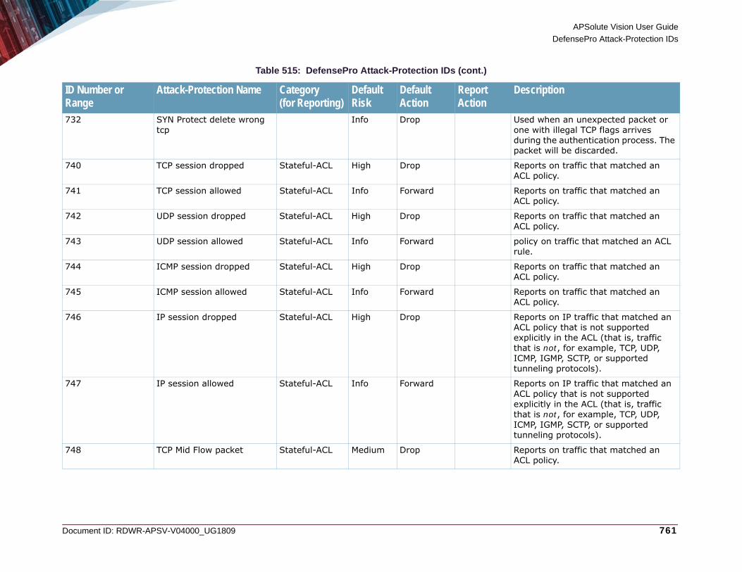
APSolute Vision User Guide
DefensePro Attack-Protection IDs
Document ID: RDWR-APSV-V04000_UG1809 761
732 SYN Protect delete wrong tcp
Info Drop Used when an unexpected packet or one with illegal TCP flags arrives during the authentication process. The packet will be discarded.
740 TCP session dropped Stateful-ACL High Drop Reports on traffic that matched an ACL policy.
741 TCP session allowed Stateful-ACL Info Forward Reports on traffic that matched an ACL policy.
742 UDP session dropped Stateful-ACL High Drop Reports on traffic that matched an ACL policy.
743 UDP session allowed Stateful-ACL Info Forward policy on traffic that matched an ACL rule.
744 ICMP session dropped Stateful-ACL High Drop Reports on traffic that matched an ACL policy.
745 ICMP session allowed Stateful-ACL Info Forward Reports on traffic that matched an ACL policy.
746 IP session dropped Stateful-ACL High Drop Reports on IP traffic that matched an ACL policy that is not supported explicitly in the ACL (that is, traffic that is not, for example, TCP, UDP, ICMP, IGMP, SCTP, or supported tunneling protocols).
747 IP session allowed Stateful-ACL Info Forward Reports on IP traffic that matched an ACL policy that is not supported explicitly in the ACL (that is, traffic that is not, for example, TCP, UDP, ICMP, IGMP, SCTP, or supported tunneling protocols).
748 TCP Mid Flow packet Stateful-ACL Medium Drop Reports on traffic that matched an ACL policy.
Table 515: DefensePro Attack-Protection IDs (cont.)
ID Number or Range
Attack-Protection Name Category(for Reporting)
Default Risk
Default Action
Report Action
Description

APSolute Vision User Guide
DefensePro Attack-Protection IDs
762 Document ID: RDWR-APSV-V04000_UG1809
749 TCP Invalid reset Stateful-ACL Medium Drop Reports on traffic that matched an ACL policy.
750 TCP handshake violation Stateful-ACL Medium Drop Reports on traffic that matched an ACL policy.
751 ICMP Smurf packet Stateful-ACL Medium Drop Reports on traffic that matched an ACL policy.
752 ICMP packet anomaly Stateful-ACL Medium Drop Reports on traffic that matched an ACL policy.
753 GRE session dropped Stateful-ACL High Drop Reports on traffic that matched an ACL policy.
754 GRE session allowed Stateful-ACL Info Forward Reports on traffic that matched an ACL policy.
755 SCTP session dropped Stateful-ACL High Drop Reports on traffic that matched an ACL policy.
756 SCTP session allowed Stateful-ACL Info Forward Reports on traffic that matched an ACL policy.
1,000–100,000 DoS Shield signatures or intrusion-protection signatures
DoS Range for signatures, from the Security Operations Center (SOC) signature file. Odd ID numbers are DoS shield signatures. Even ID numbers are Intrusion signatures.
200,000 HTTP SynFlood Medium According to policy Action
Predefined HTTP-SYN-flood attack protection.
200,001 HTTPS SynFlood Medium According to policy Action
Predefined HTTPS-SYN-flood attack protection.
200,002 RTSP SynFlood Medium According to policy Action
Predefined RTSP-SYN-flood attack protection.
Table 515: DefensePro Attack-Protection IDs (cont.)
ID Number or Range
Attack-Protection Name Category(for Reporting)
Default Risk
Default Action
Report Action
Description

APSolute Vision User Guide
DefensePro Attack-Protection IDs
Document ID: RDWR-APSV-V04000_UG1809 763
200,003 FTP_CTRL SynFlood Medium According to policy Action
Predefined FTP_CTRL-SYN-flood attack protection.
200,004 POP3 SynFlood Medium According to policy Action
Predefined POP3-SYN-flood attack protection.
200,005 IMAP SynFlood Medium According to policy Action
Predefined IMAP-SYN-flood attack protection.
200,006 SMTP SynFlood Medium According to policy Action
Predefined SMTP-SYN-flood attack protection.
200,007 TELNET SynFlood Medium According to policy Action
Predefined TELNET-SYN-flood attack protection.
200,008 RPC SynFlood Medium According to policy Action
Predefined RPC-SYN-flood attack protection.
300,000–449,999 User-defined custom signatures
DoS Range for user-defined protections. The device generates the ID number sequentially when the user creates the signature.
450,000–475,000 User-defined Connection Limit protections
DoS Range for user-defined Connection Limit protections. The device generates the ID number sequentially when the user creates the protection.
500,000–599,999 User-defined SYN-flood protections
SYNFlood Low According to policy Action
Range for user-defined SYN-flood protections device generates the ID number sequentially when the user creates the protection.
Table 515: DefensePro Attack-Protection IDs (cont.)
ID Number or Range
Attack-Protection Name Category(for Reporting)
Default Risk
Default Action
Report Action
Description

APSolute Vision User Guide
DefensePro Attack-Protection IDs
764 Document ID: RDWR-APSV-V04000_UG1809
600,000–675,000 User-defined Connection PPS Limit protections
DoS Range for user-defined Connection PPS Limit protections device generates the ID number sequentially when the user creates the protection.
700,000–1,000,000 User-defined Traffic Filters Traffic Filters High Drop Range for user-defined Traffic Filters. The device generates the ID number sequentially when the user creates the Traffic Filter.
Table 515: DefensePro Attack-Protection IDs (cont.)
ID Number or Range
Attack-Protection Name Category(for Reporting)
Default Risk
Default Action
Report Action
Description

Document ID: RDWR-APSV-V04000_UG1809 765
APPENDIX G – APSOLUTE VISION SPECIFICATIONS AND REQUIREMENTSThis section contains various specifications and requirements for APSolute Vision, which comprise the following:• UDP/TCP Ports and IP Protocols, page 765• APSolute Vision Web Based Management Interface Requirements, page 768• Application Performance Monitoring Requirements, page 768• Device Performance Monitoring Requirements, page 769• APSolute Vision Reporter Requirements, page 769
Notes
• APSolute Vision server can run as a physical or virtual appliance called APSolute Vision server. For hardware and virtual-appliance (VA) specifications, see the APSolute Vision Installation and Maintenance Guide.
• APSolute Vision supports a Web-based management interface, which is called Web Based Management (WBM).
• APSolute Vision supports multiple device types and versions. For the most up-to-date lists of supported devices and versions, see the APSolute Vision Release Notes for the required version.
UDP/TCP Ports and IP ProtocolsRadware management interfaces communicate with various UDP/TCP ports using various protocols—including HTTPS, HTTP, Telnet, and SSH. If you intend to use these interfaces, ensure they are accessible and not blocked by your firewall.The following table lists the ports for APSolute Vision server-client communication.
Table 516: Ports for APSolute Vision Server-WBM Communication and Operating System
Port Protocol Type Usage Opened on APSolute Vision Server Firewall by Default
22 SSH, SFTP, SCP
TCP • Terminal client to server.• Server CLI management, file
transfer.• Server to northbound.• Push backups, reports, and so
on.• Used for communication with
vDirect.
Yes
25 SMTP TCP Server to external e-mail server. No

APSolute Vision User Guide
APSolute Vision Specifications and Requirements
766 Document ID: RDWR-APSV-V04000_UG1809
80 HTTP TCP • Web browser to APSolute Vision server.
• APSolute Vision server to APM server (over the APM Management interface), for Application Performance Monitoring (APM). Port 80 is the default port for this functionality, but you can configure another port. For more information, see the Application Performance Monitoring Troubleshooting and Technical Guide.1
Yes
443 HTTPS TCP • APSolute Vision WBM to server.
• Used for communication between APSolute Vision server instances in configuration-synchronization setups.
Yes
514 Syslog UDP Server to external syslog server. No
2189 Proprietary TCP UDP Used for communication with vDirect.
Yes
5602 HTTPS TCP Used for communication with the Vision Reporting Module (VRM) server.
N/A. This port is opened on the VRM server.
5672 TCP TCP Used for communication between APSolute Vision server instances in configuration-synchronization setups.
Yes
9216 HTTPS TCP APSolute Vision Reporter client to APSolute Vision Reporter server.
Yes
9443 TCP TCP WBM Web browser to APSolute Vision server, for Device Performance Monitoring (DPM).
Yes
1 – Alteon also uses port 80 to communicate with the APM server (over the APM Data interface).
Table 516: Ports for APSolute Vision Server-WBM Communication and Operating System
Port Protocol Type Usage Opened on APSolute Vision Server Firewall by Default

APSolute Vision User Guide
APSolute Vision Specifications and Requirements
Document ID: RDWR-APSV-V04000_UG1809 767
The following table lists the ports for communication between APSolute Vision server and Radware devices.
Table 517: Communication Ports for APSolute Vision Server with Radware Devices and Radware Services
Port Protocol Type Usage Opened on APSolute Vision Server Firewall by Default
7 TCP TCP Used by vDirect to determine if a device (for example, DefensePro) is reachable.
Yes
221
1 – This is the default port. The value is configurable.
SSH TCP APSolute Vision server to Alteon, DefensePro, and LinkProof NG devices, to run CLI commands on the device.
Yes
80 HTTP TCP APSolute Vision server to Radware services.Such services include SUS updates and ERT Active DDoS Feed updates.
Yes
161 SNMP UDP APSolute Vision server to devices, for SNMP management.
No
162 SNMP UDP Devices to APSolute Vision server, for traps.
Yes
443 HTTPS TCP APSolute Vision server to devices and Radware services, and devices and services to APSolute Vision server for REST calls and file transfer.Such services include SUS updates and ERT Active DDoS Feed updates.
Yes
2088 IRP UDP Devices to APSolute Vision server, for statistics.
Yes
2214 Syslog TCP UDP AppWall devices—and AppWall for Alteon—to APSolute Vision server for AVR reporting only.
Yes
2215 Syslog TCP UDP AppWall devices—and AppWall for Alteon—to APSolute Vision server for AVR reporting and APSolute Vision real-time Security Monitoring.
Yes
3030 TCP TCP APSolute Vision server to Alteon device, for Device Performance Monitoring (DPM).
Note: APSolute Vision pulls the data from Alteon.
No
8200 8270 8300
SSL TCP APSolute Vision server to AppWall devices (AppWall servers only).
No

APSolute Vision User Guide
APSolute Vision Specifications and Requirements
768 Document ID: RDWR-APSV-V04000_UG1809
The following IP protocols are opened on the APSolute Vision server firewall by default:• ICMP—Internet Control Message Protocol. All types (an ICMP term) are opened except
Timestamp (type 13) and Timestamp Reply (type 14).• ESP—Encapsulating Security Payload part of the IPsec (Internet Protocol Security).• AH—Authentication Header part of the IPsec (Internet Protocol Security).
APSolute Vision Web Based Management Interface RequirementsBefore you use the APSolute Vision client, ensure your computer meets the hardware and software requirements.This section includes the following topics:• APSolute Vision WBM Supported Operating Systems, page 768• APSolute Vision WBM Supported Browsers, page 768
APSolute Vision WBM Supported Operating SystemsThe following operating systems support APSolute Vision WBM:• Windows Server 2008 R2 64-bit• Windows 8 64-bit• Windows 7 SP1 32-bit and 64-bit• Windows Server 2012 R2 64-bit• Linux Ubuntu (Desktop)• Mac OS X
APSolute Vision WBM Supported BrowsersYou can access APSolute Vision Web-based management (and APSolute Vision Reporter, Device Performance Monitor, and the APM server Web interface) using the following browsers:• Mozilla Firefox build 31• Chrome 37
Application Performance Monitoring RequirementsThe APSolute Vision WBM can connect to the APSolute Vision Application Performance Monitor (APM). The APM is a process that runs on the APSolute Vision server with APM server VA offering. APSolute Vision WBM includes an option to open the APM Web interface.For the APM server requirements, see the relevant chapter in the APSolute Vision Installation and Maintenance Guide.

APSolute Vision User Guide
APSolute Vision Specifications and Requirements
Document ID: RDWR-APSV-V04000_UG1809 769
Device Performance Monitoring RequirementsAPSolute Vision WBM can connect to the APSolute Vision Device Performance Monitor (DPM) for Alteon devices. APSolute Vision WBM includes a button that opens the DPM in a separate browser tab.
APSolute Vision Reporter RequirementsAPSolute Vision WBM can connect to the APSolute Vision Reporter (AVR). APSolute Vision WBM includes a button that opens the AVR in a separate browser tab.Java client version 1.6.0_22 or later must be installed to run the APSolute Vision Reporter.The Java client must be 32-bit.

APSolute Vision User Guide
APSolute Vision Specifications and Requirements
770 Document ID: RDWR-APSV-V04000_UG1809

Document ID: RDWR-APSV-V04000_UG1809 771
RADWARE LTD. END USER LICENSE AGREEMENTBy accepting this End User License Agreement (this “License Agreement”) you agree to be contacted by Radware Ltd.'s (“Radware”) sales personnel.If you would like to receive license rights different from the rights granted below or if you wish to acquire warranty or support services beyond the scope provided herein (if any), please contact Radware's sales team.THIS LICENSE AGREEMENT GOVERNS YOUR USE OF ANY SOFTWARE DEVELOPED AND/OR DISTRIBUTED BY RADWARE AND ANY UPGRADES, MODIFIED VERSIONS, UPDATES, ADDITIONS, AND COPIES OF THE SOFTWARE FURNISHED TO YOU DURING THE TERM OF THE LICENSE GRANTED HEREIN (THE “SOFTWARE”). THIS LICENSE AGREEMENT APPLIES REGARDLESS OF WHETHER THE SOFTWARE IS DELIVERED TO YOU AS AN EMBEDDED COMPONENT OF A RADWARE PRODUCT (“PRODUCT”), OR WHETHER IT IS DELIVERED AS A STANDALONE SOFTWARE PRODUCT. FOR THE AVOIDANCE OF DOUBT IT IS HEREBY CLARIFIED THAT THIS LICENSE AGREEMENT APPLIES TO PLUG-INS, CONNECTORS, EXTENSIONS AND SIMILAR SOFTWARE COMPONENTS DEVELOPED BY RADWARE THAT CONNECT OR INTEGRATE A RADWARE PRODUCT WITH THE PRODUCT OF A THIRD PARTY (COLLECTIVELY, “CONNECTORS”) FOR PROVISIONING, DECOMMISSIONING, MANAGING, CONFIGURING OR MONITORING RADWARE PRODUCTS. THE APPLICABILITY OF THIS LICENSE AGREEMENT TO CONNECTORS IS REGARDLESS OF WHETHER SUCH CONNECTORS ARE DISTRIBUTED TO YOU BY RADWARE OR BY A THIRD PARTY PRODUCT VENDOR. IN CASE A CONNECTOR IS DISTRIBUTED TO YOU BY A THIRD PARTY PRODUCT VENDOR PURSUANT TO THE TERMS OF AN AGREEMENT BETWEEN YOU AND THE THIRD PARTY PRODUCT VENDOR, THEN, AS BETWEEN RADWARE AND YOURSELF, TO THE EXTENT THERE IS ANY DISCREPANCY OR INCONSISTENCY BETWEEN THE TERMS OF THIS LICENSE AGREEMENT AND THE TERMS OF THE AGREEMENT BETWEEN YOU AND THE THIRD PARTY PRODUCT VENDOR, THE TERMS OF THIS LICENSE AGREEMENT WILL GOVERN AND PREVAIL. PLEASE READ THE TERMS AND CONDITIONS OF THIS LICENSE AGREEMENT CAREFULLY BEFORE OPENING THE PACKAGE CONTAINING RADWARE'S PRODUCT, OR BEFORE DOWNLOADING, INSTALLING, COPYING OR OTHERWISE USING RADWARE'S STANDALONE SOFTWARE (AS APPLICABLE). THE SOFTWARE IS LICENSED (NOT SOLD). BY OPENING THE PACKAGE CONTAINING RADWARE'S PRODUCT, OR BY DOWNLOADING, INSTALLING, COPYING OR USING THE SOFTWARE (AS APPLICABLE), YOU CONFIRM THAT YOU HAVE READ AND UNDERSTAND THIS LICENSE AGREEMENT AND YOU AGREE TO BE BOUND BY THE TERMS OF THIS LICENSE AGREEMENT. FURTHERMORE, YOU HEREBY WAIVE ANY CLAIM OR RIGHT THAT YOU MAY HAVE TO ASSERT THAT YOUR ACCEPTANCE AS STATED HEREINABOVE IS NOT THE EQUIVALENT OF, OR DEEMED AS, A VALID SIGNATURE TO THIS LICENSE AGREEMENT. IF YOU ARE NOT WILLING TO BE BOUND BY THE TERMS OF THIS LICENSE AGREEMENT, YOU SHOULD PROMPTLY RETURN THE UNOPENED PRODUCT PACKAGE OR YOU SHOULD NOT DOWNLOAD, INSTALL, COPY OR OTHERWISE USE THE SOFTWARE (AS APPLICABLE). THIS LICENSE AGREEMENT REPRESENTS THE ENTIRE AGREEMENT CONCERNING THE SOFTWARE BETWEEN YOU AND RADWARE, AND SUPERSEDES ANY AND ALL PRIOR PROPOSALS, REPRESENTATIONS, OR UNDERSTANDINGS BETWEEN THE PARTIES. “YOU” MEANS THE NATURAL PERSON OR THE ENTITY THAT IS AGREEING TO BE BOUND BY THIS LICENSE AGREEMENT, THEIR EMPLOYEES AND THIRD PARTY CONTRACTORS. YOU SHALL BE LIABLE FOR ANY FAILURE BY SUCH EMPLOYEES AND THIRD PARTY CONTRACTORS TO COMPLY WITH THE TERMS OF THIS LICENSE AGREEMENT.
1. License Grant. Subject to the terms of this Agreement, Radware hereby grants to you, and you accept, a limited, nonexclusive, nontransferable license to install and use the Software in machine-readable, object code form only and solely for your internal business purposes (“Commercial License”). If the Software is distributed to you with a software development kit (the “SDK”), then, solely with regard to the SDK, the Commercial License above also includes a limited, nonexclusive, nontransferable license to install and use the SDK solely on computers within your organization, and solely for your internal development of an integration or interoperation of the Software and/or other Radware Products with software or hardware products owned, licensed and/or controlled by you (the “SDK Purpose”). To the extent an SDK is

APSolute Vision User Guide
Radware Ltd. End User License Agreement
772 Document ID: RDWR-APSV-V04000_UG1809
distributed to you together with code samples in source code format (the “Code Samples”) that are meant to illustrate and teach you how to configure, monitor and/or control the Software and/or any other Radware Products, the Commercial License above further includes a limited, nonexclusive, nontransferable license to copy and modify the Code Samples and create derivative works based thereon solely for the SDK Purpose and solely on computers within your organization. The SDK shall be considered part of the term “Software” for all purposes of this License Agreement. You agree that you will not sell, assign, license, sublicense, transfer, pledge, lease, rent or share your rights under this License Agreement nor will you distribute copies of the Software or any parts thereof. Rights not specifically granted herein, are specifically prohibited.
2. Evaluation Use. Notwithstanding anything to the contrary in this License Agreement, if the Software is provided to you for evaluation purposes, as indicated in your purchase order or sales receipt, on the website from which you download the Software, as inferred from any time-limited evaluation license keys that you are provided with to activate the Software, or otherwise, then You may use the Software only for internal evaluation purposes (“Evaluation Use”) for a maximum of 30 days or such other duration as may specified by Radware in writing at its sole discretion (the “Evaluation Period”). The evaluation copy of the Software contains a feature that will automatically disable it after expiration of the Evaluation Period. You agree not to disable, destroy, or remove this feature of the Software, and any attempt to do so will be a material breach of this License Agreement. During or at the end of the evaluation period, you may contact Radware sales team to purchase a Commercial License to continue using the Software pursuant to the terms of this License Agreement. If you elect not to purchase a Commercial License, you agree to stop using the Software and to delete the evaluation copy received hereunder from all computers under your possession or control at the end of the Evaluation Period. In any event, your continued use of the Software beyond the Evaluation Period (if possible) shall be deemed your acceptance of a Commercial License to the Software pursuant to the terms of this License Agreement, and you agree to pay Radware any amounts due for any applicable license fees at Radware's then-current list prices.
3. Lab/Development License. Notwithstanding anything to the contrary in this License Agreement, if the Software is provided to you for use in your lab or for development purposes, as indicated in your purchase order, sales receipt, the part number description for the Software, the Web page from which you download the Software, or otherwise, then You may use the Software only in your lab and only in connection with Radware Products that you purchased or will purchase (in case of a lab license) or for internal testing and development purposes (in case of a development license) but not for any production use purposes.
4. Subscription Software. If you licensed the Software on a subscription basis, your rights to use the Software are limited to the subscription period. You have the option to extend your subscription. If you extend your subscription, you may continue using the Software until the end of your extended subscription period. If you do not extend your subscription, after the expiration of your subscription, you are legally obligated to discontinue your use of the Software and completely remove the Software from your system.
5. Feedback. Any feedback concerning the Software including, without limitation, identifying potential errors and improvements, recommended changes or suggestions (“Feedback”), provided by you to Radware will be owned exclusively by Radware and considered Radware's confidential information. By providing Feedback to Radware, you hereby assign to Radware all of your right, title and interest in any such Feedback, including all intellectual property rights therein. With regard to any rights in such Feedback that cannot, under applicable law, be assigned to Radware, you hereby irrevocably waives such rights in favor of Radware and grants Radware under such rights in the Feedback, a worldwide, perpetual royalty-free, irrevocable, sub-licensable and non-exclusive license, to use, reproduce, disclose, sublicense, modify, make, have made, distribute, sell, offer for sale, display, perform, create derivative works of and otherwise exploit the Feedback without restriction. The provisions of this Section 5 will survive the termination or expiration of this Agreement.
6. Limitations on Use. You agree that you will not: (a) copy, modify, translate, adapt or create any derivative works based on the Software; or (b) sublicense or transfer the Software, or include the Software or any portion thereof in any product; or (b) reverse assemble, disassemble, decompile, reverse engineer or otherwise attempt to derive source code (or the
APSolute Vision User Guide
Radware Ltd. End User License Agreement
Document ID: RDWR-APSV-V04000_UG1809 773
underlying ideas, algorithms, structure or organization) from the Software, in whole or in part, except and only to the extent: (i) applicable law expressly permits any such action despite this limitation, in which case you agree to provide Radware at least ninety (90) days advance written notice of your belief that such action is warranted and permitted and to provide Radware with an opportunity to evaluate if the law's requirements necessitate such action, or (ii) required to debug changes to any third party LGPL-libraries linked to by the Software; or (c) create, develop, license, install, use, or deploy any software or services to circumvent, enable, modify or provide access, permissions or rights which violate the technical restrictions of the Software; (d) in the event the Software is provided as an embedded or bundled component of another Radware Product, you shall not use the Software other than as part of the combined Product and for the purposes for which the combined Product is intended; (e) remove any copyright notices, identification or any other proprietary notices from the Software (including any notices of Third Party Software (as defined below); or (f) copy the Software onto any public or distributed network or use the Software to operate in or as a time-sharing, outsourcing, service bureau, application service provider, or managed service provider environment. Notwithstanding the foregoing, if you provide hosting or cloud computing services to your customers, you are entitled to use and include the Software in your IT infrastructure on which you provide your services. It is hereby clarified that the prohibitions on modifying, or creating derivative works based on, any Software provided by Radware, apply whether the Software is provided in a machine or in a human readable form. Human readable Software to which this prohibition applies includes (without limitation) “Radware AppShape++ Script Files” that contain “Special License Terms”. It is acknowledged that examples provided in a human readable form may be modified by a user.
7. Intellectual Property Rights. You acknowledge and agree that this License Agreement does not convey to you any interest in the Software except for the limited right to use the Software, and that all right, title, and interest in and to the Software, including any and all associated intellectual property rights, are and shall remain with Radware or its third party licensors. You further acknowledge and agree that the Software is a proprietary product of Radware and/or its licensors and is protected under applicable copyright law.
8. No Warranty. The Software, and any and all accompanying software, files, libraries, data and materials, are distributed and provided “AS IS” by Radware or by its third party licensors (as applicable) and with no warranty of any kind, whether express or implied, including, without limitation, any non-infringement warranty or warranty of merchantability or fitness for a particular purpose. Neither Radware nor any of its affiliates or licensors warrants, guarantees, or makes any representation regarding the title in the Software, the use of, or the results of the use of the Software. Neither Radware nor any of its affiliates or licensors warrants that the operation of the Software will be uninterrupted or error-free, or that the use of any passwords, license keys and/or encryption features will be effective in preventing the unintentional disclosure of information contained in any file. You acknowledge that good data processing procedure dictates that any program, including the Software, must be thoroughly tested with non-critical data before there is any reliance on it, and you hereby assume the entire risk of all use of the copies of the Software covered by this License. Radware does not make any representation or warranty, nor does Radware assume any responsibility or liability or provide any license or technical maintenance and support for any operating systems, databases, migration tools or any other software component provided by a third party supplier and with which the Software is meant to interoperate.
This disclaimer of warranty constitutes an essential and material part of this License. In the event that, notwithstanding the disclaimer of warranty above, Radware is held liable under any warranty provision, Radware shall be released from all such obligations in the event that the Software shall have been subject to misuse, neglect, accident or improper installation, or if repairs or modifications were made by persons other than by Radware's authorized service personnel.
9. Limitation of Liability. Except to the extent expressly prohibited by applicable statutes, in no event shall Radware, or its principals, shareholders, officers, employees, affiliates, licensors, contractors, subsidiaries, or parent organizations (together, the “Radware Parties”), be liable for any direct, indirect, incidental, consequential, special, or punitive damages whatsoever relating to the use of, or the inability to use, the Software, or to your relationship with, Radware or any of the Radware Parties (including, without limitation, loss or disclosure of data or information,
APSolute Vision User Guide
Radware Ltd. End User License Agreement
774 Document ID: RDWR-APSV-V04000_UG1809
and/or loss of profit, revenue, business opportunity or business advantage, and/or business interruption), whether based upon a claim or action of contract, warranty, negligence, strict liability, contribution, indemnity, or any other legal theory or cause of action, even if advised of the possibility of such damages. If any Radware Party is found to be liable to You or to any third-party under any applicable law despite the explicit disclaimers and limitations under these terms, then any liability of such Radware Party, will be limited exclusively to refund of any license or registration or subscription fees paid by you to Radware.
10. Third Party Software. The Software includes software portions developed and owned by third parties (the “Third Party Software”). Third Party Software shall be deemed part of the Software for all intents and purposes of this License Agreement; provided, however, that in the event that a Third Party Software is a software for which the source code is made available under an open source software license agreement, then, to the extent there is any discrepancy or inconsistency between the terms of this License Agreement and the terms of any such open source license agreement (including, for example, license rights in the open source license agreement that are broader than the license rights set forth in Section 1 above and/or no limitation in the open source license agreement on the actions set forth in Section 6 above), the terms of any such open source license agreement will govern and prevail. The terms of open source license agreements and copyright notices under which Third Party Software is being licensed to Radware or a link thereto, are included with the Software documentation or in the header or readme files of the Software. Third Party licensors and suppliers retain all right, title and interest in and to the Third Party Software and all copies thereof, including all copyright and other intellectual property associated therewith. In addition to the use limitations applicable to Third Party Software pursuant to Section 6 above, you agree and undertake not to use the Third Party Software as a general SQL server, as a stand-alone application or with applications other than the Software under this License Agreement.
11. Term and Termination. This License Agreement is effective upon the first to occur of your opening the package of the Product, purchasing, downloading, installing, copying or using the Software or any portion thereof, and shall continue until terminated. However, sections 5-15 shall survive any termination of this License Agreement. The Licenses granted under this License Agreement are not transferable and will terminate upon: (i) termination of this License Agreement, or (ii) transfer of the Software, or (iii) in the event the Software is provided as an embedded or bundled component of another Radware Product, when the Software is unbundled from such Product or otherwise used other than as part of such Product. If the Software is licensed on subscription basis, this Agreement will automatically terminate upon the termination of your subscription period if it is not extended.
12. Export. The Software or any part thereof may be subject to export or import controls under applicable export/import control laws and regulations including such laws and regulations of the United States and/or Israel. You agree to comply with such laws and regulations, and, agree not to knowingly export, re-export, import or re-import, or transfer products without first obtaining all required Government authorizations or licenses therefor. Furthermore, You hereby covenant and agree to ensure that your use of the Software is in compliance with all other foreign, federal, state, and local laws and regulations, including without limitation all laws and regulations relating to privacy rights, and data protection. You shall have in place a privacy policy and obtain all of the permissions, authorizations and consents required by applicable law for use of cookies and processing of users' data (including without limitation pursuant to Directives 95/46/EC, 2002/58/EC and 2009/136/EC of the EU if applicable) for the purpose of provision of any services.
13. US Government. To the extent you are the U.S. government or any agency or instrumentality thereof, you acknowledge and agree that the Software is a “commercial computer software” and “commercial computer software documentation” pursuant to applicable regulations and your use of the Software is subject to the terms of this License Agreement.
14. Federal Acquisition Regulation (FAR)/Data Rights Notice. Radware's commercial computer software is created solely at private expense and is subject to Radware's commercial license rights.
APSolute Vision User Guide
Radware Ltd. End User License Agreement
Document ID: RDWR-APSV-V04000_UG1809 775
15. Governing Law. This License Agreement shall be construed and governed in accordance with the laws of the State of Israel.
16. Miscellaneous. If a judicial determination is made that any of the provisions contained in this License Agreement is unreasonable, illegal or otherwise unenforceable, such provision or provisions shall be rendered void or invalid only to the extent that such judicial determination finds such provisions to be unreasonable, illegal or otherwise unenforceable, and the remainder of this License Agreement shall remain operative and in full force and effect. In any event a party breaches or threatens to commit a breach of this License Agreement, the other party will, in addition to any other remedies available to, be entitled to injunction relief. This License Agreement constitutes the entire agreement between the parties hereto and supersedes all prior agreements between the parties hereto with respect to the subject matter hereof. The failure of any party hereto to require the performance of any provisions of this License Agreement shall in no manner affect the right to enforce the same. No waiver by any party hereto of any provisions or of any breach of any provisions of this License Agreement shall be deemed or construed either as a further or continuing waiver of any such provisions or breach waiver or as a waiver of any other provision or breach of any other provision of this License Agreement.
IF YOU DO NOT AGREE WITH THE TERMS OF THIS LICENSE YOU MUST REMOVE THE SOFTWARE FROM ANY DEVICE OWNED BY YOU AND IMMEDIATELY CEASE USING THE SOFTWARE. COPYRIGHT © 2018, Radware Ltd. All Rights Reserved.