
SmartCenter - Check Point Software
256
SmartCenter NGX (R60A) For additional technical information about Check Point products, consult Check Point’s SecureKnowledge at: https://secureknowledge.checkpoint.com See the latest version of this document in the User Center at: http://www.checkpoint.com/support/technical/documents/docs_r60a.html Part No.: 701309 September 2005
-
Upload
khangminh22 -
Category
Documents
-
view
1 -
download
0
Transcript of SmartCenter - Check Point Software

SmartCenter
NGX (R60A)
For additional technical information about Check Point products, consult Check Point’s SecureKnowledge at:
https://secureknowledge.checkpoint.com
See the latest version of this document in the User Center at:
http://www.checkpoint.com/support/technical/documents/docs_r60a.html
Part No.: 701309September 2005


© 2003-2005 Check Point Software Technologies Ltd.All rights reserved. This product and related documentation are protected by copyright and distributed under licensing restricting their use, copying, distribution, and decompilation. No part of this product or related documentation may be reproduced in any form or by any means without prior written authorization of Check Point. While every precaution has been taken in the preparation of this book, Check Point assumes no responsibility for errors or omissions. This publication and features described herein are subject to change without notice.
RESTRICTED RIGHTS LEGEND: Use, duplication, or disclosure by the government is subject to restrictions as set forth in subparagraph (c)(1)(ii) of the Rights in Technical Data and Computer Software clause at DFARS 252.227-7013 and FAR 52.227-19.
TRADEMARKS:©2003-2005 Check Point Software Technologies Ltd. All rights reserved. Check Point, Application Intelligence, Check Point Express, the Check Point logo, AlertAdvisor, ClusterXL, Cooperative Enforcement, ConnectControl, Connectra, CoSa, Cooperative Security Alliance, Eventia, Eventia Analyzer, FireWall-1, FireWall-1 GX, FireWall-1 SecureServer, FloodGate-1, Hacker ID, IMsecure, INSPECT, INSPECT XL, Integrity, InterSpect, IQ Engine, Open Security Extension, OPSEC, Policy Lifecycle Management, Provider-1, Safe@Home, Safe@Office, SecureClient, SecureKnowledge, SecurePlatform, SecuRemote, SecureXL Turbocard, SecureServer, SecureUpdate, SecureXL, SiteManager-1, SmartCenter, SmartCenter Pro, Smarter Security, SmartDashboard, SmartDefense, SmartLSM, SmartMap, SmartUpdate, SmartView, SmartView Monitor, SmartView Reporter, SmartView Status, SmartViewTracker, SofaWare, SSL Network Extender, Stateful Clustering, TrueVector, Turbocard, UAM, User-to-Address Mapping, UserAuthority, VPN-1, VPN-1 Accelerator Card, VPN-1 Edge, VPN-1 Pro, VPN-1 SecureClient, VPN-1 SecuRemote, VPN-1 SecureServer, VPN-1 VSX, VPN-1 XL, Web Intelligence, ZoneAlarm, ZoneAlarm Pro, Zone Labs, and the Zone Labs logo, are trademarks or registered trademarks of Check Point Software Technologies Ltd. or its affiliates. All other product names mentioned herein are trademarks or registered trademarks of their respective owners. The products described in this document are protected by U.S. Patent No. 5,606,668, 5,835,726, 6,496,935 and 6,850,943 and may be protected by other U.S. Patents, foreign patents, or pending applications.
THIRD PARTIES:Entrust is a registered trademark of Entrust Technologies, Inc. in the United States and other countries. Entrust’s logos and Entrust product and service names are also trademarks of Entrust Technologies, Inc. Entrust Technologies Limited is a wholly owned subsidiary of Entrust Technologies, Inc. FireWall-1 and SecuRemote incorporate certificate management technology from Entrust.
Verisign is a trademark of Verisign Inc. The following statements refer to those portions of the software copyrighted by University of Michigan. Portions of the software copyright © 1992-1996 Regents of the University of Michigan. All rights reserved. Redistribution and use in source and binary forms are permitted provided that this notice is preserved and that due credit is given to the University of Michigan at Ann Arbor. The name of the University may not be used to endorse or promote products derived from this software without specific prior written permission. This software is provided “as is” without express or implied warranty. Copyright © Sax Software (terminal emulation only).
The following statements refer to those portions of the software copyrighted by Carnegie Mellon University.Copyright 1997 by Carnegie Mellon University. All Rights Reserved.Permission to use, copy, modify, and distribute this software and its documentation for any purpose and without fee is hereby granted, provided that the above copyright notice appear in all copies and that both that copyright notice and this permission notice appear in supporting documentation, and that the name of CMU not be used in advertising or publicity pertaining to distribution of the software without specific, written prior permission.CMU DISCLAIMS ALL WARRANTIES WITH REGARD TO THIS SOFTWARE, INCLUDING ALL IMPLIED WARRANTIES OF MERCHANTABILITY AND FITNESS, IN NO EVENT SHALL CMU BE LIABLE FOR ANY SPECIAL, INDIRECT OR CONSEQUENTIAL DAMAGES OR ANY DAMAGES WHATSOEVER RESULTING FROM LOSS OF USE, DATA OR PROFITS, WHETHER IN AN ACTION OF CONTRACT, NEGLIGENCE OR OTHER TORTIOUS ACTION, ARISING OUT OF OR IN CONNECTION WITH THE USE OR PERFORMANCE OF THIS SOFTWARE.The following statements refer to those portions of the software copyrighted by The Open Group.THE SOFTWARE IS PROVIDED "AS IS", WITHOUT WARRANTY OF ANY KIND, EXPRESS OR IMPLIED, INCLUDING BUT NOT LIMITED TO THE WARRANTIES OF MERCHANTABILITY, FITNESS FOR A PARTICULAR PURPOSE AND
NONINFRINGEMENT. IN NO EVENT SHALL THE OPEN GROUP BE LIABLE FOR ANY CLAIM, DAMAGES OR OTHER LIABILITY, WHETHER IN AN ACTION OF CONTRACT, TORT OR OTHERWISE, ARISING FROM, OUT OF OR IN CONNECTION WITH THE SOFTWARE OR THE USE OR OTHER DEALINGS IN THE SOFTWARE.The following statements refer to those portions of the software copyrighted by The OpenSSL Project. This product includes software developed by the OpenSSL Project for use in the OpenSSL Toolkit (http://www.openssl.org/).THIS SOFTWARE IS PROVIDED BY THE OpenSSL PROJECT ``AS IS'' AND ANY * EXPRESSED OR IMPLIED WARRANTIES, INCLUDING, BUT NOT LIMITED TO, THE IMPLIED WARRANTIES OF MERCHANTABILITY AND FITNESS FOR A PARTICULAR PURPOSE ARE DISCLAIMED. IN NO EVENT SHALL THE OpenSSL PROJECT OR ITS CONTRIBUTORS BE LIABLE FOR ANY DIRECT, INDIRECT, INCIDENTAL, SPECIAL, EXEMPLARY, OR CONSEQUENTIAL DAMAGES (INCLUDING, BUT NOT LIMITED TO, PROCUREMENT OF SUBSTITUTE GOODS OR SERVICES; LOSS OF USE, DATA, OR PROFITS; OR BUSINESS INTERRUPTION) HOWEVER CAUSED AND ON ANY THEORY OF LIABILITY, WHETHER IN CONTRACT, STRICT LIABILITY, OR TORT (INCLUDING NEGLIGENCE OR OTHERWISE) ARISING IN ANY WAY OUT OF THE USE OF THIS SOFTWARE, EVEN IF ADVISED OF THE POSSIBILITY OF SUCH DAMAGE.The following statements refer to those portions of the software copyrighted by Eric Young. THIS SOFTWARE IS PROVIDED BY ERIC YOUNG ``AS IS'' AND ANY EXPRESS OR IMPLIED WARRANTIES, INCLUDING, BUT NOT LIMITED TO, THE IMPLIED WARRANTIES OF MERCHANTABILITY AND FITNESS FOR A PARTICULAR PURPOSE ARE DISCLAIMED. IN NO EVENT SHALL THE AUTHOR OR CONTRIBUTORS BE LIABLE FOR ANY DIRECT, INDIRECT, INCIDENTAL, SPECIAL, EXEMPLARY, OR CONSEQUENTIAL DAMAGES (INCLUDING, BUT NOT LIMITED TO, PROCUREMENT OF SUBSTITUTE GOODS OR SERVICES; LOSS OF USE, DATA, OR PROFITS; OR BUSINESS INTERRUPTION) HOWEVER CAUSED AND ON ANY THEORY OF LIABILITY, WHETHER IN CONTRACT, STRICT LIABILITY, OR TORT (INCLUDING NEGLIGENCE OR OTHERWISE) ARISING IN ANY WAY OUT OF THE USE OF THIS SOFTWARE, EVEN IF ADVISED OF THE POSSIBILITY OF SUCH DAMAGE. Copyright © 1998 The Open Group.The following statements refer to those portions of the software copyrighted by Jean-loup Gailly and Mark Adler Copyright (C) 1995-2002 Jean-loup Gailly and Mark Adler. This software is provided 'as-is', without any express or implied warranty. In no event will the authors be held liable for any damages arising from the use of this software. Permission is granted to anyone to use this software for any purpose, including commercial applications, and to alter it and redistribute it freely, subject to the following restrictions:1. The origin of this software must not be misrepresented; you must not claim that you wrote the original software. If you use this software in a product, an acknowledgment in the product documentation would be appreciated but is not required.2. Altered source versions must be plainly marked as such, and must not be misrepresented as being the original software.3. This notice may not be removed or altered from any source distribution.The following statements refer to those portions of the software copyrighted by the Gnu Public License. This program is free software; you can redistribute it and/or modify it under the terms of the GNU General Public License as published by the Free Software Foundation; either version 2 of the License, or (at your option) any later version. This program is distributed in the hope that it will be useful, but WITHOUT ANY WARRANTY; without even the implied warranty of MERCHANTABILITY or FITNESS FOR A PARTICULAR PURPOSE. See the GNU General Public License for more details.You should have received a copy of the GNU General Public License along with this program; if not, write to the Free Software Foundation, Inc., 675 Mass Ave, Cambridge, MA 02139, USA.The following statements refer to those portions of the software copyrighted by Thai Open Source Software Center Ltd and Clark Cooper Copyright (c) 2001, 2002 Expat maintainers. Permission is hereby granted, free of charge, to any person obtaining a copy of this software and associated documentation files (the "Software"), to deal in the Software without restriction, including without limitation the rights to use, copy, modify, merge, publish, distribute, sublicense, and/or sell copies of the Software, and to permit persons to whom the Software is furnished to do so, subject to the following conditions: The above copyright notice and this permission notice shall be included in all copies or substantial portions of the Software. THE SOFTWARE IS PROVIDED "AS IS", WITHOUT WARRANTY OF ANY KIND, EXPRESS OR IMPLIED, INCLUDING BUT NOT LIMITED TO THE WARRANTIES OF MERCHANTABILITY, FITNESS FOR A PARTICULAR PURPOSE AND NONINFRINGEMENT. IN NO EVENT SHALL THE AUTHORS OR COPYRIGHT HOLDERS BE LIABLE FOR ANY CLAIM, DAMAGES OR OTHER LIABILITY, WHETHER IN AN ACTION OF CONTRACT, TORT OR OTHERWISE, ARISING FROM, OUT OF OR IN CONNECTION WITH THE SOFTWARE OR THE USE OR OTHER DEALINGS IN THE SOFTWARE.GDChart is free for use in your applications and for chart generation. YOU MAY NOT re-distribute or represent the code as your own. Any re-distributions of the code MUST reference the author, and include any and all original documentation. Copyright. Bruce Verderaime. 1998, 1999, 2000, 2001. Portions copyright 1994, 1995, 1996, 1997, 1998, 1999, 2000, 2001, 2002 by Cold Spring Harbor Laboratory. Funded under Grant P41-RR02188 by the National Institutes of Health. Portions copyright 1996, 1997, 1998, 1999, 2000, 2001, 2002 by Boutell.Com, Inc. Portions relating to GD2 format copyright 1999,
Check Point Software Technologies Ltd.U.S. Headquarters: 800 Bridge Parkway, Redwood City, CA 94065, Tel: (650) 628-2000 Fax: (650) 654-4233, [email protected] Headquarters: 3A Jabotinsky Street, Ramat Gan, 52520, Israel, Tel: 972-3-753 4555 Fax: 972-3-575 9256, http://www.checkpoint.com

2000, 2001, 2002 Philip Warner. Portions relating to PNG copyright 1999, 2000, 2001, 2002 Greg Roelofs. Portions relating to gdttf.c copyright 1999, 2000, 2001, 2002 John Ellson ([email protected]). Portions relating to gdft.c copyright 2001, 2002 John Ellson ([email protected]). Portions relating to JPEG and to color quantization copyright 2000, 2001, 2002, Doug Becker and copyright (C) 1994, 1995, 1996, 1997, 1998, 1999, 2000, 2001, 2002, Thomas G. Lane. This software is based in part on the work of the Independent JPEG Group. See the file README-JPEG.TXT for more information. Portions relating to WBMP copyright 2000, 2001, 2002 Maurice Szmurlo and Johan Van den Brande. Permission has been granted to copy, distribute and modify gd in any context without fee, including a commercial application, provided that this notice is present in user-accessible supporting documentation. This does not affect your ownership of the derived work itself, and the intent is to assure proper credit for the authors of gd, not to interfere with your productive use of gd. If you have questions, ask. "Derived works" includes all programs that utilize the library. Credit must be given in user-accessible documentation. This software is provided "AS IS." The copyright holders disclaim all warranties, either express or implied, including but not limited to implied warranties of merchantability and fitness for a particular purpose, with respect to this code and accompanying documentation. Although their code does not appear in gd 2.0.4, the authors wish to thank David Koblas, David Rowley, and Hutchison Avenue Software Corporation for their prior contributions.Licensed under the Apache License, Version 2.0 (the "License"); you may not use this file except in compliance with the License. You may obtain a copy of the License at http://www.apache.org/licenses/LICENSE-2.0The curl license COPYRIGHT AND PERMISSION NOTICE Copyright (c) 1996 - 2004, Daniel Stenberg, <[email protected]>.All rights reserved.Permission to use, copy, modify, and distribute this software for any purposewith or without fee is hereby granted, provided that the above copyrightnotice and this permission notice appear in all copies.THE SOFTWARE IS PROVIDED "AS IS", WITHOUT WARRANTY OF ANY KIND, EXPRESS OR IMPLIED, INCLUDING BUT NOT LIMITED TO THE WARRANTIES OF MERCHANTABILITY, FITNESS FOR A PARTICULAR PURPOSE AND NONINFRINGEMENT OF THIRD PARTY RIGHTS. IN NO EVENT SHALL THE AUTHORS OR COPYRIGHT HOLDERS BE LIABLE FOR ANY CLAIM, DAMAGES OR OTHER LIABILITY, WHETHER IN AN ACTION OF CONTRACT, TORT OR OTHERWISE, ARISING FROM, OUT OF OR IN CONNECTION WITH THE SOFTWARE OR THE USE OR OTHER DEALINGS IN THE SOFTWARE.Except as contained in this notice, the name of a copyright holder shall not be used in advertising or otherwise to promote the sale, use or other dealings in this Software without prior written authorization of the copyright holder.The PHP License, version 3.0Copyright (c) 1999 - 2004 The PHP Group. All rights reserved.Redistribution and use in source and binary forms, with or without modification, is permitted provided that the following conditions are met:1. Redistributions of source code must retain the above copyright notice, this list of conditions and the following disclaimer.2. Redistributions in binary form must reproduce the above copyright notice, this list of conditions and the following disclaimer in the documentation and/or other materials provided with the distribution.3. The name "PHP" must not be used to endorse or promote products derived from this software without prior written permission. For written permission, please contact [email protected]. 4. Products derived from this software may not be called "PHP", nor may "PHP" appear in their name, without prior written permission from [email protected]. You may indicate that your software works in conjunction with PHP by saying "Foo for PHP" instead of calling it "PHP Foo" or "phpfoo" 5. The PHP Group may publish revised and/or new versions of the license from time to time. Each version will be given a distinguishing version number. Once covered code has been published under a particular version of the license, you may always continue to use it under the terms of that version. You may also choose to use such covered code under the terms of any subsequent version of the license published by the PHP Group. No one other than the PHP Group has the right to modify the terms applicable to covered code created under this License.6. Redistributions of any form whatsoever must retain the following acknowledgment:"This product includes PHP, freely available from <http://www.php.net/>".THIS SOFTWARE IS PROVIDED BY THE PHP DEVELOPMENT TEAM ``AS IS'' AND ANY EXPRESSED OR IMPLIED WARRANTIES, INCLUDING, BUT NOT LIMITED TO, THE IMPLIED WARRANTIES OF MERCHANTABILITY AND FITNESS FOR A PARTICULAR PURPOSE ARE DISCLAIMED. IN NO EVENT SHALL THE PHP DEVELOPMENT TEAM OR ITS CONTRIBUTORS BE LIABLE FOR ANY DIRECT, INDIRECT, INCIDENTAL, SPECIAL, EXEMPLARY, OR CONSEQUENTIAL DAMAGES (INCLUDING, BUT NOT LIMITED TO, PROCUREMENT OF SUBSTITUTE GOODS OR SERVICES; LOSS OF USE, DATA, OR PROFITS; OR BUSINESS INTERRUPTION) HOWEVER CAUSED AND ON ANY THEORY OF LIABILITY, WHETHER IN
CONTRACT, STRICT LIABILITY, OR TORT (INCLUDING NEGLIGENCE OR OTHERWISE) ARISING IN ANY WAY OUT OF THE USE OF THIS SOFTWARE, EVEN IF ADVISED OF THE POSSIBILITY OF SUCH DAMAGE.This software consists of voluntary contributions made by many individuals on behalf of the PHP Group. The PHP Group can be contacted via Email at [email protected] more information on the PHP Group and the PHP project, please see <http://www.php.net>. This product includes the Zend Engine, freely available at <http://www.zend.com>.This product includes software written by Tim Hudson ([email protected]).Copyright (c) 2003, Itai Tzur <[email protected]>All rights reserved.Redistribution and use in source and binary forms, with or without modification, are permitted provided that the following conditions are met:Redistribution of source code must retain the above copyright notice, this list of conditions and the following disclaimer.Neither the name of Itai Tzur nor the names of other contributors may be used to endorse or promote products derived from this software without specific prior written permission.THIS SOFTWARE IS PROVIDED BY THE COPYRIGHT HOLDERS AND CONTRIBUTORS "AS IS" AND ANY EXPRESS OR IMPLIED WARRANTIES, INCLUDING, BUT NOT LIMITED TO, THE IMPLIED WARRANTIES OF MERCHANTABILITY AND FITNESS FOR A PARTICULAR PURPOSE ARE DISCLAIMED. IN NO EVENT SHALL THE COPYRIGHT OWNER OR CONTRIBUTORS BE LIABLE FOR ANY DIRECT, INDIRECT, INCIDENTAL, SPECIAL, EXEMPLARY, OR CONSEQUENTIAL DAMAGES (INCLUDING, BUT NOT LIMITED TO, PROCUREMENT OF SUBSTITUTE GOODS OR SERVICES; LOSS OF USE, DATA, OR PROFITS; OR BUSINESSINTERRUPTION) HOWEVER CAUSED AND ON ANY THEORY OF LIABILITY, WHETHER IN CONTRACT, STRICT LIABILITY, OR TORT (INCLUDING NEGLIGENCE OR OTHERWISE) ARISING IN ANY WAY OUT OF THE USE OF THIS SOFTWARE, EVEN IF ADVISED OF THE POSSIBILITY OF SUCH DAMAGE.Copyright (c) 1998, 1999, 2000 Thai Open Source Software Center LtdPermission is hereby granted, free of charge, to any person obtaining a copy of this software and associated documentation files (the "Software"), to deal in the Software without restriction, including without limitation the rights to use, copy, modify, merge, publish, distribute, sublicense, and/or sell copies of the Software, and to permit persons to whom the Software is furnished to do so, subject to the following conditions: The above copyright notice and this permission notice shall be included in all copies or substantial portions of the Software.THE SOFTWARE IS PROVIDED "AS IS", WITHOUT WARRANTY OF ANY KIND, EXPRESS OR IMPLIED, INCLUDING BUT NOT LIMITED TO THE WARRANTIES OF MERCHANTABILITY, FITNESS FOR A PARTICULAR PURPOSE AND NONINFRINGEMENT. IN NO EVENT SHALL THE AUTHORS OR COPYRIGHT HOLDERS BE LIABLE FOR ANY CLAIM, DAMAGES OR OTHER LIABILITY, WHETHER IN AN ACTION OF CONTRACT, TORT OR OTHERWISE, ARISING FROM, OUT OF OR IN CONNECTION WITH THE SOFTWARE OR THE USE OR OTHER DEALINGS IN THE SOFTWARE.Copyright © 2003, 2004 NextHop Technologies, Inc. All rights reserved.Confidential Copyright NoticeExcept as stated herein, none of the material provided as a part of this document may be copied, reproduced, distrib-uted, republished, downloaded, displayed, posted or transmitted in any form or by any means, including, but not lim-ited to, electronic, mechanical, photocopying, recording, or otherwise, without the prior written permission of NextHop Technologies, Inc. Permission is granted to display, copy, distribute and download the materials in this doc-ument for personal, non-commercial use only, provided you do not modify the materials and that you retain all copy-right and other proprietary notices contained in the materials unless otherwise stated. No material contained in this document may be "mirrored" on any server without written permission of NextHop. Any unauthorized use of any material contained in this document may violate copyright laws, trademark laws, the laws of privacy and publicity, and communications regulations and statutes. Permission terminates automatically if any of these terms or condi-tions are breached. Upon termination, any downloaded and printed materials must be immediately destroyed.Trademark Notice The trademarks, service marks, and logos (the "Trademarks") used and displayed in this document are registered and unregistered Trademarks of NextHop in the US and/or other countries. The names of actual companies and products mentioned herein may be Trademarks of their respective owners. Nothing in this document should be construed as granting, by implication, estoppel, or otherwise, any license or right to use any Trademark displayed in the document. The owners aggressively enforce their intellectual property rights to the fullest extent of the law. The Trademarks may not be used in any way, including in advertising or publicity pertaining to distribution of, or access to, materials inthis document, including use, without prior, written permission. Use of Trademarks as a "hot" link to any website is prohibited unless establishment of such a link is approved in advance in writing. Any questions concerning the use of these Trademarks should be referred to NextHop at U.S. +1 734 222 1600.

U.S. Government Restricted RightsThe material in document is provided with "RESTRICTED RIGHTS." Software and accompanying documentation are provided to the U.S. government ("Government") in a transaction subject to the Federal Acquisition Regulations with Restricted Rights. The Government's rights to use, modify, reproduce, release, perform, display or disclose arerestricted by paragraph (b)(3) of the Rights in Noncommercial Computer Software and Noncommercial Computer Soft-ware Documentation clause at DFAR 252.227-7014 (Jun 1995), and the other restrictions and terms in paragraph (g)(3)(i) of Rights in Data-General clause at FAR 52.227-14, Alternative III (Jun 87) and paragraph (c)(2) of the Commer-cialComputer Software-Restricted Rights clause at FAR 52.227-19 (Jun 1987).Use of the material in this document by the Government constitutes acknowledgment of NextHop's proprietary rights in them, or that of the original creator. The Contractor/Licensor is NextHop located at 1911 Landings Drive, Mountain View, California 94043. Use, duplication, or disclosure by the Government is subject to restrictions as set forth in applicable laws and regulations.Disclaimer Warranty Disclaimer Warranty Disclaimer Warranty Disclaimer WarrantyTHE MATERIAL IN THIS DOCUMENT IS PROVIDED "AS IS" WITHOUT WARRANTIES OF ANY KIND EITHER EXPRESS OR IMPLIED. TO THE FULLEST EXTENT POSSIBLE PURSUANT TO THE APPLICABLE LAW, NEXTHOP DISCLAIMS ALL WARRANTIES,EXPRESSED OR IMPLIED, INCLUDING, BUT NOT LIMITED TO, IMPLIED WARRANTIES OF MERCHANTABILITY, FITNESS FOR A PARTICULAR PURPOSE, NON INFRINGEMENT OR OTHER VIOLATION OF RIGHTS. NEITHER NEXTHOP NOR ANY OTHER PROVIDER OR DEVELOPER OF MATERIAL CONTAINED IN THIS DOCUMENT WARRANTS OR MAKES ANY REPRESEN-TATIONS REGARDING THE USE, VALIDITY, ACCURACY, OR RELIABILITY OF, OR THE RESULTS OF THE USE OF, OR OTHERWISE RESPECTING, THE MATERIAL IN THIS DOCUMENT.Limitation of LiabilityUNDER NO CIRCUMSTANCES SHALL NEXTHOP BE LIABLE FOR ANY DIRECT, INDIRECT, SPECIAL, INCIDENTAL OR CONSEQUENTIAL DAMAGES, INCLUDING, BUT NOT LIMITED TO, LOSS OF DATA OR PROFIT, ARISING OUT OF THE USE, OR THE INABILITY TO USE, THE MATERIAL IN THIS DOCUMENT, EVEN IF NEXTHOP OR A NEXTHOP AUTHORIZED REPRESENTATIVE HAS ADVISED OF THE POSSIBILITY OF SUCH DAMAGES. IF YOUR USE OF MATERIAL FROM THIS DOCUMENT RESULTS IN THE NEED FOR SERVICING, REPAIR OR CORRECTION OF EQUIPMENT OR DATA, YOU ASSUME ANY COSTS THEREOF. SOME STATES DO NOT ALLOW THE EXCLUSION OR LIMITATION OF INCIDENTAL OR CONSEQUENTIAL DAMAGES, SO THE ABOVE LIMITATION OR EXCLUSION MAY NOT FULLY APPLY TO YOU.Copyright © ComponentOne, LLC 1991-2002. All Rights Reserved.BIND: ISC Bind (Copyright (c) 2004 by Internet Systems Consortium, Inc. ("ISC"))Copyright 1997-2001, Theo de Raadt: the OpenBSD 2.9 Release
PCRE LICENCEPCRE is a library of functions to support regular expressions whose syntax and semantics are as close as possible to those of the Perl 5 language. Release 5 of PCRE is distributed under the terms of the "BSD" licence, as specified below. The documentation for PCRE, supplied in the "doc" directory, is distributed under the same terms as the software itself.Written by: Philip Hazel <[email protected]>University of Cambridge Computing Service, Cambridge, England. Phone: +44 1223 334714.Copyright (c) 1997-2004 University of Cambridge All rights reserved.Redistribution and use in source and binary forms, with or without modification, are permitted provided that the following conditions are met:* Redistributions of source code must retain the above copyright notice, this list of conditions and the following disclaimer.* Redistributions in binary form must reproduce the above copyright notice, this list of conditions and the following disclaimer in the documentation and/or other materials provided with the distribution.* Neither the name of the University of Cambridge nor the names of its contributors may be used to endorse or promote products derived from this software without specific prior written permission.THIS SOFTWARE IS PROVIDED BY THE COPYRIGHT HOLDERS AND CONTRIBUTORS "AS IS" AND ANY EXPRESS OR IMPLIED WARRANTIES, INCLUDING, BUT NOT LIMITED TO, THE IMPLIED WARRANTIES OF MERCHANTABILITY AND FITNESS FOR A PARTICULAR PURPOSE ARE DISCLAIMED. IN NO EVENT SHALL THE COPYRIGHT OWNER OR CONTRIBUTORS BE LIABLE FOR ANY DIRECT, INDIRECT, INCIDENTAL, SPECIAL, EXEMPLARY, OR CONSEQUENTIAL DAMAGES (INCLUDING, BUT NOT LIMITED TO, PROCUREMENT OF SUBSTITUTE GOODS OR SERVICES; LOSS OF USE, DATA, OR PROFITS; OR BUSINESS INTERRUPTION) HOWEVER CAUSED AND ON ANY THEORY OF LIABILITY, WHETHER IN CONTRACT, STRICT LIABILITY, OR TORT (INCLUDING NEGLIGENCE OR OTHERWISE) ARISING IN ANY WAY OUT OF THE USE OF THIS SOFTWARE, EVEN IF ADVISED OF THE POSSIBILITY OF SUCH DAMAGE.

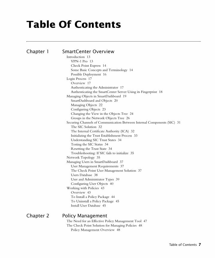
Table Of Contents
Chapter 1 SmartCenter Overview Introduction 13
VPN-1 Pro 13Check Point Express 14Some Basic Concepts and Terminology 14Possible Deployment 16
Login Process 17Overview 17Authenticating the Administrator 17Authenticating the SmartCenter Server Using its Fingerprint 18
Managing Objects in SmartDashboard 19SmartDashboard and Objects 20Managing Objects 22Configuring Objects 23Changing the View in the Objects Tree 24Groups in the Network Objects Tree 26
Securing Channels of Communication Between Internal Components (SIC) 31The SIC Solution 32The Internal Certificate Authority (ICA) 32Initializing the Trust Establishment Process 33Understanding SIC Trust States 34Testing the SIC Status 34Resetting the Trust State 34Troubleshooting: If SIC fails to initialize 35
Network Topology 35Managing Users in SmartDashboard 37
User Management Requirements 37The Check Point User Management Solution 37Users Database 38User and Administrator Types 39Configuring User Objects 40
Working with Policies 43Overview 43To Install a Policy Package 44To Uninstall a Policy Package 45Install User Database 45
Chapter 2 Policy Management The Need for an Effective Policy Management Tool 47The Check Point Solution for Managing Policies 48
Policy Management Overview 48
Table of Contents 7

Policy Packages 49Dividing the Rule Base into Sections using Section Titles 51Querying and Sorting Rules and Objects 52
Policy Management Considerations 53Conventions 53
Policy Management Configuration 54Policy Package 54Rule Sections 56Querying the Rule Base 56Querying and Sorting Objects 58
Chapter 3 SmartMap Overview of SmartMap 59
The SmartMap Solution 60Working with SmartMap 60
Enabling and Viewing SmartMap 60Adjusting and Customizing SmartMap 61Working with Network Objects and Groups in SmartMap 63Working with SmartMap Objects 65Working with Folders in SmartMap 67Integrating SmartMap and the Rule Base 70Troubleshooting SmartMap 72Working with SmartMap Output 74
Chapter 4 The Internal Certificate Authority (ICA) and the ICA Manage-ment Tool
The Need for the ICA 75The ICA Solution 76
Introduction to the ICA 76ICA Clients 77Certificate Longevity and Statuses 77SIC Certificate Management 79Gateway VPN Certificate Management 79User Certificate Management 80CRL Management 81ICA Advanced Options 82The ICA Management Tool 82
ICA Configuration 85Retrieving the ICA Certificate 85Management of SIC Certificates 86Management of Gateway VPN Certificates 86Management of User Certificates via SmartDashboard 87Invoking the ICA Management Tool 88Search for a Certificate 89Certificate Operations Using the ICA Management Tool 90Initializing Multiple Certificates Simultaneously 93CRL Operations 94
8
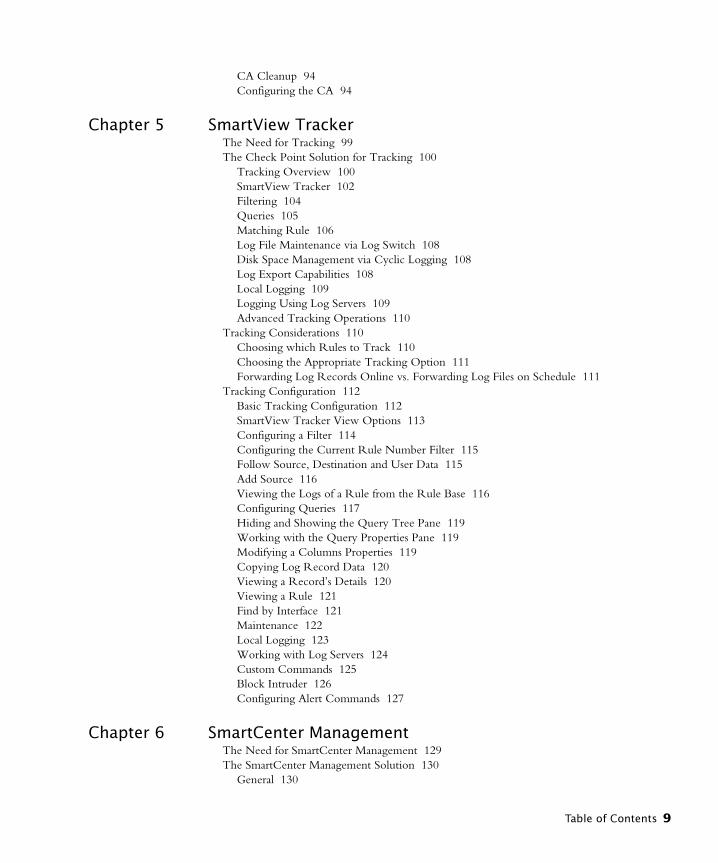
CA Cleanup 94Configuring the CA 94
Chapter 5 SmartView Tracker The Need for Tracking 99The Check Point Solution for Tracking 100
Tracking Overview 100SmartView Tracker 102Filtering 104Queries 105Matching Rule 106Log File Maintenance via Log Switch 108Disk Space Management via Cyclic Logging 108Log Export Capabilities 108Local Logging 109Logging Using Log Servers 109Advanced Tracking Operations 110
Tracking Considerations 110Choosing which Rules to Track 110Choosing the Appropriate Tracking Option 111Forwarding Log Records Online vs. Forwarding Log Files on Schedule 111
Tracking Configuration 112Basic Tracking Configuration 112SmartView Tracker View Options 113Configuring a Filter 114Configuring the Current Rule Number Filter 115Follow Source, Destination and User Data 115Add Source 116Viewing the Logs of a Rule from the Rule Base 116Configuring Queries 117Hiding and Showing the Query Tree Pane 119Working with the Query Properties Pane 119Modifying a Columns Properties 119Copying Log Record Data 120Viewing a Record’s Details 120Viewing a Rule 121Find by Interface 121Maintenance 122Local Logging 123Working with Log Servers 124Custom Commands 125Block Intruder 126Configuring Alert Commands 127
Chapter 6 SmartCenter Management The Need for SmartCenter Management 129The SmartCenter Management Solution 130
General 130
Table of Contents 9
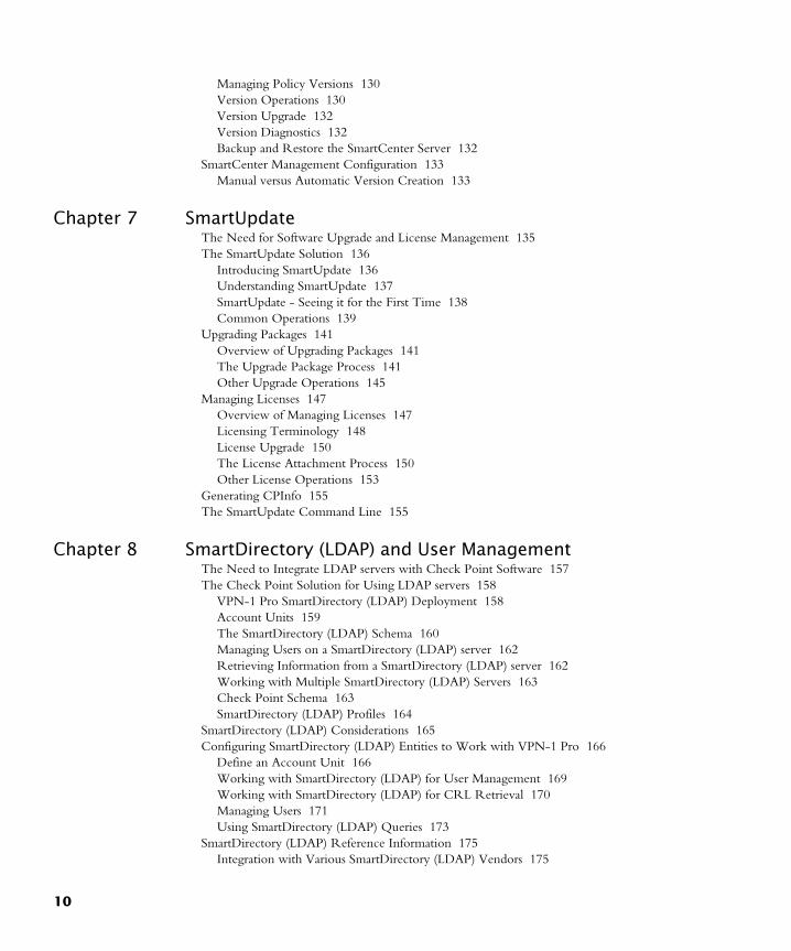
Managing Policy Versions 130Version Operations 130Version Upgrade 132Version Diagnostics 132Backup and Restore the SmartCenter Server 132
SmartCenter Management Configuration 133Manual versus Automatic Version Creation 133
Chapter 7 SmartUpdate The Need for Software Upgrade and License Management 135The SmartUpdate Solution 136
Introducing SmartUpdate 136Understanding SmartUpdate 137SmartUpdate - Seeing it for the First Time 138Common Operations 139
Upgrading Packages 141Overview of Upgrading Packages 141The Upgrade Package Process 141Other Upgrade Operations 145
Managing Licenses 147Overview of Managing Licenses 147Licensing Terminology 148License Upgrade 150The License Attachment Process 150Other License Operations 153
Generating CPInfo 155The SmartUpdate Command Line 155
Chapter 8 SmartDirectory (LDAP) and User Management The Need to Integrate LDAP servers with Check Point Software 157The Check Point Solution for Using LDAP servers 158
VPN-1 Pro SmartDirectory (LDAP) Deployment 158Account Units 159The SmartDirectory (LDAP) Schema 160Managing Users on a SmartDirectory (LDAP) server 162Retrieving Information from a SmartDirectory (LDAP) server 162Working with Multiple SmartDirectory (LDAP) Servers 163Check Point Schema 163SmartDirectory (LDAP) Profiles 164
SmartDirectory (LDAP) Considerations 165Configuring SmartDirectory (LDAP) Entities to Work with VPN-1 Pro 166
Define an Account Unit 166Working with SmartDirectory (LDAP) for User Management 169Working with SmartDirectory (LDAP) for CRL Retrieval 170Managing Users 171Using SmartDirectory (LDAP) Queries 173
SmartDirectory (LDAP) Reference Information 175Integration with Various SmartDirectory (LDAP) Vendors 175
10

SmartDirectory (LDAP) Schema 180Proprietary Attributes 180Attributes 180Schema Checking 189
Modifying SmartDirectory (LDAP) Profiles 189Profile Attributes 189Fetch User Information Effectively by Modifying the Profile 200
Chapter 9 Management High Availability The Need for Management High Availability 203The Management High Availability Solution 203
Backing Up the SmartCenter Server 203Management High Availability Deployment 204Active versus Standby 205What Data is Backed Up by the Standby SmartCenter Servers? 205Synchronization Modes 206Synchronization Status 206Changing the Status of the SmartCenter Server 208Synchronization Diagnostics 208
Management High Availability Considerations 209Remote versusLocal Installation of the Secondary SCS 209Different Methods of Synchronizations 209Data Overload During Synchronization 209
Management High Availability Configuration 210Secondary Management Creation and Synchronization - the First Time 210Changing the Active SCS to the Standby SCS 212Changing the Standby SCS to the Active SCS 212Refreshing the Synchronization Status of the SCS 213Selecting the Synchronization Method 214Tracking Management High Availability Throughout the System 215
Chapter 10 Working with SNMP Management Tools The Need to Support SNMP Management Tools 217The Check Point Solution for SNMP 217
Understanding the SNMP MIB 218Handling SNMP Requests on Windows NT 219Handling SNMP Requests on Unix 219SNMP Traps 220
Special Consideration for the Unix SNMP Daemon 220Configuring VPN-1 Pro for SNMP 220
Configuring VPN-1 Pro for SNMP Requests 220Configuring VPN-1 Pro for SNMP Traps 221
Chapter 11 FAQ Network Objects Management 223Policy Management 224
Table of Contents 11
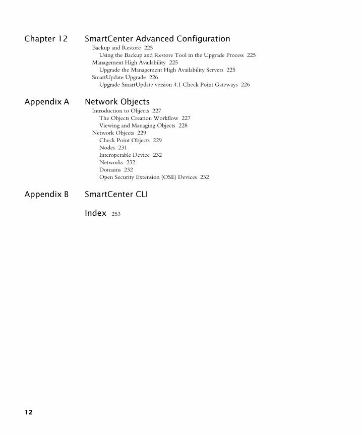
Chapter 12 SmartCenter Advanced Configuration Backup and Restore 225
Using the Backup and Restore Tool in the Upgrade Process 225Management High Availability 225
Upgrade the Management High Availability Servers 225SmartUpdate Upgrade 226
Upgrade SmartUpdate version 4.1 Check Point Gateways 226
Appendix A Network Objects Introduction to Objects 227
The Objects Creation Workflow 227Viewing and Managing Objects 228
Network Objects 229Check Point Objects 229Nodes 231Interoperable Device 232Networks 232Domains 232Open Security Extension (OSE) Devices 232
Appendix B SmartCenter CLI
Index 253
12
CHAPTER 1
SmartCenter Overview
In This Chapter
IntroductionTo make the most of Check Point products and to best use all their capabilities and features, you must be familiar with some basic concepts and components. This chapter includes an overview of usage, and describes the terminology and procedures that will help you install VPN-1 Pro for NGX R60A and Check Point Express.
Unless otherwise stated, all references to VPN-1 Pro in this Guide are relevant to Check Point Express. Additionally you will be shown how to create your first Policy Package. Refer to the Check Point Express Supplemental Guide to see a list of supported features.
VPN-1 Pro
VPN-1 Pro is part of the Check Point Suite. It provides a comprehensive security solution for very large enterprises and organizations. It integrates access control, authentication, and encryption to guarantee the security of network connections, the authenticity of local and remote users, and the privacy and integrity of data communications. VPN-1 Pro supports both site-to-site and, along with VPN-1 SecuRemote/SecureClient, remote access VPN solutions.
Introduction page 13
Managing Objects in SmartDashboard page 19
Securing Channels of Communication Between Internal Components (SIC) page 31
Network Topology page 35
Managing Users in SmartDashboard page 37
Working with Policies page 43
13
Introduction
Check Point Express
Check Point Express provides comprehensive enterprise-class security for medium sized organizations (organizations with up to 500 users). It includes SmartCenter management for a specified number of sites, VPN Express Gateways protecting a specified number of users, SmartDefense and VPN SecuRemote for users.
Some Basic Concepts and Terminology• Administrators are the designated managers of SmartConsole. They are assigned
different levels of access permissions, which define their ability to view and/or modify data using the SmartConsole. At least one administrator must have full Read/Write permissions so that he or she can manage the Security Policy.
• Configuration is the process by which VPN-1 Pro and Check Point Express is configured using the Check Point Configuration Tool. This tool runs immediately after the initial stages of installation are complete. However, it can be run and modified at any time. During the configuration process, the major attributes of the installed product are defined, such as the definition of Administrators, Fingerprint (for first time SmartCenter Server identity verification), as well features such as Management High Availability.
• An Enforcement module is the component that enforces a Policy (for example, a Security Policy). This module is referred to as VPN-1 Pro module. The Check Point Express module is called the VPN Express module.
• Installation is the process by which the VPN-1 Pro or Check Point Express components are installed on a computer. Check Point products are based on a 3-tier technology architecture where a typical Check Point deployment is composed of an Enforcement module, the SmartCenter Server and a SmartConsole (usually SmartDashboard). There are several different ways to deploy these components:
• A standalone deployment is the simplest deployment, where the VPN-1 Pro or Check Point Express components that are responsible for the management of the Security Policy (the SmartCenter Server and the Enforcement module) are installed on the same machine.
• A distributed deployment is a more complex deployment where the Enforcement module and the SmartCenter Server are deployed on different machines.In all deployments, SmartConsole can be installed on any machine, unless stated otherwise.
• Licenses are required in order to use certain Check Point products and features. It is recommended to use SmartUpdate for license management.
• Login is the process by which the administrator connects to the SmartCenter Server using a SmartConsole. The recommended method to login to the SmartCenter Server is by using a certificate.
14
Some Basic Concepts and Terminology
• Objects are defined and managed in SmartDashboard to represent actual network components such as gateways, servers and networks.
• A Policy Package is a set of Policies that are enforced on selected Enforcement modules. These Policies may include different types of policies, such as a Security Policy or a QoS policy.
• A Security Policy defines the rules and conditions that govern which communications are permitted to enter and to leave the organization.
• SmartConsole are GUI applications used to manage different aspects of the corporate network. For example, SmartView Tracker track logs and alerts issued by the system.
• SmartCenter Server is the component that manages the database and policies, and downloads policies to Enforcement modules. This server is also referred to as SmartCenter Pro server. The Check Point Express server is called the SmartCenter Express server.
• A Log Server is the repository for log entries generated on Enforcement modules, that is, the Enforcement modules send their log entries to the Log Server. A Log Server is often installed on the same machine as the SmartCenter Server.
• SmartDashboard is the SmartConsole used to create, edit and install policies.
• Users are the people defined in SmartDashboard as the users of an organization. For example, users may be the employees of a specified organization
Chapter 1 SmartCenter Overview 15
Introduction
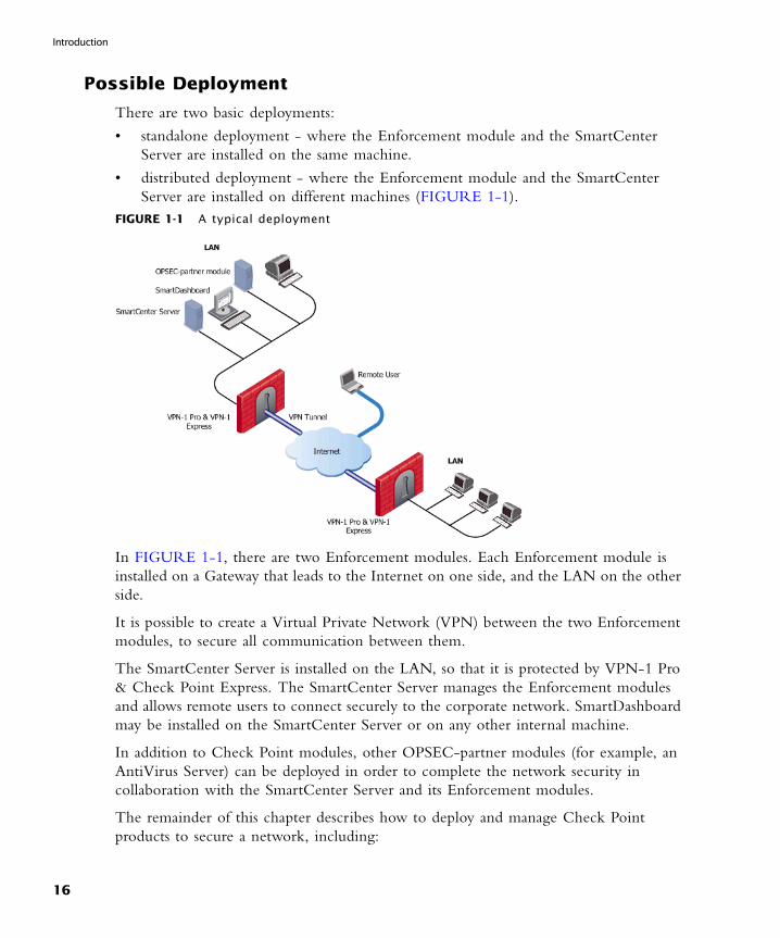
Possible Deployment
There are two basic deployments:
• standalone deployment - where the Enforcement module and the SmartCenter Server are installed on the same machine.
• distributed deployment - where the Enforcement module and the SmartCenter Server are installed on different machines (FIGURE 1-1).
FIGURE 1-1 A typical deployment
In FIGURE 1-1, there are two Enforcement modules. Each Enforcement module is installed on a Gateway that leads to the Internet on one side, and the LAN on the other side.
It is possible to create a Virtual Private Network (VPN) between the two Enforcement modules, to secure all communication between them.
The SmartCenter Server is installed on the LAN, so that it is protected by VPN-1 Pro & Check Point Express. The SmartCenter Server manages the Enforcement modules and allows remote users to connect securely to the corporate network. SmartDashboard may be installed on the SmartCenter Server or on any other internal machine.
In addition to Check Point modules, other OPSEC-partner modules (for example, an AntiVirus Server) can be deployed in order to complete the network security in collaboration with the SmartCenter Server and its Enforcement modules.
The remainder of this chapter describes how to deploy and manage Check Point products to secure a network, including:
16

Overview
• Managing Objects in SmartDashboard describes how to manage objects, the building blocks of policies.
• Securing Channels of Communication Between Internal Components (SIC) describes how Check Point components installed on different machines securely communicate with each other for policy installation, status information, etc.
• Network Topology describes how the structure of the internal network protected by the Enforcement module is represented on the Network Object which represents the Enforcement module.
• Managing Users in SmartDashboard describes how to manage administrators and users.
• Working with Policies describes how to define and install policies.
Login Process
Overview
The login process, in which administrators connect to the SmartCenter Server, is common to all Check Point SmartConsole (SmartDashboard, SmartUpdate, etc.). This process consists of a bidirectional operation, in which the administrator and the SmartCenter Server authenticate each other and create a secure channel of communication between them using Secure Internal Communication (SIC). Once both the administrator and the SmartCenter Server have been successfully authenticated, SmartCenter launches the selected SmartConsole.
Authenticating the Administrator
Administrators can authenticate themselves in two different ways, depending on the tool used to create them: the Check Point Configuration Tool or the SmartDashboard.
Administrators defined through the Check Point Configuration Tool authenticate themselves with a User Name and Password combination. This process is known as asymmetric SIC, since only the Smart Center Server is authenticated using a certificate.
Administrators defined through the SmartDashboard authenticate themselves with a Certificate. The administrator browses to the certificate and unlocks it by entering its password. This process is known as an symmetric SIC, since both the SmartCenter Server and the administrator authenticate each other using certificates.
After providing the authentication information, the administrator specifies the name or IP address of the target SmartCenter Server and clicks OK to perform the authentication. If the administrator is authenticated successfully by the SmartCenter Server, one of the following operations takes place:
Chapter 1 SmartCenter Overview 17
Login Process
• If this is the first time this SmartConsole has been used to connect to the SmartCenter Server, the administrator must manually authenticate the SmartCenter Server using its Fingerprint.
• If this SmartConsole has already been used to connect to the SmartCenter Server, and an administrator has already authenticated the SmartCenter Server, Fingerprint authentication is performed automatically.
Authenticating the SmartCenter Server Using its Fingerprint
The administrator authenticates the SmartCenter Server using the SmartCenter Server’s Fingerprint. This Fingerprint, shown in the Fingerprint tab of the Check Point Configuration Tool, is obtained by the administrator before attempting to connect to the SmartCenter Server.
The first time the administrator connects to the SmartCenter Server, the SmartCenter Server displays a Fingerprint verification window. The administrator, who has the original Fingerprint on hand, compares it to the displayed Fingerprint. If the two are identical, the administrator approves the Fingerprint as valid. This action saves the Fingerprint (along with the SmartCenter Server’s IP address) to the SmartConsole machine’s registry, where it remains available for automatically authenticating the SmartCenter Server in the future.
If the Fingerprints are not identical, the administrator quits the Fingerprint verification window and returns to the initial login window. In this case, the administrator should verify the resolvable name or IP address of the SmartCenter Server.
18
Authenticating the SmartCenter Server Using its Fingerprint
Managing Objects in SmartDashboard
In This Section
Objects are created by the system administrator in order to represent actual hosts and devices, as well as intangible components such as services (for example, HTTP and TELNET) and resources, (for example, URI and FTP). Each component of an organization has a corresponding object which represents it. Once these objects are created, they can be used in the rules of the Security Policy. Objects are the building blocks of Security Policy rules and are stored in the Objects database on the SmartCenter Server.
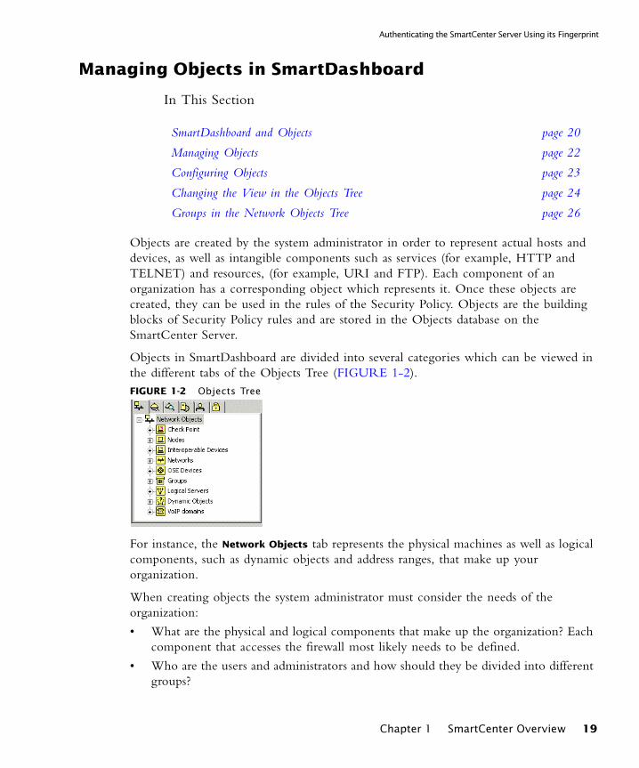
Objects in SmartDashboard are divided into several categories which can be viewed in the different tabs of the Objects Tree (FIGURE 1-2).FIGURE 1-2 Objects Tree
For instance, the Network Objects tab represents the physical machines as well as logical components, such as dynamic objects and address ranges, that make up your organization.
When creating objects the system administrator must consider the needs of the organization:
• What are the physical and logical components that make up the organization? Each component that accesses the firewall most likely needs to be defined.
• Who are the users and administrators and how should they be divided into different groups?
SmartDashboard and Objects page 20
Managing Objects page 22
Configuring Objects page 23
Changing the View in the Objects Tree page 24
Groups in the Network Objects Tree page 26
Chapter 1 SmartCenter Overview 19
Managing Objects in SmartDashboard
In other words, a substantial amount of planning should go into deciding what objects should be created and how they should be implemented.
SmartDashboard and Objects
In This Section
Introduction to SmartDashboard and Objects
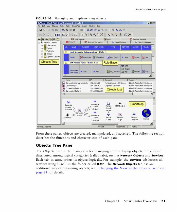
SmartDashboard is comprised of four principal areas known as panes. Each pane is labeled in FIGURE 1-3:
Introduction to SmartDashboard and Objects page 20
Objects Tree Pane page 21
Objects List Pane page 22
Rule Base Pane page 22
SmartMap Pane page 22
20
SmartDashboard and Objects
FIGURE 1-3 Managing and implementing objects
From these panes, objects are created, manipulated, and accessed. The following section describes the functions and characteristics of each pane.
Objects Tree Pane
The Objects Tree is the main view for managing and displaying objects. Objects are distributed among logical categories (called tabs), such as Network Objects and Services. Each tab, in turn, orders its objects logically. For example, the Services tab locates all services using ICMP in the folder called ICMP. The Network Objects tab has an additional way of organizing objects; see “Changing the View in the Objects Tree” on page 24 for details.
Chapter 1 SmartCenter Overview 21
Managing Objects in SmartDashboard
Objects List Pane
The Objects Tree works in conjunction with the Objects List. The Objects List displays current information for a selected object category. For example, when a Logical Server Network Object is selected in the Objects Tree, the Objects List displays a list of Logical Servers, with certain details displayed.
Rule Base Pane
Objects are implemented across various Rule Bases where they are used in the rules of the various policies. For example, Network Objects are generally used in the Source, Destination or Install On columns, while Time objects can be applied in any Rule Base with a Time column.
SmartMap Pane
A graphical display of objects in the system is displayed in SmartMap view. This view is a visual representation of the network topology. Existing objects representing physical components such as Gateways or Hosts are displayed in SmartMap, but logical objects such as dynamic objects cannot be displayed.
Managing Objects
The Objects Tree is the main view for adding, editing and deleting objects, although these operations can also be performed from the menus, toolbars and the various views such as in Rule Bases or in SmartMap.
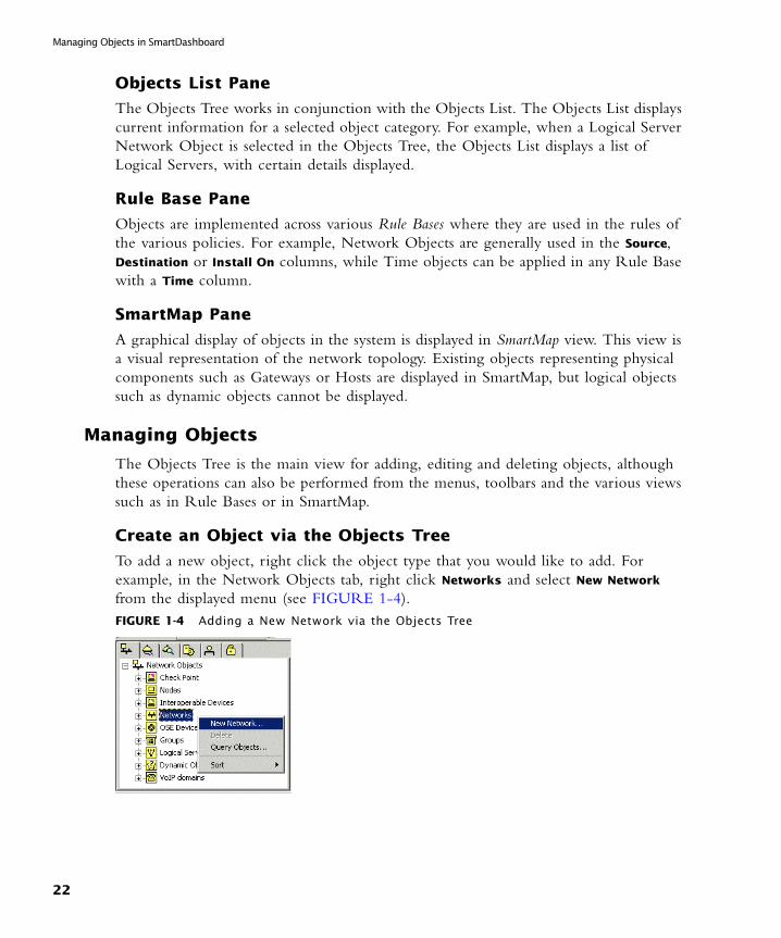
Create an Object via the Objects Tree
To add a new object, right click the object type that you would like to add. For example, in the Network Objects tab, right click Networks and select New Network from the displayed menu (see FIGURE 1-4).FIGURE 1-4 Adding a New Network via the Objects Tree
22
Configuring Objects
Edit an Object via the Objects Tree
To edit an existing object, right click the desired object in the Objects Tree and select Edit from the displayed menu, or double click on the object that you would like to modify.
Delete an Object via the Objects Tree
To delete an existing object, right click on the object in the Objects Tree and click Delete from the displayed menu.
Configuring Objects
An object consists of one or more tabs and/or pages. It is in these tabs and/or pages that the object settings are configured.
A Typical Object Configuration
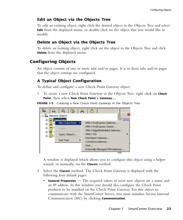
To define and configure a new Check Point Gateway object:
1 To create a new Check Point Gateway in the Objects Tree, right click on Check
Point, then select New Check Point > Gateway….FIGURE 1-5 Creating a New Check Point Gateway in the Objects Tree
A window is displayed which allows you to configure this object using a helper wizard, or manually, via the Classic method.
2 Select the Classic method. The Check Point Gateway is displayed with the following four default pages:
• General Properties — The required values of most new objects are a name and an IP address. In this window you should also configure the Check Point products to be installed on the Check Point Gateway. For this object to communicate with the SmartCenter Server, you must initialize Secure Internal Communication (SIC) by clicking Communication.
Chapter 1 SmartCenter Overview 23

Managing Objects in SmartDashboard
• Topology — Enter the interfaces that make up the network topology of your organization.
• NAT — If relevant, configure this object for NAT and anti-spoofing purposes.
• Advanced — If relevant, configure this object for use of the SNMP daemon.
3 Once you have configured the object, click OK to apply the changes to the new object. This object will be added to the Network Objects tab of the Objects Tree and to the Objects List.
Changing the View in the Objects Tree
The Network Objects Tree provides two possible ways of viewing and organizing network objects. The first is known as Classic View, which automatically places each object in a pre-defined logical category. The second is Group View, which provides additional flexibility in organizing objects by groups.
Classic View of the Objects Tree
In Classic View, network objects are displayed beneath their object type. For example, a corporate mail server would appear under the Node category (see FIGURE 1-6).FIGURE 1-6 Nodes in the Objects Tree
Check Point management stations and enforcement modules appear under the category Check Point, DAIP servers appear in the category Dynamic Objects, etc. Organizing objects by category is preferred for small to medium sized deployments. SmartDashboard opens to Classic View by default unless set to Group View.
Note - It is possible to clone a Host object and a Network object (that is, duplicate the object). To do this right-click the Host or Network object you would like to duplicate, select Clone... and enter a new name.
24
Changing the View in the Objects Tree
Group View of the Objects Tree
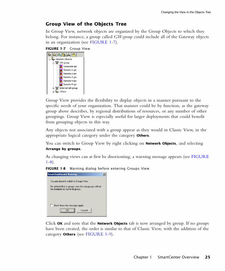
In Group View, network objects are organized by the Group Objects to which they belong. For instance, a group called GW-group could include all of the Gateway objects in an organization (see FIGURE 1-7). FIGURE 1-7 Group View
Group View provides the flexibility to display objects in a manner pursuant to the specific needs of your organization. That manner could be by function, as the gateway group above describes, by regional distributions of resources, or any number of other groupings. Group View is especially useful for larger deployments that could benefit from grouping objects in this way.
Any objects not associated with a group appear as they would in Classic View, in the appropriate logical category under the category Others.
You can switch to Group View by right clicking on Network Objects, and selecting Arrange by groups.
As changing views can at first be disorienting, a warning message appears (see FIGURE 1-8).FIGURE 1-8 Warning dialog before entering Groups View
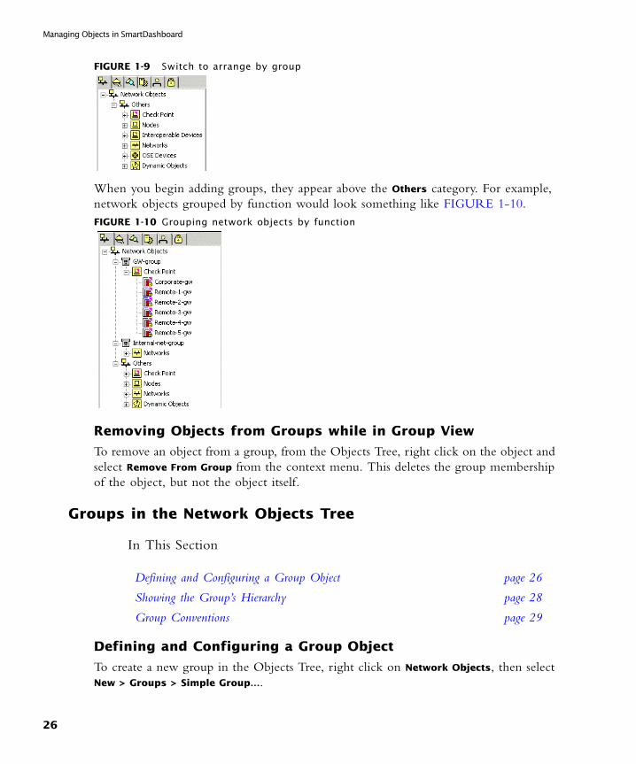
Click OK and note that the Network Objects tab is now arranged by group. If no groups have been created, the order is similar to that of Classic View, with the addition of the category Others (see FIGURE 1-9).
Chapter 1 SmartCenter Overview 25
Managing Objects in SmartDashboard
FIGURE 1-9 Switch to arrange by group
When you begin adding groups, they appear above the Others category. For example, network objects grouped by function would look something like FIGURE 1-10.FIGURE 1-10 Grouping network objects by function
Removing Objects from Groups while in Group View
To remove an object from a group, from the Objects Tree, right click on the object and select Remove From Group from the context menu. This deletes the group membership of the object, but not the object itself.
Groups in the Network Objects Tree
In This Section
Defining and Configuring a Group Object
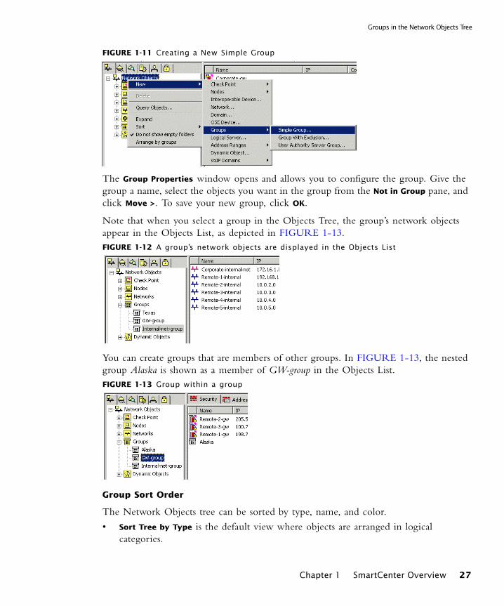
To create a new group in the Objects Tree, right click on Network Objects, then select New > Groups > Simple Group….
Defining and Configuring a Group Object page 26
Showing the Group’s Hierarchy page 28
Group Conventions page 29
26
Groups in the Network Objects Tree
FIGURE 1-11 Creating a New Simple Group
The Group Properties window opens and allows you to configure the group. Give the group a name, select the objects you want in the group from the Not in Group pane, and click Move >. To save your new group, click OK.
Note that when you select a group in the Objects Tree, the group’s network objects appear in the Objects List, as depicted in FIGURE 1-13.FIGURE 1-12 A group’s network objects are displayed in the Objects List
You can create groups that are members of other groups. In FIGURE 1-13, the nested group Alaska is shown as a member of GW-group in the Objects List.FIGURE 1-13 Group within a group
Group Sort Order
The Network Objects tree can be sorted by type, name, and color.
• Sort Tree by Type is the default view where objects are arranged in logical categories.
Chapter 1 SmartCenter Overview 27

Managing Objects in SmartDashboard
• Sort Tree by Name removes all categories from the Network Objects pane and orders objects alphabetically. Group objects are always listed first, however.
• Sort Tree by Color removes all categories from the Network Objects pane and orders objects by color. As in Sort by Name, group objects are listed first.
To change the sorting order of the Network Objects tree, right click on any category or object in the Network Objects tree and select one of the three Sort Tree by options.
Assigning and Removing Group Membership
You can assign group membership to an object by dragging it to a group, as well as by copying and pasting. Removing it from the group, however, is performed by editing the group object.
Showing the Group’s Hierarchy
You can set groups to display their member objects within the Objects Tree. Thus, in a glance you can see each group and the network objects associated with it. Each object added appears in its logical category under the group. For example, in FIGURE 1-14, GW-group contains the folder Check Point and its member gateway objects. FIGURE 1-14 Groups Hierarchy
This ability to view group member objects in a hierarchical fashion is useful in providing context to each device. Grouping objects in meaningful ways can make locating and working with them faster and easier. For instance, remote gateway object in a group called GW-group is easily located.
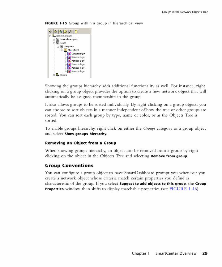
Also, when creating nested groups (groups within groups), displaying their hierarchy naturally adds clarity to the organizational structure. In FIGURE 1-15, group GW-group is a member of group Texas.
28
Groups in the Network Objects Tree
FIGURE 1-15 Group within a group in hierarchical view
Showing the groups hierarchy adds additional functionality as well. For instance, right clicking on a group object provides the option to create a new network object that will automatically be assigned membership in the group.
It also allows groups to be sorted individually. By right clicking on a group object, you can choose to sort objects in a manner independent of how the tree or other groups are sorted. You can sort each group by type, name or color, or as the Objects Tree is sorted.
To enable groups hierarchy, right click on either the Groups category or a group object and select Show groups hierarchy.
Removing an Object from a Group
When showing groups hierarchy, an object can be removed from a group by right clicking on the object in the Objects Tree and selecting Remove from group.
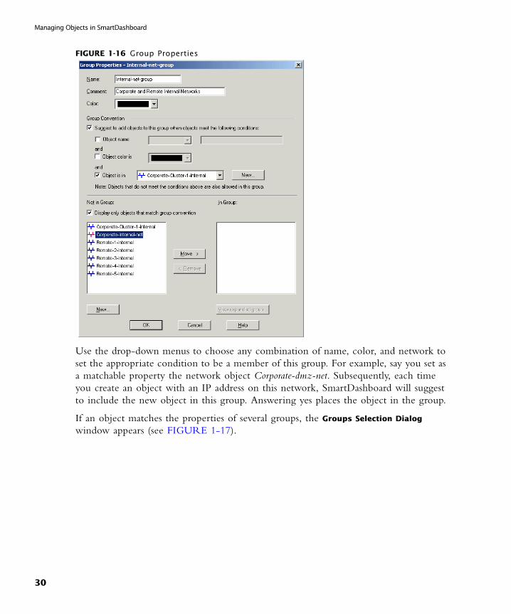
Group Conventions
You can configure a group object to have SmartDashboard prompt you whenever you create a network object whose criteria match certain properties you define as characteristic of the group. If you select Suggest to add objects to this group, the Group
Properties window then shifts to display matchable properties (see FIGURE 1-16).
Chapter 1 SmartCenter Overview 29
Managing Objects in SmartDashboard
FIGURE 1-16 Group Properties
Use the drop-down menus to choose any combination of name, color, and network to set the appropriate condition to be a member of this group. For example, say you set as a matchable property the network object Corporate-dmz-net. Subsequently, each time you create an object with an IP address on this network, SmartDashboard will suggest to include the new object in this group. Answering yes places the object in the group.
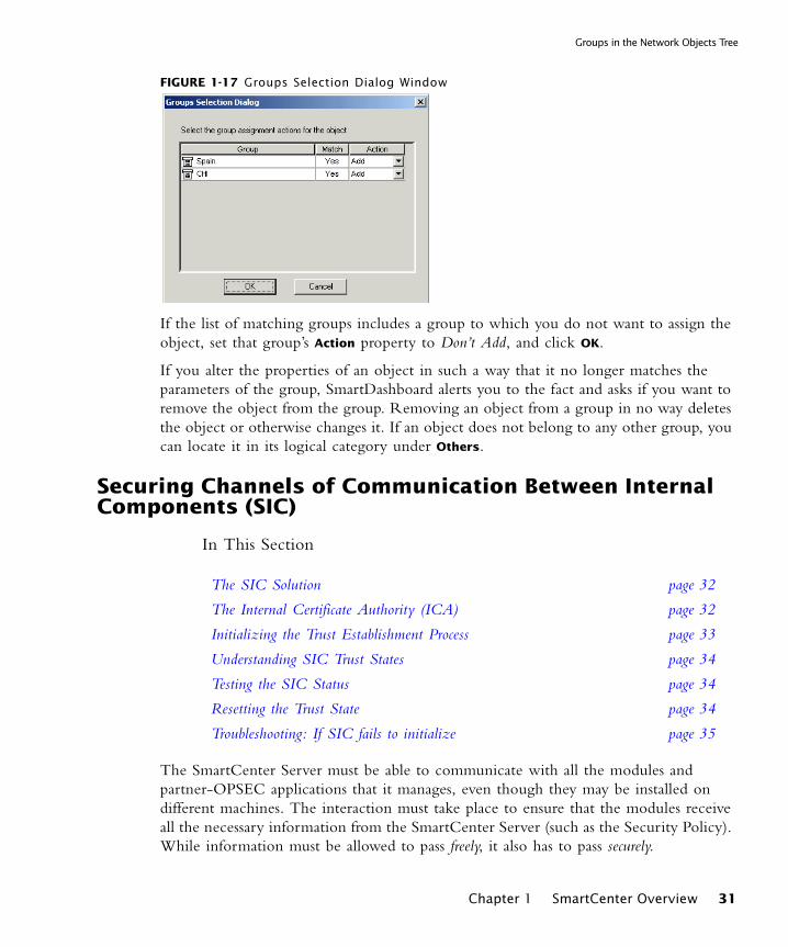
If an object matches the properties of several groups, the Groups Selection Dialog window appears (see FIGURE 1-17).
30
Groups in the Network Objects Tree
FIGURE 1-17 Groups Selection Dialog Window
If the list of matching groups includes a group to which you do not want to assign the object, set that group’s Action property to Don’t Add, and click OK.
If you alter the properties of an object in such a way that it no longer matches the parameters of the group, SmartDashboard alerts you to the fact and asks if you want to remove the object from the group. Removing an object from a group in no way deletes the object or otherwise changes it. If an object does not belong to any other group, you can locate it in its logical category under Others.
Securing Channels of Communication Between Internal Components (SIC)
In This Section
The SmartCenter Server must be able to communicate with all the modules and partner-OPSEC applications that it manages, even though they may be installed on different machines. The interaction must take place to ensure that the modules receive all the necessary information from the SmartCenter Server (such as the Security Policy). While information must be allowed to pass freely, it also has to pass securely.
The SIC Solution page 32
The Internal Certificate Authority (ICA) page 32
Initializing the Trust Establishment Process page 33
Understanding SIC Trust States page 34
Testing the SIC Status page 34
Resetting the Trust State page 34
Troubleshooting: If SIC fails to initialize page 35
Chapter 1 SmartCenter Overview 31
Securing Channels of Communication Between Internal Components (SIC)
This means that:
• The communication must be encrypted so that an imposter cannot send, receive or intercept communication meant for someone else.
• The communication must be authenticated, there can be no doubt as to the identity of the communicating peers.
• The transmitted communication should have data integrity, that is, the communication has not been altered or distorted in any form.
• The SIC setup process allowing the intercommunication to take place must be user-friendly.
If these criteria are met, secure channels of communication between inter-communicating components of the system can be set up and enforced to protect the free and secure flow of information.
The SIC Solution
Secure communication channels between Check Point modules (such as SmartCenter Server, Enforcement modules or OPSEC modules) can be set up using Secure Internal Communication (SIC). This Check Point feature ensures that these modules can communicate freely and securely using a simple communication initialization process,
The following security measures are taken to ensure the safety of SIC:
• Certificates for authentication
• Standards-based SSL for the creation of the secure channel
• 3DES for encryption.
The Internal Certificate Authority (ICA)
The ICA, is created during the SmartCenter Server installation process. The ICA is responsible for issuing certificates for authentication. For example, ICA issues certificates, such as SIC certificates for authentication purposes to administrators and VPN certificates to users and Gateways.
32
Initializing the Trust Establishment Process
Initializing the Trust Establishment Process
The purpose of the Communication Initialization process is to establish a trust between SmartCenter Server and the Check Point modules. This trust enables these components to communicate freely and securely. Trust can only be established when the modules and the SmartCenter Server have been issued SIC certificates. The SIC initialization process occurs as follows:
1 In the Check Point Configuration Tool, when the SmartCenter Server is installed, the Internal Certificate Authority (ICA) is created.
After the ICA is created, it issues and delivers a certificate to the SmartCenter Server.
2 SIC can be initialized, for every module in the Secure Internal Communication tab of the Check Point Configuration tool. An Activation Key must be decided upon and remembered. This same Activation Key must be applied on the appropriate network object in SmartDashboard. At this point only the Module side has been prepared. The Trust state remains Uninitialized.
3 In SmartDashboard, connect to the SmartCenter server. Create a new object that represents the module. In the General Properties page of the module, click Communication to initialize the SIC procedure.
4 In the Communication window of the object, enter the Activation Key that you created in step 2.
5 To continue the SIC procedure, click Initialize. At this point the module is issued a certificate by the ICA. The certificate is signed by the ICA.
6 SSL negotiation takes place after which the two communicating peers are authenticating with their Activation Key.
7 The certificate is downloaded securely and stored on the module.
8 After successful Initialization, the module can communicate with any module that possesses a SIC certificate, signed by the same ICA. The Activation Key is deleted. The SIC process no longer requires the Activation Key, only the SIC certificates.
Note - In order for SIC between the Management and the Module to succeed, their clocks must be properly and accurately synchronized.
Chapter 1 SmartCenter Overview 33
Securing Channels of Communication Between Internal Components (SIC)
Understanding SIC Trust States
When the SIC certificate has been securely delivered to the module, the Trust state is Trust Established. Until that point the module can be in one of two states: Uninitialized or Initialized but not trusted. Initialized but not trusted means that the certificate has been issued for the module, but has not yet been delivered.
Testing the SIC Status
The SIC status reflects the state of the Module after it has received the certificate issued by the ICA. This status conveys whether or not the SmartCenter Server is able to communicate securely with the module. The most typical status is Communicating. Any other status indicates that the SIC communication is problematic. For example, if the SIC status is Unknown then there is no connection between the Module and the SmartCenter Server. If the SIC status is Not Communicating, the SmartCenter Server is able to contact the module, but SIC communication cannot be established. In this case an error message will appear, which may contain specific instructions how to remedy the situation.
Resetting the Trust State
Resetting the Trust State revokes the module’s SIC certificate. This must be done if the security of the module has been breached, or if for any other reason the module functionality must be stopped. When the module is reset, the Certificate Revocation List (CRL) is updated to include the name of the revoked certificate. The CRL is signed by the ICA and issued to all the modules in this system the next time a SIC connection is made. If there is a discrepancy between the CRL of two communicating components, the newest CRL is always used. The modules refer to the latest CRL and deny a connection from an imposter posing as a module and using a SIC certificate that has already been revoked.
1 To reset the Trust State in SmartDashboard:
• In SmartDashboard, in the General Properties window of the module, click Communication.
• In the Communication window, click Reset.
2 To reset the Trust State in the Check Point Configuration tool of the module, click Reset in the Secure Internal Communication tab.
Warning - The Reset operation must be performed on the module’s object, using SmartDashboard, as well as physically on the module using the Check Point Configuration Tool.
34
Troubleshooting: If SIC fails to initialize
3 Install the Security Policy on all modules. This deploys the updated CRL to all modules.
Troubleshooting: If SIC fails to initialize
SIC Initialization will succeed if:
• The SmartCenter Server and its modules are of version NG and higher.
• The module is up and connected to the network.
• The Activation Key is properly set for both the Module and the SmartCenter Server.
• The clocks of the SmartCenter Server and its modules are properly set and accurately synchronized.
Network TopologyThe network topology represents the internal network (both the LAN and the DMZ) protected by the Enforcement module. The module must be aware of the layout of the network topology to:
• Correctly enforce the Security Policy.
• Ensure the validity of IP addresses in eitherbound traffic.
• Configure a special domain for Virtual Private Networks.
Each component in the network topology is distinguished on the network by its IP address and net mask. The combination of objects and their respective IP information make up the topology. For example:
• The IP address of the LAN is 10.111.254.0 with Net Mask 255.255.255.0.
• A Check Point Gateway on this network has an external interface with the following IP address 192.168.1.1, and an internal interface with 10.111.254.254.
In this case, there is one simple internal network.
In more complicated scenarios, the LAN is composed of many different networks, as in the FIGURE 1-18.
Chapter 1 SmartCenter Overview 35
Network Topology
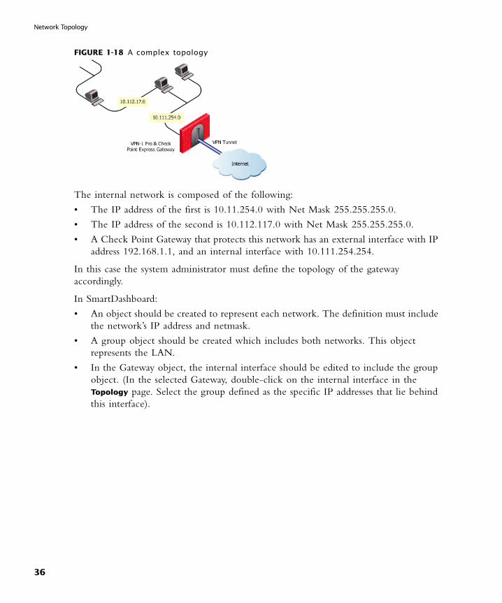
FIGURE 1-18 A complex topology
The internal network is composed of the following:
• The IP address of the first is 10.11.254.0 with Net Mask 255.255.255.0.
• The IP address of the second is 10.112.117.0 with Net Mask 255.255.255.0.
• A Check Point Gateway that protects this network has an external interface with IP address 192.168.1.1, and an internal interface with 10.111.254.254.
In this case the system administrator must define the topology of the gateway accordingly.
In SmartDashboard:
• An object should be created to represent each network. The definition must include the network’s IP address and netmask.
• A group object should be created which includes both networks. This object represents the LAN.
• In the Gateway object, the internal interface should be edited to include the group object. (In the selected Gateway, double-click on the internal interface in the Topology page. Select the group defined as the specific IP addresses that lie behind this interface).
36
User Management Requirements
Managing Users in SmartDashboard
In This Section
User Management Requirements
Your network can be accessed and managed by multiple users and administrators. To manage your network securely and efficiently, you must:
• Centrally manage all users through a single administrative framework.
• Ensure only authenticated users can access your network and allow users to securely access your network from remote locations.
The Check Point User Management Solution
Check Point users can be managed using either the Lightweight Directory Access Protocol (LDAP) or SmartDashboard.
SmartDirectory (LDAP)
LDAP is a standardized protocol that makes a single Users Database available to multiple applications (for example, email, domains, firewalls, etc.) and requires a special deployment (in addition to the VPN-1 Pro deployment). For information on managing users through LDAP, see “SmartDirectory (LDAP) and User Management”.
SmartDashboard
Check Point’s user management solution is part of SmartDashboard. Users, Administrators and their groups are managed as objects, using the standard object administration tools: the Objects Tree pane and the Objects Manager window.
• The Objects Tree pane (Users and Administrators tab):
• Provides a graphical overview of all users and administrators.
• Allows you to manage users and administrators by right clicking the relevant folder (for example, Administrator, Administrator Groups, External User Profiles, etc.) and selecting the appropriate command (Add, Edit, Delete, etc.) from the menu.
User Management Requirements page 37
The Check Point User Management Solution page 37
Users Database page 38
User and Administrator Types page 39
Configuring User Objects page 40
Chapter 1 SmartCenter Overview 37
Managing Users in SmartDashboard
• The Objects Manager (Users and Administrators window):
• Lists all users and administrators (you can filter this list to focus on a specific type of users or administrators).
• Allows you to define new objects using the New... menu, and to delete or modify an object by selecting them in the list and clicking Remove or Edit (respectively).
The user’s definition includes access permissions to and from specific machines at specific times of the day. The user definition can be used in the Rule Base’s Authentication Rules and in Remote Access VPN.
SmartDashboard further facilitates user management by allowing you to define user and administrator templates. Templates serve as prototypes of standard users, whose properties are common to many users. Any user you create based on a template inherits all of the template’s properties, including membership in groups.
Users Database
The users defined in SmartDashboard (as well as their authentication schemes and encryption keys) are saved to the proprietary Check Point Internal Users Database (a.k.a. the Users Databases). The Users Database resides on the SmartCenter Server and on the firewalled machines (the enforcement points).
The Users Database is automatically downloaded to the VPN-1 Pro Modules as part of the Policy installation process. Alternatively, you can manually install the Users Database by selecting Policy > Install Database... from the menu.
The Users Database does not contain information about users defined externally to VPN-1 Pro (such as users in external SmartDirectory (LDAP) groups), but it does contain information about the external groups themselves (for example, on which Account Unit the external group is defined). For this reason, changes to external groups take effect only after the Security Policy is installed or after the Users Database is downloaded.
38
User and Administrator Types
User and Administrator Types
SmartDashboard allows you to manage a variety of user and administrator types:
• Administrators — Login to a Check Point SmartConsole (SmartDashboard, SmartUpdate, etc.) with either Read Only or Read/Write permissions, to view or manage (respectively) the network’s various databases and policies.
• Administrator Groups — Consist of administrators and of administrator sub-groups. Administrator Groups are used to specify which administrators have permissions to install Policies on a specific gateway.
• External User Profiles — Profiles of externally defined users, that is, users who are not defined in the internal users database or on an LDAP server. External user profiles are used to avoid the burden of maintaining multiple Users Databases, by defining a single, generic profile for all external users. External users are authenticated based on either their name or their domain.
• Groups — User groups consist of users and of user sub-groups. Including users in groups is required for performing a variety of operations, such as defining user access rules or RemoteAccess communities.
• LDAP Groups — An LDAP group specifies certain LDAP user characteristics. All LDAP users defined on the LDAP server that match these characteristics are included in the LDAP group. LDAP groups are required for performing a variety of operations, such as defining LDAP user access rules or LDAP RemoteAccess communities. For detailed information on LDAP Groups, see “SmartDirectory (LDAP) and User Management” on page 157.
• Templates — User templates facilitate the user definition process and prevent mistakes, by allowing you to create a new user based on the appropriate template and change only a few relevant properties as needed.
• Users — Either local clients or remote clients, who access your network and its resources.
Chapter 1 SmartCenter Overview 39
Managing Users in SmartDashboard
Configuring User Objects
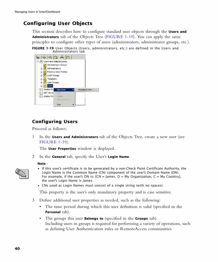
This section describes how to configure standard user objects through the Users and
Administrators tab of the Objects Tree (FIGURE 1-19). You can apply the same principles to configure other types of users (administrators, administrator groups, etc.).FIGURE 1-19 User Objects (Users, administrators, etc.) are defined in the Users and
Administrators tab
Configuring Users
Proceed as follows:
1 In the Users and Administrators tab of the Objects Tree, create a new user (see FIGURE 1-19).
The User Properties window is displayed.
2 In the General tab, specify the User’s Login Name.
This property is the user’s only mandatory property and is case sensitive.
3 Define additional user properties as needed, such as the following:
• The time period during which this user definition is valid (specified in the Personal tab).
• The groups this user Belongs to (specified in the Groups tab). Including users in groups is required for performing a variety of operations, such as defining User Authentication rules or RemoteAccess communities.
Note -
• If this user’s certificate is to be generated by a non-Check Point Certificate Authority, the Login Name is the Common Name (CN) component of the user’s Domain Name (DN).For example, if the user’s DN is: [CN = James, O = My Organization, C = My Country], the user’s Login Name is James.
• CNs used as Login Names must consist of a single string (with no spaces).
40

Configuring User Objects
• The network objects from which (Source objects) and to which (Destination
objects) the user is allowed access (specified in the Location tab).
• The days and times during which the user is allowed to connect to the network (specified in the Time tab).
• Authentication, certificates and encryption settings (for details, please refer to the Firewall and SmartDefense Guide and the VPN Guide).
The user’s definition is saved to the Users Database on the SmartCenter Server.
Configuring Administrators
1 In the Users and Administrators tab of the Objects Tree, create a new administrator.
The Administrator Properties window is displayed.
2 In the General tab, specify the administrator’s Login Name and Permissions Profile.
3 In the Admin Certificates tab, create a login certificate for this administrator as follows:
A Click Generate and save.
You are warned that the certificate generation cannot be undone unless you click Revoke.
B Click OK.
The Enter Password window is displayed.
C Enter and confirm the Password to be used with this certificate.
D Click OK.
The Save Certificate File As window is displayed.
E Browse to the folder in which you wish to save the certificate and click Save (by default, the certificate is saved under the administrator’s Login Name but you can rename it as needed).
Back in the Admin Certificates tab, the Certificate State changes to Object has a certificate and the administrator’s Distinguished Name (DN) is displayed.
4 Click OK.
The administrator’s definition is saved to the Users Database on the SmartCenter Server.
Chapter 1 SmartCenter Overview 41

Managing Users in SmartDashboard
Configuring Templates
To create a new user template:
1 In the Users and Administrators tab of the Objects Tree, create a new template
The User Template Properties window is displayed.
2 In the General tab, specify the template’s name in the Login Name field. This property is mandatory and is case sensitive.
3 Define additional user properties as needed (see step 3 on page 40).
To use this template to define a new user:
1 Right click the Users folder and select New User > Template name...
2 In the General tab, specify the new user’s Login Name. This is the only property the user cannot inherit from the template.
3 Choose one of the following:
• To complete the user definition using the template’s default settings, click OK.
• To specify the user’s unique properties, modify the relevant settings as needed and click OK.
The template’s definition is saved to the Users Database on the SmartCenter Server.
Configuring Groups
To create a new user group:
1 In the Users and Administrators tab of the Objects Tree, create a new user group.
The Group Properties window is displayed.
2 Specify the groups name in the Name field.
This property is the group’s only mandatory property and is case sensitive.
3 Move the users, external user profiles or groups to be included in this group from the Not in Group list to the In Group list.
• To easily locate objects in the Not in Group list, limit the View to a specific type of objects (for example, users).
• The In Group list shows collapsed sub-groups, without listing their members. For a list of all group members (including the sub-groups’ members), click View
Expanded Group...
4 Click OK to complete the definition.
The group’s definition is saved to the Users Database on the SmartCenter Server.
42
Overview
Working with Policies
In This Section
Overview
A Policy Package is a set of Policies that are enforced by the Enforcement modules. They can be installed or uninstalled together on selected VPN-1 Pro modules. The Policy Package components include:
• Advanced Security — consisting of
• the Security Rule Base
• the Address Translation (NAT) Rule Base
• the Users Database — the proprietary Check Point Internal User Database, containing the definitions and authentication schemes of all users defined in SmartDashboard.
• the Objects Database — the proprietary Check Point Objects Database, containing the definitions of all network objects defined in SmartDashboard.
• QoS — the Quality of Service (Check Point QoS) Rule Base
• Desktop Security — the Desktop Security Rule Base
The installation process does the following:
1 Performs a heuristic verification on rules, to ensure they are consistent and that no rule is redundant. If there are verification errors (for example, when two of the Policy’s rules are identical) the Policy is not installed. However, if there are verification warnings (for example, when anti-spoofing is not enabled for a module with multiple interfaces), the Policy Package is installed with a warning.
2 Confirms that each of the Modules on which the rule is enforced (known as the Install On objects) enforces at least one of the rules. Install On objects that do not enforce any of the rules enforce the default rule, which rejects all communications.
3 Converts the Security Policy into an Inspection Script and compiles this Script to generate an Inspection Code.
4 Distributes the Inspection Code to the selected installation targets.
5 Distributes the User and Encryption databases to the selected installation targets.
Overview page 43
To Install a Policy Package page 44
To Uninstall a Policy Package page 45
Chapter 1 SmartCenter Overview 43
Working with Policies
To Install a Policy Package
To install a Policy Package:
1 Display the Policy package in the Rule Base.
2 Choose Policy > Install... from the menu.
The Install Policy window is displayed.
3 Choose the installation components:
A Installation Targets — the VPN-1 Pro Modules on which the Policy is installed. By default, all internal Modules are available for selection. Alternatively, you defined specific Modules per Policy Package through the Select Installation Targets window (accessed by clicking Select Targets...).
B For each installation target, choose the Policy components (Advanced Security, QoS or Desktop Security) to be installed.
C The installation Mode — what to do if the installation is not successful for all targets (so different targets enforce different Policies):
- Install on each Module independently, or
- Install on all Modules, or on none of the Modules
4 Click OK.
The Installation Process window is displayed, allowing you to monitor the progress of the verification, compilation and installation.
If the verification is completed with no errors and the SmartCenter Server is able to connect to the module securely, the Policy installation succeeds.
If there are verification or installation errors, the installation fails (in which case you can view the errors to find the source of the problem).
If there are verification warnings, the installation succeeds with the exception of the component specified in the warning.
To find out which Policy is installed on each Module, select File > Installed Policies...
Note - The Policy to be installed includes implied rules, resulting from the Global Properties settings. To view the implied rules, select View > Implied Rules from the menu.
Note - If you are installing the Policy on a Gateway Cluster, specify if the installation must be successful for all Cluster Members.
44
To Uninstall a Policy Package
To Uninstall a Policy Package
To uninstall a Policy Package:
1 Display the Policy package in the Rule Base.
2 Choose Policy > Install... from the menu.
The Install Policy window is displayed.
3 Choose the Uninstall components.
4 Click OK.
The Uninstall window is displayed, allowing you to monitor the progress of the operation. You are notified whether the uninstall has been complete successfully or has failed, and if so, for what reason.
Install User Database
The changes you make through SmartDashboard to user or administrator definitions are saved to the User Database. To provide your Modules with the latest user definitions, you must install the User Database on all relevant targets. Choose one of the following options:
• Install the Policy Package — Choose this option if you have modified additional Policy Package components (for example, added new Security Policy rules) that are used by the installation targets.
• Install the User Database — Choose this option if the only changes you wish to implement are in the user or administrator definitions.
Note - Uninstalling the Policy removes its implied rules as well.
Chapter 1 SmartCenter Overview 45

Working with Policies
46

CHAPTER 2
Policy Management
In This Chapter
The Need for an Effective Policy Management ToolAs corporate structures grow in size, more network resources, machines, servers, routers etc. are deployed. It stands to reason that as the Security Policy possesses more and more network objects and logical structures (representing these entities), used in an increasing number of rules, it becomes more complex and more of a challenge for the system administrator to manage.
Because of the complexity of the Security Policy, many system administrators operate according to the "if it ain’t broke, don't fix it" axiom:
• New rules are often placed in a “safe” position (e.g. at the end of the Rule Base) rather than in the most effective position.
• Obsolete rules and objects are seldom eliminated.
These practices clutter and inflate the Security Policy and the databases unnecessarily, which invariably affects the performance of the Security Policy and the ability of the system administrator to manage it properly.
A simple, seamless solution is needed to facilitate the administration and management of the Security Policy by the system administrator. This easy-to -use policy management tool needs to take into account
The Need for an Effective Policy Management Tool page 47
The Check Point Solution for Managing Policies page 48
Policy Management Considerations page 53
Policy Management Configuration page 54
47

The Check Point Solution for Managing Policies
• The complexity of the corporate structure, with its multiple sites and branches, each of which has its own specific corporate needs.
• The need to be easily locate objects of interest.
• The need to analyze the Rule Base.
The Check Point Solution for Managing Policies
In This Section
Policy Management Overview
The SmartCenter Server provides a wide range of tools that address the various policy management tasks, both at the definition stage and at the maintenance stage:
• Policy Packages allow you to easily group different types of Policies, to be installed together on the same installation target(s).
• Predefined Installation Targets allow you to associate each Policy Package with the appropriate set of modules. This feature frees you of the need to repeat the module selection process every time you install (or uninstall) the Package, with the option to easily modify the list at any given time. In addition, it minimizes the risk of installing policies on inappropriate targets.
• Section Titles allow you to visually break down your Rule Base into subjects, thereby instantly improving your orientation and ability to locate rules and objects of interest.
• Queries provide versatile search capabilities for both objects and the rules in which they are used.
• Sorting your objects in the Objects Tree and Objects List pane is a simple and quick way to locate objects. This feature is greatly facilitated by consistent use of naming and coloring conventions.
Policy Management Overview page 48
Policy Packages page 49
Dividing the Rule Base into Sections using Section Titles page 51
Querying and Sorting Rules and Objects page 52
48
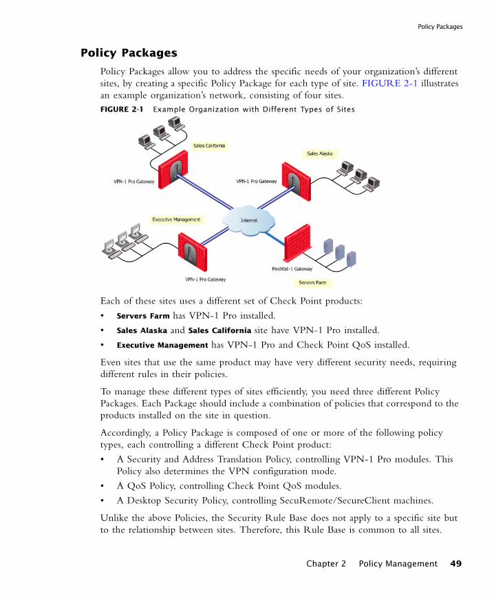
Policy Packages
Policy Packages
Policy Packages allow you to address the specific needs of your organization’s different sites, by creating a specific Policy Package for each type of site. FIGURE 2-1 illustrates an example organization’s network, consisting of four sites.FIGURE 2-1 Example Organization with Different Types of Sites
Each of these sites uses a different set of Check Point products:
• Servers Farm has VPN-1 Pro installed.
• Sales Alaska and Sales California site have VPN-1 Pro installed.
• Executive Management has VPN-1 Pro and Check Point QoS installed.
Even sites that use the same product may have very different security needs, requiring different rules in their policies.
To manage these different types of sites efficiently, you need three different Policy Packages. Each Package should include a combination of policies that correspond to the products installed on the site in question.
Accordingly, a Policy Package is composed of one or more of the following policy types, each controlling a different Check Point product:
• A Security and Address Translation Policy, controlling VPN-1 Pro modules. This Policy also determines the VPN configuration mode.
• A QoS Policy, controlling Check Point QoS modules.
• A Desktop Security Policy, controlling SecuRemote/SecureClient machines.
Unlike the above Policies, the Security Rule Base does not apply to a specific site but to the relationship between sites. Therefore, this Rule Base is common to all sites.
Chapter 2 Policy Management 49

The Check Point Solution for Managing Policies
The Web Access Rule Base is independent of Policy Packages, since it applies to the organization as a whole (as opposed to a specific site). Its appearance in the Rule Base pane is determined by SmartDashboard’s Global Properties settings (see the SmartDashboard Customization page of the Global Properties window).
File Operations
File operations (New, Open, Save etc.) are performed at the Policy Package level (as opposed to the single policy level).
• New allows you to either define a new Policy Package, or add a single policy to an existing Policy Package.
• Open allows you to display an existing Policy Package. The policy types included in the Policy Package determine which tabs are displayed in the Rule Base.
• Save allows you to save the entire Policy Package.
• Save As allows you to save the entire Policy Package, or to save a specific policy that is currently in focus in the Rule Base (i.e. Security and Address Translation, QoS or Desktop Security).
• Delete allows you to delete the entire Policy Package.
• Add to Policy Package allows you to add existing Policies to your Policy Package.
• Copy Policy to Package allows you to copy existing Policies to your Policy Package.
Installation Targets
To install (and uninstall) Policy Packages correctly and eliminate errors, each Policy Package is associated with a set of appropriate installation targets. This association both eliminates the need to repeat the module selection process per installation, and ensures that Policy Package is not mistakenly installed on any inappropriate target.
The installation targets are defined for the whole Policy Package, thereby eliminating the need to specify them per-rule in each policy. The selected targets are automatically displayed every time you perform an Install or Uninstall operation (FIGURE 2-2 on page 51).
Note - To back up a Policy Package before you modify it, use the Database Revision Control feature. Do not use File operations for backup or testing purposes, since they clutter the system with extraneous Packages. In addition, as there are multiple Packages but only one Objects Database, the saved Package may not correspond to changes in the Objects Databases.
50
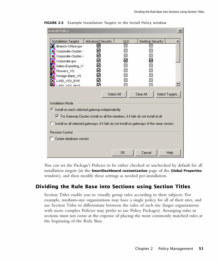
Dividing the Rule Base into Sections using Section Titles
FIGURE 2-2 Example Installation Targets in the Install Policy window
You can set the Package’s Policies to be either checked or unchecked by default for all installation targets (in the SmartDashboard customization page of the Global Properties
window), and then modify these settings as needed per-installation.
Dividing the Rule Base into Sections using Section Titles
Section Titles enable you to visually group rules according to their subjects. For example, medium-size organizations may have a single policy for all of their sites, and use Section Titles to differentiate between the rules of each site (larger organizations with more complex Policies may prefer to use Policy Packages). Arranging rules in sections must not come at the expense of placing the most commonly matched rules at the beginning of the Rule Base.
Chapter 2 Policy Management 51

The Check Point Solution for Managing Policies
Querying and Sorting Rules and Objects
Querying Rules
Querying rules can deepen your understanding of the policy and help you identify the most appropriate place for new rules. You can run queries on the Security, Desktop
Security and Web Access Rule Bases.
A query consists of one or more clause statements. Each statement refers to the relationship between the selected object(s) and a specific column in the rule. You can apply the query to single objects, groups of objects or both. To further enhance the query, you can use the appropriate logical condition (“Negate”, “And” or “Or”).
Once you apply the query, only rules matching its criteria are displayed in the Rule Base. Rules that do not match the query are hidden, but remain an integral part of the policy and are included in its installation. You can refine these query results by running additional queries.
An example scenario in which Rule Base queries are useful is when a server running on host A is moved to host B. Such a change requires updating the access permissions of both hosts. To find the rules you need to change, you can run a query that searches for all rules where host A or host B appear in the Destination column.
By default, the query searches not only for rules that include these hosts, but also for rules that include networks or groups that contain them, as well as rules whose Destination is Any. Alternatively, you can search only for rules that explicitly include these objects.
Querying Network Objects
The Network Objects query allows you to find objects that match the query criteria. You can use this query tool to both control and troubleshoot object-related issues.
The query lists either All objects in your system (the default selection) or a specific type of object (e.g. VPN-1 Pro installed, Check Point QoS installed, Gateway Clusters etc.). You can refine this list using a variety of filters (e.g. Search by Name, Search by IP etc.) and use wildcards in the string you search for.
In addition to these basic searches, you can also perform more advanced queries for
• objects whose IP address does not match their interface(s)
• duplicate IP addresses used by several objects
52

Conventions
• objects that are not used
You can further benefit from the query results by defining them as a group. For example, you may wish to create a group of all Mail Servers in your system and use this group in your Rule Base. If your naming convention is to include the word “Mail” in a Mail Server’s name, you can easily find these objects by showing All network objects, choosing the Search by Name filter and entering the string *Mail*. Then create a group out of the results and use it in the appropriate rule.
This group object is also available through other Check Point SmartConsoles, for example: if you are using the Eventia Reporter, you can include this group as the source of connections in the Email Activity report.
Sorting the Objects Tree and the Objects List Pane
The Objects Tree features a right-click Sort menu, allowing you to sort each tab by type (the default selection), name or color. This sort parameter applies to the Objects List pane as well. In addition, the Objects List pane can be sorted by clicking the relevant column’s title.
Sorting can be a useful troubleshooting tool, for example:
• To easily determine which site an object belongs to, assign a different color to objects in each site and then sort the relevant Objects Tree’s tab by color.
• To expose IP address duplications, display the Network Objects tab of the Objects Tree and sort the IP Address column of the Objects List pane.
• To find out which service is occupying the port you wish to use, display the Services tab of the Objects Tree and sort the Port column of the Objects List pane.
Policy Management Considerations
Conventions
It is recommended to define a set of object naming and coloring conventions, which can significantly facilitate locating the object(s) you need. For example, if you use a prefix indicating the object’s location (e.g. NYC_Mail_Server), you can easily group all objects by their location, by simply sorting the Object List pane’s Name column. Similarly, you can implement a coloring convention that indicates which site an object belongs to, and then sort the relevant Object Tree’s tab by color.
Note - Objects that are used by entities defined on an LDAP server are considered by the query as “not used”.
Chapter 2 Policy Management 53
Policy Management Configuration
Policy Management Configuration
In This Section
Policy Package
Creating a New Policy Package
1 Choose File > New... from the menu.
The New Policy Package window is displayed.
2 Enter the New Policy Package Name. This name cannot
• Contain any reserved words, spaces, numbers at the beginning, any of the following characters: %, #, ‘, &, *, !, @, ?, <, >, /, \, :
• End with any of the following suffixes: .w, .pf, .W.
3 In the Include the following Policy types section, select any or all of the following policy types, to be included in the Policy Package:
• Security and Address Translation — choose between a Simplified and Traditional VPN configuration mode.
• QoS — choose between a Traditional mode and an Express mode.• Desktop Security
TABLE 2-1 lists the Rule Base tabs corresponding to each policy type.
Policy Package page 54
Rule Sections page 56
Querying the Rule Base page 56
Querying and Sorting Objects page 58
TABLE 2-1 Rule Base tabs per Policy Type
Policy Type Rule Base Tabs Displayed
Security and Address Translation:Traditional mode
Security, Address Translation and Web Access
Security and Address Translation:Simplified mode
Security, Address Translation, VPN Manager and Web Access
QoS QoS
Desktop Security Desktop Security
54
Policy Package
4 Click OK to create the Policy Package.
SmartDashboard displays the new Policy Package, consisting of the selected policy type tabs.
Defining the Policy Package’s Installation Targets
1 Choose Policy > Policy Installation Targets... from the menu.
The Select Installation Targets window is displayed.
2 Choose one of the following:
• All internal modules (the default option)
• Specific modules, selected by moving the relevant installation targets from the Not in Installation Targets list to the In Installation Targets list.
3 Click OK.
The selected modules will be available as installation targets whenever you install or uninstall this Policy Package.
4 To set the default state of all modules to either Selected or Not Selected, thereby facilitating the policy installation (or uninstall) process, choose Policy > Global
Properties and select the appropriate setting in the Global Properties window’s SmartDashboard Customization page.
5 You can further modify the installation targets as part of the installation (or uninstall) operation:
• To modify the targets of this operation only, check the relevant modules and Policies and uncheck all others.
• To modify the targets of all future operations as well, click Select Targets... to display the Select Installation Targets window and modify the list as needed.
Adding a Policy to an Existing Policy Package
1 Choose File > New... from the menu.
The New Policy Package window is displayed.
2 Select Add Policy to an existing Package and choose the Policy Package in question from the drop-down list (Policy Packages that include all policy type are not available for selection).
3 In the Include the following Policy types section, select the policy type you wish to add to the Policy Package (for a list of the Rule Base tabs corresponding to each policy type, see TABLE 2-1 on page 54).
Chapter 2 Policy Management 55
Policy Management Configuration
4 Click OK.
The selected Policy Package is displayed, with an additional Rule Base tab corresponding to the policy type you added.
Rule Sections
Adding a Section Title
1 Select the rule above which or under which you want to add a section title.
2 Choose Rules > Add Section Title > Above or Below (respectively) from the menu.
The Header window is displayed.
3 Specify the title of the new section and click OK.
The new section title is displayed in the appropriate location. All rules between this title and the next title (or the end of the rule base) are now visually grouped together.
4 By default, the section is expanded. To hide the section’s rules, collapse its title by clicking the (-) sign.
5 If the rules following this section are not proceeded by their own section title, you can mark the end of this section by adding an appropriate title (e.g. “End of Alaska Rules”).
Querying the Rule Base
Configuring a New Query
1 Display the Rule Base you wish to query (Security, Desktop Security or Web Access) and select Search>Query Rules... from the menu.
The Rule Base Query Clause / View Policy of Gateway window is displayed.
2 Select the Column you wish to query (e.g. Destination) from the drop-down list.
3 Move the object(s) to which your query applies from Not in List to In List.
4 If you have selected more than one object, specify whether it is enough for the selected column to contain at least one of these objects (the default option), or must it contain all of them.
5 This clause searches for rules where the specified column contains either the selected objects, or other objects they belong to (e.g. groups or networks).
• To search for rules where the specified column does not contain the selected objects, check Negate.
56

Querying the Rule Base
• To search only for rules where the specified column contains the objects themselves (as opposed to a group of network they belong to), check Explicit.
6 To run this query clause, click Apply.
The rules matching the query clause are displayed in the Rule Base, while all other rules are hidden.
7 To save this query clause, click Save.
The Save Query window is displayed.
8 Specify this query’s name and click OK.
The Rule Base Queries window is displayed, showing the new query in the SmartDashboard Queries List.
Intersecting Queries
1 Display the Rule Base you wish to query (Security, Desktop Security or Web Access) and select Search>Manage Rule Queries from the menu.
The Rule Base Queries window is displayed.
2 Select the first query you wish to run and click Apply.
The rules matching this query are displayed in the Rule Base, while all other rules are hidden.
3 If you cannot find a relevant query on the list, you can define one now as follows:
A Click New...
The Rule Base Query window is displayed.
B Specify the new query’s Name and click New...
The Rule Base Query Clause / View Policy of Gateway window is displayed.
C Define the query (see step 2 on page 56 to step 5 on page 56) and click OK.
The query is added to the Clause list.
D You can add new clauses to the query and use the following logical operations:And, to search for rules matching all clausesOr, to search for rules matching at least one of the clausesNegate query, to search for the negation of these clauses.
4 Select the second query you wish to run.
5 Click one of the following:
• And, so that only rules matching both queries are displayed.
Chapter 2 Policy Management 57

Policy Management Configuration
• Or, to show rules that match either one of queries.
6 Run the selected query by clicking Apply.
7 To unhide all rules, click Clear all.
Querying and Sorting Objects
Querying Objects
1 Choose Search > Query Network Objects from the menu.
The Network Objects window is displayed, showing All network objects in your system (the default selection) in the Network objects section. Alternatively, you can narrow down the display to the relevant object type (e.g. VPN-1 Pro installed, Check Point QoS installed etc.).
2 In the Refined Filter section, specify the appropriate search criterion, for example:
• To find objects whose names contain a specific strings, choose Search by Name from the Refine by drop-down list, enter the string you wish to search for (you may use wildcards) and click Apply.
• To find objects with duplicate IP addresses, choose Duplicates from the Refine by drop-down list.
The objects that match the search criteria are displayed.
3 To find one of these objects in SmartMap, click Show.
4 To create a group consisting of the search results, click Define query results as
group... and specify the new group’s name in the Group Properties window.
Sorting Objects in the Objects List Pane
1 Display the Object Tree’s relevant tab (e.g. Services).
2 In the Objects List pane, click the relevant column’s title (e.g. Port).
You can now easily locate the object(s) in question, for example: you can find services that are using the same port.
58

CHAPTER 3
SmartMap
In This Chapter
Overview of SmartMapMost organizations have multiple gateways, hosts, networks and servers. The topology of these organizations is represented in SmartDashboard by network objects. The topology is often highly complex, vastly distributed over many different machines and enforced in many different rules and rule bases. While this layout matches the needs of your organization, it is difficult to visualize, and even harder to translate in a schematic format. While the network objects are easy to use in the rule base, it would be easier to understand and troubleshoot the policy if the rules were displayed in format where they could be understood visually.
Overview of SmartMap page 59
The SmartMap Solution page 60
Enabling and Viewing SmartMap page 60
Adjusting and Customizing SmartMap page 61
Working with Network Objects and Groups in SmartMap page 63
Working with SmartMap Objects page 65
Working with Folders in SmartMap page 67
Integrating SmartMap and the Rule Base page 70
Troubleshooting SmartMap page 72
59

Working with SmartMap
The SmartMap Solution
SmartMap view is a visual representation of your network. This view is used to facilitate and enhance the understanding of the physical deployment and organization of your network.
SmartMap is used in order to:
• Convert the logical layout of your organization into a graphical schematic layout which can be exported as an image file, or printed out.
• Show selected network objects, communities and rules within the graphical representation, by right-clicking on these items from numerous places in the various Rule Bases, Object Tree pages and Object List. For enhanced visualization you can zoom into these selected items.
• Edit objects displayed in SmartMap. The changes made will be integrated throughout SmartDashboard.
• Troubleshoot the policy, for instance SmartMap can resolve unresolved objects, and it can make automatic calculations for objects behind the Gateway, Install On targets and for anti-spoofing purposes.
Working with SmartMap
In This Section
Enabling and Viewing SmartMap
Before you begin to work with SmartMap you need to enable it. In this section you can learn how to enable, toggle and launch SmartMap.
Enable SmartMap
It is not possible to work with SmartMap until it has been enabled.
• To enable SmartMap go to Policy > Global Properties > SmartMap.
Enabling and Viewing SmartMap page 60
Adjusting and Customizing SmartMap page 61
Working with Network Objects and Groups in SmartMap page 63
Working with SmartMap Objects page 65
Working with Folders in SmartMap page 67
Integrating SmartMap and the Rule Base page 70
Troubleshooting SmartMap page 72
60

Adjusting and Customizing SmartMap
Toggle SmartMap
In order to clear SmartDashboard of visual clutter, SmartMap can be toggled until such time that you need to work with it again.
• To view SmartMap go to View > SmartMap.
• To disable SmartMap go to View > SmartMap.
Launching SmartMap
SmartMap can be displayed, embedded or docked into the GUI window, or it can be displayed outside of the SmartDashboard window.
• To display SmartMap outside the SmartDashboard window go to SmartMap >
Docked View.
Adjusting and Customizing SmartMap
All of the following options affect the way that SmartMap is viewed or displayed.
In This Section
Magnifying and Diminishing the SmartMap View
The level of magnification can be selected or customized. The operations that can be executed include:
• enhancing the view so that all or a selected part of SmartMap is optimally fit into the display window.
• selecting from one of the displayed zoom values or customize your own (for example, Zoom In (magnify) or Zoom Out (diminish) the current SmartMap display).
• magnifying an area in SmartMap by dragging the mouse over a specific area. All objects that fall within the area of the select box will be magnified.
Note - When the SmartMap view is hidden or inactive, all of its menus and commands are disabled; however, topology calculations do continue.
Magnifying and Diminishing the SmartMap View page 61
Scrolling page 62
Adjusting SmartMap using the Navigator page 62
Affecting SmartMap Layout (Arranging Styles) page 62
Optimally arranging SmartMap (Global Arrange) page 62
Optimally arranging SmartMap (Incremental Arrange) page 62
Chapter 3 SmartMap 61

Working with SmartMap
To automatically zoom into a particular area of SmartMap:
1 Select SmartMap > Zoom Mode.
2 Drag the mouse over a specific area in SmartMap. The area you selected will zoom into view.
To select the level of magnification
1 Select SmartMap > Select Mode
2 Drag the mouse over a specific area in SmartMap.
3 Select SmartMap > Zoom > sub menu and the options that best meets your needs.
Scrolling
If you have an IntelliMouse you can use the scroll wheel to scroll SmartMap.
Adjusting SmartMap using the Navigator
The Navigator is a secondary window that displays an overview of SmartMap. This view can be adjusted by altering the select box. As parts of SmartMap are selected in the Navigator window, the SmartMap display is altered to match the selected area. When the Navigator window is closed, its coordinates are saved and when it is reopened, the same view of SmartMap is be displayed.
• To launch the Navigator go to SmartMap > View Navigator.
Affecting SmartMap Layout (Arranging Styles)
SmartMap enables you to determine the manner in which network objects are placed within SmartMap in one of two possible arrange styles.
• To select a SmartMap style go to SmartMap > Customization > Arranging Styles and select one of the following:
• hierarchic — SmartMap resembles a tree graph
• symmetric — SmartMap resembles star and ring structures
Optimally arranging SmartMap (Global Arrange)
Use Global Arrange to optimally arrange the whole SmartMap within the entire view, SmartMap will be arranged according to the currently set arrange style.
• To arrange the entire SmartMap go to SmartMap > Arrange > Global Arrange.
Optimally arranging SmartMap (Incremental Arrange)
Use Incremental Arrange to optimally arrange a selected area of SmartMap within the entire view, SmartMap will be arranged according to the currently set arrange style.
62
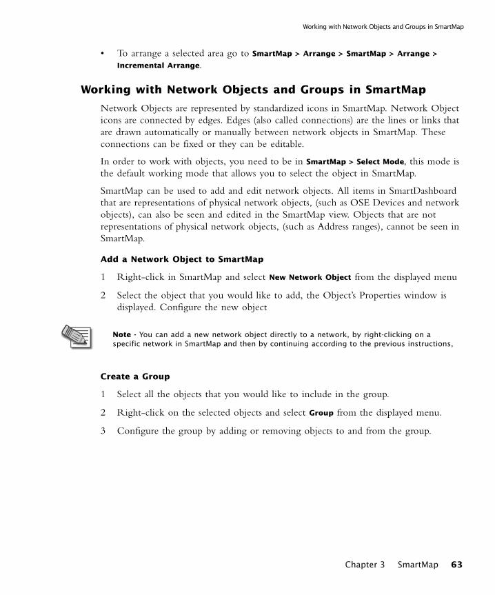
Working with Network Objects and Groups in SmartMap
• To arrange a selected area go to SmartMap > Arrange > SmartMap > Arrange >
Incremental Arrange.
Working with Network Objects and Groups in SmartMap
Network Objects are represented by standardized icons in SmartMap. Network Object icons are connected by edges. Edges (also called connections) are the lines or links that are drawn automatically or manually between network objects in SmartMap. These connections can be fixed or they can be editable.
In order to work with objects, you need to be in SmartMap > Select Mode, this mode is the default working mode that allows you to select the object in SmartMap.
SmartMap can be used to add and edit network objects. All items in SmartDashboard that are representations of physical network objects, (such as OSE Devices and network objects), can also be seen and edited in the SmartMap view. Objects that are not representations of physical network objects, (such as Address ranges), cannot be seen in SmartMap.
Add a Network Object to SmartMap
1 Right-click in SmartMap and select New Network Object from the displayed menu
2 Select the object that you would like to add, the Object’s Properties window is displayed. Configure the new object
Create a Group
1 Select all the objects that you would like to include in the group.
2 Right-click on the selected objects and select Group from the displayed menu.
3 Configure the group by adding or removing objects to and from the group.
Note - You can add a new network object directly to a network, by right-clicking on a specific network in SmartMap and then by continuing according to the previous instructions,
Chapter 3 SmartMap 63
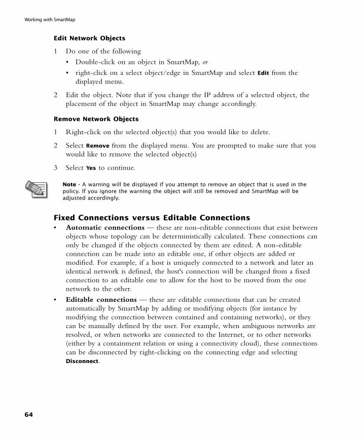
Working with SmartMap
Edit Network Objects
1 Do one of the following
• Double-click on an object in SmartMap, or
• right-click on a select object/edge in SmartMap and select Edit from the displayed menu.
2 Edit the object. Note that if you change the IP address of a selected object, the placement of the object in SmartMap may change accordingly.
Remove Network Objects
1 Right-click on the selected object(s) that you would like to delete.
2 Select Remove from the displayed menu. You are prompted to make sure that you would like to remove the selected object(s)
3 Select Yes to continue.
Fixed Connections versus Editable Connections• Automatic connections — these are non-editable connections that exist between
objects whose topology can be deterministically calculated. These connections can only be changed if the objects connected by them are edited. A non-editable connection can be made into an editable one, if other objects are added or modified. For example, if a host is uniquely connected to a network and later an identical network is defined, the host's connection will be changed from a fixed connection to an editable one to allow for the host to be moved from the one network to the other.
• Editable connections — these are editable connections that can be created automatically by SmartMap by adding or modifying objects (for instance by modifying the connection between contained and containing networks), or they can be manually defined by the user. For example, when ambiguous networks are resolved, or when networks are connected to the Internet, or to other networks (either by a containment relation or using a connectivity cloud), these connections can be disconnected by right-clicking on the connecting edge and selecting Disconnect.
Note - A warning will be displayed if you attempt to remove an object that is used in the policy. If you ignore the warning the object will still be removed and SmartMap will be adjusted accordingly.
64
Working with SmartMap Objects
Select an area in SmartMap (Select Mode)
Select an area in SmartMap by dragging the mouse over a specific area. All objects that fall within the area of the select box will be selected. Objects that are selected in Select Mode can be dragged to another area in SmartMap.
• To move to Select mode go to SmartMap > Select Mode.
Customize color and width of objects and edges
Only the width of edges can be customized.
• To change options go to SmartMap > Customization > View Options.
Setting the Layers for SmartMap
Not all object types can be viewed automatically in SmartMap. You can decide what types of layers you would like to add to your view. You can select from the basic layer which provides you all default objects, and from the OPSEC layer which adds certain OPSEC object types.
• To set layers go to SmartMap > Customization > View Options.
Customize Tooltips for Objects
Select the Information about the network object to be displayed when the cursor passes over the object in SmartMap.
• To customize tooltip information go to SmartMap > Customization > Tooltips
Information.
Customize the Display of Object Labels and IP Addresses
Select Object Label and IP Address attributes and limitations.
• To customize go to SmartMap > Customization > Object Label Options.
Working with SmartMap Objects
SmartMap maintains graphic connectivity between different parts of the network by creating and adding several new topology objects, such as:
• Internet Objects — represents the Internet.
• Connectivity Clouds — represents a private web or an Intranet.
• Implied Networks — a network that is created when a network object is created that has no viable network to which it can be connected. This network is read-only and non-editable although it can be actualized, that is made into a real network.
Chapter 3 SmartMap 65
Working with SmartMap
• Ambiguous Networks — a network that is created when a network object is created that has multiple viable networks to which it can be connected, the network object is connected to the ambiguous network and the user needs to decide to which network the network object should be connected.
• Contained Networks — A Contained network is always derived from the same or lower net mask class as the Containing network.
Add an Internet cloud
The Internet Cloud defines connectivity between the network object and a public network without supplying technical details of the path between them. Multiple Internet clouds can be added to SmartMap. These clouds are non-editable. When SmartMap performs calculations it looks for Internet clouds and uses them to identify whether interfaces are external or internal.
• To create a new cloud go to SmartMap > New Internet Cloud.
Add a Connectivity Cloud
The Connectivity Cloud defines connectivity between the network object and a private network without supplying technical details of the path between them. Multiple Connectivity clouds can be added to SmartMap. These clouds are editable.
• To add a connectivity cloud go to SmartMap > New Connectivity Cloud.
Connecting a network to Internet clouds
There is always at least one Internet cloud in SmartMap. This cloud cannot be deleted. A line is automatically drawn between an existing network and the sole Internet cloud.
Connecting a network to Connectivity clouds/an Internet cloud, where there is more than one/a Containing Network
1 Right-click on the network you would like to connect to the Connectivity cloud by holding the ctrl key down until all networks are selected.
2 Right-click the last selected network.
3 Select Connect to and select the option that you would like
Note - Topology objects, or objects created by the SmartMap view, such as clouds and implied networks, etc., cannot be defined as protected objects. They cannot be included in any group, nor can they be pasted into the SmartDashboard Rule Base.
66
Working with Folders in SmartMap
Connecting multiple networks to a Connectivity cloud
Since SmartMap connects networks according to their IP addresses hierarchy, contained networks are automatically connected to their parent network. This connection is editable and can be removed.
1 Select the networks that you would like to connect to the Connectivity cloud.
2 Select Connect Networks.
3 Specify the Connectivity cloud settings.
Viewing the Settings of an Implied network
The Implied network is named by its IP address and a superimposed “I”. It is Read Only, unless it is actualized, or made into a real network.
1 Right-click the Implied Network.
2 Select View from the displayed menu.
Actualizing an Implied network
The Implied network is Read Only, unless it is actualized, or made into a real network. This means that it is made into a functioning network with its own specification and legitimate (legal or illegal) IP address.
1 Right-click the Implied network.
2 Select Actualize from the displayed menu.
3 Configure the settings.
Removing the connection between a Containing and a Contained network
1 Right-click the edge of the contained network.
2 Select Disconnect from the displayed menu.
Working with Folders in SmartMap
Topology collapsing, often referred to as folding, facilitates the use of SmartMap by expanding or collapsing topology structures. This collapsing mechanism simplifies SmartMap, by ridding it of visual clutter, but still preserving its underlying structure. The folding mechanism allows you to collapse certain topology structure types. The folders can be created at the following points:
• On an edge that is an interface as well as all the object behind it.
• On any network which has hosts or containing networks.
Chapter 3 SmartMap 67

Working with SmartMap
• On any gateway and its locales.
• There are two special folders which can be collapsed:
• Objects To Resolve — contains network objects and unresolved hosts that are ambiguous.
• External Objects — contains hosts which have no networks to which they can be connected (because they do not fit into any network’s IP address range) as well as any standalone networks. This folder does not include Check Point installed objects.
Collapsing locales
1 Right-click the locale.
2 Select Collapse Locale from the displayed menu.
Collapsing other Topology Structures
1 Right-click on the object or edge that you would like to collapse.
2 Select Collapse Object where object is a variable depending on the object or edge that you selected.
Expanding Topology folders
1 Right-click the folder which contains the content that you would like to view.
2 Select Expand from the displayed menu.
Viewing the Content of “special” foldersExternal Objects and Unresolved Objects are two special types of folders which cannot be expanded, but whose contents can be viewed:
1 Right-click the folder whose contents you would like to view.
2 Select Show Contents from the displayed menu.
Hiding the contents of “special” folders
External Objects and Unresolved Objects are two special types of folders which cannot be expanded, but whose contents can be hidden:
1 Right-click the folder whose contents you would like to hide.
2 Select Hide Contents from the displayed menu.
Defining the contents of a “special” folder as a group
1 Right-click the folder whose member you would like to group.
68

Working with Folders in SmartMap
2 Select Define as Group from the displayed menu.
3 Configure the Group Properties window.
Renaming Topology folders
Folders are given a default name. This name can be edited.
1 Right-click the folder that you would like to rename.
2 Select Rename from the displayed menu.
3 Enter a new name for the Folder.
Adding the contents of a SmartMap folder to the Rule Base
When the contents of the folder are dragged and copied into the Rule Base you will be prompted to decide whether or not to save the members of the folder as a group, or to add the contents member by member.
1 Select the folder whose contents you would like to add to the Rule Base.
2 Press the Shift key.
3 Drag the Selected folder to the desired location in the Rule Base.
4 If the contents are added as a group, configure the Group Properties window.
Editing External Objects
External Objects are hosts which have no viable networks to which they can be connected. That is to say that their IP address is not within the range of the IP address of any currently defined network.
1 Right-click the External Objects folder.
2 Select Edit from the displayed menu.
3 Configure the Properties window of the selected external object.
Viewing Gateway ClustersThe Gateway Cluster objects are never included in the Objects to Resolve folder, even though they may be unresolved
1 Right-click the selected Gateway Cluster.
2 Select Show Members from the displayed menu.
Chapter 3 SmartMap 69
Working with SmartMap
Integrating SmartMap and the Rule Base
You can drag rules from the Rule Base and show them in SmartMap. You can enhance your understanding of the displayed rule by adding a Legend. You can paste objects and folders from SmartMap. You can show network objects selected in the Rule Base and some other locations in SmartMap.
Display a Legend for regular and/or NAT rulesThe Legend provides a key to the understanding of rules displayed in SmartMap.
• To display a legend go to SmartMap > Customization > View Options.
Adding the contents of a SmartMap folder to the Rule Base
see “Working with Folders in SmartMap” on page 67.
Pasting Network Objects in the Rule Base
Topology objects (for instance clouds, ambiguous networks, etc.) cannot be pasted into the Rule Base.
1 Right-click on a selected network object.
2 Select Copy to Rule Base from the displayed menu.
3 Right-click the column in which the selected network object should be pasted.
4 Select Paste from the displayed menu.
Viewing a Network Object selected in the Rule Base in SmartMap
1 Select the Network Object in the Rule Base that you would like to show in SmartMap.
2 Drag the network object using the left mouse button, and drop it into SmartMap.
Viewing Network Objects selected in SmartMap in the Rule Base
1 Select the Network Object in SmartMap that you would like to show in the Rule Base.
2 Drag the network object using the left mouse button and the shift and alt buttons of the keyboard, and drop it into SmartMap.
70
Integrating SmartMap and the Rule Base
Showing a rule in SmartMap
A rule that you select to show in SmartMap can be shown in a magnified view or according to the current zoom level.
1 Select a rule in the Rule Base that you would like to display in SmartMap from the rule number.
2 Select Show and a view option from the displayed menu.
Display the Rule Color Legend
Rules appear as combinations of highlighted colors and arrows on SmartMap. For instance, colors are designated to represent the Source, Destination and Install On columns of SmartDashboard. These colors can be viewed in the Rule Color Legend window, which is displayed when a rule is shown.
Drag a rule into SmartMap and the Rule Color Legend is automatically displayed.
Understanding the Rule Color Legend
Rules appear as combinations of highlighted colors and arrows on SmartMap. The colors assigned to the arrows represents the action being performed. The arrow also indicates the direction of the rule; from whence the rule came (source), and to where it is going (destination).
• Red—Drop, Reject
• Green—Accept
• Blue—User Auth, Client Auth, Session Auth
• Purple—Encrypt, Client Encrypt
Rules that require special attention
When rules are shown in SmartMap, the “Any” value is represented by the icon at the base or the head of the arrow, to indicate that the Source or Destination, respectively, is Any.
The rules mentioned below are mapped and displayed in a specific manner:
• Where the Source is Any, the rule is mapped from the Install On to the Destination.
• Where the Destination is Any, the rule is mapped out from the Source to the Install On.
Note - Only Security Policy rules, can be shown in SmartMap View.
Chapter 3 SmartMap 71
Working with SmartMap
• Where both Source and Destination are Any, only the paths between the Install Ons are shown
Troubleshooting SmartMap
SmartMap can be used as a troubleshooting tool, mostly for topology calculations and certain connectivity issues such as duplicated networks and unresolved object interfaces.
For what objects are topology calculations made?
Topology information specifies data about the objects interfaces and the IP addresses behind the interfaces
• Gateways which are VPN-1 Pro installed with two or more interfaces
• OSE Devices
Calculating topology information
You can calculate topology for objects selected in the following places:
• SmartMap
• Objects Tree
• Objects List
The Legend in the Topology Calculation Results window explains how you are meant to read the Interfaces topology list.
• Red— the results of the calculation are different from the currently defined topology information. This information needs to be approved. Click Approve to display and contrast the current topology information with the resulting topology information. click Approve all to automatically approve all calculations without comparing and contrasting results.
• Blue— the calculation has been automatically approved.
• Regular— no change has been made to the topology information.
to calculate topology for a selected object
1 Right-click the selected object.
2 Select Calculate Topology from the displayed menu
3 The Topology Calculation Results window displays the topology information after a calculation has been made for the selected object
What is SmartMap Helper
SmartMap Helper teaches you how to solve tasks relating to connectivity such as:
72
Troubleshooting SmartMap
• Duplicated networks
• Unresolved object interfaces
The Helper is a learning tool. Once you understand how to solve these connectivity tasks, you can solve them directly in SmartMap View, and not via the Helper.
Troubleshooting duplicated networks
Duplicated networks occur if there is more than one network with an identical net mask and IP address.
To solve duplicated networks you can modify the shared IP address so that they are all unique. Alternately you can delete the duplicated network.
Troubleshooting unresolved object interfaces
When there is more than one viable network to which a network object can be connected, the network object is temporarily connected to an Ambiguous network until such time that it can be properly resolved. See Ambiguous Networks in “Working with SmartMap Objects” on page 65
What objects can be defined as protected objects?
Any object which does not lead to the Internet can be defined as a protected object. This includes:
• Gateway Clusters
• Gateways which are VPN-1 Pro installed with two or more interfaces
• OSE Devices
• Embedded Devices
Defining Protected Objects as Groups
Any object which does not lead to the Internet can be defined as a protected object.
1 Right-click the selected object(s).
2 Select Define Protected Objects as Group from the displayed menu.
3 Configure the Group Properties window.
Note - Some network systems may require duplicated networks. Consider the needs of your system before modifying duplicated networks.
Chapter 3 SmartMap 73
Working with SmartMap
Working with SmartMap Output
Once you have set up your deployment there are several operations that can be performed. Make sure that you save and/or install your policy in order to ensure that all the changes made in SmartMap are applied. SmartMap is always displayed in the layout and with the last coordinates that it had when it was last saved. Once SmartMap is saved you can print SmartMap or even export it to another format for ease of use.
Print SmartMap
Set the attributes by which SmartMap will be printed. This includes how the output is to be scaled, the size of the margins and finally information to be included (such as page numbers, borders, crop marks, or even a customized caption).
Export SmartMap (as an image file)
Configure the attributes for images that are exported to an image file. Including the type and size of the image. Specify the treatment of folders in the exported image. Specify general information, including name, label, the date of export as well as a logical prefix that can be referred to and understood. This is especially important when saving multiple image files. Finally specify, the location to which the image file will be saved and whether you want to open or to print the image files once they have been exported.
Export SmartMap (to Microsoft Visio)
In this window you can configure the settings for SmartMap exported to Microsoft Visio. Specify object data that you would like to include. This includes general information about the object such as name, IP address and net mask. Specify the treatment of folders and icons during the export operation. You can preserve the Check Point icons and colors or you can choose to use icons from the Microsoft Visio stencil. Finally, decide which general information should be included on the output for instance, the date, a label and the location to which the exported SmartMap will be saved.
74
CHAPTER 4
The Internal Certificate Authority (ICA) and the ICA Management Tool
In This Chapter
The Need for the ICAThe security needs of the customer are always foremost in Check Point software. Strong authentication is required and this authentication must comply with international security standards in order to ensure the secure connections of:
• Secure Internal Communication (SIC) – the feature which ensures strong authentication between internal Check Point entities
• VPN – for both gateways and users
The Need for the ICA page 75
The ICA Solution page 76
ICA Configuration page 85
75
The ICA Solution
The ICA Solution
In This Section
Introduction to the ICA
The ICA is a Certificate Authority which is an integral part of the Check Point product suite. It is fully compliant with X.509 standards for both certificates and CRLs. See the relevant X.509 and PKI documentation, as well as RFC 2459 standards for more information. You can read more about Check Point and PKI in the VPN book.
The ICA is located on the SmartCenter server. It is created during the installation process, when VPN-1 Pro is configured.
The ICA issues certificates for:
• SIC – certificates are issued for the SmartCenter server, its modules, OPSEC modules, and product administrators in order to enable secure communication for all Check Point-related operations (such as policy installation on modules, logging, SmartConsole-SmartCenter server connectivity, etc.)
• VPN certificates for gateways – to enable efficient and seamless strong authentication in VPN tunnel creation
• Users – to enable strong authentication between remote access users and gateways, as well as other features, such as clientless VPN
The ICA issues Certificate Revocation Lists (CRLs) in order to publish a list of certificates that have been revoked. This revocation may be due to a number of factors: key compromise, certificate loss, etc. The CRLs are published on an HTTP server running on the SmartCenter Server, and can be retrieved by any Check Point module for certificate validation.
Introduction to the ICA page 76
ICA Clients page 77
Certificate Longevity and Statuses page 77
SIC Certificate Management page 79
Gateway VPN Certificate Management page 79
User Certificate Management page 80
CRL Management page 81
ICA Advanced Options page 82
The ICA Management Tool page 82
76
ICA Clients
ICA Clients
ICA operations are performed using the following clients:
• Check Point configuration tool, or cpconfig on the Command Line. Using this tool, the ICA is created and a SIC certificate is issued for the SmartCenter server. For more information, see “Securing Channels of Communication Between Internal Components (SIC)” on page 31.
• SmartDashboard. This SmartConsole is used to manage:
• SIC certificates for the various modules, as well as for administrators. For more information see “Securing Channels of Communication Between Internal Components (SIC)” on page 31.
• VPN certificates
• user certificates managed in the internal database, for more information see Introduction to Remote Access VPN in VPN Guide.
• ICA Management tool. This tool is used to manage VPN certificates for users which are either managed on the internal database or on a LDAP server. Additionally it is used to perform ICA management operations.
The ICA generates audit logs when ICA operations are performed. These logs can be viewed in the SmartView Tracker.
Certificate Longevity and Statuses
Each certificate issued by the ICA has a defined validity period. When this validity period is over, the certificate becomes expired.
An administrator can revoke a certificate. This may be done for a number of reasons, for instance, when a user leaves the organization. If a certificate is revoked, the serial number of the certificate is published on the CRL indicating that the certificate has been officially revoked, and cannot be used or recognized by any entity in the system.
Certificates are created in different stages. SIC certificates, VPN certificates for modules and User certificates are created in one step via SmartDashboard, although the latter can also be created in two step process using either SmartDashboard or the ICA Management Tool. If the User certificate is created in two steps, these steps include:
• Initialization – during this stage a registration code is created for the user. When this is done, the certificate state is pending
• Registration – when the user completes the registration process in the remote client (SecuRemote/SecureClient) using the registration code the certificate becomes valid
The advantages of the two-step process are as follows:
Chapter 4 The Internal Certificate Authority (ICA) and the ICA Management Tool 77
The ICA Solution
enhanced security
• the private key is created and stored on the user’s machine
• the certificate issued by the ICA is downloaded securely to the client machine (and not handed to the user by the administrator)
pre-issuance automatic and administrator-initiated certificate removal
if a user does not complete the registration process within a given period of time (which is by default two weeks), the registration code is automatically removed. An administrator can remove the registration key before the user completes the registration process. After that, the administrator can revoke the user certificate.
Explicit or Automatic Renewal of User certificates ensuring continuous User connectivity
A user certificate of type PKCS12, can be renewed explicitly by the user or it can be set to be renewed automatically when it is about to expire. This renewal operation ensures that the user can continuously connect to the organization’s network. The administrator can choose when to set the automatic revocation of the old user certificate.
Another added advantage is:
Automatic renewal of SIC certificates ensuring continuous SIC connectivity
SIC certificates are renewed automatically after 75% of the validity time of the certificate has passed. If, for example, the SIC certificate is valid for five years, 3.75 years after it was issued, a new certificate is created and downloaded automatically to the SIC entity. This automatic renewal ensures that the SIC connectivity of the module is continuous. The administrator can decide to revoke the old certificate automatically or after a set period of time. By default, the old certificate is revoked one week after the certificate renewal has taken place.
78
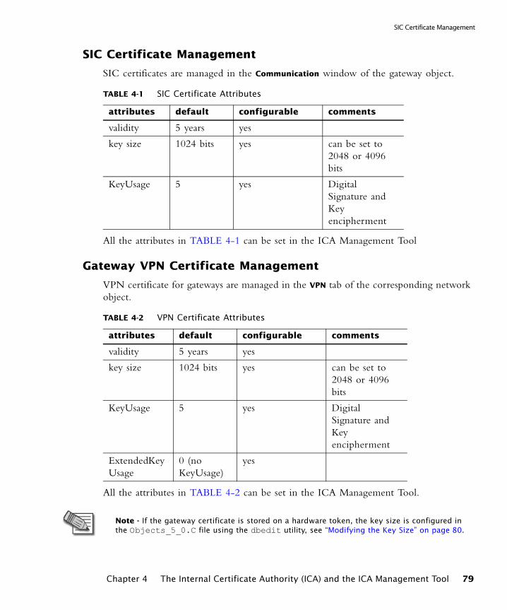
SIC Certificate Management
SIC Certificate Management
SIC certificates are managed in the Communication window of the gateway object.
All the attributes in TABLE 4-1 can be set in the ICA Management Tool
Gateway VPN Certificate Management
VPN certificate for gateways are managed in the VPN tab of the corresponding network object.
All the attributes in TABLE 4-2 can be set in the ICA Management Tool.
TABLE 4-1 SIC Certificate Attributes
attributes default configurable comments
validity 5 years yes
key size 1024 bits yes can be set to 2048 or 4096 bits
KeyUsage 5 yes Digital Signature and Key encipherment
TABLE 4-2 VPN Certificate Attributes
attributes default configurable comments
validity 5 years yes
key size 1024 bits yes can be set to 2048 or 4096 bits
KeyUsage 5 yes Digital Signature and Key encipherment
ExtendedKeyUsage
0 (no KeyUsage)
yes
Note - If the gateway certificate is stored on a hardware token, the key size is configured in the Objects_5_0.C file using the dbedit utility, see “Modifying the Key Size” on page 80.
Chapter 4 The Internal Certificate Authority (ICA) and the ICA Management Tool 79
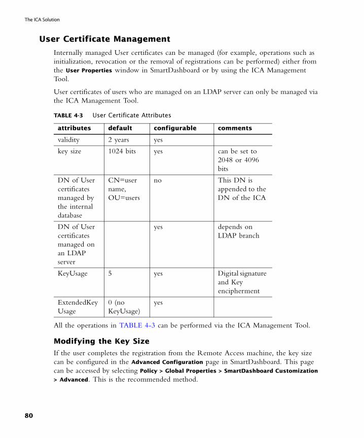
The ICA Solution
User Certificate Management
Internally managed User certificates can be managed (for example, operations such as initialization, revocation or the removal of registrations can be performed) either from the User Properties window in SmartDashboard or by using the ICA Management Tool.
User certificates of users who are managed on an LDAP server can only be managed via the ICA Management Tool.
All the operations in TABLE 4-3 can be performed via the ICA Management Tool.
Modifying the Key Size
If the user completes the registration from the Remote Access machine, the key size can be configured in the Advanced Configuration page in SmartDashboard. This page can be accessed by selecting Policy > Global Properties > SmartDashboard Customization
> Advanced. This is the recommended method.
TABLE 4-3 User Certificate Attributes
attributes default configurable comments
validity 2 years yes
key size 1024 bits yes can be set to 2048 or 4096 bits
DN of User certificates managed by the internal database
CN=user name, OU=users
no This DN is appended to the DN of the ICA
DN of User certificates managed on an LDAP server
yes depends on LDAP branch
KeyUsage 5 yes Digital signature and Key encipherment
ExtendedKeyUsage
0 (no KeyUsage)
yes
80

CRL Management
Alternately you can edit the key size using the dbedit utility of the Objects_5_0.C by modifying the size of the key as it is listed in users_certs_key_size Global Property. The new value is downloaded when the user updates his site.
How is it done?
In SmartDashboard or in the dbedit utility:
1 Change the attribute ica_key_size to one of the following values: 1024, 2048 or 4096.
2 Run fwm sic_reset.
3 Run cpconfig and define the CA name in the Certificate Authority tab.
4 When you are done, click OK.
5 Run cpstart.
CRL Management
By default, the CRL is valid for one week. This value can be configured. Fresh CRLs are issued:
• when approximately 60% of the CRL validity period has passed
• immediately following the revocation of a certificate
It is possible to recreate a specified CRL via the ICA Management Tool. This acts as a recovery mechanism in the event that the CRL is deleted or corrupted. Moreover, an administrator can download a DER encoded version of the CRL using the ICA Management Tool.
CRL Modes
Until NG FP1, all revoked certificates appeared in the same CRL (this is referred to as “CRL old mode”).
From NG FP2, the ICA is able to issue multiple CRLs (this is referred to as “CRL new mode”). The purpose of multiple CRLs is to eliminate any CRL from becoming larger than 10K. If the CRL exceeds 10K, IKE negotiations may fail when trying to establish VPN tunnels.
Multiple CRLs are achieved by attributing every certificate which is issued to a specific CRL. If revoked, the serial number of the certificate appears in this specific CRL.
The CRL Distribution Point (CRLDP) extension of the certificate contains the URL of the specific CRL, this ensures that the correct CRL is retrieved when the certificate is validated.
Chapter 4 The Internal Certificate Authority (ICA) and the ICA Management Tool 81

The ICA Solution
It is possible to upgrade the pre NG FP2 ICA to work in the CRL new mode. This can be done using the ICA Management Tool provided there are no valid certificates with an empty CRLDP extension. Once a pre NG FP2 ICA has been upgraded, it is possible to revert to CRL old mode using the ICA Management Tool.
ICA Advanced Options
Modifying the ICA Key
The ICA is created with a key of size 2048 bits. There are certain cases in which a key of a different size is required (of either 1024 or 4096 bits). In such a case, the ICA must be re-created. This can be done using the command lines and the ICA Configuration file.
The ICA Management Tool
The ICA Management Tool is a user-friendly tool that allows an administrator to perform multiple operations on and for the ICA, such as:
• Certificates management and searches
• CRL recreation and download
• ICA configuration
• ICA cleanup resulting in the removal of expired certificates
Note - The ICA Management Tool is supported by SSL version 3 and TLS.
82

The ICA Management Tool
The ICA Management Tool GUIFIGURE 4-1 Manage Certificates - Operations Pane
The Interface is divided into three panes:
• The Menu pane - select the operation to be performed from the menu pane.
• The Operations pane - the operation is configured and applied in this pane. From this window you can
• Manage Certificates - this window (FIGURE 4-1) is divided into search attributes configuration and bulk operation configuration
• Create Certificates - from this window you can create certificates.
• Configure the CA - this window contains the configuration parameters and enables the administrator to configure them. You can also view the CA’s time, name, and the version and build number of the SmartCenter server.
• Manage CRLs - from this window you can download, publish, or recreate CRLs
• The Search Results pane - the results of the applied operation are displayed in this pane. This window consists of a table with a list of searched certificates attributes.
Chapter 4 The Internal Certificate Authority (ICA) and the ICA Management Tool 83
The ICA Solution
The ICA Management Tool is operational from any browser on any platform. Using HTTPS it is possible to connect securely from the ICA Management Tool to the ICA provided that an administrator certificate is added to the browser.
Notifying Users about Certificate Initialization
The ICA Management Tool can be used to send mail to users to notify them about certificate initialization. In order to send mail notifications, the administrator must configure:
1 the mail server
2 the mail “From” address
3 an optional ‘To’ address, which can be used if the users’ address is not known. In this case, when the certificates are issued, the administrator can get the mails and forward them to the corresponding address.
Performing Multiple Simultaneous Operations
In order to ease the management of user certificates the ICA Management Tool can perform multiple simultaneous operations. For example, it is possible to:
1 make a single LDAP query for getting the details of all the organization employees,
2 create a file out of this data, and then using this file to
• initiate the creation of certificates for all employees,
• notify all employees of these new certificates
The following are the types of operations that can be performed simultaneously:
• initiate user certificates
• revoke users’ certificates
• send mail to users
• remove expired certificates
• remove certificates for which the registration process was not completed
Note - The ICA Management Tool can connect to the ICA in clear, however for the sake of security it is recommended to work encrypted in HTTPS.
84
Retrieving the ICA Certificate
ICA Administrators with Reduced Privileges
The ICA Management Tool supports administrators with reduced privileges. These administrators can make basic searches and initialize certificates for new users. Multiple concurrent operations cannot be executed by these administrators. These administrators may typically be help desk operators who are charged with the handling of new employees.
ICA Configuration
In This Section
Retrieving the ICA Certificate
In certain scenarios it is required to obtain the ICA certificate. Peer gateways that are not managed by the SmartCenter server need to use it for Trust purposes. Also, clients using Clientless VPN, as well as, the machine on which the ICA Management Tool is run, require this certificate. In this case, these peers are requested to proceed as follows:
1 Open a browser and enter the appropriate URL (in the format http://<smart_dns_name>:18264)
The Certificate Services window is displayed.
Retrieving the ICA Certificate page 85
Management of SIC Certificates page 86
Management of Gateway VPN Certificates page 86
Management of User Certificates via SmartDashboard page 87
Invoking the ICA Management Tool page 88
Search for a Certificate page 89
Certificate Operations Using the ICA Management Tool page 90
Initializing Multiple Certificates Simultaneously page 93
CRL Operations page 94
CA Cleanup page 94
Configuring the CA page 94
Chapter 4 The Internal Certificate Authority (ICA) and the ICA Management Tool 85
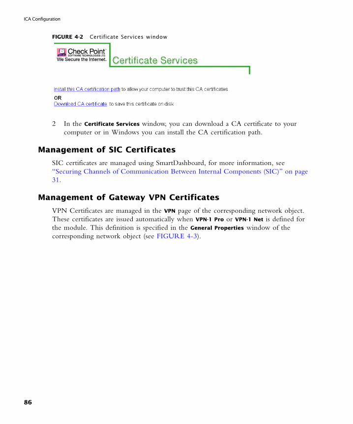
ICA Configuration
FIGURE 4-2 Certificate Services window
2 In the Certificate Services window, you can download a CA certificate to your computer or in Windows you can install the CA certification path.
Management of SIC Certificates
SIC certificates are managed using SmartDashboard, for more information, see “Securing Channels of Communication Between Internal Components (SIC)” on page 31.
Management of Gateway VPN Certificates
VPN Certificates are managed in the VPN page of the corresponding network object. These certificates are issued automatically when VPN-1 Pro or VPN-1 Net is defined for the module. This definition is specified in the General Properties window of the corresponding network object (see FIGURE 4-3).
86
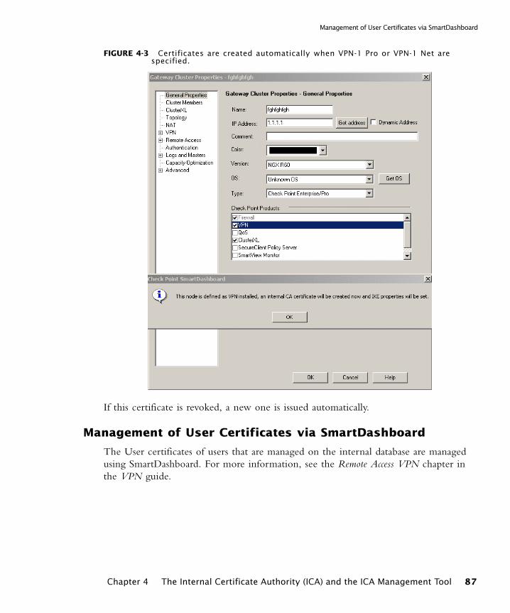
Management of User Certificates via SmartDashboard
FIGURE 4-3 Certificates are created automatically when VPN-1 Pro or VPN-1 Net are specified.
If this certificate is revoked, a new one is issued automatically.
Management of User Certificates via SmartDashboard
The User certificates of users that are managed on the internal database are managed using SmartDashboard. For more information, see the Remote Access VPN chapter in the VPN guide.
Chapter 4 The Internal Certificate Authority (ICA) and the ICA Management Tool 87
ICA Configuration
Invoking the ICA Management Tool
The ICA Management Tool is disabled by default, and can be enabled via the command line.
1 Enable or disable the ICA Management tool using the command line on the SmartCenter server.Usage
cpca_client [-d] set_mgmt_tool on|off [-p <ca_port>] [-no_ssl] [-a|-u "administrator|user DN" ... ]
where:
• on means to start the ICA Management Tool (by opening port 18265)
• off means to stop the ICA Management Tool (by closing port 18265)
• -p changes the port used to connect to the CA (if the default port is not being used)
• -no_ssl configures the server to use clear HTTP rather than HTTPS.
• -a "administrator DN" ... - sets the DNs of the administrators that will be allowed to use the ICA Management Tool
• -u "user DN" ... - sets the DNs of the users that will be allowed to use the ICA Management Tool. This option is intended for administrators with limited privileges.
2 In order to connect to the ICA, add the administrators certificate to the browser’s certificate repository.
3 Open the ICA Management tool from the browser.
Open the browser and type the location: https://<Management_Host_Name>:18265
You will be requested to authenticate.
Note - If cpca_client is run without -a or -u, the list of the allowed users and administrators will not be changed and the server will be started/stopped with the previously allowed users/administrators.
Note - The ICA Management Tool should not be on the same subnet as the SmartCenter server.
88
Search for a Certificate
Search for a Certificate
In This Section
Initiating a Search
This is performed in the Create Certificates - Operations Pane.
There are two search options, a basic search that includes only the user name, type, status and serial number fields, as well as an advanced search that includes all the search fields. The second option can only be performed by administrators with unlimited privileges.
Search Attributes
Basic Search Attributes
• User name - the exact string which is user name. By default this field is empty.
• Type - a drop-down list with the following options: Any, SIC, Gateway, Internal User or LDAP user, where the default is Any.
• Status - a drop-down list with the following options: Any, Pending, Valid, Revoked, Expired or Renewed (superseded), where the default is Any.
• Serial Number - the serial number of the requested certificate. By default this field is empty.
Advanced Search Attributes
This search includes all of the attributes described for the Basic Search, as well as, the following:
• Sub DN - the string that represents the DN substring. By default this field is empty.
• Valid From - a text box with an option to open a calendar and select a date with the format dd-mmm-yyyy [hh:mm:ss] (for example 15-Jan-2003). By default this field is empty.
• Valid To - a text box with an option to open a calendar and select a date with the format dd-mmm-yyyy [hh:mm:ss] (for example 14-Jan-2003 15:39:26). By default this field is empty.
Initiating a Search page 89
Viewing and Saving Certificate Details page 90
The Search Results page 90
Search Attributes page 89
Chapter 4 The Internal Certificate Authority (ICA) and the ICA Management Tool 89

ICA Configuration
• CRL Distribution Point - a drop-down list with the following options: Any, No CRLDP (for certificates issued before the management upgrade - old CRL mode certificates) or any CRL number available, where the default is Any.
The Search Results
The results of the search are displayed in the Search Results pane. This pane consists of a table with a list of searched certificate attributes such as:
• (SN) Serial Number - the SN of the certificate
• User Name (CN), a user name is considered a string that appears after the first “=” until the next comma “,”.
• DN
• Status (where the statuses may be any of the following: Pending, Valid, Revoked, Expired, Renewed (superseded))
• The date from which the certificates are valid until the date that they are due to expire.
Search statistics will be displayed in the status bar after every search is performed.
Viewing and Saving Certificate Details
Click on the DN link in the Search Results pane in order to display certificate details.
• If the status is pending a window will be displayed which displays certificate information, including its registration key. In this case a log will be created and displayed in the SmartView Tracker.
• If the certificate was already created, a new window is displayed in which the certificate can be saved on a disk or opened directly, (assuming that this file extension is known to the operating system).
Certificate Operations Using the ICA Management Tool
Certificate operations (such as certificate creation) when done via the ICA Management Tool can only be used for user certificates.
Check the certificates on which you would like to perform the operations.
Warning - SIC certificates and VPN certificates should not be modified using the ICA Management Tool, but via SmartDashboard.
90

Certificate Operations Using the ICA Management Tool
Removing & Revoking Certificates and Sending Email Notifications
1 Select Manage Certificates in the Menu pane. In the Manage Certificates - Operations
pane:
2 Configure a search according to the required attributes, and click Search (see FIGURE 4-1) The results are shown in the Search Results pane.
3 Select the requested certificates from the search results and click on one of the following three options:
• Revoke Selected - this operation revokes the selected certificates. If a certificate is pending than this operation will remove it from the CA’s database.
• Remove Selected - this operation removes the selected certificates from the Database of the CA and from the CRL if it was found there. You can only remove expired or pending certificates.
• Mail to Selected - this operation sends mail for all selected pending certificates that include the authorization codes to the selected users. Messages to users that do not have an email defined will be sent to a default address that can be defined in the CA Configuration window (select Menu pane > Configure the CA). For more information, see “Notifying Users about Certificate Initialization” on page 84.
Submitting a Certificate Request to the CA Using the ICA Management Tool
There are three methods of submitting certificates:
• Initiate - a registration key is created on the CA and used once by a user to create a certificate.
• Generate - a certificate file is created and associated with a password which must be entered whenever the certificate is accessed.
• PKCS#10 - when a PKCS#10 request for a certificate has been received, a certificate is created and delivered to the requestor.
Initiating a Certificate
To initiate a certificate, proceed as follows:
1 In the Menu pane, select Create Certificates.
2 Select Initiate.
3 Enter a User Name or Full DN, or fill in the Form.
4 If you would like to enter expiration details for certificates or registration keys, click Advanced.
Chapter 4 The Internal Certificate Authority (ICA) and the ICA Management Tool 91

ICA Configuration
• Certificate Expiration Date: open the calendar to select a date or enter the date in the format dd-mmm-yyyy [hh:mm:ss]. The default is two years from now.
• Registration Key Expiration Date: open the calendar to select a date or enter the date in the format dd-mmm-yyyy [hh:mm:ss]. The default is two weeks from now.
5 Click Go. A registration key is created and displayed in the Results pane.
6 If desired, you can click Send mail to user to email the registration key. Note that the number of characters in the email is limited to 1900.
7 The certificate becomes usable upon supplying the proper registration key.
Generating a Certificate
To generate a certificate, proceed as follows:
1 In the Menu pane, select Create Certificates.
2 Select Generate.
3 Enter a User Name or Full DN, or fill in the Form.
4 If you would like to enter expiration details for certificates or registration keys, click Advanced.
• Certificate Expiration Date: open the calendar to select a date or enter the date in the format dd-mmm-yyyy [hh:mm:ss]. The default is two years from now.
• Registration Key Expiration Date: open the calendar to select a date or enter the date in the format dd-mmm-yyyy [hh:mm:ss]. The default is two weeks from now.
5 Enter a password.
6 Click Go.
7 Save the P12 file, and deliver it to the user.
Creating a PKCS#10 Certificate
To create a PKCS#10 certificate, proceed as follows:
1 In the Menu pane, select Create Certificates.
2 Select PKCS#10.
3 Either paste into the space the encrypted base-64 buffer text provided or click on Browse for a file to insert (IE only) to import the request file.
4 Click Create and save the resulting certificate.
92
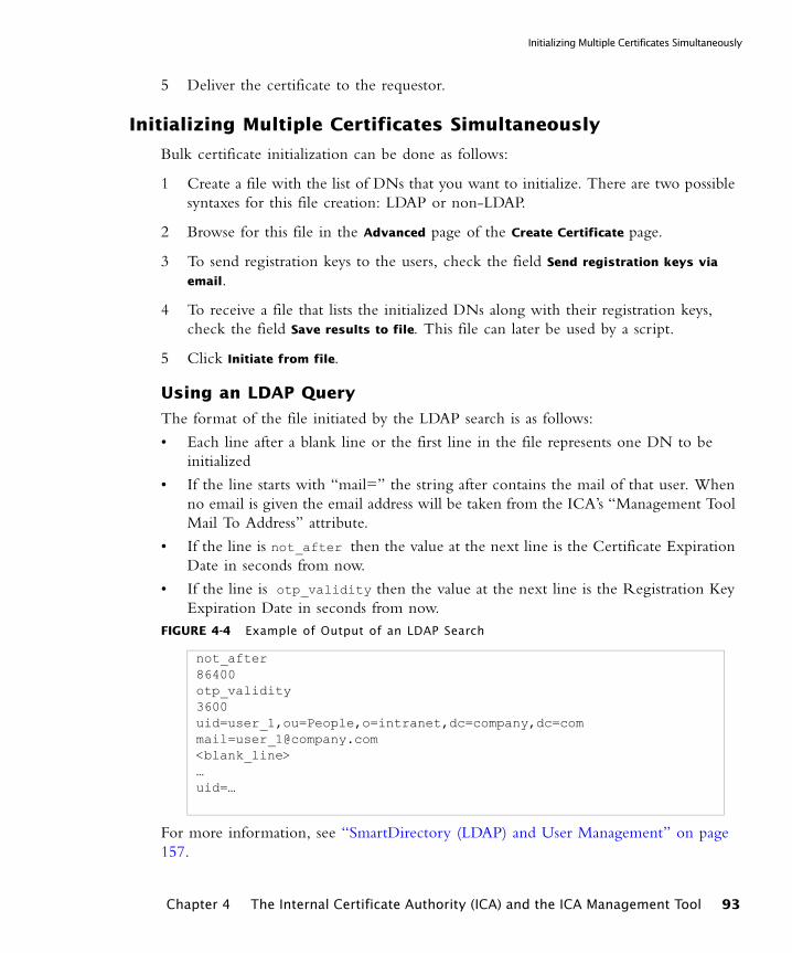
Initializing Multiple Certificates Simultaneously
5 Deliver the certificate to the requestor.
Initializing Multiple Certificates Simultaneously
Bulk certificate initialization can be done as follows:
1 Create a file with the list of DNs that you want to initialize. There are two possible syntaxes for this file creation: LDAP or non-LDAP.
2 Browse for this file in the Advanced page of the Create Certificate page.
3 To send registration keys to the users, check the field Send registration keys via
email.
4 To receive a file that lists the initialized DNs along with their registration keys, check the field Save results to file. This file can later be used by a script.
5 Click Initiate from file.
Using an LDAP Query
The format of the file initiated by the LDAP search is as follows:
• Each line after a blank line or the first line in the file represents one DN to be initialized
• If the line starts with “mail=” the string after contains the mail of that user. When no email is given the email address will be taken from the ICA’s “Management Tool Mail To Address” attribute.
• If the line is not_after then the value at the next line is the Certificate Expiration Date in seconds from now.
• If the line is otp_validity then the value at the next line is the Registration Key Expiration Date in seconds from now.
FIGURE 4-4 Example of Output of an LDAP Search
For more information, see “SmartDirectory (LDAP) and User Management” on page 157.
not_after86400otp_validity3600uid=user_1,ou=People,o=intranet,dc=company,[email protected]<blank_line>…uid=…
Chapter 4 The Internal Certificate Authority (ICA) and the ICA Management Tool 93
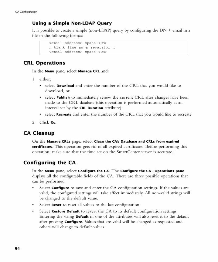
ICA Configuration
Using a Simple Non-LDAP Query
It is possible to create a simple (non-LDAP) query by configuring the DN + email in a file in the following format:
CRL Operations
In the Menu pane, select Manage CRL and:
1 either:
• select Download and enter the number of the CRL that you would like to download, or
• select Publish to immediately renew the current CRL after changes have been made to the CRL database (this operation is performed automatically at an interval set by the CRL Duration attribute).
• select Recreate and enter the number of the CRL that you would like to recreate
2 Click Go.
CA Cleanup
On the Manage CRLs page, select Clean the CA’s Database and CRLs from expired
certificates. This operation gets rid of all expired certificates. Before performing this operation, make sure that the time set on the SmartCenter server is accurate.
Configuring the CA
In the Menu pane, select Configure the CA. The Configure the CA - Operations pane displays all the configurable fields of the CA. There are three possible operations that can be performed:
• Select Configure to save and enter the CA configuration settings. If the values are valid, the configured settings will take affect immediately. All non-valid strings will be changed to the default value.
• Select Reset to reset all values to the last configuration.
• Select Restore Default to revert the CA to its default configuration settings.Entering the string Default in one of the attributes will also reset it to the default after pressing Configure. Values that are valid will be changed as requested and others will change to default values.
<email address> space <DN>… blank line as a separator …<email address> space <DN>
94
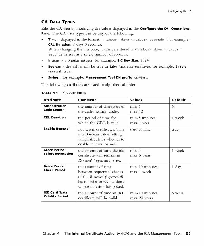
Configuring the CA
CA Data Types
Edit the CA data by modifying the values displayed in the Configure the CA - Operations
Pane. The CA data types can be any of the following:
• Time - displayed in the format: <number> days <number> seconds. For example: CRL Duration: 7 days 0 seconds.When changing the attribute, it can be entered as <number> days <number> seconds or just as a single number of seconds.
• Integer - a regular integer, for example: SIC Key Size: 1024
• Boolean - the values can be true or false (not case sensitive). for example: Enable
renewal: true.
• String - for example: Management Tool DN prefix: cn=tests
The following attributes are listed in alphabetical order:
TABLE 4-4 CA Attributes
Attribute Comment Values Default
Authorization Code Length
the number of characters of the authorization codes.
min-6max-12
6
CRL Duration the period of time for which the CRL is valid.
min-5 minutesmax-1 year
1 week
Enable Renewal For Users certificates. This is a Boolean value setting which stipulates whether to enable renewal or not.
true or false true
Grace Period Before Revocation
the amount of time the old certificate will remain in Renewed (superseded) state.
min-0max-5 years
1 week
Grace Period Check Period
the amount of time between sequential checks of the Renewed (superseded) list in order to revoke those whose duration has passed.
min-10 minutesmax-1 week
1 day
IKE Certificate Validity Period
the amount of time an IKE certificate will be valid.
min-10 minutesmax-20 years
5 years
Chapter 4 The Internal Certificate Authority (ICA) and the ICA Management Tool 95
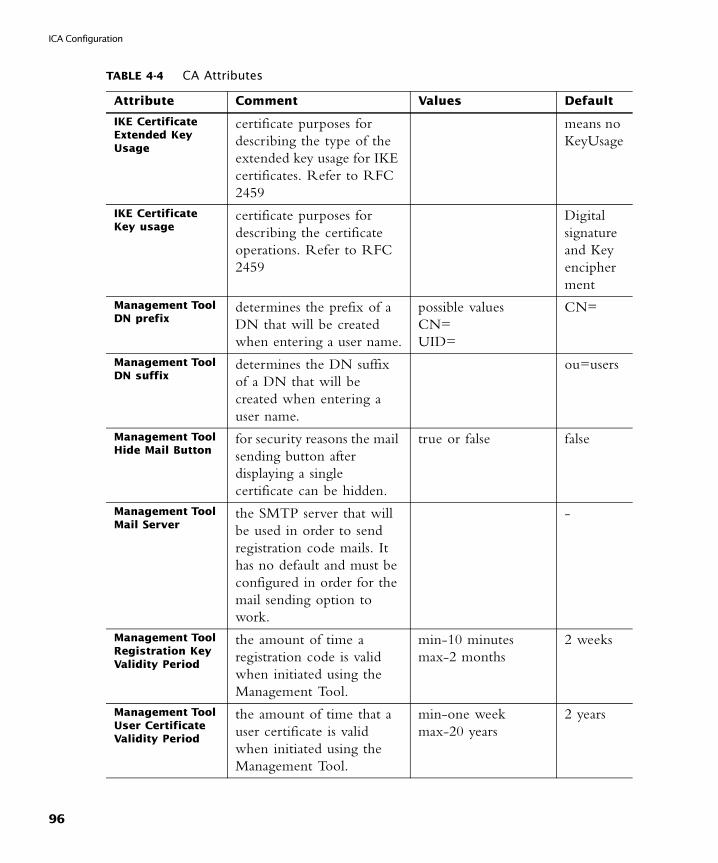
ICA Configuration
IKE Certificate Extended Key Usage
certificate purposes for describing the type of the extended key usage for IKE certificates. Refer to RFC 2459
means no KeyUsage
IKE Certificate Key usage
certificate purposes for describing the certificate operations. Refer to RFC 2459
Digital signature and Key encipherment
Management Tool DN prefix
determines the prefix of a DN that will be created when entering a user name.
possible valuesCN=UID=
CN=
Management Tool DN suffix
determines the DN suffix of a DN that will be created when entering a user name.
ou=users
Management Tool Hide Mail Button
for security reasons the mail sending button after displaying a single certificate can be hidden.
true or false false
Management Tool Mail Server
the SMTP server that will be used in order to send registration code mails. It has no default and must be configured in order for the mail sending option to work.
-
Management Tool Registration Key Validity Period
the amount of time a registration code is valid when initiated using the Management Tool.
min-10 minutesmax-2 months
2 weeks
Management Tool User Certificate Validity Period
the amount of time that a user certificate is valid when initiated using the Management Tool.
min-one weekmax-20 years
2 years
TABLE 4-4 CA Attributes
Attribute Comment Values Default
96
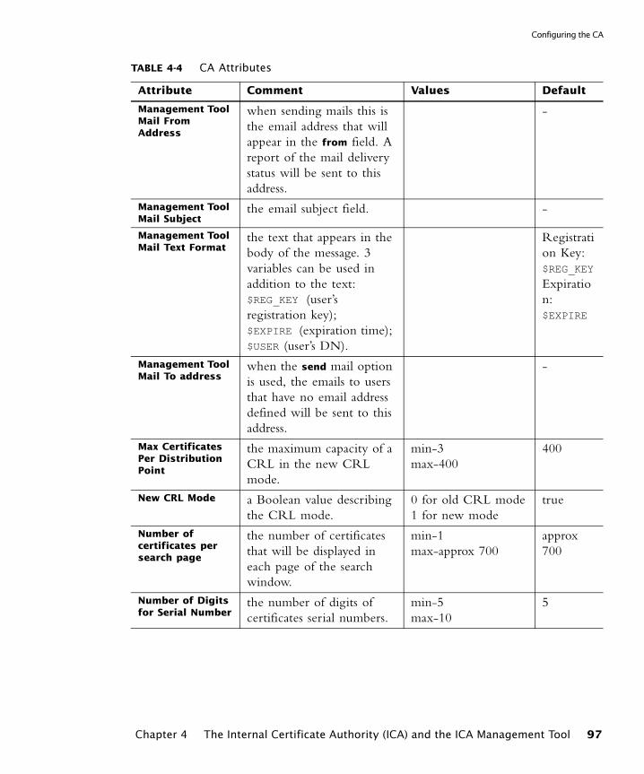
Configuring the CA
Management Tool Mail From Address
when sending mails this is the email address that will appear in the from field. A report of the mail delivery status will be sent to this address.
-
Management Tool Mail Subject
the email subject field. -
Management Tool Mail Text Format
the text that appears in the body of the message. 3 variables can be used in addition to the text: $REG_KEY (user’s registration key); $EXPIRE (expiration time); $USER (user’s DN).
Registration Key: $REG_KEY
Expiration: $EXPIRE
Management Tool Mail To address
when the send mail option is used, the emails to users that have no email address defined will be sent to this address.
-
Max Certificates Per Distribution Point
the maximum capacity of a CRL in the new CRL mode.
min-3max-400
400
New CRL Mode a Boolean value describing the CRL mode.
0 for old CRL mode1 for new mode
true
Number of certificates per search page
the number of certificates that will be displayed in each page of the search window.
min-1max-approx 700
approx 700
Number of Digits for Serial Number
the number of digits of certificates serial numbers.
min-5max-10
5
TABLE 4-4 CA Attributes
Attribute Comment Values Default
Chapter 4 The Internal Certificate Authority (ICA) and the ICA Management Tool 97
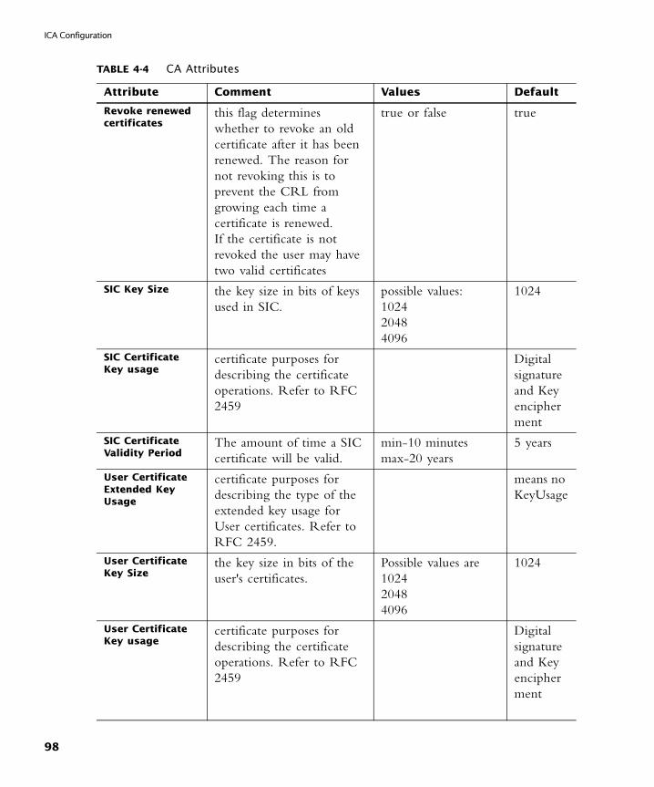
ICA Configuration
Revoke renewed certificates
this flag determines whether to revoke an old certificate after it has been renewed. The reason for not revoking this is to prevent the CRL from growing each time a certificate is renewed. If the certificate is not revoked the user may have two valid certificates
true or false true
SIC Key Size the key size in bits of keys used in SIC.
possible values:102420484096
1024
SIC Certificate Key usage
certificate purposes for describing the certificate operations. Refer to RFC 2459
Digital signature and Key encipherment
SIC Certificate Validity Period
The amount of time a SIC certificate will be valid.
min-10 minutesmax-20 years
5 years
User Certificate Extended Key Usage
certificate purposes for describing the type of the extended key usage for User certificates. Refer to RFC 2459.
means no KeyUsage
User Certificate Key Size
the key size in bits of the user's certificates.
Possible values are 102420484096
1024
User Certificate Key usage
certificate purposes for describing the certificate operations. Refer to RFC 2459
Digital signature and Key encipherment
TABLE 4-4 CA Attributes
Attribute Comment Values Default
98
CHAPTER 5
SmartView Tracker
In This Chapter
The Need for TrackingAs a system administrator, you need an advanced tracking tool in order to;
• Ensure your products are operating properly, to confirm that both basic operations such as access control and more advanced operations like IKE are all performed correctly.
• Troubleshoot system and security issues
• Gather information for legal reasons
• Generate reports to analyze your traffic patterns
You need different levels of tracking, depending on the data’s importance. For example, while you may choose to track standard network patterns (e.g., your users’ surfing patterns), this information is not urgent and you can inspect it at your convenience. However, if your firewall is being attacked, you must be alerted immediately.
The Need for Tracking page 99
The Check Point Solution for Tracking page 100
Tracking Considerations page 110
Tracking Configuration page 112
99
The Check Point Solution for Tracking
The Check Point Solution for Tracking
In This Section
Tracking Overview
Check Point products provide you with the ability to collect comprehensive information on your network activity in the form of logs. You can then audit these logs at any given time, analyze your traffic patterns and troubleshoot networking and security issues. FIGURE 5-1 illustrates the log collection and tracking process:FIGURE 5-1 Log Collection and Tracking Process
The SmartDashboard allows you to customize your tracking settings for each Rule Base, by specifying per-rule whether or not to track the events that match it.
Tracking Overview page 100
SmartView Tracker page 102
Filtering page 104
Queries page 105
Matching Rule page 106
Log File Maintenance via Log Switch page 108
Disk Space Management via Cyclic Logging page 108
Log Export Capabilities page 108
Local Logging page 109
Logging Using Log Servers page 109
Advanced Tracking Operations page 110
100
Tracking Overview
If you decide to track the events that match a certain rule, you can choose from a variety of tracking options, based on the information’s urgency. For example, you can choose a standard Log for allowed http connections; opt for an Account log when you wish to save byte data; or issue an Alert (in addition to the log) when a connection’s destination is your firewall machine. For a list of the available tracking options, right-click the relevant rule’s Track column.
The modules on which this Policy is installed collect data as specified in the Policy, and forward the logs to the SmartCenter Server (and/or to Log Servers, depending on their settings). The logs are organized in files according to the order in which they arrived to the SmartCenter Server. All new logs are saved to the fw.log file, except for audit (management-related) logs, which are saved to the fw.adtlog file.
The SmartCenter Server makes these logs available for inspection via SmartView Tracker - a comprehensive auditing solution, enabling central management of both active and old logs of all Check Point products. You can conveniently customize searches to address your specific tracking needs; integrate the logs with Check Point’s Eventia Reporter; or export them to text files or to an external Oracle database.
The SmartCenter Server also performs the operations specified in the Policy for events matching certain rules (e.g., issuing an alert, sending email, running a user-defined script etc.).
In addition to the above solutions, you can benefit from the tracking and auditing capabilities of the following Check Point SmartConsole:
• SmartView Monitor allows you to manage, view and test the status of various Check Point components throughout the system, as well as to generate reports on traffic on interfaces, VPN-1 Pro and QoS modules, and other Check Point system counters.
• Eventia Reporter allows you to save consolidated records (as opposed to “raw” logs) and conveniently focus on events of interest.
Tracking Network Traffic
The SmartView Tracker can be used to track all daily network traffic and activity logged by any Check Point and OPSEC Partners log-generating product. It can also be used to give an indication of certain problems. Network administrators can use the log information for:
• Detecting and monitoring security-related events.
For example, alerts, repeated rejected connections or failed authentication attempts, might point to possible intrusion attempts.
Chapter 5 SmartView Tracker 101
The Check Point Solution for Tracking
• Collection information about problematic issues.
For example, a client has been authorized to establish a connection but the attempts to connect have failed. The SmartView Tracker might indicate that the Rule Base has been erroneously defined to block the client’s connection attempts.
• Statistical purposes such as, analyzing network traffic patterns.
For example, how many HTTP services were used during peak activity as opposed to Telnet services.
SmartView Tracker
FIGURE 5-2 displays the main window of SmartView Tracker. Each entry in the Records pane is a record of an event that was logged according to a specific rule in the Rule Base. New records that are added to the fw.log file are automatically added to the Records pane as well.
To understand FIGURE 5-2 refer to the numbers in the figure and the following list.
1 The Log, Active and Audit modes display different types of logs.
2 The Query Tree pane displays the Predefined and Custom queries.
3 The Query Properties pane displays the properties of the fields in the Records pane.
4 The Records pane displays the fields of each record in the log file.
102
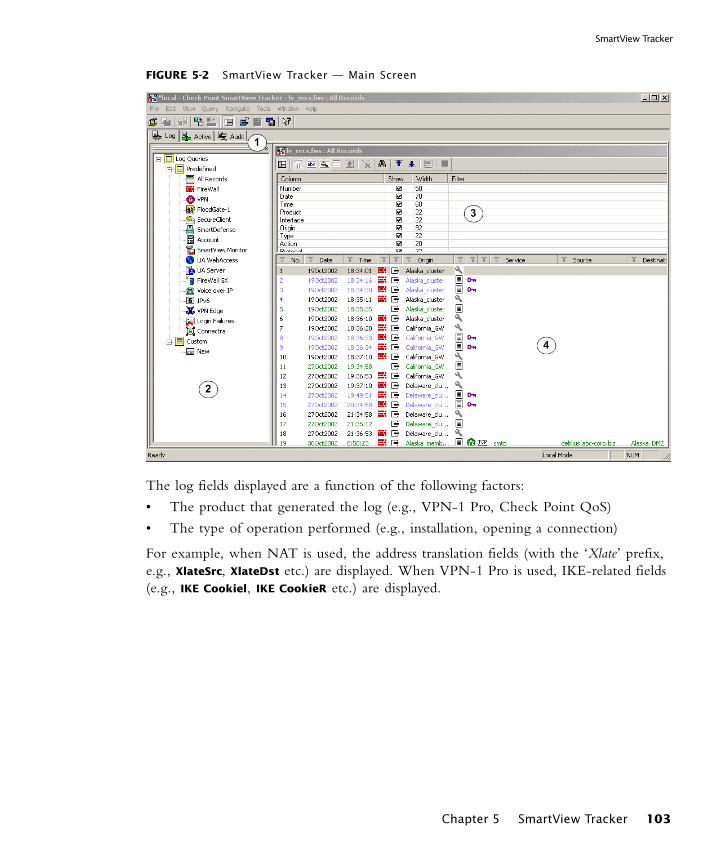
SmartView Tracker
FIGURE 5-2 SmartView Tracker — Main Screen
The log fields displayed are a function of the following factors:
• The product that generated the log (e.g., VPN-1 Pro, Check Point QoS)
• The type of operation performed (e.g., installation, opening a connection)
For example, when NAT is used, the address translation fields (with the ‘Xlate’ prefix, e.g., XlateSrc, XlateDst etc.) are displayed. When VPN-1 Pro is used, IKE-related fields (e.g., IKE Cookiel, IKE CookieR etc.) are displayed.
Chapter 5 SmartView Tracker 103

The Check Point Solution for Tracking
The following table gives a description of the different types of actions recorded by SmartView Tracker (TABLE 5-1).
SmartView Tracker Modes
SmartView Tracker consists of three different modes:
• Log, the default mode, displays all logs in the current fw.log file. These include entries for security-related events logged by different Check Point products, as well as Check Point’s OPSEC partners. New logs that are added to the fw.log file are added to the bottom or the Records pane.
• Active allows you to focus on connections that are currently open through the VPN-1 Pro modules that are logging to the active Log file.
• Audit allows you to focus on management-related records, such as records of changes made to objects in the Rule Base and general SmartDashboard usage. This mode displays audit-specific data, such as the record’s Administrator, Application or Operation details, which is read from the fw.adt log file.
You can toggle between modes by clicking the desired tab.
Filtering
SmartView Tracker’s filtering mechanism allows you to conveniently focus on log data of interest and hide other data, by defining the appropriate criteria per-log field. Once you have applied the filtering criteria, only entries matching the selected criteria are displayed.
TABLE 5-1 Action icons
Icon Action Icon Action
Accept — The connection was allowed to proceed.
Decrypt — The connection was decrypted.
Reject — The connection was blocked.
Key Install — encryption keys were created
Drop — The connection was dropped without notifying the source.
Authorize — Client Authentication logon
Encrypt — The connection was encrypted.
Deauthorize — Client Authentication logoff
Authcrypt — SecuRemote user logon
104
Queries
The filtering options available are a function of the log field in question. For example, while the Date field is filtered to show data that is after, before or in the range of the specified date, the Source, Destination and Origin fields are filtered to match (or differ from) the specified machines.
Since it is very useful to filter the Product field and focus on a specific Check Point product, SmartView Tracker features these filters as predefined queries, described in the following section.
Queries
SmartView Tracker gives you control over the Log file information displayed. You can either display all records in the Log file, or filter the display to focus on a limited set of records matching one or more conditions you are interested in. This filtering is achieved by running a query.
A query consists of the following components:
• Condition(s) applied to one or more log fields (record columns) — for example, to investigate all HTTP requests arriving from a specific source, you can run a query specifying HTTP as the Service column’s filter and the machine in question as the Source column’s filter.
• A selection of the columns you wish to show — for example, when investigating HTTP requests it is relevant to show the URL log field.
Each of the SmartDashboard’s three modes (Log, Active and Audit) has its own Query
Tree, consisting of the following folders:
• Predefined, containing the default queries that cannot be directly modified or saved.The predefined queries available depend on the mode you are in. The default query of all three modes is All Records. In addition, the Log mode includes predefined per product or feature.
• Custom, allowing you to customize your own Query based on a predefined one, to better address your needs. Customized queries are the main querying tool, allowing you to pinpoint the data you are interested in. An existing query that is copied or saved under a new name is automatically added to the Custom folder.
The attributes of the selected query are displayed in the Query Properties pane.
Chapter 5 SmartView Tracker 105

The Check Point Solution for Tracking
Matching Rule
SmartView Tracker records the Security Rule Base rule to which a connection was matched. The matching rule is recorded in four columns in SmartView Tracker, as depicted in FIGURE 5-3:FIGURE 5-3 Recording the Matching Rule
• The Rule column, which records the number of the rule in the Rule Base at the time the log entry was recorded. Like other properties in SmartView Tracker, logs can be sorted and queried by rule number.
• The Current Rule Number column, which is a dynamic field that reflects the current placement of the rule in the Rule Base and displays the current policy package name. As the Rule Base is typically subject to change, this column makes it possible to locate the rules that have changed their relative positions in the Rule Base since the log was recorded, and to create filters for log entries that match the rule, not just the rule number. By way of example, note the log entry in FIGURE 5-3. When this log was first recorded, it recorded the matching rule as Rule 1. Since then the rule’s position in the Rule Base has changed, and so the Current Rule
Number column reports its present position as 2 [Standard], where [Standard] is the name of the policy package in which this rule resides.
• The Rule Name column, which records the short textual description of the rule in the Name column of the Rule Base, when in use.
• The Rule UID column, which records the unique identifying number (UID) that is generated for each rule at the time that it is created. This number serves an internal tracking function, and as such the column is hidden by default. To display this column, click on View > Query Properties and enable the Rule UID property.
Filtering Log Entries by Matching Rule
In order to filter log entries based on a matching rule, right click on a log entry and choose either Follow Rule or Follow Rule Number.
• Follow Rule generates a filtered view of all logs that matched this rule, and is based on the UID number of the rule.
• Follow Rule Number generates a filtered view of all log files that match the number recorded in the Rule column of the selected log.
Note - SmartCenter supports UID rule numbers from NG with Application Intelligence R55 and later. However, in order to enable enforcement modules of versions R55 and R55W to include the UID field when forwarding logs, you must first install a policy generated by a NGX R60A SmartCenter Server to those enforcement modules.
106

Matching Rule
These two operations are essentially short-cuts to creating a filter. You can achieve the same results by right clicking anywhere in a given column and selecting Edit Filter, and then entering the filtering criteria you want to apply.
The Rule and Current Rule Number filters, which provide the same functionality as the Follow Rule and Follow Rule Number commands, can also create filtered views based on multiple matching rules. FIGURE 5-4 shows the Current Rule Number Filter. FIGURE 5-4 Current Rule Number Filter
For configuration information, see “Configuring the Current Rule Number Filter” on page 115.
Viewing the Matching Rule in Context
From SmartView Tracker, you can launch SmartDashboard to examine the rule within the context of the Security Rule Base. By right clicking on the relevant log and selecting View rule in SmartDashboard, SmartDashboard will open with the rule highlighted in white, as Rule 10 is in FIGURE 5-5. FIGURE 5-5 Rule highlighted in SmartDashboard
If you are using version control, SmartDashboard opens with the revision that was saved when this record was created. If no revision is available and the record was created after installing NG with Application Intelligence R55 (or later), SmartDashboard uses the unique identifying number to display the relevant rule. If neither version control nor a UID number are available, the View rule in SmartDashboard option is not available.
Chapter 5 SmartView Tracker 107

The Check Point Solution for Tracking
Viewing the Logs of a Rule from SmartDashboard
From the Security Rule Base in SmartDashboard, there are two methods by which you can launch SmartView Tracker to view all of the log entries that matched on a particular rule. By right clicking on the rule, you can choose to either:
• View rule logs in SmartView Tracker, which opens SmartView Tracker to a filtered view of all logs that matched on the rule.
• Copy Rule ID, which copies the unique identifying number of the rule to the clipboard, allowing the user to paste the value into the Rule UID Filter in SmartView Tracker.
For detailed instructions, see “Viewing the Logs of a Rule from the Rule Base” on page 116.
Log File Maintenance via Log Switch
The active Log file’s size is kept below the 2 GB default limit by closing the current file when it approaches this limit and starting a new file. This operation, known as a log switch, is performed either automatically, when the Log file reaches the specified size or according to a log switch schedule; or manually, from SmartView Tracker.
The file that is closed is written to the disk and named according to the current date and time. The new Log file automatically receives the default Log file name, $FWDIR/log/fw.log.
Disk Space Management via Cyclic Logging
When there is a lack of sufficient free disk space, the system stops generating logs. To ensure the logging process continues even when there is not enough disk space, you can set a process known as Cyclic Logging. This process automatically starts deleting old log files when the specified free disk space limit is reached, so that the module can continue logging new information. The Cyclic Logging process is controlled by;
• Modifying the amount of required free disk space.
• Setting the module to refrain from deleting logs from a specific number of days back.
Log Export Capabilities
While SmartView Tracker is the standard log tracking solution, you may also wish to use your logs in other ways that are specific to your organization. For that purpose, Check Point products provide you with the option to export log files to the appropriate destination.
A log file can be exported in two different ways:
108
Local Logging
• As a simple text file
• In a database format, exported to an external Oracle database
SmartView Tracker supports a basic export operation, in which the display is copied as-is into a text file. More advanced export operations (for example, exporting the whole log file or exporting log online) are performed using the command line (using the fwm logexport, log_export and fw log commands).
With the Export option (File > Export...) you can create a comma delimited ASCII file that can be used as input for other applications.
Local Logging
By default, modules forward their log records online to the SmartCenter Server. Alternatively, to improve the module’s performance, you can free it from constantly sending logs by saving the information to local log files. These files can either be automatically forwarded to the SmartCenter Server or Log Server, according to a specified schedule; or manually imported through SmartView Tracker, using the Remote
File Management operation.
If you choose to use a local logging configuration, you need to manually configure the standard log maintenance settings (log switch, cyclic logging, etc.) on the module.
Logging Behavior During Downtime
During downtime, when the module cannot forward its logs, they are written to a local file. To view these local files, you must manually import them using the Remote File
Management operation.
Logging Using Log Servers
To reduce the load on the SmartCenter Server, administrators can install Log Servers and then configure the modules to forward their logs to these Log Servers. In this case, the logs are viewed by logging with SmartView Tracker into the Log Server machine (instead of the SmartCenter Server machine).
A Log Server behaves just like a SmartCenter Server for all log management purposes: it executes the operation specified in the Policy for events matching certain rules (e.g., issuing an alert or an email); performs an Automatic Log Switch when fw.log reaches 2GB, allows you to export files, etc.
Chapter 5 SmartView Tracker 109
Tracking Considerations
Advanced Tracking Operations
Block Intruder
The Active mode of SmartView Tracker allows you to shut out intruders, by selecting the connection you’ve identified as intrusive and blocking one of the following. Block
Intruder uses SAM to perform the block action.
• The connection - block the selected connection or any other connection with the same service, source or destination.
• The source of the connection - block access to and from this source. Block all connections that are headed to or coming from the machine specified in the Source field.
• The destination of the connection - block access to and from this destination. Block all connections that are headed to or coming from the machine specified in the Destination field.
• Specify a time frame during which this connection is to be blocked.
Custom Commands
SmartView Tracker allows you to conveniently run commands from the SmartConsole, instead of working in the command line. The commands available by default are ping and whois. These commands, along with the ones you add manually, are available through the menu displayed by right-clicking a relevant cell in the Records pane.
Tracking Considerations
Choosing which Rules to Track
The extent to which you can benefit from the events log depends on how well they represent the traffic patterns you are interested in. Therefore, you must ensure your Security Policy is indeed tracking all events you may later wish to study. On the other hand, you should keep in mind that tracking multiple events results in an inflated log file, which requires more disk space and management operations.
To balance these conflicting needs, and determine which of your Policy’s rules should be tracked, consider how useful this information is to you. For example, consider whether this information:
• Improves your network’s security
• Enhances your understanding of your users’ behavior
• Is the kind of data you wish to see in reports
• May be useful for future purposes
110
Choosing the Appropriate Tracking Option
Choosing the Appropriate Tracking Option
For each rule you track, specify one of the following tracking options:
• Log, saving the event’s details to your log file, for future reference. This option is useful for obtaining general information on your network’s traffic.
• Account, required for including byte information in the record you save.
• Alert, allowing you to both log the event and set the SmartCenter Server to execute a relevant command: display a popup window, send an email alert or an SNMP trap alert, or run a user-defined script.
Forwarding Log Records Online vs. Forwarding Log Files on Schedule
By default, modules forward their log records online, one by one, to the selected destination (the SmartCenter Server or a Log Server). In this case, SmartView Tracker allows you to see new records as they are forwarded to the machine you logged into.
To improve the module’s performance, you can free it from constantly forwarding logs by configuring a Local Logging system in which the records are saved to a local log file. If you set a log forwarding schedule, you can open this file (instead of the active file) in SmartView Tracker. Otherwise, you can manually import this file from the module, using the Remote File Management operation.
Chapter 5 SmartView Tracker 111
Tracking Configuration
Tracking Configuration
In This Section
Basic Tracking Configuration
To track connections in your network:
1 For each of the Security Policy rules you wish to track, right click in the Track column and choose Log from the menu.All events matching these rules are logged.
2 Launch SmartView Tracker through the SmartDashboard’s Window menu.The Log mode is displayed, showing the records of all events you have logged.
Basic Tracking Configuration page 112
SmartView Tracker View Options page 113
Configuring a Filter page 114
Configuring Queries page 117
Hiding and Showing the Query Tree Pane page 119
Working with the Query Properties Pane page 119
Modifying a Columns Properties page 119
Copying Log Record Data page 120
Viewing a Record’s Details page 120
Viewing a Rule page 121
Find by Interface page 121
Find by Interface page 121
Maintenance page 122
Working with Log Servers page 124
Local Logging page 123
Custom Commands page 125
Block Intruder page 126
Configuring Alert Commands page 127
112
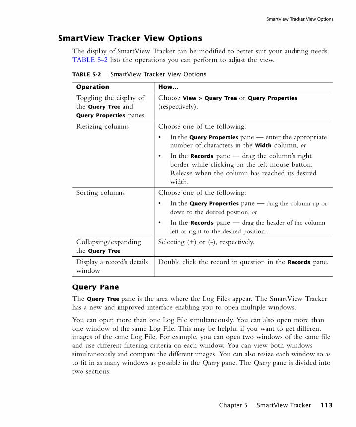
SmartView Tracker View Options
SmartView Tracker View Options
The display of SmartView Tracker can be modified to better suit your auditing needs. TABLE 5-2 lists the operations you can perform to adjust the view.
Query Pane
The Query Tree pane is the area where the Log Files appear. The SmartView Tracker has a new and improved interface enabling you to open multiple windows.
You can open more than one Log File simultaneously. You can also open more than one window of the same Log File. This may be helpful if you want to get different images of the same Log File. For example, you can open two windows of the same file and use different filtering criteria on each window. You can view both windows simultaneously and compare the different images. You can also resize each window so as to fit in as many windows as possible in the Query pane. The Query pane is divided into two sections:
TABLE 5-2 SmartView Tracker View Options
Operation How...
Toggling the display of the Query Tree and Query Properties panes
Choose View > Query Tree or Query Properties (respectively).
Resizing columns Choose one of the following:
• In the Query Properties pane — enter the appropriate number of characters in the Width column, or
• In the Records pane — drag the column’s right border while clicking on the left mouse button. Release when the column has reached its desired width.
Sorting columns Choose one of the following:
• In the Query Properties pane — drag the column up or down to the desired position, or
• In the Records pane — drag the header of the column left or right to the desired position.
Collapsing/expanding the Query Tree
Selecting (+) or (-), respectively.
Display a record’s details window
Double click the record in question in the Records pane.
Chapter 5 SmartView Tracker 113
Tracking Configuration
• Query Properties pane shows all the attributes of the fields contained in the Records pane.
• Records pane displays the fields of each record in the Log File.
Resolving IP Addresses
Since the IP address resolution process consumes time and resources, SmartView Tracker allows you to choose whether or not to display source and destination host names in the Log file.
Click the Resolve IP toolbar button to toggle between:
• Displaying the name of the host and the domain.
• Displaying the addresses in conventional IP dot notation.
Resolving Services
With the Resolving Services option you can control the display of the source and destination port in the Log File. Each port number is mapped to the type of service it uses.
This option toggles between:
• Displaying the destination port number.
• Displaying the type of service the port uses.
Showing Null Matches
This option controls the display of Null Matches, that is, log entries that are neither included nor excluded by the current filtering criteria.
For example, if you choose to display only log entries whose Action is either Reject or Drop, control logs are null matches because Action is not relevant to a control log. They are neither included nor excluded. If the Show Null Matches toolbar button is clicked, the null matches are displayed.
Configuring a Filter
To filter a log field and focus on data of interest:
1 Choose one of the following:
• Display the Query Properties pane (by selecting View > Query Properties) and right-click the desired log field in the Filter column, or
Note - If you clicked the Resolving Services button to display the type of service the port uses, and the port number appears, it means that a service has not been previously defined for this port. A port number can be mapped to a service either in the Objects database us-ing the Object Manager or in the Services Configuration file. In SecurePlatform, the Services Configuration file name is called /etc/services
114

Configuring the Current Rule Number Filter
• In the Records pane, right-click the log field (e.g., the column) you wish to filter.The right-click menu is displayed.
2 Choose Edit Filter from the displayed menu.Each field displays a type-specific Filter window. Configure the window as desired and the log data will be displayed according to the filtering criteria used.
3 Click OK to apply the filter settings.
Configuring the Current Rule Number Filter
To launch the Current Rule Number Filter:
1 Right click anywhere in the column Curr. Rule No. and select Edit Filter.
2 Select the appropriate policy package from the drop-down list.
3 Select the current rule number(s) of the logs you want to display and click OK.
Follow Source, Destination and User Data
With the Follow Source... commands you can create a filter that matches a specific query to a specific Source, Destination or User.
Right-click the record with the value of interest in the Records pane and select one of the following Follow commands:
• Follow Source enables a search for a log record according to a specific source.
• Follow Destination enables a search for a log record according to a specific destination.
• Follow User enables a search for a log record according to a specific user.
Note - Filtering criteria takes effect only if the Apply Filter toolbar button is activated.
Note - A new window opens, displaying the relevant column (Source, Destination or User) first.
Chapter 5 SmartView Tracker 115

Tracking Configuration
Add Source
With the Add Source option you can add a Source to the communication.
Right-click the record with the value of interest in the Records pane and select one of the following Add Source commands:
• Add Source to Bypass indicates that connections from this source pass transparently through InterSpect. However, basic sanity tests on the packets are performed, and malformed packets are dropped. IP addresses can also be added to and removed from the bypass list via SmartDashboard.
• Add Source to Block indicates that connections from this source are not allowed. This Action isolates the zone from the rest of the network, and can be used when a zone is infected, or is under threat. IP addresses can also be added to and removed from the bypass list via SmartDashboard.
• Add Source to Quarantine means that the hosts or network of worm or attack victims at this source are blocked at the borders of the zone for a limited period of time, and quarantined users of a web browser are informed that they are blocked via a customized web page. IP addresses can also be added to and removed from quarantine via SmartDashboard. Also, the administrator can decide that if SmartDefense detects an attack, then the source of the attack will be put into quarantine.
Viewing the Logs of a Rule from the Rule Base
From the Rule Base in SmartDashboard, it is possible to generate a filtered view of logs that match a specific rule. There are two ways of achieving this:
• View rule logs in SmartView Tracker
1 Right click on a rule in the No. column in SmartDashboard and select View
rule logs in SmartView Tracker. SmartView Tracker opens with a filter applied to the Curr. Rule No. column to display only those logs that match on the selected rule.
• Copy rule ID
1 Right click on the rule in the No. column in SmartDashboard and select Copy
rule ID.
2 In SmartView Tracker, click View > Query Properties and enable the Rule UID
column.
3 Right click on the Rule UID column heading and choose Edit Filter.
4 Paste the UID in the Value field and click OK.
116
Configuring Queries
A filter is applied to the Curr. Rule No. column to display only those logs that matched on the Rule UID.
Configuring Queries
In This Section
New queries are created by customizing existing queries and saving them under new names. Proceed as follows:
1 Select an existing query in the Query Tree (either a predefined query or a custom query) and choose Query > Copy from the menu.A copy of the query, named New, is added to the Custom folder.
2 Rename the new query.
3 In the Query Properties pane, modify the query as desired by specifying the following for each relevant log field (column):
• Whether or not to Show the information available for that column.
• The Width of the column displaying the information.
• The Filter (conditions) applied to the column.
4 Double click the query in order to run it.
Opening An Existing Query
You can open an existing query in an active window by:
• Using the Query menu:
In the Query Tree pane, select the query you would like to open. Select Query >
Open. The desired query appears in the Records pane.
• Right-clicking an existing query
Right-click the query you would like to open. Select Open. The desired query appears in the Records pane.
• Double-clicking an existing query
Opening An Existing Query page 117
Creating A Customized Entry page 118
Saving a Query Under a New Name page 118
Renaming a Customized Query page 118
Deleting a Customized Query page 119
Chapter 5 SmartView Tracker 117
Tracking Configuration
Double-clicking the query you would like to open. The desired query appears in the Records pane.
Creating A Customized Entry
Predefined queries contained in the Predefined folder cannot be modified but they can be saved under a different name.
Saving a predefined query under a different name:
1) Open a predefined query.
2) Modify the query as desired.
3) From the Query menu, select Save As.
4) Type the desired query name.
5) Click OK. The modified view is placed in the Custom folder.
Saving a Query Under a New Name
You can modify a query and save it under a new name.
To modify a predefined Query and save it under a new name:
1) Modify the predefined query as desired.
2) Choose Save As from the Query menu, and specify a file name for the modified query.
3) Click OK. The modified query is placed in the Custom folder.
To save the changes made to a custom Query
1) Modify the query as desired.
2) Choose Save from the Query menu.
Renaming a Customized Query
1) Select the query you want to rename.
• From the Query menu, select Rename, or
• Right-click the desired query and select Rename from the displayed menu. The newly-duplicated query is placed in the Custom folder.
2) Enter the desired query name and click Enter.
118
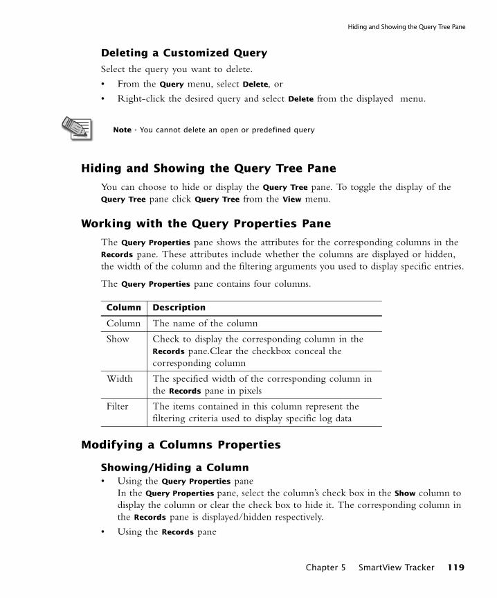
Hiding and Showing the Query Tree Pane
Deleting a Customized Query
Select the query you want to delete.
• From the Query menu, select Delete, or
• Right-click the desired query and select Delete from the displayed menu.
Hiding and Showing the Query Tree Pane
You can choose to hide or display the Query Tree pane. To toggle the display of the Query Tree pane click Query Tree from the View menu.
Working with the Query Properties Pane
The Query Properties pane shows the attributes for the corresponding columns in the Records pane. These attributes include whether the columns are displayed or hidden, the width of the column and the filtering arguments you used to display specific entries.
The Query Properties pane contains four columns.
Modifying a Columns Properties
Showing/Hiding a Column• Using the Query Properties pane
In the Query Properties pane, select the column’s check box in the Show column to display the column or clear the check box to hide it. The corresponding column in the Records pane is displayed/hidden respectively.
• Using the Records pane
Note - You cannot delete an open or predefined query
Column Description
Column The name of the column
Show Check to display the corresponding column in the Records pane.Clear the checkbox conceal the corresponding column
Width The specified width of the corresponding column in the Records pane in pixels
Filter The items contained in this column represent the filtering criteria used to display specific log data
Chapter 5 SmartView Tracker 119

Tracking Configuration
In the Records pane, right-click the column heading. Select Hide from the displayed menu.The column is hidden and at the same time, the check box in the Show column in the Query Properties pane is automatically cleared.
Changing a Column’s Width
If you change the width of a column in one pane, it is automatically changed in the other. You can change the width of a column either in the:
• Query Properties paneDouble-click the Width field that you would like to edit in the Width column. The Width field becomes an editable field in which you can specify a new width (in pixels). Edit the width value and click Enter. The corresponding column in the Records pane is widened/narrowed accordingly.
• Records panePlace the cursor on the column’s right border in the header. The cursor changes to the column resize cursor. Click on the left mouse button without releasing it. Move the column border to the desired position while keeping the left mouse button down. Release the left mouse button. The value in the column’s corresponding Width field in the Query Properties pane is automatically modified accordingly.
Rearranging a Column’s Position
You can rearrange a column’s position in the Query Properties or the Records pane. If you change the position in one pane, it is automatically changed in the other.
• In the Queries Properties pane, drag the column up or down to the desired position.
• In the Records pane, drag the header of the column left or right to the desired position.
Copying Log Record Data
You can copy a whole log record or only one of its cells to the clipboard:
• Right-click the desired record.
• Select Copy Cell from the displayed menu to copy only the cell on which the cursor is standing or select Copy Line to copy the entire record.
Viewing a Record’s Details
The Record Details window is displayed by double-clicking the desired record in the Records pane.
120
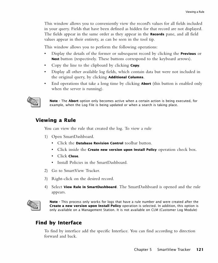
Viewing a Rule
This window allows you to conveniently view the record's values for all fields included in your query. Fields that have been defined as hidden for that record are not displayed. The fields appear in the same order as they appear in the Records pane, and all field values appear in their entirety, as can be seen in the tool tip.
This window allows you to perform the following operations:
• Display the details of the former or subsequent record by clicking the Previous or Next button (respectively. These buttons correspond to the keyboard arrows).
• Copy the line to the clipboard by clicking Copy.
• Display all other available log fields, which contain data but were not included in the original query, by clicking Additional Columns.
• End operations that take a long time by clicking Abort (this button is enabled only when the server is running).
Viewing a Rule
You can view the rule that created the log. To view a rule
1) Open SmartDashboard.
• Click the Database Revision Control toolbar button.
• Click inside the Create new version upon Install Policy operation check box.
• Click Close.
• Install Policies in the SmartDashboard.
2) Go to SmartView Tracker.
3) Right-click on the desired record.
4) Select View Rule in SmartDashboard. The SmartDashboard is opened and the rule appears.
Find by Interface
To find by interface add the specific Interface. You can find according to direction forward and back.
Note - The Abort option only becomes active when a certain action is being executed, for example, when the Log File is being updated or when a search is taking place.
Note - This process only works for logs that have a rule number and were created after the Create a new version upon Install Policy operation is selected. In addition, this option is only available on a Management Station. It is not available on CLM (Customer Log Module)
Chapter 5 SmartView Tracker 121

Tracking Configuration
Maintenance
The following maintenance operation apply to all logging systems, whether the logs are forwarded to the SmartCenter Server (the default setting), sent to Log Servers or saved locally.
Managing the Log Switch Settings
A log switch can be performed in one of the following ways:
• Automatically, when the log file’s size is 2 GB.You can modify this default size limit, as well as define a log switch schedule, through the SmartDashboard, by editing the properties of the object collecting the logs (the SmartCenter Server, Log Server or the module).
• Manually, from SmartView Tracker.
Modifying the Automatic Log Switch Settings
1 In the SmartDashboard, double click the module in question.The module’s properties window is displayed.
2 In Log switch section of the Logs and Masters page, specifies when to perform the log switch:
• To specify the file size that should trigger a log switch, check Log switch when
file size is... MBytes and specify the appropriate size.
• To setup a log switch schedule, check Schedule log switch to and choose the appropriate time object from the drop-down list.
If you specify both options, the log switch is performed when the first criterion is met.
3 Click OK.
Manual Log Switch
1 In SmartView Tracker, choose File > Switch Active File from the menu.The Switch active Log File window is displayed.
2 By default, the current log file is named based on the current date and time.To specify a different name, uncheck Default and enter the appropriate name under Log File Name.
Managing the Cyclic Logging Settings
To configure the Cyclic Logging process:
1 In the SmartDashboard, double click the module in question.The module’s properties window is displayed.
122

Local Logging
2 In the Disk Space Management section of the Logs and Masters page, specify the following:
• Whether to Measure free disk space in MBytes or Percent.
• Check Required Free Disk Space and enter the appropriate value.
• To refrain from deleting the most recent log files among your old log files, check Do not delete log files from the last and specify the appropriate number of Days.
Purging a Log File
To delete all records in the active fw.log log file, display the Log or Audit mode and choose Purge Active File from the File menu.
Local Logging
To save logs to a local file (instead of forwarding them to the SmartCenter Server or to a Log Server):
1 In the SmartDashboard, double click the module in question to display its properties window.
2 In the Log Servers page (under the Logs and Masters branch), check Define Log
Servers and then check Save logs locally, on this machine (VM).
3 You can either set a schedule for forwarding the local file to the appropriate machine (the SmartCenter Server or a Log Server), or manually import these files using SmartView Tracker.
• To specify a log file forwarding schedule:
i Display the Additional Logging Configuration page (under the Logs and
Masters branch).
ii In the Log forwarding settings section, set the following:
- Check Forward log files to SmartCenter Server and choose the Log Server from the drop-down list.
- Set a Log forwarding schedule by choosing the appropriate time object from the drop-down list.
• To view the local file using SmartView Tracker:
i Select Tools > Remote Files Management...
The Remote Files Management window is displayed, listing all Check Point Gateways from which you can fetch Log files.
ii Select the desired Check Point Gateway and click Get File List.
Chapter 5 SmartView Tracker 123
Tracking Configuration
iii The Files on <Module Name> window is displayed, listing all Log files found on the selected Check Point Gateway.
iv Select one or more files to be fetched.
v Click Fetch Files.
The Files Fetch Progress window is displayed, showing the progress of the file transfer operation.
Working with Log Servers
To reduce the SmartCenter Server’s load via Log Servers:
1 Install the Log Server software on the machine you wish to dedicate to logging purposes.
2 Launch the SmartDashboard and add the Log Server you have installed as a Check Point network object:
i Choose Manage > New > Check Point > Host... from the menu.
The Check Point Host window is displayed.
ii In the General Properties page, define the standard network object properties, including:
- Checking Log Server in the Check Point Products list.- Setting up Secure Internal Communication between this Log Server and the SmartCenter Server.
iii Define additional properties as needed and click OK.
3 Install the Check Point Objects Database on the Log Server object:
• Choose Policy > Install Database... from the menu.The Install Database window is displayed.
• In the Install Database on list, check the Log Server object and click OK.
4 To setup the module to forward its logs to this Log Server, double click the module so that its properties window is displayed.
5 You can either forward the log records online, one by one; or save the records locally, and then forward them in a file according to a specific schedule.
• To forward log records online:
Note - You cannot fetch an active Log File. If you want to fetch the current file, you must first perform a log switch.
124
Custom Commands
i Display the Log Servers page (under the Logs and Masters branch).
ii Check Define Log Servers.
iii Add this Log Server to the Always send logs to table (click Add... to display the Add Logging Servers window, and move the Log Server from the Available Log Servers list to the Select Log Servers list).
• To specify a log file forwarding schedule:
i Display the Additional Logging Configuration page (under the Logs and
Masters branch).
ii In the Log forwarding settings section, set the following:
- Check Forward log files to Management Server and choose the Log Server from the drop-down list.
- Set a Log forwarding schedule by choosing the appropriate time object from the drop-down list.
6 By default, when the selected Log Server is unreachable, the logs are written to a local file. Alternatively, you can select a backup Log Server as follows:
i Display the Log Servers page (under the Logs and Masters branch).
ii Under When a Log Server is unreachable, send logs to section, click Add...to display the Add Logging Servers window.
iii Move the Log Server from the Available Log Servers list to the Select Log
Servers list and click OK.
7 Repeat step 4 to step 6 on all relevant modules.
8 Launch SmartView Tracker and login to this Log Server (instead of the SmartCenter Server).
Custom Commands
To configure the commands you can run through SmartView Tracker:
1 Choose Tools > Custom Commands... from the menu.The Custom Commands window is displayed.
2 Click Add...
The Add New Command window is displayed.
3 Specify the following command properties:
• Menu Text, defines how this command is to be displayed in the right-click menu (e.g. Ping).
Chapter 5 SmartView Tracker 125

Tracking Configuration
• Command, specifying the name of the command (e.g. ping.exe).
• Arguments to be used by the command.
• IP Columns only, allowing you to apply this command only to columns that have an IP address value (e.g. Origin, Source, Destination etc.).
Example:
1 Use the Add New Command window to add the Menu Content TELNET, which runs the command TELNET using <Cell Value> as its Parameter.
2 In the Records pane, right click a record whose IP address is 20.13.5.2. and select telnet from the menu.
The executed command is: telnet 20.13.5.2.
Block Intruder
SmartView Tracker allows you to terminate an active connection and block further connections from and to specific IP addresses. Proceed as follows:
1 Select the connection you wish to block by clicking it in the Active mode’s Records pane.
2 From the Tools menu, select Block Intruder. The Block Intruder window is displayed.
3 In Blocking Scope, select the connections that you would like to block:
• Block all connections with the same source, destination and service - block the selected connection or any other connection with the same service, source or destination.
• Block access from this source - block access from this source. Block all connections that are coming from the machine specified in the Source field.
• Block access to this destination - block access to this destination. Block all connections that are headed to the machine specified in the Destination field.
4 In Blocking Timeout, select one of the following:
• Indefinite blocks all further access
• For... minutes blocks all further access attempts for the specified number of minutes
Note - It is recommended not to use a full path name in the Executable field, since the executable file may be found in different directories of different SmartView Tracker clients. The administrator must ensure that the command can be executed from the SmartView Tracker installation directory. Commands requiring a full path can be executed by a script, which all administrators save in the same directory, but each administrator edits according to his or her needs.
126
Configuring Alert Commands
5 In Force this blocking, select one of the following:
• Only on... blocks access attempts through the indicated VPN-1 Pro module.
• On any VPN-1 & FireWall-1 Module blocks access attempts through all VPN-1 Pro modules defined as gateways or hosts on the Log Server.
6 Click OK.To clear blocked connections from the display, choose Clear Blocking from the Tools menu.
Configuring Alert Commands
When you set a rule’s Track column to Alert, SNMP Trap, Mail or UserDefined, a log of the event matching the rule is written to the active log file and the SmartCenter Server executes the appropriate alert script.
Alert scripts are defined through the SmartDashboard, in the Global Properties
window’s Alert Commands page. You can use the default mail alert and SNMP trap alert scripts, by entering the appropriate IP addresses. Alternatively, define your own alert(s) in the three UserDefined fields.
Chapter 5 SmartView Tracker 127

Tracking Configuration
128
CHAPTER 6
SmartCenter Management
The Need for SmartCenter ManagementSmartCenter is the security center of the organization. Changes that are made in SmartCenter must be completely secure and efficient in order to avoid even the most temporary compromise of the system.
Organizations are dynamically shifting all the time. Network security needs to be maintained constantly, and occasionally certain modifications are necessary, such as updating the Security Policy and Check Point software.
When modifications need to be made to the network, you must ensure that backups are available and in place. These backups are usually replicas of the functioning environment which can be used if the changes are not applied successfully. In other words, it is possible to use backups in order to revert to the version of the network as it was before the significant changes were applied. There may also be legal reasons which compel companies to maintain backup versions.
By taking precautions prior to making changes to the Security Policy, the system administrator can make extra sure that all the conditions necessary for a smooth, seamless upgrade operation exist. Although it is possible to perform a live upgrade on a SmartCenter Server, it is advisable to prepare an upgraded machine which can be examined carefully to ensure that it is functioning properly. Once it is certain that this upgraded machine is working properly, it can slowly be integrated in place of the existing SmartCenter Server. Under these circumstances, information can be exported to the upgraded machine from the original machine without any problems.
129
The SmartCenter Management Solution
The SmartCenter Management Solution
General
SmartCenter has several tools which allow changes in the production environment to be made securely, smoothly and efficiently. These include:
• Revision control – SmartCenter can manage multiple versions of policies. Different versions of policies can be stored and viewed using the Revision control tool. This tool enables the system administrator to revert the current policy to a previously saved version. For more information, see “Managing Policy Versions” on page 130.
• Backup & Restore – when it is imperative that the SmartCenter Server be upgraded, it is possible to create a functioning SmartCenter Server which will replace the existing machine while it is being serviced. This Backup server is an upgraded clone of the existing SmartCenter Server. The system administrator tests it in order to ensure that it is fully functioning and thereafter integrates it in place of the original SmartCenter Server. For more information, see “Backup and Restore the SmartCenter Server” on page 132.
Managing Policy Versions
Policies are created by the system administrator and managed via the SmartCenter Server. Different versions of these policies can be saved. Each version includes backups of the various databases (objects, users, Certificate Authority data, etc.). This information is zipped and saved.
The existing versions are recorded in a “Version table”. This table can be viewed and the versions which are displayed can be modified. It is possible to:
• Create a Version
• Export and Import a Version
• View a Version
• Revert to a Previous version
• Delete a version
Versions can be created manually by the system administrator, or the system can be set to automatically create a new version every time Security Policy installation takes place.
Version Operations
The following operations can be executed for version control:
130
Version Operations
Create a Version
A new version can be created manually by the system administrator, or the system can be set to create new versions automatically every time a new policy is installed. Each new version has the following attributes:
• the creation date
• the system administrator who initiated the new version
• the version of the software
• two editable options determined by the system administrator: the name of the version, as well as, an additional optional comment.
Export and Import a Version
It is possible to export existing versions using the Command Line. This can be useful in order to save disk space. When the exported version is necessary, it can be imported back into the Versions table. The imported version appears in the version table as a regular maintained version
View a Version
A saved version can be viewed in SmartDashboard. For every saved version you can view certain entities such as objects, users, rules. Various operations, such as queries can be executed on these entities.
Revert to a Previous version
The revert operation allows you to revert to a previously saved version. Once you initiate the revert operation, the selected version overwrites the current policy. The one type of information that is not overwritten, is Certificate Authority (CA) data. For security reasons, CA data is not overwritten, but it is merged with the CA data of the current policy.
Before the revert operation is done, the system administrator can expect to receive a report on the expected outcome of the revert operation. For example, information certificates that are going to be revoked is supplied. At this point it is necessary for the system administrator to decide whether or not to continue with the revert operation. Of all the entities included in the reverted version, the user database is not automatically reverted. This is because the users database is extremely dynamic; users are added and deleted frequently. The user database is always changing regardless of the policy version.
Note - It is recommended to create a version before upgrading the system. This enables the administrator to back out to a functioning environment in case of problems during the upgrade operation.
Chapter 6 SmartCenter Management 131

The SmartCenter Management Solution
The system administrator can decide to revert to a selected Policy version, but to maintain the current users database. In this manner, the current user base is used with the restored Policy.
Delete a version
A previously saved version can be deleted. This operation will also delete the various databases included in the policy version.
Version Upgrade
When the SmartCenter Server is upgraded, the various versions are upgraded as well. This means that saved versions will be compliant with the upgraded software, and there will not be a need to downgrade to a previous software version in order to revert to a saved version. For example, new object attributes are added to comply with the new features.
Version Diagnostics
The success or failure of version operations that require modification of the Versions table (such as creating, reverting to or deleting a version) are audited in the audit log of the SmartView Tracker. It is recommended to make use of these logs to ensure that operations have taken place successfully.
Saved versions require disk space. If the existing disk space is exhausted, a threshold alert is sent to the SmartView Monitor. Use this SmartConsole in order to make sure that you meet the disk space requirements needed to implement the versioning feature.
Backup and Restore the SmartCenter Server
The Backup and Restore operation exports the SmartCenter environment from the SmartCenter Server, and allows it to be imported to another machine. This other machine is a working clone of the SmartCenter Server. It has identical functionalities and capabilities as the original SmartCenter Server. This operation supports Operating System (OS) migration, namely the OS of the original, as well as, the clone machines can be different.
Using the Backup and Restore feature it is possible to:
• Replace the original SmartCenter Server with another clone SmartCenter Server, while the original is being serviced.
• Maintain a backup of the SmartCenter Server to be used in case of failover
• Upgrade the SmartCenter Server. System administrators are cautious when upgrading the SmartCenter Server in the production environment. It is more secure to upgrade another machine, import the information from the original
132
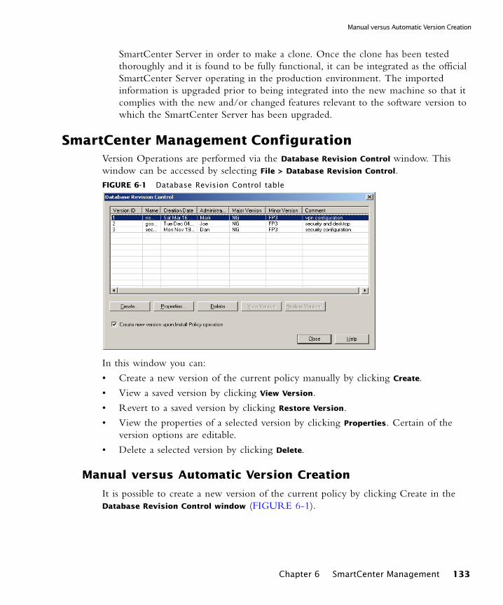
Manual versus Automatic Version Creation
SmartCenter Server in order to make a clone. Once the clone has been tested thoroughly and it is found to be fully functional, it can be integrated as the official SmartCenter Server operating in the production environment. The imported information is upgraded prior to being integrated into the new machine so that it complies with the new and/or changed features relevant to the software version to which the SmartCenter Server has been upgraded.
SmartCenter Management ConfigurationVersion Operations are performed via the Database Revision Control window. This window can be accessed by selecting File > Database Revision Control. FIGURE 6-1 Database Revision Control table
In this window you can:
• Create a new version of the current policy manually by clicking Create.
• View a saved version by clicking View Version.
• Revert to a saved version by clicking Restore Version.
• View the properties of a selected version by clicking Properties. Certain of the version options are editable.
• Delete a selected version by clicking Delete.
Manual versus Automatic Version Creation
It is possible to create a new version of the current policy by clicking Create in the Database Revision Control window (FIGURE 6-1).
Chapter 6 SmartCenter Management 133

SmartCenter Management Configuration
Alternately, new versions can be configured to be created automatically every time a policy is installed. You can do this by selecting Create new version upon install policy
operation in the Install Policy window. You can access this window by selecting Policy >
Install.
134
CHAPTER 7
SmartUpdate
In This Chapter
The Need for Software Upgrade and License ManagementManaging remote enforcement points can be time-consuming and difficult. Keeping remote firewalls and gateways up-to-date with the latest security patches and software often requires expertise on-site, an expensive proposition when managing dispersed networks. Even in small local networks, the routine of applying patches and distributing licenses can tax an organization’s technical resources.
The Need for Software Upgrade and License Management page 135
The SmartUpdate Solution page 136
Upgrading Packages page 141
Managing Licenses page 147
Generating CPInfo page 155
The SmartUpdate Command Line page 155
135
The SmartUpdate Solution
The SmartUpdate Solution
In This Section
Introducing SmartUpdate
SmartUpdate is an optional module for VPN-1 Pro that automatically distributes software applications and updates for Check Point and OPSEC Certified products, and manages product licenses. It provides a centralized means to guarantee that Internet security throughout the enterprise network is always up to date. SmartUpdate turns time-consuming tasks that could otherwise be performed only by experts into simple point and click operations.
SmartUpdate extends your organization’s ability to provide centralized policy management across enterprise-wide deployments. SmartUpdate can deliver automated software and license updates to hundreds of distributed security gateways from a single management console. SmartUpdate ensures security deployments are always up-to-date by enforcing the most current security software. This provides greater control and efficiency while dramatically decreasing maintenance costs of managing global security installations.
SmartUpdate enables remote upgrade, installation and license management to be performed securely and easily. A system administrator can monitor and manage remote gateways from a central location, and decide whether there is a need for software upgrade, new installations and license modification. On a Check Point Gateway, it is possible to remotely upgrade:
• VPN-1 Pro enforcement modules
• Hotfixes, Hotfix Accumulators (HFAs) and patches
• Third party OPSEC applications
• VPN-1 Edge/Embedded devices
• Nokia Operating System
• SecurePlatform
All operations that can be performed via SmartUpdate can also be done via the command line interface. See “The SmartUpdate Command Line” on page 155 for more information.
Introducing SmartUpdate page 136
Understanding SmartUpdate page 137
SmartUpdate - Seeing it for the First Time page 138
Common Operations page 139
136

Understanding SmartUpdate
Understanding SmartUpdateFIGURE 7-1 SmartUpdate Architecture
SmartUpdate installs two repositories on the SmartCenter Server:
• License Repository, which is stored on all platforms in the directory $FWDIR\conf\.
• Package Repository, which is stored:
• on Windows machines in C:\SUroot.
• on UNIX machines in /var/suroot. The Package Repository requires a separate license, in addition to the license for the SmartCenter Server. This license should stipulate the number of nodes that can be managed in the Package Repository.
Packages and licenses are loaded into these repositories from several sources:
• the Download Center web site (packages)
• the Check Point CD (packages)
• the User Center (licenses)
• by importing a file (packages and licenses)
• by running the cplic command line
Chapter 7 SmartUpdate 137
The SmartUpdate Solution
Of the many processes that run on the Check Point Gateways distributed across the corporate network, two in particular are used for SmartUpdate. Upgrade operations require the cprid daemon, and license operations use the cpd daemon. These processes listen and wait for the information to be summoned by the SmartCenter Server.
From a remote location, an administrator logged into the SmartCenter Server initiates operations using the SmartUpdate tool. The SmartCenter Server makes contact with the Check Point Gateways via the processes that are running on these modules in order to execute the operations initiated by the system administrator (e.g., attach a license, or upload an upgrade). Information is taken from the repositories on the SmartCenter Server. For instance, if a new installation is being initiated, the information is retrieved from the Package Repository; if a new license is being attached to remote gateway, information is retrieved from the License Repository.
This entire process is Secure Initial Communication (SIC) based, and therefore completely secure.
SmartUpdate - Seeing it for the First Time
SmartUpdate has two tabs:
• Packages tab shows the packages and Operating Systems installed on the Check Point Gateways managed by the SmartCenter Server. Operations that relate to packages can only be performed in the Packages tab.
• Licenses tab shows the licenses on the managed Check Point Gateways. Operations that relate to licenses can only be performed in the Licenses tab.
These tabs are divided into a tree structure that displays the packages installed and the licenses attached to each managed Check Point Gateway.
The tree has three levels:
• Root level shows the name of the SmartCenter Server to which the GUI is connected.
• Second level shows the names of the Check Point Gateways configured in SmartDashboard.
• Third level shows the Check Point packages (in the Packages tab) or installed licenses (in the Licenses tab) on the Check Point Gateway.
Additionally, the following panes can be displayed:
• Package Repository - shows all the packages available for installation. To view this pane, select Packages > View Repository.
• License Repository - shows all licenses (attached or unattached). To view this pane, select Licenses > View Repository.
138
Common Operations
• Operation Status - shows past and current SmartUpdate operations. To view this pane, select Operations > View Status. In this pane you can read about:
• Operations performed (e.g., Installing package <X> on Check Point Gateway <Y>, or Attaching license <L> to Check Point Gateway <Y>.).
• The status of the operation being performed, throughout all the stages of its development (for instance, operation started, or a warning)
• A progress indicator.
• The time that the operation takes to complete.
Common Operations
Dragging and Dropping
Packages and licenses can be dragged and dropped from the Repositories onto the Check Point Gateways in the Package/Licenses Management tree. This drag and drop operation will invoke the distribute or attach operation respectively.
Sorting
To sort in ascending or descending order, click the column title in the Licenses or Packages tab.
Expanding or Collapsing
To expand or collapse the Check Point Gateways tree structure, right-click on the tree root and choose Expand/Collapse.
Dragging and Dropping page 139
Sorting page 139
Expanding or Collapsing page 139
Modifying the Repository View page 140
Viewing Operation Details page 140
Searching for Text page 140
Printing Views page 140
Chapter 7 SmartUpdate 139
The SmartUpdate Solution
Modifying the Repository View
Modify the Repository View as follows:
1 right-click on a blank row or column in the Repository window
2 Select one of the options. For instance, in the Licenses Repository you can select to view only the attached licenses, whereas, in the Packages Repository, you can select to view certain packages, like the available OS packages.
Clearing the Repository of Completed Operations
To clear a single operation, select the line in the Operation Status window and press the Delete key, or right click and select Clear.
To clear all completed operations from the Operation Status window, select Status >
Clear all completed operations.
Viewing Operation Details
To view operation details, in the Operation Status window, double click the operation entry. The Operation Details window shows the operation description, start and finish times, and progress history. The window is resizable.
To copy the Status lines to the clipboard, select the line, right-click and choose Copy.
Searching for Text
To search for any text string: select Tools > Find. The Find window is displayed.
• Enter the string for which you would like to search in the Find what field.
• Select where you would like to search, e.g., License tab or Package Repository.
Printing Views
To print a view, select File > Print. The Choose Window is displayed. Select the window that you would like to print, e.g., Operation Status or License Repository. Optionally, you can adjust the print setup settings, or preview the output.
Logging SmartUpdate Operations• A log file of SmartUpdate package operations is generated in the file
$SUROOT\log\<Check Point Node name>_SmartUpdate.elg
• An audit log of SmartUpdate operations can be viewed in the SmartView Tracker Audit View.
140
Overview of Upgrading Packages
Upgrading Packages
In This Section
Overview of Upgrading Packages
The latest management version can be applied to a single Check Point Gateway, or to multiple Check Point Gateways simultaneously. Use the Upgrade all Packages operation to bring packages up to the most current management version.
To upgrade Check Point packages to versions earlier than the latest available version, they must be upgraded one-by-one. Use the Distribute operation to upgrade packages to management versions other than the most current, or to apply specific HFAs.
The Upgrade Package Process
In This Section
Prerequisites for Remote Upgrades• Ensure that CPRID connections are allowed. Go to SmartDashboard > Policy >
Global Properties > FireWall-1 Implied Rules, and ensure that the Accept CPRID
Connections (SmartUpdate) check box is checked.
• Secure Internal Communication (SIC) must be enabled to allow secure communications between the SmartCenter Server and remote Check Point Gateways.
Overview of Upgrading Packages page 141
The Upgrade Package Process page 141
Other Upgrade Operations page 145
Prerequisites for Remote Upgrades page 141
Retrieving Data From Check Point Gateways page 142
Adding New Packages to the Package Repository page 142
Verifying the Viability of an Installation page 143
Transferring Files to Remote Devices page 143
Performing Distributions and Upgrades page 144
Chapter 7 SmartUpdate 141
Upgrading Packages
Retrieving Data From Check Point Gateways
In order to know exactly what OS, vendor and management version is on each remote gateway, you can retrieve that data directly from the gateway.
• To retrieve data on a specific Check Point Gateway, right-click on the gateway in the Package Management window and select Get Gateway Data.
• If you are installing or upgrading multiple Check Point Gateways, from the Packages menu select Get Data From All.
Adding New Packages to the Package Repository
To distribute or upgrade a package, you must first add it to the Package Repository. You can add packages to the Package Repository from the following three locations:
Download Center
1 Select Packages > New Package > Add from Download Center.
2 Accept the Software Subscription Download Agreement.
3 Enter your user credentials.
4 Select the packages to be downloaded. Use the Ctrl and Shift keys to select multiple files. You can also use the Filter to show just the packages you need.
5 Click Download to add the packages to the Package Repository.
User Center
Use this procedure for adding OPSEC packages and Hotfixes to the Package Repository.
1 Open a browser to the Download Center at: http://www.checkpoint.com/techsupport/downloads.jsp
2 Select the package you want to upgrade.
3 Enter your user credentials.
4 Accept the Software Subscription Download Agreement.
5 Choose the appropriate platform and package, and save the download to the local disk.
6 Select Packages > New Package > Import File
7 In the Add Package window, navigate to the desired .tgz file and click Open to add the packages to the Package Repository.
142
The Upgrade Package Process
Check Point CD
1 Select Packages > New Package > Add from CD
2 Browse to the location of the CD drive, and click OK. The Add Package From CD window opens, showing the available packages on the CD. (If you wish to upload packages from a Check Point Comprehensive CD, select the CD-Rom drive as the path.)
3 Select the package(s) to be added to the Package Repository (Ctrl-select for more than one package), and click OK.
Verifying the Viability of an Installation
Verify that the installation/upgrade is viable based upon the Check Point Gateway data retrieved. The verification process checks that:
• the Operating System and currently installed packages are appropriate for the package to be installed,
• there is sufficient disk space,
• the package is not already installed,
• the package dependencies are fulfilled.
To manually verify an installation, select Packages > Pre-Install Verifier….
Transferring Files to Remote Devices
When you are ready to upgrade or distribute packages from the Package Repository, it is recommended to transfer the package files to the devices to be upgraded. Placing the file on the remote device shortens the overall installation time, frees SmartCenter Server for other operations, and reduces the chance of a communications error during the distribute/upgrade process. Once the package file is located on the remote device, you can activate the distribute/upgrade whenever it is convenient.
Transfer the package file(s) to the directory $SUROOT/tmp on the remote device. If this directory does not exist, do one of the following:
• For Windows Gateways, place the package file in the directory SYSTEMDRIVE\temp (SYSTEMDRIVE is usually C:\)
• For UNIX Gateways, place the package file in the directory /opt/.
Chapter 7 SmartUpdate 143
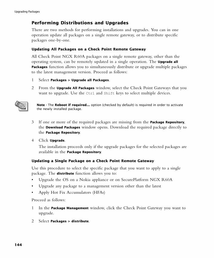
Upgrading Packages
Performing Distributions and Upgrades
There are two methods for performing installations and upgrades. You can in one operation update all packages on a single remote gateway, or to distribute specific packages one-by-one.
Updating All Packages on a Check Point Remote Gateway
All Check Point NGX R60A packages on a single remote gateway, other than the operating system, can be remotely updated in a single operation. The Upgrade all
Packages function allows you to simultaneously distribute or upgrade multiple packages to the latest management version. Proceed as follows:
1 Select Packages > Upgrade all Packages.
2 From the Upgrade All Packages window, select the Check Point Gateways that you want to upgrade. Use the Ctrl and Shift keys to select multiple devices.
3 If one or more of the required packages are missing from the Package Repository, the Download Packages window opens. Download the required package directly to the Package Repository.
4 Click Upgrade.
The installation proceeds only if the upgrade packages for the selected packages are available in the Package Repository.
Updating a Single Package on a Check Point Remote Gateway
Use this procedure to select the specific package that you want to apply to a single package. The distribute function allows you to:
• Upgrade the OS on a Nokia appliance or on SecurePlatform NGX R60A
• Upgrade any package to a management version other than the latest
• Apply Hot Fix Accumulators (HFAs)
Proceed as follows:
1 In the Package Management window, click the Check Point Gateway you want to upgrade.
2 Select Packages > distribute.
Note - The Reboot if required... option (checked by default) is required in order to activate the newly installed package.
144

Other Upgrade Operations
3 From the distribute Packages window, select the package that you want to distribute. Use the Ctrl and Shift keys to select multiple packages, and then click distribute.
The installation proceeds only if the upgrade packages selected are available in the Package Repository.
Other Upgrade Operations
In This Section
Cancelling an Operation
You can halt the installation/upgrade while in progress. To cancel an operation:
• Select Status > Stop Operation.
At a certain point in any operation, the Stop Operation function becomes unavailable. If you decide you want to cancel after this point is reached, wait for the operation to complete, and then select Packages > Uninstall.
Uninstalling Installations and Upgrades
If you want to cancel an operation and you have passed the point of no return, or the operation has finished, you can uninstall the upgrade by selecting Packages > Uninstall.
Rebooting the Check Point Gateway
After installation/uninstallation, it is recommended to reboot the module.
To reboot the Gateway, either:
• Check the Reboot if required... property during the final stage of each respective operation, or
• Select Packages > Reboot Gateway.
Cancelling an Operation page 145
Uninstalling Installations and Upgrades page 145
Rebooting the Check Point Gateway page 145
Recovering From a Failed Upgrade page 146
Deleting Packages From the Package Repository page 146
Note - Uninstallation restores the Gateway to the last management version installed.
Chapter 7 SmartUpdate 145
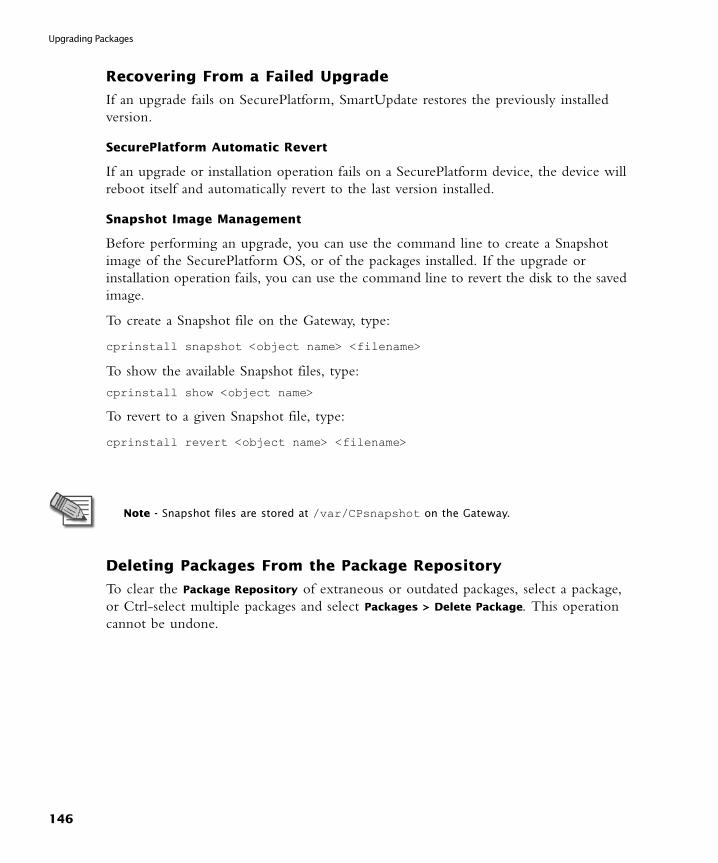
Upgrading Packages
Recovering From a Failed Upgrade
If an upgrade fails on SecurePlatform, SmartUpdate restores the previously installed version.
SecurePlatform Automatic Revert
If an upgrade or installation operation fails on a SecurePlatform device, the device will reboot itself and automatically revert to the last version installed.
Snapshot Image Management
Before performing an upgrade, you can use the command line to create a Snapshot image of the SecurePlatform OS, or of the packages installed. If the upgrade or installation operation fails, you can use the command line to revert the disk to the saved image.
To create a Snapshot file on the Gateway, type:
cprinstall snapshot <object name> <filename>
To show the available Snapshot files, type:
cprinstall show <object name>
To revert to a given Snapshot file, type:
cprinstall revert <object name> <filename>
Deleting Packages From the Package Repository
To clear the Package Repository of extraneous or outdated packages, select a package, or Ctrl-select multiple packages and select Packages > Delete Package. This operation cannot be undone.
Note - Snapshot files are stored at /var/CPsnapshot on the Gateway.
146
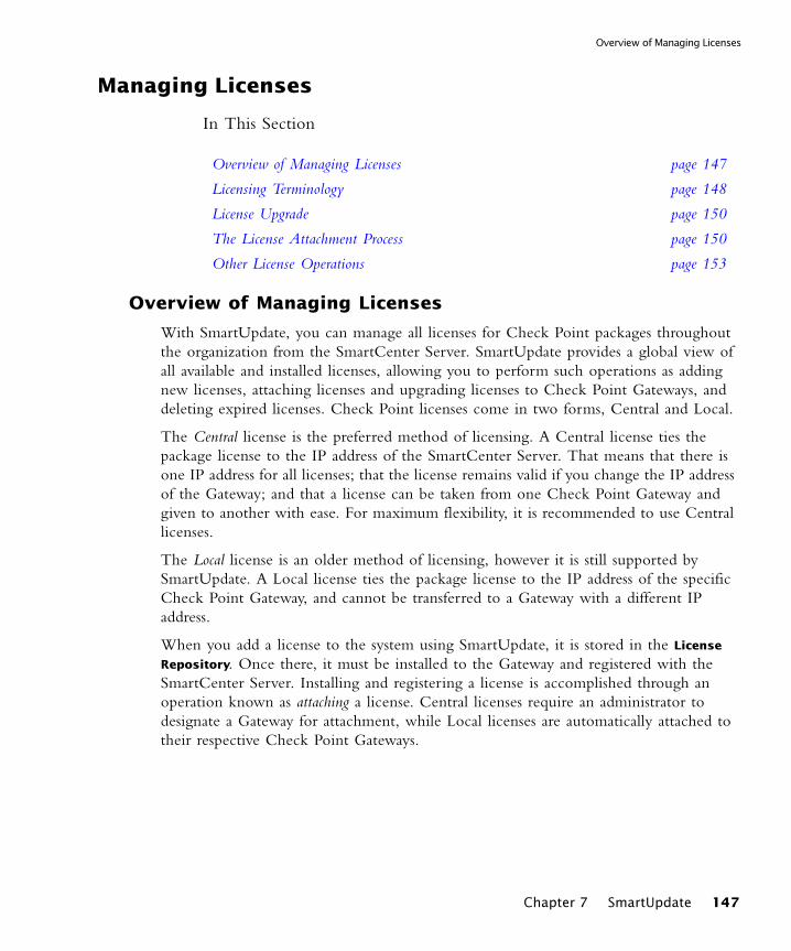
Overview of Managing Licenses
Managing Licenses
In This Section
Overview of Managing Licenses
With SmartUpdate, you can manage all licenses for Check Point packages throughout the organization from the SmartCenter Server. SmartUpdate provides a global view of all available and installed licenses, allowing you to perform such operations as adding new licenses, attaching licenses and upgrading licenses to Check Point Gateways, and deleting expired licenses. Check Point licenses come in two forms, Central and Local.
The Central license is the preferred method of licensing. A Central license ties the package license to the IP address of the SmartCenter Server. That means that there is one IP address for all licenses; that the license remains valid if you change the IP address of the Gateway; and that a license can be taken from one Check Point Gateway and given to another with ease. For maximum flexibility, it is recommended to use Central licenses.
The Local license is an older method of licensing, however it is still supported by SmartUpdate. A Local license ties the package license to the IP address of the specific
Check Point Gateway, and cannot be transferred to a Gateway with a different IP address.
When you add a license to the system using SmartUpdate, it is stored in the License
Repository. Once there, it must be installed to the Gateway and registered with the SmartCenter Server. Installing and registering a license is accomplished through an operation known as attaching a license. Central licenses require an administrator to designate a Gateway for attachment, while Local licenses are automatically attached to their respective Check Point Gateways.
Overview of Managing Licenses page 147
Licensing Terminology page 148
License Upgrade page 150
The License Attachment Process page 150
Other License Operations page 153
Chapter 7 SmartUpdate 147

Managing Licenses
Licensing Terminology• Add
Licenses received from the User Center should first be added to the SmartUpdate License Repository. Adding a local license to the License Repository also attaches it to the gateway. Licenses can be conveniently imported to the License Repository via a file and they can be added manually by pasting or typing the license details.
• Attach Licenses are attached to a gateway via SmartUpdate. Attaching a license to a gateway involves installing the license on the remote gateway, and associating the license with the specific gateway in the License Repository.
• Central License A Central License is a license attached to the SmartCenter Server IP address, rather than the gateway IP address. The benefits of a Central License are:
• Only one IP address is needed for all licenses.
• A license can be taken from one gateway and given to another.
• The new license remains valid when changing the gateway IP address. There is no need to create and install a new license.
• Certificate Key The Certificate Key is a string of 12 alphanumeric characters. The number is unique to each package. For an evaluation license your certificate key can be found inside the mini pack. For a permanent license you should receive your certificate key from your reseller.
• CPLIC A command line for managing local licenses and local license operations. Refer to Local Licensing Commands in the NGX R60A SmartCenter User Guide for additional information.
• Detach Detaching a license from a gateway involves uninstalling the license from the remote gateway and making the license in the License Repository available to any gateway.
• State Licenses can be in one of the following states: Requires Upgrade, No NGX License, Obsolete or Assigned. The license state depends on whether the license is associated with the enforcement module in the License Repository, and whether the license is installed on the remote enforcement module. The license state definitions are as follows:
• Attached indicates that the license is associated with the enforcement module in the License Repository, and is installed on the remote enforcement module.
148
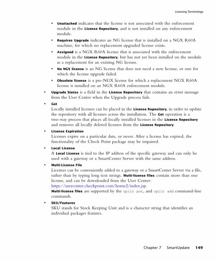
Licensing Terminology
• Unattached indicates that the license is not associated with the enforcement module in the License Repository, and is not installed on any enforcement module.
• Requires Upgrade indicates an NG license that is installed on a NGX R60A machine, for which no replacement upgraded license exists.
• Assigned is a NGX R60A license that is associated with the enforcement module in the License Repository, but has not yet been installed on the module as a replacement for an existing NG license.
• No NGX license is an NG license that does not need a new license, or one for which the license upgrade failed.
• Obsolete license is a pre-NGX license for which a replacement NGX R60A license is installed on an NGX R60A enforcement module.
• Upgrade Status is a field in the License Repository that contains an error message from the User Center when the Upgrade process fails.
• Get Locally installed licenses can be placed in the License Repository, in order to update the repository with all licenses across the installation. The Get operation is a two-way process that places all locally installed licenses in the License Repository and removes all locally deleted licenses from the License Repository.
• License Expiration Licenses expire on a particular date, or never. After a license has expired, the functionality of the Check Point package may be impaired.
• Local License A Local License is tied to the IP address of the specific gateway and can only be used with a gateway or a SmartCenter Server with the same address.
• Multi-License File Licenses can be conveniently added to a gateway or a SmartCenter Server via a file, rather than by typing long text strings. Multi-license files contain more than one license, and can be downloaded from the User Center: https://usercenter.checkpoint.com/home2/index.jsp.Multi-license files are supported by the cplic put, and cplic add command-line commands.
• SKU/Features SKU stands for Stock Keeping Unit and is a character string that identifies an individual packages features.
Chapter 7 SmartUpdate 149
Managing Licenses
License Upgrade
One of the many SmartUpdate features is to upgrade licenses that reside in the License
Repository. SmartUpdate will take all the licenses in the License Repository and will attempt to upgrade them with the use of the Upgrade tool.
For a full explanation on how to upgrade licenses refer to the Upgrading Licenses to NGX chapter in the NGX Upgrade Guide.
The License Attachment Process
In This Section
Introducing the License Attachment Process
When a Central license is placed in the License Repository, SmartUpdate allows you to attach it to Check Point packages. Attaching a license installs it to the remote Gateway and registers it with the SmartCenter Server.
New licenses need to be attached when:
• An existing license expires.
• An existing license is upgraded to a newer license.
• A Local license is replaced with a Central license.
• The IP address of the SmartCenter Server or Check Point Gateway changes.
Attaching a license is a three step process.
1 Get real-time license data from the remote gateway.
2 Add the appropriate license to the License Repository.
3 Attach the license to the device.
The following explains the process in detail.
Introducing the License Attachment Process page 150
Retrieving License Data From Check Point Gateways page 151
Adding New Licenses to the License Repository page 151
Attaching Licenses page 152
150
The License Attachment Process
Retrieving License Data From Check Point Gateways
To know exactly what type of license is on each remote gateway, you can retrieve that data directly from the gateway.
• To retrieve license data from a single remote gateway, right-click on the gateway in the License Management window and select Get Check Point Gateway Licenses.
• To retrieve license data from multiple Check Point Gateways, from the Licenses menu and select Get All Licenses.
Adding New Licenses to the License Repository
To install a license, you must first add it to the License Repository. You can add licenses to the License Repository in the following ways:
Download From the User Center
1 Select Licenses > New License > Add from User Center
2 Enter your credentials.
3 Perform one of the following:
• Generate a new license - if there are no identical licenses, the license is added to the License Repository.
• Change the IP address of an existing license, i.e., Move IP.
• Change the license from Local to Central.
• Upgrade the license from version 4.1 to NGX R60A.
Importing License Files
1 Select Licenses > New License > Import File.
2 Browse to the location of the license file, select it, and click Open.
A license file can contain multiple licenses. Unattached Central licenses appear in the License Repository, and Local licenses are automatically attached to their Check Point Gateway. All licenses are assigned a default name in the format SKU@ time date, which you can modify at a later time.
Add License Details Manually
You may add licenses that you have received from the Licensing Center by email. The email contains the license installation instructions.
1 Locate the license:
Chapter 7 SmartUpdate 151

Managing Licenses
• If you have received a license by email, copy the license to the clipboard. Copy the string that starts with cplic putlic... and ends with the last SKU/Feature. For example: cplic putlic 1.1.1.1 06Dec2002 dw59Ufa2-eLLQ9NB-gPuyHzvQ-WKreSo4Zx CPSUITE-EVAL-3DES-NGX CK-1234567890
• If you have a hardcopy printout, continue to step 2.
2 Select the License tab in SmartUpdate.
3 Select Licenses > New License > Add Manually. The Add Licenses window appears.
4 Enter the license details:
• If you copied the license to the clipboard, click Paste License. The fields will be populated with the license details.
• Alternatively, enter the license details from a hard-copy printout.
5 Click Calculate, and make sure the result matches the validation code received from the User Center.
6 You may assign a name to the license, if desired. If you leave the Name field empty, the license is assigned a name in the format SKU@ time date.
7 Click OK to complete the operation.
Attaching Licenses
After licenses have been added to the License Repository, select one or more licenses to attach to a Check Point Gateway.
1 Select the license(s).
2 Select Licenses > Attach.
3 From the Attach Licenses window, select the desired device.
If the attach operation fails, the Local licenses are deleted from the Repository.
152

Other License Operations
Other License Operations
In This Section
Detaching Licenses
Detaching a license involves deleting a single Central license from a remote Check Point Gateway and marking it as unattached in the License Repository. This license is then available to be used by any Check Point Gateway.
To detach a license, select Licenses > Detach and select the licenses to be detached from the displayed window.
Deleting Licenses From the License Repository
Licenses that are not attached to any Check Point Gateway and are no longer needed can be deleted from the License Repository.
To delete a license:
1 Right-click anywhere in the License Repository and select View Unattached
Licenses.
2 Select the unattached license(s) to be deleted, and click Delete.
Viewing License Properties
The overall view of the License Repository displays general information on each license such as the name of the license and the IP address of the machine to which it is attached. You can view other properties as well, such as expiration date, SKU, license type, certificate key and signature key.
To view license properties, double-click on the license in the Licenses tab.
Detaching Licenses page 153
Deleting Licenses From the License Repository page 153
Viewing License Properties page 153
Checking for Expired Licenses page 154
Exporting a License to a File page 154
Note - Local licenses, prior to NGX R60A, cannot be detached from a remote Check Point Gateway.
Chapter 7 SmartUpdate 153
Managing Licenses
Checking for Expired Licenses
After a license has expired, the functionality of the Check Point package will be impaired; therefore, it is advisable to be aware of the pending expiration dates of all licenses.
To check for expired licenses, select Licenses > Show Expired Licenses.
To check for licenses nearing their dates of expiration:
1 In the License Expiration window, set the Search for licenses expiring within the
next x days property.
2 Click Apply to run the search.
To delete expired licenses from the License Expiration window, select the detached license(s) and click Delete.
Exporting a License to a File
Licenses can be exported to a file. The file can later be imported to the License
Repository. This can be useful for administrative or support purposes.
To export a license to a file:
1 In the Licenses Repository select one or more license, right-click, and from the menu select Export to File….
2 In the Choose File to Export License(s) To window, name the file (or select an existing file), and browse to the desired location. Click Save.
All selected licenses are exported. If the file already exists, the new licenses are added to the file.
154
Other License Operations
Generating CPInfoCPInfo is a support tool that gathers into one text file a wide range of data concerning the Check Point packages in your system. When speaking with a Check Point Technical Support Engineer, you may be asked to run CPInfo and transmit the data to the Support Center.
To launch CPInfo, select Packages > Generate CPInfo.
1 Choose the directory to which you want to save the output file.
2 Choose between two methods to name the file:
• based on the SR number the technician assigns you, or
• a custom name that you define.
3 Optionally, you may choose to add:
• log files to the CPInfo output
• the registry to the CPInfo output
The SmartUpdate Command LineAll management operations that are performed via the SmartUpdate GUI can also be executed via the command line. There are three main commands:
• cppkg to work with the Packages Repository
• cprinstall to perform remote installations of packages
• cplic for license management
For details on how to use these commands, see the Command Line Interface (CLI) Guide.
Chapter 7 SmartUpdate 155

The SmartUpdate Command Line
156
CHAPTER 8
SmartDirectory (LDAP) and User Management
This chapter assumes that you have working knowledge of LDAP technology.
In This Chapter
The Need to Integrate LDAP servers with Check Point Software
When Check Point software is purchased, you may already have an effective user management infrastructure, such as LDAP. VPN-1 Pro supports LDAP technology and uses existing LDAP servers to obtain user information for authentication and authorization purposes.
If you do not have a user management infrastructure in place, you can make a choice between managing customers on the internal users database or choosing to implement an LDAP server. If you have a large user count, it is recommended to opt for an external user management database, such as LDAP. By maintaining the a large user database externally, VPN-1 Pro performance is greatly enhanced. For example, if the user database is external, the database will not have to be reinstalled every time the user information changes. Additionally, the LDAP user database can be used as the user database by other applications.
The Need to Integrate LDAP servers with Check Point Software page 157
The Check Point Solution for Using LDAP servers page 158
SmartDirectory (LDAP) Considerations page 165
Configuring SmartDirectory (LDAP) Entities to Work with VPN-1 Pro page 166
SmartDirectory (LDAP) Reference Information page 175
157
The Check Point Solution for Using LDAP servers
The Check Point Solution for Using LDAP servers
In This Section
Check Point products are compliant with LDAP technology. This compliancy enables:
• Users to be managed externally by an LDP server.
• The Enforcement modules to retrieve CRLs.
• User information from other applications gathered in the LDAP users database, to be shared by many different applications. VPN-1 Pro uses the user information for authentication purposes.
LDAP is an open industry standard that is used by multiple vendors. It is widely accepted as the directory access method of the Internet. One of the reasons that it is the obvious choice for so many vendors is because of its cross-platform compliancy, LDAP is automatically installed on different Operating Systems (e.g. the Microsoft Active Directory) and servers (such as Novell, Netscape etc.).
When integrated with SmartCenter, LDAP is referred to as SmartDirectory (LDAP).
VPN-1 Pro SmartDirectory (LDAP) Deployment
When deployed with a SmartDirectory (LDAP) server, VPN-1 Pro components such as the SmartCenter Server and Enforcement modules, function as SmartDirectory (LDAP) clients. For instance, in FIGURE 8-1:
• The SmartCenter Server manages the user information on the SmartDirectory (LDAP) server
• The Enforcement modules acts as a SmartDirectory (LDAP) client in order to
• Query user information
• Retrieve CRLs
• In some cases perform bind operations for authentication purposes.
Account Units page 159
Managing Users on a SmartDirectory (LDAP) server page 162
Retrieving Information from a SmartDirectory (LDAP) server page 162
Working with Multiple SmartDirectory (LDAP) Servers page 163
Check Point Schema page 163
SmartDirectory (LDAP) Profiles page 164
158
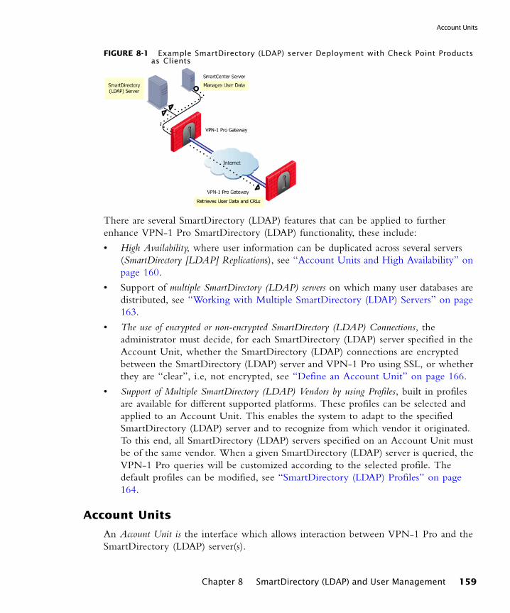
Account Units
FIGURE 8-1 Example SmartDirectory (LDAP) server Deployment with Check Point Products as Clients
There are several SmartDirectory (LDAP) features that can be applied to further enhance VPN-1 Pro SmartDirectory (LDAP) functionality, these include:
• High Availability, where user information can be duplicated across several servers (SmartDirectory [LDAP] Replications), see “Account Units and High Availability” on page 160.
• Support of multiple SmartDirectory (LDAP) servers on which many user databases are distributed, see “Working with Multiple SmartDirectory (LDAP) Servers” on page 163.
• The use of encrypted or non-encrypted SmartDirectory (LDAP) Connections, the administrator must decide, for each SmartDirectory (LDAP) server specified in the Account Unit, whether the SmartDirectory (LDAP) connections are encrypted between the SmartDirectory (LDAP) server and VPN-1 Pro using SSL, or whether they are “clear”, i.e, not encrypted, see “Define an Account Unit” on page 166.
• Support of Multiple SmartDirectory (LDAP) Vendors by using Profiles, built in profiles are available for different supported platforms. These profiles can be selected and applied to an Account Unit. This enables the system to adapt to the specified SmartDirectory (LDAP) server and to recognize from which vendor it originated. To this end, all SmartDirectory (LDAP) servers specified on an Account Unit must be of the same vendor. When a given SmartDirectory (LDAP) server is queried, the VPN-1 Pro queries will be customized according to the selected profile. The default profiles can be modified, see “SmartDirectory (LDAP) Profiles” on page 164.
Account Units
An Account Unit is the interface which allows interaction between VPN-1 Pro and the SmartDirectory (LDAP) server(s).
Chapter 8 SmartDirectory (LDAP) and User Management 159
The Check Point Solution for Using LDAP servers
Each Account Unit represents one or more branches of the information maintained on the SmartDirectory (LDAP) server. An organization may have several Account Units, which represent the various SmartDirectory (LDAP) servers. In this case, the users in the system are split between the different Account Units, as well as between the different branches within the Account Unit. For instance, in a bank with one SmartDirectory (LDAP) server, one Account Unit may represent users with businesses accounts and another Account Unit may represent users with private accounts. Within the former, large business users may be defined in one branch and small business users may be defined on another branch.
In order to work with SmartDirectory (LDAP) servers, the administrator needs to
• define the Account Unit(s) that represents the organization
• enter the access information required in order to connect to the relevant SmartDirectory (LDAP) server.
After this is done, the SmartCenter server or VPN-1 Pro modules can then connect to that SmartDirectory (LDAP) server in order to manage the users or to make queries.
The SmartDirectory (LDAP) Schema
The SmartDirectory (LDAP) server has a default schema which is simply a description of the structure of the data in a SmartDirectory (LDAP) directory. It includes user definitions defined for that proprietary SmartDirectory (LDAP) server. This schema does not possess VPN-1 Pro specific information, such as IKE-related attributes, authentication schemes and values for remote users.
It is possible to make do with the default SmartDirectory (LDAP) schema. Especially in the case when all users use the same authentication scheme and are defined according to a default template. However, if the users in the database have different definitions, it is more effective to apply a Check Point schema to the SmartDirectory (LDAP) server. The Check Point schema complements structure of the information in the SmartDirectory (LDAP) server and provides VPN-1 Pro specific information, see “Check Point Schema” on page 163.
Account Units and High Availability
If you are using SmartDirectory (LDAP) replications for High Availability purposes, the same Account Unit can be used to represent all the replicated SmartDirectory (LDAP) servers. FIGURE 8-2 illustrates a network in which two SmartDirectory (LDAP) server replications, defined on the same Account Unit, are used by different Check Point modules.
160
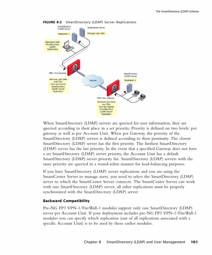
The SmartDirectory (LDAP) Schema
FIGURE 8-2 SmartDirectory (LDAP) Server Replications
When SmartDirectory (LDAP) servers are queried for user information, they are queried according to their place in a set priority. Priority is defined on two levels: per gateway as well as per Account Unit. When per Gateway, the priority of the SmartDirectory (LDAP) servers is defined according to their proximity. The closest SmartDirectory (LDAP) server has the first priority. The furthest SmartDirectory (LDAP) server has the last priority. In the event that a specified Gateway does not have a set SmartDirectory (LDAP) server priority, the Account Unit has a default SmartDirectory (LDAP) server priority list. SmartDirectory (LDAP) servers with the same priority are queried in a round-robin manner for load-balancing purposes.
If you have SmartDirectory (LDAP) server replications and you are using the SmartCenter Server to manage users, you need to select the SmartDirectory (LDAP) server to which the SmartCenter Server connects. The SmartCenter Server can work with one SmartDirectory (LDAP) server, all other replications must be properly synchronized with the SmartDirectory (LDAP) server
Backward Compatibility
Pre-NG FP3 VPN-1/FireWall-1 modules support only one SmartDirectory (LDAP) server per Account Unit. If your deployment includes pre-NG FP3 VPN-1/FireWall-1 modules you can specify which replication (out of all replications associated with a specific Account Unit) is to be used by these earlier modules.
Chapter 8 SmartDirectory (LDAP) and User Management 161
The Check Point Solution for Using LDAP servers
Managing Users on a SmartDirectory (LDAP) server
In order to manage users on a SmartDirectory (LDAP) server a special license is required. Once the license has been obtained, an Account Unit that represents the SmartDirectory (LDAP) server needs to be defined. The users and user groups are arranged on the Account Unit in a tree structure which reflects the structure of the SmartDirectory (LDAP) server. This tree reflects the internal user hierarchy of the organization represented by the Account Unit. Users which are managed on an external SmartDirectory (LDAP) server are managed (added, edited or deleted) as if they were users managed by the SmartCenter Server. There are two main difference between user management on the internal database, and user management on a SmartDirectory (LDAP) server. Firstly, user management in the SmartDirectory (LDAP) server is done externally and not locally. Secondly, on a SmartDirectory (LDAP) server templates can be modified and applied to users dynamically. This means that user definitions are easy to change and to manage; and changes are instantaneous or “live”. Changes that are applied to a SmartDirectory (LDAP) template are reflected immediately for all users who are using that template.
Retrieving Information from a SmartDirectory (LDAP) server
When a Gateway requires user information for authentication purposes, it searches for this information in three different places:
1 The first place that is queried is the internal users database.
2 If the specified user is not defined in this database, the Gateway queries the SmartDirectory (LDAP) servers defined in the Account Unit one at a time, and according to their priority. If for some reason the query against a specified SmartDirectory (LDAP) server fails, for instance the SmartDirectory (LDAP) connection is lost, the SmartDirectory (LDAP) server with the next highest priority is queried. If there is more than one Account Unit, the Account Units are queried concurrently. The results of the query are either taken from the first Account Unit to meet the conditions, or from all the Account Units which meet the conditions. The choice between taking the result of one Account Unit as opposed to many is a matter of Gateway configuration.
3 If the information still cannot be found, the Gateway uses the external users template to see if there is a match against the generic profile. This generic profile has the default attributes applied to the specified user.
For performance issues, it is better to query SmartDirectory (LDAP) Account Units when there are open connections. For this reason, some open connections are maintained by the modules. These open connections will be used on order to execute a series of queries on user information, such as:
162
Working with Multiple SmartDirectory (LDAP) Servers
• Who is the user?
• To what groups does the user belong?
A SmartDirectory (LDAP) group is a user group which consists of members who are defined on a SmartDirectory (LDAP) server and not on the internal VPN-1 Pro database. For more information, see “SmartDirectory (LDAP) Groups” on page 171.
The Gateway queries the SmartDirectory (LDAP) server in order to determine if the user belongs to a group that is permitted to perform certain operations, (for instance whether the user is allowed to open a VPN tunnel).
Working with Multiple SmartDirectory (LDAP) Servers
Distributing Users across Multiple SmartDirectory (LDAP) Servers
The users of an organization may be distributed across several SmartDirectory (LDAP) servers. Each SmartDirectory (LDAP) server must be represented by a separate Account Unit.
Querying Multiple SmartDirectory (LDAP) Servers
The SmartCenter Server and the Enforcement modules can work with multiple SmartDirectory (LDAP) servers concurrently. For example, if a Gateway needs to find users information, and it does not know where the specified user is defined, it is able to query all the SmartDirectory (LDAP) servers in the system. (Sometimes a Gateway may be able to ascertain the location of a user by looking at the user DN when working with certificates).
Check Point Schema
The SmartDirectory (LDAP) schema is the default schema which assigns objects their properties and attributes. While it is often enough to work with the default, in certain cases, like when the default authentication scheme and the default templates, are not used globally by all users, it is advisable to enhance the default SmartDirectory (LDAP) schema by adding the Check Point schema.
The Check Point schema acts as an extension to the default SmartDirectory (LDAP) schema. It can be used in order to enhance the definition of various objects for extended user authentication functionality. For example, an Object Class, entitled, fw1Person is part of the Check Point schema, this Object Class has some mandatory and some optional attributes and it enhances the definition of the Person attribute. Another example is fw1Template, this is a standalone attribute which is used to define a template of user information to which a user can be associated. See “SmartDirectory (LDAP) Schema” on page 180 for the Check Point schema.
Chapter 8 SmartDirectory (LDAP) and User Management 163
The Check Point Solution for Using LDAP servers
SmartDirectory (LDAP) Profiles
There are different LDAP servers which are designed by several different LDAP vendors. SmartDirectory (LDAP) profiles are assigned to ensure that the default attributes for a given SmartDirectory (LDAP) server are properly in place. In other words, if you have a certified OPSEC SmartDirectory (LDAP) server, apply the OPSEC_DS profile to get enhanced OPSEC-specific SmartDirectory (LDAP) server attributes.
The existing SmartDirectory (LDAP) servers and SmartDirectory (LDAP) deployments differ in terms of object repositories, schema, and object relations. The following examples illustrate this variety:
• The organization’s users database may have unconventional object types and relations due to the use of a specific application.
• Some applications use the cn attribute in the User object’s Relatively Distinguished Name (RDN) while others use uid.
• In Microsoft Active Directory, the user attribute memberOf describes which group the user belongs to, while standard LDAP schemes define the member attribute in the group object itself.
• Different servers implement different storage formats for passwords.
• Some servers are considered v3 but do not implement some of v3 specifications. Therefore, the organizations using such servers will not be able to extend the schema.
• Some LDAP servers already have built in support for certain user data while others require a Check Point schema extended attribute. For example, Microsoft Active Directory has the accountExpires user attribute while other SmartDirectory (LDAP) servers require the Check Point attribute fw1expirationdate which is part of the Check Point defined fw1person objectclass.
• Some servers allow queries with non-defined types while others do not.
To help the administrators successfully cope with diverse technical solutions, a new layer, SmartDirectory (LDAP) profiles, has been added that controls most of the SmartDirectory (LDAP) server-specific knowledge. The SmartDirectory (LDAP) profile is a configurable LDAP policy that allows administrators to define more precise SmartDirectory (LDAP) requests and enhance communication with the server.
Modifying SmartDirectory (LDAP) Profiles
Profiles consist of three major categories
• Common - this category lists profile settings that common both when reading and writing to the SmartDirectory (LDAP) server
164

SmartDirectory (LDAP) Profiles
• Read - this category lists profile settings that are relevant only when reading from the SmartDirectory (LDAP) server
• Write - this category lists profile settings that are relevant only when writing to the SmartDirectory (LDAP) server
Some of these categories list the same entry with different values. This is because the behavior differs depending on the type of operation.
Default SmartDirectory (LDAP) profiles
Four profiles are defined by default, each corresponding to a specific SmartDirectory (LDAP) server:
• OPSEC_DS - the default profile for a standard OPSEC certified SmartDirectory (LDAP) server
• Netscape_DS - the profile for a Netscape Directory Server
• Novell_DS - the profile for a Novell Directory Server
• Microsoft_AD - the profile for Microsoft Active Directory.
Working with the SmartDirectory (LDAP) profile
The profile is selected and applied during the creation or modification of a SmartDirectory (LDAP) Account Unit. However, you can modify certain parameters of the default profiles for finer granularity and performance tuning. This is done by copying the settings of an existing SmartDirectory (LDAP) profile into a newly created profile and then modifying the profile to fit the requirements.
See, “Modifying SmartDirectory (LDAP) Profiles” on page 189 for details on how to modify SmartDirectory (LDAP) profiles.
SmartDirectory (LDAP) ConsiderationsThe key to effective use of SmartDirectory (LDAP) servers is careful planning the system administrator needs to decide:
• How to use the SmartDirectory (LDAP) server, whether for user management, CR retrieval, user authentication or all three.
• How many SmartDirectory (LDAP) servers to use. If High Availability is being implemented, the use of Replications also needs to be carefully considered. For each SmartDirectory (LDAP) server an Account Unit needs to be created to represent it. Account Units need to be properly installed in a place whether they can communicate securely and effectively with the Enforcement modules.
• The priority (for High Availability and querying purposes) of the SmartDirectory (LDAP) servers. The order of priority of SmartDirectory (LDAP) servers is defined in two places: on the Account Unit and on the Gateway. The priority for the
Chapter 8 SmartDirectory (LDAP) and User Management 165
Configuring SmartDirectory (LDAP) Entities to Work with VPN-1 Pro
SmartDirectory (LDAP) server may be different on these entities. Generally, the priority for Gateways is defined according to proximity, where the nearest SmartDirectory (LDAP) server has the highest priority.
• Users need to be effectively and efficiently spread out across the available Account Units, branches and sub branches. Moreover, they need to be classified in logical groups whose members all share a common thread (such as role in the organization, permissions, etc.).
Configuring SmartDirectory (LDAP) Entities to Work with VPN-1 Pro
The predominant reasons for integrating VPN-1 Pro and SmartDirectory (LDAP) are:
• To query user information
• To enable User management
• To enable CRL retrieval
• To authenticate users
The first step for any of these objectives is to define an Account Unit. If you are implementing SmartDirectory (LDAP) user management, you will need to know which entities to define, and how to manage the users defined on the SmartDirectory (LDAP) server. SmartDirectory (LDAP) user management requires a special license.
In This Section
Define an Account Unit
Create a new SmartDirectory (LDAP) Account unit via the Servers tab of the Objects Tree, see (FIGURE 8-7). The SmartDirectory (LDAP) Account Unit Properties window consists of several tabs:
Define an Account Unit page 166
Working with SmartDirectory (LDAP) for CRL Retrieval page 170
Managing Users page 171
Authenticating with the SmartDirectory (LDAP) Server using Certificates page 172
Using SmartDirectory (LDAP) Queries page 173
166

Define an Account Unit
1 In the General tab define the general settings of the SmartDirectory (LDAP) Account Unit. Decide whether this Account Unit is to be used for CRL retrieval, user management or both.
Select a profile to be applied to the new Account Unit.
2 In the Servers tab, display the SmartDirectory (LDAP) servers to be used by the Account Unit. The order in which they are displayed is also the default order in which they will be queriedThis priority can be defined per Gateway and in addition it can be defined on the Account Unit. You can add, remove and modify SmartDirectory (LDAP) servers from the displayed list. Additionally, for purposes of backwards compatibility, select a SmartDirectory (LDAP) server which is able to work with pre-NG FP3 VPN-1/FireWall-1 modules.Modifying the SmartDirectory (LDAP) server
Double-click on a SmartDirectory (LDAP) server in the displayed list in order to modify it. The SmartDirectory (LDAP) server Properties window is displayed.
FIGURE 8-3 SmartDirectory (LDAP) Server Properties window
Configure the following tabs:
Note - If you do not select this option, the SSO for LDAP users will not work if this checkbox is unmarked.
Chapter 8 SmartDirectory (LDAP) and User Management 167
Configuring SmartDirectory (LDAP) Entities to Work with VPN-1 Pro
• In the General tab, you can modify the login DN of the SmartDirectory (LDAP) server. Define the priority of the selected SmartDirectory (LDAP) server. Specify a password to be used for authentication purposes. You will need to confirm this password. Finally, decide whether or not this SmartDirectory (LDAP) server is allowed to be queried.
• In the Encryption tab, define whether or not SmartDirectory (LDAP) connections are SSL encrypted. If the connections are encrypted, define the relevant encryption port. and the minimum and maximum encryption strengths. Finally, verify the SmartDirectory (LDAP) server’s Fingerprints by comparing the displayed fingerprint, with the SmartDirectory (LDAP) Fingerprint.Authenticating Modules with certificates
SmartDirectory (LDAP) connections can be authenticated by using client certificates that are supplied by a trust Certificate Authority (CA). To use certificates, the SmartDirectory (LDAP) server must be configured with SSL strong authentication. For more information, see “Defining a new SmartDirectory (LDAP) Account Unit in the Objects Tree” on page 170.
3 In the Objects Management tab, select the SmartDirectory (LDAP) server on which the objects are managed. The branches for the selected SmartDirectory (LDAP) server can be retrieved by selecting Fetch branches, or they can be added manually. Some versions of SmartDirectory (LDAP) do not support automatic branch retrieval using Fetch branches. These branches will be searched when this SmartDirectory (LDAP) server is queried. The administrator can add or modify the branches.
For enhanced security, this Account Unit object can be locked with a password which must be entered when this Account Unit is accessed from SmartDashboard for managing users.
4 In the Authentication tab, the authentication limitations and default authentication settings for a user on an Account Unit are defined. The Allowed Authentication schemes limits the user’s authentication access only to those authentication schemes. You can allow several authentication schemes which can be applied per user, or you can apply a default authentication scheme which is applied to all the users.
Users that are retrieved through this Account Unit, but which are missing authentication-related definitions, will be granted these definition using the default authentication scheme, or a complete user template.
These default settings are useful, if the Check Point schema is not in place. In the place of the Check Point schema, a user template is used to supply the authentication attributes and the other options described on this page will by default be automatically configured per user.
168
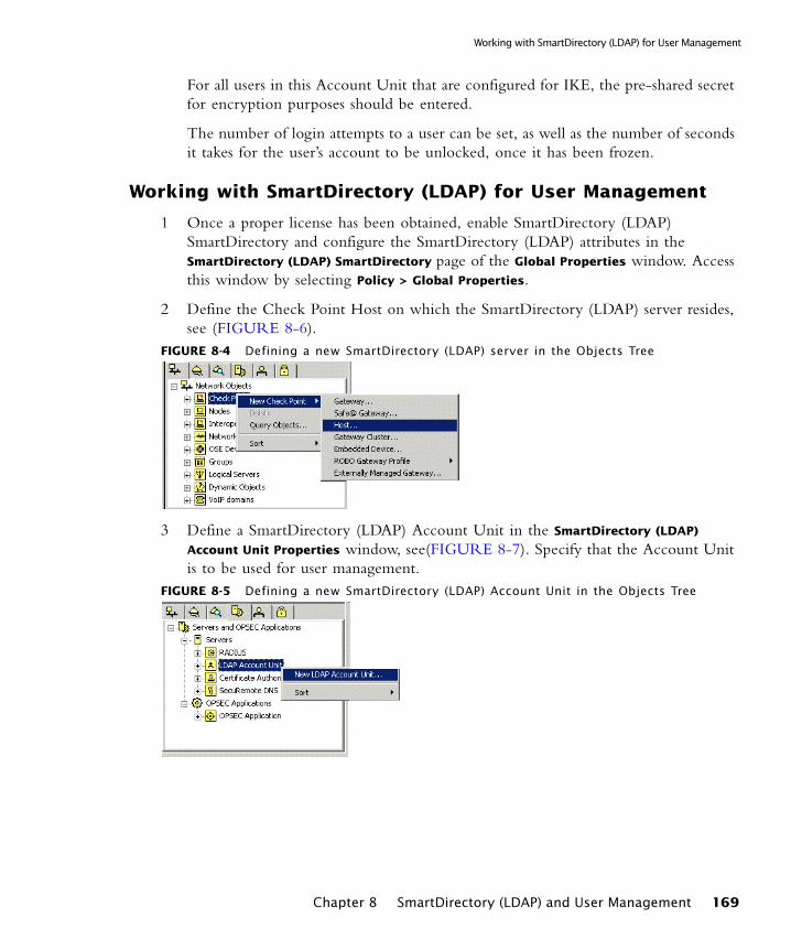
Working with SmartDirectory (LDAP) for User Management
For all users in this Account Unit that are configured for IKE, the pre-shared secret for encryption purposes should be entered.
The number of login attempts to a user can be set, as well as the number of seconds it takes for the user’s account to be unlocked, once it has been frozen.
Working with SmartDirectory (LDAP) for User Management
1 Once a proper license has been obtained, enable SmartDirectory (LDAP) SmartDirectory and configure the SmartDirectory (LDAP) attributes in the SmartDirectory (LDAP) SmartDirectory page of the Global Properties window. Access this window by selecting Policy > Global Properties.
2 Define the Check Point Host on which the SmartDirectory (LDAP) server resides, see (FIGURE 8-6).
FIGURE 8-4 Defining a new SmartDirectory (LDAP) server in the Objects Tree
3 Define a SmartDirectory (LDAP) Account Unit in the SmartDirectory (LDAP)
Account Unit Properties window, see(FIGURE 8-7). Specify that the Account Unit is to be used for user management.
FIGURE 8-5 Defining a new SmartDirectory (LDAP) Account Unit in the Objects Tree
Chapter 8 SmartDirectory (LDAP) and User Management 169
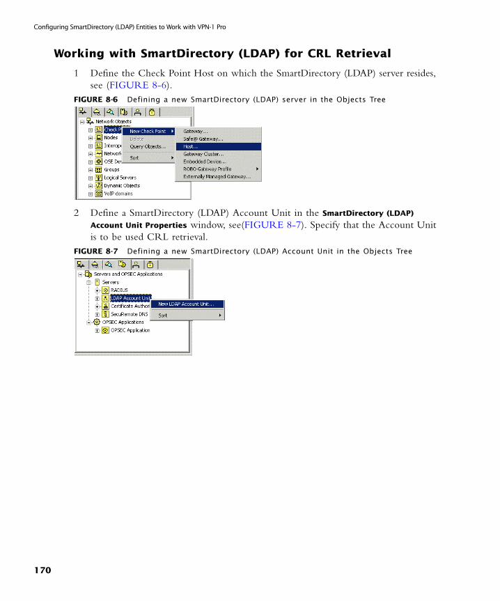
Configuring SmartDirectory (LDAP) Entities to Work with VPN-1 Pro
Working with SmartDirectory (LDAP) for CRL Retrieval
1 Define the Check Point Host on which the SmartDirectory (LDAP) server resides, see (FIGURE 8-6).
FIGURE 8-6 Defining a new SmartDirectory (LDAP) server in the Objects Tree
2 Define a SmartDirectory (LDAP) Account Unit in the SmartDirectory (LDAP)
Account Unit Properties window, see(FIGURE 8-7). Specify that the Account Unit is to be used CRL retrieval.
FIGURE 8-7 Defining a new SmartDirectory (LDAP) Account Unit in the Objects Tree
170
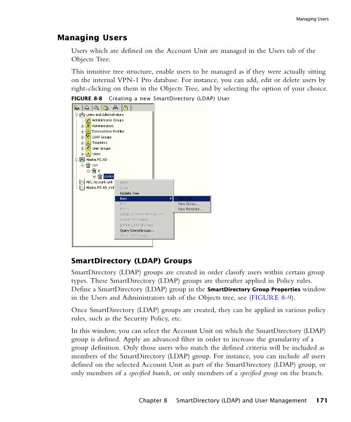
Managing Users
Managing Users
Users which are defined on the Account Unit are managed in the Users tab of the Objects Tree.
This intuitive tree structure, enable users to be managed as if they were actually sitting on the internal VPN-1 Pro database. For instance, you can add, edit or delete users by right-clicking on them in the Objects Tree, and by selecting the option of your choice.FIGURE 8-8 Creating a new SmartDirectory (LDAP) User
SmartDirectory (LDAP) Groups
SmartDirectory (LDAP) groups are created in order classify users within certain group types. These SmartDirectory (LDAP) groups are thereafter applied in Policy rules. Define a SmartDirectory (LDAP) group in the SmartDirectory Group Properties window in the Users and Administrators tab of the Objects tree, see (FIGURE 8-9).
Once SmartDirectory (LDAP) groups are created, they can be applied in various policy rules, such as the Security Policy, etc.
In this window, you can select the Account Unit on which the SmartDirectory (LDAP) group is defined. Apply an advanced filter in order to increase the granularity of a group definition. Only those users who match the defined criteria will be included as members of the SmartDirectory (LDAP) group. For instance, you can include all users defined on the selected Account Unit as part of the SmartDirectory (LDAP) group, or only members of a specified branch, or only members of a specified group on the branch.
Chapter 8 SmartDirectory (LDAP) and User Management 171
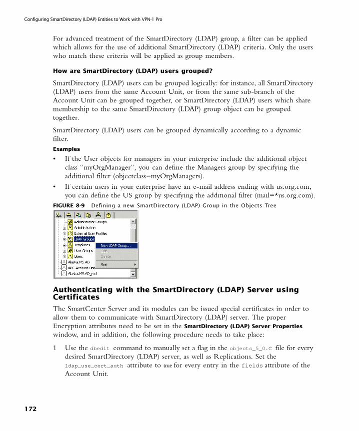
Configuring SmartDirectory (LDAP) Entities to Work with VPN-1 Pro
For advanced treatment of the SmartDirectory (LDAP) group, a filter can be applied which allows for the use of additional SmartDirectory (LDAP) criteria. Only the users who match these criteria will be applied as group members.
How are SmartDirectory (LDAP) users grouped?
SmartDirectory (LDAP) users can be grouped logically: for instance, all SmartDirectory (LDAP) users from the same Account Unit, or from the same sub-branch of the Account Unit can be grouped together, or SmartDirectory (LDAP) users which share membership to the same SmartDirectory (LDAP) group object can be grouped together.
SmartDirectory (LDAP) users can be grouped dynamically according to a dynamic filter.Examples
• If the User objects for managers in your enterprise include the additional object class “myOrgManager”, you can define the Managers group by specifying the additional filter (objectclass=myOrgManagers).
• If certain users in your enterprise have an e-mail address ending with us.org.com, you can define the US group by specifying the additional filter (mail=*us.org.com).
FIGURE 8-9 Defining a new SmartDirectory (LDAP) Group in the Objects Tree
Authenticating with the SmartDirectory (LDAP) Server using Certificates
The SmartCenter Server and its modules can be issued special certificates in order to allow them to communicate with SmartDirectory (LDAP) server. The proper Encryption attributes need to be set in the SmartDirectory (LDAP) Server Properties window, and in addition, the following procedure needs to take place:
1 Use the dbedit command to manually set a flag in the objects_5_0.C file for every desired SmartDirectory (LDAP) server, as well as Replications. Set the ldap_use_cert_auth attribute to true for every entry in the fields attribute of the Account Unit.
172
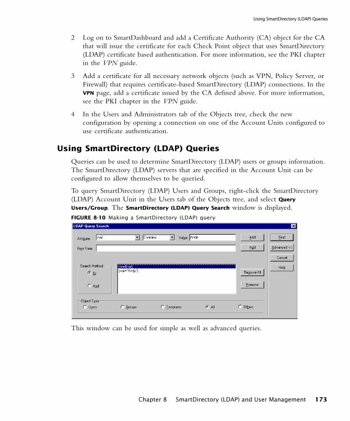
Using SmartDirectory (LDAP) Queries
2 Log on to SmartDashboard and add a Certificate Authority (CA) object for the CA that will issue the certificate for each Check Point object that uses SmartDirectory (LDAP) certificate based authentication. For more information, see the PKI chapter in the VPN guide.
3 Add a certificate for all necessary network objects (such as VPN, Policy Server, or Firewall) that requires certificate-based SmartDirectory (LDAP) connections. In the VPN page, add a certificate issued by the CA defined above. For more information, see the PKI chapter in the VPN guide.
4 In the Users and Administrators tab of the Objects tree, check the new configuration by opening a connection on one of the Account Units configured to use certificate authentication.
Using SmartDirectory (LDAP) Queries
Queries can be used to determine SmartDirectory (LDAP) users or groups information. The SmartDirectory (LDAP) servers that are specified in the Account Unit can be configured to allow themselves to be queried.
To query SmartDirectory (LDAP) Users and Groups, right-click the SmartDirectory (LDAP) Account Unit in the Users tab of the Objects tree, and select Query
Users/Group. The SmartDirectory (LDAP) Query Search window is displayed.FIGURE 8-10 Making a SmartDirectory (LDAP) query
This window can be used for simple as well as advanced queries.
Chapter 8 SmartDirectory (LDAP) and User Management 173

Configuring SmartDirectory (LDAP) Entities to Work with VPN-1 Pro
Defining Queries
1 Select an attribute, an operator and a value for each query. These represent the component being queried, the condition of the query and the specific item.
For example, <mail, contains, Andy,> means that all mail that contains the value Andy should be found. The operators are explained in TABLE 8-1.
2 There are several advanced methods which can be applied to enhance your queries. Click Advanced to see these options, which include:
• click Add each time you would like to filter by another criterion, after selecting the new attributes, operators and values.
• enter a free form SmartDirectory (LDAP) expression. See RFC 1558 for information about the syntax of SmartDirectory (LDAP) query expressions
• use the Boolean AND/OR conditions
• object types can selected in order to narrow the query. For instance, you can filter by users, groups and templates.
3 Click Find to run the query.
TABLE 8-1 Operators - meaning of values
value meaning
is The attribute’s value must be equal to the Value.is not The attribute’s value is not equal to the Value.starts with The attribute’s value starts with the Value.ends with The attribute’s value ends with the Value.contains The attribute’s value contains the Value.equal or less than
The attribute’s value is less than or equal to the Value.
equal or greater than
The attribute’s value is greater than or equal to the Value.
sounds like The attribute’s value sounds like the Value.
Note - The “less than” and “greater than” operators are supported by LDAP Version 3.0 and higher servers only.
174
Integration with Various SmartDirectory (LDAP) Vendors
When a query is executed, the SmartDirectory (LDAP) server queries the SmartDirectory (LDAP) directory, using a filter constructed from the query. For example, the query described in shown in “Defining Queries” on page 174 becomes the following filter:
SmartDirectory (LDAP) Reference Information
In This Section
Integration with Various SmartDirectory (LDAP) Vendors
In This Section
Microsoft Active Directory
The Microsoft Windows 2000 advanced server includes a sophisticated SmartDirectory (LDAP) server that can be adjusted to work as user database for VPN-1 Pro.
By default, the Active Directory services are disabled. In order to enable the directory services:
• run the dcpromo command from the Start > Run menu, or
• run the Active Directory setup wizard using the System Configuration window.
filter:(&(|(objectclass=fw1person)(objectclass=person)(objectclass=organizationalPerson)(objectclass=inetOrgPerson))(|(cn=Brad)(mail=*Andy*)))
Integration with Various SmartDirectory (LDAP) Vendors page 175
SmartDirectory (LDAP) Schema page 180
Modifying SmartDirectory (LDAP) Profiles page 189
Microsoft Active Directory page 175
Netscape LDAP Schema page 179
Chapter 8 SmartDirectory (LDAP) and User Management 175
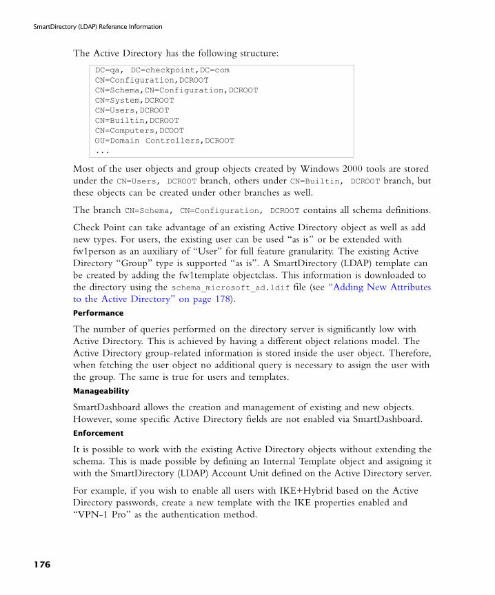
SmartDirectory (LDAP) Reference Information
The Active Directory has the following structure:
Most of the user objects and group objects created by Windows 2000 tools are stored under the CN=Users, DCROOT branch, others under CN=Builtin, DCROOT branch, but these objects can be created under other branches as well.
The branch CN=Schema, CN=Configuration, DCROOT contains all schema definitions.
Check Point can take advantage of an existing Active Directory object as well as add new types. For users, the existing user can be used “as is” or be extended with fw1person as an auxiliary of “User” for full feature granularity. The existing Active Directory “Group” type is supported “as is”. A SmartDirectory (LDAP) template can be created by adding the fw1template objectclass. This information is downloaded to the directory using the schema_microsoft_ad.ldif file (see “Adding New Attributes to the Active Directory” on page 178).Performance
The number of queries performed on the directory server is significantly low with Active Directory. This is achieved by having a different object relations model. The Active Directory group-related information is stored inside the user object. Therefore, when fetching the user object no additional query is necessary to assign the user with the group. The same is true for users and templates.Manageability
SmartDashboard allows the creation and management of existing and new objects. However, some specific Active Directory fields are not enabled via SmartDashboard.Enforcement
It is possible to work with the existing Active Directory objects without extending the schema. This is made possible by defining an Internal Template object and assigning it with the SmartDirectory (LDAP) Account Unit defined on the Active Directory server.
For example, if you wish to enable all users with IKE+Hybrid based on the Active Directory passwords, create a new template with the IKE properties enabled and “VPN-1 Pro” as the authentication method.
DC=qa, DC=checkpoint,DC=comCN=Configuration,DCROOTCN=Schema,CN=Configuration,DCROOTCN=System,DCROOTCN=Users,DCROOTCN=Builtin,DCROOTCN=Computers,DCOOTOU=Domain Controllers,DCROOT...
176
Integration with Various SmartDirectory (LDAP) Vendors
Modifying the Active Directory Schema
Updating the registry settings
To modify the Active Directory schema, add a new registry DWORD key named Schema Update Allowed with the value different from zero under HKLM\System\CurrentControlSet\Services\NTDS\Parameters.
Delegating control
Delegating control over the directory to a specific user or group is important since by default the Administrator is not allowed to modify the schema or even manage directory objects through SmartDirectory (LDAP) protocol.
To delegate control over the directory:
1 Display the Users and Computers Control console.
2 Right-click on the domain name displayed in the left pane and choose Delegate
control from the right-click menu.
The Delegation of Control wizard window is displayed.
3 Add an Administrator or another user from the System Administrators group to the list of users who can control the directory.
4 Reboot the machine.
Chapter 8 SmartDirectory (LDAP) and User Management 177
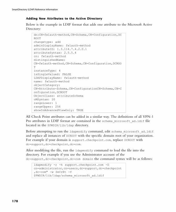
SmartDirectory (LDAP) Reference Information
Adding New Attributes to the Active Directory
Below is the example in LDIF format that adds one attribute to the Microsoft Active Directory:
All Check Point attributes can be added in a similar way. The definitions of all VPN-1 Pro attributes in LDIF format are contained in the schema_microsoft_ad.ldif file located in the $FWDIR/lib/ldap directory.
Before attempting to run the ldapmodify command, edit schema_microsoft_ad.ldif and replace all instances of DCROOT with the specific domain root of your organization. For example if your domain is support.checkpoint.com, replace DCROOT with dc=support,dc=checkpoint,dc=com.
After modifying the file, run the ldapmodify command to load the file into the directory. For example if you use the Administrator account of the dc=support,dc=checkpoint,dc=com domain the command syntax will be as follows:
dn:CN=fw1auth-method,CN=Schema,CN=Configuration,DCROOT changetype: addadminDisplayName: fw1auth-methodattributeID: 1.3.114.7.4.2.0.1attributeSyntax: 2.5.5.4cn: fw1auth-methoddistinguishedName:CN=fw1auth-method,CN=Schema,CN=Configuration,DCROOTinstanceType: 4isSingleValued: FALSELDAPDisplayName: fw1auth-methodname: fw1auth-methodobjectCategory:CN=Attribute-Schema,CN=ConfigurationCN=Schema,CN=Configuration,DCROOTObjectClass: attributeSchemaoMSyntax: 20rangeLower: 1rangeUpper: 256showInAdvancedViewOnly: TRUE
ldapmodify -c -h support.checkpoint.com -D cn=administrator,cn=users,dc=support,dc=checkpoint,dc=com" -w SeCrEt -f $FWDIR/lib/ldap/schema_microsoft_ad.ldif
178
Integration with Various SmartDirectory (LDAP) Vendors
Netscape LDAP Schema
If you would like to add the propriety schema to your Netscape directory server, use the file schema.ldif which is located in the $FWDIR/lib/ldap directory.
Updating Netscape Schema
The Netscape schema should be updated if the following criteria are met:
• VPN-1 Pro users are being managed on the Netscape Directory server and
• you have used the schema.ldif file supplied with VPN-1/FireWall-1 4.x versions to install the Check Point schema to your directory server;
• you have already installed VPN-1 Pro or wish to upgrade to NGX R60A.
How is the Netscape Schema Updated?
You should use the file update_schema.ldif which is located in the $FWDIR/lib/ldap directory.
The ldif file performs the following operations:
• adds the new attributes to the schema,
• deletes old definitions of fw1person and fw1template
• adds new definitions of fw1person and fw1template.
Note - A shell script is available for UNIX gateways. The script is located at: $FWDIR/lib/ldap/update_schema_microsoft_ad.
Warning - This operation deletes objectclass definition from the schema and adds the updated one instead. It is recommended to backup the SmartDirectory (LDAP) server before this operation. You can use this file with the ldapmodify command line. On some server versions the delete objectclass operation may return with error although it was successful. You can run ldapmodify with -c (continuous) option.
Chapter 8 SmartDirectory (LDAP) and User Management 179
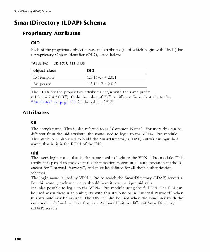
SmartDirectory (LDAP) Schema
SmartDirectory (LDAP) Schema
Proprietary Attributes
OID
Each of the proprietary object classes and attributes (all of which begin with “fw1”) has a proprietary Object Identifier (OID), listed below.
The OIDs for the proprietary attributes begin with the same prefix (“1.3.114.7.4.2.0.X”). Only the value of “X” is different for each attribute. See “Attributes” on page 180 for the value of “X”.
Attributes
cn
The entry’s name. This is also referred to as “Common Name”. For users this can be different from the uid attribute, the name used to login to the VPN-1 Pro module. This attribute is also used to build the SmartDirectory (LDAP) entry’s distinguished name, that is, it is the RDN of the DN.
uidThe user’s login name, that is, the name used to login to the VPN-1 Pro module. This attribute is passed to the external authentication system in all authentication methods except for “Internal Password”, and must be defined for all these authentication schemes.The login name is used by VPN-1 Pro to search the SmartDirectory (LDAP) server(s). For this reason, each user entry should have its own unique uid value. It is also possible to login to the VPN-1 Pro module using the full DN. The DN can be used when there is an ambiguity with this attribute or in “Internal Password” when this attribute may be missing. The DN can also be used when the same user (with the same uid) is defined in more than one Account Unit on different SmartDirectory (LDAP) servers.
TABLE 8-2 Object Class OIDs
object class OID
fw1template 1.3.114.7.4.2.0.1
fw1person 1.3.114.7.4.2.0.2
180
Attributes
description
Descriptive text about the user.
mailUser’s email address.
memberAn entry can have zero or more values for this attribute.In a template: The DN of user entries using this template. DNs that are not users (object classes that are not one of: “person”, “organizationalPerson”, “inetOrgPerson” or “fw1person”) are ignored.
In a group: The DN of user.
userPasswordMust be given if the authentication method (fw1auth-method) is “Internal Password”. The value can be hashed using “crypt”. In this case the syntax of this attribute is:“{crypt}xxyyyyyyyyyyy”where “xx” is the “salt” and “yyyyyyyyyyy” is the hashed password.It is possible (but not recommended) to store the password without hashing. However, if hashing is specified in the SmartDirectory (LDAP) server, you should not specify hashing here, in order to prevent the password from being hashed twice. You should also use SSL in this case, to prevent sending an unencrypted password.The VPN-1 Pro module never reads this attribute, though it does write it. Instead, the SmartDirectory (LDAP) bind operation is used to verify a password.
fw1auth-method
One of the following:
RADIUS, TACACS, SecurID, OS Password, Defender
This default value for this attribute is overridden by Default Scheme in the Authentication tab of the Account Unit window in SmartDashboard. For example: a SmartDirectory (LDAP) server can contain SmartDirectory (LDAP) entries that are all
default
“no value”
default
“no value”
Chapter 8 SmartDirectory (LDAP) and User Management 181
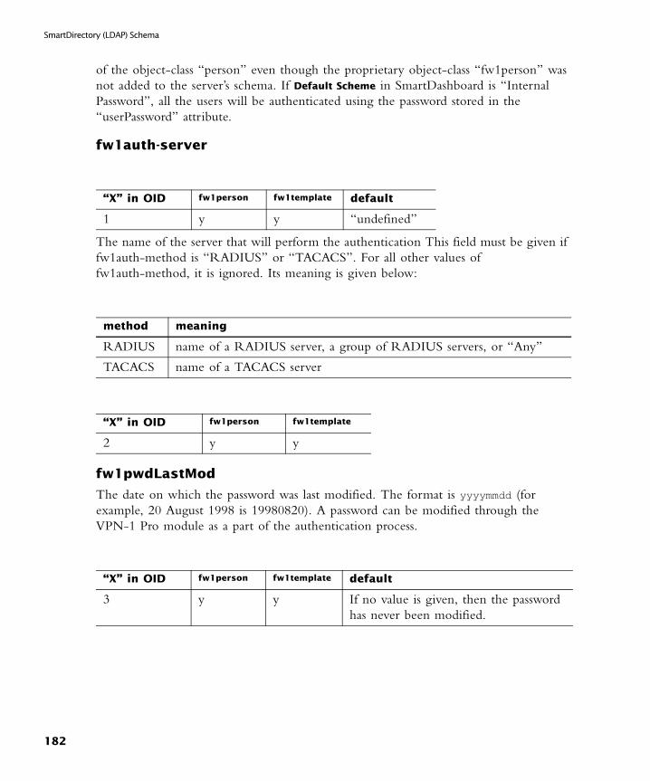
SmartDirectory (LDAP) Schema
of the object-class “person” even though the proprietary object-class “fw1person” was not added to the server’s schema. If Default Scheme in SmartDashboard is “Internal Password”, all the users will be authenticated using the password stored in the “userPassword” attribute.
fw1auth-server
The name of the server that will perform the authentication This field must be given if fw1auth-method is “RADIUS” or “TACACS”. For all other values of fw1auth-method, it is ignored. Its meaning is given below:
fw1pwdLastMod
The date on which the password was last modified. The format is yyyymmdd (for example, 20 August 1998 is 19980820). A password can be modified through the VPN-1 Pro module as a part of the authentication process.
“X” in OID fw1person fw1template default
1 y y “undefined”
method meaning
RADIUS name of a RADIUS server, a group of RADIUS servers, or “Any”
TACACS name of a TACACS server
“X” in OID fw1person fw1template
2 y y
“X” in OID fw1person fw1template default
3 y y If no value is given, then the password has never been modified.
182
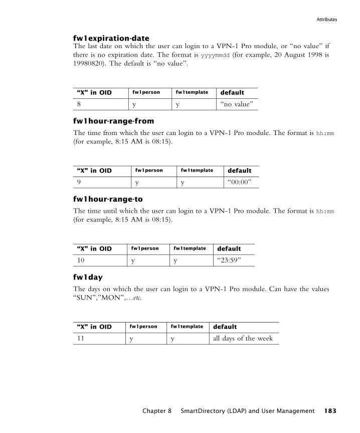
Attributes
fw1expiration-dateThe last date on which the user can login to a VPN-1 Pro module, or “no value” if there is no expiration date. The format is yyyymmdd (for example, 20 August 1998 is 19980820). The default is “no value”.
fw1hour-range-from
The time from which the user can login to a VPN-1 Pro module. The format is hh:mm (for example, 8:15 AM is 08:15).
fw1hour-range-to
The time until which the user can login to a VPN-1 Pro module. The format is hh:mm (for example, 8:15 AM is 08:15).
fw1day
The days on which the user can login to a VPN-1 Pro module. Can have the values “SUN”,”MON”,…etc.
“X” in OID fw1person fw1template default
8 y y “no value”
“X” in OID fw1person fw1template default
9 y y “00:00”
“X” in OID fw1person fw1template default
10 y y “23:59”
“X” in OID fw1person fw1template default
11 y y all days of the week
Chapter 8 SmartDirectory (LDAP) and User Management 183
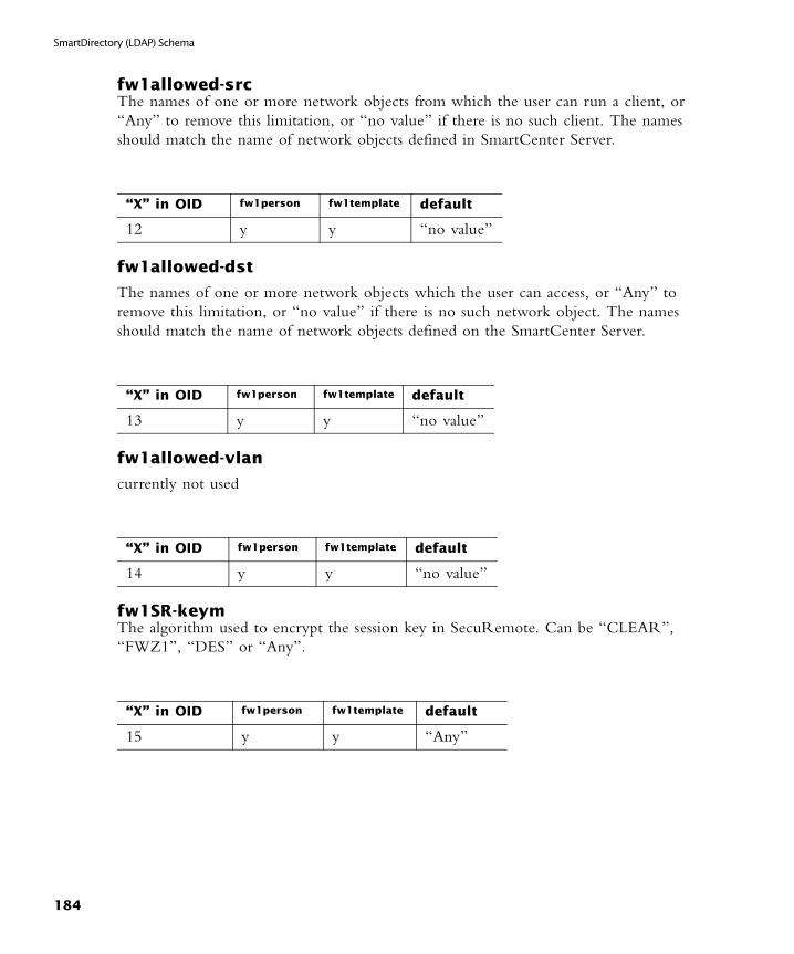
SmartDirectory (LDAP) Schema
fw1allowed-srcThe names of one or more network objects from which the user can run a client, or “Any” to remove this limitation, or “no value” if there is no such client. The names should match the name of network objects defined in SmartCenter Server.
fw1allowed-dst
The names of one or more network objects which the user can access, or “Any” to remove this limitation, or “no value” if there is no such network object. The names should match the name of network objects defined on the SmartCenter Server.
fw1allowed-vlan
currently not used
fw1SR-keymThe algorithm used to encrypt the session key in SecuRemote. Can be “CLEAR”, “FWZ1”, “DES” or “Any”.
“X” in OID fw1person fw1template default
12 y y “no value”
“X” in OID fw1person fw1template default
13 y y “no value”
“X” in OID fw1person fw1template default
14 y y “no value”
“X” in OID fw1person fw1template default
15 y y “Any”
184
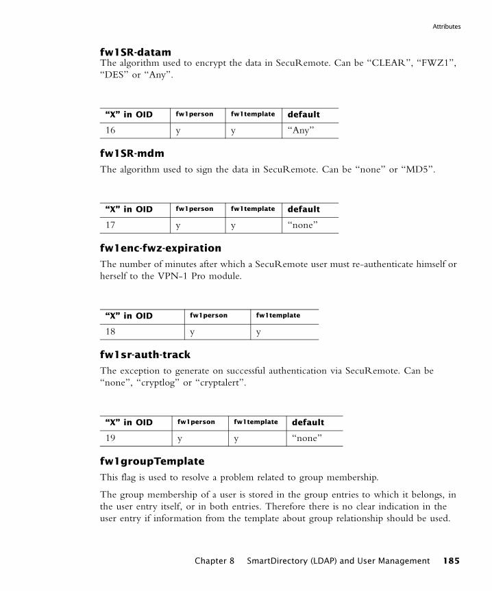
Attributes
fw1SR-datamThe algorithm used to encrypt the data in SecuRemote. Can be “CLEAR”, “FWZ1”, “DES” or “Any”.
fw1SR-mdm
The algorithm used to sign the data in SecuRemote. Can be “none” or “MD5”.
fw1enc-fwz-expiration
The number of minutes after which a SecuRemote user must re-authenticate himself or herself to the VPN-1 Pro module.
fw1sr-auth-track
The exception to generate on successful authentication via SecuRemote. Can be “none”, “cryptlog” or “cryptalert”.
fw1groupTemplate
This flag is used to resolve a problem related to group membership.
The group membership of a user is stored in the group entries to which it belongs, in the user entry itself, or in both entries. Therefore there is no clear indication in the user entry if information from the template about group relationship should be used.
“X” in OID fw1person fw1template default
16 y y “Any”
“X” in OID fw1person fw1template default
17 y y “none”
“X” in OID fw1person fw1template
18 y y
“X” in OID fw1person fw1template default
19 y y “none”
Chapter 8 SmartDirectory (LDAP) and User Management 185

SmartDirectory (LDAP) Schema
If this flag is “TRUE”, then the user is taken to be a member of all the groups to which the template is a member. This is in addition to all the groups in which the user is directly a member.
fw1ISAKMP-EncMethod
The key encryption methods for SecuRemote users using IKE. This can be one or more of: “DES”, “3DES”. A user using IKE (formerly known as ISAMP) may have both methods defined.
fw1ISAKMP-AuthMethods
The allowed authentication methods for SecuRemote users using IKE, (formerly known as ISAMP). This can be one or more of: “preshared”, “signatures”.
fw1ISAKMP-HashMethods
The data integrity method for SecuRemote users using IKE, (formerly known as ISAMP). This can be one or more of: “MD5”, “SHA1”. A user using IKE must have both methods defined.
“X” in OID fw1person fw1template default
20 y y “False”
“X” in OID fw1person fw1template default
21 y y “DES”, “3DES”
“X” in OID fw1person fw1template default
22 y y “signatures”
“X” in OID
fw1person fw1template default
23 y y “MD5”, “SHA1”
186
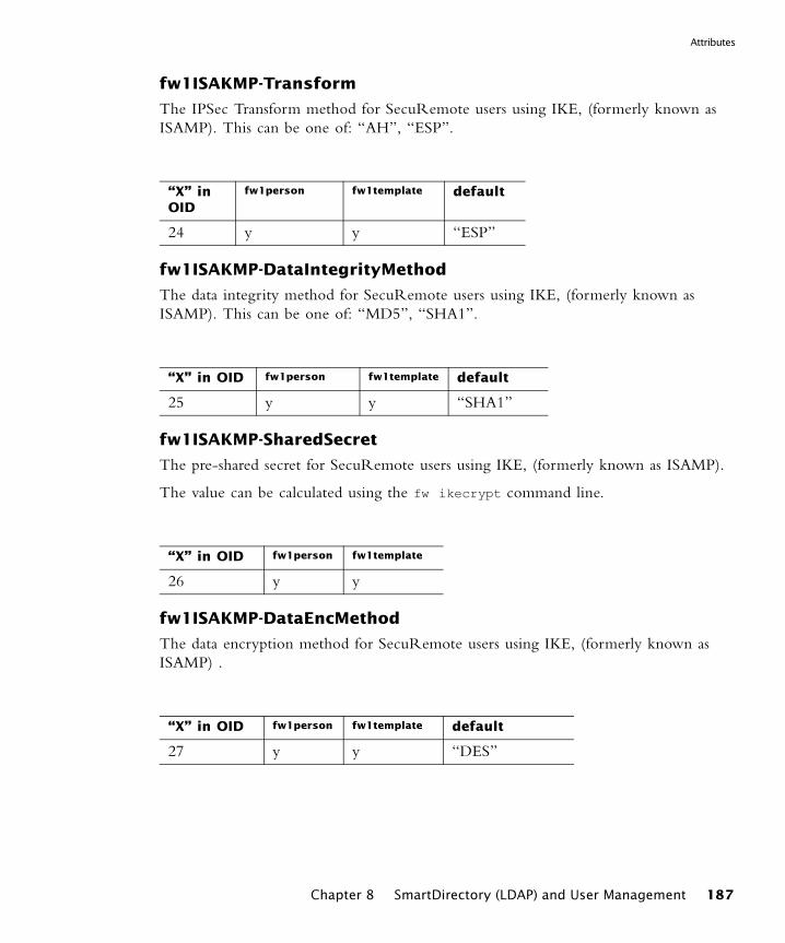
Attributes
fw1ISAKMP-Transform
The IPSec Transform method for SecuRemote users using IKE, (formerly known as ISAMP). This can be one of: “AH”, “ESP”.
fw1ISAKMP-DataIntegrityMethod
The data integrity method for SecuRemote users using IKE, (formerly known as ISAMP). This can be one of: “MD5”, “SHA1”.
fw1ISAKMP-SharedSecret
The pre-shared secret for SecuRemote users using IKE, (formerly known as ISAMP).
The value can be calculated using the fw ikecrypt command line.
fw1ISAKMP-DataEncMethod
The data encryption method for SecuRemote users using IKE, (formerly known as ISAMP) .
“X” in OID
fw1person fw1template default
24 y y “ESP”
“X” in OID fw1person fw1template default
25 y y “SHA1”
“X” in OID fw1person fw1template
26 y y
“X” in OID fw1person fw1template default
27 y y “DES”
Chapter 8 SmartDirectory (LDAP) and User Management 187
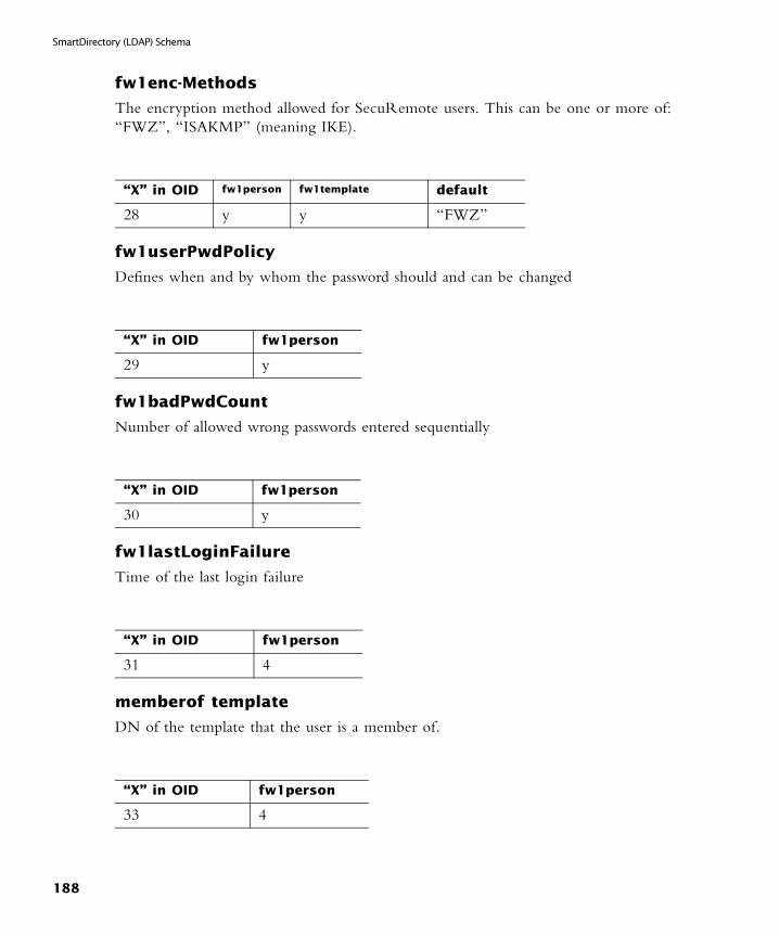
SmartDirectory (LDAP) Schema
fw1enc-Methods
The encryption method allowed for SecuRemote users. This can be one or more of: “FWZ”, “ISAKMP” (meaning IKE).
fw1userPwdPolicy
Defines when and by whom the password should and can be changed
fw1badPwdCount
Number of allowed wrong passwords entered sequentially
fw1lastLoginFailure
Time of the last login failure
memberof template
DN of the template that the user is a member of.
“X” in OID fw1person fw1template default
28 y y “FWZ”
“X” in OID fw1person
29 y
“X” in OID fw1person
30 y
“X” in OID fw1person
31 4
“X” in OID fw1person
33 4
188
Schema Checking
Schema Checking
When schema checking is enabled, SmartDirectory (LDAP) requires that every object class and its associated attributes be defined in the directory schema.
Before working with SmartDirectory (LDAP), schema checking should be disabled. Once the VPN-1 Pro object classes and attributes to the SmartDirectory (LDAP) server’s schema, schema checking should be enabled.
Modifying SmartDirectory (LDAP) ProfilesThe objects.C file contains four profiles, each corresponding to a SmartDirectory (LDAP) server type.
In This Section
Profile Attributes
The attributes that are commonly configured by category are described.
UserLoginAttr
The unique username SmartDirectory (LDAP) attribute (uid). In addition, when fetching users by the username, this attribute is used for query.
Note - The objects.C file should not be edited directly. Instead, use GUIdbEdit (see the Check Point CLI Guide) to edit the objects_5_0.C file on the SmartCenter Server.
Profile Attributes page 189
Fetch User Information Effectively by Modifying the Profile page 200
default Other
• uid (most servers)• SamAccountName (in Microsoft_AD)
One value allowed
Chapter 8 SmartDirectory (LDAP) and User Management 189
Modifying SmartDirectory (LDAP) Profiles
UserPasswordAttr
This user password SmartDirectory (LDAP) attribute.
TemplateObjectClass
The object class for VPN-1 Pro SmartDirectory (LDAP) templates. If you change the default value with another objectclass, make sure to extend that objectclass schema definition with relevant attributes from fw1template.
ExpirationDateAttr
The account expiration date SmartDirectory (LDAP) attribute. This could be a Check Point extended attribute or an existing attribute.
ExpirationDateFormat
Expiration date format. This format will be applied to the value defined at ExpirationDateAttr.
default Other
• userPassword (most servers)• unicodePwd (in Microsoft_AD)
One value allowed
default Other
fw1template Multiple values allowed
default Other
• fw1expiration-date (most servers)• accountExpires (in Microsoft_AD)
One value allowed
default Other
CP format is yyyymmdd One value allowed
190
Profile Attributes
PsswdDateFormat
The format of the password modified date SmartDirectory (LDAP) attribute. This formation will be applied to the value defined at PsswdDateAttr
PsswdDateAttr
The password last modified date SmartDirectory (LDAP) attribute.
BadPwdCountAttr
SmartDirectory (LDAP) attribute to store and read bad password authentication count.
ClientSideCrypt
If 0, the sent password will not be encrypted. If 1, the sent password will be encrypted with the algorithm specified in the DefaultCryptAlgorithm.
default Other
• CP (most servers) format is yyyymmdd
• MS (in Microsoft_AD)
One value allowed
default Other
• fw1pwdLastMod (most servers)• pwdLastSet (in Microsoft_AD)
One value allowed
default Other
fw1BadPwdCount One value allowed
default Other
• 0 for most servers• 1 for Netscape_DSif not using encrypted password, SSL is recommended
One value allowed
Chapter 8 SmartDirectory (LDAP) and User Management 191

Modifying SmartDirectory (LDAP) Profiles
DefaultCryptAlgorith
The algorithm used to encrypt a password before updating the SmartDirectory (LDAP) server with a new password.
CryptedPasswordPrefix
The text to prefix to the encrypted password when updating the SmartDirectory (LDAP) server with a modified password.
PhoneNumberAttr
SmartDirectory (LDAP) attribute to store and read the user phone number.
AttributesTranslationMap
General purpose attribute translation map, to resolve problems related to peculiarities of different server types. For example, an X.500 server does not allow the "-" character in an attribute name. To enable the Check Point attributes containing "-", specify a translation entry: (e.g., "fw1-expiration =fw1expiration").
default Other
• Plain (for most servers)• Crypt (for Netscape_DS)• SHAI1
One value allowed
default Other
{Crypt} (for Netscape_DS) One value allowed
default Other
internationalisednumber One value allowed
default Other
none Multiple values allowed
192
Profile Attributes
ListOfAttrsToAvoid
All attribute names listed here will be removed from the default list of attributes included in read/write operations. This is most useful in cases where these attributes are not supported by the SmartDirectory (LDAP) server schema, which might fail the entire operation. This is especially relevant when the SmartDirectory (LDAP) server schema is not extended with the Check Point schema extension.
BranchObjectClass
Use this attribute to define which type of objects (objectclass) is queried when the object tree branches are displayed after the Account Unit is opened in SmartDashboard.
BranchOCOperator
If One is set, an ORed query will be sent and every object that matches the criteria will be displayed as a branch. If All, an ANDed query will be sent and only objects of all types will be displayed.
default Other
There are no values by default. In case the SmartDirectory (LDAP) server was not extended by the Check Point schema, the best thing to do is to list here all the new Check Point schema attributes
Multiple values allowed
default Other
• Organization OrganizationalUnit Domain (most servers)
• Container (extra for Microsoft_AD)
Multiple values allowed
default Other
One One value allowed
Chapter 8 SmartDirectory (LDAP) and User Management 193

Modifying SmartDirectory (LDAP) Profiles
OrganizationObjectClass
This attribute defines what objects should be displayed with an organization object icon. A new object type specified here should also be in BranchObjectClass.
OrgUnitObjectClass
This attribute defines what objects should be displayed with an organization object icon. A new object type specified here should also be in BranchObjectClass.
DomainObjectClass
This attribute defines what objects should be displayed with a Domain object icon. A new object type specified here should also be in BranchObjectClass.
UserObjectClass
This attribute defines what objects should be read as user objects. The user icon will be displayed on the tree for object types specified here.
default Other
organization Multiple values allowed
default Other
• organizationalUnit (most servers)• Contained (added to
Microsoft_AD)
Multiple values allowed
default Other
Domain Multiple values allowed
default Other
• User (in Microsoft_AD)• Person OrganizationalPersonInertOrgPersonFW1 Person (most servers)
Multiple values allowed
194
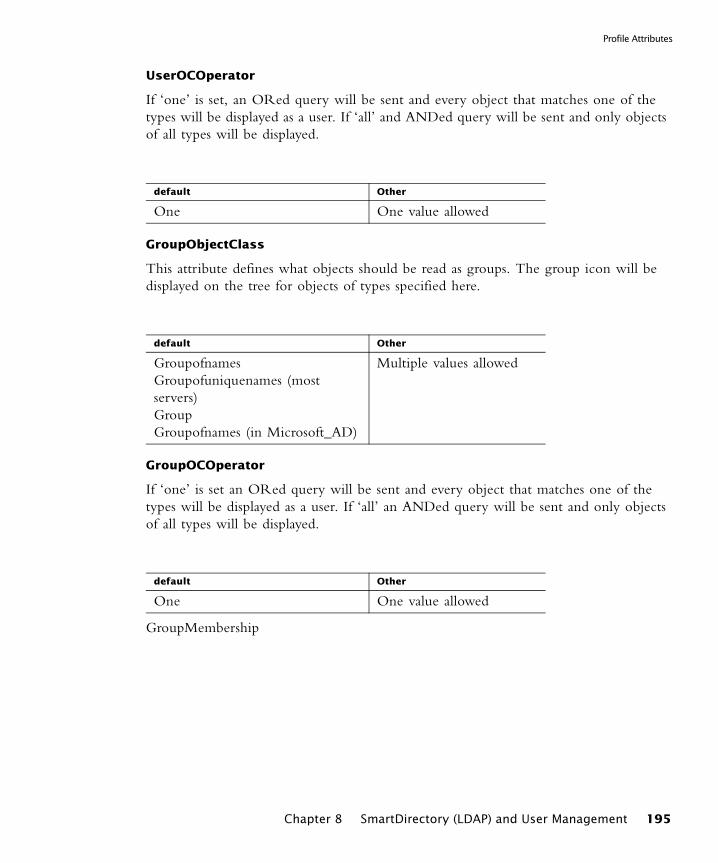
Profile Attributes
UserOCOperator
If ‘one’ is set, an ORed query will be sent and every object that matches one of the types will be displayed as a user. If ‘all’ and ANDed query will be sent and only objects of all types will be displayed.
GroupObjectClass
This attribute defines what objects should be read as groups. The group icon will be displayed on the tree for objects of types specified here.
GroupOCOperator
If ‘one’ is set an ORed query will be sent and every object that matches one of the types will be displayed as a user. If ‘all’ an ANDed query will be sent and only objects of all types will be displayed.
GroupMembership
default Other
One One value allowed
default Other
GroupofnamesGroupofuniquenames (most servers)GroupGroupofnames (in Microsoft_AD)
Multiple values allowed
default Other
One One value allowed
Chapter 8 SmartDirectory (LDAP) and User Management 195

Modifying SmartDirectory (LDAP) Profiles
Defines the relationship Mode between the group and its members (user or template objects) when reading group membership.
UserMembershipAttr
Defines what SmartDirectory (LDAP) attribute to use when reading group membership from the user or template object if GroupMembership mode is ‘MemberOf ’ or ‘Both’ you may be required to extend the user/template object schema in order to use this attribute.
TemplateMembership
Defines the user to template membership mode when reading user template membership information.
default Other
• Member mode defines the member DN in the Group object (most servers)• MemberOf mode defines the group DN in the member object (in Microsoft_AD)• Both mode defines both the member DN in the Group object and the group DN in the Member object.
One value allowed
default Other
MemberOf One value allowed
default Other
• Member mode defines the member DN in the Group object (most servers)• MemberOf mode defines the group DN in the member object (in Microsoft_AD)
One value allowed
196
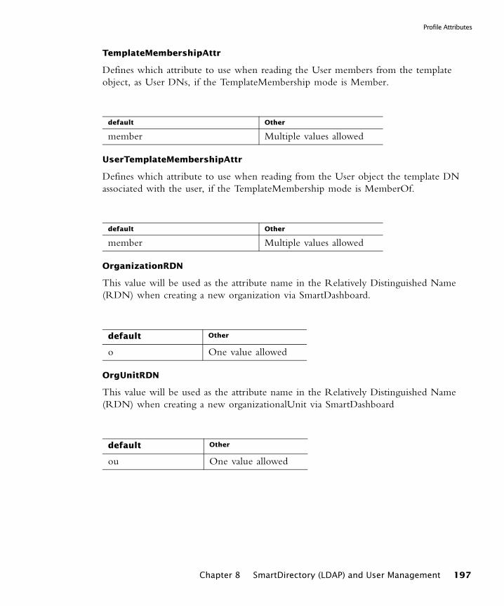
Profile Attributes
TemplateMembershipAttr
Defines which attribute to use when reading the User members from the template object, as User DNs, if the TemplateMembership mode is Member.
UserTemplateMembershipAttr
Defines which attribute to use when reading from the User object the template DN associated with the user, if the TemplateMembership mode is MemberOf.
OrganizationRDN
This value will be used as the attribute name in the Relatively Distinguished Name (RDN) when creating a new organization via SmartDashboard.
OrgUnitRDN
This value will be used as the attribute name in the Relatively Distinguished Name (RDN) when creating a new organizationalUnit via SmartDashboard
default Other
member Multiple values allowed
default Other
member Multiple values allowed
default Other
o One value allowed
default Other
ou One value allowed
Chapter 8 SmartDirectory (LDAP) and User Management 197
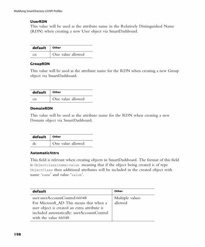
Modifying SmartDirectory (LDAP) Profiles
UserRDNThis value will be used as the attribute name in the Relatively Distinguished Name (RDN) when creating a new User object via SmartDashboard.
GroupRDN
This value will be used as the attribute name for the RDN when creating a new Group object via SmartDashboard.
DomainRDN
This value will be used as the attribute name for the RDN when creating a new Domain object via SmartDashboard.
AutomaticAttrs
This field is relevant when creating objects in SmartDashboard. The format of this field is Objectclass:name:value meaning that if the object being created is of type ObjectClass then additional attributes will be included in the created object with name ‘name’ and value ‘value’.
default Other
cn One value allowed
default Other
cn One value allowed
default Other
dc One value allowed
default Other
user:userAccountControl:66048For Microsoft_AD This means that when a user object is created an extra attribute is included automatically: userAccountControl with the value 66048
Multiple values allowed
198

Profile Attributes
GroupObjectClass
This field is used when modifying an existing group in SmartDashboard. The format of this field is ObjectClass:memberattr meaning that for each group objectclass there is a group membership attribute mapping. List here all the possible mappings for this SmartDirectory (LDAP) server profile. When a group is modified, based on the group’s objectclass the right group membership mapping will be used.
OrgUnitObjectClass
This determines which ObjectClass to use when creating/modifying an OrganizationalUnit object. These values can be different from the read counterpart.
OrganizationObjectClass
This determines which ObjectClass to use when creating and/or modifying an Organization object. These values can be different from the read counterpart.
default Other
groupOfNames:membergroupOfUniqueNames:uniqueMember(All other servers)
Multiple values allowed
default Other
OrganizationalUnit Multiple values allowed
default Other
Organization Multiple values allowed
Chapter 8 SmartDirectory (LDAP) and User Management 199
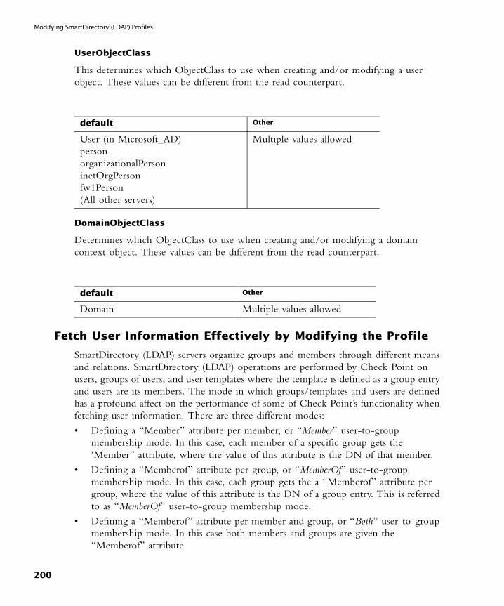
Modifying SmartDirectory (LDAP) Profiles
UserObjectClass
This determines which ObjectClass to use when creating and/or modifying a user object. These values can be different from the read counterpart.
DomainObjectClass
Determines which ObjectClass to use when creating and/or modifying a domain context object. These values can be different from the read counterpart.
Fetch User Information Effectively by Modifying the Profile
SmartDirectory (LDAP) servers organize groups and members through different means and relations. SmartDirectory (LDAP) operations are performed by Check Point on users, groups of users, and user templates where the template is defined as a group entry and users are its members. The mode in which groups/templates and users are defined has a profound affect on the performance of some of Check Point’s functionality when fetching user information. There are three different modes:
• Defining a “Member” attribute per member, or “Member” user-to-group membership mode. In this case, each member of a specific group gets the ‘Member” attribute, where the value of this attribute is the DN of that member.
• Defining a “Memberof” attribute per group, or “MemberOf” user-to-group membership mode. In this case, each group gets the a “Memberof” attribute per group, where the value of this attribute is the DN of a group entry. This is referred to as “MemberOf” user-to-group membership mode.
• Defining a “Memberof” attribute per member and group, or “Both” user-to-group membership mode. In this case both members and groups are given the “Memberof” attribute.
default Other
User (in Microsoft_AD)personorganizationalPersoninetOrgPersonfw1Person(All other servers)
Multiple values allowed
default Other
Domain Multiple values allowed
200

Fetch User Information Effectively by Modifying the Profile
The most effective mode is the “MemberOf” and “Both” modes where user’s groups membership information is available on the user itself and no additional SmartDirectory (LDAP) queries are necessary.
Setting the User-to-Group Membership Mode
Set the user-to-group membership mode in the profile objects for each SmartDirectory (LDAP) server in objects_5_0.C.
• To specify the user-to-group and template-to-group membership mode set the GroupMembership attribute to one of the following values: Member, MemberOf, Both accordingly.
• To specify the user-to-template membership mode set the TemplateMembership attribute to one of the following values: Member, MemberOf accordingly.
After successfully converting the database, set the SmartDirectory (LDAP) server profile in objects_5_0.C to the proper membership setting and start VPN-1 Pro. Make sure to install policy/user database on all gateways to enable the new configuration.
Chapter 8 SmartDirectory (LDAP) and User Management 201

Modifying SmartDirectory (LDAP) Profiles
202
CHAPTER 9
Management High Availability
In This Chapter
The Need for Management High AvailabilityThe SmartCenter consists of several databases with information on different aspects of the system, such as objects, users and policy information. This data changes each time the system administrator makes modifications to the system. It is important to maintain a backup for this data, so that crucial information is not permanently lost in the event of SmartCenter Server failure.
Moreover, if the SmartCenter Server fails or is down for administrative purposes, a backup server needs to be in place in order to take over its activities. In the absence of the SmartCenter Server, essential operations performed by the Modules, such as the fetching of the Security Policy and the retrieval of the CRL, cannot take place.
The Management High Availability Solution
Backing Up the SmartCenter Server
In Management High Availability the Active SmartCenter Server (Active SCS) always has one or more backup Standby SmartCenter Servers (Standby SCS) which are ready to take over from the Active SmartCenter Server. These SmartCenter Servers must all
The Need for Management High Availability page 203
The Management High Availability Solution page 203
Management High Availability Considerations page 209
Management High Availability Configuration page 210
203

The Management High Availability Solution
be of the same Operating System (for instance, all Windows NT), but do not have to be of the same version. The existence of the Standby SCS allows for crucial backups to be in place:
• for the SmartCenter Server - the various databases in the corporate organization, such as the database of objects and users, policy information and ICA files are stored on both the Standby SCSs as well as the Active SCS. These SmartCenter Servers are synchronized so data is maintained and ready to be used. If the Active SCS is down a Standby SCS needs to become Active in order to be able to edit and install the Security Policy.
• for the module - certain operations that are performed by the modules via the Active SCS, such as fetching a Security Policy, or retrieving a CRL from the SmartCenter Server, can be performed on Standby SCS.
Management High Availability DeploymentFIGURE 9-1 Management High Availability Deployment
In a Management High Availability deployment the first installed SmartCenter Server is specified as the Primary SmartCenter Server. This is a regular SmartCenter Server used by the system administrator to manage the Security Policy. When any subsequent SmartCenter Server is installed, these must be specified as Secondary SmartCenter Servers. Once the Secondary SmartCenter Server has been installed and manually synchronized, the distinctions between Primary versus Secondary is no longer significant. These servers are now referred to according to their role in the Management High Availability scenario as Active or Standby, where any SmartCenter Server can function as the Active SCS.
204
Active versus Standby
The Management High Availability Environment
The Management High Availability environment requires an Active SCS and at least one Standby SCS.
The Secondary SCS is created with empty databases. These databases are filled with information that the newly created Secondary SCS gleans from the Active SCS. The Secondary SCS is ready once:
• it is represented on the Primary SmartCenter by a network object
• SIC has been initialized between it and the Primary SmartCenter
• manual synchronization has been done with the Primary SmartCenter for the first time.
It is possible to install an Enforcement module on any of the SmartCenter Servers. The role of these Enforcement modules is to protect the SmartCenter Servers. Although the SmartCenter Servers backup one another, High Availability is not implemented between the Enforcement modules installed on SmartCenter Servers.
Active versus Standby
All management operations such as editing and installing the Security Policy and modifying users and objects, are done by the Active SCS. If the Active SCS is down, and any of the aforementioned operations need to be performed, one of the Standby SCSs should be made active by the system administrator. This transition from Standby to Active should be initiated manually.
The Standby SCSs are synchronized to the Active SCS, and therefore, are kept up to date with all changes in the databases and Security Policy. Thus modules can fetch the Security Policy and retrieve a CRL from both the Active SCS and the Standby SCS.
The frequency of the synchronization between the Standby SCS and the Active SCS is set by the System Administrator. This process can be configured to take place automatically, or it can be set to occur manually.
What Data is Backed Up by the Standby SmartCenter Servers?
In order for Management High Availability to function properly, the following data must be synchronized and backed up:
• configuration and ICA data, such as:
• databases (such as the Objects and Users)
• certificate information such as Certificate Authority data and the CRL which is available to be fetched by the Check Point Modules
Chapter 9 Management High Availability 205
The Management High Availability Solution
• the latest installed Security Policy. The installed Security Policy is the applied Security Policy. The modules must be able to fetch the latest Security Policy from either the Active or the Standby SCS.
Synchronization Modes
There are two ways to perform synchronization:
• manual synchronization is a process initialized by the system administrator. It can be set to synchronize
• databases, or
• databases as well as the installed Security Policy. The former option synchronizes quicker than the latter option. It should be the preferred mode of synchronization provided that the system administrator has edited the objects or the Security Policy, but has not installed the newly edited Security Policy since the previous synchronization.
• automatic synchronization is a process configured by the system administrator to allow the Standby SCSs to be synchronized with the Active SCSs at set intervals of time. This is generally the preferred mode of synchronization, since it keeps the Standby SCSs updated. The basis for the synchronization schedule is that when the Security Policy is installed, both the installed Security Policy and all the databases are synchronized. Additionally, it is possible to synchronize the Standby SCSs when:
• the system administrator saves the Security Policy
• at a specified scheduled timeEven when automatic synchronization has been selected as the synchronization mode, it is possible to perform a manual synchronization.
Synchronization Status
The synchronization status indicates the status of the peer SCSs in relation to that of the selected SmartCenter Server. This status can be viewed in the Management High
Availability Servers window or in SmartView Monitor, whether you are connected to the Active or Standby SCS.
Note - previous versions of the Database, SmartMap data, as well as View Installed Policy data are not synchronized.
206
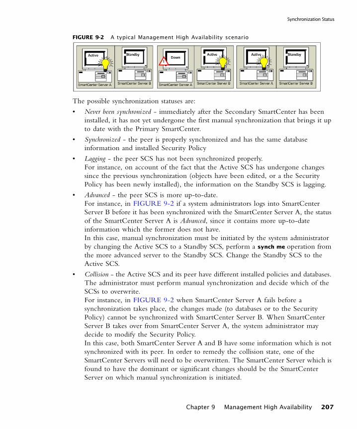
Synchronization Status
FIGURE 9-2 A typical Management High Availability scenario
The possible synchronization statuses are:
• Never been synchronized - immediately after the Secondary SmartCenter has been installed, it has not yet undergone the first manual synchronization that brings it up to date with the Primary SmartCenter.
• Synchronized - the peer is properly synchronized and has the same database information and installed Security Policy
• Lagging - the peer SCS has not been synchronized properly. For instance, on account of the fact that the Active SCS has undergone changes since the previous synchronization (objects have been edited, or a the Security Policy has been newly installed), the information on the Standby SCS is lagging.
• Advanced - the peer SCS is more up-to-date. For instance, in FIGURE 9-2 if a system administrators logs into SmartCenter Server B before it has been synchronized with the SmartCenter Server A, the status of the SmartCenter Server A is Advanced, since it contains more up-to-date information which the former does not have.In this case, manual synchronization must be initiated by the system administrator by changing the Active SCS to a Standby SCS, perform a synch me operation from the more advanced server to the Standby SCS. Change the Standby SCS to the Active SCS.
• Collision - the Active SCS and its peer have different installed policies and databases. The administrator must perform manual synchronization and decide which of the SCSs to overwrite. For instance, in FIGURE 9-2 when SmartCenter Server A fails before a synchronization takes place, the changes made (to databases or to the Security Policy) cannot be synchronized with SmartCenter Server B. When SmartCenter Server B takes over from SmartCenter Server A, the system administrator may decide to modify the Security Policy. In this case, both SmartCenter Server A and B have some information which is not synchronized with its peer. In order to remedy the collision state, one of the SmartCenter Servers will need to be overwritten. The SmartCenter Server which is found to have the dominant or significant changes should be the SmartCenter Server on which manual synchronization is initiated.
Chapter 9 Management High Availability 207
The Management High Availability Solution
At this point the system administrator needs to decide which of the SmartCenter Server’s should become the Standby SCS, and change its status, if necessary.
Changing the Status of the SmartCenter Server
Although modules can use the Standby SmartCenter Server to fetch a Security Policy or a fresh CRL, in the event that the Active SCS fails, the Standby SCS must become the Active SCS for two predominant reasons:
1 The Standby SCS cannot perform management operations such as editing and installing the Security Policy. While the Standby is identical in its databases and installed Security Policy to the Active SCS, if changes are needed for the Security Policy the Standby SCS does not have the capacity to make them.
2 The ICA database can only be modified on the Active SCS.
If the Active SCS is going down for administrative purposes, the system administrator should login to the Standby SCS and manually set it as the Active SCS.
Thereafter manual synchronization should be initiated. Once the Standby SCS has become the Active SCS, it is recommended to perform an Install Policy operation, in order to verify that this machine is functioning properly as an Active SCS.
If the Active SCS is in failover, it is likely that the synchronization status of the Active SCS and its peer will be collision. In this case the system administrator will need to decide which information will be overwritten.
Synchronization Diagnostics
The status of all SmartCenter Servers can be viewed in the Management High
Availability Servers window in SmartDashboard or via SmartView Monitor.
Audit Logs can be used to view and track management operations as well as Synchronization operations in the SmartView Tracker.
When Synchronization Fails
There are several instances in which the synchronization process might fail
• synchronization failure - for instance, the Active SCS was unable to make a connection with the Standby SCS at the moment of synchronization, to solve this:
• manually synchronize the Standby SCS at a later opportunity, or
Note - Changes made by the CA, such as the issuance of certificates, could lead to breaches of security if they are overwritten; therefore, any CA changes that are made are merged in order to eliminate security issues.
208
Remote versusLocal Installation of the Secondary SCS
• if you are working in automatic mode, reinstall the Security Policy when the Standby SCS can be reached. After the install operation takes place, synchronization occurs automatically
• Collision between the SmartCenter Servers, in this case the system administrator should perform a manual synchronization and decide which database is the dominant database. The CA is always merged in order to eliminate security issues. When a collision occurs and one of the SmartCenter Servers is overwritten, it is very useful to follow management operations performed on the overwritten SmartCenter Server in the audit logs of the SmartView Tracker. In this manner it is possible to track and redo these operations, where necessary, on the dominant SmartCenter Server.
Management High Availability Considerations
Remote versusLocal Installation of the Secondary SCS
In the Management High Availability deployment the Secondary SCS is often installed locally on the LAN. The system administrator should consider the usefulness of maintaining a remote Standby SCS. This remote SmartCenter Server will not be affected in the case of networking problems on the LAN. This Standby SCS can be made into the Active SCS by the remote system administrator.
Different Methods of Synchronizations
Automatic synchronization keeps the peer SCSs updated. However the synchronization may take some time and affect the system performance. It may be useful to schedule a synchronization event that automatically synchronizes the SmartCenter Servers after working hours when the system performance cannot affect the regular work of the employees.
Manual synchronization can be initiated at any stage by the system administrator. Manual synchronization is recommended when changing the Standby SCS to Active (if the Active SCS is about to go down for administrative purposes). It is essential when the synchronization status is collision.
Data Overload During Synchronization
The data saved during the synchronization process is very heavy. Synchronization is optimized if the connectivity between the SmartCenter Server is fast and efficient.
Chapter 9 Management High Availability 209
Management High Availability Configuration
Management High Availability Configuration
In This Section
Secondary Management Creation and Synchronization - the First Time
1 When installing the SmartCenter Server you will be prompted to specify whether it is the Primary Management or the Secondary Management, in a Management High Availability deployment. Select the latter.
2 In SmartDashboard create a network object to represent the Secondary SmartCenter, as follows:
Secondary Management Creation and Synchronization - the First Time page 210
Changing the Active SCS to the Standby SCS page 212
Refreshing the Synchronization Status of the SCS page 213
Selecting the Synchronization Method page 214
Tracking Management High Availability Throughout the System page 215
210
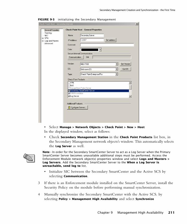
Secondary Management Creation and Synchronization - the First Time
FIGURE 9-3 initializing the Secondary Management
• Select Manage > Network Objects > Check Point > New > Host
In the displayed window, select as follows:
• Check Secondary Management Station in the Check Point Products list box, in the Secondary Management network objects’s window. This automatically selects the Log Server as well.
• Initialize SIC between the Secondary SmartCenter and the Active SCS by selecting Communication.
3 If there is an Enforcement module installed on the SmartCenter Server, install the Security Policy on the module before performing manual synchronization.
4 Manually synchronize the Secondary SmartCenter with the Active SCS. by selecting Policy > Management High Availability and select Synchronize
Note - In order for the Secondary SmartCenter Server to act as a Log Server when the Primary SmartCenter Server becomes unavailable additional steps must be performed. Access the Enforcement Module network object(s) properties window and select Logs and Masters > Log Servers. Add the Secondary SmartCenter Server to the When a Log Server is unreachable, send log to list.
Chapter 9 Management High Availability 211
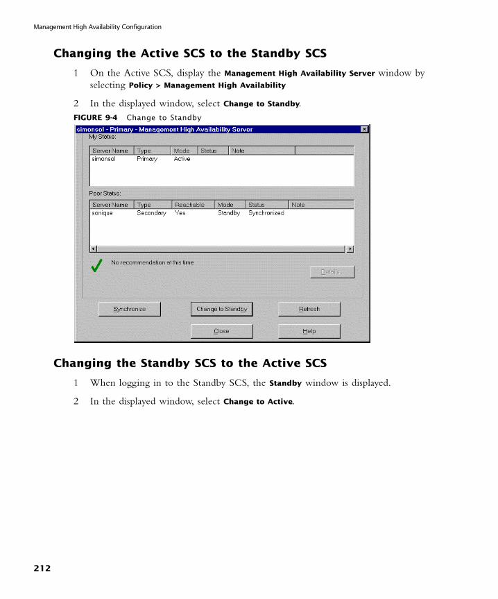
Management High Availability Configuration
Changing the Active SCS to the Standby SCS
1 On the Active SCS, display the Management High Availability Server window by selecting Policy > Management High Availability
2 In the displayed window, select Change to Standby.FIGURE 9-4 Change to Standby
Changing the Standby SCS to the Active SCS
1 When logging in to the Standby SCS, the Standby window is displayed.
2 In the displayed window, select Change to Active.
212
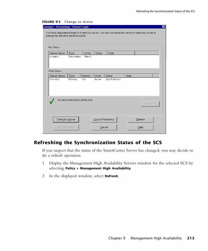
Refreshing the Synchronization Status of the SCS
FIGURE 9-5 Change to Active
Refreshing the Synchronization Status of the SCS
If you suspect that the status of the SmartCenter Server has changed, you may decide to do a refresh operation.
1 Display the Management High Availability Servers window for the selected SCS by selecting Policy > Management High Availability
2 In the displayed window, select Refresh.
Chapter 9 Management High Availability 213
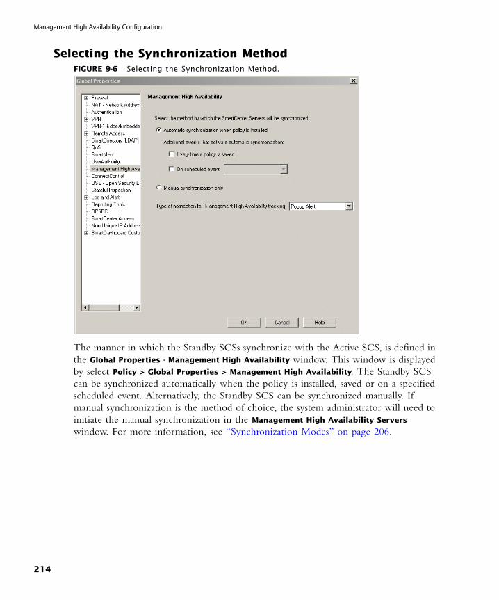
Management High Availability Configuration
Selecting the Synchronization MethodFIGURE 9-6 Selecting the Synchronization Method.
The manner in which the Standby SCSs synchronize with the Active SCS, is defined in the Global Properties - Management High Availability window. This window is displayed by select Policy > Global Properties > Management High Availability. The Standby SCS can be synchronized automatically when the policy is installed, saved or on a specified scheduled event. Alternatively, the Standby SCS can be synchronized manually. If manual synchronization is the method of choice, the system administrator will need to initiate the manual synchronization in the Management High Availability Servers
window. For more information, see “Synchronization Modes” on page 206.
214
Tracking Management High Availability Throughout the System
Tracking Management High Availability Throughout the System
The statuses of all the SmartCenter Servers in the system are displayed in the Management High Availability window. This window is displayed by selecting Policy >
Management High Availability. Details about the SmartCenter Server and its peers that are displayed include the name, status and type of SmartCenter Server.
All Management High Availability management operations can be viewed in the SmartView Tracker in Audit mode.
Chapter 9 Management High Availability 215

Management High Availability Configuration
216

CHAPTER 10
Working with SNMP Management Tools
In This Chapter
The Need to Support SNMP Management ToolsSNMP management tools are used to monitor the activity of various devices on the network. Because system administrators prefer to work with familiar tools, they might feel more comfortable obtaining status information regarding Check Point products through their regular SNMP Network Management Station (NMS).
The Check Point Solution for SNMPCheck Point addresses this issue by running SNMP agents on Enforcement Points. These Enforcement Points need to respond to requests from an SNMP Management Station.
The Need to Support SNMP Management Tools page 217
The Check Point Solution for SNMP page 217
Special Consideration for the Unix SNMP Daemon page 220
Configuring VPN-1 Pro for SNMP page 220
217
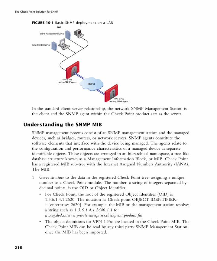
The Check Point Solution for SNMP
FIGURE 10-1 Basic SNMP deployment on a LAN
In the standard client-server relationship, the network SNMP Management Station is the client and the SNMP agent within the Check Point product acts as the server.
Understanding the SNMP MIB
SNMP management systems consist of an SNMP management station and the managed devices, such as bridges, routers, or network servers. SNMP agents constitute the software elements that interface with the device being managed. The agents relate to the configuration and performance characteristics of a managed device as separate identifiable objects. These objects are arranged in an hierarchical namespace, a tree-like database structure known as a Management Information Block, or MIB. Check Point has a registered MIB sub-tree with the Internet Assigned Numbers Authority (IANA). The MIB:
1 Gives structure to the data in the registered Check Point tree, assigning a unique number to a Check Point module. The number, a string of integers separated by decimal points, is the OID or Object Identifier.
• For Check Point, the root of the registered Object Identifier (OID) is 1.3.6.1.4.1.2620. The notation is: Check point OBJECT IDENTIFIER:: ={enterprises 2620}. For example, the MIB on the management station resolves a string such as 1.3.6.1.4.1.2640.1.1 to: iso.org.dod.internet.private.enterprises.checkpoint.products.fw.
• The object definitions for VPN-1 Pro are located in the Check Point MIB. The Check Point MIB can be read by any third party SNMP Management Station once the MIB has been imported.
218
Handling SNMP Requests on Windows NT
2 Provides name resolution, resolving the OID integer string to a user-friendly name. For example, if an administrator wants to know the version number of a particular firewall, the administrator selects “version number” as the property of the managed device and the MIB maps “version number” to an integer string before sending the information request to the agent.
Handling SNMP Requests on Windows NT
When VPN-1 Pro is installed, a special Check Point dynamic link library (DLL) is listed in the window’s registry. The SNMP service running on the Operating System loads this DLL. The SNMP service listens in the standard way on port 161 for incoming SNMP requests from the SNMP Network Management Station. The Check Point DLL extends the Windows NT SNMP service to identify those status requests directed at Check Point products. The relevant data is then retrieved by the DLL and sent to the SNMP management station.
Handling SNMP Requests on Unix
For the Unix platform, a special Check Point SNMP daemon, called cpsnmpd, is installed. This daemon provides status information on VPN-1 Pro specific objects. This daemon is not run by default. The daemon is enabled or disabled through cpconfig. Once enabled, the daemon runs with other Check Point processes. The SNMP Network Management Station queries the daemon for status information. The daemon retrieves the information, and replies.
Note - The SNMP management station can read but not modify the object definitions for Check Point products.
Note - The VPN-1 Pro SNMP agent is an extension of the Windows NT SNMP agent. If you have not installed the standard Windows NT SNMP agent, you cannot use the VPN-1 Pro SNMP agent.
Note - While the Check Point daemon is SNMP compliant, the daemon listens on port 260 instead of 161. The standard Unix SNMP daemon loads before the Check Point daemon and binds to port 161. If the regular daemon is not running, cpsnmpd binds to both ports (161 and 260). If both ports are occupied by a previous process, the Check Point daemon will not run. Further, if the Check Point daemon receives an request for an unrecognized OID, it does not forward this to the standard snmp unix daemon.
Chapter 10 Working with SNMP Management Tools 219
Special Consideration for the Unix SNMP Daemon
SNMP Traps
While VPN-1 Pro has Alert as one of its tracking types, you might prefer to receive alert messages through your regular SNMP Management Station in the form of an SNMP trap. An SNMP trap is notification that a certain event has occurred. VPN-1 Pro offers SNMP traps as one of its tracking types. When the conditions of the trap are met, the Enforcement module sends a log to SmartCenter Server. SmartCenter Server saves the log and sends (via port 162) an SNMP trap to the configured catcher—the SNMP Network Management station. The trap includes the text of the log file.
If any machine outside of the organization tries to make a http connection to a machine within the internal network, the packet is dropped and an SNMP trap is sent:
Special Consideration for the Unix SNMP DaemonIf you need to run the standard Unix SNMP daemon on port 161, run this daemon before you start cpsnmpd, otherwise cpsnmpd will take the port.
Configuring VPN-1 Pro for SNMPTo handle SNMP requests and traps, the various supported platforms need to be configured in slightly different ways.
Configuring VPN-1 Pro for SNMP Requests
1 On the SNMP Management Station, import the Check Point MIB file from $CPDIR/lib/snmp/chkpnt.mib.
2 If the platform is Windows NT, verify that the Operating System is running the SNMP service. On the Unix platform, verify that port 260 is not bound to another process. If port 260 is available, run cpconfig to enable the cpsnmpd daemon.
3 In the Security Policy Rule Base:
• Open port 161 if the platform is Windows NT.
• Open port 260 if the platform is Unix.
Do this only on Enforcement Points through which the SNMP packets need to pass.
Source Destination VPN Service Action Track
Any Internal_private_network Any HTTP Drop Log
220

Configuring VPN-1 Pro for SNMP Traps
FIGURE 10-2 Allowing SNMP packets through Enforcement Points
This policy rule allows the SNMP Management Station to communicate with VPN-1 Pro.
4 Install the new Security Policy.
Configuring VPN-1 Pro for SNMP Traps
To configure VPN-1 Pro for SNMP traps, the built-in trap script has to be assigned an appropriate catcher. To assign an appropriate catcher:
1 Open the Global Properties window, Alert Commands page.
2 Select the Run SNMP trap alert script option.
3 In the corresponding text box, replace internal_snmp_trap localhost with internal_snmp_trap <snmp_trap_catcher>, where the <variable> is replaced with the name of the configured catcher. For example, if the configured catcher is a machine called Alaska, the new script would read internal_snmp_trap Alaska.
Chapter 10 Working with SNMP Management Tools 221
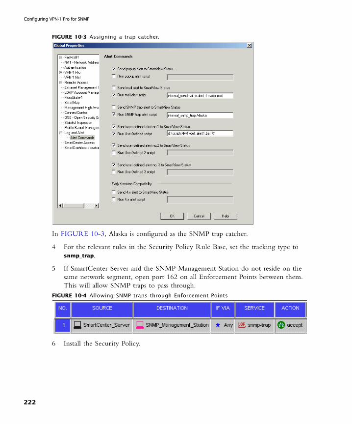
Configuring VPN-1 Pro for SNMP
FIGURE 10-3 Assigning a trap catcher.
In FIGURE 10-3, Alaska is configured as the SNMP trap catcher.
4 For the relevant rules in the Security Policy Rule Base, set the tracking type to snmp_trap.
5 If SmartCenter Server and the SNMP Management Station do not reside on the same network segment, open port 162 on all Enforcement Points between them. This will allow SNMP traps to pass through.
FIGURE 10-4 Allowing SNMP traps through Enforcement Points
6 Install the Security Policy.
222

CHAPTER 11
FAQ
In This Chapter
Network Objects ManagementQuestion: What is the difference between a Check Point Gateway and a Check Point Host
A FireWalled gateway is a machine that has a network or few networks behind it. The FireWall on this machine protects these networks.
A FireWalled host is a machine (usually a server) that does not have networks behind it, and the FireWall on this machine protects the machine itself. Since there are no machines behind the host, it’s topology does not include internal interfaces or anti-spoofing definitions.
Question: What do I do if I cannot perform a “Get> Interfaces with Topology” operation for a Check Point Host?
The interfaces of a Check Point Host are automatically configured; therefore, it is not possible to retrieve them by performing a Get operation.
If you are trying to Get> Interfaces with Topology for a Check Point Host it is likely that your host should in fact be a Check Point Gateway. Convert the host to a gateway, by right-clicking on the specified host icon in the Objects tree and select Convert to Gateway.
Network Objects Management page 223
Policy Management page 224
223
Policy Management
Policy ManagementQuestion: How can I open or save a specific Policy?
All Policy operations (opening, saving etc.) are performed at the Policy Package-level (as opposed to the single policy-level). For detailed instructions, please refer to Chapter 2, “Policy Management””.
Question: Why are some Rule Base tabs missing when I open a Policy Package?
Policy Packages may include one or more of the following policies:- a Security and Address Translation Policy, consisting of the Security, Address Translation and VPN Manager Rule.- a QoS Policy, displayed in the QoS Rule Base.- a Desktop Security Policy, displayed in the Desktop Security Rule Base.- The Web Access Rule Bases is The Rule Bases you see correspond to the Policies included in this specific Policy Package.
Question: After upgrading all of my products, why does the SmartDashboard show only the Security Rue Base?
The Policy Package you are currently displaying contains only the Security and Address Translation Policies, so the QoS and Desktop Security Policies are not displayed. For more details, please refer to Chapter 2, “Policy Management””.
Question: How can I locate duplicate IP addresses?
Select Search > Query Network Objects... from the SmartDashboard menu and choose Duplicates from the Refine by drop-down list.
Question: The port I need to use is occupied. How can I find the corresponding service?
Display the Object Tree’s Services tab and then sort the Objects List by its Port column.
224
CHAPTER 12
SmartCenter Advanced Configuration
In This Chapter
Backup and Restore
Using the Backup and Restore Tool in the Upgrade Process
1 Export the SmartCenter database (user, objects, etc.) to a CD.
2 When upgrading another machine, use this CD to import the exported SmartCenter database.
Management High Availability
Upgrade the Management High Availability Servers
1 Synchronize the Standby SmartCenter Servers (SCSs) with the Active SCS by selecting Synchronize in the Policy > Management High Availability window.
2 Upgrade all the SCSs in the organization.
3 Login to SmartDashboard via the Active SCS. For each Standby SCS, change the software version in Check Point Products listbox of its network objects window.
4 Synchronize the Standby SCSs with the Active SCS. The synchronization status is expected to be collision. This occurs on account of the Upgrade operation.
Backup and Restore page 225
Management High Availability page 225
225

SmartUpdate Upgrade
5 Make sure that you select the Active SCS as the dominant SCS, in order that all the Standby SCSs will be overwritten. Once again, synchronize the remaining Standby SCSs to the Active SCS.
SmartUpdate Upgrade
Upgrade SmartUpdate version 4.1 Check Point Gateways
Add the following rule in SmartDashboard: Any/Any/Any/FW1_CPRID/Accept.
226

CHAPTER A
Network Objects
In This Appendix
Introduction to ObjectsNetwork Objects are created in order to represent actual physical machines and components such as Gateway, Servers, embedded devices, as well as logical components such as IP Address Ranges and Dynamic Objects.
Objects are created and managed by the system administrator via SmartDashboard.
All objects are managed using SmartDashboard; therefore, it is recommended that the objects database must not be accessed or edited directly. In this appendix you will find general information about network objects, including configuration specifications, where necessary.
The Objects Creation Workflow
1 Objects created by the system administrator, are automatically stored in the objects database on the SmartCenter Server in $FWDIR/conf/objects_5_0.c.
2 When the Security Policy is installed on the module, SmartCenter Server computes the objects.c file for the module, this file is computed and derived from the objects_5_0.c file
3 SmartCenter Server downloads the objects.c file to the module.
4 When a policy is installed, all changes made to objects are applied and saved. These changes are also registered in the objects database which is automatically updated.
Introduction to Objects page 227
Network Objects page 229
227
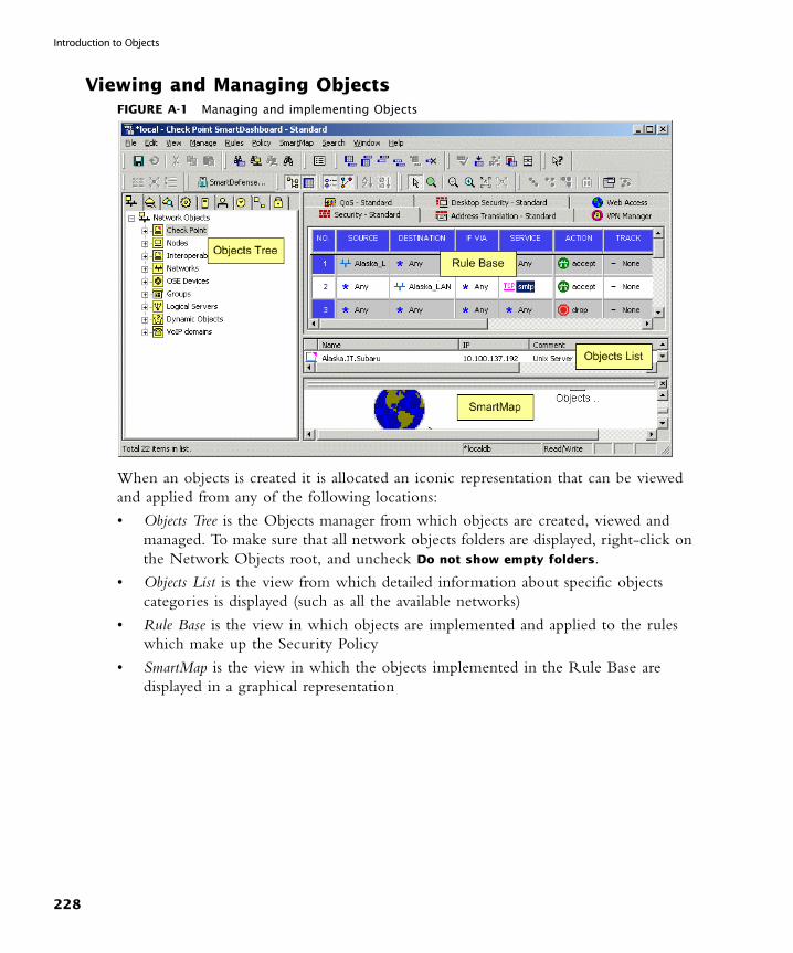
Introduction to Objects
Viewing and Managing ObjectsFIGURE A-1 Managing and implementing Objects
When an objects is created it is allocated an iconic representation that can be viewed and applied from any of the following locations:
• Objects Tree is the Objects manager from which objects are created, viewed and managed. To make sure that all network objects folders are displayed, right-click on the Network Objects root, and uncheck Do not show empty folders.
• Objects List is the view from which detailed information about specific objects categories is displayed (such as all the available networks)
• Rule Base is the view in which objects are implemented and applied to the rules which make up the Security Policy
• SmartMap is the view in which the objects implemented in the Rule Base are displayed in a graphical representation
228
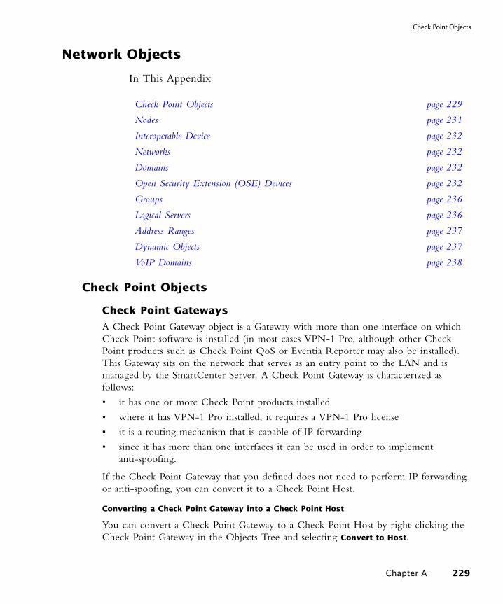
Check Point Objects
Network Objects
In This Appendix
Check Point Objects
Check Point Gateways
A Check Point Gateway object is a Gateway with more than one interface on which Check Point software is installed (in most cases VPN-1 Pro, although other Check Point products such as Check Point QoS or Eventia Reporter may also be installed). This Gateway sits on the network that serves as an entry point to the LAN and is managed by the SmartCenter Server. A Check Point Gateway is characterized as follows:
• it has one or more Check Point products installed
• where it has VPN-1 Pro installed, it requires a VPN-1 Pro license
• it is a routing mechanism that is capable of IP forwarding
• since it has more than one interfaces it can be used in order to implement anti-spoofing.
If the Check Point Gateway that you defined does not need to perform IP forwarding or anti-spoofing, you can convert it to a Check Point Host.
Converting a Check Point Gateway into a Check Point Host
You can convert a Check Point Gateway to a Check Point Host by right-clicking the Check Point Gateway in the Objects Tree and selecting Convert to Host.
Check Point Objects page 229
Nodes page 231
Interoperable Device page 232
Networks page 232
Domains page 232
Open Security Extension (OSE) Devices page 232
Groups page 236
Logical Servers page 236
Address Ranges page 237
Dynamic Objects page 237
VoIP Domains page 238
Chapter A 229
Network Objects
VPN-1 Edge/Embedded Gateway
A VPN-1 Edge/Embedded Gateway object is a network object that represents a VPN-1 Edge/Embedded device. This Gateway sits on the network and can be managed by the SmartCenter Server or by an external management server.
Defining VPN-1 Edge/Embedded Gateway Objects
1 In the Network Objects tab of the Objects Tree create a new VPN-1 Edge/Embedded Gateway.
• Configure the general settings of the window, including its name and IP address (whether static or dynamic) and version information.
• To define the VPN-1 Edge/Embedded Gateway as a member of a VPN community, select the VPN Enabled check box and select the VPN Community type (whether Site to Site or Remote Access).
Check Point Host
A Check Point Host is a host on which Check Point software has been installed which is managed by the SmartCenter Server.
A Check Point Host is characterized as follows:
• It has one or more Check Point products installed.
• It is not a routing mechanism and is not capable of IP forwarding.
• Since it only has one interface, its topology cannot be modified and therefore it cannot be used to implement Anti-spoofing.
• It requires a SecureServer license and not a VPN-1 Pro license.
If you have defined a Check Point Host and you are trying to use it to perform IP forwarding or anti-spoofing, you must convert it to a Check Point Gateway.
Converting a Check Point Host into a Check Point Gateway
You can convert a Check Point Host to a Check Point Gateway by right-clicking the Check Point Host in the Objects Tree and selecting Convert to Gateway.
Gateway Cluster
A Gateway Cluster is a group of VPN-1 Pro module machines on which Check Point software has been installed which have been configured to provide failover services using ClusterXL or another Cluster solution.
Converting a Cluster Member into a Check Point Gateway
You can detach a Cluster member from a Gateway Cluster and convert it into a Check Point Gateway as follows:
230

Nodes
1 Right-click on a Cluster object in the Objects Tree or List.
2 Select Detach Cluster Members from the menu.
3 Select the member from the displayed window and click Detach.
4 Ignore the displayed warning in order to complete the conversion.
5 The Gateway Properties window of the converted cluster member is displayed. Click OK to finalize the conversion.
Embedded Devices
An embedded device is a routing device, for example a switch or a router, on which Check Point software has been installed. The limitation of Embedded Device names in SmartDashboard is 25 characters.
Externally Managed Gateway/Host
An Externally Managed Check Point Gateway or Host is a Gateway or Host which has been installed with Check Point software. This Externally Managed Gateway is a Check Point Gateway which managed by an external SmartCenter Server. While it does not receive the Check Point Security Policy, it can participate in Check Point VPN communities and solutions.
Nodes
A node can represent any network entity. The two most common uses of this object are to create non-Check Point Gateways and Hosts.
• A Gateway Node is a Gateway which does not have Check Point software installed.
• A Host Node is a Host which does not have Check Point software installed.
Converting Nodes
• Gateway Nodes can be converted to Host Nodes and vice versa. Right-click on the specified Node in the Objects Tree and selecting Convert to Host or Gateway.
• Gateway Nodes can be converted to Check Point Gateways. Right-click on the Gateway Node in the Objects Tree and selecting Convert to Check Point Gateway.
• Host Nodes can be converted to Check Point Hosts. Right-click on the specified Host Node in the Objects Tree and selecting Convert to Check Point Host.
Chapter A 231
Network Objects
Interoperable Device
An Interoperable Device is a device which has no Check Point product software installed. This device is managed by any Management Server, including SmartCenter Server, although, it cannot receive the Check Point Security Policy, and it can participate in Check Point VPN communities and solutions.
Networks
A Network is a group of IP addresses defined by a network address and a net mask. The net mask indicates the size of the network.
A Broadcast IP address is an IP address which is destined for all hosts on the specified network. If this address is included, the Broadcast IP address will be considered as part of the network.
Domains
This object defines a DNS domain name.
The format of the domain name is .x.y, where each section of the domain name is the demarcated by a period. For instance .mysite.com or .mysite.co.uk. The domain name that is specified must be an actual domain name in order that it can be resolved to a valid IP address. The first time that a domain name is resolved by VPN-1 Pro a brief delay may occur. Once the domain name has been resolved it is entered into the cache, and no further delays will take place on any subsequent access attempts. On account of the initial delays which delay may occur for each new domain name; the rules that contain Domain objects in their Source or Destination should be placed towards the end of the Rule Base.
Open Security Extension (OSE) Devices
In This Section
Overview to OSE Devices page 233
OSE Device Properties Window — General Tab page 233
OSE Device Properties Window — Topology Tab page 234
Defining Router Anti-Spoofing Properties page 234
232
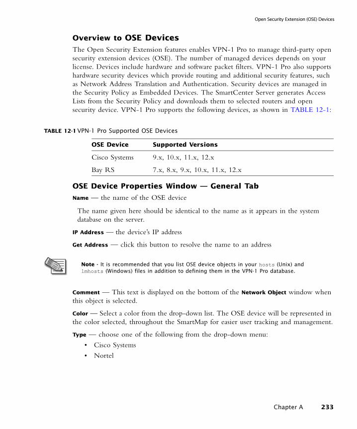
Open Security Extension (OSE) Devices
Overview to OSE DevicesThe Open Security Extension features enables VPN-1 Pro to manage third-party open security extension devices (OSE). The number of managed devices depends on your license. Devices include hardware and software packet filters. VPN-1 Pro also supports hardware security devices which provide routing and additional security features, such as Network Address Translation and Authentication. Security devices are managed in the Security Policy as Embedded Devices. The SmartCenter Server generates Access Lists from the Security Policy and downloads them to selected routers and open security device. VPN-1 Pro supports the following devices, as shown in TABLE 12-1:
OSE Device Properties Window — General Tab
Name — the name of the OSE device
The name given here should be identical to the name as it appears in the system database on the server.
IP Address — the device’s IP address
Get Address — click this button to resolve the name to an address
Comment — This text is displayed on the bottom of the Network Object window when this object is selected.
Color — Select a color from the drop-down list. The OSE device will be represented in the color selected, throughout the SmartMap for easier user tracking and management.
Type — choose one of the following from the drop-down menu:
• Cisco Systems
• Nortel
TABLE 12-1 VPN-1 Pro Supported OSE Devices
OSE Device Supported Versions
Cisco Systems 9.x, 10.x, 11.x, 12.x
Bay RS 7.x, 8.x, 9.x, 10.x, 11.x, 12.x
Note - It is recommended that you list OSE device objects in your hosts (Unix) and lmhosts (Windows) files in addition to defining them in the VPN-1 Pro database.
Chapter A 233
Network Objects
OSE Device Properties Window — Topology Tab
OSE devices report their network interfaces and setup at boot time. Each OSE device has a different command for listing its configuration.
Show all IPs behind gateway — Show all IP addresses behind the device in the SmartMap View.
To add an interface, click Add. The Interface Properties window is displayed.
To edit an interface, select the interface and click Edit, or double-click the interface. The Interface Properties window is displayed.
To delete an interface, select the interface and click Remove.
The manner in which names are specified for OSE device interfaces is different from the manner in which they are specified for interfaces of other network objects.
Name — name of the network interface as specified in the router’s interface configuration scheme
This name does not include a trailing number.
IP Address — the IP address of the device
Net Mask — the net mask of the device.
Exportable for SecuRemote/SecureClient — Specifies whether information about this object can be made available to SecuRemote/SecureClient machines.
Defining Router Anti-Spoofing Properties
The Interface Properties window allows you to define router anti-spoofing parameters when installing Access Lists on routers. The Interface Properties window is almost identical to the Interface Properties window for network objects.
Note - At least one interface must be defined in the Topology tab or Install Policy will fail.
Note - To implement anti-spoofing for Cisco (version 10.x and higher), you must define additional properties in the Setup tab of each router after you define the Valid Addresses in the Interfaces Properties window. For more information, see “Anti-spoofing Parameters and OSE Devices Setup (Cisco and Nortel)” on page 235.
234
Open Security Extension (OSE) Devices
Anti-spoofing Parameters and OSE Devices Setup (Cisco and Nortel)
For Cisco (Version 10.x and higher) and Nortel OSE devices, you must specify the direction of the filter rules generated from anti-spoofing parameters. The direction of enforcement is specified in the Setup tab of each router.
For Cisco routers, the direction of enforcement is defined by the Spoof Rules Interface
Direction property.
Access List No — the number of Cisco access lists enforced
Cisco routers Version 12x and below support an ACL number range from 101-200. Cisco routers Version 12x and above support an ACL range number from 101-200 and also an ACL number range from 2000-2699. Inputting this ACL number range enables the support of more interfaces.
Username — the name required to logon to the OSE device
Password — the Administrator password (Read only) as defined on the router
Enable Username — the user name required to install Access Lists
Enable Password — the password required to install Access Lists
The security administrator must select one of the following options from the drop-down list for the above Username and Password fields (this includes the Enable fields):
None — Indicates the parameter is not needed.
Known — the value of the parameter must be entered
Prompt — Indicates that the security administrator will be prompted for this parameter.
Version — the Cisco OSE device version (9.x, 10.x, 11.x, 12,x)
OSE Device Interface Direction — Installed rules are enforced on data packets traveling in this direction on all interfaces.
Spoof Rules Interface Direction — The spoof tracking rules are enforced on data packets traveling in this direction on all interfaces.
Security —The security administrator must select either none, Wellfleet or Other from the drop-down list.
Note - Logging for spoofing attempts is available for external interfaces only.
Chapter A 235
Network Objects
Password — the password to access the OSE device
Additional Managers — additional managers as defined in the Bay Site Manager software
Volume — the volume on the OSE device
Config File — name of the config file on the OSE device
Version — the version of the OSE device (7.x, 8.x, 9.x, 10.x, 11.x, or 12.x) OSE Device Access
Username — the name required to logon to the OSE device
Password — the password to access the OSE device
Manager Password — password required to connect to the OSE device
Interface Directions
Rules — the direction in which the rules are enforced on the OSE device interfaces
Spoof Rules — the direction in which spoof rules are enforced on each OSE device interface
Generate ICMP Errors — For denied packets, this option specifies whether or not the OSE Device should generate ICMP destination administratively unreachable messages (ICMP type 13).
Groups
A network objects group is a collection of hosts, gateways, networks or other groups.
Groups are used in cases where you cannot work with single objects, e.g. when working with VPN domains or with topology definitions.
In addition, groups can greatly facilitate and simplify network management, since they allow you to perform operations only once instead of repeating them for every group member.
The Group Properties window lists the network objects included from the group versus those excluded from the group. To configure the group, move objects between the lists as needed.
To include an unlisted network object in the group, create it now by clicking New...
This window shows collapsed sub-groups, without listing their members. For a list of all group members (including the sub-groups’ members), click View Expanded Group....
Logical Servers
236
Open Security Extension (OSE) Devices
A Logical Server is a group of machines that provides the same services. The workload of this group is distributed between all its members.
When a Server group is stipulated in the Servers group field, the client is bound to this physical server. In Persistent server mode the client and the physical server are bound for the duration of the session.
• Persistency by Service — once a client is connected to a physical server for a specified service, subsequent connection to the same Logical Server and the same service will be redirected to the same physical server for the duration of the session.
• Persistency by Server — once a client is connected to a physical server, subsequent connections to the same Logical Server (for any service) will be redirected to the same physical server for the duration of the session.
Balance Method
The load balancing algorithm stipulates how the traffic is balanced between the servers. There are several types of balancing methods:
• Server Load — VPN-1 Pro determines which Server is best equipped to handle the new connection
• Round Trip Time — On the basis of the shortest round trip time between VPN-1 Pro and the servers, executed by a simple ping, VPN-1 Pro determines which Server is best equipped to handle the new connection
• Round Robin — the new connection is assigned to the first available server
• Random — the new connection is assigned to a server at random
• Domain — the new connection is assigned to a server based on domain names
Address Ranges
An Address Range object stipulates the range of IP addresses used in the network from the first to the last IP address.
This object is used when the networks themselves do not have IP address-net mask alignment, so an Address Range is necessary for the implementation of:
• NAT, and
• VPN
Dynamic Objects
A dynamic object is a "logical" object where the IP address will be resolved differently per VPN-1 Pro module using the dynamic_objects command.
The following are the predefined Dynamic Objects:
Chapter A 237
Network Objects
• LocalMachine-all-interfaces – The DAIP machine interfaces (static and dynamic) are resolved into this object.
• LocalMachine – The external interface (dynamic) of the ROBO gateway (as declared in cpconfig when configuring the ROBO gateway).
• InternalNet – The internal interface of the ROBO gateway (as declared in cpconfig when configuring the ROBO gateway).
• AuxiliaryNet – The auxiliary interface of the ROBO gateway (as declared in cpconfig when configuring the ROBO gateway).
• DMZNet – The DMZ interface of the ROBO gateway (as declared in cpconfig when configuring the ROBO gateway).
For more information see the CLI Guide.
VoIP Domains
There are five types of VoIP Domain objects:
• VoIP Domain SIP Proxy
• VoIP Domain H.323 Gatekeeper
• VoIP Domain H.323 Gateway
• VoIP Domain MGCP Call Agent
• VoIP Domain SCCP CallManager
In many VoIP networks, the control signals follow a different route through the network than the media. This is the case when the call is managed by a signal routing device. Signal routing is done in SIP by the Redirect Server, Registrar, and/or Proxy. In SIP, signal routing is done by the Gatekeeper and/or Gateway.
Enforcing signal routing locations is an important aspect of VoIP security. It is possible to specify the endpoints that the signal routing device is allowed to manage. This set of locations is called a VoIP Domain. For more information refer to the Firewall and SmartDefense Guide.
238
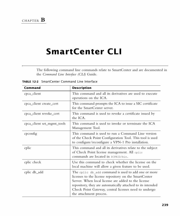
CHAPTER B
SmartCenter CLI
The following command line commands relate to SmartCenter and are documented in the Command Line Interface (CLI) Guide.
TABLE 12-2 SmartCenter Command Line Interface
Command Description
cpca_client This command and all its derivatives are used to execute operations on the ICA.
cpca_client create_cert This command prompts the ICA to issue a SIC certificate for the SmartCenter server.
cpca_client revoke_cert This command is used to revoke a certificate issued by the ICA.
cpca_client set_mgmt_tools This command is used to invoke or terminate the ICA Management Tool.
cpconfig This command is used to run a Command Line version of the Check Point Configuration Tool. This tool is used to configure/reconfigure a VPN-1 Pro installation.
cplic This command and all its derivatives relate to the subject of Check Point license management. All cplic commands are located in $CPRID/bin.
cplic check Use this command to check whether the license on the local machine will allow a given feature to be used.
cplic db_add The cplic db_add command is used to add one or more licenses to the license repository on the SmartCenter Server. When local license are added to the license repository, they are automatically attached to its intended Check Point Gateway, central licenses need to undergo the attachment process.
239
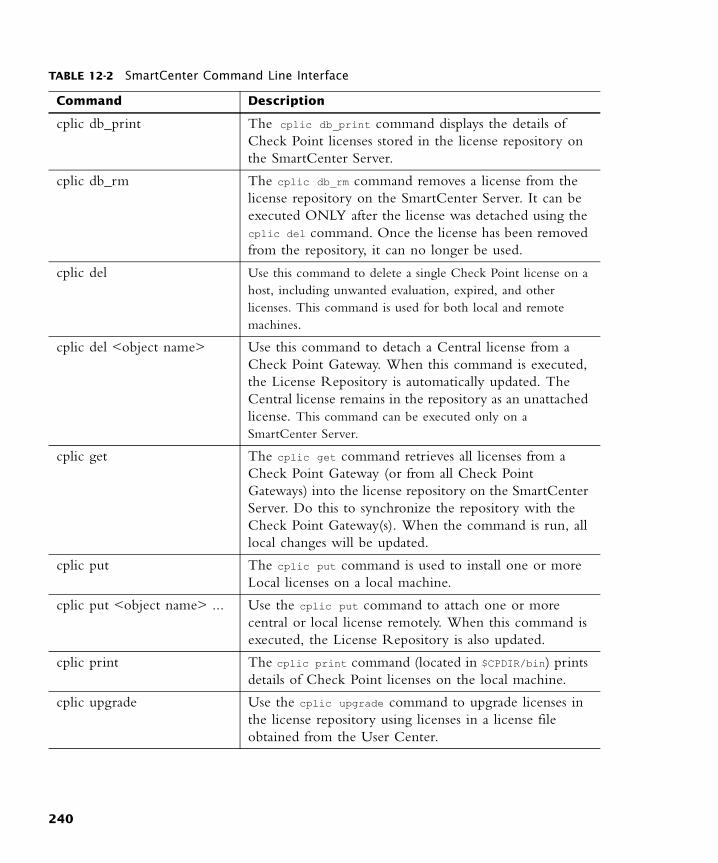
cplic db_print The cplic db_print command displays the details of Check Point licenses stored in the license repository on the SmartCenter Server.
cplic db_rm The cplic db_rm command removes a license from the license repository on the SmartCenter Server. It can be executed ONLY after the license was detached using the cplic del command. Once the license has been removed from the repository, it can no longer be used.
cplic del Use this command to delete a single Check Point license on a host, including unwanted evaluation, expired, and other licenses. This command is used for both local and remote machines.
cplic del <object name> Use this command to detach a Central license from a Check Point Gateway. When this command is executed, the License Repository is automatically updated. The Central license remains in the repository as an unattached license. This command can be executed only on a SmartCenter Server.
cplic get The cplic get command retrieves all licenses from a Check Point Gateway (or from all Check Point Gateways) into the license repository on the SmartCenter Server. Do this to synchronize the repository with the Check Point Gateway(s). When the command is run, all local changes will be updated.
cplic put The cplic put command is used to install one or more Local licenses on a local machine.
cplic put <object name> ... Use the cplic put command to attach one or more central or local license remotely. When this command is executed, the License Repository is also updated.
cplic print The cplic print command (located in $CPDIR/bin) prints details of Check Point licenses on the local machine.
cplic upgrade Use the cplic upgrade command to upgrade licenses in the license repository using licenses in a license file obtained from the User Center.
TABLE 12-2 SmartCenter Command Line Interface
Command Description
240
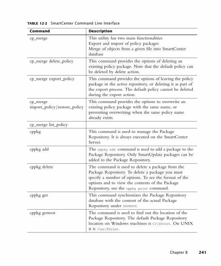
cp_merge This utility has two main functionalitiesExport and import of policy packagesMerge of objects from a given file into SmartCenter database
cp_merge delete_policy This command provides the options of deleting an existing policy package. Note that the default policy can be deleted by delete action.
cp_merge export_policy This command provides the options of leaving the policy package in the active repository, or deleting it as part of the export process. The default policy cannot be deleted during the export action.
cp_merge import_policy|restore_policy
This command provides the options to overwrite an existing policy package with the same name, or preventing overwriting when the same policy name already exists.
cp_merge list_policy
cppkg This command is used to manage the Package Repository. It is always executed on the SmartCenter Server.
cppkg add The cppkg add command is used to add a package to the Package Repository. Only SmartUpdate packages can be added to the Package Repository.
cppkg delete The command is used to delete a package from the Package Repository. To delete a package you must specify a number of options. To see the format of the options and to view the contents of the Package Repository, use the cppkg print command.
cppkg get This command synchronizes the Package Repository database with the content of the actual Package Repository under $SUROOT.
cppkg getroot The command is used to find out the location of the Package Repository. The default Package Repository location on Windows machines is C:\SUroot. On UNIX it is /var/SUroot.
TABLE 12-2 SmartCenter Command Line Interface
Command Description
Chapter B 241
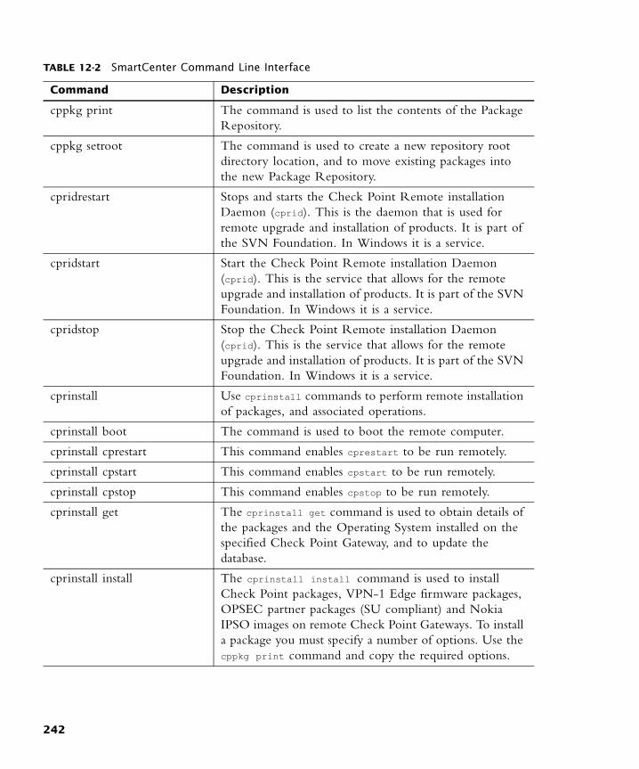
cppkg print The command is used to list the contents of the Package Repository.
cppkg setroot The command is used to create a new repository root directory location, and to move existing packages into the new Package Repository.
cpridrestart Stops and starts the Check Point Remote installation Daemon (cprid). This is the daemon that is used for remote upgrade and installation of products. It is part of the SVN Foundation. In Windows it is a service.
cpridstart Start the Check Point Remote installation Daemon (cprid). This is the service that allows for the remote upgrade and installation of products. It is part of the SVN Foundation. In Windows it is a service.
cpridstop Stop the Check Point Remote installation Daemon (cprid). This is the service that allows for the remote upgrade and installation of products. It is part of the SVN Foundation. In Windows it is a service.
cprinstall Use cprinstall commands to perform remote installation of packages, and associated operations.
cprinstall boot The command is used to boot the remote computer.
cprinstall cprestart This command enables cprestart to be run remotely.
cprinstall cpstart This command enables cpstart to be run remotely.
cprinstall cpstop This command enables cpstop to be run remotely.
cprinstall get The cprinstall get command is used to obtain details of the packages and the Operating System installed on the specified Check Point Gateway, and to update the database.
cprinstall install The cprinstall install command is used to install Check Point packages, VPN-1 Edge firmware packages, OPSEC partner packages (SU compliant) and Nokia IPSO images on remote Check Point Gateways. To install a package you must specify a number of options. Use the cppkg print command and copy the required options.
TABLE 12-2 SmartCenter Command Line Interface
Command Description
242
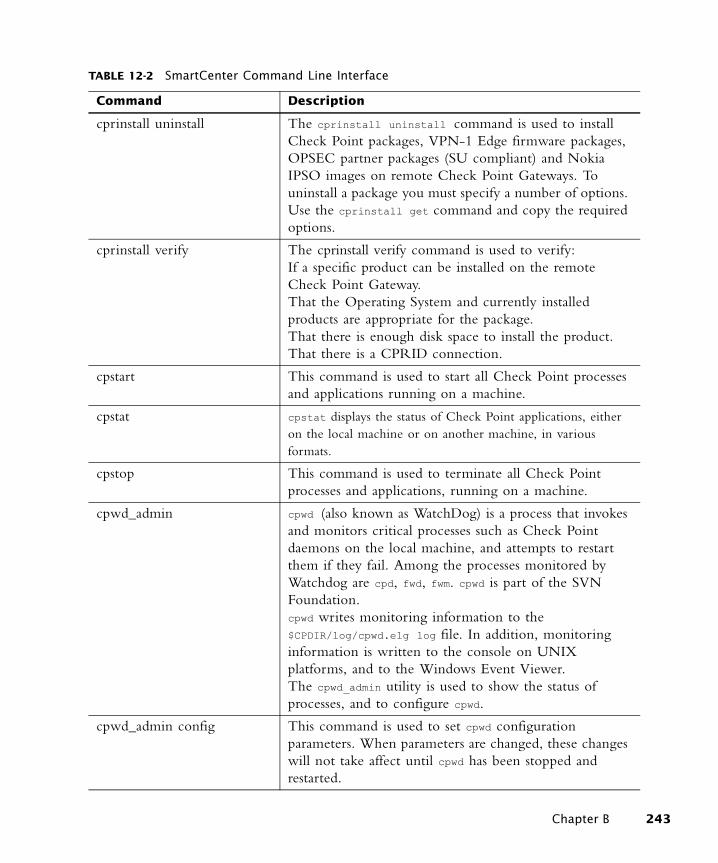
cprinstall uninstall The cprinstall uninstall command is used to install Check Point packages, VPN-1 Edge firmware packages, OPSEC partner packages (SU compliant) and Nokia IPSO images on remote Check Point Gateways. To uninstall a package you must specify a number of options. Use the cprinstall get command and copy the required options.
cprinstall verify The cprinstall verify command is used to verify:If a specific product can be installed on the remote Check Point Gateway.That the Operating System and currently installed products are appropriate for the package.That there is enough disk space to install the product.That there is a CPRID connection.
cpstart This command is used to start all Check Point processes and applications running on a machine.
cpstat cpstat displays the status of Check Point applications, either on the local machine or on another machine, in various formats.
cpstop This command is used to terminate all Check Point processes and applications, running on a machine.
cpwd_admin cpwd (also known as WatchDog) is a process that invokes and monitors critical processes such as Check Point daemons on the local machine, and attempts to restart them if they fail. Among the processes monitored by Watchdog are cpd, fwd, fwm. cpwd is part of the SVN Foundation. cpwd writes monitoring information to the $CPDIR/log/cpwd.elg log file. In addition, monitoring information is written to the console on UNIX platforms, and to the Windows Event Viewer. The cpwd_admin utility is used to show the status of processes, and to configure cpwd.
cpwd_admin config This command is used to set cpwd configuration parameters. When parameters are changed, these changes will not take affect until cpwd has been stopped and restarted.
TABLE 12-2 SmartCenter Command Line Interface
Command Description
Chapter B 243
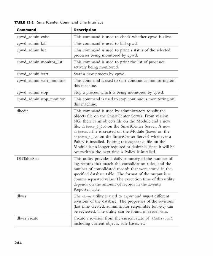
cpwd_admin exist This command is used to check whether cpwd is alive.
cpwd_admin kill This command is used to kill cpwd.
cpwd_admin list This command is used to print a status of the selected processes being monitored by cpwd.
cpwd_admin monitor_list This command is used to print the list of processes actively being monitored.
cpwd_admin start Start a new process by cpwd.
cpwd_admin start_monitor This command is used to start continuous monitoring on this machine.
cpwd_admin stop Stop a process which is being monitored by cpwd.
cpwd_admin stop_monitor This command is used to stop continuous monitoring on this machine.
dbedit This command is used by administrators to edit the objects file on the SmartCenter Server. From version NG, there is an objects file on the Module and a new file, objects_5_0.C on the SmartCenter Server. A new objects.C file is created on the Module (based on the objects_5_0.C on the SmartCenter Server) whenever a Policy is installed. Editing the objects.C file on the Module is no longer required or desirable, since it will be overwritten the next time a Policy is installed.
DBTableStat This utility provides a daily summary of the number of log records that match the consolidation rules, and the number of consolidated records that were stored in the specified database table. The format of the output is a comma separated value. The execution time of this utility depends on the amount of records in the Eventia Reporter table.
dbver The dbver utility is used to export and import different revisions of the database. The properties of the revisions (last time created, administrator responsible for, etc) can be reviewed. The utility can be found in $FWDIR/bin.
dbver create Create a revision from the current state of $fwdir/conf, including current objects, rule bases, etc.
TABLE 12-2 SmartCenter Command Line Interface
Command Description
244

dbver export Archive the revision as an archive file in the revisions repository: $fwdir/conf/db_versions/export.
dbver import Add an exported revision to the repository a version from $fwdir/conf/db_versions/export. Give filename of revision as input.
dbver print Print the properties of the revision.
dbver print_all Print the properties of all revisions to be found on the server side: $fwdir/conf/db_versions.
dynamic_objects dynamic_objects specifies an IP address to which the dynamic object will be resolved on this machine.
fw The fw commands are used for working with various aspects of the firewall component of VPN-1 Pro. All fw commands are executed on the enforcement module. Typing fw at the command prompt sends a list of available fw commands to the standard output.
fw ctl The fw ctl command controls the VPN-1 Pro kernel module.
fw expdate This command is used to modify the expiration date of all users and administrators.
fw fetch This command fetches the Inspection Code from the specified host and installs it to the kernel.
fw fetchlogs fw fetchlogs fetches Log Files from a remote machine. You can use the fw fetchlogs command to transfer Log Files to the machine on which the fw fetchlogs command is executed. The Log Files are read from and written to the directory $FWDIR/log.
TABLE 12-2 SmartCenter Command Line Interface
Command Description
Chapter B 245
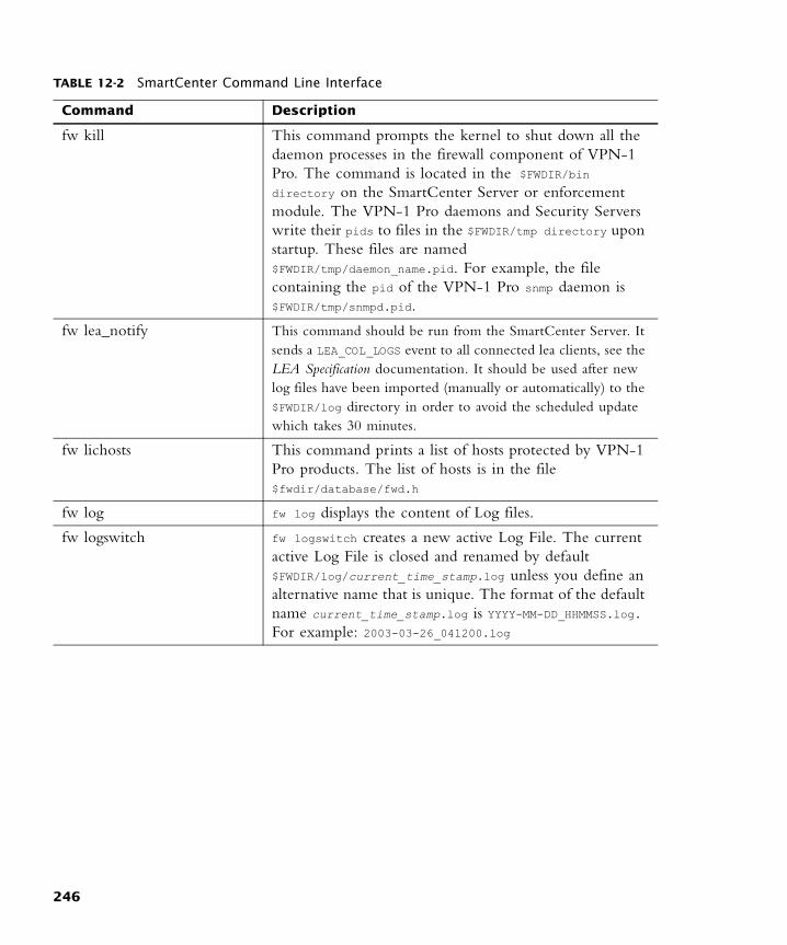
fw kill This command prompts the kernel to shut down all the daemon processes in the firewall component of VPN-1 Pro. The command is located in the $FWDIR/bin directory on the SmartCenter Server or enforcement module. The VPN-1 Pro daemons and Security Servers write their pids to files in the $FWDIR/tmp directory upon startup. These files are named $FWDIR/tmp/daemon_name.pid. For example, the file containing the pid of the VPN-1 Pro snmp daemon is $FWDIR/tmp/snmpd.pid.
fw lea_notify This command should be run from the SmartCenter Server. It sends a LEA_COL_LOGS event to all connected lea clients, see the LEA Specification documentation. It should be used after new log files have been imported (manually or automatically) to the $FWDIR/log directory in order to avoid the scheduled update which takes 30 minutes.
fw lichosts This command prints a list of hosts protected by VPN-1 Pro products. The list of hosts is in the file $fwdir/database/fwd.h
fw log fw log displays the content of Log files.
fw logswitch fw logswitch creates a new active Log File. The current active Log File is closed and renamed by default $FWDIR/log/current_time_stamp.log unless you define an alternative name that is unique. The format of the default name current_time_stamp.log is YYYY-MM-DD_HHMMSS.log. For example: 2003-03-26_041200.log
TABLE 12-2 SmartCenter Command Line Interface
Command Description
246
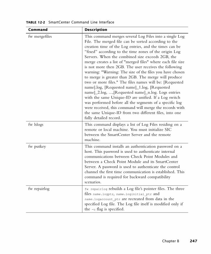
fw mergefiles This command merges several Log Files into a single Log File. The merged file can be sorted according to the creation time of the Log entries, and the times can be “fixed” according to the time zones of the origin Log Servers. When the combined size exceeds 2GB, the merge creates a list of "merged files" where each file size is not more then 2GB. The user receives the following warning: "Warning: The size of the files you have chosen to merge is greater than 2GB. The merge will produce two or more files." The files names will be: [Requested name].log, [Requested name]_1.log, [Requested name]_2.log, ...,[Requested name]_n.log. Logs entries with the same Unique-ID are unified. If a Log switch was performed before all the segments of a specific log were received, this command will merge the records with the same Unique-ID from two different files, into one fully detailed record.
fw lslogs This command displays a list of Log Files residing on a remote or local machine. You must initialize SIC between the SmartCenter Server and the remote machine.
fw putkey This command installs an authentication password on a host. This password is used to authenticate internal communications between Check Point Modules and between a Check Point Module and its SmartCenter Server. A password is used to authenticate the control channel the first time communication is established. This command is required for backward compatibility scenarios.
fw repairlog fw repairlog rebuilds a Log file’s pointer files. The three files name.logptr, name.loginitial_ptr and name.logaccount_ptr are recreated from data in the specified Log file. The Log file itself is modified only if the -u flag is specified.
TABLE 12-2 SmartCenter Command Line Interface
Command Description
Chapter B 247
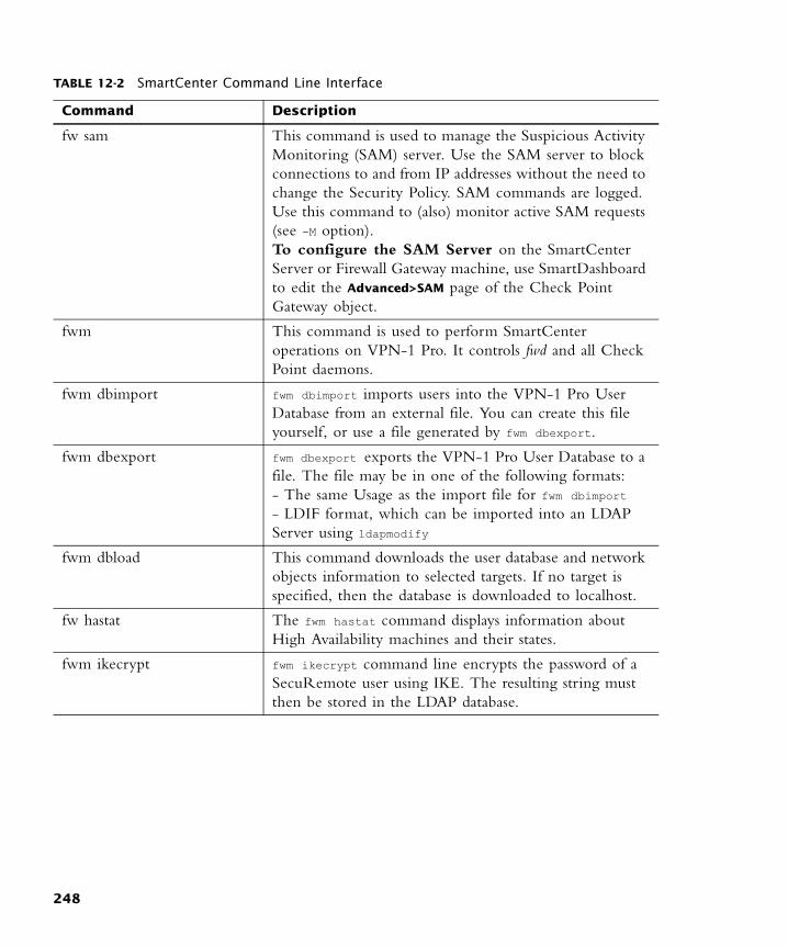
fw sam This command is used to manage the Suspicious Activity Monitoring (SAM) server. Use the SAM server to block connections to and from IP addresses without the need to change the Security Policy. SAM commands are logged. Use this command to (also) monitor active SAM requests (see -M option).To configure the SAM Server on the SmartCenter Server or Firewall Gateway machine, use SmartDashboard to edit the Advanced>SAM page of the Check Point Gateway object.
fwm This command is used to perform SmartCenter operations on VPN-1 Pro. It controls fwd and all Check Point daemons.
fwm dbimport fwm dbimport imports users into the VPN-1 Pro User Database from an external file. You can create this file yourself, or use a file generated by fwm dbexport.
fwm dbexport fwm dbexport exports the VPN-1 Pro User Database to a file. The file may be in one of the following formats: - The same Usage as the import file for fwm dbimport- LDIF format, which can be imported into an LDAP Server using ldapmodify
fwm dbload This command downloads the user database and network objects information to selected targets. If no target is specified, then the database is downloaded to localhost.
fw hastat The fwm hastat command displays information about High Availability machines and their states.
fwm ikecrypt fwm ikecrypt command line encrypts the password of a SecuRemote user using IKE. The resulting string must then be stored in the LDAP database.
TABLE 12-2 SmartCenter Command Line Interface
Command Description
248

fwm load This command compiles and installs a Security Policy or a specific version of the Security Policy on the target’s VPN-1 Pro Modules. This is done in one of two ways:- fwm load compiles and installs an Inspection Script (*.pf) file on the designated VPN-1 Pro Modules.- fwm load converts a Rule Base (*.W) file created by the GUI into an Inspection Script (*.pf) file then installs it to the designated VPN-1 Pro Modules.Versions of the Security Policy and databases are maintained in a version repository on the SmartCenter Server. Using this command specific versions of the Security Policy can be installed on a Module (local or remote) without changing the definition of the current active database version on the SmartCenter Server.To protect a target, you must load a Policy that contains rules whose scope matches the target. If none of the rules are enforced on the target, then all traffic through the target is blocked.
fwm lock_admin This commands enables you to view and unlock locked administrators.
fwm logexport fwm logexport exports the Log file to an ASCII file.
fwm unload <targets> This command uninstalls the currently loaded Inspection Code from selected targets.
fwm ver fwm ver displays the build number.
GeneratorApp This command generates a report for the Eventia Reporter. Both command line parameters are required.
TABLE 12-2 SmartCenter Command Line Interface
Command Description
Chapter B 249
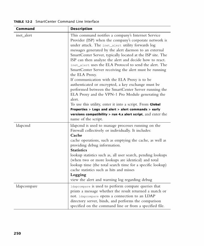
inet_alert This command notifies a company’s Internet Service Provider (ISP) when the company’s corporate network is under attack. The inet_alert utility forwards log messages generated by the alert daemon to an external SmartCenter Server, typically located at the ISP site. The ISP can then analyze the alert and decide how to react. inet_alert uses the ELA Protocol to send the alert. The SmartCenter Server receiving the alert must be running the ELA Proxy.If communication with the ELA Proxy is to be authenticated or encrypted, a key exchange must be performed between the SmartCenter Server running the ELA Proxy and the VPN-1 Pro Module generating the alert. To use this utility, enter it into a script. From Global
Properties > Logs and alert > alert commands > early
versions compatibility > run 4.x alert script, and enter the name of the script.
ldapcmd ldapcmd is used to manage processes running on the Firewall collectively or individually. It includes:Cache cache operations, such as emptying the cache, as well as providing debug information.Statistics lookup statistics such as, all user search, pending lookups (when two or more lookups are identical) and total lookup time (the total search time for a specific lookup)cache statistics such as hits and missesLoggingview the alert and warning log regarding debug
ldapcompare ldapcompare is used to perform compare queries that prints a message whether the result returned a match or not. ldapcompare opens a connection to an LDAP directory server, binds, and performs the comparison specified on the command line or from a specified file.
TABLE 12-2 SmartCenter Command Line Interface
Command Description
250
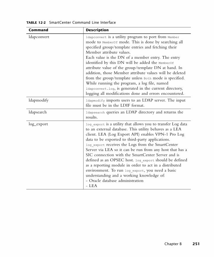
ldapconvert ldapconvert is a utility program to port from Member mode to MemberOf mode. This is done by searching all specified group/template entries and fetching their Member attribute values. Each value is the DN of a member entry. The entry identified by this DN will be added the MemberOf attribute value of the group/template DN at hand. In addition, those Member attribute values will be deleted from the group/template unless Both mode is specified. While running the program, a log file, named ldapconvert.log, is generated in the current directory, logging all modifications done and errors encountered.
ldapmodify ldapmodify imports users to an LDAP server. The input file must be in the LDIF format.
ldapsearch ldapsearch queries an LDAP directory and returns the results.
log_export log_export is a utility that allows you to transfer Log data to an external database. This utility behaves as a LEA client. LEA (Log Export API) enables VPN-1 Pro Log data to be exported to third-party applications. log_export receives the Logs from the SmartCenter Server via LEA so it can be run from any host that has a SIC connection with the SmartCenter Server and is defined as an OPSEC host. log_export should be defined as a reporting module in order to act in a distributed environment. To run log_export, you need a basic understanding and a working knowledge of:- Oracle database administration- LEA
TABLE 12-2 SmartCenter Command Line Interface
Command Description
Chapter B 251
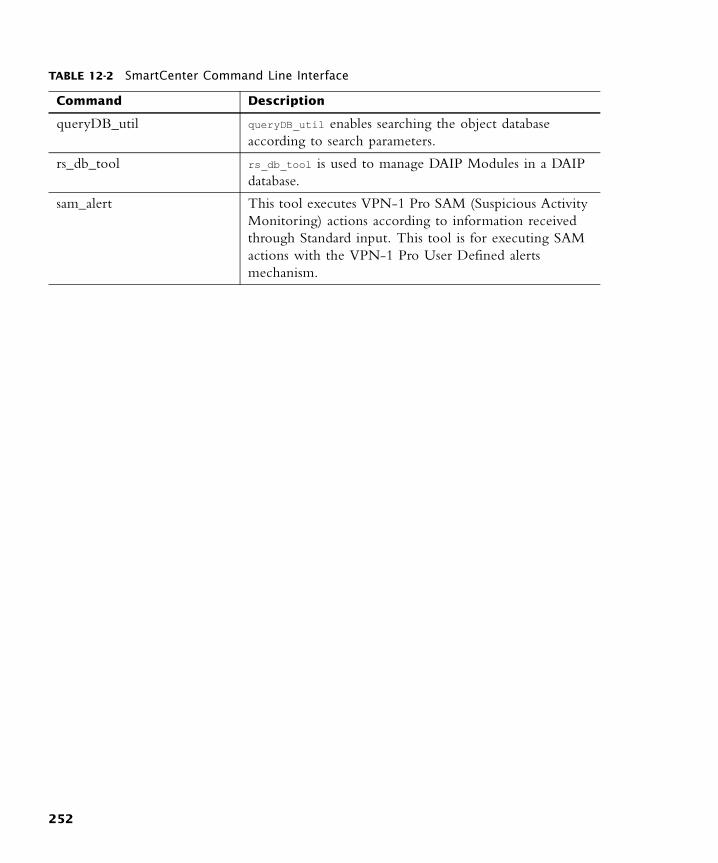
queryDB_util queryDB_util enables searching the object database according to search parameters.
rs_db_tool rs_db_tool is used to manage DAIP Modules in a DAIP database.
sam_alert This tool executes VPN-1 Pro SAM (Suspicious Activity Monitoring) actions according to information received through Standard input. This tool is for executing SAM actions with the VPN-1 Pro User Defined alerts mechanism.
TABLE 12-2 SmartCenter Command Line Interface
Command Description
252
Index
AAdd Package From CD 143administrator
authentication 17configuring 41login 17template 38types 39
alert commandsmail alert 127SNMP trap alert 127user defined 127
attach 139attaching licenses 147AttributesTranslationMap 192audit log 140authentication
administrator 17automated software 136
BBadPwdCountAttr 191block intruder 110
configuration 126BranchObjectClass 193BranchOCOperator 193
CCentral License 148Central license 147, 150centralized policy management 136Certificate Key 148Check Point CD 137ClientSideCrypt 192color 233command line 146, 155command line interface 136compiling a Security Policy 249contains operator 174cpd 138
CPInfo 155CPLIC 148cplic 155cplic get 240cplic print 240cplic put
remote operation 240cppkg 155cppkg delete 241cppkg getroot 242cppkg setroot 242CPRID 141cprid daemon 138cprinstall 155cprinstall boot 242cprinstall get 242cprinstall stop 243cyclic logging 108
configuration 122
DDAIP Module
managing from the command line 252
databaseusers 38
Database Revision Control 132Distribute 141distribute 139, 144distribute packages 143Download Center 137dynamic_objects 245
Eends with operator 174Expand/Collapse 139ExpirationDateAttr 191ExpirationDateFormat 190export
user database 248Exporting a License 154external group
when changes take effect 38
Ffilter 104
configuration 114fingerprint
SmartCenter server authentication 18
FireWalled hostdisplaying status of 243
fw fetchlogs 245fw lea_notify 246fw lea_notify command 246fw lslogs 246fw mergefiles 247fw repairlog 247fw sam 248fw unload 249fw.adtlog 100fw.log 108fw1allowed-dst 184fw1allowed-src 184fw1allowed-vlan 184fw1authmethod 181fw1auth-server 182fw1day 183fw1enc-fwz-expiration 185fw1expiration-date 183fw1groupTemplate 185fw1hour-range-from 183fw1hour-range-to 183fw1person 175fw1pwdLastMod 182fw1sr-auth-track 185fw1SR-datam 185fw1SR-keym 184fw1SR-mdm 185fwm dbimport 248fwm ikecrypt 248fwm logexport 249fwm unload 249fwm ver 249
253
G
Ggreater than operator 174
compatibility with LDAP versions 174
GroupMembershipAttr 197GroupObjectClass 195GroupOCOperator 193GroupRDN 198
HHFA 141hosts file 233Hot Fix Accumulators 144Hotfixes 142
IinetOrgPerson 175installation
targets 50installation target
configuring 55installing a FireWall license 240Integrated Firewalls 236Internal Certificate Authority
SIC, ICA 32Internal Template object 176is not operator 174is operator 174
LLDAP 37
group 39LDAP profiles
modifying 189types of 165
LDAP Serverexporting users from 248importing users to 251
LDAP serversdifferences between 164
LDAP Version 3.0 174ldapmodify command 178ldapsearch 251LDIF syntax 248less than operator 174
compatibility with LDAP versions 174
licensechecking 239displaying 240finding expired 154installing 240removing from repository 153viewing properties 153
License Expiration 149License Management 151license management 136License Repository 137, 138, 147,
150, 151, 154license updates 136Licenses 138Licenses Repository 140lmhosts file 233loading a Security Policy 249Local License 149Local license 147, 150log
cyclic logging 108, 122downtime 109export 108fw.adtlog 100local 109, 123log server 109log server configuration 124maintenance 108, 122overview 100purge 123remote file management 109switching the active log file 108,
122Log File
creating new 246displaying contents of 246displaying, using command-line
interface 247, 248exporting 249unified log 247
Log filerepairing pointer files 247
log file 140log server 109
configuration 124log servers 109log switch 108
configuration 122schedule 122
loginbi-directional authentication 17SIC 17
MMaster
fetching Security Policy from 245
Microsoft Active Directoryadding attributes to 178alternative to extending the
schema 176delegating control over 177enabling 175number of queries in 176registry settings for 177structure of 176
monitoring system status 113Multi-License File 149
NNokia 144null matches 114
Oobject database
querying 252Objects
configuring 23database 227in SmartDashboard 20management operations 22managing 19
objects tree 53sorting 53
objects_5_0.C file 244Obsolete license 149Operation Status 140OPSEC 136, 142organizationalPerson 175OrganizationObjectClass 194OrgUnitObjectClass 194OrgUnitRDN 197
PPackage Management 142Package Repository 137, 138, 142,
143Package/Licenses Management 139
254

T
Packages 138Packages Repository 140password
verifying 181person 175policy
adding to a policy package 55policy package 43
adding a policy 55advanced security 43desktop security 43, 49file operations 50install 44installation target 55installation targets 50overview 43, 49QoS 43, 49query network object 52query rules 52rule section title 51security and address
translation 49uninstall 45user database 43VPN manager 49web access 49
PsswdDateAttr 191PsswdDateFormat 191
Qquery
all records 105configuration 117custom 105definition 105intersecting queries 57network object 52predefined 105rule 52rule base 56
queryDB_util utility 252
Rreboot 145remote device 143remote enforcement points 135remote firewalls 135remote upgrade 136Repository 140
routersanti-spoofing capabilities 234
rulesection titles 51
Sschema_microsoft_ad.ldif file 178Secure Initial Communication
(SIC) 138Secure Internal Communication
(SIC) 141SecurePlatform 144, 146Security Policy
compiling 249fetching from Master 245loading 249uninstalling 249
Show 114SIC 17
ICA, Internal Certificate Authority 32
initialize, Configuration Tool 33
reset Trust state 34Secure Internal
Communication 31test SIC status 34the solution 32troubleshooting 35Trust states 34
single management console 136SKU 149SmartCenter Server
fingerprint 18SmartDirectory (LDAP) 157SmartMap
adjust,customize,magnify,scroll,Navigator,Layout 61
connections 64enable,view, toggle, launch 60Folders 67integration with Rule Base 70Internet, Connectivity Clouds,
Implied Networks, Ambiguous Networks, Contained Networks 65
output 74overview 59solution 60troubleshooting 72working with Network Objects
and Groups,select mode 63
SmartUpdateOperation Status pane, using
the 139SmartView Tracker
account 111active 104alert 111alert command
configuration 127audit 104block intruder 110, 126custom commands 110, 125filter 104, 114fw.adtlog 104fw.log 104, 108local logging 109log 104, 111log export 108log switch 108, 122modes 104null matches 114overview 102purge 123query 105, 117remote file management 123resolving IP addresses 114track options 111view options 113working with 109
Snapshot 146SNMP 217
Check Point Solution 217Configuring 220MIB 218Requests on Unix 219Requests on Windows NT 219Special Consideration 220trap 245Traps 220
sort 53objects list pane 53
sounds like operator 174starts with operator 174status
of Check Point Modules, displaying 243
Stop Operation 145
Ttemplate 39
administrator 38configuring 42
255

U
user 38TemplateObjectClass 190Topology
of the network, definition 35track
account 111alert 111basic configuration 112column 100log 111options 111overview 100rule 110
UUninstallation 145uninstalling a Security Policy 249UNIX 143upgrade 143Upgrade all Packages 141, 144Upgrade Status 149upgrading licenses 147user
configuring 40database 38managing in LDAP 37managing in
SmartDashboard 37template 38types 39
User Center 137User Database
downloading 248user database
exporting 248importing 248
UserLoginAttr 189UserMembershipAttr 196UserObjectClass 194UserPasswordAttr 190UserRDN 198users database 38
install 45
VVPN communities 230VPN-1 Pro 136VPN-1 Pro license, see license
256