60000/40000 security platforms r76sp.50 - Check Point Software
171
27 July 2019 Getting Started Guide 60000/40000 SECURITY PLATFORMS R76SP.50 Protected
-
Upload
khangminh22 -
Category
Documents
-
view
2 -
download
0
Transcript of 60000/40000 security platforms r76sp.50 - Check Point Software

27 July 2019
Getting Started Guide
60000/40000 SECURITY PLATFORMS
R76SP.50
Pro
tect
ed

C H A P T E R 1
2019 Check Point Software Technologies Ltd.
All rights reserved. This product and related documentation are protected by copyright and distributed under licensing restricting their use, copying, distribution, and decompilation. No part of this product or related documentation may be reproduced in any form or by any means without prior written authorization of Check Point. While every precaution has been taken in the preparation of this book, Check Point assumes no responsibility for errors or omissions. This publication and features described herein are subject to change without notice.
RESTRICTED RIGHTS LEGEND:
Use, duplication, or disclosure by the government is subject to restrictions as set forth in subparagraph (c)(1)(ii) of the Rights in Technical Data and Computer Software clause at DFARS 252.227-7013 and FAR 52.227-19.
TRADEMARKS:
Refer to the Copyright page https://www.checkpoint.com/copyright/ for a list of our trademarks.
Refer to the Third Party copyright notices https://www.checkpoint.com/about-us/third-party-trademarks-and-copyrights/ for a list of relevant copyrights and third-party licenses.

Important Information
Latest Software
We recommend that you install the most recent software release to stay up-to-date with the latest functional improvements, stability fixes, security enhancements and protection against new and evolving attacks.
Check Point R76SP.50
For more about this release, see the R76SP.50 home page http://supportcontent.checkpoint.com/solutions?id=sk115735.
Latest Version of this Document
Open the latest version of this document in a Web browser https://sc1.checkpoint.com/documents/R76SP.50/CP_R76SP.50_for_40000_60000_SecuritySystems_GettingStartedGuide/html_frameset.htm.
Download the latest version of this document in PDF format http://supportcontent.checkpoint.com/documentation_download?ID=54148.
Feedback
Check Point is engaged in a continuous effort to improve its documentation.
Please help us by sending your comments mailto:[email protected]?subject=Feedback on 60000/40000 Security Platforms R76SP.50 Getting Started Guide.
Revision History
Date Description
27 July 2019 Updated:
• Health and Safety Information (on page 9)
• Shipping Carton Contents for the 64000 Security System Appliance (on page 17)
• DC Power Entry Modules (PEMs) for 64000 Security System (on page 82)
• DC PEM Panel and LED Indicators for 64000 Security System (on page 82)
• Step 2: Installing the Chassis in a Rack (on page 94)
• Connecting DC Power to 64000 Security System (on page 107)
Added:
• 64000 Security System Rear Panel with DC PEMs (on page 82)
• Technical Specifications (on page 170)
03 April 2019 Improved document formatting.

Date Description
19 February 2019 Updated:
• Installing the SGM Image with Removable Media (on page 121) (in Step 6: Installing the Software)
17 December 2018 Updated:
• SGM400 Security Gateway Module (on page 58) (LAN1 and LAN2 ports are for Check Point internal use only)
• SGM260 Security Gateway Module (on page 62) (LAN1, LAN2 and LAN3 ports are for Check Point internal use only)
11 December 2018 Updated:
• Configuring a VSX Gateway (on page 131) (added the note "While running VSX Gateway Wizard, only one SGM (SMO) should be defined in the Security Group")
30 July 2018 General formatting updates
19 July 2018 Updated:
• SSM440 Security Switch Module (on page 48) (corrected the callouts on the image)
11 June 2018 Added:
• DC Power Entry Modules (PEMs) for 64000 Security System (on page 82)
• DC PEM Panel and LED Indicators for 64000 Security System (on page 83)
• Connecting DC Power to 64000 Security System (on page 107) Updated:
• Connecting DC Power to 61000 and 41000 Security Systems (on page 109)
13 May 2018 Formatting changes. Updated:
• Information about all Hardware Components (on page 26)
• Installing the SGM Image on page 121
Added:
• Setting up the Chassis ID
Removed:
• "Installing the SGM with Snapshot Import" as not supported
04 January 2018
Added:
• Step 6 (on page 115), Step 7 (on page 124), Step 8 (on page 125) and Step 9 (on page 129)
• License and Registration information (on page 135)
• Basic Configuration Using gClish (on page 136)
• Monitoring and Configuration details (on page 138)
• Troubleshooting (on page 167)

Date Description
12 November 2017 Updated:
• SGM information (on page 57)
25 October 2017 Updated:
• Shipping Carton Contents for the 64000 Security System Appliance (on page 17)
• AC Power Supply Units (PSUs) (on page 70)
• DC Power Entry Modules (PEMs) (on page 85)
21 August 2017 Formatting changes
12 July 2017 Added:
• Control Panel for 64000 and 61000 N+N Security Systems (on page 43)
• AC Power Supply Units (PSUs) (on page 70)
Updated:
• SGM400 (on page 34) information
23 April 2017 First release of this document l

Contents Important Information .............................................................................................................. 3 Health and Safety Information................................................................................................. 9 Introduction .............................................................................................................................. 14
Overview of Check Point 60000/40000 Security Platforms .......................................... 14 Check Point Virtual Systems ............................................................................................. 15 In this Document ................................................................................................................. 16
Shipping Carton Contents for the 64000 Security System Appliance ............................. 17 Shipping Carton Contents for the 44000 Security System Appliance ............................. 19 Shipping Carton Contents for 61000 N+N Security System Appliance ........................... 20 Shipping Carton Contents for the 61000 Security System Appliance ............................. 22 Shipping Carton Contents for the 41000 Security System Appliance ............................. 24 Hardware Components ........................................................................................................... 26
64000 Security System Front Panel ................................................................................. 27 44000 Security System Front Panel ................................................................................. 31 61000 N+N Security System Front Panel ........................................................................ 34 61000 Security System Front Panel ................................................................................. 37 41000 Security System Front Panel ................................................................................. 40 Control Panel for 64000 and 61000 N+N Security Systems ......................................... 43 Control Panel for 44000 Security System ....................................................................... 45 Security Switch Module (SSM) .......................................................................................... 47
SSM440 Security Switch Module ...................................................................................... 48 SSM440 Security Switch Module LEDs ............................................................................. 50 SSM160 Security Switch Module ...................................................................................... 52 SSM160 Security Switch Module LEDs ............................................................................. 55
Security Gateway Module (SGM) ....................................................................................... 57 SGM400 Security Gateway Module ................................................................................... 58 SGM400 Security Gateway Module LEDs.......................................................................... 60 SGM260 Security Gateway Module ................................................................................... 62 SGM260 Security Gateway Module LEDs.......................................................................... 64
Chassis Management Modules (CMMs) for 64000, 44000 and 61000 N+N Security Systems................................................................................................................................. 67 Chassis Management Modules (CMMs) for 61000 and 41000 Security Systems ...... 68 AC Power Supply Units (PSUs) .......................................................................................... 70 AC Power Cords ................................................................................................................... 74
AC Power Cords for the 64000 Security System .............................................................. 74 AC Power Cords for the 44000 Security System .............................................................. 75 AC Power Cords for the 61000 N+N Security System ...................................................... 77 AC Power Cords for the 61000 Security System .............................................................. 78 AC Power Cords for the 41000 Security System .............................................................. 80
DC Power Entry Modules (PEMs) for 64000 Security System ...................................... 82 64000 Security System Rear Panel with DC PEMs........................................................... 82 DC PEM Panel and LED Indicators for 64000 Security System........................................ 83
DC Power Entry Modules (PEMs) for 61000 and 41000 Security Systems................. 85 DC PEM Panel and LED Indicators for 61000 and 41000 Security Systems .................... 85
Installing Cable Management Tray .................................................................................. 87 Fan Trays for the 64000 and 61000 N+N Security System............................................ 88

Fan Trays for the 41000, 44000 and 61000 Security Systems.......................................... 89 Fan Trays for the 64000 and 61000 N+N Security Systems ............................................. 90
Blank Filler Panels for Airflow Management ................................................................. 91 Front Blank Panels with Air Baffles ................................................................................. 91
Step 1: Site Preparation.......................................................................................................... 92 Customer Supplied Hardware........................................................................................... 92 Rack Mounting Requirements........................................................................................... 92 Required Tools..................................................................................................................... 93
Step 2: Installing the Chassis in a Rack ............................................................................... 94 Step 3: Installing Hardware Components and Connecting Power Cables ..................... 96
Inserting AC Power Supply Units...................................................................................... 97 Inserting SSMs for the 61000, 61000 N+N and 64000 Security System ..................... 98 Inserting SSMs for the 41000 Security System .............................................................. 99 Inserting SGMs for the 64000, 61000 and 61000 N+N Security System ...................100 Inserting SGMs for the 44000 and 41000 Security System.........................................101 Inserting Transceivers .....................................................................................................102
Inserting Twisted Pair Transceivers .............................................................................. 102 Inserting Fiber Optic Transceivers ................................................................................. 103 Inserting QSFP Splitters ................................................................................................. 103
Inserting Front Blank Panels ..........................................................................................104 Connecting AC Power Cables ..........................................................................................105 Inserting AC Power Supply Units....................................................................................106 Connecting DC Power to 64000 Security System .........................................................107 Connecting DC Power for 61000 and 41000 Security Systems ..................................109 Connecting a Second Chassis..........................................................................................111
Step 4: Turning on the System.............................................................................................112 Step 5: Dual Chassis System Validation.............................................................................113
Validating the Chassis ID .................................................................................................113 Setting the Chassis ID.......................................................................................................114
Step 6: Installing the Software ............................................................................................115 Before Installing SSM160 Firmware and Software .....................................................115 Installing SSM160 Firmware ...........................................................................................118 Upgrading SSM Firmware................................................................................................120 Installing the SGM Image .................................................................................................121
Installing the SGM Image with Removable Media.......................................................... 121 Upgrading the SGM220 BIOS Firmware ......................................................................... 123
Step 7: Connecting to the Network .....................................................................................124 Step 8: Initial Software Configuration ................................................................................125
Connecting over Console (Serial) Port ..........................................................................125 Running the Initial Setup..................................................................................................127
Step 9: SmartDashboard Configuration .............................................................................129 Defining a Security Gateway ............................................................................................129
Confirming the Security Gateway Software Configuration ............................................ 130 Configuring a VSX Gateway..............................................................................................131
Wizard Step 1: Defining VSX Gateway General Properties ............................................ 132 Wizard Step 2: Selecting Virtual Systems Creation Templates ..................................... 132 Wizard Step 3: Establishing SIC Trust ............................................................................ 132 Wizard Step 4: Defining Physical Interfaces .................................................................. 133 Wizard Step 5: VSX Gateway Management..................................................................... 133 Wizard Step 6: Completing the VSX Wizard.................................................................... 134

Confirming the VSX Gateway Software Configuration ................................................... 134 Licensing and Registration ..................................................................................................135 Basic Configuration Using gClish........................................................................................136 Monitoring and Configuration ..............................................................................................138
Showing Chassis and Component States (asg stat).....................................................138 Chassis Status Summary ................................................................................................ 139 Chassis Status Details .................................................................................................... 140 Compact Output for Selected Virtual Systems ............................................................... 142 Output State Acronyms ................................................................................................... 143
Monitoring Chassis and Component Status (asg monitor) .........................................144 Collecting System Diagnostics (smo verifiers) ............................................................146
Running all Diagnostic Tests .......................................................................................... 147 Summary of Results for a Diagnostic Test ..................................................................... 148 Running Specific Diagnostic Tests ................................................................................. 149 Troubleshooting Failures ............................................................................................... 150 Error Types ..................................................................................................................... 152 Changing Compliance Thresholds.................................................................................. 152
Monitoring Performance (asg perf)................................................................................153 Monitoring Service Traffic (asg profile).........................................................................155 Monitoring Hardware Components (asg hw_monitor) ...............................................157 Monitoring SGM Resources (asg resource) ..................................................................161 Searching for a Connection (asg search) ......................................................................163 Configuring Alerts for SGM and Chassis Events (asg alert).......................................164 Monitoring the System with SNMP.................................................................................165
SNMP in a VSX Gateway .................................................................................................. 166 Troubleshooting .....................................................................................................................167
Collecting System Diagnostics (smo verifiers) ............................................................167 Error Types ..................................................................................................................... 168 Changing Compliance Thresholds.................................................................................. 169
Technical Specifications .......................................................................................................170

Health and Safety Information
60000/40000 Security Platforms Getting Started Guide R76SP.50 | 9
Health and Safety Information Read these warnings before setting up or using the appliance.
Warning -
• Do not block air vents. This is to ensure sufficient airflow for the individual SGMs in the Chassis.
• This appliance does not contain any user-serviceable parts. Do not remove any covers or attempt to gain access to the inside of the product. Opening the device or modifying it in any way has the risk of personal injury and will void your warranty. The following instructions are for trained service personnel only.
Handle SGM system parts carefully to prevent damage. These measures are sufficient to protect your equipment from static electricity discharge:
• When handling components (CMMs, SGMs, PSUs, SSMs) use a grounded wrist-strap designed for static discharge elimination.
• Touch a grounded metal object before removing the board from the anti-static bag.
• Hold the board by its edges only. Do not touch its components, peripheral chips, memory modules or gold contacts.
• When holding memory modules, do not touch their pins or gold edge fingers.
• Restore SGMs to the anti-static bag when they are not in use or not installed in the Chassis. Some circuitry on the SGM can continue operating after the power is switched off.
• Do not let the lithium battery cell (used to power the real-time clock on the CMM) short. The battery can heat up and become a burn hazard.
Warning -
• DANGER OF EXPLOSION IF BATTERY IS INCORRECTLY REPLACED. REPLACE ONLY WITH SAME OR EQUIVALENT TYPE RECOMMENDED BY CHECK POINT SUPPORT.
• DISCARD USED BATTERIES ACCORDING TO INSTRUCTIONS FROM CHECK POINT.
• Do not operate the processor without a thermal solution. Damage to the processor can occur in seconds.
• Before you install or remove a chassis, or work near power supplies, turn off the power and unplug the power cord.

Health and Safety Information
60000/40000 Security Platforms Getting Started Guide R76SP.50 | 10
For California:
Perchlorate Material - special handling can apply. See http://www.dtsc.ca.gov/hazardouswaste/perchlorate
The foregoing notice is provided in accordance with California Code of Regulations Title 22, Division 4.5, Chapter 33. Best Management Practices for Perchlorate Materials. This product, part, or both may include a lithium manganese dioxide battery, which contains a perchlorate substance.
Proposition 65 Chemical
Chemicals identified by the State of California, pursuant to the requirements of the California Safe Drinking Water and Toxic Enforcement Act of 1986, California Health & Safety Code s. 25249.5, et seq. ("Proposition 65"), that is "known to the State to cause cancer or reproductive toxicity" (see http://www.calepa.ca.gov)
WARNING:
Handling the cord on this product will expose you to lead, a chemical known to the State of California to cause cancer, and birth defects or other reproductive harm. Wash hands after handling.
Declaration of Conformity
Manufacturer's Name: Check Point Software Technologies Ltd.
Manufacturer's Address: 5 Ha'Solelim Street, Tel Aviv 67897, Israel
Declares under our sole responsibility, that the products:
Model Number: CPXXXX64000XXXXXXXXXXXXXXXX
CPXXXX44000XXXXXXXXXXXXXXXX
(where X may be any alphanumeric character, blank and "-") Class A product
Product Options: 64000
44000
Date First Applied: April 2017
Conform to the Following Product Specifications:

Health and Safety Information
60000/40000 Security Platforms Getting Started Guide R76SP.50 | 11
Certification Type
CE, AS/NZS,
Emissions EN 55032:2015
CISPR 32:2015
AS/NZS CISPR 32:2015
EN 300 386 EN 55011:2009+A1:2010
EN 61000-6-4:2007+A1:2011
IEC 61000-3-12:2011
EN 61000-3-12:2011 IEC 61000-3-11:2000
EN 61000-3-11:2000
Immunity
EN 55024:2010+A1:2015 CISPR 24:2010
EN 61000-6-2:2005
IEC 61000-4-2:2008
IEC 61000-4-3:2006+A1:2007+A2010 IEC 61000-4-4:2012
IEC 61000-4-5:2014
IEC 61000-4-6:2013
IEC 61000-4-8:2009 IEC 61000-4-11:2004
EN 61000-4-2:2009
EN 61000-4-3:2006+A1:2008+A2:2010
EN 61000-4-4:2012 EN 61000-4-5:2014
EN 61000-4-6:2014
EN 61000-4-8:2010
EN 61000-4-11:2004
Information Technology Equipment - Radio Disturbance Characteristics Information Technology Equipment - Immunity Characteristics
FCC 47 CFR, Part 15 Subpart B
CSA Standard C108.8 / Interference-Causing Equipment Standard ICES-003
ANSI C63.4:2014
Information Technology Equipment - Radio Disturbance Characteristics
Unintentional Radiators
VCCI, V-3/2015.4, V4/2012.04 - Class A EMC/EMI
EN 60950-1 IEC 60950-1
UL 60950-1
AS/NZS 60950.1
Information Technology Equipment - Safety

Health and Safety Information
60000/40000 Security Platforms Getting Started Guide R76SP.50 | 12
Federal Communications Commission (FCC) Statement:
Note: This equipment has been tested and found to comply with the limits for a Class A digital device, pursuant to Part 15 of the FCC Rules. These limits are designed to provide reasonable protection against harmful interference when the equipment is operated in a commercial environment. This equipment generates, uses, and can radiate radio frequency energy and, if not installed and used in accordance with the instruction manual, may cause harmful interference to radio communications. Operation of this equipment in a residential area is likely to cause harmful interference in which case the user will be required to correct the interference at his own expense.
Information to user:
The user's manual or instruction manual for an intentional or unintentional radiator shall caution the user that changes or modifications not expressly approved by the party responsible for compliance could void the user's authority to operate the equipment. In cases where the manual is provided only in a form other than paper, such as on a computer disk or over the Internet, the information required by this section may be included in the manual in that alternative form, provided the user can reasonably be expected to have the capability to access information in that form.
Canadian Department Compliance Statement:
This Class A digital apparatus complies with Canadian ICES-003. Cet appareil numérique de la classe A est conforme à la norme NMB-003 du Canada.
Japan Class A Compliance Statement:
European Union (EU) Electromagnetic Compatibility Directive
This product is herewith confirmed to comply with the requirements set out in the Council Directive on the Approximation of the Laws of the Member States relating to Electromagnetic Compatibility Directive 2014/30/EU.
This product is in conformity with Low Voltage Directive 2014/35/EU, and complies with the requirements in the Council Directive 2014/35/EU relating to electrical equipment designed for use within certain voltage limits and the Amendment Directive 93/68/EEC.
Health and Safety Information
60000/40000 Security Platforms Getting Started Guide R76SP.50 | 13
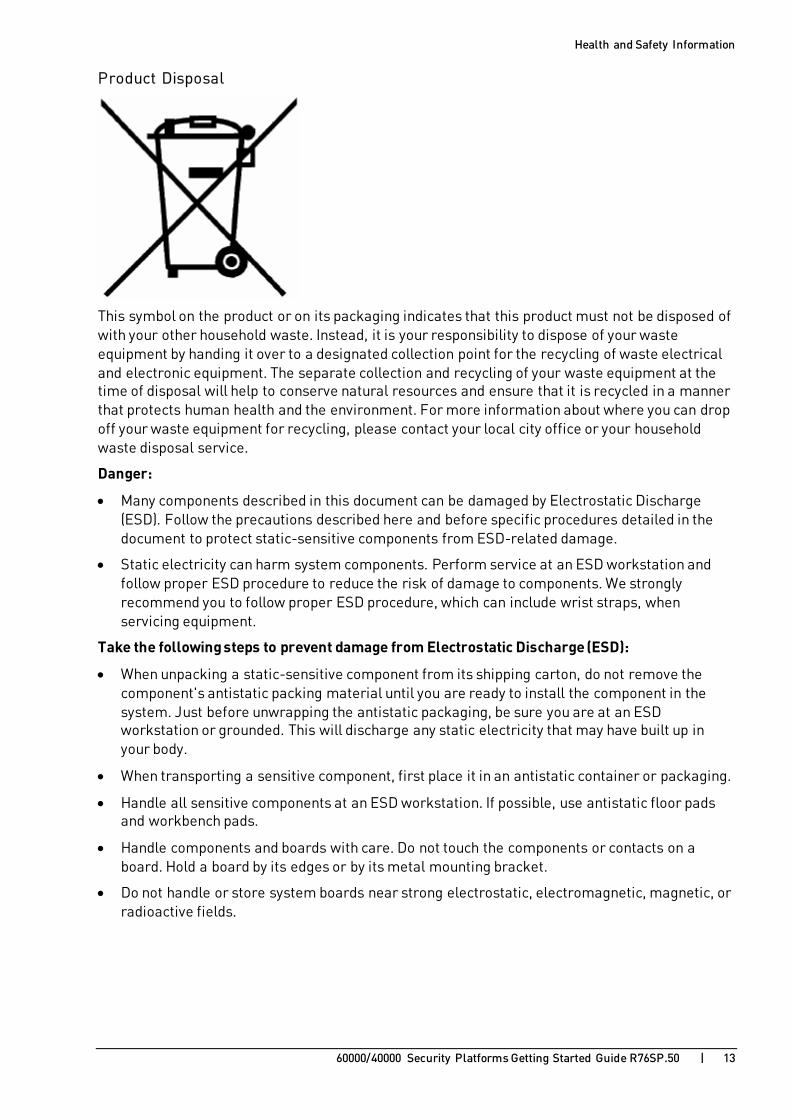
Product Disposal
This symbol on the product or on its packaging indicates that this product must not be disposed of with your other household waste. Instead, it is your responsibility to dispose of your waste equipment by handing it over to a designated collection point for the recycling of waste electrical and electronic equipment. The separate collection and recycling of your waste equipment at the time of disposal will help to conserve natural resources and ensure that it is recycled in a manner that protects human health and the environment. For more information about where you can drop off your waste equipment for recycling, please contact your local city office or your household waste disposal service.
Danger:
• Many components described in this document can be damaged by Electrostatic Discharge (ESD). Follow the precautions described here and before specific procedures detailed in the document to protect static-sensitive components from ESD-related damage.
• Static electricity can harm system components. Perform service at an ESD workstation and follow proper ESD procedure to reduce the risk of damage to components. We strongly recommend you to follow proper ESD procedure, which can include wrist straps, when servicing equipment.
Take the following steps to prevent damage from Electrostatic Discharge (ESD):
• When unpacking a static-sensitive component from its shipping carton, do not remove the component's antistatic packing material until you are ready to install the component in the system. Just before unwrapping the antistatic packaging, be sure you are at an ESD workstation or grounded. This will discharge any static electricity that may have built up in your body.
• When transporting a sensitive component, first place it in an antistatic container or packaging.
• Handle all sensitive components at an ESD workstation. If possible, use antistatic floor pads and workbench pads.
• Handle components and boards with care. Do not touch the components or contacts on a board. Hold a board by its edges or by its metal mounting bracket.
• Do not handle or store system boards near strong electrostatic, electromagnetic, magnetic, or radioactive fields.

60000/40000 Security Platforms Getting Started Guide R76SP.50 | 14
C H A P T E R 2
Introduction In This Section:
Overview of Check Point 60000/40000 Security Platforms................................... 14
Check Point Virtual Systems ............................................................................ 15
In this Document ............................................................................................. 16
Thank you for choosing the Check Point 60000/40000 Security Platforms. We hope that you will be satisfied with this system and our support services. Check Point products supply your business with the most up to date and secure solutions available today.
Check Point also delivers worldwide technical services including educational, professional and support services through a network of Authorized Training Centers, Certified Support Partners and Check Point technical support personnel to ensure that you get the most out of your security investment.
For additional information on the Internet Security Product Suite and other security solutions, refer to the Check Point Web site https://www.checkpoint.com/, or call Check Point at 1(800) 429-4391. For additional technical information about Check Point products, consult the Check Point Support Center https://supportcenter.checkpoint.com.
Welcome to the Check Point family. We look forward to meeting all of your current and future network, application and management security needs.
Overview of Check Point 60000/40000 Security Platforms
The Check Point 60000/40000 Security Platform is a high performance, scalable, carrier class solution for Service Providers and high-end data centers. The system gives advanced Security Gateway functionality to meet your dynamically changing security needs. Supported Security Gateway Software Blades include: Firewall, IPS, Application Control, Identity Awareness, URL Filtering, IPSec VPN, Anti-Bot, and Anti-Virus.
The 60000 appliance is a 14-15U chassis and the 40000 appliance is a 6-7U chassis. The components are:
Components Function
Up to 12 Security Gateway Modules (SGMs) in 61000, 61000 N+N, and 64000
Up to 4 SGMs in 41000
Up to 6 SGMs in 44000
Runs a high performance Firewall, and other Software Blades.
Up to 2 Security Switch Modules (SSMs) in 64000, 61000, 44000, and 41000
Up to 4 SSMs in 61000 N+N
Distributes network traffic to SGMs.
2 Chassis Management Modules (CMMs) Monitors the chassis, the SSMs and the SGMs with zero downtime.

Introduction
60000/40000 Security Platforms Getting Started Guide R76SP.50 | 15
The 60000/40000 Security Platform:
• Is highly fault tolerant, and provides redundancy between chassis modules, power supplies and fans. For extra redundancy, you can install a Dual Chassis deployment.
• Has NEBS-ready and Non-NEBS versions. The Network Equipment Building Systems (NEBS) certificate ensures that 60000/40000 Security Platform meets the environmental and spatial requirements for products used in telecommunications networks.
• Includes a rich variety of CLI monitoring and management tools. The system can be centrally managed from Check Point Security Management Server or a Multi-Domain Security Management.
• Lets you install different numbers of SGMs to match the processing needs of your network.
You can operate the 60000/40000 Security Platform as a Security Gateway, or as a VSX Gateway for Check Point Virtual Systems.
Check Point Virtual Systems Administrators can replicate physical security gateways with Virtual Systems with advanced protection for many networks and network segments. Virtual Systems can support up to 250 Virtual Systems on a 60000/40000 Security Platform. This gives you scalability, availability, reliability and optimal performance while minimizing hardware investment, space requirements and maintenance costs.
Network virtualization supports easy deployment and configuration of network topology with simple inter-Virtual System communication. Integrated Virtual Switches and direct links to destinations eliminate the requirement for external network switches.
Key Features:
• Consolidate many Security Gateways
• Software Blade architecture
• Gaia 64-bit operating system
• Separation of management duties
• Customized security policies per Virtual System
• Per-Virtual System monitoring of resource usage
Key Benefits:
• Easily add Virtual Systems to a VSX Gateway
• Decreased hardware cost and simplified network policy
• High performance
• Granularity with customizable policies for each Virtual System
• Better usage-based resource planning with per-Virtual System monitoring
• Better performance with multi-core CoreXL technology

Introduction
60000/40000 Security Platforms Getting Started Guide R76SP.50 | 16
In this Document • A brief overview of necessary 60000/40000 Security Platform concepts
• A step by step guide to getting the 60000/40000 Security Platform up and running
Note - Many examples in this guide show the largest model available at the time of publication. The concepts and procedures are applicable to all models.

60000/40000 Security Platforms Getting Started Guide R76SP.50 | 17
C H A P T E R 3
Shipping Carton Contents for the 64000 Security System Appliance
This section describes the contents of the shipping carton for the 64000 Security System.
Item Description
Check Point 64000 Security System Appliance
One single 64000 Security System Appliance Chassis
64000 components • 2 to 12 Security Gateway Modules (SGMs)
• 2 Security Switch Modules (SSMs)
• 2 Chassis Management Modules (CMMs)
• Power Supply Units (PSUs) - preinstalled • 4 AC PSUs, or
• 1 to 2 DC Power Entry Modules (PEMs)
• Power cord set
• 2 to 12 shielded console cables (in the SGM package)
Documentation • EULA
• Welcome document
Shipping Carton Contents for the 64000 Security System Appliance
60000/40000 Security Platforms Getting Started Guide R76SP.50 | 18
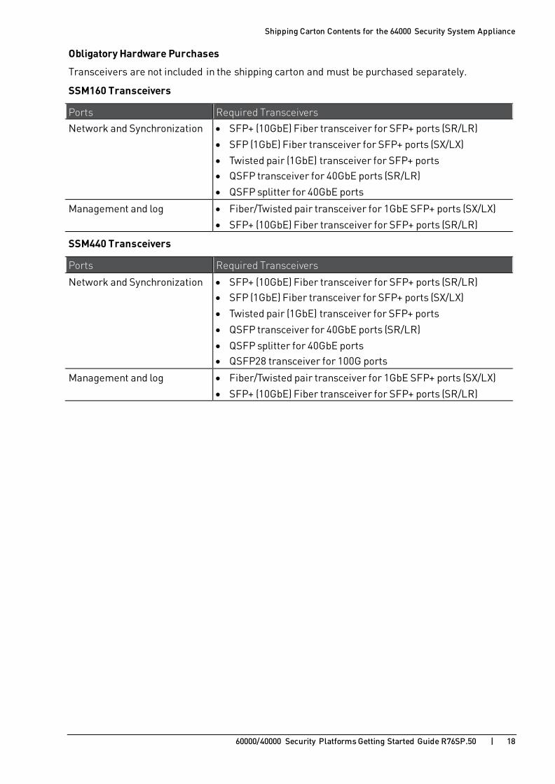
Obligatory Hardware Purchases
Transceivers are not included in the shipping carton and must be purchased separately.
SSM160 Transceivers
Ports Required Transceivers
Network and Synchronization • SFP+ (10GbE) Fiber transceiver for SFP+ ports (SR/LR)
• SFP (1GbE) Fiber transceiver for SFP+ ports (SX/LX)
• Twisted pair (1GbE) transceiver for SFP+ ports • QSFP transceiver for 40GbE ports (SR/LR)
• QSFP splitter for 40GbE ports
Management and log • Fiber/Twisted pair transceiver for 1GbE SFP+ ports (SX/LX)
• SFP+ (10GbE) Fiber transceiver for SFP+ ports (SR/LR)
SSM440 Transceivers
Ports Required Transceivers
Network and Synchronization • SFP+ (10GbE) Fiber transceiver for SFP+ ports (SR/LR) • SFP (1GbE) Fiber transceiver for SFP+ ports (SX/LX)
• Twisted pair (1GbE) transceiver for SFP+ ports
• QSFP transceiver for 40GbE ports (SR/LR)
• QSFP splitter for 40GbE ports • QSFP28 transceiver for 100G ports
Management and log • Fiber/Twisted pair transceiver for 1GbE SFP+ ports (SX/LX)
• SFP+ (10GbE) Fiber transceiver for SFP+ ports (SR/LR)

60000/40000 Security Platforms Getting Started Guide R76SP.50 | 19
C H A P T E R 4
Shipping Carton Contents for the 44000 Security System Appliance
This section describes the contents of the shipping carton for the 44000 Security System Appliance.
Item Description
Check Point 44000 Security System Appliance
One single 44000 Security System Appliance Chassis
44000 components • 1 to 6 Security Gateway Modules (SGMs)
• 1 to 2 Security Switch Modules (SSMs)
• 2 Chassis Management Modules (CMMs)
• Power Supply Units (PSUs) - preinstalled
• 4 AC PSUs
• Power cord set
Documentation • EULA
• Welcome document
Obligatory Hardware Purchases
Transceivers are not included in the shipping carton and must be purchased separately.
SSM440 Transceivers
Ports Required Transceivers
Network and Synchronization • SFP+ (10GbE) Fiber transceiver for SFP+ ports (SR/LR)
• SFP (1GbE) Fiber transceiver for SFP+ ports (SX/LX) • Twisted pair (1GbE) transceiver for SFP+ ports
• QSFP transceiver for 40GbE ports (SR/LR)
• QSFP splitter for 40GbE ports • QSFP28 transceiver for 100G ports
Management and log • Fiber/Twisted pair transceiver for 1GbE SFP+ ports (SX/LX)
• SFP+ (10GbE) Fiber transceiver for SFP+ ports (SR/LR)

60000/40000 Security Platforms Getting Started Guide R76SP.50 | 20
C H A P T E R 5
Shipping Carton Contents for 61000 N+N Security System Appliance
This section describes the contents of the shipping carton for the 61000 N+N Security System Appliance.
Item Description
Check Point 61000 N+N Security System Appliance
One single 61000 N+N Security System Appliance Chassis
61000 N+N components • 2 to 12 Security Gateway Modules (SGMs)
• 2 or 4 Security Switch Modules (SSMs)
• 2 Chassis Management Modules (CMMs)
• Power Supply Units (PSUs) - preinstalled
• 4 AC PSUs, or
• 1 to 2 DC Power Entry Modules (PEMs)
• 9 Fans (preinstalled)
• Power cord set
Documentation • EULA
• Welcome document

Shipping Carton Contents for 61000 N+N Security System Appliance
60000/40000 Security Platforms Getting Started Guide R76SP.50 | 21
Obligatory Hardware Purchases
Transceivers are not included in the shipping carton and must be purchased separately.
SSM160 Transceivers
Ports Required Transceivers
Network and Synchronization • SFP+ (10GbE) Fiber transceiver for SFP+ ports (SR/LR)
• SFP (1GbE) Fiber transceiver for SFP+ ports (SX/LX)
• Twisted pair (1GbE) transceiver for SFP+ ports • QSFP transceiver for 40GbE ports (SR/LR)
• QSFP splitter for 40GbE ports
Management and log • Fiber/Twisted pair transceiver for 1GbE SFP+ ports (SX/LX)
• SFP+ (10GbE) Fiber transceiver for SFP+ ports (SR/LR)
SSM440 Transceivers
Ports Required Transceivers
Network and Synchronization • SFP+ (10GbE) Fiber transceiver for SFP+ ports (SR/LR) • SFP (1GbE) Fiber transceiver for SFP+ ports (SX/LX)
• Twisted pair (1GbE) transceiver for SFP+ ports
• QSFP transceiver for 40GbE ports (SR/LR)
• QSFP splitter for 40GbE ports • QSFP28 transceiver for 100G ports
Management and log • Fiber/Twisted pair transceiver for 1GbE SFP+ ports (SX/LX)
• SFP+ (10GbE) Fiber transceiver for SFP+ ports (SR/LR)

60000/40000 Security Platforms Getting Started Guide R76SP.50 | 22
C H A P T E R 6
Shipping Carton Contents for the 61000 Security System Appliance
This section describes the contents of the shipping carton for the 61000 Security System Appliance.
Item Description
Check Point 61000 Security System
One single 61000 Security System Chassis
61000 Security System components
• 2 to 12 Security Gateway Modules (SGMs)
• 2 Security Switch Modules (SSMs)
• 2 Chassis Management Modules (CMMs)
• Power Supply Units (PSUs) - preinstalled
• 5 AC PSUs, or
• 1 to 2 DC Power Entry Modules (PEMs)
• 6 Fans (preinstalled)
• Power cord set
Documentation • EULA
• Welcome document

Shipping Carton Contents for the 61000 Security System Appliance
60000/40000 Security Platforms Getting Started Guide R76SP.50 | 23
Obligatory Hardware Purchases
Transceivers are not included in the shipping carton and must be purchased separately.
SSM160 Transceivers
Ports Required Transceivers
Network and Synchronization • SFP+ (10GbE) Fiber transceiver for SFP+ ports (SR/LR)
• SFP (1GbE) Fiber transceiver for SFP+ ports (SX/LX)
• Twisted pair (1GbE) transceiver for SFP+ ports • QSFP transceiver for 40GbE ports (SR/LR)
• QSFP splitter for 40GbE ports
Management and log • Fiber/Twisted pair transceiver for 1GbE SFP+ ports (SX/LX)
• SFP+ (10GbE) Fiber transceiver for SFP+ ports (SR/LR)
SSM440 Transceivers
Ports Required Transceivers
Network and Synchronization • SFP+ (10GbE) Fiber transceiver for SFP+ ports (SR/LR) • SFP (1GbE) Fiber transceiver for SFP+ ports (SX/LX)
• Twisted pair (1GbE) transceiver for SFP+ ports
• QSFP transceiver for 40GbE ports (SR/LR)
• QSFP splitter for 40GbE ports • QSFP28 transceiver for 100G ports
Management and log • Fiber/Twisted pair transceiver for 1GbE SFP+ ports (SX/LX)
• SFP+ (10GbE) Fiber transceiver for SFP+ ports (SR/LR)

60000/40000 Security Platforms Getting Started Guide R76SP.50 | 24
C H A P T E R 7
Shipping Carton Contents for the 41000 Security System Appliance
This section describes the contents of the shipping carton for the 41000 Security System Appliance.
Item Description
Check Point 41000 Security System
One single 41000 Security System Chassis
41000 Security System components
• 1 to 4 Security Gateway Modules (SGMs)
• 1 to 2 Security Switch Modules (SSMs)
• 2 Chassis Management Modules (CMMs)
• Power Supply Units (PSUs) - preinstalled
• 3 AC PSUs, or
• 1 to 2 DC Power Entry Modules (PEMs)
• 6 Fans (preinstalled)
• Power cord set
Documentation • EULA
• Welcome document

Shipping Carton Contents for the 41000 Security System Appliance
60000/40000 Security Platforms Getting Started Guide R76SP.50 | 25
Obligatory Hardware Purchases
Transceivers are not included in the shipping carton and must be purchased separately.
SSM160 Transceivers
Ports Required Transceivers
Network and Synchronization • SFP+ (10GbE) Fiber transceiver for SFP+ ports (SR/LR)
• SFP (1GbE) Fiber transceiver for SFP+ ports (SX/LX)
• Twisted pair (1GbE) transceiver for SFP+ ports • QSFP transceiver for 40GbE ports (SR/LR)
• QSFP splitter for 40GbE ports
Management and log • Fiber/Twisted pair transceiver for 1GbE SFP+ ports (SX/LX)
• SFP+ (10GbE) Fiber transceiver for SFP+ ports (SR/LR)
SSM440 Transceivers
Ports Required Transceivers
Network and Synchronization • SFP+ (10GbE) Fiber transceiver for SFP+ ports (SR/LR) • SFP (1GbE) Fiber transceiver for SFP+ ports (SX/LX)
• Twisted pair (1GbE) transceiver for SFP+ ports
• QSFP transceiver for 40GbE ports (SR/LR)
• QSFP splitter for 40GbE ports • QSFP28 transceiver for 100G ports
Management and log • Fiber/Twisted pair transceiver for 1GbE SFP+ ports (SX/LX)
• SFP+ (10GbE) Fiber transceiver for SFP+ ports (SR/LR)
60000/40000 Security Platforms Getting Started Guide R76SP.50 | 26
C H A P T E R 8
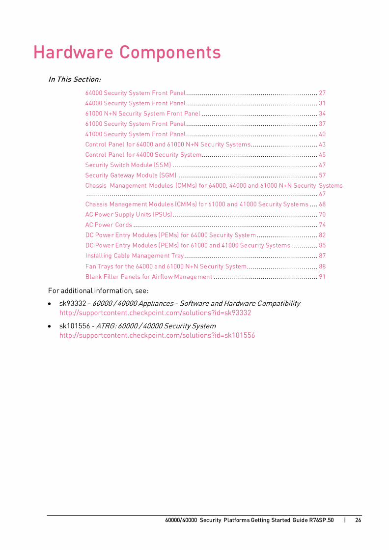
Hardware Components In This Section:
64000 Security System Front Panel................................................................... 27
44000 Security System Front Panel................................................................... 31
61000 N+N Security System Front Panel ........................................................... 34
61000 Security System Front Panel................................................................... 37
41000 Security System Front Panel................................................................... 40
Control Panel for 64000 and 61000 N+N Security Systems.................................. 43
Control Panel for 44000 Security System........................................................... 45
Security Switch Module (SSM) .......................................................................... 47
Security Gateway Module (SGM) ....................................................................... 57
Chassis Management Modules (CMMs) for 64000, 44000 and 61000 N+N Security Systems ...................................................................................................................... 67
Chassis Management Modules (CMMs) for 61000 and 41000 Security Systems .... 68
AC Power Supply Units (PSUs).......................................................................... 70
AC Power Cords .............................................................................................. 74
DC Power Entry Modules (PEMs) for 64000 Security System ............................... 82
DC Power Entry Modules (PEMs) for 61000 and 41000 Security Systems ............. 85
Install ing Cable Management Tray.................................................................... 87
Fan Trays for the 64000 and 61000 N+N Security System.................................... 88
Blank Filler Panels for Airflow Management ..................................................... 91
For additional information, see:
• sk93332 - 60000 / 40000 Appliances - Software and Hardware Compatibility http://supportcontent.checkpoint.com/solutions?id=sk93332
• sk101556 - ATRG: 60000 / 40000 Security System http://supportcontent.checkpoint.com/solutions?id=sk101556

Hardware Components
60000/40000 Security Platforms Getting Started Guide R76SP.50 | 27
64000 Security System Front Panel

Hardware Components
60000/40000 Security Platforms Getting Started Guide R76SP.50 | 28
Item Description
1 The Security Gateway Modules (SGMs) in the Chassis work together as a single, high performance Security Gateway or VSX Gateway. Security Gateway Modules improve system performance. You can add or remove a Security Gateway Module without losing connections. If an SGM is removed or fails, traffic is sent to the other active SGMs.
These SGM models are available for the 64000 Security System (see sk93332 http://supportcontent.checkpoint.com/solutions?id=sk93332):
• SGM260
• SGM400
For more information, see Security Gateway Module (SGM) (on page 57).
2 Console ports for a serial connection to a specific SGM using a terminal emulation program.
3 USB v2.0 ports for connecting a bootable USB drive to install a Check Point software ISO image.
4 The Chassis Management Modules (CMMs) monitor the status of the Chassis hardware components. If the CMM fails or is removed from the Chassis, the appliance continues to forward traffic, but hardware monitoring is not available. If you add or remove an SGM to or from the Chassis, it is not recognized.
Warning - There must be at least one CMM in the Chassis. A second CMM can be used to supply CMM High Availability.
Note - In the CLI output:
• The upper CMM slot is listed as bay 1.
• The lower CMM slot is listed as bay 2.

Hardware Components
60000/40000 Security Platforms Getting Started Guide R76SP.50 | 29
Item Description
5 AC Power Supply Units (PSUs):
• Voltage: from 200 VAC to 240 VAC
• Quantity: 4 - 6 PSUs
• 4 PSUs for up to 9 SGMs
Up to 9 SGMs are the default
• 6 PSUs for 10-12 SGMs
Above 10 SGMs, 2 additional PSUs are required
• Field replaceable and hot swappable.
Warning - Only Bays 1, 2, 3, 4, 5 and 6 are available for use. You must not use the leftmost Bays. Note - In the CLI output:
• The slots for AC PSUs are listed as (excluding the leftmost bays):
• On the upper level -
bay 1, bay 2, and bay 3, numbered from left to right.
• On the lower level -
bay 4, bay 5, and bay 6, numbered from left to right.
• The AC PSUs are listed as PowerUnit(AC): • On the upper level -
AC PSU 1, AC PSU 2, and AC PSU 3, numbered from left to right.
• On the lower level -
AC PSU 4, AC PSU 5, and AC PSU 6, numbered from left to right.
6 Chassis Control Panel. You can use it for a serial connection to a specific CMM. It also shows the status of cooling fans and additional Chassis alerts.
For more information, see Control Panel for 64000 and 61000 N+N Security Systems (on page 43).
7 Cooling fans.
8 The Security Switch Modules (SSMs) manage the flow of network traffic to and from the SGMs.
These SSM models are available for the 64000 Security System (see sk93332 http://supportcontent.checkpoint.com/solutions?id=sk93332):
• SSM160
• SSM440
For more information, see Security Switch Module (SSM) (on page 47).
Hardware Components
60000/40000 Security Platforms Getting Started Guide R76SP.50 | 30
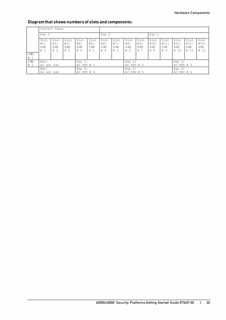
Diagram that shows numbers of slots and components: Control Panel
Fan 3 Fan 2 Fan 1
Slot #1:
Slot #2:
Slot #3:
Slot #4:
Slot #5:
Slot #6:
Slot #7:
Slot #8:
Slot #9:
Slot #10:
Slot #11:
Slot #12:
Slot #13:
Slot #14:
SGM # 1
SGM # 2
SGM # 3
SGM # 4
SGM # 5
SGM # 6
SSM # 1
SSM # 2
SGM # 7
SGM # 8
SGM # 9
SGM # 10
SGM # 11
SGM # 12
CMM # 1
CMM # 2
Bay: do not use
Bay 1: AC PSU # 1
Bay 2: AC PSU # 2
Bay 3: AC PSU # 3
Bay: do not use
Bay 4: AC PSU # 4
Bay 5: AC PSU # 5
Bay 6: AC PSU # 6

Hardware Components
60000/40000 Security Platforms Getting Started Guide R76SP.50 | 31
44000 Security System Front Panel
Item Description
1 The Security Switch Modules (SSMs) manage the flow of network traffic to and from the SGMs.
These SSM models are available for the 44000 Security System (see sk93332 http://supportcontent.checkpoint.com/solutions?id=sk93332):
• SSM160
• SSM440
For more information, see Security Switch Module (SSM) (on page 47).
2 The Security Gateway Modules (SGMs) in the Chassis work together as a single, high performance Security Gateway or VSX Gateway. Security Gateway Modules improve system performance. You can add or remove a Security Gateway Module without losing connections. If an SGM is removed or fails, traffic is sent to the other active SGMs.
These SGM models are available for the 44000 Security System (see sk93332 http://supportcontent.checkpoint.com/solutions?id=sk93332):
• SGM260
• SGM400
For more information, see Security Gateway Module (SGM) (on page 57).
3 Console ports for a serial connection to a specific SGM using a terminal emulation program.
4 USB v2.0 ports for connecting a bootable USB drive to install a Check Point software ISO image.

Hardware Components
60000/40000 Security Platforms Getting Started Guide R76SP.50 | 32
Item Description
5 AC Power Supply Units (PSUs):
• Voltage: from 85 VAC to 240 VAC
• Quantity: 4 PSUs
• Field replaceable and hot swappable.
Warning - Only Bays 1, 2, 3, and 4 are available for use. You must not use the rightmost Bay.
Note - In the CLI output:
• The slots for AC PSUs are listed as:
bay 1, bay 2, bay 3 and bay 4, numbered from left to right.
• The AC PSUs are listed as PowerUnit(AC): AC PSU 1, AC PSU 2, AC PSU 3 and AC PSU 4, numbered from left to right.
6 The Chassis Management Modules (CMMs) monitor the status of the Chassis hardware components. If the CMM fails or is removed from the Chassis, the appliance continues to forward traffic, but hardware monitoring is not available. If you add or remove an SGM to or from the Chassis, it is not recognized.
Warning - There must be at least one CMM in the Chassis.
A second CMM can be used to supply CMM High Availability.
Note - In the CLI output:
• The upper CMM slot is listed as bay 2.
• The lower CMM slot is listed as bay 1.
7 Cooling fans.
Note - In the CLI output:
• The upper Fan slot is listed as fan 2.
• The lower Fan slot is listed as fan 1.
8 Chassis Control Panel. You can use it for a serial connection to a specific CMM.
It also shows the status of cooling fans and additional Chassis alerts. For more information, see Control Panel for 44000 Security System (on page 45).

Hardware Components
60000/40000 Security Platforms Getting Started Guide R76SP.50 | 33
Diagram that shows numbers of slots and components: Slot #1: CMM # 2
SSM # 1 CMM # 1
Slot #2: Fan 2
SGM # 6 / SSM # 2
Slot #3:
SGM # 5
Slot #4:
SGM # 4 Fan 1
Slot #5:
SGM # 3
Slot #6:
SGM # 2
Slot #7: Control Panel
SGM # 1
Bay 1: AC PSU # 1
Bay 2: AC PSU # 2
Bay 3: AC PSU # 3
Bay 4: AC PSU # 4
Bay: do not use

Hardware Components
60000/40000 Security Platforms Getting Started Guide R76SP.50 | 34
61000 N+N Security System Front Panel

Hardware Components
60000/40000 Security Platforms Getting Started Guide R76SP.50 | 35
Item Description
1 The Security Gateway Modules (SGMs) in the Chassis work together as a single, high performance Security Gateway or VSX Gateway. Security Gateway Modules improve system performance. You can add or remove a Security Gateway Module without losing connections. If an SGM is removed or fails, traffic is sent to the other active SGMs.
These SGM models are available for 61000 N+N Security System (see sk93332 http://supportcontent.checkpoint.com/solutions?id=sk93332):
• SGM220
• SGM260
• SGM400 - When using more than 9 x SGM400, the 64000 Chassis is required to maintain N+N capabilities
For more information, see Security Gateway Module (SGM) (on page 57).
2 USB v2.0 ports for connecting a bootable USB drive to install a Check Point software ISO image.
3 Console ports for a serial connection to a specific SGM using a terminal emulation program.
4 The Chassis Management Modules (CMMs) monitor the status of the Chassis hardware components. If the CMM fails or is removed from the Chassis, the appliance continues to forward traffic, but hardware monitoring is not available. If you add or remove an SGM to or from the Chassis, it is not recognized. Warning - There must be at least one CMM in the Chassis.
A second CMM can be used to supply CMM High Availability.
Note - In the CLI output:
• The upper CMM slot is listed as bay 1.
• The lower CMM slot is listed as bay 2.
5 AC Power Supply Units (PSUs):
• Voltage: from 100 VAC to 240 VAC
• Quantity: 4 PSUs
• Field-replaceable and hot-swappable
Note - In the CLI output:
• The slots for AC PSUs are listed as:
bay 1, bay 2, bay 3, and bay 4, numbered from left to right.
• The AC PSUs are listed as PowerUnit(AC): AC PSU 1, AC PSU 2, AC PSU 3, and AC PSU 4, numbered from left to right.
6 Chassis Control Panel. You can use it for a serial connection to a specific CMM. It also shows the status of cooling fans and additional Chassis alerts. For more information, see Control Panel for 64000 and 61000 N+N Security Systems (on page 43).
7 Cooling fans.

Hardware Components
60000/40000 Security Platforms Getting Started Guide R76SP.50 | 36
Item Description
8 The Security Switch Modules (SSMs) manage the flow of network traffic to and from the SGMs.
These SSM models are available for the 61000 N+N Security System:
• SSM160
• SSM440
For more information, see Security Switch Module (SSM) (on page 47).
Diagram that shows numbers of slots and components: Control Panel
Fan 3 Fan 2 Fan 1
Slot #1:
Slot #2:
Slot #3:
Slot #4:
Slot #5:
Slot #6:
Slot #7:
Slot #8:
Slot #9:
Slot #10:
Slot #11:
Slot #12:
Slot #13:
Slot #14:
CMM # 1
SGM # 1
SGM # 2
SGM # 3
SGM # 4
SGM # 5
SGM # 6/
SGM # 7/
SGM # 8
SGM # 9
SGM # 10
SGM # 11
SGM # 12
CMM # 2
SSM # 3
SSM # 1
SSM # 2
SSM # 4
Bay 1: AC PSU # 1
Bay 2: AC PSU # 2
Bay 3: AC PSU # 3
Bay 4: AC PSU # 4

Hardware Components
60000/40000 Security Platforms Getting Started Guide R76SP.50 | 37
61000 Security System Front Panel

Hardware Components
60000/40000 Security Platforms Getting Started Guide R76SP.50 | 38
Item Description
1 The Security Gateway Modules (SGMs) in the Chassis work together as a single, high performance Security Gateway or VSX Gateway. Security Gateway Modules improve system performance. You can add or remove a Security Gateway Module without losing connections. If an SGM is removed or fails, traffic is sent to the other active SGMs.
These SGM models are available for the 61000 Security System (see sk93332 http://supportcontent.checkpoint.com/solutions?id=sk93332):
• SGM220
• SGM260
For more information, see Security Gateway Module (SGM) (on page 57).
2 USB v2.0 ports for connecting a bootable USB drive to install a Check Point software ISO image.
3 The Chassis Management Modules (CMMs) monitor the status of the Chassis hardware components. If the CMM fails or is removed from the Chassis, the appliance continues to forward traffic, but hardware monitoring is not available. If you add or remove an SGM to or from the Chassis, it is not recognized. Warning - There must be at least one CMM in the Chassis.
A second CMM can be used to supply CMM High Availability.
Note - In the CLI output:
• The upper CMM slot is listed as bay 2.
• The lower CMM slot is listed as bay 1.
4 Control Panel that shows the status of the cooling fans.
5 Console ports for a serial connection to a specific SGM using a terminal emulation program.
6 The Security Switch Modules (SSMs) manage the flow of network traffic to and from the SGMs.
This SSM model is available for the 61000 Security System (see sk93332 http://supportcontent.checkpoint.com/solutions?id=sk93332):
• SSM160
For more information, see Security Switch Module (SSM) (on page 47).
Hardware Components
60000/40000 Security Platforms Getting Started Guide R76SP.50 | 39
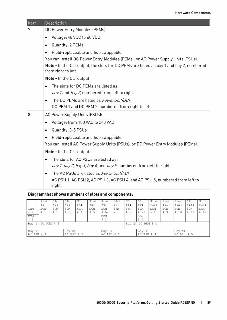
Item Description
7 DC Power Entry Modules (PEMs):
• Voltage: 48 VDC to 60 VDC
• Quantity: 2 PEMs
• Field-replaceable and hot-swappable.
You can install DC Power Entry Modules (PEMs), or AC Power Supply Units (PSUs).
Note - In the CLI output, the slots for DC PEMs are listed as bay 1 and bay 2, numbered from right to left.
Note - In the CLI output:
• The slots for DC PEMs are listed as:
bay 1 and bay 2, numbered from left to right.
• The DC PEMs are listed as PowerUnit(DC): DC PEM 1 and DC PEM 2, numbered from right to left.
8 AC Power Supply Units (PSUs):
• Voltage: from 100 VAC to 240 VAC
• Quantity: 3-5 PSUs
• Field-replaceable and hot-swappable.
You can install AC Power Supply Units (PSUs), or DC Power Entry Modules (PEMs).
Note - In the CLI output:
• The slots for AC PSUs are listed as: bay 1, bay 2, bay 3, bay 4, and bay 5, numbered from left to right.
• The AC PSUs are listed as PowerUnit(AC): AC PSU 1, AC PSU 2, AC PSU 3, AC PSU 4, and AC PSU 5, numbered from left to right.
Diagram that shows numbers of slots and components: Slot
#1: Slot #2:
Slot #3:
Slot #4:
Slot #5:
Slot #6:
Slot #7:
Slot #8:
Slot #9:
Slot #10:
Slot #11:
Slot #12:
Slot #13:
Slot #14:
CMM # 2
SGM # 1
SGM # 2
SGM # 3
SGM # 4
SGM # 5
SGM # 6/
SSM # 1
SSM # 2
SGM # 7/
SGM # 8
SGM # 9
SGM # 10
SGM # 11
SGM # 12
CMM # 1
SSM # 3
SSM # 4
Bay 1: DC PEM # 2 Bay 2: DC PEM # 1
Bay 1: AC PSU # 1
Bay 2: AC PSU # 2
Bay 3: AC PSU # 3
Bay 4: AC PSU # 4
Bay 5: AC PSU # 5

Hardware Components
60000/40000 Security Platforms Getting Started Guide R76SP.50 | 40
41000 Security System Front Panel
Item Description
1 The cooling system has two fan trays - one on the left and one on the right side of the Chassis. Each fan tray has 10 fans that supply air volume and velocity for cooling the front and rear Chassis components.
Note - In the CLI output:
• The left fan is listed as fan 1.
• The right fan is listed as fan 2.
2 USB v2.0 ports for connecting a bootable USB drive to install a Check Point software ISO image.
3 Console ports for a serial connection to a specific SGM using a terminal emulation program.

Hardware Components
60000/40000 Security Platforms Getting Started Guide R76SP.50 | 41
Item Description
4 The Security Gateway Modules (SGMs) in the Chassis work together as a single, high performance Security Gateway or VSX Gateway. Security Gateway Modules improve system performance. You can add or remove a Security Gateway Module without losing connections. If an SGM is removed or fails, traffic is sent to the other active SGMs.
These SGM models are available for 41000 Security System (see sk93332 http://supportcontent.checkpoint.com/solutions?id=sk93332):
• SGM220
• SGM260
For more information, see Security Gateway Module (SGM) (on page 57).
5 The Security Switch Modules (SSMs) manage the flow of network traffic to and from the SGMs. This SSM model is available for the 41000 Security System (see sk93332 http://supportcontent.checkpoint.com/solutions?id=sk93332):
• SSM160
For more information, see Security Switch Module (SSM) (on page 47).
6 The Chassis Management Modules (CMMs) monitor the status of the Chassis hardware components. If the CMM fails or is removed from the Chassis, the appliance continues to forward traffic, but hardware monitoring is not available. If you add or remove an SGM to or from the Chassis, it is not recognized. Warning - There must be at least one CMM in the Chassis.
A second CMM can be used to supply CMM High Availability.
Note - In the CLI output:
• The left CMM slot is listed as bay 1.
• The right CMM slot is listed as bay 2.

Hardware Components
60000/40000 Security Platforms Getting Started Guide R76SP.50 | 42
Item Description
7 AC Power Supply Unites (PSUs):
• Voltage: from 90 VAC to 240 VAC
• Quantity: 3 PSUs
• Field replaceable and hot swappable.
OR
DC Power Entry Modules (PEMs):
• Voltage: 48 VDC to 60 VDC
• Quantity: 2 PEMs
• Field replaceable and hot swappable.
Note - In the CLI output:
• The slots for DC PEMs are listed as bay 1 and bay 2, numbered from left to right.
• The DC PEMs are listed as PowerUnit(DC): DC PEM 1 and DC PEM 2, numbered from right to left.
• The slots for AC PSUs are listed as:
bay 1, bay 2 and bay 3, numbered from left to right.
• The AC PSUs are listed as PowerUnit(AC): AC PSU 1, AC PSU 2, and AC PSU 3, numbered from right to left.
Diagram that shows numbers of slots and components: Fan # 1 Slot #6: SGM # 1 Fan # 2
Slot #5: SGM # 2
Slot #4: SGM # 3
Slot #3: SGM # 4
Slot #2: SSM # 2
Slot #1: SSM # 1
Bay 1: CMM # 1
Bay 2: CMM # 2
Bay 1: AC PSU # 3
Bay 2: AC PSU # 2 / DC PEM # 2
Bay 3: AC PSU # 1 / DC PEM # 1

Hardware Components
60000/40000 Security Platforms Getting Started Guide R76SP.50 | 43
Control Panel for 64000 and 61000 N+N Security Systems
You can use the Control Panel for a serial connection to a specific Chassis Management Module (CMM). It also shows the status of cooling fans and additional Chassis alerts.
This Control Panel is installed only in 64000 Security Systems (see 64000 Security System Front Panel (on page 27)) and 61000 N+N Security Systems (see 61000 N+N Security System Front Panel (on page 34)).
Item Name on Panel Description
1 Upper CMM Serial Serial port for connecting to the upper Chassis Management Module (CMM).
2 Lower CMM Serial Serial port for connecting to the lower Chassis Management Module (CMM).
3 ALARM Chassis alarm port - for connecting to customer supplied external device.
4 ALARM CUTOFF Chassis alarm reset button.
5 Chassis Alerts Normally off. If the LEDs are lit in red, the chassis sends system alarm events:
• CRT - Critical.
• MJR - Major.
• MNT - Minor.
For assistance, contact Check Point Support https://www.checkpoint.com/support-services/contact-support/.

Hardware Components
60000/40000 Security Platforms Getting Started Guide R76SP.50 | 44
Item Name on Panel Description 6 FAN Numbers of cooling fans.
7 STATUS Cooling fans status LEDs:
• Green - All fan tray components work correctly.
• Red - Fan tray failure.
• Off - Fan tray is not installed.
8 FAULT Normally off. If the LED is lit, there is a failure in the cooling fan.

Hardware Components
60000/40000 Security Platforms Getting Started Guide R76SP.50 | 45
Control Panel for 44000 Security System You can use the Control Panel for a serial connection to a specific Chassis Management Module (CMM). It also shows the status of Chassis and additional Chassis alerts.
This Control Panel is installed only in 44000 Security Systems (see 44000 Security System Front Panel (on page 31)).
Item Name on Panel Description
1 SERIAL 1 Serial port for connecting to the upper Chassis Management Module (CMM).
2 MNR
MJR
CRT
Normally off.
If the LEDs are lit in red, the chassis sends system alarm events:
• MNR - Minor alert.
• MJR - Major alert.
• CRT - Critical alert.
For assistance, contact Check Point Support https://www.checkpoint.com/support-services/contact-support/.
3 SERIAL 2 Serial port for connecting to the lower Chassis Management Module (CMM).
Hardware Components
60000/40000 Security Platforms Getting Started Guide R76SP.50 | 46
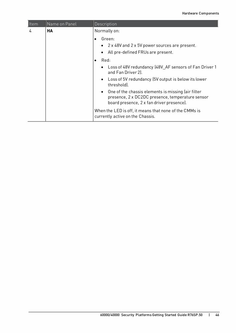
Item Name on Panel Description
4 HA Normally on:
• Green: • 2 x 48V and 2 x 5V power sources are present.
• All pre-defined FRUs are present.
• Red:
• Loss of 48V redundancy (48V_AF sensors of Fan Driver 1 and Fan Driver 2).
• Loss of 5V redundancy (5V output is below its lower threshold).
• One of the chassis elements is missing (air filter presence, 2 x DC2DC presence, temperature sensor board presence, 2 x fan driver presence).
When the LED is off, it means that none of the CMMs is currently active on the Chassis.

Hardware Components
60000/40000 Security Platforms Getting Started Guide R76SP.50 | 47
Security Switch Module (SSM) The Security Switch Module (SSM) distributes network traffic to the Security Gateway Modules (SGMs) and forwards traffic from the SGMs. Two are inserted in a Chassis.
These are the available models (see sk93332 http://supportcontent.checkpoint.com/solutions?id=sk93332):
• SSM160
• SSM440
Hardware Components
60000/40000 Security Platforms Getting Started Guide R76SP.50 | 48
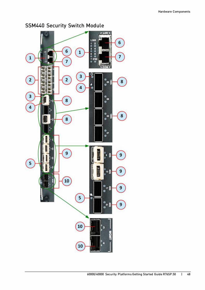
SSM440 Security Switch Module

Hardware Components
60000/40000 Security Platforms Getting Started Guide R76SP.50 | 49
Item Name Description
1 LINK LEDs that show the status of the FI ports that are denoted as (2).
2 1-7, SYNC 8 x 1/10GbE SFP/SFP+ FI ports.
3
LED that shows the Out of Service status.
4
LED that shows the Power status.
5
LED that shows the Hot-swap status of the SSM.
6 LAN 10/100/1000BASETX RJ45 Ethernet port () used to perform chassis management and software upgrade through direct connection to the chassis.
7 COM 1 RJ45 port for direct access through console.
This port uses RS232 level signaling and is configured for 9600 Baud.
This port is an EIA232 VT-100 compatible.
TX and RX lines are protected for 15kV ESD.
8 100G QSFP28/QSFP+ FI ports:
• 2 x 40GbE/100GbE (using QSFP28/QSFP+) ports.
OR
• 16 x 10GbE (using 4 x 40Gbe QSFP+ and MPO breakout cable) ports.
9 40G QSFP+ FI ports:
• 4 x 40GbE (using 40Gbe QSFP+) ports.
OR
• 16 x 10GE (using 4 x 40Gbe QSFP+ and MPO breakout cable) ports.
10 MGMT 2 x 1/10GbE SFP/SFP+ BI ports.

Hardware Components
60000/40000 Security Platforms Getting Started Guide R76SP.50 | 50
SSM440 Security Switch Module LEDs

Hardware Components
60000/40000 Security Platforms Getting Started Guide R76SP.50 | 51
Item LED Status Description
1 LINK
1, 2, 3, 4, 5, 6, 7, SYNC
On (Normal) Traffic in SSM flows correctly.
Off Traffic does not flow in SSM.
2 Out of Service
Red SSM is out of service.
Off (Normal) SSM hardware works normally.
3 Power
On (Normal) Power on SSM is on.
Off Power on SSM is off.
4 25 100G 33 100G
On (Normal) Traffic flows correctly through the QSFP28/QSFP+ FI port.
Off Traffic does not flow through the QSFP28/QSFP+ FI port.
5 9 40G 13 40G
17 40G
21 40G
On (Normal) Traffic flows correctly through the FI QSFP+ port.
Off Traffic does not flow through the FI QSFP+ port.
6 Hot-swap status
Blue SSM can be safely removed.
Blue blinking SSM is going to Standby mode. Do not remove.
Off (Normal) SSM is in Active mode. Do not remove.
7 3 MGMT
4 MGMT
On (Normal) Traffic flows correctly through the SFP/SFP+ BI port.
Off Traffic does not flow through the SFP/SFP+ BI port.

Hardware Components
60000/40000 Security Platforms Getting Started Guide R76SP.50 | 52
SSM160 Security Switch Module

Hardware Components
60000/40000 Security Platforms Getting Started Guide R76SP.50 | 53
Item Name Description
1 LAN 1 port for direct access through LAN.
2 SERIAL 1 port for direct access through console (serial).
3
LED that shows the Out of Service status.
4
LED that shows the Power status.
5
This LED is not used.
6 RESET Reset (reboot) button for SSM.
7
LED that shows the Hot-swap status of the SSM.
8 9-12
13-16 • 2 x 40GbE QSFP data ports.
In the initial setup program, the interface names are: • In SSM1 (left in 61000, upper in 41000):
eth1-09, eth1-13
• In SSM2 (right in 61000, lower in 41000): eth2-09, eth2-13
• Use a QSFP splitter to split each of the two QSFP ports to 4 x 10GbE. When using a QSFP splitter, the interface names are:
• In SSM1 (left in 61000, upper in 41000):
Upper QSFP port: from eth1-09 to eth1-12
Lower QSFP port: from eth1-13 to eth1-16
• In SSM2 (right in 61000, lower in 41000):
Upper QSFP port: from eth2-09 to eth2-12
Lower QSFP port: from eth2-13 to eth2-16
9 1 2 3 4 • 4 x 10GbE SFP+ data ports.
• Can use 1GbE or 10GbE transceivers.
• In the initial setup program, the interface names are:
• In SSM1 (left in 61000, upper in 41000): eth1-01, eth1-02, ... eth1-07
• In SSM2 (right in 61000, lower in 41000): eth2-01, eth2-02, ... eth2-07
• In SmartDashboard, define the Topology of the interfaces that you use as Internal or External and install the policy.
10 1 2 3 4 LEDs that show activity statuses for 10GbE SFP+ data ports (denoted as 9).

Hardware Components
60000/40000 Security Platforms Getting Started Guide R76SP.50 | 54
Item Name Description
11 5 6 7 • 4 x 10GbE SFP+ data ports.
• Can use 1GbE or 10GbE transceivers.
• In the initial setup program, the interface names are:
• In SSM1 (left in 61000, upper in 41000): eth1-01, eth1-02, ... eth1-07
• In SSM2 (right in 61000, lower in 41000): eth2-01, eth2-02, ... eth2-07
• In SmartDashboard, define used interfaces as internal or external.
12 8 / SYNC • 1 synchronization port for connecting to and synchronizing with another 61000 appliance on the High Availability configuration.
• 10 GbE SFP+ port.
• Interface names are:
• In SSM1 (left in 61000): eth1-Sync
• In SSM2 (right in 61000): eth2-Sync
13 5 6 7 8 LEDs that show activity statuses for 10GbE SFP+ data ports (denoted as 9) and the 8/SYNC port (denoted 12).
14 MGMT1
MGMT2
Management and logging ports.
Connect these ports to the management/logging network. Note - Security Management Server or dedicated Log Servers should be accessible from these interfaces.
• 2 x 10GbE SFP+ ports.
• In the 61000 appliance initial setup program, the interface names are:
• In SSM1 (left in 61000): eth1-Mgmt1, eth1-Mgmt2
• In SSM2 (right in 61000): eth2-Mgmt1, eth2-Mgmt2
15 MGMT3 MGMT4
Management and logging ports. Connect these ports to the management/logging network.
Note - Security Management Server or dedicated Log Servers should be accessible from these interfaces.
• 2 x 1GbE SFP ports.
• In the 61000 appliance initial setup program, the interface names are:
• In SSM1 (left in 61000): eth1-Mgmt3, eth1-Mgmt4
• In SSM2 (right in 61000): eth2-Mgmt3, eth2-Mgmt4
16 1 2 3 4 LEDs that show activity statuses for MGMT data ports (denoted as 14 and 15).

Hardware Components
60000/40000 Security Platforms Getting Started Guide R76SP.50 | 55
SSM160 Security Switch Module LEDs

Hardware Components
60000/40000 Security Platforms Getting Started Guide R76SP.50 | 56
Item LED Status Description
1 Out of Service
Red SSM is out of service.
Off (Normal) SSM hardware is normal.
2 Power
On (Normal) Power on SSM is on.
Off Power on SSM is off.
3
This LED is not used.
4 1 2 3 4 Green Link is enabled on the 10GbE SFP+ data ports.
Yellow blinking Link is active on the 10GbE SFP+ data ports.
Off Link is disabled on the 10GbE SFP+ data ports.
5 5 6 7 8 Green Link is enabled on the 10GbE SFP+ data ports and of the 8/SYNC port.
Yellow blinking Link is active on the 10GbE SFP+ data ports and of the 8/SYNC port.
Off Link is disabled on the 10GbE SFP+ data ports and of the 8/SYNC port.
6 Hot-swap status
Blue SSM can be safely removed.
Blue blinking SSM is going to Standby mode. Do not remove.
Off (Normal) SSM is in Active mode. Do not remove.
7 1 2 3 4 Green Link is enabled on the MGMT data ports.
Yellow blinking Link is active on the MGMT data ports.
Off Link is disabled on the MGMT data ports.

Hardware Components
60000/40000 Security Platforms Getting Started Guide R76SP.50 | 57
Security Gateway Module (SGM) The Security Gateway Modules (SGMs) in the Chassis work together as a single, high performance Security Gateway or VSX Gateway. Add a Security Gateway Module to improve system performance. A Security Gateway Module can be added or removed without a loss of connection. If an SGM is removed or fails, traffic is sent to the other active SGM.
These are the available models (see sk93332 http://supportcontent.checkpoint.com/solutions?id=sk93332):
• SGM220
• SGM260
• SGM400

Hardware Components
60000/40000 Security Platforms Getting Started Guide R76SP.50 | 58
SGM400 Security Gateway Module

Hardware Components
60000/40000 Security Platforms Getting Started Guide R76SP.50 | 59
Item Name Description
1
LED that shows the Out of Service status.
2
LED that shows the Power status.
3 COM 1 x RJ45 port for direct access through console.
4 2 x USB v2.0 ports.
Use these ports to connect a bootable USB drive to install a Check Point software ISO image.
5 LAN1 For Check Point internal use only (output of the ifconfig command shows this port as interface eth1)
6 LAN2 For Check Point internal use only (output of the ifconfig command shows this port as interface eth2)
7
LED that shows the Hot-swap status of the SGM.
8 TRAFFIC LEDs that show status of SGM Data and Sync traffic in SSM1 / SSM2.
9 MGMT LEDs that show status of link and activity on SSM1 / SSM2 management ports.
10 USR LEDs that show the installation status on SGM.
11 USR This button is not used.
12 RESET Reset (reboot) button for SGM.

Hardware Components
60000/40000 Security Platforms Getting Started Guide R76SP.50 | 60
SGM400 Security Gateway Module LEDs
Item LED Status Description
1 Out of Service
Red SGM is out of service.
Off (Normal) SGM hardware works normally.
2 Power
On (Normal) Power on SGM is on.
Off Power on SGM is off.
3 TRAFFIC
On (Normal) SGM Data and Sync traffic in SSM1 / SSM2 flow correctly.
Off SGM Data and Sync traffic do not flow in SSM1 / SSM2.
4 MGMT
L - Orange Link from SGM to SSM1 / SSM2 is on.
S - Orange blinking There is activity in SSM1 / SSM2.
Off Link from SGM to SSM1 / SSM2 is off.

Hardware Components
60000/40000 Security Platforms Getting Started Guide R76SP.50 | 61
Item LED Status Description 5 USR
Lower right LED is lit in red
Installation started.
All LEDs are blinking in red, in sequence
Installation in progress.
All LEDs are lit in red
Installation failure.
Left LEDs are lit in yellow
Installation completed.
Right LEDs are lit in green
SGM is being configured. (Using First Time Configuration Wizard or adding a new SGM into a Chassis).
All LEDs are off SGM is configured and ready.
6 Hot-swap status
Blue SGM can be safely removed.
Blue blinking SGM is going to Standby mode. Do not remove.
Off (Normal) SGM is in Active mode. Do not remove.

Hardware Components
60000/40000 Security Platforms Getting Started Guide R76SP.50 | 62
SGM260 Security Gateway Module

Hardware Components
60000/40000 Security Platforms Getting Started Guide R76SP.50 | 63
Item Name Description
1 CTRL,
LINK SPEED
LEDs that show status of link and activity of SSM1 / SSM2 management ports.
2
LED that shows the Out of Service status.
3
LED that shows the Health status.
4 A Alternative port for direct access through console.
5 Mini USB port for direct access through console.
6 CONSOLE 1 x RJ45 port for direct access through console.
7
LED that shows the Hot-swap status of the SGM.
8 TRAFFIC LEDs that show status of SGM Data and Sync traffic in SSM1 / SSM2.
9 TRAFFIC LEDs that show status of SGM Data and Sync traffic in SSM1 / SSM2.
10 CTRL LEDs that show status of link and activity of SSM1 / SSM2 management ports.
11 L2 These LEDs are not used.
12 L1 LEDs that show the installation status on SGM.
13 RESET Reset (reboot) button for SGM.
14 2 x USB v2.0 ports. Use these ports to connect a bootable USB drive to install a Check Point software ISO image.
15 LAN
1 2 3 For Check Point internal use only (output of the ifconfig command shows these ports as interfaces eth1, eth2 and eth3)

Hardware Components
60000/40000 Security Platforms Getting Started Guide R76SP.50 | 64
SGM260 Security Gateway Module LEDs

Hardware Components
60000/40000 Security Platforms Getting Started Guide R76SP.50 | 65
Item LED Status Description
1 CTRL
Green 1 Gbps.
Yellow 10 Gbps.
Off 100 Mbps.
2 TRAFFIC
On Data and Sync traffic from SGM flows in SSM1, SSM2, SSM3 ,and SSM4.
3 Out of Service
Red SGM is out of service.
Off (Normal) SGM hardware works normally.
4 Health
Green (Normal) SGM core operating system is Active.
Green blinking SGM core operating system is partially Active.
Off SGM operating system is in Standby mode.
5 TRAFFIC
On Data and Sync traffic from SGM flows in SSM1, SSM2, SSM3 ,and SSM4.
6 CTRL
Green 1 Gbps.
Yellow 10 Gbps.
Off 100 Mbps.
7 L2 Off These LEDs are not used.

Hardware Components
60000/40000 Security Platforms Getting Started Guide R76SP.50 | 66
Item LED Status Description 8 L1
Lower right LED is lit in red
Installation started on SGM.
All LEDs are blinking in red, in sequence
Installation in progress on SGM.
All LEDs are lit in red
Installation failure on SGM.
Left LEDs are lit in yellow
Installation completed on SGM.
Right LEDs are lit in green
SGM is being configured. (Using First Time Configuration Wizard or adding a new SGM into a Chassis).
All LEDs are off SGM is configured and ready.
9 Hot-swap status
Blue SGM can be safely removed.
Blue blinking SGM is going to Standby mode. Do not remove.
Off (Normal) SGM is in Active mode. Do not remove.

Hardware Components
60000/40000 Security Platforms Getting Started Guide R76SP.50 | 67
Chassis Management Modules (CMMs) for 64000, 44000 and 61000 N+N Security Systems
To insert a Chassis Management Module:
1. On the CMM, remove the tape on the battery.
This tape protects the battery life before installation. 2. Open the upper latch.
3. Insert the Chassis Management Module into the allocated slot.
Note - If you have only one CMM, we recommend inserting it into the lower Chassis slot.
4. Close the latch. 5. Tighten the two thumb screws.
6. After power up, all LEDs must light up for 1-2 seconds.
The ACT and PWR LEDs continue to show green after the other LEDs turn off.

Hardware Components
60000/40000 Security Platforms Getting Started Guide R76SP.50 | 68
Chassis Management Modules (CMMs) for 61000 and 41000 Security Systems
The Chassis Management Module (CMM) controls and monitors Chassis operation. This includes fan speed, chassis and module temperature, and component hot-swapping.
Item Description
1 General LEDs
2 Telco Alarm LEDs
3 Application defined LEDs
4 Latch
5 Network port
6 Serial port
7 Alarm
8 Thumb screw
General LEDs
LED Status Meaning
ACT Green CMM is active
Red CMM failed
Green blinking CMM is inactive
PWR Green Good local voltage supply on CMM
Off Local voltage failure
HS
(Hot Swap)
Blue steady CMM is powering up or ready for extraction
Blue blinking CMM is being hot swapped
Off CMM is in operation

Hardware Components
60000/40000 Security Platforms Getting Started Guide R76SP.50 | 69
Telco Alarm LEDs
LED Status Meaning
CRT
(Critical)
Off Normal operation
Red System Alarm event
MJR
(Major)
Off Normal operation
Red System Alarm event
MNR
(Minor)
Off Normal operation
Red System Alarm event

Hardware Components
60000/40000 Security Platforms Getting Started Guide R76SP.50 | 70
AC Power Supply Units (PSUs) Replaceable and hot swappable AC PSUs supply:
• Power to the Chassis.
• Power filtering and over-current protection.
Each AC PSU is located on a tray that slides directly into the backplane.
The AC Power inlets are located in the rear of the Chassis. Each AC PSU has one power inlet.
Important - The AC PSU for 44000 is not compatible for 64000.
AC PSU for 64000, 44000, 61000 and 61000 N+N
Item Description
1 Air filter. Prevents dust from entering the AC PSU.
2 Latch for extracting and inserting the AC PSU.
3 AC Power Supply LED:
• Green: AC power is OK
• OFF: AC power is OFF
DC Power Supply LED (not relevant for 44000): • Green: DC power is OK
• Red: DC power failure or Hot Swap is ready
4 Handle for holding the AC PSU during extraction and insertion.

Hardware Components
60000/40000 Security Platforms Getting Started Guide R76SP.50 | 71
AC PSU for 41000
Item Description
1 AC PSU fan.
2 Latch for extracting and inserting the AC PSU.
3 AC Power Supply LED:
• Green: AC power is OK
• OFF: AC power is OFF
4 DC Power Supply LED:
• Green: DC power is OK
• Red: DC power failure
5 Hot Swap LED:
• Green: Power Supply is OK
• Blue: Hot swap ready
6 Locking captive screw.
Power Requirements for 44000, 61000, and 41000:
Each AC PSU supplies power at these values:
• 1500W at 220VAC
• 1200W at 110VAC
Power Requirements for 64000 and 61000 N+N:
• 2500W at 230VAC
• 2500W at 208VAC
• 1500W at 110VAV
• 1300W at 100VAC
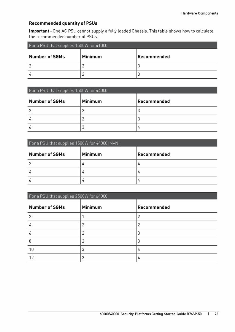
Hardware Components
60000/40000 Security Platforms Getting Started Guide R76SP.50 | 72
Recommended quantity of PSUs
Important - One AC PSU cannot supply a fully loaded Chassis. This table shows how to calculate the recommended number of PSUs.
For a PSU that supplies 1500W for 41000
Number of SGMs Minimum Recommended
2 2 3
4 2 3
For a PSU that supplies 1500W for 44000
Number of SGMs Minimum Recommended
2 2 3
4 2 3
6 3 4
For a PSU that supplies 1500W for 44000 (N+N)
Number of SGMs Minimum Recommended
2 4 4
4 4 4
6 4 4
For a PSU that supplies 2500W for 64000
Number of SGMs Minimum Recommended
2 1 2
4 2 2
6 2 3
8 2 3
10 3 4
12 3 4

Hardware Components
60000/40000 Security Platforms Getting Started Guide R76SP.50 | 73
For a PSU that supplies 2500W for 64000 (N+N)
Number of SGMs Minimum Recommended
2 2 4
4 4 4
6 4 4
8 4 6
10 6 6
12 6 6

Hardware Components
60000/40000 Security Platforms Getting Started Guide R76SP.50 | 74
AC Power Cords The supplied AC power cords are specific to the geographical region. These are some of the available power cords.
AC Power Cords for the 64000 Security System Region Plug Connector Cable Diagram
EU KC-015A, 16A 250V~
KC-003A, 16A 250V~
H05VV-F 3G 1.5 mm2
AUSTRALIA KC-014, 15A 250V~
KC-003A, 16A 250V~
H05VV-F 3G 1.5mm2
UK KC-036, 13A 250V~
KC-003A, 16A 250V~
H05VV-F 3G 1.5mm2
JP WS-120, 20A 250~
WS-002F, 20A 250V~
VCT 3.5mm2 * 3C
US WS1I, 20A 250V~
WS-002F, 20A 250V~
SJT12 AWG * 3C 105ºC
CHINA KC-069, 16A 250V~
KC-003A, 16A 250V~
H05VV-F 3G 1.5mm2

Hardware Components
60000/40000 Security Platforms Getting Started Guide R76SP.50 | 75
AC Power Cords for the 44000 Security System Region Plug Connector Cable Diagram
EU KC-015, 16A 250V~
KC-003H, 10A 250V~
H05RR-F,3G 0.75mm2
AUSTRALIA KC-014, 10A 250V~
KC-003H, 10A 250V~
H05RR-F 3G 0.75mm2
UK KC-039, 13A 250V~
KC-003H, 10A 250V~
H05RR-F 3G 0.75mm2
JP KC-001, 15A 125V~
KC-003H, 15A 125V~
VCTF 3G 2.0mm2
US KC-001, 15A 125V~
KC-003H, 15A 125V~
SJT 14/3C 75ºC

Hardware Components
60000/40000 Security Platforms Getting Started Guide R76SP.50 | 76
Region Plug Connector Cable Diagram
CHINA KC-017N, 10A 250V~
KC-003H, 10A 250V~
H05RR-F 3G 0.7mm2

Hardware Components
60000/40000 Security Platforms Getting Started Guide R76SP.50 | 77
AC Power Cords for the 61000 N+N Security System Region Plug Connector Cable Diagram
EU KC-015A, 16A 250V~
KC-003A, 16A 250V~
H05VV-F 3G 1.5 mm2
AUSTRALIA KC-014, 15A 250V~
KC-003A, 16A 250V~
H05VV-F 3G 1.5mm2
UK KC-036, 13A 250V~
KC-003A, 16A 250V~
H05VV-F 3G 1.5mm2
JP WS-120, 20A 250~
WS-002F, 20A 250V~
VCT 3.5mm2 * 3C
US WS1I, 20A 250V~
WS-002F, 20A 250V~
SJT12 AWG * 3C 105ºC
CHINA KC-069, 16A 250V~
KC-003A, 16A 250V~
H05VV-F 3G 1.5mm2
Patch Panel USA
WS-003D, 15/16A 250V~
WS-002F, 15/16A 250V~
SJT 15AWG 3C + HO5VVV-F3 1.5mm2
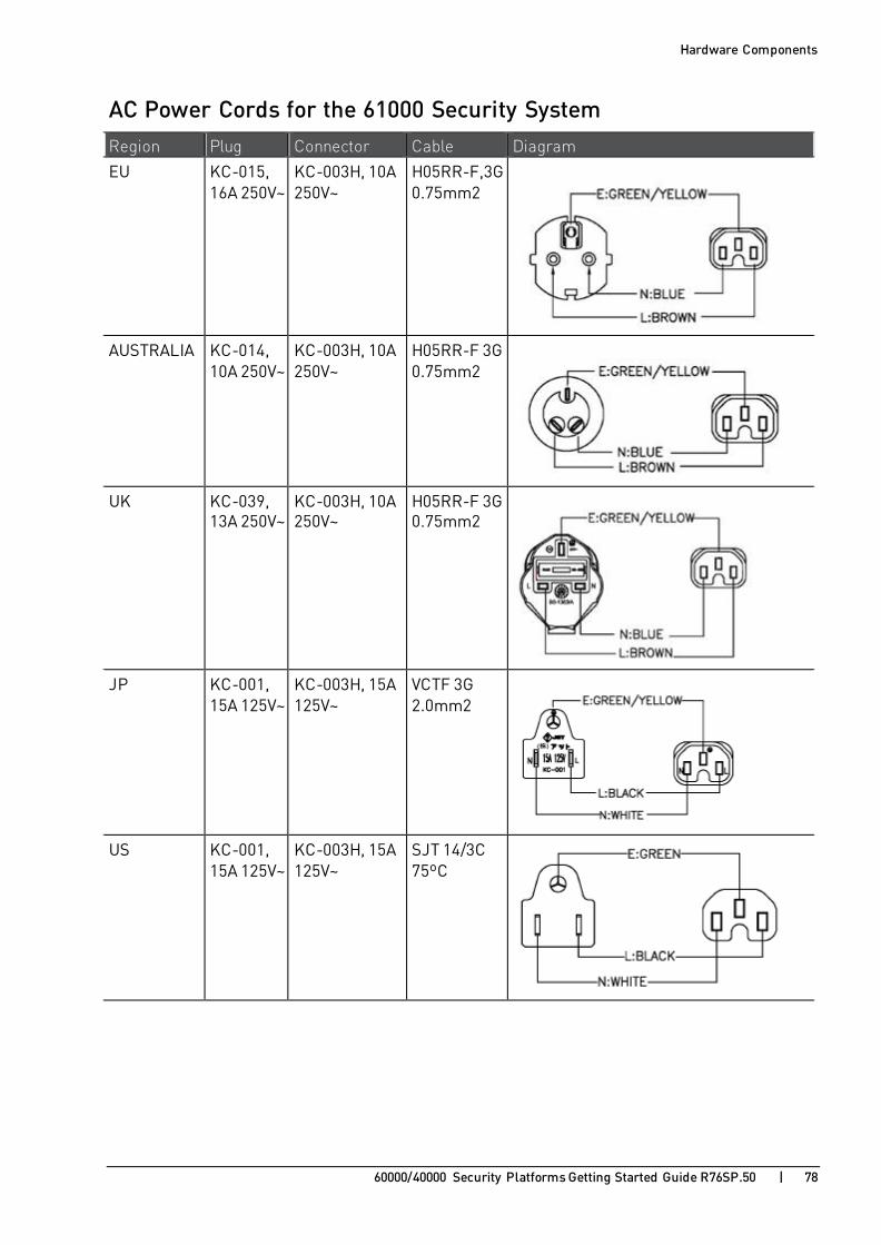
Hardware Components
60000/40000 Security Platforms Getting Started Guide R76SP.50 | 78
AC Power Cords for the 61000 Security System Region Plug Connector Cable Diagram
EU KC-015, 16A 250V~
KC-003H, 10A 250V~
H05RR-F,3G 0.75mm2
AUSTRALIA KC-014, 10A 250V~
KC-003H, 10A 250V~
H05RR-F 3G 0.75mm2
UK KC-039, 13A 250V~
KC-003H, 10A 250V~
H05RR-F 3G 0.75mm2
JP KC-001, 15A 125V~
KC-003H, 15A 125V~
VCTF 3G 2.0mm2
US KC-001, 15A 125V~
KC-003H, 15A 125V~
SJT 14/3C 75ºC

Hardware Components
60000/40000 Security Platforms Getting Started Guide R76SP.50 | 79
Region Plug Connector Cable Diagram
CHINA KC-017N, 10A 250V~
KC-003H, 10A 250V~
H05RR-F 3G 0.7mm2

Hardware Components
60000/40000 Security Platforms Getting Started Guide R76SP.50 | 80
AC Power Cords for the 41000 Security System Region Plug Connector Cable Diagram
EU KC-015, 16A 250V~
KC-003H, 10A 250V~
H05RR-F,3G 0.75mm2
AUSTRALIA KC-014, 10A 250V~
KC-003H, 10A 250V~
H05RR-F 3G 0.75mm2
UK KC-039, 13A 250V~
KC-003H, 10A 250V~
H05RR-F 3G 0.75mm2
JP KC-001, 15A 125V~
KC-003H, 15A 125V~
VCTF 3G 2.0mm2
US KC-001, 15A 125V~
KC-003H, 15A 125V~
SJT 14/3C 75ºC

Hardware Components
60000/40000 Security Platforms Getting Started Guide R76SP.50 | 81
Region Plug Connector Cable Diagram
CHINA KC-017N, 10A 250V~
KC-003H, 10A 250V~
H05RR-F 3G 0.7mm2

Hardware Components
60000/40000 Security Platforms Getting Started Guide R76SP.50 | 82
DC Power Entry Modules (PEMs) for 64000 Security System
The DC configuration on 64000 Security System includes two Power Entry Modules (PEMs), each with a rating of -48/-60VDC up to 250A. These PEMs supply DC power, EMC filtering and over-current protection for the Chassis. Each PEM can supply 100% of Chassis power.
On each DC PEM, there are 5 power segments (5 circuit breakers on the DC PEM). Both DC PEMs provide power redundancy, a total of 10KW.
The DC configuration does not have its own power source. For each DC PEM, you must supply a mains DC power source that includes batteries and branch circuit breaker of 50A for each terminal block (250A in total).
The DC PEM is a customer replaceable unit. The two-DC PEM configuration provides full redundancy. The DC PEMs are located in the bottom-rear of the Chassis.
64000 Security System Rear Panel with DC PEMs

Hardware Components
60000/40000 Security Platforms Getting Started Guide R76SP.50 | 83
Item Description
1 Grill panel that allows for air exhaust.
2 Card cage that holds the rear transition modules (RTM).
3 Backplane that supports up to 14 RTMs.
4 ESD wrist strap terminal.
5 Grounding point.
6 DC Power Entry Modules (PEMs).
7 Rear cable holder.
DC PEM Panel and LED Indicators for 64000 Security System
Item Description
1 (+) Return and (-) 48V terminal blocks with pluggable connectors.
2 5 x 50A circuit breakers.
3 PEM LEDs.
4 Locking captive screws to secure the PEM in the Chassis.
5 Extraction latch.

Hardware Components
60000/40000 Security Platforms Getting Started Guide R76SP.50 | 84
PEM LEDs
Item Description
Status • Green: OK
• Red: Failure
Fault • Green: OK
• Red: -48VDC is missing
HS
(Hot swap)
• Blue steady: Powering up or ready for extraction
• Blue blinking: Hot swap process
• OFF: Working
Important -
• Do not remove a PEM while it is connected to the DC power source.
• Before replacing a PEM, confirm that the DC power source is disconnected and isolated.

Hardware Components
60000/40000 Security Platforms Getting Started Guide R76SP.50 | 85
DC Power Entry Modules (PEMs) for 61000 and 41000 Security Systems
The DC configuration on 61000 and 41000 Security Systems includes two Power Entry Modules (PEMs), each with a rating of -48/-60VDC up to 125A. The PEMs supply DC power, EMC filtering and over-current protection for the Chassis. Each DC PEM can supply 100% of Chassis power.
On each DC PEM there are 4 power segments (4 circuit breakers on the DC PEM), for a total power of 10KW. Both DC PEMs provide power redundancy, a total of 10KW.
If the DC voltages of the 2 DC PEMs are the same, for example, they are both -47.8, the two DC PEMs share the load. If one of the DC voltages is higher than the other by ~0.5V or more, then one DC PEM will carry the entire load and the other DC PEM will be standby.
The DC configuration does not have its own power source. For each DC PEM, you must supply:
• A DC power source that includes an external battery and a branch circuit breaker of 125A.
• Lugs (Panduit LCD6-14A-L), to connect the wires to the terminal blocks of the PEMs.
The DC PEM is a customer replaceable unit. The two-DC PEM configuration provides full redundancy. The DC PEMs are located in the bottom-rear of the Chassis.
DC PEM Panel and LED Indicators for 61000 and 41000 Security Systems

Hardware Components
60000/40000 Security Platforms Getting Started Guide R76SP.50 | 86
Item Description
1 Locking captive screws to secure the PEM in the Chassis.
2 Handles for holding the PEM during insertion and extraction.
3 Terminal blocks: -48/-60 VDC and Return. Each terminal block has 4 terminal studs.
4 PEM LEDs.
5 Hot-Swap button used to start the hot-swap sequence.
6 4 x 50A circuit breakers.
PEM LEDs
Item Description
Status • Green: OK
• Red: Failure
Fault • Green: OK
• Red: -48VDC is missing
HS
(Hot swap)
• Blue steady: Powering up or ready for extraction
• Blue blinking: Hot swap process
• OFF: Working
Important -
• Do not remove a PEM while it is connected to the DC power source.
• Before replacing a PEM, confirm that the DC power source is disconnected and isolated.
• The PEM circuit breaker has only one pole and only disconnects the -48V lead. The 48VDC RTN lead is always connected.

Hardware Components
60000/40000 Security Platforms Getting Started Guide R76SP.50 | 87
Installing Cable Management Tray 1. Attach 2 brackets, the curve facing up (using 2 screws each), to the Chassis.
2. Attach the cable management between the brackets.

Hardware Components
60000/40000 Security Platforms Getting Started Guide R76SP.50 | 88
3. Attach a screw to the cable management pivot on both sides.
Fan Trays for the 64000 and 61000 N+N Security System Fans are pre-installed on trays in the Chassis. We recommend that you contact technical support if it is necessary to replace a fan.
Item Description
1 Power fault LED
2 Hot swap switch
3 Thumb latch
4 Handle

Hardware Components
60000/40000 Security Platforms Getting Started Guide R76SP.50 | 89
To remove a fan tray:
1. If the upper Chassis cable management unit is installed, pull it out and down until it is out of the way.
2. Press the Hot Swap switch (2).
The blue Power fault LED (1) comes on.
3. Pull up the thumb latch (3) on the fan tray.
4. Hold the handle (4) and pull the fan tray out of the Chassis.
To insert a fan tray:
1. Push the fan tray into its slot.
The thumb latch locks into place and the Power fault LED turns off. 2. If the upper Chassis cable management unit is installed, pull it back up and push it into place.
Make sure that the pins go into the slot on both side brackets.
Fan Trays for the 41000, 44000 and 61000 Security Systems The cooling system consists of three high performance fan trays. The fan trays are at the rear of the Chassis. Each tray contains two fans that supply air volume and velocity for cooling front and rear Chassis components. Air flows from the inside to the outside of the Chassis.
Item Description
1 Power fault LED
2 Locking captive screw
Three fan trays are pre-installed (6 fans).

Hardware Components
60000/40000 Security Platforms Getting Started Guide R76SP.50 | 90
Fan Trays for the 64000 and 61000 N+N Security Systems
Item Description
1 Power fault LED
2 Hot swap switch
3 Thumb latch
4 Handle

Hardware Components
60000/40000 Security Platforms Getting Started Guide R76SP.50 | 91
Blank Filler Panels for Airflow Management Compliance with temperature specifications requires a stable air flow in the Chassis. To make sure that Chassis cooling is effective, add blank filler panels to all empty slots.
Two types of airflow-management panels are available for the empty slots on the Chassis:
• Front blank panels with air baffles
• Rear panel with air baffles
Front Blank Panels with Air Baffles
Item Description
1 Slot cover
2 Tightening screws
3 Air Baffles

60000/40000 Security Platforms Getting Started Guide R76SP.50 | 92
C H A P T E R 9
Step 1: Site Preparation In This Section:
Customer Supplied Hardware .......................................................................... 92
Rack Mounting Requirements .......................................................................... 92
Required Tools ................................................................................................ 93
Customer Supplied Hardware You must have these items available for installation:
• Standard 19" rack
• Eight M6x10 (or longer) rack mounting screws
• Cage bolts, nuts and screws for the racks
• Rack rails set
• Shelf
Check Point does not supply these items.
Rack Mounting Requirements Before mounting the 60000/40000 Security Platform in a standard 19" rack, make sure that:
• The rack is stable, level, and secured to the building.
• The rack is sufficiently strong to support the weight of a fully loaded Security System.
• The rack rails are spaced sufficiently wide to accommodate the system's external dimensions.
• The shelf is mounted on the rack.
• There is sufficient space at the front and rear of the Chassis to let service personnel to swap out hardware components.
• The rack has a sufficient supply of cooling air.
• The rack is correctly grounded.
• A readily accessible disconnect device is incorporated into the building’s wiring. The disconnect device must be placed between the system's AC power inlet and the power source. The disconnect device rating required must be determined by the nominal input voltage.
• There are at least two inches of clearance at the air inlets and outlets to make sure there is sufficient airflow.
• Hot exhaust air is not circulated back into the system.
• At least two persons are available to lift the Chassis.
Step 1: Site Preparation
60000/40000 Security Platforms Getting Started Guide R76SP.50 | 93
Required Tools To install the appliance in a standard 19" rack, these tools are required:
• Standard Phillips (+) screwdriver set
• Wrench
• Electrostatic Discharge (ESD) grounding wrist strap

60000/40000 Security Platforms Getting Started Guide R76SP.50 | 94
C H A P T E R 1 0
Step 2: Installing the Chassis in a Rack Important - Before mounting the Chassis on the rack, attach the rear static grounding screws to the Chassis.
To install the Chassis on the Rack:
1. Set the Chassis in front of the rack, centering the Chassis in front the rack.
2. Lift and slide the Chassis on to the rack shelf.
3. Make sure that the holes in the front mounting flanges of the Chassis align with the holes in the rack rails.
4. Insert mounting screws into the front mounting flanges aligned with the rack.
5. Secure the appliance by fastening the mounting screws to the rack. The appliance must be level, and not positioned at an angle.
6. Attach grounding cables to the grounding screws on the Chassis.
Caution: The intrabuilding ports (Ethernet and serial) of the equipment or subassembly is suitable for connection to intrabuilding or unexposed wiring or cabling only. The intrabuilding ports of the equipment or subassembly must not be metallically connected to interfaces that connect to the outside plant (OSP) or its wiring. These interfaces are designed for use as intrabuilding interfaces only (Type 2 or Type 4 ports as described in GR-1089-CORE) and require isolation from the exposed OSP cabling. The addition of primary protectors is not sufficient protection in order to connect these interfaces metallically to OSP wiring.
To ground the Chassis:
Background:
• The chassis is suitable for installation as part f the Common Bonding Network (CBN).
• The 64000 Security System can be installed in network telecommunication facilities or locations, where the National Electric Code applies.
• The chassis includes a two-hole grounding lug, Panduit LCD1-38D-E. Use one AWG grounding cable with this lug.
• Grounding design must comply with the country or local electrical codes. In the United States, grounding must comply with Article 250 of the NEC unless superseded by local codes.
• Ground connection is essential before connecting the power supply.
• There must be an uninterruptable safety earth ground from the main power source to the chassis. In case the grounding connection fails, disconnect the power cord from the chassis until the ground is restored.
• To avoid the potential for an electrical shock hazard, the safety-grounding conductor must be determined based on the feed current rating and cable length.

Step 2: Installing the Chassis in a Rack
60000/40000 Security Platforms Getting Started Guide R76SP.50 | 95
Procedure:
1. On the rear of the chassis, locate the grounding connection on the right.
2. Using the appropriate wrench, unfasten the two nuts and remove the lug.
3. Crimp the 1 AWG wire to the lug.
4. Return the lug to its place on the rear-right of the chassis and refasten the nuts. The maximum application Torque of the nuts is 35 lbf-in (4 N·m).
5. Connect the ground wire to the appropriate ground connection of the building infrastructure.

60000/40000 Security Platforms Getting Started Guide R76SP.50 | 96
C H A P T E R 1 1
Step 3: Installing Hardware Components and Connecting Power Cables
In This Section:
Inserting AC Power Supply Units ...................................................................... 97
Inserting SSMs for the 61000, 61000 N+N and 64000 Security System ................. 98
Inserting SSMs for the 41000 Security System ................................................... 99
Inserting SGMs for the 64000, 61000 and 61000 N+N Security System ................100
Inserting SGMs for the 44000 and 41000 Security System ..................................101
Inserting Transceivers ....................................................................................102
Inserting Front Blank Panels...........................................................................104
Connecting AC Power Cables ..........................................................................105
Inserting AC Power Supply Units .....................................................................106
Connecting DC Power to 64000 Security System ...............................................107
Connecting DC Power for 61000 and 41000 Security Systems ............................109
Connecting a Second Chassis ..........................................................................111
This section covers inserting:
• Chassis Management Modules
• Security Switch Modules
• Security Gateway Modules
• Twisted pair and fiber optic transceivers into ports on the Security Switch Modules
• Transceivers into the management ports on the Security Switch Modules
• Covers for blank slots
This section also covers:
• Backup Chassis in a dual Chassis environment
• Power cables

Step 3: Installing Hardware Components and Connecting Power Cables
60000/40000 Security Platforms Getting Started Guide R76SP.50 | 97
Inserting AC Power Supply Units AC Power Supply Units (AC only) are pre-installed in the Chassis.
You can swap in more units, or replace units, without interfering with the operation of the 60000/40000 Security Platform.
Note - One AC PSU cannot supply sufficient power to support a fully populated Chassis.
To insert an AC Power Supply Unit:
1. Pull out the latch.
2. Push in the Power Supply until it locks in place.
3. Push in the Power Supply insertion latch. 4. Make sure that the DC LED show green.

Step 3: Installing Hardware Components and Connecting Power Cables
60000/40000 Security Platforms Getting Started Guide R76SP.50 | 98
Inserting SSMs for the 61000, 61000 N+N and 64000 Security System
To insert a Security Switch Module:
1. Open the latches at the top and bottom of the Security Switch Module.
2. Slide the SSM into the allocated slot.
3. Fasten the latches. 4. Tighten the screws.

Step 3: Installing Hardware Components and Connecting Power Cables
60000/40000 Security Platforms Getting Started Guide R76SP.50 | 99
Inserting SSMs for the 41000 Security System To insert a Security Switch Module:
1. Open the latches at the left and right of the Security Switch Module.
2. Slide the SSM into the allocated slot.
3. Fasten the latches. 4. Tighten the screws.

Step 3: Installing Hardware Components and Connecting Power Cables
60000/40000 Security Platforms Getting Started Guide R76SP.50 | 100
Inserting SGMs for the 64000, 61000 and 61000 N+N Security System
To insert a Security Gateway Module:
1. Open the latches at the top and bottom of the Security Gateway Module.
2. Make sure the SGM is located correctly on the Chassis rail.
3. Slide the SGM into the allocated slot. 4. Fasten the latches.
5. Tighten the thumb screws.

Step 3: Installing Hardware Components and Connecting Power Cables
60000/40000 Security Platforms Getting Started Guide R76SP.50 | 101
Inserting SGMs for the 44000 and 41000 Security System
To insert a Security Gateway Module:
1. Open the latches at the left and right of the Security Gateway Module.
2. Make sure the SGM is located correctly on the Chassis rail.
3. Slide the SGM into the allocated slot. 4. Fasten the latches.
5. Tighten the thumb screws.

Step 3: Installing Hardware Components and Connecting Power Cables
60000/40000 Security Platforms Getting Started Guide R76SP.50 | 102
Inserting Transceivers To connect different interface types to the 60000/40000 Security Platform using SFP or SFP+ ports on the SSM, Security Switch Modules support Twisted Pair and Fiber Optic transceivers.
The type and number of transceiver ports available depends on the SSM.
Note - Remember to select a transceiver that matches the speed of the designated port.
Inserting Twisted Pair Transceivers Twisted pair transceivers can be inserted into data and management ports on the SSM160.
Slide the transceiver into the open Security Switch Module port.

Step 3: Installing Hardware Components and Connecting Power Cables
60000/40000 Security Platforms Getting Started Guide R76SP.50 | 103
Inserting Fiber Optic Transceivers Fiber transceivers can be inserted into data and management ports on the SSM160 switch modules. The ports can be SFP and SFP+.
Slide the transceiver into the open Security Switch Module port.
Inserting QSFP Splitters 1. Insert the QSFP transceiver into the Security Switch Module. 2. Insert the QSFP splitter cable into the transceiver.
This converts the 40GbE QSPF port to 4 x 10GbE ports.

Step 3: Installing Hardware Components and Connecting Power Cables
60000/40000 Security Platforms Getting Started Guide R76SP.50 | 104
Inserting Front Blank Panels Blank panels contain cooled air in the appliance. Use the blank panels to close open slots.
To insert a blank panel at the front:
1. Insert the blank panel into the open slot.
2. Tighten the two thumb screws.
Note - Rear blank panels are preinstalled on the Chassis.

Step 3: Installing Hardware Components and Connecting Power Cables
60000/40000 Security Platforms Getting Started Guide R76SP.50 | 105
Connecting AC Power Cables To connect AC power:
1. Make sure the circuit breaker at the mains is off.
2. Insert an AC power cable into each AC power inlet on the rear-bottom of the Chassis.
AC Power Configuration for Maximum Power Resilience
For increased power availability, it is recommended to use redundant power circuits with a dual Chassis configuration. A redundant power circuit has a second circuit path that keeps power to the Chassis in case of failure of one of the power circuits.
For maximum resilience against power failure, use two power circuits and three PSUs in each Chassis. In each Chassis, connect three PSU to one power circuit, and two PSUs to the other power circuit. For example:
• Chassis A contains 3 PSUs: A1, A2, A3.
• Chassis B contains 3 PSUs: B1, B2, B3.
Connect the PSUs to the Power Circuits as follows:
• PSUs A1, A2, B3 to Power Circuit X.
• PSUs B1, B2, A3 to Power Circuit Y.

Step 3: Installing Hardware Components and Connecting Power Cables
60000/40000 Security Platforms Getting Started Guide R76SP.50 | 106
Inserting AC Power Supply Units AC Power Supply Units (AC only) are pre-installed in the Chassis.
You can swap in more units, or replace units, without interfering with the operation of the 60000/40000 Security Platform.
Note - One AC PSU cannot supply sufficient power to support a fully populated Chassis.
To insert an AC Power Supply Unit:
1. Pull out the latch.
2. Push in the Power Supply until it locks in place.
3. Push in the Power Supply insertion latch. 4. Make sure that the DC LED show green.

Step 3: Installing Hardware Components and Connecting Power Cables
60000/40000 Security Platforms Getting Started Guide R76SP.50 | 107
Connecting DC Power to 64000 Security System Connect the DC PEMs in the 60000/40000 Security Platform to an external battery power source. You must have a mains DC power supply system that includes batteries and a branch circuit breaker of 50A for each terminal block (250A in total) for each DC PEM.
The DC PEM is described in DC Power Entry Modules (PEMs) for 64000 Security System (on page 82).
For DC power redundancy, connect the two DC PEMs to two separate DC power sources. The two DC power sources must not connect one to the other. This is important to prevent excessive EMC radiation due to imbalance of the incoming and outgoing currents of each DC PEM. Specifically, do not connect the two DC PEMs to the same DC power source and do not connect the Return lines of the two DC PEMs.
Required Tools and Parts:
• 10 DC wire leads for each DC PEM that connects to the DC power supply. Use 6AWG wires. There is no standard for DC wire color coding. Use the color codes on the DC power source (battery) for the DC wire leads.
• Wire cutter.
• Wire stripper.
• Screwdriver for tightening the screws in the Phoenix Contact PC 16/ 2-ST-10,16 (1967375) terminal connectors.
To connect DC power:
Note - These instructions assume that you already installed the DC PEMs in the 60000/40000 Security Platform Chassis.
1. Set the branch circuit breakers at the mains to the OFF position. 2. On each DC PEM, set all the circuit breakers to the OFF position.
3. With the appropriate wire stripper, strip the ends of the wire leads you plan to attach to the terminal block pluggable connector. Stripping length is 7.5mm.
4. Insert the stripped end of the plus wire lead into the leftmost contact of the terminal block pluggable connector. With an appropriate screwdriver, tighten the screw clamp.
5. Insert the stripped end of the minus wire lead into the rightmost contact of the terminal block pluggable connector. With an appropriate screwdriver, tighten the screw clamp.
6. Plug the terminal connector into its terminal block socket on each DC PEM. Repeat Steps 3 - 6 for the remaining terminal blocks on each DC PEM.
7. Set the branch circuit breakers at the mains to the ON position.

Step 3: Installing Hardware Components and Connecting Power Cables
60000/40000 Security Platforms Getting Started Guide R76SP.50 | 108
8. Use a multimeter to make sure the polarity and the range of the DC voltage are correct. Use a multimeter to measure the resistance between the disconnected DC PEM wire leads and the Battery's Return terminal.
For all the DC PEM wire leads, one at a time:
a) At the battery, disconnect a DC PEM wire lead from the battery.
b) Connect one multimeter probe to the battery's Return and the other probe to the DC PEM wire lead.
A very large resistance (indicating an open circuit) shows that the wire lead connects to
the-48/-60VDC terminal on the DC PEM.
A very low resistance (indicating a closed circuit) shows that the wire lead connects to the Return terminal on the DC PEM.
c) Reconnect the DC PEM wire lead to the battery.
9. On each DC PEM, set all the circuit breakers to ON position.
DC PEM with wires connected to the terminal connectors

Step 3: Installing Hardware Components and Connecting Power Cables
60000/40000 Security Platforms Getting Started Guide R76SP.50 | 109
Connecting DC Power for 61000 and 41000 Security Systems
Connect the DC PEMs in the 60000/40000 Security Platform to an external battery power source. You must have a mains DC power supply system that includes batteries and a branch circuit breaker of 125A for each DC PEM.
The DC PEM is described in DC Power Entry Modules (PEMs) for 61000 and 41000 Security Systems (on page 85).
Required Tools and Parts:
• 4 DC wire leads for each DC PEM that connect to the DC power supply.
Use 6AWG wires. There is no standard for DC wire color coding. Use the color codes on the DC power source (battery) for the DC wire leads.
• 4 barrel lugs (Panduit LCD6-10A-L) for each DC PEM to connect the wire leads to the DC PEM terminal blocks.
• Crimping tool to connect the wire leads to the lugs.
• Wire cutter.
• Wire stripper.
• Hexagonal-head socket wrench, or nut driver for tightening nuts to terminal studs on each DC PEM.
• Screwdriver.
To connect DC power:
Note - These instructions assume that you already installed the DC PEMs in the 60000/40000 Security Platform Chassis.
1. Set the branch circuit breakers at the mains to the OFF position.
2. On the both DC PEMs, set all the circuit breakers to the OFF position. 3. On the first DC PEM, remove the protective plastic cover. Use an appropriate screwdriver.
4. Where the PEM is marked -48/-60 VDC and Return, remove the nuts from the terminal studs. Use a socket wrench or nut driver.
5. Connect the -48/-60 VDC cables to the battery:
a) Use the crimping tool to connect two wire leads to two lugs.
b) Attach the two wire lugs to the -48/-60 VDC terminal studs on the DC PEM. Use the socket wrench or nut driver.
c) Connect the other ends of the two wires to the -48/-60VDC terminal on the DC battery.
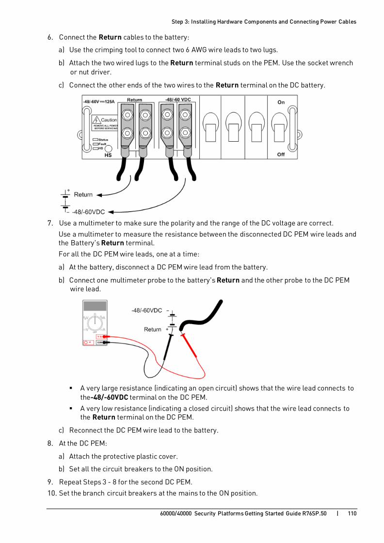
Step 3: Installing Hardware Components and Connecting Power Cables
60000/40000 Security Platforms Getting Started Guide R76SP.50 | 110
6. Connect the Return cables to the battery:
a) Use the crimping tool to connect two 6 AWG wire leads to two lugs.
b) Attach the two wired lugs to the Return terminal studs on the PEM. Use the socket wrench or nut driver.
c) Connect the other ends of the two wires to the Return terminal on the DC battery.
7. Use a multimeter to make sure the polarity and the range of the DC voltage are correct.
Use a multimeter to measure the resistance between the disconnected DC PEM wire leads and the Battery's Return terminal.
For all the DC PEM wire leads, one at a time:
a) At the battery, disconnect a DC PEM wire lead from the battery.
b) Connect one multimeter probe to the battery's Return and the other probe to the DC PEM wire lead.
A very large resistance (indicating an open circuit) shows that the wire lead connects to
the-48/-60VDC terminal on the DC PEM.
A very low resistance (indicating a closed circuit) shows that the wire lead connects to the Return terminal on the DC PEM.
c) Reconnect the DC PEM wire lead to the battery.
8. At the DC PEM:
a) Attach the protective plastic cover.
b) Set all the circuit breakers to the ON position.
9. Repeat Steps 3 - 8 for the second DC PEM.
10. Set the branch circuit breakers at the mains to the ON position.

Step 3: Installing Hardware Components and Connecting Power Cables
60000/40000 Security Platforms Getting Started Guide R76SP.50 | 111
Connecting a Second Chassis If you have a dual Chassis environment (for Chassis high availability):
1. For the second Chassis, repeat these steps:
a) Step 1: Site Preparation (on page 92)
b) Step 2: Installing the Chassis in a Rack (on page 94)
c) Step 3: Installing Components and Connecting Power Cables (on page 96)
2. Connect the second Chassis.
3. On each SSM, connect the sync ports to the corresponding sync ports on the backup Chassis:
• eth1-Sync in Chassis1 to eth1-Sync in Chassis2
• eth2-Sync in Chassis1 to eth2-Sync in Chassis2
4. Make sure to attach the RX cable to the RX ports and the TX cable to the TX ports.

60000/40000 Security Platforms Getting Started Guide R76SP.50 | 112
C H A P T E R 1 2
Step 4: Turning on the System Turning on the 60000/40000 Security Platform
Connect the appliance to the power source. At power up:
• Fan speed goes to maximum.
• LEDs on the Chassis Management Module light up.
• After 1-60 seconds, fan speed slows down until it reaches the optimum rate for cooling.
• Chassis Management Module ACT and PWR LEDs show green.
• Other LEDs turn off.
Turning off the 60000/40000 Security Platform
1. Shutdown the SGMs:
• If the installation wizard (Step 5) has not yet run, release the levers on each SGM to shut them down
• If the installation wizard has run, from gClish run:
asg_hard_shutdown -b all
2. Shutdown the SSMs and CMMs by releasing the levers.
3. After the LEDs on SGMs, SSMs and CMMs (both Chassis) show a steady blue, unplug the power cords.

60000/40000 Security Platforms Getting Started Guide R76SP.50 | 113
C H A P T E R 1 3
Step 5: Dual Chassis System Validation In This Section:
Validating the Chassis ID.................................................................................113
Setting the Chassis ID.....................................................................................114
When you install and configure a dual Chassis deployment in high availability, make sure that all CMMs on each Chassis have the same Chassis ID.
The CMMs on Chassis 1 must include chassis_id 1 (SHMM_CHASSID=’1’).
The CMMs on Chassis 2 must include chassis_id 2 (SHMM_CHASSID=’2’).
Note - When you add a new CMM to a Chassis, you must validate the Chassis ID. Make sure that the Chassis is in the Standby mode when you do this.
Validating the Chassis ID To validate the Chassis ID:
1. Make sure that the sticker on the outer box of one Chassis identifies it as Chassis 1 and the other as Chassis 2. If the numbers are the same, contact Check Point support https://www.checkpoint.com/support-services/contact-support/.
2. Open the outer box, and confirm that the stickers on the Chassis and the CMM blades are different for each Chassis.
If the numbers are the same, contact Check Point Support http://downloads.checkpoint.com/dc/download.htm?ID=46534.
3. Make sure that Chassis ID is configured correctly on the CMM:
a) Connect an RJ-45 serial cable to the CMM console port on the Control Panel.
b) Connect the other end of the serial cable to a computer.
c) Connect to the 60000/40000 Security Platform with a terminal emulation application.
d) Make sure the Speed (baud rate) is set to 9600.
e) No IP address is necessary.
Log in with these user name and password: admin/admin.

Step 5: Dual Chassis System Validation
60000/40000 Security Platforms Getting Started Guide R76SP.50 | 114
4. Run this command to make sure that the CMM ID is correct:
# cat /etc/shmm.cfg | grep CHASSID
Sample output:
SHMM_CHASSID=’1’
5. Do these steps again to validate the IDs of CMMs on the other Chassis.
If the numbers are the same, contact Check Point Support https://www.checkpoint.com/support-services/contact-support/.
Setting the Chassis ID To set the Chassis ID:
1. Remove the first CMM from the Chassis. 2. Connect to the remaining CMM with Serial cable (baud rate - 9600).
3. Log in with these user name and password: admin/admin
4. Open the /etc/shmm.cfg file in Vi editor and search for 'SHMM_CHASSIS='
5. Set the correct Chassis ID and save the file:
• SHMM_CHASSID=”1” for Chassis 1
• SHMM_CHASSID=”2” for Chassis 2
6. Remove the current CMM and insert the second CMM. 7. Repeat Steps 2 - 5 for the second CMM.
8. Insert both CMMs into the Chassis.
9. Remove all SGMs from the Chassis and then reinsert them.

60000/40000 Security Platforms Getting Started Guide R76SP.50 | 115
C H A P T E R 1 4
Step 6: Installing the Software In This Section:
Before Installing SSM160 Firmware and Software ............................................115
Install ing SSM160 Firmware ...........................................................................118
Upgrading SSM Firmware ...............................................................................120
Install ing the SGM Image ................................................................................121
If your 60000/40000 Security Platform is equipped with SSM160, you must install the SSM160 firmware. Then continue with Installing the SGM Image on page 121.
Before Installing SSM160 Firmware and Software Installing hardware components and connecting cables:
1. Install all hardware components into the Chassis (SGMs, SSMs and CMMs).
See Step 3: Installing Hardware Components and Connecting Power Cables (on page 96).
2. If you have a dual Chassis environment, connect one Sync cable between both Chassis:
• Connect eth1-Sync on chassis1 to eth1-Sync on chassis2.
3. For IP management of the 60000/40000 Security Platform, connect a cable to one of the management interfaces on chassis1:
• Connect to the eth1-Mgmt1, if using a 10Gbps network
• Connect to the eth1-Mgmt4, if using a 1Gbps network
Connecting over Console (Serial)
See Connecting over Console (Serial) Port (on page 125).
Configuring a Security Group and a Management IP Address
1. Start the installation wizard. Run: # setup
2. In the Welcome screen, press any key.

Step 6: Installing the Software
60000/40000 Security Platforms Getting Started Guide R76SP.50 | 116
3. Select Set SGMs for Security Group Define the SGMs that belong to the Security Group. There are two lines, one for Chassis 1, one for Chassis 2.
In each line, you can enter:
• all (same as 1-12)
• A range, such as: 1-9
• A number of comma-separated ranges, such as: 1-3,5-7
• Single SGMs, such as: 1,4
• A combination of single SGMs and ranges, such as: 10,2,3-7.
By default, the SGM you are connected to belongs to the group: Chassis 1, SGM 1 (Slot 1 in Chassis 1). For more about Security Gateway Module numbering, see 60000/40000 Security Platform Front Panel Modules (on page 37).
4. Select Network Connections.
For the management interface, configure: An IP address
The net mask length
5. Configure Routing. • If you are directly connected to the management interface: Skip this step.
• If you are not directly connected to the management interface: Define a route which will allow you to access the 60000/40000 Security Platform.
6. Click Next until you finish the installation wizard. At the SIC stage, enter a dummy key.
Configuration settings are applied, and the Security Gateway Modules reboots. Other Security Gateway Modules in the Security Group are installed automatically.

Step 6: Installing the Software
60000/40000 Security Platforms Getting Started Guide R76SP.50 | 117
Validating the Initial System Setup
To make sure that the initial system setup is completed successfully:
• Run the asg monitor command. An Initial Policy must be installed on the local SGM after initial setup completes and the SGM reboots.
• To monitor the automatic installation of other SGMs, run:
# tail -f /var/log/start_mbs.log
• Wait until the installation process is complete. The installation process is complete when all the SGMs in the security group are UP and in the Initial Policy state.
SCP password for SSM160 firmware installation
Contact Check Point Support https://www.checkpoint.com/support-services/contact-support/. All firmware installations should be performed with the assistance of the Check Point Support.

Step 6: Installing the Software
60000/40000 Security Platforms Getting Started Guide R76SP.50 | 118
Installing SSM160 Firmware You have to install firmware on the Security Switch Module SSM160.
Installing the SSM160 Firmware
1. Download the SSM160 firmware from sk93332 http://supportcontent.checkpoint.com/solutions?id=sk93332.
2. Connect to one SGM, using the management IP address configured in the installation wizard.
3. Connect to the Management Interface of the SGM and copy the file using SCP, to /home/admin directory.
4. From this SGM, copy the firmware file to the other SGMs in the Security Group. Run: # asg_cp2blades –b <blade_list> /home/admin/<file>
5. From this SGM, copy the firmware to the two SSMs in the Chassis. Run for each SSM: # scp -P 2024 2.4.C9.T-HUB4.tar.bz2 root@SSM1:/batm/current_version/ # scp -P 2024 2.4.C9.T-HUB4.tar.bz2 root@SSM2:/batm/current_version/
6. Enter the SCP password you received from Check Point Support https://www.checkpoint.com/support-services/contact-support/. You may see a read-only file system error. For example: # scp -P 2024 2.4.C9.T-HUB4.tar.bz2 root@ssm2:/batm/current_version/ root@ssm2's password: scp: /batm/current_version//2.4.C9.T-HUB4.tar.bz2: Read-only file system
If you see a read-only file system error do this:
a) From the Expert mode, connect to the applicable SSM over SSH. Run:
# ssh ssm1
# ssh ssm2
The password is admin
b) From the default shell, run:
# unhide private
The password is private
c) Run the following commands:
# show private shell
# mount -rw -o remount /batm/
# exit
# logout
d) Run the firmware copy command for each SSM:
# scp -P 2024 2.4.C9.T-HUB4.tar.bz2 root@ssm2:/batm/current_version/
e) Enter the SCP password you received from Check Point Support https://www.checkpoint.com/support-services/contact-support/.

Step 6: Installing the Software
60000/40000 Security Platforms Getting Started Guide R76SP.50 | 119
7. Activate the new firmware on the SSM. Do this for the two SSMs on the Standby Chassis:
a) From the Expert mode, connect to the applicable SSM over SSH. Run:
# ssh ssm1
# ssh ssm2
b) The password is admin
c) Run:
# file ls os-image
Copy the name of the new image file.
d) Run:
# file activate-os-image 2.4.C9.T-HUB4.tar.bz2
e) Move to configuration shell. Run:
# config terminal
f) Reload the SSM with the new image. Run:
# system reload manufacturing-defaults
Example: T-HUB4# file activate-os-image 2.4.C9.T-HUB4.tar.bz2 Image file 2.4.C9.T-HUB4.tar.bz2 is tested for validity, please wait... OK Activating image 2.4.C9.T-HUB4.tar.bz2.. T-HUB4# config terminal Entering configuration mode terminal T-HUB4(config)# system reload manufacturing-defaults Are you sure that you want to delete existing configuration and reload manufacturing default configuration (yes/no)? yes
8. Connect to SGM on the other Chassis. From the Expert shell, run:
# blade <SGM number>
For example: blade 2_01
Run exit to return to the previous SGM.
9. Repeat the firmware upgrade procedure on the two SSMs of the other Chassis.
Validation
To verify the upgrade, run:
# asg_version
All SSMs should have firmware version 2.4.C9.
For more information, see sk93332 http://supportcontent.checkpoint.com/solutions?id=sk93332.

Step 6: Installing the Software
60000/40000 Security Platforms Getting Started Guide R76SP.50 | 120
Upgrading SSM Firmware Use the asg_ssm_upgrade utility to upgrade the SSM firmware to the most recent version. Do the upgrade for one SSM at a time.
Syntax # asg_ssm_upgrade ssm <SSM_ID> [chassis <Chassis_ID>] [file <Firmware File>]
Parameters
Parameter Description
<SSM_ID> SSM ID to be upgraded (1, 2, or all)
<Chassis_ID> Chassis ID (1, 2, or all)
<Firmware File> New firmware file name and fully qualified path
Notes:
• Before you upgrade, confirm that the new firmware file checksum is valid.
• You must copy the new firmware file to all SGMs.
• Console is mandatory if you upgrade the local Chassis SSM.
• The SSM automatically reboots after the upgrade. This can cause traffic interruption.

Step 6: Installing the Software
60000/40000 Security Platforms Getting Started Guide R76SP.50 | 121
Installing the SGM Image Use an ISO image on removable media (DVD or USB) to install an image on the Security Gateway Modules.
Use one of these procedures to install an image on the Security Gateway Modules:
• Using an ISO image on removable media: DVD or USB (see instructions below).
• Using an HFA Upgrade package (see instructions in the R76SP.50 Upgrade Guide https://sc1.checkpoint.com/documents/R76SP.50/CP_R76SP.50_SecuritySystem_UpgradeGuide/html_frameset.htm - Chapter Upgrading from a Minor Release).
Installing the SGM Image with Removable Media You can install an ISO image on the Security Gateway Modules from a USB stick or DVD.
To copy the ISO image to the removable media:
1. Download the ISO image file from the R76SP.50 60000/40000 Security Platforms Home Page http://supportcontent.checkpoint.com/solutions?id=sk115735. Note - For Multiple Security Groups, make sure to choose the designated ISO file under the title Clean install for Multiple Security Groups.
2. Copy the file to removable media with one of these steps:
• Burn the ISO file to a DVD. • Download the Check Point ISOmorphic utility to create a bootable USB device from the ISO.
See sk65205 http://supportcontent.checkpoint.com/solutions?id=sk65205.
Make sure that your USB device is compatible with ISOmorphic. See sk92423 http://supportcontent.checkpoint.com/solutions?id=sk92423 for details.
3. You can install many SGMs at one time. Copy the ISO image to many USB sticks or DVD drives.
Example:
Step 6: Installing the Software
60000/40000 Security Platforms Getting Started Guide R76SP.50 | 122
Item Description
1 USB port
2 One of two latches for extracting and inserting the SGM
To install an ISO image on the Security Gateway Modules:
See the detailed instructions in the R76SP.50 Upgrade Guide https://sc1.checkpoint.com/documents/R76SP.50/CP_R76SP.50_SecuritySystem_UpgradeGuide/html_frameset.htm - Chapter Upgrading from Major Releases.
1. Connect the removable media to the left-most Security Gateway Module in one of these ways:
• Connect the USB stick to the USB port.
• Connect an external DVD drive to the USB port. Put the DVD with the ISO file in the DVD drive.
2. Connect the supplied DB9 serial cable to the console port on the front of the left-most SGM on the 60000/40000 Security Platform.
3. Connect to the left-most SGM using a terminal emulation program. 4. Reboot the SGM by partially sliding it out and immediately pushing it back in place:
a) Loosen the thumb screws at the top and bottom of the SGM.
b) Open the latches at the top and bottom of the SGM.
c) Fasten the latches.
d) Tighten the thumb screws.
5. When the first screen shows, select Install Gaia on the system and press Enter. 6. You must press Enter within 60 seconds, or the computer will try to start from the hard drive.
The timer countdown stops once you press Enter. There is no time limit for the subsequent steps.
7. Press OK to continue with the installation.
After the installation, the 60000/40000 Security Platform begins the boot process, and status messages show in the terminal emulation program.
8. Install the SGM image on the other SGMs. To install on one SGM at a time repeat all the steps for each SGM. To install on many SGMs at one time:
a) Insert all the USB sticks or DVD drives into the USB ports of the other SGMs.
b) Do this for one SGM at a time:
Connect to the console.
Reboot the SGM. Partially remove the SGM and then push it back in place.
Select Install Gaia on the system and press Enter.
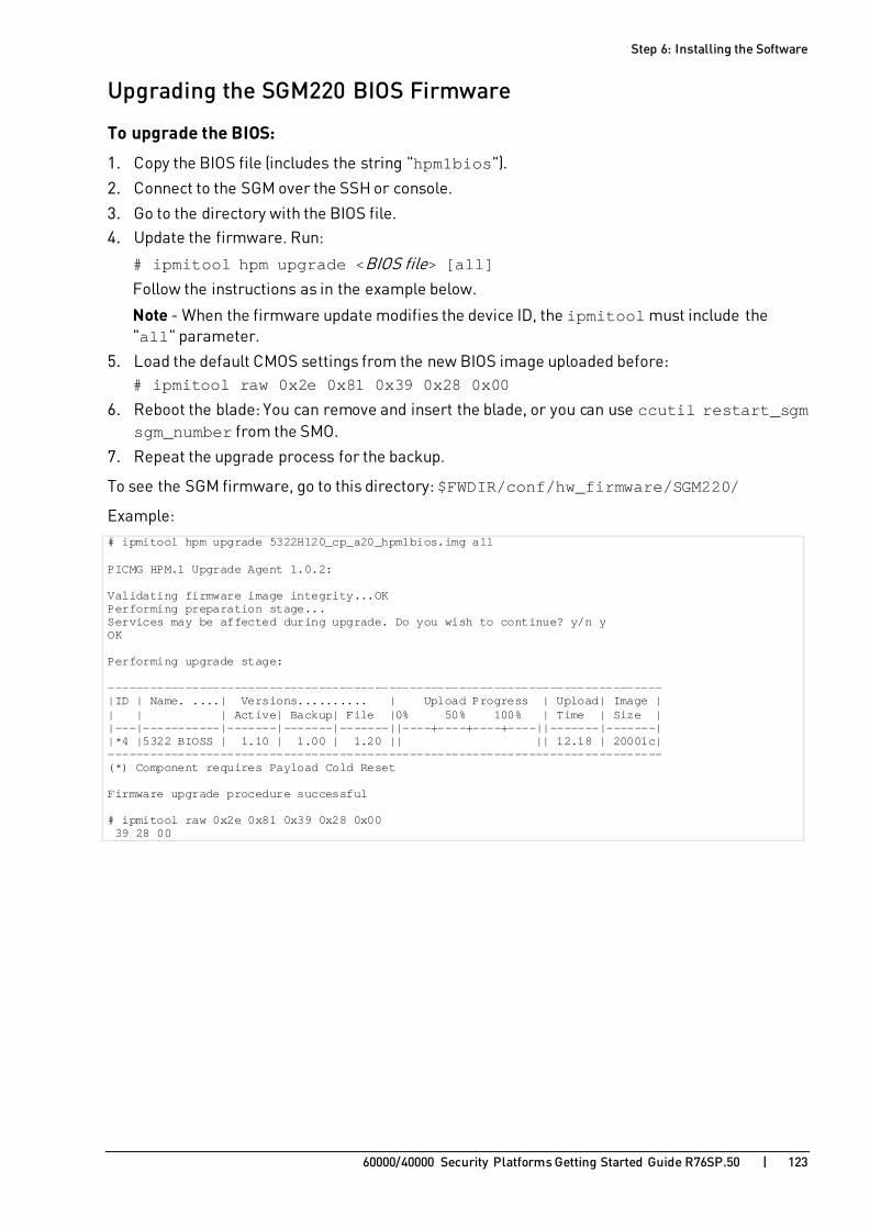
Step 6: Installing the Software
60000/40000 Security Platforms Getting Started Guide R76SP.50 | 123
Upgrading the SGM220 BIOS Firmware
To upgrade the BIOS:
1. Copy the BIOS file (includes the string "hpm1bios").
2. Connect to the SGM over the SSH or console.
3. Go to the directory with the BIOS file. 4. Update the firmware. Run:
# ipmitool hpm upgrade <BIOS file> [all]
Follow the instructions as in the example below.
Note - When the firmware update modifies the device ID, the ipmitool must include the "all" parameter.
5. Load the default CMOS settings from the new BIOS image uploaded before: # ipmitool raw 0x2e 0x81 0x39 0x28 0x00
6. Reboot the blade: You can remove and insert the blade, or you can use ccutil restart_sgm sgm_number from the SMO.
7. Repeat the upgrade process for the backup.
To see the SGM firmware, go to this directory: $FWDIR/conf/hw_firmware/SGM220/
Example: # ipmitool hpm upgrade 5322H120_cp_a20_hpm1bios.img all PICMG HPM.1 Upgrade Agent 1.0.2: Validating firmware image integrity...OK Performing preparation stage... Services may be affected during upgrade. Do you wish to continue? y/n y OK Performing upgrade stage: ------------------------------------------------------------------------------- |ID | Name. ....| Versions.......... | Upload Progress | Upload| Image | | | | Active| Backup| File |0% 50% 100% | Time | Size | |---|-----------|-------|-------|-------||----+----+----+----||-------|-------| |*4 |5322 BIOSS | 1.10 | 1.00 | 1.20 || || 12.18 | 20001c| ------------------------------------------------------------------------------- (*) Component requires Payload Cold Reset Firmware upgrade procedure successful # ipmitool raw 0x2e 0x81 0x39 0x28 0x00 39 28 00

60000/40000 Security Platforms Getting Started Guide R76SP.50 | 124
C H A P T E R 1 5
Step 7: Connecting to the Network 1. Connect the serial cable to the applicable CMM console port on the Control Panel.
For more information, see:
• Control Panel for 64000 and 61000 N+N Security Systems (on page 43) • Control Panel for 44000 Security System (on page 45)
2. Connect the management ports on the Security Switch Modules to your network.
3. Connect the data ports on the Security Switch Modules to your network.
For more information, see the front panel of your appliance (on page 26).

60000/40000 Security Platforms Getting Started Guide R76SP.50 | 125
C H A P T E R 1 6
Step 8: Initial Software Configuration In This Section:
Connecting over Console (Serial) Port..............................................................125
Running the Initial Setup.................................................................................127
When you install and configure the 60000/40000 Security Platform, start with the Security Gateway Module furthest to the left in the Chassis. After the first SGM is configured, installation and configuration settings are automatically propagated to all other SGMs in the defined security group. The Security Group is the group of SGMs that make up the Security Gateway.
Note - In SmartDashboard, one Security Gateway object represents all the SGMs in the security group.
Connecting over Console (Serial) Port Connecting a Console
1. Connect the DB9 serial cable to the console (serial) port on the far, left-hand SGM in the chassis. See:
• 64000 Security System Front Panel (on page 27)
• 44000 Security System Front Panel (on page 31)
• 61000 N+N Security System Front Panel (on page 34) • 61000 Security System Front Panel (on page 37)
• 41000 Security System Front Panel (on page 40)
Example:

Step 8: Initial Software Configuration
60000/40000 Security Platforms Getting Started Guide R76SP.50 | 126
2. Connect the other end of the cable to the serial port on your computer. 3. Define the communication parameters in your terminal emulation application (for example,
PuTTY):
• Serial port - 9600 BPS, 8 bits, no parity, 1 stop bit
• Flow control - None 4. Turn on the 60000/40000 Security Platform.
5. Log in with these credentials:
• username = admin
• password = admin

Step 8: Initial Software Configuration
60000/40000 Security Platforms Getting Started Guide R76SP.50 | 127
Running the Initial Setup 1. To start the installation wizard run:
# setup
2. In the Welcome screen, press any key.
3. Select Set SGMs for Security Group. 4. Define the SGMs that belong to the Security Group.
There are two lines, one for Chassis 1, one for chassis 2. In each line, you can enter:
• all (same as 1-12)
• A range, such as: 1-9
• A number of comma-separated ranges, such as: 1-3,5-7
• Single SGMs, such as: 1,4
• A combination of single SGMs and ranges, such as: 10,2, 3-7.
By default, the SGM you are connected belongs to the group: Chassis 1, SGM 1 (slot 1 in chassis 1). To define a fully populated dual chassis system, select all in the top and bottom lines. For more about Security Gateway Module numbering, see the front panel of your appliance (on page 26).
5. The subnet for internal communication in the chassis is 192.0.2.0/24 by default. Change the IP address, if it conflicts with an existing subnet on your network.
6. Configure parameters for:
• Host Name
• Time and Date.
To configure the local time, choose the geographical area and city.
7. Select Network Connections.
Configure the management ports and the data ports of the Security Switch Module.
• There are 4 management ports on each SSM. Only configure those ports you intend to use. To associate port names with the physical ports, refer to Security Switch Module Ports (on page 47). For each management port configure:
An IP address
The net mask length • To associate data port names with the physical ports, refer to Security Switch Module Ports
(on page 47). For each data port configure:
An IP address
The net mask length

Step 8: Initial Software Configuration
60000/40000 Security Platforms Getting Started Guide R76SP.50 | 128
8. Configure Routing. Note - Wait 10-20 seconds for routing information to be updated throughout the system.
9. The Welcome to Check Point Suite screen shows. Wait for Check Point products packages to install.
10. Wait for the: • Installation Program Completed Successfully message to show
• Check Point Configuration Program to start.
This program guides you through the configuration of Check Point products.
11. Configure Secure Internal Communication.
When prompted, enter and confirm the activation key. Remember this activation key. The same activation key is used for configuring the 60000/40000 Security Platform object in SmartDashboard.
Configuration settings are applied, and the SGM reboots. The other Security Gateway Modules in the security group install automatically.
System Validation
To make sure that the initial system setup completed successfully:
• Run: # asg monitor
An Initial Policy must be installed on the local SGM after initial setup completes and the SGM reboots.
• To monitor the automatic installation of other SGMs, run:
# tail -f /var/log/start_mbs.log
• After installation, all the SGMs in the security group must be in the Initial Policy state.

60000/40000 Security Platforms Getting Started Guide R76SP.50 | 129
C H A P T E R 1 7
Step 9: SmartDashboard Configuration In This Section:
Defining a Security Gateway ............................................................................129
Configuring a VSX Gateway..............................................................................131
The 60000/40000 Security Platform can work as a Security Gateway, or as a VSX Gateway. The Security Management Server must be R76 or higher.
Important - R76 GA SmartDashboard is not supported. You must download and install the updated R76 SmartDashboard as instructed. See sk98423 http://supportcontent.checkpoint.com/solutions?id=sk98423.
Do one of these procedures:
• Configuring a Security Gateway (on page 129).
• Configuring a VSX Gateway (on page 131).
Defining a Security Gateway Note - There can be some variations in the Creation Wizard steps due to release updates. In these cases, follow the instructions on the screen.
To configure a Security Gateway:
1. Open SmartDashboard.
2. When prompted, enter your credentials to connect for the Security Management Server. 3. Create a Security Gateway object.
In the Network Objects tree, right click Check Point and then select New > Check Point > Security Gateway/Management The Check Point Security Gateway Creation wizard opens.
4. Select Wizard Mode or Classic Mode.
This procedure uses the Wizard mode. If you choose Classic Mode, make sure you set all the necessary configuration parameters.
5. In the General Properties screen, configure: • Gateway name
• Gateway platform (your Chassis type)
• Gateway IP address
6. Click Next. 7. In the Secure Internal Communication Initialization screen, enter the One-time password.
This is the same as the Activation Key you entered during the initial setup procedure.
8. Click Next. 9. View the Configuration Summary.
10. Select Edit Gateway properties for further configuration.

Step 9: SmartDashboard Configuration
60000/40000 Security Platforms Getting Started Guide R76SP.50 | 130
11. Click Finish. The General Properties page of the 60000/40000 Security Platform object opens.
12. In the General Properties page, make sure the Version is correct.
13. Enable the Firewall Software Blade. Enable other supported Software Blades as necessary.
14. In the navigation tree, select Topology. 15. Configure:
• Topology of Interfaces as Internal or External.
• Anti-Spoofing.
Note - Only data and management interfaces show in the list.
16. Click OK.
17. Install the Security Policy.
Confirming the Security Gateway Software Configuration
To make sure that the policy was successfully installed:
1. Connect to the appliance with SSH or a serial console.
2. Run: # asg monitor
3. Make sure that the SGM status is Enforcing Security on the ACTIVE and STANDBY Chassis.
4. Make sure the Policy Date matches the date and time the policy was installed.
To verify the configuration:
After configuring the Security Gateway and installing the policy, validate the configuration using the asg diag command (on page 146). Use the command to collect and show diagnostic information about the system.
If there is a problem, fix it before using the system.

Step 9: SmartDashboard Configuration
60000/40000 Security Platforms Getting Started Guide R76SP.50 | 131
Configuring a VSX Gateway The 60000/40000 Security Platform can work as a Security Gateway, or as a VSX Gateway.
This procedure shows how to configure a VSX Gateway in SmartDashboard.
Important - While running VSX Gateway Wizard, only one SGM (SMO) should be defined in the Security Group.
Before creating the VSX Gateway
It is important to know how VSX works, and understand the VSX architecture and concepts. It is also important to understand how to deploy and configure your security environment using VSX Virtual Devices:
• Virtual System
• Virtual System in Bridge Mode
• Virtual Switch
To learn about how VSX works, architecture, concepts and Virtual Devices, see the R76 VSX Administration Guide https://sc1.checkpoint.com/documents/R76/CP_R76_VSX_AdminGuide/html_frameset.htm.
The VSX Gateway Wizard
The VSX Gateway in this example has one Virtual System (VS0) and one dedicated management interface.
After you complete the VSX Gateway Wizard, you can change the VSX Gateway definition from SmartDashboard. For example, you can add Virtual Systems, add or delete interfaces, or configure existing interfaces to support VLANs.
Notes:
1. Do not enable IPv6 before you create and configure a new VSX Gateway. This can cause system instability. You must first create the new VSX Gateway and then enable and configure IPv6 using gclish.
2. There can be some variations in the Creation Wizard steps due to release updates. In these cases, do the instructions on the screen.

Step 9: SmartDashboard Configuration
60000/40000 Security Platforms Getting Started Guide R76SP.50 | 132
To start the VSX Gateway wizard:
1. Open SmartDashboard.
If you are using Multi-Domain Security Management, open SmartDashboard from the Domain Management Server of the VSX Gateway.
2. From the Network Objects tree, right-click Check Point and select VSX > Gateway.
The General Properties page of the VSX Gateway Wizard opens.
Wizard Step 1: Defining VSX Gateway General Properties Configure these parameters on the General Properties page:
• VSX Gateway Name: Unique, alphanumeric name for the VSX Gateway. The name cannot contain spaces or special characters except the underscore.
• VSX Gateway IPv4 Address: Management interface IPv4 address.
• VSX Gateway IPv6 Address: Management interface IPv6 address.
• VSX Gateway Version: Select the VSX version installed on the VSX Gateway from the drop-down list.
Wizard Step 2: Selecting Virtual Systems Creation Templates The Creation Templates page lets you configure predefined, default topology and routing definitions for Virtual Systems. This makes sure that Virtual Systems are consistent and makes the definition process faster. You always have the option to override the default creation template when you create or change a Virtual System.
The Creation Templates are:
• Shared Interface - Not supported for the 60000/40000 Security Platform.
• Separate Interfaces: Virtual Systems use their own separate internal and external interfaces. This template creates a Dedicated Management Interface (DMI) by default.
• Custom Configuration: Define Virtual System, Virtual Switch, and Interface configurations.
For this example, choose Custom configuration.
Wizard Step 3: Establishing SIC Trust Initialize SIC trust between the VSX Gateway and the Management Server. They cannot communicate without Trust.
Initializing SIC Trust When you create a VSX Gateway, you must enter the Activation Key that you defined in the installation wizard setup program (on page 127). Enter and confirm the activation key and then click Initialize. If you enter the correct activation key, the Trust State changes to Trust established.
For more about SIC trust, see the R76 VSX Administration Guide https://sc1.checkpoint.com/documents/R76/CP_R76_VSX_AdminGuide/html_frameset.htm.

Step 9: SmartDashboard Configuration
60000/40000 Security Platforms Getting Started Guide R76SP.50 | 133
Wizard Step 4: Defining Physical Interfaces In the VSX Gateway Interfaces window, define physical interfaces as VLAN trunks. The window shows the interfaces currently defined on the VSX Gateway.
To define an interface as a VLAN trunk, select VLAN Trunk for the interface.
Virtual Network Device Configuration Note - If you chose Shared Interface or Separate Interface, proceed to Wizard Step 5 (on page 133).
If you chose the Custom Configuration option, the Virtual Network Device Configuration window opens. In this window, define a Virtual Device with an interface shared with the VSX Gateway. If you do not want to define a Virtual Device at this time, click Next to continue.
To define a Virtual Device with a shared interface:
1. Select Create a Virtual Device.
2. Select the Virtual Network Device type (Virtual Router or Virtual Switch). 3. Select the shared physical interface to define a non-DMI gateway.
Do not select the management interface if you want to define a Dedicated Management Interface (DMI) gateway. If you do not define a shared Virtual Device, a DMI gateway is created by default.
Important - This setting cannot be changed after you complete the VSX Gateway Wizard. If you define a non-DMI gateway, you cannot change it to a DMI gateway later.
4. Define the IP address and Net Mask for a Virtual Router. These options are not available for a Virtual Switch.
5. Optional: Define a Default Gateway for a Virtual Router (DMI only).
Wizard Step 5: VSX Gateway Management In the VSX Gateway Management window, define security policy rules that protect the VSX Gateway. This policy is installed automatically on the new VSX Gateway.
Note - This policy applies only to traffic destined for the VSX Gateway. Traffic destined for Virtual Systems, other Virtual Devices, external networks, and internal networks is not affected by this policy.
The security policy consists of predefined rules for these services:
• UDP - SNMP requests
• TCP - SSH traffic
• ICMP - Echo-request (ping)
• TCP - HTTPS traffic

Step 9: SmartDashboard Configuration
60000/40000 Security Platforms Getting Started Guide R76SP.50 | 134
To modify the Gateway Security Policy:
1. Allow: Select to pass traffic on the selected services. Clear this option to block traffic on this service. By default, all services are blocked. For example, to be able to ping the gateway from the management server, allow ICMP echo-request traffic.
2. Source: Click the arrow and select a Source Object from the list.
The default value is *Any. Click New Source Object to define a new source. You can modify the security policy rules that protect the VSX Gateway later.
3. Click Next.
Wizard Step 6: Completing the VSX Wizard Click Next to continue and then click Finish to complete the VSX Gateway wizard.
This may take several minutes to complete. A message shows successful or unsuccessful completion of the process.
If the process ends unsuccessfully, click View Report to see the error messages. See Troubleshooting (on page 167).
Confirming the VSX Gateway Software Configuration
To make sure that the policy was successfully installed:
1. Connect to the appliance with an SSH client or the serial console.
2. Run: # asg monitor -vs all
3. Make sure that the status for SGMs is Enforcing Security on the Active and Standby Chassis, for all Virtual Systems.
This example shows the output for a dual Chassis VSX Gateway. Chassis 1 (Active) has 1 SGM in its Security Group. -------------------------------------------------------------------------------- | Chassis 1 ACTIVE | -------------------------------------------------------------------------------- | SGM | 1 (local) | - | - | -------------------------------------------------------------------------------- | State | UP | - | - | -------------------------------------------------------------------------------- | VS ID | -------------------------------------------------------------------------------- | 0 | Enforcing Security | - | - | --------------------------------------------------------------------------------
4. You can now add more SGMs to the Security Group. Run: # asg security_group
5. After all SGMs are UP and enforcing Security, you can add Virtual Systems to the VSX Gateway.

60000/40000 Security Platforms Getting Started Guide R76SP.50 | 135
C H A P T E R 1 8
Licensing and Registration 60000/40000 Security Platforms have an initial 15-day evaluation license. After the evaluation license expires, you must license and register the system.
Each chassis is licensed separately. If you have dual chassis system, you must install two licenses.
The license key (CK) is the chassis serial number. The chassis serial number is printed on the chassis sticker. You can also retrieve the chassis serial number from the CMM.
To retrieve the serial number from the CMM:
1. Connect to one of the SGMs on the chassis over SSH or console.
2. Get the IP address of the CMM by running (from gClish): gaia> show chassis id all module CMM1 ip
3. Using the IP address, open an SSH connection to the CMM:
# ssh <IP Address of CMM>
Log in with these credentials:
• Username: admin
• Password: admin
4. On the CMM, run: # clia fruinfo 20 254
5. The output shows the Chassis Serial Number.
To register the 60000/40000 Security Platform
1. Log in to the User Center https://usercenter.checkpoint.com.
2. In the applicable account, search for the chassis serial number.
3. Generate a license based on the IP address of the SSM interface connected to your Security Management Server. Note - Because the 60000/40000 Security Platform has a single Management IP address, in dual chassis environments, the Active and Standby chassis should be bound to the same IP address in the license. Generate two licenses and enter the same IP address in each license.
4. Install the license on the system.
• If you use the cplic put command, run it from gClish, so that it applies to all SGMs.
• Run the cplic put command twice, if you have a dual chassis environment.

60000/40000 Security Platforms Getting Started Guide R76SP.50 | 136
C H A P T E R 1 9
Basic Configuration Using gClish Use the gClish shell for basic system configuration.
For more information, see the R76 Gaia Administration Guide https://sc1.checkpoint.com/documents/R76/CP_R76_Gaia_WebAdmin/html_frameset.htm.
To Run Applicable Mode
Virtual Context
Move to a different virtual context
# set virtual-system <VSID> VSX Gateway
Physical Interfaces
Set an IPv4 address on an interface
# set interface eth1-01 ipv4-address 192.0.20.10 mask-length 24
Security Gateway
Show the IPv4 interface address
# show interface eth1-01 ipv4-address
Security Gateway,
VSX Gateway
Delete the IPv4 address from an interface
# delete interface eth1-01 ipv4-address
Security Gateway
Hostname
Set the hostname # set hostname <Security System Name>
Each SGM gets its local identity as suffix. For example: gcp-X1000-ch01-04
Security Gateway,
VSX Gateway
Show the hostname # show hostname Security Gateway,
VSX Gateway
Routes
Set a default route # set static-route default nexthop gateway address 192.0.20.1 on
Security Gateway
Show the route table # show route Security Gateway,
VSX Gateway

Basic Configuration Using gClish
60000/40000 Security Platforms Getting Started Guide R76SP.50 | 137
To Run Applicable Mode Bond Interfaces
Create a bond and assign an interface to it
# add bonding group 1000 interface eth2-03
Security Gateway,
VSX Gateway
Show existing bonds # show bonding groups Security Gateway,
VSX Gateway
VLAN Interfaces
Add a VLAN interface # add interface eth2-02 vlan 1023 Security Gateway
Show a VLAN interface # show interface eth2-02 vlans Security Gateway, VSX Gateway
Gaia Image Management (Snapshots)
Add a snapshot # add snapshot <snapshot name> desc <description>
Security Gateway,
VSX Gateway
Revert to a snapshot # set snapshot revert <snapshot name>
Security Gateway,
VSX Gateway
Show snapshots and monitor snapshot progress
# show snapshots Security Gateway

60000/40000 Security Platforms Getting Started Guide R76SP.50 | 138
C H A P T E R 2 0
Monitoring and Configuration In This Section:
Showing Chassis and Component States (asg stat) ...........................................138
Monitoring Chassis and Component Status (asg monitor)..................................144
Collecting System Diagnostics (smo verifiers) ..................................................146
Monitoring Performance (asg perf) ..................................................................153
Monitoring Service Traffic (asg profile).............................................................155
Monitoring Hardware Components (asg hw_monitor) .......................................157
Monitoring SGM Resources (asg resource) .......................................................161
Searching for a Connection (asg search) ..........................................................163
Configuring Alerts for SGM and Chassis Events (asg alert) ................................164
Monitoring the System with SNMP...................................................................165
This section lists the most important gClish commands that you can use to monitor and configure the 60000/40000 Security Platform.
Showing Chassis and Component States (asg stat) Description
Use this command to show the Chassis and hardware component state for single and Dual-Chassis configurations. The command shows system:
• Uptime • Chassis Mode
• Number of Virtual Systems
• System Version
Use the Verbose Mode to show SGM state, process and policy.
Syntax
> asg stat [-v] [-vs <VS_IDs>] [-l]
Note - If you run this command in a VSX context, the output is for the applicable Virtual System.
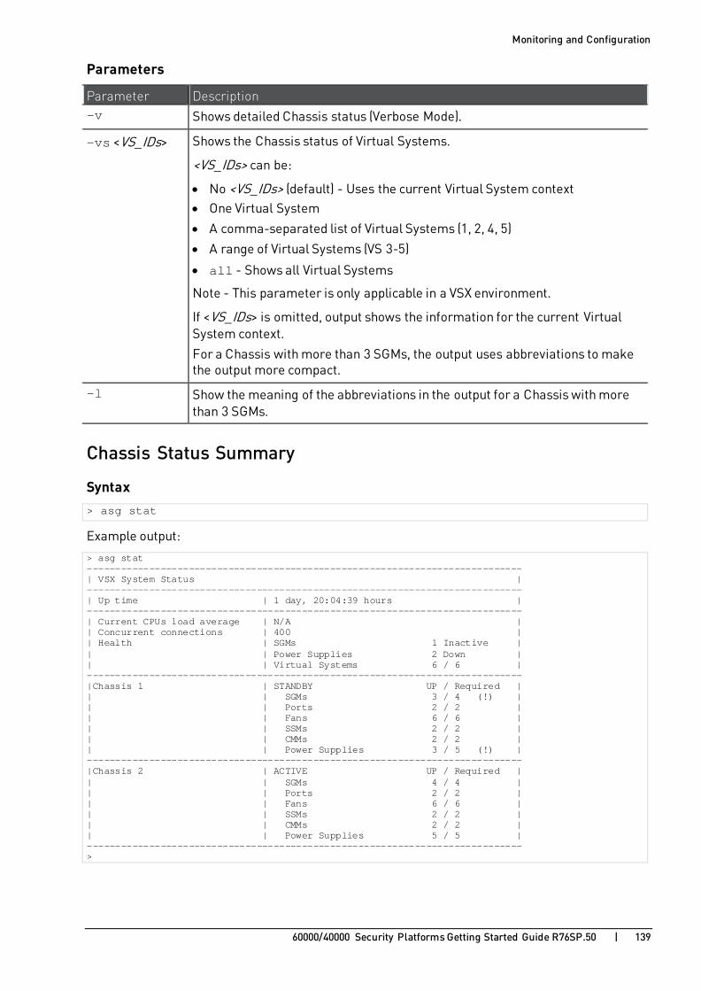
Monitoring and Configuration
60000/40000 Security Platforms Getting Started Guide R76SP.50 | 139
Parameters
Parameter Description -v Shows detailed Chassis status (Verbose Mode).
-vs <VS_IDs> Shows the Chassis status of Virtual Systems.
<VS_IDs> can be:
• No <VS_IDs> (default) - Uses the current Virtual System context • One Virtual System
• A comma-separated list of Virtual Systems (1, 2, 4, 5)
• A range of Virtual Systems (VS 3-5)
• all - Shows all Virtual Systems
Note - This parameter is only applicable in a VSX environment.
If <VS_IDs> is omitted, output shows the information for the current Virtual System context.
For a Chassis with more than 3 SGMs, the output uses abbreviations to make the output more compact.
-l Show the meaning of the abbreviations in the output for a Chassis with more than 3 SGMs.
Chassis Status Summary
Syntax
> asg stat
Example output:
> asg stat ----------------------------------------------------------------------------- | VSX System Status | ----------------------------------------------------------------------------- | Up time | 1 day, 20:04:39 hours | ----------------------------------------------------------------------------- | Current CPUs load average | N/A | | Concurrent connections | 400 | | Health | SGMs 1 Inactive | | | Power Supplies 2 Down | | | Virtual Systems 6 / 6 | ----------------------------------------------------------------------------- |Chassis 1 | STANDBY UP / Required | | | SGMs 3 / 4 (!) | | | Ports 2 / 2 | | | Fans 6 / 6 | | | SSMs 2 / 2 | | | CMMs 2 / 2 | | | Power Supplies 3 / 5 (!) | ----------------------------------------------------------------------------- |Chassis 2 | ACTIVE UP / Required | | | SGMs 4 / 4 | | | Ports 2 / 2 | | | Fans 6 / 6 | | | SSMs 2 / 2 | | | CMMs 2 / 2 | | | Power Supplies 5 / 5 | ----------------------------------------------------------------------------- >
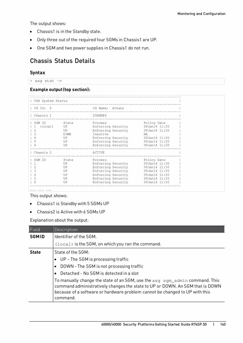
Monitoring and Configuration
60000/40000 Security Platforms Getting Started Guide R76SP.50 | 140
The output shows:
• Chassis1 is in the Standby state.
• Only three out of the required four SGMs in Chassis1 are UP.
• One SGM and two power supplies in Chassis1 do not run.
Chassis Status Details
Syntax
> asg stat -v
Example output (top section): ----------------------------------------------------------------------------- | VSX System Status | ----------------------------------------------------------------------------- | VS ID: 0 VS Name: Athens | ----------------------------------------------------------------------------- | Chassis 1 STANDBY | ----------------------------------------------------------------------------- | SGM ID State Process Policy Date | | 1 (local) UP Enforcing Security 09Jan14 11:30 | | 2 UP Enforcing Security 09Jan14 11:30 | | 3 DOWN Inactive NA | | 4 UP Enforcing Security 09Jan14 11:30 | | 5 UP Enforcing Security 09Jan14 11:30 | | 6 UP Enforcing Security 09Jan14 11:30 | ----------------------------------------------------------------------------- | Chassis 2 ACTIVE | ----------------------------------------------------------------------------- | SGM ID State Process Policy Date | | 1 UP Enforcing Security 09Jan14 11:30 | | 2 UP Enforcing Security 09Jan14 11:30 | | 3 UP Enforcing Security 09Jan14 11:30 | | 4 UP Enforcing Security 09Jan14 11:30 | | 5 UP Enforcing Security 09Jan14 11:30 | | 6 UP Enforcing Security 09Jan14 11:30 | ----------------------------------------------------------------------------- ... ... ...
This output shows:
• Chassis1 is Standby with 5 SGMs UP
• Chassis2 is Active with 6 SGMs UP
Explanation about the output:
Field Description
SGM ID Identifier of the SGM.
(local) is the SGM, on which you ran the command.
State State of the SGM:
• UP - The SGM is processing traffic
• DOWN - The SGM is not processing traffic
• Detached - No SGM is detected in a slot
To manually change the state of an SGM, use the asg sgm_admin command. This command administratively changes the state to UP or DOWN. An SGM that is DOWN because of a software or hardware problem cannot be changed to UP with this command.

Monitoring and Configuration
60000/40000 Security Platforms Getting Started Guide R76SP.50 | 141
Field Description
Process Status of the SGM security enforcement:
• Enforcing Security - UP and works properly • Inactive - DOWN and is experiencing a problem. It is not handling traffic.
• Initial policy - The SGM is UP but the policy is not installed on the SGM.
Example output (bottom section): ... ... ... -------------------------------------------------------------------------------- | Chassis Parameters | -------------------------------------------------------------------------------- | Unit Chassis 1 Chassis 2 Unit Weight | | | | SGMs 5 / 6 (!) 6 / 6 (!) 6 | | Ports | | Standard 0 / 0 0 / 0 11 | | Bond 2 / 2 2 / 2 11 | Other 0 / 0 0 / 0 6 | | Sensors | | Fans 9 / 9 9 / 9 5 | | SSMs 2 / 2 2 / 2 11 | | CMMs 2 / 2 2 / 2 6 | | Power Supplies 4 / 4 3 / 3 6 | | | | Chassis Grade 133 / 139 139 / 139 - | -------------------------------------------------------------------------------- | Minimum grade gap for chassis failover: 11 | | Synchronization | | Within chassis: Enabled (Default) | | Between chassis: Enabled (Default) | | Exception Rules: (Default) | --------------------------------------------------------------------------------
Note - The X/X notation shows the number of components that are UP and the components must be UP. For example, on the SGMs line, 6/6 means that 6 SGMs are UP and 6 must be UP.
Field Description
Chassis Grade The sum of the grades of all components. In a Dual-Chassis deployment, the Chassis with a higher grade (by at least the Minimum grade gap) becomes ACTIVE. The grade of each component is the unit weight multiplied by the number of components that are UP.
You can configure the unit weight of each component to show the importance of the component in the system. To configure the unit weight run:
> set chassis high-availability factors <sensor_name>
For example, to change the weight of the SGM to 12, run: > set chassis high-availability factors sgm 12
If you run asg stat -v, the output shows a higher unit weight and Chassis grade
Minimum grade gap for chassis failover
Chassis failover occurs to the Chassis with the higher grade only if its grade is greater than the other Chassis by more than the minimum gap.
Minimum threshold for traffic processing - The minimum grade required for the Chassis to become Active.

Monitoring and Configuration
60000/40000 Security Platforms Getting Started Guide R76SP.50 | 142
Field Description
Synchronization Status of synchronization:
• Within chassis - Between SGMs located in the same Chassis • Between chassis - Between SGMs located in different Chassis
• Exception Rules - User configured exception rules. To configure, run: g_sync_exception
Compact Output for Selected Virtual Systems
Syntax > asg stat -v -vs <VSID1>,<VSID2>,<VSID3>,...,<VSIDn>
Example output: > asg stat -v -vs 0,1,2 ------------------------------------------------------------------------------ | Chassis 1 STANDBY | ------------------------------------------------------------------------------ |SGM |1 |2 |3 |4 | - | - | - | - | - | - | - | -| ------------------------------------------------------------------------------ |State | UP | UP |DOWN | UP | - | - | - | - | - | - | - | -| ------------------------------------------------------------------------------ | VS ID | ------------------------------------------------------------------------------ | 0 | ES | ES | ES | ES | - | - | - | - | - | - | - | -| ------------------------------------------------------------------------------ | 1 | ES | ES | ES | ES | - | - | - | - | - | - | - | -| ------------------------------------------------------------------------------ | 2 | ES | ES | ES | ES | - | - | - | - | - | - | - | -| ------------------------------------------------------------------------------ | Chassis 2 ACTIVE | ------------------------------------------------------------------------------ |SGM |1 (l)|2 |3 |4 | - | - | - | - | - | - | - | -| ------------------------------------------------------------------------------ |State | UP | UP | UP | UP | - | - | - | - | - | - | - | -| ------------------------------------------------------------------------------ | VS ID | ------------------------------------------------------------------------------ | 0 | ES | ES | ES | ES | - | - | - | - | - | - | - | -| ------------------------------------------------------------------------------ | 1 | ES | ES | ES | ES | - | - | - | - | - | - | - | -| ------------------------------------------------------------------------------ | 2 | ES | ES | ES | ES | - | - | - | - | - | - | - | -| ------------------------------------------------------------------------------ | Chassis Parameters ------------------------------------------------------------------------------ | Unit Chassis 1 Chassis 2 Unit Weight | | | | SGMs 3 / 4 (!) 4 / 4 6 | | Ports | | Standard 0 / 0 0 / 0 50 | | Other 0 / 0 0 / 0 6 | | Sensors | | Fans 6 / 6 6 / 6 5 | | SSMs 2 / 2 2 / 2 11 | | CMMs 2 / 2 2 / 2 6 | | Power Supplies 6 / 6 6 / 6 6 | | | | Chassis Grade 118 / 124 124 / 124 - | ------------------------------------------------------------------------------ | Minimum grade gap for chassis failover: 11 | | Synchronization | | Within chassis: Enabled (Default) | | Between chassis: Enabled (Default) | | Exception Rules: (Default) | | Distribution | | Control Blade: Disabled (Default) | | Chassis HA mode: Active Up | ------------------------------------------------------------------------------

Monitoring and Configuration
60000/40000 Security Platforms Getting Started Guide R76SP.50 | 143
Output State Acronyms To see a list of the acronyms that show in the reports, run:
> asg stat -l
Example output: > asg stat -l Legend: SGM States: ACT - ACTIVE DTC - DETACHED DWN - DOWN NSG - NOT IN SECURITY GROUP VS States: ES - Enforcing Security FSC - FullSync Client FSS - FullSync Server IAC - Inactive IF - Iteration Finished IPO - Initial Policy IS - Iteration Started NPO - No Policy PC - Policy Completed PRF - Policy Ready2Finish PS - Policy Started >

Monitoring and Configuration
60000/40000 Security Platforms Getting Started Guide R76SP.50 | 144
Monitoring Chassis and Component Status (asg monitor)
Description
Use the asg monitor command to continuously monitor Chassis and component status.
This command shows the same information as asg stat, but the information stays on the screen and refreshes at user-specified intervals (default = 1 second). To stop the monitor session, press CTRL-C.
Note - If you run this command in a Virtual System context, you only see the output for that Virtual System. You can also specify the Virtual System as a command parameter.
Syntax
> asg monitor -h
> asg monitor
> asg monitor [-v|-all] [-amw] [-vs <VS_IDs>] <Interval>
> asg monitor -l
Parameters
Parameter Description
No Parameters Shows the SGM status.
-h Shows the command syntax and help information.
-amw Shows the Anti-Malware policy date instead of the Firewall policy date.
-v Shows only Chassis component status.
-all Shows both SGM and Chassis component status.
<Interval> Sets the data refresh interval (in seconds) for this session.
-vs <VS_IDs> Shows the component status for one or more Virtual Systems.
<VS_IDs> can be:
• No <VS_IDs> (default) - Uses the current Virtual System context
• One Virtual System
• A comma-separated list of Virtual Systems (1, 2, 4, 5) • A range of Virtual Systems (VS 3-5)
• all - Shows all Virtual Systems
Note - This parameter is only applicable in a VSX environment.
If <VS_IDs> is omitted, output shows the information for the current Virtual System context.
For a Chassis with more than 3 SGMs, the output has abbreviations to make the output more compact
-l Shows legend of column title abbreviations

Monitoring and Configuration
60000/40000 Security Platforms Getting Started Guide R76SP.50 | 145
Example 1- Shows the SGM status with the Anti-Malware policy date: > asg monitor -amw --------------------------------------------------------------------------- | Chassis 1 ACTIVE | --------------------------------------------------------------------------- | SGM ID State Process AMW Policy Date | | 1 UP Enforcing Security 10Feb14 19:56 | | 2 (local) UP Enforcing Security 10Feb14 19:56 | | 3 UP Enforcing Security 10Feb14 19:56 | | 4 UP Enforcing Security 10Feb14 19:56 | --------------------------------------------------------------------------- | Chassis 2 STANDBY | --------------------------------------------------------------------------- | SGM ID State Process AMW Policy Date | | 1 UP Enforcing Security 10Feb14 19:56 | | 2 UP Enforcing Security 10Feb14 19:56 | | 3 UP Enforcing Security 10Feb14 19:56 | | 4 UP Enforcing Security 10Feb14 19:56 | --------------------------------------------------------------------------- | Chassis HA mode: Active Up | --------------------------------------------------------------------------- >
Example 2 - Shows the Chassis component status: > asg monitor -v ----------------------------------------------------------------------------- | Chassis Parameters | ----------------------------------------------------------------------------- | Unit Chassis 1 Chassis 2 Unit Weight | | | | SGMs 4 / 4 3 / 4 (!) 6 | | Ports | | Standard 2 / 2 2 / 2 11 | | Bond 2 / 2 2 / 2 11 | | Mgmt 1 / 1 1 / 1 11 | | Other 0 / 0 0 / 0 6 | | Sensors | | Fans 4 / 6 (!) 6 / 6 5 | | SSMs 2 / 2 2 / 2 11 | | CMMs 2 / 2 2 / 2 6 | | Power Supplies 3 / 5 (!) 3 / 5 (!) 6 | | | | Chassis Grade 157 / 173 155 / 173 - | ----------------------------------------------------------------------------- | Minimum grade gap for chassis failover: 200 | | Synchronization | | Within chassis: Enabled (Default) | | Between chassis: Enabled (Default) | | Exception Rules: (Default) | ----------------------------------------------------------------------------- | Chassis HA mode: Primary Up (Chassis 1) | ----------------------------------------------------------------------------- >
Example 3 - Shows the status of the SGMs and Virtual System 3: > asg monitor –vs 3 -------------------------------------------------------------------------------- | Chassis 1 ACTIVE | -------------------------------------------------------------------------------- |SGM |1 (l)|2 |3 |4 | - | - | - | - | - | - | - | - | -------------------------------------------------------------------------------- |State | UP | UP | UP | DWN | - | - | - | - | - | - | - | - | -------------------------------------------------------------------------------- | VS ID | -------------------------------------------------------------------------------- | 3 | ES | ES | ES | IAC | - | - | - | - | - | - | - | - | -------------------------------------------------------------------------------- >

Monitoring and Configuration
60000/40000 Security Platforms Getting Started Guide R76SP.50 | 146
Collecting System Diagnostics (smo verifiers) Description
The smo verifiers commands in gClish run a specific set of diagnostic tests.
The full set of tests run by default. but you can manually select the tests you want to run.
The output shows the result of the test, Passed or Failed, and the location of the output log file.
Syntax > show smo verifiers list [id <TestId1>,<TestId2>,...] [section <SectionName>] > show smo verifiers report [except] [id <TestId1>,<TestId2>,...] [name <TestName>] [section <SectionName>] > show smo verifiers print [except] [id <TestId1>,<TestId2>,...] [name <TestName>] [section <SectionName>] > show smo verifiers periodic last-run report print > delete smo verifiers purge [save <Num_Logs>]
Parameters
Parameter Description list Shows the list of tests to run.
report Runs tests and shows a summary of the test results.
print Runs tests and shows the full output and summary of the test results.
except Runs all tests except the specified tests.
Shows the requested results.
id <TestId1>,<TestId2>,... Specifies the tests by their IDs (comma separated list). To see a list of test IDs, run: > show smo verifiers list
name <TestName> Specifies the tests by their names. Press the Tab key to see a full list of verifiers names.
section <SectionName> Specifies the verifiers section by its name.
Press the Tab key to see a full list of the existing sections.
purge Deletes the old smo verifiers logs. Keeps the newest log.
save <Num_Logs> Number of logs to save from the smo verifiers log files.
Default = 5.

Monitoring and Configuration
60000/40000 Security Platforms Getting Started Guide R76SP.50 | 147
Parameter Description periodic Shows the latest periodic run results.
last-run Shows the latest run results.
Running all Diagnostic Tests
Syntax > show smo verifiers report
This example output shows the summary output for all diagnostic tests.
When a test fails, the reasons for failure show in the Reason column. > show smo verifiers report Duration of the tests can vary and can take a few minutes to complete. --------------------------------------------------------------------------------- | Tests Status | --------------------------------------------------------------------------------- | ID | Title | Result | Reason | --------------------------------------------------------------------------------- | System Components | --------------------------------------------------------------------------------- | 1 | System Health | Failed (!) | (1)Chassis 2 error | | 2 | Hardware | Failed (!) | (1)Power unit is missing | | | | | (2)Power consumption exceeds threshold | | 3 | Resources | Failed (!) | (1)Memory capacity | | | | | (2)Memory capacity mismatch | | 4 | Software Versions | Failed (!) | | | 5 | Software Provision | Passed | | | 6 | CPU Type | Failed (!) | (1)Non-compliant CPU type | | 7 | Media Details | Failed (!) | (1)SSM 1 on chassis 2 | | 8 | Chassis ID | Passed | | --------------------------------------------------------------------------------- | Policy and Configuration | --------------------------------------------------------------------------------- | 9 | Distribution Mode | Passed | | | 10 | DXL Balance | Passed | | | 11 | Policy | Passed | | | 12 | AMW Policy | Passed | | | 13 | SWB Updates | Passed | | | 16 | Security Group | Failed (!) | (1)DB error | | 17 | SPI Affinity | Passed | (1)Not configured | | 18 | Clock | Passed | | | 19 | Licenses | Passed | (1)Trial license installed | | 20 | Hide NAT range | Passed | (1)Not configured | | 21 | LTE | Passed | (1)Not configured | | 22 | IPS Enhancement | Passed | (1)Not configured | | 23 | Configuration File | Passed | | --------------------------------------------------------------------------------- | Networking | --------------------------------------------------------------------------------- | 24 | MAC Setting | Passed | | | 25 | ARP Consistency | Passed | | | 26 | Interfaces | Failed (!) | (1)RX drop | | 27 | Bond | Passed | (1)Not configured | | 28 | Bridge | Passed | (1)Not configured | | 29 | IPv4 Route | Passed | | | 30 | IPv6 Route | Passed | (1)Not configured | | 31 | OS Route Cache | Passed | | | 32 | Dynamic Routing | Passed | (1)Not configured | | 33 | Local ARP | Passed | (1)Not configured | | 34 | Port Speed | Passed | | | 35 | SSM QoS | Passed | | | 36 | IGMP Consistency | Passed | (1)Not configured | | 37 | PIM Neighbors | Passed | (1)Not configured | | 38 | ACL Filter | Passed | | --------------------------------------------------------------------------------- | DoS | --------------------------------------------------------------------------------- | 39 | SYN Defender | Passed | | | 40 | F2F Quota | Passed | | ---------------------------------------------------------------------------------
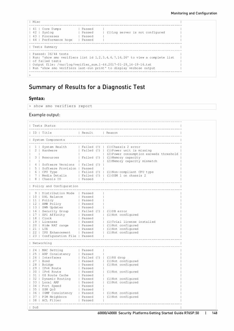
Monitoring and Configuration
60000/40000 Security Platforms Getting Started Guide R76SP.50 | 148
| Misc | --------------------------------------------------------------------------------- | 41 | Core Dumps | Passed | | | 42 | Syslog | Passed | (1)Log server is not configured | | 43 | Processes | Passed | | | 44 | Performance hogs | Passed | | --------------------------------------------------------------------------------- | Tests Summary | --------------------------------------------------------------------------------- | Passed: 36/44 tests | | Run: "show smo verifiers list id 1,2,3,4,6,7,16,26" to view a complete list | | of failed tests | | Output file: /var/log/verifier_sum.1-44.2017-01-29_14-19-16.txt | | Run "show smo verifiers last-run print" to display verbose output | --------------------------------------------------------------------------------- >
Summary of Results for a Diagnostic Test
Syntax: > show smo verifiers report
Example output: --------------------------------------------------------------------------------- | Tests Status | --------------------------------------------------------------------------------- | ID | Title | Result | Reason | --------------------------------------------------------------------------------- | System Components | --------------------------------------------------------------------------------- | 1 | System Health | Failed (!) | (1)Chassis 2 error | | 2 | Hardware | Failed (!) | (1)Power unit is missing | | | | | (2)Power consumption exceeds threshold | | 3 | Resources | Failed (!) | (1)Memory capacity | | | | | (2)Memory capacity mismatch | | 4 | Software Versions | Failed (!) | | | 5 | Software Provision | Passed | | | 6 | CPU Type | Failed (!) | (1)Non-compliant CPU type | | 7 | Media Details | Failed (!) | (1)SSM 1 on chassis 2 | | 8 | Chassis ID | Passed | | --------------------------------------------------------------------------------- | Policy and Configuration | --------------------------------------------------------------------------------- | 9 | Distribution Mode | Passed | | | 10 | DXL Balance | Passed | | | 11 | Policy | Passed | | | 12 | AMW Policy | Passed | | | 13 | SWB Updates | Passed | | | 16 | Security Group | Failed (!) | (1)DB error | | 17 | SPI Affinity | Passed | (1)Not configured | | 18 | Clock | Passed | | | 19 | Licenses | Passed | (1)Trial license installed | | 20 | Hide NAT range | Passed | (1)Not configured | | 21 | LTE | Passed | (1)Not configured | | 22 | IPS Enhancement | Passed | (1)Not configured | | 23 | Configuration File | Passed | | --------------------------------------------------------------------------------- | Networking | --------------------------------------------------------------------------------- | 24 | MAC Setting | Passed | | | 25 | ARP Consistency | Passed | | | 26 | Interfaces | Failed (!) | (1)RX drop | | 27 | Bond | Passed | (1)Not configured | | 28 | Bridge | Passed | (1)Not configured | | 29 | IPv4 Route | Passed | | | 30 | IPv6 Route | Passed | (1)Not configured | | 31 | OS Route Cache | Passed | | | 32 | Dynamic Routing | Passed | (1)Not configured | | 33 | Local ARP | Passed | (1)Not configured | | 34 | Port Speed | Passed | | | 35 | SSM QoS | Passed | | | 36 | IGMP Consistency | Passed | (1)Not configured | | 37 | PIM Neighbors | Passed | (1)Not configured | | 38 | ACL Filter | Passed | | --------------------------------------------------------------------------------- | DoS |

Monitoring and Configuration
60000/40000 Security Platforms Getting Started Guide R76SP.50 | 149
--------------------------------------------------------------------------------- | 39 | SYN Defender | Passed | | | 40 | F2F Quota | Passed | | --------------------------------------------------------------------------------- | Misc | --------------------------------------------------------------------------------- | 41 | Core Dumps | Passed | | | 42 | Syslog | Passed | (1)Log server is not configured | | 43 | Processes | Passed | | | 44 | Performance hogs | Passed | | --------------------------------------------------------------------------------- | Tests Summary | --------------------------------------------------------------------------------- | Passed: 36/44 tests | | Run: "asg diag list 1,2,3,4,6,7,16,26" to view a complete list of failed tests| | Output file: /var/log/verifier_sum.1-44.2017-01-29_14-19-16.txt | | Run "asg diag last_run print" to display verbose output | ---------------------------------------------------------------------------------
Running Specific Diagnostic Tests
Syntax to show a report by a test name: > show smo verifiers report name <Test Name>
Note - Press the Tab key after the name parameter to see a full list of verifiers names.
This example collects diagnostic information for specified test. > show smo verifiers report name System_Health Duration of tests vary and may take a few minutes to complete -------------------------------------------------------------------------------- | Tests Status | -------------------------------------------------------------------------------- | ID | Title | Result | Reason | -------------------------------------------------------------------------------- | System Components | -------------------------------------------------------------------------------- | 1 | System Health | Failed (!) | (1)Chassis 1 error | -------------------------------------------------------------------------------- | Tests Summary | -------------------------------------------------------------------------------- | Passed: 0/1 test | | Run: "show smo verifiers list id 1" to view a complete list of failed tests | | Output file: /var/log/verifier_sum.1.2017-02-20_19-58-03.txt | | Run "show smo verifiers last-run print" to display verbose output | -------------------------------------------------------------------------------- >
Syntax to show a report by a test ID:
> show smo verifiers report id <TestID1>,<TestID2>,...,<TestIDn>
Note - To see a list of test IDs, run: show smo verifiers list
This example collects diagnostic information for specified tests 1, 2, 3, 4, 5, and 30. > show smo verifiers report id 1,2,3,4,5,30 Duration of tests can vary and can take a few minutes to complete. -------------------------------------------------------------------------------- | Tests Status | -------------------------------------------------------------------------------- | ID | Title | Result | Reason | -------------------------------------------------------------------------------- | System Components | -------------------------------------------------------------------------------- | 1 | System Health | Failed (!) | (1)Verifier error - Check raw output | | 2 | Hardware | Passed | | | 3 | Resources | Failed (!) | (1)Memory capacity | | | | | (2)Primary HD capacity | | | | | (3)Primary HD exceed threshold | | | | | (4)Log HD capacity | | | | | (5)Boot HD capacity | | 4 | Software Versions | Failed (!) | |

Monitoring and Configuration
60000/40000 Security Platforms Getting Started Guide R76SP.50 | 150
| 5 | Software Provision | Failed (!) | | -------------------------------------------------------------------------------- | Networking | -------------------------------------------------------------------------------- | 30 | IPv6 Route | Passed | (1)Not configured | -------------------------------------------------------------------------------- | Tests Summary | -------------------------------------------------------------------------------- | Passed: 2/6 tests | | Run: "show smo verifiers list id 1,3,4,5" to view a complete list of failed | | tests | | Setting MOTD... | | Output file: /var/log/verifier_sum.1-5.30.2017-01-29_11-42-13.txt | | Run "show smo verifiers last-run print" to display verbose output | -------------------------------------------------------------------------------- >
Troubleshooting Failures Use the smo verifiers command to troubleshoot a failed diagnostic test.
In the example below, the test shows that two fans are down and the CPU temperature exceeds its threshold. The output identifies the failed components. [Expert@MyChassis-ch01-01:0]# gclish [Global] MyChassis-ch01-01 > show smo verifiers report id 2 [Global] MyChassis-ch01-01 > [Global] MyChassis-ch01-01 > show smo verifiers report id 2 -------------------------------------------------------------------------------- | Tests Status | -------------------------------------------------------------------------------- | ID | Title | Result | Reason | -------------------------------------------------------------------------------- | System Components | -------------------------------------------------------------------------------- | 2 | Hardware | Failed (!) | (1)Chassis fan is down | | | | | (2)Chassis fan exceeds threshold | | | | | (3)CPU exceeds threshold | -------------------------------------------------------------------------------- | Tests Summary | -------------------------------------------------------------------------------- | Passed: 0/1 test | | Run: "show smo verifiers list id 2" to view a complete list of failed tests | | Output file: /var/log/verifier_sum.2.2017-01-29_15-46-58.txt | | Run "show smo verifiers last-run print" to display verbose output | -------------------------------------------------------------------------------- [Global] MyChassis-ch01-01 >

Monitoring and Configuration
60000/40000 Security Platforms Getting Started Guide R76SP.50 | 151
[Global] MyChassis-ch01-01 > show smo verifiers print id 2 ----------------------------------------------------------------------------- | Hardware Monitor | ----------------------------------------------------------------------------- | Sensor | Location | Value | Threshold | Units | State | ----------------------------------------------------------------------------- | Chassis 1 | ----------------------------------------------------------------------------- | CMM | bay 1 | 1 | 0 | <S,D>/<A> | 1 | | CMM | bay 2 | 0 | 0 | <S,D>/<A> | 1 | | CPUtemp | blade 1, CPU0 | 0 | 65 | Celsius | 1 | | CPUtemp | blade 1, CPU1 | 0 | 65 | Celsius | 1 | | CPUtemp | blade 2, CPU0 | 44 | 65 | Celsius | 1 | | CPUtemp | blade 2, CPU1 | 41 | 65 | Celsius | 1 | | CPUtemp | blade 3, CPU0 | 44 | 65 | Celsius | 1 | | CPUtemp | blade 3, CPU1 | 40 | 65 | Celsius | 1 | | CPUtemp | blade 4, CPU0 | 47 | 65 | Celsius | 1 | | CPUtemp | blade 4, CPU1 | 43 | 65 | Celsius | 1 | | CPUtemp | blade 5, CPU0 | 46 | 65 | Celsius | 1 | | CPUtemp | blade 5, CPU1 | 42 | 65 | Celsius | 1 | | Fan | bay 1, fan 1 | 0 | 11 | Speed Level | 0 | | Fan | bay 1, fan 2 | 0 | 11 | Speed Level | 0 | | Fan | bay 2, fan 1 | 15 | 11 | Speed Level | 1 | | Fan | bay 2, fan 2 | 15 | 11 | Speed Level | 1 | | Fan | bay 3, fan 1 | 15 | 11 | Speed Level | 1 | | Fan | bay 3, fan 2 | 15 | 11 | Speed Level | 1 | | PowerConsumption | N/A | 2471 | 4050 | Watts | 1 | | PowerUnit(AC) | bay 1 | 0 | 0 | NA | 1 | | PowerUnit(AC) | bay 2 | 0 | 0 | NA | 1 | | PowerUnit(AC) | bay 3 | 0 | 0 | NA | 1 | | PowerUnit(AC) | bay 4 | 0 | 0 | NA | 0 | | PowerUnit(AC) | bay 5 | 0 | 0 | NA | 0 | | PowerUnitFan | bay 1, fan 1 | 0 | 0 | NA | 1 | | PowerUnitFan | bay 1, fan 2 | 0 | 0 | NA | 1 | | PowerUnitFan | bay 2, fan 1 | 0 | 0 | NA | 1 | | PowerUnitFan | bay 2, fan 2 | 0 | 0 | NA | 1 | | PowerUnitFan | bay 3, fan 1 | 0 | 0 | NA | 1 | | PowerUnitFan | bay 3, fan 2 | 0 | 0 | NA | 1 | | PowerUnitFan | bay 4, fan 1 | 0 | 0 | NA | 0 | | PowerUnitFan | bay 4, fan 2 | 0 | 0 | NA | 0 | | PowerUnitFan | bay 5, fan 1 | 0 | 0 | NA | 0 | | PowerUnitFan | bay 5, fan 2 | 0 | 0 | NA | 0 | | SSM | bay 1 | 136 | 0 | Mbps | 1 | | SSM | bay 2 | 128 | 0 | Mbps | 1 | ----------------------------------------------------------------------------- | Chassis 2 | ----------------------------------------------------------------------------- | CMM | bay 1 | 1 | 0 | <S,D>/<A> | 1 | | CMM | bay 2 | 0 | 0 | <S,D>/<A> | 1 | | CPUtemp | blade 1, CPU0 | 50 | 65 | Celsius | 1 | | CPUtemp | blade 1, CPU1 | 64 | 65 | Celsius | 1 | | CPUtemp | blade 2, CPU0 | 48 | 65 | Celsius | 1 | | CPUtemp | blade 2, CPU1 | 64 | 65 | Celsius | 1 | | CPUtemp | blade 3, CPU0 | 48 | 65 | Celsius | 1 | | CPUtemp | blade 3, CPU1 | 64 | 65 | Celsius | 1 | | CPUtemp | blade 4, CPU0 | 47 | 65 | Celsius | 1 | | CPUtemp | blade 4, CPU1 | 74 | 65 | Celsius | 1 | | CPUtemp | blade 5, CPU0 | 84 | 65 | Celsius | 1 | | CPUtemp | blade 5, CPU1 | 71 | 65 | Celsius | 1 | | Fan | bay 1, fan 1 | 4 | 11 | Speed Level | 1 | | Fan | bay 1, fan 2 | 4 | 11 | Speed Level | 1 | | Fan | bay 2, fan 1 | 4 | 11 | Speed Level | 1 | | Fan | bay 2, fan 2 | 4 | 11 | Speed Level | 1 | | Fan | bay 3, fan 1 | 4 | 11 | Speed Level | 1 | | Fan | bay 3, fan 2 | 4 | 11 | Speed Level | 1 | | . | | . | ----------------------------------------------------------------------------- [Global] MyChassis-ch01-01 >

Monitoring and Configuration
60000/40000 Security Platforms Getting Started Guide R76SP.50 | 152
Error Types Errors detected by smo verifiers:
Error Type Error Description System health Chassis <X> error The Chassis quality grade is less than the defined
threshold. We recommend that you correct this issue immediately.
Hardware <Component> is missing
The component is not installed in the Chassis.
<Component> is down The component is installed in the Chassis, but is inactive.
Resources <Resource> capacity The specified resource capacity is not sufficient. You can change the defined resource capacity.
<Resource> exceed threshold
The resource usage is greater than the defined threshold.
CPU type Non compliant CPU type
At least one SGM CPU type is not configured in the list of compliant CPUs. You can define the compliant CPU types.
Security group
<Source> error The information collected from this source is different between the SGMs.
<Sources> differ The information collected from many sources is different.
Changing Compliance Thresholds You can change some compliance thresholds that define a healthy, working system. In $FWDIR/conf/asg_diag_config, change the threshold values.
These are the resources you can control:
Resource Description Memory RAM memory capacity in GB
HD: / Disk capacity in GB for <disk> - the root (/) partition
HD:/var/log Disk capacity in GB for the /var/log partition
HD: /boot Disk capacity in GB for the /boot partition
Skew The maximum permissible clock difference, in seconds, between the SGMs and CMMs
Certified cpu Each line represents one compliant CPU type

Monitoring and Configuration
60000/40000 Security Platforms Getting Started Guide R76SP.50 | 153
Monitoring Performance (asg perf) Description
Use asg perf to continuously monitor key performance indicators and load statistics. There are different commands for IPv4 and IPv6. You can show the performance statistics for IPv4 traffic, IPv6 traffic or for all traffic.
When you run asg perf, the statistics show on the screen. The output automatically updates after a predefined interval (default = 10 seconds). To stop asg perf and return to the command line, press: e
Syntax > asg perf -h
> asg perf [-b <SGM_IDs>] [-vs <VS_IDs>] [-k] [-v] [-vv] [-p] [-4 | -6] [-c]
> asg perf [-b <SGM_IDs>] [-vs <VS_IDs>] [-k] [--peak_hist | --perf_hist] [-e] [--delay <seconds>] > asg perf [-b <SGM_IDs>] [-vs <VS_IDs>] [-v] [-vv [ mem [fwk | cpd | fwd | all_daemons] | cpu [1m | 1h | 24h]]]
Parameters
Parameter Description
-h Shows the command syntax and help information.
-b <SGM_IDs> Works with SGMs and/or Chassis as specified by <SGM_IDs>.
<SGM_IDs> can be:
• No <SGM_IDs> specified, or all - Applies to all SGMs and Chassis
• One SGM (for example, 1_1)
• A comma-separated list of SGMs (for example, 1_1,1_4)
• A range of SGMs (for example, 1_1-1_4)
• One Chassis (chassis1, or chassis2)
• The active Chassis (chassis_active)
-vs <VS_IDs> Shows the Chassis status of Virtual Systems.
<VS_IDs> can be:
• No <VS_IDs> (default) - Uses the current Virtual System context
• One Virtual System • A comma-separated list of Virtual Systems (1, 2, 4, 5)
• A range of Virtual Systems (VS 3-5)
• all - Shows all Virtual Systems
Note - This parameter is only applicable in a VSX environment.
If <VS_IDs> is omitted, output shows the information for the current Virtual System context.
-v Shows statistics for each SGM.

Monitoring and Configuration
60000/40000 Security Platforms Getting Started Guide R76SP.50 | 154
-vv Shows statistics for each Virtual System.
Note - This parameter is only relevant in a VSX environment.
mem Shows memory usage for each daemon.
Use this with -vv. Possible values:
• fwk (Default)
• fwd
• cpd
• all_daemons cpu Shows CPU usage for a specified period of time.
Use this with -vv.
Possible values:
• 1m (default) - The last 60 seconds
• 1h - The last hour
• 24h - The last 24 hours -p Show detailed statistics and traffic distribution between these paths on the
Active Chassis:
• Acceleration path (SecureXL)
• Medium path (PXL) • Slow path (Firewall)
-4 | -6 • -4 - Shows IPv4 information only.
• -6 - Shows IPv6 information only.
If no value is specified, the combined performance information for both IPv4 and IPv6 shows.
-c Shows percentages instead of absolute values.
-k Shows peak (maximum) system performance values.
--peak_hist Creates an exportable text file that contains all data saved in the peak performance files. You must use this parameter together with -k.
--perf_hist Creates exportable text files that contain all performance data saved in the history files. You must use this parameter together with -k.
-e Resets peak values and deletes all peaks files and system history files.
--delay <seconds>
Temporarily changes the update interval for the current asg perf session.
Enter a delay value in seconds. Default = 10 seconds.
Notes:
• The -b <SGM_IDs> and -vs <VS_IDs> parameters must be at the start of the command. If both parameters are used, -b <SGM_IDs> must be first.
• If your 60000/40000 Security Platform is not configured for VSX, the VSX related commands are not available. They do not show when you run the asg perf -h command.

Monitoring and Configuration
60000/40000 Security Platforms Getting Started Guide R76SP.50 | 155
Monitoring Service Traffic (asg profile) Description
Use the asg profile command to monitor traffic for each service that passes through the 60000/40000 Security Platform.
This information is equivalent to SmartView Monitor traffic monitoring.
This command has a minimal performance hit.
Syntax > asg profile --help
> asg profile [ --delay <timeout>] [ -b <SGM_IDs> ] [-v | -p | -g] [--rel] [--tcp | --udp] [--ipv6 | --ipv4] > asg profile -m
> asg profile --enable
> asg profile --disable
Parameters
Parameter Description
--delay <timeout> Information refresh interval (seconds).
-b <SGM_IDs> Works with SGMs and/or Chassis as specified by <SGM_IDs>.
<SGM_IDs> can be:
• No <SGM_IDs> specified, or all - Applies to all SGMs and Chassis
• One SGM (for example, 1_1)
• A comma-separated list of SGMs (for example, 1_1,1_4)
• A range of SGMs (for example, 1_1-1_4)
• One Chassis (chassis1, or chassis2)
• The active Chassis (chassis_active)
-v | -p | -g The default view (with none of these options) shows values for each service - throughput, packet rate, connection rate and the number of concurrent connections. As an alternative, you can select one of these options:
• -v - Shows verbose service statistics.
• -p - Shows service statistics for these paths:
• Accelerated (SecureXL)
• Medium
• Slow (Firewall)
• -g - Shows graph view of BPS per service --rel Shows the results as a percentage for the -v, –p, and default views.
--tcp | --udp Select one of these options:
• --tcp - Show TCP statistics only
• --udp - Show UDP statistics only

Monitoring and Configuration
60000/40000 Security Platforms Getting Started Guide R76SP.50 | 156
Parameter Description --ipv6 | --ipv4 Select one of these options:
• --ipv4 - Show ipv4 statistics only
• --ipv6 - Show ipv6 statistics only
-m Run in a convenient interactive menu mode.
--enable Enable statistics collection.
--disable Disable statistics collection.
--help Shows the command syntax and help information.
Example: > asg profile -m Aggregated statistics of SGMs: 1_1 Virtual Systems: 0 +--------------------------------------------------------------------+ |Service distribution summary | +-------------------------+----------+-------+-----------+-----------+ |Service |Throughput|Packet |Connection |Concurrent | + + +rate +rate |connections| +-------------------------+----------+-------+-----------+-----------+ |8116/udp cp-cluster |116.2 K |112 |0 |0 | +-------------------------+----------+-------+-----------+-----------+ |22/tcp ssh |4.5 K |5 |0 |0 | +-------------------------+----------+-------+-----------+-----------+ |33628/tcp |2.0 K |1 |0 |0 | +-------------------------+----------+-------+-----------+-----------+ |33635/tcp |1.2 K |0 |0 |0 | +-------------------------+----------+-------+-----------+-----------+ |33624/tcp |1.2 K |0 |0 |0 | +-------------------------+----------+-------+-----------+-----------+ |33630/tcp |400 |0 |0 |0 | +-------------------------+----------+-------+-----------+-----------+ |33626/tcp |400 |0 |0 |0 | +-------------------------+----------+-------+-----------+-----------+ |33632/tcp |336 |0 |0 |0 | +-------------------------+----------+-------+-----------+-----------+ |67/udp bootps |288 |0 |0 |0 | +-------------------------+----------+-------+-----------+-----------+ |257/tcp set |48 |0 |0 |2 | +-------------------------+----------+-------+-----------+-----------+ +-------------------------+----------+-------+-----------+-----------+ |Totals | +-------------------------+----------+-------+-----------+-----------+ |Total tcp |10.2 K |9 |0 |8 | |Total udp |116.5 K |112 |0 |0 | |Total other |0 |0 |0 |2 | +-------------------------+----------+-------+-----------+-----------+ |System |126.7 K |121 |0 |10 | +-------------------------+----------+-------+-----------+-----------+ Time: Sun Jul 07 14:34:30 IDT 2013 SGMs: 1_1 1_2 VSs: 0 1 Choose one of the following option:(Bold options are current view) n) Normal View a) Absolute Values r) Relative Values v) Verbose View V) Move to a different Virtual System p) Path View g) Graph View O) Online H) History S) Move to next sgm b) Back one menu e) Exit
Note - This example shows the normal (not verbose) view with absolute values. The highest throughput and packet rate is from the service 8116/udp cp-cluster. To show this view, type: a

Monitoring and Configuration
60000/40000 Security Platforms Getting Started Guide R76SP.50 | 157
Monitoring Hardware Components (asg hw_monitor) Description
Use the asg hw_monitor command in gClish or Expert mode to show and monitor hardware information and thresholds for monitored components:
• SGM - CPU temperature for each socket
• Chassis fan speeds
• SSM - Throughput rates
• Power consumption for each Chassis
• Power Supply Unit - Installed or not installed, and the PSU fan speed
• CMM - Installed, Active or Standby
Syntax > asg hw_monitor [-v] [-f <filter>]
Parameters
Parameter Description -v Show detailed component status report (verbose)
-f Show status of one or more specified (filtered) components
<filter> One or more of these component types, in a comma separated list:
• CMM
• CPUtemp
• Fan
• PowerConsumption
• PowerUnit
• SSM
Example output for the 61000 N+N: [Expert@MyChassis-ch01-01:0]# gclish [Global] MyChassis-ch01-01 > asg hw_monitor -v ------------------------------------------------------------------------------ | Hardware Monitor | ------------------------------------------------------------------------------ | Sensor | Location | Value | Threshold | Units | State| ------------------------------------------------------------------------------ | Chassis 1 | ------------------------------------------------------------------------------ | CMM | bay 1 | 1 | 0 | <S,D>/<A> | 1 | | CMM | bay 2 | 0 | 0 | <S,D>/<A> | 1 | | CPUtemp | blade 1, CPU0 | 45 | 65 | Celsius | 1 | | CPUtemp | blade 1, CPU1 | 39 | 65 | Celsius | 1 | | CPUtemp | blade 2, CPU0 | 44 | 65 | Celsius | 1 | | CPUtemp | blade 2, CPU1 | 39 | 65 | Celsius | 1 | | CPUtemp | blade 3, CPU0 | 44 | 65 | Celsius | 1 | | CPUtemp | blade 3, CPU1 | 38 | 65 | Celsius | 1 | | CPUtemp | blade 4, CPU0 | 47 | 65 | Celsius | 1 | | CPUtemp | blade 4, CPU1 | 42 | 65 | Celsius | 1 | | CPUtemp | blade 5, CPU0 | 0 | 65 | Celsius | 1 | | CPUtemp | blade 5, CPU1 | 0 | 65 | Celsius | 1 | | CPUtemp | blade 6, CPU0 | 0 | 65 | Celsius | 0 | | CPUtemp | blade 6, CPU1 | 0 | 65 | Celsius | 0 |
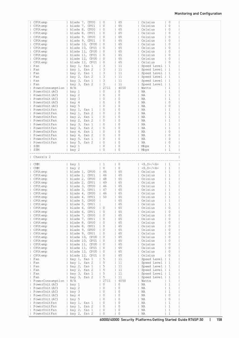
Monitoring and Configuration
60000/40000 Security Platforms Getting Started Guide R76SP.50 | 158
| CPUtemp | blade 7, CPU0 | 0 | 65 | Celsius | 0 | | CPUtemp | blade 7, CPU1 | 0 | 65 | Celsius | 0 | | CPUtemp | blade 8, CPU0 | 0 | 65 | Celsius | 0 | | CPUtemp | blade 8, CPU1 | 0 | 65 | Celsius | 0 | | CPUtemp | blade 9, CPU0 | 0 | 65 | Celsius | 0 | | CPUtemp | blade 9, CPU1 | 0 | 65 | Celsius | 0 | | CPUtemp | blade 10, CPU0 | 0 | 65 | Celsius | 0 | | CPUtemp | blade 10, CPU1 | 0 | 65 | Celsius | 0 | | CPUtemp | blade 11, CPU0 | 0 | 65 | Celsius | 0 | | CPUtemp | blade 11, CPU1 | 0 | 65 | Celsius | 0 | | CPUtemp | blade 12, CPU0 | 0 | 65 | Celsius | 0 | | CPUtemp | blade 12, CPU1 | 0 | 65 | Celsius | 0 | | Fan | bay 1, fan 1 | 3 | 11 | Speed Level | 1 | | Fan | bay 1, fan 2 | 3 | 11 | Speed Level | 1 | | Fan | bay 2, fan 1 | 3 | 11 | Speed Level | 1 | | Fan | bay 2, fan 2 | 3 | 11 | Speed Level | 1 | | Fan | bay 3, fan 1 | 3 | 11 | Speed Level | 1 | | Fan | bay 3, fan 2 | 3 | 11 | Speed Level | 1 | | PowerConsumption | N/A | 2711 | 4050 | Watts | 1 | | PowerUnit(AC) | bay 1 | 0 | 0 | NA | 1 | | PowerUnit(AC) | bay 2 | 0 | 0 | NA | 1 | | PowerUnit(AC) | bay 3 | 0 | 0 | NA | 1 | | PowerUnit(AC) | bay 4 | 0 | 0 | NA | 0 | | PowerUnit(AC) | bay 5 | 0 | 0 | NA | 0 | | PowerUnitFan | bay 1, fan 1 | 0 | 0 | NA | 1 | | PowerUnitFan | bay 1, fan 2 | 0 | 0 | NA | 1 | | PowerUnitFan | bay 2, fan 1 | 0 | 0 | NA | 1 | | PowerUnitFan | bay 2, fan 2 | 0 | 0 | NA | 1 | | PowerUnitFan | bay 3, fan 1 | 0 | 0 | NA | 1 | | PowerUnitFan | bay 3, fan 2 | 0 | 0 | NA | 1 | | PowerUnitFan | bay 4, fan 1 | 0 | 0 | NA | 0 | | PowerUnitFan | bay 4, fan 2 | 0 | 0 | NA | 0 | | PowerUnitFan | bay 5, fan 1 | 0 | 0 | NA | 0 | | PowerUnitFan | bay 5, fan 2 | 0 | 0 | NA | 0 | | SSM | bay 1 | 0 | 0 | Mbps | 1 | | SSM | bay 2 | 0 | 0 | Mbps | 1 | ------------------------------------------------------------------------------ | Chassis 2 | ------------------------------------------------------------------------------ | CMM | bay 1 | 1 | 0 | <S,D>/<A> | 1 | | CMM | bay 2 | 0 | 0 | <S,D>/<A> | 1 | | CPUtemp | blade 1, CPU0 | 46 | 65 | Celsius | 1 | | CPUtemp | blade 1, CPU1 | 46 | 65 | Celsius | 1 | | CPUtemp | blade 2, CPU0 | 48 | 65 | Celsius | 1 | | CPUtemp | blade 2, CPU1 | 49 | 65 | Celsius | 1 | | CPUtemp | blade 3, CPU0 | 46 | 65 | Celsius | 1 | | CPUtemp | blade 3, CPU1 | 47 | 65 | Celsius | 1 | | CPUtemp | blade 4, CPU0 | 46 | 65 | Celsius | 1 | | CPUtemp | blade 4, CPU1 | 50 | 65 | Celsius | 1 | | CPUtemp | blade 5, CPU0 | | 65 | Celsius | 1 | | CPUtemp | blade 5, CPU1 | | 65 | Celsius | 1 | | CPUtemp | blade 6, CPU0 | 0 | 65 | Celsius | 0 | | CPUtemp | blade 6, CPU1 | 0 | 65 | Celsius | 0 | | CPUtemp | blade 7, CPU0 | 0 | 65 | Celsius | 0 | | CPUtemp | blade 7, CPU1 | 0 | 65 | Celsius | 0 | | CPUtemp | blade 8, CPU0 | 0 | 65 | Celsius | 0 | | CPUtemp | blade 8, CPU1 | 0 | 65 | Celsius | 0 | | CPUtemp | blade 9, CPU0 | 0 | 65 | Celsius | 0 | | CPUtemp | blade 9, CPU1 | 0 | 65 | Celsius | 0 | | CPUtemp | blade 10, CPU0 | 0 | 65 | Celsius | 0 | | CPUtemp | blade 10, CPU1 | 0 | 65 | Celsius | 0 | | CPUtemp | blade 11, CPU0 | 0 | 65 | Celsius | 0 | | CPUtemp | blade 11, CPU1 | 0 | 65 | Celsius | 0 | | CPUtemp | blade 12, CPU0 | 0 | 65 | Celsius | 0 | | CPUtemp | blade 12, CPU1 | 0 | 65 | Celsius | 0 | | Fan | bay 1, fan 1 | 5 | 11 | Speed Level | 1 | | Fan | bay 1, fan 2 | 5 | 11 | Speed Level | 1 | | Fan | bay 2, fan 1 | 5 | 11 | Speed Level | 1 | | Fan | bay 2, fan 2 | 5 | 11 | Speed Level | 1 | | Fan | bay 3, fan 1 | 5 | 11 | Speed Level | 1 | | Fan | bay 3, fan 2 | 5 | 11 | Speed Level | 1 | | PowerConsumption | N/A | 2711 | 4050 | Watts | 1 | | PowerUnit(AC) | bay 1 | 0 | 0 | NA | 1 | | PowerUnit(AC) | bay 2 | 0 | 0 | NA | 1 | | PowerUnit(AC) | bay 3 | 0 | 0 | NA | 1 | | PowerUnit(AC) | bay 4 | 0 | 0 | NA | 0 | | PowerUnit(AC) | bay 5 | 0 | 0 | NA | 0 | | PowerUnitFan | bay 1, fan 1 | 0 | 0 | NA | 1 | | PowerUnitFan | bay 1, fan 2 | 0 | 0 | NA | 1 | | PowerUnitFan | bay 2, fan 1 | 0 | 0 | NA | 1 | | PowerUnitFan | bay 2, fan 2 | 0 | 0 | NA | 1 |

Monitoring and Configuration
60000/40000 Security Platforms Getting Started Guide R76SP.50 | 159
| PowerUnitFan | bay 3, fan 1 | 0 | 0 | NA | 1 | | PowerUnitFan | bay 3, fan 2 | 0 | 0 | NA | 1 | | PowerUnitFan | bay 4, fan 1 | 0 | 0 | NA | 0 | | PowerUnitFan | bay 4, fan 2 | 0 | 0 | NA | 0 | | PowerUnitFan | bay 5, fan 1 | 0 | 0 | NA | 0 | | PowerUnitFan | bay 5, fan 2 | 0 | 0 | NA | 0 | | SSM | bay 1 | 0 | 0 | Mbps | 1 | | SSM | bay 2 | 0 | 0 | Mbps | 1 | ------------------------------------------------------------------------------ [Global] MyChassis-ch01-01 >
Example output on a 60000/40000 Security Platform 41000: [Expert@MyChassis-ch01-01:0]# gclish [Global] MyChassis-ch01-01 > asg hw_monitor -v ------------------------------------------------------------------------------ | Hardware Monitor | ------------------------------------------------------------------------------ | Sensor | Location | Value | Threshold | Units | State| ------------------------------------------------------------------------------ | Chassis 1 | ------------------------------------------------------------------------------ | CMM | bay 1 | 0 | 0 | <S,D>/<A> | 1 | | CMM | bay 2 | 1 | 0 | <S,D>/<A> | 1 | | CPUtemp | blade 1, CPU0 | 47 | 65 | Celsius | 1 | | CPUtemp | blade 1, CPU1 | 46 | 65 | Celsius | 1 | | CPUtemp | blade 2, CPU0 | 46 | 65 | Celsius | 1 | | CPUtemp | blade 2, CPU1 | 44 | 65 | Celsius | 1 | | CPUtemp | blade 3, CPU0 | 46 | 65 | Celsius | 1 | | CPUtemp | blade 3, CPU1 | 45 | 65 | Celsius | 1 | | CPUtemp | blade 4, CPU0 | 45 | 65 | Celsius | 1 | | CPUtemp | blade 4, CPU1 | 46 | 65 | Celsius | 1 | | Fan | bay 1, fan 1 | 4 | 11 | Speed Level | 1 | | Fan | bay 1, fan 2 | 4 | 11 | Speed Level | 1 | | Fan | bay 1, fan 3 | 4 | 11 | Speed Level | 1 | | Fan | bay 1, fan 4 | 4 | 11 | Speed Level | 1 | | Fan | bay 1, fan 5 | 4 | 11 | Speed Level | 1 | | Fan | bay 1, fan 6 | 4 | 11 | Speed Level | 1 | | Fan | bay 1, fan 7 | 4 | 11 | Speed Level | 1 | | Fan | bay 1, fan 8 | 4 | 11 | Speed Level | 1 | | Fan | bay 1, fan 9 | 4 | 11 | Speed Level | 1 | | Fan | bay 1, fan 10 | 4 | 11 | Speed Level | 1 | | Fan | bay 2, fan 1 | 4 | 11 | Speed Level | 1 | | Fan | bay 2, fan 2 | 4 | 11 | Speed Level | 1 | | Fan | bay 2, fan 3 | 4 | 11 | Speed Level | 1 | | Fan | bay 2, fan 4 | 4 | 11 | Speed Level | 1 | | Fan | bay 2, fan 5 | 4 | 11 | Speed Level | 1 | | Fan | bay 2, fan 6 | 4 | 11 | Speed Level | 1 | | Fan | bay 2, fan 7 | 4 | 11 | Speed Level | 1 | | Fan | bay 2, fan 8 | 4 | 11 | Speed Level | 1 | | Fan | bay 2, fan 9 | 4 | 11 | Speed Level | 1 | | Fan | bay 2, fan 10 | 4 | 11 | Speed Level | 1 | | PowerConsumption | N/A | 1894 | 4050 | Watts | 1 | | PowerUnit(AC) | bay 1 | 0 | 0 | NA | 1 | | PowerUnit(AC) | bay 2 | 0 | 0 | NA | 1 | | PowerUnit(AC) | bay 3 | 0 | 0 | NA | 1 | | PowerUnitFan | bay 1, fan 1 | 0 | 0 | NA | 1 | | PowerUnitFan | bay 1, fan 2 | 0 | 0 | NA | 1 | | PowerUnitFan | bay 2, fan 1 | 0 | 0 | NA | 1 | | PowerUnitFan | bay 2, fan 2 | 0 | 0 | NA | 1 | | PowerUnitFan | bay 3, fan 1 | 0 | 0 | NA | 1 | | PowerUnitFan | bay 3, fan 2 | 0 | 0 | NA | 1 | | SSM | bay 1 | 40 | 0 | Mbps | 1 | | SSM | bay 2 | 0 | 0 | Mbps | 1 | ------------------------------------------------------------------------------ | Chassis 2 | ------------------------------------------------------------------------------ | CMM | bay 1 | 1 | 0 | <S,D>/<A> | 1 | | CMM | bay 2 | 0 | 0 | <S,D>/<A> | 1 | | CPUtemp | blade 1, CPU0 | 47 | 65 | Celsius | 0 | | CPUtemp | blade 1, CPU1 | 51 | 65 | Celsius | 0 | | CPUtemp | blade 2, CPU0 | 46 | 65 | Celsius | 1 | | CPUtemp | blade 2, CPU1 | 56 | 65 | Celsius | 1 | | CPUtemp | blade 3, CPU0 | 49 | 65 | Celsius | 1 | | CPUtemp | blade 3, CPU1 | 51 | 65 | Celsius | 1 | | CPUtemp | blade 4, CPU0 | 0 | 65 | Celsius | 0 | | CPUtemp | blade 4, CPU1 | 0 | 65 | Celsius | 0 | | Fan | bay 1, fan 1 | 3 | 11 | Speed Level | 1 | | Fan | bay 1, fan 2 | 3 | 11 | Speed Level | 1 | | Fan | bay 1, fan 3 | 3 | 11 | Speed Level | 1 |

Monitoring and Configuration
60000/40000 Security Platforms Getting Started Guide R76SP.50 | 160
| Fan | bay 1, fan 4 | 3 | 11 | Speed Level | 1 | | Fan | bay 1, fan 5 | 3 | 11 | Speed Level | 1 | | Fan | bay 1, fan 6 | 3 | 11 | Speed Level | 1 | | Fan | bay 1, fan 7 | 3 | 11 | Speed Level | 1 | | Fan | bay 1, fan 8 | 3 | 11 | Speed Level | 1 | | Fan | bay 1, fan 9 | 3 | 11 | Speed Level | 1 | | Fan | bay 1, fan 10 | 3 | 11 | Speed Level | 1 | | Fan | bay 2, fan 1 | 3 | 11 | Speed Level | 1 | | Fan | bay 2, fan 2 | 3 | 11 | Speed Level | 1 | | Fan | bay 2, fan 3 | 3 | 11 | Speed Level | 1 | | Fan | bay 2, fan 4 | 3 | 11 | Speed Level | 1 | | Fan | bay 2, fan 5 | 3 | 11 | Speed Level | 1 | | Fan | bay 2, fan 6 | 3 | 11 | Speed Level | 1 | | Fan | bay 2, fan 7 | 3 | 11 | Speed Level | 1 | | Fan | bay 2, fan 8 | 3 | 11 | Speed Level | 1 | | Fan | bay 2, fan 9 | 3 | 11 | Speed Level | 1 | | Fan | bay 2, fan 10 | 3 | 11 | Speed Level | 1 | | PowerConsumption | N/A | 1624 | 4050 | Watts | 1 | | PowerUnit(AC) | bay 1 | 0 | 0 | NA | 1 | | PowerUnit(AC) | bay 2 | 0 | 0 | NA | 1 | | PowerUnit(AC) | bay 3 | 0 | 0 | NA | 0 | | PowerUnitFan | bay 1, fan 1 | 0 | 0 | NA | 1 | | PowerUnitFan | bay 1, fan 2 | 0 | 0 | NA | 1 | | PowerUnitFan | bay 2, fan 1 | 0 | 0 | NA | 1 | | PowerUnitFan | bay 2, fan 2 | 0 | 0 | NA | 1 | | PowerUnitFan | bay 3, fan 1 | 0 | 0 | NA | 0 | | PowerUnitFan | bay 3, fan 2 | 0 | 0 | NA | 0 | | SSM | bay 1 | 2 | 0 | Mbps | 1 | | SSM | bay 2 | 0 | 0 | Mbps | 1 | ------------------------------------------------------------------------------ [Expert@MyChassis-ch01-01:0]#
Output description:
Column Description
Location Front panel location.
Value Threshold Units Most components have a defined threshold value. The threshold gives an indication of the health and functionality of the component. When the value of the resource is greater than the threshold, an alert is sent (on page 164).
State • 0 = Component not installed
• 1 = Component is installed

Monitoring and Configuration
60000/40000 Security Platforms Getting Started Guide R76SP.50 | 161
Monitoring SGM Resources (asg resource) Description
Use the asg resource command to show SGM resource usage and thresholds for the 60000/40000 Security Platform.
Syntax
> asg resource -h
> asg resource [-b <SGM_IDs>]
Parameters
Parameter Description
-b <SGM_IDs> Works with SGMs and/or Chassis as specified by <SGM_IDs>.
<SGM_IDs> can be:
• No <SGM_IDs> specified, or all - Applies to all SGMs and Chassis
• One SGM (for example, 1_1)
• A comma-separated list of SGMs (for example, 1_1,1_4)
• A range of SGMs (for example, 1_1-1_4)
• One Chassis (chassis1, or chassis2)
• The active Chassis (chassis_active)
-h Shows usage and exits
Example: > asg resource +-------------------------------------------------------------------------+ |Resource Table | +------------+-------------------------+------------+------------+--------+ |SGM ID |Resource Name |Usage |Threshold |Total | +------------+-------------------------+------------+------------+--------+ |1_01 |Memory |14% |50% |31.3G | | |HD: / |22% |80% |19.4G | | |HD: /var/log |1% |80% |58.1G | | |HD: /boot |19% |80% |288.6M | +------------+-------------------------+------------+------------+--------+ |1_02 |Memory |9% |50% |62.8G | | |HD: / |23% |80% |19.4G | | |HD: /var/log |1% |80% |58.1G | | |HD: /boot |19% |80% |288.6M | +------------+-------------------------+------------+------------+--------+ |1_03 |Memory |9% |50% |62.8G | | |HD: / |23% |80% |19.4G | | |HD: /var/log |1% |80% |58.1G | | |HD: /boot |19% |80% |288.6M | +------------+-------------------------+------------+------------+--------+ |2_01 |Memory |9% |50% |62.8G | | |HD: / |23% |80% |19.4G | | |HD: /var/log |1% |80% |58.1G | | |HD: /boot |19% |80% |288.6M | +------------+-------------------------+------------+------------+--------+ |2_02 |Memory |9% |50% |62.8G | | |HD: / |23% |80% |19.4G | | |HD: /var/log |1% |80% |58.1G | | |HD: /boot |19% |80% |288.6M | +------------+-------------------------+------------+------------+--------+ |2_03 |Memory |9% |50% |62.8G | | |HD: / |23% |80% |19.4G | | |HD: /var/log |1% |80% |58.1G | | |HD: /boot |19% |80% |288.6M | +------------+-------------------------+------------+------------+--------+ >

Monitoring and Configuration
60000/40000 Security Platforms Getting Started Guide R76SP.50 | 162
Output description
Column Description
SGM Shows the SGM ID.
Resource Identifies the resource. There are four types of resources:
• Memory
• HD – Hard drive space (/)
• HD: /var/log – Space on hard drive committed to log files • HD: /boot - Location of the kernel
Usage Shows the percentage of the resource in use
Threshold Indicates the health and functionality of the component. When the value of the resource is greater than the threshold, an alert is sent. The threshold can be modified in gClish.
Total Total absolute value in units.
For example, the first row shows that SGM1 on Chassis1 has 31.3 GB of memory, 14% of which is used. An alert is sent if the usage is greater than 50%.

Monitoring and Configuration
60000/40000 Security Platforms Getting Started Guide R76SP.50 | 163
Searching for a Connection (asg search) Use the asg search command in gClish or Expert mode to:
• Search for a connection or a filtered list of connections.
• See which SGM handles the connection, actively or as backup, and on which Chassis.
You can run this command directly or in Interactive Mode. In the Interactive Mode, you can enter the parameters in the correct sequence.
The asg search command also runs a consistency test between SGMs.
This command supports both IPv4 and IPv6 connections.
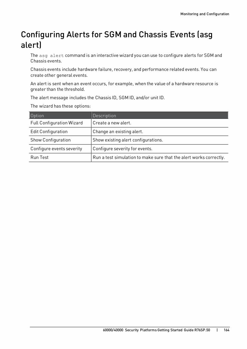
Monitoring and Configuration
60000/40000 Security Platforms Getting Started Guide R76SP.50 | 164
Configuring Alerts for SGM and Chassis Events (asg alert)
The asg alert command is an interactive wizard you can use to configure alerts for SGM and Chassis events.
Chassis events include hardware failure, recovery, and performance related events. You can create other general events.
An alert is sent when an event occurs, for example, when the value of a hardware resource is greater than the threshold.
The alert message includes the Chassis ID, SGM ID, and/or unit ID.
The wizard has these options:
Option Description
Full Configuration Wizard Create a new alert.
Edit Configuration Change an existing alert.
Show Configuration Show existing alert configurations.
Configure events severity Configure severity for events.
Run Test Run a test simulation to make sure that the alert works correctly.
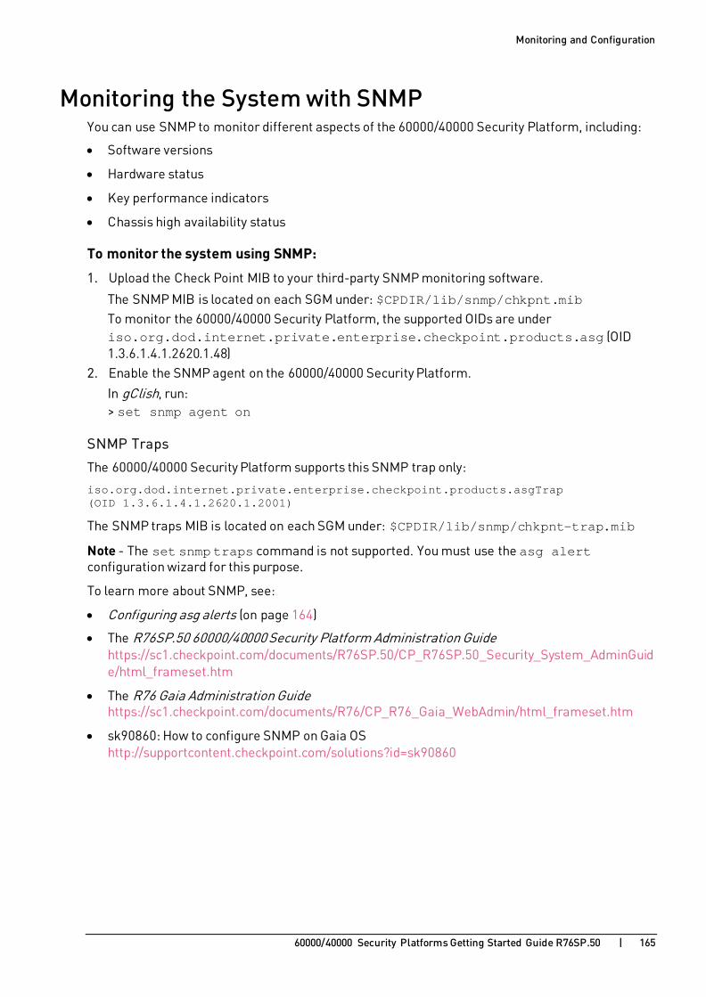
Monitoring and Configuration
60000/40000 Security Platforms Getting Started Guide R76SP.50 | 165
Monitoring the System with SNMP You can use SNMP to monitor different aspects of the 60000/40000 Security Platform, including:
• Software versions
• Hardware status
• Key performance indicators
• Chassis high availability status
To monitor the system using SNMP:
1. Upload the Check Point MIB to your third-party SNMP monitoring software.
The SNMP MIB is located on each SGM under: $CPDIR/lib/snmp/chkpnt.mib To monitor the 60000/40000 Security Platform, the supported OIDs are under iso.org.dod.internet.private.enterprise.checkpoint.products.asg (OID 1.3.6.1.4.1.2620.1.48)
2. Enable the SNMP agent on the 60000/40000 Security Platform.
In gClish, run: > set snmp agent on
SNMP Traps
The 60000/40000 Security Platform supports this SNMP trap only:
iso.org.dod.internet.private.enterprise.checkpoint.products.asgTrap (OID 1.3.6.1.4.1.2620.1.2001)
The SNMP traps MIB is located on each SGM under: $CPDIR/lib/snmp/chkpnt-trap.mib
Note - The set snmp traps command is not supported. You must use the asg alert configuration wizard for this purpose.
To learn more about SNMP, see:
• Configuring asg alerts (on page 164)
• The R76SP.50 60000/40000 Security Platform Administration Guide https://sc1.checkpoint.com/documents/R76SP.50/CP_R76SP.50_Security_System_AdminGuide/html_frameset.htm
• The R76 Gaia Administration Guide https://sc1.checkpoint.com/documents/R76/CP_R76_Gaia_WebAdmin/html_frameset.htm
• sk90860: How to configure SNMP on Gaia OS http://supportcontent.checkpoint.com/solutions?id=sk90860

Monitoring and Configuration
60000/40000 Security Platforms Getting Started Guide R76SP.50 | 166
SNMP in a VSX Gateway There are two SNMP modes for a 60000/40000 Security Platform configured as a VSX Gateway:
Default Mode Monitor global SNMP data from the 60000/40000 Security Platform. Data comes from all SGMs on all Virtual Systems.
VS Mode Monitor each Virtual System separately.
Note - SNMP traps are supported for VS0 only.
Supported SNMP Versions
SNMP VS mode uses SNMP version 3 to query the Virtual Systems. You can run remote SNMP queries on each Virtual System in the VSX Gateway.
For systems that only support SNMP versions 1 and 2:
• You cannot run remote SNMP queries for each Virtual System. You can only run a remote SNMP query on VS0.
• You can use the CLI to change the Virtual System context and then run a local SNMP query on a Virtual System.
To use SNMP in the Virtual System mode:
1. Configure an SNMP V3 user: add snmp usm user jon security-level authNoPriv authpass-phrase VALUE
2. Set the SNMP mode: set snmp mode vs or set snmp mode default
3. Start SNMP agent: set snmp agent on
VS Mode Example 1:
To run a Virtual System query for traffic throughput, from a remote Linux host:
[Expert@VSX:0] snmpwalk -m $CPDIR/lib/snmp/chkpnt.mib -n ctxname_vsid1 -v 3 -l authNoPriv -u jon -A mypassword 192.0.2.72 asgThroughput
VS Mode Example 2:
To run a Virtual System query for traffic throughput, from its virtual context:
1. Go to the Expert mode. 2. Go to the applicable Virtual System:
vsenv <vs_id>
3. Run: # snmpwalk -m $CPDIR/lib/snmp/chkpnt.mib -v 2c -c public localhost asgThroughput

Troubleshooting
60000/40000 Security Platforms Getting Started Guide R76SP.50 | 167
C H A P T E R 2 1
Troubleshooting In This Section:
Collecting System Diagnostics (smo verifiers) ..................................................167
This section lists the most important gClish commands that you can use to troubleshoot the 60000/40000 Security Platform.
Collecting System Diagnostics (smo verifiers) Description
The smo verifiers commands in gClish run a specific set of diagnostic tests.
The full set of tests run by default. but you can manually select the tests you want to run.
The output shows the result of the test, Passed or Failed, and the location of the output log file.
Syntax > show smo verifiers list [id <TestId1>,<TestId2>,...] [section <SectionName>] > show smo verifiers report [except] [id <TestId1>,<TestId2>,...] [name <TestName>] [section <SectionName>] > show smo verifiers print [except] [id <TestId1>,<TestId2>,...] [name <TestName>] [section <SectionName>] > show smo verifiers periodic last-run report print > delete smo verifiers purge [save <Num_Logs>]
Parameters
Parameter Description list Shows the list of tests to run.
report Runs tests and shows a summary of the test results.
print Runs tests and shows the full output and summary of the test results.
except Runs all tests except the specified tests.
Shows the requested results.
id <TestId1>,<TestId2>,... Specifies the tests by their IDs (comma separated list).
To see a list of test IDs, run: > show smo verifiers list

Troubleshooting
60000/40000 Security Platforms Getting Started Guide R76SP.50 | 168
Parameter Description
name <TestName> Specifies the tests by their names.
Press the Tab key to see a full list of verifiers names.
section <SectionName> Specifies the verifiers section by its name.
Press the Tab key to see a full list of the existing sections.
purge Deletes the old smo verifiers logs.
Keeps the newest log.
save <Num_Logs> Number of logs to save from the smo verifiers log files.
Default = 5.
periodic Shows the latest periodic run results.
last-run Shows the latest run results.
Error Types Errors detected by smo verifiers:
Error Type Error Description System health
Chassis <X> error The Chassis quality grade is less than the defined threshold. We recommend that you correct this issue immediately.
Hardware <Component> is missing
The component is not installed in the Chassis.
<Component> is down The component is installed in the Chassis, but is inactive.
Resources <Resource> capacity The specified resource capacity is not sufficient. You can change the defined resource capacity.
<Resource> exceed threshold
The resource usage is greater than the defined threshold.
CPU type Non compliant CPU type
At least one SGM CPU type is not configured in the list of compliant CPUs. You can define the compliant CPU types.
Security group
<Source> error The information collected from this source is different between the SGMs.
<Sources> differ The information collected from many sources is different.

Troubleshooting
60000/40000 Security Platforms Getting Started Guide R76SP.50 | 169
Changing Compliance Thresholds You can change some compliance thresholds that define a healthy, working system. In $FWDIR/conf/asg_diag_config, change the threshold values.
These are the resources you can control:
Resource Description Memory RAM memory capacity in GB
HD: / Disk capacity in GB for <disk> - the root (/) partition
HD:/var/log Disk capacity in GB for the /var/log partition
HD: /boot Disk capacity in GB for the /boot partition
Skew The maximum permissible clock difference, in seconds, between the SGMs and CMMs
Certified cpu Each line represents one compliant CPU type
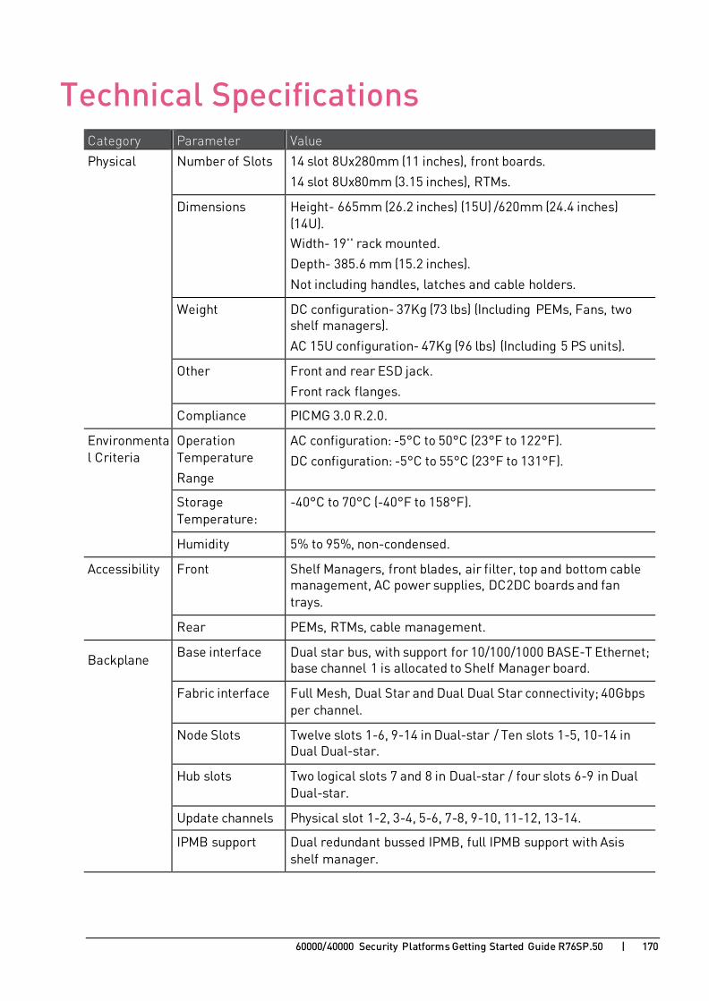
60000/40000 Security Platforms Getting Started Guide R76SP.50 | 170
C H A P T E R 2 2
Technical Specifications Category Parameter Value
Physical Number of Slots 14 slot 8Ux280mm (11 inches), front boards.
14 slot 8Ux80mm (3.15 inches), RTMs.
Dimensions Height- 665mm (26.2 inches) (15U) /620mm (24.4 inches) (14U). Width- 19'' rack mounted.
Depth- 385.6 mm (15.2 inches).
Not including handles, latches and cable holders.
Weight DC configuration- 37Kg (73 lbs) (Including PEMs, Fans, two
shelf managers).
AC 15U configuration- 47Kg (96 lbs) (Including 5 PS units).
Other Front and rear ESD jack.
Front rack flanges.
Compliance PICMG 3.0 R.2.0.
Environmental Criteria
Operation Temperature
Range
AC configuration: -5°C to 50°C (23°F to 122°F).
DC configuration: -5°C to 55°C (23°F to 131°F).
Storage Temperature:
-40°C to 70°C (-40°F to 158°F).
Humidity 5% to 95%, non-condensed.
Accessibility Front Shelf Managers, front blades, air filter, top and bottom cable management, AC power supplies, DC2DC boards and fan trays.
Rear PEMs, RTMs, cable management.
Backplane Base interface Dual star bus, with support for 10/100/1000 BASE-T Ethernet; base channel 1 is allocated to Shelf Manager board.
Fabric interface Full Mesh, Dual Star and Dual Dual Star connectivity; 40Gbps per channel.
Node Slots Twelve slots 1-6, 9-14 in Dual-star / Ten slots 1-5, 10-14 in Dual Dual-star.
Hub slots Two logical slots 7 and 8 in Dual-star / four slots 6-9 in Dual Dual-star.
Update channels Physical slot 1-2, 3-4, 5-6, 7-8, 9-10, 11-12, 13-14.
IPMB support Dual redundant bussed IPMB, full IPMB support with Asis shelf manager.

Technical Specifications
60000/40000 Security Platforms Getting Started Guide R76SP.50 | 171
Category Parameter Value Power AC Power Supply Up to ten 1600W or eight 2500W front-accessible, redundant,
self-cooled, hot swappable power supplies with IPMI support.
DC Power Supply Up to two 125W front-accessible, redundant, self-cooled, hot swappable power supplies with IPMI support.
Cooling Cooling Mechanism
14U: Push-pull, front bottom to back top cooling. Upper pull tray with 9 fans for front and RTM cooling and lower push tray with 6 fans for front blades.
13U: Pull, front bottom to back top cooling. Upper tray with 9 fans for front and RTM cooling.
Fans Up to 15 fans with 300 CFM each for maximal pressurized cooling.
Redundancy N+1 (i.e., any one fan can fail with no service degradation).
Fan speed Variable speed under shelf manager control.
Air filter Front washable field replaceable NEBS GR63 compatible air filter.
Front Panel Display Nine LEDs to indicate chassis status, fans status, Telco alarm and user-defined status.
Telco Alarm Control of external alarms (see below).
Interfaces Serial link for the shelf manager, Telco alarms.
Shelf Management
Shelf Manager Two front accessible, redundant, hot-swappable IPMI Shelf Managers based on Pigeon Point ShMM Sentry 500 or 700.
Managed IPMI Peripherals
Shelf EEPROM, AC power supply, Fan Tray, PEM, Air filter, Alarm panel.
Protocol Support Multiple management interfaces supported: RMCP, RPC, SNMP, CLI, and OpenHPI.
Interface 10/100 Base-T Ethernet and serial link (on the front panel).
Software Upgrades
Software version is remotely upgradable.
IPM Sensor Entries
Fan speed, temperature, voltage, presence.
Alarm I/O Telco Alarm Alarm I/O on shelf front panel.
Electrical/Mechanical
Front accessible through Micro D-type 15 pin connector.
Alarm I/O interfaces
Supports 4 outputs (Major, Minor, Critical, Power), 2 inputs (Major and Minor) and 2 switches (Reset and Alarm Cutoff).
Alarm relays with a maximum rating of 60VDC/1A or 30VAC.