PHASE IV REMEDY IMPLEMENTATION PLAN - Community ...
108
PHASE IV REMEDY IMPLEMENTATION PLAN – REVISION 5 FORMER NEW ENGLAND LOG HOMES SITE 100 BRIDGE STREET GREAT BARRINGTON, MASSACHUSETTS MASSDEP RELEASE TRACKING NO. 1-0682 Prepared for: Community Development Corp. of South Berkshire Post Office Box 733 Great Barrington, Massachusetts 01230 Prepared by: Ransom Consulting, Inc. 12 Kent Way, Suite 100 Byfield, Massachusetts 01922 (978) 465-1822 Project 021.01074.010 March 7, 2019 __________________________ Timothy J. Snay Licensed Site Professional
-
Upload
khangminh22 -
Category
Documents
-
view
1 -
download
0
Transcript of PHASE IV REMEDY IMPLEMENTATION PLAN - Community ...

PHASE IV REMEDY IMPLEMENTATION PLAN – REVISION 5 FORMER NEW ENGLAND LOG HOMES SITE
100 BRIDGE STREET GREAT BARRINGTON, MASSACHUSETTS MASSDEP RELEASE TRACKING NO. 1-0682
Prepared for:
Community Development Corp. of South Berkshire Post Office Box 733
Great Barrington, Massachusetts 01230
Prepared by:
Ransom Consulting, Inc. 12 Kent Way, Suite 100
Byfield, Massachusetts 01922 (978) 465-1822
Project 021.01074.010
March 7, 2019
__________________________ Timothy J. Snay
Licensed Site Professional

Ransom Project 021.01074.009 Executive Summary Page 1 of 3 P:\2002\021074\Phase IV RIP5 - 2019\text.docx March 7, 2019
EXECUTIVE SUMMARY
On behalf of the Community Development Corporation of South Berkshire (CDC), Ransom Consulting, Inc. (Ransom) has prepared this Phase IV Remedy Implementation Plan (RIP) – Revision 5 for the former New England Log Homes (NELH) property located at 100 Bridge Street in Great Barrington, Massachusetts (the Site). The Site is defined as the approximately 8.2-acre area located southwest of the intersection of Bridge Street and Bentley Road that has been impacted primarily by dioxins and pentachlorophenol (PCP), with secondary impacts from metals, petroleum hydrocarbons, and polycyclic aromatic hydrocarbons (PAHs). The primary affected media at the Site is soil; groundwater has been impacted primarily by PCP.
The Site is bounded by the Housatonic River to the west, Bridge Street and Bentley Street to the north and east, respectively, and the publicly operated wastewater treatment works to the south. The area surrounding the Site is primarily residential, but a commercial district is located to the west of the Housatonic River. Properties around the Site are serviced by the public water supply and there are no known private water supply wells within 500 feet of the Site; however, the Site is located within the Zone II of the Town of Sheffield public water supply. The Site is also located in the 100-year flood plain for the Housatonic River as designated by the Federal Emergency Management Agency (FEMA).
The Site was first developed in 1894 with a manufacturing plant for bedspreads and cotton goods. Those operations ceased in 1963 and the Site remained vacant until 1971. From 1971 through 1993, NELH occupied the property and manufactured log homes. The NELH manufacturing operations included the use of wood preservatives containing PCP, which was one of the most widely used biocides in the U.S. prior to1987. NELH ceased operations in 1993 and the Site was vacated. The perimeter of the Site is fenced to prevent access by the public. In March 2001, a fire significantly damaged the main building on the Site, burning half of it to the ground. Soot and debris from the fire was deposited onto the ground surface of the Site. The damaged main building and the remaining buildings were demolished in 2012 and most of the debris was removed from the Site. The base of the former building’s smokestack remained, along with three debris piles (crushed concrete, mixed concrete and brick, and soil/woodchips). These debris piles were subsequently moved to the south end of the Site.
The CDC purchased the Site with the intent of redeveloping this Brownfield site into a sustainable, mixed-use development with mixed-income housing opportunities, retail and commercial space, and an open-space public gathering places. In August 2013, the CDC submitted a Revised Phase IV RIP which included the use of in-situ bioremediation to reduce the concentrations of dioxins and other organic contaminants in shallow soil (i.e., 18 to 20 inches) prior to proceeding with redevelopment of the Site. The bioremediation efforts were initiated in July 2014 but terminated by the Massachusetts Department of Environmental Protection (MassDEP) in August 2015. In September 2015, the bioremediation contractor collected 97 soil samples across the Site for field analysis of dioxins. Reported dioxin concentrations ranged from 1,324 to 1,898 nanograms per kilogram (ng/kg) or parts per trillion (ppt).
Between September 14, 2016 and June 30, 2017, the CDC submitted three revisions of the Phase IV RIP to the MassDEP. The remediation strategies have included various grading and development scenarios that would cap the shallow dioxin-contaminated soils in place. Since submittal of the Phase IV RIP – Revision 4, the CDC has continued to investigate alternative redevelopment scenarios that will facilitate funding for the project and has revised the development plan for the Site.
The proposed redevelopment project will now be completed in three phases of work; Phase 1, the remediation of the Site, followed immediately with Phase 2, the construction of 45 units of affordable
Ransom Project 021.01074.009 Executive Summary Page 2 of 3 P:\2002\021074\Phase IV RIP5 - 2019\text.docx March 7, 2019
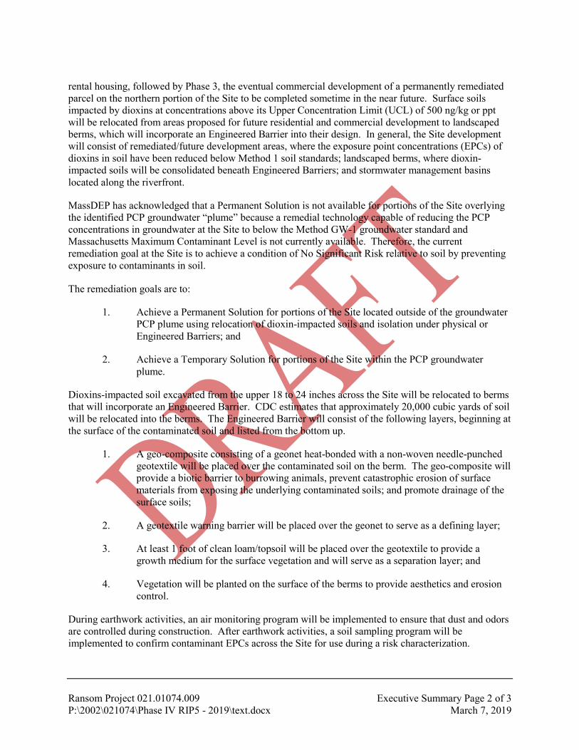
rental housing, followed by Phase 3, the eventual commercial development of a permanently remediated parcel on the northern portion of the Site to be completed sometime in the near future. Surface soils impacted by dioxins at concentrations above its Upper Concentration Limit (UCL) of 500 ng/kg or ppt will be relocated from areas proposed for future residential and commercial development to landscaped berms, which will incorporate an Engineered Barrier into their design. In general, the Site development will consist of remediated/future development areas, where the exposure point concentrations (EPCs) of dioxins in soil have been reduced below Method 1 soil standards; landscaped berms, where dioxin-impacted soils will be consolidated beneath Engineered Barriers; and stormwater management basins located along the riverfront.
MassDEP has acknowledged that a Permanent Solution is not available for portions of the Site overlying the identified PCP groundwater “plume” because a remedial technology capable of reducing the PCP concentrations in groundwater at the Site to below the Method GW-1 groundwater standard and Massachusetts Maximum Contaminant Level is not currently available. Therefore, the current remediation goal at the Site is to achieve a condition of No Significant Risk relative to soil by preventing exposure to contaminants in soil.
The remediation goals are to:
1. Achieve a Permanent Solution for portions of the Site located outside of the groundwater PCP plume using relocation of dioxin-impacted soils and isolation under physical or Engineered Barriers; and
2. Achieve a Temporary Solution for portions of the Site within the PCP groundwater plume.
Dioxins-impacted soil excavated from the upper 18 to 24 inches across the Site will be relocated to berms that will incorporate an Engineered Barrier. CDC estimates that approximately 20,000 cubic yards of soil will be relocated into the berms. The Engineered Barrier will consist of the following layers, beginning at the surface of the contaminated soil and listed from the bottom up.
1. A geo-composite consisting of a geonet heat-bonded with a non-woven needle-punched geotextile will be placed over the contaminated soil on the berm. The geo-composite will provide a biotic barrier to burrowing animals, prevent catastrophic erosion of surface materials from exposing the underlying contaminated soils; and promote drainage of the surface soils;
2. A geotextile warning barrier will be placed over the geonet to serve as a defining layer;
3. At least 1 foot of clean loam/topsoil will be placed over the geotextile to provide a growth medium for the surface vegetation and will serve as a separation layer; and
4. Vegetation will be planted on the surface of the berms to provide aesthetics and erosion control.
During earthwork activities, an air monitoring program will be implemented to ensure that dust and odors are controlled during construction. After earthwork activities, a soil sampling program will be implemented to confirm contaminant EPCs across the Site for use during a risk characterization.

Ransom Project 021.01074.009 Executive Summary Page 3 of 3 P:\2002\021074\Phase IV RIP5 - 2019\text.docx March 7, 2019
A Financial Assurance Mechanism will be established to ensure the functioning of the Engineered Barriers at the Site. Periodic groundwater monitoring will be required while a Temporary Solution is in effect at the Site, with a focus on monitoring PCP concentrations in groundwater. A post-development groundwater monitoring program will be included in the Temporary Solution Statement that will be submitted following completion of the remediation described herein.
Implementation of the remedial measures will be performed under the direction of Timothy J. Snay, the LSP-of-Record for the Site. Federal, state, and local permits, licenses and/or approvals related to wetlands, storm water management, floodplains, and solid waste are required and will be obtained by the CDC or the redevelopment contractor, as specified in the contract. Other approvals may be required from the Great Barrington Select Board, Planning Board, Conservation Commission, Building Department, and Public Works Department.

TABLE OF CONTENTS
1.0 INTRODUCTION ............................................................................................................................ 1
2.0 SITE HISTORY AND REGULATORY STATUS ........................................................................ 3 2.1 Site Description and Synopsis .................................................................................................. 3 2.2 Site Investigation and Regulatory History ............................................................................... 4 2.3 Current Regulatory Status ...................................................................................................... 10
3.0 EXISTING SITE CONDITIONS .................................................................................................. 11 3.1 Site Geology and Hydrogeology ............................................................................................ 11 3.2 Source Areas and Contaminants of Concern.......................................................................... 11
3.2.1 Contaminants in Soil ................................................................................................... 12 3.2.2 Contaminants in Groundwater ..................................................................................... 15
3.3 Exposure Pathways ................................................................................................................ 15 3.3.1 Soil ............................................................................................................................. 15 3.3.2 Groundwater ................................................................................................................ 16
4.0 COMPLETED SITE PREPARATION ACTIVITIES................................................................ 17 4.1 Environmental Permitting ...................................................................................................... 17 4.2 Groundwater Monitoring Well Abandonment ....................................................................... 17 4.3 Visual Asbestos Assessment .................................................................................................. 17 4.4 Protection of Sensitive Resources .......................................................................................... 17 4.5 Removal of Stockpiled Materials ........................................................................................... 17 4.6 Temporary Irrigation System ................................................................................................. 18 4.7 Regrading of Bentley Street Swale ........................................................................................ 18 4.8 Relocation of Hot Spot Soils .................................................................................................. 18 4.9 Discovery of Additional AOCs .............................................................................................. 18 4.10 Bioremediation Treatment ..................................................................................................... 18
5.0 PROPOSED DEVELOPMENT PLAN ........................................................................................ 19
6.0 ENGINEERING DESIGN ............................................................................................................. 20 6.1 Remediation Goals ................................................................................................................. 20 6.2 Erosion and Sedimentation Controls ...................................................................................... 20 6.3 Air Monitoring Program ........................................................................................................ 20
6.3.1 Air Monitoring Plan ..................................................................................................... 20 6.3.2 Ambient Air Monitoring Program ............................................................................... 21
6.4 Remediation Plan Design Assumptions ................................................................................. 23 6.5 Proposed Soil Excavation/Relocation Plan ............................................................................ 24 6.6 Engineered Barrier Requirements .......................................................................................... 24
6.6.1 Water Solubility ........................................................................................................... 25 6.6.2 Vapor Pressure ............................................................................................................. 26 6.6.3 Henry’s Law Constant ................................................................................................. 26 6.6.4 Octanol-Water Partition Coefficient (Kow) .................................................................. 26 6.6.5 Adsorption Coefficient (Koc) ....................................................................................... 26
6.7 Contaminant Migration and Potential Exposure Scenarios .................................................... 27 6.8 Engineered Barrier Design ..................................................................................................... 27 6.9 Assessment of Engineered Barrier Performance Requirements............................................. 29
6.9.1 Prevent Direct Contact with Contaminated Media ...................................................... 29
6.9.2 Control Vapors or Dust Emanating from Contaminated Media .................................. 29 6.9.3 Prevent Erosion and Infiltration that Could Jeopardize the Integrity of the Barrier .... 29 6.9.4 Comprised of Materials Resistant to Degradation ....................................................... 29 6.9.5 Consistent with Technical Standards ........................................................................... 30 6.9.6 Include a Defining Layer to Identify the Beginning of the Barrier ............................. 30 6.9.7 Monitoring and Maintenance ....................................................................................... 30
6.10 Controls and Contingencies ................................................................................................... 30
7.0 SAMPLING PROGRAM .............................................................................................................. 32 7.1 Pre-Remediation Soil Sampling Program .............................................................................. 32 7.2 Post-Excavation Soil Sampling Program ............................................................................... 32 7.3 Soil Sample Collection ........................................................................................................... 33 7.4 Analytical Methods ................................................................................................................ 34
7.4.1 Dioxin Sampling .......................................................................................................... 34 7.4.2 PCP Sampling .............................................................................................................. 34 7.4.3 PAHs ............................................................................................................................ 34 7.4.4 EPH ............................................................................................................................. 34
7.5 Management of Remediation Wastes/Excess Soil ................................................................. 34 7.6 Groundwater Monitoring Program ......................................................................................... 35
8.0 POST-CONSTRUCTION ACTIVITIES, MAINTENANCE AND MONITORING ............... 36 8.1 Construction Documentation ................................................................................................. 36 8.2 Financial Assurance Mechanism ............................................................................................ 36 8.3 Routine Inspection, Maintenance and Monitoring ................................................................. 36 8.4 Property Access Issues ........................................................................................................... 36 8.5 Routine Reporting .................................................................................................................. 36
9.0 REQUIRED PERMITS, LICENSES, OR APPROVALS .......................................................... 38 9.1 Federal Permits, Licenses, or Approvals ................................................................................ 38
9.1.1 Wetlands ...................................................................................................................... 38 9.1.2 Stormwater................................................................................................................... 38
9.2 State and Local Permits, Licenses, or Approvals ................................................................... 38 9.2.1 Waste Site Cleanup ...................................................................................................... 38 9.2.2 Stormwater................................................................................................................... 38 9.2.3 Historical Resources .................................................................................................... 39 9.2.4 Beneficial Use Determination...................................................................................... 39
9.3 Additional Local Permits, Licenses, or Approvals ................................................................ 39 9.3.1 Floodplain Development ............................................................................................. 39 9.3.2 Water Quality Protection Overlay District .................................................................. 39 9.3.3 Rare Species ................................................................................................................ 39 9.3.4 MEPA .......................................................................................................................... 39 9.3.5 Other Local Approvals ................................................................................................ 40
10.0 PUBLIC NOTIFICATION ............................................................................................................ 41
11.0 HEALTH AND SAFETY PLAN ................................................................................................... 42

TABLES
Table 1: Fate and Transport Characteristics of Dioxins Table 2: Post-Remediation Sampling Plan
FIGURES
Figure 1: Site Location Map Figure 2: Historical Site Plan Figure 3: Dioxin Concentrations in Soil and Groundwater Figure 4: Pentachlorophenol (PCP) Concentrations in Soil and Groundwater Figure 5: Petroleum Hydrocarbon Concentrations in Soil Figure 6: PAHs and Metals Concentrations in Soil (Detail) Figure 7: Ambient Air Monitoring Locations Figure 8 Proposed Post-Remediation Sampling Plan
APPENDICES
Appendix A: Site Remediation Bid Set Drawings, Furrow Engineering Appendix B: Community Air Monitoring Program Appendix C: Public Notifications

Ransom Project 021.01074.009 Page 1 P:\2002\021074\Phase IV RIP5 - 2019\text.docx March 7, 2019
1.0 INTRODUCTION
On behalf of the Community Development Corporation of South Berkshire (CDC), Ransom Consulting, Inc. (Ransom) has prepared this Phase IV Remedy Implementation Plan (RIP) – Revision 5 for the former New England Log Homes (NELH) property located at 100 Bridge Street in Great Barrington, Massachusetts (the Site). The Site is defined as the approximately 8.2-acre area located southwest of the intersection of Bridge Street and Bentley Road that has been impacted primarily by dioxins and pentachlorophenol (PCP), with secondary impacts from metals, petroleum hydrocarbons, and polycyclic aromatic hydrocarbons (PAHs). The primary affected media at the Site is soil; groundwater has been impacted primarily by PCP.
The ultimate goal of the CDC is to redevelop this Brownfield site into a sustainable, mixed-use development with mixed-income housing opportunities, retail and commercial space, and/or open-space public gathering places. The entire Site will be developed with buildings, pavement, or landscaped areas. The Massachusetts Department of Environmental Protection (MassDEP) has acknowledged that a Permanent Solution is not available for portions of the Site overlying the identified PCP groundwater “plume” because a remedial technology capable of reducing the PCP concentrations in groundwater at the Site to below the Method GW-1 groundwater standard and Massachusetts Maximum Contaminant Level (MMCL) is not currently available. Therefore, the remediation goal at the Site is to achieve a condition of No Significant Risk relative to soil by preventing exposure to residual contaminants in soil.
Between August 2013 and June 30, 2017, the CDC submitted four revisions of the Phase IV RIP to the MassDEP. The remediation strategies have varied from the use of in-situ bioremediation to reduce the concentrations of dioxins and other organic contaminants in shallow soil (i.e., 18 to 20 inches) to various grading and development scenarios that would cap the contaminated soils in place.
Since submittal of the Phase IV RIP – Revision 4, the CDC has continued to pursue alternative redevelopment scenarios that will facilitate funding for the project and the development plan was revised in 2018. The proposed redevelopment project will now be completed in three phases of work; Phase 1, the remediation of the Site, followed immediately with Phase 2, the construction of 45 units of affordable rental housing, followed by Phase 3, the eventual commercial development of a permanently remediated parcel on the northern portion of the Site to be completed sometime in the near future. A revision of the previous RIP is needed to describe the current remediation plan.
This Phase IV RIP – Revision 5 was prepared in accordance with the requirements of the Massachusetts Contingency Plan (MCP), 310 CMR 40.0874. A draft will be available to the public for comment. The final IV RIP – Revision 5 will include responses to comments on the draft and will be submitted to MassDEP with a completed Comprehensive Response Action Transmittal Form & Phase I Completion Statement (BWSC108) via the eDEP online system.

Ransom Project 021.01074.009 Page 2 P:\2002\021074\Phase IV RIP5 - 2019\text.docx March 7, 2019
The responsible party for submittal of the Phase IV RIP – Revision 5 is:
Community Development Corporation of South Berkshire (CDC) 17 Bridge Street (Post Office Box 733) Great Barrington, MA 01230 [email protected] Tel: 413-528-7788 Cell: 413-329-2324 Attn: Mr. Timothy Geller, Executive Director
The Licensed Site Professional for implementation of the Phase IV RIP is:
Mr. Timothy J. Snay, LSP Ransom Consulting, Inc. 12 Kent Way, Suite 100 Byfield, Massachusetts 01922 [email protected] Tel: 978-465-1822 Fax: 978-465-2986
CDC will own and operate the Site during implementation of the proposed remedial action alternative and following completion of the Site’s redevelopment. CDC will be responsible for activities to be conducted under the MCP, future maintenance of the Site, and compliance with a Notice of Activity and Use Limitation (AUL) anticipated as part of the site closure activities. CDC may contract with others to perform these services on their behalf.

Ransom Project 021.01074.009 Page 3 P:\2002\021074\Phase IV RIP5 - 2019\text.docx March 7, 2019
2.0 SITE HISTORY AND REGULATORY STATUS
2.1 Site Description and Synopsis
The Site consists of an 8.2-acre parcel of land bounded by the Housatonic River to the west, Bridge Street and Bentley Road to the north and east, respectively, and the publicly operated wastewater treatment works (POTW) to the south. The area surrounding the Site is primarily residential, but a commercial district is located to the west of the Housatonic River. Properties around the Site are serviced by the public water supply and there are no known private water supply wells within 500 feet of the Site; however, the Site is located within the Zone II of the Town of Sheffield public water supply. The Site is also located in the 100-year flood plain for the Housatonic River as designated by the Federal Emergency Management Agency (FEMA). The Site location is shown on an excerpt of a United States Geological Survey (U.S. GS) quadrangle map provided as Figure 1.
The Site was first developed in 1894 with a manufacturing plant for bedspreads and cotton goods. Those operations ceased in 1963 and the Site remained vacant until 1971. From 1971 through 1993, NELH occupied the property and manufactured log homes. The NELH manufacturing operations included the use of wood preservatives containing PCP, which was one of the most widely used biocides in the U.S. prior to1987. NELH ceased operations in 1993 and the Site was vacated. The perimeter of the Site is fenced to prevent access by the public. In March 2001, a fire significantly damaged the main building on the Site, burning half of it to the ground. Soot and debris from the fire was deposited onto the ground surface of the Site. The damaged main building and the remaining buildings were demolished in 2012 and most of the debris was removed from the Site. The base of the former building’s smokestack remained, along with three debris piles (crushed concrete, mixed concrete and brick, and soil/woodchips). These debris piles were subsequently moved to the south end of the Site. The past layout of the Site is shown on the Historical Site Plan provided as Figure 2.
In August 2013, the CDC submitted a Revised Phase IV RIP to conduct in-situ bioremediation at the Site in lieu of the generalized capping proposed in the Phase IV RIP originally submitted to MassDEP in March 2011. In spring/early summer 2014, the Site was cleared, grubbed, and ripped in preparation for bioremediation. Soil amendments (compost, agricultural lime, and urea nitrogen) were applied between June 25 and July 3, 2014, and a bioremediation “Factor” was applied to surface soils across the Site on July 7, 2014. The upper 18 to 20 inches of soil were subsequently tilled using farming equipment to incorporate the “Factor” into the soils and provide aeration. Tilling continued into October 2014. In late fall 2014, the area was seeded to provide stabilization over the winter months. In May 2015, MassDEP suspended additional bioremediation at the Site pending documentation of success related to the process. Despite arguments that bioremediation processes were occurring, in August 2015, MassDEP terminated further bioremediation efforts. Additional field investigations or related response actions were not performed at the Site following MassDEP’s termination of the bioremediation program.
On February 12, 2016, the CDC met with MassDEP to discuss the next steps at the Site. Because the in-situ bioremediation strategy had been terminated by MassDEP, CDC proposed to eliminate exposure to contaminated soils with the construction of a variety of “cap-like” structures integrated into the proposed redevelopment of the Site, followed by the placement of a Notice of AUL at the Site. The proposed “cap-like” structures included building foundations and parking lots. In green space areas, the proposed cap consists of a geotextile warning barrier placed beneath a soil cap system to be approved by MassDEP.
On September 14, 2016, the CDC submitted Phase IV RIP – Revision 2 to MassDEP. The proposed remediation plan would achieve a Partial Permanent Solution in areas of the Site outside of the PCP

Ransom Project 021.01074.009 Page 4 P:\2002\021074\Phase IV RIP5 - 2019\text.docx March 7, 2019
groundwater “plume” (located beneath the central portion of the Site). The remediation plan for the Site was simple in concept; namely, to prevent exposures to dioxin-contaminated soils currently located in surface soils at the Site by excavating and removing them from the area or by isolating them under the structures proposed as part of redevelopment of the Site. However, because the Site is subject to restrictions regarding flood storage capacity, maintaining the existing site elevations would require the use of on-site uncontaminated soil as cover material and the relocation of contaminated soil to deeper elevations.
On November 1, 2016, MassDEP issued their response to the proposed Phase IV RIP. MassDEP concluded that relocating contaminated soil below the current elevations would expand the existing disposal site, and therefore, was not acceptable under the Response Action Performance Standard at 310 CMR 40.0191(2) provided in the MCP.
On January 3 and June 30, 2017, the CDC submitted Phase IV RIP – Revisions 3 and 4, respectively, following discussions with MassDEP regarding an alternate remediation strategy. The remediation plan presented in Phase IV RIP Revisions 3 and 4 was again based on the concept of preventing exposures to dioxin-contaminated soils by removing them from an area and isolating them under a barrier. The Phase IV RIP – Revisions 3 and 4 provided a remediation strategy focused only on the initial phase of development of the Site (i.e., construction of multi-family housing on the south end and development of green space along the riverfront). It included a temporary 1-foot soil cap over the Future Development Area in the northern half of the Site to prevent exposure to contaminated soil remaining at the Site, and a Notice of AUL to maintain the temporary cap until the rest of the Site development would proceed.
Since submittal of the Phase IV RIP – Revision 4, the CDC has continued to pursue alternative development scenarios that will facilitate funding for the project and the development plan was revised in 2018. The project is now proposed for development in one phase of work, with remediation completed prior to construction of the Site buildings. The purpose of this Phase IV RIP – Revison 5 is to describe the current remediation plan.
2.2 Site Investigation and Regulatory History
Numerous investigations were performed at the Site from the late 1980s through 2015 to evaluate soil and/or groundwater at the Site for evidence of a release of oil and/or hazardous material (OHM). The early investigations were summarized in a Phase III Remedial Action Plan (RAP) prepared by Ransom and amended in May 2013. Additional investigations have been completed since that time to supplement the earlier data; those results were described in the Phase IV Status Reports referenced below. A chronology with brief descriptions of the historical investigations and regulatory submittals for this site is as follows:
1. October 1987: “Site Assessment Report,” prepared by HRP Associates (HRP), Inc., dated October 23, 1987, and revised in August 1989.
2. January 1990: Designated as a Tier Class Transition Site (Release Tracking No. [RTN]) 1-06820 on January 15, 1990 by the MassDEP.
3. March 1996: “Subsurface Investigation Report” prepared by HRP, dated March 1996. The field investigations included excavation of test pits, advancement of soil borings, installation of monitoring wells, and collection of soil and groundwater samples for chemical analysis. A magnetometer survey was conducted in the southeastern portion of

Ransom Project 021.01074.009 Page 5 P:\2002\021074\Phase IV RIP5 - 2019\text.docx March 7, 2019
the Site to investigate an area where drums containing waste PCP were allegedly buried; no buried drums were encountered in that area during the survey.
4. 1996 and 1997: Investigations by the U.S. Environmental Protection Agency (U.S. EPA) and the MassDEP in 1996 and 1997, which included the collection of shallow soil samples, characterization of tank and drum contents at the Site, consolidation of wastes in drums inside the main building, enclosure of the dip tank and drip pad, and securing the Site from trespassers. Based on the results of the environmental investigations completed at the Site, dioxins and PCP were present at elevated concentrations in soil and/or groundwater.
5. March 1997: “Environmental Sampling Report,” prepared by Coneco Environmental for the MassDEP, dated March 17, 1997.
6. October 2000: “Phase I-Initial Site Investigation Report, Former New England Log Homes Site, Great Barrington, Massachusetts, Release Tracking Number: 1-0682,” prepared by Fuss & O’Neill, Inc. (F&O).
7. November 2, 2000: “Tier II Classification and Public Notice, Former New England Log Homes Site 100 Bridge Street, Great Barrington, Massachusetts, Release Tracking Number: 1-0682,” prepared by F&O. F&O classified the Site as a Tier II disposal site based on a Numerical Ranking System (NRS) score of 277, which was below the Tier II cut-off score of 350. F&O noted that the Site is located within the Zone II for a public water supply for the neighboring Town of Sheffield; however, they stated that conditions at the Site did not pose a potential for human exposure at the Sheffield public water supply.
8. January 2002: “Phase II-Comprehensive Site Assessment Report, Former New England Log Homes Site, 100 Bridge Street, Great Barrington, Massachusetts, Release Tracking Number: 1-0682,” prepared by F&O. F&O concluded that soil at the Site was impacted by PCP, dioxins, extractable petroleum hydrocarbons (EPH), metals, and semi-volatile organic compounds (SVOCs), with some concentrations greater than the Upper Concentration Limits (UCLs) provided in the MCP. Elevated concentrations of lead and PCP were detected in groundwater samples at the Site, but concentrations of contaminants in surface water and river sediments of the abutting Housatonic River were consistent with background conditions.
9. November 2003: Ransom collected groundwater samples from six monitoring wells for analysis of PCP and/or dioxins and dissolved lead. PCP was present in the groundwater samples collected from one of the wells at the Site at an elevated concentration; dioxins were present at low concentrations and dissolved lead was not detected at concentrations above the laboratory reporting limits.
10. January 2004: Ransom completed a Ground Penetrating Radar (GPR) survey at the Site with Hager GeoScience, Inc. to field verify the presence of underground utilities, particularly near the fire-damaged building.
11. August 2004: At the request of the MassDEP, Ransom installed two additional groundwater wells near former Dip Tank No. 2 and along the Housatonic River. An
Ransom Project 021.01074.009 Page 6 P:\2002\021074\Phase IV RIP5 - 2019\text.docx March 7, 2019
elevated concentration of PCP was detected in the groundwater sample collected from the well along the river; dioxins were present in the groundwater samples at trace concentrations.
12. January 2005: “Phase III Remedial Action Plan, Former New England Log Homes Site, 100 Bridge Street, Great Barrington, Massachusetts, MA DEP Release Tracking Number: 1-0682,” (Phase III RAP) prepared by Ransom. The Phase III RAP recommended the construction of a physical barrier across the entire Site to prevent exposure to dioxin-impacted soils. No groundwater remedial alternative was proposed.
13. March 2011: “Phase IV Remedy Implementation Plan, Former New England Log Homes Site, 100 Bridge Street, Great Barrington, Massachusetts, MA DEP Release Tracking No. 1-0682,” (Phase IV RIP) prepared by Ransom. The Phase IV RIP was based on the premise that the entire physical barrier would be constructed at the Site prior to redevelopment of the property, such that the Site could be “closed” under the MCP through the filing of a Class C Response Action Outcome (RAO) Statement (i.e., a Temporary Solution).
14. October 2011: “Release Abatement Measure (RAM) Plan, Former New England Log Homes, Great Barrington, Massachusetts, RTN: 1-00682,” (RAM Plan) prepared by F&O. The RAM Plan provided procedures to be used during demolition of the Site building and to manage contaminated soil and construction debris.
15. August 13, 2012: “Release Abatement Measure (RAM) Completion, Former New England Log Homes, Great Barrington, Massachusetts, RTN: 1-00682,” prepared by F&O. The RAM Completion Report summarized the demolition activities completed at the Site. Commingled asbestos-containing material (ACM) and demolition debris were managed consistent with an approved Asbestos Work Plan. Three other debris piles generated during the demolition activities were left at the Site.
16. March 2013: Ransom collected additional soil samples for dioxins analysis to supplement the earlier data and confirm the vertical distribution of dioxins in soil. The sampling indicated that dioxin-contaminated soils were generally limited to the top 1 foot of soil at the Site.
17. Spring 2013: Biotech Restorations LLC (BTR) of Denver, North Carolina, completed a bench study to verify the effectiveness of the proposed in-situ bioremediation treatment for Site soils, determined the appropriate formulation and volumes of soil amendments needed during the treatment period, and estimated the duration of treatment that is likely to be required. After 10 weeks of treatment, one formulation reduced the concentrations of individual dioxins congeners by 97 to 100 percent, and the overall dioxin Toxicity Equivalency (TE) by 99.2 percent. This formulation was used in the field application.
18. May 29, 2013: “Phase III Remedial Action Plan Addendum No. 1, Former New England Log Homes Site, 100 Bridge Street, Great Barrington, Massachusetts, MA DEP Release Tracking No. 1-0682” (Amended RAP), prepared by Ransom. The Amended RAP introduced the in-situ bioremediation process proposed by BTR.
Ransom Project 021.01074.009 Page 7 P:\2002\021074\Phase IV RIP5 - 2019\text.docx March 7, 2019
19. August 2, 2013: “Revised Phase IV Remedy Implementation Plan, Former New England Log Homes Site, 100 Bridge Street, Great Barrington, Massachusetts, MA DEP Release Tracking No. 1-0682,” (Revised RIP), prepared by Ransom. The Revised RIP described implementation of the in-situ bioremediation process proposed by BTR.
20. August 19, 2013: “Amended Soil Sampling Plan for the Phase IV Remedy Implementation Plan, Former New England Log Homes Site, 100 Bridge Street, Great Barrington, Massachusetts, MA DEP Release Tracking No. 1-0682,” prepared by Ransom.
21. December 23, 2013: “Phase IV Status Report, Former New England Log Homes Site, 100 Bridge Street, Great Barrington, Massachusetts, MA DEP Release Tracking No. 1-0682,” prepared by Ransom. The report included a description of the collection of soil samples at 45 locations and depths of 0-1 foot, 1.5 to 3 feet, 3 to 4 feet, and 4 to 8 feet below the ground surface (bgs) for analysis of dioxins and furans, and additional soil samples at 13 locations for analysis of PCP, PAHs, lead, arsenic, thallium, and/or EPH.
22. June 27, 2014: “Phase IV Status Report No. 2, Former New England Log Homes Site, 100 Bridge Street, Great Barrington, Massachusetts, MA DEP Release Tracking No. 1-0682,” prepared by Ransom. The report documented the completion of site preparation activities, including installation of erosion controls, clearing and grubbing of the Site, management of existing demolition debris piles, relocation of Hot Spot soils for treatment and re-grading, and ripping of the Site.
23. July 15, 2014: “Modification to the Phase IV Remedial Implementation Plan, Former New England Log Homes Site, 100 Bridge Street, Great Barrington, Massachusetts, MA DEP Release Tracking No. 1-00682,” prepared by Ransom in response to a Notice of Noncompliance (NON-WE-14-3041) issued by the MassDEP on July 14, 2014;
24. July 25, 2014: “Immediate Response Action (IRA) Plan, Buried Drum, 100 Bridge Street, Great Barrington, Massachusetts, MA DEP Release Tracking No. 1-19427,” prepared by Ransom following the completion of response actions related to the discovery of a buried 55-gallon drum in June 2014.
25. August 1, 2014: “Modification No. 2, Phase IV Remedial Implementation Plan, Former New England Log Homes Site, 100 Bridge Street, Great Barrington, Massachusetts, MA DEP Release Tracking No. 1-00682,” prepared by Ransom in response to email correspondence from the MassDEP on July 31, 2014.
26. August 2014: “Community Air Monitoring Plan, Former New England Log Homes, 100 Bridge Street, Great Barrington, MA” prepared by URS Corporation (URS) of Clifton, New Jersey in response to correspondence from the MassDEP dated August 4, 2014.
27. August 27, 2014: Submittal of the July 2014 (baseline) dioxin soil sampling data package (site plan, summary table, laboratory report) prepared by Ransom to the MassDEP.

Ransom Project 021.01074.009 Page 8 P:\2002\021074\Phase IV RIP5 - 2019\text.docx March 7, 2019
28. September 30, 2014: “Immediate Response Action (IRA) Completion Report, Buried Drum, 100 Bridge Street, Great Barrington, Massachusetts, MA DEP Release Tracking No. 1-19427,” prepared by Ransom.
29. November 26, 2014: “Response to Interim Deadline, Former New England Log Homes Site, 100 Bridge Street, Great Barrington, Massachusetts, MA DEP Release Tracking No. 1-00682,” prepared by Ransom in response to correspondence from the MassDEP dated November 10, 2014. This document included the “Community Air Monitoring Report” prepared by URS following implementation of the air monitoring program in September 2014.
30. December 16, 2014: “Phase IV Status Report No. 3, Former New England Log Homes Site, 100 Bridge Street, Great Barrington, Massachusetts, MA DEP Release Tracking No. 1-0682,” prepared by Ransom. The report documented the discovery of an abandoned underground storage tank (UST), assigned RTN 1-19434 by the MassDEP, and the activities conducted since June 2014, as referenced above.
31. June 3, 2015: CDC submitted a revised Tier Classification to the MA DEP to link the UST release discovered in June 2014 (RTN 1-19434) to the primary site-wide release (RTN 1-682);
32. June 11, 2015: “Phase IV Status Report No.4, Former New England Log Homes Site, 100 Bridge Street, Great Barrington, Massachusetts, MA DEP Release Tracking No. 1-0682,” prepared by Ransom. No field activities occurred since the December 2014 Status Report was submitted. The Site was covered by snow until April 2015 and the MassDEP had not authorized further field activities.
33. July 13, 2015: Submittal of Addendum No. 1 to the Quality Assurance Project Plan (QAPP Addendum). The QAPP Addendum presented the rationales for and designs of environmental sampling programs associated with the implementation and evaluation of in-situ bioremediation activities being conducted at the Site;
34. August 18, 2015: The MassDEP terminated approval for the in-situ bioremediation pilot project;
35. September 11, 2015: BTR collected 97 soil samples across the Site for field-based immunoassay analysis for dioxins. Reported dioxin concentrations ranged from 1,324 to 1,898 nanograms per kilogram (ng/kg) or parts per trillion (ppt).
36. January 6, 2016: “Phase IV Status Report No. 5, Former New England Log Homes Site, 100 Bridge Street, Great Barrington, Massachusetts, MA DEP Release Tracking No. 1-0682,” prepared by Ransom. The report documented additional soil sampling for dioxins analysis as conducted by BTR in September 2015.
37. June 24, 2016: “Phase IV Status Report No. 6, Former New England Log Homes Site, 100 Bridge Street, Great Barrington, Massachusetts, MA DEP Release Tracking No. 1-0682,” prepared by Ransom. The report discussed the intent to revise the remediation strategy for the Site.

Ransom Project 021.01074.009 Page 9 P:\2002\021074\Phase IV RIP5 - 2019\text.docx March 7, 2019
38. September 14, 2016: “Phase IV Remedy Implementation Plan – Revision 2, Former New England Log Homes Site, 100 Bridge Street, Great Barrington, Massachusetts, MA DEP Release Tracking No. 1-0682,” (RIP- Revision 2), prepared by Ransom.
39. December 16, 2016: “Phase IV Status Report No. 7, Former New England Log Homes Site, 100 Bridge Street, Great Barrington, Massachusetts, MA DEP Release Tracking No. 1-0682,” prepared by Ransom. The report discussed the Phase IV RIP – Revision 2 and proposed changes to the remediation strategy for the Site.
40. January 3, 2017: “Phase IV Remedy Implementation Plan – Revision 3, Former New England Log Homes Site, 100 Bridge Street, Great Barrington, Massachusetts, MA DEP Release Tracking No. 1-0682,” (RIP- Revision 3), prepared by Ransom. The report presented the current two-phased remediation strategy for the Site.
41. April 14, 2017: “Revised Environmental Sampling Plan for Phase IV Remedy Implementation Plan – Revision 3, Former New England Log Homes Site, 100 Bridge Street, Great Barrington, Massachusetts, MA DEP Release Tracking No. 1-0682,” (Revised RIP- Revision 3 Sampling Plan), prepared by Ransom. The Revised RIP- Revision 3 Sampling Plan addressed technical comments provided by the MassDEP on January 27, 2017.
42. June 22, 2017: “Phase IV Status Report No. 8, Former New England Log Homes Site, 100 Bridge Street, Great Barrington, Massachusetts, MA DEP Release Tracking No. 1-0682,” prepared by Ransom. The report discussed the Phase IV RIP – Revision 3 and revised sampling plan for the Site and noted that a Public Involvement Plan was submitted by the CDC on June 9, 2017.
43. June 30, 2017: “Phase IV Remedy Implementation Plan – Revision 4, Former New England Log Homes Site, 100 Bridge Street, Great Barrington, Massachusetts, MA DEP Release Tracking No. 1-0682,” prepared by Ransom. The report discussed the Phase IV RIP – Revision 4 and revised sampling plan for the Site and included responses to public comments provided on the draft document.
44. March 13, 2018: “Phase IV Status Report No. 9, Former New England Log Homes Site, 100 Bridge Street, Great Barrington, Massachusetts, MA DEP Release Tracking No. 1-0682,” prepared by Ransom. No response actions occurred during this period while funding was pursued for the Site. The anticipated date listed for submittal of a Temporary Solution based on the Phase IV RIP – Revision 5 was December 31, 2019.
45. March 13, 2018: “LSP Opinion in Support of Application for Tier I Permit Extension, 100 Bridge Street, Great Barrington, Massachusetts, MA DEP Release Tracking No. 1-0682, Tier I Permit #548535,” prepared by Ransom. The Opinion indicated that a Partial Permanent Solution Statement was anticipated by December 31, 2019.
46. February 5, 2019: “Phase IV Status Report No. 10, Former New England Log Homes Site, 100 Bridge Street, Great Barrington, Massachusetts, MA DEP Release Tracking No. 1-0682,” prepared by Ransom. The report included a discussion of a revised development plan and justification in support of site-specific cross-sections for engineered barriers proposed under the new development scenario.

Ransom Project 021.01074.009 Page 10 P:\2002\021074\Phase IV RIP5 - 2019\text.docx March 7, 2019
2.3 Current Regulatory Status
The MassDEP issued the Tier IB Permit Approval (Permit 548535) to CDC, effective on April 26, 2013. The original Tier IB Permit expired on April 26, 2018, 5 years from its effective date. The Tier I permit was presumptively approved and is currently valid through April 26, 2020.

Ransom Project 021.01074.009 Page 11 P:\2002\021074\Phase IV RIP5 - 2019\text.docx March 7, 2019
3.0 EXISTING SITE CONDITIONS
3.1 Site Geology and Hydrogeology
Based on soil borings advanced at the Site, fill material was commonly encountered at depths shallower than 5 feet bgs. The fill contains various materials including wood chips, gravel, glass, brick and ash. Beneath the shallow fill, native unconsolidated deposits consisting generally of silty, fine to coarse sand with varying amounts of clay and occasional fine gravel are present consistent with glacial till. According to the Bedrock Map of Massachusetts, bedrock underlying the Site consists of marble, phyllite and quartzite members of the Cambrian age Stockbridge Formation. Bedrock has not been encountered during previous investigations at the Site including borings advanced to a maximum depth of 42 feet bgs.
Groundwater elevations determined from historical monitoring indicate that the depths to groundwater were generally 10 to 15 feet bgs. Groundwater flows to the west in the direction of the Housatonic River. Based on a slight upward gradient observed in a groundwater monitoring well pair located along the east bank of the river, it appears that the Housatonic River serves as a discharge location for groundwater at the Site. Hydraulic conductivity testing completed by F&O in 2000 indicated that the hydraulic conductivity of unconsolidated deposits at the Site range from 1.14 to 7.8 feet per day, with a geometric mean of 2.52 feet per day. Given a geometric mean of hydraulic conductivity of 2.52 feet per day, an effective porosity of 0.35 and a hydraulic gradient of 0.003 foot per foot, F&O calculated a linear groundwater flow velocity of 0.02 foot per day or 7.3 feet per year.
3.2 Source Areas and Contaminants of Concern
Historical activities at the Site resulted in several potential environmental concerns. Petroleum use at the Site likely began with the Site’s first industrial development. Gasoline and diesel fuel were stored in aboveground storage tanks (ASTs) located east of the former main building along Bentley Street and No. 2 heating fuel was stored in several ASTs located within the main building and in a UST located to the east of the main building.
While NELH was operating at the Site from 1971 through 1993, several types of wood preservatives including PCP, zinc naphthenate, and copper arsenate were utilized. Finished wood products were submersed in three “dip-tanks” containing wood preservative; the dip tanks were located on the east and west sides of the main building and at the southeast corner of the main building. Pending use in the dip tanks, the preservatives were stored in drums and ASTs in the main building. Mineral spirits, also stored inside in 55-gallon drums, were used to remove residues of pitch and tar from equipment during the production of wood products. Finished, treated wood products were stockpiled outside in unpaved areas, particularly in the southern portion of the Site, but also in the east and north along Bentley and Bridge Streets, respectively.
In 2001, the main building was significantly damaged by fire with greater than 50 percent of the building having burned to the ground. Soot from the fire was deposited on the ground surface across the Site, and fire debris was present in the central portion until the remaining buildings were demolished and most of the debris was removed in 2012. Some debris piles were left at the Site, including piles of wood waste, metal, concrete, and brick intermixed with surface soils. The debris piles were later screened to remove the soil and relocated to the southern end of the Site during the site preparation activities conducted in 2014. The CDC intends to process the remaining debris materials on-site and place them under the Temporary Cap; these materials may be beneficially reused in a later phase of development.

Ransom Project 021.01074.009 Page 12 P:\2002\021074\Phase IV RIP5 - 2019\text.docx March 7, 2019
For assessment purposes, the Site was divided into four areas of concern (AOCs) based on the historical operations. The assessment areas are shown on Figure 2.
AOC Location Primary Environmental Concerns from Former Operations
Area A Southern Site Area Wood-preservative residues from storage of wood in open areas, bulky waste piles. Based on previous testing, it appears that only final wood products were treated with preservatives.
Area B West of main building Dip tank, wood-preservative residues, vertical ASTs. Area C Main building Minor wood-preservative residues, machine activities, fuel
oil ASTs. Area D East of main building Wood-preservative residues from storage of treated wood in
open areas, dip tank, fuel oil UST, diesel and gasoline ASTs.
3.2.1 Contaminants in Soil
Soil samples collected at the Site have been analyzed for dioxins, petroleum hydrocarbons, volatile organic compounds (VOCs), SVOCs, and/or various metals beginning in 1988 and continuing through 2014. Based on the analytical results gathered to date, dioxins and furans (expressed as 2,3,7,8-tetrachlorodibenzo-p-dioxin [2,3,7,8-TCDD] toxicity equivalency [TE] and calculated using the MassDEP Toxicity Equivalency Factors [TEFs]), are the primary contaminant of concern (COC) for soil, with secondary impacts from PCP, EPH, PAH, and metals (i.e., arsenic, lead, thallium, and zinc). Volatile petroleum hydrocarbons (VPH) and VOCs were eliminated as COCs.
The nature and extent of contamination in soil at the Site and the COCs as determined by the investigations completed to date are briefly summarized below. Note that in 2014, the shallow soils in the upper 18 inches were amended to promote in-situ bioremediation and tilled to promote aeration and degradation since much of the sampling was completed. The dioxin concentrations shown in Figure 3 predate the bioremediation efforts. Post-remediation surface soil sampling locations are not included on Figure 3 but are described below; specific sampling locations were included in previous correspondence to MassDEP.
Dioxins
Site investigations completed through August 2013 indicated that dioxins in soil were present site-wide, but data points were relatively scarce, and the vertical extent of dioxin impacts had not been defined. Therefore, in December 2013, Ransom collected soil samples at 45 locations across the Site from depths of 0 to 1 foot, 1.5 to 3 feet, 3 to 4 feet, and 4 to 8 feet bgs to further define both the horizontal and vertical extent of dioxins in soil. All of the surface samples collected were analyzed for dioxins and furans by U.S. EPA Method 8290. Deeper soil samples were held and analyzed only if dioxins were present at elevated concentrations in the overlying sample. Because the holding time for U.S. EPA Method 8290 had expired by the time that the deeper samples were selected for analysis, those samples were analyzed for dioxins and furans via U.S. EPA Method 1613B. In all, a total of 77 samples collected in December 2013 were analyzed for dioxins and furans.

Ransom Project 021.01074.009 Page 13 P:\2002\021074\Phase IV RIP5 - 2019\text.docx March 7, 2019
The results indicated that dioxin TE concentrations are generally greater than the current UCL of 500 ng/kg or ppt in the upper 1 foot of soil across most of the Site, but concentrations drop to less than 20 ng/kg at a depth of 1.5 to 3 feet bgs in most areas. Dioxin-impacted soil was identified at depths of 4 and 8 feet bgs in two isolated areas identified as Hot Spot 1, located by the dip tank on the west side of the main plant building l, and Hot Spot 2, located east of the plant building. During the site preparation activities, the deeper dioxin-impacted soils in the two Hot Spots were relocated to the surface Treatment Zone in two borrow/laydown areas located along Bridge Street. The Hot Spot excavations were backfilled with soil with dioxins concentrations below the UCL which was taken from the borrow/laydown areas before the Hot Spot soils were spread in those areas.
On September 11, 2015, after the bioremediation efforts were terminated, BTR contracted with CAPE Technologies (CAPE) to collect 97 soil samples across the Site to evaluate the current dioxin concentrations in surface soils. CAPE divided the Site into 7 approximately 1-acre zones from north to south. Zone 1, which included the Hot Spot borrow/laydown areas, was divided into three separate zones. Soil samples from within each zone were composited and tested in the field using U.S. EPA Method 4025M, an immunoassay-based analytical method (CAPE Technologies DFI Dioxin/Furan Immunoassay Kit). Dioxin concentrations reported by CAPE as MassDEP Toxicity Equivalency Factor concentrations ranged from 1,324 to 1,898 ng/kg in the surface soils (0 to 1.5 feet bgs) across the entire Site.
Removal of the top 2 feet of soil should be sufficient to reduce the exposure point concentrations (EPCs) of dioxins to less than the Method 1 S-1 soil standard of 20 ng/kg or pp. That said, at certain areas of the Site, deeper soils exhibiting dioxins concentrations above the Method 1 S-1 soil standard of 20 ng/kg may remain (shown on Figure 3):
1. Hot Spot 1: Soils with dioxin concentrations of greater than 500 ng/kg located within Hot Spot 1 were excavated to a depth of 4 feet bgs and replaced with soil removed from an area at which dioxin concentrations of less than 500 ng/kg were located.
2. Hot Spot 2: Soils with dioxin concentrations of greater than 500 ng/kg located within Hot Spot 2 were excavated to a depth of 8 feet bgs and replaced with soil from an area at which dioxin concentrations of less than 500 ng/kg were located.
3. Vicinity of SD102-S1 (Southwest corner of Future Development Area): Based on the previous sampling, dioxin concentrations in soil samples collected from four borings advanced in this area were greater than the S-1 soil standard of 20 ng/kg at depths of at least 3 to 4 feet bgs.
PCP
PCP concentrations in soil are shown on Figure 4. Historically, elevated PCP concentrations in soil (i.e., concentrations greater than the Method 1 soil standard of 3 milligrams per kilogram [mg/kg] or parts per million [ppm]) were detected in two locations. The greatest impact was near the former dip tank on the west side of the former main building (B-16 and SB-10), where PCP concentrations were 800 and 65 mg/kg at depths of 6 and 10 feet bgs, respectively, but dropped to 2.5 mg/kg at a depth of 18 to 20 feet bgs. Samples collected in this area in December 2013

Ransom Project 021.01074.009 Page 14 P:\2002\021074\Phase IV RIP5 - 2019\text.docx March 7, 2019
indicated a surface concentration of PCP of 540 mg/kg, and PCP concentrations ranged from 12 to 32 mg/kg at depths of 8 to 18 feet bgs.
Historically, PCP impacts were also noted in the vicinity of a former woodpile located in the southeast corner of the Site (B-10), where the PCP concentration in soil was 5.1 mg/kg at a depth of 6 feet bgs. Samples collected in this area in December 2013 indicated that PCP was not detected at concentrations above the laboratory reporting limit of 0.03 mg/kg in the six samples collected from depths of 0 to 18 feet bgs.
Additional PCP samples are being collected in March 2019 in the vicinity of the three dip tanks and the wood pile to better define the horizontal and vertical extent of PCP in soil in the potential release areas. Analytical results were pending at the time this document was published.
PCP concentration in soil are currently less than the UCL of 700 mg/kg or ppm. In areas where PCP concentrations are not below the Method 1 standards, caps will be used to prevent exposure to PCP-impacted soil.
Petroleum Hydrocarbons
Historically, the highest petroleum hydrocarbon concentrations were detected beneath the floor of the former main building and in the vicinity of the dip tanks located on the east and west sides of the main building. These releases are attributed to leaking storage tanks or historical vehicle or machine maintenance in the building. EPH fractions were detected at concentrations above 1,000 mg/kg in shallow soils collected in May 2000 from SB-5, located in the vicinity of a former AST containment area. However, EPH fractions were detected at a maximum concentration of 16.5 mg/kg in the same vicinity in the soil samples collected during the December 2013 sampling event.
During site preparation activities in 2014, petroleum-impacted soils were observed while relocating dioxin-impacted soil from Hot Spot 2 and in the vicinity of an abandoned UST in the south-central portion of the Site, which was discovered and removed in July 2014. The petroleum-impacted soils were relocated to the surface in the middle of the Site for bioremediation.
Polycyclic Aromatic Hydrocarbons (PAHs)
PAH concentrations in soil are shown on Figure 6. Based on soil samples collected in 1996 and 2000, PAHs were present in surface soils in the area to the west of the former main building and in soils located north of the former building footprint. Based on the December 2013 sampling data, PAH concentrations continue to be high (greater than 100 mg/kg) in surface soils in the west-central portion of the Site in the vicinity of borings SS305 and SS-2, respectively, both located along the waterfront area.
PAH concentrations in soil are currently less than UCLs. In areas where PAH concentrations are not below the Method 1 standards, caps will be used to prevent exposure to PAH-impacted soil.
Ransom Project 021.01074.009 Page 15 P:\2002\021074\Phase IV RIP5 - 2019\text.docx March 7, 2019
Metals
Metals concentrations in soil are also shown on Figure 6. Based on soil samples collected in 1996 and 2000, arsenic, lead, and thallium were each present at elevated concentrations in isolated areas around the former chimney and along the riverfront. However, based on soil samples collected in this area in December 2013, arsenic, lead and thallium concentrations in the later soil samples were less than their corresponding Method 1 soil standards.
Zinc was present at an elevated concentration (3,960 mg/kg) in soils impacted by a buried drum discovered in June 2014 while excavating Hot Spot 2. Zinc remains a COC in that area, but the concentration is below the UCL of 10,000 mg/kg. In the area where zinc concentrations are not below the Method 1 soil standards, a cap will be used to prevent exposure to zinc-impacted soil.
3.2.2 Contaminants in Groundwater
Based on the historical chemical analysis results available through 2004, the primary groundwater COC is PCP, which was present in groundwater at concentrations of up to 1,200 micrograms per liter (µg/l) in the central portion of the Site. Note that the Method 1 GW-1 standard for PCP is 1 µg/l. Ransom concludes that the source of the PCP in groundwater at the Site is related to the former use of wood preservatives contained in former dip tanks and ASTs, and on-site storage of treated wood over exposed soils. Precipitation through areas of PCP-impacted soil has allowed PCP to be transported vertically to the groundwater, and the PCP contaminant plume is moving to the west with groundwater flow. The estimated location of the historical groundwater PCP contaminant plume is shown on Figure 4.
Based on the historical sampling results, dioxins were detected in groundwater at concentrations of up to 1.562 nanograms per liter (ng/l); these concentrations exceed the Method 1 GW-1 standard of 0.03 ng/l. Dioxins are persistent in the environment; however, they have very low water solubility and not expected to leach. Ransom suspects that the dioxins detected at low concentrations in the groundwater samples were associated with sediment and/or suspended soil contained in the historical groundwater samples.
Arsenic, chromium, copper, lead, and zinc were detected in groundwater samples collected during the 2000 Phase Initial Site Investigation. Of these metals, lead was identified as a COC in groundwater in the central portion of the Site.
Additional groundwater samples will be collected in March/April 2019 and will be analyzed for PCP, dioxins, and lead.
3.3 Exposure Pathways
3.3.1 Soil
Contaminants, particularly dioxins, are present in surface soils at the Site. Potential exposures are via dermal contact and ingestion/inhalation of fugitive dust; therefore, the primary route of exposure at this time is fugitive dust, if generated from earth disturbing activities. Site controls will be used to minimize the generation of dust and migration of contaminants from the Site. Future site workers will also use personal protective equipment, as needed and as described in a

Ransom Project 021.01074.009 Page 16 P:\2002\021074\Phase IV RIP5 - 2019\text.docx March 7, 2019
site-specific health and safety plan. The Site is also fenced to prohibit access by the public, and wind barriers will be installed within the fencing prior to the initiation of earthwork activities.
The contaminants at the Site exhibit low volatility so air is not considered to be an exposure pathway for the contaminants. An air monitoring program designed and implemented at the Site is discussed in Section 5.3.
3.3.2 Groundwater
The proposed future redevelopment plan for the Site includes occupied buildings over a portion of the groundwater plume. However, the contaminants at the Site exhibit low volatility so volatilization to indoor air is not considered to be an exposure pathway for the contaminants. Groundwater is not directly in use at the Site, but the Site is located within a Zone II.

Ransom Project 021.01074.009 Page 17 P:\2002\021074\Phase IV RIP5 - 2019\text.docx March 7, 2019
4.0 COMPLETED SITE PREPARATION ACTIVITIES
A summary of the site preparation activities completed to date is provided below.
4.1 Environmental Permitting
A WPA Form 5 Order of Conditions (OOC) (167-0373) was issued by the Great Barrington Conservation Commission (ConCom) on May 2, 2013 for disturbance of the entire Site. The OOC has been extended; the current expiration date is May 2, 2019.
On July 12, 2013, the Executive Office of Energy and Environmental Affairs (EOEEA) issued a Certificate (EEA 15059) on the Environmental Notification Form (ENF) submitted by the CDC in May 2013. Permits required for the proposed work as outlined in the ENF Certificate are described in Section 6.3. Approved permits will be in place prior to commencing activities that require permitting.
4.2 Groundwater Monitoring Well Abandonment
On April 29, 2014, General Borings of Prospect, Connecticut was on site with a representative of the CDC to decommission the ten groundwater monitoring wells that remained at the Site from the historical assessment activities.
4.3 Visual Asbestos Assessment
On May 14, 2014, Ransom walked the Site to complete a visual assessment for residual non-friable asbestos-containing building materials (ACBM) on the ground surface. Ransom collected a small volume (i.e., approximately 1/8 to ¼ of a large contractor trash bag) of visible ACBM, double bagged the material, labeled the bag, and left it at the Site for later disposal by a licensed hauler contracted through the CDC.
4.4 Protection of Sensitive Resources
Prior to disturbing the surface of the Site, a gravel track pad was constructed at the construction entrance to Bridge Street, and silt fence and security fence with screening was installed around the perimeter of the Site. On-site catch basins and storm drains were marked and protected with sediment traps/hay bales. A check dam was constructed above the discharge to the Housatonic River. After activities at the Site were suspended in late 2014, the exposed soil areas were seeded, and the Site is currently stabilized with tall grass.
4.5 Removal of Stockpiled Materials
Concrete and brick rubble were screened to separate soil from the construction rubble. The rubble was stockpiled in the southeast corner of the Site. Prior to relocation of the rubble to the proposed stockpile location, the contaminated surface soils from that area were relocated to the surface in an open portion of the Site, along with the soil screened from the rubble piles.
The material from a wood stockpile was placed in a tub grinder and then a screener for processing. The processed material was spread in a thin lift (less than 6 inches) in a proposed green space area in the southwestern corner of the Site.

Ransom Project 021.01074.009 Page 18 P:\2002\021074\Phase IV RIP5 - 2019\text.docx March 7, 2019
4.6 Temporary Irrigation System
A temporary “farm-type” irrigation system was installed around the perimeter of the treatment area for use, if needed, for dust control. The system was connected to the municipal water system.
4.7 Regrading of Bentley Street Swale
Prior to site grading, a portion of the swale in the vicinity of the Crosby Street intersection was an estimated 4 feet lower than the surrounding grade. Prior to filling the area, the top 12 inches of dioxins-impacted soil was temporarily relocated to an open area of the Site. Fill soil was obtained from on-site soil with minimal concentrations of contaminants, and the surface soils were distributed back onto the surface within the former swale area.
4.8 Relocation of Hot Spot Soils
Soils with concentrations of dioxins above the UCL of 500 ng/kg that were located at depths of greater than 2 feet bgs were excavated and dispersed on the surface for treatment. The excavations were backfilled with on-site soil with contaminant concentrations less than the UCLs.
4.9 Discovery of Additional AOCs
During excavation of the identified Hot Spots and ripping of the Site, Ransom discovered a buried drum, a UST, and petroleum-impacted soils in three separate areas of the Site. The drum and AST were removed and impacted soil from each of the areas was distributed to the surface for treatment.
4.10 Bioremediation Treatment
Between June 25 and July 3, 2014, BTR amended the surface soils at the Site with 200 cubic yards of compost, 30 tons of agricultural lime, 10 tons of urea nitrogen (46-0-0). Between July and 11, 2014, BTR applied 10 tons of their proprietary “Factor” to the surface soils and began to till the material into the upper 18 inches of soil. Tilling of the upper 18 to 24 inches of soil continued periodically as allowed by the MassDEP until fall 2014.

Ransom Project 021.01074.009 Page 19 P:\2002\021074\Phase IV RIP5 - 2019\text.docx March 7, 2019
5.0 PROPOSED DEVELOPMENT PLAN
The Site is currently proposed for redevelopment with mixed-income multi-unit housing and public open space. Remediation across the entirety of the Site will be completed prior to the construction of the proposed buildings. Surface soils impacted by dioxins at concentrations above its UCL will be relocated from areas proposed for future residential development to future landscaped berms, which will incorporate an Engineered Barrier into their design. In general, the Site development will consist of these distinct areas:
1. Remediated/Future Development Areas: Dioxin-impacted soil will be relocated from portions of the northern and southern halves of the Site that are proposed for construction of multi-unit residential buildings and parking lots. The soil will be excavated until EPCs for dioxins in soil are less than its corresponding Method 1 soil standards as provided in 310 CMR 40.0975; the preferred goal is to achieve the S-1 soil standard of 20 ng/kg. The majority of the contaminated soil proposed for relocation is present in the upper 18 to 20 inches of soil at the Site; however, some contaminant concentrations greater than Method 1 S-1 soil standards are present below a depth of 20 inches in limited areas of the Site. Finished grades in the northern portion will range from approximately 670 to 673 feet above Mean Sea Level (MSL), while finished grades in the southern portion will range from approximately 670 to 678 feet above MSL.
2. Landscaped Berms: Contaminated soil excavated from the future development areas will be used to construct two landscaped berms which will include an Engineered Barrier to prevent exposure to the impacted soils. The northern berm is L-shaped and borders the eastern and southern sides of the northern development area. The southern berm is located along the southern property line. The berms will be constructed with 3-horizontal to 1-vertical (3:1) side slopes, and the peak elevation of both berms is 684 feet above MSL.
3. Stormwater Management Basins: Two stormwater management basins will be constructed between the Housatonic River and the Remediated/Future Development Areas. The bottom elevations of the northern and southern basins are 666 and 664 feet above MSL, respectively, and the basins will be constructed with 3:1 side slopes.
The Bid Set Site Remediation drawings dated February 8, 2019 and prepared by Furrow Engineering are included as Appendix A.

Ransom Project 021.01074.009 Page 20 P:\2002\021074\Phase IV RIP5 - 2019\text.docx March 7, 2019
6.0 ENGINEERING DESIGN
The Remedial Action Alternative (RAA) selected for the Site is a combination of soil removal and relocation, physical barriers over soil with contaminant concentrations above Method 1 soil standards but below UCLs, engineered barriers over soil concentrations present above UCLs, and the recording of a Notice of AUL to achieve a condition of No Significant Risk at the Site.
6.1 Remediation Goals
A Permanent Solution can be achieved for portions of the Site outside of the groundwater contaminant plume if the following remediation goals are met:
1. Reduction of contaminant EPCs in soil to below their corresponding S-1 soil standards;
2. Prevention of exposure to residual contaminants in soil for which their EPCs exceed their corresponding S-1 soil standards but are below their corresponding UCLs using appropriate physical barriers;
3. Prevention of exposure to soil with dioxin EPCs above its UCL by isolation under an Engineered Barrier; and/or
4. Placement of a Notice of AUL to maintain the physical barriers and Engineered Barriers into the future.
A Temporary Solution can be achieved for portions of the Site located within the groundwater contaminant plume if the above conditions are met.
6.2 Erosion and Sedimentation Controls
The previously installed erosion and sedimentation control features will be inspected and maintained or re-established as needed prior to additional disturbance of the Site to prevent the discharge of sediments to the Housatonic River.
6.3 Air Monitoring Program
6.3.1 Air Monitoring Plan
The CDC contracted with a Certified Industrial Hygienist (CIH) at URS Corporation to prepare a Community Air Monitoring Plan (CAMP) for use during the bioremediation activities. The site-specific CAMP, dated August 2014, was approved by the MassDEP on September 3, 2014. The CAMP prepared by URS provides an air monitoring plan which addresses the potential for human health exposures and nuisance conditions from potential airborne contaminant releases which could be generated as a direct result of site disturbance during remediation. The intent of the CAMP is to provide a measure of protection for the adjacent community. A copy of the CAMP is provided in Appendix B.
The CAMP was implemented at the Site by URS in September 2014 to evaluate the impacts of bioremediation activities on the local community. URS determined that tilling activities (i.e., earthwork) are not anticipated to generate elevated concentrations of ammonia, hydrogen sulfide,

Ransom Project 021.01074.009 Page 21 P:\2002\021074\Phase IV RIP5 - 2019\text.docx March 7, 2019
chlorine, VOCs, and PCP in the air around the Site, but that dust generated by the tilling operations has the potential of containing trace concentrations of dioxins.
Because the earthwork proposed in this Phase IV RIP-Revision 3 has the potential to generate the same airborne contaminants as were generated during the routine bioremediation tilling and earthwork evaluated during implementation of the CAMP, portions of the August 2014 CAMP remain relevant for the remediation excavation proposed herein prior to capping of the Site. The early monitoring eliminated VOCs, turpentine, and PCP as contaminants of concern in the ambient air, but the dust monitoring protocols included therein and described in Section 6.3.2 will be used during remediation earthwork at the Site. Monitoring for parameters relative to nuisance odors will be implemented as discussed in Section 6.3.3 if problematic odors are generated during remediation.
6.3.2 Ambient Air Monitoring Program
Dust Monitoring
Control of dust is necessary to prevent possible exposures to dioxins via fugitive dust emissions. Because direct analysis of dioxin concentrations in dust is not practicable given the 3- to 4-week analytical turnaround time, monitoring for particulate matter with an aerodynamic diameter of less than or equal to 10 micrometers (PM10) will be used to prevent exposures to dioxin concentrations in air. Real-time perimeter dust monitoring will be conducted during work activities that have potential to generate dust for a period of at least 30 minutes. A laser-photometer-based aerosol monitor (i.e., TSI Dust Trak DRX Aerosol Monitor integrated with a Netronix Thiamis Intelligent Control Unit, or equivalent) will be used to provide full-time remote dust monitoring. The real-time dust monitoring data will be sent to a web-based program such as ENVIRONET. Ransom will set up the web-based program to record the data, calculate the required averages, and send out automated notifications when alarm triggers are reached.
One upwind and three downwind dust monitors in fixed locations will be operated during activities which involve soil disturbance. Because the wind direction is variable, the proposed fixed locations for the four dust monitors are:
1. Mid-point of the southern boundary of the Site (mostly upwind);
2. Mid-point of the northern boundary of the Site (mostly downwind);
3. Along Bentley Road, approximately 160 feet south of Bridge Street and 80 feet north of a proposed construction access; and
4. Along Bentley Road, approximately 60 feet south of Crosby Street and 80 feet north of a proposed construction access.
Refer to Figure 7 for the proposed dust monitoring locations.
The U.S. EPA’s ambient air limit for PM10 is 150 micrograms per cubic meter (µg/m3) averaged over 24 hours. Practically, this limit is not applicable to the Site because operations will not extend overnight. Instead, NELH will use the following action levels as alarm conditions:
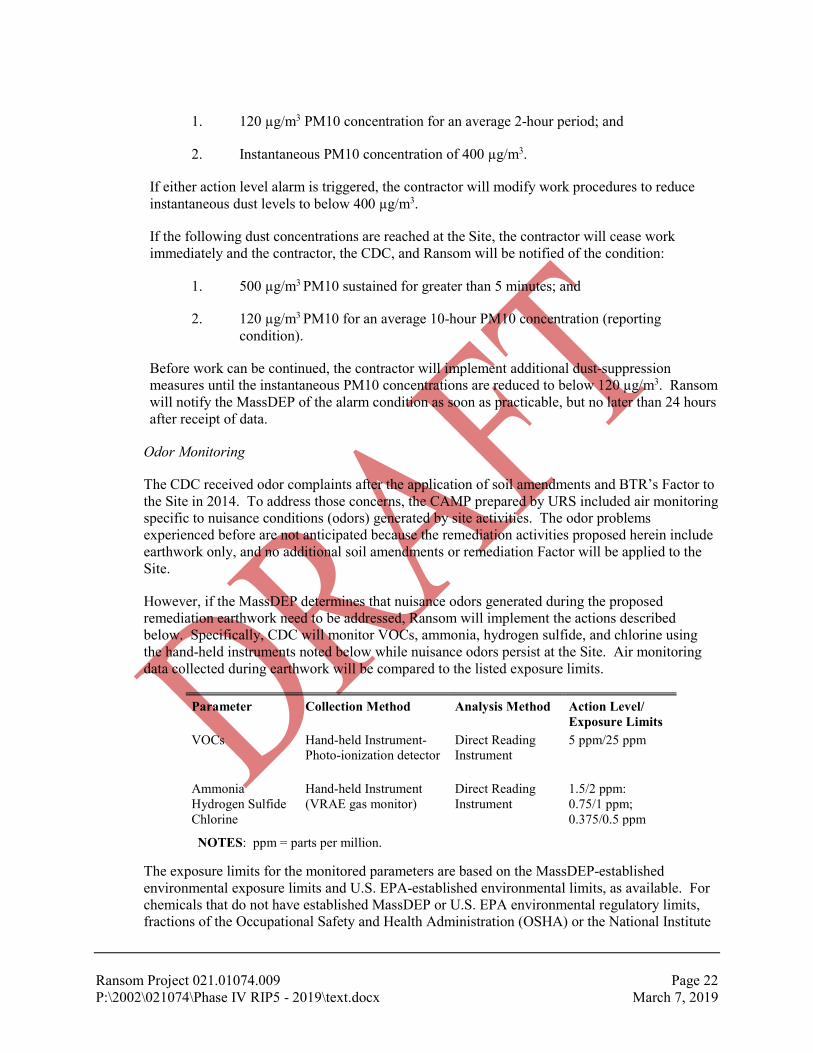
Ransom Project 021.01074.009 Page 22 P:\2002\021074\Phase IV RIP5 - 2019\text.docx March 7, 2019
1. 120 µg/m3 PM10 concentration for an average 2-hour period; and
2. Instantaneous PM10 concentration of 400 µg/m3.
If either action level alarm is triggered, the contractor will modify work procedures to reduce instantaneous dust levels to below 400 µg/m3.
If the following dust concentrations are reached at the Site, the contractor will cease work immediately and the contractor, the CDC, and Ransom will be notified of the condition:
1. 500 µg/m3 PM10 sustained for greater than 5 minutes; and
2. 120 µg/m3 PM10 for an average 10-hour PM10 concentration (reporting condition).
Before work can be continued, the contractor will implement additional dust-suppression measures until the instantaneous PM10 concentrations are reduced to below 120 µg/m3. Ransom will notify the MassDEP of the alarm condition as soon as practicable, but no later than 24 hours after receipt of data.
Odor Monitoring
The CDC received odor complaints after the application of soil amendments and BTR’s Factor to the Site in 2014. To address those concerns, the CAMP prepared by URS included air monitoring specific to nuisance conditions (odors) generated by site activities. The odor problems experienced before are not anticipated because the remediation activities proposed herein include earthwork only, and no additional soil amendments or remediation Factor will be applied to the Site.
However, if the MassDEP determines that nuisance odors generated during the proposed remediation earthwork need to be addressed, Ransom will implement the actions described below. Specifically, CDC will monitor VOCs, ammonia, hydrogen sulfide, and chlorine using the hand-held instruments noted below while nuisance odors persist at the Site. Air monitoring data collected during earthwork will be compared to the listed exposure limits.
Parameter Collection Method Analysis Method Action Level/ Exposure Limits
VOCs Hand-held Instrument- Photo-ionization detector
Direct Reading Instrument
5 ppm/25 ppm
Ammonia Hydrogen Sulfide Chlorine
Hand-held Instrument (VRAE gas monitor)
Direct Reading Instrument
1.5/2 ppm: 0.75/1 ppm; 0.375/0.5 ppm
NOTES: ppm = parts per million.
The exposure limits for the monitored parameters are based on the MassDEP-established environmental exposure limits and U.S. EPA-established environmental limits, as available. For chemicals that do not have established MassDEP or U.S. EPA environmental regulatory limits, fractions of the Occupational Safety and Health Administration (OSHA) or the National Institute

Ransom Project 021.01074.009 Page 23 P:\2002\021074\Phase IV RIP5 - 2019\text.docx March 7, 2019
for Occupational Safety and Health (NIOSH) occupational exposure limits were used for establishing the exposure limit.
URS also established Action Levels intended to trigger the implementation of site control measures in response to elevated levels of target compounds or odors. In general, a tiered warning Action Level and response action will be implemented during the air monitoring program. Tiered warning Action Levels are defined as follows.
Action Level 1: Normal or ambient air conditions where target concentrations are less than 75 percent of the Action Level.
Action Level 2: Concentration of at least one target is equal to or greater than 75 percent of the Action Level but less than the Action Level.
Action Level 3: Concentration of at least one target is greater than the Action Level.
The exposure limits are listed as the “Target Concentrations” in Table 1 of the CAMP, along with the Action Levels described above.
Response to Odor-Generating Conditions
The odors previously generated at the Site were attributed to the compost, organic fertilizers (bone, blood, and fish meal), and anaerobic biodegradation due to water-saturated conditions and low pH (from 4.2 to 5.9 S.U.). If the MassDEP determines it necessary, the CDC will commence with the odor monitoring described above and initiate actions to control the odors. Such actions may include:
1. Addition of agricultural lime;
2. Drying of soils by promoting drainage and relocating materials as needed;
3. Application of a temporary cover (such as a tarp); and/or
4. Application of odor suppressant foam.
Air monitoring will continue if warranted by the analytical results but will be discontinued if monitoring during odor-generating conditions indicates that parameter concentrations are less than 75 percent of the Action Level.
6.4 Remediation Plan Design Assumptions
The remediation plan for the Site is simple in concept; namely, to prevent exposures to dioxin-contaminated soils currently located in surface soils at the Site by excavating them from the proposed development areas and by consolidating them into berms, where soils containing dioxins will be isolated under Engineered Barriers. Other contaminants (e.g., PCP, petroleum, PAHs, metals), if present in soil within the developed areas in concentrations above their corresponding Method 1 S-1 soil standards, will be isolated under permanent caps such as building slabs, pavement, etc., which will be protected by the recording of a Notice of AUL.
The proposed remediation plan is based on the following assumptions:
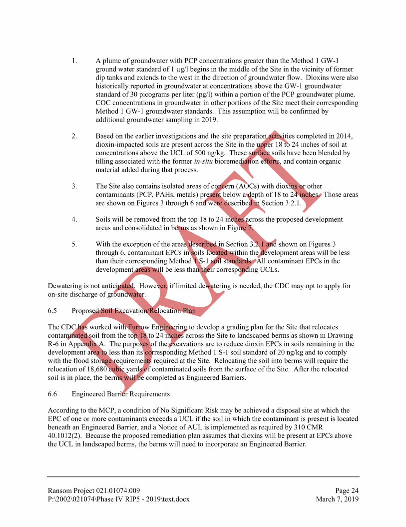
Ransom Project 021.01074.009 Page 24 P:\2002\021074\Phase IV RIP5 - 2019\text.docx March 7, 2019
1. A plume of groundwater with PCP concentrations greater than the Method 1 GW-1 ground water standard of 1 µg/l begins in the middle of the Site in the vicinity of former dip tanks and extends to the west in the direction of groundwater flow. Dioxins were also historically reported in groundwater at concentrations above the GW-1 groundwater standard of 30 picograms per liter (pg/l) within a portion of the PCP groundwater plume. COC concentrations in groundwater in other portions of the Site meet their corresponding Method 1 GW-1 groundwater standards. This assumption will be confirmed by additional groundwater sampling in 2019.
2. Based on the earlier investigations and the site preparation activities completed in 2014, dioxin-impacted soils are present across the Site in the upper 18 to 24 inches of soil at concentrations above the UCL of 500 ng/kg. These surface soils have been blended by tilling associated with the former in-situ bioremediation efforts, and contain organic material added during that process.
3. The Site also contains isolated areas of concern (AOCs) with dioxins or other contaminants (PCP, PAHs, metals) present below a depth of 18 to 24 inches. Those areas are shown on Figures 3 through 6 and were described in Section 3.2.1.
4. Soils will be removed from the top 18 to 24 inches across the proposed development areas and consolidated in berms as shown in Figure 7.
5. With the exception of the areas described in Section 3.2.1 and shown on Figures 3 through 6, contaminant EPCs in soils located within the development areas will be less than their corresponding Method 1 S-1 soil standards. All contaminant EPCs in the development areas will be less than their corresponding UCLs.
Dewatering is not anticipated. However, if limited dewatering is needed, the CDC may opt to apply for on-site discharge of groundwater.
6.5 Proposed Soil Excavation/Relocation Plan
The CDC has worked with Furrow Engineering to develop a grading plan for the Site that relocates contaminated soil from the top 18 to 24 inches across the Site to landscaped berms as shown in Drawing R-6 in Appendix A. The purposes of the excavations are to reduce dioxin EPCs in soils remaining in the development area to less than its corresponding Method 1 S-1 soil standard of 20 ng/kg and to comply with the flood storage requirements required at the Site. Relocating the soil into berms will require the relocation of 18,680 cubic yards of contaminated soils from the surface of the Site. After the relocated soil is in place, the berms will be completed as Engineered Barriers.
6.6 Engineered Barrier Requirements
According to the MCP, a condition of No Significant Risk may be achieved a disposal site at which the EPC of one or more contaminants exceeds a UCL if the soil in which the contaminant is present is located beneath an Engineered Barrier, and a Notice of AUL is implemented as required by 310 CMR 40.1012(2). Because the proposed remediation plan assumes that dioxins will be present at EPCs above the UCL in landscaped berms, the berms will need to incorporate an Engineered Barrier.

Ransom Project 021.01074.009 Page 25 P:\2002\021074\Phase IV RIP5 - 2019\text.docx March 7, 2019
An Engineered Barrier is defined in the MCP as a permanent cap with or without a liner that is designed and constructed in accordance with the requirements of 310 CMR 40.0996 and 310 CMR 40.0000. It must achieve and maintain the following Performance Standards listed in 310 CMR 40.0996 for any foreseeable period of time:
1. Prevent direct contact with contaminated media;
2. Control any vapors or dust emanating from contaminated media;
3. Prevent erosion and any infiltration of precipitation or run-off that could jeopardize the integrity of the barrier or result in the potential mobilization and migration of contaminants;
4. Be comprised of materials that are resistant to degradation;
5. Be consistent with the technical standards of RCRA Subpart N, 40 CFR 264.300, 310 CMR 30.600: Technical Standards for All Hazardous Waste Facilities or equivalent standards;
6. Include a defining layer that visually identifies the beginning of the barrier; and
7. Be appropriately monitored and maintained to ensure the long-term integrity and performance.
The Engineered Barrier must address the risks of harm to public welfare and the environment posed by the COCs. The berms will be constructed of soil containing dioxins above UCLs; therefore, the design of the Engineered Barrier for the berms must take into consideration the possible exposure scenarios and fate and transport mechanisms of dioxins. A summary of the chemical properties of dioxins is provided in Table 1. For comparison, Table 1 also includes the chemical properties for benzene, a common organic environmental contaminant.
6.6.1 Water Solubility
Water solubility is the upper limit on a chemical’s dissolved concentration in pure water, at a specified temperature. Solubility is typically expressed in terms of milligrams per liter (mg/l). Highly soluble contaminants are easily and quickly distributed in groundwater. These contaminants tend to have relatively low adsorption coefficients for soils and sediments and relatively low bioconcentration factors in aquatic life. They are also generally more readily biodegraded by microorganisms present in the environment. Relative solubilities of contaminants can be divided into four groups: insoluble; low (less than 1 mg/l); moderate (between 1 and 1,000 mg/l); and high (greater than 1,000 mg/l).
The solubility of dioxins (2,3,7,8-TCDD) is 1.9 x 10⁻⁵ (or 0.000019) mg/l, identifying dioxin as insoluble in water (benzene’s solubility is 1,800 mg/l). Therefore, dioxin is generally immobile in subsurface environments. The presence of dioxins in shallow surface soils only is consistent with a very low solubility. In isolated locations where dioxins are present at depth, the source is presumed to have been present at that depth.

Ransom Project 021.01074.009 Page 26 P:\2002\021074\Phase IV RIP5 - 2019\text.docx March 7, 2019
6.6.2 Vapor Pressure
Vapor pressure is the pressure exerted by a chemical vapor in equilibrium with its solid or liquid phase and is a measure of a compound’s tendency to volatilize. Vapor pressures are typically expressed in terms of millimeters of mercury (mm Hg) at a given temperature. Compounds with high vapor pressures (i.e., greater than 1 mm Hg), such as VOCs, tend to volatilize readily from open containers holding them in liquid form. VOCs will enter the pore spaces in unsaturated soils (vadose zone) as a gas and eventually migrate to the atmosphere or into the indoor air of an overlying building if a pathway exists.
In contrast, dioxin has a very low vapor pressure on the order of 1.7 x 10⁻⁶ (0.0000017) mm Hg, indicating that dioxin is not volatile when compared to a compound like benzene which has a vapor pressure of 95 mm Hg.
6.6.3 Henry’s Law Constant
Henry’s Law Constant is a measure at equilibrium of the ratio of chemical activity in the gas above a liquid to chemical activity in the liquid. Diffusion coefficients describe the movement of a molecule in a liquid or gas medium as a result of concentration differences. Henry’s Law Constant is typically expressed in atmospheres-cubic meters/mole (atm-m3/mol). In general, compounds with higher Henry’s Law Constants are more likely to move in response to concentration gradients. For Henry’s Law constants below about 2x10⁻⁵ atm-m3/mol, the contaminant tends to remain in solution. In the range of 1x10⁻⁵ to 1x10⁻³ atm-m3/mol, volatilization for these compounds is less rapid than for compounds with greater Henry’s Law Constants but is still a significant transfer mechanism. For compounds with Henry’s Law Constants greater than 1x10⁻³ atm-m3/mol, volatilization is rapid.
The Henry’s Law Constant for dioxin is 1.62 x 10⁻⁵ (0.0000162) atm-m3/mol, indicating that dioxin tends not to move in response to concentration gradients. Benzene’s Henry’s Law Constant is 5.5 x 10⁻³ (0.0055) atm-m3/mol.
6.6.4 Octanol-Water Partition Coefficient (Kow)
The octanol/water partition coefficient (Kow) is defined as the ratio of a chemical’s concentration in the octanol phase to its concentration in the aqueous phase of a two-phase octanol/water system. It represents the tendency of a chemical to partition itself between an organic phase (e.g., soil) and an aqueous phase. Chemicals with low Kow values (less than 10) may be considered relatively hydrophilic. They tend to have higher water solubilities, small soil/sediment adsorption coefficients, and small bioconcentration factors for aquatic life. Conversely, chemicals with high Kow values (greater than 1x10⁴) are very hydrophobic.
The Kow values for dioxins range between 1.4 x 10⁶ and 1.05 x 10⁷ (1,400,000 to 10,500,000), indicating that dioxins are very hydrophobic. Accordingly, they tend to adsorb to particulate matter and be rendered immobile. Benzene’s Kow is 130.
6.6.5 Adsorption Coefficient (Koc)
The extent to which an organic chemical partitions between the solid and solution phases of a water-saturated or unsaturated soil and sediment is determined by several physical and chemical

Ransom Project 021.01074.009 Page 27 P:\2002\021074\Phase IV RIP5 - 2019\text.docx March 7, 2019
properties of both the chemical and the soil or sediment. However, in most cases, it is possible to express the tendency of a chemical to be adsorbed to soil in terms of Koc. Koc represents the ratio of the amount of a chemical adsorbed per unit weight of organic carbon (oc) in the soil or sediment to the concentration of the chemical in solution at equilibrium. Koc is generally expressed in terms of milliliters/gram (ml/g). The larger the Koc value, the greater the tendency to be adsorbed to soil/sediment particles (organic carbon), and thus the less mobile the compound is. Those compounds with Koc values greater than 1,000 ml/g are likely to be relatively immobile and tend to stay adsorbed to soil/sediment particles. Conversely, those compounds with Koc values less than 10 ml/g do not adsorb strongly to soil/sediment particles and are much more likely to be mobile with water.
The Kow value for dioxin is 1.9 x 10⁶ (1,900,000), indicating that dioxin will remain adsorbed to soil and will not leach from soil to water. Benzene’s Kow is 58.
6.7 Contaminant Migration and Potential Exposure Scenarios
Potential migration pathways for contaminants present in the berms were identified and evaluated. An understanding of the potential exposure routes is needed to ensure that the Engineered Barrier will be protective of human health. Potential migration pathways considered for dioxins included the following:
1. Migration with water: Dioxin are insoluble and prefer to sorb to soil. Therefore, migration of dioxins from water permeating through the dioxin-impacted soils in the landscaped berms has been eliminated as a concern at the Site.
2. Volatilization: Dioxins are not volatile. Therefore, volatilization of dioxins from impacted soils in the landscaped berms has been eliminated as a concern at the Site.
3. Dispersion as dust: Dioxins will stay sorbed to soil particles and will not naturally biodegrade when exposed at the surface. Therefore, dioxins can be present in and be dispersed with dust if generated at the Site.
Potential exposure pathways to dioxins present in the landscaped berms are:
1. Dermal Contact: Dioxins may be present at EPCs exceeding its UCL in the soils that comprise the landscaped berms. Dermal contact represents a potential exposure pathway.
2. Inhalation/Ingestion of dust: Dioxins may be present at EPCs exceeding its UCL in the soil dust generated during earthwork at the Site. Inhalation/ingestion of dust represents a potential exposure pathway.
3. Volatilization to air: Dioxins are not volatile. Inhalation of dioxins in ambient air (other than through dust) has been eliminated as a potential exposure pathway.
6.8 Engineered Barrier Design
Installation of physical barriers required to prevent exposure to residual COCs remaining in areas outside of the landscaped berms will be integrated into the redevelopment plan for the Site. The EPCs for the COCs will be reduced to below their corresponding UCLs in these areas so the physical barrier will not need to comply with the requirements for an Engineered Barrier. However, soil with dioxins EPCs above

Ransom Project 021.01074.009 Page 28 P:\2002\021074\Phase IV RIP5 - 2019\text.docx March 7, 2019
its UCL will be present beneath the landscaped berms. Therefore, the physical covers in the berm areas will need to comply with the Engineered Barrier performance standards.
The typical components of an Engineered Barrier design are listed below. The intended function is discussed, along with the applicability to the needs for this Site. Layers are listed from the bottom up.
1. Gas Vent Layer: Gas vent layers are used to collect and redirect gases that are generated from the underlying layer. Typical applications would be to control landfill gas or emissions from VOCs in soil and/or groundwater. The dioxins in the soil are stable and not volatile; therefore, a gas venting layer is not warranted at this site.
2. Low Hydraulic Conductivity (K) Layer(s): Low K layers are used to prevent infiltration of surface water and the associated migration of contaminants when mobile contaminants are present in the underlying soils. Typical applications would be to prevent the migration of soluble contaminants (e.g., VOCs, petroleum hydrocarbons) from impacted soils to the underlying groundwater. The dioxins in soil are not soluble in water and will remain adhered to the soil particles; therefore, a low K layer is not warranted at this site.
3. Drainage Layer: A drainage layer is used to divert water from the underlying low K layer, thereby minimizing the volume and driving head of water above the low K layer. Because a low K layer is not warranted at this Site, a drainage layer is not needed to further reduce the potential for permeability into the underlying berm.
4. Defining Layer: A defining layer is used to isolate the contaminated soils below and provide a warning that the underlying layers pose a potential health risk and should not be disturbed. A defining layer is required for this site.
5. Separation Layer: A separation layer is used to provide support for the surface layer and to provide a buffer between the surface layer and the defining layer below. A separation layer is required for this site.
6. Surface Layer: A surface layer is placed consistent with the future use of a site and to protect the integrity of the underlying layers. A surface layer is required for this site.
Dioxins-impacted soil excavated from the upper 18 to 24 inches across the Site will be relocated to construct the berms indicated in Appendix A. CDC estimates that approximately 20,000 cubic yards of soil will be relocated into the berms. The soils will be placed and compacted in lifts to the density specified by the site engineer. The Engineered Barrier will consist of the following layers, beginning at the surface of the contaminated soil and listed from the bottom up.
1. A geo-composite consisting of a geonet heat-bonded with a non-woven needle-punched geotextile will be placed over the contaminated soil on the berm. The geo-composite will provide a biotic barrier to burrowing animals and will prevent catastrophic erosion of surface materials from exposing the underlying contaminated soils. Although not required to prevent infiltration, the geo-composite will also promote drainage of the surface soils.
2. A geotextile warning barrier be placed over the geonet. The warning barrier will consist of a high-visibility orange demarcation woven geotextile with the words “DANGER—

Ransom Project 021.01074.009 Page 29 P:\2002\021074\Phase IV RIP5 - 2019\text.docx March 7, 2019
DO NOT DIG” printed in both English and Spanish in 8-inch-high letters every 8 feet of material length). Design parameters of the geotextile (e.g., permeability, strength, durability, etc.) will be specified by the site engineer. The geotextile will serve as the defining layer.
3. At least 1 foot of clean loam/topsoil will be placed over the geotextile consistent with the compaction requirements specified by the site engineer/landscape designer. The clean soil layer will provide a growth medium for the surface vegetation and will serve as the separation layer.
4. Vegetation will be planted on the surface of the berms. In addition to aesthetics, the vegetated surface layer will provide erosion control.
6.9 Assessment of Engineered Barrier Performance Requirements
In Ransom’s opinion, the proposed cap for the landscaped berm meets the performance requirements for an Engineered Barrier. Compliance with each of the performance standards is discussed below.
6.9.1 Prevent Direct Contact with Contaminated Media
The geonet portion of the geo-composite provides a flexible but robust media that will provide a barrier to accidental digging and to burrowing by animals. The geonet component of the geo-composite will prevent the migration of fine soil particles from the underlying contaminated soil to the clean soils under the surface vegetation. The warning barrier alerts the public to prevent disturbance and contact with the contaminated soils.
6.9.2 Control Vapors or Dust Emanating from Contaminated Media
The contaminants in the berms are not volatile; therefore, vapor migration is not a concern. The emanation of dust will be prevented by the geonet component of the geo-composite and the overlying surface materials.
6.9.3 Prevent Erosion and Infiltration that Could Jeopardize the Integrity of the Barrier
The contaminants in the berms are not soluble; therefore, migration of contaminants as a result of the infiltration of precipitation or run-off in not a concern. The berm will be constructed with 3H:1V side slope and adequate compaction to provide stability of the slope itself. One foot of clean loam will provide a growth medium for the vegetation, which will stabilize the surface soils to prevent erosion of this separation layer. The geo-composite allows for drainage within the slopes of the berm and provides physical support to prevent an erosion gully, if it occurs and go undetected, from extending into the underlying contaminated soils.
6.9.4 Comprised of Materials Resistant to Degradation
The geo-composite and geotextile warning barrier will not be exposed to sunlight and will be composed of synthetic materials resistant to degradation in soil.

Ransom Project 021.01074.009 Page 30 P:\2002\021074\Phase IV RIP5 - 2019\text.docx March 7, 2019
6.9.5 Consistent with Technical Standards
The proposed barrier meets the equivalent standards listed in RCRA Subpart N, 40 CFR 264.300, and 310 CMR 30.600: Technical Standards for All Hazardous Waste Facilities or equivalent standards and will provide a level of No Significant Risk for any foreseeable period of time by preventing exposure to contaminants present at the Site.
6.9.6 Include a Defining Layer to Identify the Beginning of the Barrier
A geotextile warning barrier with written warning will be placed over the geonet, and the geo-composite has sufficient structural integrity to remain intact if digging does not first expose the warning barrier.
6.9.7 Monitoring and Maintenance
In areas at which an Engineered Barrier is present and assuming that a condition of No Significant Risk has been achieved, the Permanent Solution Statement with Conditions (PSSC) will include a long-term monitoring and maintenance plan that describes the responsibility for and contents of routine inspections activities and response actions that will be conducted to ensure continued performance of the Engineered Barrier. The PSSC will also include documentation of one or more financial assurance mechanism(s) established to adequately provide for ongoing future monitoring, maintenance and any necessary replacement of the barrier.
6.10 Controls and Contingencies
Environmental oversight will be required during construction until testing confirms that contaminated soils have been removed from the remediated areas and all soils with contaminant concentrations above UCLs are isolated under an Engineered Barrier. The following construction controls will be used to assure the success of the proposed remediation strategy:
1. Excavators and dozers operating on the Site will be equipped with in-cab 3D grading capabilities. Excavator(s) will grade with the assistance of grade stakes placed by a licensed surveyor. Grading activities will be within +/- 0.1 foot of proposed cuts and fills. A horizontal survey grid of 25 feet by 25 feet will be established by a licensed surveyor and used for determining an as-built construction plan. Sampling locations and grades will be either located using a high resolution (~ 1 meter) GPS system and/or verified by a licensed surveyor.
2. Environmental testing will be provided during construction. All areas of clean and contaminated soils will remain separate and no equipment will pass between clean and contaminated areas. An environmental professional will be present for all construction activities through placement of the Engineered Barrier to confirm implementation of the remediation plan as proposed.
3. Remediation activities will be halted if soil becomes water-saturated and remediation equipment cannot work effectively. If soil becomes overly dry, dust control measures, such as use of a water truck, will be implemented to prevent on-site soils from becoming airborne. As will other on-site equipment, the water truck will not pass between clean and contaminated areas unless it has been cleaned as discussed below.

Ransom Project 021.01074.009 Page 31 P:\2002\021074\Phase IV RIP5 - 2019\text.docx March 7, 2019
4. Remediation equipment will remain on site until the remediation work is completed, tested, and approved by the LSP. Prior to leaving the Site, equipment that has been exposed to contaminated soils must be cleaned to remove soil from the body/tracks/ wheels/undercarriage. The equipment will be moved onto an impervious and curbed wash pad and pressure washed to remove site soils. Rinse water from washing done on vehicles coming from contaminated areas of the Site will be infiltrated back into the ground surface.
5. Fueling vehicles will remain on the street and not enter the Site to refuel on-site equipment. On-site equipment will pull us a close to the fueling vehicle as possible based on its coverage area (i.e., clean or contaminated soil).

Ransom Project 021.01074.009 Page 32 P:\2002\021074\Phase IV RIP5 - 2019\text.docx March 7, 2019
7.0 SAMPLING PROGRAM
The remediation plan described above is based on the Conceptual Model (CSM) developed from the previous sampling data, which indicated that dioxins are present within the upper 2 feet of soil located across the Site, with the exception of isolated areas as discussed previously and shown on Figure 3. In addition, elevated concentrations of PCP, petroleum hydrocarbons, PAHs, and zinc are COCs in isolated areas of the Site.
7.1 Pre-Remediation Soil Sampling Program
Implementation of the pre-remediation sampling plan presented in the Phase IV RIP – Revision 4 will be completed in late winter/early spring 2019. The results of that sampling program are not anticipated to have an impact on the remediation plan described herein. Instead, the results of the sampling program will be used in the risk characterization that will be required upon completion of the Site remediation and in determining the boundary of the PCP groundwater plume and the limit of the Site at which a Permanent Solution has been achieved.
7.2 Post-Excavation Soil Sampling Program
The post-excavation soil sampling plan has been designed to meet the following objective: Confirm that EPCs for contaminants in soils remaining in the proposed development areas meet their corresponding Method 1 S-1 soil standards in the upper 3 feet.
The sampling plan takes into consideration the relocation of soils during the in-situ bioremediation efforts, and areas where COCs were present below a depth of 2 feet bgs during previous sampling. The proposed post-excavation sampling plan is described below and summarized in Table 2, and the sampling locations for dioxins and the other COCs are shown on Figure 8.
1. After excavating 18- to 24-inches of dioxin-impacted soils from the development areas, collect 48 soil samples from the top 6 inches of the in-place soil at the locations shown on Figure 8 for dioxins analysis by immunoassay Method 4025. At critical locations (such as those suggested in Figure 8), split the soil samples and hold for possible confirmatory laboratory analysis by EPA Method 1613.
2. Review the results of the Method 4025 sampling. If dioxin concentrations are greater than 20 ng/kg in a given soil sample, consider excavation of additional soil from the sample area. At the bottom of the expanded excavation, collect a soil sample for analysis by Method 4025, and split the sample for possible analysis by EPA Method 1613. Proceed with analysis of dioxins by Method 4025. Repeat until the Method 4025 results indicate that the sample dioxin concentration is less than 20 ng/kg.
3. Once the Method 4025 results indicate that dioxins concentrations have been reduced to less than 20 ng/kg, submit at least 10 of the split samples collected from critical locations to the laboratory for analysis of dioxins by EPA Method 1613 to confirm the Method 4025 results. These results will be used in the final site assessment to confirm that dioxin EPCs in the soils remaining in place are less than the Method 1 S-1 soil standard;
4. Note that the immunoassay screening results that will be used for correlation with U.S. EPA Method 1613 results will be in the limited range between 20 ng/kg and the Toxicity
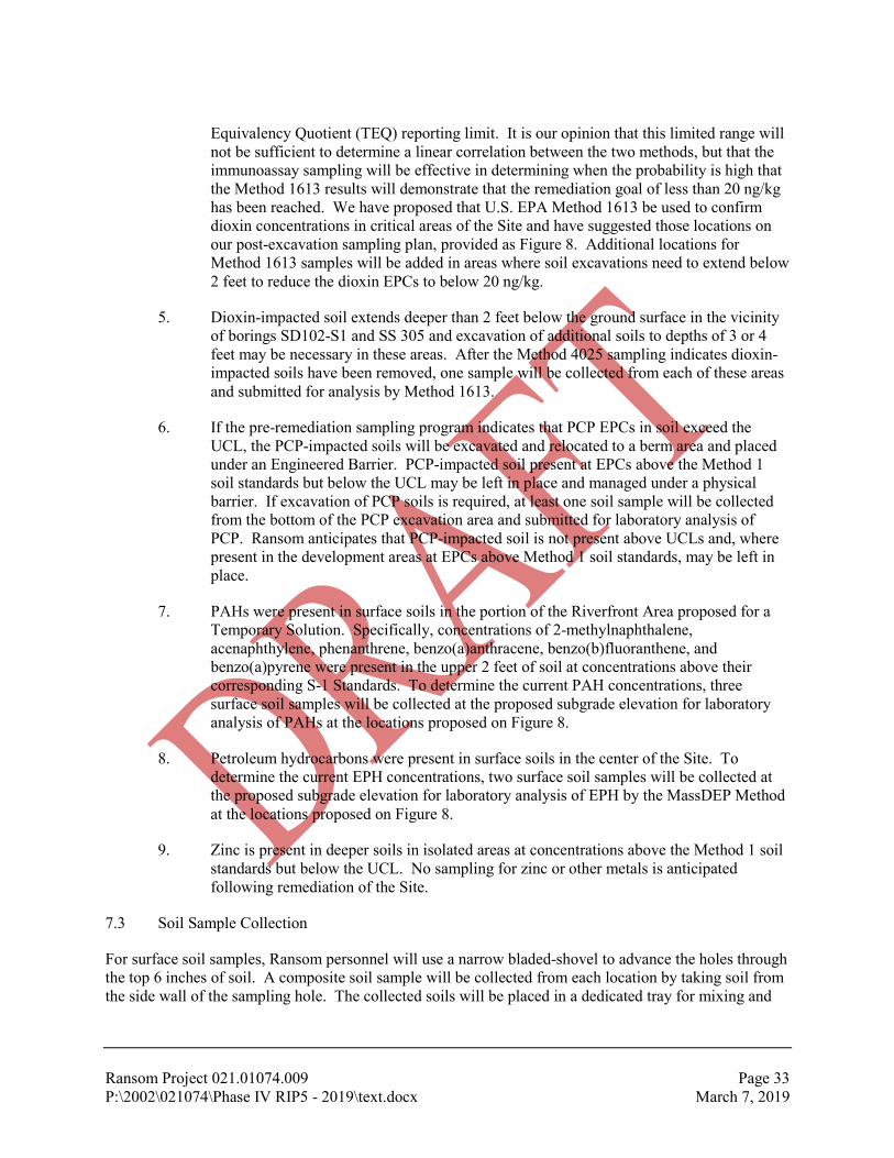
Ransom Project 021.01074.009 Page 33 P:\2002\021074\Phase IV RIP5 - 2019\text.docx March 7, 2019
Equivalency Quotient (TEQ) reporting limit. It is our opinion that this limited range will not be sufficient to determine a linear correlation between the two methods, but that the immunoassay sampling will be effective in determining when the probability is high that the Method 1613 results will demonstrate that the remediation goal of less than 20 ng/kg has been reached. We have proposed that U.S. EPA Method 1613 be used to confirm dioxin concentrations in critical areas of the Site and have suggested those locations on our post-excavation sampling plan, provided as Figure 8. Additional locations for Method 1613 samples will be added in areas where soil excavations need to extend below 2 feet to reduce the dioxin EPCs to below 20 ng/kg.
5. Dioxin-impacted soil extends deeper than 2 feet below the ground surface in the vicinity of borings SD102-S1 and SS 305 and excavation of additional soils to depths of 3 or 4 feet may be necessary in these areas. After the Method 4025 sampling indicates dioxin-impacted soils have been removed, one sample will be collected from each of these areas and submitted for analysis by Method 1613.
6. If the pre-remediation sampling program indicates that PCP EPCs in soil exceed the UCL, the PCP-impacted soils will be excavated and relocated to a berm area and placed under an Engineered Barrier. PCP-impacted soil present at EPCs above the Method 1 soil standards but below the UCL may be left in place and managed under a physical barrier. If excavation of PCP soils is required, at least one soil sample will be collected from the bottom of the PCP excavation area and submitted for laboratory analysis of PCP. Ransom anticipates that PCP-impacted soil is not present above UCLs and, where present in the development areas at EPCs above Method 1 soil standards, may be left in place.
7. PAHs were present in surface soils in the portion of the Riverfront Area proposed for a Temporary Solution. Specifically, concentrations of 2-methylnaphthalene, acenaphthylene, phenanthrene, benzo(a)anthracene, benzo(b)fluoranthene, and benzo(a)pyrene were present in the upper 2 feet of soil at concentrations above their corresponding S-1 Standards. To determine the current PAH concentrations, three surface soil samples will be collected at the proposed subgrade elevation for laboratory analysis of PAHs at the locations proposed on Figure 8.
8. Petroleum hydrocarbons were present in surface soils in the center of the Site. To determine the current EPH concentrations, two surface soil samples will be collected at the proposed subgrade elevation for laboratory analysis of EPH by the MassDEP Method at the locations proposed on Figure 8.
9. Zinc is present in deeper soils in isolated areas at concentrations above the Method 1 soil standards but below the UCL. No sampling for zinc or other metals is anticipated following remediation of the Site.
7.3 Soil Sample Collection
For surface soil samples, Ransom personnel will use a narrow bladed-shovel to advance the holes through the top 6 inches of soil. A composite soil sample will be collected from each location by taking soil from the side wall of the sampling hole. The collected soils will be placed in a dedicated tray for mixing and
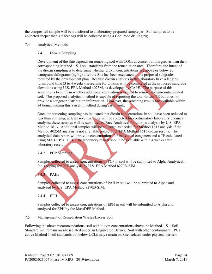
Ransom Project 021.01074.009 Page 34 P:\2002\021074\Phase IV RIP5 - 2019\text.docx March 7, 2019
the composited sample will be transferred to a laboratory-prepared sample jar. Soil samples to be collected deeper than 1.5 feet bgs will be collected using a GeoProbe drilling rig.
7.4 Analytical Methods
7.4.1 Dioxin Sampling
Development of the Site depends on removing soil with COCs at concentrations greater than their corresponding Method 1 S-1 soil standards from the remediation area. Therefore, the intent of the dioxin sampling is to determine whether dioxin concentrations are above or below 20 nanograms/kilograms (ng/kg) after the Site has been excavated to the proposed subgrades required by the development plan. Because dioxin analyses in the laboratory have a lengthy turnaround time (3 to 4 weeks), screening for dioxins will be completed at the proposed subgrade elevations using U.S. EPA Method 4025M, as developed by CAPE. The purpose of this sampling is to confirm whether additional excavation is needed to remove dioxin-contaminated soil. The proposed analytical method is capable of reporting the total dioxin TE but does not provide a congener distribution information. However, the screening results are available within 24 hours, making this a useful method during earth work.
Once the screening sampling has indicated that dioxin concentrations in soil have been reduced to less than 20 ng/kg, at least seven samples will be collected for confirmatory laboratory chemical analysis; these samples will be submitted to Pace Analytical for dioxins analysis by U.S. EPA Method 1613. Additional samples will be collected as needed for Method 1613 analysis if the Method 4025M analysis is not a reliable predictor of EPA Method 1613 dioxin results. The analytical data report will provide concentrations for individual congeners and a TE calculated using MA DEP’s TEFs. The laboratory results should be available within 4 weeks after laboratory receipt.
7.4.2 PCP Sampling
Samples collected to assess concentrations of PCP in soil will be submitted to Alpha Analytical, Inc. (Alpha) for PCP analysis by U.S. EPA Method 8270D-SIM.
7.4.3 PAHs
Samples collected to assess concentrations of PAH in soil will be submitted to Alpha and analyzed by U.S. EPA Method 8270D-SIM.
7.4.4 EPH
Samples collected to assess concentrations of EPH in soil will be submitted to Alpha and analyzed for EPH by the MassDEP Method.
7.5 Management of Remediation Wastes/Excess Soil
Following the above recommendations, soil with dioxin concentrations above the Method 1 S-1 Soil Standard will remain on site isolated under an Engineered Barrier. Soil with other contaminant EPCs above Method 1 soil standards but below UCLs may remain on Site isolated under physical barriers

Ransom Project 021.01074.009 Page 35 P:\2002\021074\Phase IV RIP5 - 2019\text.docx March 7, 2019
installed as part of the Site redevelopment. At present, no remediation waste is anticipated to leave the Site.
7.6 Groundwater Monitoring Program
Periodic groundwater monitoring will be required while a Temporary Solution is in effect at the Site. A post-development groundwater monitoring program will be included in the Temporary Solution Statement that will be submitted following the completion of the remediation phase.

Ransom Project 021.01074.009 Page 36 P:\2002\021074\Phase IV RIP5 - 2019\text.docx March 7, 2019
8.0 POST-CONSTRUCTION ACTIVITIES, MAINTENANCE AND MONITORING
8.1 Construction Documentation
Upon completion of the remediation, Ransom will prepare an As-Built Construction Report (As-Built) and a Final Inspection Report (FIR) documenting the relocation of dioxin-contaminated soils to berms and the installation of the Engineered Barriers. The intent of the As-Built and the FIR is to document that the remediation activities were performed in accordance with the plans provided in this Phase IV RIP, and to document modifications or adjustments to the remediation plan described herein.
8.2 Financial Assurance Mechanism
Because the Engineered Barriers will need to be maintained in perpetuity, CDC will establish and continuously maintain a Financial Assurance Mechanism (FAM) to ensure post-closure care of the constructed Engineered Barriers in accordance with the Notice of AUL recorded for the Site. The value of the FAM shall be calculated by multiplying the annual post-closure cost estimate by 30 years, adjusted annually for inflation. The FAM may consist of a post-closure trust fund, a surety bond, a letter of credit, post-closure insurance , or other method as approved by MassDEP. Development of the cost estimate will proceed after cost estimates are provided for construction of the Engineered Barrier itself.
8.3 Routine Inspection, Maintenance and Monitoring
At a minimum, CDC will conduct a site visit on a semiannual basis to evaluate the integrity of the Engineered Barrier and physical barriers referenced under the Notice of AUL and determine the need for maintenance activities. The Engineered Barriers will be inspected for signs of disturbance such as erosion, slumping, disturbance by burrowing animals or human activity. Maintenance activities could include placement of additional soil, reseeding, replacement of the geonet or other layers, and/or prevention of access to minimize disturbance.
8.4 Property Access Issues
Site control is currently maintained by the CDC. Public access to the Site will remain restricted by a chain-link fence until the dioxin-contaminated soil is relocated to the berms and construction of the Engineered Barriers is complete. A fence is currently present along Bridge Street, Bentley Road, and the southern side of the property. Access along the western side of the Site along the Housatonic River is inhibited by the lack of pedestrian access and a steep bank along the riverfront. Following construction of the initial buildings, the developed area of the Site will be open to the public. Ongoing construction areas will remain fenced and public access to those area will be prohibited until the development is complete.
8.5 Routine Reporting
As new buildings are constructed, the CDC intends to occupy the completed portion(s) of the Site. Undeveloped areas will be surrounded by a fence until construction is complete in those areas. The CDC will implement an inspection plan to ensure that the Engineered Barrier and other physical barriers are performing as intended. In accordance with 310 CMR 40.0877 (3), the CDC will submit Phase IV Status Reports to the MassDEP semi-annually to document the progress of the remediation and the routine inspection results until Permanent Solution is submitted for the Site. Each report will include the following information:

Ransom Project 021.01074.009 Page 37 P:\2002\021074\Phase IV RIP5 - 2019\text.docx March 7, 2019
1. A description of the completed remedial actions and inspection results;
2. A description of significant modifications to the inspection program made since the preceding Phase IV Status Report;
3. A description of conditions or problems which are or may be affecting the performance of the temporary cap;
4. A description of measures taken to correct conditions which are affecting the performance of the remedial action (i.e., cap);
5. The results of sampling analyses and screening, if any, conducted as part of the monitoring program; and
6. The name, license number, signature, and seal of the LSP-of-Record.
After the Site is fully redeveloped, the CDC will submit periodic 5-year evaluations of the Temporary Solution until a Permanent Solution is achieved for the Site.

Ransom Project 021.01074.009 Page 38 P:\2002\021074\Phase IV RIP5 - 2019\text.docx March 7, 2019
9.0 REQUIRED PERMITS, LICENSES, OR APPROVALS
Below is a description of required permits/approvals referenced in the Certificate. The CDC will contract with an engineer to provide civil engineering support services for this Site and assist with permitting efforts.
9.1 Federal Permits, Licenses, or Approvals
9.1.1 Wetlands
Section 404 of the U.S. Clean Water Act (CWA) applies to the filling or alteration of waters of the U.S., including wetland areas. The U.S. Army Corps of Engineers (ACOE) has prime responsibility in administering the Section 404 Program. Other resource agencies, such as the U.S. EPA and U.S. Fish and Wildlife Services, are also involved in project reviews. The proposed wetland disturbances for the project are greater than 5,000 square feet and less than 1 acre and will require a U.S. ACOE Category II permit. The plans attached to the wetlands permit applications indicate replication of the wetlands off-site.
9.1.2 Stormwater
The Federal National Pollutant Discharge Elimination System (NPDES) stormwater permit program sets controls for storm discharges into state and federal waters from certain industrial activities, land disturbance over 1 acre, and municipal storm drains in highly populated areas. The project will require a NPDES Permit for Stormwater Discharge from Construction Activities (i.e., Construction General Permit). Existing storm drains on the Site will be capped during construction. Stormwater is expected to infiltrate into the disturbed soils at the Site. Stormwater runoff will flow towards a low area located in the southwest corner by the Housatonic River. Soils berms will be constructed in this area to retain the runoff on the Site. A new or revised NPDES permit application along with a Stormwater Pollution Prevention Plan (SWPPP) will be required for submission to the U.S. EPA.
9.2 State and Local Permits, Licenses, or Approvals
9.2.1 Waste Site Cleanup
As noted in Section 2.3, a Tier Re-Classification Opinion/Tier IB Application was submitted to the MassDEP on March 21, 2013. The MassDEP issued the Tier IB Permit Approval (Permit 548535) to CDC on April 26, 2013. The Tier IB Permit is effective through April 26, 2018. If a Permanent Solution Statement or Remedy Operation Status (ROS) is not achieved prior to the expiration date of the Permit, an application for Permit Extension will be submitted to the MassDEP.
9.2.2 Stormwater
Massachusetts has several sets of regulations that address impacts from stormwater discharges. The MassDEP has authority under the state Clean Water Act to require facilities to obtain individual surface water discharge permits for stormwater. The permits require compliance with the Surface Water Quality Standards (314 CMR 3.00 and 4.00). Stormwater may also be regulated through an Order of Conditions under the Massachusetts WPA. The MassDEP issued a

Ransom Project 021.01074.009 Page 39 P:\2002\021074\Phase IV RIP5 - 2019\text.docx March 7, 2019
Stormwater Management Policy including Stormwater Management Standards to establish guidelines for stormwater management in Massachusetts. The proposed remediation work is not subject to the Stormwater Standards. However, a copy of the SWPPP prepared for EPA’s Construction General Permit will need to be submitted to the MassDEP and the Great Barrington Conservation Commission. The ultimate redevelopment and capping of the Site will be subject to the stormwater management standards to the maximum extent practicable for redevelopment of the historic mill complex and previously degraded site.
9.2.3 Historical Resources
The project was reviewed by the Massachusetts Historical Commission (MHC). MHC concluded that the project is unlikely to affect significant historic or archaeological resources.
9.2.4 Beneficial Use Determination
The CDC intends to process and reuse the construction debris (concrete, bricks) remaining at the Site for structural fill during future development stages. On-site reuse of this material may require issuance of a Beneficial Use Determination from the MassDEP.
9.3 Additional Local Permits, Licenses, or Approvals
9.3.1 Floodplain Development
Development within a 100-year floodplain is regulated according to the Great Barrington Zoning Bylaws §171-37, “Floodplain Restrictions,” and will require a special permit from the special permit granting authority.
9.3.2 Water Quality Protection Overlay District
Development within the local Water Quality Protection Overlay District as defined by the Great Barrington Zoning Bylaws Section 9.2, will require a special permit from the special permit granting authority.
9.3.3 Rare Species
A portion of the Site along the Housatonic River is mapped as Priority Habitat for Rare or Endangered Species under the Massachusetts Endangered Species Act (MESA). The area was unavoidably altered by the bioremediation work; however, the Massachusetts Natural Heritage and Endangered Species Program (NHESP) has already issued a determination that the work will not result in a “Taking” of the rare species. The site plan for the ultimate redevelopment and capping of the Site will have to be designed to provide for proper restoration of suitable habitat for the protected state-listed species and an environmental benefit compared to the previous conditions. The final redevelopment plans will need to be submitted to NHESP for review under MESA.
9.3.4 MEPA
The proposed capping work will alter more than 5,000 square feet of wetlands, alter more than 2 acres of Priority Habitat, and is being funded in part by a grant from MassDevelopment;
Ransom Project 021.01074.009 Page 40 P:\2002\021074\Phase IV RIP5 - 2019\text.docx March 7, 2019
therefore, the project must be reviewed under the Massachusetts Environmental Policy Act (MEPA). On May 31, 2013, the CDC submitted an ENF to the MassDEP for review. On July 12, 2013, the Executive Office of Energy and Environmental Affairs (EOEA) issued a Certificate on the ENF submitted by the CDC in May 2013.
Comments on the ENF from the following agencies were included in the Certificate:
1. Commonwealth of Massachusetts Natural Heritage & Endangered Species Program, Division of Fisheries & Wildlife (MassWildlife);
2. Berkshire Regional Planning Commission; and
3. MassDEP, Western Regional Office.
9.3.5 Other Local Approvals
The redevelopment and capping work may also require other approvals from the Great Barrington Planning Board, Zoning Board of Appeals, Building Department, and Public Works Department. The details of the specific local permits and approvals have yet to be determined and will depend on the final site plan.

Ransom Project 021.01074.009 Page 41 P:\2002\021074\Phase IV RIP5 - 2019\text.docx March 7, 2019
10.0 PUBLIC NOTIFICATION
In accordance with 310 CMR 40.1403(3)(e), Ransom prepared letters summarizing the Phase IV RIP – Revision 5 for transmittal to the chief municipal officer and local board of health. Copies of the letters are provided as Appendix C.
A public meeting is scheduled for March 8, 2019 to discuss the Phase IV RIP – Revision 5. CDC will respond to comments provided by the public in a subsequent submittal to MassDEP.
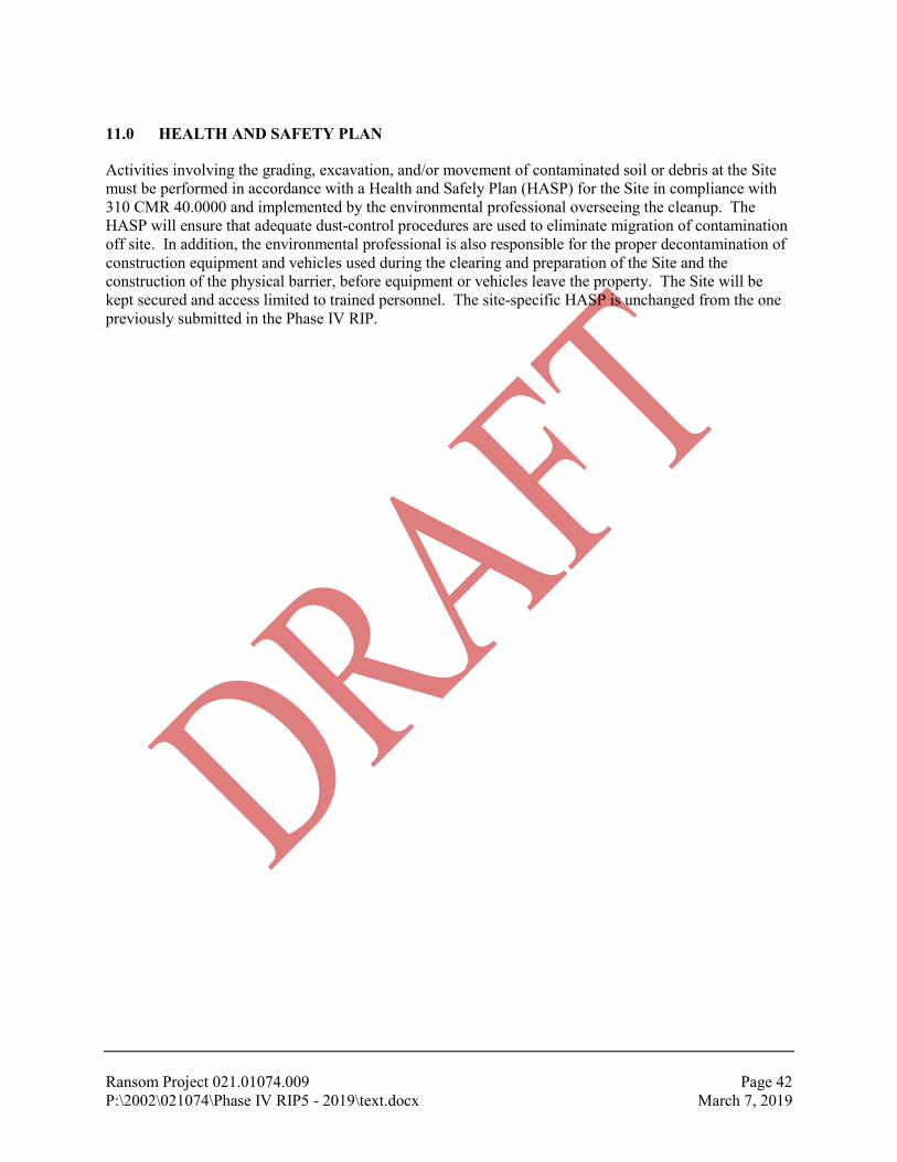
Ransom Project 021.01074.009 Page 42 P:\2002\021074\Phase IV RIP5 - 2019\text.docx March 7, 2019
11.0 HEALTH AND SAFETY PLAN
Activities involving the grading, excavation, and/or movement of contaminated soil or debris at the Site must be performed in accordance with a Health and Safely Plan (HASP) for the Site in compliance with 310 CMR 40.0000 and implemented by the environmental professional overseeing the cleanup. The HASP will ensure that adequate dust-control procedures are used to eliminate migration of contamination off site. In addition, the environmental professional is also responsible for the proper decontamination of construction equipment and vehicles used during the clearing and preparation of the Site and the construction of the physical barrier, before equipment or vehicles leave the property. The Site will be kept secured and access limited to trained personnel. The site-specific HASP is unchanged from the one previously submitted in the Phase IV RIP.

TABLE 1: FATE AND TRANSPORT CHARACTERISTICS OF DIOXINS Phase IV Remedy Implementation Plan – Revision 5 Former New England Log Homes Site 100 Bridge Street Great Barrington, Massachusetts MassDEP Release Tracking No. 1-0682
Ransom Project 021.01074.009 Page 1 of 1 P:\2002\021074\Phase IV RIP5 - 2019\Table 1.docx March 7, 2019
Study Chemicals Molecular
Weight (g/mol)
Solubility (mg/l)
Henry’s Law Constant
(atm-m3/mol))
Vapor Pressure (mm Hg @ 25ºC)
Partition Coefficients
Kow Koc (ml/g)
Dioxins/furans as tetrachlorodibenzo-p-dioxin (2,3,7,8-TCDD)
322 0.000019 0.0000162 0.0000000987 to 0.0000017
1,400,000 to 10,500,000 1,900,000
Benzene 78 1,800 0.0055 95.2 130 58
NOTES: 1. Reference for the dioxin data was collected from Agency for Toxic Substances and Disease Registry (atsdr.cdc.gov/toxprofiles/tp104-c3);
NIH/U.S. National Library of Medicine/National Center or Biotechnology Information (pubchem.ncbi.nlm.nih.gov); and U.S. EPA Technical Factsheet on: Dioxin (2,3,7,8-TCDD). Physical properties for benzene provided for comparison purposes only.
2. g/mol = grams per mole; mg/l = milligrams per liter; atm-m3/mol = atmospheres-cubic meter per mole; ml/g – milliliters per gram. 2. Kow = Octanol-water partition coefficient. 3. Koc = Organic carbon partition coefficient.

TABLE 2: POST-REMEDIATION SAMPLING PLAN Phase IV Remedy Implementation Plan – Revision 5 Former New England Log Homes Site 100 Bridge Street Great Barrington, Massachusetts MassDEP Release Tracking No. 1-0682
Ransom Project 021.01074.009 Page 1 of 1 P:\2002\021074\Phase IV RIP5 - 2019\Table 2- Post-remed-03-19.docx March 7, 2019
Area Sampling Schedule Sampling Objective Sampling Details
Development Areas
After excavation to the proposed subgrade elevation
Confirm dioxin concentrations in remaining soils are less than 20 ng/kg.
Collect 48 samples from 0-6 inches (measured from the top of subgrade) for dioxin analysis by immunoassay testing (U.S. EPA Method 4025). If dioxin concentrations are greater than 20 ng/kg, excavate additional soil and repeat immunoassay testing. Once immunoassay testing suggests dioxin concentrations are less than 20 ng/kg, submit 10 split samples for dioxins analysis by U.S. EPA Method 1613. If Method 1613 results are greater than 20 ng/kg, excavate additional soil and repeat testing process described above. (Minimum 48 samples for Method 4025) (Minimum 10 samples for Method 1613)
Vicinity of Borings: SD102-S1; SS305
Collect additional samples at the excavation bottom after the excavation is extended at least 3 feet below grade.
Confirm that dioxins previously present at depths of 3 to 4 feet have been removed and that dioxins concentrations in remaining soils are less than 20 ng/kg.
Evaluate results from the base of the excavation. Complete additional excavation, if needed, and collect a sample for dioxin analysis by U.S. EPA Method 4025 to determine if the impacted soils have been removed. After the excavation has reached its final extent, collect one sample for dioxins analysis by U.S. EPA Method 1613. (2 samples)
PCP Investigation Areas
After excavation to the proposed subgrade.
Confirm that PCP concentrations in soil are less than 700 mg/kg.
If PCPs present above UCLs require relocation, collect min. 1 sample from the base of each excavation (depth as required) for PCP analysis by U.S. EPA Method 8270D-SIM. (None anticipated)
In the Riverfront, near the former Chimney area, to the north and west
After excavation to the proposed subgrade elevation.
Determine current PAH concentrations for risk characterization.
Collect 3 samples from the base of the excavation (~3 to 4 feet deep) for PAH analysis by U.S. EPA Method 8270D-SIM. (3 samples)
Former Petroleum Laydown Area
After excavation to the proposed subgrade elevation.
Determine current EPH concentrations for risk characterization.
Collect 2 samples from the base of the excavation for EPH analysis by the MassDEP Method (2 samples)
Note: Refer to Figure 8 for the proposed sampling locations.


AREA C
AREA B
AREA A
AREA D
1. SITE PLAN BASED ON "COMPILED EXISTING CONDITIONS PLAN"PREPARED BY FORESIGHT LAND SERVICES DATED FEBRUARY 4, 2013 AND"AS-BUILT SURVEY PLAN" PREPARED BY R LEVESQUE ASSOCIATES, INC.DATED JULY 2012.
2. ALL SAMPLING LOCATIONS ARE APPROXIMATE AND BASED ON"HISTORICAL SAMPLING LOCATIONS" AND "PHASE 2 SAMPLINGLOCATIONS" PREPARED BY FUSS & O'NEILL DATED SEPTEMBER 2001 ANDRANSOM'S SITE VISIT ON MARCH 21, 2013.
nmarshall
Line
nmarshall
Polygonal Line

1. HISTORICAL SAMPLING LOCATIONS ARE APPROXIMATE AND BASED ON“HISTORICAL SAMPLING LOCATIONS” AND PHASE 2 SAMPLING LOCATION”PREPARED BY FUSS & O'NEILL DATED SEPTEMBER 2001, AND ON RANSOM'SSUBSEQUENT SITE VISITS.
2. SOIL SAMPLES WERE COLLECTED BY VARIOUS ENTITIES AS FOLLOWS:a. 1996: US EPA AND/OR MA DEPb. 2000-01: FUSS & O'NEILLc. AUG 2004: RANSOM ENVIRONMENTAL CONSULTANTS, INCd. DEC 2013: BIOTECH RESTORATIONS LLC.e. MAR 2013: RANSOM CONSULTING, INC.f. 2014: RANSOM CONSULTING, INC.
3. DIOXIN TOXICITY EQUIVALENCY (TE) CONCENTRATIONS WERECALCULATED USING THE MA DEP FACTORS.
4. BEGINNING IN DECEMBER 2013, SAMPLE LOCATIONS WERE DOCUMENTEDBY RANSOM CONSULTING, INC. USING A HANDHELD GPS DEVICE.
5. SOME FEATURES HAVE BEEN REMOVED FOR CLARITY.
5/24/2000
94 pg/L
9/2/2004
1,582 pg/L
5/10/2000 1-3'2,894
12/12/2013 1.5-3'7,900
12/12/2013 3-4' 20
12/12/2013 0-1'2,500
12/12/2013 1.5-3' 2.90
12/12/2013 0-1'1,200
12/12/2013 1.5-3' 38
12/23/1996 0-1' 599
12/12/2013 1.5-3' 38
12/23/1996 0-1'3,547
12/12/2013 1.5-3' 6.3
12/23/1996 0-1'3,547
12/12/2013 1.5-3' 0.066
12/12/2013 0-1'3,000
12/12/2013 1.5-3' 3.60
12/10/2013 0-1'6,500
12/10/2013 1.5-3' 8.7
12/10/2013 0-1'2,100
12/10/2013 1.5-3' 4.6
12/10/2013 0-1'1,700
12/10/2013 1.5-3' 0.021
12/10/2013 0-1' 990
12/10/2013 1.5-3' 0.034
12/10/2013 0-1'1,000
12/10/2013 1.5-3' 0.86
12/12/2013 0-1'2,000
12/12/2013 1.5-3'8,700
12/12/2013 4-8'1,000
12/23/1996 0-1'2,010
12/12/2013 1.5-3' 0.019
12/23/1996 0-1' 800
12/12/2013 1.5-3' 0
12/23/1996 0-1' 800
12/12/2013 1.5-3' 5
3/21/2013 0-1'1,636
3/21/2013 1-2' 0
3/21/2013 0-1'1,048
12/11/2013 1.5-3' 12
5/11/2000 1-3' 728
12/11/2013 1.5-3' 13
12/23/1996 0-1'1,080
12/11/2013 1.5-3' 180
12/11/2013 3-4' 4.50
11/28/2000 0.5-1'2,146
11/28/2000 2-2.5' 17
12/11/2013 3-4' 0.015
12/11/2013 0-1' 340
12/11/2013 1.5-3' 530
12/11/2013 3-4' 0.021
12/11/2013 0-1'1,200
12/11/2013 1.5-3' 91
12/11/2013 3-4' 0.021
12/11/2013 0-1'2,600
12/11/2013 1.5-3'1,100
12/11/2013 3-4' 390
3,547
1,582
7/8/2014 0-16"1,100
7/8/2014 0-16" 790 7/8/2014 0-10" 360
7/8/2014 0-16" 710
7/8/2014 0-13"1,400
7/8/2014 0-14" 850
7/8/2014 0-12"13,000
9/15/2014 0-12"23,000
7/8/2014 0-11"2,900
7/8/2014 0-14"5,700
7/8/2014 0-12" 950
7/9/2014 0-14"2,300
7/9/2014 0-14"1,400
7/8/2014 0-13"1,300
7/8/2014 0-17" 520

1. HISTORICAL SAMPLING LOCATIONS ARE APPROXIMATE AND BASED ON“HISTORICAL SAMPLING LOCATIONS” AND PHASE 2 SAMPLING LOCATION”PREPARED BY FUSS & O'NEILL DATED SEPTEMBER 2001, AND ON RANSOM'SSUBSEQUENT SITE VISITS.
2. SOIL SAMPLES WERE COLLECTED BY VARIOUS ENTITIES AS FOLLOWS:a. 1996: US EPA AND/OR MA DEPb. 2000-01: FUSS & O'NEILLc. AUG 2004: RANSOM ENVIRONMENTAL CONSULTANTS, INCd. DEC 2013: BIOTECH RESTORATIONS LLC.e. MAR 2013: RANSOM CONSULTING, INC.f. 2014, 2019: RANSOM CONSULTING, INC.
3. BEGINNING IN DECEMBER 2013, SAMPLE LOCATIONS WERE DOCUMENTEDBY RANSOM CONSULTING, INC. USING A HANDHELD GPS DEVICE.
4. SOME FEATURES HAVE BEEN REMOVED FOR CLARITY.

1. HISTORICAL SAMPLING LOCATIONS ARE APPROXIMATE AND BASED ON“HISTORICAL SAMPLING LOCATIONS” AND PHASE 2 SAMPLING LOCATION”PREPARED BY FUSS & O'NEILL DATED SEPTEMBER 2001, AND ON RANSOM'SSUBSEQUENT SITE VISITS.
2. SOIL SAMPLES WERE COLLECTED BY VARIOUS ENTITIES AS FOLLOWS:a. 1996: US EPA AND/OR MA DEPb. 2000-01: FUSS & O'NEILLc. AUG 2004: RANSOM ENVIRONMENTAL CONSULTANTS, INCd. DEC 2013: BIOTECH RESTORATIONS LLC.e. MAR 2013: RANSOM CONSULTING, INC.f. 2014: RANSOM CONSULTING, INC.
3. BEGINNING IN DECEMBER 2013, SAMPLE LOCATIONS WERE DOCUMENTEDBY RANSOM CONSULTING, INC. USING A HANDHELD GPS DEVICE.
4. SOME FEATURES HAVE BEEN REMOVED FOR CLARITY.


Ransom Consulting, Inc. Project 021.01074.010
APPENDIX A
Site Remediation Bid Set Drawings, Furrow Engineering
Phase IV Remedy Implementation Plan – Revision 5 Former New England Log Homes Site
100 Bridge Street Great Barrington, Massachusetts
MassDEP Release Tracking No. 1-0682

SITE REMEDIATION
100 BRIDGE STREET
DATE: 2-25-2019
OWNER & PROFESSIONALS
OWNER/APPLICANT:
ENGINEER:
LICENSED SITE PROFESSIONAL:
PROJECT SITE PLAN LOCUS PLAN
T-1 TITLE SHEET
DRAWING LIST
GREAT BARRINGTON, MASSACHUSETTS
BID SET
199 Servistar Industrial Way - Suite 2Westfield, MA 01085Phone: (413) 562-4884
FurrowEngineering
AutoCAD SHX Text
R-0 NOTES
AutoCAD SHX Text
R-3 LAYOUT PLAN
AutoCAD SHX Text
T-1 TITLE SHEET
AutoCAD SHX Text
R-1 EXISTING CONDITIONS PLAN
AutoCAD SHX Text
R-2 DEMOLITION PLAN
AutoCAD SHX Text
R-5 GRADING & UTILITIES PLAN
AutoCAD SHX Text
2-8-19
AutoCAD SHX Text
R-4 LANDSCAPE PLAN
AutoCAD SHX Text
R-6 SOIL MOVEMENT PLAN
AutoCAD SHX Text
R-7 BERM CROSS SECTIONS & DETAILS
AutoCAD SHX Text
R-8 EROSION & SEDIMENT CONTROL PLAN
AutoCAD SHX Text
2-8-19
AutoCAD SHX Text
2-8-19
AutoCAD SHX Text
2-8-19
AutoCAD SHX Text
2-8-19
AutoCAD SHX Text
2-8-19
AutoCAD SHX Text
2-8-19
AutoCAD SHX Text
2-8-19
AutoCAD SHX Text
2-8-19
AutoCAD SHX Text
2-8-19
AutoCAD SHX Text
SITE
AutoCAD SHX Text
QUARRY ST
AutoCAD SHX Text
EAST ST
AutoCAD SHX Text
COTTAGE ST
AutoCAD SHX Text
SOUTH MAIN ST
AutoCAD SHX Text
MAPLE AVE
AutoCAD SHX Text
BENTLEY RD
AutoCAD SHX Text
BRIDGE ST
AutoCAD SHX Text
HOUSATONIC RIVER
AutoCAD SHX Text
674
AutoCAD SHX Text
670
AutoCAD SHX Text
670
AutoCAD SHX Text
672
AutoCAD SHX Text
675
AutoCAD SHX Text
676
AutoCAD SHX Text
683
AutoCAD SHX Text
682
AutoCAD SHX Text
681
AutoCAD SHX Text
680
AutoCAD SHX Text
680
AutoCAD SHX Text
671
AutoCAD SHX Text
670
AutoCAD SHX Text
670
AutoCAD SHX Text
671
AutoCAD SHX Text
672
AutoCAD SHX Text
673
AutoCAD SHX Text
674
AutoCAD SHX Text
674
AutoCAD SHX Text
673
AutoCAD SHX Text
672
AutoCAD SHX Text
671
AutoCAD SHX Text
671
AutoCAD SHX Text
672
AutoCAD SHX Text
673
AutoCAD SHX Text
674
AutoCAD SHX Text
674
AutoCAD SHX Text
675
AutoCAD SHX Text
675
AutoCAD SHX Text
675
AutoCAD SHX Text
675
AutoCAD SHX Text
679
AutoCAD SHX Text
678
AutoCAD SHX Text
677
AutoCAD SHX Text
676
AutoCAD SHX Text
675
AutoCAD SHX Text
670
AutoCAD SHX Text
674
AutoCAD SHX Text
673
AutoCAD SHX Text
672
AutoCAD SHX Text
671
AutoCAD SHX Text
675
AutoCAD SHX Text
674
AutoCAD SHX Text
675
AutoCAD SHX Text
676
AutoCAD SHX Text
674
AutoCAD SHX Text
673
AutoCAD SHX Text
675
AutoCAD SHX Text
674
AutoCAD SHX Text
675
AutoCAD SHX Text
674
AutoCAD SHX Text
675
AutoCAD SHX Text
674
AutoCAD SHX Text
673
AutoCAD SHX Text
675
AutoCAD SHX Text
674
AutoCAD SHX Text
673
AutoCAD SHX Text
672
AutoCAD SHX Text
673
AutoCAD SHX Text
674
AutoCAD SHX Text
670
AutoCAD SHX Text
671
AutoCAD SHX Text
671
AutoCAD SHX Text
672
AutoCAD SHX Text
673
AutoCAD SHX Text
674
AutoCAD SHX Text
673
AutoCAD SHX Text
673
AutoCAD SHX Text
677
AutoCAD SHX Text
676
AutoCAD SHX Text
675
AutoCAD SHX Text
674
AutoCAD SHX Text
674
AutoCAD SHX Text
675
AutoCAD SHX Text
675
AutoCAD SHX Text
675
AutoCAD SHX Text
680
AutoCAD SHX Text
679
AutoCAD SHX Text
678
AutoCAD SHX Text
677
AutoCAD SHX Text
679
AutoCAD SHX Text
676
AutoCAD SHX Text
677
AutoCAD SHX Text
674
AutoCAD SHX Text
678
AutoCAD SHX Text
677
AutoCAD SHX Text
681
AutoCAD SHX Text
685
AutoCAD SHX Text
684
AutoCAD SHX Text
683
AutoCAD SHX Text
682
AutoCAD SHX Text
681
AutoCAD SHX Text
676
AutoCAD SHX Text
675
AutoCAD SHX Text
678
AutoCAD SHX Text
677
AutoCAD SHX Text
679
AutoCAD SHX Text
678
AutoCAD SHX Text
677
AutoCAD SHX Text
676
AutoCAD SHX Text
678
AutoCAD SHX Text
679
AutoCAD SHX Text
680
AutoCAD SHX Text
BRIDGE STREET
AutoCAD SHX Text
BENTLEY ROAD
AutoCAD SHX Text
S 21%%d23'41'' W
AutoCAD SHX Text
311.02'
AutoCAD SHX Text
S 18%%d05'45'' W
AutoCAD SHX Text
109.22'
AutoCAD SHX Text
S 13%%d43'24'' W
AutoCAD SHX Text
406.39'
AutoCAD SHX Text
S 82%%d19'20'' E
AutoCAD SHX Text
496.96'
AutoCAD SHX Text
N 08%%d45'00'' E
AutoCAD SHX Text
247.91'
AutoCAD SHX Text
N 08%%d45'00'' E
AutoCAD SHX Text
479.58'
AutoCAD SHX Text
N 69%%d20'00'' W
AutoCAD SHX Text
384.10'
AutoCAD SHX Text
HOUSATONIC RIVER
AutoCAD SHX Text
(APPROX. EDGE OF WATER)
AutoCAD SHX Text
BRIDGE (APPX. LOCATION)
AutoCAD SHX Text
HUMPHREY STREET
AutoCAD SHX Text
N/F BRIDGE-BUILDING LLC
AutoCAD SHX Text
N/F LISA ANN LINDELL
AutoCAD SHX Text
N/F GLEN & ANNE E JOST
AutoCAD SHX Text
N/F BENJAMIN E WOHLFERT
AutoCAD SHX Text
N/F EDWARD & ELIZABETH DOMANEY
AutoCAD SHX Text
N/F CHARLES & JANET BOUTEILLER
AutoCAD SHX Text
N/F MICHAEL LEONARD
AutoCAD SHX Text
N/F COLLEEN FERNBACHER
AutoCAD SHX Text
N/F COMMUNITY DEVELOPMENT CORP 8.034 ACRES BK 1780 PG 278
AutoCAD SHX Text
N/F MELISSA CONSOLINI TRUSTEE
AutoCAD SHX Text
N/F COMMUNITY DEVELOPMENT CORP
AutoCAD SHX Text
N/F TOWN OF GREAT BARRINGTON BK 360 PG 206
AutoCAD SHX Text
25 FT STREET LINE SETBACK
AutoCAD SHX Text
10 FT FRONT SETBACK
AutoCAD SHX Text
10 FT FRONT SETBACK
AutoCAD SHX Text
10 FT SIDE SETBACK
AutoCAD SHX Text
673
AutoCAD SHX Text
672
AutoCAD SHX Text
674
AutoCAD SHX Text
671
AutoCAD SHX Text
675
AutoCAD SHX Text
676
AutoCAD SHX Text
677
AutoCAD SHX Text
CROSBY STREET
AutoCAD SHX Text
674
AutoCAD SHX Text
673
AutoCAD SHX Text
667
AutoCAD SHX Text
670
AutoCAD SHX Text
667
AutoCAD SHX Text
671
AutoCAD SHX Text
670
AutoCAD SHX Text
669
AutoCAD SHX Text
668
AutoCAD SHX Text
669
AutoCAD SHX Text
670
AutoCAD SHX Text
671
AutoCAD SHX Text
673
AutoCAD SHX Text
672
AutoCAD SHX Text
672
AutoCAD SHX Text
673
AutoCAD SHX Text
674
AutoCAD SHX Text
672
AutoCAD SHX Text
673
AutoCAD SHX Text
672
AutoCAD SHX Text
673
AutoCAD SHX Text
674
AutoCAD SHX Text
675
AutoCAD SHX Text
674
AutoCAD SHX Text
684
AutoCAD SHX Text
673
AutoCAD SHX Text
672
AutoCAD SHX Text
671
AutoCAD SHX Text
675
AutoCAD SHX Text
677
AutoCAD SHX Text
684
AutoCAD SHX Text
683
AutoCAD SHX Text
682
AutoCAD SHX Text
680
AutoCAD SHX Text
681
AutoCAD SHX Text
682
AutoCAD SHX Text
683
AutoCAD SHX Text
678
AutoCAD SHX Text
674
AutoCAD SHX Text
COMMUNITY DEVELOPMENT CORPORATION OF SOUTH BERKSHIRE 176 BRIDGE STREET - PO BOX 733 GREAT BARRINGTON, MA 01230
AutoCAD SHX Text
RANSOM CONSULTING, INC. 12 KENT WAY, SUITE 100 BYFIELD, MA 01922
AutoCAD SHX Text
NOT TO SCALE
AutoCAD SHX Text
SCALE: 1" = 80'
AutoCAD SHX Text
FURROW ENGINEERING 199 SERVISTAR INDUSTRIAL WAY - SUITE 2 WESTFIELD, MA 01085

R-0R-0 NOTES
199
Serv
ista
r In
dust
rial
Way
- S
uite
2W
estf
ield
, MA
010
85P
hone
: (41
3) 5
62-4
884
Furr
ow Eng
inee
ring
LOCUS PLAN
AutoCAD SHX Text
SITE
AutoCAD SHX Text
QUARRY ST
AutoCAD SHX Text
EAST ST
AutoCAD SHX Text
COTTAGE ST
AutoCAD SHX Text
SOUTH MAIN ST
AutoCAD SHX Text
MAPLE AVE
AutoCAD SHX Text
BENTLEY RD
AutoCAD SHX Text
BRIDGE ST
AutoCAD SHX Text
HOUSATONIC RIVER
AutoCAD SHX Text
PROJECT DESCRIPTION:
AutoCAD SHX Text
APPLICANT:
AutoCAD SHX Text
SCALE:
AutoCAD SHX Text
--
AutoCAD SHX Text
DATE:
AutoCAD SHX Text
NO.
AutoCAD SHX Text
DATE:
AutoCAD SHX Text
REVISION DESCRIPTION
AutoCAD SHX Text
BY:
AutoCAD SHX Text
DRAWN BY:
AutoCAD SHX Text
SHEET:
AutoCAD SHX Text
1
AutoCAD SHX Text
2
AutoCAD SHX Text
3
AutoCAD SHX Text
4
AutoCAD SHX Text
5
AutoCAD SHX Text
PROJECT #:
AutoCAD SHX Text
ORIGINAL SEAL IS IN BLUE INK COPIES ARE NOT VALID
AutoCAD SHX Text
BENTLEY APARTMENTS 100 BRIDGE ROAD GREAT BARRINGTON, MA 01230
AutoCAD SHX Text
---
AutoCAD SHX Text
---
AutoCAD SHX Text
---
AutoCAD SHX Text
---
AutoCAD SHX Text
---
AutoCAD SHX Text
---
AutoCAD SHX Text
---
AutoCAD SHX Text
---
AutoCAD SHX Text
---
AutoCAD SHX Text
---
AutoCAD SHX Text
---
AutoCAD SHX Text
---
AutoCAD SHX Text
LDS
AutoCAD SHX Text
0869-7-18
AutoCAD SHX Text
2-8-19
AutoCAD SHX Text
COMMUNITY DEVELOPMENT CORP. PO BOX 733 GREAT BARRINGTON, MA 01230
AutoCAD SHX Text
2-25-19
AutoCAD SHX Text
LDS
AutoCAD SHX Text
100% BID SET
AutoCAD SHX Text
SCALE: N.T.S.
AutoCAD SHX Text
LEGEND
AutoCAD SHX Text
EX. CATCH BASIN
AutoCAD SHX Text
EX. DRAINAGE MANHOLE
AutoCAD SHX Text
EX. SANITARY MANHOLE
AutoCAD SHX Text
EX. UTILITY POLE
AutoCAD SHX Text
EX. HYDRANT
AutoCAD SHX Text
EX. WATER SHUT-OFF
AutoCAD SHX Text
D
AutoCAD SHX Text
S
AutoCAD SHX Text
EX. SPOT GRADE
AutoCAD SHX Text
EX. ELECTRIC MANHOLE
AutoCAD SHX Text
E
AutoCAD SHX Text
X 500.00
AutoCAD SHX Text
EX. GAS LINE
AutoCAD SHX Text
EX. WATER LINE
AutoCAD SHX Text
EX. OVERHEAD ELECTRIC WIRES
AutoCAD SHX Text
EX. UNDERGROUND TEL-CATV-DATA
AutoCAD SHX Text
EX. STORM WATER DRAIN
AutoCAD SHX Text
EX. SANITARY SEWER
AutoCAD SHX Text
150
AutoCAD SHX Text
W
AutoCAD SHX Text
S
AutoCAD SHX Text
O
AutoCAD SHX Text
EX. UNDERGROUND ELECTIC
AutoCAD SHX Text
D
AutoCAD SHX Text
Y
AutoCAD SHX Text
H
AutoCAD SHX Text
DEEP HOLE
AutoCAD SHX Text
PERCOLATION TEST
AutoCAD SHX Text
OBSERVATION
AutoCAD SHX Text
EX. MANHOLE (UNMARKED)
AutoCAD SHX Text
M
AutoCAD SHX Text
EX. MONITORING WELL
AutoCAD SHX Text
MW
AutoCAD SHX Text
PR. GAS LINE
AutoCAD SHX Text
PR. WATER LINE
AutoCAD SHX Text
PR. OVERHEAD ELECTRIC WIRES
AutoCAD SHX Text
PR. UNDERGROUND TEL-CATV-DATA
AutoCAD SHX Text
PR. STORM WATER DRAIN
AutoCAD SHX Text
PR. UNDERGROUND ELECTIC
AutoCAD SHX Text
PR. SANITARY SEWER
AutoCAD SHX Text
PR. DRAINAGE MANHOLE
AutoCAD SHX Text
PR. SANITARY MANHOLE
AutoCAD SHX Text
D
AutoCAD SHX Text
S
AutoCAD SHX Text
PR. ELECTRIC MANHOLE
AutoCAD SHX Text
E
AutoCAD SHX Text
EX. WELL
AutoCAD SHX Text
W
AutoCAD SHX Text
PR. WELL
AutoCAD SHX Text
W
AutoCAD SHX Text
PLAN REFERENCES 1. FOR REFERENCE TO ENCLOSED PERIMETER SEE PLAN ENTITLED "BENTLEY APARTMENTS - C-110 SITE FOR REFERENCE TO ENCLOSED PERIMETER SEE PLAN ENTITLED "BENTLEY APARTMENTS - C-110 SITE PLAN" AS PREPARED BY THE CHAZEN COMPANIES AND DATED FEBRUARY 15, 2018. 2. THE TOPOGRAPHIC INFORMATION SHOWN WAS OBTAINED FROM A PLAN ENTITLED "BENTLEY APARTMENTS THE TOPOGRAPHIC INFORMATION SHOWN WAS OBTAINED FROM A PLAN ENTITLED "BENTLEY APARTMENTS - C-120 GRADING & DRAINAGE PLAN" AS PREPARED BY THE CHAZEN COMPANIES AND DATED FEBRUARY 15, 2018. 3. UNDERGROUND UTILITY LOCATIONS SHOWN HEREON ARE APPROXIMATE AND BASED UPON PLAN ENTITLED UNDERGROUND UTILITY LOCATIONS SHOWN HEREON ARE APPROXIMATE AND BASED UPON PLAN ENTITLED "BENTLEY APARTMENTS - C-110 SITE PLAN" AS PREPARED BY THE CHAZEN COMPANIES AND DATED FEBRUARY 15, 2018 AND PLAN ENTITLED "GENERAL PLAN BENTLEY AVE" AS PREPARED BY STANTEC CONSULTING SERVICES, INC. AND DATED MAY 29, 2018. 4. ABUTTING PROPERTY LINES ARE APPROXIMATE, INFORMATION WAS OBTAINED FROM GREAT BARRINGTON ABUTTING PROPERTY LINES ARE APPROXIMATE, INFORMATION WAS OBTAINED FROM GREAT BARRINGTON GIS. 5. SOME STORMWATER DRAINAGE INFORMATION WAS OBTAINED FROM AUTOCAD FILES OF PLANS PROVIDED SOME STORMWATER DRAINAGE INFORMATION WAS OBTAINED FROM AUTOCAD FILES OF PLANS PROVIDED BY FORESIGHT LAND SERVICES, INC. ON 1-9-2019, AND IS APPROXIMATE. GENERAL SITE/UTILITY NOTES 1. ALL WORK DEPICTED ON PLANS SHALL BE COMPLETED IN CONFORMANCE WITH THE PROJECT SCOPE OF ALL WORK DEPICTED ON PLANS SHALL BE COMPLETED IN CONFORMANCE WITH THE PROJECT SCOPE OF WORK AND SPECIFICATIONS. 2. PRIOR TO STARTING EXCAVATION WORK ON THE SITE, THE CONTRACTOR SHALL CONTACT DIG SAFE PRIOR TO STARTING EXCAVATION WORK ON THE SITE, THE CONTRACTOR SHALL CONTACT DIG SAFE (FOUR DAYS PRIOR TO WORK), TO HAVE ALL UTILITIES PROPERLY MARKED IN THE FIELD. 3. CONTRACTOR TO VERIFY EXISTING CONDITIONS PRIOR TO CONSTRUCTION. IF FIELD CONDITIONS ARE CONTRACTOR TO VERIFY EXISTING CONDITIONS PRIOR TO CONSTRUCTION. IF FIELD CONDITIONS ARE OBSERVED THAT SIGNIFICANTLY VARY FROM THOSE SHOWN ON THESE PLANS, IMMEDIATELY NOTIFY THE ENGINEER TO RESOLVE THE CONFLICTING INFORMATION. 4. PRIOR TO SUBMITTAL OF PROPOSAL, THE GENERAL CONTRACTOR AND HIS SUBCONTRACTORS SHALL BE PRIOR TO SUBMITTAL OF PROPOSAL, THE GENERAL CONTRACTOR AND HIS SUBCONTRACTORS SHALL BE RESPONSIBLE FOR BECOMING FAMILIAR WITH ALL CONDITIONS. NO EXTRAS DUE TO UNFAMILIARITY WITH THE EXISTING SITE OR WORKING CONDITIONS SHALL BE PERMITTED. 5. ALL EXCAVATIONS SHALL COMPLY WITH THE CURRENT OSHA STANDARDS. ALL EXCAVATIONS SHALL COMPLY WITH THE CURRENT OSHA STANDARDS. 6. THE LOCATIONS OF EXISTING UNDERGROUND UTILITIES ARE APPROXIMATE AND HAVE NOT BEEN THE LOCATIONS OF EXISTING UNDERGROUND UTILITIES ARE APPROXIMATE AND HAVE NOT BEEN INDEPENDENTLY VERIFIED BY THE OWNER OR ITS REPRESENTATIVE. THE CONTRACTOR SHALL DETERMINE THE EXACT LOCATION OF ALL EXISTING UTILITIES BEFORE COMMENCING WORK, AND SHALL BE FULLY RESPONSIBLE FOR ANY AND ALL DAMAGES THAT RESULT FROM THE CONTRACTORS FAILURE TO EXACTLY LOCATE AND PRESERVE ANY AND ALL UNDERGROUND UTILITIES. 7. IF THE LOCATION, ELEVATION, OR SIZE OF AN EXISTING UTILITY IS FOUND TO CONFLICT WITH PROPOSED IF THE LOCATION, ELEVATION, OR SIZE OF AN EXISTING UTILITY IS FOUND TO CONFLICT WITH PROPOSED WORK THE CONTRACTOR SHALL IMMEDIATELY NOTIFY THE ENGINEER TO RESOLVE THE CONFLICT. 8. THE CONTRACTOR SHALL BE RESPONSIBLE FOR REPAIRING DAMAGE TO WORK PERFORMED DURING THE CONTRACTOR SHALL BE RESPONSIBLE FOR REPAIRING DAMAGE TO WORK PERFORMED DURING CONSTRUCTION, SUCH AS, BUT NOT LIMITED TO, DRAINAGE, UTILITIES, PAVEMENT, SIDEWALKS, STRIPING AND CURBING. 9. CONTRACTOR SHALL BE RESPONSIBLE FOR MAKING ARRANGEMENTS TO ALTER ALL PRIVATE UTILITIES, CONTRACTOR SHALL BE RESPONSIBLE FOR MAKING ARRANGEMENTS TO ALTER ALL PRIVATE UTILITIES, INCLUDING GAS AND ELECTRIC. 10. CONTRACTOR SHALL BE RESPONSIBLE FOR MAINTAINING ALL SURFACE DRAINAGE ON-SITE DURING CONTRACTOR SHALL BE RESPONSIBLE FOR MAINTAINING ALL SURFACE DRAINAGE ON-SITE DURING CONSTRUCTION. 11. AREAS OUTSIDE THE LIMITS OF PROPOSED WORK DISTURBED BY THE CONTRACTOR'S OPERATIONS SHALL AREAS OUTSIDE THE LIMITS OF PROPOSED WORK DISTURBED BY THE CONTRACTOR'S OPERATIONS SHALL BE RESTORED BY THE CONTRACTOR TO THEIR ORIGINAL CONDITION AT NO EXPENSE TO THE OWNER. 12. ACCESS TO THE SITE FOR EMERGENCY VEHICLES MUST BE PRESERVED AT ALL TIMES. ACCESS TO THE SITE FOR EMERGENCY VEHICLES MUST BE PRESERVED AT ALL TIMES. 13. ALL STRUCTURES AND SITE FEATURES, INCLUDING PROPOSED DRAINAGE, SEWER SYSTEMS, AND ALL STRUCTURES AND SITE FEATURES, INCLUDING PROPOSED DRAINAGE, SEWER SYSTEMS, AND ROADWAY, SHALL BE CLEANED AND ALL DEBRIS REMOVED PRIOR TO THE ACCEPTANCE BY THE OWNER. 14. ALL EXISTING DRAINAGE STRUCTURES BEING CONNECTED TO ARE TO BE CLEANED OUT AND REPAIRED ALL EXISTING DRAINAGE STRUCTURES BEING CONNECTED TO ARE TO BE CLEANED OUT AND REPAIRED AS NEEDED. EXISTING DRAINAGE PIPES BEING UTILIZED BY THE PROPOSED DRAINAGE ARE TO BE CLEANED OUT TO REMOVE ALL SILT AND DEBRIS. 15. CONTRACTOR SHALL ENSURE THE STORM DRAINAGE SYSTEM IS WATERTIGHT. ALL DRAINAGE PIPE CONTRACTOR SHALL ENSURE THE STORM DRAINAGE SYSTEM IS WATERTIGHT. ALL DRAINAGE PIPE ENTERING CONCRETE STRUCTURES SHALL BE SEALED TO ENSURE A WATERTIGHT CONNECTION. 16. CONTRACTOR SHALL BE RESPONSIBLE FOR ALL DEWATERING OF TRENCHES AND EXCAVATIONS DURING CONTRACTOR SHALL BE RESPONSIBLE FOR ALL DEWATERING OF TRENCHES AND EXCAVATIONS DURING CONSTRUCTION. 17. ALL DEMOLISHED MATERIALS, PAVEMENT, CURBING, DEMOLISHED TREES, SURPLUS MATERIAL, AND ALL DEMOLISHED MATERIALS, PAVEMENT, CURBING, DEMOLISHED TREES, SURPLUS MATERIAL, AND RUBBLE SHALL BE HANDLED/DISPOSED OF OFF SITE BY THE CONTRACTOR AT HIS EXPENSE IN ACCORDANCE WITH ALL OF THE CITY/TOWN ORDINANCES AND ALL APPLICABLE STATE AND FEDERAL ENVIRONMENTAL REGULATIONS. 18. ALL WORK PERFORMED IN THE CITY/TOWN RIGHT-OF-WAY AND EASEMENTS SHALL BE IN ACCORDANCE ALL WORK PERFORMED IN THE CITY/TOWN RIGHT-OF-WAY AND EASEMENTS SHALL BE IN ACCORDANCE WITH THE CITY/TOWN STANDARDS AND SPECIFICATIONS. 19. CONTRACTOR SHALL BE RESPONSIBLE FOR OBTAINING ALL REQUIRED WORK PERMITS FOR WORK WITHIN CONTRACTOR SHALL BE RESPONSIBLE FOR OBTAINING ALL REQUIRED WORK PERMITS FOR WORK WITHIN A PUBLIC WAY. 20. ALL WORK INCLUDED IN THE CONDITIONS OF APPROVAL FOR STATE AND LOCAL PERMITS SHALL BE THE ALL WORK INCLUDED IN THE CONDITIONS OF APPROVAL FOR STATE AND LOCAL PERMITS SHALL BE THE RESPONSIBILITY OF THE CONTRACTOR AND SHALL BE CONFORMED TO DURING CONSTRUCTION. 21. UNLESS OTHERWISE NOTED, ALL BACKFILL TO BE PLACED IN 8" LIFTS AND SHALL BE COMPACTED TO UNLESS OTHERWISE NOTED, ALL BACKFILL TO BE PLACED IN 8" LIFTS AND SHALL BE COMPACTED TO 95% OF MAXIMUM DRY DENSITY DETERMINED BY MODIFIED PROCTOR TEST FOR ALL APPLICABLE TYPES OF BACKFILL MATERIAL. 22. ALL STRUCTURAL FILL TO BE PLACED IN 8" LIFTS AND SHALL BE COMPACTED TO 98% OF MAXIMUM ALL STRUCTURAL FILL TO BE PLACED IN 8" LIFTS AND SHALL BE COMPACTED TO 98% OF MAXIMUM DRY DENSITY DETERMINED BY MODIFIED PROCTOR TEST. 23. CONTRACTOR SHALL HAVE FIELD COMPACTION TEST PERFORMED IN ACCORDANCE WITH ASTM D5195-02 CONTRACTOR SHALL HAVE FIELD COMPACTION TEST PERFORMED IN ACCORDANCE WITH ASTM D5195-02 AND PROVIDE RESULTS TO ENGINEER PRIOR TO PLACEMENT OF INFRASTRUCTURE OR BITUMINOUS BINDER. 24. WHERE APPLICABLE, ALL MATERIALS AND METHODS ARE TO COMPLY WITH THE CITY/TOWN DPW WHERE APPLICABLE, ALL MATERIALS AND METHODS ARE TO COMPLY WITH THE CITY/TOWN DPW STANDARDS OR MASSACHUSETTS DEPARTMENT OF TRANSPORTATION, UNLESS OTHERWISE DIRECTED BY THE ENGINEER. LAYOUT NOTES 1. THE CONTRACTOR SHALL BE RESPONSIBLE FOR THE COORDINATION AND COST OF ALL FIELD LAYOUT THE CONTRACTOR SHALL BE RESPONSIBLE FOR THE COORDINATION AND COST OF ALL FIELD LAYOUT BASED ON INFORMATION SUPPLIED BY THE SURVEYOR OF RECORD. ANY DISCREPANCIES BETWEEN THE PLANS AND FIELD LAYOUT SHALL BE IMMEDIATELY REPORTED TO THE ENGINEER. 2. THE CONTRACTOR SHALL BE RESPONSIBLE FOR TAKING TIES TO ALL UTILITY CONNECTIONS, BENDS, THE CONTRACTOR SHALL BE RESPONSIBLE FOR TAKING TIES TO ALL UTILITY CONNECTIONS, BENDS, VALVES, AND INVERTS AND PROVIDE ALL INFORMATION ON AS-BUILT PLANS TO BE REVIEWED AND APPROVED BY THE ENGINEER AND OWNER. 3. CONTRACTOR SHALL PROTECT ALL BENCHMARKS AND PROPERTY MONUMENTATION AND SHALL REPAIR OR CONTRACTOR SHALL PROTECT ALL BENCHMARKS AND PROPERTY MONUMENTATION AND SHALL REPAIR OR REPLACE AT HIS OWN EXPENSE IF DISTURBED DURING CONSTRUCTION. EROSION CONTROL NOTES 1. ALL EROSION CONTROL MEASURES SHOWN ON THE PLANS, SPECIFIED, AND REQUIRED BY THE ENGINEER ALL EROSION CONTROL MEASURES SHOWN ON THE PLANS, SPECIFIED, AND REQUIRED BY THE ENGINEER SHALL BE INSTALLED PRIOR TO CONSTRUCTION OR IMMEDIATELY UPON REQUEST. EROSION CONTROL MEASURES SHALL BE MAINTAINED UNTIL WORK IS COMPLETE AND/OR PERMANENT VEGETATION IS ESTABLISHED. 2. AREAS THAT HAVE BEEN PREVIOUSLY DISTURBED AND WORK HAS BEEN COMPLETED SHALL BE AREAS THAT HAVE BEEN PREVIOUSLY DISTURBED AND WORK HAS BEEN COMPLETED SHALL BE STABILIZED AND RESTORED IN ACCORDANCE WITH PROJECT SPECIFICATIONS. 3. ALL GRADING IS TO HAVE A MAXIMUM SLOPE OF 3:1 UNLESS OTHERWISE NOTED. ALL GRADING IS TO HAVE A MAXIMUM SLOPE OF 3:1 UNLESS OTHERWISE NOTED. 4. ALL SLOPES GREATER THAN 3:1, AFTER BEING LOAMED AND SEEDED, SHALL BE SECURED WITH ALL SLOPES GREATER THAN 3:1, AFTER BEING LOAMED AND SEEDED, SHALL BE SECURED WITH EROSION CONTROL BLANKETS (NORTH AMERICAN GREEN S150 OR EQUAL) INSTALLED IN ACCORDANCE WITH THE MANUFACTURER. 5. ALL SEDIMENT TRACKED ONTO THE PUBLIC RIGHT-OF-WAY SHALL BE REMOVED AT THE END OF EACH ALL SEDIMENT TRACKED ONTO THE PUBLIC RIGHT-OF-WAY SHALL BE REMOVED AT THE END OF EACH DAY. 6. CONSTRUCTION ENTRANCE SHALL BE CONSTRUCTED IN ACCORDANCE WITH THESE DRAWINGS. CONSTRUCTION ENTRANCE SHALL BE CONSTRUCTED IN ACCORDANCE WITH THESE DRAWINGS. 7. SILT FENCE SHALL BE INSTALLED IN ACCORDANCE WITH THESE DRAWINGS. SILT FENCE SHOULD BE SILT FENCE SHALL BE INSTALLED IN ACCORDANCE WITH THESE DRAWINGS. SILT FENCE SHOULD BE INSPECTED AND REPAIRED ROUTINELY AND FOLLOWING STORM EVENTS. TOPSOIL NOTES 1. TOPSOIL SHALL CONSIST OF FERTILE, FRIABLE, NATURAL LOAM FREE OF SUBSOIL, CLAY LUMPS, BRUSH, TOPSOIL SHALL CONSIST OF FERTILE, FRIABLE, NATURAL LOAM FREE OF SUBSOIL, CLAY LUMPS, BRUSH, STONES OR OTHER DELETERIOUS MATERIALS LARGER THAN 2" IN GREATEST DIMENSION AND MEETING THE FOLLOWING GRADATION, pH AND ORGANIC CONTENT REQUIREMENTS: PH RANGE: 5.5 - 7.6 ORGANIC CONTENT: 2 % - 20 % 2. PROPOSED TOPSOIL SHALL BE TESTED BY INDEPENDENT TESTING FACILITY WITH TEST RESULTS PROPOSED TOPSOIL SHALL BE TESTED BY INDEPENDENT TESTING FACILITY WITH TEST RESULTS SUBMITTED TO THE ENGINEER FOR APPROVAL. CONTRACTOR SHALL PAY FOR ALL TESTING. ACCEPTANCE OF TOPSOIL SHALL BE BASED UPON TEST RESULTS. ONE TEST SHALL BE PERFORMED PER 100 C.Y. OF TOPSOIL. 3. ALL DISTURBED AREAS SHALL BE LOAMED, PREPARED, AND SEEDED IN ACCORDANCE WITH PROJECT ALL DISTURBED AREAS SHALL BE LOAMED, PREPARED, AND SEEDED IN ACCORDANCE WITH PROJECT SPECIFICATIONS.
AutoCAD SHX Text
PR. SPOT GRADE
AutoCAD SHX Text
X 500.00
AutoCAD SHX Text
PR. CATCH BASIN
AutoCAD SHX Text
PR. UTILITY POLE
AutoCAD SHX Text
PR. HYDRANT
AutoCAD SHX Text
PR. MONITORING WELL
AutoCAD SHX Text
MW
AutoCAD SHX Text
EX. WATER VALVE
AutoCAD SHX Text
PR. WATER VALVE
AutoCAD SHX Text
EX. FENCE
AutoCAD SHX Text
EX. CONTOUR 1' INTERVALS
AutoCAD SHX Text
EX. CONTOUR 5' INTERVALS
AutoCAD SHX Text
PR. CONTOUR
AutoCAD SHX Text
149
AutoCAD SHX Text
150
AutoCAD SHX Text
WV
AutoCAD SHX Text
WV
AutoCAD SHX Text
EX. GAS VALVE
AutoCAD SHX Text
PR. GAS VALVE
AutoCAD SHX Text
GV
AutoCAD SHX Text
GV
AutoCAD SHX Text
SIEVE
AutoCAD SHX Text
PERCENT PASSING
AutoCAD SHX Text
2"
AutoCAD SHX Text
100
AutoCAD SHX Text
1"
AutoCAD SHX Text
85-100
AutoCAD SHX Text
1/4"
AutoCAD SHX Text
65-100
AutoCAD SHX Text
NO. 200
AutoCAD SHX Text
20-60
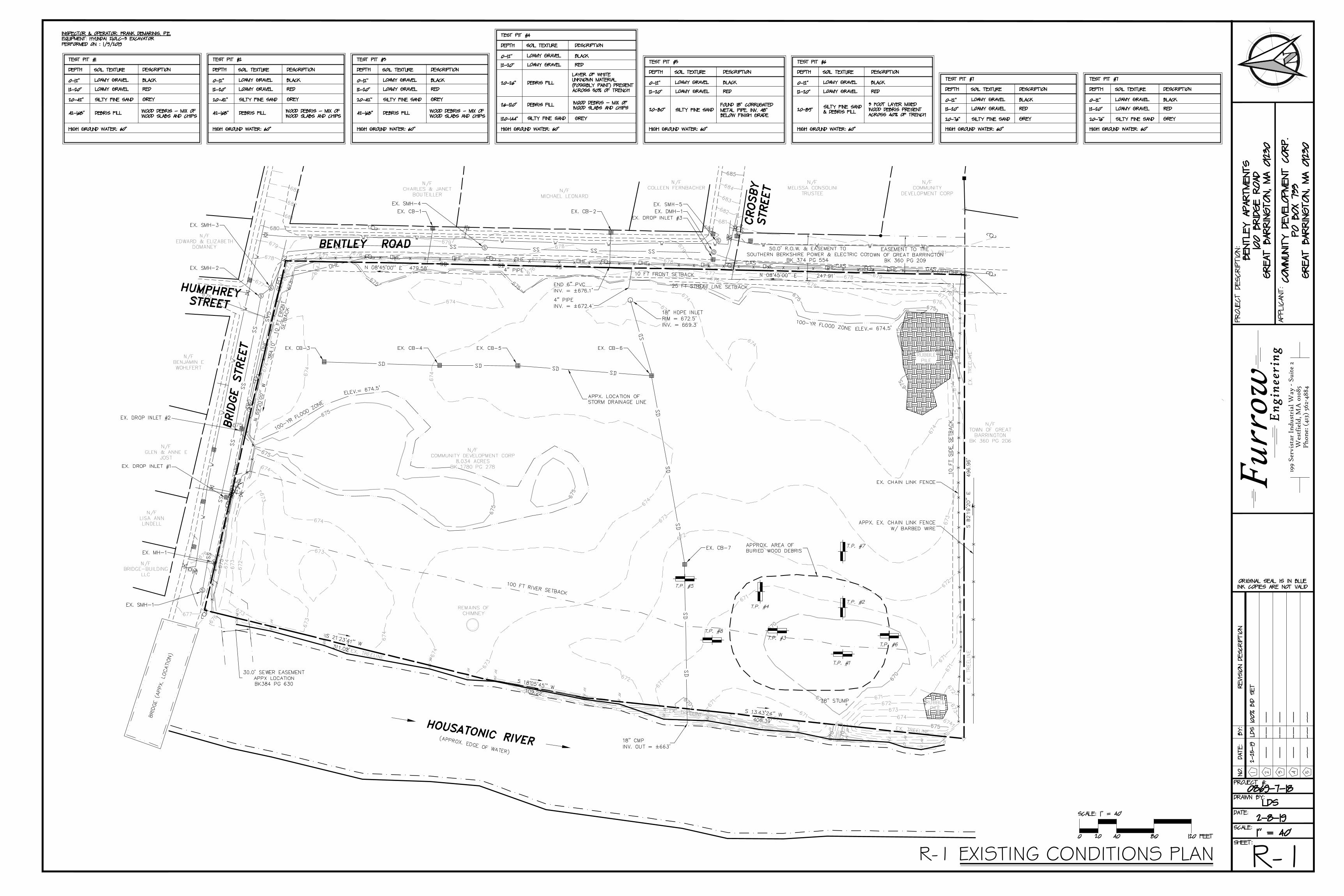
R-1R-1 EXISTING CONDITIONS PLAN
199
Serv
ista
r In
dust
rial
Way
- S
uite
2W
estf
ield
, MA
010
85P
hone
: (41
3) 5
62-4
884
Furr
ow Eng
inee
ring
AutoCAD SHX Text
674
AutoCAD SHX Text
670
AutoCAD SHX Text
670
AutoCAD SHX Text
672
AutoCAD SHX Text
675
AutoCAD SHX Text
676
AutoCAD SHX Text
683
AutoCAD SHX Text
682
AutoCAD SHX Text
681
AutoCAD SHX Text
680
AutoCAD SHX Text
680
AutoCAD SHX Text
671
AutoCAD SHX Text
670
AutoCAD SHX Text
670
AutoCAD SHX Text
671
AutoCAD SHX Text
672
AutoCAD SHX Text
673
AutoCAD SHX Text
674
AutoCAD SHX Text
674
AutoCAD SHX Text
673
AutoCAD SHX Text
672
AutoCAD SHX Text
671
AutoCAD SHX Text
671
AutoCAD SHX Text
672
AutoCAD SHX Text
673
AutoCAD SHX Text
674
AutoCAD SHX Text
674
AutoCAD SHX Text
675
AutoCAD SHX Text
675
AutoCAD SHX Text
675
AutoCAD SHX Text
675
AutoCAD SHX Text
679
AutoCAD SHX Text
678
AutoCAD SHX Text
677
AutoCAD SHX Text
676
AutoCAD SHX Text
675
AutoCAD SHX Text
670
AutoCAD SHX Text
674
AutoCAD SHX Text
673
AutoCAD SHX Text
672
AutoCAD SHX Text
671
AutoCAD SHX Text
675
AutoCAD SHX Text
674
AutoCAD SHX Text
675
AutoCAD SHX Text
676
AutoCAD SHX Text
674
AutoCAD SHX Text
673
AutoCAD SHX Text
675
AutoCAD SHX Text
674
AutoCAD SHX Text
675
AutoCAD SHX Text
674
AutoCAD SHX Text
675
AutoCAD SHX Text
674
AutoCAD SHX Text
673
AutoCAD SHX Text
675
AutoCAD SHX Text
674
AutoCAD SHX Text
673
AutoCAD SHX Text
672
AutoCAD SHX Text
673
AutoCAD SHX Text
674
AutoCAD SHX Text
670
AutoCAD SHX Text
671
AutoCAD SHX Text
671
AutoCAD SHX Text
672
AutoCAD SHX Text
673
AutoCAD SHX Text
674
AutoCAD SHX Text
673
AutoCAD SHX Text
673
AutoCAD SHX Text
677
AutoCAD SHX Text
676
AutoCAD SHX Text
675
AutoCAD SHX Text
674
AutoCAD SHX Text
674
AutoCAD SHX Text
675
AutoCAD SHX Text
675
AutoCAD SHX Text
675
AutoCAD SHX Text
680
AutoCAD SHX Text
679
AutoCAD SHX Text
678
AutoCAD SHX Text
677
AutoCAD SHX Text
679
AutoCAD SHX Text
676
AutoCAD SHX Text
677
AutoCAD SHX Text
674
AutoCAD SHX Text
678
AutoCAD SHX Text
677
AutoCAD SHX Text
681
AutoCAD SHX Text
685
AutoCAD SHX Text
684
AutoCAD SHX Text
683
AutoCAD SHX Text
682
AutoCAD SHX Text
681
AutoCAD SHX Text
676
AutoCAD SHX Text
675
AutoCAD SHX Text
678
AutoCAD SHX Text
677
AutoCAD SHX Text
679
AutoCAD SHX Text
678
AutoCAD SHX Text
677
AutoCAD SHX Text
676
AutoCAD SHX Text
678
AutoCAD SHX Text
679
AutoCAD SHX Text
680
AutoCAD SHX Text
BRIDGE STREET
AutoCAD SHX Text
X
AutoCAD SHX Text
X
AutoCAD SHX Text
X
AutoCAD SHX Text
X
AutoCAD SHX Text
X
AutoCAD SHX Text
X
AutoCAD SHX Text
X
AutoCAD SHX Text
X
AutoCAD SHX Text
X
AutoCAD SHX Text
X
AutoCAD SHX Text
X
AutoCAD SHX Text
X
AutoCAD SHX Text
X
AutoCAD SHX Text
X
AutoCAD SHX Text
X
AutoCAD SHX Text
X
AutoCAD SHX Text
X
AutoCAD SHX Text
X
AutoCAD SHX Text
X
AutoCAD SHX Text
X
AutoCAD SHX Text
X
AutoCAD SHX Text
X
AutoCAD SHX Text
X
AutoCAD SHX Text
X
AutoCAD SHX Text
X
AutoCAD SHX Text
X
AutoCAD SHX Text
X
AutoCAD SHX Text
X
AutoCAD SHX Text
X
AutoCAD SHX Text
BENTLEY ROAD
AutoCAD SHX Text
S 21%%d23'41'' W
AutoCAD SHX Text
311.02'
AutoCAD SHX Text
S 18%%d05'45'' W
AutoCAD SHX Text
109.22'
AutoCAD SHX Text
S 13%%d43'24'' W
AutoCAD SHX Text
406.39'
AutoCAD SHX Text
S 82%%d19'20'' E
AutoCAD SHX Text
496.96'
AutoCAD SHX Text
N 08%%d45'00'' E
AutoCAD SHX Text
247.91'
AutoCAD SHX Text
N 08%%d45'00'' E
AutoCAD SHX Text
479.58'
AutoCAD SHX Text
N 69%%d20'00'' W
AutoCAD SHX Text
384.10'
AutoCAD SHX Text
X
AutoCAD SHX Text
X
AutoCAD SHX Text
X
AutoCAD SHX Text
X
AutoCAD SHX Text
X
AutoCAD SHX Text
X
AutoCAD SHX Text
X
AutoCAD SHX Text
X
AutoCAD SHX Text
X
AutoCAD SHX Text
X
AutoCAD SHX Text
X
AutoCAD SHX Text
X
AutoCAD SHX Text
X
AutoCAD SHX Text
X
AutoCAD SHX Text
X
AutoCAD SHX Text
X
AutoCAD SHX Text
X
AutoCAD SHX Text
X
AutoCAD SHX Text
X
AutoCAD SHX Text
X
AutoCAD SHX Text
X
AutoCAD SHX Text
X
AutoCAD SHX Text
X
AutoCAD SHX Text
X
AutoCAD SHX Text
X
AutoCAD SHX Text
X
AutoCAD SHX Text
X
AutoCAD SHX Text
X
AutoCAD SHX Text
X
AutoCAD SHX Text
X
AutoCAD SHX Text
X
AutoCAD SHX Text
X
AutoCAD SHX Text
X
AutoCAD SHX Text
X
AutoCAD SHX Text
X
AutoCAD SHX Text
X
AutoCAD SHX Text
X
AutoCAD SHX Text
X
AutoCAD SHX Text
X
AutoCAD SHX Text
X
AutoCAD SHX Text
X
AutoCAD SHX Text
X
AutoCAD SHX Text
X
AutoCAD SHX Text
X
AutoCAD SHX Text
X
AutoCAD SHX Text
X
AutoCAD SHX Text
X
AutoCAD SHX Text
X
AutoCAD SHX Text
X
AutoCAD SHX Text
X
AutoCAD SHX Text
X
AutoCAD SHX Text
X
AutoCAD SHX Text
X
AutoCAD SHX Text
X
AutoCAD SHX Text
X
AutoCAD SHX Text
X
AutoCAD SHX Text
X
AutoCAD SHX Text
X
AutoCAD SHX Text
X
AutoCAD SHX Text
X
AutoCAD SHX Text
X
AutoCAD SHX Text
X
AutoCAD SHX Text
X
AutoCAD SHX Text
X
AutoCAD SHX Text
X
AutoCAD SHX Text
X
AutoCAD SHX Text
X
AutoCAD SHX Text
X
AutoCAD SHX Text
X
AutoCAD SHX Text
X
AutoCAD SHX Text
X
AutoCAD SHX Text
HOUSATONIC RIVER
AutoCAD SHX Text
(APPROX. EDGE OF WATER)
AutoCAD SHX Text
BRIDGE (APPX. LOCATION)
AutoCAD SHX Text
HUMPHREY STREET
AutoCAD SHX Text
S
AutoCAD SHX Text
S
AutoCAD SHX Text
S
AutoCAD SHX Text
S
AutoCAD SHX Text
D
AutoCAD SHX Text
Y
AutoCAD SHX Text
H
AutoCAD SHX Text
D
AutoCAD SHX Text
D
AutoCAD SHX Text
Y
AutoCAD SHX Text
H
AutoCAD SHX Text
M
AutoCAD SHX Text
S
AutoCAD SHX Text
100-YR FLOOD ZONE
AutoCAD SHX Text
ELEV.= 674.5'
AutoCAD SHX Text
100-YR FLOOD ZONE
AutoCAD SHX Text
ELEV.= 674.5'
AutoCAD SHX Text
REMAINS OF CHIMNEY
AutoCAD SHX Text
N/F BRIDGE-BUILDING LLC
AutoCAD SHX Text
N/F LISA ANN LINDELL
AutoCAD SHX Text
N/F GLEN & ANNE E JOST
AutoCAD SHX Text
N/F BENJAMIN E WOHLFERT
AutoCAD SHX Text
N/F EDWARD & ELIZABETH DOMANEY
AutoCAD SHX Text
N/F CHARLES & JANET BOUTEILLER
AutoCAD SHX Text
N/F MICHAEL LEONARD
AutoCAD SHX Text
N/F COLLEEN FERNBACHER
AutoCAD SHX Text
N/F COMMUNITY DEVELOPMENT CORP 8.034 ACRES BK 1780 PG 278
AutoCAD SHX Text
N/F MELISSA CONSOLINI TRUSTEE
AutoCAD SHX Text
N/F COMMUNITY DEVELOPMENT CORP
AutoCAD SHX Text
N/F TOWN OF GREAT BARRINGTON BK 360 PG 206
AutoCAD SHX Text
RUBBLE PILE
AutoCAD SHX Text
RUBBLE PILE
AutoCAD SHX Text
EX. CHAIN LINK FENCE
AutoCAD SHX Text
18" STUMP
AutoCAD SHX Text
18" CMP INV. OUT = ±663'
AutoCAD SHX Text
EX. DROP INLET #1
AutoCAD SHX Text
EX. DROP INLET #2
AutoCAD SHX Text
EX. SMH-1
AutoCAD SHX Text
EX. MH-1
AutoCAD SHX Text
EX. SMH-2
AutoCAD SHX Text
EX. SMH-3
AutoCAD SHX Text
EX. CB-1
AutoCAD SHX Text
EX. SMH-4
AutoCAD SHX Text
EX. CB-2
AutoCAD SHX Text
EX. DMH-1
AutoCAD SHX Text
EX. SMH-5
AutoCAD SHX Text
EX. DROP INLET #3
AutoCAD SHX Text
EX. CB-3
AutoCAD SHX Text
EX. CB-4
AutoCAD SHX Text
EX. CB-5
AutoCAD SHX Text
EX. CB-6
AutoCAD SHX Text
18" HDPE INLET RIM = 672.5' INV. = 669.3'
AutoCAD SHX Text
EX. CB-7
AutoCAD SHX Text
APPX. LOCATION OF STORM DRAINAGE LINE
AutoCAD SHX Text
END 6" PVC INV. = ±676.1'
AutoCAD SHX Text
4" PIPE INV. = ±672.4'
AutoCAD SHX Text
4" PIPE
AutoCAD SHX Text
25 FT STREET LINE SETBACK
AutoCAD SHX Text
10 FT FRONT SETBACK
AutoCAD SHX Text
10 FT FRONT SETBACK
AutoCAD SHX Text
10 FT SIDE SETBACK
AutoCAD SHX Text
RF 78
AutoCAD SHX Text
CROSBY STREET
AutoCAD SHX Text
T.P. #1
AutoCAD SHX Text
T.P. #2
AutoCAD SHX Text
T.P. #3
AutoCAD SHX Text
T.P. #7
AutoCAD SHX Text
T.P. #6
AutoCAD SHX Text
T.P. #8
AutoCAD SHX Text
T.P. #4
AutoCAD SHX Text
T.P. #5
AutoCAD SHX Text
APPROX. AREA OF BURIED WOOD DEBRIS
AutoCAD SHX Text
APPX. EX. CHAIN LINK FENCE W/ BARBED WIRE
AutoCAD SHX Text
RF 74
AutoCAD SHX Text
RF 84
AutoCAD SHX Text
RF 88
AutoCAD SHX Text
RF 80
AutoCAD SHX Text
RF 73
AutoCAD SHX Text
RF 90
AutoCAD SHX Text
RF 82
AutoCAD SHX Text
RF 75
AutoCAD SHX Text
RF 85
AutoCAD SHX Text
RF 77
AutoCAD SHX Text
RF 70
AutoCAD SHX Text
RF 87
AutoCAD SHX Text
RF 79
AutoCAD SHX Text
RF 72
AutoCAD SHX Text
RF 89
AutoCAD SHX Text
RF 81
AutoCAD SHX Text
RF 76
AutoCAD SHX Text
RF 86
AutoCAD SHX Text
RF 71
AutoCAD SHX Text
100 FT RIVER SETBACK
AutoCAD SHX Text
EX. TREELINE
AutoCAD SHX Text
EX. TREELINE
AutoCAD SHX Text
EX. TREELINE
AutoCAD SHX Text
EX. TREELINE
AutoCAD SHX Text
EX. TREELINE
AutoCAD SHX Text
PROJECT DESCRIPTION:
AutoCAD SHX Text
APPLICANT:
AutoCAD SHX Text
SCALE:
AutoCAD SHX Text
1" = 40'
AutoCAD SHX Text
DATE:
AutoCAD SHX Text
NO.
AutoCAD SHX Text
DATE:
AutoCAD SHX Text
REVISION DESCRIPTION
AutoCAD SHX Text
BY:
AutoCAD SHX Text
DRAWN BY:
AutoCAD SHX Text
SHEET:
AutoCAD SHX Text
1
AutoCAD SHX Text
2
AutoCAD SHX Text
3
AutoCAD SHX Text
4
AutoCAD SHX Text
5
AutoCAD SHX Text
PROJECT #:
AutoCAD SHX Text
SCALE: 1" = 40'
AutoCAD SHX Text
20
AutoCAD SHX Text
0
AutoCAD SHX Text
120 FEET
AutoCAD SHX Text
40
AutoCAD SHX Text
80
AutoCAD SHX Text
ORIGINAL SEAL IS IN BLUE INK COPIES ARE NOT VALID
AutoCAD SHX Text
BENTLEY APARTMENTS 100 BRIDGE ROAD GREAT BARRINGTON, MA 01230
AutoCAD SHX Text
---
AutoCAD SHX Text
---
AutoCAD SHX Text
---
AutoCAD SHX Text
---
AutoCAD SHX Text
---
AutoCAD SHX Text
---
AutoCAD SHX Text
---
AutoCAD SHX Text
---
AutoCAD SHX Text
---
AutoCAD SHX Text
---
AutoCAD SHX Text
---
AutoCAD SHX Text
---
AutoCAD SHX Text
LDS
AutoCAD SHX Text
0869-7-18
AutoCAD SHX Text
COMMUNITY DEVELOPMENT CORP. PO BOX 733 GREAT BARRINGTON, MA 01230
AutoCAD SHX Text
0-12"
AutoCAD SHX Text
12-20"
AutoCAD SHX Text
20-42"
AutoCAD SHX Text
TEST PIT #1
AutoCAD SHX Text
DEPTH
AutoCAD SHX Text
GREY
AutoCAD SHX Text
RED
AutoCAD SHX Text
BLACK
AutoCAD SHX Text
DESCRIPTION
AutoCAD SHX Text
SOIL TEXTURE
AutoCAD SHX Text
LOAMY GRAVEL
AutoCAD SHX Text
LOAMY GRAVEL
AutoCAD SHX Text
SILTY FINE SAND
AutoCAD SHX Text
HIGH GROUND WATER: 60"
AutoCAD SHX Text
INSPECTOR & OPERATOR: FRANK DEMARINIS, P.E. EQUIPMENT: HYUNDAI 210LC-3 EXCAVATOR PERFORMED ON : 1/9/2019
AutoCAD SHX Text
42-168"
AutoCAD SHX Text
WOOD DEBRIS - MIX OF WOOD SLABS AND CHIPS
AutoCAD SHX Text
DEBRIS FILL
AutoCAD SHX Text
0-12"
AutoCAD SHX Text
12-20"
AutoCAD SHX Text
20-26"
AutoCAD SHX Text
TEST PIT #4
AutoCAD SHX Text
DEPTH
AutoCAD SHX Text
LAYER OF WHITE UNKNOWN MATERIAL (POSSIBLY PAINT) PRESENT ACROSS 50% OF TRENCH
AutoCAD SHX Text
RED
AutoCAD SHX Text
BLACK
AutoCAD SHX Text
DESCRIPTION
AutoCAD SHX Text
SOIL TEXTURE
AutoCAD SHX Text
LOAMY GRAVEL
AutoCAD SHX Text
LOAMY GRAVEL
AutoCAD SHX Text
DEBRIS FILL
AutoCAD SHX Text
HIGH GROUND WATER: 60"
AutoCAD SHX Text
26-120"
AutoCAD SHX Text
WOOD DEBRIS - MIX OF WOOD SLABS AND CHIPS
AutoCAD SHX Text
DEBRIS FILL
AutoCAD SHX Text
0-12"
AutoCAD SHX Text
12-20"
AutoCAD SHX Text
20-42"
AutoCAD SHX Text
TEST PIT #2
AutoCAD SHX Text
DEPTH
AutoCAD SHX Text
GREY
AutoCAD SHX Text
RED
AutoCAD SHX Text
BLACK
AutoCAD SHX Text
DESCRIPTION
AutoCAD SHX Text
SOIL TEXTURE
AutoCAD SHX Text
LOAMY GRAVEL
AutoCAD SHX Text
LOAMY GRAVEL
AutoCAD SHX Text
SILTY FINE SAND
AutoCAD SHX Text
HIGH GROUND WATER: 60"
AutoCAD SHX Text
42-168"
AutoCAD SHX Text
WOOD DEBRIS - MIX OF WOOD SLABS AND CHIPS
AutoCAD SHX Text
DEBRIS FILL
AutoCAD SHX Text
120-144"
AutoCAD SHX Text
GREY
AutoCAD SHX Text
SILTY FINE SAND
AutoCAD SHX Text
0-12"
AutoCAD SHX Text
12-20"
AutoCAD SHX Text
20-80"
AutoCAD SHX Text
TEST PIT #5
AutoCAD SHX Text
DEPTH
AutoCAD SHX Text
FOUND 18" CORRUGATED METAL PIPE. INV. 48" BELOW FINISH GRADE
AutoCAD SHX Text
RED
AutoCAD SHX Text
BLACK
AutoCAD SHX Text
DESCRIPTION
AutoCAD SHX Text
SOIL TEXTURE
AutoCAD SHX Text
LOAMY GRAVEL
AutoCAD SHX Text
LOAMY GRAVEL
AutoCAD SHX Text
HIGH GROUND WATER: 60"
AutoCAD SHX Text
SILTY FINE SAND
AutoCAD SHX Text
0-12"
AutoCAD SHX Text
12-20"
AutoCAD SHX Text
20-42"
AutoCAD SHX Text
TEST PIT #3
AutoCAD SHX Text
DEPTH
AutoCAD SHX Text
GREY
AutoCAD SHX Text
RED
AutoCAD SHX Text
BLACK
AutoCAD SHX Text
DESCRIPTION
AutoCAD SHX Text
SOIL TEXTURE
AutoCAD SHX Text
LOAMY GRAVEL
AutoCAD SHX Text
LOAMY GRAVEL
AutoCAD SHX Text
SILTY FINE SAND
AutoCAD SHX Text
HIGH GROUND WATER: 60"
AutoCAD SHX Text
42-168"
AutoCAD SHX Text
WOOD DEBRIS - MIX OF WOOD SLABS AND CHIPS
AutoCAD SHX Text
DEBRIS FILL
AutoCAD SHX Text
0-12"
AutoCAD SHX Text
12-20"
AutoCAD SHX Text
20-89"
AutoCAD SHX Text
TEST PIT #6
AutoCAD SHX Text
DEPTH
AutoCAD SHX Text
3 FOOT LAYER MIXED WOOD DEBRIS PRESENT ACROSS 40% OF TRENCH
AutoCAD SHX Text
RED
AutoCAD SHX Text
BLACK
AutoCAD SHX Text
DESCRIPTION
AutoCAD SHX Text
SOIL TEXTURE
AutoCAD SHX Text
LOAMY GRAVEL
AutoCAD SHX Text
LOAMY GRAVEL
AutoCAD SHX Text
HIGH GROUND WATER: 60"
AutoCAD SHX Text
SILTY FINE SAND & DEBRIS FILL
AutoCAD SHX Text
0-12"
AutoCAD SHX Text
12-20"
AutoCAD SHX Text
20-76"
AutoCAD SHX Text
TEST PIT #7
AutoCAD SHX Text
DEPTH
AutoCAD SHX Text
GREY
AutoCAD SHX Text
RED
AutoCAD SHX Text
BLACK
AutoCAD SHX Text
DESCRIPTION
AutoCAD SHX Text
SOIL TEXTURE
AutoCAD SHX Text
LOAMY GRAVEL
AutoCAD SHX Text
LOAMY GRAVEL
AutoCAD SHX Text
SILTY FINE SAND
AutoCAD SHX Text
HIGH GROUND WATER: 60"
AutoCAD SHX Text
2-8-19
AutoCAD SHX Text
2-25-19
AutoCAD SHX Text
LDS
AutoCAD SHX Text
100% BID SET

REMOVE 18" CMP
REMOVE CATCH BASIN
REMOVE CATCH BASIN
REMOVE 18" CMP
DEMO & REMOVE REMAINS OFCHIMNEY AND DISPOSE OF OFF-SITE
REMOVE 18" PIPE
EXCAVATE & REMOVE BURIED WOODDEBRIS AND DISPOSE OF OFF-SITE INACCORDANCE WITH LOCAL, STATE,AND FEDERAL REGULATIONS & FILL TODESIGN GRADE PER PROJECTSPECIFICATIONS
REMOVE STORMDRAINAGE PIPE
CUT AND CAP 18" CMPABANDON SECTION TO RIVER
REMOVE CATCH BASINS
REMOVE RUBBLE PILE ANDDISPOSE OF OFF-SITE INACCORDANCE WITH LOCAL, STATE,AND FEDERAL REGULATIONS
REMOVE RUBBLE PILE ANDDISPOSE OF OFF-SITE INACCORDANCE WITH LOCAL, STATE,AND FEDERAL REGULATIONS
REMOVE CHAIN LINK FENCE & POSTS
R-2R-2 DEMOLITION PLAN
199
Serv
ista
r In
dust
rial
Way
- S
uite
2W
estf
ield
, MA
010
85P
hone
: (41
3) 5
62-4
884
Furr
ow Eng
inee
ring
AutoCAD SHX Text
674
AutoCAD SHX Text
670
AutoCAD SHX Text
670
AutoCAD SHX Text
672
AutoCAD SHX Text
675
AutoCAD SHX Text
676
AutoCAD SHX Text
683
AutoCAD SHX Text
682
AutoCAD SHX Text
681
AutoCAD SHX Text
680
AutoCAD SHX Text
680
AutoCAD SHX Text
671
AutoCAD SHX Text
670
AutoCAD SHX Text
670
AutoCAD SHX Text
671
AutoCAD SHX Text
672
AutoCAD SHX Text
673
AutoCAD SHX Text
674
AutoCAD SHX Text
674
AutoCAD SHX Text
673
AutoCAD SHX Text
672
AutoCAD SHX Text
671
AutoCAD SHX Text
671
AutoCAD SHX Text
672
AutoCAD SHX Text
673
AutoCAD SHX Text
674
AutoCAD SHX Text
674
AutoCAD SHX Text
675
AutoCAD SHX Text
675
AutoCAD SHX Text
675
AutoCAD SHX Text
675
AutoCAD SHX Text
679
AutoCAD SHX Text
678
AutoCAD SHX Text
677
AutoCAD SHX Text
676
AutoCAD SHX Text
675
AutoCAD SHX Text
670
AutoCAD SHX Text
674
AutoCAD SHX Text
673
AutoCAD SHX Text
672
AutoCAD SHX Text
671
AutoCAD SHX Text
675
AutoCAD SHX Text
674
AutoCAD SHX Text
675
AutoCAD SHX Text
676
AutoCAD SHX Text
674
AutoCAD SHX Text
673
AutoCAD SHX Text
675
AutoCAD SHX Text
674
AutoCAD SHX Text
675
AutoCAD SHX Text
674
AutoCAD SHX Text
675
AutoCAD SHX Text
674
AutoCAD SHX Text
673
AutoCAD SHX Text
675
AutoCAD SHX Text
674
AutoCAD SHX Text
673
AutoCAD SHX Text
672
AutoCAD SHX Text
673
AutoCAD SHX Text
674
AutoCAD SHX Text
670
AutoCAD SHX Text
671
AutoCAD SHX Text
671
AutoCAD SHX Text
672
AutoCAD SHX Text
673
AutoCAD SHX Text
674
AutoCAD SHX Text
673
AutoCAD SHX Text
673
AutoCAD SHX Text
677
AutoCAD SHX Text
676
AutoCAD SHX Text
675
AutoCAD SHX Text
674
AutoCAD SHX Text
674
AutoCAD SHX Text
675
AutoCAD SHX Text
675
AutoCAD SHX Text
675
AutoCAD SHX Text
680
AutoCAD SHX Text
679
AutoCAD SHX Text
678
AutoCAD SHX Text
677
AutoCAD SHX Text
679
AutoCAD SHX Text
676
AutoCAD SHX Text
677
AutoCAD SHX Text
674
AutoCAD SHX Text
678
AutoCAD SHX Text
677
AutoCAD SHX Text
681
AutoCAD SHX Text
685
AutoCAD SHX Text
684
AutoCAD SHX Text
683
AutoCAD SHX Text
682
AutoCAD SHX Text
681
AutoCAD SHX Text
676
AutoCAD SHX Text
675
AutoCAD SHX Text
678
AutoCAD SHX Text
677
AutoCAD SHX Text
679
AutoCAD SHX Text
678
AutoCAD SHX Text
677
AutoCAD SHX Text
676
AutoCAD SHX Text
678
AutoCAD SHX Text
679
AutoCAD SHX Text
680
AutoCAD SHX Text
BRIDGE STREET
AutoCAD SHX Text
X
AutoCAD SHX Text
X
AutoCAD SHX Text
X
AutoCAD SHX Text
X
AutoCAD SHX Text
X
AutoCAD SHX Text
X
AutoCAD SHX Text
X
AutoCAD SHX Text
X
AutoCAD SHX Text
X
AutoCAD SHX Text
X
AutoCAD SHX Text
X
AutoCAD SHX Text
X
AutoCAD SHX Text
X
AutoCAD SHX Text
X
AutoCAD SHX Text
X
AutoCAD SHX Text
X
AutoCAD SHX Text
X
AutoCAD SHX Text
X
AutoCAD SHX Text
X
AutoCAD SHX Text
X
AutoCAD SHX Text
X
AutoCAD SHX Text
X
AutoCAD SHX Text
X
AutoCAD SHX Text
X
AutoCAD SHX Text
X
AutoCAD SHX Text
X
AutoCAD SHX Text
X
AutoCAD SHX Text
X
AutoCAD SHX Text
X
AutoCAD SHX Text
BENTLEY ROAD
AutoCAD SHX Text
S 21%%d23'41'' W
AutoCAD SHX Text
311.02'
AutoCAD SHX Text
S 18%%d05'45'' W
AutoCAD SHX Text
109.22'
AutoCAD SHX Text
S 13%%d43'24'' W
AutoCAD SHX Text
406.39'
AutoCAD SHX Text
S 82%%d19'20'' E
AutoCAD SHX Text
496.96'
AutoCAD SHX Text
N 08%%d45'00'' E
AutoCAD SHX Text
247.91'
AutoCAD SHX Text
N 08%%d45'00'' E
AutoCAD SHX Text
479.58'
AutoCAD SHX Text
N 69%%d20'00'' W
AutoCAD SHX Text
384.10'
AutoCAD SHX Text
X
AutoCAD SHX Text
X
AutoCAD SHX Text
X
AutoCAD SHX Text
X
AutoCAD SHX Text
X
AutoCAD SHX Text
X
AutoCAD SHX Text
X
AutoCAD SHX Text
X
AutoCAD SHX Text
X
AutoCAD SHX Text
X
AutoCAD SHX Text
X
AutoCAD SHX Text
X
AutoCAD SHX Text
X
AutoCAD SHX Text
X
AutoCAD SHX Text
X
AutoCAD SHX Text
X
AutoCAD SHX Text
X
AutoCAD SHX Text
X
AutoCAD SHX Text
X
AutoCAD SHX Text
X
AutoCAD SHX Text
X
AutoCAD SHX Text
X
AutoCAD SHX Text
X
AutoCAD SHX Text
X
AutoCAD SHX Text
X
AutoCAD SHX Text
X
AutoCAD SHX Text
X
AutoCAD SHX Text
X
AutoCAD SHX Text
X
AutoCAD SHX Text
X
AutoCAD SHX Text
X
AutoCAD SHX Text
X
AutoCAD SHX Text
X
AutoCAD SHX Text
X
AutoCAD SHX Text
X
AutoCAD SHX Text
X
AutoCAD SHX Text
X
AutoCAD SHX Text
X
AutoCAD SHX Text
X
AutoCAD SHX Text
X
AutoCAD SHX Text
X
AutoCAD SHX Text
X
AutoCAD SHX Text
X
AutoCAD SHX Text
X
AutoCAD SHX Text
X
AutoCAD SHX Text
X
AutoCAD SHX Text
X
AutoCAD SHX Text
X
AutoCAD SHX Text
X
AutoCAD SHX Text
X
AutoCAD SHX Text
X
AutoCAD SHX Text
X
AutoCAD SHX Text
X
AutoCAD SHX Text
X
AutoCAD SHX Text
X
AutoCAD SHX Text
X
AutoCAD SHX Text
X
AutoCAD SHX Text
X
AutoCAD SHX Text
X
AutoCAD SHX Text
X
AutoCAD SHX Text
X
AutoCAD SHX Text
X
AutoCAD SHX Text
X
AutoCAD SHX Text
X
AutoCAD SHX Text
X
AutoCAD SHX Text
X
AutoCAD SHX Text
X
AutoCAD SHX Text
X
AutoCAD SHX Text
X
AutoCAD SHX Text
X
AutoCAD SHX Text
X
AutoCAD SHX Text
HOUSATONIC RIVER
AutoCAD SHX Text
(APPROX. EDGE OF WATER)
AutoCAD SHX Text
BRIDGE (APPX. LOCATION)
AutoCAD SHX Text
HUMPHREY STREET
AutoCAD SHX Text
S
AutoCAD SHX Text
S
AutoCAD SHX Text
S
AutoCAD SHX Text
S
AutoCAD SHX Text
D
AutoCAD SHX Text
Y
AutoCAD SHX Text
H
AutoCAD SHX Text
D
AutoCAD SHX Text
D
AutoCAD SHX Text
Y
AutoCAD SHX Text
H
AutoCAD SHX Text
M
AutoCAD SHX Text
S
AutoCAD SHX Text
REMAINS OF CHIMNEY
AutoCAD SHX Text
N/F BRIDGE-BUILDING LLC
AutoCAD SHX Text
N/F LISA ANN LINDELL
AutoCAD SHX Text
N/F GLEN & ANNE E JOST
AutoCAD SHX Text
N/F BENJAMIN E WOHLFERT
AutoCAD SHX Text
N/F EDWARD & ELIZABETH DOMANEY
AutoCAD SHX Text
N/F CHARLES & JANET BOUTEILLER
AutoCAD SHX Text
N/F MICHAEL LEONARD
AutoCAD SHX Text
N/F COLLEEN FERNBACHER
AutoCAD SHX Text
N/F COMMUNITY DEVELOPMENT CORP 8.034 ACRES BK 1780 PG 278
AutoCAD SHX Text
N/F MELISSA CONSOLINI TRUSTEE
AutoCAD SHX Text
N/F COMMUNITY DEVELOPMENT CORP
AutoCAD SHX Text
N/F TOWN OF GREAT BARRINGTON BK 360 PG 206
AutoCAD SHX Text
RUBBLE PILE
AutoCAD SHX Text
RUBBLE PILE
AutoCAD SHX Text
25 FT STREET LINE SETBACK
AutoCAD SHX Text
10 FT FRONT SETBACK
AutoCAD SHX Text
10 FT FRONT SETBACK
AutoCAD SHX Text
10 FT SIDE SETBACK
AutoCAD SHX Text
RF 78
AutoCAD SHX Text
CROSBY STREET
AutoCAD SHX Text
T.P. #1
AutoCAD SHX Text
T.P. #2
AutoCAD SHX Text
T.P. #3
AutoCAD SHX Text
T.P. #7
AutoCAD SHX Text
T.P. #6
AutoCAD SHX Text
T.P. #8
AutoCAD SHX Text
T.P. #4
AutoCAD SHX Text
T.P. #5
AutoCAD SHX Text
APPROX. AREA OF BURIED WOOD DEBRIS
AutoCAD SHX Text
RF 74
AutoCAD SHX Text
RF 84
AutoCAD SHX Text
RF 88
AutoCAD SHX Text
RF 80
AutoCAD SHX Text
RF 73
AutoCAD SHX Text
RF 90
AutoCAD SHX Text
RF 82
AutoCAD SHX Text
RF 75
AutoCAD SHX Text
RF 85
AutoCAD SHX Text
RF 77
AutoCAD SHX Text
RF 70
AutoCAD SHX Text
RF 87
AutoCAD SHX Text
RF 79
AutoCAD SHX Text
RF 72
AutoCAD SHX Text
RF 89
AutoCAD SHX Text
RF 81
AutoCAD SHX Text
X
AutoCAD SHX Text
RF 76
AutoCAD SHX Text
RF 86
AutoCAD SHX Text
RF 71
AutoCAD SHX Text
X
AutoCAD SHX Text
X
AutoCAD SHX Text
X
AutoCAD SHX Text
X
AutoCAD SHX Text
X
AutoCAD SHX Text
X
AutoCAD SHX Text
X
AutoCAD SHX Text
X
AutoCAD SHX Text
X
AutoCAD SHX Text
X
AutoCAD SHX Text
X
AutoCAD SHX Text
X
AutoCAD SHX Text
X
AutoCAD SHX Text
X
AutoCAD SHX Text
X
AutoCAD SHX Text
X
AutoCAD SHX Text
X
AutoCAD SHX Text
X
AutoCAD SHX Text
X
AutoCAD SHX Text
X
AutoCAD SHX Text
X
AutoCAD SHX Text
X
AutoCAD SHX Text
X
AutoCAD SHX Text
X
AutoCAD SHX Text
X
AutoCAD SHX Text
X
AutoCAD SHX Text
X
AutoCAD SHX Text
100 FT RIVER SETBACK
AutoCAD SHX Text
EX. TREELINE
AutoCAD SHX Text
EX. TREELINE
AutoCAD SHX Text
EX. TREELINE
AutoCAD SHX Text
EX. TREELINE
AutoCAD SHX Text
EX. TREELINE
AutoCAD SHX Text
PROJECT DESCRIPTION:
AutoCAD SHX Text
APPLICANT:
AutoCAD SHX Text
SCALE:
AutoCAD SHX Text
1" = 40'
AutoCAD SHX Text
DATE:
AutoCAD SHX Text
NO.
AutoCAD SHX Text
DATE:
AutoCAD SHX Text
REVISION DESCRIPTION
AutoCAD SHX Text
BY:
AutoCAD SHX Text
DRAWN BY:
AutoCAD SHX Text
SHEET:
AutoCAD SHX Text
1
AutoCAD SHX Text
2
AutoCAD SHX Text
3
AutoCAD SHX Text
4
AutoCAD SHX Text
5
AutoCAD SHX Text
PROJECT #:
AutoCAD SHX Text
SCALE: 1" = 40'
AutoCAD SHX Text
20
AutoCAD SHX Text
0
AutoCAD SHX Text
120 FEET
AutoCAD SHX Text
40
AutoCAD SHX Text
80
AutoCAD SHX Text
ORIGINAL SEAL IS IN BLUE INK COPIES ARE NOT VALID
AutoCAD SHX Text
BENTLEY APARTMENTS 100 BRIDGE ROAD GREAT BARRINGTON, MA 01230
AutoCAD SHX Text
---
AutoCAD SHX Text
---
AutoCAD SHX Text
---
AutoCAD SHX Text
---
AutoCAD SHX Text
---
AutoCAD SHX Text
---
AutoCAD SHX Text
---
AutoCAD SHX Text
---
AutoCAD SHX Text
---
AutoCAD SHX Text
---
AutoCAD SHX Text
---
AutoCAD SHX Text
---
AutoCAD SHX Text
LDS
AutoCAD SHX Text
0869-7-18
AutoCAD SHX Text
COMMUNITY DEVELOPMENT CORP. PO BOX 733 GREAT BARRINGTON, MA 01230
AutoCAD SHX Text
2-8-19
AutoCAD SHX Text
2-25-19
AutoCAD SHX Text
LDS
AutoCAD SHX Text
100% BID SET

PR. SPLIT RAIL FENCEW/ TWO 10 FT RAILS
PR. SPLIT RAIL FENCEW/ TWO 10 FT RAILS
R-3R-3 LAYOUT PLAN
199
Serv
ista
r In
dust
rial
Way
- S
uite
2W
estf
ield
, MA
010
85P
hone
: (41
3) 5
62-4
884
Furr
ow Eng
inee
ring
AutoCAD SHX Text
674
AutoCAD SHX Text
670
AutoCAD SHX Text
670
AutoCAD SHX Text
672
AutoCAD SHX Text
675
AutoCAD SHX Text
676
AutoCAD SHX Text
683
AutoCAD SHX Text
682
AutoCAD SHX Text
681
AutoCAD SHX Text
680
AutoCAD SHX Text
680
AutoCAD SHX Text
671
AutoCAD SHX Text
670
AutoCAD SHX Text
670
AutoCAD SHX Text
671
AutoCAD SHX Text
672
AutoCAD SHX Text
673
AutoCAD SHX Text
674
AutoCAD SHX Text
674
AutoCAD SHX Text
673
AutoCAD SHX Text
672
AutoCAD SHX Text
671
AutoCAD SHX Text
671
AutoCAD SHX Text
672
AutoCAD SHX Text
673
AutoCAD SHX Text
674
AutoCAD SHX Text
674
AutoCAD SHX Text
675
AutoCAD SHX Text
675
AutoCAD SHX Text
675
AutoCAD SHX Text
675
AutoCAD SHX Text
679
AutoCAD SHX Text
678
AutoCAD SHX Text
677
AutoCAD SHX Text
676
AutoCAD SHX Text
675
AutoCAD SHX Text
670
AutoCAD SHX Text
674
AutoCAD SHX Text
673
AutoCAD SHX Text
672
AutoCAD SHX Text
671
AutoCAD SHX Text
675
AutoCAD SHX Text
674
AutoCAD SHX Text
675
AutoCAD SHX Text
676
AutoCAD SHX Text
674
AutoCAD SHX Text
673
AutoCAD SHX Text
675
AutoCAD SHX Text
674
AutoCAD SHX Text
675
AutoCAD SHX Text
674
AutoCAD SHX Text
675
AutoCAD SHX Text
674
AutoCAD SHX Text
673
AutoCAD SHX Text
675
AutoCAD SHX Text
674
AutoCAD SHX Text
673
AutoCAD SHX Text
672
AutoCAD SHX Text
673
AutoCAD SHX Text
674
AutoCAD SHX Text
670
AutoCAD SHX Text
671
AutoCAD SHX Text
671
AutoCAD SHX Text
672
AutoCAD SHX Text
673
AutoCAD SHX Text
674
AutoCAD SHX Text
673
AutoCAD SHX Text
673
AutoCAD SHX Text
677
AutoCAD SHX Text
676
AutoCAD SHX Text
675
AutoCAD SHX Text
674
AutoCAD SHX Text
674
AutoCAD SHX Text
675
AutoCAD SHX Text
675
AutoCAD SHX Text
675
AutoCAD SHX Text
680
AutoCAD SHX Text
679
AutoCAD SHX Text
678
AutoCAD SHX Text
677
AutoCAD SHX Text
679
AutoCAD SHX Text
676
AutoCAD SHX Text
677
AutoCAD SHX Text
674
AutoCAD SHX Text
678
AutoCAD SHX Text
677
AutoCAD SHX Text
681
AutoCAD SHX Text
685
AutoCAD SHX Text
684
AutoCAD SHX Text
683
AutoCAD SHX Text
682
AutoCAD SHX Text
681
AutoCAD SHX Text
676
AutoCAD SHX Text
675
AutoCAD SHX Text
678
AutoCAD SHX Text
677
AutoCAD SHX Text
679
AutoCAD SHX Text
678
AutoCAD SHX Text
677
AutoCAD SHX Text
676
AutoCAD SHX Text
678
AutoCAD SHX Text
679
AutoCAD SHX Text
680
AutoCAD SHX Text
BRIDGE STREET
AutoCAD SHX Text
BENTLEY ROAD
AutoCAD SHX Text
S 21%%d23'41'' W
AutoCAD SHX Text
311.02'
AutoCAD SHX Text
S 18%%d05'45'' W
AutoCAD SHX Text
109.22'
AutoCAD SHX Text
S 13%%d43'24'' W
AutoCAD SHX Text
406.39'
AutoCAD SHX Text
S 82%%d19'20'' E
AutoCAD SHX Text
496.96'
AutoCAD SHX Text
N 08%%d45'00'' E
AutoCAD SHX Text
247.91'
AutoCAD SHX Text
N 08%%d45'00'' E
AutoCAD SHX Text
479.58'
AutoCAD SHX Text
N 69%%d20'00'' W
AutoCAD SHX Text
384.10'
AutoCAD SHX Text
HOUSATONIC RIVER
AutoCAD SHX Text
(APPROX. EDGE OF WATER)
AutoCAD SHX Text
BRIDGE (APPX. LOCATION)
AutoCAD SHX Text
HUMPHREY STREET
AutoCAD SHX Text
S
AutoCAD SHX Text
S
AutoCAD SHX Text
S
AutoCAD SHX Text
S
AutoCAD SHX Text
D
AutoCAD SHX Text
Y
AutoCAD SHX Text
H
AutoCAD SHX Text
D
AutoCAD SHX Text
D
AutoCAD SHX Text
Y
AutoCAD SHX Text
H
AutoCAD SHX Text
M
AutoCAD SHX Text
S
AutoCAD SHX Text
N/F BRIDGE-BUILDING LLC
AutoCAD SHX Text
N/F LISA ANN LINDELL
AutoCAD SHX Text
N/F GLEN & ANNE E JOST
AutoCAD SHX Text
N/F BENJAMIN E WOHLFERT
AutoCAD SHX Text
N/F EDWARD & ELIZABETH DOMANEY
AutoCAD SHX Text
N/F CHARLES & JANET BOUTEILLER
AutoCAD SHX Text
N/F MICHAEL LEONARD
AutoCAD SHX Text
N/F COLLEEN FERNBACHER
AutoCAD SHX Text
N/F COMMUNITY DEVELOPMENT CORP 8.034 ACRES BK 1780 PG 278
AutoCAD SHX Text
N/F MELISSA CONSOLINI TRUSTEE
AutoCAD SHX Text
N/F COMMUNITY DEVELOPMENT CORP
AutoCAD SHX Text
N/F TOWN OF GREAT BARRINGTON BK 360 PG 206
AutoCAD SHX Text
25 FT STREET LINE SETBACK
AutoCAD SHX Text
10 FT FRONT SETBACK
AutoCAD SHX Text
10 FT FRONT SETBACK
AutoCAD SHX Text
10 FT SIDE SETBACK
AutoCAD SHX Text
673
AutoCAD SHX Text
672
AutoCAD SHX Text
674
AutoCAD SHX Text
671
AutoCAD SHX Text
675
AutoCAD SHX Text
676
AutoCAD SHX Text
677
AutoCAD SHX Text
RF 78
AutoCAD SHX Text
CROSBY STREET
AutoCAD SHX Text
RF 74
AutoCAD SHX Text
RF 84
AutoCAD SHX Text
RF 88
AutoCAD SHX Text
RF 80
AutoCAD SHX Text
RF 73
AutoCAD SHX Text
RF 90
AutoCAD SHX Text
RF 82
AutoCAD SHX Text
RF 75
AutoCAD SHX Text
RF 85
AutoCAD SHX Text
RF 77
AutoCAD SHX Text
RF 70
AutoCAD SHX Text
RF 87
AutoCAD SHX Text
RF 79
AutoCAD SHX Text
RF 72
AutoCAD SHX Text
RF 89
AutoCAD SHX Text
RF 81
AutoCAD SHX Text
RF 76
AutoCAD SHX Text
RF 86
AutoCAD SHX Text
RF 71
AutoCAD SHX Text
674
AutoCAD SHX Text
673
AutoCAD SHX Text
667
AutoCAD SHX Text
670
AutoCAD SHX Text
667
AutoCAD SHX Text
671
AutoCAD SHX Text
670
AutoCAD SHX Text
669
AutoCAD SHX Text
668
AutoCAD SHX Text
669
AutoCAD SHX Text
670
AutoCAD SHX Text
671
AutoCAD SHX Text
673
AutoCAD SHX Text
672
AutoCAD SHX Text
672
AutoCAD SHX Text
673
AutoCAD SHX Text
674
AutoCAD SHX Text
672
AutoCAD SHX Text
673
AutoCAD SHX Text
672
AutoCAD SHX Text
673
AutoCAD SHX Text
674
AutoCAD SHX Text
675
AutoCAD SHX Text
674
AutoCAD SHX Text
684
AutoCAD SHX Text
673
AutoCAD SHX Text
672
AutoCAD SHX Text
671
AutoCAD SHX Text
675
AutoCAD SHX Text
677
AutoCAD SHX Text
684
AutoCAD SHX Text
683
AutoCAD SHX Text
682
AutoCAD SHX Text
680
AutoCAD SHX Text
681
AutoCAD SHX Text
682
AutoCAD SHX Text
683
AutoCAD SHX Text
678
AutoCAD SHX Text
674
AutoCAD SHX Text
100 FT RIVER SETBACK
AutoCAD SHX Text
EX. TREELINE
AutoCAD SHX Text
EX. TREELINE
AutoCAD SHX Text
EX. TREELINE
AutoCAD SHX Text
EX. TREELINE
AutoCAD SHX Text
EX. TREELINE
AutoCAD SHX Text
PROJECT DESCRIPTION:
AutoCAD SHX Text
APPLICANT:
AutoCAD SHX Text
SCALE:
AutoCAD SHX Text
1" = 40'
AutoCAD SHX Text
DATE:
AutoCAD SHX Text
NO.
AutoCAD SHX Text
DATE:
AutoCAD SHX Text
REVISION DESCRIPTION
AutoCAD SHX Text
BY:
AutoCAD SHX Text
DRAWN BY:
AutoCAD SHX Text
SHEET:
AutoCAD SHX Text
1
AutoCAD SHX Text
2
AutoCAD SHX Text
3
AutoCAD SHX Text
4
AutoCAD SHX Text
5
AutoCAD SHX Text
PROJECT #:
AutoCAD SHX Text
SCALE: 1" = 40'
AutoCAD SHX Text
20
AutoCAD SHX Text
0
AutoCAD SHX Text
120 FEET
AutoCAD SHX Text
40
AutoCAD SHX Text
80
AutoCAD SHX Text
ORIGINAL SEAL IS IN BLUE INK COPIES ARE NOT VALID
AutoCAD SHX Text
BENTLEY APARTMENTS 100 BRIDGE ROAD GREAT BARRINGTON, MA 01230
AutoCAD SHX Text
---
AutoCAD SHX Text
---
AutoCAD SHX Text
---
AutoCAD SHX Text
---
AutoCAD SHX Text
---
AutoCAD SHX Text
---
AutoCAD SHX Text
---
AutoCAD SHX Text
---
AutoCAD SHX Text
---
AutoCAD SHX Text
---
AutoCAD SHX Text
---
AutoCAD SHX Text
---
AutoCAD SHX Text
LDS
AutoCAD SHX Text
0869-7-18
AutoCAD SHX Text
COMMUNITY DEVELOPMENT CORP. PO BOX 733 GREAT BARRINGTON, MA 01230
AutoCAD SHX Text
2-8-19
AutoCAD SHX Text
2-25-19
AutoCAD SHX Text
LDS
AutoCAD SHX Text
100% BID SET

R-4R-4 LANDSCAPING PLAN
199
Serv
ista
r In
dust
rial
Way
- S
uite
2W
estf
ield
, MA
010
85P
hone
: (41
3) 5
62-4
884
Furr
ow Eng
inee
ring
AutoCAD SHX Text
674
AutoCAD SHX Text
670
AutoCAD SHX Text
670
AutoCAD SHX Text
672
AutoCAD SHX Text
675
AutoCAD SHX Text
676
AutoCAD SHX Text
683
AutoCAD SHX Text
682
AutoCAD SHX Text
681
AutoCAD SHX Text
680
AutoCAD SHX Text
680
AutoCAD SHX Text
671
AutoCAD SHX Text
670
AutoCAD SHX Text
670
AutoCAD SHX Text
671
AutoCAD SHX Text
672
AutoCAD SHX Text
673
AutoCAD SHX Text
674
AutoCAD SHX Text
674
AutoCAD SHX Text
673
AutoCAD SHX Text
672
AutoCAD SHX Text
671
AutoCAD SHX Text
671
AutoCAD SHX Text
672
AutoCAD SHX Text
673
AutoCAD SHX Text
674
AutoCAD SHX Text
674
AutoCAD SHX Text
675
AutoCAD SHX Text
675
AutoCAD SHX Text
675
AutoCAD SHX Text
675
AutoCAD SHX Text
679
AutoCAD SHX Text
678
AutoCAD SHX Text
677
AutoCAD SHX Text
676
AutoCAD SHX Text
675
AutoCAD SHX Text
670
AutoCAD SHX Text
674
AutoCAD SHX Text
673
AutoCAD SHX Text
672
AutoCAD SHX Text
671
AutoCAD SHX Text
675
AutoCAD SHX Text
674
AutoCAD SHX Text
675
AutoCAD SHX Text
676
AutoCAD SHX Text
674
AutoCAD SHX Text
673
AutoCAD SHX Text
675
AutoCAD SHX Text
674
AutoCAD SHX Text
675
AutoCAD SHX Text
674
AutoCAD SHX Text
675
AutoCAD SHX Text
674
AutoCAD SHX Text
673
AutoCAD SHX Text
675
AutoCAD SHX Text
674
AutoCAD SHX Text
673
AutoCAD SHX Text
672
AutoCAD SHX Text
673
AutoCAD SHX Text
674
AutoCAD SHX Text
670
AutoCAD SHX Text
671
AutoCAD SHX Text
671
AutoCAD SHX Text
672
AutoCAD SHX Text
673
AutoCAD SHX Text
674
AutoCAD SHX Text
673
AutoCAD SHX Text
673
AutoCAD SHX Text
677
AutoCAD SHX Text
676
AutoCAD SHX Text
675
AutoCAD SHX Text
674
AutoCAD SHX Text
674
AutoCAD SHX Text
675
AutoCAD SHX Text
675
AutoCAD SHX Text
675
AutoCAD SHX Text
680
AutoCAD SHX Text
679
AutoCAD SHX Text
678
AutoCAD SHX Text
677
AutoCAD SHX Text
679
AutoCAD SHX Text
676
AutoCAD SHX Text
677
AutoCAD SHX Text
674
AutoCAD SHX Text
678
AutoCAD SHX Text
677
AutoCAD SHX Text
681
AutoCAD SHX Text
685
AutoCAD SHX Text
684
AutoCAD SHX Text
683
AutoCAD SHX Text
682
AutoCAD SHX Text
681
AutoCAD SHX Text
676
AutoCAD SHX Text
675
AutoCAD SHX Text
678
AutoCAD SHX Text
677
AutoCAD SHX Text
679
AutoCAD SHX Text
678
AutoCAD SHX Text
677
AutoCAD SHX Text
676
AutoCAD SHX Text
678
AutoCAD SHX Text
679
AutoCAD SHX Text
680
AutoCAD SHX Text
BRIDGE STREET
AutoCAD SHX Text
BENTLEY ROAD
AutoCAD SHX Text
S 21%%d23'41'' W
AutoCAD SHX Text
311.02'
AutoCAD SHX Text
S 18%%d05'45'' W
AutoCAD SHX Text
109.22'
AutoCAD SHX Text
S 13%%d43'24'' W
AutoCAD SHX Text
406.39'
AutoCAD SHX Text
S 82%%d19'20'' E
AutoCAD SHX Text
496.96'
AutoCAD SHX Text
N 08%%d45'00'' E
AutoCAD SHX Text
247.91'
AutoCAD SHX Text
N 08%%d45'00'' E
AutoCAD SHX Text
479.58'
AutoCAD SHX Text
N 69%%d20'00'' W
AutoCAD SHX Text
384.10'
AutoCAD SHX Text
HOUSATONIC RIVER
AutoCAD SHX Text
(APPROX. EDGE OF WATER)
AutoCAD SHX Text
BRIDGE (APPX. LOCATION)
AutoCAD SHX Text
HUMPHREY STREET
AutoCAD SHX Text
S
AutoCAD SHX Text
S
AutoCAD SHX Text
S
AutoCAD SHX Text
S
AutoCAD SHX Text
D
AutoCAD SHX Text
Y
AutoCAD SHX Text
H
AutoCAD SHX Text
D
AutoCAD SHX Text
D
AutoCAD SHX Text
Y
AutoCAD SHX Text
H
AutoCAD SHX Text
M
AutoCAD SHX Text
S
AutoCAD SHX Text
N/F BRIDGE-BUILDING LLC
AutoCAD SHX Text
N/F LISA ANN LINDELL
AutoCAD SHX Text
N/F GLEN & ANNE E JOST
AutoCAD SHX Text
N/F BENJAMIN E WOHLFERT
AutoCAD SHX Text
N/F EDWARD & ELIZABETH DOMANEY
AutoCAD SHX Text
N/F CHARLES & JANET BOUTEILLER
AutoCAD SHX Text
N/F MICHAEL LEONARD
AutoCAD SHX Text
N/F COLLEEN FERNBACHER
AutoCAD SHX Text
N/F COMMUNITY DEVELOPMENT CORP 8.034 ACRES BK 1780 PG 278
AutoCAD SHX Text
N/F MELISSA CONSOLINI TRUSTEE
AutoCAD SHX Text
N/F COMMUNITY DEVELOPMENT CORP
AutoCAD SHX Text
N/F TOWN OF GREAT BARRINGTON BK 360 PG 206
AutoCAD SHX Text
25 FT STREET LINE SETBACK
AutoCAD SHX Text
10 FT FRONT SETBACK
AutoCAD SHX Text
10 FT FRONT SETBACK
AutoCAD SHX Text
10 FT SIDE SETBACK
AutoCAD SHX Text
673
AutoCAD SHX Text
672
AutoCAD SHX Text
674
AutoCAD SHX Text
671
AutoCAD SHX Text
675
AutoCAD SHX Text
676
AutoCAD SHX Text
677
AutoCAD SHX Text
RF 78
AutoCAD SHX Text
CROSBY STREET
AutoCAD SHX Text
RF 74
AutoCAD SHX Text
RF 84
AutoCAD SHX Text
RF 88
AutoCAD SHX Text
RF 80
AutoCAD SHX Text
RF 73
AutoCAD SHX Text
RF 90
AutoCAD SHX Text
RF 82
AutoCAD SHX Text
RF 75
AutoCAD SHX Text
RF 85
AutoCAD SHX Text
RF 77
AutoCAD SHX Text
RF 70
AutoCAD SHX Text
RF 87
AutoCAD SHX Text
RF 79
AutoCAD SHX Text
RF 72
AutoCAD SHX Text
RF 89
AutoCAD SHX Text
RF 81
AutoCAD SHX Text
RF 76
AutoCAD SHX Text
RF 86
AutoCAD SHX Text
RF 71
AutoCAD SHX Text
674
AutoCAD SHX Text
673
AutoCAD SHX Text
667
AutoCAD SHX Text
670
AutoCAD SHX Text
667
AutoCAD SHX Text
671
AutoCAD SHX Text
670
AutoCAD SHX Text
669
AutoCAD SHX Text
668
AutoCAD SHX Text
669
AutoCAD SHX Text
670
AutoCAD SHX Text
671
AutoCAD SHX Text
673
AutoCAD SHX Text
672
AutoCAD SHX Text
672
AutoCAD SHX Text
673
AutoCAD SHX Text
674
AutoCAD SHX Text
672
AutoCAD SHX Text
673
AutoCAD SHX Text
672
AutoCAD SHX Text
673
AutoCAD SHX Text
674
AutoCAD SHX Text
675
AutoCAD SHX Text
674
AutoCAD SHX Text
684
AutoCAD SHX Text
673
AutoCAD SHX Text
672
AutoCAD SHX Text
671
AutoCAD SHX Text
675
AutoCAD SHX Text
677
AutoCAD SHX Text
684
AutoCAD SHX Text
683
AutoCAD SHX Text
682
AutoCAD SHX Text
680
AutoCAD SHX Text
681
AutoCAD SHX Text
682
AutoCAD SHX Text
683
AutoCAD SHX Text
678
AutoCAD SHX Text
674
AutoCAD SHX Text
100 FT RIVER SETBACK
AutoCAD SHX Text
EX. TREELINE
AutoCAD SHX Text
EX. TREELINE
AutoCAD SHX Text
EX. TREELINE
AutoCAD SHX Text
EX. TREELINE
AutoCAD SHX Text
EX. TREELINE
AutoCAD SHX Text
PROJECT DESCRIPTION:
AutoCAD SHX Text
APPLICANT:
AutoCAD SHX Text
SCALE:
AutoCAD SHX Text
1" = 40'
AutoCAD SHX Text
DATE:
AutoCAD SHX Text
NO.
AutoCAD SHX Text
DATE:
AutoCAD SHX Text
REVISION DESCRIPTION
AutoCAD SHX Text
BY:
AutoCAD SHX Text
DRAWN BY:
AutoCAD SHX Text
SHEET:
AutoCAD SHX Text
1
AutoCAD SHX Text
2
AutoCAD SHX Text
3
AutoCAD SHX Text
4
AutoCAD SHX Text
5
AutoCAD SHX Text
PROJECT #:
AutoCAD SHX Text
SCALE: 1" = 40'
AutoCAD SHX Text
20
AutoCAD SHX Text
0
AutoCAD SHX Text
120 FEET
AutoCAD SHX Text
40
AutoCAD SHX Text
80
AutoCAD SHX Text
ORIGINAL SEAL IS IN BLUE INK COPIES ARE NOT VALID
AutoCAD SHX Text
BENTLEY APARTMENTS 100 BRIDGE ROAD GREAT BARRINGTON, MA 01230
AutoCAD SHX Text
---
AutoCAD SHX Text
---
AutoCAD SHX Text
---
AutoCAD SHX Text
---
AutoCAD SHX Text
---
AutoCAD SHX Text
---
AutoCAD SHX Text
---
AutoCAD SHX Text
---
AutoCAD SHX Text
---
AutoCAD SHX Text
---
AutoCAD SHX Text
---
AutoCAD SHX Text
---
AutoCAD SHX Text
LDS
AutoCAD SHX Text
0869-7-18
AutoCAD SHX Text
COMMUNITY DEVELOPMENT CORP. PO BOX 733 GREAT BARRINGTON, MA 01230
AutoCAD SHX Text
BERM AREAS LOAM AND SEED WITH WILDFLOWER MIX (SEE BERM SECTIONS SHEET R-7 FOR LOAM THICKNESS)
AutoCAD SHX Text
LANDSCAPE LEGEND
AutoCAD SHX Text
NO LOAM, SEED WITH PERENNIAL RYE
AutoCAD SHX Text
NO LOAM OR SEED
AutoCAD SHX Text
GENERAL NOTES 1. TOPSOIL SHALL CONSIST OF FERTILE, FRIABLE, NATURAL LOAM FREE OF SUBSOIL, TOPSOIL SHALL CONSIST OF FERTILE, FRIABLE, NATURAL LOAM FREE OF SUBSOIL, CLAY LUMPS, BRUSH, STONES OR OTHER DELETERIOUS MATERIALS LARGER THAN 2" IN GREATEST DIMENSION AND MEETING THE FOLLOWING GRADATION, pH AND ORGANIC CONTENT REQUIREMENTS: PH RANGE: 5.5 - 7.6 ORGANIC CONTENT: 2 % - 20 % 2. PROPOSED TOPSOIL SHALL BE TESTED BY INDEPENDENT TESTING FACILITY WITH TEST PROPOSED TOPSOIL SHALL BE TESTED BY INDEPENDENT TESTING FACILITY WITH TEST RESULTS SUBMITTED TO THE ENGINEER FOR APPROVAL. CONTRACTOR SHALL PAY FOR ALL TESTING. ACCEPTANCE OF TOPSOIL SHALL BE BASED UPON TEST RESULTS. ONE TEST SHALL BE PERFORMED PER 100 C.Y. OF TOPSOIL. 3. NATURAL TOPSOIL MAY BE AMENDED WITH APPROVED MATERIALS, BY APPROVED NATURAL TOPSOIL MAY BE AMENDED WITH APPROVED MATERIALS, BY APPROVED METHODS, TO MEET THE ABOVE SPECIFICATIONS. 4. ALL DISTURBED AREAS SHALL BE LOAMED, PREPARED, AND SEEDED IN ACCORDANCE ALL DISTURBED AREAS SHALL BE LOAMED, PREPARED, AND SEEDED IN ACCORDANCE WITH PROJECT SPECIFICATIONS.
AutoCAD SHX Text
SIEVE
AutoCAD SHX Text
PERCENT PASSING
AutoCAD SHX Text
2"
AutoCAD SHX Text
100
AutoCAD SHX Text
1"
AutoCAD SHX Text
85-100
AutoCAD SHX Text
1/4"
AutoCAD SHX Text
65-100
AutoCAD SHX Text
NO. 200
AutoCAD SHX Text
20-60
AutoCAD SHX Text
2-8-19
AutoCAD SHX Text
2-25-19
AutoCAD SHX Text
LDS
AutoCAD SHX Text
100% BID SET
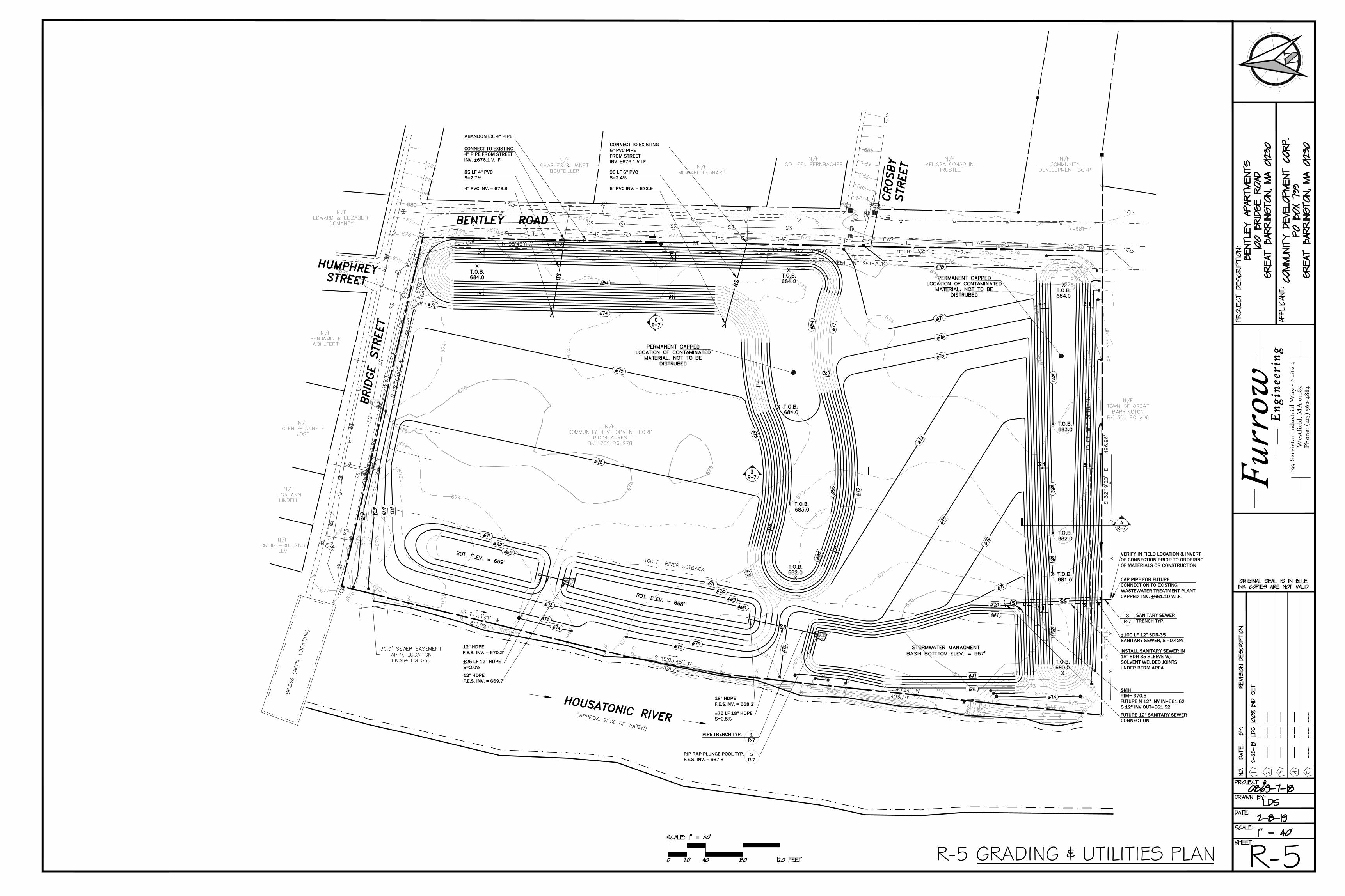
CONNECT TO EXISTING4" PIPE FROM STREETINV. ±676.1 V.I.F.
85 LF 4" PVCS=2.7%
4" PVC INV. = 673.9
CONNECT TO EXISTING6" PVC PIPEFROM STREETINV. ±676.1 V.I.F.
90 LF 6" PVCS=2.4%
6" PVC INV. = 673.9
ABANDON EX. 4" PIPE
CAP PIPE FOR FUTURECONNECTION TO EXISTINGWASTEWATER TREATMENT PLANTCAPPED INV. ±661.10 V.I.F.
±100 LF 12" SDR-35SANITARY SEWER, S =0.42%
VERIFY IN FIELD LOCATION & INVERTOF CONNECTION PRIOR TO ORDERINGOF MATERIALS OR CONSTRUCTION
SMHRIM= 670.5FUTURE N 12" INV IN=661.62S 12" INV OUT=661.52FUTURE 12" SANITARY SEWERCONNECTION
±75 LF 18" HDPES=0.5%
18" HDPEF.E.S.INV. = 668.2'
RIP-RAP PLUNGE POOL TYP.F.E.S. INV. = 667.8
5R-7
PIPE TRENCH TYP. 1R-7
SANITARY SEWERTRENCH TYP.
3R-7
±25 LF 12" HDPES=2.0%
12" HDPEF.E.S. INV. = 670.2'
12" HDPEF.E.S. INV. = 669.7'
INSTALL SANITARY SEWER IN18" SDR-35 SLEEVE W/SOLVENT WELDED JOINTSUNDER BERM AREA
R-5R-5 GRADING & UTILITIES PLAN
199
Serv
ista
r In
dust
rial
Way
- S
uite
2W
estf
ield
, MA
010
85P
hone
: (41
3) 5
62-4
884
Furr
ow Eng
inee
ring
AutoCAD SHX Text
674
AutoCAD SHX Text
670
AutoCAD SHX Text
670
AutoCAD SHX Text
672
AutoCAD SHX Text
675
AutoCAD SHX Text
676
AutoCAD SHX Text
683
AutoCAD SHX Text
682
AutoCAD SHX Text
681
AutoCAD SHX Text
680
AutoCAD SHX Text
680
AutoCAD SHX Text
671
AutoCAD SHX Text
670
AutoCAD SHX Text
670
AutoCAD SHX Text
671
AutoCAD SHX Text
672
AutoCAD SHX Text
673
AutoCAD SHX Text
674
AutoCAD SHX Text
674
AutoCAD SHX Text
673
AutoCAD SHX Text
672
AutoCAD SHX Text
671
AutoCAD SHX Text
671
AutoCAD SHX Text
672
AutoCAD SHX Text
673
AutoCAD SHX Text
674
AutoCAD SHX Text
674
AutoCAD SHX Text
675
AutoCAD SHX Text
675
AutoCAD SHX Text
675
AutoCAD SHX Text
675
AutoCAD SHX Text
679
AutoCAD SHX Text
678
AutoCAD SHX Text
677
AutoCAD SHX Text
676
AutoCAD SHX Text
675
AutoCAD SHX Text
670
AutoCAD SHX Text
674
AutoCAD SHX Text
673
AutoCAD SHX Text
672
AutoCAD SHX Text
671
AutoCAD SHX Text
675
AutoCAD SHX Text
674
AutoCAD SHX Text
675
AutoCAD SHX Text
676
AutoCAD SHX Text
674
AutoCAD SHX Text
673
AutoCAD SHX Text
675
AutoCAD SHX Text
674
AutoCAD SHX Text
675
AutoCAD SHX Text
674
AutoCAD SHX Text
675
AutoCAD SHX Text
674
AutoCAD SHX Text
673
AutoCAD SHX Text
675
AutoCAD SHX Text
674
AutoCAD SHX Text
673
AutoCAD SHX Text
672
AutoCAD SHX Text
673
AutoCAD SHX Text
674
AutoCAD SHX Text
670
AutoCAD SHX Text
671
AutoCAD SHX Text
671
AutoCAD SHX Text
672
AutoCAD SHX Text
673
AutoCAD SHX Text
674
AutoCAD SHX Text
673
AutoCAD SHX Text
673
AutoCAD SHX Text
677
AutoCAD SHX Text
676
AutoCAD SHX Text
675
AutoCAD SHX Text
674
AutoCAD SHX Text
674
AutoCAD SHX Text
675
AutoCAD SHX Text
675
AutoCAD SHX Text
675
AutoCAD SHX Text
680
AutoCAD SHX Text
679
AutoCAD SHX Text
678
AutoCAD SHX Text
677
AutoCAD SHX Text
679
AutoCAD SHX Text
676
AutoCAD SHX Text
677
AutoCAD SHX Text
674
AutoCAD SHX Text
678
AutoCAD SHX Text
677
AutoCAD SHX Text
681
AutoCAD SHX Text
685
AutoCAD SHX Text
684
AutoCAD SHX Text
683
AutoCAD SHX Text
682
AutoCAD SHX Text
681
AutoCAD SHX Text
676
AutoCAD SHX Text
675
AutoCAD SHX Text
678
AutoCAD SHX Text
677
AutoCAD SHX Text
679
AutoCAD SHX Text
678
AutoCAD SHX Text
677
AutoCAD SHX Text
676
AutoCAD SHX Text
678
AutoCAD SHX Text
679
AutoCAD SHX Text
680
AutoCAD SHX Text
BRIDGE STREET
AutoCAD SHX Text
BENTLEY ROAD
AutoCAD SHX Text
S 21%%d23'41'' W
AutoCAD SHX Text
311.02'
AutoCAD SHX Text
S 18%%d05'45'' W
AutoCAD SHX Text
109.22'
AutoCAD SHX Text
S 13%%d43'24'' W
AutoCAD SHX Text
406.39'
AutoCAD SHX Text
S 82%%d19'20'' E
AutoCAD SHX Text
496.96'
AutoCAD SHX Text
N 08%%d45'00'' E
AutoCAD SHX Text
247.91'
AutoCAD SHX Text
N 08%%d45'00'' E
AutoCAD SHX Text
479.58'
AutoCAD SHX Text
N 69%%d20'00'' W
AutoCAD SHX Text
384.10'
AutoCAD SHX Text
HOUSATONIC RIVER
AutoCAD SHX Text
(APPROX. EDGE OF WATER)
AutoCAD SHX Text
BRIDGE (APPX. LOCATION)
AutoCAD SHX Text
HUMPHREY STREET
AutoCAD SHX Text
S
AutoCAD SHX Text
S
AutoCAD SHX Text
S
AutoCAD SHX Text
S
AutoCAD SHX Text
D
AutoCAD SHX Text
Y
AutoCAD SHX Text
H
AutoCAD SHX Text
D
AutoCAD SHX Text
D
AutoCAD SHX Text
Y
AutoCAD SHX Text
H
AutoCAD SHX Text
M
AutoCAD SHX Text
S
AutoCAD SHX Text
N/F BRIDGE-BUILDING LLC
AutoCAD SHX Text
N/F LISA ANN LINDELL
AutoCAD SHX Text
N/F GLEN & ANNE E JOST
AutoCAD SHX Text
N/F BENJAMIN E WOHLFERT
AutoCAD SHX Text
N/F EDWARD & ELIZABETH DOMANEY
AutoCAD SHX Text
N/F CHARLES & JANET BOUTEILLER
AutoCAD SHX Text
N/F MICHAEL LEONARD
AutoCAD SHX Text
N/F COLLEEN FERNBACHER
AutoCAD SHX Text
N/F COMMUNITY DEVELOPMENT CORP 8.034 ACRES BK 1780 PG 278
AutoCAD SHX Text
N/F MELISSA CONSOLINI TRUSTEE
AutoCAD SHX Text
N/F COMMUNITY DEVELOPMENT CORP
AutoCAD SHX Text
N/F TOWN OF GREAT BARRINGTON BK 360 PG 206
AutoCAD SHX Text
25 FT STREET LINE SETBACK
AutoCAD SHX Text
10 FT FRONT SETBACK
AutoCAD SHX Text
10 FT FRONT SETBACK
AutoCAD SHX Text
10 FT SIDE SETBACK
AutoCAD SHX Text
A
AutoCAD SHX Text
R-7
AutoCAD SHX Text
R-7
AutoCAD SHX Text
B
AutoCAD SHX Text
R-7
AutoCAD SHX Text
C
AutoCAD SHX Text
3:1
AutoCAD SHX Text
3:1
AutoCAD SHX Text
3:1
AutoCAD SHX Text
3:1
AutoCAD SHX Text
3:1
AutoCAD SHX Text
3:1
AutoCAD SHX Text
3:1
AutoCAD SHX Text
3:1
AutoCAD SHX Text
3:1
AutoCAD SHX Text
3:1
AutoCAD SHX Text
3:1
AutoCAD SHX Text
3:1
AutoCAD SHX Text
3:1
AutoCAD SHX Text
3:1
AutoCAD SHX Text
X T.O.B. 684.0
AutoCAD SHX Text
T.O.B. 682.0 X
AutoCAD SHX Text
X T.O.B. 683.0
AutoCAD SHX Text
X T.O.B. 684.0
AutoCAD SHX Text
X T.O.B. 684.0
AutoCAD SHX Text
T.O.B. 680.0 X
AutoCAD SHX Text
X T.O.B. 681.0
AutoCAD SHX Text
X T.O.B. 682.0
AutoCAD SHX Text
X T.O.B. 683.0
AutoCAD SHX Text
673
AutoCAD SHX Text
672
AutoCAD SHX Text
674
AutoCAD SHX Text
671
AutoCAD SHX Text
675
AutoCAD SHX Text
676
AutoCAD SHX Text
677
AutoCAD SHX Text
PERMANENT CAPPED LOCATION OF CONTAMINATED MATERIAL. NOT TO BE DISTRUBED
AutoCAD SHX Text
X T.O.B. 684.0
AutoCAD SHX Text
STORMWATER MANAGMENT BASIN BOTTTOM ELEV. = 667'
AutoCAD SHX Text
RF 78
AutoCAD SHX Text
PERMANENT CAPPED LOCATION OF CONTAMINATED MATERIAL. NOT TO BE DISTRUBED
AutoCAD SHX Text
CROSBY STREET
AutoCAD SHX Text
RF 74
AutoCAD SHX Text
RF 84
AutoCAD SHX Text
RF 88
AutoCAD SHX Text
RF 80
AutoCAD SHX Text
RF 73
AutoCAD SHX Text
RF 90
AutoCAD SHX Text
RF 82
AutoCAD SHX Text
RF 75
AutoCAD SHX Text
RF 85
AutoCAD SHX Text
RF 77
AutoCAD SHX Text
RF 70
AutoCAD SHX Text
RF 87
AutoCAD SHX Text
RF 79
AutoCAD SHX Text
RF 72
AutoCAD SHX Text
RF 89
AutoCAD SHX Text
RF 81
AutoCAD SHX Text
RF 76
AutoCAD SHX Text
RF 86
AutoCAD SHX Text
RF 71
AutoCAD SHX Text
674
AutoCAD SHX Text
673
AutoCAD SHX Text
667
AutoCAD SHX Text
670
AutoCAD SHX Text
667
AutoCAD SHX Text
BOT. ELEV. = 668'
AutoCAD SHX Text
BOT. ELEV. = 669'
AutoCAD SHX Text
671
AutoCAD SHX Text
670
AutoCAD SHX Text
669
AutoCAD SHX Text
668
AutoCAD SHX Text
669
AutoCAD SHX Text
670
AutoCAD SHX Text
671
AutoCAD SHX Text
673
AutoCAD SHX Text
672
AutoCAD SHX Text
672
AutoCAD SHX Text
673
AutoCAD SHX Text
674
AutoCAD SHX Text
672
AutoCAD SHX Text
673
AutoCAD SHX Text
672
AutoCAD SHX Text
673
AutoCAD SHX Text
674
AutoCAD SHX Text
675
AutoCAD SHX Text
674
AutoCAD SHX Text
684
AutoCAD SHX Text
673
AutoCAD SHX Text
672
AutoCAD SHX Text
671
AutoCAD SHX Text
675
AutoCAD SHX Text
677
AutoCAD SHX Text
684
AutoCAD SHX Text
683
AutoCAD SHX Text
682
AutoCAD SHX Text
680
AutoCAD SHX Text
681
AutoCAD SHX Text
682
AutoCAD SHX Text
683
AutoCAD SHX Text
678
AutoCAD SHX Text
674
AutoCAD SHX Text
S
AutoCAD SHX Text
100 FT RIVER SETBACK
AutoCAD SHX Text
EX. TREELINE
AutoCAD SHX Text
EX. TREELINE
AutoCAD SHX Text
EX. TREELINE
AutoCAD SHX Text
EX. TREELINE
AutoCAD SHX Text
EX. TREELINE
AutoCAD SHX Text
PROJECT DESCRIPTION:
AutoCAD SHX Text
APPLICANT:
AutoCAD SHX Text
SCALE:
AutoCAD SHX Text
1" = 40'
AutoCAD SHX Text
DATE:
AutoCAD SHX Text
NO.
AutoCAD SHX Text
DATE:
AutoCAD SHX Text
REVISION DESCRIPTION
AutoCAD SHX Text
BY:
AutoCAD SHX Text
DRAWN BY:
AutoCAD SHX Text
SHEET:
AutoCAD SHX Text
1
AutoCAD SHX Text
2
AutoCAD SHX Text
3
AutoCAD SHX Text
4
AutoCAD SHX Text
5
AutoCAD SHX Text
PROJECT #:
AutoCAD SHX Text
SCALE: 1" = 40'
AutoCAD SHX Text
20
AutoCAD SHX Text
0
AutoCAD SHX Text
120 FEET
AutoCAD SHX Text
40
AutoCAD SHX Text
80
AutoCAD SHX Text
ORIGINAL SEAL IS IN BLUE INK COPIES ARE NOT VALID
AutoCAD SHX Text
BENTLEY APARTMENTS 100 BRIDGE ROAD GREAT BARRINGTON, MA 01230
AutoCAD SHX Text
---
AutoCAD SHX Text
---
AutoCAD SHX Text
---
AutoCAD SHX Text
---
AutoCAD SHX Text
---
AutoCAD SHX Text
---
AutoCAD SHX Text
---
AutoCAD SHX Text
---
AutoCAD SHX Text
---
AutoCAD SHX Text
---
AutoCAD SHX Text
---
AutoCAD SHX Text
---
AutoCAD SHX Text
LDS
AutoCAD SHX Text
0869-7-18
AutoCAD SHX Text
COMMUNITY DEVELOPMENT CORP. PO BOX 733 GREAT BARRINGTON, MA 01230
AutoCAD SHX Text
2-8-19
AutoCAD SHX Text
2-25-19
AutoCAD SHX Text
LDS
AutoCAD SHX Text
100% BID SET
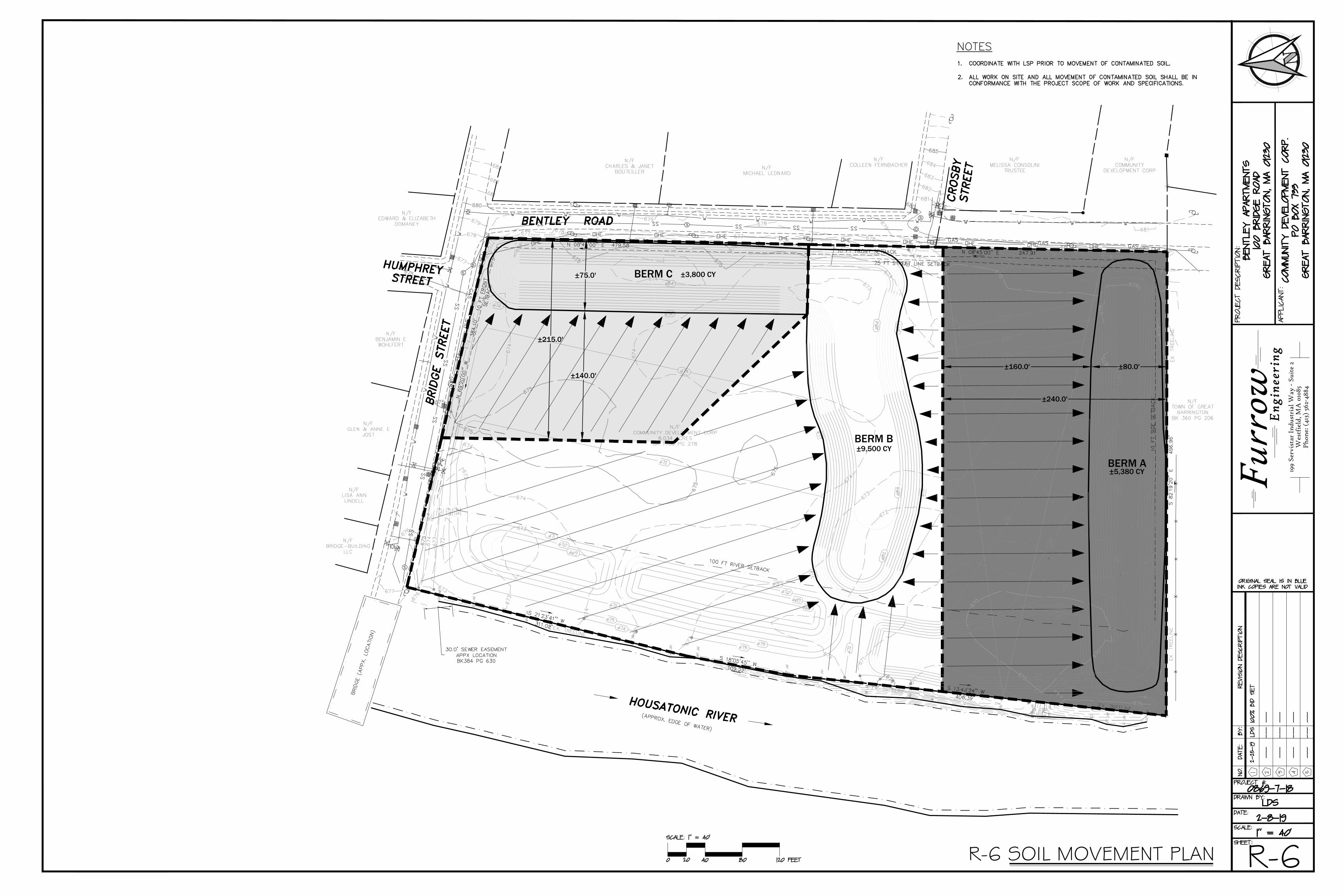
BERM A
BERM B
BERM C
±215.0'
±75.0'
±140.0'
±3,800 CY
±9,500 CY
±5,380 CY
±240.0'
±160.0' ±80.0'
R-6R-6 SOIL MOVEMENT PLAN
199
Serv
ista
r In
dust
rial
Way
- S
uite
2W
estf
ield
, MA
010
85P
hone
: (41
3) 5
62-4
884
Furr
ow Eng
inee
ring
AutoCAD SHX Text
674
AutoCAD SHX Text
670
AutoCAD SHX Text
670
AutoCAD SHX Text
672
AutoCAD SHX Text
675
AutoCAD SHX Text
676
AutoCAD SHX Text
683
AutoCAD SHX Text
682
AutoCAD SHX Text
681
AutoCAD SHX Text
680
AutoCAD SHX Text
680
AutoCAD SHX Text
671
AutoCAD SHX Text
670
AutoCAD SHX Text
670
AutoCAD SHX Text
671
AutoCAD SHX Text
672
AutoCAD SHX Text
673
AutoCAD SHX Text
674
AutoCAD SHX Text
674
AutoCAD SHX Text
673
AutoCAD SHX Text
672
AutoCAD SHX Text
671
AutoCAD SHX Text
671
AutoCAD SHX Text
672
AutoCAD SHX Text
673
AutoCAD SHX Text
674
AutoCAD SHX Text
674
AutoCAD SHX Text
675
AutoCAD SHX Text
675
AutoCAD SHX Text
675
AutoCAD SHX Text
675
AutoCAD SHX Text
679
AutoCAD SHX Text
678
AutoCAD SHX Text
677
AutoCAD SHX Text
676
AutoCAD SHX Text
675
AutoCAD SHX Text
670
AutoCAD SHX Text
674
AutoCAD SHX Text
673
AutoCAD SHX Text
672
AutoCAD SHX Text
671
AutoCAD SHX Text
675
AutoCAD SHX Text
674
AutoCAD SHX Text
675
AutoCAD SHX Text
676
AutoCAD SHX Text
674
AutoCAD SHX Text
673
AutoCAD SHX Text
675
AutoCAD SHX Text
674
AutoCAD SHX Text
675
AutoCAD SHX Text
674
AutoCAD SHX Text
675
AutoCAD SHX Text
674
AutoCAD SHX Text
673
AutoCAD SHX Text
675
AutoCAD SHX Text
674
AutoCAD SHX Text
673
AutoCAD SHX Text
672
AutoCAD SHX Text
673
AutoCAD SHX Text
674
AutoCAD SHX Text
670
AutoCAD SHX Text
671
AutoCAD SHX Text
671
AutoCAD SHX Text
672
AutoCAD SHX Text
673
AutoCAD SHX Text
674
AutoCAD SHX Text
673
AutoCAD SHX Text
673
AutoCAD SHX Text
677
AutoCAD SHX Text
676
AutoCAD SHX Text
675
AutoCAD SHX Text
674
AutoCAD SHX Text
674
AutoCAD SHX Text
675
AutoCAD SHX Text
675
AutoCAD SHX Text
675
AutoCAD SHX Text
680
AutoCAD SHX Text
679
AutoCAD SHX Text
678
AutoCAD SHX Text
677
AutoCAD SHX Text
679
AutoCAD SHX Text
676
AutoCAD SHX Text
677
AutoCAD SHX Text
674
AutoCAD SHX Text
678
AutoCAD SHX Text
677
AutoCAD SHX Text
681
AutoCAD SHX Text
685
AutoCAD SHX Text
684
AutoCAD SHX Text
683
AutoCAD SHX Text
682
AutoCAD SHX Text
681
AutoCAD SHX Text
676
AutoCAD SHX Text
675
AutoCAD SHX Text
678
AutoCAD SHX Text
677
AutoCAD SHX Text
679
AutoCAD SHX Text
678
AutoCAD SHX Text
677
AutoCAD SHX Text
676
AutoCAD SHX Text
678
AutoCAD SHX Text
679
AutoCAD SHX Text
680
AutoCAD SHX Text
BRIDGE STREET
AutoCAD SHX Text
BENTLEY ROAD
AutoCAD SHX Text
S 21%%d23'41'' W
AutoCAD SHX Text
311.02'
AutoCAD SHX Text
S 18%%d05'45'' W
AutoCAD SHX Text
109.22'
AutoCAD SHX Text
S 13%%d43'24'' W
AutoCAD SHX Text
406.39'
AutoCAD SHX Text
S 82%%d19'20'' E
AutoCAD SHX Text
496.96'
AutoCAD SHX Text
N 08%%d45'00'' E
AutoCAD SHX Text
247.91'
AutoCAD SHX Text
N 08%%d45'00'' E
AutoCAD SHX Text
479.58'
AutoCAD SHX Text
N 69%%d20'00'' W
AutoCAD SHX Text
384.10'
AutoCAD SHX Text
HOUSATONIC RIVER
AutoCAD SHX Text
(APPROX. EDGE OF WATER)
AutoCAD SHX Text
BRIDGE (APPX. LOCATION)
AutoCAD SHX Text
HUMPHREY STREET
AutoCAD SHX Text
S
AutoCAD SHX Text
S
AutoCAD SHX Text
S
AutoCAD SHX Text
S
AutoCAD SHX Text
D
AutoCAD SHX Text
Y
AutoCAD SHX Text
H
AutoCAD SHX Text
D
AutoCAD SHX Text
D
AutoCAD SHX Text
Y
AutoCAD SHX Text
H
AutoCAD SHX Text
M
AutoCAD SHX Text
S
AutoCAD SHX Text
N/F BRIDGE-BUILDING LLC
AutoCAD SHX Text
N/F LISA ANN LINDELL
AutoCAD SHX Text
N/F GLEN & ANNE E JOST
AutoCAD SHX Text
N/F BENJAMIN E WOHLFERT
AutoCAD SHX Text
N/F EDWARD & ELIZABETH DOMANEY
AutoCAD SHX Text
N/F CHARLES & JANET BOUTEILLER
AutoCAD SHX Text
N/F MICHAEL LEONARD
AutoCAD SHX Text
N/F COLLEEN FERNBACHER
AutoCAD SHX Text
N/F COMMUNITY DEVELOPMENT CORP 8.034 ACRES BK 1780 PG 278
AutoCAD SHX Text
N/F MELISSA CONSOLINI TRUSTEE
AutoCAD SHX Text
N/F COMMUNITY DEVELOPMENT CORP
AutoCAD SHX Text
N/F TOWN OF GREAT BARRINGTON BK 360 PG 206
AutoCAD SHX Text
25 FT STREET LINE SETBACK
AutoCAD SHX Text
10 FT FRONT SETBACK
AutoCAD SHX Text
10 FT FRONT SETBACK
AutoCAD SHX Text
10 FT SIDE SETBACK
AutoCAD SHX Text
673
AutoCAD SHX Text
672
AutoCAD SHX Text
674
AutoCAD SHX Text
671
AutoCAD SHX Text
675
AutoCAD SHX Text
676
AutoCAD SHX Text
677
AutoCAD SHX Text
RF 78
AutoCAD SHX Text
CROSBY STREET
AutoCAD SHX Text
RF 74
AutoCAD SHX Text
RF 84
AutoCAD SHX Text
RF 88
AutoCAD SHX Text
RF 80
AutoCAD SHX Text
RF 73
AutoCAD SHX Text
RF 90
AutoCAD SHX Text
RF 82
AutoCAD SHX Text
RF 75
AutoCAD SHX Text
RF 85
AutoCAD SHX Text
RF 77
AutoCAD SHX Text
RF 70
AutoCAD SHX Text
RF 87
AutoCAD SHX Text
RF 79
AutoCAD SHX Text
RF 72
AutoCAD SHX Text
RF 89
AutoCAD SHX Text
RF 81
AutoCAD SHX Text
RF 76
AutoCAD SHX Text
RF 86
AutoCAD SHX Text
RF 71
AutoCAD SHX Text
674
AutoCAD SHX Text
673
AutoCAD SHX Text
667
AutoCAD SHX Text
670
AutoCAD SHX Text
667
AutoCAD SHX Text
671
AutoCAD SHX Text
670
AutoCAD SHX Text
669
AutoCAD SHX Text
668
AutoCAD SHX Text
669
AutoCAD SHX Text
670
AutoCAD SHX Text
671
AutoCAD SHX Text
673
AutoCAD SHX Text
672
AutoCAD SHX Text
672
AutoCAD SHX Text
673
AutoCAD SHX Text
674
AutoCAD SHX Text
672
AutoCAD SHX Text
673
AutoCAD SHX Text
672
AutoCAD SHX Text
673
AutoCAD SHX Text
674
AutoCAD SHX Text
675
AutoCAD SHX Text
674
AutoCAD SHX Text
684
AutoCAD SHX Text
673
AutoCAD SHX Text
672
AutoCAD SHX Text
671
AutoCAD SHX Text
675
AutoCAD SHX Text
677
AutoCAD SHX Text
684
AutoCAD SHX Text
683
AutoCAD SHX Text
682
AutoCAD SHX Text
680
AutoCAD SHX Text
681
AutoCAD SHX Text
682
AutoCAD SHX Text
683
AutoCAD SHX Text
678
AutoCAD SHX Text
674
AutoCAD SHX Text
100 FT RIVER SETBACK
AutoCAD SHX Text
EX. TREELINE
AutoCAD SHX Text
EX. TREELINE
AutoCAD SHX Text
EX. TREELINE
AutoCAD SHX Text
EX. TREELINE
AutoCAD SHX Text
EX. TREELINE
AutoCAD SHX Text
PROJECT DESCRIPTION:
AutoCAD SHX Text
APPLICANT:
AutoCAD SHX Text
SCALE:
AutoCAD SHX Text
1" = 40'
AutoCAD SHX Text
DATE:
AutoCAD SHX Text
NO.
AutoCAD SHX Text
DATE:
AutoCAD SHX Text
REVISION DESCRIPTION
AutoCAD SHX Text
BY:
AutoCAD SHX Text
DRAWN BY:
AutoCAD SHX Text
SHEET:
AutoCAD SHX Text
1
AutoCAD SHX Text
2
AutoCAD SHX Text
3
AutoCAD SHX Text
4
AutoCAD SHX Text
5
AutoCAD SHX Text
PROJECT #:
AutoCAD SHX Text
SCALE: 1" = 40'
AutoCAD SHX Text
20
AutoCAD SHX Text
0
AutoCAD SHX Text
120 FEET
AutoCAD SHX Text
40
AutoCAD SHX Text
80
AutoCAD SHX Text
ORIGINAL SEAL IS IN BLUE INK COPIES ARE NOT VALID
AutoCAD SHX Text
BENTLEY APARTMENTS 100 BRIDGE ROAD GREAT BARRINGTON, MA 01230
AutoCAD SHX Text
---
AutoCAD SHX Text
---
AutoCAD SHX Text
---
AutoCAD SHX Text
---
AutoCAD SHX Text
---
AutoCAD SHX Text
---
AutoCAD SHX Text
---
AutoCAD SHX Text
---
AutoCAD SHX Text
---
AutoCAD SHX Text
---
AutoCAD SHX Text
---
AutoCAD SHX Text
---
AutoCAD SHX Text
LDS
AutoCAD SHX Text
0869-7-18
AutoCAD SHX Text
COMMUNITY DEVELOPMENT CORP. PO BOX 733 GREAT BARRINGTON, MA 01230
AutoCAD SHX Text
NOTES 1. COORDINATE WITH LSP PRIOR TO MOVEMENT OF CONTAMINATED SOIL. COORDINATE WITH LSP PRIOR TO MOVEMENT OF CONTAMINATED SOIL. 2. ALL WORK ON SITE AND ALL MOVEMENT OF CONTAMINATED SOIL SHALL BE IN ALL WORK ON SITE AND ALL MOVEMENT OF CONTAMINATED SOIL SHALL BE IN CONFORMANCE WITH THE PROJECT SCOPE OF WORK AND SPECIFICATIONS.
AutoCAD SHX Text
2-8-19
AutoCAD SHX Text
2-25-19
AutoCAD SHX Text
LDS
AutoCAD SHX Text
100% BID SET

R-7R-7 BERM CROSS SECTIONS & DETAILS
199
Serv
ista
r In
dust
rial
Way
- S
uite
2W
estf
ield
, MA
010
85P
hone
: (41
3) 5
62-4
884
Furr
ow Eng
inee
ring
BERM AA
BERM BB
BERM CC
AutoCAD SHX Text
PROJECT DESCRIPTION:
AutoCAD SHX Text
APPLICANT:
AutoCAD SHX Text
SCALE:
AutoCAD SHX Text
AS NOTED
AutoCAD SHX Text
DATE:
AutoCAD SHX Text
NO.
AutoCAD SHX Text
DATE:
AutoCAD SHX Text
REVISION DESCRIPTION
AutoCAD SHX Text
BY:
AutoCAD SHX Text
DRAWN BY:
AutoCAD SHX Text
SHEET:
AutoCAD SHX Text
1
AutoCAD SHX Text
2
AutoCAD SHX Text
3
AutoCAD SHX Text
4
AutoCAD SHX Text
5
AutoCAD SHX Text
PROJECT #:
AutoCAD SHX Text
ORIGINAL SEAL IS IN BLUE INK COPIES ARE NOT VALID
AutoCAD SHX Text
BENTLEY APARTMENTS 100 BRIDGE ROAD GREAT BARRINGTON, MA 01230
AutoCAD SHX Text
---
AutoCAD SHX Text
---
AutoCAD SHX Text
---
AutoCAD SHX Text
---
AutoCAD SHX Text
---
AutoCAD SHX Text
---
AutoCAD SHX Text
---
AutoCAD SHX Text
---
AutoCAD SHX Text
---
AutoCAD SHX Text
---
AutoCAD SHX Text
---
AutoCAD SHX Text
---
AutoCAD SHX Text
LDS
AutoCAD SHX Text
0869-7-18
AutoCAD SHX Text
COMMUNITY DEVELOPMENT CORP. PO BOX 733 GREAT BARRINGTON, MA 01230
AutoCAD SHX Text
CAP TO BE CLEAN LOAM BROUGHT IN FROM OFF-SITE. TOPSOIL TO MEET SPECIFICATIONS SHOWN ON PLAN SHEET R-3.
AutoCAD SHX Text
1
AutoCAD SHX Text
3
AutoCAD SHX Text
1
AutoCAD SHX Text
3
AutoCAD SHX Text
2'-0" CAP ON TOP
AutoCAD SHX Text
SCALE: NTS
AutoCAD SHX Text
CAP TO BE CLEAN LOAM BROUGHT IN FROM OFF-SITE. TOPSOIL TO MEET SPECIFICATIONS SHOWN ON PLAN SHEET R-3.
AutoCAD SHX Text
1
AutoCAD SHX Text
3
AutoCAD SHX Text
1
AutoCAD SHX Text
3
AutoCAD SHX Text
1'-0" CAP ON TOP
AutoCAD SHX Text
SCALE: NTS
AutoCAD SHX Text
CAP TO BE CLEAN LOAM BROUGHT IN FROM OFF-SITE. TOPSOIL TO MEET SPECIFICATIONS SHOWN ON PLAN SHEET R-3.
AutoCAD SHX Text
1
AutoCAD SHX Text
3
AutoCAD SHX Text
3
AutoCAD SHX Text
1
AutoCAD SHX Text
1'-0" CAP ON TOP
AutoCAD SHX Text
SCALE: NTS
AutoCAD SHX Text
LOCATION OF CONTAMINATED SOIL TO BE PERMANENTLY ENCAPSULATED WITHIN THE BERM.
AutoCAD SHX Text
LOCATION OF CONTAMINATED SOIL TO BE PERMANENTLY ENCAPSULATED WITHIN THE BERM.
AutoCAD SHX Text
LOCATION OF CONTAMINATED SOIL TO BE PERMANENTLY ENCAPSULATED WITHIN THE BERM.
AutoCAD SHX Text
%%U SILT FENCE DETAIL
AutoCAD SHX Text
4
AutoCAD SHX Text
N.T.S.
AutoCAD SHX Text
GEOTEXTILE FABRIC
AutoCAD SHX Text
FLOW DIRECTION
AutoCAD SHX Text
USE SILT FENCE INSTALLATION ATTACHMENT TO ENTRENCH SILT FENCE
AutoCAD SHX Text
EXISTING GROUND
AutoCAD SHX Text
3 FOOT WOOD SUPPORT POSTS 8 FT. ON CENTER
AutoCAD SHX Text
R-7
AutoCAD SHX Text
8" LOAM AND SEED
AutoCAD SHX Text
R-7
AutoCAD SHX Text
BIT. SURFACE COURSE
AutoCAD SHX Text
BIT. BINDER COURSE
AutoCAD SHX Text
8" OF PROCESSED GRAVEL
AutoCAD SHX Text
4" OR 24" SDR-35 SEWER PIPE
AutoCAD SHX Text
WARNING TAPE MIN. 12" ABOVE PIPE
AutoCAD SHX Text
6"-MIN.
AutoCAD SHX Text
6"-MIN.
AutoCAD SHX Text
2'-0" MIN.
AutoCAD SHX Text
6"-MIN.
AutoCAD SHX Text
6"-MIN.
AutoCAD SHX Text
N.T.S.
AutoCAD SHX Text
PROVIDE GEOTEXTILE FILTER FABRIC ENVELOPE
AutoCAD SHX Text
3
AutoCAD SHX Text
%%U SANITARY SEWER TRENCH DETAIL
AutoCAD SHX Text
2'-0" MIN.
AutoCAD SHX Text
3/4" STONE TO BE COMPACTED IN 1'-0" LIFTS W/2 PASSES
AutoCAD SHX Text
6. MAINTENANCE-THE ENTRANCE SHALL BE MAINTAINED IN A CONDITION WHICH WILL PREVENT TRACKING OR FLOWING OF SEDIMENT ONTO PUBLIC RIGHTS-OF-WAY. THIS MAY REQUIRE PERIODIC TOP DRESSING WITH ADDITIONAL STONE AS CONDITIONS DEMAND AND REPAIR AND/OR CLEANOUT OF ANY MEASURES USED TO TRAP SEDIMENT. ALL SEDIMENT SPILLED,DROPPED,WASHED, OR TRACKED ONTO PUBLIC RIGTHS-OF-WAY MUST BE REMOVED IMMEDIATELY.
AutoCAD SHX Text
10'
AutoCAD SHX Text
10'
AutoCAD SHX Text
PAVEMENT
AutoCAD SHX Text
EXISTING
AutoCAD SHX Text
PLAN VIEW
AutoCAD SHX Text
PROFILE
AutoCAD SHX Text
PAVEMENT
AutoCAD SHX Text
EXISTING
AutoCAD SHX Text
EXISTING GROUND
AutoCAD SHX Text
PER PLAN
AutoCAD SHX Text
6" MIN.
AutoCAD SHX Text
PER PLAN
AutoCAD SHX Text
10'
AutoCAD SHX Text
CONSTRUCTION ENTRANCE PLAN
AutoCAD SHX Text
R-7
AutoCAD SHX Text
N.T.S.
AutoCAD SHX Text
2
AutoCAD SHX Text
1. STONE SIZE-USE 2" STONE, OR RECLAIMED OR RECYCLED CONCRETE EQUIVALENT.
AutoCAD SHX Text
2. LENGTH-AS REQUIRED, BUT NOT LESS THAN 50'
AutoCAD SHX Text
3. THICKNESS-NOT LESS THAN 6".
AutoCAD SHX Text
4. WIDTH- 24' MINIMUM FOR SINGLE ENTRANCE TO SITE, 12' MINIMUM FOR MULTIPLE ENTRANCE TO SITE
AutoCAD SHX Text
5. FILTER CLOTH-WILL BE PLACED OVER THE ENTIRE AREA PRIOR TO PLACING OF STONE.
AutoCAD SHX Text
7. PERIODIC INSPECTION AND NEEDED MAINTENANCE SHALL BE PROVIDED AFTER EACH RAIN.
AutoCAD SHX Text
24' MIN. SEE NOTE 4
AutoCAD SHX Text
NOTES: 1. 5'-0" MINIMUM COVER FOR SANITARY SEWER FORCE MAIN ONLY. 5'-0" MINIMUM COVER FOR SANITARY SEWER FORCE MAIN ONLY. 2. FOR PAVED AREAS COMPACT ALL BACKFILL TO 95% MODIFIED PROCTOR. FOR PAVED AREAS COMPACT ALL BACKFILL TO 95% MODIFIED PROCTOR. 3. FOR UNPAVED AREAS COMPACT ALL BACKFILL TO 90% MODIFIED PROCTORFOR UNPAVED AREAS COMPACT ALL BACKFILL TO 90% MODIFIED PROCTOR
AutoCAD SHX Text
BACKFILL TO BE NATIVE MATERIAL PROVIDED IT IS WELL-GRADED AND FREE OF CLAY, ORGANIC MATTER, CONTAMINATED SOIL, DEBRIS, OR SOIL WITH A HIGH MOISTURE CONTENT.
AutoCAD SHX Text
CLDI WATER OR HDPE STORM DRAIN PIPE FOR SIZES AND INVERTS SEE PLANS
AutoCAD SHX Text
%%U TYPICAL PIPE TRENCH DETAIL
AutoCAD SHX Text
1
AutoCAD SHX Text
R-7
AutoCAD SHX Text
N.T.S.
AutoCAD SHX Text
NATIVE MATERIAL BACKFILL AS APPROVED BY PROJECT ENGINEER TO BE COMPACTED IN 1'-0" LIFTS W/2 PASSES
AutoCAD SHX Text
8" OF PROCESSED GRAVEL
AutoCAD SHX Text
BIT. BINDER COURSE
AutoCAD SHX Text
BIT. SURFACE COURSE
AutoCAD SHX Text
8" LOAM AND SEED
AutoCAD SHX Text
NOTES: 1. 5'-0" MINIMUM COVER FOR WATER MAIN ONLY. 5'-0" MINIMUM COVER FOR WATER MAIN ONLY. 2. FOR PAVED AREAS COMPACT ALL BACKFILL TO 95% MODIFIED PROCTOR. FOR PAVED AREAS COMPACT ALL BACKFILL TO 95% MODIFIED PROCTOR. 3. FOR UNPAVED AREAS COMPACT ALL BACKFILL TO 90% MODIFIED PROCTORFOR UNPAVED AREAS COMPACT ALL BACKFILL TO 90% MODIFIED PROCTOR
AutoCAD SHX Text
6"-MIN.
AutoCAD SHX Text
12"-MIN.
AutoCAD SHX Text
12"-MIN.
AutoCAD SHX Text
BACKFILL TO BE NATIVE MATERIAL PROVIDED IT IS WELL-GRADED AND FREE OF CLAY, ORGANIC MATTER, CONTAMINATED SOIL, DEBRIS, OR SOIL WITH A HIGH MOISTURE CONTENT.
AutoCAD SHX Text
WARNING TAPE MIN. 12" ABOVE PIPE FOR WATER ONLY
AutoCAD SHX Text
12"-MIN.
AutoCAD SHX Text
FILTER FABRIC
AutoCAD SHX Text
MIRAFI 140N
AutoCAD SHX Text
OR EQUAL
AutoCAD SHX Text
F.E.S.
AutoCAD SHX Text
12"
AutoCAD SHX Text
3:1
AutoCAD SHX Text
2x PIPE DIA.
AutoCAD SHX Text
3x PIPE DIA.
AutoCAD SHX Text
3:1
AutoCAD SHX Text
3:1
AutoCAD SHX Text
FLARED
AutoCAD SHX Text
END
AutoCAD SHX Text
SECTION
AutoCAD SHX Text
1' MIN
AutoCAD SHX Text
VARIES
AutoCAD SHX Text
3:1
AutoCAD SHX Text
FLARED END SECTION PLUNGE POOL DETAIL
AutoCAD SHX Text
R-7
AutoCAD SHX Text
5
AutoCAD SHX Text
N.T.S.
AutoCAD SHX Text
12" MIN. OR 1.5x PIPE DIAM THICK OF 7" MINIMUM MODIFIED RIP RAP S.G. MIN 2.65
AutoCAD SHX Text
0.5-1.0x PIPE DIA. 12" MIN DEPTH
AutoCAD SHX Text
VARIES AS REQUIRED TO MATCH EX. GRADE
AutoCAD SHX Text
VARIES AS REQUIRED TO MATCH EX. GRADE
AutoCAD SHX Text
PLAN
AutoCAD SHX Text
SECTION
AutoCAD SHX Text
2-8-19
AutoCAD SHX Text
SPLIT RAIL FENCE ALONG BOTTOM OF BERM (BY OTHERS)
AutoCAD SHX Text
SPLIT RAIL FENCE ALONG BOTTOM OF BERM
AutoCAD SHX Text
SPLIT RAIL FENCE ALONG BOTTOM OF BERM (BY OTHERS)
AutoCAD SHX Text
SPLIT RAIL FENCE ALONG BOTTOM OF BERM
AutoCAD SHX Text
SPLIT RAIL FENCE ALONG BOTTOM OF BERM
AutoCAD SHX Text
1'-0" CAP W/ MARKER LAYER & 175 MIL GSE HYPERNET GEONET ROLLED PERPENDICULAR TO BERM
AutoCAD SHX Text
DIRECTION OF GEONET ROLLING
AutoCAD SHX Text
1'-0" CAP W/ MARKER LAYER & 175 MIL GSE HYPERNET GEONET ROLLED PERPENDICULAR TO BERM
AutoCAD SHX Text
DIRECTION OF GEONET ROLLING
AutoCAD SHX Text
1'-0" CAP W/ MARKER LAYER & 175 MIL GSE HYPERNET GEONET ROLLED PERPENDICULAR TO BERM
AutoCAD SHX Text
DIRECTION OF GEONET ROLLING
AutoCAD SHX Text
GEONET NOTES: 1. EACH COMPONENT OF THE GEONET SHALL BE SECURED TO THE LIKE COMPONENT AT OVERLAPS. EACH COMPONENT OF THE GEONET SHALL BE SECURED TO THE LIKE COMPONENT AT OVERLAPS. 2. ADJACENT EDGES ALONG THE LENGTH OF THE GEONET ROLL SHALL BE OVERLAPPED A MINIMUM OF 6". ADJACENT EDGES ALONG THE LENGTH OF THE GEONET ROLL SHALL BE OVERLAPPED A MINIMUM OF 6". 3. THE OVERLAPPED EDGES SHALL BE JOINED BY TYING THE GEONET STRUCTURE WITH CABLE TIES. TIES SHALL THE OVERLAPPED EDGES SHALL BE JOINED BY TYING THE GEONET STRUCTURE WITH CABLE TIES. TIES SHALL BE SPACED EVERY 5 FEET ALONG ROLL LENGTH. 4. ADJOINING ROLLS ACROSS THE ROLL WIDTH SHALL BE SHINGLED DOWN IN THE DIRECTION OF THE SLOPE AND ADJOINING ROLLS ACROSS THE ROLL WIDTH SHALL BE SHINGLED DOWN IN THE DIRECTION OF THE SLOPE AND JOINED TOGETHER WITH CABLE TIES SPACED EVERY FOOT ALONG THE ROLL WIDTH.
AutoCAD SHX Text
2-25-19
AutoCAD SHX Text
LDS
AutoCAD SHX Text
100% BID SET
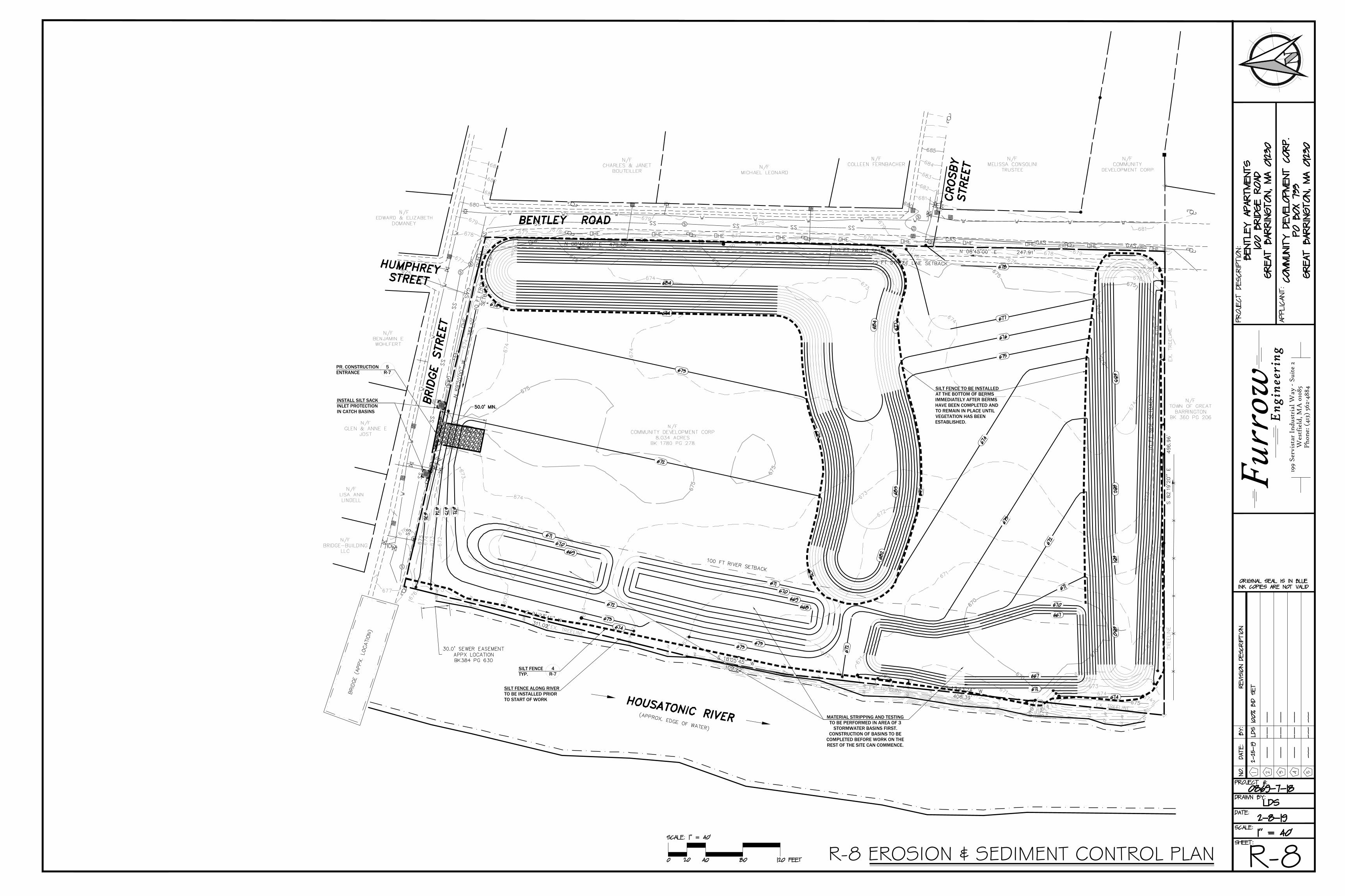
SILT FENCETYP.
4R-7
PR. CONSTRUCTIONENTRANCE
5R-7
SILT FENCE ALONG RIVERTO BE INSTALLED PRIORTO START OF WORK
SILT FENCE TO BE INSTALLEDAT THE BOTTOM OF BERMSIMMEDIATELY AFTER BERMSHAVE BEEN COMPLETED ANDTO REMAIN IN PLACE UNTILVEGETATION HAS BEENESTABLISHED.
MATERIAL STRIPPING AND TESTINGTO BE PERFORMED IN AREA OF 3
STORMWATER BASINS FIRST.CONSTRUCTION OF BASINS TO BE
COMPLETED BEFORE WORK ON THEREST OF THE SITE CAN COMMENCE.
INSTALL SILT SACKINLET PROTECTIONIN CATCH BASINS
R-8R-8 EROSION & SEDIMENT CONTROL PLAN
199
Serv
ista
r In
dust
rial
Way
- S
uite
2W
estf
ield
, MA
010
85P
hone
: (41
3) 5
62-4
884
Furr
ow Eng
inee
ring
AutoCAD SHX Text
674
AutoCAD SHX Text
670
AutoCAD SHX Text
670
AutoCAD SHX Text
672
AutoCAD SHX Text
675
AutoCAD SHX Text
676
AutoCAD SHX Text
683
AutoCAD SHX Text
682
AutoCAD SHX Text
681
AutoCAD SHX Text
680
AutoCAD SHX Text
680
AutoCAD SHX Text
671
AutoCAD SHX Text
670
AutoCAD SHX Text
670
AutoCAD SHX Text
671
AutoCAD SHX Text
672
AutoCAD SHX Text
673
AutoCAD SHX Text
674
AutoCAD SHX Text
674
AutoCAD SHX Text
673
AutoCAD SHX Text
672
AutoCAD SHX Text
671
AutoCAD SHX Text
671
AutoCAD SHX Text
672
AutoCAD SHX Text
673
AutoCAD SHX Text
674
AutoCAD SHX Text
674
AutoCAD SHX Text
675
AutoCAD SHX Text
675
AutoCAD SHX Text
675
AutoCAD SHX Text
675
AutoCAD SHX Text
679
AutoCAD SHX Text
678
AutoCAD SHX Text
677
AutoCAD SHX Text
676
AutoCAD SHX Text
675
AutoCAD SHX Text
670
AutoCAD SHX Text
674
AutoCAD SHX Text
673
AutoCAD SHX Text
672
AutoCAD SHX Text
671
AutoCAD SHX Text
675
AutoCAD SHX Text
674
AutoCAD SHX Text
675
AutoCAD SHX Text
676
AutoCAD SHX Text
674
AutoCAD SHX Text
673
AutoCAD SHX Text
675
AutoCAD SHX Text
674
AutoCAD SHX Text
675
AutoCAD SHX Text
674
AutoCAD SHX Text
675
AutoCAD SHX Text
674
AutoCAD SHX Text
673
AutoCAD SHX Text
675
AutoCAD SHX Text
674
AutoCAD SHX Text
673
AutoCAD SHX Text
672
AutoCAD SHX Text
673
AutoCAD SHX Text
674
AutoCAD SHX Text
670
AutoCAD SHX Text
671
AutoCAD SHX Text
671
AutoCAD SHX Text
672
AutoCAD SHX Text
673
AutoCAD SHX Text
674
AutoCAD SHX Text
673
AutoCAD SHX Text
673
AutoCAD SHX Text
677
AutoCAD SHX Text
676
AutoCAD SHX Text
675
AutoCAD SHX Text
674
AutoCAD SHX Text
674
AutoCAD SHX Text
675
AutoCAD SHX Text
675
AutoCAD SHX Text
675
AutoCAD SHX Text
680
AutoCAD SHX Text
679
AutoCAD SHX Text
678
AutoCAD SHX Text
677
AutoCAD SHX Text
679
AutoCAD SHX Text
676
AutoCAD SHX Text
677
AutoCAD SHX Text
674
AutoCAD SHX Text
678
AutoCAD SHX Text
677
AutoCAD SHX Text
681
AutoCAD SHX Text
685
AutoCAD SHX Text
684
AutoCAD SHX Text
683
AutoCAD SHX Text
682
AutoCAD SHX Text
681
AutoCAD SHX Text
676
AutoCAD SHX Text
675
AutoCAD SHX Text
678
AutoCAD SHX Text
677
AutoCAD SHX Text
679
AutoCAD SHX Text
678
AutoCAD SHX Text
677
AutoCAD SHX Text
676
AutoCAD SHX Text
678
AutoCAD SHX Text
679
AutoCAD SHX Text
680
AutoCAD SHX Text
BRIDGE STREET
AutoCAD SHX Text
BENTLEY ROAD
AutoCAD SHX Text
S 21%%d23'41'' W
AutoCAD SHX Text
311.02'
AutoCAD SHX Text
S 18%%d05'45'' W
AutoCAD SHX Text
109.22'
AutoCAD SHX Text
S 13%%d43'24'' W
AutoCAD SHX Text
406.39'
AutoCAD SHX Text
S 82%%d19'20'' E
AutoCAD SHX Text
496.96'
AutoCAD SHX Text
N 08%%d45'00'' E
AutoCAD SHX Text
247.91'
AutoCAD SHX Text
N 08%%d45'00'' E
AutoCAD SHX Text
479.58'
AutoCAD SHX Text
N 69%%d20'00'' W
AutoCAD SHX Text
384.10'
AutoCAD SHX Text
HOUSATONIC RIVER
AutoCAD SHX Text
(APPROX. EDGE OF WATER)
AutoCAD SHX Text
BRIDGE (APPX. LOCATION)
AutoCAD SHX Text
HUMPHREY STREET
AutoCAD SHX Text
S
AutoCAD SHX Text
S
AutoCAD SHX Text
S
AutoCAD SHX Text
S
AutoCAD SHX Text
D
AutoCAD SHX Text
Y
AutoCAD SHX Text
H
AutoCAD SHX Text
D
AutoCAD SHX Text
D
AutoCAD SHX Text
Y
AutoCAD SHX Text
H
AutoCAD SHX Text
M
AutoCAD SHX Text
S
AutoCAD SHX Text
N/F BRIDGE-BUILDING LLC
AutoCAD SHX Text
N/F LISA ANN LINDELL
AutoCAD SHX Text
N/F GLEN & ANNE E JOST
AutoCAD SHX Text
N/F BENJAMIN E WOHLFERT
AutoCAD SHX Text
N/F EDWARD & ELIZABETH DOMANEY
AutoCAD SHX Text
N/F CHARLES & JANET BOUTEILLER
AutoCAD SHX Text
N/F MICHAEL LEONARD
AutoCAD SHX Text
N/F COLLEEN FERNBACHER
AutoCAD SHX Text
N/F COMMUNITY DEVELOPMENT CORP 8.034 ACRES BK 1780 PG 278
AutoCAD SHX Text
N/F MELISSA CONSOLINI TRUSTEE
AutoCAD SHX Text
N/F COMMUNITY DEVELOPMENT CORP
AutoCAD SHX Text
N/F TOWN OF GREAT BARRINGTON BK 360 PG 206
AutoCAD SHX Text
25 FT STREET LINE SETBACK
AutoCAD SHX Text
10 FT FRONT SETBACK
AutoCAD SHX Text
10 FT FRONT SETBACK
AutoCAD SHX Text
10 FT SIDE SETBACK
AutoCAD SHX Text
673
AutoCAD SHX Text
672
AutoCAD SHX Text
674
AutoCAD SHX Text
671
AutoCAD SHX Text
675
AutoCAD SHX Text
676
AutoCAD SHX Text
677
AutoCAD SHX Text
RF 78
AutoCAD SHX Text
CROSBY STREET
AutoCAD SHX Text
RF 74
AutoCAD SHX Text
RF 84
AutoCAD SHX Text
RF 88
AutoCAD SHX Text
RF 80
AutoCAD SHX Text
RF 73
AutoCAD SHX Text
RF 90
AutoCAD SHX Text
RF 82
AutoCAD SHX Text
RF 75
AutoCAD SHX Text
RF 85
AutoCAD SHX Text
RF 77
AutoCAD SHX Text
RF 70
AutoCAD SHX Text
RF 87
AutoCAD SHX Text
RF 79
AutoCAD SHX Text
RF 72
AutoCAD SHX Text
RF 89
AutoCAD SHX Text
RF 81
AutoCAD SHX Text
RF 76
AutoCAD SHX Text
RF 86
AutoCAD SHX Text
RF 71
AutoCAD SHX Text
674
AutoCAD SHX Text
673
AutoCAD SHX Text
667
AutoCAD SHX Text
670
AutoCAD SHX Text
667
AutoCAD SHX Text
671
AutoCAD SHX Text
670
AutoCAD SHX Text
669
AutoCAD SHX Text
668
AutoCAD SHX Text
669
AutoCAD SHX Text
670
AutoCAD SHX Text
671
AutoCAD SHX Text
673
AutoCAD SHX Text
672
AutoCAD SHX Text
672
AutoCAD SHX Text
673
AutoCAD SHX Text
674
AutoCAD SHX Text
672
AutoCAD SHX Text
673
AutoCAD SHX Text
672
AutoCAD SHX Text
673
AutoCAD SHX Text
674
AutoCAD SHX Text
675
AutoCAD SHX Text
674
AutoCAD SHX Text
684
AutoCAD SHX Text
673
AutoCAD SHX Text
672
AutoCAD SHX Text
671
AutoCAD SHX Text
675
AutoCAD SHX Text
677
AutoCAD SHX Text
684
AutoCAD SHX Text
683
AutoCAD SHX Text
682
AutoCAD SHX Text
680
AutoCAD SHX Text
681
AutoCAD SHX Text
682
AutoCAD SHX Text
683
AutoCAD SHX Text
678
AutoCAD SHX Text
674
AutoCAD SHX Text
100 FT RIVER SETBACK
AutoCAD SHX Text
EX. TREELINE
AutoCAD SHX Text
EX. TREELINE
AutoCAD SHX Text
EX. TREELINE
AutoCAD SHX Text
EX. TREELINE
AutoCAD SHX Text
EX. TREELINE
AutoCAD SHX Text
PROJECT DESCRIPTION:
AutoCAD SHX Text
APPLICANT:
AutoCAD SHX Text
SCALE:
AutoCAD SHX Text
1" = 40'
AutoCAD SHX Text
DATE:
AutoCAD SHX Text
NO.
AutoCAD SHX Text
DATE:
AutoCAD SHX Text
REVISION DESCRIPTION
AutoCAD SHX Text
BY:
AutoCAD SHX Text
DRAWN BY:
AutoCAD SHX Text
SHEET:
AutoCAD SHX Text
1
AutoCAD SHX Text
2
AutoCAD SHX Text
3
AutoCAD SHX Text
4
AutoCAD SHX Text
5
AutoCAD SHX Text
PROJECT #:
AutoCAD SHX Text
SCALE: 1" = 40'
AutoCAD SHX Text
20
AutoCAD SHX Text
0
AutoCAD SHX Text
120 FEET
AutoCAD SHX Text
40
AutoCAD SHX Text
80
AutoCAD SHX Text
ORIGINAL SEAL IS IN BLUE INK COPIES ARE NOT VALID
AutoCAD SHX Text
BENTLEY APARTMENTS 100 BRIDGE ROAD GREAT BARRINGTON, MA 01230
AutoCAD SHX Text
---
AutoCAD SHX Text
---
AutoCAD SHX Text
---
AutoCAD SHX Text
---
AutoCAD SHX Text
---
AutoCAD SHX Text
---
AutoCAD SHX Text
---
AutoCAD SHX Text
---
AutoCAD SHX Text
---
AutoCAD SHX Text
---
AutoCAD SHX Text
---
AutoCAD SHX Text
---
AutoCAD SHX Text
LDS
AutoCAD SHX Text
0869-7-18
AutoCAD SHX Text
COMMUNITY DEVELOPMENT CORP. PO BOX 733 GREAT BARRINGTON, MA 01230
AutoCAD SHX Text
2-8-19
AutoCAD SHX Text
2-25-19
AutoCAD SHX Text
LDS
AutoCAD SHX Text
100% BID SET

Ransom Consulting, Inc. Project 021.01074.010
APPENDIX B
Community Air Monitoring Program
Phase IV Remedy Implementation Plan – Revision 5 Former New England Log Homes Site
100 Bridge Street Great Barrington, Massachusetts
MassDEP Release Tracking No. 1-0682
COMMUNITY AIR MONITORING PLAN
Former New England Log Homes 100 Bridge Street Great Barrington, MA
Prepared for:
Community Development Corporation of South Berkshire PO Box 733 / 17 Bridge Street Great Barrington, MA 01230 Prepared by:
URS Corporation 1255 Broad Street, Suite 201 Clifton, New Jersey 07013
Prepared by:___ ______________ Bharti Ujjani, CIH, Certification 7129
August 2014 URS Project No.: 11130459

Community Air Monitoring Plan, Former New England Log Homes– August 2014
2
TABLE OF CONTENTS
1.0 Introduction ....................................................................................................................... 1
2.0 Site Background ................................................................................................................ 2
2.1 Site Location and Current Usage ................................................................................2
2.2 Description of Surrounding Property ..........................................................................2
3.0 Remedial Investigation ..................................................................................................... 4
3.1 Summary of Environmental Findings .........................................................................4
3.2 Summary of Remedial Action ....................................................................................4
4.0 Evaluation of Potential Human Health Exposure .......................................................... 6
4.1 Potential Routes of Exposure ......................................................................................6
4.2 Receptor Populations ..................................................................................................7
4.3 Overall Human Health Exposure Assessment ............................................................7
4.4 Camp Management .....................................................................................................7
Project Organization and Oversight ............................................................ 7 4.4.1 Site Security ................................................................................................ 8 4.4.2 Work Hours ................................................................................................. 8 4.4.3
4.5 Onsite Activities with Potential to Affect Air Quality................................................8
5.0 Community Air Monitoring Plan .................................................................................. 10
5.1 Air Sampling for Chemicals of Concern ..................................................................10
Initial Air Monitoring Program ................................................................. 10 5.1.1 Background Air Sampling ........................................................................ 10 5.1.2 Sampling During Remedial Actions ......................................................... 11 5.1.3 FINAL CAMP .......................................................................................... 11 5.1.4
5.2 Exposure Limits ........................................................................................................12
Contingency Plan ...................................................................................... 12 5.2.1
6.0 Air Monitoring Procedures ............................................................................................ 15
6.1 Turpentine and Other VOCs Monitoring, Response Levels, and Actions ................15
Analytical Methods ................................................................................... 15 6.1.16.2 Dioxins Sampling, Analysis and Action Levels .......................................................16
6.3 Pentachlorophenol Sampling, Analysis and Action Levels ......................................16
6.4 Ammonia, Chlorine and Hydrogen Sulfide Gas Monitoring ....................................16

Community Air Monitoring Plan, Former New England Log Homes– August 2014
3
6.5 Hydrogen Sulfide, Response Levels, and Actions ....................................................17
6.6 Dust/Particulate Matter Monitoring, Response Levels, and Actions ........................17
6.7 VOC Monitoring, Response Levels, and Actions .....................................................18
6.8 Nuisance Odor Monitoring, Response Levels, and Actions .....................................19
6.9 Visible Dust ...............................................................................................................19
7.0 Reporting and Record Keeping ..................................................................................... 20
7.1 Daily Reports ............................................................................................................20
7.2 Record Keeping and Photo-Documentation .............................................................20
7.3 Complaint Management ............................................................................................20
8.0 Odor, Dust and Nuisance Control ................................................................................. 21
8.1 Odor Control .............................................................................................................21
8.2 Dust Control ..............................................................................................................21
Tables
Table 1: Action Level
Table 2: Target Concentrations for Air Monitoring
Figures
Figure 1- Site Plan
Figure 2- Pre Remediation Soil Management Plan
Figure 3- Dioxin Concentrations in Soil
Figure 4 - Proposed Sampling Locations

Community Air Monitoring Plan, Former New England Log Homes– August 2014
1
1.0 INTRODUCTION
The Former New England Log Homes Site, owned by Community Development Corporation of South Berkshire (CDC), is located at 100 Bridge Street, Great Barrington, Massachusetts (Site). The Site is currently under remedial action.
This Community Air Monitoring Plan (CAMP) was prepared as required by the Massachusetts Department of Environmental Protection (MA DEP). The purpose of this CAMP is to provide a measure of protection for the adjacent community (i.e., off-site receptors including residences and businesses and on-site workers not directly involved with the subject work activities) from potential airborne contaminant releases as a direct result of remedial work activities. Additionally, the CAMP helps to confirm that work activities did not spread contamination off-site through the air.
This CAMP is prepared in response to MA DEP letter dated August 4, 2014 requiring CDC to address odor and potential hazardous chemical exposure. Community Air Monitoring program is developed for monitoring Dioxins, Pentachlorophenol, Ammonia, Volatile Organic Compounds, Particulates; and other potential odor causing chemicals to include Hydrogen Sulfide, Ammonia and Chlorine.
The purpose of the air monitoring program is to prevent and/or mitigate potential short- term emissions and off-site migration of Site-related contaminants by early detection in the field. The early detection of emissions and associated contingency measures will mitigate the potential for the community and general public to be exposed to hazardous constituents at levels above accepted regulatory limits and guidelines.
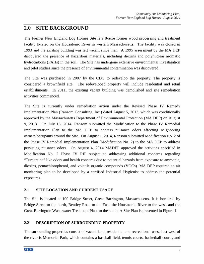
Community Air Monitoring Plan, Former New England Log Homes– August 2014
2
2.0 SITE BACKGROUND
The Former New England Log Homes Site is a 8-acre former wood processing and treatment facility located on the Housatonic River in western Massachusetts. The facility was closed in 1993 and the existing building was left vacant since then. A 1995 assessment by the MA DEP discovered the presence of hazardous materials, including dioxins and polynuclear aromatic hydrocarbons (PAHs) in the soil. The Site has undergone extensive environmental investigation and pilot studies since the presence of environmental contamination was discovered.
The Site was purchased in 2007 by the CDC to redevelop the property. The property is considered a brownfield site. The redeveloped property will include residential and retail establishments. In 2011, the existing vacant building was demolished and site remediation activities commenced.
The Site is currently under remediation action under the Revised Phase IV Remedy Implementation Plan (Ransom Consulting, Inc.) dated August 5, 2013, which was conditionally approved by the Massachusetts Department of Environmental Protection (MA DEP) on August 9, 2013. On July 15, 2014, Ransom submitted the Modification to the Phase IV Remedial Implementation Plan to the MA DEP to address nuisance odors affecting neighboring owners/occupants around the Site. On August 1, 2014, Ransom submitted Modification No. 2 of the Phase IV Remedial Implementation Plan (Modification No. 2) to the MA DEP to address persisting nuisance odors. On August 4, 2014 MADEP approved the activities specified in Modification No. 2 Phase IV RIP subject to addressing additional concerns regarding “Turpentine” like odors and health concerns due to potential hazards from exposure to ammonia, dioxins, pentachlorophenol, and volatile organic compounds (VOCs). MA DEP required an air monitoring plan to be developed by a certified Industrial Hygienist to address the potential exposures.
2.1 SITE LOCATION AND CURRENT USAGE
The Site is located at 100 Bridge Street, Great Barrington, Massachusetts. It is bordered by Bridge Street to the north, Bentley Road to the East, the Housatonic River to the west, and the Great Barrington Wastewater Treatment Plant to the south. A Site Plan is presented in Figure 1.
2.2 DESCRIPTION OF SURROUNDING PROPERTY
The surrounding properties consist of vacant land, residential and recreational uses. Just west of the river is Memorial Park, which contains a baseball field, tennis courts, basketball courts, and

Community Air Monitoring Plan, Former New England Log Homes– August 2014
3
green space. Residential properties are located to north and east of Bridge Street and Bentley Road. Currently, the Site is a vacant lot. There are no hospitals or day care facilities within a 500-foot radius area. Figure 1 shows the surrounding land usage.

Community Air Monitoring Plan, Former New England Log Homes– August 2014
4
3.0 REMEDIAL INVESTIGATION
A remedial investigation of the site identified site wide shallow soil impacts by various contaminants.
3.1 SUMMARY OF ENVIRONMENTAL FINDINGS
Contaminants of concern include various PAHs, dioxins, pentachlorophenol, and metals.
Soil results indicated widespread low to moderate concentrations of dioxins, the highest being 16,700 ug/m3 at the center of the site and to the immediate west of the former Production building and at Hot Spots 1 and 2. The Hot Spots are identified in Figure 2 (Pre Remediation Soil Management Plan). The concentrations of dioxins at the site are as indicated on Figure 3 (Dioxin Concentrations in Soil).
3.2 SUMMARY OF REMEDIAL ACTION
On August 9, 2013, MA DEP conditionally approved the Revised Phase IV Remedy Implementation Plan submitted by Ransom Consulting, Inc. The plan proposed remediation through in situ - bioremediation to remove dioxins and other toxic compounds from the brownfield site. The bioremediation plan includes applying BRT’s granular factor (BRT Factor) along with 200 cubic yards of compost and 10 tons of nitrogen across the site. The BRT Factor is a proprietary protein set that promotes enzyme production in the indigenous bacterial population. The formulation also contains soils as a carrier, nitrogen fertilizer, and organic fertilizers including bone, blood and fish meal. The Factor applied using farming methods and equipment – a rotary spreader. The soil will be turned and irrigated using water every seven to ten days.
The Factor treatment promotes enzyme production, which in turn liberates chlorine from the dioxins and pentachlorophenol (PCP) molecules. Enzymatic dechlorination occurs under both aerobic and anaerobic conditions. Under anaerobic conditions, metabolic byproducts that have an unpleasant odor are created. To prevent nuisance odors from forming, Ransom will ensure soil remediation occur under aerobic conditions by providing proper site drainage, periodic tilling and keeping soil pH between 7.5 and 8.5.
BRT’s granular Factor was applied to the Site using rotary equipment on July 7, 2014. On July 14, 2014 a Notice of Noncompliance (NON-WE-14-3041) was issued by the MA DEP to CDC following a site visit on July 11, 2014. The site visit was precipitated by complaints of odors and

Community Air Monitoring Plan, Former New England Log Homes– August 2014
5
dust from neighboring property owners/occupants following application of the BTR Factor. Ransom submitted a letter in response to the NON on July 15, 2014 titled Modification to the Phase IV Remedial Implementation Plan (Modification No. 1) to remedy the generated nuisance odors. Implementation of the remediation work recommenced on July 17, 2014 as outlined in Modification No. 1.
On July 31, 2014, MA DEP issued a directive during a conference call and subsequent email correspondence precipitated by complaints from neighboring property owners/occupants regarding nuisance odors emanating from the Site. The MA DEP stated the need for immediate actions to control nuisance odors coming from the Site and halted soil disturbing activities on the Site until a plan to immediately address nuisance odor is received and approved by the MA DEP. On August 1, 2014, Ransom submitted Modification No. 2 Phase IV Remedial Implementation Plan (Modification No. 2) in response to the directive and proposed soil pH adjustment to remedy the generated nuisance. On August 4, 2014, MA DEP issued a letter titled Review of Modification No. 2 to the Phase IV Remedy Implementation Plan (Review). The Review conditionally approved Modification No. 2. This CAMP addresses condition No. 1 of the Review which requires an air monitoring plan to be developed by a Certified Industrial Hygienist.

Community Air Monitoring Plan, Former New England Log Homes– August 2014
6
4.0 EVALUATION OF POTENTIAL HUMAN HEALTH EXPOSURE
Metals, dioxins and PAHs were identified in the soil in the Remedial Investigation. Potential pathways for exposure are direct exposure through dermal contact, inhalation, and ingestion.
Current Conditions: There are limited potential migration pathways for direct contact with soil and fill and associated absorption or ingestion, since the Site is securely locked and access is restricted to onsite workers and representatives. The groundwater at the site is contaminated, however, it is addressed by administrative controls. There are no occupied structures that could be affected by soil vapors.
Remediation Activities: The work performed at the site will include plowing of soil and general tilling, Factor blending activities that could affect the on-site construction/remediation workers and the off-site local population. The remediation work at the site will expose the soils to the short duration of the intrusive work. The remediation work at the site has the potential to expose the contaminants to off-site local residents via inhalation of soil (by means of dust) and soil vapors and on-site workers via direct contact to the soil, and ingestion or inhalation of the soil (by means of dust), and soil vapors.
4.1 POTENTIAL ROUTES OF EXPOSURE
The five elements of an exposure pathway are: (1) a contaminant source; (2) contaminant release and transport mechanisms; (3) a point of exposure; (4) a route of exposure; and (5) a receptor population.
An exposure pathway is considered complete when all five elements of an exposure pathway are documented. A potential exposure pathway exists when any one or more of the five elements comprising an exposure pathway cannot be ruled out. An exposure pathway may be eliminated from further evaluation when any one of the five elements comprising an exposure pathway has not existed in the past, does not exist in the present, and will never exist in the future.
Three potential primary routes exist by which chemicals can enter the body:
• Ingestion of water, or soil; • Inhalation of vapors and particulates; and • Dermal contact with soil.
These routes of exposure are possible before, and during the remedial action if proper precautions are not taken.

Community Air Monitoring Plan, Former New England Log Homes– August 2014
7
4.2 RECEPTOR POPULATIONS
Receptor populations include: on-site personnel conducting remedial activities, future workers/residents of the development, off-site residents, workers, and potentially, nearby surface water bodies.
On-Site Receptors: The site is currently vacant. Therefore the only potential human receptors are on-site personnel and potential trespassers.
Off-Site Receptors: Potential off-site receptors within a 0.25 mile radius of the Site include: adult and child residents; commercial and construction workers; pedestrians; trespassers; and cyclists, based on the following:
1. Wastewater treatment facility located to the south of the site (up to 0.25 mile) 2. Residential Buildings (up to 0.25 mile) 3. Pedestrians, Trespassers, Cyclists (up to 0.25 mile) 4. Recreational facilities (up to 0.25 mile)
4.3 OVERALL HUMAN HEALTH EXPOSURE ASSESSMENT
Complete on-site exposure pathways appear to be present during the current remediation phase. Under current conditions, on-site exposure pathways are limited by preventing access to the site.
Exposure of both on-site workers and the off-site local population to site contaminated media (soil and soil vapor) has the greatest potential during remediation work. In order to mitigate possible exposure, a Health and Safety Plan will be implemented during remedial work for the safety of the on-site workers and off-site local population. Other measures include conducting a community air monitoring programs (CAMP) for dust and VOCs, SVOCs to track on-site and off-site conditions, and, when necessary, requiring personal protective equipment, provisions for upgrading the level of personal protective equipment when needed, and, when necessary, applying dust and vapor suppression measures and stormwater controls will be employed.
4.4 CAMP MANAGEMENT
Project Organization and Oversight 4.4.1
Principal personnel who will participate in the CAMP include:
• Timothy Geller CDC Project Manager

Community Air Monitoring Plan, Former New England Log Homes– August 2014
8
• Timothy Snay Licensed Site Professional
• Nancy Marshall, PE Ransom Field Task Manager
• Bharti Ujjani, CIH URS CAMP Advisor
Site Security 4.4.2
Site access will be controlled by monitored gated entrances. Site security will be maintained by chain link with fabric screen construction fencing. Barriers and posted signage will designate restricted areas.
Work Hours 4.4.3
The typical hours for operation of remedial construction will be from 7:00 am to 3:00 pm.
4.5 ONSITE ACTIVITIES WITH POTENTIAL TO AFFECT AIR QUALITY
Lime Application – Allyndale Limestone is standing by to apply approximately 4 tons of lime across the Site once approval of this plan is provided by the MA DEP to achieve the optimum pH. The application of lime in the area of the odorous soil along Bridge Street will be heavier than in other areas. Following application of the lime, it will be immediately incorporated into the soil. Soil pH adjustments occur very quickly so odor reductions should be noted almost immediately. Soil pH readings will be incorporated into the site activity plan and additional lime will be applied as required to provide optimal conditions.
Routine Tilling/Plowing – The cultivation necessary to incorporate the lime, followed by weekly cultivation and deep plowing will continue to improve the Site’s soil health. Cultivation and plowing will restore the aerobic condition, eliminate the production of the odor producing anaerobic bacterial byproducts, and accelerate the utilization of the soil amendments applied to increase the population of beneficial bacteria. These same soil amendments are readily utilized by the anaerobic bacteria. Restoring the aerobic condition is, therefore, essential for reducing the potential for future odors emanating from the Site.
BRT Factor Application – BRT Factor is applied to the Site using rotary equipment and tilled into the upper soils. Visible dust was generated during the application. Factor debris from the site was observed on porches of neighboring residential properties. A second application of BRT’s Factor may occur later in mid-Fall.

Community Air Monitoring Plan, Former New England Log Homes– August 2014
9
Dormant Phase – After the tilling process, the soils will sit dormant and allow the biodegradation of the soils to take place for approximately seven days before the tilling process reconvenes.
Community Air Monitoring Plan, Former New England Log Homes– August 2014
10
5.0 COMMUNITY AIR MONITORING PLAN
Application of the bioremediation materials involve ground-intrusive activities that could result in the release of subsurface contaminants to the atmosphere. This Community Air Monitoring Plan was prepared to present a description of air monitoring activities to be performed during application and farming of the bioremediation materials and related activities at the Site.
Real-time air monitoring for particulate levels at the perimeter of the work area will be performed. Continuous monitoring will be performed as needed for all ground intrusive activities and during the handling of contaminated or potentially contaminated media.
5.1 AIR SAMPLING FOR CHEMICALS OF CONCERN
Given the apparent chemical type odor being generated at the site, the MA DEP has concerns about potential hazard from exposure to ammonia, dioxins, pentachlorophenol, and volatile organic compounds. Sampling will be required to determine which contaminants exist on the site. Additionally, turpentine and chlorine are included in sampling program based on detection of “turpentine” like odor at the site and potential for release of chlorine as a byproduct during remediation.
Initial Air Monitoring Program 5.1.1
An initial air monitoring program is planned to address the odor complaints and health concerns due to potential exposure to site contaminants. The results of the initial air monitoring will be used to evaluate the health risks posed to the receptors to conduct specific tests to control exposures in real time for the duration of the remediation project.
The objective of the initial air sampling is to identify the air concentration of various contaminants of concern and to identify suspect odor causing chemicals resulting from the remedial activities.
Background Air Sampling 5.1.2
Air samples will be collected and analyzed prior to the tilling process to analyze existing gases prior to bioremediation. Background sampling will be conducted at both upwind and downwind locations. Proposed sampling locations are as illustrated in Figure 4. These locations are subject to change based on site conditions.
Parameters identified for sampling and testing include:

Community Air Monitoring Plan, Former New England Log Homes– August 2014
11
• Chlorine gas • Ammonia gas • Hydrogen Sulfide gas • Dust • Turpentine (TO-15) or OSHA method 1551 • Volatile Organic Compounds (TO-15) • Dioxin, EPA Method 23 and 8290 • PCP
Initial Sampling During Tilling 5.1.3
Air samples will be collected and analyzed during the first tilling process after approval of the CAMP to analyze gases during the tilling activities. This sampling will be conducted at both upwind and downwind locations.
Parameters identified for sampling and testing include:
• Chlorine gas • Ammonia gas • Hydrogen Sulfide gas • Dust • Turpentine (TO-15) or OSHA method 1551 • Volatile Organic Compounds (TO-15) • Dioxin, EPA Method 23 and 8290 • PCP
FINAL CAMP 5.1.4
Final CAMP shall be based on the results for the initial sampling. If contaminants are detected above the action limits for various contaminants, engineering and administrative controls shall be implemented to reduce the air concentration of contaminants migrating off-site. Additional sampling of the specific chemicals shall be conducted during intrusive work to ensure the effectiveness of the engineering controls. As a minimum dust monitoring program shall be conducted during all intrusive activities at the site.
Community Air Monitoring Plan, Former New England Log Homes– August 2014
12
5.2 EXPOSURE LIMITS
The exposure levels and target action levels selected for the CAMP include, MA DEP established environmental exposure limits, and United States Environmental Protection Agency (USEPA) established environmental limits as available. For chemicals that do not have established MA DEP and USEPA environmental regulatory limits, a fraction of the OSHA or NIOSH occupational exposure limits have been used for establishing the action levels for the CAMP.
Contingency Plan 5.2.1
The purpose of the contingency plan is to identify potential site control measures that may be implemented in response to elevated levels of target compounds or odor. In general, a tiered warning Action Level and response action will be implemented during the air monitoring program. Tiered warning Action Levels are defined as follows.
Action Level 1: Normal or ambient air conditions where all target concentrations are less than 75 percent of the Action Level.
Action Level 2: Concentration of at least one target is equal to or greater than 75 percent of the Action Level but less than the Action Level.
Action Level 3: Concentration of at least one target is greater than the Action Level. Action levels and corresponding response levels are presented in Table 1.
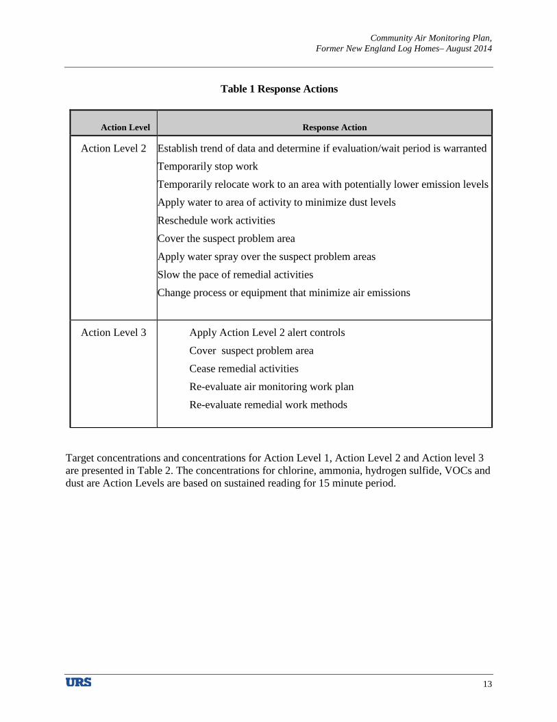
Community Air Monitoring Plan, Former New England Log Homes– August 2014
13
Table 1 Response Actions
Action Level
Response Action
Action Level 2 Establish trend of data and determine if evaluation/wait period is warranted Temporarily stop work
Temporarily relocate work to an area with potentially lower emission levels Apply water to area of activity to minimize dust levels
Reschedule work activities
Cover the suspect problem area
Apply water spray over the suspect problem areas
Slow the pace of remedial activities
Change process or equipment that minimize air emissions
Action Level 3 Apply Action Level 2 alert controls
Cover suspect problem area
Cease remedial activities
Re-evaluate air monitoring work plan
Re-evaluate remedial work methods
Target concentrations and concentrations for Action Level 1, Action Level 2 and Action level 3 are presented in Table 2. The concentrations for chlorine, ammonia, hydrogen sulfide, VOCs and dust are Action Levels are based on sustained reading for 15 minute period.

Community Air Monitoring Plan, Former New England Log Homes– August 2014
14
Table 2 Target Concentrations for Air Monitoring
Chlorine: 0.5 ppm (ATSDR). EPA established an environmental air limit of 0.5 ppm. Exposure to higher levels could result in discomfort and irritation.
Ammonia: An important property of ammonia is its pungent odor. The threshold concentration at which ammonia is detectable varies from person to person; however, ammonia can be usually detected at concentrations in the range of 5 ppm to 25 ppm. OSHA PEL=25 ppm. Short Term Exposure Level (STEL)= 35 ppm. Ammonia is very soluble in water. It is removed from the air by rainfall and readily enters soil where it is absorbed by plants in manufacturing proteins. Odor Threshold, 5 ppm (ATSDR, 2000; Amoore & Hautala, 1983).
Hydrogen Sulfide: The Occupational Safety and Health Administration (OSHA) has set an acceptable ceiling limit for hydrogen sulfide of 20 ppm in the workplace. The National Institute for Occupational Safety and Health (NIOSH) recommends a 10-minute ceiling limit of 10 ppm in the workplace.
Dust: Environmental Exposure limit USEPA PM10=150 mcg/m3
Turpentine: OSHA PEL=100 ppm
Dioxin: MA DEP 0.045 pcg/m3
VOCs: Environmental exposure limits are various depending on the specific compounds present.
The Occupational Safety and Health Administration (OSHA) has set a limit of 0.5 milligrams of pentachlorophenol per cubic
meter of workplace air (0.5 mg/m3) for 8 hour shifts and 40 hour work weeks.
Test Parameter Target Concentrations
Action Level 1 Action Level 2 Action Level 3
Chlorine 0.5 ppm <0.375 ppm >0.375 ppm and <0.5 ppm
>0.5 ppm
Ammonia
2 ppm <1.5 ppm >1.5 ppm and <2 ppm
>2 ppm
Hydrogen Sulfide
1 ppm < 0.75ppm >0.75ppm and <1 ppm
>1 ppm
Dust 150 mcg/m3 <112.5mcg/m3 >112.5mcg/m3 and <150mcg/m3
>150 mcg/m3
Turpentine 10 ppm <7.5 ppm >07.5ppm and <10 ppm
<10 ppm
Dioxin 0.045pcg/m3 <0.034pcg/m3 >0.034pcg/m3 and <0.045 pcg/m3
>0.045pcg/m3
VOCs 5 ppm <3.75 ppm >3.75 ppm and <5 ppm
>5 ppm
Pentachlorophenol 0.1 mg/m3 <0.075mg/m3 >0.075mg/m3 and <0.1mg/m3
>0.1 mg/m3

Community Air Monitoring Plan, Former New England Log Homes– August 2014
15
6.0 AIR MONITORING PROCEDURES
6.1 TURPENTINE AND OTHER VOCS MONITORING, RESPONSE LEVELS, AND
ACTIONS
It is anticipated that up to five (5) air samples will be collected at the site during the initial evaluation. Two (2) air samples will be collected during baseline sampling, prior to tilling, one sample will be collected outside the site upwind and one at rest sample will be collected downwind on the site.
Three (3) samples shall be collected during the tilling process, one sample shall be collected upwind and two (2) samples down wind. Based on the results of the baseline sampling and sampling during the tilling and presence of odors during the cultivation.
The following steps will be followed in conducting air sampling.
• Sampling flow rates for the air samples will be controlled not to exceed 0.2 liters per minute to ensure collection of an integrated sample over the sampling period.
• A laboratory-certified-clean 6-liter stainless steel Summa canister with an 8-hour pre-set flow controller will be used to collect the samples. Each sample will be collected over an eight (8) hour period.
• Conditions at the site will be documented during the sampling event to include temperature, barometric pressure and wind direction.
• The field sampling team will maintain a sample log sheet for the sampling event
If turpentine and other VOCs are identified above the MA DEP environmental screening levels, engineering controls shall be evaluated and VOCs shall be monitored using PD or Draeger tubes to monitor the effectiveness of the control measure.
Analytical Methods 6.1.1
After the sampling has been completed, the Summa canister vacuum readings will be recorded, chain-of-custody documentation will be completed, and the samples will be delivered for analysis to an MA DEP certified laboratory, (Alpha Analytical, Westborough, MA). The maximum reporting limit for all compounds will be 1 µg/m3. Sample analysis will be performed following the U.S. EPA Compendium Method TO-15: Determination of Volatile Organic
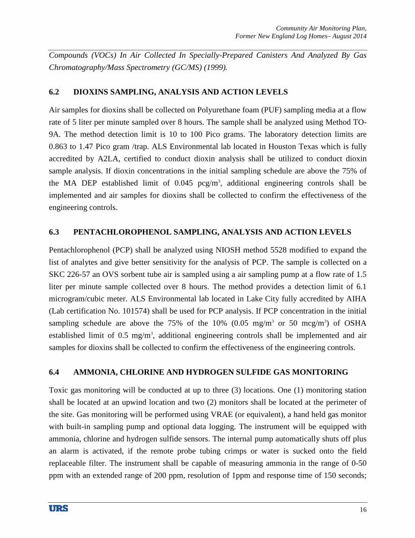
Community Air Monitoring Plan, Former New England Log Homes– August 2014
16
Compounds (VOCs) In Air Collected In Specially-Prepared Canisters And Analyzed By Gas Chromatography/Mass Spectrometry (GC/MS) (1999).
6.2 DIOXINS SAMPLING, ANALYSIS AND ACTION LEVELS
Air samples for dioxins shall be collected on Polyurethane foam (PUF) sampling media at a flow rate of 5 liter per minute sampled over 8 hours. The sample shall be analyzed using Method TO-9A. The method detection limit is 10 to 100 Pico grams. The laboratory detection limits are 0.863 to 1.47 Pico gram /trap. ALS Environmental lab located in Houston Texas which is fully accredited by A2LA, certified to conduct dioxin analysis shall be utilized to conduct dioxin sample analysis. If dioxin concentrations in the initial sampling schedule are above the 75% of the MA DEP established limit of 0.045 pcg/m3, additional engineering controls shall be implemented and air samples for dioxins shall be collected to confirm the effectiveness of the engineering controls.
6.3 PENTACHLOROPHENOL SAMPLING, ANALYSIS AND ACTION LEVELS
Pentachlorophenol (PCP) shall be analyzed using NIOSH method 5528 modified to expand the list of analytes and give better sensitivity for the analysis of PCP. The sample is collected on a SKC 226-57 an OVS sorbent tube air is sampled using a air sampling pump at a flow rate of 1.5 liter per minute sample collected over 8 hours. The method provides a detection limit of 6.1 microgram/cubic meter. ALS Environmental lab located in Lake City fully accredited by AIHA (Lab certification No. 101574) shall be used for PCP analysis. If PCP concentration in the initial sampling schedule are above the 75% of the 10% (0.05 mg/m3 or 50 mcg/m3) of OSHA established limit of 0.5 mg/m3, additional engineering controls shall be implemented and air samples for dioxins shall be collected to confirm the effectiveness of the engineering controls.
6.4 AMMONIA, CHLORINE AND HYDROGEN SULFIDE GAS MONITORING
Toxic gas monitoring will be conducted at up to three (3) locations. One (1) monitoring station shall be located at an upwind location and two (2) monitors shall be located at the perimeter of the site. Gas monitoring will be performed using VRAE (or equivalent), a hand held gas monitor with built-in sampling pump and optional data logging. The instrument will be equipped with ammonia, chlorine and hydrogen sulfide sensors. The internal pump automatically shuts off plus an alarm is activated, if the remote probe tubing crimps or water is sucked onto the field replaceable filter. The instrument shall be capable of measuring ammonia in the range of 0-50 ppm with an extended range of 200 ppm, resolution of 1ppm and response time of 150 seconds;

Community Air Monitoring Plan, Former New England Log Homes– August 2014
17
Chlorine in the range of 0-10 ppm with an extended range of 30 ppm, resolution of 0.1ppm and response time of 60 seconds; and hydrogen sulfide in the range of 0-100 ppm with an extended range of 500 ppm, resolution of 1 ppm and response time of 30 seconds. 16,000 points (53 hours, 5 channels at one minute intervals) down load to PC with serial number of unit, user identification, site identification and calibration date. Gas monitoring shall be conducted during background sampling prior to tilling and during the plowing/tilling activities.
6.5 HYDROGEN SULFIDE, RESPONSE LEVELS, AND ACTIONS
Hydrogen sulfide concentrations will be monitored continuously at the downwind monitoring stations. The monitoring equipment will be calibrated at least daily. The equipment should be capable of calculating 15-minute running average concentrations, which will be compared to the levels specified below. Calibration information will be recorded in a CAMP Log Book.
• If the ambient air concentration of hydrogen sulfide at the downwind perimeter of the work area or exclusion zone exceeds 1.0 ppm for the 15-minute average, work activities will be temporarily halted, monitoring continued and the project managers will be notified. If the hydrogen sulfide level readily decreases (per instantaneous readings) below 1.0 ppm, work activities will resume with continued monitoring.
All readings will be logged by the instrument, downloaded to a computer daily and be available for review. Instantaneous readings, if any, used for decision purposes will be recorded in a CAMP Log Book.
6.6 DUST/PARTICULATE MATTER MONITORING, RESPONSE LEVELS, AND
ACTIONS
Particulate monitoring will be performed during ground-intrusive activities. Particulate concentrations will be monitored at the start of the day and periodically at the upwind perimeter of the exclusion zone. Particulate concentrations will be monitored continuously at the downwind perimeters of the exclusion zone at a temporary particulate monitoring station. The particulate monitoring will be performed using real-time monitoring equipment capable of measuring particulate matter less than 10 micrometers in size (PM-10) and capable of integrating over a period of 15 minutes (or less) for comparison to the airborne particulate action level. The equipment will be equipped with an audible alarm to indicate exceedance of the action level. In addition, fugitive dust migration will be visually assessed during all work activities.

Community Air Monitoring Plan, Former New England Log Homes– August 2014
18
• If the downwind PM-10 particulate level is 100 micrograms per cubic meter (mcg/m3) greater than background (upwind perimeter) for the 15-minute period or if airborne dust is observed leaving the work area, then dust suppression techniques will be employed and the project managers will be notified. Work may continue with dust suppression techniques provided that downwind PM-10 particulate levels do not exceed 150 mcg/m3 above the upwind level and provided that no visible dust is migrating from the work area.
• If, after implementation of dust suppression techniques, downwind PM-10 particulate levels are greater than 150 mcg/m3 above the upwind level, work will be stopped and a re-evaluation of activities initiated. Project managers will be notified. Work will resume provided that dust suppression measures and other controls are successful in reducing the downwind PM-10 particulate concentration to within 150 mcg/m3 of the upwind level and in preventing visible dust migration.
All readings will be logged by the instrument, downloaded to a computer daily and be available for State personnel and local (county or municipal) health departments to review.
6.7 VOC MONITORING, RESPONSE LEVELS, AND ACTIONS
Upon confirmation of the presence of Volatile organic compounds (VOCs) above the action levels VOCs monitoring shall be conducted at the downwind perimeter of the immediate work area on a continuous basis during invasive work. Upwind concentrations will be measured at the start of each workday and periodically thereafter to establish background conditions. The monitoring work will be performed using equipment appropriate to measure the types of contaminants known or suspected to be present. The equipment will be calibrated at least daily for the contaminant(s) of concern or for an appropriate surrogate. The equipment will be capable of calculating 15-minute running average concentrations, which will be compared to the levels specified below.
• If the ambient air concentration of total organic vapors at the downwind perimeter of the work area exceeds 5 parts per million (ppm) above background for the 15-minute average, work activities will be temporarily halted and monitoring continued. If the total organic vapor level readily decreases (per instantaneous readings) below 5 ppm over background, work activities will resume with continued monitoring.
• If total organic vapor levels at the downwind perimeter of the work area or exclusion zone persist at levels in excess of 5 ppm over background but less than 25 ppm, work

Community Air Monitoring Plan, Former New England Log Homes– August 2014
19
activities will be halted, the source of vapors identified, corrective actions taken to abate emissions, and monitoring continued. After these steps, work activities will resume provided that the total organic vapor level 200 feet downwind of the site or half the distance to the nearest potential receptor or residential/commercial structure, whichever is less - but in no case less than 20 feet, is below 5 ppm over background for the 15-minute average.
• If the organic vapor level is above 25 ppm at the perimeter of the work area, activities will be shutdown.
All 15-minute readings must be recorded and be available for CDC project manager to review. Instantaneous readings, if any, used for decision purposes will also be recorded.
6.8 NUISANCE ODOR MONITORING, RESPONSE LEVELS, AND ACTIONS
Periodic monitoring of nuisance odors will be conducted at the downwind perimeter of the exclusion zone by smelling the ambient air. If nuisance odors are detected the work area will be checked to evaluate whether the odors are emanating from the source area. Other facilities (wastewater treatment plant located to the south of the site) in the area may produce nuisance odors. If the origin of the nuisance odors is determined to be the work area, work will be stopped and a re-evaluation of activities initiated. Hydrogen sulfide has a distinctive odor, but those who smell it are quickly subject to olfactory fatigue. If site-related nuisance odors (i.e. VOCs and/or hydrogen sulfide) are noted, monitoring with a PID and/or multi-gas meter will be conducted at that location until readings return to background levels.
6.9 VISIBLE DUST
In addition to measured PM10 levels, the CAMP requires monitoring of visible dust conditions. If site personnel observe visible airborne dust or if members of the surrounding community report dust leaving the work area during remedial activities, then dust suppression techniques must be employed. Work may continue with dust suppression techniques provided that
downwind PM10 levels do not exceed 150 µg/m3 averaged over 15 minutes period above the
upwind level and provided that no visible dust is migrating from the work area.

Community Air Monitoring Plan, Former New England Log Homes– August 2014
20
7.0 REPORTING AND RECORD KEEPING
7.1 DAILY REPORTS
Daily reports providing a general summary of activities for each day of active remedial work will be emailed to the CDC Project Manager by the end of the following day. Those reports will include:
• Project number and statement of the activities and an update of progress made and locations of work performed;
• Status of on-Site soil/fill stockpiles;
• A summary of all citizen complaints, with relevant details (basis of complaint; actions taken; etc.);
• A summary of CAMP excursions, if any;
• Photograph of notable Site conditions and activities.
The frequency of the reporting period may be revised in consultation with CDC project manager based on planned project tasks. Daily email reports are not intended to be the primary mode of communication for notification to CDC project manager of emergencies (accidents, spills), requests for changes to the CAMP or other sensitive or time critical information. However, such information will be included in the daily reports. Emergency conditions and changes to the CAMP will be communicated directly to the CDC project manager by personal communication.
7.2 RECORD KEEPING AND PHOTO-DOCUMENTATION
Job-site record keeping for remedial work will be performed. These records will be maintained on-Site during the project and will be available for inspection by MA DEP staff. Representative photographs will be taken of the Site prior to any remedial activities and during major remedial activities to illustrate remedial program elements and contaminant source areas.
7.3 COMPLAINT MANAGEMENT
Complaints from citizens will be promptly reported to project manager. Complaints will be addressed and outcomes will also be reported to project manager in daily reports. Notices to project manager will include the nature of the complaint, the party providing the complaint, and the actions taken to resolve any problems, if necessary.
Community Air Monitoring Plan, Former New England Log Homes– August 2014
21
8.0 ODOR, DUST AND NUISANCE CONTROL
8.1 ODOR CONTROL
Necessary means will be employed to prevent on- and off-Site odor nuisances. At a minimum, procedures will include: (a) avoiding suspect problem areas; (b) covering suspect problems areas with tarps and other covers; and (c) use of water to cover exposed odorous soils or aerating water saturated soil depending on the type of odor . If odors develop and cannot otherwise be controlled, additional means to eliminate odor nuisances will include: (e) use of chemical odorants in spray or misting systems.
This odor control plan is capable of controlling emissions of nuisance odors. If nuisance odors are identified, work will be halted and the source of odors will be identified and corrected. Implementation of all odor controls, including halt of work, will be the responsibility of the remediation project manager.
8.2 DUST CONTROL
Dust management during invasive on-Site work will include, at a minimum:
• Use of a dedicated water spray methodology for stockpiles.
• Use of properly anchored tarps to cover soils.
• Exercise extra care during dry and high-wind periods.
• Use of gravel or recycled concrete aggregate on egress and other roadways to provide a clean and dust-free road surface.
This dust control plan is capable of controlling emissions of dust. If nuisance dust emissions are identified, work will be halted and the source of dusts will be identified and corrected. Work will not resume until all nuisance dust emissions have been abated. CDC project manager will be notified of all dust complaint events. Implementation of all dust controls, including halt of work, will be the responsibility of the remediation project manager responsible for certifying the Remedial Action Report.


1.
HIS
TO
RIC
AL
SA
MP
LIN
G L
OC
AT
ION
S A
RE
AP
PR
OX
IMA
TE
AN
D B
AS
ED
ON
“H
IST
OR
ICA
L S
AM
PL
ING
LO
CA
TIO
NS
” A
ND
PH
AS
E 2
SA
MP
LIN
G L
OC
AT
ION
”
PR
EP
AR
ED
BY
FU
SS
& O
'NE
ILL
DA
TE
D S
EP
TE
MB
ER
2001,
AN
D O
N R
AN
SO
M'S
SU
BS
EQ
UE
NT
SIT
E V
ISIT
S.
2.
SO
IL S
AM
PL
ES
WE
RE
CO
LL
EC
TE
D B
Y V
AR
IOU
S E
NT
ITIE
S A
S F
OL
LO
WS
:
a.
1996:
US
EP
A A
ND
/OR
MA
DE
P
b.
2000-0
1:
FU
SS
& O
'NE
ILL
c. A
UG
2004:
RA
NS
OM
EN
VIR
ON
ME
NT
AL
CO
NS
UL
TA
NT
S,
INC
d.
DE
C 2
013:
BIO
TE
CH
RE
ST
OR
AT
ION
S L
LC
.
e.
MA
R 2
013:
RA
NS
OM
CO
NS
UL
TIN
G,
INC
.
f. 2
014:
RA
NS
OM
CO
NS
UL
TIN
G,
INC
.
3.
BE
GIN
NIN
G I
N D
EC
EM
BE
R 2
013,
SA
MP
LE
LO
CA
TIO
NS
WE
RE
DO
CU
ME
NT
ED
BY
RA
NS
OM
CO
NS
UL
TIN
G,
INC
. U
SIN
G A
HA
ND
HE
LD
GP
S D
EV
ICE
.
4.
SO
ME
FE
AT
UR
ES
HA
VE
BE
EN
RE
MO
VE
D F
OR
CL
AR
ITY
.
5.
RE
FE
R T
O A
PP
EN
DIX
D F
OR
NA
RR
AT
IVE
DE
SC
RIP
TIO
N O
F T
HE
PR
E-R
EM
ED
IAT
ION
SO
IL M
AN
AG
EM
EN
T P
LA
N.

1. BOLD CONCENTRATIONS ARE ABOVE THE PROPOSED UPPERCONCENTRATION LIMIT (UCL) OF 500 NANOGRAMS PER KILOGRAM (ng/kg).
2. ADDITION OF THE BIOREMEDIATION AMENDMENTS AND BRTs "FACTOR"WAS COMPLETED ON JULY 7, 2014. THE SAMPLES COLLECTED ON JUL7-8, 2014COMPRISE THE PRE-REMEDIATION BASELINE SAMPLING EVENT.
3. THE SAMPLE DEPTHS FOR THE JULY SAMPLING EVENT WERE BASED ONOBSERVATIONS OF THE THICKNESS OF TILLED SOILS IN THE FIELD. SAMPLETHICKNESSES IN THE SOIL MANAGEMENT ARES (i.e., DIOXIN HOT SPOTS,LAYDOWN AREAS) WERE LIMITED TO 1.5 FEET.
4. BEGINNING IN DECEMBER 2013, SAMPLE LOCATIONS WERE DOCUMENTEDBY RANSOM CONSULTING, INC. USING A HANDHELD GPS DEVICE.
5. SOME FEATURES HAVE BEEN REMOVED FOR CLARITY.

PROPOSED SAMPLING LOCATIONS
100 Bridge Street, Great Barrington, MA
Typical Wind Direction: Generally from southwest or south
Monthly Average Wind Speed, Sept-October: 5 – 12 mph
Proposed air sampling and monitoring location.
Note: Monitor locations will be adjusted as needed based on actual wind direction.
Unit 1- Upwind
Unit 2 – Downwind
Unit 3 – Downwind

Ransom Consulting, Inc. Project 021.01074.010
APPENDIX C
Public Notifications
Phase IV Remedy Implementation Plan – Revision 5 Former New England Log Homes Site
100 Bridge Street Great Barrington, Massachusetts
MassDEP Release Tracking No. 1-0682

12 Kent Way, Suite 100, Byfield, Massachusetts 01922-1221, Tel (978) 465-1822, Fax (978) 465-2986 400 Commercial Street, Suite 404, Portland, Maine 04101, Tel (207) 772-2891 Pease International Tradeport, 112 Corporate Drive, Portsmouth, New Hampshire 03801, Tel (603) 436-1490 60 Valley Street, Building F, Suite 106, Providence, Rhode Island 02909, Tel (401) 433-2160 2127 Hamilton Avenue, Hamilton, New Jersey 08619, Tel (609) 584-0090 www.ransomenv.com
March 7, 2019 Project 021.01074.010
Great Barrington Board of Health 334 Main Street Great Barrington, Massachusetts 01230
RE: Availability of Phase IV Remedy Implementation Plan – Revision 5 Former New England Log Homes Site 100 Bridge Street Great Barrington, Massachusetts MassDEP Release Tracking No. 1-0682
Dear Board Members:
In accordance with the Massachusetts Contingency Plan (MCP) and on behalf of the Community Development Corporation of South Berkshire (CDC), Ransom Consulting, Inc. (Ransom) and has prepared this letter notifying you of the availability of the Phase IV Remedy Implementation Plan (RIP) – Revision 5 for the former New England Log Homes (NELH) property (the Site) located at 100 Bridge Street in Great Barrington, Massachusetts. This RIP – Revision 5 is warranted because of changes to the proposed development strategy. This Phase IV RIP – Revision 5 was prepared in accordance with the requirements of the MCP, 310 CMR 40.0874.
The Site is defined as the approximately 8.2-acre area located southwest of the intersection of Bridge and Bentley Streets that has been impacted primarily by dioxins and pentachlorophenol (PCP), with secondary impacts from metals, petroleum hydrocarbons, and polycyclic aromatic hydrocarbons (PAHs). The primary affected media at the Site is soil; groundwater has been impacted primarily by PCP and low concentrations of dioxins. The MCP requires that the chief municipal officer and board of health be notified of the availability of all “phased” reports prepared in accordance with the MCP.
SUMMARY OF FINDINGS
Site Description
The Site is bounded by the Housatonic River to the west, Bridge Street and Bentley Street to the north and east, respectively, and the publicly operated wastewater treatment works to the south. The area surrounding the Site is primarily residential, but a commercial district is located to the west of the Housatonic River. Properties around the Site are serviced by the public water supply and there are no known private water supply wells within 500 feet of the Site; however, the Site is located within the Zone II of the Town of Sheffield public water supply. The Site is also located in the 100-year flood plain for the Housatonic River as designated by the Federal Emergency Management Agency (FEMA).
Board of Health Great Barrington, Massachusetts
Ransom Project 021.01074.010 Page 2 P:\2002\021074\Phase IV RIP5 - 2019\App C\BOH.docx March 7, 2019
Site History
The Site was first developed in 1894 with a manufacturing plant for bedspreads and cotton goods. Those operations ceased in 1963 and the Site remained vacant until 1971. From 1971 through 1993, NELH occupied the property and manufactured log homes. The NELH manufacturing operations included the use of wood preservatives containing PCP, which was one of the most widely used biocides in the U.S. prior to1987. NELH ceased operations in 1993 and the Site was vacated. The perimeter of the Site is fenced to prevent access by the public. In March 2001, a fire significantly damaged the main building on the Site, burning half of it to the ground. Soot and debris from the fire was deposited onto the ground surface of the Site. The damaged main building and the remaining buildings were demolished in 2012 and most of the debris was removed from the Site. The base of the former building’s smokestack remained, along with three debris piles (crushed concrete, mixed concrete and brick, and soil/woodchips). These debris piles were subsequently moved to the south end of the Site.
The CDC purchased the Site with the intent of redeveloping this Brownfield site into a sustainable, mixed-use development with mixed-income housing opportunities, retail and commercial space, and an open-space public gathering places. In August 2013, the CDC submitted a Revised Phase IV RIP which included the use of in-situ bioremediation to reduce the concentrations of dioxins and other organic contaminants in shallow soil (i.e., 18 to 20 inches) prior to proceeding with redevelopment of the Site. The bioremediation efforts were initiated in July 2014 but terminated by the Massachusetts Department of Environmental Protection (MassDEP) in August 2015. In September 2015, the bioremediation contractor collected 97 soil samples across the Site for field analysis of dioxins. Reported dioxin concentrations ranged from 1,324 to 1,898 nanograms per kilogram (ng/kg) or parts per trillion (ppt).
Status of Response Actions
Between September 14, 2016 and June 30, 2017, the CDC submitted three revisions of the Phase IV RIP to the MassDEP. The remediation strategies have included various grading and development scenarios that would cap the shallow dioxin-contaminated soils in place. Since submittal of the Phase IV RIP – Revision 4, the CDC has continued to investigate alternative redevelopment scenarios that will facilitate funding for the project and has revised the development plan for the Site.
The proposed redevelopment project will now be completed in one phase of work with the remediation completed prior to construction of Site buildings. Surface soils impacted by dioxins at concentrations above its Upper Concentration Limit (UCL) of 500 ng/kg or ppt will be relocated from areas proposed for future residential development to future landscaped berms, which will incorporate an Engineered Barrier into their design. In general, the Site development will consist of remediated/future development areas, where the exposure point concentrations (EPCs) of dioxins in soil have been reduced below Method 1 soil standards; landscaped berms, where dioxin-impacted soils will be consolidated beneath Engineered Barriers; and stormwater management basins located along the riverfront.
MassDEP has acknowledged that a Permanent Solution is not available for portions of the Site overlying the identified PCP groundwater “plume” because a remedial technology capable of reducing the PCP concentrations in groundwater at the Site to below the Method GW-1 groundwater standard and Massachusetts Maximum Contaminant Level is not currently available. Therefore, the current

Board of Health Great Barrington, Massachusetts
Ransom Project 021.01074.010 Page 3 P:\2002\021074\Phase IV RIP5 - 2019\App C\BOH.docx March 7, 2019
remediation goal at the Site is to achieve a condition of No Significant Risk relative to soil by preventing exposure to contaminants in soil.
The remediation goals are to:
1. Achieve a Permanent Solution for portions of the Site located outside of the groundwater PCP plume using relocation of dioxin-impacted soils and isolation under physical or Engineered Barriers; and
2. Achieve a Temporary Solution for portions of the Site within the PCP groundwater plume.
Proposed Remediation
Dioxins-impacted soil excavated from the upper 18 to 20 inches across the Site will be relocated to berms that will incorporate an Engineered Barrier. CDC estimates that approximately 20,000 cubic yards of soil will be relocated into the berms. The Engineered Barrier will consist of the following layers, beginning at the surface of the contaminated soil and listed from the bottom up.
1. A geo-composite consisting of a geonet heat-bonded with a non-woven needle-punched geotextile will be placed over the contaminated soil on the berm. The geo-composite will provide a biotic barrier to burrowing animals, prevent catastrophic erosion of surface materials from exposing the underlying contaminated soils; and promote drainage of the surface soils;
2. A geotextile warning barrier will be placed over the geonet to serve as a defining layer;
3. At least 1 foot of clean loam/topsoil will be placed over the geotextile to provide a growth medium for the surface vegetation and will serve as a separation layer; and
4. Vegetation will be planted on the surface of the berms to provide aesthetics and erosion control.
During earthwork activities, an air monitoring program will be implemented to ensure that dust and odors are controlled during construction. After earthwork activities, a soil sampling program will be implemented to confirm contaminant EPCs across the Site for use during a risk characterization.
A Financial Assurance Mechanism will be established to ensure the functioning of the Engineered Barriers at the Site. Periodic groundwater monitoring will be required while a Temporary Solution is in effect at the Site, with a focus on monitoring PCP concentrations in groundwater. A post-development groundwater monitoring program will be included in the Temporary Solution Statement that will be submitted following completion of the remediation described herein.
Implementation of the remedial measures will be performed under the direction of Timothy J. Snay, the LSP-of-Record for the Site. Federal, state, and local permits, licenses and/or approvals related to wetlands, storm water management, floodplains, and solid waste are required and will be obtained by the

Board of Health Great Barrington, Massachusetts
Ransom Project 021.01074.010 Page 4 P:\2002\021074\Phase IV RIP5 - 2019\App C\BOH.docx March 7, 2019
CDC or the redevelopment contractor, as specified in the contract. Other approvals may be required from the Great Barrington Select Board, Planning Board, Conservation Commission, Building Department, and Public Works Department.
AVAILABILITY OF REPORT
A copy of the Phase IV RIP – Revision 5 is available on the MassDEP website for Release Tracking Number (RTN) 1-0682 at http://public.dep.state.ma.us/SearchableSites2/Search.aspx. Alternatively, you may contact the MassDEP Western Regional Office at (413)-784-1100 for more information on reviewing MassDEP files.
Please contact me at 978-465-1822 if you have any questions regarding the report. Sincerely, RANSOM CONSULTING, INC. Timothy J. Snay Licensed Site Professional TJS:cnt cc: Timothy Geller, Community Development Corporation of South Berkshire Massachusetts Department of Environmental Protection

12 Kent Way, Suite 100, Byfield, Massachusetts 01922-1221, Tel (978) 465-1822, Fax (978) 465-2986 400 Commercial Street, Suite 404, Portland, Maine 04101, Tel (207) 772-2891 Pease International Tradeport, 112 Corporate Drive, Portsmouth, New Hampshire 03801, Tel (603) 436-1490 60 Valley Street, Building F, Suite 106, Providence, Rhode Island 02909, Tel (401) 433-2160 2127 Hamilton Avenue, Hamilton, New Jersey 08619, Tel (609) 584-0090 www.ransomenv.com
March 7, 2019 Project 021.01074.010
Great Barrington Selectboard 334 Main Street Great Barrington, Massachusetts 01230
RE: Availability of Phase IV Remedy Implementation Plan – Revision 5 Former New England Log Homes Site 100 Bridge Street Great Barrington, Massachusetts MA DEP Release Tracking No. 1-0682
Dear Board Members:
In accordance with the Massachusetts Contingency Plan (MCP) and on behalf of the Community Development Corporation of South Berkshire (CDC), Ransom Consulting, Inc. (Ransom) and has prepared this letter notifying you of the availability of the Phase IV Remedy Implementation Plan (RIP) – Revision 5 for the former New England Log Homes (NELH) property (the Site) located at 100 Bridge Street in Great Barrington, Massachusetts. This RIP – Revision 5 is warranted because of changes to the proposed development strategy. This Phase IV RIP – Revision 5 was prepared in accordance with the requirements of the MCP, 310 CMR 40.0874.
The Site is defined as the approximately 8.2-acre area located southwest of the intersection of Bridge and Bentley Streets that has been impacted primarily by dioxins and pentachlorophenol (PCP), with secondary impacts from metals, petroleum hydrocarbons, and polycyclic aromatic hydrocarbons (PAHs). The primary affected media at the Site is soil; groundwater has been impacted primarily by PCP and low concentrations of dioxins. The MCP requires that the chief municipal officer and board of health be notified of the availability of all “phased” reports prepared in accordance with the MCP.
SUMMARY OF FINDINGS
Site Description
The Site is bounded by the Housatonic River to the west, Bridge Street and Bentley Street to the north and east, respectively, and the publicly operated wastewater treatment works to the south. The area surrounding the Site is primarily residential, but a commercial district is located to the west of the Housatonic River. Properties around the Site are serviced by the public water supply and there are no known private water supply wells within 500 feet of the Site; however, the Site is located within the Zone II of the Town of Sheffield public water supply. The Site is also located in the 100-year flood plain for the Housatonic River as designated by the Federal Emergency Management Agency (FEMA).

Great Barrington Selectboard Great Barrington, Massachusetts
Ransom Project 021.01074.010 Page 2 P:\2002\021074\Phase IV RIP5 - 2019\App C\CMO.docx March 7, 2019
Site History
The Site was first developed in 1894 with a manufacturing plant for bedspreads and cotton goods. Those operations ceased in 1963 and the Site remained vacant until 1971. From 1971 through 1993, NELH occupied the property and manufactured log homes. The NELH manufacturing operations included the use of wood preservatives containing PCP, which was one of the most widely used biocides in the U.S. prior to1987. NELH ceased operations in 1993 and the Site was vacated. The perimeter of the Site is fenced to prevent access by the public. In March 2001, a fire significantly damaged the main building on the Site, burning half of it to the ground. Soot and debris from the fire was deposited onto the ground surface of the Site. The damaged main building and the remaining buildings were demolished in 2012 and most of the debris was removed from the Site. The base of the former building’s smokestack remained, along with three debris piles (crushed concrete, mixed concrete and brick, and soil/woodchips). These debris piles were subsequently moved to the south end of the Site.
The CDC purchased the Site with the intent of redeveloping this Brownfield site into a sustainable, mixed-use development with mixed-income housing opportunities, retail and commercial space, and an open-space public gathering places. In August 2013, the CDC submitted a Revised Phase IV RIP which included the use of in-situ bioremediation to reduce the concentrations of dioxins and other organic contaminants in shallow soil (i.e., 18 to 20 inches) prior to proceeding with redevelopment of the Site. The bioremediation efforts were initiated in July 2014 but terminated by the Massachusetts Department of Environmental Protection (MassDEP) in August 2015. In September 2015, the bioremediation contractor collected 97 soil samples across the Site for field analysis of dioxins. Reported dioxin concentrations ranged from 1,324 to 1,898 nanograms per kilogram (ng/kg) or parts per trillion (ppt).
Status of Response Actions
Between September 14, 2016 and June 30, 2017, the CDC submitted three revisions of the Phase IV RIP to the MassDEP. The remediation strategies have included various grading and development scenarios that would cap the shallow dioxin-contaminated soils in place. Since submittal of the Phase IV RIP – Revision 4, the CDC has continued to investigate alternative redevelopment scenarios that will facilitate funding for the project and has revised the development plan for the Site.
The proposed redevelopment project will now be completed in one phase of work with the remediation completed prior to construction of Site buildings. Surface soils impacted by dioxins at concentrations above its Upper Concentration Limit (UCL) of 500 ng/kg or ppt will be relocated from areas proposed for future residential development to future landscaped berms, which will incorporate an Engineered Barrier into their design. In general, the Site development will consist of remediated/future development areas, where the exposure point concentrations (EPCs) of dioxins in soil have been reduced below Method 1 soil standards; landscaped berms, where dioxin-impacted soils will be consolidated beneath Engineered Barriers; and stormwater management basins located along the riverfront.
MassDEP has acknowledged that a Permanent Solution is not available for portions of the Site overlying the identified PCP groundwater “plume” because a remedial technology capable of reducing the PCP concentrations in groundwater at the Site to below the Method GW-1 groundwater standard and Massachusetts Maximum Contaminant Level is not currently available. Therefore, the current

Great Barrington Selectboard Great Barrington, Massachusetts
Ransom Project 021.01074.010 Page 3 P:\2002\021074\Phase IV RIP5 - 2019\App C\CMO.docx March 7, 2019
remediation goal at the Site is to achieve a condition of No Significant Risk relative to soil by preventing exposure to contaminants in soil.
The remediation goals are to:
1. Achieve a Permanent Solution for portions of the Site located outside of the groundwater PCP plume using relocation of dioxin-impacted soils and isolation under physical or Engineered Barriers; and
2. Achieve a Temporary Solution for portions of the Site within the PCP groundwater plume.
Proposed Remediation
Dioxins-impacted soil excavated from the upper 18 to 20 inches across the Site will be relocated to berms that will incorporate an Engineered Barrier. CDC estimates that approximately 20,000 cubic yards of soil will be relocated into the berms. The Engineered Barrier will consist of the following layers, beginning at the surface of the contaminated soil and listed from the bottom up.
1. A geo-composite consisting of a geonet heat-bonded with a non-woven needle-punched geotextile will be placed over the contaminated soil on the berm. The geo-composite will provide a biotic barrier to burrowing animals, prevent catastrophic erosion of surface materials from exposing the underlying contaminated soils; and promote drainage of the surface soils;
2. A geotextile warning barrier will be placed over the geonet to serve as a defining layer;
3. At least 1 foot of clean loam/topsoil will be placed over the geotextile to provide a growth medium for the surface vegetation and will serve as a separation layer; and
4. Vegetation will be planted on the surface of the berms to provide aesthetics and erosion control.
During earthwork activities, an air monitoring program will be implemented to ensure that dust and odors are controlled during construction. After earthwork activities, a soil sampling program will be implemented to confirm contaminant EPCs across the Site for use during a risk characterization.
A Financial Assurance Mechanism will be established to ensure the functioning of the Engineered Barriers at the Site. Periodic groundwater monitoring will be required while a Temporary Solution is in effect at the Site, with a focus on monitoring PCP concentrations in groundwater. A post-development groundwater monitoring program will be included in the Temporary Solution Statement that will be submitted following completion of the remediation described herein.
Implementation of the remedial measures will be performed under the direction of Timothy J. Snay, the LSP-of-Record for the Site. Federal, state, and local permits, licenses and/or approvals related to wetlands, storm water management, floodplains, and solid waste are required and will be obtained by the

Great Barrington Selectboard Great Barrington, Massachusetts
Ransom Project 021.01074.010 Page 4 P:\2002\021074\Phase IV RIP5 - 2019\App C\CMO.docx March 7, 2019
CDC or the redevelopment contractor, as specified in the contract. Other approvals may be required from the Great Barrington Select Board, Planning Board, Conservation Commission, Building Department, and Public Works Department.
AVAILABILITY OF REPORT
A copy of the Phase IV RIP – Revision 5 is available on the MassDEP website for Release Tracking Number (RTN) 1-0682 at http://public.dep.state.ma.us/SearchableSites2/Search.aspx. Alternatively, you may contact the MassDEP Western Regional Office at (413)-784-1100 for more information on reviewing MassDEP files.
Please contact me at 978-465-1822 if you have any questions regarding the report. Sincerely, RANSOM CONSULTING, INC. Timothy J. Snay Licensed Site Professional TJS:cnt cc: Timothy Geller, Community Development Corporation of South Berkshire Massachusetts Department of Environmental Protection