
IV/IV B. Tech (Regular) DEGREE EXAMINATIONS October ...
22
Page 1 of 22 IV/IV B. Tech (Regular) DEGREE EXAMINATIONS October’2018 Mechanical Engineering CAD/CAM (14ME 704) Scheme of Evaluation Max. Marks: 60 -------------------------------------------------------------------------------------------------------------------------------------- 1. Answer all the questions. (1x12=12) (a) Write about various display devices Answer: 1) Cathode Ray Tube (CRT) 2) Raster scan Display 3) Random Scan Display 4) Liquid Crystal Display (LCD) 5) Light Emitting Diode (LED) (b) What is a pixel? Answer: The pixel (a word invented from "picture element") is the basic unit of programmable color on a computer display or in a computer image. The No. of Pixels in a square area is called Resolution. If the resolution is more the quality of picture is more and clear. If resolution is less, the quality of image is less. (c) Can you explain the need of concatenation of Transformations? Answer: In many applications, it is desirable to apply more than one transformation to an object. For instance, a translation and rotation may be required to position and orientate an object. The process of following one transformation by another to form a new transformation with a combined effect is called concatenation or Composition of transformation. (d) Mention any two characteristics of Bezier curves. Answer: • They generally follow the shape of the control polygon, which consists of the segments joining the control points. • They always pass through the first and last control points. • They are contained in the convex hull of their defining control points. • The degree of the polynomial defining the curve segment is one less that the number of defining polygon point. Therefore, for 4 control points, the degree of the polynomial is 3, i.e. cubic polynomial. (e) What is Boundary representation? Answer: In solid modeling and computer-aided design, boundary representation—often abbreviated as B-rep or BREP—is a method for representing shapes using the limits. A solid is represented as a collection of connected surface elements, the boundary between solid and non-solid.
-
Upload
khangminh22 -
Category
Documents
-
view
0 -
download
0
Transcript of IV/IV B. Tech (Regular) DEGREE EXAMINATIONS October ...

Page 1 of 22
IV/IV B. Tech (Regular) DEGREE EXAMINATIONS October’2018
Mechanical Engineering
CAD/CAM (14ME 704)
Scheme of Evaluation
Max. Marks: 60
--------------------------------------------------------------------------------------------------------------------------------------
1. Answer all the questions. (1x12=12)
(a) Write about various display devices
Answer:
1) Cathode Ray Tube (CRT)
2) Raster scan Display
3) Random Scan Display
4) Liquid Crystal Display (LCD)
5) Light Emitting Diode (LED)
(b) What is a pixel?
Answer: The pixel (a word invented from "picture element") is the basic unit of
programmable color on a computer display or in a computer image. The No. of Pixels in a
square area is called Resolution. If the resolution is more the quality of picture is more and
clear. If resolution is less, the quality of image is less.
(c) Can you explain the need of concatenation of Transformations?
Answer: In many applications, it is desirable to apply more than one transformation to an object. For instance, a translation and rotation may be required to position and orientate an object. The process of following one transformation by another to form a new transformation with a combined effect is called concatenation or Composition of transformation.
(d) Mention any two characteristics of Bezier curves.
Answer:
• They generally follow the shape of the control polygon, which consists of the segments joining the control points.
• They always pass through the first and last control points.
• They are contained in the convex hull of their defining control points.
• The degree of the polynomial defining the curve segment is one less that the number of defining polygon point. Therefore, for 4 control points, the degree of the polynomial is 3, i.e. cubic polynomial.
(e) What is Boundary representation?
Answer: In solid modeling and computer-aided design, boundary representation—often abbreviated as B-rep or BREP—is a method for representing shapes using the limits. A solid is represented as a collection of connected surface elements, the boundary between solid and non-solid.

Page 2 of 22
Boundary representation of models are composed of two parts: topology and geometry (surfaces, curves and points). The main topological items are: faces, edges and vertices. A face is a bounded portion of a surface; an edge is a bounded piece of a curve and a vertex lies at a point. Other elements are the shell (a set of connected faces), the loop (a circuit of edges bounding a face) and loop-edge links (also known as winged edge links or half-edges) which are used to create the edge circuits. The edges are like the edges of a table, bounding a surface portion.
(f) Define Clipping
Answer: Clipping is a process of identifying and saving all surface segments within the view
volume for display on the output device. All parts of objects that are outside the view
volume are discarded.
(g) List basic components of NC system.
Answer:
1) Program of instructions or Program
2) Machine control unit (MCU)
3) Processing equipment
(h) Describe the concept of Cutter offset in NC machining.
Answer: The use of cutter compensation allows the programmer to use the part geometry exactly as from the print for programmed coordinates. Without using compensation, the programmer must always know the cutter size and offset the programmed coordinates for the geometry by the amount of the radius. In this scenario, if a different size cutter is used the part will not be machined correctly. An added advantage for using cutter compensation is the ability to use any size cutter as long as the offset amount is input accurately into the offset register. It is also very effectively used for fine-tuning of dimensional results by minor adjustments to the amount in the offset register.
• G40 = Cutter Compensation Cancel • G41 = Cutter Compensation Left • G42 = Cutter Compensation Right
(i) What is computer assisted part programming? Answer: In computer-assisted part programming, the machining instructions are written in English like statements that are subsequently translated by the computer into the low-level machine code that can be interpreted and executed by the machine tool controller When using one of the part programming languages. the two main tasks of the programmer are: (1) defining the geometry of the work part and (2) specifying the tool path and operation-sequence
(j) Can you explain the significance of parts classification and coding? Answer: In parts classification and coding, similarities among parts are identified, and these
similarities are related in a coding system. Two categories of part similarities can be
distinguished: (1) design attributes, which are concerned with part characteristics such as
geometry, size, and material; and (2) manufacturing attributes, which consider the sequence
of processing steps required to make a part. While the design and manufacturing attributes
of a part are usually correlated, the correlation is less than perfect. Accordingly, classification
and coding systems are devised to include both a part's design attributes and its
manufacturing attributes

Page 3 of 22
(k) What is CAPP? Answer: Computer-aided process planning (CAPP) is the use of computer technology to aid
in the process planning of a part or product, in manufacturing. CAPP is the link between CAD
and CAM in that it provides for the planning of the process to be used in producing a
designed part.
(l) Mention the benefits of FMS Answer:
1. Large variety of same products. 2. Profitable investment. 3. Requires limited inventory. 4. Low labour cost. 5. Flexible system. 6. Speedy production
UNIT-I
2. (a) Write a short note on interactive Graphics display (6M) Answer: Computer graphics is an art of drawing pictures, lines, charts, etc. using computers with the help of programming. Computer graphics is made up of number of pixels. Pixel is the smallest graphical picture or unit represented on the computer screen. Basically there are two types of computer graphics namely.
Interactive Computer Graphics: Interactive Computer Graphics involves a two-way communication between computer and user. Here the observer is given some control over the image by providing him with an input device for example the video game controller of the ping pong game. This helps him to signal his request to the computer.
The computer on receiving signals from the input device can modify the displayed picture appropriately. To the user it appears that the picture is changing instantaneously in response to his commands. He can give a series of commands, each one generating a graphical response from the computer. In this way he maintains a conversation, or dialogue, with the computer.
Interactive computer graphics affects our lives in a number of indirect ways. For example, it helps to train the pilots of our airplanes. We can create a flight simulator which may help the pilots to get trained not in a real aircraft but on the grounds at the control of the flight simulator. The flight simulator is a mockup of an aircraft flight deck, containing all the usual controls and surrounded by screens on which we have the projected computer-generated views of the terrain visible on takeoff and landing.
Flight simulators have many advantages over the real aircrafts for training purposes, including fuel savings, safety, and the ability to familiarize the trainee with a large number of the world’s airports.
(b) Write Bresenham’s line drawing algorithm and its advantages (6M)
Answer: The Bresenham’s algorithm is an incremental scan conversion algorithm. The big
advantage of this algorithm is that, it uses only integer calculations. Moving across the x axis
in unit intervals and at each step choose between two different y coordinates.

Page 4 of 22
This algorithm samples a line by incrementing by one unit either x or y depending on the
slope of the line and then selects the pixel lying at least a distance from the true line path at
each sampling position.
To illustrate Bresenham’s approach let us consider a line (L) with positive slope less than 1.
So the line will be sampled at unit intervals in X direction. Assuming we have already
determined that the pixel at (xk, yk) is to be displayed, we next need to decide which pixel to
plot at next sampling position, i.e., at xk + 1 grid line.
Our choices are clearly the pixels at (xk +1, yk +1) and (xk + 1, yk), i.e., A and B respectively in
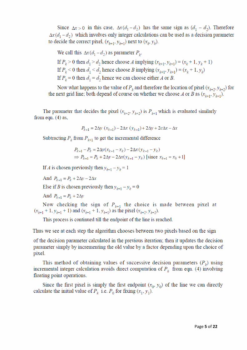
Figure. Let C be the intersection point of the line L with the gridline x = xk + 1. In Bresenham’s
formulation, the difference between the vertical distances of A and B to C is computed, and
the sign of the difference is used to select the pixel whose distance from C is smaller as the
best approximation to the line.
Page 5 of 22

Page 6 of 22
Advantages:
1. Simple in calculations
2. Uses integer values thus avoids floating point

Page 7 of 22
(OR)
3. (a) Explain the working principle of a CRT display device. (6M)
Answer: The Cathode Ray Tube is today used in computer monitors, TV set s and oscilloscope
tubes. The path of the electrons in the tube filled with a low-pressure rare gas can be observed in a
darkened room as a trace of light. Electron beam deflection can be effected by means of either an
electrical or a magnetic field.
Working Principle: The source of the electron beam is the electron gun, which produces a stream of
electrons through thermionic emission at the heated cathode and focuses it into a thin beam by the
control grid
• A strong electric field between cathode and anode accelerates the electrons, before they leave the electron gun through a small hole in the anode. • The electron beam can be deflected by a capacitor or coils in a way which causes it to display an image on the screen. The image may represent electrical waveforms (oscilloscope), pictures (television, computer monitor), echoes of aircraft detected by radar etc. •When electrons strike the fluorescent screen, light is emitted. • The whole configuration is placed in a vacuum tube to avoid collisions between electrons and gas molecules of the air, which would attenuate the beam.
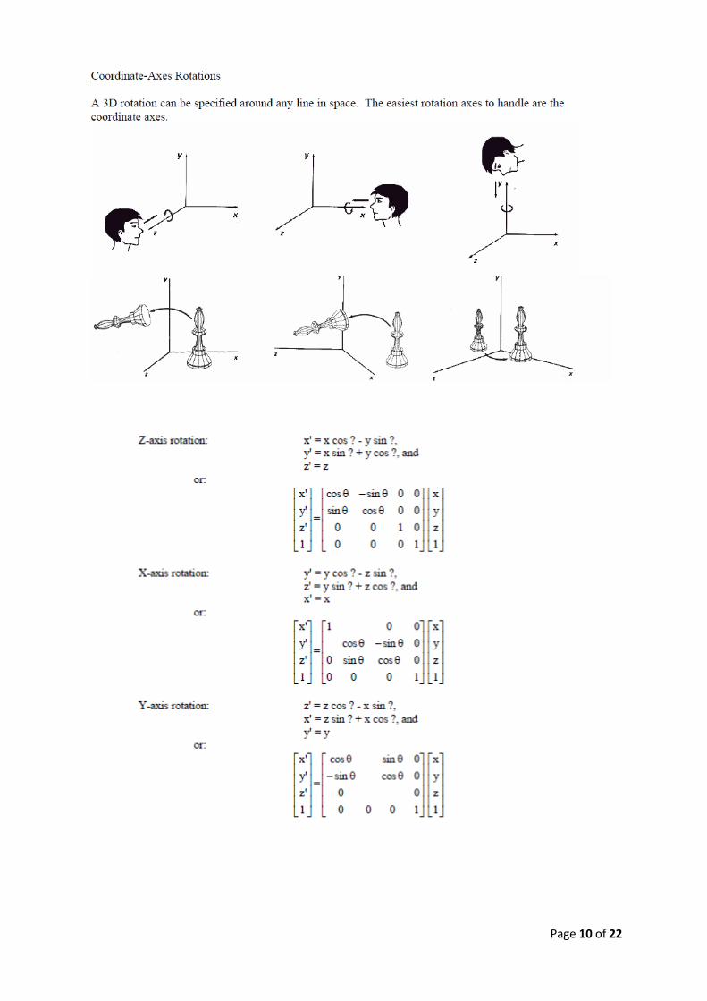
(b) Write 2D and 3D transformations for Translation, Rotation and Scaling (6M)
Answer: Transformation means changing some graphics into something else by applying rules. We can have various types of transformations such as translation, scaling up or down, rotation, shearing, etc. When a transformation takes place on a 2D plane, it is called 2D transformation.
Transformations play an important role in computer graphics to reposition the graphics on the screen and change their size or orientation.
Basic geometric transformations are:
(a) Translation
(b) Rotation
(c) Scaling

Page 8 of 22

Page 9 of 22
Page 10 of 22

Page 11 of 22
UNIT-II
4. (a) Explain hidden line removal (6M)
Answer: Hidden line removal (HLR) is the method of computing which edges are not hidden by the faces of parts for a specified view and the display of parts in the projection of a model into a 2D plane. Hidden line removal is utilized by a CAD to display the visual lines. It is considered that information openly exists to define a 2D wireframe model as well as the 3D topological information. Typically, the best algorithm is required for viewing this information from an available part representation. 3D parts are simply manufactured and frequently happen in a CAD design of such a part. In addition, the degrees of freedom are adequate to show the majority of models and are not overwhelming in the number of constraints to be forced. Also, almost all the surface-surface intersections and shadow computations can be calculated analytically which results in significant savings in the number of computations over numerical methods Priority algorithm: Priority algorithm is basis on organization all the polygons in the view according to the biggest Z-coordinate value of each. If a face intersects more than one face, other visibility tests besides the Z- depth required to solve any issue. This step comprises purposes of wrapper. Imagines that objects are modeled with lines and lines are generated where surfaces join. If only the visible surfaces are created, then the invisible lines are automatically removed.
ABCD, ADFG, DCEF are given higher priority-1. Hence, all lines in this face are visible, that is, AB, BC, CD, DA, AD, DF, FG, AG, DC, CE, EF and DF are visible. AGHB, EFGH, BCEH are given lower priority-2. Hence, all lines in this face other than priority-1 are
invisible, that is BH, EH and GH. These lines must be eliminated.
(b) Explain CSG in solid modelling (6M)
Answer: The Constructive Solid Geometry (CSG) systems allow the user to build the model out of
solid graphic primitives, such as rectangular blocks, cubes, spheres, cylinders, and pyramids. In this
building-block approach a solid three- dimensional representation of the object is produced. The
most common method of structuring the solid model in the graphics data base is to use Boolean
operations.

Page 12 of 22
A CSG model is based on the topological notion that a physical object can be divided into a set off primitives ((basic elements or shapes)) that can be combined in a certain order following a set off rules (Boolean operations) to form the object. Each primitive is bounded by a set of surfaces; usually closed and orientable. A CSG model is fundamentally and topologically different from a B-rep model in that the former does not store explicitly the faces, edges, and vertices. Instead, it evaluates them whenever they are needed by applications’ algorithms, e.g., generation of line drawings. The concept of primitives offers a different conceptual way of thinking that may be extended to model engineering processes such as design and manufacturing. It also appears that CSG representations might be of considerable importance for manufacturing automation as in the study of process planning and rough machining operations. The modeling domain off a CSG scheme depends on the half--spaces that underlie its bounded solid
primitives, on the available rigid motion and on the available set operators. For example, if two
schemes have the same rigid motion and set operations but one has just a block and a cylinder
primitive and the other has these two plus a tetrahedron, the two schemes are considered to have
the same domain. Each has only planar and cylindrical half-spaces, and the tetrahedron primitive the
other system offers is just a convenience to the user and does not extend its modeling domain.
Extending the solid modeling domain to cover sculptured surfaces requires representing a
“sculptured” half-space and its supporting utilities.
(OR)
5. (a) Write the parametric equation for B-Spline (4M)
Answer: Given n + 1 control points P0, P1, ..., Pn and a knot vector U = { u0, u1, ..., um }, the B-spline curve of degree p defined by these control points and knot vector U is
where Ni,p(u)'s are B-spline basis functions of degree p. The form of a B-spline curve is very similar to that of a Bézier curve. Unlike a Bézier curve, a B-spline curve involves more information, namely: a set of n+1 control points, a knot vector of m+1 knots, and a degree p. Note that n, m and p must satisfy m = n + p + 1. More precisely, if we want to define a B-spline curve of degree p with n + 1 control points, we must supply n + p + 2 knots u0, u1, ..., un+p+1. On the other hand, if a knot vector of m + 1 knots and n + 1 control points are given, the degree of the B-spline curve is p = m - n - 1. The point on the curve that corresponds to a knot ui, C(ui), is referred to as a knot point. Hence, the knot points divide a B-spline curve into curve segments, each of which is defined on a knot span.
(b) Explain shading and rendering algorithms (8M) Answer: Shading refers to depicting depth perception in 3D models or illustrations by varying levels of darkness. In the field of computer graphics, a shader is a special type of computer program that was originally used to do shading (the production

Page 13 of 22
of appropriate levels of light, darkness, and color within an image) but which now perform a variety of specialized functions in various fields of computer graphics special effects or do video post-processing unrelated to shading, and even functions unrelated to graphics at all.
Shaders calculate rendering effects on graphics hardware with a high degree of flexibility. Most shaders are coded for a graphics processing unit (GPU), though this is not a strict requirement. Shading languages are usually used to program the programmable GPU rendering pipeline, which has mostly superseded the fixed-function pipeline that allowed only common geometry transformation and pixel-shading functions; with shaders, customized effects can be used. The position, hue, saturation, brightness, and contrast of all pixels, vertices, or textures used to construct a final image can be altered on the fly, using algorithms defined in the shader, and can be modified by external variables or textures introduced by the program calling the shader.
The following shading models are popularly used.
1. Flat shading
2. Smooth shading
(a) Gouraud shading
(b) Phong shading
(c) Fast Phong shading
Rendering or image synthesis is the automatic process of generating a photorealistic or non-
photorealistic image from a 2D or 3D model (or models in what collectively could be called a scene
file) by means of computer programs. Also, the results of displaying such a model can be called a
render. A scene file contains objects in a strictly defined language or data structure; it would contain
geometry, viewpoint, texture, lighting, and shading information as a description of the virtual scene.
The data contained in the scene file is then passed to a rendering program to be processed and
output to a digital image or raster graphics image file. The term "rendering" may be by analogy with
an "artist's rendering" of a scene.
Many rendering algorithms have been researched, and software used for rendering may employ a number of different techniques to obtain a final image.
Tracing every particle of light in a scene is nearly always completely impractical and would take a stupendous amount of time. Even tracing a portion large enough to produce an image takes an inordinate amount of time if the sampling is not intelligently restricted.
Therefore, a few loose families of more-efficient light transport modelling techniques have emerged:
• rasterization, including scanline rendering, geometrically projects objects in the scene to an image plane, without advanced optical effects;
• ray casting considers the scene as observed from a specific point of view, calculating the observed image based only on geometry and very basic optical laws of reflection intensity, and perhaps using Monte Carlo techniques to reduce artifacts;
• ray tracing is similar to ray casting, but employs more advanced optical simulation, and usually uses Monte Carlo techniques to obtain more realistic results at a speed that is often orders of magnitude faster.
In ray casting the geometry which has been modeled is parsed pixel by pixel, line by line, from the point of view outward, as if casting rays out from the point of view. Where an object is intersected, the color value at the point may be evaluated using several methods. In the simplest, the color value

Page 14 of 22
of the object at the point of intersection becomes the value of that pixel. The color may be determined from a texture-map. A more sophisticated method is to modify the colour value by an illumination factor, but without calculating the relationship to a simulated light source. To reduce artifacts, a number of rays in slightly different directions may be averaged.
Ray casting involves calculating the "view direction" (from camera position), and incrementally following along that "ray cast" through "solid 3d objects" in the scene, while accumulating the resulting value from each point in 3D space. This is related and similar to "ray tracing" except that the raycast is usually not "bounced" off surfaces (where the "ray tracing" indicates that it is tracing out the lights path including bounces). "Ray casting" implies that the light ray is following a straight path (which may include travelling through semi-transparent objects). The ray cast is a vector that can originate from the camera or from the scene endpoint ("back to front", or "front to back"). Sometimes the final light value is a derived from a "transfer function" and sometimes it's used directly.
UNIT-III
6. (a) Explain classification of NC systems (6M)
Answer: The NC system must possess a means of controlling the relative movement of the tool
with respect to the work. Then are three types of motion control used in numerical control:
1. Point-to-point
2. Straight cut
3. Contouring
The three types are listed in order of increasing level of control sophistication.
Point to point NC: Point to point (PTP) is also sometimes called a positioning system. In PTP, the
objective of the machine tool control system is to move the cutting tool to a predefined location.
The speed or path by which this movement is accomplished is not important in point-to-point NC.
Once the tool reaches the desired location, the
machining operation is performed at that
position.
NC drill presses are a good example of FTP
systems. The spindle must first be positioned at a
particular location on the workpiece. This is done
under FTP control. Then, the drilling of the hole is
performed at that location, the tool is moved to
the next hole location, and so on. Since no cutting
is performed between holes, there is no need for controlling the relative motion of the tool and
workpiece between hole locations. On positioning systems, the speeds and feeds used by the
machine tool are often controlled by the operator rather than by the NC tape. Figure 8.5 illustrates
the point-to-point type of control.
Positioning systems are the simplest machine tool control systems and are therefore the
least expensive of the three types. However, for certain processes such as drilling operations and
spot welding, PTP is perfectly suited to the task and any higher level of control would be
unnecessary.
Straight cut NC: Straight-cut control systems are capable of moving the cutting tool parallel to one of
the major axes at a controlled rate suitable for machining. It is therefore appropriate for performing
milling operations to fabricate workpieces of rectangular configurations. With this type of NC system
it is not possible to combine movements in more than a single axis direction. Therefore, angular cuts
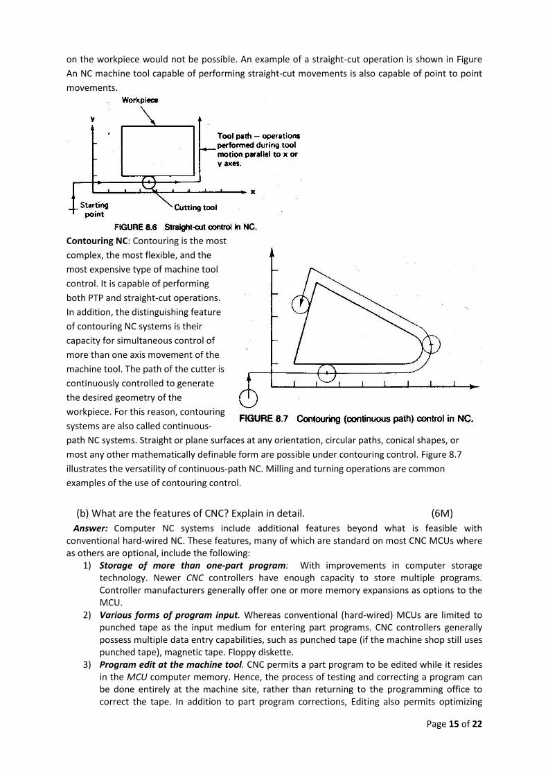
Page 15 of 22
on the workpiece would not be possible. An example of a straight-cut operation is shown in Figure
An NC machine tool capable of performing straight-cut movements is also capable of point to point
movements.
Contouring NC: Contouring is the most
complex, the most flexible, and the
most expensive type of machine tool
control. It is capable of performing
both PTP and straight-cut operations.
In addition, the distinguishing feature
of contouring NC systems is their
capacity for simultaneous control of
more than one axis movement of the
machine tool. The path of the cutter is
continuously controlled to generate
the desired geometry of the
workpiece. For this reason, contouring
systems are also called continuous-
path NC systems. Straight or plane surfaces at any orientation, circular paths, conical shapes, or
most any other mathematically definable form are possible under contouring control. Figure 8.7
illustrates the versatility of continuous-path NC. Milling and turning operations are common
examples of the use of contouring control.
(b) What are the features of CNC? Explain in detail. (6M)
Answer: Computer NC systems include additional features beyond what is feasible with conventional hard-wired NC. These features, many of which are standard on most CNC MCUs where as others are optional, include the following:
1) Storage of more than one-part program: With improvements in computer storage technology. Newer CNC controllers have enough capacity to store multiple programs. Controller manufacturers generally offer one or more memory expansions as options to the MCU.
2) Various forms of program input. Whereas conventional (hard-wired) MCUs are limited to punched tape as the input medium for entering part programs. CNC controllers generally possess multiple data entry capabilities, such as punched tape (if the machine shop still uses punched tape), magnetic tape. Floppy diskette.
3) Program edit at the machine tool. CNC permits a part program to be edited while it resides in the MCU computer memory. Hence, the process of testing and correcting a program can be done entirely at the machine site, rather than returning to the programming office to correct the tape. In addition to part program corrections, Editing also permits optimizing

Page 16 of 22
cutting conditions in the machining cycle. After correcting and optimizing the program. The revised version can be stored on punched tape or other media for future use.
4) Fixed cycles and programming subroutines. The increased memory capacity and the ability to program the control computer provide the opportunity to store frequently used machining cycles as macros that can be called by the part program. Instead of writing the full instructions for the particular cycle into every program, a call statement is included in the part program to indicate that the macro cycle should be executed. These cycles often require that certain parameters be defined; for example. A bolt hole circle, in which the diameter of the bolt circle, the spacing of the bolt holes, and other parameters must be specified.
5) Interpolation. Some of the interpolation schemes are normally executed only on a CNC system because of the computational requirements. Linear and circular interpolation arc sometimes hard-wired into the control unit, but helical, parabolic and cubic interpolations are usually executed in a stored program algorithm.
6) Positioning features for setup. Setting up the machine tool for a given work part involves installing and aligning a fixture on the machine tool table. This must be accomplished so that the machine axes are established with respect to the work part; the alignment task can be facilitated using certain features made possible by software options in a CNC system. Position set is one of these features. With position set, the operator is not required to locate the fixture on the machine table with extreme accuracy. Instead, the machine tool axes are referenced to the location of the fixture by using a target point or set of target points on the work or fixture.
7) Cutter length and size compensation. In older style controls, cutter dimensions had to be set very precisely to agree with the tool path defined in the part program. Alternative methods for ensuring accurate tool path definition have been incorporated into CNC controls. One method involves manually entering the actual tool dimensions into the MCU. These actual dimensions may differ from those originally programmed Compensations are then automatically made in the computed tool path. Another method involves use of a tool length sensor built into the machine. In this technique, the cutter is mounted in the spindle and the sensor measures its length. This measured value is then used to correct the programmed tool path.
8) Acceleration and deceleration calculations: This feature is applicable when the cutter moves at high feed rates. It is designed to avoid tool marks on the work surface that would be generated due to machine tool dynamics when the cutter path changes abruptly. Instead, the feed rate is smoothly decelerated in anticipation of a tool path change and then accelerated back up to the programmed feed rate after the direction change.
9) Communications interface. With the trend toward interfacing and networking in plants today, most modem CNC con/rollers are equipped with a standard RS-232 or other communications interface to allow the machine to be linked to other computers and computer-driven devices. This is useful for various applications, such as: (1) downloading part programs from a central data file as in distributed NC; (2) collecting operational data such as work piece counts, cycle times, and machine utilization; and (3) interfacing with peripheral equipment, such as robots that load and unload parts.
10) Diagnostics. Many modern CNC systems possess an on-line diagnostics capability that monitors certain aspects of the machine tool to detect malfunctions or signs of impending malfunctions or to diagnose system breakdowns.
Page 17 of 22
(OR)
7. (a) Explain APT Geometry and Motion statements (8M) Answer: APT stands for Automatically Programmed Tool. It is a language that defines the
tool path with respect to the part geometry, and often forms the basis for post-processor generated NC files. The APT language consists of four types of statements. Geometry statements will be used to specify the elemental features defining the part shape. Motion statements are used to specify the path taken by the tool. Post-processor statements control the machinery, controlling coolants as well as the feeds and speeds. Auxiliary statements complete the picture, specifying the part, required tools, etc. The following sections describe each of the APT statements. Geometry Statements: All geometric elements must be defined before tool motion may be programmed. Geometry statements associate a symbol with a description of the geometric element and its parameters. The general form for a geometry statement is: symbol = geometric type/parametric description The symbol consists of up to six alpha-numeric characters, containing at least one alpha character, and avoiding APT reserved words. The symbols provide a means to name the geometric features. The equals sign separates the symbol from the geometric type. The geometric type describes these features. POINT, LINE, PLANE, and CIRCLE are valid APT geometric types. The forward slash character separates the geometric type from the parametric description of the feature. The parametric description specifies the location and size of the feature. It may include dimensional data, positional data, and other APT words relating the feature to previously defined APT symbols. The APT language provides a rich means to specify the geometry, as is evidenced by the following examples. To specify a point:
P0 = POINT/1.0, 1.2, 1.3 specifies a point at XYZ coordinates 1.0, 1.2, and 1.3, respectively.
P1 = POINT/INTOF L1, L2 specifies a point at the intersection of lines L1 and L2, which must have been defined prior to the statement.
P2 = POINT/YLARGE, INTOF, L3, C1 specifies a point at the intersection of line L3 and circle C1 at a Y position above the center point of the circle.
To specify a line: L1 = LINE/P0, P1 specifies a line by two points, previously defined. L1 = LINE/1.0, 1.2, 1.3, 2.0, 2.1, 2.3 specifies a line by two points, given as explicit
coordinates. L2 = LINE/P2, PARLEL, L1 specifies a line through point P2 and parallel to line L1. L3 = LINE/P1, RIGHT, TANTO, C1 specifies a line through point P1 and tangent to
circle C1 on the right side of the center point. L4 = LINE/P1, ATANGL, 45, L1 specifies a line through point P1 at an angle of 45o to line L1.
To specify a plane: PL0 = PLANE/P0, P1, P2 specifies a plane through three, non-colinear, previously defined
points. PL1 = PLANE/P3, PARLEL, PL0 specifies a plane through a point P3 parallel to a plane PL0.
To specify a circle: C0 = CIRCLE/CENTER, P0, RADIUS, 1.0 specifies a circle of radius 1 from a center point of P0.
Lines and planes extend infinitely. Circles are always complete. The same geometry may be defined only once, and may not have more than one symbol. Motion Statements: The format for motion commands follows the pattern: motion/description
Page 18 of 22
The initial motion starts from a home position, and takes the form: FROM/P0 or FROM/ 0.0, 1.0, 2.0 The FROM motion statement occurs only once for each set of a motion type, at the start of the set of motions. Contouring motion – is the most common motion used in APT programming, and these statements specify the tool path continuously throughout the motion. They make use of three surfaces: (a) drive; (b) check; and (c) part surfaces. Drive surfaces represent the surface along which the vertical edges of the tool will follow. Part surfaces specify the surfaces the tip of the tool will follow. And check surfaces describe where the tool will come to rest after it has completed the motion of the current step. There are four locations for the tool to stop with respect to a check surface. These four possibilities each have their own modifier words. The TO modifier stops the tool when the first surface of the tool would come into contact with the check surface. The ON modifier stops the tool where the center point of the tool would come into contact with the check surface. The PAST modifier stops the tool where the last surface of the tool would contact the check surface. And the TANTO modifier stops the tool at the point of circular tangency with the edge of the tool. The initial contouring motion statement is the GO/TO, which defines the initial drive, part and check surfaces. It takes the form: GO/TO, drive surface, TO, part surface, TO, check surface An example would be: GO/TO, L1, TO, PL1, TO, L2 specifying that the tool should use line L1 as the drive surface, plane P1 as the part surface, and line L2 as the check surface. Note: the GOTO and the GO/TO statements are not the same. The former specifies point to point motion (see below), and the latter initiates contouring motion.
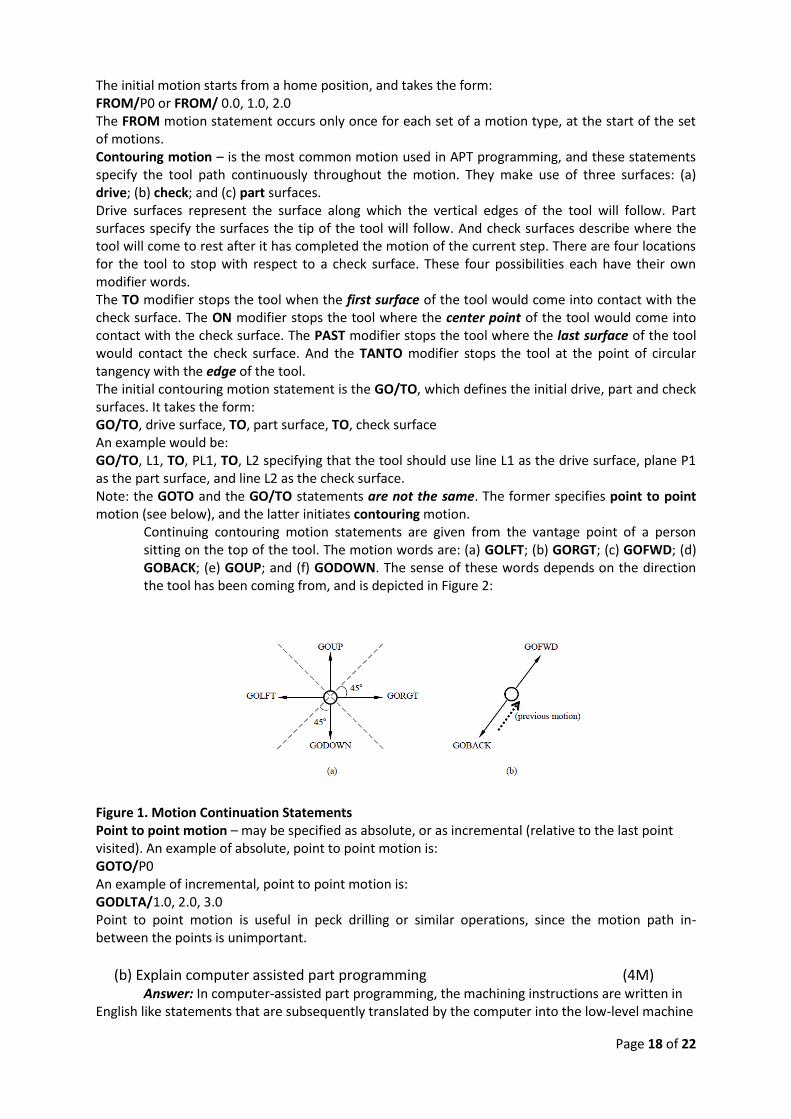
Continuing contouring motion statements are given from the vantage point of a person sitting on the top of the tool. The motion words are: (a) GOLFT; (b) GORGT; (c) GOFWD; (d) GOBACK; (e) GOUP; and (f) GODOWN. The sense of these words depends on the direction the tool has been coming from, and is depicted in Figure 2:
Figure 1. Motion Continuation Statements Point to point motion – may be specified as absolute, or as incremental (relative to the last point visited). An example of absolute, point to point motion is: GOTO/P0 An example of incremental, point to point motion is: GODLTA/1.0, 2.0, 3.0 Point to point motion is useful in peck drilling or similar operations, since the motion path in-between the points is unimportant.
(b) Explain computer assisted part programming (4M) Answer: In computer-assisted part programming, the machining instructions are written in
English like statements that are subsequently translated by the computer into the low-level machine

Page 19 of 22
code that can be interpreted and executed by the machine tool controller When using one of the part programming languages. the two main tasks of the programmer are: (1) defining the geometry of the work part and (2) specifying the tool path and operation-sequence
Defining the Part Geometry: No matter how complicated the work part may appear, it is composed of basic geometric elements and mathematically defined surfaces. Consider our sample part in Figure 6.18. Although its appearance is somewhat irregular, the outline of the part consists of intersecting straight lines and a partial circle. The hole locations in the part can be defined in terms of the x and y coordinates of their centers. Nearly any component that can be conceived by a designer can be described by points, straight lines, planes, circles, cylinders, and other mathematically defined surfaces. It is the part programmer's task to identify and enumerate the geometric elements of which the part is comprised, each element must be defined in terms of its dimensions and location relative to other elements. A few examples will be instructive here to show how geometric elements arc defined. Specifying Tool Path and Operation Sequence: After the part geometry has been defined, the part programmer must next specify the tool path that the cutter will follow to machine the part. The tool path consists of a sequence of connected line and arc segments, using the previously defined geometry elements to guide the cutter.
UNIT-IV
8. (a) What is group technology? Write about Parts classification and coding (6M)
Answer: Group technology is an approach in which similar parts are identified and grouped
together in order to take advantage of the similarities in design and production. Similarities among
parts permit them to be classified into part families.
There are three general methods for making part families. All three are time consuming and involve
the analysis of much data by properly trained personnel. The three methods are; (1) visual
inspection, (2) parts classification and coding, and (3) production flow analysis
Parts classification and coding:
This is the most time consuming of the three methods. In parts classification and coding,
similarities among parts are identified, and these similarities are related in a coding system. Two
categories of part similarities can be distinguished: (1) design attributes, which are concerned with
part characteristics such as geometry, size, and material; and (2) manufacturing attributes, which
consider the sequence of processing steps required to make a part. While the design and
manufacturing attributes of a part are usually correlated, the correlation is less than perfect.
Accordingly, classification and coding systems are devised to include both a part's design attributes
and its manufacturing attributes.
Features of Parts Classification and Coding Systems: The principal functional areas that utilize a parts classification and coding system are design and manufacturing. Accordingly. parts classification systems fall into one of three categories;
systems based on part design attributes systems based on part manufacturing attributes systems based on both design and manufacturing attributes
Examples: Some of the important systems (with emphasis on those in the United States) include: the Opitz classification system, which is nonproprietary; the Brisch System (Brisch-Birn, Inc.); CODE (Manufacturing Data Systems. lnc.]: CUTPLAN (Metcut Associates); DCLASS (Brigham Young University): Multi-Class (OIR: Organization for Industrial Research);and Part Analog System (Lovelace. Lawrence & Co., Inc.).

Page 20 of 22
(b) Explain OPITZ coding system. (6M)
Answer: This system was developed by H. OPITZ of the University of Aachen in Germany. It represents one of the pioneering efforts in group technology and is probably the best known, if not the most frequently used, of the parts classification and coding systems. It is intended for machined parts. The OPITZ coding scheme uses the following digit sequence:
12345 6789 ABCD The basic code consists of nine digits, which can be extended by adding four more digits. The first nine are intended to convey both design and manufacturing data. The interpretation of the first nine digits is defined in Figure. The first five digits, 12345, are called the form code. It describes the primary design attributes of the part, such as external shape (e.g., rotational vs. rectangular) and machined features (e.g., holes, threads, gear teeth, etc.) The next four digits, 6789, constitute the supplementary code, which indicates some of the attributes that would be of use in manufacturing (e.g., dimensions, work material, starting shape, and accuracy). The extra four digits, ABCD, are referred to as the secondary code and are intended to identify the production operation type and sequence. The secondary code can be designed by the user firm to serve its own needs.
(OR)
9. (a) Define FMS. Describe the types of FMS (8M)
Answer: A flexible manufacturing system (FMS) is a highly automated CIM system. Regardless of its components, any FMS has as its goal making the plant more flexible—that is, achieving the ability to quickly produce wide varieties of products using the same equipment. There are several basic components of an FMS: (1) workstations, (2) material handling and storage system, and (3) computer control system. In addition, even though an FMS is highly automated, (4) people are required to manage and operate the system. Types of FMS:
Each FMS is designed for a specific application, that is, a specific family of parts and processes Therefore, each FMS is custom engineered; each FMS is unique. Given these circumstances, one would expect to find a great variety of system designs to satisfy a wide variety of application requirements.

Page 21 of 22
Flexible manufacturing systems can be distinguished according to the kinds of operations they perform:
(a) processing operations or
(b) (2) assembly operations. An FMS is usually designed to perform one or the other but rarely both. A difference that is
applicable to machining systems is whether the system will process rotational parts or non-rotational parts.
Flexible machining systems with multiple stations that process rotational parts are much less common than systems that process non-rotational parts. Two other ways to classify FMSs are by: (1) Number of machines and (2) Level of flexibility
Number of Machines. Flexible manufacturing systems can be distinguished according to the number of machines in the system. The following are typical categories:
(a) Single machine cell
(b) Flexible manufacturing cell
(c) Flexible manufacturing system Level of Flexibility. Another classification of FMS is according to the level of flexibility designed into
the system. This method of classification can be applied to systems with any number of workstations, but its application seems most common with FMCs and FMSs. The categories are distinguished here:
(a) Dedicated FMS
(b) Random-order FMS
A dedicated FMS is designed to produce a limited variety of part styles, and the complete universe of parts to be made on the system is known in advance. The term special manufacturing system has also been used in reference to this FMS type. The part family is likely to be based on product commonality rather than geometric similarity. The product design is considered stable, and so the system can be designed with a certain amount of process specialization to make the operations more efficient. Instead of using general-purpose machines, the machines can be designed for the specific processes required to make the limited part family, thus increasing the production rate of the system. In some instances, the machine sequence may be identical or nearly identical for all parts processed and so a transfer line may be appropriate. in which the workstations possess the necessary flexibility to process the different parts in the mix. Indeed, the term flexible transfer lint is sometimes used for this case.
A random-order EMS is more appropriate when the part family is large, there are substantial variations in part configurations, there will be new part designs introduced into the system and engineering changes in parts currently produced, and the production schedule is subject to change from day-to-day, To accommodate these variations, the random-order FMS must be more flexible than the dedicated FMS. It is equipped with general-purpose machines to deal with the variations in product and is capable of processing parts in various sequences (random-order). A more sophisticated computer control system is required for this FMS type.
(b) Discuss about computer integrated
manufacturing (CIM) (4M)
Answer: CAD/CAM is concerned with the engineering functions in both design and manufacturing. Product design, engineering analysis, and documentation of the design (e.g. drafting) represent engineering activities in design. Process planning, NC part programming, and other activities associated with CAM represent engineering activities in manufacturing. The

Page 22 of 22
CAD/CAM systems developed during the 1970s and early 1980s were designed primarily to address these types of engineering problems. In addition, CAM has evolved to include many other functions in manufacturing, such as material requirements planning, production scheduling, computer production monitoring, and computer process control. It should also be noted that CAD/CAM denotes an integration of design and manufacturing activities by means of computer systems. The method of manufacturing a product is a direct function of its design. Computer integrated manufacturing (CIM) includes all of the engineering functions of CAD/CAM, but it also includes the firm's business functions that are related to manufacturing. The ideal CIM system applies computer and communications technology to all of the operational functions and information processing functions in manufacturing from order receipt, through design and production, to product shipment. The scope of CIM, compared with the more limited scope of CAD/CAM is shown in the diagram.
Prepared by:
Rajasekharababu. K,
Asst. Professor,
Dept. of Mechanical Engineering
Cell: +91 8106199932
Bapatla,
07. Nov. 2018