
Distributed Fading Memory for Stimulus Properties in the Primary Visual Cortex
Digital Signal Processing 21 (2011) 296–306
Contents lists available at ScienceDirect
Digital Signal Processing
www.elsevier.com/locate/dsp
Performance of rotated PSK modulation in Nakagami-m fading channels
Ahmet Yılmaz, Oguz Kucur ∗
Electronics Engineering Dept., Gebze Institute of Technology, 41400 Gebze-Kocaeli, Turkey
a r t i c l e i n f o a b s t r a c t
Article history:Available online 11 July 2010
Keywords:Modulation diversityNakagami-m fadingCombining techniques
This paper studies performance of Rotation & Component Interleaving Diversity (RCID)over frequency non-selective and slowly Nakagami-m fading channels for arbitrary fadingparameter m. Briefly, RCID is to rotate signal constellation and use component interleavingat the transmitter and de-interleaving at the receiver. First, Symbol Error Probability(SEP) of the system is derived by using moment generating function based approach andoptimum rotation angles minimizing SEP are found for M = 2,4,8 Phase Shift Keying (PSK).Upper bound is also derived in order to obtain asymptotic diversity order. The analyticalresults are validated by the simulation results. Then, RCID is applied on receive antennacombining techniques and their error performances are studied by the simulations. Theoptimum rotation angles are also obtained for combining techniques with rotated M-PSK modulation. Results show that performance of the systems improves significantly anddiversity order of the systems doubles as compared to those of the equivalent unrotatedsystems.
© 2010 Elsevier Inc. All rights reserved.
1. Introduction
Recently, researchers have interested in improving the performance of wireless communication systems, because of therapidly growing need of high data rate transmission over fading channels. Performance of wireless digital communicationsystems significantly degrades due to fading since the fading has destructive effects on the transmitted signal. The best wayto reduce the impact of fading is to apply diversity on the communication systems. Time, frequency and antenna diver-sity techniques are frequently used in wireless digital communication systems. Another diversity technique is modulationdiversity [1,2], also known as Rotation & Component Interleaving Diversity (RCID).
RCID is applied by rotating the signal constellation, then by interleaving components at the transmitter and de-interleaving components at the receiver. By the rotation of the signal constellation, any two points achieve the maximumnumber of distinct components. Interleaving destroys the fading correlation and provides that the in-phase and quadraturecomponents of received symbol are affected by independent fading coefficients [2].
Using RCID, significant Signal-to-Noise Ratio (SNR) gain can be obtained as compared to unrotated scheme for the sameSymbol Error Probability (SEP) [3,4]. In this work, we obtain 14.7 dB, 2.6 dB SNR gains at a SEP of 10−4 for Binary PhaseShift Keying (BPSK) modulation and fading figure of m = 1,4, respectively.
In [5], the authors have calculated optimum rotation angle at high SNRs for QPSK over Rayleigh fading channels bymaximizing minimum product distance of the signal constellation. In [6], optimal rotation angle is obtained for QPSK overRayleigh fading channels by optimally dividing Euclidean distance between the quadrature components. In [3], the authorsfind the optimum rotation angle for M = 2,4,8 PSK over Ricean fading channels by directly minimizing the union bound forthe SEP. In this paper, differing from previous studies on RCID we use Moment Generating Function (MGF) based approach
* Corresponding author.E-mail addresses: [email protected] (A. Yılmaz), [email protected] (O. Kucur).
1051-2004/$ – see front matter © 2010 Elsevier Inc. All rights reserved.doi:10.1016/j.dsp.2010.06.009
A. Yılmaz, O. Kucur / Digital Signal Processing 21 (2011) 296–306 297
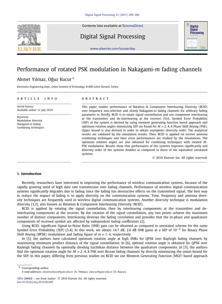
Fig. 1. Signal constellations for unrotated and rotated QPSK schemes.
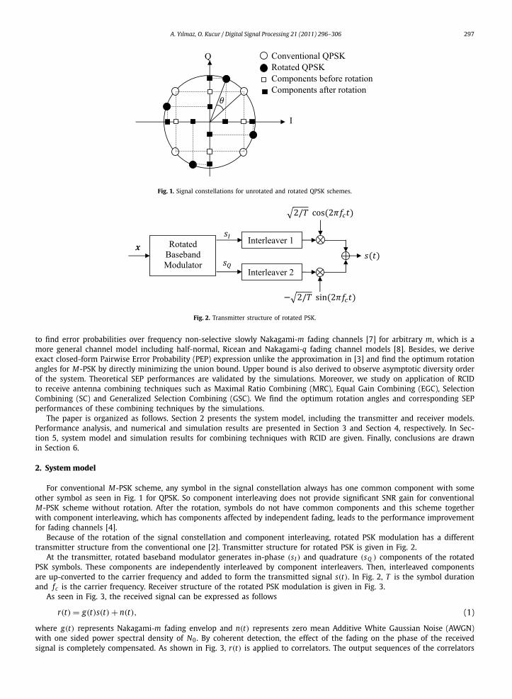
Fig. 2. Transmitter structure of rotated PSK.
to find error probabilities over frequency non-selective slowly Nakagami-m fading channels [7] for arbitrary m, which is amore general channel model including half-normal, Ricean and Nakagami-q fading channel models [8]. Besides, we deriveexact closed-form Pairwise Error Probability (PEP) expression unlike the approximation in [3] and find the optimum rotationangles for M-PSK by directly minimizing the union bound. Upper bound is also derived to observe asymptotic diversity orderof the system. Theoretical SEP performances are validated by the simulations. Moreover, we study on application of RCIDto receive antenna combining techniques such as Maximal Ratio Combining (MRC), Equal Gain Combining (EGC), SelectionCombining (SC) and Generalized Selection Combining (GSC). We find the optimum rotation angles and corresponding SEPperformances of these combining techniques by the simulations.
The paper is organized as follows. Section 2 presents the system model, including the transmitter and receiver models.Performance analysis, and numerical and simulation results are presented in Section 3 and Section 4, respectively. In Sec-tion 5, system model and simulation results for combining techniques with RCID are given. Finally, conclusions are drawnin Section 6.
2. System model
For conventional M-PSK scheme, any symbol in the signal constellation always has one common component with someother symbol as seen in Fig. 1 for QPSK. So component interleaving does not provide significant SNR gain for conventionalM-PSK scheme without rotation. After the rotation, symbols do not have common components and this scheme togetherwith component interleaving, which has components affected by independent fading, leads to the performance improvementfor fading channels [4].
Because of the rotation of the signal constellation and component interleaving, rotated PSK modulation has a differenttransmitter structure from the conventional one [2]. Transmitter structure for rotated PSK is given in Fig. 2.
At the transmitter, rotated baseband modulator generates in-phase (sI ) and quadrature (sQ ) components of the rotatedPSK symbols. These components are independently interleaved by component interleavers. Then, interleaved componentsare up-converted to the carrier frequency and added to form the transmitted signal s(t). In Fig. 2, T is the symbol durationand fc is the carrier frequency. Receiver structure of the rotated PSK modulation is given in Fig. 3.
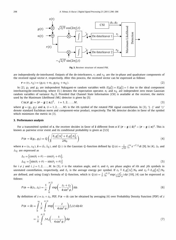
As seen in Fig. 3, the received signal can be expressed as follows
r(t) = g(t)s(t) + n(t), (1)
where g(t) represents Nakagami-m fading envelop and n(t) represents zero mean Additive White Gaussian Noise (AWGN)with one sided power spectral density of N0. By coherent detection, the effect of the fading on the phase of the receivedsignal is completely compensated. As shown in Fig. 3, r(t) is applied to correlators. The output sequences of the correlators
298 A. Yılmaz, O. Kucur / Digital Signal Processing 21 (2011) 296–306
Fig. 3. Receiver structure of rotated PSK.
are independently de-interleaved. Outputs of the de-interleavers, rI and rQ are the in-phase and quadrature components ofthe received signal vector r, respectively. After this process, the received vector can be expressed as follows
r = (rI , rQ ) = (g1sI + nI , g2sQ + nQ ). (2)
In (2), g1 and g2 are independent Nakagami-m random variables with E[g21] = E[g2
2] = 1 due to the ideal componentinterleaving/de-interleaving, where E[·] denotes the expectation operator. nI and nQ are independent zero mean Gaussianrandom variables of variance N0/2. Provided that Channel State Information (CSI) is available at the receiver, the metricused by the Maximum Likelihood (ML) detector is given by [5]
C(si|r, g) = ‖r − g � si‖2, i = 1,2, . . . , M, (3)
where g = (g1, g2) and si (i = 1,2, . . . , M) is the ith symbol of the rotated PSK signal constellation. In (3), ‘‖ · ‖’ and ‘�’denote standard Euclidean norm and component-wise product, respectively. The ML detector decides in favor of the symbolwhich minimizes the metric in (3).
3. Performance analysis
For a transmitted symbol of s, the receiver decides in favor of s different from s if ‖r − g � s‖2 < ‖r − g � s‖2. This isknown as pairwise error event and its conditional probability is given as [3,5]
P (s → s|g1, g2) = Q
(√Es g2
1�2I + Es g2
2�2Q
2N0
)(4)
where s = (sI , sQ ), s = (s I , sQ ), and Q (·) is the Gaussian Q -function defined by Q (x) = 1√2π
∫ ∞x e−t2/2 dt [9]. In (4), �I and
�Q are expressed as
�I = [cos(θi + θ) − cos(θ j + θ)
],
�Q = [sin(θi + θ) − sin(θ j + θ)
](5)
for i �= j and i, j = 1,2, . . . , M . In (5), θ is the rotation angle, and θi and θ j are phase angles of ith and jth symbols inunrotated constellation, respectively, and Es is the average energy per symbol. If z1 � Es g2
1�2I /N0 and z2 � Es g2
2�2I /N0
are defined, and using Craig’s formula of Q -function, which is Q (x) = 1π
∫ π/20 exp( −x2
2 sin2 φ)dφ [10], (4) can be expressed as
follows:
P (s → s|z1, z2) = 1
π
π/2∫0
exp
(− z1 + z2
4 sin2 φ
)dφ. (6)
By definition of z = z1 + z2, PEP, P (s → s) can be obtained by averaging (6) over Probability Density Function (PDF) of z
P (s → s) =∞∫
0
1
π
π/2∫0
exp
(− z
4 sin2 φ
)f z(z)dφ dz
= 1
π
π/2∫Mz
(− 1
4 sin2 φ
)dφ (7)
0

A. Yılmaz, O. Kucur / Digital Signal Processing 21 (2011) 296–306 299
where Mz(·) is MGF of z, defined as Mz(s) = E[esz]. Since gi , i = 1,2 are independent Nakagami-m random variables withE[g2
i ] = 1, i = 1,2, zi , i = 1,2 follow Gamma distribution and their MGFs are given by [11]:
Mzi (s) =(
1 − szi
m
)−m
, i = 1,2 (8)
where m is Nakagami-m fading parameter. zi , i = 1,2 are expected values of zi and can be expressed as z1 = Es�2I /N0,
z2 = Es�2Q /N0. Since zi , i = 1,2 are independent Gamma random variables, MGF of z can be expressed as Mz(s) =
Mz1 (s)Mz2 (s) [12], then (7) can be expressed as follows:
P (s → s) = 1
π
π/2∫0
Mz1
(− 1
4 sin2 φ
)Mz2
(− 1
4 sin2 φ
)dφ. (9)
Substituting (8) into (9) gives, after some manipulations
P (s → s) = 1
π
π/2∫0
(sin2 φ
sin2 φ + c1
)m(sin2 φ
sin2 φ + c2
)m
dφ, (10)
where ci � zi/4m, i = 1,2. In (10), c1 and c2 depend on the rotation angle θ , thus P (s → s) also depends on θ . By makingthe change of variable x = cos2 φ, we obtain
P (s → s) = 1
2π
1∫0
(1 − x)2m−0.5√x(c1 + 1 − x)−m(c2 + 1 − x)−m dx. (11)
With the help of [13, Eq. (3.211)], we obtain exact closed-form PEP expression for arbitrary values of m as follows
P (s → s) = B(2m + 1
2 , 12
)2π(c1 + 1)m(c2 + 1)m
F1
(1
2,m,m,2m + 1,
1
c1 + 1,
1
c2 + 1
), (12)
where F1(a,b,b′, t, x, y) is Appell hypergeometric function [13, Eq. (9.180.1)] and B(a,b) is Beta function [13, Eq. (8.380.1)].Note that Beta and Appell hypergeometric functions are available in well known software programs such as MATHEMATICAand MAPLE. An alternative expression to (12) has been obtained in [4] for only integer values of m.
At high SNRs, Appell hypergeometric function in (12) converges to 1 and ci + 1, i = 1,2 converge to ci , i = 1,2. Bydefinition of γs � Es/N0, which is the average SNR per symbol, upper bound for PEP can be expressed in terms of γs asfollows:
P (s → s) �B(2m + 1
2 , 12
)2π
( γs�2I
4m
)m( γs�2Q
4m
)m�
B(2m + 1
2 , 12
)2π(γs)2m
(�2I �
2Q
16m2
)m. (13)
Thus we can easily say that the diversity order of RCID technique is 2m.By assuming that symbols are equally likely, the union bound for the SEP of M-PSK is given as [9]
P s � 1
M
M∑i=1
M∑j=1j �=i
P (si → s j). (14)
SEP for M-PSK is expressed in terms of θ by replacing �I and �Q in (12) together with (14). Then, SEP depending on θ
must be minimized with respect to θ in order to obtain optimum rotation angles. However, due to the complexity of (12),it is very difficult to find optimum rotation angles analytically. For this reason, we prefer to examine (14) by small degreeincrements of θ in order to observe the change of SEP and find optimum rotation angles. We also confirm optimum rotationangles by using the “Minimize” function of MATHEMATICA.
4. Performance results
Here, optimum rotation angles are found by minimizing (12) and (14) together for M = 2,4,8 PSK, respectively. ThenSEP performances of rotated M-PSK are obtained and compared to those of unrotated M-PSK.
300 A. Yılmaz, O. Kucur / Digital Signal Processing 21 (2011) 296–306
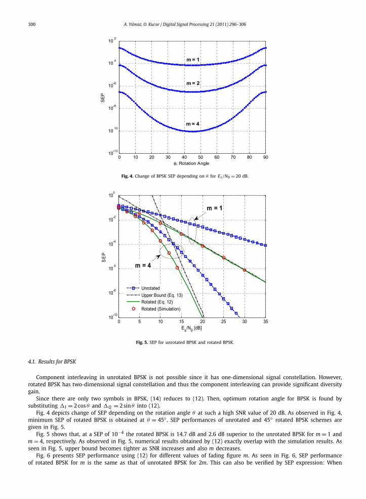
Fig. 4. Change of BPSK SEP depending on θ for Es/N0 = 20 dB.
Fig. 5. SEP for unrotated BPSK and rotated BPSK.
4.1. Results for BPSK
Component interleaving in unrotated BPSK is not possible since it has one-dimensional signal constellation. However,rotated BPSK has two-dimensional signal constellation and thus the component interleaving can provide significant diversitygain.
Since there are only two symbols in BPSK, (14) reduces to (12). Then, optimum rotation angle for BPSK is found bysubstituting �I = 2 cos θ and �Q = 2 sin θ into (12).
Fig. 4 depicts change of SEP depending on the rotation angle θ at such a high SNR value of 20 dB. As observed in Fig. 4,minimum SEP of rotated BPSK is obtained at θ = 45◦ . SEP performances of unrotated and 45◦ rotated BPSK schemes aregiven in Fig. 5.
Fig. 5 shows that, at a SEP of 10−4 the rotated BPSK is 14.7 dB and 2.6 dB superior to the unrotated BPSK for m = 1 andm = 4, respectively. As observed in Fig. 5, numerical results obtained by (12) exactly overlap with the simulation results. Asseen in Fig. 5, upper bound becomes tighter as SNR increases and also m decreases.
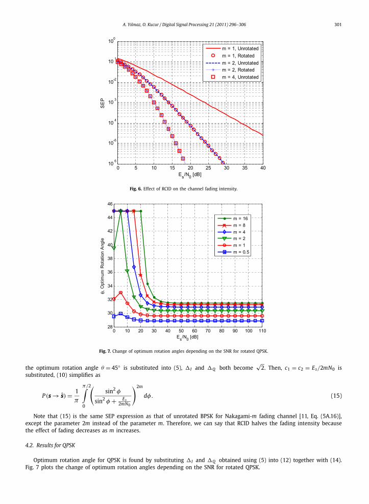
Fig. 6 presents SEP performance using (12) for different values of fading figure m. As seen in Fig. 6, SEP performanceof rotated BPSK for m is the same as that of unrotated BPSK for 2m. This can also be verified by SEP expression: When
A. Yılmaz, O. Kucur / Digital Signal Processing 21 (2011) 296–306 301
Fig. 6. Effect of RCID on the channel fading intensity.
Fig. 7. Change of optimum rotation angles depending on the SNR for rotated QPSK.
the optimum rotation angle θ = 45◦ is substituted into (5), �I and �Q both become√
2. Then, c1 = c2 = Es/2mN0 issubstituted, (10) simplifies as
P (s → s) = 1
π
π/2∫0
(sin2 φ
sin2 φ + Es2mN0
)2m
dφ. (15)
Note that (15) is the same SEP expression as that of unrotated BPSK for Nakagami-m fading channel [11, Eq. (5A.16)],except the parameter 2m instead of the parameter m. Therefore, we can say that RCID halves the fading intensity becausethe effect of fading decreases as m increases.
4.2. Results for QPSK
Optimum rotation angle for QPSK is found by substituting �I and �Q obtained using (5) into (12) together with (14).Fig. 7 plots the change of optimum rotation angles depending on the SNR for rotated QPSK.
302 A. Yılmaz, O. Kucur / Digital Signal Processing 21 (2011) 296–306
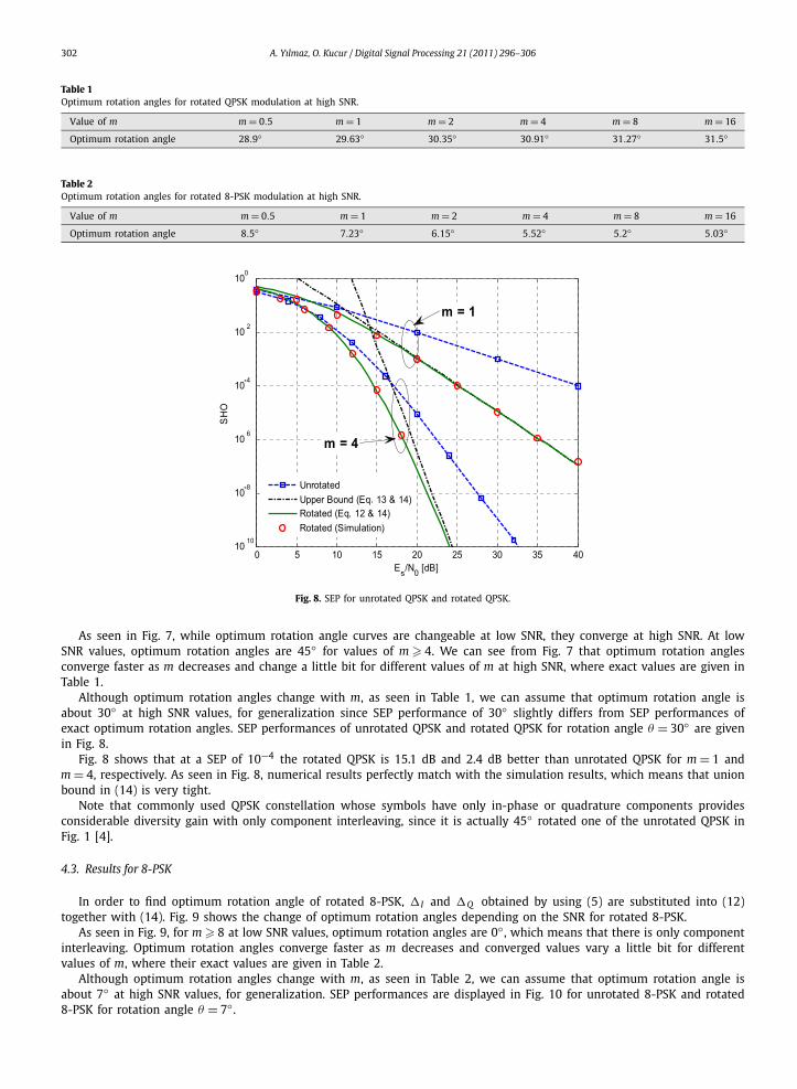
Table 1Optimum rotation angles for rotated QPSK modulation at high SNR.
Value of m m = 0.5 m = 1 m = 2 m = 4 m = 8 m = 16
Optimum rotation angle 28.9◦ 29.63◦ 30.35◦ 30.91◦ 31.27◦ 31.5◦
Table 2Optimum rotation angles for rotated 8-PSK modulation at high SNR.
Value of m m = 0.5 m = 1 m = 2 m = 4 m = 8 m = 16
Optimum rotation angle 8.5◦ 7.23◦ 6.15◦ 5.52◦ 5.2◦ 5.03◦
Fig. 8. SEP for unrotated QPSK and rotated QPSK.
As seen in Fig. 7, while optimum rotation angle curves are changeable at low SNR, they converge at high SNR. At lowSNR values, optimum rotation angles are 45◦ for values of m � 4. We can see from Fig. 7 that optimum rotation anglesconverge faster as m decreases and change a little bit for different values of m at high SNR, where exact values are given inTable 1.
Although optimum rotation angles change with m, as seen in Table 1, we can assume that optimum rotation angle isabout 30◦ at high SNR values, for generalization since SEP performance of 30◦ slightly differs from SEP performances ofexact optimum rotation angles. SEP performances of unrotated QPSK and rotated QPSK for rotation angle θ = 30◦ are givenin Fig. 8.
Fig. 8 shows that at a SEP of 10−4 the rotated QPSK is 15.1 dB and 2.4 dB better than unrotated QPSK for m = 1 andm = 4, respectively. As seen in Fig. 8, numerical results perfectly match with the simulation results, which means that unionbound in (14) is very tight.
Note that commonly used QPSK constellation whose symbols have only in-phase or quadrature components providesconsiderable diversity gain with only component interleaving, since it is actually 45◦ rotated one of the unrotated QPSK inFig. 1 [4].
4.3. Results for 8-PSK
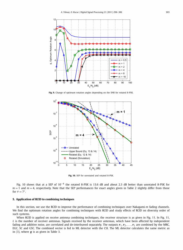
In order to find optimum rotation angle of rotated 8-PSK, �I and �Q obtained by using (5) are substituted into (12)together with (14). Fig. 9 shows the change of optimum rotation angles depending on the SNR for rotated 8-PSK.
As seen in Fig. 9, for m � 8 at low SNR values, optimum rotation angles are 0◦ , which means that there is only componentinterleaving. Optimum rotation angles converge faster as m decreases and converged values vary a little bit for differentvalues of m, where their exact values are given in Table 2.
Although optimum rotation angles change with m, as seen in Table 2, we can assume that optimum rotation angle isabout 7◦ at high SNR values, for generalization. SEP performances are displayed in Fig. 10 for unrotated 8-PSK and rotated8-PSK for rotation angle θ = 7◦ .
A. Yılmaz, O. Kucur / Digital Signal Processing 21 (2011) 296–306 303
Fig. 9. Change of optimum rotation angles depending on the SNR for rotated 8-PSK.
Fig. 10. SEP for unrotated and rotated 8-PSK.
Fig. 10 shows that at a SEP of 10−4 the rotated 8-PSK is 13.6 dB and about 2.3 dB better than unrotated 8-PSK form = 1 and m = 4, respectively. Note that the SEP performances for exact angles given in Table 2 slightly differ from thosefor θ = 7◦ .
5. Application of RCID to combining techniques
In this section, we use the RCID to improve the performance of combining techniques over Nakagami-m fading channels.We find the optimum rotation angles for combining techniques with RCID and study effects of RCID on diversity order ofsuch systems.
When RCID is applied on receive antenna combining techniques, the receiver structure is as given in Fig. 11. In Fig. 11,L is the number of receiver antennas. Signals received by the receiver antennas, which have been affected by independentfading and additive noise, are correlated and de-interleaved separately. The outputs r1, r2, . . . , rL are combined by the MRC,EGC, SC and GSC. The combined vector is fed to ML detector with the CSI. The ML detector calculates the same metric asin (3), where g is as given in Table 3.

304 A. Yılmaz, O. Kucur / Digital Signal Processing 21 (2011) 296–306
Fig. 11. Receiver structure of combining techniques with RCID.
Table 3g used by ML detector.
Combining technique g = (G1, G2)
MRC G1 = ∑Li=1 g2
1i , G2 = ∑Li=1 g2
2i
EGC G1 = ∑Li=1 g1i , G2 = ∑L
i=1 g2i
GSC (L; Ls) G1 = ∑Lsi=1 g2
1i , G2 = ∑Lsi=1 g2
2i
SC Ls = 1, in GSC case
Fig. 12. SEP performances of rotated BPSK with combining techniques for m = 1 and L = 2.
In Table 3, for GSC (L; Ls) case g i = (g1i, g2i) are the highest Ls ones among g i = (g1i, g2i), i = 1,2, . . . , L when g i s aresorted in descending order. In this section error performance results are obtained via simulations.
For all combination techniques given Table 3 using any number of available or selected antennas, optimum rotationangle of BPSK modulation is obtained as 45◦ which is independent of SNR or fading figure m. On the other hand, optimumrotation angles of QPSK and 8-PSK modulations change with SNR and m but they can be generalized to 30◦ for QPSK and7◦ for 8-PSK as in the case without combining [14]. Therefore, we can say that optimum rotation angle is independent ofthe number of available or selected receive antennas.
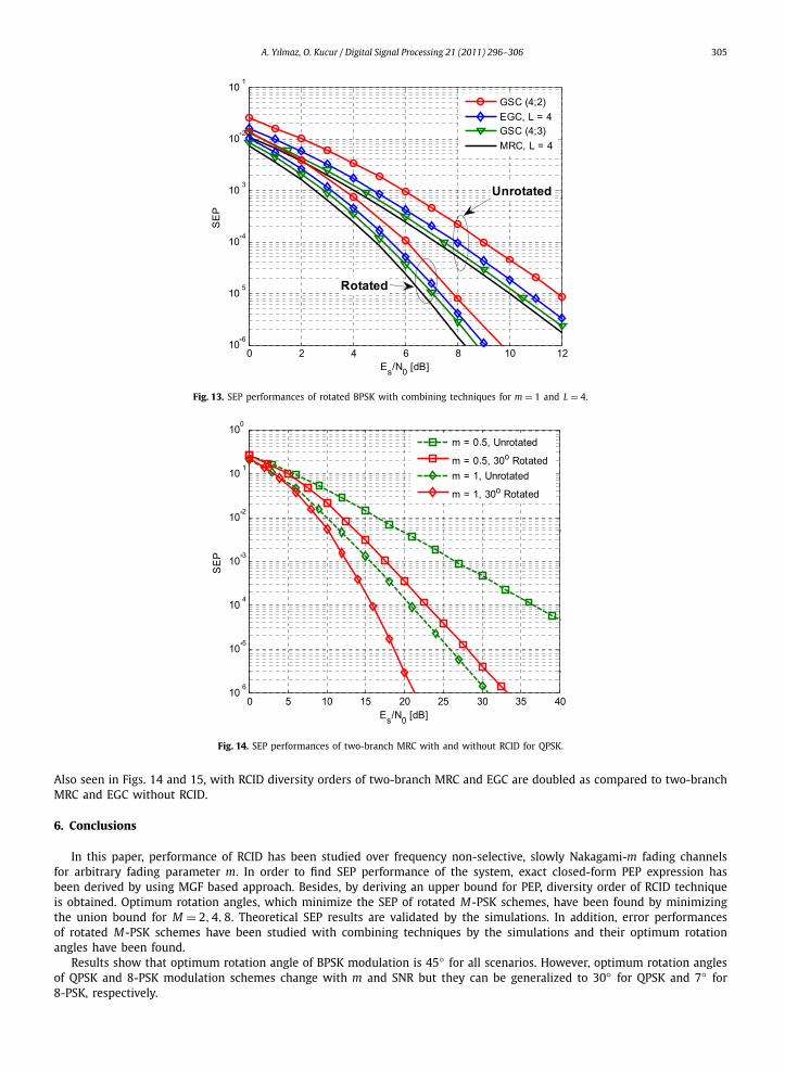
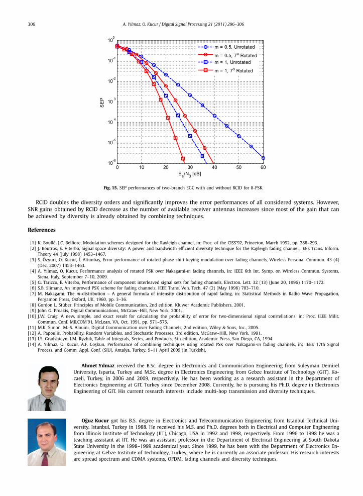
SEP performances of unrotated and rotated modulation schemes with combining techniques are given in Figs. 12–15.In Figs. 12 and 13, SEP performances of BPSK and 45◦ rotated BPSK schemes are given for m = 1 and various combiningtechniques using L = 2 and L = 4 antennas. In Figs. 14 and 15, SEP performances of QPSK, 8-PSK and their rotated ones aregiven for various m values and two-branch MRC and EGC, respectively.
As seen in Figs. 12 and 13, RCID provides approximately 6 dB and 2.5 dB SNR gains for L = 2 and L = 4, respectivelyand also doubles the diversity order of combining techniques. As available number of receiver antennas increases, SNRgain obtained with RCID decreases, because most of the gain that can be achieved are already obtained through combiningtechniques.
As observed in Figs. 14 and 15, for QPSK and 8-PSK SEP performances of two-branch MRC and EGC with RCID are about14 dB and 5 dB superior to those of two-branch MRC and EGC without RCID at a SEP of 10−4 for m = 0.5 and 1, respectively.
A. Yılmaz, O. Kucur / Digital Signal Processing 21 (2011) 296–306 305
Fig. 13. SEP performances of rotated BPSK with combining techniques for m = 1 and L = 4.
Fig. 14. SEP performances of two-branch MRC with and without RCID for QPSK.
Also seen in Figs. 14 and 15, with RCID diversity orders of two-branch MRC and EGC are doubled as compared to two-branchMRC and EGC without RCID.
6. Conclusions
In this paper, performance of RCID has been studied over frequency non-selective, slowly Nakagami-m fading channelsfor arbitrary fading parameter m. In order to find SEP performance of the system, exact closed-form PEP expression hasbeen derived by using MGF based approach. Besides, by deriving an upper bound for PEP, diversity order of RCID techniqueis obtained. Optimum rotation angles, which minimize the SEP of rotated M-PSK schemes, have been found by minimizingthe union bound for M = 2,4,8. Theoretical SEP results are validated by the simulations. In addition, error performancesof rotated M-PSK schemes have been studied with combining techniques by the simulations and their optimum rotationangles have been found.
Results show that optimum rotation angle of BPSK modulation is 45◦ for all scenarios. However, optimum rotation anglesof QPSK and 8-PSK modulation schemes change with m and SNR but they can be generalized to 30◦ for QPSK and 7◦ for8-PSK, respectively.
306 A. Yılmaz, O. Kucur / Digital Signal Processing 21 (2011) 296–306
Fig. 15. SEP performances of two-branch EGC with and without RCID for 8-PSK.
RCID doubles the diversity orders and significantly improves the error performances of all considered systems. However,SNR gains obtained by RCID decrease as the number of available receiver antennas increases since most of the gain that canbe achieved by diversity is already obtained by combining techniques.
References
[1] K. Boullé, J.C. Belfiore, Modulation schemes designed for the Rayleigh channel, in: Proc. of the CISS’92, Princeton, March 1992, pp. 288–293.[2] J. Boutros, E. Viterbo, Signal space diversity: A power and bandwidth efficient diversity technique for the Rayleigh fading channel, IEEE Trans. Inform.
Theory 44 (July 1998) 1453–1467.[3] S. Özyurt, O. Kucur, I. Altunbas, Error performance of rotated phase shift keying modulation over fading channels, Wireless Personal Commun. 43 (4)
(Dec. 2007) 1453–1463.[4] A. Yılmaz, O. Kucur, Performance analysis of rotated PSK over Nakagami-m fading channels, in: IEEE 6th Int. Symp. on Wireless Commun. Systems,
Siena, Italy, September 7–10, 2009.[5] G. Taricco, E. Viterbo, Performance of component interleaved signal sets for fading channels, Electron. Lett. 32 (13) (June 20, 1996) 1170–1172.[6] S.B. Slimane, An improved PSK scheme for fading channels, IEEE Trans. Veh. Tech. 47 (2) (May 1998) 703–710.[7] M. Nakagami, The m-distribution – A general formula of intensity distribution of rapid fading, in: Statistical Methods in Radio Wave Propagation,
Pergamon Press, Oxford, UK, 1960, pp. 3–36.[8] Gordon L. Stüber, Principles of Mobile Communication, 2nd edition, Kluwer Academic Publishers, 2001.[9] John G. Proakis, Digital Communications, McGraw–Hill, New York, 2001.
[10] J.W. Craig, A new, simple, and exact result for calculating the probability of error for two-dimensional signal constellations, in: Proc. IEEE Milit.Commun. Conf. MILCOM’91, McLean, VA, Oct. 1991, pp. 571–575.
[11] M.K. Simon, M.-S. Alouini, Digital Communication over Fading Channels, 2nd edition, Wiley & Sons, Inc., 2005.[12] A. Papoulis, Probability, Random Variables, and Stochastic Processes, 3rd edition, McGraw–Hill, New York, 1991.[13] I.S. Gradshteyn, I.M. Ryzhik, Table of Integrals, Series, and Products, 5th edition, Academic Press, San Diego, CA, 1994.[14] A. Yılmaz, O. Kucur, A.F. Coskun, Performance of combining techniques using rotated PSK over Nakagami-m fading channels, in: IEEE 17th Signal
Process. and Comm. Appl. Conf. (SIU), Antalya, Turkey, 9–11 April 2009 (in Turkish).
Ahmet Yılmaz received the B.Sc. degree in Electronics and Communication Engineering from Suleyman DemirelUniversity, Isparta, Turkey and M.Sc. degree in Electronics Engineering from Gebze Institute of Technology (GIT), Ko-caeli, Turkey, in 2006 and 2009, respectively. He has been working as a research assistant in the Department ofElectronics Engineering at GIT, Turkey since December 2008. Currently, he is pursuing his Ph.D. degree in ElectronicsEngineering of GIT. His current research interests include multi-hop transmission and diversity techniques.
Oguz Kucur got his B.S. degree in Electronics and Telecommunication Engineering from Istanbul Technical Uni-versity, Istanbul, Turkey in 1988. He received his M.S. and Ph.D. degrees both in Electrical and Computer Engineeringfrom Illinois Institute of Technology (IIT), Chicago, USA in 1992 and 1998, respectively. From 1996 to 1998 he was ateaching assistant at IIT. He was an assistant professor in the Department of Electrical Engineering at South DakotaState University in the 1998–1999 academical year. Since 1999, he has been with the Department of Electronics En-gineering at Gebze Institute of Technology, Turkey, where he is currently an associate professor. His research interestsare spread spectrum and CDMA systems, OFDM, fading channels and diversity techniques.
Copyright © 2022 FDOKUMEN