Feedback amplifier configurations - Circuits, Devices and ...
Performance of external and internal coil configurations forprostate investigations at 7 Tesla
Gregory J. Metzger1, Pierre-Francois van de Moortele1, Can Akgun1, Carl J. Snyder1, SteenMoeller1, John Strupp1, Peter Andersen1, Devashish Shrivastava1, Tommy Vaughan1,Kamil Ugurbil1, and Gregor Adriany1
1University of Minnesota Medical School, Center for Magnetic Resonance Research,Minneapolis, Minnesota 55455, USA
AbstractThree different coil configurations were evaluated through simulation and experimentally todetermine safe operating limits and evaluate subject size dependent performance for prostateimaging at 7 Tesla. The coils included a transceiver endorectal coil (trERC), a 16 channeltransceiver external surface array (trESA) and a trESA combined with a receive-only ERC (trESA+roERC). While the transmit B1 (B1
+) homogeneity was far superior for the trESA, the maximumachievable B1
+ is subject size dependent and limited by transmit chain losses and amplifierperformance. For the trERC, limitations in transmit homogeneity greatly compromised imagequality and limited coverage of the prostate. Despite these challenges, the high peak B1
+ close tothe trERC and subject size independent performance provides potential advantages especially forspectroscopic localization where high bandwidth RF pulses are required. On the receive side, thecombined trESA+roERC provided the highest SNR and improved homogeneity over the trERCresulting in better visualization of the prostate and surrounding anatomy. In addition, the parallelimaging performance of the trESA+roERC holds strong promise for diffusion weighted imagingand dynamic contrast enhanced MRI.
KeywordsProstate; 7 Tesla; Endorectal Coil; Stripline Array; Body Imaging
INTRODUCTIONAnatomic and functional magnetic resonance imaging (MRI) has been shown to be avaluable tool in staging prostate cancer above and beyond what is possible with standardclinical tests such as digital rectal exams, transrectal ultrasound guided biopsy and serumprostate specific antigen (PSA) measures (1). While anatomic MRI based primarily on T2-weighted contrast provides delineation of zonal anatomy, extracapsular extension, andregions of cancer, functional MRI studies have been shown to further increase sensitivityand specificity over anatomic imaging alone by improving the differentiation of cancer frombenign processes. Many studies have demonstrated the utility of combining anatomicimaging with various combinations of functional studies in determining disease volume,targeting biopsy, treatment planning and therapy monitoring (2-5).
Send Correspondence to: Greg Metzger, Ph.D. Center for Magnetic Resonance Research University of Minnesota 2021 6th StreetS.E. Minneapolis, MN 55455 [email protected] Phone: 612-626-2001 Fax: 612-626-2004.
NIH Public AccessAuthor ManuscriptMagn Reson Med. Author manuscript; available in PMC 2011 December 1.
Published in final edited form as:Magn Reson Med. 2010 December ; 64(6): 1625–1639. doi:10.1002/mrm.22552.
NIH
-PA Author Manuscript
NIH
-PA Author Manuscript
NIH
-PA Author Manuscript
As with many other applications, the impetus behind the use of higher magnetic field forprostate MRI is driven by the promise of improved disease characterization resulting fromincreased spectral dispersion, parallel imaging performance, and signal-to-noise ratio (SNR).When comparing 3T with 1.5T, increase in SNR alone has resulted in a diagnosticallyrelevant increase in spatial resolution which is crucial for the identification of extracapsularextension in anatomic T2-weighted images, and for decreasing partial voluming inspectroscopy studies thus improving the identification and characterization of smallervolumes of disease (6,7). Increasing field strength also results in increased spectralresolution in spectroscopy, increasing the potential to quantify individual metabolites (8)and to lead to more sensitive and specific biomarkers as demonstrated in high resolutionmagic angle spinning spectroscopy (HRMAS) spectra of prostate cancer tissue (9).
Increased temporal resolution directly benefits dynamic contrast enhanced MRI (DCE-MRI)where higher temporal sampling has been shown to improve the determination ofpharmacokinetic parameters used to characterize neovascularization (10). In addition toincreasing SNR and thus spatial resolution, the increase in field strength can be used toimprove temporal resolution by reducing the necessity to signal average and, even moresignificantly, by improved parallel imaging performance. It was shown by Wiesinger et al.(11) that the increased spatial encoding capability of the receive B1 field (B1
−) of each coilelement at high field can be used to increase reduction factors (R) while maintaining arelatively low geometry factor (g-factor). Maintaining a low g-factor is critical as itinversely scales the resulting SNR for a given R based on the relation SNR ∝ 1/(g*√R).
In order to take full advantage of the promise of prostate MRI, coil configurations have beenoptimized based of different design criteria. Initially, to improve the SNR of prostate studiesat 1.5T, receive only external surface arrays (roESA) were combined with receive onlyendorectal coils (roERC). However, with the arrival of the clinical 3T platform, somestudies returned to focus on the roESA alone where the field strength dependent increase inSNR provided a similar performance compared to the combined roERC+roESA coil at 1.5T(12). While there are several advantages to the sole use of an roESA, the diagnosticinformation obtained with the roERC (13) and roESA+roERC coils (6) at 3T have beendemonstrated to be superior.
Optimizing RF coil configurations for ultra high field (UHF) applications, i.e. higher than3T, requires attention to additional issues not present on lower field systems. For example,UHF whole body MRI systems typically do not make use of whole body RF transmit coilsdue to the increased power requirements and power deposition in tissues, both roughlyproportional to B0
2 (14). In the absence of a whole body volume transmit coil, local transmitcoils must be developed and typically each of these transmit coil elements are also utilizedas receive coil elements (then referred to as transceiver coil elements).
Beyond roESA and roERC coils currently in use clinically, there are several examples wherelocal transmit coils have been developed for prostate imaging. Transceiver external surfacearrays (trESA) have been previously presented for use at field strengths of 3T (15,16), 4T(17) and 7T (18). Other coil configurations have included a trESA in combination with aroERC at 4T (19) and transceiver ERCs (trERC) at 7T (20-22). Each of these coilconfigurations has advantages and disadvantages. The trERC coils developed for 7T prostateimaging provide the advantage of high SNR and high peak transmit B1 (B1
+) but suffergreatly from receive B1 (B1
−) and B1+ inhomogeneity. The trESA coils, even at lower field
strengths, provide the ability for B1+ shimming (or field focusing) resulting in increased
transmit efficiency compared to whole body volume transmit. While the trESA coils canprovide homogeneous transmit and receive profiles in the prostate, they cannot achieve themaximum SNR and peak B1
+of the local trERC. Finally, the combination of a trESA with a
Metzger et al. Page 2
Magn Reson Med. Author manuscript; available in PMC 2011 December 1.
NIH
-PA Author Manuscript
NIH
-PA Author Manuscript
NIH
-PA Author Manuscript
roERC provides the flexibility of B1+ shimming while maintaining the SNR advantages of
the ERC but still lacks the peak B1+ of a trERC coil.
While the previously described coil configurations are all options for prostate imaging at 7T,the challenges of optimizing these coils in terms of performance and safety greatly increasewith field strength. These challenges are a result of the quadratic relationship between B0and RF power as well as the increasingly complex B1
+ fields. With respect to performance,it was sufficient at 3T and 4T to predetermine B1
+ shimming solutions determined from thegeometric design of trESA RF coils (15-17). However, this one size fits all approachbecomes far less optimal at 7 T, where the RF wavelength becomes as short as ~12 cm in thebody, so that B1
+ fields vary much more rapidly and are increasingly affected by bodygeometry and coil position. This has been experimentally demonstrated in the work done at7T using a trESA coil, where a subject dependent B1
+ shimming method (rather than aunique, coil based method) was employed (18). With respect to safety, the E-fields areresponsible for RF induced heating in the body and, at 7T, they surpass the B1
+ fields interm of spatial complexity. An important consequence of the latter is that at UHF the mostconstraining limits on RF power, with regards to patient safety, are typically the result oflocal rather than whole body heating. These local effects become even more prominentwhen using transmit coils that are positioned close to, as well as inside, the body as in thepresent study. Understanding these local E-fields and/or local heating is of paramountimportance for determining safe operating limits while not unnecessarily limiting powerwhich would compromise performance.
In this paper, we developed three different coil configurations at 7T and investigated theircharacteristics: a transceiver ERC coil (trERC), a transceiver external surface array (trESA)and a trESA combined with a receive only ERC (roERC) which will be referred to as atrESA+roERC. These coils were evaluated by simulation, phantom studies and in vivostudies to determine parallel imaging performance, SNR and receive B1 (B1
−) homogeneity,transmit B1 (B1
+) homogeneity and peak B1+ performance under the constraints of available
RF power and local specific absorption rates (SAR) or heating limits.
METHODSMagnet and RF subsystems
Phantom and in vivo data were acquired on a Magnex (Magnex, Oxford, UK) 7T, 90cm boremagnet with a Siemens 32 channel console, using whole body gradients and 16 RFtransceiver channels. For this setup, the RF transmit path of each coil element was equippedwith a broadband T/R switch and preamplifier (Varian Inc, Palo Alto, CA). For RFtransmission, 16 × 1 kW amplifiers (CPC, Hauppauge, NY) were used when transmittingwith the trESA either by itself or in combination with the roERC (23,24). The phase andgain of the low voltage input of the 16 amplifiers were modulated by a remotely controlledmulti channel RF phase and gain unit (CPC, Hauppauge, NY). When using the trERC, asingle 1 kW RF amplifier was used for RF transmission. In all cases, power optimizationwas determined in the region of the prostate based on calculated B1
+ maps acquired usingthe double flip angle method (DAM) (25).
In addition to the standard MR console RF power monitoring system of forward andreflected power for one channel, a similar 16-channel RF power monitoring system wasdeveloped in-house. The RF power amplifiers for each of the 16 RF channels were equippedwith a directional coupler that provides an attenuated version of the output waveform. Inorder to estimate the instantaneous power, a diode based envelope detector circuit was usedto rectify and smooth the forward power signal to a quasi-static signal to allow for ADCsampling at a moderate rate of 50 kHz. Each channel of the system was calibrated by
Metzger et al. Page 3
Magn Reson Med. Author manuscript; available in PMC 2011 December 1.
NIH
-PA Author Manuscript
NIH
-PA Author Manuscript
NIH
-PA Author Manuscript

measuring the peak-to-peak voltage delivered to a 50 Ω terminator at the position of the coil.This RF voltage measurement was used to calculate the power delivered to the coil withrespect to the plateau voltage of the pulse envelope measured with the diode detector.
The system maintains additionally a 10 second and 5 minute moving average. If the meanpower over the 5 minute window exceeds the coil dependent time average power limit(TAPlimit) on any transmit channel, all RF amplifiers are immediately disabled untilmanually reset by the operator. The determination of TAPlimit for the trESA and trERC aredescribed below. The monitoring software is written in LabVIEW and runs on a controllerboard housed in a PXI chassis along with the ADC boards (National InstrumentsCorporation, Austin, TX). A remote host GUI is provided to the operator for setting thethreshold limits and allows for viewing graphically the current average RF doses on a perchannel basis.
Local B1+ phase shimmingLocal B1
+ phase shimming was performed in all simulations and experiments in whichmultiple transmit channels were used. Experimentally, local B1
+ phase shimming usedmethods previously published by our group (18). Briefly, a series of low-resolution, low flipangle GRE images were acquired while pulsing RF power through only one channel at atime. This was accomplished for all 16 transmit channels in a single acquisition by settingup a dynamic table used by the CPC's phase and gain controller. The relative transmit B1
+
phases were then calculated for each channel and used to perform local B1+ phase shimming.
B1+ shimming consisted of drawing a region of interest around the prostate in which, for
each channel the average relative transmit phase was determined and subtracted through theremotely controlled multi channel RF phase and gain unit. For the region within the chosenROI, the procedure maximizes the transmit efficiency. For the 16 channel ESA used in thiswork, local B1
+ shimming required approximately 2 minutes to acquire the subjectdependent calibration data as well as calculate and apply the optimal phases.
Coil DesignA 16 channel external surface array (ESA) similar to that previously described andcharacterized consisted of two 8-element TEM stripline arrays, positioned anterior andposterior to the pelvis (26,27). Figure 1a shows the coil positioned on a volunteer with >1cm padding between the coil and patient. The eight coil elements within each of the twoarrays were attached in parallel configuration with minimal gap between twopolytetrafluoroethylene (PTFE) plates measuring 22.7×35.6 cm2 with 0.3 cm thicknessflexed to have a fixed curvature of 4 degrees. The anterior array, without the patient sidePTFE plate, is shown in Fig. 1b. The individual coil elements were 15.3 cm long with a 1.27cm wide inner conductor and a 5.0 cm wide outer conductor, separated by a 1.9 cm thickPTFE dielectric bar stock with a low loss tangent and a permittivity of 2.08. All elementswere individually tuned to 297 MHz (7T), and matched to a 50Ω coaxial line. Capacitivedecoupling facilitated more than 21 dB isolation between elements when unloaded and 26dB isolation when loaded. Figure 1c shows a diagram depicting the relative positioning ofthe tuning, matching and decoupling capacitors all of which are variable in the range of 1 to10 pF.
The transmit-receive endorectal loop coil (trERC) was built from a modified commerciallyavailable inflatable 3T endorectal coil (Medrad, Pittsburgh, PA) where the conductor andcircuitry were completely replaced. The basic housing of this coil includes a 32 cm flexibleplastic rod with a balloon surrounding the distal 7 cm. The rod extends through the middleof the balloon providing rigidity for coil insertion and houses both the conductor leading upto the tune and match circuitry and a tube for balloon inflation. The tune and match circuitry
Metzger et al. Page 4
Magn Reson Med. Author manuscript; available in PMC 2011 December 1.
NIH
-PA Author Manuscript
NIH
-PA Author Manuscript
NIH
-PA Author Manuscript

exits the rod at the proximal end of balloon at which point the loop coil originates whichmeasures 7.0×3.5 cm2. The trERC circuitry consists of fixed fcapacitors (ATC 100B Series,Huntington Station, NY) for matching and tuning with an additional 3 capacitors equallydistributed around the coil to reduce local E-fields. The location and values of the capacitorsare provided in Fig. 2a.
The roERC had the same basic geometry as the trERC but included a sleeve balun and bothactive and passive diodes to detune the ERC during RF transmission as it was used incombination with the trESA (28). The housing and flexibility of the inflatable ERC coil wasfound to limit the choices of the detune circuitry. We pursued a simple circuitry withminimal components that primarily achieves suppression of coil currents through a shift inresonance frequency. The actively switched diode (Microsemi Corporation, Irvine, CA,UM9401) created a short across the tune and match circuitry and shifted the ERC loop coil~20 MHz off resonance during RF transmission. An additional passive cross-diode(Voltronics, Denville, NJ,MX51363-145) was used across the distributed capacitor at the topof the coil to detune the loop structure in the presence of induced currents in case of failureof the active diode. The modified coil circuitry is shown in Fig. 2b. The safety andeffectiveness of this simplified detune circuitry was evaluated in phantom and in vivostudies.
All bench measurements required for coil tuning, matching, isolation and other circuitcharacterizations were performed using a calibrated Hewlet-Packard (Palo Alto, CA) HP4396A network analyzer together with an 85046A “S” parameter test set. Specifically, coilswere evaluated in terms of their reflectivity (S11), coupling (S12), unloaded quality factor(Q0), and loaded quality factor (QL). Coil efficiency, Ceff, was then estimated by thestandard relation (Ceff = 1 − QL/Q0). Conditions of loading were obtained in vivo on avolunteer. Experimentally, in vivo DAM B1
+ maps were generated to investigate thecoupling between the ERC coils and the trESA.
Phantom StudiesPrior to in vivo use, each endorectal coil was tested and characterized with a phantom. Thisphantom consisted of a ~9L plastic (Nalge Nunc, Rochester NY) bottle filled with a solutionof 4 mM CuSO4 and 77 mM NaCl in deionized water. A 30 cm long plastic tube (TuoloxPlastics, Marion, IN) with an inside diameter of 4.45 cm and a wall thickness of 0.04 cmpassed through and was attached to the lid of the larger plastic container with epoxy. Thetube accepted the un-inflated ERC allowing it to be positioned near the center of thephantom. The coil was secured in position by inflating the balloon. This phantom setupallowed consistent positioning of the trERC and roERC coils for testing with and withoutthe trESA.
B1+ mappingMapping of the transmit B1 both in phantoms and in vivo was accomplished with the DAMapproach (25) using a GRE acquisition with the following parameters: FOV = 160 to320mm, TR = 6 s, TE = 4.1 ms, acquisition matrix = 128×96,slice thickness of 5 mm resultingin an acquisition time of 9.6 minutes per flip angle. Based on the two images acquired, thelow flip angle, Θ, is estimated by arccos(|S2(r)/2S1(r)|), where S2(r) and S1(r) are the signalintensities from the higher and lower flip angles, respectively. The peak B1
+ is subsequentlycalculated knowing the integral of the B1
+ mapping RF pulse (IRF) and its duration (tRF) bythe relationship (Θ* 2π) / (IRF * tRF * 360 * γ). This value is then scaled to report the peakB1
+ assuming 1 W input power (B1_1W) for each element of the transmit coil and themaximum B1
+ (B1_max) for the specific RF amplifiers and transmit chain used. All B1+
Metzger et al. Page 5
Magn Reson Med. Author manuscript; available in PMC 2011 December 1.
NIH
-PA Author Manuscript
NIH
-PA Author Manuscript
NIH
-PA Author Manuscript
mapping and subsequent calculations were performed in IDL (ITT Visual InformationSolutions, Boulder, CO, USA).
Receive and Parallel Imaging PerformanceReceive and parallel imaging performance was calculated from an axial gradient echoacquisition acquired with the trESA+roERC with the following parameters: TR = 76 ms, TE= 3.8 ms, nominal flip angle 10° and a resolution of 1.3×1.3×10 mm3. To determine receiveperformance, the noise covariance matrix for each study, estimated from a separate noisescan, was used to decorrelate the roERC from the trESA. The remaining trESA elementswere re-correlated and the SNR for the decorrelated roERC and the trESA were calculatedindependently using the pseudo-multiple replica method described by Robson et al. (29).Parallel imaging performance was evaluated by calculating geometry factors (g-factors) overranges of accelerations in both the left-right and anterior-posterior directions (30). Averageand maximum g-factors are then reported over the prostate and the region of the internaliliac artery. Both SNR and g-factor maps calculations were performed in Matlab (TheMathworks, Inc., Natick, MA, USA).
trESA ModelingXFDTD, a finite difference time domain (FDTD) solver was used to evaluate coilperformance and transmit power limits (REMCOM, Pittsburgh, PA). Coil performancemeasures included geometry factors, transmit B1 (B1
+) and receive B1 (B1−) profiles.
Transmit power limits were based on maintaining predicted local SAR limits below 8 W/kgaveraged over one gram as recommended by the Center for Devices and Radiological Healthwithin the U.S. Food and Drug Adminstration (FDA) (31).
Simulations were made in three-dimensions using a human body model consisting of a 5mm cubical FDTD mesh generated from data from the Visual Human Project. Each tissuewas characterized by its density, conductivity and permittivity. The trESA was simulatedwith and without the presence of the roERC. To incorporate the presence of the ERC, thehuman body model was modified by removing tissue posterior to the prostate toaccommodate the space occupied by a fully inflated balloon. Both the trERC and the trESAcoils were tuned to 297.2 MHz. When simulating the trESA, optimal phase based local B1
+
shimming was performed for the region of the prostate as previously demonstrated (18). B1+
shimming provided the optimal transmit phases for each of the coil elements thusmaximizing transmit efficiency when combined in the region of the prostate. These phaseswere used when performing the complex addition of the simulated B1
+ and E-fields fromeach individual transmit element for the ESA in order to determine the final B1
+ and SARmaps in the torso model. The simulated B and E fields were normalized to 1 W input powerper channel for comparison with measured B1
+ maps and determination of time averagedpower limits based on calculated local peak SAR values. The simulated B1
+ assumes closeto an ideal coil with minimal losses. To more accurately represent experimental conditions,the transmit B1 calculated by XFDTD are also scaled by the measured coil efficiencies,(Ceff)1/2.
At ultra-high fields, the application of RF over time is limited not by whole body averageSAR but rather by local SAR (32). Therefore, in order to operate within FDArecommendations for local SAR of 8 W/kg per gram of tissue averaged over any 5 minuteperiod, simulations were used to determine local peak SAR values normalized to 1 W inputpower per channel. The normalized peak SAR in 1 g of tissue (SARpeak_norm) for a givencoil was then converted to a limit on time averaged power (TAPlimit,coil) such that local SARdoes not exceed the one gram averaged power of 8 W/kg by the relation
Metzger et al. Page 6
Magn Reson Med. Author manuscript; available in PMC 2011 December 1.
NIH
-PA Author Manuscript
NIH
-PA Author Manuscript
NIH
-PA Author Manuscript
[1]
Only power absorbed by the tissue can contribute to local E-fields, and thus SAR. Coillosses reduce the available power for generating electric as well as magnetic fields in thebody. If the TAPlimit was exceeded, measures were taken to reduce the TAP by modifyingRF pulses and/or adjusting other imaging parameters such as increasing repetition times orreducing the acquired slices.
trERC Modeling and Heating StudiesSimulations and heating experiments were performed with the trERC coil to validateacceptable power limits for in vivo use. Experimental safety testing was warranted for thetrERC coil given the internal nature of this coil. For experimental testing, a cylindricalacrylic phantom with a 22 cm diameter and 20 cm long was filled with a polyacrylamide gel(6.5% acrylamide, 0.3% bisacrylamide, 0.05% TEMED, 0.08% ammonium persulfate;Fischer Scientific, Pittsburgh, PA) (33) constructed following the methods detailed by Biniet al. (34). The permittivity (73) and conductivity (0.79 S/m) were measured with animpedance/material analyzer (Agilent, Santa Clara, CA). The trERC was filled withperfluorocarbon and held in the center of the phantom during the polymerization processthus allowing the gel to completely surround the coil. Fiberoptic temperature probes(Luxtron Corp., Santa Clara, CA, USA) were positioned at 16 locations around the loop ofthe coil and feed circuitry including the feed point and the three distributed capacitors.Power was applied to the coil and forward and reflected power were monitored where thedifference of the two was used to determine the input power to the coil. This input powerwould be equivalent to the power monitored during in vivo studies. The resulting inputpower applied to the trERC was a continuous 14.9 W for 10 minutes while temperatureswere recorded at 1 s intervals. Local SAR in units of W/kg were calculated for compairsonwith simulation using the relation dT/dt = SAR / c, where dT is the difference in temperatureover the initial linear part of the heating curve and c is the heat capacity of the gel estimatedat ~ 4200 J/°C·kg (34).
Simulations of the trERC in the heating phantom setup were used to determine the expectedE-field distribution for comparison with the heating studies, generation of B1
+ profiles forcomparison with in vivo measurements, and calculation of one gram averaged SAR fordetermination of TAPlimit,trERC. For the simulation, the trERC was modeled inside a uniformmaterial with a 2 mm3 resolution which was assigned the measured conductivity andpermittivity values of the polyacrylamide gel.
In vivo MRI StudiesIn vivo imaging data were collected on healthy volunteers under an IRB approved protocol.For the quantitative in vivo characterization of the coils, a single subject with a body massindex (BMI) of 22.3, height 1.62 m and weight 59 kg, was imaged with all three coilconfigurations. Results from this individual will be referred to as originating from the“reference volunteer”. In addition to the gradient echo acquisitions described above for B1
+
mapping, shimming and evaluation of SNR and parallel imaging performance, anatomicT2w turbo spin echo (TSE) images were acquired to assess image quality obtainable fromthe 3 different coil configurations (TR 3500 ms, TE 130 ms, 3 mm slice thickness, 130bandwidth per pixel, echo train length of 9 and a 220 mm FOV). A total of 10 slices with anacquisition time of 2:48 were acquired with a nominal in-plane resolution of 0.7 × 0.7 mm2.For the combined trESA+roERC, higher resolution images (0.5 × 0.5 mm2 in-place) wereacquired by reducing the FOV to 160 mm while keeping all other parameters the same. In all
Metzger et al. Page 7
Magn Reson Med. Author manuscript; available in PMC 2011 December 1.
NIH
-PA Author Manuscript
NIH
-PA Author Manuscript
NIH
-PA Author Manuscript

acquisitions, the phase encoding direction was in the left-right direction with 60%oversampling to avoid fold-over artifact on the prostate. To minimize the intense lipid signalimmediately adjacent to the ESA and ERC coils on receive, a local volume was used forboth B0 shimming and center frequency determination allowing the effective use of achemically shift selective saturation pre-pulse.
Subject Size DependenceBoth transmit and receive performance of the trESA were evaluated against subject size.Subject size was characterized by the width of the body from anterior to posterior(APdistance) as determined from axial scout images at the level of the prostate. BMI valueswere also recorded and compared to APdistance. In addition to the reference volunteer's B1
+
information generated with the DAM method, four additional studies were performed involunteers with varying body sizes. These B1
+ maps were generated with the actual flipangle imaging technique which is a 3D gradient echo double TR approach (35). Resultswere comparable to the DAM values (36) with the added advantage of shorter acquisitiontimes and volumetric coverage. The AFI sequence parameters included: FOV = 400 mm,TR1/TR2 = 20/120 ms, TE = 3.0 ms, acquisition matrix = 128×128, 18 slices and 3 mmslice thickness. The data for the two TR's were acquired in an interleaved manner resultingin a single acquisition of 4 minutes.
To investigate subject size dependence on receive performance, relative SNR maps weregenerated for eight additional subjects. Using a center profile normal to the plane of theroERC, the distance from the surface of the ERC at which the SNR of the trESA and roERCare equal (rSNR1distance) was plotted against APdistance.
RESULTSCoil Characterization
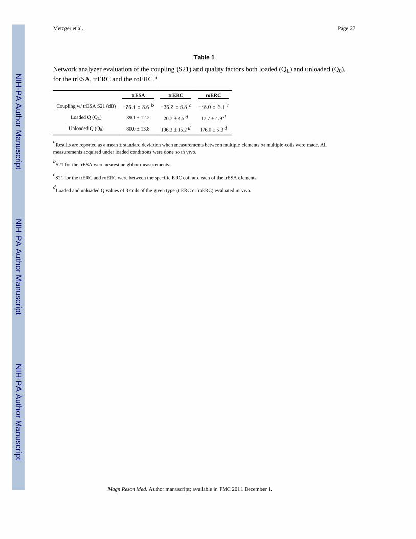
The network analyzer results for coupling (S21) as well as loaded (QL) and unloaded (Q0)quality factors are given in Table 1. The S21 values represent the average coupling betweenthe trESA and each of the coil configurations under in vivo load. The coupling of the trESAwith itself, −26.4±3.6 dB, is the average and standard deviation of the coupling betweennearest neighbors on the anterior or posterior TEM arrays. When DC power is used to drivethe diode in the roERC, the already low coupling between the trESA and the trERC of−36.2±5.3 dB is decreased to −48.0±6.1 dB.
However, since such port measurements do not allow for an evaluation of potentialremaining local B1 field effects due to imperfect decoupling, the loop structure undervarious states of detuning was also investigated. For this purpose, B1
+ maps were generatedin vivo with both the roERC and the trERC as receive only coils while transmitting with thetrESA. As expected, there is residual coupling with the remaining off-resonant structurewhen the roERC's active diode was biased and even more so with the trERC (i.e. nodetuning). In each configuration a new B1
+ shim was determined and a B1+ map measured.
The B1+ values in the region of the prostate for the trESA, trESA+roERC and trESA+trERC,
with the trERC in receive-only mode, were 0.15±0.016, 0.18±0.027 and 0.26±0.054 μT/W0.5, respectively. These B1
+ measurements were compared against the performance of thetrERC when using it as a transceiver coil as originally intended. The trERC as a transmit coilgenerated an average B1
+ of 1.24 μT/W0.5 in the prostate (Table 2). Therefore, coupling ofthe roERC with the trESA resulted in an increase which was 2.4% (0.18−0.15/1.24=0.024)of the B1
+ when transmitting with the trERC. Coupling of the trERC, in receive-only mode,with the trESA resulted in an increase which was 9.6% (0.26−0.15/1.24=0.096) of the B1
+
when transmitting with the trERC. Therefore, this translates to a 12 dB
Metzger et al. Page 8
Magn Reson Med. Author manuscript; available in PMC 2011 December 1.
NIH
-PA Author Manuscript
NIH
-PA Author Manuscript
NIH
-PA Author Manuscript
(10×log10[(0.024/0.096)2]) decrease in coupling when using the detuning circuitry of theroERC which experimentally validates the benchtop measurements.
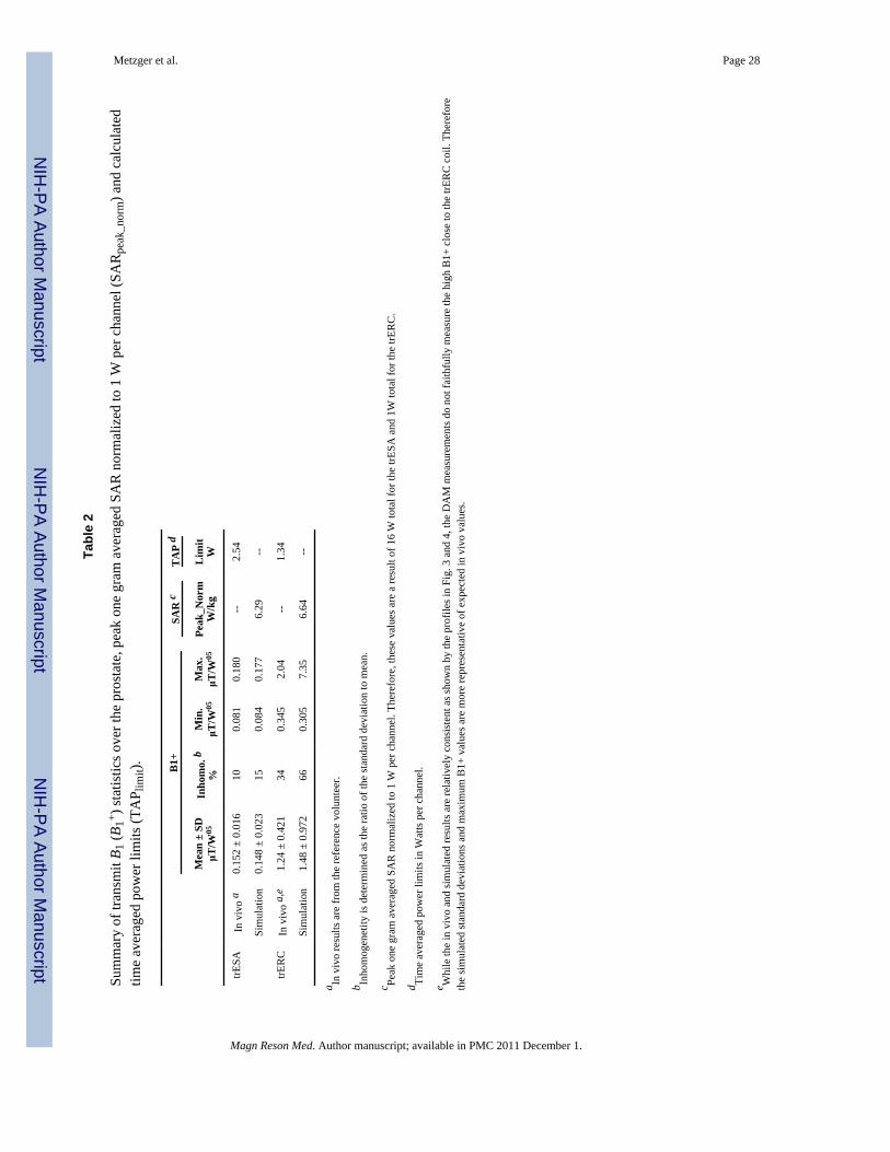
Transmit and Receive PerformanceSimulated and measured B1
+ profiles through the prostate are shown for both the trERC andtrESA in Fig. 3 and 4, respectively. For both the simulated and experimental values, thegenerated B1
+ was scaled to 1 W input power (B1_1W) per element. This corresponds to atotal input power of 16 W for the 16 channel trESA and 1 W for the trERC. For simulation,the B1
+ profiles are shown for the case of a nearly ideal coil with minimal losses (dashedcurves) and scaled by the measured Ceff to account for losses realized experimentally (solidcurves). The maximum achievable B1
+ (B1_max) for the investigated coils takes intoconsideration the peak output of the RF amplifiers and losses in the transmit chain. Thelosses from the RF amplifiers to the distribution panel at the back of the scanner isapproximately 1 dB while from the back of the scanner to the coil is another 3.6 dB.
Summary statistics from the simulated and experimental results are provided in Table 2 froma prostate shaped region encompassing the profiles provided in Fig. 3 and 4. Along with themean values, the B1
+ distribution can be further appreciated by an estimate of B1+
inhomogeneity as given by the ratio of the standard deviation to the mean B1+ over the same
regions. The inhomogeneity of the trESA from both simulation and in vivo results were 15%and 10%, respectively. The RF inhomogeneity of the trERC was 66% and 34% fromsimulation and experimental measurements, respectively. The difference in the simulatedversus measured B1
+ with the trERC is not surprising due to the limitations of theexperimental technique and the extremely high B1
+ close to the coil in vivo. The use ofDAM to measure B1
+ suffers from errors due to increasingly non-ideal slice profiles at theextremes in B1
+. This can be appreciated further by the minimum and maximum values fromeach region and also partially explains the slightly higher mean B1+ from simulation.
With the trESA, transmit efficiency associated with B1+ shimming as determined by the
fractional available B1+ also needs to be considered and is typically around 85% for prostate
studies in vivo (18). In this case, the fractional available B1+ realized in the prostate was
0.84 in simulation and 0.88 experimentally which means that 84% and 88% of the RFconstructively interferes over the region of the prostate.
Receive B1 values in vivo from the reference volunteer from approximately the samelocations are shown in Fig. 5 for all three coil configurations: trESA, trERC and trESA+roERC. The ERC coil performs approximately 5 times better on receive than the trESAclose to the rectum while the distance from the surface of the ERC at which the SNR of thetrESA and roERC are equal (rSNR1distance) was 2.8 cm based on the profile given in Fig. 5a.The vertical SNR profile was taken from the middle of the prostate which is over 6 mmanterior to the plane of the loop element in the ERC due to the inflation of the coil's balloon.In general, the SNR will favor the ERC more if the profile is taken further to the right andless with a profile further to the left as evidenced by the SNR taken horizontally as shown inFig. 5b.
Coil Dependent TAP limitsA representative axial slice of the 3D body model with the trESA and the void resultingfrom the ERC coil balloon is shown in Fig. 6a. An image of the SAR is shown in Fig. 6b atthe location of peak SAR. The peak 1 g average SAR (SARpeak_norm) in the body was 6.29W/kg. Using SARpeak_norm, the TAPlimit,trESA is equal to 2.54 W based on Equation 1.
The TAP limit for the trERC, TAPlimit,trERC, was determined from simulation and heatingexperiments in the gel phantom. From the 16 locations tested in the heating experiments,
Metzger et al. Page 9
Magn Reson Med. Author manuscript; available in PMC 2011 December 1.
NIH
-PA Author Manuscript
NIH
-PA Author Manuscript
NIH
-PA Author Manuscript
maximum heating and SAR occurred adjacent to the feed point of the coil and the firstdistributed capacitor as indicated by the horizontal and vertical arrows respectively in Fig.6c and 6d. The heating curves at these locations are shown in Fig. 6e. For an input power of13.4 W, the temperature at the first distributed capacitor and the feed point increased 9.9 °Cover 10 minutes. Despite the similarities in maximum temperature at the 10 minute mark,the probe at the distributed capacitor measured the highest SAR of 12.4 W/kg normalized toone Watt. The peak SAR determined in the phantom simulation was 13.6 W/kg in a single2×2×2 mm3 cell which is consistent with the point source value calculated in the heatingexperiment providing confidence in the simulated results. The one gram averagedSARpeak_norm determined from simulation was 6.64 W/kg resulting in a TAPlimit,trERC of1.34 W based on Equation 1. Both the SARpeak_norm and TAPlimit are summarized in Table2.
Parallel Imaging PerformanceAs parallel imaging plays an important part in improved spatial and temporal resolution ofdynamic contrast enhanced imaging studies, mean g-factors were calculated over theprostate and the region of the major feeding vessels typically used to obtain an arterial inputfunction. As shown in Table 3, the trESA performs well, exhibiting low g-factors in both theregion of the prostate and the artery with a range of reduction factors along the left-right andanterior-posterior directions. With the inclusion of the roERC, there is only a modestincrease in parallel imaging performance in the prostate with little or no observabledifference in the region of the artery which is far from the roERC. These in vivo results aresupported by similar g-factors calculated from simulated data in the region of the prostate(data not shown).
Anatomic Imaging StudiesFig. 7 shows T2w anatomic images from the reference volunteer at nearly the same level ofthe prostate obtained in different imaging sessions with each of the three coil configurations.The full FOV images are shown in the top row (Fig. 7a) while the same images zoomed in tothe region of the prostate in the lower row (Fig. 7b). There are two data sets shown for thetrERC coil. The trERC-low image is acquired with a lower power setting more appropriatefor achieving the desired T2 contrast close to the coil at the expense of under exciting spinson the anterior side of the gland as indicated by the horizontal arrow. The trERC-high data isacquire with three times as much power as the trERC-low in order to generate a sufficientB1
+ in the anterior portion of the prostate at the expense of over-flipping spins close to thecoil as shown by the vertical arrow. The trESA+roERC image shows consistent contrastthroughout the prostate as with the trESA alone with the added advantage of improved SNRclose to the rectum. Taking advantage of the increased SNR of the combined coil, theimages in Fig. 8 show the transverse, sagittal and coronal views of the prostate with an in-plane resolution of 0.5 × 0.5 mm2. This data was acquired by reducing the FOV to 160 mmwhile keeping all parameters the same as the images in Fig. 7.
Subject Size DependenceThe relationship between transmit and receive performance as a function of APdistance areshown in Fig. 9. For the 13 subjects included in these comparisons, BMI and APdistance werehighly correlated with the following estimated relationship: BMI = 1.56×APdistance−6.6 withR2=0.93. Therefore, in this study, an APdistance of 22.1 cm will be used to represent theaverage size adult male in the U.S. which corresponds to average BMI reported by the CDCof 27.9 (37). For the reference volunteer the APdistance was 19.0 cm. B1
+ was found to beinversely correlated to APdistance by the relation B1
+(μT/W0.5) =−1.17×10⁻²×APdistance+0.380 with R2= 0.73. Based on this relationship, a B1
+ of 0.122 μT/
Metzger et al. Page 10
Magn Reson Med. Author manuscript; available in PMC 2011 December 1.
NIH
-PA Author Manuscript
NIH
-PA Author Manuscript
NIH
-PA Author Manuscript
W0.5 is expected for the average adult male with the trESA; a decrease of 20% from thereference volunteer.
A positive, linear correlation was determined between rSNR1distance and APdistance as givenby the relation rSNR1distance = 0.266×APdistance−2.03 with R2=0.75. For the average adultmale, rSNR1distance is equal to 3.8 cm which is an increase of 36% over that of the referencevolunteer.
DISCUSSIONOn closed bore clinical scanners, a body coil is typically used to generate a relativelyhomogenous transmit RF field while local receive arrays are typically used for reception.However, whole body transmit coils, standard on most clinical scanners, becomeincreasingly challenging for applications at 7 Tesla resulting from increased powerabsorption and decreased wavelengths. Even though the feasibility of whole body RF coilshas been demonstrated at high fields including 4T (38) and 7T (39), the limits on maximumpeak transmit B1 and strong field inhomogeneity have not yet been adequately addressed forgeneral use. The decreased efficiency and homogeneity at high field is a result of destructiveinterferences exacerbated by the short wavelengths in tissue at 300 MHz (~12 cm) (40).
Along with destructive interferences, increased power deposition which is proportional toB0
2 decreases the available power to generate B1+ at 7T. That is, a greater percentage of the
power transmitted into the body is absorbed by the tissue in the form of E-fields resulting inheating. The E-field distribution in the body is complex and results from destructive/constructive interferences plaguing B1
+ and is greatly influenced by the distribution oftissues with widely varying electrical properties such as fat and muscle (41). This can beseen in the simulated SAR maps of the trESA coil, Fig. 6b. The E-fields track the conductivestructures in the body resulting in peak SAR in the skin and muscle. The presence oftremendous E-field and thus SAR inhomogeneity in the body disallows the use of wholebody averaged SAR as a criteria for determining safe limits of operation. Instead, local SARor temperature increases are used to determine limits on time averaged power for a givencoil configuration. This can be determined through simulation or through experimentalheating studies as demonstrated in this paper and by others (22).
A partial solution to the practical limits of field homogeneity, peak B1+ and SAR
management associated with the use of whole body RF coils at high field involves the use ofsmaller or local transmit coils, either as transceivers or transmit only designs. Combiningthis local coil strategy with B1
+ shimming greatly improves head imaging and makes bodyimaging possible (18). However, issues with achieving sufficient B1
+ for certain acquisitionssuch as spectroscopy still persist even with local transceiver arrays. The use of adiabaticpulses can be used to obtain the high bandwidth RF pulses required to minimize chemicalshift displacement in spectroscopy studies even with low peak B1
+ performance ((42) andreferences therein) however, the increasing pulse lengths and high local SAR become alimiting factor. In conjunction with adiabatic pulses or by itself, the variable rate selectiveexcitation (VERSE) technique may also help address limitations in peak B1
+, but comes atthe expense of poor off-resonance performance (19,43).
The local trESA transceiver array characterized in this paper was able to generate a B1+
0.152 μT/W0.5 in general with a system specific maximum B1+ of 11.9 μT using the current
RF amplifiers and cabling in the reference volunteer. This performance is achieved afterusing a B1
+ shimming method optimizing for transmit efficiency. Using B1+ shimming to
optimize B1+ homogeneity over the whole prostate area would greatly reduce the achievable
B1+ even further. Even though homogeneity was not a goal of the type of B1
+ shimming
Metzger et al. Page 11
Magn Reson Med. Author manuscript; available in PMC 2011 December 1.
NIH
-PA Author Manuscript
NIH
-PA Author Manuscript
NIH
-PA Author Manuscript
performed, B1+ in homogeneity was only 10% (ratio of standard deviation to mean B1
+)after B1
+ shimming over the region of the prostate and typically performs at least this well aspreviously reported (18).
The trERC coil provides improved peak transmit and receive B1 but at the expense ofreduced homogeneity compared to the trESA. With respect to B1
− in the referencevolunteer, the trERC exhibits approximately a 5-fold advantage near the loop coil comparedto the trESA and has an rSNR1distance of 2.8 cm. While trERC receive inhomogeneity resultsin correctable display issues, the most deleterious effects originate from the inhomogeneoustransmit B1 which was measured at 34% in vivo and 66% in simulation. For reasonspreviously explained, the simulated inhomogeneity is most likely closer to what is actuallybeing realized in vivo. As shown in the vertical and horizontal profiles in Fig. 4, the B1
+
inhomogeneity is not only dependent on the distance normal to the coil but is alsoasymmetric across the coil from left to right. As shown in Fig. 7, the B1
+ inhomogeneity ofthe trERC makes it difficult to achieve a uniform contrast across the entire prostate. Close tothe coil, B1
+ insensitive adiabatic pulses can be used to achieve good localization inspectroscopic studies as previously demonstrated by Klomp et al. (22). For T2w imaginghowever, a previously presented adiabatic RARE sequence (44) is acknowledged to have amuch high power deposition than the TSE sequence used in this study which was alreadyclose to the allowable local SAR limit. Again, combining adiabatic RARE with SARreduction strategies such as VERSE may help mitigate these issues to a level sufficient toallow reasonable anatomic imaging.
When attempting to cover the entire prostate the limited peak B1+ again becomes a factor
even with the trERC. In the reference volunteer, the trERC decreases from a maximum of1.8 μT/W0.5 at the posterior margin of the prostate near the coil at the midline, to 0.4 μT/W0.5 at a distance of 3cm. From the anterior midline through the right anterior quadrant ofthe prostate, the average B1
+ generated by the trESA is approximately equivalent to orgreater than that generated by the trERC even when considering the reduced performance ina larger average size adult male. Furthermore, the B1
+ distribution of the trERC is highlydependent on the rotation of the coil which is not easy to accurately adjust in vivo with theballoon-type coil currently used.
The trESA+roERC coil combines several benefits of both coils and has resulted in the bestanatomic imaging of the prostate to date at 7T as shown in Fig. 8. Combining the roERCwith the trESA improves the imaging of critical structures such as the posterior prostatecapsule, neurovascular bundle, and peripheral zone in several ways. First, the trESAprovides a homogeneous B1
+ resulting in uniform contrast across the prostate. Meanwhile,the roERC increases receive sensitivity, reduces prostate/rectum motion and allows controlover susceptibility by filling the coil balloon with a perfluorocarbon. The challenge with thisconfiguration is the same as the trESA coil alone, a relatively low peak B1
+.
TAP determinationThe SAR limits for the trESA were chosen based on simulation as opposed to heatingmeasurements for several reasons. First, temperature measurements in vivo are impracticalas the location of maximum heating is at first unknown making it difficult to accuratelyplace probes on the surface and unreasonable to place probes subcutaneously. Second, it isdifficult to build a phantom to reasonably approximate the widely varying tissue propertieswhich have a tremendous effect on E-field distributions. Finally, the multi-channeltransmitter further complicates the issue as there are complex E-fields generated by eachtransmit element which constructively and destructively interfere. The situation is similar tothe issues faced with B1
+ but additionally complicated by the influence of tissue boundariesand varying electrical properties. Therefore, in order to incorporate this complexity, the
Metzger et al. Page 12
Magn Reson Med. Author manuscript; available in PMC 2011 December 1.
NIH
-PA Author Manuscript
NIH
-PA Author Manuscript
NIH
-PA Author Manuscript
human body model was used in simulations accepting its overall size and shape would differfrom in vivo measurements.
To determine TAP limits for the trERC, the phantom study was most appropriate as itallowed both simulation and experimental testing. Experimentally, the phantom allowedinterrogation of the temperature at multiple locations in the polyacrylamide gel immediatelyadjacent to the coil. Along with simulation, it was deemed important with this internal coilto measure the maximum local heating along the conductor which, except for a latexballoon, is immediately adjacent to the tissue. Temperature measurements confirmedsimulation results that the location of maximum heating occurs directly above the capacitors(Fig. 6e), and the resulting local SAR measurements from the heating study were similar tothe local SAR predicted in the phantom model from a single cell in the simulation. Theseresults along with similar B1
+ profiles in both simulation and in vivo, gave confidence in thecalculation of TAPlimit,trERC from the simulated SARpeak_norm.
Limitations on Transmit B 1Considering the local SAR constraint alone, more power can be used for the trESA than forthe trERC by the factor TAPlimit,trESA/TAPlimit,trERC = 2.54/1.34 = 1.9. Despite thisapparent advantage, the average B1
+ in the prostate is still lower for the trESA than thetrERC. For demonstration purposes, assuming we are at the SAR limit with 1 W input powerfor the trERC, the trESA could use 1.9 W. Therefore, for the reference volunteer, the trESAcoil could generate a relative field of 0.152×(16×1.9)0.5 = 0.84 μT compared to the averagetrERC value of 1.24 μT. In the average male, the generated field by the trESA would bereduced by 20% compared to the reference volunteer resulting in a B1
+ of 0.67 μT.
In reality however, there is a finite amount of power available to generate B1+ especially in
the case of the trESA. This limit is a function of the power rating and performance of theamplifiers, losses in the cables and connections from the amplifier to the coil as well as thecoil match and efficiency. For the specific system used in this study, the maximumachievable B1
+ (B1_max) in Fig. 3 and 4 for the reference volunteer corresponds to themaximum possible output of our RF amplifiers. In this power limited case, as presented inFig. 3 and 4, the maximum B1
+ of the trESA was 11.9 μT for the reference volunteer whichwould correspond to an B1
+ of 9.3 μT in the average adult male. In comparison, starting witha single 1 kW amplifier the maximum achievable B1+ achieved for the trERC averaged overthe prostate was 24.2 μT.
Parallel Imaging PerformanceIt has been previously demonstrated that the 16 channel stripline array used in this workperforms quite well for parallel imaging across the entire human torso (27,45). In this study,local g-factors were determined in the prostate and external iliac artery as these locations arethe most relevant for prostate DCE-MRI studies. Even at the location of its maximumcontribution in receive B1, the roERC only modestly improves g-factors and this benefit isseen primarily in the anterior-posterior direction. In the artery, where the contribution of thetrERC is much less, there is almost no difference when compared with the trESA alone aswould be expected. It is important to mention that if the AIF from the external iliac artery isdesired for pharmacokinetic modeling, then using a trESA or at least a local transmit coil isan absolute requirement. On the receive side, improving local parallel imaging of theprostate could be improved further in this configuration through the use of longitudinal (46)and horizontal (47) ERC arrays.
Metzger et al. Page 13
Magn Reson Med. Author manuscript; available in PMC 2011 December 1.
NIH
-PA Author Manuscript
NIH
-PA Author Manuscript
NIH
-PA Author Manuscript
Coil Design ConsiderationsThe current roERC was a first attempt to provide a safe coil for in vivo use which fit theform factor of the available commercial housing and provided high quality images of theprostate. The first step in its design involved testing various configurations with a primaryfocus on understanding and mitigating coupling with the trESA for both reasons of safetyand image quality. While the regional B1
+ perturbations were in a large part manageablewith B1
+ shimming methods, even in the case of the trERC, there were induced fields closeto the coil which resulted in poor image quality (B1 components) and potentially localheating (E components). Therefore, the goal was to mitigate these induced fields. The invivo studies demonstrated that the current roERC significantly improves receiveperformance and minimally impacts B1+ homogeneity when combined with local B1
+ phaseshimming.
With a modification of the current coil design there is the potential to further exploitinductive coupling to augment the local B1
+ performance in the region of the prostate. Suchmethods have been previously published to increase local transmit B1 in the body and head(48,49). Some of these effects were observed in the data presented in the coilcharacterization results. When transmitting with the trESA and using the roERC and trERCas receive only coils, the average transmit B1 in the prostate increased, 20% and 73%,respectively. While not unexpected, the current coil design was not specifically designed forthis purpose and is an area for future investigation.
CONCLUSIONSThree different coil configurations to investigate the prostate at 7 Tesla were compared inthis study: a transceiver ERC coil (trERC), a 16 channel transceiver external surface array(trESA) and a trESA combined with a receive only ERC (roERC) be referred to as trESA+roERC. The advantages of the trERC are higher peak B1
+ performance, improved SNR, theability to perform reduced FOV imaging, decreased prostate motion and control oversusceptibility mismatches with the rectum, better visualization of the neurovascular bundleand patient size independent performance. Our results suggest that trERC could play asignificant role in cases where peak B1
+ value is the most critical factor at least close to thecoil, such as in spectroscopic studies. However, the B1
+ asymmetry across the coil and rapiddecrease of B1
+ with increasing distance from the coil limit the advantage of the peak B1+
performance and compromise anatomic and other functional imaging studies. The trESAbenefits from B1
+ and B1- homogeneity over the prostate area, increased anatomical
coverage, capability of performing both parallel transmit and receive methods along withimproved patient acceptance. However, in its current implementation the trESAconfiguration is limited in power on the transmit side and in SNR on the receive side. ThetrESA+roERC coil combines many of the best attributes of each such as the trESA'shomogenous B1
+ and parallel imaging performance along with the ERC's superior SNR toobtain optimal image quality. Another limiting factor for both the trESA and the combinedtrESA+roERC is the subject size dependent available B1
+ in the prostate that decreases asthe coil elements move further away from the target anatomy. Improving transmit chain andcoil efficiency in the trESA configuration would further extend the promise of the trESA+roERC for prostate studies.
AcknowledgmentsFunding for this work was provided by the National Institutes of Health (NIH) grants P41-RR008079, R01-EB000895-04, R01-EB007327, M01-RR00400 and R01-CA131013. The original acquisition of the 7 Tesla systemwas funded by the Keck Foundation. We would also like to acknowledge Chris Collins (Penn State University,Hershey, PA) and his group for providing permittivity and conductivity characteristics for the phantom studies,
Metzger et al. Page 14
Magn Reson Med. Author manuscript; available in PMC 2011 December 1.
NIH
-PA Author Manuscript
NIH
-PA Author Manuscript
NIH
-PA Author Manuscript
Jinfeng Tian (University of Minnesota, Minneapolis, MN) for useful discussion on FDTD simulations and RajeshVenkataraman (University of Minnesota, Minneapolis, MN) for assistance with data analysis.
REFERENCES1. Shukla-Dave A, Hricak H, Kattan MW, Pucar D, Kuroiwa K, Chen HN, Spector J, Koutcher JA,
Zakian KL, Scardino PT. The utility of magnetic resonance imaging and spectroscopy for predictinginsignificant prostate cancer: an initial analysis. BJU Int. 2007; 99(4):786–793. [PubMed:17223922]
2. Haider MA, Chung P, Sweet J, Toi A, Jhaveri K, Menard C, Warde P, Trachtenberg J, Lockwood G,Milosevic M. Dynamic contrast-enhanced magnetic resonance imaging for localization of recurrentprostate cancer after external beam radiotherapy. Int J Radiat Oncol Biol Phys. 2008; 70(2):425–430. [PubMed: 17881141]
3. Coakley FV, Kurhanewicz J, Lu Y, Jones KD, Swanson MG, Chang SD, Carroll PR, Hricak H.Prostate cancer tumor volume: measurement with endorectal MR and MR spectroscopic imaging.Radiology. 2002; 223(1):91–97. [PubMed: 11930052]
4. Claus FG, Hricak H, Hattery RR. Pretreatment evaluation of prostate cancer: role of MR imagingand 1H MR spectroscopy. Radiographics. 2004; 24(Suppl 1):S167–180. [PubMed: 15486239]
5. Reinsberg SA, Payne GS, Riches SF, Ashley S, Brewster JM, Morgan VA, deSouza NM. Combineduse of diffusion-weighted MRI and 1H MR spectroscopy to increase accuracy in prostate cancerdetection. AJR Am J Roentgenol. 2007; 188(1):91–98. [PubMed: 17179350]
6. Bloch BN, Rofsky NM, Baroni RH, Marquis RP, Pedrosa I, Lenkinski RE. 3 Tesla magneticresonance imaging of the prostate with combined pelvic phased-array and endorectal coils; Initialexperience(1). Acad Radiol. 2004; 11(8):863–867. [PubMed: 15288036]
7. Futterer JJ, Scheenen TW, Huisman HJ, Klomp DW, van Dorsten FA, Hulsbergen-van de Kaa CA,Witjes JA, Heerschap A, Barentsz JO. Initial experience of 3 tesla endorectal coil magneticresonance imaging and 1H-spectroscopic imaging of the prostate. Invest Radiol. 2004; 39(11):671–680. [PubMed: 15486528]
8. Metzger, G.; Ocak, I.; Bernardo, M.; Choyke, P. Quantification of prostate spectra at 3T usingLCModel with a simulated basis set; Proceedings of the 15th Annual Meeting of ISMRM; Berlin,Germany. 2007. p. 802
9. Swanson MG, Vigneron DB, Tabatabai ZL, Males RG, Schmitt L, Carroll PR, James JK, Hurd RE,Kurhanewicz J. Proton HR-MAS spectroscopy and quantitative pathologic analysis of MRI/3D-MRSI-targeted postsurgical prostate tissues. Magn Reson Med. 2003; 50(5):944–954. [PubMed:14587005]
10. Henderson E, Rutt BK, Lee TY. Temporal sampling requirements for the tracer kinetics modelingof breast disease. Magn Reson Imaging. 1998; 16(9):1057–1073. [PubMed: 9839990]
11. Wiesinger F, Van de Moortele PF, Adriany G, De Zanche N, Ugurbil K, Pruessmann KP. Parallelimaging performance as a function of field strength--an experimental investigation usingelectrodynamic scaling. Magn Reson Med. 2004; 52(5):953–964. [PubMed: 15508167]
12. Sosna J, Pedrosa I, Dewolf WC, Mahallati H, Lenkinski RE, Rofsky NM. MR imaging of theprostate at 3 Tesla: comparison of an external phased-array coil to imaging with an endorectal coilat 1.5 Tesla. Acad Radiol. 2004; 11(8):857–862. [PubMed: 15354305]
13. Futterer JJ, Heijmink SW, Scheenen TW, Jager GJ, Hulsbergen-Van de Kaa CA, Witjes JA,Barentsz JO. Prostate cancer: local staging at 3-T endorectal MR imaging--early experience.Radiology. 2006; 238(1):184–191. [PubMed: 16304091]
14. Hoult DI, Phil D. Sensitivity and power deposition in a high-field imaging experiment. J MagnReson Imaging. 2000; 12(1):46–67. [PubMed: 10931564]
15. Kaji Y, Kuroda K, Maeda T, Kitamura Y, Fujiwara T, Matsuoka Y, Tamura M, Takei N, MatsudaT, Sugimura K. Anatomical and metabolic assessment of prostate using a 3-Tesla MR scannerwith a custom-made external transceive coil: healthy volunteer study. J Magn Reson Imaging.2007; 25(3):517–526. [PubMed: 17279524]
16. Kim HW, Buckley DL, Peterson DM, Duensing GR, Caserta J, Fitzsimmons J, Blackband SJ. Invivo prostate magnetic resonance imaging and magnetic resonance spectroscopy at 3 Tesla using a
Metzger et al. Page 15
Magn Reson Med. Author manuscript; available in PMC 2011 December 1.
NIH
-PA Author Manuscript
NIH
-PA Author Manuscript
NIH
-PA Author Manuscript
transceive pelvic phased array coil: preliminary results. Invest Radiol. 2003; 38(7):443–451.[PubMed: 12821859]
17. Pinkerton RG, Near JP, Barberi EA, Menon RS, Bartha R. Transceive surface coil array for MRIof the human prostate at 4T. Magn Reson Med. 2007; 57(2):455–458. [PubMed: 17260367]
18. Metzger GJ, Snyder C, Akgun C, Vaughan T, Ugurbil K, Van de Moortele PF. Local B(1) (+)shimming for prostate imaging with transceiver arrays at 7T based on subject-dependent transmitphase measurements. Magn Reson Med. 2008; 59(2):396–409. [PubMed: 18228604]
19. Near J, Romagnoli C, Bartha R. Reduced power magnetic resonance spectroscopic imaging of theprostate at 4.0 Tesla. Magn Reson Med. 2009; 61(2):273–281. [PubMed: 19165876]
20. Metzger GJ, Snyder CJ, Akgun C, Adriany G. Comparison of Transceive Endorectal and ExternalSurface Array Coils for Prostate Imaging at 7 Tesla. Proc Intl Soc Mag Reson Med. 2008; 16:171.
21. Klomp D, Bitz AK, Heerschap A, Scheenen TW. Proton Spectroscopic Imaging of the HumanProstate in Vivo at 7T. Proc Intl Soc Magn Reson in Med. 2008; (16):1598.
22. Klomp DW, Bitz AK, Heerschap A, Scheenen TW. Proton spectroscopic imaging of the humanprostate at 7 T. NMR Biomed. 2009; 22(5):495–501. [PubMed: 19170072]
23. Vaughan, JT.; Adriany, G.; Strup, J.; Andersen, P.; Ugurbil, K.; Massachusetts General Hospital,assignee. Parallel tranceiver for nuclear magnetic resonance systems. 2005. USA patent 6,633,161
24. Vaughan T, DelaBarre L, Snyder C, Tian J, Akgun C, Shrivastava D, Liu W, Olson C, Adriany G,Strupp J, Andersen P, Gopinath A, van de Moortele PF, Garwood M, Ugurbil K. 9.4T humanMRI: preliminary results. Magn Reson Med. 2006; 56(6):1274–1282. [PubMed: 17075852]
25. Insko E, Bolinger L. Mapping of the radiofrequency field. J Magn Reson. 1993; 103:82–85. SeriesA.
26. Vaughan, JT.; Massachusetts General Hospital, assignee. RF coil for imaging system. 2003. USApatent 6,633,161
27. Snyder, CJ.; DelaBarre, L.; Van de Moortele, PF.; Snyder, A.; Akgun, C.; Jinfeng, T.; Metzger, G.;Ugurbil, K.; Vaughan, JT. Stripline/TEM Transceiver Array for 7T Body Imaging; Proceedings ofthe 15th Annual Meeting of ISMRM; Berlin, Germany. 2007. p. 164
28. Metzger GJ, Moeller S, Snyder CJ, Ugurbil K, Van de Moortele PF, Adriany G. Endorectalcombined surface array for prostate imaging at 7T. Proc Intl Soc Mag Reson Med. 2009;17:#6038.
29. Robson PM, Grant AK, Madhuranthakam AJ, Lattanzi R, Sodickson DK, McKenzie CA.Comprehensive quantification of signal-to-noise ratio and g-factor for image-based and k-space-based parallel imaging reconstructions. Magn Reson Med. 2008; 60(4):895–907. [PubMed:18816810]
30. Pruessmann KP, Weiger M, Scheidegger MB, Boesiger P. SENSE: sensitivity encoding for fastMRI. Magn Reson Med. 1999; 42(5):952–962. [PubMed: 10542355]
31. CDRH. Services DoHaH. Criteria for Significant Risk Investigations of Magnetic ResonanceDiagnostic Devices. 2003
32. Center for Devices and Radiological Health. Criteria for Significant Risk Investigations ofMagnetic Resonance Diagnostic Devices. U.S. Department of Health and Human Services Foodand Drug Administration; 2003.
33. Yeung CJ, Karmarkar P, McVeigh ER. Minimizing RF heating of conducting wires in MRI. MagnReson Med. 2007; 58(5):1028–1034. [PubMed: 17969097]
34. Bini MG, Ignesti A, Millanta L, Olmi R, Rubino N, Vanni R. The polyacrylamide as a phantommaterial for electromagnetic hyperthermia studies. IEEE Trans Biomed Eng. 1984; 31(3):317–322.[PubMed: 6715003]
35. Yarnykh VL. Actual flip-angle imaging in the pulsed steady state: a method for rapid three-dimensional mapping of the transmitted radiofrequency field. Magn Reson Med. 2007; 57(1):192–200. [PubMed: 17191242]
36. Malik SJ, Larkman DJ, Hajnal JV. Optimal linear combinations of array elements for B1 mapping.Magn Reson Med. 2009; 62(4):902–909. [PubMed: 19658161]
37. Ogden, CL.; Fryar, CD.; Carroll, MD.; Flegal, KM. Advance data from vital and health statistics;no 347. National Center for Health Statistics; Hyattsville, Maryland: 2004. Mean body weight,height, and body mass index, United States 1960-2002.
Metzger et al. Page 16
Magn Reson Med. Author manuscript; available in PMC 2011 December 1.
NIH
-PA Author Manuscript
NIH
-PA Author Manuscript
NIH
-PA Author Manuscript
38. Vaughan JT, Adriany G, Snyder CJ, Tian J, Thiel T, Bolinger L, Liu H, DelaBarre L, Ugurbil K.Efficient high-frequency body coil for high-field MRI. Magn Reson Med. 2004; 52(4):851–859.[PubMed: 15389967]
39. Vaughan JT, Snyder CJ, DelaBarre LJ, Bolan PJ, Tian J, Bolinger L, Adriany G, Andersen P,Strupp J, Ugurbil K. Whole-body imaging at 7T: preliminary results. Magn Reson Med. 2009;61(1):244–248. [PubMed: 19097214]
40. Van de Moortele PF, Akgun C, Adriany G, Moeller S, Ritter J, Collins CM, Smith MB, VaughanJT, Ugurbil K. B(1) destructive interferences and spatial phase patterns at 7 T with a headtransceiver array coil. Magn Reson Med. 2005; 54(6):1503–1518. [PubMed: 16270333]
41. Hand JW, Lagendijk JJ, Hajnal JV, Lau RW, Young IR. SAR and temperature changes in the legdue to an RF decoupling coil at frequencies between 64 and 213 MHz. J Magn Reson Imaging.2000; 12(1):68–74. [PubMed: 10931565]
42. Tannus A, Garwood M. Adiabatic pulses. NMR Biomed. 1997; 10(8):423–434. [PubMed:9542739]
43. Gai ND, Zur Y. Design and optimization for variable rate selective excitation using an analytic RFscaling function. J Magn Reson. 2007; 189(1):78–89. [PubMed: 17889579]
44. de Graaf RA, Rothman DL, Behar KL. Adiabatic RARE imaging. NMR Biomed. 2003; 16(1):29–35. [PubMed: 12577295]
45. Snyder CJ, DelaBarre L, Metzger GJ, van de Moortele PF, Akgun C, Ugurbil K, Vaughan JT.Initial results of cardiac imaging at 7 Tesla. Magn Reson Med. 2009; 61(3):517–524. [PubMed:19097233]
46. Kim DY, Schnall MD, Rosen MA, Connick T. Prostate MR imaging at 3T with a longitudinalarray endorectal surface coil and phased array body coil. J Magn Reson Imaging. 2008; 27(6):1327–1330. [PubMed: 18504745]
47. Yung AC, Oner AY, Serfaty JM, Feneley M, Yang X, Atalar E. Phased-array MRI of canineprostate using endorectal and endourethral coils. Magn Reson Med. 2003; 49(4):710–715.[PubMed: 12652542]
48. Schmitt M, Feiweier T, Voellmecke E, Lazar R, Krueger G, Reykowski A. B1-Homogenization inabdominal imaging at 3T by means of coupling coils. Proc Intl Soc Mag Reson Med. 2005;13:331.
49. Wiggins GC, Zakszewski E, Wiggins CJ, Wald LL. B1 Transmit Field Manipulation at 7 TeslaUsing Controlled Decoupling of Array Coil Elements (CODACE). Proc Intl Soc Mag Reson Med.2007; 15:1054.
Metzger et al. Page 17
Magn Reson Med. Author manuscript; available in PMC 2011 December 1.
NIH
-PA Author Manuscript
NIH
-PA Author Manuscript
NIH
-PA Author Manuscript

Figure 1.(a) The 16 channel external surface array (ESA) consisted of two 8-element TEM arrayspositioned anterior and posterior to the pelvis. (b) The anterior array with the patient sidePTFE plate removed showing the copper strip conductors on top. (c) A schematic of a 4channel version of the TEM array demonstrating the relative positioning of the tuning,matching and decoupling capacitors.
Metzger et al. Page 18
Magn Reson Med. Author manuscript; available in PMC 2011 December 1.
NIH
-PA Author Manuscript
NIH
-PA Author Manuscript
NIH
-PA Author Manuscript
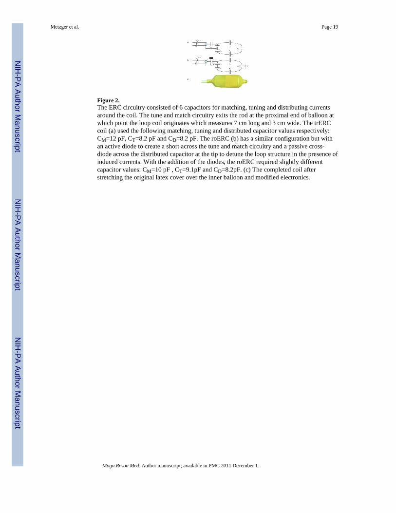
Figure 2.The ERC circuitry consisted of 6 capacitors for matching, tuning and distributing currentsaround the coil. The tune and match circuitry exits the rod at the proximal end of balloon atwhich point the loop coil originates which measures 7 cm long and 3 cm wide. The trERCcoil (a) used the following matching, tuning and distributed capacitor values respectively:CM=12 pF, CT=8.2 pF and CD=8.2 pF. The roERC (b) has a similar configuration but withan active diode to create a short across the tune and match circuitry and a passive cross-diode across the distributed capacitor at the tip to detune the loop structure in the presence ofinduced currents. With the addition of the diodes, the roERC required slightly differentcapacitor values: CM=10 pF , CT=9.1pF and CD=8.2pF. (c) The completed coil afterstretching the original latex cover over the inner balloon and modified electronics.
Metzger et al. Page 19
Magn Reson Med. Author manuscript; available in PMC 2011 December 1.
NIH
-PA Author Manuscript
NIH
-PA Author Manuscript
NIH
-PA Author Manuscript

Figure 3.B1
+ profiles for the trESA. The line within each plots inset picture shows the location atwhich the profile was obtained. Vertical profiles from simulation (a) and measurement (c)from the middle of the prostate starting from the rectal wall and extending 3 cm anteriorly.Horizontal profiles from simulation (b) and measurement (d) approximately parallel and 1cm away from the most anterior aspect of the rectum. All profiles are scaled to 1W inputpower per element corresponding to a total input power of 16 W for the trESA. Simulateddata (a) and (b) show both the original calculated B1
+ profiles (broken curve) and the B1+
scaled by coil efficiency Ceff (solid curve). Experimental profiles (c) and (d) are also scaledfor maximum achievable B1
+ (B1_max) with the currently available transmit chain.
Metzger et al. Page 20
Magn Reson Med. Author manuscript; available in PMC 2011 December 1.
NIH
-PA Author Manuscript
NIH
-PA Author Manuscript
NIH
-PA Author Manuscript
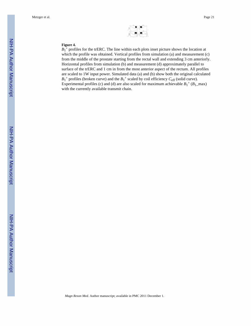
Figure 4.B1
+ profiles for the trERC. The line within each plots inset picture shows the location atwhich the profile was obtained. Vertical profiles from simulation (a) and measurement (c)from the middle of the prostate starting from the rectal wall and extending 3 cm anteriorly.Horizontal profiles from simulation (b) and measurement (d) approximately parallel tosurface of the trERC and 1 cm in from the most anterior aspect of the rectum. All profilesare scaled to 1W input power. Simulated data (a) and (b) show both the original calculatedB1
+ profiles (broken curve) and the B1+ scaled by coil efficiency Ceff (solid curve).
Experimental profiles (c) and (d) are also scaled for maximum achievable B1+ (B1_max)
with the currently available transmit chain.
Metzger et al. Page 21
Magn Reson Med. Author manuscript; available in PMC 2011 December 1.
NIH
-PA Author Manuscript
NIH
-PA Author Manuscript
NIH
-PA Author Manuscript
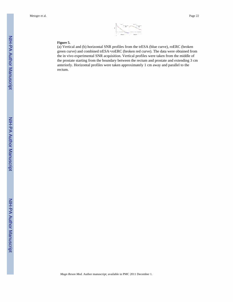
Figure 5.(a) Vertical and (b) horizontal SNR profiles from the trESA (blue curve), roERC (brokengreen curve) and combined trESA+roERC (broken red curve). The data were obtained fromthe in vivo experimental SNR acquisition. Vertical profiles were taken from the middle ofthe prostate starting from the boundary between the rectum and prostate and extending 3 cmanteriorly. Horizontal profiles were taken approximately 1 cm away and parallel to therectum.
Metzger et al. Page 22
Magn Reson Med. Author manuscript; available in PMC 2011 December 1.
NIH
-PA Author Manuscript
NIH
-PA Author Manuscript
NIH
-PA Author Manuscript
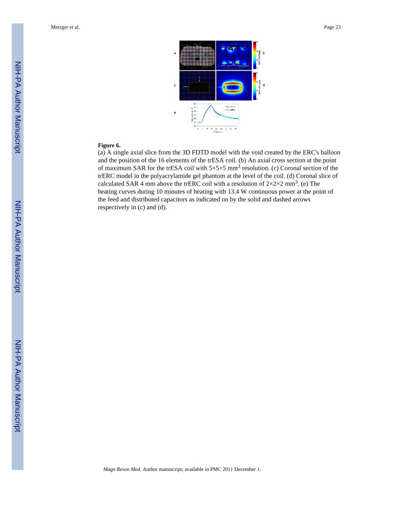
Figure 6.(a) A single axial slice from the 3D FDTD model with the void created by the ERC's balloonand the position of the 16 elements of the trESA coil. (b) An axial cross section at the pointof maximum SAR for the trESA coil with 5×5×5 mm3 resolution. (c) Coronal section of thetrERC model in the polyacrylamide gel phantom at the level of the coil. (d) Coronal slice ofcalculated SAR 4 mm above the trERC coil with a resolution of 2×2×2 mm3. (e) Theheating curves during 10 minutes of heating with 13.4 W continuous power at the point ofthe feed and distributed capacitors as indicated on by the solid and dashed arrowsrespectively in (c) and (d).
Metzger et al. Page 23
Magn Reson Med. Author manuscript; available in PMC 2011 December 1.
NIH
-PA Author Manuscript
NIH
-PA Author Manuscript
NIH
-PA Author Manuscript
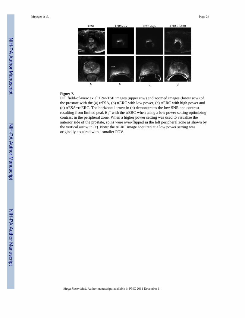
Figure 7.Full field-of-view axial T2w-TSE images (upper row) and zoomed images (lower row) ofthe prostate with the (a) trESA, (b) trERC with low power, (c) trERC with high power and(d) trESA+roERC. The horizontal arrow in (b) demonstrates the low SNR and contrastresulting from limited peak B1
+ with the trERC when using a low power setting optimizingcontrast in the peripheral zone. When a higher power setting was used to visualize theanterior side of the prostate, spins were over-flipped in the left peripheral zone as shown bythe vertical arrow in (c). Note: the trERC image acquired at a low power setting wasoriginally acquired with a smaller FOV.
Metzger et al. Page 24
Magn Reson Med. Author manuscript; available in PMC 2011 December 1.
NIH
-PA Author Manuscript
NIH
-PA Author Manuscript
NIH
-PA Author Manuscript

Figure 8.High resolution anatomic T2w-TSE images were acquired in the (a) axial, (b) coronal and(c) sagittal planes with the trESA+roERC.
Metzger et al. Page 25
Magn Reson Med. Author manuscript; available in PMC 2011 December 1.
NIH
-PA Author Manuscript
NIH
-PA Author Manuscript
NIH
-PA Author Manuscript

Figure 9.Patient size dependent performance for the trESA on transmit (top) and receive (bottom). Toevaluate transmit performance of the trESA, B1
+ (mean and standard deviation) from aregion around the prostate were measured for 5 subjects and plotted against their respectiveanterior-posterior width (APdistance) (top). Receive performance (bottom) was evaluated byplotting the distance normal to the ERC where the ratio in SNR was equal between theinternal and external coils (rSNR1distance) against APdistance. As expected, the performanceof the external array decreased with increasing patient size on both transmit and receive. TheB1
+ and rSNR1distance values for the reference volunteer are indicated by the circled datapoints on each plot.
Metzger et al. Page 26
Magn Reson Med. Author manuscript; available in PMC 2011 December 1.
NIH
-PA Author Manuscript
NIH
-PA Author Manuscript
NIH
-PA Author Manuscript
NIH
-PA Author Manuscript
NIH
-PA Author Manuscript
NIH
-PA Author Manuscript
Metzger et al. Page 27
Table 1
Network analyzer evaluation of the coupling (S21) and quality factors both loaded (QL) and unloaded (Q0),for the trESA, trERC and the roERC.a
trESA trERC roERC
Coupling w/ trESA S21 (dB) −26.4 ± 3.6 b −36.2 ± 5.3 c −48.0 ± 6.1 c
Loaded Q (QL) 39.1 ± 12.2 20.7 ± 4.5 d 17.7 ± 4.9 d
Unloaded Q (Q0) 80.0 ± 13.8 196.3 ± 15.2 d 176.0 ± 5.3 d
aResults are reported as a mean ± standard deviation when measurements between multiple elements or multiple coils were made. All
measurements acquired under loaded conditions were done so in vivo.
bS21 for the trESA were nearest neighbor measurements.
cS21 for the trERC and roERC were between the specific ERC coil and each of the trESA elements.
dLoaded and unloaded Q values of 3 coils of the given type (trERC or roERC) evaluated in vivo.
Magn Reson Med. Author manuscript; available in PMC 2011 December 1.
NIH
-PA Author Manuscript
NIH
-PA Author Manuscript
NIH
-PA Author Manuscript
Metzger et al. Page 28
Tabl
e 2
Sum
mar
y of
tran
smit
B 1 (B
1+ ) st
atis
tics o
ver t
he p
rost
ate,
pea
k on
e gr
am a
vera
ged
SAR
nor
mal
ized
to 1
W p
er c
hann
el (S
AR
peak
_nor
m) a
nd c
alcu
late
dtim
e av
erag
ed p
ower
lim
its (T
AP l
imit)
.
B1+
SAR
cT
AP
d
Mea
n ±
SDμT
/W05
Inho
mo.
b%
Min
.μT
/W05
Max
.μT
/W05
Peak
_Nor
mW
/kg
Lim
itW
trESA
In v
ivo
a0.
152
± 0.
016
100.
081
0.18
0--
2.54
Sim
ulat
ion
0.14
8 ±
0.02
315
0.08
40.
177
6.29
--
trER
CIn
viv
o a,
e1.
24 ±
0.4
2134
0.34
52.
04--
1.34
Sim
ulat
ion
1.48
± 0
.972
660.
305
7.35
6.64
--
a In v
ivo
resu
lts a
re fr
om th
e re
fere
nce
volu
ntee
r.
b Inho
mog
enet
ity is
det
erm
ined
as t
he ra
tio o
f the
stan
dard
dev
iatio
n to
mea
n.
c Peak
one
gra
m a
vera
ged
SAR
nor
mal
ized
to 1
W p
er c
hann
el. T
here
fore
, the
se v
alue
s are
a re
sult
of 1
6 W
tota
l for
the
trESA
and
1W
tota
l for
the
trER
C.
d Tim
e av
erag
ed p
ower
lim
its in
Wat
ts p
er c
hann
el.
e Whi
le th
e in
viv
o an
d si
mul
ated
resu
lts a
re re
lativ
ely
cons
iste
nt a
s sho
wn
by th
e pr
ofile
s in
Fig.
3 a
nd 4
, the
DA
M m
easu
rem
ents
do
not f
aith
fully
mea
sure
the
high
B1+
clo
se to
the
trER
C c
oil.
Ther
efor
eth
e si
mul
ated
stan
dard
dev
iatio
ns a
nd m
axim
um B
1+ v
alue
s are
mor
e re
pres
enta
tive
of e
xpec
ted
in v
ivo
valu
es.
Magn Reson Med. Author manuscript; available in PMC 2011 December 1.

NIH
-PA Author Manuscript
NIH
-PA Author Manuscript
NIH
-PA Author Manuscript
Metzger et al. Page 29
Tabl
e 3
Geo
met
ry fa
ctor
(g-f
acto
r) ta
ble.
Com
paris
on o
f mea
n g-
fact
ors f
rom
sim
ulat
ion
and
in v
ivo
mea
sure
men
t in
the
regi
on o
f the
pro
stat
e an
d fr
om in
viv
om
easu
rem
ent f
or th
e ar
tery
for t
he tr
ESA
and
trES
A+r
oER
C.
Ant
erio
r-Po
ster
ior
Pros
tate
Art
ery
ER
Cno
ER
CE
RC
noE
RC
RF
12
31
23
12
31
23
In V
ivio
Rig
ht-L
eft
11.
001.
021.
231.
001.
081.
301.
001.
011.
041.
001.
011.
05
21.
001.
031.
241.
011.
091.
321.
001.
011.
051.
001.
011.
07
31.
021.
061.
441.
061.
161.
521.
031.
041.
081.
021.
041.
10
41.
091.
171.
651.
101.
221.
751.
051.
081.
241.
061.
081.
28
Sim
ulat
ion
Rig
ht-L
eft
11.
001.
011.
131.
001.
011.
24
21.
011.
021.
161.
011.
031.
28
31.
061.
081.
321.
061.
091.
42
41.
161.
201.
631.
141.
201.
77
Magn Reson Med. Author manuscript; available in PMC 2011 December 1.
Copyright © 2022 FDOKUMEN