COIL-ON-PLUG …………….DIAGNOSIS - AESwave.com
17
COIL-ON-PLUG ……………. DIAGNOSIS by: Mac VandenBrink A study of primary scope pattern analysis DYNAMIC AUTO TEST CORP. - 1017 W Kilgore Rd.- Portage MI 49024 PH. 616-342-1334 Fax 616-381-4178 E-mail: [email protected]
-
Upload
khangminh22 -
Category
Documents
-
view
4 -
download
0
Transcript of COIL-ON-PLUG …………….DIAGNOSIS - AESwave.com
COIL-ON-PLUG…………….DIAGNOSIS
by:
Mac VandenBrink
A study of primary scopepattern analysis
DYNAMIC AUTO TEST CORP.- 1017 W Kilgore Rd.- Portage MI 49024PH. 616-342-1334 Fax 616-381-4178 E-mail: [email protected]
INTRODUCTIONCOIL ON PLUG is a concept where each spark plug is ignited by itsown individual ignition system, consisting of a driver or ECM andignition coil.
The objective is to reduce energy losses by bringing the coil output asclose as possible to the spark plug.
Other reasons may include to control spark timing on a per cylinderbasis, or to use coil current as feedback to the computer.
The design may vary from:
• “COIL NEAR PLUG” with a very short plug wire.• “COIL ON PLUG” with control module located away from engine
heat.• “COIL AND MODULE” in one assembly.• “DI VERSION” with one coil tower directly connected to the spark
plug, while the other tower uses a short plug wire.
As can be noticed from the chart of applications, the concept is notnew.However, when more manufacturers choose this method of ignition, itis essential to look objectively at a different approach of testing.
Using the primary pattern as a feedback from the secondary circuit isa new challenge, applying old techniques to a new concept.
Have fun with exploring the wonderful world of electronics to pinpointelectrical, mechanical and fuel related problems.
Mac Vanden Brink
2
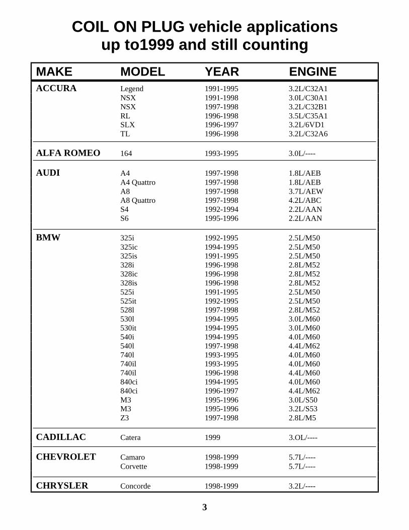
COIL ON PLUG vehicle applicationsup to1999 and still counting
MAKE MODEL YEAR ENGINEACCURA Legend 1991-1995 3.2L/C32A1
NSX 1991-1998 3.0L/C30A1NSX 1997-1998 3.2L/C32B1RL 1996-1998 3.5L/C35A1SLX 1996-1997 3.2L/6VD1TL 1996-1998 3.2L/C32A6
ALFA ROMEO 164 1993-1995 3.0L/----
AUDI A4 1997-1998 1.8L/AEBA4 Quattro 1997-1998 1.8L/AEBA8 1997-1998 3.7L/AEWA8 Quattro 1997-1998 4.2L/ABCS4 1992-1994 2.2L/AANS6 1995-1996 2.2L/AAN
BMW 325i 1992-1995 2.5L/M50325ic 1994-1995 2.5L/M50325is 1991-1995 2.5L/M50328i 1996-1998 2.8L/M52328ic 1996-1998 2.8L/M52328is 1996-1998 2.8L/M52525i 1991-1995 2.5L/M50525it 1992-1995 2.5L/M50528l 1997-1998 2.8L/M52530l 1994-1995 3.0L/M60530it 1994-1995 3.0L/M60540i 1994-1995 4.0L/M60540l 1997-1998 4.4L/M62740l 1993-1995 4.0L/M60740il 1993-1995 4.0L/M60740il 1996-1998 4.4L/M60840ci 1994-1995 4.0L/M60840ci 1996-1997 4.4L/M62M3 1995-1996 3.0L/S50M3 1995-1996 3.2L/S53Z3 1997-1998 2.8L/M5
CADILLAC Catera 1999 3.OL/----
CHEVROLET Camaro 1998-1999 5.7L/----Corvette 1998-1999 5.7L/----
CHRYSLER Concorde 1998-1999 3.2L/----
3
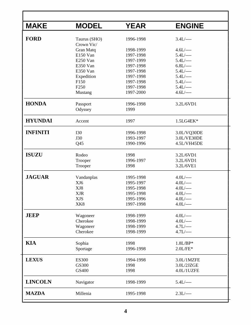
MAKE MODEL YEAR ENGINEFORD Taurus (SHO) 1996-1998 3.4L/----
Crown Vic/Gran Matq 1998-1999 4.6L/----E150 Van 1997-1998 5.4L/----E250 Van 1997-1999 5.4L/----E350 Van 1997-1998 6.8L/----E350 Van 1997-1998 5.4L/----Expedition 1997-1998 5.4L/----F150 1997-1998 5.4L/----F250 1997-1998 5.4L/----Mustang 1997-2000 4.6L/----
HONDA Passport 1996-1998 3.2L/6VD1Odyssey 1999
HYUNDAI Accent 1997 1.5LG4EK*
INFINITI I30 1996-1998 3.0L/VQ30DEJ30 1993-1997 3.0L/VE30DEQ45 1990-1996 4.5L/VH45DE
ISUZU Rodeo 1998 3.2L/6VD1Trooper 1996-1997 3.2L/6VD1Trooper 1998 3.2L/6VE1
JAGUAR Vandanplas 1995-1998 4.0L/----XJ6 1995-1997 4.0L/----XJ8 1995-1998 4.0L/----XJR 1995-1998 4.0L/----XJS 1995-1996 4.0L/----XK8 1997-1998 4.0L/----
JEEP Wagoneer 1998-1999 4.0L/----Cherokee 1998-1999 4.0L/----Wagoneer 1998-1999 4.7L/----Cherokee 1998-1999 4.7L/----
KIA Sophia 1998 1.8L/BP*Sportage 1996-1998 2.0L/FE*
LEXUS ES300 1994-1998 3.0L/1MZFEGS300 1998 3.0L/2JZGEGS400 1998 4.0L/1UZFE
LINCOLN Navigator 1998-1999 5.4L/----
MAZDA Millenia 1995-1998 2.3L/----
4
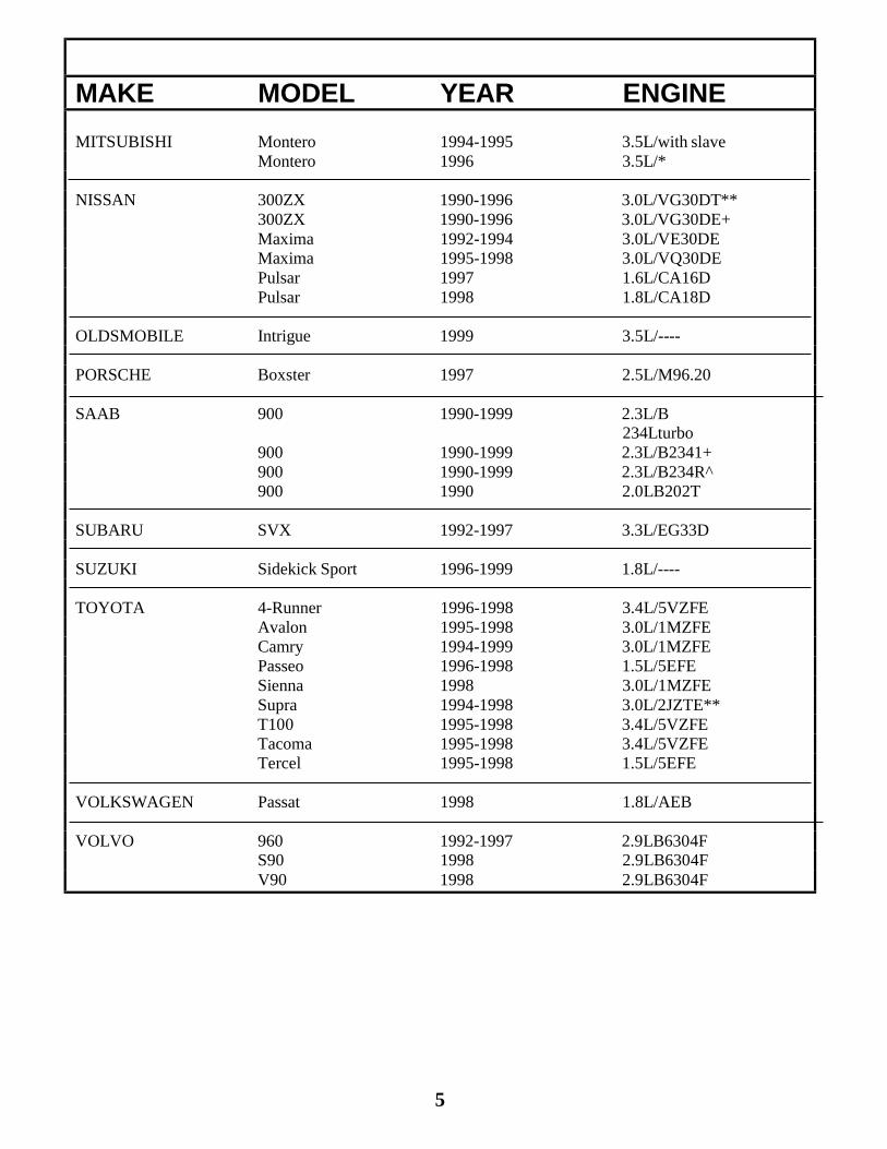
MAKE MODEL YEAR ENGINEMITSUBISHI Montero 1994-1995 3.5L/with slave
Montero 1996 3.5L/*
NISSAN 300ZX 1990-1996 3.0L/VG30DT**300ZX 1990-1996 3.0L/VG30DE+Maxima 1992-1994 3.0L/VE30DEMaxima 1995-1998 3.0L/VQ30DEPulsar 1997 1.6L/CA16DPulsar 1998 1.8L/CA18D
OLDSMOBILE Intrigue 1999 3.5L/----
PORSCHE Boxster 1997 2.5L/M96.20
SAAB 900 1990-1999 2.3L/B234Lturbo
900 1990-1999 2.3L/B2341+900 1990-1999 2.3L/B234R^900 1990 2.0LB202T
SUBARU SVX 1992-1997 3.3L/EG33D
SUZUKI Sidekick Sport 1996-1999 1.8L/----
TOYOTA 4-Runner 1996-1998 3.4L/5VZFEAvalon 1995-1998 3.0L/1MZFECamry 1994-1999 3.0L/1MZFEPasseo 1996-1998 1.5L/5EFESienna 1998 3.0L/1MZFESupra 1994-1998 3.0L/2JZTE**T100 1995-1998 3.4L/5VZFETacoma 1995-1998 3.4L/5VZFETercel 1995-1998 1.5L/5EFE
VOLKSWAGEN Passat 1998 1.8L/AEB
VOLVO 960 1992-1997 2.9LB6304FS90 1998 2.9LB6304FV90 1998 2.9LB6304F
5
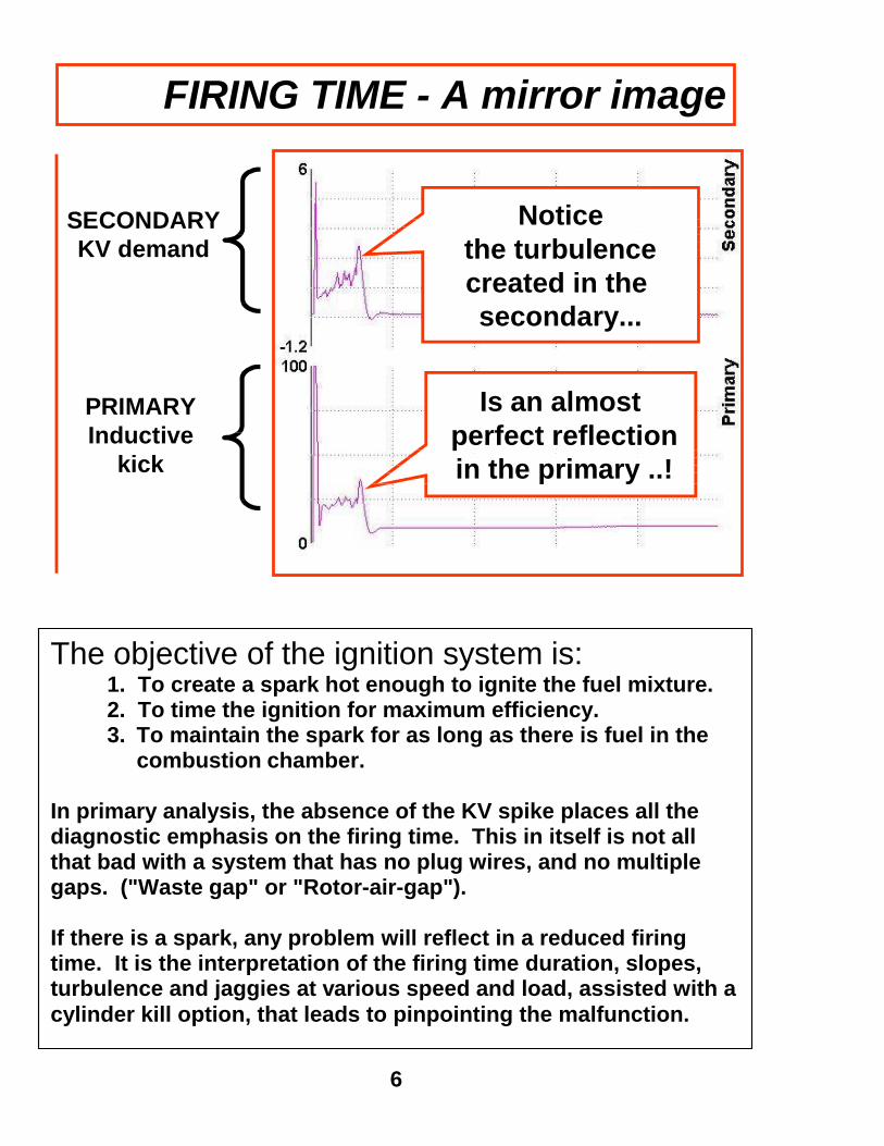
FIRING TIME - A mirror image
SECONDARYKV demand
PRIMARYInductive
kick
Noticethe turbulencecreated in thesecondary...
Is an almostperfect reflectionin the primary ..!
The objective of the ignition system is:1. To create a spark hot enough to ignite the fuel mixture.2. To time the ignition for maximum efficiency.3. To maintain the spark for as long as there is fuel in the
combustion chamber.
In primary analysis, the absence of the KV spike places all thediagnostic emphasis on the firing time. This in itself is not allthat bad with a system that has no plug wires, and no multiplegaps. ("Waste gap" or "Rotor-air-gap").
If there is a spark, any problem will reflect in a reduced firingtime. It is the interpretation of the firing time duration, slopes,turbulence and jaggies at various speed and load, assisted with acylinder kill option, that leads to pinpointing the malfunction.
6
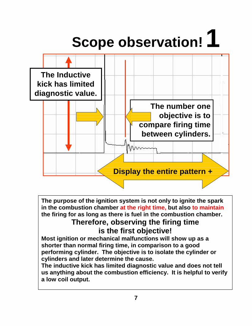
Scope observation!
The number oneobjective is to
compare firing timebetween cylinders.
1
Display the entire pattern +
The Inductivekick has limited
diagnostic value.
The purpose of the ignition system is not only to ignite the sparkin the combustion chamber at the right time, but also to maintainthe firing for as long as there is fuel in the combustion chamber.
Therefore, observing the firing timeis the first objective!
Most ignition or mechanical malfunctions will show up as ashorter than normal firing time, in comparison to a goodperforming cylinder. The objective is to isolate the cylinder orcylinders and later determine the cause.The inductive kick has limited diagnostic value and does not tellus anything about the combustion efficiency. It is helpful to verifya low coil output.
7

Scope observation! 2
Conclusion: NO NOSE!No residual energy -- No spark
When the plugstops firing,there should
be still residualenergy left,
which isdissipated inoscillations.
Look for the nose,at the end of the
firing time
Take a quick look at the upward nose of the first oscillation,which indicates the end of plug firing.When there is not enough energy left to maintain firing, this"residual energy" dissipates into oscillations.An absence of this nose indicates that the energy is drained offto ground without firing.
CONCLUSION: FOULED PLUG or SHORTED PLUG.In rare cases it may be a shorted coil to ground,
(but only if it is a dead short and no arc-over).NOTE:The old school of thought, counting the number of oscillationshas been a source to evaluate the coil integrity. However, withno rotor-air-gap and a lower primary resistance, it is no longerreliable for diagnosis.
8

Scope observation! 3A. Look for:Dwell variation comparisonbetween cylinders
B. Look for:Current limiting variationsif applicable
C. Look for:Good control moduleground connection.
Dwell area
The dwell section is a significant evaluation of module comparison.Since each cylinder has its own coil and driver, make a mental note ofany variation that does not occur on the other coils.DWELL TIME changes with RPM.If the complaint is "rough running at idle", look for the coil with ashorter dwell, to identify the cylinder. Verify with a cylinder kill.
TRANSISTORS do increase in resistance when getting hot. Ideally,the initial ground is almost perfect with a slight increase in voltagedrop when the dwell increases.Excessive heat can be caused by poor heat dissipation (heatsink) orshorted coil windings.The best spec is comparison with the other coils.
9

LEAN MISFIRE:Since hydrocarbon is a conductor, lack of HC will
reduce conductivity and raises resistance. Thiscondition will not likely occur at a steady RPM,
when the computer compensates for the leaninjector. It will show in a snap-test,
when the computer is not in control.
GOOD SPARK:This is a normal scope pattern. The jaggies and
turbulence indicate that the spark indeed firesinside the combustion chamber, where it issubject to fuel and compression variations.
Verify jaggies with quick acceleration.
CROSS-FIRING:A consistent nice clean firing time indicates that
the spark occurs outside of the combustionchamber, not affected by pressures and fuel
variables.
FOULED PLUG.The voltage does not even start to rise and the
energy is drained off, leaving no residual energyto dissipate into oscillations. If this condition
predominantly appears on deceleration or at idle,but shows oscillations again at high RPM,
suspect a leaky injector.
SCOPE PATTERN OBSERVATIONS
10
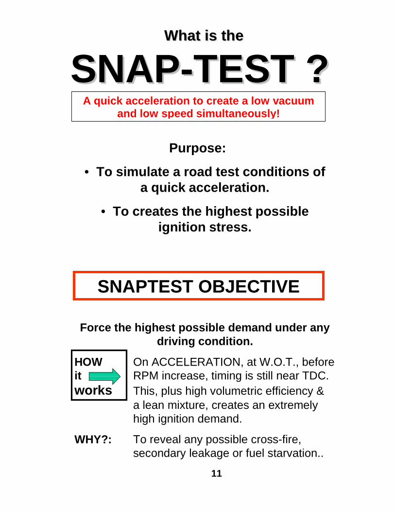
What is theWhat is the
SNAP-TEST ?SNAP-TEST ?Purpose:
• To simulate a road test conditions ofa quick acceleration.
• To creates the highest possibleignition stress.
SNAPTEST OBJECTIVE
Force the highest possible demand under anydriving condition.
HOW On ACCELERATION, at W.O.T., beforeit RPM increase, timing is still near TDC.works This, plus high volumetric efficiency &
a lean mixture, creates an extremelyhigh ignition demand.
WHY?: To reveal any possible cross-fire,secondary leakage or fuel starvation..
11
A quick acceleration to create a low vacuumand low speed simultaneously!
PRIMARY ANALYSIS before SNAP-TEST
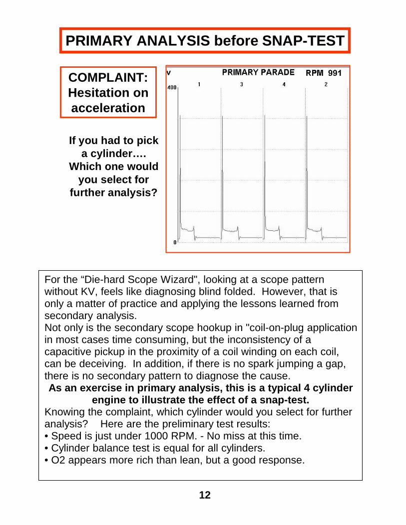
COMPLAINT:Hesitation onacceleration
If you had to picka cylinder….
Which one wouldyou select for
further analysis?
For the “Die-hard Scope Wizard", looking at a scope patternwithout KV, feels like diagnosing blind folded. However, that isonly a matter of practice and applying the lessons learned fromsecondary analysis.Not only is the secondary scope hookup in "coil-on-plug applicationin most cases time consuming, but the inconsistency of acapacitive pickup in the proximity of a coil winding on each coil,can be deceiving. In addition, if there is no spark jumping a gap,there is no secondary pattern to diagnose the cause.As an exercise in primary analysis, this is a typical 4 cylinder
engine to illustrate the effect of a snap-test.Knowing the complaint, which cylinder would you select for furtheranalysis? Here are the preliminary test results:• Speed is just under 1000 RPM. - No miss at this time.• Cylinder balance test is equal for all cylinders.• O2 appears more rich than lean, but a good response.
12
TEST RESULTS of SNAP-TEST
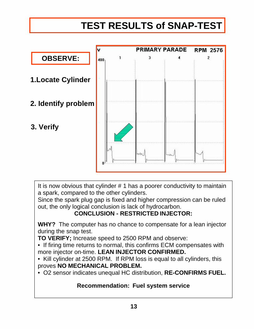
OBSERVE:
1.Locate Cylinder
2. Identify problem
3. Verify
It is now obvious that cylinder # 1 has a poorer conductivity to maintaina spark, compared to the other cylinders.Since the spark plug gap is fixed and higher compression can be ruledout, the only logical conclusion is lack of hydrocarbon.
CONCLUSION - RESTRICTED INJECTOR:
WHY? The computer has no chance to compensate for a lean injectorduring the snap test.TO VERIFY; Increase speed to 2500 RPM and observe:• If firing time returns to normal, this confirms ECM compensates withmore injector on-time. LEAN INJECTOR CONFIRMED.• Kill cylinder at 2500 RPM. If RPM loss is equal to all cylinders, thisproves NO MECHANICAL PROBLEM.• O2 sensor indicates unequal HC distribution, RE-CONFIRMS FUEL.
Recommendation: Fuel system service
13

The Logic of COP-IIITo make the Scope work for you on "Coil per Plug" ignition.
Justify:Scope hookup.Verify:1. Power input.2. Presence of a
trigger pulse.Identify:Which is triggerconnection.
Isolate: Is problemrelated to a cylinder?Identify: Whichcylinder or cylinders?The only safe way tokill a spark is byinhibiting coil outputwithout shorting thecurrent limiting....module.
Verify:1. Coil inductive kick--
to indicate that thecoil is energized.
2. The spark is killedwhen the button ispushed.
Observe: Intensity islower with a weak coil.
Above description applies to the model COP-II and the COP-III, servingas a preliminary check and a quick way to justify a scope hookup.
Additional uses for CYLINDER KILL applications:1. Use in conjunction with exhaust gas analyzer, to determine hydro-carbon
per cylinder.2. Observe O2 sensor response - upper limit and lower limit range.3. Observe idle compensation response using a tachometer.4. Verify valve malfunction with power balance at various speeds.5. Observe fuel trim compensation on the scan tool.
If no primary connection is accessible:Connect to the pulse signal. The kill button safely prevents any trigger signalto activate the module.
If engine dies when killing a cylinder:Some vehicles feature a fuel shut-off when the ignition stops firing. Thisusually occurs only when button is held in the kill position.Solution: Kill momentarily, just long enough to indicate function.
Preliminary Logic without Scope Applying Logic to the Scope
14
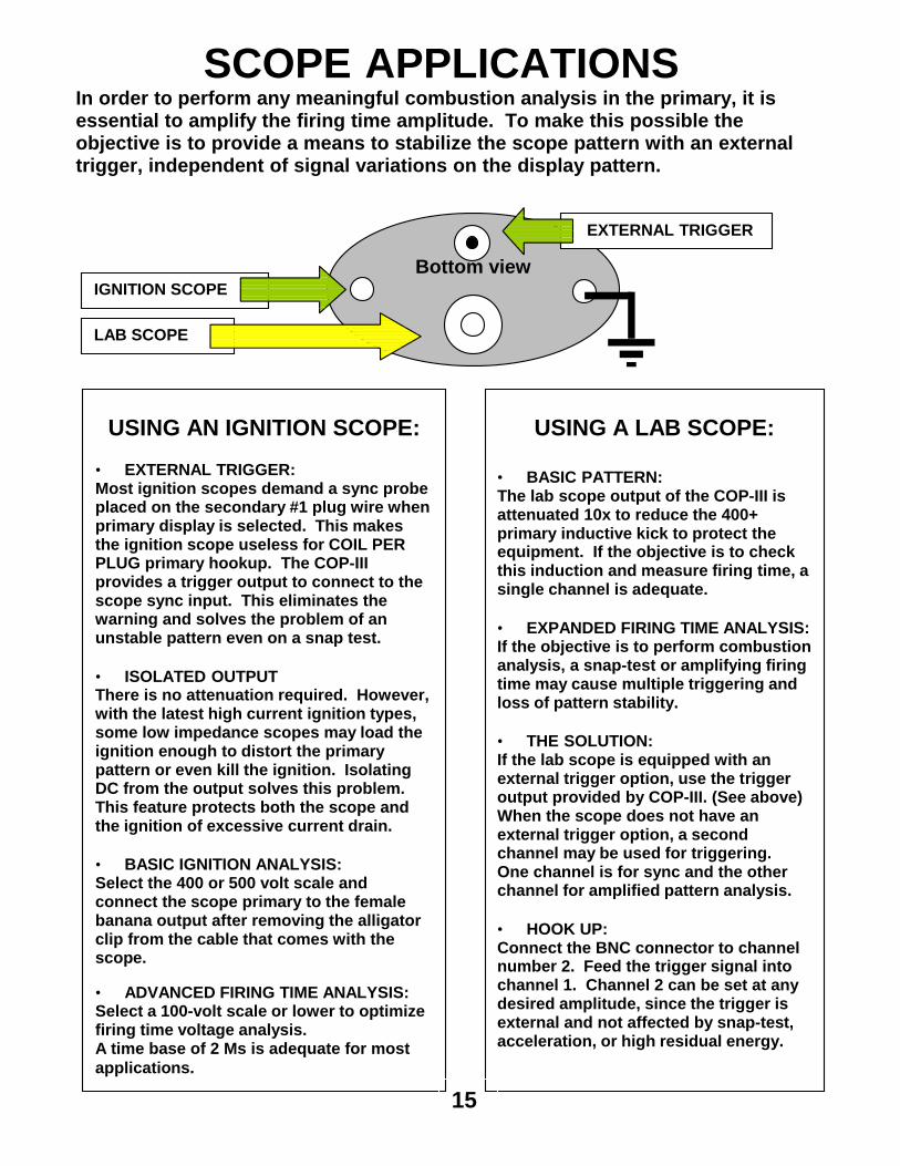
SCOPE APPLICATIONSIn order to perform any meaningful combustion analysis in the primary, it isessential to amplify the firing time amplitude. To make this possible theobjective is to provide a means to stabilize the scope pattern with an externaltrigger, independent of signal variations on the display pattern.
Bottom view
USING AN IGNITION SCOPE:• EXTERNAL TRIGGER:Most ignition scopes demand a sync probeplaced on the secondary #1 plug wire whenprimary display is selected. This makesthe ignition scope useless for COIL PERPLUG primary hookup. The COP-IIIprovides a trigger output to connect to thescope sync input. This eliminates thewarning and solves the problem of anunstable pattern even on a snap test.
• ISOLATED OUTPUTThere is no attenuation required. However,with the latest high current ignition types,some low impedance scopes may load theignition enough to distort the primarypattern or even kill the ignition. IsolatingDC from the output solves this problem.This feature protects both the scope andthe ignition of excessive current drain.
• BASIC IGNITION ANALYSIS:Select the 400 or 500 volt scale andconnect the scope primary to the femalebanana output after removing the alligatorclip from the cable that comes with thescope.
• ADVANCED FIRING TIME ANALYSIS:Select a 100-volt scale or lower to optimizefiring time voltage analysis.A time base of 2 Ms is adequate for mostapplications.
USING A LAB SCOPE:
• BASIC PATTERN:The lab scope output of the COP-III isattenuated 10x to reduce the 400+primary inductive kick to protect theequipment. If the objective is to checkthis induction and measure firing time, asingle channel is adequate.
• EXPANDED FIRING TIME ANALYSIS:If the objective is to perform combustionanalysis, a snap-test or amplifying firingtime may cause multiple triggering andloss of pattern stability.
• THE SOLUTION:If the lab scope is equipped with anexternal trigger option, use the triggeroutput provided by COP-III. (See above)When the scope does not have anexternal trigger option, a secondchannel may be used for triggering.One channel is for sync and the otherchannel for amplified pattern analysis.
• HOOK UP:Connect the BNC connector to channelnumber 2. Feed the trigger signal intochannel 1. Channel 2 can be set at anydesired amplitude, since the trigger isexternal and not affected by snap-test,acceleration, or high residual energy.
EXTERNAL TRIGGER
IGNITION SCOPE
LAB SCOPE
15
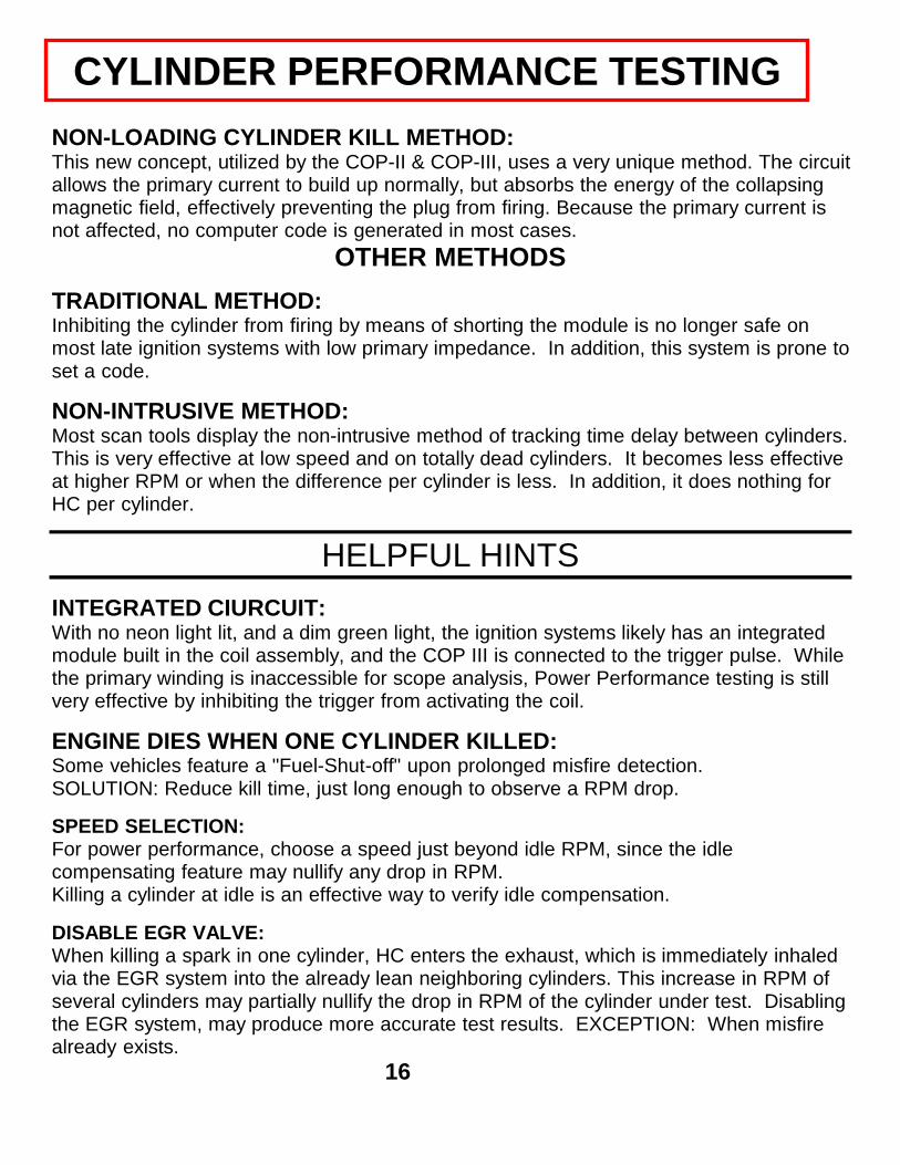
NON-LOADING CYLINDER KILL METHOD:This new concept, utilized by the COP-II & COP-III, uses a very unique method. The circuitallows the primary current to build up normally, but absorbs the energy of the collapsingmagnetic field, effectively preventing the plug from firing. Because the primary current isnot affected, no computer code is generated in most cases.
OTHER METHODSTRADITIONAL METHOD:Inhibiting the cylinder from firing by means of shorting the module is no longer safe onmost late ignition systems with low primary impedance. In addition, this system is prone toset a code.
NON-INTRUSIVE METHOD:Most scan tools display the non-intrusive method of tracking time delay between cylinders.This is very effective at low speed and on totally dead cylinders. It becomes less effectiveat higher RPM or when the difference per cylinder is less. In addition, it does nothing forHC per cylinder.
HELPFUL HINTSINTEGRATED CIURCUIT:With no neon light lit, and a dim green light, the ignition systems likely has an integratedmodule built in the coil assembly, and the COP III is connected to the trigger pulse. Whilethe primary winding is inaccessible for scope analysis, Power Performance testing is stillvery effective by inhibiting the trigger from activating the coil.
ENGINE DIES WHEN ONE CYLINDER KILLED:Some vehicles feature a "Fuel-Shut-off" upon prolonged misfire detection.SOLUTION: Reduce kill time, just long enough to observe a RPM drop.
SPEED SELECTION:For power performance, choose a speed just beyond idle RPM, since the idlecompensating feature may nullify any drop in RPM.Killing a cylinder at idle is an effective way to verify idle compensation.
DISABLE EGR VALVE:When killing a spark in one cylinder, HC enters the exhaust, which is immediately inhaledvia the EGR system into the already lean neighboring cylinders. This increase in RPM ofseveral cylinders may partially nullify the drop in RPM of the cylinder under test. Disablingthe EGR system, may produce more accurate test results. EXCEPTION: When misfirealready exists.
CYLINDER PERFORMANCE TESTING
16

Preliminary diagnosis without a scope
Cylinder killDepressing this button
prevents the magnetic field toinduce a high voltage in the
secondary winding.
DC powerThis LED indicates the
presence of a DC voltage,which is helpful in tracing
cause of dead cylinder.
Inductive kickNeon light indicates that
coil is functional and scopehookup is feasible.
Neither indicator lights up on any terminaland the pushbutton does not kill cylinder.
Bright green light on one terminal only.No neon light. (For dim light, see below.)
Proceed with scope hookupfor further analysis.
Green light on and red neon blinks OK.Power test fails.
No power. Check hookup.If OK, trace power to circuit.
Power OK. Coil OK.Module not triggering.
Power OK. Open coil.
Green light on two terminals - no redneon.
TEST OK. Proceed withsnap-test if required.
RUNNING TESTIntegrated coil & module.Primary inaccessible.
Very dim green light and no neon light.Power balance OK. (Kills 5 volt trigger.)
Bright green light & red neon light.Power balance test OK.
DEAD CYLINDER TEST