common testing application with xml conversion plug-in for lte ...
Upload
khangminh22Category
view
0download
0
Plug-in Reference

Cristina Bachmann, Heiko Bischoff, Christina Kaboth, Insa Mingers, Matthias Obrecht, Sabine Pfeifer, BenjaminSchütte, Marita Sladek
This PDF provides improved access for vision-impaired users. Please note that due to the complexity and numberof images in this document, it is not possible to include text descriptions of images.
The information in this document is subject to change without notice and does not represent a commitment onthe part of Steinberg Media Technologies GmbH. The software described by this document is subject to a LicenseAgreement and may not be copied to other media except as specifically allowed in the License Agreement. Nopart of this publication may be copied, reproduced, or otherwise transmitted or recorded, for any purpose,without prior written permission by Steinberg Media Technologies GmbH. Registered licensees of the productdescribed herein may print one copy of this document for their personal use.
All product and company names are ™ or ® trademarks of their respective owners. For more information, pleasevisit www.steinberg.net/trademarks.© Steinberg Media Technologies GmbH, 2017.
All rights reserved.
Cubase_9.5.0_en-US_2017-11-29
Table of Contents
4 Included Effect Plug-ins4 Delay Plug-ins9 Distortion Plug-ins32 Dynamics Plug-ins57 EQ Plug-ins65 Filter Plug-ins73 Mastering Plug-ins73 Modulation Plug-ins89 Network Plug-ins89 Other Plug-ins94 Pitch Shift Plug-ins97 Reverb Plug-ins113 Spatial + Panner Plug-ins125 Surround Plug-ins136 Tools Plug-ins
144 MIDI Effects144 Arpache 5146 Arpache SX148 Auto LFO149 Beat Designer156 Chorder160 Compressor160 Context Gate162 Density162 MIDI Control163 MIDI Echo165 MIDI Modifiers165 MIDI Monitor166 Micro Tuner167 Note to CC167 Quantizer168 StepDesigner172 Track Control175 Transformer
176 Included VST Instruments176 Groove Agent SE176 HALion Sonic SE176 LoopMash189 Mystic201 Padshop201 Prologue217 Retrologue217 Spector229 Functional Diagrams
231 Index
3

Included Effect Plug-ins
The included plug-in effects are arranged according to their categories.
NOTE
Most of the included effects are compatible with VST 3. For more information, see the OperationManual.
Delay Plug-ins
ModMachineModMachine combines delay modulation and filter frequency/resonance modulation and canprovide many interesting modulation effects. It also features a Drive parameter for distortioneffects.
Cubase LE Cubase AI CubaseElements
CubaseArtist
CubasePro
Nuendo
Included with – – – – X X
4

Included Effect Plug-insDelay Plug-ins
DelayIf tempo sync is activated, this sets the base note value for the delay. If tempo sync isdeactivated, the delay time can be set freely in milliseconds.
Delay – SyncActivates/Deactivates tempo sync for the Delay parameter.
RateIf tempo sync is activated, this is where you specify the base note value for tempo-syncing the effect (1/1 to 1/32, straight, triplet, or dotted).If tempo sync is deactivated, the modulation speed can be set freely with the Rateknob.
Rate – SyncActivates/Deactivates tempo sync for the Rate parameter.
WidthSets the amount of delay modulation. This allows you to create a vibrato or chorus-like effect.
FeedbackSets the number of repeats for the delay.
DriveAdds distortion to the feedback loop. The longer the feedback, the more the delayrepeats are distorted over time.
MixSets the level balance between the dry signal and the wet signal. If the effect is usedas a send effect, set this parameter to the maximum value as you can control thedry/effect balance with the send.
NudgeClicking this button once momentarily speeds up the audio coming into the plug-in,simulating the nudge command of analog tape machines.
Signal path graphic and Filter positionThe filter can either be placed in the feedback loop of the delay or in the output pathof the effect (after the Drive and Feedback parameters). To switch between the loopand output positions, click in the Filter section displayed in the graphic or click onthe Position field at the bottom right of the graphic.
Filter type (in graphic display)Allows you to select a filter type. You can choose between a low-pass, band-pass,and high-pass filter.
Filter Frequency LFO Modulation
FreqSets the cutoff frequency for the filter. It is only available if tempo sync for the Speedparameter is deactivated and the parameter is set to 0.
SpeedSets the speed of the filter frequency LFO modulation. If tempo sync is activated, thisparameter sets the base note value for synchronizing the modulation to the tempoof the host application.If tempo sync is deactivated, the speed can be set freely with the Speed knob.
5
Included Effect Plug-insDelay Plug-ins
Speed – SyncActivates/Deactivates tempo sync for the Speed parameter.
Range Lo/HiSet the range of the filter frequency modulation. Both positive (for example, Lo set to50 and Hi set to 10000) and negative (for example, Lo set to 5000 and Hi set to 500)ranges can be set. If tempo sync is off and Speed is set to zero, these parameters areinactive and the filter frequency is controlled by the Freq parameter instead.
SpatialIntroduces an offset between the channels to create a stereo panorama effect for thefilter frequency modulation. Turn clockwise for a more pronounced stereo effect.
Filter Resonance LFO Modulation
Q-FactorSets the resonance of the filter. It is only available if filter resonance LFO tempo syncis deactivated and the Speed parameter is set to 0. If tempo sync is activated, theresonance is controlled by the Speed and Range parameters.
SpeedSets the speed of the filter resonance LFO modulation. If tempo sync is activated, thisparameter sets the base note value for tempo syncing the modulation.If tempo sync is deactivated, the speed can be set freely with the Speed knob.
Speed – SyncActivates/Deactivates tempo sync for the Speed parameter.
Range Lo/HiSet the range of the filter resonance modulation. Both positive (for example, Loset to 50 and Hi set to 100) and negative (for example, Lo set to 100 and Hi set to50) ranges can be set. If tempo sync is deactivated and Speed is set to zero, theseparameters are inactive and the filter resonance is controlled by the Q-Factorparameter instead.
SpatialIntroduces an offset between the channels to create a stereo panorama effect for thefilter resonance modulation. Turn clockwise for a more pronounced stereo effect.
MonoDelayThis is a mono delay effect that can either be tempo-based or use freely specified delay timesettings.
Cubase LE Cubase AI CubaseElements
CubaseArtist
CubasePro
Nuendo
Included with X X X X X X
Side-chainsupport
– – – X X X
6

Included Effect Plug-insDelay Plug-ins
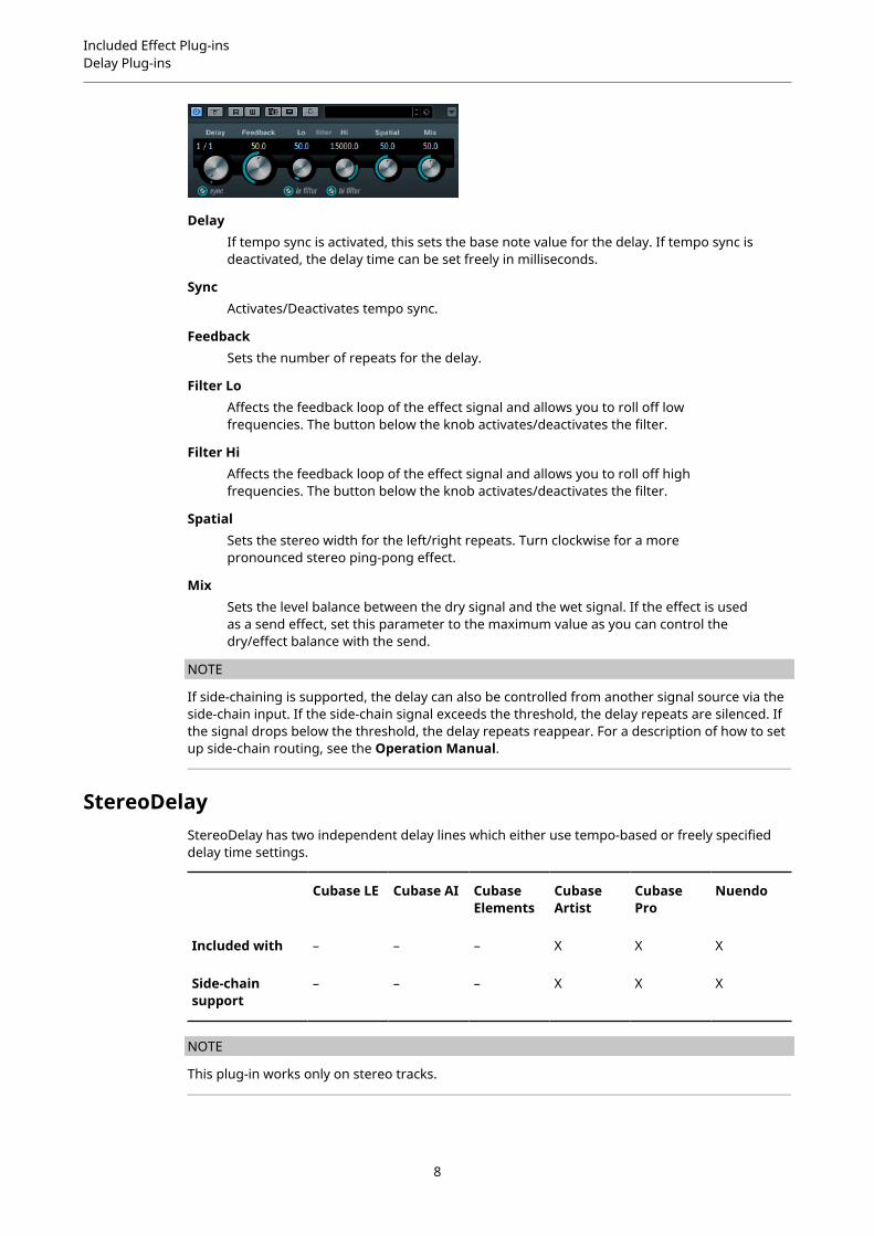
DelayIf tempo sync is activated, this sets the base note value for the delay. If tempo sync isdeactivated, the delay time can be set freely in milliseconds.
SyncActivates/Deactivates tempo sync.
FeedbackSets the number of repeats for the delay.
Filter LoAffects the feedback loop of the effect signal and allows you to roll off lowfrequencies. The button below the knob activates/deactivates the filter.
Filter HiAffects the feedback loop of the effect signal and allows you to roll off highfrequencies. The button below the knob activates/deactivates the filter.
MixSets the level balance between the dry signal and the wet signal. If the effect is usedas a send effect, set this parameter to the maximum value as you can control thedry/effect balance with the send.
NOTE
If side-chaining is supported, the delay can also be controlled from another signal source via theside-chain input. If the side-chain signal exceeds the threshold, the delay repeats are silenced. Ifthe signal drops below the threshold, the delay repeats reappear. For a description of how to setup side-chain routing, see the Operation Manual.
PingPongDelayThis is a stereo delay effect that alternates each delay repeat between the left and right channels.The effect can either be tempo-based or use freely specified delay time settings.
Cubase LE Cubase AI CubaseElements
CubaseArtist
CubasePro
Nuendo
Included with – – X X X X
Side-chainsupport
– – – X X X
NOTE
This plug-in works only on stereo tracks.
7
Included Effect Plug-insDelay Plug-ins
DelayIf tempo sync is activated, this sets the base note value for the delay. If tempo sync isdeactivated, the delay time can be set freely in milliseconds.
SyncActivates/Deactivates tempo sync.
FeedbackSets the number of repeats for the delay.
Filter LoAffects the feedback loop of the effect signal and allows you to roll off lowfrequencies. The button below the knob activates/deactivates the filter.
Filter HiAffects the feedback loop of the effect signal and allows you to roll off highfrequencies. The button below the knob activates/deactivates the filter.
SpatialSets the stereo width for the left/right repeats. Turn clockwise for a morepronounced stereo ping-pong effect.
MixSets the level balance between the dry signal and the wet signal. If the effect is usedas a send effect, set this parameter to the maximum value as you can control thedry/effect balance with the send.
NOTE
If side-chaining is supported, the delay can also be controlled from another signal source via theside-chain input. If the side-chain signal exceeds the threshold, the delay repeats are silenced. Ifthe signal drops below the threshold, the delay repeats reappear. For a description of how to setup side-chain routing, see the Operation Manual.
StereoDelayStereoDelay has two independent delay lines which either use tempo-based or freely specifieddelay time settings.
Cubase LE Cubase AI CubaseElements
CubaseArtist
CubasePro
Nuendo
Included with – – – X X X
Side-chainsupport
– – – X X X
NOTE
This plug-in works only on stereo tracks.
8
Included Effect Plug-insDistortion Plug-ins
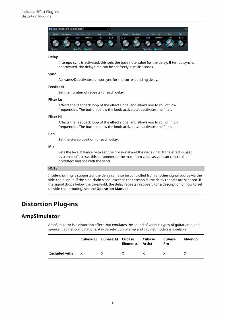
DelayIf tempo sync is activated, this sets the base note value for the delay. If tempo sync isdeactivated, the delay time can be set freely in milliseconds.
SyncActivates/Deactivates tempo sync for the corresponding delay.
FeedbackSet the number of repeats for each delay.
Filter LoAffects the feedback loop of the effect signal and allows you to roll off lowfrequencies. The button below the knob activates/deactivates the filter.
Filter HiAffects the feedback loop of the effect signal and allows you to roll off highfrequencies. The button below the knob activates/deactivates the filter.
PanSet the stereo position for each delay.
MixSets the level balance between the dry signal and the wet signal. If the effect is usedas a send effect, set this parameter to the maximum value as you can control thedry/effect balance with the send.
NOTE
If side-chaining is supported, the delay can also be controlled from another signal source via theside-chain input. If the side-chain signal exceeds the threshold, the delay repeats are silenced. Ifthe signal drops below the threshold, the delay repeats reappear. For a description of how to setup side-chain routing, see the Operation Manual.
Distortion Plug-ins
AmpSimulatorAmpSimulator is a distortion effect that emulates the sound of various types of guitar amp andspeaker cabinet combinations. A wide selection of amp and cabinet models is available.
Cubase LE Cubase AI CubaseElements
CubaseArtist
CubasePro
Nuendo
Included with X X X X X X
9

Included Effect Plug-insDistortion Plug-ins
Amplifier pop-up menuClick the amplifier name shown at the top of the amp section to open this pop-upmenu. It allows you to select an amplifier model. This section can be bypassed byselecting No Amp.
DriveControls the amount of amp overdrive.
BassTone control for the low frequencies.
MiddleTone control for the mid frequencies.
TrebleTone control for the high frequencies.
PresenceBoosts or dampens the higher frequencies.
VolumeControls the overall output level.
Cabinet pop-up menuClick the cabinet name shown at the top of the cabinet section to open this pop-upmenu. It allows you to select a speaker cabinet model. This section can be bypassedby selecting No Speaker.
Damping Lo/HiFurther tone controls for shaping the sound of the selected speaker cabinet. Click thevalues, enter a new value and press Enter.
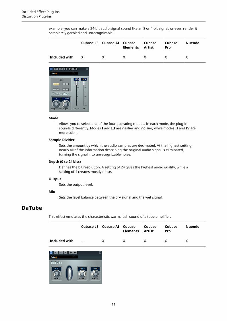
BitCrusherIf you are into lo-fi sound, BitCrusher is the effect for you. It offers the possibility of decimatingand truncating the input audio signal by bit reduction, to get a noisy, distorted sound. For
10
Included Effect Plug-insDistortion Plug-ins
example, you can make a 24-bit audio signal sound like an 8 or 4-bit signal, or even render itcompletely garbled and unrecognizable.
Cubase LE Cubase AI CubaseElements
CubaseArtist
CubasePro
Nuendo
Included with X X X X X X
ModeAllows you to select one of the four operating modes. In each mode, the plug-insounds differently. Modes I and III are nastier and noisier, while modes II and IV aremore subtle.
Sample DividerSets the amount by which the audio samples are decimated. At the highest setting,nearly all of the information describing the original audio signal is eliminated,turning the signal into unrecognizable noise.
Depth (0 to 24 bits)Defines the bit resolution. A setting of 24 gives the highest audio quality, while asetting of 1 creates mostly noise.
OutputSets the output level.
MixSets the level balance between the dry signal and the wet signal.
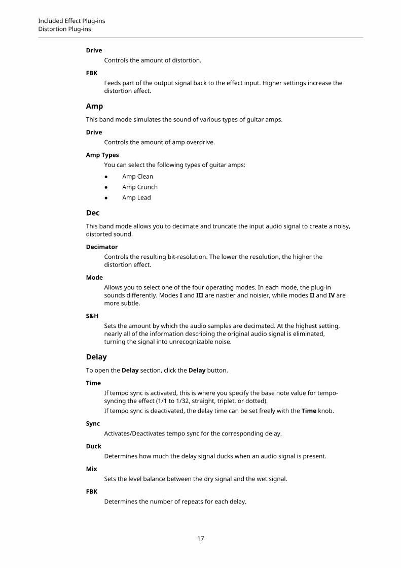
DaTubeThis effect emulates the characteristic warm, lush sound of a tube amplifier.
Cubase LE Cubase AI CubaseElements
CubaseArtist
CubasePro
Nuendo
Included with – X X X X X
11

Included Effect Plug-insDistortion Plug-ins
DriveSets the pre-gain of the amplifier. Use high values if you want an overdriven soundjust on the verge of distortion.
BalanceSets the balance between the signal processed by the Drive parameter and the dryinput signal. For maximum drive effect, set this to its highest value.
OutputAdjusts the post-gain, or output level, of the amplifier.
DistortionDistortion adds crunch to your tracks.
Cubase LE Cubase AI CubaseElements
CubaseArtist
CubasePro
Nuendo
Included with X X X X X X
BoostIncreases the distortion amount.
FeedbackFeeds part of the output signal back to the effect input. Higher settings increase thedistortion effect.
ToneLets you select a frequency range to which to apply the distortion effect.
SpatialChanges the distortion characteristics of the left and right channels, thus creating astereo effect.
OutputSets the output level.
GrungelizerGrungelizer adds noise and static to your recordings – like listening to a radio with bad reception,or a worn and scratched vinyl record.
Cubase LE Cubase AI CubaseElements
CubaseArtist
CubasePro
Nuendo
Included with X X X X X X
12

Included Effect Plug-insDistortion Plug-ins
CrackleAdds crackle to create that old vinyl record sound.
RPMWhen emulating the sound of a vinyl record, this switch lets you set the speed of therecord in RPM (revolutions per minute).
NoiseSets the amount of added static noise.
DistortAdds distortion.
EQCuts the low frequencies, and creates a hollow, lo-fi sound.
ACEmulates a constant, low AC hum.
FrequencySets the frequency of the AC current (50 or 60 Hz), and thus the pitch of the AC hum.
TimelineSets the amount of overall effect.
Magneto IIThis effect simulates the saturation and compression of recording on analog tape machines.
Cubase LE Cubase AI CubaseElements
CubaseArtist
CubasePro
Nuendo
Included with – – – X X X
13

Included Effect Plug-insDistortion Plug-ins
SaturationDetermines the amount of saturation and the generation of overtones. This leads toa small increase in input gain.
Saturation On/OffActivates/Deactivates the saturation effect.
Dual ModeSimulates the use of two machines.
Frequency Range Low/HiThese parameters set the frequency range of the spectrum band to which the tapeeffect is applied.For example, to avoid the saturation of lower frequencies, set the Freq Low value to200 Hz or 300 Hz. To avoid the saturation of very high frequencies, set the Freq Hiparameter to values below 10 kHz.
SoloAllows you to hear only the set frequency range including the tape simulation effect.This helps you to determine the appropriate frequency range.
HF-AdjustSets the amount of high frequency content of the saturated signal.
HF-Adjust On/OffActivates/Deactivates the HF-Adjust filter.
Quadrafuzz v2Quadrafuzz v2 is a multi-band distortion and multi-effect plug-in for processing drums and loopsbut also for treatment of vocals, for example. You can distort up to 4 bands. 5 different distortionmodes with several sub-modes are available.
Cubase LE Cubase AI CubaseElements
CubaseArtist
CubasePro
Nuendo
Included with – – – X X X
14

Included Effect Plug-insDistortion Plug-ins
Frequency Band Editor
The frequency band editor in the upper half of the panel is where you set the width of thefrequency bands as well as the output level. The vertical value scale to the left shows the gainlevel of each frequency band. The horizontal scale shows the available frequency range.
● To define the frequency range of the different frequency bands, use the handles at thesides of each frequency band.
● To attenuate or boost the output level of each frequency band by ±15 dB, use the handleson top of each frequency band.
Global Settings
SBSwitches between multi band and single band mode.
ScenesYou can save up to 8 different settings. If the default setting of a scene is active, theselected scene button lights up yellow.If you change the default settings, the button lights up green, indicating that thisscene has customized settings.
15

Included Effect Plug-insDistortion Plug-ins
To copy the settings of a scene to another scene, select the scene that you want tocopy, click Copy, and click one of the numbered buttons.You can automate the selection of scenes.
MixSets the level balance between the dry signal and the wet signal.
Output (-24 to 24 dB)Sets the output level.
Band Settings
MuteTo mute each frequency band, activate the M button in each section.
Bypassing Frequency Bands
To bypass each frequency band, activate the Bypass Band button in each section.
Soloing Frequency BandsTo solo a frequency band, activate the S button in each section. Only one band canbe soloed at a time.
In/Out meterDisplay the input and output level.
GateDetermines the level at which the gate is activated. Signal levels above the setthreshold trigger the gate to open, and signal levels below the set threshold closethe gate.
Tape
This band mode simulates the saturation and compression of recording on analog tapemachines.
DriveControls the amount of tape saturation.
Tape Mode DualSimulates the use of two machines.
Tube
This band mode simulates the saturation effects using analog tubes.
DriveControls the amount of tube saturation.
TubesDetermine the number of tubes that are simulated.
Dist
This band mode adds distortion to your tracks.
16
Included Effect Plug-insDistortion Plug-ins
DriveControls the amount of distortion.
FBKFeeds part of the output signal back to the effect input. Higher settings increase thedistortion effect.
Amp
This band mode simulates the sound of various types of guitar amps.
DriveControls the amount of amp overdrive.
Amp TypesYou can select the following types of guitar amps:
● Amp Clean
● Amp Crunch
● Amp Lead
Dec
This band mode allows you to decimate and truncate the input audio signal to create a noisy,distorted sound.
DecimatorControls the resulting bit-resolution. The lower the resolution, the higher thedistortion effect.
ModeAllows you to select one of the four operating modes. In each mode, the plug-insounds differently. Modes I and III are nastier and noisier, while modes II and IV aremore subtle.
S&HSets the amount by which the audio samples are decimated. At the highest setting,nearly all of the information describing the original audio signal is eliminated,turning the signal into unrecognizable noise.
Delay
To open the Delay section, click the Delay button.
TimeIf tempo sync is activated, this is where you specify the base note value for tempo-syncing the effect (1/1 to 1/32, straight, triplet, or dotted).If tempo sync is deactivated, the delay time can be set freely with the Time knob.
SyncActivates/Deactivates tempo sync for the corresponding delay.
DuckDetermines how much the delay signal ducks when an audio signal is present.
MixSets the level balance between the dry signal and the wet signal.
FBKDetermines the number of repeats for each delay.
17

Included Effect Plug-insDistortion Plug-ins
ModeIf this option is activated, the delay signal is routed back into the distortion unit tocreate a feedback with distortion.
NOTE
High FBK values and low Duck values in combination with activated Mode can lead to unwantednoise.
Slider
WidthSets the stereo width for the corresponding band.
OutSets the output gain for the corresponding band.
PanSets the stereo position for the corresponding band.
MixSets the level balance between the dry signal and the wet signal.
SoftClipperThis effect adds soft overdrive, with independent control over the second and third harmonic.
Cubase LE Cubase AI CubaseElements
CubaseArtist
CubasePro
Nuendo
Included with – – – – X X
Input (-12 to 24 dB)Sets the pre-gain. Use high values if you want an overdriven sound just on the vergeof distortion.
MixSets the level balance between the dry signal and the wet signal.
OutputSets the output level.
18
Included Effect Plug-insDistortion Plug-ins
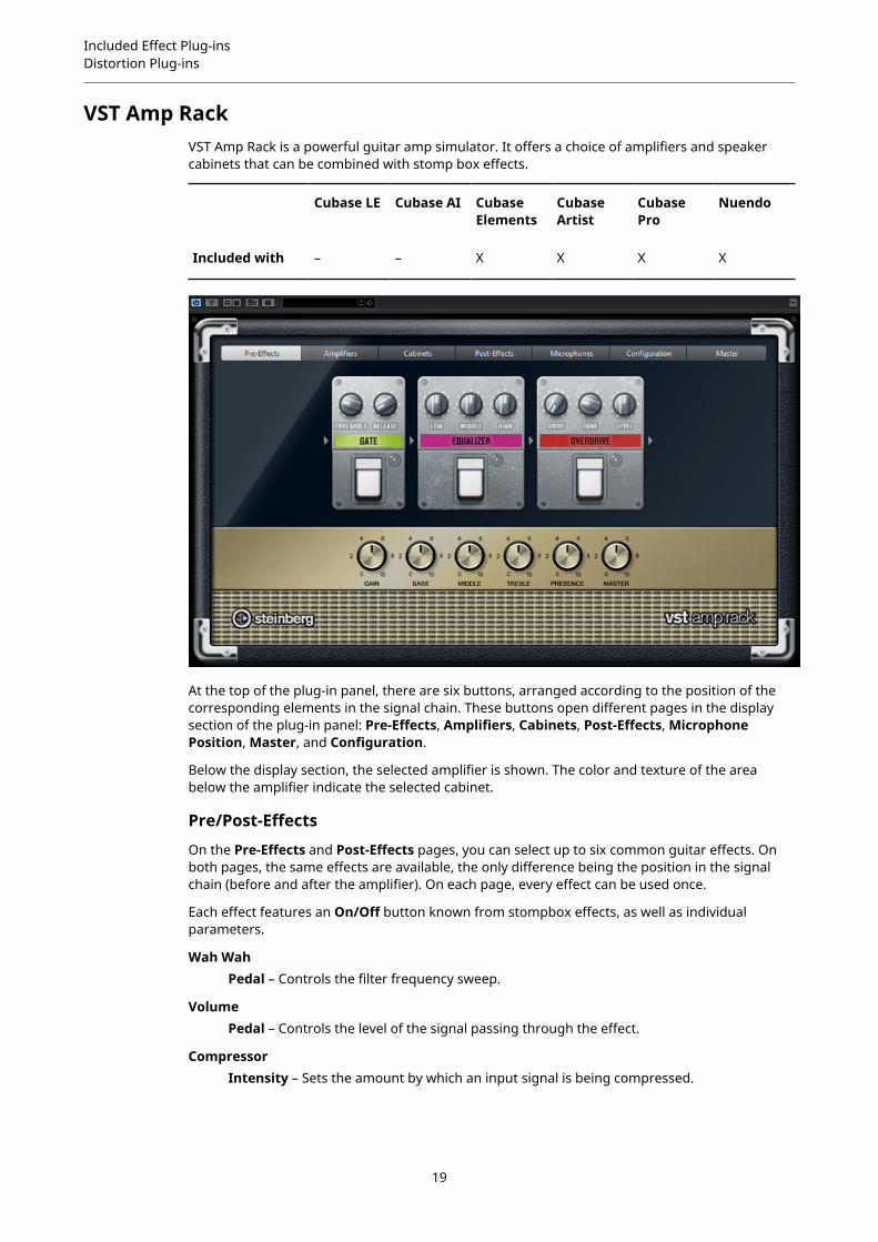
VST Amp RackVST Amp Rack is a powerful guitar amp simulator. It offers a choice of amplifiers and speakercabinets that can be combined with stomp box effects.
Cubase LE Cubase AI CubaseElements
CubaseArtist
CubasePro
Nuendo
Included with – – X X X X
At the top of the plug-in panel, there are six buttons, arranged according to the position of thecorresponding elements in the signal chain. These buttons open different pages in the displaysection of the plug-in panel: Pre-Effects, Amplifiers, Cabinets, Post-Effects, MicrophonePosition, Master, and Configuration.
Below the display section, the selected amplifier is shown. The color and texture of the areabelow the amplifier indicate the selected cabinet.
Pre/Post-Effects
On the Pre-Effects and Post-Effects pages, you can select up to six common guitar effects. Onboth pages, the same effects are available, the only difference being the position in the signalchain (before and after the amplifier). On each page, every effect can be used once.
Each effect features an On/Off button known from stompbox effects, as well as individualparameters.
Wah WahPedal – Controls the filter frequency sweep.
VolumePedal – Controls the level of the signal passing through the effect.
CompressorIntensity – Sets the amount by which an input signal is being compressed.
19

Included Effect Plug-insDistortion Plug-ins
LimiterThreshold – Determines the maximum output level. Signal levels above the setthreshold are cut off.Release – Sets the time after which the gain returns to the original level.
MaximizerAmount – Determines the loudness of the signal.
ChorusRate – Allows you to set the sweep rate. This parameter can be synchronized to theproject tempo.
Width – Determines the depth of the chorus effect. Higher settings produce a morepronounced effect.
PhaserRate – Allows you to set the sweep rate. This parameter can be synchronized to theproject tempo.
Width – Determines the width of the modulation effect between higher and lowerfrequencies.
FlangerRate – Allows you to set the sweep rate. This parameter can be synchronized to theproject tempo.
Feedback – Determines the character of the flanger effect. Higher settings produce amore metallic sounding sweep.
Mix – Sets the level balance between the dry signal and the wet signal.
TremoloRate – Allows you to set the modulation speed. This parameter can be synchronizedto the project tempo.
Depth – Governs the depth of the amplitude modulation.
OctaverDirect – Adjusts the mix of the original signal and the generated voices. A value of 0means only the generated and transposed signal is heard. By raising this value, moreof the original signal is heard.
Octave 1 – Adjusts the level of the signal that is generated one octave below theoriginal pitch. A setting of 0 means that the voice is muted.
Octave 2 – Adjusts the level of the signal that is generated two octaves below theoriginal pitch. A setting of 0 means that the voice is muted.
DelayDelay – Sets the delay time in milliseconds. This parameter can be synchronized tothe project tempo.
Feedback – Sets the number of repeats for the delay.
Mix – Sets the level balance between the dry signal and the wet signal.
Tape DelayDelay – Tape Delay creates a delay effect known from tape machines. The Delayparameter sets the delay time in milliseconds. This parameter can be synchronizedto the project tempo.
Feedback – Sets the number of repeats for the delay.
Mix – Sets the level balance between the dry signal and the wet signal.
20
Included Effect Plug-insDistortion Plug-ins
Tape Ducking DelayDelay – Tape Ducking Delay creates a delay effect known from tape machines witha ducking parameter. The Delay parameter sets the delay time in milliseconds. Thisparameter can be synchronized to the project tempo.
Feedback – Sets the number of repeats for the delay.
Duck – Works like an automatic mix parameter. If the level of the input signal is high,the portion of the effect signal is lowered, or ducked (low internal mix value). If thelevel of the input signal is low, the portion of the effect signal is raised (high internalmix value). This way the delayed signal stays rather dry during loud or intenselyplayed passages.
OverdriveDrive – Overdrive creates a tube-like overdrive effect. The higher this value, the moreharmonics are added to the output signal of this effect.
Tone – Works as a filter effect on the added harmonics.
Level – Adjusts the output level.
FuzzBoost – Fuzz creates a rather harsh distortion effect. The higher this value, the moredistortion is created.
Tone – Works as a filter effect on the added harmonics.
Level – Adjusts the output level.
GateThreshold – Determines the level at which the gate is activated. Signal levels abovethe set threshold trigger the gate to open, and signal levels below the set thresholdclose the gate.
Release – Sets the time after which the gate closes.
EqualizerLow – Changes the level of the low-frequency portion of the incoming signal.
Middle – Changes the level of the mid-frequency portion of the incoming signal.
High – Changes the level of the high-frequency portion of the incoming signal.
ReverbType – A convolution-based reverb effect. This parameter allows you to switchbetween different reverb types (Studio, Hall, Plate, and Room).
Mix – Sets the level balance between the dry signal and the wet signal.
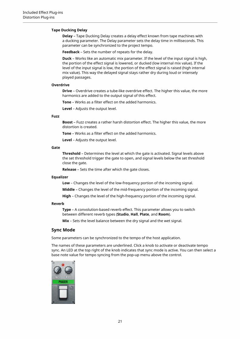
Sync Mode
Some parameters can be synchronized to the tempo of the host application.
The names of these parameters are underlined. Click a knob to activate or deactivate temposync. An LED at the top right of the knob indicates that sync mode is active. You can then select abase note value for tempo syncing from the pop-up menu above the control.
21

Included Effect Plug-insDistortion Plug-ins
Using Effects
● To insert a new effect, click the + button that appears if you point the mouse at an emptyplug-in slot or at one of the arrows before or after a used effect slot.
● To remove an effect from an effect slot, click the effect name and select None from thepop-up menu.
● To change the order of the effects in the chain, click on an effect and drag it to anotherposition.
● To activate or deactivate an effect, click the pedal-like button below the effect name. If aneffect is active, the LED next to the button is lit.
NOTE
● Pre-effects and post-effects can be mono or stereo, depending on the track configuration.
● Using quick controls you can set up an external MIDI device, such as a foot controller,to control the VST Amp Rack effects. For more information about quick controls, see theOperation Manual.
Amplifiers
The amps available on the Amplifiers page are modeled on real-life amplifiers. Each ampfeatures settings typical for guitar recording, such as gain, equalizers, and master volume. Thesound-related parameters Bass, Middle, Treble, and Presence have a significant impact on theoverall character and sound of the corresponding amp.
PlexiClassic British rock tone; extremely transparent sound, very responsive.
Plexi LeadBritish rock tone of the 70s and 80s.
DiamondThe cutting edge hard rock and metal sounds of the 90s.
BlackfaceClassic American clean tone.
TweedClean and crunchy tones; originally developed as a bass amp.
DeluxeAmerican crunch sound coming from a rather small amp with a big tone.
British CustomProduces the sparkling clean or harmonically distorted rhythm sounds of the 60s.
The different amps keep their settings if you switch models. However, if you want to use thesame settings after reloading the plug-in, you need to set up a preset.
Selecting and Deactivating Amplifiers
To switch amps on the Amplifiers page, click the model that you want to use. Select No Amplifierif you only want to use the cabinets and effects.
Cabinets
The cabinets available on the Cabinets page simulate real-life combo boxes or speakers. Foreach amp, a corresponding cabinet type is available, but you can also combine different ampsand cabinets.
Selecting and Deactivating Cabinets
22

Included Effect Plug-insDistortion Plug-ins
● To switch cabinets on the Cabinets page, click the model that you want to use. Select NoCabinet if you only want to use the amps and effects.
● If you select Link Amplifier & Cabinet Choice, the plug-in automatically selects thecabinet corresponding to the selected amp model.
Microphones
On the Microphones page, you can choose between different microphone positions. Thesepositions result from two different angles (center and edge) and three different distancesfrom the speaker, as well as an additional center position at an even greater distance from thespeaker.
You can choose between two microphone types: a large-diaphragm condenser microphone anda dynamic microphone. You can crossfade between the characteristics of the two microphones.
● To select one of the microphone types or blend between the two types, turn the Mixcontrol between the two microphones.
Placing the Microphone
● To select a microphone position, click the corresponding ball in the graphic. The selectedposition is marked in red.
Master
Use the Master page to fine-tune the sound.
Input/Output Level Meters
The input and output level meters on the left and the right of the Master section show the signallevel of your audio. The rectangle on the input meter indicates the optimum incoming levelrange. In compact view, the input and output levels are indicated by two LEDs at the top left andright.
Using the Master Controls
● To activate/deactivate the equalizer, click the pedal-like On/Off button. If the equalizer isactive, the LED next to the button is lit.
● To activate/deactivate an equalizer band, click the corresponding Gain knob. If a band isactive, the LED to the left of the Gain knob is lit.
● To tune your guitar strings, click the pedal-like On/Off button to activate the Tuner andplay a string. If the correct pitch is displayed and the row of LEDs below the digital displayis green, the string is tuned correctly.If the pitch is too low, red LEDs are lit on the left. If the pitch is too high, red LEDs are lit onthe right. The more LEDs are lit, the lower/higher is the pitch.
● To mute the output signal of the plug-in, click the pedal-like Master button. If the output ismuted, the LED is not lit. Use this to tune your guitar in silence, for example.
● To change the volume of the output signal, use the Level control on the Master page.
Configuration
On the Configuration page, you can specify whether you want to use VST Amp Rack in stereo orin mono mode.
● To process the pre-effects, the amplifier, and the cabinets in full stereo mode, make surethat the plug-in is inserted on a stereo track, and activate the Stereo button.
● To use the effect in mono-mode, make sure that the plug-in is inserted on a mono track,and activate the Mono button.
23

Included Effect Plug-insDistortion Plug-ins
NOTE
In stereo mode, the effect requires more processing power.
View Settings
You can choose between 2 views: the default view and a compact view, which takes up lessscreen space.
In the default view, you can use the buttons at the top of the plug-in panel to open thecorresponding page in the display section above the amp controls. You can horizontally resizethe plug-in panel by clicking and dragging the edges or corners.
In the compact view, the display section is hidden from view. You can change the amp settingsand switch amps or cabinets using the mouse wheel.
Using the Smart Controls
Smart controls become visible on the plug-in frame when you move the mouse pointer over onthe plug-in panel.
Switching between Default and Compact View
● To toggle between the different views, click the down/up arrow button (Show/HideExtended Display) at the top center of the plug-in frame.
Changing the Amplifier and Cabinet Selection in the Compact View
In the compact view, a smart control on the lower border of the plug-in frame allows you toselect different amplifier and cabinet models.
● To select a different amplifier or cabinet, click the name and select a different model fromthe pop-up menu.
● To lock the amplifier and cabinet combination, activate the Link/Unlink Amplifier &Cabinet Choice button. If you now select another amp model, the cabinet selectionfollows. However, if you select a different cabinet model, the lock is deactivated.
Previewing Effect Settings
In both views, you can show a preview of the pre- and post-effects that you selected on thecorresponding pages:
● Click and hold the Show Pre-Effects or Show Post-Effects button at the bottom left orright of the plug-in frame.
24
Included Effect Plug-insDistortion Plug-ins
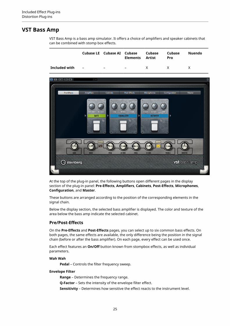
VST Bass AmpVST Bass Amp is a bass amp simulator. It offers a choice of amplifiers and speaker cabinets thatcan be combined with stomp box effects.
Cubase LE Cubase AI CubaseElements
CubaseArtist
CubasePro
Nuendo
Included with – – – X X X
At the top of the plug-in panel, the following buttons open different pages in the displaysection of the plug-in panel: Pre-Effects, Amplifiers, Cabinets, Post-Effects, Microphones,Configuration, and Master.
These buttons are arranged according to the position of the corresponding elements in thesignal chain.
Below the display section, the selected bass amplifier is displayed. The color and texture of thearea below the bass amp indicate the selected cabinet.
Pre/Post-Effects
On the Pre-Effects and Post-Effects pages, you can select up to six common bass effects. Onboth pages, the same effects are available, the only difference being the position in the signalchain (before or after the bass amplifier). On each page, every effect can be used once.
Each effect features an On/Off button known from stompbox effects, as well as individualparameters.
Wah WahPedal – Controls the filter frequency sweep.
Envelope FilterRange – Determines the frequency range.Q-Factor – Sets the intensity of the envelope filter effect.Sensitivity – Determines how sensitive the effect reacts to the instrument level.
25

Included Effect Plug-insDistortion Plug-ins
Attack – Determines how quickly an effect reacts to the input signal.Mix – Sets the level balance between the dry signal and the wet signal.Type – Sets the filter type.Release – Determines how quickly the effect fades after the input signal stops.
VolumePedal – Controls the level of the signal passing through the effect.
CompressorIntensity – Sets the amount by which an input signal is being compressed.
Compressor MBLo Intensity – Sets the compressor effect in the low frequency band. Activate/deactivate Auto Makeup Mode by clicking the LED at the top right of the knob.Hi Intensity – Sets the compressor effect in the high frequency band. Activate/deactivate Auto Makeup Mode by clicking the LED at the top right of the knob.Crossover – Determines the crossover frequency between the low frequency bandand the high frequency band.Output – Sets the output level.
LimiterThreshold – Determines the maximum output level. Signal levels above the setthreshold are cut off.Release – Sets the time after which the gain returns to the original level.
MaximizerAmount – Determines the loudness of the signal.
ChorusRate – Allows you to set the sweep rate. This parameter can be synchronized to theproject tempo.Width – Determines the depth of the chorus effect. Higher settings produce a morepronounced effect.Tone – Allows you to attenuate low frequencies.Mix – Sets the level balance between the dry signal and the wet signal.
PhaserRate – Allows you to set the sweep rate. This parameter can be synchronized to theproject tempo.Width – Determines the width of the modulation effect between higher and lowerfrequencies.Tone – Allows you to attenuate the low frequencies.Mix – Sets the level balance between the dry signal and the wet signal.
FlangerRate – Allows you to set the sweep rate. This parameter can be synchronized to theproject tempo.Feedback – Determines the character of the flanger effect. Higher settings produce amore metallic sounding sweep.Tone – Allows you to attenuate the low frequencies.Mix – Sets the level balance between the dry signal and the wet signal.
DI DriverLevel – Sets the output level.
26

Included Effect Plug-insDistortion Plug-ins
Blend – Blends between normal and tube emulation circuitry. With Blend at 0, Driveand Presence are not active.Bass – Boosts or attenuates low frequencies.Treble – Boosts or attenuates high frequencies.Presence – Boosts or attenuates upper harmonics and attacks.Drive – Sets gain and overdrive.
EnhancerEnhance – Simulates the classic enhancer effect.Tone – Allows you to attenuate low frequencies.
OctaverDirect – Adjusts the level of the original signal. A value of 0 means only thegenerated and transposed signal is heard. By raising this value, more of the originalsignal is heard.
Octave 1 – Adjusts the level of the signal that is generated one octave below theoriginal pitch. A setting of 0 means that the voice is muted.
Tone – Changes the sound character of the generated signal.
DelayDelay – Sets the delay time in milliseconds. This parameter can be synchronized tothe project tempo.
Feedback – The higher this setting, the more delay repeats are created.
Mix – Sets the level balance between the dry signal and the wet signal.
Tape Ducking DelayDelay – The Delay parameter sets the delay time in milliseconds.
Feedback – The higher this setting, the more delay repeats are created.
Duck – Works like an automatic mix parameter. If the level of the input signal is high,the portion of the effect signal is lowered, or ducked (low internal mix value). If thelevel of the input signal is low, the portion of the effect signal is raised (high internalmix value). This way the delayed signal stays rather dry during loud or intenselyplayed passages.
Tone – Allows you to attenuate the low frequencies.
Mix – Sets the level balance between the dry signal and the wet signal.
OverdriveDrive – Overdrive creates a tube-like overdrive effect. The higher this value, the moreharmonics are added to the output signal of this effect.
Tone – Works as a filter effect on the added harmonics.
Level – Adjusts the output level.
Magneto IIDrive – Controls the amount of tape saturation.Low/High – These parameters set the frequency range of the spectrum band towhich the tape effect is applied.HF-Adjust – Sets the amount of high frequency content of the saturated signal.
GateThreshold – Determines the level at which the gate is activated. Signal levels abovethe set threshold open the gate and signal levels below the set threshold close thegate.
Release – Sets the time after which the gate closes.
27
Included Effect Plug-insDistortion Plug-ins
EqualizerLow – Changes the level of the low-frequency portion of the incoming signal.
Middle – Changes the level of the mid-frequency portion of the incoming signal.
High – Changes the level of the high-frequency portion of the incoming signal.
Graphical EQDisplay – Consists of 8 sliders that set the level of each frequency band. Allows youto draw response curves by clicking and dragging with the mouse.
Reset Sliders – At the lower right of the Display. Flattens all values to 0 dB.
Output Slider – Allows you to control the frequency response.
ReverbType – A convolution-based reverb effect. This parameter allows you to switchbetween the reverb types Studio, Hall, Plate, and Room.
Mix – Sets the level balance between the dry signal and the wet signal.
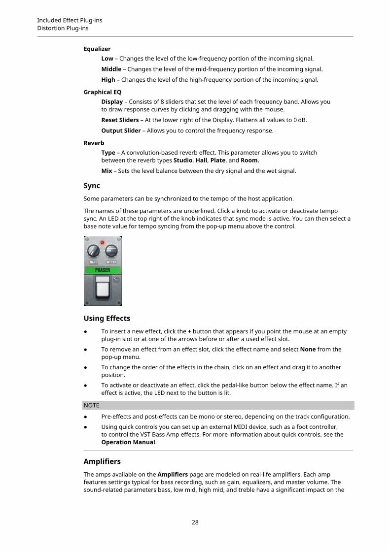
Sync
Some parameters can be synchronized to the tempo of the host application.
The names of these parameters are underlined. Click a knob to activate or deactivate temposync. An LED at the top right of the knob indicates that sync mode is active. You can then select abase note value for tempo syncing from the pop-up menu above the control.
Using Effects
● To insert a new effect, click the + button that appears if you point the mouse at an emptyplug-in slot or at one of the arrows before or after a used effect slot.
● To remove an effect from an effect slot, click the effect name and select None from thepop-up menu.
● To change the order of the effects in the chain, click on an effect and drag it to anotherposition.
● To activate or deactivate an effect, click the pedal-like button below the effect name. If aneffect is active, the LED next to the button is lit.
NOTE
● Pre-effects and post-effects can be mono or stereo, depending on the track configuration.
● Using quick controls you can set up an external MIDI device, such as a foot controller,to control the VST Bass Amp effects. For more information about quick controls, see theOperation Manual.
Amplifiers
The amps available on the Amplifiers page are modeled on real-life amplifiers. Each ampfeatures settings typical for bass recording, such as gain, equalizers, and master volume. Thesound-related parameters bass, low mid, high mid, and treble have a significant impact on the
28
Included Effect Plug-insDistortion Plug-ins
overall character and sound of the corresponding amp. Shape 1 and Shape 2 offer predefinedtone shaping.
ValveAmp300A famous tube amplifier from the 70s, useful for rock playing styles.
GreyhoundAn amplifier, well known for its typical growl, useful for several playing styles.
GreenTA classic amplifier from the 80s, useful for funk and rock playing styles.
ParadiseAn amplifier from the 90s, with a hifi-like clear tone, that makes it applicable forseveral styles.
TweedA classic vintage amplifier from the 50s, with a characterful and bright tone.Originally created for bassists, also used by many guitar players.
iTechA modern amplifier, with a universal sound.
The different amps keep their settings if you switch models, but amp settings are lost whenclosing VST Bass AMP. If you want to use the same settings after reloading the plug-in, you needto set up a preset.
Selecting and Deactivating Amplifiers
To switch amps on the Amplifiers page, click the model that you want to use. Select NoAmplifier if you only want to use the cabinets and effects.
NOTE
To scroll through amplifiers, use the mouse wheel when hovering over the amplifier panel.
Cabinets
The cabinets available on the Cabinets page simulate real-life combo boxes or speakers. Foreach amp, a corresponding cabinet type is available, but you can also combine different ampsand cabinets.
The following cabinets are available:
4x10"10" speakers provide a punchy clear sound that is suitable for “Slap” bass and regularplaying styles.
10" speakers have a cleaner sound and more punch than 15" speakers.
8x10"Compared to 4x10", double the amount of speakers.
4x12"12" speakers provide a mellow and full sound, making them a good choice between10" and 15" speakers.
1x15"15" speakers provide more low frequencies compared to the other cabinets. They aresuitable for rock and vintage oriented styles.
Selecting and Deactivating Cabinets
29

Included Effect Plug-insDistortion Plug-ins
● To switch cabinets on the Cabinets page, click the model that you want to use. Select NoCabinet if you only want to use the amps and effects.
● If you select Link Amplifier & Cabinet Choice, the plug-in automatically selects thecabinet corresponding to the selected amp model.
Microphones
On the Microphones page, you can choose between different microphone types.
57Dynamic microphone with cardioid pickup pattern.
121Ribbon microphone with figure-8 pattern.
409Dynamic microphone with supercardioid pickup pattern.
421Dynamic microphone with cardioid polar pattern.
545Dynamic microphone with cardioid pattern that minimizes feedback.
5Dynamic microphone with cardioid pickup pattern.
30Reference and measurement microphone with omni directional polar pattern.
87Condenser microphone with omni directional pattern.
You can choose between different microphone positions. These positions result from twodifferent angles (on axis and off axis) and three different distances from the cabinet.
You can crossfade between the characteristics of the two microphones.
● To select one of the microphone types or blend between the two types, turn the Mixcontrol between the two microphones.
● To select a microphone position, click the corresponding ball in front of the cabinet. Theselected position is marked in red.
● To determine the ratio between line and mic, turn the Mix control on the left of thecabinet.
NOTE
To scroll through microphones, use the mouse wheel when hovering over a microphone.
Master
Use the Master page to fine-tune the sound.
Input/Output Level MetersThe input and output level meters on the left and the right of the Master sectionshow the signal level of your audio. The rectangle on the input meter indicates theoptimum incoming level range. In all other views, the input and output levels areindicated by two LEDs at the top left and right.
Using the Master Controls
30

Included Effect Plug-insDistortion Plug-ins
● To activate/deactivate the equalizer, click the pedal-like On/Off button. If the equalizer isactive, the LED next to the button is lit.
● To activate/deactivate an equalizer band, click the corresponding Gain knob. If a band isactive, the LED to the left of the Gain knob is lit.
● To tune your guitar strings, click the pedal-like On/Off button to activate Tuner and playa string. If the correct pitch is displayed and the row of LEDs below the digital display isgreen, the string is tuned correctly.If the pitch is too low, red LEDs are lit on the left. If the pitch is too high, red LEDs are lit onthe right. The more LEDs are lit, the lower/higher is the pitch.
● To mute the output signal of the plug-in, click the pedal-like Master button. If the output ismuted, the LED is not lit. Use this to tune your guitar in silence, for example.
● To change the volume of the output signal, use the Level control on the Master page.
● NOTE
Master EQ functions only when a cabinet is selected.
Configuration
On the Configuration page, you can specify whether you want to use VST Bass Amp in stereo orin mono mode.
● To process the pre-effects, the amplifier, and the cabinets in full stereo mode, make surethat the plug-in is inserted on a stereo track, and activate the Stereo button.
● To use the effect in mono-mode, make sure that the plug-in is inserted on a mono track,and activate the Mono button.
NOTE
In stereo mode, the effect requires more processing power. Use mono configuration on a stereotrack to save processing power.
View Settings
You can choose between 2 views: the default view and a compact view, which takes up lessscreen space.
In the default view, you can use the buttons at the top of the plug-in panel to open thecorresponding page in the display section above the amp controls. You can horizontally resizethe plug-in panel by clicking and dragging the edges or corners.
In the compact view, the display section is hidden from view. You can change the amp settingsand switch amps or cabinets using the mouse wheel.
Using the Smart Controls
Smart controls become visible on the plug-in frame when you move the mouse pointer over theplug-in panel.
Switching between Default and Compact View
● To toggle between the different views, click the down/up arrow button (Show/HideExtended Display) at the top center of the plug-in frame.
Changing the Amplifier and Cabinet Selection in the Compact View
31

Included Effect Plug-insDynamics Plug-ins
In the compact view, a smart control on the lower border of the plug-in frame allows you toselect different amplifier and cabinet models.
● To select a different amplifier or cabinet, click the name and select a different model fromthe pop-up menu.
● To lock the amplifier and cabinet combination, activate the Link/Unlink Amplifier &Cabinet Choice button. If you now select another amp model, the cabinet selectionfollows. However, if you select a different cabinet model, the lock is deactivated.
Previewing Effect Settings
In both views, you can show a preview of the pre- and post-effects that you selected on thecorresponding pages:
● Click and hold the Show Pre-Effects or Show Post-Effects button at the bottom left orright of the plug-in frame.
RELATED LINKSTuner on page 141
Dynamics Plug-ins
Brickwall LimiterBrickwall Limiter ensures that the output level never exceeds a set limit.
Cubase LE Cubase AI CubaseElements
CubaseArtist
CubasePro
Nuendo
Included with – – X X X X
32

Included Effect Plug-insDynamics Plug-ins
Due to its fast attack time, Brickwall Limiter can reduce even short audio level peaks withoutcreating audible artifacts. However, this plug-in creates a latency of 1ms. Brickwall Limiterfeatures separate meters for input, output, and the amount of limiting. Position this plug-in atthe end of the signal chain, before dithering.
Threshold (-20 to 0 dB)Determines the level where the limiter kicks in. Only signal levels above the setthreshold are processed.
Release (3 to 1000 ms or Auto mode)Sets the time after which the gain returns to the original level when the signal dropsbelow the threshold. If the Auto button is activated, the plug-in automatically findsthe best release setting for the audio material.
LinkIf this button is activated, Brickwall Limiter uses the channel with the highest levelto analyze the input signal. If the button is deactivated, each channel is analyzedseparately.
Detect Intersample ClippingIf this option is activated, Brickwall Limiter uses oversampling to detect and limitsignal levels between two samples to prevent distortion when converting digitalsignals into analog signals.
NOTE
Brickwall Limiter is designed for the reduction of occasional peaks in the signal. If the GainReduction meter indicates constant limiting, try raising the threshold or lowering the overalllevel of the input signal.
CompressorThis plug-in reduces the dynamic range of the audio, making softer sounds louder or loudersounds softer, or both.
Cubase LE Cubase AI CubaseElements
CubaseArtist
CubasePro
Nuendo
Included with – – X X X X
Side-chainsupport
– – – X X X
33

Included Effect Plug-insDynamics Plug-ins
Compressor features a separate display that graphically illustrates the compressor curve thatis shaped according to the Threshold and Ratio parameter settings. Compressor also featuresa Gain Reduction meter that shows the amount of gain reduction in dB, Soft knee/Hard kneecompression modes, and a program-dependent auto feature for the Release parameter.
Threshold (-60 to 0 dB)Determines the level where the compressor kicks in. Only signal levels above the setthreshold are processed.
RatioSets the amount of gain reduction applied to signals above the set threshold. A ratioof 3:1 means that for every 3 dB the input level increases, the output level increasesby 1 dB.
Soft KneeIf this button is deactivated, signals above the threshold are compressed instantlyaccording to the set ratio (hard knee). If Soft Knee is activated, the onset ofcompression is more gradual, producing a less drastic result.
High RatioSets the ratio to a fixed value of 20:1.
Make-Up (0 to 24 dB or Auto mode)Compensates for output gain loss, caused by compression. If the Auto button isactivated, the knob becomes dark and the output is automatically adjusted for gainloss.
Dry MixMixes the dry input signal to the compressed signal.
Attack (0.1 to 100 ms)Determines how fast the compressor responds to signals above the set threshold.If the attack time is long, more of the early part of the signal passes throughunprocessed.
34

Included Effect Plug-insDynamics Plug-ins
Hold (0 to 5000 ms)Sets the time the applied compression affects the signal after exceeding thethreshold. Short hold times are useful for DJ-style ducking, while longer hold timesare required for music ducking, for example, when working on a documentary film.
Release (10 to 1000 ms or Auto mode)Sets the time after which the gain returns to its original level when the signal dropsbelow the threshold. If the Auto button is activated, the plug-in automatically findsthe best release setting for the audio material.
Analysis (Pure Peak to Pure RMS)Determines whether the input signal is analyzed according to peak or RMS values,or a mixture of both. A value of 0 is pure peak and 100 pure RMS. RMS modeoperates using the average power of the audio signal as a basis, whereas Peakmode operates more on peak levels. As a general guideline, RMS mode works betteron material with few transients such as vocals, and Peak mode works better forpercussive material with a lot of transient peaks.
LiveIf this button is activated, the look-ahead feature of the effect is deactivated. Look-ahead produces more accurate processing, but adds a specific amount of latencyas a trade-off. If Live mode is activated, there is no latency, which is better for liveprocessing.
DeEsserThis effect reduces excessive sibilance, primarily for vocal recordings. It is a special type ofcompressor that is tuned to be sensitive to the frequencies produced by the s-sound.
Cubase LE Cubase AI CubaseElements
CubaseArtist
CubasePro
Nuendo
Included with – – – X X X
Side-chainsupport
– – – X X X
35

Included Effect Plug-insDynamics Plug-ins
Close proximity microphone placement and equalizing can lead to situations where the overallsound is just right, but there is a problem with sibilants.
Display
Shows the spectrum of the input signal.
● To adjust the frequency band, drag the border lines or click in the middle of the band anddrag.
● To change the width of the frequency band, hold Shift and drag to the left or right.
Filter
Lo/HiSets the left and right border of the frequency band. You can set the frequency eitherin Hz or as a note value. If you enter a note value, the frequency is automaticallydisplayed in Hz accordingly. For example, a note value of A3 sets the frequency to440 Hz. When you enter a note value, you can also enter a cent offset. For example,enter A5 -23 or C4 +49.
NOTE
Make sure that you enter a space between the note and the cent offset. Only in thiscase, the cent offsets are taken into account.
SoloSolos the frequency band. This helps you to find the appropriate position and widthof that band.
DiffPlays back what DeEsser removed from the signal. This help you to adjust thefrequency band, threshold, and reduction parameters, so that only sharp s-soundsare removed, for example.
36
Included Effect Plug-insDynamics Plug-ins
Dynamics
ReductionControls the intensity of the de-essing effect.
Threshold (-50 to 0 dB)If the Auto option is deactivated, you can use this control to set a threshold for theincoming signal level above which the plug-in starts to reduce the sibilants.
Release (1 to 1000 ms)Sets the time after which the de-essing effect returns to zero when the signal dropsbelow the threshold.
AutoAutomatically and continually sets an optimum threshold setting independent ofthe input signal. The Auto option does not work for low-level signals (< -30 db peaklevel). To reduce the sibilants in such a file, set the threshold manually.
Side-Chain
Freq (25 Hz to 20 kHz)If the Side-Chain button is activated, this sets the frequency of the filter. You can setthe frequency either in Hz or as a note value. If you enter a note value, the frequencyis automatically displayed in Hz accordingly. For example, a note value of A3 sets thefrequency to 440 Hz. When you enter a note value, you can also enter a cent offset.For example, enter A5 -23 or C4 +49.
NOTE
Make sure that you enter a space between the note and the cent offset. Only in thiscase, the cent offsets are taken into account.
Q-FactorIf the Side-Chain button is activated, this sets the resonance or width of the filter.
SideActivates the internal side-chain filter. You can now shape the input signal accordingto the filter parameters. Internal side-chaining can be useful for tailoring how thegate operates.
MonitorAllows you to monitor the filtered signal.
LiveIf this button is activated, the look-ahead feature of the effect is deactivated. Look-ahead produces more accurate processing, but adds a specific amount of latencyas a trade-off. If Live mode is activated, there is no latency, which is better for liveprocessing.
Positioning the DeEsser in the Signal Chain
When recording a voice, the DeEsser’s position in the signal chain is usually located after themicrophone pre-amp and before a compressor/limiter. This keeps the compressor/limiter fromunnecessarily limiting the overall signal dynamics.
37

Included Effect Plug-insDynamics Plug-ins
EnvelopeShaperThis plug-in can be used to attenuate or boost the gain of the attack and release phase of audiomaterial.
Cubase LE Cubase AI CubaseElements
CubaseArtist
CubasePro
Nuendo
Included with – – X X X X
Side-chainsupport
– – – X X X
You can use the knobs or drag the breakpoints in the graphical display to change parametervalues. Be careful with levels when boosting the gain and if needed reduce the output level toavoid clipping.
Attack (-20 to 20 dB)Sets the gain of the attack phase of the signal.
Length (5 to 200 ms)Sets the length of the attack phase.
Release (-20 to 20 dB)Sets the gain of the release phase of the signal.
OutputSets the output level.
NOTE
If side-chaining is supported, the effect can also be controlled from another signal source viathe side-chain input. If the side-chain signal exceeds the threshold, the effect is triggered. For adescription of how to set up side-chain routing, see the Operation Manual.
38

Included Effect Plug-insDynamics Plug-ins
ExpanderExpander reduces the output level in relation to the input level for signals below the setthreshold. This is useful if you want to enhance the dynamic range or reduce the noise in quietpassages.
You can either use the knobs or drag the breakpoints in the graphical display to change theThreshold and the Ratio parameter values.
Cubase LE Cubase AI CubaseElements
CubaseArtist
CubasePro
Nuendo
Included with – – – – X X
Side-chainsupport
– – – – X X
Threshold (-60 to 0 dB)Determines the level where the expansion kicks in. Only signal levels below the setthreshold are processed.
RatioSets the amount of gain boost applied to signals below the threshold.
Soft KneeIf this button is deactivated, signals below the threshold are expanded instantlyaccording to the set ratio (hard knee). If Soft Knee is activated, the onset ofexpansion is more gradual, producing less drastic results.
Fall (0.1 to 100 ms)Determines how fast the expander responds to signals below the set threshold. Ifthe fall time is long, more of the early part of the signal passes through unprocessed.
Hold (0 to 2000 ms)Sets the time the applied expansion affects the signal below the threshold.
39

Included Effect Plug-insDynamics Plug-ins
Rise (10 to 1000 ms or Auto mode)Sets the time after which the gain returns to its original level when the signalexceeds the threshold. If the Auto Rise button is activated, the plug-in automaticallyfinds the best rise setting for the audio material.
Analysis (Pure Peak to Pure RMS)Determines whether the input signal is analyzed according to peak or RMS values,or a mixture of both. A value of 0 is pure peak and 100 pure RMS. RMS modeoperates using the average power of the audio signal as a basis, whereas Peakmode operates more on peak levels. As a general guideline, RMS mode works betteron material with few transients such as vocals, and Peak mode works better forpercussive material with a lot of transient peaks.
LiveIf this button is activated, the look-ahead feature of the effect is deactivated. Look-ahead produces more accurate processing, but adds a specific amount of latencyas a trade-off. If Live mode is activated, there is no latency, which is better for liveprocessing.
NOTE
If side-chaining is supported, the expansion can also be controlled from another signal source viathe side-chain input. If the side-chain signal exceeds the threshold, the expansion is triggered.For a description of how to set up side-chain routing, see the Operation Manual.
GateGating, or noise gating, silences audio signals below a set threshold. As soon as the signal levelexceeds the threshold, the gate opens to let the signal through.
Cubase LE Cubase AI CubaseElements
CubaseArtist
CubasePro
Nuendo
Included with – – – X X X
Side-chainsupport
– – – X X X
40
Included Effect Plug-insDynamics Plug-ins
Attack (0.1 to 1000 ms)Sets the time after which the gate opens when it is triggered.
NOTE
Deactivate the Live button to make sure that the gate is already open when a signalabove the threshold is played back.
Hold (0 to 2000 ms)Determines how long the gate remains open after the signal drops below thethreshold level.
Release (10 to 1000 ms or Auto mode)Sets the time after which the gate closes (after the set Hold time). If Auto Release isactivated, Gate automatically finds the best release setting for the audio material.
Threshold (-60 to 0 dB)Determines the level where the gate is activated. Signal levels above the setthreshold trigger the gate to open, and signal levels below the set threshold closethe gate.
State LEDIndicates whether the gate is open (LED lights up in green), closed (LED lights up inred) or in an intermediate state (LED lights up in yellow).
Analysis (Pure Peak to Pure RMS)Determines whether the input signal is analyzed according to peak or RMS values,or a mixture of both. A value of 0 is pure peak and 100 pure RMS. RMS modeoperates using the average power of the audio signal as a basis, whereas Peakmode operates more on peak levels. As a general guideline, RMS mode works betteron material with few transients such as vocals, and Peak mode works better forpercussive material with a lot of transient peaks.
RangeAdjusts the attenuation of the gate when it is shut. If Range is set to minus infinite
, the gate is completely shut. The higher the value, the higher the level of thesignal that passes through the shut gate.
LiveIf this button is activated, the look-ahead feature of the effect is deactivated. Look-ahead produces more accurate processing, but adds a specific amount of latencyas a trade-off. If Live mode is activated, there is no latency, which is better for liveprocessing.
Side-Chain Section
Side-ChainActivates the internal side-chain filter. The input signal can then be shaped accordingto the filter parameters. Internal side-chaining is useful for tailoring how the gateoperates.
MonitorAllows you to monitor the filtered signal.
Center (50 to 20000 Hz)If the Side-Chain button is activated, this sets the center frequency of the filter.
Q-FactorIf the Side-Chain button is activated, this sets the resonance or width of the filter.
41

Included Effect Plug-insDynamics Plug-ins
Filter buttons (LP, BP, and HP)If the Side-Chain button is activated, you can use these buttons to set the filter typeto low-pass, band-pass, or high-pass.
NOTE
If side-chaining is supported, the gate can also be controlled from another signal source via theside-chain input. If the side-chain signal exceeds the threshold, the gate opens. For a descriptionof how to set up side-chain routing, see the Operation Manual.
LimiterThis plug-in is designed to ensure that the output level never exceeds a set output level, to avoidclipping in following devices.
Cubase LE Cubase AI CubaseElements
CubaseArtist
CubasePro
Nuendo
Included with – X X X X X
Limiter can adjust and optimize the Release parameter automatically according to the audiomaterial, or it can be set manually. Limiter also features separate meters for the input, outputand the amount of limiting (middle meters).
Input (-24 to 24 dB)Sets the input gain.
Release (0.1 to 1000 ms or Auto mode)Sets the time after which the gain returns to its original level. If Auto Release isactivated, the plug-in automatically finds the best release setting for the audiomaterial.
OutputSets the maximum output level.
42
Included Effect Plug-insDynamics Plug-ins
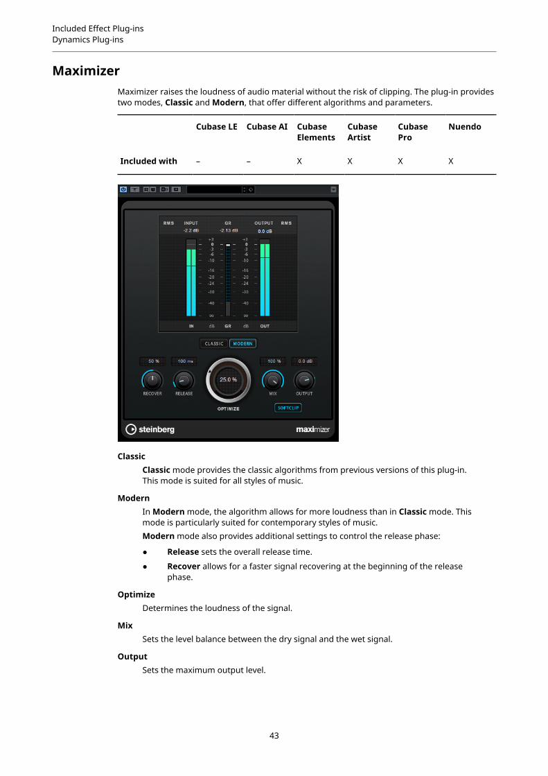
MaximizerMaximizer raises the loudness of audio material without the risk of clipping. The plug-in providestwo modes, Classic and Modern, that offer different algorithms and parameters.
Cubase LE Cubase AI CubaseElements
CubaseArtist
CubasePro
Nuendo
Included with – – X X X X
ClassicClassic mode provides the classic algorithms from previous versions of this plug-in.This mode is suited for all styles of music.
ModernIn Modern mode, the algorithm allows for more loudness than in Classic mode. Thismode is particularly suited for contemporary styles of music.Modern mode also provides additional settings to control the release phase:
● Release sets the overall release time.
● Recover allows for a faster signal recovering at the beginning of the releasephase.
OptimizeDetermines the loudness of the signal.
MixSets the level balance between the dry signal and the wet signal.
OutputSets the maximum output level.
43

Included Effect Plug-insDynamics Plug-ins
Soft ClipIf this button is activated, Maximizer starts limiting or clipping the signal softly. At thesame time, harmonics are generated, adding a warm, tube-like characteristic to theaudio material.
MIDI GateThis plug-in gates audio signals. The gate is triggered by MIDI notes.
Cubase LE Cubase AI CubaseElements
CubaseArtist
CubasePro
Nuendo
Included with – – – X X X
Gating, in its fundamental form, silences audio signals below a set threshold. If a signal risesabove the set level, the gate opens to let the signal through. Signals below the set level aresilenced. MIDI Gate, however, is not triggered by threshold levels, but MIDI notes. Therefore, itneeds both audio and MIDI data to function.
Attack (0 to 500 ms)Sets the time after which the gate opens when it is triggered.
HoldDetermines how long the gate remains open after a note-on or note-off message.The Hold Mode settings are taken into account.
Release (0 to 3000 ms)Sets the time after which the gate closes after the set Hold time.
Note To AttackDetermines to which extent the velocity values of the MIDI notes affect the attacktime. The higher the value, the more the attack time increases with high notevelocities. Negative values result in shorter attack times with high velocities. If you donot want to use this parameter, set it to 0.
Note To ReleaseDetermines to which extent the velocity values of the MIDI notes affect the releasetime. The higher the value, the more the release time increases. If you do not want touse this parameter, set it to 0.
Velocity To VCAControls to which extent the velocity values of the MIDI notes determine the outputvolume. At a value of 127, the volume is controlled entirely by the velocity values, andat a value of 0, the velocities have no effect on the volume.
44
Included Effect Plug-insDynamics Plug-ins
Hold ModeSets the Hold Mode.
● In Note-On mode, the gate only remains open for the time set with the Holdand Release parameters, regardless of the length of the MIDI note thattriggered the gate.
● In Note-Off mode, the gate remains open for as long as the MIDI note plays.The Hold and Release parameters are applied once a note-off signal has beenreceived.
Setting Up MIDI GateTo use MIDI Gate for your audio, you need an audio track and a MIDI track.
PROCEDURE
1. Select the audio track to which you want to apply MIDI Gate.This can be recorded or realtime audio material from any audio track.
2. Select MIDI Gate as an insert effect for the audio track.
3. Select a MIDI track to control the MIDI Gate effect.You can either play notes on a connected MIDI keyboard or use recorded MIDI notes.
4. Open the Output Routing pop-up menu for the MIDI track and select MIDI Gate.
Applying MIDI Gate
PREREQUISITESet up the plug-in properly.
How to apply MIDI Gate depends on whether you are using realtime or recorded MIDI. Weassume for the purposes of this manual that you are using recorded audio and play the MIDI inrealtime.
PROCEDURE
1. If you use realtime MIDI to trigger the plug-in, make sure the MIDI track is selected.
2. Start playback.
3. If you use realtime MIDI, play a few notes on your keyboard.
RESULTThe MIDI notes trigger the Gate. The plug-in gates the audio signals.
RELATED LINKSSetting Up MIDI Gate on page 45
MultibandCompressorMultibandCompressor allows a signal to be split into four frequency bands. You can specify thelevel, bandwidth, and compressor characteristics for each band.
Cubase LE Cubase AI CubaseElements
CubaseArtist
CubasePro
Nuendo
Included with – – – – X X
45
Included Effect Plug-insDynamics Plug-ins
Cubase LE Cubase AI CubaseElements
CubaseArtist
CubasePro
Nuendo
Side-chainsupport
– – – – X X
NOTE
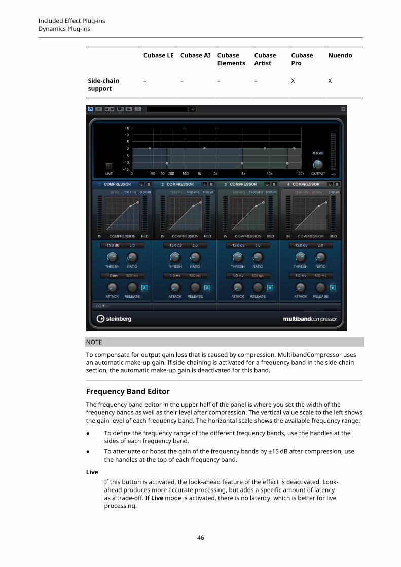
To compensate for output gain loss that is caused by compression, MultibandCompressor usesan automatic make-up gain. If side-chaining is activated for a frequency band in the side-chainsection, the automatic make-up gain is deactivated for this band.
Frequency Band Editor
The frequency band editor in the upper half of the panel is where you set the width of thefrequency bands as well as their level after compression. The vertical value scale to the left showsthe gain level of each frequency band. The horizontal scale shows the available frequency range.
● To define the frequency range of the different frequency bands, use the handles at thesides of each frequency band.
● To attenuate or boost the gain of the frequency bands by ±15 dB after compression, usethe handles at the top of each frequency band.
LiveIf this button is activated, the look-ahead feature of the effect is deactivated. Look-ahead produces more accurate processing, but adds a specific amount of latencyas a trade-off. If Live mode is activated, there is no latency, which is better for liveprocessing.
46

Included Effect Plug-insDynamics Plug-ins
Bypassing Frequency Bands
To bypass each frequency band, activate the Bypass Band button in each section.
Soloing Frequency BandsTo solo a frequency band, activate the S button in each section. Only one band canbe soloed at a time.
Output (-24 to 24 dB)Sets the output level.
Compressor Section
You can specify the Threshold and Ratio by moving breakpoints or using the correspondingknobs. The threshold is marked by the first breakpoint where the line deviates from the straightdiagonal.
Threshold (-60 to 0 dB)Determines the level where the compressor kicks in. Only signal levels above the setthreshold are processed.
RatioSets the amount of gain reduction applied to signals above the set threshold. A ratioof 3:1 means that for every 3 dB the input level increases, the output level increasesby 1 dB.
Attack (0.1 to 100 ms)Determines how fast the compressor responds to signals above the set threshold.If the attack time is long, more of the early part of the signal passes throughunprocessed.
Release (10 to 1000 ms or Auto mode)Sets the time after which the gain returns to its original level when the signal dropsbelow the threshold. If the Auto button is activated, the plug-in automatically findsthe best release setting for the audio material.
Side-Chain Section
To open the side-chain section, click the SC button at the bottom left of the plug-in window.
IMPORTANT
To be able to use the side-chain function for the bands, global side-chain must be activated forthe plug-in.
FrequencyIf the Side-Chain button is activated, this sets the frequency of the side-chain filter.
Q-FactorIf the Side-Chain button is activated, this sets the resonance or width of the filter.
47
Included Effect Plug-insDynamics Plug-ins
Side-ChainActivates the internal side-chain filter. The side-chain signal can then be shapedaccording to the filter parameter.
MonitorAllows you to monitor the filtered signal.
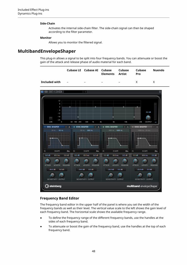
MultibandEnvelopeShaperThis plug-in allows a signal to be split into four frequency bands. You can attenuate or boost thegain of the attack and release phase of audio material for each band.
Cubase LE Cubase AI CubaseElements
CubaseArtist
CubasePro
Nuendo
Included with – – – – X X
Frequency Band Editor
The frequency band editor in the upper half of the panel is where you set the width of thefrequency bands as well as their level. The vertical value scale to the left shows the gain level ofeach frequency band. The horizontal scale shows the available frequency range.
● To define the frequency range of the different frequency bands, use the handles at thesides of each frequency band.
● To attenuate or boost the gain of the frequency band, use the handles at the top of eachfrequency band.
48
Included Effect Plug-insDynamics Plug-ins
LiveIf this button is activated, the look-ahead feature of the effect is deactivated. Look-ahead produces more accurate processing, but adds a specific amount of latencyas a trade-off. If Live mode is activated, there is no latency, which is better for liveprocessing.
Bypassing Frequency Bands
To bypass each frequency band, activate the Bypass Band button in each section.
Soloing Frequency BandsTo solo a frequency band, activate the S button in each section. Only one band canbe soloed at a time.
Output (-24 to 24 dB)Sets the output level.
Shaper Section
You can specify the Attack, Length, and Release by moving breakpoints or using thecorresponding knobs. Be careful with levels when boosting the gain. You can reduce the outputlevel to avoid clipping.
Attack (-20 to 20 dB)Sets the gain of the attack phase of the signal.
Length (5 to 200 ms)Sets the length of the attack phase.
Release (-20 to 20 dB)Sets the gain of the release phase of the signal.
Sensitivity (-40 to -10 dB)Sets the sensitivity of the detection.
OutputSets the output level.
MultibandExpanderThis plug-in allows a signal to be split into four frequency bands. You can reduce the output levelin relation to the input level for signals below the set threshold for each band. This is useful if youwant to enhance the dynamic range or reduce the noise in quiet passages.
Cubase LE Cubase AI CubaseElements
CubaseArtist
CubasePro
Nuendo
Included with – – – – X X
Side-chainsupport
– – – – X X
49

Included Effect Plug-insDynamics Plug-ins
Frequency Band Editor
The frequency band editor in the upper half of the panel is where you set the width of thefrequency bands as well as their level after expansion. The vertical value scale to the left showsthe gain level of each frequency band. The horizontal scale shows the available frequency range.
● To define the frequency range of the different frequency bands, use the handles at thesides.
● To attenuate or boost the gain of the frequency band after expansion, use the handles ontop of each frequency band.
LiveIf this button is activated, the look-ahead feature of the effect is deactivated. Look-ahead produces more accurate processing, but adds a specific amount of latencyas a trade-off. If Live mode is activated, there is no latency, which is better for liveprocessing.
Bypassing Frequency Bands
To bypass each frequency band, activate the Bypass Band button in each section.
Soloing Frequency BandsTo solo a frequency band, activate the S button in each section. Only one band canbe soloed at a time.
Output (-24 to 24 dB)Sets the output level.
50

Included Effect Plug-insDynamics Plug-ins
Expander Section
You can specify the Threshold and Ratio by moving breakpoints or using the correspondingknobs. The first breakpoint from which the line deviates from the straight diagonal is thethreshold point.
Threshold (-60 to 0 dB)Determines the level where the expansion kicks in. Only signal levels below the setthreshold are processed.
RatioSets the amount of gain boost applied to signals below the threshold.
Maximum ReductionSets the maximum amount by which the level is reduced when the signal falls belowthe set threshold.
Fall (0.1 to 100 ms)Determines how fast the expander responds to signals below the set threshold. Ifthe fall time is long, more of the early part of the signal passes through unprocessed.
Hold (0 to 2000 ms)Sets the time the applied expansion affects the signal below the threshold.
Rise (10 to 1000 ms or Auto mode)Sets the time after which the gain returns to its original level when the signalexceeds the threshold. If the Auto Rise button is activated, the plug-in automaticallyfinds the best rise setting for the audio material.
OutputSets the output level.
Side-Chain Section
FrequencyIf the Side-Chain button is activated, this sets the frequency of the side-chain filter.
Q-FactorIf the Side-Chain button is activated, this sets the resonance or width of the filter.
Side-ChainActivates the internal side-chain filter. The side-chain signal can then be shapedaccording to the filter parameters. Side-chaining is useful for tailoring how the effectoperates.
MonitorAllows you to monitor the filtered signal.
51

Included Effect Plug-insDynamics Plug-ins
Tube CompressorThis versatile compressor with integrated tube-simulation allows you to achieve smooth andwarm compression effects. The VU meter shows the amount of gain reduction. Tube Compressorfeatures an internal side-chain section that lets you filter the trigger signal.
Cubase LE Cubase AI CubaseElements
CubaseArtist
CubasePro
Nuendo
Included with – – X X X X
Side-chainsupport
– – – X X X
Drive (1.0 to 6.0 dB)Controls the amount of tube saturation.
InputDetermines the compression amount. The higher the input gain, the morecompression is applied.
RatioToggles between a low and a high ratio value.
Output (-12 to 12 dB)Sets the output gain.
CharacterKeeps the bass tight and preserves its attacks by decreasing the tube saturation forlower frequencies, and adds brilliance by creating harmonics for higher frequencies.
Attack (0.1 to 100 ms)Determines how fast the compressor responds. If the attack time is long, more of theinitial part of the signal passes through unprocessed.
52

Included Effect Plug-insDynamics Plug-ins
Release (10 to 1000 ms or Auto mode)Sets the time after which the gain returns to its original level. If the Auto buttonis activated, the plug-in automatically finds the best release setting for the audiomaterial.
MixAdjusts the mix between dry signal and wet signal, preserving the transients of theinput signal.
In/Out MetersShow the highest peaks of all available input and output channels.
VU MeterShows the amount of gain reduction.
Side-ChainActivates the internal side-chain filter. The input signal can then be shaped accordingto the filter parameters. Internal side-chaining is useful for tailoring how the gateoperates.
Side-chain section
Filter buttons (LP, BP, and HP)If the Side-Chain button is activated, you can use these buttons to set the filter typeto low-pass, band-pass, or high-pass.
Center (50 to 20000 Hz)If the Side-Chain button is activated, this sets the center frequency of the filter.
Q-FactorIf the Side-Chain button is activated, this sets the resonance or width of the filter.
MonitorAllows you to monitor the filtered signal.
VintageCompressorVintageCompressor is modeled after vintage type compressors.
Cubase LE Cubase AI CubaseElements
CubaseArtist
CubasePro
Nuendo
Included with – – X X X X
Side-chainsupport
– – – X X X
This compressor features separate controls for Input and Output gain, Attack, and Release. Inaddition, there is a Punch mode which preserves the attack phase of the signal and a program-dependent Auto feature for the Release parameter.
53
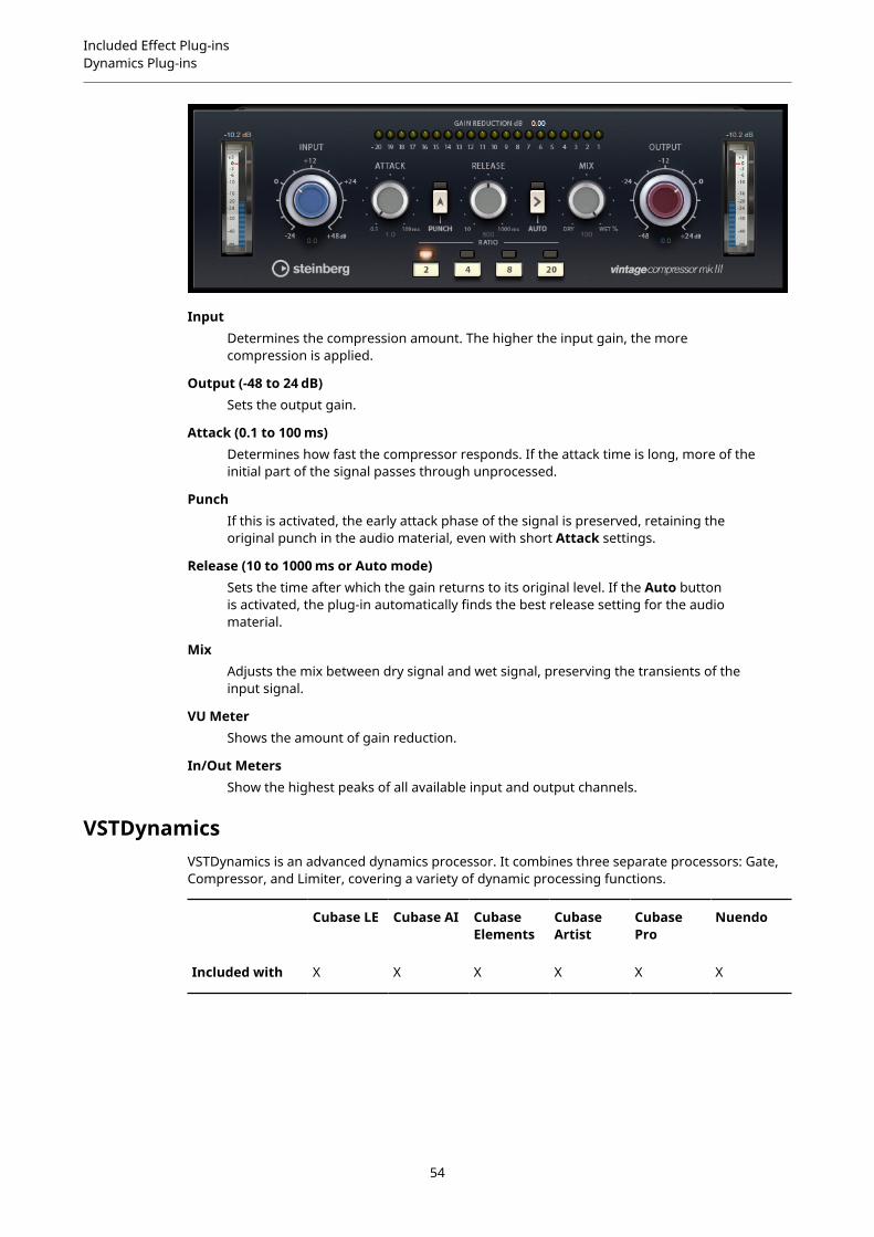
Included Effect Plug-insDynamics Plug-ins
InputDetermines the compression amount. The higher the input gain, the morecompression is applied.
Output (-48 to 24 dB)Sets the output gain.
Attack (0.1 to 100 ms)Determines how fast the compressor responds. If the attack time is long, more of theinitial part of the signal passes through unprocessed.
PunchIf this is activated, the early attack phase of the signal is preserved, retaining theoriginal punch in the audio material, even with short Attack settings.
Release (10 to 1000 ms or Auto mode)Sets the time after which the gain returns to its original level. If the Auto buttonis activated, the plug-in automatically finds the best release setting for the audiomaterial.
MixAdjusts the mix between dry signal and wet signal, preserving the transients of theinput signal.
VU MeterShows the amount of gain reduction.
In/Out MetersShow the highest peaks of all available input and output channels.
VSTDynamicsVSTDynamics is an advanced dynamics processor. It combines three separate processors: Gate,Compressor, and Limiter, covering a variety of dynamic processing functions.
Cubase LE Cubase AI CubaseElements
CubaseArtist
CubasePro
Nuendo
Included with X X X X X X
54
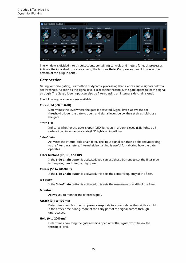
Included Effect Plug-insDynamics Plug-ins
The window is divided into three sections, containing controls and meters for each processor.Activate the individual processors using the buttons Gate, Compressor, and Limiter at thebottom of the plug-in panel.
Gate Section
Gating, or noise gating, is a method of dynamic processing that silences audio signals below aset threshold. As soon as the signal level exceeds the threshold, the gate opens to let the signalthrough. The Gate trigger input can also be filtered using an internal side-chain signal.
The following parameters are available:
Threshold (-60 to 0 dB)Determines the level where the gate is activated. Signal levels above the setthreshold trigger the gate to open, and signal levels below the set threshold closethe gate.
State LEDIndicates whether the gate is open (LED lights up in green), closed (LED lights up inred) or in an intermediate state (LED lights up in yellow).
Side-ChainActivates the internal side-chain filter. The input signal can then be shaped accordingto the filter parameters. Internal side-chaining is useful for tailoring how the gateoperates.
Filter buttons (LP, BP, and HP)If the Side-Chain button is activated, you can use these buttons to set the filter typeto low-pass, band-pass, or high-pass.
Center (50 to 20000 Hz)If the Side-Chain button is activated, this sets the center frequency of the filter.
Q-FactorIf the Side-Chain button is activated, this sets the resonance or width of the filter.
MonitorAllows you to monitor the filtered signal.
Attack (0.1 to 100 ms)Determines how fast the compressor responds to signals above the set threshold.If the attack time is long, more of the early part of the signal passes throughunprocessed.
Hold (0 to 2000 ms)Determines how long the gate remains open after the signal drops below thethreshold level.
55

Included Effect Plug-insDynamics Plug-ins
Release (10 to 1000 ms or Auto mode)Sets the time after which the gate closes after the set Hold time. If the Auto buttonis activated, the plug-in automatically finds the best release setting for the audiomaterial.
RangeAdjusts the attenuation of the gate when it is shut. If Range is set to minus infinite
, the gate is completely shut. The higher the value, the higher the level of thesignal that passes through the shut gate.
Input Gain MeterShows the input gain.
Compressor Section
The compressor reduces the dynamic range of the audio, making softer sounds louder or loudersounds softer, or both. The compressor features a separate display that graphically illustratesthe compressor curve shaped according to your settings.
Threshold (-60 to 0 dB)Determines the level where the compressor kicks in. Only signal levels above the setthreshold are processed.
RatioSets the amount of gain reduction applied to signals above the set threshold. A ratioof 3:1 means that for every 3 dB the input level increases, the output level increasesby 1 dB.
Make-Up (0 to 24 dB or Auto mode)Compensates for output gain loss, caused by compression. If the Auto button isactivated, the knob becomes dark and the output is automatically adjusted for gainloss.
Attack (0.1 to 100 ms)Determines how fast the compressor responds to signals above the set threshold. Ifthe attack time is long, more of the early part of the signal (attack) passes throughunprocessed.
Release (10 to 1000 ms or Auto mode)Sets the time after which the gain returns to its original level when the signal dropsbelow the threshold. If the Auto button is activated, the plug-in automatically findsthe best release setting for the audio material.
Graphical displayUse the graphical display to graphically set the threshold and ratio values. To the leftand right of the graphical display, you find two meters that show the amount of gainreduction in dB.
Limiter Section
The limiter ensures that the output level never exceeds a set threshold, to avoid clipping infollowing devices. Conventional limiters usually require very accurate setting up of the attack andrelease parameters to prevent the output level from going beyond the set threshold level. Thelimiter adjusts and optimizes these parameters automatically according to the audio material.
OutputSets the maximum output level.
56

Included Effect Plug-insEQ Plug-ins
Soft ClipIf this button is activated, the signal is limited when the signal level exceeds -6 dB. Atthe same time, harmonics are generated, adding a warm, tube-like characteristic tothe audio material.
Release (10 to 1000 ms or Auto mode)Sets the time after which the gain returns to its original level. If the Auto buttonis activated, the plug-in automatically finds the best release setting for the audiomaterial.
MetersThe three meters show the input gain (IN), the gain reduction (GR) and the outputgain (OUT).
Module Configuration Button
Using the Module Configuration button in the bottom right corner of the plug-in panel, youcan set the signal flow order for the three processors. Changing the order of the processors canproduce different results, and the available options allow you to quickly compare what worksbest for a given situation. Simply click the Module Configuration button to change to a differentconfiguration. There are three routing options:
● C-G-L (Compressor-Gate-Limit)
● G-C-L (Gate-Compressor-Limit)
● C-L-G (Compressor-Limit-Gate)
EQ Plug-ins
CurveEQVoxengo CurveEQ is a spline equalizer for professional music and audio production applications.CurveEQ shows the filter response you are designing by means of a spline, that is, a smoothcurvy line. This way you can see how the EQ alters the sound.
Cubase LE Cubase AI CubaseElements
CubaseArtist
CubasePro
Nuendo
Included with – – – – X X
CurveEQ implements spectrum matching technology that allows you to transfer the spectralshape of one recording to another. In other words, you can copy the frequency balanceof existing time-proven mixes so that other mixes can be improved. CurveEQ’s filters canbe switched between linear-phase and minimum-phase modes. CurveEQ also features acustomizable spectrum analyzer. Furthermore, you can display, save, and load static spectrumplots for comparison and matching purposes.
For detailed information about CurveEQ and its parameters, refer to the documentation providedby Voxengo at http://www.voxengo.com.
57

Included Effect Plug-insEQ Plug-ins
DJ-EQThis plug-in is an easy-to-use 3-band parametric equalizer that resembles the EQs found ontypical DJ mixers. This plug-in is designed for quick sound fixes.
Cubase LE Cubase AI CubaseElements
CubaseArtist
CubasePro
Nuendo
Included with X X X X X X
● To set the Low, Mid, and Hi frequency bands, click and drag the EQ points.
● To fine-adjust the Low, Mid, and Hi frequency bands, press Shift and drag the EQ points.
● To set a parameter to zero, press Ctrl/Cmd and click it.
● To change the Gain values, click them and move the mouse up or down.
Low GainSets the amount of boost or attenuation for the low band.
Low Kill (Activates Low Cut)Cuts the low band.
Mid GainSets the amount of attenuation/boost for the mid band.
Mid Kill (Activates Mid Cut)Cuts the mid band.
Hi GainSets the amount of boost or attenuation for the high band.
Hi Kill (Activates High Cut)Cuts the high band.
Output meterIndicates the level of the output signal.
58

Included Effect Plug-insEQ Plug-ins
GEQ-10/GEQ-30These graphic equalizers are identical, except for the number of available frequency bands (10and 30).
Cubase LE Cubase AI CubaseElements
CubaseArtist
CubasePro
Nuendo
Included with –/– –/– –/– X/– X/X X/X
Each band can be attenuated or boosted by up to 12 dB, allowing for fine control of thefrequency response. In addition, there are several preset modes available that can add color tothe sound of GEQ-10/GEQ-30.
You can draw response curves in the main display by clicking and dragging with the mouse. Youhave to click one of the sliders before you drag across the display.
At the bottom of the window, the individual frequency bands are shown in Hz. At the top of thedisplay, the amount of attenuation/boost is shown in dB.
OutputSets the overall gain of the equalizer.
FlattenResets all the frequency bands to 0 dB.
RangeAllows you to adjust how much a set curve cuts or boosts the signal.
InvertInverts the current response curve.
Mode pop-up menuThis pop-up menu allows you to set the filter mode that determines how the variousfrequency band controls interact to create the response curve.
EQ Modes
The Mode pop-up menu in the lower right corner allows you to select an EQ mode, which addcolor or character to the equalized output in various ways.
True ResponseApplies serial filters with an accurate frequency response.
Digi StandardIn this mode, the resonance of the last band depends on the sample rate.
59

Included Effect Plug-insEQ Plug-ins
ClassicApplies a classic parallel filter structure where the response does not follow the setgain values accurately.
VariableQApplies parallel filters where the resonance depends on the amount of gain.
ConstQ uApplies parallel filters where the resonance of the first and last bands depends onthe sample rate.
ConstQ sApplies parallel filters where the resonance is raised when boosting the gain and viceversa.
ResonantApplies serial filters where a gain increase of one band lowers the gain in adjacentbands.
StudioEQStudio EQ is a high-quality 4-band parametric stereo equalizer with two fully parametric mid-range bands. The low and high bands can act as either shelving filters (three types), or as peakfilter (band-pass), or as cut filter (low-pass/high-pass).
Cubase LE Cubase AI CubaseElements
CubaseArtist
CubasePro
Nuendo
Included with – – X X X X
Gain (-20 to +24 dB)Sets the amount of attenuation/boost for the corresponding band.
InvInverts the gain value of the filter. Use this button to filter out unwanted noise. Whenlooking for the frequency to omit, it sometimes helps to boost it in the first place (setthe filter to positive gain). After you have found the frequency of the noise, you canuse the Inv button to cancel it out.
60
Included Effect Plug-insEQ Plug-ins
Freq (20 to 20000 Hz)Sets the frequency of the corresponding band. You can set the frequency either in Hzor as a note value. If you enter a note value, the frequency is automatically changedto Hz. For example, a note value of A3 sets the frequency to 440 Hz. When you entera note value, you can also enter a cent offset. For example, enter A5 -23 or C4 +49.
NOTE
Ensure that you enter a space between the note and the cent offset. Only in this case,the cent offsets are taken into account.
Q-FactorControls the width, or resonance, of the corresponding band.
Filter modeFor the low and high band, you can choose between three types of shelving filters, apeak filter (band-pass), and a cut filter (lowpass/high-pass). If Cut mode is selected,the Gain parameter is fixed.
● Shelf I adds resonance in the opposite gain direction slightly above the setfrequency.
● Shelf II adds resonance in the gain direction at the set frequency.
● Shelf III is a combination of Shelf I and II.
Output (-24 to +24 dB)This knob on the top right of the plug-in panel allows you to adjust the overall outputlevel.
Auto GainIf this button is activated, the gain is automatically adjusted, keeping the output levelconstant regardless of the EQ settings.
SpectrumShows the spectrum before and after filtering.
ResetResets the EQ settings.
Making Settings
PROCEDURE
1. Click the corresponding On/Off button on the left of the plug-in panel to activate any or allof the 4 equalizer bands (Low, Mid 1, Mid 2, and High).If a band is activated, the corresponding EQ point appears in the EQ curve display.
2. Set the parameters for an activated EQ band.This can be done in several ways:
● By using the knobs.
● By clicking on the numeric values and entering new values.
● By dragging points in the EQ curve display.
61

Included Effect Plug-insEQ Plug-ins
Using Modifier KeysWhen using the mouse to change the parameter settings, modifier keys can be used. Whenno modifier key is pressed and you drag an EQ point in the display, the Gain and Frequencyparameters are adjusted simultaneously.
ShiftIf you keep Shift pressed and drag the mouse, the Q-factor of the corresponding EQband is modified.
AltIf you keep Alt pressed and drag the mouse, the frequency of the corresponding EQband is modified.
Ctrl/CmdIf you keep Ctrl/Cmd pressed and drag the mouse, the gain value of thecorresponding EQ band is modified.
FrequencyFrequency is a high-quality equalizer with 8 fully parametric bands. The bands can act as eithershelving filter, as peak or notch filter (band-pass), or as cut filter (low-pass/high-pass).
Cubase LE Cubase AI CubaseElements
CubaseArtist
CubasePro
Nuendo
Included with – – – – X X
62

Included Effect Plug-insEQ Plug-ins
Main Layout
Reset
Alt-click this button to reset all parameter values.
Auto Listen for Filters
If this option is activated and you edit a parameter of a band, the correspondingfrequency range is isolated. This helps you to focus on a particular frequency rangeand allows you to locate unwanted frequencies in your audio.
Global Settings
Opens the settings dialog for the spectrum display.
Show/Hide Keyboard
Shows/Hides the keyboard below the graphical editor.On the keyboard, color indicators reflect the center frequencies of all active equalizerbands. You can adjust the frequency of a band by dragging its color indicator. If youdrag the color indicator of a band to a key, the band is set to its exact frequency.
OutputAdjusts the overall output level.
Band Settings
On/OffActivates/Deactivates the corresponding band.
NOTE
● To activate/deactivate a band, you can also double-click the correspondinghandle in the graphical editor.
● If a band is deactivated, you can still modify its parameters.
Processing SwitchesAllow you to switch between left/right, stereo, and mid/side processing. In Left/Right or Mid/Side processing mode, you can make different settings for the twochannels.
NOTE
This setting is only available for stereo tracks.
Linear PhaseActivates/Deactivates linear phase mode for the corresponding band.Linear phase mode avoids unwanted frequency dependent phase shifts of the audiosignal that might occur with standard minimum phase equalizing.
NOTE
● Linear phase mode leads to an increase in latency.
63
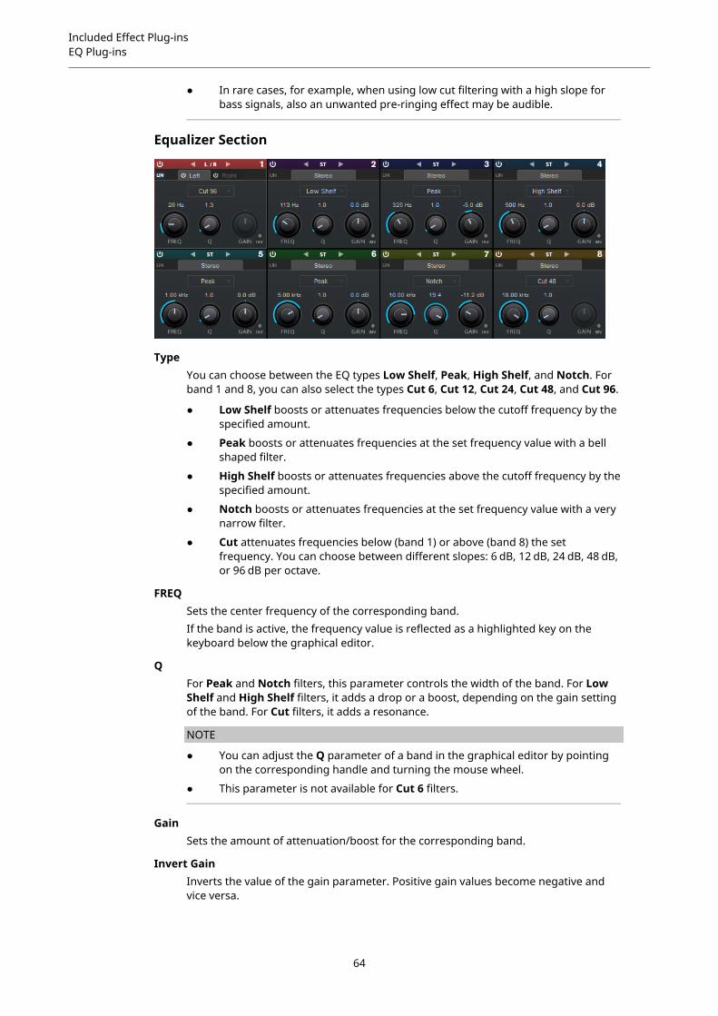
Included Effect Plug-insEQ Plug-ins
● In rare cases, for example, when using low cut filtering with a high slope forbass signals, also an unwanted pre-ringing effect may be audible.
Equalizer Section
TypeYou can choose between the EQ types Low Shelf, Peak, High Shelf, and Notch. Forband 1 and 8, you can also select the types Cut 6, Cut 12, Cut 24, Cut 48, and Cut 96.
● Low Shelf boosts or attenuates frequencies below the cutoff frequency by thespecified amount.
● Peak boosts or attenuates frequencies at the set frequency value with a bellshaped filter.
● High Shelf boosts or attenuates frequencies above the cutoff frequency by thespecified amount.
● Notch boosts or attenuates frequencies at the set frequency value with a verynarrow filter.
● Cut attenuates frequencies below (band 1) or above (band 8) the setfrequency. You can choose between different slopes: 6 dB, 12 dB, 24 dB, 48 dB,or 96 dB per octave.
FREQSets the center frequency of the corresponding band.If the band is active, the frequency value is reflected as a highlighted key on thekeyboard below the graphical editor.
QFor Peak and Notch filters, this parameter controls the width of the band. For LowShelf and High Shelf filters, it adds a drop or a boost, depending on the gain settingof the band. For Cut filters, it adds a resonance.
NOTE
● You can adjust the Q parameter of a band in the graphical editor by pointingon the corresponding handle and turning the mouse wheel.
● This parameter is not available for Cut 6 filters.
GainSets the amount of attenuation/boost for the corresponding band.
Invert GainInverts the value of the gain parameter. Positive gain values become negative andvice versa.
64
Included Effect Plug-insFilter Plug-ins
Global Settings
● To open the Global Settings, click Global Settings above the spectrum display.
Spectrum Display
Show SpectrumActivates/Deactivates the spectrum display.
Peak HoldHolds the peak values of the spectrum display for a short time.
SmoothDetermines the reaction time of the spectrum display. Lower values result in fasterreaction times.
Bar GraphIf this option is activated, the frequency spectrum is analyzed into 60 separate bandsthat are displayed as vertical bars.
Two ChannelsIf this option is activated, the spectrum of the left and right channels are displayedseparately.
SlopeTilts the spectrum display around the 1 kHz pivot.
EQ Curve
Show CurveShows/Hides the EQ curve in the spectrum display.
FilledIf this option is activated, the EQ curve is filled. Amount allows you to specify thedegree of coverage between 10 and 80 %.
Filter Plug-ins
DualFilterThis plug-in filters out specific frequencies while allowing others to pass through.
Cubase LE Cubase AI CubaseElements
CubaseArtist
CubasePro
Nuendo
Included with X X X X X X
65
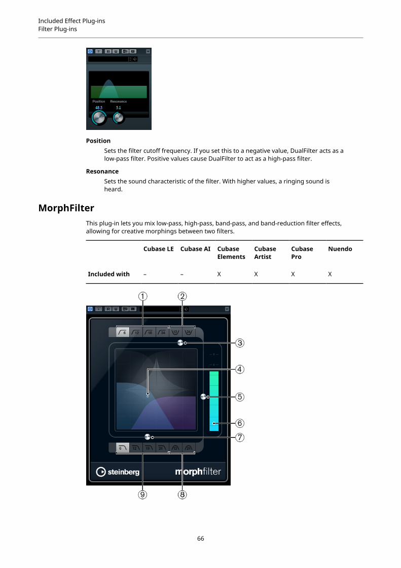
Included Effect Plug-insFilter Plug-ins
PositionSets the filter cutoff frequency. If you set this to a negative value, DualFilter acts as alow-pass filter. Positive values cause DualFilter to act as a high-pass filter.
ResonanceSets the sound characteristic of the filter. With higher values, a ringing sound isheard.
MorphFilterThis plug-in lets you mix low-pass, high-pass, band-pass, and band-reduction filter effects,allowing for creative morphings between two filters.
Cubase LE Cubase AI CubaseElements
CubaseArtist
CubasePro
Nuendo
Included with – – X X X X
66

Included Effect Plug-insFilter Plug-ins
1 High Pass (6, 12, 18, 24 dB per decade)Eliminates low-frequency signal components. Several filter slopes are available.
2 Band Rejection (12, 24 dB/per decade)Lets all frequencies pass, except those in the stop band. Several filter slopes are available.
3 Resonance FactorChanges the resonance value of the filters.
4 x/y controlAdjusts the Morph Factor and the Frequency parameters simultaneously.
5 Morph FactorLets you mix the output between the two selected filters.
6 Level meterShows the output level, giving you an indication of how the filtering affects the overall levelof the edited event.
7 FrequencyAdjusts the cutoff frequency of the filters.
8 Band Pass (12, 24 dB per decade)Allows signals falling within a certain frequency range to pass through. Several filter slopesare available.
9 Low Pass (6, 12, 18, 24 dB per decade)Eliminates high-frequency signal components. Several filter slopes are available.
PostFilterThis effect allows quick and easy filtering of unwanted frequencies, creating room for theimportant sounds in your mix.
Cubase LE Cubase AI CubaseElements
CubaseArtist
CubasePro
Nuendo
Included with – – – – – X
67
Included Effect Plug-insFilter Plug-ins
The PostFilter plug-in combines a low-cut filter, a notch filter, and a high-cut filter. You can makesettings by dragging the curve points in the graphical display, or by adjusting the controls belowthe display section.
Level meterShows the output level, giving you an indication of how the filtering affects theoverall level of the edited audio.
Low Cut Freq (20 Hz to 1 kHz, or Off)Allows you to eliminate low-frequency noise. The filter is inactive if the curve pointis located all the way to the left. You can set the frequency either in Hz or as a notevalue. If you enter a note value, the frequency is automatically changed to Hz. Forexample, a note value of A3 sets the frequency to 440 Hz. When you enter a notevalue, you can also enter a cent offset. For example, enter A5 -23 or C4 +49.
NOTE
Ensure that you enter a space between the note and the cent offset. Only in this case,the cent offsets are taken into account.
Low Cut SlopeAllows you to choose a slope value for the low-cut filter.
Low Cut PreviewUse this button between the Low Cut Freq button and the graphical display toswitch the filter to a complementary high-cut filter. This deactivates any other filters,allowing you to listen only to the frequencies that you want to filter out.
Notch FreqSets the frequency of the notch filter. You can set the frequency either in Hz or as anote value. If you enter a note value, the frequency is automatically changed to Hz.For example, a note value of A3 sets the frequency to 440 Hz. When you enter a notevalue, you can also enter a cent offset. For example, enter A5 -23 or C4 +49.
NOTE
Ensure that you enter a space between the note and the cent offset. Only in this case,the cent offsets are taken into account.
Notch GainAdjusts the gain of the selected frequency. Use positive values to identify thefrequencies that you want to filter out.
Notch Gain InvertThis button inverts the gain value of the notch filter. Use this button to filter outunwanted noise. When looking for the frequency to omit, it sometimes helps toboost it first (set the notch filter to positive gain). After you have found frequency ofthe noise, you can use the Invert button to cancel it out.
Notch Q-FactorSets the width of the notch filter.
Notch PreviewUse the Preview button between the notch filter buttons and the graphical display tocreate a band-pass filter with the peak filter's frequency and Q. This deactivates anyother filters, allowing you to listen only to the frequencies you want to filter out.
Notches buttons (1, 2, 4, 8)These buttons add additional notch filters to filter out harmonics.
68

Included Effect Plug-insFilter Plug-ins
High Cut Freq (3 Hz to 20 kHz, or Off)This high-cut filter allows you to remove high-frequency noise. The filter is inactiveif the curve point is located all the way to the right. You can set the frequency eitherin Hz or as a note value. If you enter a note value, the frequency is automaticallychanged to Hz. For example, a note value of A3 sets the frequency to 440 Hz. Whenyou enter a note value, you can also enter a cent offset. For example, enter A5 -23 orC4 +49.
NOTE
Ensure that you enter a space between the note and the cent offset. Only in this case,the cent offsets are taken into account.
High Cut SlopeAllows you to choose a slope value for the high-cut filter.
High Cut PreviewThis button between the High Cut Freq button and the graphical display allowsyou to switch the filter to a complementary low-cut filter. This deactivates any otherfilters, allowing you to listen only to the frequencies you want to filter out.
StepFilterThis plug-in is a pattern-controlled multimode filter that can create rhythmic, pulsating filtereffects.
Cubase LE Cubase AI CubaseElements
CubaseArtist
CubasePro
Nuendo
Included with – – X X X X
General Operation
StepFilter can produce two simultaneous 16-step patterns for the filter cutoff and resonanceparameters, synchronized to the sequencer tempo.
The horizontal axis shows the pattern steps 1 to 16 from left to right, and the vertical axisdetermines the (relative) filter cutoff frequency and resonance settings. The higher up onthe vertical axis a step value is entered, the higher the relative filter cutoff frequency or filterresonance setting.
By starting playback and editing the patterns for the cutoff and resonance parameters, you canhear how your filter patterns affect the sound source connected to StepFilter.
69
Included Effect Plug-insFilter Plug-ins
Setting Step Values
● To enter a step, click in the pattern grid windows.
● Individual step entries can be dragged up or down the vertical axis, or directly set byclicking in an empty grid box. By click-dragging left or right, consecutive step entries areset at the pointer position.
● Change the value for a step by dragging it up or down.
● Draw in a curve by clicking and dragging in the display.
Selecting New Patterns
● Patterns are saved with the project, and up to 8 different cutoff and resonance patternscan be saved internally. Both the cutoff and resonance settings are saved together in the 8pattern slots.
● Use the Pattern Select knob below the Resonance grid to select a new pattern. Newpatterns are all set to the same step value by default.
StepFilter Parameters
Base CutoffSets the base filter cutoff frequency. Values set in the Cutoff grid are relative to theBase Cutoff value.
Base ResonanceSets the base filter resonance. Values set in the Resonance grid are relative to theBase Resonance value.
NOTE
Very high Base Resonance settings can produce loud ringing effects at certainfrequencies.
GlideApplies glide between the pattern steps, causing values to change more smoothly.
Filter modeUse this slider to select a filter mode: low-pass, band-pass, or high-pass (from left toright).
SyncIf the Sync button to the right of the Sync pop-up menu is activated (yellow), thepattern playback is synchronized to the project tempo.
Use the pop-up menu to set the pattern beat resolution, that is, the note values thepattern plays in relation to the tempo (1/1 to 1/32, straight, triplet, or dotted).
OutputSets the output level.
MixSets the level balance between the dry signal and the wet signal.
Creating Variations for StepFilter PatternsYou can copy a pattern of the StepFilter to another pattern slot. This is useful for creatingvariations on a pattern of this plug-in.
PROCEDURE
1. Select the pattern that you want to copy.
70

Included Effect Plug-insFilter Plug-ins
2. Click the Copy button.
3. Select another pattern slot.
4. Click the Paste button.
RESULTThe pattern is copied to the new slot, and can now be edited to create variations.
ToneBoosterToneBooster is a filter that allows you to raise the gain in a selected frequency range. It isparticularly useful if it is inserted before AmpSimulator in the plug-in chain, greatly enhancingthe tonal varieties available.
Cubase LE Cubase AI CubaseElements
CubaseArtist
CubasePro
Nuendo
Included with – X X X X X
ToneSets the center filter frequency.
GainAdjusts the gain of the selected frequency range by up to 24 dB.
WidthSets the resonance of the filter.
Mode selectorSets the basic operational mode of the filter: Peak or Band Mode.
RELATED LINKSAmpSimulator on page 9
WahWahThis plug-in is a variable slope band-pass filter that can be auto-controlled by a side-chain signal(if supported) or via MIDI modeling the well-known analog pedal effect.
Cubase LE Cubase AI CubaseElements
CubaseArtist
CubasePro
Nuendo
Included with – X X X X X
Side-chainsupport
– – – X X X
71
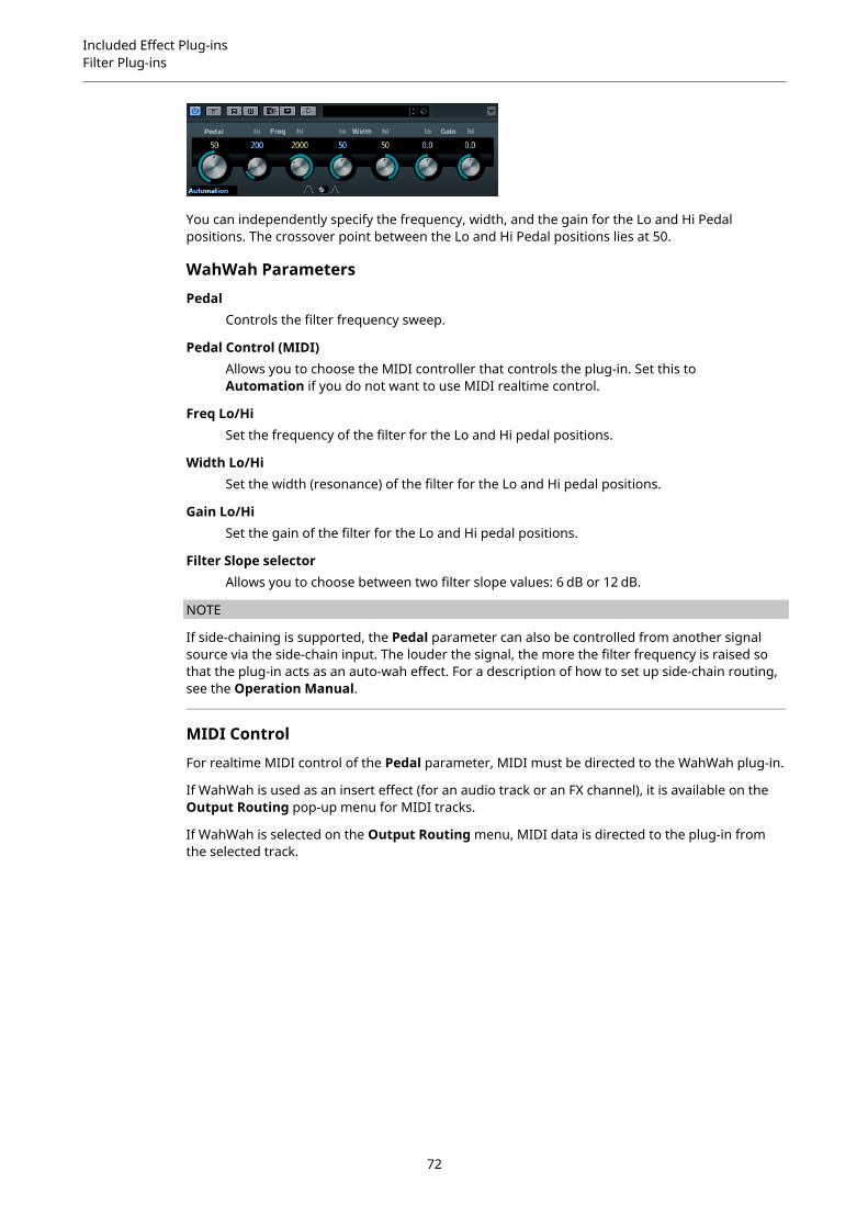
Included Effect Plug-insFilter Plug-ins
You can independently specify the frequency, width, and the gain for the Lo and Hi Pedalpositions. The crossover point between the Lo and Hi Pedal positions lies at 50.
WahWah Parameters
PedalControls the filter frequency sweep.
Pedal Control (MIDI)Allows you to choose the MIDI controller that controls the plug-in. Set this toAutomation if you do not want to use MIDI realtime control.
Freq Lo/HiSet the frequency of the filter for the Lo and Hi pedal positions.
Width Lo/HiSet the width (resonance) of the filter for the Lo and Hi pedal positions.
Gain Lo/HiSet the gain of the filter for the Lo and Hi pedal positions.
Filter Slope selectorAllows you to choose between two filter slope values: 6 dB or 12 dB.
NOTE
If side-chaining is supported, the Pedal parameter can also be controlled from another signalsource via the side-chain input. The louder the signal, the more the filter frequency is raised sothat the plug-in acts as an auto-wah effect. For a description of how to set up side-chain routing,see the Operation Manual.
MIDI Control
For realtime MIDI control of the Pedal parameter, MIDI must be directed to the WahWah plug-in.
If WahWah is used as an insert effect (for an audio track or an FX channel), it is available on theOutput Routing pop-up menu for MIDI tracks.
If WahWah is selected on the Output Routing menu, MIDI data is directed to the plug-in fromthe selected track.
72

Included Effect Plug-insMastering Plug-ins
Mastering Plug-ins
UV22HRThis is an advanced version of Apogee's renowned UV22 dithering algorithm, capable ofdithering to 8, 16, 20, or 24 bits.
Cubase LE Cubase AI CubaseElements
CubaseArtist
CubasePro
Nuendo
Included with – – X X X X
8, 16, 20, 24 bitThese buttons allow you to select the intended bit resolution for the final audio. Aswhen using the internal dithering, it is important to set this to the correct resolution.
HiApplies a normal dither gain.
LoApplies a lower level of dither noise.
Auto blackIf this option is activated, the dither noise is gated during silent passages.
IMPORTANT
Dithering should always be applied post-fader on an output bus.
Modulation Plug-ins
AutoPanThis auto-pan effect provides several parameters to modulate the left/right stereo position. Youcan use presets or create individual curves for the modulation waveform. The plug-in also allowsfor chopping effects by linking the modulation of left and right channel.
Cubase LE Cubase AI CubaseElements
CubaseArtist
CubasePro
Nuendo
Included with X X X X X X
Side-chainsupport
– – – X X X
73
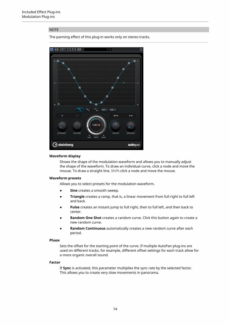
Included Effect Plug-insModulation Plug-ins
NOTE
The panning effect of this plug-in works only on stereo tracks.
Waveform displayShows the shape of the modulation waveform and allows you to manually adjustthe shape of the waveform. To draw an individual curve, click a node and move themouse. To draw a straight line, Shift-click a node and move the mouse.
Waveform presetsAllows you to select presets for the modulation waveform.
● Sine creates a smooth sweep.
● Triangle creates a ramp, that is, a linear movement from full right to full leftand back.
● Pulse creates an instant jump to full right, then to full left, and then back tocenter.
● Random One Shot creates a random curve. Click this button again to create anew random curve.
● Random Continuous automatically creates a new random curve after eachperiod.
PhaseSets the offset for the starting point of the curve. If multiple AutoPan plug-ins areused on different tracks, for example, different offset settings for each track allow fora more organic overall sound.
FactorIf Sync is activated, this parameter multiplies the sync rate by the selected factor.This allows you to create very slow movements in panorama.
74

Included Effect Plug-insModulation Plug-ins
RateSets the auto-pan speed and shows the movement within the panorama. If Sync isdeactivated, the speed is set in Hertz. If Sync is activated, you can set the speed intempo values.
SyncActivates/Deactivates tempo sync.
LinkIf this button is activated, left and right channel are modulated simultaneously. Thisresults in a chopping effect instead of auto-panning.In this mode, Width sets the intensity of the volume modulation.
WidthSets the amount of deflection to the left and right side of the stereo panorama. IfLink is activated, this parameter sets the intensity of the volume modulation.
NOTE
If side-chaining is supported, the Width parameter can also be controlled fromanother signal source via the side-chain input. For a description of how to set upside-chain routing, see the Operation Manual.
SmoothAllows you to smooth the transition between individual steps of the panorama curve.
ChopperThis effect allows you to create a tremolo with or without an additional panning effect.
Cubase LE Cubase AI CubaseElements
CubaseArtist
CubasePro
Nuendo
Included with X X X X X X
WaveformAllows you to select the modulation waveform.
DepthSets the intensity of the effect. This can also be set by clicking and dragging in thegraphical display.
SyncThe button above the Speed knob activates/deactivates tempo sync.
75

Included Effect Plug-insModulation Plug-ins
SpeedIf tempo sync is activated, this is where you specify the base note value for tempo-syncing the effect (1/1 to 1/32, straight, triplet, or dotted).If tempo sync is deactivated, the tremolo speed can be set freely with the Speedknob.
MonoIf this option is activated, Chopper acts as a tremolo effect only. If this option isdeactivated, the modulation waveforms of the left and the right channel are phase-shifted, creating an additional panning effect.
MixSets the level balance between the dry signal and the wet signal. If the effect is usedas a send effect, set this parameter to the maximum value as you can control thedry/effect balance with the send.
ChorusThis plug-in is a single-stage chorus effect. It works by doubling the audio that is sent into it witha slightly detuned version.
Cubase LE Cubase AI CubaseElements
CubaseArtist
CubasePro
Nuendo
Included with X X X X X X
Side-chainsupport
– – – X X X
RateIf tempo sync is deactivated, this sets the sweep rate.
SyncActivates/Deactivates tempo sync.
WidthSets the depth of the chorus effect. Higher settings produce a more pronouncedeffect.
SpatialSets the stereo width of the effect. Turn clockwise for a wider stereo effect.
76

Included Effect Plug-insModulation Plug-ins
MixSets the level balance between the dry signal and the wet signal. If the effect is usedas a send effect, set this parameter to the maximum value as you can control thedry/effect balance with the send.
Waveform Shape selectorAllows you to select the modulation waveform, altering the character of the chorussweep. A sine and a triangle waveform are available.
DelayAffects the frequency range of the modulation sweep by adjusting the initial delaytime.
Filter Lo/HiAllow you to roll off low and high frequencies of the effect signal.
NOTE
If side-chaining is supported, the modulation can also be controlled from another signal sourcevia the side-chain input. If the side-chain signal exceeds the threshold, the modulation iscontrolled by the side-chain signal’s envelope. For a description of how to set up side-chainrouting, see the Operation Manual.
ClonerThis plug-in adds up to 4 detuned and delayed voices to the signal, for rich modulation andchorus effects.
Cubase LE Cubase AI CubaseElements
CubaseArtist
CubasePro
Nuendo
Included with – – – – X X
VoicesSets the number of voices (up to 4). For each voice, a Detune and a Delay slider areavailable in the right half of the panel.
SpatialSpreads the voices across the stereo spectrum. Turn clockwise for a deeper stereoeffect.
MixSets the level balance between the dry signal and the wet signal. If the effect is usedas a send effect, set this parameter to the maximum value as you can control thedry/effect balance with the send.
77
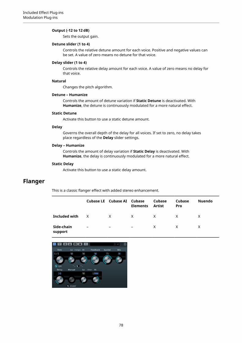
Included Effect Plug-insModulation Plug-ins
Output (-12 to 12 dB)Sets the output gain.
Detune slider (1 to 4)Controls the relative detune amount for each voice. Positive and negative values canbe set. A value of zero means no detune for that voice.
Delay slider (1 to 4)Controls the relative delay amount for each voice. A value of zero means no delay forthat voice.
NaturalChanges the pitch algorithm.
Detune – HumanizeControls the amount of detune variation if Static Detune is deactivated. WithHumanize, the detune is continuously modulated for a more natural effect.
Static DetuneActivate this button to use a static detune amount.
DelayGoverns the overall depth of the delay for all voices. If set to zero, no delay takesplace regardless of the Delay slider settings.
Delay – HumanizeControls the amount of delay variation if Static Delay is deactivated. WithHumanize, the delay is continuously modulated for a more natural effect.
Static DelayActivate this button to use a static delay amount.
FlangerThis is a classic flanger effect with added stereo enhancement.
Cubase LE Cubase AI CubaseElements
CubaseArtist
CubasePro
Nuendo
Included with X X X X X X
Side-chainsupport
– – – X X X
78

Included Effect Plug-insModulation Plug-ins
RateIf tempo sync is activated, this is where you specify the base note value forsynchronizing the flanger sweep to the tempo of the host application (1/1 to 1/32,straight, triplet, or dotted).If tempo sync is deactivated, the sweep rate can be set freely with the Rate knob.
SyncActivates/Deactivates tempo sync.
Range Lo/HiSet the frequency boundaries for the flanger sweep.
FeedbackDetermines the character of the flanger effect. Higher settings produce a moremetallic sounding sweep.
SpatialSets the stereo width of the effect. Turn clockwise for a wider stereo effect.
MixSets the level balance between the dry signal and the wet signal. If the effect is usedas a send effect, set this parameter to the maximum value as you can control thedry/effect balance with the send.
Waveform Shape selectorAllows you to select the modulation waveform, altering the character of the flangersweep. A sine and a triangle waveform are available.
DelayAffects the frequency range of the modulation sweep by adjusting the initial delaytime.
ManualIf this option is activated, the flanger sweep is static, that is, no modulation takesplace.
If the Manual button is deactivated, a knob is available, allowing you to change thesweep position manually.
Filter Lo/HiAllow you to roll off low and high frequencies of the effect signal.
NOTE
If side-chaining is supported, the modulation can also be controlled from another signal sourcevia the side-chain input. If the side-chain signal exceeds the threshold, the modulation iscontrolled by the side-chain signal’s envelope. For a description of how to set up side-chainrouting, see the Operation Manual.
MetalizerThis plug-in feeds the audio signal through a variable frequency filter, with tempo sync or timemodulation and feedback control.
Cubase LE Cubase AI CubaseElements
CubaseArtist
CubasePro
Nuendo
Included with – X X X X X
79
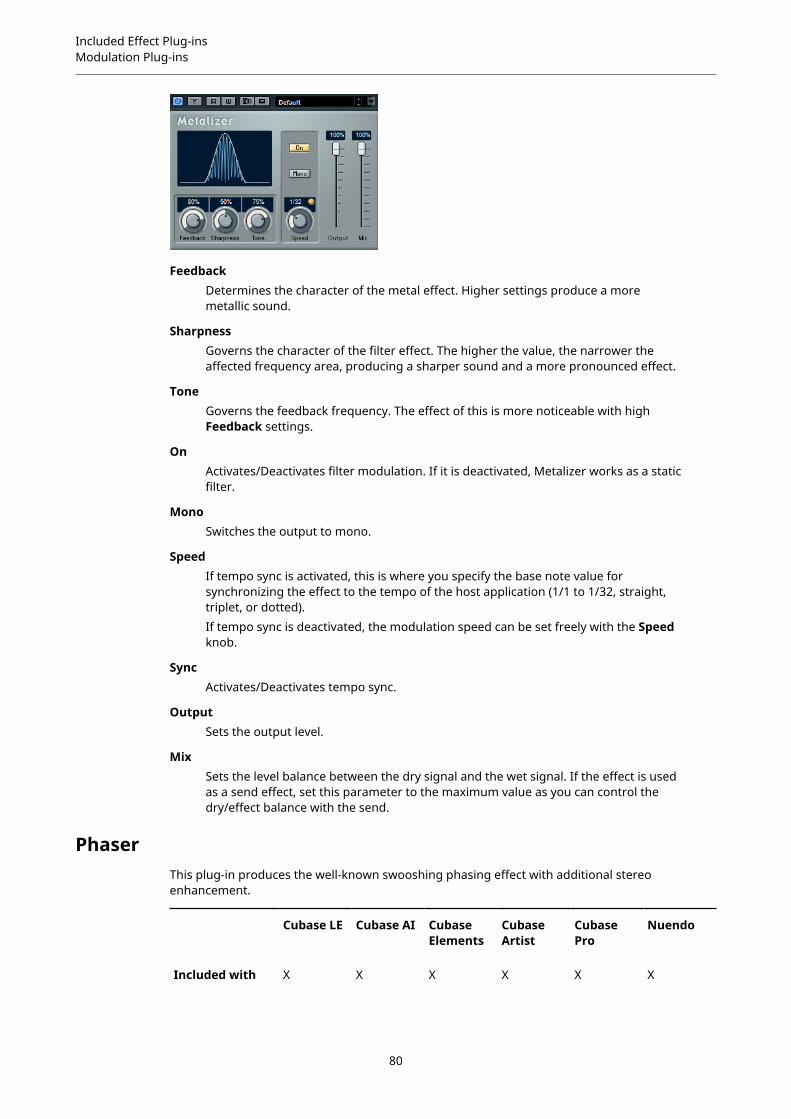
Included Effect Plug-insModulation Plug-ins
FeedbackDetermines the character of the metal effect. Higher settings produce a moremetallic sound.
SharpnessGoverns the character of the filter effect. The higher the value, the narrower theaffected frequency area, producing a sharper sound and a more pronounced effect.
ToneGoverns the feedback frequency. The effect of this is more noticeable with highFeedback settings.
OnActivates/Deactivates filter modulation. If it is deactivated, Metalizer works as a staticfilter.
MonoSwitches the output to mono.
SpeedIf tempo sync is activated, this is where you specify the base note value forsynchronizing the effect to the tempo of the host application (1/1 to 1/32, straight,triplet, or dotted).If tempo sync is deactivated, the modulation speed can be set freely with the Speedknob.
SyncActivates/Deactivates tempo sync.
OutputSets the output level.
MixSets the level balance between the dry signal and the wet signal. If the effect is usedas a send effect, set this parameter to the maximum value as you can control thedry/effect balance with the send.
PhaserThis plug-in produces the well-known swooshing phasing effect with additional stereoenhancement.
Cubase LE Cubase AI CubaseElements
CubaseArtist
CubasePro
Nuendo
Included with X X X X X X
80

Included Effect Plug-insModulation Plug-ins
Cubase LE Cubase AI CubaseElements
CubaseArtist
CubasePro
Nuendo
Side-chainsupport
– – – X X X
RateIf tempo sync is activated, this is where you specify the base note value for tempo-syncing the phaser sweep (1/1 to 1/32, straight, triplet, or dotted).If tempo sync is deactivated, the sweep rate can be set freely with the Rate knob.
SyncActivates/Deactivates tempo sync.
WidthSets the intensity of the modulation effect between higher and lower frequencies.
FeedbackDetermines the character of the phaser effect. Higher settings produce a morepronounced effect.
SpatialIf you are using multi-channel audio, the Spatial parameter creates a 3-dimensionalimpression by delaying modulation in each channel.
MixSets the level balance between the dry signal and the wet signal. If the effect is usedas a send effect, set this parameter to the maximum value as you can control thedry/effect balance with the send.
ManualIf this option is activated, the flanger sweep is static, that is, no modulation takesplace.
If the Manual button is deactivated, a knob is available, allowing you to change thesweep position manually.
Filter Lo/HiAllow you to roll off low and high frequencies of the effect signal.
NOTE
If side-chaining is supported, the modulation can also be controlled from another signal sourcevia the side-chain input. If the side-chain signal exceeds the threshold, the modulation iscontrolled by the side-chain signal’s envelope. For a description of how to set up side-chainrouting, see the Operation Manual.
81
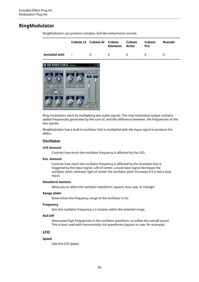
Included Effect Plug-insModulation Plug-ins
RingModulatorRingModulator can produce complex, bell-like enharmonic sounds.
Cubase LE Cubase AI CubaseElements
CubaseArtist
CubasePro
Nuendo
Included with – X X X X X
Ring modulators work by multiplying two audio signals. The ring modulated output containsadded frequencies generated by the sum of, and the difference between, the frequencies of thetwo signals.
RingModulator has a built-in oscillator that is multiplied with the input signal to produce theeffect.
Oscillator
LFO AmountControls how much the oscillator frequency is affected by the LFO.
Env. AmountControls how much the oscillator frequency is affected by the envelope that istriggered by the input signal. Left of center, a loud input signal decreases theoscillator pitch, whereas right of center the oscillator pitch increases if it is fed a loudinput.
Waveform buttonsAllow you to select the oscillator waveform: square, sine, saw, or triangle.
Range sliderDetermines the frequency range of the oscillator in Hz.
FrequencySets the oscillator frequency ± 2 octaves within the selected range.
Roll-OffAttenuates high frequencies in the oscillator waveform, to soften the overall sound.This is best used with harmonically rich waveforms (square or saw, for example).
LFO
SpeedSets the LFO speed.
82

Included Effect Plug-insModulation Plug-ins
Env. AmountControls how much the input signal level – via the envelope generator – affects theLFO speed. With negative values, a loud input signal slows down the LFO, whereaspositive values speed it up at loud input signals.
WaveformAllows you to select the LFO waveform: square, sine, saw, or triangle.
Invert StereoInverts the LFO waveform for the right channel of the oscillator, which produces awider stereo effect for the modulation.
Envelope Generator
The Envelope Generator section controls how the input signal is converted to envelope data,which can then be used to control oscillator pitch and LFO speed.
AttackControls how fast the envelope output level rises in response to a rising input signal.
DecayControls how fast the envelope output level falls in response to a falling input signal.
Lock L<RIf this button is activated, the L and R input signals are merged, and produce thesame envelope output level for both oscillator channels. If the button is deactivated,each channel has its own envelope that affects the two channels of the oscillatorindependently.
Final Settings
OutputSets the output level.
MixSets the level balance between the dry signal and the wet signal.
RotaryThis modulation effect simulates the classic effect of a rotating speaker.
Cubase LE Cubase AI CubaseElements
CubaseArtist
CubasePro
Nuendo
Included with – – X X X X
A rotary speaker cabinet features speakers rotating at variable speeds to produce a swirlingchorus effect, commonly used with organs.
83
Included Effect Plug-insModulation Plug-ins
Speed
Speed selector (stop/slow/fast)Allows you to control the speed of the Rotary in three steps.
Speed Change ModeIf this is set to the left, the speed selector settings are taken into account. If this isset to the right, you can modulate the speed with the Speed Mod knob and/or with aMIDI controller that you can select on the Speed Mod Control (MIDI) pop-up menu.
Speed ModIf the Speed Change Mode setting is set to the right side, this knob allows you tomodulate the rotary speed.
Speed Mod Control (MIDI)This pop-up menu allows you to select the MIDI controller that controls the Rotaryspeed. If you do not want to use MIDI realtime control, set this to Automation. If youselect Pitchbend as MIDI controller, the speed changes with an up or down flick ofthe bender. If other MIDI controllers are used, the speed changes at MIDI value 64.
Additional settings
OverdriveApplies a soft overdrive or distortion.
CrossOverSets the crossover frequency (200 to 3000 Hz) between the low and high frequencyloudspeakers.
Horn
SlowAllows for a fine adjustment of the high rotor slow speed.
FastAllows for a fine adjustment of the high rotor fast speed.
Accel.Allows for a fine adjustment of the high rotor acceleration time.
Amp ModControls the high rotor amplitude modulation.
Freq ModControls the high rotor frequency modulation.
Bass
SlowAllows for a fine adjustment of the low rotor slow speed.
FastAllows for a fine adjustment of the low rotor fast speed.
Accel.Allows for a fine adjustment of the low rotor acceleration time.
Amp ModAdjusts the modulation depth of the amplitude.
84

Included Effect Plug-insModulation Plug-ins
LevelAdjusts the overall bass level.
Microphones
PhaseAdjusts the phasing amount in the sound of the high rotor.
AngleSets the simulated microphone angle. 0 = mono, 180 = a mic on each side.
DistanceSets the simulated microphone distance from the speaker in inches.
Final Settings
OutputSets the output level.
MixSets the level balance between the dry signal and the wet signal.
Directing MIDI to the Rotary
For realtime MIDI control of the speed parameter, MIDI must be directed to the Rotary.
● If Rotary is used as insert effect (for an audio track or an FX channel), it is available onthe Output Routing pop-up menu for MIDI tracks. If Rotary is selected on the OutputRouting pop-up menu, MIDI is directed to the plug-in from the selected track.
StudioChorusStudioChorus is a two-stage chorus effect that adds short delays to the signal and modulatesthe pitch of the delayed signals to produce a doubling effect. The two separate stages of chorusmodulation are independent and are processed serially (cascaded).
Cubase LE Cubase AI CubaseElements
CubaseArtist
CubasePro
Nuendo
Included with – – – – X X
Side-chainsupport
– – – – X X
RateIf tempo sync is deactivated, this sets the sweep rate.
85

Included Effect Plug-insModulation Plug-ins
SyncActivates/Deactivates tempo sync.
WidthSets the depth of the chorus effect. Higher settings produce a more pronouncedeffect.
SpatialSets the stereo width of the effect. Turn clockwise for a wider stereo effect.
MixSets the level balance between the dry signal and the wet signal. If the effect is usedas a send effect, set this parameter to the maximum value as you can control thedry/effect balance with the send.
Waveform Shape selectorAllows you to select the modulation waveform, altering the character of the chorussweep. A sine and a triangle waveform are available.
DelayAffects the frequency range of the modulation sweep by adjusting the initial delaytime.
Filter Lo/HiAllow you to roll off low and high frequencies of the effect signal.
NOTE
If side-chaining is supported, the modulation can also be controlled from another signal sourcevia the side-chain input. If the side-chain signal exceeds the threshold, the modulation iscontrolled by the side-chain signal’s envelope. For a description of how to set up side-chainrouting, see the Operation Manual.
TranceformerIn this ring modulator effect, the incoming audio is ring modulated by an internal, variablefrequency oscillator, producing new harmonics. A second oscillator can be used to modulate thefrequency of the first oscillator, in sync with the Song tempo if needed.
Cubase LE Cubase AI CubaseElements
CubaseArtist
CubasePro
Nuendo
Included with – X X X X X
WaveformThese buttons allow you to select a pitch modulation waveform.
86

Included Effect Plug-insModulation Plug-ins
ToneSets the frequency (pitch) of the modulating oscillator.
DepthSets the intensity of the pitch modulation.
NOTE
Clicking and dragging in the display allows you to adjust Tone and Depth at the same time.
SpeedIf tempo sync is activated, this is where you specify the base note value forsynchronizing the effect to the tempo of the host application (1/1 to 1/32, straight,triplet, or dotted).If tempo sync is deactivated, the modulation speed can be set freely with the Speedknob.
SyncThe button above the Speed knob activates/deactivates tempo sync.
OnActivates/Deactivates the modulation of the pitch parameter.
MonoSwitches the output to mono.
OutputSets the output level.
MixSets the level balance between the dry signal and the wet signal.
TremoloTremolo produces amplitude modulation.
Cubase LE Cubase AI CubaseElements
CubaseArtist
CubasePro
Nuendo
Included with X X X X X X
Side-chainsupport
– – – X X X
RateIf tempo sync is activated, this is where you specify the base note value for tempo-syncing the effect (1/1 to 1/32, straight, triplet, or dotted).If tempo sync is deactivated, the modulation speed can be set freely with the Rateknob.
87
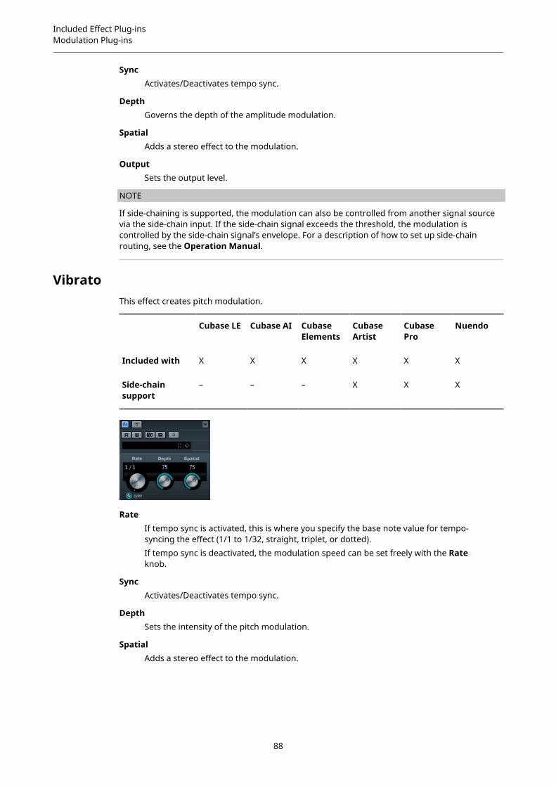
Included Effect Plug-insModulation Plug-ins
SyncActivates/Deactivates tempo sync.
DepthGoverns the depth of the amplitude modulation.
SpatialAdds a stereo effect to the modulation.
OutputSets the output level.
NOTE
If side-chaining is supported, the modulation can also be controlled from another signal sourcevia the side-chain input. If the side-chain signal exceeds the threshold, the modulation iscontrolled by the side-chain signal’s envelope. For a description of how to set up side-chainrouting, see the Operation Manual.
VibratoThis effect creates pitch modulation.
Cubase LE Cubase AI CubaseElements
CubaseArtist
CubasePro
Nuendo
Included with X X X X X X
Side-chainsupport
– – – X X X
RateIf tempo sync is activated, this is where you specify the base note value for tempo-syncing the effect (1/1 to 1/32, straight, triplet, or dotted).If tempo sync is deactivated, the modulation speed can be set freely with the Rateknob.
SyncActivates/Deactivates tempo sync.
DepthSets the intensity of the pitch modulation.
SpatialAdds a stereo effect to the modulation.
88

Included Effect Plug-insNetwork Plug-ins
NOTE
If side-chaining is supported, the modulation can also be controlled from another signal sourcevia the side-chain input. If the side-chain signal exceeds the threshold, the modulation iscontrolled by the side-chain signal’s envelope. For a description of how to set up side-chainrouting, see the Operation Manual.
Network Plug-ins
VST Connect CUE Mix
Cubase LE Cubase AI CubaseElements
CubaseArtist
CubasePro
Nuendo
Included with – – – – X X
This plug-in is described in detail in the separate PDF document VST Connect SE.
VST Connect SE
Cubase LE Cubase AI CubaseElements
CubaseArtist
CubasePro
Nuendo
Included with – – – – X X
This plug-in is described in detail in the separate PDF document VST Connect SE.
Other Plug-ins
LoopMash FXLoopMash FX is a live performance effect offering DJ effects that can be controlled by a MIDIkeyboard.
Cubase LE Cubase AI CubaseElements
CubaseArtist
CubasePro
Nuendo
Included with – – – X X X
89

Included Effect Plug-insOther Plug-ins
Quantize Note
Sets the note value on which the quantize grid of the effects is based.
Performance Controls
By clicking these buttons during playback, you can apply effects to your overall performance.
An effect is applied as long as you keep the button pressed.
NOTE
The effects can be automated. The automation of effect parameters is described in theOperation Manual.
Backspin
Simulates a turntable backspin.
Reverse
Plays the slice in reverse.
Tapestart
Simulates a tapestart, that is, speeds the slice up.
Scratch
Plays the slice as if scratched.
90

Included Effect Plug-insOther Plug-ins
Slowdown
Applies a slowdown.
Tapestop 1
Simulates a tapestop, that is, slows the slice down, first lightly then abruptly.
Tapestop 2
Simulates a tapestop, that is, slows the slice down, smoothly.
Stutter
Plays only the initial portion of a slice and repeats it 2, 3, 4, 6, or 8 times during oneslice length.
Slur
Stretches the slice over 2 or 4 slice lengths.
Cycle
Sets up a short cycle over 4, 2, or 1 slice. This short cycle is always set up within theloop range that is set in the ruler. Setting up a cycle over 1 slice means that this sliceis repeated until you release the button.
Staccato
Shortens the slice.
Mute
Mutes the slice.
Triggering the Performance Controls with Your MIDI Keyboard
You can trigger the performance controls with your MIDI keyboard starting from C3 upwards.You can also use the virtual keyboard for triggering the performance controls (for informationabout the virtual keyboard see the Operation Manual).
Controlling LoopMash FX with a MIDI Keyboard
PROCEDURE
1. Create an audio track and import an audio file, a drum loop, for example.
2. Insert LoopMash FX as an insert effect.
3. Play back the drum loop in a cycle.
4. Create a MIDI track.
91

Included Effect Plug-insOther Plug-ins
5. On the Output Routing pop-up menu for the MIDI track, select LoopMash FX.
RESULTYou can trigger the different LoopMash FX performance effects with a MIDI keyboard.
RandomizerRandomizer allows you to create variations of a sound. By setting specific parameter values, youcan determine how much these parameters are randomized. This is helpful if you want to use anaudio file, for example, the sound of a closing door, several times in your project and let it sounddifferent every time.
Cubase LE Cubase AI CubaseElements
CubaseArtist
CubasePro
Nuendo
Included with – – – – – X
NOTE
This plug-in is recommended for use in offline processing. Using it as a realtime plug-in mightincrease the latency.
Randomizer allows you to define the range within its parameters are allowed to change. Pitch,Impact, Color, and Timing act as metaparameters. This means that when you modify one ofthese metaparameters, a whole set of parameters is modified in the background.
PitchSets the maximum pitch change.This parameter allows for very basic and effective sound variations. It is especiallysuitable for voices and tonal sounds but can also give good results on atonal noises.
ImpactSets the maximum variations of attack and envelope settings.This parameter allows for variations of the onsets and transitions of sounds. Evensounds without hard attacks may get interesting variations.
ColorSets the maximum amount of coloration.
92
Included Effect Plug-insOther Plug-ins
This parameter allows you to change the tonal balance of the fundamental frequencyand its harmonics. This can give good results on rich sounds, for example, squeaksand effects but also on voices.
TimingSets the maximum timing change.This parameter allows you to vary the timing of sounds that have a recognizablepattern. At extreme settings, this may change the order of segments within a sound.
NOTE
Setting the above parameters to a value of 5 causes a noticeable yet natural sounding variation.Values higher than 8 alter the sound drastically.
RELATED LINKSCreating Variations of Audio Events on page 93
Creating Variations of Audio EventsRandomizer allows you to create several variations of audio events in one go.
PREREQUISITEIn the Direct Offline Processing window, Auto Apply is activated.
NOTE
For detailed information about Direct Offline Processing, see the Operation Manual.
PROCEDURE
1. Create as many copies of the event as you need.
2. Select all event copies.
3. Select Audio > Plug-ins > Other > Randomizer.
4. In the dialog, select New Version.
NOTE
You can also make this a permanent setting in the Preferences dialog (Editing-Audiopage).
5. In the Direct Offline Processing window, set the values for Pitch, Impact, Color, andTiming.The selected events are modified on a random basis within the defined parameter values.
RESULTYou have created different sounding variations of your audio event.
AFTER COMPLETING THIS TASKCreate audio assets by using the Export Selected Events dialog and transfer them to a gameaudio engine, for random playback. In case of Audiokinetic Wwise, use Game Audio Connect totransfer audio assets.
NOTE
For detailed information about Game Audio Connect, see the Operation Manual.
93
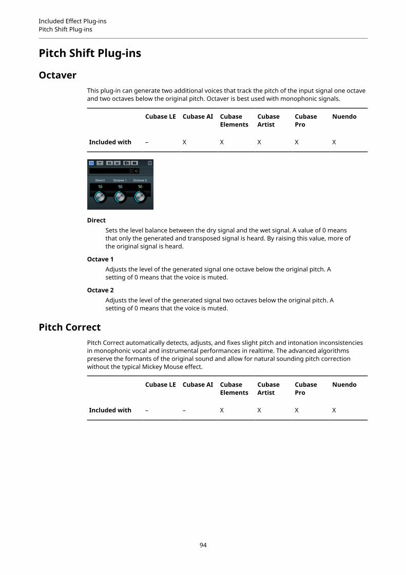
Included Effect Plug-insPitch Shift Plug-ins
Pitch Shift Plug-ins
OctaverThis plug-in can generate two additional voices that track the pitch of the input signal one octaveand two octaves below the original pitch. Octaver is best used with monophonic signals.
Cubase LE Cubase AI CubaseElements
CubaseArtist
CubasePro
Nuendo
Included with – X X X X X
DirectSets the level balance between the dry signal and the wet signal. A value of 0 meansthat only the generated and transposed signal is heard. By raising this value, more ofthe original signal is heard.
Octave 1Adjusts the level of the generated signal one octave below the original pitch. Asetting of 0 means that the voice is muted.
Octave 2Adjusts the level of the generated signal two octaves below the original pitch. Asetting of 0 means that the voice is muted.
Pitch CorrectPitch Correct automatically detects, adjusts, and fixes slight pitch and intonation inconsistenciesin monophonic vocal and instrumental performances in realtime. The advanced algorithmspreserve the formants of the original sound and allow for natural sounding pitch correctionwithout the typical Mickey Mouse effect.
Cubase LE Cubase AI CubaseElements
CubaseArtist
CubasePro
Nuendo
Included with – – X X X X
94
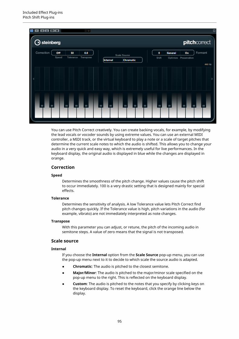
Included Effect Plug-insPitch Shift Plug-ins
You can use Pitch Correct creatively. You can create backing vocals, for example, by modifyingthe lead vocals or vocoder sounds by using extreme values. You can use an external MIDIcontroller, a MIDI track, or the virtual keyboard to play a note or a scale of target pitches thatdetermine the current scale notes to which the audio is shifted. This allows you to change youraudio in a very quick and easy way, which is extremely useful for live performances. In thekeyboard display, the original audio is displayed in blue while the changes are displayed inorange.
Correction
SpeedDetermines the smoothness of the pitch change. Higher values cause the pitch shiftto occur immediately. 100 is a very drastic setting that is designed mainly for specialeffects.
ToleranceDetermines the sensitivity of analysis. A low Tolerance value lets Pitch Correct findpitch changes quickly. If the Tolerance value is high, pitch variations in the audio (forexample, vibrato) are not immediately interpreted as note changes.
TransposeWith this parameter you can adjust, or retune, the pitch of the incoming audio insemitone steps. A value of zero means that the signal is not transposed.
Scale source
InternalIf you choose the Internal option from the Scale Source pop-up menu, you can usethe pop-up menu next to it to decide to which scale the source audio is adapted.
● Chromatic: The audio is pitched to the closest semitone.
● Major/Minor: The audio is pitched to the major/minor scale specified on thepop-up menu to the right. This is reflected on the keyboard display.
● Custom: The audio is pitched to the notes that you specify by clicking keys onthe keyboard display. To reset the keyboard, click the orange line below thedisplay.
95

Included Effect Plug-insPitch Shift Plug-ins
External MIDI ScaleSelect this option if you want the audio to be shifted to a scale of target pitches,using an external MIDI controller, the virtual keyboard, or a MIDI track.
NOTE
You have to assign the audio track as the output of your MIDI track and the Speedparameter has to be set to a value other than Off.
External MIDI NoteSelect this option if you want the audio to be shifted to a target note, using anexternal MIDI controller, the Virtual Keyboard or a MIDI track.
NOTE
You have to assign the audio track as the output of your MIDI track and the Speedparameter has to be set to a value other than Off.
Chord Track – ChordsSelect this option if you want the audio to be shifted to target chords, using thechord information from the Chord track.
NOTE
You have to add a MIDI track in addition to the Chord track and assign Pitch Correctas output of the MIDI track.
Chord Track – ScaleSelect this option if you want the audio to be shifted to a scale of target pitches,using the scale information from the Chord track.
NOTE
You have to add a MIDI track in addition to the Chord track and assign Pitch Correctas output of the MIDI track.
Formant
ShiftChanges the natural timbre, that is, the characteristic frequency components of thesource audio.
Optimize (General, Male, Female)Allows you to specify the sound characteristics of the sound sources. General is thedefault setting, Male is designed for low pitches and Female for high pitches.
Preservation (On/Off)If this parameter is set to Off, formants are raised and lowered with the pitch,provoking strange vocal effects. Higher pitch correction values result in MickeyMouse effects, lower pitch correction values in Monster sounds. If this parameter isset to On, the formants are kept, maintaining the character of the audio.
Master TuningDetunes the output signal.
96

Included Effect Plug-insReverb Plug-ins
PitchDriverThis effect allows for sound design in postproduction. It can be used for extreme up or downpitching of voices or effect samples (for example, to create eerie monster sounds). Shifting thepitch with this plug-in does not keep the formants.
Cubase LE Cubase AI CubaseElements
CubaseArtist
CubasePro
Nuendo
Included with – – – – – X
DetuneLets you detune the pitch of the incoming audio.
MixSets the level balance between the dry signal and the wet signal.
SpatialCreates an ambience effect. It introduces a light pitch offset to the incoming signal.Different offset values are used for the individual input channels in order to create apanorama effect.
NOTE
The created panorama effect can be unstable. For a stable panorama, deactivate theSpatial parameter. Then, the incoming signals are summed up to a mono signal.
OutputSets the output level.
To avoid hearing artifacts, it is recommended to set the ASIO buffer for your audio card to atleast 128 samples. The buffer size can be set on the control panel for the card (opened via theDevice Setup dialog).
Reverb Plug-ins
REVelationThis effect produces a high-quality algorithmic reverb with early reflections and reverb tail.
Cubase LE Cubase AI CubaseElements
CubaseArtist
Cubase Nuendo
Included with – – – X X X
97
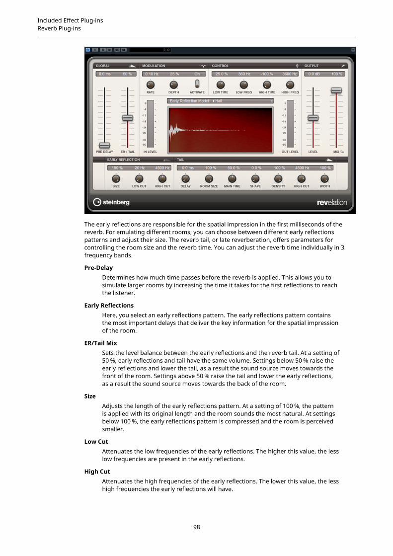
Included Effect Plug-insReverb Plug-ins
The early reflections are responsible for the spatial impression in the first milliseconds of thereverb. For emulating different rooms, you can choose between different early reflectionspatterns and adjust their size. The reverb tail, or late reverberation, offers parameters forcontrolling the room size and the reverb time. You can adjust the reverb time individually in 3frequency bands.
Pre-DelayDetermines how much time passes before the reverb is applied. This allows you tosimulate larger rooms by increasing the time it takes for the first reflections to reachthe listener.
Early ReflectionsHere, you select an early reflections pattern. The early reflections pattern containsthe most important delays that deliver the key information for the spatial impressionof the room.
ER/Tail MixSets the level balance between the early reflections and the reverb tail. At a setting of50 %, early reflections and tail have the same volume. Settings below 50 % raise theearly reflections and lower the tail, as a result the sound source moves towards thefront of the room. Settings above 50 % raise the tail and lower the early reflections,as a result the sound source moves towards the back of the room.
SizeAdjusts the length of the early reflections pattern. At a setting of 100 %, the patternis applied with its original length and the room sounds the most natural. At settingsbelow 100 %, the early reflections pattern is compressed and the room is perceivedsmaller.
Low CutAttenuates the low frequencies of the early reflections. The higher this value, the lesslow frequencies are present in the early reflections.
High CutAttenuates the high frequencies of the early reflections. The lower this value, the lesshigh frequencies the early reflections will have.
98

Included Effect Plug-insReverb Plug-ins
DelayDelays the onset of the reverb tail.
Room SizeControls the dimensions of the simulated room. At a setting of 100 %, the dimensionscorrespond to a cathedral or a large concert hall. At a setting of 50 %, the dimensionscorrespond to a medium-sized room or studio. Settings below 50 % simulate thedimensions of small rooms or a booth.
Main TimeControls the overall reverb time of the tail. The higher this value, the longer thereverb tail will decay. At a setting of 100 %, the reverb time is infinitely long. TheMain Time parameter also represents the mid band of the reverb tail.
High TimeControls the reverb time for the high frequencies of the reverb tail. With positivevalues, the decay time of the high frequencies is longer. With negative values, it isshorter. Frequencies are affected depending on the High Freq parameter.
Low TimeControls the reverb time for the low frequencies of the reverb tail. For positivevalues, low frequencies decay longer and vice versa. Frequencies will be affecteddepending on the Low Freq parameter.
High FreqSets the cross-over frequency between the mid and the high band of the reverb tail.You can offset the reverb time for frequencies above this value from the main reverbtime with the High Time parameter.
Low FreqSets the cross-over frequency between the low and the mid band of the reverb tail.The reverb time for frequencies below this value can be offset from the main reverbtime with the Low Time parameter.
ShapeControls the attack of the reverb tail. At a setting of 0 %, the attack is moreimmediate, which is a good setting for drums. The higher this value, the lessimmediate the attack.
DensityAdjusts the echo density of the reverb tail. At a setting of 100 %, single reflectionsfrom walls cannot be heard. The lower this value, the more single reflections can beheard.
High CutAttenuates the high frequencies of the reverb tail. The lower this value, the less highfrequencies the reverb tail will have.
WidthAdjusts the output of the reverb signal between mono and stereo. At a setting of 0 %,the output of the reverb is mono, at 100 % it is stereo.
MixSets the level balance between the dry signal and the wet signal. If the effect is usedas a send effect, set this parameter to the maximum value as you can control thedry/effect balance with the send.
LockActivate this button (padlock symbol) next to the Mix parameter to lock the dry/wetbalance while browsing through the available presets.
99

Included Effect Plug-insReverb Plug-ins
Modulation
Modulation allows you to enrich the reverb tail through subtle pitch modulations.
Modulation EnableActivates/Deactivates the chorusing effect.
Modulation RateSpecifies the frequency of the pitch modulation.
Modulation DepthSets the intensity of the pitch modulation.
REVerenceREVerence is a convolution tool that allows you to apply room characteristics (reverb) to theaudio.
Cubase LE Cubase AI CubaseElements
CubaseArtist
CubasePro
Nuendo
Included with – – – – X X
This is done by processing the audio signal according to an impulse response – a recording of animpulse in a room or another location that recreates the characteristics of the room. As a result,the processed audio sounds as if it were played in the same location. Included with the plug-inare top quality samples of real spaces to create reverberation.
NOTE
REVerence can be very demanding in terms of RAM. This is because the impulse responses thatyou load into the program slots are preloaded into RAM to guarantee artifact-free switchingbetween programs. Therefore, you should always load only those programs that you need for agiven task.
100

Included Effect Plug-insReverb Plug-ins
Program Matrix
A program is the combination of an impulse response and its settings. These include reverbsettings, EQ settings, pictures, and output settings. The program matrix allows you to loadprograms or to view the name of the impulse response.
Program nameIn the upper left corner of the plug-in panel, either the name of the loaded impulseresponse file or the name of the program is shown. After loading an impulseresponse, its number of channels and the length in seconds are displayed for a fewseconds.
BrowseThis button opens a browser window showing the available programs. If you selecta program in the browser, it is loaded into the active program slot. To filter the listof impulse responses by room type or the number of channels, for example, activatethe Filters section (by clicking the Set Up Window Layout button at the bottom leftof the window).
ImportClick this button to load your own impulse response files from disk. The files shouldhave a maximum length of 10 seconds. Longer files are automatically cut.
Program slotsUse these slots to load all the impulse responses that you want to work with in asession. The selected program slot is indicated by a white frame. Used slots areshown in a different color. Double-clicking an empty program slot opens a browserwindow, showing the available programs. Clicking a used program slot recalls thecorresponding program and loads it into REVerence. If you move the mouse over aused slot, the corresponding program name is displayed below the active programname.
Smooth Parameter ChangesThis button is located between the program slots and the Store/Erase buttons. If itis activated, a crossfade is performed when switching programs. Leave this buttondeactivated while looking for a suitable program or an appropriate setting for animpulse response. Once you have set up the program matrix to your liking, activatethe button to avoid hearing artifacts when switching between programs.
StoreStores the active impulse response and its settings as a program.
EraseRemoves the selected program from the matrix.
Programs vs. Presets
You can save your REVerence settings as VST plug-in presets or programs. Both presets andprograms use the file extension .vstpreset and appear in the same category in the MediaBay,but they are represented by different icons.
Preset
A REVerence preset contains all settings and parameters for the plug-in, that is, allloaded impulse responses along with their parameter settings and positions in the
101

Included Effect Plug-insReverb Plug-ins
program matrix. Presets are loaded via the Presets pop-up menu at the top of theplug-in panel.
Program
A REVerence program only contains the settings related to a single impulseresponse. Programs are loaded and managed via the program matrix.
Presets
Presets are useful in the following situations:
● To save a complete setup with different impulse responses for later use (for example,different setups for explosion sounds that can be reused for other scenes or movies).
● When you want to save different parameter sets for the same impulse response so thatyou can later choose the set that best suits your needs.
Programs
Programs offer the following advantages:
● Up to 36 programs can be loaded into the program matrix for instant recall.
● A program provides a quick and easy way to save and recall the settings for a singleimpulse response, allowing for short loading times.
● When automating a project and loading a REVerence program, only one automation eventis written.If you load a plug-in preset instead (which contains a lot more settings than a program), alot of unnecessary automation data (for the settings that you did not use) is written.
RELATED LINKSReverb Settings on page 103EQ Settings on page 105The Pictures Section on page 106Custom Impulse Responses on page 107
Setting up Programs
PROCEDURE
1. In the program matrix, click on a program slot to select it.A blinking white frame indicates that this program slot is selected.
2. Click the Browse button or click the empty slot again to load one of the includedprograms.You can also import a new impulse response file.
3. In the browser, select the program containing the impulse response that you want to useand click OK.The name of the loaded impulse response is shown in the upper left corner of theREVerence panel.
4. Set up the REVerence parameters as and click the Store button to save the impulseresponse with the current settings as a new program.
5. Set up as many programs as you need by following the steps above.
NOTE
If you want to use your set of programs in other projects, save your settings as a plug-inpreset.
102

Included Effect Plug-insReverb Plug-ins
RELATED LINKSImporting Impulse Responses on page 107
Reverb SettingsThe reverb settings allow you to change the characteristics of the room.
MainAll values shown in the top row apply to all speakers or to the front channels if youare working with surround tracks.
RearIf you are working with surround tracks up to 5.1, you can use this row to set up anoffset for the rear channels.
Auto GainIf this button is activated, the impulse response is automatically normalized.
ReverseReverses the impulse response.
Pre-DelayDetermines how much time passes before the reverb is applied. This allows you tosimulate larger rooms by increasing the time it takes for the first reflections to reachthe listener.
Time ScalingControls the reverb time.
SizeDetermines the size of the simulated room.
LevelA level control for the impulse response. This governs the volume of the reverb.
ER Tail SplitSets a split point between the early reflections and the tail, allowing you to determinewhere the reverb tail begins. A value of 60 means that the early reflections are heardfor 60 ms.
ER Tail MixAllows you to set up the relation of early reflections and tail. Values above 50attenuate the early reflections and values below 50 attenuate the tail.
103

Included Effect Plug-insReverb Plug-ins
The Impulse Response DisplayThe display section allows you to view the impulse response details and to change the length ofthe response.
PlayWhen clicking this button to apply the loaded impulse response, a short click isplayed. This provides a neutral test sound that makes it easier for you to know howdifferent settings influence the reverb characteristics.
Time ScalingThis wheel lets you adjust the reverb time.
Time DomainThis display shows the waveform of the impulse response.
SpectrogramThis display shows the analyzed spectrum of the impulse response. Time isdisplayed along the horizontal axis, frequency along the vertical axis, and volume isrepresented by the color.
InformationThis display shows additional information, such as the name of the program and theloaded impulse response, the number of channels, the length, and Broadcast WaveFile information.
Activate Impulse TrimmingUse this button at the bottom right of the impulse display section to activate impulsetrimming. The Trim slider is shown below the Impulse display.
TrimThis slider allows you to trim the start and end of the impulse response. Drag thefront handle to trim the start of the impulse response, and the end handle to trimthe reverb tail.
NOTE
The impulse response is cut without any fading.
104
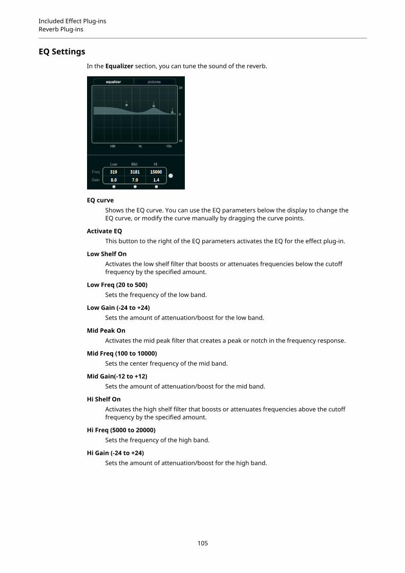
Included Effect Plug-insReverb Plug-ins
EQ SettingsIn the Equalizer section, you can tune the sound of the reverb.
EQ curveShows the EQ curve. You can use the EQ parameters below the display to change theEQ curve, or modify the curve manually by dragging the curve points.
Activate EQThis button to the right of the EQ parameters activates the EQ for the effect plug-in.
Low Shelf OnActivates the low shelf filter that boosts or attenuates frequencies below the cutofffrequency by the specified amount.
Low Freq (20 to 500)Sets the frequency of the low band.
Low Gain (-24 to +24)Sets the amount of attenuation/boost for the low band.
Mid Peak OnActivates the mid peak filter that creates a peak or notch in the frequency response.
Mid Freq (100 to 10000)Sets the center frequency of the mid band.
Mid Gain(-12 to +12)Sets the amount of attenuation/boost for the mid band.
Hi Shelf OnActivates the high shelf filter that boosts or attenuates frequencies above the cutofffrequency by the specified amount.
Hi Freq (5000 to 20000)Sets the frequency of the high band.
Hi Gain (-24 to +24)Sets the amount of attenuation/boost for the high band.
105
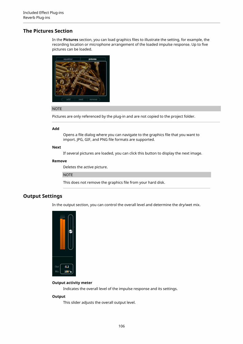
Included Effect Plug-insReverb Plug-ins
The Pictures SectionIn the Pictures section, you can load graphics files to illustrate the setting, for example, therecording location or microphone arrangement of the loaded impulse response. Up to fivepictures can be loaded.
NOTE
Pictures are only referenced by the plug-in and are not copied to the project folder.
AddOpens a file dialog where you can navigate to the graphics file that you want toimport. JPG, GIF, and PNG file formats are supported.
NextIf several pictures are loaded, you can click this button to display the next image.
RemoveDeletes the active picture.
NOTE
This does not remove the graphics file from your hard disk.
Output SettingsIn the output section, you can control the overall level and determine the dry/wet mix.
Output activity meterIndicates the overall level of the impulse response and its settings.
OutputThis slider adjusts the overall output level.
106
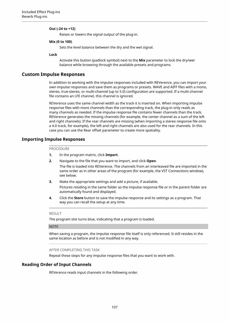
Included Effect Plug-insReverb Plug-ins
Out (-24 to +12)Raises or lowers the signal output of the plug-in.
Mix (0 to 100)Sets the level balance between the dry and the wet signal.
LockActivate this button (padlock symbol) next to the Mix parameter to lock the dry/wetbalance while browsing through the available presets and programs.
Custom Impulse ResponsesIn addition to working with the impulse responses included with REVerence, you can import yourown impulse responses and save them as programs or presets. WAVE and AIFF files with a mono,stereo, true-stereo, or multi-channel (up to 5.0) configuration are supported. If a multi-channelfile contains an LFE channel, this channel is ignored.
REVerence uses the same channel width as the track it is inserted on. When importing impulseresponse files with more channels than the corresponding track, the plug-in only reads asmany channels as needed. If the impulse response file contains fewer channels than the track,REVerence generates the missing channels (for example, the center channel as a sum of the leftand right channels). If the rear channels are missing (when importing a stereo response file ontoa 4.0 track, for example), the left and right channels are also used for the rear channels. In thiscase you can use the Rear offset parameter to create more spatiality.
Importing Impulse Responses
PROCEDURE
1. In the program matrix, click Import.
2. Navigate to the file that you want to import, and click Open.The file is loaded into REVerence. The channels from an interleaved file are imported in thesame order as in other areas of the program (for example, the VST Connections window),see below.
3. Make the appropriate settings and add a picture, if available.Pictures residing in the same folder as the impulse response file or in the parent folder areautomatically found and displayed.
4. Click the Store button to save the impulse response and its settings as a program. Thatway you can recall the setup at any time.
RESULTThe program slot turns blue, indicating that a program is loaded.
NOTE
When saving a program, the impulse response file itself is only referenced. It still resides in thesame location as before and is not modified in any way.
AFTER COMPLETING THIS TASKRepeat these steps for any impulse response files that you want to work with.
Reading Order of Input Channels
REVerence reads input channels in the following order.
107

Included Effect Plug-insReverb Plug-ins
Number of inputchannels
Channel order in REVerence
1 L
2 L/R
3 L/R/C
4 L/R/LS/RS (if inserted on a track with a 4.0 channel configuration)
4 LL/LR/RL/RR (if inserted on a track with a stereo configuration)
5 L/R/C/LS/RS
6 L/R/C/LFE/LS/RS (LFE is being ignored.)
True Stereo
Impulse responses recorded as true-stereo files allow you to create a very realistic impression ofthe corresponding room.
REVerence can only process true-stereo impulse response files with the following channelconfiguration (in exactly that order): LL, LR, RL, RR.
The channels are defined as follows:
Channel The signal from this source… …was recorded with thismicrophone
LL left source left microphone
LR left source right microphone
RL right source left microphone
RR right source right microphone
NOTE
If your true-stereo impulse responses are only available as separate mono files, you can usethe Export Audio Mixdown function to create REVerence compliant interleaved files (see theOperation Manual).
REVerence automatically works in true-stereo mode if the plug-in is inserted on a stereo trackand you load a 4-channel impulse response.
Therefore, if you are working with surround files, that is, 4-channel impulse responses recordedwith a Quadro configuration (L/R, LS/RS), you need to insert the plug-in on an audio track with a4.0 configuration. On a stereo track, these files would be processed in true-stereo mode, too.
So how can you prevent REVerence from unintentionally processing surround files in true-stereomode? The answer is a Recording Method attribute that can be written to the iXML chunk of thecorresponding impulse response file. Whenever you load an impulse response with a 4-channel
108

Included Effect Plug-insReverb Plug-ins
configuration on a stereo track, REVerence searches the iXML chunk of the file. If the plug-infinds the Recording Method attribute, the following happens:
● If the attribute is set to TrueStereo, the plug-in works in true-stereo mode.
● If the attribute is set to A/B or Quadro, the plug-in works in normal stereo mode andprocesses only the L/R channels of the surround file.
NOTE
You can use the Attribute Inspector in the MediaBay to tag your own impulse response files withthe Recording Method attribute. For more information, see the Operation Manual.
Relocating Content
Once you have imported your own impulse responses to REVerence, you can comfortably workwith them on your computer. But what if you need to transfer your content to another computer,for example, because you work sometimes with a PC and sometimes with a notebook, or youneed to hand over a project to a colleague in the studio?
The factory content is not a problem because it is also present on the other computer. For theseimpulse responses, you just need to transfer your REVerence programs and presets to be able toaccess your setups.
User content is a different matter, though. If you have transferred your audio files to an externaldrive or a different hard disk location on the other computer, REVerence cannot access theimpulse responses any more because the old file paths have become invalid.
PROCEDURE
1. Transfer you audio files to a location that you can access from the second computer (forexample, an external hard disk).If you keep the files in the same folder structure as on the first computer, REVerenceautomatically finds all files contained in this structure.
2. Transfer any REVerence presets or programs that you need to the second computer.If you are unsure where the presets need to be stored, you can find the paths in theMediaBay (see the Operation Manual).
3. Open REVerence on the second computer and try to load the preset or program that youwant to work with.The Locate Impulse Response dialog opens.
4. Navigate to the folder that contains your impulse responses.
5. Click Open.
RESULTREVerence is now able to access all the impulse responses stored in this location.
IMPORTANT
The new path to these audio files has not been saved yet. To make the files permanentlyavailable without having to use the locate dialog, you need to save your programs or presetsunder a different name.
RoomWorksRoomWorks is a highly adjustable reverb plug-in for creating realistic room ambience and reverbeffects in stereo and surround formats. The CPU usage is adjustable to fit the needs of any
109

Included Effect Plug-insReverb Plug-ins
system. From short room reflections to cavern-sized reverb, this plug-in delivers high qualityreverberation.
Cubase LE Cubase AI CubaseElements
CubaseArtist
CubasePro
Nuendo
Included with – – – – X X
Input Filters
Lo FreqDetermines the frequency at which the low-shelving filter takes effect. Both the highand low settings filter the input signal prior to reverb processing.
Hi FreqDetermines the frequency at which the high-shelving filter takes effect. Both the highand low settings filter the input signal prior to reverb processing.
Lo GainSets the amount of boost or attenuation for the low-shelving filter.
Hi GainSets the amount of boost or attenuation for the high-shelving filter.
Reverb Character
Pre-DelayDetermines how much time passes before the reverb is applied. This allows you tosimulate larger rooms by increasing the time it takes for the first reflections to reachthe listener.
Reverb TimeAllows you to set the reverb time in seconds.
SizeAlters the delay times of the early reflections to simulate larger or smaller spaces.
DiffusionAffects the character of the reverb tail. Higher values lead to more diffusion and asmoother sound, while lower values lead to a clearer sound.
WidthControls the width of the stereo image. At a setting of 0 %, the output of the reverb ismono, at 100 % it is stereo.
VariationClicking this button generates a new version of the same reverb program usingaltered reflection patterns. This is helpful if some sounds are causing odd ringing
110
Included Effect Plug-insReverb Plug-ins
or undesirable results. Creating a new variation often solves these issues. There are1000 possible variations.
HoldActivating this button freezes the reverb buffer in an infinite loop. You can createsome interesting pad sounds using this feature.
Damping
Lo FreqDetermines the frequency below which low-frequency damping occurs.
Hi FreqDetermines the frequency above which high-frequency damping occurs.
Lo LevelAffects the decay time of the low frequencies. Normal room reverb decays quickerin the high- and low-frequency range than in the mid-range. Lowering the levelpercentage causes low frequencies to decay quicker. Values above 100 % cause lowfrequencies to decay more slowly than the mid-range frequencies.
Hi LevelAffects the decay time of the high frequencies. Normal room reverb decays quickerin the high- and low-frequency range than in the mid-range. Lowering the levelpercentage causes high frequencies to decay quicker. Values above 100 % cause highfrequencies to decay more slowly than the mid-range frequencies.
Envelope
AmountDetermines how much the envelope attack and release controls affect the reverbitself. Lower values have a more subtle effect while higher values lead to a moredrastic sound.
AttackThe envelope settings in RoomWorks control how the reverb follows the dynamicsof the input signal in a fashion similar to a noise gate or downward expander. Attackdetermines how long it takes for the reverb to reach full volume after a signal peak(in milliseconds). This is similar to a pre-delay, but the reverb is ramping up insteadof starting all at once.
ReleaseDetermines how long after a signal peak the reverb can be heard before being cutoff, similar to a release time of a gate.
Output
MixSets the level balance between the dry signal and the wet signal. If RoomWorks isused as an insert effect for an FX channel, you most likely want to set this to 100 % oruse the wet only button.
Wet onlyThis button deactivates the Mix parameter, setting the effect to 100 % wet oraffected signal. This button should normally be activated if RoomWorks is used as asend effect for an FX channel or a group channel.
111
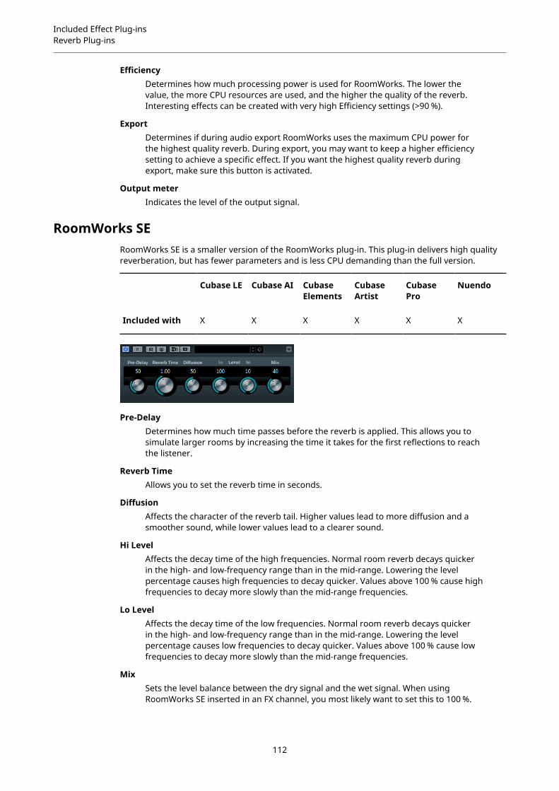
Included Effect Plug-insReverb Plug-ins
EfficiencyDetermines how much processing power is used for RoomWorks. The lower thevalue, the more CPU resources are used, and the higher the quality of the reverb.Interesting effects can be created with very high Efficiency settings (>90 %).
ExportDetermines if during audio export RoomWorks uses the maximum CPU power forthe highest quality reverb. During export, you may want to keep a higher efficiencysetting to achieve a specific effect. If you want the highest quality reverb duringexport, make sure this button is activated.
Output meterIndicates the level of the output signal.
RoomWorks SERoomWorks SE is a smaller version of the RoomWorks plug-in. This plug-in delivers high qualityreverberation, but has fewer parameters and is less CPU demanding than the full version.
Cubase LE Cubase AI CubaseElements
CubaseArtist
CubasePro
Nuendo
Included with X X X X X X
Pre-DelayDetermines how much time passes before the reverb is applied. This allows you tosimulate larger rooms by increasing the time it takes for the first reflections to reachthe listener.
Reverb TimeAllows you to set the reverb time in seconds.
DiffusionAffects the character of the reverb tail. Higher values lead to more diffusion and asmoother sound, while lower values lead to a clearer sound.
Hi LevelAffects the decay time of the high frequencies. Normal room reverb decays quickerin the high- and low-frequency range than in the mid-range. Lowering the levelpercentage causes high frequencies to decay quicker. Values above 100 % cause highfrequencies to decay more slowly than the mid-range frequencies.
Lo LevelAffects the decay time of the low frequencies. Normal room reverb decays quickerin the high- and low-frequency range than in the mid-range. Lowering the levelpercentage causes low frequencies to decay quicker. Values above 100 % cause lowfrequencies to decay more slowly than the mid-range frequencies.
MixSets the level balance between the dry signal and the wet signal. When usingRoomWorks SE inserted in an FX channel, you most likely want to set this to 100 %.
112

Included Effect Plug-insSpatial + Panner Plug-ins
Spatial + Panner Plug-ins
Anymix Pro
Cubase LE Cubase AI CubaseElements
CubaseArtist
CubasePro
Nuendo
Included with – – – – – X
The Anymix Pro plug-in from IOSONO is a sophisticated surround panner and a powerful upmix/downmix processor that converts any given audio material into output formats ranging frommono to 8.1.
Input/Output ConfigurationThe input/output configuration of the plug-in can be selected from the In and Out pop-up menusin the top left corner of the plug-in panel.
If Anymix Pro is used as an insert effect, the maximum input and output configuration cannotexceed the track width of the current track.
If Anymix Pro is used as a panner, the maximum input configuration cannot exceed the trackwidth of the current track. The maximum output configuration cannot exceed the width of theoutput bus that the track is routed to.
Channel OrderThe plug-in uses the channel order of the host application unless the selected outputconfiguration differs from the track configuration.
NOTE
Choosing an output configuration that differs from the current track configuration results inchannel oddities.
If the output configuration of the track is not a subset of the plug-in output configuration, forexample, track = 6.1 cine and plug-in output = 7.0 music, the channels are routed as follows:
1 2 3 4 5 6 7 8 9
L R C LFE LS RS RSS/ RC LSS/ LC CS
NOTE
Channels that are missing in the output configuration are automatically skipped.
113
Included Effect Plug-insSpatial + Panner Plug-ins
1 2 3 4 5 6 7 8 9
Track configuration:6.1 Cine
L R C LFE LS RS CS
Plug-in outputconfiguration: 7.0 Music
L R C LS RS LSS RSS
Result OK Mismatch
Latency CompensationAnymix Pro causes a processing delay. The amount of latency depends on the buffer size of theaudio card and the processing mode of the plug-in, that is, panning or upmix. Steinberg hostapplications can compensate this delay automatically.
The Plug-in PanelThe panel of Anymix Pro is divided into several sections, with the stage view taking the mostspace to display the position and movement of the input channels, output configuration, anddistance-dependent filter values. On the right side, there are the controls for position andmovement, and the lower section of the plug-in panel contains the upmix controls.
NOTE
The plug-in panel has two different display modes: panning and upmix.
114
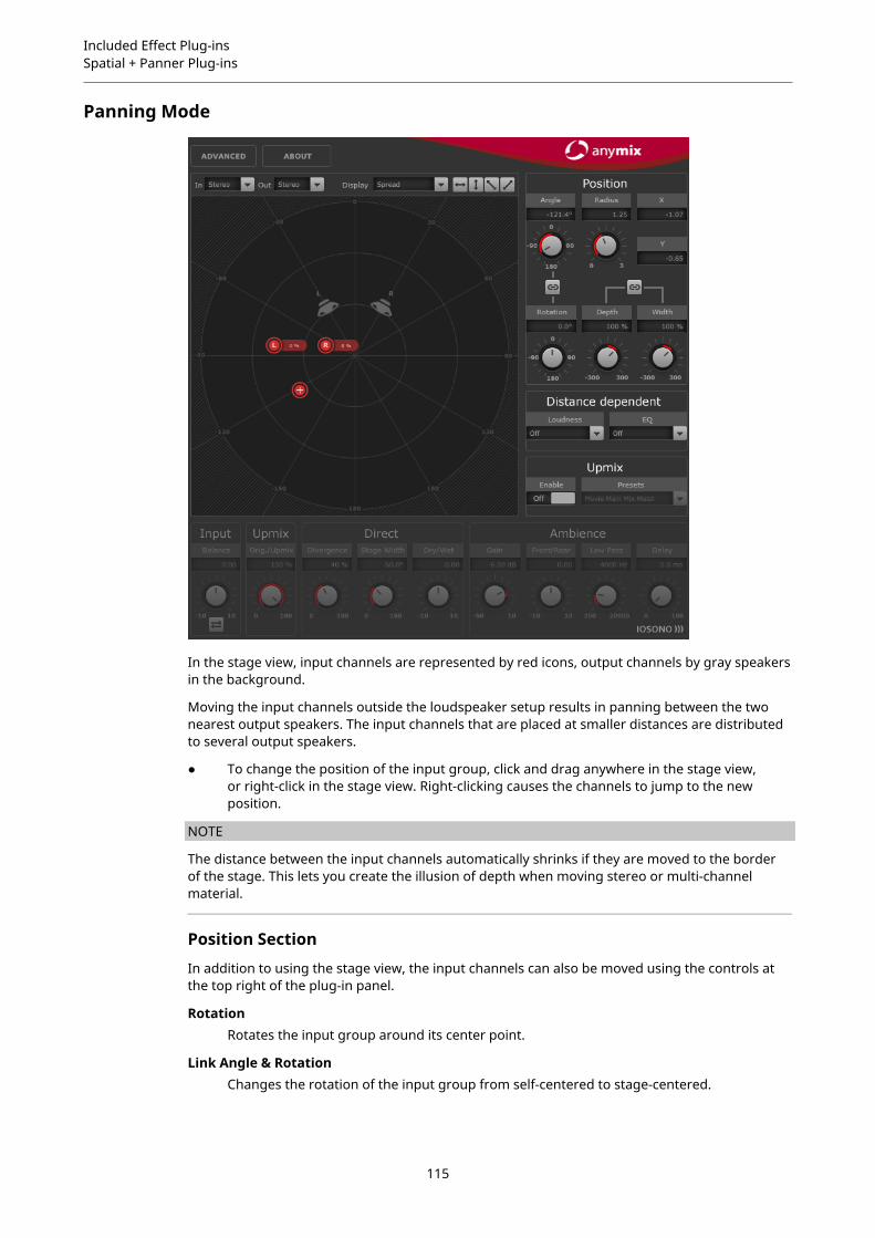
Included Effect Plug-insSpatial + Panner Plug-ins
Panning Mode
In the stage view, input channels are represented by red icons, output channels by gray speakersin the background.
Moving the input channels outside the loudspeaker setup results in panning between the twonearest output speakers. The input channels that are placed at smaller distances are distributedto several output speakers.
● To change the position of the input group, click and drag anywhere in the stage view,or right-click in the stage view. Right-clicking causes the channels to jump to the newposition.
NOTE
The distance between the input channels automatically shrinks if they are moved to the borderof the stage. This lets you create the illusion of depth when moving stereo or multi-channelmaterial.
Position Section
In addition to using the stage view, the input channels can also be moved using the controls atthe top right of the plug-in panel.
RotationRotates the input group around its center point.
Link Angle & RotationChanges the rotation of the input group from self-centered to stage-centered.
115

Included Effect Plug-insSpatial + Panner Plug-ins
DepthScales the input group vertically.
WidthScales the input group horizontally.
Link Depth & WidthKeeps the aspect ratio between Depth and Width scaling.
NOTE
To fine-adjust the parameters, press Shift while using the controls.
Individual Channel Adjustment
You can change the positions of the input channels individually by double-clicking thecorresponding input icon in the stage view. A separate panel with channel-specific parametersopens.
Radius/AngleControl the position of the selected input channel, relative to the center of the inputgroup.
X/YMove the selected input channel horizontally and vertically.
VolumeApplies gain to the selected input channel.
LFE VolumeControls the amount of LFE for the selected input channel.
SpreadDistributes the audio from the selected input channel to more than two outputchannels.
● At 0 % the audio source is rendered where the channel icon is placed.
● At 100 % the audio is evenly distributed to all speakers of the outputconfiguration.
Manual DelayAdds a delay to the selected input channel.
LinkActivate these buttons to link the corresponding parameters in the current plug-in instance. Adjusting the value of a linked parameter changes the other linkedparameters, too.
116
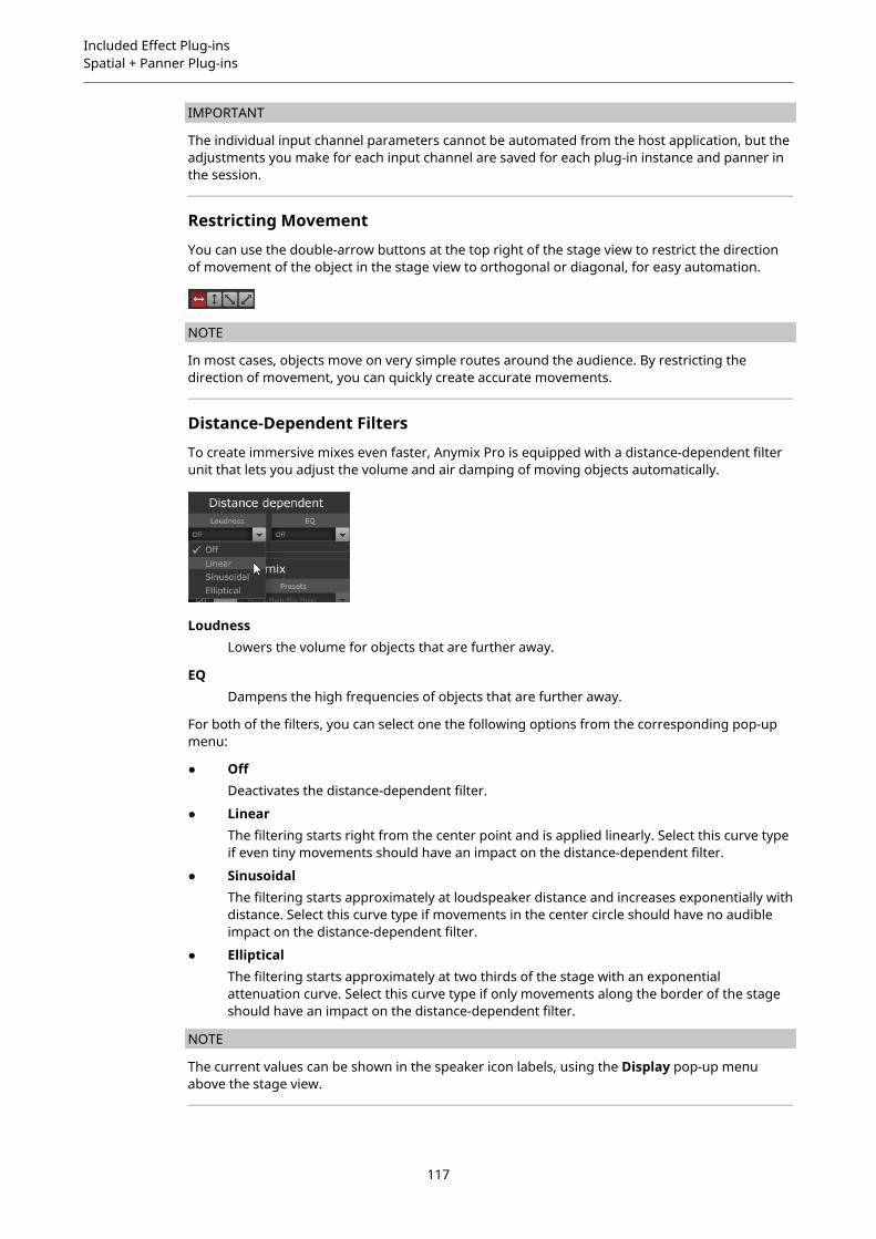
Included Effect Plug-insSpatial + Panner Plug-ins
IMPORTANT
The individual input channel parameters cannot be automated from the host application, but theadjustments you make for each input channel are saved for each plug-in instance and panner inthe session.
Restricting Movement
You can use the double-arrow buttons at the top right of the stage view to restrict the directionof movement of the object in the stage view to orthogonal or diagonal, for easy automation.
NOTE
In most cases, objects move on very simple routes around the audience. By restricting thedirection of movement, you can quickly create accurate movements.
Distance-Dependent Filters
To create immersive mixes even faster, Anymix Pro is equipped with a distance-dependent filterunit that lets you adjust the volume and air damping of moving objects automatically.
LoudnessLowers the volume for objects that are further away.
EQDampens the high frequencies of objects that are further away.
For both of the filters, you can select one the following options from the corresponding pop-upmenu:
● OffDeactivates the distance-dependent filter.
● LinearThe filtering starts right from the center point and is applied linearly. Select this curve typeif even tiny movements should have an impact on the distance-dependent filter.
● SinusoidalThe filtering starts approximately at loudspeaker distance and increases exponentially withdistance. Select this curve type if movements in the center circle should have no audibleimpact on the distance-dependent filter.
● EllipticalThe filtering starts approximately at two thirds of the stage with an exponentialattenuation curve. Select this curve type if only movements along the border of the stageshould have an impact on the distance-dependent filter.
NOTE
The current values can be shown in the speaker icon labels, using the Display pop-up menuabove the stage view.
117
Included Effect Plug-insSpatial + Panner Plug-ins
The distance-dependent filters can be further adjusted using the advanced options.
RELATED LINKSAdvanced Options on page 122
UpmixThe upmix feature of Anymix Pro is very useful if rearranging tracks with fewer input channelsinto a specific surround format is not enough.
The upmix algorithm analyzes the incoming audio signal and separates it into parts of directsound and ambient sound. While the direct sound parts are sent to the direct sound streamand can be placed at the virtual front speaker configuration, the ambient sound parts can bemodified and arranged around the virtual stage. Note that this does not add any additionalinformation to the audio stream. All sound parts that you hear from the ambient sound werealready part of the original audio material.
IMPORTANT
If your audio does not contain spatial information, there cannot be an ambient sound stream.For example, you cannot extract ambient sound from a dry recording of a narrator sitting in arecording booth.
IMPORTANT
Lossy compression, such as in MP3 files, or other deficiencies of the incoming audio cannotbe remedied using the upmix mode. For example, compression artifacts can easily bemisinterpreted and redistributed to the ambient sound stream.
Switching to Upmix Mode
● To switch to upmix mode, activate the Enable option in the Upmix section to the right ofthe stage view.
NOTE
The upmix algorithm is very sophisticated and can cause a high CPU load. Therefore, you cannotautomate the Enable option.
Stage View
In upmix mode, the parameters are represented by segments of a circle in the stage view.
118
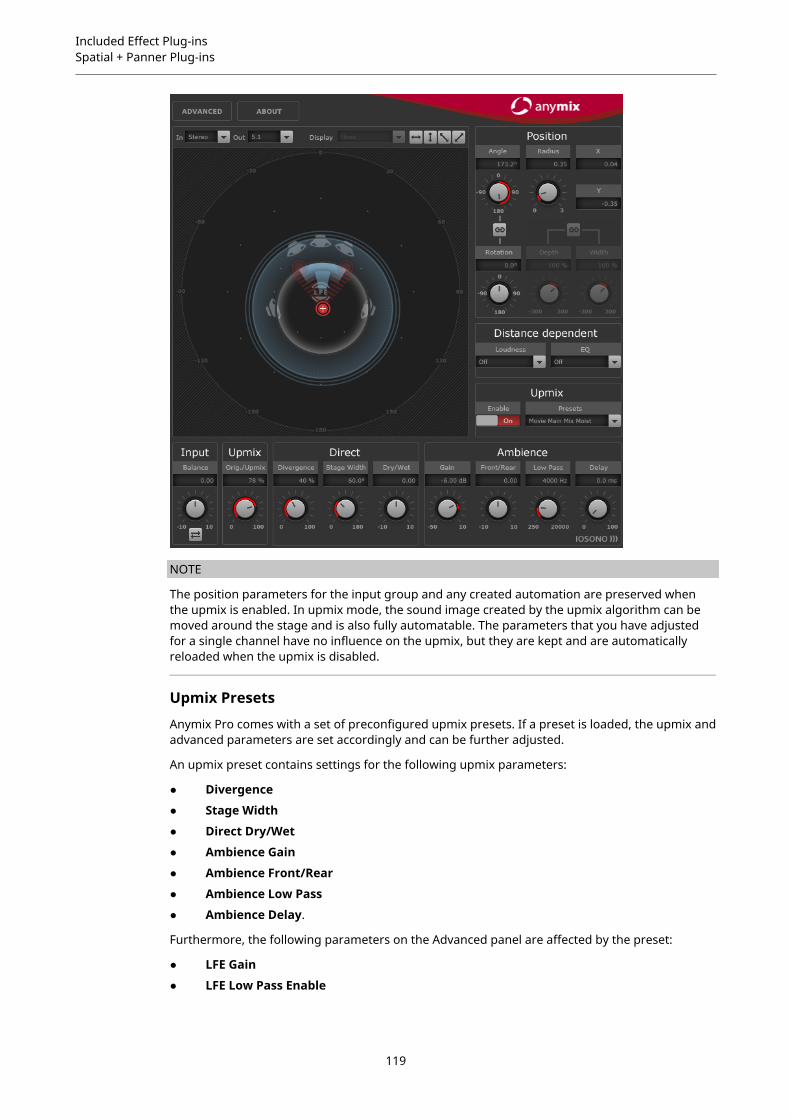
Included Effect Plug-insSpatial + Panner Plug-ins
NOTE
The position parameters for the input group and any created automation are preserved whenthe upmix is enabled. In upmix mode, the sound image created by the upmix algorithm can bemoved around the stage and is also fully automatable. The parameters that you have adjustedfor a single channel have no influence on the upmix, but they are kept and are automaticallyreloaded when the upmix is disabled.
Upmix Presets
Anymix Pro comes with a set of preconfigured upmix presets. If a preset is loaded, the upmix andadvanced parameters are set accordingly and can be further adjusted.
An upmix preset contains settings for the following upmix parameters:
● Divergence
● Stage Width
● Direct Dry/Wet
● Ambience Gain
● Ambience Front/Rear
● Ambience Low Pass
● Ambience Delay.
Furthermore, the following parameters on the Advanced panel are affected by the preset:
● LFE Gain
● LFE Low Pass Enable
119

Included Effect Plug-insSpatial + Panner Plug-ins
● LFE Low Pass Order
● LFE Low Pass Cutoff Frequency
● Output Gain.
NOTE
Upmix presets from the Cinema category are designed for the use with X-curve tuned speakersystems. The other presets are designed for listening environments with a flat speaker tuning.
Input – Balance
Adjusts the balance of the input signal if the input signal is stereo or higher.
Upmix – Orig./Upmix
Adjusts the plug-in output between original and processed signal.
Direct Sound Stream Parameters
DivergenceControls the strength of the center signal.
● At 0 % the mono components of the direct sound stream are distributed to thecenter channel.
● At 100 % the mono components of the direct sound stream are distributed tothe front left and right channels.
Stage WidthControls the position of the front channels to adjust the stereo base.
Dry/WetControls the amount of ambience that remains in the direct sound stream after theambience extraction.
Ambient Sound Stream Parameters
GainApplies gain to the ambient sound stream to either emphasize (high gain) or dampen(low gain) the amount of ambience in the mix.
Front/RearAdjusts the front/rear balance of the ambient sound stream.
Low PassControls the ambient sound stream with a low-pass filter to prevent hissing.
DelayAdds extra delay to the ambient sound stream to create the illusion of a very largespace.
ProximityThe Anymix Pro plug-in supports the Proximity surround format. Proximity allows you to take asound from the speakers and place it very close to the listener.
To make this effect audible, you need an appropriate reproduction device, for example, aProximity headphone system.
120

Included Effect Plug-insSpatial + Panner Plug-ins
If you use the Proximity format as input or output configuration, you can select one of thefollowing patterns from the In and Out pop-up menus:
Variable Input, Proximity OutputConverts incoming signals to the Proximity format. This allows you to balancethe incoming signals between a standard 5.1 setup and two additional Proximitychannels.
Proximity Input, Proximity OutputAllows you to adjust the FX Level in the Proximity signal.
Proximity Input, Variable OutputDecodes the incoming Proximity signal and converts it to any standard outputconfiguration other than 5.1.
NOTE
Convert 8.0 and 8.1 tracks to 7.1 before you encode to 7.1 Proximity. This prevents errors in thechannel order.
Proximity FX Level
Provides the Proximity effect settings.
121
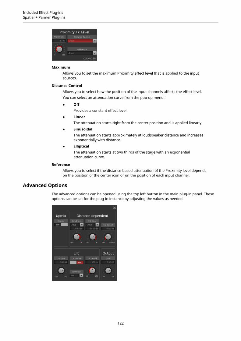
Included Effect Plug-insSpatial + Panner Plug-ins
MaximumAllows you to set the maximum Proximity effect level that is applied to the inputsources.
Distance ControlAllows you to select how the position of the input channels affects the effect level.You can select an attenuation curve from the pop-up menu:
● OffProvides a constant effect level.
● LinearThe attenuation starts right from the center position and is applied linearly.
● SinusoidalThe attenuation starts approximately at loudspeaker distance and increasesexponentially with distance.
● EllipticalThe attenuation starts at two thirds of the stage with an exponentialattenuation curve.
ReferenceAllows you to select if the distance-based attenuation of the Proximity level dependson the position of the center icon or on the position of each input channel.
Advanced OptionsThe advanced options can be opened using the top left button in the main plug-in panel. Theseoptions can be set for the plug-in instance by adjusting the values as needed.
122
Included Effect Plug-insSpatial + Panner Plug-ins
Distance Dependent Parameters
LoudnessAllows you to select whether the volume change that is to be applied depends onthe position of the center point, or if the volume change is calculated for each inputchannel separately.Sets the maximum gain reduction that is applied if the group input or channelreaches the stage border.
EQ GainAllows you to select whether the filtering that is to be applied depends on theposition of the center point, or if the amount of filtering is calculated for each inputchannel separately.Sets the maximum gain reduction of the filter that is applied if the group or inputchannel reaches the stage border.
EQ CutoffSets the cutoff frequency of the distance-dependent EQ.
Upmix – Matrix
Activates matrix decoding for matrix-encoded input signals.
NOTE
Matrix decoding is only applied in upmix mode.
LFE Parameters
LFE GainSets a separate gain level for the LFE channel that is applied to the plug-in output.
LP EnableEnables a low-pass filter that is applied to the LFE output channel after summing thesignals from the input channels.
LP CutoffSets the cutoff frequency for the generated LFE channel.
LP OrderAllows you to select the order, or slope, of the low-pass filter.
● 2nd order = 12 dB/octave
● 3rd order = 18 dB/octave
● 4th order = 24 dB/octave
NOTE
The amount of LFE can be adjusted for each input channel individually.
NOTE
If the selected input configuration includes an LFE channel, but the selected output configurationdoes not, the LFE input channel is distributed to front left and front right at a level of -3 dBautomatically. The low-pass filter is applied to the incoming LFE signal before it is distributed tothe front speakers.
123
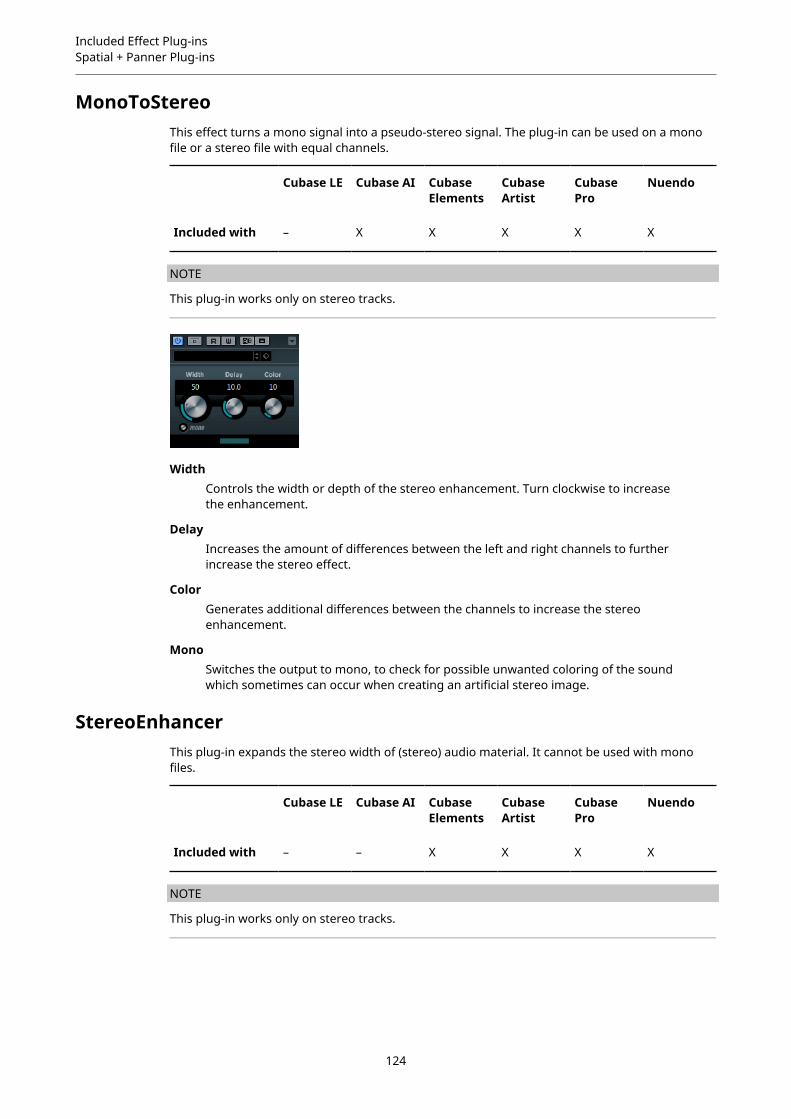
Included Effect Plug-insSpatial + Panner Plug-ins
MonoToStereoThis effect turns a mono signal into a pseudo-stereo signal. The plug-in can be used on a monofile or a stereo file with equal channels.
Cubase LE Cubase AI CubaseElements
CubaseArtist
CubasePro
Nuendo
Included with – X X X X X
NOTE
This plug-in works only on stereo tracks.
WidthControls the width or depth of the stereo enhancement. Turn clockwise to increasethe enhancement.
DelayIncreases the amount of differences between the left and right channels to furtherincrease the stereo effect.
ColorGenerates additional differences between the channels to increase the stereoenhancement.
MonoSwitches the output to mono, to check for possible unwanted coloring of the soundwhich sometimes can occur when creating an artificial stereo image.
StereoEnhancerThis plug-in expands the stereo width of (stereo) audio material. It cannot be used with monofiles.
Cubase LE Cubase AI CubaseElements
CubaseArtist
CubasePro
Nuendo
Included with – – X X X X
NOTE
This plug-in works only on stereo tracks.
124
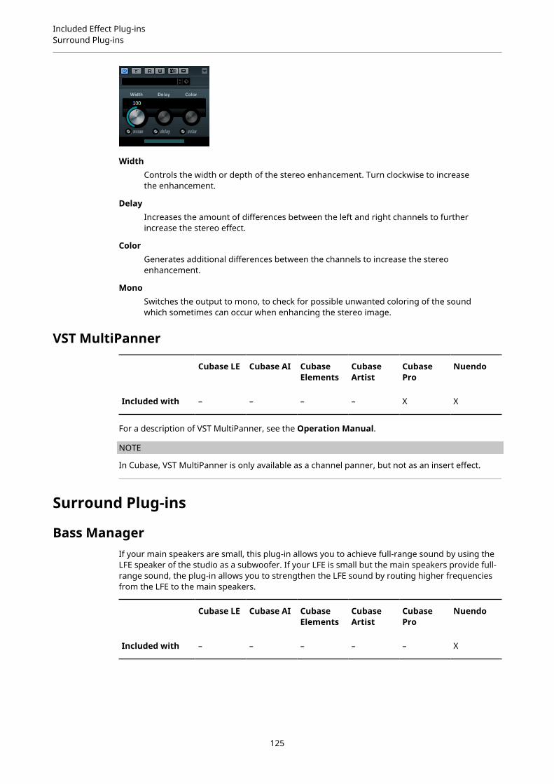
Included Effect Plug-insSurround Plug-ins
WidthControls the width or depth of the stereo enhancement. Turn clockwise to increasethe enhancement.
DelayIncreases the amount of differences between the left and right channels to furtherincrease the stereo effect.
ColorGenerates additional differences between the channels to increase the stereoenhancement.
MonoSwitches the output to mono, to check for possible unwanted coloring of the soundwhich sometimes can occur when enhancing the stereo image.
VST MultiPanner
Cubase LE Cubase AI CubaseElements
CubaseArtist
CubasePro
Nuendo
Included with – – – – X X
For a description of VST MultiPanner, see the Operation Manual.
NOTE
In Cubase, VST MultiPanner is only available as a channel panner, but not as an insert effect.
Surround Plug-ins
Bass ManagerIf your main speakers are small, this plug-in allows you to achieve full-range sound by using theLFE speaker of the studio as a subwoofer. If your LFE is small but the main speakers provide full-range sound, the plug-in allows you to strengthen the LFE sound by routing higher frequenciesfrom the LFE to the main speakers.
Cubase LE Cubase AI CubaseElements
CubaseArtist
CubasePro
Nuendo
Included with – – – – – X
125

Included Effect Plug-insSurround Plug-ins
If your monitoring system is connected directly to your audio interface and lacks a bassmanagement system, you can use Bass Manager in the Control Room inserts to adjust the signallevels and signal routing of the LFE and main speakers. Thus, small speakers can achieve full-range sound.
Input/Output Level Meters
Level InShows the level of the input signal.
Level OutShows the level of the output signal.
Mains
SubwooferIf this is activated, the low part of the main speakers is routed to the subwoofer.
FreqSets the crossover frequency. Frequencies below this value are routed to thesubwoofer.
GainSets the amount of attenuation/boost of the signal that is routed to the subwoofer.
LFE
CenterIf this is activated, the LFE signal is routed to the center channel.
L/RIf this is activated, the LFE signal is routed to the left and right channels.
FreqSets the crossover frequency. Frequencies above this value are routed to the left andright channels or to the center channel.
GainSets the amount of attenuation/boost of the signal that is routed to the left and rightchannels or to the center channel.
126

Included Effect Plug-insSurround Plug-ins
+10 dBBoosts the level of the LFE signal by 10 dB.
Subwoofer
SoloSolos the subwoofer signal.
MuteMutes the subwoofer signal.
Low CutAdditional low-cut filter for the subwoofer.
High CutAdditional high-cut filter for the subwoofer.
+10 dBBoosts the level of the subwoofer signal by 10 dB.
NOTE
You can also use the graphical displays to set the parameters or enter the parameter valuesmanually in the value fields.
MatrixEncoder
Cubase LE Cubase AI CubaseElements
CubaseArtist
CubasePro
Nuendo
Included with – – – – – X
The MatrixEncoder is intended for the Pro Logic compatible encoding of multi-channel files. Thisis a process where a 4-channel surround mix is packed into two channels for broadcasting or atwo-channel version for DVDs, for example. The MatrixEncoder takes four separate inputs (LRCS= Left, Right, Center, and Surround) and creates two final outputs: Left-total and Right-total (Ltand Rt).
NOTE
This manual does not attempt to explain the full background on how Pro Logic works, butfocuses on how you can use the MatrixEncoder/Decoder to produce a mix that is compatible withthis standard.
127

Included Effect Plug-insSurround Plug-ins
RELATED LINKSMatrixDecoder on page 130
Setting Up
PROCEDURE
1. In the VST Connections window, create an output bus with the LRCS channel configurationand route it to the physical outputs of your audio hardware.This is if you want to make a four-channel surround mix. If you want to make a five-channel mix, use MatrixEncoder with the 5.0 Surround Format.
2. Place the MatrixEncoder in the first post-fader insert slot (#7) for the output bus, followedby the MatrixDecoder (#8).
RELATED LINKSUsing the MatrixEncoder with the 5.0 Surround Format on page 129
Using the MatrixEncoder/Decoder
PROCEDURE
1. Set up the mix roughly the way you want it.Use the VST MultiPanner to place channels in the surround mix, or assign channels to theindividual LRCS outputs.
2. Activate the MatrixEncoder.What you now hear is the encoded stereo mix, the way it sounds when it is played back ona normal stereo reproducer. On the MatrixEncoder control panel, you can adjust the Gainof the Lt/Rt output by using the fader.
3. Activate the MatrixDecoder, open the control panel and click the Steering Mode button.Now you can hear how the mix is reproduced in surround on a Pro Logic compatiblesystem.
The Steering display shows an x within the surround field. The position of this x indicatesthe dominant direction of the mix, sometimes referred to as the dominance vector. Partof the processing that is applied results in the dominant channel being enhanced and thenon-dominant channels being reduced in gain.
4. By activating and deactivating the Bypass button in the MatrixDecoder, you can comparethe decoded mix with the encoded stereo mix, and make adjustments in the MixConsole asnecessary.The main goal is to produce a mix that sounds good in both the encoded and the decodedversion. To compare the encoded or decoded mix with the unprocessed mix, switch offboth the MatrixEncoder and the Decoder.
128

Included Effect Plug-insSurround Plug-ins
IMPORTANT
The encoding/decoding process produces significant signal loss compared to theunprocessed mix. This is normal, and does not indicate that something is not workingproperly. However, with careful tweaking of the mix, you can decrease the signaldegradation to a much more acceptable level. You have to adjust levels and other settingsbefore the signal runs through the MatrixEncoder, because neither the encoder ordecoder can control the mix in any way.
5. If you are satisfied with the result, bypass the MatrixDecoder, or remove it from its effectslot.
6. Connect a master recording device to the stereo mix output and perform a mixdown asusual.
RESULTThe resulting encoded stereo mix is compatible with common home systems that use the ProLogic standard.
Using the MatrixEncoder with the 5.0 Surround FormatThere are situations where you may want to mix for several surround formats. For example, youmight need to mix the same material for 5.1 and LRCS.
5.1 is similar to LRCS. Omitting the LFE channel is easy, but more of a problem is that LRCS onlyhas one surround channel whereas 5.1 has two.
For this reason, the MatrixEncoder sums up the surround channels to a mono signal.
PROCEDURE
1. Create your mix for 5.1.
2. In the VST Connections window, create an output bus with a 5.0 channel configuration androute it to the physical outputs of your audio hardware.
3. Run the mix through the MatrixEncoder.
RESULTFirst, the two surround channels are merged to make the mix compatible with LRCS. Then, thefour resulting signals are encoded as usual. This way, far fewer adjustments are necessary whenworking with 5.1 and LRCS at the same time.
Using the MatrixDecoder with the 5.0 Surround FormatNormally, two surround speakers are used even when playing back LRCS. The two speakersthen simply use the same material. The MatrixDecoder simulates this by delivering the surroundchannel to two outputs. This allows you to move between formats and listening situations withless repatching of speaker channels.
129
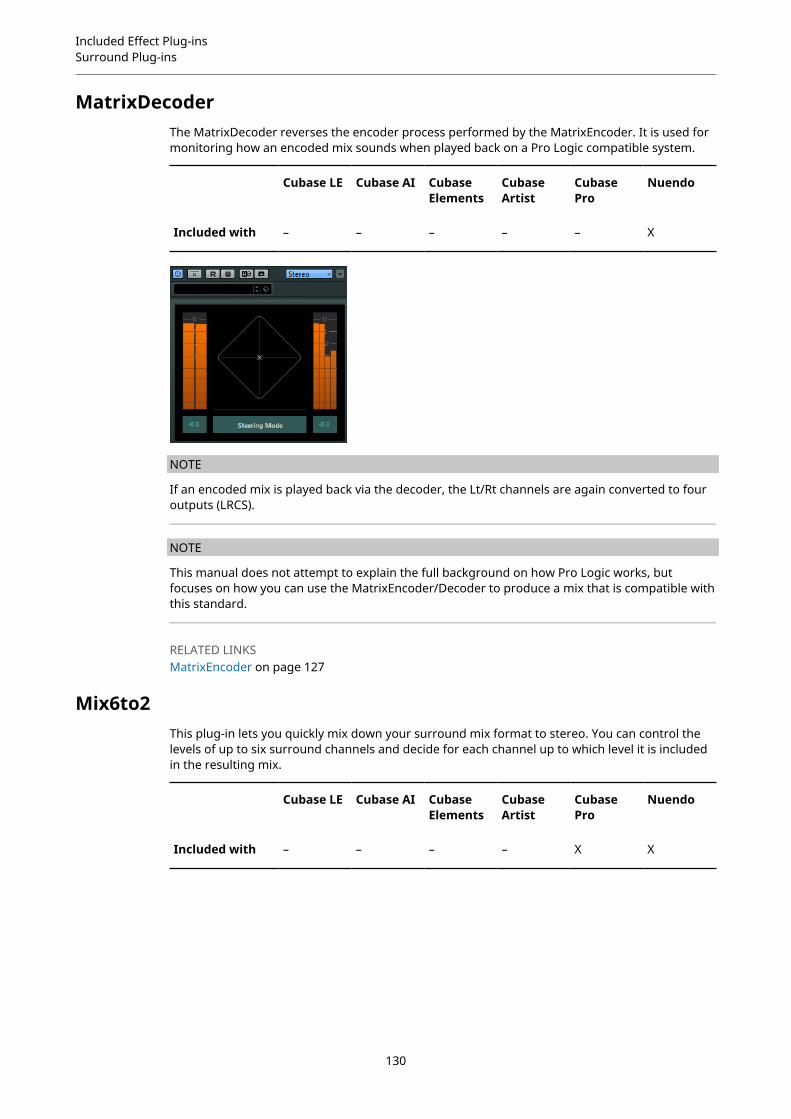
Included Effect Plug-insSurround Plug-ins
MatrixDecoderThe MatrixDecoder reverses the encoder process performed by the MatrixEncoder. It is used formonitoring how an encoded mix sounds when played back on a Pro Logic compatible system.
Cubase LE Cubase AI CubaseElements
CubaseArtist
CubasePro
Nuendo
Included with – – – – – X
NOTE
If an encoded mix is played back via the decoder, the Lt/Rt channels are again converted to fouroutputs (LRCS).
NOTE
This manual does not attempt to explain the full background on how Pro Logic works, butfocuses on how you can use the MatrixEncoder/Decoder to produce a mix that is compatible withthis standard.
RELATED LINKSMatrixEncoder on page 127
Mix6to2This plug-in lets you quickly mix down your surround mix format to stereo. You can control thelevels of up to six surround channels and decide for each channel up to which level it is includedin the resulting mix.
Cubase LE Cubase AI CubaseElements
CubaseArtist
CubasePro
Nuendo
Included with – – – – X X
130

Included Effect Plug-insSurround Plug-ins
Surround Channels
VolumeGovern how much of the signal is included in the left and/or right channel of theoutput bus.
LinkLink the volume faders.
InvertInvert the phase of the left and right channel of the surround bus.
Output Bus
VolumeSet the volume of the of the mixed output.
LinkLinks the Output faders.
NormalizeIf this option is activated, the mixed output is normalized. For example, the outputlevel is automatically adjusted so that the loudest signal is as loud as possiblewithout clipping.
Mix8to2This plug-in lets you quickly mix down your surround mix format to stereo. You can controlthe levels of up to eight surround channels and decide for each channel up to which level it isincluded in the resulting mix.
Cubase LE Cubase AI CubaseElements
CubaseArtist
CubasePro
Nuendo
Included with – – – – – X
131

Included Effect Plug-insSurround Plug-ins
Surround Channels
VolumeGovern how much of the signal is included in the left and/or right channel of theoutput bus.
LinkLink the volume faders.
InvertInvert the phase of the left and right channel of the surround bus.
Output Bus
VolumeSet the volume of the of the mixed output.
LinkLinks the Output faders.
NormalizeIf this option is activated, the mixed output is normalized. For example, the outputlevel is automatically adjusted so that the loudest signal is as loud as possiblewithout clipping.
MixConvert V6The MixConvert V6 plug-in can be used to quickly convert a multi-channel mix to a format with adifferent channel configuration, for example, to mix down a 7.1 cinema surround format to a 5.1home theater format.
Cubase LE Cubase AI CubaseElements
CubaseArtist
CubasePro
Nuendo
Included with – – – – X X
132
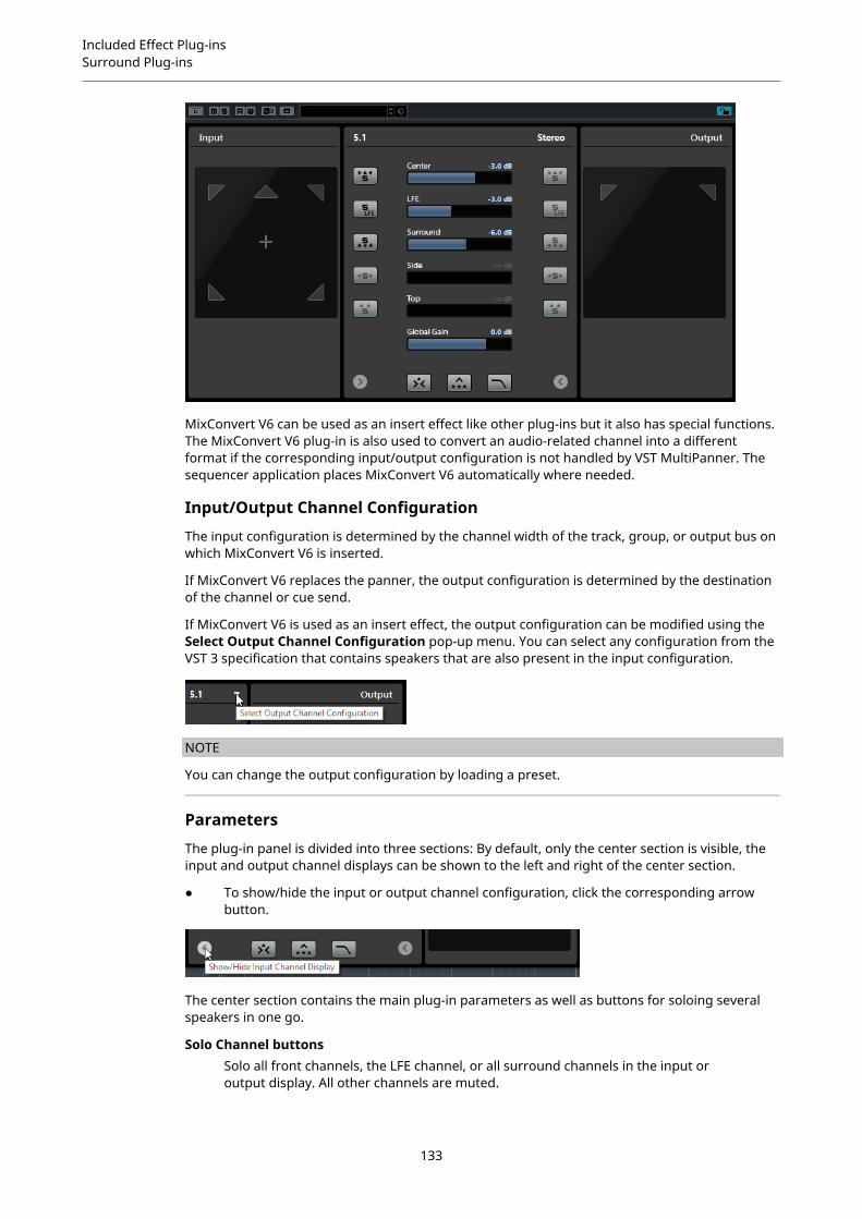
Included Effect Plug-insSurround Plug-ins
MixConvert V6 can be used as an insert effect like other plug-ins but it also has special functions.The MixConvert V6 plug-in is also used to convert an audio-related channel into a differentformat if the corresponding input/output configuration is not handled by VST MultiPanner. Thesequencer application places MixConvert V6 automatically where needed.
Input/Output Channel Configuration
The input configuration is determined by the channel width of the track, group, or output bus onwhich MixConvert V6 is inserted.
If MixConvert V6 replaces the panner, the output configuration is determined by the destinationof the channel or cue send.
If MixConvert V6 is used as an insert effect, the output configuration can be modified using theSelect Output Channel Configuration pop-up menu. You can select any configuration from theVST 3 specification that contains speakers that are also present in the input configuration.
NOTE
You can change the output configuration by loading a preset.
Parameters
The plug-in panel is divided into three sections: By default, only the center section is visible, theinput and output channel displays can be shown to the left and right of the center section.
● To show/hide the input or output channel configuration, click the corresponding arrowbutton.
The center section contains the main plug-in parameters as well as buttons for soloing severalspeakers in one go.
Solo Channel buttonsSolo all front channels, the LFE channel, or all surround channels in the input oroutput display. All other channels are muted.
133

Included Effect Plug-insSurround Plug-ins
Listen to Solo Channels on Center ChannelRoutes all soloed channels to the center channel. If no center channel is present, thesignal from the soloed channels is distributed equally to the left and right speakers.
Listen to Surround Channels on Front ChannelsSolos all surround channels, including the side channels, and routes or downmixesthem to the front speakers.
Center LevelControls the level of the front center channel.
LFE faderControls the level of the LFE channel.
Surround LevelControls the level of the surround channels. The level of the surround channelscannot be adjusted individually.
Side LevelControls the level of the side channels. The level of the side channels cannot beadjusted individually.
Top LevelControls the level of the top channels. The level of the top channels cannot beadjusted individually.
Global GainControls the level of all output channels.
Activate/Deactivate Low-Pass FilterActivates the low-pass filter that is applied to the LFE channel.
RELATED LINKSVST MultiPanner on page 125
Soloing Channels in the Channel Displays● To solo a channel, click the corresponding speaker icon.
You can solo several channels at the same time. All other channels are muted.
● To deactivate the solo state of a channel, click the corresponding speaker icon again.
● To solo a channel exclusively, Ctrl/Cmd-click the corresponding speaker icon.
● To solo the LFE channel, click the corresponding cross-hair icon in the center of thechannel display.This corresponds to the Solo Input/Output LFE Channel button in the center section.
● To mute a channel, Shift-click the corresponding speaker icon.
Depending on whether you solo a channel in the input or output configuration, the followingapplies:
● For output configurations, you can only hear the soloed speaker’s channel in the downmix.
● For input configurations, you can hear the influence of the soloed speaker’s channel on thedownmix.
134

Included Effect Plug-insSurround Plug-ins
MixerDelayMixerDelay allows you to adjust and manipulate each individual channel in a surround track,group or bus.
Cubase LE Cubase AI CubaseElements
CubaseArtist
CubasePro
Nuendo
Included with – – – – X X
Above the individual channel controls, you find global buttons for turning off Mute, Solo andInvert Phase switches for all channels.
MuteAllows you to mute individual channels.
SoloAllows you to solo individual channels.
InvLets you invert the phase or polarity for individual channels.
DelayAllows you to delay individual speaker channels. The delay times are shownin milliseconds and centimeters, making this feature very useful for distancecompensation when playing back surround mixes on different speaker setups, etc.
LevelAllows you to fine-tune the volume balance between the surround channels.
VolumeShows the level of the input signal.
RoutingLets you select/switch the outputs for the channels quickly. You can assign the sameoutput to several channels by holding down Alt while selecting. Note that there arealso several channel routing presets available.
NOTE
It is common for the center channel in a 5.1 speaker configuration to be closer to the mixposition in order to accommodate large video monitors or projection screens. MixerDelay canbe used to compensate for the center channel being too close. Simply adjust the delay for thecenter channel by the difference in distance (in cm) between it and the other speakers to the mixposition. You must delay the closer speaker so that the sound from it arrives at the same time asthe sound from the more distant speakers. Note that MixerDelay has a wide range (up to 1000 ms) and fine adjustments are best made by numerically entering the delay time in centimetersfor speaker alignment.
135
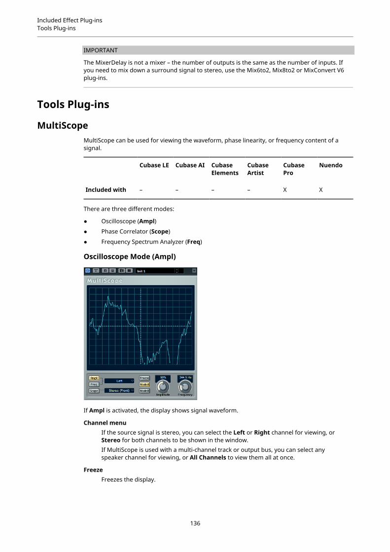
Included Effect Plug-insTools Plug-ins
IMPORTANT
The MixerDelay is not a mixer – the number of outputs is the same as the number of inputs. Ifyou need to mix down a surround signal to stereo, use the Mix6to2, Mix8to2 or MixConvert V6plug-ins.
Tools Plug-ins
MultiScopeMultiScope can be used for viewing the waveform, phase linearity, or frequency content of asignal.
Cubase LE Cubase AI CubaseElements
CubaseArtist
CubasePro
Nuendo
Included with – – – – X X
There are three different modes:
● Oscilloscope (Ampl)
● Phase Correlator (Scope)
● Frequency Spectrum Analyzer (Freq)
Oscilloscope Mode (Ampl)
If Ampl is activated, the display shows signal waveform.
Channel menuIf the source signal is stereo, you can select the Left or Right channel for viewing, orStereo for both channels to be shown in the window.If MultiScope is used with a multi-channel track or output bus, you can select anyspeaker channel for viewing, or All Channels to view them all at once.
FreezeFreezes the display.
136
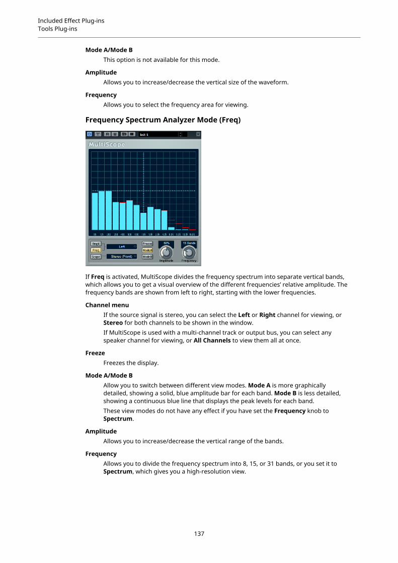
Included Effect Plug-insTools Plug-ins
Mode A/Mode BThis option is not available for this mode.
AmplitudeAllows you to increase/decrease the vertical size of the waveform.
FrequencyAllows you to select the frequency area for viewing.
Frequency Spectrum Analyzer Mode (Freq)
If Freq is activated, MultiScope divides the frequency spectrum into separate vertical bands,which allows you to get a visual overview of the different frequencies’ relative amplitude. Thefrequency bands are shown from left to right, starting with the lower frequencies.
Channel menuIf the source signal is stereo, you can select the Left or Right channel for viewing, orStereo for both channels to be shown in the window.If MultiScope is used with a multi-channel track or output bus, you can select anyspeaker channel for viewing, or All Channels to view them all at once.
FreezeFreezes the display.
Mode A/Mode BAllow you to switch between different view modes. Mode A is more graphicallydetailed, showing a solid, blue amplitude bar for each band. Mode B is less detailed,showing a continuous blue line that displays the peak levels for each band.These view modes do not have any effect if you have set the Frequency knob toSpectrum.
AmplitudeAllows you to increase/decrease the vertical range of the bands.
FrequencyAllows you to divide the frequency spectrum into 8, 15, or 31 bands, or you set it toSpectrum, which gives you a high-resolution view.
137
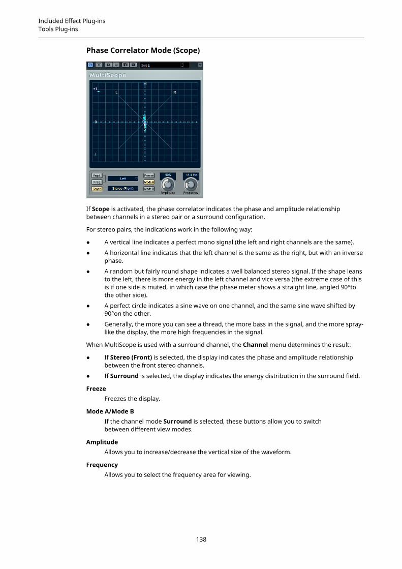
Included Effect Plug-insTools Plug-ins
Phase Correlator Mode (Scope)
If Scope is activated, the phase correlator indicates the phase and amplitude relationshipbetween channels in a stereo pair or a surround configuration.
For stereo pairs, the indications work in the following way:
● A vertical line indicates a perfect mono signal (the left and right channels are the same).
● A horizontal line indicates that the left channel is the same as the right, but with an inversephase.
● A random but fairly round shape indicates a well balanced stereo signal. If the shape leansto the left, there is more energy in the left channel and vice versa (the extreme case of thisis if one side is muted, in which case the phase meter shows a straight line, angled 90°tothe other side).
● A perfect circle indicates a sine wave on one channel, and the same sine wave shifted by90°on the other.
● Generally, the more you can see a thread, the more bass in the signal, and the more spray-like the display, the more high frequencies in the signal.
When MultiScope is used with a surround channel, the Channel menu determines the result:
● If Stereo (Front) is selected, the display indicates the phase and amplitude relationshipbetween the front stereo channels.
● If Surround is selected, the display indicates the energy distribution in the surround field.
FreezeFreezes the display.
Mode A/Mode BIf the channel mode Surround is selected, these buttons allow you to switchbetween different view modes.
AmplitudeAllows you to increase/decrease the vertical size of the waveform.
FrequencyAllows you to select the frequency area for viewing.
138

Included Effect Plug-insTools Plug-ins
SMPTEGeneratorThis plug-in is not a real audio effect. It sends out SMPTE timecode to an audio output, allowingyou to synchronize other equipment to your host application (provided that the equipment cansynchronize directly to SMPTE timecode). This can be very useful if you do not have access to aMIDI-to-timecode converter.
Cubase LE Cubase AI CubaseElements
CubaseArtist
CubasePro
Nuendo
Included with – – – – X X
Main timecode displayThis display shows the current timecode.If Link to Transport is deactivated, the generator is in free run mode. You can usethe timecode display to set the SMPTE start time.If Link to Transport is activated, you cannot change any of the values. This displayshows the current timecode in sync with the Transport panel. Where applicable, theoffset defined in the offset timecode display is taken into account.
Frame rate display and pop-up menuThe frame rate shown to the right of the timecode display corresponds to the framerate set in the Project Setup dialog. To generate timecode in a different frame rate(for example, to stripe a tape), select another format on the pop-up menu (onlyavailable if Link to Transport is deactivated).
NOTE
For another device to synchronize correctly to your host, the same frame rate has tobe set in the Project Setup dialog, the SMPTE Generator, and the receiving device.
Offset timecode displayThis display is only available if Link to Transport is activated. It allows you to set anoffset with regard to the timecode used by your host application. The offset affectsthe generated SMPTE signal, the current cursor position remains unaffected.For example, use this when playing back video using an external device, where thevideo starts at a different timecode position than in your host. A scenario couldbe as follows: You have placed the same video several times on the timeline, inorder to record different audio versions for that video one after the other. However,since video playback is done via an external machine (replaying the same video),you need an offset to match the different timecode positions in your host with the(unchanging) start position on the external machine.
Generate CodeIf this button is activated, the plug-in generates SMPTE timecode in free run mode,meaning that it outputs continuous timecode independent from the Transport panel.Use this mode if you want to stripe tape with SMPTE.
139

Included Effect Plug-insTools Plug-ins
Link to TransportIf this button is activated, the timecode is synchronized to the Transport panel.
Timecode in Still ModeIf this button is activated, the plug-in also generates SMPTE timecode in stop mode.However, note that this is not continuous timecode, but timecode generated at thecurrent cursor position. For example, this can be useful when working with videoediting software that interprets the absence of timecode as a stop command. Byusing this option, the video software can enter still mode instead so that a still frameis shown instead of a blank screen.
NOTE
To change one of the timecode values (main and offset timecode displays), double-click on any ofthe timecode fields and enter a new value.
Synchronizing a Device to Your Host
PROCEDURE
1. Use the SMPTE Generator as an insert effect on an audio track, and route that track to aseparate output.Make sure that no other insert or send effect is used on this track. Deactivate any EQsettings for this track.
2. Connect the corresponding output on the audio hardware to the timecode input on thedevice that you want to synchronize to your host application.Make all necessary settings for the external device so that it synchronizes to incomingtimecode.
3. Optional: Adjust the level of the timecode, either in your host application or in thereceiving device.Activate the Generate Code button (make the device send the SMPTE timecode in free runmode) to test the level.
4. Make sure that the frame rate in the receiving device matches the frame rate set in theSMPTE Generator.
5. Activate the Link to Transport button.The SMPTE Generator now outputs timecode that corresponds to the time display of yourhost application.
6. On the Transport panel, click Play.
RESULTThe external device is now synchronized and follows any position changes set with the transportcontrols.
TestGeneratorThis utility plug-in allows you to generate an audio signal, which can be recorded as an audio file.
Cubase LE Cubase AI CubaseElements
CubaseArtist
CubasePro
Nuendo
Included with – – – – X X
140

Included Effect Plug-insTools Plug-ins
The resulting file can then be used for a number of purposes:
● Testing the specifications of audio equipment
● Measurements of various kinds, such as calibrating tape recorders
● Testing signal processing methods
● Educational purposes
The TestGenerator is based on a waveform generator which can generate a number of basicwaveforms such as sine and saw as well as various types of noise. Furthermore, you can set thefrequency and amplitude of the generated signal. As soon as you add the TestGenerator as aneffect on an audio track and activate it, a signal is generated. You can then activate recording asusual to record an audio file according to the signal specifications.
Waveforms and noise sectionAllows you to set the basis for the signal generated by the waveform generator. Youcan choose between four basic waveforms (sine, triangle, square, and sawtooth) andthree types of noise (white, pink, and brownian).
Frequency sectionAllows you to set the frequency of the generated signal. You can set the frequencyeither in Hz or as a note value. If you enter a note value, the frequency isautomatically changed to Hz. For example, a note value of A3 sets the frequency to440 Hz. When you enter a note value, you can also enter a cent offset. For example,enter A5 -23 or C4 +49.
NOTE
Ensure that you enter a space between the note and the cent offset. Only in this case,the cent offsets are taken into account.
Gain sectionAllows you to set the amplitude of the signal. The higher the value, the strongerthe signal. You can select one of the preset values, or use the slider to set a valuebetween -81 and 0 dB.
TunerThis is a guitar tuner.
IMPORTANT
Make sure that you deactivate any other effect that alters pitch, like chorus or vibrato.
Cubase LE Cubase AI CubaseElements
CubaseArtist
CubasePro
Nuendo
Included with X X X X X X
141

Included Effect Plug-insTools Plug-ins
Simply connect a guitar or other instrument to an audio input and select Tuner as an inserteffect.
IMPORTANT
To use Tuner, you must activate Monitor for the track with Tuner.
You can display Tuner in an analog view or in a digital view.
● To switch between analog view and digital view, position the mouse pointer in the upperleft corner of the plug-in, and click the Switch between analog view and digital view
button .
Analog View
When you play a note, the pitch is shown in the middle of the display. The frequency in Hz isshown in the bottom left corner and the octave range in the bottom right corner.
The two arrows indicate any deviation in pitch. If the pitch is flat, they are positioned in the lefthalf of the display, if the pitch is sharp they are in the right half. The deviation is also shown inthe upper area of the display.
● If a string is out of tune (for example, if the pitch for the E string is shown as Eb), tune thestring so that the correct pitch is shown and the two arrows are in the middle. Repeat thisprocedure for each string.
● To mute the output signal so that you can tune the strings in silence, activate the Mutebutton at the bottom middle of the plug-in panel.
Digital View (Cubase Pro and Nuendo only)
NoteDisplays the currently played pitch.
CentDisplays the value, deviating from Note. A negative value indicates that the pitch isflat. A positive value indicates that the pitch is sharp.
Strobe/ClassicYou can switch the display between two modes: Strobe and Classic.
142
Included Effect Plug-insTools Plug-ins
In Strobe mode, a blue indicator constantly runs from right to left, that is frompositive to negative. The more flat a note is, the faster the indicator moves. As soonas you play a sharp tone, the running direction of the indicator runs from left toright, that is from negative to positive. When you play the correct pitch, the indicatorstops and the display turns gray.When you play a note in Classic mode, the pitch is shown in the middle of thedisplay. When you play the correct pitch, the middle of the indicator turns gray.
BaseDisplays the frequency of the base note A. Its default value is 440 Hz. You can adjustBase by ± 15 Hz.
OctaveDisplays the octave.
143
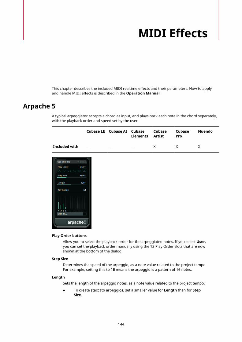
MIDI Effects
This chapter describes the included MIDI realtime effects and their parameters. How to applyand handle MIDI effects is described in the Operation Manual.
Arpache 5A typical arpeggiator accepts a chord as input, and plays back each note in the chord separately,with the playback order and speed set by the user.
Cubase LE Cubase AI CubaseElements
CubaseArtist
CubasePro
Nuendo
Included with – – – X X X
Play Order buttonsAllow you to select the playback order for the arpeggiated notes. If you select User,you can set the playback order manually using the 12 Play Order slots that are nowshown at the bottom of the dialog.
Step SizeDetermines the speed of the arpeggio, as a note value related to the project tempo.For example, setting this to 16 means the arpeggio is a pattern of 16 notes.
LengthSets the length of the arpeggio notes, as a note value related to the project tempo.
● To create staccato arpeggios, set a smaller value for Length than for StepSize.
144
MIDI EffectsArpache 5
● To create arpeggio notes that overlap each other, set a greater value forLength than for Step Size.
Key RangeDetermines the arpeggiated note range, in semitones counted from the lowest keyyou play. This works as follows:
● Any notes you play that are outside this range are transposed in octave stepsto fit within the range.
● If the range is more than one octave, octave-transposed copies of the notesyou play are added to the arpeggio (as many octaves as fit within the range).
Play Order slots
If the User play order is selected, you can use these slots to specify a customplayback order for the arpeggio notes: Each of the 12 slots corresponds to a positionin the arpeggio pattern. For each slot, you specify which note should be played onthat position by selecting a number. The numbers correspond to the keys you play,counted from the lowest key.For example, if you play the notes C3-E3-G3 (a C major chord), 1 means C3, 2 meansE3, and 3 means G3.
NOTE
You can use the same number in several slots, creating arpeggio patterns that arenot possible using the standard play modes. You need to begin with the leftmost slotand then fill the slots to the right.
MIDI ThruIf this button is activated, the notes that you play pass through the plug-in and aresent out together with the arpeggiated notes.
Creating an Arpeggio
PROCEDURE
1. Select a MIDI track and activate monitoring (or record enable it) so that you can playthrough the track.Make sure that the track is properly set up for playback to a suitable MIDI instrument.
2. Select the arpeggiator as an insert effect for the track.
3. Activate the arpeggiator.
4. On the arpeggiator panel, use the Step Size setting to set the arpeggio speed.
5. Use the Length setting to set the length of the arpeggio notes.
6. Set the Key Range parameter to 12.This makes the notes arpeggiate within an octave.
7. Play a chord on your MIDI instrument.Now, instead of hearing the chord, you hear the notes of the chord played one by one, inan arpeggio.
8. Try the different arpeggio modes by clicking the Play Order buttons.The symbols on the buttons indicate the playback order for the notes.
145

MIDI EffectsArpache SX
Arpache SXThis is a versatile and advanced arpeggiator, capable of creating anything from traditionalarpeggios to complex, sequencer-like patterns.
Cubase LE Cubase AI CubaseElements
CubaseArtist
CubasePro
Nuendo
Included with – – – X X X
Classic vs. Sequence Mode
Arpache SX has two different modes: Classic and Sequence. The Classic mode determines thebasic behavior of Arpache SX. Sequence mode uses the events of an additional MIDI part as apattern. This pattern forms the basis for the arpeggio, in conjunction with the MIDI input.
Classic Mode
DirectionAllows you to choose how the notes in the played chord should be arpeggiated.
One Shot ModeActivate this option if you want the phrase to be played only once. If this option isdeactivated, the phrase is looped.
TransposeWith a setting other than Off, the arpeggio is expanded upwards, downwards, orboth (depending on the mode). This is done by adding transposed repeats of thebasic arpeggio pattern.
RepeatsSets the number of transposed repeats.
Pitch ShiftDetermines the transposition of each repeat.
MIDI ThruIf this is activated, the played notes pass through the plug-in and are sent outtogether with the arpeggiated notes.
146

MIDI EffectsArpache SX
Step SizeDetermines the resolution of the arpeggio, that is, its speed (in fixed note valuesor PPQ, if the PPQ button is activated). In Sequence mode you can also activate thefrom sequence option.
LengthDetermines the length of the arpeggio notes (in fixed note values or PPQ, if the PPQbutton is activated).
Max. PolyphonyDetermines how many notes should be accepted in the input chord. The All settingmeans there are no limitations.
Sort byIf you play a chord, the arpeggiator sorts the notes in the chord in the orderspecified here. For example, if you play a C-E-G chord, with Note Lowest selected,C is the first note, E is the second and G the third. This affects the result of the ArpStyle setting.
VelocityDetermines the velocity of the notes in the arpeggio. Using the slider you can set afixed velocity, or you can activate the via Input button to use the velocity values ofthe notes in the chord you play. In Sequence mode you can also activate the fromsequence option.
Sequence Mode
In Sequence mode, you can import a MIDI part into Arpache SX by dragging it from the Projectwindow onto the Drop MIDI Sequence field on the right of the Arpache SX panel.
The notes in the dropped MIDI part are sorted internally, either according to their pitch if theMIDI Seq. sort by pitch checkbox is activated or according to their play order in the part. Thisresults in a list of numbers. For example, if the notes in the MIDI part are C E G A E C and they aresorted according to pitch, the list of numbers reads 1 2 3 4 2 1. Here, there are 4 different notes/numbers and 6 trigger positions.
The MIDI input (the chord you play) generates a list of numbers, with each note in the chordcorresponding to a number depending on the Sort by setting.
Furthermore, the two lists of numbers are matched – Arpache SX tries to play back the patternfrom the dropped MIDI part but using the notes from the MIDI input. The result depends on thePlay Mode setting.
TriggerThe whole pattern from the dropped MIDI file is played back, but transposedaccording to one of the notes in the MIDI input. Which note is used for transposingdepends on the Sort by setting.
Trigger Cnt.As above, but even if all keys are released, the phrase continues playing from the lastposition (where it stopped), if a new key is pressed on the keyboard. This is typicallyused when playing live through the Arpache SX.
Sort NormalMatches the notes in the MIDI input with the notes in the dropped MIDI part. Ifthere are fewer notes in the MIDI input, some steps in the resulting arpeggio remainempty.
Sort FirstAs above, but if there are fewer notes in the MIDI input, the missing notes arereplaced by the first note.
147

MIDI EffectsAuto LFO
Sort AnyAs above, but if there are fewer notes in the MIDI input, the missing notes arereplaced by random notes.
Arp. StyleAs above, but if there are fewer notes in the MIDI input, the missing notes arereplaced by the last valid note in the arpeggio.
RepeatIn this mode, the chords played are not separated into notes. Instead, they are usedas is, and only the rhythm of the dropped MIDI part is used for playback.
NOTE
You can choose to keep the original note timing, note length, and note velocities from thedropped MIDI part, by selecting from sequence for the Step Size, Length, and Velocity options.
Auto LFOThis effect works like an LFO in a synthesizer, allowing you to send out continuously changingMIDI controller messages. One typical use for this is automatic MIDI panning, but you can selectany MIDI continuous controller event type.
Cubase LE Cubase AI CubaseElements
CubaseArtist
CubasePro
Nuendo
Included with – – – X X X
WaveformDetermines the shape of the controller curves that are sent out. You can click awaveform symbol or choose a value from the pop-up menu.
WavelengthSets the speed of Auto LFO, or rather the length of a single controller curve cycle.You can set this to rhythmically exact note values or PPQ values if the PPQ button isactivated. The lower the note value, the slower the speed.
Controller TypeDetermines which continuous controller type is sent out. Typical choices wouldinclude pan, volume, and brightness, but your MIDI instrument may have controllersmapped to various settings, allowing you to modulate the synth parameter of yourchoice. Check the MIDI implementation chart for your instrument for details.
148
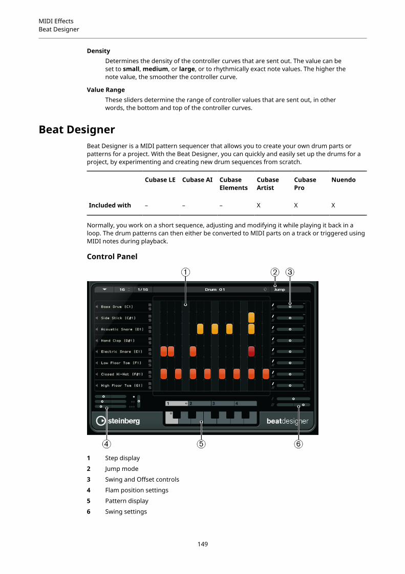
MIDI EffectsBeat Designer
DensityDetermines the density of the controller curves that are sent out. The value can beset to small, medium, or large, or to rhythmically exact note values. The higher thenote value, the smoother the controller curve.
Value RangeThese sliders determine the range of controller values that are sent out, in otherwords, the bottom and top of the controller curves.
Beat DesignerBeat Designer is a MIDI pattern sequencer that allows you to create your own drum parts orpatterns for a project. With the Beat Designer, you can quickly and easily set up the drums for aproject, by experimenting and creating new drum sequences from scratch.
Cubase LE Cubase AI CubaseElements
CubaseArtist
CubasePro
Nuendo
Included with – – – X X X
Normally, you work on a short sequence, adjusting and modifying it while playing it back in aloop. The drum patterns can then either be converted to MIDI parts on a track or triggered usingMIDI notes during playback.
Control Panel
1 Step display
2 Jump mode
3 Swing and Offset controls
4 Flam position settings
5 Pattern display
6 Swing settings
149
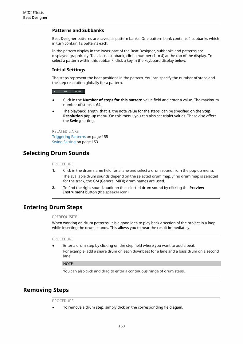
MIDI EffectsBeat Designer
Patterns and Subbanks
Beat Designer patterns are saved as pattern banks. One pattern bank contains 4 subbanks whichin turn contain 12 patterns each.
In the pattern display in the lower part of the Beat Designer, subbanks and patterns aredisplayed graphically. To select a subbank, click a number (1 to 4) at the top of the display. Toselect a pattern within this subbank, click a key in the keyboard display below.
Initial Settings
The steps represent the beat positions in the pattern. You can specify the number of steps andthe step resolution globally for a pattern.
● Click in the Number of steps for this pattern value field and enter a value. The maximumnumber of steps is 64.
● The playback length, that is, the note value for the steps, can be specified on the StepResolution pop-up menu. On this menu, you can also set triplet values. These also affectthe Swing setting.
RELATED LINKSTriggering Patterns on page 155Swing Setting on page 153
Selecting Drum Sounds
PROCEDURE
1. Click in the drum name field for a lane and select a drum sound from the pop-up menu.The available drum sounds depend on the selected drum map. If no drum map is selectedfor the track, the GM (General MIDI) drum names are used.
2. To find the right sound, audition the selected drum sound by clicking the PreviewInstrument button (the speaker icon).
Entering Drum StepsPREREQUISITEWhen working on drum patterns, it is a good idea to play back a section of the project in a loopwhile inserting the drum sounds. This allows you to hear the result immediately.
PROCEDURE
● Enter a drum step by clicking on the step field where you want to add a beat.For example, add a snare drum on each downbeat for a lane and a bass drum on a secondlane.
NOTE
You can also click and drag to enter a continuous range of drum steps.
Removing Steps
PROCEDURE
● To remove a drum step, simply click on the corresponding field again.
150
MIDI EffectsBeat Designer
NOTE
To remove a range of drum steps, click and drag over them.
Velocity SettingsWhen entering a drum step, the velocity setting of this step is determined by where you click:Click in the upper part of a step for the highest velocity setting, in the middle section for amedium velocity and in the lower part for the lowest velocity setting. In the display, the differentvelocity settings are indicated by different colors.
● To fine-tune the velocity setting for an existing drum step, click on it and drag up or down.The current velocity is indicated numerically while you drag.
● To fine-tune the velocity for a range of drum steps, click on the first step, drag up or downto enter velocity edit mode, and then drag sideways and up or down to modify the velocityfor all the steps.If you change the velocity for several steps at the same time, the relative velocitydifferences are kept for as long as possible (until the minimum or maximum setting isreached). The velocity for the steps is increased or decreased by the same amount.
NOTE
If you hold down Shift while dragging up or down, you can change the velocity for all stepson a lane.
● To create a crescendo or decrescendo for an existing range of drum steps, hold down Alt,click on the first step, drag up or down, and then drag to the left or right.
Editing Operations● To move all drum steps on a lane, hold down Shift, click on the lane, and drag to the left or
right.
● To invert a lane, that is, add drum sounds for all steps that were empty while removing allexisting drum steps, hold down Alt and drag the mouse over the lane. This lets you createunusual rhythmic patterns.
● To copy the content of a lane onto another lane, hold down Alt, click in the section to theleft of the lane that you want to copy, and drag.
Lane Handling● To add a lane, click the Add Instrument Lane button at the bottom right of the last lane.
● To remove a lane, click the Remove Instrument Lane button in the controls section at thefar right of the lane.
● To change the order of the drum lanes, click in an empty area in the section to the left of alane, and drag it to another position.
● To mute or solo a lane, click the corresponding buttons to the left of the step display.
IMPORTANT
Lane operations always affect all patterns in the Beat Designer instance.
151
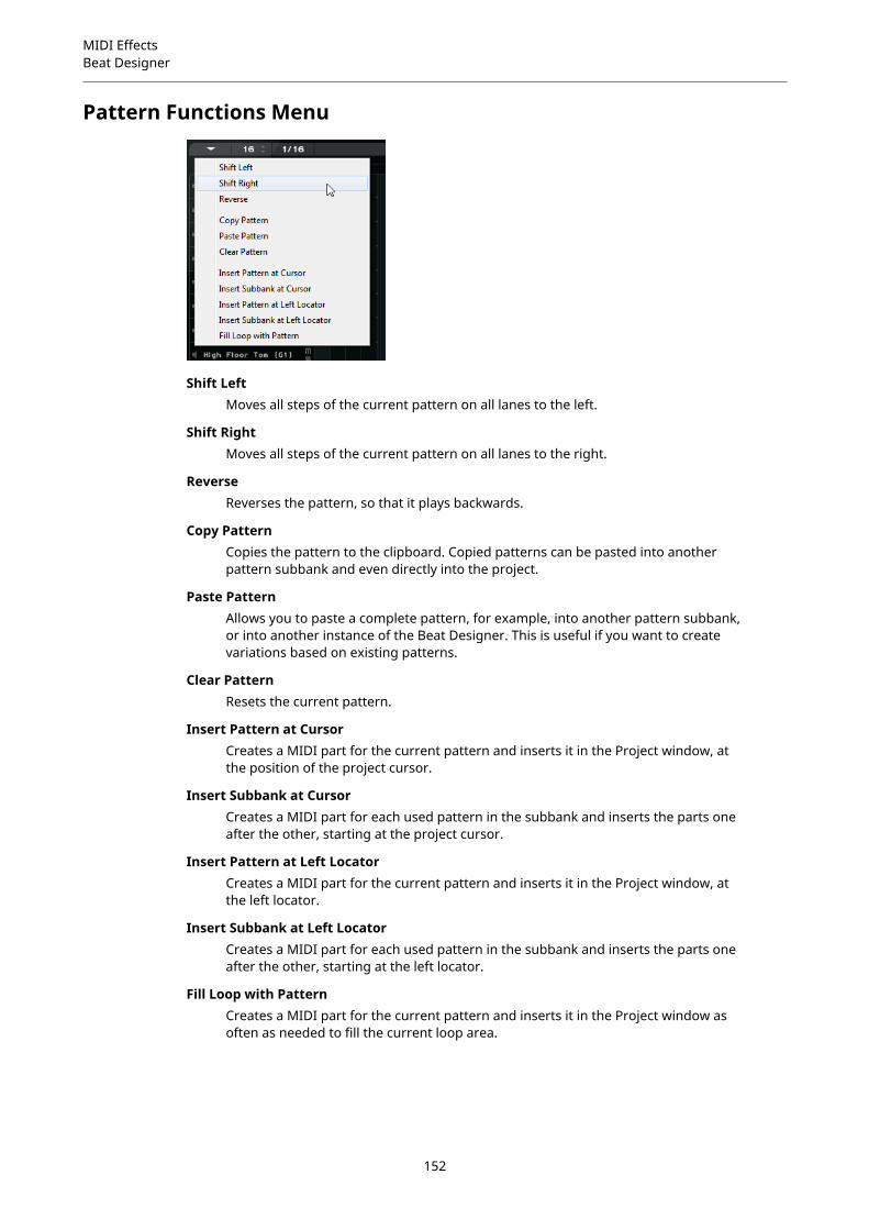
MIDI EffectsBeat Designer
Pattern Functions Menu
Shift LeftMoves all steps of the current pattern on all lanes to the left.
Shift RightMoves all steps of the current pattern on all lanes to the right.
ReverseReverses the pattern, so that it plays backwards.
Copy PatternCopies the pattern to the clipboard. Copied patterns can be pasted into anotherpattern subbank and even directly into the project.
Paste PatternAllows you to paste a complete pattern, for example, into another pattern subbank,or into another instance of the Beat Designer. This is useful if you want to createvariations based on existing patterns.
Clear PatternResets the current pattern.
Insert Pattern at CursorCreates a MIDI part for the current pattern and inserts it in the Project window, atthe position of the project cursor.
Insert Subbank at CursorCreates a MIDI part for each used pattern in the subbank and inserts the parts oneafter the other, starting at the project cursor.
Insert Pattern at Left LocatorCreates a MIDI part for the current pattern and inserts it in the Project window, atthe left locator.
Insert Subbank at Left LocatorCreates a MIDI part for each used pattern in the subbank and inserts the parts oneafter the other, starting at the left locator.
Fill Loop with PatternCreates a MIDI part for the current pattern and inserts it in the Project window asoften as needed to fill the current loop area.
152

MIDI EffectsBeat Designer
NOTE
In the Key Commands dialog, you can set up key commands for the Insert options and the FillLoop command. How to set up and use key commands is described in the Operation Manual.
RELATED LINKSConverting Patterns into MIDI Parts on page 154
Swing SettingThis parameter can be used to create a swing or shuffle rhythm. This adds a more human feel todrum patterns that might otherwise be too static.
Swing offsets every second drum step for a lane. If a triplet step resolution is used, every thirddrum step is offset instead.
In the lower right section of the Beat Designer panel, you can find two Swing sliders. You can setup two swing settings with these sliders and then quickly switch between these during playback.
● To delay every second or third drum step in the pattern, drag a slider to the right.
● To make a drum step play earlier in the pattern, drag a slider to the left.
● To switch between the swing settings, click the Swing buttons to the right of the stepdisplay.
● To deactivate swing for a lane, click on the selected Swing buttons.
FlamsThe Flam parameter lets you add flams, that is, short secondary drum hits just before or afterthe actual main drum beat. You can add up to three flams for each pattern step.
In the lower left section of the Beat Designer panel you can make settings for the flams youcreated.
The first position slider specifies the flam position for all steps containing one single flam, thesecond slider the flam positions for all steps containing two flams, and the third slider the flamposition for all steps containing three flams.
Adding Flams
PROCEDURE
1. Click in the lower left corner of the step you want to add a flam to.Little squares appear in the step when you point the mouse at it. If you click a step, thefirst square is filled to indicate that you added a flam.
2. Click again to add the second and third flam.
153

MIDI EffectsBeat Designer
3. In the lower left section of the Beat Designer panel, make settings for the flams that youcreated.
● To add the flams before or after the drum step, drag a position slider to the left orright.If you add flams before the first drum step in a pattern, this is indicated in thedisplay by a small arrow in the top left corner of this step. Starting playback at thenormal pattern start would result in these flams not being played.
● To set the velocity for the flams, use the vertical sliders to the right of the flamsliders.
4. Start playback to hear the flams you created.
Offsetting LanesTo the right of the step display, you can find the Offset sliders for the lanes. These allow you tooffset all drum steps on this lane.
PROCEDURE
1. Drag a slider to the left to make the drum steps start a little earlier and to the right to letthem start later.For example, playing the bass drum or snare a little earlier allows you to add moreurgency to the drums, while delaying these drum sounds results in a more relaxed drumpattern.
2. Experiment with the settings to find out which fit best in your project.
NOTE
This function can also be used to correct faulty drum samples: If a drum sound has anattack that is slightly late, simply adjust the Offset slider for the lane.
Using the Drum Patterns in Your Project
Converting Patterns into MIDI PartsYou can convert the drum patterns created in the Beat Designer into a MIDI part by draggingthem into the Project window.
PROCEDURE
1. Set up one or more patterns of the same subbank.
2. In the lower part of the window, click on a pattern or subbank and drag it onto a MIDI orinstrument track in the Project window.
● If you drag the pattern or subbank to an empty area in the Project window, anew MIDI track is created. This is an exact copy of the original track for which youopened the Beat Designer.
● If you drag a single pattern into the Project window, one MIDI part is createdcontaining the drum sounds of the pattern.
154

MIDI EffectsBeat Designer
● If you drag a subbank into the Project window, several MIDI parts (one for eachused pattern in the subbank) are created and inserted one after the other in theproject.
IMPORTANT
Only the used patterns in a subbank are inserted. If you did not enter drum steps in apattern, this is not converted into a MIDI part.
You can also use the Pattern Functions menu to insert patterns or subbanks into theproject.
IMPORTANT
When you have created MIDI parts for your drum patterns this way, make sure todeactivate the Beat Designer, to avoid doubling of the drums. The Beat Designer continuesto play as long as it is activated.
● If you import patterns that sound before the first step (due to flams or lane offsets),the MIDI part is lengthened accordingly.
The inserted MIDI parts can now be edited as usual in the project. For example, you canfine-tune your settings in the Drum Editor.
NOTE
Once a pattern is converted into a MIDI part, it cannot be opened in the Beat Designeragain.
RELATED LINKSPattern Functions Menu on page 152
Triggering PatternsIf you want to modify your drum patterns in Beat Designer while working on the project, you cantrigger the patterns from within the project.
You can trigger the patterns in Beat Designer using note-on events. These can either be eventson a MIDI track or be played live via a MIDI keyboard. Which pattern is triggered depends on thepitch of the MIDI notes. The trigger range is four octaves starting with C1 (that is, C1 to B4).
PROCEDURE
1. Open Beat Designer for a track.
2. Click the Jump field to activate Jump mode.
In this mode, a MIDI note-on event triggers a new pattern.
● To trigger the patterns using a MIDI part containing trigger events, you can specifywhether the pattern is switched instantly (at the moment the event is received) orat the next bar: Activate the Now button to switch patterns immediately. If Now isdeactivated, patterns switch at the beginning of the next bar in the project.
● If you want to trigger the patterns live via a MIDI keyboard, the new patterns arealways played when the next bar in the project is reached. Switching immediatelywould always produce an undesirable interruption in playback.
3. Play back the project and press a key on your MIDI keyboard to trigger the next pattern.The pattern starts at the next bar line.
155
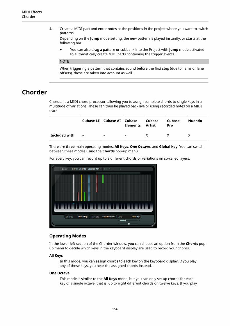
MIDI EffectsChorder
4. Create a MIDI part and enter notes at the positions in the project where you want to switchpatterns.Depending on the Jump mode setting, the new pattern is played instantly, or starts at thefollowing bar.
● You can also drag a pattern or subbank into the Project with Jump mode activatedto automatically create MIDI parts containing the trigger events.
NOTE
When triggering a pattern that contains sound before the first step (due to flams or laneoffsets), these are taken into account as well.
ChorderChorder is a MIDI chord processor, allowing you to assign complete chords to single keys in amultitude of variations. These can then be played back live or using recorded notes on a MIDItrack.
Cubase LE Cubase AI CubaseElements
CubaseArtist
CubasePro
Nuendo
Included with – – – X X X
There are three main operating modes: All Keys, One Octave, and Global Key. You can switchbetween these modes using the Chords pop-up menu.
For every key, you can record up to 8 different chords or variations on so-called layers.
Operating Modes
In the lower left section of the Chorder window, you can choose an option from the Chords pop-up menu to decide which keys in the keyboard display are used to record your chords.
All KeysIn this mode, you can assign chords to each key on the keyboard display. If you playany of these keys, you hear the assigned chords instead.
One OctaveThis mode is similar to the All Keys mode, but you can only set up chords for eachkey of a single octave, that is, up to eight different chords on twelve keys. If you play
156
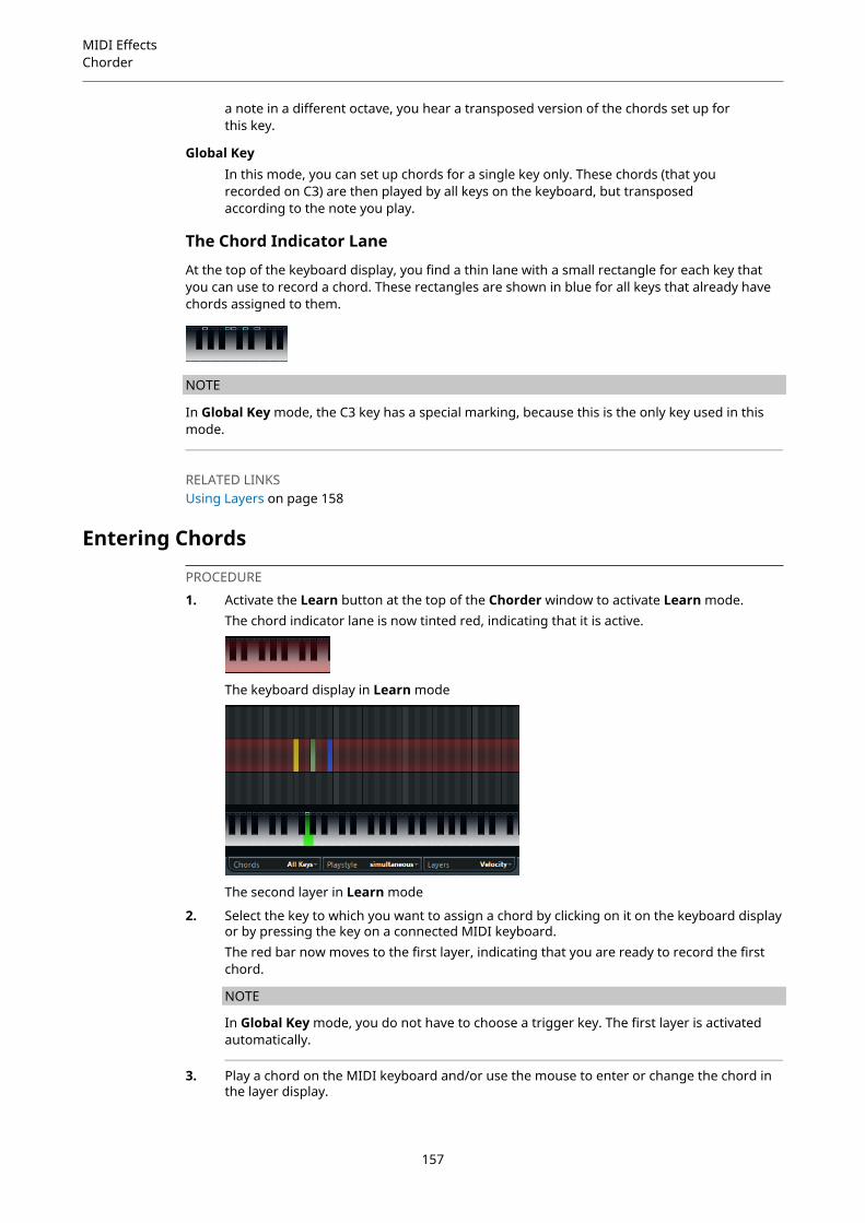
MIDI EffectsChorder
a note in a different octave, you hear a transposed version of the chords set up forthis key.
Global KeyIn this mode, you can set up chords for a single key only. These chords (that yourecorded on C3) are then played by all keys on the keyboard, but transposedaccording to the note you play.
The Chord Indicator Lane
At the top of the keyboard display, you find a thin lane with a small rectangle for each key thatyou can use to record a chord. These rectangles are shown in blue for all keys that already havechords assigned to them.
NOTE
In Global Key mode, the C3 key has a special marking, because this is the only key used in thismode.
RELATED LINKSUsing Layers on page 158
Entering Chords
PROCEDURE
1. Activate the Learn button at the top of the Chorder window to activate Learn mode.The chord indicator lane is now tinted red, indicating that it is active.
The keyboard display in Learn mode
The second layer in Learn mode
2. Select the key to which you want to assign a chord by clicking on it on the keyboard displayor by pressing the key on a connected MIDI keyboard.The red bar now moves to the first layer, indicating that you are ready to record the firstchord.
NOTE
In Global Key mode, you do not have to choose a trigger key. The first layer is activatedautomatically.
3. Play a chord on the MIDI keyboard and/or use the mouse to enter or change the chord inthe layer display.
157

MIDI EffectsChorder
● Any notes you enter are immediately shown in the Chorder display. The notes areshown in different colors, depending on the pitch.
● If you are entering chords via a MIDI keyboard, Chorder learns the chord as soon asyou release all keys of your MIDI keyboard.As long as a key is pressed, you can continue looking for the right chord.
● If more than one layer is shown, Chorder jumps automatically to the next layerwhere you can record another chord.If all layers for a key are filled, the red bar jumps back to the keyboard display sothat you can choose a different trigger key (in Global Key mode, the Learn mode isdeactivated).
● If you are entering chords with the mouse, Chorder does not jump to the next layerautomatically.You can select/deselect as many notes as you want and then click on another layeror deactivate the Learn mode to continue.
4. Repeat the above with any other keys you want to use.
Using LayersThe Layers pop-up menu at the bottom right of the window allows you to set up chord variationsin the layer display above the keyboard. This works with all three modes and provides up to 8variations for each assignable key, that is, a maximum of 8 different chords in Global Key mode,12 x 8 chords in One Octave mode and 128 x 8 chords in All Keys mode.
The different layers can be triggered by velocity or interval.
PROCEDURE
1. On the Layers pop-up menu, select Velocity or Interval. Set this to Single Mode if youwant to set up only one chord per key.
2. Use the slider below the Layers pop-up menu to specify how many variations you want touse.
3. Enter the chords.
RESULTNow you can play the keyboard and trigger the variations according to the selected layer mode.
RELATED LINKSEmpty Layers on page 159
Layer ModesYou can play the keyboard and trigger the variations according to the selected layer mode.
VelocityThe full velocity range (1 to 127) is divided into zones, according to the number oflayers you specified. For example, if you are using 2 variations, 2 velocity zones areused: 1 to 63 and 64 to 127. Playing a note with velocity 64 or higher triggers thesecond layer, while playing a softer note triggers the first layer.With the Velocity spread slider at the bottom right of the window, you can changethe velocity ranges of the layers.
IntervalIn this mode Chorder plays one chord at a time. If the Interval mode is selected, youtrigger a layer by pressing 2 keys on your keyboard. The lower key determines the
158
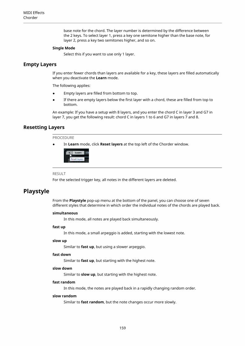
MIDI EffectsChorder
base note for the chord. The layer number is determined by the difference betweenthe 2 keys. To select layer 1, press a key one semitone higher than the base note, forlayer 2, press a key two semitones higher, and so on.
Single ModeSelect this if you want to use only 1 layer.
Empty LayersIf you enter fewer chords than layers are available for a key, these layers are filled automaticallywhen you deactivate the Learn mode.
The following applies:
● Empty layers are filled from bottom to top.
● If there are empty layers below the first layer with a chord, these are filled from top tobottom.
An example: If you have a setup with 8 layers, and you enter the chord C in layer 3 and G7 inlayer 7, you get the following result: chord C in layers 1 to 6 and G7 in layers 7 and 8.
Resetting Layers
PROCEDURE
● In Learn mode, click Reset layers at the top left of the Chorder window.
RESULTFor the selected trigger key, all notes in the different layers are deleted.
PlaystyleFrom the Playstyle pop-up menu at the bottom of the panel, you can choose one of sevendifferent styles that determine in which order the individual notes of the chords are played back.
simultaneousIn this mode, all notes are played back simultaneously.
fast upIn this mode, a small arpeggio is added, starting with the lowest note.
slow upSimilar to fast up, but using a slower arpeggio.
fast downSimilar to fast up, but starting with the highest note.
slow downSimilar to slow up, but starting with the highest note.
fast randomIn this mode, the notes are played back in a rapidly changing random order.
slow randomSimilar to fast random, but the note changes occur more slowly.
159
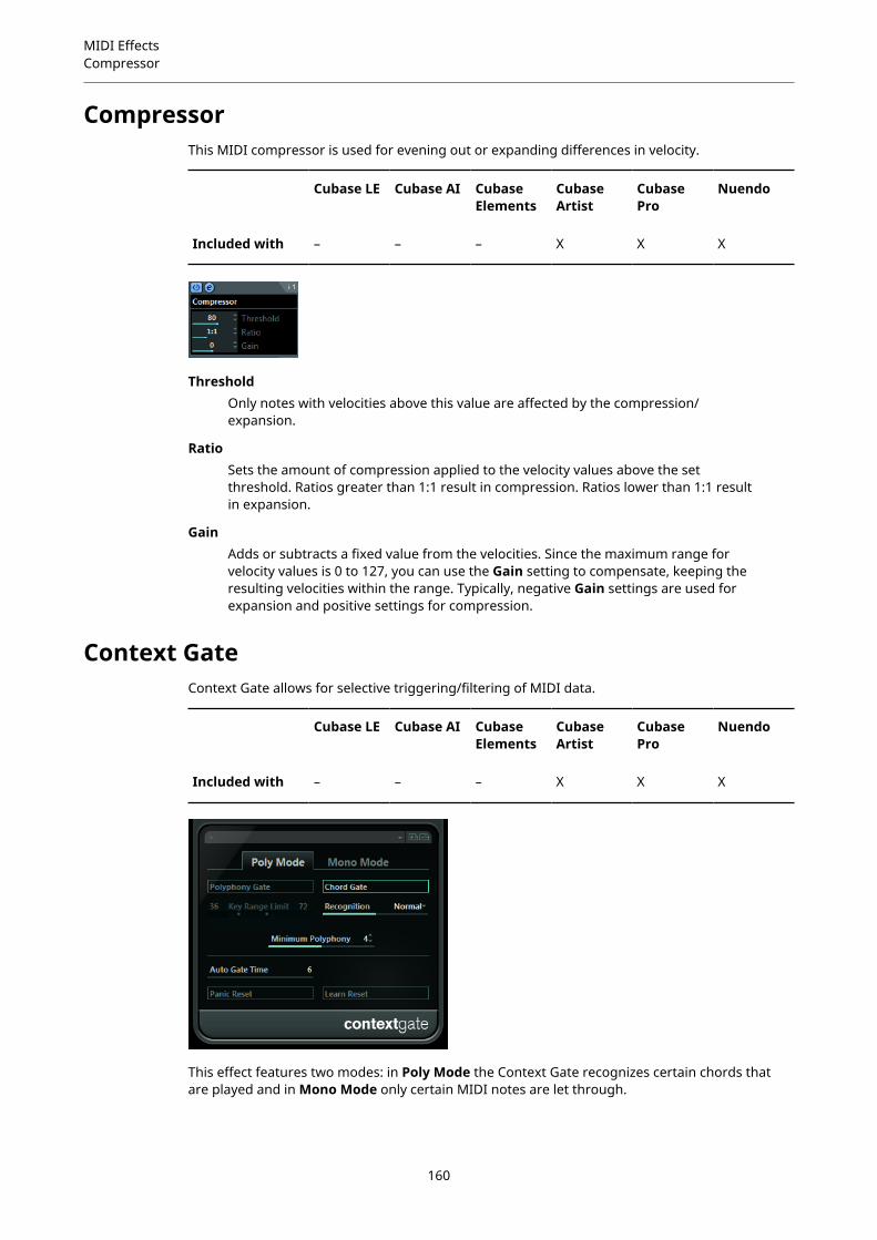
MIDI EffectsCompressor
CompressorThis MIDI compressor is used for evening out or expanding differences in velocity.
Cubase LE Cubase AI CubaseElements
CubaseArtist
CubasePro
Nuendo
Included with – – – X X X
ThresholdOnly notes with velocities above this value are affected by the compression/expansion.
RatioSets the amount of compression applied to the velocity values above the setthreshold. Ratios greater than 1:1 result in compression. Ratios lower than 1:1 resultin expansion.
GainAdds or subtracts a fixed value from the velocities. Since the maximum range forvelocity values is 0 to 127, you can use the Gain setting to compensate, keeping theresulting velocities within the range. Typically, negative Gain settings are used forexpansion and positive settings for compression.
Context GateContext Gate allows for selective triggering/filtering of MIDI data.
Cubase LE Cubase AI CubaseElements
CubaseArtist
CubasePro
Nuendo
Included with – – – X X X
This effect features two modes: in Poly Mode the Context Gate recognizes certain chords thatare played and in Mono Mode only certain MIDI notes are let through.
160
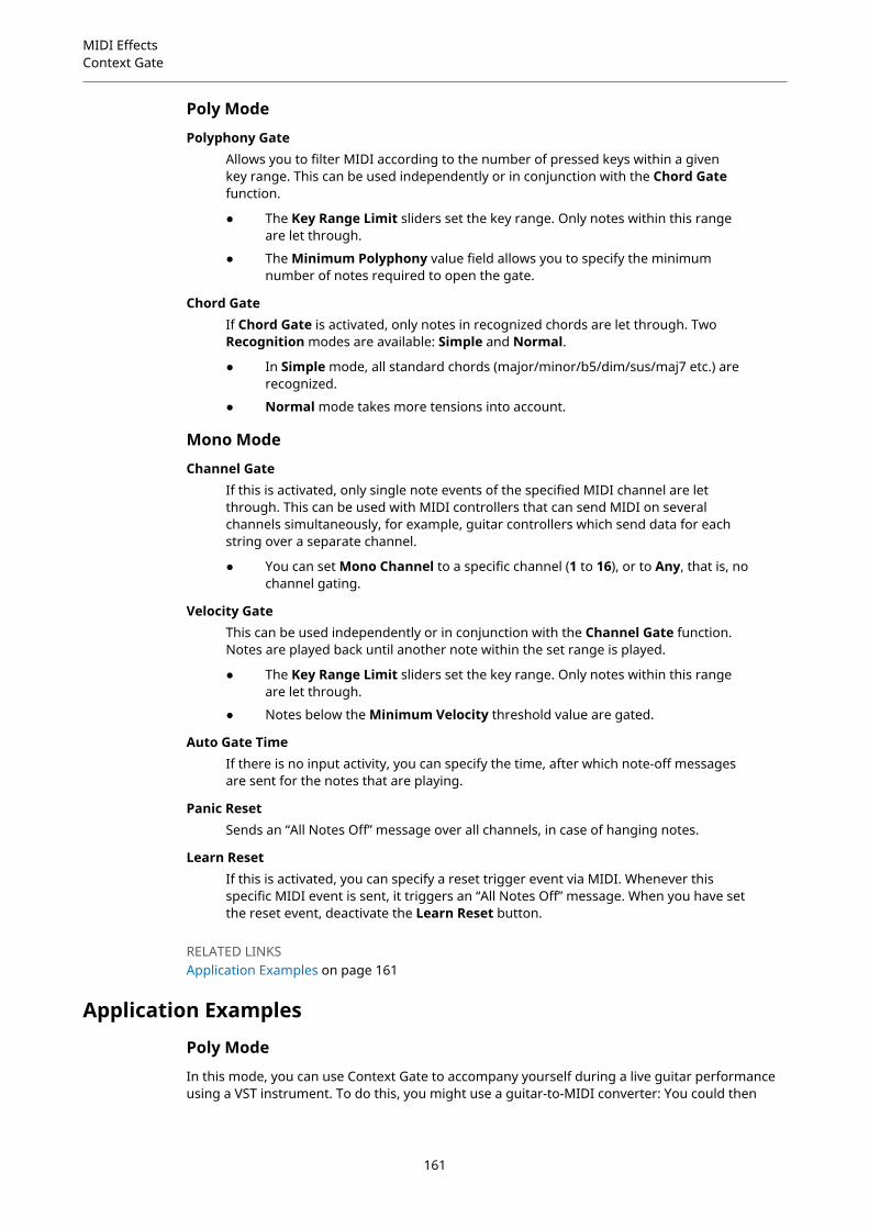
MIDI EffectsContext Gate
Poly Mode
Polyphony GateAllows you to filter MIDI according to the number of pressed keys within a givenkey range. This can be used independently or in conjunction with the Chord Gatefunction.
● The Key Range Limit sliders set the key range. Only notes within this rangeare let through.
● The Minimum Polyphony value field allows you to specify the minimumnumber of notes required to open the gate.
Chord GateIf Chord Gate is activated, only notes in recognized chords are let through. TwoRecognition modes are available: Simple and Normal.
● In Simple mode, all standard chords (major/minor/b5/dim/sus/maj7 etc.) arerecognized.
● Normal mode takes more tensions into account.
Mono Mode
Channel GateIf this is activated, only single note events of the specified MIDI channel are letthrough. This can be used with MIDI controllers that can send MIDI on severalchannels simultaneously, for example, guitar controllers which send data for eachstring over a separate channel.
● You can set Mono Channel to a specific channel (1 to 16), or to Any, that is, nochannel gating.
Velocity GateThis can be used independently or in conjunction with the Channel Gate function.Notes are played back until another note within the set range is played.
● The Key Range Limit sliders set the key range. Only notes within this rangeare let through.
● Notes below the Minimum Velocity threshold value are gated.
Auto Gate TimeIf there is no input activity, you can specify the time, after which note-off messagesare sent for the notes that are playing.
Panic ResetSends an “All Notes Off” message over all channels, in case of hanging notes.
Learn ResetIf this is activated, you can specify a reset trigger event via MIDI. Whenever thisspecific MIDI event is sent, it triggers an “All Notes Off” message. When you have setthe reset event, deactivate the Learn Reset button.
RELATED LINKSApplication Examples on page 161
Application Examples
Poly Mode
In this mode, you can use Context Gate to accompany yourself during a live guitar performanceusing a VST instrument. To do this, you might use a guitar-to-MIDI converter: You could then
161

MIDI EffectsDensity
program Context Gate, for example, to allow only those notes to pass the gate that are partof a four-note chord. During your performance you would then play a four-note chord everytime that you want to trigger the VST instrument. The instrument plays until the Auto GateTime is reached and fades out. For more complex performances this can be combined with anarpeggiator, without having to use external pedals to trigger the effect.
Mono Mode
In this mode you could use Context Gate to trigger variations played with a drum machine/VST instrument. To do this, you need a guitar-to-MIDI converter: You could then filter the MIDIchannel using the Input Transformer (optional) and program the Context Gate to allow onlycertain notes on your guitar to pass the gate (for example, beginning at the 12th band). Whenyou now play one of these notes, the note-off command is not send out and the correspondingnote sounds until the note is played again, a new note is let through, or the Auto Gate Time isreached. This way you can trigger lots of different effects or notes using the high notes on youguitar without having to use an additional MIDI instrument.
Density
Cubase LE Cubase AI CubaseElements
CubaseArtist
CubasePro
Nuendo
Included with – – – X X X
This generic control panel affects the density of the notes being played from or through thetrack. If this is set to 100 %, the notes are not affected. Density settings below 100 % randomlyfilter out or mute notes. Settings above 100 % randomly add notes that were played before.
MIDI ControlThis generic control panel allows you to select up to 8 different MIDI controller types and setvalues for these. You can then use the plug-in as a control panel to adjust the sound of a MIDIinstrument from within your host application.
Cubase LE Cubase AI CubaseElements
CubaseArtist
CubasePro
Nuendo
Included with – – – X X X
● To select a controller type, use the pop-up menus on the right.
162

MIDI EffectsMIDI Echo
● To change the value of a controller type, enter a value in the value field or click the valuefield and drag the cursor up or down.
● To deactivate a controller, type Off in the value field or click the value field and drag thecursor down until the value field displays Off.
MIDI EchoThis is an advanced MIDI Echo, which generates additional echoing notes based on the MIDInotes it receives. It creates effects similar to a digital delay, but also features MIDI pitch shiftingand much more.
Cubase LE Cubase AI CubaseElements
CubaseArtist
CubasePro
Nuendo
Included with – – – X X X
The effect does not echo the actual audio, but the MIDI notes which eventually produce thesound in the synthesizer.
Velocity OffsetAllows you to raise or lower the velocity values for each repeat so that the echo fadesaway or increases in volume (provided that the sound you use is velocity sensitive).
Pitch OffsetIf you set this to a value other than 0, the echoing notes are raised or lowered inpitch, so that each successive note has a higher or lower pitch than the previous. Thevalue is set in semitones.For example, setting this to -2 causes the first echo note to have a pitch twosemitones lower than the original note, the second echo note two semitones lowerthan the first echo note, and so on.
RepeatsThe number of echoes (1 to 12) of each incoming note.
Beat AlignDuring playback, this parameter quantizes the position of the first echo note. Youcan either set this to rhythmically exact values or activate the PPQ button and choosea PPQ value.Setting this to 1/8, for example, causes the first echo note to sound on the firsteighth position after the original note.
163
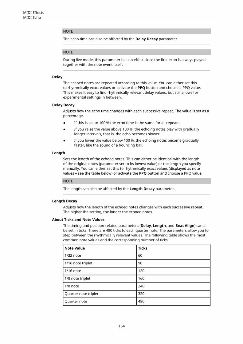
MIDI EffectsMIDI Echo
NOTE
The echo time can also be affected by the Delay Decay parameter.
NOTE
During live mode, this parameter has no effect since the first echo is always playedtogether with the note event itself.
DelayThe echoed notes are repeated according to this value. You can either set thisto rhythmically exact values or activate the PPQ button and choose a PPQ value.This makes it easy to find rhythmically relevant delay values, but still allows forexperimental settings in between.
Delay DecayAdjusts how the echo time changes with each successive repeat. The value is set as apercentage.
● If this is set to 100 % the echo time is the same for all repeats.
● If you raise the value above 100 %, the echoing notes play with graduallylonger intervals, that is, the echo becomes slower.
● If you lower the value below 100 %, the echoing notes become graduallyfaster, like the sound of a bouncing ball.
LengthSets the length of the echoed notes. This can either be identical with the lengthof the original notes (parameter set to its lowest value) or the length you specifymanually. You can either set this to rhythmically exact values (displayed as notevalues – see the table below) or activate the PPQ button and choose a PPQ value.
NOTE
The length can also be affected by the Length Decay parameter.
Length DecayAdjusts how the length of the echoed notes changes with each successive repeat.The higher the setting, the longer the echoed notes.
About Ticks and Note ValuesThe timing and position-related parameters (Delay, Length, and Beat Align) can allbe set in ticks. There are 480 ticks to each quarter note. The parameters allow you tostep between the rhythmically relevant values. The following table shows the mostcommon note values and the corresponding number of ticks.
Note Value Ticks
1/32 note 60
1/16 note triplet 90
1/16 note 120
1/8 note triplet 160
1/8 note 240
Quarter note triplet 320
Quarter note 480
164

MIDI EffectsMIDI Modifiers
Note Value Ticks
Half note 960
MIDI ModifiersThis plug-in is essentially a duplicate of the MIDI Modifiers section in the Inspector. This can beuseful, for example, if you need extra Random or Range settings.
Cubase LE Cubase AI CubaseElements
CubaseArtist
CubasePro
Nuendo
Included with – – – X X X
The MIDI Modifiers effect also includes the Scale Transpose function that is not available amongthe track parameters.
Scale Transpose
Allows you to transpose each incoming MIDI note, so that it fits within a selected musical scale.The scale is specified by selecting a key (C, C#, D, etc.) and a scale type (major, melodic orharmonic minor, blues, etc.).
● To deactivate Scale Transpose, select No Scale from the Scale pop-up menu.
MIDI MonitorThis effect monitors incoming MIDI events.
Cubase LE Cubase AI CubaseElements
CubaseArtist
CubasePro
Nuendo
Included with – – – X X X
You can choose whether to analyze live or playback events and which types of MIDI data are tobe monitored. Use this, for example, to analyze which MIDI events are generated by a MIDI track,
165

MIDI EffectsMicro Tuner
or to find suspicious events, such as notes with velocity 0 that certain MIDI devices might fail tointerpreted as note-off events.
Inputs SectionIn this section, you can choose whether to monitor live events or playback events.
Show SectionHere, you can activate/deactivate the different types of MIDI events. If you chooseController, you can also define which type of controller to monitor.
Data TableIn the table in the lower section of the window, you see detailed information aboutthe monitored MIDI events.
Buffer Pop-up MenuThis is the maximum number of events that is kept in the list of monitored events.Once this list is full, the oldest entries are deleted when new events are received.
NOTE
The larger the buffer, the more processing resources are required.
ExportAllows you to export the monitoring data as a simple text file.
Record EventsThis button to the left of the Inputs section allows you to start or stop themonitoring of MIDI events.
Clear ListThis button to the left of the Show section allows you to clear the table of recordedMIDI events.
Micro Tuner
Cubase LE Cubase AI CubaseElements
CubaseArtist
CubasePro
Nuendo
Included with – – – X X X
Micro Tuner lets you set up a different microtuning scheme for the instrument, by detuning eachkey.
166
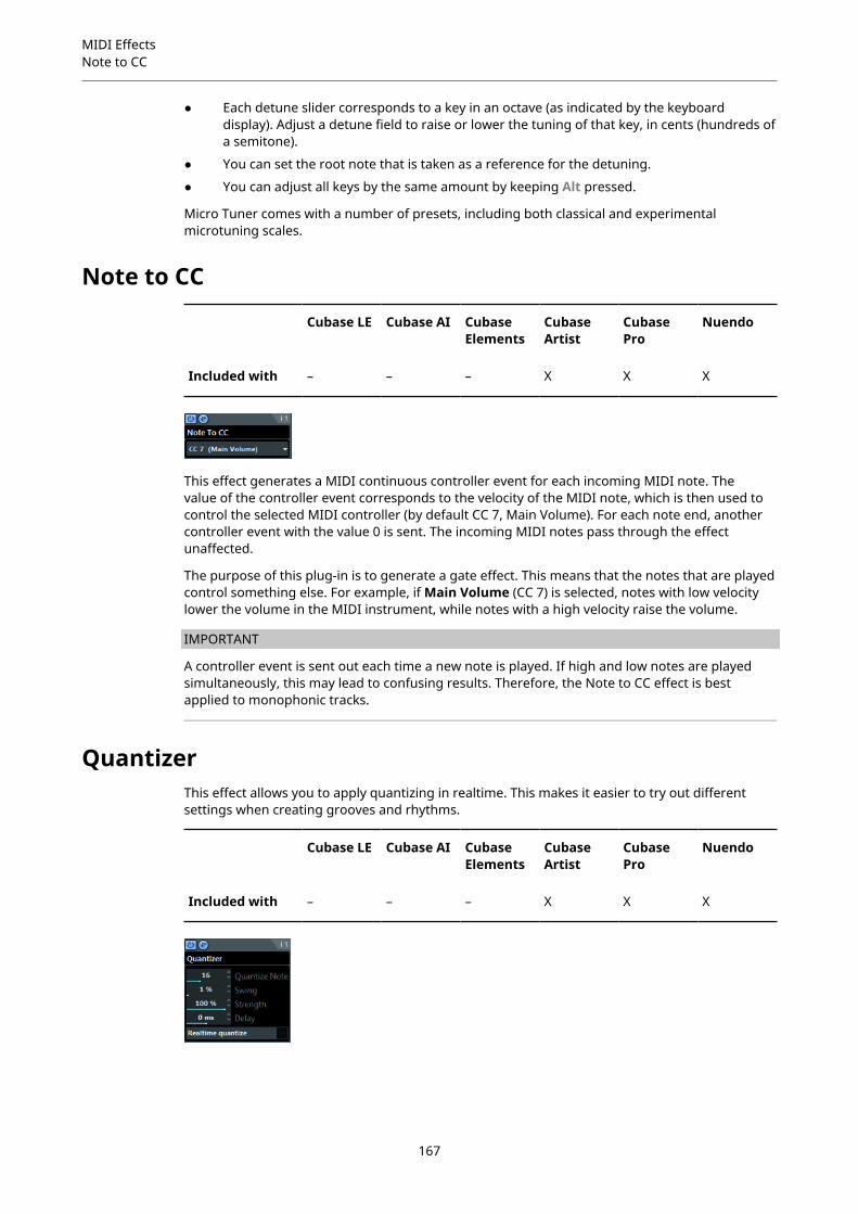
MIDI EffectsNote to CC
● Each detune slider corresponds to a key in an octave (as indicated by the keyboarddisplay). Adjust a detune field to raise or lower the tuning of that key, in cents (hundreds ofa semitone).
● You can set the root note that is taken as a reference for the detuning.
● You can adjust all keys by the same amount by keeping Alt pressed.
Micro Tuner comes with a number of presets, including both classical and experimentalmicrotuning scales.
Note to CC
Cubase LE Cubase AI CubaseElements
CubaseArtist
CubasePro
Nuendo
Included with – – – X X X
This effect generates a MIDI continuous controller event for each incoming MIDI note. Thevalue of the controller event corresponds to the velocity of the MIDI note, which is then used tocontrol the selected MIDI controller (by default CC 7, Main Volume). For each note end, anothercontroller event with the value 0 is sent. The incoming MIDI notes pass through the effectunaffected.
The purpose of this plug-in is to generate a gate effect. This means that the notes that are playedcontrol something else. For example, if Main Volume (CC 7) is selected, notes with low velocitylower the volume in the MIDI instrument, while notes with a high velocity raise the volume.
IMPORTANT
A controller event is sent out each time a new note is played. If high and low notes are playedsimultaneously, this may lead to confusing results. Therefore, the Note to CC effect is bestapplied to monophonic tracks.
QuantizerThis effect allows you to apply quantizing in realtime. This makes it easier to try out differentsettings when creating grooves and rhythms.
Cubase LE Cubase AI CubaseElements
CubaseArtist
CubasePro
Nuendo
Included with – – – X X X
167
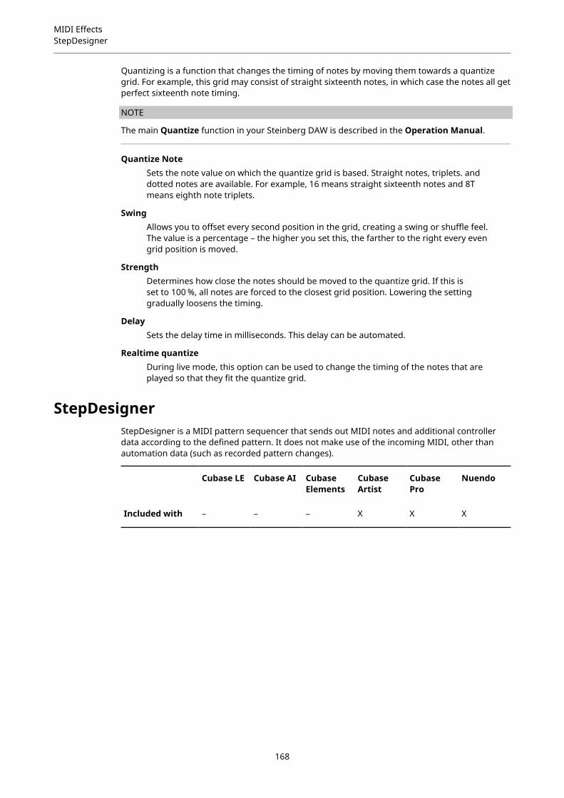
MIDI EffectsStepDesigner
Quantizing is a function that changes the timing of notes by moving them towards a quantizegrid. For example, this grid may consist of straight sixteenth notes, in which case the notes all getperfect sixteenth note timing.
NOTE
The main Quantize function in your Steinberg DAW is described in the Operation Manual.
Quantize NoteSets the note value on which the quantize grid is based. Straight notes, triplets. anddotted notes are available. For example, 16 means straight sixteenth notes and 8Tmeans eighth note triplets.
SwingAllows you to offset every second position in the grid, creating a swing or shuffle feel.The value is a percentage – the higher you set this, the farther to the right every evengrid position is moved.
StrengthDetermines how close the notes should be moved to the quantize grid. If this isset to 100 %, all notes are forced to the closest grid position. Lowering the settinggradually loosens the timing.
DelaySets the delay time in milliseconds. This delay can be automated.
Realtime quantizeDuring live mode, this option can be used to change the timing of the notes that areplayed so that they fit the quantize grid.
StepDesignerStepDesigner is a MIDI pattern sequencer that sends out MIDI notes and additional controllerdata according to the defined pattern. It does not make use of the incoming MIDI, other thanautomation data (such as recorded pattern changes).
Cubase LE Cubase AI CubaseElements
CubaseArtist
CubasePro
Nuendo
Included with – – – X X X
168

MIDI EffectsStepDesigner
1 Shift octave up/down
2 Shift steps left/right
3 Number of steps
4 Step size
5 Swing
6 Controller pop-up menu
7 Pattern selector
Creating a Basic Pattern
PROCEDURE
1. Use the Pattern selector to choose which pattern to create.Each StepDesigner can hold up to 200 different patterns.
2. Use the Step size setting to specify the resolution of the pattern.This setting determines the step length.
3. Specify the number of steps in the pattern with the Number of steps setting.The maximum number of steps is 32. For example, setting Step size to 16 and Number ofsteps to 32 creates a 2 bar pattern with sixteenth note steps.
4. Click in the note display to insert notes.You can insert notes on any of the 32 steps, but StepDesigner only plays back the numberof steps set with the Step size parameter.
● The display spans one octave (as indicated by the pitch list to the left). You can scrollthe displayed octave up or down by clicking in the pitch list and dragging up ordown.This way you can insert notes at any pitch.
● To remove a note from the pattern, click on it again.
169
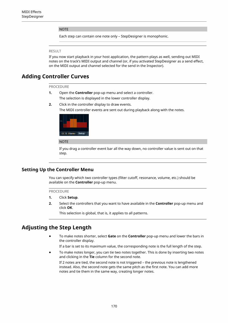
MIDI EffectsStepDesigner
NOTE
Each step can contain one note only – StepDesigner is monophonic.
RESULTIf you now start playback in your host application, the pattern plays as well, sending out MIDInotes on the track’s MIDI output and channel (or, if you activated StepDesigner as a send effect,on the MIDI output and channel selected for the send in the Inspector).
Adding Controller Curves
PROCEDURE
1. Open the Controller pop-up menu and select a controller.The selection is displayed in the lower controller display.
2. Click in the controller display to draw events.The MIDI controller events are sent out during playback along with the notes.
NOTE
If you drag a controller event bar all the way down, no controller value is sent out on thatstep.
Setting Up the Controller MenuYou can specify which two controller types (filter cutoff, resonance, volume, etc.) should beavailable on the Controller pop-up menu.
PROCEDURE
1. Click Setup.
2. Select the controllers that you want to have available in the Controller pop-up menu andclick OK.This selection is global, that is, it applies to all patterns.
Adjusting the Step Length● To make notes shorter, select Gate on the Controller pop-up menu and lower the bars in
the controller display.If a bar is set to its maximum value, the corresponding note is the full length of the step.
● To make notes longer, you can tie two notes together. This is done by inserting two notesand clicking in the Tie column for the second note.If 2 notes are tied, the second note is not triggered – the previous note is lengthenedinstead. Also, the second note gets the same pitch as the first note. You can add morenotes and tie them in the same way, creating longer notes.
170
MIDI EffectsStepDesigner
Other Pattern FunctionsShift Octave up/down
Shift the entire pattern up or down in octave steps.
Shift Steps left/rightMove the pattern one step to the left or right.
ReverseReverses the pattern, so that it plays backwards.
Copy/PasteAllow you to copy the current pattern and paste it in another pattern location (in thesame StepDesigner instance or another).
ResetClears the pattern, removing all notes and resetting controller values.
RandomizeGenerates a completely random pattern.
SwingOffsets every second step, creating a swing or shuffle feel. The value is a percentage– the higher you set this, the farther to the right every even step is moved.
PresetsAllows you to load/save presets for the effect.
NOTE
A stored preset contains all 200 patterns in the StepDesigner.
Automating Pattern ChangesYou can create up to 200 different patterns in each StepDesigner instance.
Typically, you want the pattern selection to change during the project. You can accomplish this byautomating the pattern selector, either in realtime by activating Write automation and switchingpatterns during playback or by drawing on the automation track for StepDesigner’s MIDI track.
Note that you can also press a key on your MIDI keyboard to change patterns. For this, you haveto set up the StepDesigner as an insert effect for a record enabled MIDI track. Press C1 to selectpattern 1, C#1 to select pattern 2, D1 to select pattern 3, D#1 to select pattern 4 and so on. Youcan record these pattern changes as note events on a MIDI track.
PROCEDURE
1. Select a MIDI track or create a new one and activate StepDesigner as an insert effect.
2. Set up several patterns.
3. Activate the Record button and press keys on your keyboard to select the correspondingpatterns.The pattern changes are recorded on the MIDI track.
4. Stop recording and play back the MIDI track.
RESULTYou now hear the recorded pattern changes.
171

MIDI EffectsTrack Control
NOTE
You can only automate the first 92 patterns.
Track Control
Cubase LE Cubase AI CubaseElements
CubaseArtist
CubasePro
Nuendo
Included with – – – X X X
The Track Control effect contains three control panels for adjusting parameters on a GS or XGcompatible MIDI device. The Roland GS and Yamaha XG protocols are extensions of the GeneralMIDI standard, allowing for more sounds and better control of various instrument settings.If your instrument is compatible with GS or XG, the Track Controls effect allows you to adjustsounds and effects in your instrument from within your host application.
The Available Control Panels
You select the control panel from the pop-up menu at the top of the effect panel. The followingpanels are available:
GS 1Contains effect sends and various sound control parameters for use withinstruments compatible with the Roland GS standard.
XG 1Contains effect sends and various sound control parameters for use withinstruments compatible with the Yamaha XG standard.
XG 2Global settings for instruments compatible with the Yamaha XG standard.
About the Reset and Off Buttons
You find two buttons labeled Off and Reset at the top of the control panel:
172

MIDI EffectsTrack Control
● Clicking the Off button sets all controls to their lowest value, without sending out any MIDImessages.
● Clicking the Reset button resets all parameters to their default values, and sends out thecorresponding MIDI messages.
GS 1
The following controls are available if the GS 1 Controls mode is selected:
Send 1Send level for the reverb effect.
Send 2Send level for the chorus effect.
Send 3Send level for the variation effect.
AttackAdjusts the attack time of the sound. Lowering the value shortens the attack, whileraising it makes the attack time longer.
DecayAdjusts the decay time of the sound. Lowering the value shortens the decay, whileraising it makes the decay longer.
ReleaseAdjusts the release time of the sound. Lowering the value shortens the release, whileraising it makes the release time longer.
CutoffAdjusts the filter cutoff frequency.
ResonanceSets the sound characteristic of the filter. With higher values, a ringing sound isheard.
ExpressAllows you to send out expression pedal messages on the track’s MIDI channel.
Ch. PressAllows you to send out aftertouch (channel pressure) messages on the track’s MIDIchannel. This is useful if your keyboard cannot send aftertouch, but you have soundmodules that respond to aftertouch.
BreathAllows you to send breath control messages on the track’s MIDI channel.
Modul.Allows you to send modulation messages on the track’s MIDI channel.
XG 1
The following controls are available if the XG 1 mode is selected.
Send 1Send level for the reverb effect.
Send 2Send level for the chorus effect.
173

MIDI EffectsTrack Control
Send 3Send level for the variation effect.
AttackAdjusts the attack time of the sound. Lowering this value shortens the attack, whileraising it makes the attack time longer.
ReleaseAdjusts the release time of the sound. Lowering this value shortens the release, whileraising it makes the release time longer.
Harm.ContAdjusts the harmonic content of the sound.
BrightAdjusts the brightness of the sound.
CutOffAdjusts the filter cutoff frequency.
ResonanceSets the sound characteristic of the filter. With higher values, a ringing sound isheard.
XG 2
In this mode, the parameters affect global settings in the instruments. Changing one of thesesettings for a track affects all MIDI instruments connected to the same MIDI output, regardlessof the MIDI channel setting of the track. Therefore, it might be a good idea to create an emptytrack and use this only for these global settings.
Eff. 1Allows you to select which type of reverb effect should be used: No effect (reverbdeactivated), Hall 1–2, Room 1–3, Stage 1–2, or Plate.
Eff. 2Allows you to select which type of chorus effect should be used: No effect (chorusdeactivated), Chorus 1–3, Celeste 1–3, or Flanger 1–2.
Eff. 3Allows you to select one of a large number of variation effect types. Select No Effectto deactivate the variation effect.
ResetSends an XG reset message.
MastVolControls the Master Volume of an instrument. Normally, you should leave this at itshighest position and set the volumes individually for each channel (with the volumefaders in the MixConsole or in the Inspector).
174

MIDI EffectsTransformer
TransformerThe Transformer is a realtime version of the Logical Editor. With this you can perform verypowerful MIDI processing on the fly, without affecting the actual MIDI events on the track.
Cubase LE Cubase AI CubaseElements
CubaseArtist
CubasePro
Nuendo
Included with – – – X X X
The Logical Editor is described in the Operation Manual. As the parameters and functions arealmost identical, the descriptions for the Logical Editor also apply to the Transformer. Wherethere are differences between the two, this is clearly stated.
175
Included VST Instruments
This chapter contains descriptions of the included VST instruments and their parameters.
NOTE
Most of the included instruments are compatible with VST 3. For further information, see theOperation Manual.
Groove Agent SE
Cubase LE Cubase AI CubaseElements
CubaseArtist
CubasePro
Nuendo
Included with – X X X X X
This VST instrument is described in detail in the separate PDF document Groove Agent SE.
HALion Sonic SE
Cubase LE Cubase AI CubaseElements
CubaseArtist
CubasePro
Nuendo
Included with X X X X X X
This VST instrument is described in detail in the separate PDF document HALion Sonic SE.
LoopMash
Cubase LE Cubase AI CubaseElements
CubaseArtist
CubasePro
Nuendo
Included with – – – X X X
176

Included VST InstrumentsLoopMash
LoopMash is a powerful tool for slicing and instant re-assembling of any kind of rhythmic audiomaterial. With LoopMash, you can preserve the rhythmic pattern of one audio loop, but you canreplace all sounds of this loop with the sounds from up to seven other loops.
LoopMash provides dozens of possibilities to influence the way the slices are re-assembled, thusgiving you full control over the results of your performance. You can choose from a variety ofeffects and apply them to single slices or to your overall performance. Finally, you can store yourconfiguration as scenes on scene pads, and trigger these scene pads with your MIDI keyboard.
LoopMash is fully integrated into your host application, which allows you to drag and drop audioloops from the MediaBay or Project window directly onto the LoopMash panel. Furthermore, youcan drag and drop slices from LoopMash to the sample pads of Groove Agent SE. This allows youto extract certain sounds that you like from LoopMash and use them with Groove Agent SE.
The LoopMash window has two main areas: the track section in the upper part of the panel, andthe parameter section at the bottom.
The selected track is indicated by the background color of the track and the lit button to the leftof the waveform display.
The selected track holds the master loop. The rhythmic pattern of the LoopMash output isgoverned by the master loop – that is, what you hear is the rhythmic pattern of this loop.
On the left of each track, you find the similarity gain sliders. The further to the right you move thesimilarity gain slider of a track, the more slices are played back from this track.
177

Included VST InstrumentsLoopMash
Getting StartedTo give you a first impression of what you can do with LoopMash, open the tutorial preset.
PROCEDURE
1. In your host application, create an instrument track with LoopMash as the associated VSTinstrument.
2. In the Inspector for the new track, click the Edit Instrument button to open the LoopMashpanel.
3. At the top of the plug-in panel, click on the icon to the right of the preset field and selectLoad Preset from the pop-up menu.
4. The Presets browser opens, showing presets found in the VST 3 Presets folder forLoopMash.
5. Select the preset called “A Good Start…(Tutorial) 88”.The preset is loaded into LoopMash.
6. At the bottom of the panel, make sure that the sync button in the transport controls is off,and start playback by clicking the play button.
7. Look at the 24 pads below the track section: the pad labeled Original is selected. Select thepad named Clap.A new loop is displayed on the second track in the track display, and you hear that thesnare drum sound of the first loop has been replaced with a handclap sound.
8. Select the pad labeled Trio, and then the pad labeled Section. Each time you click, a newloop is added to the mash.Note how the rhythmic pattern of the music stays the same, although an increasingnumber of sounds is taken from the other loops.
9. Select other pads to find out how different parameter settings influence the LoopMashoutput.Some of the pads have the same label, for example, Original and Replaced. The scenesthat are associated with these pads form the basis for variations of that scene. Thevariations of a scene are associated with the scene pads to the right of the original scene,that is, the scene labeled SliceFX is a variation of the scene labeled Original and shows anexample for the usage of slice effects.
RELATED LINKSLoopMash Parameters on page 180Applying Slice Selection Modifiers and Slice Effects on page 183
How Does LoopMash Work?Whenever you import a loop into LoopMash, the plug-in analyzes the audio material. It generatesperceptual descriptors (information on tempo, rhythm, spectrum, timbre, etc.) and then slicesthe loop into eighth-note segments.
This means that after you have imported several loops, LoopMash knows the rhythmic pattern ofeach loop and the location of various sounds that make up this pattern within each loop. Duringplayback, LoopMash uses the perceptual descriptors to determine how similar each slice is to thecurrent slice of the master track.
NOTE
LoopMash does not categorize the sounds, but looks for overall similarity in the sound. Forexample, LoopMash might replace a low snare drum sound with a kick drum sound, even though
178
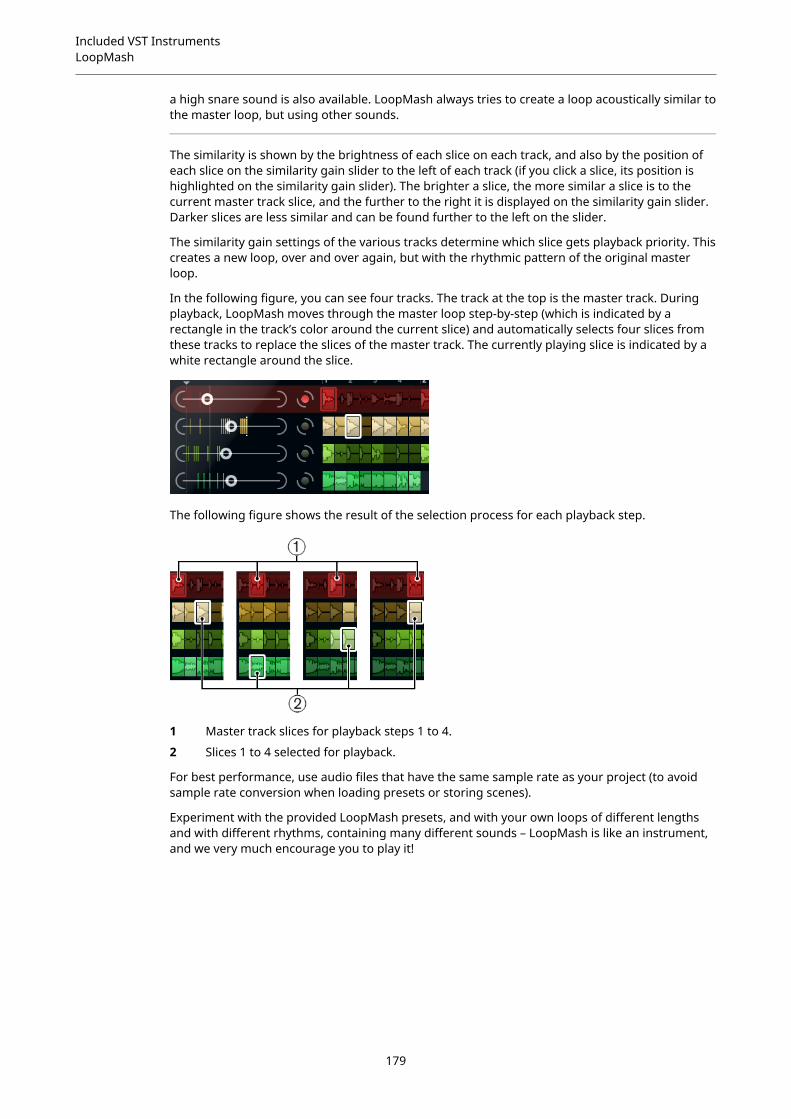
Included VST InstrumentsLoopMash
a high snare sound is also available. LoopMash always tries to create a loop acoustically similar tothe master loop, but using other sounds.
The similarity is shown by the brightness of each slice on each track, and also by the position ofeach slice on the similarity gain slider to the left of each track (if you click a slice, its position ishighlighted on the similarity gain slider). The brighter a slice, the more similar a slice is to thecurrent master track slice, and the further to the right it is displayed on the similarity gain slider.Darker slices are less similar and can be found further to the left on the slider.
The similarity gain settings of the various tracks determine which slice gets playback priority. Thiscreates a new loop, over and over again, but with the rhythmic pattern of the original masterloop.
In the following figure, you can see four tracks. The track at the top is the master track. Duringplayback, LoopMash moves through the master loop step-by-step (which is indicated by arectangle in the track’s color around the current slice) and automatically selects four slices fromthese tracks to replace the slices of the master track. The currently playing slice is indicated by awhite rectangle around the slice.
The following figure shows the result of the selection process for each playback step.
1 Master track slices for playback steps 1 to 4.
2 Slices 1 to 4 selected for playback.
For best performance, use audio files that have the same sample rate as your project (to avoidsample rate conversion when loading presets or storing scenes).
Experiment with the provided LoopMash presets, and with your own loops of different lengthsand with different rhythms, containing many different sounds – LoopMash is like an instrument,and we very much encourage you to play it!
179
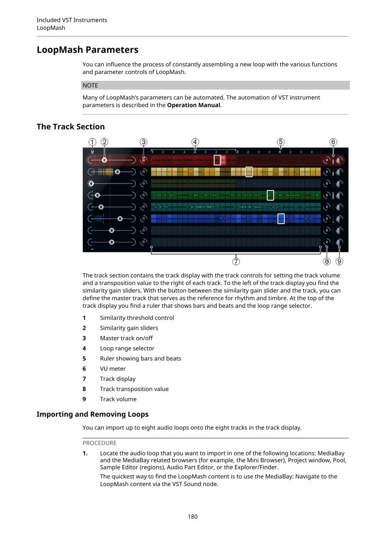
Included VST InstrumentsLoopMash
LoopMash ParametersYou can influence the process of constantly assembling a new loop with the various functionsand parameter controls of LoopMash.
NOTE
Many of LoopMash’s parameters can be automated. The automation of VST instrumentparameters is described in the Operation Manual.
The Track Section
The track section contains the track display with the track controls for setting the track volumeand a transposition value to the right of each track. To the left of the track display you find thesimilarity gain sliders. With the button between the similarity gain slider and the track, you candefine the master track that serves as the reference for rhythm and timbre. At the top of thetrack display you find a ruler that shows bars and beats and the loop range selector.
1 Similarity threshold control
2 Similarity gain sliders
3 Master track on/off
4 Loop range selector
5 Ruler showing bars and beats
6 VU meter
7 Track display
8 Track transposition value
9 Track volume
Importing and Removing Loops
You can import up to eight audio loops onto the eight tracks in the track display.
PROCEDURE
1. Locate the audio loop that you want to import in one of the following locations: MediaBayand the MediaBay related browsers (for example, the Mini Browser), Project window, Pool,Sample Editor (regions), Audio Part Editor, or the Explorer/Finder.The quickest way to find the LoopMash content is to use the MediaBay: Navigate to theLoopMash content via the VST Sound node.
180

Included VST InstrumentsLoopMash
2. Drag the loop file onto a track in LoopMash.Dragging a loop to a track already occupied replaces the original loop.
RESULTLoopMash separates the loop into slices, analyzes them, and displays them as a waveform on thetrack. One track can hold up to 32 slices. If a long loop contains more than 32 slices, LoopMashimports only the first 32. Ideally, you would use a loop file cut at bar boundaries. If you importyour file from the MediaBay, LoopMash uses the tempo information supplied by the MediaBayfor the slicing of the loop.
NOTE
To remove a loop from a LoopMash track, right-click the track and select Clear track.
Defining the Master Loop
One track is always selected. This is the master track: it provides the rhythmic pattern that youhear. The sounds of this loop are replaced by slices selected from the other loops in the currentLoopMash configuration.
PROCEDURE
● To make a track the master track, activate the button to the left of it, next to the trackdisplay.
Auditioning Slices
PROCEDURE
1. Click on the slice that you want to hear.
2. Use the Step function in the transport controls to step through the slices.
RELATED LINKSTransport Controls on page 184
Playback and Master Slice Indicators
A rectangle in the track color around a slice indicates the current position within the master loop,that is, the master slice. The slice selected for playback is indicated by a white rectangle.
Setting a Loop Range
At the top of the track display, a ruler showing bars and beats (using the project’s time signature)is displayed. In the ruler, you also find the loop range selector (the bracket) that defines the playlength.
PROCEDURE
1. To shorten the play length, click and drag the handles of the loop range selector (thebracket) at the top of the track display.This allows you to select even a very small range within your master loop for playback –the rest of the loop is not taken into account.
NOTE
Short loop ranges (less than 1 bar) may conflict with the jump interval setting.
181
Included VST InstrumentsLoopMash
2. To change the playback range, click the loop range selector and drag it to a differentposition as a whole.
RELATED LINKSStoring Your Configuration as Scenes on page 185
Setting Track Transposition Value and Track Volume
The track controls to the right of each track allow you to set a track transposition value and thetrack volume for each track individually.
PROCEDURE
1. To set a track transposition value, click the button to the right of the track and select atransposition interval from the pop-up menu.The set value is displayed on the button.
NOTE
This function is tied to the setting for the Slice Timestretch parameter. If SliceTimestretch is deactivated, transposition is created by increasing/decreasing the playbackspeed of the slices (transposing a track up by one octave corresponds to playing the slicestwice as fast). With Slice Timestretch on, you get true pitch shifting, that is, there is nochange in playback speed.
2. You can change the relative volumes of your tracks with the volume controls on the farright of each track.This is useful for level adjustments between tracks. A VU meter to the left of the volumecontrol provides visual feedback of the current volume.
RELATED LINKSAudio Parameters on page 187
Setting the Similarity
With the similarity gain slider (to the left of each track), you determine how important a particulartrack is for the mashing up of the master loop. By moving the slider, you specify that a track ismore/less similar to the master track, thus overruling the result of the LoopMash analysis. As aresult, more/less slices from this track are included in the current mash.
PROCEDURE
1. Move the slider to the right to select more slices from the corresponding track forplayback, and to the left to reduce the number of slices for playback.The vertical lines on the similarity gain slider correspond to the slices in this loop. Thechanging pattern of slices indicates similarity of each slice, on all tracks, to the currentmaster track slice. The further to the right a line is, the greater the similarity of this slice tothe master slice.
2. Drag the similarity threshold control (the thin line with handles at the top and bottomintersecting all similarity gain sliders) to the left or right to determine a minimum similaritythat slices must match to be considered for playback.Slices with a similarity below this threshold are not played.
NOTE
On the Slice Selection page at the bottom of the LoopMash panel, you can make furthersettings for influencing which slices are played.
182

Included VST InstrumentsLoopMash
RELATED LINKSSlice Selection on page 186
Creating Composite Tracks
LoopMash allows you to build composite tracks.
PROCEDURE
1. Import the loop that you want to extract sounds from.
2. Audition the slices and drag the slices that you want to use onto an empty track.A dialog opens asking you to confirm that you want to create a composite track, and todetermine the number of slices that the track contains. If you enter a higher number ofslices than the track actually contains, the track is filled up with empty slices.
3. Click OK.
RESULTThe destination track of the dragged slice becomes composite, indicated by a C to the left of thetrack.
You can use this feature in a very versatile way:
● You can assemble a combination of sounds that you like most on one track.
● You can define a certain rhythmic pattern by combining slices from different loops on acomposite track and making this track the master loop.
● You can use a composite track as a clipboard, allowing you to include sounds from morethan eight loops into your mash.You can use one track for importing and removing the loops that you want to search forsounds, and use the remaining seven tracks as composite tracks. This allows for includingup to 32 sounds from up to 32 different loop files on each of the seven composite tracks.
NOTE
Composite tracks are quantized according to the set tempo.
RELATED LINKSTransport Controls on page 184
Applying Slice Selection Modifiers and Slice Effects
Right-clicking a slice opens a context menu where you can influence the selection of individualslices and which effect is applied to them. The upper part of the context menu shows the sliceselection modifiers.
AlwaysOnly available for master track slices. The slice is played always.
183
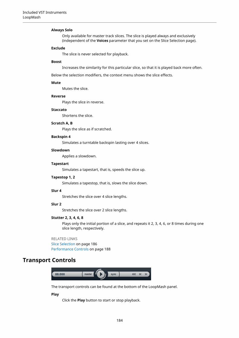
Included VST InstrumentsLoopMash
Always SoloOnly available for master track slices. The slice is played always and exclusively(independent of the Voices parameter that you set on the Slice Selection page).
ExcludeThe slice is never selected for playback.
BoostIncreases the similarity for this particular slice, so that it is played back more often.
Below the selection modifiers, the context menu shows the slice effects.
MuteMutes the slice.
ReversePlays the slice in reverse.
StaccatoShortens the slice.
Scratch A, BPlays the slice as if scratched.
Backspin 4Simulates a turntable backspin lasting over 4 slices.
SlowdownApplies a slowdown.
TapestartSimulates a tapestart, that is, speeds the slice up.
Tapestop 1, 2Simulates a tapestop, that is, slows the slice down.
Slur 4Stretches the slice over 4 slice lengths.
Slur 2Stretches the slice over 2 slice lengths.
Stutter 2, 3, 4, 6, 8Plays only the initial portion of a slice, and repeats it 2, 3, 4, 6, or 8 times during oneslice length, respectively.
RELATED LINKSSlice Selection on page 186Performance Controls on page 188
Transport Controls
The transport controls can be found at the bottom of the LoopMash panel.
PlayClick the Play button to start or stop playback.
184

Included VST InstrumentsLoopMash
LocateClick the Locate button to return to the beginning of the loop (bar 1/beat 1).Playback always starts automatically when clicking this button.
Step left/rightClicking the Step left/right button steps backwards/forwards through the timeline,playing one slice at a time.
Setting the LoopMash TempoDuring playback, LoopMash can be synchronized to the tempo set in your host application, orcan follow its own tempo setting.
● Activate the sync button (to the right of the Play button) to synchronize LoopMash to theproject tempo set in your host application.If sync is activated, you can start playback using the transport controls of your hostapplication. With sync deactivated, LoopMash starts playing when you click the Playbutton in LoopMash.
● If sync is deactivated, the current LoopMash tempo (in BPM) is displayed in the tempo fieldto the left of the master button. To change the local tempo, click in the tempo field, enter anew value, and press Enter.
● If sync is deactivated, you can click the master button (to the right of the tempo field) tocopy the tempo of the current master loop into the tempo field.The sync on/off parameter can be automated. This is useful to control LoopMash in aproject – with sync off, the playback of LoopMash within a project is paused.
Controlling Transport Functions with Your MIDI KeyboardYou can control the start, stop, sync on, and sync off functions with your MIDI keyboard.
C2Start
D2Stop
E2Sync on
F2Sync off
NOTE
If you do not have a MIDI keyboard connected to your computer, you can use the virtualkeyboard (see the Operation Manual).
Storing Your Configuration as ScenesOn the Slice Selection and the Audio Parameters pages, you find a row of 24 pads. For eachof these pads, you can save one scene, that is, a combination of up to eight tracks with allparameter settings. By triggering the pads, you can quickly change between different scenesduring your performance.
185

Included VST InstrumentsLoopMash
1 Save scene
2 Remove scene
3 Jump interval
4 Selected scene
5 Pad with associated scene
6 Empty scene pad
● To save the current settings as a scene, click the round button and then a pad. This savesyour setup to that pad.
● To recall a scene, click the corresponding scene pad.
● To remove a scene from a pad, click the x button and then a pad.
● To edit a scene pad label, double-click on the scene pad and enter a name.
● To rearrange the scene pads, click on a scene pad and drag it to a new position.
IMPORTANT
Once you have set up a LoopMash configuration, save it to a scene pad. Changing scenes withoutsaving means discarding any unsaved changes.
Setting a Jump IntervalYou can determine the point at which LoopMash changes to the next scene during playbackwhen you trigger a pad.
PROCEDURE
● Click the Jump interval button and select an option from the pop-up menu.
RESULT
NOTE
The option e: End means that the current loop is played to the end before switching scenes.When you set up a short loop range, you may need to set the interval to e: End to ensure that thejump point is reached.
Triggering Scene Pads with Your MIDI KeyboardThe scene pads are arranged according to the keys on a MIDI keyboard. You can trigger the 24scene pads with a connected MIDI keyboard starting from C0 and ending with B1.
Slice SelectionClick the Slice Selection button (above the transport controls) to open the Slice Selection page.The options on this page allow you to further influence which slices are selected for playback.
Number of VoicesHere you can set the total number of slices from all tracks that replace the masterslice (according to the current similarity gain settings). The range is from one (left)
186
Included VST InstrumentsLoopMash
to four (right) voices, that is, sounds from up to four loops can play simultaneously.Increasing the number of voices increases the CPU load.
Voices per TrackThis is the maximum number of slices that can be selected from a single track. Therange is from one to four. The fewer slices can be picked from the same track, themore variety you get in the LoopMash output.
Selection OffsetMove this slider to the right to allow slices that are less similar to be selected forplayback. This setting affects all tracks of this scene.
Random SelectionMove this slider to the right to allow more variation when selecting slices forplayback, adding a more random feel to the selection process. This setting affects alltracks of this scene.
Selection GridDetermines how often LoopMash looks for similar slices during playback: always (leftposition), or only every 2nd, 4th, or 8th (right position) step. For example, if you setthe Selection Grid to every 8th step (right position), LoopMash replaces similar slicesevery 8th step. Between two replacement steps it plays back the tracks of the slicesthat have been selected in the last replacement step, resulting in longer playbacksequences on one track.
Similarity MethodHere, you can modify the criteria that LoopMash considers when comparing theslices for similarity. There are three similarity methods:
● Standard – This is the standard method, where all slices on all tracks arecompared and various characteristics regarding rhythm, tempo, spectrum, etc.are taken into account.
● Relative – This method does not only consider the overall similarity of all sliceson all tracks, but also takes the relation to the other slices on the same trackinto account. For example, LoopMash can replace the loudest, lowest soundon one track with the loudest, lowest sound on another track.
● Harmonic – This method only takes the analyzed tonal information intoaccount, so that a slice is replaced by a harmonically similar slice, rather thanby a rhythmically similar slice. With this method, also the track transpositionvalue is considered, that is, a master slice with a C major chord is not replacedby a slice with a D major chord. But it is replaced if you set the transpositionvalue of the track of the slice with the D major chord to -2. It is advisable tokeep the similarity gain sliders in a low position when you work with thismethod, because otherwise you may produce disharmonies. You can modifythe transposition values to play back more slices of a specific track.
RELATED LINKSStoring Your Configuration as Scenes on page 185
Audio ParametersClick the Audio Parameters button (above the transport controls) to open the AudioParameters page. With the options on this page, you can influence the sound of the LoopMashaudio output.
Adapt ModeWith this mode, you can adapt the sound of the selected slice to the sound of themaster slice. The available options are:
187

Included VST InstrumentsLoopMash
● Volume – changes the overall volume of the selected slice.
● Envelope – modifies volume changes within the slice.
● Spectrum – modifies the spectrum of the slice (equalization).
● Env + Spectrum – this is a combination of the Envelope and Spectrummodes.
Adapt AmountMove this slider to the right to increase the adaptation specified with the AdaptMode parameter.
Slice QuantizeMove this slider to the right to apply quantizing to the slices, that is, the slices arealigned to an eighth-note grid. If the slider is all the way to the left, the slices followthe rhythmic pattern defined by the original master loop.
Slice TimestretchAllows you to apply realtime timestretching to the slices, filling gaps or avoidingoverlaps between slices that are not played back at their original tempo, or whencombining slices with different original tempos. Applying timestretch increases theCPU load and may affect the sound quality. Reduce the need for timestretching byusing loops with similar original tempos.
Staccato AmountIf you move this slider to the right, the length of the slices is gradually reduced,giving the output a staccato feel.
Dry/Wet MixSets the balance between the volumes of the master loop and the selected slicesfrom the other tracks.
RELATED LINKSSetting Track Transposition Value and Track Volume on page 182
Performance Controls
Click the Performance Controls button to open the Performance Controls page. On this page,you find a row of buttons that are arranged according to the keys on a MIDI keyboard.
● By clicking these buttons during playback, you can apply effects to your overallperformance.An effect is applied as long as the button is activated.
Most of the available effects correspond to the effects that you can apply to single slices, withthe green buttons corresponding to the stutter and slur effects and the red buttons to the Mute,Reverse, Staccato effects, etc.
NOTE
Effects triggered with the Performance Controls buttons override the slice effects.
With the blue buttons and the yellow button, you can apply additional effects that cannot beapplied to single slices:
188
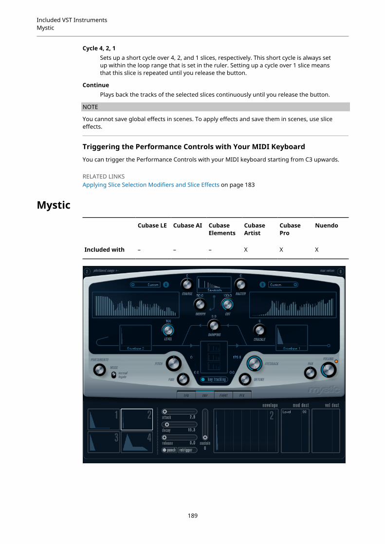
Included VST InstrumentsMystic
Cycle 4, 2, 1Sets up a short cycle over 4, 2, and 1 slices, respectively. This short cycle is always setup within the loop range that is set in the ruler. Setting up a cycle over 1 slice meansthat this slice is repeated until you release the button.
ContinuePlays back the tracks of the selected slices continuously until you release the button.
NOTE
You cannot save global effects in scenes. To apply effects and save them in scenes, use sliceeffects.
Triggering the Performance Controls with Your MIDI Keyboard
You can trigger the Performance Controls with your MIDI keyboard starting from C3 upwards.
RELATED LINKSApplying Slice Selection Modifiers and Slice Effects on page 183
Mystic
Cubase LE Cubase AI CubaseElements
CubaseArtist
CubasePro
Nuendo
Included with – – – X X X
189
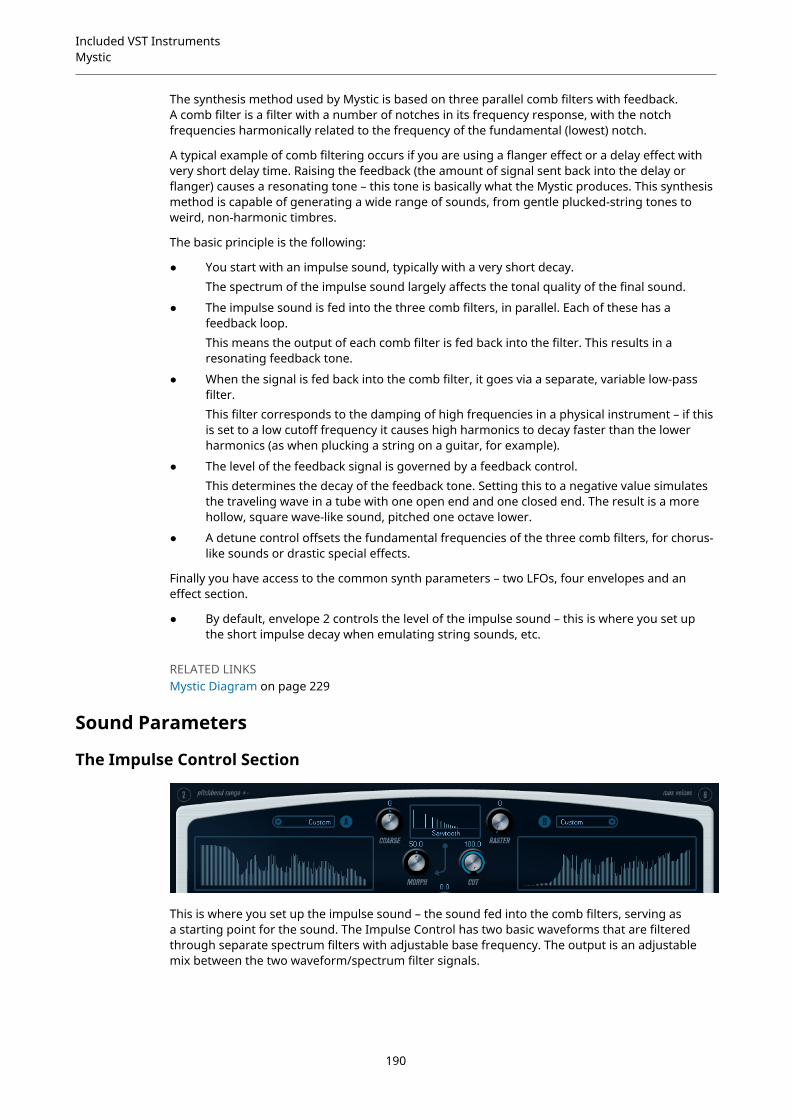
Included VST InstrumentsMystic
The synthesis method used by Mystic is based on three parallel comb filters with feedback.A comb filter is a filter with a number of notches in its frequency response, with the notchfrequencies harmonically related to the frequency of the fundamental (lowest) notch.
A typical example of comb filtering occurs if you are using a flanger effect or a delay effect withvery short delay time. Raising the feedback (the amount of signal sent back into the delay orflanger) causes a resonating tone – this tone is basically what the Mystic produces. This synthesismethod is capable of generating a wide range of sounds, from gentle plucked-string tones toweird, non-harmonic timbres.
The basic principle is the following:
● You start with an impulse sound, typically with a very short decay.The spectrum of the impulse sound largely affects the tonal quality of the final sound.
● The impulse sound is fed into the three comb filters, in parallel. Each of these has afeedback loop.This means the output of each comb filter is fed back into the filter. This results in aresonating feedback tone.
● When the signal is fed back into the comb filter, it goes via a separate, variable low-passfilter.This filter corresponds to the damping of high frequencies in a physical instrument – if thisis set to a low cutoff frequency it causes high harmonics to decay faster than the lowerharmonics (as when plucking a string on a guitar, for example).
● The level of the feedback signal is governed by a feedback control.This determines the decay of the feedback tone. Setting this to a negative value simulatesthe traveling wave in a tube with one open end and one closed end. The result is a morehollow, square wave-like sound, pitched one octave lower.
● A detune control offsets the fundamental frequencies of the three comb filters, for chorus-like sounds or drastic special effects.
Finally you have access to the common synth parameters – two LFOs, four envelopes and aneffect section.
● By default, envelope 2 controls the level of the impulse sound – this is where you set upthe short impulse decay when emulating string sounds, etc.
RELATED LINKSMystic Diagram on page 229
Sound Parameters
The Impulse Control Section
This is where you set up the impulse sound – the sound fed into the comb filters, serving asa starting point for the sound. The Impulse Control has two basic waveforms that are filteredthrough separate spectrum filters with adjustable base frequency. The output is an adjustablemix between the two waveform/spectrum filter signals.
190

Included VST InstrumentsMystic
Spectrum Displays
The displays allow you to draw a filter contour with your mouse for spectrum filters A and B.
● To set up the contour, click in one of the displays and drag the mouse to draw a curve. Thisproduces the inverse contour in the other display, for maximum sonic versatility.To set up the contour independently for the two filters, hold down Shift and click and dragthe mouse in either display.
● Use the Preset pop-up menu to select a preset contour.
● If you want to calculate a random spectrum filter curve, you can choose the Randomizefunction from the Preset pop-up menu.Each time you choose this function, a new randomized spectrum appears.
Waveform Pop-up Menu
The pop-up menu at the bottom of the waveform section (the central box at the top of thepanel) allows you to select a basic waveform to be sent through filter contour A. The options areespecially suited for use with the spectrum filter.
CutOffsets the frequency of the filter contour, working somewhat like a cutoff control ona standard synth filter. To use the filter contour in its full frequency range, set Cut toits maximum value.
MorphAdjusts the mix between the two signal paths: waveform A spectrum contour A andwaveform B spectrum contour B.
CoarseOffsets the pitch for the impulse sound. In a typical string setup, when the impulsesound is very short, this does not change the pitch of the final sound, but the tonalcolor.
RasterThis removes harmonics from the impulse sound. As the harmonic content of theimpulse sound is reflected in the comb filter sound, this changes the final timbre.
191

Included VST InstrumentsMystic
Comb Filter Sound Parameters
DampingThis is a 6 dB/oct low-pass filter that affects the sound being fed back into the combfilters. This means the sound becomes gradually softer when decaying, that is, highharmonics decay faster than the lower harmonics (as when plucking a string on aguitar, for example).
● The lower the Damping, the more pronounced this effect.If you open the filter completely (turn Damping up to max) the harmoniccontent is static – the sound does not get softer when decaying.
LevelDetermines the level of the impulse sound being fed into the comb filters. By default,this parameter is modulated by envelope 2. That is, you use envelope 2 as a levelenvelope for the impulse sound.
● For a string-type sound, you want an envelope with a quick attack, a very shortdecay and no sustain (an impulse in other words), but you can also use otherenvelopes for other types of sounds.Try raising the attack for example, or raising the sustain to allow the impulsesound to be heard together with the comb filter sound.
CrackleAllows you to send noise directly into the comb filters. Small amounts of noiseproduce a crackling, erratic effect, higher amounts give a more pronounced noisesound.
FeedbackDetermines the amount of signal sent back into the comb filters (the feedback level).
● Setting Feedback to zero (twelve o’clock) effectively turns off the comb filtersound, as no feedback tone is produced.
● Setting Feedback to a positive value creates a feedback tone, with highersettings generating longer decays.
● Setting Feedback to a negative value creates a feedback tone with a morehollow sound, pitched one octave lower. Lower settings generate longerdecays.
DetuneOffsets the notch frequencies of the three parallel comb filters, effectively changingthe pitches of their feedback tones. At low settings, this creates a chorus-like detuneeffect. Higher settings detunes the three tones in wider intervals.
Pitch and FineOverall pitch adjustment of the final sound. This changes the pitch of both theimpulse sound and the final comb filter sound.
192
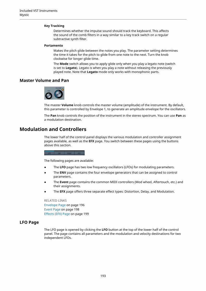
Included VST InstrumentsMystic
Key TrackingDetermines whether the impulse sound should track the keyboard. This affectsthe sound of the comb filters in a way similar to a key track switch on a regularsubtractive synth filter.
PortamentoMakes the pitch glide between the notes you play. The parameter setting determinesthe time it takes for the pitch to glide from one note to the next. Turn the knobclockwise for longer glide time.The Mode switch allows you to apply glide only when you play a legato note (switchis set to Legato). Legato is when you play a note without releasing the previouslyplayed note. Note that Legato mode only works with monophonic parts.
Master Volume and Pan
The master Volume knob controls the master volume (amplitude) of the instrument. By default,this parameter is controlled by Envelope 1, to generate an amplitude envelope for the oscillators.
The Pan knob controls the position of the instrument in the stereo spectrum. You can use Pan asa modulation destination.
Modulation and ControllersThe lower half of the control panel displays the various modulation and controller assignmentpages available, as well as the EFX page. You switch between these pages using the buttonsabove this section.
The following pages are available:
● The LFO page has two low frequency oscillators (LFOs) for modulating parameters.
● The ENV page contains the four envelope generators that can be assigned to controlparameters.
● The Event page contains the common MIDI controllers (Mod wheel, Aftertouch, etc.) andtheir assignments.
● The EFX page offers three separate effect types: Distortion, Delay, and Modulation.
RELATED LINKSEnvelope Page on page 196Event Page on page 198Effects (EFX) Page on page 199
LFO PageThe LFO page is opened by clicking the LFO button at the top of the lower half of the controlpanel. The page contains all parameters and the modulation and velocity destinations for twoindependent LFOs.
193

Included VST InstrumentsMystic
Depending on the selected preset, there may already be modulation destinations assigned, inwhich case these are listed in the Mod Dest box for each LFO.
A low frequency oscillator (LFO) is used for modulating parameters, for example the pitch of anoscillator (to produce vibrato), or for any parameter where cyclic modulation is required.
The two LFOs have identical parameters.
SpeedGoverns the rate of the LFO. If the sync mode is set to MIDI, the available rate valuesare selectable as note values, so the rate is synchronized to the sequencer tempo.
DepthControls the amount of modulation applied by the LFO. If this is set to zero, nomodulation is applied.
WaveformSets the LFO waveform.
Sync mode (Part/MIDI/Voice/Key)Sets the sync mode for the LFO.
RELATED LINKSAssigning LFO Modulation Destinations on page 195
About the Sync Modes
The Sync modes determine how the LFO cycle affects the notes you play.
PartIn this mode, the LFO cycle is free running and affects all the voices in sync. Freerunning means that the LFO cycles continuously, and does not reset when a note isplayed.
MIDIIn this mode, the LFO rate is synced in various beat increments to MIDI clock.
VoiceIn this mode, each voice in the Part has its own independent LFO cycle (the LFO ispolyphonic). These cycles are also free running – each key down starts anywhere inthe LFO cycle phase.
KeySame as Voice except that it is not free running – for each key down the LFO cyclestarts over.
About the Waveforms
Most standard LFO waveforms are available for LFO modulation. You use sine and trianglewaveforms for smooth modulation cycles, square and ramp up/down for different typesof stepped modulation cycles and random or sample for random modulation. The samplewaveform is different:
194
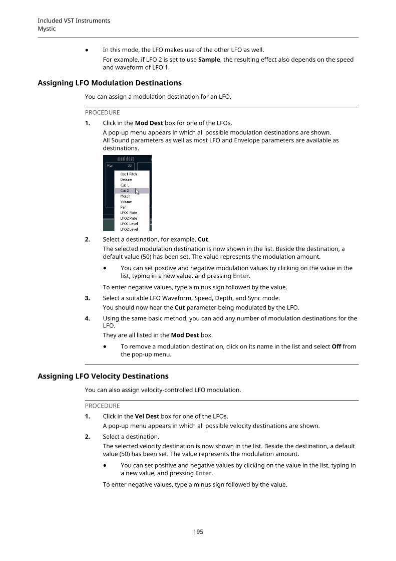
Included VST InstrumentsMystic
● In this mode, the LFO makes use of the other LFO as well.For example, if LFO 2 is set to use Sample, the resulting effect also depends on the speedand waveform of LFO 1.
Assigning LFO Modulation Destinations
You can assign a modulation destination for an LFO.
PROCEDURE
1. Click in the Mod Dest box for one of the LFOs.A pop-up menu appears in which all possible modulation destinations are shown.All Sound parameters as well as most LFO and Envelope parameters are available asdestinations.
2. Select a destination, for example, Cut.The selected modulation destination is now shown in the list. Beside the destination, adefault value (50) has been set. The value represents the modulation amount.
● You can set positive and negative modulation values by clicking on the value in thelist, typing in a new value, and pressing Enter.
To enter negative values, type a minus sign followed by the value.
3. Select a suitable LFO Waveform, Speed, Depth, and Sync mode.You should now hear the Cut parameter being modulated by the LFO.
4. Using the same basic method, you can add any number of modulation destinations for theLFO.They are all listed in the Mod Dest box.
● To remove a modulation destination, click on its name in the list and select Off fromthe pop-up menu.
Assigning LFO Velocity Destinations
You can also assign velocity-controlled LFO modulation.
PROCEDURE
1. Click in the Vel Dest box for one of the LFOs.A pop-up menu appears in which all possible velocity destinations are shown.
2. Select a destination.The selected velocity destination is now shown in the list. Beside the destination, a defaultvalue (50) has been set. The value represents the modulation amount.
● You can set positive and negative values by clicking on the value in the list, typing ina new value, and pressing Enter.
To enter negative values, type a minus sign followed by the value.
195
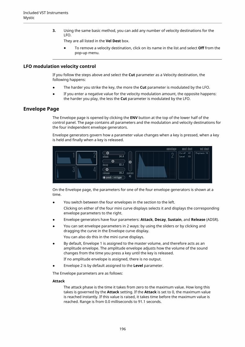
Included VST InstrumentsMystic
3. Using the same basic method, you can add any number of velocity destinations for theLFO.They are all listed in the Vel Dest box.
● To remove a velocity destination, click on its name in the list and select Off from thepop-up menu.
LFO modulation velocity control
If you follow the steps above and select the Cut parameter as a Velocity destination, thefollowing happens:
● The harder you strike the key, the more the Cut parameter is modulated by the LFO.
● If you enter a negative value for the velocity modulation amount, the opposite happens:the harder you play, the less the Cut parameter is modulated by the LFO.
Envelope PageThe Envelope page is opened by clicking the ENV button at the top of the lower half of thecontrol panel. The page contains all parameters and the modulation and velocity destinations forthe four independent envelope generators.
Envelope generators govern how a parameter value changes when a key is pressed, when a keyis held and finally when a key is released.
On the Envelope page, the parameters for one of the four envelope generators is shown at atime.
● You switch between the four envelopes in the section to the left.Clicking on either of the four mini curve displays selects it and displays the correspondingenvelope parameters to the right.
● Envelope generators have four parameters: Attack, Decay, Sustain, and Release (ADSR).
● You can set envelope parameters in 2 ways: by using the sliders or by clicking anddragging the curve in the Envelope curve display.You can also do this in the mini curve displays.
● By default, Envelope 1 is assigned to the master volume, and therefore acts as anamplitude envelope. The amplitude envelope adjusts how the volume of the soundchanges from the time you press a key until the key is released.If no amplitude envelope is assigned, there is no output.
● Envelope 2 is by default assigned to the Level parameter.
The Envelope parameters are as follows:
AttackThe attack phase is the time it takes from zero to the maximum value. How long thistakes is governed by the Attack setting. If the Attack is set to 0, the maximum valueis reached instantly. If this value is raised, it takes time before the maximum value isreached. Range is from 0.0 milliseconds to 91.1 seconds.
196
Included VST InstrumentsMystic
DecayAfter the maximum value has been reached, the value starts to drop. How long thistakes is governed by the Decay parameter. The Decay has no effect if the Sustainparameter is set to maximum.
SustainDetermines the level for the envelope after the Decay phase. Note that Sustainrepresents a level, whereas the other envelope parameters represent times.
ReleaseDetermines the time it takes for the value to fall back to zero after releasing the key.Range is from 0.0 milliseconds to 91.1 seconds.
PunchIf Punch is activated, the start of the decay phase is delayed a few milliseconds,that is, the envelope stays at top level for a moment before moving on to the decayphase. The result is a punchier attack similar to a compressor effect. This effect ismore pronounced with short attack and decay times.
RetriggerIf Retrigger is activated, the envelope retriggers each time you play a new note.However, with certain textures/pad sounds and a limited number of voices, it isrecommended to leave the button deactivated, due to click noises that might occur.
Assigning Envelope Modulation Destinations
You can assign a modulation destination for an envelope.
PROCEDURE
1. Click in the Mod Dest box for one of the envelopes.A pop-up menu appears in which all possible modulation destinations are shown.All Sound parameters as well as most LFO and Envelope parameters are available asdestinations.
2. Select a destination, for example, Cut.The selected modulation destination is now shown in the list. Beside the destination, adefault value (50) has been set. The value represents the modulation amount.
● You can set positive and negative modulation values by clicking on the value in thelist, typing in a new value, and pressing Enter.To enter negative values, type a minus sign followed by the value.
3. Select a suitable envelope curve for the modulation.You should now hear the Cut parameter being modulated by the envelope as you play.
4. Using the same basic method, you can add any number of modulation destinations for theenvelope.They are all listed in the Mod Dest box.
● To remove a modulation destination, click on its name in the list and select Off fromthe pop-up menu.
Assigning Envelope Velocity Destinations
You can also assign velocity-controlled envelope modulation, that is, the modulation is governedby how hard or soft you strike a key.
PROCEDURE
1. Click in the Vel Dest box for one of the envelopes.
197

Included VST InstrumentsMystic
A pop-up menu appears in which all possible velocity destinations are shown.
2. Select a destination.The selected velocity destination is now shown in the list. Beside the destination, a defaultvalue (50) has been set. The value represents the modulation amount. See below for anexample of how velocity modulation works.
● You can set positive and negative values by clicking on the value in the list, typing ina new value, and pressing Enter.To enter negative values, type a minus sign followed by the value.
3. Using the same basic method, you can add any number of velocity destinations for theEnvelope.They are all listed in the Vel Dest box.
● To remove a velocity destination, click on its name in the list and select Off from thepop-up menu.
Envelope modulation velocity control
If you follow the steps above and select the Cut parameter as a Velocity destination, thefollowing happens:
● The harder you strike the key, the more the parameter is modulated by the envelope.
● If you enter a negative value for the velocity modulation amount, the opposite happens;the harder you play the less the Cut parameter is modulated by the Envelope.
Event PageThe Event page is opened by clicking the EVENT button at the top of the lower half of the controlpanel. This page contains the most common MIDI controllers and their assignments.
Modulation WheelThe modulation wheel on your keyboard can be used to modulate parameters.
VelocityControls parameters according to how hard or soft you play notes on your keyboard.A common application of velocity is to make sounds brighter and louder if you strikethe key harder.
AftertouchAftertouch, or channel pressure, is MIDI data sent when pressure is applied to akeyboard after the key has been struck, and while it is being held down or sustained.Aftertouch is often routed to control filter cutoff, volume, and other parameters toadd expression.
Key Pitch TrackingThis can change parameter values linearly according to where on the keyboard youplay.
198

Included VST InstrumentsMystic
Assign a Controller to a Parameter
PROCEDURE
1. Click in the Mod Dest box for one of the controllers.A pop-up menu appears in which all possible modulation destinations are shown.All Sound parameters as well as most LFO and Envelope parameters are available asdestinations.
2. Select a destination.The selected modulation destination is now shown in the list. Beside the destination, adefault value (50) has been set. The value represents the modulation amount when thecontroller is at its full range.
● You can set positive and negative modulation values by clicking on the value in thelist, typing in a new value, and pressing Enter.To enter negative values, type a minus sign followed by the value.
3. Using the same basic method, you can add any number of modulation destinations for thecontrollers.They are all listed in the Mod Dest box for each controller.
● To remove a modulation destination, click on its name in the list and select Off fromthe pop-up menu.
Effects (EFX) PageThis page features three separate effect units: Distortion, Delay, and Modulation (Phaser/Flanger/Chorus). The Effect page is opened by clicking the EFX button at the top of the lower halfof the control panel.
● Each separate effect section is laid out with a row of buttons that determine the effect typeor characteristic and a row of sliders for making parameter settings.
● To activate an effect, click the Active button so that a dot appears.Clicking again deactivates the effect.
Distortion
You can choose between 4 basic distortion characteristics:
● Distortion provides hard clipping distortion.
● Soft Distortion provides soft clipping distortion.
● Tape Emulation produces distortion similar to magnetic tape saturation.
● Tube Emulation produces distortion similar to valve amplifiers.
DriveSets the amount of distortion by amplifying the input signal.
199
Included VST InstrumentsMystic
FilterSets the crossover frequency of the distortion filter. The distortion filter consists ofa low-pass filter and a high-pass filter with a cutoff frequency equal to the crossoverfrequency.
ToneControls the relative amount of low-pass and high-pass filtered signal.
LevelControls the output level of the effect.
Delay
You can choose between 3 basic delay characteristics:
● Stereo Delay has two separate delay lines panned left and right.
● In Mono Delay, the two delay lines are connected in series for monophonic dual tap delayeffects.
● In Cross Delay, the delayed sound bounces between the stereo channels.
Song SyncActivates/Deactivates tempo sync of the delay times.
Delay 1Sets the delay time ranging from 0 ms to 728 ms. If MIDI sync is activated, the rangeis from 1/32 to 1/1; straight, triplet or dotted.
Delay 2Same as Delay 1.
FeedbackControls the decay of the delays. With higher settings, the echoes repeat longer.
FilterA low-pass filter is built into the feedback loop of the delay. This parameter controlsthe cutoff frequency of this feedback filter. Low settings result in successive echoessounding darker.
LevelControls the output level of the effect.
Modulation
You can choose between 3 basic modulation characteristics:
● Phaser uses an 8-pole all-pass filter to produce the classic phasing effect.
● Flanger is composed of two independent delay lines with feedback for the left and theright channel. The delay time of both delays is modulated by one LFO with adjustablefrequency.
● Chorus produces a rich chorus effect with 4 delays modulated by four independent LFOs.
Song SyncActivates/Deactivates tempo sync of the Rate parameter.
RateSets the rate of the LFOs modulating the delay time. If Song Sync is activated, therate is synchronized to various beat increments.
DepthControls the depth of the delay time modulation.
200

Included VST InstrumentsPadshop
DelaySets the delay time of the four delay lines.
FeedbackControls the amount of positive or negative feedback for all four delay lines.
LevelControls the output level of the effect.
SR Parameters
With these buttons, you can change the sample rate. Lower sample rates basically reduce thehigh frequency content and sound quality, but the pitch is not altered. This is useful to emulatethe lo-fi sounds of older digital synths.
● If the F button is active, the program of the selected part plays back with the sample rateset in the host application.
● If the 1/2 button is active, the program of the selected part plays back with half the originalsample rate.
● If the 1/4 button is active, the program of the selected part plays back with a quarter of theoriginal sample rate.
A bonus effect of using lower sample rates is that it reduces the load on the computer CPU,allowing for more simultaneous voices to be played, etc.
Padshop
Cubase LE Cubase AI CubaseElements
CubaseArtist
CubasePro
Nuendo
Included with – – – X X X
Padshop is described in detail in a separate PDF document, which can be accessed via the ?button on the plug-in interface.
Prologue
Cubase LE Cubase AI CubaseElements
CubaseArtist
CubasePro
Nuendo
Included with – – X X X X
201

Included VST InstrumentsPrologue
Prologue is modelled on subtractive synthesis, the method used in classic analog synthesizers. Ithas the following basic features:
● Multimode filterVariable slope low-pass and high-pass, plus band-pass and notch filter modes.
● Three oscillators, each with 4 standard waveforms plus an assortment of specializedwaveforms.
● Frequency modulation.
● Ring Modulation.
● Built-in effects.
● Prologue receives MIDI on all MIDI channels.You do not have to select a MIDI channel to direct MIDI to the Prologue.
RELATED LINKSAbout the Filter TypesSelecting WaveformsAbout Frequency ModulationRing ModulationEffects (EFX) Page on page 199Functional Diagrams on page 229
202
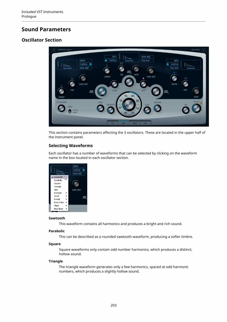
Included VST InstrumentsPrologue
Sound Parameters
Oscillator Section
This section contains parameters affecting the 3 oscillators. These are located in the upper half ofthe instrument panel.
Selecting Waveforms
Each oscillator has a number of waveforms that can be selected by clicking on the waveformname in the box located in each oscillator section.
SawtoothThis waveform contains all harmonics and produces a bright and rich sound.
ParabolicThis can be described as a rounded sawtooth waveform, producing a softer timbre.
SquareSquare waveforms only contain odd number harmonics, which produces a distinct,hollow sound.
TriangleThe triangle waveform generates only a few harmonics, spaced at odd harmonicnumbers, which produces a slightly hollow sound.
203
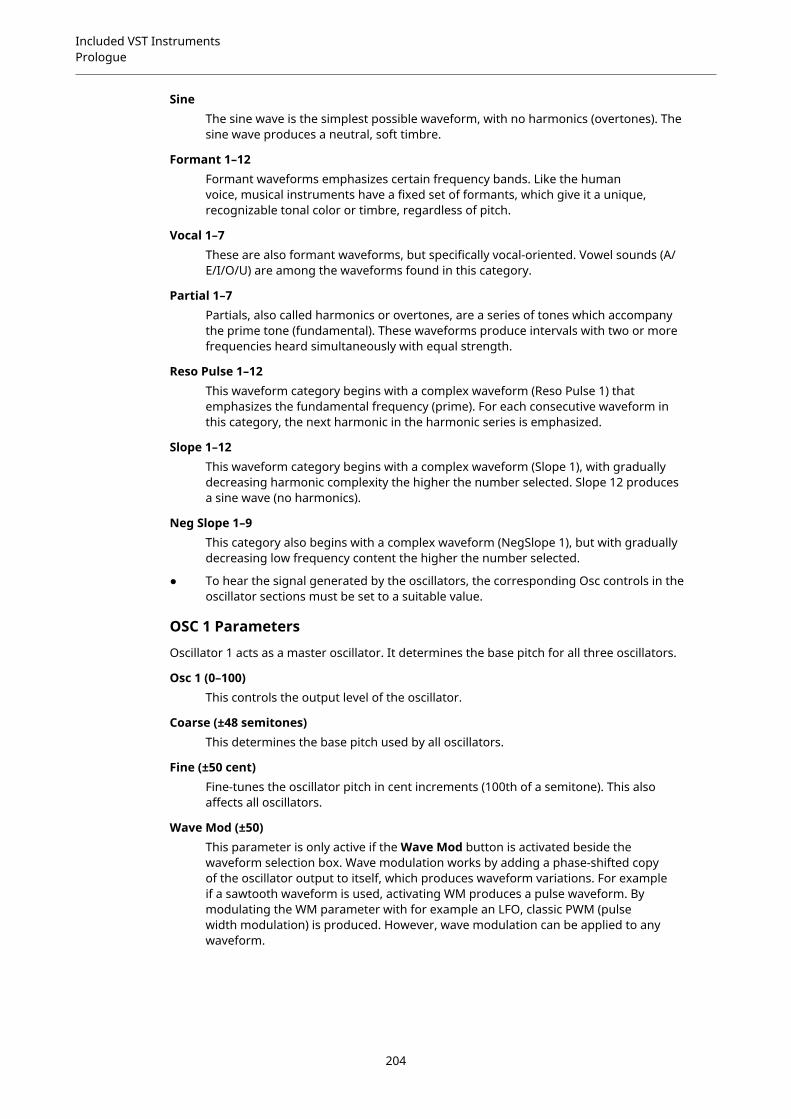
Included VST InstrumentsPrologue
SineThe sine wave is the simplest possible waveform, with no harmonics (overtones). Thesine wave produces a neutral, soft timbre.
Formant 1–12Formant waveforms emphasizes certain frequency bands. Like the humanvoice, musical instruments have a fixed set of formants, which give it a unique,recognizable tonal color or timbre, regardless of pitch.
Vocal 1–7These are also formant waveforms, but specifically vocal-oriented. Vowel sounds (A/E/I/O/U) are among the waveforms found in this category.
Partial 1–7Partials, also called harmonics or overtones, are a series of tones which accompanythe prime tone (fundamental). These waveforms produce intervals with two or morefrequencies heard simultaneously with equal strength.
Reso Pulse 1–12This waveform category begins with a complex waveform (Reso Pulse 1) thatemphasizes the fundamental frequency (prime). For each consecutive waveform inthis category, the next harmonic in the harmonic series is emphasized.
Slope 1–12This waveform category begins with a complex waveform (Slope 1), with graduallydecreasing harmonic complexity the higher the number selected. Slope 12 producesa sine wave (no harmonics).
Neg Slope 1–9This category also begins with a complex waveform (NegSlope 1), but with graduallydecreasing low frequency content the higher the number selected.
● To hear the signal generated by the oscillators, the corresponding Osc controls in theoscillator sections must be set to a suitable value.
OSC 1 Parameters
Oscillator 1 acts as a master oscillator. It determines the base pitch for all three oscillators.
Osc 1 (0–100)This controls the output level of the oscillator.
Coarse (±48 semitones)This determines the base pitch used by all oscillators.
Fine (±50 cent)Fine-tunes the oscillator pitch in cent increments (100th of a semitone). This alsoaffects all oscillators.
Wave Mod (±50)This parameter is only active if the Wave Mod button is activated beside thewaveform selection box. Wave modulation works by adding a phase-shifted copyof the oscillator output to itself, which produces waveform variations. For exampleif a sawtooth waveform is used, activating WM produces a pulse waveform. Bymodulating the WM parameter with for example an LFO, classic PWM (pulsewidth modulation) is produced. However, wave modulation can be applied to anywaveform.
204
Included VST InstrumentsPrologue
Phase button (On/Off)If phase synchronization is activated, all oscillators restart their waveform cycleswith every note that is played. With Phase deactivated, the oscillators generate awaveform cycle continuously, which produces slight variations when playing as eachnote starts from a random phase in the cycle, adding warmth to the sound. For basssounds or drum sounds, it is often required that the attack of every note sounds thesame, therefore, for these purposes activate phase sync. Phase sync also affects thenoise generator.
Tracking button (On/Off)If Tracking is activated, the oscillator pitch tracks the notes played on the keyboard.If Tracking is deactivated, the oscillator pitch remains constant, regardless of thenote that is played.
Wave Mod button (On/Off)Activates/Deactivates wave modulation.
Waveform pop-up menuSets the basic waveform for the oscillator.
OSC 2 Parameters
Osc 2 (0–100)Controls the output level of the oscillator.
Coarse (±48semitones)Determines the coarse pitch for Osc 2. If FM is enabled, this determines frequencyratio of the oscillator regarding Osc 1.
Fine (±50 cent)Fine-tunes the oscillator pitch in cent increments (100th of a semitone). If FM isactivated, this determines the frequency ratio of the oscillator regarding Osc 1.
Wave Mod (±50)This parameter is only active if the Wave Mod button next to the waveform selectoris activated. Wave modulation works by adding a phase-shifted copy of the oscillatoroutput to itself, which produces waveform variations. For example, if a sawtoothwaveform is used, activating WM produces a pulse waveform. By modulating theWM parameter with an LFO, classic PWM (pulse width modulation) is produced. Wavemodulation can be applied to any waveform.
Ratio (1–16)This parameter is only active if Freq Mod is activate. It adjusts the amount offrequency modulation applied to oscillator 2. It is normally referred to as “FM index”.
Sync button (On/Off)If Sync is activated, Osc 2 is slaved to Osc 1. This means that every time Osc 1completes its cycle, Osc 2 is forced to start its cycle from the beginning. Thisproduces a characteristic sound, suitable for lead playing. Osc 1 determines thepitch, and varying the pitch of Osc 2 produces changes in timbre. For classic syncsounds, try modulating the pitch of Osc 2 with an envelope or an LFO. The Osc 2pitch should also be set higher than the pitch of Osc 1.
Tracking button (On/Off)If Tracking is activated, the oscillator pitch tracks the notes played on the keyboard.If Tracking is deactivated, the oscillator pitch remains constant, regardless of thenote that is played.
Freq Mod button (On/Off)Activates/Deactivates frequency modulation.
205
Included VST InstrumentsPrologue
Wave Mod button (On/Off)Activates/Deactivates wave modulation.
Waveform pop-up menuSets the basic waveform for the oscillator.
OSC 3 Parameters
Osc 3 (0–100)Controls the output level of the oscillator.
Coarse (±48semitones)Determines the coarse pitch for Osc 3. If FM is activated, this determines thefrequency ratio of the oscillator regarding Osc 1/2.
Fine (±50 cent)Fine-tunes the oscillator pitch in cent increments. If FM is activated, this determinesthe frequency ratio of the oscillator regarding Osc 1/2.
Ratio (1–16)This parameter is only active if the Freq Mod button is activated. It adjusts theamount of frequency modulation applied to oscillator 3. It is normally referred to “FMindex”.
Sync button (On/Off)If Sync is activated, Osc 3 is slaved to Osc 1. This means that every time Osc 1completes its cycle, Osc 3 is forced to start its cycle from the beginning. Thisproduces a characteristic sound, suitable for lead playing. Osc 1 determines thepitch, and varying the pitch of Osc 3 produces changes in timbre. For classic syncsounds, try modulating the pitch of Osc 3 with an envelope or an LFO. The Osc 3pitch should also be set higher than the pitch of Osc 1.
Tracking button (On/Off)If Tracking is activated, the oscillator pitch tracks the notes played on the keyboard.If Tracking is deactivated, the oscillator pitch remains constant, regardless of thenote that is played.
Freq Mod button (On/Off)Activates/Deactivates frequency modulation.
Wave Mod button (On/Off)Activates/Deactivates wave modulation.
Waveform pop-up menuSets the basic waveform for the oscillator.
About Frequency Modulation
Frequency modulation or FM means that the frequency of one oscillator, called the carrier, ismodulated by the frequency of another oscillator, called the modulator.
● In Prologue, Osc 1 is the modulator, and Osc 2 and 3 are carriers.However, Osc 2 can be both carrier and modulator as if frequency modulation is appliedto Osc 2 it is modulated by Osc 3. If Osc 2 also uses frequency modulation, Osc 3 ismodulated by both Osc 1 and Osc 2.
● The pure sound of frequency modulation is output through the modulator oscillators.This means that you should turn off the Osc 1 output when using frequency modulation.
● The Freq Mod button activates/deactivates frequency modulation.
● The Ratio parameter determines the amount of frequency modulation.
206
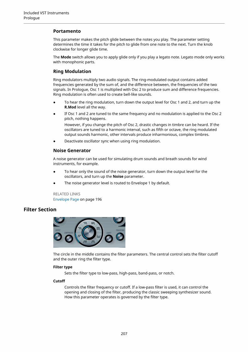
Included VST InstrumentsPrologue
Portamento
This parameter makes the pitch glide between the notes you play. The parameter settingdetermines the time it takes for the pitch to glide from one note to the next. Turn the knobclockwise for longer glide time.
The Mode switch allows you to apply glide only if you play a legato note. Legato mode only workswith monophonic parts.
Ring Modulation
Ring modulators multiply two audio signals. The ring-modulated output contains addedfrequencies generated by the sum of, and the difference between, the frequencies of the twosignals. In Prologue, Osc 1 is multiplied with Osc 2 to produce sum and difference frequencies.Ring modulation is often used to create bell-like sounds.
● To hear the ring modulation, turn down the output level for Osc 1 and 2, and turn up theR.Mod level all the way.
● If Osc 1 and 2 are tuned to the same frequency and no modulation is applied to the Osc 2pitch, nothing happens.However, if you change the pitch of Osc 2, drastic changes in timbre can be heard. If theoscillators are tuned to a harmonic interval, such as fifth or octave, the ring modulatedoutput sounds harmonic, other intervals produce inharmonious, complex timbres.
● Deactivate oscillator sync when using ring modulation.
Noise Generator
A noise generator can be used for simulating drum sounds and breath sounds for windinstruments, for example.
● To hear only the sound of the noise generator, turn down the output level for theoscillators, and turn up the Noise parameter.
● The noise generator level is routed to Envelope 1 by default.
RELATED LINKSEnvelope Page on page 196
Filter Section
The circle in the middle contains the filter parameters. The central control sets the filter cutoffand the outer ring the filter type.
Filter typeSets the filter type to low-pass, high-pass, band-pass, or notch.
CutoffControls the filter frequency or cutoff. If a low-pass filter is used, it can control theopening and closing of the filter, producing the classic sweeping synthesizer sound.How this parameter operates is governed by the filter type.
207
Included VST InstrumentsPrologue
EmphasisThis is the resonance control for the filter. For low-pass and high-pass filters, raisingthe Emphasis value emphasizes the frequencies around the set cutoff frequency.This produces a generally thinner sound, but with a sharper, more pronouncedcutoff sweep. The higher the filter Emphasis value, the more resonant the soundbecomes until it starts to self-oscillate, generating a distinct pitch. For band-passor notch filters, the Emphasis setting adjusts the width of the band. If you raisethe value, the band where frequencies are let through (band-pass), or cut (notch)becomes narrower.
DriveAdjusts the filter input level. Levels above 0 dB gradually introduce a soft distortionof the input signal, and decrease the filter resonance.
ShiftInternally, each filter consists of two or more subfilters connected in series. Thisparameter shifts the cutoff frequency of the subfilters. The result depends on thefilter type: For low-pass and high-pass filter types, it changes the filter slope. Forband-pass and notch filter types, it changes the bandwidth. The Shift parameter hasno effect for the filter types 12 dB LP or 12 dB HP.
TrackingIf this parameter is set to values over the 12 o’clock position, the filter cutofffrequency increases the further up on the keyboard you play. Negative values invertthis relationship.If the Tracking parameter is set fully clockwise, the cutoff frequency tracks thekeyboard by a semitone per key.
About the Filter Types
You select the filter type using the buttons around the filter cutoff knob. The following filter typesare available (listed clockwise starting from the 9 o’clock position):
12 dB LPLow-pass filters let low frequencies pass and cut out the high frequencies. This low-pass filter has a gentler slope (12 dB/octave above the cutoff frequency), leavingmore of the harmonics in the filtered sound.
18 dB LPThis low-pass filter also has a cascade design, attenuating frequencies above thecutoff frequency with a 18 dB/octave slope, as used in the classic TB 303 synth.
24 dB LPThis filter type attenuates frequencies above the cutoff frequency with a 24 dB/octave slope that produces a warm and fat sound.
24 dB LP IIThis low-pass filter has a cascade design that attenuates frequencies above thecutoff frequency with a 24 dB/octave slope, which produces a warm and dark sound.
12 dB BandThis band-pass filter cuts both high and low frequencies above and below the cutofffrequency with a 12 dB/octave slope, producing a nasal and thin sound.
12 dB NotchThis notch filter cuts off frequencies near the cutoff frequency by 12 dB/octave,letting the frequencies below and above through. This produces a phaser-like sound.
208

Included VST InstrumentsPrologue
12 dB HPA high-pass filter cuts out the lower frequencies and lets the high frequencies pass.This high-pass filter has a 12 dB/octave slope, producing a bright and thin sound.
24 dB HPThis filter has a 24 dB/octave slope, producing a bright and sharp sound.
Master Volume and Pan
The master Volume knob controls the master volume (amplitude) of the instrument. By default,this parameter is controlled by Envelope 1, to generate an amplitude envelope for the oscillators.
The Pan knob controls the position of the instrument in the stereo spectrum. You can use Pan asa modulation destination.
Modulation and ControllersThe lower half of the control panel displays the various modulation and controller assignmentpages available, as well as the EFX page. You switch between these pages using the buttonsabove this section.
The following pages are available:
● The LFO page has two low frequency oscillators (LFOs) for modulating parameters.
● The ENV page contains the four envelope generators that can be assigned to controlparameters.
● The Event page contains the common MIDI controllers (Mod wheel, Aftertouch, etc.) andtheir assignments.
● The EFX page offers three separate effect types: Distortion, Delay, and Modulation.
RELATED LINKSEnvelope Page on page 196Event Page on page 198Effects (EFX) Page on page 199
LFO PageThe LFO page is opened by clicking the LFO button at the top of the lower half of the controlpanel. The page contains all parameters and the modulation and velocity destinations for twoindependent LFOs.
Depending on the selected preset, there may already be modulation destinations assigned, inwhich case these are listed in the Mod Dest box for each LFO.
209
Included VST InstrumentsPrologue
A low frequency oscillator (LFO) is used for modulating parameters, for example the pitch of anoscillator (to produce vibrato), or for any parameter where cyclic modulation is required.
The two LFOs have identical parameters.
SpeedGoverns the rate of the LFO. If the sync mode is set to MIDI, the available rate valuesare selectable as note values, so the rate is synchronized to the sequencer tempo.
DepthControls the amount of modulation applied by the LFO. If this is set to zero, nomodulation is applied.
WaveformSets the LFO waveform.
Sync mode (Part/MIDI/Voice/Key)Sets the sync mode for the LFO.
RELATED LINKSAssigning LFO Modulation Destinations on page 195
About the Sync Modes
The Sync modes determine how the LFO cycle affects the notes you play.
PartIn this mode, the LFO cycle is free running and affects all the voices in sync. Freerunning means that the LFO cycles continuously, and does not reset when a note isplayed.
MIDIIn this mode, the LFO rate is synced in various beat increments to MIDI clock.
VoiceIn this mode, each voice in the Part has its own independent LFO cycle (the LFO ispolyphonic). These cycles are also free running – each key down starts anywhere inthe LFO cycle phase.
KeySame as Voice except that it is not free running – for each key down the LFO cyclestarts over.
About the Waveforms
Most standard LFO waveforms are available for LFO modulation. You use sine and trianglewaveforms for smooth modulation cycles, square and ramp up/down for different typesof stepped modulation cycles and random or sample for random modulation. The samplewaveform is different:
● In this mode, the LFO makes use of the other LFO as well.For example, if LFO 2 is set to use Sample, the resulting effect also depends on the speedand waveform of LFO 1.
Assigning LFO Modulation Destinations
You can assign a modulation destination for an LFO.
PROCEDURE
1. Click in the Mod Dest box for one of the LFOs.
210

Included VST InstrumentsPrologue
A pop-up menu appears in which all possible modulation destinations are shown.All Sound parameters as well as most LFO and Envelope parameters are available asdestinations.
2. Select a destination, for example, Cut.The selected modulation destination is now shown in the list. Beside the destination, adefault value (50) has been set. The value represents the modulation amount.
● You can set positive and negative modulation values by clicking on the value in thelist, typing in a new value, and pressing Enter.
To enter negative values, type a minus sign followed by the value.
3. Select a suitable LFO Waveform, Speed, Depth, and Sync mode.You should now hear the Cut parameter being modulated by the LFO.
4. Using the same basic method, you can add any number of modulation destinations for theLFO.They are all listed in the Mod Dest box.
● To remove a modulation destination, click on its name in the list and select Off fromthe pop-up menu.
Assigning LFO Velocity Destinations
You can also assign velocity-controlled LFO modulation.
PROCEDURE
1. Click in the Vel Dest box for one of the LFOs.A pop-up menu appears in which all possible velocity destinations are shown.
2. Select a destination.The selected velocity destination is now shown in the list. Beside the destination, a defaultvalue (50) has been set. The value represents the modulation amount.
● You can set positive and negative values by clicking on the value in the list, typing ina new value, and pressing Enter.
To enter negative values, type a minus sign followed by the value.
3. Using the same basic method, you can add any number of velocity destinations for theLFO.They are all listed in the Vel Dest box.
● To remove a velocity destination, click on its name in the list and select Off from thepop-up menu.
LFO modulation velocity control
If you follow the steps above and select the Cut parameter as a Velocity destination, thefollowing happens:
211
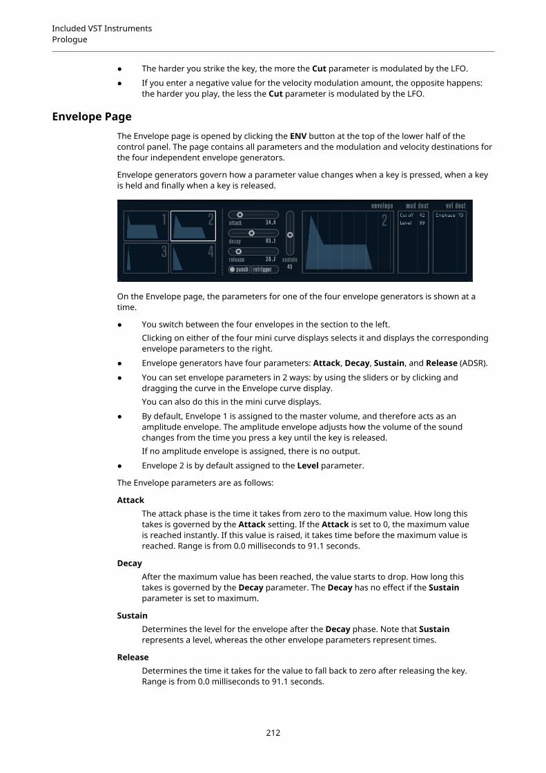
Included VST InstrumentsPrologue
● The harder you strike the key, the more the Cut parameter is modulated by the LFO.
● If you enter a negative value for the velocity modulation amount, the opposite happens:the harder you play, the less the Cut parameter is modulated by the LFO.
Envelope PageThe Envelope page is opened by clicking the ENV button at the top of the lower half of thecontrol panel. The page contains all parameters and the modulation and velocity destinations forthe four independent envelope generators.
Envelope generators govern how a parameter value changes when a key is pressed, when a keyis held and finally when a key is released.
On the Envelope page, the parameters for one of the four envelope generators is shown at atime.
● You switch between the four envelopes in the section to the left.Clicking on either of the four mini curve displays selects it and displays the correspondingenvelope parameters to the right.
● Envelope generators have four parameters: Attack, Decay, Sustain, and Release (ADSR).
● You can set envelope parameters in 2 ways: by using the sliders or by clicking anddragging the curve in the Envelope curve display.You can also do this in the mini curve displays.
● By default, Envelope 1 is assigned to the master volume, and therefore acts as anamplitude envelope. The amplitude envelope adjusts how the volume of the soundchanges from the time you press a key until the key is released.If no amplitude envelope is assigned, there is no output.
● Envelope 2 is by default assigned to the Level parameter.
The Envelope parameters are as follows:
AttackThe attack phase is the time it takes from zero to the maximum value. How long thistakes is governed by the Attack setting. If the Attack is set to 0, the maximum valueis reached instantly. If this value is raised, it takes time before the maximum value isreached. Range is from 0.0 milliseconds to 91.1 seconds.
DecayAfter the maximum value has been reached, the value starts to drop. How long thistakes is governed by the Decay parameter. The Decay has no effect if the Sustainparameter is set to maximum.
SustainDetermines the level for the envelope after the Decay phase. Note that Sustainrepresents a level, whereas the other envelope parameters represent times.
ReleaseDetermines the time it takes for the value to fall back to zero after releasing the key.Range is from 0.0 milliseconds to 91.1 seconds.
212
Included VST InstrumentsPrologue
PunchIf Punch is activated, the start of the decay phase is delayed a few milliseconds,that is, the envelope stays at top level for a moment before moving on to the decayphase. The result is a punchier attack similar to a compressor effect. This effect ismore pronounced with short attack and decay times.
RetriggerIf Retrigger is activated, the envelope retriggers each time you play a new note.However, with certain textures/pad sounds and a limited number of voices, it isrecommended to leave the button deactivated, due to click noises that might occur.
Assigning Envelope Modulation Destinations
You can assign a modulation destination for an envelope.
PROCEDURE
1. Click in the Mod Dest box for one of the envelopes.A pop-up menu appears in which all possible modulation destinations are shown.All Sound parameters as well as most LFO and Envelope parameters are available asdestinations.
2. Select a destination, for example, Cut.The selected modulation destination is now shown in the list. Beside the destination, adefault value (50) has been set. The value represents the modulation amount.
● You can set positive and negative modulation values by clicking on the value in thelist, typing in a new value, and pressing Enter.To enter negative values, type a minus sign followed by the value.
3. Select a suitable envelope curve for the modulation.You should now hear the Cut parameter being modulated by the envelope as you play.
4. Using the same basic method, you can add any number of modulation destinations for theenvelope.They are all listed in the Mod Dest box.
● To remove a modulation destination, click on its name in the list and select Off fromthe pop-up menu.
Assigning Envelope Velocity Destinations
You can also assign velocity-controlled envelope modulation, that is, the modulation is governedby how hard or soft you strike a key.
PROCEDURE
1. Click in the Vel Dest box for one of the envelopes.A pop-up menu appears in which all possible velocity destinations are shown.
2. Select a destination.The selected velocity destination is now shown in the list. Beside the destination, a defaultvalue (50) has been set. The value represents the modulation amount. See below for anexample of how velocity modulation works.
● You can set positive and negative values by clicking on the value in the list, typing ina new value, and pressing Enter.To enter negative values, type a minus sign followed by the value.
3. Using the same basic method, you can add any number of velocity destinations for theEnvelope.They are all listed in the Vel Dest box.
213

Included VST InstrumentsPrologue
● To remove a velocity destination, click on its name in the list and select Off from thepop-up menu.
Envelope modulation velocity control
If you follow the steps above and select the Cut parameter as a Velocity destination, thefollowing happens:
● The harder you strike the key, the more the parameter is modulated by the envelope.
● If you enter a negative value for the velocity modulation amount, the opposite happens;the harder you play the less the Cut parameter is modulated by the Envelope.
Event PageThe Event page is opened by clicking the EVENT button at the top of the lower half of the controlpanel. This page contains the most common MIDI controllers and their assignments.
Modulation WheelThe modulation wheel on your keyboard can be used to modulate parameters.
VelocityControls parameters according to how hard or soft you play notes on your keyboard.A common application of velocity is to make sounds brighter and louder if you strikethe key harder.
AftertouchAftertouch, or channel pressure, is MIDI data sent when pressure is applied to akeyboard after the key has been struck, and while it is being held down or sustained.Aftertouch is often routed to control filter cutoff, volume, and other parameters toadd expression.
Key Pitch TrackingThis can change parameter values linearly according to where on the keyboard youplay.
Assign a Controller to a Parameter
PROCEDURE
1. Click in the Mod Dest box for one of the controllers.A pop-up menu appears in which all possible modulation destinations are shown.All Sound parameters as well as most LFO and Envelope parameters are available asdestinations.
2. Select a destination.The selected modulation destination is now shown in the list. Beside the destination, adefault value (50) has been set. The value represents the modulation amount when thecontroller is at its full range.
214
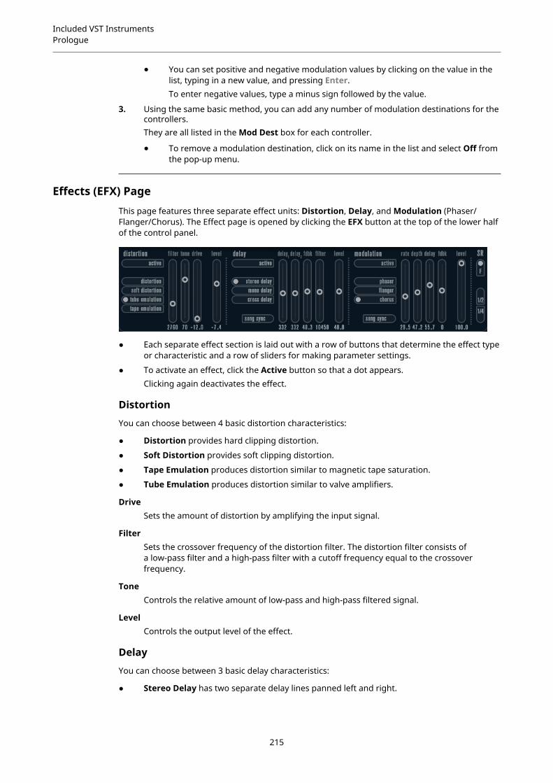
Included VST InstrumentsPrologue
● You can set positive and negative modulation values by clicking on the value in thelist, typing in a new value, and pressing Enter.To enter negative values, type a minus sign followed by the value.
3. Using the same basic method, you can add any number of modulation destinations for thecontrollers.They are all listed in the Mod Dest box for each controller.
● To remove a modulation destination, click on its name in the list and select Off fromthe pop-up menu.
Effects (EFX) PageThis page features three separate effect units: Distortion, Delay, and Modulation (Phaser/Flanger/Chorus). The Effect page is opened by clicking the EFX button at the top of the lower halfof the control panel.
● Each separate effect section is laid out with a row of buttons that determine the effect typeor characteristic and a row of sliders for making parameter settings.
● To activate an effect, click the Active button so that a dot appears.Clicking again deactivates the effect.
Distortion
You can choose between 4 basic distortion characteristics:
● Distortion provides hard clipping distortion.
● Soft Distortion provides soft clipping distortion.
● Tape Emulation produces distortion similar to magnetic tape saturation.
● Tube Emulation produces distortion similar to valve amplifiers.
DriveSets the amount of distortion by amplifying the input signal.
FilterSets the crossover frequency of the distortion filter. The distortion filter consists ofa low-pass filter and a high-pass filter with a cutoff frequency equal to the crossoverfrequency.
ToneControls the relative amount of low-pass and high-pass filtered signal.
LevelControls the output level of the effect.
Delay
You can choose between 3 basic delay characteristics:
● Stereo Delay has two separate delay lines panned left and right.
215
Included VST InstrumentsPrologue
● In Mono Delay, the two delay lines are connected in series for monophonic dual tap delayeffects.
● In Cross Delay, the delayed sound bounces between the stereo channels.
Song SyncActivates/Deactivates tempo sync of the delay times.
Delay 1Sets the delay time ranging from 0 ms to 728 ms. If MIDI sync is activated, the rangeis from 1/32 to 1/1; straight, triplet or dotted.
Delay 2Same as Delay 1.
FeedbackControls the decay of the delays. With higher settings, the echoes repeat longer.
FilterA low-pass filter is built into the feedback loop of the delay. This parameter controlsthe cutoff frequency of this feedback filter. Low settings result in successive echoessounding darker.
LevelControls the output level of the effect.
Modulation
You can choose between 3 basic modulation characteristics:
● Phaser uses an 8-pole all-pass filter to produce the classic phasing effect.
● Flanger is composed of two independent delay lines with feedback for the left and theright channel. The delay time of both delays is modulated by one LFO with adjustablefrequency.
● Chorus produces a rich chorus effect with 4 delays modulated by four independent LFOs.
Song SyncActivates/Deactivates tempo sync of the Rate parameter.
RateSets the rate of the LFOs modulating the delay time. If Song Sync is activated, therate is synchronized to various beat increments.
DepthControls the depth of the delay time modulation.
DelaySets the delay time of the four delay lines.
FeedbackControls the amount of positive or negative feedback for all four delay lines.
LevelControls the output level of the effect.
SR Parameters
With these buttons, you can change the sample rate. Lower sample rates basically reduce thehigh frequency content and sound quality, but the pitch is not altered. This is useful to emulatethe lo-fi sounds of older digital synths.
216

Included VST InstrumentsRetrologue
● If the F button is active, the program of the selected part plays back with the sample rateset in the host application.
● If the 1/2 button is active, the program of the selected part plays back with half the originalsample rate.
● If the 1/4 button is active, the program of the selected part plays back with a quarter of theoriginal sample rate.
A bonus effect of using lower sample rates is that it reduces the load on the computer CPU,allowing for more simultaneous voices to be played, etc.
Retrologue
Cubase LE Cubase AI CubaseElements
CubaseArtist
CubasePro
Nuendo
Included with – – – X X X
This VST instrument is described in detail in the separate PDF document Retrologue.
Spector
Cubase LE Cubase AI CubaseElements
CubaseArtist
CubasePro
Nuendo
Included with – – – X X X
217
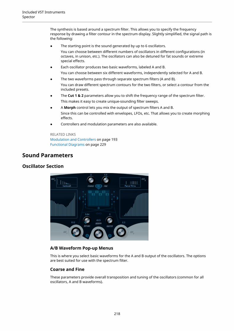
Included VST InstrumentsSpector
The synthesis is based around a spectrum filter. This allows you to specify the frequencyresponse by drawing a filter contour in the spectrum display. Slightly simplified, the signal path isthe following:
● The starting point is the sound generated by up to 6 oscillators.You can choose between different numbers of oscillators in different configurations (inoctaves, in unison, etc.). The oscillators can also be detuned for fat sounds or extremespecial effects.
● Each oscillator produces two basic waveforms, labeled A and B.You can choose between six different waveforms, independently selected for A and B.
● The two waveforms pass through separate spectrum filters (A and B).You can draw different spectrum contours for the two filters, or select a contour from theincluded presets.
● The Cut 1 & 2 parameters allow you to shift the frequency range of the spectrum filter.This makes it easy to create unique-sounding filter sweeps.
● A Morph control lets you mix the output of spectrum filters A and B.Since this can be controlled with envelopes, LFOs, etc. That allows you to create morphingeffects.
● Controllers and modulation parameters are also available.
RELATED LINKSModulation and Controllers on page 193Functional Diagrams on page 229
Sound Parameters
Oscillator Section
A/B Waveform Pop-up Menus
This is where you select basic waveforms for the A and B output of the oscillators. The optionsare best suited for use with the spectrum filter.
Coarse and Fine
These parameters provide overall transposition and tuning of the oscillators (common for alloscillators, A and B waveforms).
218

Included VST InstrumentsSpector
Oscillator Pop-up Menu
This pop-up menu is opened by clicking on the arrow below the central section (which illustratesthe selected oscillator configuration).
6 Osc6 oscillators with the same pitch.
6 Osc 1:23 oscillators with base pitch and 3 pitched one octave down.
6 Osc 1:2:3Three groups of two oscillators with the pitch ratio 1:2:3 (2 oscillators with base pitch,2 oscillators at half the frequency of the base pitch, and 2 oscillators at a third of thefrequency).
6 Osc 1:2:3:4:5:66 oscillators tuned with the pitch ratio 1:2:3:4:5:6 (known as the subharmonic series).
4 Osc 1:22 oscillators with base pitch and 2 pitched one octave down.
3 Osc3 oscillators with the same pitch.
2 Osc2 oscillators with the same pitch.
2 Osc 1:2One oscillator with base pitch and one pitched one octave down.
1 OscA single oscillator. In this mode, the Detune and Cut II parameters are not active.
Detune
Detunes the oscillators. Low values give gentle chorus-like detuning. Raising the control detunesthe oscillators by several semitones for special effects.
Raster
Reduces the number of harmonics present in the oscillator waveforms in the following manner:
● If 0 is selected, all harmonics are present.
● If 1 is selected, only every second harmonic is present.
● If 2 is selected, only every third harmonic is present.
219

Included VST InstrumentsSpector
And so on.
Portamento
This parameter makes the pitch glide between the notes you play. The parameter settingdetermines the time it takes for the pitch to glide from one note to the next. Turn the knobclockwise for longer glide time.
The Mode switch allows you to apply glide only if you play a legato note. Legato mode only workswith monophonic parts.
Spectrum Filter Sections
This is where you create the contours, that is, frequency response characteristics, for the two 128pole resonant spectrum filters A and B.
● You can use the Preset pop-up menu to select a preset contour.
● To change the contour, click and draw with the mouse.
● If you want to calculate a random spectrum filter curve, select Randomize from the Presetpop-up menu.Each time you choose this function, a new randomized spectrum is calculated.
Cut I and II
These parameters work like cutoff frequency controls on a conventional filter: With the Cutcontrols at the maximum setting, the full frequency range is used for the spectrum filter.Lowering the Cut controls gradually moves the entire contour down in frequency, closing thefilter.
NOTE
● If a 2 oscillator configuration is used, you can set different cutoffs for the two oscillators. Ifmore than two oscillators are used, they are internally divided into two groups, for whichyou can set independent cutoffs with Cut I and Cut II.
● If the Spectrum Sync button (link symbol) between the cut controls is activated, the twoknobs are linked and follow each other and are set to the same value.
Morph
Controls the mix between the sound of spectrum filters A and B. If the Morph knob is turnedfully left, only the A sound is heard. If it is turned right only the B sound is heard. This allows youto seamlessly morph between two totally different sounds.
220

Included VST InstrumentsSpector
Master Volume and Pan
The master Volume knob controls the master volume (amplitude) of the instrument. By default,this parameter is controlled by Envelope 1, to generate an amplitude envelope for the oscillators.
The Pan knob controls the position of the instrument in the stereo spectrum. You can use Pan asa modulation destination.
Modulation and ControllersThe lower half of the control panel displays the various modulation and controller assignmentpages available, as well as the EFX page. You switch between these pages using the buttonsabove this section.
The following pages are available:
● The LFO page has two low frequency oscillators (LFOs) for modulating parameters.
● The ENV page contains the four envelope generators that can be assigned to controlparameters.
● The Event page contains the common MIDI controllers (Mod wheel, Aftertouch, etc.) andtheir assignments.
● The EFX page offers three separate effect types: Distortion, Delay, and Modulation.
RELATED LINKSEnvelope Page on page 196Event Page on page 198Effects (EFX) Page on page 199
LFO PageThe LFO page is opened by clicking the LFO button at the top of the lower half of the controlpanel. The page contains all parameters and the modulation and velocity destinations for twoindependent LFOs.
Depending on the selected preset, there may already be modulation destinations assigned, inwhich case these are listed in the Mod Dest box for each LFO.
A low frequency oscillator (LFO) is used for modulating parameters, for example the pitch of anoscillator (to produce vibrato), or for any parameter where cyclic modulation is required.
The two LFOs have identical parameters.
221
Included VST InstrumentsSpector
SpeedGoverns the rate of the LFO. If the sync mode is set to MIDI, the available rate valuesare selectable as note values, so the rate is synchronized to the sequencer tempo.
DepthControls the amount of modulation applied by the LFO. If this is set to zero, nomodulation is applied.
WaveformSets the LFO waveform.
Sync mode (Part/MIDI/Voice/Key)Sets the sync mode for the LFO.
RELATED LINKSAssigning LFO Modulation Destinations on page 195
About the Sync Modes
The Sync modes determine how the LFO cycle affects the notes you play.
PartIn this mode, the LFO cycle is free running and affects all the voices in sync. Freerunning means that the LFO cycles continuously, and does not reset when a note isplayed.
MIDIIn this mode, the LFO rate is synced in various beat increments to MIDI clock.
VoiceIn this mode, each voice in the Part has its own independent LFO cycle (the LFO ispolyphonic). These cycles are also free running – each key down starts anywhere inthe LFO cycle phase.
KeySame as Voice except that it is not free running – for each key down the LFO cyclestarts over.
About the Waveforms
Most standard LFO waveforms are available for LFO modulation. You use sine and trianglewaveforms for smooth modulation cycles, square and ramp up/down for different typesof stepped modulation cycles and random or sample for random modulation. The samplewaveform is different:
● In this mode, the LFO makes use of the other LFO as well.For example, if LFO 2 is set to use Sample, the resulting effect also depends on the speedand waveform of LFO 1.
Assigning LFO Modulation Destinations
You can assign a modulation destination for an LFO.
PROCEDURE
1. Click in the Mod Dest box for one of the LFOs.A pop-up menu appears in which all possible modulation destinations are shown.All Sound parameters as well as most LFO and Envelope parameters are available asdestinations.
222
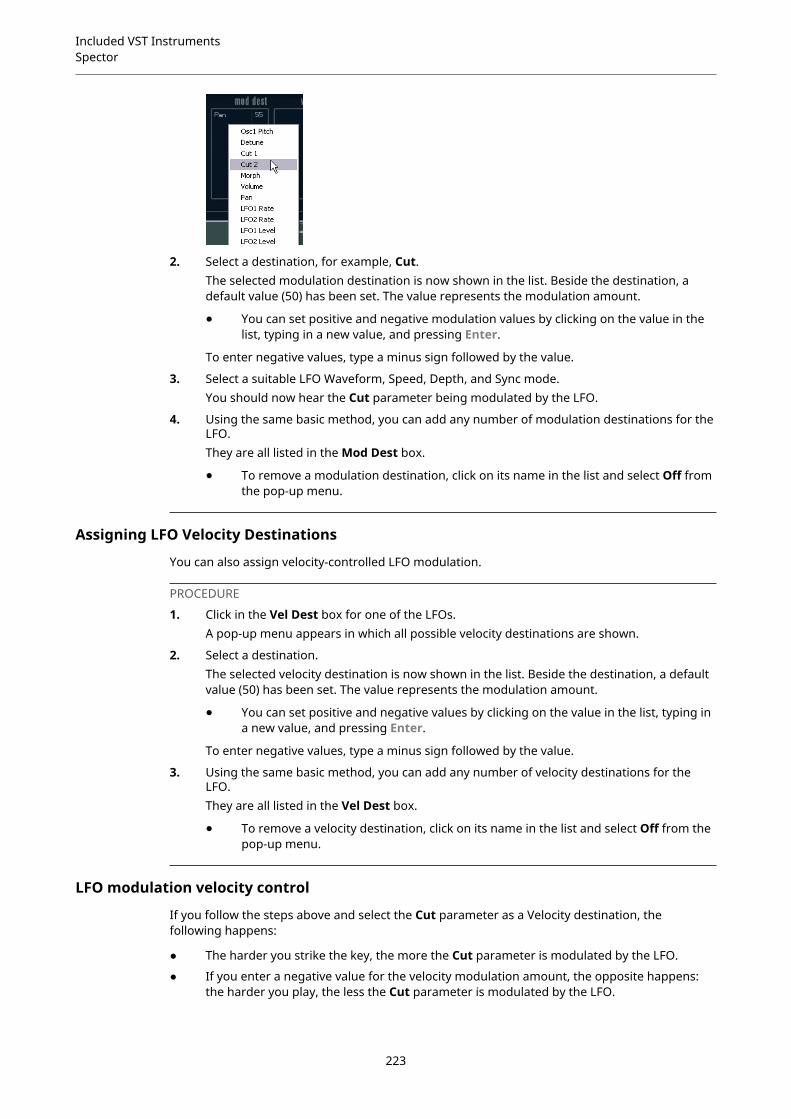
Included VST InstrumentsSpector
2. Select a destination, for example, Cut.The selected modulation destination is now shown in the list. Beside the destination, adefault value (50) has been set. The value represents the modulation amount.
● You can set positive and negative modulation values by clicking on the value in thelist, typing in a new value, and pressing Enter.
To enter negative values, type a minus sign followed by the value.
3. Select a suitable LFO Waveform, Speed, Depth, and Sync mode.You should now hear the Cut parameter being modulated by the LFO.
4. Using the same basic method, you can add any number of modulation destinations for theLFO.They are all listed in the Mod Dest box.
● To remove a modulation destination, click on its name in the list and select Off fromthe pop-up menu.
Assigning LFO Velocity Destinations
You can also assign velocity-controlled LFO modulation.
PROCEDURE
1. Click in the Vel Dest box for one of the LFOs.A pop-up menu appears in which all possible velocity destinations are shown.
2. Select a destination.The selected velocity destination is now shown in the list. Beside the destination, a defaultvalue (50) has been set. The value represents the modulation amount.
● You can set positive and negative values by clicking on the value in the list, typing ina new value, and pressing Enter.
To enter negative values, type a minus sign followed by the value.
3. Using the same basic method, you can add any number of velocity destinations for theLFO.They are all listed in the Vel Dest box.
● To remove a velocity destination, click on its name in the list and select Off from thepop-up menu.
LFO modulation velocity control
If you follow the steps above and select the Cut parameter as a Velocity destination, thefollowing happens:
● The harder you strike the key, the more the Cut parameter is modulated by the LFO.
● If you enter a negative value for the velocity modulation amount, the opposite happens:the harder you play, the less the Cut parameter is modulated by the LFO.
223
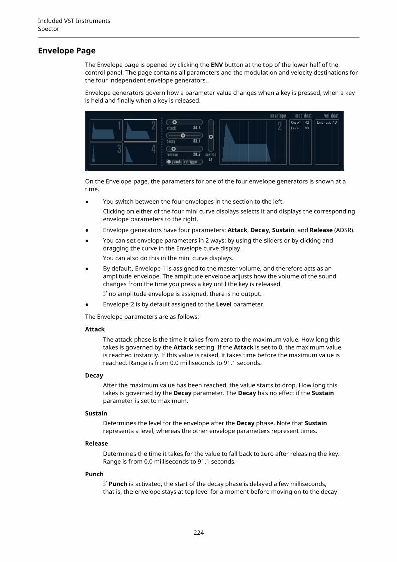
Included VST InstrumentsSpector
Envelope PageThe Envelope page is opened by clicking the ENV button at the top of the lower half of thecontrol panel. The page contains all parameters and the modulation and velocity destinations forthe four independent envelope generators.
Envelope generators govern how a parameter value changes when a key is pressed, when a keyis held and finally when a key is released.
On the Envelope page, the parameters for one of the four envelope generators is shown at atime.
● You switch between the four envelopes in the section to the left.Clicking on either of the four mini curve displays selects it and displays the correspondingenvelope parameters to the right.
● Envelope generators have four parameters: Attack, Decay, Sustain, and Release (ADSR).
● You can set envelope parameters in 2 ways: by using the sliders or by clicking anddragging the curve in the Envelope curve display.You can also do this in the mini curve displays.
● By default, Envelope 1 is assigned to the master volume, and therefore acts as anamplitude envelope. The amplitude envelope adjusts how the volume of the soundchanges from the time you press a key until the key is released.If no amplitude envelope is assigned, there is no output.
● Envelope 2 is by default assigned to the Level parameter.
The Envelope parameters are as follows:
AttackThe attack phase is the time it takes from zero to the maximum value. How long thistakes is governed by the Attack setting. If the Attack is set to 0, the maximum valueis reached instantly. If this value is raised, it takes time before the maximum value isreached. Range is from 0.0 milliseconds to 91.1 seconds.
DecayAfter the maximum value has been reached, the value starts to drop. How long thistakes is governed by the Decay parameter. The Decay has no effect if the Sustainparameter is set to maximum.
SustainDetermines the level for the envelope after the Decay phase. Note that Sustainrepresents a level, whereas the other envelope parameters represent times.
ReleaseDetermines the time it takes for the value to fall back to zero after releasing the key.Range is from 0.0 milliseconds to 91.1 seconds.
PunchIf Punch is activated, the start of the decay phase is delayed a few milliseconds,that is, the envelope stays at top level for a moment before moving on to the decay
224

Included VST InstrumentsSpector
phase. The result is a punchier attack similar to a compressor effect. This effect ismore pronounced with short attack and decay times.
RetriggerIf Retrigger is activated, the envelope retriggers each time you play a new note.However, with certain textures/pad sounds and a limited number of voices, it isrecommended to leave the button deactivated, due to click noises that might occur.
Assigning Envelope Modulation Destinations
You can assign a modulation destination for an envelope.
PROCEDURE
1. Click in the Mod Dest box for one of the envelopes.A pop-up menu appears in which all possible modulation destinations are shown.All Sound parameters as well as most LFO and Envelope parameters are available asdestinations.
2. Select a destination, for example, Cut.The selected modulation destination is now shown in the list. Beside the destination, adefault value (50) has been set. The value represents the modulation amount.
● You can set positive and negative modulation values by clicking on the value in thelist, typing in a new value, and pressing Enter.To enter negative values, type a minus sign followed by the value.
3. Select a suitable envelope curve for the modulation.You should now hear the Cut parameter being modulated by the envelope as you play.
4. Using the same basic method, you can add any number of modulation destinations for theenvelope.They are all listed in the Mod Dest box.
● To remove a modulation destination, click on its name in the list and select Off fromthe pop-up menu.
Assigning Envelope Velocity Destinations
You can also assign velocity-controlled envelope modulation, that is, the modulation is governedby how hard or soft you strike a key.
PROCEDURE
1. Click in the Vel Dest box for one of the envelopes.A pop-up menu appears in which all possible velocity destinations are shown.
2. Select a destination.The selected velocity destination is now shown in the list. Beside the destination, a defaultvalue (50) has been set. The value represents the modulation amount. See below for anexample of how velocity modulation works.
● You can set positive and negative values by clicking on the value in the list, typing ina new value, and pressing Enter.To enter negative values, type a minus sign followed by the value.
3. Using the same basic method, you can add any number of velocity destinations for theEnvelope.They are all listed in the Vel Dest box.
● To remove a velocity destination, click on its name in the list and select Off from thepop-up menu.
225

Included VST InstrumentsSpector
Envelope modulation velocity control
If you follow the steps above and select the Cut parameter as a Velocity destination, thefollowing happens:
● The harder you strike the key, the more the parameter is modulated by the envelope.
● If you enter a negative value for the velocity modulation amount, the opposite happens;the harder you play the less the Cut parameter is modulated by the Envelope.
Event PageThe Event page is opened by clicking the EVENT button at the top of the lower half of the controlpanel. This page contains the most common MIDI controllers and their assignments.
Modulation WheelThe modulation wheel on your keyboard can be used to modulate parameters.
VelocityControls parameters according to how hard or soft you play notes on your keyboard.A common application of velocity is to make sounds brighter and louder if you strikethe key harder.
AftertouchAftertouch, or channel pressure, is MIDI data sent when pressure is applied to akeyboard after the key has been struck, and while it is being held down or sustained.Aftertouch is often routed to control filter cutoff, volume, and other parameters toadd expression.
Key Pitch TrackingThis can change parameter values linearly according to where on the keyboard youplay.
Assign a Controller to a Parameter
PROCEDURE
1. Click in the Mod Dest box for one of the controllers.A pop-up menu appears in which all possible modulation destinations are shown.All Sound parameters as well as most LFO and Envelope parameters are available asdestinations.
2. Select a destination.The selected modulation destination is now shown in the list. Beside the destination, adefault value (50) has been set. The value represents the modulation amount when thecontroller is at its full range.
● You can set positive and negative modulation values by clicking on the value in thelist, typing in a new value, and pressing Enter.To enter negative values, type a minus sign followed by the value.
3. Using the same basic method, you can add any number of modulation destinations for thecontrollers.
226
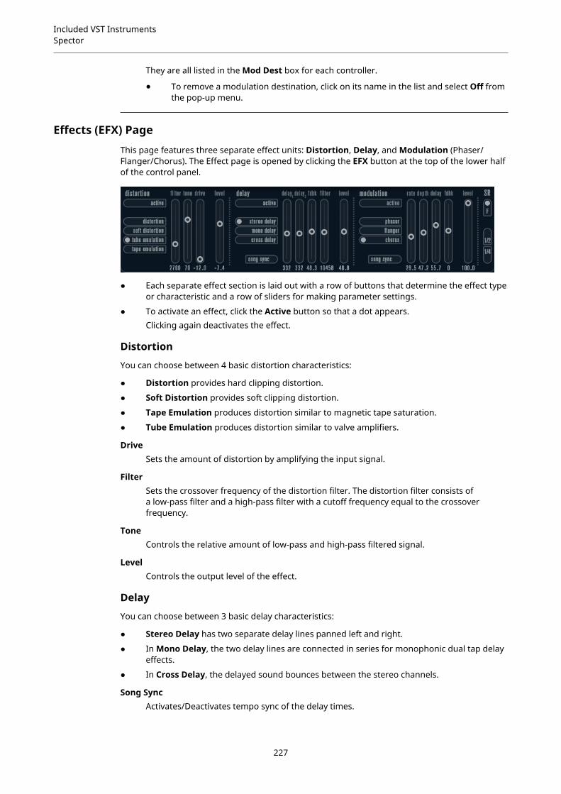
Included VST InstrumentsSpector
They are all listed in the Mod Dest box for each controller.
● To remove a modulation destination, click on its name in the list and select Off fromthe pop-up menu.
Effects (EFX) PageThis page features three separate effect units: Distortion, Delay, and Modulation (Phaser/Flanger/Chorus). The Effect page is opened by clicking the EFX button at the top of the lower halfof the control panel.
● Each separate effect section is laid out with a row of buttons that determine the effect typeor characteristic and a row of sliders for making parameter settings.
● To activate an effect, click the Active button so that a dot appears.Clicking again deactivates the effect.
Distortion
You can choose between 4 basic distortion characteristics:
● Distortion provides hard clipping distortion.
● Soft Distortion provides soft clipping distortion.
● Tape Emulation produces distortion similar to magnetic tape saturation.
● Tube Emulation produces distortion similar to valve amplifiers.
DriveSets the amount of distortion by amplifying the input signal.
FilterSets the crossover frequency of the distortion filter. The distortion filter consists ofa low-pass filter and a high-pass filter with a cutoff frequency equal to the crossoverfrequency.
ToneControls the relative amount of low-pass and high-pass filtered signal.
LevelControls the output level of the effect.
Delay
You can choose between 3 basic delay characteristics:
● Stereo Delay has two separate delay lines panned left and right.
● In Mono Delay, the two delay lines are connected in series for monophonic dual tap delayeffects.
● In Cross Delay, the delayed sound bounces between the stereo channels.
Song SyncActivates/Deactivates tempo sync of the delay times.
227
Included VST InstrumentsSpector
Delay 1Sets the delay time ranging from 0 ms to 728 ms. If MIDI sync is activated, the rangeis from 1/32 to 1/1; straight, triplet or dotted.
Delay 2Same as Delay 1.
FeedbackControls the decay of the delays. With higher settings, the echoes repeat longer.
FilterA low-pass filter is built into the feedback loop of the delay. This parameter controlsthe cutoff frequency of this feedback filter. Low settings result in successive echoessounding darker.
LevelControls the output level of the effect.
Modulation
You can choose between 3 basic modulation characteristics:
● Phaser uses an 8-pole all-pass filter to produce the classic phasing effect.
● Flanger is composed of two independent delay lines with feedback for the left and theright channel. The delay time of both delays is modulated by one LFO with adjustablefrequency.
● Chorus produces a rich chorus effect with 4 delays modulated by four independent LFOs.
Song SyncActivates/Deactivates tempo sync of the Rate parameter.
RateSets the rate of the LFOs modulating the delay time. If Song Sync is activated, therate is synchronized to various beat increments.
DepthControls the depth of the delay time modulation.
DelaySets the delay time of the four delay lines.
FeedbackControls the amount of positive or negative feedback for all four delay lines.
LevelControls the output level of the effect.
SR Parameters
With these buttons, you can change the sample rate. Lower sample rates basically reduce thehigh frequency content and sound quality, but the pitch is not altered. This is useful to emulatethe lo-fi sounds of older digital synths.
● If the F button is active, the program of the selected part plays back with the sample rateset in the host application.
● If the 1/2 button is active, the program of the selected part plays back with half the originalsample rate.
● If the 1/4 button is active, the program of the selected part plays back with a quarter of theoriginal sample rate.
228

Included VST InstrumentsFunctional Diagrams
A bonus effect of using lower sample rates is that it reduces the load on the computer CPU,allowing for more simultaneous voices to be played, etc.
Functional DiagramsPrologue Diagram
Mystic Diagram
229
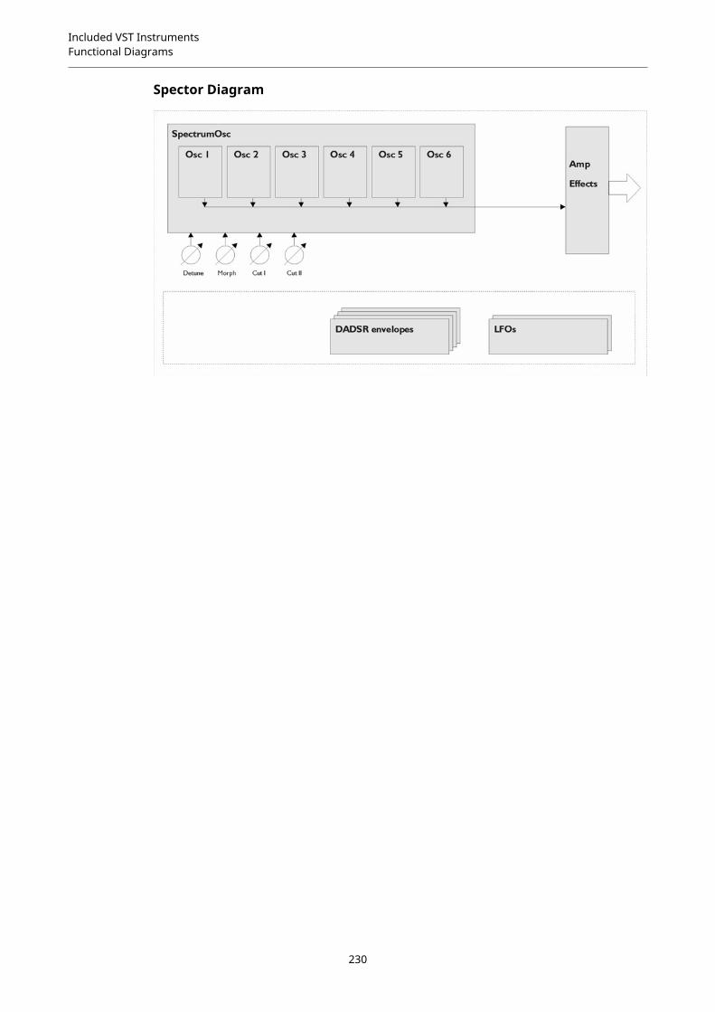
Included VST InstrumentsFunctional Diagrams
Spector Diagram
230
Index
AAmp Simulation
AmpSimulator 9Quadrafuzz v2 14VST Amp Rack 19VST Bass Rack 25
AmpSimulator 9Anymix Pro 113Arpache 5 144Arpache SX 146Auto LFO 148AutoPan 73
BBass Manager 125Beat Designer 149BitCrusher 10Brickwall Limiter 32
CChopper Effects
AutoPan 73Chopper 75
Chorder 156Chorus Effects
Chorus 76StudioChorus 85
Cloner 77Compressors
Compressor 33Compressor (MIDI) 160DeEsser 35Maximizer 43MultibandCompressor 45Tube Compressor 52Vintage Compressor 53VSTDynamics 54
Context Gate 160CurveEQ 57
DDaTube 11DeEsser 35Delays
Cloner 77ModMachine 4
MonoDelay 6PingPongDelay 7Quadrafuzz v2 14StereoDelay 8
Density 162Distortion 12Dithering
UV22HR 73DJ-EQ 58DualFilter 65
EEnvelope Shapers
EnvelopeShaper 38MultibandEnvelopeShaper 48
ExpandersExpander 39MultibandExpander 49
FFlanger 78Frequency 62
GGates
Gate 40Quadrafuzz v2 14VSTDynamics 54
GEQ-10 59GEQ-30 59Groove Agent SE 176Grungelizer 12
HHALion Sonic SE 176
LLimiters
Brickwall Limiter 32Limiter 42Maximizer 43VSTDynamics 54
LoopMash 176LoopMash FX 89
231

Index
MMagneto II 13MatrixDecoder 130MatrixEncoder 127Maximizer 43Metalizer 79Micro Tuner 166MIDI Control 162MIDI Echo 163MIDI Gate 44MIDI Modifiers 165MIDI Monitor 165Mix6to2 130Mix8to2 131MixConvert V6 132MixerDelay 135ModMachine 4MonoDelay 6MonoToStereo 124MorphFilter 66MultibandCompressor 45MultibandEnvelopeShaper 48MultibandExpander 49MultiScope 136Mystic 189
Functional Diagram 229
NNote to CC 167
OOctaver 94
PPadshop 201Phaser 80PingPongDelay 7Pitch Correct 94PitchDriver 97PostFilter 67Prologue 201
Functional Diagram 229
QQuadrafuzz v2 14Quantizer 167
RRandomizer 92Retrologue 217REVelation 97REVerence 100RingModulator 82RoomWorks 109RoomWorks SE 112Rotary 83
SSaturation
DaTube 11Magneto II 13Quadrafuzz v2 14
SMPTEGenerator 139SoftClipper 18Spector 217
Functional Diagram 229StepDesigner 168StepFilter 69StereoDelay 8StereoEnhancer 124StudioChorus 85StudioEQ 60
TTestGenerator 140ToneBooster 71Track Control 172Tranceformer 86Transformer 175Tremolo 87Tube Compressor 52Tuner 141
UUV22HR 73
VVibrato 88Vintage Compressor 53VST Amp Rack 19VST Bass Amp 25VST Connect CUE Mix 89VST Connect SE 89VST MultiPanner 125VSTDynamics 54
WWahWah 71
232
Copyright © 2022 FDOKUMEN