
Thermal hydraulic analysis of the IPR-R1 TRIGA research reactor using a RELAP5 model
Upload
khangminh22Category
view
0download
0
RELAP5 Plug-in Users Manual
Symbolic Nuclear Analysis Package (SNAP)
Version 6.5.1 - August 02, 2021
Applied Programming Technology, Inc.
240 Market St., Suite 301Bloomsburg PA 17815-1951
RELAP5 Plug-in Users ManualApplied Programming Technology, Inc.by Ken Jones, Bill Dunsford, John Rothe, Don Ulshafer, and Dustin VogtCopyright © 2007-2020
***** Disclaimer of Liability Notice ******
The Nuclear Regulatory Commission and Applied Programming Technology, Inc. provide no express warranties and/or guarantees and furtherdisclaims all other warranties of any kind whether statutory, written, oral, or implied as to the quality, character, or description of products andservices, its merchantability, or its fitness for any use or purpose. Further, no warranties are given that products and services shall be error freeor that they shall operate on specific hardware configurations. In no event shall the US Nuclear Regulatory Commission or Applied ProgrammingTechnology, Inc. be liable, whether foreseeable or unforeseeable, for direct, incidental, indirect, special, or consequential damages, including butnot limited to loss of use, loss of profit, loss of data, data being rendered inaccurate, liabilities or penalties incurred by any party, or losses sustainedby third parties even if the Nuclear Regulatory Commission or Applied Programming Technology, Inc. have been advised of the possibilities ofsuch damages or losses.

iii RELAP5 Plug-in User's Manual
Table of Contents1. Introduction ......................................................................................................... 12. Creating a RELAP5 Model .................................................................................. 3
2.1. Importing an Existing ASCII File ............................................................... 32.2. Creating a New RELAP5 Model ................................................................ 62.3. Opening an Existing RELAP5 Model ......................................................... 72.4. RELAP5 Model Editing ............................................................................ 7
3. Editing A Model .................................................................................................. 113.1. Model Properties ....................................................................................... 113.2. Hydraulic Components .............................................................................. 13
3.2.1. Single Volume ............................................................................... 133.2.2. Time Dependent Volume ................................................................ 143.2.3. Single Junction ............................................................................... 153.2.4. Time Dependent Junction ................................................................ 153.2.5. Single Flexible Wall ....................................................................... 163.2.6. Pipe ............................................................................................... 173.2.7. Annulus ......................................................................................... 273.2.8. Pressurizer ..................................................................................... 273.2.9. CANDU Channel ........................................................................... 283.2.10. Branch ......................................................................................... 293.2.11. Separator ...................................................................................... 303.2.12. Jet Mixer ...................................................................................... 313.2.13. Turbine ........................................................................................ 323.2.14. ECC Mixer ................................................................................... 333.2.15. Valve ........................................................................................... 343.2.16. Pump ........................................................................................... 343.2.17. Compressor .................................................................................. 343.2.18. Multiple Junction .......................................................................... 353.2.19. Multiple Flexible Wall .................................................................. 383.2.20. Accumulator ................................................................................. 393.2.21. Multi-Dimensional Component ...................................................... 393.2.22. Feedwater Heater .......................................................................... 46
3.3. Control Systems ........................................................................................ 463.3.1. Signal Variables ............................................................................. 463.3.2. Control Blocks ............................................................................... 503.3.3. Trips .............................................................................................. 503.3.4. General Tables ............................................................................... 513.3.5. Interactive Variables ....................................................................... 53
3.4. Heat Structures ......................................................................................... 533.5. Radiation Enclosure .................................................................................. 583.6. Materials ................................................................................................... 593.7. Reactor Kinetics ........................................................................................ 60
4. Editing a Restart Case .......................................................................................... 695. ASCII I/O ........................................................................................................... 71
5.1. Input Decks .............................................................................................. 715.2. Restart Decks ............................................................................................ 71
6. Model Validation Tests ........................................................................................ 737. 3D Visualization .................................................................................................. 75
7.1. 3D Coordinate Generation ......................................................................... 75

RELAP5 Plug-in Users Manual
RELAP5 Plug-in User's Manual iv
7.2. 3D Model Viewer ..................................................................................... 757.2.1. Camera Controls ............................................................................. 767.2.2. Transforming Components .............................................................. 767.2.3. 3D View Preferences ...................................................................... 78
8. Renodalization ..................................................................................................... 818.1. 1D Hydraulic ............................................................................................ 81
8.1.1. Split ............................................................................................... 828.1.2. Split Uniform ................................................................................. 838.1.3. Merge ............................................................................................ 838.1.4. Elevation Change ........................................................................... 838.1.5. Announce Changes ......................................................................... 838.1.6. Renodalization Results .................................................................... 84
8.2. Heat Structure ........................................................................................... 848.2.1. Radial Renodalization ..................................................................... 848.2.2. Axial Renodalization ...................................................................... 85
8.3. Pipe Split .................................................................................................. 869. Attribute Level Ownership ................................................................................... 8910. Batch Commands ............................................................................................... 9111. Importing Initial Conditions ................................................................................ 95
11.1. Managing Initial Conditions ..................................................................... 9612. Model Notebooks ............................................................................................... 9913. Resource File Import/Export ............................................................................... 103

1 RELAP5 Plug-in User's Manual
Chapter 1. IntroductionThe Symbolic Nuclear Analysis Package (SNAP) consists of a suite of integrated applicationsdesigned to simplify the process of performing thermal-hydraulic analysis. SNAP provides ahighly flexible framework for creating and editing input for engineering analysis codes as wellas extensive functionality for submitting, monitoring and interacting with the analysis codes.The modular plug-in design of the software allows functionality to be tailored to the specificrequirements of each analysis code.
RELAP5 is a generic transient analysis code for thermal-hydraulic systems using a fluid that maybe a mixture of steam, water, noncondensables, and a nonvolatile solute.
This document describes how to use SNAP to work with RELAP5 models. This manual assumesa level of familiarity with RELAP5 and the SNAP Software. Please refer to the RELAP5 User'sManual and the SNAP User's Manual for specific information on RELAP5 input requirementsand SNAP general usage.
Two versions of this plug-in are available. The first version supports RELAP5 Mod 3.3 and isavailable to CAMP members via the CAMP-SUG user agreement. The second version supportsRELAP5 Mod 3.3 as well as RELAP5-3D. This version is available to SNAP users group (SUG)members. Additional information on obtaining these plug-ins can be found on the SNAP websitehttps://www.snaphome.com.

2

3 RELAP5 Plug-in User's Manual
Chapter 2. Creating a RELAP5 ModelA RELAP5 model can be created in the ModelEditor by either importing an existing ASCIImodel, opening an existing model or by creating a new empty model.
2.1. Importing an Existing ASCII FileThe SNAP ModelEditor supports importing RELAP5 compliant ASCII input files. ASCII filesmay be imported into the SNAP Model Editor from the Import sub menu in the File menu shownin Figure 2.1, “File Import Sub-Menu”.
Figure 2.1. File Import Sub-Menu
The RELAP5 MOD3.3 plug-in automatically uses RELAP5/MOD3.3 as the code version beingimported.
The RELAP5 MOD3.3/RELAP5-3D plug-in import process allows the user to select the versionof RELAP5 for which the ASCII file was created. Choosing a specific code version requiresthat the input file adhere to that codes input specification. Specifying a code version determineswhich properties are available when editing a model and how those properties are exported.Model validation checks will report discrepancies in data that does not comply with the specifiedversion.
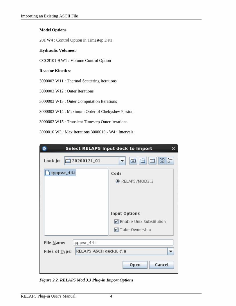
Both plug-ins support the import of Unix Substitution Variables that begin with a '$' character.Substitution variables are represented as user defined constants within the ModelEditor and areassigned a value of 0 upon creation. ( See Figure 2.3, “RELAP5 Mod 3.3/RELAP5-3D Plug-inFile Import Options” ) In addition to real values, substitution variables may be specified for thefollowing integer input:
Importing an Existing ASCII File
RELAP5 Plug-in User's Manual 4
Model Options:
201 W4 : Control Option in Timestep Data
Hydraulic Volumes:
CCC9101-9 W1 : Volume Control Option
Reactor Kinetics:
3000003 W11 : Thermal Scattering Iterations
3000003 W12 : Outer Iterations
3000003 W13 : Outer Computation Iterations
3000003 W14 : Maximum Order of Chebyshev Fission
3000003 W15 : Transient Timestep Outer iterations
3000010 W3 : Max Iterations 3000010 - W4 : Intervals
Figure 2.2. RELAP5 Mod 3.3 Plug-in Import Options

Importing an Existing ASCII File
5 RELAP5 Plug-in User's Manual
Figure 2.3. RELAP5 Mod 3.3/RELAP5-3D Plug-in File Import Options
Notice in the Figure 2.3, “RELAP5 Mod 3.3/RELAP5-3D Plug-in File Import Options” above,the RELAP5 code version, and version number must be selected during ASCII import (Only forthe RELAP5 MOD3.3/RELAP5-3D plug-in). If the model contains meta data which indicatesthe code version, this will be compared to the selection from the input dialog. If the two versionsdo not agree a confirmation dialog will be displayed, shown in Figure 2.4, “Version Mismatch”.This dialog allows the user to select what code version should be used to import the file.
Figure 2.4. Version Mismatch
Comment lines are ignored by the plug-in during the import process with one exception: Decksexported by SNAP include Description and Comment lines for components. These lines arewritten to the deck using *d: and *c: as prefixes respectively. Meta data is included at the topof the model and contains information such as the current SNAP version and the model's RELAPcode version, as shown below:

Creating a New RELAP5 Model
RELAP5 Plug-in User's Manual 6
*d: The is a description tag for the bypass which is written and read by the RELAP5 plug-in.*c: This is a comment tag for the bypass which is written and read by the RELAP5 plug-in.*m: CODE:RELAP5 3D Version 2.4* name type3200000 "dcbypass" pipe* ncells3200001 6
SNAP uses these prefixes to allow embedded comments and descriptions to be retained whenimporting a deck that was exported by the Model Editor. This mechanism can also be used toidentify comments in legacy decks that should be retained on import.
Additional Import Notes:
• The SNAP RELAP5 plug-in will replace duplicate cards with the most recent(i.e. last) cardin the input file.
• Any undefined cards encountered during the import process will be added to the Extra DeckData property in Model Options.
• Input after the first RELAP case is added to the After Case Data. After Case Data data is notprocessed by the plug-in.
• Any non ASCII format characters will be ignored on import.
2.2. Creating a New RELAP5 ModelA RELAP5 model can be created by selecting RELAP from the list of available plug-ins in theNew Model Dialog. The New Model Dialog is provided when selecting the File>New menuoption. This will create a new RELAP5 model with a single open view. New components canthen be inserted, or pasted into the model. The code type and version can be selected inside theModel Options.
Figure 2.5. New Model Dialog
Opening an Existing RELAP5Model
7 RELAP5 Plug-in User's Manual
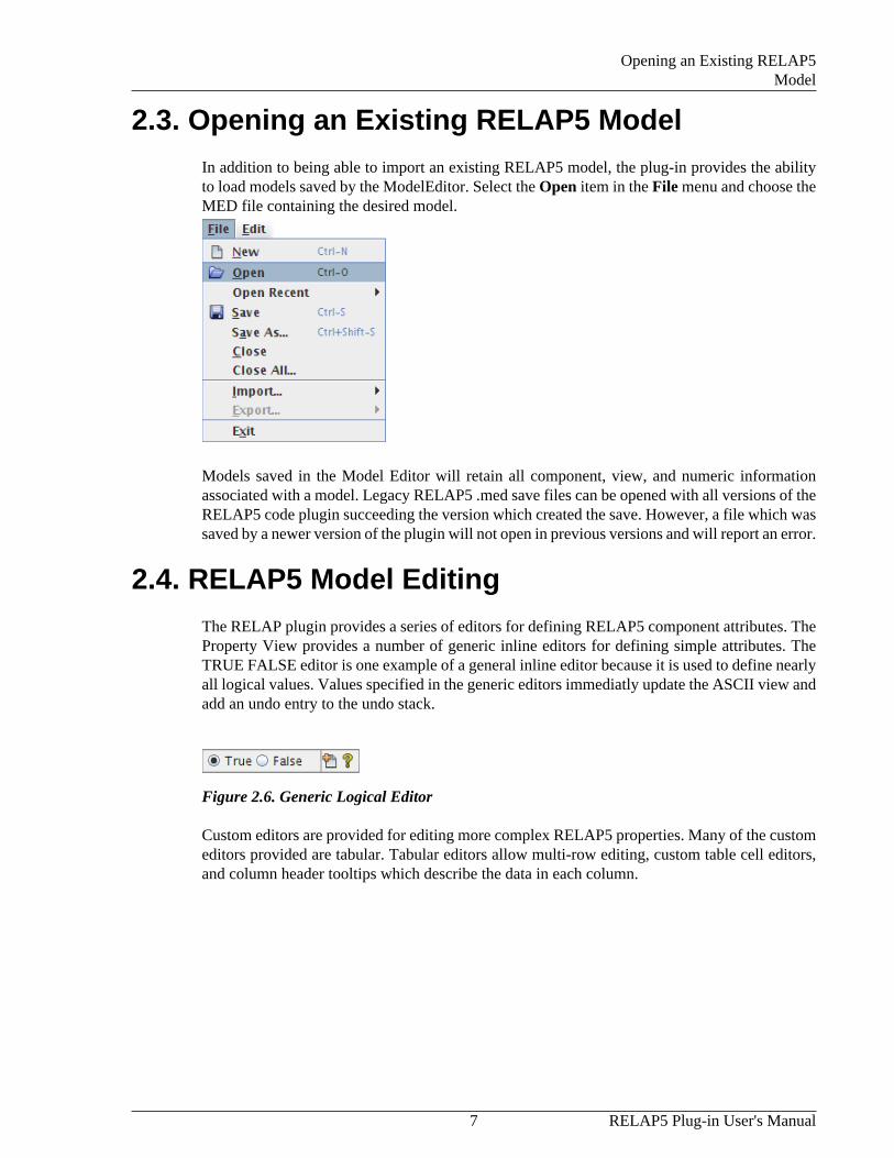
2.3. Opening an Existing RELAP5 ModelIn addition to being able to import an existing RELAP5 model, the plug-in provides the abilityto load models saved by the ModelEditor. Select the Open item in the File menu and choose theMED file containing the desired model.
Models saved in the Model Editor will retain all component, view, and numeric informationassociated with a model. Legacy RELAP5 .med save files can be opened with all versions of theRELAP5 code plugin succeeding the version which created the save. However, a file which wassaved by a newer version of the plugin will not open in previous versions and will report an error.
2.4. RELAP5 Model EditingThe RELAP plugin provides a series of editors for defining RELAP5 component attributes. TheProperty View provides a number of generic inline editors for defining simple attributes. TheTRUE FALSE editor is one example of a general inline editor because it is used to define nearlyall logical values. Values specified in the generic editors immediatly update the ASCII view andadd an undo entry to the undo stack.
Figure 2.6. Generic Logical Editor
Custom editors are provided for editing more complex RELAP5 properties. Many of the customeditors provided are tabular. Tabular editors allow multi-row editing, custom table cell editors,and column header tooltips which describe the data in each column.

RELAP5 Model Editing
RELAP5 Plug-in User's Manual 8
Figure 2.7. Custom Tabular Editor
Tabular based RELAP5 editors provide a pop-up menu containing a series of options whichfacilitate editing of attributes. These options are listed below:
• Copy - The copy command copies data from either a spreadsheet or another tabular basededitor.
• Paste - The paste command pastes copied data to either a spreadsheet or another tabular editor.
• Plot - The plot command provides a listing of available plot variables from the current tabulardata. One independent and one or more dependent variables can be selected for plotting. Datais plotted using the APTPlot pug-in.

RELAP5 Model Editing
9 RELAP5 Plug-in User's Manual
Figure 2.8. Plotting Editor Data
Some tabular editors require that edits be confirmed before any updates are made. These editorsdo not update the ASCII view or add an undo event until the OK button is pressed.
The following section contains a listing of many of the editors included in the RELAP5 plug-in.

10

11 RELAP5 Plug-in User's Manual
Chapter 3. Editing A ModelOnce a model is open in the ModelEditor ( via importing ASCII, opening an existing MED fileor creating a new model ) it can be modified in a variety of ways. New components can be addedto the model through the Navigator or by using the insert tool in a 2D view. Existing componentscan be modified, disconnected, and reconnected through the Property View or the 2D view.
3.1. Model PropertiesThe RELAP5 plug-in provides a Model Options node for all of the RELAP5 attributes whichcontrol key model characteristics. The following list describes a few of these properties and givesa description of their associated options.
• Code - The type of RELAP5 analysis code input being modeled. The RELAP5 Mod 3.3/RELAP5-3D plug-in supports various RELAP5-3D versions and changing the code type willcause the model to update to accommodate properties specific to the selected code type.
• Developmental Options - This has been added to the code for the convenience of developersin testing model improvements or new models. In the SNAP RELAP5 plug-in, enabling ordisabling certain developmental options will alter properties found elsewhere in the model.( i.e. In a Branch, if the Henry-Fauske critical flow model is active, junction dischargecoefficients are entered as opposed to the default subcooled discharge coefficients )
• Input Units - Provides the option of defining model units in either SI or British. Modifyingthis option changes the units for all reals in a given RELAP5 model
• HD Systems - The list of hydraulic systems in the current model. If a hydraulic system iscreated, the analyst should be aware that any specified fluid types must have an associatedproperty file accessible to the RELAP executable in order to be run. ( Current versions ofthe RELAP5 executable require that command line options are provided which identify thelocation of all required fluid property files. )

Model Properties
RELAP5 Plug-in User's Manual 12
• Timestep Data - This is the data used to control the problem timestep information. TheTimestep editor for the information is shown in Figure 3.1, “RELAP Plug-in Timestep Editor”.The editor allows an analyst to add and remove timesteps and specify the specific timestepoptions using a tabular interface. The composite Control Option value uses a pop-up editorallows the specific control option flags to be selected from a list of check-boxes. This pop-upeditor also allows the specification of a user-defined numeric to define the Control Option.
Figure 3.1. RELAP Plug-in Timestep Editor

Hydraulic Components
13 RELAP5 Plug-in User's Manual
• Noncondensible Gas Species - The noncondensible mass fractions of the gaseous mixturefound in a RELAP5 model are defined in this section. The total gas mass fractions shouldsum to 1.0. If no noncondesibles are specified, it is assumed that Nitrogen is the availablegas. Specifying noncondensible gases will enable noncondensible mass fraction input forindividual hydraulic components and the RELAP5 plug-in will update to provide editors forthis data.
SNAP has a fixed export order for the noncondensible gas species. On ASCII import of a fullplant model, the order from the file will be used for importing the fractions into the modeleditor correctly. Once imported however the order will be changed to the fixed export order.This can cause problems for models that include restart cases where resupplied hydrauliccomponents include noncondensible gas data. The order of these noncondensibles in the restartcase must be modified to match the SNAP default order.
3.2. Hydraulic ComponentsRELAP5 components used to model fluid dynamics are grouped together as hydrauliccomponents. These include pipes, pumps, single junctions, etc. Hydraulic components are foundby expanding the Hydraulic Components node in the Navigator. The RELAP5 plug-in providessome standard functionality for hydraulic components including:
• ASCII Views - It is possible to display the ASCII representation of hydraulic componentsbeing edited by the ModelEditor. The right click Navigator pop-up menu on a specificHydraulic component contains the menu item, Show Ascii. Selecting this option provides theanalyst with the ASCII representation of the selected components. In addition, the RELAP5plug-in will automatically update this ASCII view whenever values are changed.
• 2D Drawn Representation - The RELAP5 plug-in provides the ability to display hydrauliccomponents in a 2D view. The right-click pop-up menu for each hydraulic component orcategory in the Navigator contains the Add to View item that can be used to add the component(or components) to the selected 2D View.
• Component Documentation - Each hydraulic component has a pop-up menu item labeledReference Docs. This option will locate the segment of the RELAP input manual whichcorresponds to the component selected and display it using the default PDF viewer.
• Copy/Paste Functionality - The RELAP5 plug-in also provides the ability to copy and pastehydraulic components by using the Copy, Cut, and Paste items in the Navigator's right-clickpop-up menu. Hydraulic components can be copied between RELAP5 models open in thesame ModelEditor instance.
The RELAP5 plug-in allows a Description and set of Comments to be specified for each hydrauliccomponent that are exported as special tagged comments. An example of the formatting of theseproperties is shown in ???.
3.2.1. Single Volume
A single-volume component is one hydraulic volume. A Single Volume can also be described asa pipe component containing only one volume. As such, the single volume uses the same editingdialogs as the pipe component. Refer to Section 3.2.6, “Pipe” for more detailed information.

Time Dependent Volume
RELAP5 Plug-in User's Manual 14
Figure 3.2. Single Volume Properties
3.2.2. Time Dependent Volume
A Time-Dependent Volume is to simulate fluid entering or leaving a hydraulic system. The TDVgeometry data is nearly identical to that of a pipe and thus uses the pipe geometry editor describedin the section called “Pipe Geometry”. The TDV initial conditions data differs from the otherhydraulic components since it allows any number of desired search variable sets. ( All otherhydraulic components describe initial conditions on a per volume basis. )
Figure 3.3. TDV Cell Initial Conditions
The Time Dependent Volume initial conditions table is edited using the TDV Initial Conditionsdialog shown in Figure 3.3, “TDV Cell Initial Conditions”. The T Flag Input combo box is usedto determine which properties will be specified in the table at the top of the dialog. The B Flagcheck box will provide a column to edit initial fluid Boron Concentrations for each of the tableentries. In order to enable the N Flag property, the T Flag must be set to an appropriate valueand at least 1 Model Options noncondensible property must be enabled. Rows can be added andremoved using the buttons provided at the bottom right of the editor.

Single Junction
15 RELAP5 Plug-in User's Manual
Figure 3.4. Time Dependent Volume Properties
3.2.3. Single Junction
A Single Junction component is simply one system junction. It is used to connect othercomponents such as two pipes. The Single Junction uses the same editing dialogs as the pipecomponent for editing geometry, initial conditions and friction data. Refer to Section 3.2.6,“Pipe” for more detailed information on these dialogs.
Figure 3.5. Single Junction Properties
3.2.4. Time Dependent Junction
Time-dependent junctions can be used whenever the phasic velocities or phasic mass flow ratesare known as a function of time or other time-advanced quantity. Time-dependent junctions canconnect any two system volumes, or a system volume and a time-dependent volume. The ControlWord property controls the flow rate specification. The search variable will be associated witheither Mass Flows or Velocities depending on the value of the Control Word. By default theControl Word is set to Flow Velocities.

Single Flexible Wall
RELAP5 Plug-in User's Manual 16
Figure 3.6. Time Dependent Junction Properties
Note The TDJ hydraulic component provides a table editor for defining search variable / flowrate data. Using the Add / Remove buttons will update the table respectively. Pressingthe OK button will save any changes made and close the editor. This editor is shownin Figure 3.7, “TDJ Flow Rate Editor”.
Figure 3.7. TDJ Flow Rate Editor
3.2.5. Single Flexible Wall
The single flexible wall component is like a single-junction component, except there is no flowthrough the junction; only wall movement occurs at the junction location. In addition to the

Pipe
17 RELAP5 Plug-in User's Manual
single-junction properties, the single flexible wall also supports the flexible wall area and a tabledescribing the volume displacement and stiffness of the wall.
Figure 3.8. Single Flexible Wall Properties
3.2.6. Pipe
A pipe component is a series of volumes and interior junctions. Figure 3.9, “Pipe CompletionDialog” displays the completion dialog for a new pipe created inside the ModelEditor. If thecompletion dialogs are not enabled, the RELAP5 plug-in will remember the last values entered.For a newly created pipe, the cell volumes will be evenly divided along the specified length.
Figure 3.9. Pipe Completion Dialog
Note The number of cells and junctions inside a pipe cannot be edited directly after creation.The 1D renodalization tool can be used to easily modify the nodalization of a pipe, andautomatically update any connected components. Refer Chapter 8, Renodalization formore information on 1D renodalization.

Pipe
RELAP5 Plug-in User's Manual 18
Pipe Properties
The majority of pipe properties are cell and junction properties. These properties can beedited using the custom editors provided for Geometry, Initial Conditions, Friction Data, etc.Figure 3.10, “Pipe General Properties” below displays the general properties of a pipe.
Figure 3.10. Pipe General Properties
Pipe Geometry
The geometry of a pipe is edited through the geometry dialog. The geometry dialog consists ofa graphical representation of the pipe (at the top of the dialog) and a set of tabbed tables forediting the pipe's geometry (at the bottom of the dialog). The geometry editing tables includethe Cells, Orientation, DZ and Junctions tables. Selections made in these tables will be reflectedin the graphical representation and vice versa. Table values that cannot currently be edited areshaded in grey.
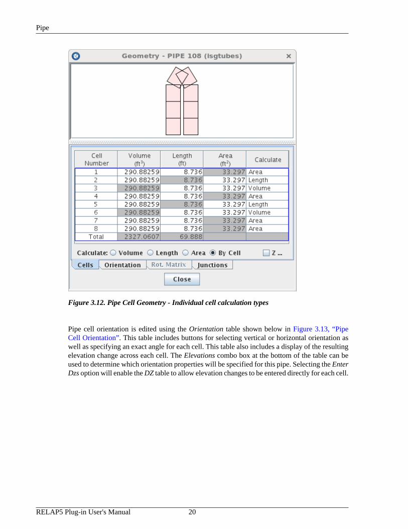
The Cells table allows the user to change the volume, length and area of cells. The calculation typecan also be set on an individual cell basis by selecting the By-Cell radio button. When definingthe calculation mode on a component basis, a set of radio buttons is provided to select whichof these values will be calculated automatically. If individual calculation types are requested,selecting the "By Cell" checkbox will enable a Calculate column where the calculate mode canbe selected. Check boxes are also included to allow the specification of Y and/or Z crossflowlengths and areas for each cell. Figure 3.11, “Pipe Cell Geometry - Single calculation mode”displays the Cells panel of the pipe geometry dialog.

Pipe
19 RELAP5 Plug-in User's Manual
Figure 3.11. Pipe Cell Geometry - Single calculation mode
Pipe
RELAP5 Plug-in User's Manual 20
Figure 3.12. Pipe Cell Geometry - Individual cell calculation types
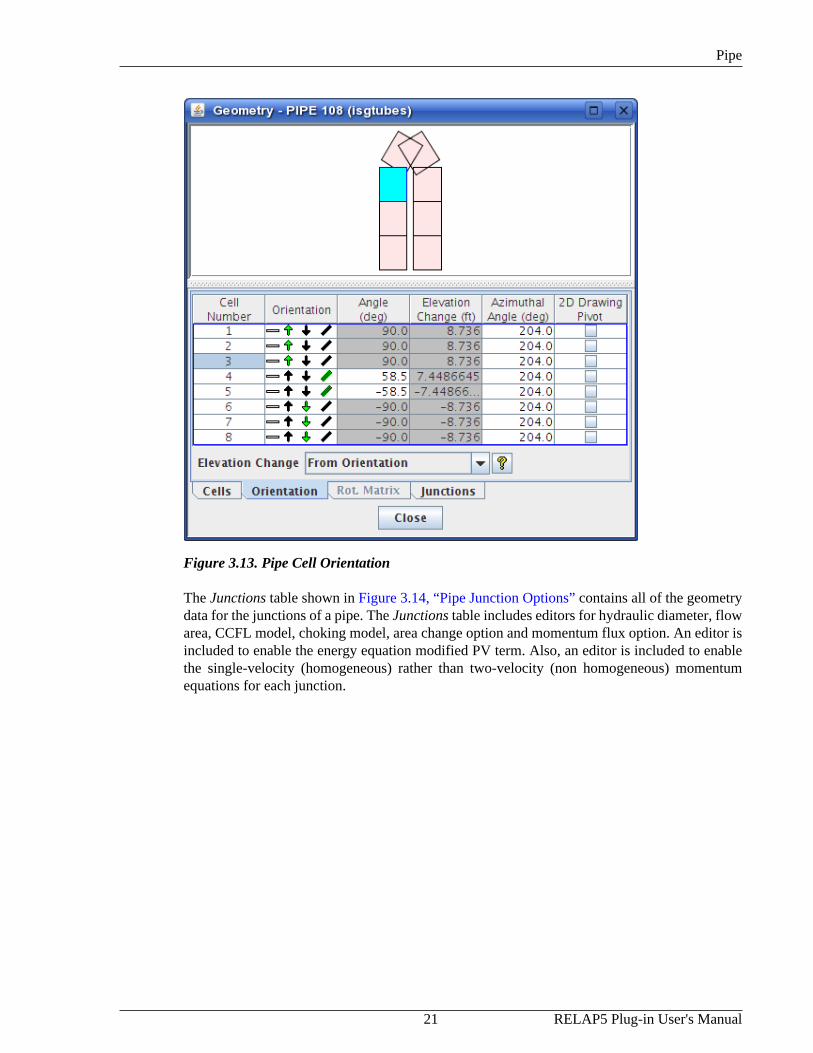
Pipe cell orientation is edited using the Orientation table shown below in Figure 3.13, “PipeCell Orientation”. This table includes buttons for selecting vertical or horizontal orientation aswell as specifying an exact angle for each cell. This table also includes a display of the resultingelevation change across each cell. The Elevations combo box at the bottom of the table can beused to determine which orientation properties will be specified for this pipe. Selecting the EnterDzs option will enable the DZ table to allow elevation changes to be entered directly for each cell.
Pipe
21 RELAP5 Plug-in User's Manual
Figure 3.13. Pipe Cell Orientation
The Junctions table shown in Figure 3.14, “Pipe Junction Options” contains all of the geometrydata for the junctions of a pipe. The Junctions table includes editors for hydraulic diameter, flowarea, CCFL model, choking model, area change option and momentum flux option. An editor isincluded to enable the energy equation modified PV term. Also, an editor is included to enablethe single-velocity (homogeneous) rather than two-velocity (non homogeneous) momentumequations for each junction.

Pipe
RELAP5 Plug-in User's Manual 22
Figure 3.14. Pipe Junction Options
Note The number of cells and junctions inside a pipe cannot be edited directly after creation.The 1D renodalization tool can be used to easily modify the nodalization of a pipe, andautomatically update any connected components. Refer Chapter 8, Renodalization formore information on 1D renodalization.
Pipe Initial Conditions
The initial conditions of the fluid inside a pipe must be defined for both the fluid cells andjunctions. The cells contain the fluid state information, while the junctions detail the fluid flowdata. These properties are modified in the Cell/Junction IC Data dialog. This dialog is used tomodify the initial conditions of all 1D hydraulic components.
The Cell Fluid initial conditions are displayed in Figure 3.15, “Pipe Initial Conditions Cell Fluid”below. The Condition (t-flag) value for each cell controls which columns are available for eachcell. Pop-up help buttons inside the Condition editor describe each of the available conditionvalues and the columns made available by each.
The Fluid (e-flag) value for each cell is not modifiable using the Model Editor. The fluid type of ahydraulic component is defined by the it's hydraulic system. The hydraulic system properties aredescribed in Section 3.1, “Model Properties”. If a non-zero e-flag is encountered during ASCIIimport, the value of that flag is compared with the fluid defined by the component's hydraulicsystem. If no hydraulic system exists that contains the component, a new hydraulic system willbe created with the fluid set to the value of the e-flag. Hydraulic systems created in this waywill have the source component and cell set as their root cell, and their reference elevation willbe set to 0.0.

Pipe
23 RELAP5 Plug-in User's Manual
Figure 3.15. Pipe Initial Conditions Cell Fluid
The Junction Flow initial conditions include the flow velocity (or mass flow) for each fluid phase.As with the cell panel, junction selection is reflected in both the table and the visual representationof the pipe. Figure 3.16, “Pipe Initial Conditions Junction Flow” below displays the junctionpanel in the pipe initial conditions dialog.

Pipe
RELAP5 Plug-in User's Manual 24
Figure 3.16. Pipe Initial Conditions Junction Flow
The Noncondensibles table includes columns for overriding the mass fraction for eachnondondensible gas included in the model.
Pipe Friction Data
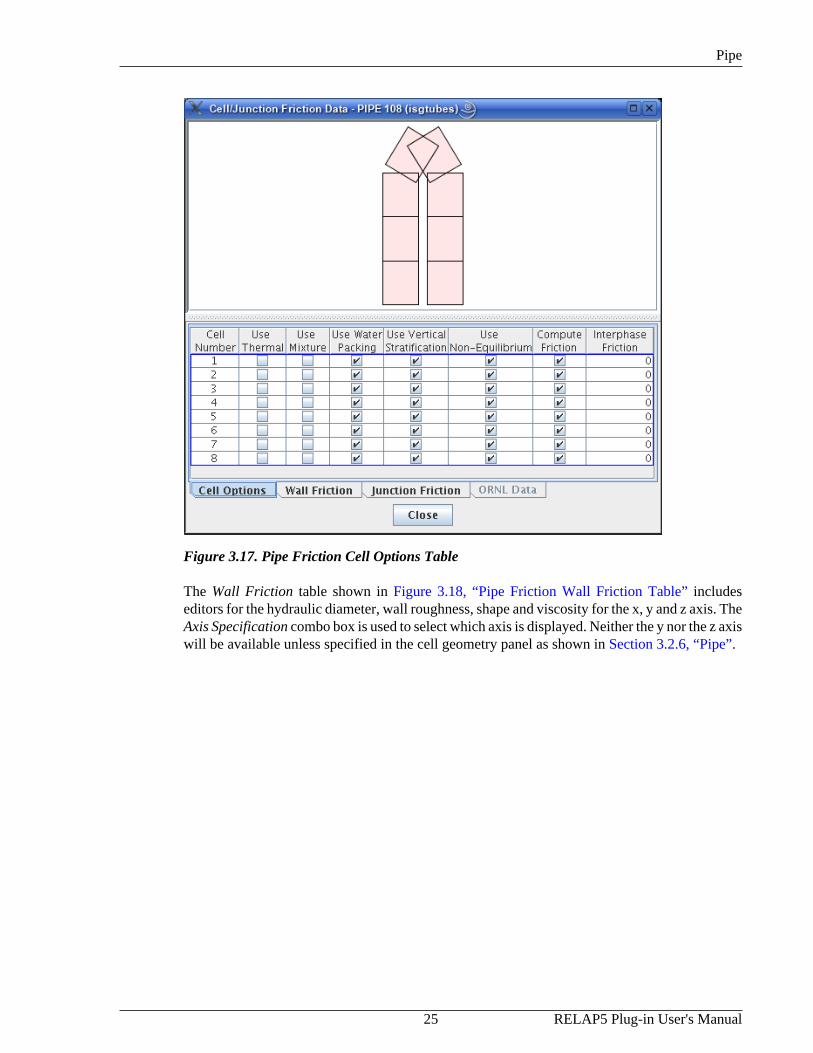
The pipe friction data defines the resistance to fluid flow through each junction. All 1D hydrauliccomponents use a similar dialog to edit their friction data. Figure 3.17, “Pipe Friction CellOptions Table” below displays an the junction friction dialog for a pipe and its included CellOptions table. The Cell Options table includes editors for the thermal front tracking model,mixture level tracking model and vertical stratification model. More detailed information on eachof these values can be found in the tool tips of each of the column headers.
Pipe
25 RELAP5 Plug-in User's Manual
Figure 3.17. Pipe Friction Cell Options Table
The Wall Friction table shown in Figure 3.18, “Pipe Friction Wall Friction Table” includeseditors for the hydraulic diameter, wall roughness, shape and viscosity for the x, y and z axis. TheAxis Specification combo box is used to select which axis is displayed. Neither the y nor the z axiswill be available unless specified in the cell geometry panel as shown in Section 3.2.6, “Pipe”.

Pipe
RELAP5 Plug-in User's Manual 26
Figure 3.18. Pipe Friction Wall Friction Table
The Junction Friction properties table shown in Figure 3.19, “Pipe Friction Junction FrictionTable” includes editors for the forward and reverse loss coefficients as well as editors for theReynolds dependent loss coefficients.

Annulus
27 RELAP5 Plug-in User's Manual
Figure 3.19. Pipe Friction Junction Friction Table
Note For any of the Pipe editors and most editors in the model which edit real valued input,the RELAP5 plug-in provides the ability to choose User-Defined Numerics. A UserDefined Numeric can be specified by doubling-clicking a cell for editing and then usingthe User Values menu item from the right-click pop-up menu. The User Values menuitem will provide the ability to choose a User Defined Numeric from the list of allavailable numerics. For more information regarding user-defined numerics refer to theSNAP User's Manual.
3.2.7. Annulus
The annulus component input is identical to a pipe component, except the annulus componentmust be vertical and the annular-mist flow regime is different. Refer to Section 3.2.6, “Pipe” formore detailed information.
3.2.8. Pressurizer
The RELAP5 Pressurizer component consist of many properties contained in the Pipe componentand utilizes many of the same editors to define them. In addition to the Pipe properties,the Pressurizer contains a Surge line Junction. In order to specify the Surge line Junction, aconnection must be made to the inlet junction or inlet cross flow faces. Once a connection iscreated ( from the 2-D view ), the Surgline Junction property editor can be used to specifythat connection as being the Surge line Junction. Refer to Figure 3.20, “Pressurizer Surge lineConnection”.

CANDU Channel
RELAP5 Plug-in User's Manual 28
Figure 3.20. Pressurizer Surge line Connection
Note The Surge line Junction editor will only display those connections which are made tothe inlet volume of the Pressurizer.
The remaining Pressurizer properties are shown in Section 3.2, “Hydraulic Components” below.
Figure 3.21. Pressurizer Property View
3.2.9. CANDU Channel
A CANCHAN is a RELAP5 specific component type used to model CANDU horizontal pressuretubes. ( Not available in RELAP3D ) The CANCHAN component input is identical to ahorizontal pipe component. Refer to Section 3.2.6, “Pipe” for more detailed information.

Branch
29 RELAP5 Plug-in User's Manual
3.2.10. BranchA branch is a single volume that is used to model 1D branching fluid flow. Each branch mayhave up to a maximum of 9 external junctions used to connect to other hydraulic components.This maximum does not include junctions from other components (single junction, pump, etc.)connecting to the branch volume.
Branch Properties
The Branch uses the same editing dialogs as the pipe component for editing geometry, initialconditions and friction data. Refer to Section 3.2.6, “Pipe” for more detailed information on thesedialogs.
Branch External Junctions (i.e. those stored in the branch) are edited using the dialog shown inFigure 3.22, “Branch Junctions Dialog”. This dialog allows junctions to be added, removed andconnected to other hydraulic components. The From Face determines where on the Branch ( inlet,outlet, cross-flow face 3-6 ) the connection will originate. The Target is the component receivingthe Branch connection. The Cell is the specific volume in the target hydraulic component towhich the connection was made. Selecting the Reverse option will reverse the flow of the mixturein the selected Branch connection.
Figure 3.22. Branch Junctions Dialog
The External Junctions property editor provides notification of the number of External Junctionsowned by the Branch. Notice that the Branch in the Property View provided below contains twoExternal Junctions.
Figure 3.23. Branch Property View

Separator
RELAP5 Plug-in User's Manual 30
3.2.11. Separator
The Separator (SEPARATR) component is a specialized branch component with three junctions:vapor/gas outlet(1), liquid fall back(2) and two-phase inlet(3). The Separator shares manyproperties with the Pipe component. Refer to Section 3.2.6, “Pipe” for more detailed information.
Figure 3.24. Separator Junction Labels
Separator Properties
RELAP5 allows the specification of multiple staged Separators. Selecting the Separator Modelproperty provides a list of options which determine the type of Separator being specified.Depending on the type of Separator being modeled, specific stage properties become available.The four types of Separators allowed in RELAP5 are listed below:
• Simple Separator
• GE dryer Model
• GE two-stage separator
• GE three-stage separator
The RELAP5 Separator modeling provides the ability to define a series of Separators based ona single Separator. Notice in the below figure, a Number of Components property is providedwhich accepts an integer value corresponding to the number of Separators represented (this isavailable for a Stage 2 or Stage 3 Separator).

Jet Mixer
31 RELAP5 Plug-in User's Manual
Figure 3.25. Separator Properties
3.2.12. Jet MixerA jet mixer (JETMIXER) component is a specialized branch component with 3 junctions:drive(1), suction(2) and discharge(3). A jet pump is modeled in RELAP5 using the jet mixercomponent. In a jet pump, the pumping action is caused by the momentum mixing of the high-speed drive line flow with the slower suction line flow. The input for a jet mixer component isthe same as that for a BRANCH component, with the following modifications:
1. For a BRANCH component, the junctions connected to that branch can be input withthe branch or as separate components. For a Jet mixer, three (and only three) junctions,representing the drive, suction, and discharge, must be input with the Jet mixer component,i.e., NJ = 3. If NJ is not equal to 3, an input error message is printed.
2. The three junction card sequences must be numbered as follows: Cards CCC1101 andCCC1201 represent the drive junction. Cards CCC2101 and CCC2201 represent the suctionjunction. Cards CCC3101 and CCC3201 represent the discharge junction in the mixingsection.
3. The drive and suction junctions must have their TO connection codes referring to the Jetmixer volume, and the discharge junction must have its FROM connection code referringto the Jet mixer volume. If this is not the case, an input error message is printed. The driveand suction junctions must be connected to the inlet side of the Jet mixer volume, and thedischarge junction must be connected to the outlet of the Jet mixer volume. If this is not thecase, an input error message is printed.
Jet mixer editing dialogs label junctions to be their appropriate name as shown in Figure 3.26,“Jet Mixer Junction Labeling”.

Turbine
RELAP5 Plug-in User's Manual 32
Figure 3.26. Jet Mixer Junction Labeling
3.2.13. Turbine
For a TURBINE component, the primary steam inlet junction must be input with the TURBINEcomponent as the first junction. If a steam extraction (bleed) junction is desired, it must beinput with the TURBINE component as the second junction. Thus, the number of junctionsmust be either 1 or 2. Cards CCC1101 and CCC1201 represent the steam inlet junction, andCards CC2101 and CCC2201 represent the steam extraction bleed junction (if desired). The"TO" connection for the steam inlet junction must refer to the inlet of the TURBINE (oldformat is CCC000000, and expanded format is CCC010001). The Number of Junctions optionin Figure 3.27, “Turbine Completion Dialog” allows the specification of 1 ( no steam extractionjunction ) or 2 ( steam extraction junction ) junctions.
Figure 3.27. Turbine Completion Dialog
In addition to standard geometry, friction, and initial condition properties, the Turbine allows aconnection to a Shaft with a connection control. A Shaft can be connected to a Turbine simplyby using the provided selection editor and selecting the a Shaft component. The Shaft selectioneditor is shown in Figure 3.28, “Turbine Shaft Selection”. Shaft Velocity, Inertia, and Frictionattributes can be defined in the Turbine Property View.

ECC Mixer
33 RELAP5 Plug-in User's Manual
Figure 3.28. Turbine Shaft Selection
The turbine also provides the option of specifying a Shaft connect/disconnect trip controller(Discon. Trip) directly below the Shaft property as shown in Figure 3.29, “Turbine PropertyView”.
Figure 3.29. Turbine Property View
3.2.14. ECC Mixer
The ECC mixing component (ECCMIX) is a specialized branch with 3 junctions: the ECCinlet(1), the normal inlet(2) and the discharge outlet(3). The geometrical description of theECCMIX component is very similar to that of the Jet mixer component with the addition of

Valve
RELAP5 Plug-in User's Manual 34
an angle for the ECC pipe connection (ECC Jun. Angle). For more information on the refer toSection 3.2.12, “Jet Mixer”.
3.2.15. ValveA Valve is used to regulate flow by varying the flow area at a specific location in a flow stream.The RELAP5 valve is modeled as a junction component that provides a means of varying flowarea as a function of time and/or hydrodynamic properties.
Since the Valve is modeled as a junction it uses the same editing dialogs as the pipe componentfor geometry, initial conditions and friction data. Refer to Section 3.2.6, “Pipe” for more detailedinformation on these dialogs.
Valve Properties
The valve properties are primarily dependent on the Valve Type selected. Figure 3.30, “ValveProperty View” below displays the properties of a sample valve.
Figure 3.30. Valve Property View
3.2.16. PumpThe hydrodynamic model of a pump component consists of one volume and two associatedjunctions. One junction is connected to the inlet and is called the suction junction; the otherjunction is connected to the outlet and is called the discharge junction.
General Properties
The pump uses the same editing dialogs as the pipe component for editing geometry, initialconditions and friction data. Refer to Section 3.2.6, “Pipe” for more detailed information on thesedialogs.
3.2.17. CompressorThe Compressor is a RELAP3D 2.4 specific component and consists of one volume and at leastone junction, attached to the inlet (suction) end of the volume. Optionally, a junction can be
Multiple Junction
35 RELAP5 Plug-in User's Manual
attached to the outlet (discharge) end of the volume. The Compressor Completion Dialog isidentical to the Turbine completion dialog shown in Figure 3.27, “Turbine Completion Dialog”.
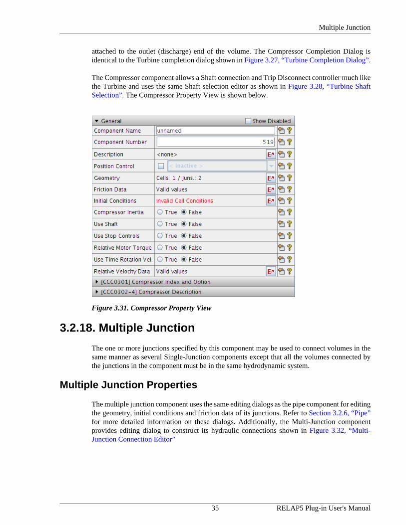
The Compressor component allows a Shaft connection and Trip Disconnect controller much likethe Turbine and uses the same Shaft selection editor as shown in Figure 3.28, “Turbine ShaftSelection”. The Compressor Property View is shown below.
Figure 3.31. Compressor Property View
3.2.18. Multiple Junction
The one or more junctions specified by this component may be used to connect volumes in thesame manner as several Single-Junction components except that all the volumes connected bythe junctions in the component must be in the same hydrodynamic system.
Multiple Junction Properties
The multiple junction component uses the same editing dialogs as the pipe component for editingthe geometry, initial conditions and friction data of its junctions. Refer to Section 3.2.6, “Pipe”for more detailed information on these dialogs. Additionally, the Multi-Junction componentprovides editing dialog to construct its hydraulic connections shown in Figure 3.32, “Multi-Junction Connection Editor”

Multiple Junction
RELAP5 Plug-in User's Manual 36
Figure 3.32. Multi-Junction Connection Editor
The Multi-Junction Connection Editor provides the ability to Add/Remove and Edit connections.The From and To component properties are edited with a hydraulic component selectioneditor. Once a component is specified, the From Cell will update to coincide with the selectedcomponents nodalization scheme. ( Refer to Figure 3.33, “Multi-Junction From-To Cell Editor”.) The From Cell and To Cell property editor provides a drop-down box which displays a listingof all available hydraulic volumes.
Figure 3.33. Multi-Junction From-To Cell Editor
The Multi-Junction Connection Editor also provides the ability to "zipper" connect two distincthydraulic components. Pressing the Set button at the bottom right-hand corner of the editor opensa utility dialog which can create multiple connections between two components using a specifiedincrement and/or starting offset. Notice in Figure 3.34, “Multi-Junction Utility Connection

Multiple Junction
37 RELAP5 Plug-in User's Manual
Editor”, the utility editor allows the specification of two hydraulic components. Once a hydrauliccomponent is specified, the Starting Cell and Ending Cell spinners constrain the cell selectionbased on the number of hydraulic cells available in the specified component.
To the right of the Starting and Ending Cell spinners is the max number of cells available to thespecified component. The Increment option provides the ability to choose a series of cells whichare in succession based on the increment selected. ( i.e. In the figure below, if the increment were2, the connected cells would be 1 3 5. ) The Inlet Face option decides which hydraulic cell faceconnections will be made. ( i.e. In order to make cross-flow connections between components,the Inlet Face should be set to appropriate crosss-flow faces. )
Figure 3.34. Multi-Junction Utility Connection Editor
The Multi-Junction component also contains basic Junction geometry, friction, and initialcondition data. Examples of the editors used to edit these properties can be seen in Section 3.2.6,“Pipe”. The RELAP5 plug-in updates the Multi-Junction editors when the number of Junctionschanges in order accurately reflect the structure of the component. The basic Multi-Junctionproperties are displayed below.

Multiple Flexible Wall
RELAP5 Plug-in User's Manual 38
Figure 3.35. Multi-Jun Property View
3.2.19. Multiple Flexible Wall
The one or more flexible walls specified by this component can connect volumes in the samemanner as several single flexible wall components except that all the volumes connected by theflexible walls in the component must be in the same hydrodynamic system.
Figure 3.36. Multiple Flexible Wall Properties
The multiple flexible wall component uses the same Connection Editor as the multiple junctioncomponent (Section 3.2.18, “Multiple Junction”). The geometry editor, however, is somewhatdifferent. The geometry of a flexible wall consists of a flexible wall area and a displacement vsvolume/stiffness table.
Figure 3.37. Multiple Flexible Wall Geometry

Accumulator
39 RELAP5 Plug-in User's Manual
3.2.20. Accumulator
An accumulator is a lumped parameter component treated by special numerical techniques thatmodel the tank, tank wall, surge line, and outlet check valve junction until the accumulatoris emptied of liquid. When the last of the liquid leaves the accumulator, RELAP5 resetsthe accumulator to an equivalent single-volume with an outlet junction and proceeds withcalculations using the normal hydrodynamic solution algorithm.
The Accumulator Geometry, Friction, and Initial Conditions editors are similar to the Pipecomponent as described in Section 3.2.6, “Pipe”. Additional properties for the RELAP5Accumulator are displayed below.
Figure 3.38. Accumulator Property View
3.2.21. Multi-Dimensional Component
The Multi-Dimensional hydraulic component(MULTID) defines a one, two, or three-dimensional array of volumes and the internal junctions connecting the volumes. It is describedas a three-dimensional component but can be reduced to two or one dimensions by defining onlyone interval in the appropriate coordinate directions. The geometry can be either Cartesian orCylindrical. The Multi-Dim component is only available in RELAP 3D.
A Multi-Dim component with a cylindrical geometry is displayed in the following figures. Multi-Dim components with a Cartesian geometry have near identical editing dialogs.

Multi-Dimensional Component
RELAP5 Plug-in User's Manual 40
Multi-Dim Completion Dialog
The RELAP5 plug-in provides a completion dialog which describes the geometrical attributes ofa newly constructed Multi-Dim. Three specific geometry types are supported and are as follows:
• Partial Cylinder
• Full Cylinder
• Cartesian
A Partial and Full cylindrical geometry Multi-Dim component contains the same set ofcompletion options. The difference between the two types is that the Full cylinder geometry typerequires an azimuthal angle of 360 degrees. The following figure shows the completion dialogfor a cylindrical geometry type.
Figure 3.39. Multi-Dim Cylindrical Completion Dialog
The completion dialog for Cartesian geometry provides X and Y attributes as opposed to radialand azimuthal specification. The completion dialog for a Multi-Dim component with a Cartesiangeometry is show below.

Multi-Dimensional Component
41 RELAP5 Plug-in User's Manual
Figure 3.40. Multi-Dim Cartesian Completion Dialog
Multi-Dim Geometry Editor
The Multi-Dim component provides a unique 3-D geometry view with utilities to rotate, translate,and zoom. Selecting a hydraulic cell from the table in the geometry dialog updates the 3-D viewto the nodes selected. The basic 3-D view is displayed below.
Figure 3.41. Multi-Dim Geometry Editor
By default, the geometry editor displays cell thicknesses. Actual positions can be displayed andedited by selecting the Display Actual Positions check-box below the axis selection editor. Thegeometry editor provides a cell highlighting feature which identifies the range of data currentlyselected in the table. The Select Axis drop-down box provides alternate selection modes. Thefigures below demonstrate the different selection modes available.

Multi-Dimensional Component
RELAP5 Plug-in User's Manual 42
Figure 3.42. Axial Selection Mode
Figure 3.43. Radial Selection Mode

Multi-Dimensional Component
43 RELAP5 Plug-in User's Manual
Figure 3.44. Azimuthal Selection Mode
The Multi-Dim geometry editor contains a tab labeled Connections. Selecting the Connectionstab provides a connections view for the current Multi-Dim component. The upper table providesa view of all external component connected to the Multi-Dim component and how manyconnections to each of those specified components have been made. The lower table liststhe specific hydraulic connection information into 2 categories, the Local Side in which thehydraulic connection originated, and the Remote Side in which the hydraulic connection connectto. Information about each of side of the hydraulic connection is then provided and is displayedin Figure 3.45, “Multi-Dim Connections”.
Figure 3.45. Multi-Dim Connections

Multi-Dimensional Component
RELAP5 Plug-in User's Manual 44
Multi-Dim 2D Editing Dialogs
The remaining Multi-Dim property editors provide a 2-D selection interface. The 2-D displayis split into 2 separate views, a Top Down View and an axial Side View. Selecting a hydraulicCell/Junction in one of the provided diagrams will select the associated hydraulic volume inthe provided table. If hydraulic cell properties are being edited, the cells themselves may beselected from the axial view. Additionally, selecting rows of data from the table will highlightthe appropriate data in the axial Side View. This can be seen in the following figure:
Figure 3.46. Multi-Dim 2D Cell Selection
Specification of hydraulic junction properties is similar to that of the cells. Notice in the followingfigure that selecting a value from the table highlights the junction region on the axial Side View.Junctions are selected from the Side View by clicking on the dotted line.

Multi-Dimensional Component
45 RELAP5 Plug-in User's Manual
Figure 3.47. Multi-Dim 2D Junction Selection
The 2D hydraulic cell/junction properties are specified by the down-down boxes at the top ofeach editor. Selecting a specific property from the drop-down boxes will update the editing tableprovided. Multi-Dim junction properties provide the option of selecting the face to which theproperties are being set.
Multi-Dim Connections
Creating hydraulic connections To/From the Multi-Dim component is done through the 2-Dview. The connection to the Multi-Dim component is done much like any other component inthe RELAP plug-in. The connection tool is used to start the connection and is done by selectinga connection point from another component and then selecting a drop zone point on the Multi-Dimensional component. Once a connection has been established, a connection completiondialog is provided. The connection completion dialog provides options to determine the properlocation to which to create the connection and is shown in Figure 3.48, “Multi-Dim ConnectionView”.

Feedwater Heater
RELAP5 Plug-in User's Manual 46
Figure 3.48. Multi-Dim Connection View
3.2.22. Feedwater HeaterThe Feedwater Heater component is a specialized horizontally oriented branch component withtwo or three junctions. The Heater is only available for RELAP3D models. Editors for Feedwatergeometry, initial conditions, etc. properties resemble the Pipe component and are described inSection 3.2.6, “Pipe”. The Feedwater Heater Property View is provided below.
Figure 3.49. Feedwater Heater Property View
3.3. Control SystemsThe control system of model is used to perform calculations and provide system inputs toallow feedback controls and user interaction to the model. The control system consists of signalvariables, control blocks, interactive variables and trips. The signal variables serve as inputs fromthe model. Control blocks provide a value based on manipulation of input data. Trips activatewhen an input value enters or exits a specified range.
3.3.1. Signal VariablesSignal variables serve as input obtained from elsewhere in the model. This may be a globalproperty, such as calculation time, or a probed value from a specific location in a component

Signal Variables
47 RELAP5 Plug-in User's Manual
such as the pressure in a cell of a pipe. The signal variables are further divided by the sourceof the property.
Signal Variable Creation
A signal variable creation dialog is available from the right-click New item provided on both theglobal signal variables category node and its children. Selecting the New option from the generalsignal variables category node will open the signal variables creation dialog with the All categoryselected. The All category shows all of the types of signal variables in the type table. If the dialogis opened from a specific signal variable category, the category which opened the dialog will beselected in the category table. A selection from the category table updates the type table to onlydisplay signal variable types appropriate for that category. When a selection is made in the Typetable, the Creation Criteria property view will update to display the attributes available for theselected type. This property set allows the user to define the type of signal variable they wishto create. Configuring these attributes will determine which signal variable will be created whenthe OK button is pressed. The "Signal Variables to be Created" list displays the signal variablethat will be added to the model when the OK button is pressed. Modifying the "Creation Criteria"properties will automatically update this list to show which signal variable will be added. If asignal variable to be created already exists in the model, the tag "{exists in model}" will bedisplayed next to the signal variable, and will not be created when the OK button is pressed.
Figure 3.50. Signal Variable Creation
The Volumetric, Junction, and Heat signals allow the analyst to define ranges of signal variables.When a variable of one of these types is created, the "Creation Critiera" properties will includeStarting and Ending values for the range. All variables which lie between the specified range(inclusive) will be created when the OK button is pressed. The "Signal Variables to be Created"list will display the range of variables that will be created. When the starting value of a rangeis adjusted, the ending value will be set to the start. For 3D volumes and junctions, the endingrange editors will ensure that only one direction is varied.

Signal Variables
RELAP5 Plug-in User's Manual 48
Figure 3.51. Signal Variable Range Creation
The creation dialog provides a filter utility to make locating the desired signal type easier. Whena value is entered into the filter, the type column will be pruned to match the specified filter.The category list will update to include a matches tag next to each category. These match tagsidentify how many of the category types match the specified filter. By default the filter will bematched against only the Signal Variable type names. If the "Include Description" checkbox isselected, the filter will be compared against the signal type and description. The signal variablecreation dialog will remember the last 5 filters entered by the user and expanding the dropdownbox will display these previous filters.
Figure 3.52. Signal Variable Creation Type Filter
Signal Variable Type Edit
The Signal Variable Signal Type property editor provides a means of modifying the type of theselected signal variable across each of its control system usages. When the type editor is opened,a category list and type list will be preselected to the type which opened the editor. The Categoryvalue is fixed to the type selected. The type table can be adjusted if a type change is requested in

Signal Variables
49 RELAP5 Plug-in User's Manual
the usages. When a type is selected, the properties for that type will be displayed in the Propertiesproperty set panel. If a usage is selected to be updated in the usages table, the data specified inthe type and properties will be applied to that usage. If all of the usages in the lower table areselected to be updated, then the signal variable which opened the type editor will be modifiedto the new type with the specified properties. If only a subset of usages are to be updated, onlythe selected usages will be updated to use the signal variable defined by the type and propertiesin the dialog. If the type and properties specified define a signal variable which already exists,that signal variable will be used instead of building a new one. If not, a new signal variable willbe created and applied to the given usage.
The type edit dialog provides a filter utility to make locating a desired signal type easier.When a value is entered into the filter, the type column will be pruned to match the specifiedfilter. By default the filter will be matched against only the Signal Variable type names. If the"Include Description" checkbox is selected, the filter will be compared against the signal typeand description. The signal variable type edit dialog will remember the last 5 filters entered bythe user and expanding the dropdown box will display these previous filters.
Figure 3.53. Signal Variable Type Editor
General Signal Variables
General signal variables serve to retrieve general system information. Current problem CPUtime, current timestep, or mass error estimate are three examples of many General signal variabletypes.
Component Signal Variable
Component signal variables obtain a specific value from a component, such as turbine efficiency,pump torque or valve area ratio. These signal variables require a component reference but haveno specific location. The properties of a sample Component signal variable are displayed belowin Figure 3.54, “Component Signal Variable”.

Control Blocks
RELAP5 Plug-in User's Manual 50
Figure 3.54. Component Signal Variable
Volumetric Signal Variable
Volume signal variables are used to obtain a value from a cell inside a hydraulic component.These signal variables require a hydraulic component reference and a location (calledParameter). Pressing the S button will open a component selection dialog displaying all hydrauliccomponents in the model.
Junction Signal Variables
Junction signal variables provide access to junction information for a specific hydrauliccomponent. Much like the Volume signal variables, the user must select a hydraulic component.Instead of specifying a cell the user must select a junction inside the component. Pressing the Sbutton opens the component selection dialog displaying all hydraulic components in the model.
Heat Signal Variables
Heat signal variables provide access to heat structure values. Much like volume and junctionsignal variables, pressing the S button will open the component selection dialog to select thetarget heat structure. Additional editors are provided to select the Surface and Parameter.
Power Signal Variables
Power signal variables are used to obtain power related values from the reactor kinetics portionof the model. Additional properties may be required depending on the Signal Type selected. Forexample: signal type RKOCRPSN requires that the Control Rod Group be specified.
3.3.2. Control Blocks
A control block is a control system component that manipulates input data. Control blockstake input from signal variables or other control blocks and output a floating point value. Inputconnections to the control blocks can be established by using the connect tool inside a 2D View.Simply use the connect tool to connect the output of the control system to the input of the controlblock.
3.3.3. Trips
Trips are special control blocks that are used to indicate when an input value reaches a certainlevel or meets a specific criteria. RELAP5 provides two types of trips: Variable and Logical.These types differ only in the operation used to determine the true or false result. Variable tripsuse a Relationship that can be equal, not equal, greater than, greater than or equal, less than orequal, or less than. Logical trips use an Operator that can be AND, OR or XOR.

General Tables
51 RELAP5 Plug-in User's Manual
Figure 3.55. Variable Trip Property View
The RELAP5 plug-in supports two different trip numbering formats, expanded and original. Thetwo different card series are available for entering trip data, but only one type may be used ina problem. The original numbering format card numbers 401-799 allow 199 variable trips and199 logical trips. The expanded format card numbers 20600010 - 20620000 allow 1000 variabletrips and 1000 logical trips.
The RELAP5 plugin provides the ability to change the trip numbering format if the numberof trips does not exceed the format trip limit. Trip numbers will be updated to accomodate theselected format's numbering scheme.
Figure 3.56. Trip Numbering Format
3.3.4. General Tables
General tables provide input for several RELAP components, including heat structures, valves,reactor kinetics, and control systems. The general table defines a table of input of with anindependent/dependent variable relationship. A few examples of available general table inputrelationships are provided below:
• Temperature Vs. Time
• Heat Transfer Vs. Time
• Reactivity Vs. Time
• Heat Transfer Vs. Temperature

General Tables
RELAP5 Plug-in User's Manual 52
The provided table editor for General Table table data is identical to other editors in the RELAPplug-in. It provides a means of adding and removing rows using an Add and Remove button.In addition, a button is provided which will sort the General Table data based on independentvariable. The table editor is shown in the figure below.
Figure 3.57. General Table - Table Data Editor
The table editor uses the foreground color of the independent variable values to indicate twodifferent errors. Independent variable values that are less than a preceeding value will bedisplayed in the table with a red foreground color. If an independent variable value is a duplicateof a preceeding independent variable value it will also be displayed in the table with a redforeground color.
The contents of the general table may be defined by a table variable reference. This referencesupports mapping individual columns of the table variable to columns in the general table. Anerror message will be reported if the table variable rows are out of order, or the column mappingis invalid.
In addition to the error checks for unset values, the general table component will also report thefollowing in the model report:
• If the independent variable values are not in ascending order an error will be reported.
• If an independent variable value is a duplicate of a preceeding value an error will be reported.
The General Table property view is provided in Figure 3.58, “General Table Property View”.

Interactive Variables
53 RELAP5 Plug-in User's Manual
Figure 3.58. General Table Property View
3.3.5. Interactive VariablesInteractive Variables define input which may be changed during interactive model execution.The card input defines input variable names and initial values. Interactive Variables can be usedin trips, control variable statements, search arguments for some tables, edited in minor edits,and plotted. With appropriate input, an Interactive Variable can effect changes similar to thosemade by a reactor operator, such as opening/closing/repositioning valves or setting new operatingpoints in controllers.
Interactive Variables can be created like any other component type in the RELAP5 plug-in andare connected to other components using the 2-D view connection tool or editors which allow theuse of Interactive controls. The following figure displays the 2-D view of an Interactive Variableas input to a Lag type Control Block.
Figure 3.59. Interactive Variable Control Connection
3.4. Heat StructuresThe RELAP5 plug-in provides the ability to construct flat slab, cylindrical, and sphericalHeatstructure components. Editors are provided to allow specification of left and rightheatstructure surface data and other heatstructure properties.
Creating a Heat StructureThe Heatstructure component is created in the same manner as other components in the RELAP5plug-in. Select the Heatstructure node in the Navigator, and open it's right-click pop up menu.

Connecting a Heat Structure
RELAP5 Plug-in User's Manual 54
Select New item from the From the right-click pop-up menu. A Heatstructure completion dialogis provided in order to initialize the component. The Heatstructure completion dialog is shownin Figure 3.60, “Heatstructure Completion Dialog”.
Figure 3.60. Heatstructure Completion Dialog
The Heatstructure completion dialog determines the geometrical layout of the component.Specifying a geometry will update the editor heatstructure properties in accordance with thegeometry selected. Axial and radial Heatstructure nodalization is also defined using this editor.
Connecting a Heat Structure
The RELAP5 plug-in Heatstructure does not have an associated 2-D drawn component and mustbe connected through its editing dialogs. Notice in the Heatstructure Property View, a propertynamed Axial Cells/BCs. The editor for this property provides the ability to create connectionsto the left and right surfaces of the given Heatstructure as well as provide axial componentrenodalization. For more information on Heatstructure renodalization, refer to Chapter 8,Renodalization.

Connecting a Heat Structure
55 RELAP5 Plug-in User's Manual
Figure 3.61. Heatstructure Connection Editor
Notice the table layout of the Heatstructure axial cells in the above editor. Selecting a cell from theAxial Cell column provides properties associated with the selected cell(s) in the Property Viewprovided below the table. The figure below shows the associated Axial Cell column properties.

Connecting a Heat Structure
RELAP5 Plug-in User's Manual 56
Figure 3.62. Heatstructure General Heat Cell Data
Selecting two or more heat cells in the table provides a property view with an intersection of theattributes specified by the selected heat cells. If two or more axial cells are selected and have thesame attribute and value, the value will appear for editing for both of the selected Heat cells. Inthe event that two or more axial cells are selected, contain the same attribute, and have differentvalues for those attributes, the editor will display a < Different Values > and will not be editable.This same type of behavior applies to the Left and Right Surface Conditions data.
The Left/Right Surface Boundary Conditions columns provide the option of connecting heatcell surfaces. A hydraulic component may be connected to the left or right surface if a BoundaryType other than simmetric is selected. The heatstucture surfaces editor provides the dialog shownin Figure 3.63, “Heat Connections Dialog” to allow the creation of multiple connections to thesame hydraulic component. At the top of the editor there are drop down boxes to specify theAdditional Boundary Data Format for the Left and Right Heat Surfaces. Specifying a formatwill update the property view for the selected surface. The activation checkboxes are available toforce output of Additional Surface data in the event the data is desired for a given surface whichhas no Hydraulic cell connections.

Axial Power / Heating Dialog
57 RELAP5 Plug-in User's Manual
Figure 3.63. Heat Connections Dialog
Pressing the E button for the Cell property will open the Heat Connections dialog to allow arange of Hydraulic cell connections to be made to the selected Heat Cells. In the above figure,three Heat Cell connections are being made. The Hydraulic Component property determinesto which component the cell connections are being made. The Starting Cell and Ending Cellproperties determine the range in which to assign volumes to the Heat Cells.
Axial Power / Heating Dialog
The Axial Power/Heating dialog in powered heat structures displays the power factor, andheating multipliers for each cell in the heat structure. This dialog is shown in X below. Thisproperty is only enabled when at least once cell in the heat structure contains source data. Thecontents of this table may be replaced with a reference to a table variable. When a table variableis referenced the contents of that table will be exported to the ASCII input and Model Notebooks.An error message will be reported if the referenced table does not match the heat structures axialgeometry, or the mapped columns do not match the expected data types.
Figure 3.64. Axial Power/Heating Dialog

Heatstructure Radial Geometry
RELAP5 Plug-in User's Manual 58
Heatstructure Radial Geometry
Radial geometry and associated properties are edited through the Geometry property editorwhich opens the dialog shown in Figure 3.65, “Heatstructure Radial Geometry Editor”. Thisdialog allows the radial mesh thicknesses as well as radial mesh positions to be specified.Optionally, the radial geometry of another heat structure may be used by specifying the heatstructure with the Node Location property.
Radial geometry may be input as either as a mesh thicknesses or radial positions. In the secondformat, only the ending radial mesh interval's position is required. User defined numerics maybe specified for values using either format. The Radial Geometry dialog also allows for radialrenodalization using the provided Split and Merge buttons. For information on componentrenodalization refer to Chapter 8, Renodalization.
Figure 3.65. Heatstructure Radial Geometry Editor
3.5. Radiation EnclosureA radiation enclosure is a set of heat structures that communicate via thermal radiation/conduction. The RELAP5 plug-in supports radiation enclosures by providing editors forgrouping available heatstructures. Radiation Enclosure components are created using theNavigator right-click pop-up menu and selecting the New option.
The following figure displays the Heatstructures property editor which defines the grouping ofheatstructures the enclosure defines. Selecting the Add button will add a new heatstructure tothe list of grouped heatstructures while the Remove button removes the selected heatstructurefrom the group. Selecting on a Heatstructure in the above list provides an appropriate propertyview the for selected item below.

Materials
59 RELAP5 Plug-in User's Manual
Figure 3.66. Radiation Enclosure HS Grouping
The RELAP5 plug-in also provides an editor for defining Radiation Enclosure View Factors.Notice in the figure below that the column tool tips provide information on the surface beingedited.
Figure 3.67. Radiation Enclosure View Factors
3.6. MaterialsRELAP5 provides a set of pre-defined materials such as carbon steel, stainless steel, zircaloy,etc. To include any of these materials in a RELAP5 model first create a new material by selecting

Reactor Kinetics
RELAP5 Plug-in User's Manual 60
the New item from the right-click pop-up menu of the Materials navigator node. Then, select thedesired Material Type in the properties of the newly created material as shown in Figure 3.68,“Material Type Editor”.
RELAP5 also supports user-defined (tabular/function) material properties. To create a user-defined material first create a new material. Then, select Table/Function for the Material Typein the properties of the newly created material.
Figure 3.68. Material Type Editor
3.7. Reactor KineticsRELAP5 supports Point Kinetics and the RELAP3D supports both Point and Nodal Kinetics.Both of these reactor kinetics options are supported by the RELAP5 plug-in.
Initializing Reactor Kinetics
To enable Reactor Kinetics, select the Reactor Kinetics node from the Navigator and change itsEnable property to True in the Property View. This will open the completion dialog shown inFigure 3.69, “Point Kinetics Completion Dialog” and Figure 3.70, “Nodal Kinetics CompletionDialog ( Cartesian / Hexagonal )”. Options that are not available for a particular kinetics orfeedback type are shaded in grey.
Note To disable Reactor Kinetics, set the Enable property False. To remove the kineticsinformation from the model select the Clear item from the right-click pop-up menu ofthe Reactor Kinetics node in the Navigator.

Point Kinetics
61 RELAP5 Plug-in User's Manual
Figure 3.69. Point Kinetics Completion Dialog
Nodal Kinetics calculations support two core geometry types; Cartesian and Hexagonal.Cartesian layout planar data is defined from left to right ( X Nodes ) top to bottom ( Y Nodes )for each axial level ( Z Nodes ). Hexagonal layout data is defined by the number of HexagonalRings for each axial level ( Z Nodes ).
Figure 3.70. Nodal Kinetics Completion Dialog ( Cartesian / Hexagonal )
Point Kinetics
Point Kinetics properties use many of the same editors present in other RELAP5 components.In addition, the following special kinetics editors are used to edit Point Kinetics properties:

Point Kinetics
RELAP5 Plug-in User's Manual 62
• Table Data Editor - The table editor provides a spreadsheet-like editor for tabular data. Rowscan be added and removed using the Add/Remove buttons. Cell values can be copied andpasted using the Copy and Paste items in the right-click pop-up menu. A Sort menu item isalso provided to sort the table rows by independent variable, where appropriate.
Figure 3.71. Kinetics Tabular Array Editor
• Point Kinetics Volumes and Weighting Factors - This editor defines Point Kinetics Volumeand Heat Weighting Factors.
The top of the dialog is a table of Hydraulic components or Heatstructures that are to proividefeedback. The Add and Remove buttons can be used to add and remove components fromthis table.
Figure 3.72. Point Kinetics Volume/Heat Weighting Factor Editor
Nodal Kinetics
63 RELAP5 Plug-in User's Manual
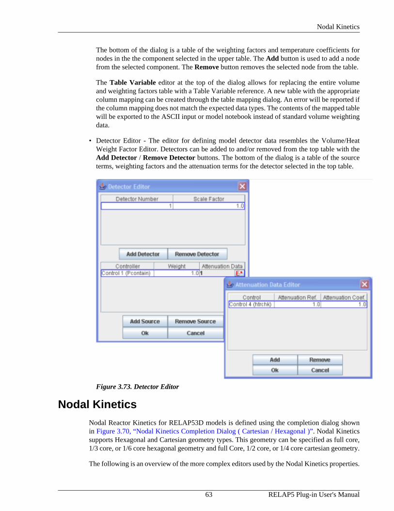
The bottom of the dialog is a table of the weighting factors and temperature coefficients fornodes in the the component selected in the upper table. The Add button is used to add a nodefrom the selected component. The Remove button removes the selected node from the table.
The Table Variable editor at the top of the dialog allows for replacing the entire volumeand weighting factors table with a Table Variable reference. A new table with the appropriatecolumn mapping can be created through the table mapping dialog. An error will be reported ifthe column mapping does not match the expected data types. The contents of the mapped tablewill be exported to the ASCII input or model notebook instead of standard volume weightingdata.
• Detector Editor - The editor for defining model detector data resembles the Volume/HeatWeight Factor Editor. Detectors can be added to and/or removed from the top table with theAdd Detector / Remove Detector buttons. The bottom of the dialog is a table of the sourceterms, weighting factors and the attenuation terms for the detector selected in the top table.
Figure 3.73. Detector Editor
Nodal KineticsNodal Reactor Kinetics for RELAP53D models is defined using the completion dialog shownin Figure 3.70, “Nodal Kinetics Completion Dialog ( Cartesian / Hexagonal )”. Nodal Kineticssupports Hexagonal and Cartesian geometry types. This geometry can be specified as full core,1/3 core, or 1/6 core hexagonal geometry and full Core, 1/2 core, or 1/4 core cartesian geometry.
The following is an overview of the more complex editors used by the Nodal Kinetics properties.

Nodal Kinetics
RELAP5 Plug-in User's Manual 64
• Mesh Length Editor - The Mesh Length Editor is used to define the X, Y and Z axis nodelengths for each node. Pressing the X, Y and Z radio buttons will display the node lengthsfor that axis in the table.
The Z axis starts from the bottom of the mesh and proceeds upward. ( Mesh #1 is the bottom. )
The X axis starts at the left side of the axial mesh ( looking down ) and proceeds right. ( Mesh#1 is the left. )
The Y axis starts at the top of the axial mesh ( looking down ) and proceeds downward. (Mesh #1 is the top. )
Figure 3.74. Mesh Length Editor
• Composition/Zone Figure Editor - Compositions/Zones are assigned to Axial Meshes usingthis editor. Axial mesh #1 corresponds to the lowest axial mesh interval. A figure selection/creating dialog is provided to help assign the figures to the Mesh Intervals. The figure selectiondialog Add button creates a new zone/composition figure and assigns it to a specified interval.The Remove button removes the selected figure from the model. To specify a figure, selectthe desired component from the list and press the Ok button.

Nodal Kinetics
65 RELAP5 Plug-in User's Manual
Figure 3.75. Composition/Zone Figure Assignment Editor
• Zones/Compositions/Control Rods Editor - The RELAP5 plug-in provides a Planar Top-Downview editor for assignment of Zones, Compositions, and Control Rod Groups. The followingfigures show each geometrical representation provided.
Figure 3.76. Planar Cartesian Editor
To display or edit the nodal data for a figure, select the figure from the Composition Figure/ Zone Figure drop-down located at the top of the dialog.

Nodal Kinetics
RELAP5 Plug-in User's Manual 66
Figure 3.77. Planar Hexagonal Full Core Editor
The planar view editor provides the ability to edit individual or multiple nodes as desired. Leftclicking on a node will provide the Selected Node property to be displayed. Left-Clicking anddragging will provide the ability to select a contiguous region. In order to define a selectedregion, open the node selection editor at the bottom right hand corner of the editor while nodesare selected. This will provide an editor which is identical to that displayed in Figure 3.75,“Composition/Zone Figure Assignment Editor”.
• Initial Power Fraction Editor - This editor defines the Initial guess for the prompt fission powerdistribution for each kinetics node. The layout of the data is a left to right, top to bottom wherex index 1,y index 1 is the top left corner of the figure. Defining the initial power distributionsis optional per level. If defining the initial power distributions is desired, the Initialize Valuescheck box should be selected. The Axial Mesh Interval property will change the current tabledisplay to that of the selected axial level.
Figure 3.78. Initial Power Fraction Editor
• Volume/Heat Region Feedback Editor - Region Feedback data is defined with this editor. Theupper table provides a count of data entries defined for the specified zone. Selecting on a

Nodal Kinetics
67 RELAP5 Plug-in User's Manual
row in the upper table will update the lower table to display the appropriate data, and enableAdding/Removing data from the lower table. The Feedback property updates the lower tableto define either volume or heatstructure feedback region data for the zone selected in the uppertable. The editor for the Volume/Heatstructure Number properties provide cell selectionthat has a max and minimum value based on the component selected.
Figure 3.79. Region Feedback Editor
• Composition Cross Section Editor - This editor defines the Nodal Kinetics cross section input.The editor provides an upper list of cross sections with an associated property view listedbelow. Selecting the Add/Remove buttons will Add and Remove cross sections from theupper table. Selecting a cross section from the upper table provides a property view witheditable properties in the lower section. In the cross section property view there is an attributemarked XS Data. This property has an associated editor that edits each of the specific crosssection types. Hovering over the displayed cross section types provides tool tips describingthe associated scattering pattern. Additional properties are provided depending on the chosencross section type.

Nodal Kinetics
RELAP5 Plug-in User's Manual 68
Figure 3.80. Cross Section Editor

69 RELAP5 Plug-in User's Manual
Chapter 4. Editing a Restart CaseRELAP5 supports restarting finished calculations through the use of a restart deck. A restart deckcontains a subset of the data in the original input deck. This includes the user defined units anduser defined materials. In addition to these properties that must be resupplied, the restart deckincludes a fully re-supplied component entry for any component that has been modified. Newcomponents may be added and existing components may be removed from the model using arestart deck.
Figure 4.1. Creating a Restart Case
Restart decks are represented in the ModelEditor by "Restart Cases." Restart cases can be createdby right-clicking on the Cases node in the Navigator and selecting the New pop-up menu item asshown below in Figure 4.1, “Creating a Restart Case”. Once created, a restart case can be editedin either ASCII or Graphical mode (depending on the Editing Mode property) by pressing theEdit button for the Restart Model property. The Show ASCII pop-up menu item can also beused to view the contents of a case.
Editing a case graphically opens the case as a "Virtual Model" in the Navigator as shown inFigure 4.2, “Graphical Restart Editing”. When graphically editing a restart case, a restart panel isshown above the Navigator tree. This panel indicates that restart case is being edited and providesshortcuts for both saving and closing the restart case. The ModelEditor tracks any changes madeto the model in this mode and colors the modified components red in the Navigator. Once thechanges have been made they can be saved back into the Restart Case as a restart input deck bypressing the Save button or discarded by pressing the Close button.

RELAP5 Plug-in User's Manual 70
Figure 4.2. Graphical Restart Editing
Note Not all properties can be edited for a restart. These properties will be disabled whenediting a restart.
The contents of a Restart Case may also be imported from or exported to a local file. To importa restart deck, select the Import Case item from the Case's right-click pop-up menu. Similarly,to export a restart deck, select the Export Case item from the Case's right-click pop-up menu.
Hydraulic components that resupply noncondensible gas fractions during a restart case can causedifficult to diagnose problems if the order of noncondensibles in the restart case do not matchthe order exported by SNAP. It is advised to adjust the order of noncondensibles in resuppliedhydraulic components in the ASCII editing mode before graphically editing a restart case. Theorder can be determined by opening the ASCII view of the Model Options component.

71 RELAP5 Plug-in User's Manual
Chapter 5. ASCII I/ORELAP5 models in the ModelEditor can be used to produce two different ASCII files. TheseASCII export options may be found on the right-click pop-up menu of the model node in theNavigator as shown below in Figure 5.1, “RELAP5 Export Options” and in the Export sub-menuof the File menu.
Figure 5.1. RELAP5 Export Options
5.1. Input DecksA RELAP5 "input deck" is an ASCII file containing all the data required by the RELAP5 analysiscode to execute a calculation. Entire RELAP5 models can be imported from RELAP5 input decksby using the File->Import->RELAP5 ASCII menu item. The RELAP5 Mod 3.3/RELAP5-3Dthe plug-in adds support for various RELAP5-3D versions in addition to the standard RELAP5Mod 3.3 version.
The plug-in import file selector contains options for selecting both code and version to import.In addition, Unix substitution variables are supported if the option is selected. Unix substitutionvariables begin with a $ character and are imported as user-defined numerics.
5.2. Restart DecksRELAP5 supports restarting finished calculations through the use of a restart deck. A restartdeck contains a subset of the data in the original input deck. The RELAP plug-in's support forRestart Decks is handled with Restart Cases in the model as described in Chapter 4, Editing aRestart Case.

72

73 RELAP5 Plug-in User's Manual
Chapter 6. Model Validation TestsThe RELAP5 plug-in performs optional tests to validate the data inside the model. These testsoccur before a model is exported to ASCII, submitted to a calculation server or when the CheckModel button is pressed. Currently the RELAP plug-in provides a loop test in addition to thestandard component validation checks for invalid data.

74

75 RELAP5 Plug-in User's Manual
Chapter 7. 3D VisualizationRELAP5 components may be modeled in 3D coordinate space. The actual three-dimensionallayout of a model can be viewed and modified using the 3D viewer built into the SNAP Pre-processor plug-in for RELAP5. 1D component models may also be displayed in 3D, howeverthe initial component locations must be generated.
7.1. 3D Coordinate GenerationThe 3D coordinate generation tool allows initial 3D locations to be generated from the existingelevation data. The coordinate generation tool may be accessed by right-clicking on the model inthe navigator and selecting the Generate 3D Coordinates option. This tool requires the user toselect a component for each hydraulic loop and an X/Y offset for that component. The geometryplacer then loops through all the hydraulic components placing them adjacent to each other in achain. Figure 7.1, “Coordinate Generation Dialog” shows the coordinate generation dialog whenopened with a standard Typpwr model.
Figure 7.1. Coordinate Generation Dialog
Each component within a loop will be placed in 3D space using a breadth-first walk through ofcomponent connections. Components will be placed in a relatively flat plane, with bends insertedonly for tee side-pipe connections, vessel connections, and parallel plenum connections. Thisprovides an initial 3D layout for the 1D components which can then be modified by shifting andpivoting components.
7.2. 3D Model ViewerAny model with defined 3D coordinates may be displayed in the 3D model viewer. To openthe 3D view for a model right-click on the model in the navigator and select the View Modelin 3D option. Figure 7.2, “3D Model Viewer” below shows the 3D viewer, and details some ofthe GUI options.

Camera Controls
RELAP5 Plug-in User's Manual 76
Figure 7.2. 3D Model Viewer
7.2.1. Camera Controls
3D views may be rotated, translated or zoomed as desired to obtain the clearest view of the model.The camera may be controlled through the mouse or using the camera control buttons on the leftside of the 3D view. The camera settings can be reset at any time using the reset buttons in thecamera controls. The mouse controls are used by pressing the mouse button and dragging on the3D view. The left mouse button rotates the view, the right mouse button translates the view andthe middle button zooms the view.
7.2.2. Transforming Components
Component locations may be modified through the 3D viewer. Selected sets of componentsmay be shifted along the X or Y axis, or Pivoted about a selected component's cell center.These transformations are performed on the selected components in the 3D viewer. To select

Transforming Components
77 RELAP5 Plug-in User's Manual
components, choose either the Selection or Lasso Select from the mouse behavior controlsshown above. The Lasso Select works by selecting a rectangular region of the view. Anycomponent wholly contained by the region will be selected. The Selection works by togglingindividual selection. A component may be added or removed from the selected componentsby holding the control (CTRL) key down and left-clicking. Selected components are displayedin yellow. Figure 7.3, “3D View of Typpwr” displays the a 3D view of Typpwr with severalcomponents selected.
Figure 7.3. 3D View of Typpwr
Pivot Components
The Pivot button will opens a dialog allowing the user to select a junction and a flow direction.The selected junction is the first junction in the rotation. The rotation will be applied to theselected junction about the cell center opposite the selected flow direction. Only componentsinside the selection will be modified by the pivot command. Figure 7.4, “Pivot SelectedComponents” shows the junction selection and flow direction dialog.
Figure 7.4. Pivot Selected Components
Once an junction and direction are selected, the Next button displays the angle selection. Theslider allows the volumes to be pivoted 180 degrees clockwise or counterclockwise about the Zaxis. As the pivot angle is modified, the selected volumes will update in the view. This allowsthe user to see the changes as they're being made. The change isn't permanent until the Apply

3D View Preferences
RELAP5 Plug-in User's Manual 78
button or the Finish button are selected. Figure 7.5, “Pivoted Components” shows the results ofpivoting the selected components 90 degrees about the Z axis.
Figure 7.5. Pivoted Components
Shift Components
The Shift dialog allows selected components to be translated along the X/Y axis. The dialogcontains a pair of sliders, one for the X axis, the other for the Y axis. Like the shift dialog,the changes will be displayed while the sliders are moved about. The actual locations won't bemodified until either Apply or OK button is pressed. Figure 7.6, “Shift Selected Components”shows shifting one of the steam generator loops of Typpwr along the X and Y Axises.
Figure 7.6. Shift Selected Components
7.2.3. 3D View Preferences
The properties of a 3D view can be modified through the view settings dialog. This dialog canbe opened by pressing the Properties button. This provides the interface for modifying the 3Dview. Figure 7.7, “3D View Preferences” shows the 3D view settings dialog.

3D View Preferences
79 RELAP5 Plug-in User's Manual
Figure 7.7. 3D View Preferences
The Show Arrows option toggles the display of internal hydraulic junctions and externalhydraulic connections which are shown as arrows. The Use Wire frame option togglesrendering the volumes as wire frames instead of full volumes. The Show Axis Lines optiontoggles rendering the axis lines, which meet at the coordinates 0.0, 0.0, 0.0. When Center OnHighlighted is selected the view will center on a component when it is selected.
The Zoom Factor, Rotation Factor and Pan Factor are scaling factors to speed up or slowdown manipulating the view using the view transformation buttons. The Rotation Point optionallows the user to specify rotating about the origin or the center of the selected components. TheShading Type is an optimization option that may help slow machines render 3D models. Thepreferred value is Nicest.
The Lighting Attenuation options allow the user to customize the properties of the light insidethe viewer. The default values have been selected for the best appearance. Different graphicscards may require some minor modification. Each coefficient represents a different portion ofthe lighting calculation.
The final 3D view property is the Cell Scale option. If all the cells inside a model are renderedat full-scale, they would ideally appear connected as a single solid volume. The Cell Scale sliderallows the user to modify what percentage of the total volume a cell will occupy on the screen.A Cell Scale of 60% is illustrated in Figure 7.6, “Shift Selected Components”.

80

81 RELAP5 Plug-in User's Manual
Chapter 8. RenodalizationThe size and shape of a hydraulic component can be modified through built-in editors. However,a special tool is required to change the number of hydraulic cells while preserving the overallgeometry and external connections.
Note All renodalization can be safely undone and redone.
8.1. 1D HydraulicAll multi-cell 1D hydraulic components may be renodalized. These include all hydrauliccomponents that can contain multiple volumes. To begin the process, select the Renodalizeoption from the right-click pop-up menu of the component in either the navigator or the 2D viewas shown in Figure 8.1, “1D Hydraulic Pop-up Menu”.
Figure 8.1. 1D Hydraulic Pop-up Menu
The Renodalize option opens the Renodalization dialog. This dialog contains a 2D view of thecomponent at the top and a table of either axial node lengths (Nodes) or total elevation (Elevation)at the bottom. Figure 8.2, “1D Hydraulic Renodalization Dialog” displays the 1D renodalizationdialog for the pipe shown in Figure 8.1, “1D Hydraulic Pop-up Menu”. This dialog allows thecomponent to be renodalized by splitting and merging selected cells. Cells can be selected eitherin the top or bottom of the dialog and split or merged by using Split, Split Uniform and Mergebuttons. The top and bottom of the dialog will update to display the results of each operation.

Split
RELAP5 Plug-in User's Manual 82
Splits and merges can be undone and redone using the forward and back buttons provided. Nochanges will be applied to the component until OK button is pressed.
Figure 8.2. 1D Hydraulic Renodalization Dialog
8.1.1. Split
The Split button is enabled when one or more cells are selected. This button opens the Split CellsDialog shown in Figure 8.3, “Split Cell Dialog”. This dialog allows the user to specify how newcells will be created from each of the selected cells. The Split Cells Dialog contains a table ofthe new cells that will be created and the fraction of the original cell they will represent. If thefractions entered do not sum to 1.0, the user will be prompted to normalize the ratios using theNormalize button before continuing.

Split Uniform
83 RELAP5 Plug-in User's Manual
Figure 8.3. Split Cell Dialog
Splitting a cell results in multiple smaller cells that occupy the same total volume as the original.The cell volume is examined and compared with the flow area's on either side of the cell. If there isan abrupt area change, then all internal junctions are based on the area corresponding to the cell'svolume. If the volume does not correspond to the flow area on either side of the cell, the cell isassumed to be a conical section, and the internal junction flow areas are calculated appropriately.These same conditions are used to determine the volume of each of the smaller cells.
8.1.2. Split Uniform
The Split Uniform button allows the user to split each of the selected cells into a user specifiednumber of evenly sized cells. Properties for each junction are determined in the same manner asdescribed in Section 8.1.1, “Split”.
8.1.3. Merge
The Merge button joins the selected cells together into a single cell. This button is enabled when2 or more cells are selected.
8.1.4. Elevation Change
The Elevation tab contains a table that displays the Original DZ, the Current DZ and theDifference between the two. This table is used to determine if the elevation change of acomponent has been affected by the current renodalization. Renodalization can drasticallychange the absolute elevation change across a component.
8.1.5. Announce Changes
Activating the Announce Changes option will provide additional information about therenodalization process when the OK button is pressed. Any component that is affected by the

Renodalization Results
RELAP5 Plug-in User's Manual 84
resulting renodalization will display a message to the Message Window. These messages allowthe user to track which components have been changed.
8.1.6. Renodalization Results
When the OK button is pressed, the hydraulic component is modified to match the nodalizationspecified in the dialog. Any component changed through a renodalization is considered modifiedfor the purposes of inclusion in restart models. Signal variables, hydraulic connections, andheatstructures are all updated when a hydraulic component is renodalized.
Volume and Junction signal variables may refer to one or more cells or junctions within ahydraulic component. When the component's nodalization is adjusted, the signal variables thatrefer to that component must be updated. Volume signal variables adjust the axial node theyconnect to by finding the closest cell center to their original connection point. Junction signalvariables adjust the axial junction they connect to in a similar fashion.
Hydraulic connections are established from a junction on the source component to a cell on thetarget component. When a hydraulic component is renodalized the hydraulic connections willupdate to connect to the correct node or junction. While this change doesn't effect the ASCII itis necessary for rendering the connection in 2D views.
8.2. Heat StructureHeat structures may be renodalized radially and axially. Radial renodalization occurs when themesh point array defining the radial geometry of a heat structure is modified. Axial renodalizationoccurs either when changing the hydraulic component connected to the heat structure or whenthe user modifies the axial nodalization directly.
8.2.1. Radial Renodalization
The radial geometry of a heat structure may be modified through the radial geometry dialogshown in Figure 8.4, “Heatstructure Radial Renodalization”. When the dialog is closed, theheat structures will interpolate all internal tables (such as fuel rod temperature) based on theradial dimension. Any heat structure signal variable reference that includes a radial location willautomatically be updated to refer to the radial location closest to the original radial locationselected.

Axial Renodalization
85 RELAP5 Plug-in User's Manual
Figure 8.4. Heatstructure Radial Renodalization
8.2.2. Axial Renodalization
The most frequent cause of an axial renodalization for a heat structure is in response torenodalization of a connected hydraulic component. The heat structure will attempt to producethe most compact nodalization that will provide equivalent heat transfer. Essentially, whenever ahydraulic cell connected to a heat structure is split, the heat cell will be split in the same locations.Heat cells will merge together as well, but only if the surface boundary conditions on both sidesof the heat cells are identical at each level. That is, if the left surface boundary conditions are thesame, and the right surface boundary conditions are the same, the two cells will automaticallycoalesce into a single cell.
The user may create a new heat structure nodalization by splitting or merging axial levels directlythrough the Axial Node / Surface BC's editor. Figure 8.5, “Heatstructure Axial Editor” showseach of the axial nodes along the heat structure. The ability to merge cells is available when twoor more cells are selected from the upper table. Splitting is allowed when one or more cells areselected.

Pipe Split
RELAP5 Plug-in User's Manual 86
Figure 8.5. Heatstructure Axial Editor
8.3. Pipe SplitThe Pipe Split operation allows Pipe and Annulus components to be split into two at an internaljunction. All of the nodes and junctions downstream of the selected interface will be movedto a new component. The selected split inteface will be extracted to a single junction thatconnects the new outlet of the original component to the inlet of the new component. Cell andjunction references to the original component are updated to reflect which component containsthe indicated edge. Figure 8.6, “Pipe Split Menu Selection” below displays the Split menu itemin the Renodalization submenu.

Pipe Split
87 RELAP5 Plug-in User's Manual
Figure 8.6. Pipe Split Menu Selection
Heat structure components that connect to nodes on both the top and the bottom are also split.The heat structure cells that connect to nodes on the new pipe component will be moved to a newheat structure. The radial geometry, and all other component level properties of the heatstructureswill be the same. The reactor kinetics feedback coefficients and heat structure signal variablesare automatically updated to point to the correct component. Figure 8.7, “Pipe Split Results”below displays the result of splitting a pipe in two.

Pipe Split
RELAP5 Plug-in User's Manual 88
Figure 8.7. Pipe Split Results

89 RELAP5 Plug-in User's Manual
Chapter 9. Attribute Level OwnershipAttribute level ownership data can be activated for a model by setting the Attribute LevelOwnership property of Model Options to On. Once activated, attribute level ownership can bedisplayed in the Properties View by selecting the Show Owner checkbox in the General attributegroup heading.
Note Because attribute level ownership must be activated for each model, newly created (orimported) models have no ownership data.
Component Ownership Data is associated with each attribute of a component that is storedwith that component. This includes owner, last modified time, reviewer, and last reviewed time.The user who last modified an attribute is its owner. When an attribute is modified the currentuser becomes the owner, the last modified time is set, and the reviewer/last reviewed time arediscarded.
The ownership data of an attribute is enabled and disabled along with the attribute. Becausesome attributes can be enabled and disabled frequently during the normal creation of a model,this data is retained until the model is saved. Saving a model discards the ownership data forall disabled attributes.
Attributes can be Reviewed in the Review Properties window. This window includes a table ofevery attribute in the model along with its component, attribute group, and owner/reviewer. Toreview an attribute, select it in the table and press the Review button on the toolbar.
The reviewer dialog also allows manually setting the owner to the current user. This is performedusing the Take Ownership button. Pressing this button clears the reviewer data and sets theowner to the current user for the selected properties.
The search parameters at the top of the window can be used to narrow the attributes to just thosenecessary to the task at hand. Only those attributes that match all of the enabled search parameterswill be displayed.
The following search parameters are available: Property Name, Component, Component Type,Owner, Reviewer, Modified Before/After, and Reviewed Before/After. The Reviewer, ModifiedBefore/After, and Reviewed Before/After search parameters are dates. The Property Name,Component, Component Type, Owner, and Reviewer parameters are matched using the wildcardor glob syntax commonly used by command line interpreters.

90

91 RELAP5 Plug-in User's Manual
Chapter 10. Batch CommandsThe RELAP5 plug-in adds support for the following ModelEditor batch commands.
RELAP IMPORT [flavor] [version] <RESTART> <LITERAL> <Mn>[filename]
This command imports data from an input file. If the file contains a complete model a new modelwill be created inside the ModelEditor. Otherwise, the data must be imported on top of an existingmodel. If no flavor and version is specified, the model will default to MOD3.3.If only the flavoris specified, the model will default to the newest plug-in supported version of that flavor.
• [flavor] - One of the following import file types:
MOD3.3 - An ASCII input file compliant with RELAP5/MOD3.3.
R53D - An ASCII input file compliant with RELAP5-3D. (Only available inthe RELAP5 MOD3.3/RELAP5-3D plug-in)
• [version] - Target RELAP5 code version. RELAP5-3D versions are only available in theRELAP5 MOD3.3/RELAP5-3D plug-in.
• 3.3 - (RELAP5 MOD3.3)
• 2.2 - (RELAP5-3D)
• 2.3 - (RELAP5-3D)
• 2.4 - (RELAP5-3D)
• 2.6 - (RELAP5-3D)
• 4.0 - (RELAP5-3D)
• 4.1 - (RELAP5-3D)
• 4.3 - (RELAP5-3D)
• 4.4 - (RELAP5-3D)
• <RESTART> - An optional argument used to indicate that the file is a restart deck and shouldbe imported on top of the current (or specified) model.
• <LITERAL> - An optional argument used to indicate that the model contains UNIXsubstitution variables that should be imported with their literal names (e.g. $VAR1 ).
• <Mn> - An optional argument used to identify the model. Valid model labels are M0-M9.
• [filename] - The file name which should include the full path to the file in quotes.
RELAP EXPORT <NOMETA> <LITERAL> <RESTART> <Mn>[filename]
RELAP5 Plug-in User's Manual 92
This command exports the specified (or current) model to the given file.
• <NOMETA> - This option indicates that no meta-data (plug-in versions, dates, etc.) shouldbe included in the exported model.
• <LITERAL> - This option indicates that the model contains UNIX substitution variables thatshould be exported with their literal names (e.g. $VAR1 ).
• <RESTART> - This option indicates that a restart deck should be exported using the changescurrently flagged by using Section 5.2, “Restart Decks”.
• <Mn> - An optional argument used to identify the model. Valid model labels are M0-M9.
• [filename] - The file name which should include the path to the file in quotes.
RELAP EXPORT CASE [case name] [filename]
This command exports the specified case to the given file.
• [case name] - The name of the restart or integration case to export (in quotes).
• [filename] - The path to the file in which to export the case (in quotes).
RELAP EXPORT METRICS_SPEC [filename]
This command exports the model specification file for the Test Suite Analyzer (TSA) to thespecified file.
• [filename] - The file name which should include the path to the file in quotes.
RELAP EXPORT METRICS <Mn> [filename]
This command exports the plug-in metrics data for the Test Suite Analyzer (TSA) to the specifiedfile.
• <Mn> - An optional argument used to identify the model. Valid model labels are M0-M9.
• [filename] - The file name which should include the path to the file in quotes.
RELAP EXPORT NOTEBOOK_ODT <Mn> [filename]
This command creates a Model Notebook as an OpenDocument Format (ODF) file.
• <Mn> - An optional argument used to identify the model. Valid model labels are M0-M9.
• [filename] - The file name which should include the path to the file in quotes.
RELAP EXPORT NOTEBOOK_DOCX <Mn> [filename]
This command creates a Model Notebook as an Office Open XML (DOCX) file.
• <Mn> - An optional argument used to identify the model. Valid model labels are M0-M9.
• [filename] - The file name which should include the path to the file in quotes.

93 RELAP5 Plug-in User's Manual
RELAP CREATE_VIEW <Mn> [category name]
This command is used to create a new view containing all the components in the specifiedcategory. Acceptable categories can be found as the names of category nodes in the Navigator.The new view will be created in either the current model or the model designated by the Mnparameter.
• <Mn> - An optional argument used to identify the model. Valid model labels are M0-M9.
• [category name] - The name of the component category in quotes.

94

95 RELAP5 Plug-in User's Manual
Chapter 11. Importing Initial ConditionsThe RELAP5 plug-in provides the ability to import initial conditions from a previouslycompleted job. The Navigator model node pop-up menu provides option "Retrieve InitialConditions" which opens a job selection dialog. The dialog has a selection utility for definingwhich components will receive updated initial conditions. The Selection dialog shown inFigure 11.1, “Select IC Receiving Components” contains a list of each of the categories ofcomponents contained in the RELAP5 model. A checkbox next to each entry indicates that thecomponents in those categories (which are selected) will be updated on Initial Conditions import.Selecting on the individual category table cells provides an additional selection dialog whichdetermines which of those category's components will be updated.
Figure 11.1. Select IC Receiving Components
Note In order to import the initial condtions from a specific job it must first be loaded usingthe load action denoted by the arrow icon.
Once the desired job is selected and loaded, an appropriate restart number should be choosen.The included arrow keys allow cycling through the restarts for a given job. The restart numberand restart time is displayed for each restart encountered in the file. Additionally, heatstructureinternal mesh temperatures can be imported from a Major Edit closest to the selected restartnumber if desired. The layout of the Retrieve Initial Conditions dialog is similar to the Job Statusinterface and is shown in the following figure:

Managing Initial Conditions
RELAP5 Plug-in User's Manual 96
Figure Retrieve Initial Conditions. Retrieve Initial Conditions
After a restart has been located pressing the OK button begins the initial condition import forthe selected components. Any errors encountered during the import process will be reported tothe Message Window. Once the initial conditions import has completed, all selected componentsshould have updated initial conditions.
11.1. Managing Initial ConditionsIn addition to being able to retrieve initial conditions, the RELAP5 plug-in allows a user tostore and load existing initial conditions. Each of the stored initial condition sets will be savedand loaded with the model. The editor for managing model initial conditions can be accessedfrom either the right-click pop-up menu item of the RELAP5 model node or in the ModelOptions property view next to the Initial Conditions property. The editor is displayed below inFigure Manage Initial Conditions, “Manage Initial Conditions Editor”.
Figure Manage Initial Conditions. Manage Initial Conditions Editor
Notice that the editor provides a few options for managing initial conditions. Selecting theRetrieve button will cause the dialog to display the retrieve initial condtions dialog shown inFigure Retrieve Initial Conditions, “Retrieve Initial Conditions”. The dialog provides a way toset the initial conditions by importing them from an existing run. Selecting the Store button willstore the current model initial conditions. This can be used in conjunction with the Retrieve

Managing Initial Conditions
97 RELAP5 Plug-in User's Manual
button to save sets of retrieved initial conditions. Once a set of conditions has been stored, aname and label can be applied to identify those conditions. Selecting the Load button will loadthe conditions of the selected set. A stored set of conditions will be deleted when the Removebuton is selected.
Note Once a set of conditions is retrieved from an existing run and stored, the conditions canbe loaded without having the existing run available.

98

99 RELAP5 Plug-in User's Manual
Chapter 12. Model NotebooksThe plug-in supports the generation of model-wide reports as a single annotated documentcalled a "Model Notebook". Information such as calculations, export data, model status, attributedescriptions, etc. are all included.
To export a model notebook, first open either the File menu or right-click on the model node inthe Navigator. In the resulting menu, select Model Notebook from the Export sub-menu. AnExport Model Notebook dialog will appear, as shown in Figure 12.1, “Export Model NotebookDialog”. Document-related settings are all placed within the General and Sub-Systems tabs,explained below. The Export button at the bottom of the dialog will initate notebook generationwith the current configuration.
Figure 12.1. Export Model Notebook Dialog
General SettingsThe majority of document configuration occurs in the General tab. The available options aredescribed below.
Title Page allows selecting or creating a model note to use as the document title page. To the rightof the field are three buttons related to the reference: Select, Edit, and Preview. Select bringsup a selection dialog to specify which note is referenced. Edit opens a dialog for modifying theselected note. Finally, Preview will export the note as an ODF to a user-specified location andopen it in the system-specific default document viewer.
Front Matter allows adding model note pages either before or after the table of contents. Multiplenotes can be added to these sections where each note added appears on its own page. The frontmatter editing dialog provides a user interface which lists a single row for the table of contentsby default. In the toolbar of the front matter organization dialog, buttons are provided for adding,removing, and adjusting front matter positions of notes. Using the Up and Down arrows will

Sub-System Settings
RELAP5 Plug-in User's Manual 100
allow the user to position the model notes relative to each other and the table of contents. Any noteappearing before the table of contents row in the editor will appear before the table of contentssection of the notebook. Notes appearing after the table of contents row in the editor will appearafter the table of contents section of the notebook.
The Classification, Header, and Footer fields are optional values placed into the documentheader and footer. Header, when specified, is placed at the top of every page in the document;likewise for Footer and the bottom of the document. If Classification is specified, the text isplaced in large type in both the header and footer.
Page Styles determines whether the document is generated as pages that alternate between "left"and "right" pages, suitable for printing in book form, or as single pages more suited to anelectronic document. This setting mostly relates to page margins and the organization of elementsin the header and footer, such as which side of the footer includes the page number.
Misc. contains the remaining options.
• Mathcad Output Format. When user numerics are included in the notebook and one or moreare Mathcad functions, this setting determines the format of the function output created byMathcad and linked in the document.
• Dollar Variable Display Format Determines the format of Dollar Variables as they appear inthe model notebook ASCII code segments. When the Names option is selected, dollar variableswill show up as their name in the displayed ASCII code block. When the Values option isselected, the ASCII displays will only show the values of the dollar variables. This mode'sbehavior is consistent with the unix substitution ASCII export modes.
• Include Input Listing. When selected, the ASCII output for each component is listed in acode section after the annotated information.
• Include Owner/Reviewer Listing. Determines whether owner and reviewer names andtimestamps are included in the annotated component information.
• Open Exported Notebook. When selected, the generated document will be opened in thesystem-specific document viewer.
• Include Component Images. Determines whether components with non-trivial Viewgraphics include the component image in the document.
• Include Control System Sub-sections When this option is selected, each of the major controlsystem types are contained within their own subsection (eg. 5.1 Logical Trips, 5.2 VariableTrips, 5.3 Control Blocks...). When the option is deselected, one section includes all of themodel control systems in a single section.
Sub-System SettingsExported model notebooks may opt to organize model components by sub-systems. Thisfunctionality is defined in the Sub-Systems tab, as shown in Figure 12.2, “Export ModelNotebook Sub-Systems Tab”.

Tables
101 RELAP5 Plug-in User's Manual
Figure 12.2. Export Model Notebook Sub-Systems Tab
The list of sub-systems is limited to top-level, "parent" sub-systems (those not found withinanother system) and any "child" sub-systems they contain directly (child status is indicated by anindented name). The Nest flag indicates whether the components in the sub-system are organizedinto a distinct section in the document (nested) or folded into their parent section (non-nested).In the case of non-nested top-level systems, the system components are folded into an implicitmodel-wide section. That same model-wide section is also the home of all model componentsnot organized into a sub-system. If either the model is devoid of sub-systems or no systems arenested, then system-level sectioning is not performed at all.
Note Third-level sub-systems and beyond are implicitly folded into their second-levelparents.
The View column allows setting a view used to represent the sub-system. When a view referenceis made, an image of the view will be placed at the top of the system section. View referencesare disabled for non-nested systems, as they have no distinct section to house the image.
TablesExported model notebooks by default will include all of the tabular data from any table varaiblesdefined inside the model. This may cause problems when very large tables are included. TheTables tab, shown in Figure 12.3, “Export Model Notebook Tables Tab”, provides the ability toexclude the tabular data from the model notebook export. The export format for tables will bestored with the model.

Tables
RELAP5 Plug-in User's Manual 102
Figure 12.3. Export Model Notebook Tables Tab

103 RELAP5 Plug-in User's Manual
Chapter 13. Resource FileImport/Export
The RELAP5 plug-in provides the ability to export an ASCII model from the Model Editorwith each of its associated resources so that the model can be quickly tweaked and read backin without losing these resources. The resources can be any combination of views, numerics, ormodel notes. The exported model contains a numerics map which is written to the top of thefile which identifies numerics that have been assigned within the model. Numerics written tothe ASCII deck are renamed and appear in the exported model in a unix substition format. Theresource map will identify the actual names of the numerics and the unix substitution names theyare mapped to.
Resource exports can be made by selecting the Include Resource Map option in the ASCIIExport menu. This is displayed in below in Figure 13.1, “ASCII Resource Export”.
Figure 13.1. ASCII Resource Export
The plug-in will prompt the user to save the .med file for the model being exported if it has notyet been saved. The ASCII export model refers to the saved .med file for its resource information.
Once the exported model has been updated through the use of a text editor, it can be importedback into the Model Editor using the normal RELAP import routine. The plug-in will identfiythe ASCII model as a resource model and attempt to locate the resources for that model. Thefollowing dialog is provided when a resource model is imported:

RELAP5 Plug-in User's Manual 104
Figure 13.2. Resource Model Import
Once the resource file has been located the RELAP5 plug-in will gather all the informationrequired to import the resources into the new model. The user has the option to decide which ofthe resources will be included in the new model once the import has completed. The de
sired resources can be choosen from the provided configuration dialog . This dialog can be seenin Figure 13.3, “Resource Options”.
Figure 13.3. Resource Options
Once all of the desired resources are selected, the import will commence and create the newmodel. The model will contain any modifications made with the text editor during the resourceexport and will include each of the selected resources.
Copyright © 2022 FDOKUMEN