common testing application with xml conversion plug-in for lte ...
87
-
Upload
khangminh22 -
Category
Documents
-
view
0 -
download
0
Transcript of common testing application with xml conversion plug-in for lte ...

COMMON TESTING APPLICATION WITH XML
CONVERSION PLUG-IN FOR LTE DSP SW INTEGRATION
Teemu Heikkilä
Master’s Thesis
27 May 2012
Degree Programme in Information
Technology
Oulu University of Applied Sciences

3
OULU UNIVERSITY OF APPLIED SCIENCES ABSTRACT
Degree programme Thesis Pages + Appendices
Information Technology MEng 85 2 + Line Date
27.5.2012 Commissioned by Author
Nokia Siemens Networks (NSN) Teemu Heikkilä Thesis title
Common Testing Application with XML Conversion Plug-In for LTE DSP SW
Integration Keywords
LTE, SW testing, integration, application, Qt, XML, UML, eNodeB, messages
The eNodeB base station is a part of the LTE telecommunication network. The amount of
features inside the eNodeB incrementally increases in the product development phase. In
the LTE DSP SW integration, the features that already exist are combined with the
incoming features by using a continuous integration method. Testing the existing and new
features leads into the fact that a shorter the time in testing cycle is used by an individual
test. The way of testing is needed to be continuously developed to keep the testing
coverage at the required level.
The main purpose of the LTE DSP SW integration is to verify that the interfaces of the
DSP software components are working according to the interface specification. In the LTE
DSP SW integration, the eNodeB is configured by eNodeB control messages. The eNodeB
control messages have a particular format because of the test environment of the LTE DSP
SW integration.
This thesis presents the technology of LTE, testing in general, integration as a part of the
incremental development process and how the issues mentioned are related into the work of
the LTE DSP SW integration. A solution to increase the performance of the testing is
studied by a computer application. The goal of this thesis is to develop a computer
application using the Qt programming language. The application requirements are based on
the needs of the LTE DSP SW integration. The application generates the eNodeB control
messages using XML source files as input. The application reduces the manual work in a
situation where the existing messages change or new messages are introduced. The
application is capable of executing a task in few seconds that takes from one hour to many
days when done manually. The development process of the application, usability and
possibilities to develop the application are further analysed based on the evaluations during
the study.

4
OULUN SEUDUN AMMATTIKORKEAKOULU TIIVISTELMÄ
Koulutusohjelma Opinnäytetyö Sivuja + Liitteitä
Information Technology MEng 85 2 + Suuntautumisvaihtoehto Aika
27.5.2012 Työn tilaaja Työn tekijä
Nokia Siemens Networks (NSN) Teemu Heikkilä Työn nimi
Yleiskäyttöinen testiohjelma XML-muunnoslisäosalla LTE DSP SW integroinnille Asiasanat
LTE, ohjelmistotestaus, integraatio, Qt, sovellus, XML, UML, eNodeB, sanomat
eNodeB-tukiasema on LTE-matkapuhelinverkon osa. Tuotekehitysvaiheessa
tukiaseman ominaisuuksien määrä on koko ajan inkrementaalisesti kasvava. Uuden
ominaisuuden yhdistäminen jo olemassa olevaan tapahtuu LTE DSP SW -integroinnissa
jatkuvaa integrointimenetelmää käyttäen. Uuden ja vanhan testaaminen johtaa
yksittäisen testin testausajan lyhenemiseen. Tilanne vaatii jatkuvaa testauksen kehitystä,
jotta kokonaistestauskattavuus pysyy riittävänä.
LTE DSP SW -integroinnin ensisijainen toimenkuva on verifioida, että tukiaseman
DSP-ohjelmistokomponenttien rajapinnat toimivat rajapintavaatimusten mukaisesti.
Integrointityössä tukiasema konfiguroidaan eNodeB-kontrollisanomilla. LTE DSP SW -
integroinnin testiympäristöstä johtuen eNodeB-kontrollisanomilla on oma formaatti.
Tässä työssä esitellään LTE-teknologiaa, testausta yleisesti ja integrointia
inkrementaalisessa tuotekehityksessä sekä lisäksi sitä, miten edellä mainitut liittyvät
LTE DSP SW -integrointiin. Ratkaisua testauksen tehostamiseen haetaan
tietokonesovelluksesta. Tässä työssä kehitetään LTE DSP SW -integroinnin tarpeiden
pohjalta tietokoneohjelma Qt-ohjelmointikielellä. Ohjelma generoi XML-
lähdetiedostoja käyttäen eNodeB kontrollisanomia. Työkalun käyttö poistaa
manuaalisen työn tarpeen tilanteista, joissa olemassa olevat kontrollisanomat muuttuvat
tai tulee kokonaan uusia sanomia. Työkalu tekee sekunneisssa työn, jonka tekeminen
manuaalisesti kestäisi tunnista jopa useisiin päiviin. Työn lopuksi analysoidaan
ohjelman kehitystyötä sekä sen käyttö- ja jatkokehitysmahdollisuuksia.

5
ACKNOWLEDGEMENTS
This Master’s Thesis was done for Nokia Siemens Networks, in Oulu, Finland. I would
like to thank Mr. Kristian Ruotsalainen for the opportunity to write this thesis. I would
also like to thank Mr. Markus Pohjoismäki and Mr. Petri Honkala for supervision and
all my colleagues who have supported me during this thesis work.
I am also grateful to my supervisor Mr. Pertti Heikkilä of Oulu University of Applied
Sciences for guidance and support as well as Mr. Ville-Veikko Keränen and Mr. Rauli
Järvinen for their valuable language advices.
Finally, I want to say special thanks to Anna-Stiina for supporting and encouraging me
during this thesis.
Oulu, 27 of May 2012
Teemu Heikkilä

6
CONTENTS
1 INTRODUCTION ................................................................................................. 11
1.1 Scope of thesis .................................................................................................. 12
1.2 Structure of thesis ............................................................................................. 13
2 EVOLUTION OF UMTS NETWORKS ............................................................. 15
2.1 Evolution of mobile networks and target for LTE ........................................... 16
2.2 E-UTRAN ........................................................................................................ 18
3 SOFTWARE TESTING ....................................................................................... 22
3.1 Definition of software testing ........................................................................... 22
3.2 Software development process model 1: Waterfall model ............................... 24
3.3 Software development process model 2: V model ........................................... 26
3.4 Integration testing ............................................................................................. 29
3.4.1 Non-incremental integration ..................................................................... 30
3.4.2 Incremental integration ............................................................................. 31
3.5 Testing types ..................................................................................................... 35
3.5.1 White-box testing ...................................................................................... 35
3.5.2 Black-box testing ...................................................................................... 36
3.5.3 Gray-box testing ........................................................................................ 36
3.6 LTE DSP SW integration ................................................................................. 37
3.6.1 ATETT ...................................................................................................... 39
3.6.2 ATE library ............................................................................................... 39
3.6.3 Test automation in LTE DSP SW integration ........................................... 40
4 APPLICATION DEVELOPMENT PROJECT ................................................. 41
4.1 Used tools and languages ................................................................................. 41
4.1.1 Qt programming language......................................................................... 41
4.1.2 XML modeling language .......................................................................... 44
4.1.3 UML modeling language .......................................................................... 46
4.1.4 SVN version control .................................................................................. 48
4.2 CTA .................................................................................................................. 51
4.2.1 User scenario of CTA................................................................................ 52
4.2.2 Plug-in interface of CTA ........................................................................... 53
4.3 XML conversion plug-in for CTA ................................................................... 55

7
4.3.1 User scenario of XML conversion plug-in................................................ 55
4.3.2 Input data for XML conversion plug-in .................................................... 57
4.3.3 Output data of XML conversion plug-in ................................................... 64
4.3.4 Data structure padding .............................................................................. 65
4.3.5 Main functionality of XML conversion plug-in ....................................... 67
5 RESULTS AND PROPOSALS ............................................................................ 74
5.1 Improvement in the testing velocity time ......................................................... 74
5.2 Quality improvements in LTE DSP SWi testing .............................................. 75
5.3 Implementation status of CTA and XML conversion plug-in.......................... 75
5.4 New plug-in proposals for CTA ....................................................................... 75
5.5 Functional extensions for the applications ....................................................... 76
5.5.1 The error management of the applications ................................................ 77
5.5.2 eNodeB control message filter in the XML conversion plug-in ............... 77
6 CONCLUSION ...................................................................................................... 78
REFERENCES .............................................................................................................. 81
APPENDICES ............................................................................................................... 85
DEFINITIONS AND ABBREVIATIONS
1G 1st generation mobile communications
2G 2nd
generation mobile communications
3G 3rd
generation mobile communications
4G 4th
generation mobile communications
3GPP 3rd Generation Partnership Project
AN Access Node
API Application Programming Interface
AT Acceptance Test
ATE Automated Test Environment
ATETT ATE Testing Tool
BTS Base Transceiver Station
CI Continuous Integration
CTA Common Testing Application
CP Control Plane
CPU Central Processing Unit
DE Definitions Element
DOM Document Object Model
DSP Digital Signal Processor
DB Database
DL Downlink
EDGE Enhanced Data Rates for GSM Evolution
eNodeB E-UTRAN Node B
EPC Evolved Packet Core
EPS Evolved Packet System
E-UTRAN Evolved Universal Terrestrial Radio Access Network
GERAN GSM/EDGE Radio Access Network
GPL General Public License
GPRS General Packet Radio Service
GSM Global System for Mobile communications
GUI Graphical User Interface
HSDPA High Speed Downlink Packet Access
HSUPA High Speed Uplink Packet Access
HSPA High Speed Packet Access
HTML Hyper Text Markup Language
HW Hardware
IDE Integrated Development Environment
IF Interface
IFS Interface Specification
IP Internet Protocol
IT Integration test
I/O Input/Output
Iu UTRAN-CN interface
Iub BTS-RNC interface
L1 Layer 1
L2 Layer 2
L3 Layer 3
LTE Long Term Evolution
MAC Medium Access Control
ME Messages Element
MME Mobile Management Entity
MT Module Test
NMT Nordic Mobile Telephone system
NodeB In UMTS equivalent to the BTS
NSN Nokia Siemens Networks
OMT Object Modeling Technique
PC Personal Computer
PCRF Policy and Charging Resource Function
PS Packet Switched
P-GW Packet Data Network Gateway
QoS Quality of Service
Qt C++ framework
R6 Release 6
RB Radio Bearer
RNC Radio Network Controller

RNS Radio Network System
RRM Radio Resource Management
Rx Receiver
R&D Research and Development
SAX Simple API for XML
SDK Software Development Kit
SCM Software Configuration Management
SDLC Software Development Lifecycle
SGML Standard Generalized Markup Language
SGSN Serving GPRS Support Node
SMS Short Message Service
ST System Test
SUT System Under Test
SVN Subversion
SW Software
SWi Software Integration
S-GW Serving Gateway
TCP/IP Transmission Control Protocol / Internet Protocol
Tx Transceiver
UE User Equipment
UI User Interface
UL Uplink
UML Unified Modeling Language
UMTS Universal Mobile Telecommunication System
UP User Plane
USIM UMTS Subscriber Identity Module
UT Unit test
UTRAN UMTS terrestrial radio access network
Uu-LTE Air interface between UE and BTS
WCDMA Wideband Code Division Multiple Access
WLAN Wireless Local Area Network
W3C Worldwide Wide Web Consortium
XHTML eXtensible HTML
XML Extensible Markup Language

11
1 INTRODUCTION
The LTE (Long Term Evolution) technology is currently the latest radio network
technology used in the universal mobile telecommunication system (UMTS). The
eNodeB (Evolved Universal Terrestrial Radio Access Network Node B) is an access
node (AN) that provides wireless connection between the user equipment (UE) and the
core network of the LTE.
The eNodeB system of Nokia Siemens Networks (NSN) consists of hardware and
embedded software. The software (SW) is build from individual SW components. When
the SW components are combined together, they provide all functionalities that are
required by the eNodeB. The SW components are performed on the digital signal
processors (DSP) of the eNodeB. The LTE DSP SW integration (SWi) is the first
testing phase where all the SW components are integrated and tested together. It is a low
level integration test phase where the eNodeB system is not controlled by an upper
control layer.
The LTE DSP SWi uses an automated testing environment (ATE) in the eNodeB SW
integration. In the ATE, the upper control layer’s functionality is replaced with the ATE
testing tool (ATETT). The ATETT controls the eNodeB system using the eNodeB
control messages.
The ATETT is the main testing tool used in the ATE of LTE DSP SWi. All the new
eNodeB control messages for the ATETT are created manually. The format of the
messages is difficult for a human. Additionally, the amount of the messages is around
one thousand and the overall size of the content of the messages’ is near 25Mbytes. In
general, manual working is very slow, extremely laborious and a risk level for human
errors is high.
Currently, the eNodeB control messages influence a bottle neck effect in the LTE DSP
SWi every time when the SW interfaces change between the DSP SW applications. This

12
happens because the eNodeB control messages are not available for testing within the
expected time frame.
In the incremental SW projects of NSN, the project management continuously measures
the velocity time for new features. The velocity time measures how quickly the features
are implemented and integrated to be a part of the eNodeB system. The overall velocity
time increases in the situation where the SW product chain contains a bottle neck. When
the bottle neck occurs in an early phase of the product chain, the impact on the total
velocity time is significant.
In case when the LTE DSP SWi is not able to execute the required tests within the
required time frame, all the later testing phases are set on hold until the LTE DSP SWi
is completed. It leads into a situation where other testing phases have less time for
testing. As a consequence, the errors in the SW are found later than expected, near the
final release date. Hence, it is important that the velocity time is kept through the SW
organization at the required level at all testing levels.
1.1 Scope of thesis
The main scope of this thesis is to decrease the velocity time for the DSP SW builds at
the LTE DSP SWi testing level. The minimum time requirement is set into two hours
per a DSP SW build regardless the size of the change in the DSP SW. The main
problem has been the changes in the application programming interface (API) of the
DSP SW applications because they cause manual work for the LTE DSP SWi. NSN’s
SW organization provides the API information of the DSP SWs in two forms:
traditional interface specification (IFS) and extensible markup language (XML). In this
thesis the XML data is taken in use, since it is already available.
A solution to replace the manual work is studied by an application. The application is
capable of processing the XML data and is able to convert the data in the form of the
eNodeB control messages for the ATETT. The development process of the application
provides a common testing application (CTA) and an XML conversion plug-in for it.
13
The CTA is a common interface for multiple small size tools, and the XML conversion
plug-in is a tailor-made tool whose main functionality is to generate the eNodeB control
messages for the ATETT. The main function of the applications is to support the current
and future testing activities of the LTE DSP SWi.
The main focus of the thesis is in the implementation work of the CTA and the XML
conversion plug-in. The content of the eNodeB control messages as well as the XML
source data files contain confidential information of the company. Because the
applications will process the confidential material, the requirements for the applications
are presented at a high level by using user scenarios and figures by using the unified
modelling language (UML). Only the key functionalities of the implementation are
opened at a more detailed level. However, the thesis does not focus on how the tool is
connected to the ATE.
The subject of the thesis supports a continuous need to improve the quality, testing and
integration performance of the LTE DSP SWi. The C++, Qt, XML and UML languages
are selected to be a part of this thesis due to technical and personal reasons. Studying
the languages and using them in practice in the application development process
improved the thesis writer’s professional skills in the areas that are needed in the work
duties on a daily basis. The selected coding languages are technically suitable languages
to the application required to handle a considerable amount of data with high
performance.
The LTE technology, the eNodeB functionality in general, the SW integration work and
the testing are all essential to this thesis since all of them are tightly related to the LTE
DSP SWi engineers’ work.
1.2 Structure of thesis
After introducing the research topic and describing the aim of the study in the
introduction chapter, chapter 2 shortly goes through the evolution of the radio network
from the first generation (1G) up to the LTE technology. Additionally, it describes at a

14
more detailed level the main reasons why the LTE technology is needed. The main
benefits of the LTE technology are introduced and compared to one of the previous
network generations. Chapter 3 presents the definition of testing and different testing
techniques. The testing of the LTE DSP SWi is described at the general level. Secondly,
ATE and ATETT of the LTE DSP SWi are presented only at the general level. Chapter
4 focuses on the application development project. Firstly, the tools and languages used
in the project are presented. Secondly, the chapter presents the main functionalities of
the CTA including its common plug-in interface. Finally, the chapter presents the main
functionalities of the XML conversion plug-in. Chapter 5 presents the result and
proposals. Chapter 6 presents the evaluations of this thesis.

15
2 EVOLUTION OF UMTS NETWORKS
The number of subscribers in the UMTS network is growing fast. The number of mobile
subscribers increased with more than one million new subscribers per day in 2008 and
the number of subscribers is still growing. In 2008 more than four billion subscribers
were connected to UMTS. Since then, the number of subscribers is much higher. (1,
p.1.)
The trend is that the systems that have been used for wire line connections are replaced
with the systems that use a wireless connection. A fast growing amount of subscribers
connected to the UMTS, the data hungry applications used in the mobile devices,
requires all the time more and more data capacity and even faster data throughput rates.
These are the reasons why a new generation of mobile networks is needed time to time.
It leads the information technology into the situation that forces them to continuously
development the performance of the current networks and creating totally new
technologies whose architecture and techniques provide even a higher performance than
the currently known technologies. These reasons also lead to the definition of the LTE
which is the first (4G) fourth generation telecommunication network. In the
standardization process for the new technologies, the 3rd
generation partnership project
(3GPP) has had a critical role over the company’s boundaries. (1, p.3-4.)
This chapter gives a general introduction about the basics of the UMTS networks
evolution up to the foundation of the LTE. This chapter presents the main
characteristics of the LTE technology and show the LTE related parts of the UMTS
network. The eNodeB’s roles in the UMTS network and the LTE radio protocol stack
are presented. Overall, this chapter helps to understand what kind of system the LTE
DSP SWi team is testing and how it is related to this thesis work.
16
2.1 Evolution of mobile networks and target for LTE
The 1G is the name for the analogue or semi-analogue mobile networks. The nordic
mobile telephone system (NMT) is an example of the 1G based mobile network and it
was developed only for voice services. The second generation (2G) mobile network also
known as the global system for mobile communication (GSM) was the first mobile
network that had a capability to transfer data. The third generation (3G) mobile
networks introduced a high speed downlink packet access (HSDPA) and the high speed
uplink packet access (HSUPA) technologies in Release 6 (R6). The R6 improved data
rates up to 14Mbps in the downlink and 5.8Mbps in the uplink. After the HSPA had
been introduced, the traffic in the networks changed from the voice dominated to the
packed data dominated. A typical case of the relation between the voice and data traffic
in the networks is illustrated in Figure 1. (1, p.2-3.)
R6 [time]
FIGURE 1. HSDPA data volume exceeds voice volume (1, p.3.)
The HSPA is fast enough to be used in providing services over the networks that has
value for the end users. The applications used in mobile devices as smart phones or
laptops increases the data transfer in the networks very much. The internet browsing, an
interactive gaming, streaming services and file transfers are few examples of the service.
(1, p.2-3.)
The 4G was based on the standard of the LTE Release 8. The LTE networks and all the
earlier mentioned network generations from the 1G up to the 3G follow the standards
made under the 3GPP. When the 3GPP started defining the requirements for the LTE, it
considered the questions presented in Figure 2. Simultaneously with the wireless the

17
technologies, technology on the wire line side is improving and the network
applications utilize all the available network resources to improve the services for
subscribers. Similar improvements are required from the LTE networks as well. The
applications that work in the wire line networks, has to work without problems in the
LTE networks. The improvements require that the LTE technology utilizes the available
radio spectrum as well as it is possible. (1, p.4.)
FIGURE 2. Reasons for LTE development (1, p.5.)
The requirements that the 3GPP project has defined for the LTE are relative to the
requirements defined for the HSPA in the R6. The comparison of the LTE and the
HSPA is presented in Figure 3. The principle is that the LTE delivers a better
performance than any existing mobile network as well as the other wireless techniques
such as the wireless local area network (WLAN). The improvements in the latency time
make the managing of the UEs more efficient and decrease the UE’s battery
consumption as well as the optimized UE power efficiency itself. (1, p.4.)

18
FIGURE 3. LTE performance targets compared to HSPA (1, p.5.)
The performance requirements for the LTE are as follows:
Spectral efficiency two to four times more than with HSPA Release 6
Peak rates exceeds 100 Mbps in downlink and 50Mbps in uplink
Enables round trip time<10ms
Packet switch optimized
High level of mobility and security
Optimized terminal power efficiency
Frequency flexibility with from below 1.5MHz up to 20MHz allocations
(1, p.4-5.)
2.2 E-UTRAN
All types of the ANs in the UMTS network architecture are located beyond the evolved
packet core (EPC) as presented in Figure 4. The UMTS access networks consist of four
main divisions: UE, AN, EPC and the service domain. (1, p.25.) The evolved universal
terrestrial radio access network (E-UTRAN) presents the 4G type of the ANs in the
UMTS. The enhanced data rates of the 2G for the GSM evolution (EDGE) radio access
network (GERAN) and the universal terrestrial radio access network of the 3G
(UTRAN) present the previous generation’s access networks before the 4G exists.
At the architectural level, the improvements done in the LTE are done in the evolved
packet system (EPS) layer. The EPS layer consists of the UEs, the E-UTRAN and the
EPC layers. These three layers represent the connectivity layer that is based on the

19
internet protocol (IP). All services including voice are served on top of the IP in the
LTE. The architecture of the EPS is optimized for the IP based data. (1, p.25-26.)
FIGURE 4. UMTS high level system architecture for radio access networks (1, p.41.)
The eNodeB is an AN for the the UE in the E-UTRAN. The E-UTRAN normally
consists of numerous eNodeBs interconnected together via the X2 interface. The S1
interface connects the eNodeB to the EPC. The LTE-Uu means the physical layer 1 (L1)
and that presents the air interface between the UE and the eNodeB. Network layer 2 (L2)
of the eNodeB is a bridge between the UE and the EPC in the functionality’s point of
view. In other words, the eNodeB provides a wireless connection for the UE to the fixed
part of the network and its services. (1, p.27.)
20
The main functionalities of the logical nodes in the EPS are shown in Figure 5. The
radio resource control (RRC) controls the radio interface of the eNodeB. Based on the
RRC requests, the eNodeB configures the radio bearers (RB), radio admission control,
allocates the requested resources, constant monitoring the usage of the resources,
prioritizing and scheduling traffic according to the required quality of service (QoS) etc.
The mobility management (MM) of the eNodeB controls and analyses the radio signal
level measurements of the UE while makes similar measurements itself. Based on result
of the measurements the eNodeB manages the required signalling during the handover
process for the UEs between the radio cells. (1, p.27.)
FIGURE 5. eNodeB connections to other logical nodes in EPS and main functions (1,
p.28.)
The radio protocol of the E-UTRAN is dividable in two terminations towards the UE:
user plane (UP) and control plane (CP). Both the UP and CP protocol stacks are shown
in Figure 6. The protocol stack of the UP consists of the packed data convergence
protocol (PDCP), the radio link control (RLC), the media access control (MAC) and the
physical (PHY). The protocol stack of CP consists of the RRC. (2, p.15.)
21
FIGURE 6. LTE radio protocol stack (3, p.138.)
A full constructed E-UTRAN system contains both the UP and the CP. It means that the
eNodeB is controlled by the RRC. As Figure 6 shows, the RRC is a part of layer3 (L3),
and all the UP related protocols are spread on L1 and L2 layers. The LTE DSP SWi
testing focuses on the eNodeB functionality testing only at the level of the UP and the
CP is not present. The ATE contains only L1 and L2 layers. The lack of L3 requires that
ATETT is used to replace the RRC and the L3 functionalities.
The RRC system controls the eNodeB by using the eNodeB configuration messages.
The ATETT uses the eNodeB control messages to control eNobeB in the same way as
the real RRC does. Additionally, ATETT is capable of encoding, and it decodes the
messages in a different format. After the message decoding operation of the ATETT,
the eNodeB control messages are in a more readable and understandable format for a
human. The CTA with the XML conversion plug-in provides the eNodeB control
messages in the format that is suitable for the ATETT.

22
3 SOFTWARE TESTING
It has been a well-known fact for years that in a typical programming project
approximately 50 percent of the project time and more than 50 percent of the total cost
are expended in testing the software being developed. Nowadays, even though there are
available new development methods, advanced program languages with more intelligent
built-in tools, well-educated programmers, the software testing is still one of the main
elements in the software development. (5, p.4.)
The defects are caused by a poor SW quality in the SW. It is important to investigate the
root causes for these errors in order to prevent them and improve the quality of the SW.
A SW defect can be an error in the source code, a procedural error, a documentation
error, or a SW data error. The causes for all these errors are made by humans. (8, p.19.)
This chapter gives an introduction about the SW testing. The chapter starts with the
basic definition of testing and a general knowledge of what the meaning of the testing is,
followed by the testing methods and the main phases of testing.
3.1 Definition of software testing
The software testing provides multiple definitions for testing in general. The main idea
behind the testing is always the same. “Software testing is a process, or a series of
processes, designed to make sure -- code does what it was designed to do and that it
does not do anything unintended.” The definition for testing by Myers: “Testing is the
process of executing a program with the intent of finding errors” (5, p.8-10.)
A need for testing is based on the fact that defect free systems do not exist. The aim of
the testing is to find defects in the SW and add more value to it. The value of the testing
means raising the quality or reliability of a SW. Raising the reliability of the program
means finding and removing errors. In the testing there is a universal rule that it is
23
impossible to find all defects. It comes reality because organizations never have enough
of human resources, time, money etc. to test everything. (4, p.3.)
The defects in the SW are discovered if the outcome of the SW does not respond the
expected. A basic test case consists of the known input data and a validity checker for
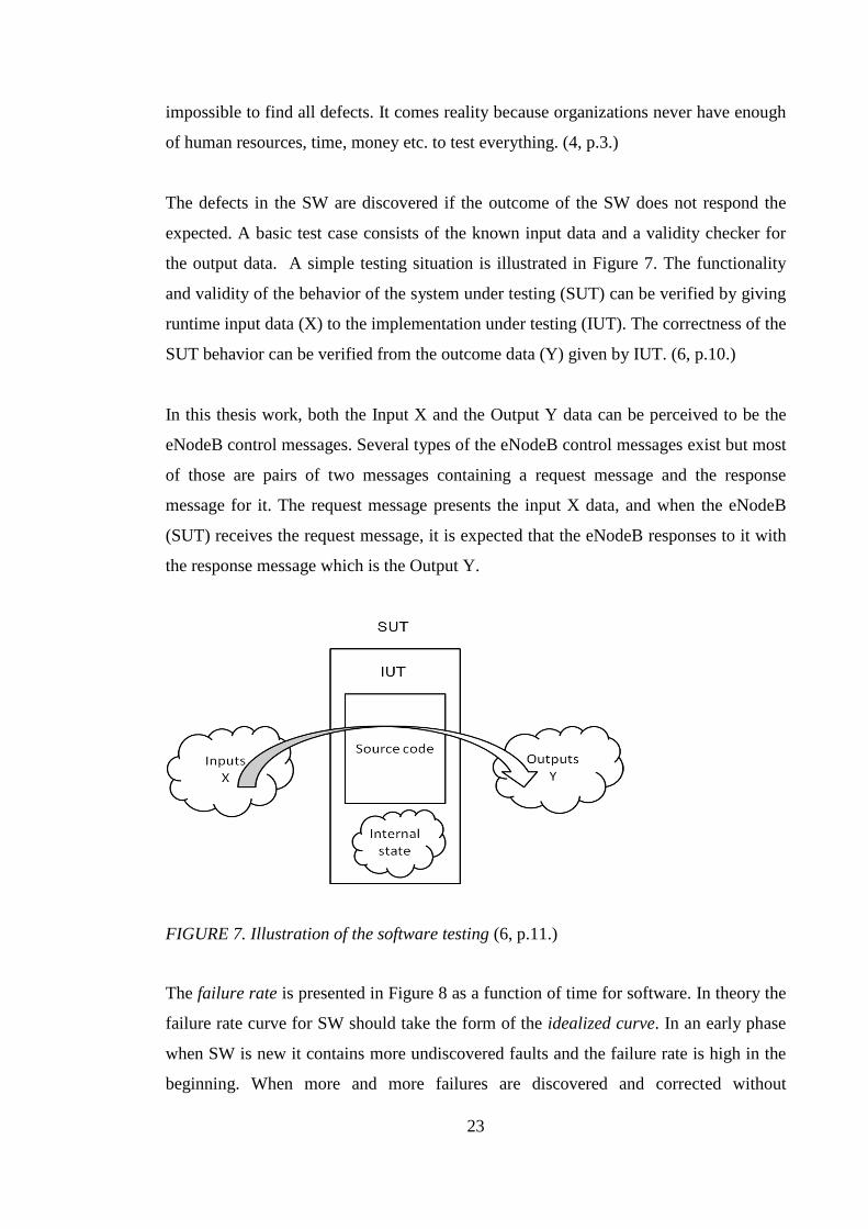
the output data. A simple testing situation is illustrated in Figure 7. The functionality
and validity of the behavior of the system under testing (SUT) can be verified by giving
runtime input data (X) to the implementation under testing (IUT). The correctness of the
SUT behavior can be verified from the outcome data (Y) given by IUT. (6, p.10.)
In this thesis work, both the Input X and the Output Y data can be perceived to be the
eNodeB control messages. Several types of the eNodeB control messages exist but most
of those are pairs of two messages containing a request message and the response
message for it. The request message presents the input X data, and when the eNodeB
(SUT) receives the request message, it is expected that the eNodeB responses to it with
the response message which is the Output Y.
FIGURE 7. Illustration of the software testing (6, p.11.)
The failure rate is presented in Figure 8 as a function of time for software. In theory the
failure rate curve for SW should take the form of the idealized curve. In an early phase
when SW is new it contains more undiscovered faults and the failure rate is high in the
beginning. When more and more failures are discovered and corrected without

24
introducing new errors, the curve flattens. The actual curve presents a more realistic
failure rate when new changes are implemented in the SW. After the changes have been
made, there is a high probability that new defects are introduced causing to spike in the
failure rate. All defects caused by the previous change are not discovered and corrected
when another change is requested causing the actual curve spike again. As a
consequence of this, the minimum level of the failure rate begins to rise. Every failure
indicates an error in the process from design to implementation. The quality of the SW
is deteriorating due to the change. (7, p.8.) The SW testing methods presented later on
strive to reduce the magnitude of the spikes and the slope of the actual curve.
FIGURE 8. Idealized and actual failure curves for software (7, p.8.)
The software testing models used in software projects are presented in the next chapters.
The models are commonly used to find defects effectively in as early a phase of a SW
project as possible.
3.2 Software development process model 1: Waterfall model
The waterfall model is a classic SW development life cycle (SDLC) model. The classic
waterfall model was suggested by Rouce in 1970. The waterfall model is the oldest and
most widely used paradigm of the SDLC. The most common illustration of the
waterfall model is presented in Figure 9. It is a linear sequential model and suggests a

25
systematic sequential approach to the SW development that begins at the system level
and progresses through the requirements, analysis, design, coding, testing, and support.
(8, p.123-125.)
FIGURE 9. Waterfall model (8, p.124.)
The basic idea in the waterfall model is to split the main phases of the SDLC in separate
steps. The number of the steps is not fixed and the amount of them depends on the scale
of the project. In complex, large-scale projects some of the presented steps could be
split to be smaller and, on the contrary, in small-scale projects the steps can be even
merged. The progress onto the next phase requires an approval of the outcome from the
previous phase. If the approval is not granted, the required corrections need to be done
before progress is possible. (8, p.125.)

26
Weaknesses of using of the waterfall model:
1. Real projects rarely follow the sequential flow that the model proposes.
Although the linear model can accommodate iteration, it does so indirectly. As a
result, changes can cause confusion as the project team proceeds.
2. It is often difficult for the customer to state all the requirements explicitly. The
linear sequential model requires this and has a difficulty in accommodating the
natural uncertainty that exists at the beginning of many projects.
3. The customer must have patience. A working version of the program(s) will not
be available until late in the project time-span. A major blunder, if undetected
until the working program is reviewed, can be disastrous.
(7, p.30.)
3.3 Software development process model 2: V model
The V model has similarities with the waterfall model but it is a further developed
version of it. The SW testing is done during the SW development process and is not left
to the end of the project, as it is done in the waterfall model. (9.) That leads to
foundation of the V model. The V model responds to the weaknesses listed in the
previous chapter well. The V model is a commonly used process model in the software
projects of NSN.
The individual steps of the V model process are from top-to-down almost the same as in
the waterfall model. Difference in the V model is that instead of going down like in the
waterfall in a linear way the process steps are bent upwards at the coding phase to form
the typical shape of the V as presented in Figure 10. The reason for this is that for each
of the design phases it was found that there is a counterpart in the testing phases which
correlate each other. (10.)
The process of the V model begins with the requirements gathering. In a close co-
operation with a customer the overall objectives for the software are defined. The
purpose is to continuously outline the areas where the further definition is required.
After a change in the code every of the testing phase results are evaluated and used to

27
refine the requirements for the software to be developed. Iteration occurs as the change
is tuned to satisfy the needs of the customer while at the same time understanding what
needs to be done is improved. (7, p.30-31.)
In the V model the testing is incorporated into the entire SDLC. The left side of the V
model represents the steps of the requirement work and creation of the system
specifications. The right side of the V model represents the integration of parts and
validation steps. (11.)
FIGURE 10. The V model of software testing (14.)
The unit testing (UT) level is the first testing phase. Entering this level requires that
80% of the requirements must be completed. The UT is also often called a module test
(MT) because it tests the individual units of the source code that comprise the
application. The UT is a series of stand-alone tests, conducted by the developer. Each of
the tests examine an individual component that is a new or has been modified. In the
NSN’s SW process the UT and the MT are separated testing phases. The system testing
(ST) described in the source material is more or less a part of the MT as the system
designates one of the eNodeB’s SW applications in the NSN’s SW process. (9, p.8.)
28
In the NSN’s SW process the MT testing level pertains under the UT in the V model’s
testing steps. Entering this level requires that the UT for each of the SW modules has to
be completed and passed. The tests of this level verify all of the SW components and
SW modules that are new, changed, affected by a change, or needed to form the
complete SW application. The testing of the individual SW application may require
involvement of other SW applications but this should be avoided as much as possible to
minimize outside factors. Working this way reduces the risk of the externally-induced
problems. On this level of testing the stubs are commonly used to replace the other SW
applications required in the system. The main targets of the MT are the validation and
verification of the functional design specification and that all the SW modules work
together.
The integration testing (IT) level is the second phase of testing in the V model. In this
level all the individual SW modules and SW applications are combined together to form
the complete system. Entering this level requires that the MT for each of the SW
modules has to be completed and passed. The IT’s focus is to test the interactions
between all the SW modules that are new, changed or affected by a change. Contrary to
the MT level, the IT requires involvement of the other systems and interfaces with the
other SW applications. (9, p.9.) The IT is discussed in more detail in the next chapter.
The ST level is the third phase of the testing in the V model. Entering this level requires
that the status of the IT has to be in the required level. The ST, in the NSN’s SW
process designates that at the first time the eNodeB is connected to be one of the
network elements under the EPC. In this phase the eNodeB becomes a part of the E-
UTRAN where the RRC starts to control the eNodeB’s baseband.
The acceptance testing (AT) level is the fourth and the last testing phase of the V model.
It is also often called the end-user testing. A software vendor often uses real end-users
in the AT to test the provided SW. In the NSN’s case it means that the AT is done as a
field trial in close co-operation with a mobile operator. In the field trial a new version of
the eNodeB SW is launched in a limited area of the operator’s mobile network. Before
29
the final release of the eNodeB SW all of the defects found from the eNodeB SW have
to be corrected. (9, p.10.)
3.4 Integration testing
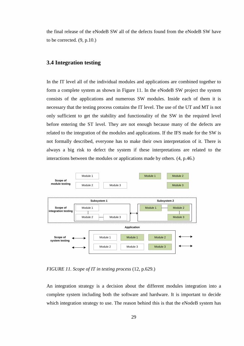
In the IT level all of the individual modules and applications are combined together to
form a complete system as shown in Figure 11. In the eNodeB SW project the system
consists of the applications and numerous SW modules. Inside each of them it is
necessary that the testing process contains the IT level. The use of the UT and MT is not
only sufficient to get the stability and functionality of the SW in the required level
before entering the ST level. They are not enough because many of the defects are
related to the integration of the modules and applications. If the IFS made for the SW is
not formally described, everyone has to make their own interpretation of it. There is
always a big risk to defect the system if these interpretations are related to the
interactions between the modules or applications made by others. (4, p.46.)
Module 1
Module 3Module 2
Module 1 Module 2
Module 3
Scope of
module testing
Module 1
Module 3Module 2
Scope of
integration testing
Subsystem 1
Module 1
Module 3Module 2
Module 1 Module 2
Module 3
Subsystem 2
Application
Scope of
system testingModule 1
Module 2 Module 3
Module 1 Module 2
Module 3
FIGURE 11. Scope of IT in testing process (12, p.629.)
An integration strategy is a decision about the different modules integration into a
complete system including both the software and hardware. It is important to decide
which integration strategy to use. The reason behind this is that the eNodeB system has
30
dependencies between the different software modules, applications, hardware parts and
the hardware and software. At certain moment all these parts have to be ready for the
integration. The moment when all the parts are ready for integration depends on the
followed strategy. The decision about the one strategy to follow should be made as early
as possible because it has a strong effect on the scheduling of project activities. (4, p.46.)
There exists three different integration strategies: Big bang, Bottom-up and Top-down.
The strategies are not mutually exclusive and there are exists variations of these three.
(4, p.46.)
3.4.1 Non-incremental integration
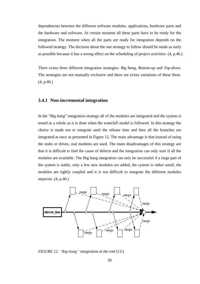
In the “Big bang” integration strategy all of the modules are integrated and the system is
tested as a whole as it is done when the waterfall model is followed. In this strategy the
choice is made not to integrate until the release time and then all the branches are
integrated at once as presented in Figure 12. The main advantage is that instead of using
the stubs or drives, real modules are used. The main disadvantages of this strategy are
that it is difficult to find the cause of defects and the integration can only start if all the
modules are available. The Big bang integration can only be successful if a large part of
the system is stable, only a few new modules are added, the system is rather small, the
modules are tightly coupled and it is too difficult to integrate the different modules
stepwise. (4, p.46.)
FIGURE 12. “Big-bang” integration at the end (13.)

31
3.4.2 Incremental integration
The incremental model software is developed and tested in small but usable pieces,
called ‘increments’ as shown in Figure 13. In general each increment builds on those
that have already been delivered. The first increment is often called as core product.
Next coming iterations modify always the previous increment version to meet better the
needs of customer and the delivery of additional features and functionality. Based on the
fact in complex systems the software evolves over a period of time. Requirements of
product often change as development proceeds, making a straight path to an end product
unrealistic. Because the evolutionary nature of software used process models should be
iterative. (7, p.34-35.)
FIGURE 13. Incremental model (7, p.35.)
The strategy of the incremental testing usually follows the main steps of the V model.
The basic idea is that the SW is tested in modules, as they are completed (unit tests);
then integrated to the test groups of the tested modules with the newly completed
modules (integration tests). This process continues until all the package modules have
been tested. Once this phase is completed, the entire package is tested as a single entity
(system test). Basically every phase of testing contains integration work. The
32
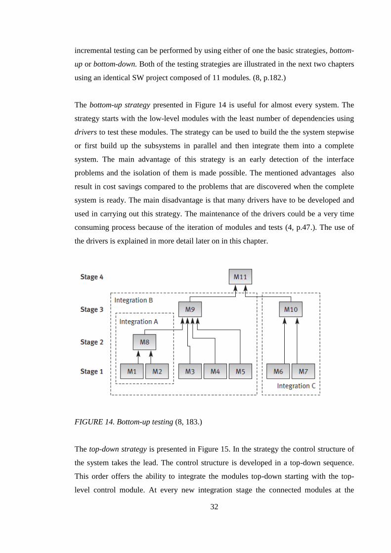
incremental testing can be performed by using either of one the basic strategies, bottom-
up or bottom-down. Both of the testing strategies are illustrated in the next two chapters
using an identical SW project composed of 11 modules. (8, p.182.)
The bottom-up strategy presented in Figure 14 is useful for almost every system. The
strategy starts with the low-level modules with the least number of dependencies using
drivers to test these modules. The strategy can be used to build the the system stepwise
or first build up the subsystems in parallel and then integrate them into a complete
system. The main advantage of this strategy is an early detection of the interface
problems and the isolation of them is made possible. The mentioned advantages also
result in cost savings compared to the problems that are discovered when the complete
system is ready. The main disadvantage is that many drivers have to be developed and
used in carrying out this strategy. The maintenance of the drivers could be a very time
consuming process because of the iteration of modules and tests (4, p.47.). The use of
the drivers is explained in more detail later on in this chapter.
FIGURE 14. Bottom-up testing (8, 183.)
The top-down strategy is presented in Figure 15. In the strategy the control structure of
the system takes the lead. The control structure is developed in a top-down sequence.
This order offers the ability to integrate the modules top-down starting with the top-
level control module. At every new integration stage the connected modules at the

33
corresponding level are integrated together and tested. The main advantage of this
strategy is that the entire system can be verified partially or as a whole. The main
disadvantage of this strategy is that if the requirements are changed and the change has
an impact on the low-level modules it may lead to changes in the top-level. Another
disadvantage is the conciderable number of stubs needed to test every integration step.
(4, p.47.)
FIGURE 15. Top-down testing (8, p.183.)
The Stubs and drivers are defined as the SW replacement simulators that are required
for the modules not available when performing UT or IT. In the top-down strategy the
testing stubs are used to replace the unavailable lower level modules as presented in
Figure 16. The main function of the stubs is to provide the result of calculations the
subordinate module is designed to perform. (8, p.184.)

34
FIGURE 16. Use of the stubs in implementing top-down tests (Stage 3. in Figure 16). (8,
p.185.)
In the bottom-up strategy the testing requires the drivers instead of stubs. A driver can
be seen as a substitute module for the stub but of an upper level. It activates the module
tested as presented in Figure 17. The driver is used for passing the test data onto the
tested module and accepting the results calculated by it. Drivers are required in the
bottom-up testing until the upper level modules are developed. (8, p.185.) The ATETT
is a one type of driver used to control the eNodeB system. Two of the main reasons why
the drivers are used in the LTE DSP SWi testing level are:
They isolate the lower level SW modules out of control by the RRC system.
They permit to test the lower level SW modules before the upper layer SW are
available.

35
FIGURE 17. Use of the drivers in implementing of bottom-up tests (Stage 2. in Figure
14). (8, p.185.)
3.5 Testing types
Various types of the SW testing exist as functional verification of requirements testing,
performance, regression, security etc. All the testing types can be categorized to one or
two of the main categories: black-box-, white-box- and gray-box testing. (15, p.11.)
3.5.1 White-box testing
The white-box test design techniques are based on the knowledge of the system’s
internal structure. The white-box testing process is illustrated in Figure 18. The unit
testing and code coverage testing are an example of the white-box testing where test
design is based on the code, program descriptions and technical design. The testing type
requires some working knowledge of the code and design. The main focus in this type
of testing is that the system successfully satisfies its functional requirements. (15, p.12.)

36
FIGURE 18. White-box testing (16.)
3.5.2 Black-box testing
The black-box test is also known as the “user interface” test. The black-box testing
process is illustrated in Figure 19. Its test design techniques are based on the functional
behavior of systems. It doesn’t require explicit knowledge of the implementation details
as the white-box testing does. In black-box testing the system is a “black box” while the
inner working of the system is not needed to know. The system is subject to input and
the result output is analyzed if it conforms to the expected system behavior based to
requirements of the system. The system behavior is verified only by viewing the output
of the user interface. (15, p.12.)
FIGURE 19. Black-box testing (16.)
3.5.3 Gray-box testing
The gray-box test design is used to increase black-box testing effectiveness. This design
overcomes the problem of not discovering all defects in a system. while using the black-
box testing. The simple reason for this is that all the errors may not be reported to the
user interface due to the error-reporting mechanism of the software. The gray-box test
design requires knowledge of the components used to build the system . Deeper
understanding of the architecture and components of an application allows a tester to
pinpoint test outcomes to different areas of the application. The gray-box testing is

37
based on the multiple outcomes, and by analyzing the results tester is able to found out
the parts of the application that are failing. (15, p.12.)
3.6 LTE DSP SW integration
NSN’s eNodeB SW projects based on the V model and the SW and hardware (HW) are
developed further using the incremental model. Additionally chosen decision is made to
follow the bottom-up strategy where lower level modules are developed before the
control elements.
NSN’s LTE DSP SWi testing is a very good example of an integration testing in a large
scale SW project and for a large size system. The eNodeB system consist of both
embedded HW and a very complex DSP SW that the LTE DSP SWi tests.
Because the use of the incremental model and the multiple combinations of HW and
SW the integration testing cycle measured in time is very short in all of the test levels.
Based on the fact mentioned earlier, in complex systems the software evolves over a
period of time. Requirements of the product often change during the development
process. The mentioned issues lead to the situation where also the requirements of DSP
SW APIs change from time to time.
In the LTE DSP SWi testing level the test engineer works most of the time by using all
three of the testing types presented in the chapter 3.5. The eNodeB control messages
(request, response and indication messages) present the input and the output of the SUT
(eNodeB system) as it is presented in Figure 20. It is specified that the eNodeB has to
respond to all received eNodeB control messages with a response message. The
response message contains specific information which depends on the received request
message. The information in the response is used to verify if the structure of the request
message is valid or not. In the scope of this thesis only the message structures are
considered . The testing type is the black-box testing since it considers only the input
and the output data of the eNodeB.

38
FIGURE 20. The eNodeB control messages are used as input and output testing data.
The eNodeB control messages have a major role in LTE DSP SWi testing because of
the type of used ATE. The ATE of the LTE DSP SWi contains only the L1 and L2
layers and not the L3 which controls the L1 and L2 layers in entity systems. The lack of
the L3 and the higher network layers defines the type of the ATE. The high level
illustration of the LTE DSP SWi type of the ATE is presented in Figure 21.
L3 layer replaced with ATE:
- ATETT
- ATE Library
- CI
- SVN
L1 & L2 layers:
- eNodeB (System module & RF
module)
- Test Terminal (UE)
eNodeB
LTE-Uu
UE
Test PC
SVN server
LAN/WAN
ATETT
SVN client: A local
copy of ATE library
ATE library
Test Data
Continuous Integration (CI)
Server
CI manager
FIGURE 21. The LTE DSP SWi type of test environment

39
3.6.1 ATETT
The ATETT is the main testing tool used in the LTE DSP SWi. It is a testing SW and it
is developed in NSN by an internal test environment team. The ATETT is used mainly
in low level integration to execute the tests and test environment configurations. It also
provides all the needed interfaces in LTE DSP SWi test environment including support
for the automation.
The ATETT is a testing SW and it is also one type of driver used in the LTE DSP SWi
testing stage to replace the RRC functionality in a required level. All the eNodeB
control messages between the eNodeB and ATETT application are handled through a
TCP connection. Figure 18 presents an example of the use of the driver in the SW
testing that follows the bottom-up strategy.
The IFS of ATETT specifies an own scripting language and a format for the eNodeB
control messages. All of the scripts, eNodeB control messages and other testing related
data are stored in the ATE testing library for maintenance.
3.6.2 ATE library
The ATE library is a database where the entire test data made for eNodeB testing
purposes by LTE DSP SWi team is collected. The main purposes of using the ATE
library is to get all the files used in testing maintained, under version control and to get
the latest test data available for every tester globally.
The ATE library is split into two main branches; tests and services. The services branch
contains all the eNodeB control messages. The test branch contains all the test case
scripts. The test scripts use the eNodeB control messages to setup the eNodeB with
different kind of configurations as comprehensively as possible. The main purpose is to
verify the correct functionality of the eNodeB in every situation.
40
3.6.3 Test automation in LTE DSP SW integration
The ATE of the LTE DSP SWi is partially automated. The current automation is based
on continuous integration (CI) which is a commonly used practice in the Agile SW
development. The aim of the automated CI testing in LTE DSP SWi testing is to
provide a quick result for every DSP SW build. It is required that the first test result of
each build has to be available within two hours.
41
4 APPLICATION DEVELOPMENT PROJECT
The definition for software by Myers: “Software is (1) instructions (computer programs)
that when executed provide desired function and performance, (2) data structures that
enable the programs to adequately manipulate information and (3) documents that
describe the operation and use of the programs.” In general, SW is used to produce
information. SW delivers the computing potential embodied by the computer HW. SW
can be used as an example to transform, produce, manage, acquire, modify, display, or
transmit information. In general, SW has multiple using purposes and one of them is to
transform data so that it is more useful in a local context. (5, p.4-6.)
This chapter presents the implementation project of the PC application made for the
LTE DSP SWi testing purposes. The chapter goes through the key languages, tools used
during the project. The requirements and key functionalities of the CTA and XML
conversion plug-in are presented.
4.1 Used tools and languages
This chapter presents all tools and languages which were used either in the development
process of the tool or are in some other way tightly related to this work.
4.1.1 Qt programming language
The first version of the Qt framework was the Qt 0.90 and it was released in 1995 by
Haavard Eirik and Chambe-Eng. The Qt was based on the C++ programming language.
At the beginning, the Qt framework only contained a cross-platform graphical user
interface (GUI) toolkit. The cross-platform approach of the Qt means that a programmer
can use a single source tree for applications that can be run on Windows 98 to XP, Mac
OS X, Linux, Solaris, HP-UX, and many other versions of Unix with X11. The cross-
platform framework is still one of the main strengths of the Qt. The later releases of the
42
Qt framework extend the framework with: signals and slots mechanism, Unicode,
multithreading, databases, internationalization, networking and XML. (17, p.xi, xv-xvi,
451-452.)
The Qt is available under various licenses. A commercial license of the Qt is required in
a case of commercial applications. The general public license (GPL) version of the Qt is
available for non commercial open source programs. (17, p.xii.) The application made
for the company’s internal use only can be done under the GPL, as the application in
this thesis for NSN.
The Qt software development kit (SDK) combines the Qt framework including the class
library with tools (simulator, local and remote compilers, internationalization support,
device toolchains etc.). The SDK is needed in the creation of the applications. The
content of the Qt SDK is presented in Figure 22. The newest release of the Qt library is
version 4.8. (18.)
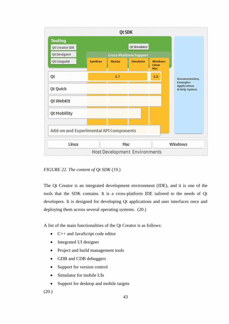
43
FIGURE 22. The content of Qt SDK (19.)
The Qt Creator is an integrated development environment (IDE), and it is one of the
tools that the SDK contains. It is a cross-platform IDE tailored to the needs of Qt
developers. It is designed for developing Qt applications and user interfaces once and
deploying them across several operating systems. (20.)
A list of the main functionalities of the Qt Creator is as follows:
C++ and JavaScript code editor
Integrated UI designer
Project and build management tools
GDB and CDB debuggers
Support for version control
Simulator for mobile UIs
Support for desktop and mobile targets
(20.)

44
In this thesis, the following were the main reasons why the Qt programming language
was chosen to the programming language of the PC application:
Support for XML data handling. The main functionality of the XML conversion
plug-in is to convert the source data from the XML format to the format of the
eNodeB control messages. Because the source data is in the XML format, most
of the functionalities of the application are related to the XML processing.
The SW organization of NSN has a mixed set of platforms in use that contains
Windows and Linux PCs. From that reason it was natural to select a
programming language that supports both of the platforms.
The Qt library version 4.7 and the Qt Creator 2.2.0 version were used in the application
development project. The Qt library version provides two different types of APIs for
processing XML data:
SAX (Simple API for XML)
DOM (Document Object Model)
(17, p.339.)
The main difference between the SAX and the DOM is that an XML document is read
in the memory when the DOM is used. The DOM represents the entire XML document
as a three of the XML node objects. After the document is read in the memory,
applications can then parse and modify it. Approach of the SAX is simpler than that of
the DOM, and it can only be used to read the XML document. The SAX does not read
the entire XML document in the memory. (17, p.339, 344.) In the implementation of the
XML conversion plug-in, the DOM was used. It provided a good base for a dynamical
XML parser.
4.1.2 XML modeling language
The first version of XML was introduced in 1998 by a group of companies and
organizations that called themselves the world wide web consortium (W3C). XML is a
programming language based on the standard generalized markup language (SGML).
SGML is a metalanguage whose primary task is to define other markup languages.

45
SGML is parent for both XML and the hypertext markup language (HTML), and this
relation is presented in Figure 23. The extensible HTML (XHTML) is a reformulation
of HTML using XML. XML is a markup language that defines a subset of SGML
meant to work more efficiently with networked applications. (21, p.15-16.)
FIGURE 23. Relations of the markup languages (21, p.15.)
XML is a software- and hardware-independent ‘tool’ for carrying information. The
main differences between HTML and XML are that HTML is about displaying
information whileXML is about carrying information. Another difference between these
languages is that the tags in XML are not defined by any XML standard. The tags are
invented by the author of the XML documents. In HTML, the tags used are predefined
by the HTML standard unlike in XML. (22.)
A markup language uses tags that can be placed in the text of a document to determine
and label the parts of that document. The tags are important in electronic documents
because computer applications use them when processing documents. The tags used to
determine the exact boundaries for a certain part of document. If the tags are missing,
the program have to has with the entire document as a unit. (23, p.2-3.)
A markup language is a language used to label, categorize and organize data or
document content. The markup describes a document or data structure and organization.
46
The content, such as text, images and data, is the content of the markup. (20, p.14)
XML is not itself a markup language. It is a set of rules for building markup languages.
It makes it possible to make up an individual markup language to express the
information in the best way possible. (23, p.12.)
A software application that contains an XML processor is able to process XML. It
means that the application is able to read an XML file and do something with it. The
basic idea is that the XML processor is used to read XML files and transforming them
into an internal representation for other applications or subroutines to use. This is called
an XML parser and it is one of the main components of every application that processes
XML data. (23, p.8.)
XML has a major role in this thesis because the source data that the XML conversion
plug-in converts is in the XML format. The Qt library version used in the application
development project offers two different types of XML APIs, which was presented in
the previous section (4.1.1).
4.1.3 UML modeling language
The first version of the UML was introduced in 1997 by Booch, Rumbaught and
Jacobson. UML is a language or notation intended for analyzing, describing and
documenting all aspects of a SW intensive system. It is further developed from the
object modeling technique (OMT) (A method found by J. Rumbaught), Booch (A
method founded by G. Booch) and OOSE (A method founded by I. Jacobson). Since the
year 1997 the language has been developed with a dynamic set of new features, and
minor releases are released by referring to them as UML1.x. Currently, the newest
versions of UML are known as UML2.x and the released versions of it are designed to
extend the UML1.x. (24, p.1.)
UML is an industry standard mechanism that provides a comprehensive set of SW
modeling instruments. The set contains: graphical elements, including notation for

47
classes, components, nodes, activities, ports, workflow, use cases, objects, states and the
relationships between all these elements. (24, p.1-2.)
A modeling represents in general a highly creative work and it is a method used to
search the best solutions for a certain module to achieve the goals and the requirements
of the project under construction. During the modeling work the designers have to
investigate the needs, preferences, structure and design for the project. The predefined
needs and preferences are called requirements. The requirements include areas such as
functionality, appearance, performance and reliability. Using the iterative approach in
co-operation with the developers the model designers try to reach a deeper
understanding of the system and can finally create models of the systems that achieve
the goals and requirements of the system and its users. Communicating a model in a
clear way to many people represents a core feature of UML. (24, p.2-3.)
There is no simple way to model a complex system. It is impossible to represent the
entire system clearly in a single picture that all understand without confusion. A single
graph cannot capture all the information needed to describe a system. A system has
many different aspects: functional (its static structure and dynamic interactions),
nonfunctional (timing requirements, reliability, deployment etc.), along with
organizational aspects (work organization, mapping to code modules etc.). A system
description requires a number of views, where each view represents a projection of the
complete system that shows a particular aspect. Each of these views requires a number
of diagrams that contain information emphasizing a particular aspect of the system. The
diagrams contain graphical symbols that represent the model elements of the system.
(24, p.21.)
A list of different views in UML is as follows:
Use-case view: A view showing the functionality of the system as perceived
by external actors.
Logical view: A view showing how the functionality is designed inside the
system, in terms of the system’s static structure and dynamic behavior.
Implementation view: A view showing the organization of the code and the
actual execution code.

48
Process view: A view showing the main elements in the system related to the
process performance. This view includes the scalability, throughput, and basic
time performance and can touch some very complex calculations for advanced
systems.
Deployment view: A view showing the deployment of the system into the
physical architecture with computers and devices called nodes.
(24, p.21.)
UML is a powerful tool when it is used in planning the architecture of the SW. In the
SW project of this thesis it was mainly used to draw use-case views and logical views.
4.1.4 SVN version control
The version control is used to manage the changes in the information. People who are
using computers to manage information that changes are often people who need the
version control. The version control is a widely used system by the SW developers who
typically spend their time making small changes in software and then undoing or
checking some of those changes the next day. It helps the developers of a team to
successfully commit new changes without losing anything into the existing files when
the developers are working concurrently using the same repository and sometimes even
simultaneously on the very same files. (25, p.1.)
In the application project of this thesis the TortoiseSVN subversion and its basic
features were used. TortoiseSVN is one of the subversion version types available. The
TortoiseSVN is a free open-source Windows client for the Apache Subversion version
control system. The subversion manages files and directories over time which is a basic
functionality in every version control system. It can operate across networks which
allow it to be used by people on different computers. The files are stored in a central
repository. The repository is much like an ordinary file server, except that it remembers
every change ever made to the files and directories. This feature allows the users to
recover older versions of the files and examine the history of how and when the data
changed and who changed it. Figure 24 illustrates the architecture of the subversion
system. (26, p.xi)

49
FIGURE 24. Subversion architecture (25, p.4.)
A SVN repository is possible to branch into separate branches. The branching makes
possible to develop multiple SW iterations in parallel. The branching isolates the SW
iterations from other iterations. Use of the branching, guarantees that a change made in
a certain iteration of the SW does not have influence to the other the SW iterations in
the same SVN repository. The branching of a repository is illustrated in Figure 25. The
original line of development (trunk) that exists independently of other lines (branches)
shares a common history. A branch always begins life as a copy of trunk, and moves on
from there generating its own history. (25, p.42.)

50
FIGURE 25. Branches of SW development (25, p.42.)
At the beginning of the project three branches were created. This was done because the
trunk branch was used to develop and maintain the common interface of the CTA. Two
other branches were reserved for two independent software plug-ins that were planned
to be developed. Another one of these two was the XML conversion plug-in.
After the first working version of Common testing tool and its interface for plug-ins was
ready, source codes from the trunk branch were merged to the other two branches. After
the merging operation the development process of the plug-ins continued independently.
The branching was used to control the influence of changes. The changes were made to
certain branch and then merged between the branch and the trunk. The changes were
tested before merging.
The branch that was used to develop the XML conversion plug-in contained 43 different
revisions in the end of SW project. It means that 43 changes committed in the SVN
repository before the functionality of the CTA’s and the XML convert plug-in was in
the required level and functionality worked without errors.

51
4.2 CTA
The CTA is a PC application. The CTA is made by using the Qt programming language
and class library of it. Testing PCs used in LTE DSP SWi testing contain both Windows
and Linux operating systems. The CTA must work on top of both of them. That is why
it was very useful to choose Qt cross-platform development environment and
framework.
Name of CTA refers in that the application is developed into the testing purposes and
‘common’ comes because it is extendable with software plug-ins. The CTA provides a
common interface for numerous of individual testing software (plug-ins). It does not
itself provide any testing functionalities without plug-ins. Basically, the CTA acts as
framework for its plug-ins. The CTA provides only the main window (widget) with
very simple visual layout from user point of view. The layout consists of common
graphical user interface (GUI) containing only basic menus.
The main idea behind the CTA and its common plug-in interface was respond to two of
the known problems related to small size tools developed inside the NSN’s SW
organization:
1. SW engineers develop numerous small size tools to help their daily work. Most
of these tools are used only by developer itself and in some cases by few other
persons.
2. The small size tools are lost many times during the time because the tools are
usually stored only in the hard drive of certain laptop or PC.
The CTA can be used to collect under its common interface all such small size tools that
are usable for more than one person inside the SW organization. In general, the common
widget where all individual tools provide their own GUI is more user friendly approach
than 100 small tools spread around the SW organization.
52
4.2.1 User scenario of CTA
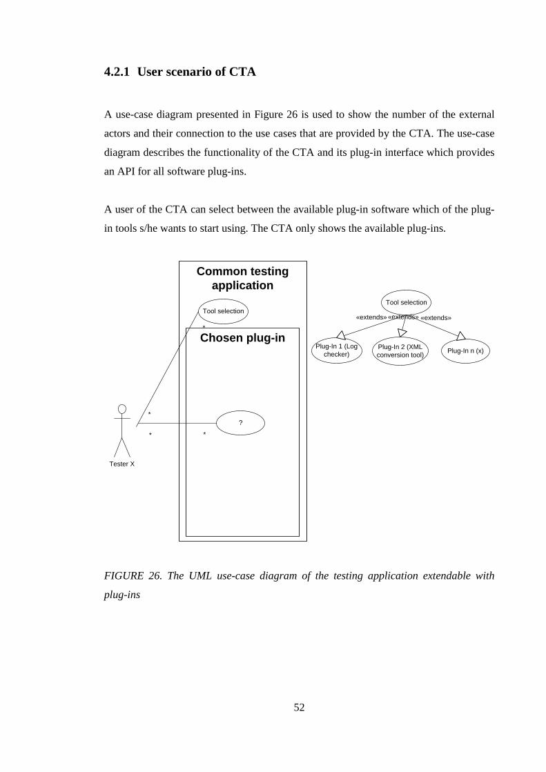
A use-case diagram presented in Figure 26 is used to show the number of the external
actors and their connection to the use cases that are provided by the CTA. The use-case
diagram describes the functionality of the CTA and its plug-in interface which provides
an API for all software plug-ins.
A user of the CTA can select between the available plug-in software which of the plug-
in tools s/he wants to start using. The CTA only shows the available plug-ins.
Common testing
application
Tester X
Tool selection
*
*
Tool selection
Plug-In 2 (XML
conversion tool)
Plug-In 1 (Log
checker)
«extends»«extends»
Chosen plug-inPlug-In n (x)
«extends»
?
* *
FIGURE 26. The UML use-case diagram of the testing application extendable with
plug-ins
53
4.2.2 Plug-in interface of CTA
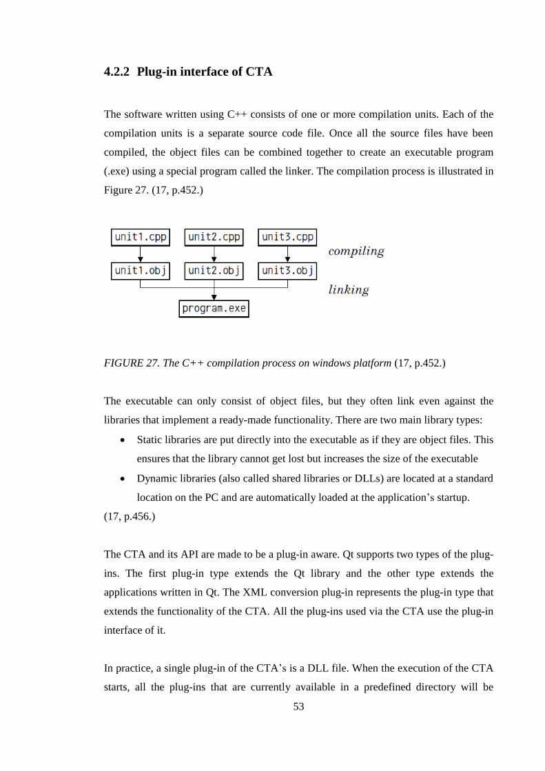
The software written using C++ consists of one or more compilation units. Each of the
compilation units is a separate source code file. Once all the source files have been
compiled, the object files can be combined together to create an executable program
(.exe) using a special program called the linker. The compilation process is illustrated in
Figure 27. (17, p.452.)
FIGURE 27. The C++ compilation process on windows platform (17, p.452.)
The executable can only consist of object files, but they often link even against the
libraries that implement a ready-made functionality. There are two main library types:
Static libraries are put directly into the executable as if they are object files. This
ensures that the library cannot get lost but increases the size of the executable
Dynamic libraries (also called shared libraries or DLLs) are located at a standard
location on the PC and are automatically loaded at the application’s startup.
(17, p.456.)
The CTA and its API are made to be a plug-in aware. Qt supports two types of the plug-
ins. The first plug-in type extends the Qt library and the other type extends the
applications written in Qt. The XML conversion plug-in represents the plug-in type that
extends the functionality of the CTA. All the plug-ins used via the CTA use the plug-in
interface of it.
In practice, a single plug-in of the CTA’s is a DLL file. When the execution of the CTA
starts, all the plug-ins that are currently available in a predefined directory will be
54
loaded in use. The plug-ins dynamically extends the functionality of the CTA’s and
implements one more interface into it. A plug-in interface is a class that only contains
pure virtual functions. This interface is inherited from the class that implements the
plug-in. The class is stored in the shared library and therefore it can be loaded by the
application at the run-time. When the plug-in is loaded, it is dynamically cast with the
interface using Qt's meta-object system. (27.)
The CTA consists of a single TabDialog class that provides an individual tab for each
plug-in. The use of tap dialogs provides a clear and efficient way for the testing
application to communicate with the user. The information that the CTA’s GUI
provides can be split between the plug-ins by using a number of tabs in a dialog. (28.)
The tabs of the testing application are implemented to provide the plug-in specific GUIs
which have no relation between them. The Qt library’s QTabWidget class was used in
the implementation. It provides a stack for tabbed widgets. The tab widget provides a
tab bar that contains an individual tab for each of the plug-ins. The "page area" display
pages were related to each tab. The tab bar of the testing tool and the page area of the
XML conversion plug-in are presented in Figure 28. Each of the tabs is associated with
a plug-in specified widget (page). Only the page of the selected plug-in is shown in the
page area and all the other pages are hidden. The user can start to use different plug-in
software by clicking on its tab. (29.)

55
FIGURE 28. The GUI of the CTA with two tab widgets (two plug-in extensions) - The
XML convert plug-in application (Sack parser V1.0) is selected in use
4.3 XML conversion plug-in for CTA
The XML conversion plug-in is developed to extend the functionalities of CTA. It is
used to generate the eNodeB control messages. The main functionality of the plug-in is
to transform the XML source data to the format of the eNodeB control messages
defined by the IFS of the ATETT.
4.3.1 User scenario of XML conversion plug-in
A user of the XML conversion plug-in could be any one of the testers who works in the
LTE DSP SWi team. When the DSP SW application interface(s) of the eNodeB system

56
changes, all the testers in the team know what to do and start to follow the protocol
made for the situation. The protocol currently contains many manual actions. The use of
the CTA with the XML conversion plug-in removes one of the manual actions and the
laborious one, from the point of view of the LTE DSP SWi.
The XML conversion plug-in is one of the software that is used to extend the CTA. It
provides all the functionalities that are needed to generate the eNodeB control messages
from the source XML files. A high level illustration of the CTA is presented in Figure
29.
Common testing
application
Tester X
Select XML source
folder
*
*
Select target folder
for the eNB messages
**
Tool selection
*
*
Tool selection
Plug-In 2 (XML
conversion tool)
Plug-In 1 (Log
checker)
«extends»«extends»
Tester Y
Tester Z
the location of the
generated eNB messages
*
*
*
*
*
*
XML convert
plug-in Plug-In n (x)
«extends»
Tester F
*
*
Start generating
the eNB messages
*
*
FIGURE 29. The UML use-case diagram of the testing application extended with the
functionality of XML conversion plug-in
57
4.3.2 Input data for XML conversion plug-in
Inside the NSN’s LTE SW project, XML is used to transform the existing data
according to the rules (refactoring). The content of the XML source data is based on the
IFS of C-Based messages. The XML conversion plug-in uses the XML source data and
convert it in the format of the eNodeB control messages. The amount of the XML
source data is considerable. It consists of 27 separate XML files whose total size is
~3.3Mbytes.
The content of the XML data files consist of the definitions of the information of the
messages. The definitions can belong to messages, definitions and interfaces. The
messages elements only contain the structure definition of the messages. The interfaces
elements store the relation information between the messages and DSP SW applications.
The definitions elements store the information about the content of the messages. The
content is a set of parameters which each have a definition of type, size and default
value. Typically, a message contains 1-1000 parameters. An example of the XML
source file’s structure with a simplified illustration can be seen below:

58
- <system name=" " - <component name=" ">
- <definitions> <typedef name=" " type="u32" />
- <enum name=" "> <enum-member name="1" value="0" /> <enum-member name="2" value="1" />
</enum> - <struct name="SDRbList"> <member name=" " type="Tx" /> <member name=" " type="Sy" /> </struct> - <union name="UUlResCtrlParamContainer">
<member discriminatorValue="0" name="" type="S1" /> <member discriminatorValue="1" name="" type="S2" />
</union> <constant name=" " value=" " />
</definitions> - <messages>
- <message name=" "> <member name=" " type="T1" /> </message>
- <messages> - <interfaces> - <interface name=" " > <message name=" " /> </interface> <interfaces> </component>
</system>
The definitions contain the type definitions for each parameters and it can be one of the
following:
Constant (const): Constants are expressions with a fixed value. (30)
o An example use of the constant in the XML source file:
<constant name="MAX_NUM_OF_FAULT_INFO" value="11" />
Typedef: C++ allows definition by developer using own types based on other
existing data types. It is possible to do by using the keyword typedef. (30)
o Typedef is declared in C++ using the following syntax:
typedef existing_type new_type_name;.
o An example use of typedef in the XML source file:
<typedef name="TBoardId" primitiveType="32 bit integer unsigned" />
59
Structure (struct): Data structure is a group of data elements. The data elements
are grouped together under one name. These data elements, known as members,
can have different types and different lengths. (30)
o Data structures are declared in C++ using the following syntax:
struct structure_name { member_type1 member_name1; member_type2 member_name2; member_type3 member_name3; … } object_names;
o An example use of struct in the XML source file:
- <struct name="SAaTime"> <member name="year" type="u32" /> <member name="month" type="u32" /> <member name="day" type="u32" /> <member name="hour" type="u32" /> <member name="minute" type="u32" /> <member name="second" type="u32" /> <member name="millisec" type="u32" /> </struct>
Union: All the elements of the union declaration occupy the same physical space
in the memory. Union’s declaration and use is similar to the one of structures
but its functionality is different. The size of union is the one of the greatest
element of the declaration. (30.) As seen in example below, the union contains
two different structures. The structures are selectable by defining the
discriminator value.
o Union structures are declared in C++ using the following syntax:
union union_name1 { member_type1 member_name1; member_type2 member_name2; member_type3 member_name3; … } object_names;
o An example use of the enumeration in the XML source file:
- <union name="UUlResCtrlParamContainer"> <member discriminatorValue="0" name="vendor1UlResCtrlParams" type="SVendor1UlResCtrlParams" /> <member discriminatorValue="1” name=" vendor2ParamContainer1" type="SVendor2ParamContainer1" /> </union>
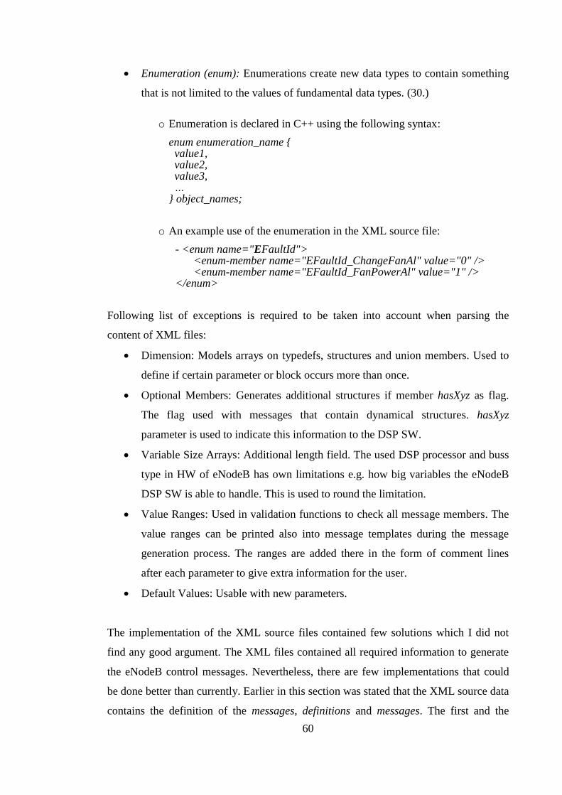
60
Enumeration (enum): Enumerations create new data types to contain something
that is not limited to the values of fundamental data types. (30.)
o Enumeration is declared in C++ using the following syntax:
enum enumeration_name { value1, value2, value3, … } object_names;
o An example use of the enumeration in the XML source file:
- <enum name="EFaultId"> <enum-member name="EFaultId_ChangeFanAl" value="0" />
<enum-member name="EFaultId_FanPowerAl" value="1" /> </enum>
Following list of exceptions is required to be taken into account when parsing the
content of XML files:
Dimension: Models arrays on typedefs, structures and union members. Used to
define if certain parameter or block occurs more than once.
Optional Members: Generates additional structures if member hasXyz as flag.
The flag used with messages that contain dynamical structures. hasXyz
parameter is used to indicate this information to the DSP SW.
Variable Size Arrays: Additional length field. The used DSP processor and buss
type in HW of eNodeB has own limitations e.g. how big variables the eNodeB
DSP SW is able to handle. This is used to round the limitation.
Value Ranges: Used in validation functions to check all message members. The
value ranges can be printed also into message templates during the message
generation process. The ranges are added there in the form of comment lines
after each parameter to give extra information for the user.
Default Values: Usable with new parameters.
The implementation of the XML source files contained few solutions which I did not
find any good argument. The XML files contained all required information to generate
the eNodeB control messages. Nevertheless, there are few implementations that could
be done better than currently. Earlier in this section was stated that the XML source data
contains the definition of the messages, definitions and messages. The first and the

61
second of the notifications below are related to the definitions of the messages. The
third of the notifications is related to the definitions of the definitions.
All the XML source files are generated automatically with a special XML generator tool.
The XML source files contain exceptions, because the way of the XML generator
implementation is done. All the exceptions have to be taken into account while
implementing an application that is used to parse the XML source data. It makes
implementation of XML parsers’ for the eNodeB control messages more complex. Next
three notations are found during the development project of the XML conversion plug-
in. All the three required additional functionalities implemented in the parser of the
XML conversion plug-in.
Description of notation 1 with text and using an example below: The size attribute of
the XML dimension element contains a constant parameter. The constant is used to
define if a certain parameter or structure in the eNodeB control message occurs more
than ones. The MAX_NUM_OF_XMBR is constant value and defines how many times
the eNodeB control message contains TXmbr parameter:
- <component name="MAC"> - <messages>
- <message name=" "> <member name="Xmbr" type="TXmbr"> <dimension isVariableSize="true" size="MAX_NUM_OF_ XMBR" /> </member>
</message> </messages>
</component>
Proposal for the notation 1 explained with text and using an example below: The
definition of the XML message element defines three indexed parameters. The
individual member elements are used instead of that the dimension element defines how
many parameters are required. The XML conversion plug-in or any other tool used to
parse the XML source data does not need extra functionality to handle the dimension. In
example the value of MAX_NUM_OF_ XMBR is three.
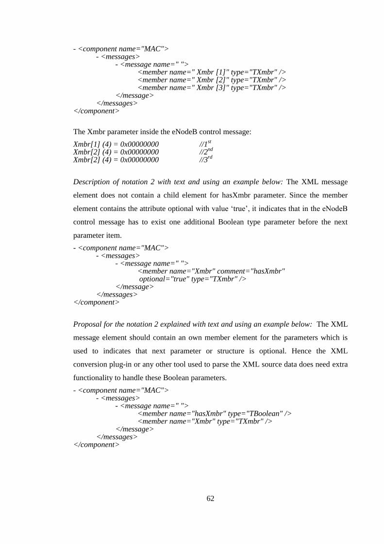
62
- <component name="MAC"> - <messages>
- <message name=" "> <member name=" Xmbr [1]" type="TXmbr" /> <member name=" Xmbr [2]" type="TXmbr" />
<member name=" Xmbr [3]" type="TXmbr" /> </message>
</messages> </component>
The Xmbr parameter inside the eNodeB control message:
Xmbr[1] (4) = 0x00000000 //1st
Xmbr[2] (4) = 0x00000000 //2nd
Xmbr[2] (4) = 0x00000000 //3
rd
Description of notation 2 with text and using an example below: The XML message
element does not contain a child element for hasXmbr parameter. Since the member
element contains the attribute optional with value ‘true’, it indicates that in the eNodeB
control message has to exist one additional Boolean type parameter before the next
parameter item.
- <component name="MAC"> - <messages>
- <message name=" "> <member name="Xmbr" comment="hasXmbr" optional="true" type="TXmbr" />
</message> </messages>
</component>
Proposal for the notation 2 explained with text and using an example below: The XML
message element should contain an own member element for the parameters which is
used to indicates that next parameter or structure is optional. Hence the XML
conversion plug-in or any other tool used to parse the XML source data does need extra
functionality to handle these Boolean parameters.
- <component name="MAC"> - <messages>
- <message name=" "> <member name="hasXmbr" type="TBoolean" /> <member name="Xmbr" type="TXmbr" />
</message> </messages>
</component>
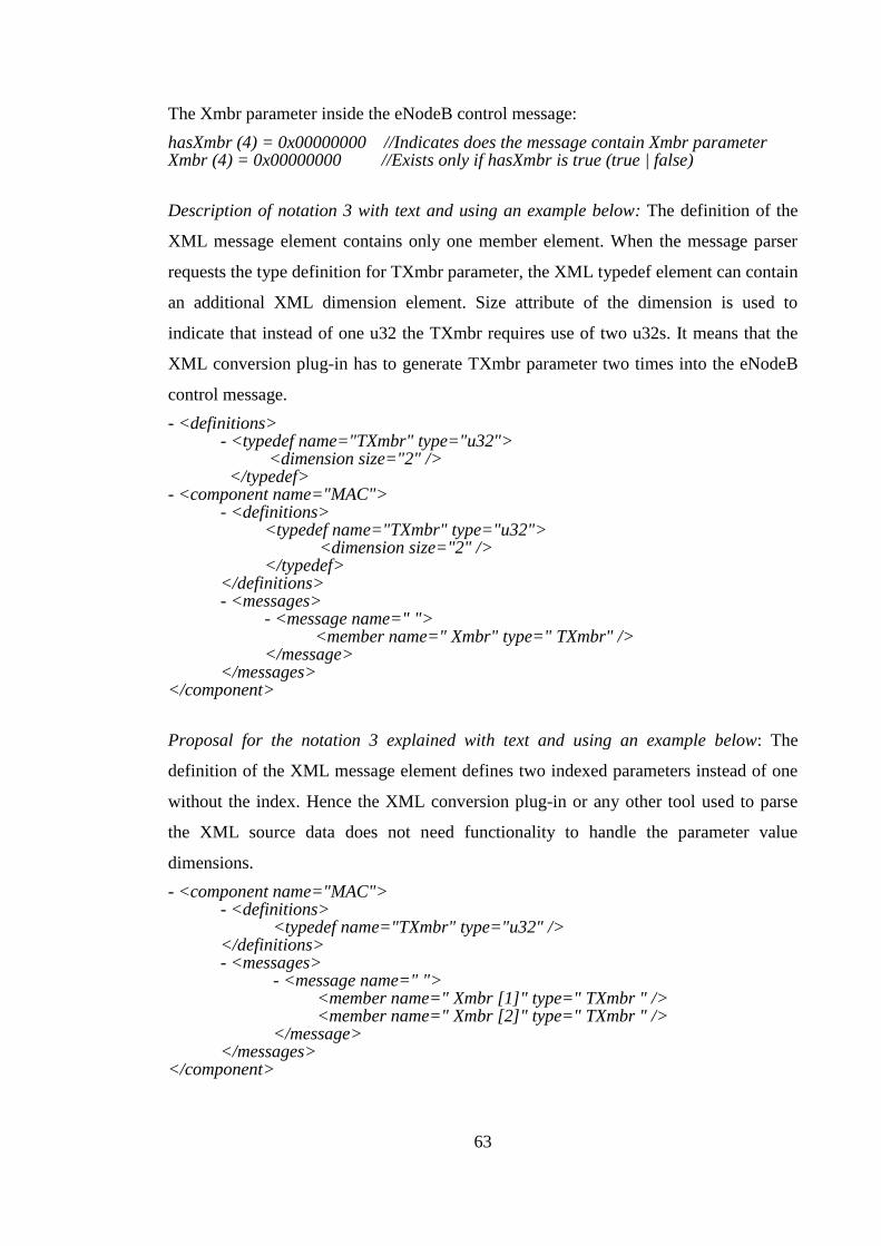
63
The Xmbr parameter inside the eNodeB control message:
hasXmbr (4) = 0x00000000 //Indicates does the message contain Xmbr parameter Xmbr (4) = 0x00000000 //Exists only if hasXmbr is true (true | false)
Description of notation 3 with text and using an example below: The definition of the
XML message element contains only one member element. When the message parser
requests the type definition for TXmbr parameter, the XML typedef element can contain
an additional XML dimension element. Size attribute of the dimension is used to
indicate that instead of one u32 the TXmbr requires use of two u32s. It means that the
XML conversion plug-in has to generate TXmbr parameter two times into the eNodeB
control message.
- <definitions> - <typedef name="TXmbr" type="u32">
<dimension size="2" /> </typedef>
- <component name="MAC"> - <definitions>
<typedef name="TXmbr" type="u32"> <dimension size="2" /> </typedef>
</definitions> - <messages>
- <message name=" "> <member name=" Xmbr" type=" TXmbr" />
</message> </messages>
</component>
Proposal for the notation 3 explained with text and using an example below: The
definition of the XML message element defines two indexed parameters instead of one
without the index. Hence the XML conversion plug-in or any other tool used to parse
the XML source data does not need functionality to handle the parameter value
dimensions.
- <component name="MAC"> - <definitions>
<typedef name="TXmbr" type="u32" /> </definitions> - <messages>
- <message name=" "> <member name=" Xmbr [1]" type=" TXmbr " /> <member name=" Xmbr [2]" type=" TXmbr " />
</message> </messages>
</component>
64
The Xmbr parameter inside the eNodeB control message:
Xmbr[1] (4) = 0x00000000 //1st part of the parameter
Xmbr[2] (4) = 0x00000000 //2nd
part of the parameter
4.3.3 Output data of XML conversion plug-in
The eNodeB control messages contain two headers and those are located in the
beginning of the each message. An actual payload data section comes after the headers.
The first hearer is used in the testing purposes. The second header defines where the
message is transmitted inside the eNodeB and the signal number (msg_nr) is used in the
DSP SW level to separate the messages from each other. The length of the messages
indicates DSP SW the end of an individual message.
Basically all the parameters are equally important from the DSP SW point of view but
the headers, the length parameter and the msg_nrs parameter of the messages has a
critical role when the XML conversion plug-in generates the eNodeB control messages.
The length need to be calculated and need of padding bytes have to be taken into
account. The msg_nrs are parsed out from the XML source data.
An example capture of eNodeB control message which shows the first header structure
of the message. The header structure consists of 8 bytes. It is presented in the message
format of the ATETT in below:
protocol_id (1) = 0x00 msg_type (1) = 0x00 length (2) = 0x0000 msg_nr (2) = 0x0000 spare (2) = 0x0000
All the eNodeB control message parameters have own line in ATETT’s message. Each
line starts with a name of parameter. The second item is a number in brackets which
reveal the size of the parameter in bytes. Last item after an equal sign are digits. The
amount of digits depends on the size of the parameter. The digits are shown in the
hexadecimal format and one digit presents four bits. One byte is eight bits and that is the
reason why 1 byte is shown with two digits. The maximum amount of digits is eight

65
bytes. It leads into the fact that one parameter value in the message can carry up to 32
bytes. Example of 32bits value:
nameOfParameter (4) = 0x00000000
When all the XML source files are converted into the target directory, the directory will
contain around thousand individual eNodeB control message and overall size of the
messages content is near to 25Mbytes.
4.3.4 Data structure padding
Data structure alignment is the way data is arranged and accessed in the computer
memory. It consists of two separate but related issues: data alignment and data
structure padding. When a modern computer reads from or writes to a memory address,
it will do this in word sized blocks (e.g. 4 byte blocks on a 32-bit system). (31.)
Data alignment means putting the data at a memory offset equal to some multiple of the
word size, which increases the system's performance because it simplifies the
calculation of starting point for memory addresses. (31.)
Data structure padding is done for same reason as the data alignment. Padding bytes are
only inserted if a data structure is not a multiplication of with the size of the biggest
member of the data structure. There have to be inserted some meaningless padding
bytes between the end of the last data structure and the start of the next one. (31.)
Data structure padding part of XML conversion’s source code is shown below. Padding
issue was one of the difficulties while programming. When the ATETT message parser
construct eNodeB control message and if the message contains one or more structures it
requires structure data handler to check that if the structures need padding bytes. If the
padding bytes are required the structure data handler also recalculates the message
length and corrects it with the amount padding bytes.

66
/* Check the size of biggest member*/ quint32 ISARTypeStruct::getSize(qint32 &biggestMemberSize, bool returnTotalSize) { ISARTypeDatabase * database = ISARTypeDatabase::instance(); quint32 size = 0; SMemberParamData memberData; for (int iter = 0; iter < m_members.count(); iter++) { memberData = m_memberTypes[m_members[iter]]; QString memberType = memberData.memberType; ISARType * member = database->getType(memberType); if (member != 0) { qint32 sizeCheck = 1; quint32 tmpSize = member->getSize(sizeCheck) *
getMemberSizeUint(memberData.memberDimensionValue); size += tmpSize; if(sizeCheck > biggestMemberSize) { biggestMemberSize = sizeCheck; } } } /* No alignment for values bigger than 16 bits*/ if (0 < biggestMemberSize && biggestMemberSize <= 16) { qint32 modulo = (size % biggestMemberSize); if (modulo != 0) { qint32 padding = biggestMemberSize - modulo; for(int iterm = 0; iterm < padding; iterm++) { addMember("size_padding_" + QString::number(iterm),"u8"); } size += padding; } } return size; }
The XML source files do not contain information about the padding bytes even though
those are required to be in the eNodeB control messages. The padding bytes are added
normally by the code compiler. When the XML conversion plug-in parses the XML
message elements, it has to add the needed padding bytes in the eNodeB control
message or the structure of the message is not well aligned. The DSP processors of the
eNodeB do not accept unaligned control messages. It takes a while to learn how and
which phase of the execution the XML conversion plug-in has to add the padding bytes
in the messages. The implementation of the padding byte algorithm was also
challenging.

67
4.3.5 Main functionality of XML conversion plug-in
Figure 30 illustrates how the XML conversion plug-in works logically at a high level
using the UML logical view. The Generate Messages button is selectable only if both of
the directories are set. QStatusBar is used to inform the user about the status and what to
do next. If the Set source directory is only set, the status bar informs the user to “Set
target directory”. If the Set target directory is only set, the status bar informs the user to
“Set source directory”. When each of the directories is set, QLabel is used to show the
defined folder path. When both of the directories are set, “Ready to start - Push the
Generate messages button” is shown in the status bar. When the Generate Message
button is pushed, the status bar shows “Parsing ongoing” as long as messages are
created. After the messages have been created, the status bar shows “Messages created”.
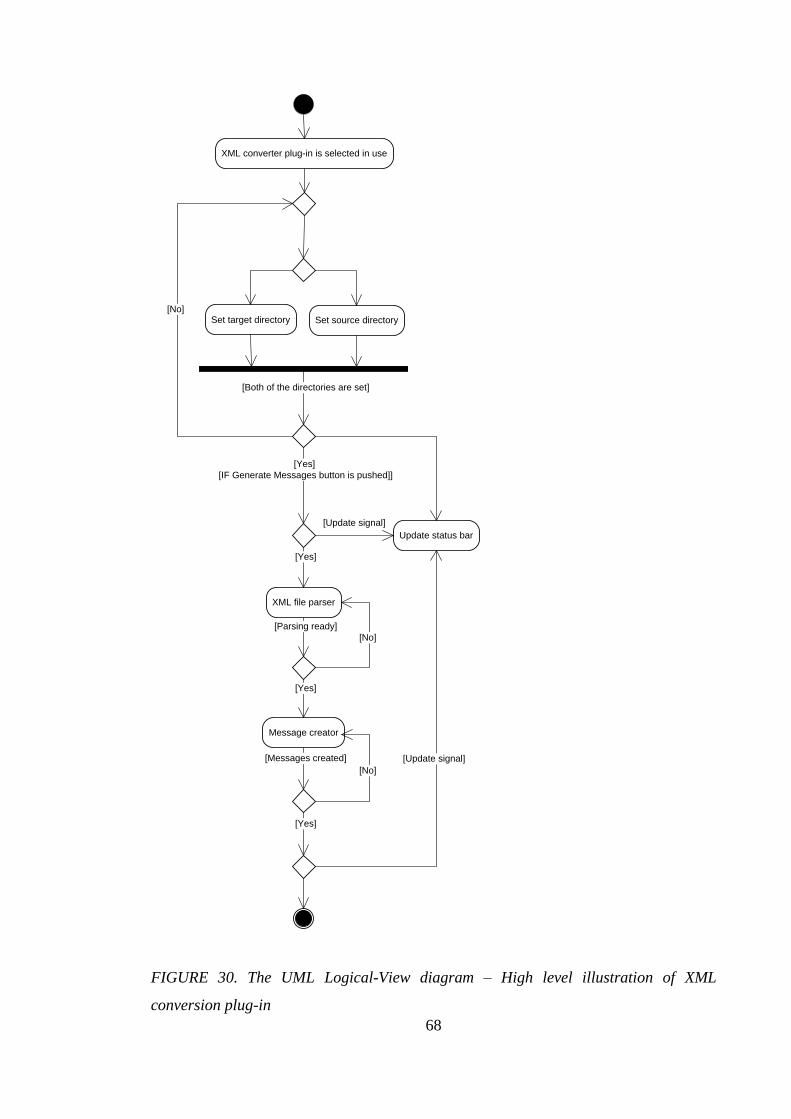
68
Set source directorySet target directory
Update status bar
[Both of the directories are set]
[Yes]
[IF Generate Messages button is pushed]]
[No]
XML file parser
[Yes]
[Parsing ready]
XML converter plug-in is selected in use
Message creator
[Yes]
[No]
[Messages created]
[Yes]
[No]
[Update signal]
[Update signal]
FIGURE 30. The UML Logical-View diagram – High level illustration of XML
conversion plug-in

69
The CTA shows the GUI of the XML conversion plug-in in its own tab when it is
selected as presented in Figure 31. The GUI in the tab is the only visible part of the
XML conversion plug-in. The layout of the GUI is kept as simple as possible.
FIGURE 31. The GUI of XML conversion plug-in is load in the tab of common testing
tool
Using the UML logical view, Figure 32 illustrates how the XML conversion plug-in
works during the actual XML conversion process. The conversion process illustrates the
functionality of the plug-in after the required user actions have been done. The process
is divided into two main phases:
Parsing of definitions elements (DE)
Parsing of messages elements (ME)
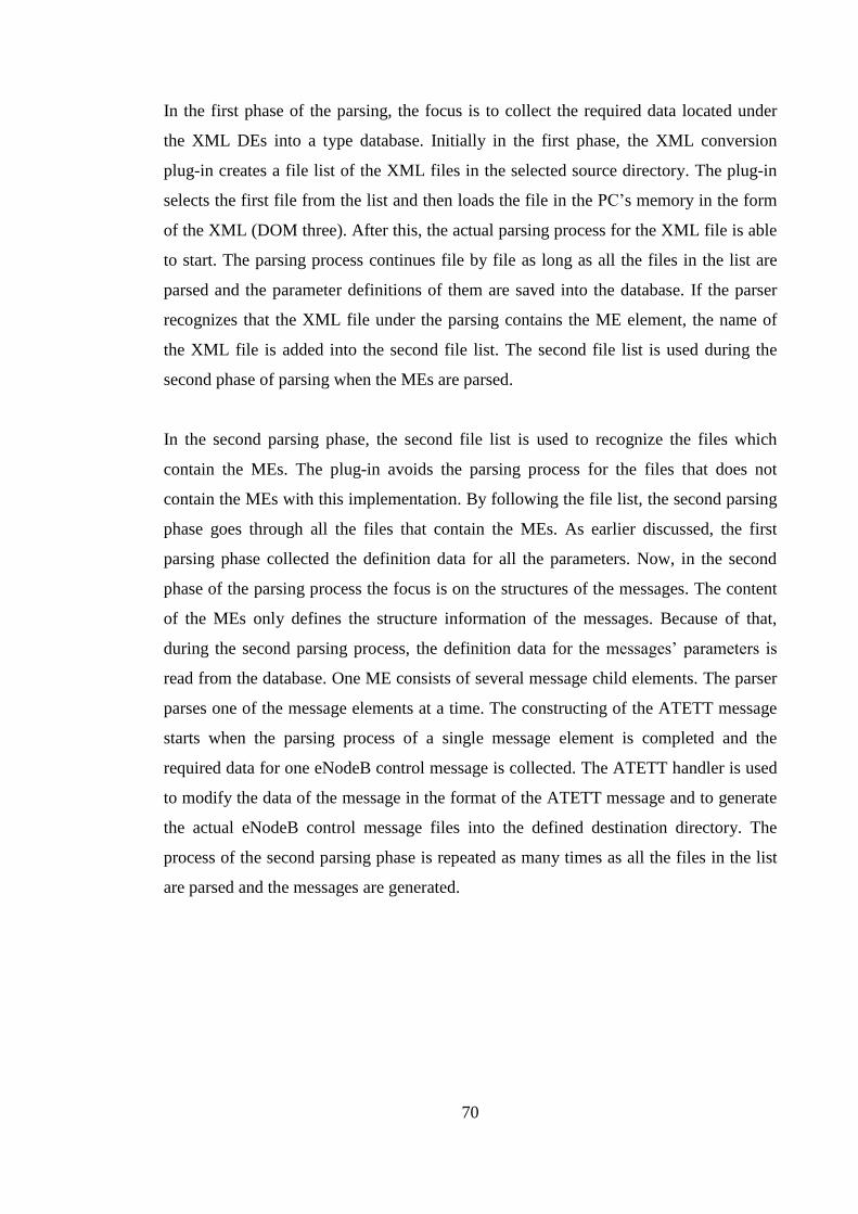
70
In the first phase of the parsing, the focus is to collect the required data located under
the XML DEs into a type database. Initially in the first phase, the XML conversion
plug-in creates a file list of the XML files in the selected source directory. The plug-in
selects the first file from the list and then loads the file in the PC’s memory in the form
of the XML (DOM three). After this, the actual parsing process for the XML file is able
to start. The parsing process continues file by file as long as all the files in the list are
parsed and the parameter definitions of them are saved into the database. If the parser
recognizes that the XML file under the parsing contains the ME element, the name of
the XML file is added into the second file list. The second file list is used during the
second phase of parsing when the MEs are parsed.
In the second parsing phase, the second file list is used to recognize the files which
contain the MEs. The plug-in avoids the parsing process for the files that does not
contain the MEs with this implementation. By following the file list, the second parsing
phase goes through all the files that contain the MEs. As earlier discussed, the first
parsing phase collected the definition data for all the parameters. Now, in the second
phase of the parsing process the focus is on the structures of the messages. The content
of the MEs only defines the structure information of the messages. Because of that,
during the second parsing process, the definition data for the messages’ parameters is
read from the database. One ME consists of several message child elements. The parser
parses one of the message elements at a time. The constructing of the ATETT message
starts when the parsing process of a single message element is completed and the
required data for one eNodeB control message is collected. The ATETT handler is used
to modify the data of the message in the format of the ATETT message and to generate
the actual eNodeB control message files into the defined destination directory. The
process of the second parsing phase is repeated as many times as all the files in the list
are parsed and the messages are generated.
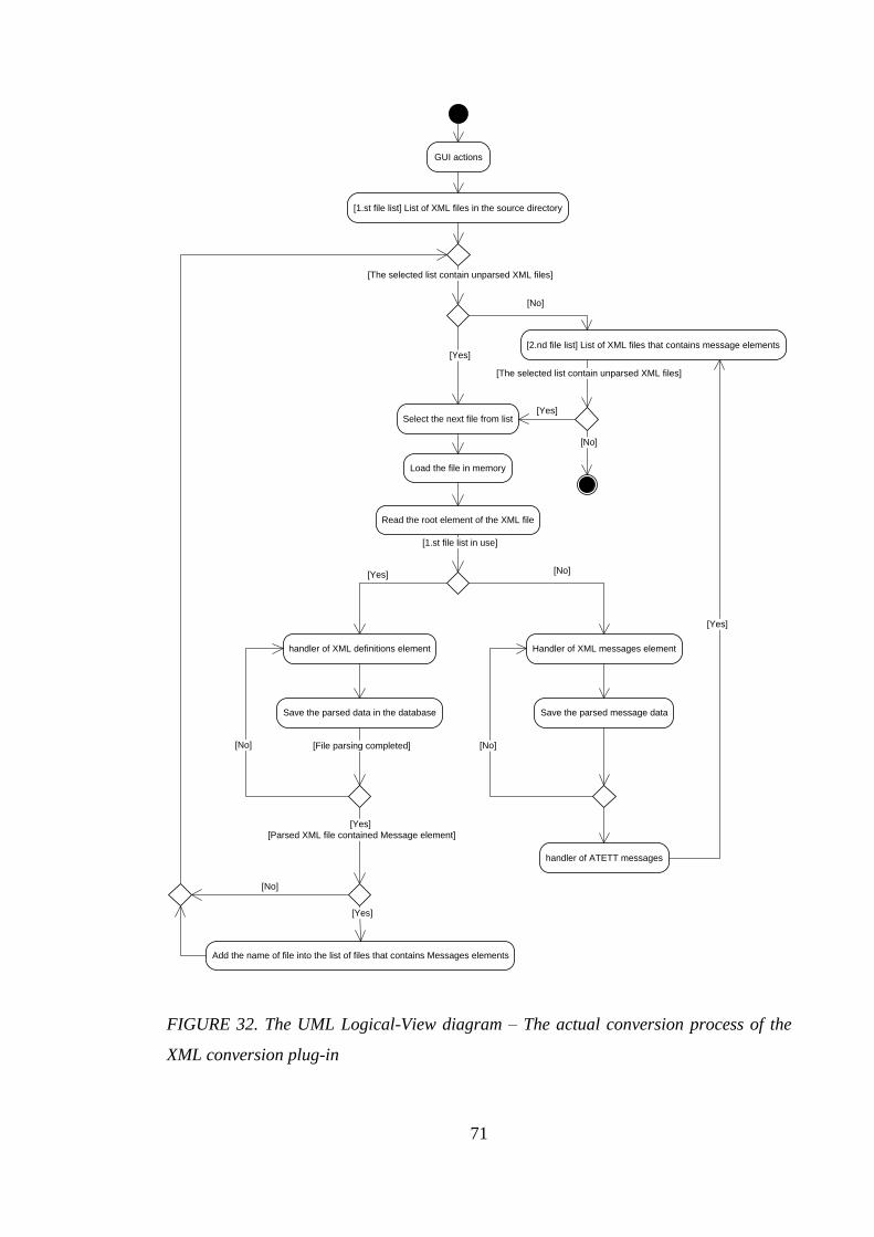
71
[1.st file list] List of XML files in the source directory
Load the file in memory
GUI actions
Read the root element of the XML file
Select the next file from list
[The selected list contain unparsed XML files]
[1.st file list in use]
[Yes]
[No]
[Yes]
[Yes]
[The selected list contain unparsed XML files]
[No]
Add the name of file into the list of files that contains Messages elements
[Yes]
[Parsed XML file contained Message element]
[Yes]
[2.nd file list] List of XML files that contains message elements
[Yes]
[No]
[No]
Handler of XML messages elementhandler of XML definitions element
handler of ATETT messages
Save the parsed data in the database
[File parsing completed] [No]
Save the parsed message data
[No]
FIGURE 32. The UML Logical-View diagram – The actual conversion process of the
XML conversion plug-in
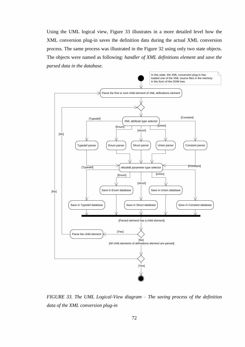
72
Using the UML logical view, Figure 33 illustrates in a more detailed level how the
XML conversion plug-in saves the definition data during the actual XML conversion
process. The same process was illustrated in the Figure 32 using only two state objects.
The objects were named as following: handler of XML definitions element and save the
parsed data in the database.
Typedef parser Enum parser Struct parser Union parser Constant parser
Save in Typedef database
[Typedef]
[struct]
[union]
Save in Enum database
Save in Struct database
[Enum]
Save in Union database
Save in Constant database
[Constant] eNodeB parameter type selector
[Typedef]
[struct]
[union] [Enum]
[Constant]
XML attribute type selector
[No]
[All child elements of definations element are parsed]
[No]
In this state, the XML conversion plug-in has
loaded one of the XML source files in the memory
in the form of the DOM tree.
[Parsed element has a child element]
Parse the first or next child element of XML definations element
Parse the child element[Yes]
[Yes]
[No]
FIGURE 33. The UML Logical-View diagram – The saving process of the definition
data of the XML conversion plug-in
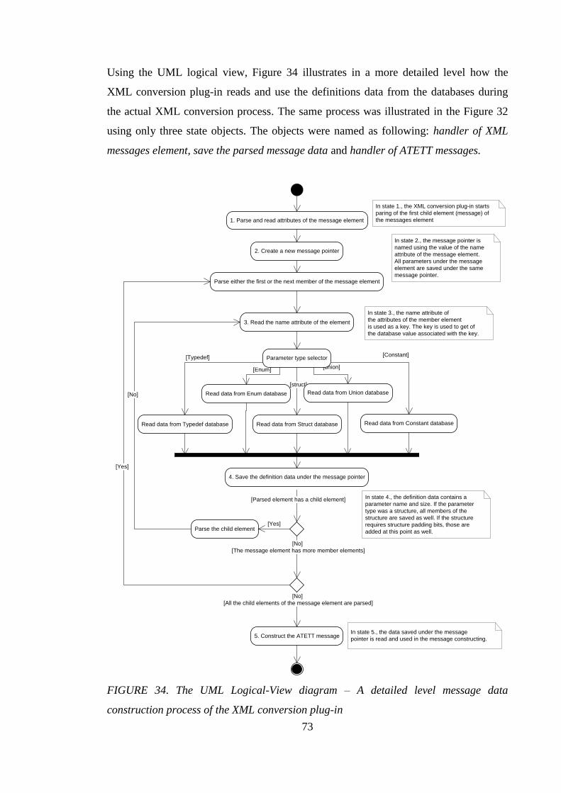
73
Using the UML logical view, Figure 34 illustrates in a more detailed level how the
XML conversion plug-in reads and use the definitions data from the databases during
the actual XML conversion process. The same process was illustrated in the Figure 32
using only three state objects. The objects were named as following: handler of XML
messages element, save the parsed message data and handler of ATETT messages.
Read data from Typedef database
[Typedef]
[struct]
[union]
Read data from Enum database
Read data from Struct database
[Enum]
Read data from Union database
Read data from Constant database
[Constant] Parameter type selector
[No]
[All the child elements of the message element are parsed]
[No]
In state 1., the XML conversion plug-in starts
paring of the first child element (message) of
the messages element
[Parsed element has a child element]
2. Create a new message pointer
1. Parse and read attributes of the message element
In state 2., the message pointer is
named using the value of the name
attribute of the message element.
All parameters under the message
element are saved under the same
message pointer.
3. Read the name attribute of the element
In state 3., the name attribute of
the attributes of the member element
is used as a key. The key is used to get of
the database value associated with the key.
4. Save the definition data under the message pointer
Parse the child element
Parse either the first or the next member of the message element
[Yes]
[Yes]
[No]
[The message element has more member elements]
5. Construct the ATETT message
In state 4., the definition data contains a
parameter name and size. If the parameter
type was a structure, all members of the
structure are saved as well. If the structure
requires structure padding bits, those are
added at this point as well.
In state 5., the data saved under the message
pointer is read and used in the message constructing.
FIGURE 34. The UML Logical-View diagram – A detailed level message data
construction process of the XML conversion plug-in
74
5 RESULTS AND PROPOSALS
Chapter 5 presents the main benefits that the usage of the CTA and XML conversion
plug-in provides compared to the time when the eNodeB control message for the
ATTET was created manually.
5.1 Improvement in the testing velocity time
The SW quality assurance agreement determines that all the DSP SW builds must be
tested within two hours after it has been released. The ATE of the LTE DSP SWi with
the CI master system was capable of fulfilling the time requirement set for the LTE DSP
SWi if the released DSP SW build did not contain considerable interface changes.
When the DSP SW build contained considerable changes, the LTE DSP SWi was not
capable of meeting target and test it within the given two hours’ time frame.
During the time when the LTE DSP SWi did not have the XML conversion plug-in, the
eNodeB control messages for the ATETT were created manually. The working need
varied from a half an hour to many days. In the worst cases the changes required that
many engineers of the LTE DSP SWi assigned to do the eNodeB control messages.
The use of the XML conversion plug-in, guarantees that the eNodeB control messages
for the ATETT are always available in time. The plug-in helps the LTE DSP SWi to
meet the time requirement. Also, the accuracy in time when the test results of the LTE
DSP SWi are available is better since the XML conversion plug-in is used and the
eNodeB control messages do not affect the additional delays anymore before the LTE
DSP SWi is capable of starting the testing.
The eNodeB control messages are ready for the ATTET and testing purposes in few
seconds when a tester starts the message conversion process by pushing the “Generate
message” button of the GUI of the XML conversion plug-in.
75
5.2 Quality improvements in LTE DSP SWi testing
One eNodeB control message can contain more than four thousand parameters. When
the messages were done manually, a big risk existed that during the change work the
engineer made writing typos or interpreted the DSP SW IFS wrongly. Any kind of an
error which is avoidable is unnecessary. Errors in the eNodeB control messages always
cause an extra work load for an engineer and as well for developers. One of the main
tasks of the LTE DSP SWi testing is to verify that the interfaces of the DSP SW
applications work as specified. If the eNodeB control messages used in testing contains
errors, the focus from SUT and IUT testing change on the testing of the control
messages and that is not acceptable. The eNodeB control messages generated using the
XML conversion plug-in do not contain errors.
5.3 Implementation status of CTA and XML conversion plug-in
Both the CTA and the XML conversion plug-in basic functionality work as specified.
The current implementations do not contain any errors.
5.4 New plug-in proposals for CTA
There are not known limitations in the amount of plug-ins used via the CTA. When
more plug-ins are developed, it is possible that unplanned problems occur related to the
common interface of the CTA. The initial version of it is as simple as possible and it
may require more functionality in the future. If the common plug-in interface has to be
changed, new interface versions have to be backward compatible. Two new ideas
already exist for new plug-ins which are presented below:
Plug-in 1. The main functionality of the plug-in is to send and receive the eNodeB
control messages. The plug-in reads and utilizes a message sequence log of the ATETT
as an input data. The message sequence logs are always available after the initial test
execution has been done.

76
Extra value that the plug-in provides: The use of plug-in provides a very efficient and
simply approach to repeat the test executions of the LTE DSP SWi for the eNodeB
system. Repeating a test does not require test scripts when the plug-in utilizes the
existing test logs. The logs contain all required test data from the message sequence to
the values of the message parameters. This approach in testing would be practical when
the intention is to repeat the test exactly as the original test execution has been done.
The error reports of eNodeB SW usually contain only the message sequence log and the
description of the error. Considering the fact that only the message sequence log is
attached in the error report, the plug-in would be a powerful tool for a tester when s/he
verifying the correction for the reported error.
Plug-in 2. The main functionality of the plug-in is to check the used eNodeB
configuration setups. Currently all tests in the LTE DSP SWi are executed using the
ATETT. The use of the ATETT and script language of it sets their own limitations in
the verification of the eNodeB functionalities.
An extra value that the plug-in provides: The Qt and the C++ programming languages
make it possible for testers to create more sophisticated verification algorithms than the
current tests based ones on the script language can provide. A practical example of this
plug-in is that the plug-in could be used to analyze a considerable amount of the system
logs from the defined directory. The plug-in goes through all the system log files in the
directory and searches an error and other relevant information which a tester is
determined to be interested in. When all the logs are processed, the plug-in creates a
summary report of the findings it has made.
5.5 Functional extensions for the applications
This chapter presents all known limitations functionally and few functional extension
proposals
77
The current implementation of the XML conversion plug-in supports the generation for
the eNodeB control message templates that are suitable for the ATETT only. The object
oriented C++ and the modularity of the source code make the functionality of the XML
conversion plug-in extendable with a small effort. In the future it is possible to extend
the plug-in to support other output data formats, too. For example, many of the testing
applications contain an XML processor and are capable of handling XML data
nowadays. A natural message format for the tools that contain the XML processor is the
XML.
5.5.1 The error management of the applications
The error management of the CTA as well as the XML convert plug-in is not as good as
it should be. Both of the applications provide only QDebug prints in error situations.
Basically, the debug checkers already exist in the source code which provides detailed
level information about what went wrong. The functionality of these debug prints
should be changed to show the error information in a pop-up window.
5.5.2 eNodeB control message filter in the XML conversion plug-in
The XML conversion plug-in does not provide a possibility to limit which of the
eNodeB control messages the user wants to generate. The XML conversion plug-in
always generates all the messages that the XML source data defines, and the amount of
the messages is around one thousand messages and the data size is ~25Mbytes. An
option to select the wanted messages which the user wants to generate at the level of the
DSP application would be a very useful feature to have.

78
6 CONCLUSION
The main focus in this master’s thesis was to provide an application that removes the
need of manual work with the eNodeB control messages. The CTA is application
developed using the Qt programming language. The application is implemented with a
common interface that makes it extendable with plug-ins.
During the study, the XML conversion plug-in for the CTA was developed. The plug-in
contains all the functionalities needed to generate the eNodeB control messages by
using the XML source files as input. The performance of the plug-in guarantees that the
changes in the eNodeB control messages does not have a negative influence into the
testing velocity time of the LTE DSP SWi. The XML conversion plug-in is capable of
generating all the control messages in few seconds.
The development project of the CTA and the XML conversion plug-in proceeded as it
was planned except the delay in the time schedule. The implementation work was ready
two months behind the original time schedule. The original time schedule for the
development project delayed due to many reasons. The main reasons for the delay are
listed below:
1. The implementation work was done outside of the normal working hours.
2. With limited programming experience the problem solving took more time
than expected. Unexpected problems occurred during the development process
with the structure padding.
3. The change of the employer was undersigned during the Master’s thesis. It
affected both the development process of the application and the writing part of
the thesis.
The CTA and XML conversion plug-in will be used continuously in the LTE DSP SWi.
The LTE DSP SWi will achieve significant time savings in long-term by using the
applications even when the development project lasted for six months. In this
perspective, developing an application to do a task on behalf of a human is an excellent
method to reduce manual work. In general, an application can provide extra value if it is

79
used to replace manual work in those tasks that are regular and need constantly some
actions.
The development process of the CTA and the XML conversion plug-in was an
interesting project. The project was very challenging since many of the questions that
are discussed in this thesis were out of the thesis writer’s personal comfort zone. The
practice started from the basics of the C++ language. The investigation of the content of
the XML source files was started in the next phase. In addition, the method to construct
the information in the files was studied. It took a while only to understand in general
how to use the information collected in the XML files. The XML source data consists
of nearly 30 separate XML files. The structure of the XML source files is described
with the XML schema file that contains 40kB information. The amount of data in the
schema describes how much effort was needed to understand the structures of the XML
source files.
After the structures of the XML source files had been studied, the application
development project was able to continue. The project continued by learning how to
parse the XML data with an application made by Qt. The modular class architecture for
the XML conversion plug-in was created in the beginning of the actual coding process
with guidance of the supervisors. The well planned SW architecture helped the coding
process through the project.
The TortoiseSVN subversion was used in the application development phase. It is
invaluable in the SW development. When a developer does not have much experience
s/he probably makes more errors, and does not always know which of the changes
caused the error. Problem solving can take a great deal of time when the code contains
many changes. The power of the subversion is that the developer can save the project as
many times as needed. If needed, the developer can always return into the revision that
is not influenced by the changes. The use of the subversion basically follows the same
principles than the incremental SW development. Every time when something useful is
made, it is saved in the subversion.
80
The application development project lasted six month. It is such a long time that
requires good documentation or it is difficult to remember all the reasons for the
decisions made during the project. The subversion makes it possible to write a comment
for all committed changes. Many times the committed changes contain multiple changes
simultaneously and the change easily becomes too large. When the size of the commit is
too large it is difficult to write a comment that describes the change explicitly. In the
beginning of the application development process the problem with too large commits
was emphasized.
Overall, the application development process was a project that developed coding skills,
acquainted in the Qt, SVN, UML and XML languages. All this is valuable knowledge
for people who work in SW related working position.
81
REFERENCES
1. Holma H. and Toskala A. 2009. LTE for UMTS - OFDMA and SC-FDMA Based
Radio Access 1st
edition. England: John Wiley & Sons, Ltd.
2. 3GPP.org 2010. Evolved Universal Terrestrial Radio Access (E-UTRA) and Evolved
Universal Terrestrial Radio Access Network (E-UTRAN); Overall description; Stage 2
(Release 8).
Available at: http://www.3gpp.org/ftp/specs/html-info/36300.htm. Date of data
acquisition 3 February 2012.
3. Signalin in E-UTRAN/LTE – LTE Uu Interface Signalling training material. 2011.
Version 1.0.1. Poland: Leliwa Sp. z o.o.
4. Broekman B. and Notenmoob E. 2003. Testing Embedded Software. Great Britain:
Adduson-Wesley.
5. Glenford J. Myers. 2004. The Art of Software Testing, Second Edition. USA: John
Wiley & Sons, Inc.
6. Pietilä P. 2010. Reuse of modular TTCN-3 test automation. Oulu: University of Oulu,
Department of Electrical and Information Engineering.
7. Pressman R. 2001. Software Engineering: a practitioner’s approach, Fifth Edition.
USA: McGraw-Hill Companies, Inc.
8. Galin D. 2004. Software Quality Assurance: From theory to implementation.
Great Britain: Pearson Education Limited.
9. John E. Bentley, Wachovia Bank, Charlotte NC. Software Testing Fundamentals.
Available at: http://www2.sas.com/proceedings/sugi30/141-30.pdf Date of data
acquisition 31 March 2012

82
10. Software Process Models
Available at: http://www.the-software-experts.de/e_dta-sw-process.htm Date of data
acquisition 31 March 2012
11. V-Model
Available at: http://en.wikipedia.org/wiki/V-Model Date of data acquisition 31 March
2012
12. Binder R.V. 1999. Testing object-oriented systems: models, patterns and tools.
Massachutes: Addison-Wesley, Reading.
13. "Big Bang" Integration
Available at:
http://www.cmcrossroads.com/bradapp/acme/branching/pitfalls.html#BigBang Date of
data acquisition 3 April 2012
14. V-model
Available at: http://en.wikipedia.org/wiki/File:V-model.JPG Date of data acquisition 18
February 2012.
15. Dustin E., Garrett T. and Gauf B. 2009. Implementing Automated Software Testing;
How to Save Time and Lower Cost While Raising Quality. USA: Pearson Education,
Inc.
16. Black-box and White-box testing
Available at: http://www.codeproject.com/Articles/5019/Advanced-Unit-Testing-Part-I-
Overview#White Box Testing5 Date of data acquisition 4 April 2012
17. Blanchette J. and Summerfield M. 2006. C++ GUI Programming
with Qt 4, 1st edition. USA: Prentice Hall PTR
18. Qt SDK
Available at: http://qt.nokia.com/products/qt-sdk Date of data acquisition 14 April 2012

83
19. Figure of Qt SDK
Available at: http://qt.nokia.com/ Date of data acquisition 14 April 2012
20. Qt Creator Whitepaper
Available at: http://qt-project.org/wiki/QtCreatorWhitepaper Date of data acquisition 14
April 2012
21. Tittel E. 2002. XML for Dummies, 3rd edition
England: John Wiley & Sons, Ltd
22. XML
Available at: http://www.w3schools.com/xml/ Date of data acquisition 10 April 2012
23. Ray Erik T. 2001. Learningn XML,
USA: O’Reilly & Associates, Inc.
24. Eriksson H-E., Penker M., Lyons B. and Fado D. 2004. UML 2 Toolkit.
Indiana: Wiley Publishing, Inc.
25. Version Control with Subversion For Subversion 1.1
Available at: http://svnbook.red-bean.com/en/1.1/svn-book.pdf Date of data acquisition
13 April 2012
26. TortoiseSVN
Available at:
http://netcologne.dl.sourceforge.net/project/tortoisesvn/1.7.6/Documentation/TortoiseS
VN-1.7.6-en.pdf Date of data acquisition 13 April 2012
27. Echo Plugin Example
Available at: http://doc.qt.nokia.com/4.3/tools-echoplugin.html Date of data acquisition
14 April 2012
84
28. Tab Dialog Example
Available at: http://doc.trolltech.com/4.7/dialogs-tabdialog.html Date of data acquisition
14 April 2012
29. QTabWidget
Available at: http://doc.trolltech.com/4.7/qtabwidget.html#details Date of data
acquisition 14 April 2012
30. C++ data types
Available at: http://www.cplusplus.com/ Date of data acquisition 13 May 2012
31. Data structure alignment
Available at: http://en.wikipedia.org/wiki/Data_structure_alignment Date of data
acquisition 6 May 2012
85
APPENDICES
Appendix 1. XML source directory example
Appendix 2. CTA’s Qt project .pro file example

XML SOURCE DIRECTORY EXAMPLE APPENDIX 1/2
Directory of D:\…\SVN\Revision42\Branches\XmlConversionPlugIn\Xml
15.04.2012 13:46 <DIR> .
15.04.2012 13:46 <DIR> ..
27.03.2012 08:26 <DIR> .externalToolBuilders
25.01.2011 14:37 .project
26.10.2011 15:45 1KB L3.xml
27.03.2012 08:27 <DIR> configuration
09.11.2011 12:48 194KB MAC1.xml
11.10.2011 12:52 89KB Tool1.xml
05.11.2011 16:19 93KB externals.xml
03.11.2011 12:04 92KB globals.xml
01.09.2011 11:02 3KB LTE.xml
24.05.2011 02:39 4KB LTE1.xml
05.07.2011 14:18 4KB LTE2.xml
04.11.2011 14:52 178KB MAC2.xml
11.10.2011 12:52 1KB MAC3.xml
22.07.2011 16:07 1KB MAC4.xml
24.05.2011 02:39 38KB MessageId_Lte.xml
27.10.2011 15:59 1610KB HW1.xml
03.11.2011 12:04 13KB PHY.xml
24.05.2011 02:39 3KB PHY1.xml
03.11.2011 12:04 141KB PHY2.xml
28.10.2011 08:26 57KB PHY3.xml
08.11.2011 14:50 63KB HW2.xml
03.11.2011 12:04 5KB SW1.xml
19.09.2011 16:24 52KB ATE.xml
24.05.2011 02:39 15KB HWSW.xml
03.11.2011 12:04 1KB TUP.1xml
08.11.2011 10:11 91KB TUP2.xml
24.05.2011 02:39 1KB TUP3.xml
17.10.2011 19:13 58KB MAC5.xml
27 File(s) 3341KB
4 Dir(s)

CTA’s Qt PROJECT .PRO FILE EXAMPLE APPENDIX 2/2
# ------------------------------------------------------------
# $Rev:: 31 $:
# $Author:: teemuhei $:
# $Date:: 2011-10-21 14:20:51 +0300 (pe, 21 loka 2011) $:
# ------------------------------------------------------------
QPRO_PWD = $$PWD
TEMPLATE = lib
CONFIG += qt
CONFIG += plugin
OBJECTS_DIR = ../lib
DESTDIR = ../../bin/plugins
TARGET = xmlConversionPlugin
DEPENDPATH += .
INCLUDEPATH += ../include
HEADERS = ../include/pluginInterface.hpp
HEADERS += xmlConversionPlugin.hpp \
xmlFileParser.hpp \
typeConstant.hpp \
xmlParser.hpp \
typeUnion.hpp \
typeStruct.hpp \
typeTypedef.hpp \
typeDatabase.hpp \
typeEnum.hpp \
type.hpp \
typePrimitive.hpp \
atettMessages.hpp
SOURCES = xmlConversionPlugin.cpp \
typeDatabase.cpp \
typeConstant.cpp \
xmlFileParser.cpp \
xmlParser.cpp \
typeUnion.cpp \
typeStruct.cpp \
typeTypedef.cpp \
typeEnum.cpp \
typePrimitive.cpp \
atettMessages.cpp \
isarType.cpp
QT += xml