Performance and Implementation Evaluation of TR PAPR Reduction Methods for DVB-T2
11
Hindawi Publishing Corporation International Journal of Digital Multimedia Broadcasting Volume 2010, Article ID 797393, 10 pages doi:10.1155/2010/797393 Research Article Performance and Implementation Evaluation of TR PAPR Reduction Methods for DVB-T2 Mohamad Mrou´ e, 1 Amor Nafkha, 1 Jacques Palicot, 1 Benjamin Gavalda, 2 and Nelly Dagorne 2 1 SUPELEC-IETR, avenue de la Boulaie CS 47601, 35576 Cesson S´ evign´ e Cedex, France 2 ENENSYS Technologies, 80 avenue des Buttes de Coesmes, 35700 Rennes, France Correspondence should be addressed to Mohamad Mrou´ e, [email protected] Received 15 April 2010; Accepted 26 August 2010 Academic Editor: Jaime Lloret Copyright © 2010 Mohamad Mrou´ e et al. This is an open access article distributed under the Creative Commons Attribution License, which permits unrestricted use, distribution, and reproduction in any medium, provided the original work is properly cited. High Peak to Average Power Ratio (PAPR) is a critical issue in multicarrier communication systems using Orthogonal Frequency Division Multiplexing (OFDM), as in the Second Generation Terrestrial Digital Video Broadcasting (DVB-T2) system. This problem can result in large performance degradation due to the nonlinearity of the High Power Amplifier (HPA) or in its low power efficiency. In this paper, we evaluate the performance of different Tone Reservation-based techniques for PAPR reduction in DVB-T2 context. Also, we propose an iterative TR-based technique called “One Kernel One Peak” (OKOP). Simulation results and performance comparison of these techniques in terms of gain in PAPR reduction, mean power variation, and complexity will be given. Finally, we describe the implementation of a PAPR reduction algorithm in the DVB-T2 modulator. 1. Introduction The performance of high data rate systems is significantly limited by the multipath interference that occurs in the radio channel environment. As an attractive technique in mitigating the multipath interference, Orthogonal Frequency Division Multiplexing (OFDM) has been widely applied in various broadcasting systems such as, the Digital Video Broadcasting (DVB) systems. Despite its competitive attributes, OFDM signals are characterized by very high Peak-to-Average Power Ratio (PAPR) levels. This characteris- tic leads the OFDM signals to be very sensitive to nonlinear- ities of analogue components of the transceiver, in particular those of the High Power Amplifier (HPA) at the emission. An HPA is conceived to operate in its saturation zone which corresponds to its high efficiency region. However, in this zone, the HPA has a severe nonlinear behaviour. These nonlinearities are sources of In-Band (IB) distortions which can both degrade the link performance in term of Bit Error Rate (BER) and also cause significant Out-Of-Band (OOB) interference products that make it harder for the operator to comply with stringent spectral masks. The simplest solution to this problem is to operate the HPA in the linear region by allowing a large enough amplifier back-off. However, this approach degrades the power efficiency of the system and often leads to unacceptable cost-efficiency conditions in the overall system. For all these reasons, reducing the PAPR of OFDM signals is increasingly being considered to be very important in maintaining the cost-effectiveness advantages of OFDM in practical systems, especially as new systems, such as DVB-T2, are being specified with large number of subcarriers (up to 32768 subcarriers and 256- QAM modulation for DVB-T2 system [1]). Many methods have been proposed to mitigate the OFDM PAPR by acting on the signal itself [2, 3]. The simplest ones use clipping and filtering techniques [4, 5]. However, these methods may lead to BER increase of the system since clipping is a nonlinear process [6]. Alternative methods are based on coding [7, 8] and others on Multiple Signal Repre- sentation (MSR) techniques: Partial Transmit Sequence (PTS) [9], Selective Mapping (SLM) [10], and Interleaving [11]. The main drawback of these methods is that a Side Information (SI) has to be transmitted from the transmitter to the receiver to recover the original data, which results in some loss of throughput efficiency. Some recent efficient methods do not need any SI transmission [12]. The Active Constellation
Transcript of Performance and Implementation Evaluation of TR PAPR Reduction Methods for DVB-T2

Hindawi Publishing CorporationInternational Journal of Digital Multimedia BroadcastingVolume 2010, Article ID 797393, 10 pagesdoi:10.1155/2010/797393
Research Article
Performance and Implementation Evaluation ofTR PAPR Reduction Methods for DVB-T2
Mohamad Mroue,1 Amor Nafkha,1 Jacques Palicot,1 Benjamin Gavalda,2 and Nelly Dagorne2
1 SUPELEC-IETR, avenue de la Boulaie CS 47601, 35576 Cesson Sevigne Cedex, France2 ENENSYS Technologies, 80 avenue des Buttes de Coesmes, 35700 Rennes, France
Correspondence should be addressed to Mohamad Mroue, [email protected]
Received 15 April 2010; Accepted 26 August 2010
Academic Editor: Jaime Lloret
Copyright © 2010 Mohamad Mroue et al. This is an open access article distributed under the Creative Commons AttributionLicense, which permits unrestricted use, distribution, and reproduction in any medium, provided the original work is properlycited.
High Peak to Average Power Ratio (PAPR) is a critical issue in multicarrier communication systems using Orthogonal FrequencyDivision Multiplexing (OFDM), as in the Second Generation Terrestrial Digital Video Broadcasting (DVB-T2) system. Thisproblem can result in large performance degradation due to the nonlinearity of the High Power Amplifier (HPA) or in its lowpower efficiency. In this paper, we evaluate the performance of different Tone Reservation-based techniques for PAPR reduction inDVB-T2 context. Also, we propose an iterative TR-based technique called “One Kernel One Peak” (OKOP). Simulation results andperformance comparison of these techniques in terms of gain in PAPR reduction, mean power variation, and complexity will begiven. Finally, we describe the implementation of a PAPR reduction algorithm in the DVB-T2 modulator.
1. Introduction
The performance of high data rate systems is significantlylimited by the multipath interference that occurs in theradio channel environment. As an attractive technique inmitigating the multipath interference, Orthogonal FrequencyDivision Multiplexing (OFDM) has been widely appliedin various broadcasting systems such as, the DigitalVideo Broadcasting (DVB) systems. Despite its competitiveattributes, OFDM signals are characterized by very highPeak-to-Average Power Ratio (PAPR) levels. This characteris-tic leads the OFDM signals to be very sensitive to nonlinear-ities of analogue components of the transceiver, in particularthose of the High Power Amplifier (HPA) at the emission.
An HPA is conceived to operate in its saturation zonewhich corresponds to its high efficiency region. However, inthis zone, the HPA has a severe nonlinear behaviour. Thesenonlinearities are sources of In-Band (IB) distortions whichcan both degrade the link performance in term of Bit ErrorRate (BER) and also cause significant Out-Of-Band (OOB)interference products that make it harder for the operator tocomply with stringent spectral masks. The simplest solutionto this problem is to operate the HPA in the linear region
by allowing a large enough amplifier back-off. However,this approach degrades the power efficiency of the systemand often leads to unacceptable cost-efficiency conditionsin the overall system. For all these reasons, reducing thePAPR of OFDM signals is increasingly being consideredto be very important in maintaining the cost-effectivenessadvantages of OFDM in practical systems, especially as newsystems, such as DVB-T2, are being specified with largenumber of subcarriers (up to 32768 subcarriers and 256-QAM modulation for DVB-T2 system [1]).
Many methods have been proposed to mitigate theOFDM PAPR by acting on the signal itself [2, 3]. The simplestones use clipping and filtering techniques [4, 5]. However,these methods may lead to BER increase of the system sinceclipping is a nonlinear process [6]. Alternative methods arebased on coding [7, 8] and others on Multiple Signal Repre-sentation (MSR) techniques: Partial Transmit Sequence (PTS)[9], Selective Mapping (SLM) [10], and Interleaving [11]. Themain drawback of these methods is that a Side Information(SI) has to be transmitted from the transmitter to the receiverto recover the original data, which results in some loss ofthroughput efficiency. Some recent efficient methods do notneed any SI transmission [12]. The Active Constellation

2 International Journal of Digital Multimedia Broadcasting
Extension (ACE) method proposed in [13] involves reducingPAPR by changing the constellation of the signal withoutchanging the minimum distance. However, the performanceof this method depends on the mapping level. Thus, it isnot relevant for DVB-T2 system with QAM modulation upto 256 states and in the case of rotated constellation. TheTone Reservation (TR) method uses allocated subcarriers togenerate additional information that minimizes the PAPR.An original classification representation for PAPR reductiontechniques was studied and proposed in [3]. The TR methodwhich is a sub-class of the adding signal technique will beour main concern. Thus, proposals for PAPR reduction in thecase of DVB-T2 system will be restrained to methods issuedfrom the TR concept.
This work was performed within the framework of theFrench regional Project DTTv2, which aimed at workingon the improvements of DVB consortium standard: DVB-T2 as well as the future mobile standard NGH (NewGeneration Handheld). This work includes the conception ofan implementation and experimentation platform, allowingto study PAPR reduction in DVB-T2 context in real-time andconforming with industrial constraints.
This paper is organized as follows. Section 2 gives abrief description of the DVB-T2 system model and PAPRdefinition. The TR-based PAPR reduction techniques forDVB-T2 will be studied in Section 3. Also, we propose aniterative technique called “One Kernel One Peak” (OKOP)which is issued from the TR-gradient-based method. InSection 4, simulation results and comparison between thestudied techniques will be presented. Section 5 describesthe PAPR reduction block in the DTTv2 ExperimentationPlatform.
2. DVB-T2 System Model and PAPR
Some basic terms and the system model which includeOFDM, DVB-T2 physical layer and PAPR, shall be presentedfirst. Let us define the notations used throughout the paper.Time and frequency domain matrices are denoted by smalland capital bold case letters, respectively. Scalars and vectorsvariables for the optimization equations are denoted by smalland capital normal letters, respectively.
2.1. OFDM-Based DVB-T2 System. The OFDM signal is thesum of many orthogonally overlapped subchannels of equalbandwidth. In order to realize the spectrally overlappingsub-channels, the Inverse Fast Fourier Transform (IFFT) isemployed at the OFDM transmitter. The base-band samplesfor OFDM symbol, with N subcarriers, at the IFFT outputare given by:
x(t) = 1√N
N−1∑
k=0
Xkej2πkt/TN , 0 � t � NT , (1)
where T is the original complex symbol duration. In practice,we assume that only NL equidistant samples of x(t) areconsidered, where L represents the oversampling factor. TheDVB-T2 system employs optionally 1% of tones for PAPR
reduction in TR context. The possible FFT sizes of a symbolin a T2-Frame are N = 1024, 2048, 4096, 8192, 16384, and32768 [1]. The associated possible modulation modes areQPSK, 16-QAM, 64-QAM, and 256-QAM.
2.2. PAPR Definition. Due to the statistical independence ofcarriers, the central-limit theorem holds and the complextime-domain samples of OFDM signals are approximatelyGaussian distributed. This means that there could be somevery high peaks present in the signal. Peak to AveragePower Ratio (PAPR) is the most common term used inthe literature to describe these temporal fluctuations of thesignal. The PAPR defines the ratio of the signal’s maximuminstantaneous power to its mean power. The oversampleddiscrete-time OFDM symbol sample of x(t) can be given by[14]:
xn = 1√NL
N−1∑
k=0
Xkej2πnk/NL, ∀n ∈ [0, . . . ,NL− 1], (2)
where L is the oversampling factor. This factor must be largeenough (L ≥ 4) to process all the continuous-time peaks andthus to better approximate the analog PAPR of the OFDMsignal. Thus, the PAPR can be expressed as [14]:
PAPR{x(t)} ≈ PAPR{xL,L ≥ 4}
= max0≤n≤NL−1|xn|2E|xL|2
,(3)
where xL = QLXL, XL is the zero-padded vector of X byfactor L, E{·} denotes the expectation operation, and QL
is the inverse discrete Fourier transform matrix of size NLscaled by
√L. The PAPR reduction performance is evaluated
using the Complementary Cumulative Distribution Function(CCDF). It is defined by the probability that the PAPR of theOFDM signal exceeds a given threshold γ [15]:
CCDFPAPRxn = Pr[PAPR{xn} > γ
]. (4)
3. TR-Based PAPR Reduction Techniques
3.1. Tone Reservation Methodology. In TR concept, the basicidea is to reserve some OFDM subcarriers called PeakReduction Tones (PRT) for PAPR reduction. These reservedsubcarriers do not carry any data information, and theyare only used for reducing PAPR. This method restricts thedata vector, and the peak reduction vector to lie in disjointfrequency subspaces. This formulation is distortionless andleads to very simple coding of the data subsymbols thatare extracted from the received sequence by choosing theset of values at the receiver FFT output. Therefore, asnatively included in the standard, this concept does notdegrade the BER performance of the system, and thus canbe categorized in downward compatible method [3]. Theproblem of computing the values for these reserved tonesthat minimize the PAPR can be formulated as a convexproblem and can be solved exactly. The Second-Order ConeProgram (SOCP) applied on unused subcarriers is described

International Journal of Digital Multimedia Broadcasting 3
NL
-IFF
TNL
-IFF
TDAC HPA
X0
X1
XNL−1
C0
C1
CNL−1
c
x x + c
fc
Figure 1: Tone Reservation method to reduce PAPR [12].
in [16]. This method has a high computational complexity.As consequence, suboptimal techniques which are able toconverge faster than the optimal solution are the subject ofthis section.
3.2. Implementation Schemes for TR. In this paper, differentimplementation schemes for TR methods shall be discussedand compared. The idea is to reduce the PAPR of the signalx = IFFT(X) such that PAPR(x + c) < PAPR(x), wherec represents the added peak reducing signal, as shown inFigure 1. Ideally the objective of reducing the peak of thecombined signal (x + c) should be attained while keeping themean power constant or nearly unchanged. Mathematically,it can be expressed by:
E{‖x + c‖2} ≈ E{‖x‖2}. (5)
However, adding signal results in a mean power increase. Therelative increase in the mean power ΔE is defined as [12]
ΔE = 10 log10E{‖x + c‖2
}
E{‖x‖2} . (6)
The aim should be to keep this ΔE as small as possible tomeet the high power amplifier constraints. Increased meanpower might drive the power amplifier into the saturationzone which results in nonlinearity and system performancedegradation. We note that the phenomenon of decreasedminimum distances in constellation due to increased meanpower in the peak power control context is discussed in [17].The ΔE must be upper bounded ensuring that individualcomponent magnitude value cannot exceed a given value asindicated in [18],
ΔE < γ dB, (7)
which follows,
E{‖x + c‖2} ≤ λE
{‖x‖2}, (8)
where λ = 10γ/10 is a constant related to power amplifiercharacteristics.
3.2.1. TR-Clipping-Based Technique. This technique consistsin applying a hard clipping to the input OFDM signal (seeFigure 2) [19]. Then, the clipped signal is subtracted fromthe input signal to obtain the correction signal. After that,
the correction signal is passed to an FFT/IFFT filter in orderto comply with the TR concept. The clipped signal can beexpressed as follows:
yn =⎧⎨⎩xn if |xn| ≤ A,
AejΦn if |xn| ≥ A,(9)
where xn = |xn|eiΦn is the input signal, yn is the clippedsignal, and A is the clipping magnitude level. The correctionsignal is obtained from the differences between the samplesof the useful multi-carrier signal xn and its clipped versionyn.
cn = xn − yn. (10)
Figure 3 shows the peak-reducing signal generator block inthe case of OFDM envelope clipping. To conform to the TRconcept, only the values of the reserved tones at the PRTpositions are kept; the others are reset to zero, thus:
Ck = FFT(cn),
Ck =⎧⎨⎩Ck if k ∈ PRT,
0 if k /∈PRT.
(11)
At each iteration, the algorithm updates the vector Xk (Xk =FFT(xn)) by adding to it the vector Ck.
Xi+1k = Xi
k + μCk, (12)
where μ is the step of the gradient method. Figure 4 showsthe principle of adding signal technique for PAPR reductionwith gradient-based method in frequency-domain issuedfrom a classical clipping. The IB filtering block guaranteesthe downward compatibility by considering only frequencycomponents of the correction signal at the PRT positions.Since this update rule is performed in the frequency domain,this algorithm can simply incorporate the necessary spectralconstraint, by simply limiting the power of the reservedtones.
3.2.2. TR-Gradient-Based Technique. The time-domaingradient-based method for PAPR reduction is proposedin the DVB-T2 norm. This method associated with ToneReservation concept was studied and proposed by Tellado-Mourelo in [12] and later defended by SAMSUNG for PAPRreduction scheme suitable for IEEE 802.16e. The principleof the gradient-based method is to iteratively cancel outthe signal peaks by a set of impulse-like kernels. Reservedcarriers are allocated according to predetermined carrierlocations which are reserved carrier indices. After the IFFT,peak cancellation is operated to reduce PAPR by using apredetermined signal. The predetermined signal, or kernel,is generated by the reserved carriers.
The gradient algorithm is one of the good solutions tocompute with low complexity. The basic idea of the gradientalgorithm is come from clipping. Clipping the peak tone tothe target clipping level can be interpreted as subtracting

4 International Journal of Digital Multimedia Broadcasting
A
A |x(t)|
|y(t)|
Conventional clippingtechnique
Figure 2: The classical amplitude clipping function.
xnyn
−+
+Signal envelope
clippercn
Figure 3: The peak-reducing signal generator block in the case ofOFDM envelope clipping.
impulse function from the peak tone in time domain. Theconventional clipping technique can be formulated as anadding signal technique where its peak reducing signal isgenerated directly in time domain [20]. The principle ofthe TR gradient-based technique is presented in Figure 5.Despite of their low computational complexity, the gradient-based methods have the drawback of increasing the signalaverage power. In addition, this increase in the average poweris dependent on the PAPR reduction gain.
(a) Impulse-Like Kernel Generation. During the first step,the kernel vector p‖2 is computed from the PRT and storedin memory during the initialization phase. For optimalperformance, the generated kernel should be designed to beas close as possible to a discrete-time impulse. This way, everytime the algorithm cancels a peak of x, no secondary peaksare generated at other locations. However, as in DVB-T2 thePRT are specified in advance, it is not possible to perfectlymatch with a discrete-time impulse. An optimum solution togenerate the peak reduction kernel was studied in [12]; thusthe kernel signal is defined as
p‖2 =√NFFT
NPRTIFFT(1PRT), (13)
where NFFT and NPRT indicate the FFT size and the numberof PRT, respectively. The (NFFT, 1) vector 1PRT has NPRT
elements of ones at the positions corresponding to thereserved-carrier indices and has (NFFT − NPRT) elements ofzeros at the others.
xnyn = xn + cn
+
Peak reducing signalgeneration cn
IB filtering
K-iterations
cn
Figure 4: The principle of adding signal technique for PAPRreduction with gradient-based method in frequency-domain issuedfrom a classical clipping.
(b) Peak Reduction Algorithm. The IFFT output x is fed intothe peak-cancellation block, and the peak position and valueof x are detected. Thus, for n = 0, . . . ,NFFT−1,
yi = maxn
∣∣xin∣∣,
mi = argmaxn
∣∣∣xin∣∣∣,
(14)
where xin represents the nth element of the vector xi; yi andmi represent the maximum magnitude and the index of thedetected peak in the ith iteration, respectively. Then, in thesecond step of the algorithm, the reference kernel, generatedby the reserved carriers corresponding to the current OFDMsymbol, is circularly shifted to the peak position, scaled sothat the power of the peak tone should be reduced to thedesired target clipping level and phase rotated. The resultingkernel is subtracted from x and the new PAPR is calculated.As the impulse-like function is designed with only the valuein the reserved tone locations, adding the peak reducingsignal to the data signal does not affect the value of OFDMsymbol in frequency domain.
xi+1 = xi + αip‖2(mi), (15)
where
αi =ximi
yi
(yi − A
), (16)
where p‖2(mi) denotes the kernel vector circularly shiftedby mi and A is the clipping magnitude level. In the thirdstep, the PAPR of the resulting signal (after adding the peakreduction kernel to the useful data signal) is calculated. If thePAPR of the resulting signal satisfies the target PAPR level,this signal is transmitted. If not, the cancellation operationis repeated iteratively, until the number of iterations reachesthe predetermined maximum iteration number. The peak-cancellation method detects and removes only the maximumremaining peak in the time-domain per iteration. Thismethod is simple and efficient in terms of peak regrowth con-trol for the following iterations, at the expense of requiring arelatively large number of iterations. Alternatively, multiplepeaks can be removed in a single iteration because thekernels can be linearly combined. However, this will increase

International Journal of Digital Multimedia Broadcasting 5
x + c
c
Scal
ing
and
phas
ero
tati
on
Cir
cula
rsh
ift
Peak
dete
ctio
nReference kernel
AdderTx signal
Con
trol
ler
PAP
Rca
lcu
lati
on
IFFT output x
Figure 5: Block diagram of the peak-cancellation algorithm.
the number of computations per iteration. The transmittedsignal after the ith iteration of the simple method is given as
xi = x + α1p‖2(m1) + · · · + αip
‖2(mi)
= x +i∑
k=1
αk p‖2(mk).
(17)
3.2.3. Proposed Method (TR-OKOP). The same energy isadded to each reserved subcarrier at each iteration of theTR algorithm. The difficulty resides in how we can predictthe evolution of the vectorial sum on each subcarrier.Controlling the power of a reserved subcarrier impliespassing to frequency domain or maintaining in memory theinformation on the amplitude and phase of each subcarrierat each iteration of the algorithm. The DVB-T2 system isdefined with a large number of subcarriers (up to 32768subcarriers). The number of reserved subcarriers for the16 K and the 32 K mode are 144 and 288, respectively. Thus,the method that we propose, called “One Kernel One Peak”(OKOP), consists in distributing the reserved subcarriersinto groups. Then one impulse-like kernel signal is generatedfrom each group of the reserved subcarriers (see Figure 6).The original idea here consists on using one kernel to reduceone peak. A simple modification on the TR-Gradient-basedalgorithm permits the implementation of this technique. Themodification concerns the impulse-like kernel generationpart of the algorithm presented in the previous section.It offers the capability to control independently the powerassociated to each group of PRT. This means that insteadof using the same reference signal at each iteration, aunique correction signal (generated from a specific group ofsubcarriers) is added to the useful signal. Thus, there is asmuch iteration as correction signals during one pass. Also, ateach pass, the PRT are used only one time.
4. Simulation Results and Comparison
The simulation model is designed to match with the DVB-T2 standard. The number of PRT is R = 10, 18, 36, 72,
Frequency domain Time domainIFFT
k1
k2
kn
...
......
Figure 6: Correction signal generation from PRT with the TR-OKOP algorithm.
144, or 288, while the FFT size is, respectively, N = 1024,2048, 4096, 8192, 16384, or 32768, with the number ofsubcarriers in use, K = 853, 1705, 3409, 6913, 13921, or27841, respectively. It should be noted that the power of thecorrection carriers should not exceed the power spectrummask specified for DVB-T2 by more than 10 dB. Theperformance of the TR-based methods is compared in termsof PAPR reduction capability, computational complexity andsystem interference (BER). Also, the power spectral density(PSD) presentations are provided to evaluate the impact ofapplying the TR methods on the power spectrum mask.
4.1. PAPR Reduction Performance. Simulation results usingMatlab (see Figures 7 and 8) show that both algorithms,TR-Clipping and TR-Gradient, have equivalent performancein term of PAPR reduction gain. However, the TR-Gradientmethod is less complex (in term of number of operations)than the TR-Clipping because all the treatments are providedin the time domain. It does not include an IB and OOBfilter since the correction signal is generated directly from thereserved tones. The advantage of the TR-Clipping techniqueis that the update rule is performed in the frequency domain.

6 International Journal of Digital Multimedia Broadcasting
8.5 9 9.5 10 10.5 11 11.5 12 12.5
10−2
10−1
100
λ (dB)
Original OFDM signal10 iterations, ΔE = 0.12 dB20 iterations, ΔE = 0.21 dB30 iterations, ΔE = 0.24 dB
TR-Clipping
CC
DF=
Pr(
PAP
R>λ)
Figure 7: PAPR CCDF for different iterations’ numbers, L = 4,DVB-T2 parameters, N = 32 K, 256 QAM with the TR-Clippingmethod.
Therefore, this algorithm can simply incorporate the neces-sary spectral constraint, by simply limiting the power of thereserved tones. The performance of the proposed TR-OKOPtechnique is compared to the TR-Clipping and TR-Gradientin Figure 9. With the TR-OKOP, the PRTs are divided into 36groups. Thus, a correction signal (kernel) is generated using8 subcarriers. The term “pass” in Figure 9 refers to the useof all the reserved subcarriers for PAPR reduction (288 PRTsin the 32 K mode) or all the generated correction signals (36kernels) only once. Thus, at each pass, 36 peaks are reducedusing 36 correction signals. The proposed algorithm has thesame performance in term of PAPR reduction compared tothe other algorithms. Its advantage lies in its capability tocontrol independently the power associated to each group ofPRTs.
4.2. Complexity Analysis. In this section, we evaluate thecomplexity performance of the different implementationschemes for TR methods described in Section 3. Only theruntime complexity in term of the number of operations isconsidered and the complexity of the initialization stage isomitted since it occurs only once.
4.2.1. TR-Clipping-Based Technique. Let us start by evaluat-ing the complexity of the algorithm in the loop. As discussedin a previous section, this algorithm evaluates the correctionsignal cn. Then, the correction signal is passed to a filter basedon FFT/IFFT pair in order to comply with the TR concept.The complexity of calculating cn is very low compared to thecomplexity of calculating the filtered correction signal cn andcan be omitted. Therefore, the complexity of the algorithm isapproximated as O(2×NL log2NL).
10 iterations, ΔE = 0.18 dB20 iterations, ΔE = 0.36 dB30 iterations, ΔE = 0.45 dB
8.5 9 9.5 10 10.5 11 11.5 12 12.5
10−2
10−1
100
λ (dB)
Original OFDM signal
TR-Gradient
CC
DF=
Pr(
PAP
R>λ)
Figure 8: PAPR CCDF for different iterations’ numbers, L = 4,DVB-T2 parameters, N = 32 K, 256 QAM with the TR gradient-based method.
8.5 9 9.5 10 10.5 11 11.5 12 12.5
10−2
10−1
100
λ (dB)
PAPR reduction gain: algorithms comparison
Original OFDM signalTR-OKOP, 1 pass, ΔE = 0.08 dBTR-OKOP, 2 passes, ΔE = 0.14 dBTR-OKOP, 3 passes, ΔE = 0.2 dB
TR-Gradient, 30 iterations, ΔE = 0.45 dBTR-Clipping, 30 iterations, ΔE = 0.24 dB
CC
DF=
Pr(
PAP
R>λ)
Figure 9: Comparison between the use of different PAPR reductionmethods with DVB-T2 parameters, L = 4, N = 32 K, 256 QAM.
4.2.2. TR-Gradient-Based Technique . This technique oper-ates in time domain. The correction signal (reference kernel)is computed from the PRT and stored in memory duringthe initialization phase. The other steps consist in circularlyshifting the reference kernel to the peak position, scaled andphase rotated. The complexity of calculating the time domainsamples of the peak-canceling signal from the referencekernel is O(NL).

International Journal of Digital Multimedia Broadcasting 7
0 2 4 6 8 10 12 14 16 18 2010−3
10−2
10−1
Eb/N0 (dB)
Bit
erro
rra
te
Conventional BERTR-OKOPTR-GradientTR-Clipping
Figure 10: BER versus Eb/N0 for the three implementation schemesof TR methods with DVB-T2 parameters, N = 32 K, 256 QAM.
4.2.3. Proposed TR-OKOP Method. The proposed methodcomputes a reference kernel from a group of PRTs at eachiteration. This means that an IFFT operation is applied ateach iteration. As for the TR-Gradient-based method, theother steps consist on circularly shifting the reference kernelto the peak position, scaled and phase rotated. Therefore,the complexity of calculating the time domain samplesof the peak-canceling signal from the reference kernel isO(NL log2NL).
The Gradient-based technique has the advantage in termof complexity over the TR-Clipping one. The complexity ofthe proposed TR-OKOP technique is higher than that of theGradient-based one and lower than that of the TR-Clippingone. The advantage of the proposed technique is that the PRTare used only once during one algorithm pass. This allowsan easier control of the power variation on each reservedsubcarrier.
4.3. IB and OOB Interference Analysis. As explained in aprevious section, all the TR-based PAPR reduction methodsdo not affect the BER performance. The TR-Gradient andthe TR-OKOP techniques create the correction signal fromreserved carriers. Thus, the data carriers are not affected. Forthe TR-clipping technique, the generated correction signalpasses through an FFT/IFFT filter in order to respect the TRconcept. Therefore, it is evident in Figure 10 that the threemethods match the conventional BER performance curvethus proving the hypothesis that out of useful band tones donot create IB interference and thus no BER degradation takesplace. It should be noted that BER calculations are performedfor useful carriers only.
The OOB distortions are nullified thanks to theFFT/IFFT filter for the TR-Clipping technique. Figure 11shows the PSD of an OFDM signal before and after applyingthe TR-Gradient PAPR reduction technique. We observethat the power level of the PRT can exceed that of theuseful signal by more than 10 dB. In Figure 12, the proposedalgorithm TR-OKOP was applied. In this case, the power
−5 −4 −3 −2 −1 0 1 2 3 4 5−60
−50
−40
−30
−20
−10
Frequency (MHz)
0
10
Pow
ersp
ectr
alde
nsi
ty(d
B)
Spectrum after TR-GradientOriginal OFDM signal
Figure 11: Power spectral density of an OFDM signal (DVB-T2parameters, L = 4, N = 32 K, 256 QAM) after applying the TR-Gradient PAPR reduction technique.
−5 −4 −3 −2 −1 0 1 2 3 4 5−60
−50
−40
−30
−20
−10
Frequency (MHz)
0
10Po
wer
spec
tral
den
sity
(dB
)
Original OFDM signalSpectrum after TR-OKOP
Figure 12: Power spectral density of an OFDM signal (DVB-T2parameters, L = 4, N = 32 K, 256 QAM) after applying theproposed TR-OKOP PAPR reduction technique.
spectrum specifications are respected. Also, Figure 9 showsthat both algorithms achieve the same PAPR reduction gainfor different values of power variation. Also, the mean powervariation in the case of TR-OKOP is lower than that of theTR-Gradient.
Table 1 summarizes the performance comparisonbetween the three TR-based PAPR reduction methods interms of PAPR reduction gain, mean power variation,complexity, and spectrum control capability. In Table 1, thesign “++” in the complexity line signifies that the method hasa low complexity.
5. PAPR Reduction Algorithm Implementation
5.1. DTTv2 Platform. DTTv2 platform is an industrialimplementation of the DVB-T2 standard. It processes inputstream (which can be for instance an encoded video stream)

8 International Journal of Digital Multimedia Broadcasting
++
+
Shiftscale
FFTIFFT
Input
stream
Kernelcache
Symbolcache
Cellmapper
PRTgeneration
Outputcache
Peakdetector
Figure 13: FPGA implementation of the PAPR reduction block in the DTTv2 modulator.
Read S10
S10
Write S11Write S10
Read K0Read K0Read K0Read K0
K0
K0
Read K0Detect S11Detect S10
Compute S11
K1K1S1
Write K1
Loading step
Processing step
Loading step
Processing stepOutput step
Write S0n
Compute S0n
Read S0n−1Read S0n−2
Write S0n−1
Detect S0n−1
Compute S0n−1
Read S0
S0
1
Write S02
Detect S02
Compute S02
Read S00
S00
Write S01
Detect S01
Compute S01
Write K0
Write S00
Detect S00
FFT input
FFT output
Symbol cache
Kernel cache
Shift/scaleOutput cache
Step
1 12 n− 1 nIterationnumber
Peak detector
Figure 14: Block utilization during the TR-Gradient processing.
Table 1: Performance comparison of TR-based PAPR reductionmethods.
TR-Gradient TR-Clipping TR-OKOP
ΔPAPR ++ ++ ++
ΔE − + +
Complexity ++ − +
Spectrum control − ++ +
and generates a compliant DVB-T2 RF signal. Most ofthe computation is done using a Field Programmable GateArray (FPGA), with the help of software when no real-timeprocessing is required. After channel coding (which includesForward Error Correction, interleaving and mapping onconstellation), OFDM symbols are assembled by adding pilotcarriers, including PRT when PAPR reduction using TR isenabled (see Figure 15). PAPR reduction block implementsthe TR-Gradient algorithm, as defined in DVB-T2 standard[18]. Thus, it operates in time domain after IFFT. A CCDFestimator is placed after up-sampling filters, to monitor theperformance. Finally the signal is converted to analog IF andthen up-converted to RF, in the UHF-VHF bands.
5.2. PAPR Reduction in the DTTv2 Platform. This sectiondescribes the TR-Gradient-based PAPR reduction blockas implemented in the DTTv2 platform (see Figure 13).The design choice was to insert the algorithm within theexisting modulation processing blocks, allowing to share andoptimize hardware resources usage.
5.2.1. Main Blocks Description. The first block Cell Mapperaggregates QAM-mapped data and OFDM pilot carriers
PAPRreduction
PA×
fc
Cyclicprefix
DAC
IFFTInput
streamChannelcoding
Up-sampling
CCDF
RF signal
Figure 15: PAPR reduction block in the DTTv2 hardware platform.
(including PRT) to form a frequency domain symbol that isthen processed by an IFFT to obtain a time domain symbol.Three memory-caches are used: “Kernel cache” that is usedto save the current kernel, “Symbol cache” used to storeinitial and iterations results, and “Output cache” that is usedto store the symbol after the final iteration that has beencompleted. The Peak-detector unit is in charge of detectingand storing peaks locations, that will be then used by theShift-Scale unit to compute the appropriate peak-cancelingsignal.
5.2.2. Processing Description. For each processed symbol,several separate steps can be distinguished.
(i) Loading Step. A kernel is computed for each symbol tosave memory; during symbols generation by Cell Mapper,PRT locations are saved and are later used to compute thekernel. At the end of this step, symbol cache and kernel cacheare filled with corresponding symbol and kernel. While thesymbol cache is written, the symbol is also processed for peak
International Journal of Digital Multimedia Broadcasting 9
detection. This specific data flow is identified with red dottedpath on Figure 13.
(ii) Processing Step. During each iteration, the Shift-Scaleunit computes a peak-canceling symbol that is added to thesymbol. The symbol is then written to its cache memorywhile remaining peaks are being localized at the same timeto prepare the next iteration.
(iii) Output Step. When end-criteria are matched (themaximum number of iteration has been reached, PAPR isbelow the target, or limits condition on ΔE requires to stopiterations), the symbol is written to the output cache. Thisone adds cyclic prefix and streams the symbol to the nextblock.
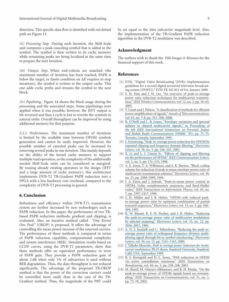
(iv) Pipelining. Figure 14 shows the block usage during theprocessing and the associated steps. Some pipelinings wereapplied when it was possible; however, the IFFT output isbit-reversed and thus a cycle is lost to rewrite the symbols innatural order. Overall throughput can be improved by usingadditional memory for that purpose.
5.2.3. Performance. The maximum number of iterationsis limited by the available time between OFDM symbolsgeneration and cannot be easily improved. However, thepossible number of canceled peaks can be increased byremoving several peaks in one iteration. This mainly dependson the ability of the kernel cache memory to supportmultiple read operation, as the complexity of the additionallyneeded Shift-Scale units can be considered as marginal.By reusing already existing operators in the design (IFFTand a large amount of cache memory), this architectureimplements DVB-T2 TR-Gradient PAPR reduction into aFPGA with a low hardware cost overhead, compared to thecomplexity of DVB-T2 processing in general.
6. Conclusion
Robustness and efficiency within DVB-T2’s transmissionsystem are further increased by new technologies such asPAPR reduction. In this paper, the performance of two TR-based PAPR reduction methods, gradient and clipping, isevaluated. Also, an iterative method called “One KernelOne Peak” (OKOP) is proposed. It offers the advantage ofcontrolling the mean power increase of the reserved carriers.The performance of these methods is compared in termsof PAPR reduction capability, computational complexityand system interference (BER). Simulation results based onCCDF curves, using the DVB-T2 parameters, show thatthese methods offer an equivalent performance in termof PAPR gain. They provide a PAPR reduction gain ofabout 2 dB when only 1% of subcarriers is used withoutBER degradation. Thus, the data throughput is not reducedsignificantly. The advantage of the proposed TR-OKOPmethod is that the power of the correction carriers couldbe controlled more easily than in the case of the TR-Gradient method. Thus, the magnitude of the PRT could
be set equal to the data subcarrier magnitude level. Also,the implementation of the TR-Gradient PAPR reductionalgorithm in the DVB-T2 modulator was described.
Acknowledgment
The authors wish to thank the Pole Images & Reseaux for thefinancial support of this work.
References
[1] ETSI, “Digital Video Broadcasting (DVB); Implementationguidelines for a second digital terrestrial television broadcast-ing system (DVBT2),” ETSI TR 102 831 v0.9.6, January 2009.
[2] S. H. Han and J. H. Lee, “An overview of peak-to-averagepower ratio reduction techniques for multicarrier transmis-sion,” IEEE Wireless Communications, vol. 12, no. 2, pp. 56–65,2005.
[3] Y. Louet and J. Palicot, “A classification of methods for efficientpower amplification of signals,” Annals of Telecommunications,vol. 63, no. 7-8, pp. 351–368, 2008.
[4] R. O’Neill and L. B. Lopes, “Envelope variations and spectralsplatter in clipped multicarrier signals,” in Proceedings ofthe 6th IEEE International Symposium on Personal, Indoorand Mobile Radio Communications (PIMRC ’95), pp. 71–75,Toronto, Canada, September 1995.
[5] J. Armstrong, “Peak-to-average power reduction for OFDM byrepeated clipping and frequency domain filtering,” ElectronicsLetters, vol. 38, no. 5, pp. 246–247, 2002.
[6] X. Li and L. J. Cimini Jr., “Effects of clipping and filteringon the performance of OFDM,” IEEE Communications Letters,vol. 2, no. 5, pp. 131–133, 1998.
[7] A. E. Jones, T. A. Wilkinson, and S. K. Barton, “Block codingscheme for reduction of peak to mean envelope power ratio ofmulticarrier transmission schemes,” Electronics Letters, vol. 30,no. 25, pp. 2098–2099, 1994.
[8] J. A. Davis and J. Jedwab, “Peak-to-mean power control inOFDM, Golay complementary sequences, and Reed-Mullercodes,” IEEE Transactions on Information Theory, vol. 45, no.7, pp. 2397–2417, 1999.
[9] S. H. Muller and J. B. Huber, “OFDM with reduced peak-to-average power ratio by optimum combination of partialtransmit sequences,” Electronics Letters, vol. 33, no. 5, pp. 368–369, 1997.
[10] R. W. Bauml, R. F. H. Fischer, and J. B. Huber, “Reducingthe peak-to-average power ratio of multicarrier modulationby selected mapping,” Electronics Letters, vol. 32, no. 22, pp.2056–2057, 1996.
[11] A. D. S. Jayalath and C. Tellambura, “Reducing the peak-to-average power ratio of orthogonal frequency division multi-plexing signal through bit or symbol interleaving,” ElectronicsLetters, vol. 36, no. 13, pp. 1161–1163, 2000.
[12] J. Tellado-Mourelo, Peak to average power reduction for multi-carrier modulation, Ph.D. thesis, Stanford University, Stanford,Calif, USA, September 1999.
[13] B. S. Krongold and D. L. Jones, “PAR reduction in OFDMvia active constellation extension,” IEEE Transactions onBroadcasting, vol. 49, no. 3, pp. 258–268, 2003.
[14] M. Sharif, M. Gharavi-Alkhansari, and B. H. Khalaj, “On thepeak-to-average power of OFDM signals based on oversam-pling,” IEEE Transactions on Communications, vol. 51, no. 1,pp. 72–78, 2003.

10 International Journal of Digital Multimedia Broadcasting
[15] R. Van Nee and R. Prasad, OFDM for Wireless MultimediaCommunications, Artech House, Boston, Mass, USA, 2000.
[16] S. Zabre, J. Palicot, Y. Louet, and C. Lereau, “SOCP approachfor OFDM peak-to-average power ratio reduction in the signaladding context,” in Proceedings of the 6th IEEE InternationalSymposium on Signal Processing and Information Technology(ISSPIT ’06), pp. 834–839, Vancouver, Canada, August 2006.
[17] R. Baxely, Analyzing selected mapping for peak to averagepower reduction in OFDM, M.S. thesis, Georgia Institute ofTechnology, May 2005.
[18] ETSI, “Digital Video Broadcasting (DVB); Frame structurechannel coding and modulation for a second generationdigital terrestrial television broadcasting system (DVB-T2),”ETSI EN 302 755 v1.2.0c, July 2009.
[19] S. Litsyn, Peak Power Control in Multicarrier Communications,Cambridge University Press, Cambridge, UK, 2007.
[20] D. Guel and J. Palicot, “Clipping formulated as an addingsignal technique for OFDM peak power reduction,” in Pro-ceedings of the 69th IEEE Vehicular Technology Conference(VTC ’09), Barcelona, Spain, April 2009.

Submit your manuscripts athttp://www.hindawi.com
VLSI Design
Hindawi Publishing Corporationhttp://www.hindawi.com Volume 2014
International Journal of
RotatingMachinery
Hindawi Publishing Corporationhttp://www.hindawi.com Volume 2014
Hindawi Publishing Corporation http://www.hindawi.com
Journal ofEngineeringVolume 2014
Hindawi Publishing Corporationhttp://www.hindawi.com Volume 2014
Shock and Vibration
Hindawi Publishing Corporationhttp://www.hindawi.com Volume 2014
Mechanical Engineering
Advances in
Hindawi Publishing Corporationhttp://www.hindawi.com Volume 2014
Civil EngineeringAdvances in
Acoustics and VibrationAdvances in
Hindawi Publishing Corporationhttp://www.hindawi.com Volume 2014
Hindawi Publishing Corporationhttp://www.hindawi.com Volume 2014
Electrical and Computer Engineering
Journal of
Hindawi Publishing Corporationhttp://www.hindawi.com Volume 2014
Distributed Sensor Networks
International Journal of
The Scientific World JournalHindawi Publishing Corporation http://www.hindawi.com Volume 2014
SensorsJournal of
Hindawi Publishing Corporationhttp://www.hindawi.com Volume 2014
Modelling & Simulation in EngineeringHindawi Publishing Corporation http://www.hindawi.com Volume 2014
Hindawi Publishing Corporationhttp://www.hindawi.com Volume 2014
Active and Passive Electronic Components
Hindawi Publishing Corporationhttp://www.hindawi.com Volume 2014
Chemical EngineeringInternational Journal of
Control Scienceand Engineering
Journal of
Hindawi Publishing Corporationhttp://www.hindawi.com Volume 2014
Antennas andPropagation
International Journal of
Hindawi Publishing Corporationhttp://www.hindawi.com Volume 2014
Hindawi Publishing Corporationhttp://www.hindawi.com Volume 2014
Navigation and Observation
International Journal of
Advances inOptoElectronics
Hindawi Publishing Corporation http://www.hindawi.com
Volume 2014
RoboticsJournal of
Hindawi Publishing Corporationhttp://www.hindawi.com Volume 2014