Maximum Likelihood Estimation of Time and Carrier Frequency Offset for DVB-T2
10
IEEE TRANSACTIONS ON BROADCASTING, VOL. 58, NO. 1, MARCH 2012 77 Maximum Likelihood Estimation of Time and Carrier Frequency Offset for DVB-T2 Marco Rotoloni, Stefano Tomasin, Senior Member, IEEE, and Lorenzo Vangelista, Senior Member, IEEE Abstract—The new terrestrial digital video broadcasting stan- dard DVB-T2 provides a specific symbol - called P1-symbol - for the initial time and frequency synchronization. In this paper the maximum likelihood (ML) time and carrier frequency offset (CFO) synchronization scheme, which exploits the structure of the P1 symbol in both time and frequency domains is derived. Two lower-complexity solutions are then proposed: 1) a ML estimator that only exploits the time structure of the P1 symbol and 2) a pseudo ML (PML) scheme that resorts to a suboptimal CFO estimator while still performing ML time synchronization. The proposed schemes are compared in terms of both synchronization capabilities and implementation complexity. The Cramèr-Rao bounds for the CFO estimators are also evaluated. Simulation results in a typical DVB-T2 scenario show that both ML and PML schemes have a very close performance while significantly outperforming existing schemes. Index Terms—Digital TV, maximum likelihood estimation, synchronization. I. INTRODUCTION T HE issues of rapid acquisition of timing and accurate es- timation of the carrier frequency offset (CFO) are of par- ticular importance to broadcasting systems, where the zapping time among channels is significantly influenced by synchroniza- tion. Therefore, in upgrading the terrestrial digital video broad- casting (DVB-T) standard [1] to its new version DVB-T2 [2], particular attention has been paid to this aspect. The adopted frame structure begins with a preamble denoted P1 symbol in- tended to fasten synchronization. The P1 symbol is obtained by an inverse Fourier transform of a block of signaling symbols, in a fashion similar to an or- thogonal frequency division multiplexing (OFDM) transmis- sion, [3]. Two guard intervals (GI’s) are then added before and after the transformed signal: the two parts are frequency-shifted versions of some samples of the central part. This peculiar struc- ture has been devised to ease synchronization while at the same time allowing the receiver to distinguish between DVB-T and DVB-T2 signals. Moreover, it provides robustness against su- perimposed signals, such as continuous-wave (CW) interferers [4]. However, since the signaling symbols are not known a-priori Manuscript received March 30, 2011; revised August 05, 2011; accepted September 28, 2011. Date of publication December 02, 2011; date of current version February 23, 2012. This work was presented in part at the Sarnoff Symposium, 2009. The authors are with the Department of Information Engineering, University of Padova, Padova 35121, Italy (e-mail: [email protected]; Stefano. [email protected]; [email protected]). Color versions of one or more of the figures in this paper are available online at http://ieeexplore.ieee.org. Digital Object Identifier 10.1109/TBC.2011.2173367 at the receiver, the P1 symbol can not be regarded as a training sequence. A correlation-based algorithm for time and CFO estimation has been proposed along with the DVB-T2 standard in its implementation guidelines [4]. However, the effectiveness of this technique has not yet been investigated in depth. In [5] it has been observed that the correlation-based algorithm does not provide an accurate timing estimate even in quite mild channel conditions as on additive white Gaussian channels and a slightly modified algorithm is proposed. The performance of the correlation-based scheme has been analyzed for a two-tap channel in [6] and [7] showing that a significant degradation occurs for special delays between the two taps. Other papers, e.g. [8] and [9], have dealt with synchronization refinement based on pilot cells that are present on the data symbols of DVB-T2 transmissions. On the other hand, existing OFDM literature does not provide algorithms that can be immediately applied to DVB-T2. In fact, although the P1 symbol is similar to an OFDM block, whose synchronization has been widely investigated [10], [11], it presents distinctive features which are not exploited by using synchronization algorithms devel- oped for multicarrier systems. In fact, instead of the tripartite structure of the P1 symbol, OFDM blocks have a single guard interval with no built-in frequency shifts. In this paper the optimum maximum likelihood (ML) syn- chronization for P1 symbols is derived. For its derivation we exploit the tripartite structure of the P1 symbol and we also exploit the presence of null carriers in the vector transformed by inverse Fourier transform. Similarly to [12], for the deriva- tion we consider a flat additive white Gaussian noise (AWGN) channel, while performance is then evaluated also on frequency- selective channels. In fact, as synchronization with P1 is the first operation of a receiver, assuming channel knowledge for its design is not realistic. Moreover, complexity considerations favor schemes where a coarse synchronization is achieved with the P1 symbol, while channel estimation is performed in subse- quent data symbols [4]. Since the maximization of the log like- lihood function for ML estimation does not provide a closed- form solution, we derive a suboptimal pseudo ML algorithm that implements a simplified CFO estimator while still using an ML approach for time synchronization. Cramèr-Rao lower bounds are also computed for both the method of [4] and the ML estimator. Note that synchronization techniques developed for OFDM have inspired the approaches proposed in this paper. In partic- ular, ML synchronization for OFDM systems with no training sequence is derived in [12], while the presence of null subcar- riers in OFDM symbols has been exploited for synchronization purposes in [13]–[15]. 0018-9316/$26.00 © 2011 IEEE
Transcript of Maximum Likelihood Estimation of Time and Carrier Frequency Offset for DVB-T2

IEEE TRANSACTIONS ON BROADCASTING, VOL. 58, NO. 1, MARCH 2012 77
Maximum Likelihood Estimation of Time and CarrierFrequency Offset for DVB-T2
Marco Rotoloni, Stefano Tomasin, Senior Member, IEEE, and Lorenzo Vangelista, Senior Member, IEEE
Abstract—The new terrestrial digital video broadcasting stan-dard DVB-T2 provides a specific symbol - called P1-symbol -for the initial time and frequency synchronization. In this paperthe maximum likelihood (ML) time and carrier frequency offset(CFO) synchronization scheme, which exploits the structure of theP1 symbol in both time and frequency domains is derived. Twolower-complexity solutions are then proposed: 1) a ML estimatorthat only exploits the time structure of the P1 symbol and 2) apseudo ML (PML) scheme that resorts to a suboptimal CFOestimator while still performing ML time synchronization. Theproposed schemes are compared in terms of both synchronizationcapabilities and implementation complexity. The Cramèr-Raobounds for the CFO estimators are also evaluated. Simulationresults in a typical DVB-T2 scenario show that both ML andPML schemes have a very close performance while significantlyoutperforming existing schemes.
Index Terms—Digital TV, maximum likelihood estimation,synchronization.
I. INTRODUCTION
T HE issues of rapid acquisition of timing and accurate es-timation of the carrier frequency offset (CFO) are of par-
ticular importance to broadcasting systems, where the zappingtime among channels is significantly influenced by synchroniza-tion. Therefore, in upgrading the terrestrial digital video broad-casting (DVB-T) standard [1] to its new version DVB-T2 [2],particular attention has been paid to this aspect. The adoptedframe structure begins with a preamble denoted P1 symbol in-tended to fasten synchronization.
The P1 symbol is obtained by an inverse Fourier transformof a block of signaling symbols, in a fashion similar to an or-thogonal frequency division multiplexing (OFDM) transmis-sion, [3]. Two guard intervals (GI’s) are then added before andafter the transformed signal: the two parts are frequency-shiftedversions of some samples of the central part. This peculiar struc-ture has been devised to ease synchronization while at the sametime allowing the receiver to distinguish between DVB-T andDVB-T2 signals. Moreover, it provides robustness against su-perimposed signals, such as continuous-wave (CW) interferers[4]. However, since the signaling symbols are not known a-priori
Manuscript received March 30, 2011; revised August 05, 2011; acceptedSeptember 28, 2011. Date of publication December 02, 2011; date of currentversion February 23, 2012. This work was presented in part at the SarnoffSymposium, 2009.
The authors are with the Department of Information Engineering, Universityof Padova, Padova 35121, Italy (e-mail: [email protected]; [email protected]; [email protected]).
Color versions of one or more of the figures in this paper are available onlineat http://ieeexplore.ieee.org.
Digital Object Identifier 10.1109/TBC.2011.2173367
at the receiver, the P1 symbol can not be regarded as a trainingsequence.
A correlation-based algorithm for time and CFO estimationhas been proposed along with the DVB-T2 standard in itsimplementation guidelines [4]. However, the effectiveness ofthis technique has not yet been investigated in depth. In [5] ithas been observed that the correlation-based algorithm doesnot provide an accurate timing estimate even in quite mildchannel conditions as on additive white Gaussian channels anda slightly modified algorithm is proposed. The performance ofthe correlation-based scheme has been analyzed for a two-tapchannel in [6] and [7] showing that a significant degradationoccurs for special delays between the two taps. Other papers,e.g. [8] and [9], have dealt with synchronization refinementbased on pilot cells that are present on the data symbols ofDVB-T2 transmissions. On the other hand, existing OFDMliterature does not provide algorithms that can be immediatelyapplied to DVB-T2. In fact, although the P1 symbol is similarto an OFDM block, whose synchronization has been widelyinvestigated [10], [11], it presents distinctive features whichare not exploited by using synchronization algorithms devel-oped for multicarrier systems. In fact, instead of the tripartitestructure of the P1 symbol, OFDM blocks have a single guardinterval with no built-in frequency shifts.
In this paper the optimum maximum likelihood (ML) syn-chronization for P1 symbols is derived. For its derivation weexploit the tripartite structure of the P1 symbol and we alsoexploit the presence of null carriers in the vector transformedby inverse Fourier transform. Similarly to [12], for the deriva-tion we consider a flat additive white Gaussian noise (AWGN)channel, while performance is then evaluated also on frequency-selective channels. In fact, as synchronization with P1 is thefirst operation of a receiver, assuming channel knowledge forits design is not realistic. Moreover, complexity considerationsfavor schemes where a coarse synchronization is achieved withthe P1 symbol, while channel estimation is performed in subse-quent data symbols [4]. Since the maximization of the log like-lihood function for ML estimation does not provide a closed-form solution, we derive a suboptimal pseudo ML algorithmthat implements a simplified CFO estimator while still usingan ML approach for time synchronization. Cramèr-Rao lowerbounds are also computed for both the method of [4] and theML estimator.
Note that synchronization techniques developed for OFDMhave inspired the approaches proposed in this paper. In partic-ular, ML synchronization for OFDM systems with no trainingsequence is derived in [12], while the presence of null subcar-riers in OFDM symbols has been exploited for synchronizationpurposes in [13]–[15].
0018-9316/$26.00 © 2011 IEEE

78 IEEE TRANSACTIONS ON BROADCASTING, VOL. 58, NO. 1, MARCH 2012
Fig. 1. P1 symbol structure.
The rest of the paper is organized as follows. We first describethe peculiar structure of the P1 symbol in Section II. Section IIIintroduces the ML time and CFO synchronization algorithm andthe suboptimal pseudo ML estimator, implemented with a re-duced complexity. The Cramèr-Rao lower bound for the CFOestimation is derived in Section IV. Numerical results for typ-ical DVB-T2 scenarios are presented in Section V. Lastly, con-cluding remarks are discussed in Section VI.
II. SYSTEM MODEL
Data transmission of DVB-T2 is organized in frames, eachpreceded by a signaling block ( P1 symbol) of the durationof 2048 samples, with sample period . As shown in Fig. 1,the P1 symbol comprises three parts. Similarly to an OFDMtransmission, the central part of the P1 symbol—denoted partA—is obtained by applying an inverse Fourier transform of size
on the signaling vector that can be regarded as trans-mitted in the frequency domain, where each symbol is on a dif-ferent carrier. In particular, carriers are active, i.e.they carry signaling information, while other carriers are set tozero ( null carriers). Let
• be the vector of signaling sym-bols, where the generic entry is zero mean with vari-ance ;
• be the matrix with entries
is the th active carrieris a null carrier,
(1)
for and ;• be the -size inverse Fourier matrix, with entries
, , ;• be the -size vector
collecting the samples of the transmitted part A.Then, part A signal can be written as
(2)
After part A has been generated, two guard intervals (GIs) areadded, before (part C) and after (part B) part A. Parts C and Bare obtained by copying the first samples and the last
samples of and by applying a frequency shift of. Let and be two matrices containing
the first and the last rows of matrix , respectively.Let and be exponential diagonal matrices of sizeand with elements , for and
, respectively. Let us define thematrix
(3)
where denotes a matrix containing zeros and isthe identity matrix of size . Defining ,where denotes the transpose operator, the -size trans-mitted vector of the P1 symbol can be written as
(4)
Note that
(5)
DVB-T2 transmissions are broadband and in general also theP1 symbol will be affected by a dispersive channel. Howeverwe observe that in the synchronization phase the receiver hasnot yet estimated the channel. Therefore, as already done inexisting literature (see e.g. [12]) we derive the synchroniza-tion scheme considering a channel with additive white Gaussiannoise (AWGN) introducing a CFO (normalized with respect tothe bandwidth ) , and a delay of samples. In Section Vwe will provide numerical results of the proposed techniqueconsidering also dispersive channels. For the AWGN channelthe received signal can be written as
(6)
where is the noise term. For a generic (estimated) delay ,we collect consecutive samples of in the column vector
(7)
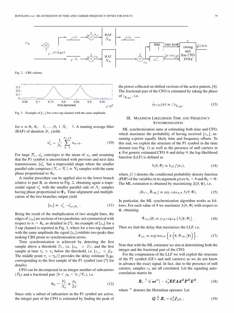
A. Correlation-Based Synchronization
We briefly describe the correlation-based synchronization(CBS) that will be partially used in one of the simplifiedapproaches proposed in this papers. The CBS scheme hasbeen proposed in [4] and is shown in Fig. 2. It comprises twobranches, one for correlating parts A and B and the other forcorrelating parts A and C. We first consider the upper branchrelative to part C, which provides
(8)
where encompasses all the noise terms and is still a zeromean random process. Note that for , sam-ples and differ only by the frequency shift ap-plied at the transmitter, i.e. . Hence (8)becomes
(9)
ROTOLONI et al.: ML ESTIMATION OF TIME AND CARRIER FREQUENCY OFFSET FOR DVB-T2 79
Fig. 2. CBS scheme.
Fig. 3. Example of �� � for a two-tap channel with the same amplitude.
for . A running average filter(RAF) of duration yields
(10)
For large , converges to the mean of and assumingthat the P1 symbol is uncorrelated with previous and next datatransmissions, has a trapezoidal shape where the smallerparallel side comprises samples with the samephase proportional to .
A similar procedure can be applied also to the lower branchrelative to part B, as shown in Fig. 2, obtaining again a trape-zoidal signal with the smaller parallel side of sampleshaving phase proportional to . Time-alignment and multipli-cation of the two branches output yield
(11)
Being the result of the multiplication of two straight lines, theedges of are sections of two parabolas, not symmetrical withrespect to , as detailed in [7]. An example of for a2-tap channel is reported in Fig. 3, where for a two-tap channelwith the same amplitude the signal exhibits two peaks thusmaking CBS prone to synchronization errors.
Time synchronization is achieved by detecting the firstsample above a threshold , i.e. , and the firstsample at time below the threshold, i.e. .The middle point provides the delay estimatecorresponding to the first sample of the P1 symbol (see [7] fordetails).
CFO can be decomposed in an integer number of subcarriersand a fractional part ), i.e.
(12)
Since only a subset of subcarriers in the P1 symbol are active,the integer part of the CFO is estimated by finding the peak of
the power collected on shifted versions of the active pattern, [4].The fractional part of the CFO is estimated by taking the phaseof , i.e.
(13)
III. MAXIMUM LIKELIHOOD TIME AND FREQUENCY
SYNCHRONIZATION
ML synchronization aims at estimating both time and CFO,which maximize the probability of having received , as-suming a-priori equally likely time and frequency offsets. Tothis end, we exploit the structure of the P1 symbol in the timedomain (see Fig. 1) as well as the presence of null carriers in. For generic estimated CFO and delay , the log-likelihood
function (LLF) is defined as
(14)
where denotes the conditional probability density function(PDF) of the variables in its argument given and .The ML estimation is obtained by maximizing , i.e.
(15)
In particular, the ML synchronization algorithm works as fol-lows. For each value of we maximize with respect to
, obtaining
(16)
Then we find the delay that maximizes the LLF, i.e.
(17)
Note that with the ML estimator we aim at determining both theinteger and the fractional part of the CFO.
For the computation of the LLF we will exploit the structureof the P1 symbol (GI’s and null carriers) as we do not knowin advance the exact signal. In fact, due to the presence of nullcarriers, samples are all correlated. Let the signaling auto-correlation matrix be
(18)
where denotes the Hermitian operator. Let
(19)
80 IEEE TRANSACTIONS ON BROADCASTING, VOL. 58, NO. 1, MARCH 2012
From (4) and (6) the correlation matrix of the received blockcan be written as
(20)
where is the -size diagonal matrix having entries, .
Now, by approximating the time domain transmitted signal asGaussian distributed (see also [12]), the conditional PDF of thereceived block can be written as
(21)
By exploiting the properties of the determinant and the defini-tion of matrix , we have
(22)Hence, the denominator of (21) does not depend neither onnor on and can be neglected in the maximization (15). There-fore we have
(23)where means that the maxima of the left and right side of theequation are attained for the same values of and .
Now, considering that is a Hermitian matrix and itsinverse is also Hermitian, exploiting the properties of the inverseof matrix products, (23) becomes
(24)
where denotes the real part of .As explained before, for each delay we must compute the
CFO that maximizes the LLF. Therefore, neglecting in this casethe terms that do not depend on and defining
(25)
we obtain
(26)
For the maximization (16) over we must resort to numericalmethods, which however in general lead only to suboptimal so-lutions. In the following we discuss relevant cases where thiscomputation can be simplified.
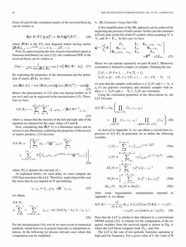
A. ML Estimator Using Only GIs
A first simplification of the ML approach can be achieved byneglecting the presence of null carriers. In this case the estimatorwill rely only on the GIs of the P1 symbol, while assuming
and . In this case we have
(27)
Hence we can operate separately on parts B and C. Moreover,correlation is limited to couples of samples. Defining the sets
we note that the samples with indices andare pairwise correlated, and similarly samples with in-
dices and are correlated.Using the correlation properties of the observations , the
LLF becomes
(28)
As derived in Appendix A, we can obtain a closed-form ex-pression of . In particular, let us define the followingvariables
(29a)
(29b)
(29c)
(29d)
(29e)
After some trigonometric manipulations reported inAppendix A, we obtain
(30)
Note that the LLF is similar to that obtained in a conventionalOFDM system [12]. A scheme for the computation of the re-quired variables from the received signal is shown in Fig. 4,where the LLF block computes both and (30).
The LLF is the sum of two periodic functions operating athigh and low frequency. For a given value of , the value of
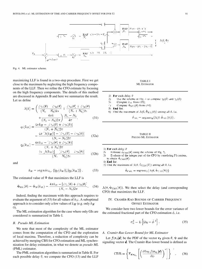
ROTOLONI et al.: ML ESTIMATION OF TIME AND CARRIER FREQUENCY OFFSET FOR DVB-T2 81
Fig. 4. ML estimator scheme.
maximizing LLF is found in a two-step procedure. First we getclose to the maximum by neglecting the high frequency compo-nents of the LLF. Then we refine the CFO estimate by focusingon the high frequency components. The details of this methodare discussed in Appendix B and here we summarize the result.Let us define
(31)
(32a)
(32b)
and
(33)
The estimated value of that maximizes the LLF is
(34)
Indeed, finding the maximum with this approach requires toevaluate the argument of (33) for all values of . A suboptimalapproach is to consider only a few values of (e.g. only
).The ML estimation algorithm for the case where only GIs are
considered is summarized in Table I.
B. Pseudo ML Estimation
We note that most of the complexity of the ML estimatorcomes from the computation of the CFO and the explorationof local maxima. Therefore, a reduction of complexity can beachieved by merging CBS for CFO estimation and ML synchro-nization for delay estimation, in what we denote as pseudo ML(PML) estimator.
The PML estimation algorithm is summarized in Table II. Foreach possible delay , we compute the CFO (13) and the LLF
TABLE IML ESTIMATOR
TABLE IIPSEUDO ML ESTIMATOR
. We then select the delay (and correspondingCFO) that maximizes the LLF.
IV. CRAMÈR-RAO BOUNDS OF CARRIER FREQUENCY
OFFSET ESTIMATOR
We consider here two lower bounds for the error variance ofthe estimated fractional part of the CFO estimation , i.e.
(35)
A. Cramèr-Rao Lower Bound for ML Estimator
Let be the PDF of the vector given , and thesignaling vector . The Cramèr-Rao lower bound is defined as
(36)
82 IEEE TRANSACTIONS ON BROADCASTING, VOL. 58, NO. 1, MARCH 2012
where expectation is taken with respect to both noise and sig-naling symbols. Note that since we are considering a single pa-rameter the Fisher information matrix boils down to a scalar.Also, we assume correct delay estimation as the focus hereis on the CFO estimate. Following the derivations of [15] theCramèr-Rao lower bound can be written as
(37)
B. Cramèr-Rao Lower Bound for the CBS Scheme
We now derive a bound for the CBS scheme, i.e., according tothe scheme of Fig. 2, obtaining the CFO estimate as the averageof the CFO estimates on parts B and C of the P1 symbol. Hence,we first evaluate the Cramèr-Rao lower bound of the estimationerror on each part and then combine the results.
Since after the shift recovery we find exactly the case of[16], the variance of the error of the estimation on a single partcan be found using the method described in [17]. Indicating with
and the estimates of the fractional CFO on B and C parts,respectively, we have
(38)
(39)
Now, using results of [18] we also have that for high signal tonoise ratio (SNR) , the Cramèr-Rao lower bound for CBSis
(40)
V. NUMERICAL RESULTS
The performance of the proposed synchronization schemesis compared in a typical DVB-T2 scenario, considering bothcomplexity of the implementations and their performance.
A. Complexity Comparison
We compare the considered schemes in terms of the numberof complex multiplications (CMUX).
For each output sample, the CBS scheme requires 2 CMUXfor the RAFs, 2 CMUX for the correlation on the two branchesand two additional CMUX due to the multiplication of theoutput of the branches and the multiplication by the frequencyshift , for a total of CMUX/sample.
For the (P)ML estimator we note that it includes the CBSscheme. Moreover, for considerations similar to that of the
TABLE IIICOMPLEXITY COMPARISON
CBS scheme, the scheme of Fig. 4 has a complexity of4 CMUX/sample. Lastly, the computation of (30) requires 2further CMUX, for a total of CMUX/sample.
For the ML scheme, the additional complexity of CMUXneeded for the estimation of the CFO and the LLF can not beestimated in closed-form, since it depends on the value ofand as from the algorithm of Table I but can be eval-uated by simulation. The total complexity of ML is therefore
CUMX/sample. From simulations we obtain. We note that the ML synchronization has a very
high complexity while both CBS and PML have a comparablecomplexity. The complexity comparison of the various architec-tures is summarized in Table III.
We have verified that all approaches need complexcells of memory to store the received samples.
Lastly, note that all schemes have a complexity that growslinearly with the number of processed samples , i.e. .
B. Performance Comparison
The performance of the schemes is assessed in terms of detec-tion probability when synchronization is achieved P[D, S], falsealarm probability P[FA] and miss detection probability P[MD].Let be the detection probability given that the system issynchronized. We have
(41)
where the probability of being synchronized is
(42)
From simulations we have verified that P[FA] is negligible forall considered schemes, hence the probability of detection giventhe synchronization is simply given by
(43)
The P1 symbol comprises two groups of bits (S1 and S2),which carry different signaling information. In order to assessthe performance of the synchronization schemes in the worstcase scenario, we consider a normalized frequency offsetuniformly distributed in the range [0, 0.5], i.e. up to half of thesubcarrier spacing of the DVB-T2 system.
Fig. 5 shows the probability of detection for the S1 and S2 bitsin a AWGN channel for the various synchronization schemes asa function of the SNR. We observe that ML always outperformsthe CBS scheme. Moreover, the PML has a performance veryclose to that of the ML approach. For comparison purposes wehave also considered the scheme in [5] where the threshold isthe same as that for the CBS scheme. We note that the scheme in

ROTOLONI et al.: ML ESTIMATION OF TIME AND CARRIER FREQUENCY OFFSET FOR DVB-T2 83
Fig. 5. Detection probability for bit groups S1 and S2 and various synchroniza-tion schemes as a function of the SNR in an AWGN scenario.
Fig. 6. Detection probability for the CBS, ML, and PML schemes as a functionof the delay between two channel taps having the same amplitude.
[5] has a performance close to that of CBS, with a slight penaltydue to unoptimized threshold.
The SNR range of Fig. 5 is very low because the synchro-nization on an AWGN channel is very robust due to the lengthof the P1 symbol. More challenging channels are usually experi-enced in a DVB-T2 transmission. In particular, in the implemen-tation guidelines for DVB-T2 [4] a transmit channel having twotaps is considered, simulating a single frequency network (SFN)scenario. In the following, the performance is investigated byvarying the relative delay and amplitudes of the taps (and ), while phases of the two taps are uniformly randomin for each simulation run. The SNR is set at 0 dB, toconsider a very noisy scenario. In the simulations, interferencegenerated by data frames around the P1 symbol is included.
We first consider two taps having the same amplitude, i.e., while delay is in the range [0, 1024].
Fig. 6 shows the probabilities for CBS, ML, PML and thescheme of [5]. From the figure we note that both ML andPML have a very close performance while significantly outper-forming both CBS and [5] approaches. In particular, CBS and[5] exhibit poor performance for long echoes withsamples, as both suffer from the issue discussed in Section II-A.
Fig. 7. P[D, S], P[MD], and P[D/S] for the (square marker) CBS, (circlemarker) ML, (triangle marker) PML, and (cross marker) scheme of [5] as afunction of the amplitude ratio ��� . Tap delay is set at � � ���.
Fig. 8. Variance of CFO estimation error and CRB.
Considering that PML has a significantly lower complexitythan ML, we conclude that it is a good alternative to ML, whileretaining its low error probability.
We now focus on the delay , which is the most criticalfor CBS. Fig. 7 shows the decoding, miss detection and condi-tional decoding probability of the schemes as a function of thetap amplitude ratio
(44)
Note that both ML and PML significantly outperform both CBSand the scheme of [5] when the amplitudes of the two taps arecomparable. When the absolute value of one of the two taps issignificantly larger than that of the other, all schemes get syn-chronous with the stronger tap and decoding is correct. On theother hand, the ML scheme is always able to decode with prob-ability close to one. We also note that both ML and PML sig-nificantly reduce the MD probability over the entire range ofwith respect to both CBS and [5].
Lastly, we compare the variance of the CFO estimators inFig. 8. We consider three channel models, namely AWGN,Rayleigh as defined in [4] and the two-ray SFN model de-scribed above with . We also report the Cramèr-Rao
84 IEEE TRANSACTIONS ON BROADCASTING, VOL. 58, NO. 1, MARCH 2012
bound (CRB) for CBS and ML estimators, which is derivedfor the AWGN channel model. First we observe that for theAWGN case the CRBs for ML and CBS coincide. Then, stillfor AWGN we observe that CBS performs almost as predictedby the CRB. Performance of ML is not reported for AWGNas CBS is already optimal and therefore we conclude that alsoML will have the same performance. For the Rayleigh case wereport the performance of both the ML and the CBS estimator.For SFN we do not plot the performance of CBS as for thischannel no synchronization is achieved and therefore the CFOestimate is not available. While in the Rayleigh case we observea performance very close to the CRB, the SFN case is morechallenging and exhibits significantly worse performance.Moreover, in the Rayleigh case CBS exhibits a limited losswith respect to the ML estimator.
VI. CONCLUSION
In this paper we have derived the ML synchronization schemefor the P1 symbol of the DVB-T2 standard. Performance resultshave shown that this scheme significantly outperforms the CBSscheme proposed in [4]. However, ML is significantly morecomplex. Therefore, we considered a hybrid scheme that usesthe CFO estimate of CBS, while still using the LLF to determinethe optimum timing. This solution has almost optimal perfor-mance while having a much lower complexity than that of theML solution.
APPENDIX ACOMPUTATION OF
The last product in (28) is independent of and , hencewe can omit this factor for the ML estimation. An equivalentexpression of (28) can thus be written as
(45)
Under the assumption that is a jointly Gaussian vector,is given by
(46)
The numerators of (45) are 2-D zero-mean complex-valuedGaussian distributions. Hence, using the correlation propertiesof (27) and defining
(47)
we obtain the following correlation matrices
(48)
(49)
where and . Since, inserting (48) into
(45) we get
(50)
Hence, using (46), the first log-ratio of (45) is given by
where we ignored constant terms. Analogously, for the secondterm of (45) we get
(51)
From (51) and (51) we obtain
(52)

ROTOLONI et al.: ML ESTIMATION OF TIME AND CARRIER FREQUENCY OFFSET FOR DVB-T2 85
and (30) or
(53)
APPENDIX BON THE MAXIMIZATION OF
In this Appendix we derive the estimate of the CFO that max-imizes the LLF. In order to ease notation we will drop depen-dence on from all variables. We aim at maximizing (53) andwe first observe that we can neglect the term . Then wehave
(54)
Since and we can focus on the case, which allows us to define
(55)
Thus we have
(56)
and using second Werner equality we can write
(57)
By defining
(58)
(59)
for the third Prosthaphaeresis equality we obtain
(60)
Now, neglecting the cosine at high-frequencies, i.e., we can approximate the
maxima of with the maxima of the following function
(61)
For the third Prosthaphaeresis equality we get
(62)
For we note that is always positiveand . The maxima are therefore achievedfor
(63)
with integer number.Now we look for frequencies around for which also the
high frequency term contributes with a maximum. In this casewe approximate the low-frequency cosine to one, i.e.
, and we have
(64)
with maxima at positions
(65)
with integer number.However must be as close as possible to , in
order to achieve the maximum of both low frequency and highfrequency terms, i.e., we select the value of satisfying
(66)
and therefore an approximated solution to the problem is pro-vided by (34).
REFERENCES
[1] Digital Video Broadcasting (DVB); Framing Structure, ChannelCoding and Modulation for Digital Terrestrial Television, ETSI EN300 744, Jan. 2001.

86 IEEE TRANSACTIONS ON BROADCASTING, VOL. 58, NO. 1, MARCH 2012
[2] Frame Structure Channel Coding and Modulation for a Second Gen-eration Digital Terrestrial Television Broadcasting System(DVB-T2),DVB Document A122, Jan. 2009.
[3] J. A. C. Bingham, “Multicarrier modulation for data transmission: Anidea whose time has come,” IEEE Commun. Mag., vol. 28, no. 5, pp.5–14, May 1990.
[4] Implementation Guidelines for a Second Generation Digital TerrestrialTelevision Broadcasting System (DVB-T2), DVB document A133, Feb.2009, (draft TR102831V1.1.1).
[5] J. G. Doblado, V. Baena, A. C. Oria, D. Perez-Calderon, and P. Lopez,“Coarse time synchronisation for DVB-T2,” Electron. Lett., vol. 46, no.11, pp. 797–799, May 2010.
[6] L. Vangelista and M. Rotoloni, “On the analysis of P1 symbol perfor-mance for DVB-T2,” in Proc. IEEE Sarnoff Symp. (SARNOFF), 2009.
[7] M. Rotoloni, S. Tomasin, and L. Vangelista, “On correlation-based syn-chronization for DVB-T2,” IEEE Commun. Lett., vol. 14, no. 3, pp.248–250, Mar. 2010.
[8] J.-S. Baek and J.-S. Seo, “Effective symbol timing recovery basedon pilot-aided channel estimation for MISO transmission mode ofDVB-T2 system,” IEEE Trans. Broad., vol. 56, no. 2, pp. 193–200,Feb. 2010.
[9] J.-S. Baek and J.-S. Seo, “Improved CIR-based receiver design forDVB-T2 system in large delay spread channels: Synchronization andequalization,” IEEE Trans. Broad., vol. 57, no. 1, pp. 103–113, Mar.2011.
[10] M. Morelli, C.-C. Jay Kuo, and M.-O. Pun, “Synchronization tech-niques for orthogonal frequency division multiple access (OFDMA): Atutorial review,” Proc. IEEE, vol. 95, no. 7, pp. 1394–1427, Jul. 2007.
[11] M. Morelli, C.-C. Jay Kuo, and M.-O. Pun, “HDTV terrestrial broad-casting,” Signal Process.: Image Commun., vol. 5, no. 5/6, p. 379403,Dec. 1993.
[12] J. van de Beek, M. Sandell, and P. Borjesson, “ML estimation of timeand frequency offset in OFDM systems,” IEEE Trans. Signal Proc.,vol. 45, pp. 1800–1805, Jul. 1997.
[13] H. Liu and U. Tureli, “A high-efficiency carrier estimator for OFDMcommunications,” IEEE Commun. Lett., vol. 2, pp. 104–106, Apr.1998.
[14] X. Ma, C. Tepedelenlioglu, G. B. Giannakis, and S. Barbarossa,“Non-data-aided carrier offset estimators for OFDM with nullsubcar-riers: Identifiability, algorithms, and performance,” IEEE J. Sel. AreasCommun., vol. 19, no. 12, pp. 2504–2515, Dec. 2001.
[15] Y.-S. Choi, P. J. Voltz, and F. A. Cassara, “ML estimation of carrierfrequency offset for multicarrier signals in Rayleigh fading channels,”IEEE Trans. Veh. Technol., vol. 50, no. 2, pp. 644–655, Mar. 2001.
[16] T. M. Schmidl and D. C. Cox, “Robust frequency and timing syn-chronization for OFDM,” IEEE Trans. Commun., vol. 45, no. 12, pp.1613–1621, Dec. 1997.
[17] P. H. Moose, “A technique for orthogonal frequency division multi-plexing frequency offset correction,” IEEE Trans. Commun., vol. 42,no. 10, pp. 2908–2914, Oct. 1994.
[18] S. M. Kay, Fundamentals of Statistical Signal Processing: EstimationTheory. Englewood Cliffs, NJ: Prentice Hall, 1993.
[19] F. Gini and R. Reggiannini, “On the use of Crameér-Rao-like bounds inthe presence of random nuisance parameters,” IEEE Trans. Commun.,vol. 48, no. 12, pp. 2120–2126, Dec. 2000.
Marco Rotoloni graduated in telecommunicationengineering from the University of Padova, Italy, in2007, where he also received his doctorate degree in2011.
During the academic year 2009–2010 he wason leave at Qualcomm in San Diego (CA). Here,he worked on channel estimation algorithms forindoor wireless repeaters which had to be fitted incellular environments. Following that, in the firsthalf of 2010, he visited the faculty of Supelec,in Gif-sur-Yvette (France), where he joined the
SDR4ALL group. The aim of this project was to simplify the software definedradio technology in order to bring this tool inside the academic environment.His research topics includes wireless signal processing topics, in particularfocused on OFDM systems (such as DVB-T and DVB-T2), optimization ofsignal processing algorithms for embedded systems, and implementation ofreal-time system interfaces.
Stefano Tomasin (S’99–M’03–SM’11) received theLaurea degree and the Ph.D. degree in telecommu-nications engineering from the University of Padova,Italy, in 1999 and 2003, respectively.
In the Academic year 1999–2000 he was onleave at the IBM Research Laboratory, Zurich,Switzerland, doing research on signal processing formagnetic recording systems. In the Academic year2001–2002 he was on leave at Philips Research,Eindhoven, the Netherlands, studying multicarriertransmission for mobile applications. In the second
half of 2004 he was visiting at Qualcomm, San Diego (CA) doing researchon receiver design for mobile cellular systems. Since 2005 he is assistantprofessor at University of Padova, Italy. In 2007 he has been visiting facultyat Polytechnic University of Brooklyn, NY, working on cooperative commu-nications. His current research interests include signal processing for wirelesscommunications, resource allocation for cellular systems and smart grids.
Lorenzo Vangelista (SM’02) was born in Bassanodel Grappa, Italy, in 1967. He received the Laureadegree from University of Padova, Padova, Italy, in1992, and the Ph.D. degree in electrical and telecom-munication engineering from University of Padova,in 1995.
He subsequently joined the Transmission andOptical Technology Department of CSELT, Torino,Italy. From December 1996 to January 2002, hewas with Telit Mobile Terminals, Sgonico (TS),Italy and then, up to May 2003, with Microcell
A/S, Copenaghen, Denmark. Until July 2006 he has been with the worldwideorganization of Infineon Technologies, as program manager. Since October2006 he is an Associate Professor of Telecommunication within the Departmentof Information Engineering of Padova University, Italy. His research interestsinclude signal theory, multicarrier modulation techniques, cellular networks,wireless sensors and actuators networks and smartgrid.