PDF Dissertação Mestrado Erika Oliveira de Almeida\374
110
Erika Oliveira de Almeida P P r r ó ó t t e e s s e e p p r r o o t t o o c c o o l l o o c c o o m m b b a a r r r r a a p p r r é é - - f f a a b b r r i i c c a a d d a a . . C C o o m m p p o o r r t t a a m m e e n n t t o o ó ó s s s s e e o o v v a a r r i i a a n n d d o o o o t t i i p p o o d d e e o o s s s s o o e e a a c c o o n n f f i i g g u u r r a a ç ç ã ã o o h h o o r r i i z z o o n n t t a a l l d d o o a a r r c c o o m m a a n n d d i i b b u u l l a a r r n n o o M M E E F F - - 3 3 D D
-
Upload
khangminh22 -
Category
Documents
-
view
1 -
download
0
Transcript of PDF Dissertação Mestrado Erika Oliveira de Almeida\374
E rika O liveira de A lm eida
������������ �
PPrróótteessee pprroottooccoolloo ccoomm bbaarrrraa pprréé--ffaabbrriiccaaddaa..
CCoommppoorrttaammeennttoo óósssseeoo vvaarriiaannddoo oo ttiippoo ddee
oossssoo ee aa ccoonnffiigguurraaççããoo hhoorriizzoonnttaall ddoo aarrccoo
mmaannddiibbuullaarr nnoo MMEEFF--33DD

1
E rika O liveira de A lm eida
D issertação apresentada à F aculdade de O dontologia do Câm pus de A raçatuba – U nesp, para a obtenção do G rau de “M estre em O dontologia” – Á rea de Concentração em Prótese D entária. O rientador: P rof. A ss. D r. E duardo Passos R ocha
������������ �
PPPrrróóóttteeessseee ppprrroootttooocccooolllooo cccooommm bbbaaarrrrrraaa ppprrrééé---fffaaabbbrrriiicccaaadddaaa...
CCCooommmpppooorrrtttaaammmeeennntttooo óóósssssseeeooo vvvaaarrriiiaaannndddooo ooo tttiiipppooo dddeee
ooossssssooo eee aaa cccooonnnfffiiiggguuurrraaaçççãããooo hhhooorrriiizzzooonnntttaaalll dddooo aaarrrcccooo
mmmaaannndddiiibbbuuulllaaarrr nnnooo MMMEEEFFF---333DDD

2
Catalogação-na-Publicação
Serviço Técnico de Biblioteca e Documentação – FOA / UNESP
Almeida, Erika Oliveira de A447i Prótese protocolo com barra pré-fabricada. Comportamento ósseo
variando o tipo de osso e a configuração horizontal do arco mandibular no MEF-3D / Erika Oliveira de Almeida. - Araçatuba:
[s.n.], 2008
116f. : il. ; tab.
Dissertação (Mestrado) – Universidade Estadual Paulista, Faculdade de Odontologia, Araçatuba, 2008 Orientador: Prof. Dr. Eduardo Passos Rocha
1. Análise de elemento finito 2. Biomecânica 3. Osso e ossos 4. Osseointegração.
Black D32 CDD 617.69
3
D adD adD adD ados os os os CurricularesCurricularesCurricularesCurriculares
E rika O liveira de A lm eida
Nascimento: 22.02.1981 - RECIFE /PE
Filiação: Rômulo José Leitão de Almeida
Edirce de Oliveira Batista
1999-2003: Curso de Graduação em Odontologia
Faculdade de Odontologia de Caruaru – SCES
2003- 2004: Curso de Aperfeiçoamento em Prótese Dental
Associação Brasileira de Especialistas e Pós-graduandos da Odontologia
– ABEPO
2004 – 2005:
2007:
2006 – 2008:
Especialização em Prótese Dentária
Associação Brasileira de Odontologia de Pernambuco – ABO /PE
Curso de Atualização em Prótese Sobre Implante
Centro de Odontologia Estética/ Sindicato dos Odontologistas da Região
de São José do Rio Preto - SP
Mestrado em Odontologia, área de Prótese Dentária
Faculdade de Odontologia de Araçatuba - UNESP
D edicatória
A os m eus pais,����������� ����������� ����������� ����������� ���������
Painho,Painho,Painho,Painho, Obrigada por ter lutado a vida inteira para me oferecer a melhor das heranças, o
conhecimento e a oportunidade de estudar.
Agradeço muito pela confiança e pelo carinho incondicional.
Exemplo de pai, trabalho, honestidade e perseverança!
M ainha,M ainha,M ainha,M ainha,Obrigada por estar presente em todos os momentos da minha vida, sempre torcendo e
me incentivando a ser uma pessoa cada vez melhor.
Agradeço pelos conselhos diários, pela atenção e pelo carinho fundamentais para a
obtenção dos meus objetivos.
Desculpe se estive ausente por este período e se, às vezes, não consegui retribuir
todo o amor que sinto por você.
Agradeço a Deus por ter uma pessoa tão especial em miha vida!
A o m eu irm ão�� �� �� �� ���
N ininho,N ininho,N ininho,N ininho, Valeu pela força em momentos difíceis, pelos ensinamentos em informática e por estar
sempre presente nos momentos em que estive ausente em nossa linda família.
D E D ICO A V O C Ê S TO D A S A S M IN H A S CO N Q U ISTA S!
A M O M U ITO V O CÊ S!A M O M U ITO V O CÊ S!A M O M U ITO V O CÊ S!A M O M U ITO V O CÊ S!

A gradecim entos E speciais
����������������������Companheiro fiel e inseparável.
Obrigada pela oportunidade de viver.
Obrigada por me mostrar os melhores caminhos.
Obrigada por colocar em meu caminho pessoas maravilhosas.
Agradeço eternamente pela oportunidade de aprender todos os dias.
A os m eus fam iliares, nas pessoas das m inhas avós ����������������������������
��������� ������������� ����������� ������������� ����������� ������������� ����������� ������������� ���Muito obrigado pelas constantes palavras de incentivo, pela confiança e pelo apoio.
Vocês contribuíram e estiveram sempre presentes na minha formação.
A o m eu orientador, P rof.���� ������������������� ������������������� ������������������� �����������������Pelo exemplo de profissional dedicado, exigente e muito competente.
Obrigada por me ajudar a fazer valer a pena todo o meu esforço de estar aqui com a
finalidade de aprender ao máximo e ainda crescer como pessoa, aumentando minha
capacidade de enxergar o mundo. O senhor conseguiu superar as minhas expectativas
com o que eu sonhava encontar em uma pós-graduação.
Obrigada pela oportunidade e credibilidade!

8
A o m eu nam orado, ������ ��������� ���������� �������� ��������� ���������� �������� ��������� ���������� �������� ��������� ���������� ������
M eu am or, obrigada pelo nosso convívio diário, por compartilhar momentos difíceis e
maravilhosos ao meu lado, pelo incentivo e carinho.
Agradeço a Deus pelo presente de ter te encontrado neste momento em minha vida,
pois você me completa e me faz muito feliz.
Pelas afinidades e objetivos em comum, pelo carinho, respeito, cumplicidade e pelo
amor verdadeiro que sentimos um pelo outro, tenho certeza que teremos um futuro
brilhante para compartilharmos juntos.
� �����!!!����������"��� �������������������#� ���$�%��&������'����������'������������������%��
��� ������ �������� �( ������#�������� ���� ������� ���� ������� ���� ������� ���� �����

AAA gggrrraaadddeeeccc iiimmm eeennn tttooosss

������������ ��� ���� �!!!�À F aculdade de O dontologia de A raçatuba – U niversidade E stadual P aulista
“Júlio de M esquita F ilho” na pessoa do seu Diretor Prof. Dr. Pedro Felício Estrada
Bernabé pela oportunidade da realização deste curso de pós-graduação.
A o Program a de Pós-G raduação em O dontologia , na pessoa de seu Coordenador
Prof. Dr. Idelmo Rangel Garcia Júnior, pela valiosa contribuição em minha formação.
À N eodent Im plantes O sseointegrados, na pessoa da Dra. Ivete Sartori, pelos
implantes e componentes protéticos cedidos para a realização desta pesquisa e pela
atenção com que sempre nos recebeu.
A os P rofessores do D epartam ento de M ateriais O dontológicos e P rótese, pelos
essenciais ensinamentos durante o curso e agradável convivência. Que Deus os
abençõe!
A o Prof. Eduardo Piza Pellizzer, pelo que pude aprender com o senhor. Obrigada
por ter me recebido nesta Instituição.
A o prof. Wirley Gonçalves Assunção, pelo apoio com palavras sábias e construtivas
em muitos momentos. Obrigada pelos ensinamentos clínicos, essenciais para
complementar a minha formação. Admiro-o pela forma humana e sensata de conduzir
a nossa profissão e me espelho no seu dinamismo e na sua liderança como professor.
A o Prof. Wilson Roberto Poi, pelo incentivo à arte de ensinar. Obrigada pela
gentileza e acessibilidade com que sempre me recebeu.

A F aculdade de O dontologia de Caruaru na pessoa do Prof. Petrônio Martelli pela
excelente formação durante meu curso de graduação; e à Profa. Anamaria Leite, pelo
constante incentivo em busca do saber.
À s professoras da A ssociação B rasileira de O dontologia de Pernam buco: Cátia
Fonseca Guerra, Sandra Moraes e Niara Branco, pelos seus ensinamentos e pelo
incentivo durante minha especialização. Em especial, à profa. Adriana da Fonte Porto
Carreiro, por sua amizade sincera e por acreditar no meu potencial para seguir a pós-
graduação, me apoiando mesmo à distância.
A os m eus tios, em especial José Rosalvo Almeida, ao qual me espelho por sua
conduta firme e disciplinada.
E aos m eus padrinhos Ramilson e Ana Almeida, por serem muito prestativos e
atenciosos, proporcinando-me suporte familiar neste Estado.
A o m eu querido tio e am igo Rui Gomes (in memorian), pelo carinho incondicional.
Guardarei eternamente o seu sorriso e seu positivismo como forma de conduzir a
minha vida. A lô B rasil!
A os am igos Paulo e Luciana Ciarlini, que me receberam com muito carinho em
Araçatuba e me proporcionaram momentos familiares e agradáveis. M uito O brigada!

À m inha am iga Lithiene, por todos os momentos compartilhados. Desejo que nossa
amizade perdure, pois temos realmente afinidades e ainda iremos aprender muito uma
com a outra.
À s am igas Jéssica e Thalita, atuais companheiras de apartamento e grandes amigas.
Vocês foram muito importantes nesta etapa final do meu curso. Obrigada pela
oportunidade de conviver com pessoas tão especiais. Estarei esperando vocês na
minha região em breve!
À s m inhas am igas de infância em R ecife, consideradas como “Amigas Felizes”:
Lígia, Maria Eduarda, Maria Parmera, Silvia, Rafaela, Marília, Juana, Roberta,
Rebecca, Letícia, Clara, Patrícia, e Mariana. Meus sinceros agradecimentos pela
eterna amizade e pela torcida com que estiveram durante este período. Muito obrigada
pela nossa união e experiências compartilhadas à distância!
À grande am iga Débora e sua família: Tia Josélia, Isabel, Luiza e Carlos Eduardo,
pelo suporte clínico enquanto estive ausente da nossa cidade e pela verdadeira
amizade em todos os momentos desde a Faculdade.
E m especial às am igas Érica Tôrres e Carol, que estiveram nesta mesma época
fazendo a pós-graduação em outras cidades de São Paulo e puderam compartilhar
minhas vitórias e dificuldades sempre ao meu lado.

A os m eus colegas de Pós-graduação Abrahão, Anna Kelly, Bianca, Carlinhos,
Daniella, Eloá, Érica, Erivan, Fellippo, Juliana Delben, Lívia, Lucas, Manoel,
Renato, Rodolfo, Rodolpho, Rosse Mary e Thiago por tudo o que pude aprender
com vocês e pelas alegrias e desafios compartilhados. Em especial ao meu super
amigo Valentim, pela amizade verdadeira e sincera. Pelo carinho nos momentos
difíceis. Desejo a vocês muito sucesso profisssional e realizações pessoais!
A os colegas e professores do D epartam ento de C irurgia e T raum atologia B uco-
M axilo-F acial desta Faculdade, em especial ao Prof. Osvaldo Magro Filho,
agradeço pelos momentos de descontração que tive junto com a “família da cirurgia”. E
à secretária Cleide Lemes pela disponibilidade em ajudar, pela atenção e amizade,
importantes para que eu sempre me sentisse muito bem neste Departamento.
A os funcionários do D epartam ento de M ateriais O dontológicos e P rótese desta
Faculdade: Ana Lúcia, Maria Lúcia, Jander, Ana Marcelina, Zé, Eduardinho e
Carlão. Pelo dia-a-dia compartilhados e pela atenção em todos os momentos.
A os funcionários da Seção de Pós-G raduação desta Faculdade: Marina, Valéria e
Diogo. Pela eficiência e bom-humor diários. Meus sinceros sentimentos de gratidão!
A os funcionários da B iblioteca de O dontologia desta Faculdade, pelas constantes
orientações e dedicação aos seus serviços.

EEE ppp íííggg rrraaa fffeee
���������������
������������������������������������������ �!�"�����������������#�"
��������#�"������$���������%%%�����������&�'(���$!�����������)��!��������*�����!�����&�'+���$�����������������%�����������&�'(������ ����,��"����!�!���
-����!������������!����������������%�����������&�'($������$������������#�%%%
�������������������"����.(����$�����"��������"����/�����%%%
�����������&�'(���)������$!�!����������%0"�!������!�"�����!���-���$���+�����*%%%�����������&�'(����(������)����-����������!���#���!���������������%%%��������������!�%%%�����������&�'
������-������)�(����1.�$%%%����)���������!�������$)��%%%2������������������������������%%%
�����������&�'(����(������)����-�������"��!��������"�����)������"�-�������$!����������!�"�)����"�����.�+��%
���-�����!�����(��+���������������������!�������.
Fonte: Jornal AconteCendo, nº. 22, Setembro de 2001

Almeida, EO. Prótese protocolo com barra pré-fabricada. Comportamento ósseo
variando o tipo de osso e a configuração horizontal do arco mandibular no MEF-
3D [dissertação]. Araçatuba: Faculdade de Odontologia da Universidade Estadual
Paulista; 2008.
R esum o G eral
A barra pré-fabricada é uma opção de tratamento vantajosa por minimizar o tempo de
confecção da prótese implantossuportada do tipo protocolo de carga imediata com
níveis de adaptação e passividade previsíveis. No entanto, para a sua aplicação, o
arco do paciente deve adaptar-se anatomicamente ao formato da barra pré-fabricada,
e a qualidade óssea deve ser compatível com a indicação da carga imediata. Além
disso, a literatura não apresenta dados numéricos sobre a influência de diferentes
formatos horizontais do arco mandibular na distribuição das tensões no osso, assim
como não é homogênea a definição do critério de análise a ser utilizado quando
materiais frágeis, como o osso, são estudados utilizando o método dos elementos
finitos. Devido a isso, foi realizada uma revisão da literatura com o objetivo de
relacionar as propriedades dos materiais estudados com o critério de análise adotado.
Para isto, foram levantados 2061 artigos através do indexador Medline database,
durante os anos de 2004 a 2008. Observou-se que tanto o critério das tensões de von
Mises como a máxima tensão principal foram utilizados para o estudo dos materiais
considerados frágeis ou não. Para o estudo da influência de diferentes formatos
horizontais do arco mandibular e diferentes tipos de osso na distribuição das tensões
no osso cortical e medular na simulação de uma prótese fixa implantossuportada do
tipo protocolo mandibular confeccionada através do sistema pré-fabricado Neopronto
(Neodent, Implante Osseointegrável), quatro modelos (M) representativos de um arco

mandibular totalmente edentado e restaurados com o sistema pré-fabricado Neopronto
(Neodent, Implant Osseointegrável), sobre quatro implantes interforaminais, foram
confeccionados no programa SolidWorks 2007 variando o tipo de osso (I ao IV) (M.I -
M.II - M.III - M.IV), considerando-se a dimensão horizontal como de tamanho regular. A
variação da dimensão horizontal (11% maior ou menor) gerou os modelos grande (Mg)
e pequeno (Mp). Os modelos de tamanho regular (M.I - M.II - M.III - M.IV) foram
duplicados para avaliar a influência da presença ou ausência das roscas dos implantes
na distribuição interna das tensões no osso. Os nós da base foram fixados nos três
eixos cartesianos, e dois carregamentos (C) foram adotados: C1 – na região anterior
da barra, entre os implantes mais anteriores; e C2 – na região posterior unilateral
esquerda da barra. A análise numérica foi realizada usando o Ansys Workbench 10.0.
A máxima tensão principal (�max) foi obtida para o osso cortical e medular. Observou-
se que não apenas o critério da máxima tensão principal foi utilizado para o estudo de
estruturas como o osso, e que as diferentes dimensões (pequeno e grande) do arco
mandibular geraram variações nos valores de �max mais evidentes na região posterior
da mandíbula, principalmente para o implante mais posterior e relacionado ao lado do
carregamento. Comparando os tipos de osso, o tipo IV apresentou pior prognóstico.
Para um mesmo formato de arco mandibular, as alterações nos valores de tensão
foram mais evidentes no osso cortical. A presença da rosca no implante aumentou a
tensão observada na interface osso-implante em comparação com o implante liso.
Concluiu-se que a literatura não é homogenêa quanto ao critério de análise adotado. A
alteração da configuração mandibular altera a distribuição das tensões, embora dados
mais evidentes possam ser obtidos com carregamento obliquo.
Palavras-chave: Análise de elemento finito, Biomecânica, Osso e ossos,
osseointegração.

Almeida, EO. P Protocol prosthesis with prefabricated bar. Bone behavior varing
the bone type and the horizontal configuration of mandibular arch using FEA-3D
[Dissertation]. Araçatuba: Sao Paulo State University; 2008.
G eneral A bstractG eneral A bstractG eneral A bstractG eneral A bstract
Prefabricated bar is a profitable treatment option for minimizing the preparation time of
fixed protocol-type prosthesis in immediate load with adaptation levels and predictable
passivity. Nevertheless, in order to be applied, the patient's arch must be anatomically
adapted to the format of the prefabricated bar, and bone quality must be compatible to
immediate load indication. However, literature does not show any numerical data about
the influence of different horizontal formats of the mandibular arch on bone stress
distribution, as well as it is not homogeneous which analysis criterion is to be used
when friable materials, such as the bone, are studied by making use of the finite
element method. Due to this, a literature review was elaborated with the purpose to
relate the materials' properties through the adopted analysis criterion. Therefore, 2061
articles were raised through the Medline Database Indexer from 2004 to 2008. It was
noticed that not only Von Mises's equivalent stress criterion but also maximum principal
stress were used for the study of materials considered as friable or not. For the study of
the influence of different horizontal formats of mandibular archs and different types of
bone in stress distribution on the cortical and medular bone in simulating a fixed
implant-supported protocol-type mandibular prosthesis prepared through the Neopronto
prefabricated system (Neodent, Osseointegratable Implant), four representative models
(M) of a totally endentulate mandibular arch restored by the Neopronto prefabricated

system (Neodent, Osseointegratable Implant) over four interforaminal implants were
prepared through the SolidWorks 2007 program with a bone range (I to IV) (M.I - M.II -
M.III - M.IV), considering the horizontal dimension as of regular size. The variation of
the horizontal dimension (11% higher or lower) generated big (Mg) and small (Mp)
models. The regular size models, M.I, M.II, M.III and M.IV were doubled in order to
evaluate the influence of the presence or absence of implant threads on inner stress
distribution in the bone. The base knots were fixed on the three Cartesian axes, and
two loadings (C) were adopted: C1 - in the anterior region of the bar, between the most
anterior implants, and C2 - in the left posterior unilateral region of the bar. The
numerical analysis was carried out by making use of Ansys Workbench 10.0. The
maximum principal stress (�max ) was obtained for the cortical and medular bone. The
Maximum Principal Stress criterion is not the only one used for the study of structures
such as the bone, and that the variation of the horizontal dimension of the mandibular
arch provided higher values of cortical bone stress, mainly around the distal implants.
Comparing the bone type, the type IV presented less satisfied results. For the same
arch configuration, the alterations in the stress values were more evident at the cortical
bone. The presence of threads in the implants increased the stress at the bone-implant
interface. In conclusion, there is no homogeneous citation of which stress criterion
should be used for friable and brittle materials and the mandibular arch configuration
have influence on the stress distribution in protocol-type prosthesis, although more solid
results should be gotten from oblique loading.
Key-words: Finite element analysis, Biomechanics, Bone and bones,
Osseointegration.

L ista de F iguras
CAPÍTULO 2 Prótese protocolo com barra pré-fabricada no MEF-3D:
comportamento ósseo variando o tipo de osso e a
configuração horizontal do arco
mandibular............................................................................... 53
Figura 1
Figura 2
Configuração do arco mandibular no plano horizontal. Mp -
arco mandibular com DIF pequena; M - arco mandibular com
DIF regular e Mp – arco mandibular com DIF
grande.......................................................................................
Componentes do sistema Neopronto: A e B - barra pré-
fabricada vista superior e inferior, respectivamente; C -
implante Titamax GT Cortical; D - implante Titamax GT
Medular; E e F - cilindro de cimentação e parafuso; G -
parafuso de fixação da barra................................................
59
60
Figura 3
Figura 4
Figura 5
A e B – Vistas inferior e frontal dos implantes conectados à
barra pré-fabricada, respectivamente; B,1-4: Identificação dos
implantes; C - Modelo finalizado; D – Representam
carregamentos C1 e C2.............................................................
Malha de elementos finitos dos modelos pequeno (M.p),
regular (M) e grande (M.g).........................................................
Condições de contorno .............................................................
61
62
65
L ista de Tabelas
CAPÍTULO 2 Prótese protocolo com barra pré-fabricada no MEF-3D:
comportamento ósseo variando o tipo de osso e a
configuração horizontal do arco
mandibular.................................................................................. 53
Tabela 1 Características dos tipos de osso (Baseado em Sevimay et al.,
2005)................................................................................................................ 58
Tabela 2
Tabela 3
Número de nós e elementos dos modelos ....................................
Propriedades mecânicas dos materiais.......................................
63
64

L ista de G ráficos
CAPÍTULO 2 Prótese protocolo com barra pré-fabricada no MEF-3D:
comportamento ósseo variando o tipo de osso e a
configuração horizontal do arco
mandibular......................................................................................... 53
Gráfico 1
Gráfico 2
Gráfico 3
Gráfico 4
Gráfico 5
Gráfico 6
Gráfico 7
Gráfico 8
Gráfico 9
Gráfico 10
Gráfico 11
Gráfico 12
Gráfico 13
Gráfico 14
Gráfico 15
Gráfico 16
Valores de �max (MPa) para o osso cortical no M.Ip, M.I e M.Ig após C1................
Valores de �max (MPa) para o osso cortical no M.Ip, M.I e M.Ig após C2................
Valores de �max (MPa) para o osso cortical no M.IIp, M.II e M.IIg após C1.............
Valores de �max (MPa) para o osso cortical no M.IIp, M.II e M.IIg após C2.............
Valores de �max (MPa) para o osso cortical no M.IIIp, M.III e M.IIIg após C1..........
Valores de �max (MPa) para o osso cortical no M.IIIp, M.III e M.IIIg após C2..........
Valores de �max (MPa) para o osso cortical no M.IVp, M.IV e M.IVg após C1. .......
Valores de �max (MPa) para o osso cortical no M.IVp, M.IV e M.IVg após C2. .......
Valores de �max (MPa) para o osso cortical no modelos M.I-IVp após C1. .............
Valores de �max (MPa) para o osso cortical no modelos M.I-IVp após C2. .............
Valores de �max (MPa) para o osso cortical no modelos M.I-IV após C1. ................
Valores de �max (MPa) para o osso cortical no modelos M.I-IV após C2. ................
Valores de �max (MPa) para o osso cortical no modelos M.I-IVg após C1. .............
Valores de �max (MPa) para o osso cortical no modelos M.I-IVg após C2. ..............
Valores de �max (MPa) para o osso cortical no modelos M.I-IVR após C1. ............
Valores de �max (MPa) para o osso cortical no modelos M.I-IVR após C2..............
66
67
68
68
69
69
70
70
71
71
72
72
73
73
74
75

L ista de A breviaturas
MEF (FEA)
MEF-3D
MEF-2D
= Método dos Elementos Finitos (Finite element analysis)
= Método dos Elementos Finitos Tridimensional
= Método dos Elementos Finitos Bidimensional
�max = Máxima tensão principal (Maximum principal stress)
mm = milímetro
I = Osso tipo I (Bone type I)
II = Osso tipo II (Bone type II)
III = Osso tipo III (Bone type II)
IV = Osso tipo IV (Bone type IV)
MPa = Mega Pascal
GPa = Giga Pascal
DIF = Distância inter-foraminal (Interforaminal distance)
M.p = Modelo com configuração do arco mandibular pequena
M = Modelo com configuração do arco mandibular regular
M.g = Modelo com configuração do arco mandibular grande
M.R = M com roscas nos implantes
C1
C2
= Carregamento Anterior (Anterior loading)
= Carregamento Posterior (Posterior loading)
Sum ário 1 Introdução Geral................................................................................................... 27
2 Capítulo 1 - Critérios de análise em estudos com elementos finitos.
Revisão da literatura.............................................................................................� 31
2.1 Resumo ................................................................................................... 32
2.2 Abstract ................................................................................................... 33
2.3 Introdução ............................................................................................... 34
2.4 Proposição .............................................................................................. 36
2.5 Revisão da Literatura ..............................................................................
2.6 Conclusão ...............................................................................................
37
44
2.7 Referências............................................................................................... 45
3 Capítulo 2 - Prótese protocolo com barra pré-fabricada no MEF-3D:
comportamento ósseo variando o tipo de osso e a configuração horizontal
do arco mandibular............................................................................................... 53
3.1 Resumo................................................................................................... 54
3.2 Abstract.................................................................................................... 55
3.3 Introdução................................................................................................ 56
3.4 Material e método..................................................................................... 58
3.5 Resultados............................................................................................... 66
3.6 Discussão................................................................................................. 76
3.7 Conclusão................................................................................................ 80
3.8 Referências.............................................................................................. 81
Anexos.....................................................................................................................
82

28
1 Introdução G eral
A determinação da qualidade óssea é um fator significante para a seleção do
implante, estabilidade primária, e determinação do momento do carregamento,
principalmente em pacientes totalmente desdentados (Sevimay et al., 2005).
A prótese de carga imediata sobre implante apresenta sucesso comprovado por
estudos clínicos longitudinais (Hatano et al., 2003; Jaffin, Kumar e Berman, 2004;
Castellon et al., 2004; Engquist et al., 2005; Ercoli et al., 2006). Mesmo assim, várias
técnicas continuam surgindo de forma a aprimorar este tratamento. A barra pré-
fabricada é uma opção que facilita a instalação da prótese fixa implanto-suportada com
maior rapidez, garantindo maior passividade ao conjunto prótese-implante, com maior
previsibilidade de sucesso para a osseointegração (Herman et al., 2007). No entanto,
para a sua indicação, o arco do paciente deve adaptar-se anatomicamente ao formato
da barra pré-fabricada, limitando o tratamento a depender do formato horizontal do
arco mandibular.
Outro fator que influencia no sucesso do tratamento é a qualidade óssea. A
qualidade de um osso refere-se às propriedades mecânicas, arquitetura, grau de
mineralização da matriz óssea, estrutura química dos cristais do osso mineral e, ainda,
propriedades mecânicas da remodelação óssea (Shapurian et al., 2006). Lekholm e
Zarb, em 1985, classificaram o tipo de osso em I, II, II e IV e esta classificação tem
sido extensamente utilizada pelos clínicos na avaliação óssea para colocação dos
implantes nos pacientes.
De acordo com esta classificação, o osso tipo I é composto de osso compacto
homogêneo. O osso tipo II possui uma camada espessa de osso compacto
29
circundando um núcleo de osso trabecular denso. O osso tipo III possui uma camada
delgada (1mm) de osso cortical circundando o osso trabecular denso com resistência
favorável. E o osso tipo IV possui uma camada delgada (1mm) de osso cortical
circundando um núcleo de osso trabecular com baixa densidade (Sevimay et al., 2005;
Misch, 2006). Dentre os quatro tipos de osso, há uma grande variação de resistência
biomecânica, ou seja, capacidade de suportar cargas fisiológicas (Tada et al., 2003), e
de acordo com Jaffin e Berman (1991), o osso tipo IV relaciona-se com as maiores
taxas de falhas.
Vários autores avaliaram a influência da qualidade óssea em relação aos
implantes osseointegrados envolvendo próteses unitárias (Jaffin e Berman, 1991;
Holmes e Loftus, 1997; Ichikawa et al., 1997; Tada et al., 2003; Sevimay et al., 2005),
porém, nenhum deles relacionou a tensão óssea que a prótese fixa implanto-suportada
do tipo protocolo proporciona sobre diferentes tipos de osso.
Para a avaliação da tensão óssea nestas situações, o método dos elementos
finitos é válido (Yokoyama et al., 2005). Entretanto, é necessário que o critério de
análise adotado seja escolhido segundo as características dos materiais em estudo.
No entanto, a literatura não é homogênea quanto à seleção do critério de análise
segundo a característica do material, uma vez que o critério das tensões equivalentes
de von Mises, por exemplo, tem sido utilizado para analisar o comportamento de
estruturas buco-dentais, notadamente não-dúcteis.
Em vista do exposto, os objetivos do presente estudo foram realizar uma revisão
da literatura dos artigos dos últimos 5 anos para verificar a relação entre as
propriedades dos materiais estudados e o critério de análise utilizado para a
interpretação dos resultados; e avaliar a influência da configuração horizontal do arco
mandibular (pequeno, regular e grande) e da qualidade óssea (tipo I ao IV) na

30
distribuição interna das tensões quando da utilização da barra pré-fabricada em
próteses fixas implanto-suportada do tipo protocolo.
31
CCC aaappp ííítttuuu lllooo 111 :::
����������������������������������������������������������
������������
&���!��!��34�������!���$5�����$���6�������!���$7��)���!�0� !����!�
�!�������7��)��!��"���8��'

32
1.1 RESUMO
O objetivo deste trabalho foi realizar uma revisão da literatura dos artigos mais
recentes que utilizaram o MEF, a fim de relacionar as propriedades dos materiais com
o critério de análise adotado e o prognóstico de falha. Foi utilizado o indexador Medline
database, de 2004 a 2008, com o termo “finite element analysis”. Foram encontrados
2061 artigos e selecionados 87 de acordo com o objetivo deste estudo. Os artigos
pesquisados não demonstraram uma relação direta entre o critério de análise e o
material adotado. A tensão de von Mises e a máxima tensão principal foram os
critérios mais utilizados. Embora fundamentos mecânicos sejam estabelecidos a
respeito dos critérios mais indicados para avaliação do comportamento ósseo, a
literatura não é homogênea.
Palavras-chave: Análise de elemento finito, Biomecânica, Avaliação dos resultados,
Propriedades de superfície, Análise de falha de equipamento.

33
1.2 ABSTRACT
The aim of this paper was to carry out a literature review of the latest articles that
made use of MEF, in order to relate the materials' properties to the adopted analysis
criterion and failure prognosis. Medline Database Indexer was used in the period from
2004 to 2008, with the term "finite element analysis", 2061 articles found and 87
selected based on the aim of the study. It is possible to notice at the selected articles
that there is no direct relation between the analysis criterion and the material used in
the study. The maximum principal stress and the von Mises Stress were the more
comum criterion. Although the mechanical fundaments have been established as
regards the most indicated criteria for bone behavior assessment, literature is
unconcluded.
Key-words: Finite element analysis, Biomechanics, Outcome assessment, Surface
properties, Equipment failure analysis.

34
1.3 INTRODUÇÃO
O método dos elementos finitos (MEF) é uma análise que consiste na
discretização de um meio contínuo em pequenos elementos, mantendo as mesmas
propriedades do meio original. É utilizado para solução de problemas físicos de
modelos com geometrias complexas, proporcionando condições reais de tensão e
deformação do modelo quando submetido a um carregamento (Power et al., 2002;
Ross, 2005; Marinescu, Daegling e Rapoff, 2005; Cirovis et al., 2006; Hinterhofer et al,
2006; Spruijt et al., 2006).
O primeiro passo para a utilização deste método é determinar as dimensões do
modelo por meio de técnicas e equipamentos como digitalização manual, utilização de
tomografias computadorizadas e scaners a laser. (Richmond et al., 2005). O objetivo é
criar um modelo que possua características e propriedades semelhantes à realidade.
Estas devem ser incorporadas ao programa de elementos finitos a fim de traduzirem
como o material responde quando submetido a um carregamento e até mesmo qual a
maior tensão suportada pelo material.
Após a determinação das condições de contorno e carregamento, o modelo é
resolvido por meio de cálculos matemáticos resultando em tensão e deformação das
estruturas em finitos nós que representam uma estrutura. Para a interpretação destes
resultados são utilizados diversos critérios de análise.
Estes critérios são responsáveis pela interpretação dos resultados de acordo
com o material em questão. A tensão equivalente de von Mises é um critério bastande
utilizado para a avaliação de materiais dúcteis e a tensão máxima principal para
materiais frágeis. No entanto, são necessárias mais informações para auxiliar na
seleção do melhor critério de acordo com o material em questão, uma vez que apenas
os fundamentos mecânicos estão estabelecidos a cerca deste assunto.

35
Como não existe na literatura uma padronização para que indique o melhor
critério de análise para cada situação estudada, torna-se necessário pesquisar a
relação entre o critério de análise adotado e os materiais utilizados nos estudos com
elementos finitos, a fim de verificar se a previsibilidade de falha é estabelecida, bem
como a confiabilidade dos resultados obtidos.

36
1.4 PROPOSIÇÃO
O objetivo do presente estudo foi realizar uma revisão da literatura a partir dos
artigos completos mais recentes (2004 a 2008) que utilizaram o método dos elementos
finitos 2D e 3D, a fim de relacionar o tipo de material, o tipo de critério utilizado e a
previsibilidade de falha estrutural.

37
1.5 REVISÃO DA LITERATURA
A presente revisão da literatura foi realizada utilizando o indexador Medline
database, no período de 2004 a 2008, utilizando o termo “finite element analysis”.
Foram encontrados 2061 resumos de diversas áreas, sendo que inicialmente
nenhum critério de exclusão foi realizado. Após a leitura do título e do resumo dos
mesmos, 87 artigos completos foram selecionados, já que esses apresentavam uma
maior correlação com o objetivo do presente trabalho.
Os artigos foram escritos por autores de diversas áreas, com prevalência às
áreas de medicina (34 artigos), engenharia (28), odontologia (14), informática (2),
nutrição (2), geologia (2), veterinária (1), física (1), matemática (1), química (1) e
zoologia (1).
Softwares de Elementos Finitos
O programa de elementos finitos (software) é responsável pela geração da
malha de elementos finitos e obtenção dos resultados por meio de mapas. Dentre os
softwares possíveis de serem utilizados, destacam-se o ANSYS (Swanson Analysis
Systems, Houston, Pa) (Chang, Shin e Baek, 2004; Hunter, Titze e Alipour, 2004; Sigal
et al., 2004; Jamal et al., 2005; Preuschft e Witzel, 2005; Sigal, Flanagan e Eithier,
2005; Kim et al., 2005; Cirovic et al., 2006; Kimura et al., 2006; Li-li et al., 2006; Ona e
Wakabayashi, 2006; Zhang et al., 2006; Dai et al., 2007; Lapathi et al. 2007; Cahng et
al., 2008; Lim et al., 2008; Yong-Wei et al., 2008), o ABAQUS (Pawtucket, RI, USA)
(Roarty e Grosland, 2004; Anderson et al., 2004; Durr et al., 2004; Stewart et al., 2004;
Anderson et al., 2005; Kumar e Balakrishan, 2005; Silva, Brodt e Hucker, 2005;
Anderson et al., 2006; Kroeker et al., 2006; Schachar e Abolmaali, 2006; Tang et al.,
2006; Anderson et al., 2007; Belaidi e Pierscionek, 2007; Yang et al., 2007; Li et al.,

38
2008; Ma, Lin e Lin, 2008), o COSMOS (Structural Research & Analysis Corp., Los
Angeles, CA, USA) (Rayfield, 2004; Zhiyong et al., 2004; Cattaneo et al., 2005;
Rayfield, 2005; Thomason et al, 2005; Ichim, Swain e Kieser, 2006) e o MSC PATRAN
(Santa Ana, CA) (Roarty e Grosland, 2004; Anderson et al., 2005; Kranenbarg et al.,
2005; Marinescu, Daegling e Rapoff, 2005; Kellemeyn et al., 2006).
Pôde-se constatar que os autores europeus utilizaram mais os softwares
ABAQUS (Anderson et al., 2004; Durr et al., 2004; Belaidi e Pierscionek, 2007),
ANSYS (Cirovic et al., 2006; Preuschft e Witzel, 2006; Lapathi et al., 2007) e COSMOS
(Rayfield, 2004; Cattaneo et al., 2005; Rayfield, 2005). Os autores americanos
utilizaram mais os softwares ABAQUS (Roarty e Grosland, 2004; Stewart et al., 2004;
Anderson et al., 2005; Silva, Brodt e Hucker, 2005; Kellemeyn et al., 2006; Kroeker et
al., 2006; Schachar e Abolmaali, 2006; Anderson et al., 2006; Tang et al., 2006;
Anderson et al., 2007) e ANSYS (Sigal et al., 2004; Hunter, Titze e Alipour, 2004; Xie et
al., 2004; Sigal, Flanagan e Eithier, 2005; Jamal et al., 2005; Zhang et al., 2006; Dai et
al., 2007). Entretanto, os asiáticos utilizaram mais o ANSYS (Chang, Shin e Baek,
2004; Jamal et al., 2004; Ona e Wakabayashi, 2006; Li-li et al., 2006; Kimura et al.,
2006; Cahng et al., 2008; Lim et al., 2008; Yong-Wei et al., 2008). Observou-se que o
ANSYS foi o software mais utilizado entre os autores, embora a literatura não
especifique o motivo.
Propriedades dos Materiais
Independente dos softwares utilizados, os estudos desenvolvidos levaram em
consideração as propriedades dos materiais, como, por exemplo, a análise estrutural
que considera a ductilidade dos materiais como fator influente para selecionar o critério
de análise. Esta propriedade depende da plasticidade e da resistência à tração e

39
representa uma medida do grau de deformação plástica que um material suportou
quando de sua fratura, ou seja, corresponde à elongação total do material devido à
deformação plástica.
Dentre os materiais e as estruturas utilizadas nos estudos selecionados, os mais
prevalentes foram o osso (Stewart et al., 2004; Roarty e Grosland, 2004; Rayfield,
2004; Ohmine et al., 2004; Medeiros et al., 2004; Durr et al., 2004; Chang, Shin e
Baek, 2004; Silva, Brodt e Hucker, 2005; Rayfield, 2005; Preuschft e Witzel, 2005;
Metzger, Daniel e Ross, 2005; Marinescu, Daegling e Rapoff, 2005; Kranenbarg et al.,
2005; Kanick et al., 2005; Kuroda e Akimoto, 2005; Dumont, Piccirillo e Grosse, 2005;
Cattaneo et al., 2005; Wexler, Segal e Kimbell, 2005; Anderson et al., 2005; Richmond
et al., 2005; Zwei-Chienget al., 2006; Zwei-Chienget al., 2006; Zhang et al., 2006; Van
Eijden et al., 2006; Tanck et al., 2006; Spruijt et al., 2006; Parelman et al., 2006; Ona e
Wakabayashi, 2006; Nomoto et al., 2006; Mchenry et al., 2006; Kimura et al., 2006;
Ichim, Swain e Kieser, 2006; Hernandez, Gupta e Keaveny, 2006; Anderson et al.,
2006; Al-Skhun, Lindqvist e Kontio, 2006; Rong-xin et al., 2007; Eswaran et al., 2007;
Dai et al., 2007; Anderson et al., 2007; Akimoto et al., 2007; Bonivtch, Bonewald e
Nicolella, 2007; Yang et al., 2007; He et al., 2008; Li et al., 2008; Noakes et al., 2008;
Yong-Wei et al., 2008), o músculo (Ohmine et al., 2004; Hunter, Titze e Alipour, 2004;
Ross et al., 2005; Richmond et al., 2005; Kuroda e Akimoto, 2005; Huang, Malhotra e
White, 2005; Wall et al., 2006; Costandi et al., 2006; Yao e Gu, 2007; Yang et al., 2007;
Akimoto et al., 2007; Noakes et al., 2008; Timm, Elayaperumal e Hegrenes, 2008), a
cartilagem (Hunter, Titze e Alipour, 2004; Ghadiali, Banks e Smarts, 2004; Wexler,
Segal e Kimbell, 2004; Anderson et al., 2005; Kellemeyn et al., 2006; Anderson et al.,
2007; Cahng et al., 2008), o dente (Zhiyong et al., 2004; Chang, Shin e Baek, 2004;
Macho et al., 2005; Ona e Wakabayashi, 2006; Li-li et al., 2006; Coelho et al., 2008), os

40
metais, como bracket ortodôntico, implantes, attachments e eletrodos (El Zohairy et al.,
2004; Zhiyong et al., 2004; Chang, Shin e Baek, 2004; Gallas et al., 2005; Lapathi et
al., 2007; Behrend, Ahuja e Weiland, 2008); e o globo ocular (Cirovic et al., 2006;
Belaidi e Pierscionek, 2007; Al-Skhun, Lindqvist e Kontio, 2007).
Outros autores realizaram ainda a análise de elementos finitos do fígado
humano (Baurauskas et al., 2007; Baurauskas, Gulbinas e Barauskas, 2007), da
superfície do ácido nucléico (Bishop, Blair e Chagovitz, 2006), da válvula aórtica
(Ranga et al., 2006), da proteína (Tang et al., 2006; Song et al., 2004), da artéria
coronária (Kumar e Balakrishan, 2005), do ventrículo cardíaco (Nicherson, Smith e
Hunter, 2005), do pericárdio (Kroeker et al., 2006), do nervo óptico (Sigal, Flanagan e
Eithier, 2005), da cápsula e estroma (Schachar e Abolmaali, 2006), da mucosa
pulmonar (Kanick et al., 2005), da trombose venosa (Xie et al., 2005), da esclera,
lâmina crivosa e pia mater (Sigal et al., 2004), do DNA (White e Bauer, 2004), da unha
de bovinos (Hinterhofer et al., 2006) e do melão (Jamal et al., 2005).
Em relação às propriedades destes materiais, a maioria dos autores considerou
os materiais como linearmente elásticos, isotrópicos e homogêneos com a finalidade
de simplificar o estudo com elementos finitos. Alguns autores acrescentaram ainda a
característica pressão-independente (Tang et al., 2006) e tempo-independente
(Akimoto et al., 2007; Kuroda e Akimoto, 2005). Estes estudos objetivaram realizar
análise de tensão, pressão, temperatura, deslocamento, mensuração de firmeza e
difusão, sendo a análise de tensão a mais utilizada.
Entretanto, outros autores consideraram o material como fluido (Baurauskas et
al., 2007; Baurauskas, Gulbinas e Barauskas, 2007). Estes estudos objetivaram
apenas realizar análises de pressão e temperatura.
41
O material mais utilizado nos artigos foi o osso e esta é uma estrutura difícil de
ser modelada, pois suas propriedades mecânicas podem variar de acordo com o tipo
de osso utilizado e com a região. Por exemplo, as propriedades do osso cortical podem
variar no cadáver seco, na mandíbula e até em algumas regiões de crânio (Peterson e
Dechow, 2003).
Além disso, assim como outras estruturas biológicas, o tecido ósseo é
anisotrópico, ou seja, sua propriedade elástica varia de acordo com a orientação das
células e fibras (Currey, 2002). Neste aspecto, pode-se considerar que na direção
axial, o módulo de elasticidade do osso cortical é maior que na direção perpendicular
ou paralela à carga aplicada (Reilly e Burstein, 1975).
Análise dos resultados
A validação dos resultados é o último passo para a análise de EF e é a fase
mais importante, sendo dependente do grau em que cada material reflete a sua
realidade biológica (Richmond et al., 2005). Nesse sentido, os critérios de análise mais
utilizados foram: tensão equivalente de von Mises (Durr et al., 2004; Medeiros et al.,
2004; Sigal et al., 2004; Zhiyong et al., 2004; Cattaneo et al., 2005; Dumont, Piccirillo e
Grosse, 2005; Ross et al., 2005; Rayfield, 2005; Sigal, Flanagan e Eithier, 2005;
Thomason et al., 2005; Cirovic et al., 2006; Hinterhofer et al., 2006; Ichim, Swain e
Kieser, 2006; Kimura et al., 2006; Kroeker et al., 2006; Mchenry et al., 2006, Nomoto et
al., 2006; Parelman et al., 2006; Ranga et al., 2006; Akimoto et al., 2007; Belaidi e
Pierscionek, 2007; Bonivtch et al., 2007; Yao e Gu, 2007; Noakes et al., 2008; Timm,
Elayaperumal e Hegrenes, 2008), a máxima e mínima tensões principais (Anderson et
al., 2004; El Zohairy et al., 2004; Rayfield, 2004; Sigal et al., 2004; Cattaneo et al.,
2005; Huang, Malhotra e White, 2005; Kumar e Balakrishan, 2005; Macho et al., 2005;

42
Marinescu, Daegling e Rapoff, 2005; Metzger, Daniel e Ross, 2005; Richmond et al.,
2005; Ross et al., 2005; Rayfield, 2005; Sigal, Flanagan e Eithier, 2005; Thomason et
al., 2005; Al-Skhun, Lindqvist e Kontio, 2006; Cirovic et al., 2006; Kellemeyn et al.,
2006; Kroeker et al., 2006; Kroeker et al., 2006; Ona e Wakabayashi, 2006; Zwei-
Chienget al., 2006; Cahng et al., 2008; Coelho et al., 2008; Timm, Elayaperumal e
Hegrenes, 2008; Yong-Wei et al. , 2008), densidade de energia de distorção (Spruijt et
al., 2006; Tanck et al., 2006; Kranenbarg et al., 2005; Ross et al., 2005), tensão de
compressão (Kellemeyn et al., 2006; Ona e Wakabayashi, 2006; Parelman et al., 2006;
Ranga et al., 2006) e pressão (Yang et al., 2007; Bonivtch, Bonewald e Nicolella, 2007;
Costandi et al., 2006).
Os autores utilizaram diferentes critérios de análise para o osso, porém os
critérios mais utilizados foram a tensão de von Mises, presente em 15 artigos; a tensão
máxima principal, utilizada em 12 artigos; a densidade de energia de distorção,
presente em 4 trabalhos; e a tensão de compressão, em 2 artigos. Dentre estes
autores, 4 avaliarm seus resultados utilizando os critérios de análise tensão de von
Mises e a máxima tensão principal no mesmo artigo.
Alguns estudos recentes associaram o risco de fratura do material (El Zohairy et
al., 2004; Durr et al., 2004; Anderson et al., 2005; Kumar e Balakrishan, 2005; Kuroda
e Akimoto, 2005; Gallas et al., 2005; Macho et al., 2005; Anderson et al., 2006;
Hernadez, Gupta e Keaveny, 2006; Kimura et al, 2006; Li-li et al., 2006; Schachar e
Abolmaali, 2006; Spruijt et al., 2006; Andreson et al., 2005; Kumar e Balakrishan, 2005;
Kuroda e Akimoto, 2006; Behrend, Ahuja e Weiland, 2008; Cahng et al., 2008; Coelho
et al., 2008; Li et al., 2008; Yong-Wei et al., 2008) ou aumento de reabsorções ósseas
(Ona e Wakabayashi, 2006; Hernadez, Gupta e Keaveny, 2006) aos altos valores de
carregamento e acentuados níveis de tensão no osso. Esta análise de falha pode estar
43
associada ao material utilizado, entretanto a literatura não é uniforme em relação a
esta observação.
Em relação ao tecido ósseo, a possibilidade de fratura foi considerada em
algumas situações, variando o critério de análise. Quando Durr et al. (2004) e Kimura
et al. (2006) utilizaram o critério de tensão de von Mises; Rayfield (2005) e Hernandez,
Gupta e Keaveny (2006) utilizaram o critério de von Mises juntamente com o critério da
tensão máxima principal; Kuroda e Akimoto (2005) e Yong-Wei et al. (2008) utilizaram
a tensão efetiva máxima; Anderson et al. (2004), Anderson et al., (2006), Li et al.
(2008) utilizaram a tensão de contato e Spruijt et al. (2006) utilizaram a densidade de
energia de distorção. Este fato demonstra que não existe na literatura uma
padronização de informações sobre o risco de fratura do osso quando submetido aos
altos valores de força.
Observações biomecânicas do processo de remodelação óssea podem prever
que o risco de fraturas é independente da densidade do osso mineral. A quantidade de
transtornos ósseos influencia a performance mecânica do osso e pode regular o
volume ósseo e o grau de mineralização (Boinvin et al., 2000; Hernandez et al., 2001).
Alguns autores acreditam que as cavidades de reabsorção formadas durante o
processo de remodelação óssea podem influenciar a micro-arquitetura óssea pela
perfuração e desconexão das trabéculas individuais (Garnero et al., 1996; Garnero,
2000) modificando a resposta dos tecidos frente a uma tensão aumentada.

44
1.6 CONCLUSÃO
Com base na revisão da literatura, pode-se concluir:
- Não existe uma relação direta entre o critério de análise utilizado e o material
estudado segundo as características do material em estudos na área da saúde.
- Os critérios de análise adotados para a avaliação do comportamento ósseo
não são homogêneos na literatura, muito embora fundamentos mecânicos sejam
estabelecidos a respeito do tema e das propriedades específicas da estrutura óssea.
- Poucos trabalhos relacionaram o risco de falha do material com a força
aplicada, principalmente na área da saúde.

45
1.7 REFERÊNCIAS
1. M. Akimoto, T. Oka and K. Oki, H. Hyakusoko, Finite element analysis of effect softness of cushion pads on stress concentration due to an oblique load on pressure sores. J. Nippon Med. Sch., vol. 74, pp. 230-233, 2007.
2. J. Al-Sukhum, C. Lindqvist and R. Kontio, Modelling of orbital deformation using finite-element analysis. J. R. Soc. Interface, vol. 3, pp. 255-262, 2006.
3. D.A. Anderson, B.R. Deshpande, T.E. Daniel and M.E. Baratz, A three-dimensional finite element model of the radiocarpal joint: distal radius fracture step-off and stress transfer. Iowa Orthop. J., vol. 38, pp. 108-117, 2005.
4. D.D. Anderson, J.K. Goldsworthy, W. Li, M. J. Rudert, Y. Tochigi and T.D. Brown, Physical validation of a patient-specific contact finite element model of the ankle. J. Biomech., vol. 40, pp. 1662-1669, 2007.
5. K. Anderson, A. El-Sheikh and T. Newson, Application of structural analysis to the mechanical behavior of the cornea. J. R. Soc. Interface, vol. 22, pp. 3-15, 2004.
6. D.D. Anderson, J.K Goldsworthy, K. Shivanna, N.M. Grosland, D.R Pedersen, T.P. Thomas, Y. Tochigi, J.L. Marsh and T.D Brown. Intra-articular contact stress distributions at the ankle throughout stance phase – patient-specific finite element analysis as a metric of degeneration propensity. Biomech. Model. Mechanobiol., vol. 5, pp. 82-89, 2006.
7. R. Barauskas, A. Gulbinas and G. Barauskas, Investigation of radiofrequency ablation process in liver tissue by finite element modeling and experiment. Medicina, vol. 43, pp. 310-325, 2007.
8. R. Barauskas, A. Gulbinas and G. Barauskas, Finite element modeling and experimental investigation of infiltration of sodium chloride solution into nonviable liver tissue. Medicina, vol. 43, pp. 399-411, 2007.
9. M.R. Behrend, A.K. Ahuja and J.D. Weiland. Dynamic current density of the disk electrode double-layer. IEEE Trans. Biomed. Eng., vol. 55, pp. 1056-1062, 2008.
10. A. Belaidi and B.K. Pierscionek. Modeling internal stress distributions in the human lens: can opponent theories coexist? J. Vis., vol. 7, pp. 1-12, 2007.
11. J. Bishop, S. Blair and A.M. Chagovetz, A competitive kinetic model of nucleic acid surface hybridization in the presence of point mutants. Biophys. J., vol. 90, pp. 831-840, 2006.
12. G.Y. Boivin, P.M. Chavassieux, A.C. Santora, J. Yates and P.J. Meunier. Alendronate inrceases bone strength by increasing the mean degree of mineralization of bone tissue in osteoporotic women. Bone, vol. 27, pp. 687-694, 2000.

46
13. A.R. Bonivtch, L.F. Bonewald and D.P. Nicolella, Tissue strain amplification at the osteocyte lacuna: a microstructural finite element analysis. J. Biomech. vol. 40, pp. 2199-2206, 2007.
14. P.M. Cattaneo, M. Dalstra and B. Melsen. The finite element method: a tool to study orthodontic tooth movement. J. Dent. Res., vol. 84, pp. 84, pp. 428-433, 2005.
15. J.Z.C. Chang, Y.J. Chen, F.H.F. Chan, J.C.C. Yao, P.H. Liu, C.H. Chang and W.H. Lan, Morphometric analysis of mandibular growth in skeletal class III malocclusion. J. Formos. Med. Assoc., vol. 105, pp. 318-328, 2006.
16. Chang, P.-Y. et al., Preliminary analysis of the forces on the thoracic cage of patients with pectus excavatum after the Nuss procedure., Clin. Biomech. , vol. 23, pp. 881-885, 2008.
17. Y. Chang, S.J. Shin and S.H. Baek. Three-dimensional finite element analysis in distal en masse movement of the maxillary dentition with the multiloop edgewise archwire. Eur. J. Orthod., vol. 26, pp. 339-345, 2004.
18. S. Cirovic, R.M. Bhola, D.R. Hose, I.C. Howard, P.V. Lawford, J.E. Marr and M.A. Parsons. Computer modeling study of the mechanism of optic nerve injury in blunt trauma. Br. J. Ophtalmol., vol. 90, pp. 778-783, 2006.
19. P.G. Coelho, et al., Laboratory and FEA evaluation of dentin-to-composite bonding as a function adhesive layer thickness, Dent Mater., vol. 27, pp. [Epub ahead of print], 2008.
20. P.M. Costandi, L.R. Frank, A.D. McCulloch and J.H. Omens. Role of diastolic properties in the transition to failure in a mouse model of the cardiac dilatation. Am. J. Physiol.Heart .Circ. Physiol., vol. 291, pp. 2971-2979, 2006.
21. J.D. Currey. Bones: structures and mechanics. Princeton, NJ: Pinceten University Press. 2002.
22. C. Dai, T. Cheng, M.W. Wood and R.Z. Gan. Fixation and detachment of superior and anterior malleolar ligaments in human middle ear: experiment and modeling. Hear. Res., vol. 230, pp. 24-33, 2007.
23. E.R.Dumont, J. Piccirillo and I.R. Grosse, Finite-element analysis of biting behavior and bone stress in the facial skeletons of bats. Anat. Rec. vol. 283, pp. 319-330, 2005.
24. H.R. Durr, H. Martin, C. Pellengahr, M. Schlemer, M. Maier and V. Jansson, The cause of subchondral bone cysts in osteoarthrosis. A finite element analysis. Acta. Orthop. Scan. vol. 75, pp. 554-558, 2004.
25. A.A. El Zohairy, A.J. Gee, N. Jager, L.J. van Ruijven, A.J. Feilzer. The influence of specimen attachment and dimension on microtensile strength. J. Dent. Res., vol. 83, pp. 420-424, 2004.

47
26. S.K. Eswaran, M.R. Allen, D.B. Burr and T.M. Keaveny. A computational assessment of the independent contribution of changes in canine trabecular bone volume fraction and microarchitecture to increased bone strength with suppression of bone turnover. J. Biomech. vol. 40, pp. 424-431, 2007.
27. M.M. Gallas, M.T. Abeleira, J.R. Fernández and M. Burguera. Three-dimensional numerical simulation of dental implants as orthodontic anchorage. Eur. J. Orthod., vol. 27, pp. 12-16, 2005.
28. P. Garnero, E. Hausherr, M.C. Chapuy, C. Marcelli, H. Grandjean, C. Muller, C. Cormier, G. Breart, P.J. Meunier and D.P.D. elmas. Makers of bone resorption predict hip fracture in elderly women: the EPIDOS prospective study. J. Bone Miner. Res., vol. 11, pp. 1531-1538, 1996.
29. P, Garnero. Makers of bone turnover for the prediction of fracture risk. Osteoporos. Int., vol.11, pp.55-65, 2000
30. S.N. Ghadiali, J. Banks and D. Swarts. Finite element analysis of active Eustachian tube function. J. Appl. Physiol. vol. 97, pp. 648-54, 2004.
31. C.J. Hernandez, G.S. Beaupré, R. Marcus and D.R. Carter. A theoretical analysis of the contributions of remodeling space, mineralization and bone balance to changes in bone mineral density during alendronate treatment. Bone, vol. 29, pp. 511-516, 2001.
32. Hernandez CJ, Gupta A and Keaveny TM. A biomechanical analysis of the effects of resorption cavitien on cancellous bone strength. J Bone Miner Res 2006; 21:1248-55.
33. R.X. He, S.-G. Yan, L.-D. Wu, X.-H. Wang and X.-S. Dai. Position of the prosthesis and the incidence of dislocation following total hip replacement. Chin. Med. J. vol. 120, pp. 1140-1144, 2007.
34. C. Hinterhofer, J.C. Ferguson, C. Apprich, H. Haider and C. Stanek. Slatted floors and solid floors: stress and strain on the bovine hoof capsule analyzed in finite element analysis. J. Dairy Sci., vol. 89, pp. 155-162, 2006.
35. Y. Huang, A. Malhotra and D.P. White, Computacional simulation of human upper airway collapse using a pressure-/state-dependent model of genioglossal muscle contraction under laminar flow conditions. J. Appl. Physiol., vol. 99, pp. 1138-1148, 2005.
36. I. Ichim, M. Swain and J.A. Kieser, Mandibular biomechanics and development of the human chin. J. Dent. Res., vol 85, pp. 638-642, 2006.
37. Y.W. Jia, L.M. Chen, G.R. Yu, C.F. Du, Z.Y. Yang, Y. Yu and Z.Q. Ding, A finite element analysis of the pelvic reconstruction using fibular transplantation fixed with four different rod-screw systems after type I resection. Chin. Med. J., vol. 121, pp. 321-6, 2008.

48
38. N.A. Kallemeyn, N.M. Grosland, D.R. Pedersen, J.A. Martin and T.D. Brown. Loading and boundary condition influences in a poroelastic finite element model of cartilage stresses in a triaxial compression bioreactor. Iowa Orthop. J., vol. 26, p. 5-16, 2006.
39. S.C. Kanick, W.J. Doyle, S.N. Ghadiali and W.J. Federspiel. On morphometric measurement of oxygen diffusing capacity in middle ear gas exchange. J .Appl. Physio, vol. 98, pp. 114-149, 2005.
40. A. Kimura, T. Nagasao, T. Kaneko, J. Miyamoto and T. Nakajima. A comparative study of most suitable miniplate fixation for mandibular symphysis fracture using a finite element model. Keio J. Med., vol. 55, pp. 1-8, 2006.
41. S. Kranenbarg, T. van Cleynenbreugel, H. Schipper and L.J. van, Adaptive bone formation in acellular vertebrae of sea bass (Dicentrarchus labrax L.). J. Exp. Biol., vol. 208, pp. 3493-34502, 2005.
42. C.A.G. Kroeker, S. Adeeb, N.G. Shrive and J.V. Tyberg, Compression induced by RV pressure overload decreases regional coronary blood flow in anesthetized dogs. Am. J. Physiol. Heart. Circ. Physiol, vol. 2900, pp. 2432-2438, 2006.
43. R.K. Kumar and K.R. Balakrishnan, Influence of lumen shape and vessel geometry on plaque stresses: possible role in the increased vulnerability of a remodelled vessel and the “shoulder” of a plaque. Heart. vol. 91, pp. 459-465, 2005.
44. S. Kuroda and M. Akimoto, Finite-element analysis of undermining of pressure ulcer with a simple cylinder model. J. Nippon. Me. Sch. vol. 72, pp. 174-178, 2005.
45. B.G. Lapatki, J. Bartholomeyczik, P. Ruther, I.E. Jonas and O. Paul, Smart bracket for multi-dimensional force and moment measurement. J. Dent. Res. vol. 86, pp. 73-78, 2007.
46. L.L Li, Z.-Y. Wang, Z-C Bai, Y Mao, B Gao, H-T Xin, B Zhou and Y Zhang, B Liu, Three-dimensional finite element analysis of weakened roots restored with different cements in combination with titanium alloy posts. Chin. Med. J., vol. 119, p. 305-311, 2006.
47. K.H. Lim, C.M. Chew, P.C. Chen, S. Jevapalina, H.N. Ho, J.K. Rappel and B.H. Lim, New extensometer to measure in vivo uniaxial mechanical properties of human skin. J. Biomech. vol. 41, 931-936, 2008.
48. W. Li, D.D. Anderson, J.K. Goldsworthy, J.L. Marsh and T.D. Brown. Patient-specific finite element analysis of chronic contact stress exposure after intraarticular fracture of the tibial plafond. J. Orthop. Vol. 10 [Epub ahead of print], 2008
49. C.C. Ma, Y.C. Lin and H.Y. Lin. Dynamic in-plane resonant characteristics of
49
piezoceramic and piezolaminated composite plates. IEEE Trans. Ultrason. Ferroelectr. Freg. Control. vol. 55, pp. 526-537, 2008.
50. G.A. Macho, D. Shimizu, Y. Jiang and I.R. Spears. Australopithecus anamensis: a finite-element approach to studying to studying the functional adaptations of extinct hominins. Anat. Rec. vol. 283, pp. 310-308, 2005.
51. R. Marinescu, D.J. Daegling and A.J. Rapoff. Finite-element modeling of the anthropoid mandible: the effects of altered boundary conditions. Anat. Rec. vol. 283, pp. 300-309, 2005.
52. C.R. McHenry, P.D. Clausen, W.J.T. Daniel, M.B. Meers and A. Pendharkar. Biomechanics of the Rostrum in Crocodilians: a comparative analysis using finite-element modeling. Anat. Rec., vol. 288, pp. 827-849, 2006.
53. D.M. Medeiros, B. Stoecker, A. Plattner and D. Jennings. Iron deficiency negatively affects vertebrae and femurs of rats independently of energy intake and body weight. J. Nutr., vol. 134, pp. 3061-3067, 2004.
54. K.A. Metzger, W.J.T. Daniel and C.F. Ross. Comparison of beam theory and finite-element analysis with in vivo bone strain data from the alligator cranium. Anat. Rec., vol. 283, pp. 331-348, 2005.
55. D. Nickerson, N. Smith and P. Hunter. New developments in a strongly couple cardiac electromechanical model. Europace., vol. 7, pp. 119-127, 2005.
56. K.F. Noakes, I.P. Bissett, A.J. Pullan and L.K. Cheng. Anatomically Realistic Three-Dimensional Meshes of the Pelvic Floor & Anal Canal for Finite Element Analysis. Ann Biomed. Eng., vol.; 4, [Epub ahead of print], 2008.
57. S. Nomoto, S. Matsunaga, Y. Id, S. Abe, T. Takahashi, F. Saito, T. Sato. Stress
distribution in maxillary alveolar ridge according to finite element analysis using micro-CT. Bull.Tokyo. Dent. Coll. vol. 47, pp. 149-156, 2006.
58. J. Nourain, Y.-B. Ying, J.-P. Wang, X.-Q. Rao and C.-G. Yu. Firmness evaluation of melon using its vibration characteristic and finite element analysis. J. Zhejiang Univ. Sci. vol. 6, pp. 483-490, 2005.
59. Y. Ohmine, T. Morimoto, Y. Kinouchi, T. Iritani, M. Takeuchi and M. Haku, H. Nishitani. Basic study of new diagnostic modality according to non-invasive measurement of the electrical condutibility of tissues. J. Med. Invest. vol. 51, 218-225, 2004.
60. M, Ona and N Wakabayashi. Influence of alveolar support on stress in periodontal structures. J Dent Res 2006; 85:1087-91.
61. Parelman M, Stoecker B, Baker A, Medeiros D. Iron restriction negatively affects bone in female rats and mineralization of hFOB osteoblast cells. Exp. Biol. Med., vol. 231, p. 378-386, 2006.

50
62. J. Peterson and P.C. Dechow. Material properties of the human cranial vault and zygoma. Anat. Rec. vol. 274, pp. 785-797, 2003.
63. E.D. Power, S.M. Duma, J. Stitzel, I.P. Herring, R.L. West, C.R. Bass, J.S. Crowley and F.T. Brozoski. Computer modeling of airbag-induced ocular injuries in pilots wearing night vision goggles. Aviat. Space Environ. Med., vol. 73, pp. 1000-1006, 2002.
64. H. Preuschoft and U. Witzel. Functional shape of the skull in vertebrates: which forces determine skull morphology in lower primates and ancestral synapsids? Anat. Rec. vol. 283, pp. 402-413, 2005.
65. A. Ranga, O. Bouchot, R. Mongrain, P. Ugolini and R. Cartier. Computational simulations of the aortic valve validated by imaging data: evaluation of valve-sparing techniques. Interact. Cardiovasc. Thorac. Surg., vol. 5, pp. 373-378, 2006.
66. E.J. Rayfield. Cranial mechanics and feeding in tyrannosaurus rex. Proc. Biol. Sci. vol. 271, pp. 1451-1459, 2004.
67. E.J. Rayfield. Using finite-element analysis to investigate suture morphology: a case study using large carnivorous dinosaurs. Anat. Rec., vol. 283, pp. 349-365, 2005.
68. D.T. Reilly and A.H. Burstein, The elastic and ultimate properties of compact bone tissue. J. Biomech., vol. 8, pp. 393-405, 1975.
69. Roarty CM and Grosland NM, Adaptive meshing technique applied to an orthopaedic finite element contact problem. Iowa Orthop J 2004; 24:21-9.
70. C.F. Ross, B.A. Patel, D.E. Slice, D.S. Strait, P.D. Dechow, Richmond B.G. and M.A. Spencer, Modeling masticatory muscle force in finite element analysis. Anat.Rec., vol. 283, p. 288-299, 2005.
71. C.F. Ross, Finite element analysis in vertebrate biomechanics. Anat. Rec.,vol. 283, pp. 253-258, 2005.
72. B.G. Richmond, B.W. Wright, I, Grosse, P,C, Dechow, C,F, Ross, M,A, Spencer and D.S. Strait. Finite element analysis in functional morphology. Anat. Rec.; vol. 283, pp. 259-274, 2005.
73. R.A. Schachar, A. Abolmaali, T. Le. Insights into the age-related decline in the amplitude of accommodation of the human lens using a non-linear finite-element model. Br. J. Ophtalmol., vol.90, pp. 1304-1309, 2006.
74. I.A. Sigal, J.G. Flanagan and C.R. Ethier, Factors influencing optic nerve head biomechanics. Invest, Ophthalmol, Vis, Sci, vol. 46, pp. 4189-4199, 2005.
75. I.A. Sigal, J.G. Flanagan, I. Tertinegg and R. Ethier. Finite element modeling of

51
optic nerve head biomechenics. Invest. Ophthalmol. Vis. Sci., vol. 45, pp. 4378-87, 2004.
76. M.J. Silva, M.D. Brot and W.J. Hucker. Finite element analysis of the mouse tibia: estimating endocortical strain during three-point bending in SAMP6 osteoporotic mice. Anat. Rec., vol. 283, pp. 380-390, 2005.
77. Y.H. Sniekers and C.C. van Donkelaar. Determining diffusion coefficients in inhomogeneous tissues using fluorescence recovery after photobleaching. Biophys. J., vol. 89, pp. 1302-1307, 2005.
78. Y. Song, Y. Zhang, C.L. Bajaj and NA Baker. Continuun difision reaction rate calculations of wild-type and mutant mouse acetylcholinesterase: Adaptive finite element analysis. Biophys. J., vol. 87, pp. 1558-1566,.2004.
79. S. Spruijt, J.C. van der Linden, P.D.S. Dijkstra, T. Wiggers, M. Oudkerk, C.J. Snijders, F. van Keulen, J.A.N., Verhaar, H. Weinans and B.A. Swierstra, Prediction of torsional failure in 22 cadaver femora with and without subtrochanteric metastatic defects. A scan-based finite element analysis. Acta. Orthop., vol. 77, pp. 474-4781, 2006.
80. E. Tanck, G. Hannink, R. Ruimerman, P. Buma, E.H. Burger and R. Huiskes, Cortical bone development under the growth plate is regulated by mechanical load transfer. J. Anat., vol. 208, pp. 73-79, 2006.
81. Y. Tang, G. Cao, X. Chen, J. Yoo, A. Yethiraj and Q. Cui. A finite element framework studying the mechanical response of macromolecules: application to the gating of the mechanosensitive channel MscL. Biophys. J., vol. 91, pp. 1248-1263, 2006.
82. JJ Thomason, HL McClinchey, B Faramarzi, JC Jofriet. Mechanical behavior and quantitative morphology of the equine laminar junction. Anat. Rec., vol. 283, pp. 366-379, 2005.
83. G.W. Timm, S. Elayaperumal and J. Hegrenes. Biomechanical analysis of penile erections: penile buckling behaviour under axial loading and radial compression. BJU Int ., vol.11,[Epub ahead of print], 2008.
84. T.M.G.J. Van Eijden, P.N. van der Helm, L.J. van Ruijven and L. Mulder, Structural and mechanical properties of mandibular condylar bone. J. Dent. Res.; vol. 85, pp. 33-37, 2006.
85. H. Xie, K. Kim, S.R. Aglyamov, S.Y. Emelianov, M. O’Donnell, W.F. Weitzel, S.K. Wrobleski, D.D Myers, T.W. Wakefield and J.M. Rubin, Correspondence of ultrasound elasticity imaging to direct mechanical measurement in aging DVT in rats. Ultrasound. in Med & Biol. vol. 31, pp. 1351-1359, 2005.
86. S.T. Wall, J.C. Walker, K.E. Healy, M.B, Ratcliffe and J.M. Guccione, Theoretical impact of the injection of the material into the myocardium. A finite element model simulation. Circulation. vol. 114, pp. 2627-2635, 2006.

52
87. D. Wexler, R. Segal and J. Kimbell, Aerodynamic effects of inferior turbinate reduction. Computational fluid dynamics simulation. Arch Otolaryngol Head Neck Surg., vol. 131, pp. 1102-1107, 2005.
88. W. Wu, et al., Topology optimization of a novel stent platform with drug reservoirs, Med. Eng. Phys., vol. 11, [Epub ahead of print], 2008.
89. W. Yang, T.C. Fung, K.S. Chian and C.K. Chong, Finite element simulation of food transport through the esophageal body. World J. Gastroenterol., vol. 13, pp. 1352-1359, 2007.
90. H. Yao and W.Y. Gu. Three-dimensional inhomogeneous triphasic finite element analysis of physical signals and solute transport in human intervertebral disc under axial compression. J. Biomech. vol. 40, pp. 2071-2077, 2007.
91. Y. He, et al., Finite element analysis of blood flow and heat transfer in an image-based human finger, Comp. Biol. Med. vol. 38, pp.555-562, 2008.
92. Y. Zhang, L. Ding, W. van Drongelen, K. Hecox, D.M. Frim and B. He, A cortical potential imaging study from simultaneous extra- and intracranial electrical recordings by means of the finite element method. Neuroimage vol. 31, pp. 1513-1524, 2006.
93. L. Zhiyong, T. Araki, I. Shimamura, M. Kishi. The influence of prosthesis designs and loading conditions on the stress distribution of tooth-implant supported prosthesis. Bull. Tokyo dent. coll., vol. 45, pp. 213-221, 2004.
94. O.C. Zienkiewicz, R. Taylor: In the finite element method, McGraw-Hill, London. 1989.

53
CCC aaappp ííítttuuu lllooo 222 :::
������� ���������� ���������� ��������������� ������������� ����
��������� �� ����� ��� ��� �� �� ����� ���!��� "���#������ ��� �����
��������������$%&�'(��
&���!��!��36$!�!��$2��$4��$����������)"���8�6'

54
2.1 RESUMO
O objetivo deste estudo foi avaliar pelo método dos elementos finitos tridimensional (MEF-
3D) a influência de diferentes formatos de arcos mandibulares e dos diferentes tipos de
osso na distribuição das tensões no osso suportante de uma prótese do tipo protocolo.
Quatro modelos (M) representativos de um arco mandibular totalmente edentado e
restaurados com o sistema de barras pré-fabricadas Neopronto (Neodent) sobre 4
implantes interforaminais foram confeccionados no programa SolidWorks 2007 variando o
tipo de osso (I ao IV) (M.I - M.II - M.III - M.IV), considerando-se a dimensão horizontal
como de tamanho regular. A variação da dimensão horizontal do osso em 11% gerou os
modelos grande (Mg) e pequeno (Mp). Os modelos de tamanho regular (M.I, M.II, M.III e
M.IV) foram duplicados para avaliar a influência da presença ou ausência das roscas dos
implantes na distribuição interna das tensões no osso. Os nós da base foram fixados nos
três eixos cartesianos, e dois carregamentos (C) foram adotados: C1 – na região anterior
da barra, entre os implantes mais anteriores; e C2 – na região posterior unilateral esquerda
da barra. A análise numérica foi realizada no programa Ansys Workbench 10.0, obtendo-
se a máxima tensão principal (�max) para o osso cortical e medular. Os resultados
demonstraram que embora o carregamento vertical não tenha refletido nítidas alterações
de tensões com a variação da configuração do arco, os maiores valores de �max foram
observados em mais situações nos modelos com arco grande (osso cortical do M.Ig em C2
(12,3MPa); osso cortical e medular do M.IIg em C2 (-7,08MPa)). Comparando os tipos de
osso, o tipo IV apresentou maiores valores de tensão no osso cortical na maioria das
situações: M.IVp (7,74MPa) em C1; M.IVp (13,7MPa) em C2; M.IV (3,41MPa) em C1; M.IV
(-10,5MPa) em C2; M.IVg (4,95MPa) em C1. Concluie-se que as diferentes dimensões
(pequeno e grande) do arco mandibular geraram variações nos valores de �max mais
evidentes na região posterior da mandíbula no lado do carregamento. A presença da rosca
no implante aumentou a tensão observada na interface osso-implante em comparação
com o implante liso.
Palavras-chave: Análise de elemento finito, Biomecânica, Implante dentário
endoósseo, Osso e ossos, Mandíbula, Osseointegração.
55
2.2 ABSTRACT
The purpose of this study was to evaluate the influence of different formats of
mandibular archs and different types of bone on stress distribution in the bone
supporting of a protocol-type prosthesis through the three-dimensional finite element
analysis (FEA-3D). Four models (M) of a complete edentulous mandibular arch
restored by Neopronto prefabricated bar system (Neodent) over 4 interforaminal
implants were built in SolidWorks 2007, varing the bone type (I to IV): (M.I - M.II - M.III -
M.IV). The variation of the bone's horizontal dimension at 11% brought forth the large
(Mg) and small (Mp) models. The regular size models (M) were doubled in order to
evaluate the influence of the presence or absence of implant threads on inner stress
distribution of the bone. The nodes at the base of the models and at the posterior
surface were fixed on the three Cartesian axes. Two loadings (L) were adopted: L1 - in
the anterior region of the bar, between the most anterior implants, and L2 - in the left
posterior unilateral region of the bar. The numerical analysis was performed through
Ansys Workbench 10.0 program, and the maximum principal stress (�max) for the
cortical and medular bone was obtained. The results showed that the large model had
the highest stress in more situations (cortical bone M.Ig L2 (12,3MPa); cortical and
medular bone M.IIg (-7,08MPa) L2. Although the vertical load didn’t reflect evidents
variations with the mandibular arch configuratins. Comparing the bone type, the type IV
showed the higest stress in more situations: M.IVp (7,74MPa), L1; M.IVp (13,7MPa), L2;
M.IV (3,41MPa), L1; M.IV (-10,5MPa), L2 and M.IVg (4,95MPa) L1. It was concluded that
the variation of the horizontal dimension of the mandibular arch provided higher values
of cortical bone stress around the distal implants. Comparing the bone type, the type IV
presented less satisfied results. For the same arch configuration, the alterations in the
stress values were more evident at the cortical bone. The presence of threads in the
implants increased the stress at the bone-implant interface.
Key-words: Finite element analysis, Biomechanics, Dental Implantation Endosseous,
Bone and bones, Osseointegration.

56
2.3 INTRODUÇÃO
A prótese implantossuportada de carga imediata apresenta sucesso
comprovado por estudos clínicos longitudinais (Jaffin, Kumar e Berman, 2004;
Castellon et al., 2004; Engquist et al., 2005; Ercoli et al., 2006) fundamentados na
presença de adequada quantidade e qualidade óssea para a osseointegração dos
implantes (Misch, 1990), no planejamento protético-cirúrgico que favoreça a
distribuição de tensões ao osso (Geng et al., 2004), bem como na higiene correta do
paciente (Kozlovsky et al., 2007).
A estabilidade primária dos implantes é outro fator importante para o sucesso da
osseointegração, e fundamenta a aplicação das barras pré-fabricadas em mandíbulas
edêntulas quando do uso de carga imediata (Simamoto et al., 2006). Este sistema
permite eliminar a fase de fundição da barra protética, minimizando o tempo entre a
inserção do implante e a instalação da prótese e apresenta níveis de adaptação e
passividade mais previsíveis, por ser cimentada sobre os cilindros.
O fator mais importante para o conceito da técnica cirúrgica da barra pré-
fabricada é a seleção do arco mandibular. A mandíbula deve ter qualidade óssea e
volume suficientes para o posicionamento dos implantes (Parei et al., 2002) e a
configuração anatômica deve ser compatível com o formato da barra.
A literatura relata a distribuição de tensão em prótese sobre implante avaliando
essencialmente o ‘’design’’ do implante (Huang et al., 2008; Kitamura et al., 2003;
Geng et al., 2004;), sem evidenciar se a condição anatômica do paciente é compatível
com o planejamento proposto. Nesse sentido, ainda não existem estudos sobre a
influência do formato do arco mandibular na utilização da barra pré-fabricada. Uma
configuração estreita ou mais larga do arco mandibular em relação ao formato da barra

57
pré-fabricada pode resultar em implantes posicionados em áreas pobremente
recobertas por osso cortical, comprometendo os índices de sucesso do tratamento.
Além do formato mandibular, o tipo de osso também exerce influência no
prognóstico do tratamento. Dentre os quatro tipos de osso (I, II, III e IV) (Lekholm e
Zarb, 1985) há uma grande variação da resistência biomecânica, ou seja, da
capacidade de suportar cargas consideradas fisiológicas. Assim, a máxima tensão no
osso cortical ao redor de implantes ocorre na área de contato com o implante, e
quando a máxima tensão ocorre no osso medular, sua localização é no ápice do
implante (O’Brein, 1997; Sevimay et al., 2005). Além disso, um osso com qualidade
óssea pobre conduz a baixas taxas de sucesso devido à reduzida quantidade de osso
cortical e mínima força adesiva necessária à união da interface osso-implante
(Shapurian et al, 2006; Drage et al., 2007). Por este motivo, o osso tipo IV tem sido
relacionado com as maiores taxas de falhas (Jaffin e Berman, 1991).
Embora alguns autores tenham avaliado a influência da qualidade óssea em
relação aos implantes osseointegrados envolvendo próteses unitárias (Jaffin e Berman,
1991; Holmes e Loftus, 1997; Ichikawa et al., 1997; Tada et al., 2003; Sevimay et al.,
2005), nenhum deles relacionou a qualidade óssea à prótese do tipo protocolo.
Diante do exposto, o objetivo deste estudo foi avaliar a influência de diferentes
formatos horizontais de arcos mandibulares (pequeno, médio e grande) e diferentes
tipos de osso (osso I ao IV) na distribuição das tensões no osso suportante de uma
prótese do tipo protocolo, confeccionada através do sistema de barras pré-fabricadas
Neopronto (Neodent, Implante Osseointegráveis), usando o método dos elementos
finitos tridimensional (MEF-3D). Adicionalmente, avaliou-se a influência do uso de
implantes lisos em estudo desta natureza.

58
2.4 MATERIAL E MÉTODO
Confecção dos Modelos
Foram confeccionados no programa SolidWorks (SolidWorks Corp., Concord,
MA, USA) 4 modelos (M) representativos de um arco mandibular totalmente edentado
e restaurados com o sistema de barras pré-fabricadas Neopronto (Neodent, Implante
Osseointegrável) sobre 4 implantes interforaminais, variando o tipo de osso (M.I ao
M.IV) (Tabela 1).
A dimensão horizontal da mandíbula variou em 11% para mais ou para menos,
estabelecendo os modelos de dimensão horizontal grande (Mg) e pequena (Mp)
(Figura 1). Este percentual foi estabelecido baseado no limite máximo de modificação
do formato da mandíbula, a fim de evitar a exposição das roscas do implante na face
vestibular para o Mp, ou lingual para o Mg.
Os modelos M.I ao M.IV de tamanho regular foram duplicados, gerando os
modelos M.IR, M.IIR, M.IIIR e M.IVR para avaliar a influência da ausência e da
presença das roscas dos implantes nos resultados do estudo, uma vez que os modelos
M, Mg e Mp foram gerados com o uso de implantes sem rosca.
Tabela 1: Características dos tipos de osso utilizados no estudo (Baseado em Sevimay et al., 2005).
TIPO DE OSSO CARACTERÍSTICAS
Tipo I Osso compacto homogêneo em todo o arco mandibular
Tipo II Osso cortical (2mm) + osso medular denso
Tipo III Osso cortical (1mm) + osso medular com resistência favorável
Tipo IV Osso cortical (1mm) + osso medular com baixa densidade

59
Figura 1: Configuração do arco mandibular no plano horizontal. Mp - arco mandibular com DIF
pequena; M - arco mandibular com DIF regular e Mg – arco mandibular com DIF grande.
Os implantes (4,00 X 13,00mm; Neodent Implante osseointegrável, Curitiba,
Brasil) apresentaram forma cilíndrica, corpo único e foram posicionados de forma
paralela conforme orientação da barra pré-fabricada. Em função da variação das
dimensões, os 2 implantes mais posteriores foram posicionados próximos à tábua
óssea vestibular nos modelos com DIF pequena (M.Ip, M.IIp, M.IIIp e M.IVp) e lingual
nos modelos com DIF grande (M.Ig, M.IIg, M.IIIg e M.IVg).
Para a geração dos modelos geométricos, inicialmente foram realizadas
fotografias com o auxílio de estativa para determinar as medidas dos componentes do
sistema Neopronto, incluindo a barra pré-fabricada, o implante Titamax GT cortical
(indicado para o osso tipo I e II), o implante Titamax GT Medular (indicado para o osso
tipo III e IV), o parafuso de fixação da barra, o cilindro de cimentação e o parafuso do
cilindro (Figura 2). As figuras foram importadas no programa SolidWorks (SolidWorks
Corp., Concord, MA, USA) no formato .tif para a cotagem.

60
Figura 2: Componentes do sistema Neopronto: A e B - barra pré-fabricada, vista superior e
inferior, respectivamente; C - implante Titamax GT Cortical; D - implante Titamax GT Medular;
E e F - cilindro de cimentação e parafuso, respectivamente; G - parafuso de fixação da barra.
A barra pré-fabricada foi conectada aos implantes juntamente com os
componentes protéticos (Fig. 3 A e B). A simulação da cimentação da barra pré-
fabricada sobre os cilindros foi feita com uma camada de 0,05mm de cimento adesivo
Panavia F (Kuraray Co, LTD., Japão) (Li-li et al., 2006). Para facilitar a análise de
resultados, os implantes foram numerados da direita para a esquerda de 1 a 4,
respectivamente (Figura 3B). Posteriormente, este conjunto foi inserido no arco
mandibular (Fig. 3C) onde foram definidas as regiões de carregamento (Fig. 3D). Os
modelos geométricos foram exportados para o programa ANSYS Workbench 10.0
(Swanson Analysis Inc., Huston, PA, USA) para o reconhecimento das regiões,
determinação das propriedades mecânicas e geração da malha de elementos finitos
(Figura 4).
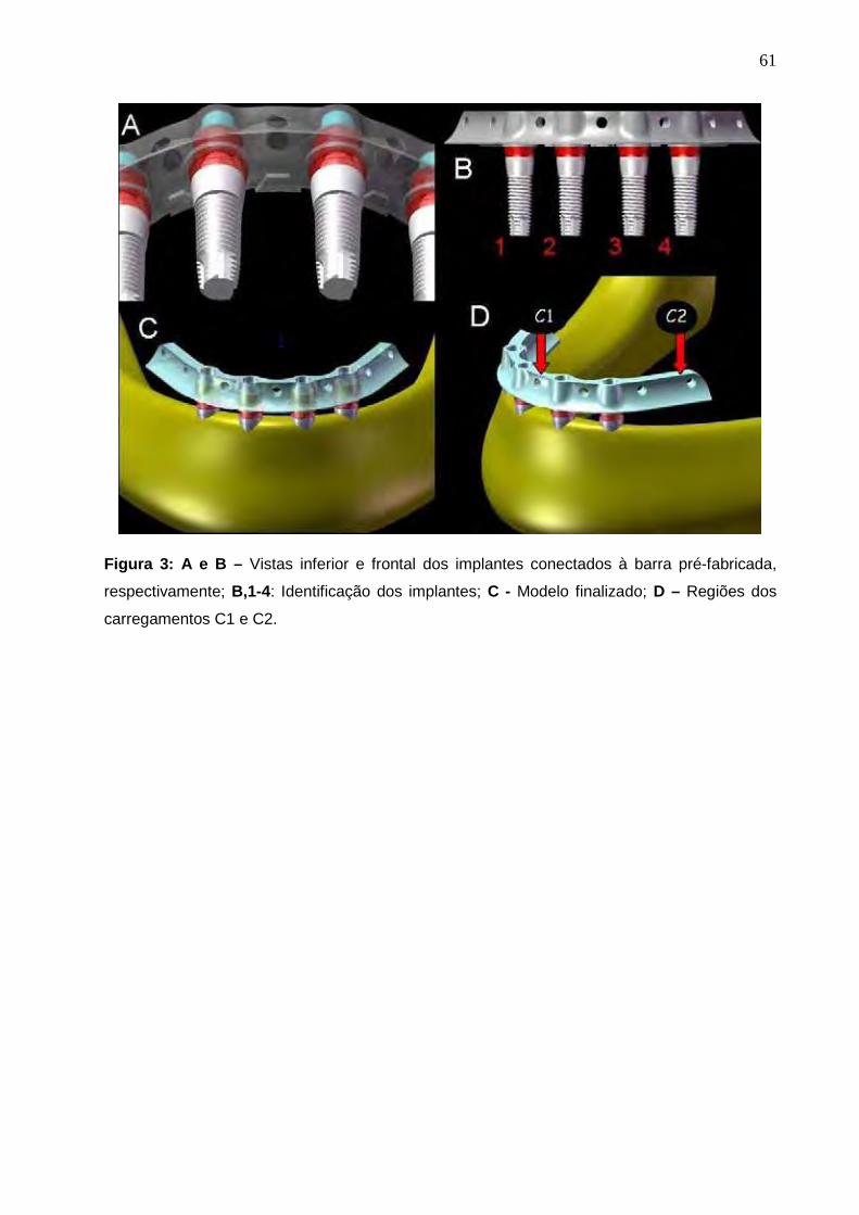
61
Figura 3: A e B – Vistas inferior e frontal dos implantes conectados à barra pré-fabricada,
respectivamente; B,1-4: Identificação dos implantes; C - Modelo finalizado; D – Regiões dos
carregamentos C1 e C2.

62
Figura 4: Malha de elementos finitos dos modelos pequeno (M.p), regular (M) e grande (M.g).
Para a convergência da análise (Cook, Malkus e Plesha, 2001), foi utilizado
um elemento sólido de interpolação tetraédrico parabólico e uma malha composta
por elementos com 0,1mm de dimensão. Os modelos apresentaram número de nós
variando entre 302.412 e 427.666, e número de elementos entre 178.525 e
259.834 (Tabela 2).

63
Tabela 2: Número de nós e elementos dos modelos.
MODELO Nº DE NÓS Nº DE ELEMENTOS
M.Ip 302.412 182.032
M.I 312.002 188.115
M.Ig 321.794 195.846
M.IIp 316.229 183.814
M.II 315.646 183.342
M.IIg 316.201 183.792
M.IIIp 307.371 178.525
M.III 314.267 183.161
M.IIIg 320.455 187.192
M.IVp 307.371 178.525
M.IV 314.267 183.161
M.IVg 320.455 187.192
M.IR 420.590 259.834
M.IIR 418.335 247.956
M.IIIR 427666 252.347
M.IVR 427666 252.347
As propriedades mecânicas: módulo de Elasticidade (E) e o coeficiente de
Poisson (ν) de cada estrutura foram utilizadas para considerar o estudo
homogêneo, isotrópico e linearmente elástico (Tabela 3).
As propriedades mecânicas do osso cortical dependem de vários fatores
como porosidade, nível de mineralização, densidade, organização das fibras
colágenas, e velocidade de deformação. Além disso, o osso cortical é tipicamente
anisotrópico, ou seja, suas propriedades elásticas variam de acordo com a
orientação das células e fibras. No material ortotrópico, ocorre um comportamento
simétrico em relação aos planos perpendiculares aos eixos de ortotropia. As
propriedades mecânicas do osso medular dependem da porosidade, da
anisotropia, da arquitetura do trabecular e das propriedades do tecido individual

64
trabecular (Bozkaya et al., 2004). Muito embora o osso tenha sido considerado
isotrópico no presente estudo, variou-se o módulo de elasticidade do osso cortical e
medular para melhor representar os tipos de osso utilizados no presente estudo
(Tabela 2).
Tabela 3: Propriedades mecânicas dos materiais
MATERIAIS MÓDULO DE
ELASTICIDADE (GPa)
COEFICIENTE DE POISSON REFERÊNCIAS
Osso Tipo I 9,5 0,3 Tada et al. (2003) Osso Tipo II 5,5 0,3 Tada et al. (2003)
Osso Tipo III 1,6 0,3 Tada et al. (2003)
Osso Tipo IV 0,69 0,3 Tada et al. (2003)
Osso cortical 13,70 0,3 Sevimay et al. (2005)
Titânio 110 0,35 Huang et al. (2008) Linha de
cimentação 0,0075 0,25 Wang e Lang (2008)
Condições de contorno e carregamento
Como condição de contorno, houve a fixação de todos os nós da base do
modelo e da superfície posterior (Figura 4).
Foram adotados 02 carregamentos (C) axiais: C1 - entre os implantes mais
anteriores; C2 – região posterior unilateral esquerda (Fig. 3D). Ambos os
carregamentos representaram forças de 150N.
Os mapas de tensão com a máxima tensão principal (�max), em MPa, foram
obtidos para o osso cortical e medular. Este critério de análise foi selecionado pelo fato
do osso ser um material frágil e apresentar valores de tensão em tração divergentes
dos valores de tensão em compressão. Para direcionar a análise dos resultados, a
influência do C1 foi avaliada no osso em torno dos implantes 2 e 3, e a influência do
C2 foi avaliada no osso em torno do implante 4.

65
Figura 5: Condições de contorno.

66
2.5 RESULTADOS
Configuração horizontal do arco mandibular
Sob um aspecto geral, a análise dos resultados evidenciou que a influência na
alteração da dimensão mandibular foi mais evidente em C2, para o osso ao redor do
implante 4. A alteração da dimensão mandibular exerceu pouca influência na alteração
das tensões nos implantes intermediários (2 e 3) em C1.
De forma específica, os modelos com osso tipo I apresentaram maiores valores
de �max no M.Ig (-0,86 MPa para C1; 12,3 MPa para C2), seguido do M.I (-0,85MPa
para C1; 6,98MPa para C2) e do M.Ip (-0,64MPa para C1; 3,93MPa para C2) (Gráficos
1 e 2; Figura 1, Anexo A). A alteração da configuração do arco mandibular em C1
exerceu pouca influência nos resultados para o osso cortical. Em C2, a alteração na
forma do arco exerceu maior influência nos resultados.
-1,00
-0,50
0,00
0,50
1,00
1,50
1 2 3 4
M.Ip
M.I
M.Ig
Gráfico 1: Valores de �max (MPa) para o osso cortical no M.Ip, M.I e M.Ig após C1.

67
-20,00
-15,00
-10,00
-5,00
0,00
5,00
10,00
15,00
20,00
1 2 3 4
M.Ip
M.I
M.Ig
Gráfico 2: Valores de �max (MPa) para o osso cortical no M.Ip, M.I e M.Ig após C2.
Os modelos com o osso tipo II apresentaram nos implantes 2 e 3 após C1
os seguintes valores de �max no osso cortical: M.II (-0,71MPa), seguido de M.IIp (-
0,59MPa) e do M.IIg (-0,47MPa) (Gráfico 3; Figura 2, Anexo A). No osso medular, em
C1, os valores foram semelhantes (Gráfico 1, Anexo A). Estes dados evidenciam a
pouca influência do formato do arco na alteração das tensões na região anterior. No
osso cortical e medular, em C2, os valores de �max no osso ao redor do implante 4
foram: M.IIg (-7,08MPa), MIIp (-7,03MPa) e M.II (-3,6MPa) (Gráfico 4 e Figura 2, Anexo
A; Gráfico 2, Anexo A). Destaca-se a influência da alteração da dimensão do arco
mandibular sob C2.

68
-1,00
-0,50
0,00
0,50
1,00
1,50
1 2 3 4
M.IIp
M.II
M.IIg
Gráfico 3: Valores de �max (MPa) para o osso cortical no M.IIp, M.II e M.IIg após C1.
-10,00
-5,00
0,00
5,00
10,00
15,00
1 2 3 4
M.IIp
M.II
M.IIg
Gráfico 4: Valores de �max (MPa) para o osso cortical no M.IIp, M.II e M.IIg após C2.
Os modelos com osso tipo III apresentaram no osso cortical ao redor dos
implantes 2 e 3, em C1, os seguintes valores de �max: M.IIIp (2,93MPa), M.III
(2,74MPa) e M.IIIg (1,56MPa) (Gráfico 5; Figura 3, Anexo A). No osso medular, em C1,
evidenciou-se a pouca influência dos formatos dos arcos nas tensões na região do
implante 2 e 3: M.III (-0,24MPa), M.IIIg (0,15MPa) e M.IIIp (0,11MPa) (Gráfico 3, Anexo
A). A maior influência da alteração da configuração do arco para o osso tipo III foi
observada na região do implante 4, em C2 (osso cortical e osso medular): M.III (-
10,3MPa e -0,24MPa), M.IIIg (-8,2MPa e 0,15MPa) e o M.IIIp (-7,54MPa e 0,11MPa)
(Gráfico 6 e Figura 3, Anexo A; Gráfico 4, Anexo A).

69
1,00
1,50
2,00
2,50
3,00
1 2 3 4
M.IIIp
M.III
M.IIIg
Gráfico 5: Valores de �max (MPa) para o osso cortical no M.IIIp, M.III e M.IIIg após C1.
-15,00
-10,00
-5,00
0,00
5,00
10,00
15,00
20,00
1 2 3 4
M.IIIp
M.III
M.IIIg
Gráfico 6: Valores de �max (MPa) para o osso cortical no M.IIIp, M.III e M.IIIg após C2.
Os modelos com osso tipo IV apresentaram nos implantes intermediários
em C1 os seguintes valores de �max no osso cortical: M.IVp (7,74MPa), MIVg
(4,95MPa) e M.IV (3,41MPa) (Gráfico 7; Figura 4, Anexo A). O mesmo aconteceu para
o osso medular, em C1, porém com menores valores de �max: M.IVp (-0,87MPa), MIVg
(-0,81MPa) e M.IV (0,33MPa) (Gráfico 5, Anexo A). Na região do osso cortical do
implante 4, após C2, observaram-se os seguintes valores �max: M.IVp (13,7MPa), MIV
(-10,5MPa) e M.IVg (-7,32MPa) (Gráfico 8; Figura 4, Anexo A). E para a mesma região,
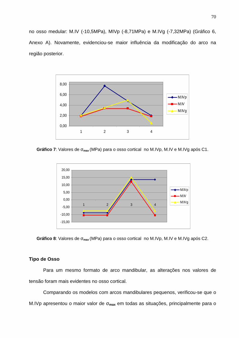
70
no osso medular: M.IV (-10,5MPa), MIVp (-8,71MPa) e M.IVg (-7,32MPa) (Gráfico 6,
Anexo A). Novamente, evidenciou-se maior influência da modificação do arco na
região posterior.
0,00
2,00
4,00
6,00
8,00
1 2 3 4
M.IVp
M.IV
M.IVg
Gráfico 7: Valores de �max (MPa) para o osso cortical no M.IVp, M.IV e M.IVg após C1.
-15,00
-10,00
-5,00
0,00
5,00
10,00
15,00
20,00
1 2 3 4
M.IVp
M.IV
M.IVg
Gráfico 8: Valores de �max (MPa) para o osso cortical no M.IVp, M.IV e M.IVg após C2.
Tipo de Osso
Para um mesmo formato de arco mandibular, as alterações nos valores de
tensão foram mais evidentes no osso cortical.
Comparando os modelos com arcos mandibulares pequenos, verificou-se que o
M.IVp apresentou o maior valor de �max em todas as situações, principalmente para o
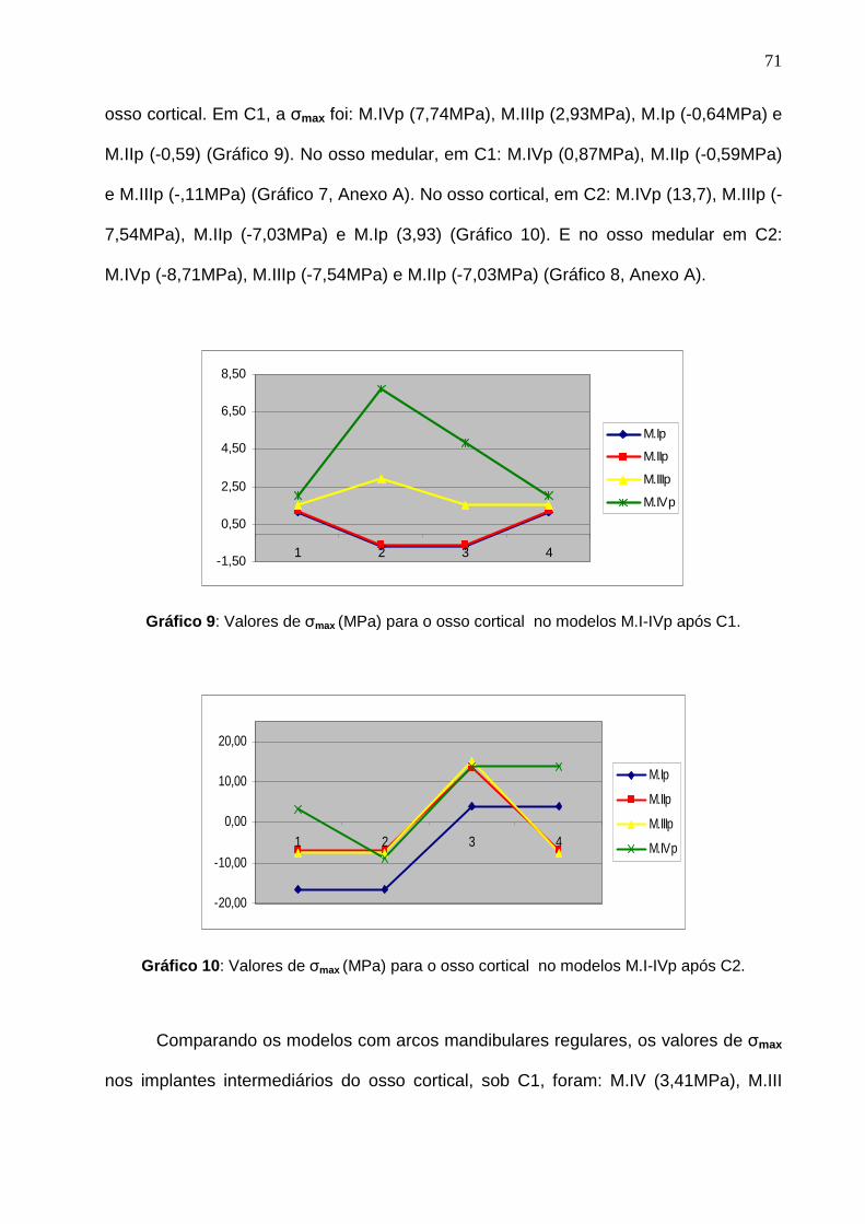
71
osso cortical. Em C1, a �max foi: M.IVp (7,74MPa), M.IIIp (2,93MPa), M.Ip (-0,64MPa) e
M.IIp (-0,59) (Gráfico 9). No osso medular, em C1: M.IVp (0,87MPa), M.IIp (-0,59MPa)
e M.IIIp (-,11MPa) (Gráfico 7, Anexo A). No osso cortical, em C2: M.IVp (13,7), M.IIIp (-
7,54MPa), M.IIp (-7,03MPa) e M.Ip (3,93) (Gráfico 10). E no osso medular em C2:
M.IVp (-8,71MPa), M.IIIp (-7,54MPa) e M.IIp (-7,03MPa) (Gráfico 8, Anexo A).
-1,50
0,50
2,50
4,50
6,50
8,50
1 2 3 4
M.Ip
M.IIp
M.IIIp
M.IVp
Gráfico 9: Valores de �max (MPa) para o osso cortical no modelos M.I-IVp após C1.
-20,00
-10,00
0,00
10,00
20,00
1 2 3 4
M.Ip
M.IIp
M.IIIp
M.IVp
Gráfico 10: Valores de �max (MPa) para o osso cortical no modelos M.I-IVp após C2.
Comparando os modelos com arcos mandibulares regulares, os valores de �max
nos implantes intermediários do osso cortical, sob C1, foram: M.IV (3,41MPa), M.III

72
(2,74MPa), M.I (-0,85MPa) e M.II (-0,71MPa) (Gráfico 11; Figura 5, Anexo A). Na
mesma região do osso medular os valores de �max foram: M.II (-0,71MPa), M.IV
(0,33MPa) e M.III (-0,24MPa), (Gráfico 9, Anexo A), evidenciando a maior influência no
osso cortical. Em C2, na região do implante 4, os valores de �max foram: M.IV (-
10,5MPa), M.III (-10,3MPa), M.I (6,98MPa) e M.II (-3,6MPa) (Gráfico 12). Para o osso
medular: M.IV (-10,5MPa), M.III (-10,5MPa) e M.II (-3,6MPa) (Gráfico 10, Anexo A).
-1,50
0,50
2,50
4,50
6,50
8,50
1 2 3 4
M.I
M.II
M.III
M.IV
Gráfico 11: Valores de �max (MPa) para o osso cortical no modelos M.I-IV após C1.
-20,00
-10,00
0,00
10,00
20,00
1 2 3 4
M.IR
M.IIR
M.IIIR
M.IVR
Gráfico 12: Valores de �max (MPa) para o osso cortical no modelos M.I-IV após C2.
Os modelos com configuração do arco mandibular grande apresentaram os
seguintes valores de �max nos implantes intermediários para o osso cortical em C1:

73
M.IVg (4,95MPa), M.IIIg (1,56MPa), M.Ig (-0,86MPa) e M.IIg (-0,47MPa), evidenciando
diferentes valores entre os tipos de osso (Gráfico 13). Para o osso medular, em C1, os
valores de �max foram: M.IVg (-0,81MPa), M.IIg (-0,47MPa) e M.IIIg (0,15MPa) (Gráfico
11, Anexo A). Para o osso cortical, em C2: M.Ig (12,3MPa), M.IIIg (-8,2MPa), M.IVg (-
7,32MPa) e M.IIg (-7,03) (Gráfico 14; Figura 6, Anexo A). Para o osso medular em C2:
M.IIIg (-8,2MPa), M.IVg (-7,32MPa) e M.IIg (-7,03MPa) (Gráfico 12, Anexo A).
-1,50
0,50
2,50
4,50
6,50
8,50
1 2 3 4
M.Ig
M.IIg
M.IIIg
M.IVg
Gráfico 13: Valores de �max (MPa) para o osso cortical no modelos M.I-IVg após C1.
-20,00
-10,00
0,00
10,00
20,00
1 2 3 4
M.Ig
M.IIg
M.IIIg
M.IVg
Gráfico 14: Valores de �max (MPa) para o osso cortical no modelos M.I-IVg após C2.

74
Influência da presença das roscas no corpo do implante
Os modelos com formato regular com rosca mostraram valores de tensão
maiores que os equivalentes sem rosca para a região dos implantes 2 e 3 no osso
cortical em C1: M.IVR (5,47MPa; 60,4% maior que o MIV), M.IIIR (2,67MPa; 2,5%
menor que o M.III), M.IR (-1,19MPa; 28,5% maior que o MI) e M.IIR (0,88MPa; 19,3%
maior que o M.II) (Gráfico 15; Figura 5, Anexo A). Para o osso medular em C1: M.IIR
(0,88MPa; 23,9% maior que o MII), M.IVR (0,73MPa; 121% maior que o M.IV); M.IIIR
(0,47MPa; 95,8% maior que o MIII) (Gráfico 13, Anexo A).
O osso cortical, em C2, apresentou valores de �max próximos aos respectivos
modelos sem rosca no M.IIIR (19,9MPa) e M.IVR (18,2MPa). O M.IR (8,2MPa) e o
M.IIR (-5,77MPa) apresentaram valores próximos ao M.I (em 11,7%) e ao M.II (em
60%) (Gráfico 16; Figura 6, Anexo A). O osso medular em C2 apresentou valores de
�max diferentes do modelo equivalente sem rosca: MIIR (-5,77MPa), M.IVR (-3,66MPa)
e M.IIIR (-2,07MPa) (Gráfico 14, Anexo A).
-1,50
0,50
2,50
4,50
6,50
8,50
1 2 3 4
M.IR
M.IIR
M.IIIR
M.IVR
Gráfico 15: Valores de �max (MPa) para o osso cortical no modelos M.I-IVR após C1.

75
-20,00
-10,00
0,00
10,00
20,00
1 2 3 4
M.IR
M.IIR
M.IIIR
M.IVR
Gráfico 16: Valores de �max (MPa) para o osso cortical no modelos M.I-IVR após C2.

76
2.6 DISCUSSÃO
Mesmo não existindo estudos que avaliem diferentes tamanhos de arco
mandibular em pacientes desdentados submetidos ao tratamento com implantes
osseointegrados, clinicamente há a preocupação no uso de barras pré-fabricadas em
condições adequadas de volume e formato ósseo (Klee de Vasconcellos et al., 2006).
Nesta pesquisa, os resultados evidenciaram a influência da alteração da
dimensão mandibular (pequena, regular e grande) na alteração das tensões,
principalmente na região posterior (implante 4), área que sofreu a maior influência
dimensional pela mudança do tamanho do arco mandibular. A alteração dimensional
gerou pouca modificação no perfil mandibular na região anterior.
O fenômeno da remodelação óssea é responsável por registrar a carga interna
recebida e a atividade das células de crescimento e reabsorção óssea. Este fenômeno
pode estar associado principalmente com a densidade interna e/ou mudanças
geométricas externas no osso (Li et al., 2007). Existem evidências que mostram que a
formação de micro-fraturas após fadiga pode ser o estímulo para a remodelação
óssea, a qual se inicia com a reabsorção seguida da formação óssea (Burr, 1985).
Falhas acentuadas são prevenidas por um eficiente processo de reparo. Entretanto, a
literatura ainda não possui pesquisas científicas que comprovem exatamente como as
cargas mecânicas são transmitidas aos osteoblastos e osteoclastos para que possa
ocorrer o processo de remodelação óssea (Huiskes et al., 1987; Beaupre et al., 1990;
Li et al., 2007).
Há autores que explicam o processo da reabsorção óssea por meio de duas
hipóteses. A primeira por uma reação biológica de desgaste das partículas que pode
induzir às reações inflamatórias nos tecidos ao redor dos implantes. A segunda baseia-
se nas considerações biomecânicas que afetam o osso pelo novo padrão de tensões

77
em torno do implante (Stadelmann, Terrier e Pioletti, 2008). No entanto, outros
acreditam que o processo de perda óssea ao redor dos implantes pode estar
associado, na maioria das vezes, ao implante (formato, comprimento, diâmetro,
material, características de superfície) e aos pacientes (qualidade óssea, forças
oclusais e condições de saúde geral) (Tada et al., 2003).
Nesse sentido, uma mandíbula que apresenta implantes próximos à tabua
óssea vestibular ou lingual, poderá sofrer maior tensão na região e, a longo prazo,
induzir perda óssea, levando ao insucesso da reabilitação
Comparando os tipos de osso com o mesmo formato do arco, os resultados
demonstraram que os valores da tensão no osso cortical apresentaram resultados
maiores no osso tipo IV, evidenciando os resultados mais desfavoráveis. Vários
autores acreditam que as chances de falhas do implante para o osso tipo IV são
maiores devido à necessidade de maior rigidez na conexão osso-implante, comum em
regiões com maior qualidade e quantidade óssea (Lekholm e Zarb, 1985; Hatano et al.,
2003; Drage et al., 2006).
Os resultados deste estudo demonstraram que os valores de �max do osso
cortical foram superiores aos valores de �max do osso medular, a semelhança de
outras pesquisas que utilizam o MEF-3D (Tada et al., 2003; Sevimey et al., 2005).
Estes achados podem ser justificados em função da densidade óssea que influencia a
quantidade de osso em contato com a superfície do implante. O osso cortical
apresenta um módulo de elasticidade maior que o osso medular. Além disso, é mais
resistente à deformação e apresenta maior habilidade em transferir tensão (Misch,
1990; Yokoyama et al., 2005). Por essa razão, o osso cortical consegue suportar maior
quantidade de cargas que o osso medular em situações clínicas (Cochran, 2000).

78
Existe uma controvérsia entre os autores a respeito do módulo de elasticidade
do osso medular. Os valores variam de 0,3 a 9,5 GPa (Yokoyama et al., 2005;
Seevimay et al., 2005; Eskitacioglu et al., 2004; Zarone et al., 2003). No entanto, Tada
et al. (2003) identificaram os módulos de elasticidade de acordo com o tipo de osso:
osso tipo I (9,5GPa); osso tipo II (5,5GPa); tipo III (1,6GPa) e osso tipo IV (0,69GPa)
justificando o uso destes valores no presente estudo. Neste sentido, o M.IV, que
apresentou os resultados mais desfavoráveis, apresentou 3,41MPa de tensão no osso
cortical (C1), sugerindo uma maior solicitação do osso cortical ao redor dos implante 2
e 3, uma vez que o M.I apresentou 0,91MPa, o M.II, 0,76MPa; e o M.III,2,74MPa.
A presença da rosca nos implantes modificou os resultados apenas no osso
medular em C2, em relação aos modelos regulares sem rosca. No osso cortical, os
tipos de osso III e IV foram os mais solicitados tanto para os modelos com rosca
quanto para os modelos sem rosca. Estes achados são corroborados por Geng et al.,
(2004) que compararam diferentes formatos de rosca de implante e encontraram que
em relação ao osso cortical, os valores de tensão de von Mises não demonstraram
diferenças entre elas. Entretanto, outros autores acreditam que clinicamente a
presença da rosca ajuda a balancear a distribuição de forças ao redor do tecido ósseo
(Albrektsson, 1983, Skalak, 1983). Huang et al., em 2008, recomendaram a utilização
da rosca do implante na análise de elementos finitos para alcançar uma distribuição de
tensão mais favorável, principalmente em casos de carga imediata. Estes autores
consideraram que a presença da rosca do implante aumentou a área de superfície do
implante com o osso, sendo vantajoso por diminuir o “pico” de tensão na
osseointegração e também na carga imediata.
A análise computacional apresenta vantagens em relação a outros métodos por
caracterizar situações clínicas complexas com grande sensibilidade em relação aos

79
parâmetros como carregamento, condições de contorno e propriedades dos materiais
(Holmes e Loftus, 1997; Sevimay et al., 2005). Entretanto, as estruturas dos modelos
matemáticos são assumidas como homogêneas, isotrópicas e linearmente elásticas. E,
algumas vezes, as propriedades dos materiais são diferentes, como por exemplo, o
osso cortical, que é transversalmente isotópico e não-homogêneo (Cochran, 2000).
Outra limitação do presente estudo é a interpretação adotada para a interface osso-
implante, assumida como totalmente osseointegrada, uma situação sem referencial
clínico, uma vez que a osseointegração não é representada por superfícies com 100%
de contato.
Além disso, como apenas o carregamento vertical foi considerado, a influência
na alteração dimensional do arco mandibular poderá ser melhor evidenciada com o
uso do carregamento oblíquo, uma vez que a concentração de tensão no osso ao
redor do implante 4, por exemplo, localizou-se na face distal do implante, área
relacionada com o perfil distal da barra e na mesma direção do carregamento.
Adicionalmente, avaliações são necessárias para investigar a homogeneidade nos
valores de tensões observados no osso medular.

80
2.7 CONCLUSÃO
Segundo a metodologia empregada, conclui-se que:
1. As diferentes dimensões (pequeno e grande) do arco mandibular
gerou variações nos valores de σmax mais evidentes na região
posterior da mandíbula, principalmente para o implante mais
posterior e relacionado ao lado do carregamento.
2. Carregamentos estritamente verticais não refletem as prováveis
alterações de tensão no osso com a variação da configuração
horizontal do arco.
3. Comparando os tipos de osso, o osso tipo IV apresentou o pior
prognóstico na maioria das situações estudadas.
4. A presença da rosca no implante aumentou a tensão observada na
interface osso-implante em comparação com o implante liso em
todas as situações.

81
2.8 - REFERÊNCIAS
1. Albrektsson, T. (1983) Direct bone anchorage of dental implants. The Journal
of Prosthetic Dentistry 50: 255-261.
2. Barbier, L., Vander Sloten, J., Krzesinski, G., Schepers, E., Van der Perre, G.
(1998) Finite element analysis of non-axial versus axial loading of oral
implants in the mandible of the dog. Journal of oral rehabilitation 25: 847-858.
3. Beaupre, G. S., Orr, T. E., Carter, D. R. (1990) An approach for time-
dependent bone modeling and remodeling - theoretical development. Journal
of orthopaedic research 8: 651-661.
4. Bozkaya, D., Muftu, S., Muftu, A. (2004) Evaluation of load transfer
characteristics of five different implants in compact bone at different levels by
finite elements analysis. The Journal of Prosthetic Dentistry 92: 523-530.
5. Bronner, F., Farach-Carson, M., Mikos, A. G. (2007) Enginnering of
Functional Skeletal Tissues. 129-138. London: Springer.
6. Burr, D. B., Martin, R. B., Schaffler, M. B., Radin, E. L. (1985) Bone
remodeling in response to in vivo fatigue macrodamage. Journal of
biomechanics 18: 180-200.
7. Castellon, P., Block, M.S., Smith, M.B., Finger, I.M. (2004) Immediating
loading of the edentulous mandible: delivery of the final restoration or a
provisional restoration – With method to use? Journal Oral Maxillofacial
Surgery 62: 30-40.
8. Choi, A.H., Ben-Nissan, B., Conway, R.C. (2005) Three dimensional
modelling and finite element analysis of the human mandible during
clenching. Australian Dental Journal 50: 42-48.
9. Cochran, D. L. (2000) The scientific basis for and clinical experiences with

82
Straumann implants including the ITI dental implants system: a consensus
report. Clinical Oral Implants Research 11: 33-58.
10. Cook, R.D., Malkus, D.S., Plesha, M.E. (2001) Concepts and applications of
finite element analysis. 542-573. New York: John Wiley e Sons.
11. Drage, N.A., Palmer, R.M., Blake, G., Wilson, R., Crane, F., Fofelman, I.
(2007) A comparison of bone mineral density in the spine, hip and jaws of
edentulous subjects. Clinical Oral Implants Research 18: 496-500.
12. Engquist, B. et al. (2005) Simplified methods of implant treatment in the
edentulous lower jaw: a 3- year follow-up report of a controlled prospective
study of one stage versus two stage surgery and early loading. Clinical
Implant Dentistry and Related Research 7: 95-104.
13. Ercoli, C., Romano, P.R., Mardini, M.A., Cordaro, L. (2006) Restoration of
immediately placed implants in 3 appointments: from surgical placement to
definitive prostheses. The Journal of Prosthetic Dentistry 96: 212-218.
14. Eskitacioglu, G., Usumez, A., Sevimey, M., Soykan, E., Unsal, E. (2004) The
influence of occlusal loading location on stress transferred to implant-
supported prostheses and supporting bone: A three-dimensional finite
element study. The Journal of Prosthetic Dentistry 91: 144-150.
15. Fugazzotto, P.A., Gulbransen, H.J., Wheeler, S.L., Lindsay, J.A. (1993) The
use os IMZ osseointegrated implants in partially and completely edentulous
patient: Success and failure rates of 2,023 implants cylinders up to 60
months in function. The International Journal of Oral Maxillofacial Implants
8:617-621.
16. Geng, J.P., Ma, Q.S., Xu, W., Tan, K.B.C., Liu, G.R. (2004) Finite element
analysis of four thread-form configurations in a stepped screw implant.
Journal of Oral Rehabilitation 31: 233-239.

83
17. Holmes, D.C., Loftus, J.T. (1997) Influence of bone quality on stress
distribution for endosseous implants. Journal Oral Implantology 23: 104-111.
18. Huang, H.L., Hsu, J.T., Fuh, L.J., Tu, M.G., Ko, C.C., Shen, Y.W. (2008)
Bone stress and interfacial sliding analysis of implant design on an
immediately loaded maxillary implant: A non-linear finite element study.
Journal of Dentistry 36: 409-417.
19. Huiskes, R., Weinans, H., Grootendoer, H. J., Dalstra, M., Fudala, B., Slooff,
T. J. (1987) Adaptive bone-remodeling theory applied to prosthetic-design
analysis. Journal of biomechanics 20: 1135-1150.
20. Ichikawa, T., Kanitani, H., Wigianto, R., Kawamato, N., Matsumato, N. (1997)
Influence of bone quality on the stress distribution. An in vitro experiment.
Clinical Oral Implants Research 8: 18-22.
21. Jaffin, R.A., Berman, C.L. (1991) The excessive loss of Branemark fixture in
type IV bone: A 5-year analysis. Journal Periodontology 62: 2-4.
22. Jaffin, R.A., Kumar, A., Berman, C.L. (2004) Immediate loading of dental
implants in the completely edentulous maxilla: a clinical report. The
International Journal of Oral Maxillofacial Implants 19:721-730.
23. Kitamura, E., Stegaroiu, R., Nomura, S., Miyakawa, O. (2004) Biomechanical
aspects of marginal bone resorption around asseointegrated implants:
considerations based on a three-dimensional element analysis. Clinical Oral
Implants Research 15: 401-412.
24. Klee de Vanconcellos, D., Bottino, M. A., Saad, P.A., Faloppa, F. (2006) A
new device in immediately loaded implant treatment in the edentulous
mandible. The International Journal of Oral Maxillofacial Implants 21:615-
622.

84
25. Kozlovsk, A., Tal, H., Laufer, B-Z., Leshem R, Rohrer M.D, Weinreb M, Artzi
Zvi. (2007) Impact of implant overloading on the peri-implant bone in inflamed
and noninflamed peri-implant mucosa. Clinical Oral Implants Research 18:
601-610.
26. Lekholm, U.; Zarb, G. A. (1985) Patient selection and preparation. In:
Branemark, P. I.; Zarb, G. A.; Albrektson, T (eds). Tissue-integrated
prostheses: osseointegration in clinical dentistry, 199-209, Chicago:
Quintessence publications Co. Inc.
27. Li, J., Li, H., Shi, L., Fox, A. S. L., Ucer, C., Devlin, H., Horner, K., Silikas, N.
(2007) A mathematical model for simulating the bone remodeling process
under mechanical stimulus. Dental Material 23: 1073-1078
28. Li-li, L., Zhong-yi, M., Zhong-cheng, B., Yong, M., Bo, G., Hai-tao, X., Bing,
Z., Yong, Z., Bing, L. (2006) Three dimensional finite element analysis of
weakened roots restored with different cements in combination with titanium
alloys posts. Chinese Medical Journal 119: 305-311.
29. Misch, C.E. (1990) Density of bone: effect on treatment plans, surgical
approach, healing, and progressive loading, International Journal Oral
Implantology 6: 23-31.
30. Morgan, M.J., James, D.F., Pilliar, R.M., (1993) Fractures of the fixture
components of an osseointegrated implants. The International Journal of Oral
Maxillofacial Implants 8: 409-414.
31. O’Brien, W.J. (1997) Dental material and their selection, 259-272. Chicago:
Quintessence Publications Co. Inc.
32. Parei, S.M., Ruff, S.L., Triplett, R.G., Schow, S.R. (2002) Bone reduction
surgical guide for the Novum implant procedure: Technical Note. The
85
International Journal of Oral Maxillofacial Implants 17: 715-719.
33. Quirynen, M., Mraiwa, N., Van Steenberghe, D., Jacobs, R. (2003)
Morphology and dimensions of the mandibular jaw bone in the interforaminal
region in patients requiring implants in the distal areas. Clin Oral Implants
Research 14: 280-285.
34. Sevimay, M., Turhan, F., Kiliçarslan, M.A., Eskitascioglu, G. (2005) Three-
dimensional finite element analysis of the effect of different bone quality on
stress distribution in an implant-supported crown. The Journal of Prosthetic
Dentistry 93: 227-234.
35. Shapurian, T., Damoulis, P., Reiser, G.M., Griffin, T.J., Rand, W.M. (2006)
Quantitative evaluation of bone density using the Hounsfield Index. The
International Journal of Oral Maxillofacial Implants 21: 290-297.
36. Sicher, H., Dubrul, E.U. (1989) Oral Anatomy. St Louis: Mosby Company.
37. Simamoto, P.C., Davi, L.R., Gomes, V.L., Nobilo, M.A.A., Neves, F..D. (2006)
Immediate function in the edentulous mandible: Replacement of a lost using
prefabricated guides. The Journal of Prosthetic Dentistry 95: 161-164.
38. Skalak, R. (1983) Biomechanical considerations in osseointegrated
prostheses. The Journal of Prosthetic Dentistry 49:843-848.
39. Stadelmann, V. A., Terrier, A., Pioletti, D. P. (2008) Microstimulation at the
bone-implant interface upregulates osteoclast activation pathways, Bone 42:
358-364.
40. Tada, S., Stegaroiu, R., Kitamura, E., Miyakawa, O., Kusakari, H. (2003)
Influence of implant design and bone quality on stress/ strain distribution in
bone around implants: a 3-dimensional finite element analysis. The
International Journal of Oral Maxillofacial Implants 18: 357-368.

86
41. Truhlar, R.S.; Orenstein, I.H., Morris, H.F.; Ochi, S. (1997) Distribution of
bone quality in patients receiving endosseous dental implants. Journal of oral
and maxillofacial surgery: official journal of the American Association of Oral
and Maxillofacial Surgeons 55: 38-45.
42. Yokoyama, S., Walabayachi, N., Shiota, M., Ohyama, T. (2005) Stress
analysis in edentulous mandibular bone supporting implant-retained 1-piece
or multiple superstructures. The International Journal of Oral Maxillofacial
Implants 20: 578-583.
43. Zarone, F., Apicella, A., Nicolais, L., Aversa, R., Sorrentino, R. (2003)
Mandibular flexure and stress build-up in mandibular full-arch prostheses
supported by osseointegrated implants. Clinical Oral Implant Research 14:
103-114.

87
AAAAAAAAAAAA NNNNNNNNNNNN EEEEEEEEEEEE XXXXXXXXXXXX OOOOOOOOOOOO

88
A nexo AA nexo AA nexo AA nexo A .... R esultados D etalhadoR esultados D etalhadoR esultados D etalhadoR esultados D etalhadossss
-0,80
-0,70
-0,60
-0,50
-0,401 2 3 4
M.IIp
M.II
M.IIg
Gráfico 1: Valores de �max (MPa) para o osso medular no M.IIp, M.II e M.IIg após C1.
-8,00
-7,00
-6,00
-5,00
-4,00
-3,00
-2,001 2 3 4
M.IIp
M.II
M.IIg
Gráfico 2: Valores de �max (MPa) para o osso medular no M.IIp, M.II e M.IIg após C2.
-1,50
-1,00
-0,50
0,00
0,50
1 2 3 4 M.IIIp
M.III
M.IIIg
Gráfico 3: Valores de �max (MPa) para o osso medular no M.IIIp, M.III e M.IIIg após C1.

A nexo
89
-11,00
-10,00
-9,00
-8,00
-7,00
-6,001 2 3 4
M.IIIp
M.III
M.IIIg
Gráfico 4: Valores de �max (MPa) para o osso medular no M.IIIp, M.III e M.IIIg após C2.
-1,50
-1,00
-0,50
0,00
0,50
1 2 3 4M.IVp
M.IV
M.IVg
Gráfico 5: Valores de �max (MPa) para o osso medular no M.IVp, M.IV e M.IVg após C1.
-12,00
-11,00
-10,00
-9,00
-8,00
-7,00
-6,001 2 3 4
M.IVp
M.IV
M.IVg
Gráfico 6: Valores de �max (MPa) para o osso medular no M.IVp, M.IV e M.IVg após C2.

A nexo
90
-1,50
-1,00
-0,50
0,00
0,50
1,00
1,50
1 2 3 4
M.IIp
M.IIIp
M.IVp
Gráfico 7: Valores de �max (MPa) para o osso medular no modelos M.I-IVp após C1.
-12,00
-10,00
-8,00
-6,00
-4,00
-2,00
0,001 2 3 4
M.IIp
M.IIIp
M.IVp
Gráfico 8: Valores de �max (MPa) para o osso medular no modelos M.I-IVp após C2
-1,50
-1,00
-0,50
0,00
0,50
1,00
1,50
1 2 3 4
M.II
M.III
M.IV
Gráfico 9: Valores de �max (MPa) para o osso medular no modelos M.I-IV após C1.

A nexo
91
-12,00
-10,00
-8,00
-6,00
-4,00
-2,00
0,001 2 3 4
M.II
M.III
M.IV
Gráfico 10: Valores de �max (MPa) para o osso medular no modelos M.I-IV após C2.
-1,50
-1,00
-0,50
0,00
0,50
1,00
1,50
1 2 3 4
M.IIg
M.IIIg
M.IVg
Gráfico 11: Valores de �max (MPa) para o osso medular no modelos M.I-IVg após C1.
-12,00
-10,00
-8,00
-6,00
-4,00
-2,00
0,001 2 3 4
M.IIg
M.IIIg
M.IVg
Gráfico 12: Valores de �max (MPa) para o osso medular no modelos M.I-IVg após C2.

A nexo
92
-1,50
-1,00
-0,50
0,00
0,50
1,00
1,50
1 2 3 4
M.IIR
M.IIIR
M.IVR
Gráfico 13: Valores de �max (MPa) para o osso medular no modelos M.I-IVR após C1.
-12,00
-10,00
-8,00
-6,00
-4,00
-2,00
0,001 2 3 4
M.IIR
M.IIIR
M.IVR
Gráfico 14: Valores de �max (MPa) para o osso medular no modelos M.I-IVR após C2.

A nexo
93
Figura 1: Imagens do osso tipo I variando a configuração mandibular nos implantes
intermediários (2 e 3) para o C1 e nos implantes distais (3 e 4) para o C2.
Figura 2: Imagens do osso tipo II cortical variando a configuração mandibular nos implantes
intermediários (2 e 3) para o C1 e nos implantes distais (3 e 4) para o C2.

A nexo
94
Figura 3: Imagens do osso tipo III cortical variando a configuração mandibular nos implantes
intermediários (2 e 3) para o C1 e nos implantes distais (3 e 4) para o C2.
Figura 4: Imagens do osso tipo IV cortical variando a configuração mandibular nos implantes
intermediários (2 e 3) para o C1 e nos implantes distais (3 e 4) para o C2.

95
Figu
ra 5
: Im
agen
s do
com
porta
men
to ó
sseo
em
torn
o do
s im
plan
tes
2 e
3 no
s m
odel
os re
gula
res
com
rosc
a e
sem
rosc
a em
C1.
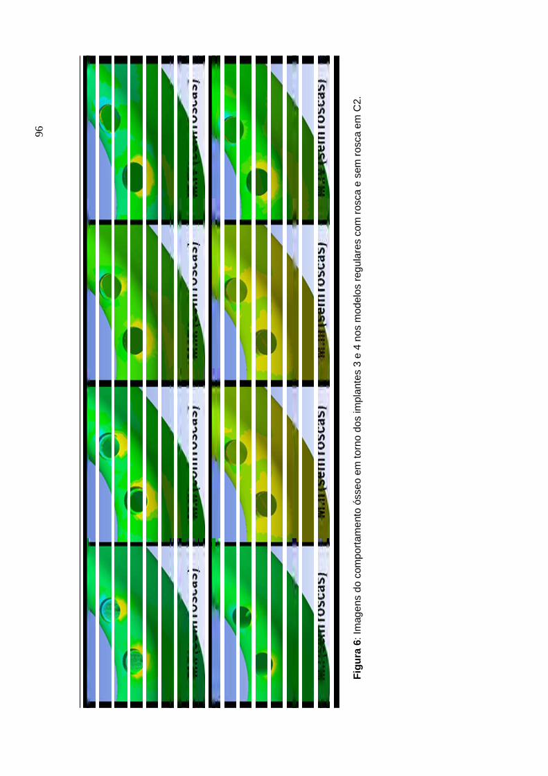
96
Figu
ra 6
: Im
agen
s do
com
porta
men
to ó
sseo
em
torn
o do
s im
plan
tes
3 e
4 no
s m
odel
os re
gula
res
com
rosc
a e
sem
rosc
a em
C2.

97
A nexo B : A nexo B : A nexo B : A nexo B : International Journal for Com putationaInternational Journal for Com putationaInternational Journal for Com putationaInternational Journal for Com putational l l l M ethods in E ngineering Science and M echanicsM ethods in E ngineering Science and M echanicsM ethods in E ngineering Science and M echanicsM ethods in E ngineering Science and M echanics
Electronic Submission Welcome! ISSN: 1550-2295 (electronic) 1550-2287 (paper) Publication Frequency: 6 issues per year Subjects: Biotechnology; Computation; Computational Mechanics; Electrical & Electronic Engineering; Fluid Mechanics; Mechanical Engineering: Heat Transfer; Mechanical Engineering: Heat Transfer; Industrial Engineering & Manufacturing; Manufacturing Technology; Materials Science; Nanoscience & Nanotechnology; Publisher: Taylor & Francis
• Sign In • Online Sample
Instructions for Authors
Instructions for Authors: International Journal For Computational Methods in Engineering Science and Mechanics
***Note to Authors: please make sure your contact address information is clearly visible on the
outside of all packages you are sending to Editors.***
An interdisciplinary forum for the publication of papers on computational methods for numerical
simulations of natural phenomena in science and engineering mechanics.
AIMS
Computational mechanics is an integral and major subject of research in many fields of science
and engineering, design and manufacturing. Major established industries such as the
automobile, aerospace, atmospheric sciences, chemical, pharmaceutical, petroleum,
electronics and communications, as well as emerging industries such as biotechnology,
nanotechnology, and information technology rely on computational mechanics-based
capabilities to model and numerically simulate complex systems for the analysis, design, and
manufacturing of high-technology products. Rapid advances in computer architecture,
hardware, software technology and tools, and numerical and non-numerical algorithms, are
making significant contributions to the development of computational models and methods to
model materials and analyze and design complex engineering systems. The main aim of the
Journal is to provide a unique interdisciplinary forum to publish papers dealing with
mathematical models and computational methods and algorithms for the numerical simulation

A nexo
98
of natural processes arising in applied science and mechanics. Special emphasis will be placed
on both upstream and applied research and on the transfer of technology to the industry in the
areas of fluid mechanics, heat transfer, solid and structural mechanics in the disciplines of
aerospace, chemical, civil, mechanical, electrical engineering, and computational biology,
chemistry, and materials science. Papers dealing with novel computational methods to model
current and emerging technologies in microelectromechanical systems, electromagnetics,
biotechnology, nanotechnology, and information technology are encouraged.
SCOPE
Through faster dissemination, this Journal offers scope for academics, researchers, and
engineering professionals to present their research and development works that have potential
for applications in several disciplines of engineering. The journal publishes manuscripts dealing
primarily with the computational science and mechanics aspects of natural phenomena (for
example, mathematical modeling of materials and systems, novel applications, and numerical
simulations). Contributions may range from new methods to novel applications of existing
methods to gain understanding of the material and/or structural behavior of new and advanced
systems. The following is a nonexhaustive list of topics considered to be within the scope of
CMES.
Computational Science and Engineering: Finite element method, boundary element method,
finite difference method, meshless techniques, automated and adaptive analysis methods and
engineering design and optimization.
Industrial Applications: Aerospace, biological, chemical, civil, mechanical, materials science,
electrical engineering, and manufacturing processes.
Computational Processes: Algorithms, software technology and tools, high performance
computing and parallel and distributed computing, artificial intelligence, scientific visualization
and virtual reality - all in the context of simulation of natural and physical phenomena.
Submission of Manuscripts - MAMS and CMES websites
All manuscripts should be submitted online at the International Journal for Computational Methods in Engineering Science and Mechanics Manuscript Central site. New users should
first register to create an account. Once a user is logged in then click the Author Center for
manuscript submissions. If you are a reviewer for this journal then click the Reviewer Center for
the work you wish to undertake. For further help, go to the tutorials in the Resources section.

A nexo
99
The submission must include: (a) a transmittal letter with the corresponding author's name, e-
mail and street address, telephone and fax numbers, and a statement that the manuscript has
not been published elsewhere and that it has not been submitted simultaneously for publication
elsewhere; (b) main manuscript document along with figures and tables; and (c) completed and
signed copyright form. The authors may download the copyright form here and fill out the
form, sign, and scan it before attaching to the e-mail.
The manuscript should be prepared using MS Word or TeX (latex or plain TeX). When TeX is
used, the authors must supply all style files and input files used to compile. Authors are
responsible for obtaining permission to reproduce copyrighted material from other sources and
are required to sign an agreement for the transfer of copyright to the publisher. All accepted
manuscripts, artwork, and photographs become the property of the publisher. All parts of the
manuscript should be typewritten, double-spaced, with margins of at least one inch on all sides.
Manuscript pages should be numbered consecutively throughout. The length of the manuscript
must not exceed 20 pages. All titles should be as brief as possible, 6 to 12 words. Authors
should also supply a short version of the title suitable for the running heading, not exceeding 50
character spaces. Each article should be summarized in an abstract of not more that 100 words
and 6-10 key words must be supplied. Avoid abbreviations, diagrams, and reference to the text.
The Editor reserves the right to return the manuscript to the author without review.
Mailing Address of Professor J. N. Reddy
Mechanical Engineering Department
Texas A & M University
College Station, TX 77843-3123, USA
REFERENCES
References to cited literature should be identified in the text in square brackets and grouped at
the end of the paper in numerical order of appearance. Double-spaced typing must be used
throughout. References should be styled and punctuated according to the following examples:
Journal Article:I. Tanasawa, S. Nishio, and K. Suzuki, Heat Transfer Bibliography-Japanese Works, Int. J.
Heat Mass Transfer, vol. 38, pp. 1533-1542, 1995.
Book:A. Bejan, Convection Heat Transfer, 2nd ed., pp. 536-538, Wiley, New York, 1995.
Thesis:

A nexo
100
D. Getachew, Non-Newtonian Convection in a Porous Matrix: Constitutive Equations and an
Application, Ph.D. thesis, The University of Illinois, Chicago, Illinois, 1994.
Report:J.E. Welch, F.H. Harlow, J.P. Shannon, and B.J. Daly, The MAC Method, Los Alamos Scientific
Lab. Rept. LA-3425, Los Alamos, New Mexico, 1996.
Proceedings:J.P. Hartnett, Single Phase Channel Flow Forced Convection Heat Transfer, Heat Transfer
1994: Proc.10th Int. Heat Transfer Conf., Brighton, UK, vol. 1, pp.247-258, Taylor & Francis,
Washington, D.C., 1994.
Edited Book:D.W. Pepper and A.J. Baker, Finite Differences Versus Finite Elements, in W.J. Minkowycz,
E.M. Sparrow, G.E. Schneider, and R.H. Pletcher (eds.), Handbook of Numerical Heat
Transfer, chap. 13, Wiley, New York, 1988.
Always give inclusive page numbers for references to journal articles and a page range or
chapter number for books. Each reference must be cited in the text.
Equations
All mathematical equations should be carefully typewritten and checked so that a compositor
can follow the copy easily. Equation numbers should be Arabic numerals enclosed in
parentheses on the right-hand margin. They should be cited in the text as, for example, Eq.
(10), or Eqs. (12)-(16).
UNITS
All manuscripts submitted for publication must use SI units throughout; however, English units
may be included parenthetically.
ILLUSTRATIONS
Illustrations submitted (line drawings, halftones, photos, photomicrographs, etc.) should be
clean originals or digital files. Digital files are recommended for highest quality reproduction and
should follow these guidelines:
• 300 dpi or higher • sized to fit on journal page • EPS, TIFF, or PSD format only • submitted as separate files, not embedded in text files

A nexo
101
Color illustrations will be considered for publication; however, the author will be required to bear
the full cost involved in their printing and publication. The charge for the first page with color is
$900.00. The next three pages with color are $450.00 each. A custom quote will be provided for
color art totaling more than 4 journal pages. Good-quality color prints or files should be
provided in their final size. The publisher has the right to refuse publication of color prints
deemed unacceptable.
TABLES AND FIGURES
For the accepted manuscript, tables and figures should not be embedded in the text, but should
be included as separate files and/or sheets. A short descriptive title should appear above each
table with a clear legend and any footnotes suitably identified below. All units must be included
in the table. The font size for the numbers and text in the table should be at least 10 Times
Roman. Figures should be completely labeled, taking into account necessary size reduction.
The font size, where applicable, should not be less than 10 Times Roman. Captions should be
typed, double-spaced, on a separate sheet. All original figures should be clearly marked in
pencil on the reverse side with the number, author's name, and top edge indicated.
PROOFS
All proofs must be corrected and returned to the publisher. If the proofs are not returned within
the allotted time, the editor will proofread the article and it will be printed per editor's instruc-
tions. Only correction of typographical errors is permitted.
OFFPRINTS
Offprints can be ordered from Taylor & Francis. A link to the offprint order form will accompany
the proofs.
A nexo
102
A nexo CA nexo CA nexo CA nexo C . N orm as do periódico . N orm as do periódico . N orm as do periódico . N orm as do periódico C linical O ral Im plants C linical O ral Im plants C linical O ral Im plants C linical O ral Im plants
R esearchR esearchR esearchR esearch
Official publication of the European Association for Osseointegration
Edited by: Niklaus P. Lang
Print ISSN: 0905-7161
Online ISSN: 1600-0501
Frequency: Bi-monthly
Current Volume: 18 / 2007
ISI Journal Citation Reports® Ranking: 2006: 5/49 (Dentistry, Oral Surgery &
Medicine); 9/42 (Engineering, Biomedical)
Impact Factor: 2.497
Content of Author Guidelines: 1. General, 2. Ethical Guidelines, 3. Manuscript
Submission Procedure, 4. Manuscript Types Accepted, 5. Manuscript Format and
Structure, 6. After Acceptance.
1. GENERAL Clinical Oral Implants Research conveys scientific progress in the field of implant
dentistry and its related areas to clinicians, teachers and researchers concerned with
the application of this information for the benefit of patients in need of oral implants. The
journal addresses itself to clinicians, general practitioners, periodontists, oral and
maxillofacial surgeons and prosthodontists, as well as to teachers, academicians and
scholars involved in the education of professionals and in the scientific promotion of the
field of implant dentistry.
Clinical Oral Implants Research publishes:
Original research articles of high scientific merit in the field of material sciences,
physiology of wound healing, biology of tissue integration of implants, diagnosis and
treatment planning, prevention of pathologic processes jeopardizing the longevity of
A nexo
103
implants, clinical trials on implant systems, stoma-tognathic physiology related to oral
implants, new developments in therapeutic concepts and prosthetic rehabilitation.
Review articles by experts on new developments in basic sciences related to implant
dentistry and clinically applied concepts.
Case reports and case series only if they provide or document new fundamental
knowledge.
Novel developments if they provide a technical novelty for any implant system.
Short communications of important research findings in a concise format and for
rapid publication.
Treatment rational by experts with evidence-based treatment approach.
Please read the instructions below carefully for details on the submission of
manuscripts, the journal's requirements and standards as well as information
concerning the procedure after a manuscript has been accepted for publication in
Clinical Oral Implants Research. Authors are encouraged to visit Blackwell Publishing
Author Services for further information on the preparation and submission of articles
and figures.
2. ETHICAL GUIDELINES Clinical Oral Implants Research adheres to the below ethical guidelines for publication
and research.
2.1. Authorship and Acknowledgements
Authors submitting a paper do so on the understanding that the manuscript have been
read and approved by all authors and that all authors agree to the submission of the
manuscript to the Journal.
Clinical Oral Implants Research adheres to the definition of authorship set up by The
International Committee of Medical Journal Editors (ICMJE). According to the ICMJE
authorship criteria should be based on 1) substantial contributions to conception and

A nexo
104
design of, or acquisition of data or analysis and interpretation of data, 2) drafting the
article or revising it critically for important intellectual content and 3) final approval of the
version to be published. Authors should meet conditions 1, 2 and 3.
Up to 6 authors are accepted without need for justification. In the case of a specific and
detailed justification of the role of every author, up to 8 authors may be mentioned. It is
a requirement that all authors have been accredited as appropriate upon submission of
the manuscript. Contributors who do not qualify as authors should be mentioned under
Acknowledgements: Under acknowledgements please specify contributors to the
article other than the authors accredited. Acknowledge only persons who have made
substantive contributions to the study. Authors are responsible for obtaining written
permission from everyone acknowledged by name because readers may infer their
endorsement of the data and conclusions.
2.2. Ethical Approvals
Experimentation involving human subjects will only be published if such research has
been conducted in full accordance with ethical principles, including the World Medical
Association Declaration of Helsinki (version, 2002 www.wma.net/e/policy/b3.htm) and
the additional requirements, if any, of the country where the research has been carried
out. Manuscripts must be accompanied by a statement that the experiments were
undertaken with the understanding and written consent of each subject and according
to the above mentioned principles. A statement regarding the fact that the study has
been independently reviewed and approved by an ethical board should also be
included. Editor reserve the right to reject papers if there are doubts as to whether
appropriate procedures have been used.
When experimental animals are used the methods section must clearly indicate that
adequate measures were taken to minimize pain or discomfort. Experiments should be
carried out in accordance with the Guidelines laid down by the National Institute of
Health (NIH) in the USA regarding the care and use of animals for experimental
procedures or with the European Communities Council Directive of 24 November 1986
(86/609/EEC) and in accordance with local laws and regulations.
2.3 Clinical Trials

A nexo
105
Clinical trials should be reported using the CONSORT guidelines available at
www.consort-statement.org. A CONSORT checklist should also be included in the
submission material.
Clinical Oral Implants Research encourages authors submitting manuscripts reporting
from a clinical trial to register the trials in any of the following free, public clinical trials
registries: www.clinicaltrials.gov, http://clinicaltrials-dev.ifpma.org/, http://isrctn.org/. The
clinical trial registration number and name of the trial register will then be published with
the paper.
2.4 Conflict of Interest and Source of Funding
Clinical Oral Implants Research requires that sources of institutional, private and
corporate financial support for the work within the manuscript be fully acknowledged,
and any potential conflicts of interest noted. Suppliers of materials should be named
and their location (town, state/county, country) included. Information concerning conflict
of interest and sources of funding should be included under Acknowledgements.
2.5 Appeal of Decision
The decision on a paper is final and cannot be appealed.
2.6 Permissions If all or parts of previously published illustrations are used, permission must be obtained
from the copyright holder concerned. It is the author's responsibility to obtain these in
writing and provide copies to the Publishers.
2.7 Copyright Assignment Authors submitting a paper do so on the understanding that the work and its essential
substance have not been published before and is not being considered for publication
elsewhere. The submission of the manuscript by the authors means that the authors
automatically agree to assign exclusive copyright to Blackwell Publishing if and when
the manuscript is accepted for publication. The work shall not be published elsewhere
in any language without the written consent of the publisher. The articles published in
this journal are protected by copyright, which covers translation rights and the exclusive
right to reproduce and distribute all of the articles printed in the journal. No material
published in the journal may be stored on microfilm or videocassettes or in electronic

A nexo
106
database and the like or reproduced photographically without the prior written
permission of the publisher.
Upon acceptance of a paper, authors are required to assign the exclusive licence to
publish their paper to Blackwell Publishing. Assignment of the exclusive licence is a
condition of publication and papers will not be passed to the publisher for production
unless licence has been assigned. (Papers subject to government or Crown copyright
are exempt from this requirement; however, the form still has to be signed). A
completed Exclusive Licence Form must be sent to the address specified on the
Exclusive Licence Form, before any manuscript can be published. Authors must send
the completed original Exclusive Licence Form by regular mail upon receiving notice of
manuscript acceptance, i.e., do not send the Exclusive Licence form at submission.
Faxing or e-mailing the Exclusive Licence Form does not meet requirements. For
questions concerning copyright, please visit Blackwell Publishing's Copyright FAQ
3. MANUSCRIPT SUBMISSION PROCEDURE Manuscripts should be submitted electronically via the online submission site
http://mc.manuscriptcentral.com/coir. The use of an online submission and peer review
site enables immediate distribution of manuscripts and consequentially speeds up the
review process. It also allows authors to track the status of their own manuscripts.
Complete instructions for submitting a paper is available online and below. Further
assistance can be obtained from the Editorial Assistant Ms. Brigitte Baur. E-mail:
3.1. Getting Started
Launch your web browser (supported browsers include Internet Explorer 5.5 or higher,
Safari 1.2.4, or Firefox 1.0.4 or higher) and go to the journal's online Submission Site:
http://mc.manuscriptcentral.com/coir
*Log-in or, if you are a new user click on "register here".
*If you are registering as a new user.
- After clicking on "register here", enter your name and e-mail information and click
"Next". Your e-mail information is very important.
- Enter your institution and address information as appropriate, and then click "Next."
- Enter a user ID and password of your choice (we recommend using your e-mail
address as your user ID), and then select your areas of expertise. Click "Finish".

A nexo
107
*If you are registered, but have forgotten your log in details, enter your e-mailaddress
under "Password Help". The system will send you an automatic user ID and a new
temporary password. *Log-in and select "Corresponding Author Center."
3.2. Submitting Your Manuscript After you have logged in to your "Corresponding Author Center", you may submit a
manuscript by clicking the submission link under "Author Resources".
* Enter data and answer questions as appropriate. You may copy and paste directly
from your manuscript and you may upload your pre-prepared covering letter.
*Click the "Next" button on each screen to save your work and advance to the next
screen.
*You are required to upload your files.
- Click on the "Browse" button and locate the file on your computer.
- Select the designation of each file in the drop down next to the Browse button.
- When you have selected all files you wish to upload, click the "Upload Files" button.
*Review your submission (in HTML and PDF format) before completing your
submisssion by sending it to the Journal. Click the "Submit" button when you are
finished reviewing.
3.3. Manuscript Files Accepted
Manuscripts should be uploaded as Word (.doc) or Rich Text Format (.rft) files (not
write-protected) plus separate figure files. GIF, JPEG, PICT or Bitmap files are
acceptable for submission, but only high-resolution TIF or EPS files are suitable for
printing. The files will be automatically converted to HTML and PDF on upload and will
be used for the review process. The text file must contain the entire manuscript
including title page, abstract, text, references, tables, and figure legends, but no
embedded figures. In the text, please reference figures as for instance "Figure 1",
"Figure 2" etc to match the tag name you choose for the individual figure files
uploaded. Manuscripts should be formatted as described in the Author Guidelines
below. Please note that any manuscripts uploaded as Word 2007 (.docx) will be
automatically rejected. Please save any .docx file as .doc before uploading.
3.4. Blinded Review

A nexo
108
All manuscripts submitted to Clinical Oral Implants Research will be reviewed by two
experts in the field. Clinical Oral Implants Research uses single blinded review. The
names of the reviewers will thus not be disclosed to the author submitting a paper.
3.5. Suggest a Reviewer Clinical Oral Implants Research attempts to keep the review process as short as
possible to enable rapid publication of new scientific data. In order to facilitate this
process, please suggest the names and current email addresses of one potential
international reviewer whom you consider capable of reviewing your manuscript. In
addition to your choice the journal editor will choose one or two reviewers as well.
3.6. Suspension of Submission Mid-way in the Submission Process You may suspend a submission at any phase before clicking the "Submit" button and
save it to submit later. The manuscript can then be located under "Unsubmitted
Manuscripts" and you can click on "Continue Submission" to continue your submission
when you choose to.
3.7. E-mail Confirmation of Submission After submission you will receive an e-mail to confirm receipt of your manuscript. If you
do not receive the confirmation email after 24 hours, please check your e-mail address
carefully in the system. If the e-mail address is correct please contact your IT
department. The error may be caused by some sort of spam filtering on your e-mail
server. Also, the e-mails should be received if the IT department adds our email server
(uranus.scholarone.com) to their whitelist.
3.8. Manuscript Status
You can access Manuscript Central any time to check your "Corresponding Author
Center" for the status of your manuscript. The Journal will inform you by e-mail once a
decision has been made.
3.9. Submission of Revised Manuscripts
To submit your revised manuscript, locate your manuscript under "Manuscripts with
Decisions" and click on "Submit a Revision" . Please remember to delete any old files
uploaded when you upload your revised manuscript.

A nexo
109
4. MANUSCRIPT TYPES ACCEPTED Original research articles of high scientific merit in the field of material sciences,
physiology of wound healing, biology of tissue integration of implants, diagnosis and
treatment planning, prevention of pathologic processes jeopardizing the longevity of
implants, clinical trials on implant systems, stomatognathic physiology related to oral
implants, new developments in therapeutic concepts and prosthetic rehabilitation.
Review articles by experts on new developments in basic sciences related to implant
dentistry and clinically applied concepts. Reviews are generally by invitation only and
have to be approved by the Editor-in-Chief before submission.
Case reports and case series, but only if they provide or document new fundamental
knowledge and if they use language understandable to the clinician.
Novel developments if they provide a technical novelty for any implant system.
Short communications of important research findings in a concise format and for
rapid publication.
Treatment rational by experts with evidence-based treatment approach.
Proceedings of international meetings may also be considered for publication at the
discretion of the Editor.
5. MANUSCRIPT FORMAT AND STRUCTURE
5.1. Format Language: The language of publication is English. Authors for whom
English is a second language might choose to have their manuscript professionally
edited by an English speaking person before submission to make sure the English is of
high quality. A list of independent suppliers of editing services can be found at
www.blackwellpublishing.com/bauthor/english_language.asp. All services are paid for
and arranged by the author, and use of one of these services does not guarantee
acceptance or preference for publication
Abbreviations, Symbols and Nomenclature: The symbol % is to be used for percent,
h for hour, min for minute, and s for second. In vitro, in vivo, in situ and other Latin
expressions are to be italicised. Use only standard abbreviations. All units will be
metric. Use no roman numerals in the text. In decimals, a decimal point and not a
comma will be used. Avoid abbreviations in the title. The full term for which an

A nexo
110
abbreviation stands should precede its first use in the text unless it is a standard unit of
measurement. In cases of doubt, the spelling orthodoxy of Webster's third new
international dictionary will be adhered to.
Scientific Names: Proper names of bacteria should be binomial and should be singly
underlined on the typescript. The full proper name (e.g., Streptococcus sanguis) must
be given upon first mention. The generic name may be abbreviated thereafter with the
first letter of the genus (e.g., S. sanguis). If abbreviation of the generic name could
cause confusion, the full name should be used. If the vernacular form of a genus name
(e.g., streptococci) is used, the first letter of the vernacular name is not capitalised and
the name is not underlined. Use of two letters of the genus (e.g., Ps. for
Peptostreptococcus) is incorrect, even though it might avoid ambiguity. With regard to
drugs, generic names should be used instead of proprietary names. If a proprietary
name is used, it must be attached when the term is first used.
5.2. Structure
All manuscripts submitted to Clinical Oral Implants Research should include Title Page,
Abstract, Main Text and Acknowledgements, Tables, Figures and Figure Legends as
appropriate.
Title Page: should contain the title of the article, full name(s) of the authors (no more
than 6) and institutional affiliation(s), a running title not exceeding 60 letters and
spaces, and the name, telephone and fax numbers, email and complete mailing
address of the author responsible for correspondence. The author must list appropriate
key words for indexing purposes.
Abstract: should not to exceed 250 words. This should be structured into: objectives,
material and methods, results, conclusions, and no other information.
Main Text of Original Research Article should include Introduction, Material and
Methods, Results and Discussion.
Introduction: Summarise the rationale and purpose of the study, giving only strictly
pertinent references. Do not review existing literature extensively. State clearly the
working hypothesis.
Material and Methods: Material and methods should be presented in sufficient detail to
allow confirmation of the observations. Published methods should be referenced and

A nexo
111
discussed only briefly, unless modifications have been made. Indicate the statistical
methods used, if applicable.
Results: Present your results in a logical sequence in the text, tables, and illustrations.
Do not repeat in the text all data in the tables and illustrations. The important
observations should be emphasised.
Discussion: Summarise the findings without repeating in detail the data given in the
Results section. Relate your observations to other relevant studies and point out the
implications of the findings and their limitations. Cite other relevant studies.
Main Text of Short Communications: Short communications are limited to two printed
pages including illustrations and references and need not follow the usual division into
material and methods, etc., but should have an abstract. Acknowledgements:
Acknowledge only persons who have made substantive contributions to the study.
Authors are responsible for obtaining written permission from everyone acknowledged
by name because readers may infer their endorsement of the data and conclusions.
Sources of financial support should be acknowledged.
5.3. References References should quote the last name(s) of the author(s) and the year of publication
(Black & Miller 1988). Three or more authors should always be referred to as, for
example, (Fox et al. 1977).
A list of references should be given at the end of the paper and should follow the
recommendations in Units, symbols and abbreviations: a guide for biological and
medical editors and authors (1988), p. 52, London: The Royal Society of Medicine.
a) The arrangement of the references should be alphabetical by author's surname.
b) The order of the items in each reference should be:
(i) for journal references: name(s) of author(s), year, title of paper, title of journal,
volume number, first and last page numbers.
(ii) for book references: name(s) of author(s), year, title of book, edition, volume,
chapter and/ or page number, town of publication, publisher.
c) Author's names should be arranged thus: Daniels, J.A., Kelly, R.A. & Til, T.C.
Note the use of the ampersand and omission of comma before it. Author's names when
repeated in the next reference are always spelled out in full.
d) The year of publication should be surrounded by parentheses: (1966).
c) The title of the paper should be included, without quotation marks.

A nexo
112
f) The journal title should be written in full, italicised (single underlining on typescript),
and followed by volume number in bold type (double underlining on typescript), and
page numbers.
Examples:
Tonetti, M. S., Schmid, J., Hämmerle,C. H. & Lang, N. P. (1993) Intraepithelial antigen-
presenting cells in the keratinized mucosa around teeth and osseointegrated implants.
Clinical Oral Implants Research 4: 177-186.
Poole, B., Ohkuma, S. & Warburton, M. (1978) Some aspects of the intracellular
breakdown of erogenous and endogenous proteins. In: Segal, H.S. & Doyle, D.J., eds.
Protein turnover and lysosome function, 1st edition, p. 43. New York: Academic Press.
We recommend the use of a tool such as EndNote or Reference Manager for reference
management and formatting. EndNote reference styles can be searched for here:
www.endnote.com/support/enstyles.asp . Reference Manager reference styles can be
searched for here: www.refman.com/support/rmstyles.asp
5.4. Tables, Figures and Figure Legends Tables: Tables should be numbered consecutively with Arabic numerals. Type each
table on a separate sheet, with titles making them self-explanatory. Due regard should
be given to the proportions of the printed page.
Figures: All figures should clarify the text and their number should be kept to a
minimum. Details must be large enough to retain their clarity after reduction in size.
Illustrations should preferably fill a single-column width (81 mm) after reduction,
although in exceptional cases 120mm (double-column) and 168 mm (full page) widths
will be accepted. Micrographs should be designed to be reproduced without reduction,
and they should be dressed directly on the micrograph with a linear size scale, arrows,
and other designators as needed. Each figure should have a legend
Preparation of Electronic Figures for Publication: Although low quality images are
adequate for review purposes, print publication requires high quality images to prevent
the final product being blurred or fuzzy. Submit EPS (lineart) or TIFF
(halftone/photographs) files only. MS PowerPoint and Word Graphics are unsuitable for
printed pictures. Do not use pixel-oriented programmes. Scans (TIFF only) should have
a resolution of 300 dpi (halftone) or 600 to 1200 dpi (line drawings) in relation to the
reproduction size (see below). EPS files should be saved with fonts embedded (and

A nexo
113
with a TIFF preview if possible). For scanned images, the scanning resolution (at final
image size) should be as follows to ensure good reproduction: lineart: >600 dpi; half-
tones (including gel photographs): >300 dpi; figures containing both halftone and line
images: >600 dpi.
Further information can be obtained at Blackwell Publishing's guidelines for figures:
www.blackwellpublishing.com/bauthor/illustration.asp.
Check your electronic artwork before submitting it:
www.blackwellpublishing.com/bauthor/eachecklist.asp
Permissions: If all or parts of previously published illustrations are used, permission
must be obtained from the copyright holder concerned. It is the author's responsibility to
obtain these in writing and provide copies to the Publishers.
6. AFTER ACCEPTANCE Upon acceptance of a paper for publication, the manuscript will be forwarded to the
Production Editor who is responsible for the production of the journal.
6.1 Proof Corrections
The corresponding author will receive an email alert containing a link to a web site. A
working email address must therefore be provided for the corresponding author. The
proof can be downloaded as a PDF (portable document format) file from this site.
Acrobat Reader will be required in order to read this file. This software can be
downloaded (free of charge) from the following Web site:
www.adobe.com/products/acrobat/readstep2.html . This will enable the file to be
opened, read on screen, and printed out in order for any corrections to be added.
Further instructions will be sent with the proof. Hard copy proofs will be posted if no e-
mail address is available; in your absence, please arrange for a colleague to access
your e-mail to retrieve the proofs. Proofs must be returned to the Production Editor
within three days of receipt.
Excessive changes made by the author in the proofs, excluding typesetting errors, will
be charged separately. Other than in exceptional circumstances, all illustrations are
retained by the publisher. Please note that the author is responsible for all statements
made in his work, including changes made by the copy editor.
6.2 Early Online Publication Prior to Print
A nexo
114
Clinical Oral Implants Research is covered by Blackwell Publishing's OnlineEarly
service. OnlineEarly articles are complete full-text articles published online in advance
of their publication in a printed issue. OnlineEarly articles are complete and final. They
have been fully reviewed, revised and edited for publication, and the authors' final
corrections have been incorporated. Because they are in final form, no changes can be
made after online publication. The nature of OnlineEarly articles means that they do not
yet have volume, issue or page numbers, so OnlineEarly articles cannot be cited in the
traditional way. They are therefore given a Digital Object Identifier (DOI), which allows
the article to be cited and tracked before it is allocated to an issue. After print
publication, the DOI remains valid and can continue to be used to cite and access the
article.
6.3 Online Production Tracking Online production tracking is available for your article through Blackwell's Author
Services. Author Services enables authors to track their article - once it has been
accepted - through the production process to publication online and in print. Authors
can check the status of their articles online and choose to receive automated e-mails at
key stages of production. The author will receive an e-mail with a unique link that
enables them to register and have their article automatically added to the system.
Please ensure that a complete e-mail address is provided when submitting the
manuscript. Visit www.blackwellpublishing.com/Bauthor/ for more details on online
production tracking and for a wealth of resources including FAQs and tips on article
preparation, submission and more.
6.4 Author Material Archive Policy
Please note that unless specifically requested, Blackwell Publishing will dispose of all
hardcopy or electronic material submitted two months after publication. If you require
the return of any material submitted, please inform the editorial office or production
editor as soon as possible.
6.5 Offprints
A PDF offprint of the online published article will be provided free of charge to the
corresponding author, and may be distributed subject to the Publisher's terms and

A nexo
115
conditions. Additional paper offprints may be ordered online. Please click on the
following link, fill in the necessary details and ensure that you type information in all of
the required fields: Offprint.Cosprinters. If you have queries about offprints please e-
mail [email protected]
6.6 Author Services For more substantial information on the services provided for authors, please see
Blackwell Publishing Author Services