Passive direct methanol fuel cells for portable electronic devices
9
Passive direct methanol fuel cells for portable electronic devices F. Achmad a , S.K. Kamarudin a,b,⇑ , W.R.W. Daud a , E.H. Majlan a a Fuel Cell Institute, Universiti Kebangsaan Malaysia, 43600 UKM Bangi, Selangor, Malaysia b Department of Chemical and Process Engineering, Universiti Kebangsaan Malaysia, 43600 UKM Bangi, Selangor, Malaysia article info Article history: Received 19 July 2010 Received in revised form 3 November 2010 Accepted 7 November 2010 Available online 18 December 2010 Keywords: Direct methanol fuel cell Electronic devices Renewable energy abstract Due to the increasing demand for electricity, clean, renewable energy resources must be developed. Thus, the objective of the present study was to develop a passive direct methanol fuel cell (DMFC) for portable electronic devices. The power output of six dual DMFCs connected in series with an active area of 4 cm 2 was approximately 600 mW, and the power density of the DMFCs was 25 mW cm 2 . The DMFCs were evaluated as a power source for mobile phone chargers and media players. The results indicated that the open circuit voltage of the DMFC was between 6.0 V and 6.5 V, and the voltage under operating con- ditions was 4.0 V. The fuel cell was tested on a variety of cell phone chargers, media players and PDAs. The cost of energy consumption by the proposed DMFC was estimated to be USD 20 W 1 , and the cost of methanol is USD 4 kW h. Alternatively, the local conventional electricity tariff is USD 2 kW h. However, for the large-scale production of electronic devices, the cost of methanol will be significantly lower. Moreover, the electricity tariff is expected to increase due to the constraints of fossil fuel resources and pollution. As a result, DMFCs will become competitive with conventional power sources. Ó 2010 Elsevier Ltd. All rights reserved. 1. Introduction Due to human population growth and the expansion of technol- ogy, the demand for electricity is rapidly increasing. A survey from the US Department of Energy revealed that the consumption of electricity increases significantly every year and is projected to in- crease by 44% from 2006 to 2030 [1]. Currently, electronic devices such as mobile phones are widespread. The International Telecom- munication Union estimates that there will be 11 billion mobile phone subscribers by the end of 2013 [2]. The large number of cell phone users will have a significant impact on the environment be- cause mobile phone batteries are charged by fossil fuel-based elec- trical resources. In 2000, approximately 6.2 billion tons of carbon were emitted into the atmosphere as CO 2 , and approximately 40% of the CO 2 released into the atmosphere was emitted during the production of electricity [3]. Thus, negative environmental im- pacts will continue to increase as the number of mobile phone users increases. Therefore, alternative energy resources that are clean and renewable must be developed. The direct methanol fuel cell (DMFC) is an appropriate power supply for electronic devices. DMFCs are a renewable source of fuel and can offer high power and energy density, low emissions, ambi- ent operating conditions, and fast and convenient refueling. How- ever, DMFCs possess several limitations including methanol crossover issues, durability and stability problems, heat and water management difficulties and high cost [4]. Furthermore, compared to single cells, the development of fuel cell stacks is more challeng- ing due to power fluctuations that occur during the integration of single cells to the stack [5]. Nevertheless, several studies on the development of DMFC stacks have been published. For instance, Guo and Faghri developed a vapor feed methanol DMFC with a power output of 75.6 mW [6]. Moreover, Guo et al. developed DMFCs on printed circuit board (PCB) and obtained a power output of 21 mW [7]. Chan et al. developed a DMFC stack for a seagull dis- play kit with a power output of 350 mW at 1.8 V [8]. Baglio et al. fabricated an active DMFC with a power output of 225 mW [9]. In addition, Zhu et al. developed a twin stack containing 8 DMFCs and obtained a power output of 545 mW [10]. In recent years, manufacturers have succeeded in producing DMFC prototypes for portable applications such as laptops, mobile phones and PDAs in which the DMFC was used to directly power the electronic device. However, due to the size, weight, complexity and price of the cells, manufacturers are beginning to use DMFCs as a secondary power source for rechargeable batteries (hybrid types) and are limiting the direct application of DMFC as a primary power source for electronic devices. Currently, DMFCs cannot compete with the price of a battery; however, DMFCs are desirable as a sec- ondary power source for long-term use due to fluctuations in the price and availability of fossil fuels and the use of methanol as a renewable energy source. In 2007 and 2009, manufacturers such as Antig [11] and Toshiba [12] and Sony [13] produced DMFC chargers for mobile phones, respectively. 0306-2619/$ - see front matter Ó 2010 Elsevier Ltd. All rights reserved. doi:10.1016/j.apenergy.2010.11.012 ⇑ Corresponding author at: Fuel Cell Institute, Universiti Kebangsaan Malaysia, 43600 UKM Bangi, Selangor, Malaysia. Tel.: +60 389216422; fax: +60 389216148. E-mail address: [email protected] (S.K. Kamarudin). Applied Energy 88 (2011) 1681–1689 Contents lists available at ScienceDirect Applied Energy journal homepage: www.elsevier.com/locate/apenergy
-
Upload
independent -
Category
Documents
-
view
1 -
download
0
Transcript of Passive direct methanol fuel cells for portable electronic devices
Applied Energy 88 (2011) 1681–1689
Contents lists available at ScienceDirect
Applied Energy
journal homepage: www.elsevier .com/locate /apenergy
Passive direct methanol fuel cells for portable electronic devices
F. Achmad a, S.K. Kamarudin a,b,⇑, W.R.W. Daud a, E.H. Majlan a
a Fuel Cell Institute, Universiti Kebangsaan Malaysia, 43600 UKM Bangi, Selangor, Malaysiab Department of Chemical and Process Engineering, Universiti Kebangsaan Malaysia, 43600 UKM Bangi, Selangor, Malaysia
a r t i c l e i n f o a b s t r a c t
Article history:Received 19 July 2010Received in revised form 3 November 2010Accepted 7 November 2010Available online 18 December 2010
Keywords:Direct methanol fuel cellElectronic devicesRenewable energy
0306-2619/$ - see front matter � 2010 Elsevier Ltd. Adoi:10.1016/j.apenergy.2010.11.012
⇑ Corresponding author at: Fuel Cell Institute, Uni43600 UKM Bangi, Selangor, Malaysia. Tel.: +60 3892
E-mail address: [email protected] (S.K. Kamar
Due to the increasing demand for electricity, clean, renewable energy resources must be developed. Thus,the objective of the present study was to develop a passive direct methanol fuel cell (DMFC) for portableelectronic devices. The power output of six dual DMFCs connected in series with an active area of 4 cm2
was approximately 600 mW, and the power density of the DMFCs was 25 mW cm�2. The DMFCs wereevaluated as a power source for mobile phone chargers and media players. The results indicated thatthe open circuit voltage of the DMFC was between 6.0 V and 6.5 V, and the voltage under operating con-ditions was 4.0 V. The fuel cell was tested on a variety of cell phone chargers, media players and PDAs.The cost of energy consumption by the proposed DMFC was estimated to be USD 20 W�1, and the costof methanol is USD 4 kW h. Alternatively, the local conventional electricity tariff is USD 2 kW h. However,for the large-scale production of electronic devices, the cost of methanol will be significantly lower.Moreover, the electricity tariff is expected to increase due to the constraints of fossil fuel resourcesand pollution. As a result, DMFCs will become competitive with conventional power sources.
� 2010 Elsevier Ltd. All rights reserved.
1. Introduction
Due to human population growth and the expansion of technol-ogy, the demand for electricity is rapidly increasing. A survey fromthe US Department of Energy revealed that the consumption ofelectricity increases significantly every year and is projected to in-crease by 44% from 2006 to 2030 [1]. Currently, electronic devicessuch as mobile phones are widespread. The International Telecom-munication Union estimates that there will be 11 billion mobilephone subscribers by the end of 2013 [2]. The large number of cellphone users will have a significant impact on the environment be-cause mobile phone batteries are charged by fossil fuel-based elec-trical resources. In 2000, approximately 6.2 billion tons of carbonwere emitted into the atmosphere as CO2, and approximately40% of the CO2 released into the atmosphere was emitted duringthe production of electricity [3]. Thus, negative environmental im-pacts will continue to increase as the number of mobile phoneusers increases. Therefore, alternative energy resources that areclean and renewable must be developed.
The direct methanol fuel cell (DMFC) is an appropriate powersupply for electronic devices. DMFCs are a renewable source of fueland can offer high power and energy density, low emissions, ambi-ent operating conditions, and fast and convenient refueling. How-ever, DMFCs possess several limitations including methanol
ll rights reserved.
versiti Kebangsaan Malaysia,16422; fax: +60 389216148.udin).
crossover issues, durability and stability problems, heat and watermanagement difficulties and high cost [4]. Furthermore, comparedto single cells, the development of fuel cell stacks is more challeng-ing due to power fluctuations that occur during the integration ofsingle cells to the stack [5]. Nevertheless, several studies on thedevelopment of DMFC stacks have been published. For instance,Guo and Faghri developed a vapor feed methanol DMFC with apower output of 75.6 mW [6]. Moreover, Guo et al. developedDMFCs on printed circuit board (PCB) and obtained a power outputof 21 mW [7]. Chan et al. developed a DMFC stack for a seagull dis-play kit with a power output of 350 mW at 1.8 V [8]. Baglio et al.fabricated an active DMFC with a power output of 225 mW [9].In addition, Zhu et al. developed a twin stack containing 8 DMFCsand obtained a power output of 545 mW [10].
In recent years, manufacturers have succeeded in producingDMFC prototypes for portable applications such as laptops, mobilephones and PDAs in which the DMFC was used to directly powerthe electronic device. However, due to the size, weight, complexityand price of the cells, manufacturers are beginning to use DMFCs asa secondary power source for rechargeable batteries (hybrid types)and are limiting the direct application of DMFC as a primary powersource for electronic devices. Currently, DMFCs cannot competewith the price of a battery; however, DMFCs are desirable as a sec-ondary power source for long-term use due to fluctuations in theprice and availability of fossil fuels and the use of methanol as arenewable energy source. In 2007 and 2009, manufacturers suchas Antig [11] and Toshiba [12] and Sony [13] produced DMFCchargers for mobile phones, respectively.
1682 F. Achmad et al. / Applied Energy 88 (2011) 1681–1689
However, very few studies on the application of DMFCs to mo-bile phone chargers have been conducted. Nevertheless, Kuan et al.[14] developed a printed circuit-based (PCB) DMFC as a power
(a) commercial
C
Fig. 1. Schematic diagram o
(a)
Fig. 2. Schematic diagram of: (a) dual side stacks a
Fig. 3. Polarization and performance of M
source for a portable charger for mobile phones, MP3 players, minipumps and LED lights. The charger consisted of three DMFC mod-ules, a pump, a fuel tank and a DC–DC voltage converter. Moreover,
(b) In this study Cathode plate
urrent collector
MEA
Anode plate
Gasket
End plate
f a single DMFC stack.
(b)
_+ +
+
+
_
_+
+_
_
_
nd (b) six dual side stacks connected in series.
EAs fabricated at different pressures.

F. Achmad et al. / Applied Energy 88 (2011) 1681–1689 1683
Voorta and Flipsena [15] developed a DMFC for a personal digitalassistant (PDA). However, all of the aforementioned devices are ac-tive systems. In practice, DMFCs must be connected in series toachieve the amount of energy required by the device. Fuel cellsusually use a bipolar system such as graphite or metal to connectthe anode and the cathode. Bipolar systems are appropriate for ac-
Fig. 4. Microscopic images of the surface morpholog
(a) Open cir
(b) polarization and p
Fig. 5. Effect of the concentration of methan
tive devices, in which an auxiliary item, such as a pump or com-pressor, is added. However, bipolar systems are too heavy forsmall applications such as mobile phones [16].
The objective of the present study was to successfully develop apassive hybrid DMFC stack and to evaluate the performance of theDMFCs in mobile phone chargers and electronic media players.
y of MEAs fabricated at 15, 20 and 31 kg cm�2.
cuit voltage
erformance curve
ol on the performance of a single cell.
1684 F. Achmad et al. / Applied Energy 88 (2011) 1681–1689
Passive systems are highly desirable because they are less expen-sive, simpler and more compact than active systems, and parasiticpower losses are not observed [17]. In the present study, a dualside stack design was applied, and a methanol reservoir was usedin each membrane electrode assemble (MEA) to reduce the num-ber of plates and the overall size of the stack. Moreover, acrylicor polymethyl methacrylate (PMMA) was used to fabricate themembranes because PMMA possesses good mechanical strengthand the membranes can be easily produced with a laser cutter orCNC machine. In this study, a single cell DMFC with an active areaof 4 cm2 was produced, and the performance and open circuit volt-age (OCV) of the DMFC was determined. The effect of hot pressing,methanol concentration, membrane thickness and catalyst loadingon the performance of the DMFC was also studied. Finally, an eco-nomic analysis of the proposed DMFC was conducted.
2. Experimental
2.1. MEA preparation
An MEA with an active area of 4 cm2 was fabricated from a pre-treated Nafion 117 membrane (Dupont) and wet-proofed carbonpaper (Electrochem) with a catalyst loading of 8 mg cm�2 at theanode and the cathode. The Nafion 117 membrane was pretreatedby sequential immersion in 3% v/v H2O2, distilled water and a boil-
(a) Open ci
(b) Polarization and pe
Fig. 6. Effect of mem
ing solution of 1 M H2SO4, and was neutralized with distilledwater. The backing layer of the anode and the cathode consistedof wet-proofed carbon paper with a thickness of 240 lm. A micro-porous layer consisting of 1 mg cm�2 PTFE was spread on one sideof the backing layer to form a gas diffusion layer (GDL), and an inkcatalyst was prepared by mixing the catalyst, water and a 5 wt.%solution of Nafion (Aldrich). The catalyst used at the anode wasPt–Ru (HiSPEC 6000, Johnson Matthey), and Pt black was used atthe cathode (HiSPEC 1000, Johnson Matthey). The catalyst inkwas spread manually onto the GDL to form the anode and the cath-ode, and the MEA was fabricated via hot pressing at a pressure of20 kgf cm�2 for 3 min to form a five-layered MEA.
2.2. Stacking
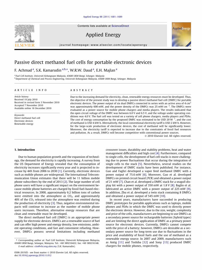
A schematic diagram of the stack developed in this study and acommercial single stack is shown in Fig. 1, and a schematic dia-gram of the dual side fuel cell stack is shown in Fig. 2a. In the dualside stack, two MEAs were stacked between a gasket, a current col-lector and anode and cathode plates. An anode plate in the centerof each stack was used as a methanol reservoir. As a result, the effi-ciency of fuel distribution was improved and less material wasused. As shown in Fig. 2b, six dual side stacks were connected inseries to achieve the appropriate amount of energy required tocharge a mobile phone battery.
rcuit voltage
rformance curve
brane thickness.

F. Achmad et al. / Applied Energy 88 (2011) 1681–1689 1685
An electrical load (Prodigit 3315D) with integrated software(National Instruments) was interfaced to a computer to obtainthe current loadings and to record the voltage–current curves.For each sample, the open circuit voltage was recorded for 2 h toobtain stability data. A continued loading of 0.01 A was introducedinto the DMFC to obtain polarization. All of the systems were pas-sive, and the experiments were performed at room temperature(25–27 �C).
Fig. 8. Design of (1) a commercial anode, (2) anode 1, (3) anode 2, (4) anode 3, (5)commercial cathode, (6) cathode 1, (7) cathode 2 and (8) cathode 3.
Table 1Summarized of optimum design parameters.
Parameter Values
Pressure for hot press 20 kg cm�2
Methanol concentration 5 MCatalyst loading for anode 8 mg cm�2
Catalyst loading for cathode 8 mg cm�2
3. Results and discussion
3.1. Optimization of MEA
3.1.1. Effect of hot pressingHot pressing is an important parameter in the fabrication of
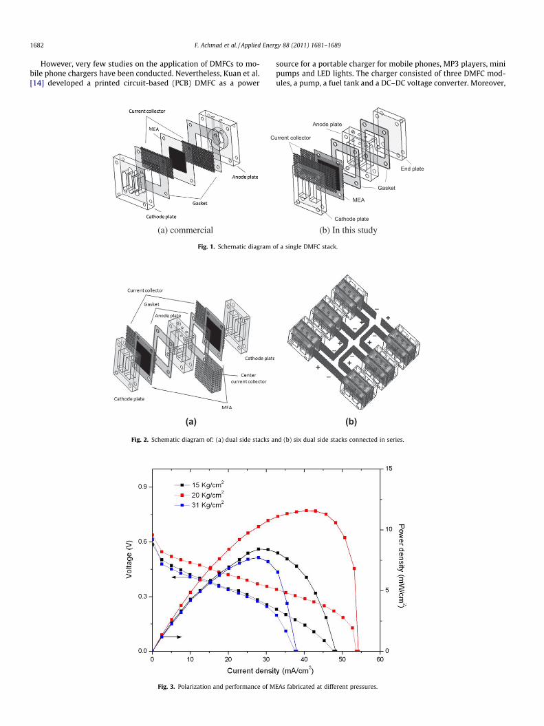
MEAs and has a significant effect on the performance of a DMFC.Thus, the effects of the fabrication conditions were evaluated byvarying the pressure from 15 to 31 kg cm�2 at a constant temper-ature of 135 �C. The performance of the resulting MEAs was evalu-ated in a DMFC with a Nafion 117 membrane and a methanolconcentration of 4 M at room temperature. Fig. 3 shows the polar-ization and performance curves of DMFCs containing MEAs ob-tained under different operating conditions. The results indicatedthat the optimal fabrication pressure was 20 kg cm�2, and a powerdensity of 11.57 mW cm�2 was obtained. MEAs fabricated at otherpressures provided lower power density due to poor contact be-tween the catalyst layer and the membrane. Optimal contact as-sures that protons reach the membrane, which is in directcontact with the catalyst [18]. Moreover, proper pressing also re-duces the MEA decay rate. Specifically, as water and CO2 areformed, the bond between the catalyst layer and the membranecan become damaged [18]. Furthermore, the results indicated thatMEAs produced at pressures greater than 20 kg cm�2 provided lowpower densities. As shown in Fig. 4, the carbon paper becomesmore compact and less permeable as the pressure increases. How-ever, at very high pressures, the carbon paper can break. Thus, thecell resistance of the DMFC increased as the pressure applied dur-ing MEA fabrication increased from 20 to 31 kg cm�2, which is sim-ilar to the results obtained by Jiang et al. [19].
Fig. 7. Effect of cat
3.1.2. Effect of methanol concentrationIn theory, a higher concentration of methanol should result in
an increase in power output because more methanol can be con-verted into electricity. In reality, a limited amount of methanolcan be converted by the cell due to methanol crossover. Methanolcrossover occurs when methanol diffuses through the membraneand is directly oxidized by oxygen at the cathode [20].
alyst loading.
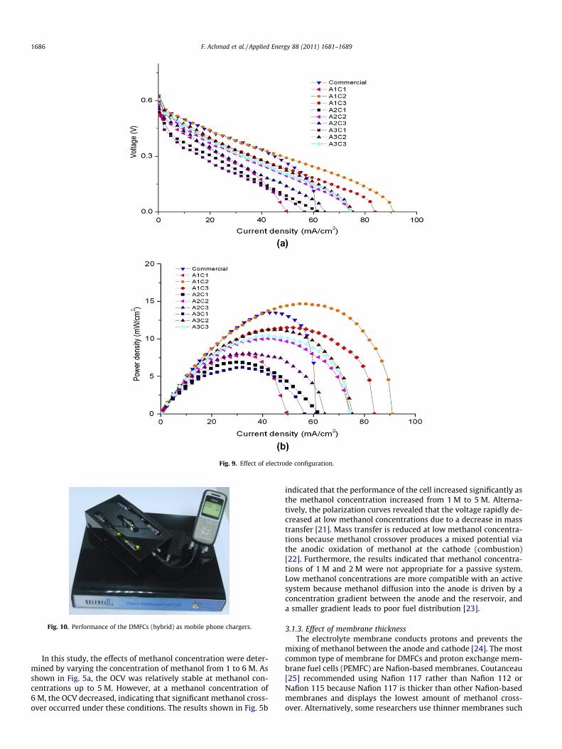
Fig. 9. Effect of electrode configuration.
Fig. 10. Performance of the DMFCs (hybrid) as mobile phone chargers.
1686 F. Achmad et al. / Applied Energy 88 (2011) 1681–1689
In this study, the effects of methanol concentration were deter-mined by varying the concentration of methanol from 1 to 6 M. Asshown in Fig. 5a, the OCV was relatively stable at methanol con-centrations up to 5 M. However, at a methanol concentration of6 M, the OCV decreased, indicating that significant methanol cross-over occurred under these conditions. The results shown in Fig. 5b
indicated that the performance of the cell increased significantly asthe methanol concentration increased from 1 M to 5 M. Alterna-tively, the polarization curves revealed that the voltage rapidly de-creased at low methanol concentrations due to a decrease in masstransfer [21]. Mass transfer is reduced at low methanol concentra-tions because methanol crossover produces a mixed potential viathe anodic oxidation of methanol at the cathode (combustion)[22]. Furthermore, the results indicated that methanol concentra-tions of 1 M and 2 M were not appropriate for a passive system.Low methanol concentrations are more compatible with an activesystem because methanol diffusion into the anode is driven by aconcentration gradient between the anode and the reservoir, anda smaller gradient leads to poor fuel distribution [23].
3.1.3. Effect of membrane thicknessThe electrolyte membrane conducts protons and prevents the
mixing of methanol between the anode and cathode [24]. The mostcommon type of membrane for DMFCs and proton exchange mem-brane fuel cells (PEMFC) are Nafion-based membranes. Coutanceau[25] recommended using Nafion 117 rather than Nafion 112 orNafion 115 because Nafion 117 is thicker than other Nafion-basedmembranes and displays the lowest amount of methanol cross-over. Alternatively, some researchers use thinner membranes such

Fig. 11. Performance of dual side cell stacks and 6 dual side stacks connected in series.
Table 2Comparison with other researches.
References Power output (mW) Power density (mW cm�2)
[6] 126 14.0[7] 320 4.18[8] 350 10.3[9] 225 20.0[10] 545 16.9This study 600 25.0
F. Achmad et al. / Applied Energy 88 (2011) 1681–1689 1687
as Nafion 112 [26–28] because thinner membranes increase protonconductivity [29].
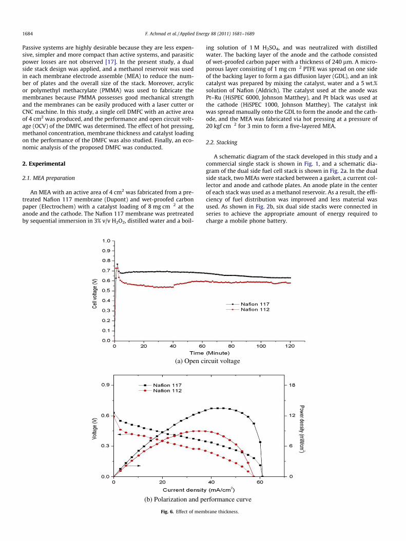
The thickness of the electrolyte membrane was varied to deter-mine the most appropriate membrane for DMFC with 5 M metha-nol in a passive system at room temperature. As shown in Fig. 6a,the open circuit voltage of a DMFC containing a Nafion 112 mem-brane was unstable and lower than that of a DMFC containing aNafion 117 membrane. Thus, with the Nafion 112 membrane,methanol crossover was significant, and low OCVs were obtained.The results shown in Fig. 6b indicated that the performance ofthe Nafion 112 membrane was inferior to that of the Nafion 117membrane. Based on the aforementioned results, subsequentexperiments were conducted with a Nafion 117 membrane.
3.1.4. Effect of catalyst loadingThe catalyst loadings applied to a DMFC must be evaluated be-
cause the amount of catalyst has a significant effect on the priceand performance of the DMFC. Catalyst loadings of 6 mg cm�2,8 mg cm�2 and 10 mg cm�2 were applied to the anode and thecathode, and the performance of the cell was evaluated. The resultsindicated that the current density and power density increasedwith an increase in catalyst loading. As shown in Fig. 7, the maxi-mum power densities obtained from the catalyst loadings were9.0 mW cm�2, 13.4 mW cm�2 and 13.7 mW cm�2, respectively,and current densities of 35.15 mA cm�2, 42.65 mA cm�2 and47.57 mA cm�2 were obtained. The results indicated that thepower density increased by approximately 21% as the catalystloading increased from 6 mg cm�2 to 8 mg cm�2. Alternatively, asthe catalyst loading increased from 8 mg cm�2 to 10 mg cm�2,
the power density increased by only 5%. Due to the additional ex-pense of a catalyst loading of 10 mg cm�2, a catalyst loading of8 mg cm�2 was applied because the power densities obtained fromthese catalyst loadings were similar. Table 1 summarizes the opti-mal operating parameters and corresponding outputs obtained inthis study.
3.2. Single stack design optimization
The anode and cathode plates distribute the reactant and sup-port the MEA. Compared to the proposed anodes, the open areaof the commercial anode is smaller due to the presence of supportsin the center and corners of the MEA. In the present study, to max-imize methanol distribution, the anode was redesigned to increasethe size of the open area. As shown in Fig. 8, anode 1 possessed asupport in the center of the MEA and an open area that was largerthan that of the commercial anode. Alternatively, anodes 2 and 3did not possess a support in the center of the MEA, and the sizeof the open areas of anodes 2 and 3 were different. Specifically,the highest open area was applied to anode 3, which possessedan open area of 79.1%. In this study, three cathodes with open areasof various sizes were also designed. The open area of the cathodeenhances air distribution, supports the MEA and facilitates waterremoval. As shown in Fig. 8, the overall stack size of the proposedcathodes was relatively low compared to that of a commercialcathode.
As shown in Fig. 9, the polarization and performance of thestacks was strongly dependent on the configuration of the elec-trodes. The power density of the stacks varied from 6.2 mW cm�2
to 14.7 mW cm�2, and the highest current density was achievedwith anode 1 and cathode 2. The commercial stacks suffered rapidloss of voltage after reaching the maximum power density, asshown in Fig. 9b. The loss of voltage of the commercial cell wasdue to the small size of the open area and the slow distributionof reactants.
3.3. Dual side stacks and six stacks connected in series
A DMFC with six dual side stacks was tested as a model in var-ious mobile phone chargers, as shown in Fig. 10. Fig. 11 displays

1688 F. Achmad et al. / Applied Energy 88 (2011) 1681–1689
the performance of DMFCs containing dual side stacks or six dualside stacks connected in series. The tests were performed at roomtemperature with a single feed of 6.6 mL of 5 M methanol. In thedual side stacks, stored methanol was supplied to the anodes toimprove methanol distribution. As a result, 125 mW of power wereobtained from the dual side stacks. In addition, the six dual sidestacks connected in series produced 600 mW of power and a power
Fig. 13. Performance of DMFC at o
Fig. 12. Performance of dual side stacks connecte
Table 3Production cost of methanol [31].
No. Methanolresources
Estimated methanolproduction cost (USDmL�1)
Estimated cost toproduce electricity (USDkW h�1)
1 Natural gas 0.00011 4.02 Coal 0.00027 10.03 Coal
(IGCC + LPMEOH)0.00017 6.0
4 Biomass 0.00046 165 CO2 from flue
gases0.00062 24
6 CO2 fromatmosphere
0.00084 32
density of 25 mW cm2, which is the highest reported output of aDMFC. A summary of the results obtained in this study is presentedin Table 2. As shown in the table, the current density obtained fromthe dual side stacks was significantly higher than that of the dualside stacks connected in series. Current loss in the series connec-tion likely occurs due to unequal performance in each stack andinternal resistance or electrical connection losses.
The voltage of the DMFC was measured using an electronic load(Prodigit 3315D) in a parallel connection and a multimeter (Fluke189) in a series connection. The initial voltage of the stack was6.0–6.5 V, and the voltage decreased to 4.0 V under stable operat-ing conditions. During charging, the voltage remained relativelyconstant, and values greater than 4.0 V were obtained. As shownin Fig. 12, the current decreased from approximately 83 mA to al-most 0 mA over 3 h. The current capacity (mA h) delivered by thestack was calculated, and a current of 243.06 mA h was obtainedafter one injection of 12.6 mL of 5 M methanol.
The DMFCs were also tested in an electronics media player(MP3). The MP3 player was powered exclusively by the DMFCs,and a battery was not required. Fig. 13 shows the performancecurve of the MP3 player. The current obtained from the DMFCsduring MP3 player operation was different from that obtained un-der charging conditions. The current required to start the MP3
perating Mode of MP3 player.
d in series (DMFC charger) at charging mode.

F. Achmad et al. / Applied Energy 88 (2011) 1681–1689 1689
player and display the screen was approximately 60 mA, and thetotal output power for the MP3 player was about 8 mW mL�1 ofmethanol.
Finally, the total cost for one prototype was estimated to be USD20 W�1 [5]. The estimated price of the MP3 player was based onone prototype, and the actual cost for large-scale production is ex-pected to be significantly lower. The estimated total cost for meth-anol fuel was USD 4 kW h�1. Alternatively, (Table 3) the cost ofconventional electricity is USD 2 kW h�1 [30]. Thus, methanol willbecome competitive with electricity because the cost of electricityis expected to increase as the supply of conventional fuel resourcesdecreases and air pollution increases.
4. Conclusions
In this study, a passive six dual side DMFC connected in seriesthat can produce a power output of 600 mW and a power densityof 25 mW cm�2 was developed. The stacks were capable of operat-ing in a variety of mobile phone chargers without connecting to asource of electricity. In addition, the MP3 was powered directly bythe DMFC, and batteries were not required. A dual side stack de-sign, in which one methanol reservoir was used by two membraneelectrode assembles, was employed. The dual side stack design re-duced the number of plates and the dimensions of the stack. Thetotal cost of the stack was estimated to be USD 20 W�1, and the to-tal cost of methanol was USD 4 kW h�1. Alternatively, the electric-ity tariff for the local area is approximately USD 2 kW�1. However,for large-scale production, the price of methanol is expected to de-crease. Moreover, because the electricity tariff is expected to in-crease in the future due to the constraints of fossil fuel resourcesand pollution, DMFCs will become competitive with conventionalpower sources.
Acknowledgements
The authors gratefully acknowledge financial support from theMalaysian Ministry of Science, Technology and Innovation (MOSTI)under research grant No: UKM-GUP-BTT-07-30-192.
References
[1] Energy, USD International energy outlook 2009. Washington, DC; 2009.[2] http://www.itu.int/ITU-D/ict/material/Telecom09_flyer.pdf [accessed
02.03.10].[3] Socolow R, Hotinski R, Greenblatt JB, Pacala S. Solving the climate problem,
Heldref Publications, vol. 4; 2004. p. 8–19.[4] Kamarudin SK, Achmad F, Daud WRW. Overview on the application of direct
methanol fuel cell (DMFC) for portable electronic devices. Int J HydrogenEnergy 2009;34:6902–16.
[5] Hashim N, Kamarudin SK, Daud WRW. Design, fabrication and testing of aPmma-based passive single cell and a multi-cell stack micro DMFC.. Int JHydrogen Energy 2009;34:8263–9.
[6] Guo Z, Faghri A. Miniature DMFCs with passive thermal-fluids managementsystem. J Power Sources 2006;160:1142–55.
[7] Guo JW, Xie XF, Wang JH, Shang YM. Effect of current collector corrosion madefrom printed circuit board (PCB) on the degradation of self-breathing directmethanol fuel cell stack. Electrochem Acta 2008;53:3056–64.
[8] Chan YH, Zhao TS, Chen R, Xu C. A small mono-polar direct methanol fuel cellstack with passive operation. J Power Sources 2008;178:118–24.
[9] Baglio V, Stassi A, Matera FV, Di Blasi A, Antonicci V, Arico AS. Optimization ofproperties and operating parameter of passive DMFC mini-stack at ambienttemperature. J Power Sources 2008;180:797–802.
[10] Zhu Y, Liang J, Chong L, Man T, Wang L. Development of a passive directmethanol fuel cell (DMFC) twin-stack for long term operation. J Power Sources2009;193:649–55.
[11] <http://www.mobilegadgetnews.com/index.php?showtopic=13440>[accessed 02.03.10].
[12] <http://www.toshiba.com/taec/news/press_releases/2009/dmfc_09_580.jsp>[accessed 02.03.10].
[13] <http://www.sonyinsider.com/2009/03/11/sony-shows-off-direct-methanol-fuel-cell-battery-usb-charging-station> [accessed 02.03.10].
[14] Kuan YD, Lee SR, Lee SM, Sung MF, Chiou HS. The performance analysis of aportable charger system using direct methanol fuel cell. Proc Int Matador Conf2007;35:129–32.
[15] Van Der Voorta EJ, Flipsena SFJ. Research by design: feasibility of a DMFCpowered PDA, a delft university of technology (DUT), faculty of industrialdesign engineering, Landbergstraat 15, 2628 CE Delft, The Netherlands.
[16] Chen R, Zhao TS. Performance characterization of passive direct methanol fuelcells. J Power Sources 2007;167:455–60.
[17] Liu JG, Zhao TS, Liang ZX, Chen R. Effect of membrane thickness on theperformance and efficiency of passive direct methanol fuel cells. J PowerSources 2006;153:61–7.
[18] Kakaç S, Pramuanjaroenkij A, Vasiliev L. Mini-micro fuel cells, Springer; 2008.[19] Zhang J, Yin GP, Wang ZB, Lai QZ, Cai KD. Effects of hot pressing conditions on
the performances of MEAs for direct methanol fuel cells. J Power Sources2007;165:73–81.
[20] Broussely M, Archdale G. Li-ion batteries and portable power source prospectsfor the next 5–10 years. J Power Sources 2004;136:386–94.
[21] Liu JG, Zhao TS, Chen R, Wong CW. The effect of methanol concentration on theperformance of a passive DMFC. J Electrochem Commun 2005;7:288–94.
[22] Kho BK, Bae B, Scibioh MA, Lee J, Ha HY. On the consequences of methanolcrossover in passive air-breathing direct methanol fuel cells. J Power Sources2005;142:50–5.
[23] Zhong L, Wang X, Jiang Y, Zhang Q, Qiu X, Zhou Y. A micro-direct methanol fuelcell stack with optimized design and micro fabrication. Sens Actuat A Phys2009;143:70–6.
[24] Menola T. Design and experimental characterization of polymer electrolytemembrane. Helsinski University of Technology; 2000.
[25] Coutanceau C, Koffi RK, L eger JM, Marestin K, Mercier R, Nayoze C.Development of materials for mini DMFC working at room temperature forportable applications. J Power Sources 2006;160:334–9.
[26] Nakagawa N, Xiu Y. Performance of a direct methanol fuel cell operated atatmospheric pressure. J Power Sources 2003;118:248–55.
[27] Abdelkareem MA, Morohashi N, Nakagawa N. Factors affecting methanoltransport in a passive DMFC employing a porous carbon plate. J Power Sources2007;172:659–65.
[28] Okada M, Konta Y, Nakagawa N. Carbon nano-fiber interlayer that provideshigh catalyst utilization in direct methanol fuel cell. J Power Sources2008;185:711–6.
[29] Tsampas MN, Pikos A, Brosda S, Katsaounis A, Vayenas CG. The effect ofmembrane thickness on the conductivity of Nafion. J Electrochim Acta2006;51:2743–55.
[30] Local electric tariff: <http://www.tnb.com.my/tnb/tariff/newrate_domestic.html>.
[31] Cifre PG, Badr O. Renewable hydrogen utilization for the production ofmethanol.