particle systems for program modeling in high-rise buildings
26
Go with the flow: particle systems for program modeling in high-rise buildings Yaniv Ophir (Junno) 171 issue 02, volume 06 international journal of architectural computing
-
Upload
khangminh22 -
Category
Documents
-
view
3 -
download
0
Transcript of particle systems for program modeling in high-rise buildings

Go with the flow: particlesystems for programmodeling in high-risebuildingsYaniv Ophir (Junno)
171issue 02, volume 06international journal of architectural computing
Go with the flow: particle systems for programmodeling in high-rise buildingsYaniv Ophir (Junno)
This paper revisits the particle flow system, a time-based computational tool, which has received a lot ofattention from the early pioneers of digitalarchitecture.The use of particle flow systems inarchitecture enables designers to materialize whatthey term as site forces which can later be formalizedinto a building.The methods offered by variousdesigners for using particle flow systems inarchitecture have kept the discourse purely formal byfocusing on the exterior and neglecting the interior.This paper offers a different way of using andconceptualizing particle flow systems in architecture.Shifting the emphasis from the formal, the paper aimsto show the potential of using particle flow systems asa parametric model for exploring the spatialorganization of an architectural program.This paperalso illustrates the application of the proposedcomputational model, i.e., the particle flow system, byusing a case study – the design of a high-rise buildingin downtown Tel Aviv, Israel.
172

1. INTRODUCTION
The metamorphosis of high-rise buildings in contemporary architecturalpractice can clearly be delineated in the project proposals submitted byleading practices to redesign the World Trade Center Towers. Inspired atfirst by the desire to make a more structurally sound and escapable high-rise, architects soon rediscovered the inherent potential in therelationship between form, function and structure as a tool for rethinkingthe high-rise. One such project is the proposal by Foreign OfficeArchitects (FOA).Their WTC2 project explores the advantages of slicingup the monolithic high-rise into thinner strands as a way of creatingmultiple footprints and increasing the stability of the building’s structure asa whole (Figure 1) [1]. In itself this new structural scheme might beregarded as a mere solution to an engineering problem but coupled withthe programmatic organization of the building it becomes an act of trueinnovation (Figure 2) [1].
173Go with the flow: particle systems for program modeling in high-rise buildings
� Figure 1: Multiple paths to safety.
Looking at the implications of this design strategy, one becomes awareof the new challenges emerging from no longer having a structure builtaround a single vertical circulatory system but rather a multi-path system ofvertical streets, intersecting at various points along the way.These places ofintersection create a need for interrupting the monotonous repetition ofthe building’s floor slabs.The result is the introduction of a new componentinto the design, the skylobby, a term coined by FOA to describe a plaza inthe sky, a kind of urban square where all streets meet to form a large publicspace (Figure 3) [1].This idea suggests an intriguing development in themetaphorical understanding of high-rise buildings, i.e., as a new form ofvertical urbanism.

Yaniv Ophir (Junno)174
� Figure 2: 3D layout of functional
spaces.
� Figure 3: Skylobby.

If we break up the term skylobby into its discrete elements we find thatlobby is defined by the Webster-Merriam dictionary as a corridor or hallconnected with a larger room or series of rooms and used as a passageway orwaiting room. In light of this definition and together with our everydayexperience of lobbies as spaces of transition between street and building, itseems the addition of the word sky suggests that the high-rise be thought ofas a system of horizontal paths or streets rotated vertically. Such anunderstanding helps to strengthen the notion of high-rise buildings as aform of vertical urbanism but also poses some difficult questions. How is thisprocess implemented? How can a high-rise building contain the multitude ofspatial and functional complexities inherent in the urban environment? Apossible path to answer this question lies in examining new approaches tothe design methodology of high-rise buildings but more specifically tounderstanding the shift in the underlying logic of these methodologies asmoving from stacking to meshing.
The typology of high-rise buildings can be characterized as a product ofstacking.Architecturally, or more specifically, programmatically, the building
175Go with the flow: particle systems for program modeling in high-rise buildings
� Figure 4: 1909 theorem: the
Skyscraper as utopian device for the
production of unlimited numbers of
virgin sites on a single metropolitan
location [2].

rationale behind high-rises is the result of trying to maximize the number ofplots per site by stacking them one on top of the other.An importantattempt to trace the historical and cultural origins of this phenomenon canbe found in Delirious New York:A Retroactive Manifesto for Manhattan [2]by Rem Koolhaas. In his manifesto, Koolhaas offers the following drawing(Figure 4) [2] as a way of illustrating the rationale behind the stackingmethodology conceived as a design solution in response to economic andphysical constraints. Stacking is also clearly evident in the works of the earlypioneers of high-rise design such as Louis Sullivan and other members of theChicago School.Their designs formulate a generic high-rise made of threedistinct parts stacked vertically – the commercial, occupying the first floors,followed by office space which comprised the significant part of the buildingand finally at the very top the mechanical floor which was later replaced byresidential spaces when new forms of urban lifestyle flourished and theirfinancial value was realized. Bounded by the constraints of this genericmodel, high-rise buildings quickly became a sort of Babylonian clichéconcentrating solely on reaching the highest height possible.This causedhigh-rise evolution to succumb to the engineering constraints enforced uponit by technological advancement, sacrificing key aspects of architectural designsuch as spatial and programmatic complexity.A quick glimpse at most typicalfloor plans in high-rise buildings reveals the autonomous behavior of eachfloor and disconnection from its vertical neighbors. In a typical high-rise, thesense of disconnection permeates from the ground floor up, gaining moreinfluence from floor to floor until the city, the urban Petri dish on which itgrows, is no longer evident.
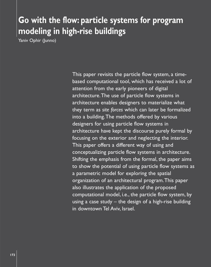
While stacking remains the prevalent method for high-rise design today,there is evidence of a shift towards meshing facilitated mainly by theintroduction of advanced computation into the design process. Meshing, as itsname implies, tries to mesh together the various complexities of design – i.e.,structural, social, economic, etc. – by translating them into parameters that arethen used in order to construct a comprehensive model of the building.Theuse of meshing can be clearly illustrated by examining the Resi-Rise Skyscraperproject (Figure 5) [3] by KOL/MAC. In this project, the proposed buildingdevelops the notion of vertical urbanism as a new metaphor for high-risebuildings guided by the use of meshing as the modus operandi. Resi-Rise takesa spatial frame and uses its inherent geometry to create a matrix of “Lots,” theequivalent of a plot of land, which can be purchased by potential residents whowish to inhabit the building.The project takes into consideration a number ofparameters such as zoning, site influences, views, adjacencies etc., and attemptsto negotiate them by using computational methods.The output of this processcan be traced to deformations in the building’s spatial frame creating a moredifferentiated surface for urban complexity to emerge.The Resi-Rise projectmarks the conceptual starting point of this paper by outlining the designobjective, i.e., designing a more spatially complex high-rise while opening thedoor for further exploration and development of tools for this purpose.
176 Yaniv Ophir (Junno)
2. FUNCTION, FORM & COMPLEXITY
The exact definition of complexity in architecture is a much debated topicand far too complex to be properly addressed within the scope of thispaper. Nevertheless, one can argue that complexity’s most basic origin is therelationship between form and function. In high-rise design it seems that thelatter has been neglected. Emphasis is put on innovative structures andforms rather than the spatial organization of program and functions within.This paper tries to draw attention to the gap between form and function in
177Go with the flow: particle systems for program modeling in high-rise buildings
� Figure 5: Vertical urbanism.

high-rise buildings. It offers a way of addressing the challenge ofprogrammatic layout using a computational tool aimed at increasing spatialcomplexity.The first step in this process requires employing the samerationale that governs performance-based form-finding procedures andapplying it to spatial organization.The problem can be simply modeled bytrying to think of ways to pack objects in three-dimensional space. Similarto the task of finding structural alternatives to a given load, modeling thesearch space of programmatic layout is a way of enabling designers toexplore different spatial organizations and their complexity.When it comesto form, parametric design offers a way of modeling a building by creatingparametric relationships between its various components. But can anarchitectural program be parameterized?
178 Yaniv Ophir (Junno)
� Figure 6: Spiral form is the result of
informing the parametric model with
environmental data.

3. PARAMETRIC DESIGN IN HIGH-RISE BUILDINGS
Parametric design is an emerging field in contemporary architecturalpractice which extends the use of CAD in order to create a more informedrepresentation of the digital model/project. Parametric modeling addsanother layer of information to the computerized architectural model bycreating a link among the various parameters of the model’s entities. High-rises are considered ideal candidates for this type of modeling procedure asthey have many repetitive parts with easily definable and interdependentparameters such as skin tessellation, window size, surface curvature etc.TheSwiss-Re building (Figure 6) [4] by Foster + Partners is a perfect example ofusing parametric modeling in the form-finding process of design evolution.The use of parametric modeling enables the designer to input much moredesign data/knowledge than previously possible, thus creating a morecomplex form. However, the input generating the form is usually devoid ofany consideration of programmatic constraints or the interior organizationof functions.This intrinsic behavior of parametric modeling in high-risebuildings is the motivation behind Performative Morphologies:The VerticalHelix (Figure 7) [5] by Neri Oxman:
179Go with the flow: particle systems for program modeling in high-rise buildings
� Figure 7: Integrating organizational,
spatial and structural parameters.
“…developed as a parametric tool…in which feedback loops areestablished between spatial and structural performance, allowing forlocal conditions to affect global spatial and structural behavior…allows for the local proliferation of the system according to externalconditions and requirements.

These aspects are defined as parametric conditions and theirrelationships to, or impact upon, the morphology of the materialsystem can be modeled using appropriate evaluation tools. One of themost significant aspects of this approach then, is the attempt to beintegrative and to develop methods that support design underconditions of multi-variant influences.This approach differs appreciablyfrom what was formerly considered, ‘typological’, or generic, design.”[5]
Although the project concentrates on the exterior skin and structuralperformance of high-rises, it in fact creates an important relationship amongorganizational, spatial and structural parameters and acknowledges thepotential inherent in their integration into a single design model.
4.THE ARCHITECTURAL PROGRAM
The act of architectural design is the constant motion between abstractionand materialization.The initial trigger of this process is the program, a list offunctional requirements and constraints, describing the desired content ofthe future building. By itself the program is merely a shopping list ofproposed functionality and does not suggest anything other than what thebuilding wants to become. Metaphorically, the program can be thought of asa telephone switchboard, each plug representing a necessary function.Thearchitect, now a switchboard operator, is faced with the task of linking thefunctions, or plugs, using abstract links or cables. Given a finite number ofplugs there are more than a few possible ways of making connections andso it becomes quite a masterful art making the right decisions. For example,connecting two distinct functions together, will either get the desiredarchitectural complexity or an agitated person replying wrong number.Faced with this tedious task of trial and error, it makes sense to find a toolthat will make searching the finite domain of possible solutions a littleeasier or at least manageable.The bubble diagram (Figure 8) [6] has beenemployed by architects for years as a flexible and intuitive way of exploringpossible programmatic links. In this diagram, each bubble represents afunction which can be linked to other bubbles to create a graphicalrepresentation of a suggested program. But what does a bubble representother than a function’s name, like restroom, bedroom, etc.? Does the linkcreated between two bubbles represent more than a physical connectionor proximity?
Today, architects are working together with computer scientists to tryand go beyond the bubble diagram and articulate a computational tool toautomate architectural programmatic layout.At the Delft University ofTechnology a group of researchers developed a computational tool basedon the idea of using voxels, volumetric pixels, to explore variousprogrammatic layouts.The tool, Flexible FunctionLayouter (FlexFL) [7], takesas its input a curvilinear NURBS-based space, converts it to voxels, creating
180 Yaniv Ophir (Junno)

a voxelized space, and tries to find an optimal organization of functions thatfits inside the space. FlexFL uses an iterative process to assign volumes tofunctions. It then draws spatial relationships between the different functionalvolumes. Finally, constraints and optimization targets are defined and asearch algorithm goes through the finite set of plausible solutionsterminating when an optimal organization of functions is found.This tooloffers a unique opportunity not only to augment the basic bubble diagrambut to extend its capabilities to three-dimensional space. Going back to theswitchboard metaphor, we can see how voxels become plugs and thealgorithm an operator plugging and unplugging jacks, searching for the rightcombination that will transfer the call.
181Go with the flow: particle systems for program modeling in high-rise buildings
� Figure 8: Typical bubble diagram.
5. PARTICLE FLOW SYSTEMS
5.1. Form finding & dynamics simulation
This paper describes a short experiment with a particle flow system as atool for exploring spatial organization of an architectural program.Theparticle flow system that is used is taken from a popular 3D modelingsoftware and customized to meet the experiment’s parameters as opposedto being developed specifically for the experiment.The rationale behind thisdecision is to show the great flexibility inherent in existing computationaltools as well as their ability to inspire creativity and ingenuity. However, theconceptual starting point of this paper as to the use of particle flow systemsin design is quite different, shifting the emphasis put on generating form toformalizing an abstract structure of an architectural programmaticorganization.
Particle flow systems as a computational tool have their origins indynamics simulation and have become widely used across different fields ofthe building industry. For example, in safety control and emergencyresponse, these systems are extensively used to simulate crowd behavior invarious cases of emergency evacuation (Figure 9) [8]. In architecture, GregLynn,Ali Rahim and others have been experimenting with particle flow

systems and their ability to generate new forms. Lynn first experimentedwith the morphogenetic potential of particle flow systems in his project, thePort Authority Gateway (Figure 10) [9]. In his book,Animate Form [10],Lynn gives the following description of the project:
182 Yaniv Ophir (Junno)
� Figure 9: Arsenal Stadium: crowd
flow modeling.
� Figure 10: Form-finding particles.
“The site was modeled using forces that simulate the movement andflow of pedestrians, cars, and buses across the site, each withdiffering speeds and intensities of movement…These various forcesof movement established a gradient field of attraction across thesite.To discover the shape of this invisible field of attraction, weintroduced geometric particles that change their position and shapeaccording to the influences of the forces. From the particle studies,we captured a series of phase portraits of the cycles of movementover a period of time.” [10]
Lynn’s experiment with particles yields a new method of translatingcontextual or site-specific data to form.The complex formal expression inthis case is closely related to the emergent behavior of data-drivencomputational processes.The decision in Lynn’s project to use a particle

flow system for the purpose of form generation as opposed to otheraspects of the design is perhaps related to the simple programmaticrequirements of the original design problem.This is not the case with AliRahim’s residential housing tower in Dubai (Figure 11) [11]. In his book,Catalytic Formations [12], Rahim calls the project Migrating Coastlines andexplains the workings of the particle flow system that was used to generatethe tower’s form:
183Go with the flow: particle systems for program modeling in high-rise buildings
� Figure 11: Migrating coastlines.
“To incorporate the myriad economic factors and site relationshipsinto the design, we generated a dynamical system model in thecomputer. A high pressure was located on the side of the site facingthe city and a low pressure on the side of the desert…Pressures

correlated to the ocean and desert views were also inserted…highpressures were located near the top and bottom of the tower andlower pressures in the middle…The pressure system was thenapplied to a series of two columns of 45 stacked particle fields.Thebehaviors of the particles fields were constrained to tend towardthree desirable conditions: privacy between units, maximization ofviews to the surrounding landscape, and the provision of severalemergency exit paths…The twisting of the particle fields generatedthe tower’s undulating profile – a vertical coastline marking the flowsand migrations within the system.”[12]
Rahim uses the particle flow system in much the same way as Lynn,differentiating his project only by the unique way in which the system is setup. Both projects take advantage of the particle’s behavior and inherentreaction to physical force in order to give form to the virtual forces thatinfluence the site.This form-finding procedure makes extensive use ofsimulation, a technique commonly used with particle flow systems, in whichan experiment reiterates over time until behavioral patterns emerge. Buthow do they relate to the internal organization of the building? If the sameparticle flow system were to take as its input programmatic parameters, willpatterns of spatial organization emerge?
The following section describes the setup of a particle flow system muchlike the ones mentioned above.There is, however, one fundamentaldifference in the task for which that system is used. Rather than generateform, we aim to build and make use of a particle flow system to exploredifferent models of spatial organization.
5.2. System outline
Before describing the experiment’s computational logic, there is a need toexplain its metaphorical framework.This process of abstraction begins bytaking the high-rise as a building typology and trying to map its physicalcharacteristics to a metaphorical domain. For example, most high-risebuildings are an extruded profile (usually a typical floor plan or footprint).Geometrically, high-rises are usually one or more primitive solids with avertical orientation. But what happens if we disregard the high-rise’s formand define it as a vector? Can we reduce the high-rise as a buildingtypology to being a vector of varying length and upwards orientation? If wecan, then that means a high-rise is metaphorically a vertical timeline withintervals of reoccurring events, i.e., floor plans.This conceptual shifteffectively creates a relationship between the time-based attributes of theparticle flow system and the high-rise. In fact, in this way the particle flowsystem is no longer detached from the high-rise but is in effect the high-rise itself. Having made that distinction we can now move on to betterunderstand how the different parts of the computational process areintrinsically connected to each other.
184 Yaniv Ophir (Junno)

185Go with the flow: particle systems for program modeling in high-rise buildings
� Figure 12: Particle flow system.
The Timeline (Figure 12) defines the length of the animation. In oursystem the length of the timeline represents the height of the high-rise.Upon reaching the last frame in the animation, particles die and theanimation reverts to its starting position. In this way, each frame can bethought of as representing a unit of measurement, and adding or subtractinga frame enables us to scale up or down the building’s height.
The Particle Flow Source (Figure 12) is essentially a plane from whichthe generated particles originate.The specific particle flow system used forthis experiment enables the user to turn any geometrical object into aparticle flow source.This is where we first encounter the emergentbehavior of the computational tool. If we restrict the particle emission to asingle point, we are in fact making sure that particles originate from thesame place at each run of the animation. However, if the particle flowsource is an object with multiple points of emission, we get a different arrayof particles every single time we animate.
The Particles (Figure 12) make up the particle flow system and areabstract entities.A particle has no shape or form but assumes thegeometrical characteristics of any object imposed on it.As we later show,this feature makes particles a perfect candidate for generating variousspatial organizations.
Forces (Figure 12), as described in Greg Lynn’s Port Authority Gateway [9]project, are used to actuate the particle flow system and influence its behavior.In the system used for this experiment there exist several types of forces. Inthis experiment, these forces are used to simulate the influence of different siteparameters on the organization of the high-rise’s programmatic layout.
The Particle View interface (Figure 13) is the control mechanism behindthe Particle Flow System. It is a tiled window containing four sections – anempty canvas, an operator inventory, a properties menu and a descriptionpane.Working with the interface is basic and intuitive.The user can drag-n-

drop a feature from the inventory onto the empty canvas, then make thedesired connections (wiring) and finally customize its properties in theappropriate menu.To test the effect of any change on the particle flowsystem, the user simply runs or renders the animation to create adocumented evolution of the spatial organization.The particle view is wherethe parametric nature of this system comes into play.The connection ofdiscrete elements within the system creates a parametric relationship wherechanges to one element cause a reaction in the subsequent elements linkedto it.This schematic wiring of different components constitutes the abstractframework which is in fact a new method for generating different spatialorganizations – a 3D digital bubble diagram.Through interaction with thisnew parametric architectural program, the user can change the spatialorganization of the building while continuously receiving immediate feedback.
186 Yaniv Ophir (Junno)
� Figure 13: Particle view interface
and parametric relationships.
6. CASE STUDY
6.1. High-rise building in downtown Tel Aviv, Israel
In order to test out the proposed system, a specific site was chosen. On a plotadjacent to the iconic Azrieli Towers in downtown Tel Aviv, Israel, the localmunicipality is planning the construction of a new business district comprisinga series of new high-rise buildings. Each of these high-rises will have a mix-useprogram of office, commercial and residential space.The ratio between thesedifferent functional spaces favors office space, followed by commercial spaceson the ground floor and a small portion of residential space on the top floors.As mentioned in the introduction of this paper, this programmatic layoutcharacterizes the typology of high-rise buildings.Although this is not the focusof this paper, we have mentioned that architectural complexity is closelyrelated to the programmatic organization of functions within a building.Drawing a direct link from this assumption we can infer that the simple,repetitive and disconnected qualities of the high-rise are rooted in the way itsprogram is organized spatially. How then can we take a typical program, which

consists of a list of the aforementioned functional spaces and their propertiesand organize it in new ways that create a more spatially complex high-rise? Toaddress this question we offer the particle flow system composed of thecomponents previously outlined (Figure 14). In order to instantiate this system,we first have to define its actuators, i.e., the site-specific forces, designrequirements and constraints that are going to influence the programmaticlayout of the building. In this crucial methodological step we are in factmaterializing and quantifying design intent by creating parameters and therelationships between them. From that point on, the particle flow systembecomes the computational construction responsible for negotiating anychanges to our pre-defined parameters as well as visualizing them. Once thesesteps have been carried out we move to formulate the protocol that definesour interaction with the system.The use of particle flow systems falls quitenicely into the category of simulation where a model is set up, tested,evaluated and then tested again repeatedly using the evaluated output of eachtest.We can call this process the feedback loop (Figure 15).The feedback loopdiagram is a truly robust mechanism allowing the designer to further extendthe model by adding more parameters to the user-defined section. It isimperative to mention that in this paper we do not implement the feedbackloop diagram in its entirety and, for example, address the evaluation sectiononly as part of the conclusions. Having said that, we elaborate on the methodsused to extract the data that is fed into the particle flow system, and on theway in which that system is set up in regard to the unique conditions of thecase study, and give examples of the output.
187Go with the flow: particle systems for program modeling in high-rise buildings
� Figure 14: Components of particle
flow system and typical high-rise
building.

188 Yaniv Ophir (Junno)
� Figure 15: Feedback loop.
6.2. Programmatic particles
Using the creation tools for particle flow systems in our 3D modelingsoftware, we generate three unique instances of a particle emission sourcecorresponding to the three main functions – commercial, office andresidential - of the mix-use high-rise. Each of these particle sources containsa number of parameters that the user can manipulate to make the modelbetter represent the building’s programmatic requirements.The defaultparticle source is made up of two components – a render operator which ituses to visualize the particle flow and an event (Figure 16).The eventcontains a list of actions required in order to generate a particle flow.Theseactions are birth, position, speed, rotation, shape and display.The birthoperator determines when particles start to emerge along the timeline,when they die or disappear and the total number of particles present in thesimulation. Since our timeline represents the full height of the high-rise, weset the birth operator to generate particles from the ground floor and killthose that have reached the maximum height.This is where we create ourfirst parametric relationship between the number of particles, i.e., functions,and the building’s height.Within the birth operator we find the amountparameter that indicates the total number of particles in the system.Theamount parameter presents an interesting dilemma. Because particle flowsystems are computationally robust, we can enter the exact number offunctions specified in the building’s program, run the simulation and get theirspatial organization. On the other hand, by grouping several functions/spacestogether, we are able to reduce the number of particles generated to get amore averaged result.We choose to do the latter as a way of exposingpatterns in the spatial organization of the high-rise rather than achieving anexact organization of functions. Next, we turn our attention to the positionoperator as it determines the place from which the particles originate.Asmentioned previously, we can restrict the flow of particles to a specific

location or otherwise distribute them across the source plane. In ourexperiment, we dimension the source plane to match the size of thebuilding’s potential footprint, thus creating a parametric relationship betweenthe two.This decision enables us to evenly distribute the production ofparticles across the source plane. Finally, the speed operator determines thefrequency at which particles change their position throughout the simulation.It is important to mention that this is merely an initial speed and that theindividual speed of particles is likely to change once they encounter otherelements in the system such as forces, which we introduce in the followingsection.The remaining operators – rotation, shape and display – do not playa significant role in our system and can be left out of the discussion. Shapeand display are inconsequential and relate to how the particles are visualizedduring simulation.The rotation operator is set to its default state in ourexperiment and is subject to further exploration and development.
189Go with the flow: particle systems for program modeling in high-rise buildings
� Figure 16: Default particle source.
6.3. Site forces
The significance of the site is in its contextual contribution to theparticle flow system. Remembering that a particle flow system is actuatedand influenced by outside forces, the site’s constraints and physicalattributes aid in developing the logic used to distribute these force fields.Much the same as the approach taken in the projects of Greg Lynn andAli Rahim, we first examine the site and take into account any conditionsthat might influence the distribution of functions.The site’s orientation isnorth to south, with the Tel Aviv coastline to the west and the city ofRamat-Gan to the east. If we assume that views from the high-rise are a

commodity, i.e., spaces facing a certain view are worth more than spacesfacing a different one, we would like our system to explore spatialorganizations which maximize the number of functions facing a morevaluable direction.We deploy push forces, provided by the 3D modelingsoftware, as view vectors around the particle flow system according tothe direction of views with more value (Figure 17).We further extendthis parametric relationship by stating that a view is an attributespecifically valuable in residential spaces and we restrict the influence ofpush forces to residential particles alone. Finally, we embed one morerule into the system, enabling residential particles to increase their sizeby a certain coefficient once affected by a push force.This last axiomillustrates a kind of economic logic which we embed in the system tomaximize the area of residential spaces facing a valuable view in order toincrease the project’s return profit.This last procedure concludes a seriesof parametric links created between economic considerations, functionalsize and orientation.The computational logic itself is encapsulated withina simple script embedded in the particle flow system in the form of aScript Test (Figure 18).The script iterates continuously through all theparticles present in the simulation and searches for the ones that matchthe objective function, i.e., are within the boundaries of a specific view. Ifa particle is found, the search terminates and returns a true message tothe script test, which then goes ahead and performs further operationssuch as increasing the particle’s size as mentioned above.The push forcehas two internal parameters, time and strength, which need to be set inorder for it to influence the particle flow system.The time parameterdetermines at what point along the timeline the force is operational andin our model is set to the same length as the timeline itself.We tie theforce’s strength parameter to a user-defined rating system, creating agradient by which to measure how valuable a view is at any specificdirection.The exact value is not important, but rather the ratio amongthe different forces/views.
190 Yaniv Ophir (Junno)
� Figure 17: View vectors and their
corresponding force.

191Go with the flow: particle systems for program modeling in high-rise buildings
� Figure 18: Scripted parametric
relationship between particles and
view (pseudo code).
6.4. Functional gravity
Following the rationale outlined by the use of push forces, we first try tounderstand what sort of force created the current programmatic layout in atypical high-rise. In order to address this question we find ourselves goingback to the argument made at the introduction of this paper which statesthat a high-rise is the product of stacking different layers of functionality.Building on this argument, we envision a gravity force acting upon thedifferent functions within the high-rise, compressing each into its ownappropriate layer. For example, the first layer of functionality is thecommercial spaces, creating the surface of interaction between the buildingand the city. Next we have the layer of office space, followed by theresidential layer at the top.The order of this stacking procedure iscontrolled by a weight property, which is different for every function basedon parameters such as the amount of space it occupies, the intensity ofactivity within it, the amount of accessibility it requires, etc. In the typicalhigh-rise, this weight property is obviously a virtual one, yet it hints at theexistence of some force acting upon the programmatic layout, a gravityforce, which ensures each function finds its place within the overallorganization.The problem arising from applying this force in the case of thetypical high-rise is the fact that it is uniformly applied to each functionregardless of its type, size, place in space, and so on. In the particle flowsystem this functional gravity is modeled using the built-in gravity force fieldthat is part of the 3D modeling software. In order to effectively use thisfeature we must assign each particle a weight that corresponds to thefunction it represents.The exact value of the weight parameter isinsignificant.What is important is that it represents a desired objective orset of objectives such as cost or accessibility. In other words, if we have acertain functional space in our program that we know is going to becomemore expensive to construct the higher it is from ground level, we canassign that space a large weight.When the particle representing this space

6.5. Preliminary design output
The work presented in this section is a snapshot of design output createdwhile working on the case study analysis which is still in its early stages ofconception. Our purpose here is to present some of the researchdirections that have been explored in order to show the potential forfuture development. For example, one direction undergoing research is thetranslation of the programmatic layout into form. Our approach to thischallenge so far has been to create an envelope that wraps around thegenerated particles much like a fit fabric, creating the minimal surface thatencloses the program (Figure 20).Another exploration has been launchedto examine the physical connection between particles as a way of exploringnew circulatory systems in high-rise buildings (Figure 21). Finally, a daylightanalysis has been performed on a minimal surface generated by the system(Figure 22) as a way of completing the evaluation section of the feedbackloop proposed in this paper.The motivation here is to have some methodof evaluating the quality of one spatial arrangement over the other andbeing able to feed this result back into the system for further explorationor optimization.
enters the simulation, the system’s gravity force makes it more difficult forthe space to bubble up with the other particles, forcing it to remain closeto the ground.This logic illustrates another parametric relationship createdbetween a function’s attributes and its location in the building’s spatialorganization. Similar to the push case, the relationship is maintained by theuse of a simple script embedded within the particle flow system (Figure 19).The script itself can be understood by focusing on the single line that takesthe inverse ratio of the particle’s size and assigns it to a special value calledparticleFloat.This unique parameter is used by the gravity force to determinethe extent of its influence over the particle.The result is of course theemergence of a spatial organization that illustrates the weighted state of thesystem over time.
192 Yaniv Ophir (Junno)
� Figure 19: Scripted parametric
relationship between particles and
gravity force (pseudo code).

193Go with the flow: particle systems for program modeling in high-rise buildings
� Figure 20: Minimal surface wrapped
around particles.
� Figure 21: Physical connections
between particles.

7. CONCLUSION
The argument we present in this paper shows that particle flow systemsin architecture have been primarily used for their form-finding capabilities.From the few project examples covered, it appears that certain patternsemerge when particle flow systems become the generator of form. Forexample, the use of these systems as a way of materializing contextualforces relating to a specific site.We further develop the idea of shiftingthe emphasis put on formal expression in favor of generating theprogrammatic layout of a building using particle flow systems.We focusthe discussion on high-rise buildings and show why we think they are, as abuilding typology, the perfect candidate for experimenting with particleflow system and spatial organization. In this paper, we also offer amethodological shift from stacking to meshing as the generativemechanism behind high-rise design and provide evidence to support thisclaim. Finally, we set up a particle flow system and launch an experimentto test our arguments using the context of a design case study. During ourresearch we have yet to find a frame of reference for using particle flowsystems as a computational tool for programmatic layout.There are ofcourse other methods currently being explored to automateprogrammatic layout, one of which has been covered here, but they take adifferent approach to the problem. Using our proposed particle flowsystem we explore the limits of the tool by taking on a design problem asoutlined in the case study.We conclude that it is possible to generate an
194 Yaniv Ophir (Junno)
� Figure 22: Daylight analysis.

infinite number of variations of spatial organizations for any given programand to some degree compare their intrinsic qualities.We would like topropose a few ideas which may be the starting point of future discussion.The first point we acknowledge relates to measuring complexity. In thispaper, we argue that the use of advanced computational tools such as theparticle flow system generates a more spatially complex high-rise building.The question remains: how do we quantify complexity? This is animportant step that needs to be taken for us to be able to guide theevolution of the programmatic layout by feeding a solution’s complexityvalue back into the system. One possible approach is to think of an arrayof particles generated by the system as a spatial graph where everyparticle is a node that is connected to other nodes. In graph theory, anode’s complexity is measured by the number of arcs coming in and/orgoing out of it, in other words, its degree of connectedness.This definitionseems suitable for our case but further research is needed to thoroughlyunderstand how it translates to programmatic layout.Another point thatneeds further investigation has been mentioned as part of the preliminarydesign output of the case study. How do we generate form out of thespatial organization? How do we model the relationship between theprogrammatic layout and the building’s form? Our approach thus far hasbeen to create a minimal surface which wraps around the spatialorganization.This may not be the best approach since it does not offer away for the surface to inform the particle flow system.The preliminarydesign output also presents some initial ideas about the evaluation sectionof the feedback loop by offering daylight analysis as one possible solution.The problem arises when there is more than one evaluation tool. How isthe solution produced by the particle flow system used in each of thedifferent evaluation tools? Is the solution translated back and forthbetween evaluation tools? Or perhaps the output of the particle flowsystem is a generic model? Still focusing on the output of the system, whatsort of operations could be invoked on the programmatic solution? Toprovide a partial answer to this question, we might think of the output asa cloud of nodes, each representing a function in space. If we extend thenotion of the node to contain more data on the function it represents,such as who are its neighbors for example, we find ourselves again in therealm of graph theory.This transition gives us access to an arsenal ofalgorithmic tools to extend the robustness of our computational model.For example, we might use a shortest-path algorithm to determine whatthe best route of escape is from our spatial organization in case of anemergency.As a final comment, we acknowledge the limitations andconstraints imposed on our experiment by using a pre-defined particleflow system taken from a commercial 3D modeling software.As a way ofextending our research, we intend to explore other existing toolsemploying particle flow systems or perhaps develop them on our own.
195Go with the flow: particle systems for program modeling in high-rise buildings

Acknowledgements
This paper revisits some fundamental ideas developed as part of myundergraduate thesis project at the Technion, Israel. I would like to thank myadvisors on the project Dr.Arch. Eran Neuman and Dr.Arch.Yasha J.Grobman. I would also like to thank Professor Terry Knight for hercomments and critique throughout the writing of this paper.
References1. http://www.f-o-a.net [15-2-2008].
2. Koolhaas, R., Delirious New York: A Retroactive Manifesto for Manhattan, Monacelli,1997.
3. http://www.kolmacllc.com/tmp/home.html [15-2-2008].
4. http://www.fosterandpartners.com/Practice/Default.aspx [15-2-2008].
5. http://www.materialecology.com/ [15-2-2008].
6. http://www.hohpe.com/Gregor/Hobbies/Architecture/peod/project7/index.html[15-2-2008].
7. Bier, H., de Jong,A., van der Hoorn, G., Brouwers, N., Heule, M., van Maaren, H.,Prototypes for Automated Architectural 3D-Layout, in: G.Wyeld,T., Kenderdine,S., Docherty, M., eds., Virtual Systems and Multimedia: 13th International Conference,1st edition, Springer, Berlin, 2008, 203–214.
8. Kolarevic, B. and Malkawi,A., Performative Architecture: Beyond Instrumentality,Taylor& Francis, New York, 2005.
9. http://www.basilisk.com/P/portauthority_561.html [15-2-2008].
10. Lynn, G., Animate Form, 1st edition, Princeton Architectural Press, New York, 1999.
11. Rahim,A. and Jamelle, H.,The Economies of Elegance Migrating Coastlines:Residential Tower, Dubai, Architectural Design, 2007, 77(1), 66–75.
12. Rahim,A., Catalytic Formations, 1st edition,Taylor & Francis, New York, 2006.
196 Yaniv Ophir (Junno)
Yaniv Ophir (Junno)
Massachusetts Institute of TechnologyDepartment of Architecture77 Massachusetts Avenue, Building 7-337Cambridge, Massachusetts 02139-4307