Energy Standard for Buildings Except Low-Rise Residential ...
443
ANSI/ASHRAE/IESNA Standard 90.1-2001 (Includes ANSI/ASHRAE/IESNA Addenda listed in Appendix F) Energy Standard for Buildings Except Low-Rise Residential Buildings I-P Edition See Appendix F for approval dates by the ASHRAE Standards Committee, the ASHRAE Board of Directors, and ANSI. This standard is under continuous maintenance by a Standing Standard Project Committee (SSPC) for which the Standards Committee has established a documented program for regu- lar publication of addenda or revisions, including procedures for timely, documented, consensus action on requests for change to any part of the standard. The change submittal form, instructions, and deadlines are given at the back of this docu- ment and may be obtained in electronic form from ASHRAEs Internet Home Page, http://www.ashrae.org, or in paper form from the Manager of Standards. The latest edition of an ASHRAE Standard and printed copies of a public review draft may be purchased from ASHRAE Customer Service, 1791 Tullie Circle, NE, Atlanta, GA 30329-2305. E-mail: [email protected]. Fax: 404- 321-5478. Telephone: 404-636-8400 (worldwide), or toll free 1- 800-527-4723 (for orders in U.S. and Canada). 'Copyright 2001 American Society of Heating, Refrigerating and Air-Conditioning Engineers, Inc. ISSN 1041-2336 Jointly sponsored by Illuminating Engineering Society of North America AMERICAN SOCIETY OF HEATING, REFRIGERATING AND AIR-CONDITIONING ENGINEERS, INC.
-
Upload
khangminh22 -
Category
Documents
-
view
1 -
download
0
Transcript of Energy Standard for Buildings Except Low-Rise Residential ...

ANSI/ASHRAE/IESNA Standard 90.1-2001(Includes ANSI/ASHRAE/IESNA Addenda listed in Appendix F)
Energy Standard forBuildings ExceptLow-Rise ResidentialBuildingsI-P Edition
See Appendix F for approval dates by the ASHRAE StandardsCommittee, the ASHRAE Board of Directors, and ANSI.
This standard is under continuous maintenance by a StandingStandard Project Committee (SSPC) for which the StandardsCommittee has established a documented program for regu-lar publication of addenda or revisions, including proceduresfor timely, documented, consensus action on requests forchange to any part of the standard. The change submittal form,instructions, and deadlines are given at the back of this docu-ment and may be obtained in electronic form from ASHRAE�sInternet Home Page, http://www.ashrae.org, or in paper formfrom the Manager of Standards. The latest edition of an ASHRAEStandard and printed copies of a public review draft may bepurchased from ASHRAE Customer Service, 1791 Tullie Circle,NE, Atlanta, GA 30329-2305. E-mail: [email protected]. Fax: 404-321-5478. Telephone: 404-636-8400 (worldwide), or toll free 1-800-527-4723 (for orders in U.S. and Canada).
©Copyright 2001 American Society of Heating,Refrigerating and Air-Conditioning Engineers, Inc.
ISSN 1041-2336
Jointly sponsored by
IlluminatingEngineering Societyof North America
120 Wall Street, 17th Floor, New York, NY 10005-4001
AMERICAN SOCIETY OF HEATING,REFRIGERATING AND
AIR-CONDITIONING ENGINEERS, INC.1791 Tullie Circle, NE · Atlanta, GA 30329

ASHRAE/IESNA Standard Project Committee 90.1-2001 Cognizant TC: TC 9.6, Systems Energy Utilization
Standards Project Committee Liaison: James K. VallortASHRAE Staff Liaison: Mark Weber
IESNA Liaison: Rita M. Harrold
Larry Spielvogel, Chair Kenneth Luther
Don Beaty, Vice-Chair R. Christopher Mathis
Safir Adeni Merle F. McBride
Karim Amrane George D. Mills
William P. Bahnfleth John Montgomery
Albert R. Barfield Frank Myers
Albert Black Steve Nadel
Valerie Block Guillermo Navas
Joseph Canal Ronald G. Nickson
Charles Claar Edward P. O’Brien
Charles Cottrell William R. Prindle
Roy Crane Jim Ranfone
Joseph J. Deringer Eric E. Richman
David Duly Jack F. Roberts
Charles Foster Steven Rosenstock
James A. Garrigus Robert D. Ross
Jason Glazer Donald L. Sampler
Magdalena Gociman Mike Schwedler
Dirk Granberg Leonard Sciarra
Ashok Gupta Peter Simmonds
Adam W. Hinge Stephen V. Skalko
Billy G. Hinton T. Kenneth Spain
John F. Hogan Frank A Stanonik
William G. Holy Donald F. Steiner
Joseph Howley Bodh R. Subherwal
Graham C. Hunter Marc Sullivan
Gerald Irvine Jay Thompson
Ronald E. Jarnagin T. Minh Tran
J. Delaine Jones Cedric S. Trueman
Hyman Kaplan Frederick F. Wajcs
Gersil Kay McHenry Wallace, Jr.
Stephen D. Kennedy Richard D. Watson
Ronald D. Kurtz Larry Wethje
Michael D. Lane Jerry W. White, Jr.
Neil P. Leslie Bruce Wilcox
Jo Anne Lindsley Robin Wilson
Steven J. Lit Michael W. Woodford
Thomas R. Worlledge

SPECIAL NOTE
This standard was developed under the auspices of the American Society of Heating, Refrigerating and Air-Conditioning Engineers(ASHRAE). Consensus is defined by the American National Standards Institute (ANSI), of which ASHRAE is a member, as ìsubstantialagreement reached by directly and materially affected interest categories. This signifies the concurrence of more than a simple majority,but not necessarily unanimity. Consensus requires that all views and objections be considered, and that an effort be made toward theirresolution.î Compliance with this standard is voluntary until and unless a legal jurisdiction makes compliance mandatory throughlegislation.
ASHRAE obtains consensus through participation of its national and international members, associated societies, and publicreview.
ASHRAE Standards are prepared by a Project Committee appointed specifically for the purpose of writing the Standard. TheProject Committee Chair and Vice-Chair must be members of ASHRAE; while other committee members may or may not be ASHRAEmembers, all must be technically qualified in the subject area of the Standard. Every effort is made to balance the concerned interestson all Project Committees.
The Manager of Standards of ASHRAE should be contacted for:a. interpretation of the contents of this Standard,b. participation in the next review of the Standard,c. offering constructive criticism for improving the Standard,d. permission to reprint portions of the Standard.
ASHRAE INDUSTRIAL ADVERTISING POLICY ON STANDARDS
ASHRAE Standards and Guidelines are established to assist industry and the public by offering a uniform method of testing for rating purposes, by suggesting safe practices in designing and installing equipment, by providing proper definitions of this equipment, and by providing other information that may serve to guide the industry. The creation of ASHRAE Standards and Guidelines is determined by the need for them, and conformance to them is completely voluntary.
In referring to this Standard or Guideline and in marking of equipment and in advertising, no claim shall be made, eitherstated or implied, that the product has been approved by ASHRAE.
DISCLAIMER
ASHRAE uses its best efforts to promulgate Standards and Guidelines for the benefit of the public in light of available informationand accepted industry practices. However, ASHRAE does not guarantee, certify, or assure the safety or performance of anyproducts, components, or systems tested, installed, or operated in accordance with ASHRAEís Standards or Guidelines or thatany tests conducted under its Standards or Guidelines will be nonhazardous or free from risk.
ASHRAE STANDARDS COMMITTEE 2000-2001
Martha J. Hewett, Chair Rodney H. LewisNance C. Lovvorn, Vice-Chair Ross D. MontgomeryVan D. Baxter Davor NovoselDean S. Borges Joseph A. PietschWaller S. Clements James A. RanfonePiotr A. Domanski Michael TavaresRichard A. Evans Steve T. TaylorJohn F. Hogan James K. VallortRonald E. Jarnagin Thomas E. WatsonDavid E. Knebel Bruce A. WilcoxFrederick H. Kohloss J. Richard WrightWilliam J. Landman Gerald C. Groff, CO
William J. Buck, ExOClaire B. Ramspeck, Manager of Standards
NOTE
This standard is under continuous maintenance. Future changes to the standard will be posted on the ASHRAE Home Pageat www.ashrae.org/STANDARDS/standa.htm.

When addenda or interpretations to this standard have been approved,they can be downloaded free of charge from the ASHRAE Home Page at www.ashrae.org/STANDARDS/addenda.htm or www.ashrae.org/STANDARDS/intpstd.htm.
© Copyright 2001 American Society of Heating,Refrigerating and Air-Conditioning Engineers, Inc.
1791 Tullie Circle NEAtlanta, GA 30329www.ashrae.org
All rights reserved.

CONTENTS
ANSI/ASHRAE/IESNA 90.1-2001Energy Standard for Buildings Except Low-Rise Residential Buildings
SECTION PAGE
Foreword............................................................................................................................................................... 2
1 Purpose ............................................................................................................................................................ 3
2 Scope................................................................................................................................................................ 3
3 Definitions, Abbreviations, and Acronyms ........................................................................................................ 3
4 Administration and Enforcement..................................................................................................................... 15
5 Building Envelope ........................................................................................................................................... 17
6 Heating, Ventilating, and Air-Conditioning ...................................................................................................... 25
7 Service Water Heating.................................................................................................................................... 50
8 Power.............................................................................................................................................................. 52
9 Lighting ........................................................................................................................................................... 53
10 Other Equipment........................................................................................................................................... 59
11 Energy Cost Budget Method......................................................................................................................... 59
12 Normative References .................................................................................................................................. 66
Normative Appendices (these appendices are normative and part of this standard)
Appendix A: Assembly U-Factor, C-Factor, and F-Factor Determinations........................................................ 67
Appendix B: Building Envelope Criteria............................................................................................................ 95
Appendix C: Method for Building Envelope Trade-Off Option in Subsection 5.4 ........................................... 122
Appendix D: Climate Data .............................................................................................................................. 131
Informative Appendices (these appendices are informative and not part of this standard)
Appendix E: Informative References .............................................................................................................. 165
Appendix F: Addenda Description Information............................................................................................... 167

2 ANSI/ASHRAE/IESNA STANDARD 90.1-2001
(This foreword is not part of this standard but is includedfor information purposes only.)
FOREWORD
The original Standard 90 was published in 1975 and againin 1980, 1989, and 1999 using the ANSI and ASHRAE peri-odic maintenance procedures. Thus, the entire standard waspublicly reviewed and published in its entirety each time. Astechnology and energy prices are changing more rapidly, theASHRAE Board of Directors voted in 1999 to place the stan-dard on continuous maintenance.
This 2001 edition of the standard has several newfeatures. The standard will now be issued on a regular three-year cycle. It will be published in its entirety every third yearin the fall, starting in 2001. This schedule allows the standardto be submitted and proposed by the deadline for inclusion orreference in model building and energy codes. All approvedaddenda and errata will be included in the new edition everythree years. It also allows users to have some certainty aboutwhen new editions will be published.
This is also the first time that the standard includeschanges resulting from continuous maintenance proposalsfrom the public. The committee welcomes suggestions forimproving the standard. Users of the standard are encouraged
and invited to use the continuous maintenance procedure tosuggest changes. The form for Submittal of Proposed Changeto ASHRAE Standard Under Continuous Maintenance isincluded in the back of this standard. The committee will takeformal action on every proposal received.
The 2001 edition is the first version to be published usingthe ANSI and ASHRAE continuous maintenance procedures.Thus, the project committee is continually consideringchanges and proposing addenda for public review. Whenaddenda are approved, notices will be published on theASHRAE website. Users are encouraged to sign up for the freeASHRAE internet list server for this standard to receive noticeof all public reviews and approved and published addenda anderrata.
Changes from the previous 1999 edition of the standardare marked in the margins. A vertical line in the margin showswhere something has been changed or added. An arrow in themargin shows where something has been deleted from theprior edition of the standard.
This edition corrects all known typographical errors in the1999 standard. It includes the content of 34 addenda that wereprocessed by the committee and approved by the ASHRAEand IESNA Boards of Directors.

1. PURPOSE
The purpose of this standard is to provide minimumrequirements for the energy-efficient design of buildingsexcept low-rise residential buildings.
2. SCOPE
2.1 This standard providesa. minimum energy-efficient requirements for the design
and construction of(1) new buildings and their systems,(2) new portions of buildings and their systems, and(3) new systems and equipment in existing buildings
andb. criteria for determining compliance with these require-
ments.
2.2 The provisions of this standard apply to
a. the envelope of buildings, provided that the enclosedspaces are(1) heated by a heating system whose output capacity
is greater than or equal to 3.4 Btu/h·ft2 or(2) cooled by a cooling system whose sensible output
capacity is greater than or equal to 5 Btu/h·ft2, and
b. the following systems and equipment used in conjunc-tion with buildings:(1) heating, ventilating, and air conditioning,(2) service water heating,(3) electric power distribution and metering provi-
sions,(4) electric motors and belt drives, and(5) lighting.
2.3 The provisions of this standard do not apply to
a. single-family houses, multi-family structures of three stories or fewer above grade, manufactured houses (mobile homes), and manufactured houses (modular),
b. buildings that do not use either electricity or fossil fuel, or
c. equipment and portions of building systems that use energy primarily to provide for industrial, manufactur-ing, or commercial processes.
2.4 Where specifically noted in this standard, certain otherbuildings or elements of buildings shall be exempt.
2.5 This standard shall not be used to circumvent any safety,health, or environmental requirements.
3. DEFINITIONS, ABBREVIATIONS, AND ACRONYMS
3.1 GeneralCertain terms, abbreviations, and acronyms are defined in
this section for the purposes of this standard. These definitionsare applicable to all sections of this standard. Terms that arenot defined shall have their ordinarily accepted meaningswithin the context in which they are used. Ordinarily acceptedmeanings shall be based upon American standard English
ANSI/ASHRAE/IESNA STANDARD 90.1-2001
language usage as documented in an unabridged dictionaryaccepted by the adopting authority.
3.2 Definitions
above-grade wall: see wall.
access hatch: see door.
addition: an extension or increase in floor area or heightof a building outside of the existing building envelope.
adopting authority: the agency or agent that adopts thisstandard.
alteration: a replacement or addition to a building or itssystems and equipment; routine maintenance, repair, andservice or a change in the building’s use classification or cate-gory shall not constitute an alteration.
annual fuel utilization efficiency (AFUE): an efficiencydescriptor of the ratio of annual output energy to annual inputenergy as developed in accordance with the requirements ofU.S. Department of Energy (DOE) 10CFR Part 430.
application part-load value (APLV): a single numberpart-load efficiency figure of merit calculated in accordancewith the method described in ARI Standard 550 or 590 refer-enced to modified rating conditions described in those stan-dards.
attic and all other roofs: see roof.
authority having jurisdiction: the agency or agentresponsible for enforcing this standard.
automatic: self-acting, operating by its own mechanismwhen actuated by some nonmanual influence, such as achange in current strength, pressure, temperature, or mechan-ical configuration. (See manual.)
automatic control device: a device capable of automati-cally turning loads off and on without manual intervention.
balancing, air: adjusting air flow rates through air distri-bution system devices, such as fans and diffusers, by manuallyadjusting the position of dampers, splitter vanes, extractors,etc., or by using automatic control devices, such as constant airvolume or variable air volume boxes.
balancing, hydronic: adjusting water flow rates throughhydronic distribution system devices, such as pumps and coils,by manually adjusting the position valves, or by using auto-matic control devices, such as automatic flow control valves.
ballast: a device used in conjunction with an electric-discharge lamp to cause the lamp to start and operate under theproper circuit conditions of voltage, current, wave form, elec-trode heat, etc.
(a) electronic ballast: a ballast constructed using elec-tronic circuitry.
3

(b) hybrid ballast: a ballast constructed using a combi-nation of magnetic core and insulated wire windingand electronic circuitry.
(c) magnetic ballast: a ballast constructed with mag-netic core and a winding of insulated wire.
below-grade wall: see wall.
boiler: a self-contained low-pressure appliance forsupplying steam or hot water.
boiler, packaged: a boiler that is shipped complete withheating equipment, mechanical draft equipment, and auto-matic controls; usually shipped in one or more sections. Apackaged boiler includes factory-built boilers manufacturedas a unit or system, disassembled for shipment, and reassem-bled at the site.
branch circuit: the circuit conductors between the finalovercurrent device protecting the circuit and the outlet(s); thefinal wiring run to the load.
budget building design: a computer representation of ahypothetical design based on the actual proposed buildingdesign. This representation is used as the basis for calculatingthe energy cost budget.
building: a structure wholly or partially enclosed withinexterior walls, or within exterior and party walls, and a roof,affording shelter to persons, animals, or property.
building entrance: any doorway, set of doors, turnstiles,or other form of portal that is ordinarily used to gain access tothe building by its users and occupants.
building envelope: the exterior plus the semi-exteriorportions of a building. For the purposes of determining build-ing envelope requirements, the classifications are defined asfollows:
(a) building envelope, exterior: the elements of abuilding that separate conditioned spaces from theexterior.
(b) building envelope, semi-exterior: the elements of abuilding that separate conditioned space fromunconditioned space or that enclose semiheatedspaces through which thermal energy may be trans-ferred to or from the exterior, or to or from uncondi-tioned spaces, or to or from conditioned spaces.
building exit: any doorway, set of doors, or other form ofportal that is ordinarily used only for emergency egress orconvenience exit.
building grounds lighting: lighting provided through abuilding's electrical service for parking lot, site, roadway,pedestrian pathway, loading dock, and security applications.
building material: any element of the building envelopethrough which heat flows and that is included in the compo-nent U-factor calculations other than air films and insulation.
4
building official: the officer or other designated repre-sentative authorized to act on behalf of the authority havingjurisdiction.
C-factor (thermal conductance): time rate of steady-state heat flow through unit area of a material or construction,induced by a unit temperature difference between the bodysurfaces. Units of C are Btu/h·ft2·°F. Note that the C-factordoes not include soil or air films.
check metering: measurement instrumentation for thesupplementary monitoring of equipment and tenant energyuse (electric, gas, oil, etc.) in addition to the revenue meteringfurnished by the utility.
circuit breaker: a device designed to open and close acircuit by nonautomatic means and to open the circuit auto-matically at a predetermined overcurrent without damage toitself when properly applied within its rating.
class of construction: for the building envelope, a subcat-egory of roof, above-grade wall, below-grade wall, floor, slab-on-grade floor, opaque door, vertical fenestration, or skylight.(See roof, wall, floor, slab-on-grade floor, door, and fenestra-tion.)
clerestory: that part of a building that rises clear of theroofs or other parts and whose walls contain windows forlighting the interior.
code official: see building official.
coefficient of performance (COP)ó cooling: the ratio ofthe rate of heat removal to the rate of energy input, in consis-tent units, for a complete refrigerating system or some specificportion of that system under designated operating conditions.
coefficient of performance (COP), heat pumpó heat-ing: the ratio of the rate of heat delivered to the rate of energyinput, in consistent units, for a complete heat pump system,including the compressor and, if applicable, auxiliary heat,under designated operating conditions.
color temperature: the absolute temperature (in degreeskelvin) of an incandescent blackbody radiator that radiateslight of the same color. Lower color temperatures are near thered-orange end of the spectrum. Higher color temperatures arenear the blue-violet end of the spectrum.
conditioned floor area: see floor area.
conditioned space: see space.
conductance: see thermal conductance.
continuous insulation (cont. ins. or ci): insulation that iscontinuous across all structural members without thermalbridges other than fasteners and service openings. It isinstalled on the interior, exterior, or is integral to any opaquesurface of the building envelope.
ANSI/ASHRAE/IESNA STANDARD 90.1-2001

control: to regulate the operation of equipment.
control device: a specialized device used to regulate theoperation of equipment.
construction: the fabrication and erection of a new build-ing or any addition to or alteration of an existing building.
construction documents: drawings and specificationsused to construct a building, building systems, or portionsthereof.
cool down: reduction of space temperature down to occu-pied set point after a period of shutdown or setup.
cooled space: see space.
cooling degree-day: see degree-day.
cooling design temperature: the outdoor dry-bulbtemperature equal to the temperature that is exceeded 1% ofthe number of hours during a typical weather year.
cooling design wet-bulb temperature: the outdoor wet-bulb temperature for sizing cooling systems and evaporativeheat rejection systems such as cooling towers.
current transformers: an electrical device used toconvert large currents to proportionally smaller currents basedon a given ratio; typically used for metering.
dead band: the range of values within which a sensedvariable can vary without initiating a change in the controlledprocess.
decorative lighting: see lighting, decorative.
degree-day: the difference in temperature between theoutdoor mean temperature over a 24-hour period and a givenbase temperature. For the purposes of determining buildingenvelope requirements, the classifications are defined asfollows:
(a) cooling degree-day base 50� F, CDD50: for any oneday, when the mean temperature is more than 50°F,there are as many degree-days as degrees Fahren-heit temperature difference between the mean tem-perature for the day and 50°F. Annual coolingdegree-days (CDDs) are the sum of the degree-daysover a calendar year.
(b) heating degree-day base 65� F, HDD65: for anyone day, when the mean temperature is less than65°F, there are as many degree-days as degreesFahrenheit temperature difference between themean temperature for the day and 65°F. Annualheating degree-days (HDDs) are the sum of thedegree-days over a calendar year.
demand: the highest amount of power (average Btu/hover an interval) recorded for a building or facility in a selectedtime frame.
ANSI/ASHRAE/IESNA STANDARD 90.1-2001
Design A: National Electrical Manufacturers Association(NEMA) design class designations for standard generalpurpose polyphase squirrel-cage induction motors.
Design B: National Electrical Manufacturers Association(NEMA) design class designations for standard generalpurpose polyphase squirrel-cage induction motors.
Design E: National Electrical Manufacturers Association(NEMA) design class designations for standard generalpurpose polyphase squirrel-cage induction motors.
design capacity: output capacity of a system or piece ofequipment at design conditions.
design conditions: specified environmental conditions,such as temperature and light intensity, required to beproduced and maintained by a system and under which thesystem must operate.
design energy cost: the annual energy cost calculated fora proposed design.
design professional: an architect or engineer licensed topractice in accordance with applicable state licensing laws.
direct digital control (DDC): a type of control wherecontrolled and monitored analog or binary data (e.g., temper-ature, contact closures) are converted to digital format formanipulation and calculations by a digital computer or micro-processor, then converted back to analog or binary form tocontrol physical devices.
disconnect: a device or group of devices or other meansby which the conductors of a circuit can be disconnected fromtheir source of supply.
distribution system: conveying means, such as ducts,pipes, and wires, to bring substances or energy from a sourceto the point of use. The distribution system includes suchauxiliary equipment as fans, pumps, and transformers.
door: all operable opening areas (which are not fenestra-tion) in the building envelope, including swinging and roll-updoors, fire doors, and access hatches. Doors that are more thanone-half glass are considered fenestration. (See fenestration.)For the purposes of determining building envelope require-ments, the classifications are defined as follows:
(a) non-swinging: roll-up, sliding, and all other doorsthat are not swinging doors.
(b) swinging: all operable opaque panels with hingeson one side and opaque revolving doors.
door area: total area of the door measured using the roughopening and including the door slab and the frame. (See fenes-tration area.)
dwelling unit: a single unit providing complete indepen-dent living facilities for one or more persons, including perma-
5

nent provisions for living, sleeping, eating, cooking, andsanitation.
economizer, air: a duct and damper arrangement andautomatic control system that together allow a cooling systemto supply outside air to reduce or eliminate the need formechanical cooling during mild or cold weather.
economizer, water: a system by which the supply air ofa cooling system is cooled indirectly with water that is itselfcooled by heat or mass transfer to the environment without theuse of mechanical cooling.
efficiency: performance at specified rating conditions.
electric meter: a mechanical/electrical device that canmeasure electric power.
electric supplier: an agency that sells and/or distributeselectric power.
emergency power system: a system that is required bycodes or other laws to automatically supply illumination orpower or both in the event of failure of the normal supply orin the event of accidents to such systems. Such systems mayalso include standby loads incidental to system operations butshall not include systems for optional standby loads only.
emittance: the ratio of the radiant heat flux emitted by aspecimen to that emitted by a blackbody at the same temper-ature and under the same conditions.
enclosed space: a volume substantially surrounded bysolid surfaces such as walls, floors, roofs, and openabledevices such as doors and operable windows.
enclosure: the case or housing of an apparatus, or thefence or walls surrounding an installation, to prevent person-nel from accidentally contacting energized parts or protectequipment from physical damage.
energy: the capacity for doing work. It takes a number offorms that may be transformed from one into another such asthermal (heat), mechanical (work), electrical, and chemical.Customary measurement units are British thermal units (Btu).
energy cost budget: the annual energy cost for the budgetbuilding.
energy efficiency ratio (EER): the ratio of net coolingcapacity in Btu/h to total rate of electric input in watts underdesignated operating conditions. (See coefficient of perfor-mance (COP)ó cooling.)
energy factor (EF): a measure of water heater overallefficiency.
envelope performance factor: the trade-off value for thebuilding envelope performance compliance option calculatedusing the procedures specified in Section 5. For the purposes
6
of determining building envelope requirements, the classifi-cations are defined as follows:
(a) base envelope performance factor: the buildingenvelope performance factor for the base design.
(b) proposed envelope performance factor: the build-ing envelope performance factor for the proposeddesign.
equipment: devices for comfort conditioning, electricpower, lighting, transportation, or service water heatingincluding, but not limited to, furnaces, boilers, air condition-ers, heat pumps, chillers, water heaters, lamps, luminaires,ballasts, elevators, escalators, or other devices or installations.
existing building: a building or portion thereof that waspreviously occupied or approved for occupancy by the author-ity having jurisdiction.
existing equipment: equipment previously installed in anexisting building.
existing system: a system or systems previously installedin an existing building.
exfiltration: uncontrolled outward air leakage frominside a building including leakage through cracks and inter-stices around windows and doors and through any other exte-rior partition or penetration.
exterior building envelope: see building envelope.
exterior lighting power allowance: see lighting powerallowance.
facade area: area of the facade, including overhangingsoffits, cornices, and protruding columns, measured in eleva-tion in a vertical plane parallel to the plane of the face of thebuilding. Nonhorizontal roof surfaces shall be included in thecalculation of vertical facade area by measuring the area in aplane parallel to the surface.
F-factor: the perimeter heat loss factor for slab-on-gradefloors, expressed in Btu/h·ft·°F.
fan system energy demand (or fan system power): thesum of the nominal power demand (nameplate horsepower) ofmotors of all fans that are required to operate at design condi-tions to supply air from the heating or cooling source to theconditioned space(s) and return it to the source or exhaust it tothe outdoors.
feeder conductors: the wires that connect the serviceequipment to the branch circuit breaker panels.
fenestration: all areas (including the frames) in the build-ing envelope that let in light, including windows, plasticpanels, clerestories, skylights, glass doors that are more thanone-half glass, and glass block walls. (See building envelopeand door.)
(a) skylight: a fenestration surface having a slope of
ANSI/ASHRAE/IESNA STANDARD 90.1-2001

less than 60 degrees from the horizontal plane.Other fenestration, even if mounted on the roof of abuilding, is considered vertical fenestration.
(b) vertical fenestration: all fenestration other thanskylights.
Trombe wall assemblies, where glazing is installed within12 in. of a mass wall, are considered walls, not fenestration.
fenestration area: total area of the fenestration measuredusing the rough opening and including the glazing, sash, andframe. For doors where the glazed vision area is less than 50%of the door area, the fenestration area is the glazed vision area.For all other doors, the fenestration area is the door area. (Seedoor area.)
fenestration, vertical: (See fenestration and skylight.)
fixture: the component of a luminaire that houses thelamp or lamps, positions the lamp, shields it from view, anddistributes the light. The fixture also provides for connectionto the power supply, which may require the use of a ballast.
floor, envelope: that lower portion of the building enve-lope, including opaque area and fenestration, that has condi-tioned or semiheated space above and is horizontal or tilted atan angle of less than 60 degrees from horizontal but excludingslab-on-grade floors. For the purposes of determining buildingenvelope requirements, the classifications are defined asfollows:
(a) mass floor: a floor with a heat capacity thatexceeds (1) 7 Btu/ft2·°F or (2) 5 Btu/ft2·°F pro-vided that the floor has a material unit mass notgreater than 120 lb/ft3.
(b) steel joist floor: a floor that (1) is not a mass floorand (2) that has steel joist members supported bystructural members.
(c) wood framed and other floors: all other floortypes, including wood joist floors.
(See building envelope, fenestration, opaque area, and slab-on-grade floor).
floor area, gross: the sum of the floor areas of the spaceswithin the building including basements, mezzanine and inter-mediate-floored tiers, and penthouses with headroom heightof 7.5 ft or greater. It is measured from the exterior faces ofexterior walls or from the centerline of walls separating build-ings, but excluding covered walkways, open roofed-overareas, porches and similar spaces, pipe trenches, exteriorterraces or steps, chimneys, roof overhangs, and similarfeatures.
(a) gross building envelope floor area: the gross floorarea of the building envelope, but excluding slab-on-grade floors.
(b) gross conditioned floor area: the gross floor areaof conditioned spaces.
(c) gross lighted floor area: the gross floor area oflighted spaces.
ANSI/ASHRAE/IESNA STANDARD 90.1-2001
(d) gross semiheated floor area: the gross floor area ofsemiheated spaces.
(See building envelope, floor, slab-on-grade floor, andspace.)
flue damper: a device in the flue outlet or in the inlet ofor upstream of the draft control device of an individual, auto-matically operated, fossil fuel-fired appliance that is designedto automatically open the flue outlet during appliance opera-tion and to automatically close the flue outlet when the appli-ance is in a standby condition.
fossil fuel: fuel derived from a hydrocarbon deposit suchas petroleum, coal, or natural gas derived from living matter ofa previous geologic time.
fuel: a material that may be used to produce heat or gener-ate power by combustion.
general lighting: see lighting, general.
generally accepted engineering standard: a specifica-tion, rule, guide, or procedure in the field of engineering, orrelated thereto, recognized and accepted as authoritative.
glazed wall system: a category of site-assembled fenes-tration products, which includes, but is not limited to, curtain-walls and solariums.
grade: the finished ground level adjoining a building atall exterior walls.
gross lighted area (GLA): see floor area, gross: grosslighted floor area.
gross roof area: see roof area, gross.
gross wall area: see wall area, gross.
gutter: the space available for wiring inside panel boardsand other electric panels. A separate wireway used to supple-ment wiring spaces in electric panels.
harmonics: voltages and currents at frequencies otherthan 60 Hz (or 50 Hz where applicable) that cause heating andother detrimental effects in the power system.
harmonic losses: the wasting of electric energy (to heat)that occurs when harmonic currents are present in the powersystem.
heat capacity (HC): the amount of heat necessary to raisethe temperature of a given mass 1°F. Numerically, the heatcapacity per unit area of surface (Btu/ft2·°F) is the sum of theproducts of the mass per unit area of each individual materialin the roof, wall, or floor surface multiplied by its individualspecific heat.
heated space: see space.
7

heat trace: a heating system where the externally appliedheat source follows (traces) the object to be heated, e.g., waterpiping.
heating design temperature: the outdoor dry-bulbtemperature equal to the temperature that is exceeded at least99.6% of the number of hours during a typical weather year.
heating degree-day: see degree-day.
heating seasonal performance factor (HSPF): the totalheating output of a heat pump during its normal annual usageperiod for heating (in Btu) divided by the total electric energyinput during the same period.
historic: a building or space that has been specificallydesignated as historically significant by the adopting authorityor is listed in “The National Register of Historic Places” or hasbeen determined to be eligible for listing by the U.S. Secretaryof the Interior.
hot water supply boiler: a boiler used to heat water forpurposes other than space heating.
humidistat: an automatic control device used to maintainhumidity at a fixed or adjustable set point.
HVAC system: the equipment, distribution systems, andterminals that provide, either collectively or individually, theprocesses of heating, ventilating, or air conditioning to a build-ing or portion of a building.
indirectly conditioned space: see space.
infiltration: the uncontrolled inward air leakage throughcracks and crevices in any building element and aroundwindows and doors of a building caused by pressure differ-ences across these elements due to factors such as wind, insideand outside temperature differences (stack effect), and imbal-ance between supply and exhaust air systems.
installed interior lighting power: the power in watts of allpermanently installed general, task, and furniture lightingsystems and luminaires.
integrated part-load value (IPLV): a single-numberfigure of merit based on part-load EER, COP, or kW/tonexpressing part-load efficiency for air-conditioning and heatpump equipment on the basis of weighted operation at variousload capacities for the equipment.
interior lighting power allowance: see lighting powerallowance.
isolation devices: devices that isolate HVAC zones sothat they can be operated independently of one another. Isola-tion devices include, but are not limited to, separate systems,isolation dampers, and controls providing shutoff at terminalboxes.
8
joist, steel: any structural steel member of a building orstructure made of hot-rolled or cold-rolled solid or open-websections.
kilovolt-ampere (kVA): where the term “kilovolt-ampere” (kVA) is used in this standard, it is the product of theline current (amperes) times the nominal system voltage (kilo-volts) times 1.732 for three-phase currents. For single-phaseapplications, kVA is the product of the line current (amperes)times the nominal system voltage (kilovolts).
kilowatt (kW): the basic unit of electric power, equal to1000 W.
labeled: equipment or materials to which a symbol orother identifying mark has been attached by the manufacturerindicating compliance with specified standards or perfor-mance in a specified manner.
lamp: a generic term for a man-made light source oftencalled a bulb or tube.
(a) compact fluorescent lamp: a fluorescent lamp of asmall compact shape, with a single base that pro-vides the entire mechanical support function.
(b) fluorescent lamp: a low-pressure electric dischargelamp in which a phosphor coating transforms someof the ultraviolet energy generated by the dischargeinto light.
(c) general service lamp: a class of incandescent lampsthat provide light in virtually all directions. Generalservice lamps are typically characterized by bulbshapes such as A, standard; S, straight side; F,flame; G, globe; and PS, pear straight.
(d) high-intensity discharge (HID) lamp: an electricdischarge lamp in that light is produced when anelectric arc is discharged through a vaporized metalsuch as mercury or sodium. Some HID lamps mayalso have a phosphor coating that contributes to thelight produced or enhances the light color.
(e) incandescent lamp: a lamp in which light is pro-duced by a filament heated to incandescence by anelectric current.
(f) reflector lamp: a class of incandescent lamps thathave an internal reflector to direct the light. Reflec-tor lamps are typically characterized by reflectivecharacteristics such as R, reflector; ER, ellipsoidalreflector; PAR, parabolic aluminized reflector; MR,mirrorized reflector; and others.
lamp wattage, rated: the power consumption of a lamp aspublished in manufacturers’ literature.
lighting, decorative: lighting that is purely ornamentaland installed for aesthetic effect. Decorative lighting shall notinclude general lighting.
lighting, general: lighting that provides a substantiallyuniform level of illumination throughout an area. Generallighting shall not include decorative lighting or lighting thatprovides a dissimilar level of illumination to serve a special-ized application or feature within such area.
ANSI/ASHRAE/IESNA STANDARD 90.1-2001

lighting system: a group of luminaires circuited orcontrolled to perform a specific function.
lighting power allowance:
(a) interior lighting power allowance: the maximumlighting power in watts allowed for the interior of abuilding.
(b) exterior lighting power allowance: the maximumlighting power in watts allowed for the exterior of abuilding.
lighting power density (LPD): the maximum lightingpower per unit area of a building classification of space func-tion.
low-rise residential: single-family houses, multi-familystructures of three stories or fewer above grade, manufacturedhouses (mobile homes), and manufactured houses (modular).
luminaire: a complete lighting unit consisting of a lampor lamps together with the housing designed to distribute thelight, position and protect the lamps, and connect the lamps tothe power supply.
manual (nonautomatic): requiring personal interventionfor control. Nonautomatic does not necessarily imply amanual controller, only that personal intervention is neces-sary. (See automatic.)
manufacturer: the company engaged in the originalproduction and assembly of products or equipment or acompany that purchases such products and equipment manu-factured in accordance with company specifications.
marked (nameplate) rating: the design load operatingconditions of a device as shown by the manufacturer on thenameplate or otherwise marked on the device.
mass floor: see floor.
mass wall: see wall.
mean temperature: one-half the sum of the minimumdaily temperature and maximum daily temperature.
mechanical heating: raising the temperature of a gas orliquid by use of fossil fuel burners, electric resistance heaters,heat pumps, or other systems that require energy to operate.
mechanical cooling: reducing the temperature of a gas orliquid by using vapor compression, absorption, desiccantdehumidification combined with evaporative cooling, oranother energy-driven thermodynamic cycle. Indirect ordirect evaporative cooling alone is not considered mechanicalcooling.
metal building: a complete integrated set of mutuallydependent components and assemblies that form a building,which consists of a steel-framed superstructure and metalskin.
ANSI/ASHRAE/IESNA STANDARD 90.1-2001
metal building roof: see roof.
metal building wall: see wall.
metering: instruments that measure electric voltage,current, power, etc.
motor power, rated: the rated output power from themotor.
nameplate rating: see marked (nameplate) rating.
nonautomatic: see manual.
nonrecirculating system: a domestic or service hot waterdistribution system that is not a recirculating system.
nonrenewable energy: energy derived from a fossil fuelsource.
nonresidential: all occupancies other than residential.(See residential.)
non-standard part load value (NPLV): a single numberpart-load efficiency figure of merit calculated and referencedto conditions other than IPLV conditions, for units that are notdesigned to operate at ARI Standard Rating Conditions.
non-swinging door: see door.
north-oriented: facing within 45 degrees of true north(northern hemisphere).
occupant sensor: a device that detects the presence orabsence of people within an area and causes lighting, equip-ment, or appliances to be regulated accordingly.
opaque: all areas in the building envelope, except fenes-tration and building service openings such as vents and grilles.(See building envelope and fenestration.)
optimum start controls: controls that are designed toautomatically adjust the start time of an HVAC system eachday with the intention of bringing the space to desired occu-pied temperature levels immediately before scheduled occu-pancy.
orientation: the direction an envelope element faces, i.e.,the direction of a vector perpendicular to and pointing awayfrom the surface outside of the element. For vertical fenestra-tion, the two categories are north-oriented and all other. (Seenorth-oriented.)
outdoor (outside) air: air that is outside the buildingenvelope or is taken from outside the building that has notbeen previously circulated through the building.
overcurrent: any current in excess of the rated current ofequipment or the ampacity of a conductor. It may result fromoverload, short circuit, or ground fault.
9

packaged terminal air conditioner (PTAC): a factory-selected wall sleeve and separate unencased combination ofheating and cooling components, assemblies, or sections. Itmay include heating capability by hot water, steam, or elec-tricity and is intended for mounting through the wall to servea single room or zone.
packaged terminal heat pump (PTHP): a PTAC capableof using the refrigerating system in a reverse cycle or heatpump mode to provide heat.
party wall: a fire wall on an interior lot line used oradapted for joint service between two buildings.
permanently installed: equipment that is fixed in placeand is not portable or movable.
plenum: a compartment or chamber to which one or moreducts are connected, that forms a part of the air distributionsystem, and that is not used for occupancy or storage. Aplenum often is formed in part or in total by portions of thebuilding.
pool: any structure, basin, or tank containing an artificialbody of water for swimming, diving, or recreational bathing.The term includes, but is not limited to, swimming pool, whirl-pool, spa, hot tub.
power factor: The ratio of total real power in watts to theapparent power (root-mean-square volt amperes).
primary air system: the central air-moving heating andcooling equipment that serves multiple zones through mixingboxes, VAV boxes, or reheat coils.
process energy: energy consumed in support of a manu-facturing, industrial, or commercial process other than condi-tioning spaces and maintaining comfort and amenities for theoccupants of a building.
process load: the load on a building resulting from theconsumption or release of process energy.
projection factor (PF): the ratio of the horizontal depth ofthe external shading projection divided by the sum of theheight of the fenestration and the distance from the top of thefenestration to the bottom of the farthest point of the externalshading projection, in consistent units.
proposed design: a computer representation of the actualproposed building design or portion thereof used as the basisfor calculating the design energy cost.
public facility restroom: a restroom used by the transientpublic.
pump system energy demand (pump system power): thesum of the nominal power demand (nameplate horsepower) ofmotors of all pumps that are required to operate at designconditions to supply fluid from the heating or cooling source
10
to all heat transfer devices (e.g., coils, heat exchanger) andreturn it to the source.
radiant heating system: a heating system that transfersheat to objects and surfaces within the heated space primarily(greater than 50%) by infrared radiation.
rated lamp wattage: see lamp wattage, rated.
rated motor power: see motor power, rated.
rated R-value of insulation: the thermal resistance of theinsulation alone as specified by the manufacturer in units ofh·ft2·°F/Btu at a mean temperature of 75°F. Rated R-valuerefers to the thermal resistance of the added insulation in fram-ing cavities or insulated sheathing only and does not includethe thermal resistance of other building materials or air films.(See thermal resistance.)
readily accessible: capable of being reached quickly foroperation, renewal, or inspections without requiring those towhom ready access is requisite to climb over or remove obsta-cles or to resort to portable ladders, chairs, etc. In public facil-ities, accessibility may be limited to certified personnelthrough locking covers or by placing equipment in lockedrooms.
recirculating system: a domestic or service hot waterdistribution system that includes a closed circulation circuitdesigned to maintain usage temperatures in hot water pipesnear terminal devices (e.g., lavatory faucets, shower heads) inorder to reduce the time required to obtain hot water when theterminal device valve is opened. The motive force for circu-lation is either natural (due to water density variations withtemperature) or mechanical (recirculation pump).
recooling: lowering the temperature of air that has beenpreviously heated by a mechanical heating system.
record drawings: drawings that record the conditions ofthe project as constructed. These include any refinements ofthe construction or bid documents.
reflectance: the ratio of the light reflected by a surface tothe light incident upon it.
reheating: raising the temperature of air that has beenpreviously cooled either by mechanical refrigeration or aneconomizer system.
repair: the reconstruction or renewal of any part of anexisting building for the purpose of its maintenance.
resistance, electric: the property of an electric circuit orof any object used as part of an electric circuit that determinesfor a given circuit the rate at which electric energy is convertedinto heat or radiant energy and that has a value such that theproduct of the resistance and the square of the current gives therate of conversion of energy.
ANSI/ASHRAE/IESNA STANDARD 90.1-2001

reset: automatic adjustment of the controller set point toa higher or lower value.
residential: spaces in buildings used primarily for livingand sleeping. Residential spaces include, but are not limitedto, dwelling units, hotel/motel guest rooms, dormitories, nurs-ing homes, patient rooms in hospitals, lodging houses, frater-nity/sorority houses, hostels, prisons, and fire stations.
roof: the upper portion of the building envelope, includ-ing opaque areas and fenestration, that is horizontal or tilted atan angle of less than 60° from horizontal. For the purposes ofdetermining building envelope requirements, the classifica-tions are defined as follows:
(a) attic and other roofs: all other roofs, includingroofs with insulation entirely below (inside of) theroof structure (i.e., attics, cathedral ceilings, andsingle-rafter ceilings), roofs with insulation bothabove and below the roof structure, and roofs with-out insulation but excluding metal building roofs.
(b) metal building roof: a roof that is constructed with(a) a metal, structural, weathering surface, (b) hasno ventilated cavity, and (c) has the insulationentirely below deck (i.e., does not include compos-ite concrete and metal deck construction nor a roofframing system that is separated from the super-structure by a wood substrate) and whose structureconsists of one or more of the following configura-tions: (1) metal roofing in direct contact with thesteel framing members or (2) insulation betweenthe metal roofing and the steel framing members or(3) insulated metal roofing panels installed asdescribed in (1) or (2).
(c) roof with insulation entirely above deck: a roofwith all insulation (1) installed above (outside of)the roof structure and (2) continuous (i.e., uninter-rupted by framing members).
(d) single-rafter roof: a subcategory of attic roofswhere the roof above and the ceiling below are bothattached to the same wood rafter and where insula-tion is located in the space between these woodrafters.
roof area, gross: the area of the roof measured from theexterior faces of walls or from the centerline of party walls.(See roof and wall.)
room air conditioner: an encased assembly designed asa unit to be mounted in a window or through a wall, or as aconsole. It is designed primarily to provide direct delivery ofconditioned air to an enclosed space, room, or zone. It includesa prime source of refrigeration for cooling and dehumidifica-tion and a means for circulating and cleaning air. It may alsoinclude a means for ventilating and heating.
room cavity ratio (RCR): a factor that characterizes roomconfiguration as a ratio between the walls and ceiling and isbased upon room dimensions.
ANSI/ASHRAE/IESNA STANDARD 90.1-2001
seasonal coefficient of performanceó cooling(SCOPC): the total cooling output of an air conditioner duringits normal annual usage period for cooling divided by the totalelectric energy input during the same period in consistent units(analogous to the SEER but for IP or other consistent units).
seasonal coefficient of performanceó heating(SCOPH): the total heating output of a heat pump during itsnormal annual usage period for heating divided by the totalelectric energy input during the same period in consistent units(analogous to the HSPF but for IP or other consistent units).
seasonal energy efficiency ratio (SEER): the total cool-ing output of an air conditioner during its normal annual usageperiod for cooling (in Btu) divided by the total electric energyinput during the same period (in Wh).
semi-exterior building envelope: see building envelope.
semiheated floor area: see floor area.
semiheated space: see space.
service: the equipment for delivering energy from thesupply or distribution system to the premises served.
service agency: an agency capable of providing calibra-tion, testing, or manufacture of equipment, instrumentation,metering, or control apparatus, such as a contractor, labora-tory, or manufacturer.
service equipment: the necessary equipment, usuallyconsisting of a circuit breaker or switch and fuses and acces-sories, located near the point of entrance of supply conductorsto a building or other structure (or an otherwise defined area)and intended to constitute the main control and means of cutoffof the supply. Service equipment may consist of circuit break-ers or fused switches provided to disconnect all under-grounded conductors in a building or other structure from theservice-entrance conductors.
service water heating: heating water for domestic orcommercial purposes other than space heating and processrequirements.
setback: reduction of heating (by reducing the set point)or cooling (by increasing the set point) during hours when abuilding is unoccupied or during periods when lesser demandis acceptable.
set point: point at which the desired temperature (°F) ofthe heated or cooled space is set.
shading coefficient (SC): the ratio of solar heat gain atnormal incidence through glazing to that occurring through1/8 in. thick clear, double-strength glass. Shading coefficient,as used herein, does not include interior, exterior, or integralshading devices.
simulation program: a computer program that is capableof simulating the energy performance of building systems.
11

single-line diagram: a simplified schematic drawing thatshows the connection between two or more items. Commonmultiple connections are shown as one line.
single-rafter roof: see roof.
single-zone system: an HVAC system serving a singleHVAC zone.
site-recovered energy: waste energy recovered at thebuilding site that is used to offset consumption of purchasedfuel or electrical energy supplies.
site-solar energy: thermal, chemical, or electrical energyderived from direct conversion of incident solar radiation atthe building site and used to offset consumption of purchasedfuel or electrical energy supplies. For the purposes of applyingthis standard, site-solar energy shall not include passive heatgain through fenestration systems.
skylight: see fenestration.
skylight well: the shaft from the skylight to the ceiling.
slab-on-grade floor: that portion of a slab floor of thebuilding envelope that is in contact with the ground and that iseither above grade or is less than or equal to 24 in. below thefinal elevation of the nearest exterior grade.
(a) heated slab-on-grade floor: a slab-on-grade floorwith a heating source either within or below it.
(b) unheated slab-on-grade floor: a slab-on-gradefloor that is not a heated slab-on-grade floor.
solar energy source: source of thermal, chemical, or elec-trical energy derived from direct conversion of incident solarradiation at the building site.
solar heat gain coefficient (SHGC): the ratio of the solarheat gain entering the space through the fenestration area tothe incident solar radiation. Solar heat gain includes directlytransmitted solar heat and absorbed solar radiation, which isthen reradiated, conducted, or convected into the space. (Seefenestration area.)
space: an enclosed space within a building. The classifi-cations of spaces are as follows for the purpose of determiningbuilding envelope requirements.
(a) conditioned space: a cooled space, heated space, orindirectly conditioned space defined as follows.
(1) cooled space: an enclosed space within a build-ing that is cooled by a cooling system whose sensi-ble output capacity exceeds 5 Btu/h·ft2 of floorarea.(2) heated space: an enclosed space within abuilding that is heated by a heating system whoseoutput capacity relative to the floor area is greaterthan or equal to the criteria in Table 3-2.(3) indirectly conditioned space: an enclosedspace within a building that is not a heated space or
12
a cooled space, which is heated or cooled indirectlyby being connected to adjacent space(s) provided(a) the product of the U-factor(s) and surfacearea(s) of the space adjacent to connected space(s)exceeds the combined sum of the product of the U-factor(s) and surface area(s) of the space adjoiningthe outdoors, unconditioned spaces, and to or fromsemiheated spaces (e.g., corridors) or (b) that airfrom heated or cooled spaces is intentionally trans-ferred (naturally or mechanically) into the space ata rate exceeding 3 air changes per hour (ACH)(e.g., atria).
(b) semiheated space: an enclosed space within a build-ing that is heated by a heating system whose outputcapacity is greater than or equal to 3.4 Btu/h·ft2 offloor area but is not a conditioned space.
(c) unconditioned space: an enclosed space within abuilding that is not a conditioned space or a semi-heated space. Crawl spaces, attics, and parkinggarages with natural or mechanical ventilation arenot considered enclosed spaces.
space-conditioning category: (1) nonresidential condi-tioned space, (2) residential conditioned space, and (3) nonres-idential and residential semiheated space. (See nonresidential,residential, and space.)
steel-framed wall: see wall.
steel joist floor: see floor.
story: portion of a building that is between one finishedfloor level and the next higher finished floor level or the roof,provided, however, that a basement or cellar shall not beconsidered a story.
substantial contact: a condition where adjacent buildingmaterials are placed so that proximal surfaces are contiguous,being installed and supported so they eliminate voids betweenmaterials without compressing or degrading the thermalperformance of either product.
swinging door: see door.
system: a combination of equipment and auxiliarydevices (e.g., controls, accessories, interconnecting means,
TABLE 3.2Heated Space Criteria
Heating Output Climate
Btu/h·⋅ft2
51015202530
HDD650-1800
1801-36003601-7200
7201-10,80010,801-16,200
16,201+
ANSI/ASHRAE/IESNA STANDARD 90.1-2001

and terminal elements) by which energy is transformed so itperforms a specific function such as HVAC, service waterheating, or lighting.
system, existing: a system or systems previously installedin an existing building.
tandem wiring: pairs of luminaires operating with lampsin each luminaire powered from a single ballast contained inone of the luminaires.
terminal: a device by which energy from a system isfinally delivered, e.g., registers, diffusers, lighting fixtures,faucets, etc.
thermal block: a collection of one or more HVAC zonesgrouped together for simulation purposes. Spaces need not becontiguous to be combined within a single thermal block.
thermal conductance: see C-factor.
thermal resistance (R-value): the reciprocal of the timerate of heat flow through a unit area induced by a unit temper-ature difference between two defined surfaces of material orconstruction under steady-state conditions. Units of R areh·ft2·°F/Btu.
thermostat: an automatic control device used to maintaintemperature at a fixed or adjustable set point.
thermostatic control: an automatic control device orsystem used to maintain temperature at a fixed or adjustableset point.
tinted: (as applied to fenestration) bronze, green, blue, orgray coloring that is integral with the glazing material. Tintingdoes not include surface applied films such as reflective coat-ings, applied either in the field or during the manufacturingprocess.
transformer: a piece of electrical equipment used toconvert electric power from one voltage to another voltage.
(a) dry-type transformer: a transformer in which thecore and coils are in a gaseous or dry compound.
(b) liquid-immersed transformer: a transformer inwhich the core and coils are immersed in an insulat-ing liquid.
U-factor (thermal transmittance): heat transmission inunit time through unit area of a material or construction andthe boundary air films, induced by unit temperature differ-ence between the environments on each side. Units of U areBtu/h·ft2·°F.
unconditioned space: see space.
unenclosed space: a space that is not an enclosed space.
unit energy costs: costs for units of energy or powerpurchased at the building site. These costs may include energy
ANSI/ASHRAE/IESNA STANDARD 90.1-2001
costs as well as costs for power demand as determined by theadopting authority.
unitary cooling equipment: one or more factory-madeassemblies that normally include an evaporator or cooling coiland a compressor and condenser combination. Units thatperform a heating function are also included.
unitary heat pump: one or more factory-made assembliesthat normally include an indoor conditioning coil, compres-sor(s), and an outdoor refrigerant-to-air coil or refrigerant-to-water heat exchanger. These units provide both heating andcooling functions.
variable air volume (VAV) system: HVAC system thatcontrols the dry-bulb temperature within a space by varyingthe volumetric flow of heated or cooled supply air to the space.
vent damper: a device intended for installation in theventing system of an individual, automatically operated, fossilfuel-fired appliance in the outlet or downstream of the appli-ance draft control device, which is designed to automaticallyopen the venting system when the appliance is in operationand to automatically close off the venting system when theappliance is in a standby or shutdown condition.
ventilation: the process of supplying or removing air bynatural or mechanical means to or from any space. Such air isnot required to have been conditioned.
vertical fenestration: see fenestration.
voltage drop: a decrease in voltage caused by losses in thelines connecting the power source to the load.
wall: that portion of the building envelope, includingopaque area and fenestration, that is vertical or tilted at anangle of 60° from horizontal or greater. This includes above-and below-grade walls, between floor spandrels, peripheraledges of floors, and foundation walls. For the purposes ofdetermining building envelope requirements, the classifica-tions are defined as follows:
(a) above-grade wall: a wall that is not a below-gradewall.
(b) below-grade wall: that portion of a wall in thebuilding envelope that is entirely below the finishgrade and in contact with the ground.
(c) mass wall: a wall with a heat capacity exceeding (1)7 Btu/ft2·°F or (2) 5 Btu/ft2·°F provided that the wallhas a material unit weight not greater than 120 lb/ft3.
(d) metal building wall: a wall whose structure con-sists of metal spanning members supported by steelstructural members (i.e., does not include spandrelglass or metal panels in curtain wall systems).
(e) steel-framed wall: a wall with a cavity (insulated orotherwise) whose exterior surfaces are separated bysteel framing members (i.e., typical steel stud wallsand curtain wall systems).
13

(f) wood-framed and other walls: all other wall types,including wood stud walls.
wall area, gross: the area of the wall measured on theexterior face from the top of the floor to the bottom of the roof.
warm-up: increase in space temperature to occupied setpoint after a period of shutdown or setback.
water heater: vessel in which water is heated and is with-drawn for use external to the system.
wood-framed and other walls: see wall.
wood-framed and other floors: see floor.
zone, HVAC: a space or group of spaces within a buildingwith heating and cooling requirements that are sufficientlysimilar so that desired conditions (e.g., temperature) can bemaintained throughout using a single sensor (e.g., thermostator temperature sensor).
3.3 Abbreviations and Acronymsac alternating current
ACH air changes per hour
AFUE annual fuel utilization efficiency
AHAM Association of Home Appliance Manufacturers
ANSI American National Standards Institute
ARI Air-Conditioning and Refrigeration Institute
ASHRAE American Society of Heating, Refrigerating and Air-Conditioning Engineers, Inc.
ASME American Society of Mechanical Engineers
ASTM American Society for Testing and Materials
BSR Board of Standards Review
Btu British thermal unit
Btu/h British thermal unit per hour
Btu/ft2·°F British thermal unit per square foot per degree Fahrenheit
Btu/h·ft2 British thermal unit per hour per square foot
Btu/h·ft·°F British thermal unit per hour per lineal foot per degree Fahrenheit
Btu/h·ft2·°F British thermal unit per hour per square foot per degree Fahrenheit
CDD cooling degree-day
CDD50 cooling degree-days base 50°F
CE combustion efficiency
cfm cubic feet per minute
ci continuous insulation
cont. ins. continuous insulation
COP coefficient of performance
CSA Canadian Standards Association
CTI Cooling Tower Institute
DDC direct digital control
DOE U.S. Department of Energy
DSM demand-side management
14
EER energy efficiency ratio
EF energy factor
ENVSTD Envelope System Performance Compliance Program
F Fahrenheit
ft foot
h hour
HC heat capacity
HDD heating degree-day
HDD65 heating degree-days base 65°F
h·ft2·°F/Btu hour per square foot per degree Fahrenheit per British thermal unit
HID high-intensity discharge
hp horsepower
HSPF heating seasonal performance factor
HVAC heating, ventilating, and air conditioning
Hz hertz
IEEE Institute of Electrical and Electronics Engineers, Inc.
IESNA Illuminating Engineering Society of North America
in. inch
IP inch-pound
IPLV integrated part-load value
K kelvin
kg kilogram
kVA kilovolt-ampere
kW kilowatt
kWh kilowatt-hour
lb pound
lin linear
lin ft linear foot
LPD lighting power density
MICA Midwest Insulation Contractors Association
NAECA U.S. National Appliance Energy Conservation Act of 1987
NAGDM National Association of Garage Door Manufacturers
NFPA National Fire Protection Association
NFRC National Fenestration Rating Council
NPLV non-standard part load value
PF projection factor
psig pounds per square inch gauge
PTAC packaged terminal air conditioner
PTHP packaged terminal heat pump
R R-value (thermal resistance)
Rc thermal resistance of a material or construction from surface to surface
Ru total thermal resistance of a material or construction including air film resistances
rpm revolutions per minute
ANSI/ASHRAE/IESNA STANDARD 90.1-2001

SC shading coefficient
SEER seasonal energy efficiency ratio
SHGC solar heat gain coefficient
SL standby loss
SMACNA Sheet Metal and Air Conditioning Contractors’ National Association
TE thermal efficiency
Tdb dry-bulb temperature
Twb wet-bulb temperature
UL Underwriters Laboratories Inc.
UV ultraviolet
VAV variable air volume
VLT visible light transmittance
W watt
W/ft2 watts per square foot
Wh watthour
4. ADMINISTRATION AND ENFORCEMENT
4.1 Compliance Requirements
4.1.1 New Buildings. New buildings shall comply witheither the provisions of Sections 5, 6, 7, 8, 9, and 10, or Sec-tion 11.
4.1.2 Existing Buildings. Additions to existing buildingsshall comply with either the provisions of Sections 5, 6, 7, 8,9, and 10 or Section 11, as described in 4.1.2.1. Alterations ofexisting buildings shall comply with either the provisions ofSections 5, 6, 7, 8, 9, and 10, or Section 11, as described in4.1.2.2, provided, however, that nothing in this standard shallrequire compliance with any provision of this standard if suchcompliance will result in an increase in the annual energy con-sumption of the building.
4.1.2.1 Additions to Existing Buildings. An extensionor increase in floor area or height of a building outside of theexisting building envelope shall comply with the provisionsof Sections 5, 6, 7, 8, 9, and 10, applicable to building enve-lope, heating, ventilating, air-conditioning, service waterheating, power, lighting, and other systems and equipment.Alternatively, additions shall comply with the provisions ofSection 11.
Exceptions to 4.1.2.1:
(a) When HVAC or service water heating to an addi-tion is provided by existing HVAC or service waterheating systems and equipment, such existing sys-tems and equipment shall not be required to complywith this standard. However, any new systems orequipment installed must comply with specificrequirements applicable to those systems and equip-ment.
(b) When an addition to an existing building cannotcomply by itself, trade-offs will be allowed by mod-ification to one or more components of the existingbuilding. Modeling of the modified components ofthe existing building and the addition shall employthe procedures of Section 11; and the addition shall
ANSI/ASHRAE/IESNA STANDARD 90.1-2001
not increase the energy consumption of the existingbuilding plus the addition beyond the energy thatwould be consumed by the existing building plusthe addition if the addition alone did comply.
4.1.2.2 Alterations to Existing Buildings. Portions of abuilding envelope, heating, ventilating, air-conditioning, ser-vice water heating, power, lighting, and other systems andequipment that are being replaced shall comply with theapplicable requirements of Sections 5, 6, 7, 8, 9, and 10 asprovided in 4.1.2.2.1 through 4.1.2.2.6.
Exceptions to 4.1.2.2:(a) A building that has been specifically designated as
historically significant by the adopting authority oris listed in “The National Register of HistoricPlaces” or has been determined to be eligible forlisting by the U.S. Secretary of the Interior need notcomply with these requirements.
(b) Where one or more components of an existingbuilding or portions thereof is being replaced, theannual energy consumption of the comprehensiveproposed design shall not be greater than the annualenergy consumption of a substantially indenticaldesign, using the same energy types, in which theindividual components comply with the applicablerequirements of Sections 5, 6, 7, 8, 9, and 10 as pro-vided in 4.1.2.2.1 through 4.1.2.2.6, and such com-pliance is verfied by a design professional, by theuse of any calculation methods acceptable to theauthority having jurisdiciton.
4.1.2.2.1 Envelope Alterations. Alterations to thebuilding envelope shall comply with the requirements of Sec-tion 5 for insulation, moisture control, air leakage, and fenes-tration applicable to those specific portions of the buildingthat are being altered.
Exceptions to 4.1.2.2.1: The following alterations neednot comply with these requirements, provided suchalterations will not increase the energy usage of thebuilding:
(a) installation of storm windows over existing glazing,
(b) replacement of glazing in existing sash and frameprovided the U-factor and SHGC will be equal to orlower than before the glass replacement,
(c) alterations to roof/ceiling, wall, or floor cavities,which are insulated to full depth with insulationhaving a minimum nominal value of R-3.0/in.,
(d) alterations to walls and floors, where the existingstructure is without framing cavaties and no newframing cavities are created, or
(e) replacement of a roof membrane where either theroof sheathing or roof insulation is not exposed or,if there is existing roof insulation, below the roofdeck,
(f) replacement of existing doors that separate condi-tioned space from the exterior shall not require theinstallation of a vestibule or revolving door, pro-vided, however, that an existing vestibule that sepa-
15

rates a conditioned space from the exterior shall notbe removed, and
(g) replacement of existing fenestration, provided,however, that the area of the replacement fenestra-tion does not exceed 25% of the total fenestrationarea of an existing building and that the U-factorand SHGC will be equal to or lower than before thefenestration replacement.
4.1.2.2.2 Heating, Ventilating, and Air-Condition-ing Alterations. New HVAC equipment as a direct replace-ment of existing HVAC equipment shall comply with thespecific minimum efficiency requirements applicable to thatequipment, including, but not limited to, air conditioners andcondensing units, heat pumps, water chilling packages, pack-aged terminal and room air conditioners and heat pumps, fur-naces, duct furnaces, unit heaters, boilers, and cooling towers.New cooling systems installed to serve previously uncooledspaces shall comply with Section 6. Alterations to existingcooling systems shall not decrease economizer capabilityunless the system complies with 6.3.1. New and replacementductwork shall comply with 6.2.4.1, 6.2.4.2, and 6.2.4.3.New and replacement piping shall comply with 6.2.4.1 and6.2.4.5.
Exceptions to 4.1.2.2.2: Compliance shall not berequired
(a) for equipment that is being modified or repaired butnot replaced, provided that such modifications and/or repairs will not result in an increase in the annualenergy consumption of the equipment using thesame energy type, or
(b) where a replacement or alteration of equipmentrequires extensive revisions to other systems, equip-ment, or elements of a building, and such replacedor altered equipment is a like-for-like replacement,or
(c) for a refrigerant change of existing equipment, or
(d) for the relocation of existing equipment, or
(e) for ducts and pipes where there is insufficient spaceor access to meet these requirements.
4.1.2.2.3 Service Water Heating Alterations. Build-ing service water heating equipment installed as a directreplacement for existing building service water heatingequipment shall comply with the requirements of Section 7applicable to being replaced. New and replacement pipingshall comply with 7.2.3.
Exception to 4.1.2.2.3: Compliance shall not be requiredwhere there is insufficient space or access to meetthese requirements.
4.1.2.2.4 Power Alterations. Building electrical sys-tems that are replaced shall comply with the requirements ofSection 8, applicable to those specific portions of the buildingand its electrical systems that are being replaced.
4.1.2.2.5 Lighting Alterations. The replacement oflighting systems in any building space shall comply with thelighting power density requirements of Section 9 applicableto that space. New lighting systems shall comply with theapplicable lighting power density requirements of Section 9.
16
Any new control devices as a direct replacement of existingcontrol devices shall comply with the specific requirements of9.2.1.2(a) and 9.2.1.2(c).
Exception to 4.1.2.2.5: Alterations that replace less than50% of the luminaires in a space need not complywith these requirements provided that such alter-ations do not increase the installed interior lightingpower.
4.1.2.2.6 Other Equipment Alterations. Alterationsto other building equipment or systems shall comply with therequirements of Section 10 applicable to those specific por-tions of the building and its systems that are being altered.Any new equipment subject to the requirements of Section 10that is installed in conjunction with the alteration as a directreplacement of existing equipment or control devices shallcomply with the specific requirements applicable to thatequipment or control devices provided, however, that compli-ance shall not be required for the relocation or reuse of exist-ing equipment.
4.1.2.3 Changes in Space Conditioning. Wheneverunconditioned or semi-heated spaces in a building are con-verted to conditioned spaces, such conditioned spaces shall bebrought into compliance with all applicable requirements ofthis standard that would apply to the building envelope, heat-ing, ventilating, air-conditioning, service water heating,power, lighting, and other systems and equipment of the spaceas if the building were new.
4.2 Administrative Requirements. Administrativerequirements relating to permit requirements, enforcement bythe authority having jurisdiction, locally adopted energy stan-dards, interpretations, claims of exemption, and rights ofappeal are specified by the authority having jurisdiction.
4.3 Compliance Documents
4.3.1 General. Compliance documents are those plans,specifications, engineering calculations, diagrams, reports,and other data that are approved as part of the permit by theauthority having jurisdiction.
4.3.2 Construction Details. Compliance documents shallshow all pertinent data and features of the building, equip-ment, and systems in sufficient detail to permit a determina-tion of the compliance by the building official and to indicatecompliance with the requirements of this standard.
4.3.3 Supplemental Information. Supplemental infor-mation necessary to verify compliance with this standard,such as calculations, worksheets, compliance forms, vendorliterature, or other data, shall be made available whenrequired by the building official.
4.4 Labeling of Materials and Equipment
4.4.1 General. Materials and equipment shall be labeledin a manner that will allow for a determination of their com-pliance with the applicable provisions of this standard.
4.4.2 Fenestration. The U-factor, SHGC, and air leakagerate for all manufactured fenestration products shall be iden-tified on a permanent nameplate installed on the product bythe manufacturer. Alternatively, when fenestration products
ANSI/ASHRAE/IESNA STANDARD 90.1-2001

do not have such nameplate, the installer or supplier of suchfenestration shall provide a signed and dated certification forthe installed fenestration listing the U-factor, SHGC, and airleakage rate.
4.4.3 Doors. The U-factor and the air leakage rate for allmanufactured doors installed between conditioned space,semi-heated space, unconditioned space, and exterior spaceas outlined in 5.1.1 shall be identified on a permanent name-plate installed on the product by the manufacturer. Alterna-tively, when doors do not have such nameplate, the installer orsupplier of any such doors shall provide a signed and datedcertification for the installed doors listing the U-factor and theair leakage rate.
4.4.4 Building Envelope Insulation. The rated R-valueshall be clearly identified by an identification mark applied bythe manufacturer to each piece of building envelope insula-tion. Alternatively, when insulation does not have such anidentification mark, the installer of such insulation shall pro-vide a signed and dated certification for the installed insula-tion listing the type of insulation, the manufacturer, the ratedR-value, and, where appropriate, the initial installed thick-ness, the settled thickness, and the coverage area.
4.4.5 Mechanical Equipment. Mechanical equipmentthat is not covered by the U.S. National Appliance EnergyConservation Act of 1987 shall carry a permanent labelinstalled by the manufacturer stating that the equipment com-plies with the requirements of ASHRAE Standard 90.1.
4.4.6 Packaged Terminal Air Conditioners. Packagedterminal air conditioners and heat pumps with sleeve sizesless than 16 in. high and 42 in. wide shall be factory labeled asfollows: Manufactured for replacement applications only: notto be installed in new construction projects.
4.4.7 Transformers. The energy-efficiency level shall beidentified on a permanent nameplate installed on the trans-former by the manufacturer.
4.5 Alternative Materials, Methods of Construction, orDesign. The provisions of this standard are not intended toprevent the use of any material, method of construction,design, equipment, or building system not specifically pre-scribed herein.
4.6 Inspections. All building construction, additions, oralterations subject to the provisions of this standard shall besubject to inspection by the building official, and all suchwork shall remain accessible and exposed for inspection pur-poses until approved in accordance with procedures specifiedby the building official. Items for inspection include at leastthe following:a. wall insulation after wall insulation and vapor retarder
are in place but before concealment,b. roof/ceiling insulation after roof/ceiling insulation is in
place but before concealment, c. slab/foundation wall after slab/foundation wall insula-
tion is in place but before concealment,d. fenestration after all glazing materials are in place,e. mechanical systems, equipment, and insulation after
installation but before concealment, and f. electrical equipment and systems after installation but
before concealment.
ANSI/ASHRAE/IESNA STANDARD 90.1-2001
4.7 Referenced Standards. The standards referenced inthis standard and listed in Section 12 shall be considered partof the requirements of this standard to the prescribed extent ofsuch reference. Where differences occur between the provi-sions of this standard and referenced standards, the provisionsof this standard shall apply. Informative references are cited toacknowledge sources and are not part of this standard. Theyare identified in Informative Appendix E.
4.8 Normative Appendices. The normative appendices tothis standard are considered to be integral parts of the manda-tory requirements of this standard, which, for reasons of con-venience, are placed apart from all other normative elements.
4.9 Informative Appendices. The informative appendicesto this standard and informative notes located within this stan-dard contain additional information and are not mandatory ora part of this standard.
4.10 Validity. If any term, part, provision, section, para-graph, subdivision, table, chart, or referenced standard of thisstandard shall be held unconstitutional, invalid, or ineffectivein whole or in part, such determination shall not be deemed toinvalidate any remaining terms, parts, provisions, sections,paragraphs, subdivisions, tables, or charts of this standard.
4.11 Manuals. Operating and maintenance informationshall be provided to the building owner. This informationshall include, but not be limited to, the information specifiedin 6.2.5.2 and 8.2.2.2.
4.12 Other Laws. The provisions of this standard shall notbe deemed to nullify any provisions of local, state, or federallaw. Where there is a conflict between a requirement of thisstandard and such other law affecting construction of build-ings, precedence shall be determined by the authority havingjurisdiction.
5. BUILDING ENVELOPE
5.1 General
5.1.1 Building Envelope Scope. Section 5 specifiesrequirements for the exterior building envelope, which sepa-rates conditioned space from the exterior.
Exceptions to 5.1.1: For buildings that contain spacesthat will be only semi-heated or unconditioned, andif alternative compliance is sought for such spaces,then Section 5 also specifies requirements for thesemi-exterior building envelope, which separates
(a) conditioned space from either semiheated space orunconditioned space,
(b) semiheated space from either unconditioned spaceor from the exterior.
Section 5 does not address moisture control or providedesign guidelines to prevent moisture migration that leads tocondensation, mold and mildew, or deterioration to insulationor equipment performance.
17

5.1.2 Compliance. For the appropriate climate, space-conditioning category, and class of construction, the buildingenvelope shall comply witha. 5.1, General, b. 5.2, Mandatory Provisions, and c. either
1. 5.3, Prescriptive Building Envelope Option, pro-vided that
(a) the vertical fenestration area does not exceed50% of the gross wall area for each space-con-ditioning category and
(b) the skylight fenestration area does not exceed5% of the gross roof area for each space-con-ditioning category,
or 2. 5.4, Building Envelope Trade-Off Option.
5.1.3 Climate. The climate shall be determined based onthe cooling degree-days base 50� F, CDD50, and heatingdegree-days base 65� F, HDD65.
5.1.3.1 Locations Listed. For those locations listed inNormative Appendix D, use the published climatic data todetermine compliance. In the case of cities or urban regionswith several climatic data entries, the designer shall select thelocation within the region or city that best represents the cli-mate of the construction site.
5.1.3.2 Locations Not Listed. For locations not listedin Normative Appendix D, designers shall select the locationthat best represents the climatic conditions of the constructionsite being analyzed to determine compliance. If there arerecorded historical climatic data available for a constructionsite, they may be used to determine compliance if approvedby the building official.
5.1.4 Envelope Requirements Are Specified by Space-Conditioning Categories. Separate exterior building enve-lope requirements are specified for each of two categories ofconditioned space:a. nonresidential conditioned space,b. residential conditioned space.
Spaces shall be assumed to be conditioned space and shallcomply with the requirements for conditioned space at thetime of construction, regardless of whether mechanical orelectrical equipment is included in the building permit appli-cation or installed at that time.
Exceptions to 5.1.4: For buildings that contain spacesthat will be only semi-heated or unconditioned, andif alternative compliance is sought for such spaces,then all semi-heated or unconditioned spaces shallbe clearly indicated on the floor plan as such, andthe following semi-exterior building enveloperequirements apply:
(a) If a space will be only semiheated, the space shallbe considered semiheated.
(b) If a space will remain unconditioned, the spaceshall be considered unconditioned.
In climates that exceed 1800 HDD 65, a space may bedesignated as either semiheated or unconditioned only ifapproved by the building official.
18
5.2 Mandatory Provisions
5.2.1 Insulation General. Where insulation is required in5.3 or 5.4, it shall also comply with 5.5.1.1 through 5.5.1.5.
5.2.2 Fenestration and doors shall comply with 5.5.2.
5.2.3 Air Leakage.
5.2.3.1 Building Envelope Sealing. Building envelopesealing shall comply with 5.5.3.1, air leakage for fenestrationand doors shall comply with 5.5.3.2, loading dock weatherseals shall comply with 5.5.3.3, and vestibules shall complywith 5.5.3.4.
5.3 Prescriptive Building Envelope OptionFor conditioned space, the exterior building envelope
shall comply with either the “nonresidential” or “residential”requirements in Table 5.3 (located in Normative Appendix B)for the appropriate climate.(Table 5.3: When adopted the appropriate tables are to beinserted here by the adopting jurisdiction (state, province,county, city, etc.). Only a limited number of tables in Norma-tive Appendix B are applicable to any one particular jurisdic-tion. The remainder of Normative Appendix B need not beadopted. See Appendix B for the process to select the appli-cable tables. Then, select the actual tables from the NormativeAppendix B and insert them here: An example table is shownon the next page.)
If a building contains any semiheated space or uncondi-tioned space, as noted in the exceptions to 5.1.1, then the semi-exterior building envelope shall comply with the requirementsfor semiheated space in Table 5.3 for the appropriate climate.(See Figure 5.3, Exterior and Semi-Exterior Building Enve-lope.)
5.3.1 Opaque Areas. Opaque surfaces shall comply withthe following sections:
a. Roof Insulation shall comply with 5.3.1.1,
b. Above-Grade Wall Insulation shall comply with5.3.1.2,
c. Below-Grade Wall Insulation shall comply with5.3.1.3,
d. Floor Insulation shall comply with 5.3.1.4,
e. Slab-On-Grade Floor Insulation shall comply with5.3.1.5,
f. Opaque doors shall comply with 5.3.1.6.
VentilatedAttic
SemiheatedStorage
ConditionedSpace
VentilatedCrawlspace
Exterior Envelope
Semi-Exterior Envelope
UnconditionedSpace
Figure 5.3 Building Envelope
ANSI/ASHRAE/IESNA STANDARD 90.1-2001

ANSI/ASHRAE/IESNA STANDARD 90.1-2001 19
Note to adopting authority: Insert appropriate tables here from Appendix B.
TABLE 5.3Example Building Envelope Requirements
(Values can be found in the appropriate tables in Normative Appendix B)
Opaque Elements
Nonresidential Residential Semiheated
Assembly Maximum
Insulation Min. R-Value
Assembly Maximum
Insulation Min. R-Value
Assembly Maximum
Insulation Min. R-Value
Roofs
Insulation Entirely Above Deck U- R- U- R- U- R-
Metal Building U- R- U- R- U- R-
Attic and Other U- R- U- R- U- R-
Walls, Above Grade
Mass U- R- U- R- U- R-
Metal Building U- R- U- R- U- R-
Steel Framed U- R- U- R- U- R-
Wood Framed and Other U- R- U- R- U- R-
Walls, Below Grade
Below-Grade Wall C- R- C- R- C- R-
Floors
Mass U- R- U- R- U- R-
Steel Joist U- R- U- R- U- R-
Wood Framed and Other U- R- U- R- U- R-
Slab-On-Grade Floors
Unheated F- R- F- R- F- R-
Heated F- R- F- R- F- R-
Opaque Doors
Swinging U- U- U-
Non-Swinging U- U- U-
Fenestration
Assembly Max. U (Fixed/
Operable)
Assembly Max. SHGC
(All Orientations/ North-Oriented)
Assembly Max. U (Fixed/
Operable)
Assembly Max. SHGC
(All Orientations/ North-Oriented)
Assembly Max. U (Fixed/
Operable)
Assembly Max. SHGC
(All Orientations/ North-Oriented)
Vertical Glazing,% of Wall
0-10.0% Ufixed- SHGCall- Ufixed- SHGCall- Ufixed- SHGCall-
Uoper- SHGCnorth- Uoper- SHGCnorth- Uoper- SHGCnorth-
10.1-20.0% Ufixed- SHGCall- Ufixed- SHGCall- Ufixed- SHGCall-
Uoper- SHGCnorth- Uoper- SHGCnorth- Uoper- SHGCnorth-
20.1-30.0% Ufixed- SHGCall- Ufixed- SHGCall- Ufixed- SHGCall-
Uoper- SHGCnorth- Uoper- SHGCnorth- Uoper- SHGCnorth-
30.1-40.0% Ufixed- SHGCall- Ufixed- SHGCall- Ufixed- SHGCall-
Uoper- SHGCnorth- Uoper- SHGCnorth- Uoper- SHGCnorth-
40.1-50.0% Ufixed- SHGCall- Ufixed- SHGCall- Ufixed- SHGCall-
Uoper- SHGCnorth- Uoper- SHGCnorth- Uoper- SHGCnorth-
Skylight with Curb, Glass,% of Roof
0-2.0% Uall- SHGCall- Uall- SHGCall- Uall- SHGCall-
2.1-5.0% Uall- SHGCall- Uall- SHGCall- Uall- SHGCall-
Skylight with Curb, Plastic,% of Roof
0-2.0% Uall- SHGCall- Uall- SHGCall- Uall- SHGCall-
2.1-5.0% Uall- SHGCall- Uall- SHGCall- Uall- SHGCall-
Skylight without Curb, All,% of Roof
0-2.0% Uall- SHGCall- Uall- SHGCall- Uall- SHGCall-
2.1-5.0% Uall- SHGCall- Uall- SHGCall- Uall- SHGCall-
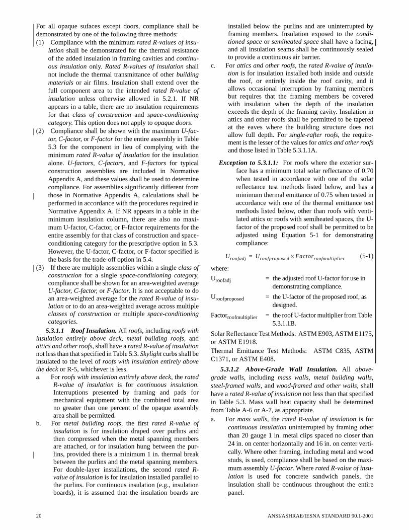
For all opaque sufaces except doors, compliance shall bedemonstrated by one of the following three methods:(1) Compliance with the minimum rated R-values of insu-
lation shall be demonstrated for the thermal resistanceof the added insulation in framing cavities and continu-ous insulation only. Rated R-values of insulation shallnot include the thermal transmittance of other buildingmaterials or air films. Insulation shall extend over thefull component area to the intended rated R-value ofinsulation unless otherwise allowed in 5.2.1. If NRappears in a table, there are no insulation requirementsfor that class of construction and space-conditioningcategory. This option does not apply to opaque doors.
(2) Compliance shall be shown with the maximum U-fac-tor, C-factor, or F-factor for the entire assembly in Table5.3 for the component in lieu of complying with theminimum rated R-value of insulation for the insulationalone. U-factors, C-factors, and F-factors for typicalconstruction assemblies are included in NormativeAppendix A, and these values shall be used to determinecompliance. For assemblies significantly different fromthose in Normative Appendix A, calculations shall beperformed in accordance with the procedures required inNormative Appendix A. If NR appears in a table in theminimum insulation column, there are also no maxi-mum U-factor, C-factor, or F-factor requirements for theentire assembly for that class of construction and space-conditioning category for the prescriptive option in 5.3.However, the U-factor, C-factor, or F-factor specified isthe basis for the trade-off option in 5.4.
(3) If there are multiple assemblies within a single class ofconstruction for a single space-conditioning category,compliance shall be shown for an area-weighted averageU-factor, C-factor, or F-factor. It is not acceptable to doan area-weighted average for the rated R-value of insu-lation or to do an area-weighted average across multipleclasses of construction or multiple space-conditioningcategories.
5.3.1.1 Roof Insulation. All roofs, including roofs withinsulation entirely above deck, metal building roofs, andattics and other roofs, shall have a rated R-value of insulationnot less than that specified in Table 5.3. Skylight curbs shall beinsulated to the level of roofs with insulation entirely abovethe deck or R-5, whichever is less.a. For roofs with insulation entirely above deck, the rated
R-value of insulation is for continuous insulation.Interruptions presented by framing and pads formechanical equipment with the combined total areano greater than one percent of the opaque assemblyarea shall be permitted.
b. For metal building roofs, the first rated R-value ofinsulation is for insulation draped over purlins andthen compressed when the metal spanning membersare attached, or for insulation hung between the pur-lins, provided there is a minimum 1 in. thermal breakbetween the purlins and the metal spanning members.For double-layer installations, the second rated R-value of insulation is for insulation installed parallel tothe purlins. For continuous insulation (e.g., insulationboards), it is assumed that the insulation boards are
20
installed below the purlins and are uninterrupted byframing members. Insulation exposed to the condi-tioned space or semiheated space shall have a facing,and all insulation seams shall be continuously sealedto provide a continuous air barrier.
c. For attics and other roofs, the rated R-value of insula-tion is for insulation installed both inside and outsidethe roof, or entirely inside the roof cavity, and itallows occasional interruption by framing membersbut requires that the framing members be coveredwith insulation when the depth of the insulationexceeds the depth of the framing cavity. Insulation inattics and other roofs shall be permitted to be taperedat the eaves where the building structure does notallow full depth. For single-rafter roofs, the require-ment is the lesser of the values for attics and other roofsand those listed in Table 5.3.1.1A.
Exception to 5.3.1.1: For roofs where the exterior sur-face has a minimum total solar reflectance of 0.70when tested in accordance with one of the solarreflectance test methods listed below, and has aminimum thermal emittance of 0.75 when tested inaccordance with one of the thermal emittance testmethods listed below, other than roofs with venti-lated attics or roofs with semiheated spaces, the U-factor of the proposed roof shall be permitted to beadjusted using Equation 5-1 for demonstratingcompliance:
(5-1)
where:
Uroofadj = the adjusted roof U-factor for use in demonstrating compliance.
Uroofproposed = the U-factor of the proposed roof, as designed.
Factorroofmultiplier = the roof U-factor multiplier from Table 5.3.1.1B.
Solar Reflectance Test Methods: ASTM E903, ASTM E1175,or ASTM E1918. Thermal Emittance Test Methods: ASTM C835, ASTMC1371, or ASTM E408.
5.3.1.2 Above-Grade Wall Insulation. All above-grade walls, including mass walls, metal building walls,steel-framed walls, and wood-framed and other walls, shallhave a rated R-value of insulation not less than that specifiedin Table 5.3. Mass wall heat capacity shall be determinedfrom Table A-6 or A-7, as appropriate.a. For mass walls, the rated R-value of insulation is for
continuous insulation uninterrupted by framing otherthan 20 gauge 1 in. metal clips spaced no closer than24 in. on center horizontally and 16 in. on center verti-cally. Where other framing, including metal and woodstuds, is used, compliance shall be based on the maxi-mum assembly U-factor. Where rated R-value of insu-lation is used for concrete sandwich panels, theinsulation shall be continuous throughout the entirepanel.
Uroofadj Uroofproposed Factorroofmultiplier×=
ANSI/ASHRAE/IESNA STANDARD 90.1-2001

Exception to 5.3.1.2a: Alternatively, for mass walls,where the requirement in the table is for a maxi-mum assembly U-0.151 followed by an asteriskonly, ASTM C90 concrete block walls, ungroutedor partially grouted at 32 in. or less on center verti-cally and 48 in. or less on center horizontally, shallhave ungrouted cores filled with material having amaximum thermal conductivity of 0.44 Btu·in./h·ft2·°F. Other mass walls with integral insulationshall meet the criteria when their U-factors areequal to or less than those for the appropriate thick-ness and density in the “Partly Grouted Cells Insu-lated” column of Table A-7.
b. For metal building walls, the first rated R-Value ofinsulation is for insulation compressed between metalwall panels and the steel structure. For double-layerinstallations, the second rated R-value of insulation isfor insulation installed from the inside, covering thegirts. For continuous insulation (e.g., insulationboards) it is assumed that the insulation boards areinstalled on the inside of the girts and uninterrupted bythe framing members. Insulation exposed to the condi-tioned space or semiheated space shall have a facing,and all insulation seams shall be continuously sealedto provide a continuous air barrier.
c. For steel-framed walls, the first rated R-value of insu-lation is for uncompressed insulation installed in thecavity between steel studs. It is acceptable for thisinsulation to also be continuous insulation uninter-rupted by framing. If there are two values, the secondrated R-value of insulation is for continuous insula-tion uninterrupted by framing, etc., to be installed inaddition to the first insulation. Opaque mullions inspandrel glass shall be covered with insulation com-plying with the steel-framed wall requirements.
TABLE 5.3.1.1ASingle Rafter Roofs
Minimum Insulation R-Value or Maximum Assembly U-Factor
Wood Rafter Depth, d (actual)
HDD65 d ≤ 8 in. 8 < d ≤ 10 in. 10 < d ≤ 12 in.
0-12,600 R-19U-0.055
R-30U-0.036
R-38 U-0.028
>12,600 R-21U-0.052
R-30U-0.036
R-38U-0.028
TABLE 5.3.1.1BRoof U-Factor Multipliers for Exception to 5.3.1.1
HDD65 Roof U-Factor Multiplier
0-900 0.77
901-1800 0.83
1801-2700 0.85
2701-3600 0.86
>3600 1.00
ANSI/ASHRAE/IESNA STANDARD 90.1-2001
d. For wood-framed and other walls, the first rated R-value of insulation is for uncompressed insulationinstalled in the cavity between wood studs. It isacceptable for this insulation to also be continuousinsulation uninterrupted by framing. If there are twovalues, the second rated R-value of insulation is forcontinuous insulation uninterrupted by framing, etc.,to be installed in addition to the first insulation.
When a wall consists of both above-grade and below-grade portions, the entire wall for that story shall be insulatedon either the exterior or the interior or be integral. If insulatedon the interior, the wall shall be insulated to the above-gradewall requirements. If insulated on the exterior or integral, thebelow-grade wall portion shall be insulated to the below-grade wall requirements, and the above-grade wall portionshall be insulated to the above-grade wall requirements.
5.3.1.3 Below-Grade Wall Insulation. Below-gradewalls shall have a rated R-value of insulation not less than thatspecified in Table 5.3. For below-grade walls, the rated R-value of insulation is for continuous insulation uninterruptedby framing. Where framing, including metal and wood studs,is used, compliance shall be based on the maximum assemblyC-factor.
5.3.1.4 Floor Insulation. All floors, including massfloors, steel joist floors, and wood-framed and other floors,shall have a rated R-value of insulation not less than that spec-ified in Table 5.3.a. For mass floors, the rated R-value of insulation is for
continuous insulation uninterrupted by framing.Where framing, including metal and wood joists, isused, compliance shall be based on the maximumassembly U-factor rather than the minimum rated R-value of insulation. For waffle-slab floors, the floorshall be insulated either on the interior above the slabor on all exposed surfaces of the waffle. For floorswith beams that extend below the floor slab, the floorshall be insulated either on the interior above the slabor on the exposed floor and all exposed surfaces of thebeams that extend 24 in. and less below the exposedfloor.
b. For steel joist floors, the first rated R-value of insula-tion is for uncompressed insulation installed in thecavity between steel joists or for spray-on insulation.It is acceptable for this insulation to also be continu-ous insulation uninterrupted by framing. All continu-ous insulation shall be installed either on the interiorabove the floor structure or below a framing cavitycompletely filled with insulation.
c. For wood-framed and other floors, the first rated R-value of insulation is for uncompressed insulationinstalled in the cavity between wood joists. It isacceptable for this insulation to also be continuousinsulation uninterrupted by framing. All continuousinsulation shall be installed either on the interiorabove the floor structure or below a framing cavitycompletely filled with insulation.
5.3.1.5 Slab-on-Grade Floor Insulation. All slab-on-grade floors, including heated slab-on-grade floors and
21

unheated slab-on-grade floors, shall have a rated R-value ofinsulation not less than that specified in Table 5.3 and shall beinstalled around the perimeter of the slab-on-grade floor tothe distance specified. Perimeter insulation installed insidethe foundation wall shall extend downward from the top of theslab a minimum of the distance specified or to the top of thefooting, whichever is less. Perimeter insulation installed out-side the foundation wall shall extend from the top of the slab,or downward to at least the bottom of the slab and then hori-zontally to a minimum of the distance specified. In all cli-mates, the horizontal insulation extending outside of thefoundation shall be covered by pavement or by soil a mini-mum of 10 in. thick.
Exception to 5.3.1.5: For a monolithic slab-on-gradefloor, the insulation shall extend from the top of theslab-on-grade to the bottom of the footing.
5.3.1.6 Opaque Doors. All opaque doors, includingswinging doors and non-swinging doors, shall have a U-fac-tor not greater than that specified in Table 5.3.
5.3.2 Fenestration. Compliance with U-factors and solarheat gain coefficient (SHGC) shall be demonstrated for theoverall fenestration product, including glass, sash, and frame,as provided in 5.2.2. Gross wall areas and gross roof areasshall be calculated separately for each space-conditioningcategory for the purposes of determining compliance.
Exception to 5.3.2: Alternatively, if there are multipleassemblies within a single class of construction fora single space-conditioning category, complianceshall be based on an area-weighted average U-fac-tor or SHGC. It is not acceptable to do an area-weighted average across multiple classes of con-struction or multiple space-conditioning categories.
5.3.2.1 Fenestration Area. The total vertical fenestra-tion area, including both fixed vertical fenestration and oper-able vertical fenestration, shall be less than 50% of the grosswall area. The total skylight area, including glass skylights,plastic skylights with a curb, and all skylights without a curb,shall be less than 5% of the gross roof area.
Exception to 5.3.2.1: Vertical fenestration complyingwith Exception (c) to 5.3.2.3.
5.3.2.2 Fenestration U-Factor. Fenestration, includingfixed vertical fenestration, operable vertical fenestration,glass skylights with a curb, plastic skylights with a curb, andall skylights without a curb shall have a U-factor not greaterthan that specified in Table 5.3 for the appropriate fenestra-tion area. U-factor for fenestration shall be determined inaccordance with 5.2.2.
Exception to 5.3.2.2: Vertical fenestration complyingwith Exception (c) to 5.3.2.3 shall have a U-factornot greater than that specified for 40% of the grosswall area.
5.3.2.3 Fenestration Solar Heat Gain Coefficient(SHGC). Vertical fenestration shall have an SHGC notgreater than that specified for “all” orientations in Table 5.3for the appropriate total vertical fenestration area. Skylights,including glass skylights with a curb, plastic skylights with acurb, and all skylights without a curb, shall have an SHGC not
22
greater than that specified for “all” orientations in Table 5.3for the appropriate total skylight area. SHGC for fenestrationshall be determined in accordance with 5.2.2. There are noSHGC requirements for semiheated spaces or for buildings inclimates with greater than 10800 HDD65.
Exceptions to 5.3.2.3:(a) Alternatively, in latitudes greater than 10 degrees, the
SHGC for north-oriented vertical fenestration shall becalculated separately and shall not be greater than thatspecified in Table 5.3 for north-oriented fenestration.When this exception is used, the fenestration areaused in selecting the criteria shall be calculated sepa-rately for north-oriented and all other-oriented fenes-tration.
Note to adopting authority: If the project is in the south-ern hemisphere, change north to south.
(b) For demonstrating compliance for vertical fenestra-tion only, the SHGC in the proposed building shall bereduced by using the multipliers in Table 5.3.2.3 foreach fenestration product shaded by permanent pro-jections that will last as long as the building itself.
(c) Vertical fenestration that is located on the street sideof the street-level story only, provided that 1. the street side of the street-level story does not
exceed 20 ft in height,2. the fenestration has a continuous overhang with a
weighted average projection factor greater than0.5, and
3. the fenestration area for the street side of thestreet-level story is less than 75% of the grosswall area for the street side of the street-levelstory.
When this exception is utilized, separate calculationsshall be performed for these sections of the buildingenvelope, and these values shall not be averaged withany others for compliance purposes. No credit shall begiven here or elsewhere in the building for not fullyutilizing the fenestration area allowed. This exceptiondoes not apply to the building envelope trade-off optionin 5.4 or the energy cost budget option in 11.
TABLE 5.3.2.3SHGC Multipliers for Permanent Projections
Projection Factor
SHGC Multiplier (All Other Orientations)
SHGC Multiplier (North-Oriented)
0 - 0.10 1.00 1.00
<0.10 - 0.20 0.91 0.95
<0.20 - 0.30 0.82 0.91
<0.30 - 0.40 0.74 0.87
<0.40 - 0.50 0.67 0.84
<0.50 - 0.60 0.61 0.81
<0.60 - 0.70 0.56 0.78
<0.70 - 0.80 0.51 0.76
<0.80 - 0.90 0.47 0.75
<0.90 - 1.00 0.44 0.73
ANSI/ASHRAE/IESNA STANDARD 90.1-2001

5.3.2.4 Visible Light Transmittance (VLT). There areno minimum visible light transmittance criteria in the Pre-scriptive Building Envelope Option; however, there are min-imum criteria in the Building Envelope Trade-Off Option.
5.4 Building Envelope Trade-Off OptionThe building envelope complies with the standard if the
proposed building satisfies the provisions of 5.1 and 5.2 andthe envelope performance factor of the proposed building isless than or equal to the envelope performance factor of thebudget building. The envelope performance factor considersonly the building envelope components. Schedules of opera-tion, lighting power, equipment power, occupant density, andmechanical systems shall be the same for both the proposedbuilding and the budget building. Envelope performancefactor shall be calculated using the procedures of NormativeAppendix C.
5.5 Mandatory Provisions
5.5.1 Insulation General
5.5.1.1 Insulation Installation. Insulation materialsshall be installed in accordance with manufacturer’s recom-mendations and in such a manner as to achieve rated R-valueof insulation.
Open-blown or poured loose-fill insulation shall not beused in attic roof spaces when the slope of the ceiling is morethan three in twelve. When eave vents are installed, baffling ofthe vent openings shall be provided to deflect the incoming airabove the surface of the insulation.
Exception to 5.5.1.1: Where metal building roof andmetal building wall insulation is compressedbetween the roof or wall skin and the structure.
5.5.1.2 Substantial Contact. Insulation shall beinstalled in a permanent manner in substantial contact withthe inside surface in accordance with manufacturer’s recom-mendations for the framing system used. Flexible batt insula-tion installed in floor cavities shall be supported in apermanent manner by supports no greater than 24 in. on cen-ter.
Exception to 5.5.1.2: Insulation materials that rely on air-spaces adjacent to reflective surfaces for their ratedperformance.
5.5.1.3 Recessed Equipment. Lighting fixtures; heat-ing, ventilating, and air-conditioning equipment, includingwall heaters, ducts, and plenums; and other equipment shallnot be recessed in such a manner as to affect the insulationthickness unless:a. the total combined area affected (including necessary
clearances) is less than one percent of the opaque areaof the assembly, or
b. the entire roof, wall, or floor is covered with insulationto the full depth required, or
c. the effects of reduced insulation are included in calcu-lations using an area-weighted average method andcompressed insulation values obtained from Table A-24.
ANSI/ASHRAE/IESNA STANDARD 90.1-2001
In all cases, air leakage through or around the recessedequipment to the conditioned space shall be limited in accor-dance with 5.2.3.1.
5.5.1.4 Location of Roof Insulation. The roof insula-tion shall not be installed on a suspended ceiling with remov-able ceiling panels.
5.5.1.5 Insulation Protection. Exterior insulation shallbe covered with a protective material to prevent damage fromsunlight, moisture, landscaping operations, equipment main-tenance, and wind. In attics and mechanical rooms, a way toaccess equipment that prevents damaging or compressing theinsulation shall be provided. Foundation vents shall not inter-fere with the insulation.
Insulation materials in ground contact shall have a waterabsorption rate no greater than 0.3% when tested in accor-dance with ASTM C272.
5.5.2 Fenestration and Doors. Product samples used fordetermining fenestration performance shall be productionline units or representative of units as purchased by the con-sumer or contractor.
5.5.2.1 U-Factor. U-factors shall be determined inaccordance with NFRC 100. U-factors for skylights shall bedetermined for a slope of 20° above the horizontal. U-factorshall be determined by a laboratory accredited by a nationallyrecognized accreditation organization, such as the NationalFenestration Rating Council, and shall be labeled and certi-fied by the manufacturer.
Exceptions to 5.5.2.1: (a) U-factors from A8.1 shall be an acceptable alternate
for determining compliance with the U-factor criteriafor skylights. Where credit is being taken for a low-emissivity coating, the emissivity of the coating shallbe determined in accordance with NFRC 301. Emis-sivity shall be verified and certified by the manufac-turer.
(b) U-factors from A8.2 shall be an acceptable alternatefor determining compliance with the U-factor criteriafor vertical fenestration.
(c) U-factors from A7 shall be an acceptable alternate fordetermining compliance with the U-factor criteria foropaque doors.
(d) For garage doors, ANSI/DASMA 105 shall be anacceptable alternate for determining U-factors.
5.5.2.2 Solar Heat Gain Coefficient. SHGC for theoverall fenestration area shall be determined in accordancewith NFRC 200. SHGC shall be determined by a laboratoryaccredited by a nationally recognized accreditation organiza-tion, such as the National Fenestration Rating Council, andshall be labeled and certified by the manufacturer.
Exceptions to 5.5.2.2:(a) Shading coefficient of the center of glass multiplied by
0.86 shall be an acceptable alternate for determiningcompliance with the SHGC requirements for the over-all fenestration area. Shading coefficient shall bedetermined using a spectral data file determined inaccordance with NFRC 300. Shading coefficient shallbe verified and certified by the manufacturer.
23

(b) SHGC of the center of glass shall be an acceptablealternate for determining compliance with the SHGCrequirements for the overall fenestration area. SHGCshall be determined using a spectral data file deter-mined in accordance with NFRC 300. SHGC shall beverified and certified by the manufacturer.
(c) SHGC from A8.1 shall be an acceptable alternate fordetermining compliance with the SHGC criteria forskylights. Where credit is being taken for a low-emis-sivity coating, the emissivity of the coating shall bedetermined in accordance with NFRC 301. Emissivityshall be verified and certified by the manufacturer.
(d) SHGC from A8.2 shall be an acceptable alternate fordetermining compliance with the SHGC criteria forvertical fenestration.
5.5.2.3 Visible Light Transmittance. When 5.4 isused, visible light transmittance shall be determined in accor-dance with NFRC 200. Visible light transmittance shall beverified and certified by the manufacturer.
5.5.3 Air Leakage5.5.3.1 Building Envelope Sealing. The following
areas of the building envelope shall be sealed, caulked, gas-keted, or weather-stripped to minimize air leakagea. joints around fenestration and door framesb. junctions between walls and foundations, between walls
at building corners, between walls and structural floorsor roofs, and between walls and roof or wall panels
c. openings at penetrations of utility services throughroofs, walls, and floors
d. site-built fenestration and doorse. building assemblies used as ducts or plenumsf. joints, seams, and penetrations of vapor retarders g. all other openings in the building envelope.
Outside air intakes, exhaust outlets, relief outlets, stairshaft, elevator shaft smoke relief openings, and othersimilar elements shall also comply with 6.2.3.2.4 and6.2.3.3.
5.5.3.2 Fenestration and Doors. Air leakage for fenes-tration and doors shall be determined in accordance withNFRC 400. Air leakage shall be determined by a laboratoryaccredited by a nationally recognized accreditation organiza-
24
tion, such as the National Fenestration Rating Council, andshall be labeled and certified by the manufacturer. Air leakageshall not exceed 1.0 cfm/ft2 for glazed swinging entrancedoors and for revolving doors and 0.4 cfm/ft2 for all otherproducts.
Exceptions to 5.5.3.2:
(a) Field-fabricated fenestration and doors.
(b) For garage doors, air leakage determined by test atstandard test conditions in accordance with ANSI/DASMA 105 shall be an acceptable alternate for com-pliance with air leakage requirements.
5.5.3.3 Loading Dock Weatherseals. In climates thatexceed 3600 HDD65, cargo doors and loading dock doorsshall be equipped with weatherseals to restrict infiltrationwhen vehicles are parked in the doorway.
5.5.3.4 Vestibules. A door that separates conditionedspace from the exterior shall be protected with an enclosedvestibule, with all doors opening into and out of the vestibuleequipped with self-closing devices. Vestibules shall bedesigned so that in passing through the vestibule it is not nec-essary for the interior and exterior doors to open at the sametime. Interior and exterior doors shall have a minimum dis-tance between them of not less than 7 ft when in the closedposition.
Exceptions to 5.5.3.4:
(a) Doors in buildings in climates that have less than1800 HDD65
(b) Doors in buildings less than four stories above grade
(c) Doors not intended to be used as a building entrancedoor, such as mechanical or electrical equipmentrooms
(d) Doors opening directly from a dwelling unit
(e) Doors that open directly from a space less than 3000 ft2
in area
(f) Doors in building entrances with revolving doors
(g) Doors used primarily to facilitate vehicular movementor material handling and adjacent personnel doors.
ANSI/ASHRAE/IESNA STANDARD 90.1-2001

6. HEATING, VENTILATING, AND AIR CONDITIONING
6.1 General6.1.1 HVAC Scope. All mechanical equipment and sys-
tems serving the building heating, cooling, or ventilatingneeds shall meet the requirements of Section 6.
6.1.2 Compliance. Compliance with Section 6 shall beachieved by meeting all requirements for eithera. 6.1.3 (Simplified Approach Option for HVAC Sys-
tems), orb. 6.2 (Mandatory Provisions) and 6.3 (Prescriptive Path),
orc. 6.2 (Mandatory Provisions) in conjunction with Sec-
tion 11 (Energy Cost Budget Method).6.1.3 Simplified Approach Option for HVAC Systems.
Each HVAC system in buildings two stories or less in heightand with less than 25,000 ft2 gross floor area that meet criteriaa. through o. given below shall be considered in compliancewith the requirements of Section 6 (Heating, Ventilating, andAir Conditioning).a. The system serves a single HVAC zone.b. Cooling (if any) shall be provided by a unitary pack-
aged or split-system air conditioner that is either air-cooled or evaporatively cooled with efficiency meet-ing the requirements shown in Table 6.2.1A (air con-ditioners), Table 6.2.1B (heat pumps), or Table 6.2.1D(packaged terminal and room air conditioners and heatpumps) for the applicable equipment category.
c. The system shall have an air economizer where indi-cated in Table 6.3.1, with controls as indicated in
ANSI/ASHRAE/IESNA STANDARD 90.1-2001
Tables 6.3.1.1.3A and 6.3.1.1.3B and with either baro-metric or powered relief sized to prevent overpressur-ization of the building. Where the cooling efficiencymeets or exceeds the efficiency requirement in Table6.1.3, no economizer is required. Outside air dampersfor economizer use shall be provided with blade andjamb seals.
d. Heating (if any) shall be provided by a unitary pack-aged or split-system heat pump that meets the applica-ble efficiency requirements shown in Table 6.2.1B(heat pumps) or Table 6.2.1D (packaged terminal androom air conditioners and heat pumps), a fuel-firedfurnace that meets the applicable efficiency require-ments shown in Table 6.2.1E (furnaces, duct furnaces,and unit heaters), an electric resistance heater, or abaseboard system connected to a boiler that meets theapplicable efficiency requirements shown in Table6.2.1F (boilers).
e. The outside air quantity supplied by the system shallbe less than or equal to 3000 cfm and less than 70% ofthe supply air quantity at minimum outside air designconditions unless an energy recovery ventilation sys-tem is provided in accordance with the requirementsin 6.3.6.
f. The system shall be controlled by a manual change-over or dual set-point thermostat.
g. If a heat pump equipped with auxiliary internal elec-tric resistance heaters is installed, controls shall beprovided that prevent supplemental heater operationwhen the heating load can be met by the heat pump
TABLE 6.1.3Eliminate Required Economizer by Increasing Cooling Efficiency
Unitary Systems with Heat Pump Heating
System Size Mandatory Cooling Degree-Days (CDD50)
(kBtu/h) Minimum EER 0 - 3600 3601 - 5400 5401 - 7200 7201 - 9000 9001 - 10800
Minimum Cooling Efficiency Required (EER)a TestProcedurec
≥ 65 and < 135 10.1 N/Ab 12.1 11.6 11.1 10.7 ARI 210/240
≥ 135 and ≤ 240 9.3 N/Ab 11.3 10.8 10.4 9.9 ARI 340/360
> 240 and < 760 9.0 N/Ab 10.9 10.5 10.0 9.6
Other Unitary Systems
System Size Mandatory Cooling Degree-Days (CDD50)
(kBtu/h) Minimum EER 0 ñ 3600 3601 - 5400 5401 - 7200 7201 - 9000 9001 - 10800
Minimum Cooling Efficiency Required (EER)aTest
Procedurec
≥ 65 and < 135 10.3 N/Ab 12.5 12.0 11.5 11.0 ARI 210/240
≥ 135 and ≤ 240 9.7 N/Ab 11.5 11.1 10.6 10.1 ARI 340/360
> 240 and < 760 9.5 N/Ab 11.2 10.7 10.3 9.9a Each EER shown below should be reduced by 0.2 for units with a heating section other than electric resistance heat.b Elimination of required economizer is not allowed.c Section 12 contains complete specification of the referenced test procedure, including the referenced year version of the test procedure
25

alone during both steady-state operation and setbackrecovery. Supplemental heater operation is permittedduring outdoor coil defrost cycles.
h. The system controls shall not permit reheat or anyother form of simultaneous heating and cooling forhumidity control.
i. Systems serving spaces other than hotel/motel guestrooms, and other than those requiring continuous oper-ation, that have a cooling or heating capacity greaterthan 65,000 Btu/h and a supply fan motor powergreater than 3/4 hp shall be provided with a timeclockthat (1) can start and stop the system under differentschedules for seven different day-types per week, (2) iscapable of retaining programming and time settingduring a loss of power for a period of at least 10 hours,(3) includes an accessible manual override that allowstemporary operation of the system for up to two hours,(4) is capable of temperature setback down to 55°Fduring off hours, and (5) is capable of temperaturesetup to 90°F during off hours.
j. Except for piping within manufacturer’s units, HVACpiping shall be insulated in accordance with Table6.2.4.1.3. Insulation exposed to weather shall be suit-able for outdoor service, e.g., protected by aluminum,sheet metal, painted canvas, or plastic cover. Cellularfoam insulation shall be protected as above or paintedwith a coating that is water retardant and providesshielding from solar radiation.
k. Ductwork and plenums shall be insulated in accor-dance with Tables 6.2.4.1.2A and 6.2.4.1.2B and shallbe sealed in accordance with Table 6.2.4.2.1A.
l. Construction documents shall require a ducted systemto be air balanced in accordance with industryaccepted procedures.
m. Where separate heating and cooling equipment servethe same temperature zone, thermostats shall be inter-locked to prevent simultaneous heating and cooling.
n. Exhausts with a design capacity of over 300 cfm onsystems that do not operate continuously shall beequipped with gravity or motorized dampers that willautomatically shut when the systems are not in use.
o. Systems with a design supply air capacity greater than10,000 cfm shall have optimum start controls.
6.2 Mandatory Provisions6.2.1 Mechanical Equipment Efficiency. Equipment
shown in Tables 6.2.1A through 6.2.1G shall have a minimumperformance at the specified rating conditions when tested inaccordance with the specified test procedure. Omission ofminimum performance requirements for equipment not listedin Tables 6.2.1A through 6.2.1G does not preclude use of suchequipment. Equipment not listed in Tables 6.2.1A through6.2.1G has no minimum performance requirements. Wheremultiple rating conditions or performance requirements areprovided, the equipment shall satisfy all stated requirements,unless otherwise exempted by footnotes in the table. However,equipment covered under the Federal Energy Policy Act of1992 (EPACT) shall have no minimum efficiency require-ments for operation at minimum capacity or other than stan-dard rating conditions. Equipment used to provide waterheating functions as part of a combination system shall satisfyall stated requirements for the appropriate space heating orcooling category.
26
If a certification program exists for a product covered inTables 6.2.1A through 6.2.1G, and it includes provisions forverification and challenge of equipment efficiency ratings,then the product shall be either listed in the certificationprogram or, alternatively, the ratings shall be verified by anindependent laboratory test report. If no certification programexists for a product covered in Tables 6.2.1A through 6.2.1G,the equipment efficiency ratings shall be supported by datafurnished by the manufacturer. Where components such asindoor or outdoor coils from different manufacturers are used,the system designer shall specify component efficiencieswhose combined efficiency meets the minimum equipmentefficiency requirements in 6.2.1.
Tables 6.2.1A through 6.2.1G contain the minimum effi-ciency requirements for equipment covered by this section ofthe standard. The tables are organized to cover the followingtypes of equipment:
Table 6.2.1A Air Conditioners and Condensing Units
Table 6.2.1B Heat Pumps
Table 6.2.1C Water Chilling Packages
Table 6.2.1D Packaged Terminal and Room AirConditioners and Heat Pumps
Table 6.2.1E Furnaces, Duct Furnaces, and Unit Heaters
Table 6.2.1F Boilers
Table 6.2.1G Heat Rejection Equipment
Gas-fired and oil-fired forced air furnaces with inputratings ≥225,000 Btu/h shall also have an intermittent ignitionor interrupted device (IID) and have either power venting or aflue damper. A vent damper is an acceptable alternative to aflue damper for furnaces where combustion air is drawn fromthe conditioned space. All furnaces with input ratings≥225,000 Btu/h, including electric furnaces, that are notlocated within the conditioned space shall have jacket lossesnot exceeding 0.75% of the input rating.
Exception to 6.2.1: Water-cooled centrifugal water-chill-ing packages that are not designed for operation atARI Standard 550/590 test conditions (and thus can-not be tested to meet the requirements of Table6.2.1C) of 44°F leaving chilled water temperatureand 85°F entering condenser water temperature shallhave a minimum full-load COP as shown in Tables6.2.1H, I, and J and a minimum NPLV rating asshown in Tables 6.2.1 K, L, and M. The table valuesare only applicable over the following full-loaddesign ranges:
Leaving Chiller Water Temperature: 40°F to 48°FEntering Condenser Water Temperature: 75°F to 85°FCondensing Water Temperature Rise: 5°F to 15°F
Chillers designed to operate outside of these ranges arenot covered by this standard.
Non-standard part-load value (NPLV) is defined as asingle-number part-load efficiency figure of merit for chillersreferenced to conditions other than IPLV conditions.
6.2.2 Load Calculations. Heating and cooling systemdesign loads for the purpose of sizing systems and equipmentshall be determined in accordance with generally acceptedengineering standards and handbooks acceptable to the adopt-ing authority (for example, ASHRAE Handbookó Fundamen-tals).
ANSI/ASHRAE/IESNA STANDARD 90.1-2001

TABLE 6.2.1A Electrically Operated Unitary Air Conditioners and Condensing Unitsó
Minimum Efficiency Requirements
Equipment Type Size Category Heating Section TypeSub-Category or Rating Condition
Minimum Efficiencyb Test Procedurea
Air Conditioners, Air Cooled
<65,000 Btu/hc All Split System 10.0 SEER ARI 210/240
Single Package 9.7 SEER
≥65,000 Btu/h and<135,000 Btu/h
Electric Resistance(or None)
Split System andSingle Package
10.3 EER
All other Split System andSingle Package
10.1 EER
≥135,000 Btu/h and<240,000 Btu/h
Electric Resistance (or None)
Split System andSingle Package
9.7 EER ARI 340/360
All other Split System andSingle Package
9.5 EER
≥240,000 Btu/h and<760,000 Btu/h
Electric Resistance(or None)
Split System andSingle Package
9.5 EER9.7 IPLV
All other Split System andSingle Package
9.3 EER9.5 IPLV
≥760,000 Btu/h Electric Resistance (or None)
Split System andSingle Package
9.2 EER9.4 IPLV
All other Split System andSingle Package
9.0 EER9.2 IPLV
Air Conditioners, Water and Evaporatively Cooled
<65,000 Btu/h All Split System andSingle Package
12.1 EER ARI 210/240
≥65,000 Btu/h and<135,000 Btu/h
Electric Resistance(or None)
Split System andSingle Package
11.5 EER
All other Split System andSingle Package
11.3 EER
≥135,000 Btu/h and<240,000 Btu/h
Electric Resistance(or None)
Split System andSingle Package
11.0 EER ARI 340/360
All other Split System andSingle Package
10.8 EER
≥240,000 Btu/h Electric Resistance(or None)
Split System andSingle Package
11.0 EER10.3 IPLV
All other Split System andSingle Package
10.8 EER10.1 IPLV
Condensing Units, Air Cooled
≥135,000 Btu/h – 10.1 EER11.2 IPLV
ARI 365
Condensing Units, Water or Evaporatively Cooled
≥135,000 Btu/h – 13.1 EER13.1 IPLV
a Section 12 contains a complete specification of the referenced test procedure, including the referenced year version of the test procedure.b IPLVs are only applicable to equipment with capacity modulation.c Single-phase, air-cooled air-conditioners < 65,000 Btu/h are regulated by NAECA. SEER values are those set by NAECA.
ANSI/ASHRAE/IESNA STANDARD 90.1-2001 27

TABLE 6.2.1BElectrically Operated Unitary and Applied Heat Pumpsó Minimum Efficiency Requirements
Equipment Type Size Category Heating Section TypeSub-Category or Rating Condition
Minimum Efficiencyb Test Procedurea
Air Cooled (Cooling Mode)
<65,000 Btu/hc All Split System 10.0 SEER ARI 210/240
Single Package 9.7 SEER
≥65,000 Btu/h and<135,000 Btu/h
Electric Resistance(or None)
Split System andSingle Package
10.1 EER
All other Split System andSingle Package
9.9 EER
≥135,000 Btu/h and<240,000 Btu/h
Electric Resistance(or None)
Split System andSingle Package
9.3 EER ARI 340/360
All other Split System andSingle Package
9.1 EER
≥240,000 Btu/h Electric Resistance(or None)
Split System andSingle Package
9.0 EER9.2 IPLV
All other Split System andSingle Package
8.8 EER9.0 IPLV
Water-Source (Cooling Mode)
<17,000 Btu/h All 86ºF Entering Water 11.2 EER ISO-13256-1
≥17,000 Btu/h and<135,000 Btu/h
All 86ºF Entering Water 12.0 EER ISO-13256-1
Groundwater-Source (Cooling Mode)
<135,000 Btu/h All 59ºF Entering Water16.2 EER
ISO-13256-1
Ground Source (Cooling Mode)
<135,000 Btu/h All 77ºF Entering Water13.4 EER
ISO-13256-1
Air Cooled (Heating Mode)
<65,000 Btu/hc
(Cooling Capacity)– Split System 6.8 HSPF ARI 210/240
Single Package 6.6 HSPF
≥65,000 Btu/h and<135,000 Btu/h
(Cooling Capacity)
– 47ºF db/43ºF wb Outdoor Air
3.2 COP
17ºF db/15ºF wb Outdoor Air
2.2 COP
≥135,000 Btu/h(Cooling Capacity)
– 47ºF db/43ºF wb Outdoor Air
3.1 COP ARI 340/360
17ºF db/15ºF wb Outdoor Air
2.0 COP
Water-Source (Heating Mode)
<135,000 Btu/h(Cooling Capacity)
– 68ºF Entering Water 4.2 COP ISO-13256-1
Groundwater-Source (Heating Mode)
<135,000 Btu/h(Cooling Capacity)
– 50ºF Entering Water 3.6 COP ISO-13256-1
Ground Source (Heating Mode)
<135,000 Btu/h(Cooling Capacity)
– 32ºF Entering Water 3.1 COP ISO-13256-1
a Section 12 contains a complete specification of the referenced test procedure, including the referenced year version of the test procedure.b IPLVs and Part load rating conditions are only applicable to equipment with capacity modulation.c Single-phase, air-cooled heat pumps < 65,000 Btu/h are regulated by NAECA. SEER and HSPF values are those set by NAECA
28 ANSI/ASHRAE/IESNA STANDARD 90.1-2001
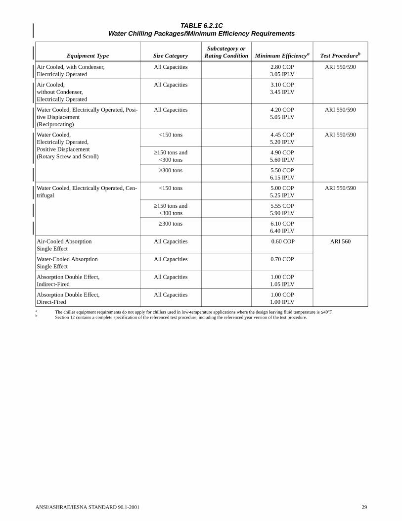
TABLE 6.2.1CWater Chilling PackagesñMinimum Efficiency Requirements
Equipment Type Size CategorySubcategory or
Rating Condition Minimum Efficiencya Test Procedureb
Air Cooled, with Condenser,Electrically Operated
All Capacities 2.80 COP3.05 IPLV
ARI 550/590
Air Cooled,without Condenser,Electrically Operated
All Capacities 3.10 COP3.45 IPLV
Water Cooled, Electrically Operated, Posi-tive Displacement(Reciprocating)
All Capacities 4.20 COP5.05 IPLV
ARI 550/590
Water Cooled,Electrically Operated,Positive Displacement(Rotary Screw and Scroll)
<150 tons 4.45 COP5.20 IPLV
ARI 550/590
≥150 tons and<300 tons
4.90 COP5.60 IPLV
≥300 tons 5.50 COP6.15 IPLV
Water Cooled, Electrically Operated, Cen-trifugal
<150 tons 5.00 COP5.25 IPLV
ARI 550/590
≥150 tons and<300 tons
5.55 COP5.90 IPLV
≥300 tons 6.10 COP6.40 IPLV
Air-Cooled AbsorptionSingle Effect
All Capacities 0.60 COP ARI 560
Water-Cooled AbsorptionSingle Effect
All Capacities 0.70 COP
Absorption Double Effect,Indirect-Fired
All Capacities 1.00 COP1.05 IPLV
Absorption Double Effect,Direct-Fired
All Capacities 1.00 COP1.00 IPLV
a The chiller equipment requirements do not apply for chillers used in low-temperature applications where the design leaving fluid temperature is ≤40ºF.b Section 12 contains a complete specification of the referenced test procedure, including the referenced year version of the test procedure.
ANSI/ASHRAE/IESNA STANDARD 90.1-2001 29

TABLE 6.2.1DElectrically Operated Packaged Terminal Air Conditioners, Packaged Terminal Heat Pumps, Room
Air Conditioners, and Room Air Conditioner Heat PumpsñMinimum Efficiency Requirements
Equipment Type Size Category (Input)Subcategory or
Rating Condition Minimum EfficiencyTest
Procedurea
PTAC (Cooling Mode)New Construction
All Capacities 95°F db Outdoor Air
12.5 – (0.213 × Cap/1000)c EER
ARI 310/380
PTAC (Cooling Mode)Replacementsb
All Capacities 95°F db Outdoor Air
10.9 – (0.213 × Cap/1000)c EER
PTHP (Cooling Mode)New Construction
All Capacities 95°F db Outdoor Air
12.3 – (0.213 × Cap/1000)c EER
PTHP (Cooling Mode)Replacementsb
All Capacities 95°F db Outdoor Air
10.8 – (0.213 × Cap/1000)c EER
PTHP (Heating Mode)New Construction
All Capacities 3.2 – (0.026 ×Cap/1000)c COP
PTHP (Heating Mode)Replacementsb
All Capacities 2.9 – (0.026 × Cap/1000)c COP
Room Air Conditioners, with Louvered Sides
<8000 Btu/h 9.7 EER ANSI/AHAM RAC-1≥8000 Btu/h and
<14,000 Btu/h9.8 EER
≥14,000 Btu/h and<20,000 Btu/h
9.7 EER
≥20,000 Btu/h 8.5 EER
Room Air Conditioners, without Louvered Sides
<8000 Btu/h 9.0 EER
≥8000 Btu/h 8.5 EER
Room Air Conditioner Heat Pumps with Lou-vered Sides
<20,000 Btu/h 9.0 EER
≥20,000 Btu/h 8.5 EER
Room Air Conditioner Heat Pumps without Lou-vered Sides
<14,000 Btu/h 8.5 EER
≥14,000 Btu/h 8.0 EER
Room Air Conditioner, Casement Only
All Capacities 8.7 EER
Room Air Conditioner, Casement–Slider
All Capacities 9.5 EER
a Section 12 contains a complete specification of the referenced test procedure, including the referenced year version of the test procedure.b Replacement units must be factory labeled as follows: “MANUFACTURED FOR REPLACEMENT APPLICATIONS ONLY; NOT TO BE INSTALLED IN NEW
CONSTRUCTION PROJECTS.” Replacement efficiencies apply only to units with existing sleeves less than 16 in. high and less than 42 in. wide.c Cap means the rated cooling capacity of the product in Btu/h. If the unit’s capacity is less than 7000 Btu/h, use 7000 Btu/h in the calculation. If the unit’s capacity is greater
than 15,000 Btu/h, use 15,000 Btu/h in the calculation.
30 ANSI/ASHRAE/IESNA STANDARD 90.1-2001

TABLE 6.2.1EWarm Air Furnaces and Combination Warm Air Furnaces/Air-Conditioning Units,
Warm Air Duct Furnaces and Unit Heaters
Equipment TypeSize Category
(Input)Subcategory or
Rating Condition Minimum Efficiencya Test Procedureb
Warm Air Furnace, Gas-Fired
<225,000 Btu/h 78% AFUE or80% Et
dDOE 10 CFR Part 430
or ANSI Z21.47
≥225,000 Btu/h Maximum Capacityd 80% Ecc ANSI Z21.47
Warm Air Furnace, Oil-Fired
<225,000 Btu/h 78% AFUE or80% Et
dDOE 10 CFR Part 430
or UL 727
≥225,000 Btu/h Maximum Capacitye 81% Etf UL 727
Warm Air Duct Furnaces, Gas-Fired
All Capacities Maximum Capacitye 80% Ecg ANSI Z83.9
Warm Air Unit Heaters, Gas-Fired All Capacities Maximum Capacitye 80% Ecg ANSI Z83.8
Warm Air Unit Heaters, Oil-Fired All Capacities Maximum Capacitye 80% Ecg UL 731
a Et = thermal efficiency. See test procedure for detailed discussion.b Section 12 contains a complete specification of the referenced test procedure, including the referenced year version of the test procedure.c Ec = combustion efficiency. Units must also include an IID, have jacket losses not exceeding 0.75% of the input rating, and have either power venting or a flue damper.
A vent damper is an acceptable alternative to a flue damper for those furnaces where combustion air is drawn from the conditioned space.d Combination units not covered by NAECA (3-phase power or cooling capacity greater than or equal to 65,000 Btu/h) may comply with either rating.e Minimum and maximum ratings as provided for and allowed by the unit's controls.f Et = thermal efficiency. Units must also include an IID, have jacket losses not exceeding 0.75% of the input rating, and have either power venting or a flue damper.
A vent damper is an acceptable alternative to a flue damper for those furnaces where combustion air is drawn from the conditioned space.g Ec = combustion efficiency (100% less flue losses). See test procedure for detailed discussion.
TABLE 6.2.1FGas- and Oil-Fired BoilersñMinimum Efficiency Requirements
Equipment TypedSize Category
(Input)Subcategory or
Rating Condition Minimum Efficiencya Test Procedureb
Boilers, Gas-Fired
<300,000 Btu/h Hot Water 80% AFUE DOE 10 CFR Part 430
Steam 75% AFUE
≥300,000 Btu/h and ≤2,500,000 Btu/h
Maximum Capacityc 75% Eta H.I. Htg Boiler Std.
>2,500,000 Btu/hd Hot Water 80% Ec
>2,500,000 Btu/hd Steam 80% Ec
Boilers,Oil-Fired
<300,000 Btu/h 80% AFUE DOE 10 CFR Part 430
≥300,000 Btu/h and ≤2,500,000 Btu/h
Maximum Capacityc 78% Eta H.I. Htg Boiler Std.
>2,500,000 Btu/hd Hot Water 83% Ec
>2,500,000 Btu/hd Steam 83% Ec
Oil-Fired (Residual) ≥300,000 Btu/h and ≤2,500,000 Btu/h
Maximum Capacityc 78% Eta H.I. Htg Boiler Std.
>2,500,000 Btu/hd Hot Water 83% Ec
>2,500,000 Btu/hd Steam 83% Eca Et = thermal efficiency. See reference document for detailed information.b Section 12 contains a complete specification of the referenced test procedure, including the referenced year version of the test procedure.c Minimum and maximum ratings as provided for and allowed by the unit's controls.d These requirements apply to boilers with rated input of 8,000,000 Btu/h or less that are not packaged boilers, and to all packaged boilers. Minimum efficiency requirements for
boilers cover all capacities of packaged boilers.
ANSI/ASHRAE/IESNA STANDARD 90.1-2001 31

TABLE 6.2.1GPerformance Requirements for Heat Rejection Equipment
Equipment Type
Total System Heat Rejection Capacity at Rated Conditions
Subcategory or Rating Condition
Performance Requireda b Test Procedurec
Propeller or Axial Fan Cooling Towers
All 95°F Entering Water85°F Leaving Water
75°F wb Outdoor Air
≥38.2 gpm/hp CTI ATC-105 and CTI STD-201
Centrifugal Fan Cooling Towers
All 95°F Entering Water85°F Leaving Water75°F wb Outdoor Air
≥20.0 gpm/hp CTI ATC-105 and CTI STD-201
Air-Cooled Condensers All 125°F Condensing Temperature R-22 Test Fluid
190°F Entering Gas Temperature15°F Subcooling 95°F Entering db
≥176,000 Btu/h·hp ARI 460
a For purposes of this table, cooling tower performance is defined as the maximum flow rating of the tower divided by the fan nameplate rated motor power.b For purposes of this table, air-cooled condenser performance is defined as the heat rejected from the refrigerant divided by the fan nameplate rated motor power.c Section 12 contains a complete specification of the referenced test procedure, including the referenced year version of the test procedure.
32 ANSI/ASHRAE/IESNA STANDARD 90.1-2001

TABLE 6.2.1HCOPs for Centrifugal Chillers < 150 Tons
COPstd = 5.0
Condenser Flow Rate
2 gpm/ton 2.5 gpm/ton 3 gpm/ton 4 gpm/ton 5 gpm/ton 6 gpm/ton
Leaving Chilled Water
Temperature (� F)
Entering Condenser Water Temperature (� F)
LIFTa
(� F) Required COP
46 75 29 5.58 5.83 6.03 6.32 6.54 6.70
45 75 30 5.50 5.74 5.92 6.19 6.38 6.53
44 75 31 5.42 5.65 5.82 6.07 6.24 6.37
43 75 32 5.35 5.57 5.72 5.95 6.11 6.23
42 75 33 5.27 5.49 5.64 5.85 6.00 6.11
41 75 34 5.19 5.41 5.56 5.75 5.89 5.99
46 80 34 5.19 5.41 5.56 5.75 5.89 5.99
40 75 35 5.11 5.33 5.48 5.67 5.79 5.88
45 80 35 5.11 5.33 5.48 5.67 5.79 5.88
44 80 36 5.03 5.26 5.40 5.58 5.70 5.79
43 80 37 4.94 5.18 5.32 5.50 5.62 5.70
42 80 38 4.84 5.10 5.25 5.43 5.53 5.61
41 80 39 4.73 5.01 5.17 5.35 5.46 5.53
46 85 39 4.73 5.01 5.17 5.35 5.46 5.53
40 80 40 4.62 4.92 5.09 5.27 5.38 5.45
45 85 40 4.62 4.92 5.09 5.27 5.38 5.45
44 85 41 4.49 4.82 5.00 5.20 5.30 5.38
43 85 42 4.35 4.71 4.91 5.12 5.23 5.30
42 85 43 4.19 4.59 4.81 5.03 5.15 5.22
41 85 44 4.02 4.46 4.70 4.94 5.06 5.14
40 85 45 3.84 4.32 4.58 4.84 4.98 5.06
Cond DTb 14.04 11.23 9.36 7.02 5.62 4.68a LIFT = Entering Condenser Water Temperature—Leaving Chilled Water Temperatureb Cond DT = Leaving Condenser Water Temperature (F)—Entering Condenser Water Temperature (F)
Kadj = 6.1507 – 0.30244(X) + 0.0062692(X)2 – 0.000045595(X)3
where X = Cond. DT + LIFTCOPadj = Kadj * COPstd
The table values are only applicable over the following full load design ranges:•Leaving chilled water temperature: 40°F to 48°F•Entering condenser water temperature: 75°F to 85°F•Condensing water temperature rise: 5°F to 15°F
Chillers designed to operate outside these ranges are not covered by th is standard.
ANSI/ASHRAE/IESNA STANDARD 90.1-2001 33

TABLE 6.2.1ICOPs for Centrifugal Chillers ≥150 tons, ≤300 tons
COPstd = 5.55
Condenser Flow Rate
2 gpm/ton 2.5 gpm/ton 3 gpm/ton 4 gpm/ton 5 gpm/ton 6 gpm/ton
Leaving Chilled Water Temperature
(� F)
Entering Condenser Water
Temperature (� F)
LIFTa (� F) Required COP
46 75 29 6.17 6.44 6.66 6.99 7.23 7.40
45 75 30 6.08 6.34 6.54 6.84 7.06 7.22
44 75 31 6.00 6.24 6.43 6.71 6.90 7.05
43 75 32 5.91 6.15 6.33 6.58 6.76 6.89
42 75 33 5.83 6.07 6.23 6.47 6.63 6.75
41 75 34 5.74 5.8 6.14 6.36 6.51 6.62
46 80 34 5.74 5.8 6.14 6.36 6.51 6.62
40 75 35 5.65 5.90 6.05 6.26 6.40 6.51
45 80 35 5.65 5.90 6.05 6.26 6.40 6.51
44 80 36 5.56 5.81 5.97 6.17 6.30 6.40
43 80 37 5.46 5.73 5.89 6.08 6.21 6.30
42 80 38 5.35 5.64 5.80 6.00 6.12 6.20
41 80 39 5.23 5.54 5.71 5.91 6.03 6.11
46 85 39 5.23 5.54 5.71 5.91 6.03 6.11
40 80 40 5.10 5.44 5.62 5.83 5.95 6.03
45 85 40 5.10 5.44 5.62 5.83 5.95 6.03
44 85 41 4.96 5.33 5.55 5.74 5.86 5.94
43 85 42 4.81 5.21 5.42 5.66 5.78 5.86
42 85 43 4.63 5.08 5.31 5.56 5.69 5.77
41 85 44 4.45 4.93 5.19 5.46 5.60 5.69
40 85 45 4.24 4.77 5.06 5.35 5.50 5.59
Cond DTb 14.04 11.23 9.36 7.02 5.62 4.68 a LIFT = entering condenser water temperature – leaving chilled water temperatureb Condenser DT = leaving condenser water temperature (°F) – entering condenser water temperature (°F)
Kadj = 6.1507 – 0.30244(X) + 0.0062692(X)2 – 0.000045595(X)3
where X = Condenser DT + LIFTCOPadj = Kadj × COPstd
The table values are only applicable over the following full load design ranges:•Leaving chilled water temperature: 40°F to 48°F•Entering condenser water temperature: 75°F to 85°F•Condensing water temperature rise: 5°F to 15°F
Chillers designed to operate outside these ranges are not covered by th is standard.
34 ANSI/ASHRAE/IESNA STANDARD 90.1-2001

TABLE 6.2.1JCOPs for Centrifugal Chillers >300 tons
COPstd = 6.1
Condenser Flow Rate
2 gpm/ton 2.5 gpm/ton 3 gpm/ton 4 gpm/ton 5 gpm/ton 6 gpm/ton
Leaving Chilled Water Temperature
(� F)
Entering Condenser Water
Temperature(� F)
LIFTa (� F) Required COP
46 75 29 6.80 7.11 7.35 7.71 7.97 8.16
45 75 30 6.71 6.99 7.21 7.55 7.78 7.96
44 75 31 6.61 6.89 7.09 7.40 7.61 7.77
43 75 32 6.52 6.79 6.98 7.26 7.45 7.60
42 75 33 6.43 6.69 6.87 7.13 7.31 7.44
41 75 34 6.33 6.60 6.77 7.02 7.18 7.30
46 80 34 6.33 6.60 6.77 7.02 7.18 7.30
40 75 35 6.23 6.50 6.68 6.91 7.06 7.17
45 80 35 6.23 6.50 6.68 6.91 7.06 7.17
44 80 36 6.13 6.41 6.58 6.81 6.95 7.05
43 80 37 6.02 6.31 6.49 6.71 6.85 6.94
42 80 38 5.90 6.21 6.40 6.61 6.75 6.84
41 80 39 5.77 6.11 6.30 6.52 6.65 6.74
46 85 39 5.77 6.11 6.30 6.52 6.65 6.74
40 80 40 5.63 6.00 6.20 6.43 6.56 6.65
45 85 40 5.63 6.00 6.20 6.43 6.56 6.65
44 85 41 5.47 5.87 6.10 6.33 6.47 6.55
43 85 42 5.30 5.74 5.98 6.24 6.37 6.46
42 85 43 5.11 5.60 5.86 6.13 6.28 6.37
41 85 44 4.90 5.44 5.72 6.02 6.17 6.27
40 85 45 4.68 5.26 5.58 5.90 6.07 6.17
Cond DTb 14.04 11.23 9.36 7.02 5.62 4.68a LIFT = entering condenser water temperature – leaving chilled water temperatureb Condenser DT = leaving condenser water temperature (°F) – entering condenser water temperature (°F)
Kadj = 6.1507 – 0.30244(X) + 0.0062692(X)2 – 0.000045595(X)3
where X = Condenser DT + LIFTCOPadj = Kadj × COPstd
The table values are only applicable over the following full load design ranges:•Leaving chilled water temperature: 40°F to 48°F•Entering condenser water temperature: 75°F to 85°F•Condensing water temperature rise: 5°F to 15°F
Chillers designed to operate outside these ranges are not covered by th is standard.
ANSI/ASHRAE/IESNA STANDARD 90.1-2001 35
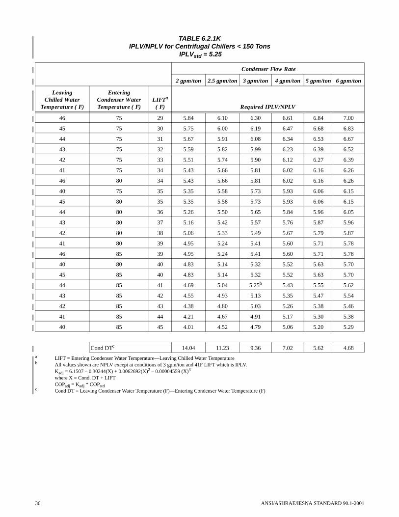
36
TABLE 6.2.1KIPLV/NPLV for Centrifugal Chillers < 150 Tons
IPLVstd = 5.25
Condenser Flow Rate
2 gpm/ton 2.5 gpm/ton 3 gpm/ton 4 gpm/ton 5 gpm/ton 6 gpm/ton
Leaving Chilled Water
Temperature (� F)
Entering Condenser Water Temperature (� F)
LIFTa
(� F) Required IPLV/NPLV
46 75 29 5.84 6.10 6.30 6.61 6.84 7.00
45 75 30 5.75 6.00 6.19 6.47 6.68 6.83
44 75 31 5.67 5.91 6.08 6.34 6.53 6.67
43 75 32 5.59 5.82 5.99 6.23 6.39 6.52
42 75 33 5.51 5.74 5.90 6.12 6.27 6.39
41 75 34 5.43 5.66 5.81 6.02 6.16 6.26
46 80 34 5.43 5.66 5.81 6.02 6.16 6.26
40 75 35 5.35 5.58 5.73 5.93 6.06 6.15
45 80 35 5.35 5.58 5.73 5.93 6.06 6.15
44 80 36 5.26 5.50 5.65 5.84 5.96 6.05
43 80 37 5.16 5.42 5.57 5.76 5.87 5.96
42 80 38 5.06 5.33 5.49 5.67 5.79 5.87
41 80 39 4.95 5.24 5.41 5.60 5.71 5.78
46 85 39 4.95 5.24 5.41 5.60 5.71 5.78
40 80 40 4.83 5.14 5.32 5.52 5.63 5.70
45 85 40 4.83 5.14 5.32 5.52 5.63 5.70
44 85 41 4.69 5.04 5.25b 5.43 5.55 5.62
43 85 42 4.55 4.93 5.13 5.35 5.47 5.54
42 85 43 4.38 4.80 5.03 5.26 5.38 5.46
41 85 44 4.21 4.67 4.91 5.17 5.30 5.38
40 85 45 4.01 4.52 4.79 5.06 5.20 5.29
Cond DTc 14.04 11.23 9.36 7.02 5.62 4.68a LIFT = Entering Condenser Water Temperature—Leaving Chilled Water Temperatureb All values shown are NPLV except at conditions of 3 gpm/ton and 41F LIFT which is IPLV.
Kadj = 6.1507 – 0.30244(X) + 0.0062692(X)2 – 0.00004559 (X)3
where X = Cond. DT + LIFTCOPadj = Kadj * COPstd
c Cond DT = Leaving Condenser Water Temperature (F)—Entering Condenser Water Temperature (F)
ANSI/ASHRAE/IESNA STANDARD 90.1-2001

TABLE 6.2.1LIPLV/NPLV for Centrifugal Chillers ≥ 150 Tons ≤ 300 Tons
IPLVstd= 5.9
Condenser Flow Rate
2 gpm/ton 2.5 gpm/ton 3 gpm/ton 4 gpm/ton 5 gpm/ton 6 gpm/ton
Leaving Chilled Water
Temperature (� F)
Entering Condenser Water Temperature (� F)
LIFTa
(� F) Required IPLV/NPLV
46 75 29 6.58 6.87 7.11 7.46 7.71 7.90
45 75 30 6.49 6.76 6.98 7.30 7.53 7.70
44 75 31 6.40 6.66 6.86 7.15 7.36 7.52
43 75 32 6.31 6.56 6.75 7.02 7.21 7.35
42 75 33 6.22 6.47 6.65 6.90 7.07 7.20
41 75 34 6.13 6.38 6.55 6.79 6.95 7.06
46 80 34 6.13 6.38 6.55 6.79 6.95 7.06
40 75 35 6.03 6.29 6.46 6.68 6.83 6.94
45 80 35 6.03 6.29 6.46 6.68 6.83 6.94
44 80 36 5.93 6.20 6.37 6.58 6.72 6.82
43 80 37 5.82 6.11 6.28 6.49 6.62 6.72
42 80 38 5.71 6.01 6.19 6.40 6.53 6.62
41 80 39 5.58 5.91 6.10 6.31 6.44 6.52
46 85 39 5.58 5.91 6.10 6.31 6.44 6.52
40 80 40 5.44 5.80 6.00 6.22 6.35 6.43
45 85 40 5.44 5.80 6.00 6.22 6.35 6.43
44 85 41 5.29 5.68 5.90b 6.13 6.26 6.34
43 85 42 5.13 5.55 5.79 6.03 6.16 6.25
42 85 43 4.94 5.41 5.67 5.93 6.07 6.16
41 85 44 4.74 5.26 5.54 5.82 5.97 6.07
40 85 45 4.52 5.09 5.40 5.71 5.87 5.97
Cond DTc 14.04 11.23 9.36 7.02 5.62 4.68a LIFT = Entering Condenser Water Temperature—Leaving Chilled Water Temperatureb All values shown are NPLV except at conditions of 3 gpm/ton and 41F LIFT which is IPLV.
Kadj = 6.1507 – 0.30244(X) + 0.0062692(X)2 – 0.000045595(X)3
where X = Cond. DT + LIFTCOPadj = Kadj * COPstd
c Cond DT = Leaving Condenser Water Temperature (F)—Entering Condenser Water Temperature (F)
ANSI/ASHRAE/IESNA STANDARD 90.1-2001 37

TABLE 6.2.1MIPLV/NPLV for Centrifugal Chillers > 300 Tons
IPLVstd = 6.4
Condenser Flow Rate
2 gpm/ton 2.5 gpm/ton 3 gpm/ton 4 gpm/ton 5 gpm/ton 6 gpm/ton
Leaving Chilled Water
Temperature (� F)
Entering Condenser Water Temperature (� F)
LIFTa
(� F) Required IPLV/NPLV
46 75 29 7.15 7.47 7.72 8.10 8.37 8.58
45 75 30 7.05 7.35 7.58 7.93 8.18 8.36
44 75 31 6.95 7.23 7.45 7.77 8.00 8.16
43 75 32 6.85 7.13 7.33 7.63 7.83 7.98
42 75 33 6.75 7.03 7.22 7.49 7.68 7.82
41 75 34 6.65 6.93 7.12 7.37 7.55 7.67
46 80 34 6.65 6.93 7.12 7.37 7.55 7.67
40 75 35 6.55 6.83 7.01 7.26 7.42 7.54
45 80 35 6.55 6.83 7.01 7.26 7.42 7.54
44 80 36 6.44 6.73 6.92 7.15 7.30 7.41
43 80 37 6.32 6.63 6.82 7.05 7.19 7.30
42 80 38 6.20 6.53 6.72 6.95 7.09 7.19
41 80 39 6.06 6.42 6.62 6.85 6.99 7.08
46 85 39 6.06 6.42 6.62 6.85 6.99 7.08
40 80 40 5.91 6.30 6.52 6.76 6.89 6.98
45 85 40 5.91 6.30 6.52 6.76 6.89 6.98
44 85 41 5.75 6.17 6.40b 6.66 6.79 6.89
43 85 42 5.57 6.03 6.28 6.55 6.70 6.79
42 85 43 5.37 5.88 6.16 6.44 6.59 6.69
41 85 44 5.15 5.71 6.01 6.33 6.49 6.59
40 85 45 4.91 5.53 5.86 6.20 6.37 6.48
Cond DTc 14.04 11.23 9.36 7.02 5.62 4.68a LIFT = Entering Condenser Water Temperature—Leaving Chilled Water Temperatureb All values shown are NPLV except at conditions of 3 gpm/ton and 41F LIFT which is IPLV.
Kadj = 6.1507 – 0.30244(X) + 0.0062692(X)2 – 0.000045595(X)3
where X = Cond. DT + LIFTCOPadj = Kadj * COPstd
c Cond DT = Leaving Condenser Water Temperature (F)—Entering Condenser Water Temperature (F)
38 ANSI/ASHRAE/IESNA STANDARD 90.1-2001

6.2.3 Controls6.2.3.1 Zone Thermostatic Controls
6.2.3.1.1 General. The supply of heating and coolingenergy to each zone shall be individually controlled by ther-mostatic controls responding to temperature within the zone.All zone and loop controllers shall use control methodologythat incorporates the application of control error reduction.For the purposes of 6.2.3.1, a dwelling unit shall be permittedto be considered a single zone.
Exceptions to 6.2.3.1.1: Independent perimeter systemsthat are designed to offset only building envelopeloads shall be permitted to serve one or more zonesalso served by an interior system provided:
(a) the perimeter system includes at least one thermostaticcontrol zone for each building exposure having exte-rior walls facing only one orientation for 50 contigu-ous ft or more, and
(b) the perimeter system heating and cooling supply iscontrolled by a thermostatic control(s) located withinthe zones(s) served by the system.
Exterior walls are considered to have different orienta-tions if the directions they face differ by more than 45 degrees.
6.2.3.1.2 Dead Band. Where used to control bothheating and cooling, zone thermostatic controls shall be capa-ble of providing a temperature range or dead band of at least5°F within which the supply of heating and cooling energy tothe zone is shut off or reduced to a minimum.
Exceptions to 6.2.3.1.2:(a) Thermostats that require manual changeover between
heating and cooling modes.(b) Special occupancy or special applications where wide
temperature ranges are not acceptable (such as retire-ment homes, process applications, data processing,museums, some areas of hospitals) and are approvedby the authority having jurisdiction
6.2.3.1.3 Set Point Overlap Restriction. Whereheating and cooling to a zone are controlled by separate zonethermostatic controls located within the zone, means (such aslimit switches, mechanical stops, or, for DDC systems, soft-ware programming) shall be provided to prevent the heatingset point from exceeding the cooling set point minus anyapplicable proportional band.
6.2.3.2 Off-Hour Controls. HVAC systems having adesign heating or cooling capacity greater than 65,000 Btu/hand fan system power greater than 3/4 hp shall have all of thefollowing off-hour controls: Automatic Shutdown (6.2.3.2.1),Setback Controls (6.2.3.2.2), Optimum Start Controls(6.2.3.2.3), Shutoff Damper Controls (6.2.3.2.4), and ZoneIsolation (6.2.3.2.5).
Exceptions to 6.2.3.2:(a) HVAC systems serving hotel/motel guest rooms.(b) HVAC systems intended to operate continuously.
6.2.3.2.1 Automatic Shutdown. HVAC systems shallbe equipped with at least one of the following:a. Controls that can start and stop the system under dif-
ferent time schedules for seven different day-types
ANSI/ASHRAE/IESNA STANDARD 90.1-2001
per week, are capable of retaining programming andtime setting during loss of power for a period of atleast 10 hours, and include an accessible manualoverride, or equivalent function, that allows tempo-rary operation of the system for up to two hours.
b. An occupant sensor that is capable of shutting the sys-tem off when no occupant is sensed for a period of upto 30 minutes.
c. A manually operated timer capable of being adjustedto operate the system for up to two hours.
d. An interlock to a security system that shuts the systemoff when the security system is activated.
Exception to 6.2.3.2.1: Residential occupancies may usecontrols that can start and stop the system undertwo different time schedules per week.
6.2.3.2.2 Setback Controls. Heating systems locatedwhere the heating design temperature is 40°F or less shall beequipped with controls that have the capability to automati-cally restart and temporarily operate the system as required tomaintain zone temperatures above a heating set point adjust-able down to 55°F or lower. (See Appendix D for heatingdesign temperatures.)
Cooling systems located where the cooling designtemperature is greater than 100°F shall be equipped withcontrols that have the capability to automatically restart andtemporarily operate the system as required to maintain zonetemperatures below a cooling set point adjustable up to 90°For higher or to prevent high space humidity levels. (SeeAppendix D for cooling design temperatures.)
Exception to 6.2.3.2.2: Radiant floor and ceiling heatingsystems.
6.2.3.2.3 Optimum Start Controls. Individual heat-ing and cooling air distribution systems with a total designsupply air capacity exceeding 10,000 cfm, served by one ormore supply fans, shall have optimum start controls. The con-trol algorithm shall, as a minimum, be a function of the dif-ference between space temperature and occupied setpoint andthe amount of time prior to scheduled occupancy.
6.2.3.2.4 Zone Isolation. HVAC systems servingzones that are intended to operate or be occupied nonsimulta-neously shall be divided into isolation areas. Zones may begrouped into a single isolation area provided it does notexceed 25,000 ft2 of conditioned floor area nor include morethan one floor.
Each isolation area shall be equipped with isolationdevices capable of automatically shutting off the supply ofconditioned air and outside air to and exhaust air from the area.Each isolation area shall be controlled independently by adevice meeting the requirements of 6.2.3.2.1 (AutomaticShutdown). For central systems and plants, controls anddevices shall be provided to allow stable system and equip-ment operation for any length of time while serving only thesmallest isolation area served by the system or plant.
Exceptions to 6.2.3.2.4: Isolation devices and controlsare not required for the following:
(a) Exhaust air and outside air connections to isolationzones when the fan system to which they connect is5000 cfm and smaller.
39

(b) Exhaust airflow from a single isolation zone of lessthan 10% of the design airflow of the exhaust systemto which it connects.
(c) Zones intended to operate continuously or intended tobe inoperative only when all other zones are inopera-tive.
6.2.3.3 Ventilation System Controls.
6.2.3.3.1 Stair and Shaft Vents. Stair and elevatorshaft vents shall be equipped with motorized dampers that arecapable of being automatically closed during normal buildingoperation and are interlocked to open as required by fire andsmoke detection systems.
6.2.3.3.2 Gravity Hoods, Vents, and Ventilators.All outdoor air supply and exhaust hoods, vents, and ventila-tors shall be equipped with motorized dampers that will auto-matically shut when the spaces served are not in use.
Exceptions to 6.2.3.3.1 and 6.2.3.3.2: (a) Gravity (nonmotorized) dampers are acceptable in
buildings less than three stories in height above gradeand for buildings of any height located in climateswith less than 2700 HDD65.
(b) Ventilation systems serving unconditioned spaces.
6.2.3.3.3 Shutoff Damper Controls. Both outdoorair supply and exhaust systems shall be equipped with motor-ized dampers that will automatically shut when the systems orspaces served are not in use. Ventilation outside air dampersshall be capable of automatically shutting off during pre-occupancy building warmup, cooldown, and setback, exceptwhen ventilation reduces energy costs (e.g., night purge) orwhen ventilation must be supplied to meet code requirements.
Exceptions to 6.2.3.3.3:(a) Gravity (nonmotorized) dampers are acceptable in
buildings less than three stories in height and forbuildings of any height located in climates with lessthan 2700 HDD65.
(b) Gravity (nonmotorized) dampers are acceptable insystems with a design outside air intake or exhaustcapacity of 300 cfm or less.
6.2.3.3.4 Dampers. Where outdoor air supply andexhaust air dampers are required by Section 6.2.3.3, they shallhave a maximum leakage rate when tested in accordance withAMCA Standard 500 as indicated in Table 6.2.3.3.4.
6.2.3.4 Heat Pump Auxiliary Heat Control. Heatpumps equipped with internal electric resistance heaters shallhave controls that prevent supplemental heater operation whenthe heating load can be met by the heat pump alone during bothsteady-state operation and setback recovery. Supplementalheater operation is permitted during outdoor coil defrost cycles.
Exception to 6.2.3.4: Heat pumps whose minimum effi-ciency is regulated by NAECA and whose HSPFrating both meets the requirements shown in Table6.2.1B and includes all usage of internal electricresistance heating.
6.2.3.5 Humidifier Preheat. Humidifiers with preheat-ing jackets mounted in the airstream shall be provided with anautomatic valve to shut off preheat when humidification is notrequired.
40
6.2.3.6 Humidification and Dehumidification.Where a zone is served by a system or systems with bothhumidification and dehumidification capability, means (suchas limit switches, mechanical stops, or, for DDC systems,software programming) shall be provided capable of pre-venting simultaneous operation of humidification and dehu-midification equipment.
Exception to 6.2.3.6:
(a) Zones served by desiccant systems, used with directevaporative cooling in series.
(b) Systems serving zones where specific humidity levelsare required, such as computer rooms, museums, andhospitals, and approved by the authority having juris-diction.
6.2.3.7 Freeze Protection and Snow/Ice Melting Sys-tems. Freeze protection systems, such as heat tracing of out-door piping and heat exchangers, including self-regulatingheat tracing, shall include automatic controls capable ofshutting off the systems when outside air temperatures areabove 40°F or when the conditions of the protected fluid willprevent freezing. Snow- and ice-melting systems shallinclude automatic controls capable of shutting off the sys-tems when the pavement temperature is above 50°F and noprecipitation is falling and an automatic or manual controlthat will allow shutoff when the outdoor temperature isabove 40°F so that the potential for snow or ice accumula-tion is negligible.
6.2.3.8 Ventilation Controls for High-OccupancyAreas. Systems with design outside air capacities greaterthan 3000 cfm serving areas having an average design occu-pancy density exceeding 100 people per 1000 ft2 shallinclude means to automatically reduce outside air intakebelow design rates when spaces are partially occupied. Ven-tilation controls shall be in compliance with ASHRAE Stan-dard 62 and local standards.
Exception to 6.2.3.8: Systems with heat recovery com-plying with 6.3.6.1.
TABLE 6.2.3.3.4Maximum Damper Leakage
Climate
Maximum Damper Leakage at 1.0 in w.g.cfm per ft2 of damper area
Motorized Non-motorized
HDD65>7200 or CDD50>7200
4 Not allowed
HDD65<2701 and CDD50<3601
20 20a
All others 10 20a
Notes:a Dampers smaller than 24 in. in either dimension may have leak-age of 40 cfm/ft2.
ANSI/ASHRAE/IESNA STANDARD 90.1-2001

TABLE 6.2.4.1.3Minimum Pipe Insulation Thicknessa
Fluid Design Operating Temp.
Range (� F)
Insulation Conductivity Nominal Pipe or Tube Size (in.)
Conductivity Btu� in./(h� ft2� � F)
Mean Rating Temp. � F <1 1 to <1-1/2 1-1/2 to <4 4 to <8 ≥8
Heating Systems (Steam, Steam Condensate, and Hot Water)b c
>350 0.32-0.34 250 2.5 3.0 3.0 4.0 4.0
251-350 0.29-0.32 200 1.5 2.5 3.0 3.0 3.0
201-250 0.27-0.30 150 1.5 1.5 2.0 2.0 2.0
141-200 0.25-0.29 125 1.0 1.0 1.0 1.5 1.5
105-140 0.22-0.28 100 0.5 0.5 1.0 1.0 1.0
Domestic and Service Hot Water Systems
105+ 0.22-0.28 100 0.5 0.5 1.0 1.0 1.0
Cooling Systems (Chilled Water, Brine, and Refrigerant)d
40-60 0.22-0.28 100 0.5 0.5 1.0 1.0 1.0
<40 0.22-0.28 100 0.5 1.0 1.0 1.0 1.5a For insulation outside the stated conductivity range, the minimum thickness (T) shall be determined as follows:
T = r{(1 + t/r)K/k – 1}
where T = minimum insulation thickness (in.), r = actual outside radius of pipe (in.), t = insulation thickness listed in this table for applicable fluid temperature and pipe size,K = conductivity of alternate material at mean rating temperature indicated for the applicable fluid temperature (Btu·in.[h·ft2·°F]); and k = the upper value of the conductivityrange listed in this table for the applicable fluid temperature.
b These thicknesses are based on energy efficiency considerations only. Additional insulation is sometimes required relative to safety issues/surface temperature.c Piping insulation is not required between the control valve and coil on run-outs when the control valve is located within 4 ft of the coil and the pipe size is 1 in. or less.d These thicknesses are based on energy efficiency considerations only. Issues such as water vapor permeability or surface condensation sometimes require vapor retarders or
additional insulation.
6.2.4 HVAC System Construction and Insulation
6.2.4.1 Insulation6.2.4.1.1 General. Insulation required by this section
shall be installed in accordance with industry accepted stan-dards (see Appendix E). These requirements do not apply toHVAC equipment. Insulation shall be protected from damage,including that due to sunlight, moisture, equipment mainte-nance, and wind, but not limited to the following:
a. Insulation exposed to weather shall be suitable for out-door service, e.g., protected by aluminum, sheet metal,painted canvas, or plastic cover. Cellular foam insula-tion shall be protected as above or painted with a coat-ing that is water retardant and provides shielding fromsolar radiation that can cause degradation of the mate-rial.
b. Insulation covering chilled water piping, refrigerantsuction piping, or cooling ducts located outside theconditioned space shall include a vapor retardantlocated outside the insulation (unless the insulation isinherently vapor retardant), all penetrations and jointsof which shall be sealed.
6.2.4.1.2 Duct and Plenum Insulation. All supplyand return ducts and plenums installed as part of an HVAC airdistribution system shall be thermally insulated in accordancewith Tables 6.2.4.1.2A and 6.2.4.1.2B.
Exceptions to 6.2.4.1.2:(a) Factory-installed plenums, casings, or ductwork fur-
ANSI/ASHRAE/IESNA STANDARD 90.1-2001
nished as a part of HVAC equipment tested and ratedin accordance with 6.2.1.
(b) Ducts or plenums located in heated spaces, semi-heated spaces, or cooled spaces.
(c) For runouts less than 10 ft in length to air terminals orair outlets, the rated R-value of insulation need notexceed R-3.5.
(d) Backs of air outlets and outlet plenums exposed tounconditioned or indirectly conditioned spaces withface areas exceeding 5 ft2 need not exceed R-2; those5 ft2 or smaller need not be insulated.
6.2.4.1.3 Piping Insulation. Piping shall be thermallyinsulated in accordance with Table 6.2.4.1.3.
Exceptions to 6.2.4.1.3:
(a) Factory-installed piping within HVAC equipmenttested and rated in accordance with 6.2.1.
(b) Piping that conveys fluids having a design operatingtemperature range between 60°F and 105°F, inclusive.
(c) Piping that conveys fluids that have not been heated orcooled through the use of nonrenewable energy (suchas roof and condensate drains, domestic cold watersupply, natural gas piping, or refrigerant liquid piping)or where heat gain or heat loss will not increaseenergy usage.
(d) Hot water piping between the shutoff valve and thecoil, not exceeding 4 ft in length, when located in con-ditioned spaces.
41

(e) Pipe unions in heating systems (steam, steam conden-sate, and hot water).
6.2.4.2 Ducts and Plenum Leakage6.2.4.2.1 Duct Sealing. Ductwork and plenums shall
be sealed in accordance with Table 6.2.4.2.1A (Table6.2.4.2.1B provides definitions of seal levels), as required tomeet the requirements of 6.2.4.2.2, and with standard industrypractice (see Appendix E).
6.2.4.2.2 Duct Leakage Tests. Ductwork that isdesigned to operate at static pressures in excess of 3 in. w.c.shall be leak tested according to industry-accepted test proce-dures (see Appendix E). Representative sections totaling noless than 25% of the total installed duct area for the designatedpressure class shall be tested. Duct systems with pressure rat-ings in excess of 3 in. w.c. shall be identified on the drawings.The maximum permitted duct leakage shall be:
Lmax = CL P0.65
where
Lmax = maximum permitted leakage in cfm/100 ft2 duct surface area
CL = duct leakage class, cfm/100 ft2 at 1 in. w.c.
6 for rectangular sheetmetal, rectangular fibrous ducts, and round flexible ducts
3 for round/flat oval sheetmetal or fibrous glass ducts
P = test pressure, which shall be equal to the design duct pressure class rating in inches w.c.
6.2.5 Completion Requirements
6.2.5.1 Drawings. Construction documents shallrequire that within 90 days after the date of system accep-tance, record drawings of the actual installation be providedto the building owner or the designated representative of thebuilding owner. Record drawings shall include as a minimumthe location and performance data on each piece of equip-ment, general configuration of duct and pipe distribution sys-tem including sizes, and the terminal air or water design flowrates.
6.2.5.2 Manuals. Construction documents shall requirethat an operating manual and a maintenance manual be pro-vided to the building owner or the designated representativeof the building owner within 90 days after the date of systemacceptance. These manuals shall be in accordance with indus-try-accepted standards (see Appendix E) and shall include, ata minimum, the following:a. Submittal data stating equipment size and selected
options for each piece of equipment requiring mainte-nance.
b. Operation manuals and maintenance manuals for eachpiece of equipment requiring maintenance, exceptequipment not furnished as part of the project.Required routine maintenance actions shall be clearlyidentified.
c. Names and addresses of at least one service agency.d. HVAC controls system maintenance and calibration
information, including wiring diagrams, schematics,and control sequence descriptions. Desired or field
42
determined set points shall be permanently recordedon control drawings at control devices or, for digitalcontrol systems, in programming comments.
e. A complete narrative of how each system is intendedto operate, including suggested set points.
6.2.5.3 System Balancing6.2.5.3.1 General. Construction documents shall
require that all HVAC systems be balanced in accordancewith generally accepted engineering standards (see AppendixE).
Construction documents shall require that a writtenbalance report be provided to the owner or the designatedrepresentative of the building owner for HVAC systems serv-ing zones with a total conditioned area exceeding 5000 ft2.
6.2.5.3.2 Air System Balancing. Air systems shall bebalanced in a manner to first minimize throttling losses. Then,for fans with fan system power greater than 1 hp, fan speedshall be adjusted to meet design flow conditions.
6.2.5.3.3 Hydronic System Balancing. Hydronicsystems shall be proportionately balanced in a manner to firstminimize throttling losses; then the pump impeller shall betrimmed or pump speed shall be adjusted to meet design flowconditions.
Exceptions to 6.2.5.3.3: Impellers need not be trimmednor pump speed adjusted:
(a) For pumps with pump motors of 10 hp or less.(b) When throttling results in no greater than 5% of the
nameplate horsepower draw, or 3 hp, whichever isgreater, above that required if the impeller wastrimmed.
6.2.5.4 System Commissioning. HVAC control sys-tems shall be tested to ensure that control elements are cali-brated, adjusted, and in proper working condition. Forprojects larger than 50,000 ft2 conditioned area, except ware-houses and semiheated spaces, detailed instructions for com-missioning HVAC systems (see Appendix E) shall beprovided by the designer in plans and specifications.
6.3 Prescriptive Path6.3.1 Economizers. Each cooling system having a fan
shall include either an air or water economizer meeting therequirements of 6.3.1.1 through 6.3.1.4.
Exceptions to 6.3.1: Economizers are not required for thesystems listed below.
(a) Individual fan-cooling units with a supply capacityless than the minimum listed in Table 6.3.1
(b) Systems that include gas phase air cleaning in order tomeet 6.1.2 of ASHRAE Standard 62.
(c) Where more than 25% of the air designed to be sup-plied by the system is to spaces that are designed to behumidified above 35°F dewpoint temperature to sat-isfy process needs.
(d) Systems that include a condenser heat recovery systemcomplying with 6.3.6.2.
(e) Systems that serve residential spaces where the systemcapacity is less than five times the requirement listed inTable 6.3.1.
ANSI/ASHRAE/IESNA STANDARD 90.1-2001

TABLE 6.2.4.1.2A Minimum Duct Insulation R-Value,a Cooling and Heating Only Supply Ducts and Return Ducts
Climate Zone Duct Location
Envelope Criteria Table HDD65 CDD50 Exterior
Ventilated Attic
Unvented Attic Above
Insulated Ceiling
Unvented Attic with
Roof Insulation
Unconditioned Spaceb
Indirectly Conditioned
Spacec Buried
Heating Ducts Only
B-1 to B-7 0-1800 all none none none none none none none
B-8 to B-12 1801-3600 all R-3.5 none none none none none none
B-13 to B-15 3601-5400 all R-3.5 none none none none none none
B-16 to B-18 5401-7200 all R-6 R-3.5 none none none none R-3.5
B-19 to B-20 7201-9000 all R-6 R-6 R-3.5 none none none R-3.5
B-21 to B-22 9001-10800 all R-8 R-6 R-6 none R-3.5 none R-3.5
B-23 10801-12600 all R-8 R-6 R-6 none R-6 none R-6
B-24 12601-16200 all R-8 R-8 R-6 none R-6 none R-6
B-25 16201-19800 all R-10 R-8 R-8 none R-6 none R-6
B-26 19801+ all R-10 R-10 R-8 none R-8 none R-6
Cooling Only Ducts
B-15, 18, 20, 22 to 26
all 0-1800 R-1.9 R-1.9 R-1.9 R-1.9 R-1.9 none none
B-12, 14, 17, 19, 21
all 1801-3600 R-3.5 R-1.9 R-3.5 R-1.9 R-1.9 none none
B-7, 9, 11, 13, 16 all 3601-5400 R-3.5 R-3.5 R-6 R-1.9 R-1.9 none none
B-4, 6, 8, 10 all 5401-7200 R-6 R-6 R-6 R-3.5 R-1.9 none none
B-3, B-5 all 7201-9000 R-6 R-6 R-6 R-3.5 R-3.5 none R-3.5
B-2 all 9001-10800 R-6 R-6 R-8 R-3.5 R-3.5 none R-3.5
B-1 all 10801+ R-8 R-8 R-8 R-3.5 R-3.5 none R-3.5
Return Ducts
B-1 to B-26 all climates R-3.5 R-3.5 R-3.5 none none none nonea Insulation R-values, measured in (h·ft2·°F)/Btu, are for the insulation as installed and do not include film resistance. The required minimum thicknesses do not consider
water vapor transmission and possible surface condensation. Where exterior walls are used as plenum walls, wall insulation shall be as required by the most restrictive con-dition of 6.2.4.2 or Section 5. Insulation resistance measured on a horizontal plane in accordance with ASTM C518 at a mean temperature of 75°F at the installed thickness.
b Includes crawl spaces, both ventilated and nonventilated.c Includes return air plenums with or without exposed roofs above.
ANSI/ASHRAE/IESNA STANDARD 90.1-2001 43

TABLE 6.2.4.1.2BMinimum Duct Insulation R-Value,a Combined Heating and Cooling Ducts
Climate Zone Duct Location
Envelope Criteria
Table HDD65 CDD50 ExteriorVentilated
Attic
Unvented Attic Above
Insulated Ceiling
Unvented Attic w/ Roof Insulationa
Uncon-ditioned Spaceb
Indirectly Condi-tioned Spacec Buried
B-1 0-900 10801+ R-8 R-6 R-8 R-3.5 R-3.5 none R-3.5
B-2 0-900 9001-10800 R-6 R-6 R-8 R-3.5 R-3.5 none R-3.5
B-3 0-900 7201-9000 R-6 R-6 R-6 R-3.5 R-3.5 none R-3.5
B-4 0-900 0-7200 R-6 R-3.5 R-6 R-3.5 R-1.9 none R-3.5
B-5 901-1800 7201+ R-6 R-6 R-6 R-3.5 R-3.5 none R-3.5
B-6 901-1800 5401-7200 R-6 R-6 R-6 R-3.5 R-3.5 none R-3.5
B-7 901-1800 0-5400 R-3.5 R-3.5 R-6 R-1.9 R-1.9 none R-1.9
B-8 1801-2700 5401+ R-6 R-6 R-6 R-3.5 R-3.5 none R-3.5
B-9 1801-2700 0-5400 R-6 R-3.5 R-6 R-1.9 R-1.9 none R-1.9
B-10 2701-3600 5401+ R-6 R-6 R-6 R-3.5 R-3.5 none R-3.5
B-11 2701-3600 3601-5400 R-6 R-6 R-6 R-3.5 R-3.5 none R-1.9
B-12 2701-3600 0-3600 R-3.5 R-3.5 R-3.5 R-1.9 R-1.9 none R-1.9
B-13 3601-5400 3601+ R-6 R-6 R-6 R-3.5 R-3.5 none R-3.5
B-14 3601-5400 1801-3600 R-6 R-3.5 R-6 R-1.9 R-3.5 none R-1.9
B-15 3601-5400 0-1800 R-3.5 R-3.5 R-3.5 R-1.9 R-1.9 none R-1.9
B-16 5401-7200 3601+ R-6 R-6 R-6 R-3.5 R-3.5 none R-3.5
B-17 5401-7200 1801-3600 R-6 R-6 R-6 R-1.9 R-3.5 none R-3.5
B-18 5401-7200 0-1800 R-6 R-3.5 R-3.5 R-1.9 R-3.5 none R-3.5
B-19 7201-9000 1801+ R-8 R-6 R-6 R-1.9 R-3.5 none R-3.5
B-20 7201-9000 0-1800 R-6 R-6 R-6 R-1.9 R-3.5 none R-3.5
B-21 9001-10800 1801+ R-8 R-6 R-6 R-1.9 R-6 none R-3.5
B-22 9001-10800 0-1800 R-8 R-6 R-6 R-1.9 R-3.5 none R-3.5
B-23 10801-12600 all R-8 R-6 R-6 R-1.9 R-6 none R-6
B-24 12601-16200 all R-8 R-8 R-8 R-1.9 R-6 none R-6
B-25 16201-19800 all R-10 R-8 R-8 R-3.5 R-6 none R-6
B-26 19801+ all R-10 R-10 R-8 R-3.5 R-8 R-3.5 R-6a Insulation R-values, measured in (h·ft2·°°F)/Btu, are for the insulation as installed and do not include film resistance. The required min-
imum thicknesses do not consider water vapor transmission and possible surface condensation. Where exterior walls are used as ple-num walls, wall insulation shall be as required by the most restrictive condition of 6.2.4.2 or Section 5. Insulation resistance measured on a horizontal plane in accordance with ASTM C518 at a mean temperature of 75°°F at the installed thickness.
b Includes crawl spaces, both ventilated and non-ventilated.c Includes return air plenums with or without exposed roofs above.
44 ANSI/ASHRAE/IESNA STANDARD 90.1-2001

(f) Systems that serve spaces whose sensible cooling loadat design conditions, excluding transmission and infil-tration loads, is less than or equal to transmission andinfiltration losses at an outdoor temperature of 60°F.
(g) Systems expected to operate less than 20 hours perweek.
(h) Where the use of outdoor air for cooling will affectsupermarket open refrigerated casework systems.
(i) Where the cooling efficiency meets or exceeds theefficiency requirements in Table 6.1.3.
6.3.1.1 Air Economizers6.3.1.1.1 Design Capacity. Air economizer systems
shall be capable of modulating outside air and return airdampers to provide up to 100% of the design supply air quan-tity as outside air for cooling.
6.3.1.1.2 Control Signal. Economizer dampers shallbe capable of being sequenced with the mechanical coolingequipment and shall not be controlled by only mixed air tem-perature.
Exception to 6.3.1.1.2: The use of mixed air temperaturelimit control shall be permitted for systems con-trolled from space temperature (such as single-zonesystems).
6.3.1.1.3 High Limit Shutoff. All air economizersshall be capable of automatically reducing outside air intaketo the design minimum outdoor air quantity when outside airintake will no longer reduce cooling energy usage. High limit
TABLE 6.2.4.2.1AMinimum Duct Seal Levela
Duct Location
Duct Type
Supply
Exhaust Return≤2 in. w.c.b >2 in. w.c.b
Outdoors A A C A
Unconditioned Spaces B A C B
Conditioned Spacesc C B B Ca See Table 6.2.4.2.1B definition of Seal Level.b Duct design static pressure classification.c Includes indirectly conditioned spaces such as return air plenums.
TABLE 6.2.4.2.1BDuct Seal Levels
Seal Level Sealing Requirementsa
A All transverse joints, longitudinal seams, and duct wall penetrations. Pressure-sensitive tape shall not be used as the primary sealant.
B All transverse joints and longitudinal seams. Pressure-sensitive tape shall not be used as the primary sealant.
C Transverse joints only.a Longitudinal seams are joints oriented in the direction of airflow. Transverse
joints are connections of two duct sections oriented perpendicular to airflow.Duct wall penetrations are openings made by any screw fastener, pipe, rod, orwire. Spiral lock seams in round and flat oval duct need not be sealed. All otherconnections are considered transverse joints, including but not limited to spin-ins, taps and other branch connections, access door frames and jambs, duct con-nections to equipment, etc.
ANSI/ASHRAE/IESNA STANDARD 90.1-2001
shutoff control types for specific climates shall be chosenfrom Table 6.3.1.1.3A. High limit shutoff control settings forthese control types shall be those listed in Table 6.3.1.1.3B.
6.3.1.1.4 Dampers. Both return air and outside airdampers shall meet the requirements of 6.2.3.3.4.
6.3.1.1.5 Relief of Excess Outside Air. Systems shallprovide a means to relieve excess outdoor air during air econ-omizer operation to prevent overpressurizing the building.The relief air outlet shall be located to avoid recirculation intothe building.
6.3.1.2 Water Economizers
6.3.1.2.1 Design Capacity. Water economizer sys-tems shall be capable of cooling supply air by indirect evap-oration and providing up to 100% of the expected systemcooling load at outside air temperatures of 50°F dry bulb/45°Fwet bulb and below.
Exception to 6.3.1.2.1: Systems in which a water econo-mizer is used and where dehumidification require-ments cannot be met using outside air temperaturesof 50°F dry bulb/45°F wet bulb must satisfy 100%of the expected system cooling load at 45°F drybulb/40°F wet bulb.
6.3.1.2.2 Maximum Pressure Drop. Precooling coilsand water-to-water heat exchangers used as part of a watereconomizer system shall either have a water-side pressuredrop of less than 15 ft of water or a secondary loop shall becreated so that the coil or heat exchanger pressure drop is notseen by the circulating pumps when the system is in the nor-mal cooling (noneconomizer) mode.
6.3.1.3 Integrated Economizer Control. Economizersystems shall be integrated with the mechanical cooling sys-tem and be capable of providing partial cooling even whenadditional mechanical cooling is required to meet the remain-der of the cooling load.
Exceptions to 6.3.1.3:(a) Direct expansion systems that include controls that
reduce the quantity of outdoor air required to preventcoil frosting at the lowest step of compressor unload-ing, provided this lowest step is no greater than 25%of the total system capacity.
(b) Individual direct expansion units that have a ratedcooling capacity less than 65,000 Btu/h and use nonin-tegrated economizer controls that preclude simulta-neous operation of the economizer and mechanicalcooling.
(c) Systems in locations having less than 800 averagehours per year between 8 a.m. and 4 p.m. when theambient dry-bulb temperatures are between 55°F and69°F inclusive. (See Appendix D for climatic data.)
6.3.1.4 Economizer Heating System Impact. HVACsystem design and economizer controls shall be such thateconomizer operation does not increase the building heatingenergy use during normal operation.
Exception to 6.3.1.4: Economizers on VAV systems thatcause zone level heating to increase due to a reduc-tion in supply air temperature.
45

TABLE 6.3.1Minimum System Size for Which an Economizer is Required
No. of Hours Between 8 a.m. and 4 p.m. with
55� F < Tdb < 69� F
1% Cooling Design Wet-Bulb Temperature
Twb < 69°F 69°F ≤ Twb ≤ 73°F Twb > 73°F
Minimum System Size (Btu/h)
Minimum System Size (Btu/h)
Minimum System Size (Btu/h)
0-199 N.R.a N.R. N.R.
200-399 135,000 N.R. N.R.
400-599 135,000 N.R. N.R.
600-799 65,000 135,000 N.R.
800-999 65,000 135,000 135,000
1000-1199 65,000 65,000 135,000
>1199 65,000 65,000 65,000a N.R. means that there is no system size for which an economizer is a requirement in this climate.
6.3.2 Simultaneous Heating and Cooling Limitation6.3.2.1 Zone Controls. Zone thermostatic controls shall
be capable of operating in sequence the supply of heating andcooling energy to the zone. Such controls shall prevent (1)reheating, (2) recooling, (3) mixing or simultaneously sup-plying air that has been previously mechanically heated andair that has been previously cooled, either by mechanicalcooling or by economizer systems, and (4) other simultaneousoperation of heating and cooling systems to the same zone.
Exceptions to 6.3.2.1:
(a) Zones for which the volume of air that is reheated,recooled, or mixed is no greater than the larger of thefollowing:
(1) The volume of outside air required to meet theventilation requirements of 6.1.3 of ASHRAE Stan-dard 62 for the zone.
(2) 0.4 cfm/ft2 of the zone conditioned floor area.(3) 30% of the zone design peak supply rate.(4) 300 cfm. This exception is for zones whosepeak flow rate totals no more than 10% of the totalfan system flow rate.(5) Any higher rate that can be demonstrated, to thesatisfaction of the authority having jurisdiction, toreduce overall system annual energy usage by off-setting reheat/recool energy losses through a reduc-tion in outdoor air intake in accordance with themultiple space requirements defined in ASHRAEStandard 62.
(b) Zones where special pressurization relationships,cross-contamination requirements, or code-requiredminimum circulation rates are such that variable airvolume systems are impractical.
(c) Zones where at least 75% of the energy for reheatingor for providing warm air in mixing systems is pro-vided from a site-recovered (including condenserheat) or site-solar energy source.
6.3.2.2 Hydronic System Controls. The heating of flu-ids in hydronic systems that have been previously mechani-
46
cally cooled and the cooling of fluids that have beenpreviously mechanically heated shall be limited in accor-dance with 6.3.2.2.1 through 6.3.2.2.3.
6.3.2.2.1 Three-Pipe System. Hydronic systems thatuse a common return system for both hot water and chilledwater shall not be used.
6.3.2.2.2 Two-Pipe Changeover System. Systemsthat use a common distribution system to supply both heatedand chilled water are acceptable provided all of the followingare met:a. The system is designed to allow a deadband between
changeover from one mode to the other of at least15°F outside air temperature.
b. The system is designed to operate and is provided withcontrols that will allow operation in one mode for atleast four hours before changing over to the othermode.
c. Reset controls are provided that allow heating andcooling supply temperatures at the changeover point tobe no more than 30°F apart.
6.3.2.2.3 Hydronic (Water Loop) Heat Pump Sys-tems. Hydronic heat pumps connected to a common heatpump water loop with central devices for heat rejection (e.g.,cooling tower) and heat addition (e.g., boiler) shall have thefollowing: a. Controls that are capable of providing a heat pump
water supply temperature deadband of at least 20°Fbetween initiation of heat rejection and heat additionby the central devices (e.g., tower and boiler).
b. For climates with greater than 1800 HDD65, if aclosed-circuit tower (fluid cooler) is used, either anautomatic valve shall be installed to bypass all but aminimal flow of water around the tower (for freeze pro-tection) or low-leakage positive closure dampers shallbe provided. If an open-circuit tower is used directly inthe heat pump loop, an automatic valve shall beinstalled to bypass all heat pump water flow around thetower. If an open-circuit tower is used in conjunctionwith a separate heat exchanger to isolate the tower
ANSI/ASHRAE/IESNA STANDARD 90.1-2001

TABLE 6.3.1.1.3AHigh-Limit Shutoff Control Options for Air Economizers
Climate Allowed Control Types Prohibited Control Types
DryTwb < 69°F or
(Twb < 75°F and Tdb ≥ 100°Fa
Fixed Dry BulbDifferential Dry BulbElectronic Enthalpyb
Differential Enthalpy
Fixed Enthalpy
Intermediate69°F ≤ Twb ≤ 73°F
Tdb < 100°F
Fixed Dry BulbDifferential Dry Bulb
Fixed EnthalpyElectronic Enthalpyb
Differential Enthalpy
HumidTwb > 73°F
Fixed Dry BulbFixed Enthalpy
Electronic Enthalpyb
Differential Enthalpy
Differential Dry Bulb
a Twb is the 1% cooling design wet-bulb temperature. Tdb is the 1% cooling design dry-bulb temperature.b Electronic enthalpy controllers are devices that use a combination of humidity and dry-bulb temperature in their switching algorithm.
TABLE 6.3.1.1.3BHigh-Limit Shutoff Control Settings for Air Economizers
Device Type Climate Required High Limit (Economizer Off When):
Fixed Dry Bulb DryIntermediate
Humid
Equation Description
TOA > 75°FTOA > 70°FTOA > 65°F
Outside air temperature exceeds 75°FOutside air temperature exceeds 70°FOutside air temperature exceeds 65°F
Differential Dry Bulb All TOA > TRA Outside air temperature exceeds return air temperature
Fixed Enthalpy All hOA > 28 Btu/lba Outside air enthalpy exceeds 28 Btu/lb of dry aira
Electronic Enthalpy All (TOA, RHOA) > A Outside air temperature/RH exceeds the “A” set point curveb
Differential Enthalpy All hOA > hRA Outside air enthalpy exceeds return air enthalpya At altitudes substantially different than sea level, the Fixed Enthalpy limit value shall be set to the enthalpy value at 75°F and 50% relative humidity. As an example, at approx-
imately 6000 ft elevation the fixed enthalpy limit is approximately 30.7 Btu/lb.b Set point “A” corresponds to a curve on the psychometric chart that goes through a point at approximately 75°F and 40% relative humidity and is nearly parallel to dry-bulb
lines at low humidity levels and nearly parallel to enthalpy lines at high humidity levels.
from the heat pump loop, then heat loss shall be con-trolled by shutting down the circulation pump on thecooling tower loop.
Exception to 6.3.2.2.3: Where a system loop temperatureoptimization controller is used to determine themost efficient operating temperature based on real-time conditions of demand and capacity, deadbands of less than 20°F shall be allowed.
6.3.2.3 Dehumidification. Where humidistatic controlsare provided, such controls shall prevent reheating, mixing ofhot and cold airstreams, or other means of simultaneous heat-ing and cooling of the same airstream.
Exceptions to 6.3.2.3:
(a) The system is capable of reducing supply air volumeto 50% or less of the design airflow rate or the mini-mum rate specified in 6.1.3 of ASHRAE Standard 62,whichever is larger, before simultaneous heating andcooling takes place.
(b) The individual fan cooling unit has a design cooling
ANSI/ASHRAE/IESNA STANDARD 90.1-2001
capacity of 80,000 Btu/h or less and is capable ofunloading to 50% capacity before simultaneous heat-ing and cooling takes place.
(c) The individual mechanical cooling unit has a designcooling capacity of 40,000 Btu/h or less. An individ-ual mechanical cooling unit is a single system com-posed of a fan or fans and a cooling coil capable ofproviding mechanical cooling.
(d) Systems serving spaces where specific humidity lev-els are required to satisfy process needs, such as com-puter rooms, museums, surgical suites, and buildingswith refrigerating systems, such as supermarkets,refrigerated warehouses, and ice arenas. This excep-tion also applies to other applications for which fanvolume controls in accordance with Exception (a) areproven to be impractical to the enforcement agency.
(e) At least 75% of the energy for reheating or for provid-ing warm air in mixing systems is provided from asite-recovered (including condenser heat) or site solarenergy source.
47

(f) Systems where the heat added to the airstream is theresult of the use of a desiccant system and 75% of theheat added by the desiccant system is removed by aheat exchanger, either before or after the desiccantsystem with energy recovery.
6.3.2.4 Humidification. Systems with hydronic coolingand humidification systems designed to maintain insidehumidity at greater than 35°F dewpoint temperature shall usea water economizer if an economizer is required by 6.3.1.
6.3.3 Air System Design and Control. HVAC systemshaving a total fan system power exceeding 5 hp shall meet theprovisions of 6.3.3.1 through 6.3.3.2 unless otherwise noted.
6.3.3.1 Fan Power Limitation.
a. The ratio of the fan system power to the supply fanairflow rate (main fan) of each HVAC system atdesign conditions shall not exceed the allowable fansystem power shown in Table 6.3.3.1.
b. Where air systems require air treatment or filteringsystems with pressure drops over 1 in. w.c. whenfilters are clean, or heat recovery coils or devices,or direct evaporative humidifiers/coolers, or otherdevices to serve process loads in the airstream, theallowable fan system power may be adjusted usingthe pressure credit in the allowable fan systemequation at the end of 6.3.3.1.
c. If the temperature difference between design roomtemperature and supply air temperature at coolingdesign conditions that is used to calculate designzone supply airflow is larger than 20°F, the allow-able fan system power may be adjusted using thetemperature ratio in the allowable fan system powerequation at the end of 6.3.3.1.
Allowable Fan System Power = [Table 6.3.3.1 Fan Power Limitation × (Temperature Ratio) + Pressure Credit
+ Relief Fan Credit]
whereTable 6.3.3.1 Fan Power Limitation = Table Value × CFMn/1000
Temperature Ratio = (Tt-stat – TS) / 20
Pressure Credit (hp) = Sum of [CFMn × (SPn – 1.0) / 3718] + Sum of [CFMHR × SPHR/3718]
Relief Fan Credit HP (kW) = FR HP (kW) × [1 – (CFMRF / CFMn)]
CFMn = supply air volume of the unit with the filtering system (cfm)
CFMHR = supply air volume of heat recovery coils or direct evaporative humidified/cooler (cfm)
CFMRF = relief fan air volume at normal cooling design
TABLE 6.3.3.1Fan Power Limitation
Supply Air Volume
Allowable Nameplate Motor Power
Constant Volume Variable Volume
<20,000 cfm 1.2 hp/1000 cfm 1.7 hp/1000 cfm
≥20,000 cfm 1.1 hp/1000 cfm 1.5 hp/1000 cfm
48
operation
SPn = air pressure drop of the filtering system when filters are clean (in. w.g.)
SPHR = air pressure drop of heat recovery coils or direct evaporative humidifier/cooler (in. w.g.).
Tt-stat = room thermostat set point
TS = design supply air temperature for the zone in which the thermostat is located
FR = name plate rating of the relief fan in hp
6.3.3.2 Variable Air Volume (VAV) Fan Control(Including Systems Using Series Fan Power Boxes).
6.3.3.2.1 Part-Load Fan Power Limitation. Indi-vidual VAV fans with motors 30 hp and larger shall meet oneof the following:
a. The fan shall be driven by a mechanical or electri-cal variable-speed drive.
b. The fan shall be a vane-axial fan with variable-pitchblades.
c. The fan shall have other controls and devices thatwill result in fan motor demand of no more than30% of design wattage at 50% of design air volumewhen static pressure set point equals one-third ofthe total design static pressure, based on manufac-turer’s certified fan data.
6.3.3.2.2 Static Pressure Sensor Location. Staticpressure sensors used to control variable air volume fans shallbe placed in a position such that the controller set point is nogreater than one-third the total design fan static pressure,except for systems with zone reset control complying with6.3.3.2.3. If this results in the sensor being located down-stream of major duct splits, multiple sensors shall be installedin each major branch to ensure that static pressure can bemaintained in each.
6.3.3.2.3 Set Point Reset. For systems with directdigital control of individual zone boxes reporting to the cen-tral control panel, static pressure set point shall be reset basedon the zone requiring the most pressure; i.e., the set point isreset lower until one zone damper is nearly wide open.
6.3.4 Hydronic System Design and Control. HVAChydronic systems having a total pump system power exceed-ing 10 hp shall meet provisions of 6.3.4.1 through 6.3.4.4.
6.3.4.1 Hydronic Variable Flow Systems. HVACpumping systems that include control valves designed tomodulate or step open and close as a function of load shall bedesigned for variable fluid flow and shall be capable of reduc-ing pump flow rates to 50% or less of the design flow rate.
Individual pumps serving variable flow systems having apump head exceeding 100 ft and motor exceeding 50 hp shallhave controls and/or devices (such as variable speed control)that will result in pump motor demand of no more than 30%of design wattage at 50% of design water flow. The controlsor devices shall be controlled as a function of desired flow orto maintain a minimum required differential pressure. Differ-ential pressure shall be measured at or near the most remoteheat exchanger or the heat exchanger requiring the greatestdifferential pressure.
Exceptions to 6.3.4.1:(a) Systems where the minimum flow is less than the
minimum flow required by the equipment manufac-
ANSI/ASHRAE/IESNA STANDARD 90.1-2001

turer for the proper operation of equipment served bythe system, such as chillers, and where total pump sys-tem power is 75 hp or less.
(b) Systems that include no more than three controlvalves.
6.3.4.2 Pump Isolation. When a chilled water plantincludes more than one chiller, provisions shall be made sothat the flow in the chiller plant can be automatically reduced,correspondingly, when a chiller is shut down. Chillersreferred to in this section, piped in series for the purpose ofincreased temperature differential, shall be considered as onechiller.
When a boiler plant includes more than one boiler, provi-sions shall be made so that the flow in the boiler plant can beautomatically reduced, correspondingly, when a boiler is shutdown.
6.3.4.3 Chilled and Hot Water Temperature ResetControls. Chilled and hot water systems with a design capac-ity exceeding 300,000 Btu/h supplying chilled or heatedwater (or both) to comfort conditioning systems shall includecontrols that automatically reset supply water temperaturesby representative building loads (including return water tem-perature) or by outside air temperature.
Exceptions to 6.3.4.3: (a) Where the supply temperature reset controls cannot be
implemented without causing improper operation ofheating, cooling, humidifying, or dehumidifying sys-tems.
(b) Hydronic systems, such as those required by 6.3.4.1,that use variable flow to reduce pumping energy.
6.3.4.4 Hydronic (Water Loop) Heat Pump Systems.Each hydronic heat pump shall have a two-position automaticvalve interlocked to shut off water flow when the compressoris off.
6.3.5 Heat Rejection Equipment. 6.3.5.1 General. Subsection 6.3.5 applies to heat rejec-
tion equipment used in comfort cooling systems such as air-cooled condensers, open cooling towers, closed-circuit cool-ing towers, and evaporative condensers.
Exception to 6.3.5.1: Heat rejection devices whoseenergy usage is included in the equipment efi-ciency ratings listed in Tables 6.2.1A through6.2.1D.
6.3.5.2 Fan Speed Control. Each fan powered by amotor of 7.5 hp or larger shall have the capability to operatethat fan at two-thirds of full speed or less and shall have con-trols that automatically change the fan speed to control theleaving fluid temperature or condensing temperature/pressureof the heat rejection device.
Exceptions to 6.3.5.2:(a) Condenser fans serving multiple refrigerant circuits.(b) Condenser fans serving flooded condensers.(c) Installations located in climates with greater than
7200 CDD50.(d) Up to one-third of the fans on a condenser or tower
with multiple fans, where the lead fans comply withthe speed control requirement
ANSI/ASHRAE/IESNA STANDARD 90.1-2001
6.3.6 Energy Recovery
6.3.6.1 Exhaust Air Energy Recovery. Individual fansystems that have both a design supply air capacity of 5000 cfmor greater and have a minimum outside air supply of 70% orgreater of the design supply air quantity shall have an energyrecovery system with at least 50% recovery effectiveness. Fiftypercent energy recovery effectiveness shall mean a change inthe enthalpy of the outdoor air supply equal to 50% of the dif-ference between the outdoor air and return air at design condi-tions. Provision shall be made to bypass or control the heatrecovery system to permit air economizer operation as requiredby 6.3.1.1.
Exceptions to 6.3.6.1:
(a) Laboratory systems meeting 6.3.7.2.
(b) Systems serving spaces that are not cooled and thatare heated to less than 60°F.
(c) Systems exhausting toxic, flammable, paint or corro-sive fumes or dust.
(d) Commercial kitchen hoods (grease) classified as Type1 by NFPA 96.
(e) Where more than 60% of the outdoor air heating energyis provided from site-recovered or site solar energy.
(f) Heating systems in climates with less than 3600HDD65.
(g) Cooling systems in climates with a 2.5% coolingdesign wet-bulb temperature less than 65°F.
(h) Where the largest exhaust source is less than 75% ofthe design outdoor airflow.
(i) Systems requiring dehumidification that employseries-style energy recovery coils wrapped around thecooling coil.
6.3.6.2 Heat Recovery for Service Water Heating.Condenser heat recovery systems shall be installed for heat-ing or preheating of service hot water provided all of the fol-lowing are true:
a. The facility operates 24 hours a day.b. The total installed heat rejection capacity of the water-
cooled systems exceeds 6,000,000 Btu/h of heat rejec-tion.
c. The design service water heating load exceeds1,000,000 Btu/h.
The required heat recovery system shall have the capacityto provide the smaller of
a. 60% of the peak heat rejection load at design condi-tions or
b. preheat of the peak service hot water draw to 85°F.
Exceptions to 6.3.6.2:(a) Facilities that employ condenser heat recovery for
space heating with a heat recovery design exceeding30% of the peak water-cooled condenser load atdesign conditions.
(b) Facilities that provide 60% of their service water heat-ing from site solar or site recovered energy or fromother sources.
49

6.3.7 Exhaust Hoods
6.3.7.1 Kitchen Hoods. Individual kitchen exhausthoods larger than 5000 cfm shall be provided with makeup airsized for at least 50% of exhaust air volume that is (a)unheated or heated to no more than 60°F and (b) uncooled orcooled without the use of mechanical cooling.
Exceptions to 6.3.7.1: (a) Where hoods are used to exhaust ventilation air that
would otherwise exfiltrate or be exhausted by otherfan systems.
(b) Certified grease extractor hoods that require a facevelocity no greater than 60 fpm.
6.3.7.2 Fume Hoods. Buildings with fume hood sys-tems having a total exhaust rate greater than 15,000 cfm shallinclude at least one of the following features:
a. Variable air volume hood exhaust and room supplysystems capable of reducing exhaust and makeup airvolume to 50% or less of design values.
b. Direct makeup (auxiliary) air supply equal to at least75% of the exhaust rate, heated no warmer than 2°Fbelow room set point, cooled to no cooler than 3°Fabove room set point, no humidification added, and nosimultaneous heating and cooling used for dehumidifi-cation control.
c. Heat recovery systems to precondition makeup airfrom fume hood exhaust in accordance with 6.3.6.1(Exhaust Air Energy Recovery) without using anyexception.
6.3.8 Radiant Heating Systems6.3.8.1 Heating Unenclosed Spaces. Radiant heating
shall be used when heating is required for unenclosed spaces.
Exception to 6.3.8.1: Loading docks equipped with aircurtains.
6.3.8.2 Heating Enclosed Spaces. Radiant heating sys-tems that are used as primary or supplemental enclosed spaceheating must be in conformance with the governing provi-sions of the standard, including, but not limited, to the follow-ing:a Radiant hydronic ceiling or floor panels (used for heat-
ing or cooling).b. Combination or hybrid systems incorporating radiant
heating (or cooling) panels.c. Radiant heating (or cooling) panels used in conjunc-
tion with other systems such as variable air volume orthermal storage systems.
6.3.9 Hot Gas Bypass Limitation. Cooling systems shallnot use hot gas bypass or other evaporator pressure controlsystems unless the system is designed with multiple steps of
TABLE 6.3.9Hot Gas Bypass Limitation
Rated CapacityMaximum Hot Gas Bypass Capacity
(% of Total Capacity)
≤240,000 Btu/h 50%
>240,000 Btu/h 25%
50
unloading or continuous capacity modulation. The capacity ofthe hot gas bypass shall be limited as indicated in Table 6.3.9.
Exception to 6.3.9: Unitary packaged systems with cool-ing capacities not greater than 90,000 Btu/h.
7. SERVICE WATER HEATING
7.1 General
7.1.1 Service Water Heating Scope. Service water heat-ing systems and equipment shall meet the requirements ofSection 7.
7.1.2 Compliance. Compliance shall be achieved bymeeting the requirements of either
a. 7.2 (Mandatory Provisions) and 7.3 (PrescriptivePath), if applicable, or
b. 7.2 (Mandatory Provisions) in conjunction with Sec-tion 11 (Energy Cost Budget Method).
7.2 Mandatory Provisions
7.2.1 Load Calculations. Service water heating systemdesign loads for the purpose of sizing systems and equipmentshall be determined in accordance with manufacturers’ pub-lished sizing guidelines or generally accepted engineeringstandards and handbooks acceptable to the adopting authority(e.g., ASHRAE Handbookó HVAC Applications).
7.2.2 Equipment Efficiency. All water heating equip-ment, hot water supply boilers used solely for heating potablewater, pool heaters, and hot water storage tanks shall meet thecriteria listed in Table 7.2.2. Where multiple criteria are listed,all criteria shall be met. Omission of minimum performancerequirements for certain classes of equipment does not pre-clude use of such equipment where appropriate. Equipmentnot listed in Table 7.2.2 has no minimum performancerequirements.
Exception to 7.2.2: All water heaters and hot water sup-ply boilers having more than 140 gal of storagecapacity are not required to meet the standby loss(SL) requirements of Table 7.2.2 when
(a) the tank surface is thermally insulated to R-12.5, and(b) a standing pilot light is not installed, and(c) gas- or oil-fired storage water heaters have a flue
damper or fan-assisted combustion.
7.2.3 Service Hot Water Piping Insulation. The fol-lowing piping shall be insulated to levels shown in Section 6,Table 6.2.4.1.3:
a. Recirculating system piping, including the supply andreturn piping of a circulating tank type water heater.
b. The first 8 ft of outlet piping for a constant tempera-ture nonrecirculating storage system.
c. The inlet pipe between the storage tank and a heat trapin a nonrecirculating storage system.
d. Pipes that are externally heated (such as heat trace orimpedance heating).
7.2.4 Service Water Heating System Controls
7.2.4.1 Temperature Controls. Temperature controlsshall be provided that allow for storage temperature adjust-
ANSI/ASHRAE/IESNA STANDARD 90.1-2001

TABLE 7.2.2Performance Requirements for Water Heating Equipment
Equipment TypeSize Category
(Input)Subcategory or
Rating Condition Performance Required aTest
Procedureb
Electric Water Heaters
≤12 kW ≥20 gal Resistance 0.93-0.00132V EF DOE 10 CFRPart 430
>12 kW ≥20 gal Resistance 20 + 35 SL, Btu/h ANSI Z21.10.3
≤24 Amps and ≤250 Volts
Heat Pump 0.93-0.00132V EF DOE 10 CFRPart 430
Gas Storage Water Heaters
≤75,000 Btu/h ≥20 gal 0.62-0.0019V EF DOE 10 CFRPart 430
>75,000 Btu/h and <4000 (Btu/h)/gal 80% Et(Q/800 + 110 )
SL, Btu/h
ANSI Z21.10.3
Gas Instantaneous Water Heaters
>50,000 Btu/h and<200,000 Btu/hc
≥4000 (Btu/h)/galand <2 gal
0.62-0.0019V EF DOE 10 CFRPart 430
≥200,000 Btu/h ≥4000 (Btu/h)/gal and <10 gal
80% Et ANSI Z21.10.3
>200,000 Btu/h ≥4000 (Btu/h)/gal and ≥10 gal
80% Et(Q/800 + 110 )
SL, Btu/h
Oil Storage Water Heaters
≤105,000 Btu/h ≥20 gal 0.59-0.0019V EF DOE 10 CFRPart 430
>105,000 Btu/h <4000 (Btu/h)/gal 78% Et(Q/800 + 110 )
SL, Btu/h
ANSI Z21.10.3
Oil Instantaneous Water Heaters
≤210,000 Btu/h ≥4000 (Btu/h)/galand <2 gal
0.59-0.0019V EF DOE 10 CFRPart 430
>210,000 Btu/h ≥4000 (Btu/h)/galand <10 gal
80% Et ANSI Z21.10.3
>210,000 Btu/h ≥4000 (Btu/h)/galand ≥10 gal
78% Et(Q/800 + 110 )
SL, Btu/h
Hot Water Supply Boilers, Gas and Oil
≥300,000 Btu/h and<12,500,000 Btu/h
≥4000 (Btu/h)/galand <10 gal
80% Et ANSI Z21.10.3
Hot Water Supply Boilers, Gas
≥4000 (Btu/h)/galand ≥10 gal
80% Et(Q/800 + 110 )
SL, Btu/h
Hot Water Supply Boilers, Oil
≥4000 (Btu/h)/galand ≥10 gal
78% Et (Q/800 + 110 )
SL, Btu/h
Pool Heaters Oil and Gas
All 78% Et ASHRAE 146
Unfired Storage Tanks
All R-12.5 (none)
a Energy factor (EF) and thermal efficiency (Et) are minimum requirements, while standby loss (SL) is maximum Btu/h based on a 70°F temperature difference betweenstored water and ambient requirements. In the EF equation, V is the rated volume in gallons. In the SL equation, V is the rated volume in gallons and Q is the nameplateinput rate in Btu/h.
b Section 12 contains a complete specification, including the year version, of the referenced test procedure.c Instantaneous water heaters with input rates below 200,000 Btu/h must comply with these requirements if the water heater is designed to heat water to temperatures 180°F
or higher.
V
V
V
V
V
V
V
ANSI/ASHRAE/IESNA STANDARD 90.1-2001 51

ment from 120°F or lower to a maximum temperature com-patible with the intended use.
Exception to 7.2.4.1: When the manufacturer's installa-tion instructions specify a higher minimum thermo-stat setting to minimize condensation and resultingcorrosion.
7.2.4.2 Temperature Maintenance Controls. Systemsdesigned to maintain usage temperatures in hot water pipes,such as recirculating hot water systems or heat trace, shall beequipped with automatic time switches or other controls thatcan be set to switch off the usage temperature maintenancesystem during extended periods when hot water is notrequired.
7.2.4.3 Outlet Temperature Controls. Temperaturecontrolling means shall be provided to limit the maximumtemperature of water delivered from lavatory faucets in publicfacility restrooms to 110°F.
7.2.4.4 Circulating Pump Controls. When used tomaintain storage tank water temperature, recirculating pumpsshall be equipped with controls limiting operation to a periodfrom the start of the heating cycle to a maximum of five min-utes after the end of the heating cycle.
7.2.5 Pools
7.2.5.1 Pool Heaters. Pool heaters shall be equippedwith a readily accessible on-off switch to allow shutting offthe heater without adjusting the thermostat setting. Pool heat-ers fired by natural gas shall not have continuously burningpilot lights.
7.2.5.2 Pool Covers. Heated pools shall be equippedwith a vapor retardant pool cover on or at the water surface.Pools heated to more than 90°F shall have a pool cover witha minimum insulation value of R-12.
Exception to 7.2.5.2: Pools deriving over 60% of theenergy for heating from site-recovered energy orsolar energy source.
7.2.5.3 Time Switches. Time switches shall be installedon swimming pool heaters and pumps.
Exceptions to 7.2.5.3:(a) Where public health standards require 24-hour pump
operation.(b) Where pumps are required to operate solar and waste
heat recovery pool heating systems.
7.2.6 Heat Traps. Vertical pipe risers serving storagewater heaters and storage tanks not having integral heat trapsand serving a nonrecirculating system shall have heat traps onboth the inlet and outlet piping as close as practical to the stor-age tank. A heat trap is a means to counteract the natural con-vection of heated water in a vertical pipe run. The means iseither a device specifically designed for the purpose or anarrangement of tubing that forms a loop of 360 degrees or pip-ing that from the point of connection to the water heater (inletor outlet) includes a length of piping directed downwardbefore connection to the vertical piping of the supply water orhot water distribution system, as applicable.
52
7.3 Prescriptive Path
7.3.1 Space Heating and Water Heating. The use of agas-fired or oil-fired space heating boiler system otherwisecomplying with Section 6 to provide the total space heatingand water heating for a building is allowed when one of thefollowing conditions is met.a. The single space heating boiler, or the component of a
modular or multiple boiler system that is heating theservice water, has a standby loss in Btu/h not exceed-ing
(13.3 × pmd + 400) / n
where pmd is the probable maximum demand in gal/h,determined in accordance with the procedures describedin generally accepted engineering standards and hand-books, and n is the fraction of the year when the outdoordaily mean temperature is greater than 64.9°F.The standby loss is to be determined for a test period of24 hours duration while maintaining a boiler watertemperature of at least 90°F above ambient, with an ambi-ent temperature between 60°F and 90°F. For a boiler witha modulating burner, this test shall be conducted at thelowest input.
b. It is demonstrated to the satisfaction of the authorityhaving jurisdiction that the use of a single heat sourcewill consume less energy than separate units.
c. The energy input of the combined boiler and waterheater system is less than 150,000 Btu/h.
7.3.2 Service Water Heating Equipment. Service waterheating equipment used to provide the additional function ofspace heating as part of a combination (integrated) systemshall satisfy all stated requirements for the service water heat-ing equipment.
8. POWER
8.1 GeneralSubsection 8.2 applies to all building power distribution
systems.
8.2 Mandatory Provisions
8.2.1 Voltage Drop
8.2.1.1 Feeders. Feeder conductors shall be sized for amaximum voltage drop of 2% at design load.
8.2.1.2 Branch Circuits. Branch circuit conductorsshall be sized for a maximum voltage drop of 3% at designload.
8.2.2 Completion Requirements
8.2.2.1 Drawings. Construction documents shallrequire that within 30 days after the date of system accep-tance, record drawings of the actual installation shall be pro-vided to the building owner, includinga. a single-line diagram of the building electrical distri-
bution system andb. floor plans indicating location and area served for all
distribution.
ANSI/ASHRAE/IESNA STANDARD 90.1-2001

8.2.2.2 Manuals. Construction documents shall requirethat an operating manual and maintenance manual be pro-vided to the building owner. The manuals shall include, at aminimum, the following:a. Submittal data stating equipment rating and selected
options for each piece of equipment requiring main-tenance.
b. Operation manuals and maintenance manuals foreach piece of equipment requiring maintenance.Required routine maintenance actions shall be clearlyidentified.
c. Names and addresses of at least one qualified serviceagency.
d. A complete narrative of how each system is intendedto operate.
(Enforcement agencies should only check to be sure that theconstruction documents require this information to be transmit-ted to the owner and should not expect copies of any of thematerials.)
9. LIGHTING
9.1 GeneralLighting systems and equipment shall comply with the
requirements of 9.2 and 9.3. This section shall apply to thefollowing:a. interior spaces of buildings;b. exterior building features, including facades, illumi-
nated roofs, architectural features, entrances, exits,loading docks, and illuminated canopies; and
c. exterior building grounds lighting provided throughthe building's electrical service.
Exceptions to 9.1:(a) emergency lighting that is automatically off during
normal building operation,(b) lighting within living units,(c) lighting that is specifically designated as required by a
health or life safety statute, ordinance, or regulation,(d) decorative gas lighting systems.
9.2 Mandatory Provisions
9.2.1 Lighting Control
9.2.1.1 Automatic Lighting Shutoff. Interior lightingin buildings larger than 5000 ft2 shall be controlled with anautomatic control device to shut off building lighting in allspaces. This automatic control device shall function on eithera. a scheduled basis using a time-of-day operated control
device that turns lighting off at specific programmedtimes—an independent program schedule shall be pro-vided for areas of no more than 25,000 ft2 but notmore than one floor—or
b. an occupant sensor that shall turn lighting off within30 minutes of an occupant leaving a space—or
c. a signal from another control or alarm system thatindicates the area is unoccupied.
Exception to 9.2.1.1: Lighting intended for 24-hour oper-ation shall not require an automatic control device.
ANSI/ASHRAE/IESNA STANDARD 90.1-2001
9.2.1.2 Space Control. Each space enclosed by ceiling-height partitions shall have at least one control device to inde-pendently control the general lighting within the space. Eachcontrol device shall be activated either manually by an occu-pant or automatically by sensing an occupant. Each controldevice shalla. control a maximum of 2500 ft2 area for a space
10,000 ft2 or less and a maximum of 10,000 ft2 areafor a space greater than 10,000 ft2,
b. be capable of overriding the shutoff control required in9.2.1.1 for no more than four hours, and
c. be readily accessible and located so the occupant cansee the controlled lighting.
Exception to 9.2.1.2: Remote location shall be permittedfor reasons of safety or security when the remotecontrol device has an indicator pilot light as part ofor next to the control device and it shall be clearlylabeled to identify the controlled lighting.
9.2.1.3 Exterior Lighting Control. Lighting for allexterior applications not exempted in 9.1 and 9.3.2 shall becontrolled by a photosensor or astronomical time switch thatis capable of automatically turning off the exterior lightingwhen sufficient daylight is available or the lighting is notrequired.
Exception to 9.2.1.3: Lighting for covered vehicleentrances or exits from buildings or parking struc-tures where required for safety, security, or eyeadaptation.
9.2.1.4 Additional Control.a. Display/Accent Lighting—display or accent light-
ing shall have a separate control device.
b. Case Lighting—lighting in cases used for displaypurposes shall have a separate control device.
c. Hotel and Motel Guest Room Lighting—hotel andmotel guest rooms and guest suites shall have amaster control device at the main room entry thatcontrols all permanently installed luminaires andswitched receptacles.
d. Task Lighting—supplemental task lighting, includ-ing permanently installed undershelf or undercabi-net lighting, shall have a control device integral tothe luminaires or be controlled by a wall-mountedcontrol device provided the control device is readilyaccessible and located so that the occupant can seethe controlled lighting.
e. Nonvisual Lighting—lighting for nonvisual appli-cations, such as plant growth and food warming,shall have a separate control device.
f. Demonstration Lighting—lighting equipment thatis for sale or for demonstrations in lighting educa-tion shall have a separate control device.
9.2.2 Tandem Wiring. Luminaires designed for use withone or three linear fluorescent lamps greater than 30 W eachshall use two-lamp tandem-wired ballasts in place of single-lamp ballasts when two or more luminaires are in the samespace and on the same control device.
53

Exceptions to 9.2.2:(a) Recessed luminaires more than 10 ft apart mea-
sured center to center.(b) Surface-mounted or pendant luminaires that are not
continuous.(c) Luminaires using single-lamp high-frequency elec-
tronic ballasts.(d) Luminaires using three-lamp high-frequency elec-
tronic or three-lamp electromagnetic ballasts.(e) Luminaires on emergency circuits.(f) Luminaires with no available pair.
9.2.3 Exit Signs. Exit sign luminaires operating atgreater than 20 watts shall have a minimum source efficacyof 35 lm/W.
TABLE 9.3.1.1Lighting Power Densities Using
the Building Area Method
Building Area TypeaLighting Power Density
(W/ft2)
Automotive Facility 1.5
Convention Center 1.4
Court House 1.4
Dining: Bar Lounge/Leisure 1.5
Dining: Cafeteria/Fast Food 1.8
Dining: Family 1.9
Dormitory 1.5
Exercise Center 1.4
Gymnasium 1.7
Hospital/Health Care 1.6
Hotel 1.7
Library 1.5
Manufacturing Facility 2.2
Motel 2.0
Motion Picture Theater 1.6
Multi-Family 1.0
Museum 1.6
Office 1.3
Parking Garage 0.3
Penitentiary 1.2
Performing Arts Theater 1.5
Police/Fire Station 1.3
Post Office 1.6
Religious Building 2.2
Retail 1.9
School/University 1.5
Sports Arena 1.5
Town Hall 1.4
Transportation 1.2
Warehouse 1.2
Workshop 1.7 a In cases where both general building area type and a specific building area type are
listed, the specific building area type shall apply.
54
9.2.4 Installed Interior Lighting Power. The installedinterior lighting power shall include all power used by theluminaires, including lamps, ballasts, current regulators, andcontrol devices except as specifically exempted in 9.3.1.
Exception to 9.2.4: If two or more independently operat-ing lighting systems in a space are capable of beingcontrolled to prevent simultaneous user operation,the installed interior lighting power shall be basedsolely on the lighting system with the highest watt-age.
9.2.5 Luminaire Wattage. Luminaire wattage incorpo-rated into the installed interior lighting power shall be deter-mined in accordance with the following criteria:
a. The wattage of incandescent or tungsten-halogenluminaires with medium screw base sockets and notcontaining permanently installed ballasts shall be themaximum labeled wattage of the luminaire.
b. The wattage of luminaires with permanently installedor remote ballasts or transformers shall be the operat-ing input wattage of the maximum lamp/auxiliarycombination based on values from the auxiliary manu-facturer’s literature or recognized testing laboratories.
c. The wattage of line-voltage lighting track and plug-inbusway that allow the addition and/or relocation ofluminaires without altering the wiring of the systemshall be the specified wattage of the luminairesincluded in the system with a minimum of 30 W/lin ft.
d. The wattage of low-voltage lighting track, cable con-ductor, rail conductor, and other flexible lighting sys-tems that allow the addition and/or relocation ofluminaires without altering the wiring of the systemshall be the specified wattage of the transformer sup-plying the system.
e. The wattage of all other miscellaneous lighting equip-ment shall be the specified wattage of the lightingequipment.
9.2.6 Exterior Building Grounds Lighting. All exteriorbuilding grounds luminaires that operate at greater than 100watts shall contain lamps having a minimum efficacy of 60lm/W unless the luminaire is controlled by a motion sensoror qualifies for one of the exceptions under 9.1 or 9.3.2.
9.3 Prescriptive Path
9.3.1 Interior Lighting Power. The interior lightingpower allowance for a building or a separately metered or per-mitted portion of a building shall be determined by either thebuilding area method described in 9.3.1.1 or the space-by-space method described in 9.3.1.2. Trade-offs of interiorlighting power allowance among portions of the building forwhich a different method of calculation has been used are notpermitted. The installed interior lighting power identified inaccordance with 9.2.4 shall not exceed the interior lightingpower allowance developed in accordance with 9.3.1.1 or9.3.1.2.
Exceptions to 9.3.1: The following lighting equipmentand applications shall not be considered whendetermining the interior lighting power allowancedeveloped in accordance with 9.3.1.1 or 9.3.1.2,
ANSI/ASHRAE/IESNA STANDARD 90.1-2001

nor shall the wattage for such lighting be includedin the installed interior lighting power identified inaccordance with 9.2.4. However, any such lightingshall not be exempt unless it is an addition to gen-eral lighting and is controlled by an independentcontrol device.
(a) Display or accent lighting that is an essential ele-ment for the function performed in galleries, muse-ums, and monuments.
(b) Lighting that is integral to equipment or instrumen-tation and is installed by its manufacturer.
(c) Lighting specifically designed for use only duringmedical or dental procedures and lighting integralto medical equipment.
(d) Lighting integral to both open and glass enclosedrefrigerator and freezer cases.
(e) Lighting integral to food warming and food prepa-ration equipment.
(f) Lighting for plant growth or maintenance.(g) Lighting in spaces specifically designed for use by
the visually impaired.(h) Lighting in retail display windows, provided the
display area is enclosed by ceiling-height partitions. (i) Lighting in interior spaces that have been specifi-
cally designated as a registered interior historiclandmark.
(j) Lighting that is an integral part of advertising ordirectional signage.
(k) Exit signs.(l) Lighting that is for sale or lighting educational
demonstration systems.(m) Lighting for theatrical purposes, including perfor-
mance, stage, and film and video production.(n) Athletic playing areas with permanent facilities for
television broadcasting.(o) Casino gaming areas.
9.3.1.1 Building Area Method of Calculating Inte-rior Lighting Power Allowance. Use the following steps todetermine the interior lighting power allowance by the build-ing area method:a. Determine the appropriate building area type from
Table 9.3.1.1 and the allowed lighting power density(watts per unit area) from the building area methodcolumn. For building area types not listed, selection ofa reasonably equivalent type shall be permitted.
b. Determine the gross lighted floor area (square feet) ofthe building area type.
c. Multiply the gross lighted floor areas of the buildingarea type(s) times the lighting power density.
d. The interior lighting power allowance for the buildingis the sum of the lighting power allowances of allbuilding area types. Trade-offs among building areatypes are permitted provided that the total installedinterior lighting power does not exceed the interiorlighting power allowance.
9.3.1.2 Space-by-Space Method of Calculating Inte-rior Lighting Power Allowance. Use the following steps todetermine the interior lighting power allowance by the space-by-space method:
ANSI/ASHRAE/IESNA STANDARD 90.1-2001
a. Determine the appropriate building type from Table9.3.1.2. For building types not listed, selection of areasonably equivalent type shall be permitted.
b. For each space enclosed by partitions 80% or greaterthan ceiling height, determine the gross interior floorarea by measuring to the center of the partition wall.Include the floor area of balconies or other projections.Retail spaces do not have to comply with the 80% par-tition height requirements.
c. Determine the interior lighting power allowance byusing the columns designated space-by-space methodin Table 9.3.1.2. Multiply the floor area(s) of thespace(s) times the allowed lighting power density forthe space type that most closely represents the pro-posed use of the space(s). The product is the lightingpower allowance for the space(s). For space types notlisted, selection of a reasonable equivalent categoryshall be permitted.
d. The interior lighting power allowance is the sum oflighting power allowances of all spaces. Trade-offsamong spaces are permitted provided that the totalinstalled interior lighting power does not exceed theinterior lighting power allowance.
9.3.1.2.1 Additional Interior Lighting Power.When using the space-by-space method, an increase in theinterior lighting power allowance is allowed for specificlighting functions. Additional power shall be allowed only ifthe specified lighting is installed, shall be used only for thespecified luminaires, and shall not be used for any other pur-pose or in any other space.
An increase in the interior lighting power allowance ispermitted in the following cases:
a. For spaces in which lighting is specified to be installedin addition to the general lighting for the purpose ofdecorative appearance, such as chandelier-type lumi-naries or sconces or for highlighting art or exhibits,provided that the additional lighting power shall notexceed 1.0 W/ft2 of such spaces.
b. For spaces in which lighting is specified to be installedto meet the requirements of visual display terminals asthe primary viewing task, provided that the additionallighting power shall not exceed 0.35 W/ft2 of suchspaces and that the specified luminaire meets require-ments for use in such spaces. Maximum average lumi-nance measured from the vertical in candelas persquare foot of not more than 80 cd/ft2 at 65 degrees, 33cd/ft2 at 75 degrees, and 17 cd/ft2 at 85 to 90 degrees.
c. For lighting equipment installed in retail spaces that isspecifically designed and directed to highlight mer-chandise, provided that the additional lighting powershall not exceed
(1) 1.6 W/ft2 times the area of specific display or
(2) 3.9 W/ft2 times the area of specific display forvaluable merchandise, such as jewelry, fine appareland accessories, china and silver, art, and similaritems, where detailed display and examination ofmerchandise are important.
55

TAB
LE
9.3
.1.2
L
igh
tin
g P
ow
er D
ensi
ties
Usi
ng
th
e S
pac
e-by
-Sp
ace
Met
ho
d
Bui
ldin
g T
ype
Spac
e-by
-Spa
ce M
etho
d L
PD
s
Com
mon
Spa
ce T
ypes
and
LP
Ds
(W/f
t2 )
Bui
ldin
g Sp
ecif
ic S
pace
Typ
es
and
LP
Ds
(W/f
t2 )
Officeó Enclosed
Officeó Open Plan
Conference Meeting/Mulitpurpose
Classroom/Lecture/Training
Audience/Seating Area
Lobby
Atriumó first three floors
Atriumó each additional floor
Lounge/Recreation
Dining Area
Food Preparation
Restrooms
Corridor/Transition
Stairsó Active
Active Storage
Inactive Storage
Electrical/Mechanical
Ath
leti
c F
acili
ty B
uild
ings
Gym
nasi
um1.
5 1.
3 1.
5 0.
51.
81.
30.
2 1.
41.
4 2.
2 1.
00.
7 0.
9 1.
1 0.
3 1.
3 Pl
ayin
g A
rea
1.9
Dre
ssin
g/L
ocke
r/Fi
tting
Roo
m0.
8
Exe
rcis
e A
rea
1.1
Exe
rcis
e C
ente
r1.
5 1.
3 1.
5 0.
5 1.
8 1.
3 0.
2 1.
4 1.
42.
21.
00.
70.
91.
10.
31.
3E
xerc
ise
Are
a1.
1
Dre
ssin
g/L
ocke
r/Fi
tting
Roo
m0.
8
Civ
il Se
rvic
e B
uild
ings
Cou
rtho
use
1.5
1.3
1.5
1.6
1.6
1.8
1.3
0.2
1.4
1.4
2.2
1.0
0.7
0.9
1.1
0.3
1.3
Cou
rtro
om2.
1
Con
fine
men
t Cel
ls1.
1
Judg
es C
ham
bers
1.1
Polic
e St
atio
ns1.
51.
31.
51.
61.
61.
81.
30.
21.
41.
42.
21.
00.
70.
91.
10.
31.
3Po
lice
Stat
ion
Lab
orat
ory
1.8
Fire
Sta
tions
1.5
1.3
1.5
1.6
1.8
1.4
1.4
2.2
1.0
0.7
0.9
1.1
0.3
1.3
Fire
Sta
tion
Eng
ine
Roo
m0.
9
Slee
ping
Qua
rter
s1.
1
Post
Off
ice
1.5
1.3
1.5
1.6
1.8
1.3
0.2
1.4
1.4
2.2
1.0
0.7
0.9
1.1
0.3
1.3
Sort
ing
Are
a1.
7
Tow
n H
all
1.5
1.3
1.5
1.6
1.6
1.8
1.4
2.2
1.0
0.7
0.9
1.1
0.3
1.3
Con
vent
ion
Cen
ter
Bui
ldin
gs
Con
vent
ion
Cen
ter
1.5
1.3
1.5
1.6
0.5
1.8
1.3
0.2
1.4
1.4
2.2
1.0
0.7
0.9
1.1
0.3
1.3
Exh
ibit
spac
e3.
3
Edu
cati
onal
Bui
ldin
gs
Scho
ol/U
nive
rsity
1.5
1.3
1.5
1.6
1.8
1.3
0.2
1.4
1.4
2.2
1.0
0.7
0.9
1.1
0.3
1.3
Lib
rary
1.5
1.3
1.5
1.6
1.8
1.3
0.2
1.4
2.2
1.0
0.7
0.9
1.1
0.3
1.3
Car
d Fi
le a
nd C
atal
ogin
g1.
4
Stac
ks1.
9
Rea
ding
Are
a1.
8
Foo
d Se
rvic
e B
uild
ings
Din
ing:
Bar
Lou
nge/
Lei
sure
1.5
1.3
1.5
1.8
1.3
0.2
1.4
1.2
2.2
1.0
0.7
0.9
1.1
0.3
1.3
Din
ing:
Fam
ily1.
51.
31.
51.
81.
3 0.
2 1.
42.
22.
21.
00.
70.
91.
10.
31.
3
Din
ing:
Caf
eter
ia1.
51.
31.
51.
81.
3 0.
2 1.
41.
42.
21.
00.
70.
91.
10.
31.
3
56 ANSI/ASHRAE/IESNA STANDARD 90.1-2001

Hos
pita
l/Hea
lthc
are
Bui
ldin
gs
Hos
pita
l/Hea
lthca
re1.
51.
31.
51.
81.
3 0.
2 1.
41.
42.
21.
01.
60.
92.
90.
31.
3E
mer
genc
y2.
8
Rec
over
y2.
6
Nur
se S
tatio
n1.
8
Exa
m/T
reat
men
t1.
6
Phar
mac
y2.
3
Patie
nt R
oom
1.2
Ope
ratin
g R
oom
7.6
Nur
sery
1.0
Med
ical
Sup
ply
3.0
Phys
ical
The
rapy
1.9
Rad
iolo
gy0.
4
Lau
ndry
-Was
hing
0.7
Indu
stri
al B
uild
ings
Wor
ksho
p1.
51.
31.
51.
81.
3 0.
2 1.
41.
42.
21.
00.
70.
91.
10.
31.
3W
orks
hop
2.5
Aut
omot
ive
Faci
lity
1.5
1.3
1.5
1.8
1.3
0.2
1.4
1.4
2.2
1.0
0.7
0.9
1.1
0.3
1.3
Gar
age
Serv
ice/
Rep
air
1.4
Man
ufac
turi
ng1.
51.
31.
51.
81.
3 0.
2 1.
41.
42.
21.
00.
50.
91.
10.
31.
3G
ener
al L
ow B
ay (
< 2
5 ft
Flo
or
to C
eilin
g H
eigh
t)2.
1
Gen
eral
Hig
h B
ay (
≥ 25
ft F
loor
to
Cei
ling
Hei
ght)
3.0
Det
aile
d6.
2
Equ
ipm
ent R
oom
0.8
Con
trol
Roo
m0.
5
Lod
ging
Bui
ldin
gs
Hot
el1.
51.
31.
51.
61.
71.
30.
21.
41.
02.
21.
00.
70.
91.
10.
31.
3G
uest
Roo
ms
2.5
Mot
el1.
51.
31.
51.
61.
81.
30.
21.
41.
22.
21.
00.
70.
91.
10.
31.
3G
uest
Roo
ms
2.5
Mul
ti-F
amily
1.5
1.3
1.5
1.8
1.3
0.2
1.4
1.4
2.2
1.0
0.7
0.9
1.1
0.3
1.3
Priv
ate
livi
ng s
pace
Dor
mito
ry1.
51.
31.
51.
81.
30.
21.
41.
42.
21.
00.
70.
91.
10.
31.
3L
ivin
g Q
uart
ers
1.9
Mus
eum
Bui
ldin
gs
Mus
eum
1.5
1.3
1.5
1.6
1.8
1.3
0.2
1.0
0.7
0.9
1.4
1.4
1.3
Gen
eral
Exh
ibiti
on1.
6
Res
tora
tion
2.5
TAB
LE
9.3
.1.2
(C
on
tin
ued
)L
igh
tin
g P
ow
er D
ensi
ties
Usi
ng
th
e S
pac
e-by
-Sp
ace
Met
ho
d
Bui
ldin
g T
ype
Spac
e-by
-Spa
ce M
etho
d L
PD
s
Com
mon
Spa
ce T
ypes
and
LP
Ds
(W/f
t2 )
Bui
ldin
g Sp
ecif
ic S
pace
Typ
es
and
LP
Ds
(W/f
t2 )
Officeó Enclosed
Officeó Open Plan
Conference Meeting/Mulitpurpose
Classroom/Lecture/Training
Audience/Seating Area
Lobby
Atriumó first three floors
Atriumó each additional floor
Lounge/Recreation
Dining Area
Food Preparation
Restrooms
Corridor/Transition
Stairsó Active
Active Storage
Inactive Storage
Electrical/Mechanical
ANSI/ASHRAE/IESNA STANDARD 90.1-2001 57

Off
ice
Bui
ldin
gs
Off
ice
1.5
1.3
1.5
1.6
1.8
1.3
0.2
1.4
1.4
2.2
1.0
0.7
0.9
1.1
0.3
1.3
Ban
king
Act
ivity
Are
a2.
4
Lab
orat
ory
1.8
Pen
iten
tiar
y B
uild
ings
Peni
tent
iary
1.5
1.3
1.4
1.9
1.8
1.4
1.4
2.2
1.0
0.7
0.9
1.1
0.3
1.3
Con
fine
men
t Cel
ls1.
1
Rel
igio
us B
uild
ings
Rel
igio
us B
uild
ings
1.5
1.3
1.5
1.6
3.2
1.8
1.3
0.2
1.4
2.2
1.0
0.7
0.9
1.1
0.3
1.3
Wor
ship
-Pul
pit,
Cho
ir5.
2
Fello
wsh
ip H
all
2.3
Ret
ail B
uild
ings
Ret
ail
1.5
1.3
1.5
1.8
1.3
0.2
1.4
1.4
2.2
1.0
0.7
0.9
1.1
0.3
1.3
Gen
eral
Sal
es A
rea
2.1
For
acce
nt li
ghtin
g, s
ee 9
.3.1
.2.1
.(c)
Mal
l Con
cour
se1.
8
Spor
ts A
rena
Bui
ldin
g
Spor
ts A
rena
1.5
1.3
1.5
0.5
1.8
1.3
0.2
1.4
1.4
2.2
1.0
0.7
0.9
1.1
0.3
1.3
Rin
g Sp
orts
Are
na3.
8
Cou
rt S
port
s A
rena
4.3
Indo
or P
layi
ng F
ield
Are
a1.
9
Stor
age
Bui
ldin
gs
War
ehou
se1.
51.
31.
51.
81.
30.
21.
00.
70.
91.
10.
31.
3Fi
ne M
ater
ial S
tora
ge1.
6
Med
ium
/Bul
ky M
ater
ial S
tora
ge1.
1
Park
ing
Gar
age
1.5
1.8
1.0
0.7
0.9
1.1
0.3
1.3
Park
ing
Are
a -
Pede
stri
an0.
2
Park
ing
Are
a -
Atte
ndan
t onl
y0.
1
The
ater
Bui
ldin
gs
Perf
orm
ing
Art
s1.
51.
81.
21.
30.
21.
41.
00.
70.
91.
10.
31.
3
Mot
ion
Pict
ure
1.3
0.8
1.4
1.0
0.7
0.9
1.1
0.3
1.3
Tra
nspo
rtat
ion
Bui
ldin
gs
Tra
nspo
rtat
ion
1.5
1.3
1.5
1.0
1.8
1.3
0.2
1.4
1.4
2.2
1.0
0.7
0.9
1.1
0.3
1.3
Air
port
- C
onco
urse
0.7
Air
/Tra
in/B
us -
Bag
gage
Are
a1.
3
Term
inal
- T
icke
t cou
nter
1.8
TAB
LE
9.3
.1.2
(C
on
tin
ued
)L
igh
tin
g P
ow
er D
ensi
ties
Usi
ng
th
e S
pac
e-by
-Sp
ace
Met
ho
d
Bui
ldin
g T
ype
Spac
e-by
-Spa
ce M
etho
d L
PD
s
Com
mon
Spa
ce T
ypes
and
LP
Ds
(W/f
t2 )
Bui
ldin
g Sp
ecif
ic S
pace
Typ
es
and
LP
Ds
(W/f
t2 )
Officeó Enclosed
Officeó Open Plan
Conference Meeting/Mulitpurpose
Classroom/Lecture/Training
Audience/Seating Area
Lobby
Atriumó first three floors
Atriumó each additional floor
Lounge/Recreation
Dining Area
Food Preparation
Restrooms
Corridor/Transition
Stairsó Active
Active Storage
Inactive Storage
Electrical/Mechanical
58 ANSI/ASHRAE/IESNA STANDARD 90.1-2001

9.3.2 Exterior Building Lighting Power. The exteriorbuilding facade lighting power shall not exceed 0.25 W/ft2 ofthe illuminated area. The exterior lighting power allowancefor all other exterior building applications is the sum of thelighting power limits permitted and specified in Table 9.3.2for these applications. Exterior lighting for all applications(except those included in the exceptions to 9.1 and 9.3.2) shallcomply with the requirements of 9.2.6.
Exceptions to 9.3.2: Lighting used for the followingexterior applications is exempt when equipped withan independent control device:
(a) specialized signal, directional, and marker lightingassociated with transportation;
(b) lighting used to highlight features of public monu-ments and registered historic landmark structures orbuildings; and
(c) lighting that is integral to advertising signage.
10. OTHER EQUIPMENT
10.1 General.All permanently wired electric motors shall meet the
requirements of 10.2.
10.2 Mandatory Provisionsó Electric Motors. Electricmotors shall comply with the requirements of the Energy Pol-icy Act of 1992 where applicable, as shown in Table 10.2.Motors that are not included in the scope of the Energy PolicyAct have no performance requirements in this section.
11. ENERGY COST BUDGET METHOD
11.1 General 11.1.1 Energy Cost Budget Method Scope. The build-
ing energy cost budget method is an alternative to the pre-scriptive provisions of this standard. It may be employed forevaluating the compliance of all proposed designs, exceptdesigns with no mechanical system.
11.1.2 Compliance. Compliance with Section 11 will beachieved ifa. all requirements of 5.2, 6.2, 7.2, 8.2, 9.2, and 10.2 are
met;b. the design energy cost does not exceed the energy cost
budget when calculated in accordance with this sec-tion; and
c. the energy efficiency level of components specified inthe building design meet or exceed the efficiency lev-els used to calculate the design energy cost.
Informative Note: The energy cost budget and the designenergy cost calculations are applicable only for determiningcompliance with this standard. They are not predictions of
TABLE 9.3.2Lighting Power Limits for Building Exteriors
Applications Power Limits
Building entrance with canopy or free standing canopy
3 W/ft2 of canopied area
Building entrance without canopy 33 W/lin ft of door width
Building exit 20 W/lin ft of door width
ANSI/ASHRAE/IESNA STANDARD 90.1-2001
actual energy consumption or costs of the proposed designafter construction. Actual experience will differ from thesecalculations due to variations such as occupancy, buildingoperation and maintenance, weather, energy use not coveredby this standard, changes in energy rates between design of thebuilding and occupancy, and precision of the calculation tool.
11.1.3 Trade-Offs Limited to Building Permit. Whenthe building permit being sought applies to less than the wholebuilding, only the calculation parameters related to the sys-tems to which the permit applies shall be allowed to vary.Parameters relating to unmodified existing conditions or tofuture building components shall be identical for both theenergy cost budget and the design energy cost calculations.Future building components shall meet the prescriptiverequirements of 5.3, 6.3, 7.3, and 9.3.
11.1.4 Envelope Limitation. For new buildings or addi-tions, the building energy cost budget method results shall notbe submitted for building permit approval to the authority
TABLE 10.2Minimum Nominal Efficiency for General Purpose
Design A and Design B Motorsa
Minimum Nominal Full-Load Efficiency (%)
Open Motors Enclosed Motors
Number of Poles ==> 2 4 6 2 4 6
Synchronous Speed
(RPM) ==> 3600 1800 1200 3600 1800 1200
Motor Horsepower
1 - 82.5 80.0 75.5 82.5 80.0
1.5 82.5 84.0 84.0 82.5 84.0 85.5
2 84.0 84.0 85.5 84.0 84.0 86.5
3 84.0 86.5 86.5 85.5 87.5 87.5
5 85.5 87.5 87.5 87.5 87.5 87.5
7.5 87.5 88.5 88.5 88.5 89.5 89.5
10 88.5 89.5 90.2 89.5 89.5 89.5
15 89.5 91.0 90.2 90.2 91.0 90.2
20 90.2 91.0 91.0 90.2 91.0 90.2
25 91.0 91.7 91.7 91.0 92.4 91.7
30 91.0 92.4 92.4 91.0 92.4 91.7
40 91.7 93.0 93.0 91.7 93.0 93.0
50 92.4 93.0 93.0 92.4 93.0 93.0
60 93.0 93.6 93.6 93.0 93.6 93.6
75 93.0 94.1 93.6 93.0 94.1 93.6
100 93.0 94.1 94.1 93.6 94.5 94.1
125 93.6 94.5 94.1 94.5 94.5 94.1
150 93.6 95.0 94.5 94.5 95.0 95.0
200 94.5 95.0 94.5 95.0 95.0 95.0a Nominal efficiencies shall be established in accordance with NEMA Standard
MG1.
59

having jurisdiction prior to submittal for approval of thebuilding envelope design.
11.1.5 Documentation Requirements. Compliance shallbe documented and submitted to the authority having juris-diction. The information submitted shall include the follow-ing:a. The energy cost budget for the budget building design
and the design energy cost for the proposed design.b. A list of the energy-related features that are included in
the design and on which compliance with the provi-sions of Section 11 is based. This list shall documentall energy features that differ between the models usedin the energy cost budget and the design energy costcalculations.
c. The input and output report(s) from the simulationprogram including a breakdown of energy usage by atleast the following components: lights, internal equip-ment loads, service water heating equipment, spaceheating equipment, space cooling and heat rejectionequipment, fans, and other HVAC equipment (such aspumps). The output reports shall also show the amountof time any loads are not met by the HVAC system forboth the proposed design and budget building design.
d. An explanation of any error messages noted in the sim-ulation program output.
11.2 Simulation General Requirements11.2.1 Simulation Program. The simulation program
shall be a computer-based program for the analysis of energyconsumption in buildings (a program such as, but not limitedto, DOE-2 or BLAST). The simulation program shall includecalculation methodologies for the building components beingmodeled.
Note to Adopting Authority: The SSPC 90.1 recommends thata compliance shell implementing the rules of the compliancesupplement that controls inputs to, and from, output formatsfrom the required computer analysis program be adopted forthe purposes of easier use and simpler compliance. Suggestedguidance for the detail that could be included in this compli-ance shell is included in the Userís Manual to this Standard.
11.2.1.1 The simulation program shall be approved bythe adopting authority and shall, at a minimum, have the abil-ity to explicitly model all of the following: a. a minimum of 1400 hours per year; b. hourly variations in occupancy, lighting power, mis-
cellaneous equipment power, thermostat set points,and HVAC system operation, defined separately foreach day of the week and holidays;
c. thermal mass effects;d. Ten or more thermal zones; e. part-load performance curves for mechanical equip-
ment;f. capacity and efficiency correction curves for mechani-
cal heating and cooling equipment;g. air-side and water-side economizers with integrated
control; andh. the budget building design characteristics specified in
11.4.
60
11.2.1.2 The simulation program shall have the abilityto either (1) directly determine the design energy cost andenergy cost budget or (2) produce hourly reports of energy useby energy source suitable for determining the design energycost and energy cost budget using a separate calculationengine.
11.2.1.3 The simulation program shall be capable ofperforming design load calculations to determine requiredHVAC equipment capacities and air and water flow rates inaccordance with 6.2.2 for both the proposed design and bud-get building design.
11.2.2 Climatic Data. The simulation program shall per-form the simulation using hourly values of climatic data, suchas temperature and humidity from representative climaticdata, for the city in which the proposed design is to be located.For cities or urban regions with several climatic data entries,and for locations where weather data are not available, thedesigner shall select available weather data that best representthe climate at the construction site. Such selected weatherdata shall be approved by the authority having jurisdiction.
11.2.3 Purchased Energy Rates. Annual energy costsshall be determined using rates for purchased energy, such aselectricity, gas, oil, propane, steam, and chilled water, andapproved by the adopting authority.
Exception to 11.2.3: On-site renewable energy sources orsite-recovered energy shall not be considered to bepurchased energy and shall not be included in thedesign energy cost. Where on-site renewable orsite-recovered sources are used, the budget build-ing design shall be based on the energy source usedas the backup energy source or electricity if nobackup energy source has been specified.
11.2.4 Compliance Calculations: The design energycost and energy cost budget shall be calculated usinga. the same simulation program,b. the same weather data, andc. the same purchased energy rates.
11.3 Calculation of the Design Energy Cost
11.3.1 Proposed Design Model. The simulation model ofthe proposed design shall be consistent with the design docu-ments, including proper accounting of window and wall typesand area; lighting power and controls; HVAC system types,sizes, and controls; and service water heating systems andcontrols.
11.3.2 Space Use Classification. The building type orspace type classifications shall be chosen in accordance with9.3.1.1 or 9.3.1.2. The user or designer shall specify the spaceuse classifications using either the building type or space typecategories but shall not combine the two types of categorieswithin a single permit application. More than one buildingtype category may be used in a building if it is a mixed-usefacility.
11.3.3 Buildings with Incomplete Energy SystemDesigns. When the energy cost budget method is applied tobuildings in which energy-related features have not yet beendesigned (e.g., a lighting system), those yet-to-be-designed
ANSI/ASHRAE/IESNA STANDARD 90.1-2001

features shall be described in the proposed design so that theyminimally comply with applicable mandatory and prescrip-tive requirements from Sections 5 through 10. Where thespace classification for a building is not known, the buildingshall be categorized as an office building.
11.3.4 Requirement for Both Heating and Cooling. Allconditioned spaces in the proposed design shall be simulatedas being both heated and cooled even if no cooling or heatingsystem is being installed.
11.3.5 HVAC Systems. The HVAC system type and allrelated performance parameters, such as equipment capacitiesand efficiencies, in the proposed design shall be determinedas follows:a. Where a complete HVAC system exists, the model
shall reflect the actual system type using actual com-ponent capacities and efficiencies.
b. Where an HVAC system has been designed, theHVAC model shall be consistent with design docu-ments. Mechanical equipment efficiencies shall beadjusted from actual design conditions to the standardrating conditions specified in 6.2.1, if required by thesimulation model.
c. Where no heating system exists or no heating systemhas been specified, the heating system shall be mod-eled as fossil fuel. The system characteristics shall beidentical to the system modeled in the budget buildingdesign.
d. Where no cooling system exists or no cooling systemhas been specified, the cooling system shall be mod-eled as an air-cooled single-zone system, one unit perthermal block. The system characteristics shall beidentical to the system modeled in the budget buildingdesign.
11.3.6 Building Envelope. All components of the build-ing envelope in the proposed design shall be modeled asshown on architectural drawings or as installed for existingbuilding envelopes.
Exceptions to 11.3.6: The following building elementsare permitted to differ from architectural drawings.
(a) Any envelope assembly that covers less than 5% ofthe total area of that assembly type (e.g., exteriorwalls) need not be separately described. If not sepa-rately described, the area of an envelope assemblymust be added to the area of the adjacent assembly ofthat same type.
(b) Exterior surfaces whose azimuth orientation and tiltdiffer by no more than 45 degrees and are otherwisethe same may be described as either a single surface orby using multipliers.
(c) For exterior roofs other than roofs with ventilatedattics, the roof surface may be modeled with a reflec-tance of 0.45 if the reflectance of the proposed designroof is greater than 0.70 and its emittance is greaterthan 0.75. The reflectance and emittance shall betested in accordance with the Exception to 5.3.1.1. Allother roof surfaces shall be modeled with a reflectanceof 0.3.
ANSI/ASHRAE/IESNA STANDARD 90.1-2001
11.3.7 Service Hot Water Systems. The service hotwater system type and all related performance parameters,such as equipment capacities and efficiencies, in the proposeddesign shall be determined as follows:
a. Where a complete service hot water system exists, themodel shall reflect the actual system type using actualcomponent capacities and efficiencies.
b. Where a service hot water system has been designed,the service hot water model shall be consistent withdesign documents.
c. Where no service hot water system exists or is speci-fied, no service hot water heating shall be modeled.
11.3.8 Lighting. Lighting power in the proposed designshall be determined as follows:
a. Where a complete lighting system exists, the actuallighting power shall be used in the model.
b. Where a lighting system has been designed, lightingpower shall be determined in accordance with 9.3.
c. Where no lighting exists or is specified, lighting powershall be determined in accordance with the BuildingArea Method for the appropriate building type.
11.3.9 Other Systems. Other systems, such as motors,covered by Section 10, may be modeled. If they are modeled,performance shall be as indicated on design drawings. Mis-cellaneous internal loads, such as those due to office and otherequipment, shall be estimated based on the building type orspace type category as approved by the authority having juris-diction.
11.3.10 Further Modeling Limitations and Exceptions
11.3.10.1 General. All elements of the proposed designenvelope, HVAC, service water heating, lighting, and electri-cal systems shall be modeled in the proposed design in accor-dance with the requirements of 11.3.4 through 11.3.9.
Exception to 11.3.10.1 Components and systems in theproposed design may be excluded from the simula-tion model provided
(a) component energy usage does not affect the energyusage of systems and components that are being con-sidered for trade-off;
(b) the applicable prescriptive requirements of 5.3, 6.3,7.3, and 9.3 applying to the excluded components aremet.
11.3.10.2 Limitations to the Simulation Program. Ifthe simulation program cannot model a component or systemincluded in the proposed design, one of the following meth-ods shall be used with the approval of the authority havingjurisdiction:
a. Ignore the component if the energy impact on thetrade-offs being considered is not significant.
b. Model the component substituting a thermodynami-cally similar component model.
c. Model the HVAC system components or systems usingthe budget building designís HVAC system in accor-dance with 11.4.3.
61

62
Whichever method is selected, the component shall bemodeled identically for both the proposed design and budgetbuilding design models.
11.3.10.3 Alterations and Additions. It is acceptableto demonstrate compliance using building models thatexclude parts of the existing building provided all of the fol-lowing conditions are met:a. Work to be performed under the current permit appli-
cation in excluded parts of the building shall meet therequirements of Sections 5 through 10.
b. Excluded parts of the building are served by HVACsystems that are entirely separate from those servingparts of the building that are included in the buildingmodel.
c. Design space temperature and HVAC system operat-ing set points and schedules, on either side of theboundary between included and excluded parts of thebuilding, are identical.
d. If a declining block or similar utility rate is being usedin the analysis and the excluded and included parts ofthe building are on the same utility meter, the rate shallreflect the utility block or rate for the building plus theaddition.
11.3.11 Schedules. The schedule types listed in 11.2.1.1(b) shall be required input. The schedules shall be typical ofthe proposed building type as determined by the designer andapproved by the authority having jurisdiction. Requiredschedules shall be identical for the proposed design and bud-get building design.
11.3.12 Thermal Blocks. Thermal blocks for the budgetbuilding design and proposed design shall be identical.
11.3.12.1 HVAC Zones Designed. Where HVAC zonesare defined on HVAC design drawings, each HVAC zoneshall be modeled as a separate thermal block.
Exception to 11.3.12.1: Different HVAC zones may becombined to create a single thermal block or identi-cal thermal blocks to which multipliers are appliedprovided all of the following conditions are met:
(a) The space use classification is the same throughoutthe thermal block.
(b) All HVAC zones in the thermal block that are adjacentto glazed exterior walls face the same orientation ortheir orientations are within 45 degrees of each other.
(c) All of the zones are served by the same HVAC systemor by the same kind of HVAC system.
11.3.12.2 HVAC Zones Not Designed. Where theHVAC zones and systems have not yet been designed, thermalblocks shall be defined based on similar internal load densi-ties, occupancy, lighting, thermal and space temperatureschedules, and in combination with the following guidelines:a. Separate thermal blocks shall be assumed for interior
and perimeter spaces. Interior spaces shall be thoselocated greater than 15 ft from an exterior wall.Perimeter spaces shall be those located closer than15 ft from an exterior wall.
b. Separate thermal blocks shall be assumed for spacesadjacent to glazed exterior walls; a separate zoneshall be provided for each orientation, except orienta-tions that differ by no more than 45 degrees may be
ANSI/ASHRAE/IESNA STANDARD 90.1-2001
considered to be the same orientation. Each zoneshall include all floor area that is 15 ft or less from aglazed perimeter wall, except that floor area within15 ft of glazed perimeter walls having more than oneorientation shall be divided proportionately betweenzones.
c. Separate thermal blocks shall be assumed for spaceshaving floors that are in contact with the ground orexposed to ambient conditions from zones that do notshare these features.
d. Separate thermal blocks shall be assumed for spaceshaving exterior ceiling or roof assemblies from zonesthat do not share these features.
11.3.12.3 Thermal Blocks in Multifamily ResidentialBuildings. Residential spaces shall be modeled using onethermal block per space except that those facing the same ori-entations may be combined into one thermal block. Cornerunits and units with roof or floor loads shall only be combinedwith units sharing these features.
11.4 Calculation of the Energy Cost Budget
11.4.1 Budget Building Design. The budget buildingdesign shall be developed by modifying the proposed designas described in 11.3. Except as specifically instructed in 11.4,all building systems and equipment shall be modeled identi-cally in the budget building design and proposed design.
11.4.2 Building Envelope. The budget building designshall have identical conditioned floor area and identical exte-rior dimensions and orientations as the proposed design,except as noted in a., b., and c. in this clause.a. Opaque assemblies. Opaque assemblies such as roof,
floors, doors, and walls shall be modeled as having thesame heat capacity as the proposed design but with theminimum U-factor required in 5.3 for new buildings oradditions and 4.1.2.2.1 for alterations.
b. Roof albedo. All roof surfaces shall be modeled with areflectivity of 0.3.
c. Fenestration. No shading projections are to be mod-eled; fenestration shall be assumed to be flush with theexterior wall or roof. If the fenestration area for newbuildings or additions exceeds the maximum allowedby 5.3.2.1, the area shall be reduced proportionallyalong each exposure until the limit set in 5.3.2.1 ismet. Fenestration U-factor shall be the minimumrequired for the climate, and the solar heat gain coeffi-cient shall be the maximum allowed for the climateand orientation. The fenestration model for envelopealterations shall reflect the limitations on area, U-fac-tor and solar heat gain coefficient as described in4.1.2.2.1.
Exception to 11.4.2: When trade-offs are made betweenan addition and an existing building as described inException (b) to 4.1.2.1, the envelope assumptionsfor the existing building in the budget buildingdesign shall reflect existing conditions prior to anyrevisions that are part of this permit.
11.4.3 HVAC Systems. The HVAC system type andrelated performance parameters for the budget buildingdesign shall be determined from Figure 11.4.3, the system

descriptions in Table 11.4.3A and accompanying notes, andthe following rules:a. Components and parameters not listed in Figure 11.4.3
and Table 11.4.3A or otherwise specifically addressedin this subsection shall be identical to those in the pro-posed design.
Exception to 11.4.3a: Where there are specific require-ments in 6.2 and 6.3, the component efficiency inthe budget building design shall be adjusted to thelowest efficiency level allowed by the requirementfor that component type.
b. All HVAC and service water heating equipment in thebudget building shall be modeled at the minimum effi-ciency levels, both part load and full load, in accor-dance with 6.2 and 7.2.
c. Where efficiency ratings, such as EER and COP,include fan energy, the descriptor shall be brokendown into its components so that supply fan energycan be modeled separately. Supply and return/reliefsystem fans shall be modeled as operating at leastwhenever the spaces served are occupied except asspecifically noted in Table 11.4.3A.
d. Minimum outdoor air ventilation rates shall be thesame for both the budget building design and proposed
CondenserCoolingSource
HeatingSystem
Classification
Single ZoneNon-Residential
System
Single ZoneResidential
SystemAll Other
Water/Ground
Air/None
Budget System Type
Electric Res ---- System 5 System 5 System 1
Fossil Fuel ------------- System 7 System 7 System 2
Heat Pump ------------- System 6 System 6 System 6
Electric Res ---- System 8 System 9 System 3
Fossil Fuel ------------- System 10 System 11 System 4
Heat Pump ------------- System 8 System 9 System 3
Figure 11.4.3 HVAC Systems Map
ANSI/ASHRAE/IESNA STANDARD 90.1-2001
building. Heat recovery shall be modeled for the bud-get building design in accordance with 6.3.6.1.
e. Budget building systems as listed in Table 11.4.3Ashall have outdoor air economizers or water econo-mizers, the same as in the proposed building, in accor-dance with 6.3.1. The high-limit shutoff shall be inaccordance with Table 11.4.3D.
f. Not used.g. If the proposed design system has a preheat coil, the
budget building designís system shall be modeled witha preheat coil controlled in the same manner.
h. System design supply air rates for the budget buildingdesign shall be based on a supply-air-to-room-air tem-perature difference of 20°F. If return or relief fans arespecified in the proposed design, the budget buildingdesign shall also be modeled with the same fan typesized for the budget system supply fan air quantity lessthe minimum outdoor air, or 90% of the supply fan airquantity, whichever is larger.
i. Fan system efficiency (BHP per cfm of supply airincluding the effect of belt losses but excluding motorand motor drive losses) shall be the same as the pro-posed design or up to the limit prescribed in 6.3.3.1,whichever is smaller. If this limit is reached, each fanshall be proportionally reduced in brake horsepoweruntil the limit is met. Fan electrical power shall then bedetermined by adjusting the calculated fan HP by theminimum motor efficiency prescribed by 10.2 for theappropriate motor size for each fan.
j. The equipment capacities for the budget buildingdesign shall be sized proportionally to the capacities inthe proposed design based on sizing runs; i.e., the ratiobetween the capacities used in the annual simulationsand the capacities determined by the sizing runs shallbe the same for both the proposed design and budgetbuilding design. Unmet load hours for the proposeddesign shall not differ from unmet load hours for thebudget building design by more than 50 hours.
k. Each HVAC system in a proposed design is mapped ona one-to-one correspondence with one of elevenHVAC systems in the budget building design. To deter-mine the budget building system:
TABLE 11.4.3A Budget System Descriptions
System 1 System 2 System 3
System TypeVariable air volume with parallel
fan-powered boxes (Note 1)Variable air volume with reheat
(Note 2)Packaged variable air volume with parallel fan-powered boxes (Note 1)
Fan Control VAV (Note 4) VAV (Note 4) VAV (Note 4)
Cooling Type Chilled Water (Note 5) Chilled Water (Note 5) Direct Expansion (Note 3)
Heating Type Electric Resistance Hot Water Fossil Fuel Boiler (Note 6) Electric Resistance
System 4 System 5 System 6
System TypePackaged variable air volume
with reheat (Note 2) Two-pipe fan-coil Water-source heat pump
Fan Control VAV (Note 4) Constant Volume (Note 9) Constant Volume (Note 9)
Cooling Type Direct Expansion (Note 3) Chilled Water (Note 5) Direct Expansion (Note 3)
Heating Type Hot Water Fossil Fuel Boiler (Note 6) Electric Resistance Electric Heat Pump and Boiler (Note 7)
63

System 7 System 8 System 9
System Type Four-pipe fan coil Packaged terminal heat pump Packaged rooftop heat pump
Fan Control Constant Volume (Note 9) Constant Volume (Note 9) Constant Volume (Note 9)
Cooling Type Chilled Water (Note 5) Direct Expansion (Note 3) Direct Expansion (Note 3)
Heating Type Hot Water Fossil Fuel Boiler (Note 6) Electric Heat Pump (Note 8) Electric Heat Pump (Note 8)
System 10 System 11
System Type Packaged terminal air conditioner Packaged rooftop air conditioner
Fan Control Constant Volume (Note 9) Constant Volume (Note 9)
Cooling Type Direct Expansion Direct Expansion
Heating Type Hot Water Fossil Fuel Boiler (Note 6) Fossil Fuel FurnaceNOTES:
1. Fans in parallel VAV fan-powered boxes shall be sized for 50% of the peak design flow rate and shall be modeled with 0.35 W/cfm fan power. Minimum volume set points forfan-powered boxes shall be equal to the minimum rate for the space required for ventilation consistent with 6.3.2.1 Exception (a) 1. Supply air temperature set point shall be con-stant at the design condition (see 11.4.3 (h)).
2. Minimum volume setpoints for VAV reheat boxes shall be 0.4 cfm/ft2 of floor area consistent with 6.3.2.1 Exception (a) 2. Supply air temperature shall be reset based on zonedemand from the design temperature difference to a 10°F temperature difference under minimum load conditions. Design air flow rates shall be sized for the reset supply air temper-ature, i.e., a 10°F temperature difference.
3. The fuel type for the cooling system shall match that of the cooling system in the proposed design.
4. Constant volume can be modeled if the system qualifies for Exception (b) to 6.3.2.1. When the proposed design system has a supply, return, or relief fan motor 25 hp or larger, thecorresponding fan in the VAV system of the budget building design shall be modeled assuming a variable speed drive. For smaller fans, a forward-curved centrifugal fan with inletvanes shall be modeled. If the proposed designís system has a direct digital control system at the zone level, static pressure set point reset based on zone requirements in accordancewith 6.3.3.2.3 shall be modeled.
5. For systems using purchased chilled water, the chillers are not explicitly modeled and chilled water costs shall be based as determined in 11.2.3. Otherwise, the budget buildingdesignís chiller plant shall be modeled with chillers having the number as indicated in Table 11.4.3B as a function of budget building chiller plant load and type as indicated in Table11.4.3C as a function of individual chiller load. Where chiller fuel source is mixed, the system in the budget building design shall have chillers with the same fuel types and withcapacities having the same proportional capacity as the proposed designís chillers for each fuel type. Chilled water supply temperature shall be modeled at 44°F design supply tem-perature and 56°F return temperature. Piping losses shall not be modeled in either building model. Chilled water supply water temperature shall be reset in accordance with 6.3.4.3.Pump system power for each pumping system shall be the same as the proposed design; if the proposed design has no chilled water pumps, the budget building design pump powershall be 22 W/gpm (equal to a pump operating against a 75 ft head, 65% combined impeller and motor efficiency). The chilled water system shall be modeled as primary-only vari-able flow with flow maintained at the design rate through each chiller using a bypass. Chilled water pumps shall be modeled as riding the pump curve or with variable-speed driveswhen required in 6.3.4.1. The heat rejection device shall be an axial fan cooling tower with two-speed fans if required in 6.3.5. Condenser water design supply temperature shall be85°F or 10°F approach to design wet-bulb temperature, whichever is lower, with a design temperature rise of 10°F. The tower shall be controlled to maintain a 70°F leaving watertemperature where weather permits, floating up to leaving water temperature at design conditions. Pump system power for each pumping system shall be the same as the proposeddesign; if the proposed design has no condenser water pumps, the budget building design pump power shall be 19 W/gpm (equal to a pump operating against a 60 ft head, 60% com-bined impeller and motor efficiency). Each chiller shall be modeled with separate condenser water and chilled water pumps interlocked to operate with the associated chiller.
6. For systems using purchased hot water or steam, the boilers are not explicitly modeled and hot water or steam costs shall be based on actual utility rates. Otherwise, the boilerplant shall use the same fuel as the proposed design and shall be natural draft. The budget building design boiler plant shall be modeled with a single boiler if the budget buildingdesign plant load is 600,000 Btu/h and less and with two equally sized boilers for plant capacities exceeding 600,000 Btu/h. Boilers shall be staged as required by the load. Hotwater supply temperature shall be modeled at 180°F design supply temperature and 130°F return temperature. Piping losses shall not be modeled in either building model. Hot watersupply water temperature shall be reset in accordance with 6.3.4.3. Pump system power for each pumping system shall be the same as the proposed design; if the proposed designhas no hot water pumps, the budget building design pump power shall be 19 W/gpm (equal to a pump operating against a 60 ft head, 60% combined impeller and motor efficiency).The hot water system shall be modeled as primary-only with continuous variable flow. Hot water pumps shall be modeled as riding the pump curve or with variable speed driveswhen required by 6.3.4.1.
7. The boiler in the budget building design system shall use the same fuel as the proposed design and shall be natural draft. If no boilers exist in the proposed design, the budgetbuilding boilers shall be fossil fuel. Other boiler parameters shall be as described in Note 6.
8. Electric air-source heat pumps shall be modeled with electric auxiliary heat. The system shall be controlled with a multi-stage space thermostat and an outdoor air thermostatwired to energize auxiliary heat only on the last thermostat stage and when outside air temperature is less than 40°F.
9. Fans shall be controlled in the same manner as in the proposed design; i.e., fan operation whenever the space is occupied or fan operation cycled on calls for heating and cooling.If the fan is modeled as cycling and the fan energy is included in the energy efficiency rating of the equipment, fan energy shall not be modeled explicitly.
TABLE 11.4.3A (Continued) Budget System Descriptions
64 ANSI/ASHRAE/IESNA STANDARD 90.1-2001

(1) Enter Figure 11.4.3 at “Water” if the proposeddesign system condenser is water or evapora-tively cooled; enter at “Air” if the condenser isair-cooled. Closed circuit dry-coolers shall beconsidered air-cooled. Systems utilizing districtcooling shall be treated as if the condenser watertype were “water.” If no mechanical cooling isspecified or the mechanical cooling system inthe proposed design does not require heat rejec-tion, the system shall be treated as if the con-denser water type were “Air.”
(2) Select the path that corresponds to the proposeddesign heat source: electric resistance, heatpump (including air-source and water-source),or fuel-fired. Systems utilizing district heating(steam or hot water) shall be treated as if theheating system type were “Fossil Fuel.” Systemswith no heating capability shall be treated as ifthe heating system type were “Fossil Fuel.” Forsystems with mixed fuel heating sources, thesystem or systems that use the secondary heating
TABLE 11.4.3BNumber of Chillers
Total Chiller Plant Capacity Number of Chillers
≤300 tons 1
> 300 tons, < 600 tons 2 sized equally
≥600 tons 2 minimum with chillers added so that no chiller is larger than 800
tons, all sized equally
TABLE 11.4.3CWater Chiller Types
Individual Chiller Plant Capacity
Electric Chiller Type Fossil Fuel Chiller Type
≤100 tons Reciprocating Single-effect absorption, direct fired
>100 tons, <300 tons Screw Double-effect absorption, direct fired
≥300 tons Centrifugal Double-effect absorption, direct fired
TABLE 11.4.3DEconomizer High Limit Shut-off
Economizer Type High Limit Shut-Off
Air Table 6.3.1.1.3B
Water (Integrated) When its operation will no longer reduce HVAC system energy
Water (Non-Integrated) When its operation can no longer provide the cooling load
ANSI/ASHRAE/IESNA STANDARD 90.1-2001
source type (the one with the smallest totalinstalled output capacity for the spaces servedby the system) shall be modeled identically inthe budget building design and the primary heat-ing source type shall be used in Figure 11.4.3 todetermine budget system type.
(3) Select the budget building design system cate-gory: The system under “Single Zone Residen-tial System” shall be selected if the HVACsystem in the proposed design is a single-zonesystem and serves a residential space. The sys-tem under “Single Zone Nonresidential System”shall be selected if the HVAC system in the pro-posed design is a single-zone system and servesother than residential spaces. The system under“All Other” shall be selected for all other cases.
11.4.4 Service Hot Water Systems. The service hotwater system type and related performance in the budgetbuilding design shall be identical to the proposed designexcept where 7.3 applies. In this case the boiler shall be splitinto a separate space heating boiler and hot water heater withefficiency requirements set to the least efficient allowed.
11.4.5 Lighting. Lighting power in the budget buildingdesign shall be determined using the same categorization pro-cedure (building area or space function) and categories as theproposed design with lighting power set equal to the maxi-mum allowed for the corresponding method and category in9.3. Lighting controls shall be the minimum required.
11.4.6 Other Systems. Other systems, such as motorscovered by Section 10, and miscellaneous loads shall be mod-eled as identical to those in the proposed design. Where thereare specific efficiency requirements in Section 10, these sys-tems or components shall be modeled as having the lowestefficiency allowed by those requirements.
11.5 Exceptional Calculation Methods: Where no simu-lation program is available that adequately models a design,material, or device, the authority having jurisdiction mayapprove an exceptional calculation method to be used to dem-onstrate compliance with Section 11. Applications forapproval of an exceptional method to include theoretical andempirical information verifying the method’s accuracy shallinclude the following documentation to demonstrate that theexceptional calculation method and results
a. make no change in any input parameter values speci-fied by this standard and the adopting authority;
b. provide input and output documentation that facilitatesthe enforcement agency’s review and meets the for-matting and content required by the adopting author-ity; and
c. are supported by instructions for using the method todemonstrate that the energy cost budget and designenergy cost required by Section 11 are met.
65

12. NORMATIVE REFERENCES
66
Reference Title
10 CFR Part 430, App E Uniform Test Method for Measuring the Energy Consumption of Furnaces
42 USC 6831, et seq., Public Law 102-486 Energy Policy Act of 1992
Air Movement and Control Association International, 30 West University Drive, Arlington Heights, IL 60004-1806
AMCA 500-1989 Test Methods for Louvers, Dampers, and Shutters
American National Standards Institute, 11 West 42nd Street, New York, NY 10036
ANSI Z21.10.3-1998 Gas Water Heater, Volume 3, Storage, with Input Ratings above 75,000 Btu/h, Circulating and Instantaneous Water Heaters
ANSI Z21.13a-1993 Gas-Fired Low-Pressure Steam and Hot Water Boilers
ANSI Z21.47-1993 Gas-Fired Central Furnaces (Except Direct Vent and Separated Combustion System Furnaces)
ANSI Z21.66-1994 Automatic Vent Damper Devices for Use with Gas-Fired Appliances
ANSI Z83.8-1990 Gas Unit Heaters
ANSI Z83.9-1990 Gas-Fired Duct Furnaces
Association of Home Appliance Manufacturers, 20 North Wacker Drive, Chicago, IL 60606
ANSI/AHAM RAC-1-87 Room Air Conditioners
Air-Conditioning and Refrigeration Institute, 4301 N. Fairfax Drive, Suite 425, Arlington, VA 22203
ARI 210/240-94 Unitary Air Conditioning and Air-Source Heat Pump Equipment
ARI 310/380-93 Packaged Terminal Air-Conditioners and Heat Pumps
ARI 320-98 Water-Source Heat Pumps
ARI 325-98 Ground Water-Source Heat Pumps
ARI 330-98 Ground Source Closed-Loop Heat Pumps
ARI 340/360-2000 Commercial and Industrial Unitary Air-Conditioning and Heat Pump Equipment
ARI 365-94 Commercial and Industrial Unitary Air-Conditioning Condensing Units
ARI 550/590-98 Water-Chilling Packages Using the Vapor Compression Cycle
ARI 560-2000 Absorption Water Chilling and Water Heating Packages
American Society of Heating, Refrigerating and Air-Conditioning Engineers, 1791 Tullie Circle, NE, Atlanta, GA 30329
ANSI/ASHRAE Standard 62-1999 Ventilation for Acceptable Indoor Air Quality
ANSI/ASHRAE 146-1998 Method of Testing for Rating Pool Heaters
American Society of Mechanical Engineers, Three Park Avenue, New York, NY 10017
ASME PTC 4.1-1964 Steam Generating Units
American Society for Testing and Materials, 100 Barr Harbor Dr., West Conshohocken, PA 19428-2959
ASTM C90-96 Standard Specification for Loadbearing Concrete Masonry Units
ASTM C177-85 Test Method for Steady-State Heat Flux Measurements and Thermal Transmission Properties by Means of the Guarded Hot Plate Apparatus
ASTM C272-91 Test Method for Water Absorption of Core Materials for Structural Sandwich Constructions
ASTM C518-91 Test Method for Steady-State Heat Flux Measurements and Thermal Transmission Properties by Means of the Heat Flow Meter Apparatus
ASTM C835-95 (1999) Standard Test Method for Total Hemispherical Emittance of Surfaces From 20ºC to 1400ºC
ASTM C976-90 Test Method for Thermal Performance of Building Assemblies by Means of a Calibrated Hot Box
ASTM C1371-98 Standard Test Method for Determination of Emittance of Materials Near Room Temperature Using Portable Emissometers
ANSI/ASHRAE/IESNA STANDARD 90.1-2001

ASTM E96-95 Test Methods for Water Vapor Transmission of Materials
ASTM E283-91 Test Method for Determining Rate of Air Leakage Through Exterior Windows, Curtain Walls, and Doors Under Specified Pressure Differences Across the Specimen
ASTM E408-71 (1996) Test Methods for Total Normal Emittance of Surfaces Using Inspection-Meter Techniques
ASTM E903-96 Test Method for Solar Absorptance, Reflectance, and Transmittance of Materials Using Integrat-ing Spheres
ASTM E1175-87 (1996) Standard Test Method for Determining Solar or Photopic Reflectance, Transmittance, and Absorptance of Materials Using a Large Diameter Integrating Sphere
ASTM E1918-97 Standard Test Method for Measuring Solar Reflectance of Horizontal or Low-Sloped Surfaces in the Field
Cooling Technology Institute, 530 Wells Fargo, Suite 218, Houston, TX 77090; P.O. Box 73383, Houston, TX 77273
CTI ATC-105(97) Acceptance Test Code for Water Cooling Towers
CTI STD-201 (96) Standard for Certification of Water Cooling Tower Thermal Performance
Hydronics Institute, 35 Russo Place, P.O. Box 218, Berkeley Heights, NJ 07922
H.I. Htg. Boiler Std. Testing and Rating Standard for Heating Boilers
ISO, 1, rue de Varembe, Case postale 56, CH-1211 Geneve 20, Switzerland
ISO 13256-1 (1998) Water-Source Heat Pumps—Testing and Rating for Performance—Part 1: Water-to-Air and Brine-to-Air Heat Pumps
Door and Access Systems Manufacturers Association, 1300 Sumner Avenue, Cleveland, OH 44115-2851
ANSI/DASMA 105-1992 (R 1998) Test Method for Thermal Transmittance and Air Infiltration of Garage Doors
National Electrical Manufacturers Association, 1300 N. 17th Street, Suite 1847, Rosslyn, VA 22209
ANSI/NEMA MG 1-1993 Motors and Generators
National Fire Protection Association, 1 Battery March Park, P.O. Box 9101, Quincy, MA 02269-9101
NFPA 96-94 Ventilation Control and Fire Protection of Commercial Cooking Operations
National Fenestration Rating Council, 1300 Spring Street, Suite 500, Silver Springs, MD 20910
NFRC 100-97 Procedure for Determining Fenestration Product U-Factors (Including 100 Section B—Proce-dure for Determining Door System Product Thermal Properties)
NFRC 200-95 Procedure for Determining Fenestration Product Solar Heat Gain Coefficients at Normal Inci-dence
NFRC 300-94 Procedure for Determining Solar Optical Properties of Simple Fenestration Products
NFRC 301-93 Standard Test Method for Emittance of Specular Surfaces Using Spectrometric Measurements
NFRC 400-95 Procedure for Determining Fenestration Product Air Leakage
Underwriters Laboratories, Inc., 333 Pfingsten Rd., Northbrook, IL 60062
UL 726-90 UL Standard for Safety—Oil-Fired Boiler Assemblies
UL 727-94 UL Standard for Safety—Oil-Fired Central Furnaces
UL 731-95 UL Standard for Safety—Oil-Fired Unit Heaters
UL 795-94 UL Standard for Safety—Commercial-Industrial Gas Heating Equipment
(This is a normative appendix and is part of this standard.)
NORMATIVE APPENDIX A
ASSEMBLY U-FACTOR, C-FACTOR, AND F-FACTOR DETERMINATION
A1 General
A1.1 Pre-Calculated Assembly U-Factors, C-Factors, F-Factors, or Heat Capacities. The U-factors, C-factors,F-factors, and heat capacities for typical construction assem-blies are included in A2 through A8. These values shall be
ANSI/ASHRAE/IESNA STANDARD 90.1-2001
used for all calculations unless otherwise allowed by A1.2.Interpolation between values in a particular table in AppendixA is allowed for rated R-values of insulation, including insu-lated sheathing. Extrapolation beyond values in a table inAppendix A is not allowed.
A1.2 Applicant-Determined Assembly U-Factors, C-Factors, F-Factors, or Heat Capacities. If the building offi-cial determines that the proposed construction assembly is notadequately represented in A2 through A8, the applicant shalldetermine appropriate values for the assembly using theassumptions in A9. An assembly is deemed to be adequatelyrepresented if
67

TABLE A-1 (Section A2.2)Assembly U-Factors for Roofs with Insulation
Entirely Above Deck
Rated R-Value of Insulation Alone
Overall U-Factor for Entire Assembly
R-0 U-1.282
R-1 U-0.562
R-2 U-0.360
R-3 U-0.265
R-4 U-0.209
R-5 U-0.173
R-6 U-0.147
R-7 U-0.129
R-8 U-0.114
R-9 U-0.102
R-10 U-0.093
R-11 U-0.085
R-12 U-0.078
R-13 U-0.073
R-14 U-0.068
R-15 U-0.063
R-16 U-0.060
R-17 U-0.056
R-18 U-0.053
R-19 U-0.051
R-20 U-0.048
R-21 U-0.046
R-22 U-0.044
R-23 U-0.042
R-24 U-0.040
R-25 U-0.039
R-26 U-0.037
R-27 U-0.036
R-28 U-0.035
R-29 U-0.034
R-30 U-0.032
R-35 U- 0.028
R-40 U-0.025
R-45 U-0.020
R-50 U-0.020
R-55 U-0.018
R-60 U-0.016
68
a. the interior structure, hereafter referred to as the baseassembly, for the class of construction is the same asdescribed in A2 through A8 and
b. changes in exterior or interior surface building materialsadded to the base assembly do not increase or decreasethe R-value by more than 2 from that indicated in thedescriptions in A2 through A8.
Insulation, including insulated sheathing, is not consid-ered a building material.
A2 Roofs
A2.1 General. The buffering effect of suspended ceilingsor attic spaces shall not be included in U-factor calculations.
A2.2 Roofs with Insulation Entirely Above Deck. U-fac-tors for roofs with insulation entirely above deck shall betaken from Table A-1. It is not acceptable to use these U-fac-tors if the insulation is not entirely above deck or not contin-uous.
For the purpose of A1.2, the base assembly is continuousinsulation over a structural deck. The U-factor includes R-0.17 for exterior air film, R-0 for metal deck, and R-0.61 forinterior air film heat flow up. Added insulation is continuousand uninterrupted by framing. The framing factor is zero.
A2.3 Metal Building Roofs. U-factors for metal buildingroofs shall be taken from Table A-2. It is not acceptable to usethese U-factors if additional insulated sheathing is not contin-uous.
For the purpose of A1.2, the base assembly is a roof wherethe insulation is draped over the steel structure (purlins) andthen compressed when the metal spanning members areattached to the steel structure (purlins). Additional assembliesinclude continuous insulation, uncompressed and uninter-rupted by framing.
A2.4 Attic Roofs with Wood Joists. U-factors for atticroofs with wood joists shall be taken from Table A-3. It is notacceptable to use these U-factors if the framing is not wood.For attic roofs with steel joists, see A2.5.
For the purpose of A1.2, the base attic roof assembly is aroof with a nominal 4 in. deep wood as the lower chord of aroof truss or ceiling joist. The ceiling is attached directly to thelower chord of the truss and the attic space above is ventilated.Insulation is located directly on top of the ceiling, first fillingthe cavities between the wood and then later covering both thewood and cavity areas. No credit is given for roofing materi-als. The single-rafter roof is similar to the base attic roof, withthe key difference being that there is a single, deep rafter towhich both the roof and the ceiling are attached. The heat flowpath through the rafter is calculated to be the same depth as theinsulation. The U-factor includes R-0.46 for semi-exterior airfilm, R-0.56 for 0.625 in. gypsum board, and R-0.61 for inte-rior air film heat flow up. U-factors are provided for thefollowing configurations:
a. Attic roof, standard framing: insulation is taperedaround the perimeter with resultant decrease in thermalresistance. Weighting factors are 85% full-depth insula-tion, 5% half-depth insulation, and 10% joists.
ANSI/ASHRAE/IESNA STANDARD 90.1-2001

TABLE A-2 (Section A2.3)Assembly U-Factors for Metal Building Roofs
Insulation System
Rated R-Value of Insulation
Total Rated R-Value of Insulation
Overall U-Factor for Entire Base
Roof Assembly
Overall U-Factor for Assembly of Base Roof Plus Continuous Insulation (uninterrupted by framing)
Rated R-Value of Continuous Insulation
R-5.6 R-11.2 R-16.8 R-22.4 R-28.0 R-33.6
Standing Seam Roofs with Thermal Blocks
Single Layer
None 0 1.280 0.162 0.087 0.059 0.045 0.036 0.030
R-6 6 0.167 0.086 0.058 0.044 0.035 0.029 0.025
R-10 10 0.097 0.063 0.046 0.037 0.031 0.026 0.023
R-11 11 0.092 0.061 0.045 0.036 0.030 0.026 0.022
R-13 13 0.083 0.057 0.043 0.035 0.029 0.025 0.022
R-16 16 0.072 0.051 0.040 0.033 0.028 0.024 0.021
R-19 19 0.065 0.048 0.038 0.031 0.026 0.023 0.020
Double Layer
R-10 + R-10 20 0.063 0.047 0.037 0.031 0.026 0.023 0.020
R-10 + R-11 21 0.061 0.045 0.036 0.030 0.026 0.023 0.020
R-11 + R-11 22 0.060 0.045 0.036 0.030 0.026 0.022 0.020
R-10 + R-13 23 0.058 0.044 0.035 0.029 0.025 0.022 0.020
R-11 + R-13 24 0.057 0.043 0.035 0.029 0.025 0.022 0.020
R-13 + R-13 26 0.055 0.042 0.034 0.029 0.025 0.022 0.019
R-10 + R-19 29 0.052 0.040 0.033 0.028 0.024 0.021 0.019
R-11 + R-19 30 0.051 0.040 0.032 0.027 0.024 0.021 0.019
R-13 + R-19 32 0.049 0.038 0.032 0.027 0.023 0.021 0.019
R-16 + R-19 35 0.047 0.037 0.031 0.026 0.023 0.020 0.018
R-19 + R-19 38 0.046 0.037 0.030 0.026 0.023 0.020 0.018
(Multiple R-values are listed in order from inside to outside)
Screw Down Roofs
R-10 10 0.153 0.082 0.056 0.043 0.035 0.029 0.025
R-11 11 0.139 0.078 0.054 0.042 0.034 0.028 0.025
R-13 13 0.130 0.075 0.053 0.041 0.033 0.028 0.024
Filled Cavity with Thermal Blocks
R19 + R-10 29 0.041 0.033 0.028 0.024 0.021 0.0198 0.017
(Multiple R-values are listed in order from inside to outside)
ANSI/ASHRAE/IESNA STANDARD 90.1-2001 69

TABLE A-3 (Section A2.4)Assembly U-Factors for Attic Roofs
with Wood Joists
Rated R-Value of Insulation Alone
Overall U-Factor for Entire Assembly
Wood-framed attic, standard framing
None 0.613
R-11 0.091
R-13 0.081
R-19 0.053
R-30 0.034
R-38 0.027
R-49 0.021
R-60 0.017
R-71 0.015
R-82 0.013
R-93 0.011
R-104 0.010
R-115 0.009
R-126 0.008
Wood-framed attic, advanced framing
None 0.613
R-11 0.088
R-13 0.078
R-19 0.051
R-30 0.032
R-38 0.026
R-49 0.020
R-60 0.016
R-71 0.014
R-82 0.012
R-93 0.011
R-104 0.010
R-115 0.009
R-126 0.008
Wood joists, single rafter roof
None 0.417
R-11 0.088
R-13 0.078
R-15 0.071
R-19 0.055
R-21 0.052
R-25 0.043
R-30 0.036
R-38 0.028
70
b. Attic roof, advanced framing: full and even depth ofinsulation extending to the outside edge of exteriorwalls. Weighting factors are 90% full-depth insulationand 10% joists.
c. Single-rafter roof: an attic roof where the roof sheathingand ceiling are attached to the same rafter. Weightingfactors are 90% full-depth insulation and 10% joists.
A2.5 Attic Roofs with Steel Joists. U-factors for attic roofswith steel joists shall be taken from Table A-4. It is acceptableto use these U-factors for any attic roof with steel joists.
For the purpose of A1.2, the base assembly is a roofsupported by steel joists with insulation between the joists.The assembly represents a roof in many ways similar to a roofwith insulation entirely above deck and a metal building roof.
It is distinguished from the metal building roof categoryin that there is no metal exposed to the exterior. It is distin-guished from the roof with insulation entirely above deck inthat the insulation is located below the deck and is interruptedby metal trusses that provide thermal bypasses to the insula-tion. The U-factor includes R-0.17 for exterior air film, R-0 for
TABLE A-4 (Section A2.5)Assembly U-Factors for Attic Roofs with Steel Joists (4.0 ft on center)
Rated R-Value of Insulation Area
Overall U-Factor for Entire Assembly
R-0 U-1.282
R-4 U-0.215
R-5 U-0.179
R-8 U-0.120
R-10 U-0.100
R-11 U-0.093
R-12 U-0.086
R-13 U-0.080
R-15 U-0.072
R-16 U-0.068
R-19 U-0.058
R-20 U-0.056
R-21 U-0.054
R-24 U-0.049
R-25 U-0.048
R-30 U-0.041
R-35 U-0.037
R-38 U-0.035
R-40 U-0.033
R-45 U-0.031
R-50 U-0.028
R-55 U-0.027
ANSI/ASHRAE/IESNA STANDARD 90.1-2001

TABLE A-5 (Section A3.1) Assembly U-Factors for Above-Grade Concrete Walls and Masonry Walls
Framing Type and Depth
Rated R-Value of Insulation Alone
Assembly U-Factors for 8 in. Normal
Weight 145 lb/ft3
Solid Concrete Walls
Assembly U-Factors for 8 in. Medium Weight 115 lb/ft3
Concrete Block Walls: Solid Grouted
Assembly U-Factors for 8 in. Medium Weight 115 lb/ft3
Concrete Block Walls: Partially Grouted (cores uninsulated
except where specified)
No Framing R-0 U-0.740 U-0.580 U-0.480
Ungrouted Cores Filled with
Loose-Fill Insulation N.A. N.A. U-0.350
Continuous metal framing at 24 in. on center horizontally
3.5 in. R-11.0 U-0.168 U-0.158 U-0.149
3.5 in. R-13.0 U-0.161 U-0.152 U-0.144
3.5 in. R-15.0 U-0.155 U-0.147 U-0.140
4.5 in. R-17.1 U-0.133 U-0.126 U-0.121
4.5 in. R-22.5 U-0.124 U-0.119 U-0.114
4.5 in. R-25.2 U-0.122 U-0.116 U-0.112
5.0 in. R-19.0 U-0.122 U-0.117 U-0.112
5.0 in. R-25.0 U-0.115 U-0.110 U-0.106
5.0 in. R-28.0 U-0.112 U-0.107 U-0.103
5.5 in. R-19.0 U-0.118 U-0.113 U-0.109
5.5 in. R-20.9 U-0.114 U-0.109 U-0.105
5.5 in. R-21.0 U-0.113 U-0.109 U-0.105
5.5 in. R-27.5 U-0.106 U-0.102 U-0.099
5.5 in. R-30.8 U-0.104 U-0.100 U-0.096
6.0 in. R-22.8 U-0.106 U-0.102 U-0.098
6.0 in. R-30.0 U-0.099 U-0.095 U-0.092
6.0 in. R-33.6 U-0.096 U-0.093 U-0.090
6.5 in. R-24.7 U-0.099 U-0.096 U-0.092
7.0 in. R-26.6 U-0.093 U-0.090 U-0.087
7.5 in. R-28.5 U-0.088 U-0.085 U-0.083
8.0 in. R-30.4 U-0.083 U-0.081 U-0.079
1 in. metal clips at 24 in. on center horizontally and 16 in. vertically
1.0 in. R-3.8 U-0.210 U-0.195 U-0.182
1.0 in. R-5.0 U-0.184 U-0.172 U-0.162
1.0 in. R-5.6 U-0.174 U-0.163 U-0.154
1.5 in. R-5.7 U-0.160 U-0.151 U-0.143
1.5 in. R-7.5 U-0.138 U-0.131 U-0.125
1.5 in. R-8.4 U-0.129 U-0.123 U-0.118
2.0 in. R-7.6 U-0.129 U-0.123 U-0.118
2.0 in. R-10.0 U-0.110 U-0.106 U-0.102
2.0 in. R-11.2 U-0.103 U-0.099 U-0.096
2.5 in. R-9.5 U-0.109 U-0.104 U-0.101
2.5 in. R-12.5 U-0.092 U-0.089 U-0.086
2.5 in. R-14.0 U-0.086 U-0.083 U-0.080
3.0 in. R-11.4 U-0.094 U-0.090 U-0.088
3.0 in. R-15.0 U-0.078 U-0.076 U-0.074
3.0 in. R-16.8 U-0.073 U-0.071 U-0.069
3.5 in. R-13.3 U-0.082 U-0.080 U-0.077
3.5 in. R-17.5 U-0.069 U-0.067 U-0.065
3.5 in. R-19.6 U-0.064 U-0.062 U-0.061
ANSI/ASHRAE/IESNA STANDARD 90.1-2001 71

Framing Type and Depth
Rated R-Value of Insulation Alone
Assembly U-Factors for 8 in. Normal
Weight 145 lb/ft3
Solid Concrete Walls
Assembly U-Factors for 8 in. Medium Weight 115 lb/ft3
Concrete Block Walls: Solid Grouted
Assembly U-Factors for 8 in. Medium Weight 115 lb/ft3
Concrete Block Walls: Partially Grouted (cores uninsulated
except where specified)
No Framing R-0 U-0.740 U-0.580 U-0.480
Ungrouted Cores Filled with
Loose-Fill Insulation N.A. N.A. U-0.350
4.0 in. R-15.2 U-0.073 U-0.071 U-0.070
4.0 in. R-20.0 U-0.061 U-0.060 U-0.058
4.0 in. R-22.4 U-0.057 U-0.056 U-0.054
5.0 in. R-28.0 U-0.046 U-0.046 U-0.045
6.0 in. R-33.6 U-0.039 U-0.039 U-0.038
7.0 in. R-39.2 U-0.034 U-0.034 U-0.033
8.0 in. R-44.8 U-0.030 U-0.030 U-0.029
9.0 in. R-50.4 U-0.027 U-0.027 U-0.026
10.0 in. R-56.0 U-0.024 U-0.024 U-0.024
11.0 in. R-61.6 U-0.022 U-0.022 U-0.022
Continuous insulation uninterrupted by framing
No Framing R-1.0 U-0.425 U-0.367 U-0.324
No Framing R-2.0 U-0.298 U-0.269 U-0.245
No Framing R-3.0 U-0.230 U-0.212 U-0.197
No Framing R-4.0 U-0.187 U-0.175 U-0.164
No Framing R-5.0 U-0.157 U-0.149 U-0.141
No Framing R-6.0 U-0.136 U-0.129 U-0.124
No Framing R-7.0 U-0.120 U-0.115 U-0.110
No Framing R-8.0 U-0.107 U-0.103 U-0.099
No Framing R-9.0 U-0.097 U-0.093 U-0.090
No Framing R-10.0 U-0.088 U-0.085 U-0.083
No Framing R-11.0 U-0.081 U-0.079 U-0.076
No Framing R-12.0 U-0.075 U-0.073 U-0.071
No Framing R-13.0 U-0.070 U-0.068 U-0.066
No Framing R-14.0 U-0.065 U-0.064 U-0.062
No Framing R-15.0 U-0.061 U-0.060 U-0.059
No Framing R-16.0 U-0.058 U-0.056 U-0.055
No Framing R-17.0 U-0.054 U-0.053 U-0.052
No Framing R-18.0 U-0.052 U-0.051 U-0.050
No Framing R-19.0 U-0.049 U-0.048 U-0.047
No Framing R-20.0 U-0.047 U-0.046 U-0.045
No Framing R-21.0 U-0.045 U-0.044 U-0.043
No Framing R-22.0 U-0.043 U-0.042 U-0.042
No Framing R-23.0 U-0.041 U-0.040 U-0.040
No Framing R-24.0 U-0.039 U-0.039 U-0.038
No Framing R-25.0 U-0.038 U-0.037 U-0.037
No Framing R-30.0 U-0.032 U-0.032 U-0.031
No Framing R-35.0 U-0.028 U-0.027 U-0.027
No Framing R-40.0 U-0.024 U-0.024 U-0.024
No Framing R-45.0 U-0.022 U-0.021 U-0.021
No Framing R-50.0 U-0.019 U-0.019 U-0.019
No Framing R-55.0 U-0.018 U-0.018 U-0.018
No Framing R-60.0 U-0.016 U-0.016 U-0.016
TABLE A-5 (Section A3.1) (Continued)Assembly U-Factors for Above-Grade Concrete Walls and Masonry Walls
72 ANSI/ASHRAE/IESNA STANDARD 90.1-2001

metal deck, and R-0.61 for interior air film heat flow up. Theperformance of the insulation/framing layer is calculatedusing the values in Table A-20.
A3 Above-Grade Walls
A3.1 Mass Wall. U-factors for mass walls shall be takenfrom Table A-5 or determined by the procedure in this sub-section. It is acceptable to use the U-factors in Table A-5 forall mass walls, provided that the grouting is equal to or lessthan that specified. Heat capacity for mass walls shall betaken from Table A-6 or A-7.
Exception to A3.1: U-factors for mass walls determinedin accordance with 5.3.1.2.
For the purpose of A1.2, the base assembly is a masonryor concrete wall. Continuous insulation is installed on the inte-rior, exterior, or within the masonry units, or it is installed onthe interior or exterior of the concrete. The U-factor includesR-0.17 for exterior air film and R-0.68 for interior air film,vertical surfaces. For insulated walls, the U-factor alsoincludes R-0.45 for 0.5 in. gypsum board. U-factors areprovided for the following configurations:
a. Concrete wall: 8 in. normal weight concrete wall with adensity of 145 lb/ft3.
b. Solid grouted concrete block wall: 8 in. medium weightASTM C90 concrete block with a density of 115 lb/ft3
and solid grouted cores.
c. Partially grouted concrete block wall: 8 in. mediumweight ASTM C90 concrete block with a density of115 lb/ft3 having reinforcing steel every 32 in. verti-cally and every 48 in. horizontally, with cores groutedin those areas only. Other cores are filled with insulat-ing material only if there is no other insulation.
If not taken from Table A-5, mass wall U-factors shall bedetermined from Tables A-6, A-7, and A-8 using the followingprocedure.
d. If the mass wall is uninsulated or only the cells are insu-lated:
1. For concrete walls, determine the U-factor fromTable A-6 based on the concrete density and wallthickness.
2. For concrete block walls, determine the U-factorfrom Table A-7 based on the block size, concretedensity, degree of grouting in the cells, and whetherthe cells are insulated.
e. If the mass wall has additional insulation:1. For concrete walls, determine the Ru from Table A-
6 based on the concrete density and wall thickness.Next, determine the effective R-value for the insula-tion/framing layer from Table A-8 based on therated R-value of insulation installed, the thicknessof the insulation, and whether it is installed betweenwood or metal framing or with no framing. Then,determine the U-factor by adding the Ru and theeffective R-value together and taking the inverse ofthe total.
ANSI/ASHRAE/IESNA STANDARD 90.1-2001
2. For concrete block walls, determine the Ru fromTable A-7 based on the block size, concrete density,degree of grouting in the cells, and whether the cellsare insulated. Next, determine the effective R-valuefor the insulation/framing layer from Table A-8based on the rated R-value of insulation installed,the thickness of the insulation, and whether it isinstalled between wood or metal framing or with noframing. Then, determine the U-factor by adding theRu and the effective R-value together and taking theinverse of the total.
A3.2 Metal Building Walls. U-factors for metal buildingwalls shall be taken from Table A-9. It is not acceptable to usethese U-factors if additional insulation is not continuous.
For the purpose of A1.2, the base assembly is a wall wherethe insulation is compressed between metal wall panels andthe metal structure. Additional assemblies include continuousinsulation, uncompressed and uninterrupted by framing.
A3.3 Steel-Framed Walls. U-factors for steel-framedwalls shall be taken from Table A-10. For steel-framed wallswith framing at less than 24 in. on center, use the standardframing values as described in (a) below. For steel-framedwalls with framing from 24 in. to 32 in. on center, use theadvanced framing values as described in (b) below. For steel-framed walls with framing greater than 32 in. on center, usethe metal building wall values in Table A9.
For the purpose of A1.2, the base assembly is a wall wherethe insulation is installed within the cavity of the steel studframing but where there is not a metal exterior surface span-ning member. The steel stud framing is a minimum uncoatedthickness of 0.043 in. for 18 gauge or 0.054 in. for 16 gauge.The U-factor includes R-0.17 for exterior air film, R-0.08 forstucco, R-0.56 for 0.625 in.16 mm gypsum board on the exte-rior, R-0.56 for 0.625 in.16 mm gypsum board on the interior,and R-0.68 for interior vertical surfaces air film. The perfor-mance of the insulation/framing layer is calculated using thevalues in Table A-21. Additional assemblies include continu-ous insulation, uncompressed and uninterrupted by framing.U-factors are provided for the following configurations:
a. Standard framing: steel stud framing at 16 in. on centerwith cavities filled with 16 in. wide insulation for both3.5 in. deep and 6.0 in. deep wall cavities.
b. Advanced framing: steel stud framing at 24 in. on centerwith cavities filled with 24 in. wide insulation for both3.5 in. deep and 6.0 in. deep wall cavities.
A3.4 Wood-Framed Walls. U-factors for wood-framedwalls shall be taken from Table A-11. For wood-framed wallswith framing at less than 24 in. on center, use the standardframing values as described in (a) below. For wood-framedwalls with framing from 24 in. to 32 in. on center, use theadvanced framing values as described in (b) below if theheaders are uninsulated or the advanced framing with insu-lated headers values as described in (c) below if the headersare insulated. For wood-framed walls with framing greaterthan 32 in. on center, U-factors shall be determined in accor-dance with A9.
For the purpose of A1.2, the base assembly is a wall wherethe insulation is installed between 2 in. nominal wood fram-
73

TABLE A-6 (Sections 5.3.1.2, A3.1, and A4.1)Assembly U-Factors, C-Factors, Ru, Rc, and Heat Capacity for Concrete
Density in lb/ft3 Properties
Thickness in inches
3 4 5 6 7 8 9 10 11 1220 U-factor 0.22 0.17 0.14 0.12 0.10 0.09 0.08 0.07 0.07 0.06
C-factor 0.27 0.20 0.16 0.13 0.11 0.10 0.09 0.08 0.07 0.07
Ru 4.60 5.85 7.10 8.35 9.60 10.85 12.10 13.35 14.60 15.85
Rc 3.75 5.00 6.25 7.50 8.75 10.00 11.25 12.50 13.75 15.00
HC 1.0 1.3 1.7 2.0 2.3 2.7 3.0 3.3 3.7 4.0
30 U-factor 0.28 0.22 0.19 0.16 0.14 0.12 0.11 0.10 0.09 0.09
C-factor 0.37 0.28 0.22 0.18 0.16 0.14 0.12 0.11 0.10 0.09
Ru 3.58 4.49 5.40 6.30 7.21 8.12 9.03 9.94 10.85 11.76
Rc 2.73 3.64 4.55 5.45 6.36 7.27 8.18 9.09 10.00 10.91
HC 1.5 2.0 2.5 3.0 3.5 4.0 4.5 5.0 5.5 6.0
40 U-factor 0.33 0.27 0.23 0.19 0.17 0.15 0.14 0.13 0.11 0.11
C-factor 0.47 0.35 0.28 0.23 0.20 0.18 0.16 0.14 0.13 0.12
Ru 2.99 3.71 4.42 5.14 5.85 6.56 7.28 7.99 8.71 9.42
Rc 2.14 2.86 3.57 4.29 5.00 5.71 6.43 7.14 7.86 8.57
HC 2.0 2.7 3.3 4.0 4.7 5.3 6.0 6.7 7.3 8.0
50 U-factor 0.38 0.31 0.26 0.23 0.20 0.18 0.16 0.15 0.14 0.13
C-factor 0.57 0.43 0.34 0.28 0.24 0.21 0.19 0.17 0.15 0.14
Ru 2.61 3.20 3.79 4.38 4.97 5.56 6.14 6.73 7.32 7.91
Rc 1.76 2.35 2.94 3.53 4.12 4.71 5.29 5.88 6.47 7.06
HC 2.5 3.3 4.2 5.0 5.8 6.7 7.5 8.3 9.2 10.0
85 U-factor 0.65 0.56 0.50 0.44 0.40 0.37 0.34 0.31 0.29 0.27
C-factor 1.43 1.08 0.86 0.71 0.61 0.54 0.48 0.43 0.39 0.36
Ru 1.55 1.78 2.01 2.25 2.48 2.71 2.94 3.18 3.41 3.64
Rc 0.70 0.93 1.16 1.40 1.63 1.86 2.09 2.33 2.56 2.79
HC 4.3 5.7 7.1 8.5 9.9 11.3 12.8 14.2 15.6 17.0
95 U-factor 0.72 0.64 0.57 0.52 0.48 0.44 0.41 0.38 0.36 0.33
C-factor 1.85 1.41 1.12 0.93 0.80 0.70 0.62 0.56 0.51 0.47
Ru 1.39 1.56 1.74 1.92 2.10 2.28 2.46 2.64 2.81 2.99
Rc 0.54 0.71 0.89 1.07 1.25 1.43 1.61 1.79 1.96 2.14
HC 4.8 6.3 7.9 9.5 11.1 12.7 14.3 15.8 17.4 19.0
105 U-factor 0.79 0.71 0.65 0.59 0.54 0.51 0.47 0.44 0.42 0.39
C-factor 2.38 1.79 1.43 1.18 1.01 0.88 0.79 0.71 0.65 0.59
Ru 1.27 1.41 1.557 1.70 1.84 1.98 2.12 2.26 2.40 2.54
Rc 0.42 0.56 0.70 0.85 0.99 1.13 1.27 1.41 1.55 1.69
HC 5.3 7.0 8.8 10.5 12.3 14.0 15.8 17.5 19.3 21.0
115 U-factor 0.84 0.77 0.70 0.65 0.61 0.57 0.53 0.50 0.48 0.45
C-factor 2.94 2.22 1.75 1.47 1.25 1.10 0.98 0.88 0.80 0.74
Ru 1.19 1.30 1.42 1.53 1.65 1.76 1.87 1.99 2.10 2.21
Rc 0.34 0.45 0.57 0.68 0.80 0.91 1.02 1.14 1.25 1.36
HC 5.8 7.7 9.6 11.5 13.4 15.3 17.3 19.2 21.1 23.0
125 U-factor 0.88 0.82 0.76 0.71 0.67 0.63 0.60 0.56 0.53 0.51
C-factor 3.57 2.70 2.17 1.79 1.54 1.35 1.20 1.08 0.98 0.90
Ru 1.13 1.22 1.31 1.41 1.50 1.59 1.68 1.78 1.87 1.96
Rc 0.28 0.37 0.46 0.56 0.65 0.74 0.83 0.93 1.02 1.11
HC 6.3 8.3 10.4 12.5 14.6 16.7 18.8 20.8 22.9 25.0
135 U-factor 0.93 0.87 0.82 0.77 0.73 0.69 0.66 0.63 0.60 0.57
C-factor 4.55 3.33 2.70 2.22 1.92 1.67 1.49 1.33 1.22 1.11
Ru 1.07 1.15 1.22 1.30 1.37 1.45 1.52 1.60 1.67 1.75
Rc 0.22 0.30 0.37 0.45 0.52 0.60 0.67 0.75 0.82 0.90
HC 6.8 9.0 11.3 13.5 15.8 18.0 20.3 22.5 24.8 27.0
144 U-factor 0.96 0.91 0.86 0.81 0.78 0.74 0.71 0.68 0.65 0.63
C-factor 5.26 4.00 3.23 2.63 2.27 2.00 1.79 1.59 1.45 1.33
Ru 1.04 1.10 1.16 1.23 1.29 1.35 1.41 1.48 1.54 1.60
Rc 0.19 0.25 0.31 0.38 0.44 0.50 0.56 0.63 0.69 0.75
HC 7.2 9.6 12.0 14.4 16.8 19.2 21.6 24.0 26.4 28.8 The U-factors and Ru include standard air film resistances.The C-factors and Rc are for the same assembly without air film resistances.Note that the following assemblies do not qualify as a mass wall or mass floor: 3 in. thick concrete with densities of 85, 95, 125, and 135 lbs/ft3.
74 ANSI/ASHRAE/IESNA STANDARD 90.1-2001

TABLE A-7 (Sections 5.3.1.2, A3.1, and A4.1) Assembly U-Factors, C-Factors, Ru, Rc, and Heat Capacity for Concrete Block Walls
Product Size: in.
Density: lb/ft3 Properties
Concrete Block Grouting and Cell Treatment
Solid Grouted
Partly Grouted, Cells Empty
Partly Grouted, Cells Insulated
Unreinforced, Cells Empty
Unreinforced, Cells Insulated
6 in. block 85 U-factor 0.57 0.46 0.34 0.40 0.20C-factor 1.11 0.75 0.47 0.60 0.23
Ru 1.75 2.18 2.97 2.52 5.13Rc 0.90 1.33 2.12 1.67 4.28HC 10.9 6.7 7.0 4.2 4.6
95 U-factor 0.61 0.49 0.36 0.42 0.22C-factor 1.25 0.83 0.53 0.65 0.27
Ru 1.65 2.06 2.75 2.38 4.61Rc 0.80 1.21 1.90 1.53 3.76HC 11.4 7.2 7.5 4.7 5.1
105 U-factor 0.64 0.51 0.39 0.44 0.24C-factor 1.38 0.91 0.58 0.71 0.30
Ru 1.57 1.95 2.56 2.26 4.17Rc 0.72 1.10 1.71 1.41 3.32HC 11.9 7.7 7.9 5.1 5.6
115 U-factor 0.66 0.54 0.41 0.46 0.26C-factor 1.52 0.98 0.64 0.76 0.34
Ru 1.51 1.87 2.41 2.16 3.79Rc 0.66 1.02 1.56 1.31 2.94HC 12.3 8.1 8.4 5.6 6.0
125 U-factor 0.70 0.56 0.45 0.49 0.30C-factor 1.70 1.08 0.73 0.84 0.40
Ru 1.44 1.78 2.23 2.04 3.38Rc 0.59 0.93 1.38 1.19 2.53HC 12.8 8.6 8.8 6.0 6.5
135 U-factor 0.73 0.60 0.49 0.53 0.35C-factor 1.94 1.23 0.85 0.95 0.49
Ru 1.36 1.67 2.02 1.90 2.89Rc 0.51 0.82 1.17 1.05 2.04HC 13.2 9.0 9.3 6.5 6.9
8 in. block 85 U-factor 0.49 0.41 0.28 0.37 0.15C-factor 0.85 0.63 0.37 0.53 0.17
Ru 2.03 2.43 3.55 2.72 6.62Rc 1.18 1.58 2.70 1.87 5.77HC 15.0 9.0 9.4 5.4 6.0
95 U-factor 0.53 0.44 0.31 0.39 0.17C-factor 0.95 0.70 0.41 0.58 0.20
Ru 1.90 2.29 3.27 2.57 5.92Rc 1.05 1.44 2.42 1.72 5.07HC 15.5 9.6 10.0 6.0 6.6
105 U-factor 0.55 0.46 0.33 0.41 0.19C-factor 1.05 0.76 0.46 0.63 0.22
Ru 1.81 2.17 3.04 2.44 5.32Rc 0.96 1.32 2.19 1.59 4.47HC 16.1 10.2 10.6 6.6 7.2
115 U-factor 0.58 0.48 0.35 0.43 0.21C-factor 1.14 0.82 0.50 0.68 0.25
Ru 1.72 2.07 2.84 2.33 4.78Rc 0.87 1.22 1.99 1.48 3.93HC 16.7 10.8 11.2 7.2 7.8
125 U-factor 0.61 0.51 0.38 0.45 0.24C-factor 1.27 0.90 0.57 0.74 0.30
Ru 1.64 1.96 2.62 2.20 4.20Rc 0.79 1.11 1.77 1.35 3.35HC 17.3 11.4 11.8 7.8 8.4
135 U-factor 0.65 0.55 0.42 0.49 0.28C-factor 1.44 1.02 0.67 0.83 0.37
Ru 1.54 1.83 2.35 2.05 3.55Rc 0.69 0.98 1.50 1.20 2.70HC 17.9 12.0 12.4 8.4 9.0
ANSI/ASHRAE/IESNA STANDARD 90.1-2001 75

10 in. block 85 U-factor 0.44 0.38 0.25 0.35 0.13C-factor 0.70 0.57 0.31 0.50 0.14
Ru 2.29 2.61 4.05 2.84 7.87Rc 1.44 1.76 3.20 1.99 7.02HC 19.0 11.2 11.7 6.5 7.3
95 U-factor 0.47 0.41 0.27 0.37 0.14C-factor 0.77 0.62 0.35 0.55 0.16
Ru 2.15 2.46 3.73 2.67 6.94Rc 1.30 1.61 2.88 1.82 6.09HC 19.7 11.9 12.4 7.3 8.1
105 U-factor 0.49 0.43 0.29 0.39 0.16C-factor 0.85 0.68 0.39 0.59 0.19
Ru 2.03 2.33 3.45 2.54 6.17Rc 1.18 1.48 2.60 1.69 5.32HC 20.4 12.6 13.1 8.0 8.8
115 U-factor 0.52 0.45 0.31 0.41 0.18C-factor 0.92 0.73 0.42 0.64 0.21
Ru 1.94 2.22 3.21 2.42 5.52Rc 1.09 1.37 2.36 1.57 4.67HC 21.1 13.4 13.9 8.7 9.5
125 U-factor 0.54 0.48 0.34 0.44 0.21C-factor 1.01 0.80 0.48 0.70 0.25
Ru 1.84 2.10 2.95 2.28 4.81Rc 0.99 1.25 2.10 1.43 3.96HC 21.8 14.1 14.6 9.4 10.2
135 U-factor 0.58 0.51 0.38 0.47 0.25C-factor 1.14 0.90 0.56 0.79 0.32
Ru 1.72 1.96 2.64 2.12 4.00Rc 0.87 1.11 1.79 1.27 3.15 HC 22.6 14.8 15.3 10.2 11.0
12 in. block 85 U-factor 0.40 0.36 0.22 0.34 0.11C-factor 0.59 0.52 0.27 0.48 0.12
Ru 2.53 2.77 4.59 2.93 9.43 Rc 1.68 1.92 3.74 2.08 8.58HC 23.1 13.3 14.0 7.5 8.5
95 U-factor 0.42 0.38 0.24 0.36 0.12C-factor 0.66 0.57 0.30 0.52 0.13
Ru 2.3 2.60 4.22 2.76 8.33Rc 1.53 1.75 3.37 1.91 7.48HC 23.9 14.2 14.8 8.3 9.3
105 U-factor 0.44 0.41 0.26 0.38 0.14C-factor 0.71 0.62 0.33 0.57 0.15
Ru 2.25 2.47 3.90 2.62 7.35 Rc 1.40 1.62 3.05 1.77 6.50HC 24.7 15.0 15.6 9.1 10.2
115 U-factor 0.47 0.42 0.28 0.40 0.15C-factor 0.77 0.66 0.36 0.61 0.18
Ru 2.15 2.36 3.63 2.49 6.54 Rc 1.30 1.51 2.78 1.64 5.69 HC 25.6 15.8 16.4 10.0 11.0
125 U-factor 0.49 0.45 0.30 0.42 0.18C-factor 0.84 0.72 0.40 0.66 0.21
Ru 2.04 2.23 3.34 2.36 5.68Rc 1.19 1.38 2.49 1.51 4.83HC 26.4 16.6 17.3 10.8 11.8
135 U-factor 0.52 0.48 0.34 0.46 0.21C-factor 0.94 0.81 0.47 0.74 0.26
Ru 1.91 2.08 2.98 2.19 4.67 Rc 1.06 1.23 2.13 1.34 3.82HC 27.2 17.5 18.1 11.6 12.6
TABLE A-7 (Sections 5.3.1.2, A3.1, and A4.1) (Continued)Assembly U-Factors, C-Factors, Ru, Rc, and Heat Capacity for Concrete Block Walls
76 ANSI/ASHRAE/IESNA STANDARD 90.1-2001

TAB
LE
A-8
(S
ecti
on
s A
3.1.
2 an
d A
4.1.
3)E
ffec
tive
R-V
alu
es f
or
Insu
lati
on
/Fra
min
g L
ayer
s A
dd
ed t
o A
bov
e-G
rad
e M
ass
Wal
ls a
nd
Bel
ow
-Gra
de
Wal
ls
Dep
th
(in.
)F
ram
ing
Typ
e
Rat
ed R
-Val
ue o
f In
sula
tion
01
23
45
67
89
1011
1213
1415
1617
1819
2021
2223
2425
Eff
ecti
ve R
-val
ue if
con
tinu
ous
insu
lati
on u
nint
erru
pted
by
fram
ing
(inc
lude
s gy
psum
boa
rd)
Non
e0.
51.
52.
53.
54.
55.
56.
57.
58.
59.
510
.511
.512
.513
.514
.515
.516
.517
.518
.519
.520
.521
.522
.523
.524
.525
.5
Eff
ecti
ve R
-val
ue if
insu
lati
on is
inst
alle
d in
cav
ity
betw
een
fram
ing
(inc
lude
s gy
psum
boa
rd)
0.5
Woo
d1.
31.
31.
92.
42.
7na
nana
nana
nana
nana
nana
nana
nana
nana
nana
nana
Met
al0.
90.
91.
11.
11.
2na
nana
nana
nana
nana
nana
nana
nana
nana
nana
nana
0.75
Woo
d1.
41.
42.
12.
73.
13.
53.
8na
nana
nana
nana
nana
nana
nana
nana
nana
nana
Met
al1.
01.
01.
31.
41.
51.
51.
6na
nana
nana
nana
nana
nana
nana
nana
nana
nana
1.0
Woo
d1.
31.
52.
22.
93.
43.
94.
34.
64.
9na
nana
nana
nana
nana
nana
nana
nana
nana
Met
al1.
01.
11.
41.
61.
71.
81.
81.
91.
9na
nana
nana
nana
nana
nana
nana
nana
nana
1.5
Woo
d1.
31.
52.
43.
13.
84.
44.
95.
45.
86.
26.
56.
87.
1na
nana
nana
nana
nana
nana
nana
Met
al1.
11.
21.
61.
92.
12.
22.
32.
42.
52.
52.
62.
62.
7na
nana
nana
nana
nana
nana
nana
2.0
Woo
d1.
41.
52.
53.
34.
04.
75.
35.
96.
46.
97.
37.
78.
18.
48.
79.
09.
3na
nana
nana
nana
nana
Met
al1.
11.
21.
72.
12.
32.
52.
72.
82.
93.
03.
13.
23.
23.
33.
33.
43.
4na
nana
nana
nana
nana
2.5
Woo
d1.
41.
52.
53.
44.
24.
95.
66.
36.
87.
47.
98.
48.
89.
29.
610
.010
.310
.610
.911
.211
.5na
nana
nana
Met
al1.
21.
31.
82.
32.
62.
83.
03.
23.
33.
53.
63.
63.
73.
83.
93.
94.
04.
04.
14.
14.
1na
nana
nana
3.0
Woo
d1.
41.
52.
53.
54.
35.
15.
86.
57.
27.
88.
38.
99.
49.
910
.310
.711
.111
.511
.912
.212
.512
.9na
nana
na
Met
al1.
21.
31.
92.
42.
83.
13.
33.
53.
73.
84.
04.
14.
24.
34.
44.
44.
54.
64.
64.
74.
74.
8na
nana
na
3.5
Woo
d1.
41.
52.
63.
54.
45.
26.
06.
77.
48.
18.
79.
39.
810
.410
.911
.311
.812
.212
.613
.013
.413
.814
.114
.514
.815
.1
Met
al1.
21.
32.
02.
52.
93.
23.
53.
84.
04.
24.
34.
54.
64.
74.
84.
95.
05.
15.
15.
25.
25.
35.
45.
45.
45.
5
4.0
Woo
d1.
41.
62.
63.
64.
55.
36.
16.
97.
68.
39.
09.
610
.210
.811
.311
.912
.412
.813
.313
.714
.214
.614
.915
.315
.716
.0
Met
al1.
21.
32.
02.
63.
03.
43.
74.
04.
24.
54.
64.
85.
05.
15.
25.
35.
45.
55.
65.
75.
85.
85.
95.
96.
06.
0
4.5
Woo
d1.
41.
62.
63.
64.
55.
46.
27.
17.
88.
59.
29.
910
.511
.211
.712
.312
.813
.313
.814
.314
.815
.215
.716
.116
.516
.9
Met
al1.
21.
32.
12.
63.
13.
53.
94.
24.
54.
74.
95.
15.
35.
45.
65.
75.
85.
96.
06.
16.
26.
36.
46.
46.
56.
6
5.0
Woo
d1.
41.
62.
63.
64.
65.
56.
37.
28.
08.
79.
410
.110
.811
.512
.112
.713
.213
.814
.314
.815
.315
.816
.316
.717
.217
.6
Met
al1.
21.
42.
12.
73.
23.
74.
14.
44.
75.
05.
25.
45.
65.
85.
96.
16.
26.
36.
56.
66.
76.
86.
86.
97.
07.
1
5.5
Woo
d1.
41.
62.
63.
64.
65.
56.
47.
38.
18.
99.
610
.311
.011
.712
.413
.013
.614
.214
.715
.315
.816
.316
.817
.317
.818
.2
Met
al1.
31.
42.
12.
83.
33.
84.
24.
64.
95.
25.
45.
75.
96.
16.
36.
46.
66.
76.
87.
07.
17.
27.
37.
47.
57.
6
ANSI/ASHRAE/IESNA STANDARD 90.1-2001 77

TABLE A-9 (Section A3.2)Assembly U-Factors for Metal Building Walls
Insulation System
Rated R-Value of Insulation
Total Rated R-Value of Insulation
Overall U-Factor for Entire Base Wall Assembly
Overall U-Factor for Assembly of Base Wall Plus Continuous Insulation(uninterrupted by framing)
Rated R-Value of Continuous Insulation
R-5.6 R-11.2 R-16.8 R-22.4 R-28.0 R-33.6
Single Layer of Mineral Fiber
None 0 1.180 0.161 0.086 0.059 0.045 0.036 0.030
R-6 6 0.184 0.091 0.060 0.045 0.036 0.030 0.026
R-10 10 0.134 0.077 0.054 0.041 0.033 0.028 0.024
R-11 11 0.123 0.073 0.052 0.040 0.033 0.028 0.024
R-13 13 0.113 0.069 0.050 0.039 0.032 0.027 0.024
Double Layer of Mineral Fiber(Second layer inside of girts)(Multiple layers are listed in order from inside to outside)
R-6 + R-13 19 0.070 na na na na na na
R-10 + R-13 23 0.061 na na na na na na
R-13 + R-13 26 0.057 na na na na na na
R-19 + R-13 32 0.048 na na na na na na
ing. Cavity insulation is full depth, but values are taken fromTable A-24 for R-19 insulation, which is compressed wheninstalled in a 5.5 in. cavity. Headers are double 2 in. nominalwood framing. The U-factor includes R-0.17 for exterior airfilm, R-0.08 for stucco, R-0.56 for 0.625 in. gypsum board onthe exterior, R-0.56 for 0.625 in. gypsum board on the interior,and R-0.68 for interior air film, vertical surfaces. Additionalassemblies include continuous insulation, uncompressed anduninterrupted by framing. U-factors are provided for thefollowing configurations:
a. Standard framing: wood framing at 16 in. on center withcavities filled with 14.5 in. wide insulation for both 3.5in. deep and 5.5 in. deep wall cavities. Double headersleave no cavity. Weighting factors are 75% insulatedcavity, 21% studs, plates, and sills, and 4% headers.
b. Advanced framing: wood framing at 24 in. on centerwith cavities filled with 22.5 in. wide insulation forboth 3.5 in. deep and 5.5 in. deep wall cavities. Doubleheaders leave uninsulated cavities. Weighting factorsare 78% insulated cavity, 18% studs, plates, and sills,and 4% headers.
c. Advanced framing with insulated headers: wood fram-ing at 24 in. on center with cavities filled with 22.5 in.wide insulation for both 3.5 in. deep and 5.5 in. deepwall cavities. Double header cavities are insulated.Weighting factors are 78% insulated cavity, 18% studs,plates, and sills, and 4% headers.
A4 Below-Grade Walls. C-factors for below-grade wallsshall be taken from Table A-12 or determined by the proce-dure described in this subsection. It is acceptable to use theC-factors in Table A-12 for all below-grade walls.
The base assembly is 8 in. medium-weight concrete blockwith a density of 115 lb/ft3 and solid grouted cores. Continu-ous insulation is installed on the interior or exterior. In contrast
78
to the U-factor for above-grade walls, the C-factor for below-grade walls does not include R-values for exterior or interiorair films or for soil. For insulated walls, the C-factor doesinclude R-0.45 for 0.5 in. gypsum board.
If not taken from Table A-12, below-grade wall C-factorsshall be determined from Tables A-6, A-7, and A-8 using thefollowing procedure:
a. If the below-grade wall is uninsulated or only the cellsare insulated:
(1) For concrete walls, determine the C-factor fromTable A-6 based on the concrete density and wallthickness.
(2) For concrete block walls, determine the C-factorfrom Table A-7 based on the block size, concretedensity, degree of grouting in the cells, and whetherthe cells are insulated.
b. If the mass wall has additional insulation:(1) For concrete walls, determine the Rc from Table A-
6 based on the concrete density and wall thickness.Next, determine the effective R-value for the insula-tion/framing layer from Table A-8 based on therated R-value of insulation installed, the thicknessof the insulation, and whether it is installed betweenwood or metal framing or with no framing. Then,determine the C-factor by adding the Rc and theeffective R-value together and taking the inverse ofthe total.
(2) For concrete block walls, determine the Rc fromTable A-7 based on the block size, concrete density,degree of grouting in the cells, and whether the cellsare insulated. Next, determine the effective R-valuefor the insulation/framing layer from Table A-8
ANSI/ASHRAE/IESNA STANDARD 90.1-2001

TAB
LE
A-1
0 (S
ecti
on
A3.
3)A
ssem
bly
U-F
acto
rs f
or
Ste
el F
ram
e W
alls
Fra
min
g T
ype
and
Spac
ing
Wid
th
(act
ual
dept
h)
Cav
ity
Insu
lati
on
R-V
alue
: R
ated
/(e
ffec
tive
inst
alle
d [s
ee T
able
A-2
1])
Ove
rall
U-F
acto
r fo
r E
ntir
e B
ase
Wal
l A
ssem
bly
Ove
rall
U-F
acto
r fo
r A
ssem
bly
of B
ase
Wal
l Plu
s C
onti
nuou
s In
sula
tion
(un
inte
rrup
ted
by f
ram
ing)
,R
ated
R-V
alue
of
Con
tinu
ous
Insu
lati
on
R-1
.00
R-2
.00
R-3
.00
R-4
.00
R-5
.00
R-6
.00
R-7
.00
R-8
.00
R-9
.00
R-1
0.00
R-1
1.00
R-1
2.00
R-1
3.00
R-1
4.00
R-1
5.00
R-2
0.00
R-2
5.00
R-3
0.00
R-3
5.00
R-4
0.00
Stee
l Fra
min
g at
16
in. O
C
(3.5
in.
dept
h)N
one
(0.0
)0.
352
0.26
0 0.
207
0.17
1 0.
146
0.12
8 0.
113
0.10
2 0.
092
0.08
4 0.
078
0.07
2 0.
067
0.06
3 0.
059
0.05
6 0.
044
0.03
6 0.
030
0.02
6 0.
023
R-1
1 (5
.5)
0.13
2 0.
117
0.10
5 0.
095
0.08
7 0.
080
0.07
4 0.
069
0.06
4 0.
060
0.05
7 0.
054
0.05
1 0.
049
0.04
6 0.
044
0.03
6 0.
031
0.02
7 0.
024
0.02
1
R-1
3 (6
.0)
0.12
4 0.
111
0.10
0 0.
091
0.08
3 0.
077
0.07
1 0.
066
0.06
2 0.
059
0.05
5 0.
052
0.05
0 0.
048
0.04
5 0.
043
0.03
6 0.
030
0.02
6 0.
023
0.02
1
R-1
5 (6
.4)
0.11
8 0.
106
0.09
6 0.
087
0.08
0 0.
074
0.06
9 0.
065
0.06
1 0.
057
0.05
4 0.
051
0.04
9 0.
047
0.04
5 0.
043
0.03
5 0.
030
0.02
6 0.
023
0.02
1
(6.0
in.
dept
h)R
-19
(7.1
)0.
109
0.09
9 0.
090
0.08
2 0.
076
0.07
1 0.
066
0.06
2 0.
058
0.05
5 0.
052
0.05
0 0.
047
0.04
5 0.
043
0.04
1 0.
034
0.02
9 0.
026
0.02
3 0.
020
R-2
1 (7
.4)
0.10
6 0.
096
0.08
7 0.
080
0.07
4 0.
069
0.06
5 0.
061
0.05
7 0.
054
0.05
1 0.
049
0.04
7 0.
045
0.04
3 0.
041
0.03
4 0.
029
0.02
5 0.
022
0.02
0
Stee
l Fra
min
g at
24
in. O
C
(3.5
in.
dept
h)N
one
(0.0
)0.
338
0.25
3 0.
202
0.16
8 0.
144
0.12
6 0.
112
0.10
0 0.
091
0.08
4 0.
077
0.07
2 0.
067
0.06
3 0.
059
0.05
6 0.
044
0.03
6 0.
030
0.02
6 0.
023
R-1
1 (6
.6)
0.11
6 0.
104
0.09
4 0.
086
0.07
9 0.
073
0.06
8 0.
064
0.06
0 0.
057
0.05
4 0.
051
0.04
8 0.
046
0.04
4 0.
042
0.03
5 0.
030
0.02
6 0.
023
0.02
1
R-1
3 (7
.2)
0.10
8 0.
098
0.08
9 0.
082
0.07
5 0.
070
0.06
6 0.
062
0.05
8 0.
055
0.05
2 0.
049
0.04
7 0.
045
0.04
3 0.
041
0.03
4 0.
029
0.02
5 0.
023
0.02
0
R-1
5 (7
.8)
0.10
2 0.
092
0.08
4 0.
078
0.07
2 0.
067
0.06
3 0.
059
0.05
6 0.
053
0.05
0 0.
048
0.04
6 0.
044
0.04
2 0.
040
0.03
4 0.
029
0.02
5 0.
022
0.02
0
(6.0
in.
dept
h)R
-19
(8.6
)0.
094
0.08
6 0.
079
0.07
3 0.
068
0.06
4 0.
060
0.05
7 0.
054
0.05
1 0.
048
0.04
6 0.
044
0.04
2 0.
041
0.03
9 0.
033
0.02
8 0.
025
0.02
2 0.
020
R-2
1 (9
.0)
0.09
0 0.
083
0.07
7 0.
071
0.06
6 0.
062
0.05
9 0.
055
0.05
2 0.
050
0.04
8 0.
045
0.04
3 0.
042
0.04
0 0.
038
0.03
2 0.
028
0.02
4 0.
022
0.02
0
ANSI/ASHRAE/IESNA STANDARD 90.1-2001 79

TAB
LE
A-1
1 (S
ecti
on
A3.
4)A
ssem
bly
U-F
acto
rs f
or
Wo
od
Fra
me
Wal
ls
Fra
min
g T
ype
and
Spac
ing
Wid
th
(act
ual
dept
h)
Cav
ity
Insu
lati
on R
-Val
ue:
Rat
ed/(
effe
ctiv
e in
stal
led
[see
T
able
A-2
4])
Ove
rall
U-F
acto
r fo
r E
ntir
e B
ase
Wal
l
Ove
rall
U-F
acto
r fo
r A
ssem
bly
of B
ase
Wal
l Plu
s C
onti
nuou
s In
sula
tion
(un
inte
rrup
ted
by f
ram
ing)
Rat
ed R
-Val
ue o
f C
onti
nuou
s In
sula
tion
R-1
.00
R-2
.00
R-3
.00
R-4
.00
R-5
.00
R-6
.00
R-7
.00
R-8
.00
R-9
.00
R-1
0.00
R-1
1.00
R-1
2.00
R-1
3.00
R-1
4.00
R-1
5.00
R-2
0.00
R-2
5.00
R-3
0.00
R-3
5.00
R-4
0.00
Woo
d St
uds
at 1
6 in
. OC
(3.5
in.
dept
h)N
one
(0.0
)0.
292
0.22
3 0.
181
0.15
2 0.
132
0.11
6 0.
104
0.09
4 0.
086
0.07
9 0.
073
0.06
8 0.
064
0.06
0 0.
056
0.05
3 0.
042
0.03
5 0.
030
0.02
6 0.
023
R-1
1 (1
1.0)
0.09
6 0.
087
0.07
9 0.
073
0.06
8 0.
063
0.05
9 0.
056
0.05
3 0.
050
0.04
8 0.
046
0.04
4 0.
042
0.04
0 0.
038
0.03
2 0.
028
0.02
4 0.
022
0.02
0
R-1
3 (1
3.0)
0.08
9 0.
080
0.07
4 0.
068
0.06
3 0.
059
0.05
6 0.
053
0.05
0 0.
047
0.04
5 0.
043
0.04
1 0.
040
0.03
8 0.
037
0.03
1 0.
027
0.02
4 0.
021
0.01
9
R-1
5 (1
5.0)
0.08
3 0.
075
0.06
9 0.
064
0.06
0 0.
056
0.05
3 0.
050
0.04
7 0.
045
0.04
3 0.
041
0.03
9 0.
038
0.03
6 0.
035
0.03
0 0.
026
0.02
3 0.
020
0.01
9
(5.5
in.
dept
h)R
-19
(18.
0)0.
067
0.06
2 0.
058
0.05
4 0.
051
0.04
8 0.
046
0.04
4 0.
042
0.04
0 0.
038
0.03
7 0.
036
0.03
4 0.
033
0.03
2 0.
027
0.02
4 0.
021
0.01
9 0.
018
R-2
1 (2
1.0)
0.06
3 0.
058
0.05
4 0.
051
0.04
8 0.
045
0.04
3 0.
041
0.03
9 0.
038
0.03
6 0.
035
0.03
4 0.
032
0.03
1 0.
030
0.02
6 0.
023
0.02
1 0.
019
0.01
7
(+ R
-10
head
ers)
R-1
9 (1
8.0)
0.06
3 0.
059
0.05
5 0.
052
0.04
9 0.
047
0.04
5 0.
043
0.04
1 0.
039
0.03
8 0.
036
0.03
5 0.
034
0.03
3 0.
031
0.02
7 0.
024
0.02
1 0.
019
0.01
7
R-2
1 (2
1.0)
0.05
9 0.
055
0.05
1 0.
049
0.04
6 0.
044
0.04
2 0.
040
0.03
8 0.
037
0.03
5 0.
034
0.03
3 0.
032
0.03
1 0.
030
0.02
6 0.
023
0.02
0 0.
018
0.01
7
Woo
d St
uds
at 2
4 in
. OC
(3.5
in.
dept
h)N
one
(0.0
)0.
298
0.22
7 0.
183
0.15
4 0.
133
0.11
7 0.
105
0.09
5 0.
086
0.07
9 0.
074
0.06
8 0.
064
0.06
0 0.
057
0.05
4 0.
042
0.03
5 0.
030
0.02
6 0.
023
R-1
1 (1
1.0)
0.09
4 0.
085
0.07
8 0.
072
0.06
7 0.
062
0.05
9 0.
055
0.05
2 0.
050
0.04
7 0.
045
0.04
3 0.
041
0.04
0 0.
038
0.03
2 0.
027
0.02
4 0.
022
0.01
9
R-1
3 (1
3.0)
0.08
6 0.
078
0.07
2 0.
067
0.06
2 0.
058
0.05
5 0.
052
0.04
9 0.
047
0.04
5 0.
043
0.04
1 0.
039
0.03
8 0.
036
0.03
1 0.
026
0.02
3 0.
021
0.01
9
R-1
5 (1
5.0)
0.08
0 0.
073
0.06
7 0.
062
0.05
8 0.
055
0.05
2 0.
049
0.04
6 0.
044
0.04
2 0.
040
0.03
9 0.
037
0.03
6 0.
035
0.02
9 0.
026
0.02
3 0.
020
0.01
8
(5.5
in.
dept
h)R
-19
(18.
0)0.
065
0.06
0 0.
056
0.05
3 0.
050
0.04
7 0.
045
0.04
3 0.
041
0.03
9 0.
038
0.03
6 0.
035
0.03
4 0.
033
0.03
2 0.
027
0.02
4 0.
021
0.01
9 0.
018
R-2
1 (2
1.0)
0.06
0 0.
056
0.05
2 0.
049
0.04
6 0.
044
0.04
2 0.
040
0.03
8 0.
037
0.03
6 0.
034
0.03
3 0.
032
0.03
1 0.
030
0.02
6 0.
023
0.02
0 0.
018
0.01
7
(+ R
-10
head
ers)
R-1
9 (1
8.0)
0.06
2 0.
058
0.05
4 0.
051
0.04
8 0.
046
0.04
4 0.
042
0.04
0 0.
039
0.03
7 0.
036
0.03
4 0.
033
0.03
2 0.
031
0.02
7 0.
024
0.02
1 0.
019
0.01
7
R-2
1 (2
1.0)
0.05
7 0.
053
0.05
0 0.
047
0.04
5 0.
043
0.04
1 0.
039
0.03
7 0.
036
0.03
5 0.
033
0.03
2 0.
031
0.03
0 0.
029
0.02
5 0.
023
0.02
0 0.
018
0.01
7
80 ANSI/ASHRAE/IESNA STANDARD 90.1-2001

TABLE A-12 (Section A4)Assembly C-Factors for Below-Grade Walls
Framing Type and Depth
Rated R-Value of Insulation
Alone
Specified C-Factors(wall only, without soil
and air films)
No Framing R-0 C-1.140
Exterior Insulation, continuous and uninterrupted by framing
No Framing R-5.0 C-0.170
No Framing R-7.5 C-0.119
No Framing R-10.0 C-0.092
No Framing R-12.5 C-0.075
No Framing R-15.0 C-0.063
No Framing R-17.5 C-0.054
No Framing R-20.0 C-0.048
No Framing R-25.0 C-0.039
No Framing R-30.0 C-0.032
No Framing R-35.0 C-0.028
No Framing R-40.0 C-0.025
No Framing R-45.0 C-0.022
No Framing R-50.0 C-0.020
Continuous metal framing at 24 in. on center horizontally
3.5 in. R-11.0 C-0.182
3.5 in. R-13.0 C-0.174
3.5 in. R-15.0 C-0.168
5.5 in. R-19.0 C-0.125
5.5 in. R-21.0 C-0.120
1 in. metal clips at 24 in. on center horizontally and 16 in. vertically
1.0 in. R-3.8 C-0.233
1.0 in. R-5.0 C-0.201
1.0 in. R-5.6 C-0.189
1.5 in. R-5.7 C-0.173
1.5 in. R-7.5 C-0.147
1.5 in. R-8.4 C-0.138
2.0 in. R-7.6 C-0.138
2.0 in. R-10.0 C-0.116
2.0 in. R-11.2 C-0.108
2.5 in. R-9.5 C-0.114
2.5 in. R-12.5 C-0.096
2.5 in. R-14.0 C-0.089
3.0 in. R-11.4 C-0.098
3.0 in. R-15.0 C-0.082
3.0 in. R-16.8 C-0.076
3.5 in. R-13.3 C-0.085
3.5 in. R-17.5 C-0.071
3.5 in. R-19.6 C-0.066
4.0 in. R-15.2 C-0.076
4.0 in. R-20.0 C-0.063
4.0 in. R-22.4 C-0.058
ANSI/ASHRAE/IESNA STANDARD 90.1-2001
based on the rated R-value of insulation installed,the thickness of the insulation, and whether it isinstalled between wood or metal framing or with noframing. Then, determine the C-factor by addingthe Rc and the effective R-value together and takingthe inverse of the total.
A5 Floors
A5.1 General. The buffering effect of crawl spaces or park-ing garages shall not be included in U-factor calculations. SeeA6 for slab-on-grade floors.
A5.2 Mass Floors. U-factors for mass floors shall be takenfrom Table A-13. It is not acceptable to use these U-factors ifthe insulation is not continuous.
For the purpose of A1.2, the base assembly is continuousinsulation over or under a solid concrete floor. The U-factorincludes R-0.92 for interior air film—heat flow down, R-1.23for carpet and rubber pad, R-0.50 for 8 in. concrete, and R-0.46for semi-exterior air film. Added insulation is continuous anduninterrupted by framing. Framing factor is zero.
A5.3 Steel Joist Floors. U-factors for steel joist floors shallbe taken from Table A-14. It is acceptable to use these U-fac-tors for any steel joist floor.
For the purpose of A1.2, the base assembly is a floorwhere the insulation is either placed between the steel joistsor is sprayed on the underside of the floor and the joists. Inboth cases, the steel provides a thermal bypass to the insula-tion. The U-factor includes R-0.92 for interior air film—heatflow down, R-1.23 for carpet and pad, R-0.25 for 4 in.concrete, R-0 for metal deck, and R-0.46 for semi-exterior airfilm. The performance of the insulation/framing layer iscalculated using the values in Table A-20.
A5.4 Wood-Framed Floors. U-factors for wood-framedfloors shall be taken from Table A-15. It is not acceptable touse these U-factors if the framing is not wood.
For the purpose of A1.2, the base assembly is a floorattached directly to the top of the wood joist and with insula-tion located directly below the floor, with a ventilatedairspace below the insulation. The heat flow path through thejoist is calculated to be the same depth as the insulation. TheU-factor includes R-0.92 for interior air film—heat flowdown, R-1.23 for carpet and pad, R-0.94 for 0.75 in. woodsubfloor, and R-0.46 for semi-exterior air film. The weight-ing factors are 91% insulated cavity and 9% framing.
A6 Slab-on-Grade Floors. F-factors for slab-on-gradefloors shall be taken from Table A-16. These F-factors areacceptable for all slab-on-grade floors.
For the purpose of A1.2, the base assembly is a slabfloor of 6 in. concrete poured directly on to the earth, thebottom of the slab is at grade line, and soil conductivity is0.75 Btu/h·ft2·°F. In contrast to the U-factor for floors, theF-factor for slab-on-grade floors is expressed per lineal footof building perimeter. F-factors are provided for unheatedslabs and for heated slabs. Unheated slab-on-grade floorsdo not have heating elements, and heated slab-on-grade
81

TAB
LE
A-1
3 (S
ecti
on
A5.
2)A
ssem
bly
U-F
acto
rs f
or
Mas
s F
loo
rs
Fra
min
g T
ype
and
Spac
ing
Wid
th
(act
ual
dept
h)
Cav
ity
Insu
lati
on
R-V
alue
: R
ated
/(e
ffec
tive
in
stal
led)
Ove
rall
U-F
acto
r fo
r E
ntir
e B
ase
Wal
l A
ssem
bly
Ove
rall
U-F
acto
r fo
r A
ssem
bly
of B
ase
Flo
or P
lus
Con
tinu
ous
Insu
lati
on (
unin
terr
upte
d by
fra
min
g)R
ated
R-V
alue
of
Con
tinu
ous
Insu
lati
on
R-1
.00
R-2
.00
R-3
.00
R-4
.00
R-5
.00
R-6
.00
R-7
.00
R-8
.00
R-9
.00
R-1
0.00
R-1
1.00
R-1
2.00
R-1
3.00
R-1
4.00
R-1
5.00
R-2
0.00
R-2
5.00
R-3
0.00
R-3
5.00
R-4
0.00
Con
cret
e F
loor
wit
h R
igid
Foa
m
Non
e (0
.0)
0.32
2 0.
243
0.19
6 0.
164
0.14
1 0.
123
0.11
0 0.
099
0.09
0 0.
083
0.07
6 0.
071
0.06
6 0.
062
0.05
8 0.
055
0.04
3 0.
036
0.03
0 0.
026
0.02
3
Con
cret
e F
loor
wit
h P
inne
d B
oard
s
R-4
.2 (
4.2)
0.13
7 0.
121
0.10
8 0.
097
0.08
9 0.
081
0.07
5 0.
070
0.06
5 0.
061
0.05
8 0.
055
0.05
2 0.
049
0.04
7 0.
045
0.03
7 0.
031
0.02
7 0.
024
0.02
1
R-6
.3 (
6.3)
0.10
7 0.
096
0.08
8 0.
081
0.07
5 0.
070
0.06
5 0.
061
0.05
8 0.
054
0.05
2 0.
049
0.04
7 0.
045
0.04
3 0.
041
0.03
4 0.
029
0.02
5 0.
023
0.02
0
R-8
.3 (
8.3)
0.08
7 0.
080
0.07
4 0.
069
0.06
5 0.
061
0.05
7 0.
054
0.05
1 0.
049
0.04
7 0.
045
0.04
3 0.
041
0.03
9 0.
038
0.03
2 0.
027
0.02
4 0.
022
0.01
9
R-1
0.4
(10.
4)0.
074
0.06
9 0.
064
0.06
0 0.
057
0.05
4 0.
051
0.04
9 0.
046
0.04
4 0.
042
0.04
1 0.
039
0.03
8 0.
036
0.03
5 0.
030
0.02
6 0.
023
0.02
1 0.
019
R-1
2.5
(12.
5)0.
064
0.06
0 0.
057
0.05
4 0.
051
0.04
8 0.
046
0.04
4 0.
042
0.04
1 0.
039
0.03
8 0.
036
0.03
5 0.
034
0.03
3 0.
028
0.02
5 0.
022
0.02
0 0.
018
R-1
4.6
(14.
6)0.
056
0.05
3 0.
051
0.04
8 0.
046
0.04
4 0.
042
0.04
0 0.
039
0.03
7 0.
036
0.03
5 0.
034
0.03
3 0.
032
0.03
1 0.
027
0.02
3 0.
021
0.01
9 0.
017
R-1
6.7
(16.
7)0.
051
0.04
8 0.
046
0.04
4 0.
042
0.04
0 0.
039
0.03
7 0.
036
0.03
5 0.
034
0.03
2 0.
031
0.03
0 0.
030
0.02
9 0.
025
0.02
2 0.
020
0.01
8 0.
017
Con
cret
e F
loor
wit
h Sp
ray-
on I
nsul
atio
n
(1 in
.)R
-4 (
4.0)
0.14
1 0.
123
0.11
0 0.
099
0.09
0 0.
083
0.07
6 0.
071
0.06
6 0.
062
0.05
8 0.
055
0.05
2 0.
050
0.04
7 0.
045
0.03
7 0.
031
0.02
7 0.
024
0.02
1
(2 in
.)R
-8 (
8.0)
0.09
0 0.
083
0.07
6 0.
071
0.06
6 0.
062
0.05
8 0.
055
0.05
2 0.
050
0.04
7 0.
045
0.04
3 0.
041
0.04
0 0.
038
0.03
2 0.
028
0.02
4 0.
022
0.02
0
(3 in
.)R
-12
(12.
0)0.
066
0.06
2 0.
058
0.05
5 0.
052
0.05
0 0.
047
0.04
5 0.
043
0.04
1 0.
040
0.03
8 0.
037
0.03
6 0.
034
0.03
3 0.
028
0.02
5 0.
022
0.02
0 0.
018
(4 in
.)R
-16
(16.
0)0.
052
0.05
0 0.
047
0.04
5 0.
043
0.04
1 0.
040
0.03
8 0.
037
0.03
6 0.
034
0.03
3 0.
032
0.03
1 0.
030
0.02
9 0.
026
0.02
3 0.
020
0.01
8 0.
017
(5 in
.)R
-20
(20.
0)0.
043
0.04
1 0.
040
0.03
8 0.
037
0.03
6 0.
034
0.03
3 0.
032
0.03
1 0.
030
0.02
9 0.
028
0.02
8 0.
027
0.02
6 0.
023
0.02
1 0.
019
0.01
7 0.
016
(6 in
.)R
-24
(24.
0)0.
037
0.03
6 0.
034
0.03
3 0.
032
0.03
1 0.
030
0.02
9 0.
028
0.02
8 0.
027
0.02
6 0.
026
0.02
5 0.
024
0.02
4 0.
021
0.01
9 0.
018
0.01
6 0.
015
82 ANSI/ASHRAE/IESNA STANDARD 90.1-2001

TAB
LE
A-1
4 (S
ecti
on
A5.
3)A
ssem
bly
U-F
acto
rs f
or
Ste
el J
ois
t F
loo
rs
Fra
min
g T
ype
and
Spac
ing
Wid
th
(act
ual
dept
h)
Cav
ity
Insu
lati
on
R-V
alue
: R
ated
/(e
ffec
tive
in
stal
led
[See
T
able
A-2
0])
Ove
rall
U-F
acto
r fo
r E
ntir
e B
ase
Wal
l A
ssem
bly
Ove
rall
U-F
acto
r fo
r A
ssem
bly
of B
ase
Flo
or P
lus
Con
tinu
ous
Insu
lati
on (
unin
terr
upte
d by
fra
min
g)R
ated
R-V
alue
of
Con
tinu
ous
Insu
lati
on
R-1
.00
R-2
.00
R-3
.00
R-4
.00
R-5
.00
R-6
.00
R-7
.00
R-8
.00
R-9
.00
R-1
0.00
R-1
1.00
R-1
2.00
R-1
3.00
R-1
4.00
R-1
5.00
R-2
0.00
R-2
5.00
R-3
0.00
R-3
5.00
R-4
0.00
Stee
l Joi
st F
loor
wit
h R
igid
Foa
m
Non
e (0
.0)
0.35
0 0.
259
0.20
6 0.
171
0.14
6 0.
127
0.11
3 0.
101
0.09
2 0.
084
0.07
8 0.
072
0.06
7 0.
063
0.05
9 0.
056
0.04
4 0.
036
0.03
0 0.
026
0.02
3
Stee
l Joi
st F
loor
wit
h Sp
ray-
on I
nsul
atio
n
(1 in
.)R
-4 (
3.88
)0.
148
0.12
9 0.
114
0.10
3 0.
093
0.08
5 0.
078
0.07
3 0.
068
0.06
4 0.
060
0.05
6 0.
053
0.05
1 0.
048
0.04
6 0.
037
0.03
2 0.
027
0.02
4 0.
021
(2 in
.)R
-8 (
7.52
)0.
096
0.08
8 0.
081
0.07
5 0.
070
0.06
5 0.
061
0.05
8 0.
054
0.05
2 0.
049
0.04
7 0.
045
0.04
3 0.
041
0.03
9 0.
033
0.02
8 0.
025
0.02
2 0.
020
(3 in
.)R
-12
(10.
80)
0.07
3 0.
068
0.06
4 0.
060
0.05
7 0.
054
0.05
1 0.
048
0.04
6 0.
044
0.04
2 0.
041
0.03
9 0.
038
0.03
6 0.
035
0.03
0 0.
026
0.02
3 0.
021
0.01
9
(4 in
.)R
-16
(13.
92)
0.06
0 0.
056
0.05
3 0.
051
0.04
8 0.
046
0.04
4 0.
042
0.04
0 0.
039
0.03
7 0.
036
0.03
5 0.
034
0.03
2 0.
031
0.02
7 0.
024
0.02
1 0.
019
0.01
8
(5 in
.)R
-20
(17.
00)
0.05
0 0.
048
0.04
6 0.
044
0.04
2 0.
040
0.03
9 0.
037
0.03
6 0.
035
0.03
3 0.
032
0.03
1 0.
030
0.03
0 0.
029
0.02
5 0.
022
0.02
0 0.
018
0.01
7
(6 in
.)R
-24
(19.
68)
0.04
4 0.
042
0.04
1 0.
039
0.03
8 0.
036
0.03
5 0.
034
0.03
3 0.
032
0.03
1 0.
030
0.02
9 0.
028
0.02
7 0.
027
0.02
4 0.
021
0.01
9 0.
017
0.01
6
Stee
l Joi
st F
loor
wit
h B
att
Insu
lati
on
Non
e (0
.0)
0.35
0 0.
259
0.20
6 0.
171
0.14
6 0.
127
0.11
3 0.
101
0.09
2 0.
084
0.07
8 0.
072
0.06
7 0.
063
0.05
9 0.
056
0.04
4 0.
036
0.03
0 0.
026
0.02
3
R-1
1 (1
0.01
)0.
078
0.07
2 0.
067
0.06
3 0.
059
0.05
6 0.
053
0.05
0 0.
048
0.04
6 0.
044
0.04
2 0.
040
0.03
9 0.
037
0.03
6 0.
030
0.02
6 0.
023
0.02
1 0.
019
R-1
3 (1
1.70
)0.
069
0.06
4 0.
060
0.05
7 0.
054
0.05
1 0.
049
0.04
6 0.
044
0.04
2 0.
041
0.03
9 0.
038
0.03
6 0.
035
0.03
4 0.
029
0.02
5 0.
022
0.02
0 0.
018
R-1
5 (1
3.20
)0.
062
0.05
9 0.
055
0.05
2 0.
050
0.04
7 0.
045
0.04
3 0.
042
0.04
0 0.
038
0.03
7 0.
036
0.03
4 0.
033
0.03
2 0.
028
0.02
4 0.
022
0.02
0 0.
018
R-1
9 (1
6.34
)0.
052
0.05
0 0.
047
0.04
5 0.
043
0.04
1 0.
040
0.03
8 0.
037
0.03
5 0.
034
0.03
3 0.
032
0.03
1 0.
030
0.02
9 0.
026
0.02
3 0.
020
0.01
8 0.
017
R-2
1 (1
7.64
)0.
049
0.04
7 0.
044
0.04
3 0.
041
0.03
9 0.
038
0.03
6 0.
035
0.03
4 0.
033
0.03
2 0.
031
0.03
0 0.
029
0.02
8 0.
025
0.02
2 0.
020
0.01
8 0.
017
R-2
5 (2
0.25
)0.
043
0.04
1 0.
040
0.03
8 0.
037
0.03
6 0.
034
0.03
3 0.
032
0.03
1 0.
030
0.02
9 0.
028
0.02
8 0.
027
0.02
6 0.
023
0.02
1 0.
019
0.01
7 0.
016
R-3
0C(2
3.70
)0.
038
0.03
6 0.
035
0.03
4 0.
033
0.03
2 0.
031
0.03
0 0.
029
0.02
8 0.
027
0.02
7 0.
026
0.02
5 0.
025
0.02
4 0.
021
0.01
9 0.
018
0.01
6 0.
015
R-3
0 (2
3.70
)0.
038
0.03
6 0.
035
0.03
4 0.
033
0.03
2 0.
031
0.03
0 0.
029
0.02
8 0.
027
0.02
7 0.
026
0.02
5 0.
025
0.02
4 0.
021
0.01
9 0.
018
0.01
6 0.
015
R-3
8C(2
8.12
)0.
032
0.03
1 0.
030
0.02
9 0.
029
0.02
8 0.
027
0.02
6 0.
026
0.02
5 0.
024
0.02
4 0.
023
0.02
3 0.
022
0.02
2 0.
020
0.01
8 0.
016
0.01
5 0.
014
R-3
8 (2
8.12
)0.
032
0.03
1 0.
030
0.02
9 0.
029
0.02
8 0.
027
0.02
6 0.
026
0.02
5 0.
024
0.02
4 0.
023
0.02
3 0.
022
0.02
2 0.
020
0.01
8 0.
016
0.01
5 0.
014
ANSI/ASHRAE/IESNA STANDARD 90.1-2001 83

TAB
LE
A-1
5 (S
ecti
on
A5.
4)A
ssem
bly
U-F
acto
rs f
or
Wo
od
Jo
ist
Flo
ors
Fra
min
g T
ype
and
Spac
ing
Wid
th
(act
ual
dept
h)
Cav
ity
Insu
lati
on R
-Val
ue:
Rat
ed/
(eff
ecti
ve
inst
alle
d)
Ove
rall
U-F
acto
r fo
r E
ntir
e B
ase
Wal
l A
ssem
bly
Ove
rall
U-F
acto
r fo
r A
ssem
bly
of B
ase
Flo
or P
lus
Con
tinu
ous
Insu
lati
on (
unin
terr
upte
d by
fra
min
g)R
ated
R-V
alue
of
Con
tinu
ous
Insu
lati
on
R-1
.00
R-2
.00
R-3
.00
R-4
.00
R-5
.00
R-6
.00
R-7
.00
R-8
.00
R-9
.00
R-1
0.00
R-1
1.00
R-1
2.00
R-1
3.00
R-1
4.00
R-1
5.00
R-2
0.00
R-2
5.00
R-3
0.00
R-3
5.00
R-4
0.00
Woo
d Jo
ists
(5.5
in.)
Non
e (0
.0)
0.28
2 0.
220
0.18
0 0.
153
0.13
2 0.
117
0.10
5 0.
095
0.08
7 0.
080
0.07
4 0.
069
0.06
4 0.
060
0.05
7 0.
054
0.04
2 0.
035
0.03
0 0.
026
0.02
3
R-1
1 (1
1.0)
0.07
4 0.
069
0.06
4 0.
060
0.05
7 0.
054
0.05
1 0.
048
0.04
6 0.
044
0.04
2 0.
040
0.03
9 0.
037
0.03
6 0.
035
0.03
0 0.
026
0.02
3 0.
020
0.01
9
R-1
3 (1
3.0)
0.06
6 0.
062
0.05
8 0.
055
0.05
2 0.
049
0.04
7 0.
045
0.04
3 0.
041
0.03
9 0.
038
0.03
6 0.
035
0.03
4 0.
033
0.02
8 0.
025
0.02
2 0.
020
0.01
8
R-1
5 (1
5.0)
0.06
0 0.
057
0.05
3 0.
050
0.04
8 0.
046
0.04
4 0.
042
0.04
0 0.
038
0.03
7 0.
036
0.03
4 0.
033
0.03
2 0.
031
0.02
7 0.
024
0.02
1 0.
019
0.01
7
R-1
9 (1
8.0)
0.05
1 0.
048
0.04
6 0.
044
0.04
2 0.
040
0.03
8 0.
037
0.03
6 0.
034
0.03
3 0.
032
0.03
1 0.
030
0.02
9 0.
028
0.02
5 0.
022
0.02
0 0.
018
0.01
7
R-2
1 (2
1.0)
0.04
6 0.
043
0.04
2 0.
040
0.03
8 0.
037
0.03
5 0.
034
0.03
3 0.
032
0.03
1 0.
030
0.02
9 0.
028
0.02
7 0.
027
0.02
3 0.
021
0.01
9 0.
017
0.01
6
(7.2
5 in
.)R
-25
(25.
0)0.
039
0.03
7 0.
036
0.03
5 0.
033
0.03
2 0.
031
0.03
0 0.
029
0.02
8 0.
028
0.02
7 0.
026
0.02
5 0.
025
0.02
4 0.
022
0.01
9 0.
018
0.01
6 0.
015
R-3
0C (
30.0
)0.
034
0.03
3 0.
032
0.03
1 0.
030
0.02
9 0.
028
0.02
7 0.
026
0.02
6 0.
025
0.02
4 0.
024
0.02
3 0.
023
0.02
2 0.
020
0.01
8 0.
016
0.01
5 0.
014
(9.2
5 in
.)R
-30
(30.
0)0.
033
0.03
2 0.
031
0.03
0 0.
029
0.02
8 0.
027
0.02
7 0.
026
0.02
5 0.
024
0.02
4 0.
023
0.02
3 0.
022
0.02
2 0.
020
0.01
8 0.
016
0.01
5 0.
014
(11.
25 in
.)R
-38C
(38
.0)
0.02
7 0.
026
0.02
5 0.
025
0.02
4 0.
024
0.02
3 0.
022
0.02
2 0.
021
0.02
1 0.
020
0.02
0 0.
020
0.01
9 0.
019
0.01
7 0.
016
0.01
5 0.
014
0.01
3
(13.
25 in
.)R
-38
(38.
0)0.
026
0.02
6 0.
025
0.02
4 0.
024
0.02
3 0.
023
0.02
2 0.
022
0.02
1 0.
021
0.02
0 0.
020
0.01
9 0.
019
0.01
9 0.
017
0.01
6 0.
015
0.01
4 0.
013
84 ANSI/ASHRAE/IESNA STANDARD 90.1-2001

TABLE A-16 (Section A6)Assembly F-Factors for Slab-on-Grade Floors
Insulation Description
Rated R-Value of Insulation
R-0 R-5 R-7.5 R-10 R-15 R-20 R-25 R-30 R-35 R-40 R-45 R-50 R-55
Unheated Slabs
None 0.73
12 in. horizontal 0.72 0.71 0.71 0.71
24 in. horizontal 0.70 0.70 0.70 0.69
36 in. horizontal 0.68 0.67 0.66 0.66
48 in. horizontal 0.67 0.65 0.64 0.63
12 in. vertical 0.61 0.60 0.58 0.57 0.567 0.565 0.564
24 in. vertical 0.58 0.56 0.54 0.52 0.510 0.505 0.502
36 in. vertical 0.56 0.53 0.51 0.48 0.472 0.464 0.460
48 in. vertical 0.54 0.51 0.48 0.45 0.434 0.424 0.419
Fully insulated slab 0.46 0.41 0.36 0.30 0.261 0.233 0.213 0.198 0.186 0.176 0.168 0.161
Heated Slabs
None 1.35
12 in. horizontal 1.31 1.31 1.30 1.30
24 in. horizontal 1.28 1.27 1.26 1.25
36 in. horizontal 1.24 1.21 1.20 1.18
48 in. horizontal 1.20 1.17 1.13 1.11
12 in. vertical 1.06 1.02 1.00 0.98 0.968 0.964 0.961
24 in. vertical 0.99 0.95 0.90 0.86 0.843 0.832 0.827
36 in. vertical 0.95 0.89 0.84 0.79 0.762 0.747 0.740
48 in. vertical 0.91 0.85 0.78 0.72 0.688 0.671 0.659
Fully insulated slab 0.74 0.64 0.55 0.44 0.373 0.326 0.296 0.273 0.255 0.239 0.227 0.217
floors do have heating elements within or beneath the slab.F-factors are provided for three insulation configurations:
a. Horizontal insulation: continuous insulation isapplied directly to the underside of the slab and extendsinward horizontally from the perimeter for the distancespecified or continuous insulation is applied downwardfrom the top of the slab and then extends horizontally tothe interior or the exterior from the perimeter for thedistance specified.
b. Vertical insulation: continuous insulation is applieddirectly to the slab exterior, extending downward fromthe top of the slab for the distance specified.
c. Fully insulated slab: continuous insulation extendsdownward from the top of the slab and along the entireperimeter and completely covers the entire area underthe slab.
A7 Opaque Doors. All opaque doors with U-factorsdetermined, certified, and labeled in accordance with NFRC100 as specified in 5.2.2 shall be assigned those U-factors.Unlabeled opaque doors shall be assigned the following U-factors:a. Uninsulated single-layer metal swinging doors or non-
swinging doors, including single-layer uninsulatedaccess hatches and uninsulated smoke vents: 1.45
ANSI/ASHRAE/IESNA STANDARD 90.1-2001
b. Uninsulated double-layer metal swinging doors or non-swinging doors, including double-layer uninsulatedaccess hatches and uninsulated smoke vents: 0.70
c. Insulated metal swinging doors, including fire-rateddoors, insulated access hatches, and insulated smokevents: 0.50
d. Wood doors, minimum nominal thickness of 1 3/4 in.,including panel doors with minimum panel thickness of1 1/8 in., solid core flush doors, and hollow core flushdoors: 0.50.
e. Any other wood door: 0.60
No credit shall be given for any other features, includingthermal breaks in metal door slabs (the operable part of thedoor) or frames, other than as determined in accordance with5.2.2.
A8 Fenestration. All fenestration with U-factors, SHGC,or visible light transmittance determined, certified, andlabeled in accordance with NFRC 100, 200, and 300, respec-tively, as specified in 5.2.2 shall be assigned those values.
A8.1 Unlabeled Skylights. Unlabeled skylights shall beassigned the U-factors in Table A-17 and are allowed to usethe SHGCs and visible light transmittances in Table A-18.The metal with thermal break frame category shall not be used
85

unless all frame members have a thermal break equal to orgreater than 1/4 in.
A8.2 Unlabeled Vertical Fenestration. Unlabeled verticalfenestration, both operable and fixed, shall be assigned the U-factors, SHGCs, and visible light transmittances in Table A-19. No credit shall be given for any other features, includingmetal frames with thermal breaks, low-emissivity coatings,gas fillings, or insulating spacers, other than as determined inaccordance with 5.2.2.
A9 Determination of Alternate Assembly U-Factors, C-Factors, F-Factors, or Heat Capacities
A9.1 General. U-factors for fenestration shall be deter-mined in accordance with 5.2.2 or A.8 only. U-factors foropaque doors shall be determined in accordance with 5.2.2 orA7 only. Component U-factors for other opaque assembliesshall be determined in accordance with A9 only if approvedby the building official in accordance with A1.2. The proce-dures required for each class of construction are specified inA9.2. Testing shall be performed in accordance with A9.3.Calculations shall be performed in accordance with A9.4.
A9.2 Required Procedures. Two- or three-dimensionalfinite difference and finite volume computer models shall bean acceptable alternative method to calculating the thermalperformance values for all assemblies and constructions listedbelow. The following procedures shall also be permitted todetermine all alternative U-factors, F-factors, and C-factors:
a. Roofs.(1) Roofs with insulation entirely above deck: testing
or series calculation method.(2) Metal building roofs: testing.(3) Attic roofs, wood joists: testing or parallel path cal-
culation method.(4) Attic roofs, steel joists: testing or parallel path cal-
culation method using the insulation/framing layeradjustment factors in Table A-20 or modified zonecalculation method.
(5) Attic roofs, concrete joists: testing or parallel pathcalculation method if concrete is solid and uniformor isothermal planes calculation method if concretehas hollow sections.
(6) Other attic roofs and other roofs: testing or two-dimensional calculation method.
b. Above-Grade Walls.(1) Mass walls: testing or the isothermal planes calcu-
lation method or two-dimensional calculationmethod. The parallel path calculation method is notacceptable.
(2) Metal building walls: testing.(3) Steel-framed walls: testing or parallel path calcula-
tion method using the insulation/framing layeradjustment factors in Table A-21 or the modifiedzone method.
(4) Wood-framed walls: testing or parallel path calcula-tion method.
(5) Other walls: testing or two-dimensional calculationmethod.
86
c. Below-Grade Walls.(1) Mass walls: testing or the isothermal planes calcu-
lation method or two-dimensional calculationmethod. The parallel path calculation method is notacceptable.
(2) Other walls: testing or two-dimensional calcula-tion method.
d. Floors.(1) Mass floors: testing or parallel path calculation
method if concrete is solid and uniform or isother-mal planes calculation method if concrete has hol-low sections.
(2) Steel joist floors: testing or modified zone calcula-tion method.
(3) Wood joist floors: testing or parallel path calcula-tion method or isothermal planes calculationmethod.
(4) Other floors: testing or two-dimensional calcula-tion method.
e. Slab-on-Grade Floors: no testing or calculationsallowed.
A9.3 Testing Procedures.
A9.3.1 Building Material Thermal Properties. If build-ing material R-values or thermal conductivities are deter-mined by testing, one of the following test procedures shall beused:
a. ASTM C177,
b. ASTM C236,
c. ASTM C518, or
d. ASTM C976.For concrete, the oven-dried conductivity shall be multi-
plied by 1.2 to reflect the moisture content as typicallyinstalled.
A9.3.2 Assembly U-Factors. If assembly U-factors aredetermined by testing, one of the following test proceduresshall be used:
a. ASTM C236 or
b. ASTM C976.Product samples tested shall be production line material
or representative of material as purchased by the consumer orcontractor. If the assembly is too large to be tested at one timein its entirety, then either a representative portion shall betested or different portions shall be tested separately and aweighted average determined. To be representative, theportion tested shall include edges of panels, joints with otherpanels, typical framing percentages, and thermal bridges.
A9.4 Calculation Procedures and Assumptions. The fol-lowing procedures and assumptions shall be used for all cal-culations. R-values for air films, insulation, and buildingmaterials shall be taken from A9.4.1 through A9.4.3, respec-tively. In addition, the appropriate assumptions listed in A2through A8, including framing factors, shall be used.
A9.4.1 Air Films: Prescribed R-values for air films shallbe as follows:
ANSI/ASHRAE/IESNA STANDARD 90.1-2001

TABLE A-17 (Section A8.1) Assembly U-Factors for Unlabeled Skylights
Product Type
Sloped Installation
Unlabeled Skylight with Curb (Includes glass/plastic, flat/domed, fixed/operable)
Unlabeled Skylight without Curb (Includes glass/plastic, flat/domed, fixed/operable)
Frame Type Aluminum without Thermal
Break
Aluminum with
Thermal Break
Reinforced Vinyl/
Aluminum Clad Wood Wood/Vinyl
Aluminum without Thermal
Break
Aluminum with
Thermal Break
Structural Glazing
ID Glazing Type
Single Glazing
1 1/8" glass 1.98 1.89 1.75 1.47 1.36 1.25 1.25
2 1/4" acrylic/polycarb 1.82 1.73 1.60 1.31 1.21 1.10 1.10
3 1/8" acrylic/polycarb 1.90 1.81 1.68 1.39 1.29 1.18 1.18
Double Glazing
4 1/4" airspace 1.31 1.11 1.05 0.84 0.82 0.70 0.66
5 1/2" airspace 1.30 1.10 1.04 0.84 0.81 0.69 0.65
6 1/4" argon space 1.27 1.07 1.00 0.80 0.77 0.66 0.62
7 1/2" argon space 1.27 1.07 1.00 0.80 0.77 0.66 0.62
Double Glazing, e=0.60 on surface 2 or 3
8 1/4" airspace 1.27 1.08 1.01 0.81 0.78 0.67 0.63
9 1/2" airspace 1.27 1.07 1.00 0.80 0.77 0.66 0.62
10 1/4" argon space 1.23 1.03 0.97 0.76 0.74 0.63 0.58
11 1/2" argon space 1.23 1.03 0.97 0.76 0.74 0.63 0.58
Double Glazing, e=0.40 on surface 2 or 3
12 1/4" airspace 1.25 1.05 0.99 0.78 0.76 0.64 0.60
13 1/2" airspace 1.24 1.04 0.98 0.77 0.75 0.64 0.59
14 1/4" argon space 1.18 0.99 0.92 0.72 0.70 0.58 0.54
15 1/2" argon space 1.20 1.00 0.94 0.74 0.71 0.60 0.56
Double Glazing, e=0.20 on surface 2 or 3
16 1/4" airspace 1.20 1.00 0.94 0.74 0.71 0.60 0.56
17 1/2" airspace 1.20 1.00 0.94 0.74 0.71 0.60 0.56
18 1/4" argon space 1.14 0.94 0.88 0.68 0.65 0.54 0.50
19 1/2" argon space 1.15 0.95 0.89 0.68 0.66 0.55 0.51
Double Glazing, e=0.10 on surface 2 or 3
20 1/4" airspace 1.18 0.99 0.92 0.72 0.70 0.58 0.54
21 1/2" airspace 1.18 0.99 0.92 0.72 0.70 0.58 0.54
22 1/4" argon space 1.11 0.91 0.85 0.65 0.63 0.52 0.47
23 1/2" argon space 1.13 0.93 0.87 0.67 0.65 0.53 0.49
Double Glazing, e=0.05 on surface 2 or 3
24 1/4" airspace 1.17 0.97 0.91 0.70 0.68 0.57 0.52
25 1/2" airspace 1.17 0.98 0.91 0.71 0.69 0.58 0.53
26 1/4" argon space 1.09 0.89 0.83 0.63 0.61 0.50 0.45
27 1/2" argon space 1.11 0.91 0.85 0.65 0.63 0.52 0.47
Triple Glazing
28 1/4" airspaces 1.12 0.89 0.84 0.64 0.64 0.53 0.48
29 1/2" airspaces 1.10 0.87 0.81 0.61 0.62 0.51 0.45
30 1/4" argon spaces 1.09 0.86 0.80 0.60 0.61 0.50 0.44
31 1/2" argon spaces 1.07 0.84 0.79 0.59 0.59 0.48 0.42
Triple Glazing, e=0.20 on surface 2,3,4, or 5
32 1/4" airspaces 1.08 0.85 0.79 0.59 0.60 0.49 0.43
33 1/2" airspaces 1.05 0.82 0.77 0.57 0.57 0.46 0.41
34 1/4" argon spaces 1.02 0.79 0.74 0.54 0.55 0.44 0.38
35 1/2" argon spaces 1.01 0.78 0.73 0.53 0.54 0.43 0.37
ANSI/ASHRAE/IESNA STANDARD 90.1-2001 87

Triple Glazing, e=0.20 on surfaces 2 or 3 and 4 or 5
36 1/4" airspaces 1.03 0.80 0.75 0.55 0.56 0.45 0.39
37 1/2" airspaces 1.01 0.78 0.73 0.53 0.54 0.43 0.37
38 1/4" argon spaces 0.99 0.75 0.70 0.50 0.51 0.40 0.35
39 1/2" argon spaces 0.97 0.74 0.69 0.49 0.50 0.39 0.33
Triple Glazing, e=0.10 on surfaces 2 or 3 and 4 or 5
40 1/4" airspaces 1.01 0.78 0.73 0.53 0.54 0.43 0.37
41 1/2" airspaces 0.99 0.76 0.71 0.51 0.52 0.41 0.36
42 1/4" argon spaces 0.96 0.73 0.68 0.48 0.49 0.38 0.32
43 1/2" argon spaces 0.95 0.72 0.67 0.47 0.48 0.37 0.31
Quadruple Glazing, e=0.10 on surfaces 2 or 3 and 4 or 5
44 1/4" airspaces 0.97 0.74 0.69 0.49 0.50 0.39 0.33
45 1/2" airspaces 0.94 0.71 0.66 0.46 0.47 0.36 0.30
46 1/4" argon spaces 0.93 0.70 0.65 0.45 0.46 0.35 0.30
47 1/2" argon spaces 0.91 0.68 0.63 0.43 0.44 0.33 0.28
48 1/4" krypton spaces 0.88 0.65 0.60 0.40 0.42 0.31 0.25
TABLE A-17 (Section A8.1) (Continued)Assembly U-Factors for Unlabeled Skylights
88 ANSI/ASHRAE/IESNA STANDARD 90.1-2001

TABLE A-18 (Section A8.1)Assembly Solar Heat Gain Coefficients (SHGC) and
Assembly Visible Light Transmittances (VLT) for Unlabeled Skylights
Glass Type
Glazing Type:Number of glazing layers
Number and emissivity of coatings(glazing is glass except where noted)
Unlabeled Skylights (includes glass/plastic, flat/domed, fixed/operable)
Frame:Metal without thermal break
Metal with thermal break
Wood/vinyl/fiberglass
Characteristic: SHGC VLT SHGC VLT SHGC VLT
Clear Single glazing, 1/8 in. glass 0.82 0.76 0.78 0.76 0.73 0.73
Single glazing, 1/4 in. glass 0.78 0.75 0.74 0.75 0.69 0.72
Single glazing, acrylic/polycarbonate 0.83 0.92 0.83 0.92 0.83 0.92
Double glazing 0.68 0.66 0.64 0.66 0.59 0.64
Double glazing, E=0.40 on surface 2 or 3 0.71 0.65 0.67 0.65 0.62 0.63
Double glazing, E=0.20 on surface 2 or 3 0.66 0.61 0.62 0.61 0.57 0.59
Double glazing, E=0.10 on surface 2 or 3 0.59 0.63 0.55 0.63 0.51 0.61
Double glazing, acrylic/polycarbonate 0.77 0.89 0.77 0.89 0.77 0.89
Triple glazing 0.60 0.59 0.56 0.59 0.52 0.57
Triple glazing, E=0.40 on surface 2, 3, 4, or 5 0.64 0.60 0.60 0.60 0.56 0.57
Triple glazing, E=0.20 on surface 2, 3, 4, or 5 0.59 0.55 0.55 0.55 0.51 0.53
Triple glazing, E=0.10 on surface 2, 3, 4, or 5 0.54 0.56 0.50 0.56 0.46 0.54
Triple glazing, E=0.40 on surfaces 3 and 5 0.62 0.57 0.58 0.57 0.53 0.55
Triple glazing, E=0.20 on surfaces 3 and 5 0.56 0.51 0.52 0.51 0.48 0.49
Triple glazing, E=0.10 on surfaces 3 and 5 0.47 0.54 0.43 0.54 0.40 0.52
Triple glazing, acrylic/polycarbonate 0.71 0.85 0.71 0.85 0.71 0.85
Quadruple glazing, E=0.10 on surfaces 3 and 5 0.41 0.48 0.37 0.48 0.33 0.46
Quadruple glazing, acrylic/polycarbonate 0.65 0.81 0.65 0.81 0.65 0.81
Tinted Single glazing, 1/8 in. glass 0.70 0.58 0.66 0.58 0.62 0.56
Single glazing, 1/4 in. glass 0.61 0.45 0.56 0.45 0.52 0.44
Single glazing, acrylic/polycarbonate 0.46 0.27 0.46 0.27 0.46 0.27
Double glazing 0.50 0.40 0.46 0.40 0.42 0.39
Double glazing, E=0.40 on surface 2 or 3 0.59 0.50 0.55 0.50 0.50 0.48
Double glazing, E=0.20 on surface 2 or 3 0.47 0.37 0.43 0.37 0.39 0.36
Double glazing, E=0.10 on surface 2 or 3 0.43 0.38 0.39 0.38 0.35 0.37
Double glazing, acrylic/polycarbonate 0.37 0.25 0.37 0.25 0.37 0.25
Triple glazing 0.42 0.22 0.37 0.22 0.34 0.21
Triple glazing, E=0.40 on surface 2, 3, 4, or 5 0.53 0.45 0.49 0.45 0.45 0.44
Triple glazing, E=0.20 on surface 2, 3, 4, or 5 0.42 0.33 0.38 0.33 0.35 0.32
Triple glazing, E=0.10 on surface 2, 3, 4, or 5 0.39 0.34 0.35 0.34 0.31 0.33
Triple glazing, E=0.40 on surfaces 3 and 5 0.51 0.43 0.47 0.43 0.43 0.42
Triple glazing, E=0.20 on surfaces 3 and 5 0.40 0.31 0.36 0.31 0.32 0.29
Triple glazing, E=0.10 on surfaces 3 and 5 0.34 0.32 0.30 0.32 0.27 0.31
Triple glazing, acrylic/polycarbonate 0.30 0.23 0.30 0.23 0.30 0.23
Quadruple glazing, E=0.10 on surfaces 3 and 5 0.30 0.29 0.26 0.29 0.23 0.28
Quadruple glazing, acrylic/polycarbonate 0.27 0.25 0.27 0.25 0.27 0.25
ANSI/ASHRAE/IESNA STANDARD 90.1-2001 89

TABLE A-19 (Section A8.2)Assembly U-Factors, Assembly Solar Heat Gain Coefficients (SHGC), and Assembly Visible Light
Transmittances (VLT) for Unlabeled Vertical Fenestration
Frame Type Glazing Type
Unlabeled Vertical Fenestration
Clear Glass Tinted Glass
U-Factor SHGC VLT U-Factor SHGC VLT
All frame types
Single glazing 1.25 0.82 0.76 1.25 0.70 0.58
Glass block 0.60 0.56 0.56 n.a. n.a. n.a.
Wood, vinyl, or fiberglass frame
Double glazing 0.60 0.59 0.64 0.60 0.42 0.39
Triple glazing 0.45 0.52 0.57 0.45 0.34 0.21
Metal and other frame type
Double glazing 0.90 0.68 0.66 0.90 0.50 0.40
Triple glazing 0.70 0.60 0.59 0.70 0.42 0.22
TABLE A-20 (Section A9.2 and A9.4.2)Effective Insulation/Framing Layer R-Values for Roof and Floor Insulation Installed Between Metal Framing
(4 ft on center)
Rated R-Value of Insulation
Correction Factor
Framing/Cavity R-Value
Rated R-Value of Insulation
Correction Factor
Framing/Cavity R-Value
0.00 1.00 0.00 20.00 0.85 17.00
4.00 0.97 3.88 21.00 0.84 17.64
5.00 0.96 4.80 24.00 0.82 19.68
8.00 0.94 7.52 25.00 0.81 20.25
10.00 0.92 9.20 30.00 0.79 23.70
11.00 0.91 10.01 35.00 0.76 26.60
12.00 0.90 10.80 38.00 0.74 28.12
13.00 0.90 11.70 40.00 0.73 29.20
15.00 0.88 13.20 45.00 0.71 31.95
16.00 0.87 13.92 50.00 0.69 34.50
19.00 0.86 16.34 55.00 0.67 36.85
90 ANSI/ASHRAE/IESNA STANDARD 90.1-2001

TABLE A-21 (Sections A9.2 and A9.4.2)Effective Insulation/Framing Layer R-Values for Wall Insulation Installed Between Steel Framing
Nominal Depth of Cavity (in.)
Actual Depth of Cavity (in.)
Rated R-Value of Airspace or Insulation
Effective Framing/Cavity R-Value at 16 in. on center
Effective Framing/Cavity at 24 in. on center
Empty cavity, no insulation
4 3.5 R-0.91 0.79 0.91
Insulated Cavity
4 3.5 R-11 5.5 6.6
4 3.5 R-13 6.0 7.2
4 3.5 R-15 6.4 7.8
6 6.0 R-19 7.1 8.6
6 6.0 R-21 7.4 9.0
8 8.0 R-25 7.8 9.6
Exterior surfaces are areas exposed to the wind. Semi-exterior surfaces are protected surfaces that face attics, crawlspaces, and parking garages with natural or mechanical venti-lation. Interior surfaces are surfaces within enclosed spaces.
The R-value for cavity airspaces shall be taken from TableA-23 based on the emissivity of the cavity from Table A-22.No credit shall be given for airspaces in cavities that containany insulation or less than 0.5 in. The values for 3.5 in. cavitiesshall be used for cavities of that width and greater.
A9.4.2 Insulation R-values: Insulation R-values shall bedetermined as follows:
a. For insulation that is not compressed, the rated R-valueof insulation shall be used.
b. For calculation purposes, the effective R-value for insu-lation that is uniformly compressed in confined cavitiesshall be taken from Table A-24.
R-Value Condition
0.17 All exterior surfaces
0.46 All semi-exterior surfaces
0.61 Interior horizontal surfaces, heat flow up
0.92 Interior horizontal surfaces, heat flow down
0.68 Interior vertical surfaces
ANSI/ASHRAE/IESNA STANDARD 90.1-2001
c. For calculation purposes, the effective R-value for insu-lation installed in cavities in attic roofs with steel joistsshall be taken from Table A-20.
d. For calculation purposes, the effective R-value for insu-lation installed in cavities in steel-framed walls shall betaken from Table A-21.
A9.4.3 Building Material Thermal Properties: R-val-ues for building materials shall be taken from Table A-25.Concrete block R-values shall be calculated using the isother-mal planes method or a two-dimensional calculation program,thermal conductivities from Table A-26, and dimensions fromASTM C90. The parallel path calculation method is notacceptable.
Exception to A9.4.3: R-values for building materials orthermal conductivities determined from testing inaccordance with A9.3
A9.4.4 Building Material Heat Capacities: The heatcapacity of assemblies shall be calculated using publishedvalues for the unit weight and specific heat of all buildingmaterial components that make up the assembly.
91

TABLE A-22 (Section A9.4.1)Emittance Values of Various Surfaces and Effective Emittances of Air Spaces
Surface Average Emittance e
Effective Emittance
e eff of Air Space
One Surface e; Other, 0.9 Both Surfaces Emittance e
Aluminum foil, bright 0.05 0.05 0.03
Aluminum foil, with condensate just visible (>0.7 gr/ft2)
0.30 0.29 -
Aluminum foil, with condensate clearly visible (>2.9 gr/ft2)
0.70 0.65 -
Aluminum sheet 0.12 0.12 0.06
Aluminum coated paper, polished 0.20 0.20 0.11
Steel, galv., bright 0.25 0.24 0.15
Aluminum paint 0.50 0.47 0.35
Bldg materials: wood, paper, masonry, nonmetallic paints
0.90 0.82 0.82
Regular glass 0.84 0.77 0.72
TABLE A-23 (Section A9.4.1)R-Values for Cavity Air Spaces
Component Airspace Thickness (in.)
R-Value
Effective Emissivity
0.03 0.05 0.20 0.50 0.82
Roof 0.50 2.13 2.04 1.54 1.04 0.77
0.75 2.33 2.22 1.64 1.09 0.80
1.50 2.53 2.41 1.75 1.13 0.82
3.50 2.83 2.66 1.88 1.19 0.85
Wall 0.50 2.54 2.43 1.75 1.13 0.82
0.75 3.58 3.32 2.18 1.30 0.90
1.50 3.92 3.62 2.30 1.34 0.93
3.50 3.67 3.40 2.21 1.31 0.91
Floor 0.50 2.55 1.28 1.00 0.69 0.53
0.75 1.44 1.38 1.06 0.73 0.54
1.50 2.49 2.38 1.76 1.15 0.85
3.50 3.08 2.90 2.01 1.26 0.90
92 ANSI/ASHRAE/IESNA STANDARD 90.1-2001

TABLE A-24 (Section A9.4.2)Effective R-Values for Fiberglass
Insulation R-Value at Standard Thickness
Rated R-Value 38 30 22 21 19 15 13 11
Standard Thickness (in.) 12 9.5 6.5 5.5 6 3.5 3.5 3.5
Nominal Lumber Size (in.)
Actual Depth of Cavity (in.)
Effective Insulation R-Valueswhen Installed in a Confined Cavity
2 × 12 11.25 37 - - - - - - -
2 × 10 9.25 32 30 - - - - - -
2 × 8 7.25 27 26 22 21 19 - - -
2 × 6 5.5 - 21 20 21 18 - - -
2 × 4 3.5 - - 14 - 13 15 13 11
2.5 - - - - - - 9.8 -
1.5 - - - - - - 6.3 6
ANSI/ASHRAE/IESNA STANDARD 90.1-2001 93

TABLE A-25 (Section A9.4.3)R-Values for Building Materials
Material Nominal Size (in.) Actual Size (in.) R-Value
Carpet and rubber pad - - 1.23
Concrete at R-0.0625/in. - 2 0.13
- 4 0.25
- 6 0.38
- 8 0.5
- 10 0.63
- 12 0.75
Flooring, wood subfloor - 0.75 0.94
Gypsum board - 0.5 0.45
- 0.625 0.56
Metal deck - - 0
Roofing, built-up - 0.375 0.33
Sheathing, vegetable fiber board, 0.78 in. - 0.78 2.06
Soil at R-0.104/in. - 12 1.25
Steel, mild 1 0.0031807
Stucco - 0.75 0.08
Wood, 2 × 4 at R-1.25/in. 4 3.5 4.38
Wood, 2 × 6 at R-1.25/in. 6 5.5 6.88
Wood, 2 × 8 at R-1.25/in. 8 7.25 9.06
Wood, 2 × 10 at R-1.25/in. 10 9.25 11.56
Wood, 2 × 12 at R-1.25/in. 12 11.25 14.06
Wood, 2 × 14 at R-1.25/in. 14 13.25 16.56
TABLE A-26 (Section A9.4.3)Thermal Conductivity of Concrete Block Material
Concrete Block Density in lb/ft3
Thermal Conductivity in Btu� in./h� ft2� °F
80 3.7
85 4.2
90 4.7
95 5.1
100 5.5
105 6.1
110 6.7
115 7.2
120 7.8
125 8.9
130 10.0
135 11.8
140 13.5
94
ANSI/ASHRAE/IESNA STANDARD 90.1-2001
(This is a normative appendix and is part of this standard.)
NORMATIVE APPENDIX B
BUILDING ENVELOPE CRITERIAThis normative appendix contains the building envelope
requirements for each climate. The criteria tables are listed innumerical order according to climate as indicated in FigureB-1 below. CDD50 and HDD65 values for U.S., Canadian,and international locations may be found in Normative
ANSI/ASHRAE/IESNA STANDARD 90.1-2001
Appendix D. (See 5.1.3 for additional information regardingthe selection of climate data.) The table numbers are alsoincluded in Normative Appendix D for each weather sitelisted. The numbers in Figure B-1 correspond to the tablesnumbered B-n to identify criteria for those corresponding tothe heating degree-days and cooling degree-days shown,where n = 1,2,3....26. The following definitions apply: ci =continuous insulation (see Section 3.2), NR = no (insulation)requirements.
CDD50
10801+ 1
9001-10800 2
7201-9000 3 5
5401-7200 4 6 8 10
3601-5400 7 9 11 13 16
1801-3600 12 14 17 19 21
0-1800 15 18 20 22 23 24 25 26
HDD65 0-900 901-1800 1801-2700
2701-3600
3601-5400
5401-7200
7201-9000
9001-10800
10801-12600
12601-16200
16201-19800
19801+
Figure B-1 Climates for building envelope requirements.
95

TABLE B-1Building Envelope Requirements (HDD65: 0-900, CDD50: 10801+)
Opaque Elements
Nonresidential Residential Semiheated
Assembly Maximum
Insulation Min. R-Value
Assembly Maximum
Insulation Min. R-Value
Assembly Maximum
Insulation Min. R-Value
Roofs
Insulation Entirely above Deck U-0.063 R-15.0 ci U-0.048 R-20 ci U-1.282 NR
Metal Building U-0.065 R-19.0 U-0.055 R-13.0 + R-13.0 U-1.280 NR
Attic and Other U-0.034 R-30.0 U-0.027 R-38.0 U-0.614 NR
Walls, Above Grade
Mass U-0.580 NR U-0.151a R-5.7 cia U-0.580 NR
Metal Building U-0.113 R-13.0 U-0.113 R-13.0 U-1.180 NR
Steel Framed U-0.124 R-13.0 U-0.084 R-13.0 + R-3.8 ci U-0.352 NR
Wood Framed and Other U-0.089 R-13.0 U-0.089 R-13.0 U-0.292 NR
Wall, Below Grade
Below Grade Wall C-1.140 NR C-1.140 NR C-1.140 NR
Floors
Mass U-0.322 NR U-0.322 NR U-0.322 NR
Steel Joist U-0.350 NR U-0.350 NR U-0.350 NR
Wood Framed and Other U-0.282 NR U-0.282 NR U-0.282 NR
Slab-On-Grade Floors
Unheated F-0.730 NR F-0.730 NR F-0.730 NR
Heated F-1.020 R-7.5 for 12 in. F-1.020 R-7.5 for 12 in. F-1.020 R-7.5 for 12 in.
Opaque Doors
Swinging U-0.700 U-0.700 U-0.700
Non-Swinging U-1.450 U-1.450 U-1.450
Fenestration
Assembly Max. U (Fixed/
Operable)
Assembly Max. SHGC (All
Orientations/North-Oriented)
Assembly Max. U (Fixed/
Operable)
Assembly Max. SHGC (All
Orientations/North-Oriented)
Assembly Max. U (Fixed/
Operable)
Assembly Max. SHGC (All
Orientations/North-Oriented)
Vertical Glazing,% of Wall
0-10.0% Ufixed-1.22 SHGCall-0.19 Ufixed-1.22 SHGCall-0.25 Ufixed-1.22 SHGCall-NR
Uoper-1.27 SHGCnorth-0.61 Uoper-1.27 SHGCnorth-0.61 Uoper-1.27 SHGCnorth-NR
10.1-20.0% Ufixed-1.22 SHGCall-0.19 Ufixed-1.22 SHGCall-0.25 Ufixed-1.22 SHGCall-NR
Uoper-1.27 SHGCnorth-0.61 Uoper-1.27 SHGCnorth-0.61 Uoper-1.27 SHGCnorth-NR
20.1-30.0% Ufixed-1.22 SHGCall-0.19 Ufixed-1.22 SHGCall-0.25 Ufixed-1.22 SHGCall-NR
Uoper-1.27 SHGCnorth-0.44 Uoper-1.27 SHGCnorth-0.44 Uoper-1.27 SHGCnorth-NR
30.1-40.0% Ufixed-1.22 SHGCall-0.19 Ufixed-1.22 SHGCall-0.25 Ufixed-1.22 SHGCall-NR
Uoper-1.27 SHGCnorth-0.44 Uoper-1.27 SHGCnorth-0.44 Uoper-1.27 SHGCnorth-NR
40.1-50.0% Ufixed-1.22 SHGCall-0.14 Ufixed-1.22 SHGCall-0.19 Ufixed-0.98 SHGCall-NR
Uoper-1.27 SHGCnorth-0.34 Uoper-1.27 SHGCnorth-0.33 Uoper-1.02 SHGCnorth-NR
Skylight with Curb, Glass,% of Roof
0-2.0% Uall-1.98 SHGCall-0.19 Uall-1.98 SHGCall-0.16 Uall-1.98 SHGCall-NR
2.1-5.0% Uall-1.98 SHGCall-0.19 Uall-1.98 SHGCall-0.16 Uall-1.98 SHGCall-NR
Skylight with Curb, Plastic,% of Roof
0-2.0% Uall-1.90 SHGCall-0.27 Uall-1.90 SHGCall-0.27 Uall-1.90 SHGCall-NR
2.1-5.0% Uall-1.90 SHGCall-0.27 Uall-1.90 SHGCall-0.27 Uall-1.90 SHGCall-NR
Skylight without Curb, All,% of Roof
0-2.0% Uall-1.36 SHGCall-0.19 Uall-1.36 SHGCall-0.19 Uall-1.36 SHGCall-NR
2.1-5.0% Uall-1.36 SHGCall-0.19 Uall-1.36 SHGCall-0.19 Uall-1.36 SHGCall-NRa Exception to 5.3.1.2a applies.
96 ANSI/ASHRAE/IESNA STANDARD 90.1-2001

TABLE B-2Building Envelope Requirements (HDD65: 0-900, CDD50: 9001-10800)
Opaque Elements
Nonresidential Residential Semiheated
Assembly Maximum
Insulation Min. R-Value
Assembly Maximum
Insulation Min. R-Value
Assembly Maximum
Insulation Min. R-Value
Roofs
Insulation Entirely above Deck U-0.063 R-15.0 ci U-0.063 R-15.0 ci U-1.282 NR
Metal Building U-0.065 R-19.0 U-0.065 R-19.0 U-1.280 NR
Attic and Other U-0.034 R-30.0 U-0.027 R-38.0 U-0.614 NR
Walls, Above Grade
Mass U-0.580 NR U-0.151a R-5.7 cia U-0.580 NR
Metal Building U-0.113 R-13.0 U-0.113 R-13.0 U-1.180 NR
Steel Framed U-0.124 R-13.0 U-0.124 R-13.0 U-0.352 NR
Wood Framed and Other U-0.089 R-13.0 U-0.089 R-13.0 U-0.292 NR
Wall, Below Grade
Below Grade Wall C-1.140 NR C-1.140 NR C-1.140 NR
Floors
Mass U-0.322 NR U-0.322 NR U-0.322 NR
Steel Joist U-0.350 NR U-0.350 NR U-0.350 NR
Wood Framed and Other U-0.282 NR U-0.282 NR U-0.282 NR
Slab-On-Grade Floors
Unheated F-0.730 NR F-0.730 NR F-0.730 NR
Heated F-1.020 R-7.5 for 12 in. F-1.020 R-7.5 for 12 in. F-1.020 R-7.5 for 12 in.
Opaque Doors
Swinging U-0.700 U-0.700 U-0.700
Non-Swinging U-1.450 U-1.450 U-1.450
Fenestration
Assembly Max. U (Fixed/
Operable)
Assembly Max. SHGC (All
Orientations/North-Oriented)
Assembly Max. U (Fixed/
Operable)
Assembly Max. SHGC (All
Orientations/North-Oriented)
Assembly Max. U (Fixed/
Operable)
Assembly Max. SHGC (All
Orientations/North-Oriented)
Vertical Glazing,% of Wall
0-10.0% Ufixed-1.22 SHGCall-0.25 Ufixed-1.22 SHGCall-0.25 Ufixed-1.22 SHGCall-NR
Uoper-1.27 SHGCnorth-0.61 Uoper-1.27 SHGCnorth-0.61 Uoper-1.27 SHGCnorthNR
10.1-20.0% Ufixed-1.22 SHGCall-0.25 Ufixed-1.22 SHGCall-0.25 Ufixed-1.22 SHGCall-NR
Uoper-1.27 SHGCnorth-0.61 Uoper-1.27 SHGCnorth-0.61 Uoper-1.27 SHGCnorthNR
20.1-30.0% Ufixed-1.22 SHGCall-0.25 Ufixed-1.22 SHGCall-0.25 Ufixed-1.22 SHGCall-NR
Uoper-1.27 SHGCnorth-0.61 Uoper-1.27 SHGCnorth-0.61 Uoper-1.27 SHGCnorthNR
30.1-40.0% Ufixed-1.22 SHGCall-0.25 Ufixed-1.22 SHGCall-0.25 Ufixed-1.22 SHGCall-NR
Uoper-1.27 SHGCnorth-0.44 Uoper-1.27 SHGCnorth-0.44 Uoper-1.27 SHGCnorthNR
40.1-50.0% Ufixed-1.22 SHGCall-0.19 Ufixed-1.22 SHGCall-0.19 Ufixed-0.98 SHGCall-NR
Uoper-1.27 SHGCnorth-0.33 Uoper-1.27 SHGCnorth-0.33 Uoper-1.02 SHGCnorthNR
Skylight with Curb, Glass,% of Roof
0-2.0% Uall-1.98 SHGCall-0.36 Uall-1.98 SHGCall-0.19 Uall-1.98 SHGCall-NR
2.1-5.0% Uall-1.98 SHGCall-0.19 Uall-1.98 SHGCall-0.16 Uall-1.98 SHGCall-NR
Skylight with Curb, Plastic,% of Roof
0-2.0% Uall-1.90 SHGCall-0.34 Uall-1.90 SHGCall-0.27 Uall-1.90 SHGCall-NR
2.1-5.0% Uall-1.90 SHGCall-0.27 Uall-1.90 SHGCall-0.27 Uall-1.90 SHGCall-NR
Skylight without Curb, All,% of Roof
0-2.0% Uall-1.36 SHGCall-0.36 Uall-1.36 SHGCall-0.19 Uall-1.36 SHGCall-NR
2.1-5.0% Uall-1.36 SHGCall-0.19 Uall-1.36 SHGCall-0.19 Uall-1.36 SHGCall-NRa Exception to 5.3.1.2a applies.
ANSI/ASHRAE/IESNA STANDARD 90.1-2001 97

TABLE B-3Building Envelope Requirements (HDD65: 0-900, CDD50: 7201-9000)
Opaque Elements
Nonresidential Residential Semiheated
Assembly Maximum
Insulation Min. R-Value
Assembly Maximum
Insulation Min. R-Value
Assembly Maximum
Insulation Min. R-Value
Roofs
Insulation Entirely above Deck U-0.063 R-15.0 ci U-0.063 R-15.0 ci U-1.282 NR
Metal Building U-0.065 R-19.0 U-0.065 R-19.0 U-1.280 NR
Attic and Other U-0.034 R-30.0 U-0.027 R-38.0 U-0.614 NR
Walls, Above Grade
Mass U-0.580 NR U-0.151a R-5.7 cia U-0.580 NR
Metal Building U-0.113 R-13.0 U-0.113 R-13.0 U-1.180 NR
Steel Framed U-0.124 R-13.0 U-0.124 R-13.0 U-0.352 NR
Wood Framed and Other U-0.089 R-13.0 U-0.089 R-13.0 U-0.292 NR
Wall, Below Grade
Below Grade Wall C-1.140 NR C-1.140 NR C-1.140 NR
Floors
Mass U-0.322 NR U-0.322 NR U-0.322 NR
Steel Joist U-0.350 NR U-0.350 NR U-0.350 NR
Wood Framed and Other U-0.282 NR U-0.282 NR U-0.282 NR
Slab-On-Grade Floors
Unheated F-0.730 NR F-0.730 NR F-0.730 NR
Heated F-1.020 R-7.5 for 12 in. F-1.020 R-7.5 for 12 in. F-1.020 R-7.5 for 12 in.
Opaque Doors
Swinging U-0.700 U-0.700 U-0.700
Non-Swinging U-1.450 U-1.450 U-1.450
Fenestration
Assembly Max. U (Fixed/
Operable)
Assembly Max. SHGC (All
Orientations/North-Oriented)
Assembly Max. U (Fixed/
Operable)
Assembly Max. SHGC (All
Orientations/North-Oriented)
Assembly Max. U (Fixed/
Operable)
Assembly Max. SHGC (All
Orientations/North-Oriented)
Vertical Glazing,% of Wall
0-10.0% Ufixed-1.22 SHGCall-0.40 Ufixed-1.22 SHGCall-0.40 Ufixed-1.22 SHGCall-NR
Uoper-1.27 SHGCnorth-0.61 Uoper-1.27 SHGCnorth-0.61 Uoper-1.27 SHGCnorthNR
10.1-20.0% Ufixed-1.22 SHGCall-0.25 Ufixed-1.22 SHGCall-0.40 Ufixed-1.22 SHGCall-NR
Uoper-1.27 SHGCnorth-0.61 Uoper-1.27 SHGCnorth-0.61 Uoper-1.27 SHGCnorthNR
20.1-30.0% Ufixed-1.22 SHGCall-0.25 Ufixed-1.22 SHGCall-0.40 Ufixed-1.22 SHGCall-NR
Uoper-1.27 SHGCnorth-0.61 Uoper-1.27 SHGCnorth-0.61 Uoper-1.27 SHGCnorthNR
30.1-40.0% Ufixed-1.22 SHGCall-0.25 Ufixed-1.22 SHGCall-0.40 Ufixed-1.22 SHGCall-NR
Uoper-1.27 SHGCnorth-0.61 Uoper-1.27 SHGCnorth-0.61 Uoper-1.27 SHGCnorthNR
40.1-50.0% Ufixed-1.22 SHGCall-0.19 Ufixed-1.22 SHGCall-0.31 Ufixed-0.98 SHGCall-NR
Uoper-1.27 SHGCnorth-0.47 Uoper-1.27 SHGCnorth-0.47 Uoper-1.02 SHGCnorthNR
Skylight with Curb, Glass,% of Roof
0-2.0% Uall-1.98 SHGCall-0.36 Uall-1.98 SHGCall-0.19 Uall-1.98 SHGCall-NR
2.1-5.0% Uall-1.98 SHGCall-0.19 Uall-1.98 SHGCall-0.19 Uall-1.98 SHGCall-NR
Skylight with Curb, Plastic,% of Roof
0-2.0% Uall-1.90 SHGCall-0.39 Uall-1.90 SHGCall-0.27 Uall-1.90 SHGCall-NR
2.1-5.0% Uall-1.90 SHGCall-0.34 Uall-1.90 SHGCall-0.27 Uall-1.90 SHGCall-NR
Skylight without Curb, All,% of Roof
0-2.0% Uall-1.36 SHGCall-0.36 Uall-1.36 SHGCall-0.19 Uall-1.36 SHGCall-NR
2.1-5.0% Uall-1.36 SHGCall-0.19 Uall-1.36 SHGCall-0.19 Uall-1.36 SHGCall-NRa Exception to 5.3.1.2a applies.
98 ANSI/ASHRAE/IESNA STANDARD 90.1-2001

TABLE B-4Building Envelope Requirements (HDD65: 0-900, CDD50: 0-7200)
Opaque Elements
Nonresidential Residential Semiheated
Assembly Maximum
Insulation Min. R-Value
Assembly Maximum
Insulation Min. R-Value
Assembly Maximum
Insulation Min. R-Value
Roofs
Insulation Entirely above Deck U-0.093 R-10.0 ci U-0.063 R-15.0 ci U-1.282 NR
Metal Building U-0.065 R-19.0 U-0.065 R-19.0 U-1.280 NR
Attic and Other U-0.034 R-30.0 U-0.034 R-30.0 U-0.614 NR
Walls, Above Grade
Mass U-0.580 NR U-0.580 NR U-0.580 NR
Metal Building U-0.123 R-11.0 U-0.113 R-13.0 U-1.180 NR
Steel Framed U-0.124 R-13.0 U-0.124 R-13.0 U-0.352 NR
Wood Framed and Other U-0.089 R-13.0 U-0.089 R-13.0 U-0.292 NR
Wall, Below Grade
Below Grade Wall C-1.140 NR C-1.140 NR C-1.140 NR
Floors
Mass U-0.322 NR U-0.322 NR U-0.322 NR
Steel Joist U-0.350 NR U-0.350 NR U-0.350 NR
Wood Framed and Other U-0.282 NR U-0.282 NR U-0.282 NR
Slab-On-Grade Floors
Unheated F-0.730 NR F-0.730 NR F-0.730 NR
Heated F-1.020 R-7.5 for 12 in. F-1.020 R-7.5 for 12 in. F-1.020 R-7.5 for 12 in.
Opaque Doors
Swinging U-0.700 U-0.700 U-0.700
Non-Swinging U-1.450 U-1.450 U-1.450
Fenestration
Assembly Max. U (Fixed/
Operable)
Assembly Max. SHGC (All
Orientations/North-Oriented)
Assembly Max. U (Fixed/
Operable)
Assembly Max. SHGC (All
Orientations/North-Oriented)
Assembly Max. U (Fixed/
Operable)
Assembly Max. SHGC (All
Orientations/North-Oriented)
Vertical Glazing,% of Wall
0-10.0% Ufixed-1.22 SHGCall-0.61 Ufixed-1.22 SHGCall-0.61 Ufixed-1.22 SHGCall-NR
Uoper-1.27 SHGCnorth-0.61 Uoper-1.27 SHGCnorth-0.61 Uoper-1.27 SHGCnorthNR
10.1-20.0% Ufixed-1.22 SHGCall-0.40 Ufixed-1.22 SHGCall-0.44 Ufixed-1.22 SHGCall-NR
Uoper-1.27 SHGCnorth-0.61 Uoper-1.27 SHGCnorth-0.61 Uoper-1.27 SHGCnorthNR
20.1-30.0% Ufixed-1.22 SHGCall-0.40 Ufixed-1.22 SHGCall-0.44 Ufixed-1.22 SHGCall-NR
Uoper-1.27 SHGCnorth-0.61 Uoper-1.27 SHGCnorth-0.61 Uoper-1.27 SHGCnorthNR
30.1-40.0% Ufixed-1.22 SHGCall-0.40 Ufixed-1.22 SHGCall-0.40 Ufixed-1.22 SHGCall-NR
Uoper-1.27 SHGCnorth-0.61 Uoper-1.27 SHGCnorth-0.61 Uoper-1.27 SHGCnorthNR
40.1-50.0% Ufixed-1.22 SHGCall-0.31 Ufixed-1.22 SHGCall-0.30 Ufixed-0.98 SHGCall-NR
Uoper-1.27 SHGCnorth-0.46 Uoper-1.27 SHGCnorth-0.46 Uoper-1.02 SHGCnorthNR
Skylight with Curb, Glass,% of Roof
0-2.0% Uall-1.98 SHGCall-0.61 Uall-1.98 SHGCall-0.36 Uall-1.98 SHGCall-NR
2.1-5.0% Uall-1.98 SHGCall-0.25 Uall-1.98 SHGCall-0.19 Uall-1.98 SHGCall-NR
Skylight with Curb, Plastic,% of Roof
0-2.0% Uall-1.90 SHGCall-0.65 Uall-1.90 SHGCall-0.34 Uall-1.90 SHGCall-NR
2.1-5.0% Uall-1.90 SHGCall-0.39 Uall-1.90 SHGCall-0.27 Uall-1.90 SHGCall-NR
Skylight without Curb, All,% of Roof
0-2.0% Uall-1.36 SHGCall-0.61 Uall-1.36 SHGCall-0.36 Uall-1.36 SHGCall-NR
2.1-5.0% Uall-1.36 SHGCall-0.25 Uall-1.36 SHGCall-0.19 Uall-1.36 SHGCall-NR
ANSI/ASHRAE/IESNA STANDARD 90.1-2001 99

TABLE B-5Building Envelope Requirements (HDD65: 901-1800, CDD50: 7201+)
Opaque Elements
Nonresidential Residential Semiheated
Assembly Maximum
Insulation Min. R-Value
Assembly Maximum
Insulation Min. R-Value
Assembly Maximum
Insulation Min. R-Value
Roofs
Insulation Entirely above Deck U-0.063 R-15.0 ci U-0.063 R-15.0 ci U-0.218 R-3.8 ci
Metal Building U-0.065 R-19.0 U-0.065 R-19.0 U-0.167 R-6.0
Attic and Other U-0.034 R-30.0 U-0.027 R-38.0 U-0.081 R-13.0
Walls, Above Grade
Mass U-0.580 NR U-0.151a R-5.7 cia U-0.580 NR
Metal Building U-0.113 R-13.0 U-0.113 R-13.0 U-0.184 R-6.0
Steel Framed U-0.124 R-13.0 U-0.124 R-13.0 U-0.352 NR
Wood Framed and Other U-0.089 R-13.0 U-0.089 R-13.0 U-0.292 NR
Wall, Below Grade
Below Grade Wall C-1.140 NR C-1.140 NR C-1.140 NR
Floors
Mass U-0.137 R-4.2 ci U-0.107 R-6.3 ci U-0.322 NR
Steel Joist U-0.052 R-19.0 U-0.052 R-19.0 U-0.350 NR
Wood Framed and Other U-0.051 R-19.0 U-0.051 R-19.0 U-0.282 NR
Slab-On-Grade Floors
Unheated F-0.730 NR F-0.730 NR F-0.730 NR
Heated F-1.020 R-7.5 for 12 in. F-1.020 R-7.5 for 12 in. F-1.020 R-7.5 for 12 in.
Opaque Doors
Swinging U-0.700 U-0.700 U-0.700
Non-Swinging U-1.450 U-1.450 U-1.450
Fenestration
Assembly Max. U (Fixed/
Operable)
Assembly Max. SHGC (All
Orientations/North-Oriented)
Assembly Max. U (Fixed/
Operable)
Assembly Max. SHGC (All
Orientations/North-Oriented)
Assembly Max. U (Fixed/
Operable)
Assembly Max. SHGC (All
Orientations/North-Oriented)
Vertical Glazing,% of Wall
0-10.0% Ufixed-1.22 SHGCall-0.25 Ufixed-1.22 SHGCall-0.39 Ufixed-1.22 SHGCall-NR
Uoper-1.27 SHGCnorth-0.61 Uoper-1.27 SHGCnorth-0.61 Uoper-1.27 SHGCnorthNR
10.1-20.0% Ufixed-1.22 SHGCall-0.25 Ufixed-1.22 SHGCall-0.25 Ufixed-1.22 SHGCall-NR
Uoper-1.27 SHGCnorth-0.61 Uoper-1.27 SHGCnorth-0.61 Uoper-1.27 SHGCnorthNR
20.1-30.0% Ufixed-1.22 SHGCall-0.25 Ufixed-1.22 SHGCall-0.25 Ufixed-1.22 SHGCall-NR
Uoper-1.27 SHGCnorth-0.61 Uoper-1.27 SHGCnorth-0.61 Uoper-1.27 SHGCnorthNR
30.1-40.0% Ufixed-1.22 SHGCall-0.25 Ufixed-1.22 SHGCall-0.25 Ufixed-1.22 SHGCall-NR
Uoper-1.27 SHGCnorth-0.61 Uoper-1.27 SHGCnorth-0.61 Uoper-1.27 SHGCnorthNR
40.1-50.0% Ufixed-1.22 SHGCall-0.17 Ufixed-1.22 SHGCall-0.17 Ufixed-0.98 SHGCall-NR
Uoper-1.27 SHGCnorth-0.44 Uoper-1.27 SHGCnorth-0.43 Uoper-1.02 SHGCnorthNR
Skylight with Curb, Glass,% of Roof
0-2.0% Uall-1.98 SHGCall-0.36 Uall-1.98 SHGCall-0.19 Uall-1.98 SHGCall-NR
2.1-5.0% Uall-1.98 SHGCall-0.19 Uall-1.98 SHGCall-0.19 Uall-1.98 SHGCall-NR
Skylight with Curb, Plastic,% of Roof
0-2.0% Uall-1.90 SHGCall-0.39 Uall-1.90 SHGCall-0.27 Uall-1.90 SHGCall-NR
2.1-5.0% Uall-1.90 SHGCall-0.34 Uall-1.90 SHGCall-0.27 Uall-1.90 SHGCall-NR
Skylight without Curb, All,% of Roof
0-2.0% Uall-1.36 SHGCall-0.36 Uall-1.36 SHGCall-0.19 Uall-1.36 SHGCall-NR
2.1-5.0% Uall-1.36 SHGCall-0.19 Uall-1.36 SHGCall-0.19 Uall-1.36 SHGCall-NRa Exception to 5.3.1.2a applies.
100 ANSI/ASHRAE/IESNA STANDARD 90.1-2001

TABLE B-6Building Envelope Requirements (HDD65: 901-1800, CDD50: 5401-7200)
Opaque Elements
Nonresidential Residential Semiheated
Assembly Maximum
Insulation Min. R-Value
Assembly Maximum
Insulation Min. R-Value
Assembly Maximum
Insulation Min. R-Value
Roofs
Insulation Entirely above Deck U-0.063 R-15.0 ci U-0.063 R-15.0 ci U-0.218 R-3.8 ci
Metal Building U-0.065 R-19.0 U-0.065 R-19.0 U-0.167 R-6.0
Attic and Other U-0.034 R-30.0 U-0.034 R-30.0 U-0.081 R-13.0
Walls, Above Grade
Mass U-0.580 NR U-0.151a R-5.7 cia U-0.580 NR
Metal Building U-0.113 R-13.0 U-0.113 R-13.0 U-0.184 R-6.0
Steel Framed U-0.124 R-13.0 U-0.124 R-13.0 U-0.352 NR
Wood Framed and Other U-0.089 R-13.0 U-0.089 R-13.0 U-0.292 NR
Wall, Below Grade
Below Grade Wall C-1.140 NR C-1.140 NR C-1.140 NR
Floors
Mass U-0.137 R-4.2 ci U-0.107 R-6.3 ci U-0.322 NR
Steel Joist U-0.052 R-19.0 U-0.052 R-19.0 U-0.350 NR
Wood Framed and Other U-0.051 R-19.0 U-0051 R-19.0 U-0.282 NR
Slab-On-Grade Floors
Unheated F-0.730 NR F-0.730 NR F-0.730 NR
Heated F-1.020 R-7.5 for 12 in. F-1.020 R-7.5 for 12 in. F-1.020 R-7.5 for 12 in.
Opaque Doors
Swinging U-0.700 U-0.700 U-0.700
Non-Swinging U-1.450 U-1.450 U-1.450
Fenestration
Assembly Max. U (Fixed/
Operable)
Assembly Max. SHGC (All
Orientations/North-Oriented)
Assembly Max. U (Fixed/
Operable)
Assembly Max. SHGC (All
Orientations/North-Oriented)
Assembly Max. U (Fixed/
Operable)
Assembly Max. SHGC (All
Orientations/North-Oriented)
Vertical Glazing,% of Wall
0-10.0% Ufixed-1.22 SHGCall-0.39 Ufixed-1.22 SHGCall-0.61 Ufixed-1.22 SHGCall-NR
Uoper-1.27 SHGCnorth-0.61 Uoper-1.27 SHGCnorth-0.61 Uoper-1.27 SHGCnorthNR
10.1-20.0% Ufixed-1.22 SHGCall-0.25 Ufixed-1.22 SHGCall-0.44 Ufixed-1.22 SHGCall-NR
Uoper-1.27 SHGCnorth-0.61 Uoper-1.27 SHGCnorth-0.61 Uoper-1.27 SHGCnorthNR
20.1-30.0% Ufixed-1.22 SHGCall-0.25 Ufixed-1.22 SHGCall-0.44 Ufixed-1.22 SHGCall-NR
Uoper-1.27 SHGCnorth-0.61 Uoper-1.27 SHGCnorth-0.61 Uoper-1.27 SHGCnorthNR
30.1-40.0% Ufixed-1.22 SHGCall-0.25 Ufixed-1.22 SHGCall-0.40 Ufixed-1.22 SHGCall-NR
Uoper-1.27 SHGCnorth-0.61 Uoper-1.27 SHGCnorth-0.61 Uoper-1.27 SHGCnorthNR
40.1-50.0% Ufixed-1.22 SHGCall-0.17 Ufixed-1.22 SHGCall-0.29 Ufixed-0.98 SHGCall-NR
Uoper-1.27 SHGCnorth-0.42 Uoper-1.27 SHGCnorth-0.41 Uoper-1.02 SHGCnorthNR
Skylight with Curb, Glass,% of Roof
0-2.0% Uall-1.98 SHGCall-0.39 Uall-1.98 SHGCall-0.36 Uall-1.98 SHGCall-NR
2.1-5.0% Uall-1.98 SHGCall-0.25 Uall-1.98 SHGCall-0.19 Uall-1.98 SHGCall-NR
Skylight with Curb, Plastic,% of Roof
0-2.0% Uall-1.90 SHGCall-0.65 Uall-1.90 SHGCall-0.27 Uall-1.90 SHGCall-NR
2.1-5.0% Uall-1.90 SHGCall-0.39 Uall-1.90 SHGCall-0.27 Uall-1.90 SHGCall-NR
Skylight without Curb, All,% of Roof
0-2.0% Uall-1.36 SHGCall-0.39 Uall-1.36 SHGCall-0.36 Uall-1.36 SHGCall-NR
2.1-5.0% Uall-1.36 SHGCall-0.25 Uall-1.36 SHGCall-0.19 Uall-1.36 SHGCall-NRa Exception to 5.3.1.2a applies.
ANSI/ASHRAE/IESNA STANDARD 90.1-2001 101

TABLE B-7Building Envelope Requirements (HDD65: 901-1800, CDD50: 0-5400)
Opaque Elements
Nonresidential Residential Semiheated
Assembly Maximum
Insulation Min. R-Value
Assembly Maximum
Insulation Min. R-Value
Assembly Maximum
Insulation Min. R-Value
Roofs
Insulation Entirely above Deck U-0.093 R-10.0 ci U-0.063 R-15.0 ci U-0.218 R-3.8 ci
Metal Building U-0.072 R-16.0 U-0.065 R-19.0 U-0.167 R-6.0
Attic and Other U-0.034 R-30.0 U-0.034 R-30.0 U-0.081 R-13.0
Walls, Above Grade
Mass U-0.580 NR U-0.151a R-5.7 cia U-0.580 NR
Metal Building U-0.113 R-13.0 U-0.113 R-13.0 U-0.184 R-6.0
Steel Framed U-0.124 R-13.0 U-0.124 R-13.0 U-0.352 NR
Wood Framed and Other U-0.089 R-13.0 U-0.089 R-13.0 U-0.292 NR
Wall, Below Grade
Below Grade Wall C-1.140 NR C-1.140 NR C-1.140 NR
Floors
Mass U-0.137 R-4.2 ci U-0.137 R-4.2 ci U-0.322 NR
Steel Joist U-0.052 R-19.0 U-0.052 R-19.0 U-0.350 NR
Wood Framed and Other U-0.066 R-13.0 U-0.051 R-19.0 U-0.282 NR
Slab-On-Grade Floors
Unheated F-0.730 NR F-0.730 NR F-0.730 NR
Heated F-1.020 R-7.5 for 12 in. F-1.020 R-7.5 for 12 in. F-1.020 R-7.5 for 12 in.
Opaque Doors
Swinging U-0.700 U-0.700 U-0.700
Non-Swinging U-1.450 U-1.450 U-1.450
Fenestration
Assembly Max. U (Fixed/
Operable)
Assembly Max. SHGC (All
Orientations/North-Oriented)
Assembly Max. U (Fixed/
Operable)
Assembly Max. SHGC (All
Orientations/North-Oriented)
Assembly Max. U (Fixed/
Operable)
Assembly Max. SHGC (All
Orientations/North-Oriented)
Vertical Glazing,% of Wall
0-10.0% Ufixed-1.22 SHGCall-0.61 Ufixed-1.22 SHGCall-0.61 Ufixed-1.22 SHGCall-NR
Uoper-1.27 SHGCnorth-0.82 Uoper-1.27 SHGCnorth-0.82 Uoper-1.27 SHGCnorthNR
10.1-20.0% Ufixed-1.22 SHGCall-0.61 Ufixed-1.22 SHGCall-0.61 Ufixed-1.22 SHGCall-NR
Uoper-1.27 SHGCnorth-0.61 Uoper-1.27 SHGCnorth-0.61 Uoper-1.27 SHGCnorthNR
20.1-30.0% Ufixed-1.22 SHGCall-0.44 Ufixed-1.22 SHGCall-0.61 Ufixed-1.22 SHGCall-NR
Uoper-1.27 SHGCnorth-0.61 Uoper-1.27 SHGCnorth-0.61 Uoper-1.27 SHGCnorthNR
30.1-40.0% Ufixed-1.22 SHGCall-0.44 Ufixed-1.22 SHGCall-0.44 Ufixed-1.22 SHGCall-NR
Uoper-1.27 SHGCnorth-0.61 Uoper-1.27 SHGCnorth-0.61 Uoper-1.27 SHGCnorthNR
40.1-50.0% Ufixed-1.22 SHGCall-0.31 Uoper-1.22 SHGCall-0.31 Ufixed-0.98 SHGCall-NR
Uoper-1.27 SHGCnorth-0.39 Uoper-1.27 SHGCnorth-0.37 Uoper-1.02 SHGCnorthNR
Skylight with Curb, Glass,% of Roof
0-2.0% Uall-1.98 SHGCall-0.61 Uall-1.98 SHGCall-0.39 Uall-1.98 SHGCall-NR
2.1-5.0% Uall-1.98 SHGCall-0.39 Uall-1.98 SHGCall-0.19 Uall-1.98 SHGCall-NR
Skylight with Curb, Plastic,% of Roof
0-2.0% Uall-1.90 SHGCall-0.65 Uall-1.90 SHGCall-0.65 Uall-1.90 SHGCall-NR
2.1-5.0% Uall-1.90 SHGCall-0.39 Uall-1.90 SHGCall-0.34 Uall-1.90 SHGCall-NR
Skylight without Curb, All,% of Roof
0-2.0% Uall-1.36 SHGCall-0.61 Uall-1.36 SHGCall-0.39 Uall-1.36 SHGCall-NR
2.1-5.0% Uall-1.36 SHGCall-0.39 Uall-1.36 SHGCall-0.19 Uall-1.36 SHGCall-NRa Exception to 5.3.1.2a applies.
102 ANSI/ASHRAE/IESNA STANDARD 90.1-2001

TABLE B-8Building Envelope Requirements (HDD65: 1801-2700, CDD50: 5401+)
Opaque Elements
Nonresidential Residential Semiheated
Assembly Maximum
Insulation Min. R-Value
Assembly Maximum
Insulation Min. R-Value
Assembly Maximum
Insulation Min. R-Value
Roofs
Insulation Entirely above Deck U-0.063 R-15.0 ci U-0.063 R-15.0 ci U-0.218 R-3.8 ci
Metal Building U-0.065 R-19.0 U-0.065 R-19.0 U-0.167 R-6.0
Attic and Other U-0.034 R-30.0 U-0.027 R-38.0 U-0.081 R-13.0
Walls, Above Grade
Mass U-0.580 NR U-0.123 R-7.6 ci U-0.580 NR
Metal Building U-0.113 R-13.0 U-0.113 R-13.0 U-0.184 R-6.0
Steel Framed U-0.124 R-13.0 U-0.084 R-13.0 + R-3.8 ci U-0.352 NR
Wood Framed and Other U-0.089 R-13.0 U-0.089 R-13.0 U-0.292 NR
Wall, Below Grade
Below Grade Wall C-1.140 NR C-1.140 NR C-1.140 NR
Floors
Mass U-0.137 R-4.2 ci U-0.107 R-6.3 ci U-0.322 NR
Steel Joist U-0.052 R-19.0 U-0.052 R-19.0 U-0.350 NR
Wood Framed and Other U-0.051 R-19.0 U-0.051 R-19.0 U-0.282 NR
Slab-On-Grade Floors
Unheated F-0.730 NR F-0.730 NR F-0.730 NR
Heated F-1.020 R-7.5 for 12 in. F-1.020 R-7.5 for 12 in. F-1.020 R-7.5 for 12 in.
Opaque Doors
Swinging U-0.700 U-0.700 U-0.700
Non-Swinging U-1.450 U-1.450 U-1.450
Fenestration
Assembly Max. U (Fixed/
Operable)
Assembly Max. SHGC (All
Orientations/North-Oriented)
Assembly Max. U (Fixed/
Operable)
Assembly Max. SHGC (All
Orientations/North-Oriented)
Assembly Max. U (Fixed/
Operable)
Assembly Max. SHGC (All
Orientations/North-Oriented)
Vertical Glazing,% of Wall
0-10.0% Ufixed-1.22 SHGCall-0.39 Ufixed-1.22 SHGCall-0.39 Ufixed-1.22 SHGCall-NR
Uoper-1.27 SHGCnorth-0.61 Uoper-1.27 SHGCnorth-0.61 Uoper-1.27 SHGCnorthNR
10.1-20.0% Ufixed-1.22 SHGCall-0.25 Ufixed-1.22 SHGCall-0.39 Ufixed-1.22 SHGCall-NR
Uoper-1.27 SHGCnorth-0.61 Uoper-1.27 SHGCnorth-0.61 Uoper-1.27 SHGCnorthNR
20.1-30.0% Ufixed-1.22 SHGCall-0.25 Ufixed-1.22 SHGCall-0.25 Ufixed-1.22 SHGCall-NR
Uoper-1.27 SHGCnorth-0.61 Uoper-1.27 SHGCnorth-0.61 Uoper-1.27 SHGCnorthNR
30.1-40.0% Ufixed-1.22 SHGCall-0.25 Ufixed-1.22 SHGCall-0.25 Ufixed-1.22 SHGCall-NR
Uoper-1.27 SHGCnorth-0.61 Uoper-1.27 SHGCnorth-0.61 Uoper-1.27 SHGCnorthNR
40.1-50.0% Ufixed-1.22 SHGCall-0.15 Ufixed-1.22 SHGCall-0.14 Ufixed-0.98 SHGCall-NR
Uoper-1.27 SHGCnorth-0.38 Uoper-1.27 SHGCnorth-0.36 Uoper-1.02 SHGCnorthNR
Skylight with Curb, Glass,% of Roof
0-2.0% Uall-1.98 SHGCall-0.39 Uall-1.98 SHGCall-0.36 Uall-1.98 SHGCall-NR
2.1-5.0% Uall-1.98 SHGCall-0.19 Uall-1.98 SHGCall-0.19 Uall-1.98 SHGCall-NR
Skylight with Curb, Plastic,% of Roof
0-2.0% Uall-1.90 SHGCall-0.65 Uall-1.90 SHGCall-0.27 Uall-1.90 SHGCall-NR
2.1-5.0% Uall-1.90 SHGCall-0.34 Uall-1.90 SHGCall-0.27 Uall-1.90 SHGCall-NR
Skylight without Curb, All,% of Roof
0-2.0% Uall-1.36 SHGCall-0.39 Uall-1.36 SHGCall-0.36 Uall-1.36 SHGCall-NR
2.1-5.0% Uall-1.36 SHGCall-0.19 Uall-1.36 SHGCall-0.19 Uall-1.36 SHGCall-NR
ANSI/ASHRAE/IESNA STANDARD 90.1-2001 103

TABLE B-9Building Envelope Requirements (HDD65: 1801-2700, CDD50: 0-5400)
Opaque Elements
Nonresidential Residential Semiheated
Assembly Maximum
Insulation Min. R-Value
Assembly Maximum
Insulation Min. R-Value
Assembly Maximum
Insulation Min. R-Value
Roofs
Insulation Entirely above Deck U-0.063 R-15.0 ci U-0.063 R-15.0 ci U-0.218 R-3.8 ci
Metal Building U-0.065 R-19.0 U-0.065 R-19.0 U-0.167 R-6.0
Attic and Other U-0.034 R-30.0 U-0.034 R-30.0 U-0.081 R-13.0
Walls, Above Grade
Mass U-0.580 NR U-0.151a R-5.7 cia U-0.580 NR
Metal Building U-0.113 R-13.0 U-0.113 R-13.0 U-0.184 R-6.0
Steel Framed U-0.124 R-13.0 U-0.124 R-13.0 U-0.352 NR
Wood Framed and Other U-0.089 R-13.0 U-0.089 R-13.0 U-0.292 NR
Wall, Below Grade
Below Grade Wall C-1.140 NR C-1.140 NR C-1.140 NR
Floors
Mass U-0.137 R-4.2 ci U-0.107 R-6.3 ci U-0.322 NR
Steel Joist U-0.052 R-19.0 U-0.052 R-19.0 U-0.350 NR
Wood Framed and Other U-0.051 R-19.0 U-0.051 R-19.0 U-0.282 NR
Slab-On-Grade Floors
Unheated F-0.730 NR F-0.730 NR F-0.730 NR
Heated F-1.020 R-7.5 for 12 in. F-1.020 R-7.5 for 12 in. F-1.020 R-7.5 for 12 in.
Opaque Doors
Swinging U-0.700 U-0.700 U-0.700
Non-Swinging U-1.450 U-1.450 U-1.450
Fenestration
Assembly Max. U (Fixed/
Operable)
Assembly Max. SHGC (All
Orientations/North-Oriented)
Assembly Max. U (Fixed/
Operable)
Assembly Max. SHGC (All
Orientations/North-Oriented)
Assembly Max. U (Fixed/
Operable)
Assembly Max. SHGC (All
Orientations/North-Oriented)
Vertical Glazing,% of Wall
0-10.0% Ufixed-1.22 SHGCall-0.61 Ufixed-1.22 SHGCall-0.61 Ufixed-1.22 SHGCall-NR
Uoper-1.27 SHGCnorth-0.82 Uoper-1.27 SHGCnorth-0.82 Uoper-1.27 SHGCnorthNR
10.1-20.0% Ufixed-1.22 SHGCall-0.39 Ufixed-1.22 SHGCall-0.61 Ufixed-1.22 SHGCall-NR
Uoper-1.27 SHGCnorth-0.61 Uoper-1.27 SHGCnorth-0.61 Uoper-1.27 SHGCnorthNR
20.1-30.0% Ufixed-1.22 SHGCall-0.39 Ufixed-1.22 SHGCall-0.39 Ufixed-1.22 SHGCall-NR
Uoper-1.27 SHGCnorth-0.61 Uoper-1.27 SHGCnorth-0.61 Uoper-1.27 SHGCnorthNR
30.1-40.0% Ufixed-1.22 SHGCall-0.34 Ufixed-1.22 SHGCall-0.34 Ufixed-1.22 SHGCall-NR
Uoper-1.27 SHGCnorth-0.61 Uoper-1.27 SHGCnorth-0.61 Uoper-1.27 SHGCnorthNR
40.1-50.0% Ufixed-1.22 SHGCall-0.20 Ufixed-0.73 SHGCall-0.25 Ufixed-0.98 SHGCall-NR
Uoper-1.27 SHGCnorth-0.30 Uoper-0.81 SHGCnorth-0.61 Uoper-1.02 SHGCnorthNR
Skylight with Curb, Glass,% of Roof
0-2.0% Uall-1.98 SHGCall-0.61 Uall-1.98 SHGCall-0.39 Uall-1.98 SHGCall-NR
2.1-5.0% Uall-1.98 SHGCall-0.39 Uall-1.98 SHGCall-0.19 Uall-1.98 SHGCall-NR
Skylight with Curb, Plastic,% of Roof
0-2.0% Uall-1.90 SHGCall-0.65 Uall-1.90 SHGCall-0.65 Uall-1.90 SHGCall-NR
2.1-5.0% Uall-1.90 SHGCall-0.39 Uall-1.90 SHGCall-0.34 Uall-1.90 SHGCall-NR
Skylight without Curb, All,% of Roof
0-2.0% Uall-1.36 SHGCall-0.61 Uall-1.36 SHGCall-0.39 Uall-1.36 SHGCall-NR
2.1-5.0% Uall-1.36 SHGCall-0.39 Uall-1.36 SHGCall-0.19 Uall-1.36 SHGCall-NRa Exception to 5.3.1.2a applies.
104 ANSI/ASHRAE/IESNA STANDARD 90.1-2001

TABLE B-10Building Envelope Requirements (HDD65: 2701-3600, CDD50: 5401+)
Opaque Elements
Nonresidential Residential Semiheated
Assembly Maximum
Insulation Min. R-Value
Assembly Maximum
Insulation Min. R-Value
Assembly Maximum
Insulation Min. R-Value
Roofs
Insulation Entirely above Deck U-0.063 R-15.0 ci U-0.063 R-15.0 ci U-0.218 R-3.8 ci
Metal Building U-0.065 R-19.0 U-0.065 R-19.0 U-0.097 R-10.0
Attic and Other U-0.034 R-30.0 U-0.027 R-38.0 U-0.081 R-13.0
Walls, Above Grade
Mass U-0.151a R-5.7 cia U-0.123 R-7.6 ci U-0.580 NR
Metal Building U-0.113 R-13.0 U-0.113 R-13.0 U-0.184 R-6.0
Steel Framed U-0.124 R-13.0 U-0.084 R-13.0 + R-3.8 ci U-0.352 NR
Wood Framed and Other U-0.089 R-13.0 U-0.089 R-13.0 U-0.089 R-13.0
Wall, Below Grade
Below Grade Wall C-1.140 NR C-1.140 NR C-1.140 NR
Floors
Mass U-0.107 R-6.3 ci U-0.087 R-8.3 ci U-0.322 NR
Steel Joist U-0.052 R-19.0 U-0.052 R-19.0 U-0.069 R-13.0
Wood Framed and Other U-0.051 R-19.0 U-0.033 R-30.0 U-0.282 NR
Slab-On-Grade Floors
Unheated F-0.730 NR F-0.730 NR F-0.730 NR
Heated F-1.020 R-7.5 for 12 in. F-1.020 R-7.5 for 12 in. F-1.020 R-7.5 for 12 in.
Opaque Doors
Swinging U-0.700 U-0.700 U-0.700
Non-Swinging U-1.450 U-0.500 U-1.450
Fenestration
Assembly Max. U (Fixed/
Operable)
Assembly Max. SHGC (All
Orientations/North-Oriented)
Assembly Max. U (Fixed/
Operable)
Assembly Max. SHGC (All
Orientations/North-Oriented)
Assembly Max. U (Fixed/
Operable)
Assembly Max. SHGC (All
Orientations/North-Oriented)
Vertical Glazing,% of Wall
0-10.0% Ufixed-0.57 SHGCall-0.39 Ufixed-0.57 SHGCall-0.39 Ufixed-1.22 SHGCall-NR
Uoper-0.67 SHGCnorth-0.49 Uoper-0.67 SHGCnorth-0.49 Uoper-1.27 SHGCnorthNR
10.1-20.0% Ufixed-0.57 SHGCall-0.25 Ufixed-0.57 SHGCall-0.39 Ufixed-1.22 SHGCall-NR
Uoper-0.67 SHGCnorth-0.49 Uoper-0.67 SHGCnorth-0.49 Uoper-1.27 SHGCnorthNR
20.1-30.0% Ufixed-0.57 SHGCall-0.25 Ufixed-0.57 SHGCall-0.25 Ufixed-1.22 SHGCall-NR
Uoper-0.67 SHGCnorth-0.39 Uoper-0.67 SHGCnorth-0.39 Uoper-1.27 SHGCnorthNR
30.1-40.0% Ufixed-0.57 SHGCall-0.25 Ufixed-0.57 SHGCall-0.25 Ufixed-1.22 SHGCall-NR
Uoper-0.67 SHGCnorth-0.39 Uoper-0.67 SHGCnorth-0.39 Uoper-1.27 SHGCnorthNR
40.1-50.0% Ufixed-0.46 SHGCall-0.19 Ufixed-0.46 SHGCall-0.19 Ufixed-0.98 SHGCall-NR
Uoper-0.47 SHGCnorth-0.26 Uoper-0.47 SHGCnorth-0.26 Uoper-1.02 SHGCnorthNR
Skylight with Curb, Glass,% of Roof
0-2.0% Uall-1.17 SHGCall-0.39 Uall-1.17 SHGCall-0.36 Uall-1.98 SHGCall-NR
2.1-5.0% Uall-1.17 SHGCall-0.19 Uall-1.17 SHGCall-0.19 Uall-1.98 SHGCall-NR
Skylight with Curb, Plastic,% of Roof
0-2.0% Uall-1.30 SHGCall-0.65 Uall-1.30 SHGCall-0.27 Uall-1.90 SHGCall-NR
2.1-5.0% Uall-1.30 SHGCall-0.34 Uall-1.30 SHGCall-0.27 Uall-1.90 SHGCall-NR
Skylight without Curb, All,% of Roof
0-2.0% Uall-0.69 SHGCall-0.39 Uall-0.69 SHGCall-0.36 Uall-1.36 SHGCall-NR
2.1-5.0% Uall-0.69 SHGCall-0.19 Uall-0.69 SHGCall-0.19 Uall-1.36 SHGCall-NRa Exception to 5.3.1.2a applies.
ANSI/ASHRAE/IESNA STANDARD 90.1-2001 105

TABLE B-11Building Envelope Requirements (HDD65: 2701-3600, CDD50: 3601-5400)
Opaque Elements
Nonresidential Residential Semiheated
Assembly Maximum
Insulation Min. R-Value
Assembly Maximum
Insulation Min. R-Value
Assembly Maximum
Insulation Min. R-Value
Roofs
Insulation Entirely above Deck U-0.063 R-15.0 ci U-0.063 R-15.0 ci U-0.218 R-3.8 ci
Metal Building U-0.065 R-19.0 U-0.065 R-19.0 U-0.097 R-10.0
Attic and Other U-0.034 R-30.0 U-0.034 R-30.0 U-0.081 R-13.0
Walls, Above Grade
Mass U-0.151a R-5.7 cia U-0.123 R-7.6 ci U-0.580 NR
Metal Building U-0.113 R-13.0 U-0.113 R-13.0 U-0.184 R-6.0
Steel Framed U-0.124 R-13.0 U-0.084 R-13.0 + R-3.8 ci U-0.352 NR
Wood Framed and Other U-0.089 R-13.0 U-0.089 R-13.0 U-0.089 R-13.0
Wall, Below Grade
Below Grade Wall C-1.140 NR C-1.140 NR C-1.140 NR
Floors
Mass U-0.107 R-6.3 ci U-0.087 R-8.3 ci U-0.322 NR
Steel Joist U-0.052 R-19.0 U-0.052 R-19.0 U-0.069 R-13.0
Wood Framed and Other U-0.051 R-19.0 U-0.033 R-30.0 U-0.282 NR
Slab-On-Grade Floors
Unheated F-0.730 NR F-0.730 NR F-0.730 NR
Heated F-1.020 R-7.5 for 12 in. F-0.950 R-7.5 for 24 in. F-1.020 R-7.5 for 12 in.
Opaque Doors
Swinging U-0.700 U-0.700 U-0.700
Non-Swinging U-1.450 U-1.450 U-1.450
Fenestration
Assembly Max. U (Fixed/
Operable)
Assembly Max. SHGC (All
Orientations/North-Oriented)
Assembly Max. U (Fixed/
Operable)
Assembly Max. SHGC (All
Orientations/North-Oriented)
Assembly Max. U (Fixed/
Operable)
Assembly Max. SHGC (All
Orientations/North-Oriented)
Vertical Glazing,% of Wall
0-10.0% Ufixed-0.57 SHGCall-0.39 Ufixed-0.57 SHGCall-0.39 Ufixed-1.22 SHGCall-NR
Uoper-0.67 SHGCnorth-0.49 Uoper-0.67 SHGCnorth-0.49 Uoper-1.27 SHGCnorthNR
10.1-20.0% Ufixed-0.57 SHGCall-0.39 Ufixed-0.57 SHGCall-0.39 Ufixed-1.22 SHGCall-NR
Uoper-0.67 SHGCnorth-0.49 Uoper-0.67 SHGCnorth-0.49 Uoper-1.27 SHGCnorthNR
20.1-30.0% Ufixed-0.57 SHGCall-0.39 Ufixed-0.57 SHGCall-0.39 Ufixed-1.22 SHGCall-NR
Uoper-0.67 SHGCnorth-0.49 Uoper-0.67 SHGCnorth-0.49 Uoper-1.27 SHGCnorthNR
30.1-40.0% Ufixed-0.57 SHGCall-0.39 Ufixed-0.57 SHGCall-0.39 Ufixed-1.22 SHGCall-NR
Uoper-0.67 SHGCnorth-0.39 Uoper-0.67 SHGCnorth-0.49 Uoper-1.27 SHGCnorthNR
40.1-50.0% Ufixed-0.46 SHGCall-0.27 Ufixed-0.46 SHGCall-0.26 Ufixed-0.98 SHGCall-NR
Uoper-0.47 SHGCnorth-0.32 Uoper-0.47 SHGCnorth-0.36 Uoper-1.02 SHGCnorthNR
Skylight with Curb, Glass,% of Roof
0-2.0% Uall-1.17 SHGCall-0.49 Uall-1.17 SHGCall-0.36 Uall-1.98 SHGCall-NR
2.1-5.0% Uall-1.17 SHGCall-0.39 Uall-1.17 SHGCall-0.19 Uall-1.98 SHGCall-NR
Skylight with Curb, Plastic,% of Roof
0-2.0% Uall-1.30 SHGCall-0.65 Uall-1.30 SHGCall-0.62 Uall-1.90 SHGCall-NR
2.1-5.0% Uall-1.30 SHGCall-0.34 Uall-1.30 SHGCall-0.34 Uall-1.90 SHGCall-NR
Skylight without Curb, All,% of Roof
0-2.0% Uall-0.69 SHGCall-0.49 Uall-0.69 SHGCall-0.36 Uall-1.36 SHGCall-NR
2.1-5.0% Uall-0.69 SHGCall-0.39 Uall-0.69 SHGCall-0.19 Uall-1.36 SHGCall-NRa Exception to 5.3.1.2a applies.
106 ANSI/ASHRAE/IESNA STANDARD 90.1-2001

TABLE B-12Building Envelope Requirements (HDD65: 2701-3600, CDD50: 0-3600)
Opaque Elements
Nonresidential Residential Semiheated
Assembly Maximum
Insulation Min. R-Value
Assembly Maximum
Insulation Min. R-Value
Assembly Maximum
Insulation Min. R-Value
Roofs
Insulation Entirely above Deck U-0.093 R-10.0 ci U-0.063 R-15.0 ci U-0.218 R-3.8 ci
Metal Building U-0.065 R-19.0 U-0.065 R-19.0 U-0.097 R-10.0
Attic and Other U-0.034 R-30.0 U-0.034 R-30.0 U-0.081 R-13.0
Walls, Above Grade
Mass U-0.151a R-5.7 cia U-0.123 R-7.6 ci U-0.580 NR
Metal Building U-0.113 R-13.0 U-0.113 R-13.0 U-0.184 R-6.0
Steel Framed U-0.124 R-13.0 U-0.124 R-13.0 U-0.352 NR
Wood Framed and Other U-0.089 R-13.0 U-0.089 R-13.0 U-0.089 R-13.0
Wall, Below Grade
Below Grade Wall C-1.140 NR C-1.140 NR C-1.140 NR
Floors
Mass U-0.137 R-4.2 ci U-0.107 R-6.3 ci U-0.322 NR
Steel Joist U-0.052 R-19.0 U-0.052 R-19.0 U-0.069 R-13.0
Wood Framed and Other U-0.051 R-19.0 U-0.051 R-19.0 U-0.282 NR
Slab-On-Grade Floors
Unheated F-0.730 NR F-0.730 NR F-0.730 NR
Heated F-1.020 R-7.5 for 12 in. F-0.950 R-7.5 for 24 in. F-1.020 R-7.5 for 12 in.
Opaque Doors
Swinging U-0.700 U-0.700 U-0.700
Non-Swinging U-1.450 U-1.450 U-1.450
Fenestration
Assembly Max. U (Fixed/
Operable)
Assembly Max. SHGC (All
Orientations/North-Oriented)
Assembly Max. U (Fixed/
Operable)
Assembly Max. SHGC (All
Orientations/North-Oriented)
Assembly Max. U (Fixed/
Operable)
Assembly Max. SHGC (All
Orientations/North-Oriented)
Vertical Glazing,% of Wall
0-10.0% Ufixed-1.22 SHGCall-0.61 Ufixed-1.22 SHGCall-0.61 Ufixed-1.22 SHGCall-NR
Uoper-1.27 SHGCnorth-0.82 Uoper-1.27 SHGCnorth-0.82 Uoper-1.27 SHGCnorthNR
10.1-20.0% Ufixed-1.22 SHGCall-0.61 Ufixed-1.22 SHGCall-0.61 Ufixed-1.22 SHGCall-NR
Uoper-1.27 SHGCnorth-0.82 Uoper-1.27 SHGCnorth-0.82 Uoper-1.27 SHGCnorthNR
20.1-30.0% Ufixed-1.22 SHGCall-0.61 Ufixed-1.22 SHGCall-0.61 Ufixed-1.22 SHGCall-NR
Uoper-1.27 SHGCnorth-0.61 Uoper-1.27 SHGCnorth-0.82 Uoper-1.27 SHGCnorthNR
30.1-40.0% Ufixed-1.22 SHGCall-0.39 Ufixed-1.22 SHGCall-0.61 Ufixed-1.22 SHGCall-NR
Uoper-1.27 SHGCnorth-0.61 Uoper-1.27 SHGCnorth-0.82 Uoper-1.27 SHGCnorthNR
40.1-50.0% Ufixed-0.73 SHGCall-0.39 Ufixed-0.73 SHGCall-0.51 Ufixed-0.98 SHGCall-NR
Uoper-0.81 SHGCnorth-0.61 Uoper- 0.81 SHGCnorth-0.72 Uoper-1.02 SHGCnorthNR
Skylight with Curb, Glass,% of Roof
0-2.0% Uall-1.98 SHGCall-0.82 Uall-1.17 SHGCall-0.49 Uall-1.98 SHGCall-NR
2.1-5.0% Uall-1.98 SHGCall-0.61 Uall-1.17 SHGCall-0.39 Uall-1.98 SHGCall-NR
Skylight with Curb, Plastic,% of Roof
0-2.0% Uall-1.30 SHGCall-0.65 Uall-1.30 SHGCall-0.65 Uall-1.90 SHGCall-NR
2.1-5.0% Uall-1.30 SHGCall-0.65 Uall-1.30 SHGCall-0.34 Uall-1.90 SHGCall-NR
Skylight without Curb, All,% of Roof
0-2.0% Uall-1.36 SHGCall-0.61 Uall-0.69 SHGCall-0.49 Uall-1.36 SHGCall-NR
2.1-5.0% Uall-1.36 SHGCall-0.61 Uall-0.69 SHGCall-0.39 Uall-1.36 SHGCall-NRa Exception to 5.3.1.2a applies.
ANSI/ASHRAE/IESNA STANDARD 90.1-2001 107

TABLE B-13Building Envelope Requirements (HDD65: 3601-5400, CDD50: 3601+)
Opaque Elements
Nonresidential Residential Semiheated
Assembly Maximum
Insulation Min. R-Value
Assembly Maximum
Insulation Min. R-Value
Assembly Maximum
Insulation Min. R-Value
Roofs
Insulation Entirely above Deck U-0.063 R-15.0 ci U-0.063 R-15.0 ci U-0.218 R-3.8 ci
Metal Building U-0.065 R-19.0 U-0.065 R-19.0 U-0.097 R-10.0
Attic and Other U-0.034 R-30.0 U-0.027 R-38.0 U-0.081 R-13.0
Walls, Above Grade
Mass U-0.151a R-5.7 cia U-0.104 R-9.5 ci U-0.580 NR
Metal Building U-0.113 R-13.0 U-0.113 R-13.0 U-0.134 R-10.0
Steel Framed U-0.124 R-13.0 U-0.064 R-13.0 + R-7.5 ci U-0.124 R-13.0
Wood Framed and Other U-0.089 R-13.0 U-0.089 R-13.0 U-0.089 R-13.0
Wall, Below Grade
Below Grade Wall C-1.140 NR C-1.140 NR C-1.140 NR
Floors
Mass U-0.107 R-6.3 ci U-0.087 R-8.3 ci U-0.322 NR
Steel Joist U-0.052 R-19.0 U-0.038 R-30.0 U-0.069 R-13.0
Wood Framed and Other U-0.051 R-19.0 U-0.033 R-30.0 U-0.066 R-13.0
Slab-On-Grade Floors
Unheated F-0.730 NR F-0.730 NR F-0.730 NR
Heated F-0.950 R-7.5 for 24 in. F-0.840 R-10 for 36 in. F-1.020 R-7.5 for 12 in.
Opaque Doors
Swinging U-0.700 U-0.700 U-0.700
Non-Swinging U-1.450 U-0.500 U-1.450
Fenestration
Assembly Max. U (Fixed/
Operable)
Assembly Max. SHGC (All
Orientations/North-Oriented)
Assembly Max. U (Fixed/
Operable)
Assembly Max. SHGC (All
Orientations/North-Oriented)
Assembly Max. U (Fixed/
Operable)
Assembly Max. SHGC (All
Orientations/North-Oriented)
Vertical Glazing,% of Wall
0-10.0% Ufixed-0.57 SHGCall-0.39 Ufixed-0.57 SHGCall-0.39 Ufixed-1.22 SHGCall-NR
Uoper-0.67 SHGCnorth-0.49 Uoper-0.67 SHGCnorth-0.49 Uoper-1.27 SHGCnorthNR
10.1-20.0% Ufixed-0.57 SHGCall-0.39 Ufixed-0.57 SHGCall-0.39 Ufixed-1.22 SHGCall-NR
Uoper-0.67 SHGCnorth-0.49 Uoper-0.67 SHGCnorth-0.49 Uoper-1.27 SHGCnorthNR
20.1-30.0% Ufixed-0.57 SHGCall-0.39 Ufixed-0.57 SHGCall-0.39 Ufixed-1.22 SHGCall-NR
Uoper-0.67 SHGCnorth-0.49 Uoper-0.67 SHGCnorth-0.49 Uoper-1.27 SHGCnorthNR
30.1-40.0% Ufixed-0.57 SHGCall-0.39 Ufixed-0.57 SHGCall-0.39 Ufixed-1.22 SHGCall-NR
Uoper-0.67 SHGCnorth-0.49 Uoper-0.67 SHGCnorth-0.49 Uoper-1.27 SHGCnorthNR
40.1-50.0% Ufixed-0.46 SHGCall-0.25 Ufixed-0.46 SHGCall-0.25 Ufixed-0.98 SHGCall-NR
Uoper-0.47 SHGCnorth-0.36 Uoper-0.47 SHGCnorth-0.36 Uoper-1.02 SHGCnorthNR
Skylight with Curb, Glass,% of Roof
0-2.0% Uall-1.17 SHGCall-0.49 Uall-0.98 SHGCall-0.36 Uall-1.98 SHGCall-NR
2.1-5.0% Uall-1.17 SHGCall-0.39 Uall-0.98 SHGCall-0.19 Uall-1.98 SHGCall-NR
Skylight with Curb, Plastic,% of Roof
0-2.0% Uall-1.30 SHGCall-0.65 Uall-1.30 SHGCall-0.62 Uall-1.90 SHGCall-NR
2.1-5.0% Uall-1.30 SHGCall-0.34 Uall-1.30 SHGCall-0.27 Uall-1.90 SHGCall-NR
Skylight without Curb, All,% of Roof
0-2.0% Uall-0.69 SHGCall-0.49 Uall-0.58 SHGCall-0.36 Uall-1.36 SHGCall-NR
2.1-5.0% Uall-0.69 SHGCall-0.39 Uall-0.58 SHGCall-0.19 Uall-1.36 SHGCall-NRa Exception to 5.3.1.2a applies.
108 ANSI/ASHRAE/IESNA STANDARD 90.1-2001

TABLE B-14Building Envelope Requirements (HDD65: 3601-5400, CDD50: 1801-3600)
Opaque Elements
Nonresidential Residential Semiheated
Assembly Maximum
Insulation Min. R-Value
Assembly Maximum
Insulation Min. R-Value
Assembly Maximum
Insulation Min. R-Value
Roofs
Insulation Entirely above Deck U-0.063 R-15.0 ci U-0.063 R-15.0 ci U-0.218 R-3.8 ci
Metal Building U-0.065 R-19.0 U-0.065 R-19.0 U-0.097 R-10.0
Attic and Other U-0.034 R-30.0 U-0.034 R-30.0 U-0.081 R-13.0
Walls, Above Grade
Mass U-0.151a R-5.7 cia U-0.104 R-9.5 ci U-0.580 NR
Metal Building U-0.113 R-13.0 U-0.113 R-13.0 U-0.134 R-10.0
Steel Framed U-0.124 R-13.0 U-0.084 R-13.0 + R-3.8 ci U-0.124 R-13.0
Wood Framed and Other U-0.089 R-13.0 U-0.089 R-13.0 U-0.089 R-13.0
Wall, Below Grade
Below Grade Wall C-1.140 NR C-1.140 NR C-1.140 NR
Floors
Mass U-0.107 R-6.3 ci U-0.087 R-8.3 ci U-0.322 NR
Steel Joist U-0.052 R-19.0 U-0.052 R-19.0 U-0.069 R-13.0
Wood Framed and Other U-0.051 R-19.0 U-0.033 R-30.0 U-0.066 R-13.0
Slab-On-Grade Floors
Unheated F-0.730 NR F-0.730 NR F-0.730 NR
Heated F-0.950 R-7.5 for 24 in. F-0.840 R-10 for 36 in. F-1.020 R-7.5 for 12 in.
Opaque Doors
Swinging U-0.700 U-0.700 U-0.700
Non-Swinging U-1.450 U-0.500 U-1.450
Fenestration
Assembly Max. U (Fixed/
Operable)
Assembly Max. SHGC (All
Orientations/North-Oriented)
Assembly Max. U (Fixed/
Operable)
Assembly Max. SHGC (All
Orientations/North-Oriented)
Assembly Max. U (Fixed/
Operable)
Assembly Max. SHGC (All
Orientations/North-Oriented)
Vertical Glazing,% of Wall
0-10.0% Ufixed-0.57 SHGCall-0.49 Ufixed-0.57 SHGCall-0.49 Ufixed-1.22 SHGCall-NR
Uoper-0.67 SHGCnorth-0.49 Uoper-0.67 SHGCnorth-0.49 Uoper-1.27 SHGCnorthNR
10.1-20.0% Ufixed-0.57 SHGCall-0.39 Ufixed-0.57 SHGCall-0.39 Ufixed-1.22 SHGCall-NR
Uoper-0.67 SHGCnorth-0.49 Uoper-0.67 SHGCnorth-0.49 Uoper-1.27 SHGCnorthNR
20.1-30.0% Ufixed-0.57 SHGCall-0.39 Ufixed-0.57 SHGCall-0.39 Ufixed-1.22 SHGCall-NR
Uoper-0.67 SHGCnorth-0.49 Uoper-0.67 SHGCnorth-0.49 Uoper-1.27 SHGCnorthNR
30.1-40.0% Ufixed-0.57 SHGCall-0.39 Ufixed-0.57 SHGCall-0.39 Ufixed-1.22 SHGCall-NR
Uoper-0.67 SHGCnorth-0.49 Uoper-0.67 SHGCnorth-0.49 Uoper-1.27 SHGCnorthNR
40.1-50.0% Ufixed-0.46 SHGCall-0.26 Ufixed-0.46 SHGCall-0.26 Ufixed-0.98 SHGCall-NR
Uoper-0.47 SHGCnorth-0.36 Uoper-0.47 SHGCnorth-0.36 Uoper-1.02 SHGCnorthNR
Skylight with Curb, Glass,% of Roof
0-2.0% Uall-1.17 SHGCall-0.49 Uall-1.17 SHGCall-0.49 Uall-1.98 SHGCall-NR
2.1-5.0% Uall-1.17 SHGCall-0.39 Uall-1.17 SHGCall-0.39 Uall-1.98 SHGCall-NR
Skylight with Curb, Plastic,% of Roof
0-2.0% Uall-1.30 SHGCall-0.77 Uall-1.30 SHGCall-0.77 Uall-1.90 SHGCall-NR
2.1-5.0% Uall-1.30 SHGCall-0.62 Uall-1.30 SHGCall-0.34 Uall-1.90 SHGCall-NR
Skylight without Curb, All,% of Roof
0-2.0% Uall-0.69 SHGCall-0.49 Uall-0.69 SHGCall-0.49 Uall-1.36 SHGCall-NR
2.1-5.0% Uall-0.69 SHGCall-0.39 Uall-0.69 SHGCall-0.39 Uall-1.36 SHGCall-NRa Exception to 5.3.1.2a applies.
ANSI/ASHRAE/IESNA STANDARD 90.1-2001 109

TABLE B-15Building Envelope Requirements (HDD65: 3601-5400, CDD50: 0-1800)
Opaque Elements
Nonresidential Residential Semiheated
Assembly Maximum
Insulation Min. R-Value
Assembly Maximum
Insulation Min. R-Value
Assembly Maximum
Insulation Min. R-Value
Roofs
Insulation Entirely above Deck U-0.063 R-15.0 ci U-0.063 R-15.0 ci U-0.218 R-3.8 ci
Metal Building U-0.065 R-19.0 U-0.065 R-19.0 U-0.097 R-10.0
Attic and Other U-0.034 R-30.0 U-0.034 R-30.0 U-0.081 R-13.0
Walls, Above Grade
Mass U-0.151a R-5.7 cia U-0.123 R-7.6 ci U-0.580 NR
Metal Building U-0.113 R-13.0 U-0.113 R-13.0 U-0.134 R-10.0
Steel Framed U-0.124 R-13.0 U-0.084 R-13.0 + R-3.8 ci U-0.124 R-13.0
Wood Framed and Other U-0.089 R-13.0 U-0.089 R-13.0 U-0.089 R-13.0
Wall, Below Grade
Below Grade Wall C-1.140 NR C-1.140 NR C-1.140 NR
Floors
Mass U-0.107 R-6.3 ci U-0.087 R-8.3 ci U-0.322 NR
Steel Joist U-0.052 R-19.0 U-0.052 R-19.0 U-0.069 R-13.0
Wood Framed and Other U-0.051 R-19.0 U-0.033 R-30.0 U-0.066 R-13.0
Slab-On-Grade Floors
Unheated F-0.730 NR F-0.730 NR F-0.730 NR
Heated F-0.950 R-7.5 for 24 in. F-0.840 R-10 for 36 in. F-1.020 R-7.5 for 12 in.
Opaque Doors
Swinging U-0.700 U-0.700 U-0.700
Non-Swinging U-1.450 U-1.450 U-1.450
Fenestration
Assembly Max. U (Fixed/
Operable)
Assembly Max. SHGC (All
Orientations/North-Oriented)
Assembly Max. U (Fixed/
Operable)
Assembly Max. SHGC (All
Orientations/North-Oriented)
Assembly Max. U (Fixed/
Operable)
Assembly Max. SHGC (All
Orientations/North-Oriented)
Vertical Glazing,% of Wall
0-10.0% Ufixed-0.57 SHGCall-0.49 Ufixed-0.57 SHGCall-0.49 Ufixed-1.22 SHGCall-NR
Uoper-0.67 SHGCnorth-0.49 Uoper-0.67 SHGCnorth-0.49 Uoper-1.27 SHGCnorthNR
10.1-20.0% Ufixed-0.57 SHGCall-0.49 Ufixed-0.57 SHGCall-0.49 Ufixed-1.22 SHGCall-NR
Uoper-0.67 SHGCnorth-0.49 Uoper-0.67 SHGCnorth-0.49 Uoper-1.27 SHGCnorthNR
20.1-30.0% Ufixed-0.57 SHGCall-0.49 Ufixed-0.57 SHGCall-0.49 Ufixed-1.22 SHGCall-NR
Uoper-0.67 SHGCnorth-0.49 Uoper-0.67 SHGCnorth-0.49 Uoper-1.27 SHGCnorthNR
30.1-40.0% Ufixed-0.57 SHGCall-0.49 Ufixed-0.57 SHGCall-0.49 Ufixed-1.22 SHGCall-NR
Uoper-0.67 SHGCnorth-0.49 Uoper-0.67 SHGCnorth-0.49 Uoper-1.27 SHGCnorthNR
40.1-50.0% Ufixed-0.46 SHGCall-0.36 Ufixed-0.46 SHGCall-0.39 Ufixed-0.98 SHGCall-NR
Uoper-0.47 SHGCnorth-0.49 Uoper-0.47 SHGCnorth-0.49 Uoper-1.02 SHGCnorthNR
Skylight with Curb, Glass,% of Roof
0-2.0% Uall-1.17 SHGCall-0.68 Uall-1.17 SHGCall-0.68 Uall-1.98 SHGCall-NR
2.1-5.0% Uall-1.17 SHGCall-0.49 Uall-1.17 SHGCall-0.49 Uall-1.98 SHGCall-NR
Skylight with Curb, Plastic,% of Roof
0-2.0% Uall-1.30 SHGCall-0.83 Uall-1.10 SHGCall-0.77 Uall-1.90 SHGCall-NR
2.1-5.0% Uall-1.30 SHGCall-0.77 Uall-1.10 SHGCall-0.77 Uall-1.90 SHGCall-NR
Skylight without Curb, All,% of Roof
0-2.0% Uall-0.69 SHGCall-0.68 Uall-0.69 SHGCall-0.68 Uall-1.36 SHGCall-NR
2.1-5.0% Uall-0.69 SHGCall-0.49 Uall-0.69 SHGCall-0.49 Uall-1.36 SHGCall-NRa Exception to 5.3.1.2a applies.
110 ANSI/ASHRAE/IESNA STANDARD 90.1-2001

TABLE B-16Building Envelope Requirements (HDD65: 5401-7200, CDD50: 3601+)
Opaque Elements
Nonresidential Residential Semiheated
Assembly Maximum
Insulation Min. R-Value
Assembly Maximum
Insulation Min. R-Value
Assembly Maximum
Insulation Min. R-Value
Roofs
Insulation Entirely above Deck U-0.063 R-15.0 ci U-0.063 R-15.0 ci U-0.173 R-5.0 ci
Metal Building U-0.065 R-19.0 U-0.065 R-19.0 U-0.097 R-10.0
Attic and Other U-0.027 R-38.0 U-0.027 R-38.0 U-0.053 R-19.0
Walls, Above Grade
Mass U-0.123 R-7.6 ci U-0.090 R-11.4 ci U-0.580 NR
Metal Building U-0.113 R-13.0 U-0.057 R-13.0 + R-13.0 U-0.123 R-11.0
Steel Framed U-0.084 R-13.0 + R-3.8 ci U-0.064 R-13.0 + R-7.5 ci U-0.124 R-13.0
Wood Framed and Other U-0.089 R-13.0 U-0.064 R-13.0 + R-3.8 ci U-0.089 R-13.0
Wall, Below Grade
Below Grade Wall C-1.140 NR C-1.140 NR C-1.140 NR
Floors
Mass U-0.087 R-8.3 ci U-0.074 R-10.4 ci U-0.322 NR
Steel Joist U-0.052 R-19.0 U-0.038 R-30.0 U-0.069 R-13.0
Wood Framed and Other U-0.033 R-30.0 U-0.033 R-30.0 U-0.066 R-13.0
Slab-On-Grade Floors
Unheated F-0.730 NR F-0.730 NR F-0.730 NR
Heated F-0.840 R-10.0 for 36 in. F-0.840 R-10 for 36 in. F-1.020 R-7.5 for 12 in.
Opaque Doors
Swinging U-0.700 U-0.700 U-0.700
Non-Swinging U-1.450 U-0.500 U-1.450
Fenestration
Assembly Max. U (Fixed/
Operable)
Assembly Max. SHGC (All
Orientations/North-Oriented)
Assembly Max. U (Fixed/
Operable)
Assembly Max. SHGC (All
Orientations/North-Oriented)
Assembly Max. U (Fixed/
Operable)
Assembly Max. SHGC (All
Orientations/North-Oriented)
Vertical Glazing,% of Wall
0-10.0% Ufixed-0.57 SHGCall-0.39 Ufixed-0.57 SHGCall-0.39 Ufixed-1.22 SHGCall-NR
Uoper-0.67 SHGCnorth-0.49 Uoper-0.67 SHGCnorth-0.49 Uoper-1.27 SHGCnorthNR
10.1-20.0% Ufixed-0.57 SHGCall-0.39 Ufixed-0.57 SHGCall-0.39 Ufixed-1.22 SHGCall-NR
Uoper-0.67 SHGCnorth-0.49 Uoper-0.67 SHGCnorth-0.49 Uoper-1.27 SHGCnorthNR
20.1-30.0% Ufixed-0.57 SHGCall-0.39 Ufixed-0.57 SHGCall-0.39 Ufixed-1.22 SHGCall-NR
Uoper-0.67 SHGCnorth-0.49 Uoper-0.67 SHGCnorth-0.49 Uoper-1.27 SHGCnorthNR
30.1-40.0% Ufixed-0.57 SHGCall-0.39 Ufixed-0.57 SHGCall-0.39 Ufixed-1.22 SHGCall-NR
Uoper-0.67 SHGCnorth-0.49 Uoper-0.67 SHGCnorth-0.49 Uoper-1.27 SHGCnorthNR
40.1-50.0% Ufixed-0.46 SHGCall-0.23 Ufixed-0.46 SHGCall-0.26 Ufixed-0.98 SHGCall-NR
Uoper-0.47 SHGCnorth-0.36 Uoper-0.47 SHGCnorth-0.36 Uoper-1.02 SHGCnorthNR
Skylight with Curb, Glass,% of Roof
0-2.0% Uall-1.17 SHGCall-0.49 Uall-0.98 SHGCall-0.46 Uall-1.98 SHGCall-NR
2.1-5.0% Uall-1.17 SHGCall-0.39 Uall-0.98 SHGCall-0.32 Uall-1.98 SHGCall-NR
Skylight with Curb, Plastic,% of Roof
0-2.0% Uall-1.10 SHGCall-0.62 Uall-1.10 SHGCall-0.62 Uall-1.90 SHGCall-NR
2.1-5.0% Uall-1.10 SHGCall-0.34 Uall-1.10 SHGCall-0.27 Uall-1.90 SHGCall-NR
Skylight without Curb, All,% of Roof
0-2.0% Uall-0.69 SHGCall-0.49 Uall-0.58 SHGCall-0.46 Uall-1.36 SHGCall-NR
2.1-5.0% Uall-0.69 SHGCall-0.39 Uall-0.58 SHGCall-0.32 Uall-1.36 SHGCall-NR
ANSI/ASHRAE/IESNA STANDARD 90.1-2001 111

TABLE B-17Building Envelope Requirements (HDD65: 5401-7200, CDD50: 1801-3600)
Opaque Elements
Nonresidential Residential Semiheated
Assembly Maximum
Insulation Min. R-Value
Assembly Maximum
Insulation Min. R-Value
Assembly Maximum
Insulation Min. R-Value
Roofs
Insulation Entirely above Deck U-0.063 R-15.0 ci U-0.063 R-15.0 ci U-0.173 R-5.0 ci
Metal Building U-0.065 R-19.0 U-0.065 R-19.0 U-0.097 R-10.0
Attic and Other U-0.034 R-30.0 U-0.027 R-38.0 U-0.053 R-19.0
Walls, Above Grade
Mass U-0.123 R-7.6 ci U-0.090 R-11.4 ci U-0.580 NR
Metal Building U-0.113 R-13.0 U-0.057 R-13.0 + R-13.0 U-0.123 R-11.0
Steel Framed U-0.084 R-13.0 + R-3.8 ci U-0.064 R-13.0 + R-7.5 ci U-0.124 R-13.0
Wood Framed and Other U-0.089 R-13.0 U-0.089 R-13.0 U-0.089 R-13.0
Wall, Below Grade
Below Grade Wall C-1.140 NR C-1.140 NR C-1.140 NR
Floors
Mass U-0.087 R-8.3 ci U-0.074 R-10.4 ci U-0.322 NR
Steel Joist U-0.052 R-19.0 U-0.038 R-30.0 U-0.069 R-13.0
Wood Framed and Other U-0.033 R-30.0 U-0.033 R-30.0 U-0.066 R-13.0
Slab-On-Grade Floors
Unheated F-0.730 NR F-0.730 NR F-0.730 NR
Heated F-0.840 R-10 for 36 in. F-0.840 R-10 for 36 in. F-1.020 R-7.5 for 12 in.
Opaque Doors
Swinging U-0.700 U-0.700 U-0.700
Non-Swinging U-1.450 U-0.500 U-1.450
Fenestration
Assembly Max. U (Fixed/
Operable)
Assembly Max. SHGC (All
Orientations/North-Oriented)
Assembly Max. U (Fixed/
Operable)
Assembly Max. SHGC (All
Orientations/North-Oriented)
Assembly Max. U (Fixed/
Operable)
Assembly Max. SHGC (All
Orientations/North-Oriented)
Vertical Glazing,% of Wall
0-10.0% Ufixed-0.57 SHGCall-0.49 Ufixed-0.57 SHGCall-0.49 Ufixed-1.22 SHGCall-NR
Uoper-0.67 SHGCnorth-0.49 Uoper-0.67 SHGCnorth-0.49 Uoper-1.27 SHGCnorthNR
10.1-20.0% Ufixed-0.57 SHGCall-0.39 Ufixed-0.57 SHGCall-0.39 Ufixed-1.22 SHGCall-NR
Uoper-0.67 SHGCnorth-0.49 Uoper-0.67 SHGCnorth-0.49 Uoper-1.27 SHGCnorthNR
20.1-30.0% Ufixed-0.57 SHGCall-0.39 Ufixed-0.57 SHGCall-0.39 Ufixed-1.22 SHGCall-NR
Uoper-0.67 SHGCnorth-0.49 Uoper-0.67 SHGCnorth-0.49 Uoper-1.27 SHGCnorthNR
30.1-40.0% Ufixed-0.57 SHGCall-0.39 Ufixed-0.57 SHGCall-0.39 Ufixed-1.22 SHGCall-NR
Uoper-0.67 SHGCnorth-0.49 Uoper-0.67 SHGCnorth-0.49 Uoper-1.27 SHGCnorthNR
40.1-50.0% Ufixed-0.46 SHGCall-0.26 Ufixed-0.46 SHGCall-0.26 Ufixed-0.98 SHGCall-NR
Uoper-0.47 SHGCnorth-0.36 Uoper-0.47 SHGCnorth-0.49 Uoper-1.02 SHGCnorthNR
Skylight with Curb, Glass,% of Roof
0-2.0% Uall-1.17 SHGCall-0.49 Uall-1.17 SHGCall-0.49 Uall-1.98 SHGCall-NR
2.1-5.0% Uall-1.17 SHGCall-0.39 Uall-1.17 SHGCall-0.39 Uall-1.98 SHGCall-NR
Skylight with Curb, Plastic,% of Roof
0-2.0% Uall-1.10 SHGCall-0.77 Uall-1.10 SHGCall-0.77 Uall-1.90 SHGCall-NR
2.1-5.0% Uall-1.10 SHGCall-0.62 Uall-1.10 SHGCall-0.62 Uall-1.90 SHGCall-NR
Skylight without Curb, All,% of Roof
0-2.0% Uall-0.69 SHGCall-0.49 Uall-0.69 SHGCall-0.49 Uall-1.36 SHGCall-NR
2.1-5.0% Uall-0.69 SHGCall-0.39 Uall-0.69 SHGCall-0.39 Uall-1.36 SHGCall-NR
112 ANSI/ASHRAE/IESNA STANDARD 90.1-2001

TABLE B-18Building Envelope Requirements (HDD65: 5401-7200, CDD50: 0-1800)
Opaque Elements
Nonresidential Residential Semiheated
Assembly Maximum
Insulation Min. R-Value
Assembly Maximum
Insulation Min. R-Value
Assembly Maximum
Insulation Min. R-Value
Roofs
Insulation Entirely above Deck U-0.063 R-15.0 ci U-0.063 R-15.0 ci U-0.173 R-5.0 ci
Metal Building U-0.065 R-19.0 U-0.065 R-19.0 U-0.097 R-10.0
Attic and Other U-0.034 R-30.0 U-0.034 R-30.0 U-0.053 R-19.0
Walls, Above Grade
Mass U-0.123 R-7.6 ci U-0.090 R-11.4 ci U-0.580 NR
Metal Building U-0.113 R-13.0 U-0.113 R-13.0 U-0.123 R-11.0
Steel Framed U-0.124 R-13.0 U-0.064 R-13.0 + R-7.5 ci U-0.124 R-13.0
Wood Framed and Other U-0.089 R-13.0 U-0.089 R-13.0 U-0.089 R-13.0
Wall, Below Grade
Below Grade Wall C-1.140 NR C-1.140 NR C-1.140 NR
Floors
Mass U-0.107 R-6.3 ci U-0.087 R-8.3 ci U-0.322 NR
Steel Joist U-0.052 R-19.0 U-0.038 R-30.0 U-0.069 R-13.0
Wood Framed and Other U-0.051 R-19.0 U-0033 R-30.0 U-0.066 R-13.0
Slab-On-Grade Floors
Unheated F-0.730 NR F-0.730 NR F-0.730 NR
Heated F-0.840 R-10 for 36 in. F-0.840 R-10 for 36 in. F-1.020 R-7.5 for 12 in.
Opaque Doors
Swinging U-0.700 U-0.700 U-0.700
Non-Swinging U-1.450 U-0.500 U-1.450
Fenestration
Assembly Max. U (Fixed/
Operable)
Assembly Max. SHGC (All
Orientations/North-Oriented)
Assembly Max. U (Fixed/
Operable)
Assembly Max. SHGC (All
Orientations/North-Oriented)
Assembly Max. U (Fixed/
Operable)
Assembly Max. SHGC (All
Orientations/North-Oriented)
Vertical Glazing,% of Wall
0-10.0% Ufixed-0.57 SHGCall-0.49 Ufixed-0.57 SHGCall-0.49 Ufixed-1.22 SHGCall-NR
Uoper-0.67 SHGCnorth-0.64 Uoper-0.67 SHGCnorth-0.64 Uoper-1.27 SHGCnorthNR
10.1-20.0% Ufixed-0.57 SHGCall-0.49 Ufixed-0.57 SHGCall-0.49 Ufixed-1.22 SHGCall-NR
Uoper-0.67 SHGCnorth-0.49 Uoper-0.67 SHGCnorth-0.49 Uoper-1.27 SHGCnorthNR
20.1-30.0% Ufixed-0.57 SHGCall-0.49 Ufixed-0.57 SHGCall-0.49 Ufixed-1.22 SHGCall-NR
Uoper-0.67 SHGCnorth-0.49 Uoper-0.67 SHGCnorth-0.49 Uoper-1.27 SHGCnorthNR
30.1-40.0% Ufixed-0.57 SHGCall-0.49 Ufixed-0.57 SHGCall-0.49 Ufixed-1.22 SHGCall-NR
Uoper-0.67 SHGCnorth-0.49 Uoper-0.67 SHGCnorth-0.49 Uoper-1.27 SHGCnorthNR
40.1-50.0% Ufixed-0.46 SHGCall-0.36 Ufixed-0.46 SHGCall-0.36 Ufixed-0.98 SHGCall-NR
Uoper-0.47 SHGCnorth-0.49 Uoper-0.47 SHGCnorth-0.49 Uoper-1.02 SHGCnorthNR
Skylight with Curb, Glass,% of Roof
0-2.0% Uall-1.17 SHGCall-0.68 Uall-1.17 SHGCall-0.68 Uall-1.98 SHGCall-NR
2.1-5.0% Uall-1.17 SHGCall-0.49 Uall-1.17 SHGCall-0.49 Uall-1.98 SHGCall-NR
Skylight with Curb, Plastic,% of Roof
0-2.0% Uall-1.10 SHGCall-0.77 Uall-1.10 SHGCall-0.77 Uall-1.90 SHGCall-NR
2.1-5.0% Uall-1.10 SHGCall-0.77 Uall-1.10 SHGCall-0.77 Uall-1.90 SHGCall-NR
Skylight without Curb, All,% of Roof
0-2.0% Uall-0.69 SHGCall-0.68 Uall-0.69 SHGCall-0.68 Uall-1.36 SHGCall-NR
2.1-5.0% Uall-0.69 SHGCall-0.49 Uall-0.69 SHGCall-0.49 Uall-1.36 SHGCall-NR
ANSI/ASHRAE/IESNA STANDARD 90.1-2001 113

TABLE B-19Building Envelope Requirements (HDD65: 7201-9000, CDD50: 1801+)
Opaque Elements
Nonresidential Residential Semiheated
Assembly Maximum
Insulation Min. R-Value
Assembly Maximum
Insulation Min. R-Value
Assembly Maximum
Insulation Min. R-Value
Roofs
Insulation Entirely above Deck U-0.063 R-15.0 ci U-0.063 R-15.0 ci U-0.173 R-5.0 ci
Metal Building U-0.065 R-19.0 U-0.065 R-19.0 U-0.097 R-10.0
Attic and Other U-0.027 R-38.0 U-0.027 R-38.0 U-0.053 R-19.0
Walls, Above Grade
Mass U-0.104 R-9.5 ci U-0.090 R-11.4 ci U-0.580 NR
Metal Building U-0.113 R-13.0 U-0.057 R-13.0 + R-13.0 U-0.113 R-13.0
Steel Framed U-0.084 R-13.0 + R-3.8 ci U-0.064 R-13.0 + R-7.5 ci U-0.124 R-13.0
Wood Framed and Other U-0.089 R-13.0 U-0.064 R-13.0 + R-3.8 ci U-0.089 R-13.0
Wall, Below Grade
Below Grade Wall C-1.140 NR C-0.119 R-7.5 ci C-1.140 NR
Floors
Mass U-0.087 R-8.3 ci U-0.064 R-12.5 ci U-0.322 NR
Steel Joist U-0.038 R-30.0 U-0.038 R-30.0 U-0.069 R-13.0
Wood Framed and Other U-0.033 R-30.0 U-0.033 R-30.0 U-.0066 R-13.0
Slab-On-Grade Floors
Unheated F-0.730 NR F-0.730 NR F-0.730 NR
Heated F-0.840 R-10 for 36 in. F-0.780 R-10 for 48 in. F-1.020 R-7.5 for 12 in.
Opaque Doors
Swinging U-0.700 U-0.500 U-0.700
Non-Swinging U-0.500 U-0.500 U-1.450
Fenestration
Assembly Max. U (Fixed/
Operable)
Assembly Max. SHGC (All
Orientations/North-Oriented)
Assembly Max. U (Fixed/
Operable)
Assembly Max. SHGC (All
Orientations/North-Oriented)
Assembly Max. U (Fixed/
Operable)
Assembly Max. SHGC (All
Orientations/North-Oriented)
Vertical Glazing,% of Wall
0-10.0% Ufixed-0.57 SHGCall-0.49 Ufixed-0.57 SHGCall-0.49 Ufixed-1.22 SHGCall-NR
Uoper-0.67 SHGCnorth-0.49 Uoper-0.67 SHGCnorth-0.64 Uoper-1.27 SHGCnorthNR
10.1-20.0% Ufixed-0.57 SHGCall-0.39 Ufixed-0.57 SHGCall-0.39 Ufixed-1.22 SHGCall-NR
Uoper-0.67 SHGCnorth-0.49 Uoper-0.67 SHGCnorth-0.49 Uoper-1.27 SHGCnorthNR
20.1-30.0% Ufixed-0.57 SHGCall-0.39 Ufixed-0.57 SHGCall-0.39 Ufixed-1.22 SHGCall-NR
Uoper-0.67 SHGCnorth-0.49 Uoper-0.67 SHGCnorth-0.49 Uoper-1.27 SHGCnorthNR
30.1-40.0% Ufixed-0.57 SHGCall-0.39 Ufixed-0.57 SHGCall-0.39 Ufixed-1.22 SHGCall-NR
Uoper-0.67 SHGCnorth-0.49 Uoper-0.67 SHGCnorth-0.49 Uoper-1.27 SHGCnorthNR
40.1-50.0% Ufixed-0.46 SHGCall-0.26 Ufixed-0.46 SHGCall-0.26 Ufixed-0.98 SHGCall-NR
Uoper-0.47 SHGCnorth-0.49 Uoper-0.47 SHGCnorth-0.49 Uoper-1.02 SHGCnorthNR
Skylight with Curb, Glass,% of Roof
0-2.0% Uall-1.17 SHGCall-0.49 Uall-0.98 SHGCall-0.46 Uall-1.98 SHGCall-NR
2.1-5.0% Uall-1.17 SHGCall-0.49 Uall-0.98 SHGCall-0.36 Uall-1.98 SHGCall-NR
Skylight with Curb, Plastic,% of Roof
0-2.0% Uall-0.87 SHGCall-0.71 Uall-0.74 SHGCall-0.65 Uall-1.90 SHGCall-NR
2.1-5.0% Uall-0.87 SHGCall-0.58 Uall-0.74 SHGCall-0.55 Uall-1.90 SHGCall-NR
Skylight without Curb, All,% of Roof
0-2.0% Uall-0.69 SHGCall-0.49 Uall-0.58 SHGCall-0.49 Uall-1.36 SHGCall-NR
2.1-5.0% Uall-0.69 SHGCall-0.49 Uall-0.58 SHGCall-0.39 Uall-1.36 SHGCall-NR
114 ANSI/ASHRAE/IESNA STANDARD 90.1-2001

TABLE B-20Building Envelope Requirements (HDD65: 7201-9000, CDD50: 0-1800)
Opaque Elements
Nonresidential Residential Semiheated
Assembly Maximum
Insulation Min. R-Value
Assembly Maximum
Insulation Min. R-Value
Assembly Maximum
Insulation Min. R-Value
Roofs
Insulation Entirely above Deck U-0.063 R-15.0 ci U-0.063 R-15.0 ci U-0.173 R-5.0 ci
Metal Building U-0.065 R-19.0 U-0.065 R-19.0 U-0.097 R-10.0
Attic and Other U-0.034 R-30.0 U-0.027 R-38.0 U-0.053 R-19.0
Walls, Above Grade
Mass U-0.104 R-9.5 ci U-0.090 R-11.4 ci U-0.580 NR
Metal Building U-0.113 R-13.0 U-0.057 R-13.0 + R-13.0 U-0.113 R-13.0
Steel Framed U-0.084 R-13.0 + R-3.8 ci U-0.064 R-13.0 + R-7.5 ci U-0.124 R-13.0
Wood Framed and Other U-0.089 R-13.0 U-0.064 R-13.0 + R-3.8 ci U-0.089 R-13.0
Wall, Below Grade
Below Grade Wall C-1.140 NR C-0.119 R-7.5 ci C-1.140 NR
Floors
Mass U-0.087 R-8.3 ci U-0.074 R-10.4 ci U-0.322 NR
Steel Joist U-0.052 R-19.0 U-0.038 R-30.0 U-0.069 R-13.0
Wood Framed and Other U-0.033 R-30.0 U-0.033 R-30.0 U-0.066 R-13.0
Slab-On-Grade Floors
Unheated F-0.730 NR F-0.730 NR F-0.730 NR
Heated F-0.840 R-10 for 36 in. F-0.780 R-10 for 48 in. F-1.020 R-7.5 for 12 in.
Opaque Doors
Swinging U-0.700 U-0.700 U-0.700
Non-Swinging U-0.500 U-0.500 U-1.450
Fenestration
Assembly Max. U (Fixed/
Operable)
Assembly Max. SHGC (All
Orientations/North-Oriented)
Assembly Max. U (Fixed/
Operable)
Assembly Max. SHGC (All
Orientations/North-Oriented)
Assembly Max. U (Fixed/
Operable)
Assembly Max. SHGC (All
Orientations/North-Oriented)
Vertical Glazing,% of Wall
0-10.0% Ufixed-0.57 SHGCall-0.49 Ufixed-0.57 SHGCall-0.49 Ufixed-1.22 SHGCall-NR
Uoper-0.67 SHGCnorth-0.64 Uoper-0.67 SHGCnorth-0.64 Uoper-1.27 SHGCnorthNR
10.1-20.0% Ufixed-0.57 SHGCall-0.49 Ufixed-0.57 SHGCall-0.49 Ufixed-1.22 SHGCall-NR
Uoper-0.67 SHGCnorth-0.64 Uoper-0.67 SHGCnorth-0.64 Uoper-1.27 SHGCnorthNR
20.1-30.0% Ufixed-0.57 SHGCall-0.49 Ufixed-0.57 SHGCall-0.49 Ufixed-1.22 SHGCall-NR
Uoper-0.67 SHGCnorth-0.64 Uoper-0.67 SHGCnorth-0.64 Uoper-1.27 SHGCnorthNR
30.1-40.0% Ufixed-0.57 SHGCall-0.49 Ufixed-0.57 SHGCall-0.49 Ufixed-1.22 SHGCall-NR
Uoper-0.67 SHGCnorth-0.64 Uoper-0.67 SHGCnorth-0.64 Uoper-1.27 SHGCnorthNR
40.1-50.0% Ufixed-0.46 SHGCall-0.36 Ufixed-0.46 SHGCall-0.36 Ufixed-0.98 SHGCall-NR
Uoper-0.47 SHGCnorth-0.64 Uoper-0.47 SHGCnorth-0.64 Uoper-1.02 SHGCnorthNR
Skylight with Curb, Glass,% of Roof
0-2.0% Uall-1.17 SHGCall-0.68 Uall-1.17 SHGCall-0.64 Uall-1.98 SHGCall-NR
2.1-5.0% Uall-1.17 SHGCall-0.49 Uall-1.17 SHGCall-0.64 Uall-1.98 SHGCall-NR
Skylight with Curb, Plastic,% of Roof
0-2.0% Uall-0.87 SHGCall-0.77 Uall-0.74 SHGCall-0.77 Uall-1.90 SHGCall-NR
2.1-5.0% Uall-0.87 SHGCall-0.71 Uall-0.74 SHGCall-0.77 Uall-1.90 SHGCall-NR
Skylight without Curb, All,% of Roof
0-2.0% Uall-0.69 SHGCall-0.68 Uall-0.69 SHGCall-0.68 Uall-1.36 SHGCall-NR
2.1-5.0% Uall-0.69 SHGCall-0.49 Uall-0.69 SHGCall-0.64 Uall-1.36 SHGCall-NR
ANSI/ASHRAE/IESNA STANDARD 90.1-2001 115

TABLE B-21Building Envelope Requirements (HDD65: 9001-10800, CDD50: 1801+)
Opaque Elements
Nonresidential Residential Semiheated
Assembly Maximum
Insulation Min. R-Value
Assembly Maximum
Insulation Min. R-Value
Assembly Maximum
Insulation Min. R-Value
Roofs
Insulation Entirely above Deck U-0.063 R-15.0 ci U-0.048 R-20.0 ci U-0.173 R-5.0 ci
Metal Building U-0.065 R-19.0 U-0.055 R-13.0 + R-13.0 U-0.097 R-10.0
Attic and Other U-0.027 R-38.0 U-0.027 R-38.0 U-0.053 R-19.0
Walls, Above Grade
Mass U-0.090 R-11.4 ci U-0.071 R-15.2 ci U-0.580 NR
Metal Building U-0.057 R-13.0 + R-13.0 U-0.057 R-13.0 + R-13.0 U-0.113 R-13.0
Steel Framed U-0.064 R-13.0 + R-7.5 ci U-0.064 R-13.0 + R-7.5 ci U-0.124 R-13.0
Wood Framed and Other U-0.089 R-13.0 U-0.051 R-13.0 + R-7.5 ci U-0.089 R-13.0
Wall, Below Grade
Below Grade Wall C-0.119 R-7.5 ci C-0.119 R-7.5 ci C-1.140 NR
Floors
Mass U-0.074 R-10.4 ci U-0.064 R-12.5 ci U-0.137 R-4.2 ci
Steel Joist U-0.038 R-30.0 U-0.038 R-30.0 U-0.052 R-19.0
Wood Framed and Other U-0.033 R-30.0 U-0.033 R-30.0 U-0.066 R-13.0
Slab-On-Grade Floors
Unheated F-0.730 NR F-0.540 R-10 for 24 in. F-0.730 NR
Heated F-0.840 R-10 for 36 in. F-0.780 R-10 for 48 in. F-1.020 R-7.5 for 12 in.
Opaque Doors
Swinging U-0.700 U-0.500 U-0.700
Non-Swinging U-0.500 U-0.500 U-1.450
Fenestration
Assembly Max. U (Fixed/
Operable)
Assembly Max. SHGC (All
Orientations/North-Oriented)
Assembly Max. U (Fixed/
Operable)
Assembly Max. SHGC (All
Orientations/North-Oriented)
Assembly Max. U (Fixed/
Operable)
Assembly Max. SHGC (All
Orientations/North-Oriented)
Vertical Glazing,% of Wall
0-10.0% Ufixed-0.46 SHGCall-0.46 Ufixed-0.46 SHGCall-0.46 Ufixed-1.22 SHGCall-NR
Uoper-0.47 SHGCnorth-0.64 Uoper-0.47 SHGCnorth-0.64 Uoper-1.27 SHGCnorthNR
10.1-20.0% Ufixed-0.46 SHGCall-0.36 Ufixed-0.46 SHGCall-0.36 Ufixed-1.22 SHGCall-NR
Uoper-0.47 SHGCnorth-0.46 Uoper-0.47 SHGCnorth-0.64 Uoper-1.27 SHGCnorthNR
20.1-30.0% Ufixed-0.46 SHGCall-0.36 Ufixed-0.46 SHGCall-0.36 Ufixed-1.22 SHGCall-NR
Uoper-0.47 SHGCnorth-0.46 Uoper-0.47 SHGCnorth-0.64 Uoper-1.27 SHGCnorthNR
30.1-40.0% Ufixed-0.46 SHGCall-0.36 Ufixed-0.46 SHGCall-0.36 Ufixed-1.22 SHGCall-NR
Uoper-0.47 SHGCnorth-0.46 Uoper-0.47 SHGCnorth-0.64 Uoper-1.27 SHGCnorthNR
40.1-50.0% Ufixed-0.35 SHGCall-0.32 Ufixed-0.35 SHGCall-0.32 Ufixed-0.98 SHGCall-NR
Uoper-0.39 SHGCnorth-0.46 Uoper-0.39 SHGCnorth-0.64 Uoper-1.02 SHGCnorthNR
Skylight with Curb, Glass,% of Roof
0-2.0% Uall-0.98 SHGCall-0.68 Uall-0.98 SHGCall-0.46 Uall-1.98 SHGCall-NR
2.1-5.0% Uall-0.98 SHGCall-0.49 Uall-0.98 SHGCall-0.36 Uall-1.98 SHGCall-NR
Skylight with Curb, Plastic,% of Roof
0-2.0% Uall-0.87 SHGCall-0.71 Uall-0.74 SHGCall-0.65 Uall-1.90 SHGCall-NR
2.1-5.0% Uall-0.87 SHGCall-0.71 Uall-0.74 SHGCall-0.65 Uall-1.90 SHGCall-NR
Skylight without Curb, All,% of Roof
0-2.0% Uall-0.58 SHGCall-0.49 Uall-0.58 SHGCall-0.46 Uall-1.36 SHGCall-NR
2.1-5.0% Uall-0.58 SHGCall-0.49 Uall-0.58 SHGCall-0.36 Uall-1.36 SHGCall-NR
116 ANSI/ASHRAE/IESNA STANDARD 90.1-2001

TABLE B-22Building Envelope Requirements (HDD65: 9001-10800, CDD50: 0-1800)
Opaque Elements
Nonresidential Residential Semiheated
Assembly Maximum
Insulation Min. R-Value
Assembly Maximum
Insulation Min. R-Value
Assembly Maximum
Insulation Min. R-Value
Roofs
Insulation Entirely above Deck U-0.063 R-15.0 ci U-0.063 R-15.0 ci U-0.173 R-5.0 ci
Metal Building U-0.065 R-19.0 U-0.065 R-19.0 U-0.097 R-10.0
Attic and Other U-0.027 R-38.0 U-0.027 R-38.0 U-0.053 R-19.0
Walls, Above Grade
Mass U-0.090 R-11.4 ci U-0.080 R-13.3 ci U-0.580 NR
Metal Building U-0.057 R-13.0 + R-13.0 U-0.057 R-13.0 + R-13.0 U-0.113 R-13.0
Steel Framed U-0.064 R-13.0 + R-7.5 ci U-0.064 R-13.0 + R-7.5 ci U-0.124 R-13.0
Wood Framed and Other U-0.089 R-13.0 U-0.051 R-13.0 + R-7.5 ci U-0.089 R-13.0
Wall, Below Grade
Below Grade Wall C-0.119 R-7.5 ci C-0.119 R-7.5 ci C-1.140 NR
Floors
Mass U-0.087 R-8.3 ci U-0.064 R-12.5 ci U-0.137 R-4.2 ci
Steel Joist U-0.038 R-30.0 U-0.038 R-30.0 U-0.052 R-19.0
Wood Framed and Other U-0.033 R-30.0 U-0.033 R-30.0 U-0.066 R-13.0
Slab-On-Grade Floors
Unheated F-0.730 NR F-0.540 R-10 for 24 in. F-0.730 NR
Heated F-0.840 R-10 for 36 in. F-0.780 R-10 for 48 in. F-1.020 R-7.5 for 12 in.
Opaque Doors
Swinging U-0.700 U-0.500 U-0.700
Non-Swinging U-0.500 U-0.500 U-1.450
Fenestration
Assembly Max. U (Fixed/
Operable)
Assembly Max. SHGC (All
Orientations/North-Oriented)
Assembly Max. U (Fixed/
Operable)
Assembly Max. SHGC (All
Orientations/North-Oriented)
Assembly Max. U (Fixed/
Operable)
Assembly Max. SHGC (All
Orientations/North-Oriented)
Vertical Glazing,% of Wall
0-10.0% Ufixed-0.57 SHGCall-0.49 Ufixed-0.57 SHGCall-0.49 Ufixed-1.22 SHGCall-NR
Uoper-0.67 SHGCnorth-0.64 Uoper-0.67 SHGCnorth-0.64 Uoper-1.27 SHGCnorthNR
10.1-20.0% Ufixed-0.57 SHGCall-0.49 Ufixed-0.57 SHGCall-0.49 Ufixed-1.22 SHGCall-NR
Uoper-0.67 SHGCnorth-0.64 Uoper-0.67 SHGCnorth-0.64 Uoper-1.27 SHGCnorthNR
20.1-30.0% Ufixed-0.57 SHGCall-0.49 Ufixed-0.57 SHGCall-0.49 Ufixed-1.22 SHGCall-NR
Uoper-0.67 SHGCnorth-0.64 Uoper-0.67 SHGCnorth-0.64 Uoper-1.27 SHGCnorthNR
30.1-40.0% Ufixed-0.57 SHGCall-0.49 Ufixed-0.57 SHGCall-0.49 Ufixed-1.22 SHGCall-NR
Uoper-0.67 SHGCnorth-0.64 Uoper-0.67 SHGCnorth-0.64 Uoper-1.27 SHGCnorthNR
40.1-50.0% Ufixed-0.46 SHGCall-0.36 Ufixed-0.46 SHGCall-0.36 Ufixed-0.98 SHGCall-NR
Uoper-0.47 SHGCnorth-0.64 Uoper-0.47 SHGCnorth-0.64 Uoper-1.02 SHGCnorthNR
Skylight with Curb, Glass,% of Roof
0-2.0% Uall-1.17 SHGCall-0.68 Uall-1.17 SHGCall-0.64 Uall-1.98 SHGCall-NR
2.1-5.0% Uall-1.17 SHGCall-0.64 Uall-1.17 SHGCall-0.64 Uall-1.98 SHGCall-NR
Skylight with Curb, Plastic,% of Roof
0-2.0% Uall-0.87 SHGCall-0.77 Uall-0.61 SHGCall-0.77 Uall-1.90 SHGCall-NR
2.1-5.0% Uall-0.87 SHGCall-0.71 Uall-0.61 SHGCall-0.77 Uall-1.90 SHGCall-NR
Skylight without Curb, All,% of Roof
0-2.0% Uall-0.69 SHGCall-0.68 Uall-0.69 SHGCall-0.64 Uall-1.36 SHGCall-NR
2.1-5.0% Uall-0.69 SHGCall-0.64 Uall-0.69 SHGCall-0.64 Uall-1.36 SHGCall-NR
ANSI/ASHRAE/IESNA STANDARD 90.1-2001 117

TABLE B-23Building Envelope Requirements (HDD65: 10801-12600, CDD50: 0+)
Opaque Elements
Nonresidential Residential Semiheated
Assembly Maximum
Insulation Min. R-Value
Assembly Maximum
Insulation Min. R-Value
Assembly Maximum
Insulation Min. R-Value
Roofs
Insulation Entirely above Deck U-0.063 R-15.0 ci U-0.048 R-20.0 ci U-0.119 R-7.6 ci
Metal Building U-0.055 R-13.0 + R-13.0 U-0.055 R-13.0 + R-13.0 U-0.083 R-13.0
Attic and Other U-0.027 R-38.0 U-0.027 R-38.0 U-0.053 R-19.0
Walls, Above Grade
Mass U-0.090 R-11.4 ci U-0.071 R-15.2 ci U-0.151a R-5.7 cia
Metal Building U-0.057 R-13.0 + R-13.0 U-0.057 R-13.0 + R-13.0 U-0.113 R-13.0
Steel Framed U-0.064 R-13.0 + R-7.5 ci U-0.064 R-13.0 + R-7.5 ci U-0.124 R-13.0
Wood Framed and Other U-0.064 R-13.0 + R-3.8 ci U-0.051 R-13.0 + R-7.5 ci U-0.089 R-13.0
Wall, Below Grade
Below Grade Wall C-0.119 R-7.5 ci C-0.119 R-7.5 ci C-1.140 NR
Floors
Mass U-0.074 R-10.4 ci U-0.064 R-12.5 ci U-0.137 R-4.2 ci
Steel Joist U-0.038 R-30.0 U-0.032 R-38.0 U-0.052 R-19.0
Wood Framed and Other U-0.033 R-30.0 U-0.033 R-30.0 U-0.051 R-19.0
Slab-On-Grade Floors
Unheated F-0.540 R-10 for 24 in. F-0.520 R-15 for 24 in. F-0.730 NR
Heated F-0.780 R-10 for 48 in. F-0.780 R-10.0 for 48 in. F-1.020 R-7.5 for 12 in.
Opaque Doors
Swinging U-0.700 U-0.500 U-0.700
Non-Swinging U-0.500 U-0.500 U-1.450
Fenestration
Assembly Max. U (Fixed/
Operable)
Assembly Max. SHGC (All
Orientations/North-Oriented)
Assembly Max. U (Fixed/
Operable)
Assembly Max. SHGC (All
Orientations/North-Oriented)
Assembly Max. U (Fixed/
Operable)
Assembly Max. SHGC (All
Orientations/North-Oriented)
Vertical Glazing,% of Wall
0-10.0% Ufixed-0.46 SHGCall-NR Ufixed-0.46 SHGCall-NR Ufixed-1.22 SHGCall-NR
Uoper-0.47 SHGCnorth-NR Uoper-0.47 SHGCnorthNR Uoper-1.27 SHGCnorthNR
10.1-20.0% Ufixed-0.46 SHGCall-NR Ufixed-0.46 SHGCall-NR Ufixed-1.22 SHGCall-NR
Uoper-0.47 SHGCnorth-NR Uoper-0.47 SHGCnorthNR Uoper-1.27 SHGCnorthNR
20.1-30.0% Ufixed-0.46 SHGCall-NR Ufixed-0.46 SHGCall-NR Ufixed-1.22 SHGCall-NR
Uoper-0.47 SHGCnorth-NR Uoper-0.47 SHGCnorthNR Uoper-1.27 SHGCnorthNR
30.1-40.0% Ufixed-0.46 SHGCall-NR Ufixed-0.46 SHGCall-NR Ufixed-1.22 SHGCall-NR
Uoper-0.47 SHGCnorth-NR Uoper-0.47 SHGCnorthNR Uoper-1.27 SHGCnorthNR
40.1-50.0% Ufixed-0.35 SHGCall-NR Ufixed-0.35 SHGCall-NR Ufixed-0.98 SHGCall-NR
Uoper-0.39 SHGCnorth-NR Uoper-0.39 SHGCnorthNR Uoper-1.02 SHGCnorthNR
Skylight with Curb, Glass,% of Roof
0-2.0% Uall-0.98 SHGCall-NR Uall-0.98 SHGCall-NR Uall-1.98 SHGCall-NR
2.1-5.0% Uall-0.98 SHGCall-NR Uall-0.98 SHGCall-NR Uall-1.98 SHGCall-NR
Skylight with Curb, Plastic,% of Roof
0-2.0% Uall-0.87 SHGCall-NR Uall-0.61 SHGCall-NR Uall-1.30 SHGCall-NR
2.1-5.0% Uall-0.87 SHGCall-NR Uall-0.61 SHGCall-NR Uall-1.30 SHGCall-NR
Skylight without Curb, All,% of Roof
0-2.0% Uall-0.58 SHGCall-NR Uall-0.58 SHGCall-NR Uall-1.36 SHGCall-NR
2.1-5.0% Uall-0.58 SHGCall-NR Uall-0.58 SHGCall-NR Uall-1.36 SHGCall-NRa Exception 5.3.1.2a applies.
118 ANSI/ASHRAE/IESNA STANDARD 90.1-2001

TABLE B-24Building Envelope Requirements (HDD65: 12601-16200, CDD50: 0+)
Opaque Elements
Nonresidential Residential Semiheated
Assembly Maximum
Insulation Min. R-Value
Assembly Maximum
Insulation Min. R-Value
Assembly Maximum
Insulation Min. R-Value
Roofs
Insulation Entirely above Deck U-0.048 R-20.0 ci U-0.048 R-20.0 ci U-0.093 R-10.0 ci
Metal Building U-0.049 R-13.0 + R-19.0 U-0.049 R-13.0 + R-19.0 U-0.072 R-16.0
Attic and Other U-0.027 R-38.0 U-0.027 R-38.0 U-0.034 R-30.0
Walls, Above Grade
Mass U-0.080 R-13.3 ci U-0.071 R-15.2 ci U-0.151a R-5.7 cia
Metal Building U-0.057 R-13.0 + R-13.0 U-0.057 R-13.0 + R-13.0 U-0.113 R-13.0
Steel Framed U-0.064 R-13.0 + R-7.5 ci U-0.055 R-13.0 + R-10.0 ci U-0.124 R-13.0
Wood Framed and Other U-0.051 R-13.0 + R-7.5 ci U-0.051 R-13.0 + R-7.5 ci U-0.089 R-13.0
Wall, Below Grade
Below Grade Wall C-0.119 R-7.5 ci C-0.119 R-7.5 ci C-1.140 NR
Floors
Mass U-0.064 R-12.5 ci U-0.057 R-14.6 ci U-0.137 R-4.2 ci
Steel Joist U-0.038 R-30.0 U-0.032 R-38.0 U-0.052 R-19.0
Wood Framed and Other U-0.033 R-30.0 U-0.033 R-30.0 U-0.051 R-19.0
Slab-On-Grade Floors
Unheated F-0.540 R-10 for 24 in. F-0.520 R-15 for 24 in. F-0.730 NR
Heated F-0.780 R-10 for 48 in. F-0.780 R-10 for 48 in. F-0.950 R-7.5 for 24 in.
Opaque Doors
Swinging U-0.500 U-0.500 U-0.700
Non-Swinging U-0.500 U-0.500 U-1.450
Fenestration
Assembly Max. U (Fixed/
Operable)
Assembly Max. SHGC (All
Orientations/North-Oriented)
Assembly Max. U (Fixed/
Operable)
Assembly Max. SHGC (All
Orientations/North-Oriented)
Assembly Max. U (Fixed/
Operable)
Assembly Max. SHGC (All
Orientations/North-Oriented)
Vertical Glazing,% of Wall
0-10.0% Ufixed-0.46 SHGCall-NR Ufixed-0.46 SHGCall-NR Ufixed-1.22 SHGCall-NR
Uoper-0.47 SHGCnorth-NR Uoper-0.47 SHGCnorth-NR Uoper-1.27 SHGCnorthNR
10.1-20.0% Ufixed-0.46 SHGCall-NR Ufixed-0.46 SHGCall-NR Ufixed-1.22 SHGCall-NR
Uoper-0.47 SHGCnorth-NR Uoper-0.47 SHGCnorth-NR Uoper-1.27 SHGCnorthNR
20.1-30.0% Ufixed-0.46 SHGCall-NR Ufixed-0.46 SHGCall-NR Ufixed-1.22 SHGCall-NR
Uoper-0.47 SHGCnorth-NR Uoper-0.47 SHGCnorth-NR Uoper-1.27 SHGCnorthNR
30.1-40.0% Ufixed-0.46 SHGCall-NR Ufixed-0.46 SHGCall-NR Ufixed-1.22 SHGCall-NR
Uoper-0.47 SHGCnorth-NR Uoper-0.47 SHGCnorth-NR Uoper-1.27 SHGCnorthNR
40.1-50.0% Ufixed-0.35 SHGCall-NR Ufixed-0.35 SHGCall-NR Ufixed-0.98 SHGCall-NR
Uoper-0.39 SHGCnorth-NR Uoper-0.39 SHGCnorth-NR Uoper-1.02 SHGCnorthNR
Skylight with Curb, Glass,% of Roof
0-2.0% Uall-0.98 SHGCall-NR Uall-0.98 SHGCall-NR Uall-1.30 SHGCall-NR
2.1-5.0% Uall-0.98 SHGCall-NR Uall-0.98 SHGCall-NR Uall-1.30 SHGCall-NR
Skylight with Curb, Plastic,% of Roof
0-2.0% Uall-0.61 SHGCall-NR Uall-0.61 SHGCall-NR Uall-1.10 SHGCall-NR
2.1-5.0% Uall-0.61 SHGCall-NR Uall-0.61 SHGCall-NR Uall-1.10 SHGCall-NR
Skylight without Curb, All,% of Roof
0-2.0% Uall-0.58 SHGCall-NR Uall-0.58 SHGCall-NR Uall-0.81 SHGCall-NR
2.1-5.0% Uall-0.58 SHGCall-NR Uall-0.58 SHGCall-NR Uall-0.81 SHGCall-NRa Exception 5.3.1.2a applies.
ANSI/ASHRAE/IESNA STANDARD 90.1-2001 119

TABLE B-25Building Envelope Requirements (HDD65: 16201-19800, CDD50: 0+)
Opaque Elements
Nonresidential Residential Semiheated
Assembly Maximum
Insulation Min. R-Value
Assembly Maximum
Insulation Min. R-Value
Assembly Maximum
Insulation Min. R-Value
Roofs
Insulation Entirely above Deck U-0.048 R-20.0 ci U-0.048 R-20.0 ci U-0.093 R-10.0 ci
Metal Building U-0.049 R-13.0 + R-19.0 U-0.049 R-13.0 + R-19.0 U-0.072 R-16.0
Attic and Other U-0.027 R-38.0 U-0.027 R-38.0 U-0.034 R-30.0
Walls, Above Grade
Mass U-0.071 R-15.2 ci U-0.071 R-15.2 ci U-0.123 R-7.6 ci
Metal Building U-0.057 R-13.0 + R-13.0 U-0.055 R-16.0 + R-13.0 U-0.113 R-13.0
Steel Framed U-0.064 R-13.0 + R-7.5 ci U-0.045 R-13.0 + R-18.0 ci U-0.124 R-13.0
Wood Framed and Other U-0.051 R-13.0 + R-7.5 ci U-0.051 R-13.0 + R-7.5 ci U-0.089 R-13.0
Wall, Below Grade
Below Grade Wall C-0.119 R-7.5 ci C-0.075 R-12.5 ci C-1.140 NR
Floors
Mass U-0.064 R-12.5 ci U-0.051 R-16.7 ci U-0.107 R-6.3 ci
Steel Joist U-0.032 R-38.0 U-0.032 R-38.0 U-0.052 R-19.0
Wood Framed and Other U-0.033 R-30.0 U-0.033 R-30.0 U-0.051 R-19.0
Slab-On-Grade Floors
Unheated F-0.520 R-15 for 24 in. F-0.520 R-15 for 24 in. F-0.730 NR
Heated F-0.780 R-10 for 48 in. F-0.780 R-10 for 48 in. F-0.950 R-7.5 for 24 in.
Opaque Doors
Swinging U-0.500 U-0.500 U-0.700
Non-Swinging U-0.500 U-0.500 U-1.450
Fenestration
Assembly Max. U (Fixed/
Operable)
Assembly Max. SHGC (All
Orientations/North-Oriented)
Assembly Max. U (Fixed/
Operable)
Assembly Max. SHGC (All
Orientations/North-Oriented)
Assembly Max. U (Fixed/
Operable)
Assembly Max. SHGC (All
Orientations/North-Oriented)
Vertical Glazing,% of Wall
0-10.0% Ufixed-0.43 SHGCall-NR Ufixed-0.43 SHGCall-NR Ufixed-1.22 SHGCall-NR
Uoper-0.44 SHGCnorthNR Uoper-0.44 SHGCnorthNR Uoper-1.27 SHGCnorthNR
10.1-20.0% Ufixed-0.43 SHGCall-NR Ufixed-0.43 SHGCall-NR Ufixed-1.22 SHGCall-NR
Uoper-0.44 SHGCnorthNR Uoper-0.44 SHGCnorthNR Uoper-1.27 SHGCnorthNR
20.1-30.0% Ufixed-0.43 SHGCall-NR Ufixed-0.43 SHGCall-NR Ufixed-1.22 SHGCall-NR
Uoper-0.44 SHGCnorthNR Uoper-0.44 SHGCnorthNR Uoper-1.27 SHGCnorthNR
30.1-40.0% Ufixed-0.43 SHGCall-NR Ufixed-0.43 SHGCall-NR Ufixed-1.22 SHGCall-NR
Uoper-0.44 SHGCnorthNR Uoper-0.44 SHGCnorthNR Uoper-1.27 SHGCnorthNR
40.1-50.0% Ufixed-0.33 SHGCall-NR Ufixed-0.33 SHGCall-NR Ufixed-0.98 SHGCall-NR
Uoper-0.34 SHGCnorthNR Uoper-0.34 SHGCnorthNR Uoper-1.02 SHGCnorthNR
Skylight with Curb, Glass,% of Roof
0-2.0% Uall-0.95 SHGCall-NR Uall-0.95 SHGCall-NR Uall-1.30 SHGCall-NR
2.1-5.0% Uall-0.95 SHGCall-NR Uall-0.95 SHGCall-NR Uall-1.30 SHGCall-NR
Skylight with Curb, Plastic,% of Roof
0-2.0% Uall-0.61 SHGCall-NR Uall-0.61 SHGCall-NR Uall-1.10 SHGCall-NR
2.1-5.0% Uall-0.61 SHGCall-NR Uall-0.61 SHGCall-NR Uall-1.10 SHGCall-NR
Skylight without Curb, All,% of Roof
0-2.0% Uall-0.55 SHGCall-NR Uall-0.55 SHGCall-NR Uall-0.81 SHGCall-NR
2.1-5.0% Uall-0.55 SHGCall-NR Uall-0.55 SHGCall-NR Uall-0.81 SHGCall-NR
120 ANSI/ASHRAE/IESNA STANDARD 90.1-2001

TABLE B-26Building Envelope Requirements (HDD65: 19801+, CDD50: 0+)
Opaque Elements
Nonresidential Residential Semiheated
Assembly Maximum
Insulation Min. R-Value
Assembly Maximum
Insulation Min. R-Value
Assembly Maximum
Insulation Min. R-Value
Roofs
Insulation Entirely above Deck U-0.039 R-25.0 ci U-0.048 R-20.0 ci U-0.093 R-10.0 ci
Metal Building U-0.047 R-16.0 + R-19.0 U-0.049 R-13.0 + R-19.0 U-0.065 R-19.0
Attic and Other U-0.017 R-60.0 U-0.017 R-60.0 U-0.034 R-30.0
Walls, Above Grade
Mass U-0.071 R-15.2 ci U-0.071 R-15.2 ci U-0.104 R-9.5 ci
Metal Building U-0.057 R-13.0 + R-13.0 U-0.055 R-16.0 + R-13.0 U-0.113 R-13.0
Steel Framed U-0.055 R-13.0 + R-10.0 ci U-0.040 R-13.0 + R-21.6 ci U-0.084 R-13.0 + R-3.8 ci
Wood Framed and Other U-0.051 R-13.0 + R-7.5 ci U-0.045 R-13.0 + R-10.0 ci U-0.089 R-13.0
Wall, Below Grade
Below Grade Wall C-0.119 R-7.5 ci C-0.063 R-15.0 ci C-1.140 NR
Floors
Mass U-0.057 R-14.6 ci U-0.051 R-16.7 ci U-0.107 R-6.3 ci
Steel Joist U-0.032 R-38.0 U-0.032 R-38.0 U-0.052 R-19.0
Wood Framed and Other U-0.033 R-30.0 U-0.033 R-30.0 U-0.051 R-19.0
Slab-On-Grade Floors
Unheated F-0.520 R-15 for 24 in. F-0.510 R-20 for 24 in. F-0.730 NR
Heated F-0.780 R-10 for 48 in. F-0.780 R-10 for 48 in. F-0.840 R-10.0 for 36 in.
Opaque Doors
Swinging U-0.500 U-0.500 U-0.700
Non-Swinging U-0.500 U-0.500 U-1.450
Fenestration
Assembly Max. U (Fixed/
Operable)
Assembly Max. SHGC (All
Orientations/North-Oriented)
Assembly Max. U (Fixed/
Operable)
Assembly Max. SHGC (All
Orientations/North-Oriented)
Assembly Max. U (Fixed/
Operable)
Assembly Max. SHGC (All
Orientations/North-Oriented)
Vertical Glazing,% of Wall
0-10.0% Ufixed-0.32 SHGCall-NR Ufixed-0.32 SHGCall-NR Ufixed-0.73 SHGCall-NR
Uoper-0.36 SHGCnorthNR Uoper-0.36 SHGCnorthNR Uoper-0.81 SHGCnorthNR
10.1-20.0% Ufixed-0.32 SHGCall-NR Ufixed-0.32 SHGCall-NR Ufixed-0.73 SHGCall-NR
Uoper-0.36 SHGCnorthNR Uoper-0.36 SHGCnorthNR Uoper-0.81 SHGCnorthNR
20.1-30.0% Ufixed-0.32 SHGCall-NR Ufixed-0.32 SHGCall-NR Ufixed-0.73 SHGCall-NR
Uoper-0.36 SHGCnorthNR Uoper-0.36 SHGCnorthNR Uoper-0.81 SHGCnorthNR
30.1-40.0% Ufixed-0.32 SHGCall-NR Ufixed-0.32 SHGCall-NR Ufixed-0.73 SHGCall-NR
Uoper-0.36 SHGCnorthNR Uoper-0.36 SHGCnorthNR Uoper-0.81 SHGCnorthNR
40.1-50.0% Ufixed-0.25 SHGCall-NR Ufixed-0.25 SHGCall-NR Ufixed-0.58 SHGCall-NR
Uoper-0.29 SHGCnorthNR Uoper-0.29 SHGCnorthNR Uoper-0.65 SHGCnorthNR
Skylight with Curb, Glass,% of Roof
0-2.0% Uall-0.88 SHGCall-NR Uall-0.88 SHGCall-NR Uall-1.30 SHGCall-NR
2.1-5.0% Uall-0.88 SHGCall-NR Uall-0.88 SHGCall-NR Uall-1.30 SHGCall-NR
Skylight with Curb, Plastic,% of Roof
0-2.0% Uall-0.61 SHGCall-NR Uall-0.61 SHGCall-NR Uall-1.10 SHGCall-NR
2.1-5.0% Uall-0.61 SHGCall-NR Uall-0.61 SHGCall-NR Uall-1.10 SHGCall-NR
Skylight without Curb, All,% of Roof
0-2.0% Uall-0.55 SHGCall-NR Uall-0.55 SHGCall-NR Uall-0.81 SHGCall-NR
2.1-5.0% Uall-0.55 SHGCall-NR Uall-0.55 SHGCall-NR Uall-0.81 SHGCall-NR
ANSI/ASHRAE/IESNA STANDARD 90.1-2001 121

(This is a normative appendix and is part of this standard.)
NORMATIVE APPENDIX C
METHODOLOGY FOR BUILDING ENVELOPE TRADE-OFF OPTION IN SUBSECTION 5.4
C1 Minimum Information. The following minimuminformation shall be specified for the proposed design:
C1.1 At the Building Level: The floor area, broken downby space-conditioning categories.
C1.2 At the Exterior Surface Level: The classification,gross area, orientation, U-factor, and exterior conditions. Formass walls only: heat capacity and insulation position. Eachsurface is associated with a space-conditioning category asdefined in C1.1.
C1.3 For Fenestration: The classification, area, U-factor,solar heat gain coefficient (SHGC), visible light transmit-tance (VLT), overhang projection factor for vertical fenestra-tion, and width, depth, and height for skylight wells. (SeeFigure C1.3 for definition of width, depth, and height for sky-light wells.) Each fenestration element is associated with asurface (defined in C1.2) and has the orientation of that sur-face.
C1.4 For Opaque Doors: The classification, area, U-fac-tor, heat capacity, and insulation position. Each opaque dooris associated with a surface (defined in C1.2) and has the ori-entation of that surface.
C1.5 For Below-Grade Walls: The area, average depth tothe bottom of the wall, and C-factor. Each below-grade wallis associated with a space-conditioning category as defined inC1.1.
C1.6 For Slab-On-Grade Floor: The perimeter length andF-factor. Each slab-on-grade floor is associated with a space-conditioning category as defined in C1.1.
C2 Output Requirements: Output reports shall containthe following information.
C2.1 Tables summarizing the minimum informationdescribed in C1.
C2.2 The envelope performance factor differential brokendown by envelope component. The differential is the differ-ence between the envelope performance factor of the pro-posed building and the envelope performance factor of thebase envelope design. Envelope components include theopaque roof, skylights, opaque above-grade walls includingvertical fenestration and opaque doors, below-grade walls,floors, and slab-on-grade floors.
C3 Base Envelope Design Specification
C3.1 The base envelope design shall have the same buildingfloor area, building envelope floor area, slab-on-grade floorperimeter, below-grade floor area, gross wall area, opaquedoor area, and gross roof area as the proposed design. Thedistribution of these areas among space-conditioning catego-ries shall be the same as the proposed design.
122
C3.2 The U-factor of each opaque element of the base enve-lope design shall be equal to the criteria from Tables B-1through B-26 for the appropriate climate for each constructionclassification. The heat capacity of mass wall elements in thebase envelope design shall be identical to the proposed design.Mass walls in the base envelope design shall have interiorinsulation, when required.
C3.3 The vertical fenestration area of each space-condi-tioning category in the base envelope design shall be the sameas the proposed building or 40% of the gross wall area,whichever is less. The distribution of vertical fenestrationamong space-conditioning categories and surface orienta-tions shall be the same as the proposed design. If the verticalfenestration area of any space-conditioning category isgreater than 40% of the gross wall area of that space-condi-tioning category, then the area of each fenestration elementshall be reduced in the base envelope design by the same per-centage so that the total vertical fenestration area is exactlyequal to 40% of the gross wall area.
C3.4 The skylight area of each space category in the baseenvelope design shall be the same as the proposed building or5% of the gross roof area, whichever is less. This distributionof skylights among space conditioning categories shall be thesame as the proposed design. If the skylight area of any spacecategory is greater than 5% of the gross roof area of thatspace-conditioning category, then the area of each skylightshall be reduced in the base envelope design by the same per-centage so that the total skylight area is exactly equal to 5% ofthe gross roof area.
C3.5 The U-factor for fenestration in the base envelopedesign shall be equal to the criteria from Tables B-1 throughB-26 for the appropriate climate. The solar heat gain coeffi-cient (SHGC) for fenestration in the base envelope designshall be equal to the criteria from Tables B-1 through B-22 forclimates with 0-10800 HDD65 and, for climates with greaterthan 10800 HDD65, shall be equal to 0.64 for north-orientedand 0.46 for all other vertical fenestration, 0.77 for plasticskylights on a curb, and 0.72 for all other skylights with a curband without. The visible light transmittance (VLT) for fenes-tration in the base envelope design shall be the VLT factorfrom Table C3.5 times the SHGC criteria as determined in thissubsection.
Figure C1.3 Skylight well dimensions.
ANSI/ASHRAE/IESNA STANDARD 90.1-2001

C4 Zoning and Building Geometry. No informationabout thermal zones needs to be entered to perform the cal-culations, but when the calculations are performed the build-ing shall be divided into thermal zones according to thefollowing procedure.
C4.1 Determine the ratio (Rc) of the gross floor area to thegross wall area for each space-conditioning category. Theindex “c” refers to the space-conditioning category, eithernonresidential conditioned, residential conditioned, or semi-heated.
C4.2 Create a perimeter zone for each unique combinationof space-conditioning category and wall orientation. Thefloor area of each perimeter zone shall be the gross wall areaof the zone times Rc or 1.25, whichever is smaller.
C4.3 For space-conditioning categories where Rc is greaterthan 1.25, interior zones shall be created and used in the trade-off procedure. The floor area of the interior zone shall be the
TABLE C3.5VLT Factor for the Base Envelope Design
Climate BinVertical
FenestrationGlass
SkylightsPlastic
Skylights
1 1.00 1.27 1.20
2 1.00 1.27 1.20
3 1.00 1.27 1.20
4 1.00 1.27 1.20
5 1.00 1.27 1.20
6 1.00 1.27 1.20
7 1.00 1.27 1.20
8 1.00 1.27 1.20
9 1.00 1.27 1.20
10 1.27 1.27 1.20
11 1.27 1.27 1.20
12 1.00 1.27 1.20
13 1.27 1.27 1.20
14 1.27 1.27 1.20
15 1.27 1.27 1.20
16 1.27 1.27 1.20
17 1.27 1.27 1.20
18 1.27 1.27 1.20
19 1.27 1.27 1.20
20 1.00 1.00 1.20
21 1.00 1.00 1.20
22 1.00 1.00 1.20
23 1.00 1.00 1.20
24 1.00 1.00 1.20
25 1.00 1.00 1.20
26 1.00 1.00 1.20
ANSI/ASHRAE/IESNA STANDARD 90.1-2001
total floor area for the space-conditioning category less thefloor area of the perimeter zones created in C4.2 for thatspace-conditioning category.
C4.4 Roof area, floor area, below-grade wall area, andslab-on-grade floor perimeter associated with each space-conditioning category shall be prorated among the zonesaccording to floor area.
C4.5 Skylights shall be assigned to the interior zone ofspace-conditioning category. If the skylight area is larger thanthe roof area of the interior zone, then the skylight area in theinterior zone shall be equal to the roof area in the interior zoneand the remaining skylight area shall be prorated among theperimeter zones based on floor area.
C5 Modeling Assumptions. The following are modelingassumptions for the purposes of this appendix only and arenot requirements for building operation.
C5.1 The residential conditioned and nonresidential condi-tioned space-conditioning categories shall be modeled withboth heating and cooling systems for both the base envelopedesign and the proposed design. The thermostat set points forresidential and nonresidential spaces shall be 70°F for heat-ing and 75°F for cooling, with night setback temperatures of55°F for heating and 99°F for cooling.
C5.2 The semiheated space categories shall be modeledwith heating-only systems for both the base envelope designand the proposed design. The thermostat set point shall be50°F for all hours.
C5.3 Both the base envelope design and the proposeddesign shall be modeled with the same heating, ventilating,and air-conditioning (HVAC) systems. The system shall con-sist of a packaged rooftop system serving each thermal zone.Cooling shall be provided by a direct expansion air condi-tioner (EER = 9.5, COPcooling = 2.78). Heating shall be pro-vided by a gas furnace (AFUE = 0.78).
C5.4 The electrical systems shall be the same for both thebase envelope design and the proposed design. The lightingpower density shall be 1.20 W/ft2 for nonresidential condi-tioned spaces, 1.00 W/ft2 for residential conditioned spaces,and 0.50 W/ft2 for semiheated spaces. The equipment powerdensity shall be 0.75 W/ft2 for nonresidential conditionedspaces, 0.25 W/ft2 for residential conditioned spaces, and0.25 W/ft2 for semiheated spaces. Continuous daylight dim-ming shall be assumed in all spaces and be activated at 50 fcfor nonresidential conditioned spaces and residential condi-tioned spaces and 30 fc for semiheated spaces.
C5.5 Surface reflectances for daylighting calculations shallbe 80% for ceilings, 50% for walls, and 20% for floors.
C5.6 Envelope performance factor is defined in the follow-ing equation.
(C-1)Envelope Performance FactorMBtu 6600 kWh 80×+×Total Building Floor Area--------------------------------------------------------------=
123

C5.7 The U-factor entered for surfaces adjacent to crawlspaces, attics, and parking garages with mechanical or naturalventilation shall be adjusted by adding R-2 to the thermalresistance to account for the buffering effect.
C5.8 Heat transfer for below-grade walls shall be based onthe temperature difference between indoor and outdoor tem-perature conditions and a heat transfer path at the average walldepth below grade.
C6 Equations for Envelope Trade-Off Calculations.The procedure defined in this subsection shall be used in allbuilding envelope trade-off calculations.
C6.1 Inputs. Building descriptions shall be converted toequation variables using Table C6.1.
C6.2 Envelope Performance Factor. The envelope perfor-mance factor (EPF) of a building shall be calculated usingEquation C-2.
EPF = FAF × [ΣHVACsurface + ΣLightingzone] (C-2)
where
FAF = floor area factor for the entire building
ΣHVACsurface = sum of HVAC for each surface calculated using Equation C-3
124
ΣLightingzone = sum of lighting for each zone calculated using Equation C-4
C6.3 HVAC. The HVAC term for each exterior or semi-exterior surface in the building shall be calculated usingEquation C-3.
HVACsurface = COOL + HEAT (C-3)
where
COOL = cooling factor for the surface calculated according to the appropriate equation in C-9, C-10 or C-11
HEAT = heating factor for the surface calculated according to the appropriate equation in C-9, C-10, or C-11
If either the HEAT or COOL term in Equation C-3 is lessthan zero, that term shall be set to zero for the calculation ofHVACsurface.
C6.4 Lighting. The lighting term for each zone in the build-ing as defined in C4 shall be calculated using Equation C-4.
Lightingzone = LPDadjzone × AREAzone × 216 (C-4)
where
LPDadjzone = lighting power density for the zone adjusted for daylighting potential using Equation C-9
TABLE C6.1Input Variables
Variable Description IP Units
Areasurface Area of surface ft2
Areazone Gross floor area of zone as defined in C.5 ft2
C-factor C-factor for below-grade walls Btu/h·ft2·oF
CDD50 Cooling degree-days Base 50oF·day
CDD65 Cooling degree-days Base 65oF·day
CDH80 Cooling degree-hours Base 80oF·hour
CFA Conditioned floor area ft2
Depth Depth of bottom of below-grade wall ft
DI Artificial lighting design illuminance from C.5.4 Footcandles
DR Daily range (average outdoor maximum-minimum in hottest month) oF
EPD Miscellaneous equipment power density from C.5.4 W/ft2
F-factor F-factor for slab-on-grade floors Btu/h·ft·oF
FAF Building floor area factor 1000/CFA, ft2
HC Wall heat capacity Btu/ft2·oF
HDD50 Heating degree-days Base 50oF·day
HDD65 Heating degree-days Base 65oF·day
Length Length of slab-on-grade floor perimeter ft
LPD Lighting power density from C.5.4 W/ft2
R-Value Effective R-value of soil for below-grade walls h·ft2·oF/Btu
U-factor U-factor Btu/h·ft2·oF
VS Annual average daily incident solar radiation on vertical surface Btu/ft2·day
ANSI/ASHRAE/IESNA STANDARD 90.1-2001

C6.5 Solar and Visible Aperture.
C6.5.1 Solar and Visible Aperture of Vertical Fenes-tration. The visible aperture (VA), solar aperture for cooling(SAc), and solar aperture for heating (SAh) of each verticalfenestration shall be calculated using Equations C-5, C-6, andC-7.
VA = Areavf × VLTvf × (1 + PCC1 × PF + PCC2 × PF2) (C-5)
SAc = Areavf × 1.163 × SHGC × (1 – PCC1 × PF + PCC2 × PF2)(C-6)
SAh = Areavf × 1.163 × SHGC × (1 + PCH1 × PF + PCH2 × PF2)(C-7)
where
Area vf = glazing area of the vertical fenestration
SHGC = the solar heat gain coefficient of the vertical fenestration assembly
VLTvf = the visible light transmittance of the vertical fenestration assembly
PF = the projection factor for the overhang shade on the vertical fenestration
PCH1, PCH2,PCC1, and PCC2 = overhang projection coefficients for the
vertical fenestration orientation from Table C6.5.1.
C6.5.2 Visible Aperture of Skylights. The visible aper-ture (VA) of a skylight shall be calculated using Equation C-8.
VA = Areasky × VLTsky × 10(-0.250 × (5 × D × (W + L) / (W × L)) (C-8)
where
Areasky = fenestration area of the skylight assembly
VLTsky = the visible light transmittance of the skylight assembly
D = average depth of skylight well from fenestration to ceiling
W = width of skylight well
L = length of skylight well
C6.6 Adjusted Lighting Power (LPDadj). The adjustedlighting power for each zone shall be calculated using Equa-tion C-9.
LPDadjzone = LPD × (1 – Kdzone) (C-9)
where
Kdzone = daylight potential fraction calculated using Equation C-10
If a zone has both skylights and vertical fenestration, thelarger of the Kd calculated independently for each shall beused to calculate LPDadj.
TABLE C6.5.1Overhang Projection Coefficients
Orientation PCC1 PCC2 PCH1 PCH2
North -0.5 0.22 0 0
East, South, West -0.97 0.38 0 0
ANSI/ASHRAE/IESNA STANDARD 90.1-2001
(C-10)
whereArea fen = total fenestration area of the vertical fenestration
or skylight assemblies in the zoneVA = total visible aperture of the vertical fenestration
or skylights in the zone, as calculated in C-5Areasurface = gross wall area of the zone for vertical
fenestration or gross roof area of the zone for skylights.
and the coefficients Φ1 through Φ4 are defined in Table C6.6.
C6.7 Delta Load Factors for Mass Walls in the ExteriorBuilding Envelope. Adjustments to cooling and heatingloads for use in Equations C-14 and C-16 due to the massproperties of each mass wall component shall be calculatedusing Equations C-11 and C-12.
(C-11)
whereCMC = cooling delta load factorAreamw = net opaque area of this mass wallAc = CDH80/10000 + 2B = DR/10 + 1HC = wall heat capacity DR = average daily temperature range for warmest
month B = DR/10 +1CP1 = C5CP2 = C15/B3 + C16/(AC
2B2) + C17CP3 = C1/AC
3 + C2B3 + C2B3 + C3/ (AC2 √B) + C4
CP4 = C12(AC2B2) + C13/B3 + C14
U = area average of U-factors of mass walls in the zone
CP5 = C18CP6 = C6
√B LN(AC) + C7LN = natural logarithmCP7 = C19/(AC
2B2) + C20/(ACB) + C21AC2 √B+ C22
CP8 = C8/(AC2B2) + C9/(ACB) + C10AC
2 √B+ C11The coefficients C1 through C22 depend on insulation
position in the wall and are taken from Table C6.7A.
TABLE C6.6Coefficients for Calculating Kd
Coefficient Skylight Vertical Fenestration
Φ1 0.589 0.737
Φ2 5.18E-07 -3.17E-04
Φ3 -220 -24.71
Φ4 2.29 0.234
Kdzone Φ1Φ2 DI× VA×
Areafen----------------------------------- +
=
1 e Φ3 Φ4 DI×+( ) VA×( ) Areasurface⁄–( )×
CMC 1.43 Areamw 1 e CP– 1 HC 1–( )–[ ]××=
CP2 CP3UCP4
1 CP5 CP6U+( )e CP7 CP8U2+( )– HC 1–( )+-----------------------------------------------------------------------------------------------------
–+×
125

(C-12)
where
HMC = heating delta load factor
HC = wall heat capacity
Areamw = net opaque area of this mass wall
HP1 = H6
AH = HDD65/100 + 2
HP2 = H14LN(AH) + H15
LN = natural logarithm
HP3 = H1AH3 + H2AH
2+ H3/√Α + H4√Α + H5
U = area average of U-factors of mass walls in the zone
HP4 = H11AH2 + H12/AH
2 + H13
HP5 = H16
HP6 = H7AH + H8
HP7 = H17/AH+ H18
HP8 = H9/AH3+ H10
TABLE C6.7ACooling Delta Load Coefficients
Variable
Insulation Position
Exterior Integral Interior
C1 220.7245 139.1057 181.6168
C2 -0.0566 -0.0340 -0.0552
C3 -118.8354 -10.3267 -34.1590
C4 -13.6744 -20.8674 -25.5919
C5 0.2364 0.2839 0.0810
C6 0.9596 0.3059 1.4190
C7 -0.2550 0.0226 0.4324
C8 -905.6780 -307.9438 -1882.9268
C9 425.1919 80.2096 443.1958
C10 -2.5106 0.0500 0.4302
C11 -43.3880 -5.9895 -28.2851
C12 -259.7234 -11.3961 -63.5623
C13 -33.9755 0.3669 20.8447
C14 20.4882 30.2535 9.8175
C15 -26.2092 8.8337 24.4598
C16 -241.1734 -22.2546 -70.3375
C17 18.8978 29.3297 9.8843
C18 -0.3538 -0.0239 -0.1146
C19 156.3056 63.3228 326.3447
C20 -74.0990 -16.3347 -77.6355
C21 0.4454 -0.0111 -0.0748
C22 7.4967 1.2956 5.2041
HMC 1.43 Areamw 1 e HP– 1 HC 1–( )–[ ]××=
HP2 HP3UHP4
1 HP5 HP6U+( )e HP7 HP8U2+( )– HC 1–( )+------------------------------------------------------------------------------------------------------
–+×
126
The coefficients H1 through H18 depend on the position ofthe insulation in the wall and are taken from Table C6.7B. Ifthe U-factor of mass wall is greater than 0.4 Btu/(h·ft2·°F),then the U-factor shall be set to 0.4 Btu/(h·ft2·°F). If the U-factor of the mass wall is less than 0.05 Btu/(h·ft2·°F), than theU-Factor shall be set to 0.5 Btu/(h·ft2·°F). If the wall heatcapacity (HC) of the mass wall is greater than 20 Btu/(ft2·°F),then HC = 20 Btu/(ft2·°F) shall be used.
C6.8 Walls and Vertical Fenestration in the ExteriorBuilding Envelope. Equations C-14 and C-16 shall be usedto calculate COOL and HEAT for exterior walls and verticalfenestration in the exterior building envelope except wallsnext to crawl spaces, attics, and parking garages with naturalor mechanical ventilation. Walls next to crawl spaces, attics,and parking garages with natural or mechanical ventilationshall use the equations in subsection C6.10 and they shall notbe included in calculations in subsection C6.8. Zones shall beconstructed according to C4 and the HEAT and COOL for thecombination of all exterior walls and vertical fenestration inthe zone shall be calculated using Equations C-14 and C-16,which include interactive effects. For a zone having a cardinalorientation (north, east, south or west), Equations C-14 andC-15 shall be applied directly. For zones with NE, NW, SW,and SE orientations, EC shall be determined by finding theaverage of the values for the two closest cardinal orientations;for instance, COOL for a wall facing NE is calculated by tak-ing the average of COOL for a north-facing wall and COOLfor an east-facing wall.
TABLE C6.7BHeating Delta Load Coefficients
Variable
Insulation Position
Exterior Integral Interior
H1 0.0000 0.0000 0.0000
H2 -0.0015 -0.0018 -0.0015
H3 13.3886 15.1161 19.8314
H4 1.9332 2.1056 1.4579
H5 -11.8967 -13.3053 -15.5620
H6 0.4643 0.1840 0.0719
H7 0.0094 0.0255 0.0264
H8 -0.1000 0.0459 0.7754
H9 -1223.3962 -622.0801 0.2008
H10 -0.9454 -0.5192 -0.6379
H11 -0.0001 -0.0001 0.0000
H12 3.8585 4.1379 2.4243
H13 7.5829 6.2380 7.9804
H14 -0.7774 -0.7711 -0.1699
H15 9.0147 7.7229 8.5854
H16 0.2007 0.2083 -0.0386
H17 206.6382 105.9849 3.1397
H18 0.2573 0.1983 0.1863
ANSI/ASHRAE/IESNA STANDARD 90.1-2001

C6.8.1 Effective Internal Gain. The effective internalgain to the zone G shall be calculated using Equation C-13.
G = EPD × LPDadjzone (C-13)
where
LPDadjzone = lighting power density adjusted for daylighting, from Equation C-9
C6.8.2 Cooling Factor. The cooling factor for the sur-faces in the zone shall be calculated using Equation C-14.
COOL = 0.005447 × [CLU + CLUO + CLXUO + CLM + CLG + CLS + CLC] (C-14)
where
CLU = Areaopaque × Uow × [CU1 × CDH80 + CU2 × CDH802
+ CU3 × (VS × CDH80)2 + CU4 x DR]
CLUO = Areagrosswall × UO × [CUO1 × EAC × VS × CDD50 + CUO2 × G + CUO3 × G2 × EAC
2 × VS × CDD50 + CUO4 × G2 × EAC
2 × VS × CDD65]
CLXUO = Areagrosswall / UO × [CXUO1 × EAC × VS × CDD50 + CXUO2 × EAC × (VS × CDD50)2 + CXUO3
× G × CDD50 + CXUO4 × G2 × EAC2 × VS × CDD50
+ CXUO5 × G2 × CDD65]
CLM = Areaopaque × SCMC × [CM1 + CM2 × EAC × VS × CDD50 + CM3 × EAC × VS × CDD65 + CM4 × EAC
2 × VS × CDD50 + CM5 × G2 × CDD65 + CM6 × G × CDD50 + CM7
× G × CDD65 + CM8 × G × EAC × VS × CDD50]
CLG = Areagrosswall × {G × [CG1 + CG2 × CDD50 + CG3 × EAC × (VS × CDD50)2 + CG4 × EAC
2 × VS × CDD50 + CG5 × CDD65 + CG6 × CDD503 + CG7 × CDD653] + G2 × [CG8
× EAC × VS × CDD50 + CG9 × EAC2 × VS × CDD50]}
CLS = Areagrosswall × {EAC × [CS1 + CS2 × VS × CDD50 + CS3 × (VS × CDD50)2 + CS4 × VS × CDD65 + CS5
× (VS × CDD65)2] + EAC2 × [CS6 + CS7 × (VS × CDD65)2]}
CLC =Areagrosswall × [CC1 × CDD50 + CC2 × CDD502 + CC3 × CDH80 + CC4 × CDH802 + CC5 × CDD65 + CC6
× (VS × CDD65)2 + CC7 × VS × CDD50 + CC8 × (VS × CDD50)2 + CC9 × (VS × CDH80)2 + CC10 × VS
+ CC11 × DR + CC12 × DR2 + CC13]
where
Areagrosswall = total gross area of all walls and vertical fenestration in the zone, including opaque and fenestration areas
Areaopaque = total opaque area of all walls in the zone
Uow = area average of U-factors of opaque walls (including those of mass construction) in the zone
VS = annual average daily incident solar energy on surface
DR = average daily temperature range for the warmest month
UO = area average of U-factor of opaque walls and vertical fenestration in the zone
ANSI/ASHRAE/IESNA STANDARD 90.1-2001
SCMC = sum of the CMC from Equation C-11 for each mass wall in the zone
G = effective internal gain to space, from Equation C-13
EAC = effective solar aperture fraction for zone calculated using Equation C-15
(C-15)
where ΣSAc= the sum of SAc from Equation C.6.6 for all ver-tical fenestration in the zone.
The coefficients used in the above equations depend onthe orientation of the surface and shall be found in TableC6.8.2.
C6.8.3 Heating Factor. The heating factor for the sur-faces in the zone shall be calculated using Equation C6.16.
HEAT = 0.007669 × [HLU + HLUO + HLXUO + HLM + HLG + HLS + HLC] (C-16)
where
HLU = Areaopaque × Uow × [HU1 × HDD50 + HU2 × (VS × HDD65)2]
HLUO = Areagrosswall × UO × [HUO1 × HDD50 + HUO2 × HDD65 + HUO3 × EAH × VS × HDD65]
HLXUO = Areagrosswall × {(1/UO) × [HXUO1 × EAH × (VS × HDD50)2 + HXUO2 × EAH × (VS × HDD65)2]
+ (1/UO2) × [HXUO3 × EAH2 × VS × HDD65]}
HLM = Areaopaque × SHMC × [HM1 + HM2 × G × UO × HDD65 + HM3 × G2 × EAH
2 × VS × HDD50 + HM4 × UO × EAH × VS × HDD65 + HM5 × UO × HDD50 + HM6 × EAH
× (VS × HDD65)2 + HM7 × EAH2 × VS × HDD65/UO]
HLG = Areagrosswall × {G × [HG1 × HDD65 + HG2 × UO × HDD65 + HG3 × EAH × VS × HDD65 + HG4 × EAH
2 × VS × HDD50] × G2 × [HG5 × HDD65 + HG6
× EAH2 × VS × HDD65]}
HLS = Areagrosswall × {EAH × [HS1 × VS × HDD65 + HS2 × (VS × HDD50)2] + EAH
2 × [HS3 × VS × HDD50 + HS4 × VS × HDD65]}
HLC = Areagrosswall × [HC1 + HC2 × HDD65 + HC3 × HDD652 + HC4 × VS2 + HC5 × VS × HDD50 + HC6
× VS × HDD65 + HC7 × (VS × HDD50)2]
where
VS = annual average daily incident solar energy on surface
SHMC = sum of the HMC from Equation C-12 for each mass wall in the zone
EAH = effective solar aperture fraction for zone calculated using Equation C-17.
(C-17)
ΣSAh = the sum of SAh from Equation C-7 for all vertical fenestration in the zone.
EAC
SAC∑
Areagrosswall-----------------------------=
EAH
SAH∑
Areagrosswall-----------------------------=
127
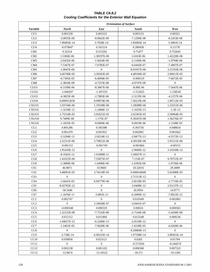
TABLE C6.8.2Cooling Coefficients for the Exterior Wall Equation
Variable
Orientation of Surface
North East South West
CU1 0.001539 0.003315 0.003153 0.00321
CU2 -3.0855E-08 -8.9662E-08 -7.1299E-08 -8.1053E-08
CU3 7.99493E-14 3.7928E-14 1.83083E-14 3.3981E-14
CU4 -0.079647 0.163114 0.286458 0.11178
CM1 0.32314 0.515262 0.71477 0.752643
CM2 1.5306E-06 1.38197E-06 1.6163E-06 1.42228E-06
CM3 -2.0432E-06 -1.6024E-06 -2.1106E-06 -1.9794E-06
CM4 -7.5367E-07 -7.6785E-07 -6.6443E-07 -7.4007E-07
CM5 -1.0047E-06 0 8.01057E-06 3.15193E-06
CM6 3.66708E-05 3.56503E-05 4.48106E-05 2.96012E-05
CM7 -6.7305E-05 -6.4094E-05 -0.000119 -7.6672E-05
CM8 -2.3834E-08 -4.7253E-08 -4.9747E-08 0
CUO1 -6.5109E-06 -8.3867E-06 -8.89E-06 -7.5647E-06
CUO2 -1.040207 -1.507235 -1.512625 -1.238545
CUO3 -4.3825E-06 -2.7883E-06 -2.3135E-06 -4.1257E-06
CUO4 0.000012658 8.09874E-06 7.36219E-06 1.06712E-05
CXUO1 1.03744E-06 1.19338E-06 1.18588E-06 1.23251E-06
CXUO2 -1.3218E-13 -1.3466E-13 -1.1625E-13 -1.3E-13
CXUO3 2.75554E-05 2.02621E-05 2.02365E-05 2.36964E-05
CXUO4 9.7409E-08 1.175E-07 9.39207E-08 1.36276E-07
CXUO5 -1.1825E-05 -9.0969E-06 -9.0919E-06 -1.1108E-05
CG1 0.891286 0.583388 0.393756 0.948654
CG2 0.001479 0.001931 0.002081 0.001662
CG3 -5.5204E-13 -2.8214E-13 -2.8477E-13 -4.5572E-13
CG4 2.52311E-06 3.70821E-06 4.30536E-06 5.91511E-06
CG5 -0.001151 -0.001745 -0.001864 -0.00153
CG6 1.95243E-12 0 -2.9606E-12 3.16358E-12
CG7 -8.3581E-12 1.01089E-11 3.30027E-11 0
CG8 1.41022E-06 7.53875E-07 7.133E-07 9.70752E-07
CG9 -2.3889E-06 -1.6496E-06 -1.6393E-06 -1.9736E-06
CS1 46.9871 33.9683 18.32016 29.3089
CS2 3.48091E-05 3.74118E-05 0.000034049 5.02498E-05
CS3 0 0 2.71313E-12 0
CS4 -1.6641E-05 6.94779E-06 -2.8218E-05 -2.7716E-05
CS5 8.42765E-12 0 -3.0468E-12 2.91137E-12
CS6 -56.5446 0 26.9954 14.9771
CS7 -1.3476E-11 -5.881E-12 -6.5009E-12 -7.8922E-12
CC1 0.002747 0 0.010349 0.001865
CC2 0 3.18928E-07 -3.0441E-07 0
CC3 -0.000348 0.000319 0.00024 0.000565
CC4 1.22123E-08 -7.7532E-08 -2.7144E-08 -5.4438E-08
CC5 0.012112 0.011894 0.013248 0.009236
CC6 1.04027E-12 -6.2266E-13 -2.0518E-12 0
CC7 -1.2401E-05 -7.0628E-06 -1.6538E-05 -6.0269E-06
CC8 0 0 8.20869E-13 0
CC9 -3.758E-14 6.06235E-14 1.97598E-14 3.89425E-14
CC10 0.030056 0.023121 0.0265 0.01704
CC11 0 0 -0.271026 -0.244274
CC12 0.002138 0.001103 0.006368 0.007323
CC13 -12.8674 -13.16522 -18.271 -10.1285
128 ANSI/ASHRAE/IESNA STANDARD 90.1-2001

The coefficients used in the above equations depend onthe orientation of the surface and shall be found in TableC6.8.3. Terms not defined for Equation C-16 are found underEquation C-14.
C6.9 Skylights in the Exterior Building Envelope. HEATand COOL shall be calculated for skylights in nonresidentialconditioned and residential conditioned zones using Equa-tions C-18 and C-19.
HEAT = Areasky × HDD65 × 0.66 × (H2 × Usky + H3 × 1.163 × SHGC) (C-18)
ANSI/ASHRAE/IESNA STANDARD 90.1-2001
COOL = Areasky × C2 × CDD50 × 0.093 × SHGC (C-19)
where
Areasky = fenestration area of the skylight assembly
SHGC = the solar heat gain coefficient of the skylight assembly
Usky = U-factor of skylight assembly
The coefficients used in the equations depend on thespace type and shall be taken from Table C6.9.
TABLE C6.8.3Heating Coefficients for the Exterior Wall Equation
Variable
Orientation of Surface
North East South West
HU1 0.006203 0.007691 0.006044 0.006672
HU2 -1.3587E-12 -5.7162E-13 -2.69E-13 -4.3566E-13
HM1 0.531005 0.545732 0.837901 0.616936
HM2 0.000152 0.000107 0.000208 0.00015
HM3 -5.3183E-07 -1.0619E-07 -6.8253E-07 -2.6457E-07
HM4 -7.7381E-07 -1.4787E-06 2.11938E-06 -4.5783E-07
HM5 -0.000712 -0.000484 -0.001042 -0.000625
HM6 3.34859E-13 4.95762E-14 7.7019E-14 7.37105E-14
HM7 2.39071E-07 2.75045E-07 -3.8989E-07 0
HUO1 0.004943 0.008683 0.009028 0.008566
HUO2 0.013686 0.011055 0.010156 0.01146
HUO3 -1.1018E-05 -8.6896E-06 -7.3232E-06 -8.9867E-06
HXUO1 1.2694E-12 7.85644E-14 -2.8202E-13 3.04904E-14
HXUO2 -7.3058E-13 -8.109E-14 7.45599E-14 -7.4718E-14
HXUO3 1.9709E-07 1.94026E-07 9.87587E-08 1.95776E-07
HG1 -0.001051 -0.000983 -0.000981 -0.000948
HG2 -0.001063 -0.00093 -0.000815 -0.000975
HG3 2.99013E-06 2.62269E-06 2.4188E-06 2.49976E-06
HG4 7.49049E-07 -1.1106E-06 -2.1669E-06 -8.5605E-07
HG5 0.000109 0.000093431 9.75523E-05 8.62389E-05
HG6 -5.5591E-07 -3.158E-07 -2.61E-07 -2.9133E-07
HS1 -2.1825E-05 -2.0922E-05 -2.1089E-05 -2.0205E-05
HS2 3.39179E-12 1.905E-12 1.48388E-12 2.18215E-12
HS3 -6.5325E-06 -2.2341E-05 -1.8473E-05 -2.4049E-05
HS4 2.23087E-05 2.41331E-05 2.45412E-05 2.30538E-05
HC1 -0.106468 -5.19297 -3.66743 -5.29681
HC2 0.00729 0.007684 0.007175 0.007672
HC3 -2.976E-07 -3.0784E-07 -2.6419E-07 -3.0713E-07
HC4 2.01569E-06 6.3035E-06 3.32112E-06 6.43491E-06
HC5 1.29061E-05 4.77552E-06 3.25089E-06 4.83233E-06
HC6 -1.2859E-05 -6.1854E-06 -4.6309E-06 -6.251E-06
HC7 2.75861E-12 8.20051E-13 4.38148E-13 8.09106E-13
TABLE C6.9Heating and Cooling Coefficients for Skylights
Coefficient Nonresidential Residential
C2 1.09E-02 1.64E-02
H2 2.12E-04 2.91E-04
H3 -1.68E-04 -2.96E-04
C6.10 Calculations for Other Exterior and Semi-Exte-rior Surfaces. For all exterior and semi-exterior surfaces notcovered in C6.8 and C6.9, the cooling factor, COOL, andheating factor, HEAT, shall be calculated using the procedurein this subsection.
C6.10.1 U-Factor for Below-Grade Walls. The effec-tive U-factor of below-grade walls shall be calculated usingEquation C-20. Rsoil shall be selected from Table C6.10.1
129

based on the average depth of the bottom of the wall below thesurface of the ground.
U-factor = 1 / (1/(C-factor) + 0.85 + Rsoil) (C-20)
where
Rsoil = effective R-value of the soil from Table C6.10.1
C6.10.2 Adjustment for Other Protected Elements ofthe Exterior Envelope. The adjusted U-factor for exteriorenvelope surfaces, which are protected from outdoor condi-tions by crawl spaces, attics, or parking garages with naturalor mechanical ventilation, shall be adjusted using Equation C-21 before calculating HEAT and COOL.
Uadj = 1 / ((1 / U-factor) + 2) (C-21)
C6.10.3 Calculation of COOL and HEAT. COOL andHEAT shall be calculated for each surface using Equations C-22 and C-23 and coefficients from Table C6.10.3, whichdepend on surface classification and space-conditioning cat-egory.
COOL = Size × Factor × 0.08 × (Ccoef1 × CDD50 + Ccoef2) (C-22)
HEAT = Size × Hcoef × Factor × HDD65 × 0.66 (C-23)
where
130
Size = area of surface or length of exposed slab-on-grade floor perimeter in the building
Ccoef1, Ccoef2 = coefficients, from Table C6.10.3
Hcoef = coefficient, from Table C6.10.3
Factor = U-factor except Uadj calculated using Equation C-21 for protected surfaces and for slab-on-grade floors, perimeter F-factor
TABLE C6.10.1Effective R-Value of Soil for Below-Grade Walls
Depth Rsoil (h� ft2� � F/Btu)
1 ft 0.86
2 ft 1.6
3 ft 2.2
4 ft 2.9
5 ft 3.4
6 ft 4.0
7 ft 4.5
8 ft 5.1
9 ft 5.6
10 ft 6.1
TABLE 6.10.3Heating and Cooling Coefficients for Other Exterior and Semi-Exterior Surfaces
Building Envelope Classification Exterior Semi-Exterior
Space-Conditioning Type Nonresidential Residential All
Surface Type Ccoef1 Ccoef2 HCoef Ccoef1 Ccoef2 HCoef Ccoef1 Ccoef2 HCoef
Roof 0.001153 5.56 2.28E-04 0.001656 9.44 3.37E-04 0 0 8.08E-05
Wall, Above-Grade and Opaque Doors 6.04E-04 0 2.28E-04 1.18E-03 0 3.37E-04 0 0 7.56E-05
Wall, Below-Grade 2.58E-04 0 2.29E-04 6.80E-04 0 3.35E-04 NA 0 7.85E-05
Mass Floor 6.91E-04 0 2.39E-04 1.01E-03 0 3.60E-04 0 0 7.14E-05
Other Floor 7.09E-04 0 2.43E-04 9.54E-04 0 3.66E-04 0 0 7.14E-05
Slab-on-Grade Floor 0 0 2.28E-04 0 0 3.37E-04 0 0 6.80E-05
Vertical Fenestration NA 0 NA NA 0 NA 0 0 7.56E-05
Skylights NA 0 NA NA 0 NA 0 0 8.08E-05
ANSI/ASHRAE/IESNA STANDARD 90.1-2001

(Thi
s is
a n
orm
ativ
e ap
pend
ix a
nd is
par
t of
thi
s st
anda
rd.)
NO
RM
AT
IVE
AP
PE
ND
IX D
CL
IMA
TIC
DA
TAT
his n
orm
ativ
e ap
pend
ix c
onta
ins t
he c
limat
ic d
ata
nece
ssar
y to
det
erm
ine
buil
ding
env
elop
e an
d m
echa
nica
l req
uire
men
ts fo
r var
ious
U.S
, Can
adia
n, a
nd in
tern
atio
nal l
ocat
ions
.(S
ee 5
.1.3
for a
dditi
onal
info
rmat
ion
rega
rdin
g th
e se
lect
ion
of c
lim
atic
dat
a.) T
he fo
llow
ing
defi
nitio
n ap
plie
s: N
.A. =
Not
Ava
ilabl
e. T
able
num
bers
cor
resp
ondi
ng to
the
enve
lope
crite
ria
tabl
es in
Nor
mat
ive
App
endi
x B
are
als
o in
clud
ed.
TAB
LE
D-1
U
.S. C
limat
ic D
ata
Stat
e C
ity
Tabl
eL
atit
ude
Lon
gitu
deE
lev.
(ft
)H
DD
65C
DD
50
Hea
ting
Des
ign
Tem
pera
ture
Coo
ling
Des
ign
Tem
pera
ture
No.
Hrs
. 8
a.m
.-4
p.m
.D
ry-B
ulb
Wet
-Bul
b
99.6
%1.
0%1.
0%55
<Tdb
<69
Ala
bam
a (A
L)
Ale
xand
er C
ityB
-11
32.9
5N
85.9
3W
640
2,91
05,
102
N.A
.N
.A.
N.A
.N
.A.
Ann
isto
n FA
A A
PB
-11
33.5
8N
85.8
5W
611
2,85
45,
217
1993
76N
.A.
Aub
urn
Agr
onom
y Fa
rmB
-832
.60
N85
.50
W65
22,
612
5,42
8N
.A.
N.A
.N
.A.
N.A
.
Bir
min
gham
FA
A A
PB
-11
33.5
7N
86.7
5W
625
2,91
85,
206
1892
7576
0
Dot
han
B-6
31.3
2N
85.4
5W
400
1,70
36,
659
2893
76N
.A.
Gad
sden
Ste
am P
lant
B-1
134
.03
N86
.00
W56
53,
317
4,80
5N
.A.
N.A
.N
.A.
N.A
.
Hun
tsvi
lle W
SO A
PB
-11
34.6
5N
86.7
7W
624
3,32
34,
855
1592
74N
.A.
Mob
ile W
SO A
PB
-630
.68
N88
.25
W21
11,
702
6,76
126
9276
774
Mon
tgom
ery
WSO
AP
B-8
32.3
0N
86.4
0W
221
2,22
45,
990
2493
7673
4
Selm
aB
-832
.42
N87
.00
W14
72,
249
6,08
0N
.A.
N.A
.N
.A.
N.A
.
Talla
dega
B-1
133
.43
N86
.08
W55
52,
790
5,09
7N
.A.
N.A
.N
.A.
N.A
.
Tus
calo
osa
FAA
AP
B-8
33.2
3N
87.6
2W
169
2,66
15,
624
2094
77N
.A.
Ala
ska
(AK
)
Anc
hora
ge W
SCM
O A
PB
-22
61.1
7N
150.
02W
114
10,5
7068
8-1
468
5752
1
Bar
row
WSO
AP
B-2
671
.30
N15
6.78
W31
20,2
260
-41
5249
N.A
.
Fair
bank
s W
SFO
AP
B-2
464
.82
N14
7.87
W43
613
,940
1,04
0-4
777
5968
2
June
au A
PB
-20
58.3
7N
134.
58W
128,
897
559
469
5854
0
Kod
iak
WSO
AP
B-2
057
.75
N15
2.50
W11
18,
817
451
765
5638
4
Nom
e W
SO A
PB
-24
64.5
0N
165.
43W
1314
,129
274
-31
6555
210
Ari
zona
(A
Z)
Dou
glas
FA
A A
PB
-11
31.4
7N
109.
60W
4,09
82,
767
4,78
6N
.A.
N.A
.N
.A.
N.A
.
Flag
staf
f W
SO A
PB
-18
35.1
3N
111.
67W
7,00
67,
131
1,66
11
8355
N.A
.
Kin
gman
B-1
135
.20
N11
4.02
W3,
539
3,21
25,
040
2297
63N
.A.
Nog
ales
B-1
131
.42
N11
0.95
W3,
560
2,92
84,
554
N.A
.N
.A.
N.A
.N
.A.
Phoe
nix
WSF
O A
PB
-533
.43
N11
2.02
W1,
110
1,35
08,
425
3410
870
746
ANSI/ASHRAE/IESNA STANDARD 90.1-2001 131

Pres
cott
B-1
434
.57
N11
2.43
W5,
205
4,99
52,
875
1591
6072
5
Tuc
son
WSO
AP
B-6
32.1
3N
110.
93W
2,58
41,
678
6,92
131
102
6571
6
Win
slow
WSO
AP
B-1
335
.02
N11
0.73
W4,
890
4,77
63,
681
1093
6063
4
Yum
a W
SO A
PB
-532
.67
N11
4.60
W20
692
78,
897
4010
972
697
Ark
ansa
s (A
R)
Bly
thev
ille
AFB
B-1
335
.97
N89
.95
W25
63,
656
5,13
312
9577
N.A
.
Cam
den
B-1
133
.60
N92
.82
W11
62,
953
5,30
9N
.A.
N.A
.N
.A.
N.A
.
Faye
ttevi
lleB
-13
36.0
0N
94.1
7W
1,25
04,
040
4,45
26
9375
N.A
.
Ft S
mith
WSO
AP
B-1
135
.33
N94
.37
W44
93,
478
5,07
813
9676
547
Hot
Spr
ings
B-1
134
.52
N93
.05
W68
03,
181
5,24
3N
.A.
N.A
.N
.A.
N.A
.
Jone
sbor
oB
-11
35.8
8N
90.7
0W
390
3,50
45,
118
N.A
.N
.A.
N.A
.N
.A.
Litt
le R
ock
FAA
AP
B-1
134
.73
N92
.23
W25
73,
155
5,29
916
9577
626
Pine
Blu
ffB
-10
34.2
2N
92.0
2W
215
3,01
65,
467
N.A
.N
.A.
N.A
.N
.A.
Texa
rkan
a FA
A A
PB
-833
.45
N94
.00
W36
12,
295
6,15
220
9577
N.A
.
Cal
ifor
nia
(CA
)
Bak
ersf
ield
WSO
AP
B-8
35.4
2N
119.
05W
495
2,18
26,
049
3210
169
848
Bly
the
FAA
Air
port
B-5
33.6
2N
114.
72W
390
1,14
48,
789
N.A
.N
.A.
N.A
.N
.A.
Bur
bank
Hol
lyw
ood
B-6
34.2
0N
118.
37W
774
1,20
45,
849
3995
69N
.A.
Chi
co U
nive
rsity
Far
mB
-11
39.7
0N
121.
82W
185
2,95
34,
454
N.A
.N
.A.
N.A
.N
.A.
Cre
scen
t City
B-1
541
.77
N12
4.20
W40
4,39
71,
628
N.A
.N
.A.
N.A
.N
.A.
El C
entr
oB
-532
.77
N11
5.57
W-3
01,
156
8,13
2N
.A.
N.A
.N
.A.
N.A
.
Eur
eka
WSO
City
B-1
540
.80
N12
4.17
W60
4,49
61,
529
N.A
.N
.A.
N.A
.N
.A.
Fair
fiel
d/T
ravi
s A
FBB
-938
.27
N12
1.93
W62
2,55
64,
223
3194
67N
.A.
Fres
no W
SO A
PB
-936
.77
N11
9.72
W32
82,
556
5,35
030
101
7078
5
Lag
una
Bea
chB
-933
.55
N11
7.78
W35
2,15
73,
881
N.A
.N
.A.
N.A
.N
.A.
Liv
erm
ore
B-1
137
.67
N12
1.77
W48
02,
909
3,81
0N
.A.
N.A
.N
.A.
N.A
.
Lom
poc
B-9
34.6
5N
120.
45W
952,
651
3,24
0N
.A.
N.A
.N
.A.
N.A
.
Lon
g B
each
WSO
AP
B-7
33.8
2N
118.
15W
341,
430
5,28
140
8867
1502
Los
Ang
eles
WSO
AP
B-7
33.9
3N
118.
38W
100
1,45
84,
777
4381
6418
49
Mer
ced/
Cas
tle A
FBB
-937
.37
N12
0.57
W18
72,
687
4,69
430
9769
N.A
.
Mon
tere
yB
-12
36.6
0N
121.
90W
385
3,12
52,
574
N.A
.N
.A.
N.A
.N
.A.
TAB
LE
D-1
(C
on
tin
ued
)U
.S. C
limat
ic D
ata
Stat
e C
ity
Tabl
eL
atit
ude
Lon
gitu
deE
lev.
(ft
)H
DD
65C
DD
50
Hea
ting
Des
ign
Tem
pera
ture
Coo
ling
Des
ign
Tem
pera
ture
No.
Hrs
. 8
a.m
.-4
p.m
.D
ry-B
ulb
Wet
-Bul
b
99.6
%1.
0%1.
0%55
<Tdb
<69
132 ANSI/ASHRAE/IESNA STANDARD 90.1-2001

Nap
a St
ate
Hos
pita
lB
-12
38.2
8N
122.
27W
602,
844
3,46
3N
.A.
N.A
.N
.A.
N.A
.
Nee
dles
FA
A A
irpo
rtB
-534
.77
N11
4.62
W91
41,
309
8,64
5N
.A.
N.A
.N
.A.
N.A
.
Oak
land
/Int
lB
-937
.73
N12
2.20
W7
2,64
43,
126
N.A
.N
.A.
N.A
.19
05
Oce
ansi
de M
arin
aB
-933
.22
N11
7.40
W10
2,01
04,
069
N.A
.N
.A.
N.A
.N
.A.
Ont
ario
/Int
lB
-634
.05
N11
7.62
W96
11,
488
5,82
335
9870
N.A
.
Oxn
ard
B-9
34.2
0N
119.
18W
491,
992
3,98
039
7964
N.A
.
Palm
Spr
ings
B-5
33.8
3N
116.
50W
425
985
8,55
5N
.A.
N.A
.N
.A.
N.A
.
Palm
dale
B-1
134
.58
N11
8.10
W2,
596
2,94
84,
863
N.A
.N
.A.
N.A
.N
.A.
Pasa
dena
B-6
34.1
5N
118.
15W
864
1,45
35,
476
N.A
.N
.A.
N.A
.N
.A.
Peta
lum
a Fi
re S
tn 3
B-1
238
.23
N12
2.63
W27
3,05
03,
188
N.A
.N
.A.
N.A
.N
.A.
Pom
ona
Cal
Pol
yB
-734
.07
N11
7.82
W74
01,
713
5,14
5N
.A.
N.A
.N
.A.
N.A
.
Red
ding
WSO
B-1
140
.50
N12
2.30
W50
22,
855
4,96
4N
.A.
N.A
.N
.A.
N.A
.
Red
land
sB
-834
.05
N11
7.18
W1,
318
1,87
55,
435
N.A
.N
.A.
N.A
.N
.A.
Ric
hmon
dB
-937
.93
N12
2.35
W55
2,57
43,
285
N.A
.N
.A.
N.A
.N
.A.
Riv
ersi
de/M
arch
AFB
B-9
33.9
0N
117.
25W
1,53
51,
861
5,29
534
9868
N.A
.
Sacr
amen
to F
AA
AP
B-1
138
.52
N12
1.50
W18
2,74
94,
474
3097
6899
0
Salin
as F
AA
AP
B-1
236
.67
N12
1.60
W69
2,96
42,
951
3378
62N
.A.
San
Ber
nard
ino/
Nor
ton
B-8
34.1
0N
117.
23W
1,15
51,
821
5,45
034
101
70N
.A.
San
Die
go W
SO A
PB
-732
.73
N11
7.17
W13
1,25
65,
223
4481
6719
11
San
Fran
cisc
o W
SO A
PB
-12
37.6
2N
122.
38W
83,
016
2,88
337
7862
1796
San
Jose
B-9
37.3
5N
121.
90W
672,
387
3,93
535
8966
N.A
.
San
Lui
s O
bisp
o Po
lyB
-935
.30
N12
0.67
W31
52,
498
3,49
2N
.A.
N.A
.N
.A.
N.A
.
Sant
a A
na F
ire
Stat
ion
B-6
33.7
5N
117.
87W
135
1,23
85,
430
N.A
.N
.A.
N.A
.N
.A.
Sant
a B
arba
ra F
AA
AP
B-9
34.4
3N
119.
83W
92,
438
3,44
934
8064
N.A
.
Sant
a C
ruz
B-1
236
.98
N12
2.02
W13
02,
969
2,91
3N
.A.
N.A
.N
.A.
N.A
.
Sant
a M
aria
WSO
AP
B-1
234
.90
N12
0.45
W25
42,
984
2,91
832
8262
2016
Sant
a M
onic
a Pi
erB
-934
.00
N11
8.50
W14
1,81
94,
145
N.A
.N
.A.
N.A
.N
.A.
Sant
a Pa
ula
B-9
34.3
2N
119.
15W
237
2,03
94,
114
N.A
.N
.A.
N.A
.N
.A.
Sant
a R
osa
B-1
238
.45
N12
2.70
W16
72,
883
3,43
2N
.A.
N.A
.N
.A.
N.A
.
Stoc
kton
WSO
AP
B-1
137
.90
N12
1.25
W22
2,70
74,
755
3097
68N
.A.
Uki
ahB
-11
39.1
5N
123.
20W
623
2,95
43,
868
N.A
.N
.A.
N.A
.N
.A.
TAB
LE
D-1
(C
on
tin
ued
)U
.S. C
limat
ic D
ata
Stat
e C
ity
Tabl
eL
atit
ude
Lon
gitu
deE
lev.
(ft
)H
DD
65C
DD
50
Hea
ting
Des
ign
Tem
pera
ture
Coo
ling
Des
ign
Tem
pera
ture
No.
Hrs
. 8
a.m
.-4
p.m
.D
ry-B
ulb
Wet
-Bul
b
99.6
%1.
0%1.
0%55
<Tdb
<69
ANSI/ASHRAE/IESNA STANDARD 90.1-2001 133

Vis
alia
B-9
36.3
3N
119.
30W
325
2,51
15,
186
N.A
.N
.A.
N.A
.N
.A.
Yre
kaB
-14
41.7
2N
122.
63W
2,62
55,
386
2,61
1N
.A.
N.A
.N
.A.
N.A
.
Col
orad
o (C
O)
Ala
mos
a W
SO A
PB
-20
37.4
5N
105.
87W
7,53
68,
749
1,37
4-1
782
55N
.A.
Bou
lder
B-1
740
.03
N10
5.28
W5,
420
5,55
42,
820
N.A
.N
.A.
N.A
.N
.A.
Col
orad
o Sp
rgs
WSO
AP
B-1
738
.82
N10
4.72
W6,
090
6,41
52,
312
-287
5872
5
Den
ver
WSF
O A
PB
-17
39.7
7N
104.
87W
5,28
66,
020
2,73
2-3
9059
739
Dur
ango
B-1
737
.28
N10
7.88
W6,
600
6,91
11,
942
N.A
.N
.A.
N.A
.N
.A.
Ft C
ollin
sB
-17
40.5
8N
105.
08W
5,00
46,
368
2,41
1N
.A.
N.A
.N
.A.
N.A
.
Gra
nd J
unct
ion
WSO
AP
B-1
639
.10
N10
8.55
W4,
849
5,54
83,
632
294
6051
8
Gre
eley
UN
CB
-17
40.4
2N
104.
70W
4,71
56,
306
2,69
8N
.A.
N.A
.N
.A.
N.A
.
La
Junt
a FA
A A
PB
-13
38.0
5N
103.
52W
4,19
05,
265
3,79
5N
.A.
N.A
.N
.A.
N.A
.
Pueb
lo W
SO A
PB
-17
38.2
8N
104.
52W
4,64
05,
413
3,35
8-1
9462
720
Ster
ling
B-1
740
.62
N10
3.22
W3,
938
6,54
12,
809
N.A
.N
.A.
N.A
.N
.A.
Tri
nida
d FA
A A
PB
-17
37.2
5N
104.
33W
5,74
65,
483
2,97
6-2
9060
N.A
.
Con
nect
icut
(C
T)
Bri
dgep
ort W
SO A
PB
-17
41.1
7N
73.1
3W
105,
537
2,99
78
8472
N.A
.
Har
tfor
d-B
rain
ard
Fld
B-1
741
.73
N72
.65
W15
6,15
52,
768
288
7259
8
Nor
wal
k G
as P
lant
B-1
741
.12
N73
.42
W37
5,86
52,
768
N.A
.N
.A.
N.A
.N
.A.
Nor
wic
h Pu
b U
til P
ltB
-17
41.5
3N
72.0
7W
205,
869
2,68
7N
.A.
N.A
.N
.A.
N.A
.
Del
awar
e (D
E)
Dov
erB
-13
39.1
5N
75.5
2W
304,
337
3,89
414
8975
N.A
.
Wilm
ingt
on W
SO A
PB
-14
39.6
7N
75.6
0W
794,
937
3,55
710
8974
617
Flor
ida
(FL
)
Bel
le G
lade
Exp
Stn
B-3
26.6
7N
80.6
3W
1645
18,
285
N.A
.N
.A.
N.A
.N
.A.
Day
tona
Bea
ch W
SO A
PB
-529
.18
N81
.05
W29
909
7,56
734
9077
641
Ft L
aude
rdal
eB
-226
.07
N80
.15
W10
171
9,73
546
9078
N.A
.
Ft M
yers
FA
A A
PB
-326
.58
N81
.87
W15
418
8,92
442
9377
N.A
.
Ft P
ierc
eB
-327
.47
N80
.35
W25
490
8,44
8N
.A.
N.A
.N
.A.
N.A
.
Gai
nesv
ille
Mun
AP
B-6
29.6
8N
82.2
7W
138
1,26
77,
009
3092
77N
.A.
Jack
sonv
ille
WSO
AP
B-6
30.5
0N
81.7
0W
261,
434
6,84
729
9377
674
TAB
LE
D-1
(C
on
tin
ued
)U
.S. C
limat
ic D
ata
Stat
e C
ity
Tabl
eL
atit
ude
Lon
gitu
deE
lev.
(ft
)H
DD
65C
DD
50
Hea
ting
Des
ign
Tem
pera
ture
Coo
ling
Des
ign
Tem
pera
ture
No.
Hrs
. 8
a.m
.-4
p.m
.D
ry-B
ulb
Wet
-Bul
b
99.6
%1.
0%1.
0%55
<Tdb
<69
134 ANSI/ASHRAE/IESNA STANDARD 90.1-2001

Key
Wes
t WSO
AP
B-2
24.5
5N
81.7
5W
410
010
,174
5589
79N
.A.
Lak
elan
dB
-328
.02
N81
.92
W14
558
88,
472
N.A
.N
.A.
N.A
.N
.A.
Mia
mi W
SCM
O A
PB
-225
.80
N80
.30
W12
200
9,47
446
9077
259
Oca
laB
-529
.20
N82
.08
W75
930
7,69
6N
.A.
N.A
.N
.A.
N.A
.
Orl
ando
WSO
Mc
Coy
B-3
28.4
3N
81.3
3W
9168
68,
227
3793
7657
1
Pana
ma
City
/Tyn
dall
B-6
30.0
7N
85.5
8W
161,
216
7,02
333
8979
N.A
.
Pens
acol
a FA
A A
PB
-630
.47
N87
.20
W11
21,
617
6,81
628
9278
N.A
.
St A
ugus
tine
WFO
YB
-529
.90
N81
.32
W8
1,04
07,
261
N.A
.N
.A.
N.A
.N
.A.
St P
eter
sbur
gB
-327
.77
N82
.63
W8
603
8,53
743
9379
N.A
.
Talla
hass
ee W
SO A
PB
-630
.38
N84
.37
W55
1,70
56,
639
2593
7674
7
Tam
pa W
SCM
O A
PB
-327
.97
N82
.53
W19
725
8,23
936
9177
592
Wes
t Pal
m B
each
WSO
AP
B-2
26.6
8N
80.1
2W
1832
39,
049
4390
7830
8
Geo
rgia
(G
A)
Alb
any
B-8
31.5
3N
84.1
3W
180
2,20
56,
020
2795
76N
.A.
Am
eric
usB
-832
.05
N84
.25
W49
02,
430
5,63
4N
.A.
N.A
.N
.A.
N.A
.
Ath
ens
WSO
AP
B-1
133
.95
N83
.32
W80
22,
893
5,07
920
9275
N.A
.
Atla
nta
WSO
AP
B-1
133
.65
N84
.43
W1,
010
2,99
15,
038
1891
7474
9
Aug
usta
WSO
AP
B-8
33.3
7N
81.9
7W
148
2,56
55,
519
2194
7677
4
Bru
nsw
ick
B-6
31.1
7N
81.5
0W
131,
578
6,72
930
9179
N.A
.
Col
umbu
s W
SO A
PB
-832
.52
N84
.95
W44
92,
261
6,05
223
9375
N.A
.
Dal
ton
B-1
134
.75
N84
.95
W70
03,
552
4,54
6N
.A.
N.A
.N
.A.
N.A
.
Dub
linB
-832
.50
N82
.90
W21
52,
476
5,66
4N
.A.
N.A
.N
.A.
N.A
.
Gai
nesv
ille
B-1
134
.30
N83
.85
W1,
170
3,50
04,
310
N.A
.N
.A.
N.A
.N
.A.
La
Gra
nge
B-9
33.0
5N
85.0
2W
715
2,66
75,
216
N.A
.N
.A.
N.A
.N
.A.
Mac
on W
SO A
PB
-832
.70
N83
.65
W35
42,
334
5,82
623
9475
787
Sava
nnah
WSO
AP
B-8
32.1
3N
81.2
0W
461,
847
6,38
926
9376
N.A
.
Val
dost
a/M
oody
AFB
B-5
30.9
7N
83.2
0W
233
1,55
27,
216
3094
77N
.A.
Way
cros
sB
-831
.25
N82
.32
W14
52,
025
6,17
229
9476
N.A
.
Haw
aii (
HI)
Hilo
(H
awai
i)B
-319
.72
N15
5.07
W36
08,
759
6184
7415
3
Hon
olul
u W
SFO
AP
(Oah
u)B
-221
.33
N15
7.92
W7
09,
949
6188
7369
Kan
eohe
Mau
ka (
Oah
u)B
-321
.42
N15
7.82
W19
00
8,95
567
8574
N.A
.
TAB
LE
D-1
(C
on
tin
ued
)U
.S. C
limat
ic D
ata
Stat
e C
ity
Tabl
eL
atit
ude
Lon
gitu
deE
lev.
(ft
)H
DD
65C
DD
50
Hea
ting
Des
ign
Tem
pera
ture
Coo
ling
Des
ign
Tem
pera
ture
No.
Hrs
. 8
a.m
.-4
p.m
.D
ry-B
ulb
Wet
-Bul
b
99.6
%1.
0%1.
0%55
<Tdb
<69
ANSI/ASHRAE/IESNA STANDARD 90.1-2001 135

Idah
o (I
D)
Boi
se W
SFO
AP
B-1
743
.57
N11
6.22
W2,
838
5,86
12,
807
294
6364
7
Bur
ley
FAA
AP
B-1
742
.53
N11
3.77
W4,
157
6,74
52,
174
-590
62N
.A.
Coe
ur D
'Ale
ne R
SB
-17
47.6
8N
116.
75W
2,15
86,
239
2,21
6N
.A.
N.A
.N
.A.
N.A
.
Idah
o Fa
lls F
AA
AP
B-1
943
.52
N11
2.07
W4,
730
8,06
31,
853
-12
8960
N.A
.
Lew
isto
n W
SO A
PB
-14
46.3
8N
117.
02W
1,43
65,
270
2,96
46
9364
748
Mos
cow
-Uni
v of
Ida
hoB
-18
46.7
3N
116.
97W
2,66
06,
782
1,78
9N
.A.
N.A
.N
.A.
N.A
.
Mou
ntai
n H
ome
B-1
743
.13
N11
5.70
W3,
190
6,17
62,
725
096
62N
.A.
Poca
tello
WSO
AP
B-1
742
.92
N11
2.60
W4,
454
7,18
02,
142
-790
6054
6
Twin
Fal
ls W
SOB
-17
42.5
5N
114.
35W
3,96
06,
769
1,99
5N
.A.
N.A
.N
.A.
N.A
.
Illin
ois
(IL
)
Aur
ora
B-1
741
.75
N88
.35
W64
46,
699
2,88
0N
.A.
N.A
.N
.A.
N.A
.
Bel
levi
lle/S
cott
AFB
B-1
338
.55
N89
.85
W45
34,
878
4,14
63
9377
N.A
.
Car
bond
ale
Sew
age
Plt
B-1
337
.73
N89
.17
W39
04,
865
3,93
4N
.A.
N.A
.N
.A.
N.A
.
Cha
mpa
ign
B-1
640
.03
N88
.28
W75
55,
689
3,69
7N
.A.
N.A
.N
.A.
N.A
.
Chi
cago
Mid
way
AP
B-1
741
.73
N87
.77
W62
06,
176
3,25
1N
.A.
N.A
.N
.A.
N.A
.
Chi
cago
O'H
are
WSO
AP
B-1
741
.98
N87
.90
W67
46,
536
2,94
1-6
8873
613
Chi
cago
Uni
vers
ityB
-17
41.7
8N
87.6
0W
594
5,75
33,
391
N.A
.N
.A.
N.A
.N
.A.
Dan
ville
B-1
740
.13
N87
.65
W55
85,
610
3,47
1-4
9077
N.A
.
Dec
atur
B-1
639
.83
N89
.02
W62
05,
522
3,65
2-2
9175
N.A
.
Dix
onB
-17
41.8
3N
89.5
2W
700
6,87
32,
965
N.A
.N
.A.
N.A
.N
.A.
Free
port
Was
te W
tr P
ltB
-17
42.3
0N
89.6
0W
750
7,16
92,
739
N.A
.N
.A.
N.A
.N
.A.
Gal
esbu
rgB
-17
40.9
5N
90.3
8W
771
6,31
43,
249
N.A
.N
.A.
N.A
.N
.A.
Jolie
t Bra
ndon
Rd
Dam
B-1
741
.50
N88
.10
W54
36,
463
3,02
5N
.A.
N.A
.N
.A.
N.A
.
Mol
ine
WSO
AP
B-1
741
.45
N90
.50
W58
26,
474
3,20
7-8
9074
640
Mt V
erno
nB
-13
38.3
5N
88.8
7W
490
5,18
93,
818
N.A
.N
.A.
N.A
.N
.A.
Peor
ia W
SO A
PB
-17
40.6
7N
89.6
8W
650
6,14
83,
339
-689
74N
.A.
Qui
ncy
FAA
AP
B-1
739
.93
N91
.20
W76
35,
763
3,57
4-4
9175
N.A
.
Ran
toul
B-1
740
.32
N88
.17
W74
06,
183
3,28
8N
.A.
N.A
.N
.A.
N.A
.
Roc
kfor
d W
SO A
PB
-17
42.2
0N
89.1
0W
724
6,96
92,
852
-10
8873
N.A
.
Spri
ngfi
eld
WSO
AP
B-1
639
.85
N89
.68
W59
45,
688
3,63
5-4
9175
600
Wau
kega
nB
-17
42.3
5N
87.8
8W
700
7,13
62,
515
N.A
.N
.A.
N.A
.N
.A.
TAB
LE
D-1
(C
on
tin
ued
)U
.S. C
limat
ic D
ata
Stat
e C
ity
Tabl
eL
atit
ude
Lon
gitu
deE
lev.
(ft
)H
DD
65C
DD
50
Hea
ting
Des
ign
Tem
pera
ture
Coo
ling
Des
ign
Tem
pera
ture
No.
Hrs
. 8
a.m
.-4
p.m
.D
ry-B
ulb
Wet
-Bul
b
99.6
%1.
0%1.
0%55
<Tdb
<69
136 ANSI/ASHRAE/IESNA STANDARD 90.1-2001

Indi
ana
(IN
)
And
erso
n Se
wag
e Pl
ant
B-1
740
.10
N85
.72
W84
75,
916
3,09
1N
.A.
N.A
.N
.A.
N.A
.
Blo
omin
gton
Ind
iana
UB
-14
39.1
7N
86.5
2W
825
5,30
93,
585
N.A
.N
.A.
N.A
.N
.A.
Col
umbu
sB
-17
39.2
0N
85.9
2W
621
5,53
63,
353
N.A
.N
.A.
N.A
.N
.A.
Eva
nsvi
lle W
SO A
PB
-13
38.0
5N
87.5
3W
380
4,70
84,
074
392
7661
1
Ft W
ayne
WSO
AP
B-1
741
.00
N85
.20
W79
76,
273
3,07
7-4
8873
601
Gos
hen
Col
lege
B-1
741
.57
N85
.83
W80
56,
282
2,94
1N
.A.
N.A
.N
.A.
N.A
.
Hob
art
B-1
741
.53
N87
.25
W60
06,
043
3,16
8N
.A.
N.A
.N
.A.
N.A
.
Indi
anap
olis
WSF
OB
-17
39.7
3N
86.2
7W
792
5,61
53,
453
-388
74N
.A.
Kok
omo
B-1
740
.42
N86
.05
W85
56,
429
2,97
8N
.A.
N.A
.N
.A.
N.A
.
Laf
ayet
teB
-17
40.3
5N
86.8
7W
600
6,22
83,
069
-590
75N
.A.
Mar
ion
B-1
740
.57
N85
.67
W79
06,
260
2,99
6N
.A.
N.A
.N
.A.
N.A
.
Mun
cie
Bal
l Sta
te U
niv
B-1
740
.22
N85
.42
W94
06,
027
3,19
6N
.A.
N.A
.N
.A.
N.A
.
Peru
/Gri
ssom
AFB
B-1
740
.65
N86
.15
W81
45,
908
3,43
9-3
8975
N.A
.
Ric
hmon
d W
tr W
ksB
-17
39.8
8N
84.8
8W
1,01
55,
963
3,00
4N
.A.
N.A
.N
.A.
N.A
.
Shel
byvi
lle S
ewag
e Pl
tB
-17
39.5
2N
85.7
8W
750
5,78
43,
291
N.A
.N
.A.
N.A
.N
.A.
Sout
h B
end
WSO
AP
B-1
741
.70
N86
.32
W77
36,
331
2,92
0-2
8772
635
Terr
e H
aute
B-1
739
.35
N87
.42
W55
55,
581
3,49
0-3
9076
N.A
.
Val
para
iso
Wat
erw
orks
B-1
741
.52
N87
.03
W80
06,
267
2,94
2N
.A.
N.A
.N
.A.
N.A
.
Iow
a (I
A)
Am
esB
-17
42.0
3N
93.8
0W
1,09
96,
776
3,07
9N
.A.
N.A
.N
.A.
N.A
.
Bur
lingt
onB
-17
40.7
8N
91.1
2W
597
5,94
33,
601
-491
7664
9
Ced
ar R
apid
s FA
A A
PB
-17
41.8
8N
91.7
0W
863
6,92
43,
003
-11
8974
N.A
.
Clin
ton
B-1
741
.80
N90
.27
W58
56,
324
3,29
1N
.A.
N.A
.N
.A.
N.A
.
Des
Moi
nes
WSF
O A
PB
-17
41.5
3N
93.6
5W
938
6,49
73,
371
-990
7466
7
Dub
uque
WSO
AP
B-1
942
.40
N90
.70
W1,
065
7,32
72,
672
N.A
.N
.A.
N.A
.N
.A.
Ft D
odge
B-1
942
.50
N94
.20
W1,
115
7,26
12,
902
-13
8873
N.A
.
Iow
a C
ityB
-17
41.6
5N
91.5
3W
640
6,22
73,
434
N.A
.N
.A.
N.A
.N
.A.
Keo
kuk
Loc
k an
d D
amB
-17
40.4
0N
91.3
7W
527
5,96
93,
467
N.A
.N
.A.
N.A
.N
.A.
Mar
shal
ltow
nB
-17
42.0
7N
92.9
3W
870
7,17
02,
813
N.A
.N
.A.
N.A
.N
.A.
Mas
on C
ity F
AA
AP
B-1
943
.17
N93
.33
W1,
194
7,83
72,
653
-15
8873
610
TAB
LE
D-1
(C
on
tin
ued
)U
.S. C
limat
ic D
ata
Stat
e C
ity
Tabl
eL
atit
ude
Lon
gitu
deE
lev.
(ft
)H
DD
65C
DD
50
Hea
ting
Des
ign
Tem
pera
ture
Coo
ling
Des
ign
Tem
pera
ture
No.
Hrs
. 8
a.m
.-4
p.m
.D
ry-B
ulb
Wet
-Bul
b
99.6
%1.
0%1.
0%55
<Tdb
<69
ANSI/ASHRAE/IESNA STANDARD 90.1-2001 137

New
ton
B-1
741
.70
N93
.05
W93
86,
783
3,13
1N
.A.
N.A
.N
.A.
N.A
.
Ottu
mw
a A
irpo
rtB
-17
41.1
0N
92.4
5W
842
6,26
93,
414
-592
75N
.A.
Siou
x C
ity W
SO A
PB
-17
42.4
0N
96.3
8W
1,10
36,
893
3,14
9-1
190
7460
2
Wat
erlo
o W
SO A
PB
-19
42.5
5N
92.4
0W
868
7,40
62,
813
-14
8873
N.A
.
Kan
sas
(KS)
Atc
hiso
nB
-13
39.5
7N
95.1
2W
945
5,18
43,
940
N.A
.N
.A.
N.A
.N
.A.
Cha
nute
FA
A A
irpo
rtB
-13
37.6
7N
95.4
8W
978
4,65
04,
226
N.A
.N
.A.
N.A
.N
.A.
Dod
ge C
ity W
SO A
PB
-13
37.7
7N
99.9
7W
2,58
25,
001
4,09
00
9770
637
El D
orad
oB
-13
37.8
2N
96.8
3W
1,34
04,
587
4,31
7N
.A.
N.A
.N
.A.
N.A
.
Gar
den
City
FA
A A
PB
-13
37.9
3N
100.
72W
2,88
25,
216
3,93
6-3
9769
N.A
.
Goo
dlan
d W
SO A
PB
-17
39.3
7N
101.
70W
3,65
05,
974
3,01
8-3
9466
625
Gre
at B
end
B-1
338
.35
N98
.77
W1,
850
4,67
94,
425
N.A
.N
.A.
N.A
.N
.A.
Hut
chin
son
B-1
337
.93
N98
.03
W1,
570
5,10
34,
106
N.A
.N
.A.
N.A
.N
.A.
Lib
eral
B-1
337
.05
N10
0.92
W2,
834
4,70
64,
185
N.A
.N
.A.
N.A
.N
.A.
Man
hatta
nB
-13
39.2
0N
96.5
8W
1,06
55,
043
4,15
5N
.A.
N.A
.N
.A.
N.A
.
Pars
ons
B-1
337
.37
N95
.28
W91
04,
606
4,33
9N
.A.
N.A
.N
.A.
N.A
.
Rus
sell
FAA
AP
B-1
338
.87
N98
.82
W1,
864
5,33
83,
939
-496
72N
.A.
Salin
a FA
A A
PB
-13
38.8
0N
97.6
3W
1,25
75,
101
4,16
7-3
9773
N.A
.
Tope
ka W
SFO
AP
B-1
339
.07
N95
.63
W87
75,
265
3,88
0-2
9375
608
Wic
hita
WSO
AP
B-1
337
.65
N97
.43
W1,
321
4,79
14,
351
297
73N
.A.
Ken
tuck
y (K
Y)
Ash
land
B-1
438
.45
N82
.62
W55
55,
225
3,28
0N
.A.
N.A
.N
.A.
N.A
.
Bow
ling
Gre
en F
AA
AP
B-1
336
.97
N86
.42
W54
74,
328
4,13
27
9175
N.A
.
Cov
ingt
on W
SO A
PB
-14
39.0
7N
84.6
7W
869
5,24
83,
488
189
7366
1
Hop
kins
ville
/Cam
pbel
lB
-13
36.6
7N
87.5
0W
571
3,92
84,
654
N.A
.N
.A.
N.A
.N
.A.
Lex
ingt
on W
SO A
PB
-13
38.0
3N
84.6
0W
966
4,78
33,
754
489
7361
8
Lou
isvi
lle W
SFO
AP
B-1
338
.18
N85
.73
W47
74,
514
4,00
06
9075
636
Mad
ison
ville
B-1
337
.35
N87
.52
W44
04,
167
4,29
0N
.A.
N.A
.N
.A.
N.A
.
Ow
ensb
oro
B-1
337
.77
N87
.15
W40
54,
334
4,22
2N
.A.
N.A
.N
.A.
N.A
.
Padu
cah
WSO
B-1
337
.07
N88
.77
W41
04,
279
4,31
77
9376
N.A
.
TAB
LE
D-1
(C
on
tin
ued
)U
.S. C
limat
ic D
ata
Stat
e C
ity
Tabl
eL
atit
ude
Lon
gitu
deE
lev.
(ft
)H
DD
65C
DD
50
Hea
ting
Des
ign
Tem
pera
ture
Coo
ling
Des
ign
Tem
pera
ture
No.
Hrs
. 8
a.m
.-4
p.m
.D
ry-B
ulb
Wet
-Bul
b
99.6
%1.
0%1.
0%55
<Tdb
<69
138 ANSI/ASHRAE/IESNA STANDARD 90.1-2001

Lou
isia
na (
LA
)
Ale
xand
ria
B-8
31.3
2N
92.4
7W
872,
003
6,40
727
9478
N.A
.
Bat
on R
ouge
WSO
AP
B-6
30.5
3N
91.1
3W
641,
669
6,84
527
9277
677
Bog
alus
aB
-830
.78
N89
.87
W10
01,
911
6,45
7N
.A.
N.A
.N
.A.
N.A
.
Hou
ma
B-6
29.5
8N
90.7
3W
151,
429
6,97
4N
.A.
N.A
.N
.A.
N.A
.
Laf
ayet
te F
AA
AP
B-6
30.2
0N
91.9
8W
381,
587
6,87
728
9378
N.A
.
Lak
e C
harl
es W
SO A
PB
-630
.12
N93
.22
W9
1,61
66,
813
2991
7866
8
Min
den
B-8
32.5
8N
93.2
8W
185
2,53
35,
823
N.A
.N
.A.
N.A
.N
.A.
Mon
roe
FAA
AP
B-8
32.5
2N
92.0
5W
782,
407
6,03
922
9478
N.A
.
Nat
chito
ches
B-8
31.7
7N
93.0
8W
130
2,15
26,
273
N.A
.N
.A.
N.A
.N
.A.
New
Orl
eans
WSC
MO
AP
B-6
29.9
8N
90.2
5W
41,
513
6,91
030
9278
789
Shre
vepo
rt W
SO A
PB
-832
.47
N93
.82
W25
42,
264
6,16
622
9577
697
Mai
ne (
ME
)
Aug
usta
FA
A A
PB
-19
44.3
2N
69.8
0W
350
7,55
02,
093
-384
69N
.A.
Ban
gor
FAA
AP
B-1
944
.80
N68
.82
W16
37,
930
1,91
6-7
8469
669
Car
ibou
WSO
AP
B-2
246
.87
N68
.02
W62
49,
651
1,47
0-1
482
6769
2
Lew
isto
nB
-19
44.1
0N
70.2
2W
180
7,24
42,
261
N.A
.N
.A.
N.A
.N
.A.
Mill
inoc
ket
B-2
045
.65
N68
.70
W36
08,
902
1,70
8N
.A.
N.A
.N
.A.
N.A
.
Port
land
WSM
O A
PB
-19
43.6
5N
70.3
2W
577,
378
1,94
3-3
8370
665
Wat
ervi
lle P
mp
Stn
B-1
944
.55
N69
.65
W90
7,38
22,
180
N.A
.N
.A.
N.A
.N
.A.
Mar
ylan
d (M
D)
Bal
timor
e W
SO A
PB
-13
39.1
8N
76.6
7W
196
4,70
73,
709
1191
74N
.A.
Cum
berl
and
B-1
439
.63
N78
.75
W73
05,
036
3,43
2N
.A.
N.A
.N
.A.
N.A
.
Hag
erst
own
B-1
439
.65
N77
.73
W66
05,
293
3,34
1N
.A.
N.A
.N
.A.
N.A
.
Salis
bury
B-1
338
.37
N75
.58
W10
4,02
74,
002
1390
76N
.A.
Mas
sach
uset
ts (
MA
)
Bos
ton
WSO
AP
B-1
742
.37
N71
.03
W20
5,64
12,
897
787
7171
3
Clin
ton
B-1
742
.40
N71
.68
W39
86,
698
2,45
7N
.A.
N.A
.N
.A.
N.A
.
Fram
ingh
amB
-17
42.2
8N
71.4
2W
170
6,26
22,
695
N.A
.N
.A.
N.A
.N
.A.
Law
renc
eB
-17
42.7
0N
71.1
7W
576,
322
2,64
8N
.A.
N.A
.N
.A.
N.A
.
Low
ell
B-1
742
.65
N71
.37
W11
06,
339
2,71
5N
.A.
N.A
.N
.A.
N.A
.
New
Bed
ford
B-1
741
.63
N70
.93
W12
05,
426
2,97
3N
.A.
N.A
.N
.A.
N.A
.
TAB
LE
D-1
(C
on
tin
ued
)U
.S. C
limat
ic D
ata
Stat
e C
ity
Tabl
eL
atit
ude
Lon
gitu
deE
lev.
(ft
)H
DD
65C
DD
50
Hea
ting
Des
ign
Tem
pera
ture
Coo
ling
Des
ign
Tem
pera
ture
No.
Hrs
. 8
a.m
.-4
p.m
.D
ry-B
ulb
Wet
-Bul
b
99.6
%1.
0%1.
0%55
<Tdb
<69
ANSI/ASHRAE/IESNA STANDARD 90.1-2001 139
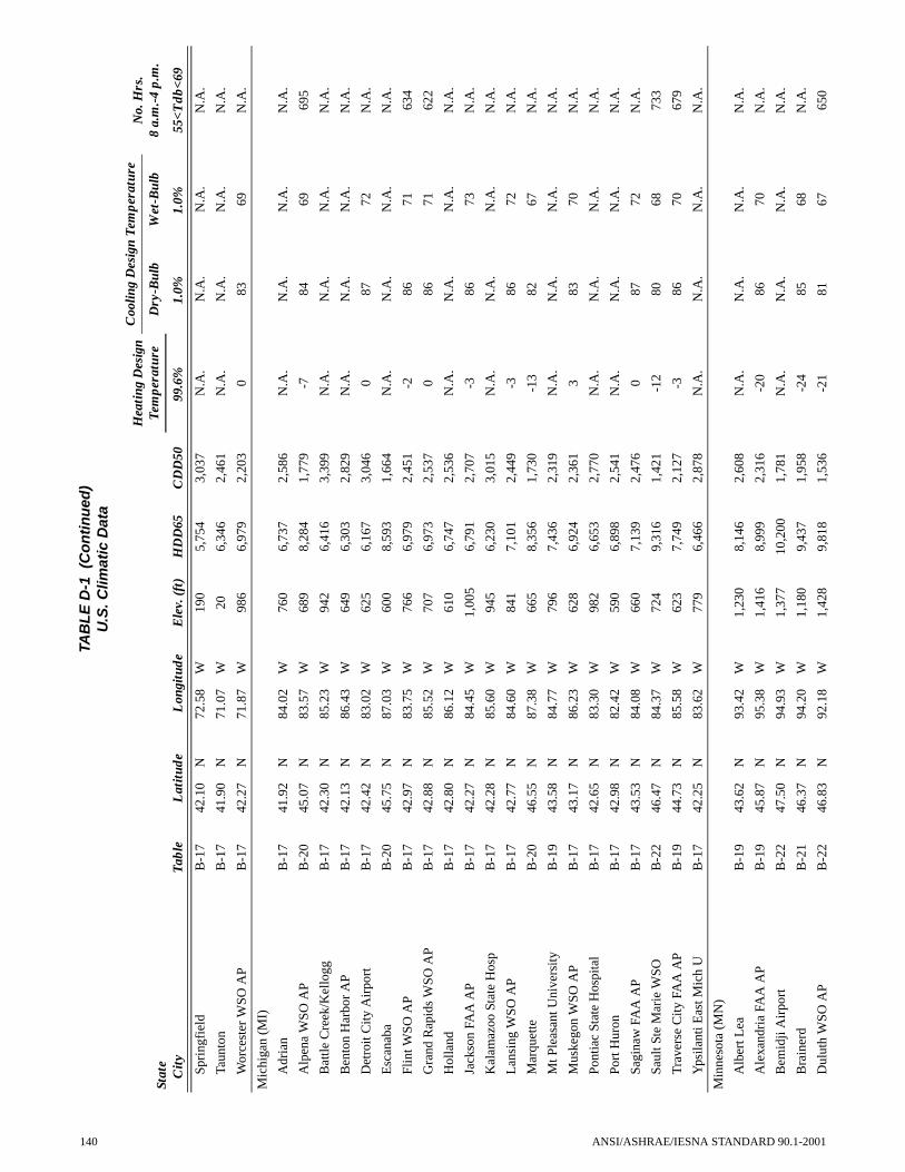
Spri
ngfi
eld
B-1
742
.10
N72
.58
W19
05,
754
3,03
7N
.A.
N.A
.N
.A.
N.A
.
Taun
ton
B-1
741
.90
N71
.07
W20
6,34
62,
461
N.A
.N
.A.
N.A
.N
.A.
Wor
cest
er W
SO A
PB
-17
42.2
7N
71.8
7W
986
6,97
92,
203
083
69N
.A.
Mic
higa
n (M
I)
Adr
ian
B-1
741
.92
N84
.02
W76
06,
737
2,58
6N
.A.
N.A
.N
.A.
N.A
.
Alp
ena
WSO
AP
B-2
045
.07
N83
.57
W68
98,
284
1,77
9-7
8469
695
Bat
tle C
reek
/Kel
logg
B-1
742
.30
N85
.23
W94
26,
416
3,39
9N
.A.
N.A
.N
.A.
N.A
.
Ben
ton
Har
bor
AP
B-1
742
.13
N86
.43
W64
96,
303
2,82
9N
.A.
N.A
.N
.A.
N.A
.
Det
roit
City
Air
port
B-1
742
.42
N83
.02
W62
56,
167
3,04
60
8772
N.A
.
Esc
anab
aB
-20
45.7
5N
87.0
3W
600
8,59
31,
664
N.A
.N
.A.
N.A
.N
.A.
Flin
t WSO
AP
B-1
742
.97
N83
.75
W76
66,
979
2,45
1-2
8671
634
Gra
nd R
apid
s W
SO A
PB
-17
42.8
8N
85.5
2W
707
6,97
32,
537
086
7162
2
Hol
land
B-1
742
.80
N86
.12
W61
06,
747
2,53
6N
.A.
N.A
.N
.A.
N.A
.
Jack
son
FAA
AP
B-1
742
.27
N84
.45
W1,
005
6,79
12,
707
-386
73N
.A.
Kal
amaz
oo S
tate
Hos
pB
-17
42.2
8N
85.6
0W
945
6,23
03,
015
N.A
.N
.A.
N.A
.N
.A.
Lan
sing
WSO
AP
B-1
742
.77
N84
.60
W84
17,
101
2,44
9-3
8672
N.A
.
Mar
quet
teB
-20
46.5
5N
87.3
8W
665
8,35
61,
730
-13
8267
N.A
.
Mt P
leas
ant U
nive
rsity
B-1
943
.58
N84
.77
W79
67,
436
2,31
9N
.A.
N.A
.N
.A.
N.A
.
Mus
kego
n W
SO A
PB
-17
43.1
7N
86.2
3W
628
6,92
42,
361
383
70N
.A.
Pont
iac
Stat
e H
ospi
tal
B-1
742
.65
N83
.30
W98
26,
653
2,77
0N
.A.
N.A
.N
.A.
N.A
.
Port
Hur
onB
-17
42.9
8N
82.4
2W
590
6,89
82,
541
N.A
.N
.A.
N.A
.N
.A.
Sagi
naw
FA
A A
PB
-17
43.5
3N
84.0
8W
660
7,13
92,
476
087
72N
.A.
Saul
t Ste
Mar
ie W
SOB
-22
46.4
7N
84.3
7W
724
9,31
61,
421
-12
8068
733
Tra
vers
e C
ity F
AA
AP
B-1
944
.73
N85
.58
W62
37,
749
2,12
7-3
8670
679
Yps
ilant
i Eas
t Mic
h U
B-1
742
.25
N83
.62
W77
96,
466
2,87
8N
.A.
N.A
.N
.A.
N.A
.
Min
neso
ta (
MN
)
Alb
ert L
eaB
-19
43.6
2N
93.4
2W
1,23
08,
146
2,60
8N
.A.
N.A
.N
.A.
N.A
.
Ale
xand
ria
FAA
AP
B-1
945
.87
N95
.38
W1,
416
8,99
92,
316
-20
8670
N.A
.
Bem
idji
Air
port
B-2
247
.50
N94
.93
W1,
377
10,2
001,
781
N.A
.N
.A.
N.A
.N
.A.
Bra
iner
dB
-21
46.3
7N
94.2
0W
1,18
09,
437
1,95
8-2
485
68N
.A.
Dul
uth
WSO
AP
B-2
246
.83
N92
.18
W1,
428
9,81
81,
536
-21
8167
650
TAB
LE
D-1
(C
on
tin
ued
)U
.S. C
limat
ic D
ata
Stat
e C
ity
Tabl
eL
atit
ude
Lon
gitu
deE
lev.
(ft
)H
DD
65C
DD
50
Hea
ting
Des
ign
Tem
pera
ture
Coo
ling
Des
ign
Tem
pera
ture
No.
Hrs
. 8
a.m
.-4
p.m
.D
ry-B
ulb
Wet
-Bul
b
99.6
%1.
0%1.
0%55
<Tdb
<69
140 ANSI/ASHRAE/IESNA STANDARD 90.1-2001

Fari
baul
tB
-19
44.3
0N
93.2
7W
940
8,27
92,
498
N.A
.N
.A.
N.A
.N
.A.
Inte
rnat
iona
l Fal
ls W
SO A
PB
-22
48.5
7N
93.3
8W
1,17
910
,487
1,63
0-2
983
6765
6
Man
kato
B-1
944
.15
N94
.02
W83
68,
005
2,69
1N
.A.
N.A
.N
.A.
N.A
.
Min
neap
olis
-St P
aul W
SO A
PB
-19
44.8
8N
93.2
2W
834
7,98
12,
680
-16
8871
566
Roc
hest
er W
SO A
PB
-19
43.9
2N
92.5
0W
1,29
78,
250
2,37
6-1
785
7165
2
St C
loud
WSO
AP
B-1
945
.55
N94
.07
W1,
037
8,92
82,
149
-20
8871
N.A
.
Vir
gini
aB
-22
47.5
0N
92.5
5W
1,43
510
,024
1,58
3N
.A.
N.A
.N
.A.
N.A
.
Will
mar
Sta
te H
ospi
tal
B-1
945
.13
N95
.02
W1,
128
8,63
72,
465
N.A
.N
.A.
N.A
.N
.A.
Win
ona
B-1
944
.05
N91
.63
W65
27,
694
2,69
5N
.A.
N.A
.N
.A.
N.A
.
Mis
siss
ippi
(M
S)
Bilo
xi/K
eesl
er A
FBB
-630
.42
N88
.92
W26
1,48
66,
946
3191
78N
.A.
Cla
rksd
ale
B-1
134
.20
N90
.57
W17
33,
188
5,35
7N
.A.
N.A
.N
.A.
N.A
.
Col
umbu
s A
FBB
-10
33.6
5N
88.4
5W
220
2,76
95,
565
2094
78N
.A.
Gre
envi
lleB
-10
33.3
8N
91.0
2W
132
2,77
85,
661
N.A
.N
.A.
N.A
.N
.A.
Gre
enw
ood
FAA
AP
B-8
33.5
0N
90.0
8W
155
2,69
85,
760
2094
78N
.A.
Hat
tiesb
urg
B-8
31.3
2N
89.3
0W
161
2,18
06,
085
N.A
.N
.A.
N.A
.N
.A.
Jack
son
WSF
O A
PB
-832
.32
N90
.08
W33
02,
467
5,90
021
9376
640
Lau
rel
B-8
31.6
8N
89.1
2W
225
2,32
75,
893
N.A
.N
.A.
N.A
.N
.A.
McC
omb
FAA
AP
B-8
31.2
3N
90.4
7W
413
2,11
56,
025
2392
76N
.A.
Mer
idia
n W
SO A
PB
-832
.33
N88
.75
W29
42,
444
5,80
421
9476
719
Nat
chez
B-8
31.5
5N
91.3
8W
195
1,90
36,
378
N.A
.N
.A.
N.A
.N
.A.
Tup
elo
WSO
AP
B-1
134
.27
N88
.73
W36
13,
079
5,22
418
9476
N.A
.
Vic
ksbu
rg M
ilita
ry P
kB
-832
.35
N90
.85
W25
52,
196
6,05
9N
.A.
N.A
.N
.A.
N.A
.
Mis
sour
i (M
O)
Cap
e G
irar
deau
FA
A A
PB
-13
37.2
3N
89.5
7W
337
4,38
64,
359
694
77N
.A.
Col
umbi
a W
SO A
PB
-13
38.8
2N
92.2
2W
887
5,21
23,
752
-192
7563
3
Farm
ingt
onB
-13
37.7
0N
90.3
8W
935
5,04
13,
653
N.A
.N
.A.
N.A
.N
.A.
Han
niba
lB
-16
39.7
2N
91.3
7W
712
5,62
83,
685
N.A
.N
.A.
N.A
.N
.A.
Jeff
erso
n C
ity W
tr P
ltB
-13
38.5
8N
92.1
5W
670
5,30
23,
705
N.A
.N
.A.
N.A
.N
.A.
Jopl
in F
AA
AP
B-1
337
.17
N94
.50
W98
04,
303
4,41
73
9475
N.A
.
Kan
sas
City
WSO
AP
B-1
339
.32
N94
.72
W97
35,
393
3,85
2-1
9375
N.A
.
TAB
LE
D-1
(C
on
tin
ued
)U
.S. C
limat
ic D
ata
Stat
e C
ity
Tabl
eL
atit
ude
Lon
gitu
deE
lev.
(ft
)H
DD
65C
DD
50
Hea
ting
Des
ign
Tem
pera
ture
Coo
ling
Des
ign
Tem
pera
ture
No.
Hrs
. 8
a.m
.-4
p.m
.D
ry-B
ulb
Wet
-Bul
b
99.6
%1.
0%1.
0%55
<Tdb
<69
ANSI/ASHRAE/IESNA STANDARD 90.1-2001 141

Kir
ksvi
lle R
adio
KIR
XB
-17
40.2
2N
92.5
8W
970
5,86
73,
494
N.A
.N
.A.
N.A
.N
.A.
Mex
ico
B-1
639
.18
N91
.88
W77
55,
590
3,66
4N
.A.
N.A
.N
.A.
N.A
.
Mob
erly
Rad
io K
WIX
B-1
339
.40
N92
.43
W84
05,
204
3,94
8N
.A.
N.A
.N
.A.
N.A
.
Popl
ar B
luff
R S
B-1
336
.77
N90
.42
W38
04,
328
4,36
88
9276
N.A
.
Rol
laB
-13
38.1
3N
91.7
7W
1,14
84,
748
4,18
6N
.A.
N.A
.N
.A.
N.A
.
Rol
la U
niv
of M
OB
-13
37.9
5N
91.7
7W
1,18
04,
959
3,98
6N
.A.
N.A
.N
.A.
N.A
.
St J
osep
hB
-16
39.7
7N
94.9
2W
811
5,59
03,
783
N.A
.N
.A.
N.A
.N
.A.
St L
ouis
WSC
MO
AP
B-1
338
.75
N90
.37
W53
54,
758
4,28
32
9375
N.A
.
Mon
tana
(M
T)
Bill
ings
WSO
AP
B-1
745
.80
N10
8.53
W3,
567
7,16
42,
466
-13
9062
617
Boz
eman
B-2
245
.82
N11
0.88
W5,
950
9,90
867
2-2
087
60N
.A.
But
te F
AA
AP
B-2
245
.95
N11
2.50
W5,
540
9,51
71,
152
-22
8456
N.A
.
Cut
Ban
k FA
A A
PB
-20
48.6
0N
112.
37W
3,83
88,
904
1,47
5-2
184
5967
2
Gla
sgow
WSO
AP
B-1
948
.22
N10
6.62
W2,
284
8,74
52,
244
-22
9063
570
Gle
ndiv
eB
-19
47.1
0N
104.
72W
2,07
68,
178
2,61
9N
.A.
N.A
.N
.A.
N.A
.
Gre
at F
alls
WSC
MO
AP
B-1
947
.48
N11
1.37
W3,
663
7,74
11,
993
-19
8860
641
Hav
re W
SO A
PB
-19
48.5
5N
109.
77W
2,58
48,
447
2,13
2-2
590
62N
.A.
Hel
ena
WSO
AP
B-1
946
.60
N11
2.00
W3,
893
8,03
11,
922
-18
8759
651
Kal
ispe
ll W
SO A
PB
-20
48.3
0N
114.
27W
2,96
58,
378
1,34
5-1
286
61N
.A.
Lew
isto
wn
FAA
AP
B-2
047
.07
N10
9.45
W4,
132
8,47
91,
580
-18
8660
673
Liv
ings
ton
FAA
AP
B-1
945
.70
N11
0.45
W4,
653
7,22
01,
900
N.A
.N
.A.
N.A
.N
.A.
Mile
s C
ity F
AA
AP
B-1
946
.43
N10
5.87
W2,
628
7,79
62,
680
-19
9365
565
Mis
soul
a W
SO A
PB
-20
46.9
2N
114.
08W
3,19
07,
792
1,67
9-9
8861
658
Neb
rask
a (N
E)
Cha
dron
FA
A A
PB
-17
42.8
3N
03.0
8W
3,31
27,
020
2,69
2N
.A.
N.A
.N
.A.
N.A
.
Col
umbu
sB
-17
41.4
7N
97.3
3W
1,45
06,
543
3,34
5N
.A.
N.A
.N
.A.
N.A
.
Frem
ont
B-1
741
.43
N96
.48
W1,
180
6,14
03,
421
N.A
.N
.A.
N.A
.N
.A.
Gra
nd I
slan
d W
SO A
PB
-17
40.9
7N
98.3
2W
1,84
16,
421
3,24
3-8
9372
611
Has
tings
B-1
740
.58
N98
.35
W1,
925
6,50
63,
217
N.A
.N
.A.
N.A
.N
.A.
Kea
rney
B-1
740
.73
N99
.02
W2,
130
6,54
83,
090
N.A
.N
.A.
N.A
.N
.A.
Lin
coln
WSO
AP
B-1
740
.85
N96
.75
W1,
190
6,27
83,
455
-794
74N
.A.
Mc
Coo
kB
-17
40.2
2N
100.
58W
2,58
06,
115
3,23
6N
.A.
N.A
.N
.A.
N.A
.
TAB
LE
D-1
(C
on
tin
ued
)U
.S. C
limat
ic D
ata
Stat
e C
ity
Tabl
eL
atit
ude
Lon
gitu
deE
lev.
(ft
)H
DD
65C
DD
50
Hea
ting
Des
ign
Tem
pera
ture
Coo
ling
Des
ign
Tem
pera
ture
No.
Hrs
. 8
a.m
.-4
p.m
.D
ry-B
ulb
Wet
-Bul
b
99.6
%1.
0%1.
0%55
<Tdb
<69
142 ANSI/ASHRAE/IESNA STANDARD 90.1-2001

Nor
folk
WSO
AP
B-1
741
.98
N97
.43
W1,
551
6,87
33,
072
-11
9272
N.A
.
Nor
th P
latte
WSO
AP
B-1
741
.13
N10
0.68
W2,
775
6,85
92,
737
-10
9269
592
Om
aha
(Epp
ley
Fiel
d)B
-17
41.3
0N
95.9
0W
980
6,30
03,
398
-792
75N
.A.
Scot
tsbl
uff
WSO
AP
B-1
741
.87
N10
3.60
W3,
945
6,72
92,
680
-11
9264
620
Sidn
eyB
-17
41.2
3N
103.
00W
4,32
06,
966
2,40
9-8
9263
N.A
.
Nev
ada
(NV
)
Car
son
City
B-1
739
.15
N11
9.77
W4,
651
5,69
12,
312
N.A
.N
.A.
N.A
.N
.A.
Elk
o FA
A A
PB
-17
40.8
3N
115.
78W
5,07
57,
077
2,14
4-5
9259
569
Ely
WSO
AP
B-2
039
.28
N11
4.85
W6,
262
7,62
11,
717
-687
5668
3
Las
Veg
as W
SO A
PB
-836
.08
N11
5.17
W2,
162
2,40
76,
745
2710
666
719
Lov
eloc
k FA
A A
PB
-17
40.0
7N
118.
55W
3,90
05,
869
2,88
6N
.A.
N.A
.N
.A.
606
Ren
o W
SFO
AP
B-1
739
.50
N11
9.78
W4,
404
5,67
42,
504
892
6075
2
Tono
pah
AP
B-1
738
.07
N11
7.08
W5,
426
5,73
32,
840
792
5766
0
Win
nem
ucca
WSO
AP
B-1
740
.90
N11
7.80
W4,
297
6,31
52,
379
194
6060
8
New
Ham
pshi
re (
NH
)
Ber
linB
-20
44.4
5N
71.1
8W
930
8,64
51,
718
N.A
.N
.A.
N.A
.N
.A.
Con
cord
WSO
AP
B-1
943
.20
N71
.50
W34
67,
554
2,08
7-8
8770
683
Kee
neB
-17
42.9
2N
72.2
7W
480
6,94
82,
398
N.A
.N
.A.
N.A
.N
.A.
Port
smou
th/P
ease
AFB
B-1
743
.08
N70
.82
W10
26,
572
2,41
84
8570
N.A
.
New
Jer
sey
(NJ)
Atla
ntic
City
WSO
AP
B-1
439
.45
N74
.57
W13
85,
169
3,19
88
8873
N.A
.
Lon
g B
ranc
h O
akhu
rst
B-1
440
.27
N74
.00
W30
5,25
33,
057
N.A
.N
.A.
N.A
.N
.A.
New
ark
WSO
AP
B-1
340
.70
N74
.17
W30
4,88
83,
748
1090
7364
4
New
Mex
ico
(NM
)
Ala
mog
ordo
/Hol
lom
anB
-11
32.8
5N
106.
10W
4,09
43,
232
4,72
620
9663
N.A
.
Alb
uque
rque
WSF
O A
PB
-13
35.0
5N
106.
62W
5,32
64,
425
3,90
813
9360
703
Art
esia
B-1
132
.77
N10
4.38
W3,
320
3,52
74,
583
N.A
.N
.A.
N.A
.N
.A.
Car
lsba
d FA
A A
PB
-10
32.3
3N
104.
27W
3,23
22,
812
5,51
219
9866
N.A
.
Clo
vis/
Can
non
AFB
B-1
334
.38
N10
3.32
W4,
295
3,98
34,
178
1093
64N
.A.
Farm
ingt
onB
-17
36.7
3N
108.
23W
5,50
25,
464
3,30
78
9260
N.A
.
Gal
lup
FAA
AP
B-1
735
.52
N10
8.78
W6,
468
6,24
42,
355
-187
56N
.A.
Gra
nts
Air
port
B-1
735
.17
N10
7.90
W6,
520
5,90
72,
481
N.A
.N
.A.
N.A
.N
.A.
TAB
LE
D-1
(C
on
tin
ued
)U
.S. C
limat
ic D
ata
Stat
e C
ity
Tabl
eL
atit
ude
Lon
gitu
deE
lev.
(ft
)H
DD
65C
DD
50
Hea
ting
Des
ign
Tem
pera
ture
Coo
ling
Des
ign
Tem
pera
ture
No.
Hrs
. 8
a.m
.-4
p.m
.D
ry-B
ulb
Wet
-Bul
b
99.6
%1.
0%1.
0%55
<Tdb
<69
ANSI/ASHRAE/IESNA STANDARD 90.1-2001 143

Hob
bsB
-11
32.7
0N
103.
13W
3,61
52,
851
5,16
0N
.A.
N.A
.N
.A.
N.A
.
Rat
on F
ilter
Pla
ntB
-17
36.9
2N
104.
43W
6,93
26,
103
2,18
7N
.A.
N.A
.N
.A.
N.A
.
Ros
wel
l FA
A A
PB
-11
33.3
0N
104.
53W
3,66
93,
267
4,96
214
9665
677
Soco
rro
B-1
334
.08
N10
6.88
W4,
585
4,07
43,
845
N.A
.N
.A.
N.A
.N
.A.
Tuc
umca
riB
-13
35.2
0N
103.
68W
4,08
63,
912
4,19
69
9565
710
New
Yor
k (N
Y)
Alb
any
WSF
O A
PB
-17
42.7
5N
73.8
0W
275
6,89
42,
525
-786
7060
5
Aub
urn
B-1
742
.92
N76
.53
W77
06,
782
2,53
1N
.A.
N.A
.N
.A.
N.A
.
Bat
avia
B-1
742
.98
N78
.18
W89
06,
657
2,53
6N
.A.
N.A
.N
.A.
N.A
.
Bin
gham
ton
WSO
AP
B-1
942
.22
N75
.98
W1,
600
7,27
32,
193
-282
6966
2
Buf
falo
WSC
MO
AP
B-1
742
.93
N78
.73
W70
56,
747
2,46
82
8469
697
Cor
tland
B-1
742
.60
N76
.18
W1,
129
7,16
82,
225
N.A
.N
.A.
N.A
.N
.A.
Elm
ira/
Che
mun
g C
oB
-17
42.1
7N
76.9
0W
951
6,84
52,
420
-287
71N
.A.
Gen
eva
Res
earc
h Fa
rmB
-17
42.8
8N
77.0
3W
718
6,93
92,
364
N.A
.N
.A.
N.A
.N
.A.
Gle
ns F
alls
FA
A A
PB
-19
43.3
5N
73.6
2W
321
7,63
52,
182
-10
8571
N.A
.
Glo
vers
ville
B-1
943
.05
N74
.35
W81
27,
664
2,11
8N
.A.
N.A
.N
.A.
N.A
.
Itha
ca C
orne
ll U
niv
B-1
942
.45
N76
.45
W96
07,
207
2,11
7N
.A.
N.A
.N
.A.
N.A
.
Loc
kpor
tB
-17
43.1
8N
78.6
5W
520
6,70
32,
482
N.A
.N
.A.
N.A
.N
.A.
Mas
sena
FA
A A
PB
-19
44.9
3N
74.8
5W
214
8,25
52,
046
-15
8471
627
N Y
Cen
tral
Pk
WSO
City
B-1
340
.78
N73
.97
W13
24,
805
3,63
4N
.A.
N.A
.N
.A.
N.A
.
N Y
Ken
nedy
WSO
AP
B-1
440
.65
N73
.78
W16
5,02
73,
342
1188
72N
.A.
N Y
La
Gua
rdia
WSO
AP
B-1
440
.77
N73
.90
W11
4,91
03,
547
1389
7379
0
Osw
ego
Eas
tB
-17
43.4
7N
76.5
0W
350
6,73
32,
431
N.A
.N
.A.
N.A
.N
.A.
Plat
tsbu
rgh
AFB
B-1
944
.65
N73
.47
W16
57,
837
2,17
5-9
8369
N.A
.
Poug
hkee
psie
FA
A A
PB
-17
41.6
3N
73.8
8W
155
6,39
12,
663
288
72N
.A.
Roc
hest
er W
SO A
PB
-17
43.1
2N
77.6
7W
547
6,73
42,
406
186
7160
8
Rom
e/G
riff
iss
AFB
B-1
943
.23
N75
.40
W50
57,
244
2,34
4-5
8670
N.A
.
Sche
nect
ady
B-1
742
.83
N73
.92
W22
06,
881
2,50
0N
.A.
N.A
.N
.A.
N.A
.
Syra
cuse
WSO
AP
B-1
743
.12
N76
.12
W42
16,
834
2,39
9-3
8571
730
Utic
aB
-17
43.1
0N
75.2
8W
500
7,06
62,
354
N.A
.N
.A.
N.A
.N
.A.
Wat
erto
wn
B-1
943
.97
N75
.87
W49
77,
540
2,29
4-1
283
70N
.A.
TAB
LE
D-1
(C
on
tin
ued
)U
.S. C
limat
ic D
ata
Stat
e C
ity
Tabl
eL
atit
ude
Lon
gitu
deE
lev.
(ft
)H
DD
65C
DD
50
Hea
ting
Des
ign
Tem
pera
ture
Coo
ling
Des
ign
Tem
pera
ture
No.
Hrs
. 8
a.m
.-4
p.m
.D
ry-B
ulb
Wet
-Bul
b
99.6
%1.
0%1.
0%55
<Tdb
<69
144 ANSI/ASHRAE/IESNA STANDARD 90.1-2001
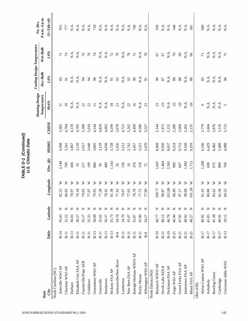
Nor
th C
arol
ina
(NC
)
Ash
evill
e W
SO A
PB
-14
35.4
3N
82.5
5W
2,14
04,
308
3,36
511
8571
915
Cha
rlot
te W
SO A
PB
-11
35.2
2N
80.9
3W
700
3,34
14,
704
1891
7477
7
Dur
ham
B-1
336
.03
N78
.97
W40
63,
867
4,15
9N
.A.
N.A
.N
.A.
N.A
.
Eliz
abet
h C
ity F
AA
AP
B-1
136
.27
N76
.18
W10
3,13
94,
765
N.A
.N
.A.
N.A
.N
.A.
Faye
ttevi
lle/P
ope
AFB
B-1
135
.17
N79
.02
W21
72,
917
5,30
822
9476
N.A
.
Gol
dsbo
roB
-11
35.3
3N
77.9
7W
109
3,04
05,
018
2294
76N
.A.
Gre
ensb
oro
WSO
AP
B-1
336
.08
N79
.95
W88
63,
865
4,14
415
9074
718
Gre
envi
lleB
-11
35.6
2N
77.3
8W
303,
129
4,82
4N
.A.
N.A
.N
.A.
N.A
.
Hen
ders
onB
-13
36.3
7N
78.4
2W
480
4,03
84,
002
N.A
.N
.A.
N.A
.N
.A.
Hic
kory
FA
A A
PB
-13
35.7
3N
81.3
8W
1,14
33,
728
4,19
918
9172
N.A
.
Jack
sonv
ille/
New
Riv
erB
-834
.70
N77
.43
W26
2,45
65,
678
2392
78N
.A.
Lum
bert
onB
-11
34.7
0N
79.0
7W
130
3,21
24,
723
N.A
.N
.A.
N.A
.N
.A.
New
Ber
n FA
A A
PB
-11
35.0
7N
77.0
5W
182,
742
5,26
222
9278
N.A
.
Ral
eigh
-Dur
ham
WSF
O A
PB
-11
35.8
7N
78.7
8W
376
3,45
74,
499
1690
7574
0
Roc
ky M
ount
B-1
135
.90
N77
.72
W11
03,
321
4,58
6N
.A.
N.A
.N
.A.
N.A
.
Wilm
ingt
on W
SO A
PB
-834
.27
N77
.90
W72
2,47
05,
557
2391
78N
.A.
Nor
th D
akot
a (N
D)
Bis
mar
ck W
SFO
AP
B-1
946
.77
N10
0.77
W1,
647
8,96
82,
144
-21
9067
556
Dev
ils L
ake
KD
LR
B-2
148
.12
N98
.87
W1,
464
9,95
01,
973
-23
8767
N.A
.
Dic
kins
on F
AA
AP
B-1
946
.78
N10
2.80
W2,
581
8,65
72,
152
N.A
.N
.A.
N.A
.N
.A.
Farg
o W
SO A
PB
-21
46.9
0N
96.8
0W
900
9,25
42,
289
-22
8870
546
Gra
nd F
orks
FA
A A
PB
-21
47.9
5N
97.1
7W
847
9,73
32,
084
-20
8869
N.A
.
Jam
esto
wn
FAA
AP
B-2
146
.92
N98
.68
W1,
492
9,16
82,
262
N.A
.N
.A.
N.A
.N
.A.
Min
ot F
AA
AP
B-2
148
.27
N10
1.28
W1,
715
9,19
32,
135
-20
8866
581
Ohi
o (O
H)
Akr
on-C
anto
n W
SO A
PB
-17
40.9
2N
81.4
3W
1,20
86,
160
2,77
90
8571
680
Ash
tabu
laB
-17
41.8
5N
80.8
0W
690
6,42
92,
604
N.A
.N
.A.
N.A
.N
.A.
Bow
ling
Gre
enB
-17
41.3
8N
83.6
2W
675
6,48
22,
876
N.A
.N
.A.
N.A
.N
.A.
Cam
brid
geB
-17
40.0
2N
81.5
8W
800
5,48
83,
118
N.A
.N
.A.
N.A
.N
.A.
Cin
cinn
ati-
Abb
e W
SOB
-13
39.1
5N
84.5
2W
760
4,98
83,
733
590
75N
.A.
TAB
LE
D-1
(C
on
tin
ued
)U
.S. C
limat
ic D
ata
Stat
e C
ity
Tabl
eL
atit
ude
Lon
gitu
deE
lev.
(ft
)H
DD
65C
DD
50
Hea
ting
Des
ign
Tem
pera
ture
Coo
ling
Des
ign
Tem
pera
ture
No.
Hrs
. 8
a.m
.-4
p.m
.D
ry-B
ulb
Wet
-Bul
b
99.6
%1.
0%1.
0%55
<Tdb
<69
ANSI/ASHRAE/IESNA STANDARD 90.1-2001 145

Cle
vela
nd W
SFO
AP
B-1
741
.42
N81
.87
W77
06,
201
2,75
51
8672
N.A
.
Col
umbu
s W
SO A
PB
-17
40.0
0N
82.8
8W
812
5,70
83,
119
188
7370
8
Day
ton
WSC
MO
AP
B-1
739
.90
N84
.20
W99
55,
708
3,24
9-1
8873
611
Def
ianc
eB
-17
41.2
8N
84.3
8W
700
6,62
82,
810
N.A
.N
.A.
N.A
.N
.A.
Find
lay
FAA
AP
B-1
741
.02
N83
.67
W79
76,
302
2,90
7-2
8772
N.A
.
Frem
ont
B-1
741
.33
N83
.12
W60
06,
439
2,82
3N
.A.
N.A
.N
.A.
N.A
.
Lan
cast
erB
-17
39.7
3N
82.6
3W
860
5,98
82,
935
N.A
.N
.A.
N.A
.N
.A.
Lim
a Se
wag
e Pl
ant
B-1
740
.72
N84
.13
W85
06,
253
3,05
0N
.A.
N.A
.N
.A.
N.A
.
Man
sfie
ld W
SO A
PB
-17
40.8
2N
82.5
2W
1,29
56,
258
2,81
8-1
8572
N.A
.
Mar
ion
B-1
740
.62
N83
.13
W96
56,
407
2,83
6N
.A.
N.A
.N
.A.
N.A
.
New
ark
Wat
er W
orks
B-1
740
.08
N82
.42
W83
55,
657
3,10
7N
.A.
N.A
.N
.A.
N.A
.
Nor
wal
kB
-17
41.2
7N
82.6
2W
670
6,43
42,
715
N.A
.N
.A.
N.A
.N
.A.
Port
smou
thB
-14
38.7
5N
82.8
8W
540
4,91
33,
581
N.A
.N
.A.
N.A
.N
.A.
Sand
usky
B-1
741
.45
N82
.72
W58
46,
131
2,98
6N
.A.
N.A
.N
.A.
N.A
.
Spri
ngfi
eld
New
Wtr
Wk
B-1
739
.97
N83
.82
W93
06,
254
2,79
0N
.A.
N.A
.N
.A.
N.A
.
Steu
benv
ille
B-1
740
.38
N80
.63
W99
25,
700
3,05
4N
.A.
N.A
.N
.A.
N.A
.
Tole
do E
xpre
ss W
SO A
PB
-17
41.5
8N
83.8
0W
669
6,57
92,
720
-287
7265
2
War
ren
B-1
741
.20
N80
.82
W90
06,
402
2,54
6N
.A.
N.A
.N
.A.
N.A
.
Woo
ster
Exp
Sta
tion
B-1
740
.78
N81
.92
W1,
020
6,37
92,
570
N.A
.N
.A.
N.A
.N
.A.
You
ngst
own
WSO
AP
B-1
741
.25
N80
.67
W1,
178
6,54
42,
536
-185
7067
9
Zan
esvi
lle F
AA
AP
B-1
739
.95
N81
.90
W88
15,
714
3,01
32
8873
N.A
.
Okl
ahom
a (O
K)
Ada
B-1
134
.78
N96
.68
W1,
015
3,18
25,
317
N.A
.N
.A.
N.A
.N
.A.
Altu
s A
FBB
-10
34.6
5N
99.2
7W
1,37
83,
151
5,70
813
100
73N
.A.
Ard
mor
eB
-10
34.2
0N
97.1
5W
860
2,70
25,
978
N.A
.N
.A.
N.A
.N
.A.
Bar
tlesv
ille
B-1
336
.75
N96
.00
W71
53,
777
4,97
6N
.A.
N.A
.N
.A.
N.A
.
Chi
ckas
ha E
xp S
tatio
nB
-11
35.0
5N
97.9
2W
1,08
53,
366
5,29
8N
.A.
N.A
.N
.A.
N.A
.
Eni
dB
-13
36.4
2N
97.8
7W
1,24
53,
788
5,11
95
9874
N.A
.
Law
ton
B-1
134
.62
N98
.45
W1,
150
3,45
75,
268
1297
73N
.A.
McA
lest
er F
AA
AP
B-1
134
.88
N95
.78
W76
03,
354
5,23
310
9676
N.A
.
Mus
koge
eB
-11
35.7
7N
95.3
3W
583
3,41
35,
185
N.A
.N
.A.
N.A
.N
.A.
TAB
LE
D-1
(C
on
tin
ued
)U
.S. C
limat
ic D
ata
Stat
e C
ity
Tabl
eL
atit
ude
Lon
gitu
deE
lev.
(ft
)H
DD
65C
DD
50
Hea
ting
Des
ign
Tem
pera
ture
Coo
ling
Des
ign
Tem
pera
ture
No.
Hrs
. 8
a.m
.-4
p.m
.D
ry-B
ulb
Wet
-Bul
b
99.6
%1.
0%1.
0%55
<Tdb
<69
146 ANSI/ASHRAE/IESNA STANDARD 90.1-2001

Nor
man
B-1
135
.18
N97
.45
W1,
109
3,29
55,
272
N.A
.N
.A.
N.A
.N
.A.
Okl
ahom
a C
ity W
SFO
AP
B-1
335
.40
N97
.60
W1,
280
3,65
94,
972
996
7473
3
Ponc
a C
ity F
AA
AP
B-1
336
.73
N97
.10
W99
94,
226
4,79
1N
.A.
N.A
.N
.A.
N.A
.
Sem
inol
eB
-10
35.2
3N
96.6
7W
865
3,09
75,
552
N.A
.N
.A.
N.A
.N
.A.
Still
wat
erB
-13
36.1
2N
97.1
0W
895
4,02
84,
718
N.A
.N
.A.
N.A
.N
.A.
Tul
sa W
SO A
PB
-13
36.1
8N
95.9
0W
668
3,69
15,
150
997
7659
1
Woo
dwar
dB
-13
36.4
5N
99.3
8W
1,90
03,
900
4,88
4N
.A.
N.A
.N
.A.
N.A
.
Ore
gon
(OR
)
Ast
oria
WSO
AP
B-1
546
.15
N12
3.88
W8
5,15
81,
437
2572
6212
36
Bak
er F
AA
AP
B-1
844
.83
N11
7.82
W3,
368
7,15
51,
741
N.A
.N
.A.
N.A
.N
.A.
Ben
dB
-18
44.0
7N
121.
28W
3,66
06,
926
1,40
5N
.A.
N.A
.N
.A.
N.A
.
Cor
valli
s St
ate
Uni
vB
-14
44.6
3N
123.
20W
225
4,92
32,
051
N.A
.N
.A.
N.A
.N
.A.
Eug
ene
WSO
AP
B-1
444
.12
N12
3.22
W36
44,
546
2,35
421
8765
N.A
.
Gra
nts
Pass
B-1
442
.42
N12
3.33
W96
04,
219
2,98
6N
.A.
N.A
.N
.A.
N.A
.
Kla
mat
h Fa
llsB
-17
42.2
0N
121.
78W
4,09
86,
634
1,95
44
8762
N.A
.
Med
ford
WSO
AP
B-1
442
.38
N12
2.88
W1,
300
4,61
12,
989
2195
6674
9
Pend
leto
n W
SO A
PB
-14
45.6
8N
118.
85W
1,49
25,
294
2,78
73
9363
N.A
.
Port
land
WSF
O A
PB
-14
45.6
0N
122.
60W
214,
522
2,51
722
8666
1060
Ros
ebur
g K
QE
NB
-14
43.2
0N
123.
35W
465
4,31
22,
607
N.A
.N
.A.
N.A
.N
.A.
Sale
m W
SO A
PB
-14
44.9
2N
123.
02W
195
4,92
72,
100
2087
6691
6
Penn
sylv
ania
(PA
)
Alle
ntow
n W
SO A
PB
-17
40.6
5N
75.4
3W
388
5,78
53,
028
588
7271
0
Alto
ona
FAA
AP
B-1
740
.30
N78
.32
W1,
476
6,14
02,
719
586
70N
.A.
Cha
mbe
rsbu
rgB
-17
39.9
3N
77.6
3W
640
5,57
43,
060
N.A
.N
.A.
N.A
.N
.A.
Eri
e W
SO A
PB
-17
42.0
8N
80.1
8W
732
6,27
92,
652
283
7071
6
Har
risb
urg
FAA
AP
B-1
440
.22
N76
.85
W33
85,
347
3,35
89
8973
648
John
stow
nB
-17
40.3
3N
78.9
2W
1,21
45,
649
3,02
8N
.A.
N.A
.N
.A.
N.A
.
Lan
cast
erB
-17
40.0
5N
76.2
8W
270
5,58
43,
079
N.A
.N
.A.
N.A
.N
.A.
Mea
dvill
eB
-17
41.6
3N
80.1
7W
1,06
56,
934
2,20
9N
.A.
N.A
.N
.A.
N.A
.
New
Cas
tleB
-17
41.0
2N
80.3
7W
825
6,54
22,
502
N.A
.N
.A.
N.A
.N
.A.
Phila
delp
hia
WSC
MO
AP
B-1
339
.88
N75
.23
W10
4,95
43,
623
1189
7464
6
TAB
LE
D-1
(C
on
tin
ued
)U
.S. C
limat
ic D
ata
Stat
e C
ity
Tabl
eL
atit
ude
Lon
gitu
deE
lev.
(ft
)H
DD
65C
DD
50
Hea
ting
Des
ign
Tem
pera
ture
Coo
ling
Des
ign
Tem
pera
ture
No.
Hrs
. 8
a.m
.-4
p.m
.D
ry-B
ulb
Wet
-Bul
b
99.6
%1.
0%1.
0%55
<Tdb
<69
ANSI/ASHRAE/IESNA STANDARD 90.1-2001 147

Pitts
burg
h W
SCM
O2
AP
B-1
740
.50
N80
.22
W1,
150
5,96
82,
836
286
7070
0
Rea
ding
B-1
740
.37
N75
.93
W27
05,
796
3,02
1N
.A.
N.A
.N
.A.
N.A
.
Stat
e C
olle
geB
-17
40.8
0N
77.8
7W
1,17
06,
364
2,62
9N
.A.
N.A
.N
.A.
N.A
.
Uni
onto
wn
B-1
739
.92
N79
.72
W95
65,
684
2,91
3N
.A.
N.A
.N
.A.
N.A
.
War
ren
B-1
741
.85
N79
.15
W1,
210
6,89
02,
334
N.A
.N
.A.
N.A
.N
.A.
Wes
t Che
ster
B-1
439
.97
N75
.63
W45
05,
283
3,28
8N
.A.
N.A
.N
.A.
N.A
.
Will
iam
spor
t WSO
AP
B-1
741
.25
N76
.92
W52
46,
087
2,79
62
8771
N.A
.
Yor
k Pu
mp
Stat
ion
22B
-14
39.9
2N
76.7
5W
390
5,25
63,
274
N.A
.N
.A.
N.A
.N
.A.
Rho
de I
slan
d (R
I)
New
port
B-1
741
.52
N71
.32
W20
5,65
92,
548
N.A
.N
.A.
N.A
.N
.A.
Prov
iden
ce W
SO A
PB
-17
41.7
3N
71.4
3W
515,
884
2,74
35
8671
684
Sout
h C
arol
ina
(SC
)
And
erso
nB
-11
34.5
3N
82.6
7W
800
2,96
54,
900
N.A
.N
.A.
N.A
.N
.A.
Cha
rles
ton
WSO
AP
B-8
32.9
0N
80.0
3W
412,
013
6,18
8N
.A.
N.A
.N
.A.
N.A
.
Cha
rles
ton
WSO
City
B-8
32.7
8N
79.9
3W
101,
866
6,30
325
9277
N.A
.
Col
umbi
a W
SFO
AP
B-8
33.9
5N
81.1
2W
213
2,64
95,
508
2194
7570
5
Flor
ence
FA
A A
PB
-834
.18
N79
.72
W14
62,
585
5,59
723
9476
N.A
.
Geo
rget
own
B-8
33.3
5N
79.2
5W
102,
081
5,94
7N
.A.
N.A
.N
.A.
N.A
.
Gre
envi
lle-S
part
anbu
rg W
SO A
PB
-11
34.9
0N
82.2
2W
973
3,27
24,
625
1991
7485
1
Gre
enw
ood
B-1
134
.17
N82
.20
W61
53,
288
4,67
3N
.A.
N.A
.N
.A.
N.A
.
Ora
ngeb
urg
B-8
33.5
0N
80.8
7W
160
2,53
45,
477
N.A
.N
.A.
N.A
.N
.A.
Spar
tanb
urg
B-1
134
.98
N81
.88
W84
02,
887
5,04
6N
.A.
N.A
.N
.A.
N.A
.
Sum
ter/
Shaw
AFB
B-8
33.9
7N
80.4
8W
240
2,50
65,
453
2493
75N
.A.
Sout
h D
akot
a (S
D)
Abe
rdee
n W
SO A
PB
-19
45.4
5N
98.4
3W
1,29
68,
446
2,49
7N
.A.
N.A
.N
.A.
N.A
.
Bro
okin
gsB
-19
44.3
2N
96.7
7W
1,64
28,
653
2,22
8N
.A.
N.A
.N
.A.
N.A
.
Hur
on W
SO A
PB
-19
44.3
8N
98.2
2W
1,28
27,
923
2,70
9-1
791
7154
5
Mitc
hell
B-1
943
.72
N98
.00
W1,
274
7,55
82,
925
N.A
.N
.A.
N.A
.N
.A.
Pier
re F
AA
AP
B-1
944
.38
N10
0.28
W1,
726
7,41
12,
938
-14
9569
557
Rap
id C
ity W
SO A
PB
-19
44.0
5N
103.
07W
3,16
27,
301
2,41
2-1
191
6557
2
Siou
x Fa
lls W
SFO
AP
B-1
943
.57
N96
.73
W1,
418
7,80
92,
735
-16
9072
599
TAB
LE
D-1
(C
on
tin
ued
)U
.S. C
limat
ic D
ata
Stat
e C
ity
Tabl
eL
atit
ude
Lon
gitu
deE
lev.
(ft
)H
DD
65C
DD
50
Hea
ting
Des
ign
Tem
pera
ture
Coo
ling
Des
ign
Tem
pera
ture
No.
Hrs
. 8
a.m
.-4
p.m
.D
ry-B
ulb
Wet
-Bul
b
99.6
%1.
0%1.
0%55
<Tdb
<69
148 ANSI/ASHRAE/IESNA STANDARD 90.1-2001

Wat
erto
wn
FAA
AP
B-1
944
.92
N97
.15
W1,
746
8,37
52,
499
N.A
.N
.A.
N.A
.N
.A.
Yan
kton
B-1
942
.88
N97
.35
W1,
180
7,30
42,
935
N.A
.N
.A.
N.A
.N
.A.
Tenn
esse
e (T
N)
Ath
ens
B-1
335
.43
N84
.58
W94
04,
054
4,04
0N
.A.
N.A
.N
.A.
N.A
.
Bri
stol
WSO
AP
B-1
336
.48
N82
.40
W1,
525
4,40
63,
621
987
72N
.A.
Cha
ttano
oga
WSO
AP
B-1
135
.03
N85
.20
W69
23,
587
4,60
915
9275
684
Cla
rksv
ille
Sew
Plt
B-1
336
.55
N87
.37
W38
24,
159
4,24
1N
.A.
N.A
.N
.A.
N.A
.
Col
umbi
aB
-13
35.6
3N
87.0
8W
650
4,20
64,
047
N.A
.N
.A.
N.A
.N
.A.
Dye
rsbu
rg F
AA
AP
B-1
136
.02
N89
.40
W33
73,
536
5,01
0N
.A.
N.A
.N
.A.
N.A
.
Gre
enev
ille
Exp
Stn
B-1
336
.10
N82
.85
W1,
320
4,39
23,
710
N.A
.N
.A.
N.A
.N
.A.
Jack
son
FAA
AP
B-1
135
.60
N88
.92
W43
33,
540
4,91
512
9376
N.A
.
Kno
xvill
e W
SO A
PB
-13
35.8
0N
84.0
0W
949
3,93
74,
164
1390
7470
3
Mem
phis
FA
A-A
PB
-10
35.0
5N
90.0
0W
265
3,08
25,
467
1694
7785
1
Mur
free
sbor
oB
-13
35.9
2N
86.3
7W
550
3,99
24,
270
N.A
.N
.A.
N.A
.N
.A.
Nas
hvill
e W
SO A
PB
-13
36.1
2N
86.6
8W
580
3,72
94,
689
1092
7574
9
Tul
laho
ma
B-1
335
.35
N86
.20
W1,
048
3,63
04,
422
N.A
.N
.A.
N.A
.N
.A.
Texa
s (T
X)
Abi
lene
WSO
AP
B-8
32.4
2N
99.6
8W
1,78
42,
584
6,05
016
9771
648
Alic
eB
-527
.73
N98
.07
W20
11,
062
8,12
1N
.A.
N.A
.N
.A.
N.A
.
Am
arill
o W
SO A
PB
-13
35.2
3N
101.
70W
3,59
04,
258
4,12
86
9466
680
Aus
tin W
SO A
PB
-630
.30
N97
.70
W59
71,
688
7,17
125
9674
664
Bay
City
Wat
erw
orks
B-5
28.9
8N
95.9
8W
521,
370
7,21
1N
.A.
N.A
.N
.A.
N.A
.
Bea
umon
t Res
earc
h C
trB
-630
.07
N94
.28
W27
1,67
76,
703
2992
79N
.A.
Bee
ville
B-5
28.4
5N
97.7
0W
255
1,37
27,
393
2898
77N
.A.
Big
Spr
ing
B-1
032
.25
N10
1.45
W2,
500
2,77
25,
621
N.A
.N
.A.
N.A
.N
.A.
Bro
wns
ville
WSO
AP
B-3
25.9
0N
97.4
3W
1963
58,
777
3694
7742
2
Bro
wnw
ood
B-8
31.7
2N
99.0
0W
1,38
52,
199
6,47
9N
.A.
N.A
.N
.A.
N.A
.
Cor
pus
Chr
isti
WSO
AP
B-5
27.7
7N
97.5
0W
441,
016
8,02
332
9478
543
Cor
sica
naB
-832
.08
N96
.47
W42
52,
396
6,13
3N
.A.
N.A
.N
.A.
N.A
.
Dal
las
FAA
AP
B-8
32.8
5N
96.8
5W
440
2,25
96,
587
1798
74N
.A.
Del
Rio
/Lau
ghlin
AFB
B-5
29.3
7N
100.
78W
1,07
91,
565
7,20
728
9873
732
TAB
LE
D-1
(C
on
tin
ued
)U
.S. C
limat
ic D
ata
Stat
e C
ity
Tabl
eL
atit
ude
Lon
gitu
deE
lev.
(ft
)H
DD
65C
DD
50
Hea
ting
Des
ign
Tem
pera
ture
Coo
ling
Des
ign
Tem
pera
ture
No.
Hrs
. 8
a.m
.-4
p.m
.D
ry-B
ulb
Wet
-Bul
b
99.6
%1.
0%1.
0%55
<Tdb
<69
ANSI/ASHRAE/IESNA STANDARD 90.1-2001 149

Den
ton
B-8
33.2
0N
97.1
0W
630
2,66
55,
816
N.A
.N
.A.
N.A
.N
.A.
Eag
le P
ass
B-5
28.7
0N
100.
48W
805
1,44
17,
682
N.A
.N
.A.
N.A
.N
.A.
El P
aso
WSO
AP
B-1
031
.80
N10
6.40
W3,
918
2,70
85,
488
2198
6473
5
Ft W
orth
/Mea
cham
B-8
32.8
2N
97.3
5W
692
2,30
46,
557
1998
74N
.A.
Gal
vest
on W
SO C
ityB
-529
.30
N94
.80
W7
1,26
37,
378
N.A
.N
.A.
N.A
.N
.A.
Gre
envi
lleB
-10
33.2
0N
96.2
2W
610
2,95
35,
527
N.A
.N
.A.
N.A
.N
.A.
Har
linge
nB
-326
.20
N97
.67
W38
813
8,40
5N
.A.
N.A
.N
.A.
N.A
.
Hou
ston
/Hob
byB
-529
.65
N95
.28
W50
1,37
17,
357
2993
77N
.A.
Hou
ston
/Bus
h In
t. A
irpo
rtB
-629
.97
N95
.35
W96
1,59
96,
876
2794
77N
.A.
Hun
tsvi
lleB
-830
.72
N95
.55
W49
41,
862
6,69
7N
.A.
N.A
.N
.A.
N.A
.
Kill
een/
Rob
ert-
Gra
yB
-831
.07
N97
.83
W1,
014
2,12
76,
477
2096
73N
.A.
Lam
esa
B-1
132
.70
N10
1.93
W2,
965
3,15
95,
107
N.A
.N
.A.
N.A
.N
.A.
Lar
edo
B-5
27.5
7N
99.5
0W
430
1,02
58,
495
3210
174
598
Lon
gvie
wB
-832
.47
N94
.73
W33
02,
433
5,92
0N
.A.
N.A
.N
.A.
N.A
.
Lub
bock
WSF
O A
PB
-11
33.6
5N
101.
82W
3,25
43,
431
4,83
311
9567
743
Luf
kin
FAA
AP
B-8
31.2
3N
94.7
5W
281
1,95
16,
527
2395
7768
1
McA
llen
B-3
26.2
0N
98.2
2W
122
778
8,59
734
9876
N.A
.
Mid
land
/Ode
ssa
WSO
AP
B-1
031
.95
N10
2.18
W2,
857
2,75
15,
588
1797
6772
9
Min
eral
Wel
ls F
AA
AP
B-8
32.7
8N
98.0
7W
934
2,62
56,
015
N.A
.N
.A.
N.A
.N
.A.
Pale
stin
eB
-831
.78
N95
.60
W46
52,
005
6,45
4N
.A.
N.A
.N
.A.
N.A
.
Pam
pa N
o 2
B-1
335
.53
N10
0.98
W3,
250
4,35
84,
131
N.A
.N
.A.
N.A
.N
.A.
Peco
sB
-831
.42
N10
3.50
W2,
610
2,50
55,
992
N.A
.N
.A.
N.A
.N
.A.
Plai
nvie
wB
-13
34.1
8N
101.
70W
3,37
03,
717
4,46
2N
.A.
N.A
.N
.A.
N.A
.
Port
Art
hur
WSO
AP
B-6
29.9
5N
94.0
2W
161,
499
6,99
4N
.A.
N.A
.N
.A.
697
San
Ang
elo
WSO
AP
B-8
31.3
7N
100.
50W
1,90
32,
414
6,07
020
9770
619
San
Ant
onio
WSF
OB
-629
.53
N98
.47
W79
41,
644
7,14
226
9673
N.A
.
Sher
man
B-1
033
.63
N96
.62
W72
02,
890
5,68
2N
.A.
N.A
.N
.A.
721
Snyd
erB
-11
32.7
2N
100.
92W
2,33
53,
185
5,17
8N
.A.
N.A
.N
.A.
N.A
.
Tem
ple
B-8
31.0
8N
97.3
7W
700
2,15
36,
487
N.A
.N
.A.
N.A
.N
.A.
Tyle
rB
-832
.35
N95
.40
W54
52,
194
6,56
2N
.A.
N.A
.N
.A.
N.A
.
Ver
non
B-1
034
.08
N99
.30
W1,
202
3,18
65,
605
N.A
.N
.A.
N.A
.N
.A.
TAB
LE
D-1
(C
on
tin
ued
)U
.S. C
limat
ic D
ata
Stat
e C
ity
Tabl
eL
atit
ude
Lon
gitu
deE
lev.
(ft
)H
DD
65C
DD
50
Hea
ting
Des
ign
Tem
pera
ture
Coo
ling
Des
ign
Tem
pera
ture
No.
Hrs
. 8
a.m
.-4
p.m
.D
ry-B
ulb
Wet
-Bul
b
99.6
%1.
0%1.
0%55
<Tdb
<69
150 ANSI/ASHRAE/IESNA STANDARD 90.1-2001
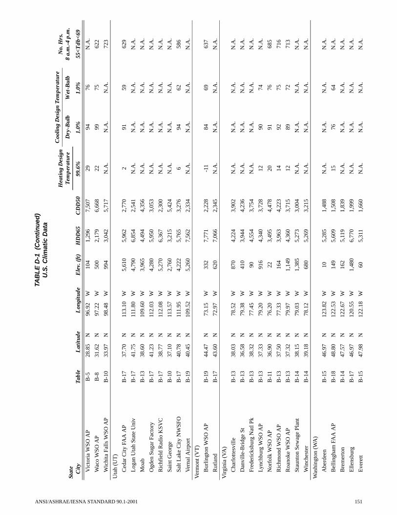
Vic
tori
a W
SO A
PB
-528
.85
N96
.92
W10
41,
296
7,50
729
9476
N.A
.
Wac
o W
SO A
PB
-831
.62
N97
.22
W50
02,
179
6,66
822
9975
622
Wic
hita
Fal
ls W
SO A
PB
-10
33.9
7N
98.4
8W
994
3,04
25,
717
N.A
.N
.A.
N.A
.72
3
Uta
h (U
T)
Ced
ar C
ity F
AA
AP
B-1
737
.70
N11
3.10
W5,
610
5,96
22,
770
291
5962
9
Log
an U
tah
Stat
e U
niv
B-1
741
.75
N11
1.80
W4,
790
6,85
42,
541
N.A
.N
.A.
N.A
.N
.A.
Moa
bB
-13
38.6
0N
109.
60W
3,96
54,
494
4,35
6N
.A.
N.A
.N
.A.
N.A
.
Ogd
en S
ugar
Fac
tory
B-1
741
.23
N11
2.03
W4,
280
5,95
03,
053
N.A
.N
.A.
N.A
.N
.A.
Ric
hfie
ld R
adio
KSV
CB
-17
38.7
7N
112.
08W
5,27
06,
367
2,30
0N
.A.
N.A
.N
.A.
N.A
.
Sain
t Geo
rge
B-1
037
.10
N11
3.57
W2,
760
3,21
55,
424
N.A
.N
.A.
N.A
.N
.A.
Salt
Lak
e C
ity N
WSF
OB
-17
40.7
8N
111.
95W
4,22
25,
765
3,27
66
9462
586
Ver
nal A
irpo
rtB
-19
40.4
5N
109.
52W
5,26
07,
562
2,33
4N
.A.
N.A
.N
.A.
N.A
.
Ver
mon
t (V
T)
Bur
lingt
on W
SO A
PB
-19
44.4
7N
73.1
5W
332
7,77
12,
228
-11
8469
637
Rut
land
B-1
743
.60
N72
.97
W62
07,
066
2,34
5N
.A.
N.A
.N
.A.
N.A
.
Vir
gini
a (V
A)
Cha
rlot
tesv
ille
B-1
338
.03
N78
.52
W87
04,
224
3,90
2N
.A.
N.A
.N
.A.
N.A
.
Dan
ville
-Bri
dge
StB
-13
36.5
8N
79.3
8W
410
3,94
44,
236
N.A
.N
.A.
N.A
.N
.A.
Fred
eric
ksbu
rg N
atl P
kB
-13
38.3
2N
77.4
5W
904,
554
3,75
4N
.A.
N.A
.N
.A.
N.A
.
Lync
hbur
g W
SO A
PB
-13
37.3
3N
79.2
0W
916
4,34
03,
728
1290
74N
.A.
Nor
folk
WSO
AP
B-1
136
.90
N76
.20
W22
3,49
54,
478
2091
7668
5
Ric
hmon
d W
SO A
PB
-13
37.5
0N
77.3
3W
164
3,96
34,
223
1492
7571
6
Roa
noke
WSO
AP
B-1
337
.32
N79
.97
W1,
149
4,36
03,
715
1289
7271
3
Stau
nton
Sew
age
Plan
tB
-14
38.1
5N
79.0
3W
1,38
55,
273
3,00
4N
.A.
N.A
.N
.A.
N.A
.
Win
ches
ter
B-1
439
.18
N78
.12
W68
05,
269
3,21
5N
.A.
N.A
.N
.A.
N.A
.
Was
hing
ton
(WA
)
Abe
rdee
nB
-15
46.9
7N
123.
82W
105,
285
1,48
8N
.A.
N.A
.N
.A.
N.A
.
Bel
lingh
am F
AA
AP
B-1
848
.80
N12
2.53
W14
95,
609
1,50
815
7664
N.A
.
Bre
mer
ton
B-1
447
.57
N12
2.67
W16
25,
119
1,83
9N
.A.
N.A
.N
.A.
N.A
.
Elle
nsbu
rgB
-17
46.9
7N
120.
55W
1,48
06,
770
1,99
9N
.A.
N.A
.N
.A.
N.A
.
Eve
rett
B-1
547
.98
N12
2.18
W60
5,31
11,
660
N.A
.N
.A.
N.A
.N
.A.
TAB
LE
D-1
(C
on
tin
ued
)U
.S. C
limat
ic D
ata
Stat
e C
ity
Tabl
eL
atit
ude
Lon
gitu
deE
lev.
(ft
)H
DD
65C
DD
50
Hea
ting
Des
ign
Tem
pera
ture
Coo
ling
Des
ign
Tem
pera
ture
No.
Hrs
. 8
a.m
.-4
p.m
.D
ry-B
ulb
Wet
-Bul
b
99.6
%1.
0%1.
0%55
<Tdb
<69
ANSI/ASHRAE/IESNA STANDARD 90.1-2001 151

Ken
new
ick
B-1
446
.22
N11
9.10
W39
04,
895
3,19
5N
.A.
N.A
.N
.A.
N.A
.
Lon
gvie
wB
-14
46.1
5N
122.
92W
125,
094
1,85
8N
.A.
N.A
.N
.A.
N.A
.
Oly
mpi
a W
SO A
PB
-18
46.9
7N
122.
90W
192
5,65
51,
558
1883
6598
5
Port
Ang
eles
B-1
848
.12
N12
3.40
W40
5,69
51,
257
N.A
.N
.A.
N.A
.N
.A.
Seat
tle E
MSU
WSO
B-1
447
.65
N12
2.30
W20
4,61
12,
120
N.A
.N
.A.
N.A
.N
.A.
Seat
tle-T
acom
a W
SCM
O A
PB
-14
47.4
5N
122.
30W
450
4,90
82,
021
2381
6498
2
Spok
ane
WSO
AP
B-1
747
.63
N11
7.53
W2,
356
6,84
22,
032
N.A
.N
.A.
N.A
.64
0
Taco
ma/
McC
hord
AFB
B-1
447
.15
N12
2.48
W32
25,
155
1,82
018
8263
N.A
.
Wal
la W
alla
FA
A A
PB
-14
46.1
0N
118.
28W
1,16
64,
958
3,16
14
9565
N.A
.
Wen
atch
eeB
-17
47.4
2N
120.
32W
640
5,57
92,
956
392
65N
.A.
Yak
ima
WSO
AP
B-1
746
.57
N12
0.53
W1,
064
5,96
72,
348
492
6470
3
Wes
t Vir
gini
a (W
V)
Bec
kley
WSO
AP
B-1
737
.78
N81
.12
W2,
504
5,55
82,
690
N.A
.N
.A.
N.A
.N
.A.
Blu
efie
ld F
AA
AP
B-1
437
.30
N81
.22
W2,
870
5,23
02,
907
583
69N
.A.
Cha
rles
ton
WSF
O A
PB
-13
38.3
7N
81.6
0W
1,01
54,
646
3,65
56
8873
704
Cla
rksb
urg
B-1
739
.27
N80
.35
W94
55,
512
3,01
4N
.A.
N.A
.N
.A.
N.A
.
Elk
ins
WSO
AP
B-1
738
.88
N79
.85
W1,
992
6,12
02,
360
-283
70N
.A.
Hun
tingt
on W
SO A
PB
-13
38.3
7N
82.5
5W
827
4,66
53,
615
689
73N
.A.
Mar
tinsb
urg
FAA
AP
B-1
439
.40
N77
.98
W53
15,
192
3,36
88
9173
N.A
.
Mor
gant
own
FAA
AP
B-1
439
.65
N79
.92
W1,
240
5,36
33,
155
487
71N
.A.
Park
ersb
urg
B-1
439
.27
N81
.57
W61
55,
094
3,50
74
8872
N.A
.
Wis
cons
in (
WI)
App
leto
nB
-19
44.2
5N
88.3
7W
750
7,69
32,
513
N.A
.N
.A.
N.A
.N
.A.
Ash
land
Exp
Far
mB
-19
46.5
7N
90.9
7W
650
8,96
01,
811
N.A
.N
.A.
N.A
.N
.A.
Bel
oit
B-1
742
.50
N89
.03
W78
07,
161
2,73
7N
.A.
N.A
.N
.A.
N.A
.
Eau
Cla
ire
FAA
AP
B-1
944
.87
N91
.48
W88
88,
330
2,40
7-1
887
7166
1
Fond
du
Lac
B-1
943
.80
N88
.45
W76
07,
541
2,57
3N
.A.
N.A
.N
.A.
N.A
.
Gre
en B
ay W
SO A
PB
-19
44.4
8N
88.1
3W
682
8,08
92,
177
-13
8572
651
La
Cro
sse
FAA
AP
B-1
943
.87
N91
.25
W65
17,
491
2,79
0-1
488
7364
4
Mad
ison
WSO
AP
B-1
943
.13
N89
.33
W85
87,
673
2,38
9-1
187
7265
8
Man
itow
ocB
-19
44.1
0N
87.6
8W
660
7,59
72,
193
N.A
.N
.A.
N.A
.N
.A.
TAB
LE
D-1
(C
on
tin
ued
)U
.S. C
limat
ic D
ata
Stat
e C
ity
Tabl
eL
atit
ude
Lon
gitu
deE
lev.
(ft
)H
DD
65C
DD
50
Hea
ting
Des
ign
Tem
pera
ture
Coo
ling
Des
ign
Tem
pera
ture
No.
Hrs
. 8
a.m
.-4
p.m
.D
ry-B
ulb
Wet
-Bul
b
99.6
%1.
0%1.
0%55
<Tdb
<69
152 ANSI/ASHRAE/IESNA STANDARD 90.1-2001

Mar
inet
teB
-19
45.1
0N
87.6
3W
605
8,05
92,
272
N.A
.N
.A.
N.A
.N
.A.
Milw
auke
e W
SO A
PB
-19
42.9
5N
87.9
0W
672
7,32
42,
388
-786
7261
8
Rac
ine
B-1
742
.70
N87
.77
W59
57,
167
2,45
9N
.A.
N.A
.N
.A.
N.A
.
Sheb
oyga
nB
-17
43.7
5N
87.7
2W
648
7,08
72,
390
N.A
.N
.A.
N.A
.N
.A.
Stev
ens
Poin
tB
-19
44.5
0N
89.5
7W
1,07
98,
009
2,32
5N
.A.
N.A
.N
.A.
N.A
.
Wau
kesh
aB
-17
43.0
2N
88.2
3W
860
7,11
72,
658
N.A
.N
.A.
N.A
.N
.A.
Wau
sau
FAA
AP
B-1
944
.92
N89
.62
W1,
196
8,42
72,
182
-15
8570
N.A
.
Wyo
min
g (W
Y)
Cas
per
WSO
AP
B-1
942
.92
N10
6.47
W5,
338
7,68
22,
082
-13
8958
535
Che
yenn
e W
SFO
AP
B-1
941
.15
N10
4.82
W6,
120
7,32
61,
886
-785
5760
8
Cod
yB
-19
44.5
2N
109.
07W
5,05
07,
431
2,05
7-1
487
58N
.A.
Eva
nsto
nB
-20
41.2
7N
110.
95W
6,81
08,
846
1,28
5N
.A.
N.A
.N
.A.
N.A
.
Lan
der
WSO
AP
B-1
942
.82
N10
8.73
W5,
370
7,88
92,
184
-14
8758
N.A
.
Lar
amie
FA
A A
PB
-22
41.3
2N
105.
68W
7,26
69,
008
1,23
7N
.A.
N.A
.N
.A.
N.A
.
New
cast
leB
-19
43.8
5N
104.
22W
4,41
07,
267
2,51
8N
.A.
N.A
.N
.A.
N.A
.
Raw
lins
FAA
AP
B-2
041
.80
N10
7.20
W6,
736
8,47
51,
605
N.A
.N
.A.
N.A
.N
.A.
Roc
k Sp
ring
s FA
A A
PB
-20
41.6
0N
109.
07W
6,74
18,
365
1,73
4-9
8454
552
Sher
idan
WSO
AP
B-1
944
.77
N10
6.97
W3,
964
7,80
42,
023
-14
9061
574
Torr
ingt
on E
xp F
arm
B-1
742
.08
N10
4.22
W4,
098
6,87
92,
429
N.A
.N
.A.
N.A
.N
.A.
U.S
. Ter
rito
ries
Puer
to R
ico
San
Juan
/Isl
a V
erde
WSF
OB
-118
.43
N66
.00
W10
011
,406
6990
78
TAB
LE
D-1
(C
on
tin
ued
)U
.S. C
limat
ic D
ata
Stat
e C
ity
Tabl
eL
atit
ude
Lon
gitu
deE
lev.
(ft
)H
DD
65C
DD
50
Hea
ting
Des
ign
Tem
pera
ture
Coo
ling
Des
ign
Tem
pera
ture
No.
Hrs
. 8
a.m
.-4
p.m
.D
ry-B
ulb
Wet
-Bul
b
99.6
%1.
0%1.
0%55
<Tdb
<69
ANSI/ASHRAE/IESNA STANDARD 90.1-2001 153

TAB
LE
D-2
C
anad
ian
Clim
atic
Dat
a
Pro
vinc
e C
ity
Tab
leL
atit
ude
Lon
gitu
deE
lev.
(ft
)H
DD
65C
DD
50
Hea
ting
Des
ign
Tem
pera
ture
Coo
ling
Des
ign
Tem
pera
ture
Dry
-Bul
bW
et-B
ulb
99.6
%1.
0%1.
0%
Alb
erta
(A
B)
Cal
gary
Int
erna
tiona
l AB
-22
51.1
2N
114.
02W
3,53
39,
885
1,16
7-2
280
59
Edm
onto
n In
tern
atio
nal A
B-2
353
.30
N11
3.58
W2,
345
11,0
231,
069
-28.
178
62
Gra
nde
Prai
rie
AB
-23
55.1
8N
118.
88W
2,18
511
,240
1,03
1-3
278
60
Jasp
erB
-22
52.8
8N
118.
07W
3,48
010
,244
848
N.A
.N
.A.
N.A
.
Let
hbri
dge
AB
-20
49.6
3N
112.
80W
3,04
78,
783
1,73
0-2
284
61
Med
icin
e H
at A
B-1
950
.02
N11
0.72
W2,
352
8,98
81,
981
-24
8762
Red
Dee
r A
B-2
252
.18
N11
3.90
W2,
969
10,7
651,
095
-27
7961
Bri
tish
Col
umbi
a (B
C)
Daw
son
Cre
ek A
B-2
355
.73
N12
0.18
W2,
148
11,4
3589
0N
.A.
N.A
.N
.A.
Ft N
elso
n A
B-2
458
.83
N12
2.58
W1,
253
12,9
411,
013
-33
7860
Kam
loop
sB
-17
50.6
7N
120.
33W
1,24
36,
779
2,33
5-8
8863
Nan
aim
o A
B-1
849
.05
N12
3.87
W98
6,05
41,
469
N.A
.N
.A.
N.A
.
New
Wes
tmin
ster
BC
Pen
B-1
849
.22
N12
2.90
W59
5,52
01,
691
N.A
.N
.A.
N.A
.
Pent
icto
n A
B-1
749
.47
N11
9.60
W1,
128
6,50
02,
002
587
64
Prin
ce G
eorg
eB
-22
53.8
8N
122.
67W
2,26
79,
495
906
-25
7859
Prin
ce R
uper
t AB
-20
54.3
0N
130.
43W
111
7,65
057
27
6357
Van
couv
er I
nter
natio
nal A
B-1
849
.18
N12
3.17
W9
5,68
21,
536
1874
64
Vic
tori
a G
onza
les
Hts
B-1
848
.42
N12
3.32
W22
95,
494
1,28
623
7562
Man
itoba
(M
B)
Bra
ndon
CD
AB
-23
49.8
7N
99.9
8W
1,19
010
,969
1,66
1-2
984
66
Chu
rchi
ll A
B-2
558
.73
N94
.07
W91
16,7
1927
5-3
672
60
Dau
phin
AB
-23
51.1
0N
100.
05W
1,00
011
,242
1,52
0-2
884
66
Flin
Flo
nB
-23
54.7
7N
101.
85W
1,09
912
,307
1,35
2N
.A.
N.A
.N
.A.
Port
age
La
Prai
rie
AB
-21
49.9
0N
98.2
7W
885
10,5
941,
807
-25
8567
The
Pas
AB
-23
53.9
7N
101.
10W
889
12,4
901,
231
-32
7964
Win
nipe
g In
tern
atio
nal A
B-2
349
.90
N97
.23
W78
410
,858
1,78
4-2
784
67
New
Bru
nsw
ick
(NB
)
Cha
tham
AB
-22
47.0
2N
65.4
5W
111
9,02
81,
531
-12
8367
Fred
eric
ton
AB
-20
45.8
7N
66.5
3W
558,
666
1,63
1-1
283
68
154 ANSI/ASHRAE/IESNA STANDARD 90.1-2001

Mon
cton
AB
-20
46.1
2N
64.6
8W
232
8,73
11,
427
-10
8067
Sain
t Joh
n A
B-2
045
.33
N65
.88
W33
78,
776
1,17
9-9
7564
New
foun
dlan
d (N
F)
Cor
ner
Bro
okB
-20
48.9
5N
57.9
5W
168,
756
1,07
5N
.A.
N.A
.N
.A.
Gan
der
Inte
rnat
iona
l AB
-22
48.9
5N
54.5
7W
495
9,35
495
6-4
7663
Goo
se A
B-2
353
.32
N60
.42
W15
012
,017
758
-23
7761
St J
ohn'
s A
B-2
047
.62
N52
.73
W43
98,
888
848
373
64
Step
henv
ille
AB
-20
48.5
3N
58.5
5W
268,
869
952
-271
64
Nor
thw
est T
erri
tori
es (
NW
)
Ft S
mith
AB
-24
60.0
2N
111.
95W
666
14,1
9293
2-3
478
61
Inuv
ik A
B-2
568
.30
N13
3.48
W19
318
,409
489
-43
7559
Res
olut
e A
B-2
674
.72
N94
.98
W21
922
,864
0-4
248
43
Yel
low
knif
e A
B-2
462
.47
N11
4.45
W67
215
,555
851
-39
7459
Nov
a Sc
otia
(N
S)
Hal
ifax
Int
erna
tiona
l AB
-20
44.8
8N
63.5
2W
416
8,13
31,
464
-278
66
Ken
tvill
e C
DA
B-2
045
.07
N64
.48
W16
07,
683
1,66
5N
.A.
N.A
.N
.A.
Sydn
ey A
B-2
046
.17
N60
.05
W18
38,
364
1,28
7-1
7867
Tru
roB
-20
45.3
7N
63.2
7W
131
8,59
61,
295
-977
67
Yar
mou
th A
B-2
043
.83
N66
.08
W14
17,
515
1,18
07
7164
Ont
ario
(O
N)
Bel
levi
lleB
-19
44.1
5N
77.4
0W
249
7,55
62,
252
N.A
.N
.A.
N.A
.
Cor
nwal
lB
-19
45.0
2N
74.7
5W
209
8,06
22,
187
N.A
.N
.A.
N.A
.
Ham
ilton
RB
GB
-17
43.2
8N
79.8
8W
334
6,87
22,
450
N.A
.N
.A.
N.A
.
Kap
uska
sing
AB
-23
49.4
2N
82.4
7W
744
11,7
421,
108
-30
8065
Ken
ora
AB
-23
49.7
8N
94.3
7W
1,33
510
,884
1,62
6-2
781
65
Kin
gsto
n A
B-1
944
.22
N76
.60
W30
57,
826
1,96
0N
.A.
N.A
.N
.A.
Lon
don
AB
-19
43.0
3N
81.1
5W
912
7,56
52,
126
-383
70
Nor
th B
ay A
B-2
246
.35
N79
.43
W1,
174
9,79
41,
509
-18
7866
Osh
awa
WPC
PB
-19
43.8
7N
78.8
3W
275
7,25
32,
106
N.A
.N
.A.
N.A
.
Otta
wa
Inte
rnat
iona
l AB
-19
45.3
2N
75.6
7W
380
8,57
12,
045
-13
8369
TAB
LE
D-2
(C
on
tin
ued
)C
anad
ian
Clim
atic
Dat
a
Pro
vinc
e C
ity
Tab
leL
atit
ude
Lon
gitu
deE
lev.
(ft
)H
DD
65C
DD
50
Hea
ting
Des
ign
Tem
pera
ture
Coo
ling
Des
ign
Tem
pera
ture
Dry
-Bul
bW
et-B
ulb
99.6
%1.
0%1.
0%
ANSI/ASHRAE/IESNA STANDARD 90.1-2001 155

Ow
en S
ound
MO
EB
-19
44.5
8N
80.9
3W
587
7,73
01,
896
N.A
.N
.A.
N.A
.
Pete
rbor
ough
B-1
944
.28
N78
.32
W63
68,
037
1,97
5N
.A.
N.A
.N
.A.
St C
atha
rine
sB
-17
43.2
0N
79.2
5W
298
6,70
02,
564
N.A
.N
.A.
N.A
.
Sudb
ury
AB
-22
46.6
2N
80.8
0W
1,14
19,
990
1,55
7-1
981
66
Thu
nder
Bay
AB
-22
48.3
7N
89.3
2W
652
10,5
621,
198
-22
8066
Tim
min
s A
B-2
348
.57
N81
.37
W96
711
,374
1,22
5-2
881
65
Toro
nto
Dow
nsvi
ew A
B-1
943
.75
N79
.48
W64
97,
306
2,37
0-4
8470
Win
dsor
AB
-17
42.2
7N
82.9
7W
623
6,61
92,
679
286
71
Prin
ce E
dwar
d Is
land
(PE
)
Cha
rlot
teto
wn
AB
-20
46.2
8N
63.1
3W
157
8,59
81,
400
-677
67
Sum
mer
side
AB
-20
46.4
3N
63.8
3W
788,
411
1,53
6-5
7766
Que
bec
(PQ
)
Bag
otvi
lle A
B-2
248
.33
N71
.00
W52
110
,603
1,30
0-2
380
65
Dru
mm
ondv
ille
B-1
945
.88
N72
.48
W26
98,
601
2,02
4N
.A.
N.A
.N
.A.
Gra
nby
B-1
945
.38
N72
.70
W55
18,
367
1,98
4N
.A.
N.A
.N
.A.
Mon
trea
l Dor
val I
nter
natio
nal A
B-1
945
.47
N73
.75
W10
18,
285
2,14
6-1
283
70
Que
bec
AB
-22
46.8
0N
71.3
8W
229
9,44
91,
571
-16
8068
Rim
ousk
iB
-22
48.4
5N
68.5
2W
118
9,66
51,
215
N.A
.N
.A.
N.A
.
Sept
-Ile
s A
B-2
350
.22
N66
.27
W18
011
,287
690
-20
6959
Shaw
inig
anB
-22
46.5
7N
72.7
5W
400
9,24
61,
720
N.A
.N
.A.
N.A
.
Sher
broo
ke A
B-2
245
.43
N71
.68
W78
09,
464
1,37
2-2
080
68
St J
ean
de C
herb
ourg
B-2
348
.88
N67
.12
W1,
151
11,2
7780
1N
.A.
N.A
.N
.A.
St J
erom
eB
-22
45.8
0N
74.0
5W
557
9,17
11,
771
N.A
.N
.A.
N.A
.
The
tfor
d M
ines
B-2
246
.10
N71
.35
W1,
250
9,68
71,
425
N.A
.N
.A.
N.A
.
Tro
is R
ivie
res
B-2
246
.37
N72
.60
W17
39,
124
1,76
6N
.A.
N.A
.N
.A.
Val
d'O
r A
B-2
348
.07
N77
.78
W1,
105
11,2
561,
193
-27
8065
Val
leyf
ield
B-1
945
.28
N74
.10
W15
08,
083
2,26
8N
.A.
N.A
.N
.A.
Sask
atch
ewan
(SK
)
Est
evan
AB
-22
49.2
2N
102.
97W
1,87
610
,092
1,79
3-2
586
65
Moo
se J
aw A
B-2
150
.33
N10
5.55
W1,
893
9,98
91,
812
-27
8764
TAB
LE
D-2
(C
on
tin
ued
)C
anad
ian
Clim
atic
Dat
a
Pro
vinc
e C
ity
Tab
leL
atit
ude
Lon
gitu
deE
lev.
(ft
)H
DD
65C
DD
50
Hea
ting
Des
ign
Tem
pera
ture
Coo
ling
Des
ign
Tem
pera
ture
Dry
-Bul
bW
et-B
ulb
99.6
%1.
0%1.
0%
156 ANSI/ASHRAE/IESNA STANDARD 90.1-2001

Nor
th B
attle
ford
AB
-23
52.7
7N
108.
25W
1,79
711
,127
1,47
3-3
182
63
Prin
ce A
lber
t AB
-23
53.2
2N
105.
68W
1,40
412
,009
1,25
2-3
481
64
Reg
ina
AB
-22
50.4
3N
104.
67W
1,89
310
,773
1,62
0-2
985
64
Sask
atoo
n A
B-2
352
.17
N10
6.68
W1,
643
11,1
181,
537
-31
8463
Swif
t Cur
rent
AB
-22
50.2
8N
107.
68W
2,68
310
,128
1,54
1-2
584
62
Yor
kton
AB
-23
51.2
7N
102.
47W
1,63
311
,431
1,47
6-3
082
64
Yuk
on T
erri
tory
(Y
T)
Whi
teho
rse
AB
-24
60.7
2N
135.
07W
2,30
612
,797
611
-34
7355
TAB
LE
D-3
In
tern
atio
nal
Clim
atic
Dat
a
Cou
ntry
C
ity
Pro
vinc
e or
R
egio
nT
able
Lat
itud
eL
ongi
tude
Ele
v. (
ft)
HD
D65
CD
D50
Hea
ting
Des
ign
Tem
pera
ture
Coo
ling
Des
ign
Tem
pera
ture
Dry
-Bul
bW
et-B
ulb
99.6
%1.
0%1.
0%
Arg
entin
a
Bue
nos
Air
es/E
zeiz
aB
-934
.82
S58
.53
W66
2,21
14,
693
3190
72
Cor
doba
B-9
31.3
2S
64.2
2W
1,55
51,
816
5,18
231
9172
Tuc
uman
/Poz
oB
-626
.85
S65
.10
W1,
444
1,14
66,
622
N.A
.N
.A.
N.A
.
Aus
tral
ia
Ade
laid
eSA
B-9
34.9
5S
138.
53E
202,
082
4,38
139
9264
Alic
e Sp
ring
sN
TB
-523
.80
S13
3.90
E1,
782
1,14
27,
777
3410
264
Bri
sban
eQ
LB
-427
.43
S15
3.08
E7
545
7,00
944
8672
Dar
win
Air
port
NT
B-1
12.4
3S
130.
87E
950
11,7
3664
9276
Pert
h/G
uild
ford
WA
B-7
31.9
2S
115.
97E
561,
507
5,35
341
9566
Sydn
ey/K
Sm
ithN
SWB
-733
.95
S15
1.18
E20
1,35
15,
259
4285
67
Azo
res
Laj
esTe
rcei
raB
-738
.75
N27
.08
W18
01,
279
4,89
246
7871
Bah
amas
Nas
sau
B-2
25.0
5N
77.4
7W
1029
9,77
557
9078
TAB
LE
D-2
(C
on
tin
ued
)C
anad
ian
Clim
atic
Dat
a
Pro
vinc
e C
ity
Tab
leL
atit
ude
Lon
gitu
deE
lev.
(ft
)H
DD
65C
DD
50
Hea
ting
Des
ign
Tem
pera
ture
Coo
ling
Des
ign
Tem
pera
ture
Dry
-Bul
bW
et-B
ulb
99.6
%1.
0%1.
0%
ANSI/ASHRAE/IESNA STANDARD 90.1-2001 157

Bel
gium
Bru
ssel
s A
irpo
rtB
-17
50.9
0N
4.47
E12
85,
460
1,86
215
7966
Ber
mud
a
St G
eorg
es/K
indl
eyB
-332
.37
N64
.68
W20
170
8,36
5N
.A.
N.A
.N
.A.
Bol
ivia
La
Paz/
El A
ltoB
-18
16.5
0S
68.1
8W
13,2
877,
189
237
2562
44
Bra
zil
Bel
emB
-11.
43S
48.4
8W
790
11,5
5272
9078
Bra
silia
B-3
15.7
7S
47.9
3W
3,80
958
7,94
348
8865
Fort
alez
aB
-13.
72S
38.5
5W
621
11,7
4872
9078
Port
o A
legr
eB
-630
.08
S51
.18
W23
902
7,07
640
9275
Rec
ife/
Cur
ado
B-1
8.13
S34
.92
W36
210
,951
7091
78
Rio
de
Jane
iro
B-2
22.9
0S
43.1
7W
1614
9,68
859
9977
Salv
ador
/Ond
ina
B-2
13.0
0S
38.5
2W
167
010
,785
6888
78
Sao
Paul
oB
-323
.50
S46
.62
W2,
608
447
7,21
948
8869
Bul
gari
a
Sofi
aB
-17
42.8
2N
23.3
8E
1,95
25,
629
2,50
810
8565
Chi
le
Con
cepc
ion
B-1
236
.77
S73
.05
W39
3,55
92,
283
3574
62
Punt
a A
rena
s/C
habu
nco
B-2
053
.03
S70
.85
W10
87,
807
395
2361
53
Sant
iago
/Ped
ahue
lB
-12
33.3
8S
70.8
8W
1,57
52,
820
3,47
129
8865
Chi
na
Shan
ghai
/Hon
gqia
oB
-11
31.1
7N
121.
43E
163,
182
5,12
426
9281
Cub
a
Gua
ntan
amo
Bay
NA
SO
te.
B-1
19.9
0N
75.1
5W
750
11,7
1967
9378
Cyp
rus
Akr
otir
iB
-634
.58
N32
.98
E75
1,28
76,
147
4089
72
Lar
naca
B-6
34.8
8N
33.6
3E
71,
452
6,02
837
9172
Paph
osB
-634
.75
N32
.40
E30
1,27
95,
924
3986
76
TAB
LE
D-3
(C
on
tin
ued
)In
tern
atio
nal
Clim
atic
Dat
a
Cou
ntry
C
ity
Pro
vinc
e or
R
egio
nT
able
Lat
itud
eL
ongi
tude
Ele
v. (
ft)
HD
D65
CD
D50
Hea
ting
Des
ign
Tem
pera
ture
Coo
ling
Des
ign
Tem
pera
ture
Dry
-Bul
bW
et-B
ulb
99.6
%1.
0%1.
0%
158 ANSI/ASHRAE/IESNA STANDARD 90.1-2001

Cze
ch R
epub
lic (
Form
er
Cze
chos
lova
kia)
Prag
ue/L
ibus
B-1
750
.00
N14
.45
E1,
001
6,37
61,
853
380
64
Dom
inic
an R
epub
lic
Sant
o D
omin
goB
-118
.47
N69
.88
W43
010
,862
N.A
.N
.A.
N.A
.
Egy
pt
Cai
roB
-330
.13
N31
.40
E24
383
47,
993
4597
69
Lux
orB
-225
.67
N32
.70
E28
958
19,
849
4010
871
Finl
and
Hel
sink
i/Seu
tula
B-2
260
.32
N24
.97
E16
79,
051
1,13
8-1
175
61
Fran
ce
Lyon
/Sat
olas
B-1
445
.73
N5.
08E
814
4,93
02,
609
1786
69
Mar
seill
eB
-11
43.4
5N
5.22
E26
3,19
43,
933
2587
70
Nan
tes
B-1
447
.17
N1.
60W
894,
286
2,48
023
8368
Nic
eB
-943
.65
N7.
20E
332,
641
3,98
335
8373
Pari
s/L
e B
ourg
etB
-14
48.9
7N
2.45
E21
75,
046
2,21
118
8268
Stra
sbou
rgB
-17
48.5
5N
7.63
E50
25,
533
2,19
312
8468
Ger
man
y
Ber
lin/S
choe
nfel
dB
-17
52.3
8N
13.5
2E
154
6,33
11,
820
1182
65
Ham
burg
B-1
853
.63
N9.
98E
526,
319
1,56
911
7964
Han
nove
rB
-18
52.4
7N
9.70
E18
06,
093
1,73
09
8065
Man
nhei
mB
-17
49.5
3N
8.50
E31
85,
428
2,26
2N
.A.
N.A
.N
.A.
Gre
ece
Soud
aC
rete
B-6
35.5
5N
24.1
2E
417
1,76
75,
472
3990
67
The
ssal
onik
a/M
ikra
B-1
140
.52
N22
.97
E26
3,38
94,
115
2590
69
Gre
enla
nd
Nar
ssar
ssua
qB
-23
61.1
8N
45.4
2W
7911
,521
292
-18
6249
Hun
gary
Bud
apes
t/Lor
inc
B-1
747
.43
N19
.18
E45
95,
534
2,64
78
8668
Icel
and
Rey
kjav
ikB
-22
64.1
3N
21.9
3W
200
9,28
629
314
5852
TAB
LE
D-3
(C
on
tin
ued
)In
tern
atio
nal
Clim
atic
Dat
a
Cou
ntry
C
ity
Pro
vinc
e or
R
egio
nT
able
Lat
itud
eL
ongi
tude
Ele
v. (
ft)
HD
D65
CD
D50
Hea
ting
Des
ign
Tem
pera
ture
Coo
ling
Des
ign
Tem
pera
ture
Dry
-Bul
bW
et-B
ulb
99.6
%1.
0%1.
0%
ANSI/ASHRAE/IESNA STANDARD 90.1-2001 159

Indi
a
Ahm
edab
adB
-123
.07
N72
.63
E18
031
11,6
4852
106
74
Ban
galo
reB
-212
.97
N77
.58
E3,
018
29,
409
5992
67
Bom
bay/
Sant
a C
ruz
B-1
19.1
2N
72.8
5E
262
11,3
7262
9374
Cal
cutta
/Dum
Dum
B-1
22.6
5N
88.4
5E
1626
11,0
6454
9779
Mad
ras
B-1
13.0
0N
80.1
8E
520
12,4
0368
9977
Nag
pur
Sone
gaon
B-1
21.1
0N
79.0
5E
1,01
418
11,2
7453
108
71
New
Del
hi/S
afda
rjun
gB
-228
.58
N77
.20
E70
248
010
,060
4410
572
Indo
nesi
a
Dja
kart
a/H
alim
perd
aJa
vaB
-16.
25S
106.
90E
980
11,4
77N
.A.
N.A
.N
.A.
Kup
ang
Penf
uiSu
nda
Isla
ndB
-110
.17
S12
3.67
E35
42
11,6
86N
.A.
N.A
.N
.A.
Mak
assa
rC
eleb
esB
-15.
07S
119.
55E
563
11,4
81N
.A.
N.A
.N
.A.
Med
anS
umat
raB
-13.
57N
98.6
8E
850
11,4
91N
.A.
N.A
.N
.A.
Pale
mba
ngS
umat
raB
-12.
90S
104.
70E
330
11,5
65N
.A.
N.A
.N
.A.
Sura
baja
Per
akJa
vaB
-17.
22S
112.
72E
100
12,0
88N
.A.
N.A
.N
.A.
Irel
and
Dub
lin A
irpo
rtB
-18
53.4
3N
6.25
W27
95,
507
1,27
629
6961
Shan
non
Air
port
B-1
552
.68
N8.
92W
665,
106
1,45
528
7163
Isra
el
Jeru
sale
mB
-931
.78
N35
.22
E2,
654
2,42
34,
609
3386
64
Tel A
viv
Port
B-6
32.1
0N
34.7
8E
3395
56,
851
4486
74
Ital
y
Mila
no/L
inat
eB
-14
45.4
3N
9.28
E35
14,
507
3,33
521
8772
Nap
oli/C
apod
ichi
noB
-940
.88
N14
.30
E23
62,
658
4,30
132
8973
Rom
a/Fi
umic
ino
B-9
41.8
0N
12.2
3E
72,
684
4,17
330
8674
Jam
aica
Kin
gsto
n/M
anle
yB
-117
.93
N76
.78
W46
011
,860
7198
78
Mon
tego
Bay
/San
gste
rB
-118
.50
N77
.92
W3
110
,915
7090
79
Japa
n
Fuka
ura
B-1
740
.65
N13
9.93
E22
35,
522
2,93
330
9178
Sapp
oro
B-1
743
.05
N14
1.33
E56
6,75
32,
518
1281
71
Toky
oB
-11
35.6
8N
139.
77E
118
2,98
64,
749
3188
77
TAB
LE
D-3
(C
on
tin
ued
)In
tern
atio
nal
Clim
atic
Dat
a
Cou
ntry
C
ity
Pro
vinc
e or
R
egio
nT
able
Lat
itud
eL
ongi
tude
Ele
v. (
ft)
HD
D65
CD
D50
Hea
ting
Des
ign
Tem
pera
ture
Coo
ling
Des
ign
Tem
pera
ture
Dry
-Bul
bW
et-B
ulb
99.6
%1.
0%1.
0%
160 ANSI/ASHRAE/IESNA STANDARD 90.1-2001

Jord
an
Am
man
B-8
31.9
8N
35.9
8E
2,51
62,
337
5,42
733
9265
Ken
ya
Nai
robi
Air
port
B-4
1.32
S36
.93
E5,
328
273
6,17
749
8360
Kor
ea
Pyon
ggan
gB
-17
38.4
0N
127.
30E
1,21
76,
735
2,84
03
8574
Seou
lB
-13
37.5
7N
126.
97E
282
5,00
73,
956
N.A
.N
.A.
N.A
.
Mal
aysi
a
Kua
la L
umpu
rB
-13.
13N
101.
55E
560
11,5
3071
9378
Pena
ng/B
ayan
Lep
asB
-15.
30N
100.
27E
100
NN
.A.
N.A
.N
.A.
Mex
ico
Mex
ico
City
Dis
trito
Fed
eral
B-4
19.4
0N
99.2
0W
5,21
370
16,
121
3982
57
Gua
dala
jara
Jalis
coB
-120
.67
N10
3.38
W30
1011
,122
N.A
.N
.A.
N.A
.
Mon
terr
eyN
uevo
Lar
edo
B-4
25.8
7N
100.
20W
6,36
874
55,
542
N.A
.N
.A.
N.A
.
Tam
pico
Tam
aulip
asB
-222
.22
N97
.85
W55
10
10,7
6050
9080
Ver
acru
zV
erac
ruz
B-9
19.1
5N
96.1
2W
7,15
62,
198
3,85
057
9280
Mer
ida
Yuc
atan
B-5
20.9
8N
89.6
5W
721,
191
10,4
3957
9876
Net
herl
ands
Am
ster
dam
/Sch
ipho
lB
-18
52.3
0N
4.77
E-1
35,
691
1,61
917
7765
New
Zea
land
Auc
klan
d A
irpo
rtB
-937
.02
S17
4.80
E23
2,24
23,
650
3576
66
Chr
istc
hurc
hB
-14
43.4
8S
172.
55E
118
4,35
92,
115
2879
61
Wel
lingt
onB
-12
41.2
8S
174.
77E
420
3,59
7 2
,258
3571
63
Nor
way
Ber
gen/
Flor
ida
B-1
860
.38
N5.
33E
128
6,88
21,
014
1668
57
Osl
o/Fo
rneb
uB
-20
59.9
0N
10.6
2E
528,
020
1,33
10
7762
Paki
stan
Kar
achi
Air
port
B-5
24.9
0N
67.1
3E
751,
155
11,0
49N
.A.
N.A
.N
.A.
Papu
a N
ew G
uine
a
Port
Mor
esby
B-1
9.43
S14
7.22
E92
211
,272
N.A
.N
.A.
N.A
.
TAB
LE
D-3
(C
on
tin
ued
)In
tern
atio
nal
Clim
atic
Dat
a
Cou
ntry
C
ity
Pro
vinc
e or
R
egio
nT
able
Lat
itud
eL
ongi
tude
Ele
v. (
ft)
HD
D65
CD
D50
Hea
ting
Des
ign
Tem
pera
ture
Coo
ling
Des
ign
Tem
pera
ture
Dry
-Bul
bW
et-B
ulb
99.6
%1.
0%1.
0%
ANSI/ASHRAE/IESNA STANDARD 90.1-2001 161

Para
guay
Asu
ncio
n/St
roes
sner
B-2
25.2
7S
57.6
3W
331
469
9,00
541
9575
Peru
Lim
a-C
alla
o/C
have
zB
-412
.00
S77
.12
W43
260
6,74
557
8474
San
Juan
de
Mar
cona
B-4
15.3
5S
75.1
5W
197
306
6,76
5N
.A.
N.A
.N
.A.
Tala
raB
-34.
57S
81.2
5W
282
48,
973
6088
75
Phili
ppin
es
Man
ila A
irpo
rtL
uzon
B-1
14.5
2N
121.
00E
750
11,4
4969
9380
Pola
nd
Kra
kow
/Bal
ice
B-1
750
.08
N19
.80
E77
86,
924
2,00
7-1
8167
Rom
ania
Buc
ures
ti/B
anca
saB
-17
44.5
0N
26.1
3E
308
5,46
12,
948
888
70
Rus
sia
(For
mer
Sov
iet U
nion
)
Kal
inin
grad
Eas
t Pru
ssia
B-1
854
.70
N20
.62
E89
7,11
51,
589
-377
64
Kra
snoi
arsk
B-2
356
.00
N92
.88
E63
611
,278
1,35
1-2
980
63
Mos
cow
Obs
erva
tory
B-2
055
.75
N37
.57
E51
28,
596
1,70
8-1
079
65
Petr
opav
lovs
kB
-22
53.0
2N
158.
72E
2310
,107
530
566
58
Ros
tov-
Na-
Don
uB
-17
47.2
5N
39.8
2E
259
6,36
03,
015
286
68
Vla
divo
stok
B-2
043
.12
N13
1.90
E45
38,
915
1,72
8-8
7567
Vol
gogr
adB
-19
48.6
8N
44.3
5E
476
7,55
82,
840
-688
65
Saud
i Ara
bia
Dha
hran
B-1
26.2
7N
50.1
7E
7238
110
,936
N.A
.N
.A.
N.A
.
Riy
adh
B-2
24.7
0N
46.7
3E
2,00
553
610
,725
4111
064
Sene
gal
Dak
ar/Y
off
B-2
14.7
3N
17.5
0W
896
9,75
061
8877
Sing
apor
e
Sing
apor
e/C
hang
iB
-11.
37N
103.
98E
490
11,9
9573
9079
Sout
h A
fric
a
Cap
e To
wn/
D F
Mal
anB
-733
.97
S18
.60
E15
11,
685
4,45
438
8367
TAB
LE
D-3
(C
on
tin
ued
)In
tern
atio
nal
Clim
atic
Dat
a
Cou
ntry
C
ity
Pro
vinc
e or
R
egio
nT
able
Lat
itud
eL
ongi
tude
Ele
v. (
ft)
HD
D65
CD
D50
Hea
ting
Des
ign
Tem
pera
ture
Coo
ling
Des
ign
Tem
pera
ture
Dry
-Bul
bW
et-B
ulb
99.6
%1.
0%1.
0%
162 ANSI/ASHRAE/IESNA STANDARD 90.1-2001

Joha
nnes
burg
B-9
26.1
3S
28.2
3E
5,55
81,
919
4,25
234
8260
Pret
oria
B-6
25.7
3S
28.1
8E
4,36
41,
151
5,82
839
8863
Spai
n
Bar
celo
naB
-941
.28
N2.
07E
132,
638
3,96
532
8474
Mad
rid
B-1
340
.47
N3.
57W
1,90
93,
669
3,70
224
9468
Val
enci
a/M
anis
esB
-939
.50
N0.
47W
203
1,94
25,
045
3488
72
Swed
en
Stoc
khol
m/A
rlan
daB
-20
59.6
5N
17.9
5E
200
8,12
31,
297
-277
61
Switz
erla
nd
Zur
ich
B-1
747
.38
N8.
57E
1,86
76,
015
1,99
513
8065
Syri
a
Dam
ascu
s A
irpo
rtB
-11
33.4
2N
36.5
2E
2,00
12,
771
5,29
325
9864
Taiw
an
Tain
anB
-222
.95
N12
0.20
E52
150
9,72
951
9181
Taip
eiB
-325
.03
N12
1.52
E26
438
8,89
648
9380
Tanz
ania
Dar
es
Sala
amB
-26.
88S
39.2
0E
180
410
,755
N.A
.N
.A.
N.A
.
Tha
iland
Ban
gkok
B-1
13.7
3N
100.
57E
520
12,4
3065
9779
Tun
isia
Tun
is/E
l Aou
ina
B-6
36.8
3N
10.2
3E
161,
657
5,76
941
9473
Tur
key
Ada
naB
-837
.00
N35
.42
E21
71,
847
6,09
832
9471
Ank
ara/
Etim
esgu
tB
-14
39.9
5N
32.6
8E
2,64
45,
162
3,07
72
8663
Ista
nbul
/Yes
ilkoy
B-1
140
.97
N28
.82
E12
13,
534
3,77
726
8469
Uni
ted
Kin
gdom
Bir
min
gham
Eng
land
B-1
852
.45
N1.
73W
325
5,86
61,
355
2175
62
Edi
nbur
ghSc
otla
ndB
-18
55.9
5N
3.35
W13
56,
347
1,00
121
6960
Gla
sgow
Apt
Scot
land
B-1
855
.87
N4.
43W
236,
287
1,04
121
7161
Lon
don/
Hea
thro
wE
ngla
ndB
-14
51.4
8N
0.45
W79
5,01
51,
894
2578
64
TAB
LE
D-3
(C
on
tin
ued
)In
tern
atio
nal
Clim
atic
Dat
a
Cou
ntry
C
ity
Pro
vinc
e or
R
egio
nT
able
Lat
itud
eL
ongi
tude
Ele
v. (
ft)
HD
D65
CD
D50
Hea
ting
Des
ign
Tem
pera
ture
Coo
ling
Des
ign
Tem
pera
ture
Dry
-Bul
bW
et-B
ulb
99.6
%1.
0%1.
0%
ANSI/ASHRAE/IESNA STANDARD 90.1-2001 163
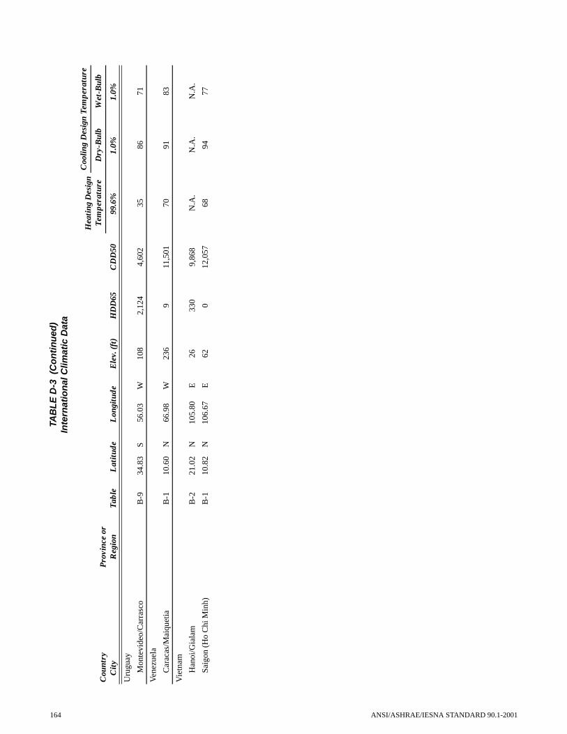
Uru
guay
Mon
tevi
deo/
Car
rasc
oB
-934
.83
S56
.03
W10
82,
124
4,60
235
8671
Ven
ezue
la
Car
acas
/Mai
quet
iaB
-110
.60
N66
.98
W23
69
11,5
0170
9183
Vie
tnam
Han
oi/G
iala
mB
-221
.02
N10
5.80
E26
330
9,86
8N
.A.
N.A
.N
.A.
Saig
on (
Ho
Chi
Min
h)B
-110
.82
N10
6.67
E62
012
,057
6894
77
TAB
LE
D-3
(C
on
tin
ued
)In
tern
atio
nal
Clim
atic
Dat
a
Cou
ntry
C
ity
Pro
vinc
e or
R
egio
nT
able
Lat
itud
eL
ongi
tude
Ele
v. (
ft)
HD
D65
CD
D50
Hea
ting
Des
ign
Tem
pera
ture
Coo
ling
Des
ign
Tem
pera
ture
Dry
-Bul
bW
et-B
ulb
99.6
%1.
0%1.
0%
164 ANSI/ASHRAE/IESNA STANDARD 90.1-2001

(This is an informative appendix and is not part of thisstandard.)
INFORMATIVE APPENDIX E
INFORMATIVE REFERENCESThis appendix contains informative references for the
convenience of users of Standard 90.1-2001 and to acknowl-edge source documents when appropriate. Some documentsare also included in Section 12 – Normative Referencesbecause there are other citations of that document within thestandard that are normative.
Address/Contact Information
AABCAssociated Air Balance Council1518 K Street Northwest, Suite 503Washington, DC [email protected]
BLASTAmerican Society of Heating, Refrigerating, andAir Conditioning Engineers, Inc.1791 Tullie Circle, NEAtlanta, GA 30329-2305http://www.ashrae.org
DOE-2 DataU.S. Department of CommerceTechnology AdministrationNational Technical Information Service5285 Port Royal RoadSpringfield, VA 22161http://www.ntis.gov
MICAMidwest Insulation Contractors Association16712 Elm CircleOmaha, NE 68130http://www.micainsulation.org
NEBBNational Environmental Balancing Bureau 8575 Grovemont Circle
ANSI/ASHRAE/IESNA STANDARD 90.1-2001
Gaithersburg, MD 20877http://www.nebb.org
SMACNASheet Metal & Air Conditioning Contractors’National Association 4201 Lafayette Center DriveChantilly, VA [email protected]://www.smacna.org
TMY DataNational Climatic Data Center National Environmental Satellite, Data, and Infor-mation ServiceNational Oceanic and Atmospheric AdministrationClimate Services Branch Federal Building Room 468151 Patton AvenueAsheville, NC 28801-5001 [email protected] download at http://doe2.com/Download/Weather/TMY
WYEC DataAmerican Society of Heating, Refrigerating andAir-Conditioning Engineers, Inc.ASHRAE Customer Service1791 Tullie Circle, NEAtlanta, GA [email protected] download at http://doe2.com/Download/Weather/WYEC
CWEC DataCanadian Climatic ServiceAtmospheric Environment Service4905 Dufferin StreetDownsview, OntarioCanada M3H [email protected]
165

Subsection No.
Reference Title/Source
6.2.2 2001 ASHRAE Handbook—Fundamentals -
6.2.4.1.1 MICA Insulation Standards - 1999 National commercial and industrial insulation standards
6.2.4.2.1 SMACNA Duct Construction Standards - 1995 HVAC duct construction standards, metal and flexible
6.2.4.2.2 SMACNA Duct Leakage Test Procedures - 1985 HVAC Air Duct Leakage Test Manual
6.2.5.3.1 NEBB Procedural Standards - 1999 Procedural standards for building systems commissioning
6.2.5.3.1 AABC 2002 Associated Air Balance Council Test and Balance procedures
6.2.5.3.1 ASHRAE Standard 111 - 1988 Practices for Measurement, Testing, Adjusting and Balancing of Building Heating, Ventilation, Air-Conditioning and Refrigeration Systems
6.2.5.2 ASHRAE Guideline 4 - 1993 Preparation of Operating and Maintenance Documentation for Building Systems
6.2.5.4 ASHRAE Guideline 1 - 1996 The HVAC Commissioning Process
7.2.1 and 7.3.1 1999 ASHRAE Handbook—HVAC Applications Chapter 48, Service Water Heating
11.2.1 DOE-2 National Technical Information Service
11.2.1 BLAST University of Illinois
11.2.2 WYEC2 Data Weather Year for Energy Calculations 2
11.2.2 TMY Data Typical Meteorological Year
11.2.2 CWEC Data Canadian Weather for Energy Calculations
166
ANSI/ASHRAE/IESNA STANDARD 90.1-2001
ANSI/ASHRAE/IESNA STANDARD 90.1-2001
(This is an informative appendix and is not part of this standard.)
Appendix F
Addenda Description InformationANSI/ASHRAE/IESNA Standard 90.1-2001 incorporates ANSI/ASHRAE/IESNA Standard 90.1-1999 and Addenda a, b,
d, e, f, g, j, k, m, n, o, q, r, s, t, u, v, w, y, z, aa, ab, ac, ad, af, ag, ah, ai, ak, al, am, an, ao, and ap. Table F-1 lists each addendumand describes the way in which the text is affected by the change. Table F-2 lists the ASHRAE and ANSI approval dates.
TABLE F-1 Addenda to ANSI/ASHRAE/IESNA Standard 90.1-1999; Changes Identified
Addenda to 90.1-1999 Sections Affected Description of Changesa
90.1a 5. Building Envelope Clarification to 5.2.1.2, Substantial Contact.
90.1b 5. Building Envelope Editorial clarification on how the exception in 5.3.1.1, Roof Insulation, is applied.
90.1d 5. Building Envelope Intended to clarify what F-factors should be used for trade-offs in the calculation procedures for slab-on-grade insulation in 5.3.1.5, Slab-on-Grade Floor Insulation. Appendix A, A6.
90.1e A9 Determination of Alternative U-Factors, C-Factors,
and F-Factors
This change makes clear that the calculation procedures in A9 can also be used for determining heat capacity of assemblies not covered in Tables A6 and A7.
90.1f Normative Appendix B, Building Envelope Criteria
Change to Appendix B changes the unheated slab-on-grade floor criteria for residential spaces.
90.1g Normative Appendix B, Building Envelope Criteria
Change to Appendix B changes the heated slab-on-grade floor values in Tables 19 through 26.
90.1j 6. Heating, Ventilating, and Air Conditioning
Changes to 6.2.1, Mechanical Equipment Efficiency, and corresponding Tables 6.2.1C, H, I and J.
90.1k 6. Heating, Ventilating, and Air Conditioning
Exceptions to 6.2.3.1.1, General, have been reworded for clarity and consistency.
90.1m 6. Heating, Ventilating, and Air Conditioning
Change to 6.2.3.2.4, Shutoff Damper Controls, adds a climatic limitation and rewords the low leakage requirement to clarify; it applies only to motorized dampers in the closed position.
90.1n 6. Heating, Ventilating, and Air Conditioning
Change to the Exceptions to 6.2.3.2.4, Shutoff Damper Controls, relates to gravity dampers and makes the statement consistent with the requirements of 6.1.3 (n), Simplified Approach Option for HVAC Systems.
90.1o 6. Heating, Ventilating, and Air Conditioning
Change to 6.2.3.2.5, Zone Isolation, clarifies how zones may be grouped and removes the detailed performance requirements.
90.1q 6. Heating, Ventilation, and Air Conditioning
This change removes 6.2.3.5, Enclosed Parking Garage Ventilation, in its entirety.
90.1r 6. Heating, Ventilation, and Air Conditioning
This is a change to the Exception to 6.3.1 (b) with regard to economizers.
90.1s 6. Heating, Ventilation, and Air Conditioning
This exception to 6.3.1.4, Economizer Heating System Impact, was added to ensure that code officials would allow economizer operation where reheat was allowed.
90.1t 6. Heating, Ventilation, and Air Conditioning
Change to 6.2.5.3.1, General, and 6.2.5.3.2, Air System Balancing, relates to system balancing and removes the exception to 6.2.5.3.1.
90.1u 6. Heating, Ventilation, and Air Conditioning
This change to Table 6.2.1B, Electrically Operated Unitary and Applied Heat Pumps-Minimum Efficiency Requirements, adds the heat pump minimum efficiency ratings using the ISO procedures that are equivalent to the current requirements.
90.1v 9. Lighting In 9.2.1.1, Automatic Lighting Shutoff, the term “occupant intervention” is vague and needed clarification.
90.1w 9. Lighting This change to 9.3.1.2, Space-by-Space Method of Calculating Interior Lighting Power Allowance, clarifies the intended use of this additional interior lighting allowance.
167

90.1y 9. Lighting This addendum clarifies the definition of “General Low Bay” and “General High Bay” under the heading of Industrial Buildings, Table 9.3.1.2, Lighting Power Densities Using the Space-by-Space Method.
90.1z 9. Lighting This change to 9.3.2, Exterior Building Lighting Power, and Table 9.3.2, Lighting Power Limits for Building Exteriors, clarifies the language and intent of exterior building lighting power.
90.1aa 8. Power Change to 8.2.1.1, Feeders, and 8.2.1.2, Branch Circuits, specifies that connection load is not always the sizing method used in electrical design.
90.1ab 9. Lighting Change to 9.3, Prescriptive Path, and Table 9.3.1.2, Space-by-Space Method of Cal-culating Interior Lighting Power Allowance, clarifies that the additional power allowances apply to any lighted area that meets the criteria.
90.1ac 7. Service Water Heating Change to 7.2.1, Sizing of Systems, provides additional wording to the designer for more flexibility in determining the load of the system.
90.1ad 6. Heating, Ventilating, and Air Conditioning
Numerous changes, including Tables 6.2.1A, 6.2.1B, 6.2.4.2B, and 6.1.3; 6.2.3.1, 6.2.4.1, 6.2.5.1 and 6.2.5.2.
90.1af 4. Administration and Enforcement
Changes to 4.1.2.2, strengthens the standard, and eliminates the possibility of loop-holes.
90.1ag 5. Building Envelope Changes to 5.2.2.1, 5.2.2.2, A8, Tables A-17, A-17 and A-19. Revises U-factor requirements for glazed wall systems in vertical fenestration to require compliance with NFRC certification programs.
90.1ah 9. Lighting Change to 9.3.1.1 to allow building area lighting power allowance method to be used for all buildings.
90.1ai 9. Lighting Change to 9.3.1.1, adding footnote to Table 9.3.1.1 to indicate specific building types apply.
90.1ak Appendix B Tables B-1 to B-26 (SI only), revises all U-factors in SI edition to be consistent with the IP edition.
90.1al 3 & 6. Definitions, Abbrevia-tions, and Acronyms & Heating, Ventilating, and Air Conditioning
In 3, modifies the definition of pump system energy demand. Also, change to 6.3.2.1, “mechanical refrigeration” to “mechanical cooling”, and 6.2.5.3, deleted certain requirements for system balancing.
90.1am 4. Administration and Enforcement
Changes to subsections of 4.1 and exceptions, rewritten version of Section 4 makes clear the different treatments given to additions and alterations to existing buildings.
90.1an 11. Energy Cost Budget Method Change to 11.4.2, coordinates subsection 11.4.2 with 4.1.2.1 and 4.1.2.2.
90.1ao 5. Building Envelope Editorial changes to the entire section. No changes to the requirements. The revision simply restructures to make it easier to read and use.
90.1ap 11. Energy Cost Budget Method Wording change to 11.4.3(e) and (f), this clarifies the rules for air and water econo-mizers for budget building design.
a These descriptions may not be complete and are provided for information only.
TABLE F-1 Addenda to ANSI/ASHRAE/IESNA Standard 90.1-1999; Changes Identified
168
ANSI/ASHRAE/IESNA STANDARD 90.1-2001
ANSI/ASHRAE/IESNA STANDARD 90.1-2001
TABLE F-2 Addenda to ANSI/ASHRAE/IESNA Standard 90.1-1999, Approval Dates
Addenda to 90.1-1999ASHRAE Standards Committee
Approval DateASHRAE Board of Directors
Approval Date ANSI Approval Date
90.1a January 27, 2001 February 01, 2001 May 22, 2001
90.1b April 1, 2001 June 24, 2001 September 17, 2001
90.1d January 27, 2001 February 01, 2001 May 22, 2001
90.1e January 27, 2001 February 01, 2001 May 22, 2001
90.1f April 1, 2001 June 24, 2001 October 11, 2001
90.1g January 27, 2001 February 01, 2001 May 22, 2001
90.1j January 27, 2001 February 01, 2001 May 22, 2001
90.1k January 27, 2001 February 01, 2001 May 22, 2001
90.1m April 1, 2001 June 24, 2001 N/A - Superseded
90.1n January 27, 2001 February 01, 2001 May 22, 2001
90.1o April 1, 2001 June 24, 2001 October 22, 2001
90.1q June 23, 2001 June 28, 2001 October 22, 2001
90.1r April 1, 2001 June 24, 2001 September 17, 2001
90.1s January 27, 2001 February 01, 2001 May 22, 2001
90.1t January 27, 2001 February 01, 2001 May 22, 2001
90.1u January 27, 2001 February 01, 2001 May 22, 2001
90.1v April 1, 2001 June 24, 2001 September 17, 2001
90.1w January 27, 2001 February 01, 2001 May 22, 2001
90.1y January 27, 2001 February 01, 2001 May 22, 2001
90.1z January 27, 2001 February 01, 2001 May 22, 2001
90.1aa January 27, 2001 February 01, 2001 May 22, 2001
90.1ab January 27, 2001 February 01, 2001 May 22, 2001
90.1ac January 27, 2001 February 01, 2001 May 22, 2001
90.1ad June 23, 2001 June 28, 2001 September 17, 2001
90.1af June 27, 2001 June 28, 2001 September 17, 2001
90.1ag April 1, 2001 June 24, 2001 September 17, 2001
90.1ah June 27, 2001 June 28, 2001 September 17, 2001
90.1ai April 1, 2001 June 24, 2001 September 17, 2001
90.1ak April 1, 2001 June 24, 2001 September 17, 2001
90.1al April 1, 2001 June 24, 2001 September 17, 2001
90.1am June 27, 2001 June 28, 2001 October 11, 2001
90.1an April 1, 2001 June 24, 2001 September 17, 2001
90.1ao April 1, 2001 June 24, 2001 September 17, 2001
90.1ap April 1, 2001 June 24, 2001 September 17, 2001
169


NOTICE
INSTRUCTIONS FOR SUBMITTING A PROPOSED CHANGE TO THIS STANDARD UNDER CONTINUOUS MAINTENANCE
This standard is maintained under continuous maintenance procedures by a Standing Standard Project Committee (SSPC) forwhich the Standards Committee has established a documented program for regular publication of addenda or revisions, includingprocedures for timely, documented, consensus action on requests for change to any part of the standard. SSPC consideration willbe given to proposed changes according to the following schedule:
Deadline for receipt of proposed changes SSPC will consider proposed changes at next
February 20 ASHRAE Annual Meeting (normally June)
Proposed changes must be submitted to the Manager of Standards (MOS) in the latest published format available from the MOS.However, the MOS may accept proposed changes in an earlier published format, if the MOS concludes that the differences areimmaterial to the proposed changes. If the MOS concludes that the current form must be utilized, the proposer may be given upto 20 additional days to resubmit the proposed changes in the current format.
Specific changes in text or values are required and must be substantiated. The Manager of Standards will return to the submitterany change proposals that do not meet these requirements. Supplemental background documents to support changes submittedmay be included.
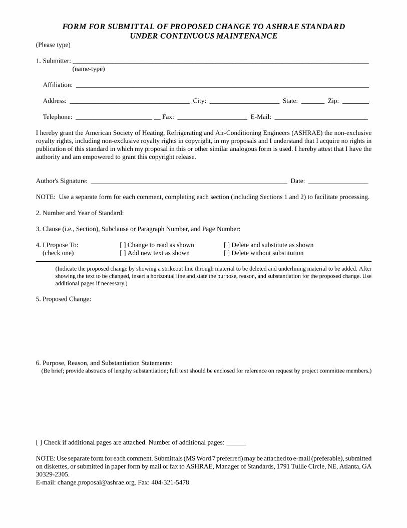
FORM FOR SUBMITTAL OF PROPOSED CHANGE TO ASHRAE STANDARD UNDER CONTINUOUS MAINTENANCE
(Please type)
1. Submitter: _________________________________________________________________________________________(name-type)
Affiliation: ________________________________________________________________________________________
Address: ____________________________________ City: _____________________ State: _______ Zip: ________
Telephone: _______________________ __ Fax: _____________________ E-Mail: ____________________________
I hereby grant the American Society of Heating, Refrigerating and Air-Conditioning Engineers (ASHRAE) the non-exclusiveroyalty rights, including non-exclusive royalty rights in copyright, in my proposals and I understand that I acquire no rights inpublication of this standard in which my proposal in this or other similar analogous form is used. I hereby attest that I have theauthority and am empowered to grant this copyright release.
Author's Signature: ___________________________________________________________ Date: __________________
NOTE: Use a separate form for each comment, completing each section (including Sections 1 and 2) to facilitate processing.
2. Number and Year of Standard:
3. Clause (i.e., Section), Subclause or Paragraph Number, and Page Number:
4. I Propose To: [ ] Change to read as shown [ ] Delete and substitute as shown (check one) [ ] Add new text as shown [ ] Delete without substitution
(Indicate the proposed change by showing a strikeout line through material to be deleted and underlining material to be added. Aftershowing the text to be changed, insert a horizontal line and state the purpose, reason, and substantiation for the proposed change. Useadditional pages if necessary.)
5. Proposed Change:
6. Purpose, Reason, and Substantiation Statements: (Be brief; provide abstracts of lengthy substantiation; full text should be enclosed for reference on request by project committee members.)
[ ] Check if additional pages are attached. Number of additional pages: ______
NOTE: Use separate form for each comment. Submittals (MS Word 7 preferred) may be attached to e-mail (preferable), submittedon diskettes, or submitted in paper form by mail or fax to ASHRAE, Manager of Standards, 1791 Tullie Circle, NE, Atlanta, GA30329-2305.E-mail: [email protected]. Fax: 404-321-5478

ELECTRONIC PREPARATION/SUBMISSION OF FORM FORPROPOSING CHANGES
An electronic version of each change, which must comply with the instructions in the Notice and the Form, is the preferred formof submittal to ASHRAE Headquarters at the address shown below. The electronic format facilitates both paper-based andcomputer-based processing. Submittal in paper form is acceptable. The following instructions apply to change proposals submit-ted in electronic form.
Use the appropriate file format for your word processor and save the file in either Microsoft Word 7 (preferred) or higher or Word-Perfect 5.1 for DOS format. Please save each change proposal file with a different name (example, prop001.doc, prop002.doc,etc., for Word files-prop001.wpm, prop002.wpm, etc., for WordPerfect files). If supplemental background documents to supportchanges submitted are included, it is preferred that they also be in electronic form as wordprocessed or scanned documents.
Electronic change proposals may be submitted either as files (MS Word 6 preferred) attached to an e-mail (uuencode preferred)or on 3.5" floppy disk. ASHRAE will accept the following as equivalent tot he signature required on the change submittal formto convey non-exclusive copyright:
Submit e-mail or disks containing change proposal files to:Manager of Standards
ASHRAE1791 Tullie Circle, NE
Atlanta, GA 30329-2305E-mail: [email protected]
(Alternatively, mail paper versions to ASHRAE address or Fax: 404-321-5478.)
The form and instructions for electronic submittal may be obtained from the Standards section of ASHRAE's Home Page, http://www.ashrae.org, or by contacting a Standards Secretary, 1791 Tullie Circle, NE, Atlanta, GA 30329-2305. Phone: 404-636-8400. Fax: 404-321-5478. Email: [email protected].
Files attached to e-mail: Electronic signature on change submittal form (as a picture; *.tif, or *.wpg), or e-mail address.
Files on disk: Electronic signature on change submittal form (as a picture; *.tif, or *.wpg), listing of the submitter's e-mail address on the change submittal form, or a letter with submitter's signature accompanying the disk or sent by facsimile (single letter may cover all of proponent's proposed changes).


POLICY STATEMENT DEFINING ASHRAEíS CONCERNFOR THE ENVIRONMENTAL IMPACT OF ITS ACTIVITIES
ASHRAE is concerned with the impact of its membersí activities on both the indoor and outdoor environment.ASHRAEís members will strive to minimize any possible deleterious effect on the indoor and outdoor environment ofthe systems and components in their responsibility while maximizing the beneficial effects these systems provide,consistent with accepted standards and the practical state of the art.
ASHRAEís short-range goal is to ensure that the systems and components within its scope do not impact theindoor and outdoor environment to a greater extent than specified by the standards and guidelines as established byitself and other responsible bodies.
As an ongoing goal, ASHRAE will, through its Standards Committee and extensive technical committeestructure, continue to generate up-to-date standards and guidelines where appropriate and adopt, recommend, andpromote those new and revised standards developed by other responsible organizations.
Through its Handbook, appropriate chapters will contain up-to-date standards and design considerations as thematerial is systematically revised.
ASHRAE will take the lead with respect to dissemination of environmental information of its primary interest andwill seek out and disseminate information from other responsible organizations that is pertinent, as guides to updatingstandards and guidelines.
The effects of the design and selection of equipment and systems will be considered within the scope of thesystemís intended use and expected misuse. The disposal of hazardous materials, if any, will also be considered.
ASHRAEís primary concern for environmental impact will be at the site where equipment within ASHRAEís scopeoperates. However, energy source selection and the possible environmental impact due to the energy source andenergy transportation will be considered where possible. Recommendations concerning energy source selectionshould be made by its members.

86245PC 12/03Errata noted in lists dated 5/8/03 and 11/10/03 have been corrected.

ANSI/ASHRAE/IESNA Addendum a toANSI/ASHRAE/IESNA Standard 90.1-2001
Energy Standard for
Buildings Except Low-Rise
Residential BuildingsAddendum a was approved by the ASHRAE StandardsCommittee January 25, 2003; by the ASHRAE Board ofDirectors January 30, 2003; and by the American NationalStandards Institute April 3, 2003.
This standard is under continuous maintenance by a Stand-ing Standard Project Committee (SSPC) for which the Stan-dards Committee has established a documented programfor regular publication of addenda or revisions, includingprocedures for timely, documented, consensus action onrequests for change to any part of the standard. Thechange submittal form, instructions, and deadlines aregiven at the back of this document and may be obtained inelectronic form from ASHRAEís Internet Home Page, http://www.ashrae.org, or in paper form from the Manager ofStandards. The latest edition of an ASHRAE Standard andprinted copies of a public review draft may be purchasedfrom ASHRAE Customer Service, 1791 Tullie Circle, NE,Atlanta, GA 30329-2305. E-mail: [email protected]. Fax:404-321-5478. Telephone: 404-636-8400 (worldwide), ortoll free 1-800-527-4723 (for orders in U.S. and Canada).
©Copyright 2003 American Society of Heating,Refrigerating and Air-Conditioning Engineers, Inc.
ISSN 1041-2336
When addenda or interpretations to this standard havebeen approved, they can be downloaded free of chargefrom the ASHRAE web site at http://xp20.ashrae.org/stan-dards/addenda.htm or http://xp20.ashrae.org/standards/intpstd.htm.

ASHRAE Standing Standard Project Committee 90.1
Cognizant TC: TC 9.6, System Energy UtilizationSPLS Liaison: Michael H. Tavares
ASHRAE Staff Liaison: Mark WeberIESNA Liaison: Rita M. Harrold
Jerry W. White, Jr., Chair* Randall T. Higa* Edward P. O’Brien*
James M. Calm, Vice-Chair* Billy G. Hinton, Jr.* Jim A. Ranfone*
Donald F. Steiner, Vice-Chair* John F. Hogan* Eric E. Richman*
Karim Amrane* Samantha Hollomon Jack F. Roberts*
William P. Bahnfleth* William G. Holy* Robert D. Ross*
Van D. Baxter* Graham C. Hunter, II* Donald L. Sampler*
Donald L. Beaty* J. Delaine Jones* David A. Schaaf, Jr.*
Albert W. Black, III* Hyman M. Kaplan* Leonard C. Sciarra*
Valerie L. Block* Gersil N. Kay* Peter Simmonds*
Donald M. Brundage* Larry Kouma* Stephen V. Skalko*
Ernest A. Conrad Ronald D. Kurtz* Frank A. Stanonik*
Charles C. Cottrell* Michael D. Lane* Joseph K. Ting*
Roy Crane* Steven J. Lit* Cedric S. Trueman*
Joseph J. Deringer* Kenneth Luther* Frederick F. Wajcs, Jr.
David Duly Ronald Majette* McHenry Wallace, Jr.*
Douglas S. Erickson* Itzhak H. Maor* Richard D. Watson*
Thomas A. Farkas Carol E. Marriott* David Weitz*
Charles R. Foster, III* R. Christopher Mathis* Robin Wilson*
Alan Fraser* Merle F. McBride Michael W. Woodford
James A. Garrigus* Louis J. Molinini* Dale L. Woodin
Jason J. Glazer* John Montgomery* Thomas R. Worlledge*
Katherine G. Hammack* Frank Myers* Donald R. Wulfinghoff*
Ronald G. Nickson* Stanley W. Zajac*
*Denotes members of voting status when the document was approved for publication

ASHRAE STANDARDS COMMITTEE 2002-2003
Thomas E. Watson, ChairVan D. Baxter, Vice-ChairCharles G. ArnoldDean S. BorgesPaul W. CabotCharles W. Coward, Jr.Brian P. DoughertyAbdelhakim ElmahdyArthur D. HallstromMatt R. HarganRichard D. HermansStephen D. Kennedy
David E. KnebelFrederick H. KohlossWilliam J. Landman
Merle F. McBrideRoss D. Montgomery
Cyrus H. NasseriDavor Novosel
Dennis A. StankeMichael H. Tavares
Steven T. TaylorDavid R. Tree
Terry E. Townsend, COMaureen Grasso, ExO
Claire B. Ramspeck, Manager of Standards
SPECIAL NOTE
This American National Standard (ANS) is a national voluntary consensus standard developed under the auspices of the AmericanSociety of Heating, Refrigerating and Air-Conditioning Engineers (ASHRAE). Consensus is defined by the American National StandardsInstitute (ANSI), of which ASHRAE is a member and which has approved this standard as an ANS, as “substantial agreement reachedby directly and materially affected interest categories. This signifies the concurrence of more than a simple majority, but not necessarilyunanimity. Consensus requires that all views and objections be considered, and that an effort be made toward their resolution.”Compliance with this standard is voluntary until and unless a legal jurisdiction makes compliance mandatory through legislation.
ASHRAE obtains consensus through participation of its national and international members, associated societies, and publicreview.
ASHRAE Standards are prepared by a Project Committee appointed specifically for the purpose of writing the Standard. TheProject Committee Chair and Vice-Chair must be members of ASHRAE; while other committee members may or may not be ASHRAEmembers, all must be technically qualified in the subject area of the Standard. Every effort is made to balance the concerned interestson all Project Committees.
The Manager of Standards of ASHRAE should be contacted for:a. interpretation of the contents of this Standard,b. participation in the next review of the Standard,c. offering constructive criticism for improving the Standard,d. permission to reprint portions of the Standard.
ASHRAE INDUSTRIAL ADVERTISING POLICY ON STANDARDSASHRAE Standards and Guidelines are established to assist industry and the public by offering a uniform method of
testing for rating purposes, by suggesting safe practices in designing and installing equipment, by providing proper definitions of this equipment, and by providing other information that may serve to guide the industry. The creation of ASHRAE Standards and Guidelines is determined by the need for them, and conformance to them is completely voluntary.
In referring to this Standard or Guideline and in marking of equipment and in advertising, no claim shall be made, eitherstated or implied, that the product has been approved by ASHRAE.
DISCLAIMER
ASHRAE uses its best efforts to promulgate Standards and Guidelines for the benefit of the public in light of availableinformation and accepted industry practices. However, ASHRAE does not guarantee, certify, or assure the safety orperformance of any products, components, or systems tested, installed, or operated in accordance with ASHRAE’s Standardsor Guidelines or that any tests conducted under its Standards or Guidelines will be nonhazardous or free from risk.

2 ANSI/ASHRAE/IESNA Addendum a to ANSI/ASHRAE/IESNA STANDARD 90.1-2001
(This foreword is not part of this standard. It is merelyinformative and does not contain requirements necessaryfor conformance to the standard. It has not been pro-cessed according to the ANSI requirements for a stan-dard and may contain material that has not been subjectto public review or a consensus process.)
FOREWORD
Requirements for transformers were deleted from a priordraft of the standard, and Section 4.4.7 was inadvertently notdeleted at the same time transformer requirements were
deleted. Without the transformer requirements in Section 8, orany sort of indication as to how transformers were to belabeled, the requirement for labeling transformers with their“energy-efficiency level” in Section 4.4.7 became meaning-less or confusing.
Addendum 90.1a (I-P and SI Editions)
Delete Section 4.4.7 in its entirety:
4.4.7 Transformers. The energy-efficiency level shall beidentified on a permanent nameplate installed on the trans-former by the manufacturer.

POLICY STATEMENT DEFINING ASHRAE’S CONCERNFOR THE ENVIRONMENTAL IMPACT OF ITS ACTIVITIES
ASHRAE is concerned with the impact of its members’ activities on both the indoor and outdoor environment. ASHRAE’smembers will strive to minimize any possible deleterious effect on the indoor and outdoor environment of the systems andcomponents in their responsibility while maximizing the beneficial effects these systems provide, consistent with acceptedstandards and the practical state of the art.
ASHRAE’s short-range goal is to ensure that the systems and components within its scope do not impact the indoor andoutdoor environment to a greater extent than specified by the standards and guidelines as established by itself and otherresponsible bodies.
As an ongoing goal, ASHRAE will, through its Standards Committee and extensive technical committee structure,continue to generate up-to-date standards and guidelines where appropriate and adopt, recommend, and promote those newand revised standards developed by other responsible organizations.
Through its Handbook, appropriate chapters will contain up-to-date standards and design considerations as the material issystematically revised.
ASHRAE will take the lead with respect to dissemination of environmental information of its primary interest and will seekout and disseminate information from other responsible organizations that is pertinent, as guides to updating standards andguidelines.
The effects of the design and selection of equipment and systems will be considered within the scope of the system’sintended use and expected misuse. The disposal of hazardous materials, if any, will also be considered.
ASHRAE’s primary concern for environmental impact will be at the site where equipment within ASHRAE’s scopeoperates. However, energy source selection and the possible environmental impact due to the energy source and energytransportation will be considered where possible. Recommendations concerning energy source selection should be made byits members.

ANSI/ASHRAE/IESNA Addendum b toANSI/ASHRAE/IESNA Standard 90.1-2001
Energy Standardfor BuildingsExcept Low-RiseResidentialBuildingsApproved by the ASHRAE Standards Committee June 22,2002; by the ASHRAE Board of Directors June 27, 2002; andby the American National Standards Institute July 30, 2002.
This standard is under continuous maintenance by a Stand-ing Standard Project Committee (SSPC) for which the Stan-dards Committee has established a documented programfor regular publication of addenda or revisions, includingprocedures for timely, documented, consensus action onrequests for change to any part of the standard. Thechange submittal form, instructions, and deadlines aregiven at the back of this document and may be obtained inelectronic form from ASHRAE’s Internet Home Page, http://www.ashrae.org, or in paper form from the Manager ofStandards. The latest edition of an ASHRAE Standard andprinted copies of a public review draft may be purchasedfrom ASHRAE Customer Service, 1791 Tullie Circle, NE,Atlanta, GA 30329-2305. E-mail: [email protected]. Fax:404-321-5478. Telephone: 404-636-8400 (worldwide), ortoll free 1-800-527-4723 (for orders in U.S. and Canada).
©Copyright 2002 American Society of Heating,Refrigerating and Air-Conditioning Engineers, Inc.
ISSN 1041-2336
When addenda or interpretations to this standard havebeen approved, they can be downloaded free of chargefrom the ASHRAE Home Page at www.ashrae.org/STAN-DARDS/ addenda.htm or www.ashrae.org/STANDARDS/intpstd.htm.
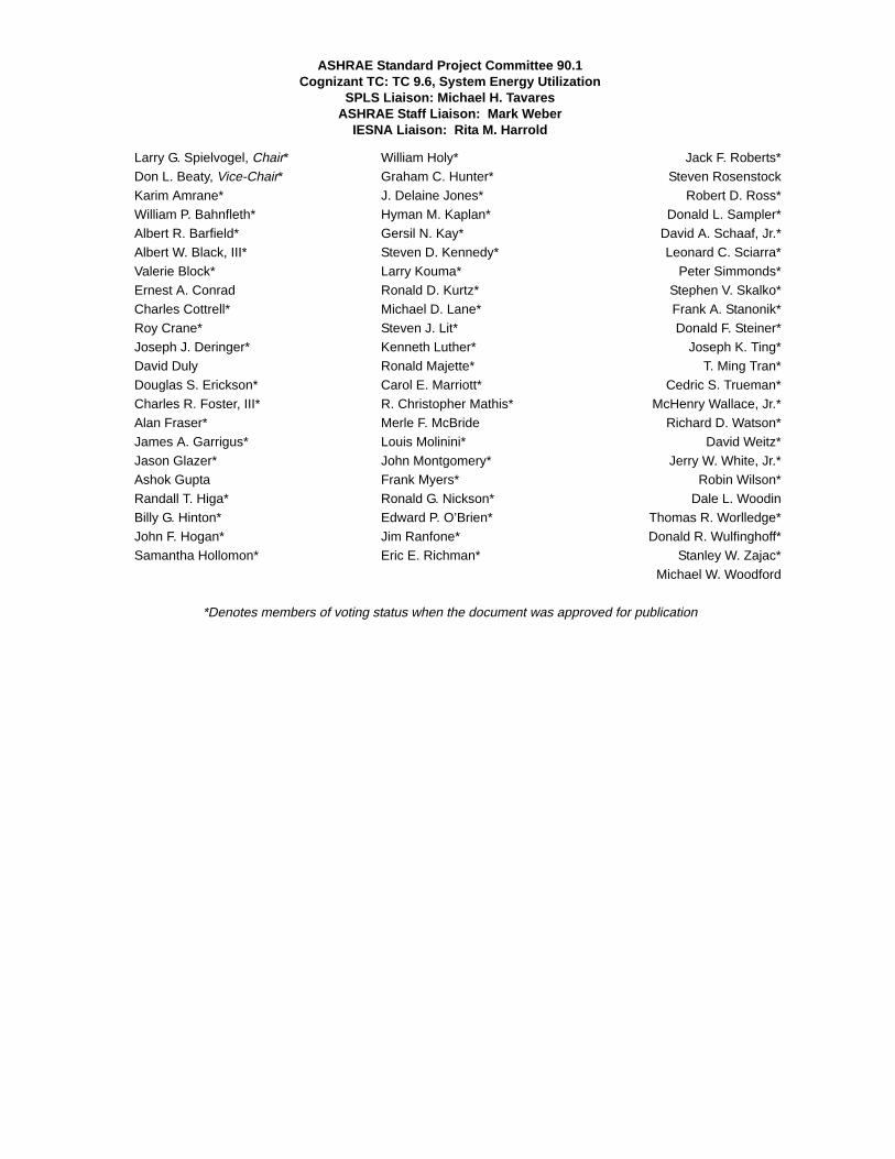
ASHRAE Standard Project Committee 90.1 Cognizant TC: TC 9.6, System Energy Utilization
SPLS Liaison: Michael H. TavaresASHRAE Staff Liaison: Mark Weber
IESNA Liaison: Rita M. Harrold
Larry G. Spielvogel, Chair* William Holy* Jack F. Roberts*Don L. Beaty, Vice-Chair* Graham C. Hunter* Steven RosenstockKarim Amrane* J. Delaine Jones* Robert D. Ross*William P. Bahnfleth* Hyman M. Kaplan* Donald L. Sampler*Albert R. Barfield* Gersil N. Kay* David A. Schaaf, Jr.*Albert W. Black, III* Steven D. Kennedy* Leonard C. Sciarra*Valerie Block* Larry Kouma* Peter Simmonds*Ernest A. Conrad Ronald D. Kurtz* Stephen V. Skalko*Charles Cottrell* Michael D. Lane* Frank A. Stanonik*Roy Crane* Steven J. Lit* Donald F. Steiner*Joseph J. Deringer* Kenneth Luther* Joseph K. Ting*David Duly Ronald Majette* T. Ming Tran*Douglas S. Erickson* Carol E. Marriott* Cedric S. Trueman*Charles R. Foster, III* R. Christopher Mathis* McHenry Wallace, Jr.*Alan Fraser* Merle F. McBride Richard D. Watson*James A. Garrigus* Louis Molinini* David Weitz*Jason Glazer* John Montgomery* Jerry W. White, Jr.*Ashok Gupta Frank Myers* Robin Wilson*Randall T. Higa* Ronald G. Nickson* Dale L. WoodinBilly G. Hinton* Edward P. O’Brien* Thomas R. Worlledge*John F. Hogan* Jim Ranfone* Donald R. Wulfinghoff*Samantha Hollomon* Eric E. Richman* Stanley W. Zajac*
Michael W. Woodford
*Denotes members of voting status when the document was approved for publication

SPECIAL NOTE
This American National Standard (ANS) is a national voluntary consensus standard developed under the auspices of the AmericanSociety of Heating, Refrigerating and Air-Conditioning Engineers (ASHRAE). Consensus is defined by the American National StandardsInstitute (ANSI), of which ASHRAE is a member and which has approved this standard as an ANS, as “substantial agreement reachedby directly and materially affected interest categories. This signifies the concurrence of more than a simple majority, but not necessarilyunanimity. Consensus requires that all views and objections be considered, and that an effort be made toward their resolution.”Compliance with this standard is voluntary until and unless a legal jurisdiction makes compliance mandatory through legislation.
ASHRAE obtains consensus through participation of its national and international members, associated societies, and publicreview.
ASHRAE Standards are prepared by a Project Committee appointed specifically for the purpose of writing the Standard. TheProject Committee Chair and Vice-Chair must be members of ASHRAE; while other committee members may or may not be ASHRAEmembers, all must be technically qualified in the subject area of the Standard. Every effort is made to balance the concerned interestson all Project Committees.
The Manager of Standards of ASHRAE should be contacted for:a. interpretation of the contents of this Standard,b. participation in the next review of the Standard,c. offering constructive criticism for improving the Standard,d. permission to reprint portions of the Standard.
ASHRAE INDUSTRIAL ADVERTISING POLICY ON STANDARDSASHRAE Standards and Guidelines are established to assist industry and the public by offering a uniform method
of testing for rating purposes, by suggesting safe practices in designing and installing equipment, by providing proper definitions of this equipment, and by providing other information that may serve to guide the industry. The creation of ASHRAE Standards and Guidelines is determined by the need for them, and conformance to them is completely voluntary.
In referring to this Standard or Guideline and in marking of equipment and in advertising, no claim shall bemade, either stated or implied, that the product has been approved by ASHRAE.
DISCLAIMER
ASHRAE uses its best efforts to promulgate Standards and Guidelines for the benefit of the public in light of availableinformation and accepted industry practices. However, ASHRAE does not guarantee, certify, or assure the safety orperformance of any products, components, or systems tested, installed, or operated in accordance with ASHRAE’s Standardsor Guidelines or that any tests conducted under its Standards or Guidelines will be nonhazardous or free from risk.
ASHRAE STANDARDS COMMITTEE 2001-2002
Nance C. Lovvorn, ChairThomas E. Watson, Vice-ChairCharles G. ArnoldVan D. BaxterDean S. BorgesPaul W. CabotWaller S. ClementsCharles W. Coward, Jr.Harold L. Crowder, Jr.Brian P. DoughertyRichard A. EvansArthur D. Hallstrom
Richard D. HermansJohn F. Hogan
Frederick H. KohlossWilliam J. Landman
Rodney H. LewisRoss D. Montgomery
Davor NovoselDennis A StankeMichael TavaresSteven T. Taylor
J. Richard WrightLee W. Burgett, CO
Gordon V.R. Holness, ExO
Claire B. Ramspeck, Manager of Standards

2 Addendum b to ANSI/ASHRAE/IESNA STANDARD 90.1-2001
(This foreword is provided for information only and isnot part of the addendum.)
FOREWORD
The existing language gives an unfair advantage tocompeting products when one of the products has a certifica-tion program in existence and the other does not. For exam-ple, there are small cooling towers that compete with air-cooled equipment. The cooling towers have an optional certi-fication program, but no program exists for competing air-cooled equipment. The current language would force theadded burden of certification onto all cooling towers, whereasno added burden would be placed on air-cooled equipment.The proposed language addresses this issue for cooling towersby requiring them to meet the same requirements as air-cooledequipment. Additionally, the current language was adjustedto avoid conflict with Department of Energy certificationrequirements for equipment covered by the Federal EnergyPolicy Act (EPACT) of 1992.
Notice: ASHRAE now has a list server for Standing Stan-dards Project Committee 90.1 (SSPC 90.1). Interested partiescan now subscribe and unsubscribe to the list server and beautomatically notified via e-mail when activities and informa-tion related to the Standard and the User’s Manual is avail-able. To sign up for the list server please vist Standards ListServers on the Standards and Codes section of the ASHRAEwebsite at http://www.ashrae.org/STANDARDS/listserv-ers.htm.
Addendum 90.1b (I-P and SI editions)
6.2.1 Mechanical Equipment Efficiency. Equipmentshown in Tables 6.2.1A through 6.2.1G shall have a minimumperformance at the specified rating conditions when tested inaccordance with the specified test procedure. Omission ofminimum performance requirements for equipment not listedin Tables 6.2.1A through 6.2.1G does not preclude use of such
equipment. Equipment not listed in Tables 6.2.1A through6.2.1G has no minimum performance requirements. Wheremultiple rating conditions or performance requirements areprovided, the equipment shall satisfy all stated requirements,unless otherwise exempted by footnotes in the table. How-ever, equipment covered under the Federal Energy Policy Act(EPACT) of 1992 shall have no minimum efficiency require-ments for operation at minimum capacity or other than stan-dard rating conditions. Equipment used to provide waterheating functions as part of a combination system shall satisfyall stated requirements for the appropriate space heating orcooling category.
Equipment covered under the Federal Energy Policy Actof 1992 (EPACT) shall comply with U.S. Department ofEnergy certification requirements. For other equipment, iIf acertification program exists for a product covered in Tables6.2.1A through 6.2.1GF, and it includes provisions for verifi-cation and challenge of equipment efficiency ratings, then theproduct shall be either listed in the certification program or,alternatively, the ratings shall be verified by an independentlaboratory test report. If no certification program exists for aproduct covered in Tables 6.2.1A through 6.2.1GF, the equip-ment efficiency ratings shall be supported by data furnished bythe manufacturer. Products covered in Table 6.2.1G shall haveefficiency ratings supported by data furnished by the manu-facturer. Where components such as indoor or outdoor coilsfrom different manufacturers are used, the system designershall specify component efficiencies whose combined effi-ciency meets the minimum equipment efficiency require-ments in 6.2.1.
Note: The reference to STD 201 in Table 6.2.1G needs tobe removed, since it is the standard used in the optional certi-fication program administered by CTI. The table should stillmake reference to ATC-105 as it is the actual test procedure towhich cooling towers are tested.

POLICY STATEMENT DEFINING ASHRAE’S CONCERNFOR THE ENVIRONMENTAL IMPACT OF ITS ACTIVITIES
ASHRAE is concerned with the impact of its members’ activities on both the indoor and outdoor environment. ASHRAE’smembers will strive to minimize any possible deleterious effect on the indoor and outdoor environment of the systems andcomponents in their responsibility while maximizing the beneficial effects these systems provide, consistent with acceptedstandards and the practical state of the art.
ASHRAE’s short-range goal is to ensure that the systems and components within its scope do not impact the indoor andoutdoor environment to a greater extent than specified by the standards and guidelines as established by itself and otherresponsible bodies.
As an ongoing goal, ASHRAE will, through its Standards Committee and extensive technical committee structure,continue to generate up-to-date standards and guidelines where appropriate and adopt, recommend, and promote those newand revised standards developed by other responsible organizations.
Through its Handbook, appropriate chapters will contain up-to-date standards and design considerations as the material issystematically revised.
ASHRAE will take the lead with respect to dissemination of environmental information of its primary interest and will seekout and disseminate information from other responsible organizations that is pertinent, as guides to updating standards andguidelines.
The effects of the design and selection of equipment and systems will be considered within the scope of the system’sintended use and expected misuse. The disposal of hazardous materials, if any, will also be considered.
ASHRAE’s primary concern for environmental impact will be at the site where equipment within ASHRAE’s scopeoperates. However, energy source selection and the possible environmental impact due to the energy source and energytransportation will be considered where possible. Recommendations concerning energy source selection should be made byits members.

ANSI/ASHRAE/IESNA Addendum c toANSI/ASHRAE/IESNA Standard 90.1-2001
Energy Standardfor BuildingsExcept Low-RiseResidentialBuildingsApproved by the ASHRAE Standards Committee June 22,2002; by the ASHRAE Board of Directors June 27, 2002; andby the American National Standards Institute July 30, 2002.
This standard is under continuous maintenance by a Stand-ing Standard Project Committee (SSPC) for which the Stan-dards Committee has established a documented programfor regular publication of addenda or revisions, includingprocedures for timely, documented, consensus action onrequests for change to any part of the standard. Thechange submittal form, instructions, and deadlines aregiven at the back of this document and may be obtained inelectronic form from ASHRAE’s Internet Home Page, http://www.ashrae.org, or in paper form from the Manager ofStandards. The latest edition of an ASHRAE Standard andprinted copies of a public review draft may be purchasedfrom ASHRAE Customer Service, 1791 Tullie Circle, NE,Atlanta, GA 30329-2305. E-mail: [email protected]. Fax:404-321-5478. Telephone: 404-636-8400 (worldwide), ortoll free 1-800-527-4723 (for orders in U.S. and Canada).
©Copyright 2002 American Society of Heating,Refrigerating and Air-Conditioning Engineers, Inc.
ISSN 1041-2336
When addenda or interpretations to this standard havebeen approved, they can be downloaded free of chargefrom the ASHRAE Home Page at www.ashrae.org/STAN-DARDS/ addenda.htm or www.ashrae.org/STANDARDS/intpstd.htm.

ASHRAE Standard Project Committee 90.1 Cognizant TC: TC 9.6, System Energy Utilization
SPLS Liaison: Michael H. TavaresASHRAE Staff Liaison: Mark Weber
IESNA Liaison: Rita M. Harrold
Larry G. Spielvogel, Chair* William Holy* Jack F. Roberts*
Don L. Beaty, Vice-Chair* Graham C. Hunter* Steven Rosenstock
Karim Amrane* J. Delaine Jones* Robert D. Ross*
William P. Bahnfleth* Hyman M. Kaplan* Donald L. Sampler*
Albert R. Barfield* Gersil N. Kay* David A. Schaaf, Jr.*
Albert W. Black, III* Steven D. Kennedy* Leonard C. Sciarra*
Valerie Block* Larry Kouma* Peter Simmonds*
Ernest A. Conrad Ronald D. Kurtz* Stephen V. Skalko*
Charles Cottrell* Michael D. Lane* Frank A. Stanonik*
Roy Crane* Steven J. Lit* Donald F. Steiner*
Joseph J. Deringer* Kenneth Luther* Joseph K. Ting*
David Duly Ronald Majette* T. Ming Tran*
Douglas S. Erickson* Carol E. Marriott* Cedric S. Trueman*
Charles R. Foster, III* R. Christopher Mathis* McHenry Wallace, Jr.*
Alan Fraser* Merle F. McBride Richard D. Watson*
James A. Garrigus* Louis Molinini* David Weitz*
Jason Glazer* John Montgomery* Jerry W. White, Jr.*
Ashok Gupta Frank Myers* Robin Wilson*
Randall T. Higa* Ronald G. Nickson* Dale L. Woodin
Billy G. Hinton* Edward P. O’Brien* Thomas R. Worlledge*
John F. Hogan* Jim Ranfone* Donald R. Wulfinghoff*
Samantha Hollomon* Eric E. Richman* Stanley W. Zajac*
Michael W. Woodford
*Denotes members of voting status when the document was approved for publication

SPECIAL NOTE
This American National Standard (ANS) is a national voluntary consensus standard developed under the auspices of the AmericanSociety of Heating, Refrigerating and Air-Conditioning Engineers (ASHRAE). Consensus is defined by the American National StandardsInstitute (ANSI), of which ASHRAE is a member and which has approved this standard as an ANS, as “substantial agreement reachedby directly and materially affected interest categories. This signifies the concurrence of more than a simple majority, but not necessarilyunanimity. Consensus requires that all views and objections be considered, and that an effort be made toward their resolution.”Compliance with this standard is voluntary until and unless a legal jurisdiction makes compliance mandatory through legislation.
ASHRAE obtains consensus through participation of its national and international members, associated societies, and publicreview.
ASHRAE Standards are prepared by a Project Committee appointed specifically for the purpose of writing the Standard. TheProject Committee Chair and Vice-Chair must be members of ASHRAE; while other committee members may or may not be ASHRAEmembers, all must be technically qualified in the subject area of the Standard. Every effort is made to balance the concerned interestson all Project Committees.
The Manager of Standards of ASHRAE should be contacted for:a. interpretation of the contents of this Standard,b. participation in the next review of the Standard,c. offering constructive criticism for improving the Standard,d. permission to reprint portions of the Standard.
ASHRAE INDUSTRIAL ADVERTISING POLICY ON STANDARDSASHRAE Standards and Guidelines are established to assist industry and the public by offering a uniform method
of testing for rating purposes, by suggesting safe practices in designing and installing equipment, by providing proper definitions of this equipment, and by providing other information that may serve to guide the industry. The creation of ASHRAE Standards and Guidelines is determined by the need for them, and conformance to them is completely voluntary.
In referring to this Standard or Guideline and in marking of equipment and in advertising, no claim shall bemade, either stated or implied, that the product has been approved by ASHRAE.
DISCLAIMER
ASHRAE uses its best efforts to promulgate Standards and Guidelines for the benefit of the public in light of availableinformation and accepted industry practices. However, ASHRAE does not guarantee, certify, or assure the safety orperformance of any products, components, or systems tested, installed, or operated in accordance with ASHRAE’s Standardsor Guidelines or that any tests conducted under its Standards or Guidelines will be nonhazardous or free from risk.
ASHRAE STANDARDS COMMITTEE 2001-2002
Nance C. Lovvorn, ChairThomas E. Watson, Vice-ChairCharles G. ArnoldVan D. BaxterDean S. BorgesPaul W. CabotWaller S. ClementsCharles W. Coward, Jr.Harold L. Crowder, Jr.Brian P. DoughertyRichard A. EvansArthur D. Hallstrom
Richard D. HermansJohn F. Hogan
Frederick H. KohlossWilliam J. Landman
Rodney H. LewisRoss D. Montgomery
Davor NovoselDennis A StankeMichael TavaresSteven T. Taylor
J. Richard WrightLee W. Burgett, CO
Gordon V.R. Holness, ExO
Claire B. Ramspeck, Manager of Standards

2 Addendum c to ANSI/ASHRAE/IESNA STANDARD 90.1-2001
(This foreword is provided for information only and isnot part of the addendum.)
FOREWORD
There are several issues that were considered in issuingthis addendum:
This restriction on pressure-sensitive tape exists in Stan-dard 90.1-1989 and is included in the ASHRAE handbooksection on duct sealing. However, both of these predate thedevelopment of new UL Standard 181A (Closure Systems forUse with Rigid Air Ducts and Air Connectors) and UL Stan-dard 181B (Closure Systems for Use with Flexible Air Ductsand Air Connectors) regarding the application of pressure-sensitive tapes. Given these UL standards, the use of pres-sure-sensitive tape is allowed.
The committee has requested that UL extend its standardsto include sheet metal ducts. Support from the related indus-tries is urged so testing in these areas can be expedited.
Notice: ASHRAE now has a list server for Standing Stan-dards Project Committee 90.1 (SSPC 90.1). Interested partiescan now subscribe and unsubscribe to the list server and beautomatically notified via e-mail when activities and informa-tion related to the Standard and the User’s Manual is avail-able. To sign up for the list server please vist Standards ListServers on the Standards and Codes section of the ASHRAEwebsite at http://www.ashrae.org/STANDARDS/listserv-ers.htm.
Addendum 90.1c (I-P and SI editions)
Modify Table 6.2.4.3B as follows:
Add UL-181A and UL-181B to Section 12, NormativeReferences.
TABLE 6.2.4.3BDuct Seal Levels
Seal Level Sealing Requirementsa
A All transverse joints, longitudinal seams, and duct wall pen-etrations. Pressure-sensitive tape shall not be used as the primary sealant unless it has been certified to comply with UL-181A or UL-181B by an independent testing laboratory and the tape is used in accordance with that certification.
B All transverse joints and longitudinal seams. Pressure-sensi-tive tape shall not be used as the primary sealant unless it has been certified to comply with UL-181A or UL-181B by an independent testing laboratory and the tape is used in accordance with that certification.
C Transverse joints only.a Longitudinal seams are joints oriented in the direction of airflow. Transverse joints
are connections of two duct sections oriented perpendicular to airflow. Duct wallpenetrations are openings made by any screw fastener, pipe, rod, or wire. Spiral lockseams in round and flat oval duct need not be sealed. All other connections are con-sidered transverse joints, including but not limited to spin-ins, taps, and other branchconnections, access door frames and jambs, duct connections to equipment, etc.

POLICY STATEMENT DEFINING ASHRAE’S CONCERNFOR THE ENVIRONMENTAL IMPACT OF ITS ACTIVITIES
ASHRAE is concerned with the impact of its members’ activities on both the indoor and outdoor environment. ASHRAE’smembers will strive to minimize any possible deleterious effect on the indoor and outdoor environment of the systems andcomponents in their responsibility while maximizing the beneficial effects these systems provide, consistent with acceptedstandards and the practical state of the art.
ASHRAE’s short-range goal is to ensure that the systems and components within its scope do not impact the indoor andoutdoor environment to a greater extent than specified by the standards and guidelines as established by itself and otherresponsible bodies.
As an ongoing goal, ASHRAE will, through its Standards Committee and extensive technical committee structure,continue to generate up-to-date standards and guidelines where appropriate and adopt, recommend, and promote those newand revised standards developed by other responsible organizations.
Through its Handbook, appropriate chapters will contain up-to-date standards and design considerations as the material issystematically revised.
ASHRAE will take the lead with respect to dissemination of environmental information of its primary interest and will seekout and disseminate information from other responsible organizations that is pertinent, as guides to updating standards andguidelines.
The effects of the design and selection of equipment and systems will be considered within the scope of the system’sintended use and expected misuse. The disposal of hazardous materials, if any, will also be considered.
ASHRAE’s primary concern for environmental impact will be at the site where equipment within ASHRAE’s scopeoperates. However, energy source selection and the possible environmental impact due to the energy source and energytransportation will be considered where possible. Recommendations concerning energy source selection should be made byits members.

ANSI/ASHRAE/IESNA Addendum d toANSI/ASHRAE/IESNA Standard 90.1-2001
Energy Standardfor BuildingsExcept Low-RiseResidentialBuildingsApproved by the ASHRAE Standards Committee June 22,2002; by the ASHRAE Board of Directors June 27, 2002; andby the American National Standards Institute July 30, 2002.
This standard is under continuous maintenance by a Stand-ing Standard Project Committee (SSPC) for which the Stan-dards Committee has established a documented programfor regular publication of addenda or revisions, includingprocedures for timely, documented, consensus action onrequests for change to any part of the standard. Thechange submittal form, instructions, and deadlines aregiven at the back of this document and may be obtained inelectronic form from ASHRAE’s Internet Home Page, http://www.ashrae.org, or in paper form from the Manager ofStandards. The latest edition of an ASHRAE Standard andprinted copies of a public review draft may be purchasedfrom ASHRAE Customer Service, 1791 Tullie Circle, NE,Atlanta, GA 30329-2305. E-mail: [email protected]. Fax:404-321-5478. Telephone: 404-636-8400 (worldwide), ortoll free 1-800-527-4723 (for orders in U.S. and Canada).
©Copyright 2002 American Society of Heating,Refrigerating and Air-Conditioning Engineers, Inc.
ISSN 1041-2336
When addenda or interpretations to this standard havebeen approved, they can be downloaded free of chargefrom the ASHRAE Home Page at www.ashrae.org/STAN-DARDS/ addenda.htm or www.ashrae.org/STANDARDS/intpstd.htm.

ASHRAE Standard Project Committee 90.1 Cognizant TC: TC 9.6, System Energy Utilization
SPLS Liaison: Michael H. TavaresASHRAE Staff Liaison: Mark Weber
IESNA Liaison: Rita M. Harrold
Larry G. Spielvogel, Chair* William Holy* Jack F. Roberts*
Don L. Beaty, Vice-Chair* Graham C. Hunter* Steven Rosenstock
Karim Amrane* J. Delaine Jones* Robert D. Ross*
William P. Bahnfleth* Hyman M. Kaplan* Donald L. Sampler*
Albert R. Barfield* Gersil N. Kay* David A. Schaaf, Jr.*
Albert W. Black, III* Steven D. Kennedy* Leonard C. Sciarra*
Valerie Block* Larry Kouma* Peter Simmonds*
Ernest A. Conrad Ronald D. Kurtz* Stephen V. Skalko*
Charles Cottrell* Michael D. Lane* Frank A. Stanonik*
Roy Crane* Steven J. Lit* Donald F. Steiner*
Joseph J. Deringer* Kenneth Luther* Joseph K. Ting*
David Duly Ronald Majette* T. Ming Tran*
Douglas S. Erickson* Carol E. Marriott* Cedric S. Trueman*
Charles R. Foster, III* R. Christopher Mathis* McHenry Wallace, Jr.*
Alan Fraser* Merle F. McBride Richard D. Watson*
James A. Garrigus* Louis Molinini* David Weitz*
Jason Glazer* John Montgomery* Jerry W. White, Jr.*
Ashok Gupta Frank Myers* Robin Wilson*
Randall T. Higa* Ronald G. Nickson* Dale L. Woodin
Billy G. Hinton* Edward P. O’Brien* Thomas R. Worlledge*
John F. Hogan* Jim Ranfone* Donald R. Wulfinghoff*
Samantha Hollomon* Eric E. Richman* Stanley W. Zajac*
Michael W. Woodford
*Denotes members of voting status when the document was approved for publication

SPECIAL NOTE
This American National Standard (ANS) is a national voluntary consensus standard developed under the auspices of the AmericanSociety of Heating, Refrigerating and Air-Conditioning Engineers (ASHRAE). Consensus is defined by the American National StandardsInstitute (ANSI), of which ASHRAE is a member and which has approved this standard as an ANS, as “substantial agreement reachedby directly and materially affected interest categories. This signifies the concurrence of more than a simple majority, but not necessarilyunanimity. Consensus requires that all views and objections be considered, and that an effort be made toward their resolution.”Compliance with this standard is voluntary until and unless a legal jurisdiction makes compliance mandatory through legislation.
ASHRAE obtains consensus through participation of its national and international members, associated societies, and publicreview.
ASHRAE Standards are prepared by a Project Committee appointed specifically for the purpose of writing the Standard. TheProject Committee Chair and Vice-Chair must be members of ASHRAE; while other committee members may or may not be ASHRAEmembers, all must be technically qualified in the subject area of the Standard. Every effort is made to balance the concerned interestson all Project Committees.
The Manager of Standards of ASHRAE should be contacted for:a. interpretation of the contents of this Standard,b. participation in the next review of the Standard,c. offering constructive criticism for improving the Standard,d. permission to reprint portions of the Standard.
ASHRAE INDUSTRIAL ADVERTISING POLICY ON STANDARDSASHRAE Standards and Guidelines are established to assist industry and the public by offering a uniform method
of testing for rating purposes, by suggesting safe practices in designing and installing equipment, by providing proper definitions of this equipment, and by providing other information that may serve to guide the industry. The creation of ASHRAE Standards and Guidelines is determined by the need for them, and conformance to them is completely voluntary.
In referring to this Standard or Guideline and in marking of equipment and in advertising, no claim shall bemade, either stated or implied, that the product has been approved by ASHRAE.
DISCLAIMER
ASHRAE uses its best efforts to promulgate Standards and Guidelines for the benefit of the public in light of availableinformation and accepted industry practices. However, ASHRAE does not guarantee, certify, or assure the safety orperformance of any products, components, or systems tested, installed, or operated in accordance with ASHRAE’s Standardsor Guidelines or that any tests conducted under its Standards or Guidelines will be nonhazardous or free from risk.
ASHRAE STANDARDS COMMITTEE 2001-2002
Nance C. Lovvorn, ChairThomas E. Watson, Vice-ChairCharles G. ArnoldVan D. BaxterDean S. BorgesPaul W. CabotWaller S. ClementsCharles W. Coward, Jr.Harold L. Crowder, Jr.Brian P. DoughertyRichard A. EvansArthur D. Hallstrom
Richard D. HermansJohn F. Hogan
Frederick H. KohlossWilliam J. Landman
Rodney H. LewisRoss D. Montgomery
Davor NovoselDennis A StankeMichael TavaresSteven T. Taylor
J. Richard WrightLee W. Burgett, CO
Gordon V.R. Holness, ExO
Claire B. Ramspeck, Manager of Standards

2 Addendum d to ANSI/ASHRAE STANDARD 90.1-2001
(This foreword is provided for information only and isnot part of the addendum.)
FOREWORD
This proposal sets minimum efficiency standards forsingle-package vertical units (SPVU), which consist of a sepa-rate encased or unencased combination of cooling andoptional heating components, factory assembled as a singlepackage, and intended for exterior mounting at an outsidewall. They include air-conditioners (SPVAC) and heat pumps(SPVHP).
Until recently, SPVUs were classified as residential prod-ucts and were covered under NAECA. However, on October5, 2000, the Department of Energy (DOE) concluded thatSPVUs were commercial products covered by EPACT. Mean-while, SPVU manufacturers have completed the development
of ARI Standard 390-2001, which rates the performance ofSPVUs in terms of energy efficiency ratio (EER) instead ofseasonal energy efficiency ratio (SEER) to maintain consis-tency with EPACT-covered products. In addition, SPVUmanufacturers have been working through ARI to develop anequipment certification program. The program is expected tostart in January 2002.
Notice: ASHRAE now has a list server for Standing Stan-dards Project Committee 90.1 (SSPC 90.1). Interested partiescan now subscribe and unsubscribe to the list server and beautomatically notified via e-mail when activities and informa-tion related to the Standard and the User’s Manual is avail-able. To sign up for the list server please vist Standards ListServers on the Standards and Codes section of the ASHRAEwebsite at http://www.ashrae.org/STANDARDS/listserv-ers.htm.
Addendum 90.1d (I-P and SI editions)
(a) Add to Table 6.2.1D the following products (below the PTHP Equipment Type)
(b) Modify caption of Table 6.2.1D to read as follows:
TABLE 6.2.1D
Electrically Operated Packaged Terminal Air Conditioners, Packaged Terminal Heat Pumps, Single-Package Vertical Air Conditioners, Single-Package Vertical Heat Pumps, Room Air Conditioners, and
Room Air Conditioner Heat Pumps-Minimum Efficiency Requirements(c) Add the following reference to Section 12, Normative References (under Air Conditioning and Refrigeration Insti-
tute):
Equipment TypeSize Category
(Input)Subcategory or
Rating ConditionMinimumEfficiency
Efficiency as of01/01/2002 Test Procedure
SPVAC (Cooling Mode) All Capacities 95°F db/ 75°F wbOutdoor Air
8.6 EER ARI 390
SPVHP (Cooling Mode) All Capacities 95°F db/ 75°F wbOutdoor Air
8.6 EER
SPVHP (Heating Mode) All Capacities 47°F db/ 43°F wbOutdoor Air
2.7 COP
Reference Title
ARI 390-2001 Single Package Vertical Air-Conditioners and Heat Pumps

POLICY STATEMENT DEFINING ASHRAE’S CONCERNFOR THE ENVIRONMENTAL IMPACT OF ITS ACTIVITIES
ASHRAE is concerned with the impact of its members’ activities on both the indoor and outdoor environment. ASHRAE’smembers will strive to minimize any possible deleterious effect on the indoor and outdoor environment of the systems andcomponents in their responsibility while maximizing the beneficial effects these systems provide, consistent with acceptedstandards and the practical state of the art.
ASHRAE’s short-range goal is to ensure that the systems and components within its scope do not impact the indoor andoutdoor environment to a greater extent than specified by the standards and guidelines as established by itself and otherresponsible bodies.
As an ongoing goal, ASHRAE will, through its Standards Committee and extensive technical committee structure,continue to generate up-to-date standards and guidelines where appropriate and adopt, recommend, and promote those newand revised standards developed by other responsible organizations.
Through its Handbook, appropriate chapters will contain up-to-date standards and design considerations as the material issystematically revised.
ASHRAE will take the lead with respect to dissemination of environmental information of its primary interest and will seekout and disseminate information from other responsible organizations that is pertinent, as guides to updating standards andguidelines.
The effects of the design and selection of equipment and systems will be considered within the scope of the system’sintended use and expected misuse. The disposal of hazardous materials, if any, will also be considered.
ASHRAE’s primary concern for environmental impact will be at the site where equipment within ASHRAE’s scopeoperates. However, energy source selection and the possible environmental impact due to the energy source and energytransportation will be considered where possible. Recommendations concerning energy source selection should be made byits members.

ANSI/ASHRAE/IESNA Addendum e toANSI/ASHRAE/IESNA Standard 90.1-2001
Energy Standard forBuildings ExceptLow-RiseResidentialBuildingsApproved by the ASHRAE Standards Committee on January 24,2004; by the ASHRAE Board of Directors on January 29, 2004; andby the American National Standards Institute on March 31, 2004.
This standard is under continuous maintenance by a StandingStandard Project Committee (SSPC) for which the StandardsCommittee has established a documented program for regularpublication of addenda or revisions, including procedures fortimely, documented, consensus action on requests for change toany part of the standard. The change submittal form, instruc-tions, and deadlines may be obtained in electronic form from theASHRAE web site, http://www.ashrae.org, or in paper form fromthe Manager of Standards. The latest edition of an ASHRAE Stan-dard and printed copies of a public review draft may be pur-chased from ASHRAE Customer Service, 1791 Tullie Circle, NE,Atlanta, GA 30329-2305. E-mail: [email protected]. Fax: 404-321-5478. Telephone: 404-636-8400 (worldwide), or toll free 1-800-527-4723 (for orders in U.S. and Canada).
©Copyright 2004 American Society of Heating,Refrigerating and Air-Conditioning Engineers, Inc.
ISSN 1041-2336

ASHRAE STANDARDS COMMITTEE 2003-2004
Van D. Baxter, ChairDavor Novosel, Vice-ChairDonald B. BivensDean S. BorgesPaul W. CabotCharles W. Coward, Jr.Hugh F. CrowtherBrian P. DoughertyHakim ElmahdyMatt R. HarganRichard D. HermansJohn F. Hogan
Frank E. JakobStephen D. Kennedy
David E. KnebelFrederick H. Kohloss
Merle F. McBrideMark P. Modera
Cyrus H. NasseriGideon ShavitDavid R. Tree
Thomas H. WilliamsJames E. Woods
Ross D. Montgomery, BOD ExOKent W. Peterson, CO
Claire B. Ramspeck, Manager of Standards
ASHRAE Standing Standard Project Committee 90.1 Cognizant TC: TC 7.6, Systems Energy Utilization
SPLS Liaison: Michael H. TavaresASHRAE Staff Liaison: Mark Weber
IESNA Liaison: Rita M. Harrold
Jerry W. White, Jr., Chair*James M. Calm, Vice-Chair*Donald F. Steiner, Vice-Chair*Karim Amrane*William P. Bahnfleth*Van D. Baxter*Donald L. Beaty*Albert W. Black, III*Donald M. Brundage*Ernest A. ConradCharles C. Cottrell*Roy Crane*Joseph J. Deringer*Keith I. EmersonDouglas S. Erickson*Thomas A. Farkas*Alan Fraser*James A. Garrigus*Jason J. Glazer*Katherine G. Hammack*Richard V. HeinischRandall T. Higa*Billy G. Hinton, Jr.*John F. Hogan*William G. Holy*Graham C. Hunter, II*Hyman M. Kaplan*Gersil N. Kay*Larry Kouma*Ronald D. Kurtz*Samanthan H. LaFleur*Michael D. Lane*Steven J. Lit*Kenneth Luther*Ronald Majette*
Itzhak H. Maor*Carol E. Marriott*
R. Christopher Mathis*Merle F. McBride
Harry P. MisurielloLouis J. Molinini*
John Montgomery*Frank Myers*
Ronald G. Nickson*Edward P. O’Brien*
Jim A. Ranfone*Eric E. Richman*Jack F. Roberts*
Michael L. RosenbergSteven Rosenstock
Robert D. Ross*David A. Schaaf, Jr.*Leonard C. Sciarra*
Peter Simmonds*Stephen V. Skalko*Frank A. Stanonik*
Joseph K. Ting*Cedric S. Trueman*
Martha G. VanGeemCarl Wagus*
Frederick F. Wajcs, Jr.McHenry Wallace, Jr.*
Richard D. Watson*David Weitz*
Robin Wilson*Michael W. Woodford
Dale L. WoodinThomas R. Worlledge*Donald R. Wulfinghoff*
Stanley W. Zajac*
*Denotes members of voting status when the document was approved for publication

SPECIAL NOTE
This American National Standard (ANS) is a national voluntary consensus standard developed under the auspices of the AmericanSociety of Heating, Refrigerating and Air-Conditioning Engineers (ASHRAE). Consensus is defined by the American National StandardsInstitute (ANSI), of which ASHRAE is a member and which has approved this standard as an ANS, as “substantial agreement reachedby directly and materially affected interest categories. This signifies the concurrence of more than a simple majority, but not necessarilyunanimity. Consensus requires that all views and objections be considered, and that an effort be made toward their resolution.”Compliance with this standard is voluntary until and unless a legal jurisdiction makes compliance mandatory through legislation.
ASHRAE obtains consensus through participation of its national and international members, associated societies, and publicreview.
ASHRAE Standards are prepared by a Project Committee appointed specifically for the purpose of writing the Standard. TheProject Committee Chair and Vice-Chair must be members of ASHRAE; while other committee members may or may not be ASHRAEmembers, all must be technically qualified in the subject area of the Standard. Every effort is made to balance the concerned interestson all Project Committees.
The Manager of Standards of ASHRAE should be contacted for:a. interpretation of the contents of this Standard,b. participation in the next review of the Standard,c. offering constructive criticism for improving the Standard,d. permission to reprint portions of the Standard.
ASHRAE INDUSTRIAL ADVERTISING POLICY ON STANDARDSASHRAE Standards and Guidelines are established to assist industry and the public by offering a uniform method of
testing for rating purposes, by suggesting safe practices in designing and installing equipment, by providing proper definitions of this equipment, and by providing other information that may serve to guide the industry. The creation of ASHRAE Standards and Guidelines is determined by the need for them, and conformance to them is completely voluntary.
In referring to this Standard or Guideline and in marking of equipment and in advertising, no claim shall be made, eitherstated or implied, that the product has been approved by ASHRAE.
DISCLAIMER
ASHRAE uses its best efforts to promulgate Standards and Guidelines for the benefit of the public in light of availableinformation and accepted industry practices. However, ASHRAE does not guarantee, certify, or assure the safety orperformance of any products, components, or systems tested, installed, or operated in accordance with ASHRAE’s Standardsor Guidelines or that any tests conducted under its Standards or Guidelines will be nonhazardous or free from risk.

2 Addendum e to ANSI/ASHRAE/IESNA STANDARD 90.1-2001
(This foreword is not part of this standard. It is merelyinformative and does not contain requirements necessaryfor conformance to the standard. It has not been pro-cessed according to the ANSI requirements for a stan-dard and may contain material that has not been subjectto public review or a consensus process.)
FOREWORD
Certain agencies, such as the U.S. Green Building Coun-cil, have referenced Section 11, Energy Cost Budget Method,of Standard 90.1 as the benchmark for a performance ratingof building designs. These agencies require the use of theEnergy Cost Budget (ECB) Method in order to gain credits forcertification of a building design.
The ECB Subcommittee and interested parties identifiedsome serious problems with using Section 11 as a benchmarkfor above-standard design, which is something that a growingnumber of users are now doing. At the same time, there was aconsensus among the participants in the discussion that Sec-tion 11 was appropriate, as written, for determining minimumcompliance with 90.1.
There is a fundamental tension between these two uses ofSection 11: for above-standard ratings and for minimum codecompliance. An effective rating procedure needs to recognizethe contribution of a broad range of features that can be usedto make buildings more energy efficient. In contrast, an alter-nate path for minimum compliance cannot penalize the use offeatures that are permitted under the standard or reward theuse of features that are outside of its scope and still representan equivalent path. A number of users of the U.S. Green Build-ings Council’s LEED rating system, which is based in part onSection 11, have recognized this as a problem and brought itto the attention of members of the ECB Subcommittee.
To meet the needs of the users of Standard 90.1 as a code-compliance tool and as a benchmark for above-standarddesign, the ECB Subcommittee decided to develop an appen-dix chapter expressly for use in above-standard ratings. Thisappendix would be an informative one because it is not to beincluded as part of the minimum requirements to comply withcode. The attempt is to provide a generic method, one that canbe referenced by any rating agency. The result, InformativeAppendix G (Performance Rating Method), parallels Section11, on which it is based, but contains some significant differ-ences. The rating method generates a performance benchmarkthat, while generally equivalent in stringency with Standard90.1, is more stable because it is based on programmaticrequirements of the project rather than on its design. Becausethe benchmark is more stable, a wider array of measuresreceive credit, and exemplary buildings will show higher rat-ings than under Section 11, which will bring the applicablecomponents of the standard in line with the requirements ofthe various rating agencies. In addition to these changes, weidentified a number of ways to clarify and streamline the useof performance methods. We hope to move some of theseimprovements into Section 11 in the future.
Addendum e to 90.1-2001 (I-P and SI editions)
Add the following new definitions to Section 3.2:
baseline building design: a computer representation of ahypothetical design based on the proposed building project.This representation is used as the basis for calculating thebaseline building performance for rating above-standarddesign.
baseline building performance: the annual energy cost for abuilding design intended for use as a baseline for rating above-standard design.
rating authority: the organization or agency that adopts orsanctions use of this rating methodology.
regulated loads: building energy load components that areregulated by this standard. HVAC, lighting, and service waterheating are regulated loads; receptacle and most process loadsare not.
performance rating method: a calculation procedure thatgenerates an index of merit for the performance of buildingdesigns that substantially exceeds the energy efficiency levelsrequired by this standard.
proposed building performance: the annual energy costcalculated for a proposed design.
Revise the following definition in Section 3.2:
energy cost budget: the annual energy cost for the budgetbuilding design intended for use in determining minimumcompliance with this standard.
Add the following new informative appendix:
(This appendix is not part of this standard. It is merelyinformative and does not contain requirements necessaryfor conformance to the standard. It has not been pro-cessed according to the ANSI requirements for a stan-dard and may contain material that has not been subjectto public review or a consensus process.)
INFORMATIVE APPENDIX GPERFORMANCE RATING METHOD
G1 GENERAL
G1.1 Performance Rating Method Scope. This buildingperformance rating method is a modification of the EnergyCost Budget (ECB) Method in Section 11 and is intended foruse in rating the energy efficiency of building designs thatexceed the requirements of this standard. This section doesNOT offer an alternative compliance path for minimum stan-dard compliance; that is the intent of Section 11, Energy CostBudget Method. Rather, it is provided for those wishing to usethe methodology developed for this standard to quantify per-formance that substantially exceeds the requirements of Stan-dard 90.1. It may be useful for evaluating the performance ofall proposed designs, including alterations and additions toexisting buildings, except designs with no mechanical sys-tems.

Addendum e to ANSI/ASHRAE/IESNA STANDARD 90.1-2001 3
G1.2 Performance RatingThis performance rating method requires conformance
with the following provisions: (a) All requirements of 5.2, 6.2, 7.2, 8.2, 9.2, and 10.2 are
met. These sections contain the mandatory provisions ofthe standard, and are prerequisites for this rating method.
(b) The improved performance of the proposed buildingdesign is calculated in accordance with provisions of thisappendix using the following formula:
Percentage improvement =100 × (Baseline building performance – Proposed building
performance) / Baseline building performance
Notes:
1. Both the proposed building performance and the base-line building performance shall include all end-useload components, such as receptacle and process loads.
2. Neither the proposed building performance nor thebaseline building performance are predictions ofactual energy consumption or costs for the proposeddesign after construction. Actual experience will differfrom these calculations due to variations such as occu-pancy, building operation and maintenance, weather,energy use not covered by this procedure, changes inenergy rates between design of the building and occu-pancy, and the precision of the calculation tool.
G1.3 Trade-off Limits. When the proposed modificationsapply to less than the whole building, only parameters relatedto the systems to be modified shall be allowed to vary. Param-eters relating to unmodified existing conditions or to futurebuilding components shall be identical for determining boththe baseline building performance and the proposed buildingperformance. Future building components shall meet theprescriptive requirements of Sections 5.3, 6.3, 7.3, and 9.3.
G1.4 Documentation Requirements. Simulated perfor-mance shall be documented, and documentation shall be sub-mitted to the rating authority. The information submittedshall include the following:(a) Calculated values for the baseline building performance,
the proposed building performance, and the percentageimprovement.
(b) A list of the energy-related features that are included inthe design and on which the performance rating is based.This list shall document all energy features that differbetween the models used in the baseline building perfor-mance and proposed building performance calculations.
(c) Input and output report(s) from the simulation program orcompliance software including a breakdown of energyusage by at least the following components: lights, inter-nal equipment loads, service water heating equipment,space heating equipment, space cooling and heat rejectionequipment, fans, and other HVAC equipment (such aspumps). The output reports shall also show the amount oftime any loads are not met by the HVAC system for boththe proposed design and baseline building design.
(d) An explanation of any error messages noted in the simu-lation program output.
G2 SIMULATION GENERAL REQUIREMENTS
G2.1 Simulation Program. The simulation program shallbe a computer-based program for the analysis of energy con-sumption in buildings (a program such as, but not limited to,DOE-2, BLAST, or EnergyPlus). The simulation programshall include calculation methodologies for the building com-ponents being modeled. For components that cannot be mod-eled by the simulation program, the exceptional calculationmethods requirements in Section G5 may be used.
G2.1.1 The simulation program shall be approved by therating authority and shall, at a minimum, have the ability toexplicitly model all of the following: (a) 8,760 hours per year; (b) hourly variations in occupancy, lighting power, miscella-
neous equipment power, thermostat setpoints, and HVACsystem operation, defined separately for each day of theweek and holidays;
(c) thermal mass effects;(d) ten or more thermal zones; (e) part-load performance curves for mechanical equipment;(f) capacity and efficiency correction curves for mechanical
heating and cooling equipment;(g) air-side economizers with integrated control;(h) baseline building design characteristics specified in G4.
G2.1.2 The simulation program shall have the ability toeither (1) directly determine the proposed building perfor-mance and baseline building performance or (2) producehourly reports of energy use by an energy source suitable fordetermining the proposed building performance and baselinebuilding performance using a separate calculation engine.
G2.1.3 The simulation program shall be capable of per-forming design load calculations to determine requiredHVAC equipment capacities and air and water flow rates inaccordance with generally accepted engineering standardsand handbooks (for example, ASHRAE Handbook—Funda-mentals) for both the proposed design and baseline buildingdesign.
G2.2 Climate Data. The simulation program shall performthe simulation using hourly values of climate data, such astemperature and humidity from representative climate data,for the site in which the proposed design is to be located. Forcities or urban regions with several climate data entries, andfor locations where weather data are not available, thedesigner shall select available weather data that best repre-sents the climate at the construction site. The selected weatherdata shall be approved by the rating authority.
G2.3 Energy Rates. Annual energy costs shall be deter-mined using either actual rates for purchased energy or stateaverage energy prices published by DOE’s Energy Informa-tion Administration (EIA) for commercial building custom-ers, but rates from different sources may not be mixed in thesame project.
Note: The above provision allows users to gain credit forfeatures that yield load management benefits. Where suchfeatures are not present, users can simply use state average unitprices from EIA, which are updated annually and readilyavailable on EIA’s web site (http://www.eia.doe.gov/).

4 Addendum e to ANSI/ASHRAE/IESNA STANDARD 90.1-2001
Exception to G2.3: On-site renewable energy sources orsite-recovered energy shall not be considered tobe purchased energy and shall not be includedin the proposed building performance. Whereon-site renewable or site-recovered sources areused, the baseline building performance shall bebased on the energy source used as the back-upenergy source or on the use of electricity if noback-up energy source has been specified.
G2.4 Performance Calculations. The proposed buildingperformance and baseline building performance shall be cal-culated using the following:
(a) the same simulation program,
(b) the same weather data, and
(c) the same energy rates.
G3 CALCULATION OF THE PROPOSED BUILDINGPERFORMANCE
G3.1 Proposed Design Model. The simulation model ofthe proposed design shall be consistent with the design docu-ments, including proper accounting of fenestration andopaque envelope types and areas; interior lighting power andcontrols; HVAC system types, sizes, and controls; and servicewater heating systems and controls. All end-use load compo-nents within and associated with the building shall be mod-eled, including, but not limited to, exhaust fans, parkinggarage ventilation fans, snow-melt and freeze-protectionequipment, facade lighting, swimming pool heaters andpumps, elevators and escalators, refrigeration, and cooking.
G3.2 Space Use Classification. Usage shall be specifiedusing the building type or space type lighting classifications inaccordance with 9.3.1.1 or 9.3.1.2. The user shall specify thespace use classifications using either the building type orspace type categories but shall not combine the two types ofcategories. More than one building type category may be usedin a building if it is a mixed-use facility. If space type catego-ries are used, the user may simplify the placement of the var-ious space types within the building model, provided thatbuilding-total areas for each space type are accurate.
G3.3 Buildings with Incomplete Energy System Designs.When the performance rating method is applied to buildingsin which energy-related features have not yet been designed(e.g., a lighting system), those yet-to-be-designed featuresshall be described in the proposed design exactly as they aredefined in the baseline building design. Where the space clas-sification for a space is not known, the space shall be catego-rized as an office space.
G3.4 Requirement for Both Heating and Cooling. Allconditioned spaces in the proposed design shall be simulatedas being both heated and cooled even if no heating or coolingsystem is to be installed, and temperature and humidity con-trol setpoints and schedules shall be the same for proposedand baseline building designs.
G3.5 HVAC Systems. The HVAC system type and allrelated performance parameters in the proposed design, such
as equipment capacities and efficiencies, shall be determinedas follows:(a) Where a complete HVAC system exists, the model shall
reflect the actual system type using actual componentcapacities and efficiencies.
(b) Where an HVAC system has been designed, the HVACmodel shall be consistent with design documents.Mechanical equipment efficiencies shall be adjusted fromactual design conditions to the standard rating conditionsspecified in 6.2.1 if required by the simulation model.
(c) Where no heating system exists or no heating system hasbeen specified, the heating system classification shall beassumed to be electric, and the system characteristicsshall be identical to the system modeled in the baselinebuilding design.
(d) Where no cooling system exists or no cooling system hasbeen specified, the cooling system shall be identical to thesystem modeled in the baseline building design.
G3.6 Building Envelope. All components of the buildingenvelope in the proposed design shall be modeled as shown onarchitectural drawings or as built for existing building enve-lopes.
Exceptions to G3.6: The following building elements arepermitted to differ from architectural drawings.
(a) All uninsulated assemblies (e.g., projecting balconies,perimeter edges of intermediate floor stabs, concrete floorbeams over parking garages) shall be separately modeled.Any other envelope assembly that covers less than 5% ofthe total area of that assembly type (e.g., exterior walls)need not be separately described provided that it is similarto an assembly being modeled. If not separatelydescribed, the area of an envelope assembly shall beadded to the area of an assembly of that same type withthe same orientation and thermal properties.
(b) Exterior surfaces whose azimuth orientation and tilt differby less than 45 degrees and are otherwise the same maybe described as either a single surface or by using multi-pliers.
(c) For exterior roofs, the roof surface may be modeled witha reflectance of 0.45 if the reflectance of the proposeddesign roof is greater than 0.70 and its emittance isgreater than 0.75. Reflectance values shall be based ontesting in accordance with ASTM E903, ASTM E1175,or ASTM E1918, and the emittance values shall be basedon testing in accordance with ASTM C835, ASTMC1371, or ASTM E408. All other roof surfaces shall bemodeled with a reflectance of 0.30.
(d) Manual fenestration shading devices such as blinds orshades shall not be modeled. Automatically controlledfenestration shades or blinds may be modeled. Permanentshading devices such as fins, overhangs, and light shelvesmay be modeled.
G3.7 Service Hot Water Systems. The service hot watersystem type and all related performance parameters, such asequipment capacities and efficiencies, in the proposed designshall be determined as follows:

Addendum e to ANSI/ASHRAE/IESNA STANDARD 90.1-2001 5
(a) Where a complete service hot water system exists, theproposed design shall reflect the actual system type usingactual component capacities and efficiencies.
(b) Where a service hot water system has been specified, theservice hot water model shall be consistent with designdocuments.
(c) Where no service hot water system exists or has beenspecified but the building will have service hot waterloads, a service hot water system shall be modeled thatmatches the system in the baseline building design andserves the same hot water loads.
(d) For buildings that will have no service hot water loads, noservice hot water system shall be modeled.
G3.8 Lighting. Lighting power in the proposed design shallbe determined as follows:(a) Where a complete lighting system exists, the actual light-
ing power shall be used in the model. (b) Where a lighting system has been designed, lighting
power shall be determined in accordance with 9.2.4 and9.2.5.
(c) Where lighting neither exists nor is specified, lightingpower shall be determined in accordance with the build-ing area method for the appropriate building type.
(d) Lighting system power shall include all lighting systemcomponents shown or provided for on the plans (includ-ing lamps and ballasts and task and furniture-mountedfixtures).
Exception to G3.8 (d): For multifamily living units, hotel/motel guest rooms, and other spaces in whichlighting systems are connected via receptaclesand are not shown or provided for on buildingplans, assume identical lighting power for theproposed and baseline building designs in thesimulations, but exclude these loads when cal-culating the baseline building performance andproposed building performance.
(e) Lighting power for parking garages and building facadesshall be modeled.
(f) Credit may be taken for the use of automatic controls fordaylight utilization but only if their operation is eithermodeled directly in the building simulation or modeled inthe building simulation through schedule adjustmentsdetermined by a separate daylighting analysis approvedby the rating authority.
(g) For automatic lighting controls in addition to thoserequired for minimum code compliance under 9.2, creditmay be taken for automatically controlled systems by
reducing the connected lighting power by the applicablepercentages listed in Table G3.8. Alternatively, credit maybe taken for these devices by modifying the lightingschedules used for the proposed design, provided thatcredible technical documentation for the modificationsare provided to the rating authority.
G3.9 Receptacle Loads. Receptacle and process loads,such as those for office and other equipment, shall be esti-mated based on the building type or space type category andshall be assumed to be identical in the proposed and baselinebuilding designs, except as specifically authorized by the rat-ing authority. These loads shall be included in simulations ofthe building and shall be included when calculating the base-line building performance and proposed building perfor-mance.
G3.10 Further Modeling Limitations and Exceptions
G3.10.1 Limitations to the Simulation Program. If thesimulation program cannot model a component or systemincluded in the proposed design explicitly, substitute a ther-modynamically similar component model that can approxi-mate the expected performance of the component that cannotbe modeled explicitly.
G3.10.2 Alterations and Additions. It is acceptable todemonstrate compliance using building models that excludeparts of the existing building provided that all of the followingconditions are met:(a) Work to be performed in excluded parts of the building
shall meet the requirements of Sections 5 through 10. (b) Excluded parts of the building are served by HVAC sys-
tems that are entirely separate from those serving parts ofthe building that are included in the building model.
(c) Design space temperature and HVAC system operatingsetpoints and schedules on either side of the boundarybetween included and excluded parts of the building areessentially the same.
(d) If a declining block or similar utility rate is being used inthe analysis and the excluded and included parts of thebuilding are on the same utility meter, the rate shall reflectthe utility block or rate for the building plus the addition.
G3.11 Schedules. Schedules capable of modeling hourlyvariations in occupancy, lighting power, miscellaneous equip-ment power, thermostat setpoints, and HVAC system opera-tion shall be used. The schedules shall be typical of theproposed building type as determined by the designer andapproved by the rating authority. Schedules shall be identicalfor the proposed design and baseline building design.
TABLE G3.8Power Adjustment Percentages for Automatic Lighting Controls
Non 24 h & All
Automatic Control Devices(s) <=5,000 ft2 (460 m2) Other
(1) Programmable timing control 10% 0%
(2) Occupancy sensor 15% 10%
(3) Occupancy sensor and programmable timing control 15% 10%Notes: The 5,000 ft2 (460 m2) condition pertains to the total conditioned floor area of the building.

6 Addendum e to ANSI/ASHRAE/IESNA STANDARD 90.1-2001
Exception to G3.11: Schedules may be allowed to differbetween proposed design and baseline buildingdesign when necessary to model nonstandardefficiency measures, provided that the revisedschedules have the approval of the ratingauthority. Measures that may warrant use of dif-ferent schedules include, but are not limited to,lighting controls, natural ventilation, demandcontrol ventilation, and measures that reduceservice water heating loads.
G3.11.1 HVAC Fan Schedules. Schedules for HVACfans shall run continuously whenever spaces are occupied andshall be cycled on and off to meet heating and cooling loadsduring unoccupied hours.
Exception to G3.11.1: Where no heating and/or cooling sys-tem is to be installed and a heating or coolingsystem is being simulated only to meet therequirements described in Section G3.4, heatingand/or cooling system fans shall not be simu-lated as running continuously during occupiedhours but shall be cycled on and off to meetheating and cooling loads during all hours.
G3.12 Thermal BlocksG3.12.1 HVAC Zones Designed. Where HVAC zones are
defined on HVAC design drawings, each HVAC zone shall bemodeled as a separate thermal block.
Exception to G3.12.1: Different HVAC zones may be com-bined to create a single thermal block or identi-cal thermal blocks to which multipliers areapplied, provided that all of the following con-ditions are met:
(a) The space use classification is the same throughout thethermal block.
(b) All HVAC zones in the thermal block that are adjacent toglazed exterior walls face the same orientation or theirorientations vary by less than 45 degrees.
(c) All of the zones are served by the same HVAC system orby the same kind of HVAC system.
G3.12.2 HVAC Zones Not Designed. Where the HVACzones and systems have not yet been designed, thermal blocksshall be defined based on similar internal load densities, occu-pancy, lighting, thermal and space temperature schedules, andin combination with the following guidelines:(a) separate thermal blocks shall be assumed for interior and
perimeter spaces. Interior spaces shall be those locatedgreater than 15 ft (5 m) from an exterior wall. Perimeterspaces shall be those located within 15 ft (5 m) of an exte-rior wall.
(b) separate thermal blocks shall be assumed for spaces adja-cent to glazed exterior walls; a separate zone shall be pro-vided for each orientation, except that orientations thatdiffer by less than 45 degrees may be considered to be thesame orientation. Each zone shall include all floor areathat is 15 ft (5 m) or less from a glazed perimeter wall,except that floor area within 15 ft (5 m) of glazed perime-ter walls having more than one orientation shall bedivided proportionately between zones.
(c) separate thermal blocks shall be assumed for spaces hav-ing floors that are in contact with the ground or exposedto ambient conditions from zones that do not share thesefeatures.
(d) separate thermal blocks shall be assumed for spaces hav-ing exterior ceiling or roof assemblies from zones that donot share these features.
G3.12.3 Thermal Blocks in Multifamily ResidentialBuildings. Residential spaces shall be modeled using at leastone thermal block per living unit, except that those units fac-ing the same orientations may be combined into one thermalblock. Corner units and units with roof or floor loads shallonly be combined with units sharing these features.
G4 CALCULATION OF THE BASELINE BUILDINGPERFORMANCE
G4.1 Baseline Building Envelope. The baseline buildingdesign shall be modeled with the same number of floors andidentical conditioned floor area as the proposed design.Equivalent dimensions shall be assumed for each exteriorenvelope component type as in the proposed design; i.e., thetotal gross area of exterior walls shall be the same in the pro-posed and baseline building designs. The same shall be truefor the areas of roofs, floors, and doors, and the exposedperimeters of concrete slabs on grade shall also be the same inthe proposed and baseline building designs. The followingadditional requirements shall apply to the modeling of thebaseline building design:(a) Orientation. The baseline building performance shall be
generated by simulating the building with its actual orien-tation and again after rotating the entire building 90, 180,270 degrees, then averaging the results. The building shallbe modeled so that it does not shade itself.
(b) Opaque Assemblies. Opaque assemblies used for newbuildings or additions shall conform with the followingcommon, light-weight assembly types and shall match theappropriate assembly maximum U-factors in Tables B-1through B-26:• Roofs—Insulation Entirely above Deck• Above-grade walls—Steel Framed• Floors—Steel Joist• Opaque door types shall match the proposed design
and conform to the U-factor requirements from thesame tables.
• Slab-on-grade floors shall match the F-factor forunheated slabs from the same tables.
Opaque assemblies used for alterations shall conform to4.1.2.2.1.
(c) Vertical Fenestration. Vertical fenestration areas for newbuildings and additions shall equal that in the proposeddesign or 40% of gross above-grade wall area, whicheveris smaller, and shall be distributed uniformly in horizontalbands across the four orientations. Fenestration U-factorsshall match the appropriate requirements in Tables B-1through B-26 for the applicable vertical glazing percent-age for Ufixed. Fenestration solar heat gain coefficient(SHGC) shall match the appropriate requirements inTables B-1 through B-26 using the value for SHGCall forthe applicable vertical glazing percentage. All verticalglazing shall be modeled as fixed and shall be assumed to

Addendum e to ANSI/ASHRAE/IESNA STANDARD 90.1-2001 7
be flush with the exterior wall, and no shading projectionsshall be modeled. Manual window shading devices suchas blinds or shades shall not be modeled. The fenestrationareas for envelope alterations shall reflect the limitationson area, U-factor, and SHGC as described in 4.1.2.2.1.
(d) Skylights and Glazed Smoke Vents. Skylight area shall beequal to that in the proposed building design or 5% of thegross roof area that is part of the building envelope,whichever is smaller. If the skylight area of the proposedbuilding design is greater than 5% of the gross roof area,baseline skylight area shall be decreased by an identicalpercentage in all roof components in which skylights arelocated to reach the 5% skylight-to-roof ratio. Skylightorientation and tilt shall be the same as in the proposedbuilding design. Skylight U-factor and SHGC propertiesshall match the appropriate requirements in Tables B-1through B-26.
(e) Roof Albedo. All roof surfaces shall be modeled with areflectivity of 0.30.
(f) Existing Buildings. For existing building envelopes, thebaseline building design shall reflect existing conditionsprior to any revisions that are part of the scope of workbeing evaluated.
G4.2 Baseline HVAC Systems. The HVAC system(s) in thebaseline building design shall be of the type and descriptionspecified in G4.2.1, shall meet the general HVAC systemrequirements specified in G4.2.2, and shall meet any system-specific requirements in G4.2.3 that are applicable to thebaseline HVAC system type(s).G4.2.1 Baseline HVAC System Type and Descrip-
tion. HVAC systems in the baseline building design shall bebased on usage, number of floors, conditioned floor area, andheating source, as specified in Table G4.2.1A, and shall con-form with the system descriptions in Table G4.2.1B.
TABLE G4.2.1A
Baseline HVAC System Types
Heating Source Residential
Nonresidential &
Three Floors or Less & <75,000 ft2 (7,000 m2)
Nonresidential &
Four or Five Floors &<75,000 ft2
(7,000 m2)or
Five Floors or Less & 75,000 ft2 (7,000 m2) to 150,000 ft2 (14,000 m2)
Nonresidential &
More than Five Floors or
>150,000 ft2 (14,000 m2)
Fossil Fuel, Fossil/Electric Hybrid & Purchased Heat
Sys. 1—PTAC Sys. 3—PSZ-AC Sys. 5—Packaged VAV w/ Reheat
Sys. 7—VAV w/Reheat
Electric and Other Sys. 2—PTHP Sys. 4—PSZ-HP Sys. 6—Packaged VAV w/PFP Boxes
Sys. 8—VAV w/PFP Boxes
Notes:1. Residential building types include dormitory, hotel, motel, and multifamily. Residential space types include guest rooms, living quarters, private living space, and sleeping quar-
ters. Other building and space types are considered nonresidential.2. Where no heating system is to be provided or no heating energy source is specified, use the “Electric and Other” heating source classification.3. Where attributes make a building eligible for more than one baseline system type, use the predominant condition to determine the system type for the entire building.
TABLE G4.2.1BBaseline System Descriptions
System 1 – PTAC System 3 – PSZ – AC System 5 – Packaged VAV w/Reheat
System 7 – VAV w/Reheat
System Type Packaged terminal air con-ditioner
Packaged rooftop air con-ditioner
Packaged rooftop variable air volume with reheat
Variable air volume with reheat
Fan Control Constant Volume Constant Volume VAV VAV
Cooling Type Direct Expansion Direct Expansion Direct Expansion Chilled Water
Heating Type Hot Water Fossil Fuel Boiler
Fossil Fuel Furnace Hot Water Fossil Fuel Boiler Hot Water Fossil Fuel Boiler
System 2 – PTHP System 4 – PSZ – HP System 6 – Packaged VAV w/ PFP Boxes
System 8 – VAV w/ PFP Boxes
System Type Packaged terminal heat pump
Packaged rooftop heat pump
Packaged rooftop variable air volume with reheat
Variable air volume with reheat
Fan Control Constant Volume Constant Volume VAV VAV
Cooling Type Direct Expansion Direct Expansion Direct Expansion Chilled Water
Heating Type Electric Heat Pump Electric Heat Pump Electric Resistance Electric Resistance

8 Addendum e to ANSI/ASHRAE/IESNA STANDARD 90.1-2001
Exceptions to G4.2.1: (a) Use additional system type(s) for nonpredominant condi-
tions (i.e., residential/nonresidential or heating source) ifthose conditions apply to more than 20,000 ft2 (1900 m2)of conditioned floor area.
(b) If the baseline HVAC system type is 5, 6, 7, or 8, use sep-arate single-zone systems conforming with the require-ments of System 3 or System 4 (depending on buildingheating source) for any spaces that have occupancy orprocess loads or schedules that differ significantly fromthe rest of the building. Peak thermal loads that differ by10 Btu/h⋅ft2 (31.2 W/m2) or more from the average ofother spaces served by the system or schedules that differby more than 40 equivalent full-load hours per week fromother spaces served by the system are considered to differsignificantly. Examples where this exception may beapplicable include, but are not limited to, computer serverrooms, natatoriums, and continually occupied securityareas.
(c) If the baseline HVAC system type is 5, 6, 7, or 8, use sep-arate single-zone systems conforming with the require-ments of System 3 or System 4 (depending on buildingheat source) for any zones having special pressurizationrelationships, cross-contamination requirements, or code-required minimum circulation rates.
G4.2.1.1 Purchased Heat. For systems using purchasedhot water or steam, hot water or steam costs shall be based onactual utility rates, and on-site boilers shall not be modeled inthe baseline building design.
G4.2.2 General Baseline HVAC System Requirements.HVAC Systems in the baseline building design shall conformwith the general provisions in this section.
G4.2.2.1 Equipment Efficiencies. All HVAC equipmentin the baseline building design shall be modeled at the mini-mum efficiency levels—both part load and full load—inaccordance with Section 6.2. Where efficiency ratings, suchas EER and COP, include fan energy, the descriptor shall bebroken down into its components so that supply fan energycan be modeled separately.
G4.2.2.2 Equipment Capacities. The equipment capaci-ties for the baseline building design shall be based on sizingruns for each orientation (per Section G4.1a) and shall beoversized by 15% for cooling and 25% for heating; i.e., theratio between the capacities used in the annual simulationsand the capacities determined by the sizing runs shall be 1.15for cooling and 1.25 for heating. Unmet load hours for theproposed design or baseline building designs shall not exceed300 (of the 8,760 hours simulated), and unmet load hours forthe proposed design shall not exceed the number of unmetload hours for the baseline building design by more than 50.If unmet load hours in the proposed design exceed the unmetload hours in the baseline building by more than 50, simulatedcapacities in the baseline building shall be decreased incre-mentally, and the building resimulated until the unmet loadhours are within 50 of the unmet load hours of the proposeddesign. If unmet load hours for the proposed design or base-line building design exceed 300, simulated capacities shall be
increased incrementally, and the building with unmet loadsresimulated until unmet load hours are reduced to 300 or less.Alternatively, unmet load hours exceeding these limits may beaccepted at the discretion of the rating authority provided thatsufficient justification is given indicating that the accuracy ofthe simulation is not significantly compromised by theseunmet loads.
G4.2.2.2.1 Sizing Runs. Weather conditions used in siz-ing runs to determine baseline equipment capacities may bebased either on hourly historical weather files containing typ-ical peak conditions or on design days developed using 99.6%heating design temperatures and 1% dry-bulb and 1% wet-bulb cooling design temperatures.
G4.2.2.3 Preheat Coils. If the HVAC system in the pro-posed design has a preheat coil, and a preheat coil can be mod-eled in the baseline system, the baseline system shall bemodeled with a preheat coil controlled in the same manner asthe proposed design.
G4.2.2.4 Fan System Operation. Supply and return fansshall operate continuously whenever spaces are occupied andshall be cycled to meet heating and cooling loads during unoc-cupied hours. If the supply fan is modeled as cycling and fanenergy is included in the energy-efficiency rating of the equip-ment, fan energy shall not be modeled explicitly.
G4.2.2.5 Ventilation. Minimum outdoor air ventilationrates shall be the same for the proposed and baseline buildingdesigns.
Exception to G4.2.2.5: When modeling demand-controlventilation in the proposed design when its useis not required by 6.2.3.8.
G4.2.2.6 Economizers. Outside air economizers shall notbe included in baseline HVAC Systems 1 and 2. Outside aireconomizers shall be included in baseline HVAC System 3and 4 as specified in Table G4.2.2.6A based on building-con-ditioned floor area, whether the zone served is an interior orperimeter zone, and climate. Outside air economizers shall beincluded in baseline HVAC Systems 5 through 8 based on cli-mate as specified in Table G4.2.2.6B. Any zone having morethan half of its floor area more than 15 ft (5 m) from a glazedexterior wall is considered an interior zone for purposes ofapplying Tables G4.2.2.6A and G4.2.2.6B.
Exceptions to G4.2.2.6: Economizers shall not be includedfor systems meeting one or more of the excep-tions listed below.
(a) Systems that include gas phase air cleaning to meet therequirements of 6.1.2 of ANSI/ASHRAE Standard 62.This exception shall be used only if the system in the pro-posed design does not match building design.
(b) Where the use of outdoor air for cooling will affect super-market open refrigerated casework systems. This excep-tion shall only be used if the system in the proposeddesign does not use an economizer. If the exception isused, an economizer shall not be included in the baselinebuilding design.

Addendum e to ANSI/ASHRAE/IESNA STANDARD 90.1-2001 9
TABLE G4.2.2.6A (I-P)Minimum Building-Conditioned Floor Areas at which
Economizers are Included for Baseline Systems 3 and 4
No. of Hours Between 8 a.m. and 4 p.m. with
55°F < Tdb < 69°F
Minimum Building-Conditioned Floor Area (ft2) at which Economizers are Included
1% Cooling Design Wet-Bulb Temperature
Twb < 69°F 69°F ≤ Twb ≤ 73°F Twb > 73°F
Type of Zone Interior Perimeter Interior Perimeter Interior Perimeter
0-199 N.R. N.R. N.R. N.R. N.R. N.R.
200-599 15,000 N.R. N.R. N.R. N.R. N.R.
600-799 10,000 25,000 15,000 N.R. N.R. N.R.
800-999 10,000 25,000 15,000 N.R. 15,000 N.R.
1000-1199 10,000 25,000 10,000 25,000 15,000 N.R.
>1199 10,000 25,000 10,000 25,000 10,000 25,000
High-Limit Dry-Bulb Shutoff 75°F 70°F 65°FTdb = 1% cooling design dry-bulb temperature.Twb = 1% cooling design wet-bulb temperature.N.R. means that there is no conditioned building floor area for which economizers are included for the type of zone and climate.
TABLE G4.2.2.6A (SI)
Minimum Building-Conditioned Floor Areas at whichEconomizers are Included for Baseline Systems 3 and 4
No. of Hours Between 8 a.m. and 4 p.m. with
13°C < Tdb < 21°C
Minimum Building-Conditioned Floor Area (m2) at which Economizers are Included
1% Cooling Design Wet-Bulb Temperature
Twb < 21°C 21°F ≤ Twb ≤ 23°C Twb > 23°C
Type of Zone Interior Perimeter Interior Perimeter Interior Perimeter
0-199 N.R. N.R. N.R. N.R. N.R. N.R.
200-599 1,400 N.R. N.R. N.R. N.R. N.R.
600-799 900 2,300 1,400 N.R. N.R. N.R.
800-999 900 2,300 1,400 N.R. 1,400 N.R.
1000-1199 900 2,300 900 2,300 1,400 N.R
>1199 900 2,300 900 2,300 900 2,300
High-Limit Dry-Bulb Shutoff 24°C 21°C 18°CTdb = 1% cooling design dry-bulb temperature.Twb = 1% cooling design wet-bulb temperature.N.R. means that there is no conditioned building floor area for which economizers are included for the type of zone and climate.
TABLE G4.2.2.6B (I-P)
Climate Conditions Under which Economizers are Included for Baseline Systems 5 through 8
No. of Hours Between 8 a.m. and 4 p.m. with
55°F < Tdb < 69°F
1% Cooling Design Wet-Bulb Temperature
Twb < 69°F 69°F ≤ Twb ≤ 73°F Twb > 73°F
0-199 N.R. N.R. N.R.
200-599 Economizer Included N.R. N.R.
600-799 Economizer Included Economizer Included N.R.
>800 Economizer Included Economizer Included Economizer Included
High-Limit Dry-Bulb Shutoff 75°F 70°F 65°FTdb = 1% cooling design dry-bulb temperature.Twb = 1% cooling design wet-bulb temperature.N.R. means that economizers are not included for these climates.

10 Addendum e to ANSI/ASHRAE/IESNA STANDARD 90.1-2001
G4.2.2.7 Economizer High-Limit Shutoff. The high-limit shutoff shall be a dry-bulb switch with setpoint temper-atures in accordance with the values listed at the bottom ofTables G4.2.2.6A and G4.2.2.6B.
G4.2.2.8 Design Airflow Rates. System design supplyairflow rates for the baseline building design shall be based ona supply-air-to-room-air temperature difference of 20°F(11°C). If return or relief fans are specified in the proposeddesign, the baseline building design shall also be modeledwith fans serving the same functions and sized for the base-line system supply fan air quantity less the minimum outdoorair, or 90% of the supply fan air quantity, whichever is larger.
G4.2.2.9 Supply Fan Power. System fan electrical powerfor supply, return, exhaust, and relief (excluding power to fan-powered VAV boxes) shall be calculated using the followingformulas:
Pfan = 746 / (1 – exp[–0.2437839 × ln(bhp) – 1.685541]) × bhp
where
Pfan = electric power to fan motor (watts)
bhp = brake horsepower of baseline fan motor from Table G4.2.2.9
where
cfm = design supply flow rate.
Exception to 4.2.2.9. If systems in the proposed designrequire air filtering systems with pressure dropsin excess of 1 in.w.c. when filters are clean, theallowable fan system power in the baselinedesign system serving the same space may beincreased using the following pressure credit:
Pressure Credit (Watts) = CFMfilter * (Spfilter – 1)/4.984
where
CFMfilter = supply air volume of the proposed system with air filtration system in excess on 1 in.w.c.
Spfilter = air pressure drop of the filtering system in w.g. when the filters are clean.
G4.2.2.10 Exhaust Air Energy Recovery. Individual fansystems that have both a design supply air capacity of5000 cfm (2400 L/s) or greater and have a minimum outsideair supply of 70% or greater of the design supply air quantityshall have an energy recovery system with at least 50% recov-ery effectiveness. Fifty percent energy recovery effectivenessshall mean a change in the enthalpy of the outdoor air supplyequal to 50% of the difference between the outdoor air andreturn air at design conditions. Provision shall be made tobypass or control the heat-recovery system to permit air econ-omizer operation, where applicable.
Exceptions to G4.2.2.10: If any of these exceptions apply,exhaust air energy recovery shall not beincluded in the baseline building design.
(a) Systems serving spaces that are not cooled and that areheated to less than 60°F (16°C).
(b) Systems exhausting toxic, flammable, or corrosive fumesor paint or dust. This exception shall only be used ifexhaust air energy recovery is not used in the proposeddesign.
(c) Commercial kitchen hoods (grease) classified as Type 1by NFPA 96. This exception shall only be used if exhaustair energy recovery is not used in the proposed design.
(d) Heating systems in climates with less than 3600 HDD65(2000 HDD18).
(e) Cooling systems in climates with a 1% cooling designwet-bulb temperature less than 64°F (18°C).
TABLE G4.2.2.6B (SI)
Climate Conditions Under which Economizers are Included for Baseline Systems 5 through 8
No. of Hours Between 8 a.m. and 4 p.m. with
13°C < Tdb < 21°C
1% Cooling Design Wet-Bulb Temperature
Twb < 21°C 21°C ≤ Twb ≤ 23°C Twb > 23°C
0-199 N.R. N.R. N.R.
200-599 Economizer Included N.R. N.R.
600-799 Economizer Included Economizer Included N.R.
>800 Economizer Included Economizer Included Economizer Included
High-Limit Dry-Bulb Shutoff 24°C 21°C 18°CTdb = 1% cooling design dry-bulb temperature.Twb = 1% cooling design wet-bulb temperature.N.R. means that economizers are not included for these climates.
TABLE G4.2.2.9
Baseline Fan Brake Horsepower
Supply Air Volume
Baseline Fan Motor Brake Horsepower
Constant VolumeSystems 1 – 4
Variable VolumeSystems 5 – 6
< 20,000 cfm (9400 L/s) 17.25 + (cfm – 20000) × 0.0008625 24 + (cfm – 20000) × 0.0012
>= 20,000 cfm (9400 L/s) 17.25 + (cfm – 20000) × 0.000825 24 + (cfm – 20000) × 0.001125

Addendum e to ANSI/ASHRAE/IESNA STANDARD 90.1-2001 11
(f) Where the largest exhaust source is less than 75% of thedesign outdoor airflow. This exception shall be used onlyif exhaust air energy recovery is not used in the proposeddesign.
(g) Systems requiring dehumidification that employ series-style energy recovery coils wrapped around the coolingcoil. This exception shall be used only if exhaust airenergy recovery and series-style energy recovery coils arenot modeled in the proposed design.
G4.2.3 System-Specific Baseline HVAC SystemRequirements. Baseline HVAC systems shall conform withprovisions in this section, where applicable, to the specifiedbaseline system types as indicated in section headings.G4.2.3.1 Heat Pumps (Systems 2 and 4). Electric air-
source heat pumps shall be modeled with electric auxiliaryheat. The systems shall be controlled with multi-stage spacethermostats and an outdoor air thermostat wired to energizeauxiliary heat only on the last thermostat stage and when out-side air temperature is less than 40°F (4°C).G4.2.3.2 Type and Number of Boilers (Systems 1, 5,
and 7). The boiler plant shall use the same fuel as the pro-posed design and shall be natural draft, except as noted underG4.2.1.1. The baseline building design boiler plant shall bemodeled as having a single boiler if the baseline buildingdesign plant serves a conditioned floor area of 15,000 ft2
(1,400 m2) or less and as having two equally sized boilers forplants serving more than 15,000 ft2 (1,400 m2). Boilers shallbe staged as required by the load. G4.2.3.3 Hot Water Supply Temperature (Systems 1,
5, and 7). Hot water design supply temperature shall be mod-eled as 180°F (82°C), and design return temperature as 130°F(54°C).G4.2.3.4 Hot Water Supply Temperature Reset (Sys-
tems 1, 5, and 7). Hot water supply temperature shall be resetbased on outside dry-bulb temperature using the followingschedule: 180°F @ 20°F (82°C @ –7°C) and below, 150°F @50°F (66°C @ 10°C) and above, and ramped linearly between180°F (82°C) and 150°F (66°C) at temperatures between20°F (–7°C) and 50°F (10°C).G4.2.3.5 Hot Water Pumps (Systems 1, 5, and 7). The
baseline building design hot water pump power shall be 19W/gpm (301 kW/1000 L/s). The pumping system shall bemodeled as primary-only with continuous variable flow. Hotwater systems serving 120,000 ft2 (11,148 m2) or more shallbe modeled with variable-speed drives, and systems serving
less than 120,000 ft2 (11,148 m2) shall be modeled as ridingthe pump curve.G4.2.3.6 Piping Losses (Systems 1, 5, 7, and 8). Piping
losses shall not be modeled in either the proposed or baselinebuilding designs for hot water, chilled water, or steam piping.G4.2.3.7 Type and Number of Chillers (Systems 7 and
8). Electric chillers shall be used in the baseline buildingdesign regardless of the cooling energy source; e.g., direct-fired absorption, absorption from purchased steam, or pur-chased chilled water. The baseline building design’s chillerplant shall be modeled with chillers having the number andtype as indicated in Table G4.2.3.7 as a function of buildingconditioned floor area. G4.2.3.8 Chilled Water Design Supply Temperature
(Systems 7 and 8). Chilled water design supply temperatureshall be modeled at 44°F (6.7°C), and return water tempera-ture at 56°F (13°C).G4.2.3.9 Chilled Water Supply Temperature Reset
(Systems 7 and 8). Chilled water supply temperature shall bereset based on outside dry-bulb temperature using the follow-ing schedule: 44°F @ 80°F (7°C @ 27°C) and above, 54°F @60°F (12°C @ 16°C) and below, and ramped linearly between44°F (7°C) and 54°F (12°C) at temperatures between 80°F(27°C) and 60°F (16°C). G4.2.3.10 Chilled Water Pumps (Systems 7 and 8). The
baseline building design pump power shall be 22 W/gpm (349kW/1000 L/s). Chilled water systems serving 120,000 ft2
(11,148 m2) or more shall be modeled as primary/secondarysystems with variable-speed drives on the secondary pumpingloop. Chilled water pumps in systems serving less than120,000 ft2 (11,148 m2) shall be modeled as a primary/second-ary system with secondary pump riding the pump curve. G4.2.3.11 Heat Rejection (Systems 7 and 8). The heat
rejection device shall be an axial fan cooling tower with two-speed fans. Condenser water design supply temperature shallbe 85°F (29°C) or 10°F (5.6°C) approach to design wet-bulbtemperature, whichever is lower, with a design temperaturerise of 10°F (5.6°C). The tower shall be controlled to maintaina 70°F (21°C) leaving water temperature where weather per-mits, floating up to leaving water temperature at design con-ditions. The baseline building design condenser water pumppower shall be 19 W/gpm (301 kW/1000 L/s). Each chillershall be modeled with separate condenser water and chilledwater pumps interlocked to operate with the associatedchiller.
TABLE G4.2.3.7
Type and Number of Chillers
Building-Conditioned Floor Area Number and Type of Chiller(s)
≤120,000 ft2
(≤11,148 m2)1 screw chiller
>120,000 ft2,, <240,000 ft2
(>11,148 m2, <22,296 m2)2 screw chillers sized equally
≥240,000 ft2
(≥22,296 m2)2 centrifugal chillers minimum with chillers added so that no chiller is larger
than 800 tons (2813 kW), all sized equally

12 Addendum e to ANSI/ASHRAE/IESNA STANDARD 90.1-2001
G4.2.3.12 Supply Air Temperature Reset (Systems 5through 8). Supply air temperature shall be reset based onzone demand from the design temperature difference to a10°F (5.6°C) temperature difference under minimum loadconditions. Design airflow rates shall be sized for the resetsupply air temperature; i.e., a 10°F (5.6°C) temperature dif-ference.
G4.2.3.13 VAV Minimum Flow Setpoints (System 5and 7). Minimum volume setpoints for VAV reheat boxesshall be 0.4 cfm/ft2 (2.15 L/s·m2) of floor area served.
G4.2.3.14 Fan Power (System 6 and 8). Fans in parallelVAV fan-powered boxes shall be sized for 50% of the peakdesign flow rate and shall be modeled with 0.35 W/cfm (0.74W per L/s) fan power. Minimum volume setpoints for fan-powered boxes shall be equal to 30% of peak design flow rateor the rate required to meet the minimum outside air ventila-tion requirement, whichever is larger. The supply air temper-ature setpoint shall be constant at the design condition.
G4.2.3.15 VAV Fan Part-Load Performance (Systems5 through 8). VAV systems supply fans shall have variable-speed drives, and their part-load performance characteristicsshall be modeled using either Method 1 or Method 2 specifiedin Table G4.2.3.15.
G4.3 Baseline Service Hot Water Systems. The servicehot water system in the baseline building design shall use thesame energy source as the corresponding system in the pro-posed design and shall conform with the following condi-tions:(a) Where a complete service hot water system exists, the
baseline building design shall reflect the actual systemtype using actual component capacities and efficiencies.
(b) Where a new service hot water system has been specified,the equipment shall match the minimum efficiency
requirements in Section 7.2. Where the energy source iselectricity, the heating method shall be electrical resis-tance.
(c) Where no service hot water system exists or has beenspecified but the building will have service hot waterloads, a service water system(s) using electrical-resis-tance heat and matching minimum efficiency require-ments of Section 7.2 shall be assumed and modeledidentically in the proposed and baseline building designs.
(d) For buildings that will have no service hot water loads, noservice hot water heating shall be modeled.
(e) Where a combined system has been specified to meetboth space heating and service water heating loads, thebaseline building system shall use separate systems meet-ing the minimum efficiency requirements applicable toeach system individually.
G4.3.1 Heat Recovery for Service Water Heating. Forlarge, 24-hour per day facilities that meet the prescriptive cri-teria for use of condenser heat recovery systems described inSection 6.3.6.2, a system meeting the requirements of thatsection shall be included in the baseline building designregardless of the exceptions to 6.3.6.2.
Exception to G4.3.1: If a condenser heat recovery systemmeeting the requirements described in Section6.3.6.2 cannot be modeled, the requirement forincluding such a system in the actual buildingshall be met as a prescriptive requirement inaccordance with 6.3.6.2, and no heat-recoverysystem shall be included in the proposed orbaseline building designs.
G4.4 Baseline Lighting Systems. Lighting power in thebaseline building design shall be determined using the samecategorization procedure (Building Area or Space Function)
TABLE G4.2.3.15Part-Load Performance for VAV Fan Systems
Method 1—Part-Load Fan Power Data
Fan Part-Load Ratio Fraction of Full-Load Power
0.000.100.200.300.400.50
0.000.030.070.130.210.30
0.600.700.800.901.00
0.410.540.680.831.00
Method 2—Part-Load Fan Power Equation
Pfan = 0.0013 + 0.1470 × PLRfan + 0.9506 × (PLRfan)2 – 0.0998 × (PLRfan)3
where Pfan = fraction of full-load fan power; and PLRfan = fan part-load ratio (current cfm/design cfm).

Addendum e to ANSI/ASHRAE/IESNA STANDARD 90.1-2001 13
and categories as the proposed design with lighting power setequal to the maximum allowed for the corresponding methodand category in 9.3. No automatic lighting controls (e.g., pro-grammable controls or automatic controls for daylight utiliza-tion) shall be modeled in the baseline building design becausethe lighting schedules used are understood to reflect the man-datory control requirements in this standard.
G4.5 Other Baseline Systems. Other systems, such asmotors covered by Section 10, and miscellaneous loads shallbe modeled as identical to those in the proposed design.Where there are specific efficiency requirements in Section
10, these systems or components shall be modeled as havingthe lowest efficiency allowed by those requirements.
G5 EXCEPTIONAL CALCULATION METHODS
Where no simulation program is available that adequatelymodels a design, material, or device, the rating authority mayapprove an exceptional calculation method to demonstrateabove-standard performance using this method. Applicationsfor approval of an exceptional method shall include documen-tation of the calculations performed and theoretical and/orempirical information supporting the accuracy of the method.

POLICY STATEMENT DEFINING ASHRAE’S CONCERNFOR THE ENVIRONMENTAL IMPACT OF ITS ACTIVITIES
ASHRAE is concerned with the impact of its members’ activities on both the indoor and outdoor environment. ASHRAE’smembers will strive to minimize any possible deleterious effect on the indoor and outdoor environment of the systems andcomponents in their responsibility while maximizing the beneficial effects these systems provide, consistent with acceptedstandards and the practical state of the art.
ASHRAE’s short-range goal is to ensure that the systems and components within its scope do not impact the indoor andoutdoor environment to a greater extent than specified by the standards and guidelines as established by itself and otherresponsible bodies.
As an ongoing goal, ASHRAE will, through its Standards Committee and extensive technical committee structure,continue to generate up-to-date standards and guidelines where appropriate and adopt, recommend, and promote those newand revised standards developed by other responsible organizations.
Through its Handbook, appropriate chapters will contain up-to-date standards and design considerations as the material issystematically revised.
ASHRAE will take the lead with respect to dissemination of environmental information of its primary interest and will seekout and disseminate information from other responsible organizations that is pertinent, as guides to updating standards andguidelines.
The effects of the design and selection of equipment and systems will be considered within the scope of the system’sintended use and expected misuse. The disposal of hazardous materials, if any, will also be considered.
ASHRAE’s primary concern for environmental impact will be at the site where equipment within ASHRAE’s scopeoperates. However, energy source selection and the possible environmental impact due to the energy source and energytransportation will be considered where possible. Recommendations concerning energy source selection should be made byits members.

ANSI/ASHRAE/IESNA Addendum g toANSI/ASHRAE/IESNA Standard 90.1-2001
Energy Standard forBuildings ExceptLow-RiseResidentialBuildingsApproved by the ASHRAE Standards Committee on June 28, 2003;by the ASHRAE Board of Directors on July 3, 2003; and by theAmerican National Standards Institute on August 6, 2003.
This standard is under continuous maintenance by a StandingStandard Project Committee (SSPC) for which the StandardsCommittee has established a documented program for regularpublication of addenda or revisions, including procedures fortimely, documented, consensus action on requests for change toany part of the standard. The change submittal form, instruc-tions, and deadlines may be obtained in electronic form from theASHRAE web site, http://www.ashrae.org, or in paper form fromthe Manager of Standards. The latest edition of an ASHRAE Stan-dard and printed copies of a public review draft may be pur-chased from ASHRAE Customer Service, 1791 Tullie Circle, NE,Atlanta, GA 30329-2305. E-mail: [email protected]. Fax: 404-321-5478. Telephone: 404-636-8400 (worldwide), or toll free 1-800-527-4723 (for orders in U.S. and Canada).
©Copyright 2003 American Society of Heating,Refrigerating and Air-Conditioning Engineers, Inc.
ISSN 1041-2336

ASHRAE STANDARDS COMMITTEE 2002-2003
Thomas E. Watson, ChairVan D. Baxter, Vice-ChairCharles G. ArnoldDean S. BorgesPaul W. CabotCharles W. Coward, Jr.Brian P. DoughertyHakim ElmahdyArthur D. HallstromMatt R. HarganRichard D. HermansStephen D. Kennedy
David E. KnebelFrederick H. KohlossWilliam J. Landman
Merle F. McBrideRoss D. Montgomery
Cyrus H. NasseriDavor Novosel
Dennis A. StankeMichael H. Tavares
Steven T. TaylorDavid R. Tree
Terry E. Townsend, COMaureen Grasso, ExO
Claire B. Ramspeck, Manager of Standards
ASHRAE Standing Standard Project Committee 90.1 Cognizant TC: TC 9.6, System Energy Utilization
SPLS Liaison: Michael H. TavaresASHRAE Staff Liaison: Mark Weber
IESNA Liaison: Rita M. Harrold
gÉêêó=tK=tÜáíÉI=gêKI=`Ü~áêG
g~ãÉë=jK=`~äãI=sáÅÉJ`Ü~áêG
açå~äÇ=cK=píÉáåÉêI=sáÅÉJ`Ü~áêG
h~êáã=^ãê~åÉG
táääá~ã=mK=_~ÜåÑäÉíÜG
s~å=aK=_~ñíÉêG
açå~äÇ=iK=_É~íóG
^äÄÉêí=tK=_ä~ÅâI=fffG
açå~äÇ=jK=_êìåÇ~ÖÉG
bêåÉëí=^K=`çåê~Ç
`Ü~êäÉë=`K=`çííêÉääG
oçó=`ê~åÉG
gçëÉéÜ==gK=aÉêáåÖÉêG
hÉáíÜ=fK=bãÉêëçå
açìÖä~ë=pK=bêáÅâëçåG
qÜçã~ë=^K=c~êâ~ëG
^ä~å=cê~ëÉêG
g~ãÉë=^K=d~êêáÖìëG
g~ëçå=gK=dä~òÉêG
h~íÜÉêáåÉ=dK=e~ãã~ÅâG
oáÅÜ~êÇ=sK=eÉáåáëÅÜ
o~åÇ~ää=qK=eáÖ~G
_áääó=dK=eáåíçåI=gêKG
gçÜå=cK=eçÖ~åG
p~ã~åíÜ~=eK=i~cäÉìê
táääá~ã=dK=eçäóG
dê~Ü~ã=`K=eìåíÉêI=ffG
eóã~å=jK=h~éä~åG
dÉêëáä=kK=h~óG
i~êêó=hçìã~G
oçå~äÇ=aK=hìêíòG
jáÅÜ~Éä=aK=i~åÉG
píÉîÉå=gK=iáíG
hÉååÉíÜ=iìíÜÉêG
oçå~äÇ=j~àÉííÉG
fíòÜ~â==eK==j~çêG
`~êçä=bK=j~êêáçííG
oK=`ÜêáëíçéÜÉê=j~íÜáëG
jÉêäÉ=cK=jÅ_êáÇÉ
içìáë=gK=jçäáåáåáG
gçÜå=jçåíÖçãÉêóG
cê~åâ=jóÉêëG
oçå~äÇ=dK=káÅâëçåG
bÇï~êÇ=mK=lÛ_êáÉåG
gáã=^K=o~åÑçåÉG
bêáÅ=bK=oáÅÜã~åG
g~Åâ=cK=oçÄÉêíëG
píÉîÉå=oçëÉåëíçÅâ
oçÄÉêí=aK=oçëëG
a~îáÇ=^K=pÅÜ~~ÑI=gêKG
iÉçå~êÇ=`K=pÅá~êê~G
mÉíÉê==páããçåÇëG
píÉéÜÉå=sK=pâ~äâçG
cê~åâ=^K=pí~åçåáâG
gçëÉéÜ=hK=qáåÖG
`ÉÇêáÅ=pK=qêìÉã~åG
`~êä=t~ÖìëG
cêÉÇÉêáÅâ=cK=t~àÅëI=gêK
jÅeÉåêó=t~ää~ÅÉI=gêKG
oáÅÜ~êÇ=aK=t~íëçåG
a~îáÇ=tÉáíòG
oçÄáå=táäëçåG
jáÅÜ~Éä=tK=tççÇÑçêÇ
a~äÉ=iK=tççÇáå
qÜçã~ë=oK=tçêääÉÇÖÉG
açå~äÇ=oK=tìäÑáåÖÜçÑÑG
pí~åäÉó=tK=w~à~ÅG
*Denotes members of voting status when the document was approved for publication
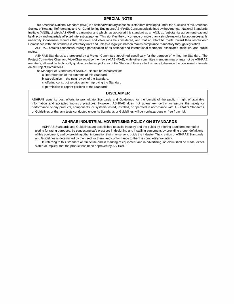
SPECIAL NOTE
This American National Standard (ANS) is a national voluntary consensus standard developed under the auspices of the AmericanSociety of Heating, Refrigerating and Air-Conditioning Engineers (ASHRAE). Consensus is defined by the American National StandardsInstitute (ANSI), of which ASHRAE is a member and which has approved this standard as an ANS, as “substantial agreement reachedby directly and materially affected interest categories. This signifies the concurrence of more than a simple majority, but not necessarilyunanimity. Consensus requires that all views and objections be considered, and that an effort be made toward their resolution.”Compliance with this standard is voluntary until and unless a legal jurisdiction makes compliance mandatory through legislation.
ASHRAE obtains consensus through participation of its national and international members, associated societies, and publicreview.
ASHRAE Standards are prepared by a Project Committee appointed specifically for the purpose of writing the Standard. TheProject Committee Chair and Vice-Chair must be members of ASHRAE; while other committee members may or may not be ASHRAEmembers, all must be technically qualified in the subject area of the Standard. Every effort is made to balance the concerned interestson all Project Committees.
The Manager of Standards of ASHRAE should be contacted for:a. interpretation of the contents of this Standard,b. participation in the next review of the Standard,c. offering constructive criticism for improving the Standard,d. permission to reprint portions of the Standard.
ASHRAE INDUSTRIAL ADVERTISING POLICY ON STANDARDSASHRAE Standards and Guidelines are established to assist industry and the public by offering a uniform method of
testing for rating purposes, by suggesting safe practices in designing and installing equipment, by providing proper definitions of this equipment, and by providing other information that may serve to guide the industry. The creation of ASHRAE Standards and Guidelines is determined by the need for them, and conformance to them is completely voluntary.
In referring to this Standard or Guideline and in marking of equipment and in advertising, no claim shall be made, eitherstated or implied, that the product has been approved by ASHRAE.
DISCLAIMER
ASHRAE uses its best efforts to promulgate Standards and Guidelines for the benefit of the public in light of availableinformation and accepted industry practices. However, ASHRAE does not guarantee, certify, or assure the safety orperformance of any products, components, or systems tested, installed, or operated in accordance with ASHRAE’s Standardsor Guidelines or that any tests conducted under its Standards or Guidelines will be nonhazardous or free from risk.

(This foreword is not part of this standard. It is merelyinformative and does not contain requirements necessaryfor conformance to the standard. It has not been pro-cessed according to the ANSI requirements for a stan-dard and may contain material that has not been subjectto public review or a consensus process.)
FOREWORD
This revision of Table 9.3.1.1 and replacement of Table9.3.1.2 represent a complete update of the LPD values in thetables based on a comprehensive review of the inputs to thespace and building models used to derive these values. Thereview included recent research data on fluorescent fixturelight loss factors and space type characteristics of new com-mercial construction, as well as revised lighting level recom-mendations as published in the IESNA Lighting Handbook,9th edition. The review covered all model inputs and appliedcurrent knowledge of lighting principles, design applications,and efficient equipment availability.
• Light level inputs. Each of the 124 individual spacemodels was reviewed and both task lighting and generallighting levels compared with the new IESNA 9th editionrecommendations. Changes were made where appropri-ate.
• Applied lighting technologies. Each of the 124 individ-ual space models incorporates up to three specific light-ing technologies represented by generic luminaire(fixture) types. Changes were made to more appropriatetechnologies where current design practice warranted.
• Lighting technology application formula. The formulawas revised to directly weight the technologies by lumenoutput of each technology, providing a more accurateassessment of power needs for all technology types.
• Lighting technology efficiencies and light loss factors.The lamp efficacy for each of the 35 generic luminaire/fixture types and the associated lamp lumen deprecia-tion factors were reevaluated based upon current, com-monly available technologies. A recent study (LuminaireDirt Depreciation Study, July 2000, NALMCO No.CX824574-01-0) was used to update these values formost fluorescent luminaire types. The luminaire dirtdepreciation value for all remaining types was reviewedagainst the latest IESNA Lighting Handbook.
• Luminaire/fixture data. The generic luminaire type per-formance characteristics (efficiency, etc.) are based onthe actual tested characteristics of over 240 specificluminaire products. These were reviewed and generallyfound to be still valid. New luminaire data were incor-porated where applicable.
• Whole building LPD development data. The proposedwhole building values are derived by applying the 124space models to detailed interior space type data on aset of 246 buildings (increased from 95).
ADDENDUM g to 90.1-2001 (I-P and SI EDITIONS)
1. Revise Table 9.3.1.1 as shown to incorporate revisedwhole building LPD values and split the previous hospital/health care category into two separate categories. Therevised LPD values reflect current light source efficiencydata, recent research work on light loss factors, and thelatest IESNA light level recommendations.
I-P TABLES:
TABLE 9.3.1.1
Lighting Power Densities Using the Building Area Method
Building Area Typea
a In cases where both general building area type and a specific building area type arelisted, the specific building area type shall apply.
Lighting Power Density (W/ft2)
Automotive Facility 1.50.9
Convention Center 1.41.2
Court House 1.41.2
Dining: Bar Lounge/Leisure 1.51.3
Dining: Cafeteria/Fast Food 1.81.4
Dining: Family 1.91.6
Dormitory 1.51.0
Exercise Center 1.41.0
Gymnasium 1.71.1
Healthcare-Clinic 1.0
Hospital/Healthcare 1.61.2
Hotel 1.71.0
Library 1.51.3
Manufacturing Facility 2.21.3
Motel 2.01.0
Motion Picture Theatre 1.61.2
Multi-Family 1.00.7
Museum 1.61.1
Office 1.31.0
Parking Garage 0.3
Penitentiary 1.21.0
Performing Arts Theatre 1.51.6
Police/Fire Station 1.31.0
Post Office 1.61.1
Religious Building 2.21.3
Retail 1.91.5
School/University 1.51.2
Sports Arena 1.51.1
Town Hall 1.41.1
Transportation 1.21.0
Warehouse 1.20.8
Workshop 1.71.4
2 Addendum g to ANSI/ASHRAE/IESNA STANDARD 90.1-2001
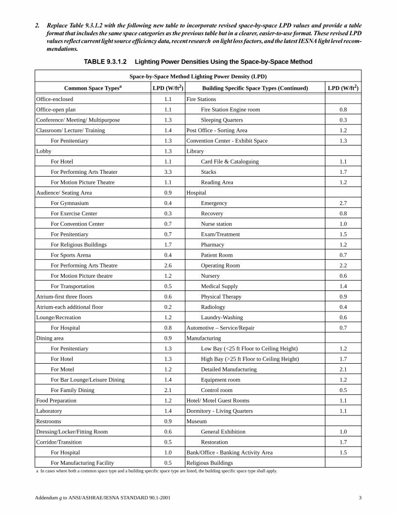
2. Replace Table 9.3.1.2 with the following new table to incorporate revised space-by-space LPD values and provide a tableformat that includes the same space categories as the previous table but in a clearer, easier-to-use format. These revised LPDvalues reflect current light source efficiency data, recent research on light loss factors, and the latest IESNA light level recom-mendations.
TABLE 9.3.1.2 Lighting Power Densities Using the Space-by-Space Method
Space-by-Space Method Lighting Power Density (LPD)
Common Space Typesa LPD (W/ft2) Building Specific Space Types (Continued) LPD (W/ft2)
Office-enclosed 1.1 Fire Stations
Office-open plan 1.1 Fire Station Engine room 0.8
Conference/ Meeting/ Multipurpose 1.3 Sleeping Quarters 0.3
Classroom/ Lecture/ Training 1.4 Post Office - Sorting Area 1.2
For Penitentiary 1.3 Convention Center - Exhibit Space 1.3
Lobby 1.3 Library
For Hotel 1.1 Card File & Cataloguing 1.1
For Performing Arts Theater 3.3 Stacks 1.7
For Motion Picture Theatre 1.1 Reading Area 1.2
Audience/ Seating Area 0.9 Hospital
For Gymnasium 0.4 Emergency 2.7
For Exercise Center 0.3 Recovery 0.8
For Convention Center 0.7 Nurse station 1.0
For Penitentiary 0.7 Exam/Treatment 1.5
For Religious Buildings 1.7 Pharmacy 1.2
For Sports Arena 0.4 Patient Room 0.7
For Performing Arts Theatre 2.6 Operating Room 2.2
For Motion Picture theatre 1.2 Nursery 0.6
For Transportation 0.5 Medical Supply 1.4
Atrium-first three floors 0.6 Physical Therapy 0.9
Atrium-each additional floor 0.2 Radiology 0.4
Lounge/Recreation 1.2 Laundry-Washing 0.6
For Hospital 0.8 Automotive – Service/Repair 0.7
Dining area 0.9 Manufacturing
For Penitentiary 1.3 Low Bay (<25 ft Floor to Ceiling Height) 1.2
For Hotel 1.3 High Bay (>25 ft Floor to Ceiling Height) 1.7
For Motel 1.2 Detailed Manufacturing 2.1
For Bar Lounge/Leisure Dining 1.4 Equipment room 1.2
For Family Dining 2.1 Control room 0.5
Food Preparation 1.2 Hotel/ Motel Guest Rooms 1.1
Laboratory 1.4 Dormitory - Living Quarters 1.1
Restrooms 0.9 Museum
Dressing/Locker/Fitting Room 0.6 General Exhibition 1.0
Corridor/Transition 0.5 Restoration 1.7
For Hospital 1.0 Bank/Office - Banking Activity Area 1.5
For Manufacturing Facility 0.5 Religious Buildingsa In cases where both a common space type and a building specific space type are listed, the building specific space type shall apply.
Addendum g to ANSI/ASHRAE/IESNA STANDARD 90.1-2001 3

Stairs – active 0.6 Worship-pulpit, choir 2.4
Active Storage 0.8 Fellowship Hall 0.9
For Hospital 0.9 Retail [For accent lighting see 9.3.1.2.1.(c)]
Inactive storage 0.3 Sales area 2.1
For Museum 0.8 Mall Concourse 1.7
Electrical/ mechanical 1.5 Sports Arena
Workshop 1.9 Ring Sports Area 2.7
Court Sports Area 2.3
Building Specific Space Types Indoor Playing Field Area 1.4
Gymnasium/ Exercise Center Warehouse
Playing Area 1.4 Fine Material Storage 1.4
Exercise Area 0.9 Medium/Bulky Material Storage 0.9
Courthouse/ Police Station/ Penitentiary Parking Garage - Garage Area 0.2
Courtroom 1.9 Transportation
Confinement Cells 0.9 Airport - Concourse 0.6
Judges Chambers 1.3 Air/Train/Bus - Baggage Area 1.0
Terminal - Ticket counter 1.5
TABLE 9.3.1.2 Lighting Power Densities Using the Space-by-Space Method (Continued)
4 Addendum g to ANSI/ASHRAE/IESNA STANDARD 90.1-2001

Addendum g to ANSI/ASHRAE/IESNA STANDARD 90.1-2001 5
SI TABLES:
TABLE 9.3.1.1
Lighting Power Densities Using the Building Area Method
Building Area Typea
a In cases where both general building area type and a specific building area type arelisted, the specific building area type shall apply.
Lighting Power Density (W/m2)
Automotive Facility 1610
Convention Center 1513
Court House 1513
Dining: Bar Lounge/Leisure 1614
Dining: Cafeteria/Fast Food 1915
Dining: Family 2017
Dormitory 1611
Exercise Center 1511
Gymnasium 1812
Healthcare-Clinic 11
Hospital/Healthcare 1713
Hotel 1811
Library 1614
Manufacturing Facility 2414
Motel 2211
Motion Picture Theatre 1713
Multi-Family 118
Museum 1712
Office 1411
Parking Garage 3
Penitentiary 1311
Performing Arts Theatre 1617
Police/Fire Station 1411
Post Office 1712
Religious Building 2414
Retail 2016
School/University 1613
Sports Arena 1612
Town Hall 1512
Transportation 1311
Warehouse 139
Workshop 1815

TABLE 9.3.1.2 Lighting Power Densities Using the Space-by-Space Method
Space-by-Space Method Lighting Power Density (LPD)
Common Space Typesa LPD (W/m2) Building Specific Space Types (Continued) LPD (W/m2)
Office-enclosed 12 Fire Stations
Office-open plan 12 Fire Station Engine room 9
Conference/ Meeting/ Multipurpose 14 Sleeping Quarters 3
Classroom/ Lecture/ Training 15 Post Office - Sorting Area 13
For Penitentiary 14 Convention Center - Exhibit Space 14
Lobby 14 Library
For Hotel 12 Card File & Cataloguing 12
For Performing Arts Theater 36 Stacks 18
For Motion Picture Theatre 12 Reading Area 13
Audience/ Seating Area 10 Hospital
For Gymnasium 4 Emergency 29
For Exercise Center 3 Recovery 9
For Convention Center 8 Nurse station 11
For Penitentiary 8 Exam/Treatment 16
For Religious Buildings 18 Pharmacy 13
For Sports Arena 4 Patient Room 8
For Performing Arts Theatre 28 Operating Room 24
For Motion Picture theatre 13 Nursery 6
For Transportation 5 Medical Supply 15
Atrium-first three floors 6 Physical Therapy 10
Atrium-each additional floor 2 Radiology 4
Lounge/Recreation 13 Laundry-Washing 6
For Hospital 9 Automotive - Service/Repair 8
Dining area 10 Manufacturing
For Penitentiary 14 Low Bay (<25 ft Floor to Ceiling Height) 13
For Hotel 14 High Bay (>25 ft Floor to Ceiling Height) 18
For Motel 13 Detailed Manufacturing 23
For Bar Lounge/Leisure Dining 15 Equipment room 13
For Family Dining 23 Control room 5
Food Preparation 13 Hotel/ Motel Guest Rooms 12
Laboratory 15 Dormitory - Living Quarters 12
Restrooms 10 Museum
Dressing/Locker/Fitting Room 6 General Exhibition 11
Corridor/Transition 5 Restoration 18
For Hospital 11 Bank/Office - Banking Activity Area 16
For Manufacturing Facility 5 Religious Buildings
Stairs – active 6 Worship-pulpit, choir 26
Active Storage 9 Fellowship Hall 10
For Hospital 10 Retail [For accent lighting see 9.3.1.2.1.(c)]
Inactive storage 3 Sales area 23a In cases where both a common space type and a building specific space type are listed, the building specific space type shall apply.
6 Addendum g to ANSI/ASHRAE/IESNA STANDARD 90.1-2001

For Museum 9 Mall Concourse 18
Electrical/ mechanical 16 Sports Arena
Workshop 20 Ring Sports Area 29
Court Sports Area 25
Building Specific Space Types Indoor Playing Field Area 15
Gymnasium/ Exercise Center Warehouse
Playing Area 15 Fine Material Storage 15
Exercise Area 10 Medium/Bulky Material Storage 10
Courthouse/ Police Station/ Penitentiary Parking Garage - Garage Area 2
Courtroom 20 Transportation
Confinement Cells 10 Airport - Concourse 6
Judges Chambers 14 Air/Train/Bus - Baggage Area 11
Terminal - Ticket counter 16
TABLE 9.3.1.2 Lighting Power Densities Using the Space-by-Space Method (Continued)
Addendum g to ANSI/ASHRAE/IESNA STANDARD 90.1-2001 7

POLICY STATEMENT DEFINING ASHRAE’S CONCERNFOR THE ENVIRONMENTAL IMPACT OF ITS ACTIVITIES
ASHRAE is concerned with the impact of its members’ activities on both the indoor and outdoor environment. ASHRAE’smembers will strive to minimize any possible deleterious effect on the indoor and outdoor environment of the systems andcomponents in their responsibility while maximizing the beneficial effects these systems provide, consistent with acceptedstandards and the practical state of the art.
ASHRAE’s short-range goal is to ensure that the systems and components within its scope do not impact the indoor andoutdoor environment to a greater extent than specified by the standards and guidelines as established by itself and otherresponsible bodies.
As an ongoing goal, ASHRAE will, through its Standards Committee and extensive technical committee structure,continue to generate up-to-date standards and guidelines where appropriate and adopt, recommend, and promote those newand revised standards developed by other responsible organizations.
Through its Handbook, appropriate chapters will contain up-to-date standards and design considerations as the material issystematically revised.
ASHRAE will take the lead with respect to dissemination of environmental information of its primary interest and will seekout and disseminate information from other responsible organizations that is pertinent, as guides to updating standards andguidelines.
The effects of the design and selection of equipment and systems will be considered within the scope of the system’sintended use and expected misuse. The disposal of hazardous materials, if any, will also be considered.
ASHRAE’s primary concern for environmental impact will be at the site where equipment within ASHRAE’s scopeoperates. However, energy source selection and the possible environmental impact due to the energy source and energytransportation will be considered where possible. Recommendations concerning energy source selection should be made byits members.

ANSI/ASHRAE/IESNA Addendum h toANSI/ASHRAE/IESNA Standard 90.1-2001
Energy Standard forBuildings ExceptLow-RiseResidentialBuildingsApproved by the ASHRAE Standards Committee on October 5,2003; by the ASHRAE Board of Directors on January 29, 2004; andby the American National Standards Institute on February 25,2004.
This standard is under continuous maintenance by a StandingStandard Project Committee (SSPC) for which the StandardsCommittee has established a documented program for regularpublication of addenda or revisions, including procedures fortimely, documented, consensus action on requests for change toany part of the standard. The change submittal form, instruc-tions, and deadlines may be obtained in electronic form from theASHRAE web site, http://www.ashrae.org, or in paper form fromthe Manager of Standards. The latest edition of an ASHRAE Stan-dard and printed copies of a public review draft may be pur-chased from ASHRAE Customer Service, 1791 Tullie Circle, NE,Atlanta, GA 30329-2305. E-mail: [email protected]. Fax: 404-321-5478. Telephone: 404-636-8400 (worldwide), or toll free 1-800-527-4723 (for orders in U.S. and Canada).
©Copyright 2004 American Society of Heating,Refrigerating and Air-Conditioning Engineers, Inc.
ISSN 1041-2336

ASHRAE STANDARDS COMMITTEE 2003-2004
Van D. Baxter, ChairDavor Novosel, Vice-ChairDonald B. BivensDean S. BorgesPaul W. CabotCharles W. Coward, Jr.Hugh F. CrowtherBrian P. DoughertyHakim ElmahdyMatt R. HarganRichard D. HermansJohn F. Hogan
Frank E. JakobStephen D. Kennedy
David E. KnebelFrederick H. Kohloss
Merle F. McBrideMark P. Modera
Cyrus H. NasseriGideon ShavitDavid R. Tree
Thomas H. WilliamsJames E. Woods
Ross D. Montgomery, BOD ExOKent W. Peterson, CO
Claire B. Ramspeck, Manager of Standards
ASHRAE Standing Standard Project Committee 90.1 Cognizant TC: TC 9.6, System Energy Utilization
SPLS Liaison: Michael H. TavaresASHRAE Staff Liaison: Mark Weber
IESNA Liaison: Rita M. Harrold
Jerry W. White, Jr., Chair*
James M. Calm, Vice-Chair*
Donald F. Steiner, Vice-Chair*
Karim Amrane*
William P. Bahnfleth*
Van D. Baxter*
Donald L. Beaty*
Albert W. Black, III*
Donald M. Brundage*
Ernest A. Conrad
Charles C. Cottrell*
Roy Crane*
Joseph J. Deringer*
Keith I. Emerson
Douglas S. Erickson*
Thomas A. Farkas*
Alan Fraser*
James A. Garrigus*
Jason J. Glazer*
Katherine G. Hammack*
Richard V. Heinisch
Randall T. Higa*
Billy G. Hinton, Jr.*
John F. Hogan*
William G. Holy*
Graham C. Hunter, II*
Hyman M. Kaplan*
Gersil N. Kay*
Larry Kouma*
Ronald D. Kurtz*
Samanthan H. LaFleur*
Michael D. Lane*
Steven J. Lit*
Kenneth Luther*
Ronald Majette*
Itzhak H. Maor*
Carol E. Marriott*
R. Christopher Mathis*
Merle F. McBride
Harry P. Misuriello
Louis J. Molinini*
John Montgomery*
Frank Myers*
Ronald G. Nickson*
Edward P. O’Brien*
Jim A. Ranfone*
Eric E. Richman*
Jack F. Roberts*
Michael L. Rosenberg
Steven Rosenstock
Robert D. Ross
David A. Schaaf, Jr.*
Leonard C. Sciarra*
Peter Simmonds*
Stephen V. Skalko*
Frank A. Stanonik*
Joseph K. Ting*
Cedric S. Trueman*
Martha G. VanGeem
Carl Wagus*
Frederick F. Wajcs, Jr.
McHenry Wallace, Jr.*
Richard D. Watson*
David Weitz*
Robin Wilson*
Michael W. Woodford
Dale L. Woodin
Thomas R. Worlledge*
Donald R. Wulfinghoff*
Stanley W. Zajac*
*Denotes members of voting status when the document was approved for publication

SPECIAL NOTE
This American National Standard (ANS) is a national voluntary consensus standard developed under the auspices of the AmericanSociety of Heating, Refrigerating and Air-Conditioning Engineers (ASHRAE). Consensus is defined by the American National StandardsInstitute (ANSI), of which ASHRAE is a member and which has approved this standard as an ANS, as “substantial agreement reachedby directly and materially affected interest categories. This signifies the concurrence of more than a simple majority, but not necessarilyunanimity. Consensus requires that all views and objections be considered, and that an effort be made toward their resolution.”Compliance with this standard is voluntary until and unless a legal jurisdiction makes compliance mandatory through legislation.
ASHRAE obtains consensus through participation of its national and international members, associated societies, and publicreview.
ASHRAE Standards are prepared by a Project Committee appointed specifically for the purpose of writing the Standard. TheProject Committee Chair and Vice-Chair must be members of ASHRAE; while other committee members may or may not be ASHRAEmembers, all must be technically qualified in the subject area of the Standard. Every effort is made to balance the concerned interestson all Project Committees.
The Manager of Standards of ASHRAE should be contacted for:a. interpretation of the contents of this Standard,b. participation in the next review of the Standard,c. offering constructive criticism for improving the Standard,d. permission to reprint portions of the Standard.
ASHRAE INDUSTRIAL ADVERTISING POLICY ON STANDARDSASHRAE Standards and Guidelines are established to assist industry and the public by offering a uniform method of
testing for rating purposes, by suggesting safe practices in designing and installing equipment, by providing proper definitions of this equipment, and by providing other information that may serve to guide the industry. The creation of ASHRAE Standards and Guidelines is determined by the need for them, and conformance to them is completely voluntary.
In referring to this Standard or Guideline and in marking of equipment and in advertising, no claim shall be made, eitherstated or implied, that the product has been approved by ASHRAE.
DISCLAIMER
ASHRAE uses its best efforts to promulgate Standards and Guidelines for the benefit of the public in light of availableinformation and accepted industry practices. However, ASHRAE does not guarantee, certify, or assure the safety orperformance of any products, components, or systems tested, installed, or operated in accordance with ASHRAE’s Standardsor Guidelines or that any tests conducted under its Standards or Guidelines will be nonhazardous or free from risk.

2 Addendum h to ANSI/ASHRAE/IESNA STANDARD 90.1-2001
(This foreword is not part of this standard. It is merelyinformative and does not contain requirements necessaryfor conformance to the standard. It has not been pro-cessed according to the ANSI requirements for a stan-dard and may contain material that has not been subjectto public review or a consensus process.)
FOREWORD
This proposed addendum updates the normative refer-ences to reflect the latest editions. These changes in referencesdo affect the testing procedures for determining the buildingmaterial thermal properties (R-values and thermal conductiv-ities) and assembly U-factors of Sections A9.3.1 and A9.3.2 ofNormative Appendix A. Alternative test procedure ASTMC1363 replaces the existing ASTM C236 and ASTM C976 forthese properties. In addition, where credit is taken for a low-emissivity coating for skylights, the emissivity of the coatingshall now be determined in accordance with NFRC 300-2001instead of NFRC 301-1993.
Addendum h to 90.1-2001 (I-P and SI editions)
In Section 12, replace the existing normative referenceswith the following updated versions:
ASTM C177-97 Standard Test Method for Steady-StateHeat Flux Measurements and ThermalTransmittance Properties by Means ofthe Guarded-Hot-Plate Apparatus
ASTM C518-98 Standard Test Method for Steady-StateThermal Transmittance Properties byMeans of the Heat Flow Meter Appara-tus
ASTM C1371-98 Standard Test Method for Determinationof Emittance of Materials Near RoomTemperature Using Portable Emissome-ters
NFRC 100:2001 Procedure for Determining FenestrationProduct U-Factors, (Second Edition)Published November 2002
NFRC 200-2001 Procedure for Determining FenestrationProduct Solar Heat Gain Coefficient andVisible Transmittance at Normal Inci-dence, (Second Edition) PublishedNovember 2002
NFRC 300-2001 Standard Test Method for Determiningthe Solar Optical Properties of GlazingMaterials and Systems, (SecondEdition) Published November 2002
NFRC 400-2001 Procedure for Determining FenestrationProduct Air Leakage, (Second Edition)Published November 2002
In Section 12, add the following new normative refer-ences:
ASTM C1363-97 Standard Test Method for the ThermalPerformance of Building Assemblies byMeans of a Hot Box Apparatus
NFRC 101: 2001 Procedure for Determining Thermo-Physical Properties of Materials for Usein NFRC–Approved SoftwarePrograms, (First Edition) PublishedNovember 2002
NFRC 102-2001 Test Procedures for Measuring theSteady-State Thermal Transmittance ofFenestration Systems, (Second Edition)Published November 2002
NFRC 201-2001 Interim Standard Test Method forMeasuring the Solar Heat Gain Coeffi-cient of Fenestration Systems UsingCalorimetry Hot Box Methods, (SecondEdition) Published November 2002
In Section 12, delete the following normative references:
ASTM C976-90 Test Method for Thermal Performanceof Building Assemblies by Means of aCalibrated Hot Box
NFRC 301-93 Standard Test Method for Emittance ofSpecular Surfaces Using SpectrometricMeasurements
In Section 5.5.2.2, make the following changes to Excep-tion (c):
Where credit is being taken for a low-emissivity coating,the emissivity of the coating shall be determined in accordancewith NFRC 301300.
In Section A9.3.1, make the following changes to the testprocedure references:
a. ASTM C177,
b. ASTM C236 ASTM C518, or
c. ASTM C518 ASTM C1363
d. ASTM C976
In Section A9.3.2, make the following changes to the testprocedure references:
A9.3.2 Assembly U-Factors. If assembly U-factors aredetermined by testing, one of the following ASTM C1363 testprocedures shall be used.
a. ASTM C236 or
b. ASTM C976

POLICY STATEMENT DEFINING ASHRAE’S CONCERNFOR THE ENVIRONMENTAL IMPACT OF ITS ACTIVITIES
ASHRAE is concerned with the impact of its members’ activities on both the indoor and outdoor environment. ASHRAE’smembers will strive to minimize any possible deleterious effect on the indoor and outdoor environment of the systems andcomponents in their responsibility while maximizing the beneficial effects these systems provide, consistent with acceptedstandards and the practical state of the art.
ASHRAE’s short-range goal is to ensure that the systems and components within its scope do not impact the indoor andoutdoor environment to a greater extent than specified by the standards and guidelines as established by itself and otherresponsible bodies.
As an ongoing goal, ASHRAE will, through its Standards Committee and extensive technical committee structure,continue to generate up-to-date standards and guidelines where appropriate and adopt, recommend, and promote those newand revised standards developed by other responsible organizations.
Through its Handbook, appropriate chapters will contain up-to-date standards and design considerations as the material issystematically revised.
ASHRAE will take the lead with respect to dissemination of environmental information of its primary interest and will seekout and disseminate information from other responsible organizations that is pertinent, as guides to updating standards andguidelines.
The effects of the design and selection of equipment and systems will be considered within the scope of the system’sintended use and expected misuse. The disposal of hazardous materials, if any, will also be considered.
ASHRAE’s primary concern for environmental impact will be at the site where equipment within ASHRAE’s scopeoperates. However, energy source selection and the possible environmental impact due to the energy source and energytransportation will be considered where possible. Recommendations concerning energy source selection should be made byits members.

ANSI/ASHRAE/IESNA Addendum i toANSI/ASHRAE/IESNA Standard 90.1-2001
Energy Standard forBuildings ExceptLow-RiseResidentialBuildingsApproved by the ASHRAE Standards Committee on June 28, 2003;by the ASHRAE Board of Directors on July 3, 2003; and by theAmerican National Standards Institute on August 6, 2003.
This standard is under continuous maintenance by a StandingStandard Project Committee (SSPC) for which the StandardsCommittee has established a documented program for regularpublication of addenda or revisions, including procedures fortimely, documented, consensus action on requests for change toany part of the standard. The change submittal form, instruc-tions, and deadlines may be obtained in electronic form from theASHRAE web site, http://www.ashrae.org, or in paper form fromthe Manager of Standards. The latest edition of an ASHRAE Stan-dard and printed copies of a public review draft may be pur-chased from ASHRAE Customer Service, 1791 Tullie Circle, NE,Atlanta, GA 30329-2305. E-mail: [email protected]. Fax: 404-321-5478. Telephone: 404-636-8400 (worldwide), or toll free 1-800-527-4723 (for orders in U.S. and Canada).
©Copyright 2003 American Society of Heating,Refrigerating and Air-Conditioning Engineers, Inc.
ISSN 1041-2336

ASHRAE STANDARDS COMMITTEE 2002-2003
Thomas E. Watson, ChairVan D. Baxter, Vice-ChairCharles G. ArnoldDean S. BorgesPaul W. CabotCharles W. Coward, Jr.Brian P. DoughertyHakim ElmahdyArthur D. HallstromMatt R. HarganRichard D. HermansStephen D. Kennedy
David E. KnebelFrederick H. KohlossWilliam J. Landman
Merle F. McBrideRoss D. Montgomery
Cyrus H. NasseriDavor Novosel
Dennis A. StankeMichael H. Tavares
Steven T. TaylorDavid R. Tree
Terry E. Townsend, COMaureen Grasso, ExO
Claire B. Ramspeck, Manager of Standards
ASHRAE Standing Standard Project Committee 90.1 Cognizant TC: TC 9.6, System Energy Utilization
SPLS Liaison: Michael H. TavaresASHRAE Staff Liaison: Mark Weber
IESNA Liaison: Rita M. Harrold
gÉêêó=tK=tÜáíÉI=gêKI=`Ü~áêG
g~ãÉë=jK=`~äãI=sáÅÉJ`Ü~áêG
açå~äÇ=cK=píÉáåÉêI=sáÅÉJ`Ü~áêG
h~êáã=^ãê~åÉG
táääá~ã=mK=_~ÜåÑäÉíÜG
s~å=aK=_~ñíÉêG
açå~äÇ=iK=_É~íóG
^äÄÉêí=tK=_ä~ÅâI=fffG
açå~äÇ=jK=_êìåÇ~ÖÉG
bêåÉëí=^K=`çåê~Ç
`Ü~êäÉë=`K=`çííêÉääG
oçó=`ê~åÉG
gçëÉéÜ=gK=aÉêáåÖÉêG
hÉáíÜ=fK=bãÉêëçå
açìÖä~ë=pK=bêáÅâëçåG
qÜçã~ë=^K=c~êâ~ëG
^ä~å=cê~ëÉêG
g~ãÉë=^K=d~êêáÖìëG
g~ëçå=gK=dä~òÉêG
h~íÜÉêáåÉ=dK=e~ãã~ÅâG
oáÅÜ~êÇ=sK=eÉáåáëÅÜ
o~åÇ~ää=qK=eáÖ~G
_áääó=dK=eáåíçåI=gêKG
gçÜå=cK=eçÖ~åG
p~ã~åíÜ~=eK=i~cäÉìê
táääá~ã=dK=eçäóG
dê~Ü~ã=`K=eìåíÉêI=ffG
eóã~å=jK=h~éä~åG
dÉêëáä=kK=h~óG
i~êêó=hçìã~G
oçå~äÇ=aK=hìêíòG
jáÅÜ~Éä=aK=i~åÉG
píÉîÉå=gK=iáíG
hÉååÉíÜ=iìíÜÉêG
oçå~äÇ=j~àÉííÉG
fíòÜ~â=eK=j~çêG
`~êçä=bK=j~êêáçííG
oK=`ÜêáëíçéÜÉê=j~íÜáëG
jÉêäÉ=cK=jÅ_êáÇÉ
içìáë=gK=jçäáåáåáG
gçÜå=jçåíÖçãÉêóG
cê~åâ=jóÉêëG
oçå~äÇ=dK=káÅâëçåG
bÇï~êÇ=mK=lÛ_êáÉåG
gáã=^K=o~åÑçåÉG
bêáÅ=bK=oáÅÜã~åG
g~Åâ=cK=oçÄÉêíëG
píÉîÉå=oçëÉåëíçÅâ
oçÄÉêí=aK=oçëëG
a~îáÇ=^K=pÅÜ~~ÑI=gêKG
iÉçå~êÇ=`K=pÅá~êê~G
mÉíÉê=páããçåÇëG
píÉéÜÉå=sK=pâ~äâçG
cê~åâ=^K=pí~åçåáâG
gçëÉéÜ=hK=qáåÖG
`ÉÇêáÅ=pK=qêìÉã~åG
`~êä=t~ÖìëG
cêÉÇÉêáÅâ=cK=t~àÅëI=gêK
jÅeÉåêó=t~ää~ÅÉI=gêKG
oáÅÜ~êÇ=aK=t~íëçåG
a~îáÇ=tÉáíòG
oçÄáå=táäëçåG
jáÅÜ~Éä=tK=tççÇÑçêÇ
a~äÉ=iK=tççÇáå
qÜçã~ë=oK=tçêääÉÇÖÉG
açå~äÇ=oK=tìäÑáåÖÜçÑÑG
pí~åäÉó=tK=w~à~ÅG
*Denotes members of voting status when the document was approved for publication

SPECIAL NOTE
This American National Standard (ANS) is a national voluntary consensus standard developed under the auspices of the AmericanSociety of Heating, Refrigerating and Air-Conditioning Engineers (ASHRAE). Consensus is defined by the American National StandardsInstitute (ANSI), of which ASHRAE is a member and which has approved this standard as an ANS, as “substantial agreement reachedby directly and materially affected interest categories. This signifies the concurrence of more than a simple majority, but not necessarilyunanimity. Consensus requires that all views and objections be considered, and that an effort be made toward their resolution.”Compliance with this standard is voluntary until and unless a legal jurisdiction makes compliance mandatory through legislation.
ASHRAE obtains consensus through participation of its national and international members, associated societies, and publicreview.
ASHRAE Standards are prepared by a Project Committee appointed specifically for the purpose of writing the Standard. TheProject Committee Chair and Vice-Chair must be members of ASHRAE; while other committee members may or may not be ASHRAEmembers, all must be technically qualified in the subject area of the Standard. Every effort is made to balance the concerned interestson all Project Committees.
The Manager of Standards of ASHRAE should be contacted for:a. interpretation of the contents of this Standard,b. participation in the next review of the Standard,c. offering constructive criticism for improving the Standard,d. permission to reprint portions of the Standard.
ASHRAE INDUSTRIAL ADVERTISING POLICY ON STANDARDSASHRAE Standards and Guidelines are established to assist industry and the public by offering a uniform method of
testing for rating purposes, by suggesting safe practices in designing and installing equipment, by providing proper definitions of this equipment, and by providing other information that may serve to guide the industry. The creation of ASHRAE Standards and Guidelines is determined by the need for them, and conformance to them is completely voluntary.
In referring to this Standard or Guideline and in marking of equipment and in advertising, no claim shall be made, eitherstated or implied, that the product has been approved by ASHRAE.
DISCLAIMER
ASHRAE uses its best efforts to promulgate Standards and Guidelines for the benefit of the public in light of availableinformation and accepted industry practices. However, ASHRAE does not guarantee, certify, or assure the safety orperformance of any products, components, or systems tested, installed, or operated in accordance with ASHRAE’s Standardsor Guidelines or that any tests conducted under its Standards or Guidelines will be nonhazardous or free from risk.

(This foreword is not part of this standard. It is merelyinformative and does not contain requirements necessaryfor conformance to the standard. It has not been pro-cessed according to the ANSI requirements for a stan-dard and may contain material that has not been subjectto public review or a consensus process.)
FOREWORD
During the development of Standard 90.1-2001, theproject committee explicitly chose not to revise standards forthree-phase air-cooled air conditioners and heat pumps lessthan 65,000 Btu/h (19 kW). This decision was based on theclose relationship the design of these products has to single-phase air-cooled air conditioners and heat pumps less than65,000 Btu/h (19 kW), products whose efficiency is regulatedin the USA under the National Appliance Energy Conserva-tion Act (NAECA).
Concurrent with the development of Standard 90.1-2001,the U.S. Department of Energy (DOE) conducted standardsrulemaking to develop and set new efficiency standards forthese single-phase products. DOE completed its analysis andpublished a Final Rule on it in the Federal Register (67FR100, Page 36368) on May 23, 2002. This rule sets effi-ciency standards for single-phase air-cooled air conditionersand heat pumps at a seasonal energy efficiency ratio, orSEER, rating of 12.0 (SCOP = 3.52) for both split and single-package systems and a heating seasonal performance factor(HSPF) of 7.4 (SCOP = 2.17) for both single-package andsplit-system heat pumps.
In the interest of supporting efficiency improvements toANSI/ASHRAE/IESNA Standard 90.1, the project committeehas adoped a 12 SEER level (SCOP = 3.52) for < 65,000 Btu/h (19 kW) capacity three-phase air-cooled unitary air condi-tioners and heat pumps, with an additional 7.4 HSPF level(SCOP = 2.17) for such heat pumps.
The DOE final rule for single-phase residential centralair conditioners sets a new product class for through-the-wall
(TTW) systems. For these products, DOE adopted a 10.9SEER (SCOP = 3.19) for split air conditioners, a 10.6 SEER(SCOP = 3.11) for packaged air conditioners, a 10.9 SEER(SCOP = 3.19) and 7.1 HSPF (SCOP = 2.08) for split heatpumps, and a 10.6 SEER (SCOP = 3.11) and 7.0 HSPF(SCOP = 2.05) for packaged heat pumps. DOE is limiting thesize to TTWs with a cooling capacity up to 30,000 Btu/h (8.8kW) and is proposing the new class for four years only (forproducts manufactured until January 23, 2010). After January23, 2010, the standards for these products will be 12 SEER(SCOP = 3.52) and 7.4 HSPF (SCOP = 2.17). The DOE FinalRule also sets a new product class for small-duct, high-veloc-ity (SDHV) systems.1 DOE concluded that the NAECA-pre-scribed minimum efficiency standards of 10 SEER/6.8 HSPF(SCOP 2.93/1/99) should remain applicable to SDHV systemspending further study to establish appropriate higher standardlevels. DOE intends to conduct a separate rulemaking forSDHV systems.
The adoption date for the new standards under Standard90.1 is specified as January 23, 2006, in order to harmonizewith the effective date mandated in the DOE Final Rule forsingle-phase central air conditioner products.
The DOE justification of the recommended efficiency lev-els can be found in its Technical Support Document, EnergyConservation Standards for Consumer Products: Central AirConditioners and Heat Pumps, October 2000 (posted onDOE’s website at http://www.eere.energy.gov/buildings/appliance_standards/residential/ac_central.html).
1 A small-duct, high-velocity product is a product that contains ablower and indoor coil combination that is designed for, andproduces, at least 1.2 in. (299 Pa) of external static pressure whenoperated at the certified air volume rate of 220-350 CFM (103.8-165.2 L/s) per rated ton (3.52 kW) of cooling. When applied in thefield, small-duct products use high-velocity room outlets (i.e.,outlets with velocities generally greater than 1000 fpm [5.1 m/s])having less than 6.0 in.2 (38.7 cm2) of free area.
2 Addendum i to ANSI/ASHRAE/IESNA STANDARD 90.1-2001

ADDENDUM i to 90.1-2001 (I-P and SI Editions)
Revise Tables 6.2.1A and 6.2.1B for air conditioners and heat pumps less than 65,000 Btu/h (19 kW) as follows:
I-P Edition:
Remainder of table left unchanged.
TABLE 6.2.1A
Electrically Operated Unitary Air Conditioners and Condensing Units—Minimum Efficiency Requirements
Equipment Type Size Category Heating Section TypeSubcategory or Rat-
ing Condition Minimum Efficiencyb Test Procedurea
Air Conditioners, Air Cooled
<65,000 Btu/hc All Split System 10.0 SEER 10.0 SEER(before 1/23/2006)
12.0 SEER(as of 1/23/2006)
ARI 210/240
Single Package 9.7 SEER 9.7 SEER(before 1/23/2006)
12.0 SEER(as of 1/23/2006)
Through-the-Wall, Air Cooled
≤ 30,000 Btu/hc All Split System 10.0 SEER(before 1/23/2006)
10.9 SEER(as of 1/23/2006)
12 SEER (as of 1/23/2010)
ARI 210/240
Single Package 9.7 SEER(before 1/23/2006)
10.6 SEER (as of 1/23/2006)
12.0 SEER(as of 1/23/2010)
Small-Duct High-Velocity, Air
Cooled
< 65,000 Btu/hc All Split System 10 SEER ARI 210/240
Addendum i to ANSI/ASHRAE/IESNA STANDARD 90.1-2001 3

Remainder of table left unchanged.
TABLE 6.2.1B
Electrically Operated Unitary and Applied Heat Pumps—Minimum Efficiency Requirements
Equipment Type Size Category Heating Section TypeSubcategory or
Rating Condition Minimum Efficiencyb Test Procedurea
Air Cooled (Cooling Mode)
<65,000 Btu/hc All Split System 10.0 SEER 10.0 SEER(before 1/23/2006)
12.0 SEER(as of 1/23/2006)
ARI 210/240
Single Package 9.7 SEER 9.7 SEER(before 1/23/2006)
12.0 SEER(as of 1/23/2006)
Through-the-Wall (Air Cooled, Cool-
ing Mode)
≤ 30,000 Btu/hc All Split System 10.0 SEER(before 1/23/2006)
10.9 SEER(as of 1/23/2006)
12 SEER (as of 1/23/2010)
ARI 210/240
Single Package 9.7 SEER(before 1/23/2006)
10.6 SEER (as of 1/23/2006)
12.0 SEER(as of 1/23/2010)
Small-Duct High-Velocity
(Air Cooled, Cool-ing Mode)
< 65,000 Btu/hc All Split System 10 SEER ARI 210/240
Air Cooled (Heat-ing Mode)
<65,000 Btu/hc (cooling capacity)
- Split System 6.8 HSPF 6.8 HSPF (before 1/23/2006)
7.4 HSPF as of 1/23/2006)
ARI 210/240
Single Package 6.6 HSPF (before 1/23/2006)
7.4 HSPF as of 1/23/2006)
Through-the-Wall, (Air Cooled, Heat-
ing Mode)
≤ 30,000 Btu/hc
(cooling capacity)- Split System 6.8 HSPF (before 1/23/
2006)7.1 HSPF (as of 1/23/
2006)7.4 HSPF as of 1/23/
2010)
ARI 210/240
Single Package 6.6 HSPF (before 1/23/2006)
7.0 HSPF (as of 1/23/2006)
7.4 HSPF (as of 1/23/2010)
Small-Duct High-Velocity
(Air Cooled, Heat-ing Mode)
< 65,000 Btu/hc
(cooling capacity)- Split System 6.8 HSPF ARI 210/240
4 Addendum i to ANSI/ASHRAE/IESNA STANDARD 90.1-2001

SI Edition:
Remainder of table left unchanged.
TABLE 6.2.1A
Electrically Operated Unitary Air Conditioners and Condensing Units—Minimum Efficiency Requirements
Equipment Type Size Category Heating Section TypeSubcategory or Rat-
ing Condition Minimum Efficiencyb Test Procedurea
Air Conditioners, Air Cooled
<19 kWc All Split System 2.93 SCOP 2.93 SCOP(before 1/23/2006)
3.52 SCOP(as of 1/23/2006)
ARI 210/240
Single Package 2.84 SCOP 2.84 SCOP(before 1/23/2006)
3.52 SCOP(as of 1/23/2006)
Through-the-Wall, Air Cooled
≤ 8.8 kWc All Split System 2.93 SCOP(before 1/23/2006)
3.19 SCOP(as of 1/23/2006)
3.52 SCOP (as of 1/23/2010)
ARI 210/240
Single Package 2.84 SCOP(before 1/23/2006)
3.11 SCOP (as of 1/23/2006)
3.52 SCOP(as of 1/23/2010)
Small-Duct High-Velocity, Air
Cooled
< 19 kWc All Split System 2.93 SCOP ARI 210/240
Addendum i to ANSI/ASHRAE/IESNA STANDARD 90.1-2001 5

Remainder of table left unchanged.
TABLE 6.1.2B
Electrically Operated Unitary and Applied Heat Pumps—Minimum Efficiency Requirements
Equipment Type Size Category Heating Section TypeSubcategory or
Rating Condition Minimum Efficiencyb Test Procedurea
Air Cooled (Cooling Mode)
<19 kWc All Split System 2.93 SCOPC 2.93 SCOPC (before 1/23/2006)
3.52 SCOPC (as of 1/23/2006)
ARI 210/240
Single Package 2.84 SCOPC 2.84 SCOPC
(before 1/23/2006)3.52 SCOPC (as of 1/23/
2006)
Through-the-Wall (Air Cooled,
Cooling Mode)
<8.8 kWc All Split System 2.93 SCOPC (before 1/23/2006)
3.19 SCOPC (as of 1/23/2006)
3.52 SCOPC (as of 1/23/2010)
ARI 210/240
Single Package 2.84 SCOPC(before 1/23/2006)
3.11 SCOPC (as of 1/23/2006)
3.52 SCOPC (as of 1/23/2010)
Small-Duct High-Velocity(Air Cooled,
Cooling Mode)
< 19 kWc All Split System 2.93 SCOPC ARI 210/240
Air Cooled (Heating Mode)
<19 kWc (cool-ing capacity)
- Split System 1.99 SCOPH 1.99 SCOPH (before 1/23/2006)
2.17 SCOPH (as of 1/23/2006)
ARI 210/240
Single Package 1.93 SCOPH 1.93 SCOPH (before 1/23/2006)
2.17 SCOPH (as of 1/23/2006)
Through-the-Wall (Air Cooled,
Heating Mode)
≤ 8.8 kWc
(cooling capacity)- Split System 1.99 SCOPH (before 1/23/
2006)2.08 SCOPH (as of 1/23/
2006)2.17 SCOPH as of 1/23/
2010)
ARI 210/240
Single Package 1.93 SCOPH (before 1/23/2006)
2.05 SCOPH (as of 1/23/2006)
2.17 SCOPH (as of 1/23/2010)
Small-Duct High-Velocity
(Air Cooled, Heat-ing Mode)
< 19 kWc
(cooling capacity)- Split System 1.99 SCOPH ARI 210/240
6 Addendum i to ANSI/ASHRAE/IESNA STANDARD 90.1-2001

POLICY STATEMENT DEFINING ASHRAE’S CONCERNFOR THE ENVIRONMENTAL IMPACT OF ITS ACTIVITIES
ASHRAE is concerned with the impact of its members’ activities on both the indoor and outdoor environment. ASHRAE’smembers will strive to minimize any possible deleterious effect on the indoor and outdoor environment of the systems andcomponents in their responsibility while maximizing the beneficial effects these systems provide, consistent with acceptedstandards and the practical state of the art.
ASHRAE’s short-range goal is to ensure that the systems and components within its scope do not impact the indoor andoutdoor environment to a greater extent than specified by the standards and guidelines as established by itself and otherresponsible bodies.
As an ongoing goal, ASHRAE will, through its Standards Committee and extensive technical committee structure,continue to generate up-to-date standards and guidelines where appropriate and adopt, recommend, and promote those newand revised standards developed by other responsible organizations.
Through its Handbook, appropriate chapters will contain up-to-date standards and design considerations as the material issystematically revised.
ASHRAE will take the lead with respect to dissemination of environmental information of its primary interest and will seekout and disseminate information from other responsible organizations that is pertinent, as guides to updating standards andguidelines.
The effects of the design and selection of equipment and systems will be considered within the scope of the system’sintended use and expected misuse. The disposal of hazardous materials, if any, will also be considered.
ASHRAE’s primary concern for environmental impact will be at the site where equipment within ASHRAE’s scopeoperates. However, energy source selection and the possible environmental impact due to the energy source and energytransportation will be considered where possible. Recommendations concerning energy source selection should be made byits members.

ANSI/ASHRAE/IESNA Addendum j toANSI/ASHRAE/IESNA Standard 90.1-2001
Energy Standard forBuildings ExceptLow-RiseResidentialBuildingsApproved by the ASHRAE Standards Committee on June 28, 2003;by the ASHRAE Board of Directors on July 3, 2003; and by theAmerican National Standards Institute on August 6, 2003.
This standard is under continuous maintenance by a StandingStandard Project Committee (SSPC) for which the StandardsCommittee has established a documented program for regularpublication of addenda or revisions, including procedures fortimely, documented, consensus action on requests for change toany part of the standard. The change submittal form, instruc-tions, and deadlines may be obtained in electronic form from theASHRAE web site, http://www.ashrae.org, or in paper form fromthe Manager of Standards. The latest edition of an ASHRAE Stan-dard and printed copies of a public review draft may be pur-chased from ASHRAE Customer Service, 1791 Tullie Circle, NE,Atlanta, GA 30329-2305. E-mail: [email protected]. Fax: 404-321-5478. Telephone: 404-636-8400 (worldwide), or toll free 1-800-527-4723 (for orders in U.S. and Canada).
©Copyright 2003 American Society of Heating,Refrigerating and Air-Conditioning Engineers, Inc.
ISSN 1041-2336

ASHRAE STANDARDS COMMITTEE 2002-2003
Thomas E. Watson, ChairVan D. Baxter, Vice-ChairCharles G. ArnoldDean S. BorgesPaul W. CabotCharles W. Coward, Jr.Brian P. DoughertyHakim ElmahdyArthur D. HallstromMatt R. HarganRichard D. HermansStephen D. Kennedy
David E. KnebelFrederick H. KohlossWilliam J. Landman
Merle F. McBrideRoss D. Montgomery
Cyrus H. NasseriDavor Novosel
Dennis A. StankeMichael H. Tavares
Steven T. TaylorDavid R. Tree
Terry E. Townsend, COMaureen Grasso, ExO
Claire B. Ramspeck, Manager of Standards
ASHRAE Standing Standard Project Committee 90.1 Cognizant TC: TC 9.6, System Energy Utilization
SPLS Liaison: Michael H. TavaresASHRAE Staff Liaison: Mark Weber
IESNA Liaison: Rita M. Harrold
gÉêêó=tK=tÜáíÉI=gêKI=`Ü~áêG
g~ãÉë=jK=`~äãI=sáÅÉJ`Ü~áêG
açå~äÇ=cK=píÉáåÉêI=sáÅÉJ`Ü~áêG
h~êáã=^ãê~åÉG
táääá~ã=mK=_~ÜåÑäÉíÜG
s~å=aK=_~ñíÉêG
açå~äÇ=iK=_É~íóG
^äÄÉêí=tK=_ä~ÅâI=fffG
açå~äÇ=jK=_êìåÇ~ÖÉG
bêåÉëí=^K=`çåê~Ç
`Ü~êäÉë=`K=`çííêÉääG
oçó=`ê~åÉG
gçëÉéÜ==gK=aÉêáåÖÉêG
hÉáíÜ=fK=bãÉêëçå
açìÖä~ë=pK=bêáÅâëçåG
qÜçã~ë=^K=c~êâ~ëG
^ä~å=cê~ëÉêG
g~ãÉë=^K=d~êêáÖìëG
g~ëçå=gK=dä~òÉêG
h~íÜÉêáåÉ=dK=e~ãã~ÅâG
oáÅÜ~êÇ=sK=eÉáåáëÅÜ
o~åÇ~ää=qK=eáÖ~G
_áääó=dK=eáåíçåI=gêKG
gçÜå=cK=eçÖ~åG
p~ã~åíÜ~=eK=i~cäÉìê
táääá~ã=dK=eçäóG
dê~Ü~ã=`K=eìåíÉêI=ffG
eóã~å=jK=h~éä~åG
dÉêëáä=kK=h~óG
i~êêó=hçìã~G
oçå~äÇ=aK=hìêíòG
jáÅÜ~Éä=aK=i~åÉG
píÉîÉå=gK=iáíG
hÉååÉíÜ=iìíÜÉêG
oçå~äÇ=j~àÉííÉG
fíòÜ~â==eK==j~çêG
`~êçä=bK=j~êêáçííG
oK=`ÜêáëíçéÜÉê=j~íÜáëG
jÉêäÉ=cK=jÅ_êáÇÉ
içìáë=gK=jçäáåáåáG
gçÜå=jçåíÖçãÉêóG
cê~åâ=jóÉêëG
oçå~äÇ=dK=káÅâëçåG
bÇï~êÇ=mK=lÛ_êáÉåG
gáã=^K=o~åÑçåÉG
bêáÅ=bK=oáÅÜã~åG
g~Åâ=cK=oçÄÉêíëG
píÉîÉå=oçëÉåëíçÅâ
oçÄÉêí=aK=oçëëG
a~îáÇ=^K=pÅÜ~~ÑI=gêKG
iÉçå~êÇ=`K=pÅá~êê~G
mÉíÉê==páããçåÇëG
píÉéÜÉå=sK=pâ~äâçG
cê~åâ=^K=pí~åçåáâG
gçëÉéÜ=hK=qáåÖG
`ÉÇêáÅ=pK=qêìÉã~åG
`~êä=t~ÖìëG
cêÉÇÉêáÅâ=cK=t~àÅëI=gêK
jÅeÉåêó=t~ää~ÅÉI=gêKG
oáÅÜ~êÇ=aK=t~íëçåG
a~îáÇ=tÉáíòG
oçÄáå=táäëçåG
jáÅÜ~Éä=tK=tççÇÑçêÇ
a~äÉ=iK=tççÇáå
qÜçã~ë=oK=tçêääÉÇÖÉG
açå~äÇ=oK=tìäÑáåÖÜçÑÑG
pí~åäÉó=tK=w~à~ÅG
*Denotes members of voting status when the document was approved for publication

SPECIAL NOTE
This American National Standard (ANS) is a national voluntary consensus standard developed under the auspices of the AmericanSociety of Heating, Refrigerating and Air-Conditioning Engineers (ASHRAE). Consensus is defined by the American National StandardsInstitute (ANSI), of which ASHRAE is a member and which has approved this standard as an ANS, as “substantial agreement reachedby directly and materially affected interest categories. This signifies the concurrence of more than a simple majority, but not necessarilyunanimity. Consensus requires that all views and objections be considered, and that an effort be made toward their resolution.”Compliance with this standard is voluntary until and unless a legal jurisdiction makes compliance mandatory through legislation.
ASHRAE obtains consensus through participation of its national and international members, associated societies, and publicreview.
ASHRAE Standards are prepared by a Project Committee appointed specifically for the purpose of writing the Standard. TheProject Committee Chair and Vice-Chair must be members of ASHRAE; while other committee members may or may not be ASHRAEmembers, all must be technically qualified in the subject area of the Standard. Every effort is made to balance the concerned interestson all Project Committees.
The Manager of Standards of ASHRAE should be contacted for:a. interpretation of the contents of this Standard,b. participation in the next review of the Standard,c. offering constructive criticism for improving the Standard,d. permission to reprint portions of the Standard.
ASHRAE INDUSTRIAL ADVERTISING POLICY ON STANDARDSASHRAE Standards and Guidelines are established to assist industry and the public by offering a uniform method of
testing for rating purposes, by suggesting safe practices in designing and installing equipment, by providing proper definitions of this equipment, and by providing other information that may serve to guide the industry. The creation of ASHRAE Standards and Guidelines is determined by the need for them, and conformance to them is completely voluntary.
In referring to this Standard or Guideline and in marking of equipment and in advertising, no claim shall be made, eitherstated or implied, that the product has been approved by ASHRAE.
DISCLAIMER
ASHRAE uses its best efforts to promulgate Standards and Guidelines for the benefit of the public in light of availableinformation and accepted industry practices. However, ASHRAE does not guarantee, certify, or assure the safety orperformance of any products, components, or systems tested, installed, or operated in accordance with ASHRAE’s Standardsor Guidelines or that any tests conducted under its Standards or Guidelines will be nonhazardous or free from risk.

2 Addendum j to ANSI/ASHRAE/IESNA STANDARD 90.1-2001
(This foreword is not part of this standard. It is merelyinformative and does not contain requirements necessaryfor conformance to the standard. It has not been pro-cessed according to the ANSI requirements for a stan-dard and may contain material that has not been subjectto public review or a consensus process.)
FOREWORD
The revision of Section 9.2.1.2 eliminates two points ofpotential confusion in understanding the application of theprovisions. Item (b) is revised to apply to any installed time-of-day controls instead of only those installed to meet therequirements of this energy standard. This ensures safe use ofoccupied spaces after normal working hours. Item (c) hasbeen changed to its own provision in order to differentiatebetween the need for accessibility of manual controls by occu-pants but not necessarily occupancy sensors or other auto-matic controls. The revision of exception (n) in Section 9.3.1makes clear the specific lights that are exempted instead ofpotentially entire areas.
ADDENDUM j to 90.1-2001 (I-P and SI EDITIONS)
Revise Section 9.2.1.2 as follows:
(a) control a maximum of 2500 ft2 (232 m2) area for aspace 10,000 ft2 (929 m2) or less and a maximum of10,000 ft2 (929 m2) area for a space greater than10,000 ft2 (929 m2) . , and
(b) be capable of overriding any time-of-day scheduledthe shut-off control required in 9.2.1.1 for no morethan four hours., and
(c) Each manual control device shall be readily acces-sible and located so the occupant can see the con-trolled lighting.
And revise Section 9.3.1 item “n” as follows:
(n) Athletic playing areas with permanent facilities forLighting for television broadcasting in sportingactivity areas.

POLICY STATEMENT DEFINING ASHRAE’S CONCERNFOR THE ENVIRONMENTAL IMPACT OF ITS ACTIVITIES
ASHRAE is concerned with the impact of its members’ activities on both the indoor and outdoor environment. ASHRAE’smembers will strive to minimize any possible deleterious effect on the indoor and outdoor environment of the systems andcomponents in their responsibility while maximizing the beneficial effects these systems provide, consistent with acceptedstandards and the practical state of the art.
ASHRAE’s short-range goal is to ensure that the systems and components within its scope do not impact the indoor andoutdoor environment to a greater extent than specified by the standards and guidelines as established by itself and otherresponsible bodies.
As an ongoing goal, ASHRAE will, through its Standards Committee and extensive technical committee structure,continue to generate up-to-date standards and guidelines where appropriate and adopt, recommend, and promote those newand revised standards developed by other responsible organizations.
Through its Handbook, appropriate chapters will contain up-to-date standards and design considerations as the material issystematically revised.
ASHRAE will take the lead with respect to dissemination of environmental information of its primary interest and will seekout and disseminate information from other responsible organizations that is pertinent, as guides to updating standards andguidelines.
The effects of the design and selection of equipment and systems will be considered within the scope of the system’sintended use and expected misuse. The disposal of hazardous materials, if any, will also be considered.
ASHRAE’s primary concern for environmental impact will be at the site where equipment within ASHRAE’s scopeoperates. However, energy source selection and the possible environmental impact due to the energy source and energytransportation will be considered where possible. Recommendations concerning energy source selection should be made byits members.

ANSI/ASHRAE/IESNA Addendum k toANSI/ASHRAE/IESNA Standard 90.1-2001
Energy Standard for
Buildings Except Low-Rise
Residential Buildings
Approved by the ASHRAE Standards Committee on Sep-tember 17, 2002; by the ASHRAE Board of Directors onOctober 14, 2002; and by the American National StandardsInstitute on December 17, 2002.
This standard is under continuous maintenance by a Stand-ing Standard Project Committee (SSPC) for which the Stan-dards Committee has established a documented programfor regular publication of addenda or revisions, includingprocedures for timely, documented, consensus action onrequests for change to any part of the standard. Thechange submittal form, instructions, and deadlines aregiven at the back of this document and may be obtained inelectronic form from ASHRAEís Internet Home Page, http://www.ashrae.org, or in paper form from the Manager ofStandards. The latest edition of an ASHRAE Standard andprinted copies of a public review draft may be purchasedfrom ASHRAE Customer Service, 1791 Tullie Circle, NE,Atlanta, GA 30329-2305. E-mail: [email protected]. Fax:404-321-5478. Telephone: 404-636-8400 (worldwide), ortoll free 1-800-527-4723 (for orders in U.S. and Canada).
©Copyright 2002 American Society of Heating,Refrigerating and Air-Conditioning Engineers, Inc.
ISSN 1041-2336

ASHRAE Standard Project Committee 90.1 Cognizant TC: TC 9.6, System Energy Utilization
SPLS Liaison: Michael H. Tavares
Jerry W. White, Chair* Billy G. Hinton* Jim Ranfone*
Jim Calm, Vice-Chair* John F. Hogan* Eric E. Richman*
Don Steiner, Vice-Chair* Samantha Hollomon Jack F. Roberts*
Karim Amrane* William Holy* Steven Rosenstock
William P. Bahnfleth* Graham C. Hunter* Robert D. Ross*
Van D. Baxter* J. Delaine Jones* Donald L. Sampler*
Donald L. Beaty* Hyman M. Kaplan* David A. Schaaf, Jr.*
Albert W. Black, III* Gersil N. Kay* Leonard C. Sciarra*
Valerie Block* Larry Kouma* Peter Simmonds*
Donald M. Brundage* Ronald D. Kurtz* Stephen V. Skalko*
Charles Cottrell* Michael D. Lane* Frank A. Stanonik*
Roy Crane* Steven J. Lit* Joseph K. Ting*
Joseph J. Deringer* Kenneth Luther* Cedric S. Trueman*
Douglas S. Erickson* Ronald Majette* McHenry Wallace, Jr.*
Thomas A. Farkas Itzhak Maor* Richard D. Watson*
Charles R. Foster, III* Carol E. Marriott* David Weitz*
Alan Fraser* R. Christopher Mathis* Robin Wilson*
James A. Garrigus* Merle F. McBride Dale L. Woodin
Jason Glazer* Louis Molinini* Thomas R. Worlledge*
Ashok Gupta John Montgomery* Donald R. Wulfinghoff*
Katherine Hammack* Frank Myers* Stanley W. Zajac*
Randall T. Higa* Ronald G. Nickson* Frederick F. Wajcs, Jr.
Adam W. Hinge* Edward P. O’Brien* Michael W. Woodford
*Denotes members of voting status when the document was approved for publication

ASHRAE STANDARDS COMMITTEE 2001-2002
Nance C. Lovvorn, ChairThomas E. Watson, Vice-ChairCharles G. ArnoldVan D. BaxterDean S. BorgesPaul W. CabotWaller S. ClementsCharles W. Coward, Jr.Harold L. Crowder, Jr.Brian P. DoughertyRichard A. EvansArthur D. Hallstrom
Richard D. HermansJohn F. Hogan
Frederick H. KohlossWilliam J. Landman
Rodney H. LewisRoss D. Montgomery
Davor NovoselDennis A StankeMichael TavaresSteven T. Taylor
J. Richard WrightLee W. Burgett, CO
Gordon V.R. Holness, ExO
Claire B. Ramspeck, Manager of Standards
SPECIAL NOTE
This American National Standard (ANS) is a national voluntary consensus standard developed under the auspices of the AmericanSociety of Heating, Refrigerating and Air-Conditioning Engineers (ASHRAE). Consensus is defined by the American National StandardsInstitute (ANSI), of which ASHRAE is a member and which has approved this standard as an ANS, as “substantial agreement reachedby directly and materially affected interest categories. This signifies the concurrence of more than a simple majority, but not necessarilyunanimity. Consensus requires that all views and objections be considered, and that an effort be made toward their resolution.”Compliance with this standard is voluntary until and unless a legal jurisdiction makes compliance mandatory through legislation.
ASHRAE obtains consensus through participation of its national and international members, associated societies, and publicreview.
ASHRAE Standards are prepared by a Project Committee appointed specifically for the purpose of writing the Standard. TheProject Committee Chair and Vice-Chair must be members of ASHRAE; while other committee members may or may not be ASHRAEmembers, all must be technically qualified in the subject area of the Standard. Every effort is made to balance the concerned interestson all Project Committees.
The Manager of Standards of ASHRAE should be contacted for:a. interpretation of the contents of this Standard,b. participation in the next review of the Standard,c. offering constructive criticism for improving the Standard,d. permission to reprint portions of the Standard.
ASHRAE INDUSTRIAL ADVERTISING POLICY ON STANDARDSASHRAE Standards and Guidelines are established to assist industry and the public by offering a uniform method
of testing for rating purposes, by suggesting safe practices in designing and installing equipment, by providing proper definitions of this equipment, and by providing other information that may serve to guide the industry. The creation of ASHRAE Standards and Guidelines is determined by the need for them, and conformance to them is completely voluntary.
In referring to this Standard or Guideline and in marking of equipment and in advertising, no claim shall bemade, either stated or implied, that the product has been approved by ASHRAE.
DISCLAIMER
ASHRAE uses its best efforts to promulgate Standards and Guidelines for the benefit of the public in light of availableinformation and accepted industry practices. However, ASHRAE does not guarantee, certify, or assure the safety orperformance of any products, components, or systems tested, installed, or operated in accordance with ASHRAE’s Standardsor Guidelines or that any tests conducted under its Standards or Guidelines will be nonhazardous or free from risk.

2 Addendum k to ANSI/ASHRAE/IESNA Standard 90.1-2001
(This foreword is provided for information only and isnot part of the draft addendum.)
FOREWORD
The stricken wording prohibited the use of standard pneu-matic controllers for either zone thermostatic or supply loopcontrol. The committee has neither undertaken nor been pro-vided with a study on which a DDC requirement could bebased.
Addendum 90.1k (I-P and SI editions)
6.2.3.1.1 General. The supply of heating and coolingenergy to each zone shall be individually controlled by ther-mostatic controls responding to temperature within the zone.All zone and loop controllers, shall use control methodologythat incorporates the application of control error reduction.For the purposes of Section 6.2.3.1, a dwelling unit shall bepermitted to be considered a single zone.

POLICY STATEMENT DEFINING ASHRAE’S CONCERNFOR THE ENVIRONMENTAL IMPACT OF ITS ACTIVITIES
ASHRAE is concerned with the impact of its members’ activities on both the indoor and outdoor environment. ASHRAE’smembers will strive to minimize any possible deleterious effect on the indoor and outdoor environment of the systems andcomponents in their responsibility while maximizing the beneficial effects these systems provide, consistent with acceptedstandards and the practical state of the art.
ASHRAE’s short-range goal is to ensure that the systems and components within its scope do not impact the indoor andoutdoor environment to a greater extent than specified by the standards and guidelines as established by itself and otherresponsible bodies.
As an ongoing goal, ASHRAE will, through its Standards Committee and extensive technical committee structure,continue to generate up-to-date standards and guidelines where appropriate and adopt, recommend, and promote those newand revised standards developed by other responsible organizations.
Through its Handbook, appropriate chapters will contain up-to-date standards and design considerations as the material issystematically revised.
ASHRAE will take the lead with respect to dissemination of environmental information of its primary interest and will seekout and disseminate information from other responsible organizations that is pertinent, as guides to updating standards andguidelines.
The effects of the design and selection of equipment and systems will be considered within the scope of the system’sintended use and expected misuse. The disposal of hazardous materials, if any, will also be considered.
ASHRAE’s primary concern for environmental impact will be at the site where equipment within ASHRAE’s scopeoperates. However, energy source selection and the possible environmental impact due to the energy source and energytransportation will be considered where possible. Recommendations concerning energy source selection should be made byits members.

ANSI/ASHRAE/IESNA Addendum m toANSI/ASHRAE/IESNA Standard 90.1-2001
Energy Standard for
Buildings Except Low-Rise
Residential BuildingsAddendum m was approved by the ASHRAE StandardsCommittee January 25, 2003; by the ASHRAE Board ofDirectors January 30, 2003; and by the American NationalStandards Institute April 3, 2003.
This standard is under continuous maintenance by a Stand-ing Standard Project Committee (SSPC) for which the Stan-dards Committee has established a documented programfor regular publication of addenda or revisions, includingprocedures for timely, documented, consensus action onrequests for change to any part of the standard. Thechange submittal form, instructions, and deadlines aregiven at the back of this document and may be obtained inelectronic form from ASHRAEís Internet Home Page, http://www.ashrae.org, or in paper form from the Manager ofStandards. The latest edition of an ASHRAE Standard andprinted copies of a public review draft may be purchasedfrom ASHRAE Customer Service, 1791 Tullie Circle, NE,Atlanta, GA 30329-2305. E-mail: [email protected]. Fax:404-321-5478. Telephone: 404-636-8400 (worldwide), ortoll free 1-800-527-4723 (for orders in U.S. and Canada).
©Copyright 2003 American Society of Heating,Refrigerating and Air-Conditioning Engineers, Inc.
ISSN 1041-2336
When addenda or interpretations to this standard havebeen approved, they can be downloaded free of chargefrom the ASHRAE web site at http://xp20.ashrae.org/stan-dards/addenda.htm or http://xp20.ashrae.org/standards/intpstd.htm.

ASHRAE Standard Project Committee 90.1
Cognizant TC: TC 9.6, System Energy UtilizationSPLS Liaison: Michael H. Tavares
ASHRAE Staff Liaison: Mark WeberIESNA Liaison: Rita M. Harrold
Jerry W. White, Jr., Chair* Randall T. Higa* Edward P. O’Brien*
James M. Calm, Vice-Chair* Billy G. Hinton, Jr.* Jim A. Ranfone*
Donald F. Steiner, Vice-Chair* John F. Hogan* Eric E. Richman*
Karim Amrane* Samantha Hollomon Jack F. Roberts*
William P. Bahnfleth* William G. Holy* Robert D. Ross*
Van D. Baxter* Graham C. Hunter, II* Donald L. Sampler*
Donald L. Beaty* J. Delaine Jones* David A. Schaaf, Jr.*
Albert W. Black, III* Hyman M. Kaplan* Leonard C. Sciarra*
Valerie L. Block* Gersil N. Kay* Peter Simmonds*
Donald M. Brundage* Larry Kouma* Stephen V. Skalko*
Ernest A. Conrad Ronald D. Kurtz* Frank A. Stanonik*
Charles C. Cottrell* Michael D. Lane* Joseph K. Ting*
Roy Crane* Steven J. Lit* Cedric S. Trueman*
Joseph J. Deringer* Kenneth Luther* Frederick F. Wajcs, Jr.
David Duly Ronald Majette* McHenry Wallace, Jr.*
Douglas S. Erickson* Itzhak H. Maor* Richard D. Watson*
Thomas A. Farkas Carol E. Marriott* David Weitz*
Charles R. Foster, III* R. Christopher Mathis* Robin Wilson*
Alan Fraser* Merle F. McBride Michael W. Woodford
James A. Garrigus* Louis J. Molinini* Dale L. Woodin
Jason J. Glazer* John Montgomery* Thomas R. Worlledge*
Katherine G. Hammack* Frank Myers* Donald R. Wulfinghoff*
Ronald G. Nickson* Stanley W. Zajac*
*Denotes members of voting status when the document was approved for publication

ASHRAE STANDARDS COMMITTEE 2002-2003
Thomas E. Watson, ChairVan D. Baxter, Vice-ChairCharles G. ArnoldDean S. BorgesPaul W. CabotCharles W. Coward, Jr.Brian P. DoughertyAbdelhakim ElmahdyArthur D. HallstromMatt R. HarganRichard D. HermansStephen D. Kennedy
David E. KnebelFrederick H. KohlossWilliam J. Landman
Merle F. McBrideRoss D. Montgomery
Cyrus H. NasseriDavor Novosel
Dennis A. StankeMichael H. Tavares
Steven T. TaylorDavid R. Tree
Terry E. Townsend, COMaureen Grasso, ExO
Claire B. Ramspeck, Manager of Standards
SPECIAL NOTE
This American National Standard (ANS) is a national voluntary consensus standard developed under the auspices of the AmericanSociety of Heating, Refrigerating and Air-Conditioning Engineers (ASHRAE). Consensus is defined by the American National StandardsInstitute (ANSI), of which ASHRAE is a member and which has approved this standard as an ANS, as “substantial agreement reachedby directly and materially affected interest categories. This signifies the concurrence of more than a simple majority, but not necessarilyunanimity. Consensus requires that all views and objections be considered, and that an effort be made toward their resolution.”Compliance with this standard is voluntary until and unless a legal jurisdiction makes compliance mandatory through legislation.
ASHRAE obtains consensus through participation of its national and international members, associated societies, and publicreview.
ASHRAE Standards are prepared by a Project Committee appointed specifically for the purpose of writing the Standard. TheProject Committee Chair and Vice-Chair must be members of ASHRAE; while other committee members may or may not be ASHRAEmembers, all must be technically qualified in the subject area of the Standard. Every effort is made to balance the concerned interestson all Project Committees.
The Manager of Standards of ASHRAE should be contacted for:a. interpretation of the contents of this Standard,b. participation in the next review of the Standard,c. offering constructive criticism for improving the Standard,d. permission to reprint portions of the Standard.
ASHRAE INDUSTRIAL ADVERTISING POLICY ON STANDARDSASHRAE Standards and Guidelines are established to assist industry and the public by offering a uniform method of
testing for rating purposes, by suggesting safe practices in designing and installing equipment, by providing proper definitions of this equipment, and by providing other information that may serve to guide the industry. The creation of ASHRAE Standards and Guidelines is determined by the need for them, and conformance to them is completely voluntary.
In referring to this Standard or Guideline and in marking of equipment and in advertising, no claim shall be made, eitherstated or implied, that the product has been approved by ASHRAE.
DISCLAIMER
ASHRAE uses its best efforts to promulgate Standards and Guidelines for the benefit of the public in light of availableinformation and accepted industry practices. However, ASHRAE does not guarantee, certify, or assure the safety orperformance of any products, components, or systems tested, installed, or operated in accordance with ASHRAE’s Standardsor Guidelines or that any tests conducted under its Standards or Guidelines will be nonhazardous or free from risk.

2 ANSI/ASHRAE/IESNA Addendum m to ANSI/ASHRAE/IESNA STANDARD 90.1-2001
(This foreword is not part of this standard. It is merely informative and does not contain requirements necessary forconformance to the standard. It has not been processed according to the ANSI requirements for a standard and maycontain material that has not been subject to public review or a consensus process.)
FOREWORD
Until recently, there was no method of test for heat pump pool heaters. In 1998, ASHRAE published Standard 146, whichincludes methods of test for all types of pool heaters. There is now a trade association of heat pump pool heater manufacturerswho have launched a certification program using the services of Intertek Testing Services. Their first directory has been pub-lished.
Addendum 90.1m (I-P and SI Editions)
Table 7.2.2: Below the line “Pool Heaters, Oil, and Gas,” add a new line, “Heat Pump Pool Heaters.”
Remainder of table left unchanged.
q^_ib=TKOKO
mÉêÑçêã~åÅÉ=oÉèìáêÉãÉåíë=Ñçê=t~íÉê=eÉ~íáåÖ=bèìáéãÉåí
Equipment TypeSize Category
(Input) Subcategory or Rating Condition Performance Requireda Test Procedureb
Heat Pump Pool Heaters All 4.0 COP ASHRAE 146

POLICY STATEMENT DEFINING ASHRAE’S CONCERNFOR THE ENVIRONMENTAL IMPACT OF ITS ACTIVITIES
ASHRAE is concerned with the impact of its members’ activities on both the indoor and outdoor environment. ASHRAE’smembers will strive to minimize any possible deleterious effect on the indoor and outdoor environment of the systems andcomponents in their responsibility while maximizing the beneficial effects these systems provide, consistent with acceptedstandards and the practical state of the art.
ASHRAE’s short-range goal is to ensure that the systems and components within its scope do not impact the indoor andoutdoor environment to a greater extent than specified by the standards and guidelines as established by itself and otherresponsible bodies.
As an ongoing goal, ASHRAE will, through its Standards Committee and extensive technical committee structure,continue to generate up-to-date standards and guidelines where appropriate and adopt, recommend, and promote those newand revised standards developed by other responsible organizations.
Through its Handbook, appropriate chapters will contain up-to-date standards and design considerations as the material issystematically revised.
ASHRAE will take the lead with respect to dissemination of environmental information of its primary interest and will seekout and disseminate information from other responsible organizations that is pertinent, as guides to updating standards andguidelines.
The effects of the design and selection of equipment and systems will be considered within the scope of the system’sintended use and expected misuse. The disposal of hazardous materials, if any, will also be considered.
ASHRAE’s primary concern for environmental impact will be at the site where equipment within ASHRAE’s scopeoperates. However, energy source selection and the possible environmental impact due to the energy source and energytransportation will be considered where possible. Recommendations concerning energy source selection should be made byits members.
ANSI/ASHRAE/IESNA Addendum n to
ANSI/ASHRAE/IESNA Standard 90.1-2001
Energy Standard for
Buildings Except
Low-Rise
Residential
BuildingsApproved by the ASHRAE Standards Committee on June 28, 2003;by the ASHRAE Board of Directors on July 3, 2003; and by theAmerican National Standards Institute on September 25, 2003.
This standard is under continuous maintenance by a StandingStandard Project Committee (SSPC) for which the StandardsCommittee has established a documented program for regularpublication of addenda or revisions, including procedures fortimely, documented, consensus action on requests for change toany part of the standard. The change submittal form, instruc-tions, and deadlines may be obtained in electronic form from theASHRAE web site, http://www.ashrae.org, or in paper form fromthe Manager of Standards. The latest edition of an ASHRAE Stan-dard and printed copies of a public review draft may be pur-chased from ASHRAE Customer Service, 1791 Tullie Circle, NE,Atlanta, GA 30329-2305. E-mail: [email protected]. Fax: 404-321-5478. Telephone: 404-636-8400 (worldwide), or toll free 1-800-527-4723 (for orders in U.S. and Canada).
©Copyright 2003 American Society of Heating,Refrigerating and Air-Conditioning Engineers, Inc.
ISSN 1041-2336

ASHRAE STANDARDS COMMITTEE 2002-2003
Thomas E. Watson, ChairVan D. Baxter, Vice-ChairCharles G. ArnoldDean S. BorgesPaul W. CabotCharles W. Coward, Jr.Brian P. DoughertyHakim ElmahdyArthur D. HallstromMatt R. HarganRichard D. HermansStephen D. Kennedy
David E. KnebelFrederick H. KohlossWilliam J. Landman
Merle F. McBrideRoss D. Montgomery
Cyrus H. NasseriDavor Novosel
Dennis A. StankeMichael H. Tavares
Steven T. TaylorDavid R. Tree
Terry E. Townsend, COMaureen Grasso, ExO
Claire B. Ramspeck, Manager of Standards
ASHRAE Standing Standard Project Committee 90.1 Cognizant TC: TC 9.6, System Energy Utilization
SPLS Liaison: Michael H. TavaresASHRAE Staff Liaison: Mark Weber
IESNA Liaison: Rita M. Harrold
gÉêêó=tK=tÜáíÉI=gêKI=`Ü~áêG
g~ãÉë=jK=`~äãI=sáÅÉJ`Ü~áêG
açå~äÇ=cK=píÉáåÉêI=sáÅÉJ`Ü~áêG
h~êáã=^ãê~åÉG
táääá~ã=mK=_~ÜåÑäÉíÜG
s~å=aK=_~ñíÉêG
açå~äÇ=iK=_É~íóG
^äÄÉêí=tK=_ä~ÅâI=fffG
açå~äÇ=jK=_êìåÇ~ÖÉG
bêåÉëí=^K=`çåê~Ç
`Ü~êäÉë=`K=`çííêÉääG
oçó=`ê~åÉG
gçëÉéÜ==gK=aÉêáåÖÉêG
hÉáíÜ=fK=bãÉêëçå
açìÖä~ë=pK=bêáÅâëçåG
qÜçã~ë=^K=c~êâ~ëG
^ä~å=cê~ëÉêG
g~ãÉë=^K=d~êêáÖìëG
g~ëçå=gK=dä~òÉêG
h~íÜÉêáåÉ=dK=e~ãã~ÅâG
oáÅÜ~êÇ=sK=eÉáåáëÅÜ
o~åÇ~ää=qK=eáÖ~G
_áääó=dK=eáåíçåI=gêKG
gçÜå=cK=eçÖ~åG
p~ã~åíÜ~=eK=i~cäÉìê
táääá~ã=dK=eçäóG
dê~Ü~ã=`K=eìåíÉêI=ffG
eóã~å=jK=h~éä~åG
dÉêëáä=kK=h~óG
i~êêó=hçìã~G
oçå~äÇ=aK=hìêíòG
jáÅÜ~Éä=aK=i~åÉG
píÉîÉå=gK=iáíG
hÉååÉíÜ=iìíÜÉêG
oçå~äÇ=j~àÉííÉG
fíòÜ~â==eK==j~çêG
`~êçä=bK=j~êêáçííG
oK=`ÜêáëíçéÜÉê=j~íÜáëG
jÉêäÉ=cK=jÅ_êáÇÉ
içìáë=gK=jçäáåáåáG
gçÜå=jçåíÖçãÉêóG
cê~åâ=jóÉêëG
oçå~äÇ=dK=káÅâëçåG
bÇï~êÇ=mK=lÛ_êáÉåG
gáã=^K=o~åÑçåÉG
bêáÅ=bK=oáÅÜã~åG
g~Åâ=cK=oçÄÉêíëG
píÉîÉå=oçëÉåëíçÅâ
oçÄÉêí=aK=oçëëG
a~îáÇ=^K=pÅÜ~~ÑI=gêKG
iÉçå~êÇ=`K=pÅá~êê~G
mÉíÉê==páããçåÇëG
píÉéÜÉå=sK=pâ~äâçG
cê~åâ=^K=pí~åçåáâG
gçëÉéÜ=hK=qáåÖG
`ÉÇêáÅ=pK=qêìÉã~åG
`~êä=t~ÖìëG
cêÉÇÉêáÅâ=cK=t~àÅëI=gêK
jÅeÉåêó=t~ää~ÅÉI=gêKG
oáÅÜ~êÇ=aK=t~íëçåG
a~îáÇ=tÉáíòG
oçÄáå=táäëçåG
jáÅÜ~Éä=tK=tççÇÑçêÇ
a~äÉ=iK=tççÇáå
qÜçã~ë=oK=tçêääÉÇÖÉG
açå~äÇ=oK=tìäÑáåÖÜçÑÑG
pí~åäÉó=tK=w~à~ÅG
*Denotes members of voting status when the document was approved for publication

SPECIAL NOTE
This American National Standard (ANS) is a national voluntary consensus standard developed under the auspices of the AmericanSociety of Heating, Refrigerating and Air-Conditioning Engineers (ASHRAE). Consensus is defined by the American National StandardsInstitute (ANSI), of which ASHRAE is a member and which has approved this standard as an ANS, as “substantial agreement reachedby directly and materially affected interest categories. This signifies the concurrence of more than a simple majority, but not necessarilyunanimity. Consensus requires that all views and objections be considered, and that an effort be made toward their resolution.”Compliance with this standard is voluntary until and unless a legal jurisdiction makes compliance mandatory through legislation.
ASHRAE obtains consensus through participation of its national and international members, associated societies, and publicreview.
ASHRAE Standards are prepared by a Project Committee appointed specifically for the purpose of writing the Standard. TheProject Committee Chair and Vice-Chair must be members of ASHRAE; while other committee members may or may not be ASHRAEmembers, all must be technically qualified in the subject area of the Standard. Every effort is made to balance the concerned interestson all Project Committees.
The Manager of Standards of ASHRAE should be contacted for:a. interpretation of the contents of this Standard,b. participation in the next review of the Standard,c. offering constructive criticism for improving the Standard,d. permission to reprint portions of the Standard.
ASHRAE INDUSTRIAL ADVERTISING POLICY ON STANDARDSASHRAE Standards and Guidelines are established to assist industry and the public by offering a uniform method of
testing for rating purposes, by suggesting safe practices in designing and installing equipment, by providing proper definitions of this equipment, and by providing other information that may serve to guide the industry. The creation of ASHRAE Standards and Guidelines is determined by the need for them, and conformance to them is completely voluntary.
In referring to this Standard or Guideline and in marking of equipment and in advertising, no claim shall be made, eitherstated or implied, that the product has been approved by ASHRAE.
DISCLAIMER
ASHRAE uses its best efforts to promulgate Standards and Guidelines for the benefit of the public in light of availableinformation and accepted industry practices. However, ASHRAE does not guarantee, certify, or assure the safety orperformance of any products, components, or systems tested, installed, or operated in accordance with ASHRAE’s Standardsor Guidelines or that any tests conducted under its Standards or Guidelines will be nonhazardous or free from risk.
2 Addendum n to ANSI/ASHRAE/IESNA STANDARD 90.1-2001
(This foreword is not part of this standard. It is merelyinformative and does not contain requirements necessaryfor conformance to the standard. It has not been pro-cessed according to the ANSI requirements for a stan-dard and may contain material that has not been subjectto public review or a consensus process.)
FOREWORD
The addition of detailed explanations of control meansclarifies the intent of the supplemental heater control require-ments. The additional exemption of NAECA-regulated equip-ment is justified since the heat pump and controls are testedfor the required functionality as part of the heating seasonalperformance factor (HSPF) rating.
ADDENDUM 90.1n to 90.1-2001 (I-P and SI EDITIONS)
Add the following to Section 6.1.3g:
SKNKPÖ If a heat pump equipped with auxiliary internalelectric resistance heaters is installed, controls shall be pro-vided that prevent supplemental heater operation when theheating load can be met by the heat pump alone during bothsteady-state operation and setback recovery. Supplementalheater operation is permitted during outdoor coil defrostcycles. Two means of meeting this requirement are (1) a dig-ital or electronic thermostat designed for heat pump use thatenergizes auxiliary heat only when the heat pump has insuffi-cient capacity to maintain setpoint or to warm up the space ata sufficient rate or (2) a multi-stage space thermostat and anoutdoor air thermostat wired to energize auxiliary heat onlyon the last stage of the space thermostat and when outside airtemperature is less than 40°F (4°C). Heat pumps whose min-imum efficiency is regulated by NAECA and whose HSPFrating both meets the requirements shown in Table 6.2.1B andincludes all usage of internal electric resistance heating areexempted from the control requirements of this part (6.1.3g).

POLICY STATEMENT DEFINING ASHRAE’S CONCERNFOR THE ENVIRONMENTAL IMPACT OF ITS ACTIVITIES
ASHRAE is concerned with the impact of its members’ activities on both the indoor and outdoor environment. ASHRAE’smembers will strive to minimize any possible deleterious effect on the indoor and outdoor environment of the systems andcomponents in their responsibility while maximizing the beneficial effects these systems provide, consistent with acceptedstandards and the practical state of the art.
ASHRAE’s short-range goal is to ensure that the systems and components within its scope do not impact the indoor andoutdoor environment to a greater extent than specified by the standards and guidelines as established by itself and otherresponsible bodies.
As an ongoing goal, ASHRAE will, through its Standards Committee and extensive technical committee structure,continue to generate up-to-date standards and guidelines where appropriate and adopt, recommend, and promote those newand revised standards developed by other responsible organizations.
Through its Handbook, appropriate chapters will contain up-to-date standards and design considerations as the material issystematically revised.
ASHRAE will take the lead with respect to dissemination of environmental information of its primary interest and will seekout and disseminate information from other responsible organizations that is pertinent, as guides to updating standards andguidelines.
The effects of the design and selection of equipment and systems will be considered within the scope of the system’sintended use and expected misuse. The disposal of hazardous materials, if any, will also be considered.
ASHRAE’s primary concern for environmental impact will be at the site where equipment within ASHRAE’s scopeoperates. However, energy source selection and the possible environmental impact due to the energy source and energytransportation will be considered where possible. Recommendations concerning energy source selection should be made byits members.

ANSI/ASHRAE/IESNA Addendum o toANSI/ASHRAE/IESNA Standard 90.1-2001
Energy Standard forBuildings ExceptLow-RiseResidentialBuildingsApproved by the ASHRAE Standards Committee on October 5,2003; by the ASHRAE Board of Directors on January 29, 2004; andby the American National Standards Institute on February 25,2004.
This standard is under continuous maintenance by a StandingStandard Project Committee (SSPC) for which the StandardsCommittee has established a documented program for regularpublication of addenda or revisions, including procedures fortimely, documented, consensus action on requests for change toany part of the standard. The change submittal form, instruc-tions, and deadlines may be obtained in electronic form from theASHRAE web site, http://www.ashrae.org, or in paper form fromthe Manager of Standards. The latest edition of an ASHRAE Stan-dard and printed copies of a public review draft may be pur-chased from ASHRAE Customer Service, 1791 Tullie Circle, NE,Atlanta, GA 30329-2305. E-mail: [email protected]. Fax: 404-321-5478. Telephone: 404-636-8400 (worldwide), or toll free 1-800-527-4723 (for orders in U.S. and Canada).
©Copyright 2004 American Society of Heating,Refrigerating and Air-Conditioning Engineers, Inc.
ISSN 1041-2336

ASHRAE STANDARDS COMMITTEE 2003-2004
Van D. Baxter, ChairDavor Novosel, Vice-ChairDonald B. BivensDean S. BorgesPaul W. CabotCharles W. Coward, Jr.Hugh F. CrowtherBrian P. DoughertyHakim ElmahdyMatt R. HarganRichard D. HermansJohn F. Hogan
Frank E. JakobStephen D. Kennedy
David E. KnebelFrederick H. Kohloss
Merle F. McBrideMark P. Modera
Cyrus H. NasseriGideon ShavitDavid R. Tree
Thomas H. WilliamsJames E. Woods
Ross D. Montgomery, BOD ExOKent W. Peterson, CO
Claire B. Ramspeck, Manager of Standards
ASHRAE Standing Standard Project Committee 90.1 Cognizant TC: TC 9.6, System Energy Utilization
SPLS Liaison: Michael H. TavaresASHRAE Staff Liaison: Mark Weber
IESNA Liaison: Rita M. Harrold
Jerry W. White, Jr., Chair*James M. Calm, Vice-Chair*Donald F. Steiner, Vice-Chair*Karim Amrane*William P. Bahnfleth*Van D. Baxter*Donald L. Beaty*Albert W. Black, III*Donald M. Brundage*Ernest A. ConradCharles C. Cottrell*Roy Crane*Joseph J. Deringer*Keith I. EmersonDouglas S. Erickson*Thomas A. Farkas*Alan Fraser*James A. Garrigus*Jason J. Glazer*Katherine G. Hammack*Richard V. HeinischRandall T. Higa*Billy G. Hinton, Jr.*John F. Hogan*William G. Holy*Graham C. Hunter, II*Hyman M. Kaplan*Gersil N. Kay*Larry Kouma*Ronald D. Kurtz*Samanthan H. LaFleur*Michael D. Lane*Steven J. Lit*Kenneth Luther*Ronald Majette*
Itzhak H. Maor*Carol E. Marriott*
R. Christopher Mathis*Merle F. McBride
Harry P. MisurielloLouis J. Molinini*
John Montgomery*Frank Myers*
Ronald G. Nickson*Edward P. O’Brien*
Jim A. Ranfone*Eric E. Richman*Jack F. Roberts*
Michael L. RosenbergSteven Rosenstock
Robert D. RossDavid A. Schaaf, Jr.*Leonard C. Sciarra*
Peter Simmonds*Stephen V. Skalko*Frank A. Stanonik*
Joseph K. Ting*Cedric S. Trueman*
Martha G. VanGeemCarl Wagus*
Frederick F. Wajcs, Jr.McHenry Wallace, Jr.*
Richard D. Watson*David Weitz*
Robin Wilson*Michael W. Woodford
Dale L. WoodinThomas R. Worlledge*Donald R. Wulfinghoff*
Stanley W. Zajac*
*Denotes members of voting status when the document was approved for publication

SPECIAL NOTE
This American National Standard (ANS) is a national voluntary consensus standard developed under the auspices of the AmericanSociety of Heating, Refrigerating and Air-Conditioning Engineers (ASHRAE). Consensus is defined by the American National StandardsInstitute (ANSI), of which ASHRAE is a member and which has approved this standard as an ANS, as “substantial agreement reachedby directly and materially affected interest categories. This signifies the concurrence of more than a simple majority, but not necessarilyunanimity. Consensus requires that all views and objections be considered, and that an effort be made toward their resolution.”Compliance with this standard is voluntary until and unless a legal jurisdiction makes compliance mandatory through legislation.
ASHRAE obtains consensus through participation of its national and international members, associated societies, and publicreview.
ASHRAE Standards are prepared by a Project Committee appointed specifically for the purpose of writing the Standard. TheProject Committee Chair and Vice-Chair must be members of ASHRAE; while other committee members may or may not be ASHRAEmembers, all must be technically qualified in the subject area of the Standard. Every effort is made to balance the concerned interestson all Project Committees.
The Manager of Standards of ASHRAE should be contacted for:a. interpretation of the contents of this Standard,b. participation in the next review of the Standard,c. offering constructive criticism for improving the Standard,d. permission to reprint portions of the Standard.
ASHRAE INDUSTRIAL ADVERTISING POLICY ON STANDARDSASHRAE Standards and Guidelines are established to assist industry and the public by offering a uniform method of
testing for rating purposes, by suggesting safe practices in designing and installing equipment, by providing proper definitions of this equipment, and by providing other information that may serve to guide the industry. The creation of ASHRAE Standards and Guidelines is determined by the need for them, and conformance to them is completely voluntary.
In referring to this Standard or Guideline and in marking of equipment and in advertising, no claim shall be made, eitherstated or implied, that the product has been approved by ASHRAE.
DISCLAIMER
ASHRAE uses its best efforts to promulgate Standards and Guidelines for the benefit of the public in light of availableinformation and accepted industry practices. However, ASHRAE does not guarantee, certify, or assure the safety orperformance of any products, components, or systems tested, installed, or operated in accordance with ASHRAE’s Standardsor Guidelines or that any tests conducted under its Standards or Guidelines will be nonhazardous or free from risk.

2 Addendum o to ANSI/ASHRAE/IESNA STANDARD 90.1-2001
(This foreword is not part of this standard. It is merelyinformative and does not contain requirements necessaryfor conformance to the standard. It has not been pro-cessed according to the ANSI requirements for a stan-dard and may contain material that has not been subjectto public review or a consensus process.)
FOREWORD
Exception d to Section 6.3.1 is being revised to clearlyindicate that it applies only to heat recovery systems that arerequired by Section 6.3.6.2. This change is being made inresponse to a concern that the current wording of “d” would
allow a misinterpretation that by just having condenser heatrecovery to preheat hot water without regard to how muchenergy was being recovered, the requirement for economizersin Section 6.3.1 could be avoided.
Addendum o to 90.1-2001 (I-P and SI editions)
Change exception (d) in Section 6.3.1 as follows:
Exceptions to 6.3.1: Economizers are not required for thesystems listed below.
(d) Systems that include a condenser heat recovery sys-tem complying with required by 6.3.6.2.

POLICY STATEMENT DEFINING ASHRAE’S CONCERNFOR THE ENVIRONMENTAL IMPACT OF ITS ACTIVITIES
ASHRAE is concerned with the impact of its members’ activities on both the indoor and outdoor environment. ASHRAE’smembers will strive to minimize any possible deleterious effect on the indoor and outdoor environment of the systems andcomponents in their responsibility while maximizing the beneficial effects these systems provide, consistent with acceptedstandards and the practical state of the art.
ASHRAE’s short-range goal is to ensure that the systems and components within its scope do not impact the indoor andoutdoor environment to a greater extent than specified by the standards and guidelines as established by itself and otherresponsible bodies.
As an ongoing goal, ASHRAE will, through its Standards Committee and extensive technical committee structure,continue to generate up-to-date standards and guidelines where appropriate and adopt, recommend, and promote those newand revised standards developed by other responsible organizations.
Through its Handbook, appropriate chapters will contain up-to-date standards and design considerations as the material issystematically revised.
ASHRAE will take the lead with respect to dissemination of environmental information of its primary interest and will seekout and disseminate information from other responsible organizations that is pertinent, as guides to updating standards andguidelines.
The effects of the design and selection of equipment and systems will be considered within the scope of the system’sintended use and expected misuse. The disposal of hazardous materials, if any, will also be considered.
ASHRAE’s primary concern for environmental impact will be at the site where equipment within ASHRAE’s scopeoperates. However, energy source selection and the possible environmental impact due to the energy source and energytransportation will be considered where possible. Recommendations concerning energy source selection should be made byits members.

ANSI/ASHRAE/IESNA Addendum p toANSI/ASHRAE/IESNA Standard 90.1-2001
Energy Standard forBuildings ExceptLow-RiseResidentialBuildingsApproved by the ASHRAE Standards Committee on October 5,2003; by the ASHRAE Board of Directors on January 29, 2004; andby the American National Standards Institute on February 25,2004.
This standard is under continuous maintenance by a StandingStandard Project Committee (SSPC) for which the StandardsCommittee has established a documented program for regularpublication of addenda or revisions, including procedures fortimely, documented, consensus action on requests for change toany part of the standard. The change submittal form, instruc-tions, and deadlines may be obtained in electronic form from theASHRAE web site, http://www.ashrae.org, or in paper form fromthe Manager of Standards. The latest edition of an ASHRAE Stan-dard and printed copies of a public review draft may be pur-chased from ASHRAE Customer Service, 1791 Tullie Circle, NE,Atlanta, GA 30329-2305. E-mail: [email protected]. Fax: 404-321-5478. Telephone: 404-636-8400 (worldwide), or toll free 1-800-527-4723 (for orders in U.S. and Canada).
©Copyright 2004 American Society of Heating,Refrigerating and Air-Conditioning Engineers, Inc.
ISSN 1041-2336

ASHRAE STANDARDS COMMITTEE 2003-2004
Van D. Baxter, ChairDavor Novosel, Vice-ChairDonald B. BivensDean S. BorgesPaul W. CabotCharles W. Coward, Jr.Hugh F. CrowtherBrian P. DoughertyHakim ElmahdyMatt R. HarganRichard D. HermansJohn F. Hogan
Frank E. JakobStephen D. Kennedy
David E. KnebelFrederick H. Kohloss
Merle F. McBrideMark P. Modera
Cyrus H. NasseriGideon ShavitDavid R. Tree
Thomas H. WilliamsJames E. Woods
Ross D. Montgomery, BOD ExOKent W. Peterson, CO
Claire B. Ramspeck, Manager of Standards
ASHRAE Standing Standard Project Committee 90.1 Cognizant TC: TC 9.6, System Energy Utilization
SPLS Liaison: Michael H. TavaresASHRAE Staff Liaison: Mark Weber
IESNA Liaison: Rita M. Harrold
Jerry W. White, Jr., Chair*James M. Calm, Vice-Chair*Donald F. Steiner, Vice-Chair*Karim Amrane*William P. Bahnfleth*Van D. Baxter*Donald L. Beaty*Albert W. Black, III*Donald M. Brundage*Ernest A. ConradCharles C. Cottrell*Roy Crane*Joseph J. Deringer*Keith I. EmersonDouglas S. Erickson*Thomas A. Farkas*Alan Fraser*James A. Garrigus*Jason J. Glazer*Katherine G. Hammack*Richard V. HeinischRandall T. Higa*Billy G. Hinton, Jr.*John F. Hogan*William G. Holy*Graham C. Hunter, II*Hyman M. Kaplan*Gersil N. Kay*Larry Kouma*Ronald D. Kurtz*Samanthan H. LaFleur*Michael D. Lane*Steven J. Lit*Kenneth Luther*Ronald Majette*
Itzhak H. Maor*Carol E. Marriott*
R. Christopher Mathis*Merle F. McBride
Harry P. MisurielloLouis J. Molinini*
John Montgomery*Frank Myers*
Ronald G. Nickson*Edward P. O’Brien*
Jim A. Ranfone*Eric E. Richman*Jack F. Roberts*
Michael L. RosenbergSteven Rosenstock
Robert D. RossDavid A. Schaaf, Jr.*Leonard C. Sciarra*
Peter Simmonds*Stephen V. Skalko*Frank A. Stanonik*
Joseph K. Ting*Cedric S. Trueman*
Martha G. VanGeemCarl Wagus*
Frederick F. Wajcs, Jr.McHenry Wallace, Jr.*
Richard D. Watson*David Weitz*
Robin Wilson*Michael W. Woodford
Dale L. WoodinThomas R. Worlledge*Donald R. Wulfinghoff*
Stanley W. Zajac*
*Denotes members of voting status when the document was approved for publication

SPECIAL NOTE
This American National Standard (ANS) is a national voluntary consensus standard developed under the auspices of the AmericanSociety of Heating, Refrigerating and Air-Conditioning Engineers (ASHRAE). Consensus is defined by the American National StandardsInstitute (ANSI), of which ASHRAE is a member and which has approved this standard as an ANS, as “substantial agreement reachedby directly and materially affected interest categories. This signifies the concurrence of more than a simple majority, but not necessarilyunanimity. Consensus requires that all views and objections be considered, and that an effort be made toward their resolution.”Compliance with this standard is voluntary until and unless a legal jurisdiction makes compliance mandatory through legislation.
ASHRAE obtains consensus through participation of its national and international members, associated societies, and publicreview.
ASHRAE Standards are prepared by a Project Committee appointed specifically for the purpose of writing the Standard. TheProject Committee Chair and Vice-Chair must be members of ASHRAE; while other committee members may or may not be ASHRAEmembers, all must be technically qualified in the subject area of the Standard. Every effort is made to balance the concerned interestson all Project Committees.
The Manager of Standards of ASHRAE should be contacted for:a. interpretation of the contents of this Standard,b. participation in the next review of the Standard,c. offering constructive criticism for improving the Standard,d. permission to reprint portions of the Standard.
ASHRAE INDUSTRIAL ADVERTISING POLICY ON STANDARDSASHRAE Standards and Guidelines are established to assist industry and the public by offering a uniform method of
testing for rating purposes, by suggesting safe practices in designing and installing equipment, by providing proper definitions of this equipment, and by providing other information that may serve to guide the industry. The creation of ASHRAE Standards and Guidelines is determined by the need for them, and conformance to them is completely voluntary.
In referring to this Standard or Guideline and in marking of equipment and in advertising, no claim shall be made, eitherstated or implied, that the product has been approved by ASHRAE.
DISCLAIMER
ASHRAE uses its best efforts to promulgate Standards and Guidelines for the benefit of the public in light of availableinformation and accepted industry practices. However, ASHRAE does not guarantee, certify, or assure the safety orperformance of any products, components, or systems tested, installed, or operated in accordance with ASHRAE’s Standardsor Guidelines or that any tests conducted under its Standards or Guidelines will be nonhazardous or free from risk.

2 Addendum p to ANSI/ASHRAE/IESNA STANDARD 90.1-2001
(This foreword is not part of this standard. It is merelyinformative and does not contain requirements necessaryfor conformance to the standard. It has not been pro-cessed according to the ANSI requirements for a stan-dard and may contain material that has not been subjectto public review or a consensus process.)
FOREWORD
The “Energy Cost Budget” section relies on the use of abuilding energy simulation program to estimate the energycost difference between the design building model and abudget building model. The building designer can select anybuilding energy simulation program for performing these esti-mates as long as the program complies with a list of require-ments (see Section 11.2.1) describing the minimumcapabilities of the software. The current section does notcontain any requirements that would indicate the minimumquality of the program being used. This addendum starts toaddress this omission by requiring that the simulationprogram be tested with ANSI/ASHRAE Standard 140-2001,Standard Method of Test for the Evaluation of BuildingEnergy Analysis Computer Programs.
The addendum proposes a new section that requires thatbuilding energy simulation programs be tested using Standard140 and that the test results be made available. The testscontained in Standard 140 focus primarily on the software’sability to simulate the building envelope and how that enve-lope responds to the climate. This is the most fundamentalrequirement of a building energy simulation program, and,clearly, if this requirement is not met, it does not matter howwell chillers and cooling towers are simulated.
The first tests in Standard 140 model a very simple “shoe-box” building. Subsequent tests progressively add new
features to this model so that the impact of each new featurecan be separately understood. The results of each test includethe simulated annual heating load, annual cooling load, peakheating load, and peak cooling load. An informative appendixto Standard 140 contains the results of these tests for eightdifferent programs including DOE-2, BLAST, ESP, andTRNSYS.
No one simulation program provides the correct answers.There is no “right” answer. These programs use many differ-ent algorithms and simulation assumptions, and none canperfectly simulate a building’s actual energy consumption.The best these programs can do is estimate the energyconsumption using various degrees of simplification. TheStandard 140 method of test requires the testing of the buildingenergy simulation program by the software developer and forthe developer to examine the differences between the perfor-mance of its program and the other programs. In this way,errors in the software can be diagnosed.
Requiring the building energy simulation program to betested using the Standard 140 procedure provides benefits topersons using the energy cost budget method by promptingdevelopers to fix bugs found during the testing.
Addendum p to 90.1-2001 (I-P and SI editions)
Add the following subsection to Section 11.2.1:
11.2.1.4 The simulation program shall be tested accord-ing to ANSI/ASHRAE Standard 140 and the results shall befurnished by the software provider.
Add the following normative reference to Section 12:ANSI/ASHRAE Standard 140-2001, Standard Method of
Test for the Evaluation of Building Energy AnalysisComputer Programs

POLICY STATEMENT DEFINING ASHRAE’S CONCERNFOR THE ENVIRONMENTAL IMPACT OF ITS ACTIVITIES
ASHRAE is concerned with the impact of its members’ activities on both the indoor and outdoor environment. ASHRAE’smembers will strive to minimize any possible deleterious effect on the indoor and outdoor environment of the systems andcomponents in their responsibility while maximizing the beneficial effects these systems provide, consistent with acceptedstandards and the practical state of the art.
ASHRAE’s short-range goal is to ensure that the systems and components within its scope do not impact the indoor andoutdoor environment to a greater extent than specified by the standards and guidelines as established by itself and otherresponsible bodies.
As an ongoing goal, ASHRAE will, through its Standards Committee and extensive technical committee structure,continue to generate up-to-date standards and guidelines where appropriate and adopt, recommend, and promote those newand revised standards developed by other responsible organizations.
Through its Handbook, appropriate chapters will contain up-to-date standards and design considerations as the material issystematically revised.
ASHRAE will take the lead with respect to dissemination of environmental information of its primary interest and will seekout and disseminate information from other responsible organizations that is pertinent, as guides to updating standards andguidelines.
The effects of the design and selection of equipment and systems will be considered within the scope of the system’sintended use and expected misuse. The disposal of hazardous materials, if any, will also be considered.
ASHRAE’s primary concern for environmental impact will be at the site where equipment within ASHRAE’s scopeoperates. However, energy source selection and the possible environmental impact due to the energy source and energytransportation will be considered where possible. Recommendations concerning energy source selection should be made byits members.

ANSI/ASHRAE/IESNA Addendum q toANSI/ASHRAE/IESNA Standard 90.1-2001
Energy Standardfor BuildingsExcept Low-RiseResidential BuildingsApproved by the ASHRAE Standards Committee on June26, 2004; by the ASHRAE Board of Directors on July 1,2004; and by the American National Standards Instituteon July 1, 2004.
This standard is under continuous maintenance by aStanding Standard Project Committee (SSPC) for whichthe Standards Committee has established a documentedprogram for regular publication of addenda or revisions,including procedures for timely, documented, consensusaction on requests for change to any part of the standard.The change submittal form, instructions, and deadlinesare given at the back of this document and may be ob-tained in electronic form from ASHRAE’s Internet HomePage, http://www.ashrae.org, or in paper form from theManager of Standards. The latest edition of an ASHRAEStandard and printed copies of a public review draft maybe purchased from ASHRAE Customer Service, 1791 TullieCircle, NE, Atlanta, GA 30329-2305. E-mail:[email protected]. Fax: 404-321-5478. Telephone: 404-636-8400 (worldwide), or toll free 1-800-527-4723 (for or-ders in U.S. and Canada).
©Copyright 2004 American Society of Heating,Refrigerating and Air-Conditioning Engineers, Inc.
ISSN 1041-2336

ASHRAE STANDARDS COMMITTEE 2003-2004
Van D. Baxter, ChairDavor Novosel, Vice-ChairDonald B. BivensDean S. BorgesPaul W. CabotCharles W. Coward, Jr.Hugh F. CrowtherBrian P. DoughertyHakim ElmahdyMatt R. HarganRichard D. HermansJohn F. Hogan
Frank E. JakobStephen D. Kennedy
David E. KnebelFrederick H. Kohloss
Merle F. McBrideMark P. Modera
Cyrus H. NasseriGideon ShavitDavid R. Tree
Thomas H. WilliamsJames E. Woods
Ross D. Montgomery, BOD ExOKent W. Peterson, CO
Claire B. Ramspeck, Manager of Standards
ASHRAE Standing Standard Project Committee 90.1 Cognizant TC: TC 7.6, Systems Energy Utilization
SPLS Liaison: Hugh F. CrowtherASHRAE Staff Liaison: Mark Weber
IESNA Liaison: Rita M. Harrold
Jerry W. White, Jr., Chair*James M. Calm, Vice-Chair*Donald F. Steiner, Vice-Chair*Karim Amrane*William P. Bahnfleth*Van D. Baxter*Denise M. BeachDonald L. Beaty*Valerie L. Block*Donald M. Brundage*Ernest A. ConradCharles C. Cottrell*Roy Crane*Joseph J. Deringer*Keith I. Emerson*Thomas A. Farkas*Alan Fraser*James A. Garrigus*Jason J. Glazer*Katherine G. Hammack*Richard V. Heinisch*Randall T. Higa*Billy G. Hinton, Jr.*John F. Hogan*William G. Holy*Hyman M. Kaplan*Larry Kouma*Ronald D. Kurtz*Samantha H. LaFleurMichael D. Lane*Dean E. LewisSteven J. Lit*Richard LordKenneth Luther*
Ronald Majette*Itzhak H. Maor*
Carol E. Marriott*R. Christopher Mathis*
Merle F. McBrideHarry P. Misuriello
Louis J. Molinini*John Montgomery*
Frank Myers*Ronald G. Nickson*Edward P. O’Brien*
Jim A. Ranfone*Eric E. Richman*
Michael L. Rosenberg*Steven Rosenstock
Robert D. Ross*David A. Schaaf, Jr.*Leonard C. Sciarra*
Bipin Vadilal ShahPeter Simmonds*
Stephen V. Skalko*Frank A. Stanonik*
Joseph K. Ting*Cedric S. Trueman*
Martha G. VanGeemCarl Wagus*
McHenry Wallace, Jr.*Richard D. Watson*
David Weitz*Robin Wilson*
Michael W. WoodfordThomas R. Worlledge*Donald R. Wulfinghoff*
Stanley W. Zajac*
*Denotes members of voting status when the document was approved for publication

SPECIAL NOTE
This American National Standard (ANS) is a national voluntary consensus standard developed under the auspices of the AmericanSociety of Heating, Refrigerating and Air-Conditioning Engineers (ASHRAE). Consensus is defined by the American National StandardsInstitute (ANSI), of which ASHRAE is a member and which has approved this standard as an ANS, as “substantial agreement reachedby directly and materially affected interest categories. This signifies the concurrence of more than a simple majority, but not necessarilyunanimity. Consensus requires that all views and objections be considered, and that an effort be made toward their resolution.”Compliance with this standard is voluntary until and unless a legal jurisdiction makes compliance mandatory through legislation.
ASHRAE obtains consensus through participation of its national and international members, associated societies, and publicreview.
ASHRAE Standards are prepared by a Project Committee appointed specifically for the purpose of writing the Standard. TheProject Committee Chair and Vice-Chair must be members of ASHRAE; while other committee members may or may not be ASHRAEmembers, all must be technically qualified in the subject area of the Standard. Every effort is made to balance the concerned interestson all Project Committees.
The Manager of Standards of ASHRAE should be contacted for:a. interpretation of the contents of this Standard,b. participation in the next review of the Standard,c. offering constructive criticism for improving the Standard,d. permission to reprint portions of the Standard.
ASHRAE INDUSTRIAL ADVERTISING POLICY ON STANDARDSASHRAE Standards and Guidelines are established to assist industry and the public by offering a uniform method of
testing for rating purposes, by suggesting safe practices in designing and installing equipment, by providing proper definitions of this equipment, and by providing other information that may serve to guide the industry. The creation of ASHRAE Standards and Guidelines is determined by the need for them, and conformance to them is completely voluntary.
In referring to this Standard or Guideline and in marking of equipment and in advertising, no claim shall be made, eitherstated or implied, that the product has been approved by ASHRAE.
DISCLAIMER
ASHRAE uses its best efforts to promulgate Standards and Guidelines for the benefit of the public in light of availableinformation and accepted industry practices. However, ASHRAE does not guarantee, certify, or assure the safety orperformance of any products, components, or systems tested, installed, or operated in accordance with ASHRAE’s Standardsor Guidelines or that any tests conducted under its Standards or Guidelines will be nonhazardous or free from risk.

[This foreword is not part of this standard. It is merelyinformative and does not contain requirements necessaryfor conformance to the standard. It has not been pro-cessed according to the ANSI requirements for a stan-dard and may contain material that has not been subjectto public review or a consensus process.]
FOREWORD
This addendum is an extensive revision of the 90.1-2001Exterior Lighting Requirements. It was prompted by com-ments and continuous maintenance proposals the committeehas received about the deficiencies of the exterior lightingrequirements in the currently published standard. The commit-tee’s review involved the following activities:
• Reviewing existing exterior lighting documents, includ-ing outdoor lighting research proposal for Californiaoutdoor lighting standards, IESNA RP-33, RP-2, RP-20,RP-10 (draft), DG-5, and the 9th edition Handbook.
• Establishing a set of categories of exterior lightingapplications for new lighting requirement tables.
• Developing a set of exterior lighting models and casesto determine appropriate LPD values. These modelsincluded current efficient, commonly available equip-ment. Multiple lighting solution models were createdand analyzed for parking areas, walkways, plazas,building entries, canopies, façade lighting, and outdoorsales.
• Revising the current supporting requirements text forclarity. This included a revision and update of exemp-tions and all basic requirements.
This addendum increases the stringency of the section.Where LPD values existed in the 2001 standard, these valueswere reduced or maintained based on current design criteriaand current lighting equipment efficiency. All of the other exte-rior lighting in the existing 2001 lighting section was only reg-ulated as a light source efficacy. This addendum enhances thisrequirement with specific LPD values that provide definitelimits for exterior lighting use.
Note: In this addendum, changes to the current standardare indicated in the text by underlining (for additions) andstrikethrough (for deletions) unless the instructions specifi-cally mention some other means of indicating the changes.
Addendum q to 90.1-2001 (I-P and SI editions)
Modify Sections 9.2.1.3 and 9.3.2 as follows:
9.2.1.3 Exterior Lighting Control. Lighting for allexterior applications not exempted in 9.1 and 9.3.2 shall becontrolled by a photosensor or astronomical time switch thatis capable of automatically turning off the exterior lightingwhen sufficient daylight is available or the lighting is notrequired. Lighting for all exterior applications not exemptedin 9.1 shall have automatic controls capable of turning off
exterior lighting when sufficient daylight is available or whenthe lighting is not required during nighttime hours. Lightingnot designated for dusk-to-dawn operation shall be controlledby an astronomical time switch. Lighting designated for dusk-to-dawn operation shall be controlled by an astronomical timeswitch or photosensor. Astronomical time switches shall becapable of retaining programming and the time setting duringloss of power for a period of at least 10 h.
Exception to 9.2.1.3: Lighting for covered vehicle entrancesor exits from buildings or parking structures whererequired for safety, security, or eye adaptation.
9.2.6 Exterior Building Grounds Lighting. All exteriorbuilding grounds luminaires that operate at greater than 100watts shall contain lamps having a minimum efficacy of 60lm/W unless the luminaire is controlled by a motion sensor orqualifies for one of the exceptions under 9.1 or 9.3.2.
9.3.2 Exterior Building Lighting Power. The exteriorbuilding façade lighting power shall not exceed 0.25 W/ft2 ofthe illuminated area. The total exterior lighting power allow-ance for all other exterior building applications is the sum ofthe individual lighting power limits densities permitted andspecified in Table 9.3.2 for these applications plus an addi-tional unrestricted allowance of 5% of that sum. Trade-offsare allowed only among exterior lighting applications listed inthe Table 9.3.2 “Tradable Surfaces” section. Exterior lightingfor all applications (except those included in the exceptions to9.1 and 9.3.2) shall comply with the requirements of 9.2.6.
Exceptions to 9.3.2: Lighting used for the following exteriorapplications is exempt when equipped with an aindependent control device independent of the con-trol of the nonexempt lighting:
(a) specialized signal, directional, and marker lightingassociated with transportation;
(b) lighting used to highlight features of public monu-ments and registered historic landmark structures orbuildings; and
(b) (c) lighting that is integral to advertising signage ordirectional signage;
(c) lighting that is integral to equipment or instrumenta-tion and is installed by its manufacturer;
(d) lighting for theatrical purposes, including perfor-mance, stage, film, and video production;
(e) lighting for athletic playing areas;
(f) temporary lighting;
(g) lighting for industrial production, material handling,transportation sites, and associated storage areas;
(h) theme elements in theme/amusement parks; and
(i) lighting used to highlight features of public monu-ments and registered historic landmark structures orbuildings.
2 Addendum q to ANSI/ASHRAE/IESNA STANDARD 90.1-2001

Replace the current IP version of Table 9.3.2 with the revised version (shown below the current version):
Current IP version of Table 9.3.2:
Revised IP version of Table 9.3.2:
TABLE 9.3.2
Lighting Power Limits for Building Exteriors
Applications Power Limits
Building entrance with canopy or freestanding canopy 3 W/ft2 of canopied area
Building entrance without canopy 33 W/lin ft of door width
Building exit 20 W/lin ft of door width
TABLE 9.3.2
Lighting Power Densities for Building Exteriors
Applications Lighting Power Densities
Tradable Surfaces (Lighting Power Densities for uncovered parking areas, building grounds, building entrances and exits, canopies and overhangs, and outdoor sales areas may be traded.)
Uncovered Parking Areas
Parking lots and drives 0.15 W/ft2
Building Grounds
Walkways less than 10 feet wide 1.0 watts per linear foot
Walkways 10 feet wide or greater, plaza areas, and special feature areas
0.2 W/ft2
Stairways 1.0 W/ft2
Building Entrances and Exits
Main entries 30 watts per linear foot of door width
Other doors 20 watts per linear foot of door width
Canopies and Overhangs
Canopies (freestanding and attached and overhangs) 1.25 W/ft2
Outdoor Sales
Open areas (including vehicle sales lots) 0.5 W/ft2
Street frontage for vehicle sales lots in addition to “open area” allow-ance
20 watts per linear foot
Non-Tradable Surfaces (Lighting Power Density calculations for the following applications can be used only for the specific application and cannot be traded between surfaces or with other exterior lighting. The following allowances are in addition to any allowance otherwise permitted in the “Tradable Surfaces” section of this table.)
Building facades 0.2 W/ft2 for each illuminated wall or surface or 5.0 watts per linear foot for each illuminated wall or surface length
Automated teller machines and night depositories 270 watts per location plus 90 watts per additional ATM per location
Entrances and gatehouse inspection stations at guarded facilities 1.25 W/ft2 of uncovered area (covered areas are included in the “Canopies and Overhangs” section of “Tradable Surfaces”)
Loading areas for law enforcement, fire, ambulance, and other emer-gency service vehicles
0.5 W/ft2 of uncovered area (covered areas are included in the “Can-opies and Overhangs” section of “Tradable Surfaces”)
Drive-up windows at fast food restaurants 400 watts per drive-through
Parking near 24-hour retail entrances 800 watts per main entry
Addendum q to ANSI/ASHRAE/IESNA STANDARD 90.1-2001 3

Replace the current SI version of Table 9.3.2 with the revised version (shown below the current version):
Current SI version of Table 9.3.2:
Revised SI version of Table 9.3.2:
TABLE 9.3.2Lighting Power Limits for Building Exteriors
Applications Power Limits
Building entrance with canopy or freestanding canopy 32.4 W/m2 of canopied area
Building entrance without canopy 108.3 W/lin m of door width
Building exit 65.6 W/lin m of door width
TABLE 9.3.2
Lighting Power Densities for Building Exteriors
Applications Lighting Power Densities
Tradable Surfaces (Lighting Power Densities for uncovered parking areas, building grounds, building entrances and exits, canopies and overhangs, and outdoor sales areas may be traded.)
Uncovered Parking Areas
Parking lots and drives 1.6 W/m2
Building Grounds
Walkways less than 10 feet wide 10.7 watts per linear meter
Walkways 10 feet wide or greater, plaza areas, and special feature areas
2.2 W/m2
Stairways 10.8 W/m2
Building Entrances and Exits
Main entries 98 watts per linear meter of door width
Other doors 66 watts per linear meter of door width
Canopies and Overhangs
Canopies (freestanding and attached and overhangs) 13.5 W/m2
Outdoor Sales
Open areas (including vehicle sales lots) 5.4 W/m2
Street frontage for vehicle sales lots in addition to “open area” allow-ance
66 watts per linear meter
Non-Tradable Surfaces (Lighting Power Density calculations for the following applications can be used only for the specific application and cannot be traded between surfaces or with other exterior lighting. The following allowances are in addition to any allowance otherwise permitted in the “Tradable Surfaces” section of this table.)
Building facades 2.2 W/m2 for each illuminated wall or surface or 16.4 watts per linear meter for each illuminated wall or surface length
Automated teller machines and night depositories 270 watts per location plus 90 watts per additional ATM per location
Entrances and gatehouse inspection stations at guarded facilities 13.5 W/m2 of uncovered area (covered areas are included in the “Canopies and Overhangs” section of “Tradable Surfaces”)
Loading areas for law enforcement, fire, ambulance, and other emer-gency service vehicles
5.4 W/m2 of uncovered area (covered areas are included in the “Can-opies and Overhangs” section of “Tradable Surfaces”)
Drive-up windows at fast food restaurants 400 watts per drive-through
Parking near 24-hour retail entrances 800 watts per main entry
4 Addendum q to ANSI/ASHRAE/IESNA STANDARD 90.1-2001

POLICY STATEMENT DEFINING ASHRAE’S CONCERNFOR THE ENVIRONMENTAL IMPACT OF ITS ACTIVITIES
ASHRAE is concerned with the impact of its members’ activities on both the indoor and outdoor environment. ASHRAE’smembers will strive to minimize any possible deleterious effect on the indoor and outdoor environment of the systems andcomponents in their responsibility while maximizing the beneficial effects these systems provide, consistent with acceptedstandards and the practical state of the art.
ASHRAE’s short-range goal is to ensure that the systems and components within its scope do not impact the indoor andoutdoor environment to a greater extent than specified by the standards and guidelines as established by itself and otherresponsible bodies.
As an ongoing goal, ASHRAE will, through its Standards Committee and extensive technical committee structure,continue to generate up-to-date standards and guidelines where appropriate and adopt, recommend, and promote those newand revised standards developed by other responsible organizations.
Through its Handbook, appropriate chapters will contain up-to-date standards and design considerations as the material issystematically revised.
ASHRAE will take the lead with respect to dissemination of environmental information of its primary interest and will seekout and disseminate information from other responsible organizations that is pertinent, as guides to updating standards andguidelines.
The effects of the design and selection of equipment and systems will be considered within the scope of the system’sintended use and expected misuse. The disposal of hazardous materials, if any, will also be considered.
ASHRAE’s primary concern for environmental impact will be at the site where equipment within ASHRAE’s scopeoperates. However, energy source selection and the possible environmental impact due to the energy source and energytransportation will be considered where possible. Recommendations concerning energy source selection should be made byits members.

ANSI/ASHRAE/IESNA Addendum r toANSI/ASHRAE/IESNA Standard 90.1-2001
Energy Standard forBuildings ExceptLow-RiseResidentialBuildingsApproved by the ASHRAE Standards Committee on October 5,2003; by the ASHRAE Board of Directors on January 29, 2004; andby the American National Standards Institute on February 25,2004.
This standard is under continuous maintenance by a StandingStandard Project Committee (SSPC) for which the StandardsCommittee has established a documented program for regularpublication of addenda or revisions, including procedures fortimely, documented, consensus action on requests for change toany part of the standard. The change submittal form, instruc-tions, and deadlines may be obtained in electronic form from theASHRAE web site, http://www.ashrae.org, or in paper form fromthe Manager of Standards. The latest edition of an ASHRAE Stan-dard and printed copies of a public review draft may be pur-chased from ASHRAE Customer Service, 1791 Tullie Circle, NE,Atlanta, GA 30329-2305. E-mail: [email protected]. Fax: 404-321-5478. Telephone: 404-636-8400 (worldwide), or toll free 1-800-527-4723 (for orders in U.S. and Canada).
©Copyright 2004 American Society of Heating,Refrigerating and Air-Conditioning Engineers, Inc.
ISSN 1041-2336

ASHRAE STANDARDS COMMITTEE 2003-2004
Van D. Baxter, ChairDavor Novosel, Vice-ChairDonald B. BivensDean S. BorgesPaul W. CabotCharles W. Coward, Jr.Hugh F. CrowtherBrian P. DoughertyHakim ElmahdyMatt R. HarganRichard D. HermansJohn F. Hogan
Frank E. JakobStephen D. Kennedy
David E. KnebelFrederick H. Kohloss
Merle F. McBrideMark P. Modera
Cyrus H. NasseriGideon ShavitDavid R. Tree
Thomas H. WilliamsJames E. Woods
Ross D. Montgomery, BOD ExOKent W. Peterson, CO
Claire B. Ramspeck, Manager of Standards
ASHRAE Standing Standard Project Committee 90.1 Cognizant TC: TC 9.6, System Energy Utilization
SPLS Liaison: Michael H. TavaresASHRAE Staff Liaison: Mark Weber
IESNA Liaison: Rita M. Harrold
Jerry W. White, Jr., Chair*James M. Calm, Vice-Chair*Donald F. Steiner, Vice-Chair*Karim Amrane*William P. Bahnfleth*Van D. Baxter*Donald L. Beaty*Albert W. Black, III*Donald M. Brundage*Ernest A. ConradCharles C. Cottrell*Roy Crane*Joseph J. Deringer*Keith I. EmersonDouglas S. Erickson*Thomas A. Farkas*Alan Fraser*James A. Garrigus*Jason J. Glazer*Katherine G. Hammack*Richard V. HeinischRandall T. Higa*Billy G. Hinton, Jr.*John F. Hogan*William G. Holy*Graham C. Hunter, II*Hyman M. Kaplan*Gersil N. Kay*Larry Kouma*Ronald D. Kurtz*Samanthan H. LaFleur*Michael D. Lane*Steven J. Lit*Kenneth Luther*Ronald Majette*
Itzhak H. Maor*Carol E. Marriott*
R. Christopher Mathis*Merle F. McBride
Harry P. MisurielloLouis J. Molinini*
John Montgomery*Frank Myers*
Ronald G. Nickson*Edward P. O’Brien*
Jim A. Ranfone*Eric E. Richman*Jack F. Roberts*
Michael L. RosenbergSteven Rosenstock
Robert D. RossDavid A. Schaaf, Jr.*Leonard C. Sciarra*
Peter Simmonds*Stephen V. Skalko*Frank A. Stanonik*
Joseph K. Ting*Cedric S. Trueman*
Martha G. VanGeemCarl Wagus*
Frederick F. Wajcs, Jr.McHenry Wallace, Jr.*
Richard D. Watson*David Weitz*
Robin Wilson*Michael W. Woodford
Dale L. WoodinThomas R. Worlledge*Donald R. Wulfinghoff*
Stanley W. Zajac*
*Denotes members of voting status when the document was approved for publication

SPECIAL NOTE
This American National Standard (ANS) is a national voluntary consensus standard developed under the auspices of the AmericanSociety of Heating, Refrigerating and Air-Conditioning Engineers (ASHRAE). Consensus is defined by the American National StandardsInstitute (ANSI), of which ASHRAE is a member and which has approved this standard as an ANS, as “substantial agreement reachedby directly and materially affected interest categories. This signifies the concurrence of more than a simple majority, but not necessarilyunanimity. Consensus requires that all views and objections be considered, and that an effort be made toward their resolution.”Compliance with this standard is voluntary until and unless a legal jurisdiction makes compliance mandatory through legislation.
ASHRAE obtains consensus through participation of its national and international members, associated societies, and publicreview.
ASHRAE Standards are prepared by a Project Committee appointed specifically for the purpose of writing the Standard. TheProject Committee Chair and Vice-Chair must be members of ASHRAE; while other committee members may or may not be ASHRAEmembers, all must be technically qualified in the subject area of the Standard. Every effort is made to balance the concerned interestson all Project Committees.
The Manager of Standards of ASHRAE should be contacted for:a. interpretation of the contents of this Standard,b. participation in the next review of the Standard,c. offering constructive criticism for improving the Standard,d. permission to reprint portions of the Standard.
ASHRAE INDUSTRIAL ADVERTISING POLICY ON STANDARDSASHRAE Standards and Guidelines are established to assist industry and the public by offering a uniform method of
testing for rating purposes, by suggesting safe practices in designing and installing equipment, by providing proper definitions of this equipment, and by providing other information that may serve to guide the industry. The creation of ASHRAE Standards and Guidelines is determined by the need for them, and conformance to them is completely voluntary.
In referring to this Standard or Guideline and in marking of equipment and in advertising, no claim shall be made, eitherstated or implied, that the product has been approved by ASHRAE.
DISCLAIMER
ASHRAE uses its best efforts to promulgate Standards and Guidelines for the benefit of the public in light of availableinformation and accepted industry practices. However, ASHRAE does not guarantee, certify, or assure the safety orperformance of any products, components, or systems tested, installed, or operated in accordance with ASHRAE’s Standardsor Guidelines or that any tests conducted under its Standards or Guidelines will be nonhazardous or free from risk.

2 Addendum r to ANSI/ASHRAE/IESNA STANDARD 90.1-2001
(This foreword is not part of this standard. It is merelyinformative and does not contain requirements necessaryfor conformance to the standard. It has not been pro-cessed according to the ANSI requirements for a stan-dard and may contain material that has not been subjectto public review or a consensus process.)
FOREWORD
The minimum insulation requirements for return ducts in90.1-2001 apply to all return ducts, whether the return duct isfor a cooling only or heating only system or a combined heat-ing and cooling duct system. Showing the return duct require-ments only under Table 6.2.4.1.2A (formerly Table 6.2.4.2A)created some potential for confusion since that table is titled,“Cooling and Heating Only Supply Ducts and Return Ducts.”This proposed addendum modifies Table 6.2.4.1.2B (formerlyTable 6.2.4.2B) to make it clear that the return duct insulationrequirements shown in Table 6.2.4.1.2A also apply to returnducts when combined heating and cooling supply ducts areused.
Addendum r to 90.1-2001 (I-P and SI editions)
Revise Table 6.2.4.1.2B (formerly Table 6.2.4.2B) in boththe I-P and the SI editions of the standard as follows:
1. Add insulation requirements for return ducts from Table6.2.4.1.2A (formerly Table 6.2.4.2A) to the bottom of Table6.2.4.1.2B (formerly Table 6.2.4.2B) (see attached revisedTable 6.2.4.1.2B).
2. Insert the title for “Supply Ducts” to create balance andconsistency with the addition for “Return Ducts” informa-tion.
3. Change the title of Table 6.2.4.1.2B (formerly Table6.2.4.2B) to read as follows: “Minimum Duct Insula-tion R-Value,a Combined Heating and Cooling SupplyDucts and Return Ducts.”
See the I-P Version of Table 6.2.4.1.2B (formerly Table6.2.4.2B) on the following page for the specific changes.

Addendum r to ANSI/ASHRAE/IESNA STANDARD 90.1-2001 3
I-P Edition:
TABLE 6.2.4.1.2B Minimum Duct Insulation R-Value,a Combined Heating and Cooling Supply Ducts and Return Ducts
Climate Zone Duct Location
Envelope Criteria
Table HDD65 CDD50 ExteriorVentilated
Attic
Unvented Attic Above
Insulated Ceiling
Unvented Attic w/ Roof Insulationa
Uncondi-tioned Spaceb
Indirectly Condi-tioned Spacec Buried
Supply Ducts
B-1 0-900 10801+ R-8 R-6 R-8 R-3.5 R-3.5 none R-3.5
B-2 0-900 9001-10800 R-6 R-6 R-8 R-3.5 R-3.5 none R-3.5
B-3 0-900 7201-9000 R-6 R-6 R-6 R-3.5 R-3.5 none R-3.5
B-4 0-900 0-7200 R-6 R-3.5 R-6 R-3.5 R-1.9 none R-3.5
B-5 901-1800 7201+ R-6 R-6 R-6 R-3.5 R-3.5 none R-3.5
B-6 901-1800 5401-7200 R-6 R-6 R-6 R-3.5 R-3.5 none R-3.5
B-7 901-1800 0-5400 R-3.5 R-3.5 R-6 R-1.9 R-1.9 none R-1.9
B-8 1801-2700 5401+ R-6 R-6 R-6 R-3.5 R-3.5 none R-3.5
B-9 1801-2700 0-5400 R-6 R-3.5 R-6 R-1.9 R-1.9 none R-1.9
B-10 2701-3600 5401+ R-6 R-6 R-6 R-3.5 R-3.5 none R-3.5
B-11 2701-3600 3601-5400 R-6 R-6 R-6 R-3.5 R-3.5 none R-1.9
B-12 2701-3600 0-3600 R-3.5 R-3.5 R-3.5 R-1.9 R-1.9 none R-1.9
B-13 3601-5400 3601+ R-6 R-6 R-6 R-3.5 R-3.5 none R-3.5
B-14 3601-5400 1801-3600 R-6 R-3.5 R-6 R-1.9 R-3.5 none R-1.9
B-15 3601-5400 0-1800 R-3.5 R-3.5 R-3.5 R-1.9 R-1.9 none R-1.9
B-16 5401-7200 3601+ R-6 R-6 R-6 R-3.5 R-3.5 none R-3.5
B-17 5401-7200 1801-3600 R-6 R-6 R-6 R-1.9 R-3.5 none R-3.5
B-18 5401-7200 0-1800 R-6 R-3.5 R-3.5 R-1.9 R-3.5 none R-3.5
B-19 7201-9000 1801+ R-8 R-6 R-6 R-1.9 R-3.5 none R-3.5
B-20 7201-9000 0-1800 R-6 R-6 R-6 R-1.9 R-3.5 none R-3.5
B-21 9001-10800 1801+ R-8 R-6 R-6 R-1.9 R-6 none R-3.5
B-22 9001-10800 0-1800 R-8 R-6 R-6 R-1.9 R-3.5 none R-3.5
B-23 10801-12600 all R-8 R-6 R-6 R-1.9 R-6 none R-6
B-24 12601-16200 all R-8 R-8 R-8 R-1.9 R-6 none R-6
B-25 16201-19800 all R-10 R-8 R-8 R-3.5 R-6 none R-6
B-26 19801+ all R-10 R-10 R-8 R-3.5 R-8 R-3.5 R-6
Return Ducts
B-1 to B-26 All climates R-3.5 R-3.5 R-3.5 none none none none
a Insulation R-values, measured in (h⋅ft2⋅°F)/Btu, are for the insulation as installed and do not include film resistance. The required minimum thicknesses do not consider watervapor transmission and possible surface condensation. Where exterior walls are used as plenum walls, wall insulation shall be as required by the most restrictive condition of6.2.4.2 or Section 5. Insulation resistance measured on a horizontal plane in accordance with ASTM C518 at a mean temperature of 75°F at the installed thickness.
b Includes crawl spaces, both ventilated and non-ventilated.c Includes return air plenums with or without exposed roofs above.

4 Addendum r to ANSI/ASHRAE/IESNA STANDARD 90.1-2001
SI Edition:
All other information in Table 6.2.4.1.2B remains the same.
TABLE 6.2.4.1.2B Minimum Duct Insulation R-Value,a Combined Heating and Cooling Supply Ducts and Return Ducts
Climate Zone Duct Location
Envelope Criteria
Table HDD65 CDD50 ExteriorVentilated
Attic
Unvented Attic Above
Insulated Ceiling
Unvented Attic w/ Roof Insulationa
Uncondi-tioned Spaceb
Indirectly Condi-tioned Spacec Buried
Supply Ducts
Return Ducts
B-1 to B-26 All climates R-0.62 R-0.62 R-0.62 none none none none
a Insulation R-values, measured in (h⋅ft2⋅°F)/Btu, are for the insulation as installed and do not include film resistance. The required minimum thicknesses do not consider watervapor transmission and possible surface condensation. Where exterior walls are used as plenum walls, wall insulation shall be as required by the most restrictive condition of6.2.4.2 or Section 5. Insulation resistance measured on a horizontal plane in accordance with ASTM C518 at a mean temperature of 75°F at the installed thickness.
b Includes crawl spaces, both ventilated and non-ventilated.c Includes return air plenums with or without exposed roofs above.

POLICY STATEMENT DEFINING ASHRAE’S CONCERNFOR THE ENVIRONMENTAL IMPACT OF ITS ACTIVITIES
ASHRAE is concerned with the impact of its members’ activities on both the indoor and outdoor environment. ASHRAE’smembers will strive to minimize any possible deleterious effect on the indoor and outdoor environment of the systems andcomponents in their responsibility while maximizing the beneficial effects these systems provide, consistent with acceptedstandards and the practical state of the art.
ASHRAE’s short-range goal is to ensure that the systems and components within its scope do not impact the indoor andoutdoor environment to a greater extent than specified by the standards and guidelines as established by itself and otherresponsible bodies.
As an ongoing goal, ASHRAE will, through its Standards Committee and extensive technical committee structure,continue to generate up-to-date standards and guidelines where appropriate and adopt, recommend, and promote those newand revised standards developed by other responsible organizations.
Through its Handbook, appropriate chapters will contain up-to-date standards and design considerations as the material issystematically revised.
ASHRAE will take the lead with respect to dissemination of environmental information of its primary interest and will seekout and disseminate information from other responsible organizations that is pertinent, as guides to updating standards andguidelines.
The effects of the design and selection of equipment and systems will be considered within the scope of the system’sintended use and expected misuse. The disposal of hazardous materials, if any, will also be considered.
ASHRAE’s primary concern for environmental impact will be at the site where equipment within ASHRAE’s scopeoperates. However, energy source selection and the possible environmental impact due to the energy source and energytransportation will be considered where possible. Recommendations concerning energy source selection should be made byits members.

ANSI/ASHRAE/IESNA Addendum s toANSI/ASHRAE/IESNA Standard 90.1-2001
Energy Standard forBuildings ExceptLow-RiseResidentialBuildingsApproved by the ASHRAE Standards Committee on October 5,2003; by the ASHRAE Board of Directors on January 29, 2004; andby the American National Standards Institute on February 25,2004.
This standard is under continuous maintenance by a StandingStandard Project Committee (SSPC) for which the StandardsCommittee has established a documented program for regularpublication of addenda or revisions, including procedures fortimely, documented, consensus action on requests for change toany part of the standard. The change submittal form, instruc-tions, and deadlines may be obtained in electronic form from theASHRAE web site, http://www.ashrae.org, or in paper form fromthe Manager of Standards. The latest edition of an ASHRAE Stan-dard and printed copies of a public review draft may be pur-chased from ASHRAE Customer Service, 1791 Tullie Circle, NE,Atlanta, GA 30329-2305. E-mail: [email protected]. Fax: 404-321-5478. Telephone: 404-636-8400 (worldwide), or toll free 1-800-527-4723 (for orders in U.S. and Canada).
©Copyright 2004 American Society of Heating,Refrigerating and Air-Conditioning Engineers, Inc.
ISSN 1041-2336

ASHRAE STANDARDS COMMITTEE 2003-2004
Van D. Baxter, ChairDavor Novosel, Vice-ChairDonald B. BivensDean S. BorgesPaul W. CabotCharles W. Coward, Jr.Hugh F. CrowtherBrian P. DoughertyHakim ElmahdyMatt R. HarganRichard D. HermansJohn F. Hogan
Frank E. JakobStephen D. Kennedy
David E. KnebelFrederick H. Kohloss
Merle F. McBrideMark P. Modera
Cyrus H. NasseriGideon ShavitDavid R. Tree
Thomas H. WilliamsJames E. Woods
Ross D. Montgomery, BOD ExOKent W. Peterson, CO
Claire B. Ramspeck, Manager of Standards
ASHRAE Standing Standard Project Committee 90.1 Cognizant TC: TC 9.6, System Energy Utilization
SPLS Liaison: Michael H. TavaresASHRAE Staff Liaison: Mark Weber
IESNA Liaison: Rita M. Harrold
Jerry W. White, Jr., Chair*James M. Calm, Vice-Chair*Donald F. Steiner, Vice-Chair*Karim Amrane*William P. Bahnfleth*Van D. Baxter*Donald L. Beaty*Albert W. Black, III*Donald M. Brundage*Ernest A. ConradCharles C. Cottrell*Roy Crane*Joseph J. Deringer*Keith I. EmersonDouglas S. Erickson*Thomas A. Farkas*Alan Fraser*James A. Garrigus*Jason J. Glazer*Katherine G. Hammack*Richard V. HeinischRandall T. Higa*Billy G. Hinton, Jr.*John F. Hogan*William G. Holy*Graham C. Hunter, II*Hyman M. Kaplan*Gersil N. Kay*Larry Kouma*Ronald D. Kurtz*Samanthan H. LaFleur*Michael D. Lane*Steven J. Lit*Kenneth Luther*Ronald Majette*
Itzhak H. Maor*Carol E. Marriott*
R. Christopher Mathis*Merle F. McBride
Harry P. MisurielloLouis J. Molinini*
John Montgomery*Frank Myers*
Ronald G. Nickson*Edward P. O’Brien*
Jim A. Ranfone*Eric E. Richman*Jack F. Roberts*
Michael L. RosenbergSteven Rosenstock
Robert D. RossDavid A. Schaaf, Jr.*Leonard C. Sciarra*
Peter Simmonds*Stephen V. Skalko*Frank A. Stanonik*
Joseph K. Ting*Cedric S. Trueman*
Martha G. VanGeemCarl Wagus*
Frederick F. Wajcs, Jr.McHenry Wallace, Jr.*
Richard D. Watson*David Weitz*
Robin Wilson*Michael W. Woodford
Dale L. WoodinThomas R. Worlledge*Donald R. Wulfinghoff*
Stanley W. Zajac*
*Denotes members of voting status when the document was approved for publication

SPECIAL NOTE
This American National Standard (ANS) is a national voluntary consensus standard developed under the auspices of the AmericanSociety of Heating, Refrigerating and Air-Conditioning Engineers (ASHRAE). Consensus is defined by the American National StandardsInstitute (ANSI), of which ASHRAE is a member and which has approved this standard as an ANS, as “substantial agreement reachedby directly and materially affected interest categories. This signifies the concurrence of more than a simple majority, but not necessarilyunanimity. Consensus requires that all views and objections be considered, and that an effort be made toward their resolution.”Compliance with this standard is voluntary until and unless a legal jurisdiction makes compliance mandatory through legislation.
ASHRAE obtains consensus through participation of its national and international members, associated societies, and publicreview.
ASHRAE Standards are prepared by a Project Committee appointed specifically for the purpose of writing the Standard. TheProject Committee Chair and Vice-Chair must be members of ASHRAE; while other committee members may or may not be ASHRAEmembers, all must be technically qualified in the subject area of the Standard. Every effort is made to balance the concerned interestson all Project Committees.
The Manager of Standards of ASHRAE should be contacted for:a. interpretation of the contents of this Standard,b. participation in the next review of the Standard,c. offering constructive criticism for improving the Standard,d. permission to reprint portions of the Standard.
ASHRAE INDUSTRIAL ADVERTISING POLICY ON STANDARDSASHRAE Standards and Guidelines are established to assist industry and the public by offering a uniform method of
testing for rating purposes, by suggesting safe practices in designing and installing equipment, by providing proper definitions of this equipment, and by providing other information that may serve to guide the industry. The creation of ASHRAE Standards and Guidelines is determined by the need for them, and conformance to them is completely voluntary.
In referring to this Standard or Guideline and in marking of equipment and in advertising, no claim shall be made, eitherstated or implied, that the product has been approved by ASHRAE.
DISCLAIMER
ASHRAE uses its best efforts to promulgate Standards and Guidelines for the benefit of the public in light of availableinformation and accepted industry practices. However, ASHRAE does not guarantee, certify, or assure the safety orperformance of any products, components, or systems tested, installed, or operated in accordance with ASHRAE’s Standardsor Guidelines or that any tests conducted under its Standards or Guidelines will be nonhazardous or free from risk.

2 Addendum s to ANSI/ASHRAE/IESNA STANDARD 90.1-2001
(This foreword is not part of this standard. It is merelyinformative and does not contain requirements necessaryfor conformance to the standard. It has not been pro-cessed according to the ANSI requirements for a stan-dard and may contain material that has not been subjectto public review or a consensus process.)
FOREWORD
The change in exception (g) to Section 6.3.6.1 is anacknowledged typo in Standard 90.1-2001, noted in the 2001User’s Manual, but not corrected to date as errata. As written,exception (i) to Section 6.3.6.1 exempts only systems thatrequire dehumidification and that use series-style energyrecovery coils wrapped around the cooling coil. Since seriesenergy recovery is accomplished by a number of technologies,including, but not limited to, heat recovery coils, run around
loops, plates, heat pipes, and wheels, the exception is beingrevised to apply to systems requiring dehumidification thatemploy any series energy recovery technology.
Addendum s to 90.1-2001 (I-P and SI editions)
Exceptions to 6.3.6.1:
Change exception (g) as follows:
(g) Cooling systems in climates with a 2.5% 1% cool-ing design wet-bulb temperature less than 65°F(18°C).
Change exception (i) as follows:
(i) Systems requiring dehumidification that employseries-style energy recovery coils wrapped aroundin series with the cooling coil.

POLICY STATEMENT DEFINING ASHRAE’S CONCERNFOR THE ENVIRONMENTAL IMPACT OF ITS ACTIVITIES
ASHRAE is concerned with the impact of its members’ activities on both the indoor and outdoor environment. ASHRAE’smembers will strive to minimize any possible deleterious effect on the indoor and outdoor environment of the systems andcomponents in their responsibility while maximizing the beneficial effects these systems provide, consistent with acceptedstandards and the practical state of the art.
ASHRAE’s short-range goal is to ensure that the systems and components within its scope do not impact the indoor andoutdoor environment to a greater extent than specified by the standards and guidelines as established by itself and otherresponsible bodies.
As an ongoing goal, ASHRAE will, through its Standards Committee and extensive technical committee structure,continue to generate up-to-date standards and guidelines where appropriate and adopt, recommend, and promote those newand revised standards developed by other responsible organizations.
Through its Handbook, appropriate chapters will contain up-to-date standards and design considerations as the material issystematically revised.
ASHRAE will take the lead with respect to dissemination of environmental information of its primary interest and will seekout and disseminate information from other responsible organizations that is pertinent, as guides to updating standards andguidelines.
The effects of the design and selection of equipment and systems will be considered within the scope of the system’sintended use and expected misuse. The disposal of hazardous materials, if any, will also be considered.
ASHRAE’s primary concern for environmental impact will be at the site where equipment within ASHRAE’s scopeoperates. However, energy source selection and the possible environmental impact due to the energy source and energytransportation will be considered where possible. Recommendations concerning energy source selection should be made byits members.

ANSI/ASHRAE/IESNA Addendum t toANSI/ASHRAE/IESNA Standard 90.1-2001
Energy Standardfor BuildingsExcept Low-RiseResidential BuildingsApproved by the ASHRAE Standards Committee on April28, 2004; by the ASHRAE Board of Directors on July 1,2004; and by the American National Standards Instituteon July 1, 2004.
This standard is under continuous maintenance by aStanding Standard Project Committee (SSPC) for whichthe Standards Committee has established a documentedprogram for regular publication of addenda or revisions,including procedures for timely, documented, consensusaction on requests for change to any part of the standard.The change submittal form, instructions, and deadlinesare given at the back of this document and may be ob-tained in electronic form from ASHRAE’s Internet HomePage, http://www.ashrae.org, or in paper form from theManager of Standards. The latest edition of an ASHRAEStandard and printed copies of a public review draft maybe purchased from ASHRAE Customer Service, 1791 TullieCircle, NE, Atlanta, GA 30329-2305. E-mail:[email protected]. Fax: 404-321-5478. Telephone: 404-636-8400 (worldwide), or toll free 1-800-527-4723 (for or-ders in U.S. and Canada).
©Copyright 2004 American Society of Heating,Refrigerating and Air-Conditioning Engineers, Inc.
ISSN 1041-2336

ASHRAE STANDARDS COMMITTEE 2003-2004
Van D. Baxter, ChairDavor Novosel, Vice-ChairDonald B. BivensDean S. BorgesPaul W. CabotCharles W. Coward, Jr.Hugh F. CrowtherBrian P. DoughertyHakim ElmahdyMatt R. HarganRichard D. HermansJohn F. Hogan
Frank E. JakobStephen D. Kennedy
David E. KnebelFrederick H. Kohloss
Merle F. McBrideMark P. Modera
Cyrus H. NasseriGideon ShavitDavid R. Tree
Thomas H. WilliamsJames E. Woods
Ross D. Montgomery, BOD ExOKent W. Peterson, CO
Claire B. Ramspeck, Manager of Standards
ASHRAE Standing Standard Project Committee 90.1 Cognizant TC: TC 9.6, System Energy Utilization
SPLS Liaison: Michael H. TavaresASHRAE Staff Liaison: Mark Weber
IESNA Liaison: Rita M. Harrold
Jerry W. White, Jr., Chair*James M. Calm, Vice-Chair*Donald F. Steiner, Vice-Chair*Karim Amrane*William P. Bahnfleth*Van D. Baxter*Denise M. BeachDonald L. Beaty*Donald M. Brundage*Ernest A. ConradCharles C. Cottrell*Roy Crane*Joseph J. Deringer*Keith I. Emerson*Thomas A. Farkas*Alan Fraser*James A. Garrigus*Jason J. Glazer*Katherine G. Hammack*Richard V. Heinisch*Randall T. Higa*Billy G. Hinton, Jr.*John F. Hogan*William G. Holy*Hyman M. Kaplan*Larry Kouma*Ronald D. Kurtz*Samantha H. LaFleurMichael D. Lane*Dean E. LewisSteven J. Lit*Richard LordKenneth Luther*Ronald Majette*
Itzhak H. Maor*Carol E. Marriott*
R. Christopher Mathis*Merle F. McBride
Harry P. MisurielloLouis J. Molinini*
John Montgomery*Frank Myers*
Ronald G. Nickson*Edward P. O’Brien*
Jim A. Ranfone*Eric E. Richman*
Michael L. Rosenberg*Steven Rosenstock
Robert D. Ross*David A. Schaaf, Jr.*Leonard C. Sciarra*
Bipin Vadilal ShahPeter Simmonds*
Stephen V. Skalko*Frank A. Stanonik*
Joseph K. Ting*Cedric S. Trueman*
Martha G. VanGeemCarl Wagus*
McHenry Wallace, Jr.*Richard D. Watson*
David Weitz*Robin Wilson*
Michael W. WoodfordThomas R. Worlledge*Donald R. Wulfinghoff*
Stanley W. Zajac*
*Denotes members of voting status when the document was approved for publication

SPECIAL NOTE
This American National Standard (ANS) is a national voluntary consensus standard developed under the auspices of the AmericanSociety of Heating, Refrigerating and Air-Conditioning Engineers (ASHRAE). Consensus is defined by the American National StandardsInstitute (ANSI), of which ASHRAE is a member and which has approved this standard as an ANS, as “substantial agreement reachedby directly and materially affected interest categories. This signifies the concurrence of more than a simple majority, but not necessarilyunanimity. Consensus requires that all views and objections be considered, and that an effort be made toward their resolution.”Compliance with this standard is voluntary until and unless a legal jurisdiction makes compliance mandatory through legislation.
ASHRAE obtains consensus through participation of its national and international members, associated societies, and publicreview.
ASHRAE Standards are prepared by a Project Committee appointed specifically for the purpose of writing the Standard. TheProject Committee Chair and Vice-Chair must be members of ASHRAE; while other committee members may or may not be ASHRAEmembers, all must be technically qualified in the subject area of the Standard. Every effort is made to balance the concerned interestson all Project Committees.
The Manager of Standards of ASHRAE should be contacted for:a. interpretation of the contents of this Standard,b. participation in the next review of the Standard,c. offering constructive criticism for improving the Standard,d. permission to reprint portions of the Standard.
ASHRAE INDUSTRIAL ADVERTISING POLICY ON STANDARDSASHRAE Standards and Guidelines are established to assist industry and the public by offering a uniform method of
testing for rating purposes, by suggesting safe practices in designing and installing equipment, by providing proper definitions of this equipment, and by providing other information that may serve to guide the industry. The creation of ASHRAE Standards and Guidelines is determined by the need for them, and conformance to them is completely voluntary.
In referring to this Standard or Guideline and in marking of equipment and in advertising, no claim shall be made, eitherstated or implied, that the product has been approved by ASHRAE.
DISCLAIMER
ASHRAE uses its best efforts to promulgate Standards and Guidelines for the benefit of the public in light of availableinformation and accepted industry practices. However, ASHRAE does not guarantee, certify, or assure the safety orperformance of any products, components, or systems tested, installed, or operated in accordance with ASHRAE’s Standardsor Guidelines or that any tests conducted under its Standards or Guidelines will be nonhazardous or free from risk.

2 Addendum t to ANSI/ASHRAE/IESNA STANDARD 90.1-2001
(This foreword is not part of this standard. It is merelyinformative and does not contain requirements necessaryfor conformance to the standard. It has not been processedaccording to the ANSI requirements for a standard andmay contain material that has not been subject to publicreview or a consensus process.)
FOREWORD
This addendum adds specific exceptions to the require-ment for automatic lighting shutoff device in Section 9.2.1.1.Exception c addresses critical maintenance areas and otherareas with dangerous equipment or materials, such as eleva-tor machine rooms, mechanical rooms, electrical rooms,industrial processes, and hazardous materials storage. Excep-tion b addresses spaces where patient care is rendered. Hospi-tals may have three different power sources feeding lightingfor equipment areas—normal, life safety, and critical
branches—that need to be independently routed, circuited,and switched. Health care clientele have expressed concernover the safety and practicality of introducing an automaticshutoff of lighting in patient care areas.
Addendum t to 90.1-2001 (I-P and SI editions)
Change the exception to 9.2.1.1 as follows:
Exceptions to 9.2.1.1: The following shall not require anautomatic control device.
a. Lighting intended for 24-hour operation. shall notrequire an automatic control device.
b. Lighting in spaces where patient care is rendered.
c. Spaces where an automatic shutoff would endangerthe safety or security of the room or building occu-pant(s).

POLICY STATEMENT DEFINING ASHRAE’S CONCERNFOR THE ENVIRONMENTAL IMPACT OF ITS ACTIVITIES
ASHRAE is concerned with the impact of its members’ activities on both the indoor and outdoor environment. ASHRAE’smembers will strive to minimize any possible deleterious effect on the indoor and outdoor environment of the systems andcomponents in their responsibility while maximizing the beneficial effects these systems provide, consistent with acceptedstandards and the practical state of the art.
ASHRAE’s short-range goal is to ensure that the systems and components within its scope do not impact the indoor andoutdoor environment to a greater extent than specified by the standards and guidelines as established by itself and otherresponsible bodies.
As an ongoing goal, ASHRAE will, through its Standards Committee and extensive technical committee structure,continue to generate up-to-date standards and guidelines where appropriate and adopt, recommend, and promote those newand revised standards developed by other responsible organizations.
Through its Handbook, appropriate chapters will contain up-to-date standards and design considerations as the material issystematically revised.
ASHRAE will take the lead with respect to dissemination of environmental information of its primary interest and will seekout and disseminate information from other responsible organizations that is pertinent, as guides to updating standards andguidelines.
The effects of the design and selection of equipment and systems will be considered within the scope of the system’sintended use and expected misuse. The disposal of hazardous materials, if any, will also be considered.
ASHRAE’s primary concern for environmental impact will be at the site where equipment within ASHRAE’s scopeoperates. However, energy source selection and the possible environmental impact due to the energy source and energytransportation will be considered where possible. Recommendations concerning energy source selection should be made byits members.

ANSI/ASHRAE/IESNA Addendum u toANSI/ASHRAE/IESNA Standard 90.1-2001
Energy Standardfor BuildingsExcept Low-RiseResidential BuildingsApproved by the ASHRAE Standards Committee on June26, 2004; by the ASHRAE Board of Directors on July 1,2004; and by the American National Standards Instituteon July 1, 2004.
This standard is under continuous maintenance by aStanding Standard Project Committee (SSPC) for whichthe Standards Committee has established a documentedprogram for regular publication of addenda or revisions,including procedures for timely, documented, consensusaction on requests for change to any part of the standard.The change submittal form, instructions, and deadlinesare given at the back of this document and may be ob-tained in electronic form from ASHRAE’s Internet HomePage, http://www.ashrae.org, or in paper form from theManager of Standards. The latest edition of an ASHRAEStandard and printed copies of a public review draft maybe purchased from ASHRAE Customer Service, 1791 TullieCircle, NE, Atlanta, GA 30329-2305. E-mail:[email protected]. Fax: 404-321-5478. Telephone: 404-636-8400 (worldwide), or toll free 1-800-527-4723 (for or-ders in U.S. and Canada).
©Copyright 2004 American Society of Heating,Refrigerating and Air-Conditioning Engineers, Inc.
ISSN 1041-2336

ASHRAE STANDARDS COMMITTEE 2003-2004
Van D. Baxter, ChairDavor Novosel, Vice-ChairDonald B. BivensDean S. BorgesPaul W. CabotCharles W. Coward, Jr.Hugh F. CrowtherBrian P. DoughertyHakim ElmahdyMatt R. HarganRichard D. HermansJohn F. Hogan
Frank E. JakobStephen D. Kennedy
David E. KnebelFrederick H. Kohloss
Merle F. McBrideMark P. Modera
Cyrus H. NasseriGideon ShavitDavid R. Tree
Thomas H. WilliamsJames E. Woods
Ross D. Montgomery, BOD ExOKent W. Peterson, CO
Claire B. Ramspeck, Manager of Standards
ASHRAE Standing Standard Project Committee 90.1 Cognizant TC: TC 7.6, Systems Energy Utilization
SPLS Liaison: Hugh F. CrowtherASHRAE Staff Liaison: Mark Weber
IESNA Liaison: Rita M. Harrold
Jerry W. White, Jr., Chair*James M. Calm, Vice-Chair*Donald F. Steiner, Vice-Chair*Karim Amrane*William P. Bahnfleth*Van D. Baxter*Denise M. BeachDonald L. Beaty*Valerie L. Block*Donald M. Brundage*Ernest A. ConradCharles C. Cottrell*Roy Crane*Joseph J. Deringer*Keith I. Emerson*Thomas A. Farkas*Alan Fraser*James A. Garrigus*Jason J. Glazer*Katherine G. Hammack*Richard V. Heinisch*Randall T. Higa*Billy G. Hinton, Jr.*John F. Hogan*William G. Holy*Hyman M. Kaplan*Larry Kouma*Ronald D. Kurtz*Samantha H. LaFleurMichael D. Lane*Dean E. LewisSteven J. Lit*Richard LordKenneth Luther*
Ronald Majette*Itzhak H. Maor*
Carol E. Marriott*R. Christopher Mathis*
Merle F. McBrideHarry P. Misuriello
Louis J. Molinini*John Montgomery*
Frank Myers*Ronald G. Nickson*Edward P. O’Brien*
Jim A. Ranfone*Eric E. Richman*
Michael L. Rosenberg*Steven Rosenstock
Robert D. Ross*David A. Schaaf, Jr.*Leonard C. Sciarra*
Bipin Vadilal ShahPeter Simmonds*
Stephen V. Skalko*Frank A. Stanonik*
Joseph K. Ting*Cedric S. Trueman*
Martha G. VanGeemCarl Wagus*
McHenry Wallace, Jr.*Richard D. Watson*
David Weitz*Robin Wilson*
Michael W. WoodfordThomas R. Worlledge*Donald R. Wulfinghoff*
Stanley W. Zajac*
*Denotes members of voting status when the document was approved for publication

SPECIAL NOTE
This American National Standard (ANS) is a national voluntary consensus standard developed under the auspices of the AmericanSociety of Heating, Refrigerating and Air-Conditioning Engineers (ASHRAE). Consensus is defined by the American National StandardsInstitute (ANSI), of which ASHRAE is a member and which has approved this standard as an ANS, as “substantial agreement reachedby directly and materially affected interest categories. This signifies the concurrence of more than a simple majority, but not necessarilyunanimity. Consensus requires that all views and objections be considered, and that an effort be made toward their resolution.”Compliance with this standard is voluntary until and unless a legal jurisdiction makes compliance mandatory through legislation.
ASHRAE obtains consensus through participation of its national and international members, associated societies, and publicreview.
ASHRAE Standards are prepared by a Project Committee appointed specifically for the purpose of writing the Standard. TheProject Committee Chair and Vice-Chair must be members of ASHRAE; while other committee members may or may not be ASHRAEmembers, all must be technically qualified in the subject area of the Standard. Every effort is made to balance the concerned interestson all Project Committees.
The Manager of Standards of ASHRAE should be contacted for:a. interpretation of the contents of this Standard,b. participation in the next review of the Standard,c. offering constructive criticism for improving the Standard,d. permission to reprint portions of the Standard.
ASHRAE INDUSTRIAL ADVERTISING POLICY ON STANDARDSASHRAE Standards and Guidelines are established to assist industry and the public by offering a uniform method of
testing for rating purposes, by suggesting safe practices in designing and installing equipment, by providing proper definitions of this equipment, and by providing other information that may serve to guide the industry. The creation of ASHRAE Standards and Guidelines is determined by the need for them, and conformance to them is completely voluntary.
In referring to this Standard or Guideline and in marking of equipment and in advertising, no claim shall be made, eitherstated or implied, that the product has been approved by ASHRAE.
DISCLAIMER
ASHRAE uses its best efforts to promulgate Standards and Guidelines for the benefit of the public in light of availableinformation and accepted industry practices. However, ASHRAE does not guarantee, certify, or assure the safety orperformance of any products, components, or systems tested, installed, or operated in accordance with ASHRAE’s Standardsor Guidelines or that any tests conducted under its Standards or Guidelines will be nonhazardous or free from risk.

(This foreword is not part of this standard. It is merely informative and does not contain requirements necessary forconformance to the standard. It has not been processed according to the ANSI requirements for a standard and maycontain material that has not been subject to public review or a consensus process.)
FOREWORD
This addendum adds dew-point and dry-bulb temperature as a shutoff control type in Tables 6.3.1.1.3.A and 6.3.1.1.3B andadds the required high-limit values for this type of control.
Note: In this addendum, changes to the current standard are indicated in the text by underlining (for additions) andstrikethrough (for deletions).
Addendum u to 90.1-2001 (I-P and SI editions)
Modify Tables 6.3.1.1.3A and 6.3.1.1.3B (I-P versions) as follows:
TABLE 6.3.1.1.3AHigh-Limit Shutoff Control Options for Air Economizers
Climate Allowed Control Types Prohibited Control Types
Dry Fixed Dry Bulb Fixed Enthalpy
Twb < 69°F or Differential Dry Bulb
(Twb < 75°F and Tdb ≥ 100°Fa Electronic Enthalpyb
Differential Enthalpy
Dew-Point and Dry-Bulb Temperature
Intermediate Fixed Dry Bulb
69°F ≤ Twb ≤ 73°F Differential Dry Bulb
Tdb < 100°F Fixed Enthalpy
Electronic Enthalpyb
Differential Enthalpy
Dew-Point and Dry-Bulb Temperature
Humid Fixed Dry Bulb Differential Dry Bulb
Twb > 73°F Fixed Enthalpy
Electronic Enthalpyb
Differential Enthalpy
Dew-Point and Dry- Bulb Temperature
a Twb is the 1% cooling design wet-bulb temperature. Tdb is the 1% cooling design dry-bulb temperature.
b Electronic enthalpy controllers are devices that use a combination of humidity and dry-bulb temperature in their switching algorithm.
2 Addendum u to ANSI/ASHRAE/IESNA STANDARD 90.1-2001

Modify Tables 6.3.1.1.3A and 6.3.1.1.3B (SI versions) as follows:
TABLE 6.3.1.1.3.B
High-Limit Shutoff Control Settings for Air Economizers
Device Type Climate Required High Limit (Economizer Off When):
Equation Description
Fixed Dry Bulb DryIntermediate
Humid
TOA > 75°F Outside air temperature exceeds 75°F
TOA > 70°F Outside air temperature exceeds 70°F
TOA > 65°F Outside air temperature exceeds 65°F
Differential Dry Bulb All TOA > TRA Outside air temperature exceeds return air temperature
Fixed Enthalpy All hOA > 28 Btu/lba Outside air enthalpy exceeds 28 Btu/lb of dry aira
Electronic Enthalpy All (TOA, RHOA) >A Outside air temperature/RH exceeds the “A” setpoint curveb
Differential Enthalpy All hOA > hRA Outside air enthalpy exceeds return air enthalpy
Dew-Point and Dry-Bulb Temperature
All DPoa>55°F or
Toa>75°F
Outside air dry bulb exceeds 75 °F or outside dew point
exceeds 55 °F (65g/lb)
a At altitudes substantially different from sea level, the fixed enthalpy limit value shall be set to the enthalpy value at 75°F and 50% relative humidity. As an example, atapproximately 6000 ft elevation, the fixed enthalpy limit is approximately 30.7 Btu/lb.
b Setpoint “A” corresponds to a curve on the psychometric chart that goes through a point at approximately 75°F and 40% relative humidity and is nearly parallel to dry-bulb lines at low humidity levels and nearly parallel to enthalpy lines at high humidity levels.
TABLE 6.3.1.1.3.A
High-Limit Shutoff Control Options for Air Economizers
Climate Allowed Control Types Prohibited Control Types
Dry Fixed Dry Bulb Fixed Enthalpy
Twb < 21°C or Differential Dry Bulb
(Twb < 24°C and Tdb ≥ 38°Ca Electronic Enthalpyb
Differential Enthalpy
Dew-Point and Dry-Bulb Temperature
Intermediate Fixed Dry Bulb
21°C ≤ Twb ≤ 23°C Differential Dry Bulb
Tdb < 38°C Fixed Enthalpy
Electronic Enthalpyb
Differential Enthalpy
Dew-Point and Dry-Bulb Temperature
Humid Fixed Dry Bulb Differential Dry Bulb
Twb > 23°C Fixed Enthalpy
Electronic Enthalpyb
Differential Enthalpy
Dew-Point and Dry-Bulb Temperature
a Twb is the 1% cooling design wet-bulb temperature. Tdb is the 1% cooling design dry-bulb temperature.
b Electronic enthalpy controllers are devices that use a combination of humidity and dry-bulb temperature in their switching algorithm.
Addendum u to ANSI/ASHRAE/IESNA STANDARD 90.1-2001 3

TABLE 6.3.1.1.3.BHigh-Limit Shutoff Control Settings for Air Economizers
Device Type Climate Required High Limit (Economizer Off When):
Equation Description
Fixed Dry Bulb DryIntermediate
Humid
TOA > 24°C Outside air temperature exceeds 24°C
TOA > 21°C Outside air temperature exceeds 21°C
TOA > 18°C Outside air temperature exceeds 18°C
Differential Dry Bulb All TOA > TRA Outside air temperature exceeds return air temperature
Fixed Enthalpy All hOA > 47 kJ/kga Outside air enthalpy exceeds 47 kJ/kg of dry aira
Electronic Enthalpy All (TOA, RHOA) >A Outside air temperature/RH exceeds the “A” setpoint curveb
Differential Enthalpy All hOA > hRA Outside air enthalpy exceeds return air enthalpy
Dew-Point and Dry-Bulb Temperature
All DPoa>13°C or
Toa>24°C
Outside air dry-bulb temperature exceeds 24 °C or outside
dew point exceeds 13 °C
a At altitudes substantially different from sea level, the fixed enthalpy limit value shall be set to the enthalpy value at 24°C and 50% relative humidity. As an example, atapproximately 1830 m elevation, the fixed enthalpy limit is approximately 53.5 Btu/lb.
b Setpoint “A” corresponds to a curve on the psychometric chart that goes through a point at approximately 24°C and 40% relative humidity and is nearly parallel to dry-bulb lines at low humidity levels and nearly parallel to enthalpy lines at high humidity levels.
4 Addendum u to ANSI/ASHRAE/IESNA STANDARD 90.1-2001

POLICY STATEMENT DEFINING ASHRAE’S CONCERNFOR THE ENVIRONMENTAL IMPACT OF ITS ACTIVITIES
ASHRAE is concerned with the impact of its members’ activities on both the indoor and outdoor environment. ASHRAE’smembers will strive to minimize any possible deleterious effect on the indoor and outdoor environment of the systems andcomponents in their responsibility while maximizing the beneficial effects these systems provide, consistent with acceptedstandards and the practical state of the art.
ASHRAE’s short-range goal is to ensure that the systems and components within its scope do not impact the indoor andoutdoor environment to a greater extent than specified by the standards and guidelines as established by itself and otherresponsible bodies.
As an ongoing goal, ASHRAE will, through its Standards Committee and extensive technical committee structure,continue to generate up-to-date standards and guidelines where appropriate and adopt, recommend, and promote those newand revised standards developed by other responsible organizations.
Through its Handbook, appropriate chapters will contain up-to-date standards and design considerations as the material issystematically revised.
ASHRAE will take the lead with respect to dissemination of environmental information of its primary interest and will seekout and disseminate information from other responsible organizations that is pertinent, as guides to updating standards andguidelines.
The effects of the design and selection of equipment and systems will be considered within the scope of the system’sintended use and expected misuse. The disposal of hazardous materials, if any, will also be considered.
ASHRAE’s primary concern for environmental impact will be at the site where equipment within ASHRAE’s scopeoperates. However, energy source selection and the possible environmental impact due to the energy source and energytransportation will be considered where possible. Recommendations concerning energy source selection should be made byits members.

ANSI/ASHRAE/IESNA Addendum x toANSI/ASHRAE/IESNA Standard 90.1-2001
Energy Standardfor BuildingsExcept Low-RiseResidential BuildingsApproved by the ASHRAE Standards Committee on May10, 2004; by the ASHRAE Board of Directors on July 1,2004; and by the American National Standards Instituteon August 5, 2004.
This standard is under continuous maintenance by aStanding Standard Project Committee (SSPC) for whichthe Standards Committee has established a documentedprogram for regular publication of addenda or revisions,including procedures for timely, documented, consensusaction on requests for change to any part of the standard.The change submittal form, instructions, and deadlinesare given at the back of this document and may be ob-tained in electronic form from ASHRAE’s Internet HomePage, http://www.ashrae.org, or in paper form from theManager of Standards. The latest edition of an ASHRAEStandard and printed copies of a public review draft maybe purchased from ASHRAE Customer Service, 1791 TullieCircle, NE, Atlanta, GA 30329-2305. E-mail:[email protected]. Fax: 404-321-5478. Telephone: 404-636-8400 (worldwide), or toll free 1-800-527-4723 (for or-ders in U.S. and Canada).
©Copyright 2004 American Society of Heating,Refrigerating and Air-Conditioning Engineers, Inc.
ISSN 1041-2336

ASHRAE STANDARDS COMMITTEE 2003-2004
Van D. Baxter, ChairDavor Novosel, Vice-ChairDonald B. BivensDean S. BorgesPaul W. CabotCharles W. Coward, Jr.Hugh F. CrowtherBrian P. DoughertyHakim ElmahdyMatt R. HarganRichard D. HermansJohn F. Hogan
Frank E. JakobStephen D. Kennedy
David E. KnebelFrederick H. Kohloss
Merle F. McBrideMark P. Modera
Cyrus H. NasseriGideon ShavitDavid R. Tree
Thomas H. WilliamsJames E. Woods
Ross D. Montgomery, BOD ExOKent W. Peterson, CO
Claire B. Ramspeck, Manager of Standards
ASHRAE Standing Standard Project Committee 90.1 Cognizant TC: TC 9.6, System Energy Utilization
SPLS Liaison: Michael H. TavaresASHRAE Staff Liaison: Mark Weber
IESNA Liaison: Rita M. Harrold
Jerry W. White, Jr., Chair*James M. Calm, Vice-Chair*Donald F. Steiner, Vice-Chair*Karim Amrane*William P. Bahnfleth*Van D. Baxter*Denise M. BeachDonald L. Beaty*Donald M. Brundage*Ernest A. ConradCharles C. Cottrell*Roy Crane*Joseph J. Deringer*Keith I. Emerson*Thomas A. Farkas*Alan Fraser*James A. Garrigus*Jason J. Glazer*Katherine G. Hammack*Richard V. Heinisch*Randall T. Higa*Billy G. Hinton, Jr.*John F. Hogan*William G. Holy*Hyman M. Kaplan*Larry Kouma*Ronald D. Kurtz*Samantha H. LaFleurMichael D. Lane*Dean E. LewisSteven J. Lit*Richard LordKenneth Luther*Ronald Majette*
Itzhak H. Maor*Carol E. Marriott*
R. Christopher Mathis*Merle F. McBride
Harry P. MisurielloLouis J. Molinini*
John Montgomery*Frank Myers*
Ronald G. Nickson*Edward P. O’Brien*
Jim A. Ranfone*Eric E. Richman*
Michael L. Rosenberg*Steven Rosenstock
Robert D. Ross*David A. Schaaf, Jr.*Leonard C. Sciarra*
Bipin Vadilal ShahPeter Simmonds*
Stephen V. Skalko*Frank A. Stanonik*
Joseph K. Ting*Cedric S. Trueman*
Martha G. VanGeemCarl Wagus*
McHenry Wallace, Jr.*Richard D. Watson*
David Weitz*Robin Wilson*
Michael W. WoodfordThomas R. Worlledge*Donald R. Wulfinghoff*
Stanley W. Zajac*
*Denotes members of voting status when the document was approved for publication

SPECIAL NOTE
This American National Standard (ANS) is a national voluntary consensus standard developed under the auspices of the AmericanSociety of Heating, Refrigerating and Air-Conditioning Engineers (ASHRAE). Consensus is defined by the American National StandardsInstitute (ANSI), of which ASHRAE is a member and which has approved this standard as an ANS, as “substantial agreement reachedby directly and materially affected interest categories. This signifies the concurrence of more than a simple majority, but not necessarilyunanimity. Consensus requires that all views and objections be considered, and that an effort be made toward their resolution.”Compliance with this standard is voluntary until and unless a legal jurisdiction makes compliance mandatory through legislation.
ASHRAE obtains consensus through participation of its national and international members, associated societies, and publicreview.
ASHRAE Standards are prepared by a Project Committee appointed specifically for the purpose of writing the Standard. TheProject Committee Chair and Vice-Chair must be members of ASHRAE; while other committee members may or may not be ASHRAEmembers, all must be technically qualified in the subject area of the Standard. Every effort is made to balance the concerned interestson all Project Committees.
The Manager of Standards of ASHRAE should be contacted for:a. interpretation of the contents of this Standard,b. participation in the next review of the Standard,c. offering constructive criticism for improving the Standard,d. permission to reprint portions of the Standard.
ASHRAE INDUSTRIAL ADVERTISING POLICY ON STANDARDSASHRAE Standards and Guidelines are established to assist industry and the public by offering a uniform method of
testing for rating purposes, by suggesting safe practices in designing and installing equipment, by providing proper definitions of this equipment, and by providing other information that may serve to guide the industry. The creation of ASHRAE Standards and Guidelines is determined by the need for them, and conformance to them is completely voluntary.
In referring to this Standard or Guideline and in marking of equipment and in advertising, no claim shall be made, eitherstated or implied, that the product has been approved by ASHRAE.
DISCLAIMER
ASHRAE uses its best efforts to promulgate Standards and Guidelines for the benefit of the public in light of availableinformation and accepted industry practices. However, ASHRAE does not guarantee, certify, or assure the safety orperformance of any products, components, or systems tested, installed, or operated in accordance with ASHRAE’s Standardsor Guidelines or that any tests conducted under its Standards or Guidelines will be nonhazardous or free from risk.

2 Addendum x to ANSI/ASHRAE/IESNA STANDARD 90.1-2001
(This foreword is not part of this standard. It is merelyinformative and does not contain requirements necessaryfor conformance to the standard. It has not been processedaccording to the ANSI requirements for a standard andmay contain material that has not been subject to publicreview or a consensus process.)
FOREWORD
This addendum broadens the requirement for off-hourcontrols for HVAC systems. It requires off-hour controls forsystems greater than 15,000 Btu/h (4.4 kW), whereas the cur-rent 2001 edition of 90.1-2001 requires such controls for sys-tems greater than 65,000 Btu/h (19 kW). Exceptions still applyfor systems intended to operate continuously and for hotel/motel guest rooms. This addendum also adds a requirementfor fan motors larger than ¾ hp (0.5 kW) to have automaticshutoff controls, with an exception for fans intended to runcontinuously.
Addendum x to 90.1-2001 (I-P and SI editions)
Revise Sections 6.1.3-i and 6.2.3.2 and add a new Section6.2.3.3.5 as follows:
6.1.3 Simplified Approach Option for HVAC Systems.i. Systems serving spaces other than hotel/motel guest
rooms, and other than those requiring continuous oper-ation, that have both a cooling or heating capacitygreater than 65,000 15,000 Btu/h (19 4.4 kW) and asupply fan motor power greater than ¾ hp (0.5 kW)shall be provided with a timeclock that (1) can startand stop the system under different schedules for
seven different day-types per week, (2) is capable ofretaining programming and time setting during a lossof power for a period of at least 10 hours, (3) includesan accessible manual override that allows temporaryoperation of the system for up to two hours, (4) iscapable of temperature setback down to 55°F (13°C)during off hours, and (5) is capable of temperaturesetup to 90°F (32°C) during off hours.
6.2.3.2 Off-Hour Controls. HVAC systems having adesign heating or cooling capacity greater than 65,000 Btu/h(19kW) and fan system power greater than ¾ hp (0.5 kW)shall have all of the following off-hour controls: AutomaticShutdown (6.2.3.2.1), Setback Controls (6.2.3.2.2), OptimumStart Controls (6.2.3.2.3), Shutoff Damper Controls(6.2.3.2.4), and Zone Isolation (6.2.3.2.5) shall have the off-hour controls required by Sections 6.2.3.2.1 to 6.2.3.2.4.
Exceptions to 6.2.3.2:a. HVAC systems serving hotel/motel guest rooms.b. HVAC systems intended to operate continuously.c. HVAC systems having a design heating capacity and
cooling capacity less than 15,000 Btu/h (4.4 kW) thatare equipped with readily accessible manual on/offcontrols.
6.2.3.3.5 Ventilation Fan Controls. Fans withmotors greater than ¾ hp (0.5 kW) shall have automatic con-trols complying with Section 6.2.3.2.1 that are capable ofshutting off fans when not required.
Exception to 6.2.3.3.5: HVAC systems intended to operatecontinuously.

POLICY STATEMENT DEFINING ASHRAE’S CONCERNFOR THE ENVIRONMENTAL IMPACT OF ITS ACTIVITIES
ASHRAE is concerned with the impact of its members’ activities on both the indoor and outdoor environment. ASHRAE’smembers will strive to minimize any possible deleterious effect on the indoor and outdoor environment of the systems andcomponents in their responsibility while maximizing the beneficial effects these systems provide, consistent with acceptedstandards and the practical state of the art.
ASHRAE’s short-range goal is to ensure that the systems and components within its scope do not impact the indoor andoutdoor environment to a greater extent than specified by the standards and guidelines as established by itself and otherresponsible bodies.
As an ongoing goal, ASHRAE will, through its Standards Committee and extensive technical committee structure,continue to generate up-to-date standards and guidelines where appropriate and adopt, recommend, and promote those newand revised standards developed by other responsible organizations.
Through its Handbook, appropriate chapters will contain up-to-date standards and design considerations as the material issystematically revised.
ASHRAE will take the lead with respect to dissemination of environmental information of its primary interest and will seekout and disseminate information from other responsible organizations that is pertinent, as guides to updating standards andguidelines.
The effects of the design and selection of equipment and systems will be considered within the scope of the system’sintended use and expected misuse. The disposal of hazardous materials, if any, will also be considered.
ASHRAE’s primary concern for environmental impact will be at the site where equipment within ASHRAE’s scopeoperates. However, energy source selection and the possible environmental impact due to the energy source and energytransportation will be considered where possible. Recommendations concerning energy source selection should be made byits members.

ANSI/ASHRAE/IESNA Addendum y toANSI/ASHRAE/IESNA Standard 90.1-2001
Energy Standardfor BuildingsExcept Low-RiseResidential BuildingsApproved by the ASHRAE Standards Committee on April28, 2004; by the ASHRAE Board of Directors on July 1,2004; and by the American National Standards Instituteon July 1, 2004.
This standard is under continuous maintenance by aStanding Standard Project Committee (SSPC) for whichthe Standards Committee has established a documentedprogram for regular publication of addenda or revisions,including procedures for timely, documented, consensusaction on requests for change to any part of the standard.The change submittal form, instructions, and deadlinesare given at the back of this document and may be ob-tained in electronic form from ASHRAE’s Internet HomePage, http://www.ashrae.org, or in paper form from theManager of Standards. The latest edition of an ASHRAEStandard and printed copies of a public review draft maybe purchased from ASHRAE Customer Service, 1791 TullieCircle, NE, Atlanta, GA 30329-2305. E-mail:[email protected]. Fax: 404-321-5478. Telephone: 404-636-8400 (worldwide), or toll free 1-800-527-4723 (for or-ders in U.S. and Canada).
©Copyright 2004 American Society of Heating,Refrigerating and Air-Conditioning Engineers, Inc.
ISSN 1041-2336

ASHRAE STANDARDS COMMITTEE 2003-2004
Van D. Baxter, ChairDavor Novosel, Vice-ChairDonald B. BivensDean S. BorgesPaul W. CabotCharles W. Coward, Jr.Hugh F. CrowtherBrian P. DoughertyHakim ElmahdyMatt R. HarganRichard D. HermansJohn F. Hogan
Frank E. JakobStephen D. Kennedy
David E. KnebelFrederick H. Kohloss
Merle F. McBrideMark P. Modera
Cyrus H. NasseriGideon ShavitDavid R. Tree
Thomas H. WilliamsJames E. Woods
Ross D. Montgomery, BOD ExOKent W. Peterson, CO
Claire B. Ramspeck, Manager of Standards
ASHRAE Standing Standard Project Committee 90.1 Cognizant TC: TC 9.6, System Energy Utilization
SPLS Liaison: Michael H. TavaresASHRAE Staff Liaison: Mark Weber
IESNA Liaison: Rita M. Harrold
Jerry W. White, Jr., Chair*James M. Calm, Vice-Chair*Donald F. Steiner, Vice-Chair*Karim Amrane*William P. Bahnfleth*Van D. Baxter*Denise M. BeachDonald L. Beaty*Donald M. Brundage*Ernest A. ConradCharles C. Cottrell*Roy Crane*Joseph J. Deringer*Keith I. Emerson*Thomas A. Farkas*Alan Fraser*James A. Garrigus*Jason J. Glazer*Katherine G. Hammack*Richard V. Heinisch*Randall T. Higa*Billy G. Hinton, Jr.*John F. Hogan*William G. Holy*Hyman M. Kaplan*Larry Kouma*Ronald D. Kurtz*Samantha H. LaFleurMichael D. Lane*Dean E. LewisSteven J. Lit*Richard LordKenneth Luther*
Ronald Majette*Itzhak H. Maor*
Carol E. Marriott*R. Christopher Mathis*
Merle F. McBrideHarry P. Misuriello
Louis J. Molinini*John Montgomery*
Frank Myers*Ronald G. Nickson*Edward P. O’Brien*
Jim A. Ranfone*Eric E. Richman*
Michael L. Rosenberg*Steven Rosenstock
Robert D. Ross*David A. Schaaf, Jr.*Leonard C. Sciarra*
Bipin Vadilal ShahPeter Simmonds*
Stephen V. Skalko*Frank A. Stanonik*
Joseph K. Ting*Cedric S. Trueman*
Martha G. VanGeemCarl Wagus*
McHenry Wallace, Jr.*Richard D. Watson*
David Weitz*Robin Wilson*
Michael W. WoodfordThomas R. Worlledge*Donald R. Wulfinghoff*
Stanley W. Zajac**Denotes members of voting status when the document was approved for publication

SPECIAL NOTE
This American National Standard (ANS) is a national voluntary consensus standard developed under the auspices of the AmericanSociety of Heating, Refrigerating and Air-Conditioning Engineers (ASHRAE). Consensus is defined by the American National StandardsInstitute (ANSI), of which ASHRAE is a member and which has approved this standard as an ANS, as “substantial agreement reachedby directly and materially affected interest categories. This signifies the concurrence of more than a simple majority, but not necessarilyunanimity. Consensus requires that all views and objections be considered, and that an effort be made toward their resolution.”Compliance with this standard is voluntary until and unless a legal jurisdiction makes compliance mandatory through legislation.
ASHRAE obtains consensus through participation of its national and international members, associated societies, and publicreview.
ASHRAE Standards are prepared by a Project Committee appointed specifically for the purpose of writing the Standard. TheProject Committee Chair and Vice-Chair must be members of ASHRAE; while other committee members may or may not be ASHRAEmembers, all must be technically qualified in the subject area of the Standard. Every effort is made to balance the concerned interestson all Project Committees.
The Manager of Standards of ASHRAE should be contacted for:a. interpretation of the contents of this Standard,b. participation in the next review of the Standard,c. offering constructive criticism for improving the Standard,d. permission to reprint portions of the Standard.
ASHRAE INDUSTRIAL ADVERTISING POLICY ON STANDARDSASHRAE Standards and Guidelines are established to assist industry and the public by offering a uniform method of
testing for rating purposes, by suggesting safe practices in designing and installing equipment, by providing proper definitions of this equipment, and by providing other information that may serve to guide the industry. The creation of ASHRAE Standards and Guidelines is determined by the need for them, and conformance to them is completely voluntary.
In referring to this Standard or Guideline and in marking of equipment and in advertising, no claim shall be made, eitherstated or implied, that the product has been approved by ASHRAE.
DISCLAIMER
ASHRAE uses its best efforts to promulgate Standards and Guidelines for the benefit of the public in light of availableinformation and accepted industry practices. However, ASHRAE does not guarantee, certify, or assure the safety orperformance of any products, components, or systems tested, installed, or operated in accordance with ASHRAE’s Standardsor Guidelines or that any tests conducted under its Standards or Guidelines will be nonhazardous or free from risk.

2 Addendum y to ANSI/ASHRAE/IESNA STANDARD 90.1-2001
(This foreword is not part of this standard. It is merelyinformative and does not contain requirements necessaryfor conformance to the standard. It has not been processedaccording to the ANSI requirements for a standard andmay contain material that has not been subject to publicreview or a consensus process.)
FOREWORD
This addendum changes the limitation on VAV fan motorrequirements from 30 hp (22 kW) to 15 hp (11 kW). The reduc-tion to 15 hp (11 kW) from 30 hp (22 kW) is justifiable sincethe cost of variable-frequency drives has decreased signifi-cantly in the last several years.
Addendum y to 90.1-2001 (I-P and SI editions)
Change Section 6.3.3.2.1 as follows:
6.3.3.2.1 Part-Load Fan Power Limitation. Individ-ual VAV fans with motors 30 15 hp (22 11 kW) and largershall meet one of the following:a. The fan shall be driven by a mechanical or electrical
variable-speed drive.b. The fan shall be a vane-axial fan with variable-pitch
blades.c. The fan shall have other controls and devices that will
result in fan motor demand of no more than 30% ofdesign wattage at 50% of design air volume whenstatic pressure setpoint equals one-third of the totaldesign static pressure, based on manufacturer’s certi-fied fan data.

POLICY STATEMENT DEFINING ASHRAE’S CONCERNFOR THE ENVIRONMENTAL IMPACT OF ITS ACTIVITIES
ASHRAE is concerned with the impact of its members’ activities on both the indoor and outdoor environment. ASHRAE’smembers will strive to minimize any possible deleterious effect on the indoor and outdoor environment of the systems andcomponents in their responsibility while maximizing the beneficial effects these systems provide, consistent with acceptedstandards and the practical state of the art.
ASHRAE’s short-range goal is to ensure that the systems and components within its scope do not impact the indoor andoutdoor environment to a greater extent than specified by the standards and guidelines as established by itself and otherresponsible bodies.
As an ongoing goal, ASHRAE will, through its Standards Committee and extensive technical committee structure,continue to generate up-to-date standards and guidelines where appropriate and adopt, recommend, and promote those newand revised standards developed by other responsible organizations.
Through its Handbook, appropriate chapters will contain up-to-date standards and design considerations as the material issystematically revised.
ASHRAE will take the lead with respect to dissemination of environmental information of its primary interest and will seekout and disseminate information from other responsible organizations that is pertinent, as guides to updating standards andguidelines.
The effects of the design and selection of equipment and systems will be considered within the scope of the system’sintended use and expected misuse. The disposal of hazardous materials, if any, will also be considered.
ASHRAE’s primary concern for environmental impact will be at the site where equipment within ASHRAE’s scopeoperates. However, energy source selection and the possible environmental impact due to the energy source and energytransportation will be considered where possible. Recommendations concerning energy source selection should be made byits members.

ANSI/ASHRAE/IESNA Addendum z toANSI/ASHRAE/IESNA Standard 90.1-2001
Energy Standardfor BuildingsExcept Low-RiseResidential BuildingsApproved by the ASHRAE Standards Committee on April28, 2004; by the ASHRAE Board of Directors on July 1,2004; and by the American National Standards Instituteon July 1, 2004.
This standard is under continuous maintenance by aStanding Standard Project Committee (SSPC) for whichthe Standards Committee has established a documentedprogram for regular publication of addenda or revisions,including procedures for timely, documented, consensusaction on requests for change to any part of the standard.The change submittal form, instructions, and deadlinesare given at the back of this document and may be ob-tained in electronic form from ASHRAE’s Internet HomePage, http://www.ashrae.org, or in paper form from theManager of Standards. The latest edition of an ASHRAEStandard and printed copies of a public review draft maybe purchased from ASHRAE Customer Service, 1791 TullieCircle, NE, Atlanta, GA 30329-2305. E-mail:[email protected]. Fax: 404-321-5478. Telephone: 404-636-8400 (worldwide), or toll free 1-800-527-4723 (for or-ders in U.S. and Canada).
©Copyright 2004 American Society of Heating,Refrigerating and Air-Conditioning Engineers, Inc.
ISSN 1041-2336

ASHRAE STANDARDS COMMITTEE 2003-2004
Van D. Baxter, ChairDavor Novosel, Vice-ChairDonald B. BivensDean S. BorgesPaul W. CabotCharles W. Coward, Jr.Hugh F. CrowtherBrian P. DoughertyHakim ElmahdyMatt R. HarganRichard D. HermansJohn F. Hogan
Frank E. JakobStephen D. Kennedy
David E. KnebelFrederick H. Kohloss
Merle F. McBrideMark P. Modera
Cyrus H. NasseriGideon ShavitDavid R. Tree
Thomas H. WilliamsJames E. Woods
Ross D. Montgomery, BOD ExOKent W. Peterson, CO
Claire B. Ramspeck, Manager of Standards
ASHRAE Standing Standard Project Committee 90.1 Cognizant TC: TC 9.6, System Energy Utilization
SPLS Liaison: Michael H. TavaresASHRAE Staff Liaison: Mark Weber
IESNA Liaison: Rita M. Harrold
Jerry W. White, Jr., Chair*James M. Calm, Vice-Chair*Donald F. Steiner, Vice-Chair*Karim Amrane*William P. Bahnfleth*Van D. Baxter*Denise M. BeachDonald L. Beaty*Donald M. Brundage*Ernest A. ConradCharles C. Cottrell*Roy Crane*Joseph J. Deringer*Keith I. Emerson*Thomas A. Farkas*Alan Fraser*James A. Garrigus*Jason J. Glazer*Katherine G. Hammack*Richard V. Heinisch*Randall T. Higa*Billy G. Hinton, Jr.*John F. Hogan*William G. Holy*Hyman M. Kaplan*Larry Kouma*Ronald D. Kurtz*Samantha H. LaFleurMichael D. Lane*Dean E. LewisSteven J. Lit*Richard LordKenneth Luther*Ronald Majette*
Itzhak H. Maor*Carol E. Marriott*
R. Christopher Mathis*Merle F. McBride
Harry P. MisurielloLouis J. Molinini*
John Montgomery*Frank Myers*
Ronald G. Nickson*Edward P. O’Brien*
Jim A. Ranfone*Eric E. Richman*
Michael L. Rosenberg*Steven Rosenstock
Robert D. Ross*David A. Schaaf, Jr.*Leonard C. Sciarra*
Bipin Vadilal ShahPeter Simmonds*
Stephen V. Skalko*Frank A. Stanonik*
Joseph K. Ting*Cedric S. Trueman*
Martha G. VanGeemCarl Wagus*
McHenry Wallace, Jr.*Richard D. Watson*
David Weitz*Robin Wilson*
Michael W. WoodfordThomas R. Worlledge*Donald R. Wulfinghoff*
Stanley W. Zajac*
*Denotes members of voting status when the document was approved for publication

SPECIAL NOTE
This American National Standard (ANS) is a national voluntary consensus standard developed under the auspices of the AmericanSociety of Heating, Refrigerating and Air-Conditioning Engineers (ASHRAE). Consensus is defined by the American National StandardsInstitute (ANSI), of which ASHRAE is a member and which has approved this standard as an ANS, as “substantial agreement reachedby directly and materially affected interest categories. This signifies the concurrence of more than a simple majority, but not necessarilyunanimity. Consensus requires that all views and objections be considered, and that an effort be made toward their resolution.”Compliance with this standard is voluntary until and unless a legal jurisdiction makes compliance mandatory through legislation.
ASHRAE obtains consensus through participation of its national and international members, associated societies, and publicreview.
ASHRAE Standards are prepared by a Project Committee appointed specifically for the purpose of writing the Standard. TheProject Committee Chair and Vice-Chair must be members of ASHRAE; while other committee members may or may not be ASHRAEmembers, all must be technically qualified in the subject area of the Standard. Every effort is made to balance the concerned interestson all Project Committees.
The Manager of Standards of ASHRAE should be contacted for:a. interpretation of the contents of this Standard,b. participation in the next review of the Standard,c. offering constructive criticism for improving the Standard,d. permission to reprint portions of the Standard.
ASHRAE INDUSTRIAL ADVERTISING POLICY ON STANDARDSASHRAE Standards and Guidelines are established to assist industry and the public by offering a uniform method of
testing for rating purposes, by suggesting safe practices in designing and installing equipment, by providing proper definitions of this equipment, and by providing other information that may serve to guide the industry. The creation of ASHRAE Standards and Guidelines is determined by the need for them, and conformance to them is completely voluntary.
In referring to this Standard or Guideline and in marking of equipment and in advertising, no claim shall be made, eitherstated or implied, that the product has been approved by ASHRAE.
DISCLAIMER
ASHRAE uses its best efforts to promulgate Standards and Guidelines for the benefit of the public in light of availableinformation and accepted industry practices. However, ASHRAE does not guarantee, certify, or assure the safety orperformance of any products, components, or systems tested, installed, or operated in accordance with ASHRAE’s Standardsor Guidelines or that any tests conducted under its Standards or Guidelines will be nonhazardous or free from risk.

2 Addendum z to ANSI/ASHRAE/IESNA STANDARD 90.1-2001
(This foreword is not part of this standard. It is merelyinformative and does not contain requirements necessaryfor conformance to the standard. It has not been processedaccording to the ANSI requirements for a standard andmay contain material that has not been subject to publicreview or a consensus process.)
FOREWORD
This addendum clarifies the language in the exception toSection 6.2.1. The language is changed to clearly show thatapplications requiring secondary coolants (e.g., glycol orbrine) for freeze protection are excluded from the standard.This exclusion was previously implied by the word “Water” inthe labels of “Leaving Chiller Water Temperature, EnteringCondenser Water Temperature, and Condensing Water Tem-perature Rise,” but now it is more clearly defined.
Addendum z to 90.1-2001 (I-P and SI editions)
Revise the Exception to 6.2.1 as follows:
Exception to 6.2.1: Water-cooled centrifugal water-chillingpackages that are not designed for operation at ARI
Standard 550/590 test conditions (and thus cannotbe tested to meet the requirements of Table 6.2.1C)of 44°F (6.7°C) leaving chilled water temperatureand 85°F (29.4°C) entering condenser water tem-perature shall have a minimum full-load COP asshown in Tables 6.2.1H, I, and J and a minimumNPLV rating as shown in Tables 6.2.1 K, L, and M.The table values are only applicable over the fol-lowing full-load design ranges:
Leaving Chiller Water Temperature: 40°F to 48°F (4.4°C to 8.96.7°C)
Entering Condenser Water Temperature: 75°F to 85°F (23.9°C to 29.4°C)
Condensing Water Temperature Rise: 5°F to 15°F (2.8°C to 8.3°C)
Chillers designed to operate outside of these ranges orapplications utilizing fluids or solutions with secondary cool-ants (e.g., glycol solutions or brines) with a freeze point of27°F (–2.8°C) or less for freeze protection are not covered bythis standard.
Non-standard part-load value (NPLV) is defined as asingle-number part-load efficiency figure of merit for chillersreferenced to conditions other than IPLV conditions.

POLICY STATEMENT DEFINING ASHRAE’S CONCERNFOR THE ENVIRONMENTAL IMPACT OF ITS ACTIVITIES
ASHRAE is concerned with the impact of its members’ activities on both the indoor and outdoor environment. ASHRAE’smembers will strive to minimize any possible deleterious effect on the indoor and outdoor environment of the systems andcomponents in their responsibility while maximizing the beneficial effects these systems provide, consistent with acceptedstandards and the practical state of the art.
ASHRAE’s short-range goal is to ensure that the systems and components within its scope do not impact the indoor andoutdoor environment to a greater extent than specified by the standards and guidelines as established by itself and otherresponsible bodies.
As an ongoing goal, ASHRAE will, through its Standards Committee and extensive technical committee structure,continue to generate up-to-date standards and guidelines where appropriate and adopt, recommend, and promote those newand revised standards developed by other responsible organizations.
Through its Handbook, appropriate chapters will contain up-to-date standards and design considerations as the material issystematically revised.
ASHRAE will take the lead with respect to dissemination of environmental information of its primary interest and will seekout and disseminate information from other responsible organizations that is pertinent, as guides to updating standards andguidelines.
The effects of the design and selection of equipment and systems will be considered within the scope of the system’sintended use and expected misuse. The disposal of hazardous materials, if any, will also be considered.
ASHRAE’s primary concern for environmental impact will be at the site where equipment within ASHRAE’s scopeoperates. However, energy source selection and the possible environmental impact due to the energy source and energytransportation will be considered where possible. Recommendations concerning energy source selection should be made byits members.

ANSI/ASHRAE/IESNA Addendum aa toANSI/ASHRAE/IESNA Standard 90.1-2001
Energy Standardfor BuildingsExcept Low-RiseResidential BuildingsApproved by the ASHRAE Standards Committee on April28, 2004; by the ASHRAE Board of Directors on July 1,2004; and by the American National Standards Instituteon July 1, 2004.
This standard is under continuous maintenance by aStanding Standard Project Committee (SSPC) for whichthe Standards Committee has established a documentedprogram for regular publication of addenda or revisions,including procedures for timely, documented, consensusaction on requests for change to any part of the standard.The change submittal form, instructions, and deadlinesare given at the back of this document and may be ob-tained in electronic form from ASHRAE’s Internet HomePage, http://www.ashrae.org, or in paper form from theManager of Standards. The latest edition of an ASHRAEStandard and printed copies of a public review draft maybe purchased from ASHRAE Customer Service, 1791 TullieCircle, NE, Atlanta, GA 30329-2305. E-mail:[email protected]. Fax: 404-321-5478. Telephone: 404-636-8400 (worldwide), or toll free 1-800-527-4723 (for or-ders in U.S. and Canada).
©Copyright 2004 American Society of Heating,Refrigerating and Air-Conditioning Engineers, Inc.
ISSN 1041-2336

ASHRAE STANDARDS COMMITTEE 2003-2004
Van D. Baxter, ChairDavor Novosel, Vice-ChairDonald B. BivensDean S. BorgesPaul W. CabotCharles W. Coward, Jr.Hugh F. CrowtherBrian P. DoughertyHakim ElmahdyMatt R. HarganRichard D. HermansJohn F. Hogan
Frank E. JakobStephen D. Kennedy
David E. KnebelFrederick H. Kohloss
Merle F. McBrideMark P. Modera
Cyrus H. NasseriGideon ShavitDavid R. Tree
Thomas H. WilliamsJames E. Woods
Ross D. Montgomery, BOD ExOKent W. Peterson, CO
Claire B. Ramspeck, Manager of Standards
ASHRAE Standing Standard Project Committee 90.1 Cognizant TC: TC 9.6, System Energy Utilization
SPLS Liaison: Michael H. TavaresASHRAE Staff Liaison: Mark Weber
IESNA Liaison: Rita M. Harrold
Jerry W. White, Jr., Chair*James M. Calm, Vice-Chair*Donald F. Steiner, Vice-Chair*Karim Amrane*William P. Bahnfleth*Van D. Baxter*Denise M. BeachDonald L. Beaty*Donald M. Brundage*Ernest A. ConradCharles C. Cottrell*Roy Crane*Joseph J. Deringer*Keith I. Emerson*Thomas A. Farkas*Alan Fraser*James A. Garrigus*Jason J. Glazer*Katherine G. Hammack*Richard V. Heinisch*Randall T. Higa*Billy G. Hinton, Jr.*John F. Hogan*William G. Holy*Hyman M. Kaplan*Larry Kouma*Ronald D. Kurtz*Samantha H. LaFleurMichael D. Lane*Dean E. LewisSteven J. Lit*Richard LordKenneth Luther*Ronald Majette*
Itzhak H. Maor*Carol E. Marriott*
R. Christopher Mathis*Merle F. McBride
Harry P. MisurielloLouis J. Molinini*
John Montgomery*Frank Myers*
Ronald G. Nickson*Edward P. O’Brien*
Jim A. Ranfone*Eric E. Richman*
Michael L. Rosenberg*Steven Rosenstock
Robert D. Ross*David A. Schaaf, Jr.*Leonard C. Sciarra*
Bipin Vadilal ShahPeter Simmonds*
Stephen V. Skalko*Frank A. Stanonik*
Joseph K. Ting*Cedric S. Trueman*
Martha G. VanGeemCarl Wagus*
McHenry Wallace, Jr.*Richard D. Watson*
David Weitz*Robin Wilson*
Michael W. WoodfordThomas R. Worlledge*Donald R. Wulfinghoff*
Stanley W. Zajac*
*Denotes members of voting status when the document was approved for publication

SPECIAL NOTE
This American National Standard (ANS) is a national voluntary consensus standard developed under the auspices of the AmericanSociety of Heating, Refrigerating and Air-Conditioning Engineers (ASHRAE). Consensus is defined by the American National StandardsInstitute (ANSI), of which ASHRAE is a member and which has approved this standard as an ANS, as “substantial agreement reachedby directly and materially affected interest categories. This signifies the concurrence of more than a simple majority, but not necessarilyunanimity. Consensus requires that all views and objections be considered, and that an effort be made toward their resolution.”Compliance with this standard is voluntary until and unless a legal jurisdiction makes compliance mandatory through legislation.
ASHRAE obtains consensus through participation of its national and international members, associated societies, and publicreview.
ASHRAE Standards are prepared by a Project Committee appointed specifically for the purpose of writing the Standard. TheProject Committee Chair and Vice-Chair must be members of ASHRAE; while other committee members may or may not be ASHRAEmembers, all must be technically qualified in the subject area of the Standard. Every effort is made to balance the concerned interestson all Project Committees.
The Manager of Standards of ASHRAE should be contacted for:a. interpretation of the contents of this Standard,b. participation in the next review of the Standard,c. offering constructive criticism for improving the Standard,d. permission to reprint portions of the Standard.
ASHRAE INDUSTRIAL ADVERTISING POLICY ON STANDARDSASHRAE Standards and Guidelines are established to assist industry and the public by offering a uniform method of
testing for rating purposes, by suggesting safe practices in designing and installing equipment, by providing proper definitions of this equipment, and by providing other information that may serve to guide the industry. The creation of ASHRAE Standards and Guidelines is determined by the need for them, and conformance to them is completely voluntary.
In referring to this Standard or Guideline and in marking of equipment and in advertising, no claim shall be made, eitherstated or implied, that the product has been approved by ASHRAE.
DISCLAIMER
ASHRAE uses its best efforts to promulgate Standards and Guidelines for the benefit of the public in light of availableinformation and accepted industry practices. However, ASHRAE does not guarantee, certify, or assure the safety orperformance of any products, components, or systems tested, installed, or operated in accordance with ASHRAE’s Standardsor Guidelines or that any tests conducted under its Standards or Guidelines will be nonhazardous or free from risk.

(This foreword is not part of this standard. It is merely informative and does not contain requirements necessary for con-formance to the standard. It has not been processed according to the ANSI requirements for a standard and may containmaterial that has not been subject to public review or a consensus process.)
FOREWORD
The following addendum updates Section 12, “Normative References.” The addendum deletes references that are no longerreferred to in the standard, adds one new reference, corrects references that were incorrect, and updates references that have beenrevised or reaffirmed since the 2001 edition of Standard 90.1 was published.
Addendum aa to 90.1-2001 (I-P and SI editions)
Make the following changes to the normative references in Section 12:
Add the following normative references in Section 12:
12. NORMATIVE REFERENCES
Reference Title
10 CFR Part 430, App EN Uniform Test Method for Measuring the Energy Consumption of Furnaces
AMCA 500-1989500-D-98 Test Methods for Louvers, Dampers, and Shutters
ANSI Z21.47-1993 (2001) Gas-Fired Central Furnaces (Except Direct Vent and Separated Combustion System Furnaces)
ANSI Z83.8-1990 (2002) Gas Unit Heaters and Duct Furnaces
Air-Conditioning and Refrigeration Institute 4301 N. Fairfax Drive, Suite 425 4100 North Fairfax Drive, Suite 200, Arlington, VA 22203
ARI 210/240-942003 Unitary Air Conditioning and Air-Source Heat Pump Equip-ment
ARI 365-94(2002) Commercial and Industrial Unitary Air-Conditioning Con-densing Units
ARI 550/590-98 with Addenda through July 2002 Water-Chilling Packages Using the Vapor Compression Cycle
ASTM C518-91 2002 Test Method for Steady-State Heat Flux Measurements and Thermal Transmission Properties by Means of the Heat Flow Meter Apparatus
Hydronics Institute Division of Gama, 35 Russo Place, P.O. Box 218, Ber-keley Heights, NJ 07922
H.I. Htg. Boiler Std.BTS 2000 Testing and Rating Standard for Heating Boilers Testing Stan-dard Method to Determine Efficiency of Commercial Space Heating Boilers
12. NORMATIVE REFERENCES
Reference Title
ARI 460-2000 Remote Mechanical Draft Air Cooled Refrigerant Condensers
2 Addendum aa to ANSI/ASHRAE/IESNA STANDARD 90.1-2001

Delete the following normative references in Section 12:
12. NORMATIVE REFERENCES
Reference Title
ANSI Z21.13a-1993 Gas-Fired Low-Pressure Steam and Hot Water Boilers
ANSI Z21.66-1994 Automatic Vent Damper Devices for Use with Gas-Fired Appliances
ANSI Z83.9-1990 Gas-Fired Duct Furnaces
ARI 320-98 Water-Source Heat Pumps
ARI 325-98 Ground Water-Source Heat Pumps
ARI 330-98 Ground Source Closed-Loop Heat Pumps
American Society of Mechanical Engineers, Three Park Avenue, New York, NY 10017
ASME PTC 4.1-1964 Steam Generating Units
UL 726-90 UL Standard for Safety—Oil-Fired Boiler Assemblies
UL 795-94 UL Standard for Safety—Commercial-Industrial Gas Heating Equipment
Addendum aa to ANSI/ASHRAE/IESNA STANDARD 90.1-2001 3

POLICY STATEMENT DEFINING ASHRAE’S CONCERNFOR THE ENVIRONMENTAL IMPACT OF ITS ACTIVITIES
ASHRAE is concerned with the impact of its members’ activities on both the indoor and outdoor environment. ASHRAE’smembers will strive to minimize any possible deleterious effect on the indoor and outdoor environment of the systems andcomponents in their responsibility while maximizing the beneficial effects these systems provide, consistent with acceptedstandards and the practical state of the art.
ASHRAE’s short-range goal is to ensure that the systems and components within its scope do not impact the indoor andoutdoor environment to a greater extent than specified by the standards and guidelines as established by itself and otherresponsible bodies.
As an ongoing goal, ASHRAE will, through its Standards Committee and extensive technical committee structure,continue to generate up-to-date standards and guidelines where appropriate and adopt, recommend, and promote those newand revised standards developed by other responsible organizations.
Through its Handbook, appropriate chapters will contain up-to-date standards and design considerations as the material issystematically revised.
ASHRAE will take the lead with respect to dissemination of environmental information of its primary interest and will seekout and disseminate information from other responsible organizations that is pertinent, as guides to updating standards andguidelines.
The effects of the design and selection of equipment and systems will be considered within the scope of the system’sintended use and expected misuse. The disposal of hazardous materials, if any, will also be considered.
ASHRAE’s primary concern for environmental impact will be at the site where equipment within ASHRAE’s scopeoperates. However, energy source selection and the possible environmental impact due to the energy source and energytransportation will be considered where possible. Recommendations concerning energy source selection should be made byits members.

ANSI/ASHRAE/IESNA Addendum ab toANSI/ASHRAE/IESNA Standard 90.1-2001
Energy Standardfor BuildingsExcept Low-RiseResidential BuildingsApproved by the ASHRAE Standards Committee on April28, 2004; by the ASHRAE Board of Directors on July 1,2004; and by the American National Standards Instituteon July 1, 2004.
This standard is under continuous maintenance by aStanding Standard Project Committee (SSPC) for whichthe Standards Committee has established a documentedprogram for regular publication of addenda or revisions,including procedures for timely, documented, consensusaction on requests for change to any part of the standard.The change submittal form, instructions, and deadlinesare given at the back of this document and may be ob-tained in electronic form from ASHRAE’s Internet HomePage, http://www.ashrae.org, or in paper form from theManager of Standards. The latest edition of an ASHRAEStandard and printed copies of a public review draft maybe purchased from ASHRAE Customer Service, 1791 TullieCircle, NE, Atlanta, GA 30329-2305. E-mail:[email protected]. Fax: 404-321-5478. Telephone: 404-636-8400 (worldwide), or toll free 1-800-527-4723 (for or-ders in U.S. and Canada).
©Copyright 2004 American Society of Heating,Refrigerating and Air-Conditioning Engineers, Inc.
ISSN 1041-2336

ASHRAE STANDARDS COMMITTEE 2003-2004
Van D. Baxter, ChairDavor Novosel, Vice-ChairDonald B. BivensDean S. BorgesPaul W. CabotCharles W. Coward, Jr.Hugh F. CrowtherBrian P. DoughertyHakim ElmahdyMatt R. HarganRichard D. HermansJohn F. Hogan
Frank E. JakobStephen D. Kennedy
David E. KnebelFrederick H. Kohloss
Merle F. McBrideMark P. Modera
Cyrus H. NasseriGideon ShavitDavid R. Tree
Thomas H. WilliamsJames E. Woods
Ross D. Montgomery, BOD ExOKent W. Peterson, CO
Claire B. Ramspeck, Manager of Standards
ASHRAE Standing Standard Project Committee 90.1 Cognizant TC: TC 9.6, System Energy Utilization
SPLS Liaison: Michael H. TavaresASHRAE Staff Liaison: Mark Weber
IESNA Liaison: Rita M. Harrold
Jerry W. White, Jr., Chair*James M. Calm, Vice-Chair*Donald F. Steiner, Vice-Chair*Karim Amrane*William P. Bahnfleth*Van D. Baxter*Denise M. BeachDonald L. Beaty*Donald M. Brundage*Ernest A. ConradCharles C. Cottrell*Roy Crane*Joseph J. Deringer*Keith I. Emerson*Thomas A. Farkas*Alan Fraser*James A. Garrigus*Jason J. Glazer*Katherine G. Hammack*Richard V. Heinisch*Randall T. Higa*Billy G. Hinton, Jr.*John F. Hogan*William G. Holy*Hyman M. Kaplan*Larry Kouma*Ronald D. Kurtz*Samantha H. LaFleurMichael D. Lane*Dean E. LewisSteven J. Lit*Richard LordKenneth Luther*Ronald Majette*
Itzhak H. Maor*Carol E. Marriott*
R. Christopher Mathis*Merle F. McBride
Harry P. MisurielloLouis J. Molinini*
John Montgomery*Frank Myers*
Ronald G. Nickson*Edward P. O’Brien*
Jim A. Ranfone*Eric E. Richman*
Michael L. Rosenberg*Steven Rosenstock
Robert D. Ross*David A. Schaaf, Jr.*Leonard C. Sciarra*
Bipin Vadilal ShahPeter Simmonds*
Stephen V. Skalko*Frank A. Stanonik*
Joseph K. Ting*Cedric S. Trueman*
Martha G. VanGeemCarl Wagus*
McHenry Wallace, Jr.*Richard D. Watson*
David Weitz*Robin Wilson*
Michael W. WoodfordThomas R. Worlledge*Donald R. Wulfinghoff*
Stanley W. Zajac*
*Denotes members of voting status when the document was approved for publication

SPECIAL NOTE
This American National Standard (ANS) is a national voluntary consensus standard developed under the auspices of the AmericanSociety of Heating, Refrigerating and Air-Conditioning Engineers (ASHRAE). Consensus is defined by the American National StandardsInstitute (ANSI), of which ASHRAE is a member and which has approved this standard as an ANS, as “substantial agreement reachedby directly and materially affected interest categories. This signifies the concurrence of more than a simple majority, but not necessarilyunanimity. Consensus requires that all views and objections be considered, and that an effort be made toward their resolution.”Compliance with this standard is voluntary until and unless a legal jurisdiction makes compliance mandatory through legislation.
ASHRAE obtains consensus through participation of its national and international members, associated societies, and publicreview.
ASHRAE Standards are prepared by a Project Committee appointed specifically for the purpose of writing the Standard. TheProject Committee Chair and Vice-Chair must be members of ASHRAE; while other committee members may or may not be ASHRAEmembers, all must be technically qualified in the subject area of the Standard. Every effort is made to balance the concerned interestson all Project Committees.
The Manager of Standards of ASHRAE should be contacted for:a. interpretation of the contents of this Standard,b. participation in the next review of the Standard,c. offering constructive criticism for improving the Standard,d. permission to reprint portions of the Standard.
ASHRAE INDUSTRIAL ADVERTISING POLICY ON STANDARDSASHRAE Standards and Guidelines are established to assist industry and the public by offering a uniform method of
testing for rating purposes, by suggesting safe practices in designing and installing equipment, by providing proper definitions of this equipment, and by providing other information that may serve to guide the industry. The creation of ASHRAE Standards and Guidelines is determined by the need for them, and conformance to them is completely voluntary.
In referring to this Standard or Guideline and in marking of equipment and in advertising, no claim shall be made, eitherstated or implied, that the product has been approved by ASHRAE.
DISCLAIMER
ASHRAE uses its best efforts to promulgate Standards and Guidelines for the benefit of the public in light of availableinformation and accepted industry practices. However, ASHRAE does not guarantee, certify, or assure the safety orperformance of any products, components, or systems tested, installed, or operated in accordance with ASHRAE’s Standardsor Guidelines or that any tests conducted under its Standards or Guidelines will be nonhazardous or free from risk.

2 Addendum ab to ANSI/ASHRAE/IESNA STANDARD 90.1-2001
(This foreword is not part of this standard. It is merelyinformative and does not contain requirements necessaryfor conformance to the standard. It has not been processedaccording to the ANSI requirements for a standard andmay contain material that has not been subject to publicreview or a consensus process.)
FOREWORD
The project committee discovered that NFPA 96 does notcontain a Type 1 classification for kitchen hoods as stated inexception (d) to Section 6.3.6.1. Type 1 comes from definitionsin the International Mechanical Code (IMC), which definesType 1 hood as a kitchen hood for collecting and removing
grease vapors and smoke. With exception (d) modified todefine commercial kitchen hoods according to IMC, the refer-ence to NFPA 96 can be deleted. Also, the wording will now bethe same as that in the IMC and, therefore, there is no need toreference it.
Addendum ab to 90.1-2001 (I-P and SI editions)
Revise exception (d) to Section 6.3.6.1 as follows:
Exceptions to 6.3.6.1:d. Commercial kitchen hoods (grease) classified as Type
1 by NFPA 96 used for collecting and removing greasevapors and smoke.

POLICY STATEMENT DEFINING ASHRAE’S CONCERNFOR THE ENVIRONMENTAL IMPACT OF ITS ACTIVITIES
ASHRAE is concerned with the impact of its members’ activities on both the indoor and outdoor environment. ASHRAE’smembers will strive to minimize any possible deleterious effect on the indoor and outdoor environment of the systems andcomponents in their responsibility while maximizing the beneficial effects these systems provide, consistent with acceptedstandards and the practical state of the art.
ASHRAE’s short-range goal is to ensure that the systems and components within its scope do not impact the indoor andoutdoor environment to a greater extent than specified by the standards and guidelines as established by itself and otherresponsible bodies.
As an ongoing goal, ASHRAE will, through its Standards Committee and extensive technical committee structure,continue to generate up-to-date standards and guidelines where appropriate and adopt, recommend, and promote those newand revised standards developed by other responsible organizations.
Through its Handbook, appropriate chapters will contain up-to-date standards and design considerations as the material issystematically revised.
ASHRAE will take the lead with respect to dissemination of environmental information of its primary interest and will seekout and disseminate information from other responsible organizations that is pertinent, as guides to updating standards andguidelines.
The effects of the design and selection of equipment and systems will be considered within the scope of the system’sintended use and expected misuse. The disposal of hazardous materials, if any, will also be considered.
ASHRAE’s primary concern for environmental impact will be at the site where equipment within ASHRAE’s scopeoperates. However, energy source selection and the possible environmental impact due to the energy source and energytransportation will be considered where possible. Recommendations concerning energy source selection should be made byits members.

ANSI/ASHRAE/IESNA Addendum ac toANSI/ASHRAE/IESNA Standard 90.1-2001
Energy Standardfor BuildingsExcept Low-RiseResidential BuildingsApproved by the ASHRAE Standards Committee on June26, 2004; by the ASHRAE Board of Directors on July 1,2004; and by the American National Standards Instituteon July 1, 2004.
This standard is under continuous maintenance by aStanding Standard Project Committee (SSPC) for whichthe Standards Committee has established a documentedprogram for regular publication of addenda or revisions,including procedures for timely, documented, consensusaction on requests for change to any part of the standard.The change submittal form, instructions, and deadlinesare given at the back of this document and may be ob-tained in electronic form from ASHRAE’s Internet HomePage, http://www.ashrae.org, or in paper form from theManager of Standards. The latest edition of an ASHRAEStandard and printed copies of a public review draft maybe purchased from ASHRAE Customer Service, 1791 TullieCircle, NE, Atlanta, GA 30329-2305. E-mail:[email protected]. Fax: 404-321-5478. Telephone: 404-636-8400 (worldwide), or toll free 1-800-527-4723 (for or-ders in U.S. and Canada).
©Copyright 2004 American Society of Heating,Refrigerating and Air-Conditioning Engineers, Inc.
ISSN 1041-2336

ASHRAE STANDARDS COMMITTEE 2003-2004
Van D. Baxter, ChairDavor Novosel, Vice-ChairDonald B. BivensDean S. BorgesPaul W. CabotCharles W. Coward, Jr.Hugh F. CrowtherBrian P. DoughertyHakim ElmahdyMatt R. HarganRichard D. HermansJohn F. Hogan
Frank E. JakobStephen D. Kennedy
David E. KnebelFrederick H. Kohloss
Merle F. McBrideMark P. Modera
Cyrus H. NasseriGideon ShavitDavid R. Tree
Thomas H. WilliamsJames E. Woods
Ross D. Montgomery, BOD ExOKent W. Peterson, CO
Claire B. Ramspeck, Manager of Standards
ASHRAE Standing Standard Project Committee 90.1 Cognizant TC: TC 7.6, Systems Energy Utilization
SPLS Liaison: Hugh F. CrowtherASHRAE Staff Liaison: Mark Weber
IESNA Liaison: Rita M. Harrold
Jerry W. White, Jr., Chair*James M. Calm, Vice-Chair*Donald F. Steiner, Vice-Chair*Karim Amrane*William P. Bahnfleth*Van D. Baxter*Denise M. BeachDonald L. Beaty*Valerie L. Block*Donald M. Brundage*Ernest A. ConradCharles C. Cottrell*Roy Crane*Joseph J. Deringer*Keith I. Emerson*Thomas A. Farkas*Alan Fraser*James A. Garrigus*Jason J. Glazer*Katherine G. Hammack*Richard V. Heinisch*Randall T. Higa*Billy G. Hinton, Jr.*John F. Hogan*William G. Holy*Hyman M. Kaplan*Larry Kouma*Ronald D. Kurtz*Samantha H. LaFleurMichael D. Lane*Dean E. LewisSteven J. Lit*Richard LordKenneth Luther*
Ronald Majette*Itzhak H. Maor*
Carol E. Marriott*R. Christopher Mathis*
Merle F. McBrideHarry P. Misuriello
Louis J. Molinini*John Montgomery*
Frank Myers*Ronald G. Nickson*Edward P. O’Brien*
Jim A. Ranfone*Eric E. Richman*
Michael L. Rosenberg*Steven Rosenstock
Robert D. Ross*David A. Schaaf, Jr.*Leonard C. Sciarra*
Bipin Vadilal ShahPeter Simmonds*
Stephen V. Skalko*Frank A. Stanonik*
Joseph K. Ting*Cedric S. Trueman*
Martha G. VanGeemCarl Wagus*
McHenry Wallace, Jr.*Richard D. Watson*
David Weitz*Robin Wilson*
Michael W. WoodfordThomas R. Worlledge*Donald R. Wulfinghoff*
Stanley W. Zajac*
*Denotes members of voting status when the document was approved for publication

SPECIAL NOTE
This American National Standard (ANS) is a national voluntary consensus standard developed under the auspices of the AmericanSociety of Heating, Refrigerating and Air-Conditioning Engineers (ASHRAE). Consensus is defined by the American National StandardsInstitute (ANSI), of which ASHRAE is a member and which has approved this standard as an ANS, as “substantial agreement reachedby directly and materially affected interest categories. This signifies the concurrence of more than a simple majority, but not necessarilyunanimity. Consensus requires that all views and objections be considered, and that an effort be made toward their resolution.”Compliance with this standard is voluntary until and unless a legal jurisdiction makes compliance mandatory through legislation.
ASHRAE obtains consensus through participation of its national and international members, associated societies, and publicreview.
ASHRAE Standards are prepared by a Project Committee appointed specifically for the purpose of writing the Standard. TheProject Committee Chair and Vice-Chair must be members of ASHRAE; while other committee members may or may not be ASHRAEmembers, all must be technically qualified in the subject area of the Standard. Every effort is made to balance the concerned interestson all Project Committees.
The Manager of Standards of ASHRAE should be contacted for:a. interpretation of the contents of this Standard,b. participation in the next review of the Standard,c. offering constructive criticism for improving the Standard,d. permission to reprint portions of the Standard.
ASHRAE INDUSTRIAL ADVERTISING POLICY ON STANDARDSASHRAE Standards and Guidelines are established to assist industry and the public by offering a uniform method of
testing for rating purposes, by suggesting safe practices in designing and installing equipment, by providing proper definitions of this equipment, and by providing other information that may serve to guide the industry. The creation of ASHRAE Standards and Guidelines is determined by the need for them, and conformance to them is completely voluntary.
In referring to this Standard or Guideline and in marking of equipment and in advertising, no claim shall be made, eitherstated or implied, that the product has been approved by ASHRAE.
DISCLAIMER
ASHRAE uses its best efforts to promulgate Standards and Guidelines for the benefit of the public in light of availableinformation and accepted industry practices. However, ASHRAE does not guarantee, certify, or assure the safety orperformance of any products, components, or systems tested, installed, or operated in accordance with ASHRAE’s Standardsor Guidelines or that any tests conducted under its Standards or Guidelines will be nonhazardous or free from risk.

[This foreword is not part of this standard. It is merelyinformative and does not contain requirements necessaryfor conformance to the standard. It has not been pro-cessed according to the ANSI requirements for a stan-dard and may contain material that has not been subjectto public review or a consensus process.]
FOREWORD
Addendum ac consists of a number of unrelated changesto the Energy Cost Budget (ECB) Method section of Standard90.1. The changes are intended to add clarity and specificityto a number of different paragraphs.
During the development of the draft for the Appendix GPerformance Rating Method, many sections from Section 11were examined to determine if items in Appendix G wereapplicable. Some of these changes are incorporated into Sec-tion 11 by this addendum.
This addendum also includes some paragraphs that wererefined based on feedback from various users of the ECBMethod.
Note: In this addendum, changes to the current standardare indicated in the text by underlining (for additions) andstrikethrough (for deletions).
Addendum ac to 90.1-2001 (I-P and SI editions)
Revise the following sections and note 7 to Table 11.4.3A asshown:
11.3.1 Proposed Design Model. The simulation model ofthe proposed design shall be consistent with the design docu-ments, including proper accounting of window and wall fen-estration and opaque envelope types and area; interior lightingpower and controls; HVAC system types, sizes, and controls;and service water heating systems and controls.
Exceptions to 11.3.6: The following building elements arepermitted to differ from architectural drawings.
(a) Any envelope assembly that covers less than 5% of thetotal area of that assembly type (e.g., exterior walls)need not be separately described. If not separatelydescribed, the area of an envelope assembly must beadded to the area of the adjacent assembly of thatsame type.
(b) Exterior surfaces whose azimuth orientation and tiltdiffer by no more than 45 degrees and are otherwisethe same may be described either as a single surface orby using multipliers.
(c) For exterior roofs other than roofs with ventilatedattics, the roof surface may be modeled with a reflec-tance of 0.45 if the reflectance of the proposed designroof is greater than 0.70 and its emittance is greaterthan 0.75. The reflectance and emittance shall betested in accordance with the Exception to 5.3.1.1. Allother roof surfaces shall be modeled with a reflectanceof 0.3.
(d) Manually operated fenestration shading devices suchas blinds or shades shall not be modeled. Permanentshading devices such as fins, overhangs, and lightshelves shall be modeled.
11.3.8 Lighting. Lighting power in the proposed designshall be determined as follows:a. Where a complete lighting system exists, the actual
lighting power shall be used in the model. b. Where a lighting system has been designed, lighting
power shall be determined in accordance with 9.39.2.4 and 9.2.5.
c. Where no lighting exists or is specified, lighting powershall be determined in accordance with the BuildingArea Method for the appropriate building type.
d. Lighting system power shall include all lighting sys-tem components shown or provided for on plans(including lamps, ballasts, task fixtures, and furniture-mounted fixtures).
11.3.9 Other Systems. Other systems, such as motors,covered by Section 10, may be modeled. If they are modeled,performance shall be as indicated on design drawings. Mis-cellaneous internal loads, such as those due to office and otherequipment, shall be estimated based on the building type orspace type category as approved by the authority having juris-diction.
11.3.9 Miscellaneous Loads. Receptacle, motor, and pro-cess loads shall be modeled and estimated based on the build-ing type or space type category and shall be assumed to beidentical in the proposed and budget building design. Theseloads shall be included in simulations of the building and shallbe included when calculating the energy cost budget anddesign energy cost. All end-use load components within andassociated with the building shall be modeled, unless specifi-cally excluded by 11.3.10, including, but not limited to,exhaust fans, parking garage ventilation fans, exterior build-ing lighting, swimming pool heaters and pumps, elevators andescalators, refrigeration equipment, and cooking equipment.
Table 11.4.3A (Note 7)
7. The boiler in the budget building design system shall use thesame fuel as the proposed design and shall be natural draft. Ifno boilers exist in the proposed design, the budget buildingboilers shall be fossil fuel. Other boiler parameters shall be asdescribed in Note 6. Water-source heat pumps shall beconnected to a common heat pump water loop controlled tomaintain temperatures between 60×F (16×C) and 90×F(32×C). Heat rejection from the loop shall be provided by anaxial fan closed circuit evaporative fluid cooler with two-speed fans if required in 6.3.5. Heat addition to the loop shallbe provided by a boiler that uses the same fuel as the proposeddesign and shall be natural draft. If no boilers exist in theproposed design, the budget building boilers shall be fossilfuel. The budget building design boiler plant shall be modeledwith a single boiler if the budget building design plant load is600,000 Btu/h (176 kW) or less and with two equally sizedboilers for plant capacities exceeding 600,000 Btu/h (176kW). Boilers shall be staged as required by the load. Pipinglosses shall not be modeled in either building model. Pumpsystem power shall be the same as the proposed design; if theproposed design has no pumps, the budget building designpump power shall be 22 W/gpm (349 kW/1000L/s), which isequal to a pump operating against a 75 foot (23 m) head, with
2 Addendum ac to ANSI/ASHRAE/IESNA STANDARD 90.1-2001

a 65% combined impeller and motor efficiency. Loop flowshall be variable with flow shut off at each heat pump when itscompressor cycles off as required by 6.3.4.4. Loop pumpsshall be modeled as riding the pump curve or with variablespeed drives when required by 6.3.4.1.
Section 11.4.3 k(1)
(1) Enter Figure 11.4.3 at “Water” if the proposed designsystem condenser is water or evaporatively cooled; enter at“Air” if the condenser is air-cooled. Closed-circuit dry-cool-ers shall be considered air-cooled. Systems utilizing districtcooling shall be treated as if the condenser water type were“water.” If no mechanical cooling is specified or the mechan-ical cooling system in the proposed design does not require
heat rejection, the system shall be treated as if the condenserwater type were “Air.” For proposed designs with ground-source or groundwater-source heat pumps, the budget systemshall be water source heat pump (System 6).
11.4.5 Lighting. Lighting power in the budget buildingdesign shall be determined using the same categorization pro-cedure (building area or space function) and categories as theproposed design with lighting power set equal to the maxi-mum allowed for the corresponding method and category in9.3. Power for fixtures not included in the lighting power den-sity calculation shall be modeled identically in the proposedand budget building. Lighting controls shall be the minimumrequired.
Addendum ac to ANSI/ASHRAE/IESNA STANDARD 90.1-2001 3

POLICY STATEMENT DEFINING ASHRAE’S CONCERNFOR THE ENVIRONMENTAL IMPACT OF ITS ACTIVITIES
ASHRAE is concerned with the impact of its members’ activities on both the indoor and outdoor environment. ASHRAE’smembers will strive to minimize any possible deleterious effect on the indoor and outdoor environment of the systems andcomponents in their responsibility while maximizing the beneficial effects these systems provide, consistent with acceptedstandards and the practical state of the art.
ASHRAE’s short-range goal is to ensure that the systems and components within its scope do not impact the indoor andoutdoor environment to a greater extent than specified by the standards and guidelines as established by itself and otherresponsible bodies.
As an ongoing goal, ASHRAE will, through its Standards Committee and extensive technical committee structure,continue to generate up-to-date standards and guidelines where appropriate and adopt, recommend, and promote those newand revised standards developed by other responsible organizations.
Through its Handbook, appropriate chapters will contain up-to-date standards and design considerations as the material issystematically revised.
ASHRAE will take the lead with respect to dissemination of environmental information of its primary interest and will seekout and disseminate information from other responsible organizations that is pertinent, as guides to updating standards andguidelines.
The effects of the design and selection of equipment and systems will be considered within the scope of the system’sintended use and expected misuse. The disposal of hazardous materials, if any, will also be considered.
ASHRAE’s primary concern for environmental impact will be at the site where equipment within ASHRAE’s scopeoperates. However, energy source selection and the possible environmental impact due to the energy source and energytransportation will be considered where possible. Recommendations concerning energy source selection should be made byits members.

ANSI/ASHRAE/IESNA Addendum ae toANSI/ASHRAE/IESNA Standard 90.1-2001
Energy Standardfor BuildingsExcept Low-RiseResidential BuildingsApproved by the ASHRAE Standards Committee on June26, 2004; by the ASHRAE Board of Directors on July 1,2004; and by the American National Standards Instituteon July 1, 2004.
This standard is under continuous maintenance by aStanding Standard Project Committee (SSPC) for whichthe Standards Committee has established a documentedprogram for regular publication of addenda or revisions,including procedures for timely, documented, consensusaction on requests for change to any part of the standard.The change submittal form, instructions, and deadlinesare given at the back of this document and may be ob-tained in electronic form from ASHRAE’s Internet HomePage, http://www.ashrae.org, or in paper form from theManager of Standards. The latest edition of an ASHRAEStandard and printed copies of a public review draft maybe purchased from ASHRAE Customer Service, 1791 TullieCircle, NE, Atlanta, GA 30329-2305. E-mail:[email protected]. Fax: 404-321-5478. Telephone: 404-636-8400 (worldwide), or toll free 1-800-527-4723 (for or-ders in U.S. and Canada).
©Copyright 2004 American Society of Heating,Refrigerating and Air-Conditioning Engineers, Inc.
ISSN 1041-2336

ASHRAE STANDARDS COMMITTEE 2003-2004
Van D. Baxter, ChairDavor Novosel, Vice-ChairDonald B. BivensDean S. BorgesPaul W. CabotCharles W. Coward, Jr.Hugh F. CrowtherBrian P. DoughertyHakim ElmahdyMatt R. HarganRichard D. HermansJohn F. Hogan
Frank E. JakobStephen D. Kennedy
David E. KnebelFrederick H. Kohloss
Merle F. McBrideMark P. Modera
Cyrus H. NasseriGideon ShavitDavid R. Tree
Thomas H. WilliamsJames E. Woods
Ross D. Montgomery, BOD ExOKent W. Peterson, CO
Claire B. Ramspeck, Manager of Standards
ASHRAE Standing Standard Project Committee 90.1 Cognizant TC: TC 7.6, Systems Energy Utilization
SPLS Liaison: Hugh F. CrowtherASHRAE Staff Liaison: Mark Weber
IESNA Liaison: Rita M. Harrold
Jerry W. White, Jr., Chair*James M. Calm, Vice-Chair*Donald F. Steiner, Vice-Chair*Karim Amrane*William P. Bahnfleth*Van D. Baxter*Denise M. BeachDonald L. Beaty*Valerie L. Block*Donald M. Brundage*Ernest A. ConradCharles C. Cottrell*Roy Crane*Joseph J. Deringer*Keith I. Emerson*Thomas A. Farkas*Alan Fraser*James A. Garrigus*Jason J. Glazer*Katherine G. Hammack*Richard V. Heinisch*Randall T. Higa*Billy G. Hinton, Jr.*John F. Hogan*William G. Holy*Hyman M. Kaplan*Larry Kouma*Ronald D. Kurtz*Samantha H. LaFleurMichael D. Lane*Dean E. LewisSteven J. Lit*Richard LordKenneth Luther*
Ronald Majette*Itzhak H. Maor*
Carol E. Marriott*R. Christopher Mathis*
Merle F. McBrideHarry P. Misuriello
Louis J. Molinini*John Montgomery*
Frank Myers*Ronald G. Nickson*Edward P. O’Brien*
Jim A. Ranfone*Eric E. Richman*
Michael L. Rosenberg*Steven Rosenstock
Robert D. Ross*David A. Schaaf, Jr.*Leonard C. Sciarra*
Bipin Vadilal ShahPeter Simmonds*
Stephen V. Skalko*Frank A. Stanonik*
Joseph K. Ting*Cedric S. Trueman*
Martha G. VanGeemCarl Wagus*
McHenry Wallace, Jr.*Richard D. Watson*
David Weitz*Robin Wilson*
Michael W. WoodfordThomas R. Worlledge*Donald R. Wulfinghoff*
Stanley W. Zajac*
*Denotes members of voting status when the document was approved for publication

SPECIAL NOTE
This American National Standard (ANS) is a national voluntary consensus standard developed under the auspices of the AmericanSociety of Heating, Refrigerating and Air-Conditioning Engineers (ASHRAE). Consensus is defined by the American National StandardsInstitute (ANSI), of which ASHRAE is a member and which has approved this standard as an ANS, as “substantial agreement reachedby directly and materially affected interest categories. This signifies the concurrence of more than a simple majority, but not necessarilyunanimity. Consensus requires that all views and objections be considered, and that an effort be made toward their resolution.”Compliance with this standard is voluntary until and unless a legal jurisdiction makes compliance mandatory through legislation.
ASHRAE obtains consensus through participation of its national and international members, associated societies, and publicreview.
ASHRAE Standards are prepared by a Project Committee appointed specifically for the purpose of writing the Standard. TheProject Committee Chair and Vice-Chair must be members of ASHRAE; while other committee members may or may not be ASHRAEmembers, all must be technically qualified in the subject area of the Standard. Every effort is made to balance the concerned interestson all Project Committees.
The Manager of Standards of ASHRAE should be contacted for:a. interpretation of the contents of this Standard,b. participation in the next review of the Standard,c. offering constructive criticism for improving the Standard,d. permission to reprint portions of the Standard.
ASHRAE INDUSTRIAL ADVERTISING POLICY ON STANDARDSASHRAE Standards and Guidelines are established to assist industry and the public by offering a uniform method of
testing for rating purposes, by suggesting safe practices in designing and installing equipment, by providing proper definitions of this equipment, and by providing other information that may serve to guide the industry. The creation of ASHRAE Standards and Guidelines is determined by the need for them, and conformance to them is completely voluntary.
In referring to this Standard or Guideline and in marking of equipment and in advertising, no claim shall be made, eitherstated or implied, that the product has been approved by ASHRAE.
DISCLAIMER
ASHRAE uses its best efforts to promulgate Standards and Guidelines for the benefit of the public in light of availableinformation and accepted industry practices. However, ASHRAE does not guarantee, certify, or assure the safety orperformance of any products, components, or systems tested, installed, or operated in accordance with ASHRAE’s Standardsor Guidelines or that any tests conducted under its Standards or Guidelines will be nonhazardous or free from risk.

2 Addendum ae to ANSI/ASHRAE/IESNA STANDARD 90.1-2001
[This foreword is not part of this standard. It is merelyinformative and does not contain requirements necessaryfor conformance to the standard. It has not been pro-cessed according to the ANSI requirements for a stan-dard and may contain material that has not been subjectto public review or a consensus process.]
FOREWORD
This occupancy sensor control requirement provides lim-ited application of occupancy sensors to provide more com-plete energy savings than the automatic shutoff control. Muchresearch and study has been done on the effectiveness and costjustification of occupancy sensor controls in building spaces.The development of this requirement by the subcommittee andother interested parties included the review of known informa-tion and analysis regarding potential energy savings, costeffectiveness, equipment availability, and application andcommissioning issues. The spaces listed in this requirementwere those that were determined to be common to many build-ing types, easily outfitted with occupancy controls, and, basedon the available analysis, were conservatively cost effectiveapplications.
Note: In this addendum, revisions are indicated in the textby underlining (for additions) and strikethrough (for dele-tions).
Addendum ae to 90.1-2001 (I-P and SI editions)
Revise Section 9.2.1.2 as follows:
9.2.1.2 Space Control. Each space enclosed by ceiling-height partitions shall have at least one control device to inde-pendently control the general lighting within the space. Each
manual device shall be readily accessible and located so theoccupants can see the controlled lighting.a. A control device shall be installed that automatically
turns lighting off within 30 minutes of all occupantsleaving a space, except spaces with multi-scene con-trol, in:
1. Classrooms (not including shop classrooms, labora-tory classrooms, and preschool through 12th gradeclassrooms)
2. Conference/meeting rooms
3. Employee lunch and break rooms
These spaces are not required to be connected to other auto-matic lighting shutoff controls.b. For all other spaces, Eeach control device shall be acti-
vated either manually by an occupant or automaticallyby sensing an occupant. Each control device shall a.control a maximum of 2500 ft2 (232 m2) area for aspace 10,000 ft2 (929 m2) or less and a maximum of10,000 ft2 (929 m2) area for a space greater than10,000 ft2 (929 m2), and b. be capable of overridingthe any time-of-day scheduled shutoff control requiredin 9.2.1.1 for no more than four hours, and.
c. be readily accessible and located so the occupant cansee the controlled lighting.
Exception to 9.2.1.2: Remote location shall be permitted forreasons of safety or security when the remote con-trol device has an indicator pilot light as part of ornext to the control device and it the light shall be isclearly labeled to identify the controlled lighting.

POLICY STATEMENT DEFINING ASHRAE’S CONCERNFOR THE ENVIRONMENTAL IMPACT OF ITS ACTIVITIES
ASHRAE is concerned with the impact of its members’ activities on both the indoor and outdoor environment. ASHRAE’smembers will strive to minimize any possible deleterious effect on the indoor and outdoor environment of the systems andcomponents in their responsibility while maximizing the beneficial effects these systems provide, consistent with acceptedstandards and the practical state of the art.
ASHRAE’s short-range goal is to ensure that the systems and components within its scope do not impact the indoor andoutdoor environment to a greater extent than specified by the standards and guidelines as established by itself and otherresponsible bodies.
As an ongoing goal, ASHRAE will, through its Standards Committee and extensive technical committee structure,continue to generate up-to-date standards and guidelines where appropriate and adopt, recommend, and promote those newand revised standards developed by other responsible organizations.
Through its Handbook, appropriate chapters will contain up-to-date standards and design considerations as the material issystematically revised.
ASHRAE will take the lead with respect to dissemination of environmental information of its primary interest and will seekout and disseminate information from other responsible organizations that is pertinent, as guides to updating standards andguidelines.
The effects of the design and selection of equipment and systems will be considered within the scope of the system’sintended use and expected misuse. The disposal of hazardous materials, if any, will also be considered.
ASHRAE’s primary concern for environmental impact will be at the site where equipment within ASHRAE’s scopeoperates. However, energy source selection and the possible environmental impact due to the energy source and energytransportation will be considered where possible. Recommendations concerning energy source selection should be made byits members.

ANSI/ASHRAE/IESNA Addendum ag toANSI/ASHRAE/IESNA Standard 90.1-2001
Energy Standardfor BuildingsExcept Low-RiseResidential BuildingsApproved by the ASHRAE Standards Committee on April28, 2004; by the ASHRAE Board of Directors on July 1,2004; and by the American National Standards Instituteon July 1, 2004.
This standard is under continuous maintenance by aStanding Standard Project Committee (SSPC) for whichthe Standards Committee has established a documentedprogram for regular publication of addenda or revisions,including procedures for timely, documented, consensusaction on requests for change to any part of the standard.The change submittal form, instructions, and deadlinesare given at the back of this document and may be ob-tained in electronic form from ASHRAE’s Internet HomePage, http://www.ashrae.org, or in paper form from theManager of Standards. The latest edition of an ASHRAEStandard and printed copies of a public review draft maybe purchased from ASHRAE Customer Service, 1791 TullieCircle, NE, Atlanta, GA 30329-2305. E-mail:[email protected]. Fax: 404-321-5478. Telephone: 404-636-8400 (worldwide), or toll free 1-800-527-4723 (for or-ders in U.S. and Canada).
©Copyright 2004 American Society of Heating,Refrigerating and Air-Conditioning Engineers, Inc.
ISSN 1041-2336

ASHRAE STANDARDS COMMITTEE 2003-2004
Van D. Baxter, ChairDavor Novosel, Vice-ChairDonald B. BivensDean S. BorgesPaul W. CabotCharles W. Coward, Jr.Hugh F. CrowtherBrian P. DoughertyHakim ElmahdyMatt R. HarganRichard D. HermansJohn F. Hogan
Frank E. JakobStephen D. Kennedy
David E. KnebelFrederick H. Kohloss
Merle F. McBrideMark P. Modera
Cyrus H. NasseriGideon ShavitDavid R. Tree
Thomas H. WilliamsJames E. Woods
Ross D. Montgomery, BOD ExOKent W. Peterson, CO
Claire B. Ramspeck, Manager of Standards
ASHRAE Standing Standard Project Committee 90.1 Cognizant TC: TC 9.6, System Energy Utilization
SPLS Liaison: Michael H. TavaresASHRAE Staff Liaison: Mark Weber
IESNA Liaison: Rita M. Harrold
Jerry W. White, Jr., Chair*James M. Calm, Vice-Chair*Donald F. Steiner, Vice-Chair*Karim Amrane*William P. Bahnfleth*Van D. Baxter*Denise M. BeachDonald L. Beaty*Donald M. Brundage*Ernest A. ConradCharles C. Cottrell*Roy Crane*Joseph J. Deringer*Keith I. Emerson*Thomas A. Farkas*Alan Fraser*James A. Garrigus*Jason J. Glazer*Katherine G. Hammack*Richard V. Heinisch*Randall T. Higa*Billy G. Hinton, Jr.*John F. Hogan*William G. Holy*Hyman M. Kaplan*Larry Kouma*Ronald D. Kurtz*Samantha H. LaFleurMichael D. Lane*Dean E. LewisSteven J. Lit*Richard LordKenneth Luther*Ronald Majette*
Itzhak H. Maor*Carol E. Marriott*
R. Christopher Mathis*Merle F. McBride
Harry P. MisurielloLouis J. Molinini*
John Montgomery*Frank Myers*
Ronald G. Nickson*Edward P. O’Brien*
Jim A. Ranfone*Eric E. Richman*
Michael L. Rosenberg*Steven Rosenstock
Robert D. Ross*David A. Schaaf, Jr.*Leonard C. Sciarra*
Bipin Vadilal ShahPeter Simmonds*
Stephen V. Skalko*Frank A. Stanonik*
Joseph K. Ting*Cedric S. Trueman*
Martha G. VanGeemCarl Wagus*
McHenry Wallace, Jr.*Richard D. Watson*
David Weitz*Robin Wilson*
Michael W. WoodfordThomas R. Worlledge*Donald R. Wulfinghoff*
Stanley W. Zajac*
*Denotes members of voting status when the document was approved for publication

SPECIAL NOTE
This American National Standard (ANS) is a national voluntary consensus standard developed under the auspices of the AmericanSociety of Heating, Refrigerating and Air-Conditioning Engineers (ASHRAE). Consensus is defined by the American National StandardsInstitute (ANSI), of which ASHRAE is a member and which has approved this standard as an ANS, as “substantial agreement reachedby directly and materially affected interest categories. This signifies the concurrence of more than a simple majority, but not necessarilyunanimity. Consensus requires that all views and objections be considered, and that an effort be made toward their resolution.”Compliance with this standard is voluntary until and unless a legal jurisdiction makes compliance mandatory through legislation.
ASHRAE obtains consensus through participation of its national and international members, associated societies, and publicreview.
ASHRAE Standards are prepared by a Project Committee appointed specifically for the purpose of writing the Standard. TheProject Committee Chair and Vice-Chair must be members of ASHRAE; while other committee members may or may not be ASHRAEmembers, all must be technically qualified in the subject area of the Standard. Every effort is made to balance the concerned interestson all Project Committees.
The Manager of Standards of ASHRAE should be contacted for:a. interpretation of the contents of this Standard,b. participation in the next review of the Standard,c. offering constructive criticism for improving the Standard,d. permission to reprint portions of the Standard.
ASHRAE INDUSTRIAL ADVERTISING POLICY ON STANDARDSASHRAE Standards and Guidelines are established to assist industry and the public by offering a uniform method of
testing for rating purposes, by suggesting safe practices in designing and installing equipment, by providing proper definitions of this equipment, and by providing other information that may serve to guide the industry. The creation of ASHRAE Standards and Guidelines is determined by the need for them, and conformance to them is completely voluntary.
In referring to this Standard or Guideline and in marking of equipment and in advertising, no claim shall be made, eitherstated or implied, that the product has been approved by ASHRAE.
DISCLAIMER
ASHRAE uses its best efforts to promulgate Standards and Guidelines for the benefit of the public in light of availableinformation and accepted industry practices. However, ASHRAE does not guarantee, certify, or assure the safety orperformance of any products, components, or systems tested, installed, or operated in accordance with ASHRAE’s Standardsor Guidelines or that any tests conducted under its Standards or Guidelines will be nonhazardous or free from risk.

(This foreword is not part of this standard. It is merelyinformative and does not contain requirements necessaryfor conformance to the standard. It has not been processedaccording to the ANSI requirements for a standard andmay contain material that has not been subject to publicreview or a consensus process.)
FOREWORD
This addendum corrects the “retail sales area” LPDvalue that was published in the previously approved Adden-dum g to the 90.1-2001 standard. When the initial table of
space-by-space method LPDs was prepared for Addendum gpublic review, the “Retail Sales area” was inadvertently left atthe previous 90.1-2001 value of 2.1 W/ft2 (23 W/m2). The cor-rect value produced by the applicable space type models is 1.7W/ft2 (18 W/m2), which should have been included in Adden-dum g. This addendum corrects this oversight.
Addendum ag to 90.1-2001 (I-P and SI editions)
Revise retail sales area space type LPD to reflect the correctvalue. Replace the incorrect value with the correct value of1.7 W/ft2 (18 W/m2) in Table 9.3.1.2 as follows:
2 Addendum ag to ANSI/ASHRAE/IESNA STANDARD 90.1-2001

I-P Version:
TABLE 9.3.1.2Lighting Power Densities Using the Space-by-Space Method
Space-By-Space Method Lighting Power Density (LPD)
Common Space Typesa LPD (W/ft2) Building Specific Space Types LPD (W/ft2)
Office-enclosed 1.1 Gymnasium/ Exercise Center
Office-open plan 1.1 Playing Area 1.4
Conference/ Meeting/ Multipurpose 1.3 Exercise Area 0.9
Classroom/ Lecture/ Training 1.4 Courthouse/ Police Station/ Penitentiary
For Penitentiary 1.3 Courtroom 1.9
Lobby 1.3 Confinement Cells 0.9
For Hotel 1.1 Judges Chambers 1.3
For Performing Arts Theater 3.3 Fire Stations
For Motion Picture Theatre 1.1 Fire Station Engine room 0.8
Audience/ Seating Area 0.9 Sleeping Quarters 0.3
For Gymnasium 0.4 Post Office—Sorting Area 1.2
For Exercise Center 0.3 Convention Center—Exhibit Space 1.3
For Convention Center 0.7 Library
For Penitentiary 0.7 Card File & Cataloguing 1.1
For Religious Buildings 1.7 Stacks 1.7
For Sports Arena 0.4 Reading Area 1.2
For Performing Arts Theatre 2.6 Hospital
For Motion Picture theatre 1.2 Emergency 2.7
For Transportation 0.5 Recovery 0.8
Atrium-first three floors 0.6 Nurse station 1.0
Atrium-each additional floor 0.2 Exam/Treatment 1.5
Lounge/Recreation 1.2 Pharmacy 1.2
For Hospital 0.8 Patient Room 0.7
Dining area 0.9 Operating Room 2.2
For Penitentiary 1.3 Nursery 0.6
For Hotel 1.3 Medical Supply 1.4
For Motel 1.2 Physical Therapy 0.9
For Bar Lounge/Leisure Dining 1.4 Radiology 0.4
For Family Dining 2.1 Laundry—Washing 0.6
Food Preparation 1.2 Automotive—Service/Repair 0.7
Laboratory 1.4 Manufacturing
Restrooms 0.9 Low Bay (<25 ft Floor to Ceiling Height) 1.2
Dressing/Locker/Fitting Room 0.6 High Bay (>25 ft Floor to Ceiling Height) 1.7
Corridor/Transition 0.5 Detailed Manufacturing 2.1
For Hospital 1.0 Equipment room 1.2
For Manufacturing Facility 0.5 Control room 0.5
Stairs – active 0.6 Hotel/ Motel Guest Rooms 1.1
Active Storage 0.8 Dormitory—Living Quarters 1.1
For Hospital 0.9 Museum
Addendum ag to ANSI/ASHRAE/IESNA STANDARD 90.1-2001 3

Common Space Typesa LPD (W/ft2) Building Specific Space Types LPD (W/ft2)
Inactive storage 0.3 General Exhibition 1.0
For Museum 0.8 Restoration 1.7
Electrical/ mechanical 1.5 Bank/Office—Banking Activity Area 1.5
Workshop 1.9 Religious Buildings
Worship-pulpit, choir 2.4
Fellowship Hall 0.9
Retail [For accent lighting see 9.3.1.2.1.(c)]
Sales area 2.1 1.7
Mall Concourse 1.7
Sports Arena
Ring Sports Area 2.7
Court Sports Area 2.3
Indoor Playing Field Area 1.4
Warehouse
Fine Material Storage 1.4
Medium/Bulky Material Storage 0.9
Parking Garage—Garage Area 0.2
Transportation
Airport—Concourse 0.6
Air/Train/Bus—Baggage Area 1.0
Terminal—Ticket counter 1.5a In cases where both a common space type and a building specific space type are listed, the building specific space type shall apply.
TABLE 9.3.1.2Lighting Power Densities Using the Space-by-Space Method (Continued)
4 Addendum ag to ANSI/ASHRAE/IESNA STANDARD 90.1-2001

SI Version:
TABLE 9.3.1.2
Lighting Power Densities Using the Space-by-Space Method
Space-By-Space Method Lighting Power Density (LPD)
Common Space Typesa LPD (W/m2) Building Specific Space Types LPD (W/m2)
Office-enclosed 12 Gymnasium/ Exercise Center
Office-open plan 12 Playing Area 15
Conference/ Meeting/ Multipurpose 14 Exercise Area 10
Classroom/ Lecture/ Training 15 Courthouse/ Police Station/ Penitentiary
For Penitentiary 14 Courtroom 20
Lobby 14 Confinement Cells 10
For Hotel 12 Judges Chambers 14
For Performing Arts Theater 36 Fire Stations
For Motion Picture Theatre 12 Fire Station Engine room 9
Audience/ Seating Area 10 Sleeping Quarters 3
For Gymnasium 4 Post Office—Sorting Area 13
For Exercise Center 3 Convention Center—Exhibit Space 14
For Convention Center 8 Library
For Penitentiary 8 Card File & Cataloguing 12
For Religious Buildings 18 Stacks 18
For Sports Arena 4 Reading Area 13
For Performing Arts Theatre 28 Hospital
For Motion Picture theatre 13 Emergency 29
For Transportation 5 Recovery 9
Atrium-first three floors 6 Nurse station 11
Atrium-each additional floor 2 Exam/Treatment 16
Lounge/Recreation 13 Pharmacy 13
For Hospital 9 Patient Room 8
Dining area 10 Operating Room 24
For Penitentiary 14 Nursery 6
For Hotel 14 Medical Supply 15
For Motel 13 Physical Therapy 10
For Bar Lounge/Leisure Dining 15 Radiology 4
For Family Dining 23 Laundry—Washing 6
Food Preparation 13 Automotive—Service/Repair 8
Laboratory 15 Manufacturing
Restrooms 10 Low Bay (<25 ft Floor to Ceiling Height) 13
Dressing/Locker/Fitting Room 6 High Bay (>25 ft Floor to Ceiling Height) 18
Corridor/Transition 5 Detailed Manufacturing 23
For Hospital 11 Equipment room 13
For Manufacturing Facility 5 Control room 5
Stairs—active 6 Hotel/ Motel Guest Rooms 12
Addendum ag to ANSI/ASHRAE/IESNA STANDARD 90.1-2001 5

Common Space Typesa LPD (W/m2) Building Specific Space Types LPD (W/m2)
Active Storage 9 Dormitory—Living Quarters 12
For Hospital 10 Museum
Inactive storage 3 General Exhibition 11
For Museum 9 Restoration 18
Electrical/ mechanical 16 Bank/Office—Banking Activity Area 16
Workshop 20 Religious Buildings
Worship-pulpit, choir 26
Fellowship Hall 10
Retail [For accent lighting see 9.3.1.2.1.(c)]
Sales area 23 18
Mall Concourse 18
Sports Arena
Ring Sports Area 29
Court Sports Area 25
Indoor Playing Field Area 15
Warehouse
Fine Material Storage 15
Medium/Bulky Material Storage 10
Parking Garage—Garage Area 2
Transportation
Airport—Concourse 6
Air/Train/Bus—Baggage Area 11
Terminal—Ticket counter 16a In cases where both a common space type and a building specific space type are listed, the building specific space type shall apply.
TABLE 9.3.1.2
Lighting Power Densities Using the Space-by-Space Method (Continued)
6 Addendum ag to ANSI/ASHRAE/IESNA STANDARD 90.1-2001

POLICY STATEMENT DEFINING ASHRAE’S CONCERNFOR THE ENVIRONMENTAL IMPACT OF ITS ACTIVITIES
ASHRAE is concerned with the impact of its members’ activities on both the indoor and outdoor environment. ASHRAE’smembers will strive to minimize any possible deleterious effect on the indoor and outdoor environment of the systems andcomponents in their responsibility while maximizing the beneficial effects these systems provide, consistent with acceptedstandards and the practical state of the art.
ASHRAE’s short-range goal is to ensure that the systems and components within its scope do not impact the indoor andoutdoor environment to a greater extent than specified by the standards and guidelines as established by itself and otherresponsible bodies.
As an ongoing goal, ASHRAE will, through its Standards Committee and extensive technical committee structure,continue to generate up-to-date standards and guidelines where appropriate and adopt, recommend, and promote those newand revised standards developed by other responsible organizations.
Through its Handbook, appropriate chapters will contain up-to-date standards and design considerations as the material issystematically revised.
ASHRAE will take the lead with respect to dissemination of environmental information of its primary interest and will seekout and disseminate information from other responsible organizations that is pertinent, as guides to updating standards andguidelines.
The effects of the design and selection of equipment and systems will be considered within the scope of the system’sintended use and expected misuse. The disposal of hazardous materials, if any, will also be considered.
ASHRAE’s primary concern for environmental impact will be at the site where equipment within ASHRAE’s scopeoperates. However, energy source selection and the possible environmental impact due to the energy source and energytransportation will be considered where possible. Recommendations concerning energy source selection should be made byits members.

ANSI/ASHRAE/IESNA Addendum ah toANSI/ASHRAE/IESNA Standard 90.1-2001
Energy Standardfor BuildingsExcept Low-RiseResidential BuildingsApproved by the ASHRAE Standards Committee on April28, 2004; by the ASHRAE Board of Directors on July 1,2004; and by the American National Standards Instituteon July 1, 2004.
This standard is under continuous maintenance by aStanding Standard Project Committee (SSPC) for whichthe Standards Committee has established a documentedprogram for regular publication of addenda or revisions,including procedures for timely, documented, consensusaction on requests for change to any part of the standard.The change submittal form, instructions, and deadlinesare given at the back of this document and may be ob-tained in electronic form from ASHRAE’s Internet HomePage, http://www.ashrae.org, or in paper form from theManager of Standards. The latest edition of an ASHRAEStandard and printed copies of a public review draft maybe purchased from ASHRAE Customer Service, 1791 TullieCircle, NE, Atlanta, GA 30329-2305. E-mail:[email protected]. Fax: 404-321-5478. Telephone: 404-636-8400 (worldwide), or toll free 1-800-527-4723 (for or-ders in U.S. and Canada).
©Copyright 2004 American Society of Heating,Refrigerating and Air-Conditioning Engineers, Inc.
ISSN 1041-2336

ASHRAE STANDARDS COMMITTEE 2003-2004
Van D. Baxter, ChairDavor Novosel, Vice-ChairDonald B. BivensDean S. BorgesPaul W. CabotCharles W. Coward, Jr.Hugh F. CrowtherBrian P. DoughertyHakim ElmahdyMatt R. HarganRichard D. HermansJohn F. Hogan
Frank E. JakobStephen D. Kennedy
David E. KnebelFrederick H. Kohloss
Merle F. McBrideMark P. Modera
Cyrus H. NasseriGideon ShavitDavid R. Tree
Thomas H. WilliamsJames E. Woods
Ross D. Montgomery, BOD ExOKent W. Peterson, CO
Claire B. Ramspeck, Manager of Standards
ASHRAE Standing Standard Project Committee 90.1 Cognizant TC: TC 9.6, System Energy Utilization
SPLS Liaison: Michael H. TavaresASHRAE Staff Liaison: Mark Weber
IESNA Liaison: Rita M. Harrold
Jerry W. White, Jr., Chair*James M. Calm, Vice-Chair*Donald F. Steiner, Vice-Chair*Karim Amrane*William P. Bahnfleth*Van D. Baxter*Denise M. BeachDonald L. Beaty*Valerie L. Block*Donald M. Brundage*Ernest A. ConradCharles C. Cottrell*Roy Crane*Joseph J. Deringer*Keith I. Emerson*Thomas A. Farkas*Alan Fraser*James A. Garrigus*Jason J. Glazer*Katherine G. Hammack*Richard V. Heinisch*Randall T. Higa*Billy G. Hinton, Jr.*John F. Hogan*William G. Holy*Hyman M. Kaplan*Larry Kouma*Ronald D. Kurtz*Samantha H. LaFleurMichael D. Lane*Dean E. LewisSteven J. Lit*Richard LordKenneth Luther*
Ronald Majette*Itzhak H. Maor*
Carol E. Marriott*R. Christopher Mathis*
Merle F. McBrideHarry P. Misuriello
Louis J. Molinini*John Montgomery*
Frank Myers*Ronald G. Nickson*Edward P. O’Brien*
Jim A. Ranfone*Eric E. Richman*
Michael L. Rosenberg*Steven Rosenstock
Robert D. Ross*David A. Schaaf, Jr.*Leonard C. Sciarra*
Bipin Vadilal ShahPeter Simmonds*
Stephen V. Skalko*Frank A. Stanonik*
Joseph K. Ting*Cedric S. Trueman*
Martha G. VanGeemCarl Wagus*
McHenry Wallace, Jr.*Richard D. Watson*
David Weitz*Robin Wilson*
Michael W. WoodfordThomas R. Worlledge*Donald R. Wulfinghoff*
Stanley W. Zajac*
*Denotes members of voting status when the document was approved for publication

SPECIAL NOTE
This American National Standard (ANS) is a national voluntary consensus standard developed under the auspices of the AmericanSociety of Heating, Refrigerating and Air-Conditioning Engineers (ASHRAE). Consensus is defined by the American National StandardsInstitute (ANSI), of which ASHRAE is a member and which has approved this standard as an ANS, as “substantial agreement reachedby directly and materially affected interest categories. This signifies the concurrence of more than a simple majority, but not necessarilyunanimity. Consensus requires that all views and objections be considered, and that an effort be made toward their resolution.”Compliance with this standard is voluntary until and unless a legal jurisdiction makes compliance mandatory through legislation.
ASHRAE obtains consensus through participation of its national and international members, associated societies, and publicreview.
ASHRAE Standards are prepared by a Project Committee appointed specifically for the purpose of writing the Standard. TheProject Committee Chair and Vice-Chair must be members of ASHRAE; while other committee members may or may not be ASHRAEmembers, all must be technically qualified in the subject area of the Standard. Every effort is made to balance the concerned interestson all Project Committees.
The Manager of Standards of ASHRAE should be contacted for:a. interpretation of the contents of this Standard,b. participation in the next review of the Standard,c. offering constructive criticism for improving the Standard,d. permission to reprint portions of the Standard.
ASHRAE INDUSTRIAL ADVERTISING POLICY ON STANDARDSASHRAE Standards and Guidelines are established to assist industry and the public by offering a uniform method of
testing for rating purposes, by suggesting safe practices in designing and installing equipment, by providing proper definitions of this equipment, and by providing other information that may serve to guide the industry. The creation of ASHRAE Standards and Guidelines is determined by the need for them, and conformance to them is completely voluntary.
In referring to this Standard or Guideline and in marking of equipment and in advertising, no claim shall be made, eitherstated or implied, that the product has been approved by ASHRAE.
DISCLAIMER
ASHRAE uses its best efforts to promulgate Standards and Guidelines for the benefit of the public in light of availableinformation and accepted industry practices. However, ASHRAE does not guarantee, certify, or assure the safety orperformance of any products, components, or systems tested, installed, or operated in accordance with ASHRAE’s Standardsor Guidelines or that any tests conducted under its Standards or Guidelines will be nonhazardous or free from risk.

2 Addendum ah to ANSI/ASHRAE/IESNA STANDARD 90.1-2001
(This foreword is not part of this standard. It is merelyinformative and does not contain requirements necessaryfor conformance to the standard. It has not been processedaccording to the ANSI requirements for a standard andmay contain material that has not been subject to publicreview or a consensus process.)
FOREWORD
This addendum adds weather data for eight new loca-tions: the District of Columbia (to remedy an earlier omis-sion), six locations in the U.S. Territories, and a new locationin the Philippines. These additions do not impact the strin-
gency of the standard but simply increase its usability. Theomission of DC from the current list of weather locations sur-faced during training sessions about 90.1-1999/2001 compli-ance that were presented in the region near Washington, D.C.
Addendum ah to 90.1-2001 (I-P and SI editions)
Change the title of Table D-1 in Appendix D as follows (bothI-P and SI editions):
TABLE D-1
U.S. and U.S. Territory Climatic Data

Addendum ah to ANSI/ASHRAE/IESNA STANDARD 90.1-2001 3
Add
the
follo
win
g w
eath
er d
ata
for
the
Dis
tric
t of
Col
umbi
a an
d U
.S. T
erri
tori
es to
Tab
le D
-1 in
App
endi
x D
. The
se d
ata
shou
ld b
e p
lace
d at
the
end
of th
e Ta
ble
D-1
, aft
erth
e en
trie
s fo
r W
yom
ing,
with
a d
oubl
e ho
rizo
ntal
lin
e se
para
ting
thes
e en
trie
s fr
om t
he W
yom
ing
entr
ies.
(I-P
Ed
itio
n)
IP U
nits
(°F
)
Win
.Su
mm
erN
o. H
rs.
Ele
v.D
es.
DB
WB
8 a.
m.-
4 p.
m.
Dis
tric
t or
Ter
rito
ryL
ocat
ion
Tab
leL
atit
ude
Lon
gitu
de(f
t)H
DD
65C
DD
5099
.6%
1.0%
1.0%
55<
Tdb
<69
Dis
tric
t of
Col
umbi
a (D
C)
Ron
ald
Rea
gan
Air
port
B-1
338
.85
N77
.03
W66
4,04
74,
391
1592
7665
7
Pue
rto
Ric
a (P
R)
San
Juan
/Isl
a V
erde
WSF
OB
-118
.43
N66
.00
W10
011
,406
6990
78N
.A.
Pac
ific
Isl
ands
(P
I)
Gua
m (
GU
) -
And
erse
n A
FBB
-213
.58
N14
4.93
E36
10
10,6
9074
8779
N.A
.
Mar
shal
l Isl
and
(MH
) -
Kw
ajal
ein
Ato
llB
-18.
73N
167.
73E
260
11,6
7076
8879
N.A
.
Mid
way
Isl
and
(MH
) -
Mid
way
Isl
and
NA
FB
-328
.22
N17
7.37
W13
134
8,32
359
8675
N.A
.
Sam
oa (
WS)
- P
ago
Pago
WSO
Air
port
B-1
14.3
3S
170.
72W
90
11,0
1872
8880
N.A
.
Wak
e Is
land
- W
ake
Isla
nd W
SO A
irpo
rtB
-119
.28
N16
6.65
E12
011
,097
7189
79N
.A.

4 Addendum ah to ANSI/ASHRAE/IESNA STANDARD 90.1-2001
(SI E
dit
ion
)
SI U
nits
(°C
)
Win
.Su
mm
erN
o. H
rs.
Ele
v.D
es.
DB
WB
8 a.
m.-
4 p.
m.
Dis
tric
t or
Ter
rito
ryL
ocat
ion
Tab
leL
atit
ude
Lon
gitu
de(m
)H
DD
18C
DD
1099
.6%
1.0%
1.0%
13<
Tdb
<21
Dis
tric
t of
Col
umbi
a (D
C)
Ron
ald
Rea
gan
Air
port
B-1
338
.85
N77
.03
W20
2,24
82,
439
-934
2465
7
Pue
rto
Ric
a (P
R)
San
Juan
/Isl
a V
erde
WSF
OB
-118
.43
N66
.00
W3
06,
337
2132
26N
.A.
Pac
ific
Isl
ands
(P
I)
Gua
m (
GU
) -
And
erse
n A
FBB
-213
.58
N14
4.93
E18
50
5,93
923
3126
N.A
.
Mar
shal
l Isl
and
(MH
) -
Kw
ajal
ein
Ato
llB
-18.
73N
167.
73E
80
6,48
324
3126
N.A
.
Mid
way
Isl
and
(MH
) -
Mid
way
Isl
and
NA
FB
-328
.22
N17
7.37
W4
744,
624
1530
24N
.A.
Sam
oa (
WS)
- P
ago
Pago
WSO
Air
port
B-1
14.3
3S
170.
72W
30
6,12
122
3127
N.A
.
Wak
e Is
land
- W
ake
Isla
nd W
SO A
irpo
rtB
-119
.28
N16
6.65
E4
06,
165
2231
26N
.A.

Addendum ah to ANSI/ASHRAE/IESNA STANDARD 90.1-2001 5
Add
the
follo
win
g w
eath
er d
ata
for
the
Phi
lippi
nes
to T
able
D-3
in A
ppen
dix
D (
both
I-P
and
S-I
sho
wn)
.
IP U
nits
(°F
)
Win
.Su
mm
erN
o. H
rs.
Ele
v.D
es.
DB
WB
8 a.
m.-
4 p.
m.
Cou
ntry
Cit
yT
able
Lat
itud
eL
ongi
tude
(ft)
HD
D65
CD
D50
99.6
%1.
0%1.
0%55
<T
db<
69
Phi
lippi
nes
Phili
ppin
es (
PH)
- A
ngel
es, C
lark
AFB
B-1
15.1
8N
120.
55E
475
011
,280
6895
77N
.A.
SI U
nits
(o C
)
Win
.Su
mm
erN
o. H
rs.
Ele
v.D
es.
DB
WB
8am
-4pm
Cou
ntry
Cit
yT
able
Lat
itud
eL
ongi
tude
(m)
HD
D18
CD
D10
99.6
%1.
0%1.
0%13
<T
db<
21
Phi
lippi
nes
Phili
ppin
es (
PH)
- A
ngel
es, C
lark
AFB
B-1
15.1
8N
120.
55E
196
06,
267
2035
25N
.A.

POLICY STATEMENT DEFINING ASHRAE’S CONCERNFOR THE ENVIRONMENTAL IMPACT OF ITS ACTIVITIES
ASHRAE is concerned with the impact of its members’ activities on both the indoor and outdoor environment. ASHRAE’smembers will strive to minimize any possible deleterious effect on the indoor and outdoor environment of the systems andcomponents in their responsibility while maximizing the beneficial effects these systems provide, consistent with acceptedstandards and the practical state of the art.
ASHRAE’s short-range goal is to ensure that the systems and components within its scope do not impact the indoor andoutdoor environment to a greater extent than specified by the standards and guidelines as established by itself and otherresponsible bodies.
As an ongoing goal, ASHRAE will, through its Standards Committee and extensive technical committee structure,continue to generate up-to-date standards and guidelines where appropriate and adopt, recommend, and promote those newand revised standards developed by other responsible organizations.
Through its Handbook, appropriate chapters will contain up-to-date standards and design considerations as the material issystematically revised.
ASHRAE will take the lead with respect to dissemination of environmental information of its primary interest and will seekout and disseminate information from other responsible organizations that is pertinent, as guides to updating standards andguidelines.
The effects of the design and selection of equipment and systems will be considered within the scope of the system’sintended use and expected misuse. The disposal of hazardous materials, if any, will also be considered.
ASHRAE’s primary concern for environmental impact will be at the site where equipment within ASHRAE’s scopeoperates. However, energy source selection and the possible environmental impact due to the energy source and energytransportation will be considered where possible. Recommendations concerning energy source selection should be made byits members.

ANSI/ASHRAE/IESNA Addendum ai toANSI/ASHRAE/IESNA Standard 90.1-2001
Energy Standardfor BuildingsExcept Low-RiseResidential BuildingsApproved by the ASHRAE Standards Committee June26, 2004; by the ASHRAE Board of Directors July 1, 2004;and by the American National Standards Institute July 1,2004.
This standard is under continuous maintenance by aStanding Standard Project Committee (SSPC) for whichthe Standards Committee has established a documentedprogram for regular publication of addenda or revisions,including procedures for timely, documented, consensusaction on requests for change to any part of the standard.The change submittal form, instructions, and deadlinesare given at the back of this document and may be ob-tained in electronic form from ASHRAE’s Internet HomePage, http://www.ashrae.org, or in paper form from theManager of Standards. The latest edition of an ASHRAEStandard and printed copies of a public review draft maybe purchased from ASHRAE Customer Service, 1791 TullieCircle, NE, Atlanta, GA 30329-2305. E-mail:[email protected]. Fax: 404-321-5478. Telephone: 404-636-8400 (worldwide), or toll free 1-800-527-4723 (for or-ders in U.S. and Canada).
©Copyright 2004 American Society of Heating,Refrigerating and Air-Conditioning Engineers, Inc.
ISSN 1041-2336

ASHRAE STANDARDS COMMITTEE 2003-2004
Van D. Baxter, ChairDavor Novosel, Vice-ChairDonald B. BivensDean S. BorgesPaul W. CabotCharles W. Coward, Jr.Hugh F. CrowtherBrian P. DoughertyHakim ElmahdyMatt R. HarganRichard D. HermansJohn F. Hogan
Frank E. JakobStephen D. Kennedy
David E. KnebelFrederick H. Kohloss
Merle F. McBrideMark P. Modera
Cyrus H. NasseriGideon ShavitDavid R. Tree
Thomas H. WilliamsJames E. Woods
Ross D. Montgomery, BOD ExOKent W. Peterson, CO
Claire B. Ramspeck, Manager of Standards
ASHRAE Standing Standard Project Committee 90.1 Cognizant TC: TC 7.6, Systems Energy Utilization
SPLS Liaison: Hugh F. CrowtherASHRAE Staff Liaison: Mark Weber
IESNA Liaison: Rita M. Harrold
Jerry W. White, Jr., Chair*James M. Calm, Vice-Chair*Donald F. Steiner, Vice-Chair*Karim Amrane*William P. Bahnfleth*Van D. Baxter*Denise M. BeachDonald L. Beaty*Valerie L. Block*Donald M. Brundage*Ernest A. ConradCharles C. Cottrell*Roy Crane*Joseph J. Deringer*Keith I. Emerson*Thomas A. Farkas*Alan Fraser*James A. Garrigus*Jason J. Glazer*Katherine G. Hammack*Richard V. Heinisch*Randall T. Higa*Billy G. Hinton, Jr.*John F. Hogan*William G. Holy*Hyman M. Kaplan*Larry Kouma*Ronald D. Kurtz*Samantha H. LaFleurMichael D. Lane*Dean E. LewisSteven J. Lit*Richard LordKenneth Luther*
Ronald Majette*Itzhak H. Maor*
Carol E. Marriott*R. Christopher Mathis*
Merle F. McBrideHarry P. Misuriello
Louis J. Molinini*John Montgomery*
Frank Myers*Ronald G. Nickson*Edward P. O’Brien*
Jim A. Ranfone*Eric E. Richman*
Michael L. Rosenberg*Steven Rosenstock
Robert D. Ross*David A. Schaaf, Jr.*Leonard C. Sciarra*
Bipin Vadilal ShahPeter Simmonds*
Stephen V. Skalko*Frank A. Stanonik*
Joseph K. Ting*Cedric S. Trueman*
Martha G. VanGeemCarl Wagus*
McHenry Wallace, Jr.*Richard D. Watson*
David Weitz*Robin Wilson*
Michael W. WoodfordThomas R. Worlledge*Donald R. Wulfinghoff*
Stanley W. Zajac*
*Denotes members of voting status when the document was approved for publication

SPECIAL NOTE
This American National Standard (ANS) is a national voluntary consensus standard developed under the auspices of the AmericanSociety of Heating, Refrigerating and Air-Conditioning Engineers (ASHRAE). Consensus is defined by the American National StandardsInstitute (ANSI), of which ASHRAE is a member and which has approved this standard as an ANS, as “substantial agreement reachedby directly and materially affected interest categories. This signifies the concurrence of more than a simple majority, but not necessarilyunanimity. Consensus requires that all views and objections be considered, and that an effort be made toward their resolution.”Compliance with this standard is voluntary until and unless a legal jurisdiction makes compliance mandatory through legislation.
ASHRAE obtains consensus through participation of its national and international members, associated societies, and publicreview.
ASHRAE Standards are prepared by a Project Committee appointed specifically for the purpose of writing the Standard. TheProject Committee Chair and Vice-Chair must be members of ASHRAE; while other committee members may or may not be ASHRAEmembers, all must be technically qualified in the subject area of the Standard. Every effort is made to balance the concerned interestson all Project Committees.
The Manager of Standards of ASHRAE should be contacted for:a. interpretation of the contents of this Standard,b. participation in the next review of the Standard,c. offering constructive criticism for improving the Standard,d. permission to reprint portions of the Standard.
ASHRAE INDUSTRIAL ADVERTISING POLICY ON STANDARDSASHRAE Standards and Guidelines are established to assist industry and the public by offering a uniform method of
testing for rating purposes, by suggesting safe practices in designing and installing equipment, by providing proper definitions of this equipment, and by providing other information that may serve to guide the industry. The creation of ASHRAE Standards and Guidelines is determined by the need for them, and conformance to them is completely voluntary.
In referring to this Standard or Guideline and in marking of equipment and in advertising, no claim shall be made, eitherstated or implied, that the product has been approved by ASHRAE.
DISCLAIMER
ASHRAE uses its best efforts to promulgate Standards and Guidelines for the benefit of the public in light of availableinformation and accepted industry practices. However, ASHRAE does not guarantee, certify, or assure the safety orperformance of any products, components, or systems tested, installed, or operated in accordance with ASHRAE’s Standardsor Guidelines or that any tests conducted under its Standards or Guidelines will be nonhazardous or free from risk.

2 Addendum ai to ANSI/ASHRAE/IESNA STANDARD 90.1-2001
(This foreword is not part of this standard. It is merely informative and does not contain requirements necessary forconformance to the standard. It has not been processed according to the ANSI requirements for a standard and maycontain material that has not been subject to public review or a consensus process.)
FOREWORD
The change in this addendum to a maximum of 5 watts per face of exit signs is achievable by commonly available technolo-gies, including, but not limited to, LED, electroluminescent, and cold cathode. An example economic analysis for LED technologyfollows:
Incandescent type: average fixture cost is $25.00 plus two 25-watt lamps @ $.50 each and 10 minutes ($10.00) to change bothlamps every 1,000 hours
Energy cost per year: 50 watts × 8760 hours = 438 kWh @ $.08 $35.08Lamp replacement per year - 18 lamps @ $.50 + 9 changes @ $10.00 $99.00
Total operating cost per year $134.08
Compact fluorescent type: average fixture cost is $35.00 plus two 7-watt lamps @ $5.00 each and 10 minutes ($10.00) to changeboth lamps every 10,000 hours
Fixture Wattage = 20 watts (two 7-watt lamps plus ballast losses)Energy cost per year – 20 watts × 8760 hours = 175.2 kWh @ $.08 $14.02Lamp replacement per year – 2 lamps @ $5.00 + 1 change @ $10.00 $20.00
Total operating cost per year $34.02
LED type: average fixture cost is $45.00; no cost for lamps, 3 to 5 watts total and rated over 100,000 hours, that are part of fixture
Energy cost per year – 5 watts × 8760 hours = 43.8 kWh @ $.08 $3.51Lamp replacement per year $0.00
Total operating cost per year $3.51
Payback compared to incandescent type (394.2 kWh per year saved);Initial installation - $45.00/($134.08 - $3.51) = 0.35 years
Payback compared to compact fluorescent type (131.4 kWh per year saved);Initial installation - $45.00/($34.02 - $3.51) = 1.5 years
Note: In this addendum, changes to the current standard are indicated in the text by underlining (for additions) andstrikethrough (for deletions).
Addendum ai to 90.1-2001 (I-P and SI editions)
Revise Section 9.2.3 as follows:
9.2.3 Exit Signs. Internally illuminated exit signs shall not exceed 5 watts per face. Exit sign luminaries operating at greaterthan 20 watts shall have a minimum source efficacy of 35 lm/W.

POLICY STATEMENT DEFINING ASHRAE’S CONCERNFOR THE ENVIRONMENTAL IMPACT OF ITS ACTIVITIES
ASHRAE is concerned with the impact of its members’ activities on both the indoor and outdoor environment. ASHRAE’smembers will strive to minimize any possible deleterious effect on the indoor and outdoor environment of the systems andcomponents in their responsibility while maximizing the beneficial effects these systems provide, consistent with acceptedstandards and the practical state of the art.
ASHRAE’s short-range goal is to ensure that the systems and components within its scope do not impact the indoor andoutdoor environment to a greater extent than specified by the standards and guidelines as established by itself and otherresponsible bodies.
As an ongoing goal, ASHRAE will, through its Standards Committee and extensive technical committee structure,continue to generate up-to-date standards and guidelines where appropriate and adopt, recommend, and promote those newand revised standards developed by other responsible organizations.
Through its Handbook, appropriate chapters will contain up-to-date standards and design considerations as the material issystematically revised.
ASHRAE will take the lead with respect to dissemination of environmental information of its primary interest and will seekout and disseminate information from other responsible organizations that is pertinent, as guides to updating standards andguidelines.
The effects of the design and selection of equipment and systems will be considered within the scope of the system’sintended use and expected misuse. The disposal of hazardous materials, if any, will also be considered.
ASHRAE’s primary concern for environmental impact will be at the site where equipment within ASHRAE’s scopeoperates. However, energy source selection and the possible environmental impact due to the energy source and energytransportation will be considered where possible. Recommendations concerning energy source selection should be made byits members.

ANSI/ASHRAE/IESNA Addendum al toANSI/ASHRAE/IESNA Standard 90.1-2001
Energy Standardfor BuildingsExcept Low-RiseResidential BuildingsApproved by the ASHRAE Standards Committee on June26, 2004; by the ASHRAE Board of Directors on July 1,2004; and by the American National Standards Instituteon July 1, 2004.
This standard is under continuous maintenance by aStanding Standard Project Committee (SSPC) for whichthe Standards Committee has established a documentedprogram for regular publication of addenda or revisions,including procedures for timely, documented, consensusaction on requests for change to any part of the standard.The change submittal form, instructions, and deadlinesare given at the back of this document and may be ob-tained in electronic form from ASHRAE’s Internet HomePage, http://www.ashrae.org, or in paper form from theManager of Standards. The latest edition of an ASHRAEStandard and printed copies of a public review draft maybe purchased from ASHRAE Customer Service, 1791 TullieCircle, NE, Atlanta, GA 30329-2305. E-mail:[email protected]. Fax: 404-321-5478. Telephone: 404-636-8400 (worldwide), or toll free 1-800-527-4723 (for or-ders in U.S. and Canada).
©Copyright 2004 American Society of Heating,Refrigerating and Air-Conditioning Engineers, Inc.
ISSN 1041-2336

ASHRAE STANDARDS COMMITTEE 2003-2004
Van D. Baxter, ChairDavor Novosel, Vice-ChairDonald B. BivensDean S. BorgesPaul W. CabotCharles W. Coward, Jr.Hugh F. CrowtherBrian P. DoughertyHakim ElmahdyMatt R. HarganRichard D. HermansJohn F. Hogan
Frank E. JakobStephen D. Kennedy
David E. KnebelFrederick H. Kohloss
Merle F. McBrideMark P. Modera
Cyrus H. NasseriGideon ShavitDavid R. Tree
Thomas H. WilliamsJames E. Woods
Ross D. Montgomery, BOD ExOKent W. Peterson, CO
Claire B. Ramspeck, Manager of Standards
ASHRAE Standing Standard Project Committee 90.1 Cognizant TC: TC 7.6, Systems Energy Utilization
SPLS Liaison: Hugh F. CrowtherASHRAE Staff Liaison: Mark Weber
IESNA Liaison: Rita M. Harrold
Jerry W. White, Jr., Chair*James M. Calm, Vice-Chair*Donald F. Steiner, Vice-Chair*Karim Amrane*William P. Bahnfleth*Van D. Baxter*Denise M. BeachDonald L. Beaty*Valerie L. Block*Donald M. Brundage*Ernest A. ConradCharles C. Cottrell*Roy Crane*Joseph J. Deringer*Keith I. Emerson*Thomas A. Farkas*Alan Fraser*James A. Garrigus*Jason J. Glazer*Katherine G. Hammack*Richard V. Heinisch*Randall T. Higa*Billy G. Hinton, Jr.*John F. Hogan*William G. Holy*Hyman M. Kaplan*Larry Kouma*Ronald D. Kurtz*Samantha H. LaFleurMichael D. Lane*Dean E. LewisSteven J. Lit*Richard LordKenneth Luther*
Ronald Majette*Itzhak H. Maor*
Carol E. Marriott*R. Christopher Mathis*
Merle F. McBrideHarry P. Misuriello
Louis J. Molinini*John Montgomery*
Frank Myers*Ronald G. Nickson*Edward P. O’Brien*
Jim A. Ranfone*Eric E. Richman*
Michael L. Rosenberg*Steven Rosenstock
Robert D. Ross*David A. Schaaf, Jr.*Leonard C. Sciarra*
Bipin Vadilal ShahPeter Simmonds*
Stephen V. Skalko*Frank A. Stanonik*
Joseph K. Ting*Cedric S. Trueman*
Martha G. VanGeemCarl Wagus*
McHenry Wallace, Jr.*Richard D. Watson*
David Weitz*Robin Wilson*
Michael W. WoodfordThomas R. Worlledge*Donald R. Wulfinghoff*
Stanley W. Zajac*
*Denotes members of voting status when the document was approved for publication

SPECIAL NOTE
This American National Standard (ANS) is a national voluntary consensus standard developed under the auspices of the AmericanSociety of Heating, Refrigerating and Air-Conditioning Engineers (ASHRAE). Consensus is defined by the American National StandardsInstitute (ANSI), of which ASHRAE is a member and which has approved this standard as an ANS, as “substantial agreement reachedby directly and materially affected interest categories. This signifies the concurrence of more than a simple majority, but not necessarilyunanimity. Consensus requires that all views and objections be considered, and that an effort be made toward their resolution.”Compliance with this standard is voluntary until and unless a legal jurisdiction makes compliance mandatory through legislation.
ASHRAE obtains consensus through participation of its national and international members, associated societies, and publicreview.
ASHRAE Standards are prepared by a Project Committee appointed specifically for the purpose of writing the Standard. TheProject Committee Chair and Vice-Chair must be members of ASHRAE; while other committee members may or may not be ASHRAEmembers, all must be technically qualified in the subject area of the Standard. Every effort is made to balance the concerned interestson all Project Committees.
The Manager of Standards of ASHRAE should be contacted for:a. interpretation of the contents of this Standard,b. participation in the next review of the Standard,c. offering constructive criticism for improving the Standard,d. permission to reprint portions of the Standard.
ASHRAE INDUSTRIAL ADVERTISING POLICY ON STANDARDSASHRAE Standards and Guidelines are established to assist industry and the public by offering a uniform method of
testing for rating purposes, by suggesting safe practices in designing and installing equipment, by providing proper definitions of this equipment, and by providing other information that may serve to guide the industry. The creation of ASHRAE Standards and Guidelines is determined by the need for them, and conformance to them is completely voluntary.
In referring to this Standard or Guideline and in marking of equipment and in advertising, no claim shall be made, eitherstated or implied, that the product has been approved by ASHRAE.
DISCLAIMER
ASHRAE uses its best efforts to promulgate Standards and Guidelines for the benefit of the public in light of availableinformation and accepted industry practices. However, ASHRAE does not guarantee, certify, or assure the safety orperformance of any products, components, or systems tested, installed, or operated in accordance with ASHRAE’s Standardsor Guidelines or that any tests conducted under its Standards or Guidelines will be nonhazardous or free from risk.

(This foreword is not part of this standard. It is merelyinformative and does not contain requirements necessaryfor conformance to the standard. It has not been pro-cessed according to the ANSI requirements for a stan-dard and may contain material that has not been subjectto public review or a consensus process.)
FOREWORD
Several of the informative references related to Section 11in Appendix E are out of date in ANSI/ASHRAE/IESNA Stan-dard 90.1-2001. This addendum updates the references relatedto building energy simulation software programs and annualweather data.
Note: In this addendum, changes to the current standardare indicated in the text by underlining (for additions) andstrikethrough (for deletions).
Addendum al to 90.1-2001 (I-P and SI editions)
In Informative Appendix E, revise the following referencesas shown:
INFORMATIVE APPENDIX E
INFORMATIVE REFERENCESBLAST
Building Systems Laboratory University of Illinois 1206 West Green Street Urbana, Illinois 61801http://www.bso.uiuc.edu/BLAST/index.htmlAmerican Society of Heating, Refrigerating andAir-Conditioning Engineers, Inc.1791 Tullie Circle, NEAtlanta, GA 30329-2305(T) 404-636-8400(F) 404-321-5478http://www.ashrae.org
DOE-2 DataBuilding Energy Simulation news http://simulationresearch.lbl.gov/un.htmlU.S Department of CommerceTechnology AdministrationNational Technical Information Service5285 Port Royal RoadSpringfield, VA 22161(T) 1-800-553-6847(T) 1-888-584-8332(T) 1-703-605-6000(F) 1-703-321-8547http://www.ntis.gov
TMY2 DataNational Renewable Energy LaboratoryNREL/RReDCAttn: Pamela Gray-Hann1617 Cole Blvd., MS-1612Golden, Colorado, USA 80401http://rredc.nrel.gov/solar/old_data/nsrdb/tmy2/
TMY DataNational Climatic Data CenterNational Environmental Satellite, Data, and InformationServiceNational Oceanic and Atmospheric AdministrationClimate Services BranchFederal BuildingRoom 468151 Patton AvenueAsheville, NC 28801-5001(T) 828-271-4800(F) [email protected] download at http://doe2.com/Download/Weather/TMY
WYEC2 DataAmerican Society of Heating, Refrigerating andAir-Conditioning Engineers, Inc.ASHRAE Bookstore1791 Tullie Circle, NEAtlanta, GA 30329-2305(T) 404-636-8400(F) 404-321-5478http://resourcecenter.ashrae.org/store/ashrae/
WYEC DataAmerican Society of Heating, Refrigerating and Air-Conditioning Engineers, Inc.ASHRAE Customer Service1791 Tullie Circle, NEAtlanta, GA 30329-2305(T) 404-636-8400(F) [email protected] download at http://doe2.com/Download/Weather/WYEC
IWEC DataAmerican Society of Heating, Refrigerating andAir-Conditioning Engineers, Inc.ASHRAE Bookstore1791 Tullie Circle, NEAtlanta, GA 30329-2305(T) 404-636-8400(F) 404-321-5478
CWEC DataCanadian Climatic ServiceAtmospheric Environment Service4905 Dufferin StreetDownsview, OntarioCanada M3H 5T4(T) 416-739-4328(F) [email protected]
2 Addendum al to ANSI/ASHRAE/IESNA STANDARD 90.1-2001

SubsectionNo. Reference Title/Source
11.2.1 DOE-2 National Technical Information Service Support provided by Lawrence Berkeley National Laboratory at the referenced web site
11.2.2 IWEC International Weather for Energy Calculations
11.2.2 TMY2 Data Typical Meteorological Year
11.2.2 CWEC Data Canadian Weather for Energy Calculations
Addendum al to ANSI/ASHRAE/IESNA STANDARD 90.1-2001 3

POLICY STATEMENT DEFINING ASHRAE’S CONCERNFOR THE ENVIRONMENTAL IMPACT OF ITS ACTIVITIES
ASHRAE is concerned with the impact of its members’ activities on both the indoor and outdoor environment. ASHRAE’smembers will strive to minimize any possible deleterious effect on the indoor and outdoor environment of the systems andcomponents in their responsibility while maximizing the beneficial effects these systems provide, consistent with acceptedstandards and the practical state of the art.
ASHRAE’s short-range goal is to ensure that the systems and components within its scope do not impact the indoor andoutdoor environment to a greater extent than specified by the standards and guidelines as established by itself and otherresponsible bodies.
As an ongoing goal, ASHRAE will, through its Standards Committee and extensive technical committee structure,continue to generate up-to-date standards and guidelines where appropriate and adopt, recommend, and promote those newand revised standards developed by other responsible organizations.
Through its Handbook, appropriate chapters will contain up-to-date standards and design considerations as the material issystematically revised.
ASHRAE will take the lead with respect to dissemination of environmental information of its primary interest and will seekout and disseminate information from other responsible organizations that is pertinent, as guides to updating standards andguidelines.
The effects of the design and selection of equipment and systems will be considered within the scope of the system’sintended use and expected misuse. The disposal of hazardous materials, if any, will also be considered.
ASHRAE’s primary concern for environmental impact will be at the site where equipment within ASHRAE’s scopeoperates. However, energy source selection and the possible environmental impact due to the energy source and energytransportation will be considered where possible. Recommendations concerning energy source selection should be made byits members.

ANSI/ASHRAE/IESNA Addendum am toANSI/ASHRAE/IESNA Standard 90.1-2001
Energy Standardfor BuildingsExcept Low-RiseResidential BuildingsApproved by the ASHRAE Standards Committee on June26, 2004; by the ASHRAE Board of Directors on July 1,2004; and by the American National Standards Instituteon July 1, 2004.
This standard is under continuous maintenance by aStanding Standard Project Committee (SSPC) for whichthe Standards Committee has established a documentedprogram for regular publication of addenda or revisions,including procedures for timely, documented, consensusaction on requests for change to any part of the standard.The change submittal form, instructions, and deadlinesare given at the back of this document and may be ob-tained in electronic form from ASHRAE’s Internet HomePage, http://www.ashrae.org, or in paper form from theManager of Standards. The latest edition of an ASHRAEStandard and printed copies of a public review draft maybe purchased from ASHRAE Customer Service, 1791 TullieCircle, NE, Atlanta, GA 30329-2305. E-mail:[email protected]. Fax: 404-321-5478. Telephone: 404-636-8400 (worldwide), or toll free 1-800-527-4723 (for or-ders in U.S. and Canada).
©Copyright 2004 American Society of Heating,Refrigerating and Air-Conditioning Engineers, Inc.
ISSN 1041-2336

ASHRAE STANDARDS COMMITTEE 2003-2004
Van D. Baxter, ChairDavor Novosel, Vice-ChairDonald B. BivensDean S. BorgesPaul W. CabotCharles W. Coward, Jr.Hugh F. CrowtherBrian P. DoughertyHakim ElmahdyMatt R. HarganRichard D. HermansJohn F. Hogan
Frank E. JakobStephen D. Kennedy
David E. KnebelFrederick H. Kohloss
Merle F. McBrideMark P. Modera
Cyrus H. NasseriGideon ShavitDavid R. Tree
Thomas H. WilliamsJames E. Woods
Ross D. Montgomery, BOD ExOKent W. Peterson, CO
Claire B. Ramspeck, Manager of Standards
ASHRAE Standing Standard Project Committee 90.1 Cognizant TC: TC 7.6, Systems Energy Utilization
SPLS Liaison: Hugh F. CrowtherASHRAE Staff Liaison: Mark Weber
IESNA Liaison: Rita M. Harrold
Jerry W. White, Jr., Chair*James M. Calm, Vice-Chair*Donald F. Steiner, Vice-Chair*Karim Amrane*William P. Bahnfleth*Van D. Baxter*Denise M. BeachDonald L. Beaty*Valerie L. Block*Donald M. Brundage*Ernest A. ConradCharles C. Cottrell*Roy Crane*Joseph J. Deringer*Keith I. Emerson*Thomas A. Farkas*Alan Fraser*James A. Garrigus*Jason J. Glazer*Katherine G. Hammack*Richard V. Heinisch*Randall T. Higa*Billy G. Hinton, Jr.*John F. Hogan*William G. Holy*Hyman M. Kaplan*Larry Kouma*Ronald D. Kurtz*Samantha H. LaFleurMichael D. Lane*Dean E. LewisSteven J. Lit*Richard LordKenneth Luther*
Ronald Majette*Itzhak H. Maor*
Carol E. Marriott*R. Christopher Mathis*
Merle F. McBrideHarry P. Misuriello
Louis J. Molinini*John Montgomery*
Frank Myers*Ronald G. Nickson*Edward P. O’Brien*
Jim A. Ranfone*Eric E. Richman*
Michael L. Rosenberg*Steven Rosenstock
Robert D. Ross*David A. Schaaf, Jr.*Leonard C. Sciarra*
Bipin Vadilal ShahPeter Simmonds*
Stephen V. Skalko*Frank A. Stanonik*
Joseph K. Ting*Cedric S. Trueman*
Martha G. VanGeemCarl Wagus*
McHenry Wallace, Jr.*Richard D. Watson*
David Weitz*Robin Wilson*
Michael W. WoodfordThomas R. Worlledge*Donald R. Wulfinghoff*
Stanley W. Zajac*
*Denotes members of voting status when the document was approved for publication

SPECIAL NOTE
This American National Standard (ANS) is a national voluntary consensus standard developed under the auspices of the AmericanSociety of Heating, Refrigerating and Air-Conditioning Engineers (ASHRAE). Consensus is defined by the American National StandardsInstitute (ANSI), of which ASHRAE is a member and which has approved this standard as an ANS, as “substantial agreement reachedby directly and materially affected interest categories. This signifies the concurrence of more than a simple majority, but not necessarilyunanimity. Consensus requires that all views and objections be considered, and that an effort be made toward their resolution.”Compliance with this standard is voluntary until and unless a legal jurisdiction makes compliance mandatory through legislation.
ASHRAE obtains consensus through participation of its national and international members, associated societies, and publicreview.
ASHRAE Standards are prepared by a Project Committee appointed specifically for the purpose of writing the Standard. TheProject Committee Chair and Vice-Chair must be members of ASHRAE; while other committee members may or may not be ASHRAEmembers, all must be technically qualified in the subject area of the Standard. Every effort is made to balance the concerned interestson all Project Committees.
The Manager of Standards of ASHRAE should be contacted for:a. interpretation of the contents of this Standard,b. participation in the next review of the Standard,c. offering constructive criticism for improving the Standard,d. permission to reprint portions of the Standard.
ASHRAE INDUSTRIAL ADVERTISING POLICY ON STANDARDSASHRAE Standards and Guidelines are established to assist industry and the public by offering a uniform method of
testing for rating purposes, by suggesting safe practices in designing and installing equipment, by providing proper definitions of this equipment, and by providing other information that may serve to guide the industry. The creation of ASHRAE Standards and Guidelines is determined by the need for them, and conformance to them is completely voluntary.
In referring to this Standard or Guideline and in marking of equipment and in advertising, no claim shall be made, eitherstated or implied, that the product has been approved by ASHRAE.
DISCLAIMER
ASHRAE uses its best efforts to promulgate Standards and Guidelines for the benefit of the public in light of availableinformation and accepted industry practices. However, ASHRAE does not guarantee, certify, or assure the safety orperformance of any products, components, or systems tested, installed, or operated in accordance with ASHRAE’s Standardsor Guidelines or that any tests conducted under its Standards or Guidelines will be nonhazardous or free from risk.

(This foreword is not part of this standard. It is merelyinformative and does not contain requirements necessaryfor conformance to the standard. It has not been pro-cessed according to the ANSI requirements for a stan-dard and may contain material that has not been subjectto public review or a consensus process.)
FOREWORD
This addendum reduces the number of climate zones from26 to 8. This change should reduce the size of 90.1 and sim-plify compliance. Also, these changes should increase the con-sistency in the treatment of climate zones between 90.1 andother standard and code documents.
Note: In this addendum, changes to the current standardare indicated in the text by underlining (for additions) andstrikethrough (for deletions) unless the instructions specifi-cally mention some other means of indicating the changes.
Addendum am to 90.1-2001 (I-P and SI editions)
[Delete the existing Table 3.2 and replace it with the follow-ing new Table 3.2.]
(I-P edition)
(SI edition)
[Revise Sections 5.1.3, 5.1.3.1, and 5.2.3.2 as shown below.]
5.1.3 Climate. The climate shall be determinedbased on the cooling degree-days base 50°F, CDD50(10°C, CDD10), and heating degree-days base 65°F,HDD65 (18 °C, HDD18). Determine the climate zonefor the location. For locations in the United States, fol-low the procedure in 5.1.3.1. For international locations
in Canada and other countries, follow the procedure in5.1.3.2.
5.1.3.1 United States Locations Listed. For those loca-tions listed in Normative Appendix D, use the published cli-matic data to determine compliance. In the case of cities orurban regions with several climatic data entries, the designershall select the location within the region or city that best rep-resents the climate of the construction site. Use Figure B-1 orTable B-1 in Appendix B to determine the required climatezone.
5.1.3.2 International Locations Not Listed. For loca-tions not listed in Normative Appendix D, designers shallselect the location that best represents the climatic conditionsof the construction site being analyzed to determine compli-ance. If there are recorded historical climatic data availablefor a construction site, they may be used to determine compli-ance if approved by the building official.. For locations inCanada that are listed in Table B-2 in Appendix B, use thistable to determine the required climate zone number and,when a climate zone letter is also required, use Table B-4 andthe Major Climate Type Definitions in Appendix B to deter-mine the letter (A, B, or C). For locations in other interna-tional countries that are listed in Table B-3, use this table todetermine the required climate zone number and, when a cli-mate zone letter is also required, use Table B-4 and the MajorClimate Type Definitions in Appendix B to determine the let-ter (A, B, or C). For all international locations that are notlisted either in Table B-2 or B-3, use Table B-4 and the MajorClimate Type Definitions in Appendix B to determine boththe climate zone letter and number.
[Revise Section 5.1.4 as shown.]
5.1.4 Envelope Requirements Are Specified by Space-Conditioning Categories. Separate exterior building enve-lope requirements are specified for each of two categories ofconditioned space:a. nonresidential conditioned space,b. residential conditioned space.
Spaces shall be assumed to be conditioned space and shallcomply with the requirements for conditioned space at thetime of construction, regardless of whether mechanical orelectrical equipment is included in the building permit appli-cation or installed at that time.
Exceptions to 5.1.4: For buildings that contain spaces thatwill be only semi-heated or unconditioned, and ifalternative compliance is sought for such spaces,then all semi-heated or unconditioned spaces shallbe clearly indicated on the floor plan as such, andthe following semi-exterior building enveloperequirements apply:
(a) If a space will be only semiheated, the space shall beconsidered semiheated.
(b) If a space will remain unconditioned, the space shallbe considered unconditioned.
In climates that exceed 1800 HDD 65 (1000 HDD18)Climate Zones 3 through 8, a space may be designated aseither semiheated or unconditioned only if approved by thebuilding official.
TABLE 3.2Heated Space Criteria
Heating Output Climate Zone
(Btu/h·ft2)
5 1 and 2
10 3
15 4 and 5
20 6 and 7
25 8
TABLE 3.2Heated Space Criteria
Heating Output Climate Zone
(W/m2)
15 1 and 2
30 3
45 4 and 5
60 6 and 7
75 8
2 Addendum am to ANSI/ASHRAE/IESNA STANDARD 90.1-2001

[Revise Tables 5.3.1.1A and 5.3.1.1B as shown below.](I-P edition)
(SI edition)
(I-P edition)
[Revise Section 5.3 as follows.]
5.3 Prescriptive Building Envelope OptionFor conditioned space, the exterior building envelope
shall comply with either the “nonresidential” or “residential”requirements in Table 5.3 (located in Normative Appendix B)for the appropriate climate.
(Table 5.3: When adopted the appropriate tables are to beinserted here by the adopting jurisdiction (state, province,county, city, etc.). Only a limited number of tables in Norma-tive Appendix B are applicable to any one particular jurisdic-tion. The remainder of Normative Appendix B need not beadopted. See Appendix B for the process to select the appli-cable tables. Then, select the actual tables from the NormativeAppendix B and insert them here: An example table is shownon the next page.)
If a building contains any semiheated space or uncondi-tioned space, as noted in the exceptions to 5.1.1, then the semi-exterior building envelope shall comply with the requirementsfor semiheated space in Table 5.3 for the appropriate climate.(See Figure 5.3, Exterior and Semi-Exterior Building Enve-lope.)
[Revise Section 5.3.2.3 as follows.]
5.3.2.3 Fenestration Solar Heat Gain Coefficient(SHGC). Vertical fenestration shall have an SHGC notgreater than that specified for “all” orientations in Table 5.3for the appropriate total vertical fenestration area. Skylights,including glass skylights with a curb, plastic skylights with acurb, and all skylights without a curb, shall have an SHGC notgreater than that specified for “all” orientations in Table 5.3for the appropriate total skylight area. SHGC for fenestrationshall be determined in accordance with 5.2.2. There are noSHGC requirements for semiheated spaces or for buildings inclimates with greater than 10800 HDD65 (6000 HDD18) Cli-mate Zone 8.
[Revise Section 5.3.3.3 as follows.]
5.5.3.3 Loading Dock Weatherseals. In climates thatexceed 3600 HDD65 (2000 HDD18) Climate Zones 4
TABLE 5.3.1.1A
Single Rafter Roofs
Minimum Insulation R-Value
or Maximum Assembly U-Factor
HDD65Climate
Zone Wood Rafter Depth, d (actual))
d 8 in. 8 < d 10 in. 10 < d 12 in.
0-12,600 1-7 R-19 R-30 R-38
U-0.055 U-0.036 U-0.028
>12,600 8 R-21 R-30 R-38
U-0.052 U-0.036 U-0.028
TABLE 5.3.1.1A
Single Rafter Roofs
Minimum Insulation R-Value
or Maximum Assembly U-Factor
HDD18Climate Zone Wood Rafter Depth, d (actual))
d 200 mm
200 < d 250 mm
250 < d 300 mm
0-7000 1-7 R-3.3 R-5.3 R-6.7
U-0.31 U-0.0.20 U-0.16
>7000 8 R-3.7 R-5.3 R-6.7
U-0.29 U-0.20 U-0.16
TABLE 5.3.1.1BRoof U-Factor Multipliers for Exception to 5.3.1.1
HDD65 Climate Zone Roof U-Factor Multiplier
0-900 1 0.77
901-1800 2 0.83
1801-2700 3 0.85
2701-3600 0.86
>3600 4 through 8 1.00
TABLE 5.3.1.1BRoof U-Factor Multipliers for Exception to 5.3.1.1
HDD18 Climate Zone Roof U-Factor Multiplier
0-500 1 0.77
501-1000 2 0.83
1001-1500 3 0.85
1501-2000 0.86
>2000 4 through 8 1.00
Addendum am to ANSI/ASHRAE/IESNA STANDARD 90.1-2001 3

through 8, cargo doors and loading dock doors shall beequipped with weatherseals to restrict infiltration when vehi-cles are parked in the doorway.
[Revise Section 5.5.3.4 as follows.]
5.5.3.4 Vestibules. A door that separates conditionedspace from the exterior shall be protected with an enclosedvestibule, with all doors opening into and out of the vestibuleequipped with self-closing devices. Vestibules shall bedesigned so that in passing through the vestibule it is not nec-essary for the interior and exterior doors to open at the sametime. Interior and exterior doors shall have a minimum dis-tance between them of not less than 7 ft (21. m) when in theclosed position.
Exceptions to 5.5.3.4:
(a) Doors in buildings in climates that have less than 1800
HDD65 (1000 HDD18) Climate Zones 1 and 2 (b) Doors in buildings less than four stories above grade (c) Doors not intended to be used as a building entrance
door, such as mechanical or electrical equipmentrooms
(d) Doors opening directly from a dwelling unit
(e) Doors that open directly from a space less than 3000
ft2 (300 m2) in area (f) Doors in building entrances with revolving doors
(g) Doors used primarily to facilitate vehicular movementor material handling and adjacent personnel doors.
[Move the following tables from Appendix B and insert themhere. Change the titles of the tables as follows to createTables 5.3-1 through 5.3-8. The I-P and SI versions of thetables appear on the following eighteen pages.]
4 Addendum am to ANSI/ASHRAE/IESNA STANDARD 90.1-2001

(I-P edition)TABLE B-25.3-1
Building Envelope Requirements For Climate Zone 1 (A,B) (HDD65: 0-900, CDD50: 9001-10800)
Nonresidential Residential Semiheated
Assembly Insulation Min. Assembly Insulation Min. Assembly Insulation Min.
Opaque Elements Maximum R-Value Maximum R-Value Maximum R-Value
Roofs
Insulation Entirely above Deck U-0.063 R-15.0 ci U-0.063 R-15.0 ci U-1.282 NR
Metal Building U-0.065 R-19.0 U-0.065 R-19.0 U-1.280 NR
Attic and Other U-0.034 R-30.0 U-0.027 R-38.0 U-0.614 NR
Walls, Above Grade
Mass U-0.580 NR U-0.151a R-5.7 cia U-0.580 NR
Metal Building U-0.113 R-13.0 U-0.113 R-13.0 U-1.180 NR
Steel Framed U-0.124 R-13.0 U-0.124 R-13.0 U-0.352 NR
Wood Framed and Other U-0.089 R-13.0 U-0.089 R-13.0 U-0.292 NR
Wall, Below Grade
Below Grade Wall C-1.140 NR C-1.140 NR C-1.140 NR
Floors
Mass U-0.322 NR U-0.322 NR U-0.322 NR
Steel Joist U-0.350 NR U-0.350 NR U-0.350 NR
Wood Framed and Other U-0.282 NR U-0.282 NR U-0.282 NR
Slab-On-Grade Floors
Unheated F-0.730 NR F-0.730 NR F-0.730 NR
Heated F-1.020 R-7.5 for 12 in. F-1.020 R-7.5 for 12 in. F-1.020 R-7.5 for 12 in.
Opaque Doors
Swinging U-0.700 U-0.700 U-0.700
Non-Swinging U-1.450 U-1.450 U-1.450
Assembly Assembly Max. Assembly Assembly Max. Assembly Assembly Max.
Max. U SHGC (All Max. U SHGC (All Max. U SHGC (All
(Fixed/ Orientations/ (Fixed/ Orientations/ (Fixed/ Orientations/
Fenestration Operable) North-Oriented) Operable) North-Oriented) Operable) North-Oriented)
Vertical Glazing,% of Wall
0-10.0% Ufixed-1.22 SHGCall-0.25 Ufixed-1.22 SHGCall-0.25 Ufixed-1.22 SHGCall-NR
Uoper-1.27 SHGCnorth-0.61 Uoper-1.27 SHGCnorth-0.61 Uoper-1.27 SHGCnorthNR
10.1-20.0% Ufixed-1.22 SHGCall-0.25 Ufixed-1.22 SHGCall-0.25 Ufixed-1.22 SHGCall-NR
Uoper-1.27 SHGCnorth-0.61 Uoper-1.27 SHGCnorth-0.61 Uoper-1.27 SHGCnorthNR
20.1-30.0% Ufixed-1.22 SHGCall-0.25 Ufixed-1.22 SHGCall-0.25 Ufixed-1.22 SHGCall-NR
Uoper-1.27 SHGCnorth-0.61 Uoper-1.27 SHGCnorth-0.61 Uoper-1.27 SHGCnorthNR
30.1-40.0% Ufixed-1.22 SHGCall-0.25 Ufixed-1.22 SHGCall-0.25 Ufixed-1.22 SHGCall-NR
Uoper-1.27 SHGCnorth-0.44 Uoper-1.27 SHGCnorth-0.44 Uoper-1.27 SHGCnorthNR
40.1-50.0% Ufixed-1.22 SHGCall-0.19 Ufixed-1.22 SHGCall-0.19 Ufixed-0.98 SHGCall-NR
Uoper-1.27 SHGCnorth-0.33 Uoper-1.27 SHGCnorth-0.33 Uoper-1.02 SHGCnorthNR
Skylight with Curb, Glass,% of Roof
0-2.0% Uall-1.98 SHGCall-0.36 Uall-1.98 SHGCall-0.19 Uall-1.98 SHGCall-NR
2.1-5.0% Uall-1.98 SHGCall-0.19 Uall-1.98 SHGCall-0.16 Uall-1.98 SHGCall-NR
Skylight with Curb, Plastic,% of Roof
0-2.0% Uall-1.90 SHGCall-0.34 Uall-1.90 SHGCall-0.27 Uall-1.90 SHGCall-NR
2.1-5.0% Uall-1.90 SHGCall-0.27 Uall-1.90 SHGCall-0.27 Uall-1.90 SHGCall-NR
Skylight without Curb, All,% of Roof
0-2.0% Uall-1.36 SHGCall-0.36 Uall-1.36 SHGCall-0.19 Uall-1.36 SHGCall-NR
2.1-5.0% Uall-1.36 SHGCall-0.19 Uall-1.36 SHGCall-0.19 Uall-1.36 SHGCall-NR
aException to 5.3.1.2a applies.
Addendum am to ANSI/ASHRAE/IESNA STANDARD 90.1-2001 5

(SI edition)
TABLE B-25.3-1
Building Envelope Requirements For Climate Zone 1 (A,B) (HDD18: 0-500, CDD10: 5001-6000)
Nonresidential Residential Semiheated
Assembly Insulation Assembly Insulation Assembly Insulation
Opaque Elements Maximum Min. R-Value Maximum Min. R-Value Maximum Min. R-Value
Roofs
Insulation Entirely above Deck U-0.360 R-2.6 ci U-0.360 R-2.6 ci U-7.280 NR
Metal Building U-0.369 R-3.3 U-0.369 R-3.3 U-7.268 NR
Attic and Other U-0.192 R-5.3 U-0.153 R-6.7 U-3.483 NR
Walls, Above Grade
Mass U-3.293 NR U-0.857a R-1.0 cia U-3.293 NR
Metal Building U-0.642 R-2.3 U-0.642 R-2.3 U-6.700 NR
Steel Framed U-0.705 R-2.3 U-0.705 R-2.3 U-1.998 NR
Wood Framed and Other U-0.504 R-2.3 U-0.504 R-2.3 U-1.660 NR
Wall, Below Grade
Below Grade Wall C-6.473 NR C-6.473 NR C-6.473 NR
Floors
Mass U-1.825 NR U-1.825 NR U-1.825 NR
Steel Joist U-1.986 NR U-1.986 NR U-1.986 NR
Wood Framed and Other U-1.599 NR U-1.599 NR U-1.599 NR
Slab-On-Grade Floors
Unheated F-1.264 NR F-1.264 NR F-1.264 NR
Heated F-1.766 R-1.3 for 300 mm F-1.766 R-1.3 for 300 mm F-1.766 R-1.3 for 300 mm
Opaque Doors
Swinging U-3.975 U-3.975 U-3.975
Non-Swinging U-8.233 U-8.233 U-8.233
Assembly Assembly Assembly Assembly Assembly Assembly
Max. U Max. SHGC Max. U Max. SHGC Max. U Max. SHGC
(Fixed/(All
Orientations/ (Fixed/(All
Orientations/ (Fixed/(All
Orientations/
Fenestration Operable) North-Oriented) Operable) North-Oriented) Operable) North-Oriented)
Vertical Glazing, % of Wall
0-10.0% Ufixed-6.93 SHGCall- 0.25 Ufixed-6.93 SHGCall- 0.25 Ufixed-6.93 SHGCall- NR
Uoper-7.21 SHGCnorth- 0.61 Uoper-7.21 SHGCnorth- 0.61 Uoper-7.21 SHGCnorth- NR
10.1-20.0% Ufixed-6.93 SHGCall- 0.25 Ufixed-6.93 SHGCall- 0.25 Ufixed-6.93 SHGCall- NR
Uoper-7.21 SHGCnorth- 0.61 Uoper-7.21 SHGCnorth- 0.61 Uoper-7.21 SHGCnorth- NR
20.1-30.0% Ufixed-6.93 SHGCall- 0.25 Ufixed-6.93 SHGCall- 0.25 Ufixed-6.93 SHGCall- NR
Uoper-7.21 SHGCnorth- 0.61 Uoper-7.21 SHGCnorth- 0.61 Uoper-7.21 SHGCnorth- NR
30.1-40.0% Ufixed-6.93 SHGCall- 0.25 Ufixed-6.93 SHGCall- 0.25 Ufixed-6.93 SHGCall- NR
Uoper-7.21 SHGCnorth- 0.44 Uoper-7.21 SHGCnorth- 0.44 Uoper-7.21 SHGCnorth- NR
40.1-50.0% Ufixed-6.93 SHGCall- 0.19 Ufixed-6.93 SHGCall- 0.19 Ufixed-5.54 SHGCall- NR
Uoper-7.21 SHGCnorth- 0.33 Uoper-7.21 SHGCnorth- 0.33 Uoper-5.77 SHGCnorth- NR
Skylight with Curb, Glass, % of Roof
0-2.0% Uall-11.24 SHGCall- 0.36 Uall-11.24 SHGCall- 0.19 Uall-11.24 SHGCall- NR
2.1-5.0% Uall-11.24 SHGCall- 0.19 Uall-11.24 SHGCall- 0.16 Uall-11.24 SHGCall- NR
Skylight with Curb, Plastic, % of Roof
0-2.0% Uall-10.79 SHGCall- 0.34 Uall-10.79 SHGCall- 0.27 Uall-10.79 SHGCall- NR
2.1-5.0% Uall-10.79 SHGCall- 0.27 Uall-10.79 SHGCall- 0.27 Uall-10.79 SHGCall- NR
Skylight without Curb, All, % of Roof
0-2.0% Uall-7.72 SHGCall- 0.36 Uall-7.72 SHGCall- 0.19 Uall-7.72 SHGCall- NR
2.1-5.0% Uall-7.72 SHGCall- 0.19 Uall-7.72 SHGCall- 0.19 Uall-7.72 SHGCall- NRa Exception to 5.3.1.2a applies
6 Addendum am to ANSI/ASHRAE/IESNA STANDARD 90.1-2001

(I-P edition)
TABLE B-55.3-2Building Envelope Requirements For Climate Zone 2 (A,B) (HDD65: 901-1800, CDD50: 7201+)
Nonresidential Residential Semiheated
Assembly Insulation Min. Assembly Insulation Min. Assembly Insulation Min.
Opaque Elements Maximum R-Value Maximum R-Value Maximum R-Value
Roofs
Insulation Entirely above Deck U-0.063 R-15.0 ci U-0.063 R-15.0 ci U-0.218 R-3.8 ci
Metal Building U-0.065 R-19.0 U-0.065 R-19.0 U-0.167 R-6.0
Attic and Other U-0.034 R-30.0 U-0.027 R-38.0 U-0.081 R-13.0
Walls, Above Grade
Mass U-0.580 NR U-0.151a R-5.7 cia U-0.580 NR
Metal Building U-0.113 R-13.0 U-0.113 R-13.0 U-0.184 R-6.0
Steel Framed U-0.124 R-13.0 U-0.124 R-13.0 U-0.352 NR
Wood Framed and Other U-0.089 R-13.0 U-0.089 R-13.0 U-0.292 NR
Wall, Below Grade
Below Grade Wall C-1.140 NR C-1.140 NR C-1.140 NR
Floors
Mass U-0.137 R-4.2 ci U-0.107 R-6.3 ci U-0.322 NR
Steel Joist U-0.052 R-19.0 U-0.052 R-19.0 U-0.350 NR
Wood Framed and Other U-0.051 R-19.0 U-0.051 R-19.0 U-0.282 NR
Slab-On-Grade Floors
Unheated F-0.730 NR F-0.730 NR F-0.730 NR
Heated F-1.020 R-7.5 for 12 in. F-1.020 R-7.5 for 12 in. F-1.020 R-7.5 for 12 in.
Opaque Doors
Swinging U-0.700 U-0.700 U-0.700
Non-Swinging U-1.450 U-1.450 U-1.450
Assembly Assembly Max. Assembly Assembly Max. Assembly Assembly Max.
Max. U SHGC (All Max. U SHGC (All Max. U SHGC (All
(Fixed/ Orientations/ (Fixed/ Orientations/ (Fixed/ Orientations/
Fenestration Operable) North-Oriented) Operable) North-Oriented) Operable) North-Oriented)
Vertical Glazing,% of Wall
0-10.0% Ufixed-1.22 SHGCall-0.25 Ufixed-1.22 SHGCall-0.39 Ufixed-1.22 SHGCall-NR
Uoper-1.27 SHGCnorth-0.61 Uoper-1.27 SHGCnorth-0.61 Uoper-1.27 SHGCnorthNR
10.1-20.0% Ufixed-1.22 SHGCall-0.25 Ufixed-1.22 SHGCall-0.25 Ufixed-1.22 SHGCall-NR
Uoper-1.27 SHGCnorth-0.61 Uoper-1.27 SHGCnorth-0.61 Uoper-1.27 SHGCnorthNR
20.1-30.0% Ufixed-1.22 SHGCall-0.25 Ufixed-1.22 SHGCall-0.25 Ufixed-1.22 SHGCall-NR
Uoper-1.27 SHGCnorth-0.61 Uoper-1.27 SHGCnorth-0.61 Uoper-1.27 SHGCnorthNR
30.1-40.0% Ufixed-1.22 SHGCall-0.25 Ufixed-1.22 SHGCall-0.25 Ufixed-1.22 SHGCall-NR
Uoper-1.27 SHGCnorth-0.61 Uoper-1.27 SHGCnorth-0.61 Uoper-1.27 SHGCnorthNR
40.1-50.0% Ufixed-1.22 SHGCall-0.17 Ufixed-1.22 SHGCall-0.17 Ufixed-0.98 SHGCall-NR
Uoper-1.27 SHGCnorth-0.44 Uoper-1.27 SHGCnorth-0.43 Uoper-1.02 SHGCnorthNR
Skylight with Curb, Glass,% of Roof
0-2.0% Uall-1.98 SHGCall-0.36 Uall-1.98 SHGCall-0.19 Uall-1.98 SHGCall-NR
2.1-5.0% Uall-1.98 SHGCall-0.19 Uall-1.98 SHGCall-0.19 Uall-1.98 SHGCall-NR
Skylight with Curb, Plastic,% of Roof
0-2.0% Uall-1.90 SHGCall-0.39 Uall-1.90 SHGCall-0.27 Uall-1.90 SHGCall-NR
2.1-5.0% Uall-1.90 SHGCall-0.34 Uall-1.90 SHGCall-0.27 Uall-1.90 SHGCall-NR
Skylight without Curb, All,% of Roof
0-2.0% Uall-1.36 SHGCall-0.36 Uall-1.36 SHGCall-0.19 Uall-1.36 SHGCall-NR
2.1-5.0% Uall-1.36 SHGCall-0.19 Uall-1.36 SHGCall-0.19 Uall-1.36 SHGCall-NR
a Exception to 5.3.1.2a applies.
Addendum am to ANSI/ASHRAE/IESNA STANDARD 90.1-2001 7

(SI edition)TABLE B-55.3-2
Building Envelope Requirements For Climate Zone 2 (A,B) (HDD18: 501-1000, CDD10: 4001+)
Nonresidential Residential Semiheated
Assembly Insulation Assembly Insulation Assembly Insulation
Opaque Elements Maximum Min. R-Value Maximum Min. R-Value Maximum Min. R-Value
Roofs
Insulation Entirely above Deck U-0.360 R-2.6 ci U-0.360 R-2.6 ci U-1.240 R-0.7 ci
Metal Building U-0.369 R-3.3 U-0.369 R-3.3 U-0.948 R-1.1
Attic and Other U-0.192 R-5.3 U-0.153 R-6.7 U-0.459 R-2.3
Walls, Above Grade
Mass U-3.293 NR U-0.857a R-1.0 cia U-3.293 NR
Metal Building U-0.642 R-2.3 U-0.642 R-2.3 U-1.045 R-6.0
Steel Framed U-0.705 R-2.3 U-0.705 R-2.3 U-1.998 NR
Wood Framed and Other U-0.504 R-2.3 U-0.504 R-2.3 U-1.660 NR
Wall, Below Grade
Below Grade Wall C-6.473 NR C-6.473 NR C-6.473 NR
Floors
Mass U-0.780 R-0.7 ci U-0.606 R-1.1 ci U-1.825 NR
Steel Joist U-0.296 R-3.3 U-0.296 R-3.3 U-1.986 NR
Wood Framed and Other U-0.288 R-3.3 U-0.288 R-3.3 U-1.599 NR
Slab-On-Grade Floors
Unheated F-1.264 NR F-1.264 NR F-1.264 NR
Heated F-1.766 R-1.3 for 300 mm F-1.766 R-1.3 for 300 mm F-1.766 R-1.3 for 300 mm
Opaque Doors
Swinging U-3.975 U-3.975 U-3.975
Non-Swinging U-8.233 U-8.233 U-8.233
Assembly Assembly Assembly Assembly Assembly Assembly
Max. U Max. SHGC Max. U Max. SHGC Max. U Max. SHGC
(Fixed/ (All Orientations/ (Fixed/ (All Orientations/ (Fixed/ (All Orientations/
Fenestration Operable) North-Oriented) Operable) North-Oriented) Operable) North-Oriented)
Vertical Glazing, % of Wall
0-10.0% Ufixed-6.93 SHGCall- 0.25 Ufixed-6.93 SHGCall- 0.39 Ufixed-6.93 SHGCall- NR
Uoper-7.21 SHGCnorth- 0.61 Uoper-7.21 SHGCnorth- 0.61 Uoper-7.21 SHGCnorth- NR
10.1-20.0% Ufixed-6.93 SHGCall- 0.25 Ufixed-6.93 SHGCall- 0.25 Ufixed-6.93 SHGCall- NR
Uoper-7.21 SHGCnorth- 0.61 Uoper-7.21 SHGCnorth- 0.61 Uoper-7.21 SHGCnorth- NR
20.1-30.0% Ufixed-6.93 SHGCall- 0.25 Ufixed-6.93 SHGCall- 0.25 Ufixed-6.93 SHGCall- NR
Uoper-7.21 SHGCnorth- 0.61 Uoper-7.21 SHGCnorth- 0.61 Uoper-7.21 SHGCnorth- NR
30.1-40.0% Ufixed-6.93 SHGCall- 0.25 Ufixed-6.93 SHGCall- 0.25 Ufixed-6.93 SHGCall- NR
Uoper-7.21 SHGCnorth- 0.61 Uoper-7.21 SHGCnorth- 0.61 Uoper-7.21 SHGCnorth- NR
40.1-50.0% Ufixed-6.93 SHGCall- 0.17 Ufixed-6.93 SHGCall- 0.17 Ufixed-5.54 SHGCall- NR
Uoper-7.21 SHGCnorth- 0.44 Uoper-7.21 SHGCnorth- 0.43 Uoper-5.77 SHGCnorth- NR
Skylight with Curb, Glass, % of Roof
0-2.0% Uall-11.24 SHGCall- 0.36 Uall-11.24 SHGCall- 0.19 Uall-11.24 SHGCall- NR
2.1-5.0% Uall-11.24 SHGCall- 0.19 Uall-11.24 SHGCall- 0.19 Uall-11.24 SHGCall- NR
Skylight with Curb, Plastic, % of Roof
0-2.0% Uall-10.79 SHGCall- 0.39 Uall-10.79 SHGCall- 0.27 Uall-10.79 SHGCall- NR
2.1-5.0% Uall-10.79 SHGCall- 0.34 Uall-10.79 SHGCall- 0.27 Uall-10.79 SHGCall- NR
Skylight without Curb, All, % of Roof
0-2.0% Uall-7.72 SHGCall- 0.36 Uall-7.72 SHGCall- 0.19 Uall-7.72 SHGCall- NR
2.1-5.0% Uall-7.72 SHGCall- 0.19 Uall-7.72 SHGCall- 0.19 Uall-7.72 SHGCall- NRaException to 5.3.1.2a applies
8 Addendum am to ANSI/ASHRAE/IESNA STANDARD 90.1-2001

(I-P edition)
TABLE B-105.3-3Building Envelope Requirements For Climate Zone 3 (A,B,C) (HDD65: 2701-3600, CDD50: 5401+)
Nonresidential Residential Semiheated
Assembly Insulation Min. Assembly Insulation Min. Assembly Insulation Min.
Opaque Elements Maximum R-Value Maximum R-Value Maximum R-Value
Roofs
Insulation Entirely above Deck U-0.063 R-15.0 ci U-0.063 R-15.0 ci U-0.218 R-3.8 ci
Metal Building U-0.065 R-19.0 U-0.065 R-19.0 U-0.097 R-10.0
Attic and Other U-0.034 R-30.0 U-0.027 R-38.0 U-0.081 R-13.0
Walls, Above Grade
Mass U-0.151a,b R-5.7 cia,b U-0.123 R-7.6 ci U-0.580 NR
Metal Building U-0.113 R-13.0 U-0.113 R-13.0 U-0.184 R-6.0
Steel Framed U-0.124 R-13.0 U-0.084 R-13.0 + R-3.8 ci U-0.352 NR
Wood Framed and Other U-0.089 R-13.0 U-0.089 R-13.0 U-0.089 R-13.0
Wall, Below Grade
Below Grade Wall C-1.140 NR C-1.140 NR C-1.140 NR
Floors
Mass U-0.107 R-6.3 ci U-0.087 R-8.3 ci U-0.322 NR
Steel Joist U-0.052 R-19.0 U-0.052 R-19.0 U-0.069 R-13.0
Wood Framed and Other U-0.051 R-19.0 U-0.033 R-30.0 U-0.282 NR
Slab-On-Grade Floors
Unheated F-0.730 NR F-0.730 NR F-0.730 NR
Heated F-1.020 R-7.5 for 12 in. F-1.020 R-7.5 for 12 in. F-1.020 R-7.5 for 12 in.
Opaque Doors
Swinging U-0.700 U-0.700 U-0.700
Non-Swinging U-1.450 U-0.500 U-1.450
Assembly Assembly Max. Assembly Assembly Max. Assembly Assembly Max.
Max. U SHGC (All Max. U SHGC (All Max. U SHGC (All
(Fixed/ Orientations/ (Fixed/ Orientations/ (Fixed/ Orientations/
Fenestration (for Zones 3A and 3B; see next page for Zone 3C) Operable) North-Oriented) Operable) North-Oriented) Operable) North-Oriented)
Vertical Glazing,% of Wall
0-10.0% Ufixed-0.57 SHGCall-0.39 Ufixed-0.57 SHGCall-0.39 Ufixed-1.22 SHGCall-NR
Uoper-0.67 SHGCnorth-0.49 Uoper-0.67 SHGCnorth-0.49 Uoper-1.27 SHGCnorthNR
10.1-20.0% Ufixed-0.57 SHGCall-0.25 Ufixed-0.57 SHGCall-0.39 Ufixed-1.22 SHGCall-NR
Uoper-0.67 SHGCnorth-0.49 Uoper-0.67 SHGCnorth-0.49 Uoper-1.27 SHGCnorthNR
20.1-30.0% Ufixed-0.57 SHGCall-0.25 Ufixed-0.57 SHGCall-0.25 Ufixed-1.22 SHGCall-NR
Uoper-0.67 SHGCnorth-0.39 Uoper-0.67 SHGCnorth-0.39 Uoper-1.27 SHGCnorthNR
30.1-40.0% Ufixed-0.57 SHGCall-0.25 Ufixed-0.57 SHGCall-0.25 Ufixed-1.22 SHGCall-NR
Uoper-0.67 SHGCnorth-0.39 Uoper-0.67 SHGCnorth-0.39 Uoper-1.27 SHGCnorthNR
40.1-50.0% Ufixed-0.46 SHGCall-0.19 Ufixed-0.46 SHGCall-0.19 Ufixed-0.98 SHGCall-NR
Uoper-0.47 SHGCnorth-0.26 Uoper-0.47 SHGCnorth-0.26 Uoper-1.02 SHGCnorthNR
Skylight with Curb, Glass,% of Roof
0-2.0% Uall-1.17 SHGCall-0.39 Uall-1.17 SHGCall-0.36 Uall-1.98 SHGCall-NR
2.1-5.0% Uall-1.17 SHGCall-0.19 Uall-1.17 SHGCall-0.19 Uall-1.98 SHGCall-NR
Skylight with Curb, Plastic,% of Roof
0-2.0% Uall-1.30 SHGCall-0.65 Uall-1.30 SHGCall-0.27 Uall-1.90 SHGCall-NR
2.1-5.0% Uall-1.30 SHGCall-0.34 Uall-1.30 SHGCall-0.27 Uall-1.90 SHGCall-NR
Skylight without Curb, All,% of Roof
0-2.0% Uall-0.69 SHGCall-0.39 Uall-0.69 SHGCall-0.36 Uall-1.36 SHGCall-NR
2.1-5.0% Uall-0.69 SHGCall-0.19 Uall-0.69 SHGCall-0.19 Uall-1.36 SHGCall-NR
aException to 5.3.1.2a applies.bInsulation is not required for non-residential mass walls in Climate Zone 3A located below the “Warm-Humid” line, and in Zone 3B.
Addendum am to ANSI/ASHRAE/IESNA STANDARD 90.1-2001 9

TABLE B-95.3-3 (continued)Building Fenestration Requirements For Climate Zone 3C
Nonresidential Residential Semiheated
Assembly Assembly Max. Assembly Assembly Max. AssemblyAssembly
Max.
Max. U SHGC (All Max. U SHGC (All Max. U SHGC (All
(Fixed/ Orientations/ (Fixed/ Orientations/ (Fixed/ Orientations/
Fenestration (for Zone 3C) Operable) North-Oriented) Operable) North-Oriented) Operable)North-
Oriented)
Vertical Glazing,% of Wall
0-10.0% Ufixed-1.22 SHGCall-0.61 Ufixed-1.22 SHGCall-0.61 Ufixed-1.22 SHGCall-NR
Uoper-1.27 SHGCnorth-0.82 Uoper-1.27 SHGCnorth-0.82 Uoper-1.27 SHGCnorthNR
10.1-20.0% Ufixed-1.22 SHGCall-0.39 Ufixed-1.22 SHGCall-0.61 Ufixed-1.22 SHGCall-NR
Uoper-1.27 SHGCnorth-0.61 Uoper-1.27 SHGCnorth-0.61 Uoper-1.27 SHGCnorthNR
20.1-30.0% Ufixed-1.22 SHGCall-0.39 Ufixed-1.22 SHGCall-0.39 Ufixed-1.22 SHGCall-NR
Uoper-1.27 SHGCnorth-0.61 Uoper-1.27 SHGCnorth-0.61 Uoper-1.27 SHGCnorthNR
30.1-40.0% Ufixed-1.22 SHGCall-0.34 Ufixed-1.22 SHGCall-0.34 Ufixed-1.22 SHGCall-NR
Uoper-1.27 SHGCnorth-0.61 Uoper-1.27 SHGCnorth-0.61 Uoper-1.27 SHGCnorthNR
40.1-50.0% Ufixed-1.22 SHGCall-0.20 Ufixed-0.73 SHGCall-0.25 Ufixed-0.98 SHGCall-NR
Uoper-1.27 SHGCnorth-0.30 Uoper-0.81 SHGCnorth-0.61 Uoper-1.02 SHGCnorthNR
Skylight with Curb, Glass,% of Roof
0-2.0% Uall-1.98 SHGCall-0.61 Uall-1.98 SHGCall-0.39 Uall-1.98 SHGCall-NR
2.1-5.0% Uall-1.98 SHGCall-0.39 Uall-1.98 SHGCall-0.19 Uall-1.98 SHGCall-NR
Skylight with Curb, Plastic,% of Roof
0-2.0% Uall-1.90 SHGCall-0.65 Uall-1.90 SHGCall-0.65 Uall-1.90 SHGCall-NR
2.1-5.0% Uall-1.90 SHGCall-0.39 Uall-1.90 SHGCall-0.34 Uall-1.90 SHGCall-NR
Skylight without Curb, All,% of Roof
0-2.0% Uall-1.36 SHGCall-0.61 Uall-1.36 SHGCall-0.39 Uall-1.36 SHGCall-NR
2.1-5.0% Uall-1.36 SHGCall-0.39 Uall-1.36 SHGCall-0.19 Uall-1.36 SHGCall-NR
aException to 5.3.1.2a applies.
10 Addendum am to ANSI/ASHRAE/IESNA STANDARD 90.1-2001

(SI edition)
TABLE B-105.3-3
Building Envelope Requirements For Climate Zone 3 (A,B,C) (HDD18: 1501-2000, CDD10: 3001+)
Nonresidential Residential Semiheated
Assembly Insulation Assembly Insulation Assembly Insulation
Opaque Elements Maximum Min. R-Value Maximum Min. R-Value Maximum Min. R-Value
Roofs
Insulation Entirely above Deck U-0.360 R-2.6 ci U-0.360 R-2.6 ci U-1.240 R-0.7 ci
Metal Building U-0.369 R-3.3 U-0.369 R-3.3 U-0.551 R-1.8
Attic and Other U-0.192 R-5.3 U-0.153 R-6.7 U-0.459 R-2.3
Walls, Above Grade
Mass U-0.857a,b R-1.0 cia,b U-0.701 R-1.3 ci U-3.293 NR
Metal Building U-0.642 R-2.3 U-0.642 R-2.3 U-1.045 R-1.1
Steel Framed U-0.705 R-2.3 U-0.479 R-2.3 + R-0.7 ci U-1.998 NR
Wood Framed and Other U-0.504 R-2.3 U-0.504 R-2.3 U-0.504 R-2.3
Wall, Below Grade
Below Grade Wall C-6.473 NR C-6.473 NR C-6.473 NR
Floors
Mass U-0.606 R-1.1 U-0.496 R-1.5 U-1.825 NR
Steel Joist U-0.296 R-3.3 U-0.296 R-3.3 U-0.390 R-2.3
Wood Framed and Other U-0.288 R-3.3 U-0.188 R-5.3 U-1.599 NR
Slab-On-Grade Floors
Unheated F-1.264 NR F-1.264 NR F-1.264 NR
Heated F-1.766 R-1.3 for 300 mm F-1.644 R-1.3 for 600 mm F-1.766 R-1.3 for 300 mm
Opaque Doors
Swinging U-3.975 U-3.975 U-3.975
Non-Swinging U-8.233 U-2.839 U-8.233
Assembly Assembly Assembly Assembly Assembly Assembly
Fenestration (for Zones 3A and 3B; see next page for Zone 3C)
Max. U Max. SHGC Max. U Max. SHGC Max. U Max. SHGC
(Fixed/ (All Orientations/ (Fixed/ (All Orientations/ (Fixed/ (All Orientations/
Operable) North-Oriented) Operable) North-Oriented) Operable) North-Oriented)
Vertical Glazing, % of Wall
0-10.0% Ufixed-3.24 SHGCall- 0.39 Ufixed-3.24 SHGCall- 0.39 Ufixed-6.93 SHGCall- NR
Uoper-3.80 SHGCnorth- 0.49 Uoper-3.80 SHGCnorth- 0.49 Uoper-7.21 SHGCnorth- NR
10.1-20.0% Ufixed-3.24 SHGCall- 0.25 Ufixed-3.24 SHGCall- 0.39 Ufixed-6.93 SHGCall- NR
Uoper-3.80 SHGCnorth- 0.49 Uoper-3.80 SHGCnorth- 0.49 Uoper-7.21 SHGCnorth- NR
20.1-30.0% Ufixed-3.24 SHGCall- 0.25 Ufixed-3.24 SHGCall- 0.25 Ufixed-6.93 SHGCall- NR
Uoper-3.80 SHGCnorth- 0.39 Uoper-3.80 SHGCnorth- 0.39 Uoper-7.21 SHGCnorth- NR
30.1-40.0% Ufixed-3.24 SHGCall- 0.25 Ufixed-3.24 SHGCall- 0.25 Ufixed-6.93 SHGCall- NR
Uoper-3.80 SHGCnorth- 0.39 Uoper-3.80 SHGCnorth- 0.39 Uoper-7.21 SHGCnorth- NR
40.1-50.0% Ufixed-2.61 SHGCall- 0.19 Ufixed-2.61 SHGCall- 0.19 Ufixed-5.54 SHGCall- NR
Uoper-2.67 SHGCnorth- 0.26 Uoper-2.67 SHGCnorth- 0.26 Uoper-5.77 SHGCnorth- NR
Skylight with Curb, Glass, % of Roof
0-2.0% Uall-6.64 SHGCall- 0.39 Uall-6.64 SHGCall- 0.36 Uall-11.24 SHGCall- NR
2.1-5.0% Uall-6.64 SHGCall- 0.19 Uall-6.64 SHGCall- 0.19 Uall-11.24 SHGCall- NR
Skylight with Curb, Plastic, % of Roof
0-2.0% Uall-7.38 SHGCall- 0.65 Uall-7.38 SHGCall- 0.27 Uall-10.79 SHGCall- NR
2.1-5.0% Uall-7.38 SHGCall- 0.34 Uall-7.38 SHGCall- 0.27 Uall-10.79 SHGCall- NR
Skylight without Curb, All, % of Roof
0-2.0% Uall-3.92 SHGCall- 0.39 Uall-3.92 SHGCall- 0.36 Uall-7.72 SHGCall- NR
2.1-5.0% Uall-3.92 SHGCall- 0.19 Uall-3.92 SHGCall- 0.19 Uall-7.72 SHGCall- NR
a Exception to 5.3.1.2a appliesbInsulation is not required for non-residential mass walls in Climate Zone 3A located below the “Warm-Humid” line, and in Zone 3B.
Addendum am to ANSI/ASHRAE/IESNA STANDARD 90.1-2001 11

TABLE B-95.3-3 (continued)
Building Envelope Requirements For Climate Zone 3C (HDD18: 1001-1500, CDD10: 0-3000)
Assembly Assembly Assembly Assembly Assembly Assembly
Max. U Max. SHGC Max. U Max. SHGC Max. U Max. SHGC
(Fixed/ (All Orientations/ (Fixed/ (All Orientations/ (Fixed/ (All Orientations/
Fenestration (for Zone 3C) Operable) North-Oriented) Operable) North-Oriented) Operable) North-Oriented)
Vertical Glazing, % of Wall
0-10.0% Ufixed-6.93 SHGCall- 0.61 Ufixed-6.93 SHGCall- 0.61 Ufixed-6.93 SHGCall- NR
Uoper-7.21 SHGCnorth- 0.82 Uoper-7.21 SHGCnorth- 0.82 Uoper-7.21 SHGCnorth- NR
10.1-20.0% Ufixed-6.93 SHGCall- 0.39 Ufixed-6.93 SHGCall- 0.61 Ufixed-6.93 SHGCall- NR
Uoper-7.21 SHGCnorth- 0.61 Uoper-7.21 SHGCnorth- 0.61 Uoper-7.21 SHGCnorth- NR
20.1-30.0% Ufixed-6.93 SHGCall- 0.39 Ufixed-6.93 SHGCall- 0.39 Ufixed-6.93 SHGCall- NR
Uoper-7.21 SHGCnorth- 0.61 Uoper-7.21 SHGCnorth- 0.61 Uoper-7.21 SHGCnorth- NR
30.1-40.0% Ufixed-6.93 SHGCall- 0.34 Ufixed-6.93 SHGCall- 0.34 Ufixed-6.93 SHGCall- NR
Uoper-7.21 SHGCnorth- 0.61 Uoper-7.21 SHGCnorth- 0.61 Uoper-7.21 SHGCnorth- NR
40.1-50.0% Ufixed-6.93 SHGCall- 0.20 Ufixed-4.14 SHGCall- 0.25 Ufixed-5.54 SHGCall- NR
Uoper-7.21 SHGCnorth- 0.30 Uoper-4.60 SHGCnorth- 0.61 Uoper-5.77 SHGCnorth- NR
Skylight with Curb, Glass, % of Roof
0-2.0% Uall-11.24 SHGCall- 0.61 Uall-11.24 SHGCall- 0.39 Uall-11.24 SHGCall- NR
2.1-5.0% Uall-11.24 SHGCall- 0.39 Uall-11.24 SHGCall- 0.19 Uall-11.24 SHGCall- NR
Skylight with Curb, Plastic, % of Roof
0-2.0% Uall-10.79 SHGCall- 0.65 Uall-10.79 SHGCall- 0.65 Uall-10.79 SHGCall- NR
2.1-5.0% Uall-10.79 SHGCall- 0.39 Uall-10.79 SHGCall- 0.34 Uall-10.79 SHGCall- NR
Skylight without Curb, All, % of Roof
0-2.0% Uall-7.72 SHGCall- 0.61 Uall-7.72 SHGCall- 0.39 Uall-7.72 SHGCall- NR
2.1-5.0% Uall-7.72 SHGCall- 0.39 Uall-7.72 SHGCall- 0.19 Uall-7.72 SHGCall- NR
a Exception to 5.3.1.2a applies
12 Addendum am to ANSI/ASHRAE/IESNA STANDARD 90.1-2001

(I-P edition)TABLE B-135.3-4
Building Envelope Requirements For Climate Zone 4 (A,B,C) (HDD65: 3601-5400, CDD50: 3601+)
Nonresidential Residential Semiheated
Assembly Insulation Min. Assembly Insulation Min. Assembly Insulation Min.
Opaque Elements Maximum R-Value Maximum R-Value Maximum R-Value
Roofs
Insulation Entirely above Deck U-0.063 R-15.0 ci U-0.063 R-15.0 ci U-0.218 R-3.8 ci
Metal Building U-0.065 R-19.0 U-0.065 R-19.0 U-0.097 R-10.0
Attic and Other U-0.034 R-30.0 U-0.027 R-38.0 U-0.081 R-13.0
Walls, Above Grade
Mass U-0.151a R-5.7 cia U-0.104 R-9.5 ci U-0.580 NR
Metal Building U-0.113 R-13.0 U-0.113 R-13.0 U-0.134 R-10.0
Steel Framed U-0.124 R-13.0 U-0.064 R-13.0 + R-7.5 ci U-0.124 R-13.0
Wood Framed and Other U-0.089 R-13.0 U-0.089 R-13.0 U-0.089 R-13.0
Wall, Below Grade
Below Grade Wall C-1.140 NR C-1.140 NR C-1.140 NR
Floors
Mass U-0.107 R-6.3 ci U-0.087 R-8.3 ci U-0.322 NR
Steel Joist U-0.052 R-19.0 U-0.038 R-30.0 U-0.069 R-13.0
Wood Framed and Other U-0.051 R-19.0 U-0.033 R-30.0 U-0.066 R-13.0
Slab-On-Grade Floors
Unheated F-0.730 NR F-0.730 NR F-0.730 NR
Heated F-0.950 R-7.5 for 24 in. F-0.840 R-10 for 36 in. F-1.020 R-7.5 for 12 in.
Opaque Doors
Swinging U-0.700 U-0.700 U-0.700
Non-Swinging U-1.450 U-0.500 U-1.450
Assembly Assembly Max. Assembly Assembly Max. Assembly Assembly Max.
Max. U SHGC (All Max. U SHGC (All Max. U SHGC (All
(Fixed/ Orientations/ (Fixed/ Orientations/ (Fixed/ Orientations/
Fenestration Operable) North-Oriented) Operable) North-Oriented) Operable) North-Oriented)
Vertical Glazing,% of Wall
0-10.0% Ufixed-0.57 SHGCall-0.39 Ufixed-0.57 SHGCall-0.39 Ufixed-1.22 SHGCall-NR
Uoper-0.67 SHGCnorth-0.49 Uoper-0.67 SHGCnorth-0.49 Uoper-1.27 SHGCnorthNR
10.1-20.0% Ufixed-0.57 SHGCall-0.39 Ufixed-0.57 SHGCall-0.39 Ufixed-1.22 SHGCall-NR
Uoper-0.67 SHGCnorth-0.49 Uoper-0.67 SHGCnorth-0.49 Uoper-1.27 SHGCnorthNR
20.1-30.0% Ufixed-0.57 SHGCall-0.39 Ufixed-0.57 SHGCall-0.39 Ufixed-1.22 SHGCall-NR
Uoper-0.67 SHGCnorth-0.49 Uoper-0.67 SHGCnorth-0.49 Uoper-1.27 SHGCnorthNR
30.1-40.0% Ufixed-0.57 SHGCall-0.39 Ufixed-0.57 SHGCall-0.39 Ufixed-1.22 SHGCall-NR
Uoper-0.67 SHGCnorth-0.49 Uoper-0.67 SHGCnorth-0.49 Uoper-1.27 SHGCnorthNR
40.1-50.0% Ufixed-0.46 SHGCall-0.25 Ufixed-0.46 SHGCall-0.25 Ufixed-0.98 SHGCall-NR
Uoper-0.47 SHGCnorth-0.36 Uoper-0.47 SHGCnorth-0.36 Uoper-1.02 SHGCnorthNR
Skylight with Curb, Glass,% of Roof
0-2.0% Uall-1.17 SHGCall-0.49 Uall-0.98 SHGCall-0.36 Uall-1.98 SHGCall-NR
2.1-5.0% Uall-1.17 SHGCall-0.39 Uall-0.98 SHGCall-0.19 Uall-1.98 SHGCall-NR
Skylight with Curb, Plastic,% of Roof
0-2.0% Uall-1.30 SHGCall-0.65 Uall-1.30 SHGCall-0.62 Uall-1.90 SHGCall-NR
2.1-5.0% Uall-1.30 SHGCall-0.34 Uall-1.30 SHGCall-0.27 Uall-1.90 SHGCall-NR
Skylight without Curb, All,% of Roof
0-2.0% Uall-0.69 SHGCall-0.49 Uall-0.58 SHGCall-0.36 Uall-1.36 SHGCall-NR
2.1-5.0% Uall-0.69 SHGCall-0.39 Uall-0.58 SHGCall-0.19 Uall-1.36 SHGCall-NR
aException to 5.3.1.2a applies.
Addendum am to ANSI/ASHRAE/IESNA STANDARD 90.1-2001 13

e
ns/
ed)
NR
NR
NR
NR
NR
NR
NR
NR
NR
NR
NR
NR
NR
NR
NR
NR
(SI edition)
TABLE B-135.3-4
Building Envelope Requirements For Climate Zone 4 (A,B,C) (HDD18: 2001-3000, CDD10: 2001+)
Nonresidential Residential Semiheated
Assembly Insulation Assembly Insulation Assembly Insulation
Opaque Elements Maximum Min. R-Value Maximum Min. R-Value Maximum Min. R-Valu
Roofs
Insulation Entirely above Deck U-0.360 R-2.6 ci U-0.360 R-2.6 ci U-1.240 R-0.7 ci
Metal Building U-0.369 R-3.3 U-0.369 R-3.3 U-0.551 R-1.8
Attic and Other U-0.192 R-5.3 U-0.153 R-6.7 U-0.459 R-2.3
Walls, Above Grade
Mass U-0.857a R-1.0 cia U-0.592 R-1.7 ci U-3.293 NR
Metal Building U-0.642 R-2.3 U-0.642 R-2.3 U-0.761 R-1.8
Steel Framed U-0.705 R-2.3 U-0.365 R-2.3 + R-1.3 ci U-0.705 R-2.3
Wood Framed and Other U-0.504 R-2.3 U-0.504 R-2.3 U-0.504 R-2.3
Wall, Below Grade
Below Grade Wall C-6.473 NR C-6.473 NR C-6.473 NR
Floors
Mass U-0.606 R-1.1 U-0.496 R-1.5 U-1.825 NR
Steel Joist U-0.296 R-3.3 U-0.214 R-5.3 U-0.390 R-2.3
Wood Framed and Other U-0.288 R-3.3 U-0.188 R-5.3 U-0.376 R-2.3
Slab-On-Grade Floors
Unheated F-1.264 NR F-1.264 NR F-1.264 NR
Heated F-1.644 R-1.3 for 600 mm F-1.454 R-1.8 for 900 mm F-1.766 R-1.3 for 300 mm
Opaque Doors
Swinging U-3.975 U-3.975 U-3.975
Non-Swinging U-8.233 U-2.839 U-8.233
Assembly Assembly Assembly Assembly Assembly Assembly
Max. U Max. SHGC Max. U Max. SHGC Max. U Max. SHGC
(Fixed/ (All Orientations/ (Fixed/ (All Orientations/ (Fixed/ (All Orientatio
Fenestration Operable) North-Oriented) Operable) North-Oriented) Operable) North-Orient
Vertical Glazing, % of Wall
0-10.0% Ufixed-3.24 SHGCall- 0.39 Ufixed-3.24 SHGCall- 0.39 Ufixed-6.93 SHGCall-
Uoper-3.80 SHGCnorth- 0.49 Uoper-3.80 SHGCnorth- 0.49 Uoper-7.21 SHGCnorth-
10.1-20.0% Ufixed-3.24 SHGCall- 0.39 Ufixed-3.24 SHGCall- 0.39 Ufixed-6.93 SHGCall-
Uoper-3.80 SHGCnorth- 0.49 Uoper-3.80 SHGCnorth- 0.49 Uoper-7.21 SHGCnorth-
20.1-30.0% Ufixed-3.24 SHGCall- 0.39 Ufixed-3.24 SHGCall- 0.39 Ufixed-6.93 SHGCall-
Uoper-3.80 SHGCnorth- 0.49 Uoper-3.80 SHGCnorth- 0.49 Uoper-7.21 SHGCnorth-
30.1-40.0% Ufixed-3.24 SHGCall- 0.39 Ufixed-3.24 SHGCall- 0.39 Ufixed-6.93 SHGCall-
Uoper-3.80 SHGCnorth- 0.49 Uoper-3.80 SHGCnorth- 0.49 Uoper-7.21 SHGCnorth-
40.1-50.0% Ufixed-2.61 SHGCall- 0.25 Ufixed-2.61 SHGCall- 0.25 Ufixed-5.54 SHGCall-
Uoper-2.67 SHGCnorth- 0.36 Uoper-2.67 SHGCnorth- 0.36 Uoper-5.77 SHGCnorth-
Skylight with Curb, Glass, % of Roof
0-2.0% Uall-6.64 SHGCall- 0.49 Uall-5.56 SHGCall- 0.36 Uall-11.24 SHGCall-
2.1-5.0% Uall-6.64 SHGCall- 0.39 Uall-5.56 SHGCall- 0.19 Uall-11.24 SHGCall-
Skylight with Curb, Plastic, % of Roof
0-2.0% Uall-7.38 SHGCall- 0.65 Uall-7.38 SHGCall- 0.62 Uall-10.79 SHGCall-
2.1-5.0% Uall-7.38 SHGCall- 0.34 Uall-7.38 SHGCall- 0.27 Uall-10.79 SHGCall-
Skylight without Curb, All, % of Roof
0-2.0% Uall-3.92 SHGCall- 0.49 Uall-3.29 SHGCall- 0.36 Uall-7.72 SHGCall-
2.1-5.0% Uall-3.92 SHGCall- 0.39 Uall-3.29 SHGCall- 0.19 Uall-7.72 SHGCall-a Exception to 5.3.1.2a applies
14 Addendum am to ANSI/ASHRAE/IESNA STANDARD 90.1-2001

(I-P edition)
TABLE B-175.3-5Building Envelope Requirements For Climate Zone 5 (A,B,C) (HDD65: 5401-7200, CDD50: 1801-3600)
Nonresidential Residential Semiheated
Assembly Insulation Min. Assembly Insulation Min. Assembly Insulation Min.
Opaque Elements Maximum R-Value Maximum R-Value Maximum R-Value
Roofs
Insulation Entirely above Deck U-0.063 R-15.0 ci U-0.063 R-15.0 ci U-0.173 R-5.0 ci
Metal Building U-0.065 R-19.0 U-0.065 R-19.0 U-0.097 R-10.0
Attic and Other U-0.034 R-30.0 U-0.027 R-38.0 U-0.053 R-19.0
Walls, Above Grade
Mass U-0.123 R-7.6 ci U-0.090 R-11.4 ci U-0.580 NR
Metal Building U-0.113 R-13.0 U-0.057 R-13.0 + R-13.0 U-0.123 R-11.0
Steel Framed U-0.084 R-13.0 + R-3.8 ci U-0.064 R-13.0 + R-7.5 ci U-0.124 R-13.0
Wood Framed and Other U-0.089 R-13.0 U-0.089 R-13.0 U-0.089 R-13.0
Wall, Below Grade
Below Grade Wall C-1.140 NR C-1.140 NR C-1.140 NR
Floors
Mass U-0.087 R-8.3 ci U-0.074 R-10.4 ci U-0.322 NR
Steel Joist U-0.052 R-19.0 U-0.038 R-30.0 U-0.069 R-13.0
Wood Framed and Other U-0.033 R-30.0 U-0.033 R-30.0 U-0.066 R-13.0
Slab-On-Grade Floors
Unheated F-0.730 NR F-0.730 NR F-0.730 NR
Heated F-0.840 R-10 for 36 in. F-0.840 R-10 for 36 in. F-1.020 R-7.5 for 12 in.
Opaque Doors
Swinging U-0.700 U-0.700 U-0.700
Non-Swinging U-1.450 U-0.500 U-1.450
Assembly Assembly Max. Assembly Assembly Max. Assembly Assembly Max.
Max. U SHGC (All Max. U SHGC (All Max. U SHGC (All
(Fixed/ Orientations/ (Fixed/ Orientations/ (Fixed/ Orientations/
Fenestration Operable) North-Oriented) Operable) North-Oriented) Operable) North-Oriented)
Vertical Glazing,% of Wall
0-10.0% Ufixed-0.57 SHGCall-0.49 Ufixed-0.57 SHGCall-0.49 Ufixed-1.22 SHGCall-NR
Uoper-0.67 SHGCnorth-0.49 Uoper-0.67 SHGCnorth-0.49 Uoper-1.27 SHGCnorthNR
10.1-20.0% Ufixed-0.57 SHGCall-0.39 Ufixed-0.57 SHGCall-0.39 Ufixed-1.22 SHGCall-NR
Uoper-0.67 SHGCnorth-0.49 Uoper-0.67 SHGCnorth-0.49 Uoper-1.27 SHGCnorthNR
20.1-30.0% Ufixed-0.57 SHGCall-0.39 Ufixed-0.57 SHGCall-0.39 Ufixed-1.22 SHGCall-NR
Uoper-0.67 SHGCnorth-0.49 Uoper-0.67 SHGCnorth-0.49 Uoper-1.27 SHGCnorthNR
30.1-40.0% Ufixed-0.57 SHGCall-0.39 Ufixed-0.57 SHGCall-0.39 Ufixed-1.22 SHGCall-NR
Uoper-0.67 SHGCnorth-0.49 Uoper-0.67 SHGCnorth-0.49 Uoper-1.27 SHGCnorthNR
40.1-50.0% Ufixed-0.46 SHGCall-0.26 Ufixed-0.46 SHGCall-0.26 Ufixed-0.98 SHGCall-NR
Uoper-0.47 SHGCnorth-0.36 Uoper-0.47 SHGCnorth-0.49 Uoper-1.02 SHGCnorthNR
Skylight with Curb, Glass,% of Roof
0-2.0% Uall-1.17 SHGCall-0.49 Uall-1.17 SHGCall-0.49 Uall-1.98 SHGCall-NR
2.1-5.0% Uall-1.17 SHGCall-0.39 Uall-1.17 SHGCall-0.39 Uall-1.98 SHGCall-NR
Skylight with Curb, Plastic,% of Roof
0-2.0% Uall-1.10 SHGCall-0.77 Uall-1.10 SHGCall-0.77 Uall-1.90 SHGCall-NR
2.1-5.0% Uall-1.10 SHGCall-0.62 Uall-1.10 SHGCall-0.62 Uall-1.90 SHGCall-NR
Skylight without Curb, All,% of Roof
0-2.0% Uall-0.69 SHGCall-0.49 Uall-0.69 SHGCall-0.49 Uall-1.36 SHGCall-NR
2.1-5.0% Uall-0.69 SHGCall-0.39 Uall-0.69 SHGCall-0.39 Uall-1.36 SHGCall-NR
Addendum am to ANSI/ASHRAE/IESNA STANDARD 90.1-2001 15

e
s/
ed)
NR
NR
NR
NR
NR
NR
NR
NR
NR
NR
NR
NR
NR
NR
NR
NR
(SI edition)
TABLE B-175.3-5
Building Envelope Requirements For Climate Zone 5 (A,B,C) (HDD18: 3001-4000, CDD10: 1001-2000)
Nonresidential Residential Semiheated
Assembly Insulation Assembly Insulation Assembly Insulation
Opaque Elements Maximum Min. R-Value Maximum Min. R-Value Maximum Min. R-Valu
Roofs
Insulation Entirely above Deck U-0.360 R-2.6 ci U-0.360 R-2.6 ci U-0.982 R-0.9 ci
Metal Building U-0.369 R-3.3 U-0.369 R-3.3 U-0.551 R-1.8
Attic and Other U-0.192 R-5.3 U-0.153 R-6.7 U-0.300 R-3.3
Walls, Above Grade
Mass U-0.701 R-1.3 ci U-0.513 R-2.0 ci U-3.293 NR
Metal Building U-0.642 R-2.3 U-0.324 R-2.3 + R-2.3 U-0.698 R-1.9
Steel Framed U-0.479 R-2.3 + R-0.7 ci U-0.365 R-2.3 + R-1.3 ci U-0.705 R-2.3
Wood Framed and Other U-0.504 R-2.3 U-0.504 R-2.3 U-0.504 R-2.3
Wall, Below Grade
Below Grade Wall C-6.473 NR C-6.473 NR C-6.473 NR
Floors
Mass U-0.496 R-1.5 U-0.420 R-1.8 U-1.825 NR
Steel Joist U-0.296 R-3.3 U-0.214 R-5.3 U-0.390 R-2.3
Wood Framed and Other U-0.188 R-5.3 U-0.188 R-5.3 U-0.376 R-2.3
Slab-On-Grade Floors
Unheated F-1.264 NR F-1.264 NR F-1.264 NR
Heated F-1.454 R-1.8 for 900 mm F-1.454 R-1.8 for 900 mm F-1.766 R-1.3 for 300 mm
Opaque Doors
Swinging U-3.975 U-3.975 U-3.975
Non-Swinging U-8.233 U-2.839 U-8.233
Assembly Assembly Assembly Assembly Assembly Assembly
Max. U Max. SHGC Max. U Max. SHGC Max. U Max. SHGC
(Fixed/(All
Orientations/ (Fixed/(All
Orientations/ (Fixed/(All
Orientation
Fenestration Operable) North-Oriented) Operable) North-Oriented) Operable) North-Orient
Vertical Glazing, % of Wall
0-10.0% Ufixed-3.24 SHGCall- 0.49 Ufixed-3.24 SHGCall- 0.49 Ufixed-6.93 SHGCall-
Uoper-3.80 SHGCnorth- 0.49 Uoper-3.80 SHGCnorth- 0.49 Uoper-7.21 SHGCnorth-
10.1-20.0% Ufixed-3.24 SHGCall- 0.39 Ufixed-3.24 SHGCall- 0.39 Ufixed-6.93 SHGCall-
Uoper-3.80 SHGCnorth- 0.49 Uoper-3.80 SHGCnorth- 0.49 Uoper-7.21 SHGCnorth-
20.1-30.0% Ufixed-3.24 SHGCall- 0.39 Ufixed-3.24 SHGCall- 0.39 Ufixed-6.93 SHGCall-
Uoper-3.80 SHGCnorth- 0.49 Uoper-3.80 SHGCnorth- 0.49 Uoper-7.21 SHGCnorth-
30.1-40.0% Ufixed-3.24 SHGCall- 0.39 Ufixed-3.24 SHGCall- 0.39 Ufixed-6.93 SHGCall-
Uoper-3.80 SHGCnorth- 0.49 Uoper-3.80 SHGCnorth- 0.49 Uoper-7.21 SHGCnorth-
40.1-50.0% Ufixed-2.61 SHGCall- 0.26 Ufixed-2.61 SHGCall- 0.26 Ufixed-5.54 SHGCall-
Uoper-2.67 SHGCnorth- 0.36 Uoper-2.67 SHGCnorth- 0.49 Uoper-5.77 SHGCnorth-
Skylight with Curb, Glass, % of Roof
0-2.0% Uall-6.64 SHGCall- 0.49 Uall-6.64 SHGCall- 0.49 Uall-11.24 SHGCall-
2.1-5.0% Uall-6.64 SHGCall- 0.39 Uall-6.64 SHGCall- 0.39 Uall-11.24 SHGCall-
Skylight with Curb, Plastic, % of Roof
0-2.0% Uall-6.25 SHGCall- 0.77 Uall-6.25 SHGCall- 0.77 Uall-10.79 SHGCall-
2.1-5.0% Uall-6.25 SHGCall- 0.62 Uall-6.25 SHGCall- 0.62 Uall-10.79 SHGCall-
Skylight without Curb, All, % of Roof
0-2.0% Uall-3.92 SHGCall- 0.49 Uall-3.92 SHGCall- 0.49 Uall-7.72 SHGCall-
2.1-5.0% Uall-3.92 SHGCall- 0.39 Uall-3.92 SHGCall- 0.39 Uall-7.72 SHGCall-
16 Addendum am to ANSI/ASHRAE/IESNA STANDARD 90.1-2001

(I-P edition)
TABLE B-195.3-6Building Envelope Requirements For Climate Zone 6 (A,B) (HDD65: 7201-9000, CDD50: 1801+)
Nonresidential Residential Semiheated
Assembly Insulation Min. Assembly Insulation Min. Assembly Insulation Min.
Opaque Elements Maximum R-Value Maximum R-Value Maximum R-Value
Roofs
Insulation Entirely above Deck U-0.063 R-15.0 ci U-0.063 R-15.0 ci U-0.173 R-5.0 ci
Metal Building U-0.065 R-19.0 U-0.065 R-19.0 U-0.097 R-10.0
Attic and Other U-0.027 R-38.0 U-0.027 R-38.0 U-0.053 R-19.0
Walls, Above Grade
Mass U-0.104 R-9.5 ci U-0.090 R-11.4 ci U-0.580 NR
Metal Building U-0.113 R-13.0 U-0.057 R-13.0 + R-13.0 U-0.113 R-13.0
Steel Framed U-0.084 R-13.0 + R-3.8 ci U-0.064 R-13.0 + R-7.5 ci U-0.124 R-13.0
Wood Framed and Other U-0.089 R-13.0 U-0.064 R-13.0 + R-3.8 ci U-0.089 R-13.0
Wall, Below Grade
Below Grade Wall C-1.140 NR C-0.119 R-7.5 ci C-1.140 NR
Floors
Mass U-0.087 R-8.3 ci U-0.064 R-12.5 ci U-0.322 NR
Steel Joist U-0.038 R-30.0 U-0.038 R-30.0 U-0.069 R-13.0
Wood Framed and Other U-0.033 R-30.0 U-0.033 R-30.0 U-.0066 R-13.0
Slab-On-Grade Floors
Unheated F-0.730 NR F-0.730 NR F-0.730 NR
Heated F-0.840 R-10 for 36 in. F-0.780 R-10 for 48 in. F-1.020 R-7.5 for 12 in.
Opaque Doors
Swinging U-0.700 U-0.500 U-0.700
Non-Swinging U-0.500 U-0.500 U-1.450
Assembly Assembly Max. Assembly Assembly Max. Assembly Assembly Max.
Max. U SHGC (All Max. U SHGC (All Max. U SHGC (All
(Fixed/ Orientations/ (Fixed/ Orientations/ (Fixed/ Orientations/
Fenestration Operable) North-Oriented) Operable) North-Oriented) Operable) North-Oriented)
Vertical Glazing,% of Wall
0-10.0% Ufixed-0.57 SHGCall-0.49 Ufixed-0.57 SHGCall-0.49 Ufixed-1.22 SHGCall-NR
Uoper-0.67 SHGCnorth-0.49 Uoper-0.67 SHGCnorth-0.64 Uoper-1.27 SHGCnorthNR
10.1-20.0% Ufixed-0.57 SHGCall-0.39 Ufixed-0.57 SHGCall-0.39 Ufixed-1.22 SHGCall-NR
Uoper-0.67 SHGCnorth-0.49 Uoper-0.67 SHGCnorth-0.49 Uoper-1.27 SHGCnorthNR
20.1-30.0% Ufixed-0.57 SHGCall-0.39 Ufixed-0.57 SHGCall-0.39 Ufixed-1.22 SHGCall-NR
Uoper-0.67 SHGCnorth-0.49 Uoper-0.67 SHGCnorth-0.49 Uoper-1.27 SHGCnorthNR
30.1-40.0% Ufixed-0.57 SHGCall-0.39 Ufixed-0.57 SHGCall-0.39 Ufixed-1.22 SHGCall-NR
Uoper-0.67 SHGCnorth-0.49 Uoper-0.67 SHGCnorth-0.49 Uoper-1.27 SHGCnorthNR
40.1-50.0% Ufixed-0.46 SHGCall-0.26 Ufixed-0.46 SHGCall-0.26 Ufixed-0.98 SHGCall-NR
Uoper-0.47 SHGCnorth-0.49 Uoper-0.47 SHGCnorth-0.49 Uoper-1.02 SHGCnorthNR
Skylight with Curb, Glass,% of Roof
0-2.0% Uall-1.17 SHGCall-0.49 Uall-0.98 SHGCall-0.46 Uall-1.98 SHGCall-NR
2.1-5.0% Uall-1.17 SHGCall-0.49 Uall-0.98 SHGCall-0.36 Uall-1.98 SHGCall-NR
Skylight with Curb, Plastic,% of Roof
0-2.0% Uall-0.87 SHGCall-0.71 Uall-0.74 SHGCall-0.65 Uall-1.90 SHGCall-NR
2.1-5.0% Uall-0.87 SHGCall-0.58 Uall-0.74 SHGCall-0.55 Uall-1.90 SHGCall-NR
Skylight without Curb, All,% of Roof
0-2.0% Uall-0.69 SHGCall-0.49 Uall-0.58 SHGCall-0.49 Uall-1.36 SHGCall-NR
2.1-5.0% Uall-0.69 SHGCall-0.49 Uall-0.58 SHGCall-0.39 Uall-1.36 SHGCall-NR
Addendum am to ANSI/ASHRAE/IESNA STANDARD 90.1-2001 17

e
ns/
d)
NR
NR
NR
NR
NR
NR
NR
NR
NR
NR
NR
NR
NR
NR
NR
NR
(SI edition)TABLE B-195.3-6
Building Envelope Requirements For Climate Zone 6 (A,B) (HDD18: 4001-5000, CDD10: 1001+)
Nonresidential Residential Semiheated
Assembly Insulation Assembly Insulation Assembly Insulation
Opaque Elements Maximum Min. R-Value Maximum Min. R-Value Maximum Min. R-Valu
Roofs
Insulation Entirely above Deck U-0.360 R-2.6 ci U-0.360 R-2.6 ci U-0.982 R-0.9 ci
Metal Building U-0.369 R-3.3 U-0.369 R-3.3 U-0.551 R-1.8
Attic and Other U-0.153 R-6.7 U-0.153 R-6.7 U-0.300 R-3.3
Walls, Above Grade
Mass U-0.592 R-1.7 ci U-0.513 R-2.0 ci U-3.293 NR
Metal Building U-0.642 R-2.3 U-0.324 R-2.3 + R-2.3 U-0.642 R-2.3
Steel Framed U-0.479 R-2.3 + R-0.7 ci U-0.365 R-2.3 + R-1.3 ci U-0.705 R-2.3
Wood Framed and Other U-0.504 R-2.3 U-0.365 R-2.3 + R-0.7 ci U-0.504 R-2.3
Wall, Below Grade
Below Grade Wall C-6.473 NR C-0.678 R-1.3 ci C-6.473 NR
Floors
Mass U-0.496 R-1.5 U-0.363 R-2.2 ci U-1.825 NR
Steel Joist U-0.214 R-5.3 U-0.214 R-5.3 U-0.390 R-2.3
Wood Framed and Other U-0.188 R-5.3 U-0.188 R-5.3 U-0.376 R-2.3
Slab-On-Grade Floors
Unheated F-1.264 NR F-1.260 NR F-1.264 NR
Heated F-1.454 R-1.8 for 900 mm F-1.35 R-1.8 for 1200 mm F-1.766 R-1.3 for 300 mm
Opaque Doors
Swinging U-3.975 U-2.839 U-3.975
Non-Swinging U-2.839 U-2.839 U-8.233
Assembly Assembly Assembly Assembly Assembly Assembly
Max. U Max. SHGC Max. U Max. SHGC Max. U Max. SHGC
(Fixed/ (All Orientations/ (Fixed/ (All Orientations/ (Fixed/ (All Orientatio
Fenestration Operable) North-Oriented) Operable) North-Oriented) Operable) North-Oriente
Vertical Glazing, % of Wall
0-10.0% Ufixed-3.24 SHGCall- 0.49 Ufixed-3.24 SHGCall- 0.49 Ufixed-6.93 SHGCall-
Uoper-3.80 SHGCnorth- 0.49 Uoper-3.80 SHGCnorth- 0.64 Uoper-7.21 SHGCnorth-
10.1-20.0% Ufixed-3.24 SHGCall- 0.39 Ufixed-3.24 SHGCall- 0.39 Ufixed-6.93 SHGCall-
Uoper-3.80 SHGCnorth- 0.49 Uoper-3.80 SHGCnorth- 0.49 Uoper-7.21 SHGCnorth-
20.1-30.0% Ufixed-3.24 SHGCall- 0.39 Ufixed-3.24 SHGCall- 0.39 Ufixed-6.93 SHGCall-
Uoper-3.80 SHGCnorth- 0.49 Uoper-3.80 SHGCnorth- 0.49 Uoper-7.21 SHGCnorth-
30.1-40.0% Ufixed-3.24 SHGCall- 0.39 Ufixed-3.24 SHGCall- 0.39 Ufixed-6.93 SHGCall-
Uoper-3.80 SHGCnorth- 0.49 Uoper-3.80 SHGCnorth- 0.49 Uoper-7.21 SHGCnorth-
40.1-50.0% Ufixed-2.61 SHGCall- 0.26 Ufixed-2.61 SHGCall- 0.26 Ufixed-5.54 SHGCall-
Uoper-2.67 SHGCnorth- 0.49 Uoper-2.67 SHGCnorth- 0.49 Uoper-5.77 SHGCnorth-
Skylight with Curb, Glass, % of Roof
0-2.0% Uall-6.64 SHGCall- 0.49 Uall-5.56 SHGCall- 0.46 Uall-11.24 SHGCall-
2.1-5.0% Uall-6.64 SHGCall- 0.49 Uall-5.56 SHGCall- 0.36 Uall-11.24 SHGCall-
Skylight with Curb, Plastic, % of Roof
0-2.0% Uall-4.94 SHGCall- 0.71 Uall-4.20 SHGCall- 0.65 Uall-10.79 SHGCall-
2.1-5.0% Uall-4.94 SHGCall- 0.58 Uall-4.20 SHGCall- 0.55 Uall-10.79 SHGCall-
Skylight without Curb, All, % of Roof
0-2.0% Uall-3.92 SHGCall- 0.49 Uall-3.29 SHGCall- 0.49 Uall-7.72 SHGCall-
2.1-5.0% Uall-3.92 SHGCall- 0.49 Uall-3.29 SHGCall- 0.39 Uall-7.72 SHGCall-
18 Addendum am to ANSI/ASHRAE/IESNA STANDARD 90.1-2001

(I-P edition)
TABLE B-225.3-7Building Envelope Requirements For Climate Zone 7(HDD65: 9001-10800, CDD50: 0-1800)
Nonresidential Residential Semiheated
Assembly Insulation Min. Assembly Insulation Min. Assembly Insulation Min.
Opaque Elements Maximum R-Value Maximum R-Value Maximum R-Value
Roofs
Insulation Entirely above Deck U-0.063 R-15.0 ci U-0.063 R-15.0 ci U-0.173 R-5.0 ci
Metal Building U-0.065 R-19.0 U-0.065 R-19.0 U-0.097 R-10.0
Attic and Other U-0.027 R-38.0 U-0.027 R-38.0 U-0.053 R-19.0
Walls, Above Grade
Mass U-0.090 R-11.4 ci U-0.080 R-13.3 ci U-0.580 NR
Metal Building U-0.057 R-13.0 + R-13.0 U-0.057 R-13.0 + R-13.0 U-0.113 R-13.0
Steel Framed U-0.064 R-13.0 + R-7.5 ci U-0.064 R-13.0 + R-7.5 ci U-0.124 R-13.0
Wood Framed and Other U-0.089 R-13.0 U-0.051 R-13.0 + R-7.5 ci U-0.089 R-13.0
Wall, Below Grade
Below Grade Wall C-0.119 R-7.5 ci C-0.119 R-7.5 ci C-1.140 NR
Floors
Mass U-0.087 R-8.3 ci U-0.064 R-12.5 ci U-0.137 R-4.2 ci
Steel Joist U-0.038 R-30.0 U-0.038 R-30.0 U-0.052 R-19.0
Wood Framed and Other U-0.033 R-30.0 U-0.033 R-30.0 U-0.066 R-13.0
Slab-On-Grade Floors
Unheated F-0.730 NR F-0.540 R-10 for 24 in. F-0.730 NR
Heated F-0.840 R-10 for 36 in. F-0.780 R-10 for 48 in. F-1.020 R-7.5 for 12 in.
Opaque Doors
Swinging U-0.700 U-0.500 U-0.700
Non-Swinging U-0.500 U-0.500 U-1.450
Assembly Assembly Max. Assembly Assembly Max. Assembly Assembly Max.
Max. U SHGC (All Max. U SHGC (All Max. U SHGC (All
(Fixed/ Orientations/ (Fixed/ Orientations/ (Fixed/ Orientations/
Fenestration Operable) North-Oriented) Operable) North-Oriented) Operable) North-Oriented)
Vertical Glazing,% of Wall
0-10.0% Ufixed-0.57 SHGCall-0.49 Ufixed-0.57 SHGCall-0.49 Ufixed-1.22 SHGCall-NR
Uoper-0.67 SHGCnorth-0.64 Uoper-0.67 SHGCnorth-0.64 Uoper-1.27 SHGCnorthNR
10.1-20.0% Ufixed-0.57 SHGCall-0.49 Ufixed-0.57 SHGCall-0.49 Ufixed-1.22 SHGCall-NR
Uoper-0.67 SHGCnorth-0.64 Uoper-0.67 SHGCnorth-0.64 Uoper-1.27 SHGCnorthNR
20.1-30.0% Ufixed-0.57 SHGCall-0.49 Ufixed-0.57 SHGCall-0.49 Ufixed-1.22 SHGCall-NR
Uoper-0.67 SHGCnorth-0.64 Uoper-0.67 SHGCnorth-0.64 Uoper-1.27 SHGCnorthNR
30.1-40.0% Ufixed-0.57 SHGCall-0.49 Ufixed-0.57 SHGCall-0.49 Ufixed-1.22 SHGCall-NR
Uoper-0.67 SHGCnorth-0.64 Uoper-0.67 SHGCnorth-0.64 Uoper-1.27 SHGCnorthNR
40.1-50.0% Ufixed-0.46 SHGCall-0.36 Ufixed-0.46 SHGCall-0.36 Ufixed-0.98 SHGCall-NR
Uoper-0.47 SHGCnorth-0.64 Uoper-0.47 SHGCnorth-0.64 Uoper-1.02 SHGCnorthNR
Skylight with Curb, Glass,% of Roof
0-2.0% Uall-1.17 SHGCall-0.68 Uall-1.17 SHGCall-0.64 Uall-1.98 SHGCall-NR
2.1-5.0% Uall-1.17 SHGCall-0.64 Uall-1.17 SHGCall-0.64 Uall-1.98 SHGCall-NR
Skylight with Curb, Plastic,% of Roof
0-2.0% Uall-0.87 SHGCall-0.77 Uall-0.61 SHGCall-0.77 Uall-1.90 SHGCall-NR
2.1-5.0% Uall-0.87 SHGCall-0.71 Uall-0.61 SHGCall-0.77 Uall-1.90 SHGCall-NR
Skylight without Curb, All,% of Roof
0-2.0% Uall-0.69 SHGCall-0.68 Uall-0.69 SHGCall-0.64 Uall-1.36 SHGCall-NR
2.1-5.0% Uall-0.69 SHGCall-0.64 Uall-0.69 SHGCall-0.64 Uall-1.36 SHGCall-NR
Addendum am to ANSI/ASHRAE/IESNA STANDARD 90.1-2001 19

ns/
d)
NR
NR
NR
NR
NR
NR
NR
NR
NR
NR
NR
NR
NR
NR
NR
NR
(SI edition)
TABLE B-225.3-7
Building Envelope Requirements For Climate Zone 7 (HDD18: 5001-6000, CDD10: 0-1000)
Nonresidential Residential Semiheated
Assembly Insulation Assembly Insulation Assembly Insulation
Opaque Elements Maximum Min. R-Value Maximum Min. R-Value Maximum Min. R-Value
Roofs
Insulation Entirely above Deck U-0.360 R-2.6 ci U-0.360 R-2.6 ci U-0.982 R-0.9 ci
Metal Building U-0.369 R-3.3 U-0.369 R-3.3 U-0.551 R-1.8
Attic and Other U-0.153 R-6.7 U-0.153 R-6.7 U-0.300 R-3.3
Walls, Above Grade
Mass U-0.513 R-2.0 ci U-0.453 R-2.3 ci U-3.293 NR
Metal Building U-0.324 R-2.3 + R-2.3 U-0.324 R-2.3 + R-2.3 U-0.642 R-2.3
Steel Framed U-0.365 R-2.3 + R-1.3 ci U-0.365 R-2.3 + R-1.3 ci U-0.705 R-2.3
Wood Framed and Other U-0.504 R-2.3 U-0.291 R-2.3 + R-1.3 ci U-0.504 R-2.3
Wall, Below Grade
Below Grade Wall C-0.678 R-1.3 ci C-0.678 R-1.3 ci C-6.473 NR
Floors
Mass U-0.496 R-1.5 U-0.363 R-2.2 U-0.780 R-0.7 ci
Steel Joist U-0.214 R-5.3 U-0.214 R-5.3 U-0.296 R-3.3
Wood Framed and Other U-0.188 R-5.3 U-0.188 R-5.3 U-0.376 R-2.3
Slab-On-Grade Floors
Unheated F-1.264 NR F-0.935 R-1.8 for 600 mm F-1.264 NR
Heated F-1.454 R-1.8 for 900 mm F-1.350 R-1.8 for 1200 mm F-1.766 R-1.3 for 300 mm
Opaque Doors
Swinging U-3.975 U-2.839 U-3.975
Non-Swinging U-2.839 U-2.839 U-8.233
Assembly Assembly Assembly Assembly Assembly Assembly
Max. U Max. SHGC Max. U Max. SHGC Max. U Max. SHGC
(Fixed/ (All Orientations/ (Fixed/ (All Orientations/ (Fixed/ (All Orientatio
Fenestration Operable) North-Oriented) Operable) North-Oriented) Operable) North-Oriente
Vertical Glazing, % of Wall
0-10.0% Ufixed-3.24 SHGCall- 0.49 Ufixed-3.24 SHGCall- 0.49 Ufixed-6.93 SHGCall-
Uoper-3.80 SHGCnorth- 0.64 Uoper-3.80 SHGCnorth- 0.64 Uoper-7.21 SHGCnorth-
10.1-20.0% Ufixed-3.24 SHGCall- 0.49 Ufixed-3.24 SHGCall- 0.49 Ufixed-6.93 SHGCall-
Uoper-3.80 SHGCnorth- 0.64 Uoper-3.80 SHGCnorth- 0.64 Uoper-7.21 SHGCnorth-
20.1-30.0% Ufixed-3.24 SHGCall- 0.49 Ufixed-3.24 SHGCall- 0.49 Ufixed-6.93 SHGCall-
Uoper-3.80 SHGCnorth- 0.64 Uoper-3.80 SHGCnorth- 0.64 Uoper-7.21 SHGCnorth-
30.1-40.0% Ufixed-3.24 SHGCall- 0.49 Ufixed-3.24 SHGCall- 0.49 Ufixed-6.93 SHGCall-
Uoper-3.80 SHGCnorth- 0.64 Uoper-3.80 SHGCnorth- 0.64 Uoper-7.21 SHGCnorth-
40.1-50.0% Ufixed-2.61 SHGCall- 0.36 Ufixed-2.61 SHGCall- 0.36 Ufixed-5.54 SHGCall-
Uoper-2.67 SHGCnorth- 0.64 Uoper-2.67 SHGCnorth- 0.64 Uoper-5.77 SHGCnorth-
Skylight with Curb, Glass, % of Roof
0-2.0% Uall-6.64 SHGCall- 0.68 Uall-6.64 SHGCall- 0.64 Uall-11.24 SHGCall-
2.1-5.0% Uall-6.64 SHGCall- 0.64 Uall-6.64 SHGCall- 0.64 Uall-11.24 SHGCall-
Skylight with Curb, Plastic, % of Roof
0-2.0% Uall-4.94 SHGCall- 0.77 Uall-3.46 SHGCall- 0.77 Uall-10.79 SHGCall-
2.1-5.0% Uall-4.94 SHGCall- 0.71 Uall-3.46 SHGCall- 0.77 Uall-10.79 SHGCall-
Skylight without Curb, All, % of Roof
0-2.0% Uall-3.92 SHGCall- 0.68 Uall-3.92 SHGCall- 0.64 Uall-7.72 SHGCall-
2.1-5.0% Uall-3.92 SHGCall- 0.64 Uall-3.92 SHGCall- 0.64 Uall-7.72 SHGCall-
20 Addendum am to ANSI/ASHRAE/IESNA STANDARD 90.1-2001

(I-P edition)TABLE B-245.3-8
Building Envelope Requirements For Cimate Zone 8 (HDD65: 12601+ -16200, CDD50: 0+)
Nonresidential Residential Semiheated
Assembly Insulation Min. Assembly Insulation Min. Assembly Insulation Min.
Opaque Elements Maximum R-Value Maximum R-Value Maximum R-Value
Roofs
Insulation Entirely above Deck U-0.048 R-20.0 ci U-0.048 R-20.0 ci U-0.093 R-10.0 ci
Metal Building U-0.049 R-13.0 + R-19.0 U-0.049 R-13.0 + R-19.0 U-0.072 R-16.0
Attic and Other U-0.027 R-38.0 U-0.027 R-38.0 U-0.034 R-30.0
Walls, Above Grade
Mass U-0.080 R-13.3 ci U-0.071 R-15.2 ci U-0.151a R-5.7 cia
Metal Building U-0.057 R-13.0 + R-13.0 U-0.057 R-13.0 + R-13.0 U-0.113 R-13.0
Steel Framed U-0.064 R-13.0 + R-7.5 ci U-0.055 R-13.0 + R-10.0 ci U-0.124 R-13.0
Wood Framed and Other U-0.051 R-13.0 + R-7.5 ci U-0.051 R-13.0 + R-7.5 ci U-0.089 R-13.0
Wall, Below Grade
Below Grade Wall C-0.119 R-7.5 ci C-0.119 R-7.5 ci C-1.140 NR
Floors
Mass U-0.064 R-12.5 ci U-0.057 R-14.6 ci U-0.137 R-4.2 ci
Steel Joist U-0.038 R-30.0 U-0.032 R-38.0 U-0.052 R-19.0
Wood Framed and Other U-0.033 R-30.0 U-0.033 R-30.0 U-0.051 R-19.0
Slab-On-Grade Floors
Unheated F-0.540 R-10 for 24 in. F-0.520 R-15 for 24 in. F-0.730 NR
Heated F-0.780 R-10 for 48 in. F-0.780 R-10 for 48 in. F-0.950 R-7.5 for 24 in.
Opaque Doors
Swinging U-0.500 U-0.500 U-0.700
Non-Swinging U-0.500 U-0.500 U-1.450
Assembly Assembly Max. Assembly Assembly Max. Assembly Assembly Max.
Max. U SHGC (All Max. U SHGC (All Max. U SHGC (All
(Fixed/ Orientations/ (Fixed/ Orientations/ (Fixed/ Orientations/
Fenestration Operable) North-Oriented) Operable) North-Oriented) Operable) North-Oriented)
Vertical Glazing,% of Wall
0-10.0% Ufixed-0.46 SHGCall-NR Ufixed-0.46 SHGCall-NR Ufixed-1.22 SHGCall-NR
Uoper-0.47 SHGCnorth-NR Uoper-0.47 SHGCnorth-NR Uoper-1.27 SHGCnorthNR
10.1-20.0% Ufixed-0.46 SHGCall-NR Ufixed-0.46 SHGCall-NR Ufixed-1.22 SHGCall-NR
Uoper-0.47 SHGCnorth-NR Uoper-0.47 SHGCnorth-NR Uoper-1.27 SHGCnorthNR
20.1-30.0% Ufixed-0.46 SHGCall-NR Ufixed-0.46 SHGCall-NR Ufixed-1.22 SHGCall-NR
Uoper-0.47 SHGCnorth-NR Uoper-0.47 SHGCnorth-NR Uoper-1.27 SHGCnorthNR
30.1-40.0% Ufixed-0.46 SHGCall-NR Ufixed-0.46 SHGCall-NR Ufixed-1.22 SHGCall-NR
Uoper-0.47 SHGCnorth-NR Uoper-0.47 SHGCnorth-NR Uoper-1.27 SHGCnorthNR
40.1-50.0% Ufixed-0.35 SHGCall-NR Ufixed-0.35 SHGCall-NR Ufixed-0.98 SHGCall-NR
Uoper-0.39 SHGCnorth-NR Uoper-0.39 SHGCnorth-NR Uoper-1.02 SHGCnorthNR
Skylight with Curb, Glass,% of Roof
0-2.0% Uall-0.98 SHGCall-NR Uall-0.98 SHGCall-NR Uall-1.30 SHGCall-NR
2.1-5.0% Uall-0.98 SHGCall-NR Uall-0.98 SHGCall-NR Uall-1.30 SHGCall-NR
Skylight with Curb, Plastic,% of Roof
0-2.0% Uall-0.61 SHGCall-NR Uall-0.61 SHGCall-NR Uall-1.10 SHGCall-NR
2.1-5.0% Uall-0.61 SHGCall-NR Uall-0.61 SHGCall-NR Uall-1.10 SHGCall-NR
Skylight without Curb, All,% of Roof
0-2.0% Uall-0.58 SHGCall-NR Uall-0.58 SHGCall-NR Uall-0.81 SHGCall-NR
2.1-5.0% Uall-0.58 SHGCall-NR Uall-0.58 SHGCall-NR Uall-0.81 SHGCall-NR
a Exception to 5.3.1.2a applies
Addendum am to ANSI/ASHRAE/IESNA STANDARD 90.1-2001 21

s/
d)
NR
NR
NR
NR
NR
NR
NR
NR
NR
NR
NR
NR
NR
NR
NR
NR
(SI edition)
TABLE B-245.3-8
Building Envelope Requirements For Climate Zone 8 (HDD18: 7001-9000, CDD10: 0+)
Nonresidential Residential Semiheated
Assembly Insulation Assembly Insulation Assembly Insulation
Opaque Elements Maximum Min. R-Value Maximum Min. R-Value Maximum Min. R-Value
Roofs
Insulation Entirely above Deck U-0.273 R-3.5 ci U-0.273 R-3.5 ci U-0.527 R-1.8 ci
Metal Building U-0.278 R-2.3 + R-3.3 U-0.278 R-2.3 + R-3.3 U-0.409 R-2.8
Attic and Other U-0.153 R-6.7 U-0.153 R-6.7 U-0.192 R-5.3
Walls, Above Grade
Mass U-0.453 R-2.3 ci U-0.404 R-2.7 ci U-0.857a R-1.0 cia
Metal Building U-0.324 R-2.3 + R-2.3 U-0.324 R-2.3 + R-2.3 U-0.642 R-2.3
Steel Framed U-0.365 R-2.3 + R-1.3 ci U-0.315 R-2.3 + R-1.8 ci U-0.705 R-2.3
Wood Framed and Other U-0.291 R-2.3 + R-1.3 ci U-0.291 R-2.3 + R-1.3 ci U-0.504 R-2.3
Wall, Below Grade
Below Grade Wall C-0.678 R-1.3 ci C-0.678 R-1.3 ci C-6.473 NR
Floors
Mass U-0.363 R-2.2 ci U-0.321 R-2.6 ci U-0.780 R-0.7 ci
Steel Joist U-0.214 R-5.3 U-0.183 R-6.7 U-0.296 R-3.3
Wood Framed and Other U-0.188 R-5.3 U-0.188 R-5.3 U-0.288 R-3.3
Slab-On-Grade Floors
Unheated F-0.935 R-1.8 for 600 mm F-0.900 R-2.6 for 600 mm F-1.264 NR
Heated F-1.350 R-1.8 for 1200 mm F-1.350 R-1.8 for 1200 mm F-1.644 R-1.3 for 600 mm
Opaque Doors
Swinging U-2.839 U-2.839 U-3.975
Non-Swinging U-2.839 U-2.839 U-8.233
Assembly Assembly Assembly Assembly Assembly Assembly
Max. U Max. SHGC Max. U Max. SHGC Max. U Max. SHGC
(Fixed/ (All Orientations/ (Fixed/ (All Orientations/ (Fixed/ (All Orientation
Fenestration Operable) North-Oriented) Operable) North-Oriented) Operable) North-Oriente
Vertical Glazing, % of Wall
0-10.0% Ufixed-2.61 SHGCall- NR Ufixed-2.61 SHGCall- NR Ufixed-6.93 SHGCall-
Uoper-2.67 SHGCnorth- NR Uoper-2.67 SHGCnorth- NR Uoper-7.21 SHGCnorth-
10.1-20.0% Ufixed-2.61 SHGCall- NR Ufixed-2.61 SHGCall- NR Ufixed-6.93 SHGCall-
Uoper-2.67 SHGCnorth- NR Uoper-2.67 SHGCnorth- NR Uoper-7.21 SHGCnorth-
20.1-30.0% Ufixed-2.61 SHGCall- NR Ufixed-2.61 SHGCall- NR Ufixed-6.93 SHGCall-
Uoper-2.67 SHGCnorth- NR Uoper-2.67 SHGCnorth- NR Uoper-7.21 SHGCnorth-
30.1-40.0% Ufixed-2.61 SHGCall- NR Ufixed-2.61 SHGCall- NR Ufixed-6.93 SHGCall-
Uoper-2.67 SHGCnorth- NR Uoper-2.67 SHGCnorth- NR Uoper-7.21 SHGCnorth-
40.1-50.0% Ufixed-1.99 SHGCall- NR Ufixed-1.99 SHGCall- NR Ufixed-5.54 SHGCall-
Uoper-2.21 SHGCnorth- NR Uoper-2.21 SHGCnorth- NR Uoper-5.77 SHGCnorth-
Skylight with Curb, Glass, % of Roof
0-2.0% Uall-5.56 SHGCall- NR Uall-5.56 SHGCall- NR Uall-7.38 SHGCall-
2.1-5.0% Uall-5.56 SHGCall- NR Uall-5.56 SHGCall- NR Uall-7.38 SHGCall-
Skylight with Curb, Plastic, % of Roof
0-2.0% Uall-3.46 SHGCall- NR Uall-3.46 SHGCall- NR Uall-6.25 SHGCall-
2.1-5.0% Uall-3.46 SHGCall- NR Uall-3.46 SHGCall- NR Uall-6.25 SHGCall-
Skylight without Curb, All, % of Roof
0-2.0% Uall-3.29 SHGCall- NR Uall-3.29 SHGCall- NR Uall-4.60 SHGCall-
2.1-5.0% Uall-3.29 SHGCall- NR Uall-3.29 SHGCall- NR Uall-4.60 SHGCall-
a Exception to 5.3.1.2a applies
22 Addendum am to ANSI/ASHRAE/IESNA STANDARD 90.1-2001

[In Section 6, revise Table 6.1.3 as shown below.]
(I-P Units)
TABLE 6.1.3
Eliminate Required Economizer by Increasing Cooling Efficiency
Unitary Systems with Heat Pump Heating
System Size Mandatory Cooling Degree-Days (CDD50)Climate Zones
(kBtu/h) Minimum EER 0-–3600 5 to 8 3601-–5400 4 5401—7200 3 7201-–9000 2 9001-– 0800
Minimum Cooling Efficiency Required (EER)a Test
Procedurec
≥65 and <135 10.1 N/Ab 12.1 11.6 11.1 10.7 ARI 210/240
≥135 and ≤240 9.3 N/Ab 11.3 10.8 10.4 9.9 ARI 340/360
>240 and <760 9.0 N/Ab 10.9 10.5 10.0 9.6
Other Unitary Systems
System Size Mandatory Cooling Degree-Days (CDD50)Climate Zones
(kBtu/h) Minimum EER 0 – 3600 5 to 8 3601-–5400 4 5401—7200 3 7201-– 9000 2 9001 - 10800
Test
Minimum Cooling Efficiency Required (EER)a Procedurec
≥65 and <135 10.3 N/Ab 12.5 12.0 11.5 11.0 ARI 210/240
≥135 and ≤240 9.7 N/Ab 11.5 11.1 10.6 10.1 ARI 340/360
>240 and <760 9.5 N/Ab 11.2 10.7 10.3 9.9a Each EER shown below should be reduced by 0.2 for units with a heating section other than electric resistance heat.b Elimination of required economizer is not allowed.c Section 12 contains complete specification of the referenced test procedure, including the referenced year version of the test procedure.
Addendum am to ANSI/ASHRAE/IESNA STANDARD 90.1-2001 23

(SI Units)
[Revise Section 6.2.3.2.2 as follows.]
6.2.3.2.2 Setback Controls. Heating systems locatedwhere the heating design temperature is 40°F (4ºC) or less inclimate zones 2-8 shall be equipped with controls that havethe capability to automatically restart and temporarily operatethe system as required to maintain zone temperatures above aheating setpoint adjustable down to 55°F (13ºC) or lower.(See Appendix D for heating design temperatures.)
Cooling systems located where the cooling designtemperature is greater than 100°F (38ºC) in climate zones 1b,2b, and 3b shall be equipped with controls that have the capa-bility to automatically restart and temporarily operate thesystem as required to maintain zone temperatures below acooling setpoint adjustable up to 90°F (32ºC) or higher or toprevent high space humidity levels. (See Appendix D for cool-ing design temperatures.)
Exception to 6.2.3.2.2: Radiant floor and ceiling heatingsystems.
[Revise the exceptions to Sections 6.2.3.3.2 and 6.2.3.3.3 asfollows.]
6.2.3.3.2 6.2.3.3.2 Gravity Hoods, Vents, and Venti-lators. All outdoor air supply and exhaust hoods, vents, andventilators shall be equipped with motorized dampers thatwill automatically shut when the spaces served are not in use.
Exceptions to 6.2.3.3.1 and 6.2.3.3.2: (a) Gravity (nonmotorized) dampers are acceptable in
buildings less than three stories in height above gradeand for buildings of any height located in climateswith less than 2700 HDD65 (1500 HDD18) ClimateZones 1,2 and 3.
(b) Ventilation systems serving unconditioned spaces.
6.2.3.3.3 Shutoff Damper Controls. Both outdoorair supply and exhaust systems shall be equipped with motor-ized dampers that will automatically shut when the systems orspaces served are not in use. Ventilation outside air dampersshall be capable of automatically shutting off during preoccu-pancy building warmup, cooldown, and setback, except whenventilation reduces energy costs (e.g., night purge) or whenventilation must be supplied to meet code requirements.
Exceptions to 6.2.3.3.3:(a) Gravity (nonmotorized) dampers are acceptable in
buildings less than three stories in height and forbuildings of any height located in climates with lessthan 2700 HDD65 (1500 HDD18) Climate Zones 1,2and 3.
(b) Gravity (nonmotorized) dampers are acceptable insystems with a design outside air intake or exhaustcapacity of 300 cfm (140 L/s) or less.
TABLE 6.1.3
Eliminate Required Economizer by Increasing Cooling Efficiency
Unitary Systems with Heat Pump Heating
System Size Mandatory Cooling Degree-Days (CDD10)Climate Zones
(kW) Minimum COPc 0-3600 5-83601-5400 4 5401-7200 3 7201-9000 2 9001-10800
Minimum Cooling Efficiency Required (COPc)a Test
Procedurec
≥19 and <40 2.96 N/Ab 3.55 3.40 3.25 2.84 ARI 210/240
≥40 and ≤70 2.72 N/Ab 3.31 3.16 3.05 2.90 ARI 340/360
>70 and <223 2.64 N/Ab 3.19 3.08 2.93 2.81
Other Unitary Sys-tems
System Size Mandatory Cooling Degree-Days (CDD10)Climate Zones
(kW) Minimum COPc 0-3600 5-83601-5400 4 5401-7200 3 7201-9000 2 9001-10800
Test
Minimum Cooling Efficiency Required (COPc)a Procedurec
≥19 and <40 3.02 N/Ab 3.66 3.52 3.37 3.22 ARI 210/240
≥40 and ≤70 2.84 N/Ab 3.37 3.24 3.11 2.96 ARI 340/360
>70 and <223 2.78 N/Ab 3.28 3.14 3.02 2.87a Each EER shown below should be reduced by 0.2 for units with a heating section other than electric resistance heat.b Elimination of required economizer is not allowed.c Section 12 contains complete specification of the referenced test procedure, including the referenced year version of the test procedure
24 Addendum am to ANSI/ASHRAE/IESNA STANDARD 90.1-2001

[Delete Table 6.2.3.3.4 as shown below and replace it withthe following new version of the table. For the deleted table,only the I-P version is shown. The replacement table showsboth I-P and SI versions.]
(I-P edition)
(SI edition)
TABLE 6.2.3.3.4Maximum Damper Leakage
Maximum Damper Leakage at 1.0 in
w.g.cfm per ft2 of damper area
Climate Motorized Non-motorized
HDD65>7200 or 4 Not allowed
CDD50>7200
HDD65<2701 and 20 20a
CDD50<3601
All others 10 20a
Notes:
a Dampers smaller than 24 in. in either dimension may have leak-ageof 40 cfm/ft2.
TABLE 6.2.3.3.4Maximum Damper Leakage
Climate ZonesMaximum Damper Leakage at 1.0 in. w.g.
cfm/ft2 of damper area
Motorized Non-Motorized
1, 2, 6, 7, 8 4 Not Allowed
All other climates 10 20a
Notes:aDampers smaller than 24 in. in either dimension may have leak-age of 40 cfm/ft2.
TABLE 6.2.3.3.4Maximum Damper Leakage
Climate ZonesMaximum Damper Leakage at 250 Pa (l/s
per m2 of damper area
Motorized Non-Motorized
1, 2, 6, 7, 8 20 Not Allowed
All other climates 50 100a
Notes:a Dampers smaller than 0.6 m in either dimension may have leakage
of 200L/s per m2.
Addendum am to ANSI/ASHRAE/IESNA STANDARD 90.1-2001 25

[Delete the I-P and SI versions of Table 6.2.4.2A and B and replace them with the new I-P and SI versions that follow eachdeleted table. The order of the deleted and replacement tables is as follows on this page and the next seven pages: deleted Table6.2.4.2A (I-P version), new Table 6.2.4.2A (I-P version), deleted Table 6.2.4.2B (I-P version), new Table 6.2.4.2B (I-P version),deleted Table 6.2.4.2A (SI version), new Table 6.2.4.2A (SI version), deleted Table 6.2.4.2B (SI version), new Table 6.2.4.2B(SI version).
(I-P edition)TABLE 6.2.4.2A
Minimum Duct Insulation R-Value,a Cooling and Heating Only, Supply Ducts and Return Ducts
Climate Zone Duct Location
Unvented Unvented
Attic with Attic with Indirectly
Envelope Ventilated Backloaded Roof Unconditioned Conditioned
Criteria Table HDD65 CDD50 Exterior Attic Ceiling Insulation Spaceb Spacec Buried
Heating Ducts Only
B-1 to B-7 0-1800 all none none none none none none none
B-8 to B-12 1801-3600 all R-3.5 none none none none none none
B-13 to B-15 3601-5400 all R-3.5 none none none none none none
B-16 to B-18 5401-7200 all R-6 R-3.5 none none none none R-3.5
B-19 to B-20 7201-9000 all R-6 R-6 R-3.5 none none none R-3.5
B-21 to B-22 9001-10800 all R-8 R-6 R-6 none R-3.5 none R-3.5
B-23 10801-12600 all R-8 R-6 R-6 none R-6 none R-6
B-24 12601-16200 all R-8 R-8 R-6 none R-6 none R-6
B-25 16201-19800 all R-10 R-8 R-8 none R-6 none R-6
B-26 19801+ all R-10 R-10 R-8 none R-8 none R-6
Cooling Only Ducts
B-15, 18, 20, all 0-1800 R-1.9 R-1.9 R-1.9 R-1.9 R-1.9 none none
22 to 26
B-12, 14, 17, all 1801-3600 R-3.5 R-1.9 R-3.5 R-1.9 R-1.9 none none
19, 21
B-7, 9, 11, 13, 16 all 3601-5400 R-3.5 R-3.5 R-6 R-1.9 R-1.9 none none
B-4, 6, 8, 10 all 5401-7200 R-6 R-6 R-6 R-3.5 R-1.9 none none
B-3, B-5 all 7201-9000 R-6 R-6 R-6 R-3.5 R-3.5 none R-3.5
B-2 all 9001-10800 R-6 R-6 R-8 R-3.5 R-3.5 none R-3.5
B-1 all 10801+ R-8 R-8 R-8 R-3.5 R-3.5 none R-3.5
Return Ducts
B-1 to B-26 all climates R-3.5 R-3.5 R-3.5 none none none none
aInsulation R-values, measured in (h·ft2·°F)/Btu, are for the insulation as installed and do not include film resistance. The required minimum thicknesses do not consider water vapor transmission and possible surface condensation. Where exterior wallsare used as plenum walls, wall insulation shall be as required by the most restrictive condition of 6.2.4.2 or Section 5. Insulation resistance measured on a horizontal plane in accordance with ASTM C518 at a mean temperature of 75°F at the installedthickness.
bIncludes crawl spaces, both ventilated and unventilated.cIncludes return air plenums with or without exposed roofs above.
26 Addendum am to ANSI/ASHRAE/IESNA STANDARD 90.1-2001

(I-P edition)TABLE 6.2.4.2A
Minimum Duct Insulation R-Value,a Cooling and Heating Only, Supply Ducts and Return Ducts
Climate Zone Duct Location
Unvented Unvented
Attic with Attic with Indirectly
Ventilated Backloaded Roof Unconditioned Conditioned
Exterior Attic Ceiling Insulation Spaceb Spacec Buried
Heating Ducts Only
1, 2 None none none none none none none
3 R-3.5 none none none none none none
4 R-3.5 none none none none none none
5 R-6 R-3.5 none none none none R-3.5
6 R-6 R-6 R-3.5 none none none R-3.5
7 R-8 R-6 R-6 none R-3.5 none R-3.5
8 R-8 R-8 R-6 none R-6 none R-6
Cooling Only Ducts
7, 8 R-1.9 R-1.9 R-1.9 R-1.9 R-1.9 none none
5, 6 R-3.5 R-1.9 R-3.5 R-1.9 R-1.9 none none
4 R-3.5 R-3.5 R-6 R-1.9 R-1.9 none none
3 R-6 R-6 R-6 R-3.5 R-1.9 none none
2 R-6 R-6 R-6 R-3.5 R-3.5 none R-3.5
1 R-6 R-6 R-8 R-3.5 R-3.5 none R-3.5
Return Ducts
1 to 8 R-3.5 R-3.5 R-3.5 none none none none
aInsulation R-values, measured in (h·ft2·°F)/Btu, are for the insulation as installed and do not include film resistance. The required minimum thicknesses do not consider water vapor transmission and possiblesurface condensation. Where exterior walls are used as plenum walls, wall insulation shall be as required by the most restrictive condition of 6.2.4.2 or Section 5. Insulation resistance measured on a horizontalplane in accordance with ASTM C518 at a mean temperature of 75°F at the installed thickness.
bIncludes crawl spaces, both ventilated and unventilated.
cIncludes return air plenums with or without exposed roofs above.
Addendum am to ANSI/ASHRAE/IESNA STANDARD 90.1-2001 27

(I-P edition)
TABLE 6.2.4.2B
Minimum Duct Insulation R-Value,a Combined Heating and Cooling Ducts
Climate Zone Duct Location
Indirectly
Envelope Unvented Attic Unvented Uncon- Condi-
Criteria Ventilated w/ Backloaded Attic w/ Roof ditioned tioned
Table HDD65 CDD50 Exterior Attic Ceiling Insulationa Spaceb Spacec Buried
B-1 0-900 10801+ R-8 R-6 R-8 R-3.5 R-3.5 none R-3.5
B-2 0-900 9001-10800 R-6 R-6 R-8 R-3.5 R-3.5 none R-3.5
B-3 0-900 7201-9000 R-6 R-6 R-6 R-3.5 R-3.5 none R-3.5
B-4 0-900 0-7200 R-6 R-3.5 R-6 R-3.5 R-1.9 none R-3.5
B-5 901-1800 7201+ R-6 R-6 R-6 R-3.5 R-3.5 none R-3.5
B-6 901-1800 5401-7200 R-6 R-6 R-6 R-3.5 R-3.5 none R-3.5
B-7 901-1800 0-5400 R-3.5 R-3.5 R-6 R-1.9 R-1.9 none R-1.9
B-8 1801-2700 5401+ R-6 R-6 R-6 R-3.5 R-3.5 none R-3.5
B-9 1801-2700 0-5400 R-6 R-3.5 R-6 R-1.9 R-1.9 none R-1.9
B-10 2701-3600 5401+ R-6 R-6 R-6 R-3.5 R-3.5 none R-3.5
B-11 2701-3600 3601-5400 R-6 R-6 R-6 R-3.5 R-3.5 none R-1.9
B-12 2701-3600 0-3600 R-3.5 R-3.5 R-3.5 R-1.9 R-1.9 none R-1.9
B-13 3601-5400 3601+ R-6 R-6 R-6 R-3.5 R-3.5 none R-3.5
B-14 3601-5400 1801-3600 R-6 R-3.5 R-6 R-1.9 R-3.5 none R-1.9
B-15 3601-5400 0-1800 R-3.5 R-3.5 R-3.5 R-1.9 R-1.9 none R-1.9
B-16 5401-7200 3601+ R-6 R-6 R-6 R-3.5 R-3.5 none R-3.5
B-17 5401-7200 1801-3600 R-6 R-6 R-6 R-1.9 R-3.5 none R-3.5
B-18 5401-7200 0-1800 R-6 R-3.5 R-3.5 R-1.9 R-3.5 none R-3.5
28 Addendum am to ANSI/ASHRAE/IESNA STANDARD 90.1-2001

(I-P edition)
B-19 7201-9000 1801+ R-8 R-6 R-6 R-1.9 R-3.5 none R-3.5
B-20 7201-9000 0-1800 R-6 R-6 R-6 R-1.9 R-3.5 none R-3.5
B-21 9001-10800 1801+ R-8 R-6 R-6 R-1.9 R-6 none R-3.5
B-22 9001-10800 0-1800 R-8 R-6 R-6 R-1.9 R-3.5 none R-3.5
B-23 10801-12600 all R-8 R-6 R-6 R-1.9 R-6 none R-6
B-24 12601-16200 all R-8 R-8 R-8 R-1.9 R-6 none R-6
B-25 16201-19800 all R-10 R-8 R-8 R-3.5 R-6 none R-6
B-26 19801+ all R-10 R-10 R-8 R-3.5 R-8 R-3.5 R-6
aInsulation R-values, measured in (h·ft2·°°F)/Btu, are for the insulation as installed and do not include film resistance. The required minimum thicknesses do not consider water vapor
transmission and possible surface condensation. Where exterior walls are used as plenum walls, wall insulation shall be as required by the most restrictive condition of 6.2.4.2or Section 5. Insulation resistance measured on a horizontal plane in accordance with ASTM C518 at a mean temperature of 75°°F at the installed thickness.
bIncludes crawl spaces, both ventilated and non-ventilated.Includes return air plenums with or without exposed roofs above.c
TABLE 6.2.4.2B (Continued)
Minimum Duct Insulation R-Value,a Combined Heating and Cooling Ducts
TABLE 6.2.4.2BMinimum Duct Insulation R-Value,a Combined Heating and Cooling Ducts
Climate Zone Duct Location
Indirectly
Climate Zone Unvented Attic Unvented Uncon- Condi-
Ventilated w/ Backloaded Attic w/ Roof ditioned tioned
Exterior Attic Ceiling Insulationa Spaceb Spacec Buried
1 R-6 R-6 R-8 R-3.5 R-3.5 none R-3.5
2 R-6 R-6 R-6 R-3.5 R-3.5 none R-3.5
3 R-6 R-6 R-6 R-3.5 R-3.5 none R-3.5
4 R-6 R-6 R-6 R-3.5 R-3.5 none R-3.5
5 R-6 R-6 R-6 R-1.9 R-3.5 none R-3.5
6 R-8 R-6 R-6 R-1.9 R-3.5 none R-3.5
7 R-8 R-6 R-6 R-1.9 R-3.5 none R-3.5
8 R-8 R-8 R-8 R-1.9 R-6 none R-6
aInsulation R-values, measured in (h·ft2·°F)/Btu, are for the insulation as installed and do not include film resistance. The required minimum thicknesses do not consider water vapor transmission and possible surface condensation. Where exterior walls
are used as plenum walls, wall insulation shall be as required by the most restrictive condition of 6.2.4.2 or Section 5. Insulation resistance measured on a horizontal plane in accordance with ASTM C518 at a mean temperature of 75°F at theinstalled thickness.
b Includes crawl spaces, both ventilated and unventilated.
C Includes return air plenums with or without exposed roofs above.
Addendum am to ANSI/ASHRAE/IESNA STANDARD 90.1-2001 29

(SI edition)
TABLE 6.2.4.2A
Minimum Duct Insulation R-Value,a Cooling and Heating Only Supply Ducts and Return Ducts
Climate Zone Duct Location
Unvented Unvented
Attic with Attic with Indirectly
Envelope Ventilated Backloaded Roof Unconditioned Conditioned
Criteria Table HDD18 CDD10 Exterior Attic Ceiling Insulation Spaceb Spacec Buried
Heating Ducts Only
B-1 to B-7 0-1000 all none none none none none none none
B-8 to B-12 1001-2000 all R-0.62 none none none none none none
B-13 to B-15 2001-3000 all R-0.62 none none none none none none
B-16 to B-18 3001-4000 all R-1.06 R-0.62 none none none none R-0.62
B-19 to B-20 4001-5000 all R-1.06 R-1.06 R-0.62 none none none R-0.62
B-21 to B-22 5001-6000 all R-1.41 R-1.06 R-1.06 none R-0.62 none R-0.62
B-23 6001-7000 all R-1.41 R-1.06 R-1.06 none R-1.06 none R-1.06
B-24 7001-9000 all R-1.41 R-1.41 R-1.06 none R-1.06 none R-1.06
B-25 9001-11000 all R-1.76 R-1.41 R-1.41 none R-1.06 none R-1.06
B-26 11001+ all R-1.76 R-1.76 R-1.41 none R-1.41 none R-1.06
Cooling Only Ducts
B-15, 18, 20, all 0-1000 R-0.34 R-0.34 R-0.34 R-0.34 R-0.34 none none
22 to 26
B-12, 14, 17, all 1001-2000 R-0.62 R-0.34 R-0.62 R-0.34 R-0.34 none none
19, 21
B-7, 9, 11, 13, 16 all 2001-3000 R-0.62 R-0.62 R-1.06 R-0.34 R-0.34 none none
B-4, 6, 8, 10 all 3001-4000 R-1.06 R-1.06 R-1.06 R-0.62 R-0.34 none none
B-3, B-5 all 4001-5000 R-1.06 R-1.06 R-1.06 R-0.62 R-0.62 none R-0.62
B-2 all 5001-6000 R-1.06 R-1.06 R-1.41 R-0.62 R-0.62 none R-0.62
B-1 all 6001+ R-1.41 R-1.41 R-1.41 R-0.62 R-0.62 none R-0.62
Return Ducts
B-1 to B-26 all climates R-3.5 R-3.5 R-3.5 none none none none
aInsulation R-values, measured in (m2·k)/W, are for the insulation as installed and do not include film resistance. The required minimum thicknesses do not consider water vapor transmission and possible surfacecondensation. Where exterior walls are used as plenum walls, wall insulation shall be as required by the most restrictive condition of 6.2.4.2 or Section 5. Insulation resistance measured on a horizontal planein accordance with ASTM C518 at a mean temperature of 23.9°C at the installed thickness.
bIncludes crawl spaces, both ventilated and nonventilated.
cIncludes return air plenums with or without exposed roofs above.
30 Addendum am to ANSI/ASHRAE/IESNA STANDARD 90.1-2001

(SI edition)
TABLE 6.2.4.2AMinimum Duct Insulation R-Value,a Cooling and Heating Only Supply Ducts and Return Ducts
Climate Zone Duct Location
Unvented Unvented
Attic with Attic with Indirectly
Ventilated Backloaded Roof UnconditionedCondi-tioned
Exterior Attic Ceiling Insulation Spaceb Spacec Buried
Heating Ducts Only
1, 2 None none none none none none none
3 R-0.62 none none none none none none
4 R-0.62 none none none none none none
5 R-1.06 R-0.62 none none none none R-0.62
6 R-1.06 R-1.06 R-0.62 none none none R-0.62
7 R-1.41 R-1.06 R-1.06 none R-0.62 none R-0.62
8 R-1.41 R-1.41 R-1.06 none R-1.06 none R-1.06
Cooling Only Ducts
7, 8 R-0.34 R-0.34 R-0.34 R-0.34 R-0.34 none none
5, 6 R-0.62 R-0.34 R-0.62 R-0.34 R-0.34 none none
4 R-0.62 R-0.62 R-1.06 R-0.34 R-0.34 none none
3 R-1.06 R-1.06 R-1.06 R-0.62 R-0.34 none none
2 R-1.06 R-1.06 R-1.06 R-0.62 R-0.62 none R-0.62
1 R-1.06 R-1.06 R-1.41 R-0.62 R-0.62 none R-0.62
Return Ducts
1 to 8 R-0.62 R-0.62 R-0.62 none none none none
aInsulation R-values, measured in (m2·K)/W, are for the insulation as installed and do not include film resistance. The required minimum thicknesses do not consider water vaportransmission and possible surface condensation. Where exterior walls are used as plenum walls, wall insulation shall be as required by the most restrictive condition of 6.2.4.2or Section 5. Insulation resistance measured on a horizontal plane in accordance with ASTM C518 at a mean temperature of 23.9°C at the installed thickness.
bIncludes crawl spaces, both ventilated and unventilated.
cIncludes return air plenums with or without exposed roofs above.
Addendum am to ANSI/ASHRAE/IESNA STANDARD 90.1-2001 31

32 Addendum am to ANSI/ASHRAE/IESNA STANDARD 90.1-2001
(SI edition)
TABLE 6.2.4.2BMinimum Duct Insulation R-Value,a Combined Heating and Cooling Ducts
Climate Zone Duct Location
Indi-rectly
Envelope Unvented Attic Unvented Uncon- Condi-
Criteria Ventilated w/ Backloaded Attic w/ Roof ditioned tioned
Table HDD18 CDD10 Exterior Attic Ceiling Insulationa Spaceb Spacec Buried
B-1 0-500 6001+ R-1.41 R-1.06 R-1.41 R-0.62 R-0.62 none R-0.62
B-2 0-500 5001-6000 R-1.06 R-1.06 R-1.41 R-0.62 R-0.62 none R-0.62
B-3 0-500 4001-5000 R-1.06 R-1.06 R-1.06 R-0.62 R-0.62 none R-0.62
B-4 0-500 0-4000 R-1.06 R-0.62 R-1.06 R-0.62 R-0.34 none R-0.62
B-5 501-1000 4001+ R-1.06 R-1.06 R-1.06 R-0.62 R-0.62 none R-0.62
B-6 501-1000 3001-4000 R-1.06 R-1.06 R-1.06 R-0.62 R-0.62 none R-0.62
B-7 501-1000 0-3000 R-0.62 R-0.62 R-1.06 R-0.34 R-0.34 none R-0.34
B-8 1001-1500 3001+ R-1.06 R-1.06 R-1.06 R-0.62 R-0.62 none R-0.62
B-9 1001-1500 0-3000 R-1.06 R-0.62 R-1.06 R-0.34 R-0.34 none R-0.34
B-10 1501-2000 3001+ R-1.06 R-1.06 R-1.06 R-0.62 R-0.62 none R-0.62
B-11 1501-2000 2001-3000 R-1.06 R-1.06 R-1.06 R-0.62 R-0.62 none R-0.34
B-12 1501-2000 0-2000 R-0.62 R-0.62 R-0.62 R-0.34 R-0.34 none R-0.34
B-13 2001-3000 2001+ R-1.06 R-1.06 R-1.06 R-0.62 R-0.62 none R-0.62
B-14 2001-3000 1001-2000 R-1.06 R-0.62 R-1.06 R-0.34 R-0.62 none R-0.34
B-15 2001-3000 0-1000 R-0.62 R-0.62 R-0.62 R-0.34 R-0.34 none R-0.34
B-16 3001-4000 2001+ R-1.06 R-1.06 R-1.06 R-0.62 R-0.62 none R-0.62
B-17 3001-4000 1001-2000 R-1.06 R-1.06 R-1.06 R-0.34 R-0.62 none R-0.62
B-18 3001-4000 0-1000 R-1.06 R-0.62 R-0.62 R-0.34 R-0.62 none R-0.62
B-19 4001-5000 1001+ R-1.41 R-1.06 R-1.06 R-0.34 R-0.62 none R-0.62
B-20 4001-5000 0-1000 R-1.06 R-1.06 R-1.06 R-0.34 R-0.62 none R-0.62
B-21 5001-6000 1001+ R-1.41 R-1.06 R-1.06 R-0.34 R-1.06 none R-0.62
B-22 5001-6000 0-1000 R-1.41 R-1.06 R-1.06 R-0.34 R-0.62 none R-0.62
B-23 6001-7000 all R-1.41 R-1.06 R-1.06 R-0.34 R-1.06 none R-1.06
B-24 7001-9000 all R-1.41 R-1.41 R-1.41 R-0.34 R-1.06 none R-1.06
B-25 9001-11000 all R-1.76 R-1.41 R-1.41 R-0.62 R-1.06 none R-1.06
B-26 11001+ all R-1.76 R-1.76 R-1.41 R-0.62 R-1.41 R-0.62 R-1.06
aInsulation R-values, measured in (m2·k)/W, are for the insulation as installed and do not include film resistance. The required minimum thicknesses do not consider water vapor trans-mission and possible surface condensation. Where exterior walls are used as plenum walls, wall insulation shall be as required by the most restrictive condition of 6.2.4.2 or Section5. Insulation resistance measured on a horizontal plane in accordance with ASTM C518 at a mean temperature of 23.9ºC at the installed thickness.
bIncludes crawl spaces, both ventilated and non-ventilated.
cIncludes return air plenums with or without exposed roofs above.

(SI edition)
[Revise Exception “c” to Section 6.3.1.3 as shown below.]
6.3.1.3 Integrated Economizer Control. Economizersystems shall be integrated with the mechanical cooling sys-tem and be capable of providing partial cooling even whenadditional mechanical cooling is required to meet the remain-der of the cooling load.
Exceptions to 6.3.1.3:
(a) Direct expansion systems that include controls thatreduce the quantity of outdoor air required to preventcoil frosting at the lowest step of compressor unload-ing, provided this lowest step is no greater than 25%
of the total system capacity.(b) Individual direct expansion units that have a rated
cooling capacity less than 65,000 Btu/h (19kW) anduse nonintegrated economizer controls that precludesimultaneous operation of the economizer andmechanical cooling.
(c) Systems in locations having less than 800 averagehours per year between 8 a.m. and 4 p.m. when theambient dry-bulb temperatures are between 55°F(13°C) and 69°F (21°C) inclusive. (See Appendix Dfor climatic data.)Climate Zones 1, 2, 3a, 4a, 5a, 5b, 6,7, 8.
TABLE 6.2.4.2BMinimum Duct Insulation R-Value,a Combined Heating and Cooling Ducts
Climate Zone Duct Location
Indirectly
Climate Zone Unvented Attic Unvented Uncon- Condi-
Ventilated w/ Backloaded Attic w/ Roof ditioned tioned
Exterior Attic Ceiling Insulationa Spaceb Spacec Buried
1 R-1.06 R-1.06 R-1.41 R-0.62 R-0.62 none R-0.62
2 R-1.06 R-1.06 R-1.06 R-0.62 R-0.62 none R-0.62
3 R-1.06 R-1.06 R-1.06 R-0.62 R-0.62 none R-0.62
4 R-1.06 R-1.06 R-1.06 R-0.62 R-0.62 none R-0.62
5 R-1.06 R-1.06 R-1.06 R-0.34 R-0.62 none R-0.62
6 R-1.41 R-1.06 R-1.06 R-0.34 R-0.62 none R-0.62
7 R-1.41 R-1.06 R-1.06 R-0.34 R-0.62 none R-0.62
8 R-1.41 R-1.41 R-1.41 R-0.34 R-1.06 none R-1.06
a Insulation R-values, measured in (m2·K)/W, are for the insulation as installed and do not include film resistance. The required minimum thicknesses do not consider water vaportransmission and possible surface condensation. Where exterior walls are used as plenum walls, wall insulation shall be as required by the most restrictive condition of 6.2.4.2or Section 5. Insulation resistance measured on a horizontal plane in accordance with ASTM C518 at a mean temperature of 23.9°C at the installed thickness.
b Includes crawl spaces, both ventilated and unventilated.
c Includes return air plenums with or without exposed roofs above.
Addendum am to ANSI/ASHRAE/IESNA STANDARD 90.1-2001 33

[Delete Table 6.3.1 as shown below and replace it with the following new version of the table. For the deleted table, only theI-P version is shown.]
(I-P edition)
(I-P edition)
(SI edition)
TABLE 6.3.1Minimum System Size for Which an Economizer is Required
1% Cooling Design Wet-Bulb Temperature
Twb < 69°F 69°F ≤ Twb ≤ 73°F Twb > 73°F
No. of Hours Between 8 a.m.
and 4 p.m. with Minimum System Size Minimum System Size Minimum System Size
55°F < Tdb < 69°F (Btu/h) (Btu/h) (Btu/h)
0-199 N.R.a N.R. N.R.
200-399 135,000 N.R. N.R.
400-599 135,000 N.R. N.R.
600-799 65,000 135,000 N.R.
800-999 65,000 135,000 135,000
1000-1199 65,000 65,000 135,000
>1199 65,000 65,000 65,000
aN.R. means that there is no system size for which an economizer is a requirement in this climate.
TABLE 6.3.1Minimum System Size for Which
an Economizer is Required
Climate ZonesCooling Capacity for Which an
Economizer is Required
1a, 1b, 2a, 3a, 4a No Economizer Requirement
2b, 5a, 6a, 7, 8 ≥135,000 Btu/h
3b, 3c, 4b, 4c, 5b, 5c, 6b ≥65,000 Btu/h
TABLE 6.3.1 Minimum System Size for Which
an Economizer is Required
Climate ZonesCooling Capacity for Which an
Economizer is Required
1a, 1b, 2a, 3a, 4a No Economizer Requirement
2b, 5a, 6a, 7, 8 ≥40kW
3b, 3c, 4b, 4c, 5b, 5c, 6b ≥19kW
34 Addendum am to ANSI/ASHRAE/IESNA STANDARD 90.1-2001

[Revise Tables 6.3.1.1.3 A and B as shown below.]
(I-P edition)
(SI edition)
TABLE 6.3.1.1.3A
High Limit Shutoff Control Options for Air Economizers
Climate Zones Allowed Control Types Prohibited Control Types
DryTwb < 69°F
or(Twb < 75°F
and Tdb ≥ 100°F)a
1b, 2b, 3b, 3c, 4b, 4c, 5b, 5c, 6b, 7, 8
Fixed Dry BulbDifferential Dry BulbElectronic Enthalpyb
Differential Enthalpy
Fixed Enthalpy
Intermediate69°F ≤ Twb ≤ 73°F
Tdb < 100°FAll Other Climates
Fixed Dry BulbDifferential Dry Bulb
Fixed EnthalpyElectronic Enthalpyba
Differential Enthalpy
HumidTwb > 73°F 1a, 2a, 3a, 4a
Fixed Dry BulbFixed Enthalpy
Electronic Enthalpyba
Differential Enthalpy
Differential Dry Bulb
aTwb is the 1% cooling design wet-bulb temperature. Tdb is the 1% cooling design dry-bulb temperature.ab Electronic enthalpy controllers are devices that use a combination of humidity and dry-bulb temperature in their switching algorithm
TABLE 6.3.1.1.3A
High Limit Shutoff Control Options for Air Economizers
Climate Zones Allowed Control Types Prohibited Control Types
DryTwb < 21°C
or(Twb < 24°C
and Tdb ≥ 38°C)a
1b, 2b, 3b, 3c, 4b, 4c, 5b, 5c, 6b, 7, 8
Fixed Dry BulbDifferential Dry BulbElectronic Enthalpyb
Differential Enthalpy
Fixed Enthalpy
Intermediate21°C ≤ Twb ≤ 23°C
Tdb < 38°CAll Other Climates
Fixed Dry BulbDifferential Dry Bulb
Fixed EnthalpyElectronic Enthalpyba
Differential Enthalpy
HumidTwb > 23°C 1a, 2a, 3a, 4a
Fixed Dry BulbFixed Enthalpy
Electronic Enthalpyba
Differential Enthalpy
Differential Dry Bulb
a Twb is the 1% cooling design wet-bulb temperature. Tdb is the 1% cooling design dry-bulb temperature.ab Electronic enthalpy controllers are devices that use a combination of humidity and dry-bulb temperature in their switching algorithm
Addendum am to ANSI/ASHRAE/IESNA STANDARD 90.1-2001 35

(I-P edition)
(SI edition)
TABLE 6.3.1.1.3B
High Limit Shutoff Control Settings for Air Economizers
Device Type Climate Zones Required High Limit (Economizer Off When):
Equation Description
Fixed Dry Bulb Dry 1b, 2b, 3b, 3c, 4b, 4c, 5b, 5c, 6b, 7, 8
Intermediate 5a, 6a, 7a
Humid All Other Zones
TOA > 75°F
TOA > 70°F
TOA > 65°F
Outside air temperature exceeds 75°F
Outside air temperature exceeds 70°F
Outside air temperature exceeds 65°F
Differential Dry Bulb All 1b, 2b, 3b, 3c, 4b, 4c, 5a, 5b, 5c, 6a, 6b, 7, 8
TOA > TRA Outside air temperature exceeds return air tem-perature
Fixed Enthalpy All hOA > 28 Btu/lb b Outside air enthalpy exceeds 28 Btu/lb of dry airb
Electronic Enthalpy All (TOA, RHOA) > A Outside air temperature/RH exceeds the “A” setpoint curvea
Differential Enthalpy All hOA > hRA Outside air enthalpy exceeds return air enthalpy
a Setpoint “A” corresponds to a curve on the psychometric chart that goes through a point at approximately 75°F and 40% relative humidityand is nearly parallel to dry-bulb lines at low humidity levels and nearly parallel to enthalpy lines at high humidity levels.
b At altitudes substantially different than sea level, the fixed enthalpy limit value shall be set to the enthalpy value at 75°F and 50% relativehumidity. As an example, at approximately 6000 ft elevation the fixed enthalpy limit is approximately 30.7 Btu/lb.
TABLE 6.3.1.1.3B
High Limit Shutoff Control Settings for Air Economizers
Device Type Climate Zones Required High Limit (Economizer Off When):
Equation Description
Fixed Dry Bulb Dry 1b, 2b, 3b, 3c, 4b, 4c, 5b, 5c, 6b, 7, 8
Intermediate 5a, 6a, 7a
Humid All Other Zones
TOA > 24°C
TOA > 21°C
TOA > 18°C
Outside air temperature exceeds 24°C
Outside air temperature exceeds 21°C
Outside air temperature exceeds 18°C
Differential Dry Bulb All 1b, 2b, 3b, 3c, 4b, 4c, 5a, 5b, 5c, 6a, 6b, 7, 8
TOA > TRA Outside air temperature exceeds return air tem-perature
Fixed Enthalpy All hOA > 47 kJ/kg b Outside air enthalpy exceeds 47 kJ/kg of dry airb
Electronic Enthalpy All (TOA, RHOA) > A Outside air temperature/RH exceeds the “A” set-point curvea
Differential Enthalpy All hOA > hRA Outside air enthalpy exceeds return air enthalpy
a Setpoint “A” corresponds to a curve on the psychometric chart that goes through a point at approximately 24°C and 40% relative humidityand is nearly parallel to dry-bulb lines at low humidity levels and nearly parallel to enthalpy lines at high humidity levels.
b At altitudes substantially different from sea level, the fixed enthalpy limit value shall be set to the enthalpy value at 24°C and 50% relativehumidity. As an example, at approximately 1830 m elevation the fixed enthalpy limit is approximately 53.5 kJ/kg.
36 Addendum am to ANSI/ASHRAE/IESNA STANDARD 90.1-2001

[Revise Section 6.3.2.2.3 as shown below.]
6.3.2.2.3 Hydronic (Water Loop) Heat Pump Sys-tems. Hydronic heat pumps connected to a common heatpump water loop with central devices for heat rejection (e.g.,cooling tower) and heat addition (e.g., boiler) shall have thefollowing: a. Controls that are capable of providing a heat pump
water supply temperature deadband of at least 20°F(12°C) between initiation of heat rejection and heataddition by the central devices (e.g., tower and boiler).
b. For climates with greater than 1800 HDD65 (1000HDD18)Climate Zones 3 through 8, if a closed-circuittower (fluid cooler) is used, either an automatic valveshall be installed to bypass all but a minimal flow ofwater around the tower (for freeze protection) or low-leakage positive closure dampers shall be provided. Ifan open-circuit tower is used directly in the heat pumploop, an automatic valve shall be installed to bypass allheat pump water flow around the tower. If an open-cir-cuit tower is used in conjunction with a separate heatexchanger to isolate the tower from the heat pumploop, then heat loss shall be controlled by shuttingdown the circulation pump on the cooling tower loop.
Exception to 6.3.2.2.3: Where a system loop temperatureoptimization controller is used to determine themost efficient operating temperature based on real-time conditions of demand and capacity, dead bandsof less than 20°F (12°C) shall be allowed.
[Revise Section 6.3.5.2 as shown below.]
6.3.5.2 Fan Speed Control. Each fan powered by amotor of 7.5 hp (5.6 kW) or larger shall have the capability tooperate that fan at two-thirds of full speed or less and shallhave controls that automatically change the fan speed to con-trol the leaving fluid temperature or condensing temperature/pressure of the heat rejection device.
Exceptions to 6.3.5.2:(a) Condenser fans serving multiple refrigerant circuits. (b) Condenser fans serving flooded condensers. (c) Installations located in climates with greater than
7200 CDD50 (4000 CDD10).Climate Zones 1 and 2.(d) Up to one-third of the fans on a condenser or tower
with multiple fans, where the lead fans comply withthe speed control requirement
[Revise the exceptions to Section 6.3.6.1 as follows.]
6.3.6 Energy Recovery
6.3.6.1 Exhaust Air Energy Recovery. Individual fansystems that have both a design supply air capacity of 5000cfm (2400 L/s) or greater and have a minimum outside airsupply of 70% or greater of the design supply air quantityshall have an energy recovery system with at least 50% recov-ery effectiveness. Fifty percent energy recovery effectivenessshall mean a change in the enthalpy of the outdoor air supplyequal to 50% of the difference between the outdoor air andreturn air at design conditions. Provision shall be made to
bypass or control the heat recovery system to permit air econ-omizer operation as required by 6.3.1.1.
Exceptions to 6.3.6.1:(a) (a) Laboratory systems meeting 6.3.7.2. (b) Systems serving spaces that are not cooled and that
are heated to less than 60°F (16°C).(c) Systems exhausting toxic, flammable, paint or corro-
sive fumes or dust.(d) Commercial kitchen hoods (grease) classified as Type
1 by NFPA 96.(e) Where more than 60% of the outdoor air heating
energy is provided from site-recovered or site solarenergy.
(f) Heating systems in climates with less than 3600HDD65 (2000 HDD18).Climate Zones 1 through 3.
(g) Cooling systems in climates with a 1% cooling designwet-bulb temperature less than 65°F (18°C).in Cli-mate Zones 3c, 4c, 5b, 5c, 6b, 7 and 8.
(h) Where the largest exhaust source is less than 75% ofthe design outdoor airflow.
(i) Systems requiring dehumidification that employseries-style energy recovery coils wrapped around thecooling coil.
[Delete the entire existing Appendix B and replace it with thefollowing new version of Appendix B.]
(This is a normative appendix and is part of this stan-dard.)
NORMATIVE APPENDIX B
BUILDING ENVELOPE CLIMATE CRITERIA
B1 General. This normative appendix provides the infor-mation to determine both United States and Interna-tional climate zones. For U.S locations, use eitherFigure B-1 or Table B-1 to determine the climate zonenumber and letter that is required for determining com-pliance regarding various sections and tables in thisstandard. Figure B-1 contains the county-by-county cli-mate zone map for the United States. Table B-1 listseach state and major counties within the state andshows the climate number and letter for each countylisted.
Table B-2 shows the climate zone number for a wide vari-ety of Canadian locations. When the climate zone letteris required to determine compliance with this standard,refer to Table B-4 and the “Major Climate Type Defini-tions” in Section B2 to determine the letter (A, B, or C).
Table B-3 shows the climate zone number for a wide vari-ety of other international locations besides Canada.When the climate zone letter is required to determinecompliance with this standard, refer to Table B-4 and the“Major Climate Type Definitions” in Section B2 to deter-mine the letter (A, B, or C).
For all international locations that are not listed either inTable B-2 or B-3, use Table B-4 and the “Major ClimateType Definitions” in Section B2 to determine both theclimate zone letter and number.
Addendum am to ANSI/ASHRAE/IESNA STANDARD 90.1-2001 37

(I-P edition)
Note: CDD50 and HDD65 values may be found in Normative Appendix D.
(SI edition)
Note: CDD10 and HDD18 values may be found in Normative Appendix D.
Figure B-1 Climate zones for United States locations.
38 Addendum am to ANSI/ASHRAE/IESNA STANDARD 90.1-2001

TABLE B-1U.S. Climate Zones
State State State State
County Zone County Zone County Zone County Zone
Alabama (AL) Searcy 4A Colorado (CO) Zone 2A Except
Zone 3A Except Stone 4A Zone 5B Except Broward 1A
Baldwin 2A Washington 4A Baca 4B Miami-Dade 1A
Mobile 2A California (CA) Las Animas 4B Monroe 1A
Alaska (AK) Zone 3B Except Otero 4B Georgia (GA)
Zone 7 Except Imperial 2B Alamosa 6B Zone 3A Except
Bethel (CA) 8 Alameda 3C Archuleta 6B Appling 2A
Dillingham (CA) 8 Marin 3C Chaffee 6B Atkinson 2A
Fairbanks North Star 8 Mendocino 3C Conejos 6B Bacon 2A
Nome (CA) 8 Monterey 3C Costilla 6B Baker 2A
North Slope 8 Napa 3C Custer 6B Berrien 2A
Northwest Arctic 8 San Benito 3C Dolores 6B Brantley 2A
Southeast Fairbanks (CA)
8 San Francisco 3C Eagle 6B Brooks 2A
Wade Hampton (CA) 8 San Luis Obispo 3C Moffat 6B Bryan 2A
Yukon-Koyukuk (CA) 8 San Mateo 3C Ouray 6B Camden 2A
Arizona (AZ) Santa Barabara 3C Rio Blanco 6B Charlton 2A
Zone 3B Except Santa Clara 3C Saguache 6B Chatham 2A
La Paz 2B Santa Cruz 3C San Miguel 6B Clinch 2A
Maricopa 2B Sonoma 3C Clear Creek 7 Colquitt 2A
Pima 2B Ventura 3C Grand 7 Cook 2A
Pinal 2B Amador 4B Gunnison 7 Decatur 2A
Yuma 2B Calaveras 4B Hinsdale 7 Echols 2A
Gila 4B Del Norte 4B Jackson 7 Effingham 2A
Yavapai 4B El Dorado 4B Lake 7 Evans 2A
Apache 5B Humboldt 4C Mineral 7 Glynn 2A
Coconino 5B Inyo 4B Park 7 Grady 2A
Navajo 5B Lake 4B Pitkin 7 Jeff Davis 2A
Arkansas (AR) Mariposa 4B Rio Grande 7 Lanier 2A
Zone 3A Except Trinity 4B Routt 7 Liberty 2A
Baxter 4A Tuolumne 4B San Juan 7 Long 2A
Benton 4A Lassen 5B Summit 7 Lowndes 2A
Boone 4A Modoc 5B Connecticut (CT) McIntosh 2A
Carroll 4A Nevada 5B Zone 5A Miller 2A
Fulton 4A Plumas 5B Delaware (DE) Mitchell 2A
Izard 4A Sierra 5B Zone 4A Pierce 2A
Madison 4A Siskiyou 5B District of Columbia (DC) Seminole 2A
Marion 4A Alpine 6B Zone 4A Tattnall 2A
Newton 4A Mono 6B Florida (FL) Thomas 2A
Addendum am to ANSI/ASHRAE/IESNA STANDARD 90.1-2001 39

State State State State
County Zone County Zone County Zone County Zone
Toombs 2A Lincoln 5B Wabash 4A Buchanan 6A
Ware 2A Minidoka 5B Washington 4A Buena Vista 6A
Wayne 2A Nez Perce 5B Wayne 4A Butler 6A
Banks 4A Owyhee 5B White 4A Calhoun 6A
Catoosa 4A Payette 5B Williamson 4A Cerro Gordo 6A
Chattooga 4A Power 5B Indiana (IN) Cherokee 6A
Dade 4A Shoshone 5B Zone 5A Except Chickasaw 6A
Dawson 4A Twin Falls 5B Brown 4A Clay 6A
Fannin 4A Washington 5B Clark 4A Clayton 6A
Floyd 4A Illinois (IL) Crawford 4A Delaware 6A
Franklin 4A Zone 5A Except Daviess 4A Dickinson 6A
Gilmer 4A Alexander 4A Dearborn 4A Emmet 6A
Gordon 4A Bond 4A Dubois 4A Fayette 6A
Habersham 4A Christian 4A Floyd 4A Floyd 6A
Hall 4A Clay 4A Gibson 4A Franklin 6A
Lumpkin 4A Clinton 4A Greene 4A Grundy 6A
Murray 4A Crawford 4A Harrison 4A Hamilton 6A
Pickens 4A Edwards 4A Jackson 4A Hancock 6A
Rabun 4A Effingham 4A Jefferson 4A Hardin 6A
Stephens 4A Fayette 4A Jennings 4A Howard 6A
Towns 4A Franklin 4A Knox 4A Humboldt 6A
Union 4A Gallatin 4A Lawrence 4A Ida 6A
Walker 4A Hamilton 4A Martin 4A Kossuth 6A
White 4A Hardin 4A Monroe 4A Lyon 6A
Whitfield 4A Jackson 4A Ohio 4A Mitchell 6A
Hawaii (HI) Jasper 4A Orange 4A O’Brien 6A
Zone 1A Jefferson 4A Perry 4A Osceola 6A
Idaho (ID) Johnson 4A Pike 4A Palo Alto 6A
Zone 6B Except Lawrence 4A Posey 4A Plymouth 6A
Ada 5B Macoupin 4A Ripley 4A Pocahontas 6A
Benewah 5B Madison 4A Scott 4A Sac 6A
Canyon 5B Monroe 4A Spencer 4A Sioux 6A
Cassia 5B Montgomery 4A Sullivan 4A Webster 6A
Clearwater 5B Perry 4A Switzerland 4A Winnebago 6A
Elmore 5B Pope 4A Vanderburgh 4A Winneshiek 6A
Gem 5B Pulaski 4A Warrick 4A Worth 6A
Gooding 5B Randolph 4A Washington 4A Wright 6A
Idaho 5B Richland 4A Iowa (IA) Kansas (KS)
Jerome 5B Saline 4A Zone 5A Except Zone 4A Except
Kootenai 5B Shelby 4A Allamakee 6A Cheyenne 5A
Latah 5B St. Clair 4A Black Hawk 6A Cloud 5A
Lewis 5B Union 4A Bremer 6A Decatur 5A
TABLE B-1 (Continued)
U.S. Climate Zones
40 Addendum am to ANSI/ASHRAE/IESNA STANDARD 90.1-2001

State State State State
County Zone County Zone County Zone County Zone
Ellis 5A Madison 3A Lake 6A Itasca 7
Gove 5A Morehouse 3A Leelanau 6A Kanabec 7
Graham 5A Natchitoches 3A Manistee 6A Kittson 7
Greeley 5A Ouachita 3A Marquette 6A Koochiching 7
Hamilton 5A Red River 3A Mason 6A Lake 7
Jewell 5A Richland 3A Mecosta 6A Lake of the Woods 7
Lane 5A Sabine 3A Menominee 6A Mahnomen 7
Logan 5A Tensas 3A Missaukee 6A Marshall 7
Mitchell 5A Union 3A Montmorency 6A Mille Lacs 7
Ness 5A Vernon 3A Newaygo 6A Norman 7
Norton 5A Webster 3A Oceana 6A Otter Tail 7
Osborne 5A West Carroll 3A Ogemaw 6A Pennington 7
Phillips 5A Winn 3A Osceola 6A Pine 7
Rawlins 5A Maine (ME) Oscoda 6A Polk 7
Republic 5A Zone 6A Except Otsego 6A Red Lake 7
Rooks 5A Aroostook 7 Presque Isle 6A Roseau 7
Scott 5A Maryland (MD) Roscommon 6A St. Louis 7
Sheridan 5A Zone 4A Except Sanilac 6A Wadena 7
Sherman 5A Garrett 5A Wexford 6A Wilkin 7
Smith 5A Massachusetts (MA) Baraga 7 Mississippi (MS)
Thomas 5A Zone 5 Chippewa 7 Zone 3A Except
Trego 5A Michigan (MI) Gogebic 7 Hancock 2A
Wallace 5A Zone 5A Except Houghton 7 Harrison 2A
Wichita 5A Alcona 6A Iron 7 Jackson 2A
Kentucky (KY) Alger 6A Keweenaw 7 Pearl River 2A
Zone 4A Alpena 6A Luce 7 Stone 2A
Louisiana (LA) Antrim 6A Mackinac 7 Missouri (MO)
Zone 2A Except Arenac 6A Ontonagon 7 Zone 4A Except
Bienville 3A Benzie 6A Schoolcraft 7 Adair 5A
Bossier 3A Charlevoix 6A Minnesota (MN) Andrew 5A
Caddo 3A Cheboygan 6A Zone 6A Except Atchison 5A
Caldwell 3A Clare 6A Aitkin 7 Buchanan 5A
Catahoula 3A Crawford 6A Becker 7 Caldwell 5A
Claiborne 3A Delta 6A Beltrami 7 Chariton 5A
Concordia 3A Dickinson 6A Carlton 7 Clark 5A
De Soto 3A Emmet 6A Cass 7 Clinton 5A
East Carroll 3A Gladwin 6A Clay 7 Daviess 5A
Franklin 3A Grand Traverse 6A Clearwater 7 Gentry 5A
Grant 3A Huron 6A Cook 7 Grundy 5A
Jackson 3A Iosco 6A Crow Wing 7 Harrison 5A
La Salle 3A Isabella 6A Grant 7 Holt 5A
Lincoln 3A Kalkaska 6A Hubbard 7 Knox 5A
TABLE B-1 (Continued)
U.S. Climate Zones
Addendum am to ANSI/ASHRAE/IESNA STANDARD 90.1-2001 41

State State State State
County Zone County Zone County Zone County Zone
Lewis 5A Chaves 3B Jefferson 6A Martin 3A
Linn 5A Dona Ana 3B Lewis 6A Mecklenburg 3A
Livingston 5A Eddy 3B Madison 6A Montgomery 3A
Macon 5A Hidalgo 3B Montgomery 6A Moore 3A
Marion 5A Lea 3B Oneida 6A New Hanover 3A
Mercer 5A Luna 3B Otsego 6A Onslow 3A
Nodaway 5A Otero 3B Schoharie 6A Pamlico 3A
Pike 5A Bernalillo 4B Schuyler 6A Pasquotank 3A
Putnam 5A Curry 4B St. Lawrence 6A Pender 3A
Ralls 5A DeBaca 4B Steuben 6A Perquimans 3A
Schuyler 5A Grant 4B Sullivan 6A Pitt 3A
Scotland 5A Guadalupe 4B Tompkins 6A Randolph 3A
Shelby 5A Lincoln 4B Ulster 6A Richmond 3A
Sullivan 5A Quay 4B Warren 6A Robeson 3A
Worth 5A Roosevelt 4B Wyoming 6A Rowan 3A
Montana (MT) Sierra 4B North Carolina (NC) Sampson 3A
Zone 6B Socorro 4B Zone 4A Except Scotland 3A
Nebraska (NE) Union 4B Anson 3A Stanly 3A
Zone 5A Valencia 4B Beaufort 3A Tyrrell 3A
Nevada (NV) New York (NY) Bladen 3A Union 3A
Zone 5B Except Zone 5A Except Brunswick 3A Washington 3A
Clark 3B Bronx 4A Cabarrus 3A Wayne 3A
New Hampshire (NH) Kings 4A Camden 3A Wilson 3A
Zone 6A Except Nassau 4A Carteret 3A Alleghany 5A
Cheshire 5A New York 4A Chowan 3A Ashe 5A
Hillsborough 5A Queens 4A Columbus 3A Avery 5A
Rockingham 5A Richmond 4A Craven 3A Mitchell 5A
Strafford 5A Suffolk 4A Cumberland 3A Watauga 5A
New Jersey (NJ) Westchester 4A Currituck 3A Yancey 5A
Zone 4A Except Allegany 6A Dare 3A North Dakota (ND)
Bergen 5A Broome 6A Davidson 3A Zone 7 Except
Hunterdon 5A Cattaraugus 6A Duplin 3A Adams 6A
Mercer 5A Chenango 6A Edgecombe 3A Billings 6A
Morris 5A Clinton 6A Gaston 3A Bowman 6A
Passaic 5A Delaware 6A Greene 3A Burleigh 6A
Somerset 5A Essex 6A Hoke 3A Dickey 6A
Sussex 5A Franklin 6A Hyde 3A Dunn 6A
Warren 5A Fulton 6A Johnston 3A Emmons 6A
New Mexico (NM) Hamilton 6A Jones 3A Gold Valley 6A
Zone 5B Except Herkimer 6A Lenoir 3A Grant 6A
TABLE B-1 (Continued)
U.S. Climate Zones
42 Addendum am to ANSI/ASHRAE/IESNA STANDARD 90.1-2001

State State State State
County Zone County Zone County Zone County Zone
Hettinger 6A Hood River 5B Yankton 5A Cherokee 2A
LaMoure 6A Jefferson 5B Tennessee (TN) Colorado 2A
Logan 6A Klamath 5B Zone 4A Except Comal 2A
McIntosh 6A Lake 5B Chester 3A Coryell 2A
McKenzie 6A Malheur 5B Crockett 3A DeWitt 2A
Mercer 6A Morrow 5B Dyer 3A Dimmit 2B
Morton 6A Sherman 5B Fayette 3A Duval 2A
Oliver 6A Umatilla 5B Hardeman 3A Edwards 2B
Ransom 6A Union 5B Hardin 3A Falls 2A
Richland 6A Wallowa 5B Haywood 3A Fayette 2A
Sargent 6A Wasco 5B Henderson 3A Fort Bend 2A
Sioux 6A Wheeler 5B Lake 3A Freestone 2A
Slope 6A Pennsylvania (PA) Lauderdale 3A Frio 2B
Stark 6A Zone 5A Except Madison 3A Galveston 2A
Ohio (OH) Bucks 4A McNairy 3A Goliad 2A
Zone 5A Except Chester 4A Shelby 3A Gonzales 2A
Adams 4A Delaware 4A Tipton 3A Grimes 2A
Brown 4A Montgomery 4A Texas (TX) Guadalupe 2A
Clermont 4A Philadelphia 4A Zone 3A Except Hardin 2A
Gallia 4A York 4A Anderson 2A Harris 2A
Hamilton 4A Rhode Island (RI) Angelina 2A Hays 2A
Lawrence 4A Zone 5A Aransas 2A Hidalgo 2A
Pike 4A South Carolina (SC) Atascosa 2A Hill 2A
Scioto 4A Zone 3A Austin 2A Houston 2A
Washington 4A South Dakota (SD) Bandera 2B Jackson 2A
Oklahoma (OK) Zone 6A Except Bastrop 2A Jasper 2A
Zone 3A Except Bennett 5A Bee 2A Jefferson 2A
Beaver 4A Bon Homme 5A Bell 2A Jim Hogg 2A
Cimarron 4A Charles Mix 5A Bexar 2A Jim Wells 2A
Texas 4A Clay 5A Bosque 2A Karnes 2A
Oregon (OR) Douglas 5A Brazoria 2A Kenedy 2A
Zone 4C Except Gregory 5A Brazos 2A Kinney 2B
Baker 5B Hutchinson 5A Brooks 2A Kleberg 2A
Crook 5B Jackson 5A Burleson 2A La Salle 2B
Deschutes 5B Mellette 5A Caldwell 2A Lavaca 2A
Gilliam 5B Todd 5A Calhoun 2A Lee 2A
Grant 5B Tripp 5A Cameron 2A Leon 2A
Harney 5B Union 5A Chambers 2A Liberty 2A
TABLE B-1 (Continued)
U.S. Climate Zones
Addendum am to ANSI/ASHRAE/IESNA STANDARD 90.1-2001 43

State State State State
County Zone County Zone County Zone County Zone
Limestone 2A Andrews 3B Knox 3B Castro 4B
Live Oak 2A Baylor 3B Lipscomb 3B Cochran 4B
Madison 2A Borden 3B Loving 3B Dallam 4B
Matagorda 2A Brewster 3B Lubbock 3B Deaf Smith 4B
Maverick 2B Callahan 3B Lynn 3B Donley 4B
McLennan 2A Childress 3B Martin 3B Floyd 4B
McMullen 2A Coke 3B Mason 3B Gray 4B
Medina 2B Coleman 3B McCulloch 3B Hale 4B
Milam 2A Concho 3B Menard 3B Hansford 4B
Montgomery 2A Cottle 3B Midland 3B Hartley 4B
Newton 2A Crane 3B Mitchell 3B Hockley 4B
Nueces 2A Crockett 3B Motley 3B Hutchinson 4B
Orange 2A Crosby 3B Nolan 3B Lamb 4B
Polk 2A Culberson 3B Pecos 3B Lipscomb 4B
Real 2B Dawson 3B Presidio 3B Moore 4B
Refugio 2A Dickens 3B Reagan 3B Ochiltree 4B
Robertson 2A Ector 3B Reeves 3B Oldham 4B
San Jacinto 2A El Paso 3B Runnels 3B Parmer 4B
San Patricio 2A Fisher 3B Schleicher 3B Potter 4B
Starr 2A Foard 3B Scurry 3B Randall 4B
Travis 2A Gaines 3B Shackelford 3B Roberts 4B
Trinity 2A Garza 3B Sterling 3B Sherman 4B
Tyler 2A Glasscock 3B Stonewall 3B Swisher 4B
Uvalde 2B Hackell 3B Sutton 3B Yoakum 4B
Val Verde 2B Hall 3B Taylor 3B Utah (UT)
Victoria 2A Hardeman 3B Terrell 3B Zone 5B Except
Walker 2A Haskell 3B Terry 3B Washington 3B
Waller 2A Hemphill 3B Throckmorton 3B Box Elder 6B
Washington 2A Howard 3B Upton 3B Cache 6B
Webb 2B Hudspeth 3B Ward 3B Carbon 6B
Wharton 2A Irion 3B Wheeler 3B Daggett 6B
Willacy 2A Jeff Davis 3B Wilbarger 3B Duchesne 6B
Williamson 2A Jones 3B Winter ? 3B Morgan 6B
Wilson 2A Kendall 3B Armstrong 4B Rich 6B
Zapata 2B Kent 3B Bailey 4B Summit 6B
Zavala 2B Kerr 3B Briscoe 4B Uintah 6B
Tom Green 3B King 3B Carson 4B Wasatch 6B
TABLE B-1 (Continued)
U.S. Climate Zones
44 Addendum am to ANSI/ASHRAE/IESNA STANDARD 90.1-2001

State State State
County Zone County Zone County Zone
Vermont (VT) Kanawha 4A Goshen 5B
Zone 6A Lincoln 4A Platte 5B
Virginia (VA) Logan 4A Lincoln 7B
Zone 4A Mason 4A Sublette 7B
Washington (WA) McDowell 4A Teton 7B
Zone 5B Except Mercer 4A Pacific Rim (PR)
Clallam 4C Mingo 4A Zone 1 Except
Clark 4C Monroe 4A Barranquitas 2 SSW 2B
Cowlitz 4C Morgan 4A Cayey 1 E 2B
Grays Harbor 4C Pleasants 4A Pacific Islands (PI)
Jefferson 4C Putnam 4A Zone 1 Except
King 4C Ritchie 4A Midway Sand Island 2B
Kitsap 4C Roane 4A Virgin Islands (VI)
Lewis 4C Tyler 4A Zone 1A
Mason 4C Wayne 4A
Pacific 4C Wirt 4A
Pierce 4C Wood 4A
Skagit 4C Wyoming 4A
Snohomish 4C Wisconsin (WI)
Thurston 4C Zone 6A Except
Wahkiakum 4C Ashland 7A
Whatcom 4C Bayfield 7A
Ferry 6B Burnett 7A
Okanogan 6B Douglas 7A
Pend Oreille 6B Florence 7A
Stevens 6B Forest 7A
West Virginia (WV) Iron 7A
Zone 5A Except Langlade 7A
Berkeley 4A Lincoln 7A
Boone 4A Oneida 7A
Braxton 4A Price 7A
Cabell 4A Sawyer 7A
Calhoun 4A Taylor 7A
Clay 4A Vilas 7A
Gilmer 4A Washburn 7A
Jackson 4A Wyoming (WY)
Jefferson 4A Zone 6B Except
TABLE B-1 (Continued)
U.S. Climate Zones
Addendum am to ANSI/ASHRAE/IESNA STANDARD 90.1-2001 45

TABLE B-2Canadian Climatic Zones
Province / City Zone
Alberta (AB)
Calgary International A 7
Edmonton International A 7
Grande Prairie A 7
Jasper 7
Lethbridge A 6
Medicine Hat A 6
Red Deer A 7
British Columbia (BC)
Dawson Creek A 7
Ft Nelson A 8
Kamloops 5
Nanaimo A 5
New Westminster BC Pen 5
Penticton A 5
Prince George 7
Prince Rupert A 6
Vancouver International A 5
Victoria Gonzales Hts 5
Manitoba (MB)
Brandon CDA 7
Churchill A 8
Dauphin A 7
Flin Flon 7
Portage La Prairie A 7
The Pas A 7
Winnipeg International A 7
New Brunswick (NB)
Chatham A 7
Fredericton A 6
Moncton A 6
Saint John A 6
Newfoundland (NF)
Corner Brook 6
Gander International A 7
Goose A 7
St John's A 6
Stephenville A 6
46 Addendum am to ANSI/ASHRAE/IESNA STANDARD 90.1-2001

Province / City Zone
Northwest Territories (NW)
Ft Smith A 8
Inuvik A 8
Resolute A 8
Yellowknife A 8
Nova Scotia (NS)
Halifax International A 6
Kentville CDA 6
Sydney A 6
Truro 6
Yarmouth A 6
Ontario (ON)
Belleville 6
Cornwall 6
Hamilton RBG 5
Kapuskasing A 7
Kenora A 7
Kingston A 6
London A 6
North Bay A 7
Oshawa WPCP 6
Ottawa International A 6
Owen Sound MOE 6
Peterborough 6
St Catharines 5
Sudbury A 7
Thunder Bay A 7
Timmins A 7
Toronto Downsview A 6
Windsor A 5
Prince Edward Island (PE)
Charlottetown A 6
Summerside A 6
Quebec (PQ)
Bagotville A 7
Drummondville 6
Granby 6
Montreal Dorval International A 6
Quebec A 7
Rimouski 7
SeptIles A 7
TABLE B-2 (Continued)
Canadian Climatic Zones
Addendum am to ANSI/ASHRAE/IESNA STANDARD 90.1-2001 47

Province / City Zone
Shawinigan 7
Sherbrooke A 7
St Jean de Cherbourg 7
St Jerome 7
Thetford Mines 7
Trois Rivieres 7
Val d'Or A 7
Valleyfield 6
Saskatchewan (SK)
Estevan A 7
Moose Jaw A 7
North Battleford A 7
Prince Albert A 7
Regina A 7
Saskatoon A 7
Swift Current A 7
Yorkton A 7
Yukon Territory (YT)
Whitehorse A 8
TABLE B-2 (Continued)
Canadian Climatic Zones
48 Addendum am to ANSI/ASHRAE/IESNA STANDARD 90.1-2001

TABLE B-3International Climatic Zones
Country CityProvince or Region Zone
Argentina
Buenos Aires/Ezeiza 3
Cordoba 3
Tucuman/Pozo 2
Australia
Adelaide SA 4
Alice Springs NT 2
Brisbane QL 2
Darwin Airport NT 1
Perth/Guildford WA 3
Sydney/K Smith NSW 3
Azores
Lajes Terceira 3
Bahamas
Nassau 1
Belgium
Brussels Airport 5
Bermuda
St Georges/Kindley 2
Bolivia
La Paz/El Alto 5
Brazil
Belem 1
Brasilia 2
Fortaleza 1
Porto Alegre 2
Recife/Curado 1
Rio de Janeiro 1
Salvador/Ondina 1
Sao Paulo 2
Bulgaria
Sofia 5
Chile
Concepcion 4
Punta Arenas/Chabunco 6
Santiago/Pedahuel 4
China
Shanghai/Hongqiao 3
Addendum am to ANSI/ASHRAE/IESNA STANDARD 90.1-2001 49

Country CityProvince or Region Zone
Cuba
Guantanamo Bay NAS Ote. 1
Cyprus
Akrotiri 3
Larnaca 3
Paphos 3
Czech Republic (Former Czechoslovakia)
Prague/Libus 5
Dominican Republic
Santo Domingo 1
Egypt
Cairo 2
Luxor 1
Finland
Helsinki/Seutula 7
France
Lyon/Satolas 4
Marseille 4
Nantes 4
Nice 4
Paris/ Le Bourget 4
Strasbourg 5
Germany
Berlin/Schoenfeld 5
Hamburg 5
Hannover 5
Mannheim 5
Greece
Souda Crete 3
Thessalonika/Mikra 4
Greenland
Narssarssuaq 7
Hungary
Budapest/Lorinc 5
Iceland
Reykjavik 7
India
Ahmedabad 1
Bangalore 1
Bombay/Santa Cruz 1
TABLE B-3 (Continued)
International Climatic Zones
50 Addendum am to ANSI/ASHRAE/IESNA STANDARD 90.1-2001

Country CityProvince or Region Zone
Calcutta/Dum Dum 1
Madras 1
Nagpur Sonegaon 1
New Delhi/Safdarjung 1
Indonesia
Djakarta/Halimperda Java 1
Kupang Penfui Sunda Island 1
Makassar Celebes 1
Medan Sumatra 1
Palembang Sumatra 1
Surabaja Perak Java 1
Ireland
Dublin Airport 5
Shannon Airport 4
Israel
Jerusalem 3
Tel Aviv Port 2
Italy
Milano/Linate 4
Napoli/Capodichino 4
Roma/Fiumicino 4
Jamaica
Kingston/Manley 1
Montego Bay/Sangster 1
Japan
Fukaura 5
Sapporo 5
Tokyo 3
Jordan
Amman 3
Kenya
Nairobi Airport 3
Korea
Pyonggang 5
Seoul 4
Malaysia
Kuala Lumpur 1
Penang/Bayan Lepas 1
Mexico
Mexico City Distrito Fed-eral
3
TABLE B-3 (Continued)
International Climatic Zones
Addendum am to ANSI/ASHRAE/IESNA STANDARD 90.1-2001 51

Country CityProvince or Region Zone
Guadalajara Jalisco 1
Monterrey Nuevo Laredo 3
Tampico Tamaulipas 1
Veracruz Veracruz 4
Merida Yucatan 1
Netherlands
Amsterdam/Schiphol 5
New Zealand
Auckland Airport 4
Christchurch 4
Wellington 4
Norway
Bergen/Florida 5
Oslo/Fornebu 6
Pakistan
Karachi Airport 1
Papua New Guinea
Port Moresby 1
Paraguay
Asuncion/Stroessner 1
Peru
LimaCallao/Chavez 2
San Juan de Marcona 2
Talara 2
Philippines
Manila Airport Luzon 1
Poland
Krakow/Balice 5
Romania
Bucuresti/Bancasa 5
Russia (Former Soviet Union)
Kaliningrad East Prussia 5
Krasnoiarsk 7
Moscow Observatory 6
Petropavlovsk 7
RostovNaDonu 5
Vladivostok 6
Volgograd 6
TABLE B-3 (Continued)
International Climatic Zones
52 Addendum am to ANSI/ASHRAE/IESNA STANDARD 90.1-2001

Country CityProvince or Region Zone
Saudi Arabia
Dhahran 1
Riyadh 1
Senegal
Dakar/Yoff 1
Singapore
Singapore/Changi 1
South Africa
Cape Town/D F Malan 4
Johannesburg 4
Pretoria 3
Spain
Barcelona 4
Madrid 4
Valencia/Manises 3
Sweden
Stockholm/Arlanda 6
Switzerland
Zurich 5
Syria
Damascus Airport 3
Taiwan
Tainan 1
Taipei 2
Tanzania
Dar es Salaam 1
Thailand
Bangkok 1
Tunisia
Tunis/El Aouina 3
Turkey
Adana 3
Ankara/Etimesgut 4
Istanbul/Yesilkoy 4
United Kingdom
Birmingham England 5
Edinburgh Scotland 5
Glasgow Apt Scotland 5
London/Heathrow England 4
TABLE B-3 (Continued)
International Climatic Zones
Addendum am to ANSI/ASHRAE/IESNA STANDARD 90.1-2001 53

Country CityProvince or Region Zone
Uruguay
Montevideo/Carrasco 3
Venezuela
Caracas/Maiquetia 1
Vietnam
Hanoi/Gialam 1
Saigon (Ho Chi Minh) 1
TABLE B-3 (Continued)
International Climatic Zones
54 Addendum am to ANSI/ASHRAE/IESNA STANDARD 90.1-2001

B2 Major Climate Type Definitions. Use the following information along with Table B-4 to determine climate zone num-bers and letters for international climate zones.
Marine (C) Definition - Locations meeting all four criteria:
1. Mean temperature of coldest month between –3ºC (27ºF) and 18ºC (65ºF)
2. Warmest month mean < 22ºC (72ºF)
3. At least four months with mean temperatures over 10ºC (50ºF)
4. Dry season in summer. The month with the heaviest precipitation in the cold season has at least three times as much precipitationas the month with the least precipitation in the rest of the year. The cold season is October through March in the Northern Hemi-sphere and April through September in the Southern Hemisphere.
Dry (B) Definition—Locations meeting the following criteria: Not Marine and
Pin < 0.44 × (TF – 19.5) (I-P units)
Pcm < 2.0 × (TC + 7) (SI units)
where:P = annual precipitation in inches (cm)T = annual mean temperature in ºF (ºC)Moist (A) Definition—Locations that are not Marine and not Dry.
[In Appendix D, delete the column entitled “Table” in Tables D-1, D-2, and D-3. In the current 2001 edition of the standard,this column provides a cross reference to various tables in Appendix B. These cross references are no longer needed and sothe column is being deleted in all three tables in Appendix D in this addendum.]
TABLE B-4 INTERNATIONAL CLIMATE ZONE DEFINITIONS
THERMAL CRITERIA
Zone Number Description IP Units SI Units
1 Very Hot – Humid (1A), Dry (1B)
9000 < CDD50°F 5000 < CDD10°C
2 Hot – Humid (2A), Dry (2B) 6300 < CDD50°F < 9000 3500 < CDD10°C < 5000
3A and 3B Warm – Humid (3A), Dry (3B) 4500 < CDD50°F < 6300 2500 < CDD10°C < 3500
3C Warm – Marine CDD50°F 4500 AND HDD65°F 3600
CDD10°C 2500 AND HDD18°C 2000
4A and 4B Mixed – Humid (4A), Dry (4B) CDD50°F < 4500 ANDHDD65°F < 5400
CDD10°C < 2500 ANDHDD18°C < 3000
4C Mixed – Marine 3600 < HDD65°F < 5400 2000 < HDD18°C < 3000
5A, 5B and 5C Cool– Humid (5A), Dry (5B), Marine (5C) 5400 < HDD65°F < 7200 3000 < HDD18°C < 4000
6A and 6B Cold – Humid (6A), Dry (6B) 7200 < HDD65°F < 9000 4000 < HDD18°C < 5000
7 Very Cold 9000 < HDD65°F < 12600 5000 < HDD18°C < 7000
8 Subarctic 12600 < HDD65°F 7000 < HDD18°C
Addendum am to ANSI/ASHRAE/IESNA STANDARD 90.1-2001 55

POLICY STATEMENT DEFINING ASHRAE’S CONCERNFOR THE ENVIRONMENTAL IMPACT OF ITS ACTIVITIES
ASHRAE is concerned with the impact of its members’ activities on both the indoor and outdoor environment. ASHRAE’smembers will strive to minimize any possible deleterious effect on the indoor and outdoor environment of the systems andcomponents in their responsibility while maximizing the beneficial effects these systems provide, consistent with acceptedstandards and the practical state of the art.
ASHRAE’s short-range goal is to ensure that the systems and components within its scope do not impact the indoor andoutdoor environment to a greater extent than specified by the standards and guidelines as established by itself and otherresponsible bodies.
As an ongoing goal, ASHRAE will, through its Standards Committee and extensive technical committee structure,continue to generate up-to-date standards and guidelines where appropriate and adopt, recommend, and promote those newand revised standards developed by other responsible organizations.
Through its Handbook, appropriate chapters will contain up-to-date standards and design considerations as the material issystematically revised.
ASHRAE will take the lead with respect to dissemination of environmental information of its primary interest and will seekout and disseminate information from other responsible organizations that is pertinent, as guides to updating standards andguidelines.
The effects of the design and selection of equipment and systems will be considered within the scope of the system’sintended use and expected misuse. The disposal of hazardous materials, if any, will also be considered.
ASHRAE’s primary concern for environmental impact will be at the site where equipment within ASHRAE’s scopeoperates. However, energy source selection and the possible environmental impact due to the energy source and energytransportation will be considered where possible. Recommendations concerning energy source selection should be made byits members.

©2002 ASHRAE. All Rights reserved.
INTERPRETATION IC 90.1-2001-1 OF ANSI/ASHRAE/IESNA STANDARD 90.1-2001
Energy Standard for Buildings Except Low-Rise Residential Buildings
Revision Approved: April 22, 2002
Originally issued as interpretation of Standard 90.1-1999 on February 7, 2000 (IC 90.1-1999-5), but revised based on the publication of 90.1-2001. Revisions made to all Background, Question and Answer statements to reflect Standard 90.1-2001 language. Request from: Douglas Mahone, Partner, Heschong Mahone Group, 11626 Fair Oaks Blvd. #302, Fair Oaks, CA 95628 Reference: This request for interpretation refers to the requirements presented in ANSI/ASHRAE/IESNA Standard 90.1-2001, Section 4.1.2.1, Additions to Existing Buildings, and Section 4.1.2.2, Alterations to Existing Buildings. Question 1a: Does Exception (b) to Section 4.1.2.1, Additions to Existing Buildings, require that trade-offs between measures be compared on the basis of energy consumption rather than energy cost? Answer: Yes. Exception (b) to Section 4.1.2.1requires that the basis of comparison be energy consumption. Question 1b: Does Exception (b) to Section 4.1.2.2, Alterations to Existing Buildings, require that trade-offs between measures be compared on the basis of annual energy usage rather than energy cost? Answer: Yes. Exception (b) to Section 4.1.2.2 requires that the basis of comparison be annual energy usage. Question 2a: Does Exception (b) to Section 4.1.2.1, Additions to Existing Buildings, require the use of the ECB method for making trade-off calculations? Answer: Yes. Compare the energy consumption using the energy analysis methodology of the ECB Chapter (Chapter 11). Question 2b(1): Does Exception (b) to Section 4.1.2.2, Alterations to Existing Buildings, require the use of the ECB method for making trade-off calculations? Answer: No. Question 2b(2): Are there any restrictions intended as to the method of calculation, or may the user apply any method acceptable to the authority having jurisdiction? Answer: Yes. The comparison must be done using a substantially identical design; annual energy usage must be calculated; it must be verified by the design professional; and, the user may apply any method acceptable to the authority having jurisdiction.

©2002 ASHRAE. All Rights reserved.
INTERPRETATION IC 90.1-2001-2 OF ANSI/ASHRAE/IESNA STANDARD 90.1-2001
Energy Standard for Buildings Except Low-Rise Residential Buildings
Revision Approved: April 22, 2002
Originally issued as interpretation of Standard 90.1-1999 on February 6, 2000 (IC 90.1-1999-3), but revised based on the publication of 90.1-2001. Revisions made to all Background, Question and Answer statements to reflect Standard 90.1-2001 language. Request from: Mark Hydeman, Taylor Engineering, 1305 Marina Village Parkway, Alameda, CA 94501
Reference: This request for interpretation relates to the water heater requirements in Section 7.2.2 and Table 7.2.2 in ANSI/ASHRAE/IESNA Standard 90.1-2001.
Background: In Table 7.2.2, the variable V used in determining standby loss (SL) limitations is defined to be equal to the “rated” volume. This distinction is not clear in two other instances where water heater storage volume is referenced:
• The exception to 7.2.2 states in part: “All water heaters, hot water storage tanks, and hot water supply boilers having more than 140 gal (530L) of storage capacity are not required…”
• Product categories in Table 7.2.2 are determined in part by the input-to-volume ratio, equal to the input energy to the water heater divided by its volume.
In these two cases, it is not clear whether the volume or capacity referred to is the measured or the rated volume of the storage tank. Interpretation: Mr. Hydeman offers the following interpretations:
1. The “storage volume” in the Exception to 7.2.2 is the measured volume.
2. The volume used to determine the input-to-volume ratio in Table 7.2.2 is the rated volume.
Question: Are these interpretations correct?
Answer: Yes.
Comment: None.

©2002 ASHRAE. All Rights reserved.
INTERPRETATION IC 90.1-2001-3 OF ANSI/ASHRAE/IESNA STANDARD 90.1-2001
Energy Standard for Buildings Except Low-Rise Residential Buildings
April 22, 2002 Request from: Mr. Chris Jones (e-mail: mailto:[email protected]), 14 Oneida Avenue, Toronto, Ontario M5J 2E3. ASHRAE Member 5068556. Reference: This request for interpretation refers to the requirements presented in ANSI/ASHRAE/IESNA Standard 90.1-2001, Section 11.4.2(c), relating to budget building envelope model glazing characteristics. Background: Prescriptive criteria require that the fenestration U-value and solar heat gain coefficient values are set based on the fenestration to wall ratio. 11.4.2(c) states “Fenestration U-factor shall be the minimum required for the climate, and the solar heat gain coefficient shall be the maximum allowed for the climate and orientation.” This statement seems to imply that the budget building model should use the lowest U-factor and the highest solar heat gain coefficient; not based on fenestration to wall ratio. Interpretation: I have interpreted this section to mean that the budget building envelope model fenestration U-value and solar heat gain coefficient be set based on the fenestration percentage taken from the budget building envelope model. For example, from Table B-18, 35% fenestration percentage, non-residential building with fixed windows, I would set the U-factor at 0.57 and the SHGC at 0.49 all faces. Question: Is this interpretation correct? Answer: Yes Comments: Your interpretation is still based on fenestration percentage. You enter the row based on the percentage you have and use the respective U-factor and SHGC. Please note that if the North-Oriented face had a different SHGC, you would use that value for the north fenestration.
INTERPRETATION IC 90.1-2001-4 OF ANSI/ASHRAE/IESNA STANDARD 90.1-2001
Energy Standard for Buildings Except Low-Rise Residential Buildings
April 22, 2002 Request from: Mr. Chris Jones (e-mail: mailto:[email protected]), 14 Oneida Avenue, Toronto, Ontario M5J 2E3. ASHRAE Member 5068556. Reference: This request refers to ASHRAE/IES 90.1-2001, Subsections 11.4.3 (a) and (d) in combination with Subsection 6.3.6.1.

©2002 ASHRAE. All Rights reserved.
Background: The HVAC systems for energy cost budget buildings which have zonal systems (e.g., fan coils or distributed heat pumps) typically are designed with make-up air units (MAUs) which provide 100% preheated outdoor air to the terminal units. The existence of MAUs for Systems 5, 6 and 7 in Table 11.4.3A is not explicitly defined, however. Subsection 11.4.3.(a) states “Components and parameters not listed in Figure 11.4.3 and Table 11.4.3A or otherwise specifically addressed in this subsection shall be identical to those in the proposed design.” If MAUs are intended to be included in these budget building cases, as is typical for most corresponding proposed building designs, it is unclear if heat reclaim should apply to the MAU. The unit to which the preheated outside air is delivered typically has less than 70% of its supply air as outside air, indicating that heat reclaim may not apply. Further, if the make-up air does not cool the outside air (as is typical here) and it preheats the outside air to less than 60°F, then heat reclaim may not apply either according to exception (b). Vagueness is introduced here since the MAU does not directly serve the conditioned space but instead pre-conditions the outside air to a terminal heat pump or fan coil. Interpretation 1: I have interpreted Section 11.4.3 to mean that the budget building model shall include a make-up air system if the proposed building model does. This system shall be modelled with the same characteristics as the proposed building model including heating/cooling efficiencies. Heat reclaim is only to be modelled if the proposed building model includes it. Question 1: Is this interpretation correct? Answer 1: Yes to the first sentence. No to the last two sentences. Comment 1: Energy recovery must be modeled in the budget building, whether it was included in the proposed design or not, unless one of the exceptions to 6.3.6 is applicable. For instance, energy recovery is not required to be modeled in the budget building if the MAU in the proposed design does not cool make-up air nor preheat it to more than 60°F (exception b). If the MAU is a packaged unit or a furnace or any product for which the Standard is regulating efficiency, then the budget model should use the lowest allowed cooling/heating efficiency for the product category. Interpretation 2: This interpretation holds true for both 90.1-1999 and 90.1-2001. Answer 2: Yes

©2002 ASHRAE. All Rights reserved.
INTERPRETATION IC 90.1-2001-5 OF ANSI/ASHRAE/IESNA STANDARD 90.1-2001
Energy Standard for Buildings Except Low-Rise Residential Buildings
Revision Approved: April 22, 2002
Originally issued as interpretation of Standard 90.1-1999 on February 4, 2000 (IC 90.1-1999-1), but revised based on the publication of 90.1-2001. Revisions made to all Background, Question and Answer statements to reflect Standard 90.1-2001 language. Request from: Charles Eley, Eley Associates, 142 Minna Street, San Francisco, California 94105 Reference: This request for interpretation refers to the requirements presented in ANSI/ASHRAE/IESNA Standard 90.1-2001, Section 9.3.2, relating to the exterior lighting power allowance. Background: Section 9.3.2 has lighting power limits for exterior building lighting. Table 9.3.2 has limits for building entrances with a canopy, building entrances without a canopy, and building exits. For a single building, the standard permits trade-offs between these three applications. Interpretation: For multi-building projects, exterior lighting power can be traded off between buildings. Each building does not have to separately meet its exterior lighting power allowance. Question: Is this interpretation correct? Answer: Yes. The exterior lighting power allowance of a multi-building project is the sum of lighting power allowances for the applicable exterior entrances (with and without canopies) and exits of all buildings. Comments: The designer is provided with additional flexibility for relatively minor lighting loads without changing the total amount of exterior power allowance for the total project. Building facades are not part of the exterior lighting power allowance. Building facade lighting power is “use-it or lose-it”.

©2002 ASHRAE. All Rights reserved.
INTERPRETATION IC 90.1-2001-6 OF ANSI/ASHRAE/IESNA STANDARD 90.1-2001
Energy Standard for Buildings Except Low-Rise Residential Buildings
Revision Approved: April 22, 2002
Originally issued as interpretation of Standard 90.1-1999 on June 25, 2001 (IC 90.1-1999-7), but revised based on the publication of 90.1-2001. Revisions made to all Background, Question and Answer statements to reflect Standard 90.1-2001 language. Request from: Jay Enck, CH2M HILL, 115 Perimeter Center Place, NE, Suite 700, Atlanta, GA 30346 (E-mail: mailto:[email protected]) Reference: This request for interpretation refers to the requirements presented in ANSI/ASHRAE/IESNA Standard 90.1-2001, Section 5.5.3.4, Vestibules. Background: Section 5.5.3.4 requires enclosed vestibules for doors that separate conditioned space from the exterior. Several exceptions to Section 5.5.3.4 are given. Exception C states that “Doors not intended to be used as a building entrance door” are not required to have a vestibule. Interpretation: A door that is not a main public entrance to the building is not required to have a vestibule. A controlled access door that opens to a patio which does not have egress from the building’s exterior would not be considered a building entrance door and therefore would not require a vestibule. Question: Is this interpretation correct? Answer: Yes. Comments: None.

©2002 ASHRAE. All Rights reserved.
INTERPRETATION IC 90.1-2001-7 OF ANSI/ASHRAE/IESNA STANDARD 90.1-2001
Energy Standard for Buildings Except Low-Rise Residential Buildings
June 23, 2002 Request from: Jwain C. White, P.E., Biagi, Chance, Cummins, London, Titzer, Inc., Consulting Engineers, 601 Main Street, Shelbyville, KY 40065 (E-mail: [email protected]) Reference: This request for interpretation refers to the requirements presented in ANSI/ASHRAE/IESNA Standard 90.1-2001, Section 6.3.6.1, Exhaust Air Energy Recovery. Background: Section 6.3.6.1 requires energy recovery with at least 50% effectiveness for supply fan systems over 5,000 cfm and 70% outside air. The energy recovery effectiveness is explicitly defined in terms of enthalpy differences. This apparently restricts such systems to enthalpy wheels. However, the ASHRAE 90.1-1999 User’s Manual regarding this section (page 6-74) states, “For sensible heat exchangers, the designer may replace enthalpy with dry bulb temperature [in the equation] to calculate recovery effectiveness.” This suggests the standard allows run-around coils and other sensible-only heat recovery technologies. Question: Was the intent of this section in the standard to require energy recovery systems with “total” (enthalpic) effectiveness of at least 50%, or to allow systems with “sensible” effectiveness of at least 50%? Answer: The intent of the standard is to require energy recovery systems that provide an energy recovery effectiveness of at least 50%, based on the enthalpy difference between outside and return air conditions. Comment: The standard’s energy recovery performance requirement may be met using any energy recovery technology; it is not limited to enthalpy wheels that directly achieve both sensible and latent heat recovery. Using a winter heat recovery example, if a sensible-only energy recovery technology is applied, its sensible effectiveness must be sufficient to achieve a dry-bulb temperature rise in the outside air as it passes through the recovery device so that the supply air leaving the device has achieved and enthalpy rise of at least 50% of the outside air, return air enthalpy difference. In practice, this means that if a sensible-only recovery technology is used, its sensible efficiency may have to be greater than 50% in order to achieve the required 50% total (or enthalpic) energy recovery effectiveness. However, for summer outside air cooling, sensible energy recovery devices may only meet the 50% total energy recovery requirement in cool dry summer climates. In most warm and hot climates, both dry and humid, a total energy, enthalpy recovery device will be required to meet the performance requirement of the standard.

©2002 ASHRAE. All Rights reserved.
INTERPRETATION IC 90.1-2001-8 OF ANSI/ASHRAE/IESNA STANDARD 90.1-2001
Energy Standard for Buildings Except Low-Rise Residential Buildings
June 24, 2002 Request from: Scott E. Frank, Jaros Baum & Bolles, 80 Pine Street, New York, New York 10005 (E-mail: [email protected]) Reference: This request for interpretation refers to the requirements presented in ANSI/ASHRAE/IESNA Standard 90.1-2001, Section 9.3.1.2, relating to interior lighting power allowance. Background: Table 9.3.1.2 provides maximum lighting power allowances for various space types, as a function of building type, as part of the space-by-space method of calculation. For Office type buildings, one of the specific space types is "Banking Activity Area". Interpretation: Banking Activity Areas include dedicated floors or portions of a floor of an office building utilized for financial services trading operations which include densely arranged work surfaces configured without dividing partitions, each containing multiple computer terminal displays and specialized telephone turret systems. Question 1: Is this interpretation correct? Answer 1: No. Question 2: This interpretation holds true for both 90.1-1999 and 90.1-2001. Answer 2: Yes. Comments: In preparing Section 9 of the standard for the term “Banking Activity Area” it was the intent of the project committee to refer only to the teller area of a commercial banking service facility.

Page 1 of 3 ©2003 ASHRAE. All Rights reserved.
INTERPRETATION IC 90.1-2001-9 OF ANSI/ASHRAE/IESNA STANDARD 90.1-2001
Energy Standard for Buildings Except Low-Rise Residential Buildings
January 26, 2003 Request from: Mick Schwedler, PE (E-mail: [email protected]), Trane, 3600 Pammel Creek Road, La Crosse, WI 54601-5199, and Wayne Morris (E-mail: [email protected]), Trane, PO Box 10271, Macon, GA 31206. Reference: This request for interpretation refers to the requirements presented in ANSI/ASHRAE/IESNA Standard 90.1-2001, Section 6.3.1 Economizers, specifically Exception 6.3.1i relating to the cooling efficiency and the efficiency requirements in Table 6.1.3. Background: (The background information provided is meant to reduce the time SSPC 90.1 needs to find the relevant sections in the standard.) “6.3.1 Economizers . Each cooling system having a fan shall include either an air or water economizer meeting the requirements of 6.3.1.1 through 6.3.1.4. Exceptions to 6.3.1: Economizers are not required for the systems listed below… (i) Where the cooling efficiency meets or exceeds the efficiency requirements in Table 6.1.3.” Table 6.1.3 (Partial)
Table 6.1.3 gives the following information for its “Other Unitary Systems” section.
Other Unitary Systems
Cooling Degree-Days (CDD50) System Size (kBtuh/h)
Mandatory Minimum EER
0-3600 3601-5400 5401-7200 7201-9000
9001-10800
Minimum Cooling Efficiency Required (EER)a
Test Procedure c
≥ 65 and < 135 10.3 N/Ab 12.5 12.0 11.5 11.0 ARI 210/240 ≥ 135 and ≤ 240 9.7 N/Ab 11.5 11.1 10.6 10.1 > 240 and < 760 9.5 N/Ab 11.2 10.7 10.3 9.9
ARI 340/360
aEach EER shown below should be reduced for units with a heating section other than electric resistance heat. bElimination of required economizer is not allowed.

Page 2 of 3 ©2003 ASHRAE. All Rights reserved.
cSection 12 contains complete specification of the referenced test procedure, including the referenced year version of the test procedure.
Table 6.2.1A (Partial) Table 6.2.1A Shows the following efficiency requirements for various pieces of equipment. (For simplicity other columns are not shown here, and only the “Electric Resistance (or Non) Heating Section type Efficiencies are shown.) Equipment Type Size Category Minimum Efficiency
<65,000 Btu/h 10.0 SEER ≥ 65,000 Btu/h and < 135,000 Btu/h 10.3 EER ≥ 135 Btu/h and ≤ 240 Btu/h 9.7 EER
Air Conditioners Air-Cooled
> 240 Btu/h and < 760 Btu/h 9.5 EER
<65,000 Btu/h 12.1 EER ≥ 65 Btu/h and < 135 Btu/h 11.5 EER ≥ 135 Btu/h and ≤ 240 Btu/h 11.0 EER
Air Conditioners, Water and Evaporatively Cooled
> 240 Btu/h and < 760 Btu/h 10.8 EER Background from ASHRAE/IESNA Standard 90.1-1999 User’s Manual
Page 6-41, Section 6.3.1i states the following
“i) High-Efficiency Unitary Equipment Exception Where installed in climates with more than 3,600 CDD50, unitary air-cooled cooling equipment that has energy efficiency ratios that meet or exceed the efficiency requirements in Table 6.1.3 are not required to have economizers.”
Exception 6.3.1i uses Table 6.1.3 and excepts an economizer from being required if “Unitary” equipment reaches a specific, climate and size dependent efficiency that is greater than the minimum required efficiency.
1. The User’s Manual (page 6-41) explicitly states that exception 6.3.1i applies to air-cooled equipment. The manual was approved for publication by SSPC 90.1 and ASHRAE.
2. The Mandatory Minimum EER’s in Table 6.1.3 and the Air Cooled Minimum Efficiency requirements in Table 6.2.1A are the same. This implies the Table 6.1.3 is to apply only to Air Cooled equipment.
3. In Table 6.2.1A, the efficiency for a Water Cooled or Evaporatively Cooled Air Conditioners ≥ 240,000 Btu/h (with electric resistance heat) is 11.0 EER. If Table 6.1.3 was meant to apply to this size and type of equipment, one would be excepted from the economizer requirement in any location that had 5401 or greater CDD(50). We don’t believe this is the committee’s intent.
We therefore conclude that the term “Unitary” as used in Table 6.1.3 is meant to apply only to “Air-Cooled Unitary” Systems.

Page 3 of 3 ©2003 ASHRAE. All Rights reserved.
Interpretation 1: Exception 6.3.1i and Table 6.1.3 are intended to be used only for air-cooled unitary equipment. Question 1: Is this interpretation correct? Answer 1: Yes Comments 1: Interpretation 2: This interpretation also applies to Section 6.1.3c with respect to evaporatively cooled unitary equipment. Question 2: Is this interpretation correct? Answer 2: No Comments 2: As clarified in Question 1, Table 6.1.3 is only applicable to air-cooled unitary equipment. Hence, the exception in 6.3.1c also applies only to air-cooled unitary equipment. Interpretation 3: These interpretations hold true for both 90.1-1999 and 90.1-2001. Question 3: Is this interpretation correct? Answer 3: Yes Comments 3: Additional Information: As a result of you request a change will be proposed to modify the title of Table 6.1.3 to “Other Air-Cooled Unitary Systems”.

INTERPRETATION IC 90.1-2001-10 OF ANSI/ASHRAE/IESNA STANDARD 90.1-2001
Energy Standard for Buildings Except Low-Rise Residential Buildings
January 25, 2004 Request from: Arthur Hallstrom (E-mail: [email protected]), Trane, 1515 Mercer Rd., Lexington, KY 40511 Reference: This request for interpretation refers to the requirements presented in ANSI/ASHRAE/IESNA Standard 90.1-2001, Section 6.2.3.3.4 and in the accompanying Table 6.2.3.3.4 “Maximum Damper Leakage”. Background: In the industry there are rectangular and round outside air dampers. Round dampers have OA flow measuring features and typically have a higher design velocity then rectangular dampers. Ball park, 2500 fpm round versus 1000 fpm rectangular. The higher velocity is needed to get an accurate flow reading. The 90.1 leak rate formula is based on square foot of damper. A smaller round damper is therefore required to have a much lower leak rate since the damper surface area is smaller. Interpretation: The intent of the 90.1 standard was to limit total cfm leak rates. A round damper leak rate is acceptable if it's leak volume is equal or less then the rectangular damper leakage volume used in the same size air handler or rooftop. Question: Is this interpretation correct? Answer: No Comment: While the intent of this section of the standard is to limit the total volume of air leakage through a damper, as currently written, the standard accomplishes this by specifying maximum leakage rates per unit of damper face area. This is the value that is published in AMCA Standard 500, which is the test standard mandated in 6.2.3.3.4 of ASHRAE Standard 90.1. This requirement does not distinguish between damper shapes. If round dampers are used, at higher face velocity than would be feasible with rectangular dampers, it is true that the absolute leakage rate permitted would be lower than for the rectangular dampers. However, the round dampers would be smaller, and thus even at a cost premium per unit area, may not increase absolute cost relative to rectangular dampers. Another important factor is enforcement. By specifying maximum leakage rates, that a particular damper’s published leakage rating either meets, or does not meet, Standard 90.1 creates a specific requirement that a building official can easily check.
Page 1 of 1 ©2004 ASHRAE. All Rights reserved.

INTERPRETATION IC 90.1-2001-11 OF ANSI/ASHRAE/IESNA STANDARD 90.1-2001
Energy Standard for Buildings Except Low-Rise Residential Buildings
January 25, 2004 Request from: Steve Tredinnick, P.E. (E-mail: [email protected]), Affiliated Engineers, Inc., PO Box 44991, 5802 Research Park Boulevard, Madison, WI 53744-4991. Reference: This request for interpretation refers to the requirements presented in ANSI/ASHRAE/IESNA Standard 90.1-2001, Section 6.3.3.1 Fan Power Limitation, and Table 6.3.3.1, specifically relating to fan power limitation ratios. Background: For HVAC systems having a fan system power exceeding 5 hp, Section 6.3.3.1a states, "The ratio of the fan system power to the supply fan airflow rate (main fan) of each HVAC system at design conditions shall not exceed the allowable fan system power shown in Table 6.3.3.1." Furthermore, Table 6.3.3.1 indicates maximum allowable nameplate motor horsepower based on either constant volume systems or variable air volume system at a low (<20,000 cfm) and high (>20,000 cfm) supply air flow rates. These limitations are obtainable for standard office air handling units (AHUs), but are difficult or impossible to obtain for AHUs serving laboratories. Lab spaces require high airflow rates and high outside air percentages or even 100% outside air. Achieving the horsepower rating is still difficult even when the AHU serves adjacent office or administration spaces and does not serve 100% lab space. High percentages of outside air required for labs result in static pressure requirements that exceed those required by AHUs serving office spaces due to:
• Increased cooling and dehumidification loads requiring greater heat transfer surface area at cooling coils.
• Increased heating loads requiring greater heat transfer surface at preheat coils. • Potential of inclusion of heat recover coils at AHUs. • Higher filter pressure drops due to higher levels of filtration as compared to an office.
Furthermore, the relief fan credit component calculation listed at the end of Section 6.3.3.1 is of no assistance in this matter due to the high percentage of outside air to makeup for the high exhaust airflows and hence very little or no return airflow. Interpretation: Section 2.3c notes that the provisions of the standard do not apply to "equipment and portions of building systems that use energy primarily to provide for industrial, manufacturing, or commercial processes". Our interpretation is that Section 6.3.3.1 and the fan power limitation ratios listed in Table 6.3.3.1 do not apply to laboratory AHU systems since they are "process" type applications and outside the intended scope of the Standard. Question: Is this interpretation correct?
Page 1 of 2 ©2004 ASHRAE. All Rights reserved.

Answer: No Comments: Section 6.3.3.1 Fan Power Limitation and fan power limitation in Table 6.3.3.1 applies to laboratories unless they serve industrial, manufacturing, or commercial processes. Additionally it is important to restate Section 2.5 which requires "This standard shall not be used to circumvent any safety, health, or environmental requirements."
Page 2 of 2 ©2004 ASHRAE. All Rights reserved.
INTERPRETATION IC 90.1-2001-12 OF ANSI/ASHRAE/IESNA STANDARD 90.1-2001
Energy Standard for Buildings Except Low-Rise Residential Buildings
January 25, 2004 Request from: Kenneth M. Fulk, PE (E-mail: [email protected]), Reed Wells Benson & Company, 1400 E. Exchange Parkway, Allen, TX 75002. Reference: This request for interpretation refers to the requirements presented in ANSI/ASHRAE/IESNA Standard 90.1-2001, Section 5 Building Envelope, specifically Sections 5.1.4, 5.2.1, 5.3.1d, 5.3.1.4 and Figure 5.3 relating to floor insulation. Background: Section 5.3.1.4 requires floor insulation per requirements specified in Table 5.3; further delineated in Tables B-1 through B-26. Floors over a ventilated crawl space under Table B-8 (North Central Texas-Dallas), as an example, (Residential) require a continuous insulation system with an R-Value of 6.3 for mass floors, R-19 for steel joist and wood framed floors. Architects are requesting assistance from engineers on how to meet the Standard. Structural engineers indicate that they can not provide for continuous insulation in or above a mass floor condition. Currently it is being suggested that insulation below the structure is the only way to meet the Standard. Most Steel joist systems (a very common structural system) have fluted steel pans laying on top of the joists. Batt insulation between joists allows airflow above the insulation through the flutes and joists. Crawl space conditions further have a high moisture content that severely reduces the effectiveness of this insulation system. Crawl spaces need to be ventilated to reduce the moisture level therein which does allow outside air into this cavity. However, there are many days and hours throughout the year where the cool ground temperature in this area is actually beneficial. The effectiveness of the required insulation system (wet and porous with significant air bypass), the added cost to install it and the potential counterproductive result have raised questions about the proper way to handle insulating these floor systems economically and effectively. Interpretation 1: For mass floors the insulation shall be on the interior above the slab/structure or on all exposed surfaces below the floor including beams that extend 24 inches and less below the exposed floor. Structural Engineers tell us the insulation must be installed underneath the structure without exception. The Standard suggests otherwise. For steel joist floors the insulation value is for uncompressed insulation installed in the cavity between the steel joists or for sprayed on insulation. This can also be continuous insulation where uninterrupted by framing, either above the floor structure or below the framing cavity completely filled with insulation. We interpret that batt insulation, meeting the R-value listed, suspended between the joists complies. Please note that this type of insulation will be in a high humidity space, will have a questionable installation quality and will have air bypassing the insulation up through the joists and floor pan system. Question 1: Is this interpretation correct? Answer 1: Your interpretation is primarily correct, but you have mixed competing issues. Your analysis of the results of using batt insulation in a vented crawl space is also correct – that there will be moisture problems. For a complete answer, the following must be considered:
Page 1 of 3 ©2004 ASHRAE. All Rights reserved.

1. Section 3.2 includes the following definitions: • mass floor: a floor with a heat capacity that exceeds (1) 7 Btu/ft2 ºF or (2) 5
Btu/ft2 ºF provided that the floor has a material unit mass not greater that 120 lb/ft3.
• steel joist floor: a floor that (1) is not a mass floor and (2) that has steel joist members supported by structural members.
In other words, if a floor meets the HC requirements above, it is considered a mass floor even if it is supported by steel joists – it is not considered a steel joist floor.
2. Section 5.3.1.4.a requires that for a mass floor “Where framing, including metal and wood joists, is used, compliance shall be based on the maximum assembly U-factor rather than the minimum rated R-value of insulation.” Therefore, if the floor is a mass floor, batt insulation meeting the R-value listed in not acceptable as a basis for compliance. You must use the slightly more complicated, but more accurate, method of calculating the overall U-factor for the assembly and compare that to the U-factor listed.
3. The second portion of your stated interpretation quotes directly from Section 5.3.1.4.b of
the Standard for a steel joist floor and is correct that uncompressed batts between framing members complies for the first rated R-value (the only rated R-value currently in Tables B-1 through B-26). However, as stated above, for mass floors the requirements of Section 5.3.1.4.b do not apply.
4. Standard 90.1 does not give guidance for moisture control in conjunction with allowable
insulation strategies. There are problems in the assumptions made and the batt insulation solution proposed. Although the project’s structural engineer may not allow interior insulation, the Standard does allow this as stated above, and there are several methods for providing insulation above the structure. Extruded polystyrene may be selected with a second wearing slab, cement board or self-leveling underlayment installed above the insulation layer. Extruded polystyrene can be purchased in various compressive strengths appropriate for most bearing conditions. Interior insulation likely to be the best solution because it will avoid the moisture and thermal bridging problems discussed below. The choice of venting the crawl space and insulating with batt insulation almost ensures moisture problems. (Once again, if you select this option, compliance requires the use of the U-factor rather than using the minimum R-value.) In your climate, the crawl space will be vented with high moisture content air much of the year. That moisture reduces the effectiveness of batt insulation and the moisture may come in contact with a surface cooled below the dew point by air conditioning or climate conditions, causing condensation, mold growth and corrosion. A better strategy for that climate is to insulate the perimeter walls, provide an unvented crawl space and control ground moisture using a taped polyethylene ground cover. This effectively brings the crawl space inside the thermal envelope and keeps the moisture out of the envelope. Assuming you still want to vent the crawl space and insulate the floor from the underside, a better solution would be a closed-cell spray foam insulation, such as spray polyurethane foam (SPF), instead of the glass-fiber batt solution proposed. The SPF would act as an air and vapor barrier as well and will reduce the potential of moist air coming in contact with
Page 2 of 3 ©2004 ASHRAE. All Rights reserved.

condensing surfaces (so long as thermal bridges are accounted for, by adding insulation at the joists).
Interpretation 2: This interpretation holds true for both 90.1-1999 and 90.1-2001. Question 2: Is this interpretation correct? Answer 2: Yes, with the comments above.
Page 3 of 3 ©2004 ASHRAE. All Rights reserved.

ERRATA SHEET FOR REPRINT 12/03 AND ALL PREVIOUS EDITIONS ANSI/ASHRAE/IESNA STANDARD 90.1-2001 (I-P edition)
Energy Standard for Buildings Except Low-Rise Residential Buildings
May 20, 2004
The corrections listed in this errata sheet apply to the reprint of ANSI/ASHRAE/IESNA Standard 90.1-2001, I-P edition, identified as “86245 PC 12/03” on the outside back cover and to all earlier editions of the standard. The outside back cover marking identifying the previous reprints are “86245 PC 2/03”, “86245 PC 2/02” and is blank for the first printing. More than one errata sheet may be required for a specific document. Please review the entire list on the ASHRAE website related to the applicable document and download all that apply.
NOTICE: ASHRAE now has a list server for Standing Standards Project Committee 90.1 (SSPC 90.1). Interested parties can now subscribe and unsubscribe to the list server and be automatically notified via e-mail when activities and information related to the Standard and the User’s Manual is available. To sign up for the list server please visit Standards List Servers on the Standards and Codes section of the ASHRAE website at http://www.ashrae.org/template/AssetDetail/assetid/22410.
Page(s) Erratum
5 Section 3.2 Definitions. Delete the “Design A”, “Design B”, “Design E”
definitions in Section 3.2.
22 Table 5.3.2.3, SHGC Multipliers for Permanent Projections. In the first column titled “Projection Factor” change all of the inequality signs from less than “<” to greater than “>”.
25 Section 6. Heating, Ventilation, and Air Conditioning. To be consistent
throughout Section 6 (and with ASHRAE Standard 62) change all references to the term “outside air” to “outdoor air”. At minimum this affects Sections 6.1.3c, 6.1.3e, 6.2.3.2.4, Exception to 6.2.3.2.4(a), 6.2.3.3.3, 6.2.3.8, 6.3.1.1.1, 6.3.1.1.3, 6.3.1.1.4, 6.3.1.1.5, 6.3.1.2.1, Exception to 6.3.1.2.1, Exception to 6.3.2.1(a), 6.3.2.2.2a, 6.3.4.3, 6.3.6.1 and Table 6.3.1.1.3B.
27 Table 6.2.1A, Electrically Operated Unitary Air Conditioners and
Condensing Units-Minimum Efficiency Requirements. In the sixth column titled “Test Procedurea” for equipment types “Air Conditioners, Air Cooled” and “Air Conditioners, Water and Evaporatively Cooled” change the test procedure for the size category “≥65,000 Btu/h and <135,000 Btu/h” from “ARI 210/240” to “ARI 340/360”.
©2004 ASHRAE. All rights reserved.

28 Table 6.2.1B, Electrically Operated Unitary and Applied Heat Pumps-
Minimum Efficiency Requirements. In the sixth column titled “Test Procedurea” for equipment types “Air Cooled (Cooling Mode)” and “Air Cooled (Heating Mode)” change the test procedure for the size category “≥65,000 Btu/h and <135,000 Btu/h” from “ARI 210/240” to “ARI 340/360”.
59 Table 10.2, Minimum Nominal Efficiency for General Purpose Design A
and Design B Motors. The terms “Design A” and “Design B” in the title should not be italicized. Also, add the following text to the current footnote “a” in Table 10.2: “Design A and Design B are National Electric Manufacturers Association (NEMA) design class designations for fixed frequency small and medium AC squirrel-cage induction motors.”
82, 83 and 84
Tables A-13, A-14, and A-15. In the third column change the heading from “Overall U-Factor for Entire Base Wall Assembly” to “Overall U-Factor for the Entire Base Floor Assembly”.
©2004 ASHRAE. All rights reserved.