Efficient Design Paradigm on HVAC System for a Cluster of High Rise Buildings in Jakarta
12
CLICK THIS BUTTON FOR APCBE 2011 PROCEEDING click here to install Adobe Acrobat Reader Page 1 of 2 APCBE 2011 Proceeding 12/21/2011 file://D:\OPEN CD PROCEEDING.html
Transcript of Efficient Design Paradigm on HVAC System for a Cluster of High Rise Buildings in Jakarta

CLICK THIS BUTTON FOR APCBE 2011 PROCEEDING
click here to install Adobe Acrobat Reader
Page 1 of 2APCBE 2011 Proceeding
12/21/2011file://D:\OPEN CD PROCEEDING.html

Page 2 of 2APCBE 2011 Proceeding
12/21/2011file://D:\OPEN CD PROCEEDING.html

TOC - 1
The 11th Asia Pacific Conference on the Built Environment (APCBE)
Jakarta, Indonesia 20-21 October 2011
Green Approach for Sustainable Building
TABLE OF CONTENT
No Title Page
01 Keynote Lecture; Indonesia Effort on Building Energy Efficient Luluk Sumiarso, Head of Indonesia National Team on Energy Conservation
1-1
02 Sustainable and energy Efficient Heating, Ventilation and Air Conditioning Design, Er Matthew P.L. Ngan, Michael K.L. Sung, Singapore
2-1
03 Energy-Saving Air Conditioning System By Using Phase Change Material As Component Of Secondary Refrigerant, Yuli S. Indartono, Indonesia
3-1
04 Reliable and Energy Efficiency Heating, Ventilating and Air Conditioning (HVAC) System and Good Indoor Air Quality, Michael K.L. Sung, Er Matthew P.L. Ngan
4-1
05 Integrated Temperature Difference Power Generator with Building Envelop, Meng-Chieh Jeffrey Lee, Chung-Yi Lai, Taiwan
5-1
06 Design for High Performance Building using Natural Ventilation, David Tang, China
6-1
07 Thermal comfort between natural and mechanical ventilation in subtropical classroom, Meng-Chieh Jeffrey Lee, Chia-Feng Chang, Taiwan
7-1
08 Efficient Design Paradigm on HVAC System for a Cluster of High Rise Buildings in Jakarta, S. Sam On, I Made Astina, Prihadi S. Darmanto, Indonesia
8-1
09 Design considerations for applying cascade refrigeration system to comply with ASHRAE 170-2008 standard for hospital operating room in hot and humid climates, Vorasen Leewattanakit, Thailand
9-1
10 The Development of Underfloor Air Distribution (UFAD) in the HVAC Laboratory of the Mapua Institute of Technology-Intramuros, M. C. T Abejar, T. L. P Asumbrado, J. P Bithao,. J. A. Cabel, L.A.L Sevilla, and M. C. E.Manuel, Philippines
10-1
11 Comparative Analysis of WACU and Split PACU Energy efficiency and IEQ Factors Classroom Application, M.C. Aleido, N.G. Bautista, R.R Dina, J.C.M. Manalo, and M.C. Belino, Philippines
11-1
12 Energy Performance Evaluation and Potential Improvement Proposals for a Semiconductor Manufacturing Plant HVAC System, M.A.D Balberona, M.C. Belino, R.D. Cordero, I.R. De Jesus, M.C.E Manuel, R.M.A.E Nuqui, I.G.O Perez I.G.O., Philippines
12-1
13 Thermal Comfort of Filipino College Students from Selected Universities in Manila, S. Ko, R. Sante, E. Dela Cruz, Philippines
13-1
14 Energy Efficient Clean Room, Mohd. Zaidi Ilamdin, Malaysia 14-1 15 Indoor Air Quality Investigation of Selected Shopping Malls in Metro
Manila, Anastacio, J.M. and Belino, M.C., Philippines 15-1
16 Assessment, Evaluation and Improvement of the Indoor Environmental Quality of a Toyota Revo GLX 2000 Model, J.P.R Gadia, J.Q. Hermogino, M.J.S. Ragub, J.M.S Tiongco, G.G. Vergara, Hans F.R Bosshard, Phillipines
16-1

TOC - 2
No Title Page
17 Keynote Lecture: Green ICT: How can ICT help to go Green Buildings? Prof. Essam E. Khalil ASME Fellow, AIAA Fellow, ASHRAE Fellow, Professor of Mechanical Engineering, Cairo University, Egypt, Chairman Arab HVAC Code Committee, Convenor ISO TC205 WG2
17-1
18 Performance Improvement of Alternative Layouts for Air Distribution in a Data Center, Fu-Jen Wang, Taiwan
18-1
19 Calculation of Discharge Coefficient in Complex Opening (Laminar Flow), Chirdpun Vitooraporn, Teerapong Boonterm, Thailand
19-1
20 Behaviour of Asymetrical Geometries in a Fully Immersed Flow, Fauziah Jerai, Malaysia
20-1
21 Design and Optimization of a Zero Energy Home (ZEH) for the Tropics, Uma Maheswaran, Singapore
21-1
22 Field Measurement and Numerical Simulation of an Energy-efficient Biomedical Cleanroom for Vaccine Production, Fu-Jen Wang, Taiwan
22-1
23 On The Investigations of Flow Regimes and Thermal Patterns in an Underground Metro Station, Essam E. Khalil, E.M. El-Bialy, Egypt
23-1
24 Technology and Application of Absorption Chillers, Hajime Yabase, Japan 24-1 25 New Estimation Method Of Product Temperature Based On Refrigerator
Thermal Model, Pratikto, Luga Martin Simbolon, Indonesia 25-1
26 A Study on Peltier Module Application in Insulin Storage Box, Hendi Riyanto, Indonesia
26-1
27 Compatibility Test Lubricant Hermetic Compressor R-12 in Cooling Machine That Uses Mixture of Refrigerant R290 and R600a, Mochamad Denny Surindra, Indonesia
27-1
28 Simulation of a Solar Assisted High Temperature Heat Pump, Djuanda, Ari D. Pasek, Nathanael P. Tandian, A. Suwono, Indonesia
28-1
29 Experimental investigation of flow regimes in an operating theatre of 1200-beds teaching hospital, Essam E. Khalil, Ramiz Kameel, Egypt
29-1
30 Environmental Impact of Refrigerants for Residential Air Conditioning in Malaysia, Ng Wen Bin, Malaysia
30-1
31 Study of liquid-suction heat exchanger (LSHX) utilization in an air conditioning unit for improving its capacity under various evaporating temperatures, Andriyanto Setyawan, Indonesia
31-1
32 Study of CO2 Transcritical Cycle using Ejector Expansion Device, Edgar Sadika, Ari D. Pasek, Indonesia
32-1

11th Asia Pacific Conference on the Built Environment Green Technology for Environment
Copyright © 2011 by ASHRAE Region XIII
EFFICIENT DESIGN PARADIGM ON HVAC SYSTEM FOR A CLUSTER OF HIGH RISE BUILDINGS IN JAKARTA
S. Sam On1, 2, I M. Astina3, P. S. Darmanto3
1 Department of Mechanical and Industrial Engineering, Institute of Technology of Cambodia, Cambodia
2Graduate student of InstitutTeknologi Bandung, Indonesia E-mail: [email protected]
3 Faculty of Mechanical and Aerospace Engineering, InstitutTeknologi Bandung, JalanGanesha 10, Bandung 40132 West Java, Indonesia
ABSTRACT
Jakarta as a metropolitan city of Indonesia has its peak
load of energy consumption in the evenings. During the time from 6 PM to 10 PM the price of electricity is double compared to other time. Similar as other sectors, air conditioning system is the main primary energy consumption.It consumes about 60% of the total energy demand of the building. In response to the World oil crisis and to the limitation of energy availability, a paradigm on development of HVAC in cluster of high rise buildings is proposed to minimize investment, operation, and life cycle costs.
In this paper, four different optional systems of air conditioning are simulated. Those systems are centralized air conditioning system for individual buildings, centralized air conditioning system without TES (thermal energy storage) for cluster of buildings, centralized air conditioning system with TES for a cluster of buildings, and hybrid centralized air conditioning system with TES for a cluster of buildings. The investment, operation, and life cycle cost for each option is compared in analyses efficiency of the systems.
As the result of the simulation, in point view of investment, operational, and life cycle cost as the main criteria for the choice of the proposed system design, option 2 is the best choice. In fact, considering the sustainability of national electric power availability which predominantly depends on fossil fuel as primary energy resources and the price of energy that is very dynamic and tends to increase every year which is not agree with this assumptions used in this calculation, it is expected that within 10 years system operation, option 3 could be better than option 2. Furthermore, when there is an application of cooling thermal storage, it is important to consider about the benefit of the condenser waste heat recovery. A huge amount of heat rejected from the condenser can be used as preheating
hot water supply to the building or in other purposes.If it is the case, option 3 is still interesting to be considered as the proposed option.
INTRODUCTION
HVAC system maintains a desired air condition in a space. Cooling equipment consumes about 60% of the total energy demand for building. Since energy supply availability is limited, a paradigm on development of heating ventilation and air conditioning system in cluster of high rise building is proposed to minimize investment, operation, and life cycle costs. Using ofTES for shifting HVAC loads from on peak cooling load to off peak cooling load hours has truly allowed the building management system to manage the time when the energy is used to avoid expensive peaking cost. Any saving in electricity cost provides by TES is based on the pricing policy of the electricity utility. Jakarta has a new tariff energy policy. The price of electricity from 6 PM to 10 PM is around 1400 Rp/kWh while other period of time the electricity cost is around 700 Rp/kWh. This paper aims to minimize the energy consumption of air conditioning system for a cluster building in order to reduce the operation cost of the system. Four different systems are considered in these simulations.The result of each simulation gives a facility of selecting an effective system to match with the design condition.
COOLING LOAD ESTIMATION AND ANALYSIS A cluster of high rise building consists of twelve towers
situating in Jakarta. The buildings lie on the land about56000 m . The building serves for several different purposes such as apartment, hotel, school, club house, hospital, restaurant, shop, mall, and sport area, etc.

cnoTth
olowaaiaSfwsfpo
Figure
In the pap
cooling load wneeded air condother buildingsTower M, whichis paper.
Table 1
CNo. Tower1 A 2 B 3 C 4 D 5 E 6 G 7 H 8 I 9 J
10 K 11 M
The charac
one to the othocation. Towe
which are usedand second floas hospital, offis used for ente
apartment buildSchool respectfloors from thewith tower M. surrounding byfor shop, superpurposes. Eachof construction
e 1Cluster of hi
per, all calculwill be focuseditioning systes such as Towch are used fo
1Data of cluste
Cluster of builr (Floor)
43 46 46 41 3
25 25 28 32 6 9
cteristics of thhers and deper A, B, C, and as apartmentors where are ice, play area, rertain purpose.dings. Tower Htively. These e Ground to 7t
Tower M is uy tower G, H, Ir market, cine
h tower buildinand orientatio
igh rise buildin
ations and simed on the builm as shown inwer F, L, andr parking area
er of high rise b
ldings SummaAC Area 19096.5 21043
21546.5 20139 1326
19433.5 15139.5
9681 21201 3850
74332.5
he buildings arend on the fnd D have tht building, exc
used for severetail, etc. Tow Tower G, I, a
H and K are usfive building
th floor serve fused for mall lI, J and K. Thema, restaurant
ngs have differon.
ngs view
mulations of tldings which an Table 1. Somd some floors a, are excluded
buildings
ary Detail
ApartmentApartmentApartmentApartmentClub HouseApartment
Hotel ApartmentApartment
School Mall
re different frofunction and the same functiept ground, fir
eral purpose suwer E has 3 flooand J are used sed for Hotel ags have specifor malls sharilies in the cen
e Mall is reservt and some othrent characteris
2
the are me in
d in
t t t t e t
t t
om the ion rst, uch ors for
and ific ing
nter ved her stic
Ancarrier ASHRAsimulatsimulatis in Jgives atwelve all the cluster the whcharact
Figure
Th
presentCooling11Dece
ALTER Chiller
A chilled a chilldevice,chillersthe opeperformtemperaduring
Ch
operateperformtempera
Co
water t
n estimation oHAP (Hourly
AE std 62-200tion is taken ftion is done foakarta city, In
a report data omonths a yeabuilding is usfor determinin
hole cluster teristic of total
e 2Daily coolin
he result of thet in the ICCHTg and Heatingember 2010.
RNATIVE SY
rs Operation D
chiller is asswater for cool
ler involves a and compress
s has to consideration conditimance varies ature, condensthe operation,
hilled water teme at low tempemance of the syature of evapor
ondenser watetemperature, ch
f cooling loady Analysis Pro01. Weather dfrom ASHRA
or a cluster of ndonesia, Asiaf cooling load
ar. The combinsed for findingng a weather loof buildings.Fcooling load o
ng load profile ithe year
e simulation oT2010-5th Integ Technologies
YSTEM DESI
Design
sembled equipling of space wan evaporatorsor or pump geder coefficiention and other
significantly ser water tempand the capaci
mperature:whrature of evap
ystem comparerator.
er temperaturhiller which i
d for each buiogram) with sdesign perimet
AE Handbook high rise build
a Pacific. HAPd for 24 hours nation of coolig the total coooad profile of cFigure 2 illu
of the cluster bu
in the different
of cooling loadernational Cons,Bandung, Ind
GN OF CHIL
pment used twithin buildingr, condenser, enerator. Select of performanconstraint in on the chil
perature, part ity of the chille
en chilled is dorator, it repre
e to which oper
re: different s designed to
ilding uses standard of ter for the 1993. The
ding which P program a day and
ing load of ling of the chillers for ustrate the uilding.
t month of
d has been nference on donesia, 9-
LLER
o produce g. Basically
expansion ction of the nce during field. The
lled water load ratio
er.
designed to esent a low rate at high
of chilled operate at

3
low temperature of condenser represents high performance of the system compare to which operate at high temperature of condenser.
Part load ratio during the operation: It is desirable to
optimize chiller size within a chiller plant to prolong their operation near full load and to decrease overall electricity consumption.
Capacity of the chiller: Basically, the chiller which has
big capacity always gives high performance during compare to which has small capacity.
These four basic considerations are used to selection the
chillers for this design simulation to match with design gold criteria.
Centralized Air Conditioning System for Individual Building (Option1)
Centralized air conditioning systems as illustrated in Figure 3, are proposed to remove the cooling to the individual building in the cluster. The conventional chillers are selected to match with cooling load demand for each building after gotten the cooling load demand profile from the computation in HAP program. In this option, three equal capacity chillers are propose to remove cooling load of the building while two are operate and one is duty. Chillers are setting to operate at normal condition which is 30oC of condenser water temperature and 7oC of chilled water temperature.
Figure 3Schematic diagram for centralized air conditioning system for individual building
Centralized Air Conditioning System without TES for Cluster of buildings (Option 2)
Centralized air conditioning system features has some of the criteria associated have to be considered to reduce the installed equipment capacity and to offers some attractive initial cost and operating cost benefits. In this optional system, since the cluster has maximum peak cooling load up
to 35098 kW, five equal capacity chillers are propose to remove cooling load of thecluster buildings in each hours while one chiller is set for duty to reserve for any failure chiller. The system will design to operate twenty four hours per day.
Figure 4Schematic diagram of centralized air conditioning system without TES
Centralized Air Conditioning System with TES for Cluster of buildings (Option 3)
Thermal energy storage (TES) in which such as used in a conventional chillers system, with the additional large container that stores cooling in ice, chillers water, or some others material. TES is analogues to an electrical system of an automobile. The chiller is similar to automobile generator and TES is the automobile’s battery. At different times, the cooling load of the facility maybe serves by the chiller directly, by the cooling storage unit, or by both. In this optional system,as illustrated inFigure 5, the system is separated into two parts which are conventional chiller system and ice chiller system. In conventional chiller system, five equal capacities chillers are selected while four chillers supply direct cooling to the cluster of buildings at low price of energy supply time and one chiller is duty. In ice chiller system, one ice chillers is proposed to shift cooling load to the TES and other ice chillers used for duty. In this option, TES is installed for full load charge and discharge. Conventional chillers and ice chillers are operated only at low price energy supply time. In the evening from 6 PM to 10 PM, the price of electricity is double from other period, all the chillers are turn off and TES is starting to discharge to supply the cooling to the building. For pump and cooling tower will be used same characteristic equipment as in option 2.

4
Figure 5 Schematic diagram of centralized air conditioning
system compute with TES
Hybrid Centralized Air Conditioning System with TES for Cluster of buildings (Option 4)
Four equal capacities ice chillers are proposed to remove cooling load from the building and to charge TES simultaneously while other one chiller is duty.When the cooling load demand is lower than the installed chillers capacities, the demand is satisfied by the chiller alone; one part is shifting in TES. During on peak cooling load demand, the total cooling load of the conventional chillers plus some part of cooling in the storage are used to remove cooling from the building. The price of energy supply is high from 6 PM to 10 PM, all the chillers are turn off and TES is discharging shift cooling to the building. In this case, the size of TES is bigger than TES in option 3 but capacities of chillers is smaller.
Figure 6 Schematic diagram of hybrid centralized air conditioning system with TES
RESULT AND DISCUSSION
Basic Data for Efficient Cost Evaluation The efficient of the systems is evaluated base on the
investment, operation, and life cycle cost. The investment cost refers to the optional system which is cost less. The operation cost of the system are contributed of chilled water power consumption, chilled water primary pump power consumption, condenser water pump power consumption, chilled water secondary pump power consumption, cooling tower fan power consumption, condenser heat rejected cost, and makeup water evaporated in the cooling tower cost which base on electrical tariff in Jakarta. The life cycle cost evaluate base on the efficient of the system during the whole economic life cycle.
Investment Cost Evaluation
The initial cost of the system is evaluated based on the
market price survey of the air conditioning equipment in Jakarta. In each option even though the system is proposed to supply cooling to the same cluster of buildings but the numbers and the capacities of the unit are different as shown inTable 2.
Table 2Summary of the capacity of the equipment of the different options
No Equipment Option 1
Option 2
Option 3
Option 4
1 Chiller (TR) 15353 12464 17005 14620
2 Cooling Tower (TR) 17663 14011 17836 14092
3 Chilled Water Pump (kW) 884 1052 1147 1355
4 Condenser Water Pump(kW) 509 404 513 401
5 TES Tank (m3) 0 0 2035 2564
By comparing in the investment cost, centralized air
conditioning system for cluster of buildings can save up to 16% from option 4, 23% from option 1 and 27% from option 3 respectively.
Operation Cost Evaluation
Chiller:Chilled power consumption can be evaluated
with the formula: = ×C eff LW C Q (1)
For this design simulation, the energy consumption of the chillers calculates in two different conditions. For base conventional chiller, the calculation is done with chilled water leaving temperature 7oC and entering condenser water temperature 30oC. For ice chillers, the calculation is done with chilled water leaving temperature -6oC and entering condenser water temperature 30oC.

5
Cooling Tower:Cooling tower fan power consumption for a standard assumption:
0.03= ×CT HW Q (2) During the operation of cooling tower, small term of
water lost to evaporation is 1% to 4% of the water through flow. For this case study, makeup water flow rate for cooling tower is assumed to be 3% of the through flow and the water price is Rp3000/m3. The amount of make-up water flow rate can be illustrated as:
0.03= ×EV CDWV V (3) Pump:Pumps power consumption is done for condenser
water pump, chiller water primary pump, and chiller water secondary pump. Power consumption of the pump can be evaluated with the equation (4):
× ×= P
PP
H VW γη
(4)
Operation Cost Analysis
Same as describe in capital cost analysis, the operation cost will done for four options of central air conditioning system which is mentioned as option 1, 2 3, and 4. The operation cost contains energy consumption cost of the chillers, pumps, cooling towers, and also include the cost of water evaporated in the cooling tower.
Chiller Energy Consumption: Figure 7illustrates the
different characteristic of daily chiller energy consumption of each optional system.
Figure 7 Daily chiller energy consumption in the different
months of the year
As shown in Figure 5-1, chillers in option 4 (hybrid
centralized air conditioning system for cluster of buildings), consume the most energy among four optional air conditioning systems. This is because of the reduction of the chiller performance at low temperature of chilled water. Option 1 consumes energy less than option 4 of about 15% but still leads option 3 and 2. This is because of the low performance of the small capacity unit which is increased in
energy consumption of the equipment. In Option 3, the combination of conventional chiller and ice chiller cause the system increase slightly in the energy consumption compare to option 2. Option 2 is the least in the energy consumption compare to other three options. This is because the entire chiller in this option has big capacity and operates at high evaporator leaving temperature which increases the performance during the operation. Figure 5-1 illustrated that during the operation of the system, chiller in option 2 can save in energy consumption about 10% from option 3, 20% from option 1, and 30% from option 4 respectively. It is reasonable to select the chiller with the maximum capacity possible to increase the performance of the equipment during the operation and also to reduce the energy consumption of the equipment.
Cooling Tower Energy Consumption: Similar to the
curve characteristic of the chiller energy consumption, when the energy consumption of the chiller increases, it will cause the capacity of the cooling tower increase. As illustrated in Figure 5-2, the cooling tower in option 2 consumes less in energy consumption since high performance of the chiller decrease in condenser heat rejected. Option 1 and 3 have similar curve of energy consumption. These two options take about 2.5% of energy consumption higher compare to option 2. This is because option 1 cause by the small capacity chiller and option 3 caused by low operating temperature of evaporator. Option 4 consumes about 10% higher in energy consumption of cooling tower compare to option 2.
Figure 8Cooling tower energy consumption curve
It is reasonable when the chiller performance decreases
it causes the heat rejected from the condenser increases and also leads to the increase of cooling tower energy consumption.
Chilled Water and Condenser Water Pump: The
characteristic of the pump energy consumption profile is different from those in chiller and cooling tower energy consumption, as presented in Figure 5.3. In option 1, the system has short cycle piping can give a benefit in the operation cost. In option 2, 3 and 4, the centralized chiller system for the whole cluster of buildings extrude the pipe
Jan Feb Mar Apr May Jun Jul Aug Sep Oct Nov Dec4
5
6
7
8
9
10
11 x 104
Months of the Year
Ener
gy C
onsu
mpt
ion
in k
Wh
Daily Chiller Energy Consumption
Centralized Chiller for Individual BuildingCentralized Chiller without TES for Cluster BuildingCentralized Chiller with TES for Cluster BuildingHybrid Centralized Chiller with TES for Cluster Building
Jan Feb Mar Apr May Jun Jul Aug Sep Oct Nov Dec3000
3500
4000
4500
5000
5500
6000
Months of the Year
Ener
gy C
onsu
mpt
ion
in k
Wh
Daily Cooling Tower Energy Consumption
Centralized Chiller for Individual BuildingCentralized Chiller without TES for Cluster BuildingCentralized Chiller with TES for Cluster BuildingHybrid Centralized Chiller with TES for Cluster Building

6
length compare to option 1 cause to increases the pressure drop of the piping system. This increasing will cause the energy consumption of the chilled water pump increase significantly. Anyways the increase in condenser heat rejected will increase condenser water flow rate and leads consequently the increasing in condenser water pump energy consumption simultaneously. Moreover, the additional TES tank will cause more pressure drop in the system in option 3 and 4.
Figure 9 Pump daily energy consumption
Figure 5-3 illustrated that during the operation of the pump, option 1 can save about 15% from option 2, 20% from option 3, and 25% from option 4 respectively.
Total Energy Consumption:The curve of the total
energy consumption of the system is similar to the curve of the chiller energy consumption. This is because chillers consume the most energy among air conditioning system equipment. The selection and the operation of the chiller will influent to the whole system. As illustrated in Figure 5-4 that the most saving in energy consumption is option 2 (centralized air conditioning system for a cluster of buildings). In option 2, during the operation, it can save in energy consumption about 7.5% from option 3, 12% form option 1, and 26.5% from option 4 respectively.
Figure 10 Averaged daily total energy consumption
Cooling Tower Makeup Water Evaporated: The water evaporated in the cooling tower also costly in the operation of air conditioning system. As sketching in Figure 5-5, daily payment cost for the water evaporated is reach to 10.5 million rupiah per day and this payment is equal to 10% of the total operation cost of the system. As shown in Figure 11, option 2 spends less for makeup water evaporated in the cooling tower.
Figure 11 Daily makeup water consumption cost
During the operation of the system, it can reduce the expanse up to about 5% from option 3, 8% from option 1, and 10% from option 4 respectively. The payment for the makeup water evaporated in the cooling tower would be reduced or eliminated from the operation cost of the system when applying the heat recovery system to the condenser heat rejected.
System Operation Cost:When applying electrical tariff
to the operating system, the curve is totally change from what it was in energy consumption profile as mentioned in Figure 5-6. In this case the advantages of the thermal energy storage system exist. However the optional of the TES system is needed to compare the efficiency of the system.
Figure 12 Daily system operation cost
Figure 5-6 illustrated option 3(centralized air
conditioning system with TES for cluster of buildings), is the costless operating system compare to others three
Jan Feb Mar Apr May Jun Jul Aug Sep Oct Nov Dec0.9
1
1.1
1.2
1.3
1.4
1.5
1.6
1.7
1.8
1.9 x 10⁴
Months of the Year
Ener
gy C
onsu
mpt
ion
in k
Wh
Daily Pump Energy Consumption
Centralized Chiller for Individual BuildingCentralized Chiller without TES for Cluster BuildingCentralized Chiller with TES for Cluster BuildingHybrid Centralized Chiller with TES for Cluster Building
Jan Feb Mar Apr May Jun Jul Aug Sep Oct Nov Dec5
6
7
8
9
10
11
12
13 x 104
Months of the Year
Ener
gy C
onsu
mpt
ion
in k
Wh
Daily Total Energy Consumption
Centralized Chiller for Individual BuildingCentralized Chiller without TES for Cluster BuildingCentralized Chiller with TES for Cluster BuildingHybrid Centralized Chiller with TES for Cluster Building
Jan Feb Mar Apr May Jun Jul Aug Sep Oct Nov Dec6
6.5
7
7.5
8
8.5
9
9.5
10
10.5
11 x 106
Months of the Year
Wat
er C
onsu
mpt
ion
Cos
t in
Rup
iah
Makeup Water Daily Consumption
Centralized Chiller for Individual BuildingCentralized Chiller without TES for Cluster BuildingCentralized Chiller with TES for Cluster BuildingHybrid Centralized Chiller with TES for Cluster Building
Jan Feb Mar Apr May Jun Jul Aug Sep Oct Nov Dec5
6
7
8
9
10
11 x 107
Months of the Year
Ener
gy C
onsu
mpt
ion
Cos
t in
Rup
iahs
Daily Total Energy Consumption Cost
Centralized Chiller for Individual BuildingCentralized Chiller without TES for Cluster BuildingCentralized Chiller with TES for Cluster BuildingHybrid Centralized Chiller with TES for Cluster Building
7
system. During the operation of the system, option 3 can save the operation cost about 7% from option 2 and about 20% of option 4 and option 1 respectively.
Life Cycle Cost Analysis
The overall estimated cost for a system alternative over the time period corresponding to the life of the system, including direct and indirect initial costs plus any periodic or continuing costs for operation and maintenance is called life cycle cost. In this case study, life cycle cost of the system equal to the summation of investment cost, interest of the investment cost, and the operation cost during the economic life of the system.
The annual payback of the system can be obtained with the equation (5).
( )( )
1
1 1
+=
+ −
n
n
i iA P
i (5)
The annual operation cost can be evaluated with the equation (6).
Energy cost = Load × hours operation ×efficiency× electrical tariff (6) In this paper, life cycle cost is evaluated with the
assumptions below: o Chiller, cooling tower, and pump have economic
life for ten years operation. o Electricity tariff is fixed o The efficiency of the equipment are fixed during
ten years operation o The interest rate of this calculation is assumed to be
at constant value equal to 10%. The analysis of the life cycle cost is used to predict the
income of the system and the efficient of the system that could be proposed to the cluster of buildings. Table 3 shows the capital cost and operation cost per year of such each option in this study.
Table 3 Capital cost and operation cost of the optional system
No Air
Conditioning System
Investments Cost Operation Cost/Year
(Million Rupiah) (Million Rupiah) 1 Option 1 42280.32 29665.00 2 Option 2 32670.51 26239.00 3 Option 3 44676.19 24505.00 4 Option 4 38818.78 30200.00
From Table 5-6, the operation cost of the system is
quite large. Option 1has the annual operation cost equal to 70% of its investment cost. Option 2 has annual operation cost equal to 80% of its investment cost. Options 3 and 4 have annual operation costs equal to 55% and 77% of its investment cost respectively.
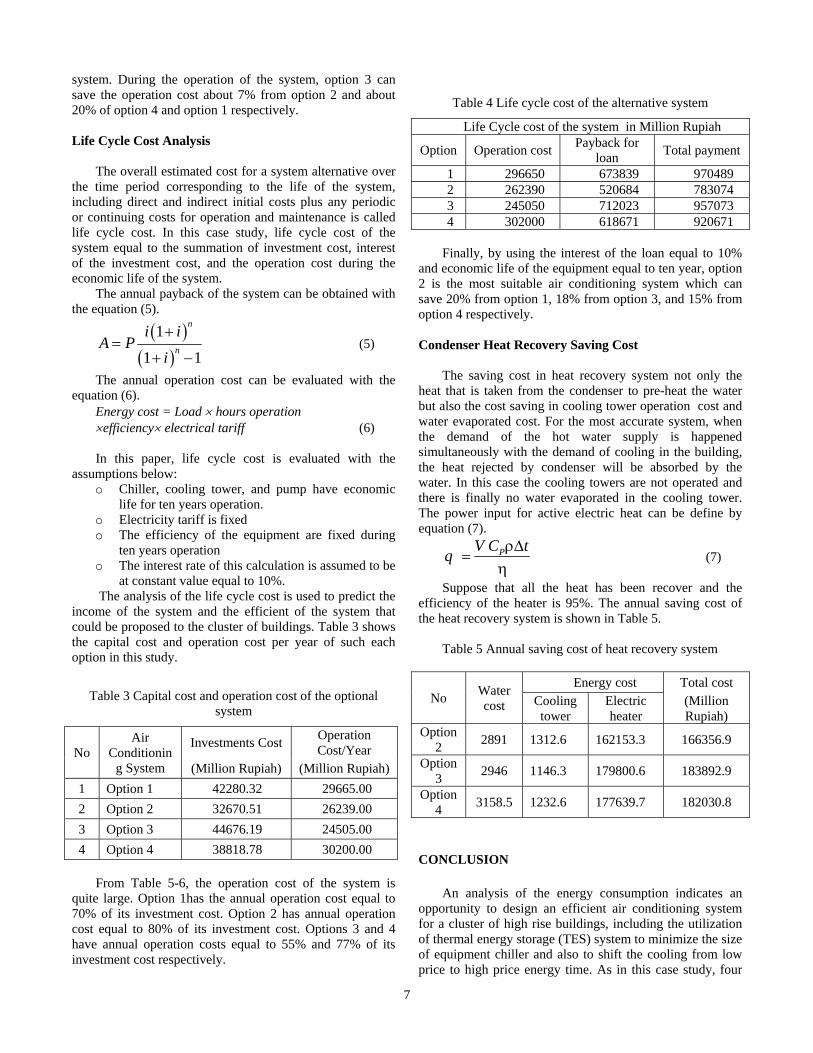
Table 4 Life cycle cost of the alternative system
Life Cycle cost of the system in Million Rupiah
Option Operation cost Payback for loan Total payment
1 296650 673839 970489 2 262390 520684 783074 3 245050 712023 957073 4 302000 618671 920671
Finally, by using the interest of the loan equal to 10%
and economic life of the equipment equal to ten year, option 2 is the most suitable air conditioning system which can save 20% from option 1, 18% from option 3, and 15% from option 4 respectively.
Condenser Heat Recovery Saving Cost
The saving cost in heat recovery system not only the heat that is taken from the condenser to pre-heat the water but also the cost saving in cooling tower operation cost and water evaporated cost. For the most accurate system, when the demand of the hot water supply is happened simultaneously with the demand of cooling in the building, the heat rejected by condenser will be absorbed by the water. In this case the cooling towers are not operated and there is finally no water evaporated in the cooling tower. The power input for active electric heat can be define by equation (7).
ρΔ=
ηPV C tq (7)
Suppose that all the heat has been recover and the efficiency of the heater is 95%. The annual saving cost of the heat recovery system is shown in Table 5.
Table 5 Annual saving cost of heat recovery system
No Water cost
Energy cost Total cost Cooling tower
Electric heater
(Million Rupiah)
Option 2 2891 1312.6 162153.3 166356.9
Option 3 2946 1146.3 179800.6 183892.9
Option 4 3158.5 1232.6 177639.7 182030.8
CONCLUSION
An analysis of the energy consumption indicates an opportunity to design an efficient air conditioning system for a cluster of high rise buildings, including the utilization of thermal energy storage (TES) system to minimize the size of equipment chiller and also to shift the cooling from low price to high price energy time. As in this case study, four

8
optional air conditioning systems are proposed to overcome cooling load requirement of this cluster of buildings in Jakarta with respect to the electrical tariff. Those four optional systems are centralized air conditioning system for individual buildings (option 1), centralized air conditioning system for cluster of buildings (option 2), centralized air conditioning system with TES for a cluster of buildings (option 3), and hybrid centralized air conditioning system with TES for a cluster of buildings (option 4).
As the result of the simulation, if the investment cost is used as criteria, option 2 is the best among the proposed options. This option requires investment cost lower of about 16% than option 4 or 23% lower than option 1 and also 27% lower than option 3. This lowest investment cost is maybe very advantageous for the developer of these properties. However this option gives direct impact on operational cost that will be paid by user, tenant or occupants of the buildings. Furthermore, the higher operational cost which is due to higher electric consumption implies to the national energy resources. Higher electric consumption could reduce sustainability of the electric energy availability if their primary energy resource is still dominated by nonrenewable energy.
In point view of operational cost as the main criteria for the choice of the proposed system option design, option 3 is the best system. With the lowest operational cost implies not only for the future sustainability of national electric energy availability but also gives direct impact on the expense of tenant and owners of the buildings. Although this option requires higher investment cost, but this could be calculated and compensated by the sale or rental prices. Moreover, with this option the operational cost that should be paid by tenant or owners is lower of about 7% than option 2, or around 20% lower than both options 1 and 4.
However, in the design consideration including economic aspect, life cycle cost is normally used as the criteria. According to the results of the simulation based on life cycle cost that assumed as 10 years, option 2 is the best choice. In fact, considering the sustainability of national electric power availability which predominantly depends on fossil fuel as primary energy resources and the price of energy that is very dynamic and tends to increase every year which is not agree with this assumptions used in this calculation, it is expected that within 10 years system operation, option 3 could be better than option 2. Furthermore, when there is an application of cooling thermal storage, it is important to consider about the benefit of the condenser waste heat recovery. A huge amount of heat rejected from the condenser can be used as preheating hot water supply to the building or in other purposes. If it is the case, with the modification of electric tariff assumption that, in fact, always increases every year with additional
consideration on condenser heat recovery for pre-heating hot water that could also reduce cooling tower fan power consumption, option 3 is still interesting to be considered as the proposed option. REFERENCES
Jan F. Kreider and Ari Rabl., 1994, Heating and Cooling of Buildings, McGraw-Hill, Singapore.
Carrier HAP version 4.30, 1999-2006, North America Edition, US.
Jeffrey D. Spitler., 2010, Load Calculation Application Manual, ASHRAE.
Donald P. Fiorino., 1999, Achieving High Chilled-Water Delta Ts, ASHERAE Journal, pages (24-30),Dalas, US.
Chan Kwork Tai and Yu Fu Wing., 2004,How Chillers React to Building Loads, ASHERAE Journal, pages (52-56), Hong Kong.
Thomas H. Durkin., 2005, Evolving Design of Chiller Plants, ASHERAE Journal,vol. 47, No. 11, pages (40-50).
ASHERAE Handbook., 2008, Thermal Storage, Chapter 50.
Ataer O. Ercan., 2006 Storage of Thermal Energy, Energy Storage Systems, EOLSS Publishers, Oxford, UK.
Wang Qingqin and Zhao Ximei., 2001, Thermal Energy Storage in China, ASHERAE Journal, pages (53-55), China.
Evan Wayne S., Apr 1998, Ice Storage Cooling For Campus Expansion, ASHERAE Journal, Lawrenceville, pages (66-68), New Jersey.
Montgomery Ross D., 1998, Ice Storage System for School Complex, ASHERAE Journal, Naples, Florida.
ASHERAE Handbook, 2003, Service Water Heating, Chapter 49.
Temos Edward., 2006, Using Waste Heat for Energy Savings, ASHERAE Journal, New Jersey.
Reindl Douglas T. and Jekel Todd B., 2007, Heat Recovery in Industrial Refrigeration, ASHERAE Journal, Madison, US.
Institute of Plumbing., 2002, Hot and Cold Water Supplies, Plumbing Engineering Services Design Guide, pages (6-10).
G. F. Hewitt, G. L. Shires, T. R. Bott., 2000, Process Heat Transfer, chapter 33, pages (747-776), US.
ASHRAE Handbook., 1997, Pipe Sizing, Chapter 33. HYDROCIAT, Water Cooled Chillers, CIAT Catalogue Cristopia., Energy System,www.cristopia.com, French ANSI/ASHRAE STANDARD 62.1-2004.