Parallel Remote Rendering of Large 3D Point-Based Models on Mobile Clients
8
Parallel Remote Rendering of Large 3D Point-Based Models on Mobile Clients Mohammed E. Fathy, Ashraf S. Hussein † , Safwat H. Hamad, Amr H. Abdelaziz, Saher H. Abdelaziz, Hossam El-Bery Faculty of Computer and Information Sciences, Ain Shams University, Abbassia, 11566, Cairo, Egypt. † e-mail: [email protected] Abstract— Mobile visualization allows users to visualize data anywhere, anytime, on various mobile clients connected by wireless networks. In this paper, an efficient framework is proposed for the remote rendering of large point-based 3D models represented by QSplats Level-Of-Detail (LOD) on mobile devices. As client-oblivious data model is used, rendering tasks are performed on mobile devices ranging from powerful workstations to PDAs and cell phones. On the server side, the framework renders the scenes of the 3D models via the effective utilization of multicore processor(s). The high- level requirements that guided the formulation of the parallel rendering are (a) the problem domain is highly irregular, motivating the use of low-overhead dynamic load-balancing to effectively utilize the multicore processor(s) and (b) the hidden delays encountered with the multicore processors, e.g. to maintain cache consistency. In this manner, novel dynamic load balancing schemes are introduced to reach the optimum performance of the parallel rendering. These schemes are evaluated through the processing of several 3D models with different sizes. In addition, the hidden delays encountered with the multicore processors are investigated. The proposed framework exhibits remarkable efficiency in rendering 3D models especially for the large and sophisticated ones. Keywords-parallel computing; multicores; load balancing; point-based rendering; remote rendering; mobile visualization I. INTRODUCTION In recent years, mobile devices like personal digital assistants (PDAs), smart phones and wearable computers have become an important component of people’s daily life. More graphics applications are being developed for them, e.g. the Mobile phone games. Thus real-time, realistic 3D graphics revealed a demand. Right now, the mobile devices have limited computational capabilities, small memory, low resolution and lack powerful 3D graphics hardware support, all of these make real-time rendering of 3D models on any mobile device become a challenging task [10]. There are two major approaches for mobile based computer graphics: local rendering and remote rendering. In the local rendering, the 3D scene is stored at the memory of the device. To render the scene, the device relies on its local computing resources to process, generate and display the raster image(s) of the scene. Therefore, local rendering follows the same scenario of the desktop computer graphics. The only difference is that mobile devices have much more limited computing resources. Particular graphics’ APIs have been introduced to suit the diverse capabilities of the mobile devices, such as PocketGL, OpenGL ES, M3D, and M3G [12]. To cope with the modest capabilities of the mobiles, Level-Of-Detail (LOD) based solutions have been considered. In general, the frame rates achieved by local rendering approaches are low. For example, Duguet and Drettakis [6] developed a LOD data structure and a traversal algorithm for point-based models, and managed to render large point- based models (1~1.2M of points) on a 200MHz Compaq iPAQ H3850 but at a very low frame rate (< 3 fps). Next, He and Liang [10] proposed a different LOD data structure and traversal algorithm for point-based models. After disabling lighting (and consequently sacrificing the rendering quality), they rendered models consisting of around 60,000 points at various frame rates (3.3 ~ 20 fps). The higher frame rates came, however, at the cost of the lower quality. Their experiments ran on a 600MHz HP iPAQ HX4700. Using the same device, Lamberti and Sanna [12] showed that a polygonal model consisting of approximately 5,000 polygons can be rendered at a frame rate of less than 7 fps. In this way, mobile clients cannot render large models consisting of millions of samples at interactive frame rates. Remote rendering uses client-server architecture where the 3D scene is rendered at the server side and the result is sent over the network to the client side for displaying purposes. This makes the frame rate, at the client side, independent of how complex or large the scene is, making it possible to render large models without extra delays. The only drawback of this approach is the inevitable delays introduced by the communications over the network [12]. Several remote rendering systems have been introduced in industry, as surveyed by Lamberti and Sanna in [12]. They also proposed a remote rendering system incorporating a cluster of PCs to handle the remote visualization sessions. Different frames were assigned to different PCs (inter-frame parallel rendering). In addition, MPEG video streaming was used to render complex 3D models. The emphasis in their research was on utilizing the parallelism introduced by multi- computers. The main contribution in this work is to obtain an efficient framework for the remote rendering problem of the large, point-based models having the QSplat level-of-detail (LOD) representation. This representation `QSplat' is a point-based representation for 3D models that was introduced by Rusinkiewicz and Levoy [13]. To render a QSplat model, a tree representation of the model should be traversed in depth-first order. Large, point-based models (consisting of millions of samples) can be interactively manipulated (with limited delays) regardless of the computing power of the client. Rather than the inter-frame approach of parallel rendering, we have investigated a more challenging problem of rendering the same frame in parallel (intra-frame parallel rendering). The problem is challenging because it involves the traversal of irregular trees and different cores may get Second International Conference on Computational Intelligence, Modelling and Simulation 978-0-7695-4262-1/10 $26.00 © 2010 IEEE DOI 10.1109/CIMSiM.2010.67 378 Second International Conference on Computational Intelligence, Modelling and Simulation 978-0-7695-4262-1/10 $26.00 © 2010 IEEE DOI 10.1109/CIMSiM.2010.67 419 Second International Conference on Computational Intelligence, Modelling and Simulation 978-0-7695-4262-1/10 $26.00 © 2010 IEEE DOI 10.1109/CIMSiM.2010.67 419
Transcript of Parallel Remote Rendering of Large 3D Point-Based Models on Mobile Clients

Parallel Remote Rendering of Large 3D Point-Based Models on Mobile Clients
Mohammed E. Fathy, Ashraf S. Hussein†, Safwat H. Hamad, Amr H. Abdelaziz, Saher H. Abdelaziz, Hossam El-Bery Faculty of Computer and Information Sciences, Ain Shams University, Abbassia, 11566, Cairo, Egypt. †e-mail: [email protected]
Abstract— Mobile visualization allows users to visualize data anywhere, anytime, on various mobile clients connected by wireless networks. In this paper, an efficient framework is proposed for the remote rendering of large point-based 3D models represented by QSplats Level-Of-Detail (LOD) on mobile devices. As client-oblivious data model is used, rendering tasks are performed on mobile devices ranging from powerful workstations to PDAs and cell phones. On the server side, the framework renders the scenes of the 3D models via the effective utilization of multicore processor(s). The high-level requirements that guided the formulation of the parallel rendering are (a) the problem domain is highly irregular, motivating the use of low-overhead dynamic load-balancing to effectively utilize the multicore processor(s) and (b) the hidden delays encountered with the multicore processors, e.g. to maintain cache consistency. In this manner, novel dynamic load balancing schemes are introduced to reach the optimum performance of the parallel rendering. These schemes are evaluated through the processing of several 3D models with different sizes. In addition, the hidden delays encountered with the multicore processors are investigated. The proposed framework exhibits remarkable efficiency in rendering 3D models especially for the large and sophisticated ones.
Keywords-parallel computing; multicores; load balancing; point-based rendering; remote rendering; mobile visualization
I. INTRODUCTION
In recent years, mobile devices like personal digital assistants (PDAs), smart phones and wearable computers have become an important component of people’s daily life. More graphics applications are being developed for them, e.g. the Mobile phone games. Thus real-time, realistic 3D graphics revealed a demand. Right now, the mobile devices have limited computational capabilities, small memory, low resolution and lack powerful 3D graphics hardware support, all of these make real-time rendering of 3D models on any mobile device become a challenging task [10].
There are two major approaches for mobile based computer graphics: local rendering and remote rendering. In the local rendering, the 3D scene is stored at the memory of the device. To render the scene, the device relies on its local computing resources to process, generate and display the raster image(s) of the scene. Therefore, local rendering follows the same scenario of the desktop computer graphics. The only difference is that mobile devices have much more limited computing resources. Particular graphics’ APIs have been introduced to suit the diverse capabilities of the mobile devices, such as PocketGL, OpenGL ES, M3D, and M3G [12]. To cope with the modest capabilities of the mobiles, Level-Of-Detail (LOD) based solutions have been considered.
In general, the frame rates achieved by local rendering approaches are low. For example, Duguet and Drettakis [6] developed a LOD data structure and a traversal algorithm for point-based models, and managed to render large point-based models (1~1.2M of points) on a 200MHz Compaq iPAQ H3850 but at a very low frame rate (< 3 fps). Next, He and Liang [10] proposed a different LOD data structure and traversal algorithm for point-based models. After disabling lighting (and consequently sacrificing the rendering quality), they rendered models consisting of around 60,000 points at various frame rates (3.3 ~ 20 fps). The higher frame rates came, however, at the cost of the lower quality. Their experiments ran on a 600MHz HP iPAQ HX4700. Using the same device, Lamberti and Sanna [12] showed that a polygonal model consisting of approximately 5,000 polygons can be rendered at a frame rate of less than 7 fps. In this way, mobile clients cannot render large models consisting of millions of samples at interactive frame rates.
Remote rendering uses client-server architecture where the 3D scene is rendered at the server side and the result is sent over the network to the client side for displaying purposes. This makes the frame rate, at the client side, independent of how complex or large the scene is, making it possible to render large models without extra delays. The only drawback of this approach is the inevitable delays introduced by the communications over the network [12].
Several remote rendering systems have been introduced in industry, as surveyed by Lamberti and Sanna in [12]. They also proposed a remote rendering system incorporating a cluster of PCs to handle the remote visualization sessions. Different frames were assigned to different PCs (inter-frame parallel rendering). In addition, MPEG video streaming was used to render complex 3D models. The emphasis in their research was on utilizing the parallelism introduced by multi-computers.
The main contribution in this work is to obtain an efficient framework for the remote rendering problem of the large, point-based models having the QSplat level-of-detail (LOD) representation. This representation `QSplat' is a point-based representation for 3D models that was introduced by Rusinkiewicz and Levoy [13]. To render a QSplat model, a tree representation of the model should be traversed in depth-first order.
Large, point-based models (consisting of millions of samples) can be interactively manipulated (with limited delays) regardless of the computing power of the client. Rather than the inter-frame approach of parallel rendering, we have investigated a more challenging problem of rendering the same frame in parallel (intra-frame parallel rendering). The problem is challenging because it involves the traversal of irregular trees and different cores may get
Second International Conference on Computational Intelligence, Modelling and Simulation
978-0-7695-4262-1/10 $26.00 © 2010 IEEE
DOI 10.1109/CIMSiM.2010.67
378
Second International Conference on Computational Intelligence, Modelling and Simulation
978-0-7695-4262-1/10 $26.00 © 2010 IEEE
DOI 10.1109/CIMSiM.2010.67
419
Second International Conference on Computational Intelligence, Modelling and Simulation
978-0-7695-4262-1/10 $26.00 © 2010 IEEE
DOI 10.1109/CIMSiM.2010.67
419

different workloads. The theory and implementation of the parallel depth-first traversal and the dynamic load-balancing were surveyed in [8, 9].
As multicores are increasing in availability and number of cores per chip [7], the server side is based on multicore processor(s). To fully utilize the available processors, the workloads have to be dynamically balanced among these processors. Dynamic load balancing schemes transfer the work requests and tasks among various processors using shared variables. However, frequent access of shared variables may lead to significant performance degradation and should consequently be reduced. In this manner, various dynamic load balancing schemes are proposed and evaluated through rendering of several models with different sizes. In addition, the hidden delays encountered with multicore processors are well investigated.
The rest of this paper is organized as follows. Section II presents the proposed system architecture. Section III provides the data structure and the original rendering algorithm of the QSplat algorithm and describes the challenges encountered to parallelize the rendering algorithm. Section IV presents the proposed parallel formulations. Section V provides the results and discussions. Finally, Section VI gives the conclusion of this work and an overview of the future work.
II. SYSTEM ARCHITECTURE
The framework is comprised of simple client-server architecture as shown in Figure 1. The server side has multicore processor(s), as the multicore processors are now main stream, with the number of cores increasing, expecting to reach hundreds of processors per chip in the future [7]. Meanwhile, the proposed framework supports consumer low-end mobile phones as well as high-end PDAs and PCs. The client device should have the capabilities of displaying JPEG-encoded images, and a connection to the server, either wired or wireless. As the client device sends the user interaction information to the server, the rendering is performed at the server side. Then, the images are sent back to the client device. Figure 2 shows sample of the point-based models rendered on i-mate K-JAM PDA using the proposed framework.
Figure 1. The architecture of the proposed framework.
A. Client Side
In addition to displaying the model, the client GUI captures the user interactions and converts them into a sequence of the desired model poses. These model poses are arranged in a packet having the format shown in Figure 3. This packet is then sent to the rendering server and the client waits for the server’s response. Upon receiving the sequence of images sent by the server, the client displays them with a reasonable inter-frame delay.
B. Server Side
After parsing the received packet, the server works to render the model and an image is generated for each desired pose included in the packet. Each rendered image is encoded into JPEG format, and the sequence of images is then arranged into another packet to be sent to the client.
III. DATA STRUCTURES AND RENDERING ALGORITHM
A. Multi-resolution Data Structure
Algorithms for constructing, quantizing, storing, and rendering the QSplat data structure are described in [13]. QSplat represents the 3D model as a hierarchical tree of bounding spheres. Each level of the tree constitutes a point-based representation of the whole model at a particular level of detail. The level of detail increases as we go down in the tree. Each node in the tree stores the sphere center and radius, the axis and the width of the cone containing the normal vectors of the node’s children, and optionally the color. A special bit, indicating whether all the children are leaves, is also stored with each node.
The QSplat hierarchy is designed to store and render large 3D models at interactive rates. To achieve this level of interactivity, QSplat employs a number of smart quantization schemes that effectively reduce the storage requirements while permitting efficient loading and rendering [13]. Figure 4 shows the tree and its storage layout. The hierarchy is arranged in a breadth-first order so that nodes at the same level are sequentially placed. This permits progressive rendering of the model while it is being loaded. Since the model could be too large to fit into the main memory, we used the OS-provided memory mapping for working set management as introduced in [13].
B. Rendering Algorithm
The rendering algorithm originally described in [13] and outlined below, which traverses the hierarchy and exploits all the available information at the node to achieve efficient rendering.
379420420

TraverseHierarchy(node) { if (node not visible) skip this branch of the tree else if (node is a leaf node) draw a splat else if (benefit of recursing further is too low) draw a splat else for each child in children(node) TraverseHierarchy(child) }
Figure 4. QSplat's bounding sphere hierarchy. Dashed arrows indicate the order in which the nodes are stored.
The availability of the model at different resolutions permits rendering with level-of-detail control. Bounding spheres permit early view frustum culling. If a node is found to be outside the view frustum, the algorithm skips it and does not traverse its children. If the node lies entirely inside the view frustum, the algorithm does not perform further frustum culling checks on its children. The cone of normals
enables early back-face culling. If the cone faces entirely away from the viewer, the node and its sub-tree will be skipped. If the cone faces entirely towards the viewer, no further back-face culling checks will be performed on the node’s children.
C. Parallelization Challenges
The sequential rendering algorithm described earlier will not enable taking of the advantages provided by the forthcoming multicore processors. In this fashion, it is necessary to develop a scalable, shared-memory parallel formulation of the rendering algorithm. Since the traversals of the different sub-trees are independent, the tree can be partitioned into smaller sub-trees, which is distributed on the individual cores to traverse them in parallel (domain decomposition). However, it is difficult to uniformly distribute the workload over the individual cores at the start of the traversal. This is because the tree, explored by the above rendering algorithm, is highly irregular. For example, a node (and its sub-tree) can be early discarded by the frustum culling or the back-face culling. LOD control might also stop the traversal of a sub-tree if it finds the projection of its bounding sphere on the screen is too small relative to the desired LOD. Additionally, the tree construction algorithm of [13] is not guaranteed to construct balanced trees. The nodes eliminated by the visibility culling and the LOD control depend on the pose of the camera. Therefore, the parts of the tree, actually traversed by the algorithm, are changed dynamically.
Dragon (1,279,481 Points) Statue (5,000,000 Points) Lucy (10,072,906 Points)
Figure 2. Point-based models rendered using our system on an i-mate K-JAM PDA.
Model ID
Bytesorder
Resolution Screen Width
Screen Height
1 1 4 2 2Packet Header
(11 bytes)Image type
1
Rotation parameters Translation parameters44 44quaternion 222X , Y , Z Packet content for
each position(22 bytes)
Pose (2)Parameters
Pose (1)Parameters
………… Pose (n)Parameters
22 22 22
Figure 3. The layout of the request packet.
380421421

All of these factors make the problem of parallelizing the traversal and the rendering irregular. Any static assignment of sub-trees to cores will cause significant load imbalance among cores. This is illustrated in Figure 5, where the static partitioning of the unstructured tree in case of two and four processors yields sub-trees with widely different number of nodes at each core (load imbalance).
In uni-processor configurations, new values computed by the processor are written back to the cache, where they remain until their space is required for other data [5]. In shared-memory parallel computers, shared variables must be written back (i.e., uploaded) to the shared cache (which is significantly slower than the local cache) shortly after modifications to prevent memory consistency problems [5]. In addition, read-accesses to the shared variables require frequent updates (i.e., downloads) from the shared cache to ensure that the values stored in the local cache are up-to-date. The shared cache is significantly slower to access than the per-core private cache. Furthermore, accessing the shared cache becomes even slower when performed by different cores simultaneously although each core may access a different variable [2]. This limits the speedup achieved by parallel formulations that rely much on shared variables.
(a) 2 processors
(b) 4 processors
Figure 5. Static partitioning leads to significant load imbalance.
Dynamic load balancing schemes use shared variables to perform communications among different cores. To control the delays introduced by using shared variables, dynamic load balancing techniques must be implemented with extreme care.
IV. PARALLEL FORMULATION
Any parallel formulation with dynamic load balancing scheme for depth-first tree traversal has three basic components [9]: (i) a task partitioning strategy that determines how the work at a given donor processor is split (stack-splitting versus node splitting), (ii) a subtask generation strategy that determines who initiates work splitting at a given donor processor (sender-initiated, receiver-initiated or master-initiated), and (iii) a work
transfer strategy that determines who initiates the work transfer between the sender and the receiver (sender-initiated, receiver-initiated or scheduler-initiated as with the OpenMP 3.0 task-construct). Various parallel formulations presented in this section are classified according to these 3 components. These parallel formulations are described in a generic way to be applicable for a wider range of problems.
A. Implementation Issues
Multi-threading is implemented using OpenMP [5]. OpenMP permits the developer to mark some sections of the program code as parallel regions. When the program is executed, the master (initial) thread executes the program sequentially. When parallel regions are encountered, the master thread creates a team of threads. Then, all these threads execute that region in parallel [5]. OpenMP work-share constructs (such as omp for and omp sections) can be used to distribute the workload over the different threads. OpenMP also supports low-level programming style in which the programmer manually distributes the workload over the different threads based on their unique threads IDs without using the built-in work-share constructs [5]. This is similar to the SPMD (Single-Program Multiple Data) paradigm [4]. The low-level OpenMP programming style is adopted in the Stack Splitting (SS) formulation and the Master-Initiated (MI) formulation proposed in this work. The other proposed formulations use the work-share constructs provided by OpenMP.
OpenMP implicitly sets memory consistency instructions (flushes) at the synchronization primitives [5]. In x86 multi-core architectures, this is not required since the locking operations cannot be reordered with stores/loads [1, 11]. We exploit this feature by directly using the native synchronization mechanisms provided by the OS instead of those provided by the OpenMP in order to avoid the redundant memory flushes and the associated slow-downs. Still, locking instructions produce significant slow-downs due to the implicit flushing of the private caches and consequently its usage should be very limited.
Precautions are taken to prevent multiple cores from rasterizing the same pixel at the same time. In this manner, each core has its own color and depth buffers. After finishing the traversal, the buffers of the different processors are combined to produce the final image. This introduces an overhead that does not exist in the sequential implementation, and can limit the attained speedup and scalability. Therefore, in this work, some optimizations are introduced. First, only the rendered part of the buffer is combined between the processors. This is performed by finding the projection of the root node sphere on the screen and computing its axis-aligned bounding rectangle R (xmin, xmax, ymin, ymax). For each buffer, only the pixels within the rectangle R are considered by the combination algorithm. Second, the combination of any two buffers is performed in parallel by assigning each core a different chunk of consecutive rows of pixels to be combined. Distributing consecutive rows is more cache-coherent than distributing columns, as color and depth buffers are stored in row-major order.
381422422

B. Scheme 1: Static Partitioning
The static task partitioning scheme distributes a frontier of n sub-trees over the n available cores. After finishing the traversal of its sub-tree, a processor ends the execution without asking other cores for more work. The advantage of this scheme is that it avoids inter-processor communication. However, it may lead to significant load imbalance.
C. Scheme 2: Stack Splitting
In this dynamic load balancing based scheme, each processor has its own message queue as well as a stack of work nodes. As indicated in Figure 6, when a core finishes its work, it sends a REQUEST_WORK message to a target processor selected using the Random Polling (RP) strategy [8]. In the RP, the target processor is randomly selected without using any global variables [8]. Other strategies for target-processor selection were presented in [8] where the experiments revealed that RP bested others from the performance point of view. After sending the request, the core periodically checks its message queue every Tr milliseconds. If it receives a REQUEST_REJECTED message, it sends the work-request to another processor and keeps waiting. If it receives a REQUEST_FULFILLED, it switches back to the active state and resumes the traversal of the nodes newly assigned to its stack.
After traversing a fixed number Wp of nodes, a core, in active state, checks its message queue for work requests. Upon request, it donates the even nodes in its stack to the stack of the requester, and sends a REQUEST_FULFILLED message to the requester. Since nodes at the bottom of the stack correspond to higher levels of the tree, they tend to have larger sub-trees. On the other hand, nodes at the top of the stack correspond to lower levels of the tree and tend to have smaller sub-trees. Sending the nodes with even (or odd) indices is an attempt to guarantee load balancing between the donor and the receiver by giving each processor nodes at similar levels. In case of k (> 1) requests, the donor adopts a similar work splitting strategy to guarantee, as much as possible, that each processor is given the same number of nodes belonging to the same levels.
It is guaranteed that work stacks are accessed by one processor at any time. Only message queues need protection via synchronization mechanisms. To avoid frequent calls to the heap memory manager (which is a shared resource), we
use an array-based representation for the node stack and the message queue rather than the linked representation. In addition, queues and stacks are pre-allocated with sufficient space to guarantee that no further expansion will be required.
The parameters Tr and Wp control the frequency of accessing the semaphores-protected message queues. Too small values would slow down the algorithm due to the frequent execution of the locking instructions. On the other hand, too large values would increase the idle time of the processors and break the load balancing scheme. The values of Tr and Wp are adjusted to maximize the average speed-up over several sets of viewing parameters:
n
i prip
is
pravgWT WTVT
VT
nWTS
pr 1 , ,
1 ,maxarg
, (1)
where n is the number of sets of viewing parameters tried and Vi is the ith set of viewing parameters. The optimal values vary from one model to another. So, one strategy is to determine these values in a preprocessing step for every model in the data set by trying different values for Tr and Wp, rendering the model from every set of viewing parameters Vi, finding Savg(Tr, Wp) and recording the values of Tr and Wp for which Savg(Tr, Wp) is minimum.
D. Scheme 3: Master-initiated Subtask Generation
Before making a team of threads, the master thread collects a frontier of Mf or more (up to Mf + 3) non-culled nodes from the tree and put them in a semaphore-protected global node list NL, as shown in Figure 7. Then, a team of threads is created. Each thread takes one node at a time from the NL and traverses its sub-tree. When a thread finishes the traversal of a sub-tree, it takes another node from the NL after acquiring its semaphore. If it finds NL empty, it stops working. Therefore, task partitioning is performed via node splitting, the subtask generation is master-initiated, and the work transfer is receiver-initiated.
The optimal value of the parameter Mf changes from one model to another. If pre-processing is allowed, the average speedup Savg for different viewing parameters is computed for each possible value of Mf. The value that maximizes Savg is stored for this model and used when rendering the model.
Figure 6. The Stack Splitting Formulation
382423423

E. Scheme 4: Receiver-initiated Node-splitting using OpenMP 3.0 Tasks
OpenMP 3.0 provides task-construct that allows expressing the parallelism in irregular problems such as the current one [3]. In our implementation, a task consists of one node whose sub-tree is to be traversed. The master core generates p tasks with the top p sub-trees. Then, the OpenMP scheduler distributes these tasks over the p cores. When a core is about to finish its task, it increments the semaphore-protected number of idle threads Ni and ends execution (receiver-initiated generation). Other working cores check Ni (after locking its semaphore) every time they finish traversing Wp nodes. If a working processor discovers that Ni is a nonzero, it generates Ni tasks with Ni nodes from the current and the subsequent levels of the tree (node splitting task partitioning). The OpenMP scheduler then awakens one of the cores and assigns it the task (scheduler-initiated work-transfer).
Figure 7. Master-Initiated Node Splitting, Mf = 8 and the frontier with 10
non-culled nodes.
The optimal value of the parameter Wp changes from one model to another. If pre-processing is allowed, the average speed-up Savg for different viewing parameters is computed for each possible value of Wp. The value that maximizes Savg is stored for this model and used when rendering the model.
F. Scheme 5: Sender-initiated Node-splitting using OpenMP 3.0 Tasks
One possible modification to the above strategy is to modify the task generation to be sender-initiated instead of receiver-initiated. This is possible by leasing every core generates a task directly every Wp nodes, which are traversed by the core without checking whether or not one or more cores are idle. The advantage is that the semaphore-protected number of idle threads Ni is no more required. The disadvantage is that generating tasks every Wp nodes might introduce overhead in case of no idle processor(s).
V. EXPERIMENTAL RESULTS
The five parallel aforesaid formulations have been implemented to test their relative performance and the overall system performance. The experimental setup and the results obtained are described.
A. Rendering Performance
The performance of the parallel formulations was measured over a set M of 3 different models and a set V of 30 different sets of viewing parameters. The description of these models is given in Table 1.
TABLE I. POINT-BASED MODELS USED AS TEST CASES
Model Number of Points
Dragon 1,279,481 Statue 5,000,000 Lucy 10,072,906
For each model m and for each method e, the parallel
rendering time Tp(e, m, v) was measured for each set v V of the viewing parameters and the average speedup was computed using:
Vv p
s
p vmeT
vmT
VmeA
, ,
,1 ,
(2)
The experiments were conducted on a server equipped with an Intel Core 2 Quad CPU (2.4 GHz, 8 MB L2 Cache) and 4.0 GB RAM. For each model m, Figure 8 shows a separate plot of the average speedup achieved by the proposed load balancing schemes using different numbers of cores.
It is obvious that the Master-Initiated scheme bested others from scalability point of view for all the considered models. Despite all the performance tunes described for the Stack-Splitting, Receiver-Initiated, and Sender-Initiated load-balancing schemes, they did not achieve as good speedup as that achieved by the Static-Partitioning scheme. Therefore, the overhead they introduce outweighs the load-balancing gains. This is in contrast to the Master-Initiated scheme which was able to improve the speedup of the Static-Partitioning scheme by using as little communication overhead as possible in balancing the load among the cores. It is interesting to point out that the speedup, the rate at which speedup increases pdA
dp, and hence the scalability of all
schemes improves as the size of the model increases.
2 3 40.5
1
1.5
2
2.5
Number of Cores
Avg
. Spe
edup
SIRISSSMI
(a) Dragon (1,279,481 points)
383424424
2 3 40.5
1
1.5
2
2.5
3
Number of Cores
Avg
. Spe
edup
SIRISSSMI
(b) Statue (5,000,000 Points)
2 3 40
1
2
3
4
Number of Cores
Avg
. Spe
ed-u
p
SIRISSSMI
(c) Lucy (10,072,906 points)
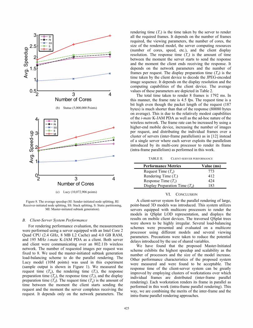
Figure 8. The average speedup (SI: Sender-initiated node splitting, RI: Receiver-initiated node splitting, SS: Stack splitting, S: Static partitioning,
MI: Master-initiated subtask generation).
B. Client-Server System Performance
For rendering performance evaluation, the measurements were performed using a server equipped with an Intel Core 2 Quad CPU (2.4 GHz, 8 MB L2 Cache) and 4.0 GB RAM, and 195 MHz i-mate K-JAM PDA as a client. Both server and client were communicating over an 802.11b wireless network. The number of requested images per request was fixed to 8. We used the master-initiated subtask generation load-balancing scheme to do the parallel rendering. The Lucy model (10M points) was used in this experiment (sample output is shown in Figure 1). We measured the request time (Tq), the rendering time (Tr), the response preparation time (Tp), the response time (Ts), and the display preparation time (Td). The request time (Tq) is the amount of time between the moment the client starts sending the request and the moment the server completes receiving the request. It depends only on the network parameters. The
rendering time (Tr) is the time taken by the server to render all the required frames. It depends on the number of frames required, the viewing parameters, the number of cores, the size of the rendered model, the server computing resources (number of cores, speed, etc.), and the client display resolution. The response time (Ts) is the amount of time between the moment the server starts to send the response and the moment the client ends receiving the response. It depends on the network parameters and the number of frames per request. The display preparation time (Td) is the time taken by the client device to decode the JPEG-encoded image sequence. It depends on the display resolution and the computing capabilities of the client device. The average values of these parameters are depicted in Table 2.
The total time taken to render 8 frames is 1792 ms. In this manner, the frame rate is 4.5 fps. The request time is a bit high even though the packet length of the request (187 bytes) is much shorter than that of the response (80080 bytes on average). This is due to the relatively modest capabilities of the i-mate K-JAM PDA as well as the ad-hoc nature of the wireless network. The frame rate can be increased by using a higher-end mobile device, increasing the number of images per request, and distributing the individual frames over a cluster of servers (inter-frame parallelism) as in [12] instead of a single server where each server exploits the parallelism introduced by its multi-core processor to render its frame (intra-frame parallelism) as performed in this work.
TABLE II. CLIENT-SERVER PERFORMANCE
Performance Metrics Value (ms)Request Time (Tq) 773 Rendering Time (Tr) 412 Response Time (Ts) 424 Display Preparation Time (Td) 183
VI. CONCLUSION
A client-server system for the parallel rendering of large, point-based 3D models was introduced. This system utilizes servers equipped with multicore processors to render the models in QSplat LOD representation, and displays the results on mobile client devices. The traversed QSplat trees were shown to be highly irregular. Several load-balancing schemes were presented and evaluated on a multicore processor using different models and several viewing parameters. Precautions were taken to reduce the potential delays introduced by the use of shared variables.
We have found that the proposed Master-Initiated scheme exhibits the highest speedup and scalability as the number of processors and the size of the model increase. Other performance characteristics of the proposed system were measured and were found to be acceptable. The response time of the client-server system can be greatly improved by employing clusters of workstations over which individual frames are distributed (inter-frame parallel rendering). Each workstation renders its frame in parallel as performed in this work (intra-frame parallel rendering). This way, we are combining the merits of the inter-frame and the intra-frame parallel rendering approaches.
384425425

As a future work, the server site will be sophisticated to consider simultaneous requests from different users (clients).
ACKNOWLEDGEMENTS
This work was supported in part by a grant from Information Technology Academia Collaboration Programs (ITAC), Information Technology Industry Development Agency (ITIDA), Ministry of Communication and Information Technology, Egypt.
REFERENCES [1] AMD64 Architecture Programmer's Manual Volume 2: System
Programming, AMD. [Online]. Available: http://support.amd.com/us/Processor_TechDocs/24593.pdf
[2] “Analyzing efficiency of shared and dedicated l2 cache in modern dual-core processors,” October 2006. [Online]. Available: http://ixbtlabs.com/articles2/cpu/rmmt-l2-cache.html
[3] E. Ayguadé, N. Copty, A. Duran, J. Hoeflinger, Y. Lin, F. Massaioli, X. Teruel, P. Unnikrishnan, and G. Zhang, “The Design of OpenMP Tasks,” IEEE Transactions on Parallel and Distributed Systems, pp. 404–418, 2009.
[4] R. Buyya, High Performance Cluster Computing: Programming and Applications. Upper Saddle River, NJ, USA: Prentice Hall PTR, 1999, vol. 2, ch. 1.
[5] B. Chapman, G. Jost, and R. v. d. Pas, Using OpenMP: Portable Shared Memory Parallel Programming (Scientific and Engineering Computation). The MIT Press, 2007.
[6] F. Duguet and G. Drettakis, “Flexible point-based rendering on mobile devices,” IEEE Computer Graphics and Applications, pp. 57–63, 2004.
[7] “From a few cores to many: A tera-scale computing research overview. white paper,” 2006. [Online]. Available: ftp://download.intel.com/research/platform/terascale/terascale overview paper.pdf
[8] A. Grama, G. Karypis, V. Kumar, and A. Gupta, Introduction to Parallel Computing (2nd Edition). Addison Wesley, January 2003.
[9] A. Grama and V. Kumar, “A survey of parallel search algorithms for discrete optimization problems,” ORSA Journal of Computing, vol. 7, no. 4, pp. 365–385, 1995.
[10] Z. He and X. Liang, “A multiresolution object space point-based rendering approach for mobile devices,” in Proceedings of the 5th international conference on Computer graphics, virtual reality, visualisation and interaction in Africa. ACM New York, NY, USA, 2007, pp. 7–13.
[11] Intel® 64 and IA-32 Architectures Software Developer's Manual Volume 3A: System Programming Guide, Intel. [Online]. Available: http://www.intel.com/assets/PDF/manual/253668.pdf
[12] F. Lamberti and A. Sanna, “A streaming-based solution for remote visualization of 3D graphics on mobile devices,” IEEE Transactions on Visualization and Computer Graphics, vol. 13, no. 2, pp. 247–260, 2007.
[13] S. Rusinkiewicz and M. Levoy, “QSplat: A multiresolution point rendering system for large meshes,” in Proceedings of ACM SIGGRAPH 2000, Jul. 2000, pp. 343–352.
385426426