
Performance analysis of matrix preconditioning algorithms on parallel optical processors
Upload
khangminh22Category
view
1download
0
CS 677: Parallel Programming for
Many-core Processors
Lecture 7
Instructor: Philippos Mordohai
Webpage: mordohai.github.io
E-mail: [email protected]
1

Logistics
• Midterm: March 11
• Project proposal presentations: March 26
– Have to be approved by me by March 12
2

Project Proposal
• Problem description– What is the computation and why is it important?
– Abstraction of computation: equations, graphic or pseudo-code, no more than 1 page
• Suitability for GPU acceleration– Amdahl’s Law: describe the inherent parallelism. Argue that it
is close to 100% of computation.
– Synchronization and Communication: Discuss what data structures may need to be protected by synchronization, or communication through host.
– Copy Overhead: Discuss the data footprint and anticipated cost of copying to/from host memory.
• Intellectual Challenges– Generally, what makes this computation worthy of a project?
– Point to any difficulties you anticipate at present in achieving high speedup
3

Midterm Reading List
• Week 1: nothing
• Week 2: everything, except #20
• Week 3: everything, except #51-57
• Week 4: everything, except #68-98
• Week 5: everything, except #1-34
• Week 6: #19-60
• Week 7: nothing
4

© David Kirk/NVIDIA and Wen-mei W. Hwu, 2007-2010
ECE408, University of Illinois, Urbana-Champaign
5
Electrostatic potential map is used in building stable structures for
molecular dynamics simulation
Electrostatic Potential Calculation

6
•The contribution of atom[i] to the electrostatic
potential at lattice point j is atom[i].charge / rij
•The total potential at lattice point j is the sum of
contributions from all atoms in the system
Core Computation
© David Kirk/NVIDIA and Wen-mei W. Hwu, 2007-2010
ECE408, University of Illinois, Urbana-Champaign

© David Kirk/NVIDIA and Wen-mei W. Hwu, 2007-2010
ECE408, University of Illinois, Urbana-Champaign 7
Sequential CPU Code
7
Computes a single slice (const z)

GPU Implementation
• Option 1: each thread calculates the
contribution of one atom to all grid points
– “Scatter”
• Option 2: each thread calculates the
accumulated contributions of all atoms to
one grid point
– “Gather”
• Pros/cons?
8© David Kirk/NVIDIA and Wen-mei W. Hwu, 2007-2010
ECE408, University of Illinois, Urbana-Champaign

Loop Transformation
• Need perfectly
nested loops
– as in MRI
example
– Move
calculation of y
into inner loop
– Pros/cons?
9© David Kirk/NVIDIA and Wen-mei W. Hwu, 2007-2010
ECE408, University of Illinois, Urbana-Champaign

10
DCS Kernel Design Overview
© David Kirk/NVIDIA and Wen-mei W. Hwu, 2007-2010
ECE408, University of Illinois, Urbana-Champaign

11
DCS Kernel Version 1
qsqrtf(): reciprocal square root© David Kirk/NVIDIA and Wen-mei W. Hwu, 2007-2010
ECE408, University of Illinois, Urbana-Champaign

12
DCS Kernel Version 1
qsqrtf(): reciprocal square root
ILP vs. TLP
atominfo[].z is already squared
© David Kirk/NVIDIA and Wen-mei W. Hwu, 2007-2010
ECE408, University of Illinois, Urbana-Champaign

13
Information Reuse
© David Kirk/NVIDIA and Wen-mei W. Hwu, 2007-2010
ECE408, University of Illinois, Urbana-Champaign

14
DCS kernel Version 2
© David Kirk/NVIDIA and Wen-mei W. Hwu, 2007-2010
ECE408, University of Illinois, Urbana-Champaign
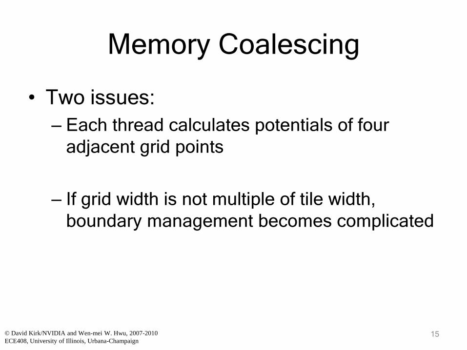
Memory Coalescing
• Two issues:
– Each thread calculates potentials of four
adjacent grid points
– If grid width is not multiple of tile width,
boundary management becomes complicated
15© David Kirk/NVIDIA and Wen-mei W. Hwu, 2007-2010
ECE408, University of Illinois, Urbana-Champaign
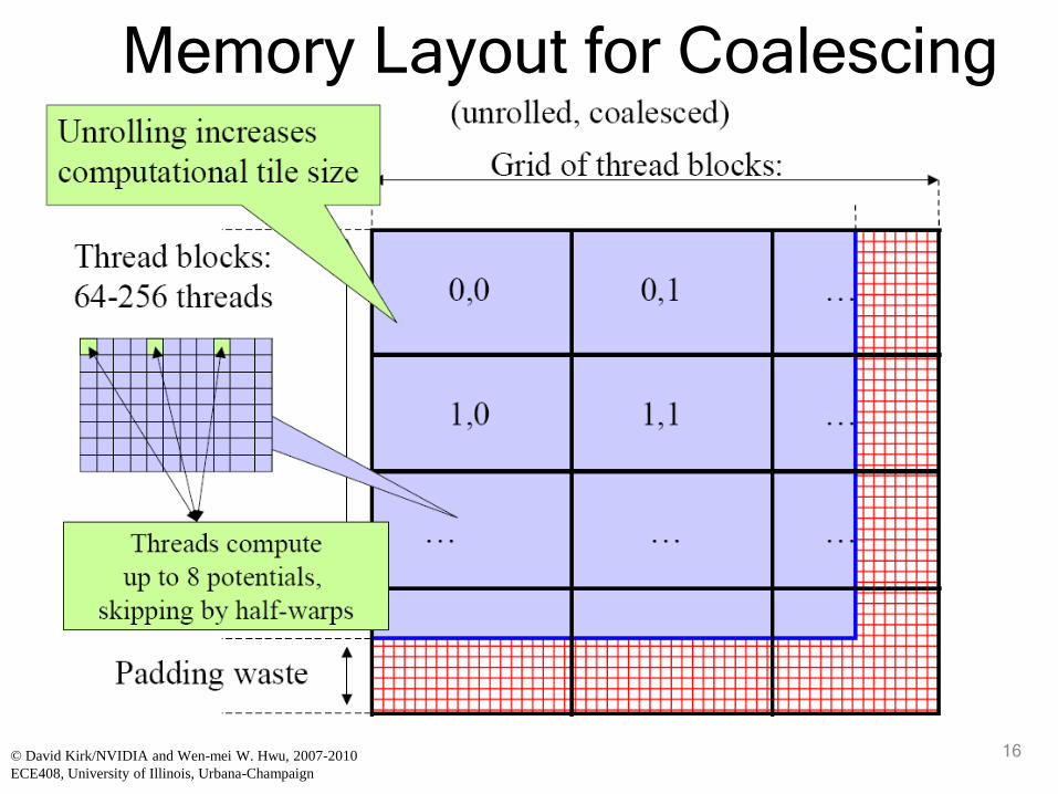
16
Memory Layout for Coalescing
© David Kirk/NVIDIA and Wen-mei W. Hwu, 2007-2010
ECE408, University of Illinois, Urbana-Champaign

© David Kirk/NVIDIA and Wen-mei W. Hwu, 2007-2010
ECE408, University of Illinois, Urbana-Champaign
DCS Kernel Version 3
ILP vs. TLP© David Kirk/NVIDIA and Wen-mei W. Hwu, 2007-2010
ECE408, University of Illinois, Urbana-Champaign

18
Performance Comparison
18© David Kirk/NVIDIA and Wen-mei W. Hwu, 2007-2010
ECE408, University of Illinois, Urbana-Champaign

19
CPU vs. CPU-GPU Comparison
© David Kirk/NVIDIA and Wen-mei W. Hwu, 2007-2010
ECE408, University of Illinois, Urbana-Champaign

UIUC ECE 598HK
Computational Thinking for
Many-core Computing
Input Binning
20

Objective
• To understand how data scalability
problems in gather parallel execution
motivate input binning
• To learn basic input binning techniques
• To understand common tradeoffs in input
binning
21©Wen-mei W. Hwu and David Kirk/NVIDIA 2010

Scatter to Gather Transformation
Thread 1 Thread 2 …in
out
Thread 1 Thread 2
…
in
out
GPU Computing Forum

However
• Input tends to be much less regular than output
– It may be difficult for each thread to efficiently locate all inputs relevant to its output
– Or, to efficiently exclude all inputs irrelevant to its output
• In a naïve arrangement, all threads may have to process all inputs to decide if each input is relevant to its output
– This makes execution time scale poorly with data set size
– Important problem when processing large data sets
23©Wen-mei W. Hwu and David Kirk/NVIDIA 2010

DCS Algorithm for Electrostatic Potentials
Revisited
• At each grid point, sum
the electrostatic
potential from all atoms
– All threads read all inputs
• Highly data-parallel
• But has quadratic
complexity– Number of grid points
number of atoms
– Both proportional to volume
– Poor data scalability
24©Wen-mei W. Hwu and David Kirk/NVIDIA 2010

Algorithm for Electrostatic Potentials
With a Cutoff
• Ignore atoms beyond a
cutoff distance, rc
– Typically 8Å–12Å
– Long-range potential may
be computed separately
• Number of atoms within
cutoff distance is
roughly constant
(uniform atom density)
– 200 to 700 atoms within
8Å–12Å cutoff sphere for
typical biomolecular
structures
25©Wen-mei W. Hwu and David Kirk/NVIDIA 2010

Implementation Challenge
• For each tile of grid points, we need to identify the set of atoms that need to be examined
– One could naively examine all atoms and only use the ones whose distance is within the given range
– But this examination still takes time, and brings the time complexity right back to • number of atoms × number of grid points
– Each thread needs to avoid examining the atoms outside the range of its grid point(s)
26©Wen-mei W. Hwu and David Kirk/NVIDIA 2010

Binning
• A process that groups data to form a
chunk called bin
• Helps problem solving due to data
coarsening
• Uniform bin arrays, Variable bins, KD
Trees, …
27©Wen-mei W. Hwu and David Kirk/NVIDIA 2010

Binning for Cut-Off Potential
• Divide the simulation volume with non-
overlapping uniform cubes
• Every atom in the simulation volume falls into a
cube based on its spatial location
– Bins represent location property of atoms
• After binning, each cube has a unique index in
the simulation space for easy parallel access
28©Wen-mei W. Hwu and David Kirk/NVIDIA 2010
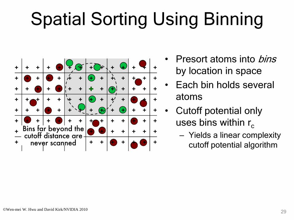
Spatial Sorting Using Binning
• Presort atoms into binsby location in space
• Each bin holds several
atoms
• Cutoff potential only
uses bins within rc
– Yields a linear complexity
cutoff potential algorithm
29©Wen-mei W. Hwu and David Kirk/NVIDIA 2010
Bin Size Considerations
• Capacity of atom bins needs to be balanced
– Too large – many dummy atoms in bins
– Too small – some atoms will not fit into bins
– Target bin capacity to cover more than 95% or atoms
• CPU places all atoms that do not fit into bins into an overflow bin
– Use a CPU sequential algorithm to calculate their contributions to the energy grid lattice points.
– CPU and GPU can do potential calculations in parallel
30©Wen-mei W. Hwu and David Kirk/NVIDIA 2010

Bin Design• Uniform sized/capacity bins allow array implementation
– And the relative offset list approach
• Bin capacity should be big enough to contain all the
atoms that fall into a bin
– Cut-off will screen away atoms that weren’t processed
– Performance penalty if too many are screened away
31©Wen-mei W. Hwu and David Kirk/NVIDIA 2010

Going from DCS Kernel to Large
Bin Cut-off Kernel
• Adaptation of techniques from the direct Coulomb
summation kernel for a cutoff kernel
• Atoms are stored in constant memory as with DCS
kernel
• CPU loops over potential map regions that are (24Å)3 in
volume (cube containing cutoff sphere)
• Large bins of atoms are appended to the constant
memory atom buffer until it is full, then GPU kernel is
launched
• Host loops over map regions reloading constant memory
and launching GPU kernels until completion
©Wen-mei W. Hwu and David Kirk/NVIDIA Urbana,
Illinois, August 2-5, 2010
32

Large Bin Design Concept
• Map regions are (24Å)3 in volume
• Regions are sized large enough to provide
the GPU enough work in a single kernel
launch
– (48 lattice points)3 for lattice with 0.5Å spacing
– Small bins don’t provide the GPU enough
work to utilize all SMs, to amortize constant
memory update time, or kernel launch
overhead
33©Wen-mei W. Hwu and David Kirk/NVIDIA Urbana,
Illinois, August 2-5, 2010

©Wen-mei W. Hwu and David Kirk/NVIDIA 2010
Large-bin Cutoff Kernel Evaluation
• 6 speedup relative to fast CPU version
• Work-inefficient
– Coarse spatial hashing into (24Å)3 bins
– Only 6.5% of the atoms a thread tests are
within the cutoff distance
• Better adaptation of the algorithm to the
GPU will gain another 2.5
34
©Wen-mei W. Hwu and David Kirk/NVIDIA 2010
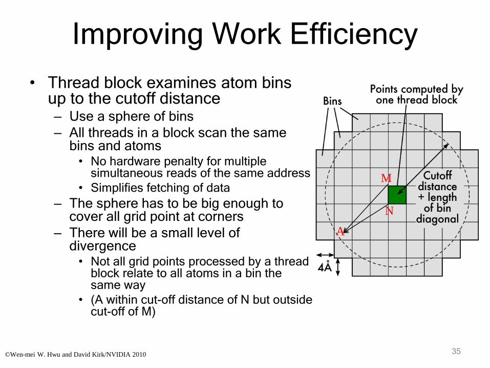
Improving Work Efficiency
• Thread block examines atom bins up to the cutoff distance– Use a sphere of bins
– All threads in a block scan the same bins and atoms• No hardware penalty for multiple
simultaneous reads of the same address
• Simplifies fetching of data
– The sphere has to be big enough to cover all grid point at corners
– There will be a small level of divergence• Not all grid points processed by a thread
block relate to all atoms in a bin the same way
• (A within cut-off distance of N but outside cut-off of M)
35
M
N
A
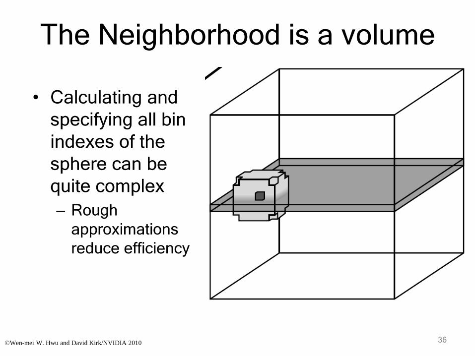
The Neighborhood is a volume
• Calculating and
specifying all bin
indexes of the
sphere can be
quite complex
– Rough
approximations
reduce efficiency
36©Wen-mei W. Hwu and David Kirk/NVIDIA 2010

Neighborhood Offset List
(Pre-calculated)• A list of relative offsets enumerating the bins
that are located within the cutoff distance for a given location in the simulation volume
• Detection of surrounding atoms becomes realistic for output grid points
– By visiting bins in the neighborhood offset list and iterating over the atoms they contain
center (0, 0)
(1, 2)
not included
cutoff distance
(-1, -1)
a bin in the neighborhood
list
37©Wen-mei W. Hwu and David Kirk/NVIDIA 2010

Performance
• O(MN’) where M and N’ are the number of
output grid points and atoms in the
neighborhood offset list, respectively
– In general, N’ is small compared to the
number of all atoms
• Works well if the distribution of atoms is
uniform
©Wen-mei W. Hwu and David Kirk/NVIDIA 2010 38

Details on Small Bin Design
• For 0.5Å lattice spacing, a (4Å)3 cube of the potential map is computed by each thread block– 888 potential map points
– 128 threads per block (4 points/thread)
– 34% of examined atoms are within cutoff distance
©Wen-mei W. Hwu and David Kirk/NVIDIA 2010 39

More Design Considerations for the
Cutoff Kernel
• High memory throughput to atom data
essential
– Group threads together for locality
– Fetch bins of data into shared memory
– Structure atom data to allow fetching
• After taking care of memory demand,
optimize to reduce instruction count
– Loop and instruction-level optimization
40©Wen-mei W. Hwu and David Kirk/NVIDIA 2010

Another thread block runs
while this one waits
Tiling Atom Data
• Shared memory used to reduce Global Memory bandwidth consumption– Threads in a thread block collectively load
one bin at a time into shared memory
– Once loaded, threads scan atoms in shared memory
– Reuse: Loaded bins used 128 times
Threads individually
compute potentials
using bin in shared mem
Collectively
load next
bin
Write bin to
shared
memorySuspend
Data returned
from global
memory Ready
Time
Execution cycle of a thread block
41©Wen-mei W. Hwu and David Kirk/NVIDIA 2010

Handling Overfull Bins
• In typical use, 2.6% of atoms exceed bin capacity
• Spatial sorting puts these into a list of extra atoms
• Extra atoms processed by the CPU
– Computed with CPU-optimized algorithm
– Takes about 66% as long as GPU computation
– Overlapping GPU and CPU computation yields additional speedup
– CPU performs final integration of grid data
42©Wen-mei W. Hwu and David Kirk/NVIDIA 2010

CPU Grid Data Integration
• Effect of overflow atoms are added to the CPU master energygrid array
• Slice of grid point values calculated by GPU are added into the master energygrid array while removing the padded elements
0,0 0,1
1,0 1,1
…
… …
…
…
43©Wen-mei W. Hwu and David Kirk/NVIDIA 2010

GPU Thread Coarsening
• Each thread computes
potentials at four potential
map points
– Reuse x and z components
of distance calculation
– Check x and z components
against cutoff distance
(cylinder test)
• Exit inner loop early upon
encountering the first
empty slot in a bin
44©Wen-mei W. Hwu and David Kirk/NVIDIA 2010

GPU Thread Inner Loopfor (i = 0; i < BIN_DEPTH; i++) {
aq = AtomBinCache[i].w;
if (aq == 0) break;
dx = AtomBinCache[i].x - x;
dz = AtomBinCache[i].z - z;
dxdz2 = dx*dx + dz*dz;
if (dxdz2 > cutoff2) continue;
dy = AtomBinCache[i].y - y;
r2 = dy*dy + dxdz2;
if (r2 < cutoff2)
poten0 += aq * rsqrtf(r2);
// Simplified example
dy = dy - 2 * grid_spacing;
/* Repeat three more times */
}
Exit when an empty atom bin
entry is encountered
Cylinder test
Cutoff test
and potential value
calculation
45©Wen-mei W. Hwu and David Kirk/NVIDIA 2010

Cutoff Summation Runtime
50k–1M atom structure size
GPU cutoff with
CPU overlap:
12x-21x faster
than CPU core
46©Wen-mei W. Hwu and David Kirk/NVIDIA 2010
Summary
• Large bins allow re-use of all-input kernels with little code change– But work efficiency can be very low
• Use of small-sized bins require more sophisticated kernel code to traverse list of small bins– Much higher work efficiency
– Small bins also serve as tiles for locality
• CPU processes overflow atoms from fixed capacity bins
47©Wen-mei W. Hwu and David Kirk/NVIDIA 2010
Copyright © 2022 FDOKUMEN