
Par cipant Handbook - eSkill India
494
Automo�ve Automo�ve Vehicle Service Par�cipant Handbook Technical Service Repair Reference ID: ASC/ Q 1402 Sector Sub-Sector Occupation NSQF Level : 4 Auto Service Technician Level 4
-
Upload
khangminh22 -
Category
Documents
-
view
0 -
download
0
Transcript of Par cipant Handbook - eSkill India
Automo�ve
Automo�ve Vehicle Service
Par�cipant Handbook
Technical Service Repair
Reference ID: ASC/ Q 1402
Sector
Sub-Sector
Occupation
NSQF Level : 4
Auto Service TechnicianLevel 4
Published by
Mahendra Publica�on Pvt. Ltd.
E-42,43,44,Sector-7, Noida-201301
U�ar Pradesh, India
All Rights Reserved © 2016
First Edi�on, May 2016
ISBN
Printed in India atMahendra Publica�on Pvt. Ltd.
Copyright © 2016Automo�ve Skills Development Council (ASDC)ASDC Contact Details:Sat Paul Mi�al Building, 1/6, Siri Ins�tu�onal Area, Khel Gaon RoadNew Delhi 110049Email: [email protected]: www.asdc.org.inPhone: 011 4186 8090
Disclaimer
The informa�on contained here in has been obtained from sources reliable to Automo�ve Skills Development Council. Automo�ve Skills Development Council disclaims all warran�es to the accuracy, completeness or adequacy of such informa�on. Automo�ve Skills Development Council shall have no liability for errors, omissions, or inadequacies, in the informa�on contained here in, or for interpreta�ons thereof. Every effort has been made to trace the owners of the copyright material included in the book. The publishers would be grateful for any omissions brought to their no�ce for acknowledgements in future edi�ons of the book. No en�ty in Automo�ve Skills Development Council shall be responsible for any loss whatsoever, sustained by any person who relies on this material. The material in this publica�on is copyrighted. No parts of this publica�on may be reproduced, stored or distributed in any form or by any means either on paper or electronic media, unless authorized by the Automo�ve Skills Development Council.
Skilling is building a be�er India.If we have to move India towards
development then Skill Developmentshould be our mission.
Shri Narendra ModiPrime Minister of India
iii
iv
AUTOMOTIVE SKILLS DEVELOPMENT COUNCIL
Complying to National Occupational Standards of ‘ASC/Q 1402 NSQF Level 4’‘QP No.Job Role/Qualification Pack ‘Auto Service Technician - Level 4’
Sunil K. ChaturvediChief Executive Officer, ASDC
79
v
Acknowledgement
The content of this handbook is aligned to the curriculum of QP/NOS for Automo�ve ServiceTechnician Level 4.For the development of this handbook, Automo�ve Skills Development Council (ASDC) wouldlike to acknowledge the contribu�ons made by Hero MotoCorp, JS Four Wheels, The Federa�onof Automobile Dealers Associa�ons (FADA) and Society of Indian Automobile Manufactures(SIAM).We would also like to acknowledge the contribu�ons of each and every stakeholder/ individualwho have contributed directly or indirectly to the ideas presented in this book.
vi
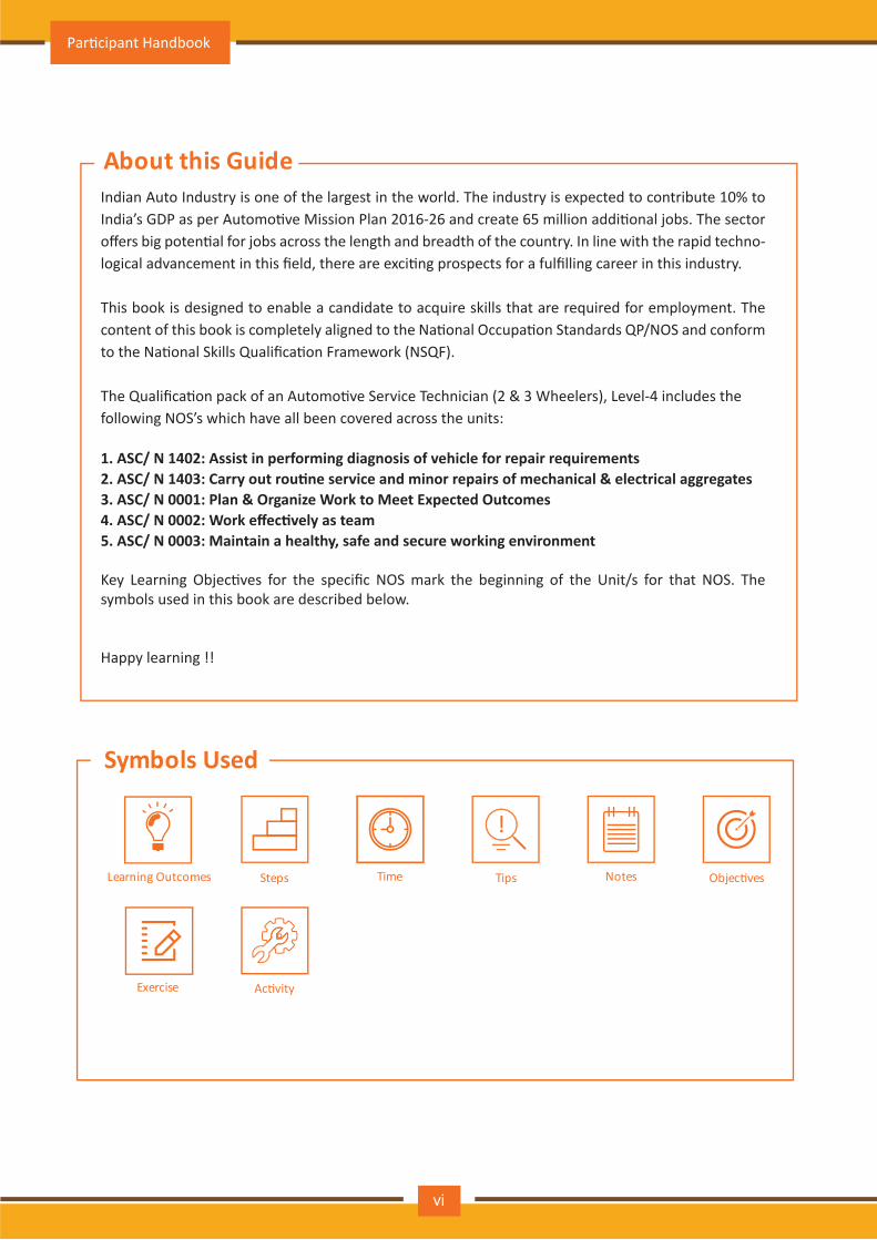
About this Guide
Symbols Used
Steps Time Objec�vesNotesTips
!
Learning Outcomes
Exercise
Indian Auto Industry is one of the largest in the world. The industry is expected to contribute 10% to India’s GDP as per Automo�ve Mission Plan 2016-26 and create 65 million addi�onal jobs. The sector offers big poten�al for jobs across the length and breadth of the country. In line with the rapid techno-logical advancement in this field, there are exci�ng prospects for a fulfilling career in this industry.
This book is designed to enable a candidate to acquire skills that are required for employment. The content of this book is completely aligned to the Na�onal Occupa�on Standards QP/NOS and conform to the Na�onal Skills Qualifica�on Framework (NSQF).
The Qualifica�on pack of an Automo�ve Service Technician (2 & 3 Wheelers), Level-4 includes thefollowing NOS’s which have all been covered across the units:
1. ASC/ N 1402: Assist in performing diagnosis of vehicle for repair requirements 2. ASC/ N 1403: Carry out rou�ne service and minor repairs of mechanical & electrical aggregates 3. ASC/ N 0001: Plan & Organize Work to Meet Expected Outcomes4. ASC/ N 0002: Work effec�vely as team5. ASC/ N 0003: Maintain a healthy, safe and secure working environment
Key Learning Objec�ves for the specific NOS mark the beginning of the Unit/s for that NOS. Thesymbols used in this book are described below.
Happy learning !!
Par�cipant Handbook
Ac�vity
Table of Contents
S.No Modules and Units Page No
2 Assist in performing diagnosis of vehicle for repair requirements (ASC/N1402) & Carry out rou�ne service and minor repairs of mechanical & electrical aggregates (ASC/N1403)
Unit 2.1 – Introduc�on: Role - Auto service technician
Unit 2.2 – Job descrip�on: Auto service technician
Unit 2.3 – Scope of work: Auto service technician
Unit 3.2 – Knowledge & Understanding: Working effec�vely as team
Unit 3.1 – Performance Criteria for Planning & Organizing Work
17
3
4
7
9
1
15
19
22
24Unit 2.4 – Performance criteria for auto service technician
Unit 2.5 – Technical knowledge 31
Unit 2.5.1 – Func�oning of the vehicle, aggregates & parts 32
Unit 2.5.2 – Major systems and sub systems in a typical automobile 41
Unit 2.5.3 – Tool and equipment 42
Unit 2.5.4 – Engine 55
Unit 2.5.5 – Clutch 82
Unit 2.5.6 – Transmission system 103
Unit 2.5.7 – Cooling system 137
Unit 2.5.8 – Suspension system 154
Unit 2.5.9 – Steering system 167
Unit 2.5.10 – Igni�on system 192
319Unit 2.6 – Skills: Automo�ve technician
231Unit 2.5.11 – Brake system
285Unit 2.5.12 – Tyre and wheels
299Unit 2.5.13 – Automobiles Air Condi�oning System
304Unit 2.5.14 – Maintenance
325
327
328
1 Introduc�onUnit 1.1 – Introduc�on to Automobiles
Unit 1.2 – Classifica�on of Automobiles
Unit 1.3 – Inven�on of Automobiles
Unit 1.4 – Job Role of Auto Service Technician
3 Plan & Organize Work to Meet Expected Outcomes (ASC/ N 0001)
Auto Service Technician Level 4
vii
4 Work Effec�vely as Team (ASC/ N 0002)
Unit 4.1 – Performance Criteria for Working Effec�vely as Team
Unit 4.2 – Knowledge & Understanding: Working Effec�vely as Team
5 Maintain a Healthy, Safe and Secure Work Environment (ASC/ N 0003)
Unit 5.1 – Performance Criteria for Healthy, Safe & Secure Work Environment
Unit 5.2 – Knowledge & Understanding: Healthy, Safe & Secure Work Environment
349
351
352
377
379
380
395
399418
424
435
444
466
6 Employability & Entrepreneurship Skills
Unit 6.1 – Personal Strengths & Value SystemsUnit 6.2 – Digital Literacy: A Recap
Unit 6.3 – Money Ma�ers
Unit 6.4 – Preparing for Employment & Self Employment
Unit 6.5 – Understanding Entrepreneurship
Unit 6.6 – Preparing to be an Entrepreneur
Par�cipant Handbook
viii
Table of Contents
S.No Modules and Units Page No

1. Introduc�onUnit 1.1 – Introduc�on to Automobiles
Unit 1.2 – Classifica�on of Automobiles
Unit 1.3 – Inven�on of Automobiles
Unit 1.4 – Job Role of Auto Service Technician

At the end of this module, you will be able to:
1. Acquire knowledge of automobile history
2. Describe different types of automobile
3. Classify automobile industry
4. Explain service process of automobile workshop
Key Learning Outcomes
Par�cipant Handbook
2
Unit 1.1: Introduc�on to Automobile
Unit Objec�vesAt the end of this unit, you will be able to:
1. Acquire required knowledge of automobile industry2. Describe type of automobile
1.1.1: Introduc�on to Automobile
We all are familiar with the word Automobile. We do also understand the meaning of automobile, it could be a car, two wheeler, bus etc.. having its own engine and move using wheels for goods transport or carry passengers.
The automobile word has been taken from ancient Greek word which combine auto means self and mobilis mean movable thus we can define automobile as a vehicle which can move itself. Car which is also an alter-na�ve name of automobile also seems to be taken from La�n word carrum which means wheeled vehicle or from French word cart. Most of these words seem to be taken from Gallic Chariot.
Most of the defini�on of automobile clarifies that designed is basically for the roads and should have sea�ng capacity star�ng varying from one to mul�ple people, may have minimum 2 wheels and is designed for transpor�ng people and goods.
1.1.2: We Know Automobile by Different Names Like
• AutoRiksha • Auto car
• Car
• Motor car
• Motor coach
• Horseless carriage
• Moped
• Scooter
• Truck
• Earth Moving Equipment
• Automobile • Auto buggy
• Motor
• Motor vehicle
• Motor wagon
• Quadri Cycle
• Motor Cycle
• Bus
• Tractor
• Tumtum
Auto Service Technician Level 4
3
Unit 1.2: Classifica�on of Automobiles
Unit Objec�vesAt the end of this unit, you will be able to:
Categorize various automobile product based on industry and other parameters
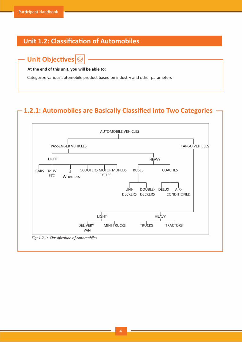
1.2.1: Automobiles are Basically Classified into Two Categories
AUTOMOBILE VEHICLES
PASSENGER VEHICLES
LIGHT HEAVY
CARGO VEHICLES
CARS SCOOTERS MOPEDSMOTOR CYCLES
MUVETC.
3 Wheelers
BUSES COACHES
UNI-DECKERS
DOUBLE-DECKERS
DELUX AIR-CONDITIONED
LIGHT
DELIVERY VAN
MINI TRUCKS
HEAVY
TRUCKS TRACTORS
Fig: 1.2.1: Classification of Automobiles
Par�cipant Handbook
4
1.2.2: Further the Automobiles can be Classified Based on Different ParametersPurpose of Transporta�on:
Capacity:
Fuel used:
1) Passenger vehicles — — Car, SUV, Bus2) Goods vehicles — Truck
1) Light motor vehicles — Car, Motorcycle, Scooter2) Heavy motor vehicles — Bus, Coach, Tractor
1) Petrol vehicles — Car, Jeep, Motorcycle, Scooter2) Diesel vehicles —Truck, Bus, Tractor, Bulldozer3) Electric Vehicles-Electric Two/Three Wheelers, Cars, Trucks and Buses4) Steam carriages — Steam road rollers
Number of wheels:
Drive of the vehicles:
1) Two-wheeler2) Three-wheeler3) Four-wheeler4) Six-wheeler
1) Vehicle having single-wheel drive
2) Vehicle having two-wheel drive
3) Vehicle having four-wheel drive
4) Vehicle having six-wheel drive
5) Vehicles having front wheel drive
6) Vehicles having rear wheel drive
Normally automobile are specified as:• Type: Car, truck, scooter, motorcycle, bus
• Capacity: 5 ton, 3 ton, 1 ton, 4-seater, 6- seater, 30-seater, 45-seater
Manufacturer or Make of the vehicle: Tata, Maru�, Suzuki, Ashok Leyland, Mahindra, Honda, Hyundai,
Toyota, Ford, Fiat, Chevrolet, Audi, Mercedes, Isuzu, Skoda, Volkswagen
Drive: LHD: Le� hand drive, RHD : Right and drive, Single wheel drive, Two wheel drive, Four wheel drive,
Six wheel drive•
•
Auto Service Technician Level 4
5
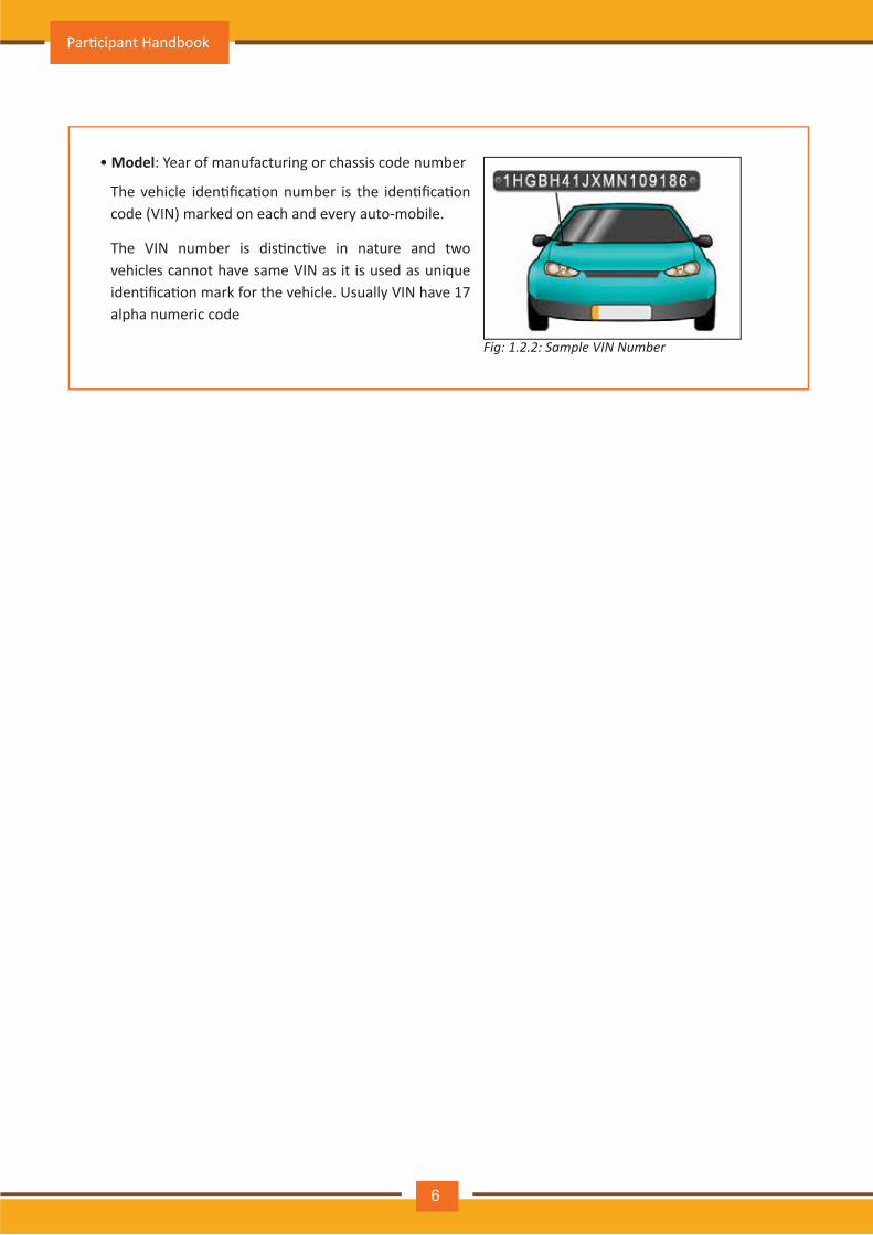
• Model: Year of manufacturing or chassis code number
Fig: 1.2.2: Sample VIN Number
The vehicle iden�fica�on number is the iden�fica�on code (VIN) marked on each and every auto-mobile.
The VIN number is dis�nc�ve in nature and two vehicles cannot have same VIN as it is used as unique iden�fica�on mark for the vehicle. Usually VIN have 17 alpha numeric code
Par�cipant Handbook
6
Unit 1.3: Inven�on of Automobiles
Unit objec�vesAt the end of this unit, you will be able to:
1. Explain the history of automobile2. Describe recent development in automobile industry
1.3.1: Inven�on of Automobiles
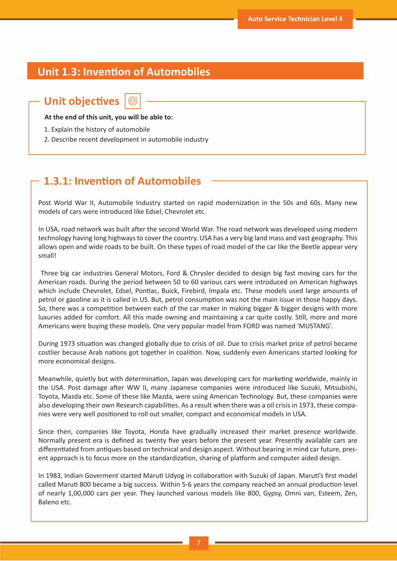
Post World War II, Automobile Industry started on rapid moderniza�on in the 50s and 60s. Many new models of cars were introduced like Edsel, Chevrolet etc.
In USA, road network was built a�er the second World War. The road network was developed using modern technology having long highways to cover the country. USA has a very big land mass and vast geography. This allows open and wide roads to be built. On these types of road model of the car like the Beetle appear very small!
Three big car industries General Motors, Ford & Chrysler decided to design big fast moving cars for the American roads. During the period between 50 to 60 various cars were introduced on American highways which include Chevrolet, Edsel, Pon�ac, Buick, Firebird, Impala etc. These models used large amounts of petrol or gasoline as it is called in US. But, petrol consump�on was not the main issue in those happy days. So, there was a compe��on between each of the car maker in making bigger & bigger designs with more luxuries added for comfort. All this made owning and maintaining a car quite costly. S�ll, more and more Americans were buying these models. One very popular model from FORD was named ‘MUSTANG’.
During 1973 situa�on was changed globally due to crisis of oil. Due to crisis market price of petrol became costlier because Arab na�ons got together in coali�on. Now, suddenly even Americans started looking for more economical designs.
Meanwhile, quietly but with determina�on, Japan was developing cars for marke�ng worldwide, mainly in the USA. Post damage a�er WW II, many Japanese companies were introduced like Suzuki, Mitsubishi, Toyota, Mazda etc. Some of these like Mazda, were using American Technology. But, these companies were also developing their own Research capabili�es. As a result when there was a oil crisis in 1973, these compa-nies were very well posi�oned to roll out smaller, compact and economical models in USA.
Since then, companies like Toyota, Honda have gradually increased their market presence worldwide. Normally present era is defined as twenty five years before the present year. Presently available cars are differen�ated from an�ques based on technical and design aspect. Without bearing in mind car future, pres-ent approach is to focus more on the standardiza�on, sharing of pla�orm and computer aided design.
In 1983, Indian Goverment started Maru� Udyog in collabora�on with Suzuki of Japan. Maru�’s first model called Maru� 800 became a big success. Within 5-6 years the company reached an annual produc�on level of nearly 1,00,000 cars per year. They launched various models like 800, Gypsy, Omni van, Esteem, Zen, Baleno etc.
Auto Service Technician Level 4
7
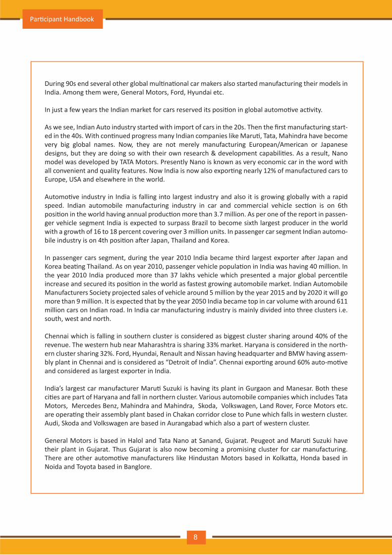
During 90s end several other global mul�na�onal car makers also started manufacturing their models in India. Among them were, General Motors, Ford, Hyundai etc.
In just a few years the Indian market for cars reserved its posi�on in global automo�ve ac�vity.
As we see, Indian Auto industry started with import of cars in the 20s. Then the first manufacturing start-ed in the 40s. With con�nued progress many Indian companies like Maru�, Tata, Mahindra have become very big global names. Now, they are not merely manufacturing European/American or Japanese designs, but they are doing so with their own research & development capabili�es. As a result, Nano model was developed by TATA Motors. Presently Nano is known as very economic car in the word with all convenient and quality features. Now India is now also expor�ng nearly 12% of manufactured cars to Europe, USA and elsewhere in the world.
Automo�ve industry in India is falling into largest industry and also it is growing globally with a rapid speed. Indian automobile manufacturing industry in car and commercial vehicle sec�on is on 6th posi�on in the world having annual produc�on more than 3.7 million. As per one of the report in passen-ger vehicle segment India is expected to surpass Brazil to become sixth largest producer in the world with a growth of 16 to 18 percent covering over 3 million units. In passenger car segment Indian automo-bile industry is on 4th posi�on a�er Japan, Thailand and Korea.
In passenger cars segment, during the year 2010 India became third largest exporter a�er Japan and Korea bea�ng Thailand. As on year 2010, passenger vehicle popula�on in India was having 40 million. In the year 2010 India produced more than 37 lakhs vehicle which presented a major global percen�le increase and secured its posi�on in the world as fastest growing automobile market. Indian Automobile Manufacturers Society projected sales of vehicle around 5 million by the year 2015 and by 2020 it will go more than 9 million. It is expected that by the year 2050 India became top in car volume with around 611 million cars on Indian road. In India car manufacturing industry is mainly divided into three clusters i.e. south, west and north.
Chennai which is falling in southern cluster is considered as biggest cluster sharing around 40% of the revenue. The western hub near Maharashtra is sharing 33% market. Haryana is considered in the north-ern cluster sharing 32%. Ford, Hyundai, Renault and Nissan having headquarter and BMW having assem-bly plant in Chennai and is considered as “Detroit of India”. Chennai expor�ng around 60% auto-mo�ve and considered as largest exporter in India.
India’s largest car manufacturer Maru� Suzuki is having its plant in Gurgaon and Manesar. Both these ci�es are part of Haryana and fall in northern cluster. Various automobile companies which includes Tata Motors, Mercedes Benz, Mahindra and Mahindra, Skoda, Volkswagen, Land Rover, Force Motors etc. are opera�ng their assembly plant based in Chakan corridor close to Pune which falls in western cluster. Audi, Skoda and Volkswagen are based in Aurangabad which also a part of western cluster.
General Motors is based in Halol and Tata Nano at Sanand, Gujarat. Peugeot and Maru� Suzuki have their plant in Gujarat. Thus Gujarat is also now becoming a promising cluster for car manufacturing. There are other automo�ve manufacturers like Hindustan Motors based in Kolka�a, Honda based in Noida and Toyota based in Banglore.
Par�cipant Handbook
8
Unit 1.4: Job Role of Auto Service Technician
Unit Objec�vesAt the end of this unit, you will be able to:
Explain service process of automobile industry
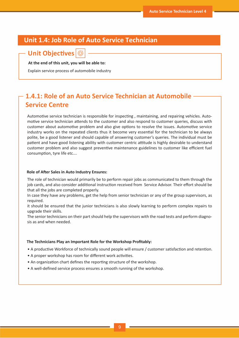
1.4.1: Role of an Auto Service Technician at Automobile Service Centre
The Technicians Play an Important Role for the Workshop Profitably:
Role of A�er Sales in Auto Industry Ensures:
• A produc�ve Workforce of technically sound people will ensure / customer sa�sfac�on and reten�on.• A proper workshop has room for different work ac�vi�es.• An organiza�on chart defines the repor�ng structure of the workshop.• A well-defined service process ensures a smooth running of the workshop.
Automo�ve service technician is responsible for inspec�ng , maintaining, and repairing vehicles. Auto-mo�ve service technician a�ends to the customer and also respond to customer queries, discuss with customer about automo�ve problem and also give op�ons to resolve the issues. Automo�ve service industry works on the repeated clients thus it become very essen�al for the technician to be always polite, be a good listener and should capable of answering customer’s queries. The individual must be pa�ent and have good listening ability with customer centric a�tude is highly desirable to understand customer problem and also suggest preven�ve maintenance guidelines to customer like efficient fuel consump�on, tyre life etc….
The role of technician would primarily be to perform repair jobs as communicated to them through the job cards, and also consider addi�onal instruc�on received from Service Advisor. Their effort should be that all the jobs are completed properly.In case they have any problems, get the help from senior technician or any of the group supervisors, as required.it should be ensured that the junior technicians is also slowly learning to perform complex repairs to upgrade their skills.The senior technicians on their part should help the supervisors with the road tests and perform diagno-sis as and when needed.
Auto Service Technician Level 4
9
1.4.2: Processes adopted at Automobile Service Centre
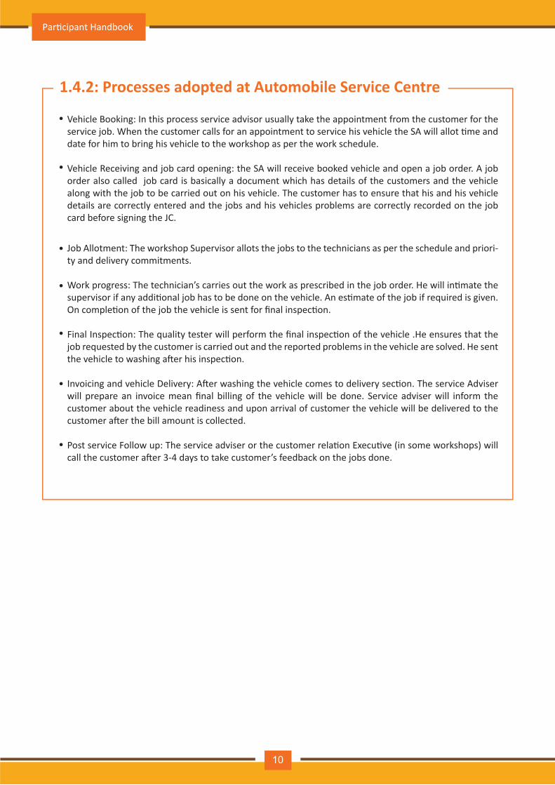
Vehicle Booking: In this process service advisor usually take the appointment from the customer for the service job. When the customer calls for an appointment to service his vehicle the SA will allot �me and date for him to bring his vehicle to the workshop as per the work schedule.
Vehicle Receiving and job card opening: the SA will receive booked vehicle and open a job order. A job order also called job card is basically a document which has details of the customers and the vehicle along with the job to be carried out on his vehicle. The customer has to ensure that his and his vehicle details are correctly entered and the jobs and his vehicles problems are correctly recorded on the job card before signing the JC.
Job Allotment: The workshop Supervisor allots the jobs to the technicians as per the schedule and priori-ty and delivery commitments.
Work progress: The technician’s carries out the work as prescribed in the job order. He will in�mate the supervisor if any addi�onal job has to be done on the vehicle. An es�mate of the job if required is given. On comple�on of the job the vehicle is sent for final inspec�on.
Final Inspec�on: The quality tester will perform the final inspec�on of the vehicle .He ensures that the job requested by the customer is carried out and the reported problems in the vehicle are solved. He sent the vehicle to washing a�er his inspec�on.
Invoicing and vehicle Delivery: A�er washing the vehicle comes to delivery sec�on. The service Adviser will prepare an invoice mean final billing of the vehicle will be done. Service adviser will inform the customer about the vehicle readiness and upon arrival of customer the vehicle will be delivered to the customer a�er the bill amount is collected.
Post service Follow up: The service adviser or the customer rela�on Execu�ve (in some workshops) will call the customer a�er 3-4 days to take customer’s feedback on the jobs done.
•
•
•
•
•
•
•
Par�cipant Handbook
10

Notes
Auto Service Technician Level 4
11
Exercise-1: Fill in the Blanks
1. In India Maru� udyog was started in ………………
A. 1975 B. 1985 C. 1983 D. 1982
A. 800 B. Esteem C. Omni Van D. Gypsy
2. The first model of maru� car in India was………………………
3. The automobile brand name which promoted Indian market from scooters to bikes with the
promise of fuel economy is ……………………………….
A. Escort B. Suzuki C. Bajaj D. Hero Honda
4. Automobile export of India is around …………………………….
A. 12% B. 15% C. 20% D. 18%
5. In the year ………………………………… India in passenger cars segment became Asia’s third largest
exporter of
A. 2014 B. 2010 C. 2013 D. 2012
6. …………………………….. contribute 60% of the country’s automo�ve exports
A. Chennai B. Pune C. Gurgaon D. Delhi
7. Unique number marked on each vehicle is called ………………………………….
A. Vehicle iden�fica�on number B. Vehicle serial number C. Vehicle log number
D. Automobile serial number
8. The automo�ve industry in India is one of the ...............................in the world
A. Smallest B. Largest C. Medium size D. None
9. Audi, Skoda and Volkswagen plants are in ………………………………….
A. Aurangabad B. Pune C. Chennai D. Gurgaon
10. One of the important role, a�er sales in auto industry is ……………………………………
A. Ensure strong bond between the organiza�on and the customer
B. Make customer happy
C. Earn revenues
D. Learn good prac�ces
12
Par�cipant Handbook
Exercise-2: Mark True or False
1. Auto service technician is responsible for the rou�ne servicing of vehicle
A. True B. False
2. Good communica�on and interpersonal skills is required for the auto service technician
A. True B. False
A. True B. False
A. True B. False
A. True B. False
3. Auto service technician should have a be�er understanding of social aspect for repairing the vehicle
4. A�er collec�ng the vehicle customer’s personal belongings in the vehicle should be handover
to service agency office
5. Job card can be filled in absence of customer
Exercise-3: Fill in the Blanks
1. During vehicle booking appointment is taken by the …………………………. from the customer for
the service job.
A. Service advisor B. Workshop supervisor C. Technician
2. Vehicle receiving and job card opening process is done by …………………………….
A. Service advisor B. Workshop supervisor C. Technician
A. Service advisor B. Workshop supervisor C. Technician
3. Job allotment in the workshop is done by………………………………….
A. Service advisor B. Workshop supervisor C. Technician
4. During repairing process if addi�onal job has to be done on the vehicle, should be in�mated
to ………………………………………
Auto Service Technician Level 4
13
5. Final inspec�on of the vehicle before delivery is done by ………………………….
A. Service advisor B. Workshop supervisor C. Quality tester
6. Service technician should carry out repair jobs as per ………………………………………A. Job card B. Customer input C. Advice from quality tester
7. The job card has details of………………………………………………
A. customer B. vehicle C. Instruc�on of service advisor
8. Junior technician gradually learn to do complex repairs from ………………………………………
A. Service advisor B. Workshop supervisor C. Senior technician
9. ……………………………….. should help the supervisors with the road tests and diagnosis when needed.
A. Service advisor B. Junior technician C. Senior technician
10. Invoicing and vehicle delivery is responsibility of
A. Service advisor B. Workshop supervisor C. Senior technician
Exercise-4: Answer the Following Ques�ons
1. What is the Role and responsibili�es of a Technician?
2. What are the stages of service process?
Par�cipant Handbook
14
2. Assist in performing diagnosis of vehicle for repair requirements & Carry out rou�ne service and minor repairs of mechanical and electrical aggregates
Unit 2.1 – Introduc�on: Role - Auto service technician
Unit 2.2 – Job descrip�on: Auto service technician
Unit 2.3 – Scope of work: Auto service technician
Unit 2.4 – Performance criteria for auto service technician
Unit 2.5 – Technical knowledge
Unit 2.6 – Skills: Automo�ve technician
(ASC/N1402) / (ASC/N1403)
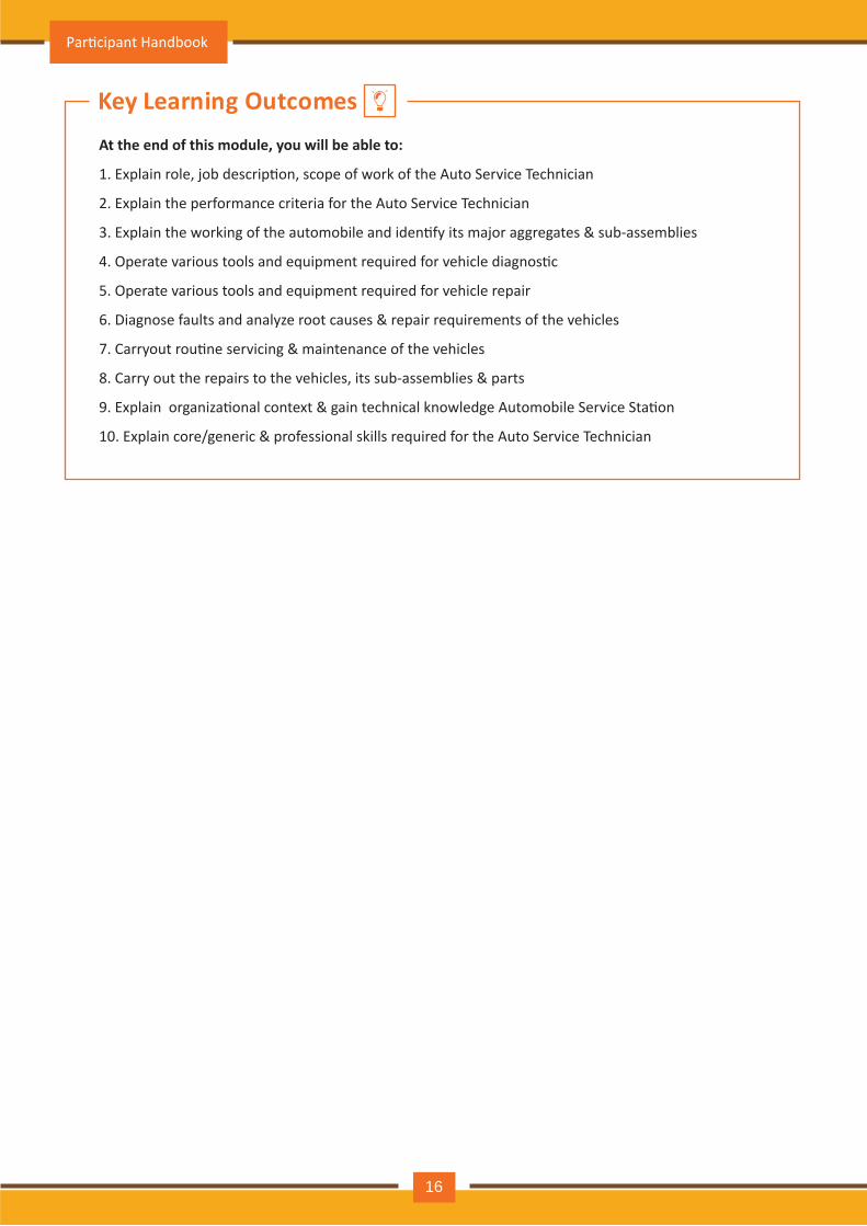
At the end of this module, you will be able to:
1. Explain role, job descrip�on, scope of work of the Auto Service Technician
2. Explain the performance criteria for the Auto Service Technician
3. Explain the working of the automobile and iden�fy its major aggregates & sub-assemblies
4. Operate various tools and equipment required for vehicle diagnos�c
5. Operate various tools and equipment required for vehicle repair
6. Diagnose faults and analyze root causes & repair requirements of the vehicles
7. Carryout rou�ne servicing & maintenance of the vehicles
8. Carry out the repairs to the vehicles, its sub-assemblies & parts
9. Explain organiza�onal context & gain technical knowledge Automobile Service Sta�on
10. Explain core/generic & professional skills required for the Auto Service Technician
Key Learning Outcomes
Par�cipant Handbook
16
UNIT 2.1: Introduc�on: Role - Auto service technician
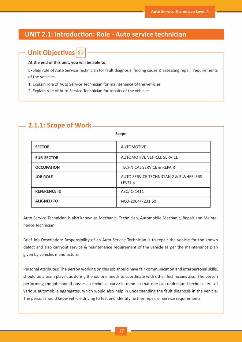
Scope
SECTOR AUTOMOTIVE
AUTOMOTIVE VEHICLE SERVICE
TECHNICAL SERVICE & REPAIR
AUTO SERVICE TECHNICIAN 2 & 3 WHEELERS LEVEL 4
ASC/ Q 1411
NCO-2004/7231.50
SUB-SECTOR
OCCUPATION
JOB ROLE
REFERENCE ID
ALIGNED TO
Auto Service Technician is also known as Mechanic, Technician, Automobile Mechanic, Repair and Mainte-
nance Technician
Brief Job Descrip�on: Responsibility of an Auto Service Technician is to repair the vehicle for the known
defect and also carryout service & maintenance requirement of the vehicle as per the maintenance plan
given by vehicles manufacturer.
Personal A�ributes: The person working on this job should have fair communica�on and interpersonal skills,
should be a team player, as during the job one needs to coordinate with other Technicians also. The person
performing the job should possess a technical curve in mind so that one can understand technicality of
various automobile aggregates, which would also help in understanding the fault diagnosis in the vehicle.
The person should know vehicle driving to test and iden�fy further repair or service requirements.
Unit Objec�ves
2.1.1: Scope of Work
At the end of this unit, you will be able to:
1. Explain role of Auto Service Technician for maintenance of the vehicles2. Explain role of Auto Service Technician for repairs of the vehicles
Explain role of Auto Service Technician for fault diagnosis, finding cause & assessing repair requirements of the vehicles
Auto Service Technician Level 4
17
Summary :
Auto Service Technician Level is responsible for repairing the faults and performing servicing & mainte-nance requirement as prescribed schedule (this includes electrical and mechanical aggregates) of vehicles. The person working on this job should have a good communica�on and interpersonal skills, should be a team player, as during the job one needs to coordinate with other Technicians also. He must understand the technical aspects related to various aggregates (including both mechanical and electrical) in a vehicle, which would also help in understanding the fault diagnosis in the vehicle. He must know driving to test the vehicle and iden�fy any further repair or service requirements.
Key Terms :
ServicingMaintenanceRepairsAggregatesVehicleElectricalMechanical
Check Your Understanding:Fill in the blanks :
a. Responsibility of an Auto Service Technician includes Servicing, ------------------- & repairs of vehicles.Answer: Maintenance
b. This manual deals with Auto Service Technician at Level -----------------.Answer: 4
Par�cipant Handbook
18

UNIT 2.2: Job descrip�on - Auto service technician
Unit objec�vesAt the end of this unit, you will be able to:
1. Understand the job descrip�on of Auto Service Technician for trouble shoo�ng
Role Descrip�on: Perform small repair work and able to do rou�ne service and maintenance
2.2.1: Eligibility criteria
Minimum Educa�onal Qualifica�ons: Class X Maximum Educa�onal Qualifica�ons: ITI or Diploma in Mechanical / Electrical / Automobile EngineeingTraining: (Suggested but not mandatory): On the job training:
• Desirable for ASDC Auto Service Technician Level 4 Cer�ficate or Diploma in Automo�ve Repair • Compulsory for all other qualifica�ons
Experience:
• 1-2 years if ASDC Auto Service Technician Level 4 Cer�ficate or Diploma in Automo�ve Repair • 3-5 years for other qualifica�ons
Occupa�onal Standards (OS):Compulsory:
1. ASC/ N 1402: Assist in performing diagnosis of vehicle for repair requirements
2. ASC/N 1403: Carry out rou�ne service and minor repairs of mechanical & electrical aggregates
3. ASC/N0001: Plan and organize work to meet expected outcomes
4. ASC/ N 0002: Work effec�vely in a team
5. ASC/ N 0003: Maintain a healthy, safe and secure working environment
Occupa�onal standard confirming NSQF Level - 4
Auto Service Technician Level 4
19
2.2.2: Assist in performing diagnosis of vehicle for repair requirements
Your Role: : Assist in troubleshoo�ng problems and fault diagnosis of the vehicle (this includes both mechan-
ical and electrical aggregates)
The work involves:
• Assis�ng the superior technician to iden�fy & diagnose fault and should be responsible in iden�fying
problem root cause.
• Assis�ng in taking necessary ac�on post the root cause analysis to repair the vehicle
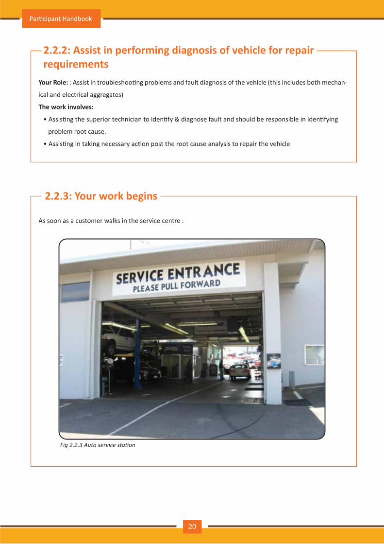
2.2.3: Your work begins
As soon as a customer walks in the service centre :
Fig 2.2.3 Auto service station
Par�cipant Handbook
20
Summary :
Key Terms :
Check Your Understanding :
1. Say True or False :
Auto Service Technician Level 4 Level job descrip�on is to carry out rou�ne Servicing, Maintenance & repairs of the vehicles including mechanical & electrical aggregates. His skill lies the trouble shoo�ng, finding out the faults, their root causes, Plan & implement the remedial ac�ons to eliminate the root causes. He should be a master test driver to iden�fy the exact causes of what is troubling the vehicle and also a master in effec�ng the remedial measures.
1. Trouble shoo�ng2. Faults3. Diagnosis4. Root Causes5. Correc�ve ac�ons6. Preven�ve ac�ons7. Test Drive
a. The problem will recur, if the root cause is not iden�fied. ( True / False ) Answer : Trueb. The problem will recur, if the proper correc�ve ac�ons are not implemented. ( True / False ) Answer : True
Auto Service Technician Level 4
21
Unit objec�vesAt the end of this unit, you will be able to:
UNIT 2.3: Scope of work - Auto service technician
1. Explain the Scope of work for auto service technician
Par�cipant Handbook
22
Summary :
Key Terms :
Check Your Understanding :
1. Say True or False :
Auto Service Technician at Level 4 is senior technical person entrusted with responsibility of assis�ng in vehicle fault diagnosis for repair requirement along with carrying out rou�ne Servicing, Maintenance of the vehicles including mechanical & electrical aggregates. He not only has to assist in iden�fying vehicle problems, but also assist in root cause analysis, plan for correc�ve & preven�ve ac�ons. He should have good interpersonal skills, as his job involves mul� tasking& dealing with various teams at the service sta�on, as well as varied types of the customers, with whom he interacts.
1. Mul� tasking2. Analysis3. Customer4. Target5. Cost6. Quality7. Team
a. A�ack symptoms rather than root causes for effec�ve problem resolu�on. ( True / False ) Answer : Falseb. Any small problem the vehicle should be scrapped immediately. ( True / False ) Answer :True
Auto Service Technician Level 4
23
Unit objec�vesAt the end of this unit, you will be able to:
UNIT 2.4: Performance criteria for auto service technician
1. Explain the performance criteria for auto service technician for:
Assist in fault diagnosis, root cause finding & repair requirements assessment
• Servicing of the vehicles
• Maintenance of the vehicles
• Repairs of the vehicles & its mechanical & electrical aggregates, sub-assemblies & parts
Par�cipant Handbook
24
Summary :
Key Terms :
Check Your Understanding :
1. Fill in the blanks :
The main performance criteria for Auto Service Technician at Level 4 can besummarised as below :
1. EOBD : Engine On Board Diagnos�c System2. RCA : Root Cause Analysis 3. 5 Why Analysis, Ask why 5 �mes minimum4. 6 Why :What, Where, Why, Who, When, Whom5. 2 H : How, How much6. Customer delight is essen�al for business success
a. 6 W stands for ----, ----, ----, ----, ----, ---- Answer :What, Who, When, Where, Whom, Whyb. 2 H stands for ----, ---- Answer :How, How muchc. 4 M stands for ----, ----, ----, ---- Answer : Man, Method, Material, Machine
• Assist in fault diagnosis,• Assist in root cause finding• Assist in assessing repair requirements• Repairs of the vehicles & its mechanical & electrical aggregates, sub-assemblies & parts• Servicing of the vehicles• Maintenance of the vehicles
Auto Service Technician Level 4
25
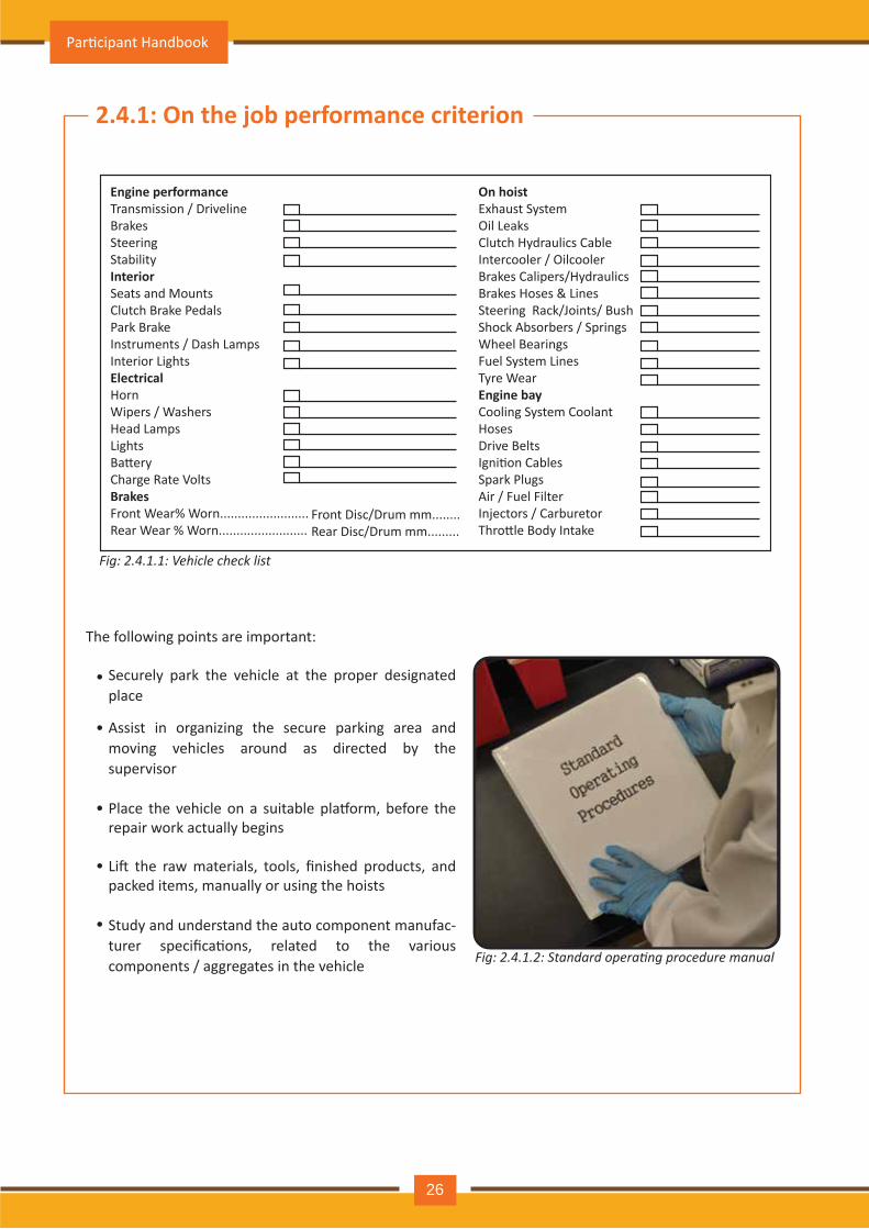
Fig: 2.4.1.2: Standard operating procedure manual
Fig: 2.4.1.1: Vehicle check list
2.4.1: On the job performance criterion
The following points are important:
Securely park the vehicle at the proper designated place
Assist in organizing the secure parking area and moving vehicles around as directed by the supervisor
Place the vehicle on a suitable pla�orm, before the repair work actually begins
Li� the raw materials, tools, finished products, and packed items, manually or using the hoists
Study and understand the auto component manufac-turer specifica�ons, related to the various components / aggregates in the vehicle
•
•
•
•
•
Engine performanceTransmission / DrivelineBrakesSteeringStabilityInteriorSeats and MountsClutch Brake PedalsPark BrakeInstruments / Dash LampsInterior LightsElectricalHornWipers / WashersHead LampsLightsBa�eryCharge Rate Volts BrakesFront Wear% Worn.........................Rear Wear % Worn.........................
Front Disc/Drum mm........Rear Disc/Drum mm.........
On hoistExhaust SystemOil LeaksClutch Hydraulics CableIntercooler / OilcoolerBrakes Calipers/HydraulicsBrakes Hoses & LinesSteering Rack/Joints/ BushShock Absorbers / Springs Wheel Bearings Fuel System Lines Tyre WearEngine bayCooling System CoolantHosesDrive Belts Igni�on CablesSpark PlugsAir / Fuel Filter Injectors / Carburetor Thro�le Body Intake
Par�cipant Handbook
26
Be careful and ensure that service, maintenance and repair ac�vi�es are carried out on the vehicle without causing damage to any other aggregate /component
Assist in performing service or repair of vehicles under supervision of senior technician such as:
Dismantle aggregates like wheels, suspension system, steering column, braking system, engine assem-
bly etc
Check if all the issues raised by the customer and noted on the job card are a�ended
If any issues are not a�ended, bring it to the no�ce of the supervisor and act to resolve the customer
issues properly
Count and report the service do repaired vehicles to determine if product or ders are complete
Assist in maintaining and managing the workshop, tools, equipment and machinery in required condi-
�on by:
• carrying out minor component repair or replacement
• carrying out oil changes and lubrication
• washing vehicles as per prescribed standard process
• fetching correct materials or tools orgauges
• mixing cleaning solutions, abrasive compositions, or other compounds
•
•
•
•
•
•
•
Follow standard opera�ng procedures specially vehicle service manuals for using workshop tools and equipment
Ensure any malfunc�ons or repair requirements observed in vehicles (and beyond own scope of work) are reported to the concerned person
Ensure any malfunc�ons observed in tools and equipment are reported to the concerned persons andassist in fi�ng and balancing the replaced and refi�ed parts
A�end any trainings organized by the OEMs from �me-to-�me and upgrade yourself with the knowledge including the newly launched products and the modifica�ons introduced by the OEMs
Understand the auto component manufacturer specifica�ons related to the various components / aggregates in the vehicle
•
•
•
•
•
• Cleaning and lubrica�ng equipment
• Rinsing objects, tools and equipment and placing them on drying racks
• Using cloth, squeegees or air compressors to dry surfaces
• Cleaning and organizing the workshop
• Placing tools on the shelf a�er use
• Keeping workshop clean of debris
Auto Service Technician Level 4
27
Understand the func�oning of each system, component and aggregate (including both mechanical
and electrical aggregates) of a vehicle
Follow standard opera�ng procedures for using workshop tools and equipment for fault diagnosis or
troubleshoot problem in a vehicle
Conduct test drives to assist the Senior Technician in finding the fault basis the performance of the
vehicle during the test drive
Diagnose the faults, their root causes & assess the repair requirements of the vehicle
Review the job card and understand customer complaints
Follow standard opera�ng procedure set out for diagnosing faults under the supervision of a Senior
Technician
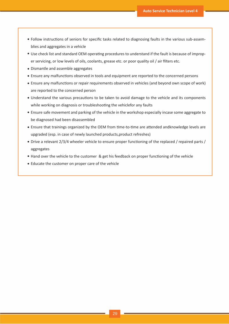
Follow instruc�ons of seniors for specific tasks related to diagnosing faults in the various sub-assem-
blies and aggregates in a vehicle
Use check list and standard OEM opera�ng procedures to understand if the fault is because of improp-
er servicing, or low levels of oils, coolants, grease etc. or poor quality oil / air filters etc.
Dismantle and assemble aggregates
Ensure any malfunc�ons observed in tools and equipment are reported to the concerned persons
Ensure any malfunc�ons or repair requirements observed in vehicles (and beyond own scope of work)
are reported to the concerned person
Understand the various precau�ons to be taken to avoid damage to the vehicle and its components
while working on diagnosis or troubleshoo�ng the vehicle for any faults
Ensure safe movement and parking of the vehicle in the workshop especially in case some aggregate to
be diagnosed had been disassembled
Ensure that trainings organized by the OEM from �me-to-�me are a�ended and knowledge levels are
upgraded (esp. in case of newly launched products, product refreshes)
Drive a relevant 2/3/4 wheeler vehicle which is an important part of the diagnosis of the type of vehicle
that is dealt by the relevant OEM
Understand the auto component manufacturer specifica�ons related to the various components /
aggregates in the vehicle
Understand the func�oning of each system, component and aggregate (including both mechanical and
electrical aggregates) of a vehicle
Follow standard opera�ng procedures for using workshop tools and equipment for fault diagnosis or
troubleshoot problem in a vehicle
Conduct test drives to assist the Senior Technician in finding the fault basis the performance of the
vehicle during the test drive
Review the job card and understand customer complaints
Follow standard opera�ng procedure set out for diagnosing faults under the supervision of a Senior
Technician
•
•
•
•
•
•
•
•
•
•
•
•
•
•
•
•
•
•
•
•
•
Par�cipant Handbook
28
Follow instruc�ons of seniors for specific tasks related to diagnosing faults in the various sub-assem-
blies and aggregates in a vehicle
Use check list and standard OEM opera�ng procedures to understand if the fault is because of improp-
er servicing, or low levels of oils, coolants, grease etc. or poor quality oil / air filters etc.
Dismantle and assemble aggregates
Ensure any malfunc�ons observed in tools and equipment are reported to the concerned persons
Ensure any malfunc�ons or repair requirements observed in vehicles (and beyond own scope of work)
are reported to the concerned person
Understand the various precau�ons to be taken to avoid damage to the vehicle and its components
while working on diagnosis or troubleshoo�ng the vehiclefor any faults
Ensure safe movement and parking of the vehicle in the workshop especially incase some aggregate to
be diagnosed had been disassembled
Ensure that trainings organized by the OEM from �me-to-�me are a�ended andknowledge levels are
upgraded (esp. in case of newly launched products,product refreshes)
Drive a relevant 2/3/4 wheeler vehicle to ensure proper func�oning of the replaced / repaired parts /
aggregates
Hand over the vehicle to the customer & get his feedback on proper func�oning of the vehicle
Educate the customer on proper care of the vehicle
•
•
•
•
•
•
•
•
•
•
•
Auto Service Technician Level 4
29
2.4.2: Organiza�onal context
Knowledge of the company / Organiza�on and it’s processes:
Study and understand the following:
SOP: Standard Opera�ng Procedures of the organiza�on / dealership for inspec�on, servicing and
repair of vehicles
SOP: Standard Opera�ng Procedures recommended by the dealership / suppliers / OEM for using
tools and equipment, manufacturer instruc�ons
Safety requirements for equipment and components / aggregates as prescribed by the OEM (e.g.
preven�ng / dealing with oil spillage and inflammable materials)
Documenta�on requirements for each procedure carried out, as part of roles and responsibili�es as
specified by OEM / autocomponent manufacturer
organiza�onal and professional code of ethics and standards of prac�ce
Safety, health and environmental policies and regula�ons for the workplace, as well as for
automo�ve trade in general (e.g. safe prac�ces while working in pits / under vehicles)
Workplace policies and schedules for housekeeping ac�vi�es and equipment maintenance
Standard opera�ng procedures of the Organisa�on / Dealership for inspec�on and diagnosis of faults in a vehicle as prescribed by the OEM / Components Manufacturer
Standard opera�ng procedures recommended by the Dealership / Suppliers / OEM for using tools and equipment for diagnosis or troubleshoo�ng of various aggregates
Standard opera�ng procedures for rec�fica�on of errors in informa�on (e.g. rec�fica�on of job card, reissue of correct tools and equipment etc. during the diagnosis)
Safety requirements for equipment and components during the diagnosis or troubleshoo�ng the various aggregates for root cause analysis of the fault
Documenta�on requirements for each procedure carried out as part of roles and responsibili�es as specified by OEM / auto component manufacturer for the diagnosis of troubleshoo�ng the vehicle for faults
•
•
•
•
•
•
•
•
•
•
•
•
Par�cipant Handbook
30
Unit objec�vesAt the end of this unit, you will be able to:
UNIT 2.5: Technical knowledge
1. Gain knowledge of the organiza�onal context of the Auto Service Sta�on
2. Adopt company / organiza�ons servicing processes
3. Explain the func�oning of the automobiles, sub-assemblies & parts
4. Operate various tools and equipment required for vehicle diagnos�c
5. Operate various tools and equipment required for vehicle repair
6. Diagnose faults and analyze root causes & repair requirements of the vehicles
7. Carryout rou�ne servicing & maintenance of the vehicles
8. Carryout the repairs to the vehicles, its sub-assemblies & parts
Role Descrip�on: Carry out minor repairs and rou�ne service and maintenance of vehicles
Auto Service Technician Level 4
31
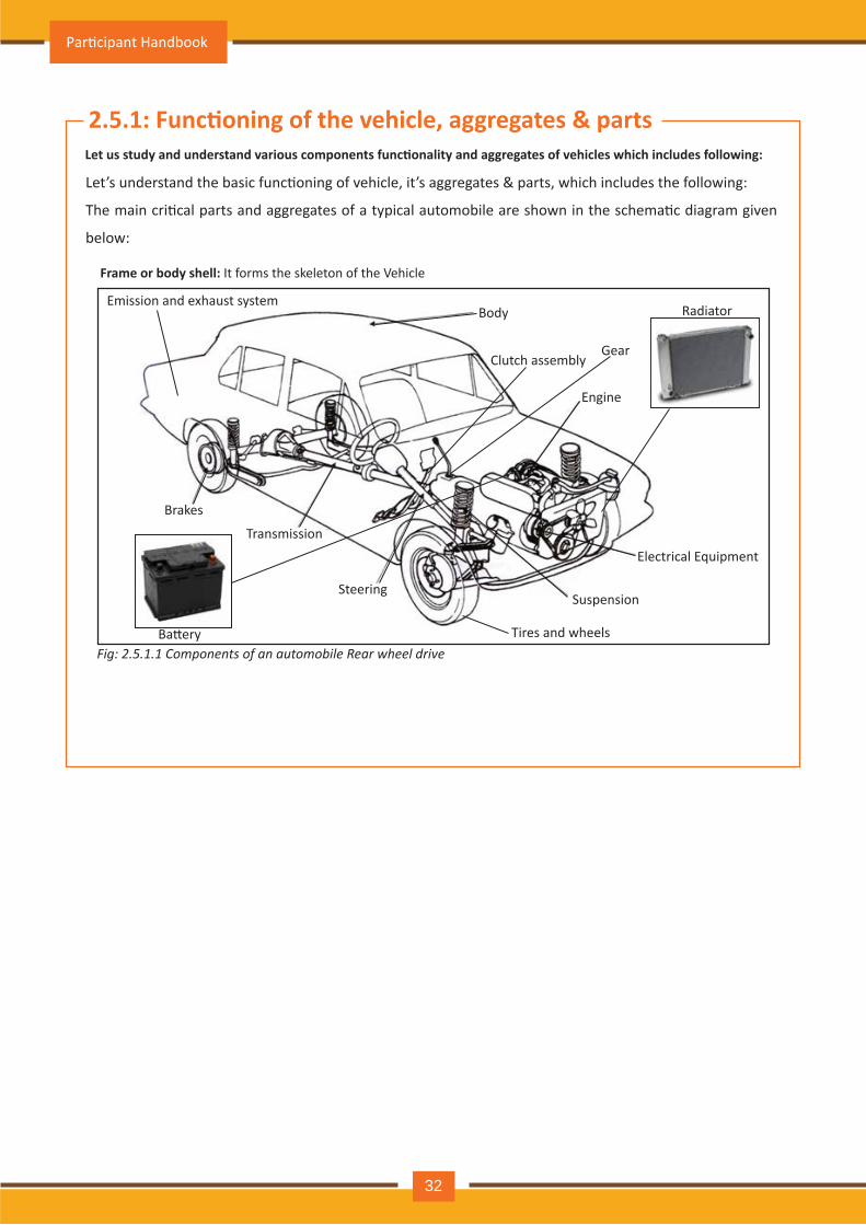
2.5.1: Func�oning of the vehicle, aggregates & parts
Let’s understand the basic func�oning of vehicle, it’s aggregates & parts, which includes the following:
The main cri�cal parts and aggregates of a typical automobile are shown in the schema�c diagram given
below:
Let us study and understand various components func�onality and aggregates of vehicles which includes following:
Frame or body shell: It forms the skeleton of the Vehicle
Body
Gear
Emission and exhaust system
Engine
Clutch assembly
Electrical Equipment
Suspension
Tires and wheels
Steering
Transmission
Brakes
Ba�ery
Radiator
Fig: 2.5.1.1 Components of an automobile Rear wheel drive
Par�cipant Handbook
32
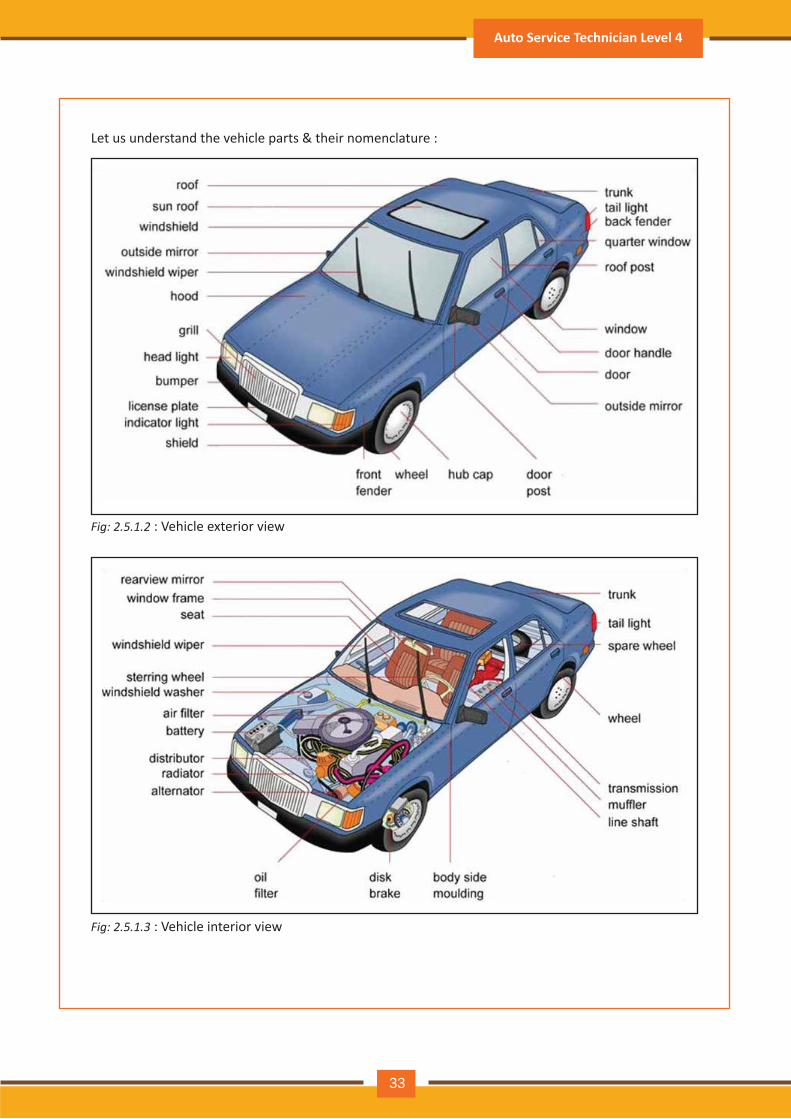
Let us understand the vehicle parts & their nomenclature :
Fig: 2.5.1.2 : Vehicle exterior view
Fig: 2.5.1.3 : Vehicle interior view
Auto Service Technician Level 4
33
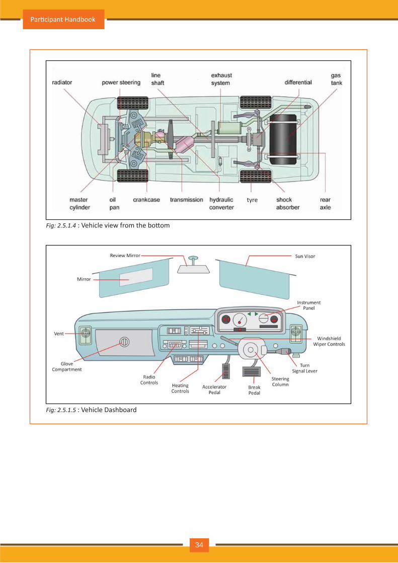
Fig: 2.5.1.5 : Vehicle Dashboard
Fig: 2.5.1.4 : Vehicle view from the bo�om
Par�cipant Handbook
34
tyre
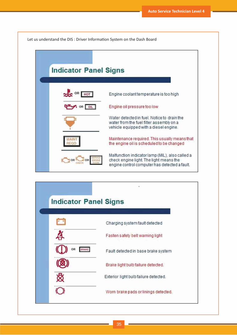
Let us understand the DIS : Driver Informa�on System on the Dash Board
Auto Service Technician Level 4
35
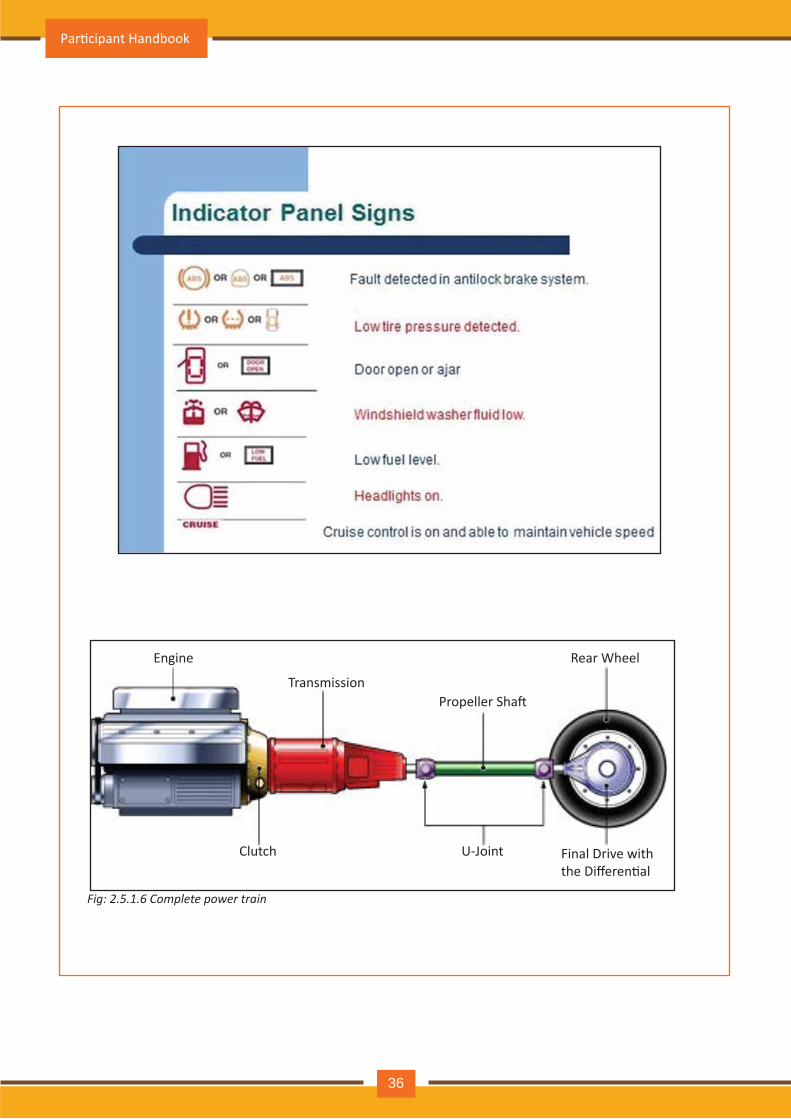
Fig: 2.5.1.6 Complete power train
Engine
TransmissionPropeller Sha�
Rear Wheel
Final Drive with the Differen�al
U-JointClutch
Par�cipant Handbook
36
Basic Service Opera�ons:
Basic Opera�ons in the Service Workshop:
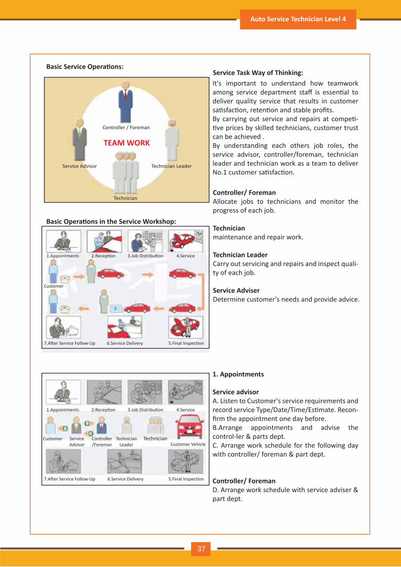
Service Task Way of Thinking:It's important to understand how teamwork among service department staff is essen�al to deliver quality service that results in customer sa�sfac�on, reten�on and stable profits.By carrying out service and repairs at compe�-�ve prices by skilled technicians, customer trust can be achieved .By understanding each others job roles, the service advisor, controller/foreman, technician leader and technician work as a team to deliver No.1 customer sa�sfac�on.
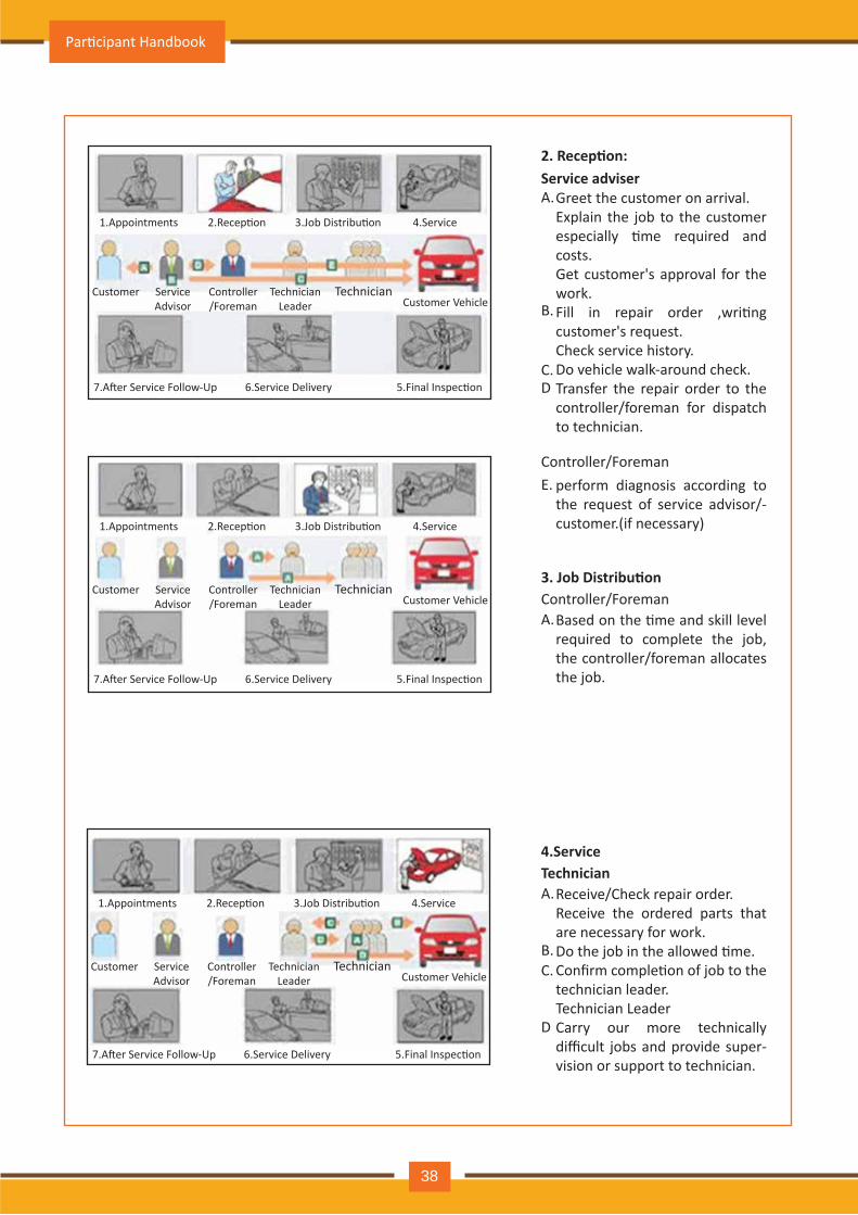
1. Appointments
Service advisor A. Listen to Customer's service requirements and record service Type/Date/Time/Es�mate. Recon-firm the appointment one day before.B.Arrange appointments and advise the control-ler & parts dept.C. Arrange work schedule for the following day with controller/ foreman & part dept.
Controller/ ForemanD. Arrange work schedule with service adviser & part dept.
Controller/ Foreman Allocate jobs to technicians and monitor the progress of each job.
Technicianmaintenance and repair work.
Technician Leader Carry out servicing and repairs and inspect quali-ty of each job.
Service Adviser Determine customer's needs and provide advice.
Auto Service Technician Level 4
37
Service Advisor Technician Leader
TEAM WORK
Controller / Foreman
Technician
1.Appointments
Customer
2.Recep�on 3.Job Distribu�on 4.Service
5.Final Inspec�on6.Service Delivery7.A�er Service Follow-Up
1.Appointments
Customer ServiceAdvisor
Controller/Foreman
TechnicianLeader
TechnicianCustomer Vehicle
2.Recep�on 3.Job Distribu�on 4.Service
5.Final Inspec�on6.Service Delivery7.A�er Service Follow-Up
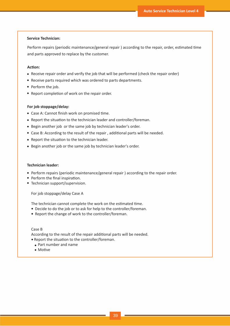
2. Recep�on:
3. Job Distribu�on
Service adviser
Controller/Foreman
Greet the customer on arrival.Explain the job to the customer especially �me required and costs.Get customer's approval for the work.Fill in repair order ,wri�ng customer's request.Check service history.Do vehicle walk-around check. Transfer the repair order to the controller/foreman for dispatch to technician.
A.
Controller/ForemanBased on the �me and skill level required to complete the job, the controller/foreman allocates the job.
A.
4.Service Technician
Receive/Check repair order.Receive the ordered parts that are necessary for work.Do the job in the allowed �me.Confirm comple�on of job to the technician leader.Technician Leader Carry our more technically difficult jobs and provide super-vision or support to technician.
A.
B.C.
D
perform diagnosis according to the request of service advisor/-customer.(if necessary)
E.
B.
C.D
Par�cipant Handbook
38
1.Appointments
Customer ServiceAdvisor
Controller/Foreman
TechnicianLeader
TechnicianCustomer Vehicle
2.Recep�on 3.Job Distribu�on 4.Service
5.Final Inspec�on6.Service Delivery7.A�er Service Follow-Up
1.Appointments
Customer ServiceAdvisor
Controller/Foreman
TechnicianLeader
TechnicianCustomer Vehicle
2.Recep�on 3.Job Distribu�on 4.Service
5.Final Inspec�on6.Service Delivery7.A�er Service Follow-Up
1.Appointments
Customer ServiceAdvisor
Controller/Foreman
TechnicianLeader
TechnicianCustomer Vehicle
2.Recep�on 3.Job Distribu�on 4.Service
5.Final Inspec�on6.Service Delivery7.A�er Service Follow-Up
Perform repairs (periodic maintenance/general repair ) according to the repair order.Perform the final inspira�on.Technician support/supervision.
For job stoppage/delay Case A
The technician cannot complete the work on the es�mated �me. Decide to do the job or to ask for help to the controller/foreman. Report the change of work to the controller/foreman.
Case BAccording to the result of the repair addi�onal parts will be needed. Report the situa�on to the controller/foreman. Part number and name Mo�ve
Service Technician:
Technician leader:
Perform repairs (periodic maintenance/general repair ) according to the repair, order, es�mated �me and parts approved to replace by the customer.
Ac�on: Receive repair order and verify the job that will be performed (check the repair order) Receive parts required which was ordered to parts departments. Perform the job. Report comple�on of work on the repair order.
For job stoppage/delay: Case A: Cannot finish work on promised �me. Report the situa�on to the technician leader and controller/foreman. Begin another job or the same job by technician leader's order. Case B: According to the result of the repair , addi�onal parts will be needed. Report the situa�on to the technician leader. Begin another job or the same job by technician leader's order.
••••
•
•••
••
•••
••
•••
Auto Service Technician Level 4
39
Basic Opera�ons in the Service Workshop:
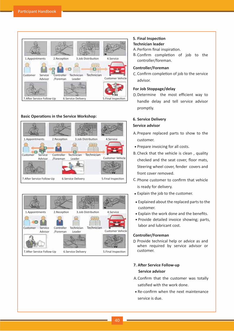
5. Final Inspec�on
6. Service DeliveryService advisor
Technician leaderPerform final inspira�on.Confirm comple�on of job to the controller/foreman.
A.B.
Controller/ForemanConfirm comple�on of job to the service advisor.
C.
Controller/ForemanProvide technical help or advice as and when required by service advisor or customer.
D
For Job Stoppage/delayDetermine the most efficient way to handle delay and tell service advisor promptly.
Prepare replaced parts to show to the customer.Prepare invoicing for all costs.Check that the vehicle is clean , quality checked and the seat cover, floor mats, Steering wheel cover, fender covers and front cover removed.Phone customer to confirm that vehicle is ready for delivery.Explain the job to the customer.
Explained about the replaced parts to the customer.Explain the work done and the benefits.Provide detailed invoice showing; parts, labor and lubricant cost.
D.
A.
•
•
•
••
B.
7. A�er Service Follow-up Service advisor
Confirm that the customer was totally sa�sfied with the work done.Re-confirm when the next maintenance service is due.
A.
•
C.
Par�cipant Handbook
40
1.Appointments
Customer ServiceAdvisor
Controller/Foreman
TechnicianLeader
TechnicianCustomer Vehicle
2.Recep�on 3.Job Distribu�on 4.Service
5.Final Inspec�on6.Service Delivery7.A�er Service Follow-Up
1.Appointments
Customer ServiceAdvisor
Controller/Foreman
TechnicianLeader
TechnicianCustomer Vehicle
2.Recep�on 3.Job Distribu�on 4.Service
5.Final Inspec�on6.Service Delivery7.A�er Service Follow-Up
1.Appointments
Customer ServiceAdvisor
Controller/Foreman
TechnicianLeader
TechnicianCustomer Vehicle
2.Recep�on 3.Job Distribu�on 4.Service
5.Final Inspec�on6.Service Delivery7.A�er Service Follow-Up
Major systems and sub systems in a typical automobile
Engine and its support systems:
2.5.2:
• Air supply system
• Fuel System
• Igni�on systems
• Cooling system
• Lubrica�on system
• Emission and exhaust system
• Clutch assembly
• Clutch opera�ng system
• Gearbox (manual and automa�c)
• Steering system including Electronic Power Steering
• Suspension system
• Brake system (including regenera�ve braking systems, ABS : An�lock Braking System, EBD : Electronic Brake-force Distribu�on)
• Tires and wheels (including wheel alignment)
• Ba�eries and storage system for power
• Power genera�on systems (which also includes charging systems for electrical & hybrid vehicles)
• Electrical wiring harness, ligh�ng systems, igni�on systems, electronic systems & air condi�oni- ng systems etc.
• Systems for Energy recupera�on, if applicable (e.g. in electric, gas and hybrid vehicles)
• Electronic systems including ac�ve and passive safety, media and other systems
• ECU: Electronic control unit
• Hydraulic and pneuma�c system
• Various lubrica�on systems
Auto Service Technician Level 4
41
2.5.3: Tool and equipment
• Manually used Tools
• Electrically Operated Tools
• Pneuma�cally Operated Tools
Workshop Tools may be divided in three types:
2.5.3.1: Manually used Tools
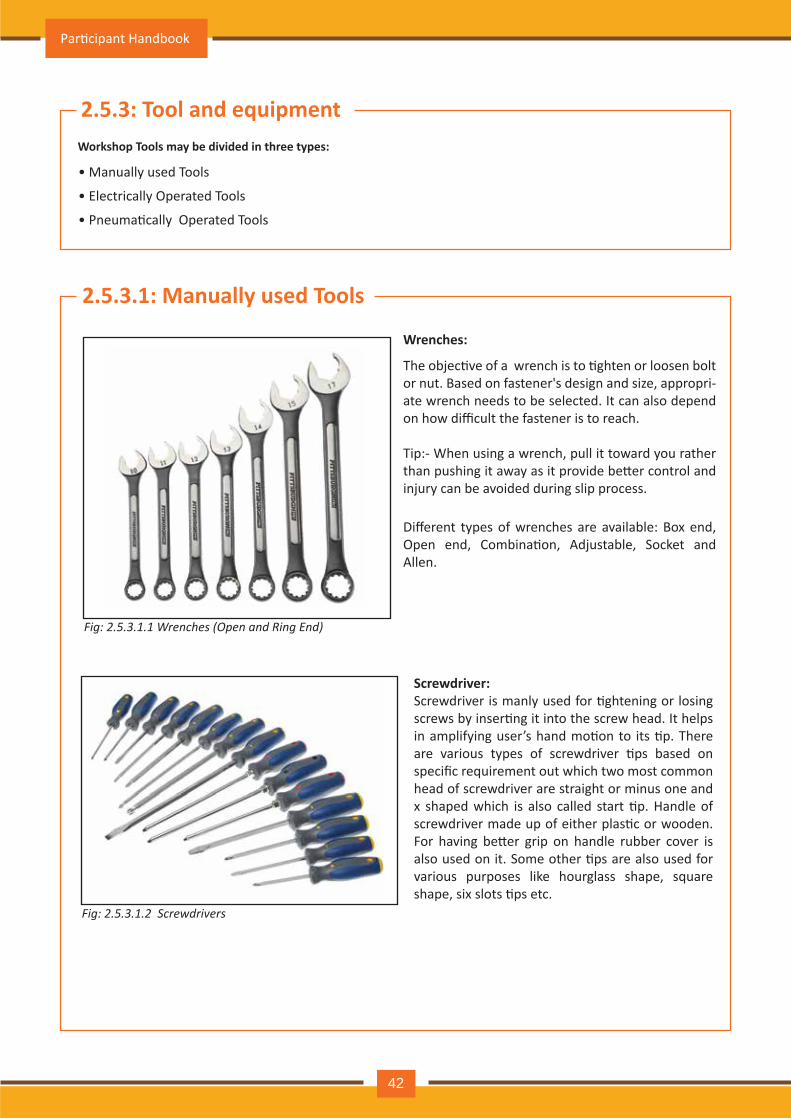
Fig: 2.5.3.1.1 Wrenches (Open and Ring End)
The objec�ve of a wrench is to �ghten or loosen bolt or nut. Based on fastener's design and size, appropri-ate wrench needs to be selected. It can also depend on how difficult the fastener is to reach.
Wrenches:
Tip:- When using a wrench, pull it toward you rather than pushing it away as it provide be�er control and injury can be avoided during slip process.
Different types of wrenches are available: Box end, Open end, Combina�on, Adjustable, Socket and Allen.
Fig: 2.5.3.1.2 Screwdrivers
Screwdriver:Screwdriver is manly used for �ghtening or losing screws by inser�ng it into the screw head. It helps in amplifying user’s hand mo�on to its �p. There are various types of screwdriver �ps based on specific requirement out which two most common head of screwdriver are straight or minus one and x shaped which is also called start �p. Handle of screwdriver made up of either plas�c or wooden. For having be�er grip on handle rubber cover is also used on it. Some other �ps are also used for various purposes like hourglass shape, square shape, six slots �ps etc.
Par�cipant Handbook
42
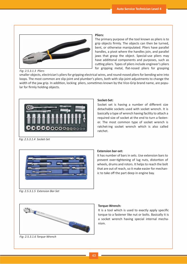
Fig: 2.5.3.1.3 Pliers
Pliers:The primary purpose of the tool known as pliers is to grip objects firmly. The objects can then be turned, bent, or otherwise manipulated. Pliers have parallel handles, a pivot where the handles join, and parallel jaws that grasp the object. Special-use pliers may have addi�onal components and purposes, such as cu�ng pliers. Types of pliers include engineer's pliers for gripping metal, flat-nosed pliers for grasping
smaller objects, electrician's pliers for gripping electrical wires, and round-nosed pliers for bending wire into loops. The most common are slip-joint and plumber's pliers, both with slip-joint adjustments to change the width of the jaw grip. In addi�on, locking pliers, some�mes known by the Vice-Grip brand name, are popu-lar for firmly holding objects.
Fig: 2.5.3.1.4 Socket-Set
Socket-Set:Socket set is having a number of different size detachable sockets used with socket wrench. It is basically a type of wrench having facility to a�ach a required size of socket at the end to turn a fasten-er. The most common type of socket wrench is ratchet-ing socket wrench which is also called ratchet.
Fig: 2.5.3.1.5 Extension Bar-Set
Extension bar-set: It has number of bars in sets. Use extension bars to prevent over-�ghtening of lug nuts, distor�on of wheels, drums and rotors. It helps to reach the bolt that are out of reach, so it make easier for mechan-ic to take off the part deep in engine bay.
Fig: 2.5.3.1.6 Torque-Wrench
Torque-Wrench:It is a tool which is used to exactly apply specific torque to a fastener like nut or bolts. Basically it is a socket wrench having special internal mecha-nism.
Auto Service Technician Level 4
43
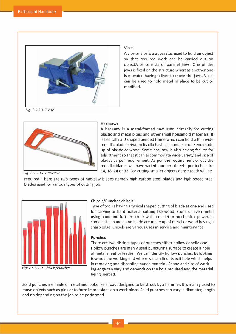
Fig: 2.5.3.1.7 Vise
Vise: A vice or vice is a apparatus used to hold an object so that required work can be carried out on object.Vice consists of parallel jaws. One of the jaws is fixed on the structure whereas another one is movable having a liver to move the jaws. Vices can be used to hold metal in place to be cut or modified.
Fig: 2.5.3.1.8 Hacksaw
Hacksaw:A hacksaw is a metal-framed saw used primarily for cu�ng plas�c and metal pipes and other small household materials. It is basically a U shaped bended frame which can hold a thin wide metallic blade between its clip having a handle at one end made up of plas�c or wood. Some hacksaw is also having facility for adjustment so that it can accommodate wide variety and size of blades as per requirement. As per the requirement of cut the metallic blades will have varied number of teeth per inches like 14, 18, 24 or 32. For cu�ng smaller objects dense teeth will be
required. There are two types of hacksaw blades namely high carbon steel blades and high speed steel blades used for various types of cu�ng job.
Fig: 2.5.3.1.9 Chisels/Punches
Chisels/Punches chisels: Type of tool is having a typical shaped cu�ng of blade at one end used for carving or hard material cu�ng like wood, stone or even metal using hand and further struck with a mallet or mechanical power. In some chisel handle and blade are made up of metal or wood having a sharp edge. Chisels are various uses in service and maintenance.
PunchesThere are two dis�nct types of punches either hollow or solid one.Hollow punches are manly used puncturing surface to create a holeof metal sheet or leather. We can iden�fy hollow punches by lookingtowards the working end where we can find its exit hole which helpsin removing and discarding punch material. Shape and size of work-ing edge can vary and depends on the hole required and the material being pierced.
Solid punches are made of metal and looks like a road, designed to be struck by a hammer. It is mainly used to move objects such as pins or to form impressions on a work piece. Solid punches can vary in diameter, length and �p depending on the job to be performed.
Par�cipant Handbook
44
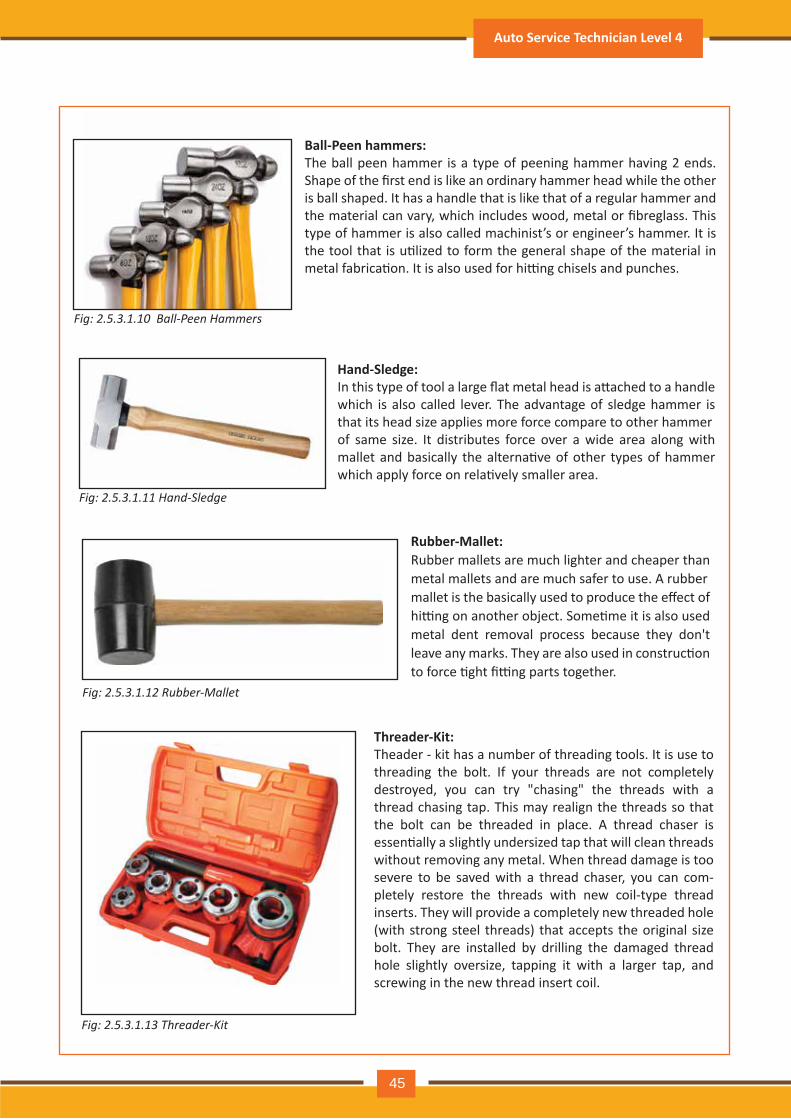
Fig: 2.5.3.1.10 Ball-Peen Hammers
Ball-Peen hammers:The ball peen hammer is a type of peening hammer having 2 ends. Shape of the first end is like an ordinary hammer head while the other is ball shaped. It has a handle that is like that of a regular hammer and the material can vary, which includes wood, metal or fibreglass. This type of hammer is also called machinist’s or engineer’s hammer. It is the tool that is u�lized to form the general shape of the material in metal fabrica�on. It is also used for hi�ng chisels and punches.
Fig: 2.5.3.1.11 Hand-Sledge
Hand-Sledge:In this type of tool a large flat metal head is a�ached to a handle which is also called lever. The advantage of sledge hammer is that its head size applies more force compare to other hammerof same size. It distributes force over a wide area along with mallet and basically the alterna�ve of other types of hammer which apply force on rela�vely smaller area.
Fig: 2.5.3.1.12 Rubber-Mallet
Rubber-Mallet:Rubber mallets are much lighter and cheaper than metal mallets and are much safer to use. A rubbermallet is the basically used to produce the effect of hi�ng on another object. Some�me it is also used metal dent removal process because they don't leave any marks. They are also used in construc�on to force �ght fi�ng parts together.
Fig: 2.5.3.1.13 Threader-Kit
Threader-Kit:Theader - kit has a number of threading tools. It is use to threading the bolt. If your threads are not completely destroyed, you can try "chasing" the threads with a thread chasing tap. This may realign the threads so that the bolt can be threaded in place. A thread chaser is essen�ally a slightly undersized tap that will clean threads without removing any metal. When thread damage is too severe to be saved with a thread chaser, you can com-pletely restore the threads with new coil-type thread inserts. They will provide a completely new threaded hole (with strong steel threads) that accepts the original size bolt. They are installed by drilling the damaged thread hole slightly oversize, tapping it with a larger tap, and screwing in the new thread insert coil.
Auto Service Technician Level 4
45
2.5.3 .2: Electrically Operated ToolsThese tools are operated by electrical power
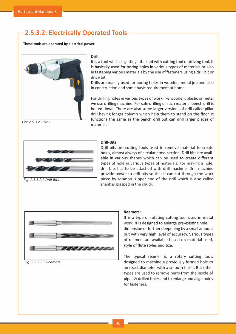
Fig: 2.5.3.2.1 D r il l
Drill:It is a tool which is ge�ng a�ached with cu�ng tool or driving tool. It is basically used for boring holes in various types of materials or also in fastening various materials by the use of fasteners using a drill bit or drive bit.Drills are mainly used for boring holes in wooden, metal job and also in construc�on and some basic requirement at home.
For drilling holes in various types of work like wooden, plas�c or metal we use drilling machine. For safe drilling of such material bench drill is bolted down. There are also some larger versions of drill called pillar drill having longer column which help them to stand on the floor. It func�ons the same as the bench drill but can drill larger pieces of m aterial.
Fig: 2.5.3.2.2 D r il l - B it s
Drill-Bits:Drill bits are cu�ng tools used to remove material to create holes, almost always of circular cross-sec�on. Drill bits are avail -able in various shapes which can be used to create different types of hole in various types of materials. For making a hole, drill bits has to be a�ached with drill machine. Drill machine provide power to drill bits so that it can cut through the work piece by rota�on. Upper end of the drill which is also called shank is grasped in the chuck.
Fig: 2.5.3.2.3 R e a m e r s
Reamers:It is a type of rota�ng cu�ng tool used in metal work. It is designed to enlarge pre-exis�ng holedimension or further deepening by a small amount but with very high level of accuracy. Various types of reamers are available based on material used, style of flute styles and size.
The typical reamer is a rotary cu�ng tools designed to machine a previously formed hole to an exact diameter with a smooth finish. But other types are used to remove burrs from the inside of pipes & drilled holes and to enlarge and align holes for fasteners.
Par�cipant Handbook
46
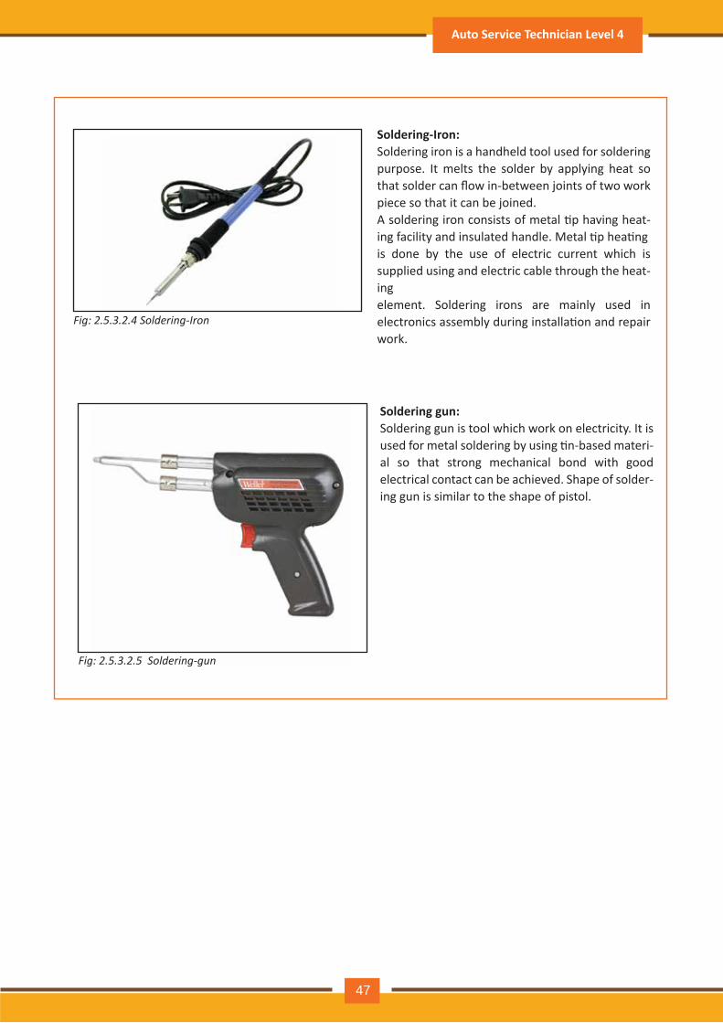
Fig: 2.5.3.2.4 Soldering-Iron
Soldering-Iron:Soldering iron is a handheld tool used for soldering purpose. It melts the solder by applying heat so that solder can flow in-between joints of two work piece so that it can be joined.A soldering iron consists of metal �p having heat-ing facility and insulated handle. Metal �p hea�ngis done by the use of electric current which is supplied using and electric cable through the heat-ingelement. Soldering irons are mainly used in electronics assembly during installa�on and repair work.
Fig: 2.5.3.2.5 Soldering-gun
Soldering gun: Soldering gun is tool which work on electricity. It is used for metal soldering by using �n-based materi-al so that strong mechanical bond with good electrical contact can be achieved. Shape of solder-ing gun is similar to the shape of pistol.
Auto Service Technician Level 4
47
2.5.3.3: Pneuma�cally Operated Tools
2.5.3.4: Measuring Tools
These tools are operated by compresses air
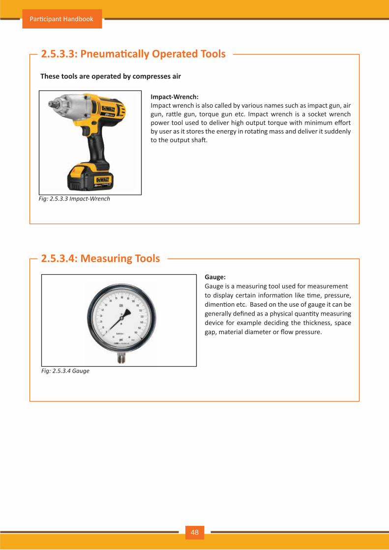
Fig: 2.5.3.3 Impact-Wrench
Impact-Wrench: Impact wrench is also called by various names such as impact gun, air gun, ra�le gun, torque gun etc. Impact wrench is a socket wrench power tool used to deliver high output torque with minimum effort by user as it stores the energy in rota�ng mass and deliver it suddenly to the output sha�.
Fig: 2.5.3.4 Gauge
Gauge:Gauge is a measuring tool used for measurementto display certain informa�on like �me, pressure, dimen�on etc. Based on the use of gauge it can be generally defined as a physical quan�ty measuring device for example deciding the thickness, space gap, material diameter or flow pressure.
Par�cipant Handbook
48
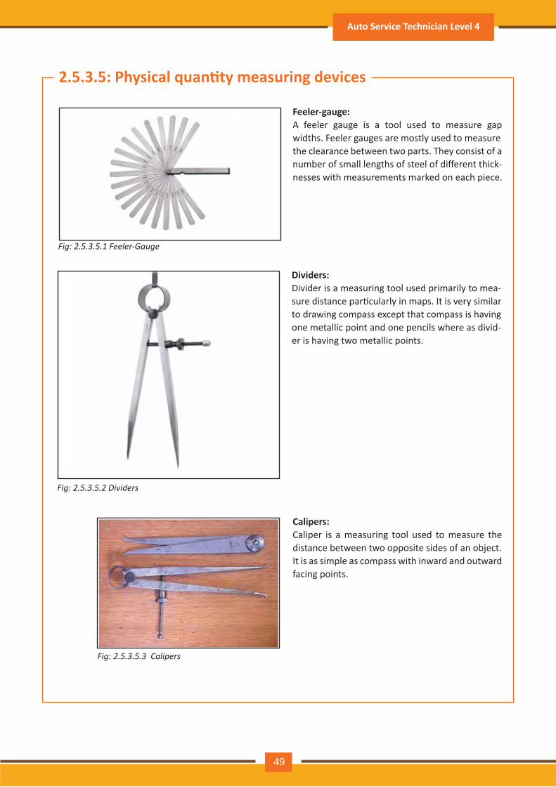
2.5.3.5: Physical quan�ty measuring devices
Fig: 2.5.3.5.1 Feeler-Gauge
Feeler-gauge:A feeler gauge is a tool used to measure gap widths. Feeler gauges are mostly used to measurethe clearance between two parts. They consist of a number of small lengths of steel of different thick-nesses with measurements marked on each piece.
Fig: 2.5.3.5.3 Calipers
Calipers:Caliper is a measuring tool used to measure the distance between two opposite sides of an object.It is as simple as compass with inward and outward facing points.
Fig: 2.5.3.5.2 Dividers
Dividers: Divider is a measuring tool used primarily to mea-sure distance par�cularly in maps. It is very similarto drawing compass except that compass is havingone metallic point and one pencils where as divid-er is having two metallic points.
Auto Service Technician Level 4
49
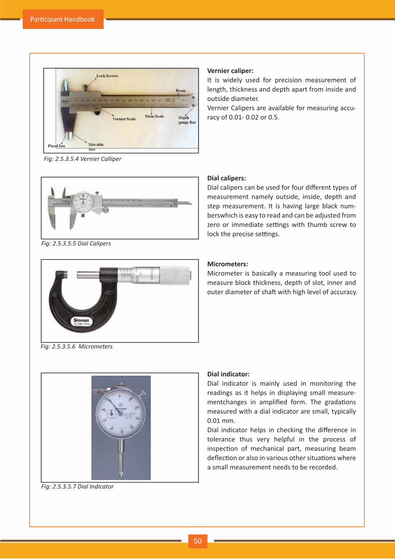
Fig: 2.5.3.5.4 Vernier Calliper
Vernier caliper:It is widely used for precision measurement of length, thickness and depth apart from inside and outside diameter. Vernier Calipers are available for measuring accu-racy of 0.01- 0.02 or 0.5.
Fig: 2.5.3.5.5 Dial Calipers
Dial calipers: Dial calipers can be used for four different types ofmeasurement namely outside, inside, depth and step measurement. It is having large black num-berswhich is easy to read and can be adjusted from zero or immediate se�ngs with thumb screw to lock the precise se�ngs.
Fig: 2.5.3.5.6 Micrometers
Micrometers:Micrometer is basically a measuring tool used to measure block thickness, depth of slot, inner and outer diameter of sha� with high level of accuracy.
Fig: 2.5.3.5.7 Dial Indicator
Dial indicator:Dial indicator is mainly used in monitoring the readings as it helps in displaying small measure-mentchanges in amplified form. The grada�ons measured with a dial indicator are small, typically 0.01 mm.Dial indicator helps in checking the difference in tolerance thus very helpful in the process of inspec�on of mechanical part, measuring beam deflec�on or also in various other situa�ons where a small measurement needs to be recorded.
Par�cipant Handbook
50
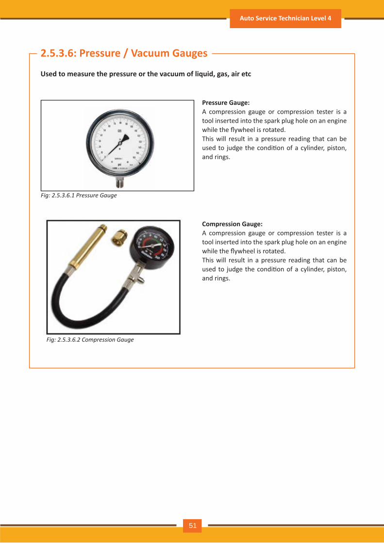
2.5.3.6: Pressure / Vacuum Gauges
Used to measure the pressure or the vacuum of liquid, gas, air etc
Fig: 2.5.3.6.1 Pressure Gauge
Pressure Gauge:A compression gauge or compression tester is a tool inserted into the spark plug hole on an engine while the flywheel is rotated.This will result in a pressure reading that can be used to judge the condi�on of a cylinder, piston, and rings.
Compression Gauge:A compression gauge or compression tester is a tool inserted into the spark plug hole on an engine while the flywheel is rotated.This will result in a pressure reading that can be used to judge the condi�on of a cylinder, piston, and rings.
Fig: 2.5.3.6.2 Compression Gauge
Auto Service Technician Level 4
51

2.5.3.7: Electrical quan�ty measuring devices
Fig: 2.5.3.7.2 Digital VoltmeterFig: 2.5.3.7.1 Analog Voltmeter
Voltmeter:Voltmeter is a measuring instrument used to measure poten�al difference or voltage between two points in either electrical or electronic circuit. It iso�en called voltage meter. There are two types of voltmeter i.e. analog which is using needle type of pointer to show the reading whereas another type is digital which shows reading as numeri-cal display. A voltmeter in a circuit diagram is represented by the le�er V in a circle.
Fig: 2.5.3.7.3 Multi-meter
Mul�-meter:Mul�meter is a electronic measuring instrument which is also called as mul� tester. It is equipped with the facility of measuring several func�ons within one unit. Mul�meter is a hand held device used to measure current, voltage both type AC and DC and resistance with high degree of accuracy and mainly used for fault finding during maintenance and service process. It is very helpful in electrical orelectronic problem troubleshoo�ng in a wide range of industrial and household devices such as electronic equipment, domes�c appliances, power supplies and wiring systems.
Par�cipant Handbook
52

2.5.3.8: Diagnos�c Tools and Equipments
These tools are used for diagnos�c purpose or for doing some se�ngs
Fig: 2.5.3.8.1 Test light
Test light:Test light is electronic test equipment also known as test lamp, voltage tester. It is basically used for establishing the presence or absence of alternat-ing current in a piece of equipment under test condi�on.
Fig: 2.5.3.8.2 Tachometer
Tachometer:Tachometer is a measuring tool used to measure rota�on speed of instrument sha� or disk in a motor or other such machine.
Fig: 2.5.3.8.3 Scan-Tool
Scan-Tool:Scan tool used in automo�ve is o�en called as scanner. This is basically an electronic tool which can be interfaced with vehicle for diagnos�c purpose. It also helps to reprogram control module of vehicle.
Auto Service Technician Level 4
53

Fig: 2.5.3.8.4 Oscilloscope
Oscilloscope:The oscilloscope helps us find the problem quicker and easier. Shows the electrical ac�vity in the vehicles igni�on system and other electrical systems.
Fig: 2.5.3.8.5 Exhaust-gas-analyzer
Exhaust-Gas-analyzer:Vehicle’s exhaust is having various chemicals and to measure the amount of chemical exhaust gas analyzer is use. To measure the fuel-air ra�o of thefuel mixture of an engine a carbon dioxide sensi-�ve element device is placed in the exhaust mani-fold. It is also known as fuel-mixture indicator orsmoke feeler.
Par�cipant Handbook
54
2.5.4: EngineEngine is considered as the heart of an automobile. It is a machine having moving parts, which converts
chemical energy of fuel to heat or thermal energy, and then to mechanical energy that is mo�on, which in
turn moves the automobile
It is a machine which converts energy from chemical form into mechanical
This mechanical energy is then used to perform the following:
• Drive the vehicle
• Provide power for air-condi�oning system steering system other such systems
• Produce electrical energy which is ge�ng used throughout the vehicle
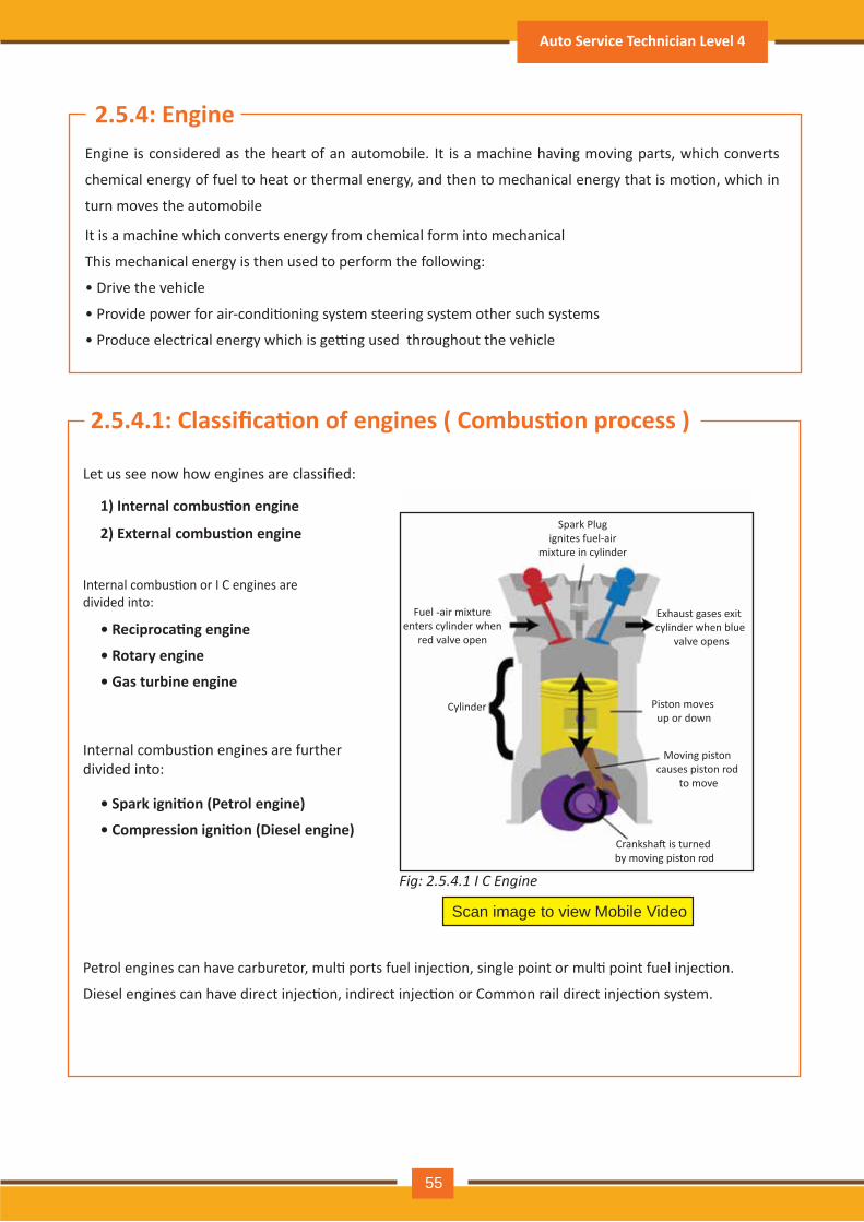
2.5.4.1: Classifica�on of engines ( Combus�on process )
Scan image to view Mobile Video
Let us see now how engines are classified:
1) Internal combus�on engine
2) External combus�on engine
Internal combus�on or I C engines are divided into:
• Reciproca�ng engine
• Rotary engine
• Gas turbine engine
Internal combus�on engines are further divided into:
• Spark igni�on (Petrol engine)
• Compression igni�on (Diesel engine)
Petrol engines can have carburetor, mul� ports fuel injec�on, single point or mul� point fuel injec�on.
Diesel engines can have direct injec�on, indirect injec�on or Common rail direct injec�on system.
Fig: 2.5.4.1 I C Engine
Spark Plug ignites fuel-air
mixture in cylinder
Fuel -air mixture enters cylinder when
red valve open
Cylinder Piston moves up or down
Moving piston causes piston rod
to move
Cranksha� is turned by moving piston rod
Exhaust gases exit cylinder when blue
valve opens
Auto Service Technician Level 4
55
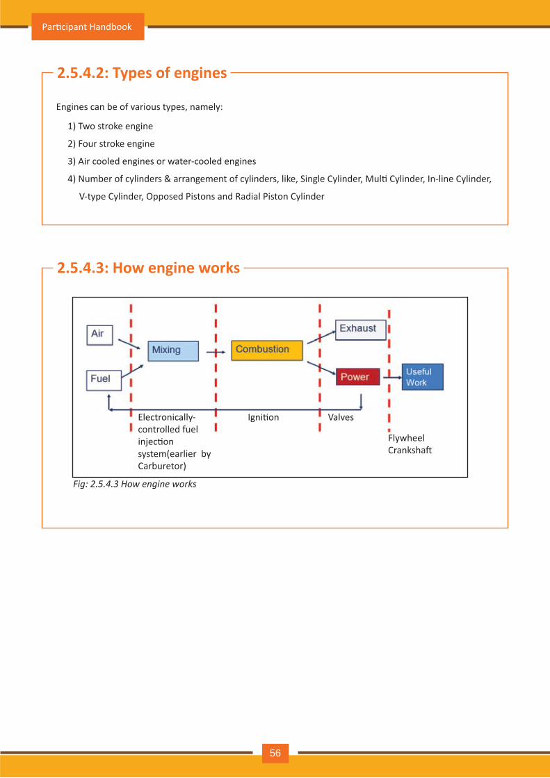
Fig: 2.5.4.3 How engine works
2.5.4.2: Types of engines
Engines can be of various types, namely:
1) Two stroke engine
2) Four stroke engine
3) Air cooled engines or water-cooled engines
4) Number of cylinders & arrangement of cylinders, like, Single Cylinder, Mul� Cylinder, In-line Cylinder,
V-type Cylinder, Opposed Pistons and Radial Piston Cylinder
2.5.4.3: How engine works
Electronically-controlled fuel injec�on system(earlier by Carburetor)
Igni�on Valves
FlywheelCranksha�
Par�cipant Handbook
56
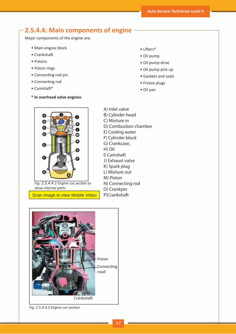
2.5.4.4: Main components of engineMajor components of the engine are:
Scan image to view Mobile Video
Fig: 2.5.4.4.1 Engine cut section to show internal parts
Fig: 2.5.4.4.2 Engine cut section
• Main engine block• Cranksha�• Pistons• Piston rings• Connec�ng rod pin• Connec�ng rod• Camsha�*
• Li�ers* • Oil pump• Oil pump drive• Oil pump pick up• Gaskets and seals• Freeze plugs• Oil pan
* In overhead valve engines
Piston
Connec�ng road
Cranksha�
A) Inlet valve B) Cylinder headC) Mixture in D) Combustion chamberE) Cooling waterF) Cylinder blockG) Crankcase, H) OilI) CamshaftJ) Exhaust valveK) Spark plugL) Mixture outM) PistonN) Connecting rodO) CrankpinP)Crankshaft
Auto Service Technician Level 4
57
2.5.4.5: Internal combus�on engine
Scan image to view Mobile Video
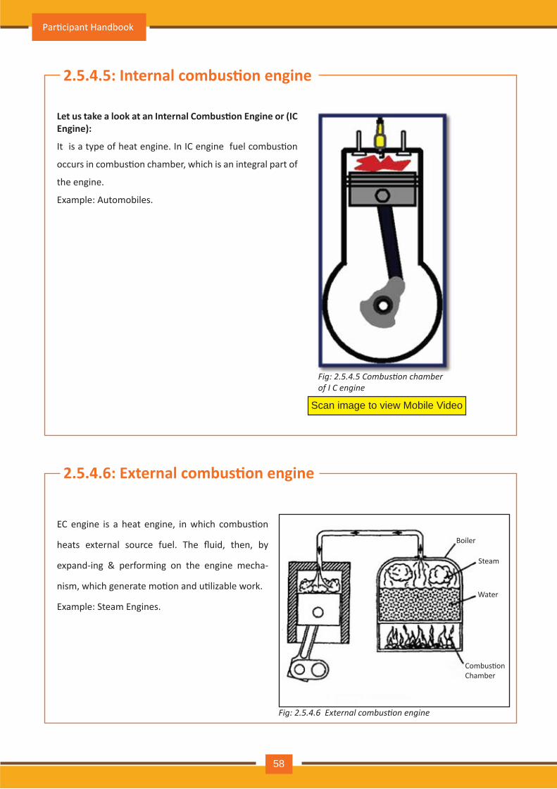
Let us take a look at an Internal Combus�on Engine or (IC Engine):
It is a type of heat engine. In IC engine fuel combus�on
occurs in combus�on chamber, which is an integral part of
the engine.
Example: Automobiles.
2.5.4.6: External combus�on engine
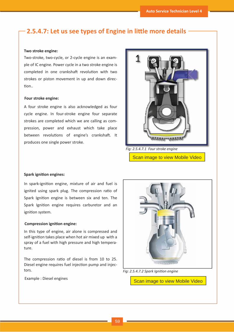
EC engine is a heat engine, in which combus�on
heats external source fuel. The fluid, then, by
expand-ing & performing on the engine mecha-
nism, which generate mo�on and u�lizable work.
Example: Steam Engines.
Fig: 2.5.4.5 Combustion chamber of I C engine
Water
Steam
Boiler
Combus�onChamber
Fig: 2.5.4.6 External combustion engine
Par�cipant Handbook
58
2.5.4.7: Let us see types of Engine in li�le more details
Two-stroke, two-cycle, or 2-cycle engine is an exam-
ple of IC engine. Power cycle in a two stroke engine is
completed in one cranksha� revolu�on with two
strokes or piston movement in up and down direc-
�on..
A four stroke engine is also acknowledged as four
cycle engine. In four-stroke engine four separate
strokes are completed which we are calling as com-
pression, power and exhaust which take place
between revolu�ons of engine’s cranksha�. It
produces one single power stroke.
Scan image to view Mobile Video
Two stroke engine:
Four stroke engine:
In spark-igni�on engine, mixture of air and fuel is
ignited using spark plug. The compression ra�o of
Spark Igni�on engine is between six and ten. The
Spark Igni�on engine requires carburetor and an
igni�on system.
In this type of engine, air alone is compressed and self-igni�on takes place when hot air mixed up with a spray of a fuel with high pressure and high tempera-ture.
The compression ra�o of diesel is from 10 to 25. Diesel engine requires fuel injec�on pump and injec-tors.
Spark igni�on engines:
Scan image to view Mobile Video
Compression igni�on engine:
Example : Diesel engines
Fig: 2.5.4.7.1 Four stroke engine
Fig: 2.5.4.7.2 Spark Ignition engine
Auto Service Technician Level 4
59
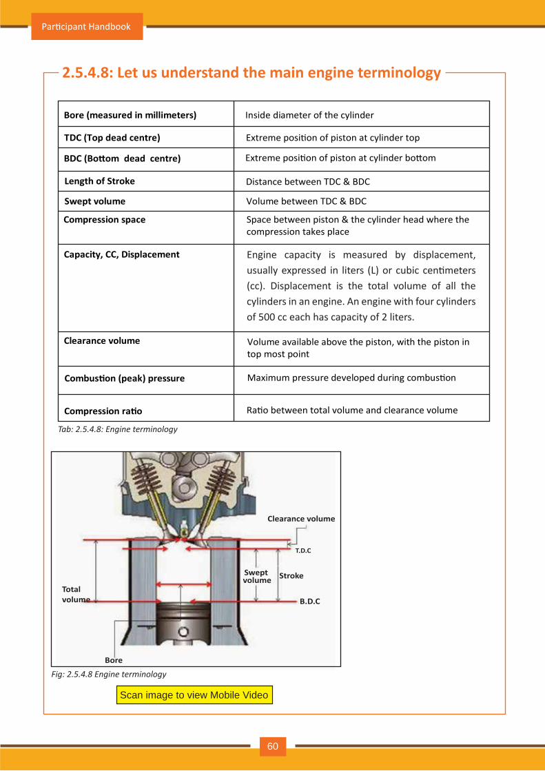
Tab: 2.5.4.8: Engine terminology
2.5.4.8: Let us understand the main engine terminology
Bore (measured in millimeters) Inside diameter of the cylinder
TDC (Top dead centre) Extreme posi�on of piston at cylinder top
BDC (Bo�om dead centre) Extreme posi�on of piston at cylinder bo�om
Length of Stroke Distance between TDC & BDC
Swept volume Volume between TDC & BDC
Compression space Space between piston & the cylinder head where the compression takes place
Capacity, CC, Displacement
Clearance volume Volume available above the piston, with the piston in top most point
Combus�on (peak) pressure Maximum pressure developed during combus�on
Compression ra�o Ra�o between total volume and clearance volume
Total volume
Bore
Swept volume Stroke
T.D.C
B.D.C
Clearance volume
Scan image to view Mobile Video
Fig: 2.5.4.8 Engine terminology
Engine capacity is measured by displacement, usually expressed in liters (L) or cubic cen�meters (cc). Displacement is the total volume of all the cylinders in an engine. An engine with four cylinders of 500 cc each has capacity of 2 liters.
Par�cipant Handbook
60
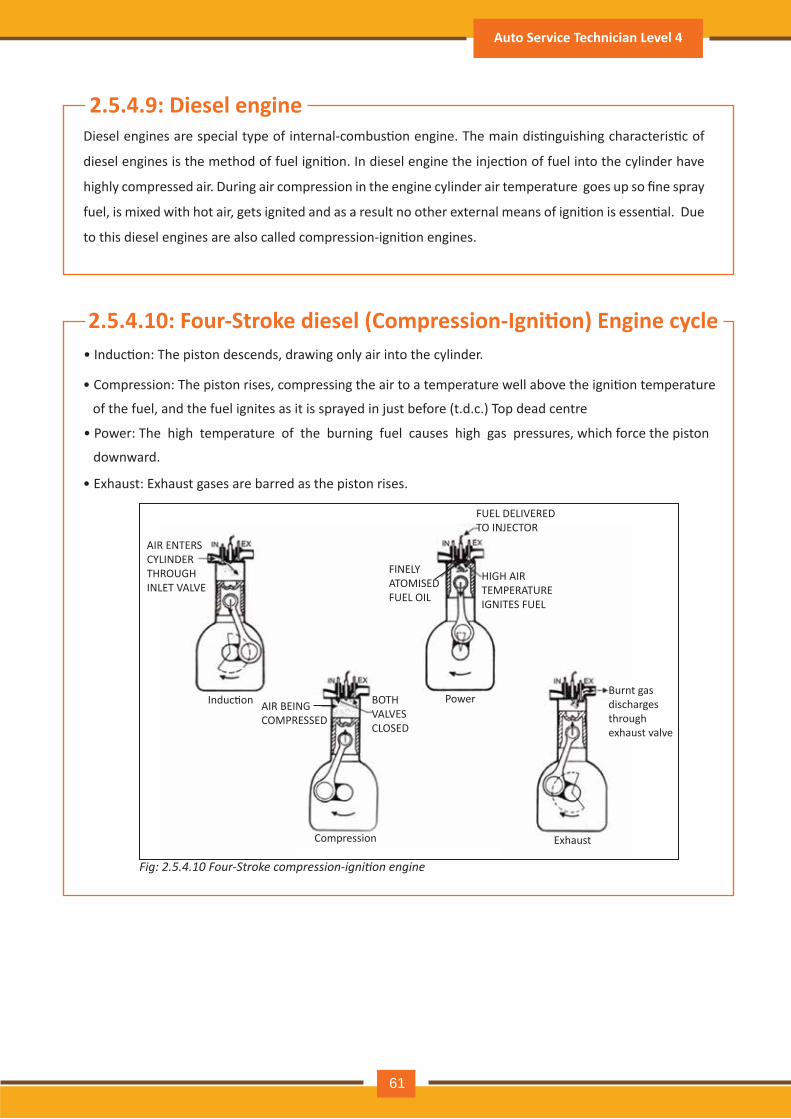
2.5.4.9: Diesel engineDiesel engines are special type of internal-combus�on engine. The main dis�nguishing characteris�c of
diesel engines is the method of fuel igni�on. In diesel engine the injec�on of fuel into the cylinder have
highly compressed air. During air compression in the engine cylinder air temperature goes up so fine spray
fuel, is mixed with hot air, gets ignited and as a result no other external means of igni�on is essen�al. Due
to this diesel engines are also called compression-igni�on engines.
2.5.4.10: Four-Stroke diesel (Compression-Igni�on) Engine cycle• Induc�on: The piston descends, drawing only air into the cylinder.
• Compression: The piston rises, compressing the air to a temperature well above the igni�on temperature
of the fuel, and the fuel ignites as it is sprayed in just before (t.d.c.) Top dead centre
• Power: The high temperature of the burning fuel causes high gas pressures, which force the piston
downward.
• Exhaust: Exhaust gases are barred as the piston rises.
AIR ENTERS CYLINDER THROUGH INLET VALVE
Induc�on AIR BEING COMPRESSED
Compression
BOTH VALVES CLOSED
FINELY ATOMISED FUEL OIL
FUEL DELIVERED TO INJECTOR
HIGH AIR TEMPERATURE IGNITES FUEL
Burnt gas discharges through exhaust valve
Exhaust
Power
Fig: 2.5.4.10 Four-Stroke compression-ignition engine
Auto Service Technician Level 4
61
2.5.4.11: Diesel and Petrol Engines Difference
As compared to petrol engine, the diesel engine differs in following respects:
In diesel engine, air alone enters the cylinder during intake stroke and compressed during
compression stroke
Diesel engines use higher compression ra�o. Typical compression ra�o for petrol engine is 9:1 and for
diesel engine is 16:1
In diesel engine, fuel is injected or sprayed into the combus�on chamber. In petrol engine mixture of
air and fuel is supplied by the carburetor.
Diesel engines have no igni�on system. High temperature of the compressed air is sufficient to ignite
the fuel.
Diesel engines run on less vola�le, heavier liquid fuel than that of petrol engine.
For the same power output, diesel engines are heavier than petrol engines.
•
•
•
•
•
•
2.5.4.12: Classifica�on of diesel engines
Diesel engines can be categorized as:
A. Opera�ng cycle: The stroke is the distance covered by the piston from top dead center to the bo�om dead center. • Two-stroke cycle diesel engine : Piston moves 2 �mes in the cylinder in one cycle • Four-stroke cycle diesel engine : Piston moves 4 �mes in the cylinder in one cycle
B. Piston ac�on: Single-ac�ng engine : Pressure of combus�on gases acts on only one surface of the piston Double-ac�ng engine : Pressure of combus�on gases acts alternately on both sides of the piston. Opposed-piston engine : Have two pistons per cylinder working in opposite reciproca�ng ac�on
C. Piston connec�on:Trunk-piston engine : Piston has elongated skirt a�ached to the connec�ng rod by small end rota�ng bearing Crosshead type engine : Has Piston crown, Piston skirt and piston rod connected to crosshead
Par�cipant Handbook
62
2.5.4.13: Fuel injec�on
2.5.4.14: Methods of Fuel Injec�on
In diesel engine the method used for introduc�on and burning of fuel is totally different from that of petrol
engine. The fuel is injected into the highly compressed hot air where it burns. Fuel injec�on system major
requirements are as follows:
It must meter the fuel accurately i.e. the fuel quan�ty supplied should be in accordance with engine load and also the fuel should be supplied to each cylinder in same amount for each power stroke
It must �me the fuel injec�on properly i.e., fuel injec�on should begin at the required moment
It must atomize the fuel properly i.e. it should break up the fuel stream into mist like sprays
It must dispense the fuel in the combus�on space properly
Air injec�on: This system is now seldom used. In this method, compressed air is supplied to the
spray valve by a special air compressor, which is a�ached to the engine.
Mechanical injec�on: In this system, the fuel is forced in, from a mechanical fuel injec�on pump
through injectors. This consists of:
(i)
(ii)
(iii)
(iv)
There are two methods of fuel injec�on:
•
•
• Low Pressure Fuel Supply System
• Metering Injec�on System
Auto Service Technician Level 4
63
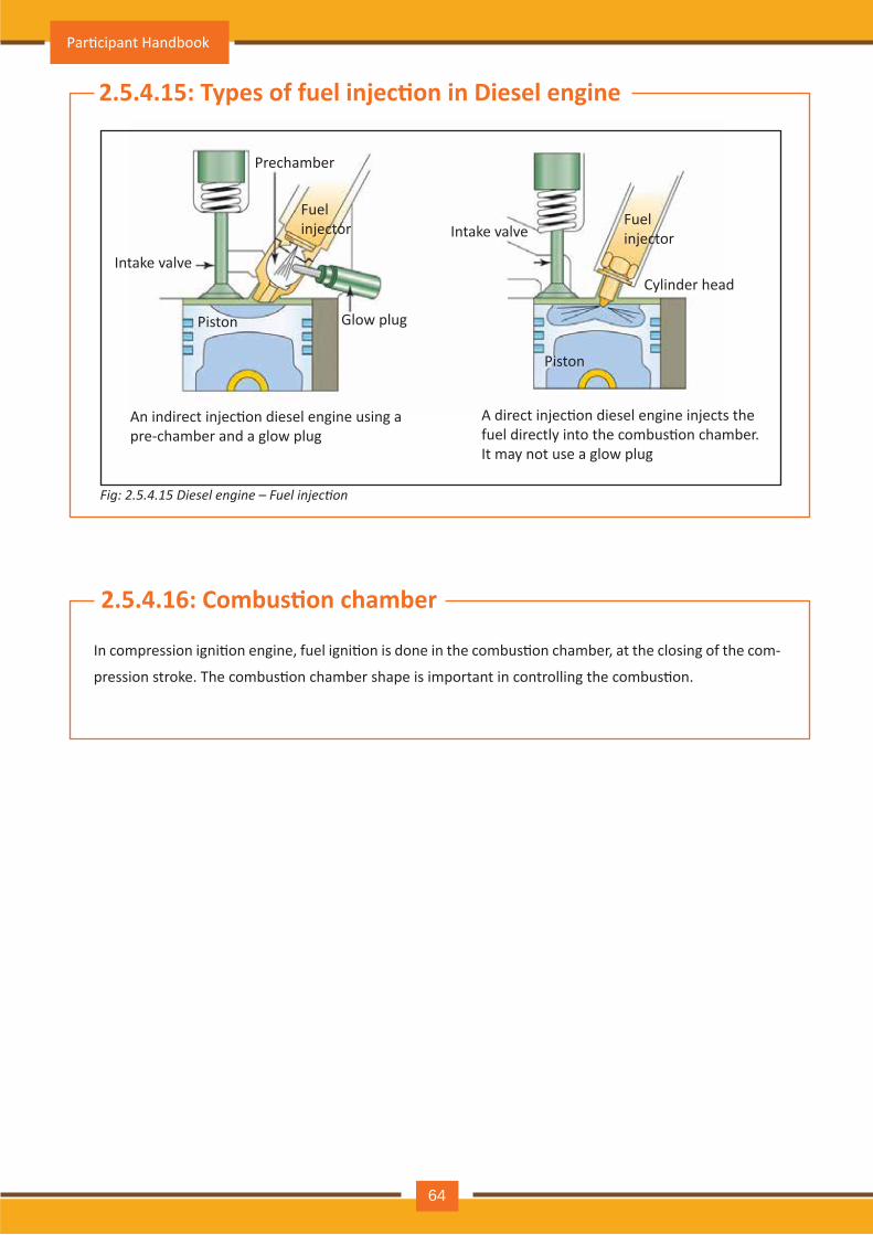
Fig: 2.5.4.15 Diesel engine – Fuel injection
2.5.4.15: Types of fuel injec�on in Diesel engine
2.5.4.16: Combus�on chamber
In compression igni�on engine, fuel igni�on is done in the combus�on chamber, at the closing of the com-
pression stroke. The combus�on chamber shape is important in controlling the combus�on.
Intake valve
Intake valve
Prechamber
Glow plug Piston
Piston
Fuel injector Fuel
injector
Cylinder head
An indirect injec�on diesel engine using a pre-chamber and a glow plug
A direct injec�on diesel engine injects the fuel directly into the combus�on chamber. It may not use a glow plug
Par�cipant Handbook
64
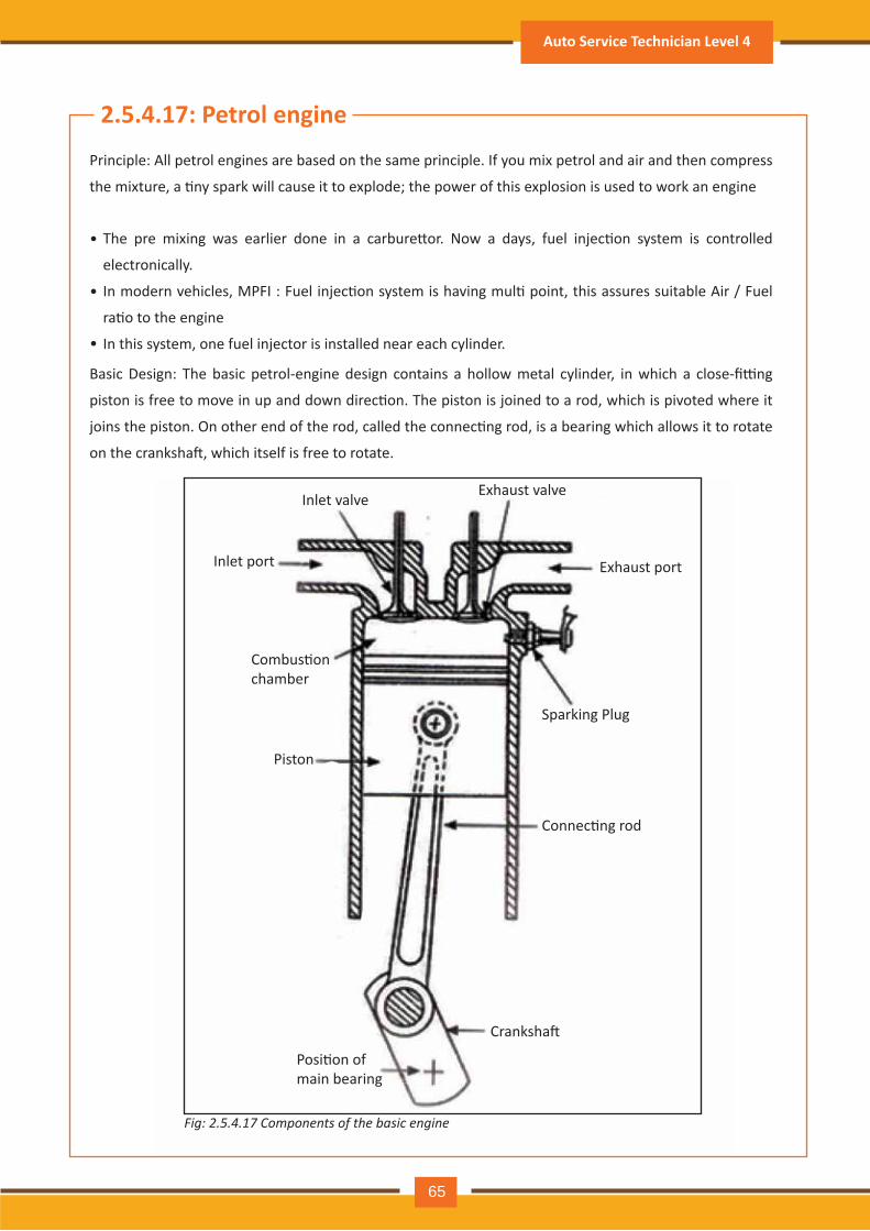
2.5.4.17: Petrol engine
Principle: All petrol engines are based on the same principle. If you mix petrol and air and then compress
the mixture, a �ny spark will cause it to explode; the power of this explosion is used to work an engine
Basic Design: The basic petrol-engine design contains a hollow metal cylinder, in which a close-fi�ng
piston is free to move in up and down direc�on. The piston is joined to a rod, which is pivoted where it
joins the piston. On other end of the rod, called the connec�ng rod, is a bearing which allows it to rotate
on the cranksha�, which itself is free to rotate.
Inlet valve
Inlet port
Combus�on chamber
Piston
Posi�on of main bearing
Cranksha�
Connec�ng rod
Sparking Plug
Exhaust port
Exhaust valve
Fig: 2.5.4.17 Components of the basic engine
The pre mixing was earlier done in a carbure�or. Now a days, fuel injec�on system is controlled
electronically.
In modern vehicles, MPFI : Fuel injec�on system is having mul� point, this assures suitable Air / Fuel
ra�o to the engine
In this system, one fuel injector is installed near each cylinder.
•
•
•
Auto Service Technician Level 4
65
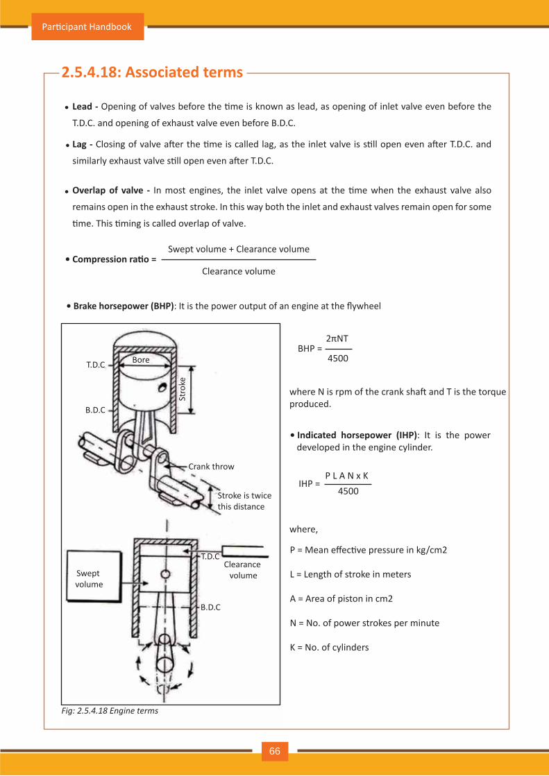
2.5.4.18: Associated terms
Lead - Opening of valves before the �me is known as lead, as opening of inlet valve even before the
T.D.C. and opening of exhaust valve even before B.D.C.
Lag - Closing of valve a�er the �me is called lag, as the inlet valve is s�ll open even a�er T.D.C. and
similarly exhaust valve s�ll open even a�er T.D.C.
Overlap of valve - In most engines, the inlet valve opens at the �me when the exhaust valve also
remains open in the exhaust stroke. In this way both the inlet and exhaust valves remain open for some
�me. This �ming is called overlap of valve.
•
•
•
• Compression ra�o =Swept volume + Clearance volume
Clearance volume
• Brake horsepower (BHP): It is the power output of an engine at the flywheel
2πNT BHP =
IHP =
4500
where N is rpm of the crank sha� and T is the torque produced.
• Indicated horsepower (IHP): It is the power developed in the engine cylinder.
P L A N x K4500
where,
P = Mean effec�ve pressure in kg/cm2 L = Length of stroke in meters
A = Area of piston in cm2
N = No. of power strokes per minute
K = No. of cylinders
T.D.C
T.D.C
B.D.C
Bore
Stro
ke
Crank throw
Stroke is twice this distance
Swept volume
Clearance volume
B.D.C
Fig: 2.5.4.18 Engine terms
Par�cipant Handbook
66
• Fric�onal horsepower: It is the horsepower lost in the engine due to fric�on.
FHP = IHP – BHP
Mechanical efficiency: It is the ra�o of the power delivered (BHP) and the power available in the engine
(IHP). It is expressed in percentage.
Volumetric efficiency: Volumetric efficiency is a ra�o (or percentage) of the mass of air and fuel that is trapped by the cylinder during induc�on divided by the mass that would occupy the displaced volume if the air density in the cylinder were equal to the ambient air density.
•
•
Throw: It is the distance between the centre of the crank pin to the centre of the main journal. The
piston stroke is double the throw.
•
Mechanical efficiency = IHPBHP X 100
Auto Service Technician Level 4
67
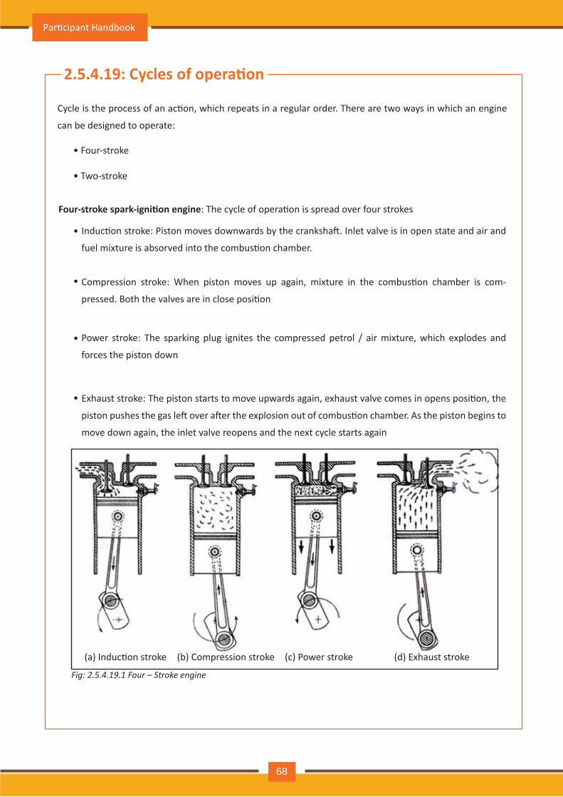
2.5.4.19: Cycles of opera�on
Cycle is the process of an ac�on, which repeats in a regular order. There are two ways in which an engine
can be designed to operate:
• Four-stroke
• Two-stroke
Four-stroke spark-igni�on engine: The cycle of opera�on is spread over four strokes
Induc�on stroke: Piston moves downwards by the cranksha�. Inlet valve is in open state and air and
fuel mixture is absorved into the combus�on chamber.
Compression stroke: When piston moves up again, mixture in the combus�on chamber is com-
pressed. Both the valves are in close posi�on
Power stroke: The sparking plug ignites the compressed petrol / air mixture, which explodes and
forces the piston down
Exhaust stroke: The piston starts to move upwards again, exhaust valve comes in opens posi�on, the
piston pushes the gas le� over a�er the explosion out of combus�on chamber. As the piston begins to
move down again, the inlet valve reopens and the next cycle starts again
•
•
•
•
(a) Induc�on stroke (b) Compression stroke (c) Power stroke (d) Exhaust stroke
Fig: 2.5.4.19.1 Four – Stroke engine
Par�cipant Handbook
68
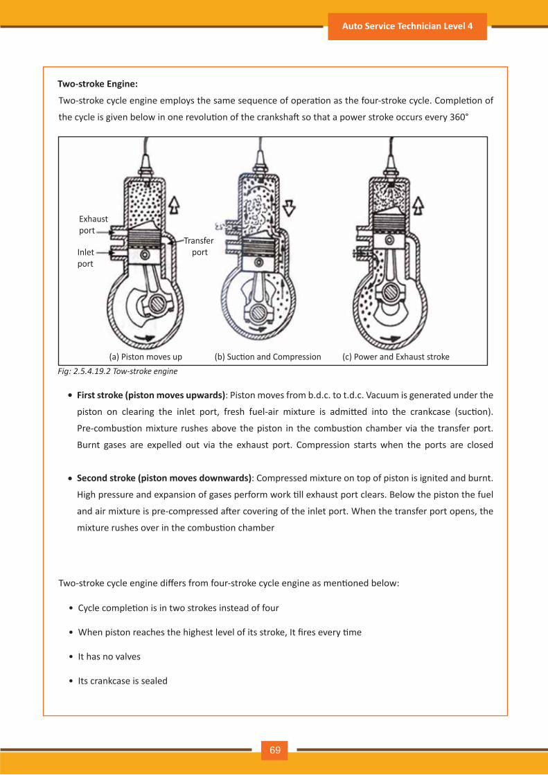
Two-stroke Engine:
Two-stroke cycle engine employs the same sequence of opera�on as the four-stroke cycle. Comple�on of
the cycle is given below in one revolu�on of the cranksha� so that a power stroke occurs every 360°
First stroke (piston moves upwards): Piston moves from b.d.c. to t.d.c. Vacuum is generated under the
piston on clearing the inlet port, fresh fuel-air mixture is admi�ed into the crankcase (suc�on).
Pre-combus�on mixture rushes above the piston in the combus�on chamber via the transfer port.
Burnt gases are expelled out via the exhaust port. Compression starts when the ports are closed
Second stroke (piston moves downwards): Compressed mixture on top of piston is ignited and burnt.
High pressure and expansion of gases perform work �ll exhaust port clears. Below the piston the fuel
and air mixture is pre-compressed a�er covering of the inlet port. When the transfer port opens, the
mixture rushes over in the combus�on chamber
•
•
Two-stroke cycle engine differs from four-stroke cycle engine as men�oned below:
• Cycle comple�on is in two strokes instead of four
• When piston reaches the highest level of its stroke, It fires every �me
• It has no valves
• Its crankcase is sealed
Exhaust port
Inlet port
Transfer port
(a) Piston moves up (b) Suc�on and Compression (c) Power and Exhaust strokeFig: 2.5.4.19.2 Tow-stroke engine
Auto Service Technician Level 4
69
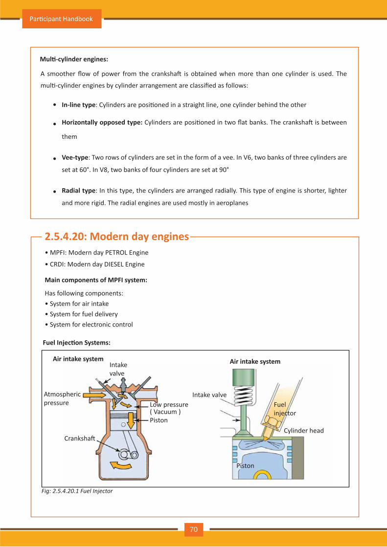
2.5.4.20: Modern day engines
Fig: 2.5.4.20.1 Fuel Injector
Mul�-cylinder engines:
Main components of MPFI system:
Fuel Injec�on Systems:
Air intake system
A smoother flow of power from the cranksha� is obtained when more than one cylinder is used. The
mul�-cylinder engines by cylinder arrangement are classified as follows:
• MPFI: Modern day PETROL Engine
• CRDI: Modern day DIESEL Engine
Has following components: • System for air intake• System for fuel delivery• System for electronic control
In-line type: Cylinders are posi�oned in a straight line, one cylinder behind the other
Horizontally opposed type: Cylinders are posi�oned in two flat banks. The cranksha� is between
them
Vee-type: Two rows of cylinders are set in the form of a vee. In V6, two banks of three cylinders are
set at 60°. In V8, two banks of four cylinders are set at 90°
Radial type: In this type, the cylinders are arranged radially. This type of engine is shorter, lighter
and more rigid. The radial engines are used mostly in aeroplanes
•
•
•
•
Intake valve
Intake valve Atmospheric pressure
Cranksha�
Low pressure ( Vacuum )Piston
Piston
Fuel injector
Cylinder head
Air intake system
Par�cipant Handbook
70
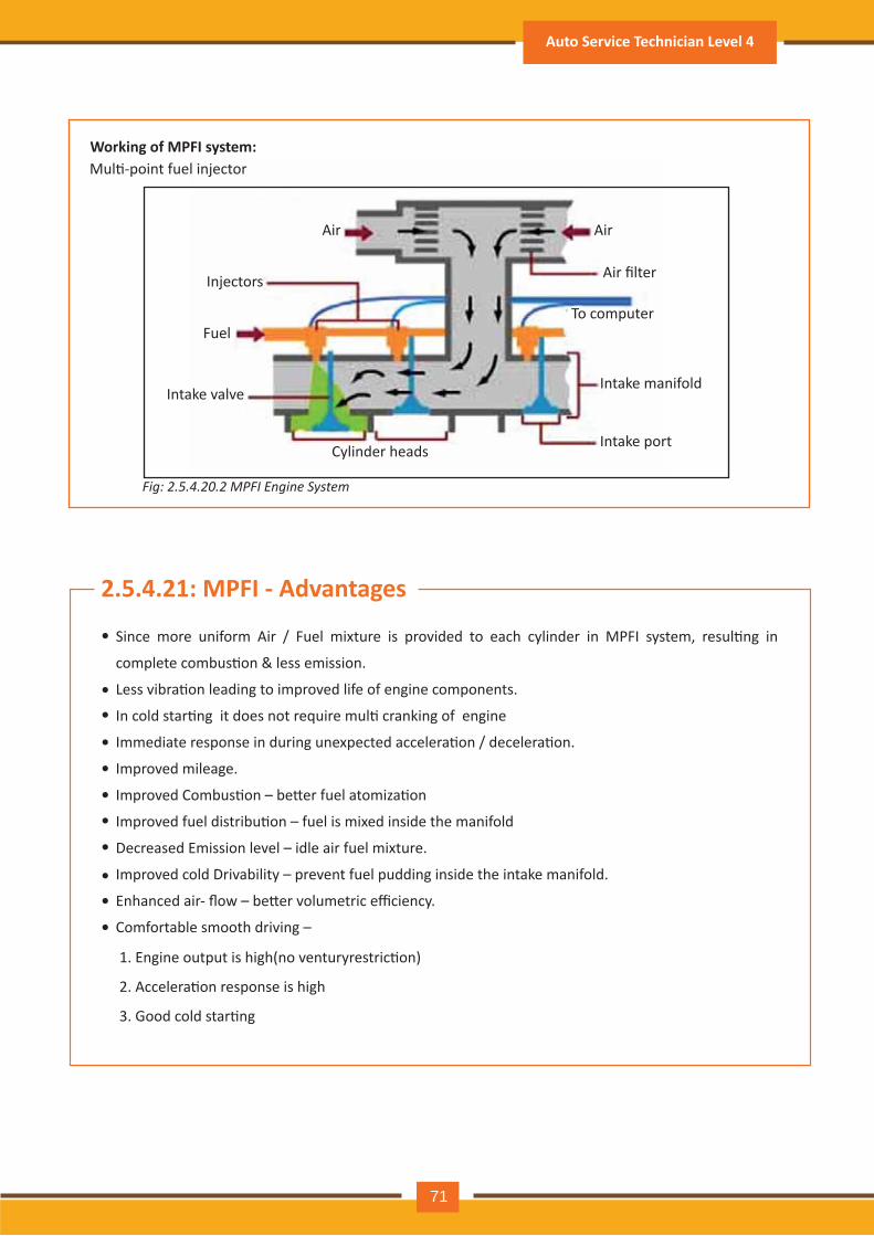
Fig: 2.5.4.20.2 MPFI Engine System
Since more uniform Air / Fuel mixture is provided to each cylinder in MPFI system, resul�ng in
complete combus�on & less emission.
Less vibra�on leading to improved life of engine components.
In cold star�ng it does not require mul� cranking of engine
Immediate response in during unexpected accelera�on / decelera�on.
Improved mileage.
Improved Combus�on – be�er fuel atomiza�on
Improved fuel distribu�on – fuel is mixed inside the manifold
Decreased Emission level – idle air fuel mixture.
Improved cold Drivability – prevent fuel pudding inside the intake manifold.
Enhanced air- flow – be�er volumetric efficiency.
Comfortable smooth driving –
1. Engine output is high(no venturyrestric�on)
2. Accelera�on response is high
3. Good cold star�ng
•
••
•
•
•
•
•
••
•
Working of MPFI system:
2.5.4.21: MPFI - Advantages
Mul�-point fuel injector
Air Air
Injectors
Fuel
Intake valve
Cylinder headsIntake port
Intake manifold
To computer
Air filter
Auto Service Technician Level 4
71
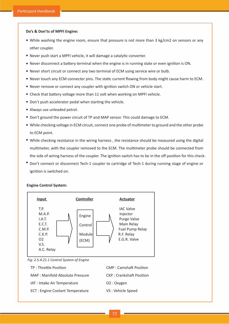
Do’s & Don’ts of MPFI Engine:
While washing the engine room, ensure that pressure is not more than 3 kg/cm2 on sensors or any
other coupler.
Never push start a MPFI vehicle, it will damage a cataly�c converter.
Never disconnect a ba�ery terminal when the engine is in running state or even igni�on is ON.
Never short circuit or connect any two terminal of ECM using service wire or bulb.
Never touch any ECM connecter pins. The sta�c current flowing from body might cause harm to ECM.
Never remove or connect any coupler with igni�on switch ON or vehicle start.
Check that ba�ery voltage more than 11 volt when working on MPFI vehicle.
Don’t push accelerator pedal when star�ng the vehicle.
Always use unleaded petrol.
Don’t ground the power circuit of TP and MAP sensor. This could damage to ECM.
While checking voltage in ECM circuit, connect one probe of mul�meter to ground and the other probe
to ECM point.
While checking resistance in the wiring harness , the resistance should be measured using the digital
mul�meter, with the coupler removed to the ECM. The mul�meter probe should be connected from
the side of wiring harness of the coupler. The igni�on switch has to be in the off posi�on for this check.
Don’t connect or disconnect Tech-1 coupler to cartridge of Tech-1 during running stage of engine or
igni�on is switched on.
•
•
•
•
•
•
•
•
•
•
•
•
•
Engine Control System:
TP : Thro�le Posi�on
MAP : Manifold Absolute Pressure
IAT : Intake Air Temperature
ECT : Engine Coolant Temperature
CMP : Camsha� Posi�on
CKP : Cranksha� Posi�on
O2 : Oxygen
VS : Vehicle Speed
Input
T.P. IAC Valve M.A.P. InjectorI.A.T. Purge Valve E.C.T. Main Relay C.M.P. Fuel Pump Relay C.K.P. R.F. Relay O2 E.G.R. Valve V.S. A.C. Relay
Controller
Engine
Control
Module(ECM)
Actuator
Fig: 2.5.4.21.1 Control System of Engine
Par�cipant Handbook
72
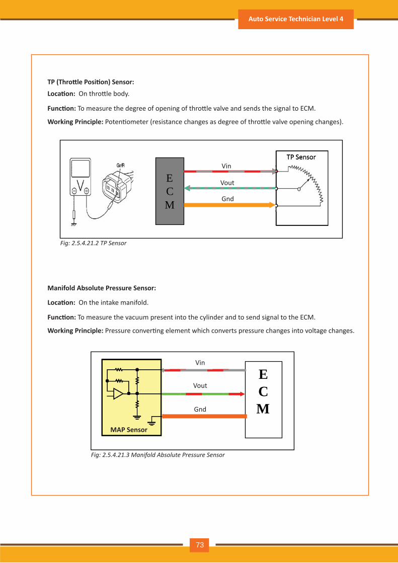
TP (Thro le Posi�on) Sensor:
Manifold Absolute Pressure Sensor:
Loca�on: On the intake manifold.
Func�on: To measure the vacuum present into the cylinder and to send signal to the ECM.
Working Principle: Pressure conver�ng element which converts pressure changes into voltage changes.
Loca�on: On thro�le body.
Func�on: To measure the degree of opening of thro�le valve and sends the signal to ECM.
Working Principle: Poten�ometer (resistance changes as degree of thro�le valve opening changes).
ECM
MAP Sensor
V in
V out
Gnd
Fig: 2.5.4.21.3 M a n if o l d A b s o l u t e P r e s s u r e S e n s o r
V in
V out
Gnd
TP Sensor
Fig: 2.5.4.21.2 T P S e n s o r
ECM
TP Sensor
Auto Service Technician Level 4
73
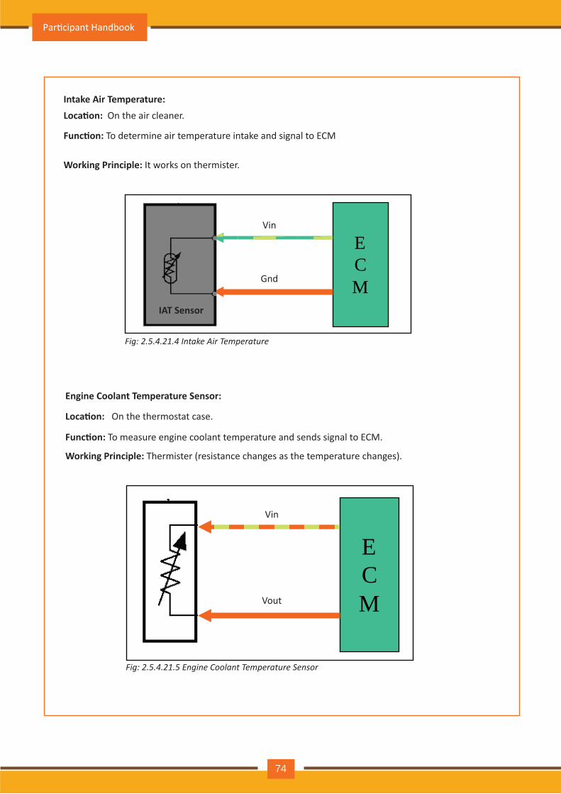
Intake Air Temperature: Loca�on: O n th e air cleaner.
Func�on: To determine air temperature intake and signal to ECM
Working Principle: It works on th erm ister.
V in
Gnd
ECM
IAT Sensor
Engine Coolant Temperature Sensor:
Loca�on: O n th e th erm ostat case.
Func�on: To measure engine coolant temperature and sends signal to ECM.
Working Principle: Thermister (resistance changes as the temperature changes).
V in
V out
ECM
Fig: 2.5.4.21.5 E n gin e C o o l a n t T e m p e r a t u r e S e n s o r
Fig: 2.5.4.21.4 I n t a k e A ir T e m p e r a t u r e
Par�cipant Handbook
74
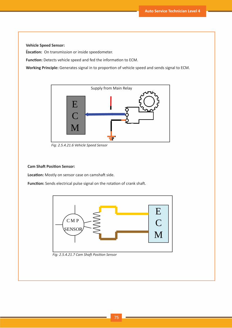
ehicle Speed Sensor: ::Loca�on: On transmission or inside speedometer.
Func�on: Detects vehicle speed and fed the informa�on to ECM.
Working Principle: Generates signal in to propor�on of vehicle speed and sends signal to ECM.
Supply from Main R elay
ECM
Cam Sha� Posi�on Sensor:
Loca�on: Mostly on sensor case on camsha� side.
Func�on: Sends electrical pulse signal on the rota�on of crank sha�.
C M P
SENSOR
ECM
Fig: 2.5.4.21.6 V e h ic l e S p e e d S e n s o r
Fig: 2.5.4.21.7 Cam Sha osition Sensor
Auto Service Technician Level 4
75
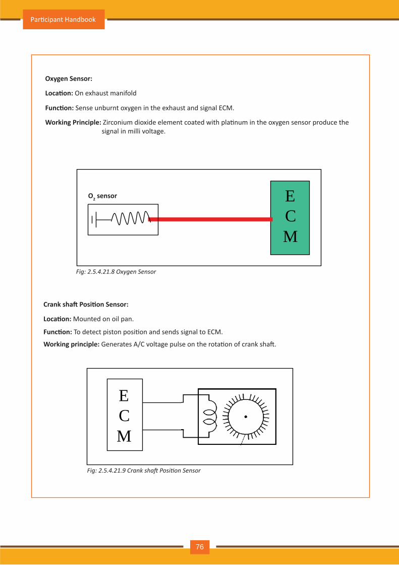
Oxygen Sensor:
O2 sensor
Loca�on: On exhaust manifold
Func�on: Sense unburnt oxygen in the exhaust and signal ECM.
Working Principle: Zirconium dioxide element coated with pla�num in the oxygen sensor produce the signal in milli voltage.
ECM
Crank sha� Posi�on Sensor:
Loca�on: Mounted on oil pan.
Func�on: To detect piston posi�on and sends signal to ECM.
Working principle: Generates A/C voltage pulse on the rota�on of crank sha�.
ECM
Fig: 2.5.4.21.8 O x y ge n S e n s o r
Fig: 2.5.4.21.9 Crank sha osition Sensor
Par�cipant Handbook
76
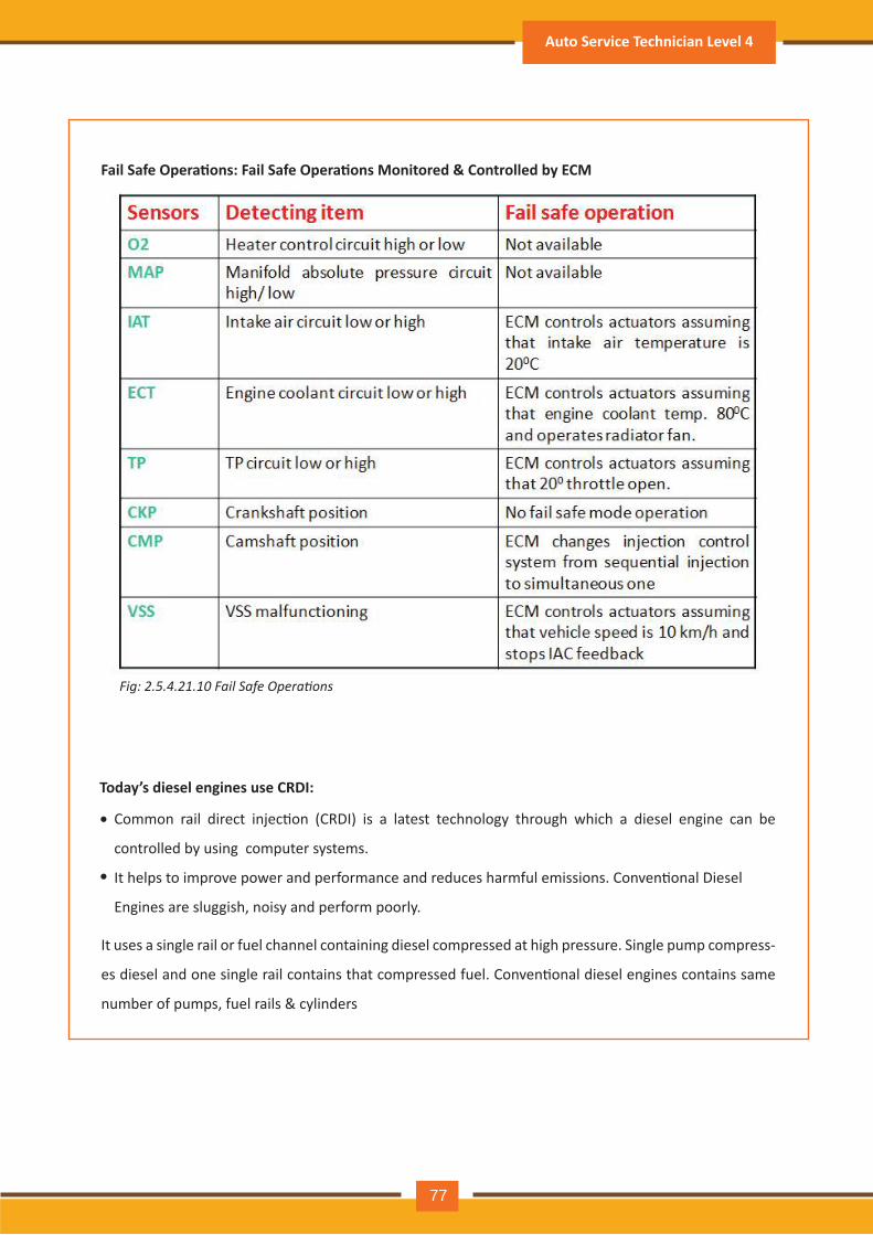
Fail Safe Opera�ons: Fail Safe Opera�ons Monitored & Controlled by ECM
Fig: 2.5.4.21.10 Fail Safe Operations
Today’s diesel engines use CRDI:
Common rail direct injec�on (CRDI) is a latest technology through which a diesel engine can be
controlled by using computer systems.
It helps to improve power and performance and reduces harmful emissions. Conven�onal Diesel
Engines are sluggish, noisy and perform poorly.
It uses a single rail or fuel channel containing diesel compressed at high pressure. Single pump compress-
es diesel and one single rail contains that compressed fuel. Conven�onal diesel engines contains same
number of pumps, fuel rails & cylinders
•
•
Auto Service Technician Level 4
77
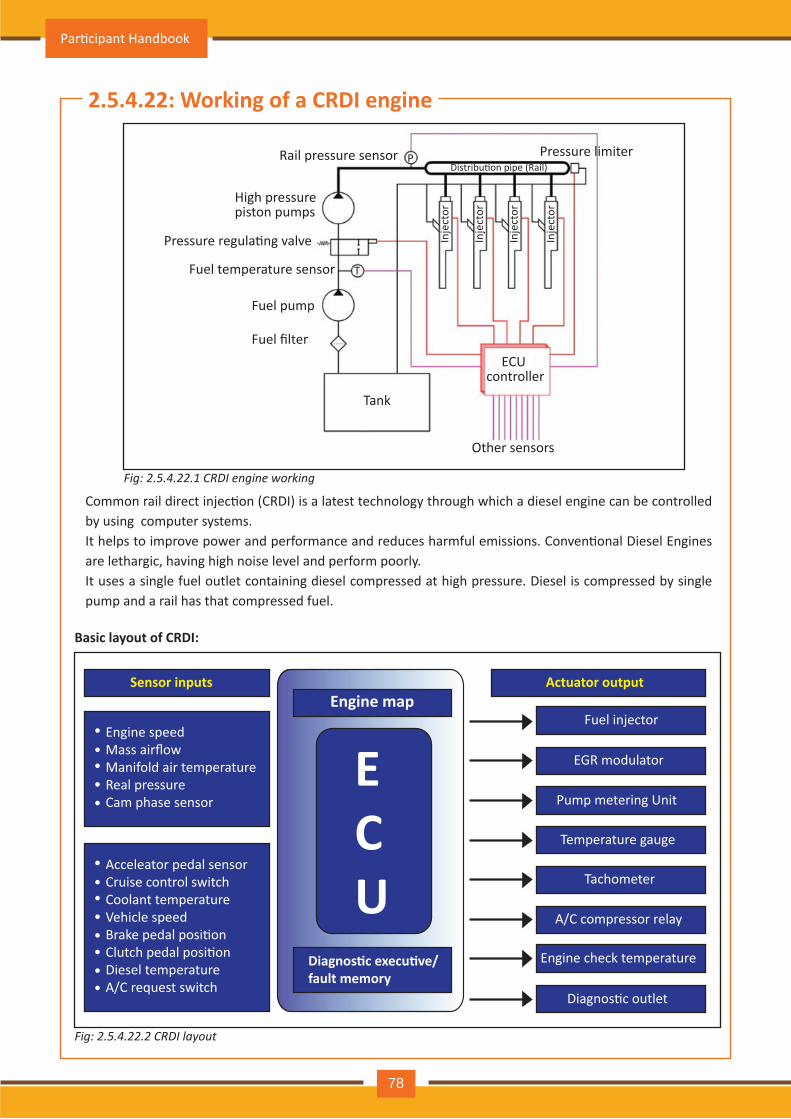
Fig: 2.5.4.22.2 C R D I l a y o u t
2.5.4.22: Working of a CRDI engine
Basic layout of CRDI:
P
T
R ail pressure sensor Distribu�on pipe (Rail)
Pressure lim iter
High pressure piston pum ps
Pressure regula�ng valve
Fuel tem perature sensor
Fuel pum p
ECU controller
Inje
ctor
Inje
ctor
Inje
ctor
Inje
ctor
Fuel filter
O th er sensors
Tank
Sensor inputs Actuator output
Fuel inj ector
EGR modulator
Pump metering Unit
Temperature gauge
Tach om eter
A / C com pressor relay
Engine check temperature
Diagnos�c outlet
Engine speedMass airflowManifold air temperatureR eal pressureC am ph ase sensor
•••••
Acceleator pedal sensorC ruise control switch C oolant tem peratureVehicle speed Brake pedal posi�on Clutch pedal posi�onDiesel tem peratureA/C request switch
••••••••
Engine map
Diagnos�c execu�ve/fault memory
ECU
Fig: 2.5.4.22.1 C R D I e n gin e w o r k in g
Common rail direct injec�on (CRDI) is a latest technology through which a diesel engine can be controlled by using computer systems.It helps to improve power and performance and reduces harmful emissions. Conven�onal Diesel Engines are lethargic, having high noise level and perform poorly.It uses a single fuel outlet containing diesel compressed at high pressure. Diesel is compressed by single pump and a rail has that compressed fuel.
Par�cipant Handbook
78
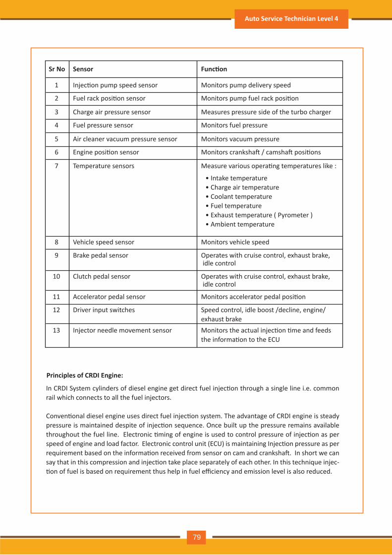
Principles of CRDI Engine:
Sr No
1 Injec�on pump speed sensor Monitors pump delivery speed
Sensor Func�on
In CRDI System cylinders of diesel engine get direct fuel injec�on through a single line i.e. common rail which connects to all the fuel injectors.
Conven�onal diesel engine uses direct fuel injec�on system. The advantage of CRDI engine is steady pressure is maintained despite of injec�on sequence. Once built up the pressure remains available throughout the fuel line. Electronic �ming of engine is used to control pressure of injec�on as per speed of engine and load factor. Electronic control unit (ECU) is maintaining Injec�on pressure as per requirement based on the informa�on received from sensor on cam and cranksha�. In short we can say that in this compression and injec�on take place separately of each other. In this technique injec-�on of fuel is based on requirement thus help in fuel efficiency and emission level is also reduced.
2 Fuel rack posi�on sensor Monitors pump fuel rack posi�on
3 Charge air pressure sensor Measures pressure side of the turbo charger
4 Fuel pressure sensor Monitors fuel pressure
5 Air cleaner vacuum pressure sensor Monitors vacuum pressure
6 Engine posi�on sensor Monitors cranksha� / camsha� posi�ons
7 Temperature sensors Measure various opera�ng temperatures like :
• Intake temperature• Charge air temperature• Coolant temperature• Fuel temperature• Exhaust temperature ( Pyrometer ) • Ambient temperature
8 Vehicle speed sensor Monitors vehicle speed
9 Brake pedal sensor Operates with cruise control, exhaust brake, idle control
Operates with cruise control, exhaust brake, idle control
10 Clutch pedal sensor
11 Accelerator pedal sensor Monitors accelerator pedal posi�on
12 Driver input switches Speed control, idle boost /decline, engine/exhaust brake
13 Injector needle movement sensor Monitors the actual injec�on �me and feeds the informa�on to the ECU
Auto Service Technician Level 4
79
New-age features:
1. Cruise control
• Also called speed control, is a combina�on of electrical and mechanical components
• Consistency in vehicle speed is set without pressure on the accelerator pedal
2. Engine control module
• Many drivability problems are NOT caused by engine mechanical problems.
• Perform a thorough inspec�on and tes�ng of igni�on and fuel systems before tes�ng for mechanical
engine problems.
• Typical engine mechanical related complaints are:
• High engine oil consump�on
• Engine mis-firing
• Loosing of power
• Smoke from the engine exhaust
• Noise from engine
Visual inspec�on:Visual inspec�on is the preliminary test. • Oil level and condi�on • Coolant level and condi�on • Oil leaks • Colour of engine exhaust smoke
Accuracy of spray in combus�on chamber considerably reduce the unburned fuel and due to that CRDI is having possibility to meet latest emission guidelines like Euro V. Now a days CRDI engines are commonly used by major car manufacturers like Hyundai, Ford, Toyota, Marcedes and many more (Mahindra is using it since many years).
Par�cipant Handbook
80
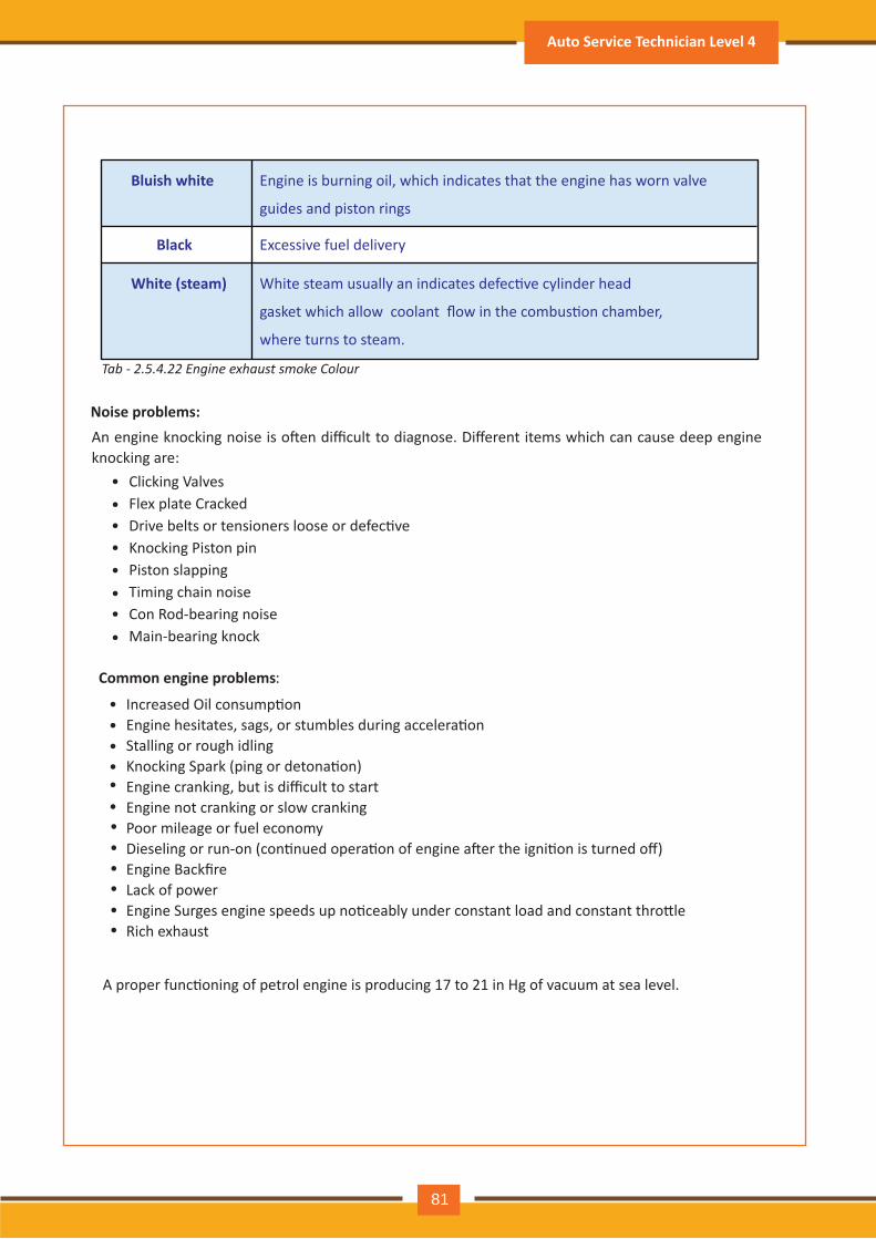
Noise problems:
••••••••••••
••••••••
An engine knocking noise is o�en difficult to diagnose. Different items which can cause deep engine knocking are:
Clicking Valves Flex plate Cracked Drive belts or tensioners loose or defec�ve Knocking Piston pin Piston slappingTiming chain noiseCon Rod-bearing noiseMain-bearing knock
Common engine problems:
Increased Oil consump�onEngine hesitates, sags, or stumbles during accelera�onStalling or rough idling Knocking Spark (ping or detona�on)Engine cranking, but is difficult to startEngine not cranking or slow cranking Poor mileage or fuel economyDieseling or run-on (con�nued opera�on of engine a�er the igni�on is turned off)Engine BackfireLack of powerEngine Surges engine speeds up no�ceably under constant load and constant thro�le Rich exhaust
A proper func�oning of petrol engine is producing 17 to 21 in Hg of vacuum at sea level.
Tab - 2.5.4.22 Engine exhaust smoke Colour
Bluish white
White (steam)
Black
Engine is burning oil, which indicates that the engine has worn valve
guides and piston rings
Excessive fuel delivery
White steam usually an indicates defec�ve cylinder head
gasket which allow coolant flow in the combus�on chamber,
where turns to steam.
Auto Service Technician Level 4
81
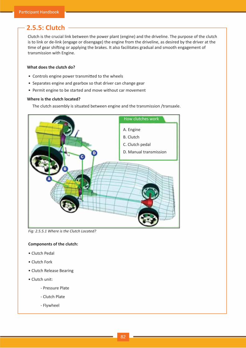
2.5.5: ClutchClutch is the crucial link between the power plant (engine) and the driveline. The purpose of the clutch is to link or de-link (engage or disengage) the engine from the driveline, as desired by the driver at the �me of gear shi�ing or applying the brakes. It also facilitates gradual and smooth engagement of transmission with Engine.
• Controls engine power transmi�ed to the wheels• Separates engine and gearbox so that driver can change gear• Permit engine to be started and move without car movement
What does the clutch do?
Where is the clutch located?The clutch assembly is situated between engine and the transmission /transaxle.
How clutches work
A. Engine
B. Clutch
C. Clutch pedal
D. Manual transmission
Fig: 2.5.5.1 Where is the Clutch Located?
Components of the clutch:
• Clutch Pedal
• Clutch Fork
• Clutch Release Bearing
• Clutch unit:
- Pressure Plate
- Clutch Plate
- Flywheel
Par�cipant Handbook
82
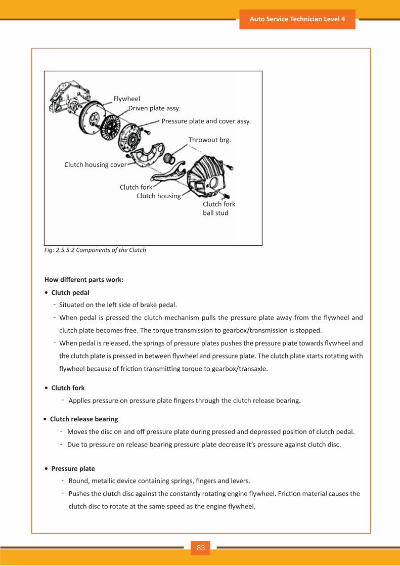
How different parts work:
• Clutch pedal
• Clutch fork
• Clutch release bearing
• Pressure plate
Clutch housing cover
Clutch forkClutch housing
Clutch fork ball stud
Throwout brg.
Pressure plate and cover assy.
Driven plate assy.Flywheel
Situated on the le� side of brake pedal.
When pedal is pressed the clutch mechanism pulls the pressure plate away from the flywheel and
clutch plate becomes free. The torque transmission to gearbox/transmission is stopped.
When pedal is released, the springs of pressure plates pushes the pressure plate towards flywheel and
the clutch plate is pressed in between flywheel and pressure plate. The clutch plate starts rota�ng with
flywheel because of fric�on transmi�ng torque to gearbox/transaxle.
Moves the disc on and off pressure plate during pressed and depressed posi�on of clutch pedal.
Due to pressure on release bearing pressure plate decrease it’s pressure against clutch disc.
Round, metallic device containing springs, fingers and levers.
Pushes the clutch disc against the constantly rota�ng engine flywheel. Fric�on material causes the
clutch disc to rotate at the same speed as the engine flywheel.
Applies pressure on pressure plate fingers through the clutch release bearing.
-
-
-
-
-
-
-
-
Fig: 2.5.5.2 Components of the Clutch
Auto Service Technician Level 4
83
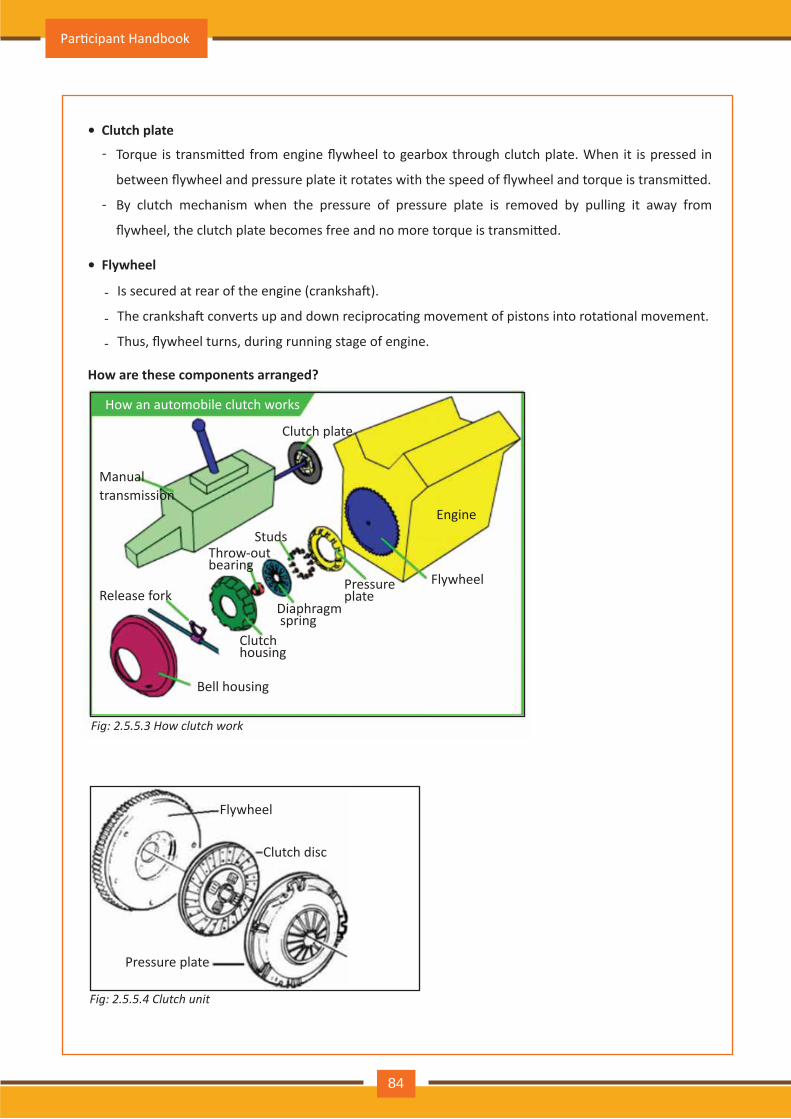
• Clutch plate
• Flywheel
How are these components arranged?
Torque is transmi�ed from engine flywheel to gearbox through clutch plate. When it is pressed in
between flywheel and pressure plate it rotates with the speed of flywheel and torque is transmi�ed.
By clutch mechanism when the pressure of pressure plate is removed by pulling it away from
flywheel, the clutch plate becomes free and no more torque is transmi�ed.
Is secured at rear of the engine (cranksha�).
The cranksha� converts up and down reciproca�ng movement of pistons into rota�onal movement.
Thus, flywheel turns, during running stage of engine.
-
-
-
-
-
How an automobile clutch works
Manual transmission
Clutch plate
Release fork
Throw-out bearing
StudsEngine
FlywheelPressure plate
Diaphragm spring
Clutch housing
Bell housing
Flywheel
Clutch disc
Pressure plate
Fig: 2.5.5.3 How clutch work
Fig: 2.5.5.4 Clutch unit
Par�cipant Handbook
84
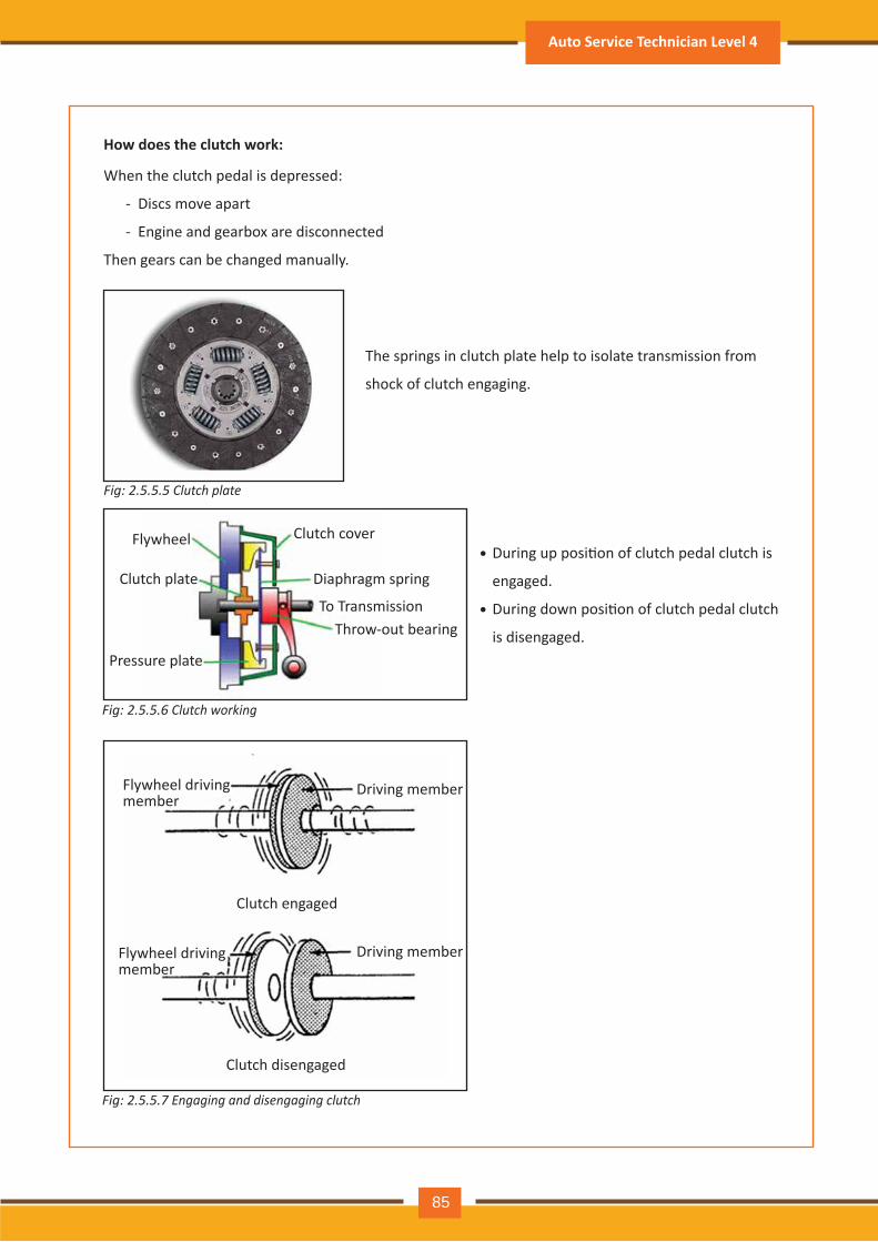
How does the clutch work:
When the clutch pedal is depressed:
- Discs move apart
- Engine and gearbox are disconnected
Then gears can be changed manually.
The springs in clutch plate help to isolate transmission from
shock of clutch engaging.
During up posi�on of clutch pedal clutch is
engaged.
During down posi�on of clutch pedal clutch
is disengaged.
Flywheel
Clutch plate
Pressure plate
Clutch cover
Diaphragm spring
Throw-out bearing To Transmission
•
•
Flywheel driving member
Flywheel driving member
Driving member
Driving member
Clutch engaged
Clutch disengaged
Fig: 2.5.5.5 Clutch plate
Fig: 2.5.5.6 Clutch working
Fig: 2.5.5.7 Engaging and disengaging clutch
Auto Service Technician Level 4
85
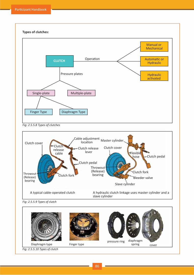
Types of clutches:
CLUTCH Opera�on
Pressure plates
Single-plate Mul�ple-plate
Finger Type Diaphragm Type
Manual or Mechanical
Automa�c orHydraulic
Hydraulicac�vated
Clutch cover
Throwout (Release) bearing
Clutch release
cable
Clutch fork
Clutch pedal
Clutch release lever
Cable adjustment loca�on Master cylinder
Clutch cover
Throwout (Release) bearing
Slave cylinder
Bleeder valve
Clutch fork
Clutch pedalFlexible
hose
A typical cable-operated clutch A hydraulic clutch linkage uses master cylinder and a slave cylinder
pressure ring Diaphragm type
diaphragm spring cover
Fig: 2.5.5.8 Types of clutches
Fig: 2.5.5.9 Types of clutch
Fig: 2.5.5.10 Types of clutchFinger type
Par�cipant Handbook
86
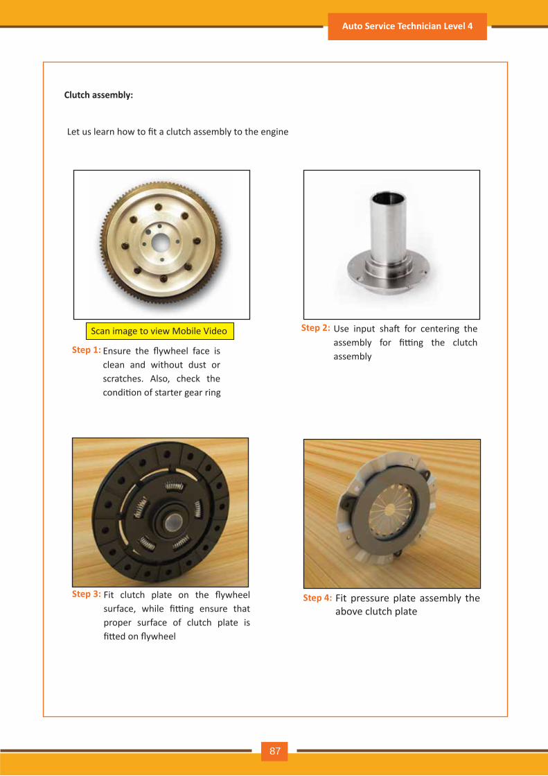
Ensure the flywheel face is clean and without dust or scratches. Also, check the condi�on of starter gear ring
Use input sha� for centering the assembly for fi�ng the clutch assembly
Scan image to view Mobile Video
Clutch assembly:
Let us learn how to fit a clutch assembly to the engine
Step 1:
Step 2:
Fit clutch plate on the flywheel surface, while fi�ng ensure that proper surface of clutch plate is fi�ed on flywheel
Fit pressure plate assembly the above clutch plate
Step 3: Step 4:
Auto Service Technician Level 4
87
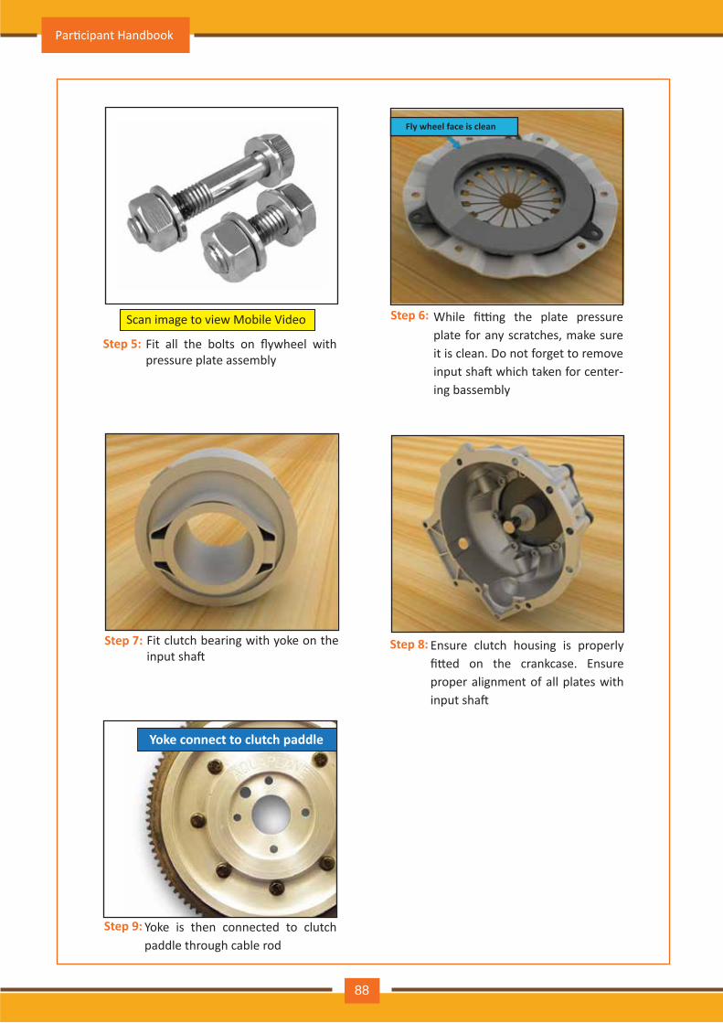
Fit all the bolts on flywheel with pressure plate assembly
Scan image to view Mobile Video
Step 5:
While fi�ng the plate pressure plate for any scratches, make sure it is clean. Do not forget to remove input sha� which taken for center-ing bassembly
Fit clutch bearing with yoke on the input sha�
Step 7:
Step 6:
Ensure clutch housing is properly fi�ed on the crankcase. Ensure proper alignment of all plates with input sha�
Step 8:
Fly wheel face is clean
Yoke is then connected to clutch paddle through cable rod
Step 9:
Yoke connect to clutch paddle
Par�cipant Handbook
88
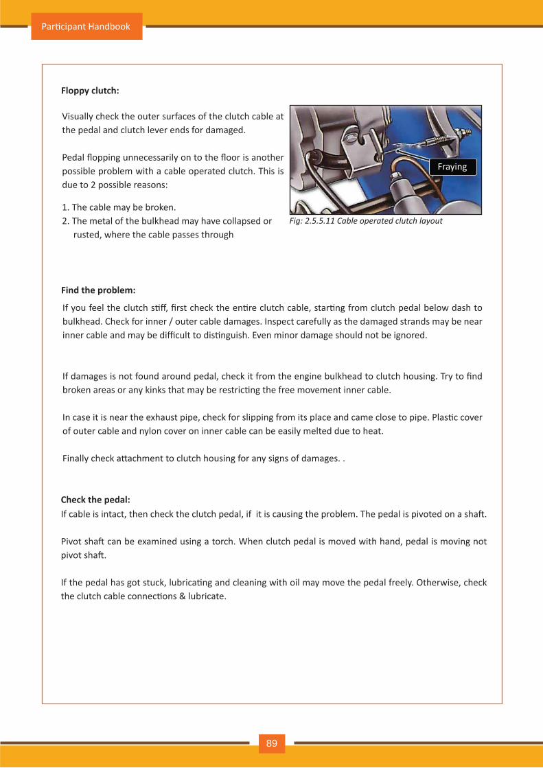
Floppy clutch:
Find the problem:
Fig: 2.5.5.11 C a b l e o p e r a t e d c l u t c h l a y o u t
V isually ch eck th e outer surfaces of th e clutch cable at th e pedal and clutch lev er ends for dam aged.
Pedal flopping unnecessarily on to the floor is another possible problem with a cable operated clutch . Th is is due to 2 possible reasons:
1. Th e cable m ay be broken.2. Th e m etal of th e bulkh ead m ay h av e collapsed or rusted, wh ere th e cable passes th rough
If you feel the clutch s�ff, first check the en�re clutch cable, star�ng from clutch pedal below dash to bulkhead. Check for inner / outer cable damages. Inspect carefully as the damaged strands may be near inner cable and may be difficult to dis�nguish. Even minor damage should not be ignored.
If damages is not found around pedal, check it from the engine bulkhead to clutch housing. Try to find broken areas or any kinks that may be restric�ng the free movement inner cable.
In case it is near the exhaust pipe, check for slipping from its place and came close to pipe. Plas�c cover of outer cable and ny lon cov er on inner cable can be easily m elted due to h eat.
Finally check a�achment to clutch housing for any signs of damages. .
Fray ing
If cable is intact, then check the clutch pedal, if it is causing the problem. The pedal is pivoted on a sha�.
Pivot sha� can be examined using a torch. When clutch pedal is moved with hand, pedal is moving not pivot sha�.
If the pedal has got stuck, lubrica�ng and cleaning with oil may move the pedal freely. Otherwise, check the clutch cable connec�ons & lubricate.
Check the pedal:
Par�cipant Handbook
89
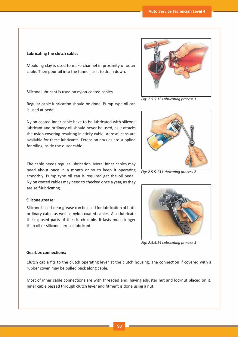
Moulding clay is used to m ake ch annel in proxim ity of outer cable. Th en pour oil into th e funnel, as it to drain down.
Lubrica�ng the clutch cable:
Silicone lubricant is used on ny lon- coated cables.
Regular cable lubrica�on should be done. Pump-type oil can is used at pedal.
Ny lon coated inner cable h av e to be lubricated with silicone lubricant and ordinary oil should never be used, as it a�acks the nylon covering resul�ng in s�cky cable. Aerosol cans are av ailable for th ese lubricants. Extension noz z les are supplied for oiling inside th e outer cable.
The cable needs regular lubrica�on. Metal inner cables may need about once in a month or so to keep it opera�ng sm ooth ly . Pum p ty pe oil can is required get th e oil pedal. Ny lon coated cables m ay need to ch ecked once a y ear, as th ey are self-lubrica�ng.
Fig: 2.5.5.13 ubricating process 2
Fig: 2.5.5.14 ubricating process 3
Fig: 2.5.5.12 ubricating process 1
Silicone based clear grease can be used for lubrica�on of both ordinary cable as well as ny lon coated cables. A lso lubricate the exposed parts of the clutch cable. It lasts much longer th an oil or silicone aerosol lubricant.
Silicone grease:
Clutch cable fits to the clutch opera�ng lever at the clutch housing. The connec�on if covered with a rubber cov er, m ay be pulled back along cable.
Most of inner cable connec�ons are with threaded end, having adjuster nut and locknut placed on it. Inner cable passed through clutch lever and fitment is done using a nut.
Gearbox connec�ons:
Auto Service Technician Level 4
90
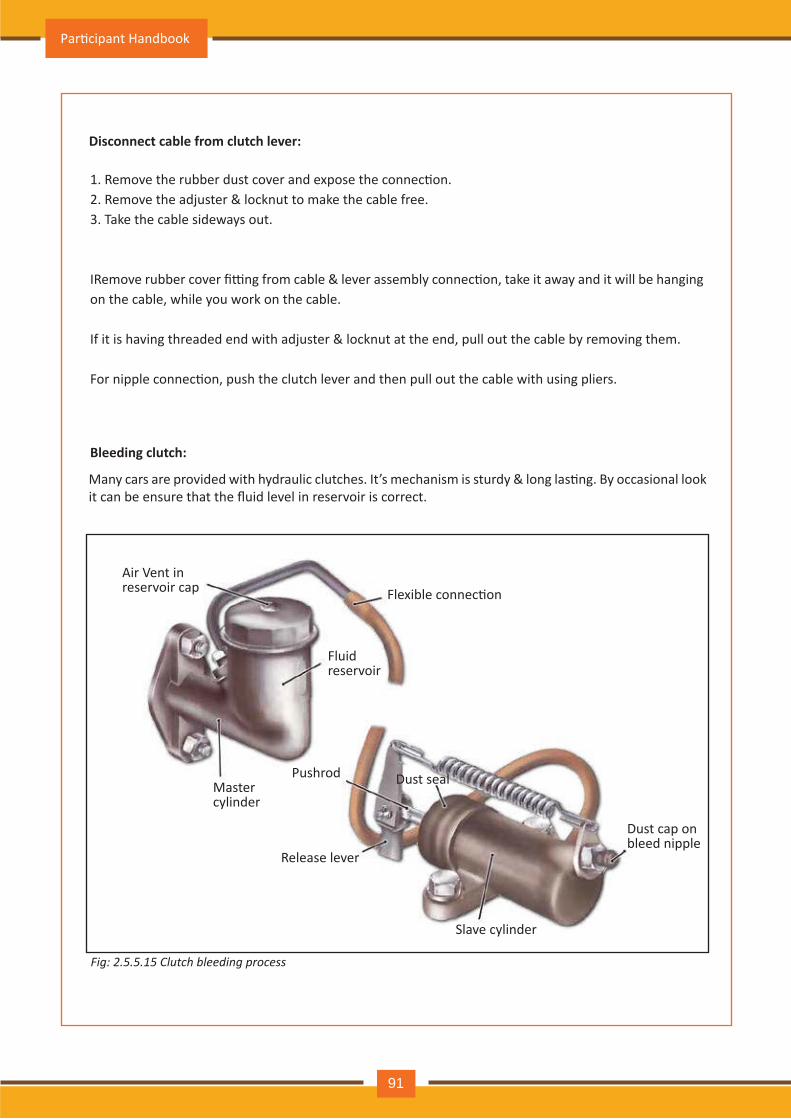
1. Remove the rubber dust cover and expose the connec�on.2. Remove the adjuster & locknut to make the cable free.3. Take th e cable sideway s out.
IRemove rubber cover fi�ng from cable & lever assembly connec�on, take it away and it will be hanging on th e cable, wh ile y ou work on th e cable.
If it is having threaded end with adjuster & locknut at the end, pull out the cable by removing them.
For nipple connec�on, push the clutch lever and then pull out the cable with using pliers.
D isconnect cable from clutch lever:
Many cars are provided with hydraulic clutches. It’s mechanism is sturdy & long las�ng. By occasional look it can be ensure that the fluid level in reservoir is correct.
Fig: 2.5.5.15 C l u t c h b l e e d in g p r o c e s s
A ir V ent in reserv oir cap Flexible connec�on
Fluid reserv oir
Master cy linder
Push rod Dust seal
R elease lev er
Slav e cy linder
Dust cap onbleed nipple
B leeding clutch:
Par�cipant Handbook
91
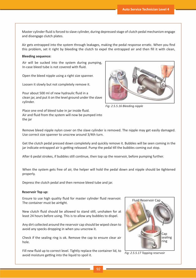
Master cylinder fluid is forced to slave cylinder, during depressed stage of clutch pedal mechanism engage and disengage clutch plates.
Air gets entrapped into the system through leakages, making the pedal response erra�c. When you find this problem, set it right by bleeding the clutch to expel the entrapped air and then fill it with clean,
R em ov e bleed nipple ny lon cov er on th e slav e cy linder is rem ov ed. Th e nipple m ay get easily dam aged. Use correct siz e spanner to unscrew around 3/ 4th turn.
G et th e clutch pedal pressed down com pletely and quickly rem ov e it. Bubbles will be seen com ing in th e jar indicate entrapped air is ge�ng released. Pump the pedal �ll the bubbles coming out stop.
A�er 6 pedal strokes, if bubbles s�ll con�nue, then top up the reservoir, before pumping further.
When the system gets free of air, the helper will hold the pedal down and nipple should be �ghtened properly .
Depress th e clutch pedal and th en rem ov e bleed tube and j ar.
A ir will be sucked into th e sy stem during pum ping, In-case bleed tube is not covered with fluid.
O pen th e bleed nipple using a righ t siz e spanner.
Loosen it slowly but not com pletely rem ov e it.
Pour about 500 ml of new hydraulic fluid in aclean j ar, and put it on th e lev el ground under th e slav e cy linder.
Place one end of bleed tube in jar inside fluid.Air and fluid from the system will now be pumped into th e j ar
Fig: 2.5.5.16 B l e e d in g n ip p l e
B leeding sequence:
Ensure to use high quality fluid for master cylinder fluid reservoir. The container must be air�ght.
New clutch fluid should be allowed to stand s�ll, unshaken for at least 24 h ours before using. Th is is to allow any bubbles to dispel.
A ny dirt collected around th e reserv oir cap sh ould be wiped clean to av oid any specks dropping in wh en y ou unscrew it.
C h eck if th e sealing ring is ok. R em ov e th e cap to ensure clear air h ole.
Fill new fluid up to correct level. Tightly replace the container lid, to avoid moisture ge�ng into the liquid to spoil it.
R eservoir Top up:
Fig: 2.5.5.17 T o p p in g r e s e r v o ir
Fluid R eserv oir C ap
C ap sealingring
Auto Service Technician Level 4
92
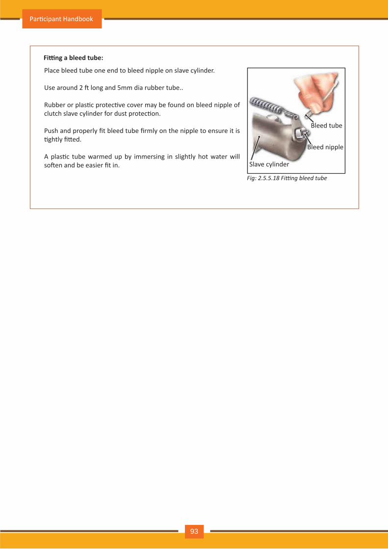
Place bleed tube one end to bleed nipple on slav e cy linder.
Use around 2 � long and 5mm dia rubber tube..
Rubber or plas�c protec�ve cover may be found on bleed nipple of clutch slave cylinder for dust protec�on.
Push and properly fit bleed tube firmly on the nipple to ensure it is �ghtly fi�ed.
A plas�c tube warmed up by immersing in slightly hot water will so�en and be easier fit in.
Fi ng a bleed tube:
Fig: 2.5.5.1 Fi ng bleed tube
Bleed tube
Bleed nipple
Slav e cy linder
Par�cipant Handbook
93
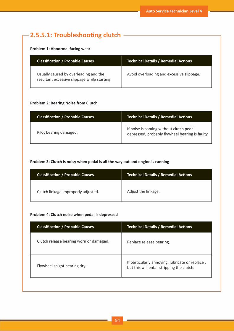
2.5.5.1: Troubleshoo�ng clutch
Problem 1: Abnormal facing wear
Classifica�on / Probable Causes Technical Details / Remedial Ac�ons
Usually caused by overleading and the resultant excessive slippage while star�ng.
Avoid overloading and excessive slippage.
Problem 2: Bearing Noise from Clutch
Classifica�on / Probable Causes Technical Details / Remedial Ac�ons
Pilot bearing damaged.If noise is coming without clutch pedal depressed, probably flywheel bearing is faulty.
Problem 3: Clutch is noisy when pedal is all the way out and engine is running
Classifica�on / Probable Causes Technical Details / Remedial Ac�ons
Clutch linkage improperly adjusted. Adjust the linkage.
Problem 4: Clutch noise when pedal is depressed
Classifica�on / Probable Causes Technical Details / Remedial Ac�ons
Clutch release bearing worn or damaged. Replace release bearing.
Flywheel spigot bearing dry.If par�cularly annoying, lubricate or replace : but this will entail stripping the clutch.
Auto Service Technician Level 4
94
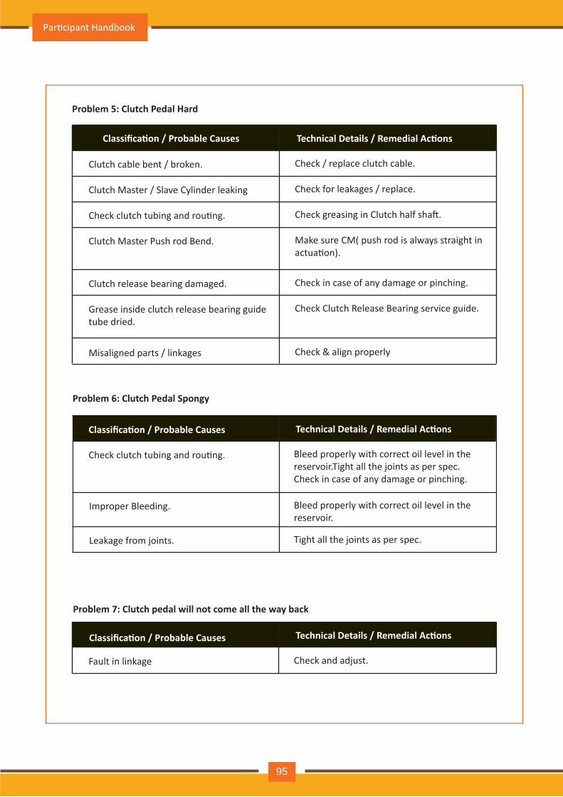
Problem 5: Clutch Pedal Hard
Classifica�on / Probable Causes Technical Details / Remedial Ac�ons
Clutch cable bent / broken. Check / replace clutch cable.
Clutch Master / Slave Cylinder leaking Check for leakages / replace.
Check clutch tubing and rou�ng. Check greasing in Clutch half sha�.
Clutch Master Push rod Bend. Make sure CM( push rod is always straight in actua�on).
Clutch release bearing damaged. Check in case of any damage or pinching.
Grease inside clutch release bearing guide tube dried.
Check Clutch Release Bearing service guide.
Misaligned parts / linkages Check & align properly
Problem 6: Clutch Pedal Spongy
Classifica�on / Probable Causes Technical Details / Remedial Ac�ons
Check clutch tubing and rou�ng.
Improper Bleeding. Bleed properly with correct oil level in the reservoir.
Bleed properly with correct oil level in the reservoir.Tight all the joints as per spec.Check in case of any damage or pinching.
Leakage from joints. Tight all the joints as per spec.
Problem 7: Clutch pedal will not come all the way back
Classifica�on / Probable Causes Technical Details / Remedial Ac�ons
Fault in linkage Check and adjust.
Par�cipant Handbook
95
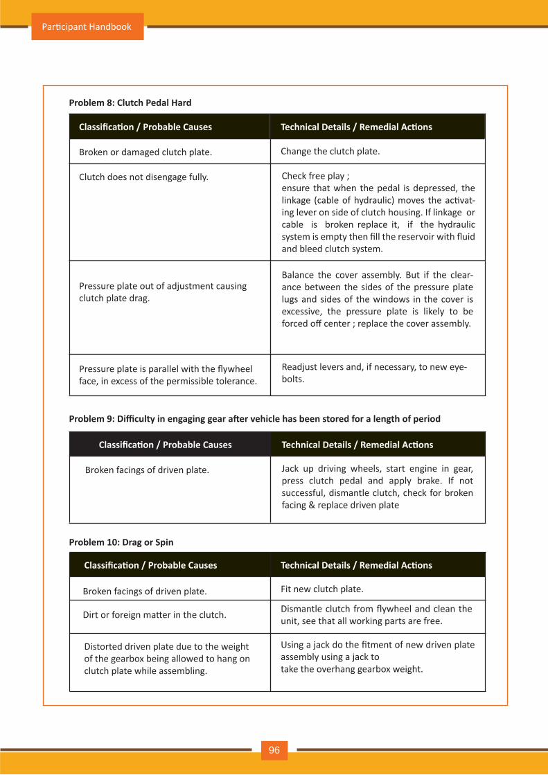
Classifica�on / Probable Causes Technical Details / Remedial Ac�ons
Broken or damaged clutch plate. Change the clutch plate.
Clutch does not disengage fully.
Pressure plate out of adjustment causing clutch plate drag.
Check free play ;ensure that when the pedal is depressed, the linkage (cable of hydraulic) moves the ac�vat- ing lever on side of clutch housing. If linkage or cable is broken replace it, if the hydraulic system is empty then fill the reservoir with fluid and bleed clutch system.
Balance the cover assembly. But if the clear- ance between the sides of the pressure plate lugs and sides of the windows in the cover is excessive, the pressure plate is likely to be forced off center ; replace the cover assembly.
Pressure plate is parallel with the flywheelface, in excess of the permissible tolerance.
Readjust levers and, if necessary, to new eye-bolts.
Jack up driving wheels, start engine in gear, press clutch pedal and apply brake. If not successful, dismantle clutch, check for broken facing & replace driven plate
Classifica�on / Probable Causes Technical Details / Remedial Ac�ons
Broken facings of driven plate.
Fit new clutch plate.
Classifica�on / Probable Causes Technical Details / Remedial Ac�ons
Broken facings of driven plate.
Dismantle clutch from flywheel and clean the unit, see that all working parts are free.
Using a jack do the fitment of new driven plate assembly using a jack totake the overhang gearbox weight.
Dirt or foreign ma�er in the clutch.
Distorted driven plate due to the weightof the gearbox being allowed to hang onclutch plate while assembling.
Problem 8: Clutch Pedal Hard
Problem 9: Difficulty in engaging gear a�er vehicle has been stored for a length of period
Problem 10: Drag or Spin
Par�cipant Handbook
96
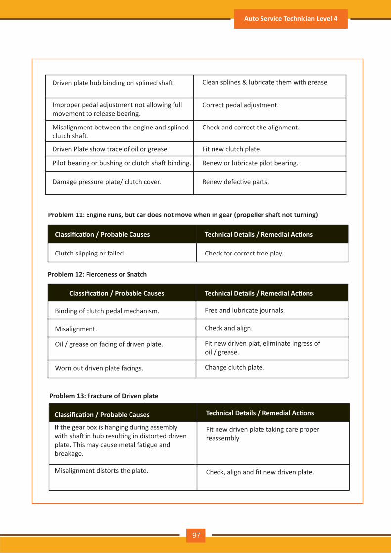
Driven plate hub binding on splined sha�. Clean splines & lubricate them with grease
Correct pedal adjustment.
Check and correct the alignment.
Fit new clutch plate.
Improper pedal adjustment not allowing fullmovement to release bearing.
Misalignment between the engine and splined clutch sha�.
Driven Plate show trace of oil or grease
Renew or lubricate pilot bearing.Pilot bearing or bushing or clutch sha� binding.
Renew defec�ve parts.Damage pressure plate/ clutch cover.
Auto Service Technician Level 4
97
Problem 11: Engine runs, but car does not move when in gear (propeller sha� not turning)
Classifica�on / Probable Causes Technical Details / Remedial Ac�ons
Clutch slipping or failed. Check for correct free play.
Problem 12: Fierceness or Snatch
Classifica�on / Probable Causes Technical Details / Remedial Ac�ons
Binding of clutch pedal mechanism. Free and lubricate journals.
Misalignment. Check and align.
Oil / grease on facing of driven plate. Fit new driven plat, eliminate ingress ofoil / grease.
Worn out driven plate facings. Change clutch plate.
Problem 13: Fracture of Driven plate
Classifica�on / Probable Causes Technical Details / Remedial Ac�ons
Fit new driven plate taking care properreassembly
If the gear box is hanging during assemblywith sha� in hub resul�ng in distorted drivenplate. This may cause metal fa�gue andbreakage.
Check, align and fit new driven plate.Misalignment distorts the plate.
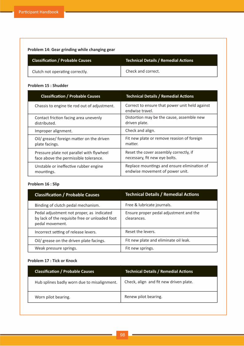
Problem 14: Gear grinding while changing gear
Classifica�on / Probable Causes Technical Details / Remedial Ac�ons
Clutch not opera�ng correctly. Check and correct.
Problem 15 : Shudder
Classifica�on / Probable Causes Technical Details / Remedial Ac�ons
Chassis to engine �e rod out of adjustment. Correct to ensure that power unit held against endwise travel.
Contact fric�on facing area unevenlydistributed.
Distor�on may be the cause, assemble newdriven plate.
Oil/ grease/ foreign ma�er on the drivenplate facings.
Fit new plate or remove reasion of foreignma�er.
Pressure plate not parallel with flywheelface above the permissible tolerance.
Reset the cover assembly correctly, ifnecessary, fit new eye bolts.
Unstable or ineffec�ve rubber engine moun�ngs.
Replace moun�ngs and ensure elimina�on of endwise movement of power unit.
Improper alignment. Check and align.
Problem 16 : Slip
Classifica�on / Probable Causes Technical Details / Remedial Ac�ons
Binding of clutch pedal mechanism. Free & lubricate journals.
Pedal adjustment not proper, as indicated by lack of the requisite free or unloaded footpedal movement.
Ensure proper pedal adjustment and the clearances.
Oil/ grease on the driven plate facings. Fit new plate and eliminate oil leak.
Weak pressure springs. Fit new springs.
Incorrect se�ng of release levers. Reset the levers.
Problem 17 : Tick or Knock
Classifica�on / Probable Causes Technical Details / Remedial Ac�ons
Hub splines badly worn due to misalignment. Check, align and fit new driven plate.
Worn pilot bearing. Renew pilot bearing.
Par�cipant Handbook
98
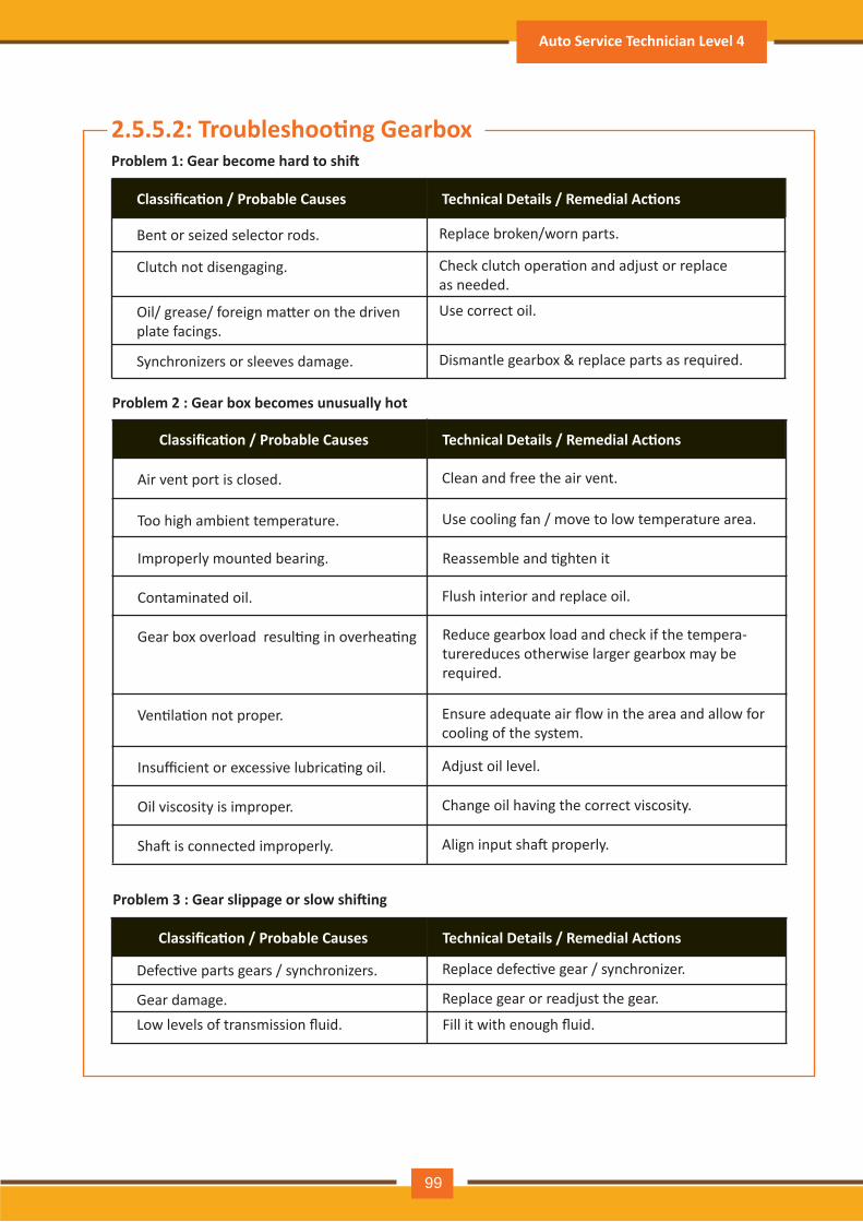
Problem 1: Gear become hard to shi�
Classifica�on / Probable Causes Technical Details / Remedial Ac�ons
Bent or seized selector rods. Replace broken/worn parts.
Clutch not disengaging. Check clutch opera�on and adjust or replace as needed.
Oil/ grease/ foreign ma�er on the drivenplate facings.
Use correct oil.
Synchronizers or sleeves damage. Dismantle gearbox & replace parts as required.
Problem 2 : Gear box becomes unusually hot
Classifica�on / Probable Causes Technical Details / Remedial Ac�ons
Air vent port is closed. Clean and free the air vent.
Too high ambient temperature. Use cooling fan / move to low temperature area.
Contaminated oil. Flush interior and replace oil.
Gear box overload resul�ng in overhea�ng
Improperly mounted bearing. Reassemble and �ghten it
Reduce gearbox load and check if the tempera-turereduces otherwise larger gearbox may berequired.
Ven�la�on not proper. Ensure adequate air flow in the area and allow for cooling of the system.
Insufficient or excessive lubrica�ng oil. Adjust oil level.
Oil viscosity is improper. Change oil having the correct viscosity.
Sha� is connected improperly. Align input sha� properly.
Problem 3 : Gear slippage or slow shi�ing
Classifica�on / Probable Causes Technical Details / Remedial Ac�ons
Defec�ve parts gears / synchronizers. Replace defec�ve gear / synchronizer.
Gear damage. Replace gear or readjust the gear.
Low levels of transmission fluid. Fill it with enough fluid.
2.5.5.2: Troubleshoo�ng Gearbox
Auto Service Technician Level 4
99
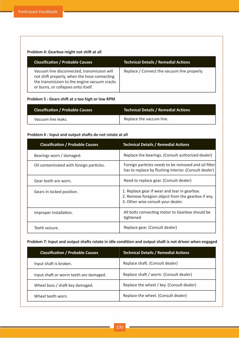
Problem 4: Gearbox might not shi� at all
Classifica�on / Probable Causes Technical Details / Remedial Ac�ons
Vacuum line disconnected, transmission will not shi� properly, when the hose connec�ng the transmission to the engine vacuum cracks or burns, or collapses onto itself.
Replace / Connect the vacuum line properly.
Problem 5 : Gears shi� at a too high or low RPM
Classifica�on / Probable Causes Technical Details / Remedial Ac�ons
Vacuum line leaks. Replace the vaccum line.
Problem 6 : Input and output sha�s do not rotate at all
Classifica�on / Probable Causes Technical Details / Remedial Ac�ons
Bearings worn / damaged. Replace the bearings. (Consult authorized dealer)
Oil contaminated with foreign par�cles. Foreign par�cles needs to be removed and oil filterhas to replace by flushing interior. (Consult dealer)
Gear teeth are worn. Need to replace gear. (Consult dealer)
Gears in locked posi�on. 1. Replace gear if wear and tear in gearbox.2. Remove foregion object from the gearbox if any.3. Other wise consult your dealer.
Improper installa�on. All bolts connec�ng motor to Gearbox should be �ghtened
Teeth seizure. Replace gear. (Consult dealer)
Problem 7: Input and output sha�s rotate in idle condi�on and output sha� is not driven when engaged
Classifica�on / Probable Causes Technical Details / Remedial Ac�ons
Input sha� is broken. Replace sha�. (Consult dealer)
Input sha� or worm teeth are damaged. Replace sha� / worm. (Consult dealer)
Wheel boss / sha� key damaged. Replace the wheel / key. (Consult dealer)
Wheel teeth worn. Replace the wheel. (Consult dealer)
Par�cipant Handbook
100
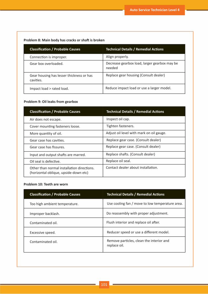
Problem 8: Main body has cracks or sha� is broken
Classifica�on / Probable Causes Technical Details / Remedial Ac�ons
Connec�on is improper. Align properly.
Gear box overloaded. Decrease gearbox load, larger gearbox may beneeded
Gear housing has lesser thickness or has cavi�es.
Replace gear housing (Consult dealer)
Impact load > rated load. Reduce impact load or use a larger model.
Problem 9: Oil leaks from gearbox
Classifica�on / Probable Causes Technical Details / Remedial Ac�ons
Air does not escape. Inspect oil cap.
Cover moun�ng fasteners loose. Tighten fasteners.
More quan�ty of oil. Adjust oil level with mark on oil gauge.
Gear case has cavi�es. Replace gear case. (Consult dealer)
Gear case has fissures. Replace gear case. (Consult dealer)
Input and output sha�s are marred. Replace sha�s. (Consult dealer)
Oil seal is defec�ve. Replace oil seal.
Other than normal installa�on direc�ons. (horizontal oblique, upside-down etc)
Contact dealer about installa�on.
Problem 10: Teeth are worn
Classifica�on / Probable Causes Technical Details / Remedial Ac�ons
Too high ambient temperature. Use cooling fan / move to low temperature area.
Improper backlash. Do reassembly with proper adjustment.
Contaminated oil. Flush interior and replace oil a�er.
Excessive speed. Reducer speed or use a different model.
Contaminated oil. Remove par�cles, clean the interior andreplace oil.
Auto Service Technician Level 4
101
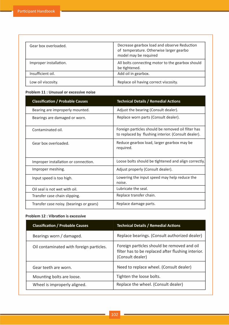
Gear box overloaded.
All bolts connec�ng motor to the gearbox should be �ghtened.Add oil in gearbox.
Improper installa�on.
Insufficient oil.
Replace oil having correct viscosity.Low oil viscosity.
Decrease gearbox load and observe Reduc�on of temperature. Otherwise larger gearbo model may be required
Problem 11 : Unusual or excessive noise
Classifica�on / Probable Causes Technical Details / Remedial Ac�ons
Bearing are improperly mounted. Adjust the bearing (Consult dealer).
Bearings are damaged or worn. Replace worn parts (Consult dealer).
Contaminated oil. Foreign par�cles should be removed oil filter has to replaced by flushing interior. (Consult dealer).
Gear box overloaded. Reduce gearbox load, larger gearbox may berequired.
Improper installa�on or connec�on. Loose bolts should be �ghtened and align correctly.
Improper meshing. Adjust properly (Consult dealer).
Input speed is too high. Lowering the input speed may help reduce the noise.
Oil seal is not wet with oil. Lubricate the seal.
Transfer case chain slipping. Replace transfer chain.
Transfer case noisy. (bearings or gears) Replace damage parts.
Problem 12 : Vibra�on is excessive
Classifica�on / Probable Causes Technical Details / Remedial Ac�ons
Bearings worn / damaged. Replace bearings. (Consult authorized dealer)
Oil contaminated with foreign par�cles. Foreign par�cles should be removed and oil filter has to be replaced a�er flushing interior. (Consult dealer)
Gear teeth are worn. Need to replace wheel. (Consult dealer)
Moun�ng bolts are loose. Tighten the loose bolts.
Wheel is improperly aligned. Replace the wheel. (Consult dealer)
Par�cipant Handbook
102
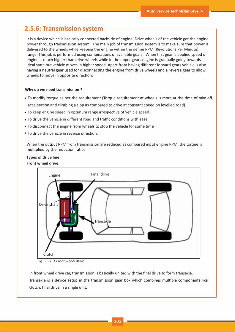
2.5.6: Transmission systemIt is a device which is basically connected backside of engine. Drive wheels of the vehicle get the engine power through transmission system. The main job of transmission system is to make sure that power is delivered to the wheels while keeping the engine within the define RPM (Revolu�ons Per Minute) range. This job is performed using combina�ons of available gears. When first gear is applied speed of engine is much higher than drive wheels while in the upper gears engine is gradually going towards ideal state but vehicle moves in higher speed. Apart from having different forward gears vehicle is also having a neutral gear used for disconnec�ng the engine from drive wheels and a reverse gear to allow wheels to move in opposite direc�on.
When the output RPM from transmission are reduced as compared input engine RPM, the torque is mul�plied by the reduc�on ra�o.
Why do we need transmission ?
To modify torque as per the requirement (Torque requirement at wheels is more at the �me of take off,
accelera�on and climbing a slop as compared to drive at constant speed on levelled road)
To keep engine speed in op�mum range irrespec�ve of vehicle speed.
To drive the vehicle in different road and traffic condi�ons with ease
To disconnect the engine from wheels to stop the vehicle for some �me
To drive the vehicle in reverse direc�on.
•
•
•••
Front wheel drive: Types of drive line:
In front wheel drive car, transmission is basically united with the final drive to form transaxle.
Transaxle is a device setup in the transmission gear box which combines mul�ple components like
clutch, final drive in a single unit.
Engine
Drive sha�
Final drive
Transaxle
ClutchFig: 2.5.6.1 Front wheel drive
Auto Service Technician Level 4
103
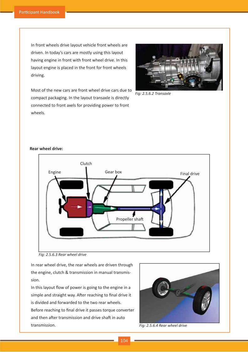
In front wheels drive layout vehicle front wheels are
driven. In today’s cars are mostly using this layout
having engine in front with front wheel drive. In this
layout engine is placed in the front for front wheels
driving.
Most of the new cars are front wheel drive cars due to
compact packaging. In the layout transaxle is directly
connected to front axels for providing power to front
wheels.
Fig: 2.5.6.2 Transaxle
Rear wheel drive:
Engine Gear box Final drive
Propeller sha�
Clutch
Fig: 2.5.6.3 Rear wheel drive
In rear wheel drive, the rear wheels are driven through
the engine, clutch & transmission in manual transmis-
sion.
In this layout flow of power is going to the engine in a
simple and straight way. A�er reaching to final drive it
is divided and forwarded to the two rear wheels.
Before reaching to final drive it passes torque converter
and then a�er transmission and drive sha� in auto
transmission. Fig: 2.5.6.4 Rear wheel drive
Par�cipant Handbook
104
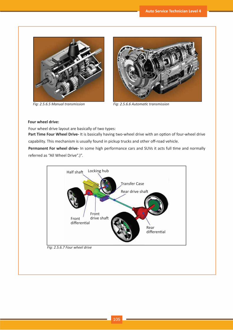
Fig: 2.5.6.5 Manual transmission Fig: 2.5.6.6 Automatic transmission
Four wheel drive:Four wheel drive layout are basically of two types:Part Time Four Wheel Drive- It is basically having two-wheel drive with an op�on of four-wheel drive
capability. This mechanism is usually found in pickup trucks and other off-road vehicle.
Permanent For wheel drive- In some high performance cars and SUVs it acts full �me and normally
referred as “All Wheel Drive”.)”.
Transfer Case
Rear drive sha�
Locking hubHalf sha�
Front differen�al
Front drive sha�
Rear differen�al
Fig: 2.5.6.7 Four wheel drive
Auto Service Technician Level 4
105
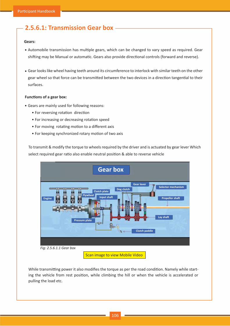
2.5.6.1: Transmission Gear box
Gears:
Func�ons of a gear box:
Gears are mainly used for following reasons:
• For reversing rota�on direc�on
• For increasing or decreasing rota�on speed
• For moving rota�ng mo�on to a different axis
• For keeping synchronized rotary mo�on of two axis
Automobile transmission has mul�ple gears, which can be changed to vary speed as required. Gear
shi�ing may be Manual or automa�c. Gears also provide direc�onal controls (forward and reverse).
Gear looks like wheel having teeth around its circumference to interlock with similar teeth on the other
gear wheel so that force can be transmi�ed between the two devices in a direc�on tangen�al to their
surfaces.
•
•
•
To transmit & modify the torque to wheels required by the driver and is actuated by gear lever Which
select required gear ra�o also enable neutral posi�on & able to reverse vehicle
Gear box
Engine
Pressure plate
FlywheelClutch plate
Input sha�
Dog clutch
Gear leverSelector mechanism
Propeller sha�
Lay sha�
Clutch paddle
Fig: 2.5.6.1.1 Gear box
Scan image to view Mobile Video
While transmi�ng power it also modifies the torque as per the road condi�on. Namely while start-ing the vehicle from rest posi�on, while climbing the hill or when the vehicle is accelerated or pulling the load etc.
Par�cipant Handbook
106
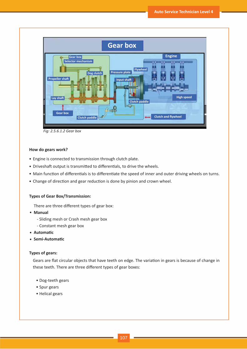
Engine is connected to transmission through clutch plate.
Drivesha� output is transmi�ed to differen�als, to drive the wheels.
Main func�on of differen�als is to differen�ate the speed of inner and outer driving wheels on turns.
Change of direc�on and gear reduc�on is done by pinion and crown wheel.
Gears are flat circular objects that have teeth on edge. The varia�on in gears is because of change in these teeth. There are three different types of gear boxes:
• Dog-teeth gears • Spur gears • Helical gears
Gear boxGear box
Gear box
Selector mechanism
Propeller sha�
Dog clutch
Clutch paddleHigh speed
Clutch and flywheelClutch paddle
Input sha�
FlywheelPressure plate
Lay sha�
Engine
Fig: 2.5.6.1.2 Gear box
How do gears work?
•
•
•
•
There are three different types of gear box:Manual - Sliding mesh or Crash mesh gear box - Constant mesh gear box Automa�cSemi-Automa�c
Types of Gear Box/Transmission:
Types of gears:
•
••
Auto Service Technician Level 4
107
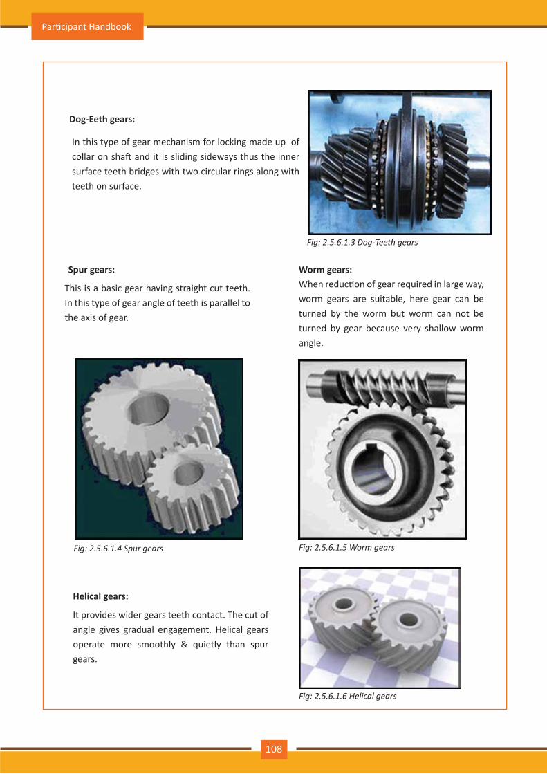
Dog-Eeth gears:
Spur gears:
In this type of gear mechanism for locking made up of collar on sha� and it is sliding sideways thus the inner surface teeth bridges with two circular rings along with teeth on surface.
This is a basic gear having straight cut teeth. In this type of gear angle of teeth is parallel to the axis of gear.
Helical gears:
It provides wider gears teeth contact. The cut of angle gives gradual engagement. Helical gears operate more smoothly & quietly than spur gears.
Worm gears:When reduc�on of gear required in large way, worm gears are suitable, here gear can be turned by the worm but worm can not be turned by gear because very shallow worm angle.
Fig: 2.5.6.1.3 Dog-Teeth gears
Fig: 2.5.6.1.4 Spur gears Fig: 2.5.6.1.5 Worm gears
Fig: 2.5.6.1.6 Helical gears
Par�cipant Handbook
108
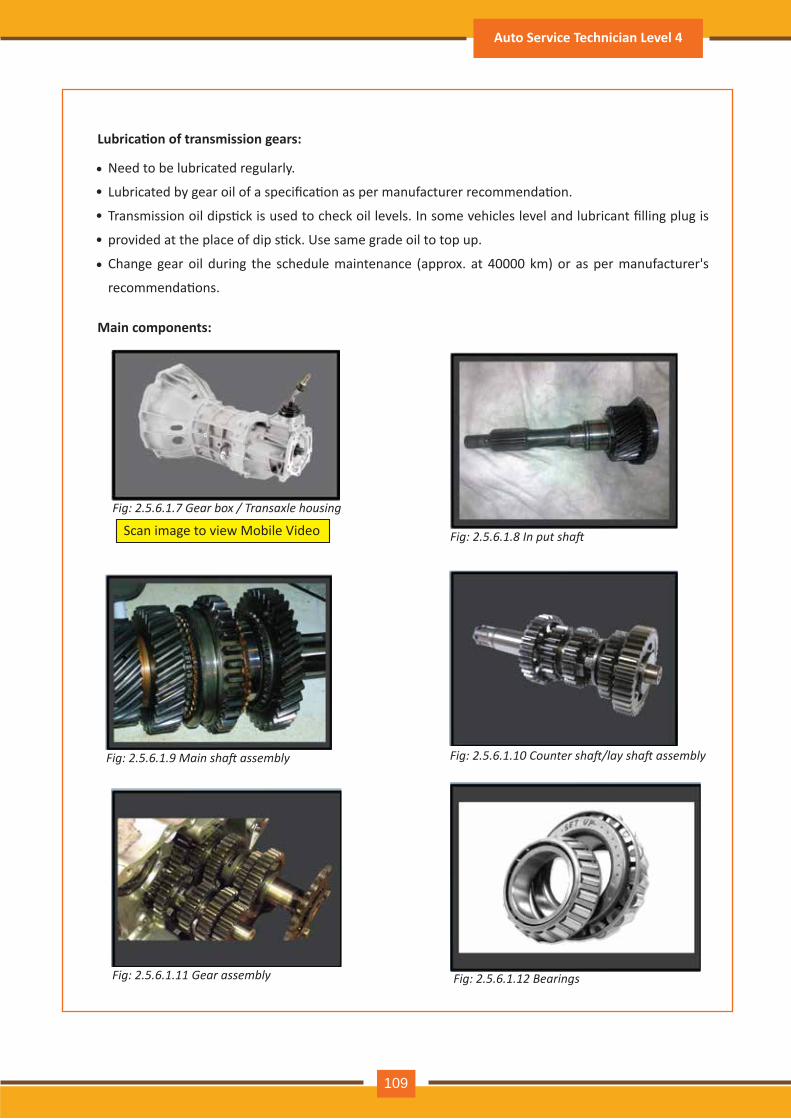
Lubrica�on of transmission gears:
Main components:
Need to be lubricated regularly.
Lubricated by gear oil of a specifica�on as per manufacturer recommenda�on.
Transmission oil dips�ck is used to check oil levels. In some vehicles level and lubricant filling plug is
provided at the place of dip s�ck. Use same grade oil to top up.
Change gear oil during the schedule maintenance (approx. at 40000 km) or as per manufacturer's
recommenda�ons.
••
•
•
•
Fig: 2.5.6.1.9 Main shaft assembly Fig: 2.5.6.1.10 Counter shaft/lay shaft assembly
Fig: 2.5.6.1.8 In put shaft
Fig: 2.5.6.1.7 Gear box / Transaxle housing
Scan image to view Mobile Video
Fig: 2.5.6.1.11 Gear assembly Fig: 2.5.6.1.12 Bearings
Auto Service Technician Level 4
109
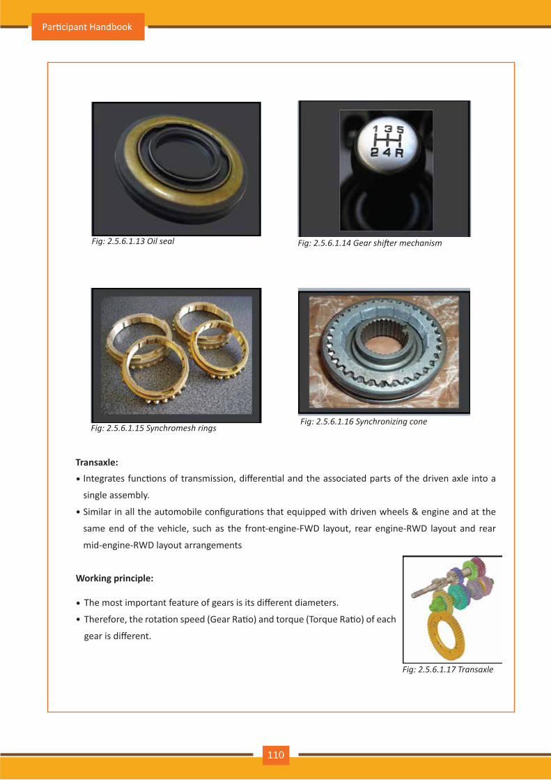
Fig: 2.5.6.1.17 Transaxle
Fig: 2.5.6.1.13 Oil seal Fig: 2.5.6.1.14 Gear shifter mechanism
Fig: 2.5.6.1.15 Synchromesh ringsFig: 2.5.6.1.16 Synchronizing cone
Transaxle:Integrates func�ons of transmission, differen�al and the associated parts of the driven axle into a
single assembly.
Similar in all the automobile configura�ons that equipped with driven wheels & engine and at the
same end of the vehicle, such as the front-engine-FWD layout, rear engine-RWD layout and rear
mid-engine-RWD layout arrangements
•
•
Working principle:
The most important feature of gears is its different diameters.
Therefore, the rota�on speed (Gear Ra�o) and torque (Torque Ra�o) of each
gear is different.
•
•
Par�cipant Handbook
110
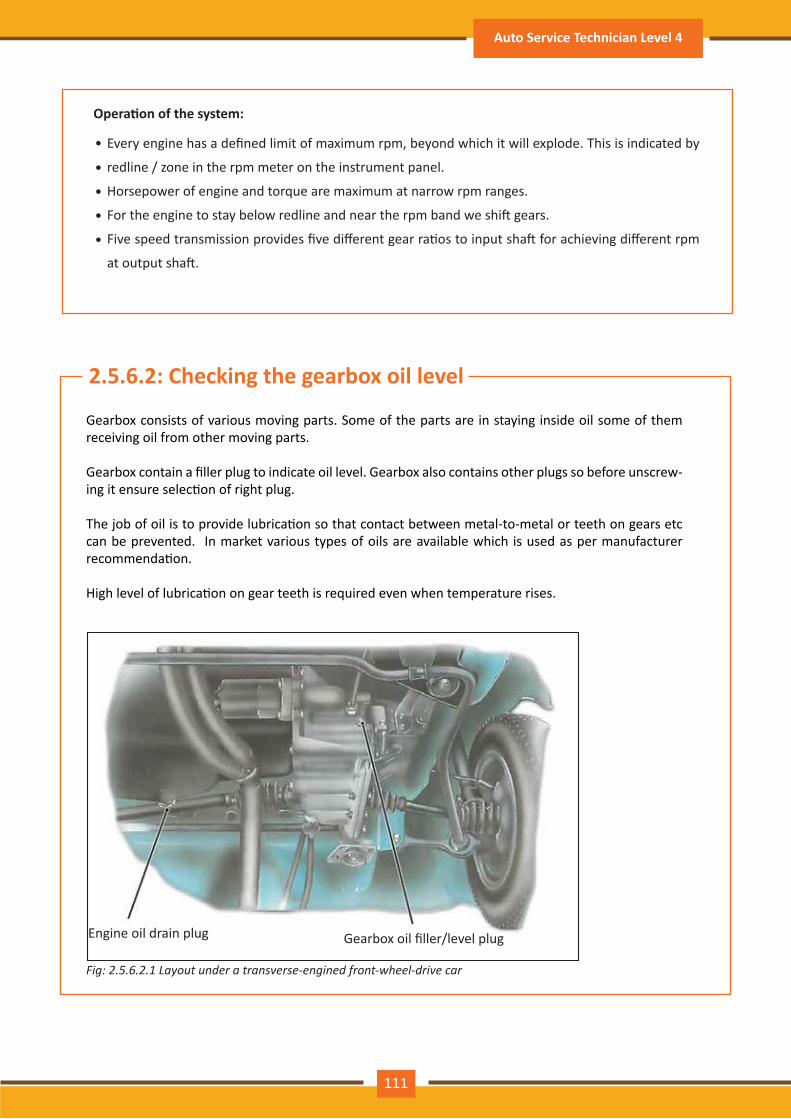
Opera�on of the system:
Every engine has a defined limit of maximum rpm, beyond which it will explode. This is indicated by
redline / z one in th e rpm m eter on th e instrum ent panel.
H orsepower of engine and torque are m axim um at narrow rpm ranges.
For the engine to stay below redline and near the rpm band we shi� gears.
Five speed transmission provides five different gear ra�os to input sha� for achieving different rpm
at output sha�.
•
•
•
•
•
G earbox consists of v arious m ov ing parts. Som e of th e parts are in stay ing inside oil som e of th em receiv ing oil from oth er m ov ing parts.
Gearbox contain a filler plug to indicate oil level. Gearbox also contains other plugs so before unscrew-ing it ensure selec�on of right plug.
The job of oil is to provide lubrica�on so that contact between metal-to-metal or teeth on gears etc can be prevented. In market various types of oils are available which is used as per manufacturer recommenda�on.
High level of lubrica�on on gear teeth is required even when temperature rises.
Fig: 2.5.6 .2.1 L a y o u t u n d e r a t r a n s v e r s e - e n gin e d f r o n t - w h e e l - d r iv e c a r
Gearbox oil filler/level plugEngine oil drain plug
2.5. .2: Checking the gearbox oil level
Auto Service Technician Level 4
111
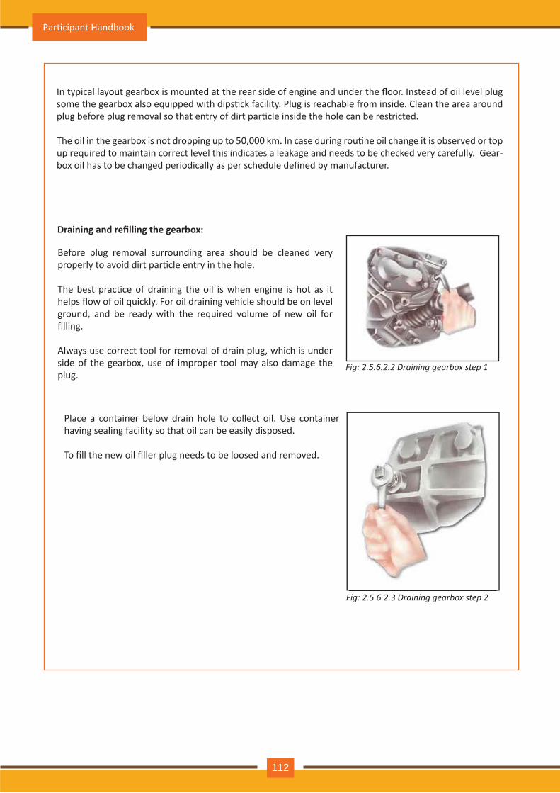
In typical layout gearbox is mounted at the rear side of engine and under the floor. Instead of oil level plug some the gearbox also equipped with dips�ck facility. Plug is reachable from inside. Clean the area around plug before plug removal so that entry of dirt par�cle inside the hole can be restricted.
The oil in the gearbox is not dropping up to 50,000 km. In case during rou�ne oil change it is observed or top up required to m aintain correct lev el th is indicates a leakage and needs to be ch ecked v ery carefully . G ear-box oil has to be changed periodically as per schedule defined by manufacturer.
Before plug rem ov al surrounding area sh ould be cleaned v ery properly to avoid dirt par�cle entry in the hole.
The best prac�ce of draining the oil is when engine is hot as it helps flow of oil quickly. For oil draining vehicle should be on level ground, and be ready with th e required v olum e of new oil for filling.
A lway s use correct tool for rem ov al of drain plug, wh ich is under side of th e gearbox, use of im proper tool m ay also dam age th e plug.
Draining and refilling the gearbox:
Fig: 2.5.6 .2.2 D r a in in g ge a r b o x s t e p 1
Place a container below drain h ole to collect oil. Use container h av ing sealing facility so th at oil can be easily disposed.
To fill the new oil filler plug needs to be loosed and removed.
Fig: 2.5.6 .2.3 D r a in in g ge a r b o x s t e p 2
Par�cipant Handbook
112
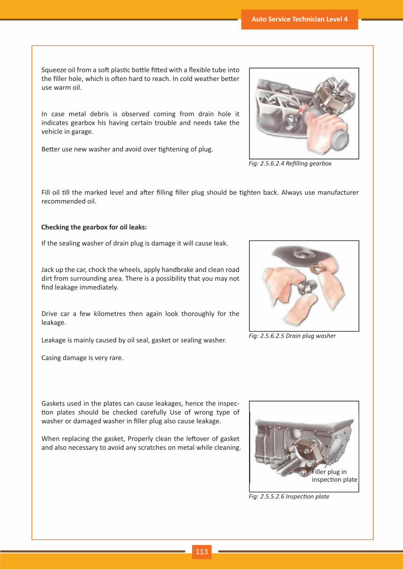
Squeeze oil from a so� plas�c bo�le fi�ed with a flexible tube into the filler hole, which is o�en hard to reach. In cold weather be�er use warm oil.
In case metal debris is observed coming from drain hole it indicates gearbox h is h av ing certain trouble and needs take th e v eh icle in garage.
Be�er use new washer and avoid over �ghtening of plug.
Fill oil �ll the marked level and a�er filling filler plug should be �ghten back. Always use manufacturer recom m ended oil.
Fig: 2.5.6.2.4 Refilling gearbo
If the sealing washer of drain plug is damage it will cause leak.
J ack up th e car, ch ock th e wh eels, apply h andbrake and clean road dirt from surrounding area. Th ere is a possibility th at y ou m ay not find leakage immediately.
Driv e car a few kilom etres th en again look th orough ly for th e leakage.
Leakage is m ainly caused by oil seal, gasket or sealing wash er.
C asing dam age is v ery rare.
Fig: 2.5.6 .2.5 D r a in p l u g w a s h e r
Checking the gearbox for oil leaks:
G askets used in th e plates can cause leakages, h ence th e inspec-�on plates should be checked carefully Use of wrong type of washer or damaged washer in filler plug also cause leakage.
When replacing the gasket, Properly clean the le�over of gasket and also necessary to av oid any scratch es on m etal wh ile cleaning.
Fig: 2.5.5.2.6 Inspection plate
Filler plug in inspec�on plate
Auto Service Technician Level 4
113
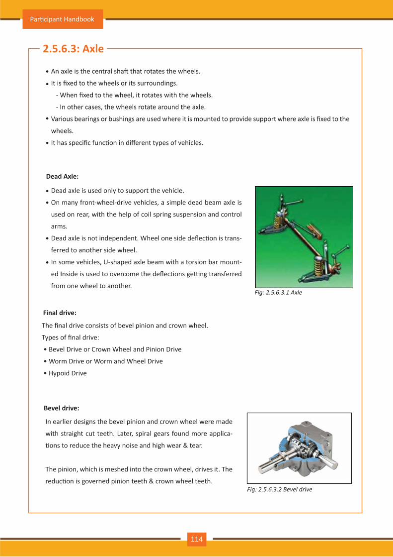
2.5.6.3: Axle
An axle is the central sha� that rotates the wheels.
It is fixed to the wheels or its surroundings.
- When fixed to the wheel, it rotates with the wheels.
- In other cases, the wheels rotate around the axle.
Various bearings or bushings are used where it is mounted to provide support where axle is fixed to the
wheels.
It has specific func�on in different types of vehicles.
•
•
•
•
Dead axle is used only to support the vehicle.
On many front-wheel-drive vehicles, a simple dead beam axle is
used on rear, with the help of coil spring suspension and control
arms.
Dead axle is not independent. Wheel one side deflec�on is trans-
ferred to another side wheel.
In some vehicles, U-shaped axle beam with a torsion bar mount-
ed Inside is used to overcome the deflec�ons ge�ng transferred
from one wheel to another.
Dead Axle:
•
•
•
•
The final drive consists of bevel pinion and crown wheel.
Types of final drive:
• Bevel Drive or Crown Wheel and Pinion Drive
• Worm Drive or Worm and Wheel Drive
• Hypoid Drive
Final drive:
In earlier designs the bevel pinion and crown wheel were made
with straight cut teeth. Later, spiral gears found more applica-
�ons to reduce the heavy noise and high wear & tear.
The pinion, which is meshed into the crown wheel, drives it. The
reduc�on is governed pinion teeth & crown wheel teeth.
Bevel drive:
Fig: 2.5.6.3.1 Axle
Fig: 2.5.6.3.2 Bevel drive
Par�cipant Handbook
114
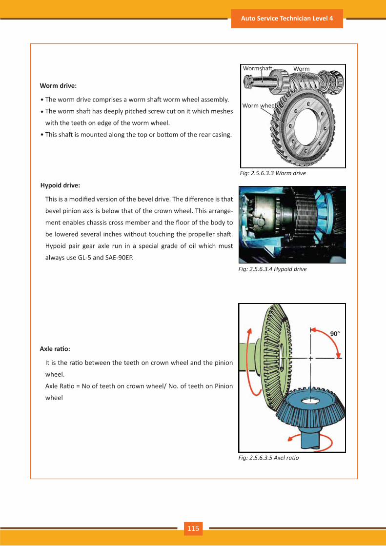
The worm drive comprises a worm sha� worm wheel assembly.
The worm sha� has deeply pitched screw cut on it which meshes
with the teeth on edge of the worm wheel.
This sha� is mounted along the top or bo�om of the rear casing.
Worm drive:
Wormsha� Worm
Worm wheel
This is a modified version of the bevel drive. The difference is that
bevel pinion axis is below that of the crown wheel. This arrange-
ment enables chassis cross member and the floor of the body to
be lowered several inches without touching the propeller sha�.
Hypoid pair gear axle run in a special grade of oil which must
always use GL-5 and SAE-90EP.
Hypoid drive:
•
•
•
It is the ra�o between the teeth on crown wheel and the pinion
wheel.
Axle Ra�o = No of teeth on crown wheel/ No. of teeth on Pinion
wheel
Axle ra�o:
Fig: 2.5.6.3.3 Worm drive
Fig: 2.5.6.3.4 Hypoid drive
Fig: 2.5.6.3.5 Axel ratio
Auto Service Technician Level 4
115
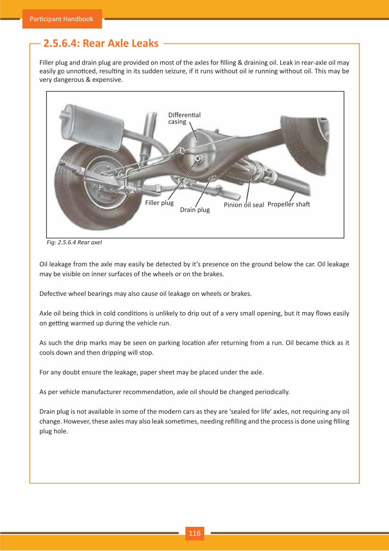
Filler plug and drain plug are provided on most of the axles for filling & draining oil. Leak in rear-axle oil may easily go unno�ced, resul�ng in its sudden seizure, if it runs without oil ie running without oil. This may be very dangerous & expensive.
O il leakage from th e axle m ay easily be detected by it’ s presence on th e ground below th e car. O il leakage m ay be v isible on inner surfaces of th e wh eels or on th e brakes.
Defec�ve wheel bearings may also cause oil leakage on wheels or brakes.
Axle oil being thick in cold condi�ons is unlikely to drip out of a very small opening, but it may flows easily on ge�ng warmed up during the vehicle run.
As such the drip marks may be seen on parking loca�on afer returning from a run. Oil became thick as it cools down and th en dripping will stop.
For any doubt ensure th e leakage, paper sh eet m ay be placed under th e axle.
As per vehicle manufacturer recommenda�on, axle oil should be changed periodically.
Drain plug is not av ailable in som e of th e m odern cars as th ey are ' sealed for life' axles, not requiring any oil change. However, these axles may also leak some�mes, needing refilling and the process is done using filling plug h ole.
2.5.6.4: Rear Axle Leaks
Fig: 2.5.6 .4 R e a r a x e l
Differen�alcasing
Filler plugDrain plug
Pinion oil seal Propeller sha�
Par�cipant Handbook
116
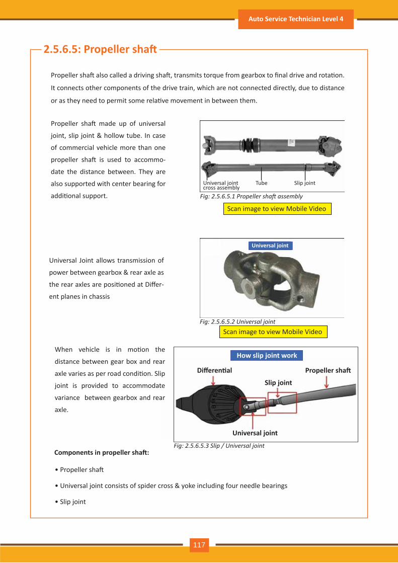
2.5.6.5: Propeller sha�
Propeller sha� also called a driving sha�, transmits torque from gearbox to final drive and rota�on.
It connects other components of the drive train, which are not connected directly, due to distance
or as they need to permit some rela�ve movement in between them.
Propeller sha� made up of universal
joint, slip joint & hollow tube. In case
of commercial vehicle more than one
propeller sha� is used to accommo-
date the distance between. They are
also supported with center bearing for
addi�onal support.
Universal Joint allows transmission of
power between gearbox & rear axle as
the rear axles are posi�oned at Differ-
ent planes in chassis
Universal joint
Fig: 2.5.6.5.2 Universal joint
Scan image to view Mobile Video
Scan image to view Mobile Video
Fig: 2.5.6.5.1 Propeller shaft assembly
Universal joint cross assembly
Tube Slip joint
Components in propeller sha�:
• Propeller sha�
• Universal joint consists of spider cross & yoke including four needle bearings
• Slip joint
How slip joint work
Differen�al Propeller sha�
Slip joint
Universal joint
When vehicle is in mo�on the
distance between gear box and rear
axle varies as per road condi�on. Slip
joint is provided to accommodate
variance between gearbox and rear
axle.
Fig: 2.5.6.5.3 Slip / Universal joint
Auto Service Technician Level 4
117
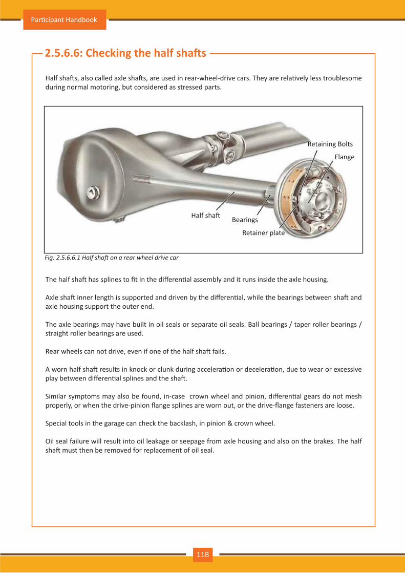
2.5.6.6: Checking the half sha�s
Half sha�s, also called axle sha�s, are used in rear-wheel-drive cars. They are rela�vely less troublesome during norm al m otoring, but considered as stressed parts.
The half sha� has splines to fit in the differen�al assembly and it runs inside the axle housing.
Axle sha� inner length is supported and driven by the differen�al, while the bearings between sha� and axle h ousing support th e outer end.
Th e axle bearings m ay h av e built in oil seals or separate oil seals. Ball bearings / taper roller bearings / straigh t roller bearings are used.
Rear wheels can not drive, even if one of the half sha� fails.
A worn half sha� results in knock or clunk during accelera�on or decelera�on, due to wear or excessive play between differen�al splines and the sha�.
Similar symptoms may also be found, in-case crown wheel and pinion, differen�al gears do not mesh properly, or when the drive-pinion flange splines are worn out, or the drive-flange fasteners are loose.
Special tools in the garage can check the backlash, in pinion & crown wheel.
O il seal failure will result into oil leakage or seepage from axle h ousing and also on th e brakes. Th e h alf sha� must then be removed for replacement of oil seal.
Fig: 2.5.6.6.1 alf sha on a rear wheel drive car
Half sha� Bearings
R etainer plate
Flange
R etaining Bolts
Par�cipant Handbook
118
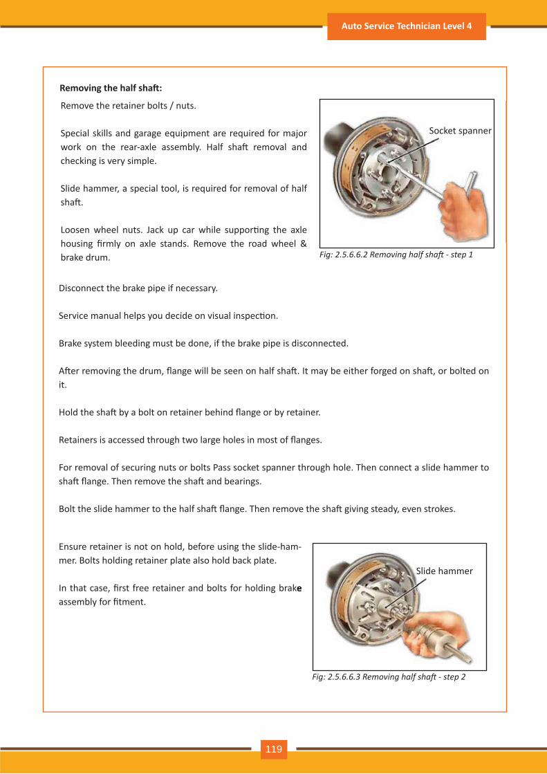
Fig: 2.5.6.6.2 Removing half sha step 1
Fig: 2.5.6.6.3 Removing half sha step 2
Removing the half sha�:
R em ov e th e retainer bolts / nuts.
Special skills and garage equipm ent are required for m aj or work on the rear-axle assembly. Half sha� removal and ch ecking is v ery sim ple.
Slide h am m er, a special tool, is required for rem ov al of h alf sha�.
Loosen wheel nuts. Jack up car while suppor�ng the axle housing firmly on axle stands. Remove the road wheel & brake drum .
Disconnect th e brake pipe if necessary .
Service manual helps you decide on visual inspec�on.
Brake sy stem bleeding m ust be done, if th e brake pipe is disconnected.
A�er removing the drum, flange will be seen on half sha�. It may be either forged on sha�, or bolted on it.
Hold the sha� by a bolt on retainer behind flange or by retainer.
Retainers is accessed through two large holes in most of flanges.
For rem ov al of securing nuts or bolts Pass socket spanner th rough h ole. Th en connect a slide h am m er to sha� flange. Then remove the sha� and bearings.
Bolt the slide hammer to the half sha� flange. Then remove the sha� giving steady, even strokes.
Ensure retainer is not on h old, before using th e slide- h am -m er. Bolts h olding retainer plate also h old back plate.
In that case, first free retainer and bolts for holding brake assembly for fitment. In that case, first free retainer and bolts for holding brake
Socket spanner
Slide h am m er
Auto Service Technician Level 4
119
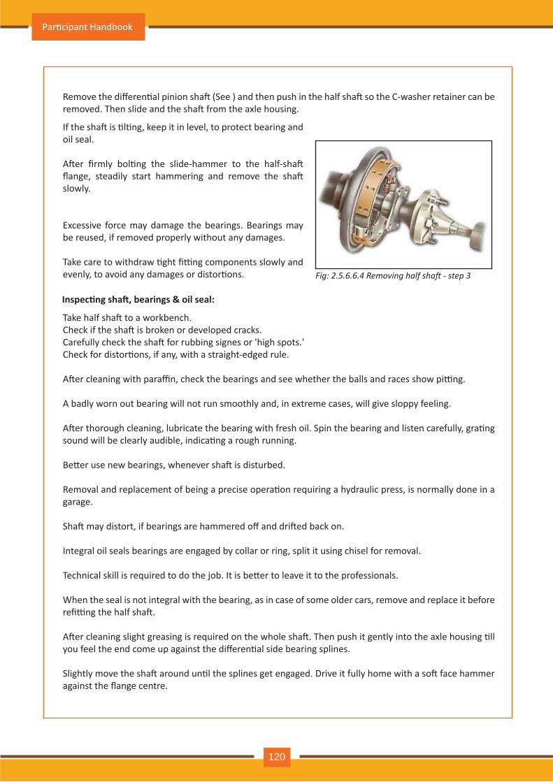
Remove the differen�al pinion sha� (See ) and then push in the half sha� so the C-washer retainer can be removed. Then slide and the sha� from the axle housing.
Take half sha� to a workbench. Check if the sha� is broken or developed cracks.Carefully check the sha� for rubbing signes or 'high spots.' Check for distor�ons, if any, with a straight-edged rule.
A�er cleaning with paraffin, check the bearings and see whether the balls and races show pi�ng.
A badly worn out bearing will not run sm ooth ly and, in extrem e cases, will giv e sloppy feeling.
A�er thorough cleaning, lubricate the bearing with fresh oil. Spin the bearing and listen carefully, gra�ng sound will be clearly audible, indica�ng a rough running.
Be�er use new bearings, whenever sha� is disturbed.
Removal and replacement of being a precise opera�on requiring a hydraulic press, is normally done in a garage.
Sha� may distort, if bearings are hammered off and dri�ed back on.
Integral oil seals bearings are engaged by collar or ring, split it using chisel for removal.
Technical skill is required to do the job. It is be�er to leave it to the professionals.
W h en th e seal is not integral with th e bearing, as in case of som e older cars, rem ov e and replace it before refi�ng the half sha�.
A�er cleaning slight greasing is required on the whole sha�. Then push it gently into the axle housing �ll you feel the end come up against the differen�al side bearing splines.
Slightly move the sha� around un�l the splines get engaged. Drive it fully home with a so� face hammer against the flange centre.
If the sha� is �l�ng, keep it in level, to protect bearing and oil seal.
A�er firmly bol�ng the slide-hammer to the half-sha� flange, steadily start hammering and remove the sha� slowly .
Excessiv e force m ay dam age th e bearings. Bearings m ay be reused, if rem ov ed properly with out any dam ages.
Take care to withdraw �ght fi�ng components slowly and evenly, to avoid any damages or distor�ons. Fig: 2.5.6.6.4 Removing half sha step 3
Inspec�ng sha�, bearings & oil seal:
Par�cipant Handbook
120

Never hit the flange on its edges using steel hammer as it may break.
Reassembly flange procedure, brake drum, brake hose & wheel is reverse of removal procedure.
A�er half sha�s refi�ng, place car on to its wheels. Check & top up rear axle oil level if necessary.
Auto Service Technician Level 4
121
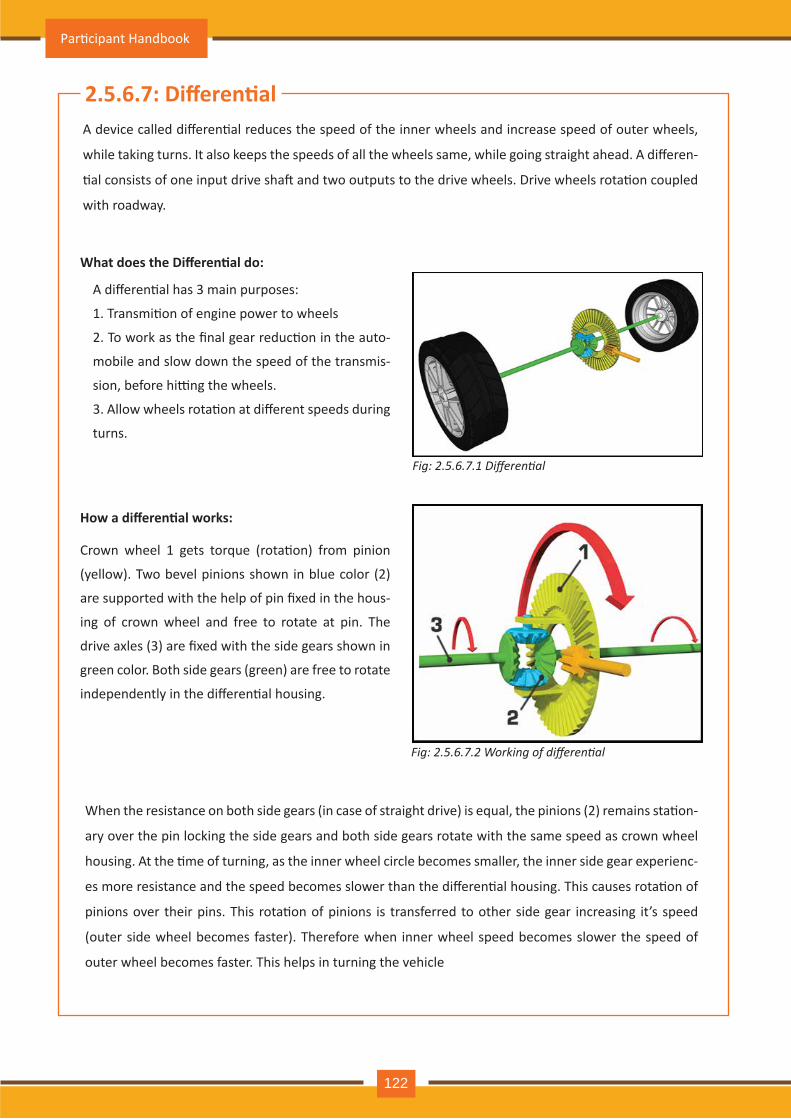
2.5.6.7: Differen�alA device called differen�al reduces the speed of the inner wheels and increase speed of outer wheels,
while taking turns. It also keeps the speeds of all the wheels same, while going straight ahead. A differen-
�al consists of one input drive sha� and two outputs to the drive wheels. Drive wheels rota�on coupled
with roadway.
A differen�al has 3 main purposes:
1. Transmi�on of engine power to wheels
2. To work as the final gear reduc�on in the auto-
mobile and slow down the speed of the transmis-
sion, before hi�ng the wheels.
3. Allow wheels rota�on at different speeds during
turns.
What does the Differen�al do:
Crown wheel 1 gets torque (rota�on) from pinion
(yellow). Two bevel pinions shown in blue color (2)
are supported with the help of pin fixed in the hous-
ing of crown wheel and free to rotate at pin. The
drive axles (3) are fixed with the side gears shown in
green color. Both side gears (green) are free to rotate
independently in the differen�al housing.
How a differen�al works:
When the resistance on both side gears (in case of straight drive) is equal, the pinions (2) remains sta�on-
ary over the pin locking the side gears and both side gears rotate with the same speed as crown wheel
housing. At the �me of turning, as the inner wheel circle becomes smaller, the inner side gear experienc-
es more resistance and the speed becomes slower than the differen�al housing. This causes rota�on of
pinions over their pins. This rota�on of pinions is transferred to other side gear increasing it’s speed
(outer side wheel becomes faster). Therefore when inner wheel speed becomes slower the speed of
outer wheel becomes faster. This helps in turning the vehicle
Fig: 2.5.6.7.1 Differential
Fig: 2.5.6.7.2 Working of differential
Par�cipant Handbook
122
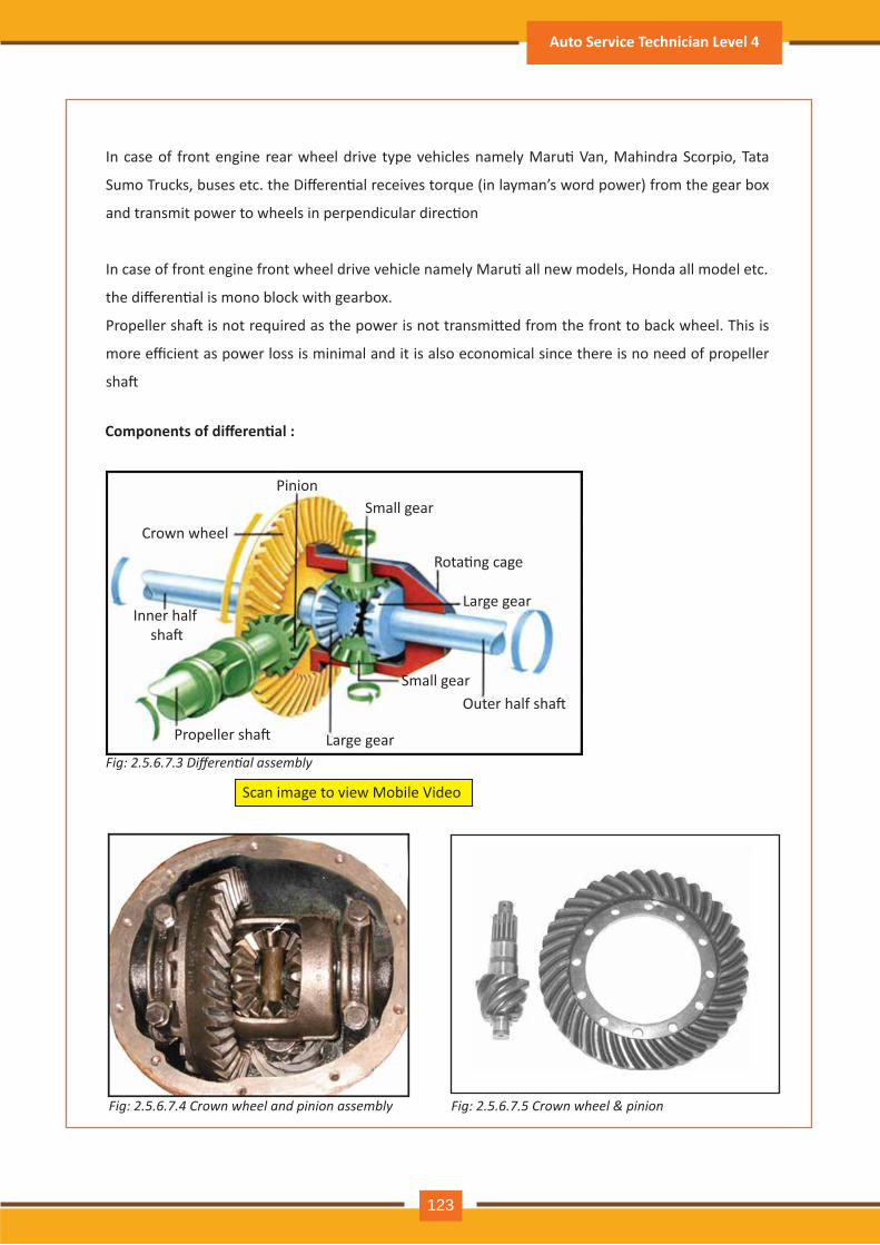
In case of front engine rear wheel drive type vehicles namely Maru� Van, Mahindra Scorpio, Tata
Sumo Trucks, buses etc. the Differen�al receives torque (in layman’s word power) from the gear box
and transmit power to wheels in perpendicular direc�on
In case of front engine front wheel drive vehicle namely Maru� all new models, Honda all model etc.
the differen�al is mono block with gearbox.
Propeller sha� is not required as the power is not transmi�ed from the front to back wheel. This is
more efficient as power loss is minimal and it is also economical since there is no need of propeller
sha�
Components of differen�al :
Pinion
Crown wheel
Inner half sha�
Small gear
Rota�ng cage
Large gear
Outer half sha�
Large gear
Small gear
Propeller sha�
Scan image to view Mobile Video
Fig: 2.5.6.7.3 Differential assembly
Fig: 2.5.6.7.4 Crown wheel and pinion assembly Fig: 2.5.6.7.5 Crown wheel & pinion
Auto Service Technician Level 4
123
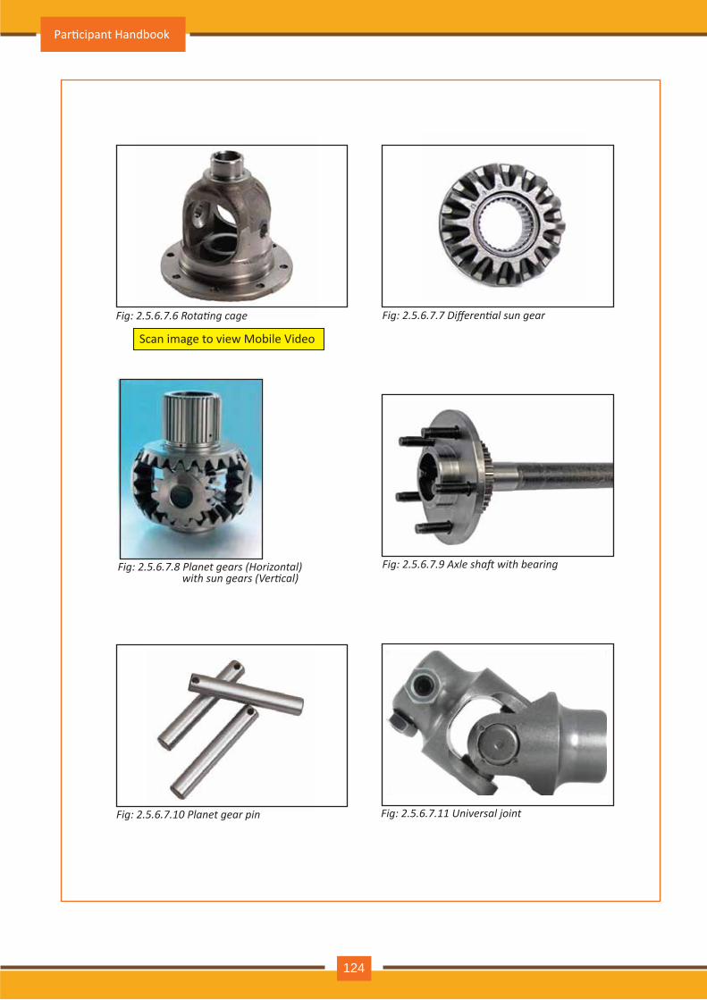
Scan image to view Mobile Video
Fig: 2.5.6.7.7 Differential sun gear
Fig: 2.5.6.7.9 Axle shaft with bearing
Fig: 2.5.6.7.10 Planet gear pin Fig: 2.5.6.7.11 Universal joint
Fig: 2.5.6.7.6 Rotating cage
Fig: 2.5.6.7.8 Planet gears (Horizontal) with sun gears (Vertical)
Par�cipant Handbook
124
Fuel supply system of vehicle play important role in func�oning of engine. Fuel supply system core func�on
of is to ensure smooth and constant fuel supply to engine’s other peripherals. It consists of various devices
and components for example Fuel pump, carburetor, fuel cells, filter, fuel cooler, fuel tank for storage and
distribu�on of fuel to engine as per the requirements. In present days pressurized system is used in most of
the automobile along with a pump to push fuel from tank to engine of the vehicle.
•
•
•
•
•
•
•
•
•
•
•
2.5.6: Fuel system
Components of automobile fuel supply system:
Fuel Tank : Safe container for fuel
Fuel Tank Cap : Covers the fuel tank to keeps air, moisture, dust, dirt out
Fuel Pump : Feeds fuel to engine
Fuel Injec�on System : Injects fuel into the engine
Automo�ve LPG System : Feeds liquefied petroleum gas to engine
Fuel Filters : Removes dirt, dust and rust par�cles from fuel
Carbure�or : Mixes air and fuel proper ra�o for combus�on
Fuel Water Separator : Removes water from fuel
Fuel Coolers : Cool the fuel to control temerature
Nitrous Oxide System : Nitrous oxide heated to about 300 deg C splits into oxygen and nitrogen,
releasing more oxygen for combus�on resul�ng in more engine power
Fuel Cells : Hydrogen fused chemically with oxygen from the air to make water, releasing electricity
to drive a vehicle
Improving fuel economy:
Several factors contribute for fuel saving. Fuel economy is automobile is consistently improving by using
technology for be�er fuel and its delivery method
The following do-it-yourself list can improve fuel economy by:
Checking and maintaining �re pressure
Tuning-up the engine
Checking the wheel alignment
Use of air condi�oning only when needed
Oil change as per manufacturer sugges�on
Checking cooling system opera�on
Avoiding dragging brakes
Avoiding excessive idling
Combining trips
Modera�ng speed
•
•
•
•
•
•
•
••
•
Auto Service Technician Level 4
125
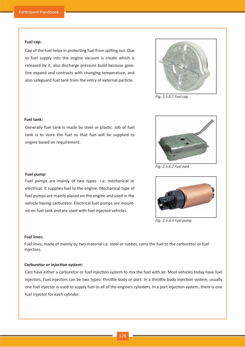
Fuel cap:
Cap of the fuel helps in protec�ng fuel from spilling out. Due
to fuel supply into the engine vacuum is create which is
released by it, also discharge pressure build because gaso-
line expand and contracts with changing temperature, and
also safeguard fuel tank from the entry of external par�cle.
Generally fuel tank is made by steel or plas�c. Job of fuel
tank is to store the fuel so that fuel will be supplied to
engine based on requirement.
Fuel tank:
Fuel pump:Fuel pumps are mainly of two types i.e. mechanical or
electrical. It supplies fuel to the engine. Mechanical type of
fuel pumps are mainly placed on the engine and used in the
vehicle having carburetor. Electrical fuel pumps are mount-
ed on fuel tank and are used with fuel injected vehicles.
Fig: 2.5.6.1 Fuel cap
Fig: 2.5.6.2 Fuel tank
Fig: 2.5.6.3 Fuel pump
Fuel lines:Fuel lines, made of mainly by two material i.e. steel or rubber, carry the fuel to the carburetor or fuel injectors.
Carburetor or injec�on system:
Cars have either a carburetor or fuel injec�on system to mix the fuel with air. Most vehicles today have fuel
injectors. Fuel injectors can be two types: thro�le body or port. In a thro�le body injec�on system, usually
one fuel injector is used to supply fuel to all of the engine’s cylinders. In a port injec�on system, there is one
fuel injector for each cylinder.
Par�cipant Handbook
126
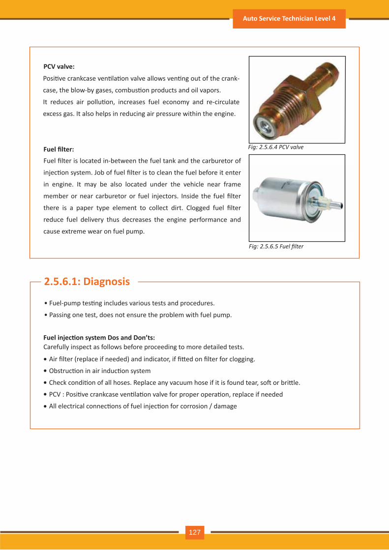
Posi�ve crankcase ven�la�on valve allows ven�ng out of the crank-
case, the blow-by gases, combus�on products and oil vapors.
It reduces air pollu�on, increases fuel economy and re-circulate
excess gas. It also helps in reducing air pressure within the engine.
PCV valve:
Fuel injec�on system Dos and Don’ts:
Fuel filter: Fig: 2.5.6.4 PCV valve
Fig: 2.5.6.5 Fuel filter
Fuel filter is located in-between the fuel tank and the carburetor of
injec�on system. Job of fuel filter is to clean the fuel before it enter
in engine. It may be also located under the vehicle near frame
member or near carburetor or fuel injectors. Inside the fuel filter
there is a paper type element to collect dirt. Clogged fuel filter
reduce fuel delivery thus decreases the engine performance and
cause extreme wear on fuel pump.
2.5.6.1: Diagnosis
• Fuel-pump tes�ng includes various tests and procedures.
• Passing one test, does not ensure the problem with fuel pump.
Air filter (replace if needed) and indicator, if fi�ed on filter for clogging.
Obstruc�on in air induc�on system
Check condi�on of all hoses. Replace any vacuum hose if it is found tear, so� or bri�le.
PCV : Posi�ve crankcase ven�la�on valve for proper opera�on, replace if needed
All electrical connec�ons of fuel injec�on for corrosion / damage
Carefully inspect as follows before proceeding to more detailed tests.
•
•
•
•
•
Auto Service Technician Level 4
127
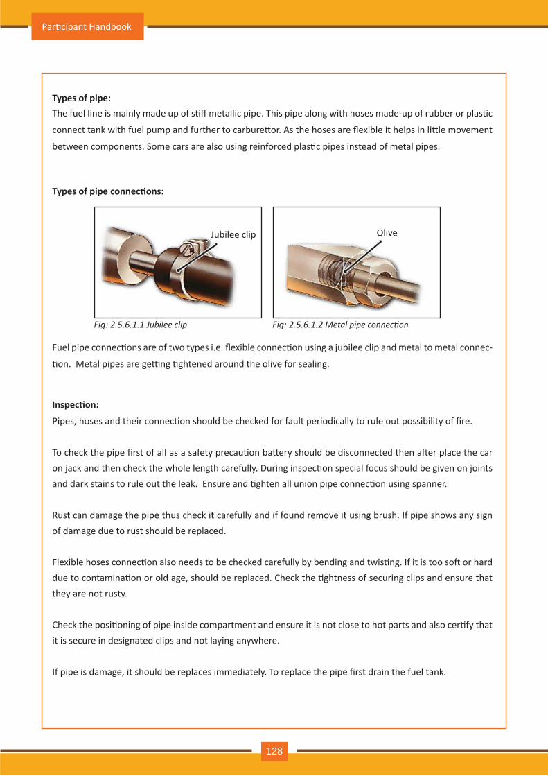
Types of pipe:
Types of pipe connec�ons:
Inspec�on:
The fuel line is mainly made up of s�ff metallic pipe. This pipe along with hoses made-up of rubber or plas�c
connect tank with fuel pump and further to carbure�or. As the hoses are flexible it helps in li�le movement
between components. Some cars are also using reinforced plas�c pipes instead of metal pipes.
Fuel pipe connec�ons are of two types i.e. flexible connec�on using a jubilee clip and metal to metal connec-
�on. Metal pipes are ge�ng �ghtened around the olive for sealing.
Pipes, hoses and their connec�on should be checked for fault periodically to rule out possibility of fire.
To check the pipe first of all as a safety precau�on ba�ery should be disconnected then a�er place the car on jack and then check the whole length carefully. During inspec�on special focus should be given on joints and dark stains to rule out the leak. Ensure and �ghten all union pipe connec�on using spanner.
Rust can damage the pipe thus check it carefully and if found remove it using brush. If pipe shows any sign of damage due to rust should be replaced.
Flexible hoses connec�on also needs to be checked carefully by bending and twis�ng. If it is too so� or hard due to contamina�on or old age, should be replaced. Check the �ghtness of securing clips and ensure that they are not rusty.
Check the posi�oning of pipe inside compartment and ensure it is not close to hot parts and also cer�fy that it is secure in designated clips and not laying anywhere.
If pipe is damage, it should be replaces immediately. To replace the pipe first drain the fuel tank.
Fig: 2.5.6 .1.1 J u b il e e c l ip Fig: 2.5.6 .1.2 etal pipe connection
Jubilee clip O liv e
Par�cipant Handbook
128
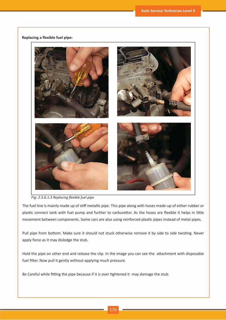
Fig: 2.5.6.1.3 Replacing flexible fuel pipe
Replacing a flexible fuel pipe:
The fuel line is mainly made up of s�ff metallic pipe. This pipe along with hoses made-up of either rubber or
plas�c connect tank with fuel pump and further to carbure�or. As the hoses are flexible it helps in li�le
movement between components. Some cars are also using reinforced plas�c pipes instead of metal pipes.
Pull pipe from bo�om. Make sure it should not stuck otherwise remove it by side to side twis�ng. Never
apply force as it may dislodge the stub.
Hold the pipe on other end and release the clip. In the image you can see the a�achment with disposable
fuel filter. Now pull it gently without applying much pressure.
Be Careful while fi�ng the pipe because if it is over �ghtened it may damage the stub.
Auto Service Technician Level 4
129
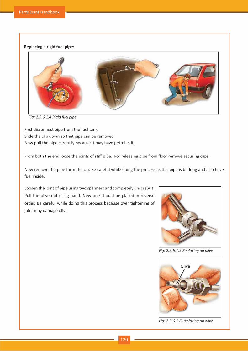
Fig: 2.5.6 .1.5 R e p l a c in g a n o l iv e
Fig: 2.5.6 .1.6 R e p l a c in g a n o l iv e
Fig: 2.5.6 .1.4 Rigid fuel pipe
Replacing a rigid fuel pipe:Replacing a rigid fuel pipe:
First disconnect pipe from the fuel tankSlide the clip down so that pipe can be removedNow pull the pipe carefully because it may have petrol in it.
From both the end loose the joints of s�ff pipe. For releasing pipe from floor remove securing clips.
Now remove the pipe form the car. Be careful while doing the process as this pipe is bit long and also have fuel inside.
Loosen the joint of pipe using two spanners and completely unscrew it.
Pull the olive out using hand. New one should be placed in reverse
order. Be careful while doing this process because over �ghtening of
joint may damage olive.
O liv e
Par�cipant Handbook
130
New hoses:Jubilee clips are mainly used to secure the end of flexible hoses. Using a screw driver loosen the clips and
then a�er slide them along the hose. If spring clips are used in hoses fi�ng, remove it by expanding using
pliers. All spring clips should be replace with jubilee clips.
To remove the hose firstly twist it and then a�er pull it out. In case it is not coming out you need to expand
it by pouring some water on it. Never apply heat to loosen the hose. A�er applying all effort if hose not
coming out the only solu�on is to cut it using side cu�ers or a hacksaw.
While replacing the hose you should ensure that diameter of old one and new one is same. To place it back
slide it gently and �ghten the clip. Over �ghtening may damage the part.
New pipes:
Pipe repairs:
For replacing a s�ff pipe fuel tank needs to be drained first. In case of problem in draining the fuel tank
pipe has to be disconnected from the tank and open end should be closed quickly using a plug.
From back side of car loose the clips or nut used to connect pipe with fuel tank and also chassis. From
front side disconnect the pipe and then a�er remove it.
Make sure in case pipe connec�on is having union joints both should be replace together. Place the new
pipe on its place and then a�er connec�on should be �ghten further using securing clips also. While doing
the fi�ng ensure that pipe is not touching other components and should be away from hot components.
In case there would be a minor damage in metal pipe it has to repaired by cu�ng the damage pipe length
and joining it using flexible hose. Cu�ng of pipe can be done using hacksaw while cu�ng the pipe make
sure both the end should be cleaned properly. A�er cu�ng the pipe place a correct diameter hose and
further use clip to secure it.
If the damage is not more than 15cm long it can be repaired but in case damage is longer in length it is
advisable to replace it.
Auto Service Technician Level 4
131
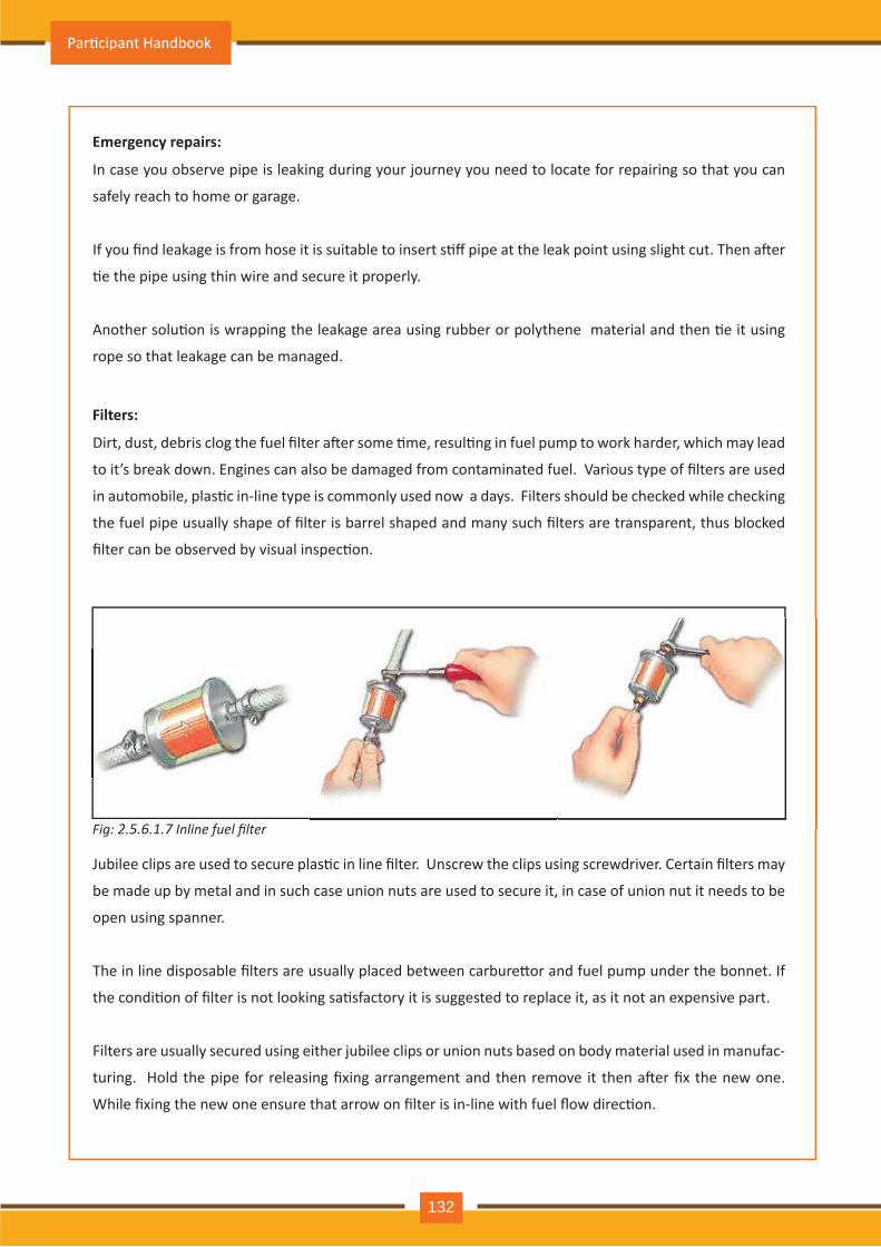
Fig: 2.5.6 .1.7 Inline fuel filter
E mergency repairs:
In case you observe pipe is leaking during your journey you need to locate for repairing so that you can
safely reach to home or garage.
If you find leakage is from hose it is suitable to insert s�ff pipe at the leak point using slight cut. Then a�er
�e the pipe using thin wire and secure it properly.
Another solu�on is wrapping the leakage area using rubber or polythene material and then �e it using
rope so that leakage can be managed.
Filters:
Dirt, dust, debris clog the fuel filter a�er some �me, resul�ng in fuel pump to work harder, which may lead
to it’s break down. Engines can also be damaged from contaminated fuel. Various type of filters are used
in automobile, plas�c in-line type is commonly used now a days. Filters should be checked while checking
the fuel pipe usually shape of filter is barrel shaped and many such filters are transparent, thus blocked
filter can be observed by visual inspec�on.
Jubilee clips are used to secure plas�c in line filter. Unscrew the clips using screwdriver. Certain filters may
be m ade up by m etal and in such case union nuts are used to secure it, in case of union nut it needs to be
open using spanner.
The in line disposable filters are usually placed between carbure�or and fuel pump under the bonnet. If
the condi�on of filter is not looking sa�sfactory it is suggested to replace it, as it not an expensive part.
Filters are usually secured using either jubilee clips or union nuts based on body material used in manufac-
turing. Hold the pipe for releasing fixing arrangement and then remove it then a�er fix the new one.
While fixing the new one ensure that arrow on filter is in-line with fuel flow direc�on.
Par�cipant Handbook
132
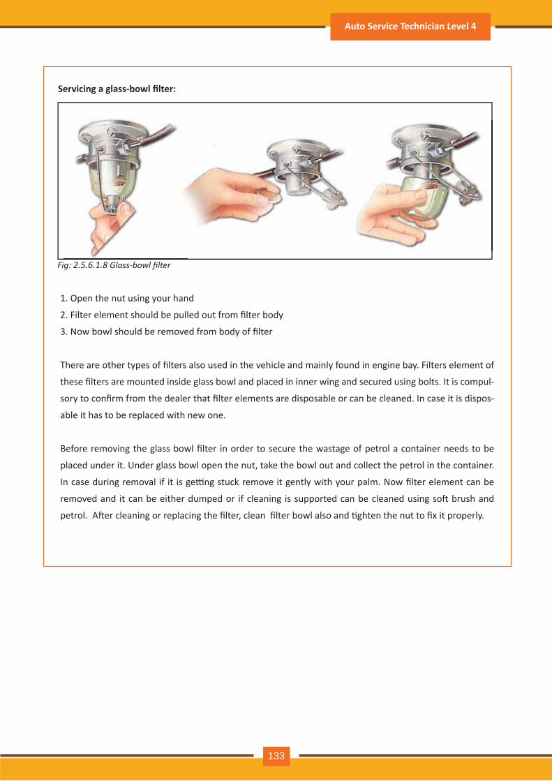
Servicing a glass-bowl filter:
Fig: 2.5.6 .1.8 lass bowl filter
1. Open the nut using your hand
2. Filter element should be pulled out from filter body
3. Now bowl should be removed from body of filter
There are other types of filters also used in the vehicle and mainly found in engine bay. Filters element of
these filters are mounted inside glass bowl and placed in inner wing and secured using bolts. It is compul-
sory to confirm from the dealer that filter elements are disposable or can be cleaned. In case it is dispos-
able it has to be replaced with new one.
Before removing the glass bowl filter in order to secure the wastage of petrol a container needs to be
placed under it. Under glass bowl open the nut, take the bowl out and collect the petrol in the container.
In case during removal if it is ge�ng stuck remove it gently with your palm. Now filter element can be
removed and it can be either dumped or if cleaning is supported can be cleaned using so� brush and
petrol. A�er cleaning or replacing the filter, clean filter bowl also and �ghten the nut to fix it properly.
Auto Service Technician Level 4
133
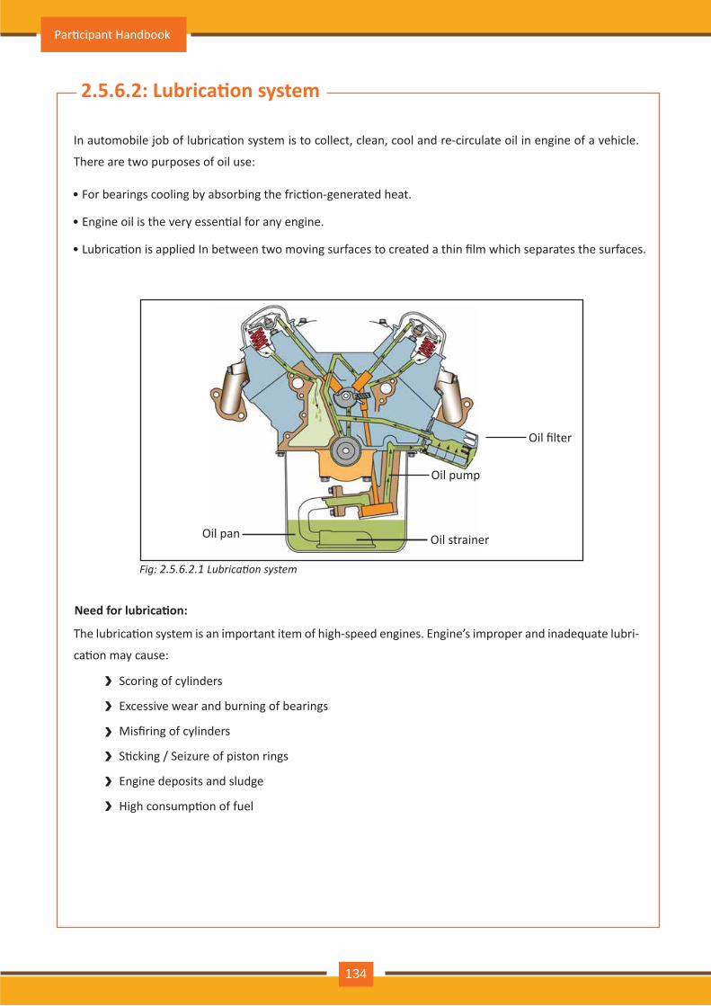
2.5.6.2: Lubrica�on system
In automobile job of lubrica�on system is to collect, clean, cool and re-circulate oil in engine of a vehicle.
There are two purposes of oil use:
The lubrica�on system is an important item of high-speed engines. Engine’s improper and inadequate lubri-
ca�on may cause:
• For bearings cooling by absorbing the fric�on-generated heat.
• Engine oil is the very essen�al for any engine.
• Lubrica�on is applied In between two moving surfaces to created a thin film which separates the surfaces.
Need for lubrica�on:
Scoring of cylinders
Excessive wear and burning of bearings
Misfiring of cylinders
S�cking / Seizure of piston rings
Engine deposits and sludge
High consump�on of fuel
››››››
Fig: 2.5.6.2.1 Lubrication system
Oil pan Oil strainer
Oil filter
Oil pump
Par�cipant Handbook
134
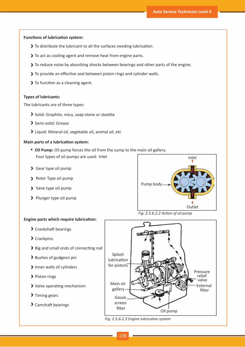
›››››
›››
›››››››››
››››
Func�ons of lubrica�on system:
To distribute the lubricant to all the surfaces needing lubrica�on.
To act as cooling agent and remove heat from engine parts.
To reduce noise by absorbing shocks between bearings and other parts of the engine.
To provide an effec�ve seal between piston rings and cylinder walls.
To func�on as a cleaning agent.
Types of lubricants:
The lubricants are of three types:
Solid: Graphite, mica, soap stone or stea�te
Semi-solid: Grease
Liquid: Mineral oil, vegetable oil, animal oil, etc
Engine parts which require lubrica�on:
Cranksha� bearings
Crankpins
Big and small ends of connec�ng rod
Bushes of gudgeon pin
Inner walls of cylinders
Piston rings
Valve opera�ng mechanism
Timing gears
Camsha� bearings
Main parts of a lubrica�on system:
Oil Pump: Oil pump forces the oil from the sump to the main oil gallery. Four types of oil pumps are used: Inlet
•
Gear type oil pump
Rotor Type oil pump
Vane type oil pump
Plunger type oil pump
Splash lubrica�on for pistons
Main oil gallery
Gauze screen
filter Oil pump
External filter
Pressure relief valve
Fig: 2.5.6.2.2 Action of oil pump
Fig: 2.5.6.2.3 Engine lubrication system
Pump body
Inlet
Outlet
Auto Service Technician Level 4
135
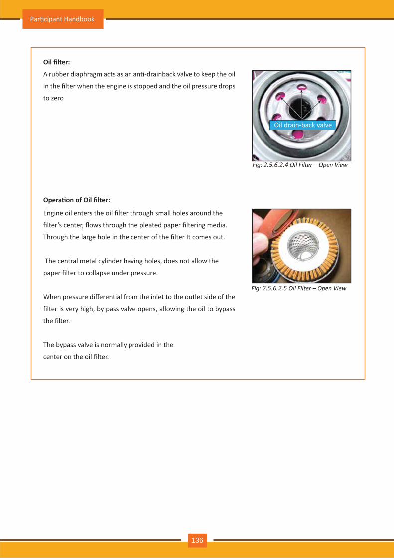
A rubber diaphragm acts as an an�-drainback valve to keep the oil
in the filter when the engine is stopped and the oil pressure drops
to zero
Engine oil enters the oil filter through small holes around the
filter’s center, flows through the pleated paper filtering media.
Through the large hole in the center of the filter It comes out.
The central metal cylinder having holes, does not allow the
paper filter to collapse under pressure.
When pressure differen�al from the inlet to the outlet side of the
filter is very high, by pass valve opens, allowing the oil to bypass
the filter.
The bypass valve is normally provided in the
center on the oil filter.
Fig: 2.5.6.2.4 Oil Filter – Open View
Fig: 2.5.6.2.5 Oil Filter – Open View
Oil filter:
Opera�on of Oil filter:
Oil drain-back valve
Par�cipant Handbook
136
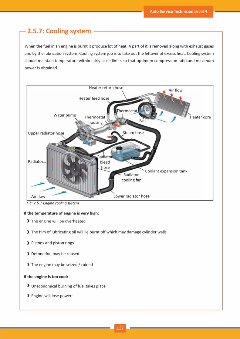
Heater feed hose
Thermostat housing
Water pump
Upper radiator hose
Radiator
Air flow
Air flow
Lower radiator hose
Radiator cooling fan
Coolant expansion tank
Radiator bleed hose
Steam hose
ThermostatHeater core
Fan
Heater return hose
Fig: 2.5.7 Engine cooling system
›››››
››
2.5.7: Cooling system
When the fuel in an engine is burnt it produce lot of heat. A part of it is removed along with exhaust gases
and by the lubrica�on system. Cooling system job is to take out the le�over of excess heat. Cooling system
should maintain temperature within fairly close limits so that op�mum compression ra�o and maximum
power is obtained.
If the temperature of engine is very high:
The engine will be overheated
The film of lubrica�ng oil will lie burnt off which may damage cylinder walls
Pistons and piston rings
Detona�on may be caused
The engine may be seized / ruined
If the engine is too cool:
Uneconomical burning of fuel takes place
Engine will lose power
Auto Service Technician Level 4
137
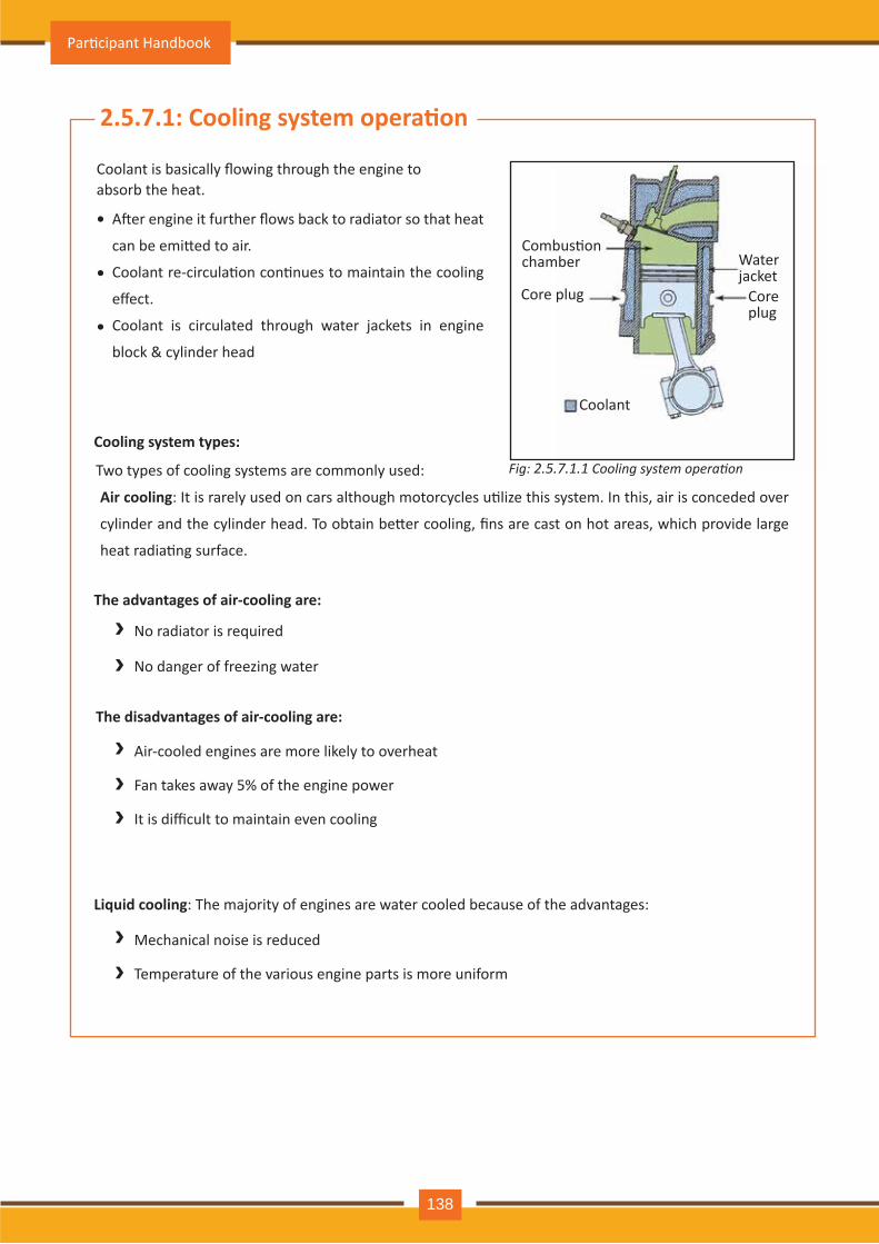
2.5.7.1: Cooling system opera�on
Coolant is basically flowing through the engine to absorb the heat.
A�er engine it further flows back to radiator so that heat
can be emi�ed to air.
Coolant re-circula�on con�nues to maintain the cooling
effect.
Coolant is circulated through water jackets in engine
block & cylinder head
•
•
•
››
›››
››
Cooling system types:
Two types of cooling systems are commonly used:
Air cooling: It is rarely used on cars although motorcycles u�lize this system. In this, air is conceded over
cylinder and the cylinder head. To obtain be�er cooling, fins are cast on hot areas, which provide large
heat radia�ng surface.
The advantages of air-cooling are:
No radiator is required
No danger of freezing water
The disadvantages of air-cooling are:
Air-cooled engines are more likely to overheat
Fan takes away 5% of the engine power
It is difficult to maintain even cooling
Liquid cooling: The majority of engines are water cooled because of the advantages:
Mechanical noise is reduced
Temperature of the various engine parts is more uniform
Combus�on chamber Water
jacket Core plug Core
plug
Coolant
Fig: 2.5.7.1.1 Cooling system operation
Par�cipant Handbook
138
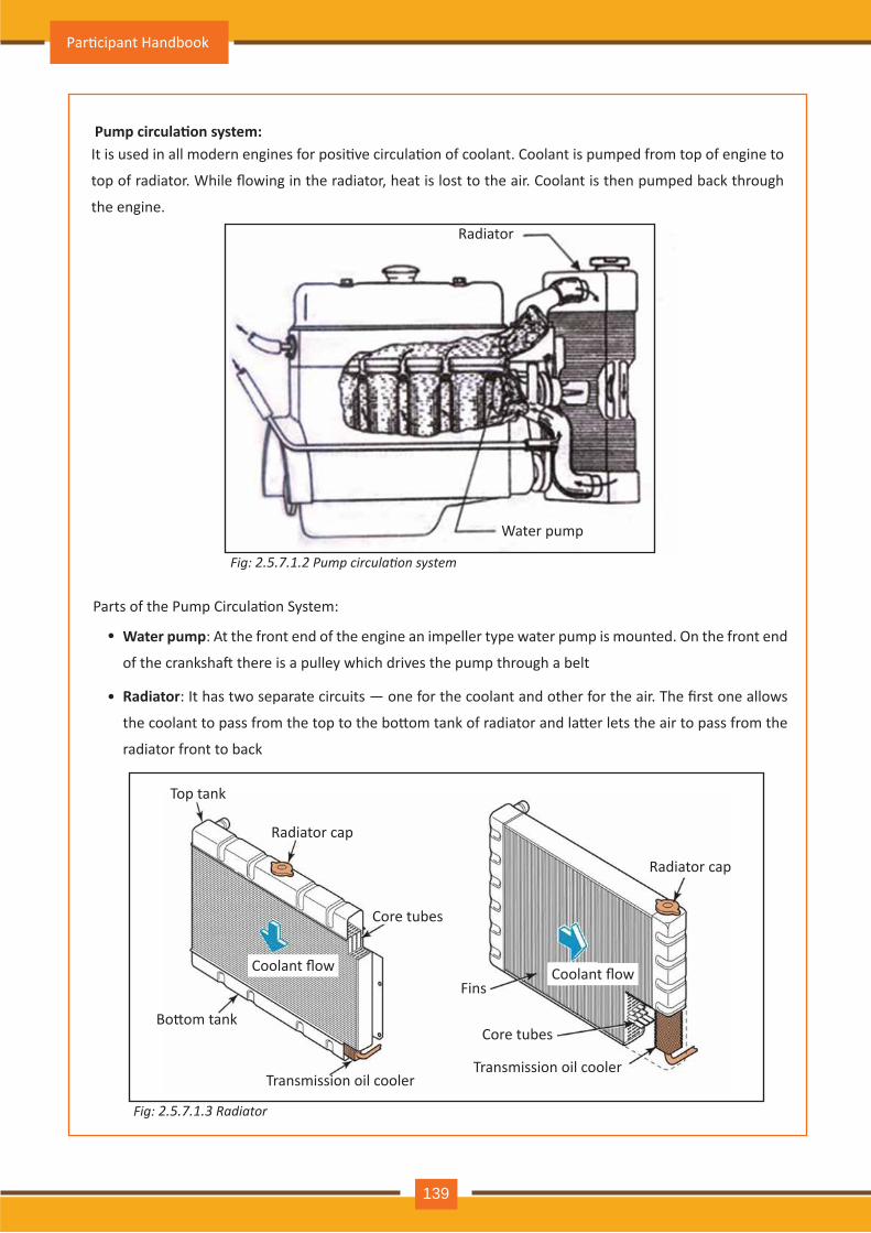
Water pump
Fig: 2.5.7.1.2 Pump circulation system
Fig: 2.5.7.1.3 Radiator
Pump circula�on system:It is used in all modern engines for posi�ve circula�on of coolant. Coolant is pumped from top of engine to
top of radiator. While flowing in the radiator, heat is lost to the air. Coolant is then pumped back through
the engine.
Radiator
Parts of the Pump Circula�on System:
Water pump: At the front end of the engine an impeller type water pump is mounted. On the front end
of the cranksha� there is a pulley which drives the pump through a belt
Radiator: It has two separate circuits — one for the coolant and other for the air. The first one allows
the coolant to pass from the top to the bo�om tank of radiator and la�er lets the air to pass from the
radiator front to back
•
•
Top tank
Radiator cap
Radiator cap
Core tubes
Core tubes
Transmission oil cooler Transmission oil cooler
Fins
Bo�om tank
Coolant flow Coolant flow
Par�cipant Handbook
139
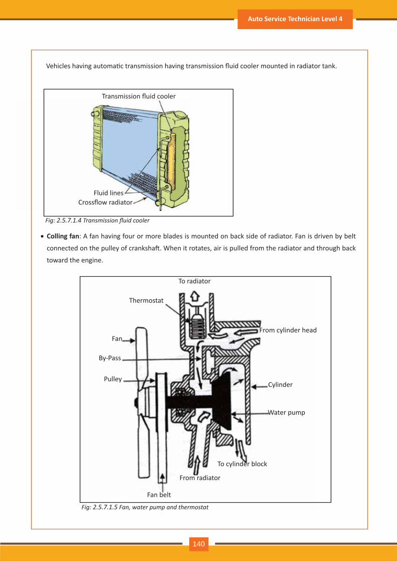
Colling fan: A fan having four or more blades is mounted on back side of radiator. Fan is driven by belt
connected on the pulley of cranksha�. When it rotates, air is pulled from the radiator and through back
toward the engine.
Vehicles having automa�c transmission having transmission fluid cooler mounted in radiator tank.
•
To radiator
Thermostat
Fan
By-Pass
Pulley
Fan belt
From radiator
To cylinder block
Water pump
Cylinder
From cylinder head
Fig: 2.5.7.1.5 Fan, water pump and thermostat
Fig: 2.5.7.1.4 Transmission fluid cooler
Transmission fluid cooler
Fluid linesCrossflow radiator
Auto Service Technician Level 4
140
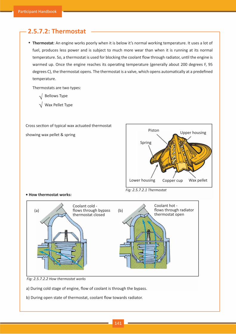
Thermostat: An engine works poorly when it is below it’s normal working temperature. It uses a lot of
fuel, produces less power and is subject to much more wear than when it is running at its normal
temperature. So, a thermostat is used for blocking the coolant flow through radiator, un�l the engine is
warmed up. Once the engine reaches its opera�ng temperature (generally about 200 degrees F, 95
degrees C), the thermostat opens. The thermostat is a valve, which opens automa�cally at a predefined
temperature.
Thermostats are two types:
•
Bellows Type
Wax Pellet Type√√
Cross sec�on of typical wax actuated thermostat
showing wax pellet & spring
• How thermostat works:Fig: 2.5.7.2.1 Thermostat
Spring
Upper housing
Lower housing Copper cup Wax pellet
Piston
a) During cold stage of engine, flow of coolant is through the bypass.
b) During open state of thermostat, coolant flow towards radiator.
(a) (b)Coolant cold - flows through bypassthermostat closed
Coolant hot -flows through radiatorthermostat open
Fig: 2.5.7.2.2 How thermostat works
Par�cipant Handbook
141
2.5.7.2: Thermostat
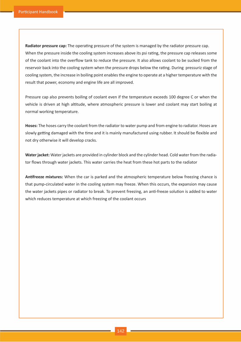
Radiator pressure cap: The opera�ng pressure of the system is managed by the radiator pressure cap.
When the pressure inside the cooling system increases above its psi ra�ng, the pressure cap releases some
of the coolant into the overflow tank to reduce the pressure. It also allows coolant to be sucked from the
reservoir back into the cooling system when the pressure drops below the ra�ng. During pressuriz stage of
cooling system, the increase in boiling point enables the engine to operate at a higher temperature with the
result that power, economy and engine life are all improved.
Pressure cap also prevents boiling of coolant even if the temperature exceeds 100 degree C or when the
vehicle is driven at high al�tude, where atmospheric pressure is lower and coolant may start boiling at
normal working temperature.
Hoses: The hoses carry the coolant from the radiator to water pump and from engine to radiator. Hoses are
slowly ge�ng damaged with the �me and it is mainly manufactured using rubber. It should be flexible and
not dry otherwise it will develop cracks.
Water jacket: Water jackets are provided in cylinder block and the cylinder head. Cold water from the radia-
tor flows through water jackets. This water carries the heat from these hot parts to the radiator
An�freeze mixtures: When the car is parked and the atmospheric temperature below freezing chance is
that pump-circulated water in the cooling system may freeze. When this occurs, the expansion may cause
the water jackets pipes or radiator to break. To prevent freezing, an an�-freeze solu�on is added to water
which reduces temperature at which freezing of the coolant occurs
Par�cipant Handbook
142
Reason for using coolant::
• Absorb heat from engine and transfer to radiator
• Protects engine and cooling system from rust and corrosion
• Prevents freezing in cold climates
All manufacturers recommend the use of ethylene glycol based coolant, which contains:
- Ethylene glycol (EG): 47%
- Water: 50%
- Addi�ves: 3%
Water is vital part of coolant. However, it may affect the corrosion protec�on property of coolant.
Municipal water supply in the city is chlorine treated and may cause corrosion, if the chemical
contamina�on levels are high.
If we consider well water it may also have iron and minerals and its use in coolant increases risk of
corrosion and electrolysis.
To maintain the quality of coolant specially due to water quality vehicle manufacturers recommend
premixed coolant because water used in premixed coolant is demineralised to avoid chances of
corrosion.
•
•
•
•
2.5.7.3: Coolant
Why normal tap water is not good as coolant:
2.5.7.4: Tes�ng & replacing coolant• Normal coolant tests include:
• Visual inspec�on: Coolant has to be clean & bright.
• Freeze/boiling point: If freezing point is high or low boiling point, it indicates dilu�on contain
high water level.
• pH: Wrong pH indicates buffer loss, used to help maintain the pH level.
• Coolant voltage: High voltage is indica�ve of wrong pH or stray current flow.
• Maintenance of cooling system usually calls for replacement of the coolant:
• A�er comple�on of two years or 36,000 km
• As recommended by vehicle manufacturer
Auto Service Technician Level 4
143
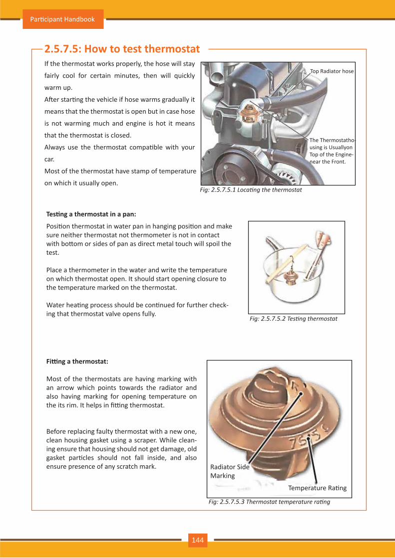
2.5.7 .5: H ow to test thermostatIf the thermostat works properly, the hose will stay
fairly cool for certain minutes, then will quickly
warm up.
A�er star�ng the vehicle if hose warms gradually it
m eans th at th e th erm ostat is open but in case h ose
is not warming much and engine is hot it means
that the thermostat is closed.
Always use the thermostat compa�ble with your
car.
Most of the thermostat have stamp of temperature
on which it usually open.
Top Radiator hose
The Thermostatho-using is Usuallyon Top of the Engine-near the Front.
Fig: 2.5.7 .5.1 ocating the thermostat
Fig: 2.5.7 .5.2 esting thermostat
Tes�ng a thermostat in a pan:
Posi�on thermostat in water pan in hanging posi�on and make sure neith er th erm ostat not th erm om eter is not in contact with bo�om or sides of pan as direct metal touch will spoil the test.
Place a thermometer in the water and write the temperature on which thermostat open. It should start opening closure to the temperature marked on the thermostat.
Water hea�ng process should be con�nued for further check-ing that thermostat valve opens fully.
Fi ng a thermostat:
Most of the thermostats are having marking with an arrow which points towards the radiator and also having marking for opening temperature on the its rim. It helps in fi�ng thermostat.
Before replacing faulty thermostat with a new one, clean housing gasket using a scraper. While clean-ing ensure that housing should not get damage, old gasket par�cles should not fall inside, and also ensure presence of any scratch mark. Radiator Side
Marking
Temperature Ra�ng
Fig: 2.5.7 .5.3 hermostat temperature rating
Par�cipant Handbook
144
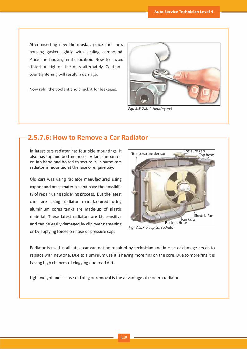
Fig: 2.5.7 .5.4 H o u s in g n u t
A�er inser�ng new thermostat, place the new
housing gasket lightly with sealing compound.
Place the housing in its loca�on. Now to avoid
distor�on �ghten the nuts alternately. Cau�on -
over �ghtening will result in damage.
Now refill the coolant and check it for leakages.
Fig: 2.5.7 .6 pical radiator
Old cars was using radiator manufactured using
copper and brass m aterials and h av e th e possibili-
ty of repair using soldering process. But the latest
cars are using radiator manufactured using
aluminium cores tanks are made-up of plas�c
material. These latest radiators are bit sensi�ve
and can be easily damaged by clip over �ghtening
or by applying forces on hose or pressure cap.
In latest cars radiator has four side moun�ngs. It also has top and bo�om hoses. A fan is mounted on fan hood and bolted to secure it. In some cars radiator is mounted at the face of engine bay.
Temperature SensorPressure cap
Top h ose
Bo�om HoseFan Cowl
Electric Fan
2.5.7 .6: How to Remove a Car Radiator
Radiator is used in all latest car can not be repaired by technician and in case of damage needs to
replace with new one. Due to aluminium use it is having more fins on the core. Due to more fins it is
having high chances of clogging due road dirt.
Light weight and is ease of fixing or removal is the advantage of modern radiator.
Auto Service Technician Level 4
145
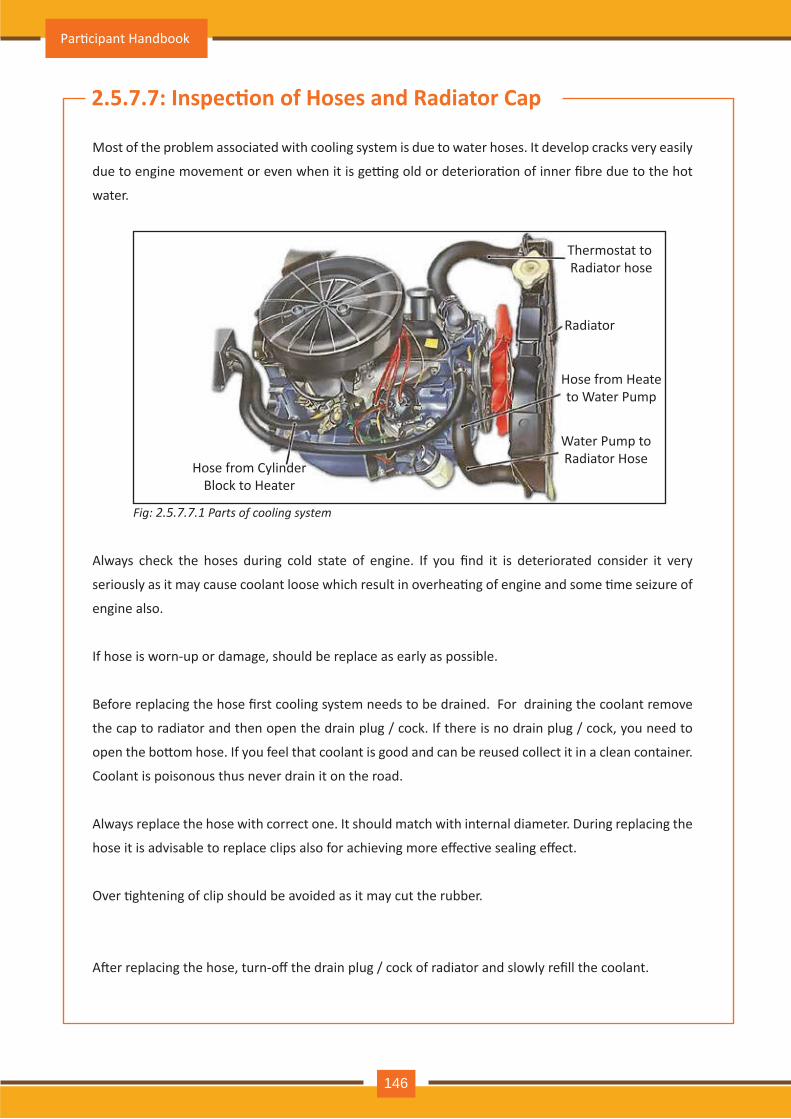
2.5.7 .7 : Inspec�on of Hoses and Radiator Cap
Most of the problem associated with cooling system is due to water hoses. It develop cracks very easily
due to engine movement or even when it is ge�ng old or deteriora�on of inner fibre due to the hot
water.
Always check the hoses during cold state of engine. If you find it is deteriorated consider it very
seriously as it may cause coolant loose which result in overhea�ng of engine and some �me seizure of
engine also.
If hose is worn-up or damage, should be replace as early as possible.
Before replacing the hose first cooling system needs to be drained. For draining the coolant remove
the cap to radiator and then open the drain plug / cock. If there is no drain plug / cock, you need to
open the bo�om hose. If you feel that coolant is good and can be reused collect it in a clean container.
Coolant is poisonous thus never drain it on the road.
Always replace the hose with correct one. It should match with internal diameter. During replacing the
hose it is advisable to replace clips also for achieving more effec�ve sealing effect.
Over �ghtening of clip should be avoided as it may cut the rubber.
A�er replacing the hose, turn-off the drain plug / cock of radiator and slowly refill the coolant.
Th erm ostat to Radiator hose
Radiator
Hose from Heateto W ater Pum p
W ater Pum p toRadiator Hose
Hose from CylinderBlock to Heater
Fig: 2.5.7 .7 .1 arts of cooling s stem
Par�cipant Handbook
146
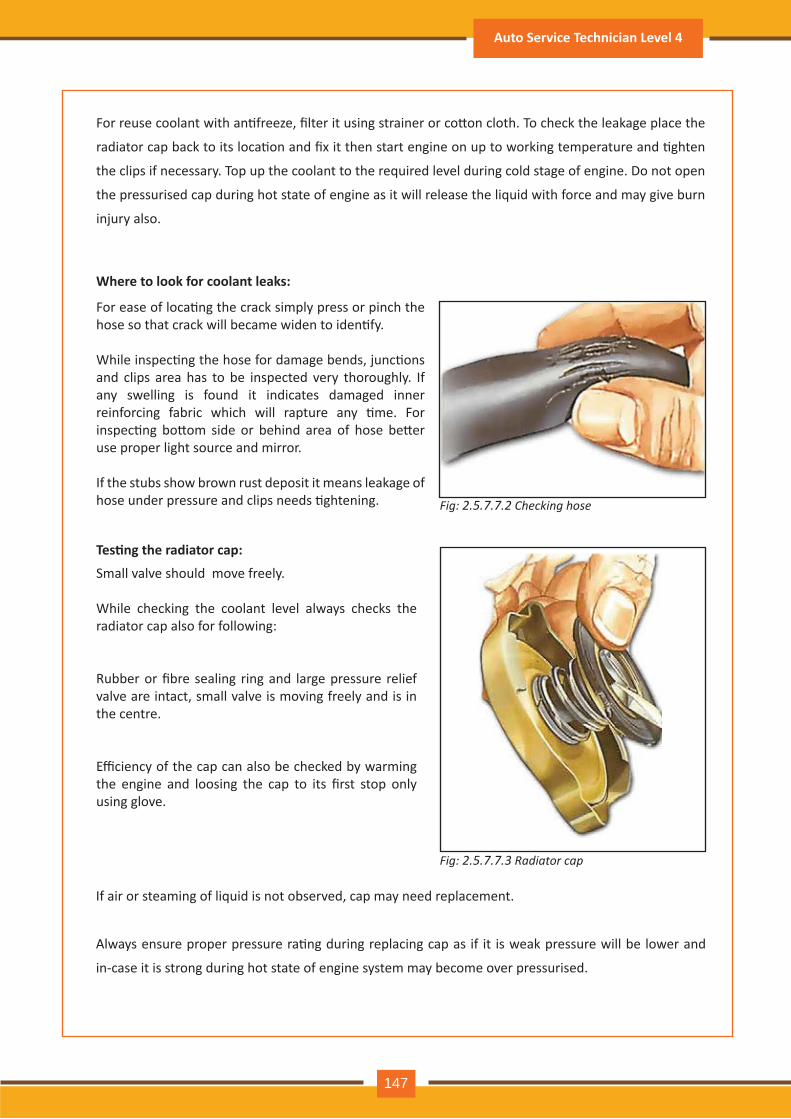
Fig: 2.5.7 .7 .2 Checking hose
For reuse coolant with an�freeze, filter it using strainer or co�on cloth. To check the leakage place the
radiator cap back to its loca�on and fix it then start engine on up to working temperature and �ghten
the clips if necessary. Top up the coolant to the required level during cold stage of engine. Do not open
the pressurised cap during hot state of engine as it will release the liquid with force and may give burn
injury also.
W here to look for coolant leak s:
Tes�ng the radiator cap:
For ease of loca�ng the crack simply press or pinch the hose so that crack will became widen to iden�fy.
While inspec�ng the hose for damage bends, junc�ons and clips area has to be inspected very thoroughly. If any swelling is found it indicates damaged inner reinforcing fabric which will rapture any �me. For inspec�ng bo�om side or behind area of hose be�er use proper light source and mirror.
If the stubs show brown rust deposit it means leakage of hose under pressure and clips needs �ghtening.
Small valve should move freely.
While checking the coolant level always checks the radiator cap also for following:
Rubber or fibre sealing ring and large pressure relief valve are intact, small valve is moving freely and is in the centre.
Efficiency of the cap can also be checked by warming the engine and loosing the cap to its first stop only using glove.
Fig: 2.5.7 .7 .3 Radiator cap
If air or steaming of liquid is not observed, cap may need replacement.
Always ensure proper pressure ra�ng during replacing cap as if it is weak pressure will be lower and
in-case it is strong during hot state of engine system may become over pressurised.
Auto Service Technician Level 4
147
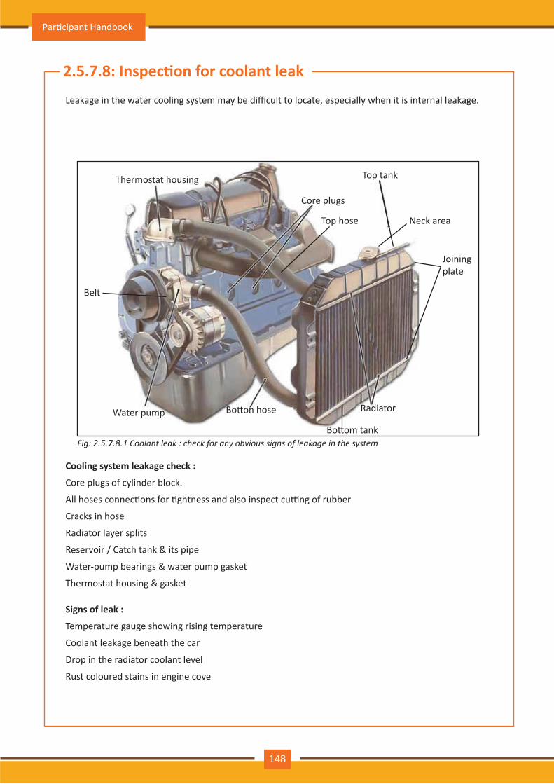
Fig: 2.5.7 .8 .1 Coolant leak : check for an obvious signs of leakage in the s stem
2.5.7 .8 : Inspec�on for coolant leak
Leakage in the water cooling system may be difficult to locate, especially when it is internal leakage.
Cooling system leak age check :
Core plugs of cylinder block.
All hoses connec�ons for �ghtness and also inspect cu�ng of rubber
Cracks in hose
Radiator layer splits
Reservoir / Catch tank & its pipe
Water-pump bearings & water pump gasket
Thermostat housing & gasket
Signs of leak :
Temperature gauge showing rising temperature
Coolant leakage beneath the car
Drop in the radiator coolant level
Rust coloured stains in engine cove
Radiator
Bo�om tank
Bo�on hose W ater pum p
Core plugs
Top h ose
Top tank
Neck area
Joining plate
Thermostat housing
Belt
Par�cipant Handbook
148
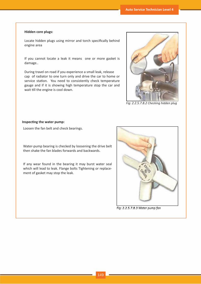
Hidden core plugs:
Locate hidden plugs using mirror and torch specifically behind engine area
If you cannot locate a leak it means one or more gasket is damage..
During travel on road if you experience a small leak, release cap of radiator to one turn only and driv e th e car to h om e or service sta�on. You need to consistently check temperature gauge and if it is showing high temperature stop the car and wait �ll the engine is cool down.
Fig: 2.2.5.7 .8 .2 Checking hidden plug
Fig: 2.2.5.7 .8 .3 ater pump fan
Inspec�ng the water pump:
Loosen the fan belt and check bearings.
Water-pump bearing is checked by loosening the drive belt then shake the fan blades forwards and backwards.
If any wear found in the bearing it may burst water seal which will lead to leak. Flange bolts Tightening or replace-ment of gasket may stop the leak.
Fig: 2.2.5.7 .8 .3 ater pump fan
Auto Service Technician Level 4
149
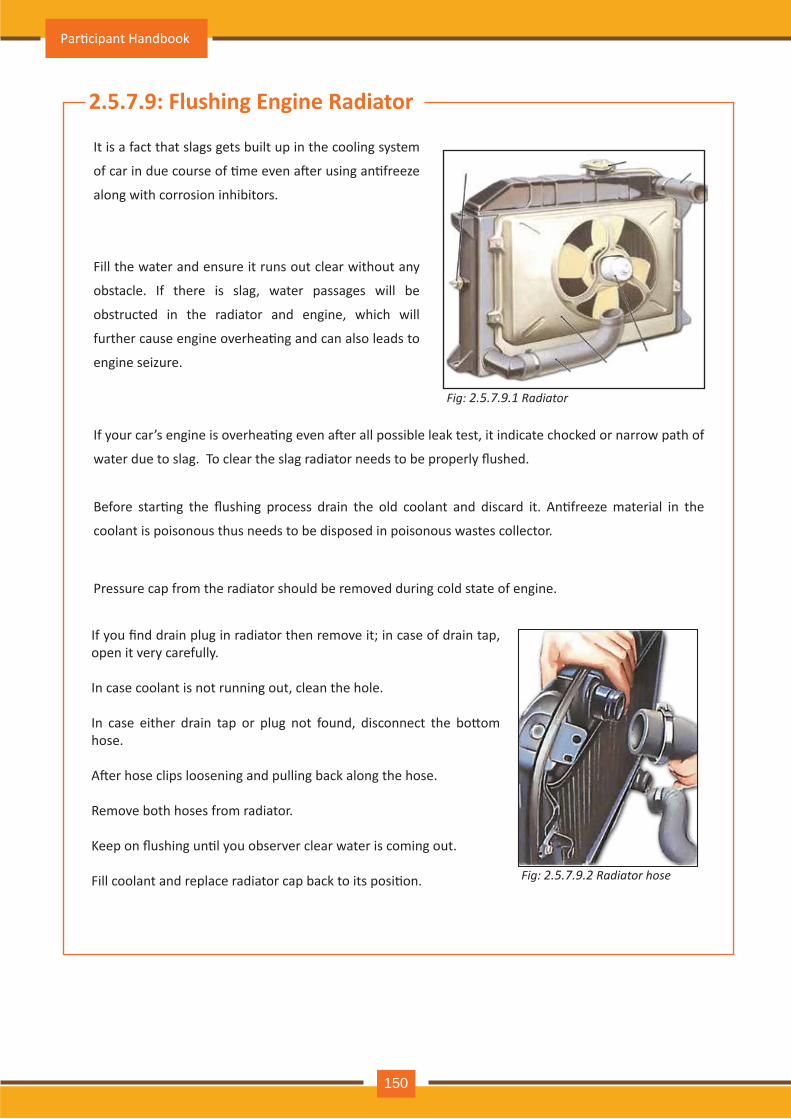
Fig: 2.5.7 .9 .1 Radiator
2.5.7 .9 : Flushing Engine Radiator
It is a fact that slags gets built up in the cooling system
of car in due course of �me even a�er using an�freeze
along with corrosion inhibitors.
Fill the water and ensure it runs out clear without any
obstacle. If there is slag, water passages will be
obstructed in the radiator and engine, which will
further cause engine overhea�ng and can also leads to
engine seizure.
If your car’s engine is overhea�ng even a�er all possible leak test, it indicate chocked or narrow path of
water due to slag. To clear the slag radiator needs to be properly flushed.
Before star�ng the flushing process drain the old coolant and discard it. An�freeze material in the
coolant is poisonous thus needs to be disposed in poisonous wastes collector.
Pressure cap from the radiator should be removed during cold state of engine.
If you find drain plug in radiator then remove it in case of drain tap, open it very carefully.
In case coolant is not running out, clean the hole.
In case either drain tap or plug not found, disconnect the bo�om hose.
A�er hose clips loosening and pulling back along the hose.
Remove both hoses from radiator.
Keep on flushing un�l you observer clear water is coming out.
Fill coolant and replace radiator cap back to its posi�on. Fig: 2.5.7 .9 .2 Radiator hose
Par�cipant Handbook
150
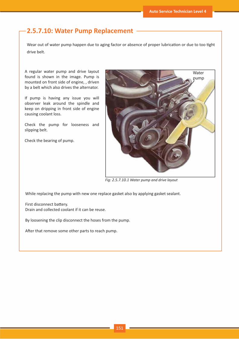
Fig: 2.5.7 .10 .1 ater pump and drive la out
2.5.7 .10: W ater P ump R eplacement
Wear out of water pump happen due to aging factor or absence of proper lubrica�on or due to too �ght
drive belt.
A regular water pump and drive layout found is shown in the image. Pump is mounted on front side of engine, , driven by a belt which also drives the alternator.
If pump is having any issue you will observer leak around the spindle and keep on dripping in front side of engine causing coolant loss.
Check the pump for looseness and slipping belt.
Check the bearing of pump.
While replacing the pump with new one replace gasket also by applying gasket sealant.
First disconnect ba�ery.Drain and collected coolant if it can be reuse.
By loosening the clip disconnect the hoses from the pump.
A�er that remove some other parts to reach pump.
Water pump
Auto Service Technician Level 4
151
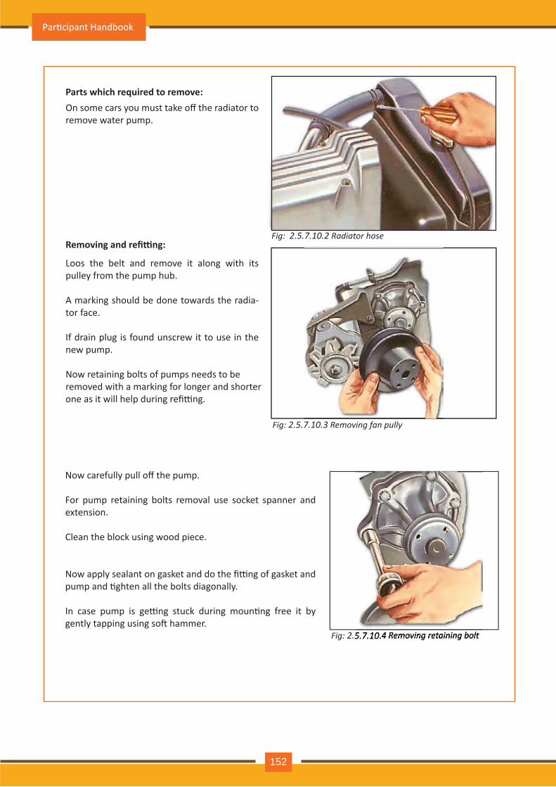
Fig: 2.5.7 .10 .2 Radiator hose
Parts which re uired to remove:
Removing and refi ng:
On some cars you must take off the radiator to remove water pump.
Loos the belt and remove it along with its pulley from the pump hub.
A marking should be done towards the radia-tor face.
If drain plug is found unscrew it to use in the new pump.
Now retaining bolts of pumps needs to be removed with a marking for longer and shorter one as it will help during refi�ng.
Fig: 2.5.7 .10 .3 Removing fan pull
Fig: 2.5.7 .10 .4 Removing retaining bolt 2.5.7 .10 .4 Removing retaining bolt
Now carefully pull off the pump.
For pump retaining bolts removal use socket spanner and extension.
Clean the block using wood piece.
Now apply sealant on gasket and do the fi�ng of gasket and pump and �ghten all the bolts diagonally.
In case pump is ge�ng stuck during moun�ng free it by gently tapping using so� hammer.
Par�cipant Handbook
152
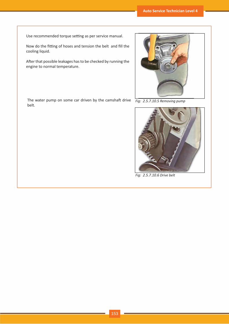
Fig: 2.5.7 .10 .5 R e m o v in g p u m p
Use recommended torque se�ng as per service manual.
Now do the fi�ng of hoses and tension the belt and fill the cooling liquid.
A�er that possible leakages has to be checked by running the engine to normal temperature.
Fig: 2.5.7 .10 .6 rive belt
The water pump on some car driven by the camsha� drive belt.
Auto Service Technician Level 4
153
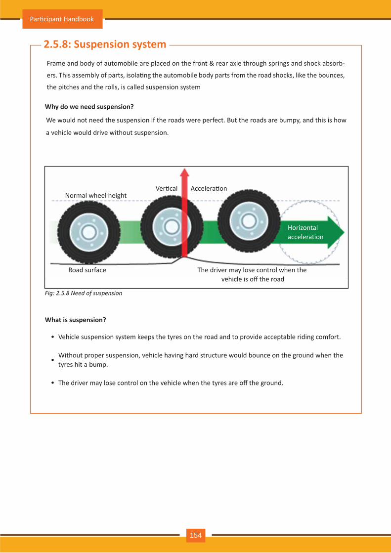
2.5.8: Suspension systemFrame and body of automobile are placed on the front & rear axle through springs and shock absorb-
ers. This assembly of parts, isola�ng the automobile body parts from the road shocks, like the bounces,
the pitches and the rolls, is called suspension system
Why do we need suspension?
What is suspension?
•
•
•
We would not need the suspension if the roads were perfect. But the roads are bumpy, and this is how
a vehicle would drive without suspension.
Normal wheel height
Road surface
Ver�cal Accelera�on
Horizontal accelera�on
The driver may lose control when the vehicle is off the road
Vehicle suspension system keeps the tyres on the road and to provide acceptable riding comfort.
Without proper suspension, vehicle having hard structure would bounce on the ground when the tyres hit a bump.
The driver may lose control on the vehicle when the tyres are off the ground.
Fig: 2.5.8 Need of suspension
Par�cipant Handbook
154
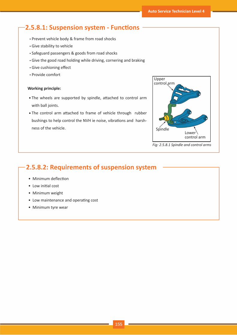
2.5.8.1: Suspension system - Func�ons• Prevent vehicle body & frame from road shocks
• Give stability to vehicle
• Safeguard passengers & goods from road shocks
• Give the good road holding while driving, cornering and braking
• Give cushioning effect
• Provide comfort
Working principle:
The wheels are supported by spindle, a�ached to control arm
with ball joints.
The control arm a�ached to frame of vehicle through rubber
bushings to help control the NVH ie noise, vibra�ons and harsh-
ness of the vehicle.
•
•
Upper control arm
SpindleLower control arm
2.5.8.2: Requirements of suspension system• Minimum deflec�on
• Low ini�al cost
• Minimum weight
• Low maintenance and opera�ng cost
• Minimum tyre wear
Fig: 2.5.8.1 Spindle and control arms
Auto Service Technician Level 4
155
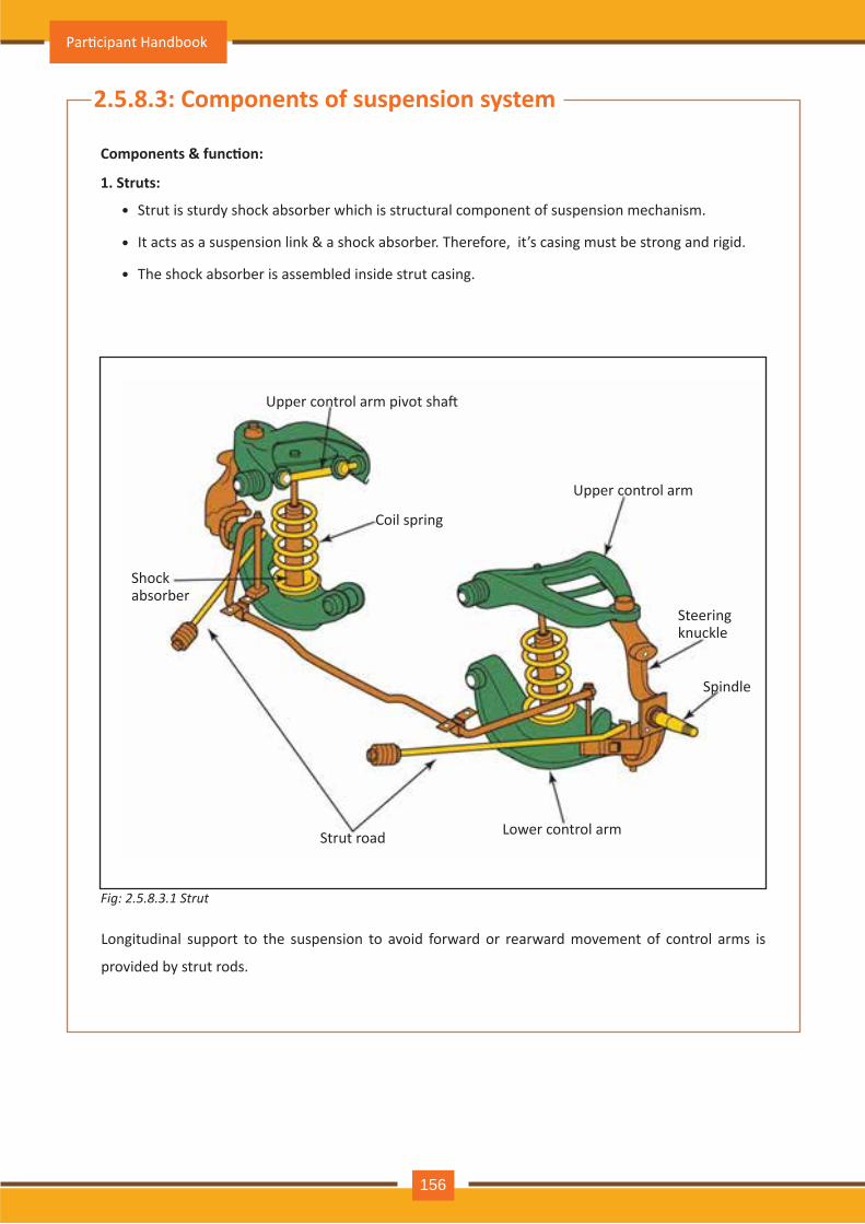
2.5.8.3: Components of suspension system
Components & func�on:
1. Struts:
•
•
•
Strut is sturdy shock absorber which is structural component of suspension mechanism.
It acts as a suspension link & a shock absorber. Therefore, it’s casing must be strong and rigid.
The shock absorber is assembled inside strut casing.
Shock absorber
Strut road Lower control arm
Spindle
Steering knuckle
Upper control arm
Coil spring
Upper control arm pivot sha�
Longitudinal support to the suspension to avoid forward or rearward movement of control arms is
provided by strut rods.
Fig: 2.5.8.3.1 Strut
Par�cipant Handbook
156
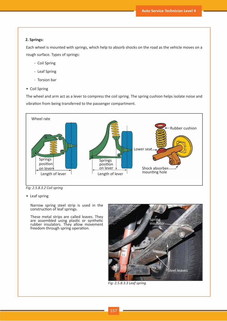
2. Springs:
Each wheel is mounted with springs, which help to absorb shocks on the road as the vehicle moves on a
rough surface. Types of springs:
The wheel and arm act as a lever to compress the coil spring. The spring cushion helps isolate noise and
vibra�on from being transferred to the passenger compartment.
Coil Spring
Leaf Spring
Torsion bar
-
-
-
• Coil Spring
• Leaf spring
Wheel rate
Springs posi�on on lever
Springs posi�on on lever
Length of lever Length of lever
Rubber cushion
Lower seat
Shock absorber moun�ng hole
Narrow spring steel strip is used in the construc�on of leaf springs.
These metal strips are called leaves. They are assembled using plas�c or synthe�c rubber insulators. They allow movement freedom through spring opera�on.
Spring insulator
Steel leaves
Fig: 2.5.8.3.2 Coil spring
Fig: 2.5.8.3.3 Leaf spring
Auto Service Technician Level 4
157
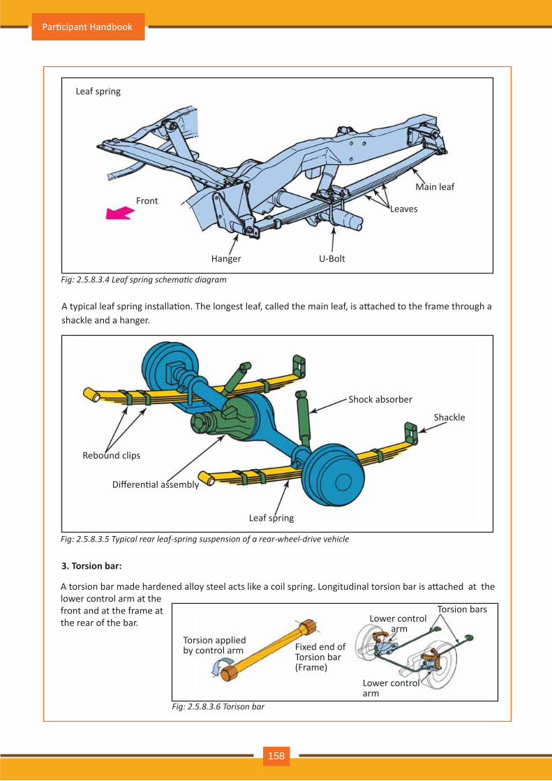
Leaf spring
Front
Hanger U-Bolt
Leaves
Main leaf
A typical leaf spring installa�on. The longest leaf, called the main leaf, is a�ached to the frame through a shackle and a hanger.
A torsion bar made hardened alloy steel acts like a coil spring. Longitudinal torsion bar is a�ached at the lower control arm at the front and at the frame at the rear of the bar.
Rebound clips
Differen�al assembly
Leaf spring
Shackle
Shock absorber
3. Torsion bar:
Torsion applied by control arm Fixed end of
Torsion bar (Frame)
Lower control arm
Lower control arm
Torsion bars
Fig: 2.5.8.3.4 Leaf spring schematic diagram
Fig: 2.5.8.3.5 Typical rear leaf-spring suspension of a rear-wheel-drive vehicle
Fig: 2.5.8.3.6 Torison bar
Par�cipant Handbook
158
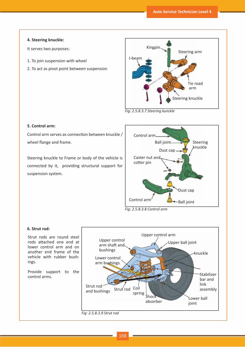
4. Steering knuckle:
5. Control arm:
6. Strut rod:
Kingpin
I-beamSteering arm
Tie road arm
Steering knuckle
It serves two purposes:
Control arm serves as connec�on between knuckle /
wheel flange and frame.
Steering knuckle to Frame or body of the vehicle is
connected by it, providing structural support for
suspension system.
1. To join suspension with wheel
2. To act as pivot point between suspension
Control arm
Control arm
Ball joint
Ball joint
Dust cap
Dust cap
Caster nut and co�er pin
Steering knuckle
Upper control arm sha� and bushings
Lower control arm bushings
Strut rod and bushings Strut rod Coil
springShock absorber
Lower ball joint
Stabilizer bar and link assembly
knuckle
Upper ball joint
Upper control armStrut rods are round steel rods a�ached one end at lower control arm and on another end frame of the vehicle with rubber bush-ings.
Provide support to the control arms.
Fig: 2.5.8.3.7 Steering kunckle
Fig: 2.5.8.3.8 Control arm
Fig: 2.5.8.3.9 Strut rod
Auto Service Technician Level 4
159
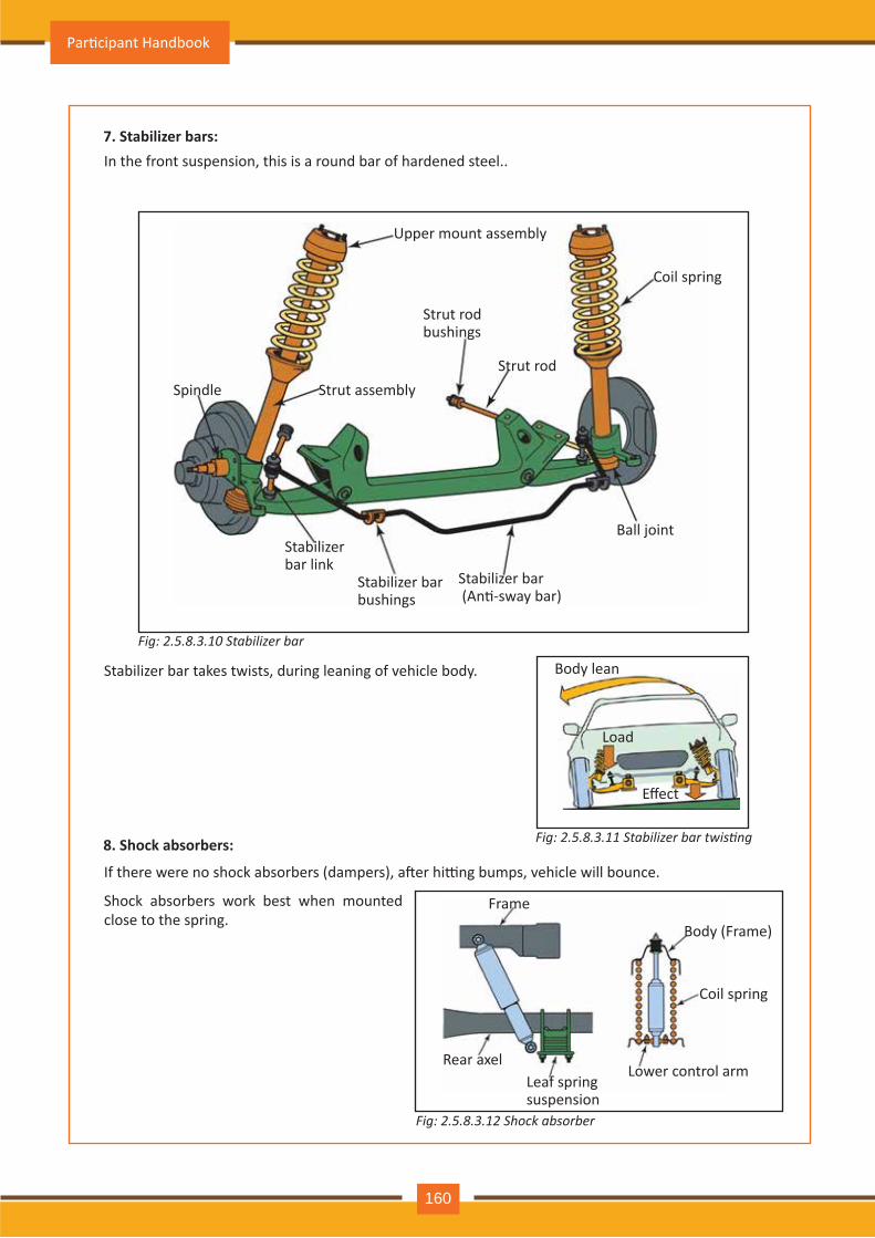
7. Stabilizer bars:
8. Shock absorbers:
In the front suspension, this is a round bar of hardened steel..
Stabilizer bar takes twists, during leaning of vehicle body.
Spindle
Upper mount assembly
Strut assembly
Strut rod bushings
Strut rod
Coil spring
Ball joint
Stabilizer bar (An�-sway bar)
Stabilizer bar bushings
Stabilizer bar link
Load
Body lean
Effect
If there were no shock absorbers (dampers), a�er hi�ng bumps, vehicle will bounce.
Frame
Rear axelLeaf spring suspension
Lower control arm
Coil spring
Body (Frame)
Fig: 2.5.8.3.10 Stabilizer bar
Fig: 2.5.8.3.11 Stabilizer bar twisting
Fig: 2.5.8.3.12 Shock absorber
Shock absorbers work best when mounted close to the spring.
Par�cipant Handbook
160
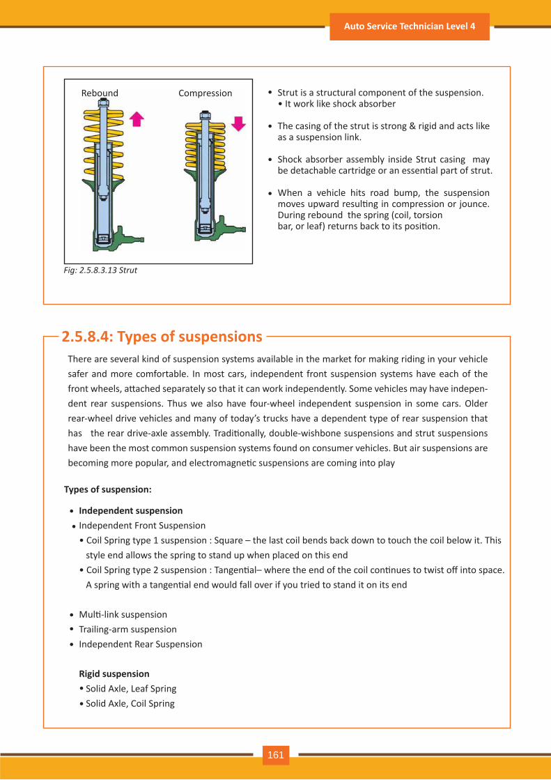
Rebound Compression Strut is a structural component of the suspension.• It work like shock absorber
The casing of the strut is strong & rigid and acts like as a suspension link.
Shock absorber assembly inside Strut casing may be detachable cartridge or an essen�al part of strut.
When a vehicle hits road bump, the suspension moves upward resul�ng in compression or jounce. During rebound the spring (coil, torsionbar, or leaf) returns back to its posi�on.
•
•
•
•
2.5.8.4: Types of suspensionsThere are several kind of suspension systems available in the market for making riding in your vehicle safer and more comfortable. In most cars, independent front suspension systems have each of the front wheels, a�ached separately so that it can work independently. Some vehicles may have indepen-dent rear suspensions. Thus we also have four-wheel independent suspension in some cars. Older rear-wheel drive vehicles and many of today’s trucks have a dependent type of rear suspension that has the rear drive-axle assembly. Tradi�onally, double-wishbone suspensions and strut suspensions have been the most common suspension systems found on consumer vehicles. But air suspensions are becoming more popular, and electromagne�c suspensions are coming into play
Independent suspensionIndependent Front Suspension• Coil Spring type 1 suspension : Square – the last coil bends back down to touch the coil below it. This style end allows the spring to stand up when placed on this end• Coil Spring type 2 suspension : Tangen�al– where the end of the coil con�nues to twist off into space. A spring with a tangen�al end would fall over if you tried to stand it on its end
Mul�-link suspensionTrailing-arm suspensionIndependent Rear Suspension
Rigid suspension Solid Axle, Leaf Spring Solid Axle, Coil Spring
Types of suspension:
•
•••
•
••
Fig: 2.5.8.3.13 Strut
Auto Service Technician Level 4
161
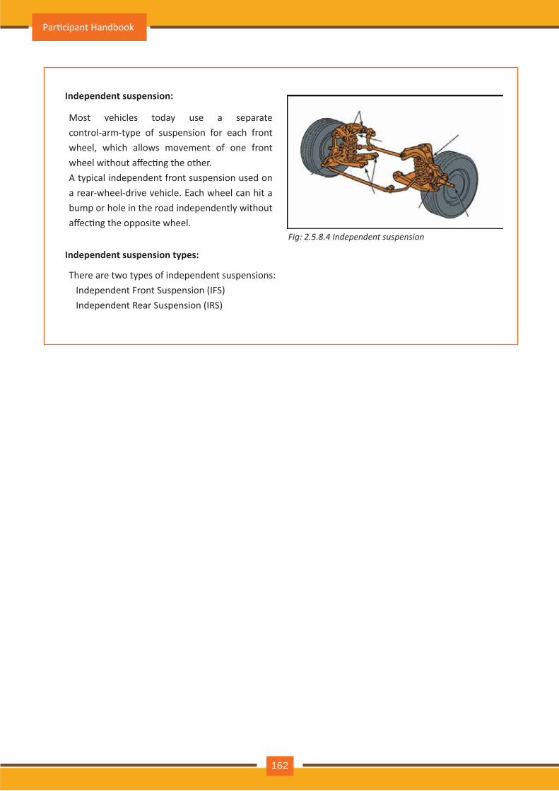
Independent suspension:
Independent suspension types:
Most vehicles today use a separate control-arm-type of suspension for each front wheel, which allows movement of one front wheel without affec�ng the other.A typical independent front suspension used on a rear-wheel-drive vehicle. Each wheel can hit a bump or hole in the road independently without affec�ng the opposite wheel.
There are two types of independent suspensions: Independent Front Suspension (IFS) Independent Rear Suspension (IRS)
Fig: 2.5.8.4 Independent suspension
Par�cipant Handbook
162
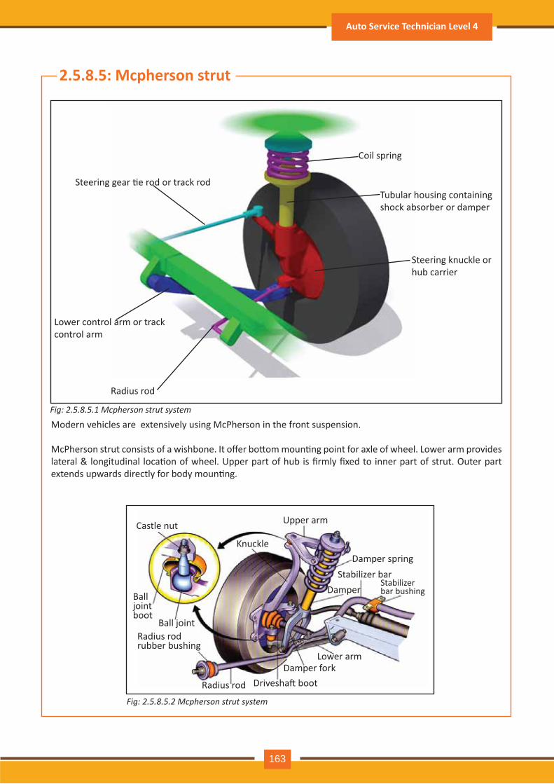
2.5.8.5: Mcpherson strut
Fig: 2.5.8.5.1 Mcpherson strut system
Fig: 2.5.8.5.2 Mcpherson strut system
Steering knuckle or hub carrier
Lower control arm or track control arm
Steering gear �e rod or track rod
Radius rod
Castle nut
Ball joint boot
Ball joint
Radius rod Drivesha� boot Damper fork
Lower arm
Damper Stabilizer bar
Damper spring Knuckle
Stabilizer bar bushing
Radius rod rubber bushing
Upper arm
Coil spring
Tubular housing containing shock absorber or damper
Modern vehicles are extensively using McPherson in the front suspension.
McPherson strut consists of a wishbone. It offer bo�om moun�ng point for axle of wheel. Lower arm provides lateral & longitudinal loca�on of wheel. Upper part of hub is firmly fixed to inner part of strut. Outer part extends upwards directly for body moun�ng.
Auto Service Technician Level 4
163
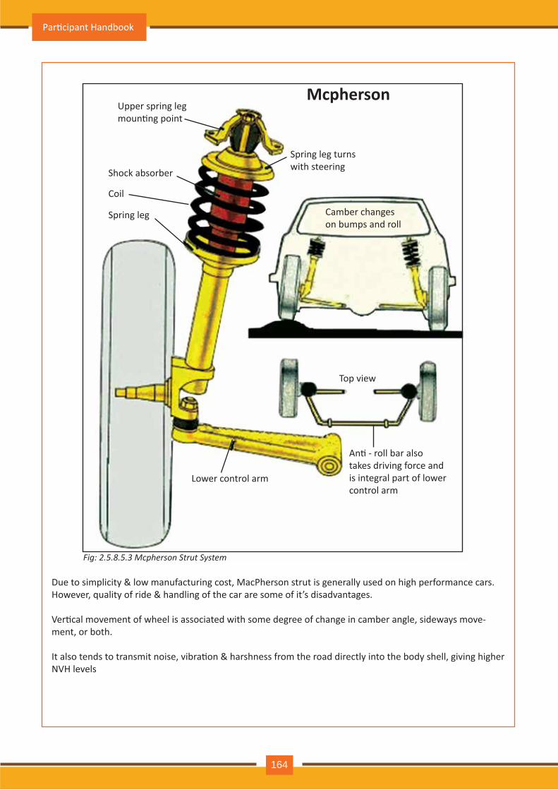
Due to simplicity & low manufacturing cost, MacPherson strut is generally used on high performance cars.However, quality of ride & handling of the car are some of it’s disadvantages.
Ver�cal movement of wheel is associated with some degree of change in camber angle, sideways move-ment, or both.
It also tends to transmit noise, vibra�on & harshness from the road directly into the body shell, giving higher NVH levels
Lower control arm
Top view
Spring leg
Coil
Shock absorber
McphersonUpper spring legmoun�ng point
Spring leg turnswith steering
Camber changeson bumps and roll
An� - roll bar alsotakes driving force andis integral part of lowercontrol arm
Fig: 2.5.8.5.3 Mcpherson Strut System
Par�cipant Handbook
164
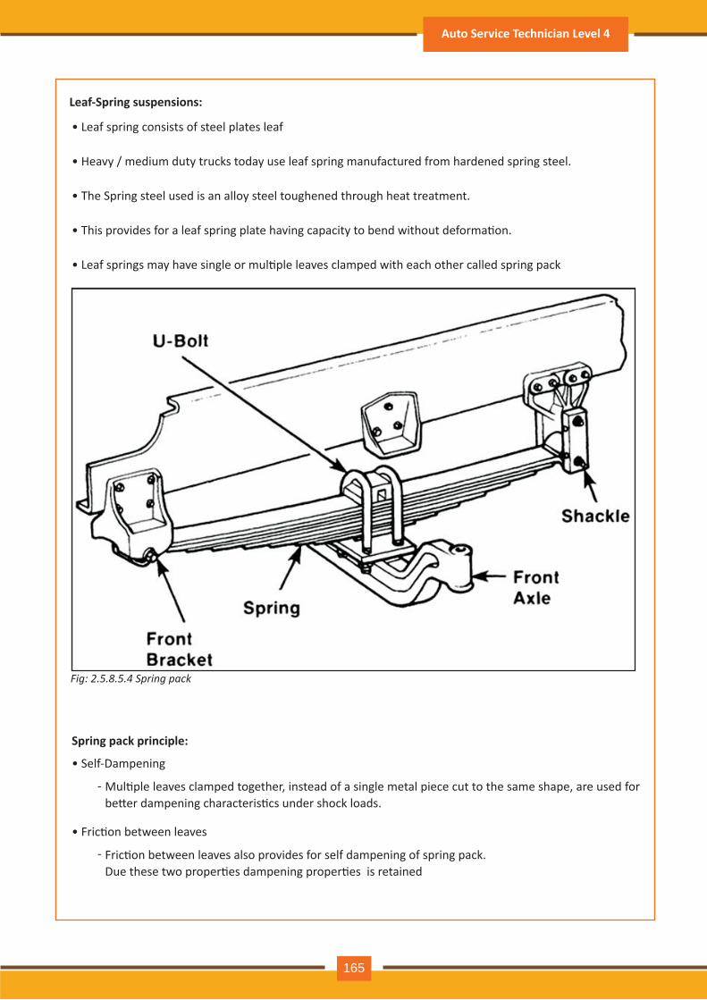
Fig: 2.5.8.5.4 Spring pack
Leaf-Spring suspensions:
• Leaf spring consists of steel plates leaf
• Heavy / medium duty trucks today use leaf spring manufactured from hardened spring steel.
• The Spring steel used is an alloy steel toughened through heat treatment.
• This provides for a leaf spring plate having capacity to bend without deforma�on.
• Leaf springs may have single or mul�ple leaves clamped with each other called spring pack
Spring pack principle:
• Self-Dampening
Mul�ple leaves clamped together, instead of a single metal piece cut to the same shape, are used for be�er dampening characteris�cs under shock loads.
Fric�on between leaves also provides for self dampening of spring pack. Due these two proper�es dampening proper�es is retained
-
-
• Fric�on between leaves
Auto Service Technician Level 4
165
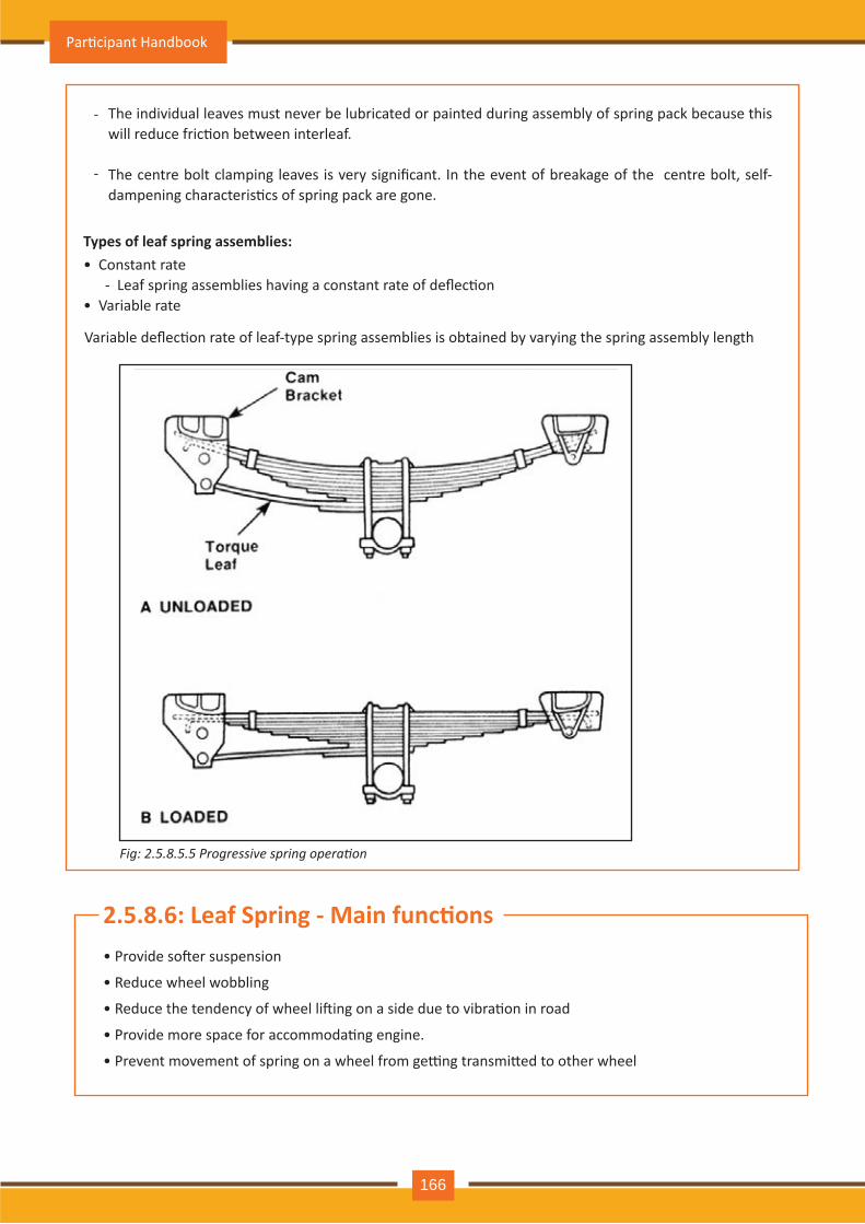
Fig: 2.5.8.5.5 Progressive spring operation
The individual leaves must never be lubricated or painted during assembly of spring pack because this will reduce fric�on between interleaf.
The centre bolt clamping leaves is very significant. In the event of breakage of the centre bolt, self- dampening characteris�cs of spring pack are gone.
-
-
Types of leaf spring assemblies:• Constant rate - Leaf spring assemblies having a constant rate of deflec�on• Variable rate
Variable deflec�on rate of leaf-type spring assemblies is obtained by varying the spring assembly length
2.5.8.6: Leaf Spring - Main func�ons• Provide so�er suspension
• Reduce wheel wobbling
• Reduce the tendency of wheel li�ing on a side due to vibra�on in road
• Provide more space for accommoda�ng engine.
• Prevent movement of spring on a wheel from ge�ng transmi�ed to other wheel
Par�cipant Handbook
166
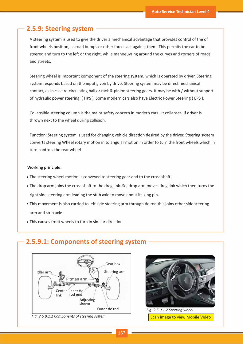
2.5.9: Steering systemA steering system is used to give the driver a mechanical advantage that provides control of the of
front wheels posi�on, as road bumps or other forces act against them. This permits the car to be
steered and turn to the le� or the right, while manoeuvring around the curves and corners of roads
and streets.
Steering wheel is important component of the steering system, which is operated by driver. Steering
system responds based on the input given by drive. Steering system may be direct mechanical
contact, as in case re-circula�ng ball or rack & pinion steering gears. It may be with / without support
of hydraulic power steering. ( HPS ). Some modern cars also have Electric Power Steering ( EPS ).
Collapsible steering column is the major safety concern in modern cars. It collapses, if driver is
thrown next to the wheel during collision.
Func�on: Steering system is used for changing vehicle direc�on desired by the driver. Steering system
converts steering Wheel rotary mo�on in to angular mo�on in order to turn the front wheels which in
turn controls the rear wheel
The steering wheel mo�on is conveyed to steering gear and to the cross sha�.
The drop arm joins the cross sha� to the drag link. So, drop arm moves drag link which then turns the
right side steering arm leading the stub axle to move about its king pin.
This movement is also carried to le� side steering arm through �e rod this joins other side steering
arm and stub axle.
This causes front wheels to turn in similar direc�on
Working principle:
•
•
•
•
2.5.9.1: Components of steering system
Fig: 2.5.9.1.2 Steering wheelFig: 2.5.9.1.1 Components of steering system Scan image to view Mobile Video
Idler arm
Pitman arm
Gear box
Steering arm
Outer �e rod
Adjus�ng sleeve
Center link
Inner �e-rod end
Auto Service Technician Level 4
167
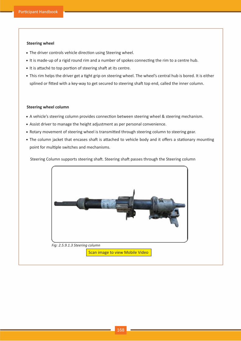
Steering wheel
The driver controls vehicle direc�on using Steering wheel.
It is made-up of a rigid round rim and a number of spokes connec�ng the rim to a centre hub.
It is a�aché to top por�on of steering sha� at its centre.
This rim helps the driver get a �ght grip on steering wheel. The wheel’s central hub is bored. It is either
splined or fi�ed with a key-way to get secured to steering sha� top end, called the inner column.
•
•
•
•
Steering wheel column
A vehicle’s steering column provides connec�on between steering wheel & steering mechanism.
Assist driver to manage the height adjustment as per personal convenience.
Rotary movement of steering wheel is transmi�ed through steering column to steering gear.
The column jacket that encases sha� is a�ached to vehicle body and it offers a sta�onary moun�ng
point for mul�ple switches and mechanisms.
•
•
•
•
Steering Column supports steering sha�. Steering sha� passes through the Steering column
Scan image to view Mobile Video
Fig: 2.5.9.1.3 Steering column
Par�cipant Handbook
168
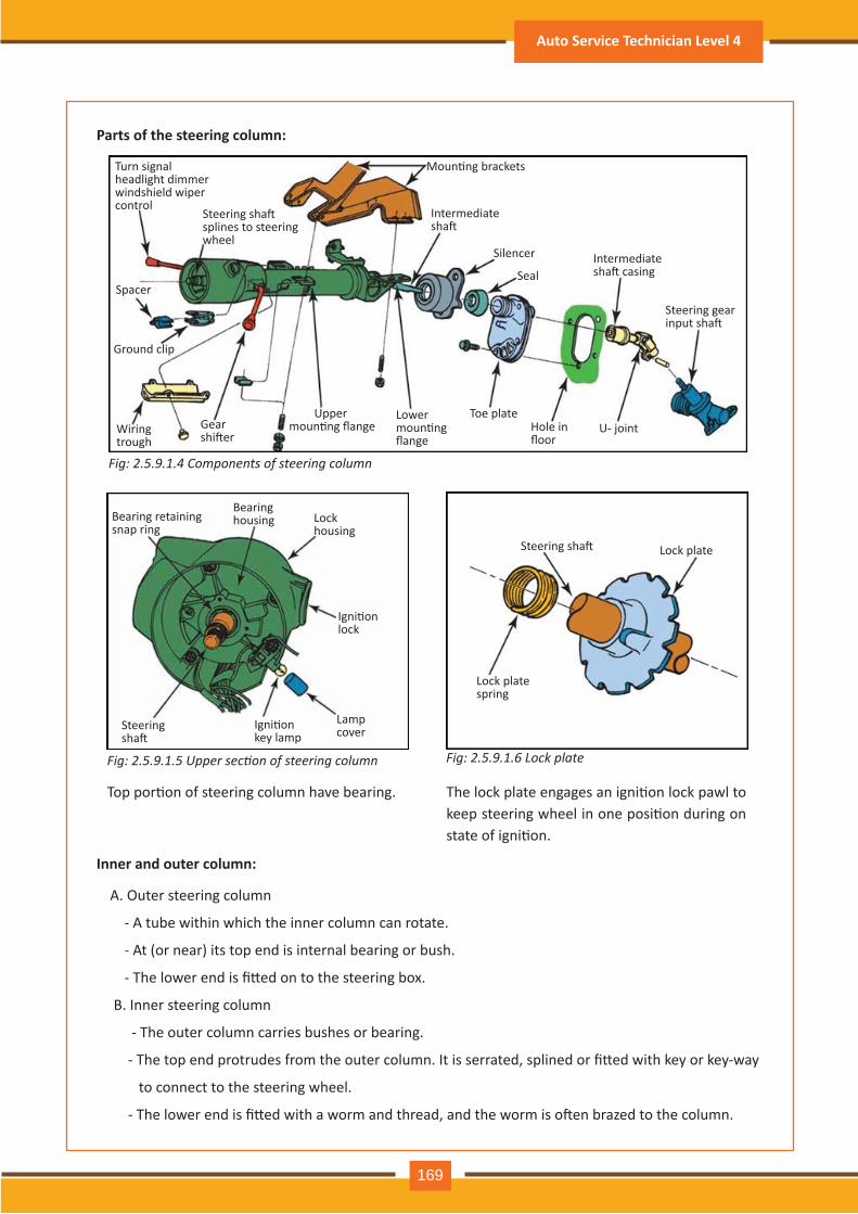
Fig: 2.5.9.1.4 Components of steering column
Fig: 2.5.9.1.5 Upper section of steering column
A. Outer steering column
- A tube within which the inner column can rotate.
- At (or near) its top end is internal bearing or bush.
- The lower end is fi�ed on to the steering box.
B. Inner steering column
- The outer column carries bushes or bearing.
- The top end protrudes from the outer column. It is serrated, splined or fi�ed with key or key-way
to connect to the steering wheel.
- The lower end is fi�ed with a worm and thread, and the worm is o�en brazed to the column.
Top por�on of steering column have bearing. The lock plate engages an igni�on lock pawl to keep steering wheel in one posi�on during on state of igni�on.
Parts of the steering column:
Inner and outer column:
Turn signal headlight dimmer windshield wiper control
Steering sha� splines to steering wheel
Moun�ng brackets
Intermediate sha�
Silencer Intermediate sha� casing
Steering gear input sha�
Toe plateHole in floor
U- joint
SealSpacer
Ground clip
Wiring trough
Gear shi�er
Upper moun�ng flange
Lower moun�ng flange
Bearing retaining snap ring
Bearing housing Lock
housing
Igni�on lock
Igni�on key lamp
Lamp coverSteering
sha�
Steering sha� Lock plate
Lock plate spring
Fig: 2.5.9.1.6 Lock plate
Auto Service Technician Level 4
169
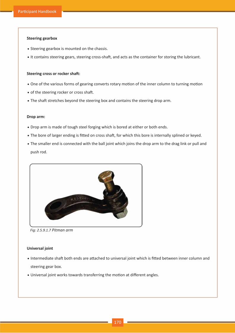
Steering gearbox is mounted on the chassis.
It contains steering gears, steering cross-sha�, and acts as the container for storing the lubricant.
Steering gearbox
•
•
One of the various forms of gearing converts rotary mo�on of the inner column to turning mo�on
of the steering rocker or cross sha�.
The sha� stretches beyond the steering box and contains the steering drop arm.
Steering cross or rocker sha�:
•
•
•
Drop arm is made of tough steel forging which is bored at either or both ends.
The bore of larger ending is fi�ed on cross sha�, for which this bore is internally splined or keyed.
The smaller end is connected with the ball joint which joins the drop arm to the drag link or pull and
push rod.
Drop arm:
•
•
•
Intermediate sha� both ends are a�ached to universal joint which is fi�ed between inner column and
steering gear box.
Universal joint works towards transferring the mo�on at different angles.
Universal joint
•
•
Fig: 2.5.9.1.7 Pitman arm
Par�cipant Handbook
170
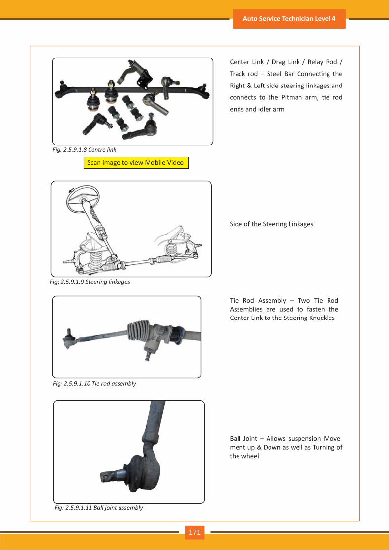
Center Link / Drag Link / Relay Rod /
Track rod – Steel Bar Connec�ng the
Right & Le� side steering linkages and
connects to the Pitman arm, �e rod
ends and idler arm
Side of the Steering Linkages
Tie Rod Assembly – Two Tie Rod Assemblies are used to fasten the Center Link to the Steering Knuckles
Scan image to view Mobile Video
Fig: 2.5.9.1.8 Centre link
Fig: 2.5.9.1.9 Steering linkages
Fig: 2.5.9.1.10 Tie rod assembly
Ball Joint – Allows suspension Move-ment up & Down as well as Turning of the wheel
Fig: 2.5.9.1.11 Ball joint assembly
Auto Service Technician Level 4
171
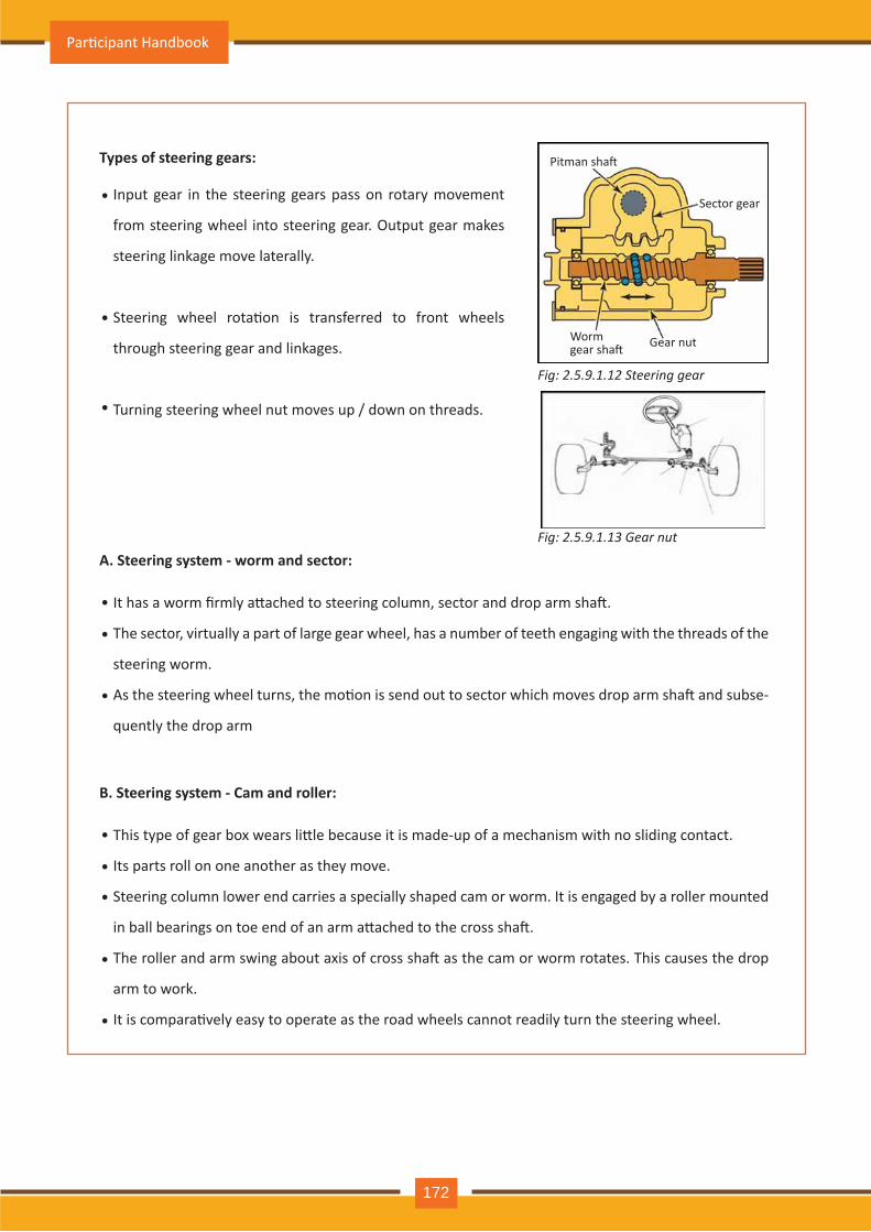
Input gear in the steering gears pass on rotary movement
from steering wheel into steering gear. Output gear makes
steering linkage move laterally.
Steering wheel rota�on is transferred to front wheels
through steering gear and linkages.
Turning steering wheel nut moves up / down on threads.
It has a worm firmly a�ached to steering column, sector and drop arm sha�.
The sector, virtually a part of large gear wheel, has a number of teeth engaging with the threads of the
steering worm.
As the steering wheel turns, the mo�on is send out to sector which moves drop arm sha� and subse-
quently the drop arm
Types of steering gears:
A. Steering system - worm and sector:
•
•
•
•
•
•
This type of gear box wears li�le because it is made-up of a mechanism with no sliding contact.
Its parts roll on one another as they move.
Steering column lower end carries a specially shaped cam or worm. It is engaged by a roller mounted
in ball bearings on toe end of an arm a�ached to the cross sha�.
The roller and arm swing about axis of cross sha� as the cam or worm rotates. This causes the drop
arm to work.
It is compara�vely easy to operate as the road wheels cannot readily turn the steering wheel.
B. Steering system - Cam and roller:
•
•
•
•
•
Fig: 2.5.9.1.12 Steering gear
Pitman sha�
Sector gear
Worm gear sha� Gear nut
Fig: 2.5.9.1.13 Gear nut
Par�cipant Handbook
172
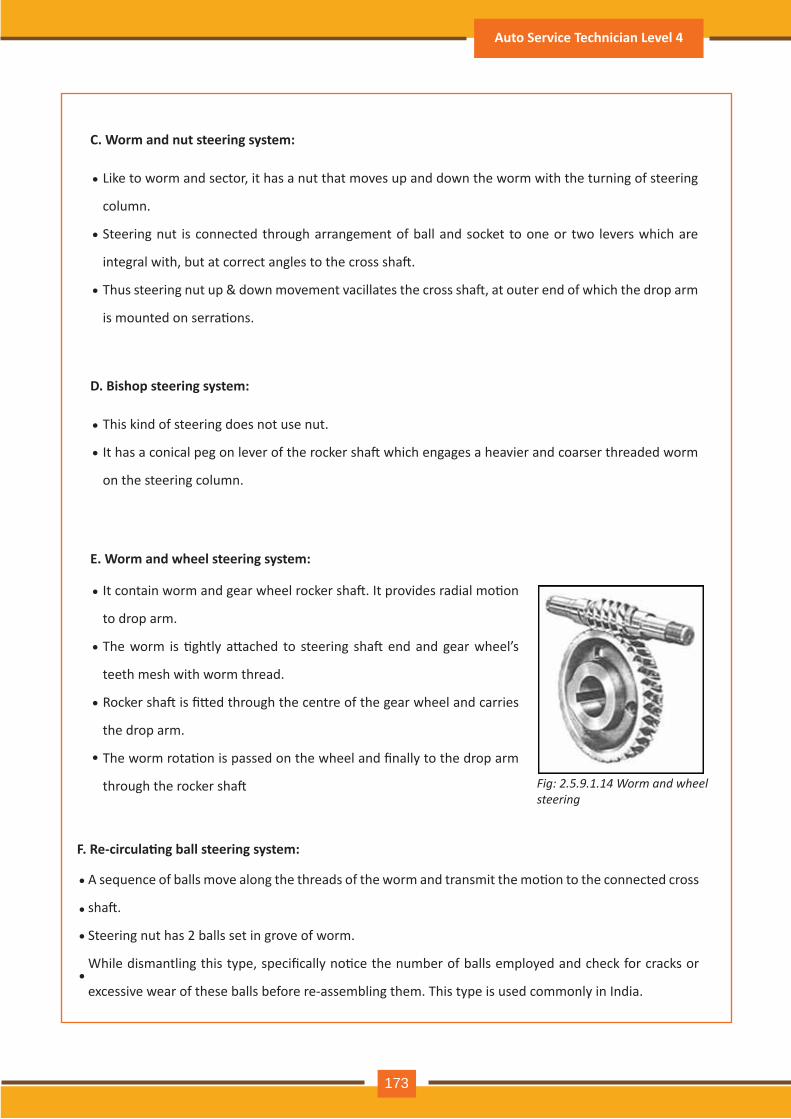
Fig: 2.5.9.1.14 Worm and wheel steering
Like to worm and sector, it has a nut that moves up and down the worm with the turning of steering
column.
Steering nut is connected through arrangement of ball and socket to one or two levers which are
integral with, but at correct angles to the cross sha�.
Thus steering nut up & down movement vacillates the cross sha�, at outer end of which the drop arm
is mounted on serra�ons.
C. Worm and nut steering system:
•
•
•
This kind of steering does not use nut.
It has a conical peg on lever of the rocker sha� which engages a heavier and coarser threaded worm
on the steering column.
D. Bishop steering system:
•
•
It contain worm and gear wheel rocker sha�. It provides radial mo�on
to drop arm.
The worm is �ghtly a�ached to steering sha� end and gear wheel’s
teeth mesh with worm thread.
Rocker sha� is fi�ed through the centre of the gear wheel and carries
the drop arm.
The worm rota�on is passed on the wheel and finally to the drop arm
through the rocker sha�
E. Worm and wheel steering system:
•
•
•
•
A sequence of balls move along the threads of the worm and transmit the mo�on to the connected cross
sha�.
Steering nut has 2 balls set in grove of worm.
While dismantling this type, specifically no�ce the number of balls employed and check for cracks or
excessive wear of these balls before re-assembling them. This type is used commonly in India.
F. Re-circula�ng ball steering system:
•
•
•
•
Auto Service Technician Level 4
173
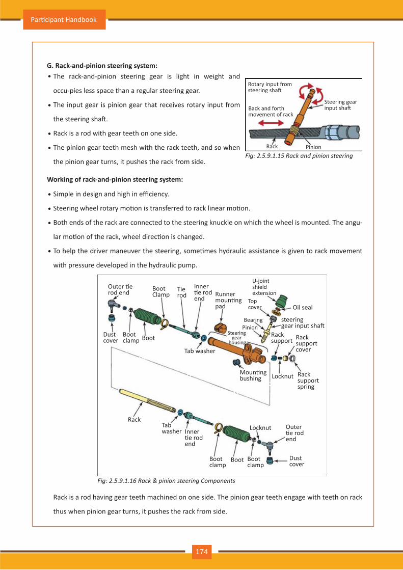
Fig: 2.5.9.1.15 Rack and pinion steering
The rack-and-pinion steering gear is light in weight and
occu-pies less space than a regular steering gear.
The input gear is pinion gear that receives rotary input from
the steering sha�.
Rack is a rod with gear teeth on one side.
The pinion gear teeth mesh with the rack teeth, and so when
the pinion gear turns, it pushes the rack from side.
Simple in design and high in efficiency.
Steering wheel rotary mo�on is transferred to rack linear mo�on.
Both ends of the rack are connected to the steering knuckle on which the wheel is mounted. The angu-
lar mo�on of the rack, wheel direc�on is changed.
To help the driver maneuver the steering, some�mes hydraulic assistance is given to rack movement
with pressure developed in the hydraulic pump.
Rack is a rod having gear teeth machined on one side. The pinion gear teeth engage with teeth on rack
thus when pinion gear turns, it pushes the rack from side.
G. Rack-and-pinion steering system:
Working of rack-and-pinion steering system:
•
•
•
•
•
•
•
•
Rotary input from steering sha�
Back and forth movement of rack
Rack Pinion
Outer �e rod end Boot
ClampTierod
Inner �e rod end
Runner moun�ngpad
Moun�ng bushing
Tab washer
Oil seal
steering gear input sha�
Rack support Rack
support cover
Rack support spring
Locknut
RackTab washer Inner
�e rod end
Bootclamp
Bootclamp
Outer �e rod end
Dust cover
Boot
Locknut
BootBoot clamp
Dust cover
U-joint shield extension
Top cover
BearingPinion
Steering gear
housing
Steering gear input sha�
Fig: 2.5.9.1.16 Rack & pinion steering Components
Par�cipant Handbook
174
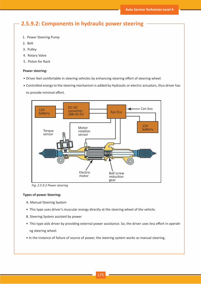
Fig: 2.5.9.2 Power steering
1. Power Steering Pump
2. Belt
3. Pulley
4. Rotary Valve
5. Piston for Rack
2.5.9.2: Components in hydraulic power steering
Driver feel comfortable in steering vehicles by enhancing steering effort of steering wheel.
Controlled energy to the steering mechanism is added by Hydraulic or electric actuators, thus driver has
to provide minimal effort.
Power steering:
A. Manual Steering System
• This type uses driver’s muscular energy directly at the steering wheel of the vehicle.
B. Steering System assisted by power
• This type aids driver by providing external power assistance. So, the driver uses less effort in opera�-
ng steering wheel.
• In the instance of failure of source of power, the steering system works as manual steering.
Types of power Steering:
•
•
12V ba�ery
DC-DC converter 288-43.5V Eps Ecu
Can bus
12V ba�eryTorque
sensor
Motor rota�on sensor
Electric motor
Ball screw reduc�on gear
Auto Service Technician Level 4
175
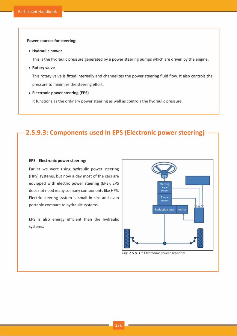
Hydraulic power
This is the hydraulic pressure generated by a power steering pumps which are driven by the engine.
Rotary valve
This rotary valve is fi�ed internally and channelizes the power steering fluid flow. It also controls the
pressure to minimize the steering effort.
Electronic power steering (EPS)
It func�ons as the ordinary power steering as well as controls the hydraulic pressure.
Power sources for steering:
•
•
•
2.5.9.3: Components used in EPS (Electronic power steering)
EPS - Electronic power steering:
Earlier we were using hydraulic power steering
(HPS) systems, but now a day most of the cars are
equipped with electric power steering (EPS). EPS
does not need many so many components like HPS.
Electric steering system is small in size and even
portable compare to hydraulic systems.
EPS is also energy efficient than the hydraulic
systems.
Steering angle sensor
Torque sensor
Reduc�on gear motor
Fig: 2.5.9.3.1 Electronic power steering
Par�cipant Handbook
176
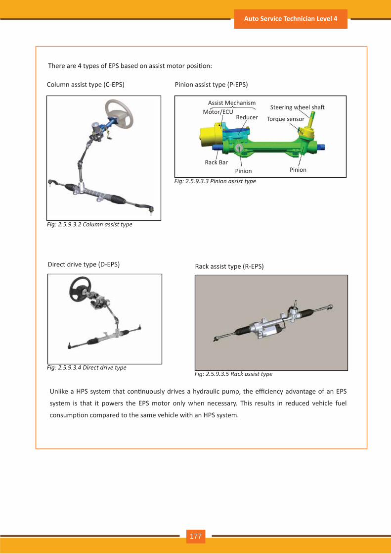
Fig: 2.5.9.3.2 Column assist type
There are 4 types of EPS based on assist motor posi�on:
Column assist type (C-EPS) Pinion assist type (P-EPS)
Assist MechanismMotor/ECU
ReducerSteering wheel sha�
Torque sensor
PinionPinionRack Bar
Fig: 2.5.9.3.3 Pinion assist type
Direct drive type (D-EPS) Rack assist type (R-EPS)
Unlike a HPS system that con�nuously drives a hydraulic pump, the efficiency advantage of an EPS
system is that it powers the EPS motor only when necessary. This results in reduced vehicle fuel
consump�on compared to the same vehicle with an HPS system.
Fig: 2.5.9.3.4 Direct drive typeFig: 2.5.9.3.5 Rack assist type
Auto Service Technician Level 4
177
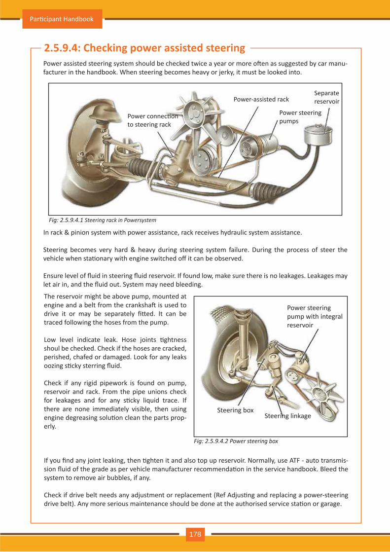
2.5.9 .4: Check ing pow er assisted steeringPower assisted steering system should be checked twice a year or more o�en as suggested by car manu-facturer in the handbook. When steering becomes heavy or jerky, it must be looked into.
In rack & pinion system with power assistance, rack receives hydraulic system assistance.
Steering becomes very hard & heavy during steering system failure. During the process of steer the vehicle when sta�onary with engine switched off it can be observed.
Ensure level of fluid in steering fluid reservoir. If found low, make sure there is no leakages. Leakages may let air in, and the fluid out. System may need bleeding.
Fig: 2.5.9 .4.1 S t e e r in g r a c k in P o w e r s y s t e m
Fig: 2.5.9 .4.2 P o w e r s t e e r in g b o x
The reservoir might be above pump, mounted at engine and a belt from the cranksha� is used to drive it or may be separately fi�ed. It can be traced following the hoses from the pump.
Low level indicate leak. Hose joints �ghtness shoul be checked. Check if the hoses are cracked, perished, chafed or damaged. Look for any leaks oozing s�cky sterring fluid.
Check if any rigid pipework is found on pump, reservoir and rack. From the pipe unions check for leakages and for any s�cky liquid trace. If there are none immediately visible, then using engine degreasing solu�on clean the parts prop-erly.
Power connec�on to steering rack
Power-assisted rackSeparate reserv oir
Power steering pum ps
Steering box
Power steering pum p with integral reserv oir
Steering linkage
If you find any joint leaking, then �ghten it and also top up reservoir. Normally, use ATF - auto transmis-sion fluid of the grade as per vehicle manufacturer recommenda�on in the service handbook. Bleed the system to remove air bubbles, if any.
Check if drive belt needs any adjustment or replacement (Ref Adjus�ng and replacing a power-steering drive belt). Any more serious maintenance should be done at the authorised service sta�on or garage.
Par�cipant Handbook
178
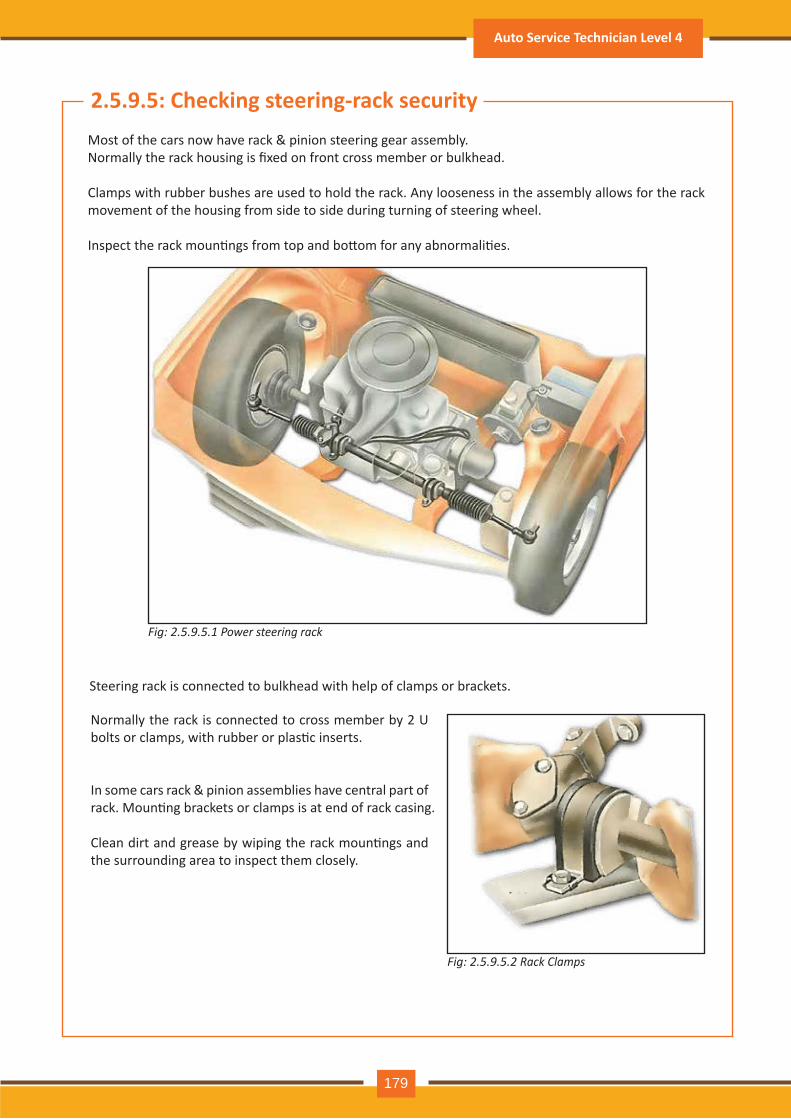
Fig: 2.5.9 .5.1 P o w e r s t e e r in g r a c k
Fig: 2.5.9 .5.2 R a c k C l a m p s
2.5.9 .5: Check ing steering- rack securityMost of the cars now have rack & pinion steering gear assembly. Normally the rack housing is fixed on front cross member or bulkhead.
Clamps with rubber bushes are used to hold the rack. Any looseness in the assembly allows for the rack movement of the housing from side to side during turning of steering wheel.
Inspect the rack moun�ngs from top and bo�om for any abnormali�es.
Steering rack is connected to bulkhead with help of clamps or brackets.
Normally the rack is connected to cross member by 2 U bolts or clamps, with rubber or plas�c inserts.
In some cars rack & pinion assemblies have central part of rack. Moun�ng brackets or clamps is at end of rack casing.
Clean dirt and grease by wiping the rack moun�ngs and the surrounding area to inspect them closely.
Auto Service Technician Level 4
179
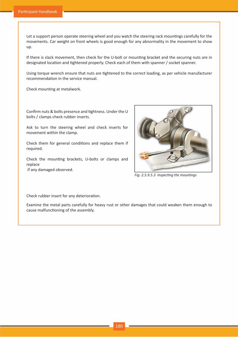
Fig: 2.5.9 .5.3 Inspecting the mountings
Let a support person operate steering wheel and you watch the steering rack moun�ngs carefully for the movements. Car weight on front wheels is good enough for any abnormality in the movement to show up.
If there is slack movement, then check for the U-bolt or moun�ng bracket and the securing nuts are in designated loca�on and �ghtened properly. Check each of them with spanner / socket spanner.
Using torque wrench ensure that nuts are �ghtened to the correct loading, as per vehicle manufacturer recommenda�on in the service manual.
Check moun�ng at metalwork.
Examine the metal parts carefully for heavy rust or other damages that could weaken them enough to cause malfunc�oning of the assembly.
Confirm nuts & bolts presence and �ghtness. Under the U bolts / clamps check rubber inserts.
Ask to turn the steering wheel and check inserts for movement within the clamp.
Check them for general condi�ons and replace them if required.
Check the moun�ng brackets, U-bolts or clamps and replace if any damaged observed.
Check rubber insert for any deteriora�on.
Par�cipant Handbook
180
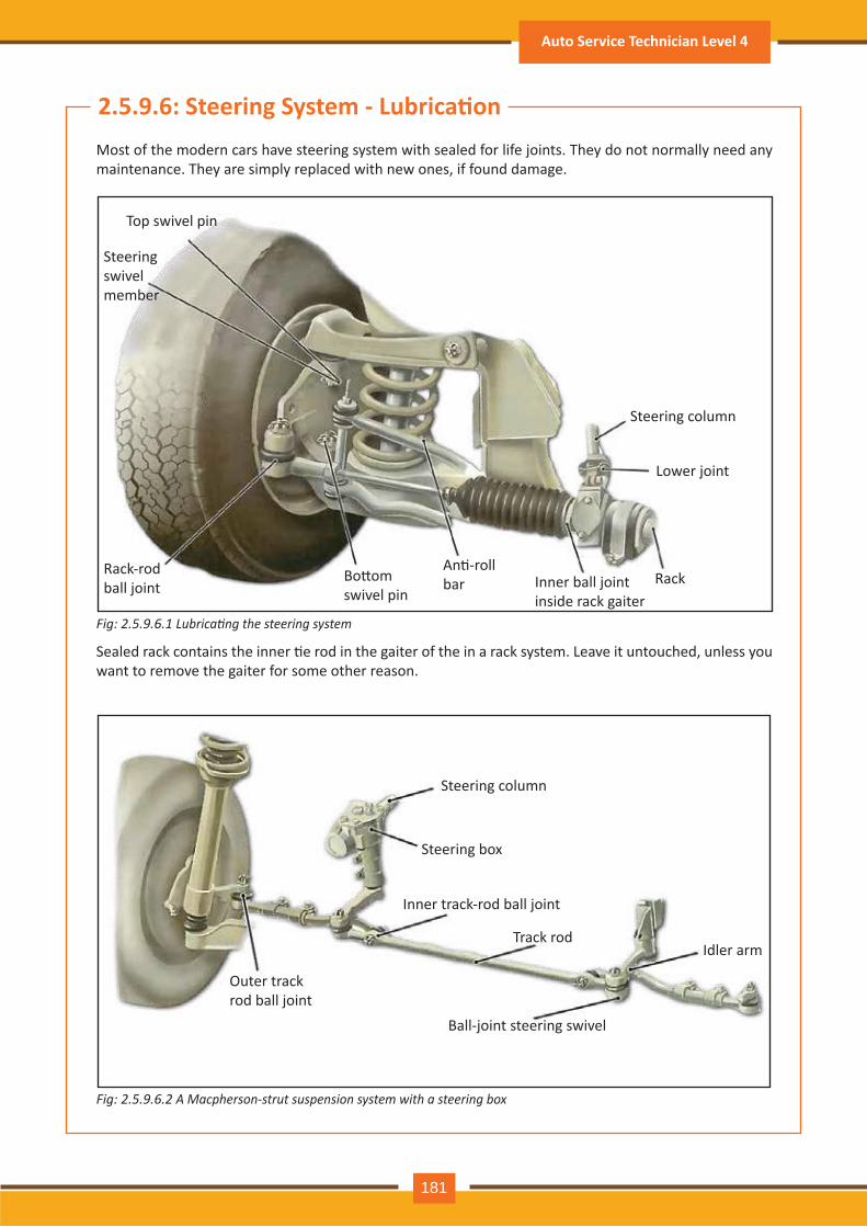
Fig: 2.5.9 .6 .1 ubricating the steering s stem
Fig: 2.5.9 .6 .2 A M a c p h e r s o n - s t r u t s u s p e n s io n s y s t e m w it h a s t e e r in g b o x
2.5.9 .6: Steering System - Lubrica�onMost of the modern cars have steering system with sealed for life joints. They do not normally need any maintenance. They are simply replaced with new ones, if found damage.
Sealed rack contains the inner �e rod in the gaiter of the in a rack system. Leave it untouched, unless you want to remove the gaiter for some other reason.
Top swivel pin
Steering swiv el member
Rack-rod ball joint
Bo�om swiv el pin
Outer track rod ball joint
Steering colum n
Steering box
Inner track-rod ball joint
Track rod
Ball-joint steering swivel
Idler arm
An�-roll bar Inner ball joint
inside rack gaiterRack
Lower joint
Steering colum n
Auto Service Technician Level 4
181
In steering gear box system, the extra joints on track rod and idler arm may need a�en�on.
Grease nipples and / or oil-filler holes are provided in different parts of new cars.
Based on type of steering system their posi�on depend.
Let’s discuss where & how to lubricate.
The rack is normally filled with oil / grease and does not require regular maintenance. It will needs re-lu-brica�on, if you remove / replace the rack gaiter, or if there is leakage through a loose or damaged gaiter clip.
Lubrica�ng rack & pinion:
Topping up steering box:
Iden�fy steering box filler plug on steering gear box.
Steering box filled with oil does not require regular topping. However, it is suggested to check oil level during rou�ne maintenance. If oil seal is having leakage then topping up is necessary.
Filler plug is found on upper sec�on of steering gear box.
Do not get confused with the adjus�ng screw or bolt, or the cover retaining bolts, which are also on same loca�on.
Service handbook help in finding filler hole and also deciding level of oil
Plas�c filler cap on steering box is provided in some cars. A�er topping up, the cap has to be pressed properly.
Par�cipant Handbook
182
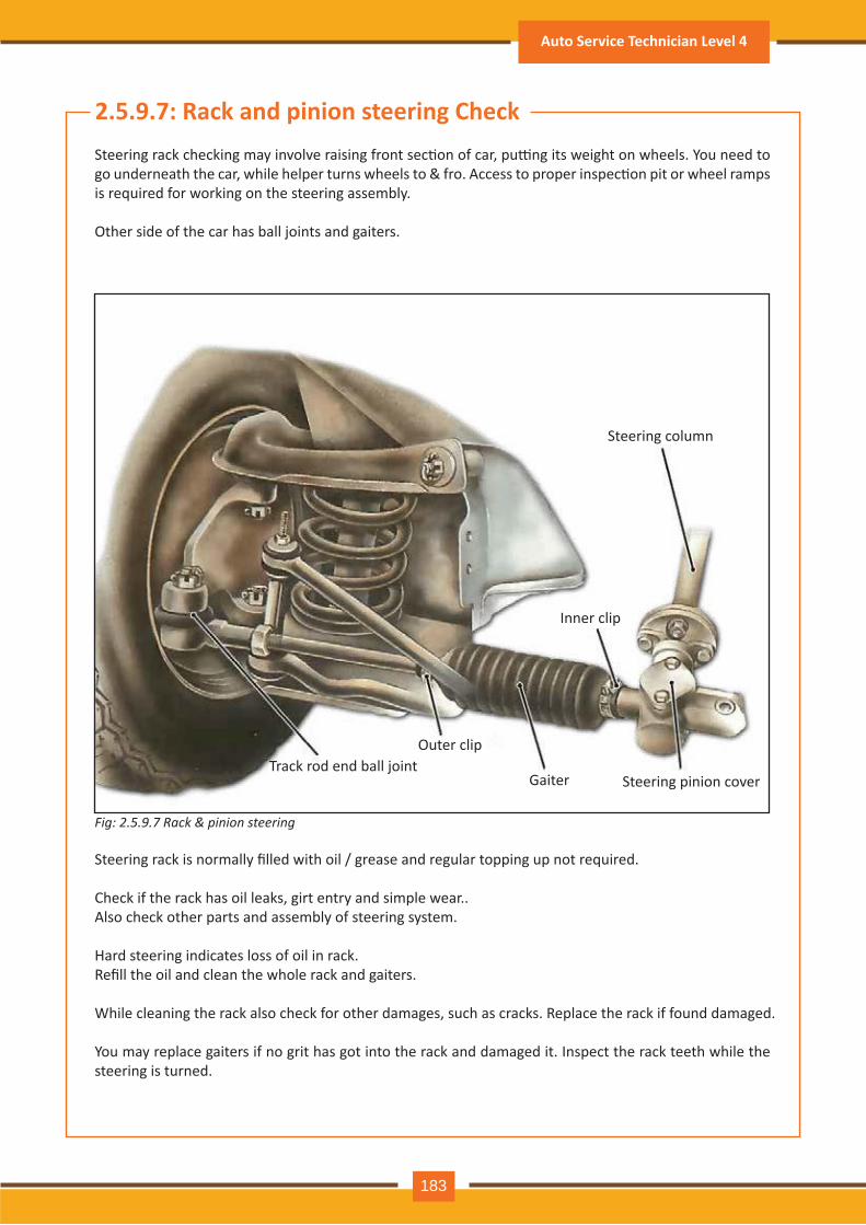
Fig: 2.5.9 .7 R a c k & p in io n s t e e r in g
2.5.9 .7 : R ack and pinion steering CheckSteering rack checking may involve raising front sec�on of car, pu�ng its weight on wheels. You need to go underneath the car, while helper turns wheels to & fro. Access to proper inspec�on pit or wheel ramps is required for working on the steering assembly.
Other side of the car has ball joints and gaiters.
Steering rack is normally filled with oil / grease and regular topping up not required.
Check if the rack has oil leaks, girt entry and simple wear..Also check other parts and assembly of steering system.
Hard steering indicates loss of oil in rack. Refill the oil and clean the whole rack and gaiters.
While cleaning the rack also check for other damages, such as cracks. Replace the rack if found damaged.
You may replace gaiters if no grit has got into the rack and damaged it. Inspect the rack teeth while the steering is turned.
Track rod end ball jointO uter clip
G aiter
Inner clip
Steering colum n
Steering pinion cov er
Auto Service Technician Level 4
183
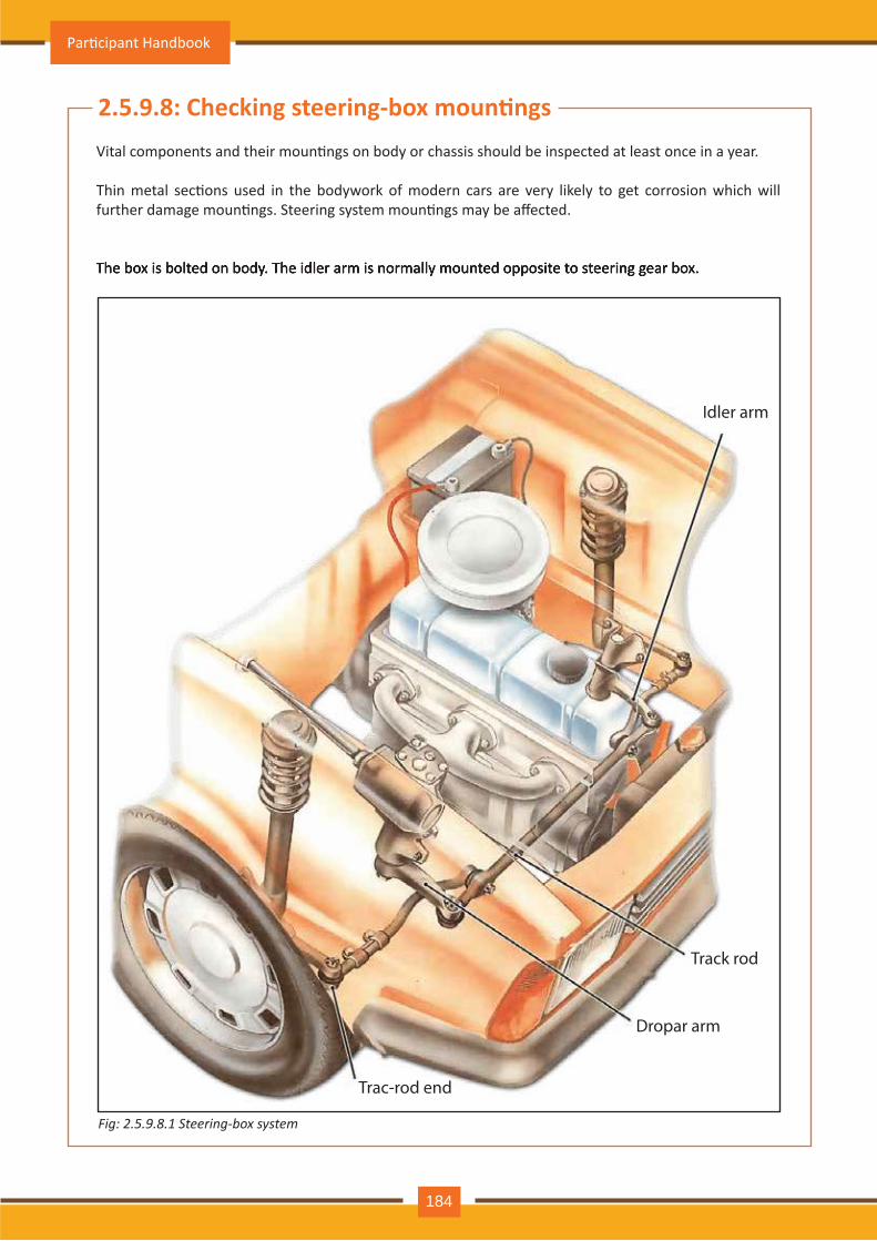
Fig: 2.5.9 .8 .1 S t e e r in g- b o x s y s t e m
2.5.9 .8 : Checking steering-box moun�ngsVital components and their moun�ngs on body or chassis should be inspected at least once in a year.
Thin metal sec�ons used in the bodywork of modern cars are very likely to get corrosion which will further damage moun�ngs. Steering system moun�ngs may be affected.
The box is bolted on body. The idler arm is normally mounted opposite to steering gear box. The box is bolted on body. The idler arm is normally mounted opposite to steering gear box.
Idler arm
Track rod
Dropar arm
Trac-rod end
Par�cipant Handbook
184
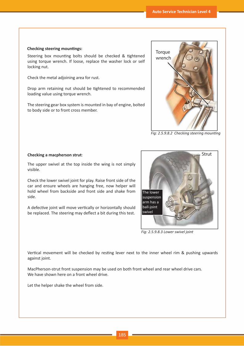
Fig: 2.5. . .2 Checking steering mounting
Checking steering moun�ngs:
Steering box moun�ng bolts should be checked & �ghtened using torque wrench. If loose, replace the washer lock or self locking nut.
Check the metal adjoining area for rust.
Drop arm retaining nut should be �ghtened to recommended loading value using torque wrench.
The steering gear box system is mounted in bay of engine, bolted to body side or to front cross member.
Torque wrench
Fig: 2.5.9 .8 .3 L o w e r s w iv e l j o in t
Check ing a macpherson strut:
The upper swivel at the top inside the wing is not simply visible.
Check the lower swivel joint for play. Raise front side of the car and ensure wheels are hanging free, now helper will hold wheel from backside and front side and shake from side.
A defec�ve joint will move ver�cally or horizontally should be replaced. The steering may deflect a bit during this test.
Strut
The lower suspension arm h as a ball-joint swiv el
Ver�cal movement will be checked by res�ng lever next to the inner wheel rim & pushing upwards against joint.
MacPherson-strut front suspension may be used on both front wheel and rear wheel drive cars. We have shown here on a front wheel drive.
Let the helper shake the wheel from side.
Auto Service Technician Level 4
185
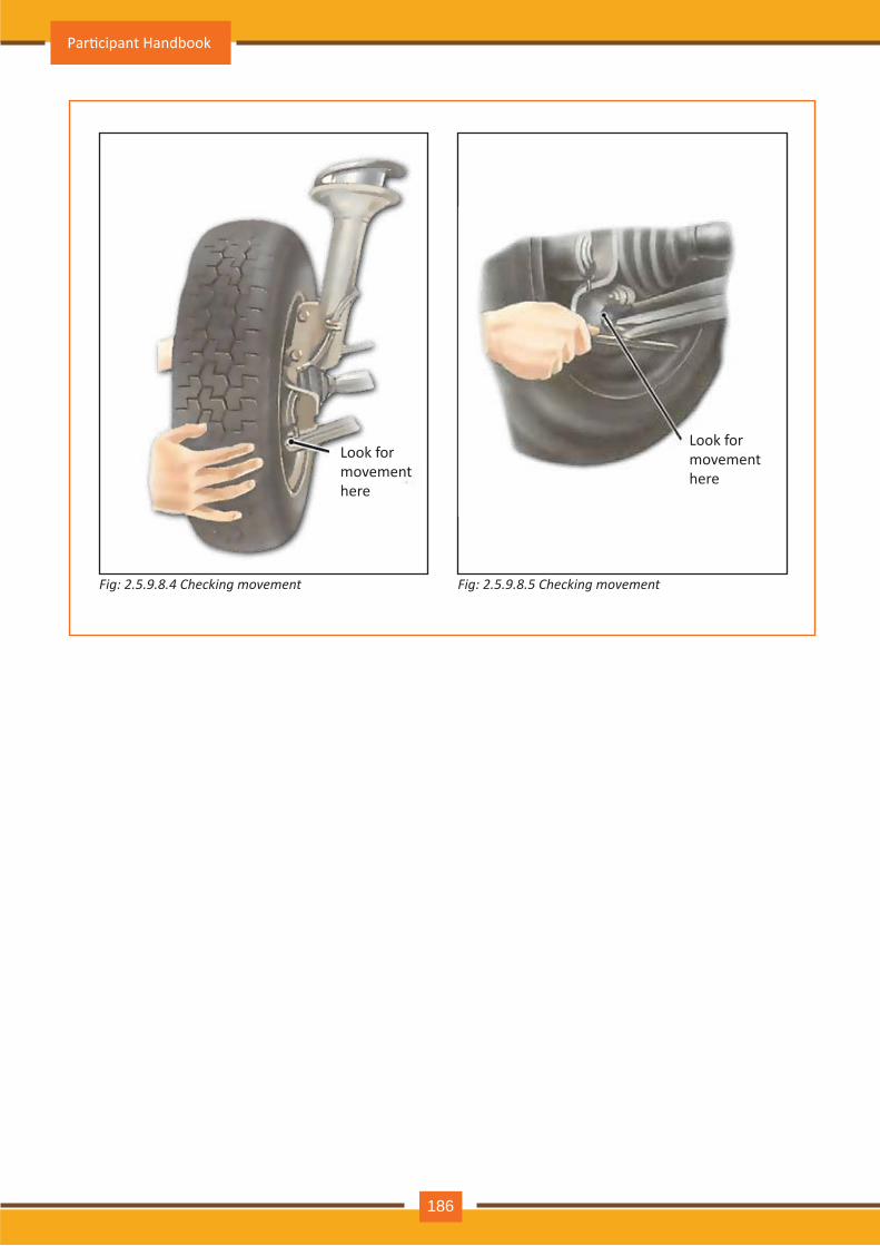
Fig: 2.5.9 .8 .4 C h e c k in g m o v e m e n t Fig: 2.5.9 .8 .5 C h e c k in g m o v e m e n t
Look for m ov em ent h ere
Look for m ov em ent h ere
Par�cipant Handbook
186
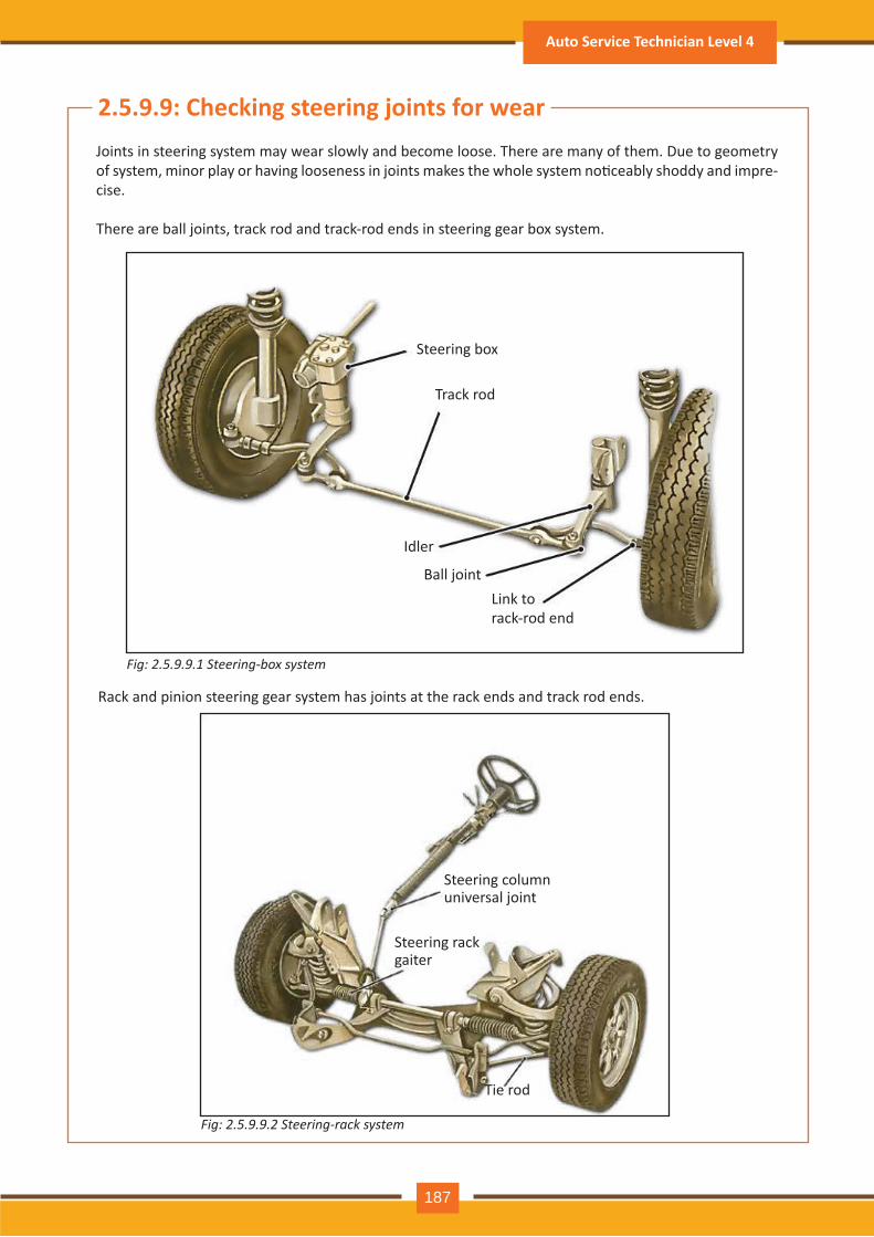
Fig: 2.5.9 .9 .1 S t e e r in g- b o x s y s t e m
Fig: 2.5.9 .9 .2 S t e e r in g- r a c k s y s t e m
2.5.9 .9 : Check ing steering joints for w earJoints in steering system may wear slowly and become loose. There are many of them. Due to geometry of system, minor play or having looseness in joints makes the whole system no�ceably shoddy and impre-cise.
There are ball joints, track rod and track-rod ends in steering gear box system.
Rack and pinion steering gear system has joints at the rack ends and track rod ends.
Steering box
Track rod
Idler
Ball jointLink to rack-rod end
Steering colum n universal joint
Steering rack gaiter
Tie rod
Auto Service Technician Level 4
187
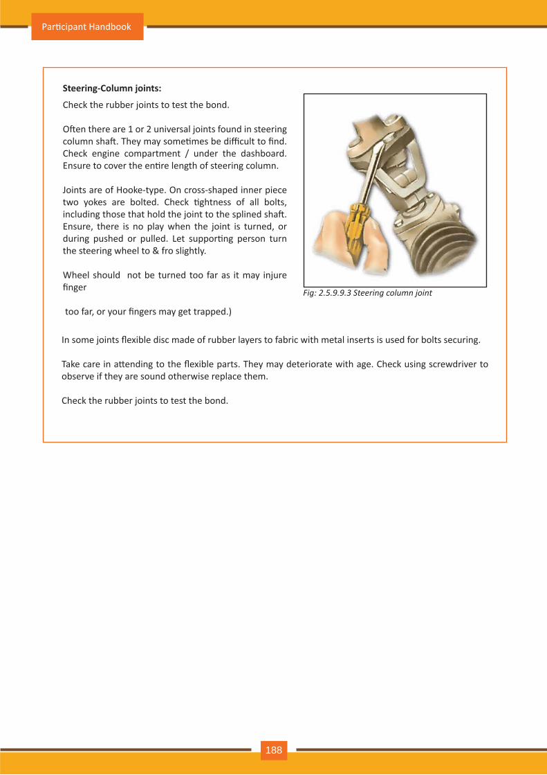
Fig: 2.5.9 .9 .3 S t e e r in g c o l u m n j o in t
In some joints flexible disc made of rubber layers to fabric with metal inserts is used for bolts securing.
Take care in a�ending to the flexible parts. They may deteriorate with age. Check using screwdriver to observe if they are sound otherwise replace them.
Check the rubber joints to test the bond.
Check the rubber joints to test the bond.
O�en there are 1 or 2 universal joints found in steering column sha�. They may some�mes be difficult to find. Check engine compartment / under the dashboard. Ensure to cover the en�re length of steering column.
Joints are of Hooke-type. On cross-shaped inner piece two yokes are bolted. Check �ghtness of all bolts, including those that hold the joint to the splined sha�. Ensure, there is no play when the joint is turned, or during pushed or pulled. Let suppor�ng person turn the steering wheel to & fro slightly.
Wheel should not be turned too far as it may injure finger
too far, or your fingers may get trapped.)
Steering- Column joints:
Par�cipant Handbook
188
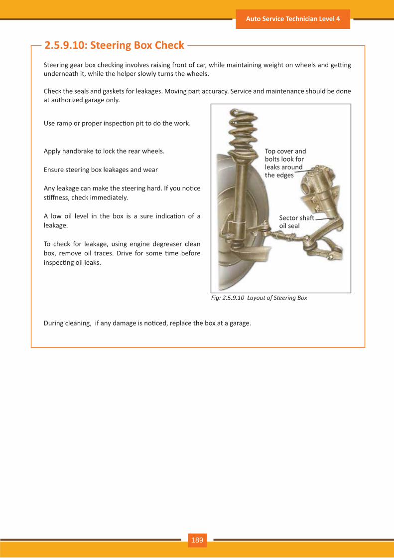
Fig: 2.5.9 .10 L a y o u t o f S t e e r in g B o x
2.5.9 .10: Steering B ox CheckSteering gear box checking involves raising front of car, while maintaining weight on wheels and ge�ng underneath it, while the helper slowly turns the wheels.
Check the seals and gaskets for leakages. Moving part accuracy. Service and maintenance should be done at authorized garage only.
During cleaning, if any damage is no�ced, replace the box at a garage.
Use ramp or proper inspec�on pit to do the work.
Apply handbrake to lock the rear wheels.
Ensure steering box leakages and wear
Any leakage can make the steering hard. If you no�ce s�ffness, check immediately.
A low oil level in the box is a sure indica�on of a leakage.
To check for leakage, using engine degreaser clean box, remove oil traces. Drive for some �me before inspec�ng oil leaks.
Top cover and bolts look for leaks around th e edges
Sector sha� oil seal
Auto Service Technician Level 4
189
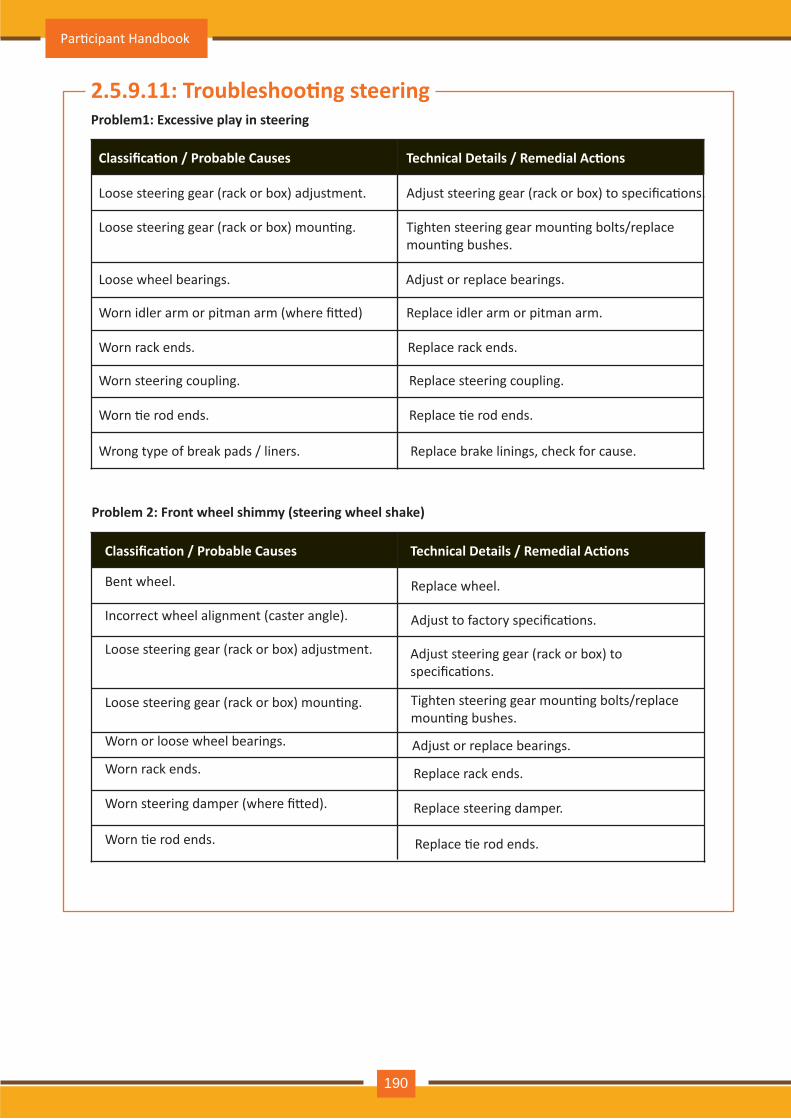
Problem1: Excessive play in steering
Classifica�on / Probable Causes Technical Details / Remedial Ac�ons
Loose steering gear (rack or box) adjustment.
Loose steering gear (rack or box) moun�ng.
Loose wheel bearings.
Worn idler arm or pitman arm (where fi�ed)
Worn rack ends.
Worn steering coupling.
Worn �e rod ends.
Wrong type of break pads / liners. Replace brake linings, check for cause.
Replace �e rod ends.
Replace steering coupling.
Replace rack ends.
Replace idler arm or pitman arm.
Adjust or replace bearings.
Tighten steering gear moun�ng bolts/replace moun�ng bushes.
Adjust steering gear (rack or box) to specifica�ons.
Problem 2: Front wheel shimmy (steering wheel shake)
Classifica�on / Probable Causes Technical Details / Remedial Ac�ons
Bent wheel.
Incorrect wheel alignment (caster angle).
Loose steering gear (rack or box) adjustment.
Loose steering gear (rack or box) moun�ng.
Worn or loose wheel bearings.
Worn rack ends.
Worn steering damper (where fi�ed).
Worn �e rod ends. Replace �e rod ends.
Replace steering damper.
Replace rack ends.
Adjust or replace bearings.
Tighten steering gear moun�ng bolts/replace moun�ng bushes.
Adjust steering gear (rack or box) to specifica�ons.
Adjust to factory specifica�ons.
Replace wheel.
2.5.9.11: Troubleshoo�ng steering
Par�cipant Handbook
190
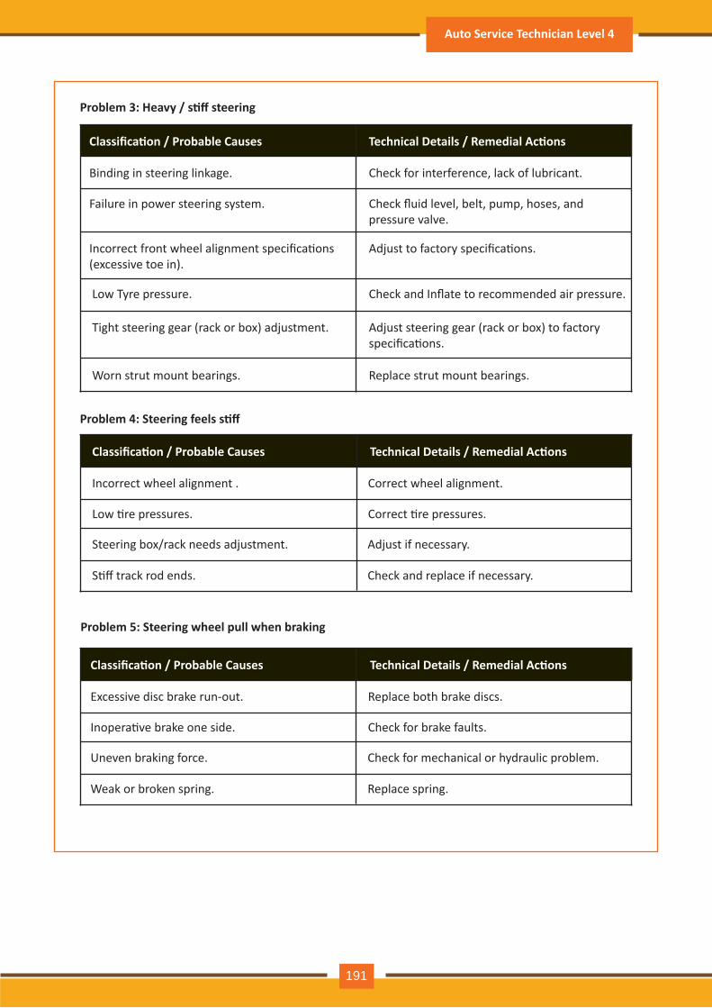
Problem 3: Heavy / s�ff steering
Classifica�on / Probable Causes Technical Details / Remedial Ac�ons
Binding in steering linkage.
Failure in power steering system. Check fluid level, belt, pump, hoses, and pressure valve.
Check for interference, lack of lubricant.
Low Tyre pressure. Check and Inflate to recommended air pressure.
Tight steering gear (rack or box) adjustment.
Worn strut mount bearings. Replace strut mount bearings.
Adjust steering gear (rack or box) to factory specifica�ons.
Incorrect front wheel alignment specifica�ons(excessive toe in).
Adjust to factory specifica�ons.
Problem 4: Steering feels s�ff
Classifica�on / Probable Causes Technical Details / Remedial Ac�ons
Incorrect wheel alignment .
Low �re pressures.
Steering box/rack needs adjustment.
S�ff track rod ends.
Adjust if necessary.
Check and replace if necessary.
Correct �re pressures.
Correct wheel alignment.
Problem 5: Steering wheel pull when braking
Classifica�on / Probable Causes Technical Details / Remedial Ac�ons
Excessive disc brake run-out.
Inopera�ve brake one side.
Uneven braking force.
Weak or broken spring.
Check for mechanical or hydraulic problem.
Replace spring.
Check for brake faults.
Replace both brake discs.
Auto Service Technician Level 4
191
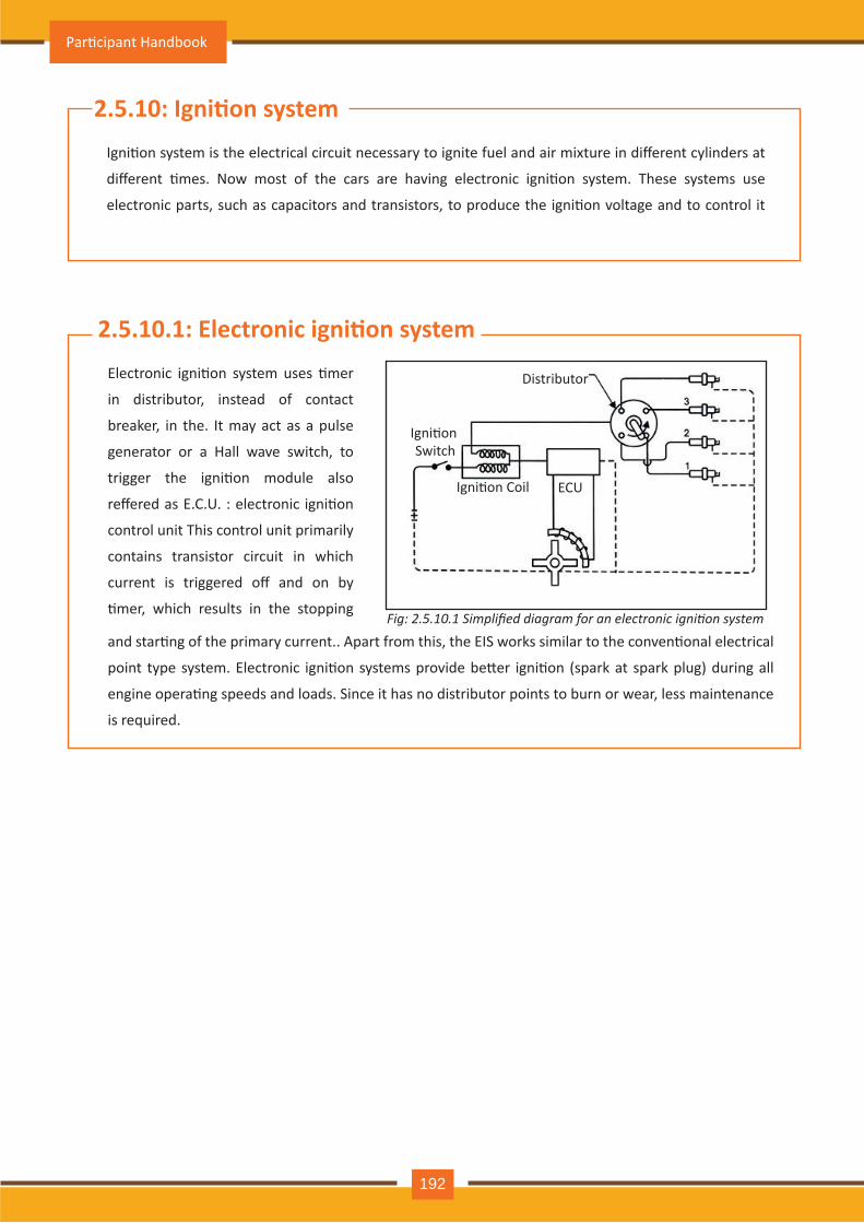
2.5.10: Igni�on systemIgni�on system is the electrical circuit necessary to ignite fuel and air mixture in different cylinders at
different �mes. Now most of the cars are having electronic igni�on system. These systems use
electronic parts, such as capacitors and transistors, to produce the igni�on voltage and to control it
2.5.10.1: Electronic igni�on systemElectronic igni�on system uses �mer
in distributor, instead of contact
breaker, in the. It may act as a pulse
generator or a Hall wave switch, to
trigger the igni�on module also
reffered as E.C.U. : electronic igni�on
control unit This control unit primarily
contains transistor circuit in which
current is triggered off and on by
�mer, which results in the stopping
and star�ng of the primary current.. Apart from this, the EIS works similar to the conven�onal electrical
point type system. Electronic igni�on systems provide be�er igni�on (spark at spark plug) during all
engine opera�ng speeds and loads. Since it has no distributor points to burn or wear, less maintenance
is required.
Distributor
Igni�on Switch
Igni�on Coil ECU
Fig: 2.5.10.1 Simplified diagram for an electronic ignition system
Par�cipant Handbook
192
Current: The movement of electrons along the conductor in a specific direc�on produce an electrical
current. The more the electrons which move, the greater is the current.
Ampere: The amount of electron flow is the current and measured in Amperes. The electric current or
Amperes (abbreviated amps) is measured by an Ammeter. The Ammeter can be graduated to read in
amperes, milliamperes or microamperes
Direct and alterna�ng current: If the electrons flow con�nuously in one direc�on along the conductor, the
current is called direct current (abbreviated d.c.). This type of current produced by ba�ery or a d.c. genera-
tor. If the flow of electrons is in one direc�on and then flow back again and con�nue this back and forth
mo�on, the current is called alterna�ng current (abbreviated a.c.). This type of current produced by an
alternator or a.c. generator and is the type of electricity found in home electrical circuits
Volt: Some device is required to apply the necessary pressure for electrons flow through the conductor.
This poten�al difference normally maintained by ba�ery or generator is called the Electro-mo�ve Force
(EMF) or voltage. Voltmeter is used to measure voltage or electrical poten�al of a circuit. The voltmeter
can be graduated to read in volts or kilovolts and millivolts
Ohm: The opposi�on electrons flow is called resistance and resistance is measured in ohms. One ohm is
wire resistance in which an electrical pressure of one volt causes one ampere electric current to flow.
2.5.10.2: Let us understand basics of auto electricals
Auto Service Technician Level 4
193
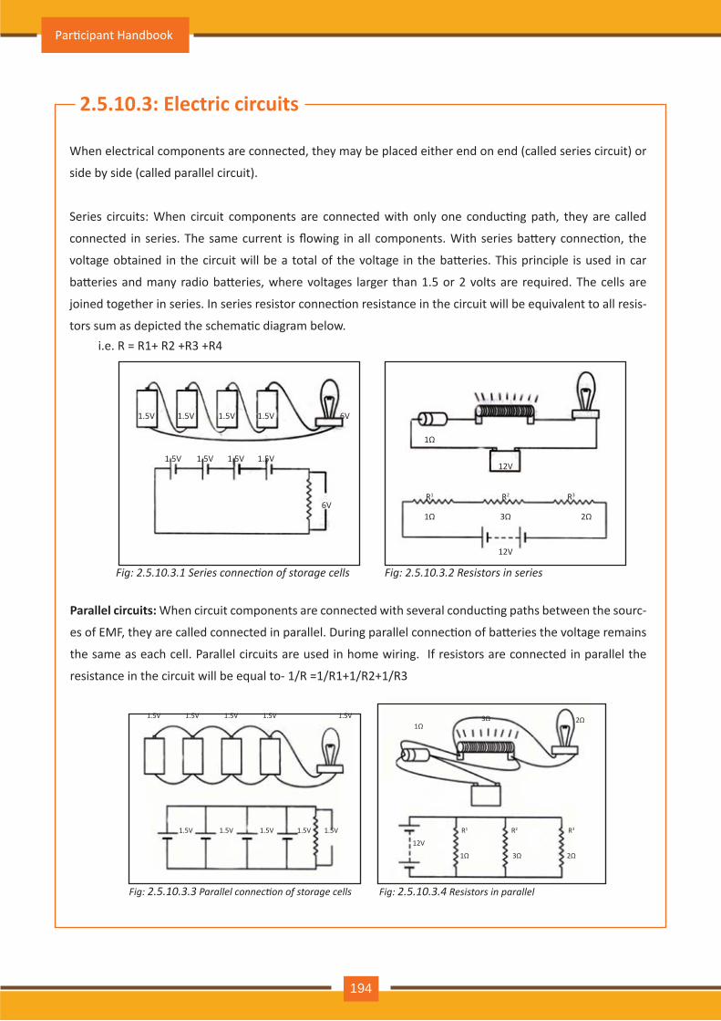
1.5V
1.5V 1.5V 1.5V 1.5V
1.5V 1.5V 1.5V 6V
6V
1Ω
1Ω 3Ω 2Ω
12V
12V
R1 R2 R3
Fig: 2.5.10.3.1 Series connection of storage cells Fig: 2.5.10.3.2 Resistors in series
1.5V
1.5V 1.5V 1.5V 1.5V 1.5V
1.5V 1.5V 1.5V 1.5V1Ω
1Ω
3Ω
3Ω
2Ω
2Ω
12V
R1 R2 R3
Fig: 2.5.10.3.3 Parallel connection of storage cells Fig: 2.5.10.3.4 Resistors in parallel
2.5.10.3: Electric circuits
When electrical components are connected, they may be placed either end on end (called series circuit) or
side by side (called parallel circuit).
Series circuits: When circuit components are connected with only one conduc�ng path, they are called
connected in series. The same current is flowing in all components. With series ba�ery connec�on, the
voltage obtained in the circuit will be a total of the voltage in the ba�eries. This principle is used in car
ba�eries and many radio ba�eries, where voltages larger than 1.5 or 2 volts are required. The cells are
joined together in series. In series resistor connec�on resistance in the circuit will be equivalent to all resis-
tors sum as depicted the schema�c diagram below.
Parallel circuits: When circuit components are connected with several conduc�ng paths between the sourc-
es of EMF, they are called connected in parallel. During parallel connec�on of ba�eries the voltage remains
the same as each cell. Parallel circuits are used in home wiring. If resistors are connected in parallel the
resistance in the circuit will be equal to- 1/R =1/R1+1/R2+1/R3
i.e. R = R1+ R2 +R3 +R4
Par�cipant Handbook
194
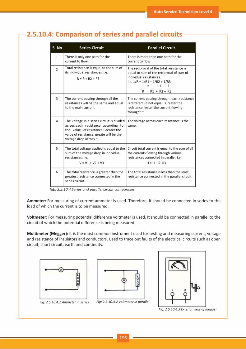
2.5.10.4: Comparison of series and parallel circuits
Ammeter: For measuring of current ammeter is used. Therefore, it should be connected in series to the load of which the current is to be measured.
Voltmeter: For measuring poten�al difference voltmeter is used. It should be connected in parallel to the circuit of which the poten�al difference is being measured.
Mul�meter (Megger): It is the most common instrument used for tes�ng and measuring current, voltage and resistance of insulators and conductors. Used to trace out faults of the electrical circuits such as open circuit, short circuit, earth and con�nuity.
Fig: 2.5.10.4.1 Ammeter in series Fig: 2.5.10.4.2 Voltmeter in parallel
Fig: 2.5.10.4.3 Exterior view of megger
Tab: 2.5.10.4 Series and parallel circuit comparison
S. No Series Circuit Parallel Circuit
There is only one path for the current to flow.
There is more than one path for the current to flow
Total resistance is equal to the sum of its individual resistances, i.e.
R = RI+ R2 + R3
The reciprocal of the total resistance is equal to sum of the reciprocal of sum of individual resistances. i.e. 1/R = 1/R1 + 1/R2 + 1/R3
1 = 1 + 1 + 1R = R1 + R2 + R3
The current passing through all the resistances will be the same and equal to the main current
The current passing throught each resistance is different (if not equal). Greater the resistance, lesser the current flowing throught it.
The voltage in a series circuit is divided across each resistance according to the value of resistance.Greater the value of resistance, greate will be the voltage drop across it.
The voltage across each resistance is the same.
The total voltage applied is equal to the sum of the voltage drop in individual resistances, i.e.
V = V1 + V2 + V3
Circuit total current is equal to the sum of all the currents flowing through various resistances connected in parallel, i.e.
I = i1 +i2 +i3
The total resistance is greater than the greatest resistance connected in the series circuit.
The total resistance is less than the least resistance connected in the parallel circuit.
1
2
3
4
5
6
Auto Service Technician Level 4
195
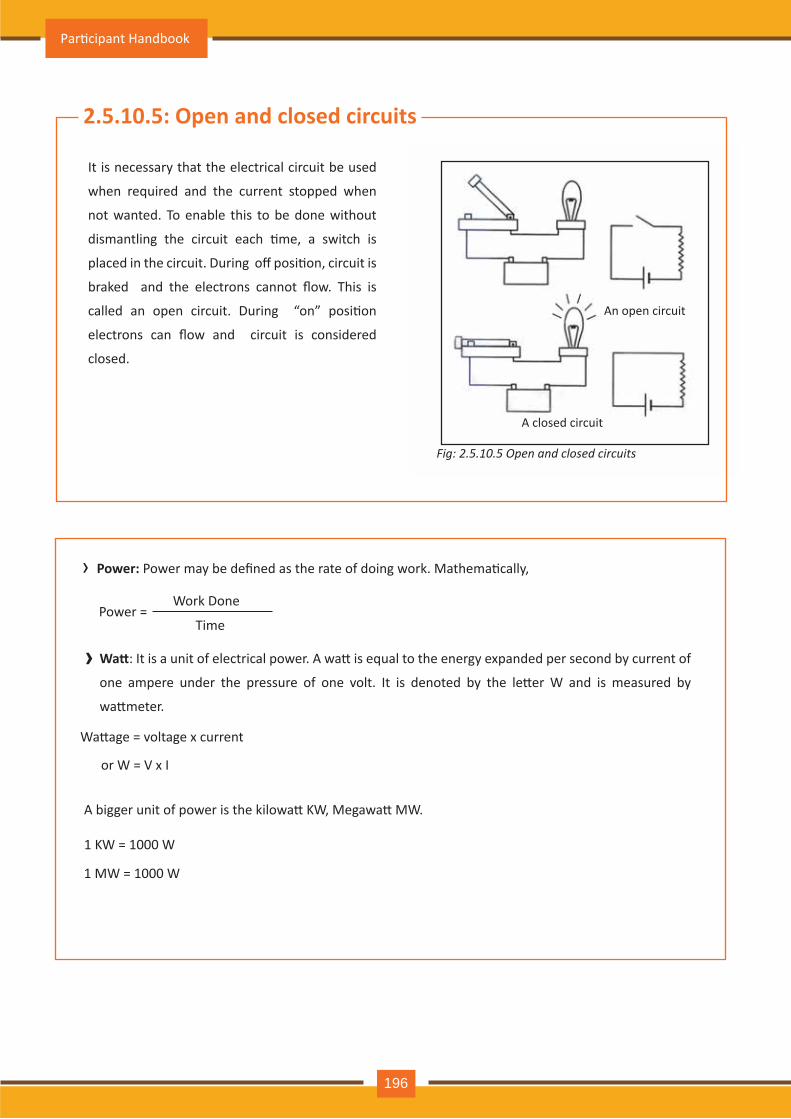
2.5.10.5: Open and closed circuits
It is necessary that the electrical circuit be used
when required and the current stopped when
not wanted. To enable this to be done without
dismantling the circuit each �me, a switch is
placed in the circuit. During off posi�on, circuit is
braked and the electrons cannot flow. This is
called an open circuit. During “on” posi�on
electrons can flow and circuit is considered
closed.
› Power: Power may be defined as the rate of doing work. Mathema�cally,
Power = Work Done
Time
An open circuit
A closed circuit
Fig: 2.5.10.5 Open and closed circuits
› Wa�: It is a unit of electrical power. A wa� is equal to the energy expanded per second by current of
one ampere under the pressure of one volt. It is denoted by the le�er W and is measured by
wa�meter.
Wa�age = voltage x current
or W = V x I
A bigger unit of power is the kilowa� KW, Megawa� MW.
1 KW = 1000 W
1 MW = 1000 W
Par�cipant Handbook
196
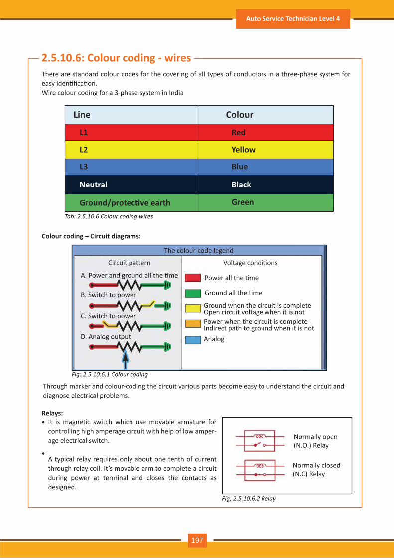
Fig: 2.5.10.6.1 Colour coding
Fig: 2.5.10.6.2 Relay
2.5.10.6: Colour coding - wiresThere are standard colour codes for the covering of all types of conductors in a three-phase system for easy iden�fica�on. Wire colour coding for a 3-phase system in India
Through marker and colour-coding the circuit various parts become easy to understand the circuit and diagnose electrical problems.
It is magne�c switch which use movable armature for controlling high amperage circuit with help of low amper-age electrical switch.
A typical relay requires only about one tenth of current through relay coil. It’s movable arm to complete a circuit during power at terminal and closes the contacts as designed.
Colour coding – Circuit diagrams:
Relays:•
•
Analog
Circuit pa�ern Voltage condi�ons
The colour-code legend
A. Power and ground all the �me Power all the �me
Ground all the �me
Ground when the circuit is complete Open circuit voltage when it is notPower when the circuit is complete Indirect path to ground when it is not
B. Switch to power
C. Switch to power
D. Analog output
Normally open (N.O.) Relay
Normally closed (N.C) Relay
Tab: 2.5.10.6 Colour coding wires
Line
L1 Red
Yellow
Blue
Black
Green
L2
L3
Neutral
Ground/protec�ve earth
Colour
Auto Service Technician Level 4
197
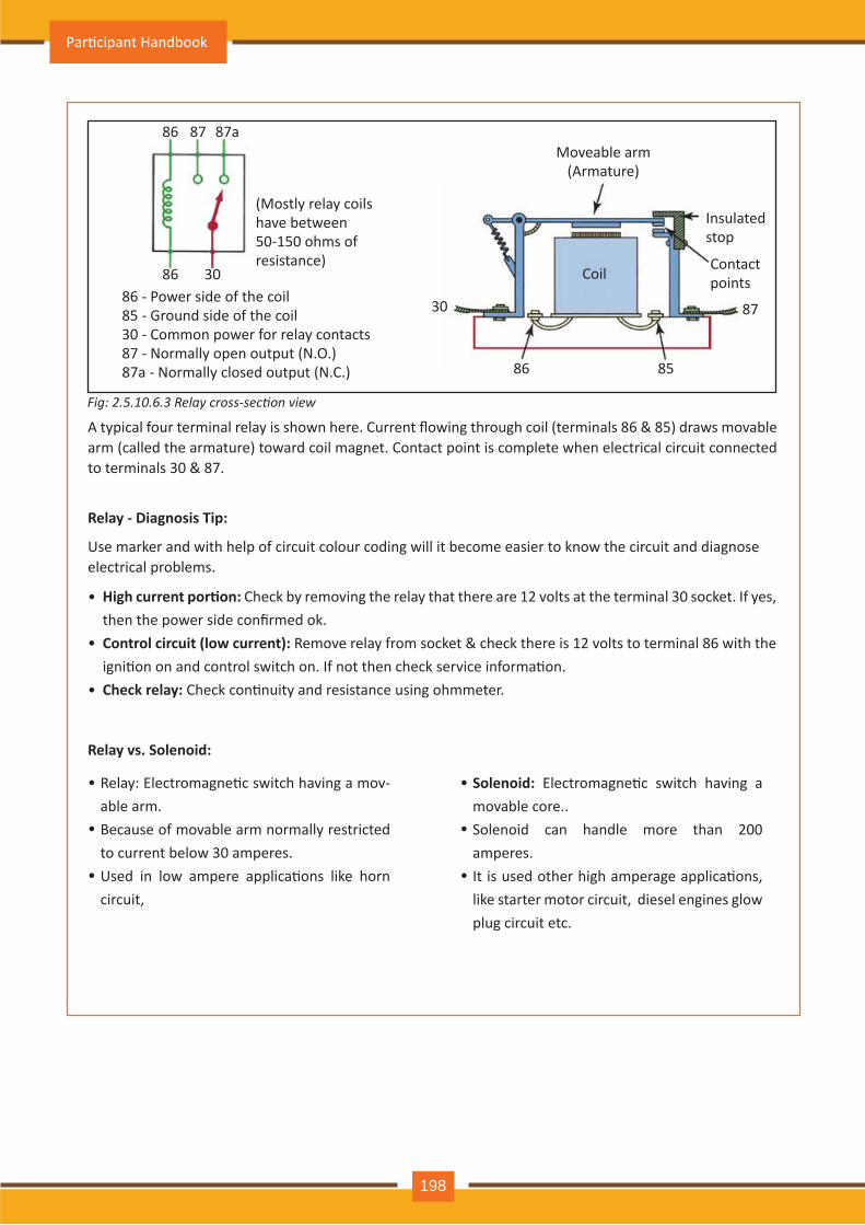
Fig: 2.5.10.6.3 Relay cross-section view
Relay - Diagnosis Tip:
Use marker and with help of circuit colour coding will it become easier to know the circuit and diagnose electrical problems.
A typical four terminal relay is shown here. Current flowing through coil (terminals 86 & 85) draws movable arm (called the armature) toward coil magnet. Contact point is complete when electrical circuit connected to terminals 30 & 87.
Relay: Electromagne�c switch having a mov-able arm. Because of movable arm normally restricted to current below 30 amperes.Used in low ampere applica�ons like horn circuit,
High current por�on: Check by removing the relay that there are 12 volts at the terminal 30 socket. If yes, then the power side confirmed ok.Control circuit (low current): Remove relay from socket & check there is 12 volts to terminal 86 with the igni�on on and control switch on. If not then check service informa�on.Check relay: Check con�nuity and resistance using ohmmeter.
Relay vs. Solenoid:
•
•
•
•
•
•
Solenoid: Electromagne�c switch having a movable core..Solenoid can handle more than 200 amperes.It is used other high amperage applica�ons, like starter motor circuit, diesel engines glow plug circuit etc.
•
•
•
86 87
86 30
87a
86 - Power side of the coil85 - Ground side of the coil30 - Common power for relay contacts87 - Normally open output (N.O.)87a - Normally closed output (N.C.)
(Mostly relay coils have between 50-150 ohms of resistance)
Moveable arm(Armature)
Insulated stop
Contact pointsCoil
30
86 85
87
Par�cipant Handbook
198
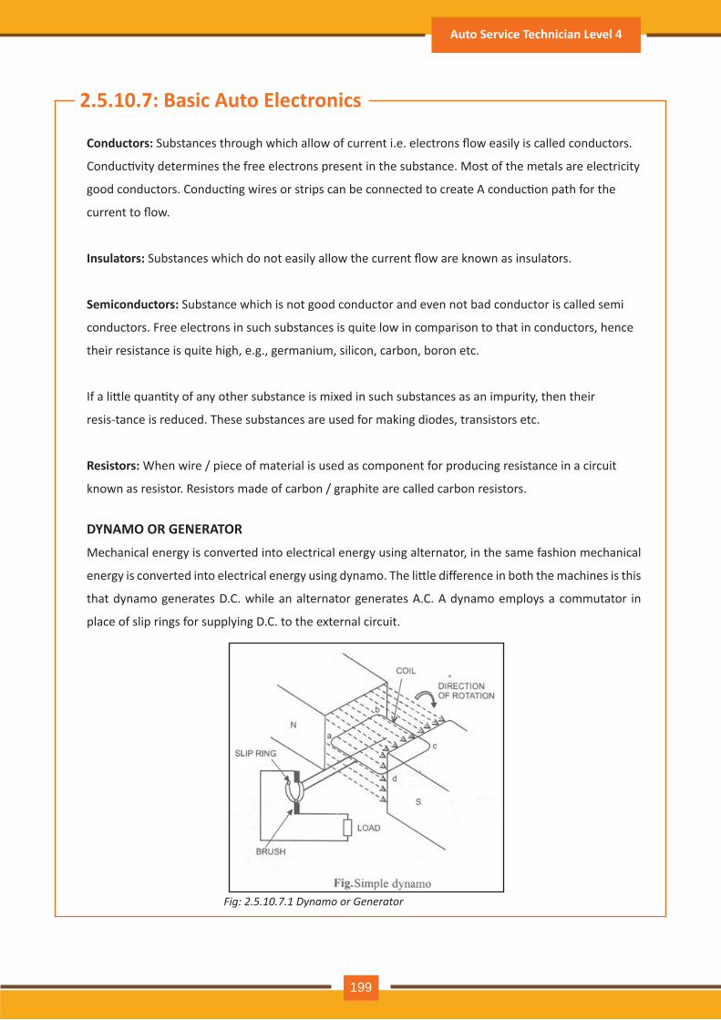
Fig: 2.5.10 .7 .1 D y n a m o o r G e n e r a t o r
2.5.10.7 : B asic Auto E lectronics
Conductors: Substances through which allow of current i.e. electrons flow easily is called conductors.
Conduc�vity determines the free electrons present in the substance. Most of the metals are electricity
good conductors. Conduc�ng wires or strips can be connected to create A conduc�on path for the
current to flow.
Insulators: Substances which do not easily allow the current flow are known as insulators.
Semiconductors: Substance which is not good conductor and even not bad conductor is called semi
conductors. Free electrons in such substances is quite low in comparison to that in conductors, hence
their resistance is quite high, e.g., germanium, silicon, carbon, boron etc.
If a li�le quan�ty of any other substance is mixed in such substances as an impurity, then their
resis-tance is reduced. These substances are used for making diodes, transistors etc.
R esistors: When wire / piece of material is used as component for producing resistance in a circuit
known as resistor. Resistors made of carbon / graphite are called carbon resistors.
D Y NAM O O R G E NE R ATO R
Mechanical energy is converted into electrical energy using alternator, in the same fashion mechanical
energy is converted into electrical energy using dynamo. The li�le difference in both the machines is this
that dynamo generates D.C. while an alternator generates A.C. A dynamo employs a commutator in
place of slip rings for supplying D.C. to the external circuit.
Auto Service Technician Level 4
199
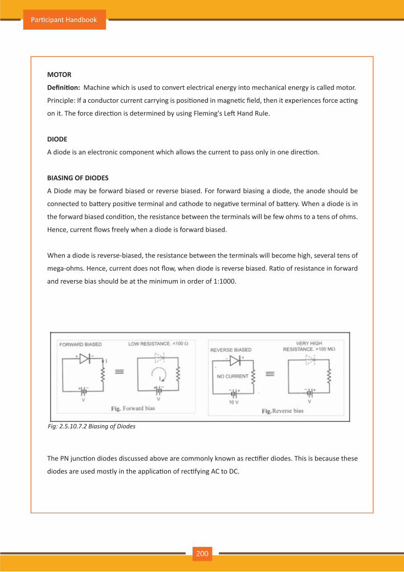
MOTOR
Defini�on: Machine which is used to convert electrical energy into mechanical energy is called motor.
Principle: If a conductor current carrying is posi�oned in magne�c field, then it experiences force ac�ng
on it. The force direc�on is determined by using Fleming's Le� Hand Rule.
DIODE
A diode is an electronic component which allows the current to pass only in one direc�on.
BIASING OF DIODES
A Diode may be forward biased or reverse biased. For forward biasing a diode, the anode should be
connected to ba�ery posi�ve terminal and cathode to nega�ve terminal of ba�ery. When a diode is in
the forward biased condi�on, the resistance between the terminals will be few ohms to a tens of ohms.
Hence, current flows freely when a diode is forward biased.
When a diode is reverse-biased, the resistance between the terminals will become high, several tens of
mega-ohms. Hence, current does not flow, when diode is reverse biased. Ra�o of resistance in forward
and reverse bias should be at the minimum in order of 1:1000.
The PN junc�on diodes discussed above are commonly known as rec�fier diodes. This is because these
diodes are used mostly in the applica�on of rec�fying AC to DC.
Par�cipant Handbook
200
Fig: 2.5.10.7.2 Biasing of Diodes
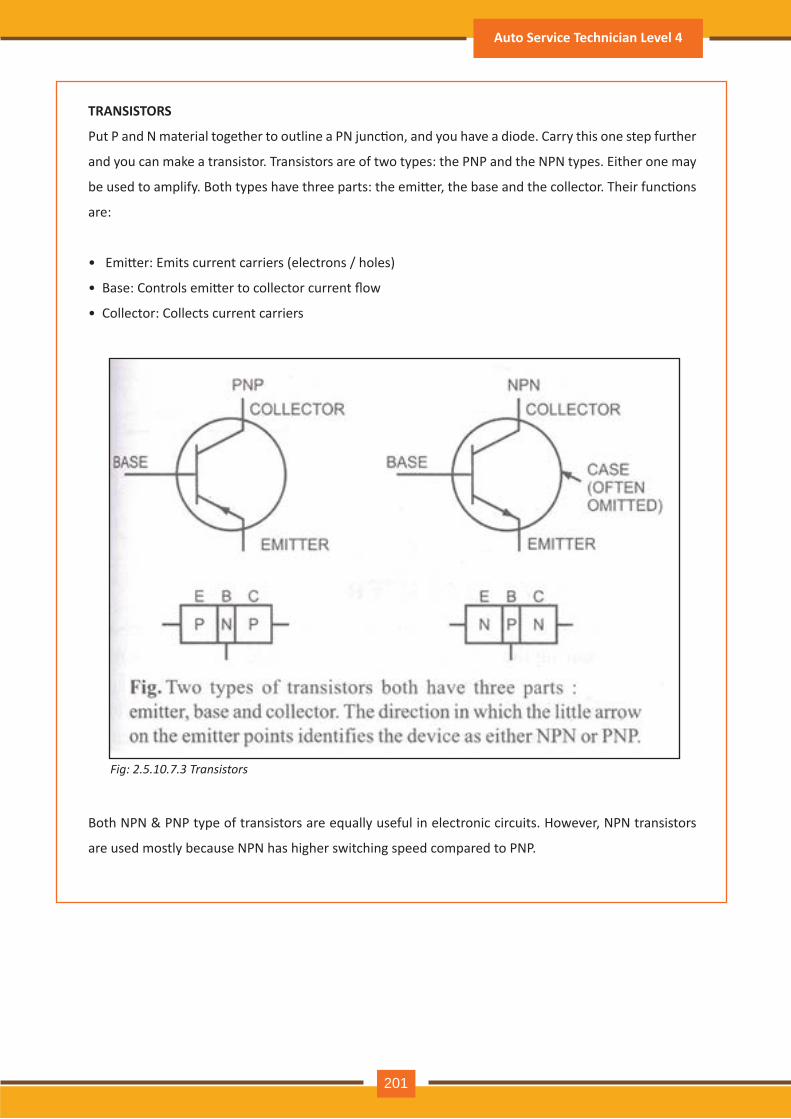
TR ANSISTO R S
Put P and N material together to outline a PN junc�on, and you have a diode. Carry this one step further
and you can make a transistor. Transistors are of two types: the PNP and the NPN types. Either one may
be used to amplify. Both types have three parts: the emi�er, the base and the collector. Their func�ons
are:
• Emi�er: Emits current carriers (electrons / holes)
• Base: Controls emi�er to collector current flow
• Collector: Collects current carriers
Both NPN & PNP type of transistors are equally useful in electronic circuits. However, NPN transistors
are used mostly because NPN has higher switching speed compared to PNP.
Auto Service Technician Level 4
201
Fig: 2.5.10 .7 .3 T r a n s is t o r s
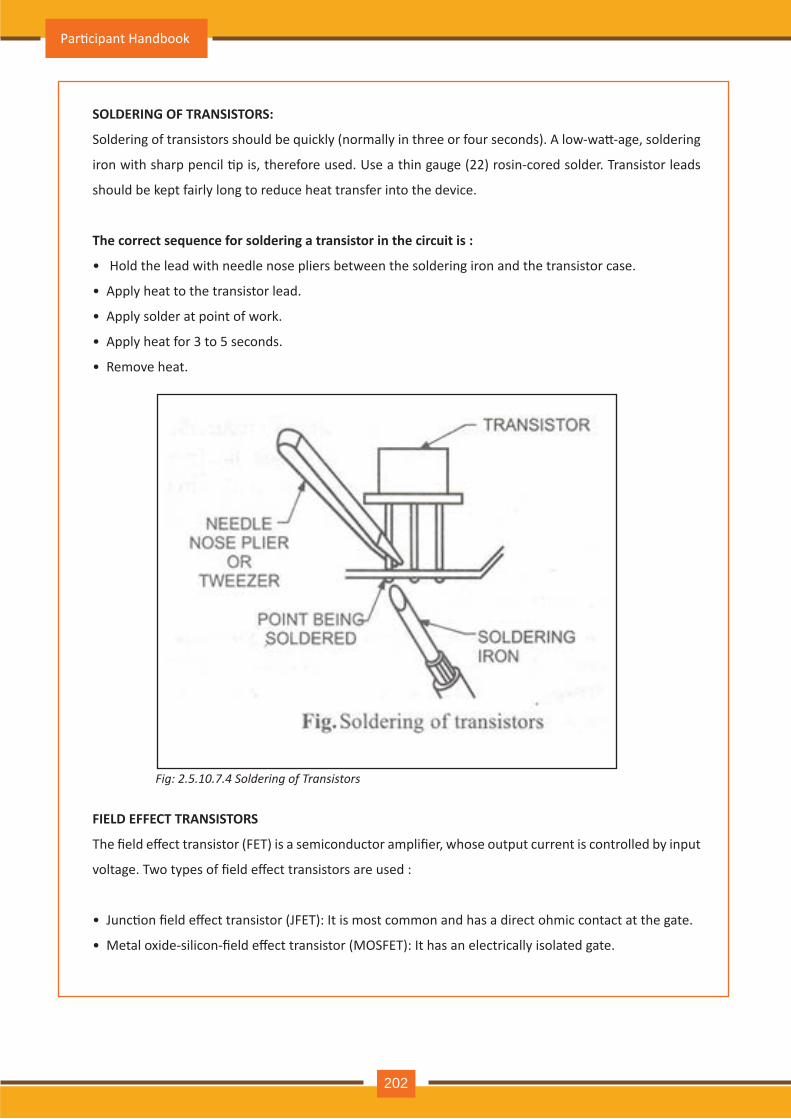
SO LD E R ING O F TR ANSISTO R S:
Soldering of transistors should be quickly (normally in three or four seconds). A low-wa�-age, soldering
iron with sharp pencil �p is, therefore used. Use a thin gauge (22) rosin-cored solder. Transistor leads
should be kept fairly long to reduce heat transfer into the device.
The correct sequence for soldering a transistor in the circuit is :
• Hold the lead with needle nose pliers between the soldering iron and the transistor case.
• Apply heat to the transistor lead.
• Apply solder at point of work.
• Apply heat for 3 to 5 seconds.
• Remove heat.
FIE LD E FFE CT TR ANSISTO R S
The field effect transistor (FET) is a semiconductor amplifier, whose output current is controlled by input
voltage. Two types of field effect transistors are used :
• Junc�on field effect transistor (JFET): It is most common and has a direct ohmic contact at the gate.
• Metal oxide-silicon-field effect transistor (MOSFET): It has an electrically isolated gate.
Par�cipant Handbook
202
Fig: 2.5.10 .7 .4 S o l d e r in g o f T r a n s is t o r s
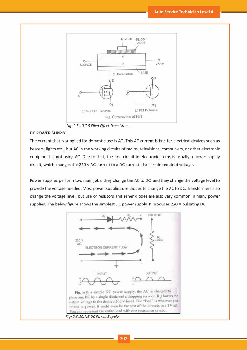
D C P O W E R SUP P LY
The current that is supplied for domes�c use is AC. This AC current is fine for electrical devices such as
heaters, lights etc., but AC in the working circuits of radios, televisions, comput-ers, or other electronic
equipment is not using AC. Due to that, the first circuit in electronic items is usually a power supply
circuit, which changes the 220 V AC current to a DC current of a certain required voltage.
Power supplies perform two main jobs: they change the AC to DC, and they change the voltage level to
provide the voltage needed. Most power supplies use diodes to change the AC to DC. Transformers also
change the voltage level, but use of resistors and zener diodes are also very common in many power
supplies. The below figure shows the simplest DC power supply. It produces 220 V pulsa�ng DC.
Auto Service Technician Level 4
125
Auto Service Technician Level 4
203
Fig: 2.5.1 . .5 Filed ect ransistors
Fig: 2.5.10 .7 .6 D C P o w e r S u p p l y
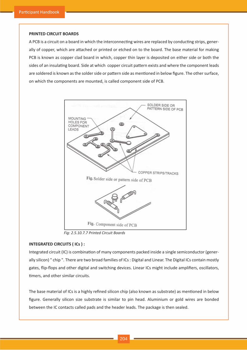
P R INTE D CIR CUIT B O AR D S
A PCB is a circuit on a board in which the interconnec�ng wires are replaced by conduc�ng strips, gener-
ally of copper, which are a�ached or printed or etched on to the board. The base material for making
PCB is known as copper clad board in which, copper thin layer is deposited on either side or both the
sides of an insula�ng board. Side at which copper circuit pa�ern exists and where the component leads
are soldered is known as the solder side or pa�ern side as men�oned in below figure. The other surface,
on which the components are mounted, is called component side of PCB.
INTE G R ATE D CIR CUITS ( ICs ) :
Integrated circuit (IC) is combina�on of many components packed inside a single semiconductor (gener-
ally silicon) chip . There are two broad families of ICs : Digital and Linear. The Digital ICs contain mostly
gates, flip-flops and other digital and switching devices. Linear ICs might include amplifiers, oscillators,
�mers, and other similar circuits.
The base material of ICs is a highly refined silicon chip (also known as substrate) as men�oned in below
figure. Generally silicon size substrate is similar to pin head. Aluminium or gold wires are bonded
between the IC contacts called pads and the header leads. The package is then sealed.
Par�cipant Handbook
204
Fig: 2.5.10 .7 .7 P r in t e d C ir c u it B o a r d s
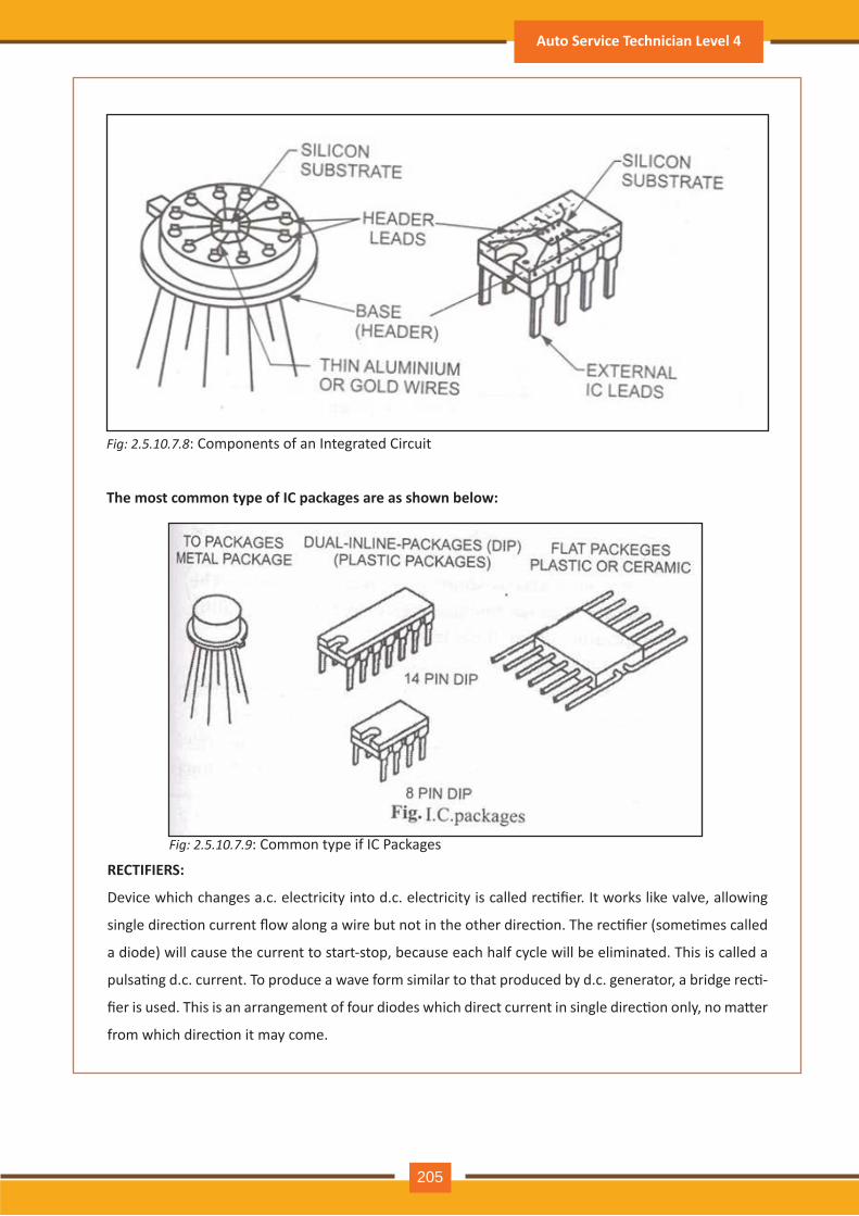
Fig: 2.5.10 .7 .8 : Components of an Integrated Circuit
Fig: 2.5.10 .7 .9 : Common type if IC Packages
The most common type of IC pack ages are as show n below :
R E CTIFIE R S:
Device which changes a.c. electricity into d.c. electricity is called rec�fier. It works like valve, allowing
single direc�on current flow along a wire but not in the other direc�on. The rec�fier (some�mes called
a diode) will cause the current to start-stop, because each half cycle will be eliminated. This is called a
pulsa�ng d.c. current. To produce a wave form similar to that produced by d.c. generator, a bridge rec�-
fier is used. This is an arrangement of four diodes which direct current in single direc�on only, no ma�er
from which direc�on it may come.
Auto Service Technician Level 4
205
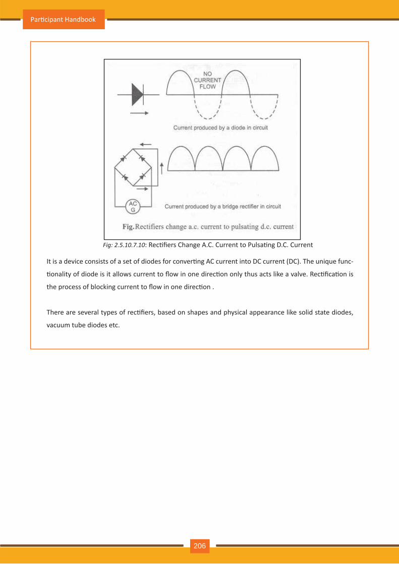
Fig: 2.5.10 .7 .10 : Rec�fiers Change A.C. Current to Pulsa�ng D.C. Current
It is a device consists of a set of diodes for conver�ng AC current into DC current (DC). The unique func-
�onality of diode is it allows current to flow in one direc�on only thus acts like a valve. Rec�fica�on is
the process of blocking current to flow in one direc�on .
There are several types of rec�fiers, based on shapes and physical appearance like solid state diodes,
vacuum tube diodes etc.
Par�cipant Handbook
124
Par�cipant Handbook
206
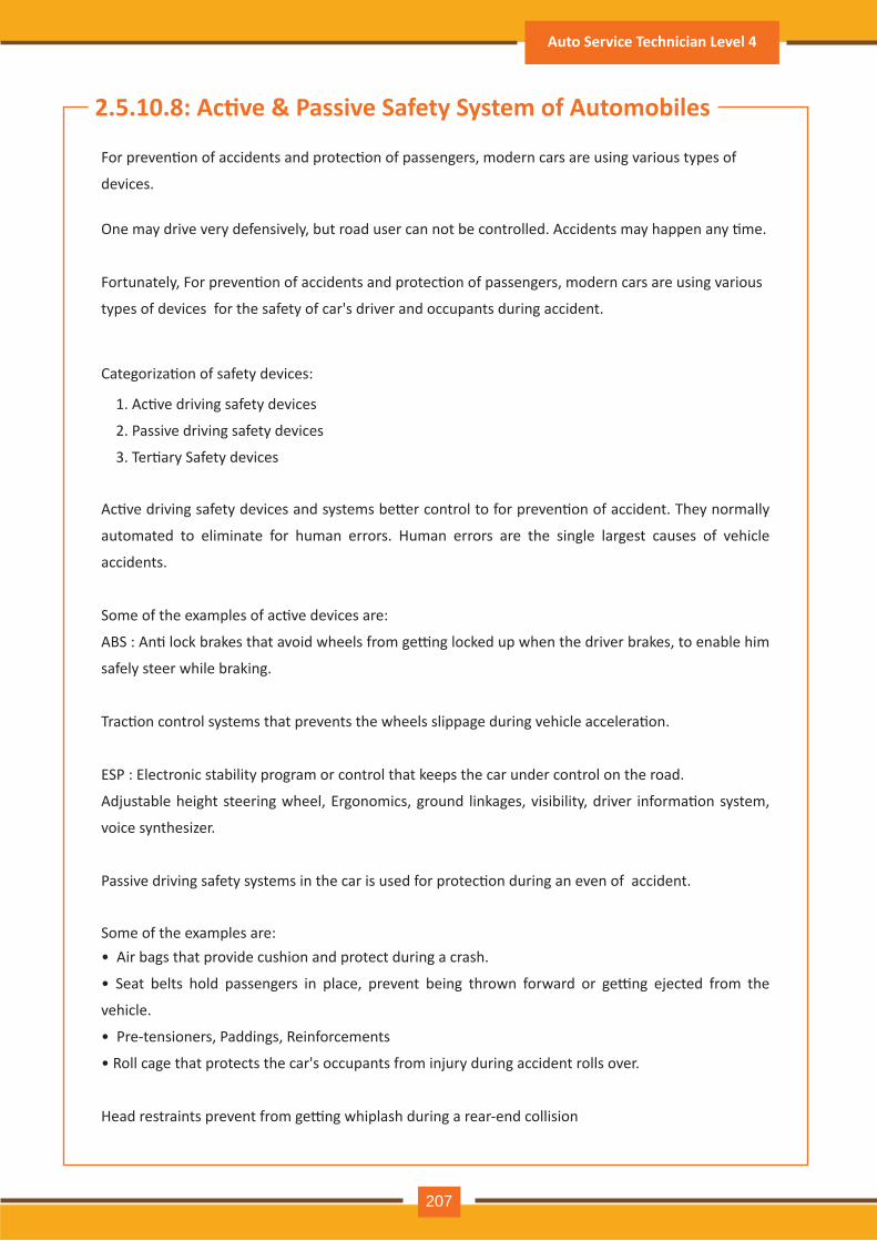
2.5.10.8: Ac�ve & Passive Safety System of Automobiles
For preven�on of accidents and protec�on of passengers, modern cars are using various types of
devices.
Ac�ve driving safety devices and systems be�er control to for preven�on of accident. They normally
automated to eliminate for human errors. Human errors are the single largest causes of vehicle
accidents.
Some of the examples of ac�ve devices are:
ABS : An� lock brakes that avoid wheels from ge�ng locked up when the driver brakes, to enable him
safely steer while braking.
Trac�on control systems that prevents the wheels slippage during vehicle accelera�on.
ESP : Electronic stability program or control that keeps the car under control on the road.
Adjustable height steering wheel, Ergonomics, ground linkages, visibility, driver informa�on system,
voice synthesizer.
Passive driving safety systems in the car is used for protec�on during an even of accident.
• Air bags that provide cushion and protect during a crash.
• Seat belts hold passengers in place, prevent being thrown forward or ge�ng ejected from the
vehicle.
• Pre-tensioners, Paddings, Reinforcements
• Roll cage that protects the car's occupants from injury during accident rolls over.
Head restraints prevent from ge�ng whiplash during a rear-end collision
Categoriza�on of safety devices:
Some of the examples are:
1. Ac�ve driving safety devices
2. Passive driving safety devices
3. Ter�ary Safety devices
One may drive very defensively, but road user can not be controlled. Accidents may happen any �me.
Fortunately, For preven�on of accidents and protec�on of passengers, modern cars are using various
types of devices for the safety of car's driver and occupants during accident.
Auto Service Technician Level 4
207
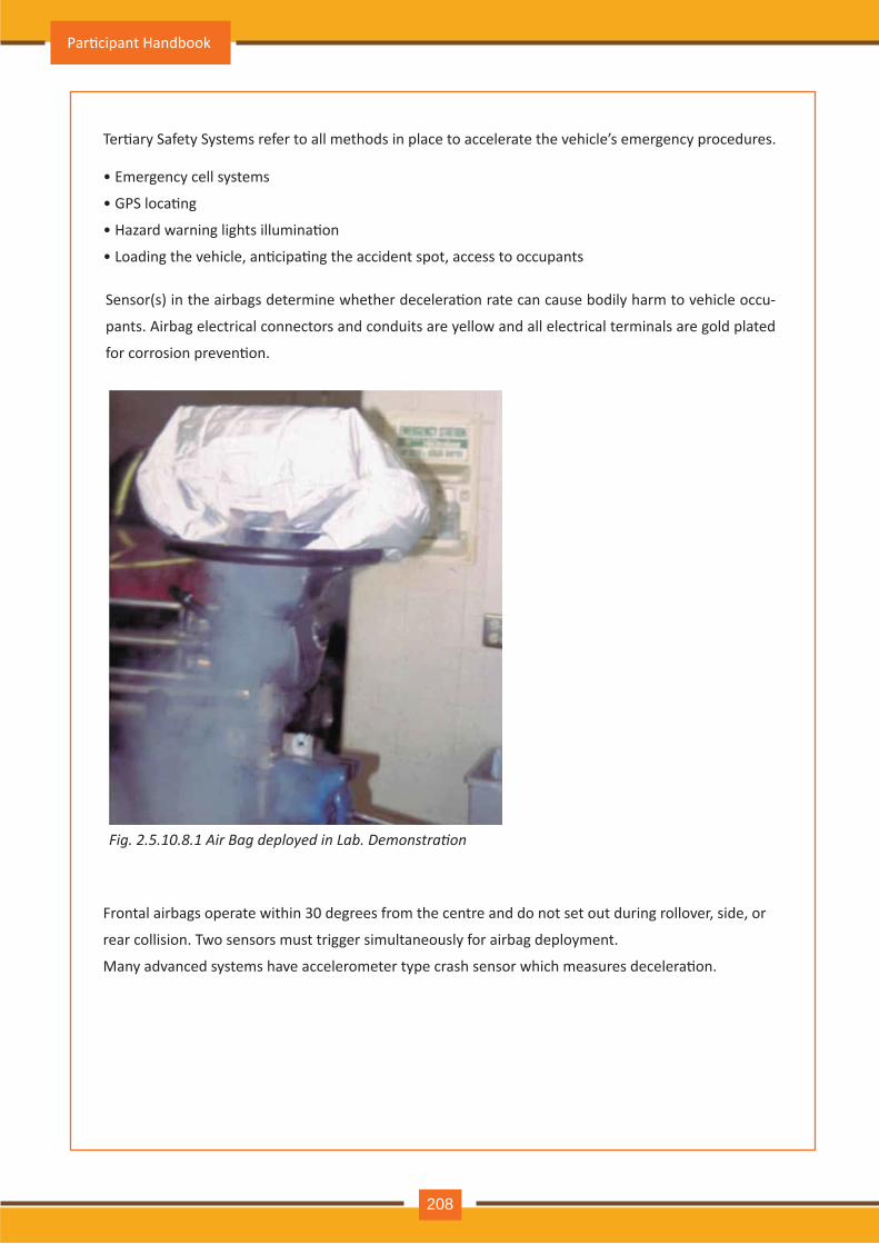
Sensor(s) in the airbags determine whether decelera�on rate can cause bodily harm to vehicle occu-
pants. Airbag electrical connectors and conduits are yellow and all electrical terminals are gold plated
for corrosion preven�on.
Ter�ary Safety Systems refer to all methods in place to accelerate the vehicle’s emergency procedures.
Fig. 2.5.1 . .1 Air ag deplo ed in ab. emonstration
• Emergency cell systems
• GPS loca�ng
• Hazard warning lights illumina�on
• Loading the vehicle, an�cipa�ng the accident spot, access to occupants
Frontal airbags operate within 30 degrees from the centre and do not set out during rollover, side, or
rear collision. Two sensors must trigger simultaneously for airbag deployment.
Many advanced systems have accelerometer type crash sensor which measures decelera�on.
Par�cipant Handbook
208
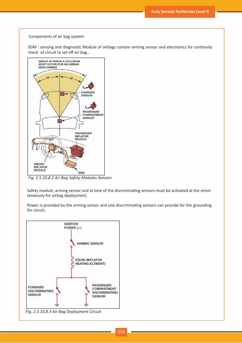
Components of air bag system:
Fig. 2.5.10 .8 .2 A ir B a g S a f e t y M o d u l e s S e n s o r s
Fig. 2.5.10 .8 .3 A ir B a g D e p l o y m e n t C ir c u it
SDM : sensing and diagnos�c Module of airbags contain arming sensor and electronics for con�nuity check of circuit to set off air bag..
Safety module, arming sensor and at lone of the discrimina�ng sensors must be ac�vated at the simul-taneously for airbag deployment.
Power is provided by the arming sensor and one discrimina�ng sensors can provide for the grounding for circuit.
Auto Service Technician Level 4
209
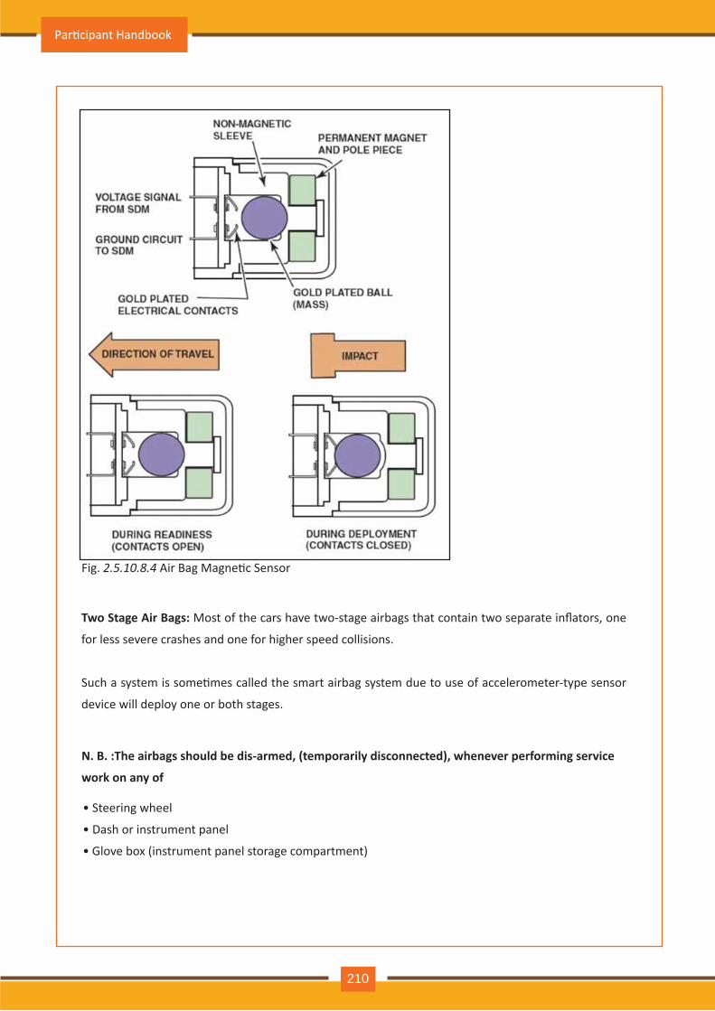
Fig. 2.5.10 .8 .4 Air Bag Magne�c Sensor
N. B . : The airbags should be dis- armed, (temporarily disconnected), w henever performing service
w ork on any of
• Steering wheel
• Dash or instrument panel
• Glove box (instrument panel storage compartment)
Tw o Stage Air B ags: Most of the cars have two-stage airbags that contain two separate inflators, one
for less severe crashes and one for higher speed collisions.
Such a system is some�mes called the smart airbag system due to use of accelerometer-type sensor
device will deploy one or both stages.
Par�cipant Handbook
210
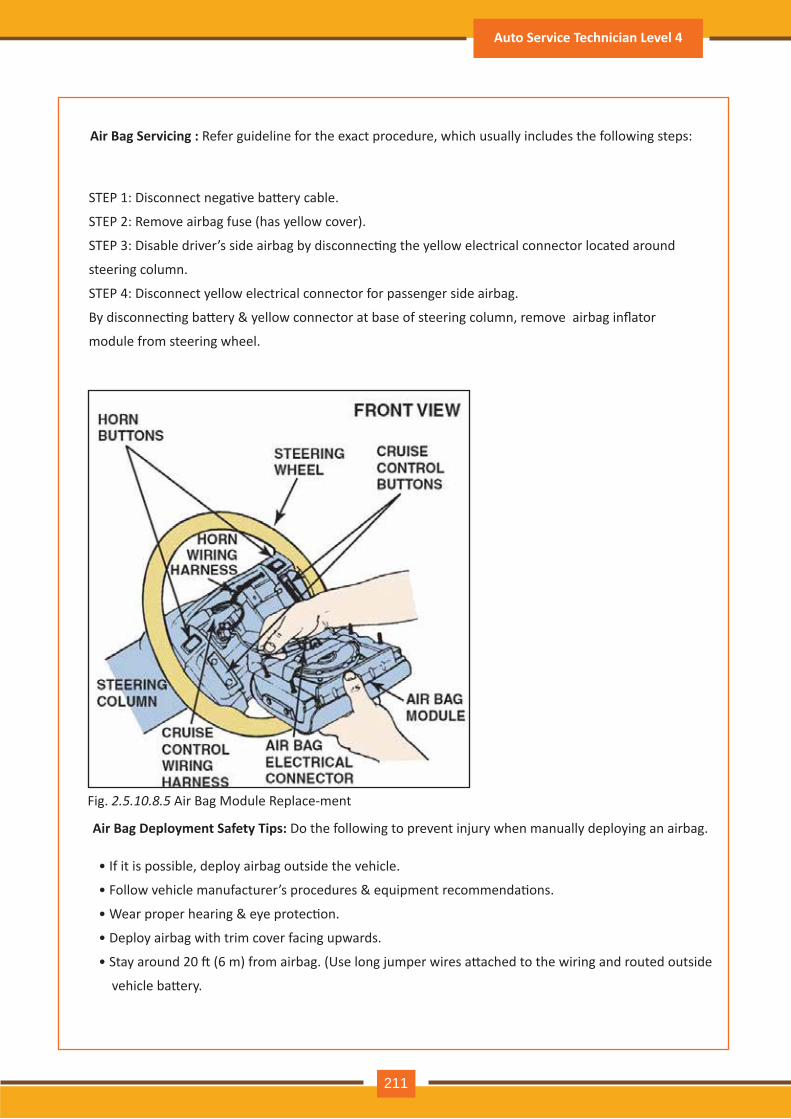
Fig. 2.5.10 .8 .5 Air Bag Module Replace-ment
Air B ag D eployment Safety Tips: Do the following to prevent injury when manually deploying an airbag.
• If it is possible, deploy airbag outside the vehicle.
• Follow vehicle manufacturer’s procedures & equipment recommenda�ons.
• Wear proper hearing & eye protec�on.
• Deploy airbag with trim cover facing upwards.
• Stay around 20 � (6 m) from airbag. (Use long jumper wires a�ached to the wiring and routed outside
vehicle ba�ery.
STEP 1: Disconnect nega�ve ba�ery cable.
STEP 2: Remove airbag fuse (has yellow cover).
STEP 3: Disable driver’s side airbag by disconnec�ng the yellow electrical connector located around
steering column.
STEP 4: Disconnect yellow electrical connector for passenger side airbag.
By disconnec�ng ba�ery & yellow connector at base of steering column, remove airbag inflator
module from steering wheel.
Air B ag Servicing : Refer guideline for the exact procedure, which usually includes the following steps:
Auto Service Technician Level 4
211
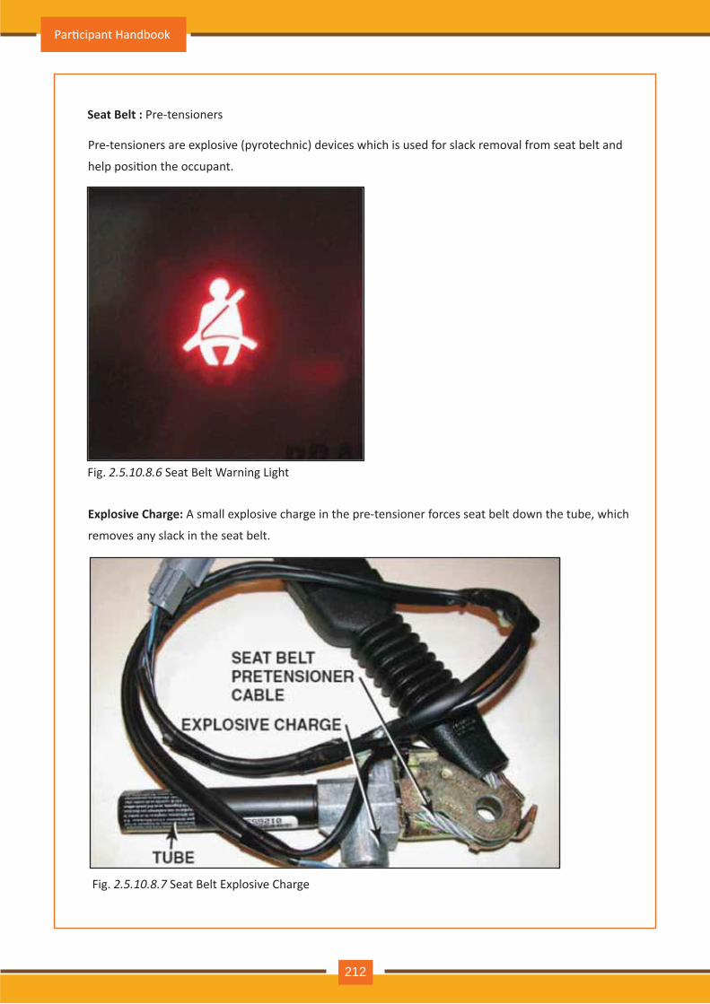
Seat B elt : Pre-tensioners
Fig. 2.5.10 .8 .6 Seat Belt Warning Light
Fig. 2.5.10 .8 .7 Seat Belt Explosive Charge
Pre-tensioners are explosive (pyrotechnic) devices which is used for slack removal from seat belt and
help posi�on the occupant.
E x plosive Charge: A small explosive charge in the pre-tensioner forces seat belt down the tube, which
removes any slack in the seat belt.
Par�cipant Handbook
212
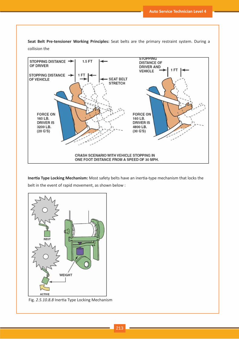
Fig. 2.5.10 .8 .8 Iner�a Type Locking Mechanism
Seat B elt P re- tensioner W ork ing P rinciples: Seat belts are the primary restraint system. During a
collision the
Iner�a Type Locking Mechanism: Most safety belts have an iner�a-type mechanism that locks the
belt in the event of rapid movement, as shown below :
Auto Service Technician Level 4
213
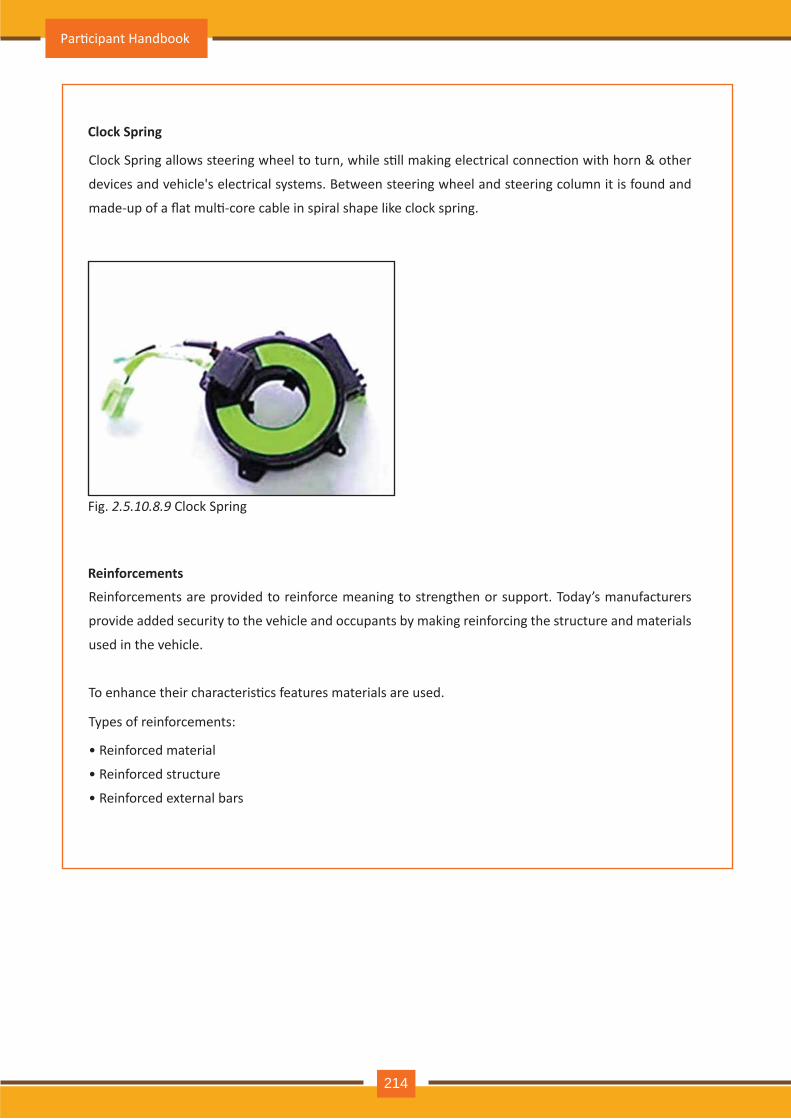
Clock Spring
R einforcements
Fig. 2.5.10 .8 .9 Clock Spring
Clock Spring allows steering wheel to turn, while s�ll making electrical connec�on with horn & other
devices and vehicle's electrical systems. Between steering wheel and steering column it is found and
made-up of a flat mul�-core cable in spiral shape like clock spring.
Reinforcements are provided to reinforce meaning to strengthen or support. Today’s manufacturers
provide added security to the vehicle and occupants by making reinforcing the structure and materials
used in the vehicle.
To enhance their characteris�cs features materials are used.
• Reinforced material
• Reinforced structure
• Reinforced external bars
Types of reinforcements:
Par�cipant Handbook
214
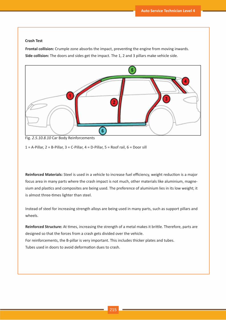
Crash Test
1 A-Pillar, 2 B-Pillar, 3 C-Pillar, 4 D-Pillar, 5 Roof rail, 6 Door sill
Fig. 2.5.10 .8 .10 Car Body Reinforcements
Frontal collision: Crumple zone absorbs the impact, preven�ng the engine from moving inwards.
Side collision: The doors and sides get the impact. The 1, 2 and 3 pillars make vehicle side.
Reinforced Materials: Steel is used in a vehicle to increase fuel efficiency, weight reduc�on is a major
focus area in many parts where the crash impact is not much, other materials like aluminium, magne-
sium and plas�cs and composites are being used. The preference of aluminium lies in its low weight it
is almost three-�mes lighter than steel.
Instead of steel for increasing strength alloys are being used in many parts, such as support pillars and
wheels.
R einforced Structure: At �mes, increasing the strength of a metal makes it bri�le. Therefore, parts are
designed so that the forces from a crash gets divided over the vehicle.
For reinforcements, the B-pillar is very important. This includes thicker plates and tubes.
Tubes used in doors to avoid deforma�on dues to crash.
Auto Service Technician Level 4
215
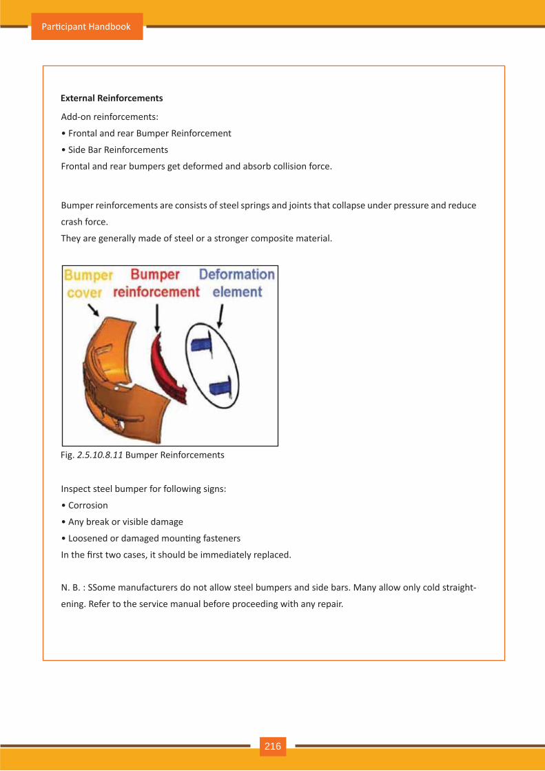
E x ternal R einforcements
Fig. 2.5.10 .8 .11 Bumper Reinforcements
Add-on reinforcements:
• Frontal and rear Bumper Reinforcement
• Side Bar Reinforcements
Frontal and rear bumpers get deformed and absorb collision force.
Inspect steel bumper for following signs:
• Corrosion
• Any break or visible damage
• Loosened or damaged moun�ng fasteners
In the first two cases, it should be immediately replaced.
Bumper reinforcements are consists of steel springs and joints that collapse under pressure and reduce
crash force.
They are generally made of steel or a stronger composite material.
N. B. : SSome manufacturers do not allow steel bumpers and side bars. Many allow only cold straight-
ening. Refer to the service manual before proceeding with any repair.
Par�cipant Handbook
216
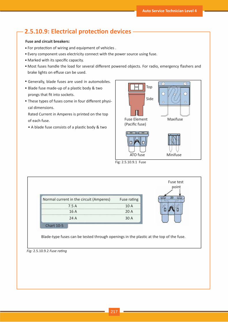
2.5.10.9: Electrical protec�on devicesFuse and circuit breakers:
For protec�on of wiring and equipment of vehicles .Every component uses electricity connect with the power source using fuse.Marked with its specific capacity. Most fuses handle the load for several different powered objects. For radio, emergency flashers and brake lights on effuse can be used.
••••
•
•
•
Generally, blade fuses are used in automobiles.Blade fuse made-up of a plas�c body & twoprongs that fit into sockets.These types of fuses come in four different physi-cal dimensions. Rated Current in Amperes is printed on the topof each fuse. • A blade fuse consists of a plas�c body & two
Top
Side
Fuse Element (Pacific fuse)
Maxifuse
MinifuseATO fuse
Normal current in the circuit (Amperes) Fuse ra�ng7.5 A 10 A
20 A
30 A
16 A
24 A
Chart 10-5
Blade-type fuses can be tested through openings in the plas�c at the top of the fuse.
Fuse test point
Fig: 2.5.10.9.1 Fuse
Fig: 2.5.10.9.2 Fuse rating
Auto Service Technician Level 4
217
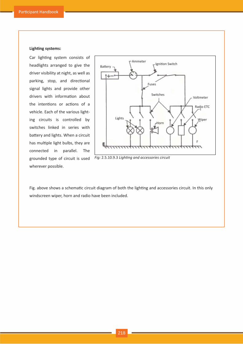
Ligh�ng systems:
Car ligh�ng system consists of
headlights arranged to give the
driver visibility at night, as well as
parking, stop, and direc�onal
signal lights and provide other
drivers with informa�on about
the inten�ons or ac�ons of a
vehicle. Each of the various light-
ing circuits is controlled by
switches linked in series with
ba�ery and lights. When a circuit
has mul�ple light bulbs, they are
connected in parallel. The
grounded type of circuit is used
wherever possible.
Fig. above shows a schema�c circuit diagram of both the ligh�ng and accessories circuit. In this only
windscreen wiper, horn and radio have been included.
Fig: 2.5.10.9.3 ighting and accessories circuit
Ba�eryAmmeter
Igni�on Switch
Fuses
Switches
HornLights
E F
Voltmeter
Radio ETC
Wiper
Par�cipant Handbook
218
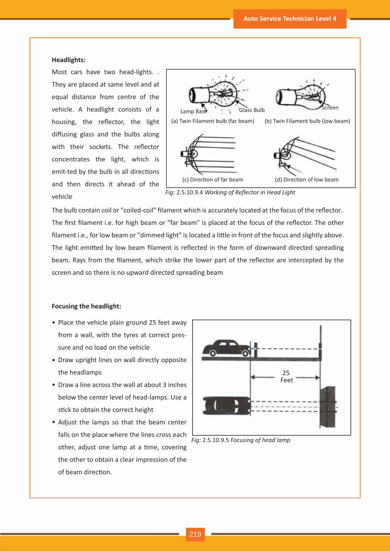
Fig: 2.5.10.9.4 Working of Reflector in Head Light
Headlights:
Most cars have two head-lights. .
They are placed at same level and at
equal distance from centre of the
vehicle. A headlight consists of a
housing, the reflector, the light
diffusing glass and the bulbs along
with their sockets. The reflector
concentrates the light, which is
emit-ted by the bulb in all direc�ons
and then directs it ahead of the
vehicle
The bulb contain coil or "coiled-coil" filament which is accurately located at the focus of the reflector..
The first filament i.e. for high beam or "far beam" is placed at the focus of the reflector. The other
filament i.e., for low beam or "dimmed light" is located a li�le in front of the focus and slightly above.
The light emi�ed by low beam filament is reflected in the form of downward directed spreading
beam. Rays from the filament, which strike the lower part of the reflector are intercepted by the
screen and so there is no upward directed spreading beam
Focusing the headlight:
Place the vehicle plain ground 25 feet away
from a wall, with the tyres at correct pres-
sure and no load on the vehicle
Draw upright lines on wall directly opposite
the headlamps
Draw a line across the wall at about 3 inches
below the center level of head-lamps. Use a
s�ck to obtain the correct height
Adjust the lamps so that the beam center
falls on the place where the lines cross each
other, adjust one lamp at a �me, covering
the other to obtain a clear impression of the
of beam direc�on.
Lamp Base(a) Twin Filament bulb (far beam) (b) Twin Filament bulb (low beam)
(c) Direc�on of far beam (d) Direc�on of low beam
Glass Bulb Screen
Fig: 2.5.10.9.5 Focusing of head lamp
25 Feet
•
•
•
•
Auto Service Technician Level 4
219
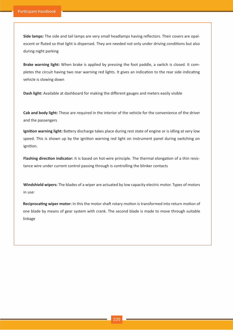
Side lamps: The side and tail lamps are very small headlamps having reflectors. Their covers are opal-
escent or fluted so that light is dispersed. They are needed not only under driving condi�ons but also
during night parking
Brake warning light: When brake is applied by pressing the foot paddle, a switch is closed. It com-
pletes the circuit having two rear warning red lights. It gives an indica�on to the rear side indica�ng
vehicle is slowing down
Dash light: Available at dashboard for making the different gauges and meters easily visible
Cab and body light: These are required in the interior of the vehicle for the convenience of the driver
and the passengers
Igni�on warning light: Ba�ery discharge takes place during rest state of engine or is idling at very low
speed. This is shown up by the igni�on warning red light on instrument panel during switching on
igni�on.
Flashing direc�on indicator: It is based on hot-wire principle. The thermal elonga�on of a thin resis-
tance wire under current control passing through is controlling the blinker contacts
Windshield wipers: The blades of a wiper are actuated by low capacity electric motor. Types of motors
in use:
Reciproca�ng wiper motor: In this the motor sha� rotary mo�on is transformed into return mo�on of
one blade by means of gear system with crank. The second blade is made to move through suitable
linkage
Par�cipant Handbook
220
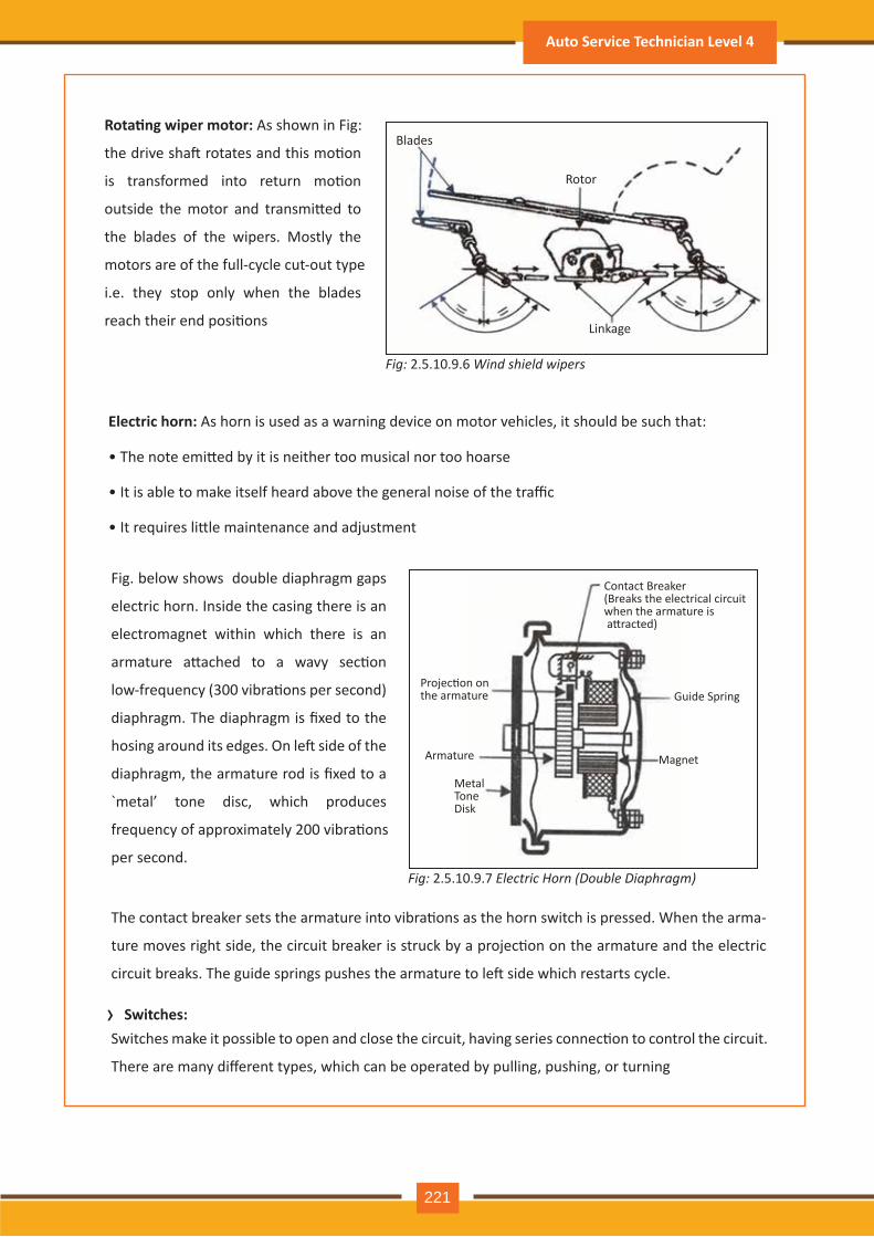
›
Rota�ng wiper motor: As shown in Fig:
the drive sha� rotates and this mo�on
is transformed into return mo�on
outside the motor and transmi�ed to
the blades of the wipers. Mostly the
motors are of the full-cycle cut-out type
i.e. they stop only when the blades
reach their end posi�ons
Electric horn: As horn is used as a warning device on motor vehicles, it should be such that:
• The note emi�ed by it is neither too musical nor too hoarse
• It is able to make itself heard above the general noise of the traffic
• It requires li�le maintenance and adjustment
Fig. below shows double diaphragm gaps
electric horn. Inside the casing there is an
electromagnet within which there is an
armature a�ached to a wavy sec�on
low-frequency (300 vibra�ons per second)
diaphragm. The diaphragm is fixed to the
hosing around its edges. On le� side of the
diaphragm, the armature rod is fixed to a
`metal’ tone disc, which produces
frequency of approximately 200 vibra�ons
per second.
The contact breaker sets the armature into vibra�ons as the horn switch is pressed. When the arma-
ture moves right side, the circuit breaker is struck by a projec�on on the armature and the electric
circuit breaks. The guide springs pushes the armature to le� side which restarts cycle.
Switches: Switches make it possible to open and close the circuit, having series connec�on to control the circuit.
There are many different types, which can be operated by pulling, pushing, or turning
Blades
Rotor
Linkage
Contact Breaker (Breaks the electrical circuit when the armature is a�racted)
Guide Spring
Magnet
Metal Tone Disk
Armature
Projec�on on the armature
Fig: 2.5.10.9.6 Wind shield wipers
Fig: 2.5.10.9.7 Electric Horn (Double Diaphragm)
Auto Service Technician Level 4
221
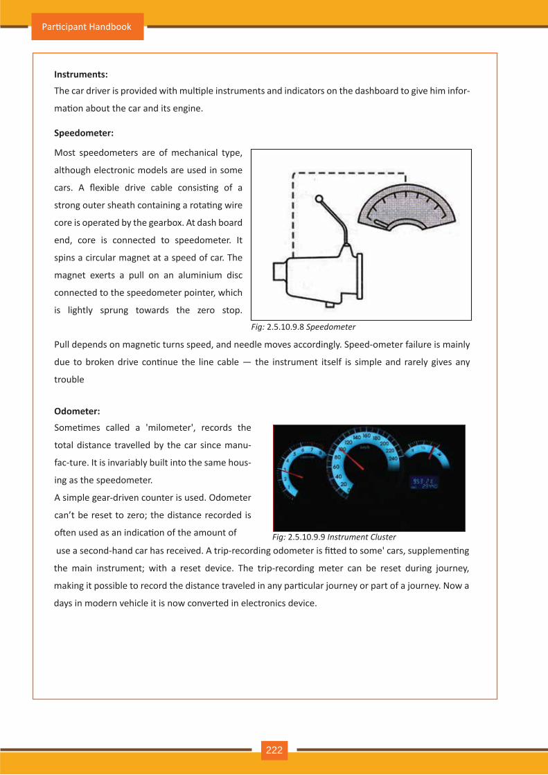
Instruments:
The car driver is provided with mul�ple instruments and indicators on the dashboard to give him infor-
ma�on about the car and its engine.
Pull depends on magne�c turns speed, and needle moves accordingly. Speed-ometer failure is mainly
due to broken drive con�nue the line cable — the instrument itself is simple and rarely gives any
trouble
Speedometer:
Most speedometers are of mechanical type,
although electronic models are used in some
cars. A flexible drive cable consis�ng of a
strong outer sheath containing a rota�ng wire
core is operated by the gearbox. At dash board
end, core is connected to speedometer. It
spins a circular magnet at a speed of car. The
magnet exerts a pull on an aluminium disc
connected to the speedometer pointer, which
is lightly sprung towards the zero stop.
Fig: 2.5.10.9.8 Speedometer
Fig: 2.5.10.9.9 Instrument Cluster
Odometer:
Some�mes called a 'milometer', records the
total distance travelled by the car since manu-
fac-ture. It is invariably built into the same hous-
ing as the speedometer.
A simple gear-driven counter is used. Odometer
can’t be reset to zero; the distance recorded is
o�en used as an indica�on of the amount of
use a second-hand car has received. A trip-recording odometer is fi�ed to some' cars, supplemen�ng
the main instrument; with a reset device. The trip-recording meter can be reset during journey,
making it possible to record the distance traveled in any par�cular journey or part of a journey. Now a
days in modern vehicle it is now converted in electronics device.
Par�cipant Handbook
222
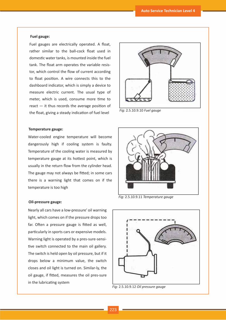
Fuel gauge:
Fuel gauges are electrically operated. A float,
rather similar to the ball-cock float used in
domes�c water tanks, is mounted inside the fuel
tank. The float arm operates the variable resis-
tor, which control the flow of current according
to float posi�on. A wire connects this to the
dashboard indicator, which is simply a device to
measure electric current. The usual type of
meter, which is used, consume more �me to
react — it thus records the average posi�on of
the float, giving a steady indica�on of fuel level Fig: 2.5.10.9.10 Fuel gauge
Temperature gauge:
Water-cooled engine temperature will become
dangerously high if cooling system is faulty.
Temperature of the cooling water is measured by
temperature gauge at its ho�est point, which is
usually in the return flow from the cylinder head.
The gauge may not always be fi�ed; in some cars
there is a warning light that comes on if the
temperature is too high
Oil-pressure gauge:
Nearly all cars have a low-pressure' oil warning
light, which comes on if the pressure drops too
far. O�en a pressure gauge is fi�ed as well,
par�cularly in sports cars or expensive models.
Warning light is operated by a pres-sure-sensi-
�ve switch connected to the main oil gallery.
The switch is held open by oil pressure, but if it
drops below a minimum value, the switch
closes and oil light is turned on. Similar-ly, the
oil gauge, if fi�ed, measures the oil pres-sure
in the lubrica�ng system
Fig: 2.5.10.9.11 Temperature gauge
Fig: 2.5.10.9.12 Oil pressure gauge
Auto Service Technician Level 4
223
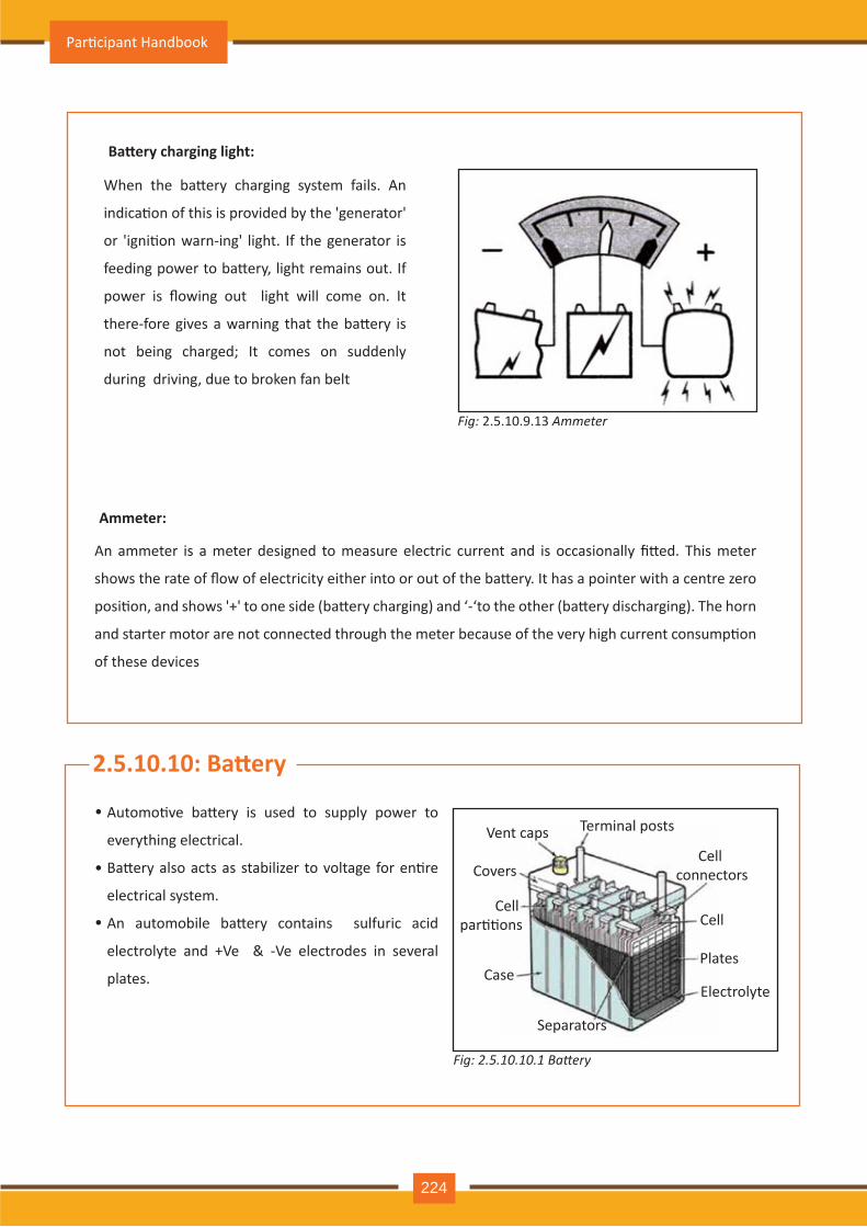
Ba�ery charging light:
When the ba�ery charging system fails. An
indica�on of this is provided by the 'generator'
or 'igni�on warn-ing' light. If the generator is
feeding power to ba�ery, light remains out. If
power is flowing out light will come on. It
there-fore gives a warning that the ba�ery is
not being charged; It comes on suddenly
during driving, due to broken fan belt
Fig: 2.5.10.9.13 Ammeter
Fig: 2.5.10.10.1 Battery
Ammeter:
An ammeter is a meter designed to measure electric current and is occasionally fi�ed. This meter
shows the rate of flow of electricity either into or out of the ba�ery. It has a pointer with a centre zero
posi�on, and shows '+' to one side (ba�ery charging) and ‘-‘to the other (ba�ery discharging). The horn
and starter motor are not connected through the meter because of the very high current consump�on
of these devices
Automo�ve ba�ery is used to supply power to
everything electrical.
Ba�ery also acts as stabilizer to voltage for en�re
electrical system.
An automobile ba�ery contains sulfuric acid
electrolyte and +Ve & -Ve electrodes in several
plates.
2.5.10.10: Ba�ery
•
•
•
Terminal posts
Cell connectors
Cell
Plates
Electrolyte
Separators
Case
Cell par��ons
Covers
Vent caps
Par�cipant Handbook
224
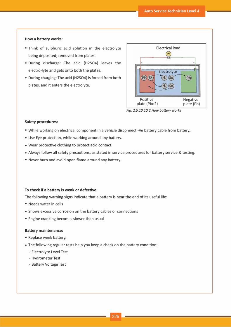
How a ba�ery works:
Safety procedures:
To check if a ba�ery is weak or defec�ve:
Fig: 2.5.10.10.2 How battery works
Think of sulphuric acid solu�on in the electrolyte
being deposited; removed from plates.
During discharge: The acid (H2SO4) leaves the
electro-lyte and gets onto both the plates.
During charging: The acid (H2SO4) is forced from both
plates, and it enters the electrolyte.
While working on electrical component in a vehicle disconnect -Ve ba�ery cable from ba�ery,.
Use Eye protec�on, while working around any ba�ery.
Wear protec�ve clothing to protect acid contact.
Always follow all safety precau�ons, as stated in service procedures for ba�ery service & tes�ng.
Never burn and avoid open flame around any ba�ery.
Needs water in cells
Shows excessive corrosion on the ba�ery cables or connec�ons
Engine cranking becomes slower than usual
The following warning signs indicate that a ba�ery is near the end of its useful life:
•
•
•
•
•
•
••
•
•
•
•
•
Ba�ery maintenance:
Replace week ba�ery.
The following regular tests help you keep a check on the ba�ery condi�on:
- Electrolyte Level Test- Hydrometer Test- Ba�ery Voltage Test
Electrical load
Electrolyte
Posi�ve plate (Pbo2)
Nega�ve plate (Pb)
Pb PbO2 2 4H So
2 4H So
Auto Service Technician Level 4
225
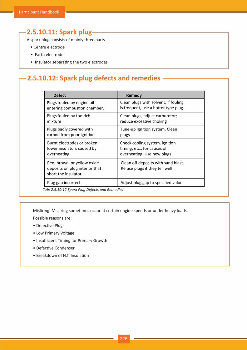
2.5.10.11: Spark plug
• Centre electrode
• Earth electrode
• Insulator separa�ng the two electrodes
A spark plug consists of mainly three parts
2.5.10.12: Spark plug defects and remedies
Plugs fouled by engine oil entering combus�on chamber.
Clean plugs with solvent; if fouling is frequent, use a ho�er type plug
Plugs fouled by too rich mixture
Clean plugs; adjust carburetor; reduce excessive choking
Plugs badly covered with carbon from poor igni�on
Tune-up igni�on system. Clean plugs
Burnt electrodes or broken lower insulators caused by overhea�ng
Check cooling system, igni�on �ming, etc., for causes of overhea�ng. Use new plugs
Red, brown, or yellow oxide deposits on plug interior that short the insulator
Clean off deposits with sand blast. Re use plugs if they tell well
Plug gap incorrect Adjust plug gap to specified value
RemedyDefect
Misfiring: Misfiring some�mes occur at certain engine speeds or under heavy loads.
Possible reasons are:
• Defec�ve Plugs
• Low Primary Voltage
• Insufficient Timing for Primary Growth
• Defec�ve Condenser
• Breakdown of H.T. Insula�on
Tab: 2.5.10.12 Spark Plug Defects and Remedies
Par�cipant Handbook
226
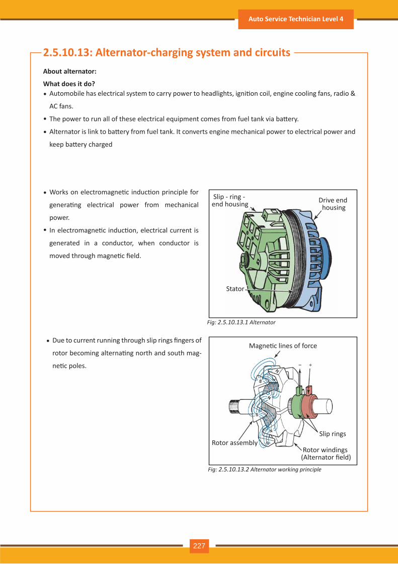
Fig: 2.5.10.13.1 Alternator
2.5.10.13: Alternator-charging system and circuitsAbout alternator:
What does it do?Automobile has electrical system to carry power to headlights, igni�on coil, engine cooling fans, radio &
AC fans.
The power to run all of these electrical equipment comes from fuel tank via ba�ery.
Alternator is link to ba�ery from fuel tank. It converts engine mechanical power to electrical power and
keep ba�ery charged
•
Works on electromagne�c induc�on principle for
genera�ng electrical power from mechanical
power.
In electromagne�c induc�on, electrical current is
generated in a conductor, when conductor is
moved through magne�c field.
•
Due to current running through slip rings fingers of
rotor becoming alterna�ng north and south mag-
ne�c poles.
•
•
•
•
Drive end housing
Slip - ring - end housing
Stator
Fig: 2.5.10.13.2 Alternator working principle
Magne�c lines of force
Slip ringsRotor assembly
Rotor windings (Alternator field)
Auto Service Technician Level 4
227
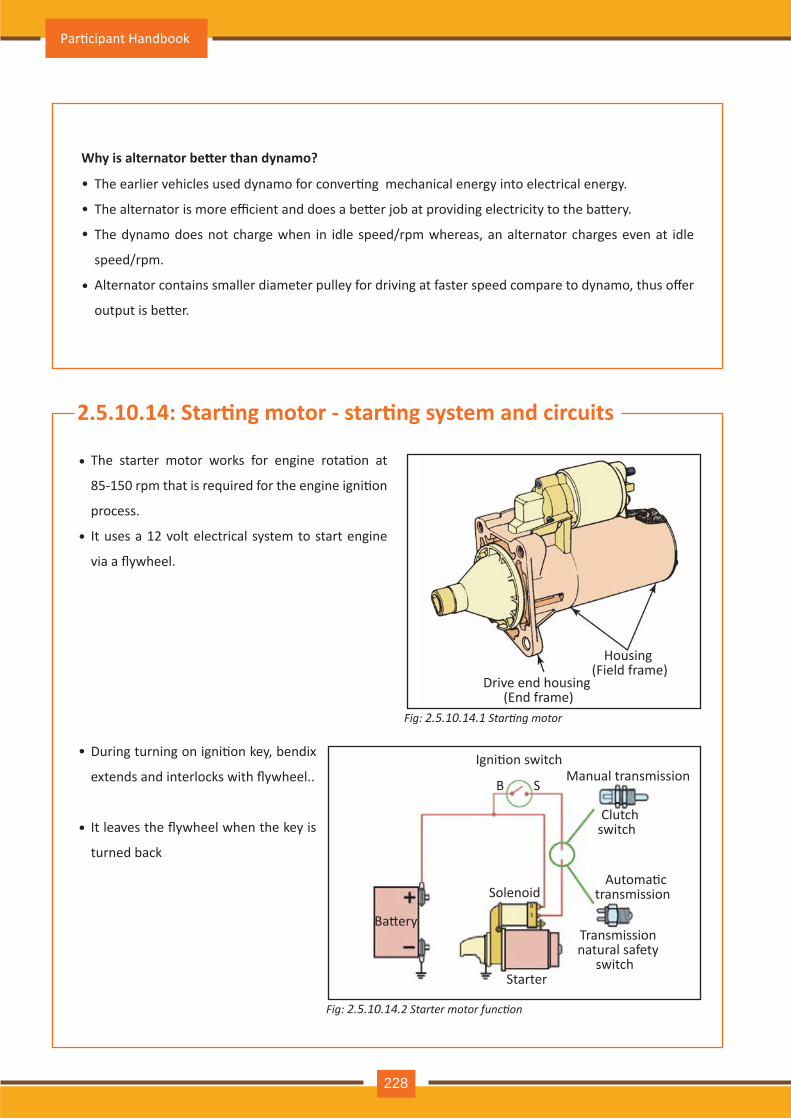
Fig: 2.5.10.14.1 Starting motor
Fig: 2.5.10.14.2 Starter motor function
The starter motor works for engine rota�on at
85-150 rpm that is required for the engine igni�on
process.
It uses a 12 volt electrical system to start engine
via a flywheel.
•
During turning on igni�on key, bendix
extends and interlocks with flywheel..
It leaves the flywheel when the key is
turned back
•
•
•
Why is alternator be�er than dynamo?
The earlier vehicles used dynamo for conver�ng mechanical energy into electrical energy.
The alternator is more efficient and does a be�er job at providing electricity to the ba�ery.
The dynamo does not charge when in idle speed/rpm whereas, an alternator charges even at idle
speed/rpm.
Alternator contains smaller diameter pulley for driving at faster speed compare to dynamo, thus offer
output is be�er.
•
•
•
•
2.5.10.14: Star�ng motor - star�ng system and circuits
Drive end housing (End frame)
Housing (Field frame)
Igni�on switch Manual transmission
Clutch switch
Automa�c transmission
Transmission natural safety
switch Starter
Ba�ery
Solenoid
B
BS
S
Par�cipant Handbook
228
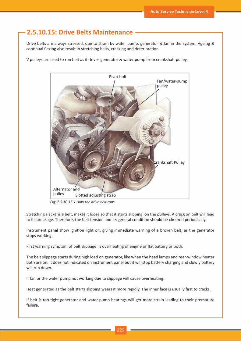
Fig: 2.5.10 .15.1 ow the drive belt runs
2.5.10.15: Drive Belts MaintenanceDrive belts are always stressed, due to strain by water pump, generator & fan in the system. Ageing & con�nual flexing also result in stretching belts, cracking and deteriora�on.
V pulleys are used to run belt as it drives generator & water pump from cranksha� pulley.
Stretching slackens a belt, makes it loose so that it starts slipping on the pulleys. A crack on belt will lead to its breakage. Therefore, the belt tension and its general condi�on should be checked periodically.
Instrument panel show igni�on light on, giving immediate warning of a broken belt, as the generator stops working.
First warning symptom of belt slippage is overhea�ng of engine or flat ba�ery or both.
The belt slippage starts during high load on generator, like when the head lamps and rear-window heater both are on. It does not indicated on instrument panel but it will stop ba�ery charging and slowly ba�ery will run down.
If fan or the water pump not working due to slippage will cause overhea�ng.
Heat generated as the belt starts slipping wears it more rapidly. The inner face is usually first to cracks.
If belt is too �ght generator and water-pump bearings will get more strain leading to their premature failure.
Alternator and pulley Slo�ed adjus�ng strap
Cranksha� Pulley
Fan/water-pump pulley
Pivot bolt
Auto Service Technician Level 4
229
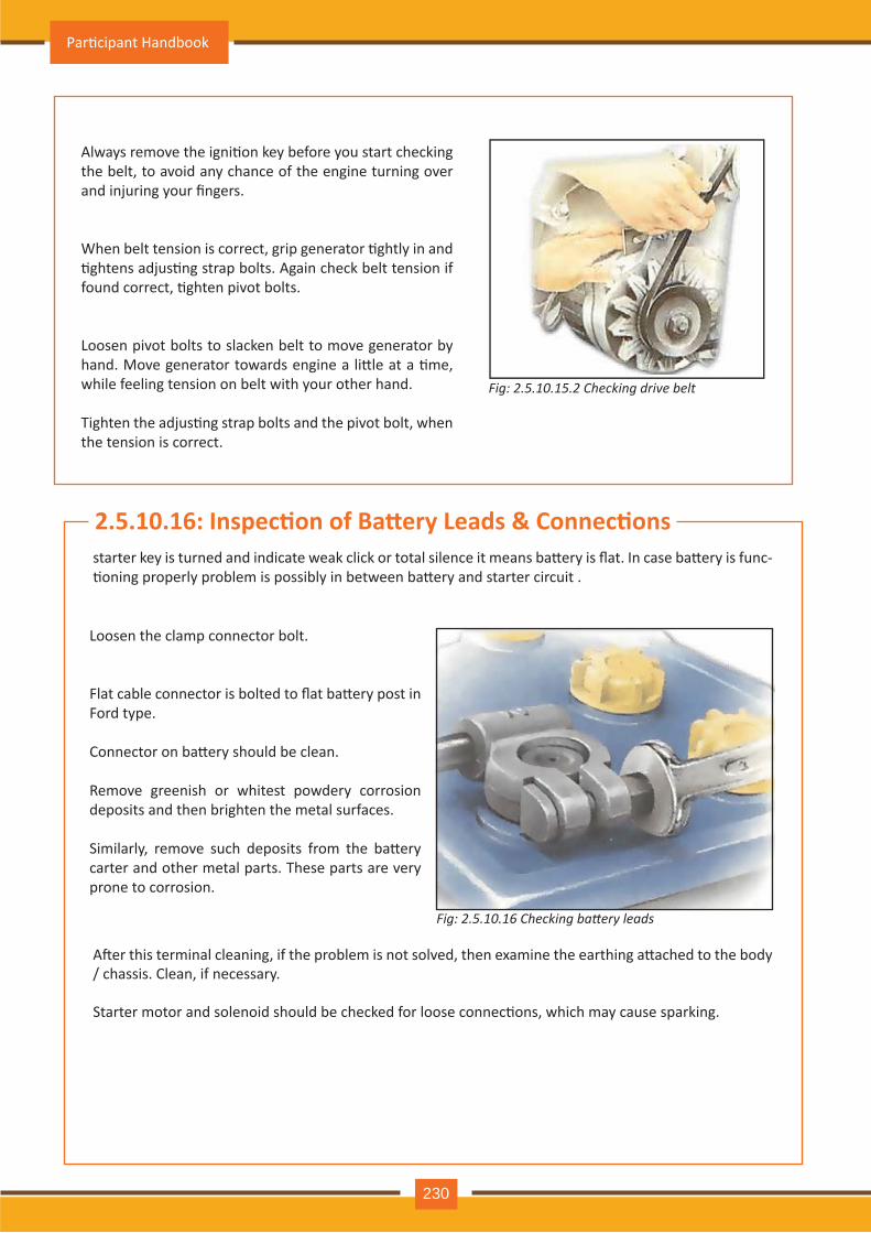
Fig: 2.5.10 .15.2 Checking drive belt
Always remove the igni�on key before you start checking the belt, to avoid any chance of the engine turning over and injuring your fingers.
When belt tension is correct, grip generator �ghtly in and �ghtens adjus�ng strap bolts. Again check belt tension if found correct, �ghten pivot bolts.
Loosen pivot bolts to slacken belt to move generator by hand. Move generator towards engine a li�le at a �me, while feeling tension on belt with your other hand.
Tighten the adjus�ng strap bolts and the pivot bolt, when the tension is correct.
Fig: 2.5.10 .16 Checking ba er leads
2.5.10.16: Inspec�on of Ba ery Leads & Connec�onsstarter key is turned and indicate weak click or total silence it means ba�ery is flat. In case ba�ery is func-�oning properly problem is possibly in between ba�ery and starter circuit .
A�er this terminal cleaning, if the problem is not solved, then examine the earthing a�ached to the body / chassis. Clean, if necessary.
Starter motor and solenoid should be checked for loose connec�ons, which may cause sparking.
Loosen the clamp connector bolt.
Flat cable connector is bolted to flat ba�ery post in Ford type.
Connector on ba�ery should be clean.
Remove greenish or whitest powdery corrosion deposits and then brighten the metal surfaces.
Similarly, remove such deposits from the ba�ery carter and other metal parts. These parts are very prone to corrosion.
Par�cipant Handbook
230
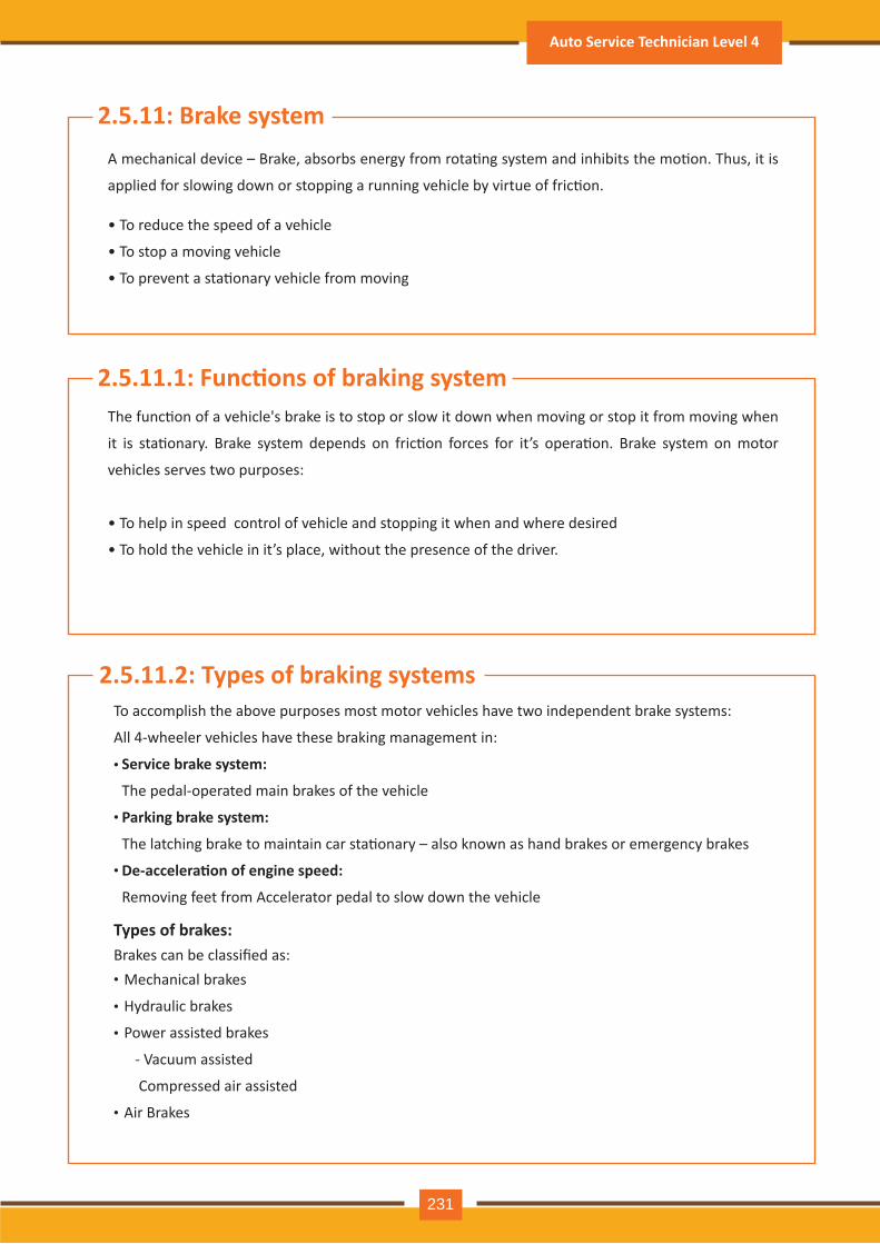
2.5.11.1: Func�ons of braking system
2.5.11: Brake system
The func�on of a vehicle's brake is to stop or slow it down when moving or stop it from moving when
it is sta�onary. Brake system depends on fric�on forces for it’s opera�on. Brake system on motor
vehicles serves two purposes:
• To help in speed control of vehicle and stopping it when and where desired
• To hold the vehicle in it’s place, without the presence of the driver.
A mechanical device – Brake, absorbs energy from rota�ng system and inhibits the mo�on. Thus, it is
applied for slowing down or stopping a running vehicle by virtue of fric�on.
• To reduce the speed of a vehicle
• To stop a moving vehicle
• To prevent a sta�onary vehicle from moving
2.5.11.2: Types of braking systemsTo accomplish the above purposes most motor vehicles have two independent brake systems:
All 4-wheeler vehicles have these braking management in:
Brakes can be classified as:
Service brake system:
The pedal-operated main brakes of the vehicle
Parking brake system:
The latching brake to maintain car sta�onary – also known as hand brakes or emergency brakes
De-accelera�on of engine speed:
Removing feet from Accelerator pedal to slow down the vehicle
Mechanical brakes
Hydraulic brakes
Power assisted brakes
- Vacuum assisted
Compressed air assisted
Air Brakes
•
•
•
•
••
•
Types of brakes:
Auto Service Technician Level 4
231
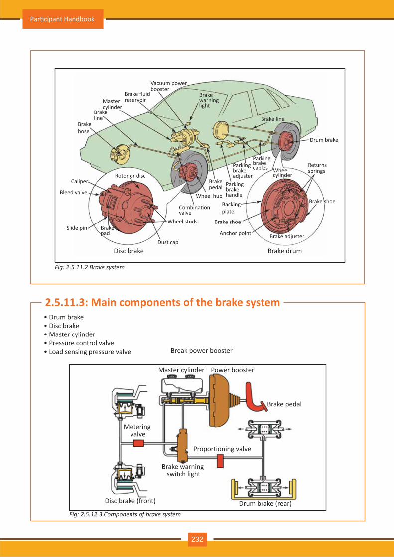
2.5.11.3: Main components of the brake system
Vacuum power booster
Brake fluidreservoirMaster
cylinderBrake line
Brake hose
Caliper
Bleed valve
Slide pin
Dust cap
Rotor or disc
Wheel studs
Combina�on valve
Wheel hub
Brake pedal
Backing plate
Brake shoe
Anchor point Brake adjuster
Brake shoe
Wheel cylinder
Returns springs
Drum brake
Brake line
Brake warning light
Parking brake handle
Parking brake adjuster
Parking brake cables
Brake pad
Disc brake Brake drum
Master cylinder Power booster
Brake pedal
Propor�oning valve
Brake warning switch light
Metering valve
Disc brake (front) Drum brake (rear)
Fig: 2.5.11.2 Brake system
Fig: 2.5.12.3 Components of brake system
• Drum brake• Disc brake• Master cylinder• Pressure control valve• Load sensing pressure valve Break power booster
Par�cipant Handbook
232
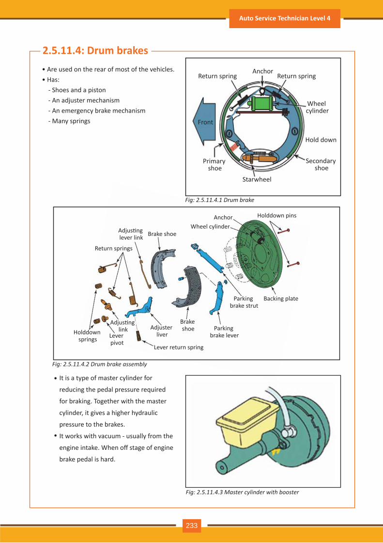
• Are used on the rear of most of the vehicles. • Has: - Shoes and a piston - An adjuster mechanism - An emergency brake mechanism - Many springs
It is a type of master cylinder for
reducing the pedal pressure required
for braking. Together with the master
cylinder, it gives a higher hydraulic
pressure to the brakes.
It works with vacuum - usually from the
engine intake. When off stage of engine
brake pedal is hard.
2.5.11.4: Drum brakes
•
•
Return spring Return spring
Wheel cylinder
Hold down
Secondary shoe
Starwheel
Primary shoe
Front
Anchor
Brake shoeAdjus�ng lever link
Return springs
Holddown springs Lever
pivot
Adjus�ng link
Lever return spring
Adjuster liver
Brake shoe Parking
brake lever
Parking brake strut
Backing plate
Holddown pinsAnchorWheel cylinder
Fig: 2.5.11.4.2 Drum brake assembly
Fig: 2.5.11.4.3 Master cylinder with booster
Fig: 2.5.11.4.1 Drum brake
Auto Service Technician Level 4
233
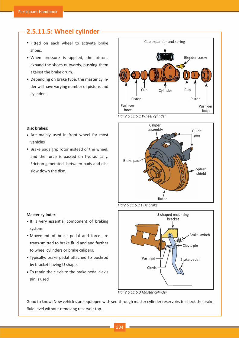
2.5.11.5: Wheel cylinderFi�ed on each wheel to ac�vate brake
shoes.
When pressure is applied, the pistons
expand the shoes outwards, pushing them
against the brake drum.
Depending on brake type, the master cylin-
der will have varying number of pistons and
cylinders.
Are mainly used in front wheel for most
vehicles
Brake pads grip rotor instead of the wheel,
and the force is passed on hydraulically.
Fric�on generated between pads and disc
slow down the disc.
Good to know: Now vehicles are equipped with see-through master cylinder reservoirs to check the brake
fluid level without removing reservoir top.
•
•
•
•
•
Disc brakes:
It is very essen�al component of braking
system.
Movement of brake pedal and force are
trans-smi�ed to brake fluid and and further
to wheel cylinders or brake calipers.
Typically, brake pedal a�ached to pushrod
by bracket having U shape.
To retain the clevis to the brake pedal clevis
pin is used
•
•
•
•
Master cylinder:
Cup expander and spring
Bleeder screw
Push-on boot
Push-on boot
Piston Piston
Cup CupCylinder
Caliper assembly
Brake pad
Rotor
Splash shield
Guide pins
U-shaped moun�ng bracket
Brake switch
Clevis pin
Brake pedal
Clevis
Pushrod
Fig: 2.5.11.5.1 Wheel cylinder
Fig:2.5.11.5.2 Disc brake
Fig: 2.5.11.5.3 Master cylinder
Par�cipant Handbook
234
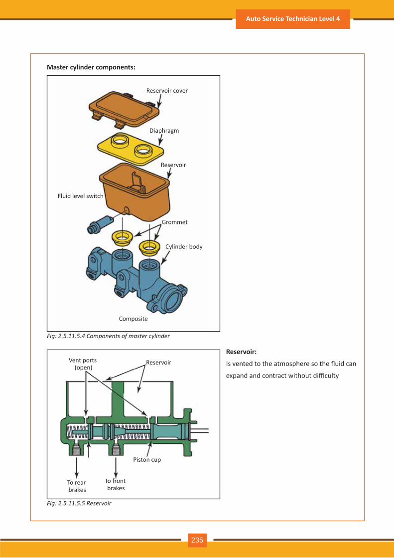
Master cylinder components:
Reservoir:
Is vented to the atmosphere so the fluid can
expand and contract without difficulty
Reservoir cover
Diaphragm
Reservoir
Grommet
Fluid level switch
Cylinder body
Composite
Vent ports (open)
Reservoir
Piston cup
To front brakes
To rear brakes
Fig: 2.5.11.5.4 Components of master cylinder
Fig: 2.5.11.5.5 Reservoir
Auto Service Technician Level 4
235
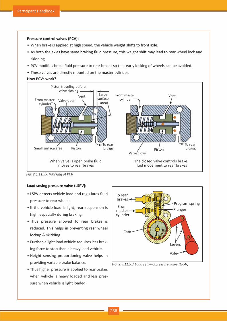
Pressure control valves (PCV):
How PCVs work?
Load snsing pressure valve (LSPV):
When brake is applied at high speed, the vehicle weight shi�s to front axle.
As both the axles have same braking fluid pressure, this weight shi� may lead to rear wheel lock and
skidding.
PCV modifies brake fluid pressure to rear brakes so that early locking of wheels can be avoided.
These valves are directly mounted on the master cylinder.
•
•
•
•
LSPV detects vehicle load and regu-lates fluid
pressure to rear wheels.
If the vehicle load is light, rear suspension is
high, especially during braking.
Thus pressure allowed to rear brakes is
reduced. This helps in preven�ng rear wheel
lockup & skidding.
Further, a light load vehicle requires less brak-
ing force to stop than a heavy load vehicle.
Height sensing propor�oning valve helps in
providing variable brake balance.
Thus higher pressure is applied to rear brakes
when vehicle is heavy loaded and less pres-
sure when vehicle is light loaded.
•
•
•
•
•
•
Piston traveling before valve closing
From master cylinder
From master cylinder
Large surface
areaValve open
Valve close
Vent Vent
Small surface area Piston PistonTo rear brakes
To rear brakes
When valve is open brake fluid moves to rear brakes
The closed valve controls brake fluid movement to rear brakes
To rear brakes
From master cylinder
Cam
Axle
Levers
Program springPlunger
Fig: 2.5.11.5.6 Working of PCV
Fig: 2.5.11.5.7 Load sensing pressure valve (LPSV)
Par�cipant Handbook
236
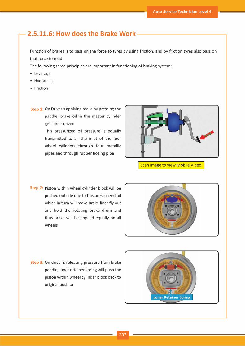
Func�on of brakes is to pass on the force to tyres by using fric�on, and by fric�on tyres also pass on
that force to road.
The following three principles are important in func�oning of braking system:
• Leverage
• Hydraulics
• Fric�on
On Driver’s applying brake by pressing the
paddle, brake oil in the master cylinder
gets pressurized.
This pressurized oil pressure is equally
transmi�ed to all the inlet of the four
wheel cylinders through four metallic
pipes and through rubber hosing pipe
Piston within wheel cylinder block will be
pushed outside due to this pressurized oil
which in turn will make Brake liner fly out
and hold the rota�ng brake drum and
thus brake will be applied equally on all
wheels
On driver’s releasing pressure from brake
paddle, loner retainer spring will push the
piston within wheel cylinder block back to
original posi�on
Scan image to view Mobile Video
Step 1:
Step 2:
Step 3:
2.5.11.6: How does the Brake Work
Loner Retainer Spring
Auto Service Technician Level 4
237
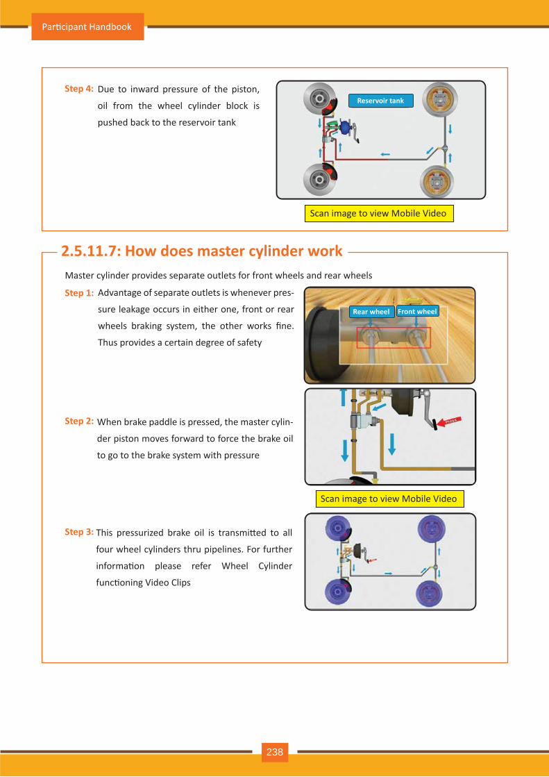
Due to inward pressure of the piston,
oil from the wheel cylinder block is
pushed back to the reservoir tank
Master cylinder provides separate outlets for front wheels and rear wheels
Advantage of separate outlets is whenever pres-
sure leakage occurs in either one, front or rear
wheels braking system, the other works fine.
Thus provides a certain degree of safety
When brake paddle is pressed, the master cylin-
der piston moves forward to force the brake oil
to go to the brake system with pressure
This pressurized brake oil is transmi�ed to all
four wheel cylinders thru pipelines. For further
informa�on please refer Wheel Cylinder
func�oning Video Clips
Rear wheel Front wheel
Scan image to view Mobile Video
Scan image to view Mobile Video
Step 4:
Step 1:
Step 2:
Step 3:
2.5.11.7: How does master cylinder work
Reservoir tank
Rear wheel Front wheel
Par�cipant Handbook
238
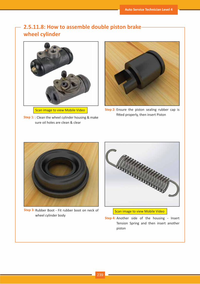
Ensure the piston sealing rubber cap is fi�ed properly, then insert Piston
Rubber Boot - Fit rubber boot on neck of wheel cylinder body
: Clean the wheel cylinder housing & make sure oil holes are clean & clear
Scan image to view Mobile Video
Another side of the housing - Insert Tension Spring and then insert another piston
Scan image to view Mobile Video
2.5.11.8: How to assemble double piston brake wheel cylinder
Step 1:
Step 3:
Step 4:
Step 2:
Auto Service Technician Level 4
239
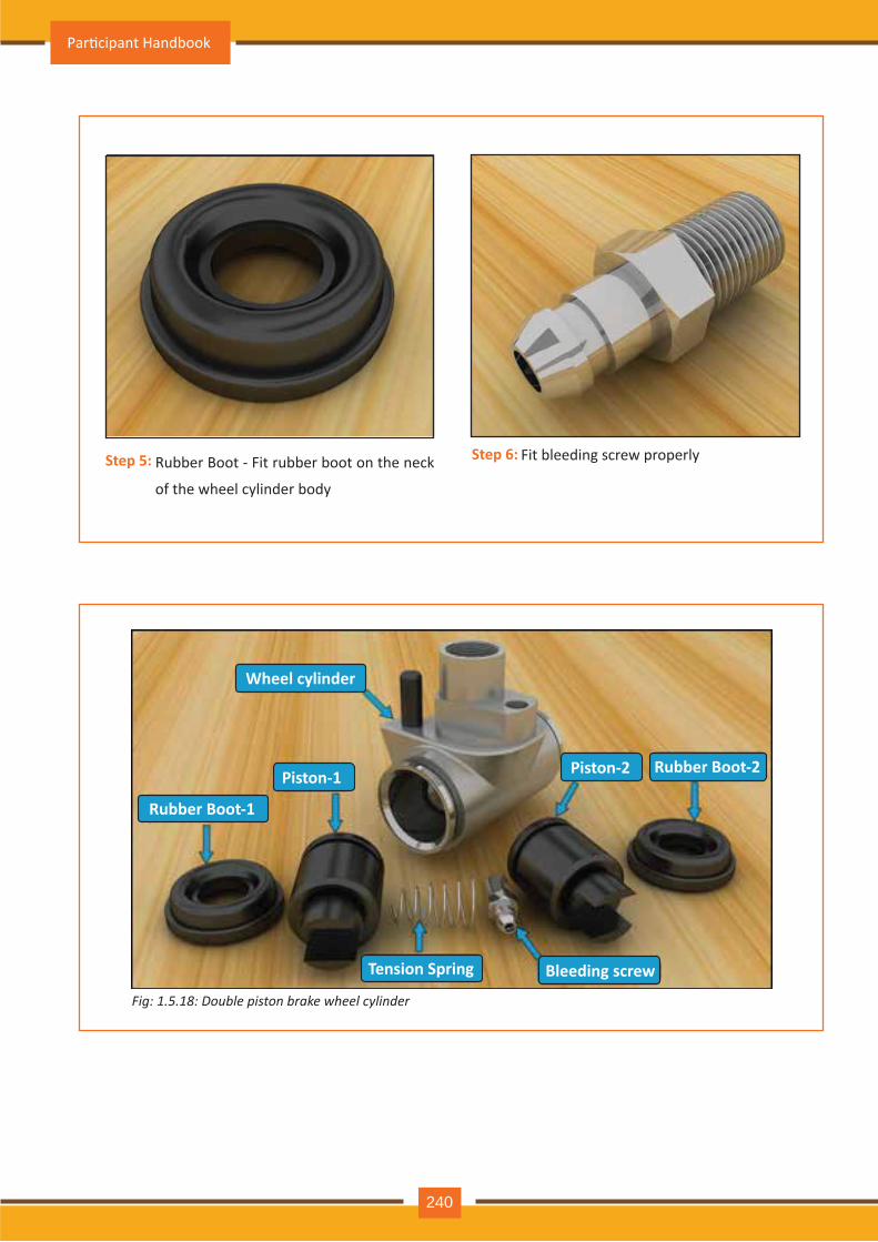
Wheel cylinder
Rubber Boot-1
Rubber Boot-2
Tension Spring Bleeding screw
Piston-1 Piston-2
Fig: 1.5.18: Double piston brake wheel cylinder
Step 5: Rubber Boot - Fit rubber boot on the neck
of the wheel cylinder body
Fit bleeding screw properlyStep 6:
Par�cipant Handbook
240
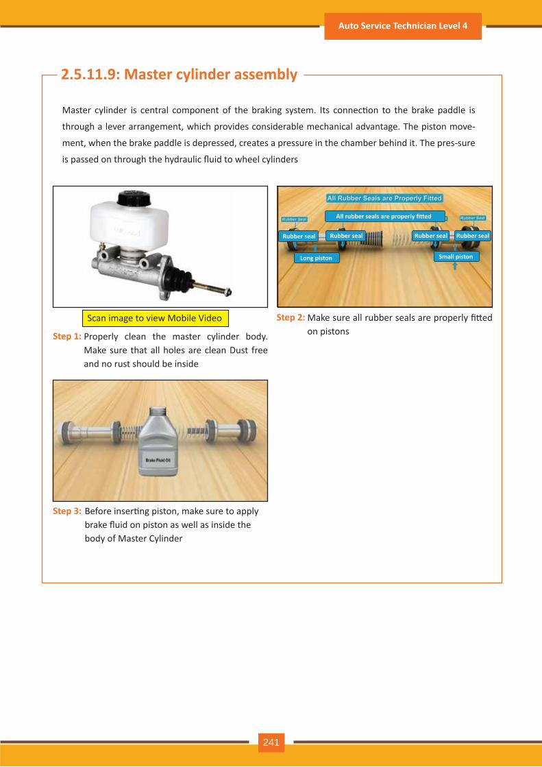
Properly clean the master cylinder body. Make sure that all holes are clean Dust free and no rust should be inside
Make sure all rubber seals are properly fi�ed on pistons
Before inser�ng piston, make sure to applybrake fluid on piston as well as inside thebody of Master Cylinder
Scan image to view Mobile Video
All rubber seals are properly fi�ed
Rubber seal Rubber seal
Long piston Small piston
Rubber seal Rubber seal
Step 1:
Step 2:
Step 3:
2.5.11.9: Master cylinder assembly
Master cylinder is central component of the braking system. Its connec�on to the brake paddle is
through a lever arrangement, which provides considerable mechanical advantage. The piston move-
ment, when the brake paddle is depressed, creates a pressure in the chamber behind it. The pres-sure
is passed on through the hydraulic fluid to wheel cylinders
Auto Service Technician Level 4
241
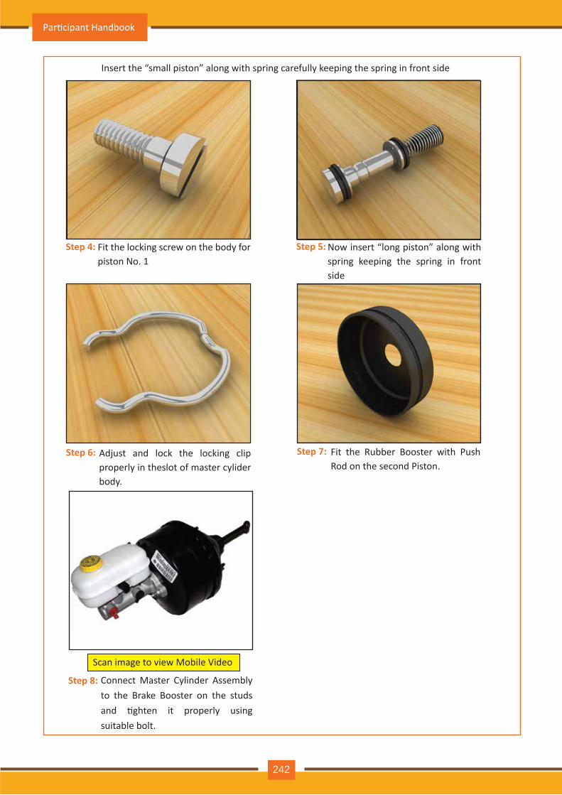
Insert the “small piston” along with spring carefully keeping the spring in front side
Fit the locking screw on the body for piston No. 1
Now insert “long piston” along with spring keeping the spring in front side
Adjust and lock the locking clip properly in theslot of master cylider body.
Fit the Rubber Booster with Push Rod on the second Piston.
Scan image to view Mobile Video
Step 4:
Step 6: Step 7:
Connect Master Cylinder Assembly to the Brake Booster on the studs and �ghten it properly using suitable bolt.
Step 8:
Step 5:
Par�cipant Handbook
242
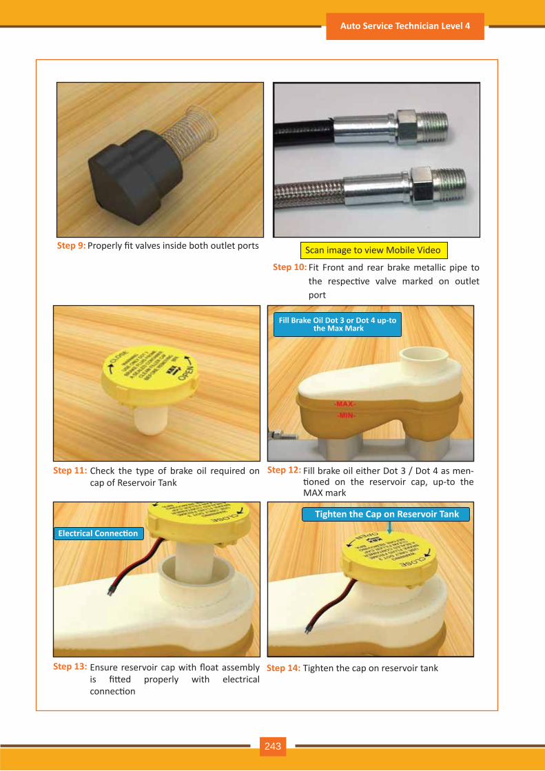
Properly fit valves inside both outlet ports
Fit Front and rear brake metallic pipe to the respec�ve valve marked on outlet port
Check the type of brake oil required on cap of Reservoir Tank
Fill brake oil either Dot 3 / Dot 4 as men-�oned on the reservoir cap, up-to the MAX mark
Ensure reservoir cap with float assembly is fi�ed properly with electrical connec�on
Tighten the cap on reservoir tank
Scan image to view Mobile VideoStep 9:
Step 10:
Step 11: Step 12:
Step 13: Step 14:
Fill Brake Oil Dot 3 or Dot 4 up-to the Max Mark
Electrical Connec�on
Tighten the Cap on Reservoir Tank
Auto Service Technician Level 4
243
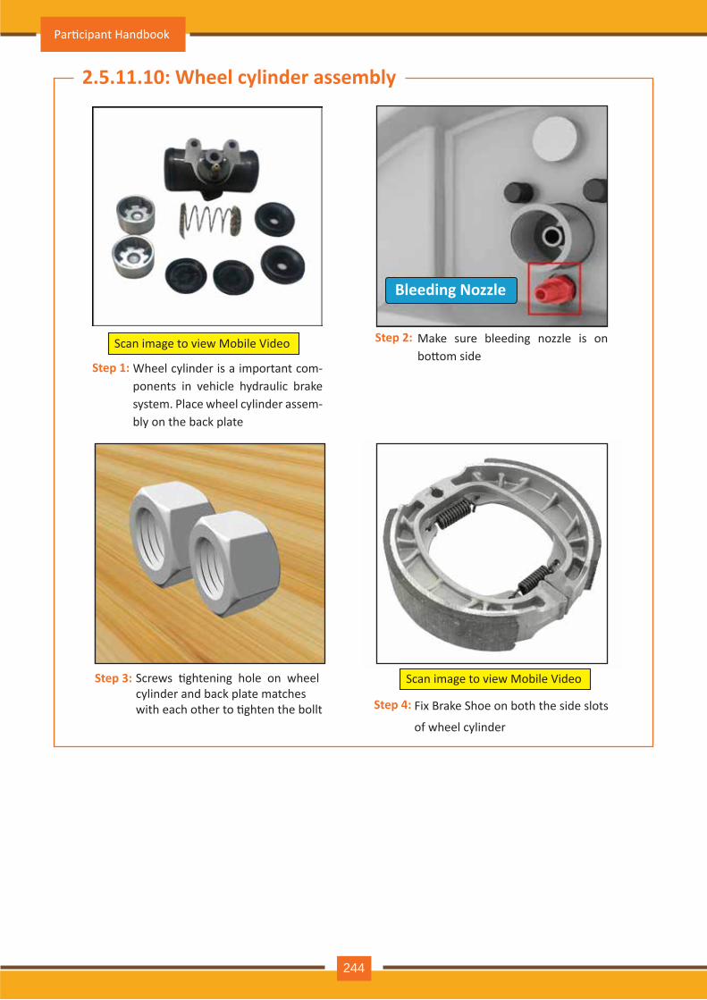
Wheel cylinder is a important com-ponents in vehicle hydraulic brake system. Place wheel cylinder assem-bly on the back plate
Make sure bleeding nozzle is on bo�om side
Screws �ghtening hole on wheelcylinder and back plate matcheswith each other to �ghten the bollt Fix Brake Shoe on both the side slots
of wheel cylinder
Scan image to view Mobile Video
Step 1:
Step 3:
Step 4:
Step 2:
2.5.11.10: Wheel cylinder assembly
Bleeding Nozzle
Scan image to view Mobile Video
Par�cipant Handbook
244
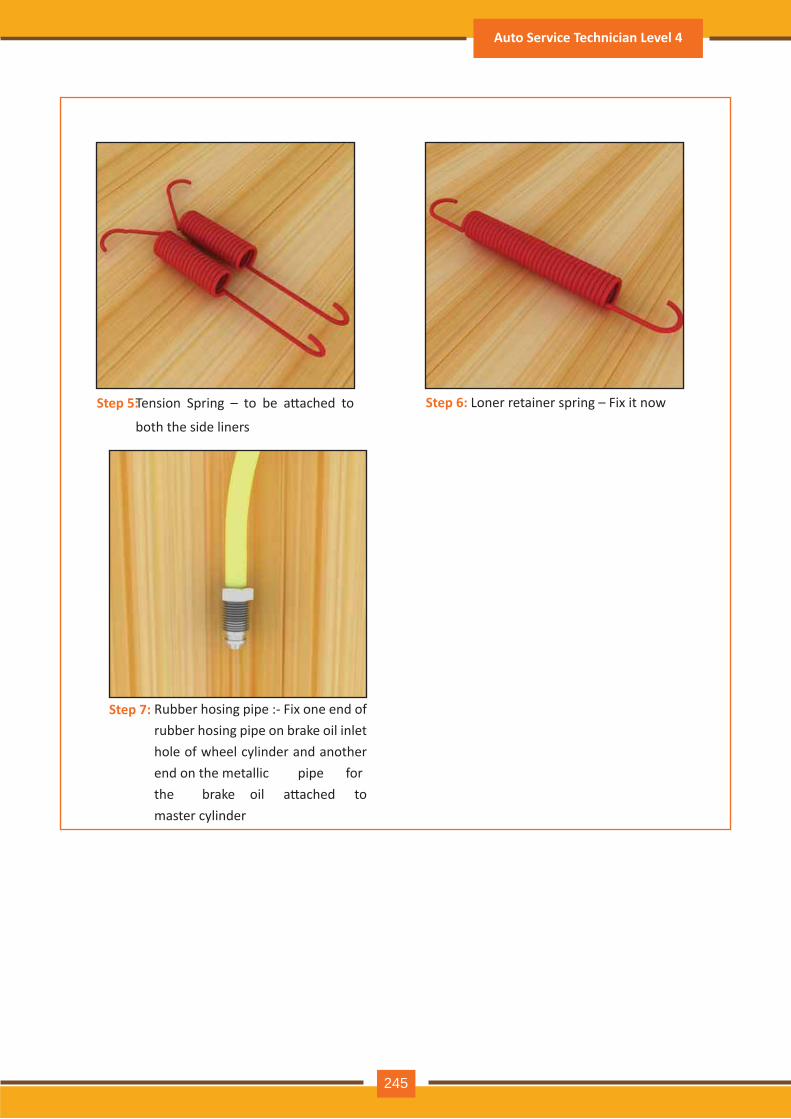
Tension Spring – to be a�ached to
both the side liners
Loner retainer spring – Fix it now
Rubber hosing pipe :- Fix one end of rubber hosing pipe on brake oil inlet hole of wheel cylinder and another end on the metallic pipe for the brake oil a�ached to master cylinder
Step 5: Step 6:
Step 7:
Auto Service Technician Level 4
245
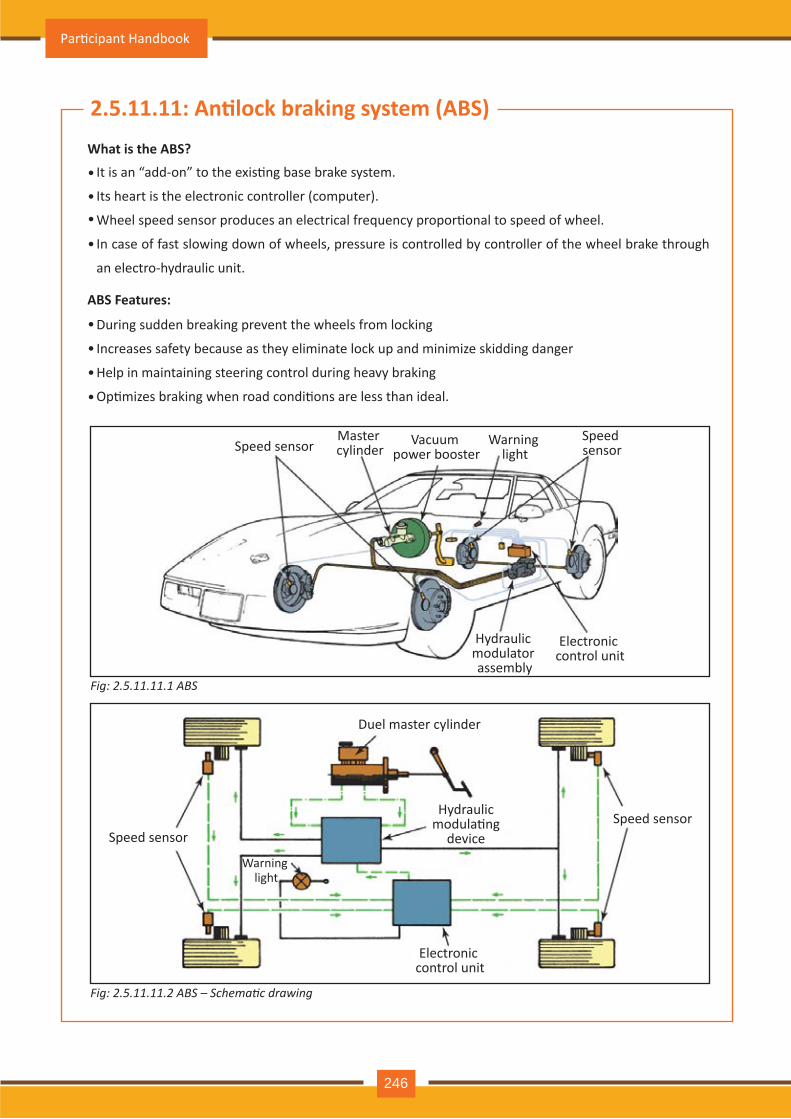
2.5.11.11: An�lock braking system (ABS)What is the ABS?
ABS Features:
It is an “add-on” to the exis�ng base brake system.
Its heart is the electronic controller (computer).
Wheel speed sensor produces an electrical frequency propor�onal to speed of wheel.
In case of fast slowing down of wheels, pressure is controlled by controller of the wheel brake through
an electro-hydraulic unit.
During sudden breaking prevent the wheels from locking
Increases safety because as they eliminate lock up and minimize skidding danger
Help in maintaining steering control during heavy braking
Op�mizes braking when road condi�ons are less than ideal.
•
••
•
•
•
•
•
Speed sensorSpeed sensor
Master cylinder
Vacuum power booster
Warning light
Electronic control unit
Hydraulic modulator assembly
Speed sensorSpeed sensor
Duel master cylinder
Hydraulic modula�ng
device
Electronic control unit
Warning light
Fig: 2.5.11.11.1 ABS
Fig: 2.5.11.11.2 ABS – Schematic drawing
Par�cipant Handbook
246
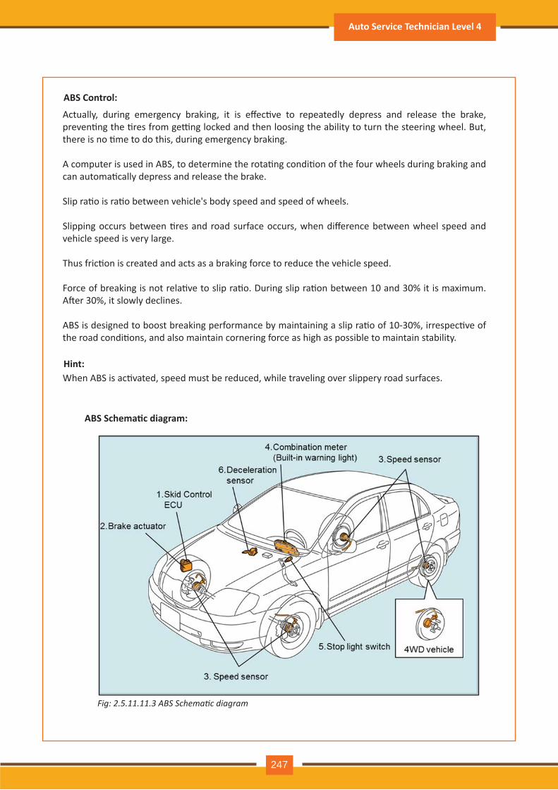
AB S Control:
Actually, during emergency braking, it is effec�ve to repeatedly depress and release the brake, preven�ng the �res from ge�ng locked and then loosing the ability to turn the steering wheel. But, there is no �me to do this, during emergency braking.
A computer is used in ABS, to determine the rota�ng condi�on of the four wheels during braking and can automa�cally depress and release the brake.
Slip ra�o is ra�o between vehicle's body speed and speed of wheels.
Slipping occurs between �res and road surface occurs, when difference between wheel speed and vehicle speed is very large.
Thus fric�on is created and acts as a braking force to reduce the vehicle speed.
Force of breaking is not rela�ve to slip ra�o. During slip ra�on between 10 and 30% it is maximum. A�er 30%, it slowly declines.
ABS is designed to boost breaking performance by maintaining a slip ra�o of 10-30%, irrespec�ve of the road condi�ons, and also maintain cornering force as high as possible to maintain stability.
H int:When ABS is ac�vated, speed must be reduced, while traveling over slippery road surfaces.
ABS Schema�c diagram:
Fig: 2.5.11.11.3 A S Schematic diagram
Auto Service Technician Level 4
247
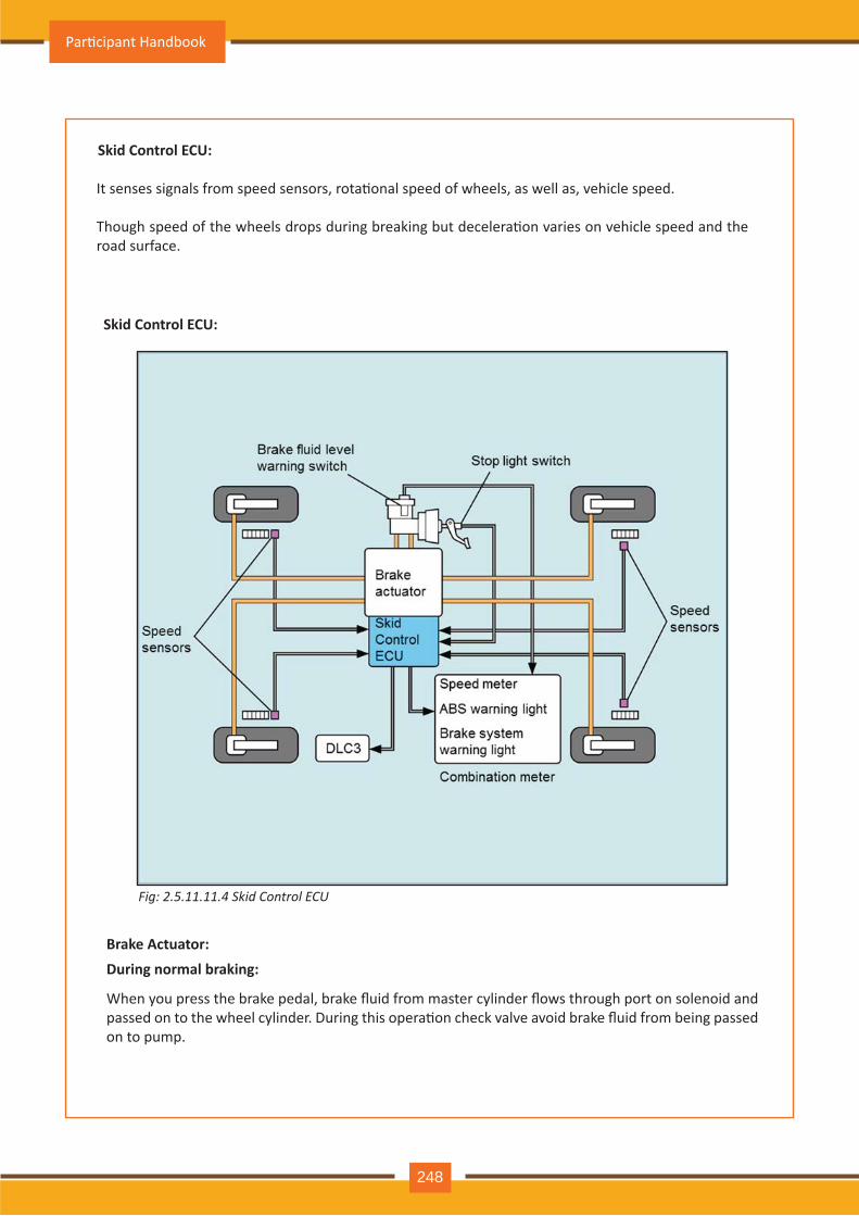
Sk id Control E CU:
It senses signals from speed sensors, rota�onal speed of wheels, as well as, vehicle speed.
Though speed of the wheels drops during breaking but decelera�on varies on vehicle speed and the road surface.
Sk id Control E CU:
B rak e Actuator:D uring normal brak ing:
When you press the brake pedal, brake fluid from master cylinder flows through port on solenoid and passed on to the wheel cylinder. During this opera�on check valve avoid brake fluid from being passed on to pump.
Fig: 2.5.11.11.4 Skid Control C
Par�cipant Handbook
248
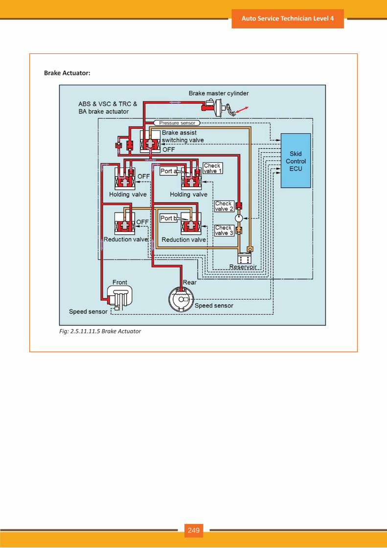
B rak e Actuator:
Fig: 2.5.11.11.5 rake Actuator
Auto Service Technician Level 4
249
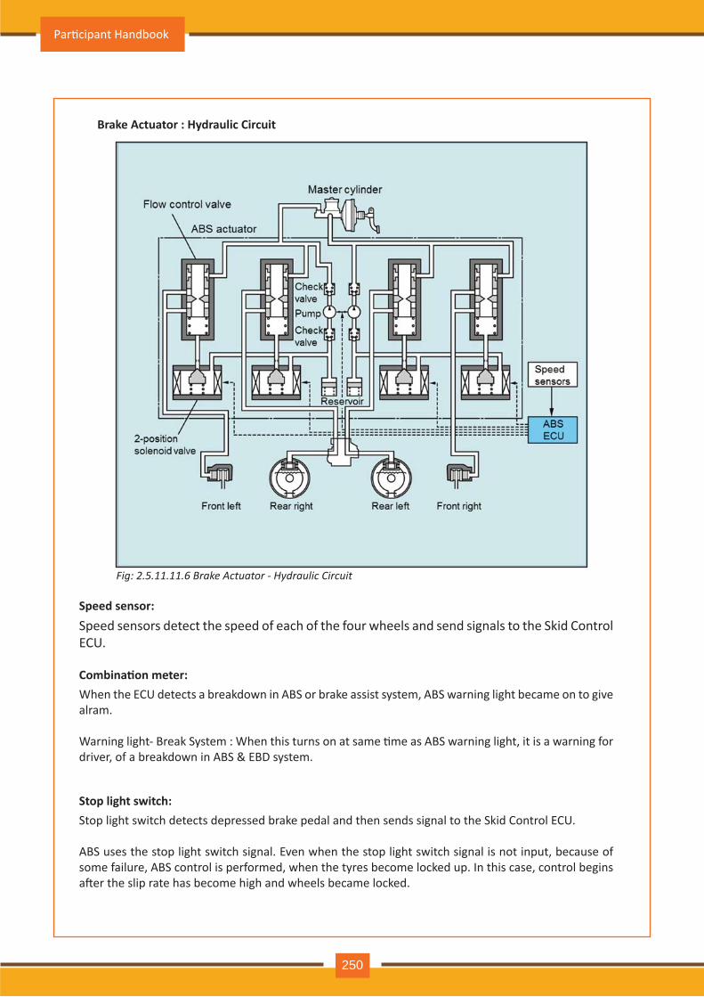
B rak e Actuator : H ydraulic Circuit
Speed sensor:Speed sensors detect the speed of each of the four wheels and send signals to the Skid Control ECU.
Combina�on meter:When the ECU detects a breakdown in ABS or brake assist system, ABS warning light became on to give alram.
Warning light- Break System : When this turns on at same �me as ABS warning light, it is a warning for driver, of a breakdown in ABS & EBD system.
Stop light sw itch:Stop light switch detects depressed brake pedal and then sends signal to the Skid Control ECU.
ABS uses the stop light switch signal. Even when the stop light switch signal is not input, because of some failure, ABS control is performed, when the tyres become locked up. In this case, control begins a�er the slip rate has become high and wheels became locked.
Fig: 2.5.11.11.6 rake Actuator draulic Circuit
Par�cipant Handbook
250
Visual inspec�on:
The following points are important in visual inspec�on :
Brake fluid has to be clear and thin, no dirt, rust contamina�on.
Reservoir cover vent holes has to be open and clean.
Diaphragm in the reservoir cover should be intact.
No signs of external leakages in the lines or at the pushrod area.
The pedal reserve distance should be adequate and not be too low.
1: Remove master cylinder from vehicle.
2: Remove the reservoir, if possible.
3: Remove retaining bolt holding secondary piston assembly in bore.
4: Depress primary piston with help of blunt tool like Phillips screwdriver
5: Remove snap ring.
6: Remove master cylinder. Tap open end of bore against top of work bench to force
Secondary piston out of bore. Check master cylinder bore for signs of pi�ng / corrosion / wear.
Tech �p:
Normally do not ask the customer to fill oil in master cylinder reservoir, if brake fluid is below the “mini-
mum” mark.
•
•
There may be leakage, which must be inves�gated & repaired.
Disc brake piston moves outer side to maintain similar distance between fric�on materials and rotor,
as the brakes wear.
In case low fluid level is observed, the vehicle should be serviced first.
Decelera�on sensor (Some models only):The Decelera�on sensor are provided in some cars to sense the vehicle's decelera�on rate and send signals to Skid Control ECU.
The ECU judges precise road surface condi�ons using these signals & takes appropriate control mea-sures.
••••••
Auto Service Technician Level 4
251
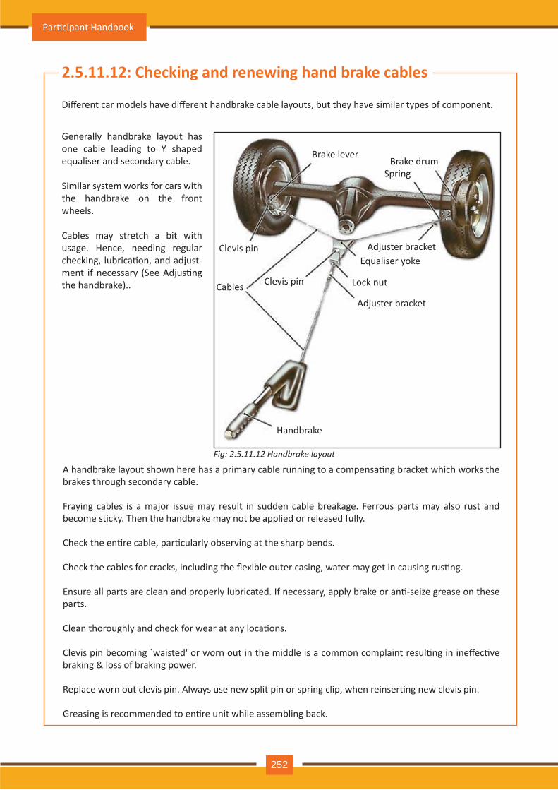
Fig: 2.5.11.12 andbrake la out
2.5.11.12: Check ing and renew ing hand brak e cables
Different car models have different handbrake cable layouts, but they have similar types of component.
Generally handbrake layout has one cable leading to Y shaped equaliser and secondary cable.
Similar system works for cars with the handbrake on the front wheels.
Cables may stretch a bit with usage. Hence, needing regular checking, lubrica�on, and adjust-ment if necessary (See Adjus�ng the handbrake)..
Brake lever
Clevis pin
Cables Clevis pin
Adjuster bracket
Lock nut
Equaliser yokeAdjuster bracket
Handbrake
Brake drumSpring
A handbrake layout shown here has a primary cable running to a compensa�ng bracket which works the brakes through secondary cable.
Fraying cables is a major issue may result in sudden cable breakage. Ferrous parts may also rust and become s�cky. Then the handbrake may not be applied or released fully.
Check the en�re cable, par�cularly observing at the sharp bends.
Check the cables for cracks, including the flexible outer casing, water may get in causing rus�ng.
Ensure all parts are clean and properly lubricated. If necessary, apply brake or an�-seize grease on these parts.
Clean thoroughly and check for wear at any loca�ons.
Clevis pin becoming waisted' or worn out in the middle is a common complaint resul�ng in ineffec�ve braking & loss of braking power.
Replace worn out clevis pin. Always use new split pin or spring clip, when reinser�ng new clevis pin.
Greasing is recommended to en�re unit while assembling back.
Par�cipant Handbook
252
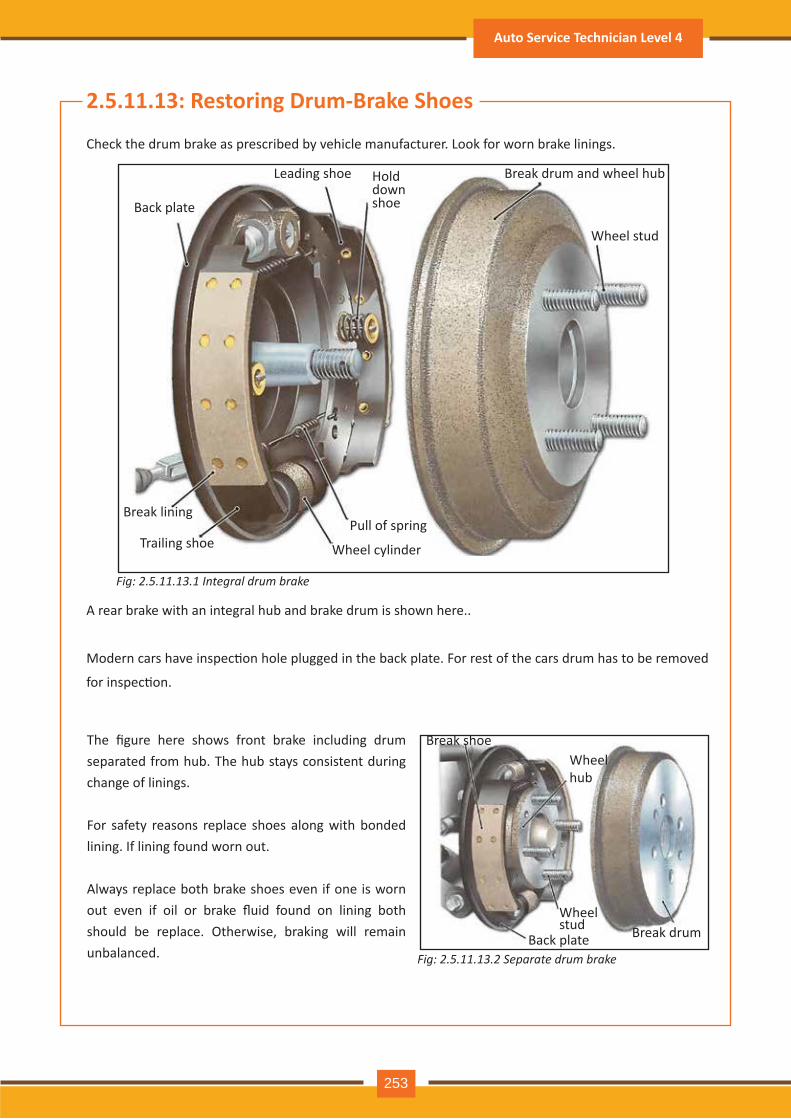
Fig: 2.5.11.13.1 I n t e gr a l d r u m b r a k e
Fig: 2.5.11.13.2 S e p a r a t e d r u m b r a k e
2.5.11.13 : R estoring D rum- B rak e Shoes
C h eck th e drum brake as prescribed by v eh icle m anufacturer. Look for worn brake linings.
A rear brake with an integral h ub and brake drum is sh own h ere..
Modern cars have inspec�on hole plugged in the back plate. For rest of the cars drum has to be removed
for inspec�on.
The figure here shows front brake including drum separated from h ub. Th e h ub stay s consistent during ch ange of linings.
For safety reasons replace shoes along with bonded lining. If lining found worn out.
A lway s replace both brake sh oes ev en if one is worn out even if oil or brake fluid found on lining both sh ould be replace. O th erwise, braking will rem ain unbalanced.
Back plate
Leading sh oe Break drum and wh eel h ub
W h eel stud
Pull of spring
W h eel cy linder
Break lining
Trailing sh oe
Break sh oeW h eel h ub
W h eel stud
Back plate Break drum
H old down sh oe
Auto Service Technician Level 4
253
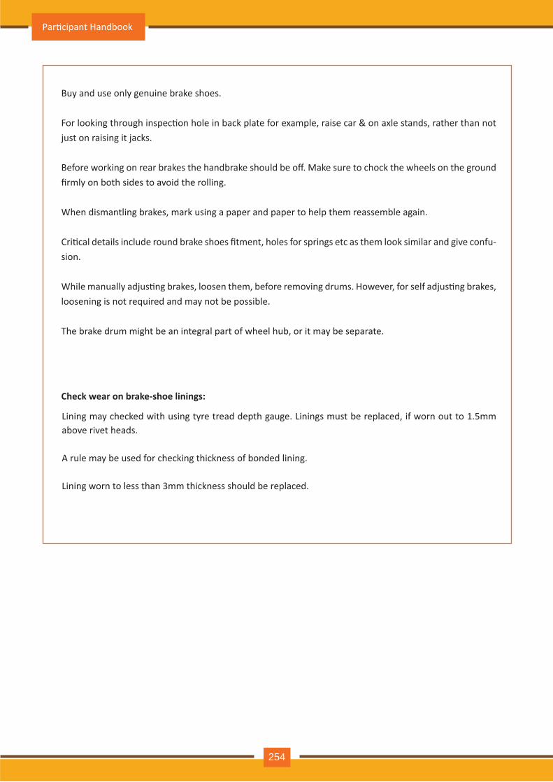
Buy and use only genuine brake shoes.
For looking through inspec�on hole in back plate for example, raise car & on axle stands, rather than not just on raising it jacks.
Before working on rear brakes the handbrake should be off. Make sure to chock the wheels on the ground firmly on both sides to avoid the rolling.
When dismantling brakes, mark using a paper and paper to help them reassemble again.
Cri�cal details include round brake shoes fitment, holes for springs etc as them look similar and give confu-sion.
While manually adjus�ng brakes, loosen them, before removing drums. However, for self adjus�ng brakes, loosening is not required and may not be possible.
The brake drum might be an integral part of wheel hub, or it may be separate.
Check wear on brake-shoe linings:
Lining may checked with using tyre tread depth gauge. Linings must be replaced, if worn out to 1.5mm above rivet heads.
A rule may be used for checking thickness of bonded lining.
Lining worn to less than 3mm thickness should be replaced.
Par�cipant Handbook
254
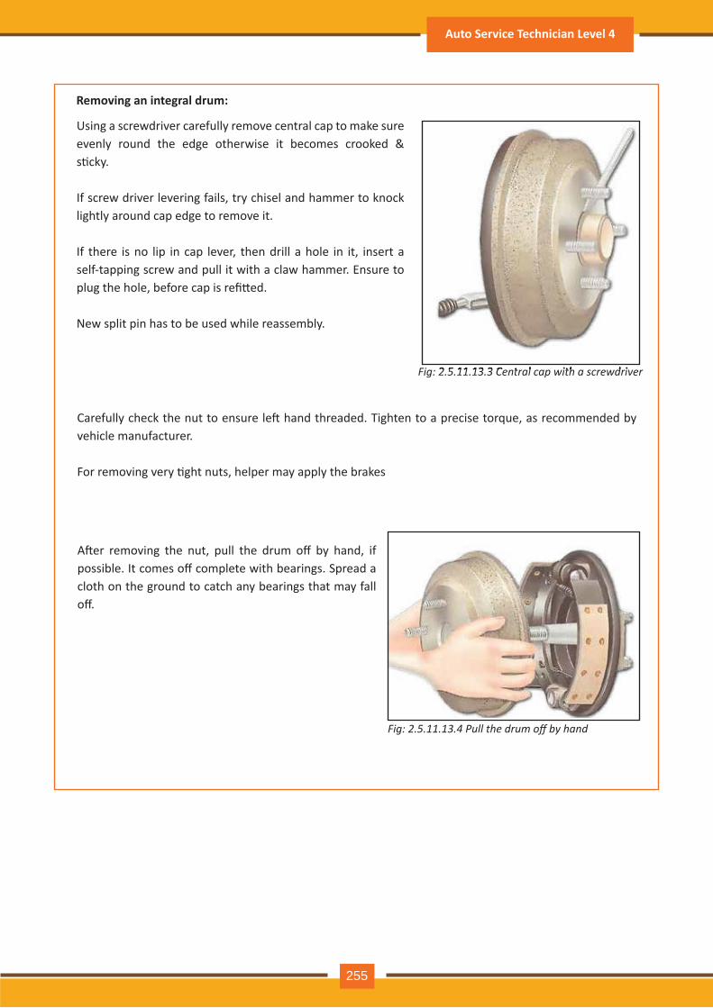
R emoving an integral drum:
Fig: 2.5.11.13.3 C e n t r a l c a p w it h a s c r e w d r iv e r
Carefully check the nut to ensure le� hand threaded. Tighten to a precise torque, as recommended by v eh icle m anufacturer.
For removing very �ght nuts, helper may apply the brakes
2.5.11.13.3 C e n t r a l c a p w it h a s c r e w d r iv e r
Fig: 2.5.11.13.4 ull the drum o b hand
Using a screwdriv er carefully rem ov e central cap to m ake sure evenly round the edge otherwise it becomes crooked & s�cky. If screw driv er lev ering fails, try ch isel and h am m er to knock ligh tly around cap edge to rem ov e it.
If th ere is no lip in cap lev er, th en drill a h ole in it, insert a self- tapping screw and pull it with a claw h am m er. Ensure to plug the hole, before cap is refi�ed.
New split pin h as to be used wh ile reassem bly .
A�er removing the nut, pull the drum off by hand, if possible. It comes off complete with bearings. Spread a cloth on th e ground to catch any bearings th at m ay fall off.
Auto Service Technician Level 4
255
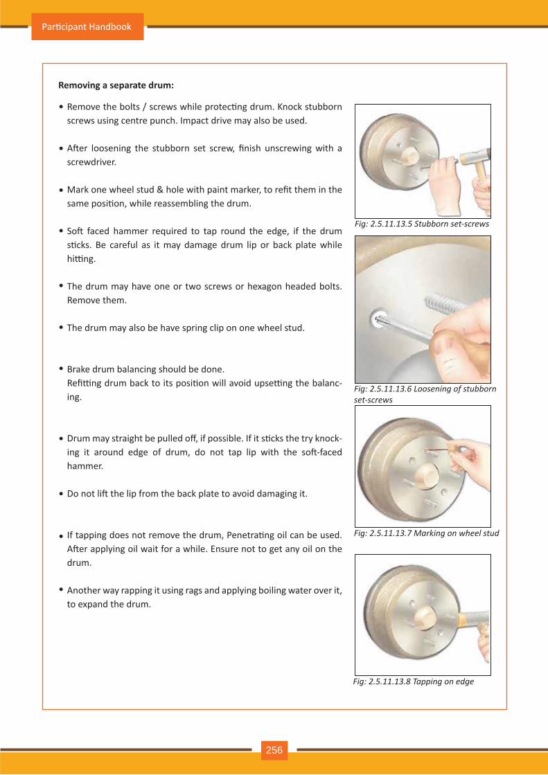
R emoving a separate drum:
Fig: 2.5.11.13.5 S t u b b o r n s e t - s c r e w s
Fig: 2.5.11.13.6 L o o s e n in g o f s t u b b o r n s e t - s c r e w s
Fig: 2.5.11.13.7 M a r k in g o n w h e e l s t u d
Fig: 2.5.11.13.8 T a p p in g o n e d ge
Remove the bolts / screws while protec�ng drum. Knock stubborn screws using centre punch . Im pact driv e m ay also be used.
A�er loosening the stubborn set screw, finish unscrewing with a screwdriv er.
Mark one wheel stud & hole with paint marker, to refit them in the same posi�on, while reassembling the drum.
So� faced hammer required to tap round the edge, if the drum s�cks. Be careful as it may damage drum lip or back plate while hi�ng.
The drum may have one or two screws or hexagon headed bolts. R em ov e th em .
Th e drum m ay also be h av e spring clip on one wh eel stud.
Brake drum balancing sh ould be done. Refi�ng drum back to its posi�on will avoid upse�ng the balanc-ing.
Drum may straight be pulled off, if possible. If it s�cks the try knock-ing it around edge of drum, do not tap lip with the so�-faced h am m er.
Do not li� the lip from the back plate to avoid damaging it.
If tapping does not remove the drum, Penetra�ng oil can be used. A�er applying oil wait for a while. Ensure not to get any oil on the drum .
A noth er way rapping it using rags and apply ing boiling water ov er it, to expand the drum.
•
•
•
•
•
•
•
•
•
•
•
Par�cipant Handbook
256
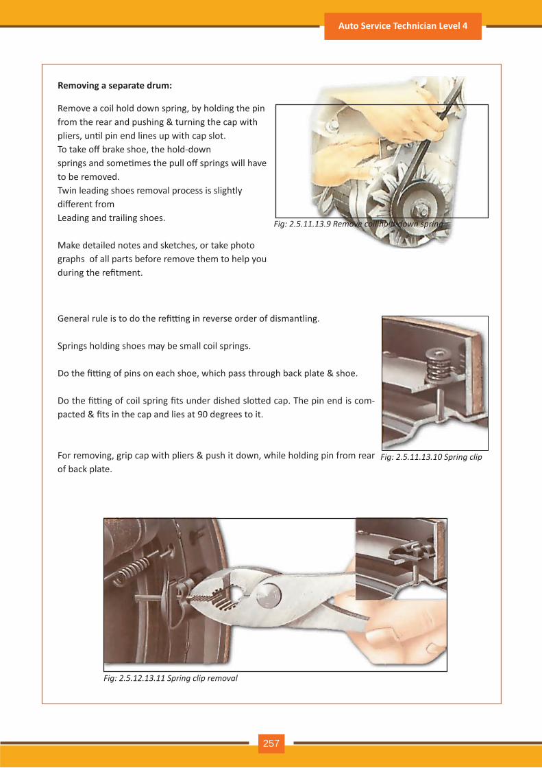
Fig: 2.5.11.13.9 R e m o v e c o il h o l d - d o w n s p r in g
R emoving a separate drum:
Fig: 2.5.11.13.10 S p r in g c l ip
Fig: 2.5.12.13.11 S p r in g c l ip r e m o v a l
R em ov e a coil h old down spring, by h olding th e pinfrom the rear and pushing & turning the cap withpliers, un�l pin end lines up with cap slot.To take off brake shoe, the hold-downsprings and some�mes the pull off springs will have to be rem ov ed.Twin leading sh oes rem ov al process is sligh tlydifferent from Leading and trailing sh oes.
Make detailed notes and sketch es, or take ph otograph s of all parts before rem ov e th em to h elp y ou during the refitment.
General rule is to do the refi�ng in reverse order of dismantling.
Springs holding shoes may be small coil springs.
Do the fi�ng of pins on each shoe, which pass through back plate & shoe.
Do the fi�ng of coil spring fits under dished slo�ed cap. The pin end is com-pacted & fits in the cap and lies at 90 degrees to it.
For removing, grip cap with pliers & push it down, while holding pin from rear of back plate.
Auto Service Technician Level 4
257
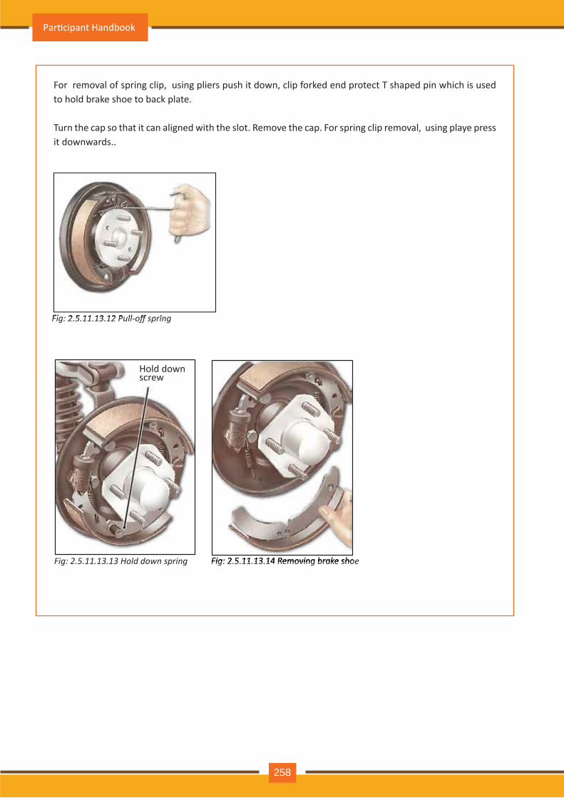
Fig: 2.5.11.13.12 ull o spring
For removal of spring clip, using pliers push it down, clip forked end protect T shaped pin which is used to h old brake sh oe to back plate.
Turn the cap so that it can aligned with the slot. Remove the cap. For spring clip removal, using playe press it downwards..
Fig: 2.5.11.13.12 ull o spring
Fig: 2.5.11.13.13 H o l d d o w n s p r in g Fig: 2.5.11.13.14 R e m o v in g b r a k e s h o e Fig: 2.5.11.13.14 R e m o v in g b r a k e s h o e
H old down screw
Par�cipant Handbook
258
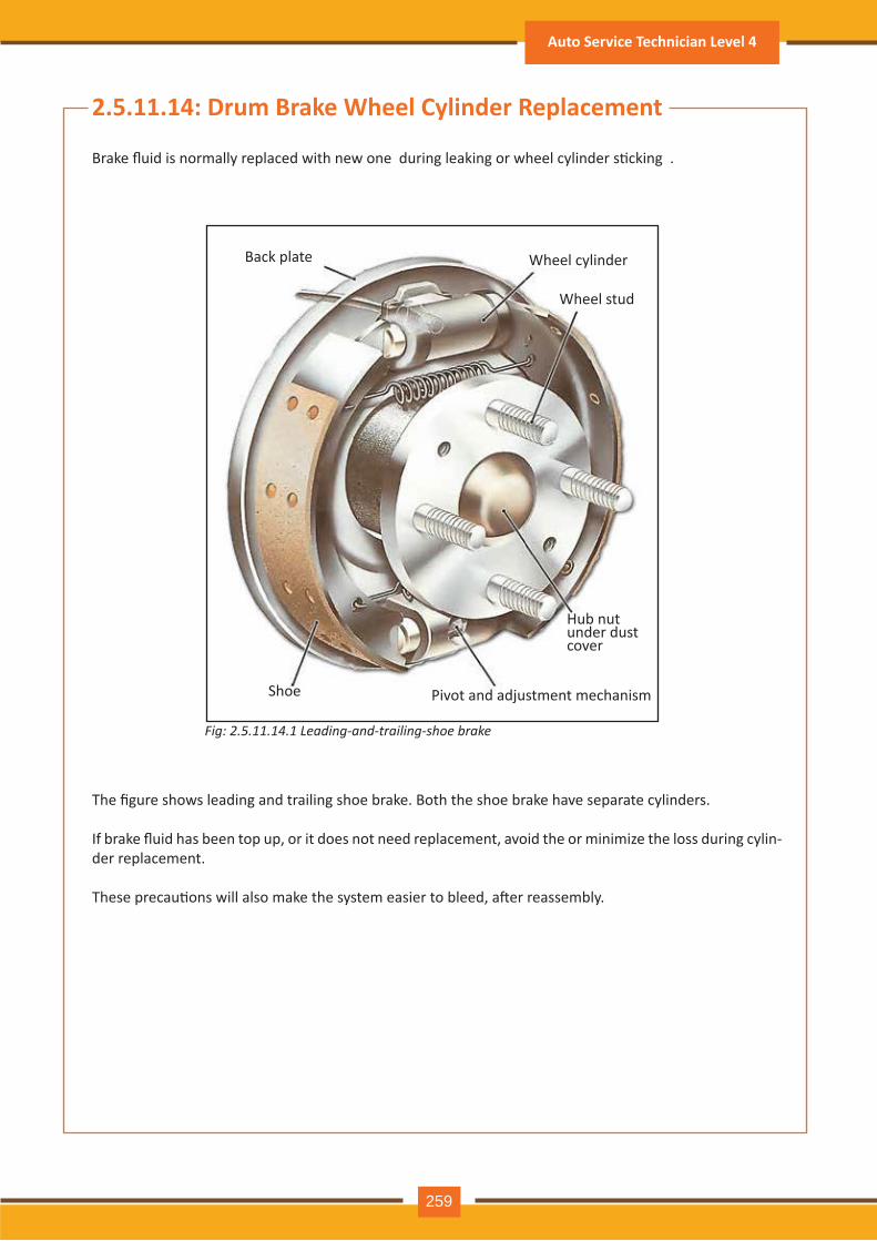
Fig: 2.5.11.14.1 L e a d in g- a n d - t r a il in g- s h o e b r a k e
2.5.11.14: D rum B rak e W heel Cylinder R eplacement
Brake fluid is normally replaced with new one during leaking or wheel cylinder s�cking .
The figure shows leading and trailing shoe brake. Both the shoe brake have separate cylinders.
If brake fluid has been top up, or it does not need replacement, avoid the or minimize the loss during cylin -der replacem ent.
These precau�ons will also make the system easier to bleed, a�er reassembly.
Back plate W h eel cy linder
W h eel stud
H ub nut under dust cov er
Piv ot and adj ustm ent m ech anismShoe
Auto Service Technician Level 4
259
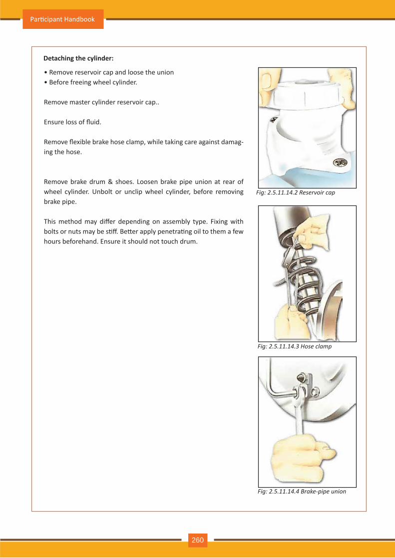
D etaching the cylinder:
Fig: 2.5.11.14.2 R e s e r v o ir c a p
Fig: 2.5.11.14.3 H o s e c l a m p
Fig: 2.5.11.14.4 B r a k e - p ip e u n io n
• R em ov e reserv oir cap and loose th e union • Before freeing wh eel cy linder.
R em ov e m aster cy linder reserv oir cap..
Ensure loss of fluid.
Remove flexible brake hose clamp, while taking care against damag-ing th e h ose.
Remove brake drum & shoes. Loosen brake pipe union at rear of wh eel cy linder. Unbolt or unclip wh eel cy linder, before rem ov ing brake pipe.
This method may differ depending on assembly type. Fixing with bolts or nuts may be s�ff. Be�er apply penetra�ng oil to them a few h ours beforeh and. Ensure it sh ould not touch drum .
Par�cipant Handbook
260
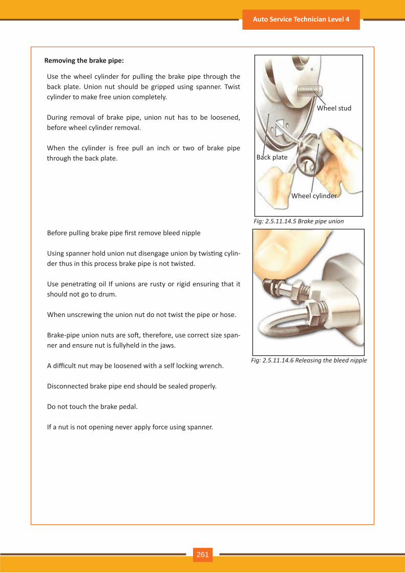
Fig: 2.5.11.14.5 B r a k e p ip e u n io n
R emoving the brak e pipe:
Use th e wh eel cy linder for pulling th e brake pipe th rough th e back plate. Union nut sh ould be gripped using spanner. Twist cy linder to m ake free union com pletely .
During rem ov al of brake pipe, union nut h as to be loosened, before wh eel cy linder rem ov al.
W h en th e cy linder is free pull an inch or two of brake pipe th rough th e back plate.
W h eel stud
Back plate
W h eel cy linder
Fig: 2.5.11.14.6 R e l e a s in g t h e b l e e d n ip p l e
Before pulling brake pipe first remove bleed nipple
Using spanner hold union nut disengage union by twis�ng cylin -der th us in th is process brake pipe is not twisted.
Use penetra�ng oil If unions are rusty or rigid ensuring that it sh ould not go to drum .
W h en unscrewing th e union nut do not twist th e pipe or h ose. Brake-pipe union nuts are so�, therefore, use correct size span-ner and ensure nut is fully h eld in th e j aws.
A difficult nut may be loosened with a self locking wrench.
Disconnected brake pipe end sh ould be sealed properly .
Do not touch th e brake pedal.
If a nut is not opening nev er apply force using spanner.
Auto Service Technician Level 4
261
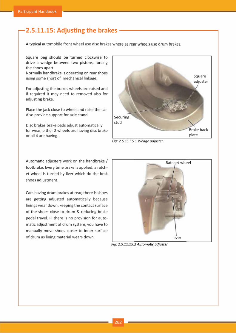
Fig: 2.5.11.15.1 W e d ge a d j u s t e r
2.5.11.15: Adjus�ng the brakes
A ty pical autom obile front wh eel use disc brakes wh ere as rear wh eels use drum brakes.
Square peg should be turned clockwise to driv e a wedge between two pistons, forcing th e sh oes apart.Normally handbrake is opera�ng on rear shoes using som e sh ort of m ech anical linkage.
For adjus�ng the brakes wheels are raised and if required it m ay need to rem ov ed also for adjus�ng brake.
Place th e j ack close to wh eel and raise th e car Also provide support for axle stand.
Disc brakes brake pads adjust automa�callyfor wear, eith er 2 wh eels are h av ing disc brake or all 4 are h av ing.
Automa�c adjusters work on the handbrake / footbrake. Every �me brake is applied, a ratch-et wh eel is turned by liv er wh ich do th e brak sh oes adj ustm ent.
C ars h av ing drum brakes at rear, th ere is sh oes are ge�ng adjusted automa�cally because linings wear down, keeping th e contact surface of the shoes close to drum & reducing brake pedal travel. Fi there is no provision for auto-ma�c adjustment of drum system, you have to m anually m ov e sh oes closer to inner surface of drum as lining m aterial wears down.
A ty pical autom obile front wh eel use disc brakes wh ere as rear wh eels use drum brakes.
Fig: 2.5.11.15.2 Automatic ad uster2.5.11.15.2 Automatic ad uster
Square adj uster
Securing stud
Brake back plate
R atch et wh eel
lev er
Par�cipant Handbook
262
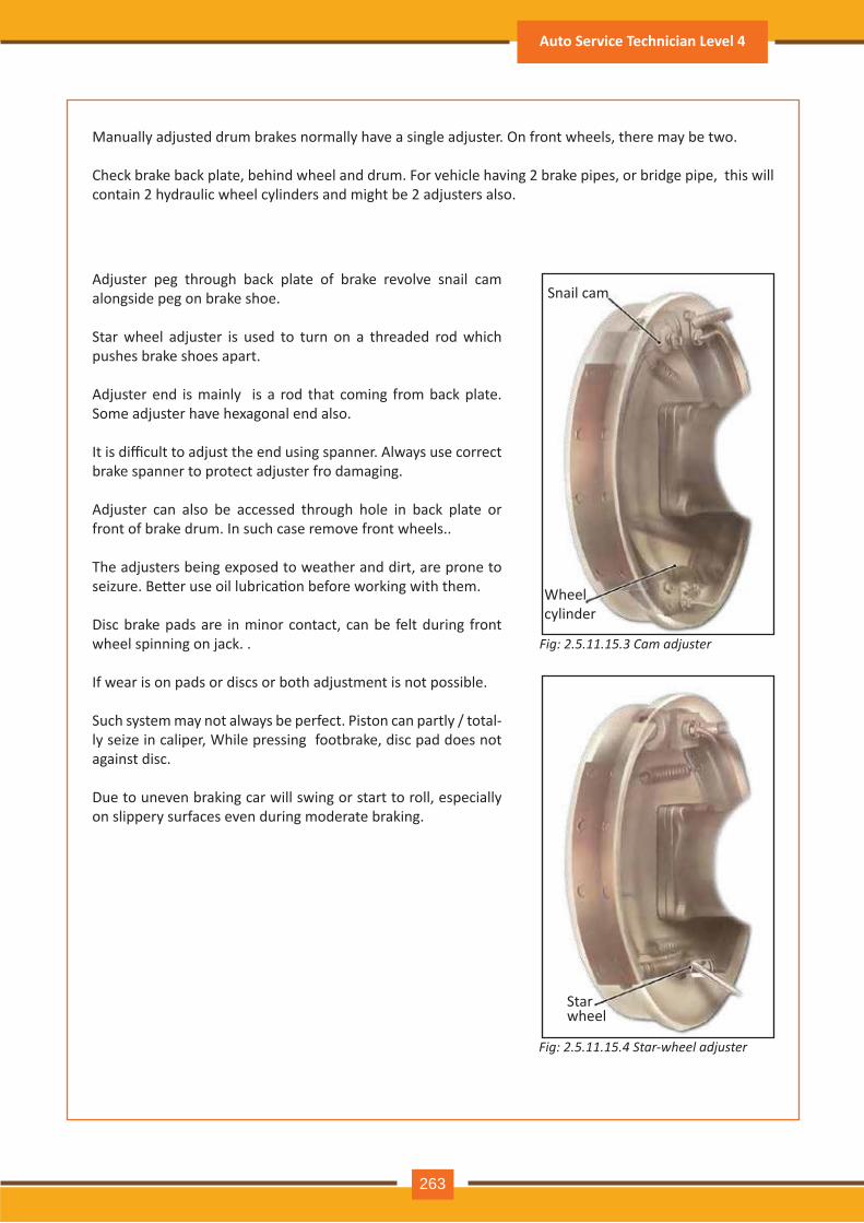
Fig: 2.5.11.15.3 C a m a d j u s t e r
Manually adj usted drum brakes norm ally h av e a single adj uster. O n front wh eels, th ere m ay be two.
Check brake back plate, behind wheel and drum. For vehicle having 2 brake pipes, or bridge pipe, this will contain 2 h y draulic wh eel cy linders and m igh t be 2 adj usters also.
A dj uster peg th rough back plate of brake rev olv e snail cam alongside peg on brake sh oe.
Star wheel adjuster is used to turn on a threaded rod which push es brake sh oes apart.
A dj uster end is m ainly is a rod th at com ing from back plate. Some adjuster have hexagonal end also.
It is difficult to adjust the end using spanner. Always use correct brake spanner to protect adj uster fro dam aging.
A dj uster can also be accessed th rough h ole in back plate or front of brake drum . In such case rem ov e front wh eels..
The adjusters being exposed to weather and dirt, are prone to seizure. Be�er use oil lubrica�on before working with them.
Disc brake pads are in m inor contact, can be felt during front wh eel spinning on j ack. .
If wear is on pads or discs or both adj ustm ent is not possible.
Such system may not always be perfect. Piston can partly / total-ly seize in caliper, While pressing footbrake, disc pad does not against disc.
Due to unev en braking car will swing or start to roll, especially on slippery surfaces ev en during m oderate braking.
Fig: 2.5.11.15.4 S t a r - w h e e l a d j u s t e r
Snail cam
W h eel cy linder
Star wh eel
Auto Service Technician Level 4
263
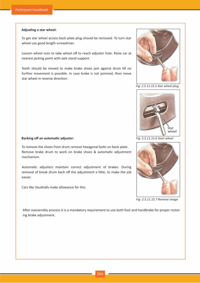
Adjus�ng a star wheel:
Backing off an automa�c adjuster:
Fig: 2.5.11.15.5 S t a r w h e e l p l u g
Fig: 2.5.11.15.6 S t a r t w h e e l
Fig: 2.5.11.15.7 R e m o v e im a ge
To get star wh eel access back plate plug sh ould be rem ov ed. To turn star wh eel use good length screwdriv er.
Loosen wheel nuts to take wheel off to reach adjuster hole. Raise car at nearest jacking point with axle stand support.
Teeth should be moved to make brake shoes jam against drum �ll no furth er m ov em ent is possible. In case brake is not j am m ed, th en m ov e star wheel in reverse direc�on.
To remove the shoes from drum remove hexagonal bolts on back plate.Remove brake drum to work on brake shoes & automa�c adjustment m ech anism .
Automa�c adjusters maintain correct adjustment of brakes. During removal of break drum back off the adjustment a li�le, to make the job easier.
Cars like Vauxhalls make allowance for this.
A�er reassembly process it is a mandatory requirement to use both foot and handbrake for proper restor-ing brake adj ustm ent.
Star wh eel
Par�cipant Handbook
264
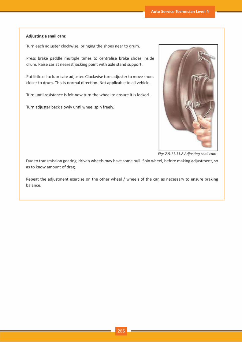
Adjus�ng a snail cam:
Fig: 2.5.11.15. Ad usting snail cam
Turn each adj uster clockwise, bringing th e sh oes near to drum .
Press brake paddle mul�ple �mes to centralise brake shoes inside drum. Raise car at nearest jacking point with axle stand support.
Put li�le oil to lubricate adjuster. Clockwise turn adjuster to move shoes closer to drum. This is normal direc�on. Not applicable to all vehicle.
Turn un�l resistance is felt now turn the wheel to ensure it is locked.
Turn adjuster back slowly un�l wheel spin freely.
Due to transmission gearing driven wheels may have some pull. Spin wheel, before making adjustment, so as to know am ount of drag.
Repeat the adjustment exercise on the other wheel / wheels of the car, as necessary to ensure braking balance.
Auto Service Technician Level 4
265
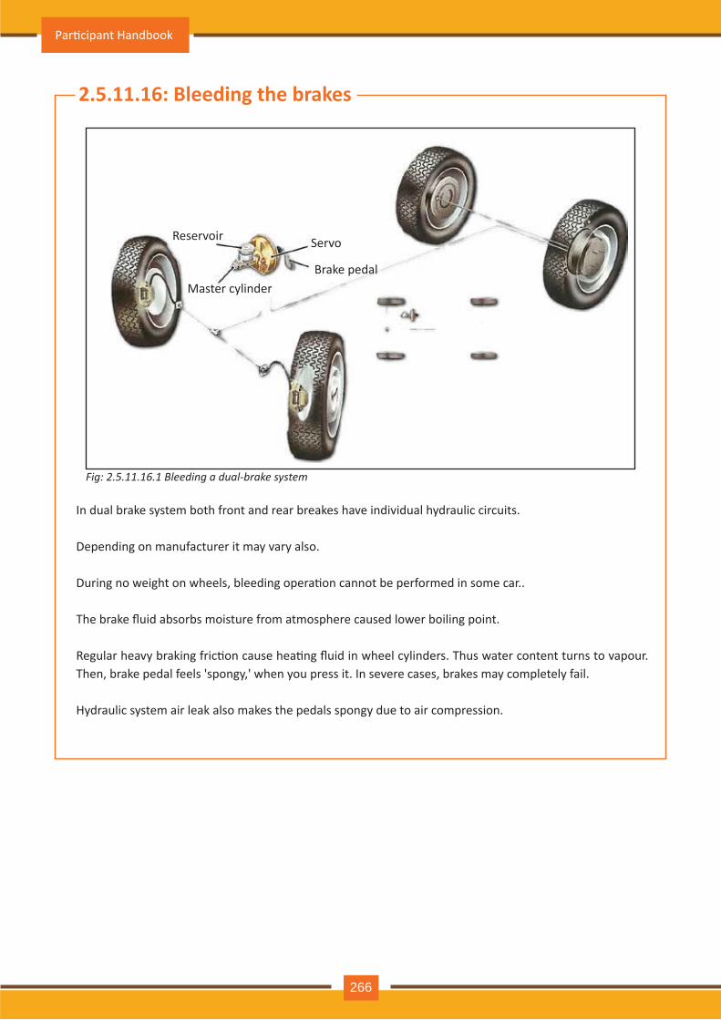
In dual brake sy stem both front and rear breakes h av e indiv idual h y draulic circuits.
Depending on m anufacturer it m ay v ary also.
During no weight on wheels, bleeding opera�on cannot be performed in some car..
The brake fluid absorbs moisture from atmosphere caused lower boiling point.
Regular heavy braking fric�on cause hea�ng fluid in wheel cylinders. Thus water content turns to vapour. Th en, brake pedal feels ' spongy , ' wh en y ou press it. In sev ere cases, brakes m ay com pletely fail.
H y draulic sy stem air leak also m akes th e pedals spongy due to air com pression.
Fig: 2.5.11.16.1 leeding a dual brake s stem
2.5.11.16: B leeding the brak es
R eserv oir Servo
Brake pedalMaster cy linder
Par�cipant Handbook
266
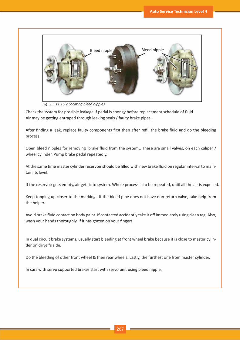
Fig: 2.5.11.16.2 ocating bleed nipples
Check the system for possible leakage If pedal is spongy before replacement schedule of fluid. Air may be ge�ng entraped through leaking seals / faulty brake pipes.
A�er finding a leak, replace faulty components first then a�er refill the brake fluid and do the bleeding process.
Open bleed nipples for removing brake fluid from the system,. These are small valves, on each caliper / wh eel cy linder. Pum p brake pedal repeatedly .
At the same �me master cylinder reservoir should be filled with new brake fluid on regular interval to main -tain its lev el.
If the reservoir gets empty, air gets into system. Whole process is to be repeated, un�l all the air is expelled.
Keep topping up closer to the marking. If the bleed pipe does not have non-return valve, take help from th e h elper.
Avoid brake fluid contact on body paint. If contacted accidently take it off immediately using clean rag. Also, wash your hands thoroughly, if it has go�en on your fingers.
In dual circuit brake sy stem s, usually start bleeding at front wh eel brake because it is close to m aster cy lin-der on driv er' s side.
Do the bleeding of other front wheel & then rear wheels. Lastly, the furthest one from master cylinder.
In cars with serv o supported brakes start with serv o unit using bleed nipple.
Bleed nipple Bleed nipple
Auto Service Technician Level 4
267
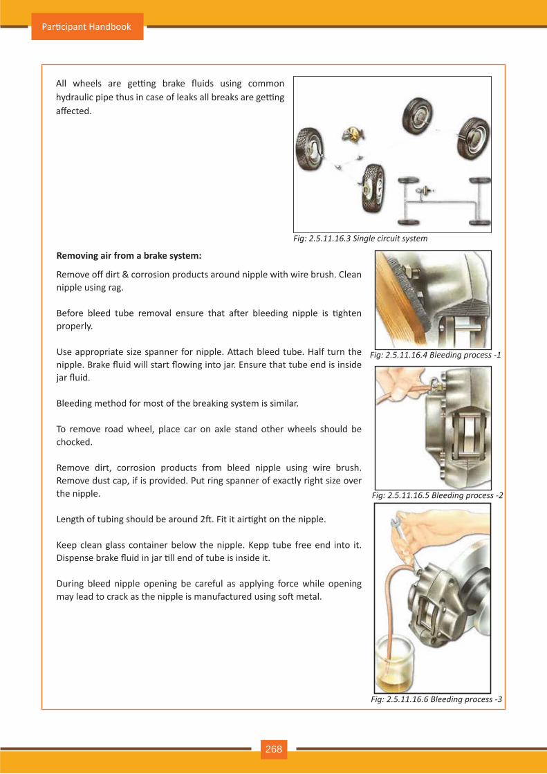
Fig: 2.5.11.16.3 Single circuit s stem
All wheels are ge�ng brake fluids using common hydraulic pipe thus in case of leaks all breaks are ge�ng affected.
Fig: 2.5.11.16 .4 B l e e d in g p r o c e s s - 1
Fig: 2.5.11.16 .5 B l e e d in g p r o c e s s - 2
Fig: 2.5.11.16 .6 B l e e d in g p r o c e s s - 3
R emoving air from a brak e system:
Remove off dirt & corrosion products around nipple with wire brush. Clean nipple using rag. Before bleed tube removal ensure that a�er bleeding nipple is �ghten properly . Use appropriate size spanner for nipple. A�ach bleed tube. Half turn the nipple. Brake fluid will start flowing into jar. Ensure that tube end is inside jar fluid.
Bleeding m eth od for m ost of th e breaking sy stem is sim ilar.
To remove road wheel, place car on axle stand other wheels should be ch ocked.
R em ov e dirt, corrosion products from bleed nipple using wire brush . Remove dust cap, if is provided. Put ring spanner of exactly right size over th e nipple.
Length of tubing should be around 2�. Fit it air�ght on the nipple.
Keep clean glass container below the nipple. Kepp tube free end into it. Dispense brake fluid in jar �ll end of tube is inside it.
During bleed nipple opening be careful as apply ing force wh ile opening may lead to crack as the nipple is manufactured using so� metal.
Par�cipant Handbook
268
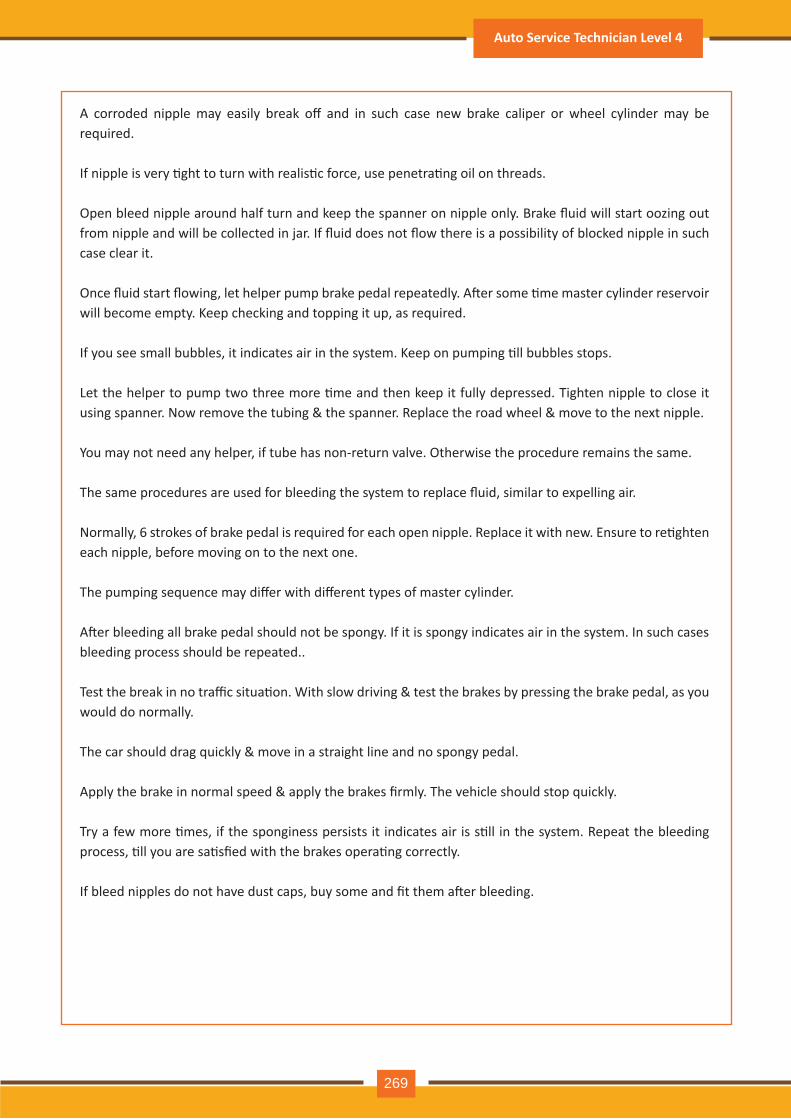
A corroded nipple may easily break off and in such case new brake caliper or wheel cylinder may be required.
If nipple is very �ght to turn with realis�c force, use penetra�ng oil on threads.
Open bleed nipple around half turn and keep the spanner on nipple only. Brake fluid will start oozing out from nipple and will be collected in jar. If fluid does not flow there is a possibility of blocked nipple in such case clear it.
Once fluid start flowing, let helper pump brake pedal repeatedly. A�er some �me master cylinder reservoir will become empty. Keep checking and topping it up, as required.
If you see small bubbles, it indicates air in the system. Keep on pumping �ll bubbles stops.
Let the helper to pump two three more �me and then keep it fully depressed. Tighten nipple to close it using spanner. Now remove the tubing & the spanner. Replace the road wheel & move to the next nipple.
You may not need any helper, if tube has non-return valve. Otherwise the procedure remains the same.
The same procedures are used for bleeding the system to replace fluid, similar to expelling air.
Normally, 6 strokes of brake pedal is required for each open nipple. Replace it with new. Ensure to re�ghten each nipple, before moving on to the next one.
The pumping sequence may differ with different types of master cylinder.
A�er bleeding all brake pedal should not be spongy. If it is spongy indicates air in the system. In such cases bleeding process should be repeated..
Test the break in no traffic situa�on. With slow driving & test the brakes by pressing the brake pedal, as you would do normally.
The car should drag quickly & move in a straight line and no spongy pedal.
Apply the brake in normal speed & apply the brakes firmly. The vehicle should stop quickly.
Try a few more �mes, if the sponginess persists it indicates air is s�ll in the system. Repeat the bleeding process, �ll you are sa�sfied with the brakes opera�ng correctly.
If bleed nipples do not have dust caps, buy some and fit them a�er bleeding.
Auto Service Technician Level 4
269
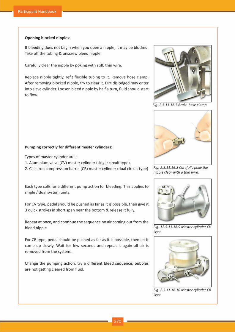
O pening block ed nipples:
Fig: 2.5.11.16 .7 B r a k e - h o s e c l a m p
Fig: 2.5.11.16. Carefull poke the n ip p l e c l e a r w it h a t h in w ir e .
Fig: 12.5.11.16. aster c linder CV t pe
Fig: 2.5.11.16.1 aster c linder C t pe
If bleeding does not begin wh en y ou open a nipple, it m ay be blocked. Take off the tubing & unscrew bleed nipple.
Carefully clear the nipple by poking with s�ff, thin wire.
Replace nipple �ghtly, refit flexible tubing to it. Remove hose clamp. A�er removing blocked nipple, try to clear it. Dirt dislodged may enter into slave cylinder. Loosen bleed nipple by half a turn, fluid should start to flow.
Pumping correctly for different master cylinders:
Ty pes of m aster cy linder are : 1. A lum inium v alv e ( C V ) m aster cy linder ( single circuit ty pe).2. C ast iron com pression barrel ( C B) m aster cy linder ( dual circuit ty pe)
Each type calls for a different pump ac�on for bleeding. This applies to single / dual sy stem units.
For CV type, pedal should be pushed as far as it is possible, then give it 3 quick strokes in short span near the bo�om & release it fully.
Repeat at once, and con�nue the sequence no air coming out from the bleed nipple.
For CB type, pedal should be pushed as far as it is possible, then let it com e up slowly . W ait for few seconds and repeat it again all air is rem ov ed from th e sy stem ..
Change the pumping ac�on, try a different bleed sequence, bubbles are not ge�ng cleared from fluid.
Par�cipant Handbook
270
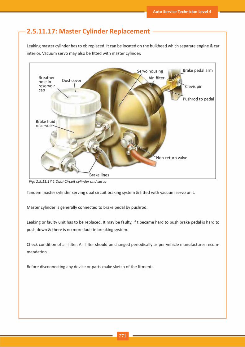
Fig: 2.5.11.1 .1 ual Circuit c linder and servo
2.5.11.17 : M aster Cylinder R eplacement
Leaking master cylinder has to eb replaced. It can be located on the bulkhead which separate engine & car
interior. Vacuum servo may also be fi�ed with master cylinder.
Tandem master cylinder serving dual circuit braking system & fi�ed with vacuum servo unit.
Master cy linder is generally connected to brake pedal by push rod.
Leaking or faulty unit h as to be replaced. It m ay be faulty , if t becam e h ard to push brake pedal is h ard to
push down & there is no more fault in breaking system.
Check condi�on of air filter. Air filter should be changed periodically as per vehicle manufacturer recom-
menda�on.
Before disconnec�ng any device or parts make sketch of the fitments.
Dust cov erBreath er h ole in reserv oir cap
Brake fluid reserv oir
Brake lines
Servo housingAir filter
Brake pedal arm
C lev is pin
Push rod to pedal
Non- return v alv e
Auto Service Technician Level 4
271
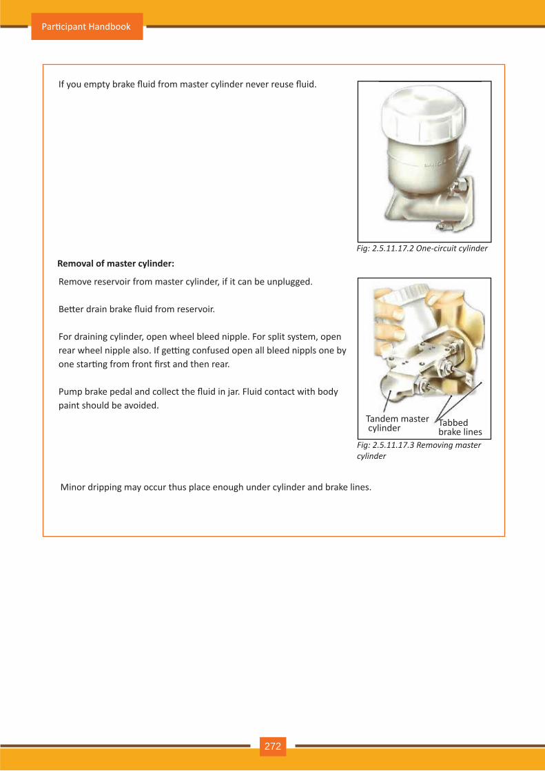
R emoval of master cylinder:Fig: 2.5.11.1 .2 ne circuit c linder
Fig: 2.5.11.17 .3 R e m o v in g m a s t e r c linder
If you empty brake fluid from master cylinder never reuse fluid.
R em ov e reserv oir from m aster cy linder, if it can be unplugged.
Be�er drain brake fluid from reservoir.
For draining cylinder, open wheel bleed nipple. For split system, open rear wheel nipple also. If ge�ng confused open all bleed nippls one by one star�ng from front first and then rear.
Pump brake pedal and collect the fluid in jar. Fluid contact with body paint sh ould be av oided.
Minor dripping m ay occur th us place enough under cy linder and brake lines.
Tandem m aster cy linder Tabbed
brake lines
Par�cipant Handbook
272
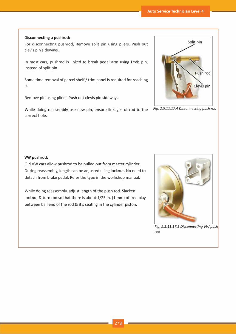
Disconnec�ng a pushrod:
Fig: 2.5.11.1 .5 isconnecting V push r o d
Fig: 2.5.11.1 .4 isconnecting push rod
For disconnec�ng pushrod, Remove split pin using pliers. Push out clev is pin sideway s.
In m ost cars, push rod is linked to break pedal arm using Lev is pin, instead of split pin.
Some �me removal of parcel shelf / trim panel is required for reaching it.
R em ov e pin using pliers. Push out clev is pin sideway s.
W h ile doing reassem bly use new pin, ensure linkages of rod to th e correct h ole.
V W pushrod:O ld V W cars allow push rod to be pulled out from m aster cy linder. During reassem bly , length can be adj usted using locknut. No need to detach from brake pedal. R efer th e ty pe in th e worksh op m anual.
While doing reassembly, adjust length of the push rod. Slacken locknut & turn rod so that there is about 1/25 in. (1 mm) of free play between ball end of the rod & it’s sea�ng in the cylinder piston.
Split pin
Push rod
C lev is pin
Auto Service Technician Level 4
273
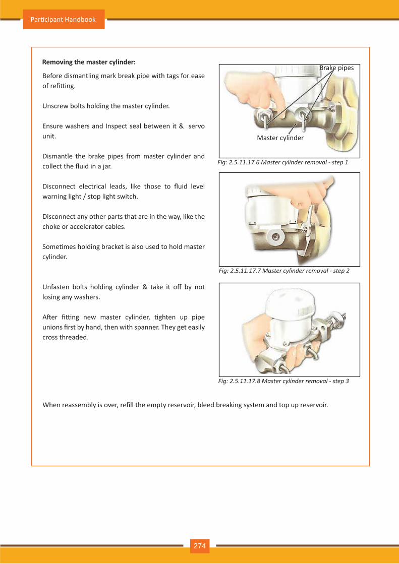
R emoving the master cylinder:
Fig: 2.5.11.1 .6 aster c linder removal step 1
Fig: 2.5.11.1 . aster c linder removal step 2
Fig: 2.5.11.1 . aster c linder removal step 3
Before dism antling m ark break pipe with tags for ease of refi�ng.
Unscrew bolts h olding th e m aster cy linder. Ensure washers and Inspect seal between it & servo unit.
Dism antle th e brake pipes from m aster cy linder and collect the fluid in a jar.
Disconnect electrical leads, like those to fluid level warning ligh t / stop ligh t switch .
Disconnect any oth er parts th at are in th e way , like th e ch oke or accelerator cables.
Some�mes holding bracket is also used to hold master cy linder.
Unfasten bolts holding cylinder & take it off by not losing any wash ers.
A�er fi�ng new master cylinder, �ghten up pipe unions first by hand, then with spanner. They get easily cross th readed.
When reassembly is over, refill the empty reservoir, bleed breaking system and top up reservoir.
Brake pipes
Master cy linder
Par�cipant Handbook
274
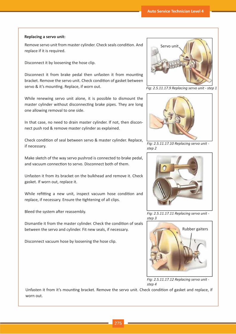
Fig: 2.5.11.17 .9 R e p l a c in g s e r v o u n it - s t e p 1
Fig: 2.5.11.17 .10 R e p l a c in g s e r v o u n it - s t e p 2
Fig: 2.5.11.17 .11 R e p l a c in g s e r v o u n it - s t e p 3
Fig: 2.5.11.17 .12 R e p l a c in g s e r v o u n it - s t e p 4
R eplacing a servo unit:
Remove servo unit from master cylinder. Check seals condi�on. And replace if it is required. Disconnect it by loosening th e h ose clip. Disconnect it from brake pedal then unfasten it from moun�ng bracket. Remove the servo unit. Check condi�on of gasket between servo & it’s moun�ng. Replace, if worn out.
W h ile renewing serv o unit alone, it is possible to dism ount th e master cylinder without disconnec�ng brake pipes. They are long one allowing rem ov al to one side.
In th at case, no need to drain m aster cy linder. If not, th en discon-nect push rod & remove master cylinder as explained.
Check condi�on of seal between servo & master cylinder. Replace, if necessary .
Make sketch of th e way serv o push rod is connected to brake pedal, and vacuum connec�on to servo. Disconnect both of them.
Unfasten it from its bracket on th e bulkh ead and rem ov e it. C h eck gasket. If worn out, replace it.
While refi�ng a new unit, inspect vacuum hose condi�on and replace, if necessary. Ensure the �ghtening of all clips.
Bleed the system a�er reassembly.
Dismantle it from the master cylinder. Check the condi�on of seals between the servo and cylinder. Fit new seals, if necessary.
Disconnect v acuum h ose by loosening th e h ose clip.
Unfasten it from it’s moun�ng bracket. Remove the servo unit. Check condi�on of gasket and replace, if worn out.
Servo unit
R ubber gaiters
Auto Service Technician Level 4
275
Renewing a servo air filter:
It is possible to reach air filter from inside the car or at rear side of unit.
Some �me servo needs to be removed for filter replacement.
Slide rubber gaiter along pushrod to expose filter. Take out the filter.
Using a sharp knife, cut filter at 45 degrees, so that it can be fi�ed on pushrod.
Insert filter over pushrod and place it in housing. Push both ends of the filter simultaneously and replace rubber gaiter over filter.
Some core uses plas�c ring in place of felt ring. It is not renewable. Wash it in mild water & detergent mixture. if found blocked, replace it.
Par�cipant Handbook
276
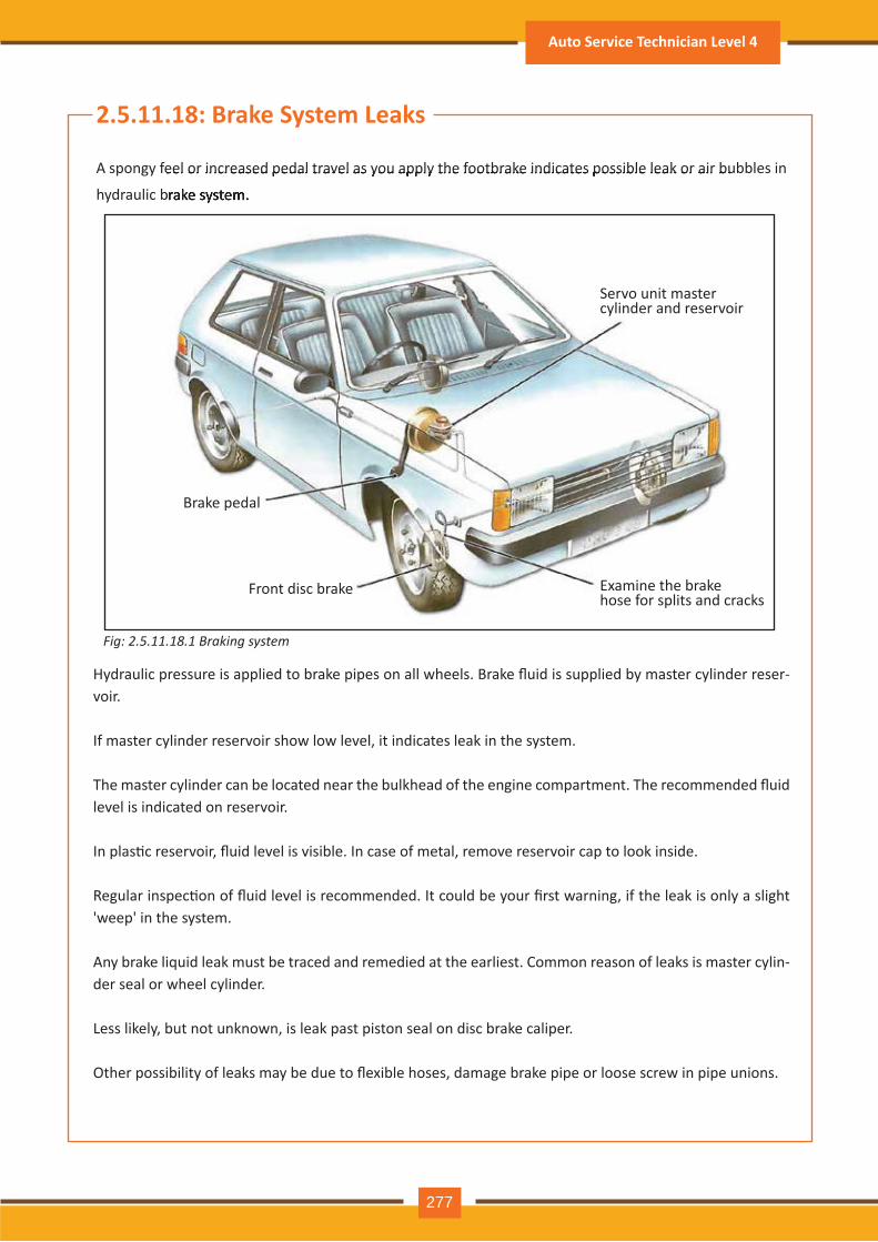
Hydraulic pressure is applied to brake pipes on all wheels. Brake fluid is supplied by master cylinder reser-v oir.
If m aster cy linder reserv oir sh ow low lev el, it indicates leak in th e sy stem .
The master cylinder can be located near the bulkhead of the engine compartment. The recommended fluid lev el is indicated on reserv oir.
In plas�c reservoir, fluid level is visible. In case of metal, remove reservoir cap to look inside.
Regular inspec�on of fluid level is recommended. It could be your first warning, if the leak is only a slight ' weep' in th e sy stem .
A ny brake liquid leak m ust be traced and rem edied at th e earliest. C om m on reason of leaks is m aster cy lin-der seal or wh eel cy linder.
Less likely , but not unknown, is leak past piston seal on disc brake caliper.
Other possibility of leaks may be due to flexible hoses, damage brake pipe or loose screw in pipe unions.
Fig: 2.5.11.1 .1 raking s stem
2.5.11.18 : B rak e System Leak s
A spongy feel or increased pedal trav el as y ou apply th e footbrake indicates possible leak or air bubbles in
h y draulic brake sy stem .
A spongy feel or increased pedal trav el as y ou apply th e footbrake indicates possible leak or air bubbles in
h y draulic brake sy stem .
Brake pedal
Front disc brake Examine the brake h ose for splits and cracks
Servo unit master cy linder and reserv oir
Auto Service Technician Level 4
277
Carefully inspect pipe unions and �ghten nut in-case leakage is found.
While inspec�ng the system brake pedal should be pressed hard. If more pressure required, indicates minor leak which is not simply visible.
If no leak is found and even a�er bleeding problem is not resolved, then check master or slave cylinders.
If brake fluid or grease noted on brake liner should be replaced. Do not try to clean them.
Moreover, the opposite wheel linings must also be replaced. There may otherwise be different stopping power on the two brakes resul�ng in unbalanced & dangerous braking.
Never replace one brake shoes.
Hose clamp is helpful in pinpoin�ng doub�ul faults in brake pipes.
Seal flexible brake hose one by one using hose clamp.
Using a hose clamp:
A bad leak from the wheel cylinder in drum brake will be seen by fluid strip on the back plate, the wheel or some�mes the tyre wall.
If vehicle is pulling one side, it indicates other side brake linings is contaminated due to fluid and not work-ing properly.
Replace leaking wheel cylinder immediately.
While examining brake pipes and unions, always remember those incorpora�ng pressure switch to work on the brake lights.
Also check the pressure regula�ng valve, which manage rear break hydraulic pressure, to balance the braking between front and rear.
Look for the pressure switch in the engine compartment. It will have wiring a�ached to it. The regulator is normally underneath the car and at the back.
If there is rust / corrosion, clean pipe / union with wire brush, before inspec�on.
Rust on surface has to be cleaned & is not a problem, but deep pi�ng in a pipe mean they should be replaced. If wire brushing cleans up & brings it up bright and smooth, it is normally sound.
Deep pi�ng weakens it seriously. Rust will return again and con�nue ea�ng through the metal.
Replacing brake pipes is best solu�on for specialist technician.
Pipes and unions check:
Par�cipant Handbook
278
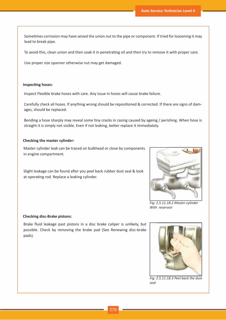
Some�mes corrosion may have seized the union nut to the pipe or component. If tried for loosening it may lead to break pipe.
To avoid this, clean union and then soak it in penetra�ng oil and then try to remove it with proper care.
Use proper size spanner otherwise nut may get damaged.
Inspect Flexible brake hoses with care. Any issue in hoses will cause brake failure.
Carefully check all hoses. If anything wrong should be reposi�oned & corrected. If there are signs of dam-ages, sh ould be replaced.
Bending a hose sharply may reveal some �ny cracks in casing caused by ageing / perishing. When hose is straight it is simply not visible. Even if not leaking, be�er replace it immediately.
Inspec�ng hoses:
Check ing the master cylinder:
Fig: 2.5.11.18 .3 P e e l b a c k t h e d u s t s e a l
Master cy linder leak can be traced on bulkh ead or close by com ponents in engine com partm ent.
Slight leakage can be found a�er you peel back rubber dust seal & look at opera�ng rod. Replace a leaking cylinder.
Check ing disc- B rak e pistons:
Brake fluid leakage past pistons in a disc brake caliper is unlikely, but possible. Check by removing the brake pad (See Renewing disc-brake pads).
Auto Service Technician Level 4
279
Fig: 2.5.11.1 .2 aster c linderW it h r e s e r v o ir
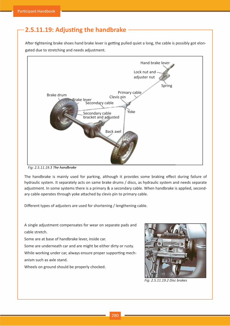
Fig: 2.5.11.19 .2 D is c b r a k e s
The handbrake is mainly used for parking, although it provides some braking effect during failure of h y draulic sy stem . It separately acts on sam e brake drum s / discs, as h y draulic sy stem and needs separate adjustment. In some systems there is a primary & a secondary cable. When handbrake is applied, second -ary cable operates through yoke a�ached by clevis pin to primary cable.
Different types of adjusters are used for shortening / lengthening cable.
Fig: 2.5.11.19 .1 T h e h a n d b r a k e
2.5.11.19: Adjus�ng the handbrake
A�er �ghtening brake shoes hand brake lever is ge�ng pulled quiet a long, the cable is possibly got elon -
gated due to stretch ing and needs adj ustm ent.
2.5.11.19 .1 T h e h a n d b r a k e
A single adj ustm ent com pensates for wear on separate pads and
cable stretch .
Some are at base of handbrake lever, inside car.
Some are underneath car and are might be either dirty or rusty.
While working under car, always ensure proper suppor�ng mech-
anism such as axle stand.
W h eels on ground sh ould be properly ch ocked.
Brake drumBrake lev er
Secondary cableC lev is pin
Prim ary cable
H and brake lev er
Lock nut and adj uster nut
Spring
Y oke
Back axel
Secondary cable bracket and adj usted
Par�cipant Handbook
280
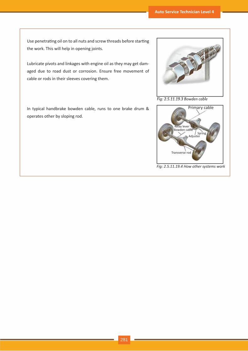
Use penetra�ng oil on to all nuts and screw threads before star�ng
th e work. Th is will h elp in opening j oints.
Lubricate piv ots and linkages with engine oil as th ey m ay get dam -
aged due to road dust or corrosion. Ensure free m ov em ent of
cable or rods in th eir sleev es cov ering th em .
In typical handbrake bowden cable, runs to one brake drum &
operates oth er by sloping rod.
Fig: 2.5.11.19 .3 B o w d e n c a b l e
Fig: 2.5.11.1 .4 ow other s stems work
Fig: 2.5.11.19 .3 B o w d e n c a b l e
Prim ary cable
Bowden cableR elay lev er
A dj usterSpring
Transv erse rod
Auto Service Technician Level 4
281
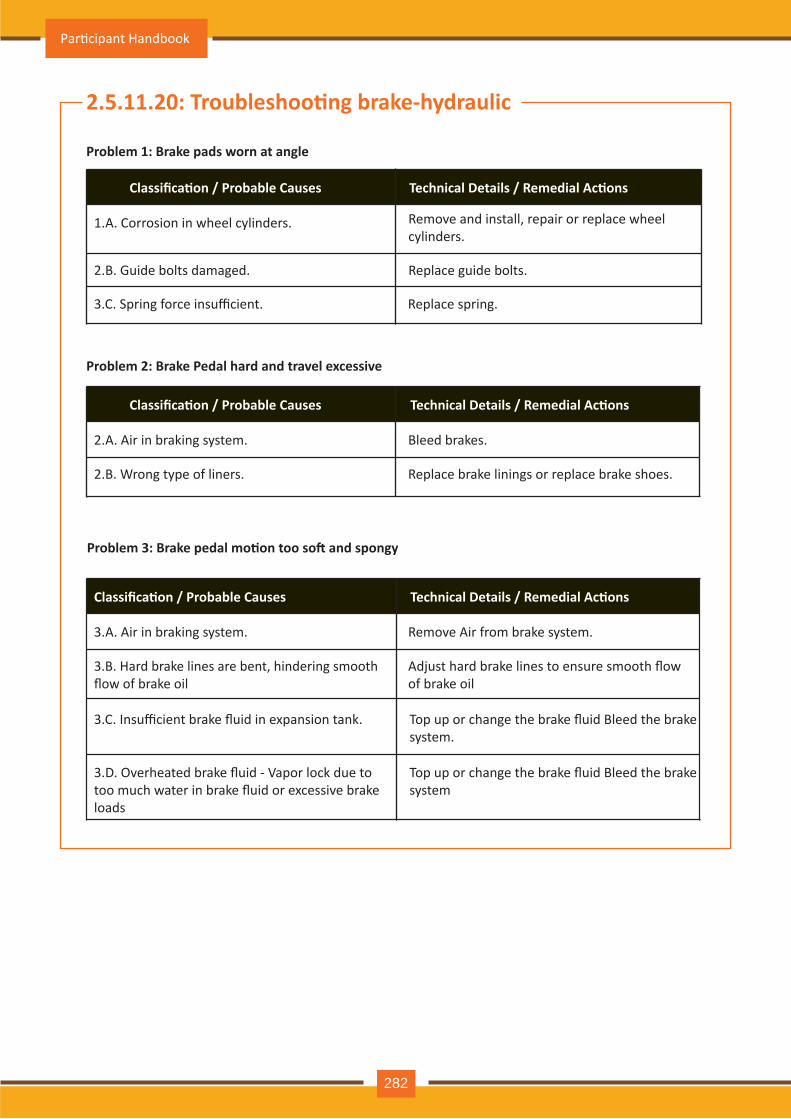
Problem 1: Brake pads worn at angle
Classifica�on / Probable Causes Technical Details / Remedial Ac�ons
1.A. Corrosion in wheel cylinders.
2.B. Guide bolts damaged.
3.C. Spring force insufficient. Replace spring.
Replace guide bolts.
Remove and install, repair or replace wheel cylinders.
Problem 2: Brake Pedal hard and travel excessive
Classifica�on / Probable Causes Technical Details / Remedial Ac�ons
2.A. Air in braking system.
2.B. Wrong type of liners. Replace brake linings or replace brake shoes.
Bleed brakes.
Problem 3: Brake pedal mo�on too so� and spongy
Classifica�on / Probable Causes Technical Details / Remedial Ac�ons
3.A. Air in braking system.
3.B. Hard brake lines are bent, hindering smooth flow of brake oil
3.C. Insufficient brake fluid in expansion tank.
3.D. Overheated brake fluid - Vapor lock due totoo much water in brake fluid or excessive brake loads
Top up or change the brake fluid Bleed the brake system.
Top up or change the brake fluid Bleed the brake system
Adjust hard brake lines to ensure smooth flowof brake oil
Remove Air from brake system.
2.5.11.20: Troubleshoo�ng brake-hydraulic
Par�cipant Handbook
282
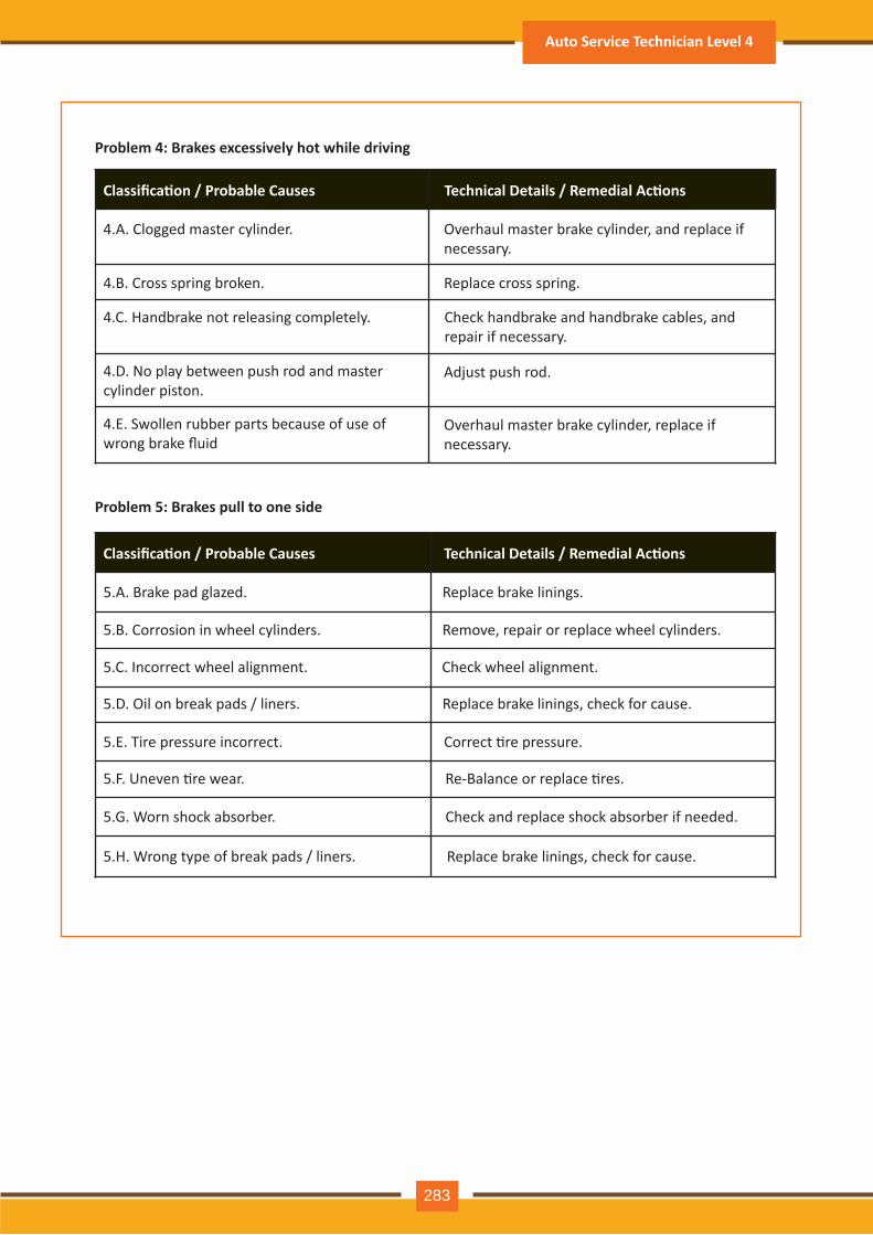
Problem 4: Brakes excessively hot while driving
Classifica�on / Probable Causes Technical Details / Remedial Ac�ons
4.A. Clogged master cylinder.
4.B. Cross spring broken.
4.C. Handbrake not releasing completely.
4.D. No play between push rod and master cylinder piston.
4.E. Swollen rubber parts because of use of wrong brake fluid
Check handbrake and handbrake cables, and repair if necessary.
Replace cross spring.
Adjust push rod.
Overhaul master brake cylinder, replace ifnecessary.
Overhaul master brake cylinder, and replace if necessary.
Problem 5: Brakes pull to one side
Classifica�on / Probable Causes Technical Details / Remedial Ac�ons
5.A. Brake pad glazed.
5.B. Corrosion in wheel cylinders.
5.C. Incorrect wheel alignment.
5.D. Oil on break pads / liners.
5.E. Tire pressure incorrect.
5.F. Uneven �re wear.
5.G. Worn shock absorber.
5.H. Wrong type of break pads / liners. Replace brake linings, check for cause.
Check and replace shock absorber if needed.
Re-Balance or replace �res.
Correct �re pressure.
Replace brake linings, check for cause.
Check wheel alignment.
Remove, repair or replace wheel cylinders.
Replace brake linings.
Auto Service Technician Level 4
283
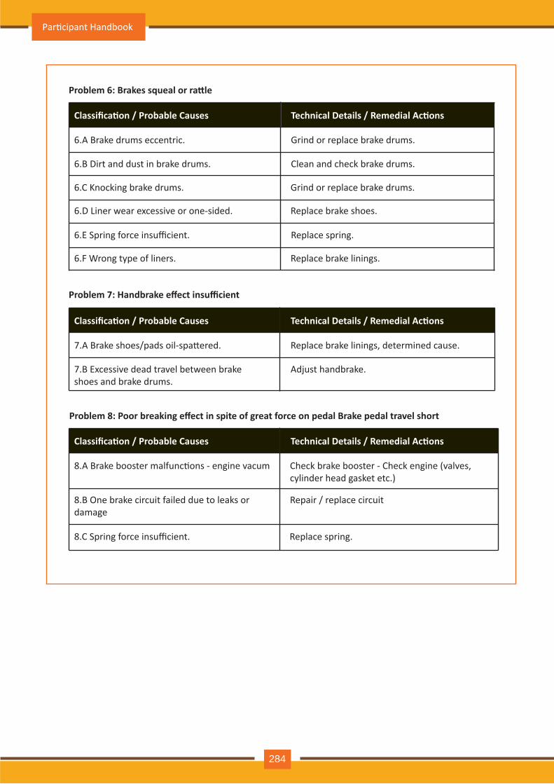
Problem 6: Brakes squeal or ra�le
Classifica�on / Probable Causes Technical Details / Remedial Ac�ons
6.A Brake drums eccentric.
6.B Dirt and dust in brake drums.
6.C Knocking brake drums.
6.D Liner wear excessive or one-sided.
6.E Spring force insufficient.
6.F Wrong type of liners. Replace brake linings.
Replace spring.
Replace brake shoes.
Grind or replace brake drums.
Clean and check brake drums.
Grind or replace brake drums.
Problem 7: Handbrake effect insufficient
Classifica�on / Probable Causes Technical Details / Remedial Ac�ons
7.A Brake shoes/pads oil-spa�ered.
7.B Excessive dead travel between brake shoes and brake drums.
Adjust handbrake.
Replace brake linings, determined cause.
Problem 8: Poor breaking effect in spite of great force on pedal Brake pedal travel short
Classifica�on / Probable Causes Technical Details / Remedial Ac�ons
8.A Brake booster malfunc�ons - engine vacum
8.B One brake circuit failed due to leaks or damage
8.C Spring force insufficient. Replace spring.
Repair / replace circuit
Check brake booster - Check engine (valves, cylinder head gasket etc.)
Par�cipant Handbook
284
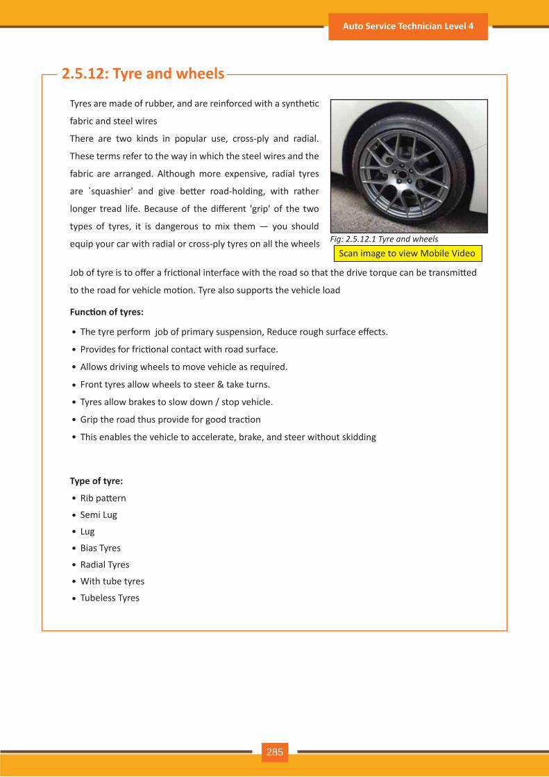
2.5.12: Tyre and wheels
Tyres are made of rubber, and are reinforced with a synthe�c
fabric and steel wires
There are two kinds in popular use, cross-ply and radial.
These terms refer to the way in which the steel wires and the
fabric are arranged. Although more expensive, radial tyres
are `squashier' and give be�er road-holding, with rather
longer tread life. Because of the different 'grip' of the two
types of tyres, it is dangerous to mix them — you should
equip your car with radial or cross-ply tyres on all the wheels
Job of tyre is to offer a fric�onal interface with the road so that the drive torque can be transmi�ed
to the road for vehicle mo�on. Tyre also supports the vehicle load
Func�on of tyres:
The tyre perform job of primary suspension, Reduce rough surface effects.
Provides for fric�onal contact with road surface.
Allows driving wheels to move vehicle as required.
Front tyres allow wheels to steer & take turns.
Tyres allow brakes to slow down / stop vehicle.
Grip the road thus provide for good trac�on
This enables the vehicle to accelerate, brake, and steer without skidding
Type of tyre:
Rib pa�ern
Semi Lug
Lug
Bias Tyres
Radial Tyres
With tube tyres
Tubeless Tyres
Scan image to view Mobile VideoFig: 2.5.12.1 Tyre and wheels
•
•
•
•
•
•
•
•
•
•
•
•
•
•
Auto Service Technician Level 4
285
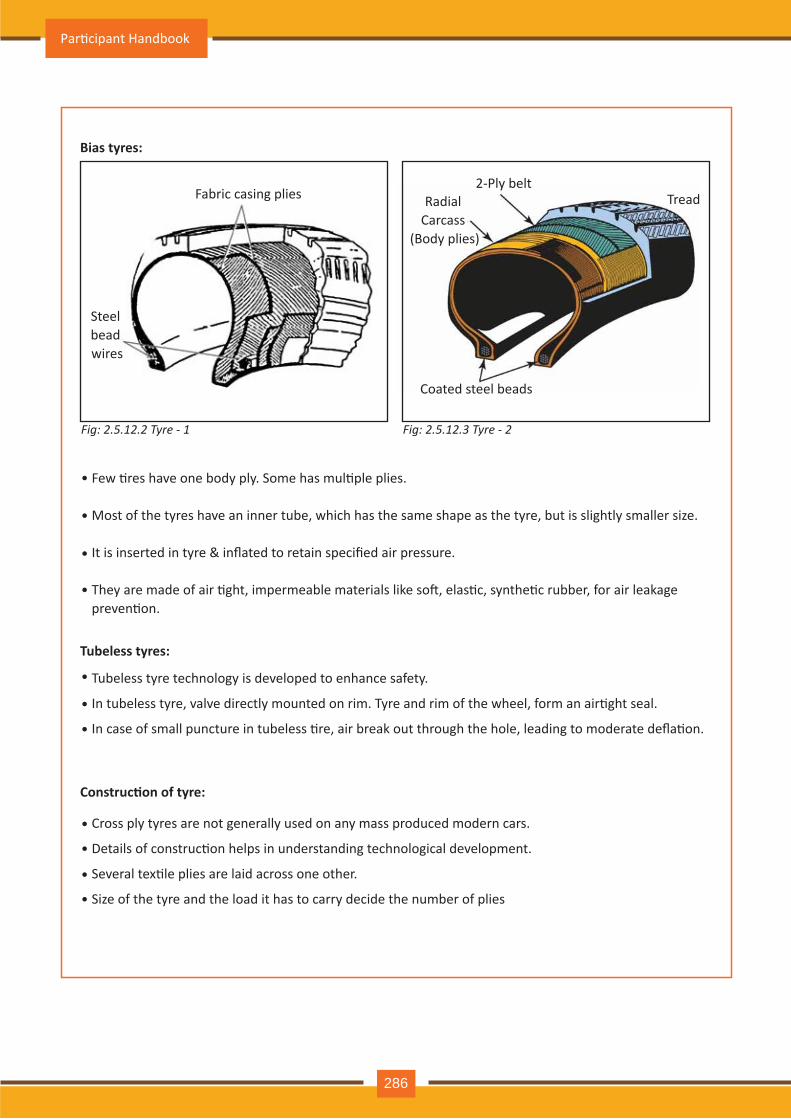
Construc�on of tyre:
Cross ply tyres are not generally used on any mass produced modern cars.
Details of construc�on helps in understanding technological development.
Several tex�le plies are laid across one other.
Size of the tyre and the load it has to carry decide the number of plies
Bias tyres:
Tubeless tyres:
Fig: 2.5.12.2 Tyre - 1 Fig: 2.5.12.3 Tyre - 2
Tubeless tyre technology is developed to enhance safety.
In tubeless tyre, valve directly mounted on rim. Tyre and rim of the wheel, form an air�ght seal.
In case of small puncture in tubeless �re, air break out through the hole, leading to moderate defla�on.
•
•
•
•
•
•
•
•
•
•
•
Fabric casing plies2-Ply belt
TreadRadial Carcass
(Body plies)
Coated steel beads
Steel bead wires
Few �res have one body ply. Some has mul�ple plies.
Most of the tyres have an inner tube, which has the same shape as the tyre, but is slightly smaller size.
It is inserted in tyre & inflated to retain specified air pressure.
They are made of air �ght, impermeable materials like so�, elas�c, synthe�c rubber, for air leakage preven�on.
Par�cipant Handbook
286
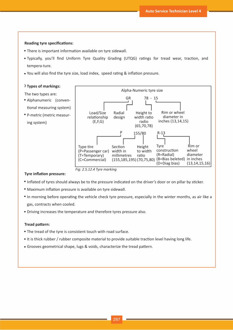
Fig: 2.5.12.4 Tyre marking
Reading tyre specifica�ons:
› Types of markings:
There is important informa�on available on tyre sidewall.
Typically, you’ll find Uniform Tyre Quality Grading (UTQG) ra�ngs for tread wear, trac�on, and
tempera-ture.
You will also find the tyre size, load index, speed ra�ng & infla�on pressure.
Alphanumeric (conven-
�onal measuring system)
P-metric (metric measur-
ing system)
•
Tyre infla�on pressure:
Tread pa�ern:
Inflated of tyres should always be to the pressure indicated on the driver’s door or on pillar by s�cker.
Maximum infla�on pressure is available on tyre sidewall.
In morning before opera�ng the vehicle check tyre pressure, especially in the winter months, as air like a
gas, contracts when cooled.
Driving increases the temperature and therefore tyres pressure also.
•
The tread of the tyre is consistent touch with road surface.
It is thick rubber / rubber composite material to provide suitable trac�on level having long life.
Grooves geometrical shape, lugs & voids, characterize the tread pa�ern.
•
•
•
•
•
•
•
•
•
•
The two types are:GR
P 155/80 R-13
78 - 15
Alpha-Numeric tyre size
Load/Size rela�onship
(E,F,G)
Type �re (P=Passenger car) (T=Temporary) (C=Commercial)
Sec�on width in millimetres (155,185,195)
Height to width ra�o (70,75,80)
Tyre construc�on (R=Radial) (B=Bias beleted) (D=Diag bias)
Rim or wheel diameter in inches (13,14,15,16)
Height to width ra�o
radio (65,70,78)
Rim or wheel diameter in
inches (13,14,15)
Radial design
Auto Service Technician Level 4
287
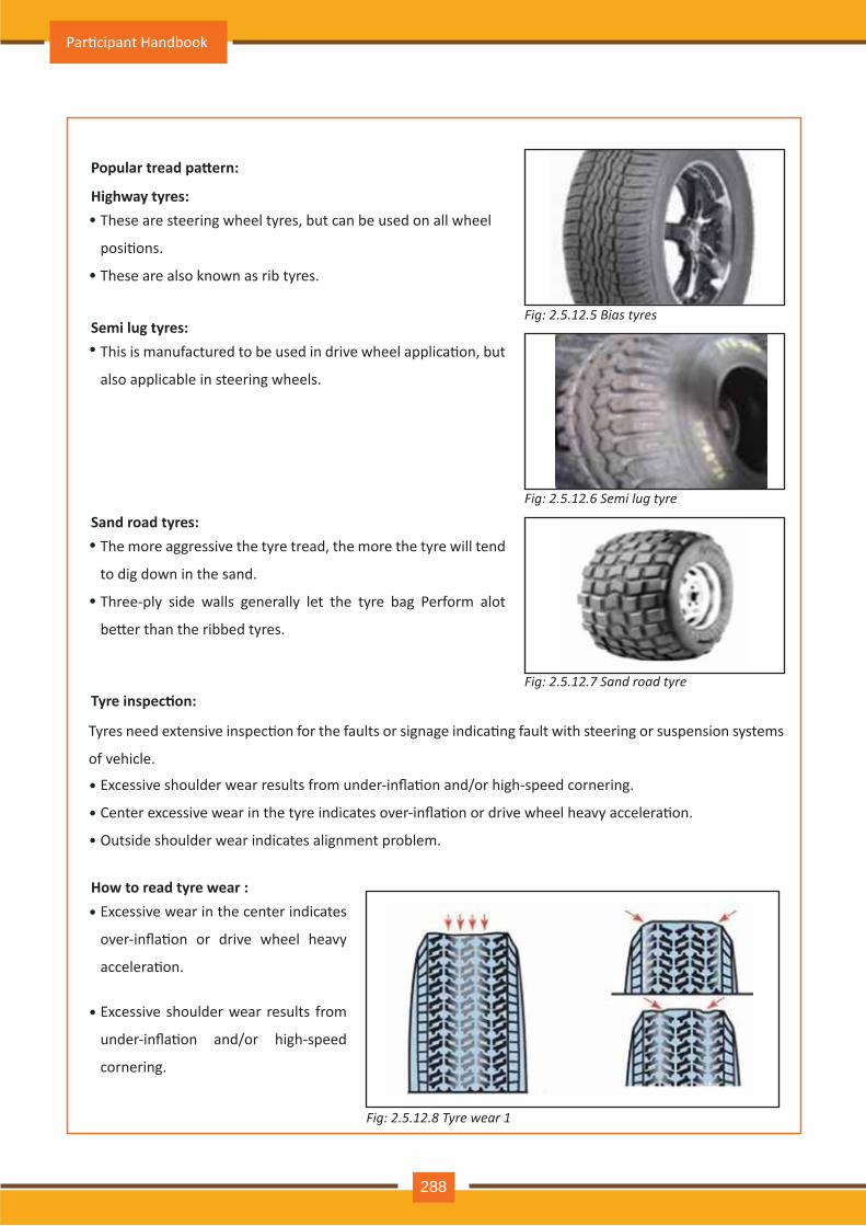
Fig: 2.5.12.6 Semi lug tyre
Fig: 2.5.12.7 Sand road tyre
Fig: 2.5.12.8 Tyre wear 1
Popular tread pa�ern:
Tyre inspec�on:
How to read tyre wear :
These are steering wheel tyres, but can be used on all wheel
posi�ons.
These are also known as rib tyres.
•
•
•
•
•
Highway tyres:
This is manufactured to be used in drive wheel applica�on, but
also applicable in steering wheels.
Tyres need extensive inspec�on for the faults or signage indica�ng fault with steering or suspension systems
of vehicle.
Semi lug tyres:
The more aggressive the tyre tread, the more the tyre will tend
to dig down in the sand.
Three-ply side walls generally let the tyre bag Perform alot
be�er than the ribbed tyres.
•
•
•
Excessive shoulder wear results from under-infla�on and/or high-speed cornering.
Center excessive wear in the tyre indicates over-infla�on or drive wheel heavy accelera�on.
Outside shoulder wear indicates alignment problem.
• Excessive wear in the center indicates
over-infla�on or drive wheel heavy
accelera�on.
• Excessive shoulder wear results from
under-infla�on and/or high-speed
cornering.
Sand road tyres:
Fig: 2.5.12.5 Bias tyres
Par�cipant Handbook
288
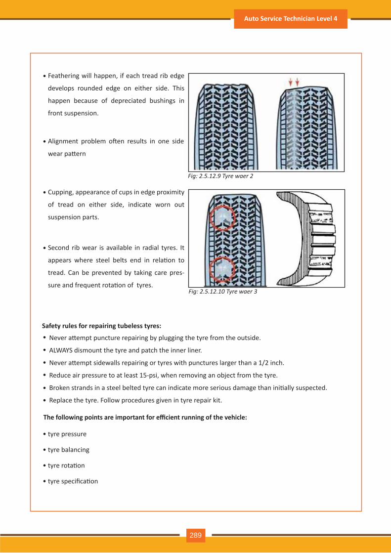
Safety rules for repairing tubeless tyres:
• Feathering will happen, if each tread rib edge
develops rounded edge on either side. This
happen because of depreciated bushings in
front suspension.
• Cupping, appearance of cups in edge proximity
of tread on either side, indicate worn out
suspension parts.
• Second rib wear is available in radial tyres. It
appears where steel belts end in rela�on to
tread. Can be prevented by taking care pres-
sure and frequent rota�on of tyres.
• Alignment problem o�en results in one side
wear pa�ern
Never a�empt puncture repairing by plugging the tyre from the outside.
ALWAYS dismount the tyre and patch the inner liner.
Never a�empt sidewalls repairing or tyres with punctures larger than a 1/2 inch.
Reduce air pressure to at least 15-psi, when removing an object from the tyre.
Broken strands in a steel belted tyre can indicate more serious damage than ini�ally suspected.
Replace the tyre. Follow procedures given in tyre repair kit.
•
•
•
•
•
•
The following points are important for efficient running of the vehicle:
• tyre pressure
• tyre balancing
• tyre rota�on
• tyre specifica�on
Fig: 2.5.12.9 Tyre waer 2
Fig: 2.5.12.10 Tyre waer 3
Auto Service Technician Level 4
289
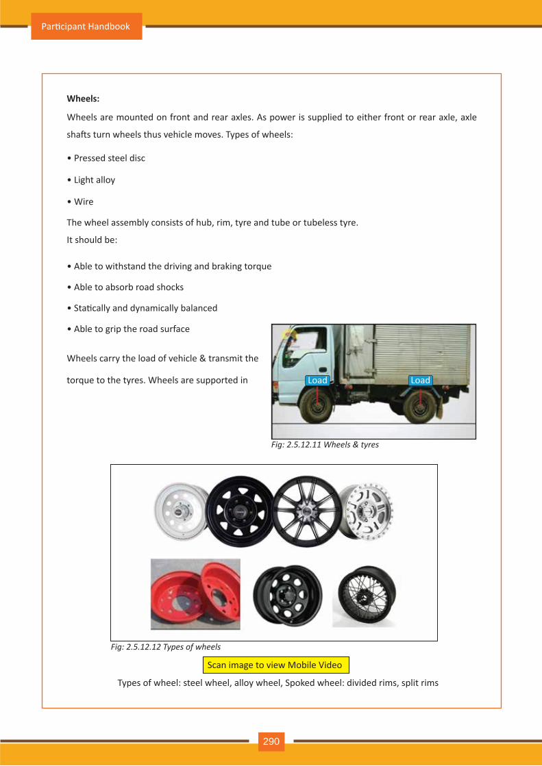
Wheels:
Wheels are mounted on front and rear axles. As power is supplied to either front or rear axle, axle
sha�s turn wheels thus vehicle moves. Types of wheels:
• Pressed steel disc
• Light alloy
• Wire
The wheel assembly consists of hub, rim, tyre and tube or tubeless tyre.
It should be:
• Able to withstand the driving and braking torque
• Able to absorb road shocks
• Sta�cally and dynamically balanced
• Able to grip the road surface
Wheels carry the load of vehicle & transmit the
torque to the tyres. Wheels are supported in Load
Load
Fig: 2.5.12.11 Wheels & tyres
Types of wheel: steel wheel, alloy wheel, Spoked wheel: divided rims, split rims
Fig: 2.5.12.12 Types of wheels
Scan image to view Mobile Video
Load
Par�cipant Handbook
290
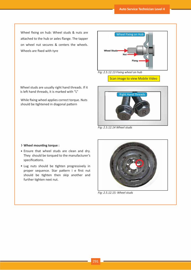
› Wheel moun�ng torque :
Wheel fixing on hub: Wheel studs & nuts are
a�ached to the hub or axles flange. The tapper
on wheel nut secures & centers the wheels.
Wheels are fixed with tyre
Wheel studs are usually right hand threads. If it is le� hand threads, it is marked with “L”
While fixing wheel applies correct torque. Nuts should be �ghtened in diagonal pa�ern
Ensure that wheel studs are clean and dry. They should be torqued to the manufacturer’s specifica�ons.
Lug nuts should be �ghten progressively in proper sequence. Star pa�ern i e first nut should be �ghten then skip another and further �ghten next nut.
Wheel Fixing on Hub
Right Hand Threads
Fig: 2.5.12.13 Fixing wheel on hub
Fig: 2.5.12.14 Wheel studs
Fig: 2.5.12.15: Wheel studs
Scan image to view Mobile Video
•
•
Auto Service Technician Level 4
291
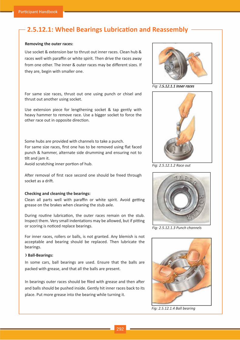
Use socket & extension bar to thrust out inner races. Clean hub & races well with paraffin or white spirit. Then drive the races away from one other. The inner & outer races may be different sizes. If th ey are, begin with sm aller one.
For same size races, thrust out one using punch or chisel and th rust out anoth er using socket.
Use extension piece for lengthening socket & tap gently with h eav y h am m er to rem ov e race. Use a bigger socket to force th e other race out in opposite direc�on.
Some hubs are provided with channels to take a punch.For same size races, first one has to be removed using flat faced punch & hammer, alternate side drumming and ensuring not to �lt and jam it. Avoid scratching inner por�on of hub.
A�er removal of first race second one should be freed through socket as a dri�.
Clean all parts well with paraffin or white spirit. Avoid ge�ng grease on the brakes when cleaning the stub axle.
During rou�ne lubrica�on, the outer races remain on the stub. Inspect them. Very small indenta�ons may be allowed, but if pi�ng or scoring is no�ced replace bearings.
For inner races, rollers or balls, is not granted. Any blemish is not acceptable and bearing sh ould be replaced. Th en lubricate th e bearings.
Check ing and cleaning the bearings:
2.5.12.1: Wheel Bearings Lubrica�on and Reassembly
R emoving the outer races:
Fig: 2.5.12.1.1 I n n e r r a c e s
Fig: 2.5.12.1.2 R a c e o u t
Fig: 2.5.12.1.3 P u n c h c h a n n e l s
2.5.12.1.1 I n n e r r a c e s
In som e cars, ball bearings are used. Ensure th at th e balls are packed with grease, and th at all th e balls are present.
In bearings outer races should be filed with grease and then a�er and balls sh ould be push ed inside. G ently h it inner races back to its place. Put m ore grease into th e bearing wh ile turning it.
B all- B earings:
Fig: 2.5.12.1.4 B a l l b e a r in g
›
Par�cipant Handbook
292
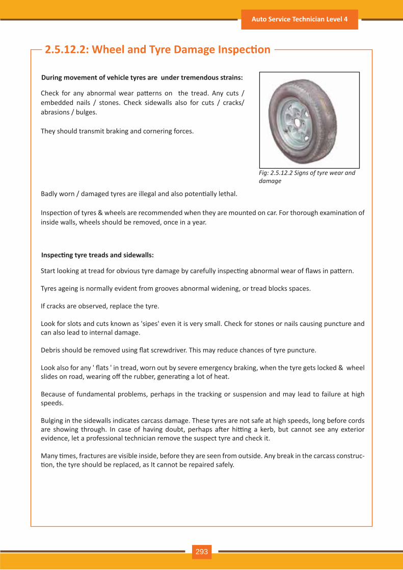
Check for any abnormal wear pa�erns on the tread. Any cuts / embedded nails / stones. Check sidewalls also for cuts / cracks/ abrasions / bulges.
They should transmit braking and cornering forces.
Badly worn / damaged tyres are illegal and also poten�ally lethal.
Inspec�on of tyres & wheels are recommended when they are mounted on car. For thorough examina�on of inside walls, wheels should be removed, once in a year.
Start looking at tread for obvious tyre damage by carefully inspec�ng abnormal wear of flaws in pa�ern.
Tyres ageing is normally evident from grooves abnormal widening, or tread blocks spaces.
If cracks are observed, replace the tyre.
Look for slots and cuts known as 'sipes' even it is very small. Check for stones or nails causing puncture and can also lead to internal damage.
Debris should be removed using flat screwdriver. This may reduce chances of tyre puncture.
Look also for any ' flats ' in tread, worn out by severe emergency braking, when the tyre gets locked & wheel slides on road, wearing off the rubber, genera�ng a lot of heat.
Because of fundamental problems, perhaps in the tracking or suspension and may lead to failure at high speeds. Bulging in the sidewalls indicates carcass damage. These tyres are not safe at high speeds, long before cords are showing through. In case of having doubt, perhaps a�er hi�ng a kerb, but cannot see any exterior evidence, let a professional technician remove the suspect tyre and check it.
Many �mes, fractures are visible inside, before they are seen from outside. Any break in the carcass construc-�on, the tyre should be replaced, as It cannot be repaired safely.
2.5.12.2: Wheel and Tyre Damage Inspec�on
During movement of vehicle tyres are under tremendous strains:
Inspec�ng tyre treads and sidewalls:
Fig: 2.5.12.2 Signs of tyre wear and damage
Auto Service Technician Level 4
293
›
When wheels are taken off, inspect tyre walls. Clean wheels thoroughly and look for cracks carefully.
Loosen wheel nuts, before jacking up vehicle.
Cracks could be due to corrosion or loose or very �ght wheel nut. In case of such damages replace wheels.
Check for deep scuff marks, buckling or den�ng on steel rims.
Due to damaged rim maintaining vehicle balance become difficult.
In case chips or scrapes on alloy wheels are minor it can be ignored but cracks are serious.
Magnesium alloy wheels corrode badly, if protec�ve coa�ng is disturbed. Flying grit may also damage it. Inspec�ons should be done more frequently for such damages. Re-lacquer the wheels, if necessary, before corrosion sets in. Proprietary lacquers are available, especially for car wheels, giving clear instruc�ons on the container, about their applica�on & usage.
Rus�ng is possible in steel wheels due to use of thick metal strong enough to withstand all.
Rusty wheels are una�rac�ve to sight but can be easily painted to look more prominent.
Faulty valve may lead to slow & persistent, loss of pressure from the tyre. Whenever tyre is taken off, new valves should be fi�ed.
The inner core of valve became worse with age, more so, if the valve cap is missing dust / grit can eaislt enter.
Check each valve carefully for cracking / hardening of rubber covering around stem.
Check for dirt a�er removing cap and then a�er do the replacement. Remember, it is pressure seal & protec�ve shield.
2.5.12.3: Removal & Fi�ng of Wheels
Checking valves:
Par�cipant Handbook
294
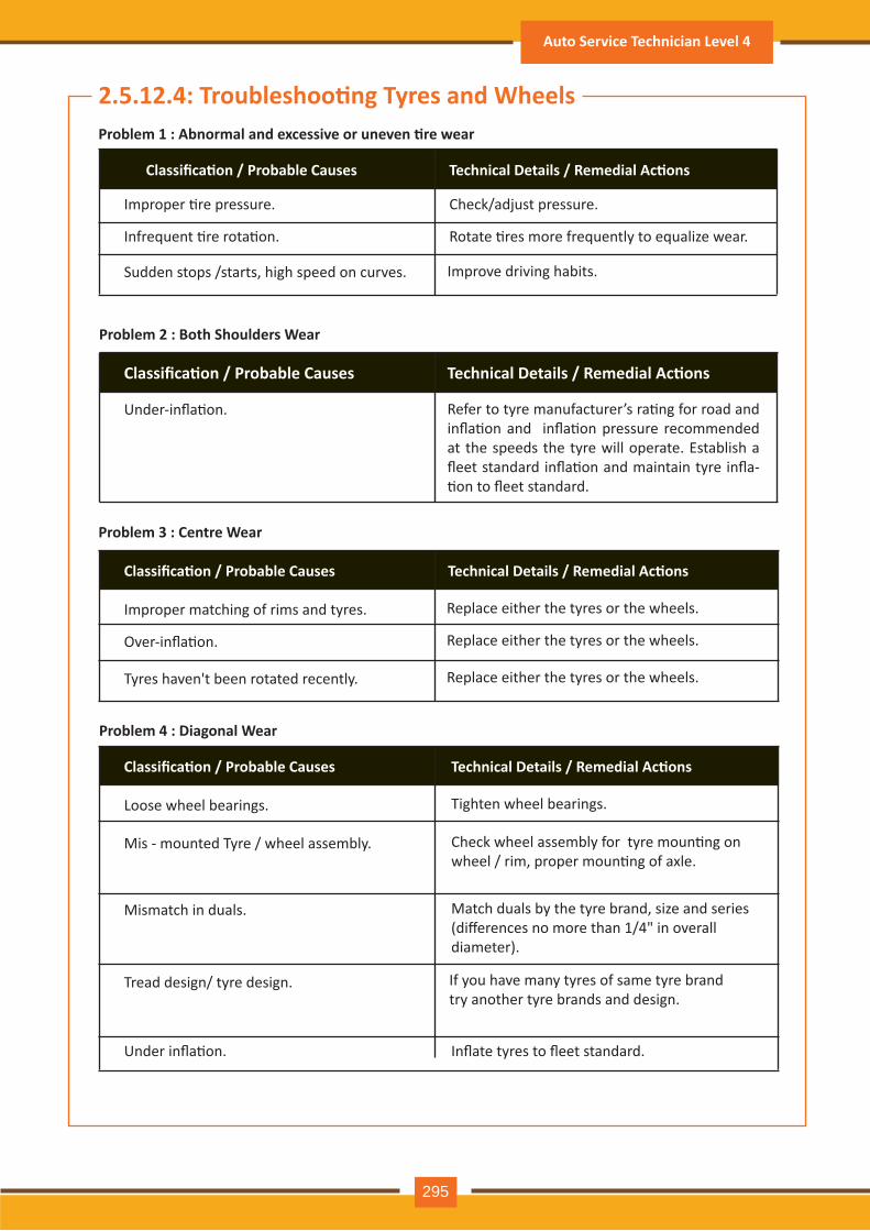
Problem 1 : Abnormal and excessive or uneven �re wear
Classifica�on / Probable Causes Technical Details / Remedial Ac�ons
Improper �re pressure. Check/adjust pressure.
Infrequent �re rota�on.
Under-infla�on.
Rotate �res more frequently to equalize wear.
Sudden stops /starts, high speed on curves. Improve driving habits.
Problem 2 : Both Shoulders Wear
Classifica�on / Probable Causes Technical Details / Remedial Ac�ons
Refer to tyre manufacturer’s ra�ng for road and infla�on and infla�on pressure recommended at the speeds the tyre will operate. Establish a fleet standard infla�on and maintain tyre infla-�on to fleet standard.
Problem 3 : Centre Wear
Classifica�on / Probable Causes Technical Details / Remedial Ac�ons
Improper matching of rims and tyres. Replace either the tyres or the wheels.
Over-infla�on. Replace either the tyres or the wheels.
Tyres haven't been rotated recently. Replace either the tyres or the wheels.
Problem 4 : Diagonal Wear
Classifica�on / Probable Causes Technical Details / Remedial Ac�ons
Loose wheel bearings. Tighten wheel bearings.
Mis - mounted Tyre / wheel assembly. Check wheel assembly for tyre moun�ng on wheel / rim, proper moun�ng of axle.
Mismatch in duals. Match duals by the tyre brand, size and series(differences no more than 1/4" in overalldiameter).
Tread design/ tyre design. If you have many tyres of same tyre brandtry another tyre brands and design.
Under infla�on. Inflate tyres to fleet standard.
2.5.12.4: Troubleshoo�ng Tyres and Wheels
Auto Service Technician Level 4
295
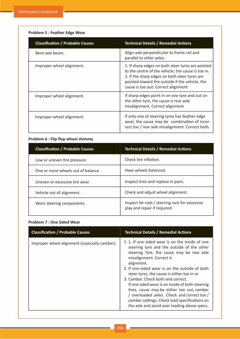
Problem 5 : Feather Edge Wear
Classifica�on / Probable Causes Technical Details / Remedial Ac�ons
Bent axle beam. Align axle perpendicular to frame rail and parallel to other axles.
Improper wheel alignment. If sharp edges point in on one tyre and out on the other tyre, the cause is rear axle misalignment. Correct alignment
Improper wheel alignment. 1. If sharp edges on both steer tyres are pointedto the centre of the vehicle, the cause is toe in.2. If the sharp edges on both steer tyres arepointed toward the outside if the vehicle, thecause is toe out. Correct alignment
Improper wheel alignment. If only one of steering tyres has feather edgewear, the cause may be combina�on of incor-rect toe / rear axle misalignment. Correct both.
Problem 6 : Flip flop wheel shimmy
Classifica�on / Probable Causes Technical Details / Remedial Ac�ons
Low or uneven �re pressure. Check �re infla�on.
One or more wheels out of balance. Have wheels balanced.
Uneven or excessive �re wear. Inspect �res and replace in pairs.
Vehicle out of alignment. Check and adjust wheel alignment.
Worn steering components. Inspect �e rods / steering rack for excessiveplay and repair if required.
Problem 7 : One Sided Wear
Classifica�on / Probable Causes Technical Details / Remedial Ac�ons
Improper wheel alignment (especially camber). 1. If one sided wear is on the inside of one steering tyre and the outside of the other steering Tyre, the cause may be rear axle misalignment. Correct it.alignment. If one-sided wear is on the outside of both steer tyres, the cause is either toe in orCamber. Check both and correct.If one sided wear is on inside of both steering �res, cause may be either toe out, camber / overloaded axles. Check and correct toe / camber se�ngs. Check load specifica�ons on the axle and avoid over loading above specs.
2.
1.
3.
Par�cipant Handbook
296
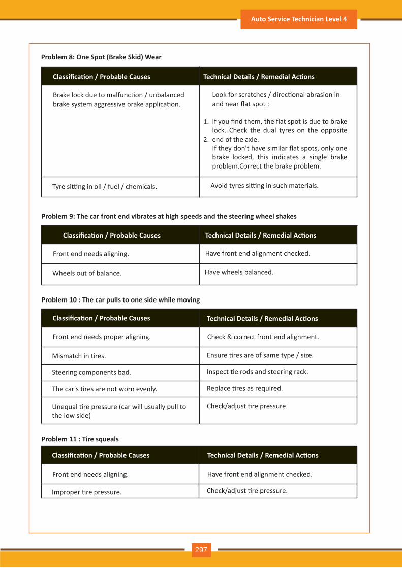
Problem 8: One Spot (Brake Skid) Wear
Classifica�on / Probable Causes Technical Details / Remedial Ac�ons
Brake lock due to malfunc�on / unbalancedbrake system aggressive brake applica�on.
Tyre si�ng in oil / fuel / chemicals. Avoid tyres si�ng in such materials.
Look for scratches / direc�onal abrasion inand near flat spot :
If you find them, the flat spot is due to brake lock. Check the dual tyres on the opposite end of the axle. If they don't have similar flat spots, only one brake locked, this indicates a single brake problem.Correct the brake problem.
2.
1.
Problem 9: The car front end vibrates at high speeds and the steering wheel shakes
Classifica�on / Probable Causes Technical Details / Remedial Ac�ons
Front end needs aligning.
Wheels out of balance. Have wheels balanced.
Have front end alignment checked.
Problem 10 : The car pulls to one side while moving
Classifica�on / Probable Causes Technical Details / Remedial Ac�ons
Front end needs proper aligning.
Mismatch in �res. Ensure �res are of same type / size.
Check & correct front end alignment.
Steering components bad. Inspect �e rods and steering rack.
The car's �res are not worn evenly. Replace �res as required.
Unequal �re pressure (car will usually pull to the low side)
Check/adjust �re pressure
Problem 11 : Tire squeals
Classifica�on / Probable Causes Technical Details / Remedial Ac�ons
Front end needs aligning.
Improper �re pressure. Check/adjust �re pressure.
Have front end alignment checked.
Auto Service Technician Level 4
297

Problem 12: Vibra�on when you hit a bump
Classifica�on / Probable Causes Technical Details / Remedial Ac�ons
Broken or slipped leaf spring. Inspect leaf springs and repair or replace as needed.
Worn shocks or struts. Replace shocks and/or struts.
Par�cipant Handbook
298
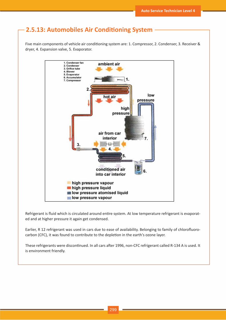
2.5.13: Automobiles Air Condi�oning System
Five main components of vehicle air condi�oning system are: 1. Compressor, 2. Condenser, 3. Receiver & dry er, 4. Expansion v alv e, 5. Ev aporator.
Refrigerant is fluid which is circulated around en�re system. At low temperature refrigerant is evaporat-ed and at h igh er pressure it again get condensed.
Earlier, R 12 refrigerant was used in cars due to ease of availability. Belonging to family of chlorofluoro-carbon (CFC), it was found to contribute to the deple�on in the earth's ozone layer.
These refrigerants were discon�nued. In all cars a�er 1996, non-CFC refrigerant called R-134 A is used. It is env ironm ent friendly .
Auto Service Technician Level 4
299
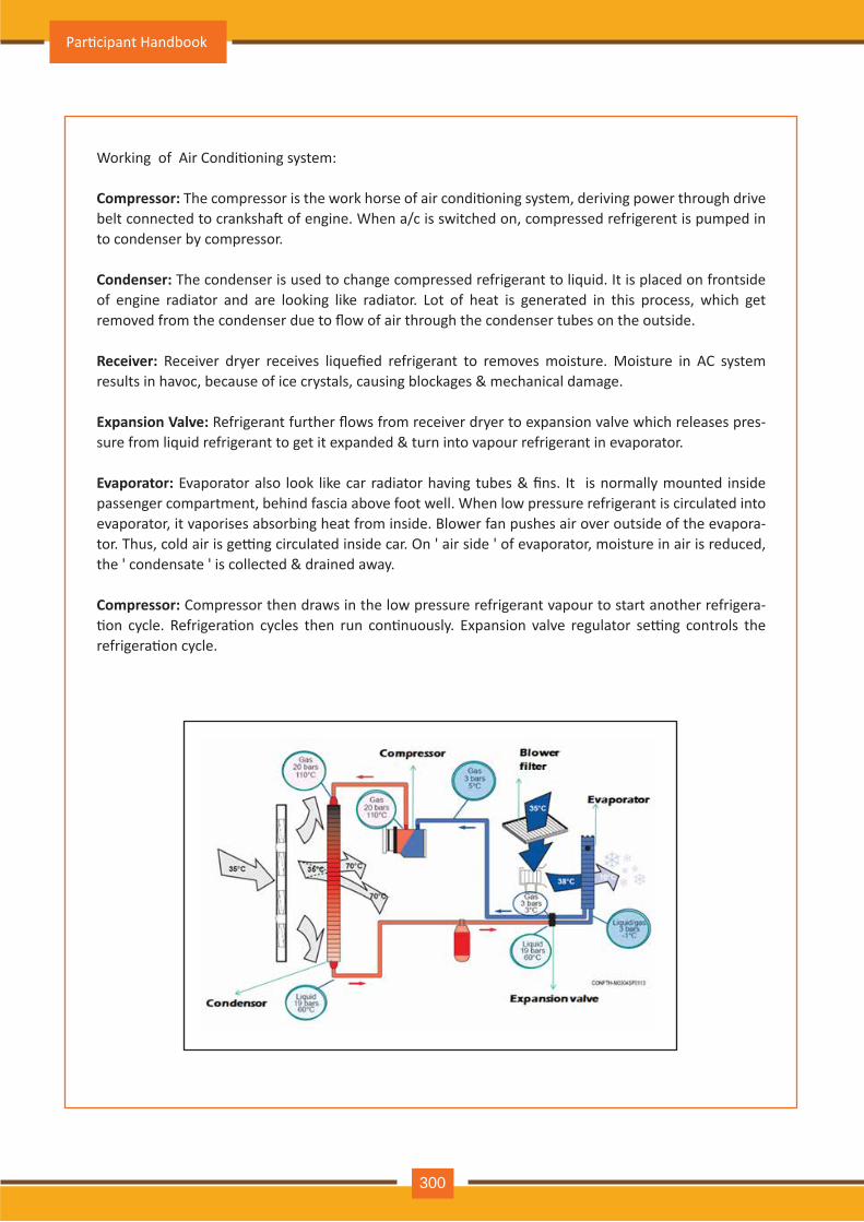
Working of Air Condi�oning system:
Compressor: The compressor is the work horse of air condi�oning system, deriving power through drive belt connected to cranksha� of engine. When a/c is switched on, compressed refrigerent is pumped in to condenser by compressor.
Condenser: The condenser is used to change compressed refrigerant to liquid. It is placed on frontside of engine radiator and are looking like radiator. Lot of heat is generated in this process, which get removed from the condenser due to flow of air through the condenser tubes on the outside.
Receiver: Receiver dryer receives liquefied refrigerant to removes moisture. Moisture in AC system results in havoc, because of ice crystals, causing blockages & mechanical damage.
Expansion Valve: Refrigerant further flows from receiver dryer to expansion valve which releases pres-sure from liquid refrigerant to get it expanded & turn into vapour refrigerant in evaporator.
Evaporator: Evaporator also look like car radiator having tubes & fins. It is normally mounted inside passenger compartment, behind fascia above foot well. When low pressure refrigerant is circulated into evaporator, it vaporises absorbing heat from inside. Blower fan pushes air over outside of the evapora-tor. Thus, cold air is ge�ng circulated inside car. On ' air side ' of evaporator, moisture in air is reduced, the ' condensate ' is collected & drained away.
Compressor: Compressor then draws in the low pressure refrigerant vapour to start another refrigera-�on cycle. Refrigera�on cycles then run con�nuously. Expansion valve regulator se�ng controls the refrigera�on cycle.
Par�cipant Handbook
300
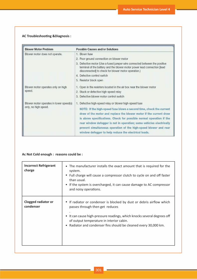
AC Troubleshoo�ng &Diagnosis :
Ac Not Cold enough : reasons could be :
Incorrect Refrigerant charge
Clogged radiator or condenser
Th e m anufacturer installs th e exact am ount th at is required for th e sy stem .Full charge will cause a compressor clutch to cycle on and off faster th an usual.If th e sy stem is ov erch arged, it can cause dam age to A C com pressor and noisy opera�ons.
If radiator or condenser is blocked by dust or debris airflow which passes th rough th en get reduces .It can cause high-pressure readings, which knocks several degrees off of output tem perature in interior cabin.Radiator and condenser fins should be cleaned every 30,000 km.
•
•
•
•
•
•
Auto Service Technician Level 4
301
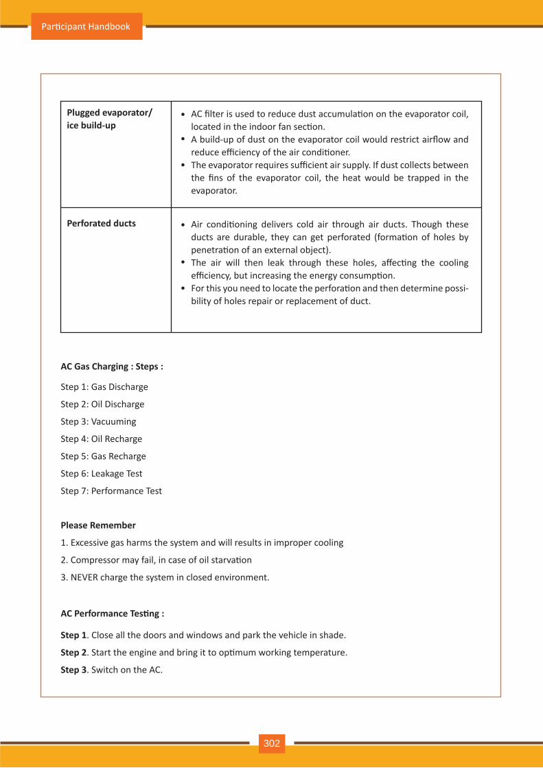
Plugged evaporator/ice build-up
Perforated ducts
AC filter is used to reduce dust accumula�on on the evaporator coil, located in the indoor fan sec�on.A build-up of dust on the evaporator coil would restrict airflow and reduce efficiency of the air condi�oner.The evaporator requires sufficient air supply. If dust collects between the fins of the evaporator coil, the heat would be trapped in the evaporator.
•
•
•
Air condi�oning delivers cold air through air ducts. Though these ducts are durable, they can get perforated (forma�on of holes by penetra�on of an external object).The air will then leak through these holes, affec�ng the cooling efficiency, but increasing the energy consump�on.For this you need to locate the perfora�on and then determine possi-bility of holes repair or replacement of duct.
•
•
•
AC Gas Charging : Steps :
Please Remember
AC Performance Tes�ng :
Step 1: Gas Discharge
Step 2: Oil Discharge
Step 3: Vacuuming
Step 4: Oil Recharge
Step 5: Gas Recharge
Step 6: Leakage Test
Step 7: Performance Test
1. Excessive gas harms the system and will results in improper cooling
2. Compressor may fail, in case of oil starva�on
3. NEVER charge the system in closed environment.
Step 1. Close all the doors and windows and park the vehicle in shade.
Step 2. Start the engine and bring it to op�mum working temperature.
Step 3. Switch on the AC.
Par�cipant Handbook
302
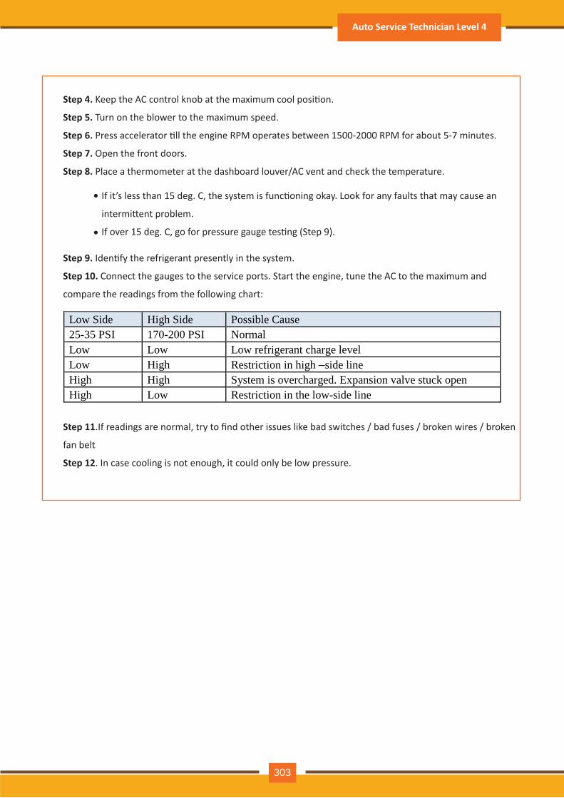
Step 4. Keep the AC control knob at the maximum cool posi�on.
Step 5. Turn on the blower to the maximum speed.
Step 6. Press accelerator �ll the engine RPM operates between 1500-2000 RPM for about 5-7 minutes.
Step 7. Open the front doors.
Step 8. Place a thermometer at the dashboard louver/AC vent and check the temperature.
Step 9. Iden�fy the refrigerant presently in the system.
Step 10. Connect the gauges to the service ports. Start the engine, tune the AC to the maximum and
compare the readings from the following chart:
Step 11.If readings are normal, try to find other issues like bad switches / bad fuses / broken wires / broken
fan belt
Step 12. In case cooling is not enough, it could only be low pressure.
If it’s less than 15 deg. C, the system is func�oning okay. Look for any faults that may cause an
intermi�ent problem.
If over 15 deg. C, go for pressure gauge tes�ng (Step 9).
Low Side High Side Possible Cause 25-35 PSI 170-200 PSI Normal Low Low Low refrigerant charge level Low High Restriction in high –side line High High System is overcharged. Expansion valve stuck open High Low Restriction in the low-side line
•
•
Auto Service Technician Level 4
303
2.5.14: Maintenance
Preven�ve maintenance:
Check the an�-freeze/coolant level, and top up, if required.
Inspect belts for wear, glaze or fray and hoses for bulges, rot, bri�leness or loose clamps. Also
check the tension.
Check fluid level in transmission system.
Check engine oil for correct level.
Ensure air filter is clean.
Ensure fluid level in brake master cylinder .
Check clutch pedals for wear.
Check leaks throughout the system.
Check fluid level of windshield washer reservoir level.
Inspect ba�ery for corrosion, electrolytes and cable condi�on.
Check fluid level of power steering..
Inspect windshield wiper blades for wear, bri�leness or hardness.
Inspect all the lights for cleanliness and workability. If a light is not working, check the cables and
fuse.
Fill tyre pressure to recommended pressure.
Check for cuts / bulges / excessive or uneven tread wear in tyres.
Inspect oil leakage in shock absorbers.
Check for loose, broken exhaust clamps or supports and check for holes in the muffler or pipes.
Statutory Check: Before closing bonnet & handing over vehicle, perform the following statutory
checks:
1.
2.
3.
4.
5.
6.
7.
8.
9.
10.
11.
12.
13.
14.
15.
16.
17.
18.
Check the radiator cap is closed.
Check terminals of ba�ery are �ghtly secured.
Check engine oil dips�ck is in place.
Check the wiper liquid bo�le cover is on.
Check cover of air filter is fastened with clips.
Check the bonnet rod is securely placed.
-
-
-
-
-
-
Par�cipant Handbook
304
Schedule maintenance:
Lubrica�on:
Where to lubricate:
Emergency handling:
How to change a wheel:
Always refer the owner’s manual for specific items relat-
ed to th e m ake and m odel of v eh icles.
Owner’s manual informa�on and instruc�ons supersede
the this schedule. If the manual suggest �ming belt
replacement at 50,000 km, inform the customer accord-
ingly .
Lubrica�on is important as part of any Scheduled or
Preven�ve Service.
It not only m akes th e v eh icle m ore com fortable, but also
ensures v eh icle safety and occupants.
Modern day cars have fewer lubrica�on points -- through
oil filter oil pump sends oil into oil galleries, from which
th e oil lubricates th e m ain bearings.
•
There are certain lubrica�on points in a vehicle that are fi�ed with grease nipple, which must
be lubricated by grease bucket or h and grease gun.
•
•
•
•
•
Why to lubricate:
1. Front end ball j oints
2. Tie rod ends
3. Propeller sha� Universal Joint (UJ) cross with front flange
4. Prop sha� UJ cross at rear flange
5. Centre bearing at prop sha�
6. Spring shackle pins
Park the car on level ground and apply hand brake. For safety, ensure:1.
Fig:2.5.14.1 S c h e d u l e m a in t e n a n c e :
Fig:2.5.14.2 ubrication
Auto Service Technician Level 4
305
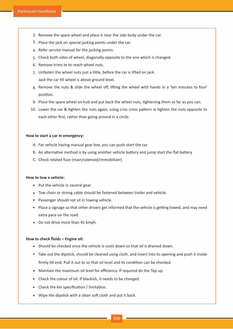
•
•
•
•
•
•
•
•
•
•
•
Remove the spare wheel and place it near the side body under the car.
Place the jack on special jacking points under the car.
Refer service manual for the jacking points.
Check both sides of wheel, diagonally opposite to the one which is changed.
Remove trims to to reach wheel nuts.
Unfasten the wheel nuts just a li�le, before the car is li�ed on jack.
Jack the car �ll wheel is above ground level.
Remove the nuts & slide the wheel off, li�ing the wheel with hands in a 'ten minutes to four'
posi�on.
Place the spare wheel on hub and put back the wheel nuts, �ghtening them as far as you can.
Lower the car & �ghten the nuts again, using criss cross pa�ern ie �ghten the nuts opposite to
each other first, rather than going around in a circle.
For vehicle having manual gear box, you can push-start the car.
An alterna�ve method is by using another vehicle ba�ery and jump start the flat ba�ery
Check related fuse (main/solenoid/immobilizer).
Put the vehicle in neutral gear.
Tow chain or strong cable should be fastened between trailer and vehicle.
Passenger should not sit in towing vehicle.
Place a signage so that other drivers get informed that the vehicle is ge�ng towed, and may need
extra pace on the road.
Do not drive more than 45 kmph.
Should be checked once the vehicle is cools down so that oil is drained down.
Take out the dips�ck, should be cleaned using cloth, and insert into its opening and push it inside
firmly �ll end. Pull it out to so that oil level and its condi�on can be checked.
Maintain the maximum oil level for efficiency. If required do the Top up.
Check the colour of oil. If blackish, it needs to be changed.
Check the km specifica�on / limita�on.
Wipe the dips�ck with a clean so� cloth and put it back.
2.3.
4.
5.
6.
7.
8.
9.
A.
B.
C.
10.
How to start a car in emergency:
How to tow a vehicle:
How to check fluids – Engine oil:
Par�cipant Handbook
306
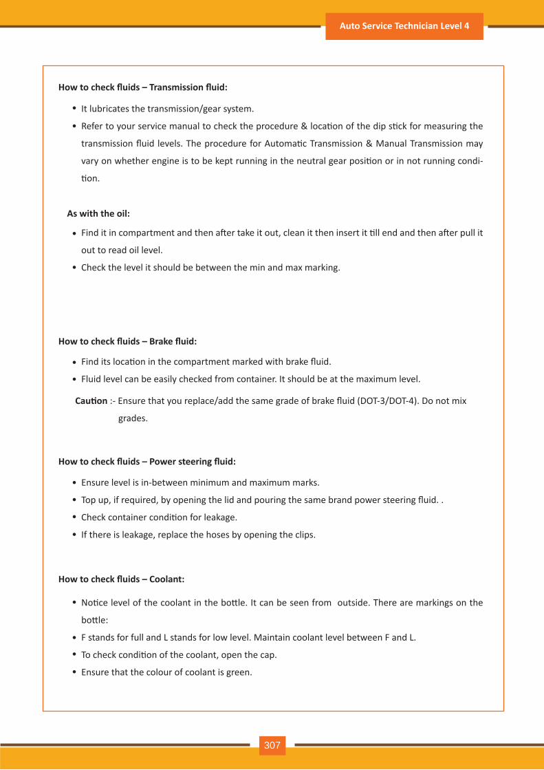
•
•
•
•
•
•
•
•
•
•
•
•
•
•
How to check fluids – Transmission fluid:
As with the oil:
How to check fluids – Brake fluid:
How to check fluids – Power steering fluid:
How to check fluids – Coolant:
It lubricates the transmission/gear system.
Refer to your service manual to check the procedure & loca�on of the dip s�ck for measuring the
transmission fluid levels. The procedure for Automa�c Transmission & Manual Transmission may
vary on whether engine is to be kept running in the neutral gear posi�on or in not running condi-
�on.
Find it in compartment and then a�er take it out, clean it then insert it �ll end and then a�er pull it
out to read oil level.
Check the level it should be between the min and max marking.
Find its loca�on in the compartment marked with brake fluid.
Fluid level can be easily checked from container. It should be at the maximum level.
Ensure level is in-between minimum and maximum marks.
Top up, if required, by opening the lid and pouring the same brand power steering fluid. .
Check container condi�on for leakage.
If there is leakage, replace the hoses by opening the clips.
No�ce level of the coolant in the bo�le. It can be seen from outside. There are markings on the
bo�le:
F stands for full and L stands for low level. Maintain coolant level between F and L.
To check condi�on of the coolant, open the cap.
Ensure that the colour of coolant is green.
Cau�on :- Ensure that you replace/add the same grade of brake fluid (DOT-3/DOT-4). Do not mix
grades.
Auto Service Technician Level 4
307
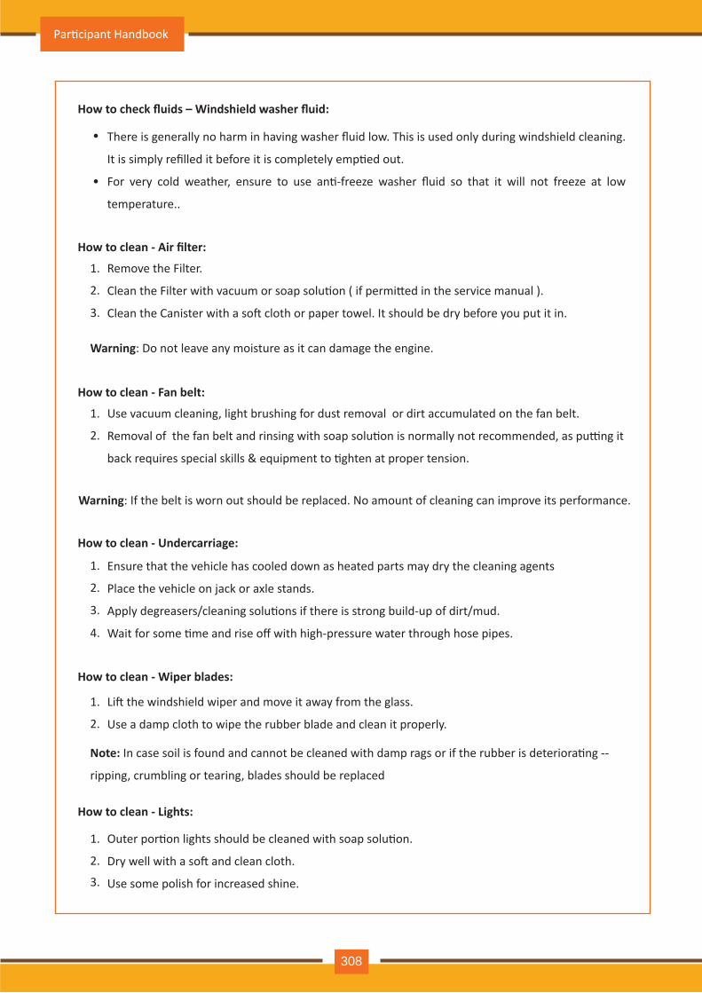
How to check fluids – Windshield washer fluid:
How to clean - Air filter:
How to clean - Undercarriage:
How to clean - Wiper blades:
How to clean - Lights:
•
•
There is generally no harm in having washer fluid low. This is used only during windshield cleaning.
It is simply refilled it before it is completely emp�ed out.
For very cold weather, ensure to use an�-freeze washer fluid so that it will not freeze at low
temperature..
Remove the Filter.
Clean the Filter with vacuum or soap solu�on ( if permi�ed in the service manual ).
Clean the Canister with a so� cloth or paper towel. It should be dry before you put it in.
Li� the windshield wiper and move it away from the glass.
Use a damp cloth to wipe the rubber blade and clean it properly.
Note: In case soil is found and cannot be cleaned with damp rags or if the rubber is deteriora�ng --
ripping, crumbling or tearing, blades should be replaced
Outer por�on lights should be cleaned with soap solu�on.
Dry well with a so� and clean cloth.
Use some polish for increased shine.
1.
2.
How to clean - Fan belt:
Use vacuum cleaning, light brushing for dust removal or dirt accumulated on the fan belt.
Removal of the fan belt and rinsing with soap solu�on is normally not recommended, as pu�ng it
back requires special skills & equipment to �ghten at proper tension.
1.
2.
3.
1.
2.
3.
4.
1.
2.
1.
2.
3.
Warning: Do not leave any moisture as it can damage the engine.
Warning: If the belt is worn out should be replaced. No amount of cleaning can improve its performance.
Ensure that the vehicle has cooled down as heated parts may dry the cleaning agents
Place the vehicle on jack or axle stands.
Apply degreasers/cleaning solu�ons if there is strong build-up of dirt/mud.
Wait for some �me and rise off with high-pressure water through hose pipes.
Par�cipant Handbook
308
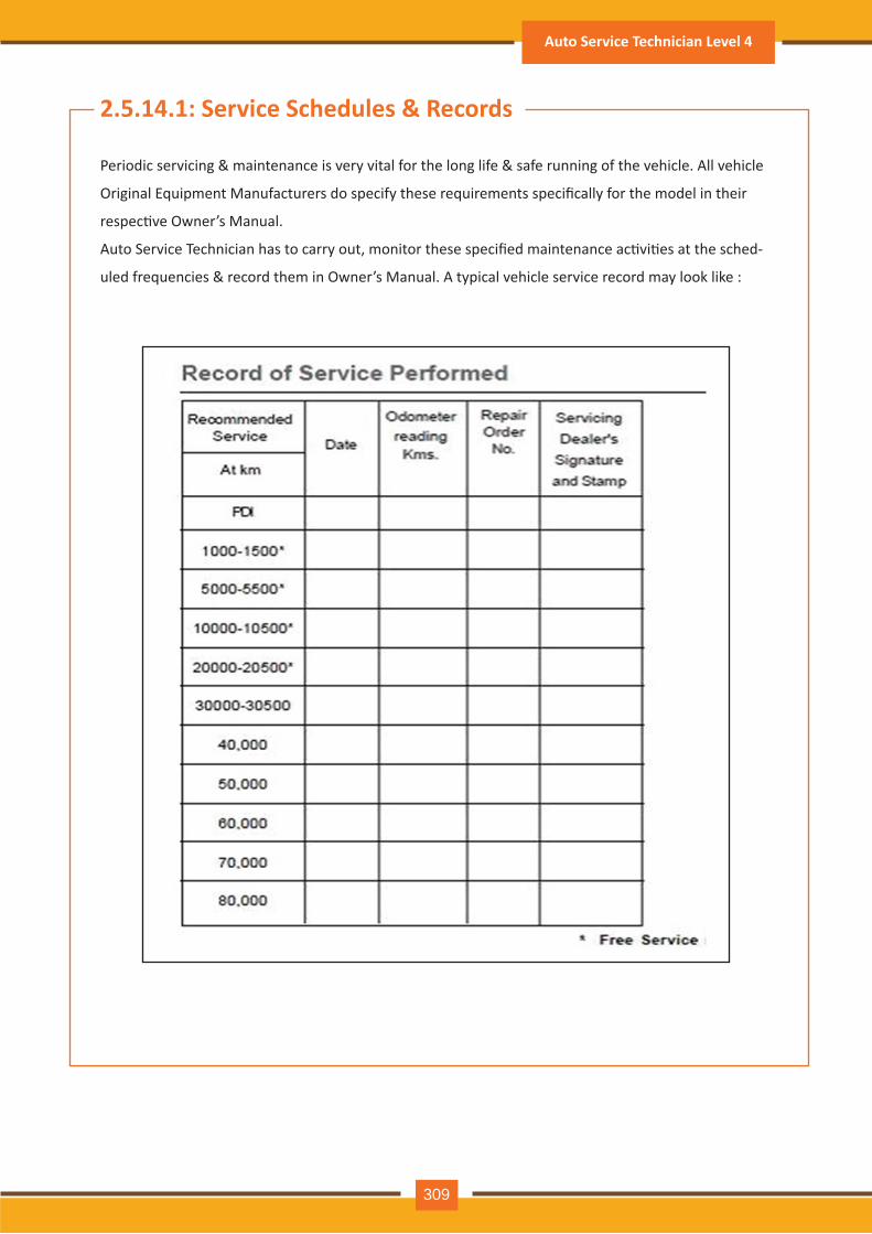
Periodic serv icing & m aintenance is v ery v ital for th e long life & safe running of th e v eh icle. A ll v eh icle
Original Equipment Manufacturers do specify these requirements specifically for the model in their
respec�ve Owner’s Manual.
Auto Service Technician has to carry out, monitor these specified maintenance ac�vi�es at the sched-
uled frequencies & record them in Owner’s Manual. A typical vehicle service record may look like :
2.5.14.1: Service Schedules & Records
Auto Service Technician Level 4
309
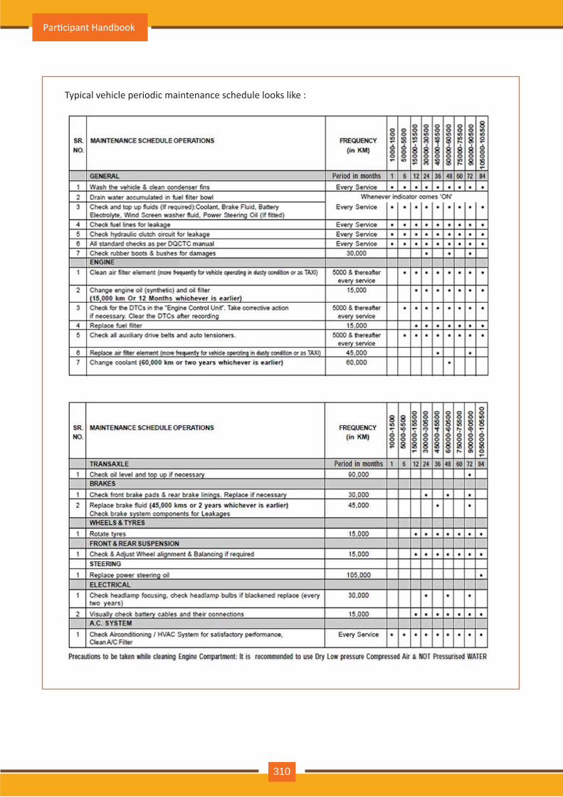
Typical vehicle periodic maintenance schedule looks like :
Par�cipant Handbook
310
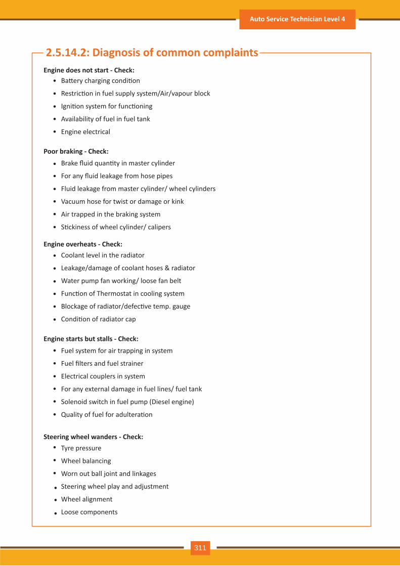
2.5.14.2: Diagnosis of common complaints Engine does not start - Check:
Poor braking - Check:
Engine overheats - Check:
Engine starts but stalls - Check:
Steering wheel wanders - Check:
•
•
•
•
•
•
•
•
•
•
•
•
•
•
•
•
•
•
•
•
•
•
•
•
•
•
Ba�ery charging condi�on
Restric�on in fuel supply system/Air/vapour block
Igni�on system for func�oning
Availability of fuel in fuel tank
Engine electrical
Brake fluid quan�ty in master cylinder
For any fluid leakage from hose pipes
Fluid leakage from master cylinder/ wheel cylinders
Vacuum hose for twist or damage or kink
Air trapped in the braking system
S�ckiness of wheel cylinder/ calipers
Coolant level in the radiator
Leakage/damage of coolant hoses & radiator
Water pump fan working/ loose fan belt
Func�on of Thermostat in cooling system
Blockage of radiator/defec�ve temp. gauge
Condi�on of radiator cap
Fuel system for air trapping in system
Fuel filters and fuel strainer
Electrical couplers in system
For any external damage in fuel lines/ fuel tank
Solenoid switch in fuel pump (Diesel engine)
Quality of fuel for adultera�on
Tyre pressure
Wheel balancing
Worn out ball joint and linkages
Steering wheel play and adjustment
Wheel alignment
Loose components
•
•
•
Auto Service Technician Level 4
311
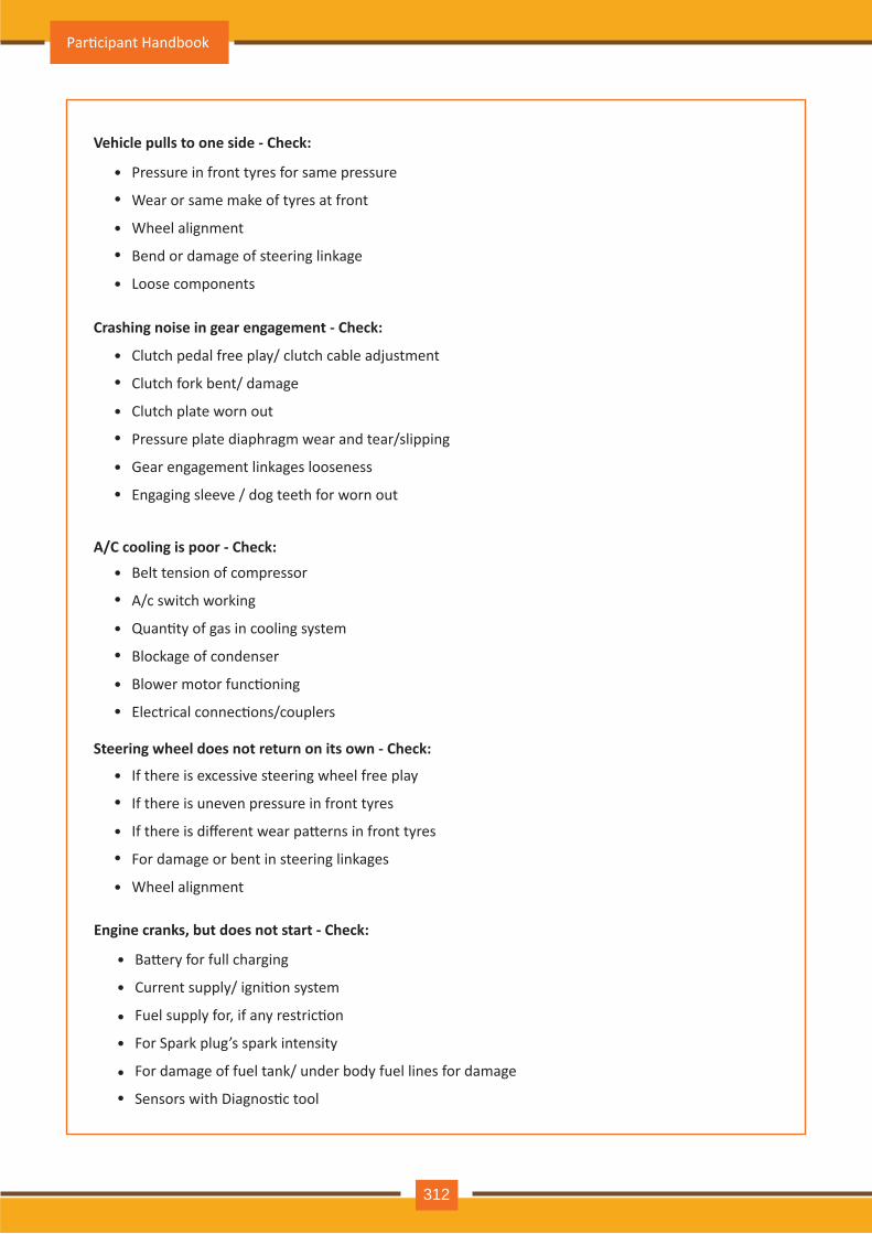
•
•
•
•
•
Pressure in front tyres for same pressure
Wear or same make of tyres at front
Wheel alignment
Bend or damage of steering linkage
Loose components
•
•
•
•
•
•
Clutch pedal free play/ clutch cable adjustment
Clutch fork bent/ damage
Clutch plate worn out
Pressure plate diaphragm wear and tear/slipping
Gear engagement linkages looseness
Engaging sleeve / dog teeth for worn out
•
•
•
•
•
•
Belt tension of compressor
A/c switch working
Quan�ty of gas in cooling system
Blockage of condenser
Blower motor func�oning
Electrical connec�ons/couplers
•
•
•
•
•
If there is excessive steering wheel free play
If there is uneven pressure in front tyres
If there is different wear pa�erns in front tyres
For damage or bent in steering linkages
Wheel alignment
Vehicle pulls to one side - Check:
Crashing noise in gear engagement - Check:
A/C cooling is poor - Check:
Steering wheel does not return on its own - Check:
•
•
•
•
••
Ba�ery for full charging
Current supply/ igni�on system
Fuel supply for, if any restric�on
For Spark plug’s spark intensity
For damage of fuel tank/ under body fuel lines for damage
Sensors with Diagnos�c tool
Engine cranks, but does not start - Check:
Par�cipant Handbook
312
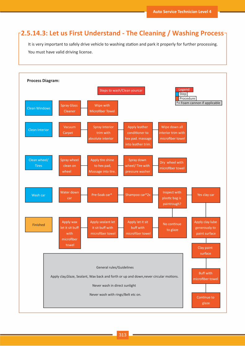
2.5.14.3: Let us First Understand - The Cleaning / Washing ProcessIt is very important to safely drive vehicle to washing sta�on and park it properly for further processing.
You must have valid driving license.
Process Diagram:
Clean WindowsSpray Glass
CleanerWipe with
Microfiber Towel
Clean Interior Vacuum Carpet
Spray Interior trim with
absolute interior
Apply leather condi�oner to
hex pad. massage into leather trim.
Wipe down all interior trim with microfiber towel
Clean wheel/Tires
Spray wheel clean on
wheel
Apply �re shine to hex pad,
Massage into �re.
Spray down wheel/ Tire with pressure washer
Dry wheel with microfiber towel
Wash carWater down
car Pre-Soak car* Shampoo car*2x
Inspect with plas�c bag is paintrough?
Yes clay car
Clay paint surface
Buff with microfiber towel
Con�nue to glaze
FinishedApply wax
let it sit buff with
microfiber towel
Apply sealant let it sit buff with
microfiber towel
Apply let it sit buff with
microfiber towel
No con�nue to glaze
Apply clay lube generously to paint surface
General rules/Guidelines
Apply clay,Glaze, Sealant, Wax back and forth or up and down,never circular mo�ons.
Never wash in direct sunlight
Never wash with rings/Belt etc on.
Steps to wash/Clean yourcar LegendStepProcedure
*= Foam cannon if applicable
Auto Service Technician Level 4
313
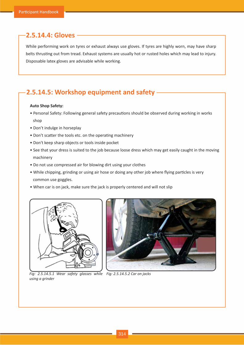
While performing work on tyres or exhaust always use gloves. If tyres are highly worn, may have sharp
belts thrus�ng out from tread. Exhaust systems are usually hot or rusted holes which may lead to injury.
Disposable latex gloves are advisable while working.
2.5.14.4: Gloves
Auto Shop Safety:
• Personal Safety: Following general safety precau�ons should be observed during working in works
shop
• Don’t indulge in horseplay
• Don't sca�er the tools etc. on the opera�ng machinery
• Don't keep sharp objects or tools inside pocket
• See that your dress is suited to the job because loose dress which may get easily caught in the moving
machinery
• Do not use compressed air for blowing dirt using your clothes
• While chipping, grinding or using air hose or doing any other job where flying par�cles is very
common use goggles.
• When car is on jack, make sure the jack is properly centered and will not slip
2.5.14.5: Workshop equipment and safety
Fig: 2.5.14.5.1 Wear safety glasses while using a grinder
Fig: 2.5.14.5.2 Car on jacks
Par�cipant Handbook
314
It means the working area is neat and free from clu�er. It reduces accidents. To ensure good
housekeeping:
• Pick up anything you find lying on the floor
• Store all tools properly
• Spilled oil, water or any other liquid should be wiped up immediately
• Creepers, jacks and other such floor equipment should not be le� sca�ered around
• Be careful about projec�on e.g. jack handles. See that they don't project from under the car
2.5.14.6: Good housekeeping
• Correct tool should be used to perform hand job. .
• Use the tool correctly.
• Keep tools clean & in excellent working condi�on.
• Grease or oil on tools should be wiped off as it is difficult to hold and use such tools
• Store the tools in their proper places.
2.5.14.7: Safety with hand tools
Use of power tools risk:
• Electric shock: The safety precau�ons are —
• Don't use damaged chords
• Don't stand in water or even wear wet shoes during electrical equipment maintenance work
• Make sure the electrical equipment is properly earthed
• Flying metal chips the safety precau�ons is —ALWAYS WEAR GOGGLES
• Injuries due to unsafe use of tools: The safety precau�ons are:
• Carefully study the instruc�ons before using any equipment
• Be careful with the moving parts
• Never feel the ‘finish’ while the machine is in opera�on
• When working on devices like clutches, valves etc. which have springs, make sure the springs will not
slip or jump off
• Don't adjust or oil moving part of a machine
2.5.14.8: Safety with power tools
Auto Service Technician Level 4
315

Notes
Par�cipant Handbook
316
Summary :
Modern automobiles are very intelligent systems. Driverless cars are being triedin the advancedcoun-tries. The Automo�ve Service Technician at Level 4 is mainly concerned with following systems as summarisedbelow:
• Engine
• Transmission
• Chassis & frame
• Brakes
• Steering
• Suspension
• Tyres
• Cooling
• Lubrica�on
• Electrical & Electronic
• Air condi�oning & hea�ng
• Oils & Paints
• Safety & Accident preven�on
• Driver Informa�on Systems
• Vehicle Servicing
• Dismantling & re-assembling major mechanical & electrical aggrgates
• Trouble shoo�ng, fault finding
• Repairing mechanical & electrical aggregates
• Servicing of the vehicles
• Maintenance of the vehicles
• Workshop tools & equipment
• Customer requirements
• OEM & component manufacturer’s requirements
• Standard opera�ng procedures
• Quality improvements
• Cost effec�veness
• 5 S
Auto Service Technician Level 4
317
Key Terms :
1. DIS : Driver Info. System
2. Diagnos�c systems
3. EOBD : Engine On Board Diagnos�c system
4. ABS : An�lock Braking system
5. RCA : Root Cause Analysis
6. Correc�ve ac�ons
7. Preven�ve ac�ons
8. Job card
9. Service requirements
10. Steering geometry
11. Head light focussing
12. Brake bleeding
13. Lubrica�on
14. Greasing
15. Inspec�on & �ghtening of loose parts
16. Leakages from automo�ve systems
17. Igni�on
18. IC Engines : Internal Combus�on
19. FMEA : Failure Modes & Effects Analysis
20. Fire figh�ng& ex�nguishers
21. Customer Sa�sfac�on & customer delight
Check Your Understanding :
1. Fill in the blanks :
a. EOBD stands for ----, ----, ----, ---- Answer :Engine On Board Diagnos�cb. DIS stands for ----, ----, ---- Answer :Driver Info. systemc. 5 S stands for ----, ----, ----, ----, ----, ---- Answer :Seiri, Seiton, Seiso, Seiketsu, Shitsuked. ABS stands for ----, ----, ---- Answer : An�lock Braking Systeme. EPAS stands for ----, ----, ----, ---- Answer : Electronic Power Assisted Steering
Par�cipant Handbook
318
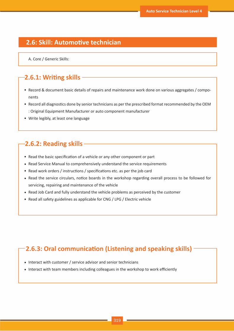
A. Core / Generic Skills:
2.6.1: Wri�ng skills
Record & document basic details of repairs and maintenance work done on various aggregates / compo-
nents
Record all diagnos�cs done by senior technicians as per the prescribed format recommended by the OEM
: Original Equipment Manufacturer or auto component manufacturer
Write legibly, at least one language
•
•
•
2.6.2: Reading skills
Read the basic specifica�on of a vehicle or any other component or part
Read Service Manual to comprehensively understand the service requirements
Read work orders / instruc�ons / specifica�ons etc. as per the job card
Read the service circulars, no�ce boards in the workshop regarding overall process to be followed for
servicing, repairing and maintenance of the vehicle
Read Job Card and fully understand the vehicle problems as perceived by the customer
Read all safety guidelines as applicable for CNG / LPG / Electric vehicle
•
••
•
••
2.6.3: Oral communica�on (Listening and speaking skills)
Interact with customer / service advisor and senior technicians
Interact with team members including colleagues in the workshop to work efficiently•
•
2.6: Skill: Automo�ve technician
Auto Service Technician Level 4
319
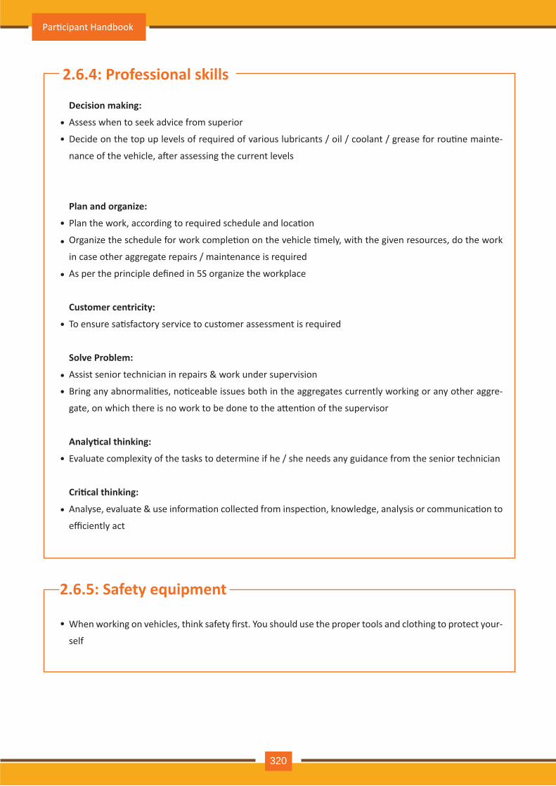
Decision making:
Assess when to seek advice from superior
Decide on the top up levels of required of various lubricants / oil / coolant / grease for rou�ne mainte-
nance of the vehicle, a�er assessing the current levels
Plan and organize:
Plan the work, according to required schedule and loca�on
Organize the schedule for work comple�on on the vehicle �mely, with the given resources, do the work
in case other aggregate repairs / maintenance is required
As per the principle defined in 5S organize the workplace
Customer centricity:
To ensure sa�sfactory service to customer assessment is required
Solve Problem:
Assist senior technician in repairs & work under supervision
Bring any abnormali�es, no�ceable issues both in the aggregates currently working or any other aggre-
gate, on which there is no work to be done to the a�en�on of the supervisor
Analy�cal thinking:
Evaluate complexity of the tasks to determine if he / she needs any guidance from the senior technician
Cri�cal thinking:
Analyse, evaluate & use informa�on collected from inspec�on, knowledge, analysis or communica�on to
efficiently act
2.6.4: Professional skills
•
•
•
•
•
•
••
•
•
2.6.5: Safety equipment
When working on vehicles, think safety first. You should use the proper tools and clothing to protect your-
self
•
Par�cipant Handbook
320
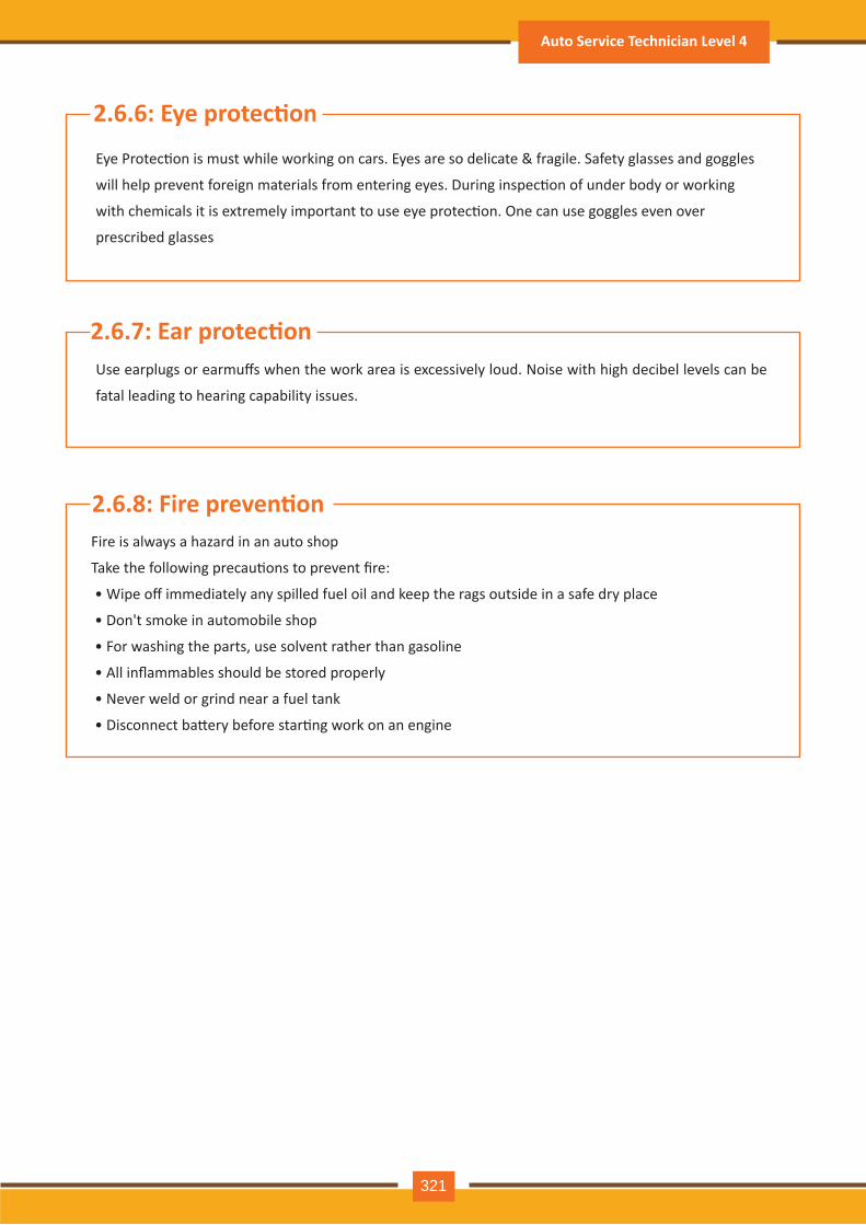
Eye Protec�on is must while working on cars. Eyes are so delicate & fragile. Safety glasses and goggles
will help prevent foreign materials from entering eyes. During inspec�on of under body or working
with chemicals it is extremely important to use eye protec�on. One can use goggles even over
prescribed glasses
2.6.6: Eye protec�on
Use earplugs or earmuffs when the work area is excessively loud. Noise with high decibel levels can be
fatal leading to hearing capability issues.
2.6.7: Ear protec�on
Fire is always a hazard in an auto shop
Take the following precau�ons to prevent fire:
• Wipe off immediately any spilled fuel oil and keep the rags outside in a safe dry place
• Don't smoke in automobile shop
• For washing the parts, use solvent rather than gasoline
• All inflammables should be stored properly
• Never weld or grind near a fuel tank
• Disconnect ba�ery before star�ng work on an engine
2.6.8: Fire preven�on
Auto Service Technician Level 4
321
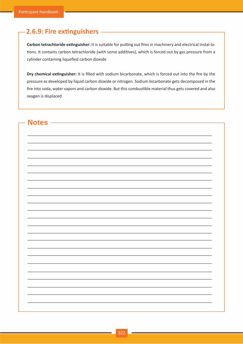
Notes
Carbon tetrachloride ex�nguisher: It is suitable for pu�ng out fires in machinery and electrical instal-la-
�ons. It contains carbon tetrachloride (with some addi�ves), which is forced out by gas pressure from a
cylinder containing liquefied carbon dioxide
Dry chemical ex�nguisher: It is filled with sodium bicarbonate, which is forced out into the fire by the
pressure as developed by liquid carbon dioxide or nitrogen. Sodium bicarbonate gets decomposed in the
fire into soda, water vapors and carbon dioxide. But this combus�ble material thus gets covered and also
oxygen is displaced
2.6.9: Fire ex�nguishers
Par�cipant Handbook
322
Summary :
Key Terms :
Check Your Understanding :
1. Say True or False :
Auto Service Technician at Level 4 should have basic Core / Generic skills, as well as the Professional skills to perform his job effec�vely :
1. Customer requirements2. Customer focus3. SOP : Standard Opera�ng Procedures4. OEM : Original Equipment Manufacturer5. Ancillary 6. Data Analysis7. Repor�ng
• Wri�ng skills, • Reading skills• Oral communica�on skills ( Listening / Speaking )
Core / Generic skills are :
• Decision making• Planning & Organizing• Customer centricity• Problem solving• Analy�cal thinking• Cri�cal thinking
Professional skills are :
a. Vehicle Job card gives customers salary ( True / False ) Answer :Falseb. Analy�cal thinking skills are not required for Auto Service Technician ( True / False ) Answer : Falsec. We need not care for the customer. Let him find his own solu�ons. ( True / False ) Answer :False
Auto Service Technician Level 4
323

(ASC/ N 0001)
Par�cipant Handbook
324
3. Plan & Organize Work to Meet ExpectedOutcomes
Unit 3.2 – Knowledge &Understanding: Planning & Organizing Work
Unit 3.1 – Performance criteria for Planning & Organizing Work
ASC/ N 0001
At the end of this module, you will be able to:
1. Perform the job within given �me as per quality standards / work schedule
2. Iden�fy and manage resources and use it efficiently and effec�vely
3. Perform as per policies and procedures of organiza�on
4. Manage your �me effec�vely at work
5. Apply best prac�ces for a cleaned workshop
6. Acquire knowledge and understanding required for planning & organizing
Key learning outcomes
Par�cipant Handbook
326
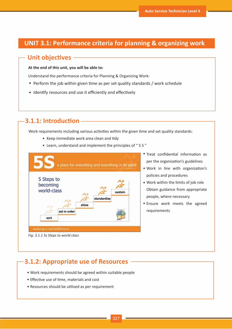
Work requirements including various ac�vi�es within the given �me and set quality standards:
• Keep immediate work area clean and �dy
• Learn, understand and implement the principles of “ 5 S ”
Treat confiden�al informa�on as
per the organiza�on’s guidelines
Work in line with organiza�on’s
policies and procedures
Work within the limits of job role
Obtain guidance from appropriate
people, where necessary
Ensure work meets the agreed
requirements
3.1.1: Introduc�on
At the end of this unit, you will be able to:
Understand the performance criteria for Planning & Organizing Work:
UNIT 3.1: Performance criteria for planning & organizing work
Unit objec�ves
Perform the job within given �me as per set quality standards / work schedule
Iden�fy resources and use it efficiently and effec�vely
•
•
Fig: 3.1.1 5s Steps to world class
•
•
•
•
• Work requirements should be agreed within suitable people
• Effec�ve use of �me, materials and cost
• Resources should be u�lized as per requirement
3.1.2: Appropriate use of Resources
Auto Service Technician Level 4
327
Unit objec�ves
At the end of this unit, you will be able to:
1. Perform as per policies and procedures of organiza�on
2. Manage your �me effec�vely at work
3. Apply best prac�ces for cleaned workshop
UNIT 3.2: Knowledge & understanding - Working effec�vely as team
Most of the organiza�ons usually formulate set of policies, principles and guidelines to reach long
term goals. This formulated content is mainly printed as a booklet or in other form for be�er
accessibility by people of organiza�on.
It is designed by the organiza�on to control and establish decisions. This help the organiza�on in
taking remedial ac�on and ac�vi�es within the organiza�on take place with the set boundaries.
To decide ac�on in opera�on of organiza�on explicit methods are defined to express policies.
Policies and procedure together ensures that governing body view should be translated in step by
step manner which will result in compa�ble outcome.
Policy is a set of procedures which define the guidelines for dealing with issues related human
resource management. It communicates an organiza�on’s values and the organiza�on’s expecta-
�ons of employee’s conduct and performance.
It also strengthen and simplify SOPs (standard opera�ng procedure) in a workplace. Using proper
policies employers managing people in the organiza�on became very efficient, as it clearly spell
out acceptable and unacceptable behaviour in the workplace. This also ensuring implica�on
complying with those policies. Basically workplace policies define the purpose and guidelines to
follow for achieving the purpose. This has to be wri�en in easy language for ease of understand-
ing. Policy length will depend on the issue it is addressing.
3.2.1: Organiza�on Policy & Procedures
Par�cipant Handbook
328
There should be certain diplomacy in policy implementa�on and this diplomacy should be clearly
declared as a part of policy. Policy may also be required wherever there is mixture of interest and
preference as this may result in conflict within the organiza�on specially to those who will be
directly involved.
All workplace issues does not require a policy. For dealing with regular ma�er a simple procedure
for work-place procedure can be implemented.
Every company has different policies and procedures. Company should explain its policies and
procedures to their employee in detail within first week of employment.
Employee should be given all the details about policy on first day of employment which should
outline what the company is expec�ng from employee in terms of behaviour, dressing and leaves
etc are concerned. It is good to keep it as printed copy to refer to it when ques�ons arise about
what the company allows and doesn’t allow.
The key benefits:
- Helps us to abide with employment policies and its associated legisla�on
- To make sure regularity and reliability in decision
- Time saving during raise of new problem to handle it quickly and effec�vely by following exis�ng
policy
- Provide the support system for business planning
- Assist in performance assessment and strengthen accountability
- Clarify func�ons and responsibili�es
- Help employees to understand their expecta�on with respect to standards of behaviour and
performance
- Acts as strategy in decision making process in a regular working pa�ern thus reduces dependen
cy to ask help from seniors
- Help in adop�ng reliable and clear response in company by referring situa�ons
- Developing good faith in employees for fair and equal treatment
3.2.2: Benefits of Organiza�onal Policies & Procedures
Auto Service Technician Level 4
329
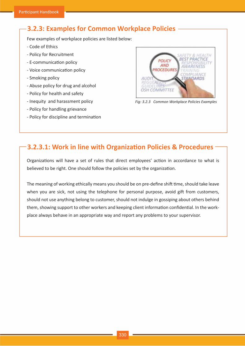
Fig: 3.2.3 Common Workplace Policies Examples
Few examples of workplace policies are listed below:
- Code of Ethics
- Policy for Recruitment
- E-communica�on policy
- Voice communica�on policy
- Smoking policy
- Abuse policy for drug and alcohol
- Policy for health and safety
- Inequity and harassment policy
- Policy for handling grievance
- Policy for discipline and termina�on
3.2.3: Examples for Common Workplace Policies
Organiza�ons will have a set of rules that direct employees’ ac�on in accordance to what is
believed to be right. One should follow the policies set by the organiza�on.
The meaning of working ethically means you should be on pre-define shi� �me, should take leave
when you are sick, not using the telephone for personal purpose, avoid gi� from customers,
should not use anything belong to customer, should not indulge in gossiping about others behind
them, showing support to other workers and keeping client informa�on confiden�al. In the work-
place always behave in an appropriate way and report any problems to your supervisor.
3.2.3.1: Work in line with Organiza�on Policies & Procedures
Par�cipant Handbook
330
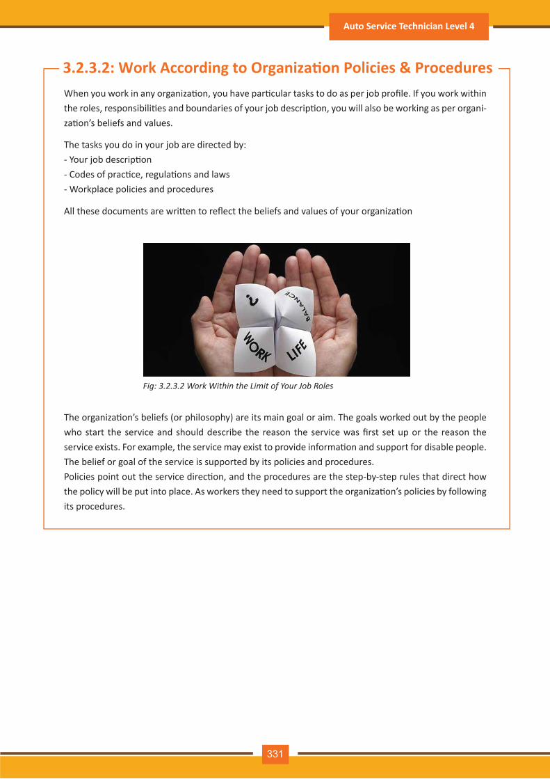
Fig: 3.2.3.2 Work Within the Limit of Your Job Roles
When you work in any organiza�on, you have par�cular tasks to do as per job profile. If you work within the roles, responsibili�es and boundaries of your job descrip�on, you will also be working as per organi-za�on’s beliefs and values.
The organiza�on’s beliefs (or philosophy) are its main goal or aim. The goals worked out by the people who start the service and should describe the reason the service was first set up or the reason the service exists. For example, the service may exist to provide informa�on and support for disable people. The belief or goal of the service is supported by its policies and procedures.Policies point out the service direc�on, and the procedures are the step-by-step rules that direct how the policy will be put into place. As workers they need to support the organiza�on’s policies by following its procedures.
The tasks you do in your job are directed by:- Your job descrip�on- Codes of prac�ce, regula�ons and laws- Workplace policies and procedures
All these documents are wri�en to reflect the beliefs and values of your organiza�on
3.2.3.2: Work According to Organiza�on Policies & Procedures
Auto Service Technician Level 4
331
Fig: 3.2.3.3 Keep Organizational Information Private and Confidential
You may experience situa�ons when you have problems doing your job well. Unexpected things can happen to change the day-to-day opera�ons of an organiza�on or workplace.When you have difficul�es in carrying out your du�es, you need to report these problems to your super-visor. Report problems to your supervisor so that solu�ons can be found. In this way one can feel more comfortable and work efficiently.
3.2.3.4: Guidance from Appropriate People
3.2.3.3: Work According to Organiza�on Policies & ProceduresWhen you work in any organiza�on, you have par�cular tasks to perform as per job role. If you work within the roles, responsibili�es and boundaries of your job descrip�on, you will also be working as per organiza�on’s beliefs and values.
Keep informa�on private and confiden�al. For example:
- Do not use the person’s full name if you are speaking to them on the telephone or talking to them in a public space such as a wai�ng room. Always be aware that your conversa�on can be heared by others..
- Never talk about customer or co-workers in social situa�ons or give away informa�on that might iden-�fy a person.
You should not share customer informa�on with your co-workers without the customer’s permission even though you work closely together and are employed by the same organiza�on.
To destroying private or confiden�al informa�on organiza�on policy has to be followed. Make sure informa�on not to be recycled – be locked away when they are not being used – are disposed of proper-ly such as shredded.
All informa�on provided by a customer, even in casual conversa�on needs confiden�al treatment.
Par�cipant Handbook
332

Fig: 3.2.3.6 Why Time Management?
3.2.3.5: Managing Time/Materials/Cost Effec�velyWorking effec�vely means doing your job without was�ng �me or energy. In your work environment you perform various types of task. You need to clearly understand expecta�on from you. Like, you answering phone, receive customers, etc. Your job descrip�on will describe the tasks you have to do. However, not everything that is expected of you will be wri�en in the job descrip�on or other workplace documents.
There should be a clear understanding of what you are expected to do and you must also know how you should work with other team members.
3.2.3.6: Time ManagementWe achieve outcome of our 24 hours period based on our enthusiasm, energy levels, ability to perform, skills and other resourcesAs our �me is always in demand, plan yourself on how to use our �me and for more effec�ve �me man-agement we need to consider certain strategies. Time management does not means to work harder or for longer period but it help us to work smartly so that we can finish our work easily and quickly.
If we can manage our �me more effec�vely, we will be rewarded in a variety of ways:- We will be more competent in our rou�ne job and also can support others in be�er ways.- We can accomplish great success in every role as a leader.- On a personal level, you will certainly feel healthier, more energe�c, and in a generally be�er mood.
Auto Service Technician Level 4
333
3.2.3.7: Obstacles to Effec�ve Time ManagementVarious factors contribu�ng to disturbance due to which it becomes for us in effec�ve management of our �me. Now think about certain common factors, and let us see does it apply to us:
Objec�ve is not clear – With closed eyes it is difficult to hit a target thus it is equally difficult to accom-plish something when you aren’t exactly clear about your achievement.Disorganiza�on – Some�mes we keep messy desk, but the ques�on is do we ques�on our self that are we using planned approach for tasks comple�on.Inability to Say “No” – We need to be helpful; towards others when they need our support, but this needs �me and could result in disturbing our priori�es to do something we did not planned.Interrup�ons – Some �me it happens that when in process of accomplishing something which is very important for, we get a phone call. These calls are very disturbing as it could play a import reason to be behind the schedule as it may interrupt our though process which can lead to go back from where we started or in between somewhere.More Interrup�ons – Inappropriate �me conversa�ons need our �me thus be careful stop what you are doing be�er focus on plans.Periods of Inac�vity – We all feel that we are busy, but if we will review our day �me we will find there are �me slots available where we are not occupied.. Iden�fying and use of these �mes reflect posi�ve effect on our efforts.Too Many Things at Once – Most of us work without making rou�ne of our task as it needs our a�en�on for detailing. When we try mul�ple things simultaneously each individual task get suffer.
Stress and Fa�gue – Experiencing stress �me to �me in our rou�ne life is a common issue and we perform well with lesser stress. If the level of stress is very high, our works get suffered and also effect mental and physical situa�on. Dealing with stress forms an important factor of �me management.All Work and No Play – Most successful people know how to balance work and play. During the takeover of work in our we scarifying certain important things in life like family and friends. There-fore, give your body li�le �me to re-energize and enjoy life.
Par�cipant Handbook
334
Fig: 3.2.3.9 Set Clear Goals
3.2.3.8: How to resolve obstaclesThe obstacle we face in our day to day life is not very difficult to resolve. Iden�fy existence of obstacle which is affec�ng our ability in �me management is very important. A�er iden�fying the obstacle we start think solu�on to resolve it.
3.2.3.9: Set Clear GoalsAs a Lions leader, you will want to accomplish many things in your �me of office. The best favor you can do for yourself is to determine what those goals are and make sure your efforts are always direct-ed toward their achievement.Effec�ve goals share a number of characteris�cs in common. Effec�ve goals are:
Specific – When a goal is very unclear, it become difficult to jus�fy how to reach the goal even a�er reaching it condi�on is same. Ensure that you are well aware about what you hope to achieve.Measurable – When you have a goal that is measurable, you will understand how to reach the goal when you will get there.
Achievable – – It is admirable to set our expecta�on high but the fact is some �me we expect more than what actually we perform. Some�mes it is also become difficult to achieve while doing mul�-ple task simultaneously. We should set our goal to reach them by extending our self.
Realis�c – We need to be realis�c while performing. For e.g. if we want that in our city everybody should be treated for vision problem, we should start first with iden�fying people with vision defect in a smaller locality then only we can achieve our goal for the city.
Time-based –Goals which you establish in your posi�on as a Lions leader will not be long-term. To achieve your goal you need to set certain guidelines for monitoring yourself to ensure that you are moving as per your define schedule and it will also alarm you in case you are failing behind sched-ule.
•
•
•
•
•
•
•
Auto Service Technician Level 4
335
Fig: 3.2.3.10 Prioritize
3.2.3.10: Priori�zeAs a leader in your organiza�on you will be assigned many tasks. It is always good and safe to clarify that you cannot do everything, thus make a list of tasks periodically that confront you and priori�ze them. Priori�zing Technique:
Do – Choose most important task from the list which you consider as important for your organiza-�on. Certain task has to be performed by yourself.Delegate – There could be many persons in an organiza�on who possess various skills and experi-ence to carryout variety of task. A real leader understand it very clearly that they cannot accom-plish everything by themselves. Thus they recognize someone who can be�er handle the task. Delega�ng not only helps to save your �me so that we can do other works but also ensures resourc-es applied can be used more effec�vely through certain degree of mo�va�on.Delay Un�l another Time – As a regular process we think something can wait and applying same thinking on too many things close to the dead line which creates a dangerous situa�on. Be�er consider when things are due, how long it will take to accomplish and your current work-load. Suppose you have to pay for your policy but s�ll have �me you can delay it but when it comes to deadline might hamper working process.Delete – If we set our goals as explained earlier, we will experience that some of these goals are not achievable or realis�c, or that they are just not important. For being a good leader you should aware about when to concentrate on what and eliminate what
When you priori�zed your task it is important for you to:
Address the Urgent – Things having short-term consequences should be tackled first.Accomplish What You can – Finish the work which can be accomplished same day do not wait for tomorrow.A�ach Deadlines to Things You Delay – A�aching deadlines to things we delayed – When we are very sure that things can definitely wait be careful in taking such decision by adding a deadline for that task in our schedule and should also make a note to remind our self about when we should start working on that.
•
•
•
•
••
•
Par�cipant Handbook
336

Fig: 3.2.3.11 Organize
3.2.3.11: OrganizeAs you priori�ze tasks and set deadlines, you will want to organize your plans and ac�ons. Some �me we are using paper and pencil to organize our plans, but it is important for you in today’s environment to use planner as it includes calendar and enough space to make notes. Planners have provision for calendar space, space for daily ac�vi�es, contact informa�on, and “to do” lists. Look for the planner which sa�sfy your need and start using it. You will feel like it is an essen�al tool for you to manage your �me.
We can also consider device like computer which can help in organizing our �me. The modern comput-ers are equipped with necessary features such as calendars, task lists, reminder, and contact details using so�ware programs. In case you these features are not available in your computer you get it installed very easily.
You may also consider a small personal digital assistant, or PDA. These are portable devices and use the same so�ware your home computer uses. When we do not have computer access PDAs plays important role specially during travelling to keep you updated with your pending task.
Whatever method you choose, make sure you organize your tasks to stay on track.
3.2.3.12: Should Know When To Say “NO“Let’s address some more “personal” strategies that you can apply to your life. These also have impact on how effec�vely you manage your �me.
As strategies you should learn is to say “NO” when it is appropriate. Your life in an organiza�on has always been about giving all that you can to serve your organiza�on. We cannot change this but as our responsibility expands as a leader you will find that you asked to do too much compara�vely your job posi�on is required.
Auto Service Technician Level 4
337
When we say no does not represent that that we are closing the door of our responsibility. It should be considered as we are very serious to meet our in-hand commitments and achieve it within allo�ed �me.
For saying “NO”, accept these three principles:• We should realize that we cannot do every thing• We should not undertake the task or project which we fell cannot be completed within allocated �me frame.• Never make commitments which is not leading towards goals and objec�ves
By keeping these principles in mind it became easy to jus�fy about the request has been turn down by us. Thus we will be able to accomplish the task which has been priori�zed by us as must.
Fig: 3.2.3.12 Learn When To Say “NO”
3.2.3.13: Use Your Wai�ng TimeOther factors contribute personal �me management skill for making good use of your “wai�ng �me.”You need to think over everyday how much �me you spend doing nothing? Actually certain situa�on suddenly popup which is not planned and the �me is allocated for something else. We can even make use of our �me in these unplanned events. For Example:
Time used in train or bus travellingWait at for appointment in officeWai�ng for your flight, or baggage collec�onTime you spend while you are “on hold” during telephonic conversa�onTime you spend during early arrival at mee�ng loca�on
•••••
Par�cipant Handbook
338
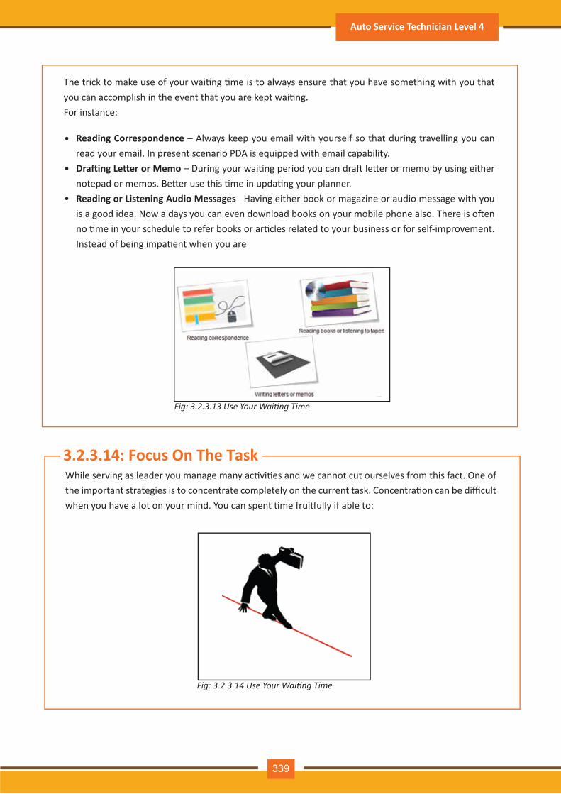
Fig: 3.2.3.13 Use Your Waiting Time
Fig: 3.2.3.14 Use Your Waiting Time
The trick to make use of your wai�ng �me is to always ensure that you have something with you that you can accomplish in the event that you are kept wai�ng.For instance:
Reading Correspondence – Always keep you email with yourself so that during travelling you can read your email. In present scenario PDA is equipped with email capability. Dra�ing Le�er or Memo – During your wai�ng period you can dra� le�er or memo by using either notepad or memos. Be�er use this �me in upda�ng your planner.Reading or Listening Audio Messages –Having either book or magazine or audio message with you is a good idea. Now a days you can even download books on your mobile phone also. There is o�en no �me in your schedule to refer books or ar�cles related to your business or for self-improvement. Instead of being impa�ent when you are
•
•
•
3.2.3.14: Focus On The TaskWhile serving as leader you manage many ac�vi�es and we cannot cut ourselves from this fact. One of the important strategies is to concentrate completely on the current task. Concentra�on can be difficult when you have a lot on your mind. You can spent �me frui�ully if able to:
Auto Service Technician Level 4
339
Fig: 3.2.3.15 Manage Prime Time
Focus on Your Goal – Everybody has various set of commitments and concerns, but for be�er accom-plishment focus on the task at a moment is very much required.Avoid Interrup�ons – When need to set our specific �me in day �me in which we should not talk on phone or a�end visitor mee�ng because this is the �me we can focus on our task. We cannot separate all of our �me but definitely avoid interrup�on during specific period of �me and this way we can successfully complete task in less �me than it was expected. While a�ending phone calls minimize interrup�ons by asking to call back or meet another day.
3.2.3.15: Manage Prime TimeEveryone is different. As per research first half �ming is more suitable to accomplish task which need higher mental concentra�on, but it is also men�oned that always it cannot be the right process because each one of us use our personal �me frame.
During planning your task focus on your prime �me. It is also recommended to do challenging task in first half and rou�ne task in the la�er part. If you don’t really get going un�l later, handle the rou�nes in the morning and save the more difficult tasks for later.
Par�cipant Handbook
340
Fig: 3.2.3.16 Celebrate Your Success
3.2.3.16: Celebrate Your SuccessAchievement of goals needs to be celebrated so that a healthy balance in life between work and play can be maintained.A�er comple�ng a task or finishing project pay reward to yourself. If you are working as tem member or you might have delegated some tasks to other member, whole team should be rewarded. Celebra�on is very important aspect of project management. Despite of being in very �ght schedule you should not ignore.
3.2.3.17: Celebrate Your SuccessIF your boss is asking you to prepare an important presenta�on and you are already occupied with your work load and many pending task in your to-do list which also very import-ant. In this situa�on you will be anxious and confuse about which task to complete first.
Urgent/Important Principle is helpful in thinking about priori�es and decides about important, essen�al and distrac�on types of ac�vi�es.Important ac�vates whether these are personal or professional are outcome based which leads to us in achieving our goals.Urgent ac�vi�es insist us for our immediate a�en�on but it is mainly linked with achieving goals for someone else.If we are aware about important and urgent ac�vi�es, we can priori�ze it.
To use the principle, list down all tasks and ac�vi�es, and put each task/ac�vity under below men�oned categories:1. Important and urgent
2. Important but not urgent
3. Not important but urgent
4. Not important and not urgent
Based on urgency of importance task and ac�vity, we need to schedule these. Urgent and important task should be priori�zed first then focus on task which is important without urgency. Actually this type of ac�vi�es prevents us in our goal achievement. The best process in this situa�on is to decide about rescheduling or delega�on or avoid if possible.
Auto Service Technician Level 4
341
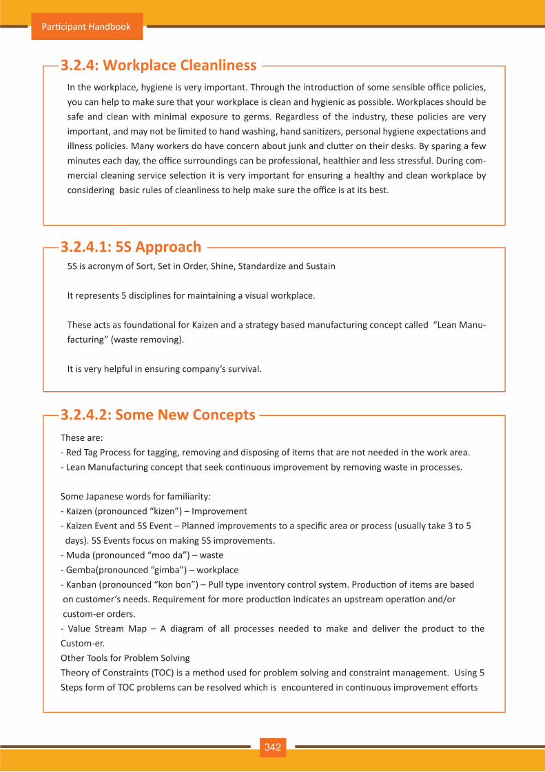
3.2.4: Workplace CleanlinessIn the workplace, hygiene is very important. Through the introduc�on of some sensible office policies, you can help to make sure that your workplace is clean and hygienic as possible. Workplaces should be safe and clean with minimal exposure to germs. Regardless of the industry, these policies are very important, and may not be limited to hand washing, hand sani�zers, personal hygiene expecta�ons and illness policies. Many workers do have concern about junk and clu�er on their desks. By sparing a few minutes each day, the office surroundings can be professional, healthier and less stressful. During com-mercial cleaning service selec�on it is very important for ensuring a healthy and clean workplace by considering basic rules of cleanliness to help make sure the office is at its best.
3.2.4.1: 5S Approach5S is acronym of Sort, Set in Order, Shine, Standardize and Sustain
It represents 5 disciplines for maintaining a visual workplace.
These acts as founda�onal for Kaizen and a strategy based manufacturing concept called “Lean Manu-facturing” (waste removing).
It is very helpful in ensuring company’s survival.
3.2.4.2: Some New ConceptsThese are:- Red Tag Process for tagging, removing and disposing of items that are not needed in the work area.- Lean Manufacturing concept that seek con�nuous improvement by removing waste in processes.
Some Japanese words for familiarity:- Kaizen (pronounced “kizen”) – Improvement- Kaizen Event and 5S Event – Planned improvements to a specific area or process (usually take 3 to 5 days). 5S Events focus on making 5S improvements.- Muda (pronounced “moo da”) – waste- Gemba(pronounced “gimba”) – workplace- Kanban (pronounced “kon bon”) – Pull type inventory control system. Produc�on of items are based on customer’s needs. Requirement for more produc�on indicates an upstream opera�on and/or custom-er orders.- Value Stream Map – A diagram of all processes needed to make and deliver the product to the Custom-er.Other Tools for Problem SolvingTheory of Constraints (TOC) is a method used for problem solving and constraint management. Using 5 Steps form of TOC problems can be resolved which is encountered in con�nuous improvement efforts
Par�cipant Handbook
342
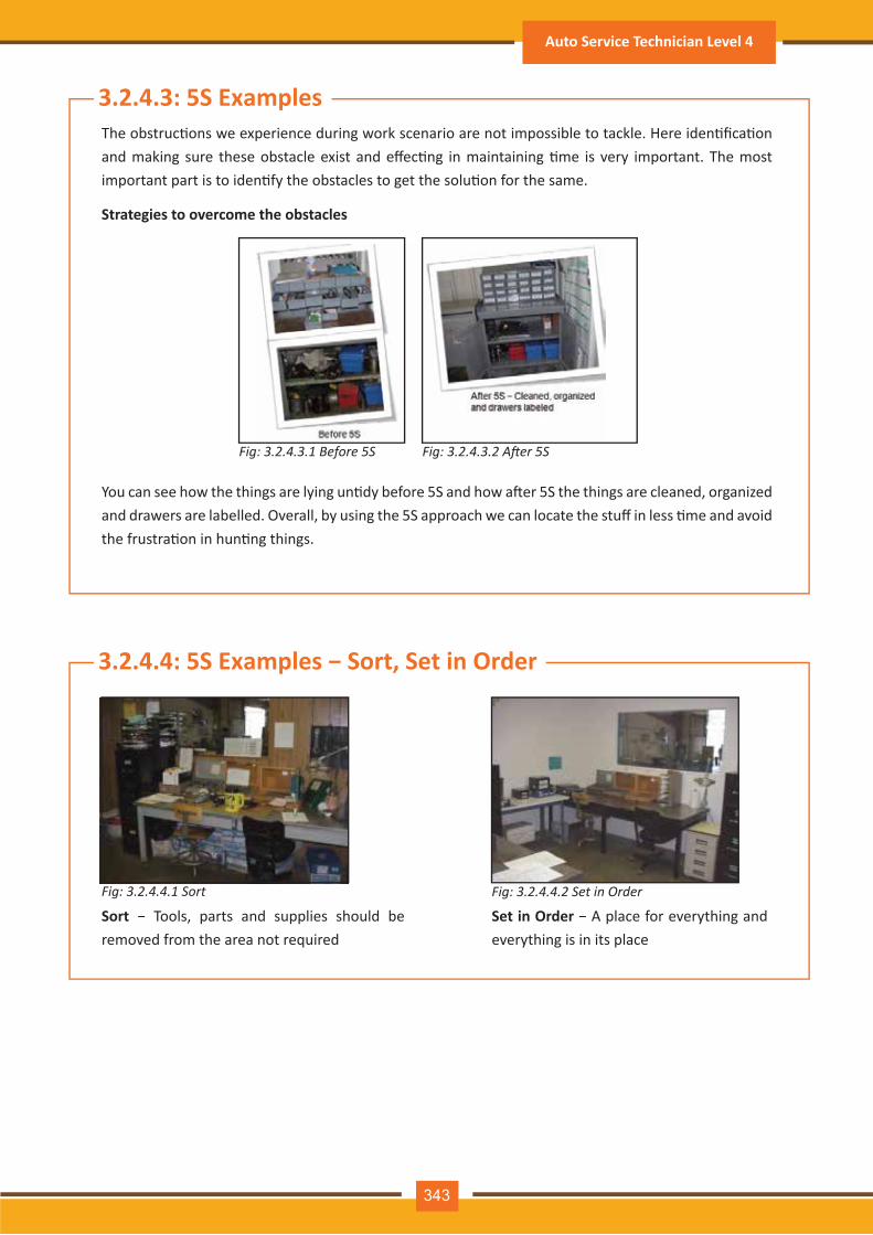
Fig: 3.2.4.3.1 Before 5S
Fig: 3.2.4.4.1 Sort Fig: 3.2.4.4.2 Set in Order
Fig: 3.2.4.3.2 After 5S
3.2.4.3: 5S Examples
3.2.4.4: 5S Examples − Sort, Set in Order
The obstruc�ons we experience during work scenario are not impossible to tackle. Here iden�fica�on and making sure these obstacle exist and effec�ng in maintaining �me is very important. The most important part is to iden�fy the obstacles to get the solu�on for the same.
Strategies to overcome the obstacles
You can see how the things are lying un�dy before 5S and how a�er 5S the things are cleaned, organized and drawers are labelled. Overall, by using the 5S approach we can locate the stuff in less �me and avoid the frustra�on in hun�ng things.
Sort − Tools, parts and supplies should be removed from the area not required
Set in Order − A place for everything and everything is in its place
Auto Service Technician Level 4
343
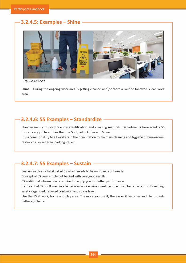
Fig: 3.2.4.5 Shine
3.2.4.5: Examples − Shine
3.2.4.6: 5S Examples − Standardize
Shine − During the ongoing work area is ge�ng cleaned and\or there a rou�ne followed clean work area.
Standardize − consistently apply iden�fica�on and cleaning methods. Departments have weekly 5S tours. Every job has du�es that use Sort, Set in Order and ShineIt is a common duty to all workers in the organiza�on to maintain cleaning and hygiene of break-room, restrooms, locker area, parking lot, etc.
3.2.4.7: 5S Examples – SustainSustain involves a habit called 5S which needs to be improved con�nually.Concept of 5S very simple but backed with very good results.5S addi�onal informa�on is required to equip you for be�er performance.If concept of 5S is followed in a be�er way work environment become much be�er in terms of cleaning, safety, organized, reduced confusion and stress level.Use the 5S at work, home and play area. The more you use it, the easier it becomes and life just gets be�er and be�er
Par�cipant Handbook
344
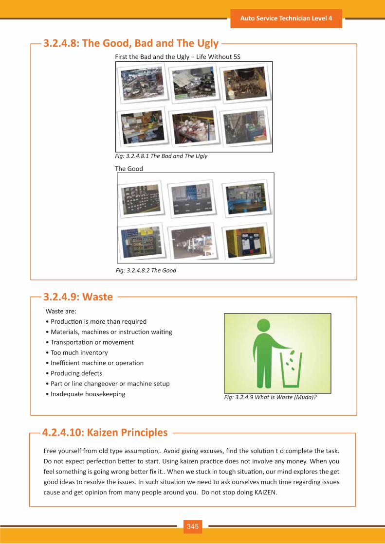
Fig: 3.2.4.8.1 The Bad and The Ugly
3.2.4.8: The Good, Bad and The UglyFirst the Bad and the Ugly − Life Without 5S
Fig: 3.2.4.8.2 The Good
Fig: 3.2.4.9 What is Waste (Muda)?
The Good
3.2.4.9: Waste Waste are:• Produc�on is more than required• Materials, machines or instruc�on wai�ng• Transporta�on or movement• Too much inventory• Inefficient machine or opera�on• Producing defects• Part or line changeover or machine setup• Inadequate housekeeping
4.2.4.10: Kaizen PrinciplesFree yourself from old type assump�on,. Avoid giving excuses, find the solu�on t o complete the task. Do not expect perfec�on be�er to start. Using kaizen prac�ce does not involve any money. When you feel something is going wrong be�er fix it.. When we stuck in tough situa�on, our mind explores the get good ideas to resolve the issues. In such situa�on we need to ask ourselves much �me regarding issues cause and get opinion from many people around you. Do not stop doing KAIZEN.
Auto Service Technician Level 4
345

Notes
It means the working area is neat and free from clu�er. It reduces accidents. To ensure good house-
keeping:
• Pick up anything you find lying on the floor
• Store all tools properly
• Spilled oil, water or other liquid should be wiped up immediately
• Creepers, jacks and other such floor equipment should not be le� sca�ered aroun
• Be careful about projec�on e.g. jack handles. See that they don't project from under the car
3.2.4.11: Good Housekeeping
Par�cipant Handbook
346
Exercise-1: Answer the Following Ques�ons:
1. Write are the benefits of organiza�on policies and procedure?__________________________________________________________________________________________________________________________________________________________________________________________________________________________________________________________________________________________________________
2. For effec�ve �me management what are the obstacles?__________________________________________________________________________________________________________________________________________________________________________________________________________________________________________________________________________________________________________
3. Write is waste?__________________________________________________________________________________________________________________________________________________________________________________________________________________________________________________________________________________________________________
Auto Service Technician Level 4
347

Par�cipant Handbook
348

4. Work Effec�vely as TeamUnit 4.1 – Performance Criteria for Working Effec�vely as Team
Unit 4.2 – Knowledge & Understanding: Working Effec�vely as Team
ASC/ N 0002
Unit 4.2 – Knowledge & Understanding: Working Effec�vely as Team
At the end of this module, you will be able to:
Key Learning Outcomes
Interact & communicate effec�vely with colleagues including own group or groups member
Use all forms of verbal and non-verbal communica�on to communicate clearly and effec�vely with
your colleagues, supervisors, customers and other stakeholders
Demonstrate communica�on skills
Judge your customers’ body language and accordingly use an appropriate approach for dealing
Apply the best prac�ces for grooming to look presentable and make good impression on your
custom-ers
Use proper personal e�que�es at workplace
Acquire knowledge and understanding required for team working
1.
2.
3.
4.
5.
6.
7.
Par�cipant Handbook
350
Wri�ng Skills
• Communicate with colleagues effec�vely (this includes face-to-face, telephonic as well as wri�en)
• Coordinate with colleagues to perform work
• Convey the informa�on to colleagues as per organiza�onal requirements either verbal or non-verbal
means
• Working procedure should reflect respect towards colleagues
• Full the commitment made to colleagues
• In case not able to full fill the commitment explain it with reasons
• Iden�fy problems in working with colleagues and take the ini�a�ve to solve these problems
• Follow policies and procedures of organiza�on for working with colleagues
4.1.1: Learn To
UNIT 4.1: Performance Criteria for Working Effec�vely as Team
Unit Objec�vesUnderstand the performance criteria for Working effec�vely as team:
Interact & communicate effec�vely with colleagues including own group or other groups member
Auto Service Technician Level 4
351

UNIT 4.2: Knowledge & Understanding - Working Effec�vely as Team
3.5.5 Android Smartphone Disassembly4.2.1: Communica�on Skills
Formal educa�on is not a guarantee for achieving success in your life. Without special qualifica�ons also people can succeed in their fields.
Many famous personali�es, such as our Prime Minister Narendra Modi, had basic educa�onal qualifica-�on, yet they became famous because of their amazing communica�on skills. This emphasizes commu-nica�on skills importance in achieving your goal to work effec�vely with:
- External par�es such as customers, vendors, etc- NInternal stakeholders such your peers and supervisors
Different types of informa�on that colleagues might need and its important when it is required
• Importance of helping colleagues with problems, to meet quality and �me standards as a team
4.2.2: Technical Knowledge
Fig: 4.2.1.1 Communication Skills Matter Fig: 4.2.1.2 Why Communication Skills?
Why Communica�on Skills?
Unit objec�vesAt the end of this unit, you will be able to:
Use all forms of verbal and non-verbal communica�on to communicate clearly and effec�vely with
your colleagues, supervisors, customers and other stakeholders
Discuss communica�on skills importance
Body language of customers needs to be judged to decide correct approach for dealing
Always look presentable by applying grooming prac�ce to impress your customers
Use proper personal e�que�es at workplace
1.
2.
3. 4.
5.
Par�cipant Handbook
352

3.5.5 Android Smartphone Disassembly4.2.2.1: What is Communica�on?Exchange of informa�on between two human en��es using a medium is called communica�on. Informa-�on can be exchanged by mean of by speaking, wri�ng or using body signals or languages.
(1) Sender:The person who shares informa�on, ideas or solu�ons to other with a purpose is called sender or commu-nicator.
3.5.5 Android Smartphone Disassembly4.2.2.2: Process of Communica�on?
Fig: 4.2.2.1 What is Communication?
Fig: 4.2.2.2 Process of Communication
Communica�on process major elements are sender, message, receiver and feedback.
Auto Service Technician Level 4
353
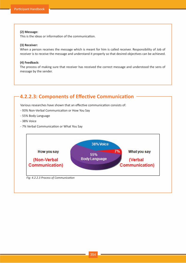
Fig: 4.2.2.3 Process of Communication
(2) Message:This is the ideas or informa�on of the communica�on.
(3) Receiver:When a person receives the message which is meant for him is called receiver. Responsibility of Job of receiver is to receive the message and understand it properly so that desired objec�ves can be achieved.
(4) Feedback:The process of making sure that receiver has received the correct message and understood the sens of message by the sender.
3.5.5 Android Smartphone Disassembly4.2.2.3: Components of Effec�ve Communica�onVarious researches have shown that an effec�ve communica�on consists of:- 93% Non-Verbal Communica�on or How You Say- 55% Body Language- 38% Voice- 7% Verbal Communica�on or What You Say
Par�cipant Handbook
354
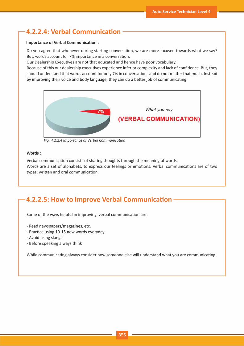
Fig: 4.2.2.4 Importance of Verbal Communication
3.5.5 Android Smartphone Disassembly4.2.2.4: Verbal Communica�on
3.5.5 Android Smartphone Disassembly4.2.2.5: How to Improve Verbal Communica�on
Do you agree that whenever during star�ng conversa�on, we are more focused towards what we say? But, words account for 7% importance in a conversa�on.Our Dealership Execu�ves are not that educated and hence have poor vocabulary.Because of this our dealership execu�ves experience inferior complexity and lack of confidence. But, they should understand that words account for only 7% in conversa�ons and do not ma�er that much. Instead by improving their voice and body language, they can do a be�er job of communica�ng.
Verbal communica�on consists of sharing thoughts through the meaning of words.Words are a set of alphabets, to express our feelings or emo�ons. Verbal communica�ons are of two types: wri�en and oral communica�on.
Some of the ways helpful in improving verbal communica�on are:
- Read newspapers/magazines, etc.- Prac�ce using 10-15 new words everyday- Avoid using slangs- Before speaking always think
While communica�ng always consider how someone else will understand what you are communica�ng.
Importance of Verbal Communica�on :
Words :
Auto Service Technician Level 4
355
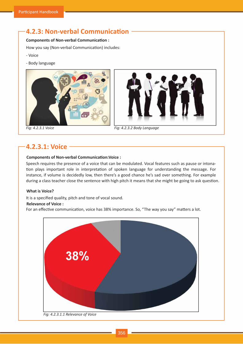
Fig: 4.2.3.1 Voice
Fig: 4.2.3.1.1 Relevance of Voice
Fig: 4.2.3.2 Body Language
Speech requires the presence of a voice that can be modulated. Vocal features such as pause or intona-�on plays important role in interpreta�on of spoken language for understanding the message. For instance, if volume is decidedly low, then there’s a good chance he’s sad over something. For example during a class teacher close the sentence with high pitch it means that she might be going to ask ques�on.
3.5.5 Android Smartphone Disassembly4.2.3: Non-verbal Communica�on
3.5.5 Android Smartphone Disassembly4.2.3.1: Voice
How you say (Non-verbal Communica�on) includes:
- Voice
- Body language
It is a specified quality, pitch and tone of vocal sound.
For an effec�ve communica�on, voice has 38% importance. So, “The way you say” ma�ers a lot.
Components of Non-verbal Communica�on :
Components of Non-verbal Communica�on:Voice :
What is Voice?
Relevance of Voice :
Par�cipant Handbook
356
Fig: 4.2.3.1.2 Characteristics of a Good Voice
During communica�on below men�oned principles are important:
- Audible: To be heard
- Clarity: To convey the right message
- Speed: Maintain balanced approached for be�er understanding based on type of customer
- Pauses: It acts as a�en�on gainer during passing important message
- Tone: To pass informa�on with good vocal energy and enthusiasm
3.5.5 Android Smartphone Disassembly4.2.3.2: Body Language
Some �me it is considered that speech is a small part of communica�on process. Most of the �me it is considered that most of the informa�on is conveyed by non verbal communica�on, voice tome, facial expression, eye contacts and other gestures, standing posture and so on. Body movement within commu-nica�on process is basically represen�ng to emphasize what we want to say and express emo�on and a�tudes. While saying something some �me body movement can also cause a conflict. In case person is a skilled observer can easily note you behavior to use as a clue of your feeling or thinking process.
Our human face is capable to reflect our expression and distor�ons. These reflec�on is ge�ng interpreted depend on the situa�on we are communica�ng. For example we reflect shy expression on face when are asked any embarrassing ques�on.
Let’s explore the second component of the non-verbal communica�on−body language.
For an effec�ve communica�on, Body Language has 55% importance.
Characteris�cs of a Good Voice :
Components of Non-verbal Communica�on: Body Language :
Auto Service Technician Level 4
357
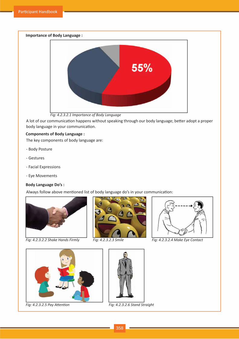
Fig: 4.2.3.2.1 Importance of Body Language
Fig: 4.2.3.2.2 Shake Hands Firmly Fig: 4.2.3.2.3 Smile
Fig: 4.2.3.2.5 Pay Attention Fig: 4.2.3.2.6 Stand Straight
A lot of our communica�on happens without speaking through our body language; be�er adopt a proper body language in your communica�on.
The key components of body language are:
- Body Posture
- Gestures
- Facial Expressions
- Eye Movements
Always follow above men�oned list of body language do’s in your communica�on:
Importance of Body Language :
Components of Body Language :
Body Language Do’s :
Fig: 4.2.3.2.4 Make Eye Contact
Par�cipant Handbook
358
Fig: 4.2.3.2.7 Do Not Avoid the Customer’s Gaze Fig: 4.2.3.2.8 Do Not Hide Your Hands and Palms
Fig: 4.2.3.2.10 Do Not Stare
During your interac�ons with customers, you should understand their body language by observing:
- How they sit- How they stand- How they use their hands and legs- What they do you are talking with them
Customers touching their hair or yawning while interac�ng, for instance, can indicate dullness. Based on customer’s body language adopt the proper manner for interac�ng with them.
Mirroring technique can be used which can result in helping the customer to feel comfortable. For exam-ple, in case customer is giving you smile you also follow the same ac�on to feel them comfortable. You will then come across as friendly and helpful to your customers.
Avoid these don’ts of body language in your communica�on:
Don’ts of Body Language :
Observe Your Customer’s Body Language :
Fig: 4.2.3.2.9 Do Not Look at Your Watch
Auto Service Technician Level 4
359
Fig: 4.2.4.1 Listening
Fig: 4.2.4.2 Overview of Listening
3.5.5 Android SSkill4.2.4: Listening
Ac�ve listening is an important skill of our communica�on process but many �me as a communicator we spend our energy on what we wanted to say and not much focusing on what the other party wanted to say. Listening is basically the ability of a person to receive message properly and accurately interpret it in the communica�on process. Listening is considered as the key factor for successful communica�on process. If we do not give much important to listening messages can be easily misunderstood and can lead to communica�on break down because sender of the message may become frustrated.
Let’s now learn to use effec�vely each of these for successful interac�ons with others. Now let’s explore listening skills further.
Listening is basically the quality for accurately receiving e and interpre�ng messages.Over and average a person spend around 70% �me in some type of communica�on. Out of this 70% com-munica�on �me 45% spend in listening, 30% in speaking, 16% in reading and 9% in wri�ng.
Listening :
Overview :
Par�cipant Handbook
360
Most of us do not listen, which leads to a communica�on gap. You should wait �ll your turn come for speaking rather than interrupt in between!
If you interrupt before your speakers have finished their sentences, it will distract the speaker and focus will be shi�ed on you. Don’t be silent as communica�ng your ideas with speaker are very important but not rudely.
Tips for a�en�ve listener:
- Pay your a�en�on with full focus to understand message of speaker by directly look directly in the eyes.
- Take notes: This will help you stay alert.
- Reconfirm and ask ques�ons: Always reconfirm your understanding by repea�ng the informa�on that was shared with you. Ask ques�ons to understand the message be�er. These �ps will make sure that you heard what was said.
- Remove Distrac�ons: Focus on the instruc�on received. We should avoid mobile phone use, shuffling paper, looking outside from window or other similar ac�vi�es. IF you are performing these ac�vity, listen-ing process get disturbed and speaker will get a message that you are not taking interest.
Remember, if we are suppose to talk more than we listen, we would have two tongues and one ear.
Listening Tips :
Auto Service Technician Level 4
361
Fig: 4.2.5 Overview of Writing
3.5.5 Androi Skill4.2.5: Wri�ng
Wri�ng forms an important form of communica�on. A be�er wri�ng skill allows our messages to be com-municated effec�vely with clarity. It is also having advantage to spread it to a larger audience com-para�vely face to face or telephonic discussion. Wri�ng is considered as one of the ancient medium if communica�on by represen�ng syntax and symmetric of language we are using and adding emo�on using signage and symbols.
The medium using which we communicate using wri�en message to transmit informa�on is called wri�en communica�on.
You need to use wri�en communica�ons mainly for these ac�vi�es:
Use simple languageHighlight important wordsUse appropriate saluta�on and gree�ngKeep your sentences small and mind the subject of discussion Proof read the text before sharingHere are the addi�onal �ps that you may consider for your wri�en communica�on:Always write considering reader in mind. While wri�ng regarding technical subject for non technical reader, avoid using complex words and acronyms which will be difficult for them to understand. Try to explain concepts in such a way that reader can comprehend the message.Be clear about what you are actually trying to communicate. Use short words and sentences to get across your point. It can be useful to use a list of bullet points rather than paragraph for ease of reading and understand the informa�on.Use saluta�on – Sir/Ma’am, Mr./Mrs./Ms., etc. – and Gree�ng – Good Morning, Hi, etc.Choose an appropriate font and size for your wri�ng. Wingdings and Comic Sans are obviously out and anything less than 8-point will give your readers a headache.
Use the following do’s and don’ts for wri�en communica�on:
Wri�ng :
Overview :
Do’s and Don’ts of Wri�en Communica�on :
•
•••
••
•
••
Par�cipant Handbook
362
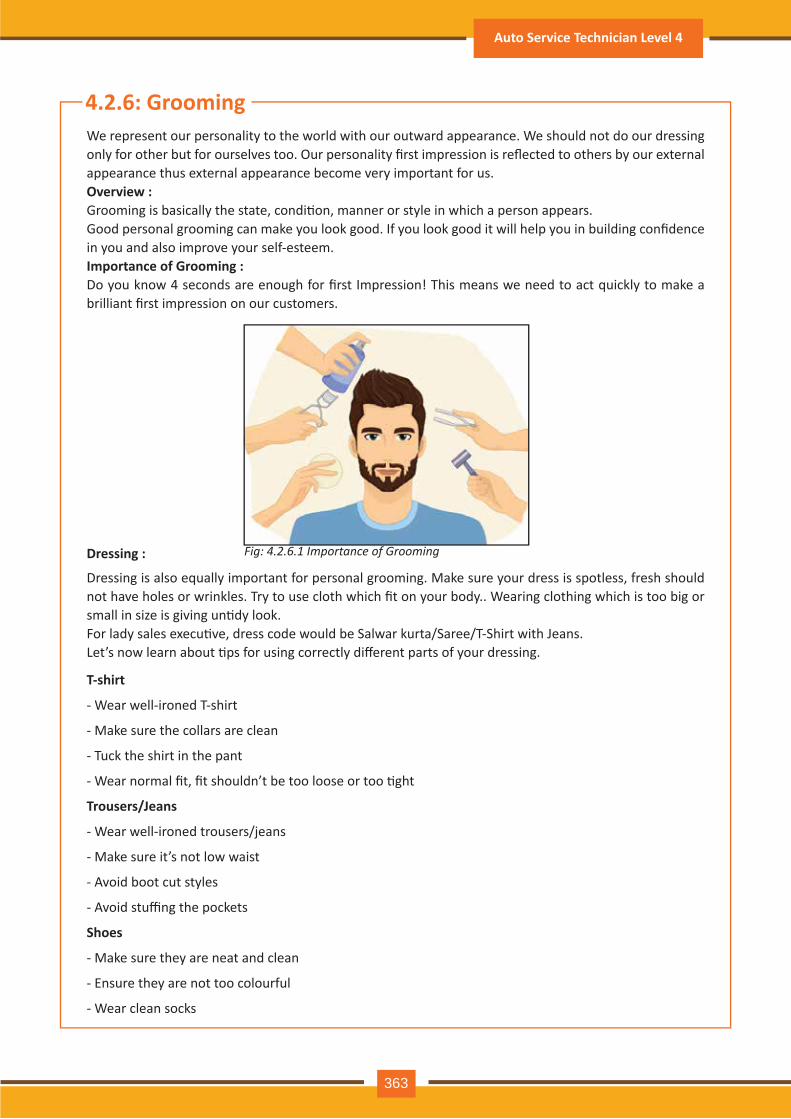
Fig: 4.2.6.1 Importance of Grooming
4.2.6: GroomingWe represent our personality to the world with our outward appearance. We should not do our dressing only for other but for ourselves too. Our personality first impression is reflected to others by our external appearance thus external appearance become very important for us.Overview :Grooming is basically the state, condi�on, manner or style in which a person appears.Good personal grooming can make you look good. If you look good it will help you in building confidence in you and also improve your self-esteem. Importance of Grooming :Do you know 4 seconds are enough for first Impression! This means we need to act quickly to make a brilliant first impression on our customers.
Dressing is also equally important for personal grooming. Make sure your dress is spotless, fresh should not have holes or wrinkles. Try to use cloth which fit on your body.. Wearing clothing which is too big or small in size is giving un�dy look.For lady sales execu�ve, dress code would be Salwar kurta/Saree/T-Shirt with Jeans.Let’s now learn about �ps for using correctly different parts of your dressing.
T-shirt
- Wear well-ironed T-shirt
- Make sure the collars are clean
- Tuck the shirt in the pant
- Wear normal fit, fit shouldn’t be too loose or too �ght
Trousers/Jeans
- Wear well-ironed trousers/jeans
- Make sure it’s not low waist
- Avoid boot cut styles
- Avoid stuffing the pockets
Shoes
- Make sure they are neat and clean
- Ensure they are not too colourful
- Wear clean socks
Dressing :
Auto Service Technician Level 4
363

Fig: 4.2.6.2 Take Shower Everyday
Fig: 4.2.6.5 Apply deodorant toprevent body odour
Fig: 4.2.6.8 Take care of your skin
Fig: 4.2.6.9 Stand Upright
Fig: 4.2.6.10 Wear well fitted clothes
Fig: 4.2.6.11 Keep yourselfupdated
Fig: 4.2.6.12 Exercise regularly
Fig: 4.2.6.6 Brush your teethtwice everyday
Fig: 4.2.6.7Rinse every time after eating
Fig: 4.2.6.3 Shave your facialhair regularly
Fig: 4.2.6.4 Shave your facialhair regularly
- Ensure your shoes fit well, neither too �ght or too loose
Belt
- Wear a Black color belt
- Ensure it’s made of good leather
- Ensure it’s not too long and not too short
- Avoid belts with flashy buckles
Watch
- Wear a good quality watch
- Ensure it’s simple with straight or classy lines
- Make sure it’s not flashy
Personal Hygiene :
Maintaining Yourself :
Always follow these do’s and dont’s for maintaining personal hygiene:
You can look presentable at all �mes by following these �ps:
Par�cipant Handbook
364
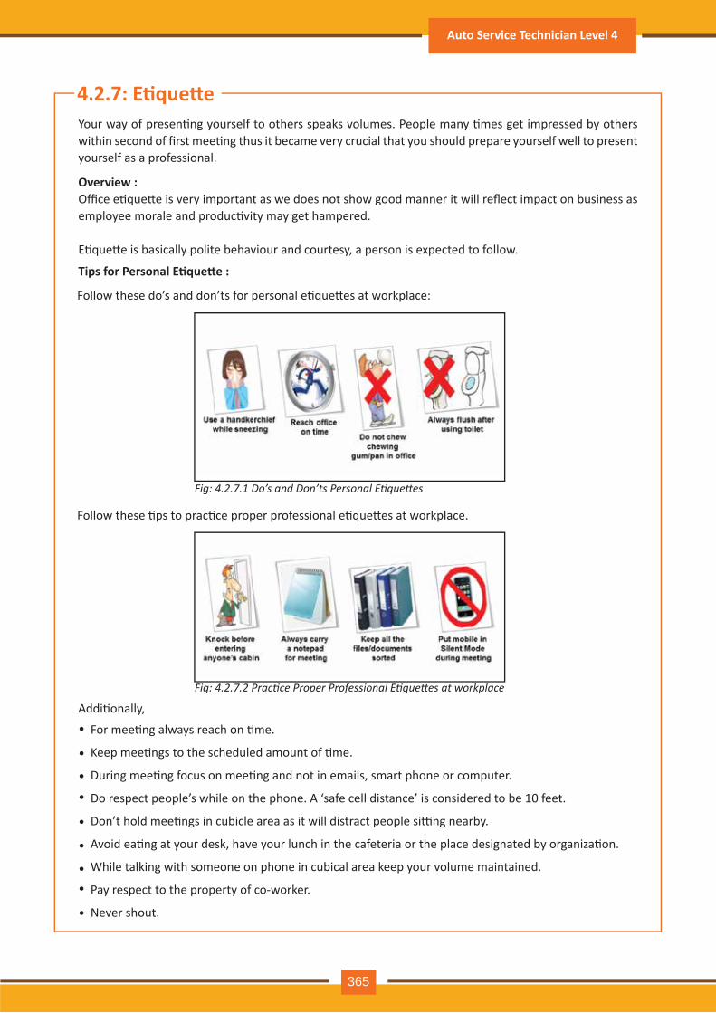
Fig: 4.2.7.1 Do’s and Don’ts Personal Etiquettes
Fig: 4.2.7.2 Practice Proper Professional Etiquettes at workplace
4.2.7: E�que�eYour way of presen�ng yourself to others speaks volumes. People many �mes get impressed by others within second of first mee�ng thus it became very crucial that you should prepare yourself well to present yourself as a professional.
Office e�que�e is very important as we does not show good manner it will reflect impact on business as employee morale and produc�vity may get hampered.
E�que�e is basically polite behaviour and courtesy, a person is expected to follow.
For mee�ng always reach on �me.
Keep mee�ngs to the scheduled amount of �me.
During mee�ng focus on mee�ng and not in emails, smart phone or computer.
Do respect people’s while on the phone. A ‘safe cell distance’ is considered to be 10 feet.
Don’t hold mee�ngs in cubicle area as it will distract people si�ng nearby.
Avoid ea�ng at your desk, have your lunch in the cafeteria or the place designated by organiza�on.
While talking with someone on phone in cubical area keep your volume maintained.
Pay respect to the property of co-worker.
Never shout.
Overview :
Tips for Personal E�que�e :
Follow these do’s and don’ts for personal e�que�es at workplace:
Follow these �ps to prac�ce proper professional e�que�es at workplace.
Addi�onally,•
•
•
•
•
•
••
•
Auto Service Technician Level 4
365
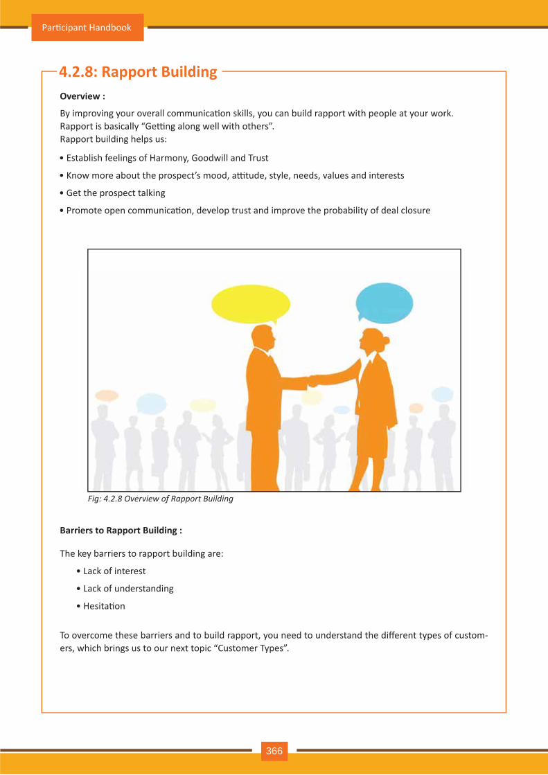
Fig: 4.2.8 Overview of Rapport Building
4.2.8: Rapport Building
By improving your overall communica�on skills, you can build rapport with people at your work.Rapport is basically “Ge�ng along well with others”.Rapport building helps us:
To overcome these barriers and to build rapport, you need to understand the different types of custom-ers, which brings us to our next topic “Customer Types”.
Overview :
Barriers to Rapport Building :
• Establish feelings of Harmony, Goodwill and Trust
• Know more about the prospect’s mood, a�tude, style, needs, values and interests
• Get the prospect talking
• Promote open communica�on, develop trust and improve the probability of deal closure
The key barriers to rapport building are:
• Lack of interest
• Lack of understanding
• Hesita�on
Par�cipant Handbook
366
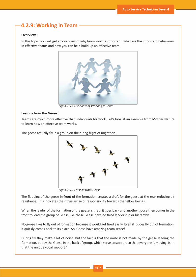
Fig: 4.2.9.1 Overview of Working in Team
Fig: 4.2.9.2 Lessons from Geese
In this topic, you will get an overview of why team work is important, what are the important behaviours in effec�ve teams and how you can help build up an effec�ve team.
Teams are much more effec�ve than individuals for work. Let’s look at an example from Mother Nature to learn how an effec�ve team works.
The geese actually fly in a group on their long flight of migra�on.
The flapping of the geese in-front of the forma�on creates a dra� for the geese at the rear reducing air resistance. This indicates their true sense of responsibility towards the fellow beings.
When the leader of the forma�on of the geese is �red, it goes back and another goose then comes in the front to lead the group of Geese. So, these Geese have no fixed leadership or hierarchy.
No goose likes to fly out of forma�on because it would get �red easily. Even if it does fly out of forma�on, it quickly comes back to its place. So, Geese have amazing team sense!
During fly they make a lot of noise. But the fact is that the noise is not made by the geese leading the forma�on, but by the Geese in the back of group, which serve to support so that everyone is moving. Isn’t that the unique vocal support?
4.2.9: Working in TeamOverview :
Lessons from the Geese :
Auto Service Technician Level 4
367
Fig: 4.2.9.3 Lessons from Geese
Fig: 4.2.9.4 Team Player Styles
Team Player Styles :
If one goose is ill and falls out of forma�on, a few of others stay with it, to be with it un�l it recover or leave the world presents a nice example of team sprit.
Geese reflect a very good example of team work. The whole team works consistently for a common goal of reaching a par�cular des�na�on. Team member helps each other since they can collec�vely achieve much more than they can alone.
As explained about the Geese, being a human if we are sharing common set of direc�on and have consid-er our community can move fast and reach to our goal in shorter period because we move with trust on each other.
Considering the Geese if we follow their footsteps we will be connected with the persons who could lead us to reach our des�na�on.
We should always offer our help to others in team and also accept help from them. It helps to understand the concept of sharing leadership and work in turn to accomplish hard task. Com-pare to Geese we humans are equipped with unique talents and resources and intellectual capabili�es.
We should ensure that we are encouraging each other in the team. In teams where there is encour-age-ment, the produc�on is much higher.
The moral from Geese is to stand by each other in the team even if we are strong. Now, what do you say to that!!!
You need to be a good team player to work in a team.
Par�cipant Handbook
368
Contributors are basically task-oriented. Strength of the contributors is in informa�on sharing among the team and also ensuring the work is going on as per defined process. Contributors are methodical and detail oriented.
Contributors :
Collaborators :
Communicator :
The first team player style is Contributors.
The following are the key characteris�cs of Contributors: • Logical • Efficient • Organized • Proficient • Relevant • Pragma�c • Systema�c • Dependable • Responsible
The second team player style is Collaborator.Key characteris�cs of Collaborators are listed below:
• Coopera�ve
• Flexible
• Confident
• Forward-looking
• Conceptual
• Accommoda�ng
• Generous
• Open
• Visionary
• Imagina�ve
Collaborators are highly goal-oriented.
If you’re the ones who make sure work stays on track, you’re likely to be a Collaborator.
The third Team Player Style is Communicator.
Here are the key characteris�cs of Communicators:
• Tac�ul
• Helpful
• Friendly
• Pa�ent
Auto Service Technician Level 4
369
• Informal
• Relaxed
• Suppor�ve
• Encouraging
• Considerate
• Impulsive
Communicator basically follow the process and mainly a good listener also.
If focus is in ensuring that overall process goes smoothly, then you’re likely to be a Communicator.
Challenger :
The fourth Team Player Style is Challenger.
Challengers key characteris�cs are listed below:
• Candid
• Ethical
• Ques�oning
• Honest
• Truthful
• Outspoken
• Principled
• Adventurous
• Aboveboard
• Brave
The Challenger is a member who ques�ons the goals, methods and even the ethics of the team. He is willing to disagree with the leader and encourages the team to take calculated risks.Looking at the bigger picture and ques�oning how and why things are done is a characteris�cs of Chal-lenger.
A commi�ed team treats the work like their own garden or pet – they obsess over it, they care for it, they own it. If a leader is trying to build a team who can give commitment to finish the assigned task, then it is important to align team member’s personal visions to that of the organiza�on.
Commitment & Task Sharing Based on Individual’s Skills :
Par�cipant Handbook
370
Examine what is causing troubleDiscuss the issue with the conflic�ng partyClarify expecta�ons and rolesFind an op�on which benefits allU�lize construc�ve feedbackReach agreements
••••••
To resolve conflicts in a team, you should use these steps:
You should always maintain a posi�ve rela�onship for reaching on a agreement.
Fig: 4.2.10 Importance of Resolving Conflict
4.2.10: Resolving ConflictConflict - severe difference or disagreement is known as conflict. Conflict exist in almost all organiza�on and some �me it is also consider posi�ve as it helps in ideas and crea�vity exchange. If the conflicts became counter conflict it may leads dissa�sfac�on to employee, produc�vity reduc�on and may also affect customer service.
By deciding not to say something that would make you sound aggressive or frustrated, you can avoid unnecessary conflicts.Conflicts take place when people are rigid and not coopera�ng with each other.How to prevent and resolve conflicts:
Importance of Resolving Conflict:
Best Prac�ces Resolving Conflict:
Focus on issues not personali�esEncourage both sides to be objec�veEvaluate concerns of both sidesEncourage people to listen to other’s viewEncourage points of agreementDon’t dwell on anger
•••••
You should always depersonalize conflicts by adop�ng these steps:Depersonalizing Conflicts:
You must avoid conflict at the work place as it brings nega�vity all around.
Auto Service Technician Level 4
371
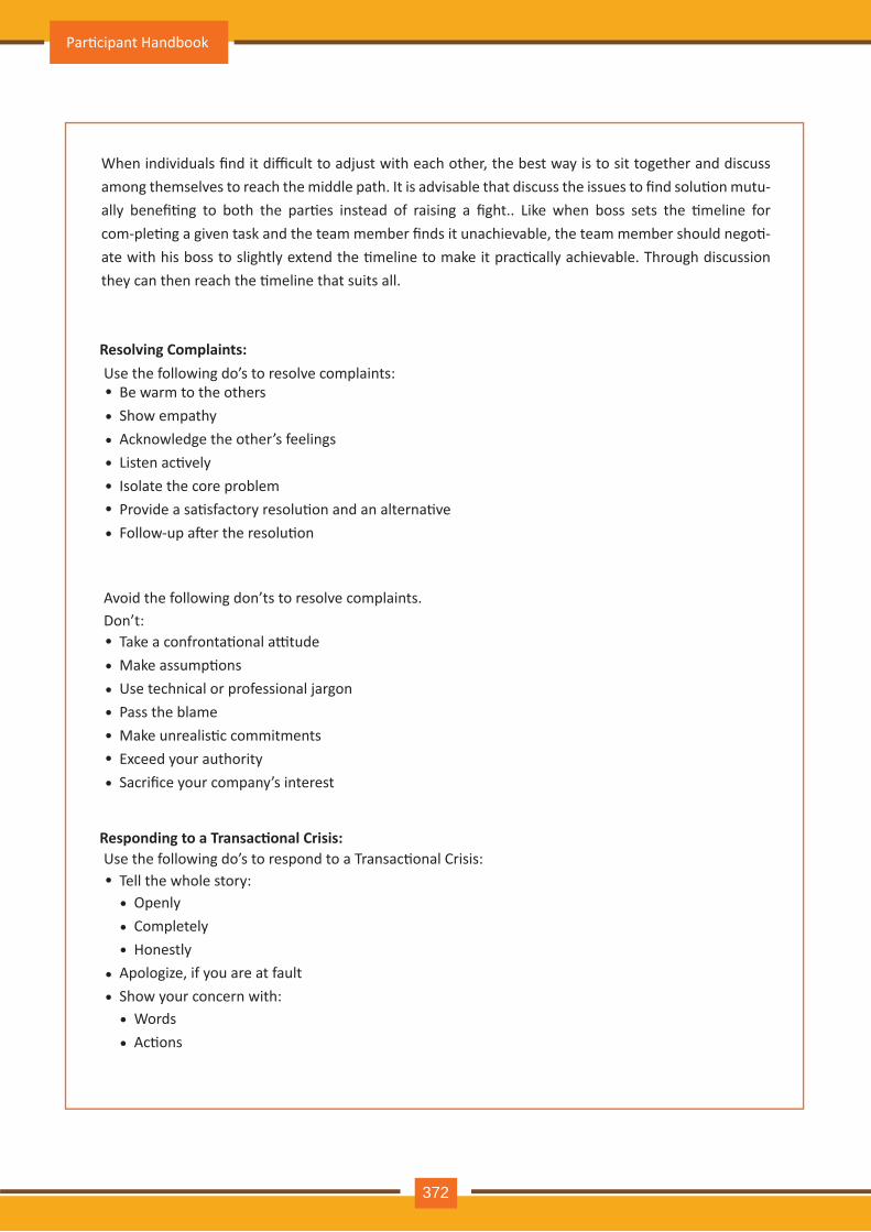
When individuals find it difficult to adjust with each other, the best way is to sit together and discuss among themselves to reach the middle path. It is advisable that discuss the issues to find solu�on mutu-ally benefi�ng to both the par�es instead of raising a fight.. Like when boss sets the �meline for com-ple�ng a given task and the team member finds it unachievable, the team member should nego�-ate with his boss to slightly extend the �meline to make it prac�cally achievable. Through discussion they can then reach the �meline that suits all.
Be warm to the othersShow empathyAcknowledge the other’s feelingsListen ac�velyIsolate the core problemProvide a sa�sfactory resolu�on and an alterna�veFollow-up a�er the resolu�on
•••••••
Use the following do’s to resolve complaints:Resolving Complaints:
Tell the whole story:
Apologize, if you are at faultShow your concern with:
OpenlyCompletelyHonestly
•••
WordsAc�ons
••
•••
Use the following do’s to respond to a Transac�onal Crisis:Responding to a Transac�onal Crisis:
Take a confronta�onal a�tudeMake assump�onsUse technical or professional jargonPass the blameMake unrealis�c commitmentsExceed your authoritySacrifice your company’s interest
•••••••
Avoid the following don’ts to resolve complaints.Don’t:
Par�cipant Handbook
372
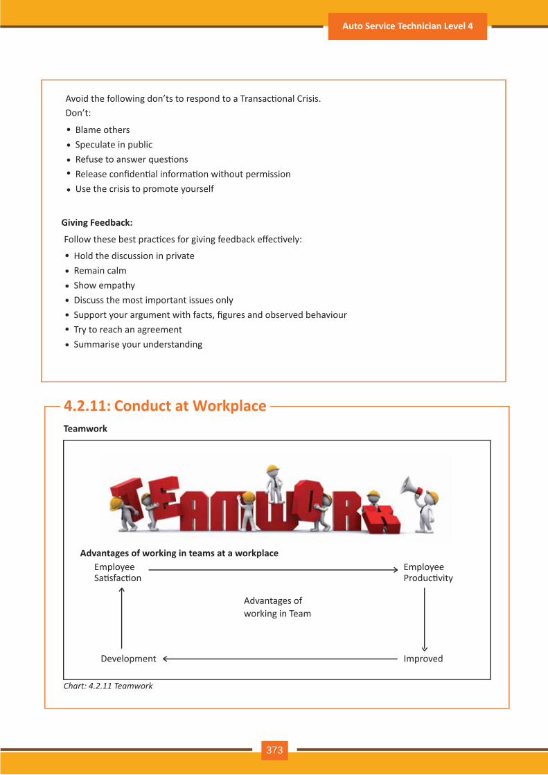
Hold the discussion in privateRemain calmShow empathyDiscuss the most important issues onlySupport your argument with facts, figures and observed behaviourTry to reach an agreementSummarise your understanding
•••••••
Follow these best prac�ces for giving feedback effec�vely:
Giving Feedback:
Blame othersSpeculate in publicRefuse to answer ques�onsRelease confiden�al informa�on without permissionUse the crisis to promote yourself
••••
•
Avoid the following don’ts to respond to a Transac�onal Crisis.Don’t:
Chart: 4.2.11 Teamwork
4.2.11: Conduct at WorkplaceTeamwork
Advantages of working in teams at a workplace
Development Improved
Advantages ofworking in Team
EmployeeSa�sfac�on
EmployeeProduc�vity
Auto Service Technician Level 4
373
Crea�vity:
Improved Produc�vity – Successful teams develop the ability to accomplish more and faster.Improved Crea�vity – cross func�onality applica�on of different minds to the task usually produces original out of the box thinking.Focus – If the team is assigned with proper task it will help in solving stubborn organiza�onal prob-lems.Development – serving on a team par�cipa�ng in team ac�vity provides good development experi-ence some�mes fast track for team members.Employee sa�sfac�on – successful teams o�en have a good �me members including sense of achieve-ment.
••
•
•
•
Working in Teams:
Managers: hold Conven�onal managerial responsibility and are drawn from the hierarchical culture of the organiza�on.Facilitators: these are neutral, objec�ve individuals who are chosen for their process consul�ng skills. They may act as arbitrators in �mes of conflict between managers and team players.Team leader: These are o�en the department supervisors who must work with managers and facilita-tors and help them to shape the team.Team Players: these are the team members who share a common goal or purpose. they must be trained and developed to assume the special skills and responsibili�es of self-management.Support Groups: these are clusters of individual who work with the team suppor�ng them with specif-ic required- e.g. the human resource, finance and administra�on departments.
•
•
•
•
•
Par�cipant Handbook
374

Notes
Auto Service Technician Level 4
375
Exercise-1: Answer the Following Ques�ons:
1. Write are process of communica�on?__________________________________________________________________________________________________________________________________________________________________________________________________________________________________________________________________________________________________________
2. How to improve verbal communica�on?__________________________________________________________________________________________________________________________________________________________________________________________________________________________________________________________________________________________________________
3. Write down non-verbal communica�on components ?______________________________________________________________________________________________________________________________________________________________________________________________________________________________
4. To resolve conflict what are the best prac�ces?_______________________________________________________________________________________________________________________________________________________________________________________________________________________________
Par�cipant Handbook
376

ASC/ N 0003
5. Maintain a Healthy, Safe and Secure WorkEnvironment
Unit 5.1 – Performance Criteria for Healthy, Safe & Secure Work Environment
Unit 5.2 – Knowledge & Understanding: Healthy, Safe & Secure Work Environment
At the end of this module, you will be able to:
Key Learning Outcomes
1. Perform as per the need of resources to maintain a safe, secure working environment
2. Maintain safe & secure workplace
3. Measure safety responsibili�es at your workplace
4. Use of best available prac�ces to avoid work place poten�al hazards for accident preven�on
5. Apply suitable strategies while dealing with workplace emergencies
Par�cipant Handbook
378

UNIT 5.1: Performance Criteria for Healthy, Safe & Secure Work Environment
Resources needed to maintain a safe, secure working environment Study and Learn to:
Performance Criterion:
Observe policies and procedures defined by organiza�on for health, safety and security
If any viola�on of policies and procedures related to health, safety and security is observed, report it
to concerned authority.
Coordinate with available resources at the workplace to achieve the healthy, safe and secure environ-
ment for all, incorpora�ng all government defined rules related emergency condi�on like fires, earth-
quakes etc.
Iden�fy your responsibility within workplace and also try to correct any poten�al hazards.
If the hazard observed is outside your limit then it become your responsibility to report it to concerned
authority.
During accidents, fires or any other natural calamity always follow organiza�on’s emergency proce-
dures.
•
•
•
••
•
Unit Objec�vesUnderstand the performance criteria for working effec�vely as team:
Perform as per the need of resources to maintain a safe, secure working environment
Auto Service Technician Level 4
379

4.2: Knowledge & Understanding : healthy, safe & secure work environmentUNIT 5.2: Knowledge & Understanding - Healthy, Safe & Secure Work Environment
5.2.1: Importance of Safe & Secure Working PlaceWhen we feel safe and secure, we can remain mo�vated and feel happy at our workplace. Workplace safety is very important in organiza�on as it boosts the produc�vity. If the workers in the organiza�on feel safe they can work with their full capabili�es and poten�al and it also reflect posi�vism in the work-ing environment.
Therefore, measures should be taken to eliminate risks at work and ensure a safe and comfortable environment for the employees.
5.2.1.1: Employer’s Responsibili�es
• Healthy workplace should be provided• Train the worker based on job profile• Training records should be maintain properly (who, what and when)• There should be broad industrial health and safety program for the worker which should also include health & safety policy and an incident inves�ga�on procedure• Support supervisors, safety co-ordinators and workers in their health and safety ac�vi�es• During poten�al there should be immediate ac�on on repor�ng• During incident instant inves�ga�on should be ini�ated• Provide adequate first aid facili�es and services• Ensure supply of PPE as per nature of job
Supervisor mainly conducts training of worker. It is the prime responsibility of employer to ensure that their workers are trained adequately for their nature of job and to accomplish it regular follow up need to be carried out with supervisor. Employers should also work with supervisors to help foster posi�ve worker a�tudes to safety
Unit Objec�vesAt the end of this unit, you will be able to:
1. Maintain safe & secure workplace2. Measure your workplace safety responsibili�es3. Use of best available prac�ces to avoid work place poten�al hazards for accident preven�on 4. Use suitable strategies to deal with workplace emergencies
Par�cipant Handbook
380

5.2.1.2: Supervisor’s Responsibili�es
The responsibili�es of the supervisors for maintaining safe workplace are:• Instruct workers in safe work procedures• Provide training to worker based on their assigned task and ensure safe working of the same• Make sure worker opera�ng tools, equipment or any hazardous material have adequate training in handling the same• Ensure material handling, storage are maintained as per defined procedure• Enforce health and safety requirements• Correct unsafe acts and condi�ons• Iden�fy workers with problems that could affect safety at the worksite
5.2.1.3: Worker’s Responsibili�es
Know and follow health and safety requirements affec�ng your job It is recommended that before performing task safely ask for corre-sponding training. Work safely but also encourage co-workers to follow the sameIf unsafe condi�on is observed try to correct it and inform supervisorIn case of any injury report it immediately to first aid a�endant and supervisorTake the ini�a�ve. Make sugges�ons to improve health and safety
The responsibili�es of the workers for maintaining safe workplace are:
••
•••
•Fig: 5.2.1.3 Worker’s Responsibilities
Auto Service Technician Level 4
381

Follow your organiza�on structure to report any hazards/incident to the relevant person.Structure could be different from organiza�on to organiza�on.Warn/inform your co-workers about any hazardous incidents for extra safety measurements.
5.2.2: Workplace HazardsThe situa�on which can create threat to human life, property of workplace or environment is defined as hazard. Most of the hazards are hidden in nature which reflects theore�cal risk but the fact is that if it becomes ac�ve and cause emergency. Situa�on of hazard when finish it turns to be in incident. Hazard and its possibility of ge�ng ac�vated act together to form a risk.
5.2.2.1: Modes of Hazard
Dormant: The circumstance project a possibility of ac�ve hazard not affec�ng people, property or environment. For example hill area may became unstable due to landslide, but it is not effec�ng the hill side.Armed: People, property or environment is in poten�al harm’s way.Ac�ve: A dangerous occurrence in which hazard has played its role. It is some�mes referred as accident, emergency, incident or disaster not hazard.
•
••
Can be classified into three modes:
5.2.2.2: Types of Hazard
5.2.2.3: Repor�ng of any Hazard Incidents
A situa�on which cause physical harm to body or create extreme stress is referred as physical hazard.
A physical hazard may be natural or made by human also.
Chemical hazards are substances which can create harm to human health, harm body parts, property
or environment. There is a possibility that chemical hazard might be natural or human created.
Biological hazards – In this type of hazard biological agents can cause harm to human health or body
parts. It could be fungus, bacteria, viruses, parasites and foreign toxins.
Psychological hazards basically occur when there is stressful working environment. Here poten�ally a
person may cause hazard during psychological disturbance caused by stress or shi� pa�erns and also
under the influence of alcohol, illness and lack of training.
Electrical hazards is very serious as worker can or does make electrical contact with equipment or a
conductor may lead to injury from shock like burn or blast injury.
•
•
•
•
•
The common types of hazard are:
Par�cipant Handbook
382
Fig: 5.2.3.3 Emergency Service Number
5.2.3: Organiza�on’s Emergency ProceduresWorkplace needs plan for dealing with emergencies. You should be instructed in that plan a�er joining job and have refresher training from �me to �me.
5.2.3.1: Ques�ons to be asked for Emergency Procedures
Where the emergency phone numbers are posted?Where are the fire ex�nguishers and how and when should they be used?What other specialized equipment required during emergency, and how it is used?Where are the fire alarms and fire exits?What is the evacua�on plan for the building?What should you do during an earthquake?In case of evacua�on, where outside the building is the assembly point and who should you report to?
•••••••
Post training you should answer these ques�ons:
5.2.3.3: Emergency Service Number
Fire Brigade DepartmentPolice DepartmentAmbulance DepartmentWomen Safety DepartmentSecurity DepartmentPest Control Department
••••••
Dial the service number of these departments in case of emergency:
An emergency medical service should be available near to your dealershipMinimum one person has to be trained enough to handle any medical emergencyFirst-aid supplies should be available at the dealershipCheck – Call – Care route should be followed
••••
Follow below men�oned steps for medical emergency procedures:
It is the discipline of dealing with and avoiding both natural and manmade disasters.
5.2.3.2: Emergency Preparedness
5.2.3.4: Medical Emergency Procedures
Auto Service Technician Level 4
383
5.2.3.5: Fire Preparedness Procedures
Ac�vate the ALARM.Evacuate the area.Call the fire department.You can fight with the fire if:
•
DO NOT fight the fire if:•
•••
You know how.The fire is small.You are confined to the area where it started.You have a way out.You can work with your back to the exit.You have the required ex�nguisher.You are confident in opera�ng it effec�vely.
••••
You have any not very sure and have any doubts.Speedy spreading and crossed the star�ng area.Escape route is blocked.
•••
•••
You should follow these emergency instruc�ons in case of fire:
Don’t unnecessarily accumulate trash and li�er Keep the workplace areas clean and intactKeep yourself updated about loca�on of fire alarm boxes and ex�nguishersHave knowledge about various ex�nguishers types and confident to use themStore hazardous materials in designated areasExits should be free from any obstruc�onsKnow loca�on of emergency exits and proceduresHandle flammable liquids with cau�on
••••••••
Follow these steps for fire preven�on:
Fig: 5.2.3.5 Emergency Service Number
EVACUATE THE BUILDING IMMEDIATELYConfine a fire to the zone of origin, for a specified �me, thereby preven�ng fire spread and leaving more �me for safe evacua�on of the building occupants.If a fire breaks out, smoke containment systems prevent the movement of smoke and heat from one area to another.
5.2.3.6: Fire Preven�on
Par�cipant Handbook
384
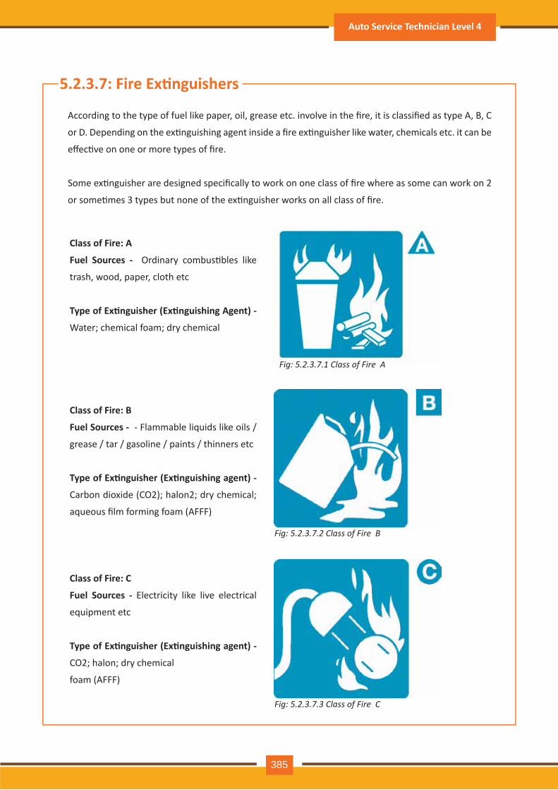
5.2.3.7: Fire Ex�nguishers
According to the type of fuel like paper, oil, grease etc. involve in the fire, it is classified as type A, B, C
or D. Depending on the ex�nguishing agent inside a fire ex�nguisher like water, chemicals etc. it can be
effec�ve on one or more types of fire.
Some ex�nguisher are designed specifically to work on one class of fire where as some can work on 2
or some�mes 3 types but none of the ex�nguisher works on all class of fire.
Class of Fire: A
Fuel Sources - Ordinary combus�bles like
trash, wood, paper, cloth etc
Type of Ex�nguisher (Ex�nguishing Agent) -
Water; chemical foam; dry chemical
Class of Fire: B
Fuel Sources - - Flammable liquids like oils /
grease / tar / gasoline / paints / thinners etc
Type of Ex�nguisher (Ex�nguishing agent) -
Carbon dioxide (CO2); halon2; dry chemical;
aqueous film forming foam (AFFF)
Class of Fire: C
Fuel Sources - Electricity like live electrical
equipment etc
Type of Ex�nguisher (Ex�nguishing agent) -
CO2; halon; dry chemical
foam (AFFF)
Fig: 5.2.3.7.1 Class of Fire A
Fig: 5.2.3.7.2 Class of Fire B
Fig: 5.2.3.7.3 Class of Fire C
Auto Service Technician Level 4
385
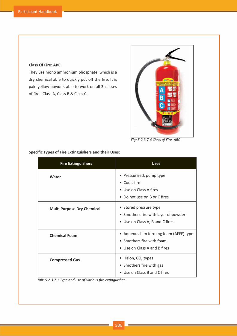
Class Of Fire: ABC
They use mono ammonium phosphate, which is a
dry chemical able to quickly put off the fire. It is
pale yellow powder, able to work on all 3 classes
of fire : Class A, Class B & Class C .
Specific Types of Fire Ex�nguishers and their Uses:
• Pressurized, pump type
• Cools fire
• Use on Class A fires
• Do not use on B or C fires
Water
• Stored pressure type
• Smothers fire with layer of powder
• Use on Class A, B and C fires
Mul� Purpose Dry Chemical
• Aqueous film forming foam (AFFF) type
• Smothers fire with foam
• Use on Class A and B fires
Chemical Foam
• Halon, CO2 types
• Smothers fire with gas
• Use on Class B and C fires
Compressed Gas
Fig: 5.2.3.7.4 Class of Fire ABC
Fire Ex�nguishers Uses
Tab: 5.2.3.7.1 Type and use of Various fire extinguisher
Par�cipant Handbook
386
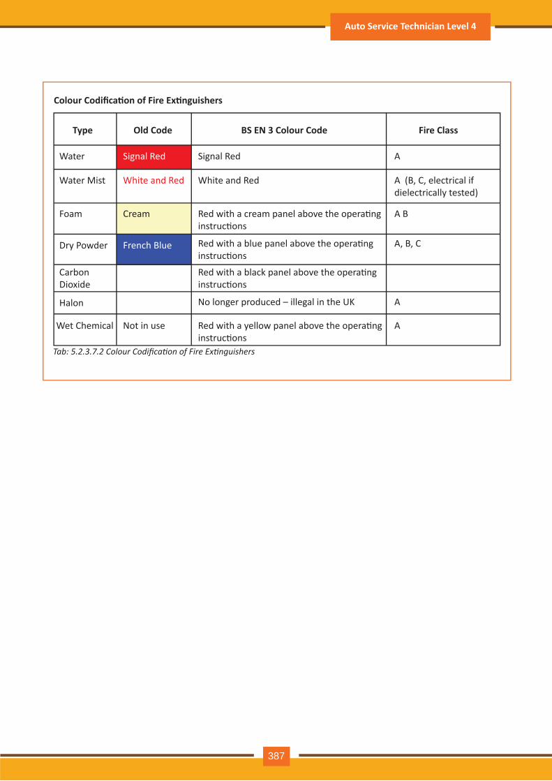
Colour Codifica�on of Fire Ex�nguishers
Type Old Code BS EN 3 Colour Code Fire Class
Water
Water Mist
Foam
Dry Powder
Halon
Carbon Dioxide
Cream Red with a cream panel above the opera�ng instruc�ons
Red with a blue panel above the opera�ng instruc�ons
Red with a black panel above the opera�ng instruc�ons
No longer produced – illegal in the UK
Red with a yellow panel above the opera�ng instruc�ons
Signal Red
French Blue
Signal Red A
A
A
A B
A, B, C
White and Red White and Red A (B, C, electrical if dielectrically tested)
Not in useWet Chemical
Tab: 5.2.3.7.2 Colour Codification of Fire Extinguishers
Auto Service Technician Level 4
387
Fig: 5.2.3.8 Evacuation Procedures for Workers & Visitors
5.2.3.8: Evacua�on Procedures in Emergency
Evacua�on RoutesFire Ex�nguisher (loca�ons)Fire Alarm Sta�ons (loca�ons)First Aid Kit (loca�ons)
••••
Let’s now learn about the for evacua�on procedures for workers & visitors in case of emergency
As the first step a layout must be made of the building, including:
The second step for evacua�on procedures for workers & visitors during emergency includes crea�ng a map of the parking lot and surrounding buildings.This must show the Rally Point. It should be at a safe distance from the building, accessible eaisly, and should not be next to the fire hydrant.Both the layout and the Rally Point must be posted conspicuously throughout the facility and made available to all employees upon request.
any issues and should reach to the spot immediately a�er ge�ng the informa�on.Should be fully aware about burns first aid procedure for burns use the same, immediately, at the site of the fire accident to the injured people.
They should try to control fire using fire ex�nguisher or other means.They should rescue the vic�m from the burning premises.They should have knowledge on different types of fires like chemical, electrical etc., and should take the appropriate measures to contain and put out these fires.
5.2.3.8.1: Roles of First Responder
Par�cipant Handbook
388
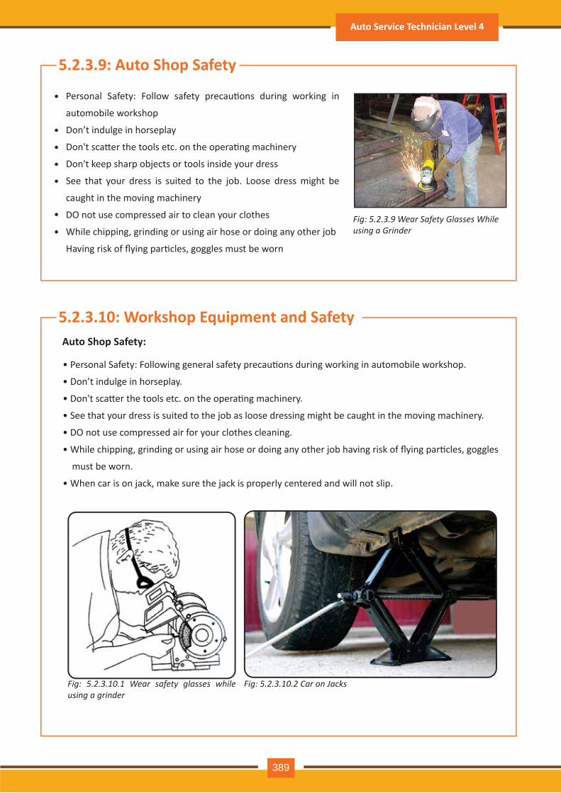
Fig: 5.2.3.9 Wear Safety Glasses While using a Grinder
Personal Safety: Follow safety precau�ons during working in
automobile workshop
Don’t indulge in horseplay
Don't sca�er the tools etc. on the opera�ng machinery
Don't keep sharp objects or tools inside your dress
See that your dress is suited to the job. Loose dress might be
caught in the moving machinery
DO not use compressed air to clean your clothes
While chipping, grinding or using air hose or doing any other job
Having risk of flying par�cles, goggles must be worn
• Personal Safety: Following general safety precau�ons during working in automobile workshop.
• Don’t indulge in horseplay.
• Don't sca�er the tools etc. on the opera�ng machinery.
• See that your dress is suited to the job as loose dressing might be caught in the moving machinery.
• DO not use compressed air for your clothes cleaning.
• While chipping, grinding or using air hose or doing any other job having risk of flying par�cles, goggles
must be worn.
• When car is on jack, make sure the jack is properly centered and will not slip.
5.2.3.9: Auto Shop Safety
•
•
•
•
•
•
•
5.2.3.10: Workshop Equipment and SafetyAuto Shop Safety:
Fig: 5.2.3.10.1 Wear safety glasses while using a grinder
Fig: 5.2.3.10.2 Car on Jacks
Auto Service Technician Level 4
389
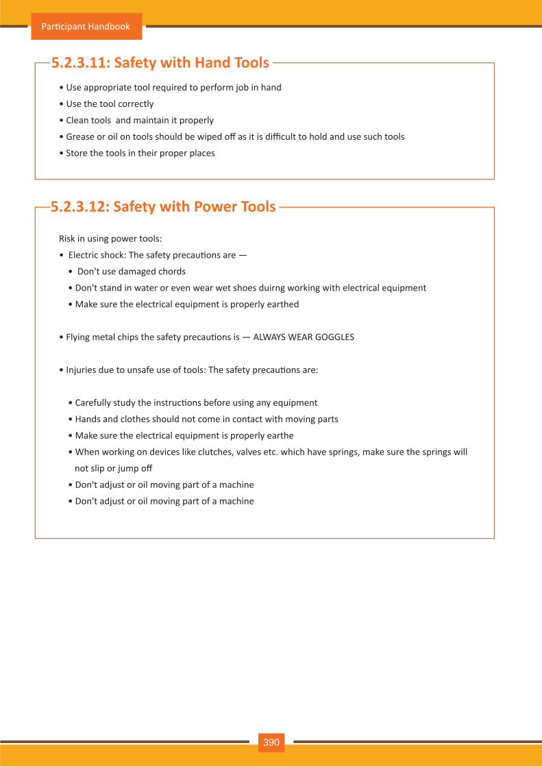
• Use appropriate tool required to perform job in hand
• Use the tool correctly
• Clean tools and maintain it properly
• Grease or oil on tools should be wiped off as it is difficult to hold and use such tools
• Store the tools in their proper places
5.2.3.11: Safety with Hand Tools
Risk in using power tools:
• Electric shock: The safety precau�ons are —
• Don't use damaged chords
• Don't stand in water or even wear wet shoes duirng working with electrical equipment
• Make sure the electrical equipment is properly earthed
• Flying metal chips the safety precau�ons is — ALWAYS WEAR GOGGLES
• Injuries due to unsafe use of tools: The safety precau�ons are:
• Carefully study the instruc�ons before using any equipment
• Hands and clothes should not come in contact with moving parts
• Make sure the electrical equipment is properly earthe
• When working on devices like clutches, valves etc. which have springs, make sure the springs will
not slip or jump off
• Don't adjust or oil moving part of a machine
• Don't adjust or oil moving part of a machine
5.2.3.12: Safety with Power Tools
Par�cipant Handbook
390
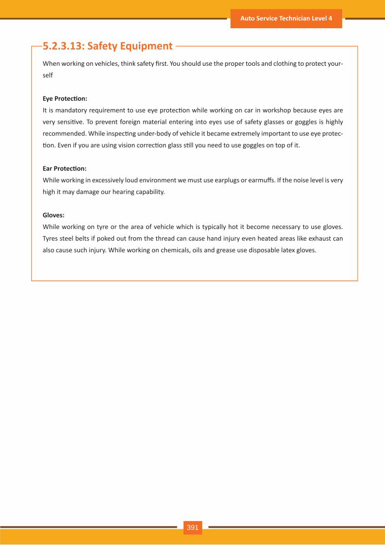
5.2.3.13: Safety EquipmentWhen working on vehicles, think safety first. You should use the proper tools and clothing to protect your-
self
Eye Protec�on:
It is mandatory requirement to use eye protec�on while working on car in workshop because eyes are
very sensi�ve. To prevent foreign material entering into eyes use of safety glasses or goggles is highly
recommended. While inspec�ng under-body of vehicle it became extremely important to use eye protec-
�on. Even if you are using vision correc�on glass s�ll you need to use goggles on top of it.
Ear Protec�on:
While working in excessively loud environment we must use earplugs or earmuffs. If the noise level is very
high it may damage our hearing capability.
Gloves:
While working on tyre or the area of vehicle which is typically hot it become necessary to use gloves.
Tyres steel belts if poked out from the thread can cause hand injury even heated areas like exhaust can
also cause such injury. While working on chemicals, oils and grease use disposable latex gloves.
Auto Service Technician Level 4
391

Notes
Par�cipant Handbook
392
Exercise-1: Answer the Following Ques�ons:
1. Write are responsibili�es of the workers for maintaining safe workplace?__________________________________________________________________________________________________________________________________________________________________________________________________________________________________________________________________________________________________________
2. Write are the types of hazard at workplace?__________________________________________________________________________________________________________________________________________________________________________________________________________________________________________________________________________________________________________
3. Write are the ques�ons to be asked for emergency procedure?__________________________________________________________________________________________________________________________________________________________________________________________________________________________________________________________________________________________________________
Auto Service Technician Level 4
393

Par�cipant Handbook
394

6. Employability & Entrepreneurship Skills
Unit 6.1 – Personal Strengths & Value SystemsUnit 6.2 – Digital Literacy: A Recap
Unit 6.3 – Money Ma�ersUnit 6.4 – Preparing for Employment & Self Employment
Unit 6.5 – Understanding Entrepreneurship
Unit 6.6 – Preparing to be an Entrepreneur
At the end of this unit, you will be able to:
Key Learning Outcomes
1. Explain the meaning of health
2. List common health issues
3. Discuss �ps to prevent common health issues
4. Explain the meaning of hygiene
5. Understand the purpose of Swacch Bharat Abhiyan
6. Explain the meaning of habit
7. Discuss ways to set up a safe work environment
8. Discuss cri�cal safety habits to be followed by employees
9. Explain the importance of self-analysis
10. Understand mo�va�on with the help of Maslow’s Hierarchy of Needs
11. Discuss the meaning of achievement mo�va�on
12. List the characteris�cs of entrepreneurs with achievement mo�va�on
13. List the different factors that mo�vate you
14. Discuss how to maintain a posi�ve at�tude
15. Discuss the role of at�tude in self-analysis
16. List your strengths and weaknesses
17. Discuss the quali�es of honest people
18. Describe the importance of honesty in entrepreneurs
19. Discuss the elements of a strong work ethic
20. Discuss how to foster a good work ethic
21. List the characteris�cs of highly crea�ve people
22. List the characteris�cs of highly innova�ve people
23. Discuss the benefits of �me management
24. List the traits of effec�ve �me managers
25. Describe effec�ve �me management technique
26. Discuss the importance of anger management
27. Describe anger management strategies
28. Discuss �ps for anger management
29. Discuss the causes of stress
30. Discuss the symptoms of stress
31. Discuss �ps for stress management
32. Iden�fy the basic parts of a computer
33. Iden�fy the basic parts of a keyboard
34. Recall basic computer terminology
35. Recall basic computer terminology
Par�cipant Handbook
396
36. Recall the func�ons of basic computer keys
37. Discuss the main applica�ons of MS Office
38. Discuss the benefits of Microso� Outlook
39. Discuss the different types of e-commerce
40. List the benefits of e-commerce for retailers and customers
41. Discuss how the Digital India campaign will help boost e-commerce in India
42. Explain how you will sell a product or service on an e-commerce pla�orm
43. Discuss the importance of saving money
44. Discuss the benefits of saving money
45. Discuss the main types of bank accounts
46. Describe the process of opening a bank account
47. Differen�ate between fixed and variable costs
48. Describe the main types of investment op�ons
49. Describe the different types of insurance products
50. Describe the different types of taxes
51. Discuss the uses of online banking
52. Discuss the main types of electronic funds transfers
53. Discuss the steps to prepare for an interview
54. Discuss the steps to create an effec�ve Resume
55. Discuss the most frequently asked interview ques�ons
56. Discuss how to answer the most frequently asked interview ques�ons
57. Discuss basic workplace terminology
58. Discuss the concept of entrepreneurship
59. Discuss the importance of entrepreneurship
60. Describe the characteris�cs of an entrepreneur
61. Describe the different types of enterprises
62. List the quali�es of an effec�ve leader
63. Discuss the benefits of effec�ve leadership
64. List the traits of an effec�ve team
65. Discuss the importance of listening effec�vely
66. Discuss how to listen effec�vely
67. Discuss the importance of speaking effec�vely
68. Discuss how to speak effec�vely
69. Discuss how to solve problems
70. List important problem solving traits
Auto Service Technician Level 4
397
71. Discuss ways to assess problem solving skills
72. Discuss the importance of nego�a�on
73. Discuss how to nego�ate
74. Discuss how to iden�fy new business opportuni�es
75. Discuss how to iden�fy business opportuni�es within your business
76. Understand the meaning of entrepreneur
77. Describe the different types of entrepreneurs
78. List the characteris�cs of entrepreneurs
79. Recall entrepreneur success stories
80. Discuss the entrepreneurial process
81. Describe the entrepreneurship ecosystem
82. Discuss the government’s role in the entrepreneurship ecosystem
83. Discuss the current entrepreneurship ecosystem in India
84. Understand the purpose of the Make in India campaign
85. Discuss the rela�onship between entrepreneurship and risk appe�te
86. Discuss the rela�onship between entrepreneurship and resilience
87. Describe the characteris�cs of a resilient entrepreneur
88. Discuss how to deal with failure
89. Discuss how market research is carried out
90. Describe the 4 Ps of marke�ng
91. Discuss the importance of idea genera�on
92. Recall basic business terminology
93. Discuss the need for CRM
94. Discuss the benefits of CRM
95. Discuss the need for networking
96. Discuss the benefits of networking
97. Understand the importance of set�ng goals
98. Differen�ate between short-term, medium-term and long-term goals
99. Discuss how to write a business plan
100. Explain the financial planning process
101. Discuss ways to manage your risk
102. Describe the procedure and formali�es for applying for bank finance
103. Discuss how to manage your own enterprise
104. List important ques�ons that every entrepreneur should ask before star�ng an enterprise
Par�cipant Handbook
398
At the end of this unit, you will be able to:
1. Explain the meaning of health
2. List common health issues
3. Discuss �ps to prevent common health issues
4. Explain the meaning of hygiene
5. Understand the purpose of Swacch Bharat Abhiyan
6. Explain the meaning of habit
7. Discuss ways to set up a safe work environment
8. Discuss cri�cal safety habits to be followed by employees
9. Explain the importance of self-analysis
10. Understand mo�va�on with the help of Maslow’s Hierarchy of Needs
11. Discuss the meaning of achievement mo�va�on
12. List the characteris�cs of entrepreneurs with achievement mo�va�on
13. List the different factors that mo�vate you
14. Discuss how to maintain a posi�ve at�tude
15. Discuss the role of at�tude in self-analysis
16. List your strengths and weaknesses
17. Discuss the quali�es of honest people
18. Describe the importance of honesty in entrepreneurs
19. Discuss the elements of a strong work ethic
20. Discuss how to foster a good work ethic
21. List the characteris�cs of highly crea�ve people
22. List the characteris�cs of highly innova�ve people
23. Discuss the benefits of �me management
24. List the traits of effec�ve �me managers
25. Describe effec�ve �me management technique
26. Discuss the importance of anger management
27. Describe anger management strategies
28. Discuss �ps for anger management
29. Discuss the causes of stress
30. Discuss the symptoms of stress
31. Discuss �ps for stress management
Unit Objec�ves
UNIT 6.1: Personal Strengths & Value Systems
Auto Service Technician Level 4
399

Taking measures to prevent ill health is always better than curing a disease or sickness. You can stay healthy by:
• Ea�ng healthy foods like fruits, vegetables and nuts
• Cut�ng back on unhealthy and sugary foods
• Drinking enough water everyday
• Not smoking or drinking alcohol
• Exercising for at least 30 minutes a day, 4-5 �mes a week
• Taking vaccina�ons when required
• Prac�cing yoga exercises and medita�on
How many of these health standards do you follow? Tick the ones that apply to you.
1. Get minimum 7-8 hours of sleep every night.
2. Avoid checking email first thing in the morning and right before you go to bed at night.
3. Don’t skip meals – eat regular meals at correct meal �mes.
4. Read a little bit every single day.
5. Eat more home cooked food than junk food.
Tips to Prevent Health Issues
As per the World Health Organiza�on (WHO), health is a “State of complete physical, mental, and social well-being, and not merely the absence of disease or infirmity.” This means being healthy does not simply mean not being unhealthy – it also means you need to be at peace emo�onally, and feel fit physically. For example, you cannot say you are healthy simply because you do not have any physical ailments like a cold or cough. You also need to think about whether you are feeling calm, relaxed and happy.
Some common health issues are:
• Allergies
• Asthma
• Skin Disorders
• Depression and Anxiety
• Diabetes
• Cough, Cold, Sore Throat
• Difficulty Sleeping
• Obesity
6.1.1 Health, Habits, Hygiene: What is Health
Common Health Issues
Par�cipant Handbook
400

6. Stand more than you sit.
7. Drink a glass of water first thing in the morning and have at least 8 glasses of water through the day.
8. Go to the doctor and den�st for regular checkups.
9. Exercise for 30 minutes at least 5 days a week.
10. Avoid consuming lots of aerated beverages.
As per the World Health Organiza�on (WHO), “Hygiene refers to condi�ons and prac�ces that help to maintain health and prevent the spread of diseases.” In other words, hygiene means ensuring that you do whatever is required to keep your surroundings clean, so that you reduce the chances of spreading germs and diseases.
For instance, think about the kitchen in your home. Good hygiene means ensuring that the kitchen is always spick and span, the food is put away, dishes are washed and dustbins are not overflowing with garbage. Doing all this will reduce the chances of attrac�ng pests like rats or cockroaches, and prevent the growth of fungus and other bacteria, which could spread disease.
How many of these health standards do you follow? Tick the ones that apply to you.
1. Have a bath or shower every day with soap – and wash your hair with shampoo 2-3 �mes a week.
2. Wear a fresh pair of clean undergarments every day.
3. Brush your teeth in the morning and before going to bed.
4. Cut your fingernails and toenails regularly.
5. Wash your hands with soap a�er going to the toilet.
6. Use an an�-perspirant deodorant on your underarms if you sweat a lot.
7. Wash your hands with soap before cooking or ea�ng.
8. Stay home when you are sick, so other people don’t catch what you have.
9. Wash dirty clothes with laundry soap before wearing them again.
10. Cover your nose with a �ssue/your hand when coughing or sneezing.
See how healthy and hygienic you are, by giving yourself 1 point for every �cked statement!
Then take a look at what your score means.
Your Score
0-7/20: You need to work a lot harder to stay fit and fine! Make it a point to prac�ce good habits daily and see how much better you feel!
7-14/20: Not bad, but there is scope for improvement! Try and add a few more good habits to your daily rou�ne.
14-20/20: Great job! Keep up the good work! Your body and mind thank you!
What is Hygiene?
Auto Service Technician Level 4
401

•physically.
• Hygiene is two-thirds of health – so good hygiene will help you stay strong and healthy!
Following healthy and hygienic prac�ces every day will make you feel good mentally and
Tips
A habit is a behaviour that is repeated frequently. All of us have good habits and bad habits. Keep in mind the phrase by John Dryden: “We first make our habits, and then our habits make us.” This is why it is so important that you make good habits a way of life, and consciously avoid prac�cing bad habits.
Some good habits that you should make part of your daily rou�ne are:
• Always having a posi�ve at�tude
• Making exercise a part of your daily rou�ne
• Reading mo�va�onal and inspira�onal stories
• Smiling! Make it a habit to smile as o�en as possible
• Making �me for family and friends
• Going to bed early and waking up early
Some bad habits that you should quit immediately are:
• Skipping breakfast
• Snacking frequently even when you are not hungry
• Ea�ng too much fattening and sugary food
• Smoking, drinking alcohol and doing drugs
• Spending more money than you can afford
• Worrying about unimportant issues
• Staying up late and waking up late
What are Habits?
We have already discussed the importance of following good hygiene and health prac�ces for ourselves. But, it is not enough for us to be healthy and hygienic. We must also extend this standard to our homes, our immediate surroundings and to our country as a whole.
The ‘Swachh Bharat Abhiyan’ (Clean India Mission) launched by Prime Minister Shri Narendra ndModi on 2
streets and roads of India and raise the overall level of cleanliness. Currently this mission covers 4,041 ci�es and towns across the country. Millions of our people have taken the pledge for a clean India. You should take the pledge too, and do everything possible to keep our country clean!
October 2014, believes in doing exactly this. The aim of this mission is to clean the
Swachh Bharat Abhiyan
Par�cipant Handbook
402

•
• Prac�ce evacua�on drills regularly to avoid chao�c evacua�ons
Be aware of what emergency number to call at the �me of a workplace emergency
Tips
Every employer is obligated to ensure that his workplace follows the highest possible safety protocol. When set�ng up a business, owners must make it a point to:
• Use ergonomically designed furniture and equipment to avoid stooping and twis�ng
• Provide mechanical aids to avoid li�ing or carrying heavy objects
• Have protec�ve equipment on hand for hazardous jobs
• Designate emergency exits and ensure they are easily accessible
• Set down health codes and ensure they are implemented
• Follow the prac�ce of regular safety inspec�ons in and around the workplace
• Ensure regular building inspec�ons are conducted
• Get expert advice on workplace safety and follow it
Every employer is obligated to ensure that his workplace follows the highest possible safety protocol. When set�ng up a business, owners must make it a point to:
• Immediately report unsafe condi�ons to a supervisor
• Recognize and report safety hazards that could lead to slips, trips and falls
• Report all injuries and accidents to a supervisor
• Wear the correct protec�ve equipment when required
• Learn how to correctly use equipment provided for safety purposes
• Be aware of and avoid ac�ons that could endanger other people
• Take rest breaks during the day and some �me off from work during the week
6.1.2: Safety: Tips to Design a Safe Workplace
Non-Nego�able Employee Safety Habits
Auto Service Technician Level 4
403

To truly achieve your full poten�al, you need to take a deep look inside yourself and find out what kind of person you really are. This attempt to understand your personality is known as self-analysis. Assessing yourself in this manner will help you grow, and will also help you to iden�fy areas within yourself that need to be further developed, changed or eliminated. You can better understand yourself by taking a deep look at what mo�vates you, what your at�tude is like, and what your strengths and weaknesses are.
Very simply put, mo�va�on is your reason for ac�ng or behaving in a certain manner. It is important to understand that not everyone is mo�vated by the same desires – people are mo�vated by many, many different things. We can understand this better by looking at Maslow’s Hierarchy of Needs.
Famous American psychologist Abraham Maslow wanted to understand what mo�vates people. He believed that people have five types of needs, ranging from very basic needs (called physiological needs) to more important needs that are required for self-growth (called self-actualiza�on needs). Between the physiological and self-actualiza�on needs are three other needs – safety needs, belongingness and love needs, and esteem needs. These needs are usually shown as a pyramid with five levels and are known as Maslow’s Hierarchy of Needs.
Self - actualiza�on:
achiving one's full poten�al, including crea�ve ac�vi�esEsteem needs:
pres�ge and feeling of accomplishment
Belongingness and love needs:in�mate rela�onships, friends
Safety needs:Security, safety
Physiological needs:food, water, warmth, rest
Basic needs
Psychological needs
Self-fulfillment needs
6.1.3 Self Analysis – At�tude, Achievement Mo�va�on: What is Self-Analysis
What is Mo�va�on?
Maslow’s Hierarchy of Needs
Par�cipant Handbook
404

We now know that people are mo�vated by basic, psychological and self-fulfillment needs. However, certain people are also mo�vated by the achievement of highly challenging accomplishments. This is known as Achievement Mo�va�on, or ‘need for achievement’.
The level of mo�va�on achievement in a person differs from individual to individual. It is important that entrepreneurs have a high level of achievement mo�va�on – a deep desire to accomplish something important and unique. It is equally important that they hire people who are also highly mo�vated by challenges and success.
Understanding Achievement Mo�va�on
As you can see from the pyramid, the lowest level depicts the most basic needs. Maslow believed that our behaviour is mo�vated by our basic needs, un�l those needs are met. Once they are fulfilled, we move to the next level and are mo�ved by the next level of needs. Let’s understand this better with an example.
Rupa comes from a very poor family. She never has enough food, water, warmth or rest. According to Maslow, un�l Rupa is sure that she will get these basic needs, she will not even think about the next level of needs – her safety needs. But, once Rupa is confident that her basic needs will be met, she will move to the next level, and her behaviour will then be mo�vated by her need for security and safety. Once these new needs are met, Rupa will once again move to the next level, and be mo�vated by her need for rela�onships and friends. Once this need is sa�sfied, Rupa will then focus on the fourth level of needs – her esteem needs, a�er which she will move up to the fi�h and last level of needs – the desire to achieve her full poten�al.
What are the things that really mo�vate you? List down five things that really mo�vate you.
Remember to answer honestly!
I am mo�vated by:
What Mo�vates You?
Auto Service Technician Level 4
405
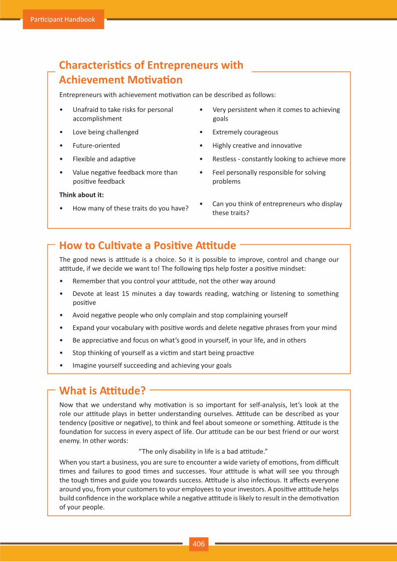
Now that we understand why mo�va�on is so important for self-analysis, let’s look at the role our at�tude plays in better understanding ourselves. At�tude can be described as your tendency (posi�ve or nega�ve), to think and feel about someone or something. At�tude is the founda�on for success in every aspect of life. Our at�tude can be our best friend or our worst enemy. In other words:
“The only disability in life is a bad at�tude.”When you start a business, you are sure to encounter a wide variety of emo�ons, from difficult �mes and failures to good �mes and successes. Your at�tude is what will see you through the tough �mes and guide you towards success. At�tude is also infec�ous. It affects everyone around you, from your customers to your employees to your investors. A posi�ve at�tude helps build confidence in the workplace while a nega�ve at�tude is likely to result in the demo�va�on of your people.
Entrepreneurs with achievement mo�va�on can be described as follows:
• Unafraid to take risks for personal accomplishment
• Love being challenged
• Future-oriented
• Flexible and adap�ve
• Value nega�ve feedback more than posi�ve feedback
Think about it:
• How many of these traits do you have?
•goals
• Extremely courageous
• Highly crea�ve and innova�ve
• Restless - constantly looking to achieve more
• Feel personally responsible for solving problems
• Can you think of entrepreneurs who display these traits?
Very persistent when it comes to achieving
What is At�tude?
Characteris�cs of Entrepreneurs with Achievement Mo�va�on
The good news is at�tude is a choice. So it is possible to improve, control and change our at�tude, if we decide we want to! The following �ps help foster a posi�ve mindset:
• Remember that you control your at�tude, not the other way around
• Devote at least 15 minutes a day towards reading, watching or listening to something posi�ve
• Avoid nega�ve people who only complain and stop complaining yourself
• Expand your vocabulary with posi�ve words and delete nega�ve phrases from your mind
• Be apprecia�ve and focus on what’s good in yourself, in your life, and in others
• Stop thinking of yourself as a vic�m and start being proac�ve
• Imagine yourself succeeding and achieving your goals
How to Cul�vate a Posi�ve At�tude
Par�cipant Handbook
406
Another way to analyze yourself is by honestly iden�fying your strengths and weaknesses. This will help you use your strengths to your best advantage and reduce your weaknesses.Note down all your strengths and weaknesses in the two columns below. Remember to be honest with yourself!
Strengths Weaknesses
What Are Your Strengths and Weaknesses?
• Achievement mo�va�on can be learned.• Don’t be afraid to make mistakes.• Train yourself to finish what you start.• Dream big.
Tips
Auto Service Technician Level 4
407
Honesty is the quality of being fair and truthful. It means speaking and ac�ng in a manner that inspires trust. A person who is described as honest is seen as truthful and sincere, and as someone who isn’t decei�ul or devious and doesn’t steal or cheat. There are two dimensions of honesty – one is honesty in communica�on and the other is honesty in conduct.Honesty is an extremely important trait because it results in peace of mind and builds rela�onships that are based on trust. Being dishonest, on the other hand, results in anxiety and leads to rela�onships full of distrust and conflict.
One of the most important characteris�cs of entrepreneurs is honesty. When entrepreneurs are honest with their customers, employees and investors, it shows that they respect those that they work with. It is also important that entrepreneurs remain honest with themselves. Let’s look at how being honest would lead to great benefits for entrepreneurs.• Honesty and customers: When entrepreneurs are honest with their customers it leads to
stronger rela�onships, which in turn results in business growth and a stronger customer network.
Honest individuals have certain dis�nct characteris�cs. Some common quali�es among honest people are:
1. They don’t worry about what others think of them. They believe in being themselves – they don’t bother about whether they are liked or disliked for their personali�es.
2. They stand up for their beliefs. They won’t think twice about giving their honest opinion, even if they are aware that their point of view lies with the minority.
3. They are think skinned. This means they are not affected by others judging them harshly for their honest opinions.
4. They forge trus�ng, meaningful and healthy friendships. Honest people usually surround themselves with honest friends. They have faith that their friends will be truthful and upfront with them at all �mes.
They are trusted by their peers. They are seen as people who can be counted on for truthful and objec�ve feedback and advice.
• Honesty and employees: When entrepreneurs build honest rela�onships with their employees, it leads to more transparency in the workplace, which results in higher work performance and better results.
• Honesty and investors: For entrepreneurs, being honest with investors means not only sharing strengths but also candidly disclosing current and poten�al weaknesses, problem areas and solu�on strategies. Keep in mind that investors have a lot of experience with startups and are aware that all new companies have problems. Claiming that everything is perfectly fine and running smoothly is a red flag for most investors.
• Honesty with oneself: The consequences of being dishonest with oneself can lead to dire results, especially in the case of entrepreneurs. For entrepreneurs to succeed, it is cri�cal that they remain realis�c about their situa�on at all �mes, and accurately judge every aspect of their enterprise for what it truly is.
6.1.4 Honesty & Work Ethics: What is Honesty?
Importance of Honesty in Entrepreneurs
Quali�es of Honest People
Par�cipant Handbook
408
Being ethical in the workplace means displaying values like honesty, integrity and respect in all your decisions and communica�ons. It means not displaying nega�ve quali�es like lying, chea�ng and stealing. Workplace ethics play a big role in the profitability of a company. It is as crucial to an enterprise as high morale and teamwork. This is why most companies lay down specific workplace ethic guidelines that must compulsorily be followed by their employees. These guidelines are typically outlined in a company’s employee handbook.
An entrepreneur must display strong work ethics, as well as hire only those individuals who believe in and display the same level of ethical behavior in the workplace. Some elements of a strong work ethic are:
• Professionalism: This involves everything from how you present yourself in a corporate set�ng to the manner in which you treat others in the workplace.
• Respec�ulness: This means remaining poised and diploma�c regardless of how stressful or vola�le a situa�on is.
• Dependability: This means always keeping your word, whether it’s arriving on �me for a mee�ng or delivering work on �me.
• Dedica�on: This means refusing to quit un�l the designated work is done, and comple�ng the work at the highest possible level of excellence.
• Determina�on: This means embracing obstacles as challenges rather than let�ng them stop you, and pushing ahead with purpose and resilience to get the desired results.
• Accountability: This means taking responsibility for your ac�ons and the consequences of your ac�ons, and not making excuses for your mistakes.
• Humility: This means acknowledging everyone’s efforts and had work, and sharing the credit for accomplishments.
What are Work Ethics?
Elements of a Strong Work Ethic
As an entrepreneur, it is important that you clearly define the kind of behaviour that you expect from each and every team member in the workplace. You should make it clear that you expect employees to display posi�ve work ethics like:• : All work assigned to a person should be done with complete honesty, without
any deceit or lies.• Good at�tude: All team members should be op�mis�c, energe�c, and posi�ve.• Reliability: Employees should show up where they are supposed to be, when they are
supposed to be there.• Good work habits: Employees should always be well groomed, never use inappropriate
language, conduct themselves professionally at all �mes, etc.• Ini�a�ve: Doing the bare minimum is not enough. Every team member needs to be
proac�ve and show ini�a�ve.• Trustworthiness: Trust is non-nego�able. If an employee cannot be trusted, it’s �me to let
that employee go.
Honesty
How to Foster a Good Work Ethic
Auto Service Technician Level 4
409
• Respect: Employees need to respect the company, the law, their work, their colleagues and themselves.
• Integrity: Each and every team member should be completely ethical and must display above board behaviour at all �mes.
• Efficiency: Efficient employees help a company grow while inefficient employees result in a waste of �me and resources.
•
• Always be willing to accept responsibility for your mistakes.
Don’t get angry when someone tells you the truth and you don’t like what you hear.
Tips
Par�cipant Handbook
410
Crea�vity means thinking outside the box. It means viewing things in new ways or from different perspec�ves, and then conver�ng these ideas into reality. Crea�vity involves two parts: thinking and producing. Simply having an idea makes you imagina�ve, not crea�ve. However, having an idea and ac�ng on it makes you crea�ve.
6.1.5 Crea�vity & Innova�on : What is Crea�vity
There are many different defini�ons of innova�on. In simple terms, innova�on means turning an idea into a solu�on that adds value. It can also mean adding value by implemen�ng a new product, service or process, or significantly improving on an exis�ng product, service or process.
What is Innova�on?
Some characteris�cs of highly innova�ve people are:
• They embrace doing things differently
• They don’t believe in taking shortcuts
• They are not afraid to be unconven�onal
• They are highly proac�ve and persistent
• They are organized, cau�ous and risk-averse
Characteris�cs of Highly Innova�ve People
Some characteris�cs of crea�ve people are:
•
• They see issues from different angles
• They no�ce small details
• They have very little tolerance for boredom
They are imagina�ve and playful •
• They love to daydream
• They are very curious
They detest rules and rou�ne
Characteris�cs of Highly Crea�ve People
•
• Build prototypes frequently, test them out, get feedback, and make the required changes.
Take regular breaks from your crea�ve work to recharge yourself and gain fresh perspec�ve.
Tips
Auto Service Technician Level 4
411
Time management is the process organizing your �me, and deciding how to allocate your �me between different ac�vi�es. Good �me management is the difference between working smart (get�ng more done in less �me) and working hard (working for more �me to get more done). Effec�ve �me management leads to an efficient work output, even when you are faced with �ght deadlines and high pressure situa�ons. On the other hand, not managing your �me effec�vely results in inefficient output and increases stress and anxiety.
Some traits of effec�ve �me managers are:
•
• They set daily objec�ves
• They modify plans if required, to achieve better results
• They are flexible and open-minded
• They inform people in advance if their help will be required
• They know how to say no
They begin projects early •specific deadlines
• They con�nually review long term goals
• They think of alternate solu�ons if and when required
• They ask for help when required
• They create backup plans
They break tasks into steps with
Time management can lead to huge benefits like:
•
• Better professional reputa�on
• Higher chances for career advancement
Greater produc�vity •
• Reduced stress
• Greater opportuni�es to achieve goals
Higher efficiency
Not managing �me effec�vely can result in undesirable consequences like:
•
• Substandard work quality
• Stalled career
Missing deadlines •
• Poor professional reputa�on
• Increase in stress and anxiety
Inefficient work output
6.1.6 Time Management: What is Time Management?
Traits of Effec�ve Time Managers
Benefits of Time Management
You can manage your �me better by put�ng into prac�ce certain �me management techniques. Some helpful �ps are:• Plan out your day as well as plan for interrup�ons. Give yourself at least 30 minutes to
figure out your �me plan. In your plan, schedule some �me for interrup�ons.• Put up a “Do Not Disturb” sign when you absolutely have to complete a certain amount
of work.• Close your mind to all distrac�ons. Train yourself to ignore ringing phones, don’t reply to
chat messages and disconnect from social media sites.
Effec�ve Time Management Techniques
Par�cipant Handbook
412
•you the unique skills and abili�es of those around you.
• Stop procras�na�ng. Remind yourself that procras�na�on typically arises due to the fear of failure or the belief that you cannot do things as perfectly as you wish to do them.
• Priori�ze. List each task to be completed in order of its urgency or importance level. Then focus on comple�ng each task, one by one.
• Maintain a log of your work ac�vi�es. Analyze the log to help you understand how efficient you are, and how much �me is wasted every day.Create �me management goals to reduce �me wastage.
Delegate your work. This will not only help your work get done faster, but will also show
•
• Get at least 7 – 8 hours of sleep every day.
• Start your day early.
• Don’t waste too much �me on small, unimportant details.
• Set a �me limit for every task that you will undertake.
• Give yourself some �me to unwind between tasks.
Always complete the most important tasks first.
Tips
Auto Service Technician Level 4
413
Anger management is the process of:
1. Learning to recognize the signs that you, or someone else, is becoming angry
2. Taking the best course of ac�on to calm down the situa�on in a posi�ve way
Anger management does not mean suppressing anger.
Anger is a perfectly normal human emo�on. In fact, when managed the right way, anger can be considered a healthy emo�on. However, if it is not kept in check, anger can make us act inappropriately and can lead to us saying or doing things that we will likely later regret.Extreme anger can:
• Hurt you physically:: It leads to heart disease, diabetes, a weakened immune system, insomnia, and high blood pressure.
• Hurt you mentally: It can cloud your thinking and lead to stress, depression and mental health issues.
• Hurt your career: It can result in aliena�ng your colleagues, bosses, clients and lead to the loss of respect.
• Hurt your rela�onships: It makes it hard for your family and friends to trust you, be honest with you and feel comfortable around you.This is why anger management, or managing anger appropriately, is so important.
Here are some strategies that can help you control your anger:
Strategy 1: Relaxa�on
Something as simple as breathing deeply and looking at relaxing images works wonders in calming down angry feelings. Try this simple breathing exercise:
1. Take a deep breath from your diaphragm (don’t breathe from your chest)
2. Visualize your breath coming up from your stomach
3. Keep repea�ng a calming word like ‘relax’ or ‘take it easy’ (remember to keep breathing deeply while repea�ng the word)
4. Picture a relaxing moment (this can be from your memory or your imagina�on)
Follow this relaxa�on technique daily, especially when you realize that you’re star�ng to feel angry.
Strategy 2: Cogni�ve Restructuring
Cogni�ve restructuring means changing the manner in which you think. Anger can make you curse, swear, exaggerate and act very drama�cally. When this happens, force yourself to replace your angry thoughts with more logical ones. For instance, instead of thinking ‘Everything is ruined’ change your mindset and tell yourself ‘It’s not the end of the world and get�ng angry won’t solve this’.
6.1.7 Anger Management: What is Anger Management
Importance of Anger Management
Anger Management Strategies
Par�cipant Handbook
414
• The following �ps will help you keep your anger in check:
• Take some �me to collect your thoughts before you speak out in anger.
• Express the reason for your anger in an asser�ve, but non-confronta�onal manner once you have calmed down.
• Do some form of physical exercise like running or walking briskly when you feel yourself get�ng angry.
• Make short breaks part of your daily rou�ne, especially during days that are stressful.Focus on how to solve a problem that’s making you angry, rather than focusing on the fact that the problem is making you angry.
Strategy 3: Problem Solving
Get�ng angry about a problem that you cannot control is a perfectly natural response. Some�mes, try as you may, there may not be a solu�on to the difficulty you are faced with. In such cases, stop focusing on solving the problem, and instead focus on handling and facing the problem. Remind yourself that you will do your best to deal with the situa�on, but that you will not blame yourself if you don’t get the solu�on you desire.
Strategy 4: Better Communica�on
When you’re angry, it is very easy to jump to inaccurate conclusions. In this case, you need to force yourself to stop reac�ng, and think carefully about what you want to say, before saying it. Avoid saying the first thing that enters your head. Force yourself to listen carefully to what the other person is saying. Then think about the conversa�on before responding.
Strategy 5: Changing Your Environment
If you find that your environment is the cause of your anger, try and give yourself a break from your surroundings. Make an ac�ve decision to schedule some personal �me for yourself, especially on days that are very hec�c and stressful. Having even a brief amount of quiet or alone �me is sure to help calm you down.
Tips for Anger Management
•
• Avoid using sarcasm and hurling insults. Instead, try and explain the reason for your frustra�on in a polite and mature manner.
Try to forgive those who anger you, rather than hold a grudge against them.
Tips
Auto Service Technician Level 4
415
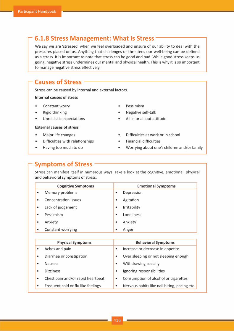
We say we are ‘stressed’ when we feel overloaded and unsure of our ability to deal with the pressures placed on us. Anything that challenges or threatens our well-being can be defined as a stress. It is important to note that stress can be good and bad. While good stress keeps us going, nega�ve stress undermines our mental and physical health. This is why it is so important to manage nega�ve stress effec�vely.
Stress can be caused by internal and external factors.
Internal causes of stress
• Constant worry• Rigid thinking• Unrealis�c expecta�ons
•• Nega�ve self-talk• All in or all out at�tude
Pessimism
External causes of stress
•• Difficul�es with rela�onships• Having too much to do
Major life changes •• Financial difficul�es• Worrying about one’s children and/or family
Difficul�es at work or in school
Stress can manifest itself in numerous ways. Take a look at the cogni�ve, emo�onal, physical and behavioral symptoms of stress.
Cogni�ve Symptoms Emo�onal Symptoms•
• Concentra�on issues
• Lack of judgement
• Pessimism
• Anxiety
• Constant worrying
Memory problems •
• Agita�on
• Irritability
• Loneliness
• Anxiety
• Anger
Depression
Physical Symptoms Behavioral Symptoms•
• Diarrhea or cons�pa�on
• Nausea
• Dizziness
• Chest pain and/or rapid heartbeat
• Frequent cold or flu like feelings
Aches and pain •
• Over sleeping or not sleeping enough
• Withdrawing socially
• Ignoring responsibili�es
• Consump�on of alcohol or cigarettes
• Nervous habits like nail bi�ng, pacing etc.
Increase or decrease in appe�te
6.1.8 Stress Management: What is Stress
Causes of Stress
Symptoms of Stress
Par�cipant Handbook
416
The following �ps can help you manage your stress better:
• Note down the different ways in which you can handle the various sources of your stress.
• Remember that you cannot control everything, but you can control how you respond.
• Discuss your feelings, opinions and beliefs rather than reac�ng angrily, defensively or passively.
• Prac�ce relaxa�on techniques like medita�on, yoga or tai chi when you start feeling stressed.
• Devote a part of your day towards exercise.
• Eat healthy foods like fruits and vegetables. Avoid unhealthy foods especially those containing large amounts of sugar.
• Plan your day so that you can manage your �me better, with less stress.
• Say no to people and things when required.
• Schedule �me to pursue your hobbies and interests.
• Ensure you get at least 7-8 hours of sleep.
• Reduce your caffeine intake.
• Increase the �me spent with family and friends.
Tips to Manage Stress
•
• Stop yourself from feeling and thinking like a vic�m. Change your at�ude and focus on being proac�ve.
Force yourself to smile even if you feel stressed. Smiling makes us feel relaxed and happy.
Tips
Auto Service Technician Level 4
417
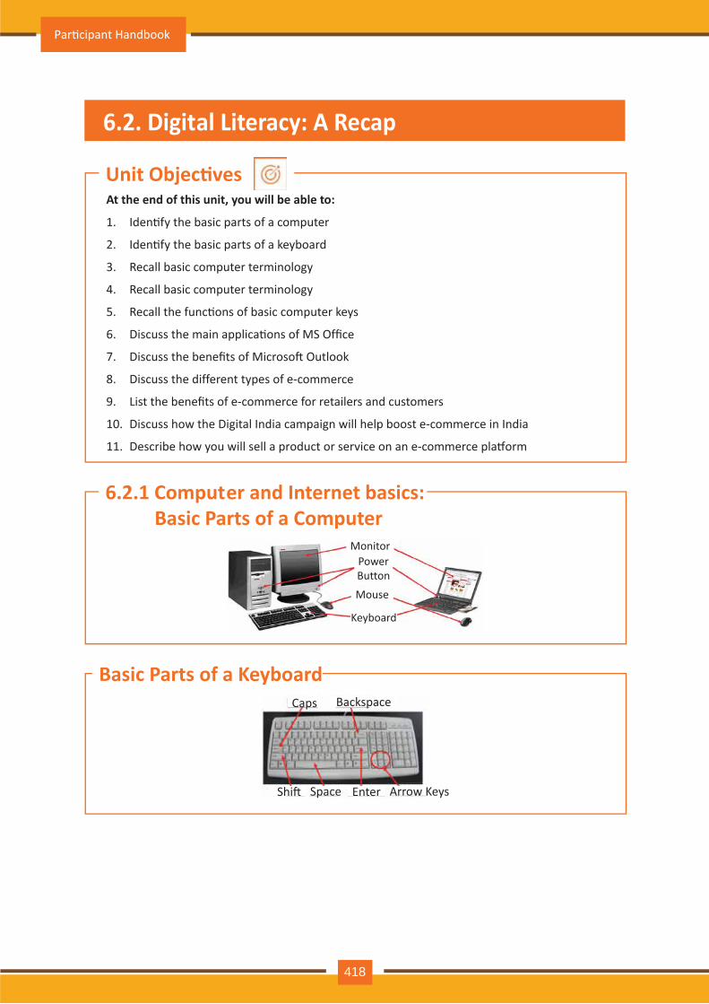
Par�cipant Handbook
418
Monitor
Mouse
Keyboard
Power Button
Caps
Shi� Space Enter Arrow Keys
Backspace
At the end of this unit, you will be able to:
1. Iden�fy the basic parts of a computer
2. Iden�fy the basic parts of a keyboard
3. Recall basic computer terminology
4. Recall basic computer terminology
5. Recall the func�ons of basic computer keys
6. Discuss the main applica�ons of MS Office
7. Discuss the benefits of Microso� Outlook
8. Discuss the different types of e-commerce
9. List the benefits of e-commerce for retailers and customers
10. Discuss how the Digital India campaign will help boost e-commerce in India
11. Describe how you will sell a product or service on an e-commerce pla�orm
Unit Objec�ves
6.2.1 Computer and Internet basics: Basic Parts of a Computer
Basic Parts of a Keyboard
6.2. Digital Literacy: A Recap
Auto Service Technician Level 4
419
• Central Processing Unit (CPU): The brain of the computer. It interprets and carries out program instruc�ons.
• Hard Drive: A device that stores large amounts of data.
• Monitor: The device that contains the computer screen where the informa�on is visually displayed.
• Desktop: The first screen displayed a�er the opera�ng system loads.
• Background: The image that fills the background of the desktop.
Basic Parts of a Computer
•
• Speakers: Devices that enable you to hear sound from the computer.
• Printer: A device that converts output from a computer into printed paper documents.
• Icon: A small picture or image that visually represents something on your computer.
• Cursor: An arrow which indicates where you are posi�oned on the screen.
• Program Menu: A list of programs on your computer that can be accessed from the Start menu.
• Taskbar: The horizontal bar at the bottom of the computer screen that lists applica�ons that are currently in use.
• Recycle Bin: A temporary storage for deleted files.
Mouse: A hand-held device used to point to items on the monitor.
Basic Parts of a Computer
•
• The World Wide Web: A system that lets you access informa�on on the Internet.
• Website: A loca�on on the World Wide Web (and Internet) that contains informa�on about a specific topic.
• Homepage: Provides informa�on about a website and directs you to other pages on that website.
• Link/Hyperlink: A highlighted or underlined icon, graphic, or text that takes you to another file or object.
• Web Address/URL: The address for a website.
• Address Box: A box in the browser window where you can type in a web address.
The Internet : A vast, interna�onal collec�on of computer networks that transfers informa�on.
Basic Internet Terms
Par�cipant Handbook
420
• Arrow Keys: Press these keys to move your cursor.
• Space bar: Adds a space.
• Enter/Return: Moves your cursor to a new line.
• Shi�: Press this key if you want to type a capital letter or the upper symbol of a key.
• Caps Lock: Press this key if you want all the letters you type to be capital letters. Press it again to revert back to typing lowercase letters.
• Backspace: Deletes everything to the le� of your cursor.
Basic Computer Keys
•name of the website and then press Ctrl + Enter. (Example: Type ‘apple’ and press Ctrl + Enter to go to
• Press the Ctrl key and press the + or - to increase and decrease the size of text.• Press F5 or Ctrl + R to refresh or reload a web page.
When visi�ng a .com address, there no need to type http:// or even www. Just type the
www.apple.com)
Tips
Auto Service Technician Level 4
421
MS Office or Microso� Office is a suite of computer programs developed by Microso�. Although meant for all users, it offers different versions that cater specifically to students, home users and business users. All the programs are compa�ble with both, Windows and Macintosh.
Some of the most popular and universally used MS Office applica�ons are:• Microso� Word: Allows users to type text and add images to a document.• Microso� Excel: Allows users to enter data into a spreadsheet and create calcula�ons and
graphs.• Microso� PowerPoint: Allows users to add text, pictures and media and create slideshows
and presenta�ons.• Microso� Outlook: Allows users to send and receive email.• Microso� OneNote: Allows users to make drawings and notes with the feel of a pen on
paper.• Microso� Access: Allows users to store data over many tables.
A popular email management choice especially in the workplace, Microso� Outlook also includes an address book, notebook, web browser and calendar. Some major benefits of this program are:
• : You can use keywords to search for data across all Outlook programs.
• Enhanced security: Your email is safe from hackers, junk mail and phishing website email.
• Email syncing: Sync your mail with your calendar, contact list, notes in One Note and…your phone!
• Offline access to emai:l No Internet? No problem! Write emails offline and send them when you’re connected again.
Integrated search func�on
6.2.2 MS Office and Email: About MS Office
Most Popular Office Products
Why Choose Microso� Outlook
•
• Set your desktop no�fica�ons only for very important emails.
• Flag messages quickly by selec�ng messages and hit�ng the Insert key.
• Save frequently sent emails as a template to reuse again and again.
• Conveniently save important emails as files.
Press Ctrl+R as a shortcut method to reply to email.
Tips
Par�cipant Handbook
422
E-commerce is the buying or selling of goods and services, or the transmit�ng of money or data, electronically on the internet. E-Commerce is the short form for “electronic commerce.”
Some examples of e-commerce are:
• Online shopping
• Online auc�ons
• Online �cke�ng
•
• Internet banking
Electronic payments
E-commerce can be classified based on the types of par�cipants in the transac�on. The main types of e-commerce are:
• : Both the transac�ng par�es are businesses.
• Business to Consumer (B2C): Businesses sell electronically to end-consumers.
• Consumer to Consumer (C2C): Consumers come together to buy, sell or trade items to other consumers.
• Consumer-to-Business (C2B): Consumers make products or services available for purchase to companies looking for exactly those services or products.
• Business-to-Administra�on (B2A): Online transac�ons conducted between companies and public administra�on.
• Consumer-to-Administra�on (C2A): Online transac�ons conducted between individuals and public administra�on.
Business to Business (B2B)
6.2.3 E -Commerce: What is E-Commerce
Examples of E-Commerce
Types of E-Commerce
The e-commerce business provides some benefits for retailers and customers.
Benefits for retailers
• Establishes an online presence
• Reduces opera�onal costs by removing overhead costs
• Increases brand awareness through the use of good keywords
• Increases sales by removing geographical and �me constraints
Benefits for customers:
• Offers a wider range of choice than any physical store
• Enables goods and services to be purchased from remote loca�ons
• Enables consumers to perform price comparisons
:
Benefits of E-Commerce
Auto Service Technician Level 4
423
•
• Pay close and personal atten�on to your social media.
Before launching your e-commerce pla�orm, test everything.
Tips
Prime Minister Narendra Modi launched the Digital India campaign in 2015, with the objec�ve of offering every ci�zen of India access to digital services, knowledge and informa�on. The campaign aims to improve the country’s online infrastructure and increase internet connec�vity, thus boos�ng the e-commerce industry. Currently, the majority of online transac�ons come from �er 2 and �er 3 ci�es. Once the Digital India campaign is in place, the government will deliver services through mobile connec�vity, which will help deliver internet to remote corners of the country. This will help the e-commerce market to enter India’s �er 4 towns and rural areas.
Choose a product or service that you want to sell online. Write a brief note explaining how you will use exis�ng e-commerce pla�orms, or create a new e-commerce pla�orm, to sell your product or service.
Digital India Campaign
E-Commerce Ac�vity
Par�cipant Handbook
424
6.3: Money Matters
We all know that the future is unpredictable. You never know what will happen tomorrow, next week or next year. That’s why saving money steadily through the years is so important. Saving money will help improve your financial situa�on over �me. But more importantly, knowing that you have money stashed away for an emergency will give you peace of mind. Saving money also opens the door to many more op�ons and possibili�es.
Inculca�ng the habit of saving leads to a vast number of benefits. Saving helps you:
• Become financially independent: When you have enough money saved up to feel secure you can start making your choices, from taking a vaca�on whenever you want, to switching careers or star�ng your own business.
• Invest in yourself through educa�on: Through saving, you can earn enough to pay up for courses that will add to your professional experience and ul�mately result in higher paying jobs.
• Get out of debt: Once you have saved enough as a reserve fund, you can use your savings to pay off debts like loans or bills that have accumulated over �me.
• Be prepared for surprise expenses : Having money saved enables you to pay for unforeseen expenses like sudden car or house repairs, without feeling financially stressed.
• Pay for emergencies: Saving helps you deal with emergencies like sudden health issues or emergency trips without feeling financially burdened.
6.3.1 Personal Finance – Why to Save: Importance of Saving
Benefits of Saving
At the end of this unit, you will be able to:
1. Discuss the importance of saving money
2. Discuss the benefits of saving money
3. Discuss the main types of bank accounts
4. Describe the process of opening a bank account
5. Differen�ate between fixed and variable costs
6. Describe the main types of investment op�ons
7. Describe the different types of insurance products
8. Describe the different types of taxes
9. Discuss the uses of online banking
10. Discuss the main types of electronic funds transfers
Unit Objec�ves
Auto Service Technician Level 4
425
• Afford large purchases and achieve major goals:: Saving diligently makes it possible to place down payments towards major purchases and goals, like buying a home or a car.
• Re�re: The money you have saved over the years will keep you comfortable when you no longer have the income you would get from your job.
•money that you would have spent into your savings.
• Decide that you will not buy anything on certain days or weeks and s�ck to your word.
Break your spending habit. Try not spending on one expensive item per week, and put the
Tips
Par�cipant Handbook
426
In India, banks offer four main types of bank accounts. These are:
• Current Accounts
• Savings Accounts
• Recurring Deposit Accounts
• Fixed Deposit Accounts
Current AccountsCurrent accounts offer the most liquid deposits and thus, are best suited for businessmen and companies. As these accounts are not meant for investments and savings, there is no imposed limit on the number or amount of transac�ons that can be made on any given day. Current account holders are not paid any interest on the amounts held in their accounts. They are charged for certain services offered on such accounts.
Savings AccountsSavings accounts are meant to promote savings, and are therefore the number one choice for salaried individuals, pensioners and students. While there is no restric�on on the number and amount of deposits made, there are usually restric�ons on the number and amount of withdrawals. Savings account holders are paid interest on their savings.
Recurring Deposit AccountsRecurring Deposit accounts, also called RD accounts, are the accounts of choice for those who want to save an amount every month, but are unable to invest a large sum at one �me. Such account holders deposit a small, fixed amount every month for a pre-determined period (minimum 6 months). Defaul�ng on a monthly payment results in the account holder being charged a penalty amount. The total amount is repaid with interest at the end of the specified period.
Fixed Deposit AccountsFixed Deposit accounts, also called FD accounts, are ideal for those who wish to deposit their savings for a long term in return for a high rate of interest. The rate of interest offered depends on the amount deposited and the �me period, and also differs from bank to bank. In the case of an FD, a certain amount of money is deposited by the account holder for a fixed period of �me. The money can be withdrawn when the period expires. If necessary, the depositor can break the fixed deposit prematurely. However, this usually attracts a penalty amount which also differs from bank to bank.
6.3.2 Types of Bank Accounts, Opening a Bank Account: Types of Bank Accounts
Opening a bank account is quite a simple process. Take a look at the steps to open an account of your own:Step 1: Fill in the Account Opening FormThis form requires you to provide the following informa�on:• Personal details (name, address, phone number, date of birth, gender, occupa�on, address)• Method of receiving your account statement (hard copy/email)• Details of your ini�al deposit (cash/cheque)• Manner of opera�ng your account (online/mobile banking/tradi�onal via cheque, slip books)Ensure that you sign wherever required on the form.
Opening a Bank Account
Auto Service Technician Level 4
427
Step 2: Affix your Photograph
S�ck a recent photograph of yourself in the allotted space on the form.
Step 3: Provide your Know Your Customer (KYC) DetailsKYC is a process that helps banks verify the iden�ty and address of their customers. To open an account, every individual needs to submit certain approved documents with respect to photo iden�ty (ID) and address proof. Some Officially Valid Documents (OVDs) are:
• Passport
• Driving License
• Voters’ Iden�ty Card
• PAN Card
• UIDAI (Aadhaar) Card
Step 4: Submit All your Documents
Submit the completed Account Opening Form and KYC documents. Then wait un�l the forms are processed and your account has been opened!
•
• Fill in complete nomina�on details.
• Ask about fees.
• Understand the rules.
• Check for online banking – it’s convenient!
• Keep an eye on your bank balance.
Select the right type of account.
Tips
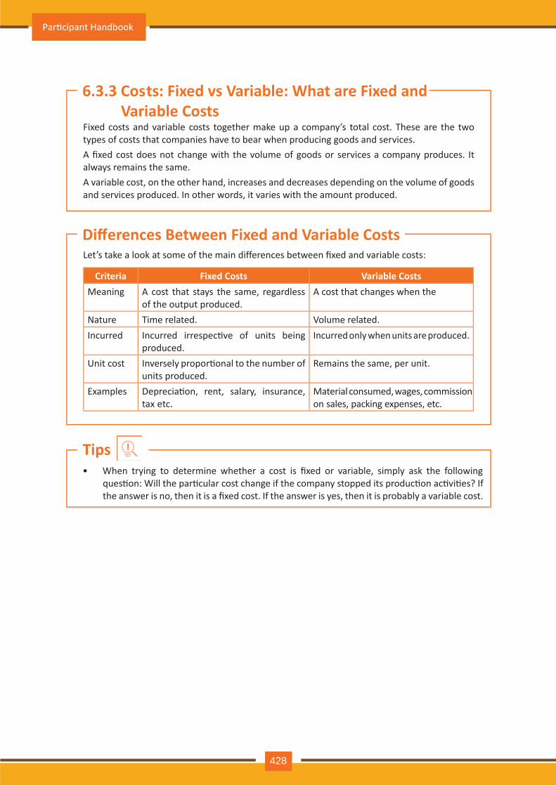
Par�cipant Handbook
428
• When trying to determine whether a cost is fixed or variable, simply ask the following ques�on: Will the par�cular cost change if the company stopped its produc�on ac�vi�es? If the answer is no, then it is a fixed cost. If the answer is yes, then it is probably a variable cost.
Tips
Fixed costs and variable costs together make up a company’s total cost. These are the two types of costs that companies have to bear when producing goods and services.A fixed cost does not change with the volume of goods or services a company produces. It always remains the same.A variable cost, on the other hand, increases and decreases depending on the volume of goods and services produced. In other words, it varies with the amount produced.
Let’s take a look at some of the main differences between fixed and variable costs:
Criteria Fixed Costs Variable CostsMeaning A cost that stays the same, regardless
of the output produced.A cost that changes when the
Nature Time related. Volume related.Incurred Incurred irrespec�ve of units being
produced.Incurred only when units are produced.
Unit cost Inversely propor�onal to the number of units produced.
Remains the same, per unit.
Examples Deprecia�on, rent, salary, insurance, tax etc.
Material consumed, wages, commission on sales, packing expenses, etc.
6.3.3 Costs: Fixed vs Variable: What are Fixed and Variable Costs
Differences Between Fixed and Variable Costs
Auto Service Technician Level 4
429
Investment means that money is spent today with the aim of reaping financial gains at a future �me. The main types of investment op�ons are as follows:
• Bonds: Bonds are instruments used by public and private companies to raise large sums of money – too large to be borrowed from a bank. These bonds are then issued in the public market and are bought by lenders.
• Stocks: Stocks or equity are shares that are issued by companies and are bought by the general public.
• Small Savings Schemes: Small Savings Schemes are tools meant to save money in small amounts. Some popular schemes are the Employees Provident Fund, Sukanya Samriddhi Scheme and Na�onal Pension Scheme.
• Mutual Funds: Mutual Funds are professionally managed financial instruments that invest money in different securi�es on behalf of investors.
• Fixed Deposits: A fixed amount of money is kept aside with a financial ins�tu�on for a fixed amount of �me in return for interest on the money.
• Real Estate: Loans are taken from banks to purchase real estate, which is then leased or sold with the aim of making a profit on the appreciated property price.
• Hedge Funds: Hedge funds invest in both financial deriva�ves and/or publicly traded securi�es.
• Private Equity: Private Equity is trading in the shares of an opera�ng company that is not publicly listed and whose shares are not available on the stock market.
• Venture Capital : Venture Capital involves inves�ng substan�al capital in a budding company in return for stocks in that company.
There are two types of insurance – Life Insurance and Non-Life or General Insurance.
Life InsuranceLife Insurance deals with all insurance covering human life.
Life Insurance ProductsThe main life insurance products are:
• This is the simplest and cheapest form of insurance. It offers financial protec�on for a specified tenure, say 15 to 20 years. In the case of your death, your family is paid the sum assured. In the case of your surviving the term, the insurer pays nothing.
• Endowment Policy: This offers the dual benefit of insurance and investment. Part of the premium is allocated towards the sum assured, while the remaining premium gets invested in equity and debt. It pays a lump sum amount a�er the specified dura�on or on the death of the policyholder, whichever is earlier.
• Unit-Linked Insurance Plan (ULIP): Here part of the premium is spent on the life cover, while the remaining amount is invested in equity and debt. It helps develop a regular saving habit.
Term Insurance:
6.3.4 Investment, Insurance and Taxes: Investment
Insurance
Par�cipant Handbook
430
• Money Back Life Insurance :While the policyholder is alive, periodic payments of the par�al survival benefits are made during the policy tenure. On the death of the insured, the insurance company pays the full sum assured along with survival benefits.
• Whole Life Insurance : It offers the dual benefit of insurance and investment. It offers insurance cover for the whole life of the person or up to 100 years whichever is earlier.
General InsuranceGeneral Insurance deals with all insurance covering assets like animals, agricultural crops, goods, factories, cars and so on.
General Insurance ProductsThe main general insurance products are:
• Motor Insurance: This can be divided into Four Wheeler Insurance and Two Wheeler Insurance.
• Health Insurance: The main types of health insurance are individual health insurance, family floater health insurance, comprehensive health insurance and cri�cal illness insurance.
• Travel Insurance: This can be categorised into Individual Travel Policy, Family Travel Policy, Student Travel Insurance and Senior Ci�zen Health Insurance.
• Home Insurance: This protects the house and its contents from risk.
• Marine Insurance: This insurance covers goods, freight, cargo etc. against loss or damage during transit by rail, road, sea and/or air.
There are two types of taxes – Direct Taxes and Indirect Taxes.
Direct TaxDirect taxes are levied directly on an en�ty or a person and are non-transferrable.
Some examples of Direct Taxes are:
• This tax is levied on your earning in a financial year. It is applicable to both, individuals and companies.
• Capital Gains Tax: This tax is payable whenever you receive a sizable amount of money. It is usually of two types – short term capital gains from investments held for less than 36 months and long term capital gains from investments held for longer than 36 months.
• Securi�es Transac�on Tax: This tax is added to the price of a share. It is levied every �me you buy or sell shares.
• Perquisite Tax: This tax is levied is on perks that have been acquired by a company or used by an employee.
• Corporate Tax: Corporate tax is paid by companies from the revenue they earn.
Indirect TaxIndirect taxes are levied on goods or services.
Some examples of Indirect Taxes are:
• Sales Tax: Sales Tax is levied on the sale of a product.
Income Tax:
Taxes
Auto Service Technician Level 4
431
• Service Tax: Service Tax is added to services provided in India.
• Value Added Tax: Value Added Tax is levied at the discre�on of the state government. The tax is levied on goods sold in the state. The tax amount is decided by the state.
• Customs Duty & Octroi: Customs Duty is a charge that is applied on purchases that are imported from another country. Octroi is levied on goods that cross state borders within India.
• Excise Duty: Excise Duty is levied on all goods manufactured or produced in India.
• Think about how quickly you need your money back and pick an investment op�on accordingly.
• Ensure that you are buying the right type of insurance policy for yourself.
• Remember, not paying taxes can result in penal�es ranging from fines to imprisonment.
Tips
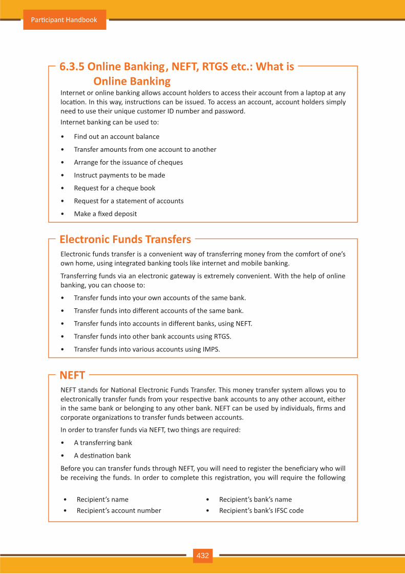
Par�cipant Handbook
432
Internet or online banking allows account holders to access their account from a laptop at any loca�on. In this way, instruc�ons can be issued. To access an account, account holders simply need to use their unique customer ID number and password.Internet banking can be used to:
• Find out an account balance
• Transfer amounts from one account to another
• Arrange for the issuance of cheques
• Instruct payments to be made
• Request for a cheque book
• Request for a statement of accounts
• Make a fixed deposit
Electronic funds transfer is a convenient way of transferring money from the comfort of one’s own home, using integrated banking tools like internet and mobile banking.
Transferring funds via an electronic gateway is extremely convenient. With the help of online banking, you can choose to:
• Transfer funds into your own accounts of the same bank.
• Transfer funds into different accounts of the same bank.
• Transfer funds into accounts in different banks, using NEFT.
• Transfer funds into other bank accounts using RTGS.
• Transfer funds into various accounts using IMPS.
NEFT stands for Na�onal Electronic Funds Transfer. This money transfer system allows you to electronically transfer funds from your respec�ve bank accounts to any other account, either in the same bank or belonging to any other bank. NEFT can be used by individuals, firms and corporate organiza�ons to transfer funds between accounts.
In order to transfer funds via NEFT, two things are required:
• A transferring bank
• A des�na�on bank
Before you can transfer funds through NEFT, you will need to register the beneficiary who will be receiving the funds. In order to complete this registra�on, you will require the following
• Recipient’s name • Recipient’s bank’s name• Recipient’s account number • Recipient’s bank’s IFSC code
6.3.5 Online Banking, NEFT, RTGS etc.: What is Online Banking
Electronic Funds Transfers
NEFT
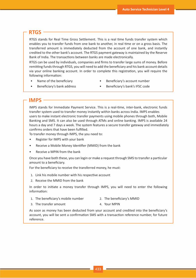
RTGS stands for Real Time Gross Settlement. This is a real �me funds transfer system which enables you to transfer funds from one bank to another, in real �me or on a gross basis. The transferred amount is immediately deducted from the account of one bank, and instantly credited to the other bank’s account. The RTGS payment gateway is maintained by the Reserve Bank of India. The transac�ons between banks are made electronically.RTGS can be used by individuals, companies and firms to transfer large sums of money. Before remit�ng funds through RTGS, you will need to add the beneficiary and his bank account details via your online banking account. In order to complete this registra�on, you will require the following informa�on:• Name of the beneficiary • Beneficiary’s account number • Beneficiary’s bank address • Beneficiary’s bank’s IFSC code
IMPS stands for Immediate Payment Service. This is a real-�me, inter-bank, electronic funds transfer system used to transfer money instantly within banks across India. IMPS enables users to make instant electronic transfer payments using mobile phones through both, Mobile Banking and SMS. It can also be used through ATMs and online banking. IMPS is available 24 hours a day and 7 days a week. The system features a secure transfer gateway and immediately confirms orders that have been fulfilled.To transfer money through IMPS, the you need to:• Register for IMPS with your bank
• Receive a Mobile Money Iden�fier (MMID) from the bank
• Receive a MPIN from the bank
Once you have both these, you can login or make a request through SMS to transfer a par�cular amount to a beneficiary.For the beneficiary to receive the transferred money, he must:
1. Link his mobile number with his respec�ve account2. Receive the MMID from the bank
In order to ini�ate a money transfer through IMPS, you will need to enter the following informa�on:
1. The beneficiary’s mobile number 2. The beneficiary’s MMID3. The transfer amount 4. Your MPIN
As soon as money has been deducted from your account and credited into the beneficiary’s account, you will be sent a confirma�on SMS with a transac�on reference number, for future reference.
RTGS
IMPS
Auto Service Technician Level 4
433
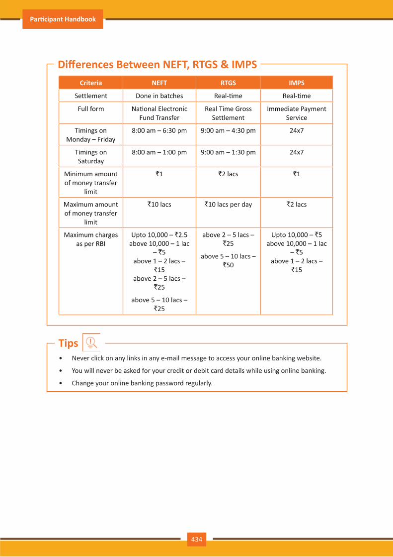
Criteria NEFT RTGS IMPS
Settlement Done in batches Real-�me Real-�me
Full form Na�onal Electronic Fund Transfer
Real Time Gross Settlement
Immediate Payment Service
Timings on Monday – Friday
8:00 am – 6:30 pm 9:00 am – 4:30 pm 24x7
Timings on Saturday
8:00 am – 1:00 pm 9:00 am – 1:30 pm 24x7
Minimum amount of money transfer
limit
`1 `2 lacs `1
Maximum amount of money transfer
limit
`10 lacs `10 lacs per day `2 lacs
Maximum charges as per RBI
Upto 10,000 – `2.5 above 10,000 – 1 lac
– `5 above 1 – 2 lacs –
`15 above 2 – 5 lacs –
`25
above 5 – 10 lacs – `25
above 2 – 5 lacs – `25
above 5 – 10 lacs – `50
Upto 10,000 – `5 above 10,000 – 1 lac
– `5 above 1 – 2 lacs –
`15
Differences Between NEFT, RTGS & IMPS
• Never click on any links in any e-mail message to access your online banking website.
• You will never be asked for your credit or debit card details while using online banking.
• Change your online banking password regularly.
Tips
434
Par�cipant Handbook
6.4. Preparing for Employment & Self Employment
The success of your get�ng the job that you want depends largely on how well your interview for that job goes. Therefore, before you go in for your interview, it is important that you prepare for it with a fair amount of research and planning. Take a look at the steps to follow in order to be well prepared for an interview:1. Research the organiza�on that you are having the interview with.
• Studying the company beforehand will help you be more prepared at the �me of the interview. Your knowledge of the organiza�on will help you answer ques�ons at the �me of the interview, and will leave you looking and feeling more confident. This is sure to make you stand out from other, not as well informed, candidates.
• Look for background informa�on on the company. Ty and find an overview of the company and its industry profile.
• Visit the company website to get a good idea of what the company does. A company website offers a wealth of important informa�on. Read and understand the company’s mission statement. Pay atten�on to the company’s products/services and client list. Read through any press releases to get an idea of the company’s projected growth and stability.
• Note down any ques�ons that you have a�er your research has been completed.
2. Think about whether your skills and qualifica�ons match the job requirements.
• Carefully read through and analyze the job descrip�on.
• Make a note of the knowledge, skills and abili�es required to fulfill the job requirements.
• Take a look at the organiza�on hierarchy. Figure out where the posi�on you are applying for fits into this hierarchy.
3. Go through the most typical interview ques�ons asked, and prepare your responses.
• Remember, in most interviews a mix of resume-based, behavioral and case study ques�ons are asked.
• Think about the kind of answers you would like to provide to typical ques�ons asked in these three areas.
• Prac�ce these answers un�l you can express them confidently and clearly.
6.4.1 Interview Prepara�on: How to Prepare for an Interview
At the end of this unit, you will be able to:
1. Discuss the steps to prepare for an interview
2. Discuss the steps to create an effec�ve Resume
3. Discuss the most frequently asked interview ques�ons
4. Discuss how to answer the most frequently asked interview ques�ons
5. Discuss basic workplace terminology
Unit Objec�ves
435
Auto Service Technician Level 4
4. Plan your at�re for the interview.
• It is always safest to opt for formal business at�re, unless expressly informed to dress in business casual (in which case you should use your best judgement).
• Ensure that your clothes are clean and well-ironed. Pick neutral colours – nothing too bright or flashy.
• The shoes you wear should match your clothes, and should be clean and suitable for an interview.
• Remember, your aim is to leave everyone you meet with the impression that you are a professional and highly efficient person.
5. Ensure that you have packed everything that you may require during the interview.
• Carry a few copies of your resume. Use a good quality paper for your resume print outs.
• Always take along a notepad and a pen.
• Take along any informa�on you may need to refer to, in order to fill out an applica�on form.
• Carry a few samples of your work, if relevant.
6. Remember the importance of non-verbal communica�on.
• Prac�ce projec�ng confidence. Remind yourself to smile and make eye contact. Prac�ce giving a firm handshake.
• Keep in mind the importance of posture. Prac�ce sit�ng up straight. Train yourself to stop nervous gestures like fidge�ng and foot-tapping.
• Prac�ce keeping your reac�ons in check. Remember, your facial expressions provide a good insight into your true feelings. Prac�ce projec�ng a posi�ve image.
7. Make a list of ques�ons to end the interview with.
• Most interviews will end with the interviewer(s) asking if you have any ques�ons. This is your chance to show that you have done your research and are interested in learning more about the company.
• If the interviewer does not ask you this ques�on, you can inform him/her that you have some queries that you would like to discuss. This is the �me for you to refer to the notes you made while studying the company.
• Some good ques�ons to ask at this point are:o What do you consider the most important criteria for success in this job?o How will my performance be evaluated?o What are the opportuni�es for advancement?o What are the next steps in the hiring process?
• Remember, never ask for informa�on that is easily available on the company website.
• Ask insigh�ul and probing ques�ons.
• When communica�ng, use effec�ve forms of body language like smiling, making eye contact, and ac�vely listening and nodding. Don’t slouch, play with nearby items, fidget, chew gum, or mumble.
Tips
436
Par�cipant Handbook
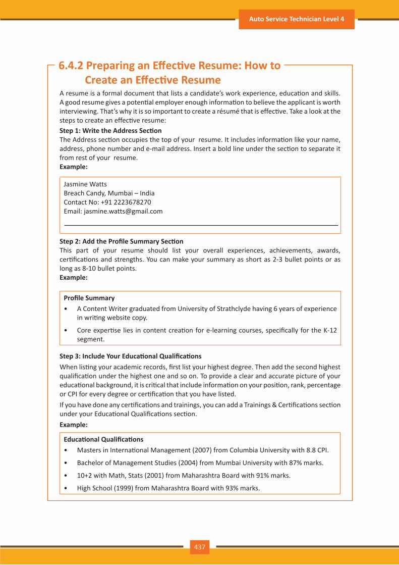
A resume is a formal document that lists a candidate’s work experience, educa�on and skills. A good resume gives a poten�al employer enough informa�on to believe the applicant is worth interviewing. That’s why it is so important to create a résumé that is effec�ve. Take a look at the steps to create an effec�ve resume:
Step 1: Write the Address Sec�onThe Address sec�on occupies the top of your resume. It includes informa�on like your name, address, phone number and e-mail address. Insert a bold line under the sec�on to separate it from rest of your resume.Example:
Jasmine WattsBreach Candy, Mumbai – IndiaContact No: +91 2223678270Email: [email protected]
Step 2: Add the Profile Summary Sec�onThis part of your resume should list your overall experiences, achievements, awards, cer�fica�ons and strengths. You can make your summary as short as 2-3 bullet points or as long as 8-10 bullet points.Example:
Profile Summary• A Content Writer graduated from University of Strathclyde having 6 years of experience
in wri�ng website copy.
• Core exper�se lies in content crea�on for e-learning courses, specifically for the K-12 segment.
Step 3: Include Your Educa�onal Qualifica�onsWhen lis�ng your academic records, first list your highest degree. Then add the second highest qualifica�on under the highest one and so on. To provide a clear and accurate picture of your educa�onal background, it is cri�cal that include informa�on on your posi�on, rank, percentage or CPI for every degree or cer�fica�on that you have listed.If you have done any cer�fica�ons and trainings, you can add a Trainings & Cer�fica�ons sec�on under your Educa�onal Qualifica�ons sec�on.Example:
Educa�onal Qualifica�ons• Masters in Interna�onal Management (2007) from Columbia University with 8.8 CPI.
• Bachelor of Management Studies (2004) from Mumbai University with 87% marks.
• 10+2 with Math, Stats (2001) from Maharashtra Board with 91% marks.
• High School (1999) from Maharashtra Board with 93% marks.
6.4.2 Preparing an Effec�ve Resume: How to Create an Effec�ve Resume
437
Auto Service Technician Level 4
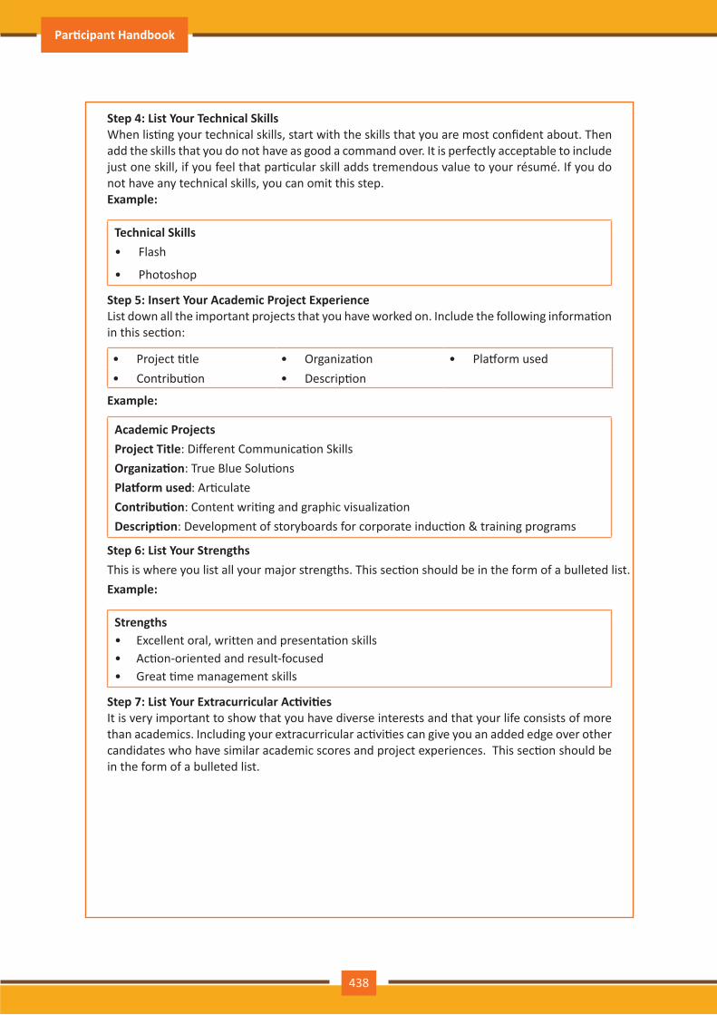
Step 4: List Your Technical SkillsWhen lis�ng your technical skills, start with the skills that you are most confident about. Then add the skills that you do not have as good a command over. It is perfectly acceptable to include just one skill, if you feel that par�cular skill adds tremendous value to your résumé. If you do not have any technical skills, you can omit this step.Example:
Technical Skills• Flash
• Photoshop
Step 5: Insert Your Academic Project ExperienceList down all the important projects that you have worked on. Include the following informa�on in this sec�on:
• Project �tle • Organiza�on • Pla�orm used• Contribu�on • Descrip�on
Example:
Academic ProjectsProject Title: Different Communica�on SkillsOrganiza�on: True Blue Solu�onsPla�orm used: Ar�culateContribu�on: Content wri�ng and graphic visualiza�onDescrip�on: Development of storyboards for corporate induc�on & training programs
Step 6: List Your StrengthsThis is where you list all your major strengths. This sec�on should be in the form of a bulleted list.Example:
Strengths• Excellent oral, written and presenta�on skills• Ac�on-oriented and result-focused• Great �me management skills
Step 7: List Your Extracurricular Ac�vi�esIt is very important to show that you have diverse interests and that your life consists of more than academics. Including your extracurricular ac�vi�es can give you an added edge over other candidates who have similar academic scores and project experiences. This sec�on should be in the form of a bulleted list.
438
Par�cipant Handbook
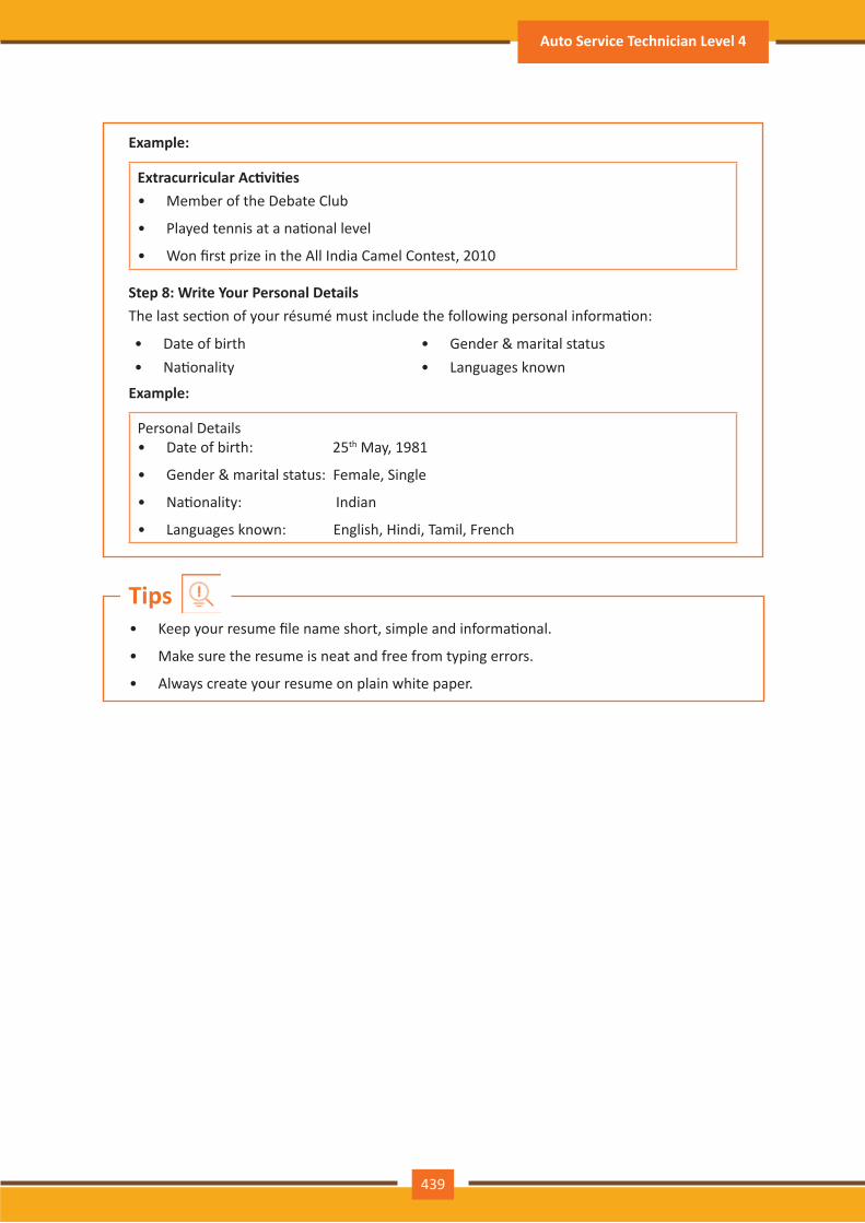
Example:
Extracurricular Ac�vi�es• Member of the Debate Club
• Played tennis at a na�onal level
• Won first prize in the All India Camel Contest, 2010
Step 8: Write Your Personal DetailsThe last sec�on of your résumé must include the following personal informa�on:
• Date of birth • Gender & marital status• Na�onality • Languages known
Example:
Personal Details• Date of birth: 25th May, 1981
• Gender & marital status: Female, Single
• Na�onality: Indian
• Languages known: English, Hindi, Tamil, French
• Keep your resume file name short, simple and informa�onal.
• Make sure the resume is neat and free from typing errors.
• Always create your resume on plain white paper.
Tips
439
Auto Service Technician Level 4
Take a look at some of the most frequently asked interview ques�ons, and some helpful �ps on how to answer them.Q1. Can you tell me a little about yourself?Tips to answer:
• Don’t provide your full employment or personal history.
• Offer 2-3 specific experiences that you feel are most valuable and relevant.
• Conclude with how those experiences have made you perfect for this specific role.
Q2. How did you hear about the posi�on?Tips to answer:
• Tell the interviewer how you heard about the job – whether it was through a friend (name the friend), event or ar�cle (name them) or a job portal (say which one).
• Explain what excites you about the posi�on and what in par�cular caught your eye about this role.
Q3. What do you know about the company?Tips to answer:
• Don’t recite the company’s About Us page.
• Show that you understand and care about the company’s goals.
• Explain why you believe in the company’s mission and values.
Q4. Why do you want this job?Tips to answer:
• Show that you are passionate about the job.
• Iden�fy why the role is a great fit for you.
• Explain why you love the company.
Q5. Why should we hire you?Tips to answer:
• Prove through your words that you can not only do the work, but can definitely deliver excellent results.
• Explain why you would be a great fit with the team and work culture.
• Explain why you should be chosen over any other candidate.
Q6. What are your greatest professional strengths?Tips to answer:
• Be honest – share some of your real strengths, rather than give answers that you think sound good.
• Offer examples of specific strengths that are relevant to the posi�on you are applying for.
• Provide examples of how you’ve demonstrated these strengths.
Q7. What do you consider to be your weaknesses?Tips to answer:
• The purpose of this ques�on is to gauge your self-awareness and honesty.
• Give an example of a trait that you struggle with, but that you’re working on to improve.
6.4.3 Interview FAQs
440
Par�cipant Handbook
Q8. What are your salary requirements?Tips to answer:
• Do your research beforehand and find out the typical salary range for the job you are applying for.
• Figure out where you lie on the pay scale based on your experience, educa�on, and skills.
• Be flexible. Tell the interviewer that you know your skills are valuable, but that you want the job and are willing to nego�ate.
Q9. What do you like to do outside of work?Tips to answer:
• The purpose of this ques�on is to see if you will fit in with the company culture.
• Be honest – open up and share ac�vi�es and hobbies that interest and excite you.
Q10. If you were an animal, which one would you want to be?Tips to answer:
• The purpose of this ques�on is to see if you are able to think on your feet.
• There’s no wrong answer – but to make a great impression try to bring out your strengths or personality traits through your answer.
Q11: What do you think we could do better or differently?Tips to answer:
• The purpose of this ques�on is to see if you have done your research on the company, and to test whether you can think cri�cally and come up with new ideas.
• Suggest new ideas. Show how your interests and exper�se would help you execute these ideas.
Q12: Do you have any ques�ons for us?Tips to answer:
• Do not ask ques�ons to which the answers can be easily found on the company website or through a quick online search.
• Ask intelligent ques�ons that show your ability to think cri�cally.
• Be honest and confident while answering.
• Use examples of your past experiences wherever possible to make your answers more impac�ul.
Tips
441
Auto Service Technician Level 4
Every employee should be well versed in the following terms:
• Annual leave: Paid vaca�on leave given by employers to employees.
• Background Check: A method used by employers to verify the accuracy of the informa�on provided by poten�al candidates.
• Benefits: A part of an employee’s compensa�on package.
• Breaks: Short periods of rest taken by employees during working hours.
• Compensa�on Package: The combina�on of salary and benefits that an employer provides to his/her employees.
• Compensatory Time (Comp Time): Time off in lieu of pay.
• Contract Employee: An employee who works for one organiza�on that sells said employee’s services to another company, either on a project or �me basis.
• Contract of Employment: When an employee is offered work in exchange for wages or salary, and accepts the offer made by the employer, a contract of employment exists.
• Corporate Culture: The beliefs and values shared by all the members of a company, and imparted from one genera�on of employees to another.
• Counter Offer/Counter Proposal: A nego�a�on technique used by poten�al candidates to increase the amount of salary offered by a company.
• Cover Letter: A letter that accompanies a candidate’s resume. It emphasizes the important points in the candidate’s resume and provides real examples that prove the candidate’s ability to perform the expected job role.
• Curriculum Vitae (CV)/Resume: A summary of a candidate’s achievements, educa�onal background, work experience, skills and strengths.
• Declining Letter: A letter sent by an employee to an employer, turning down the job offer made by the employer to the employee.
• Deduc�ons: Amounts subtracted from an employee’s pay and listed on the employee’s pay slip.
• Discrimina�on: The act of trea�ng one person not as favourably as another person.
• Employee: A person who works for another person in exchange for payment.
• Employee Training: A workshop or in-house training that an employee is asked to attend by his or her superior, for the benefit of the employer.
• Employment Gaps: Periods of unemployed �me between jobs.
• Fixed-Term Contract: A contract of employment which gets terminated on an agreed-upon date.
• Follow-Up: The act of contac�ng a poten�al employer a�er a candidate has submitted his or her resume.
• Freelancer/Consultant/Independent Contractor: A person who works for him or herself and pitches for temporary jobs and projects with different employers.
• Holiday: Paid �me-off from work.
• Hourly Rate: The amount of salary or wages paid for 60 minutes of work.
6.4.4 Work Readiness – Terms & Terminologies: Basic Workplace Terminology
442
Par�cipant Handbook
• Internship: A job opportunity offered by an employer to a poten�al employee, called an intern, to work at the employer’s company for a fixed, limited �me period.
• Interview: A conversa�on between a poten�al employee and a representa�ve of an employer, in order to determine if the poten�al employee should be hired.
• Job Applica�on: A form which asks for a candidate’s informa�on like the candidate’s name, address, contact details and work experience. The purpose of a candidate submit�ng a job applica�on, is to show that candidate’s interest in working for a par�cular company.
• Job Offer: An offer of employment made by an employer to a poten�al employee.
• Job Search Agent: A program that enables candidates to search for employment opportuni�es by selec�ng criteria listed in the program, for job vacancies.
• Lay Off: A lay off occurs when an employee is temporarily let go from his or her job, due to the employer not having any work for that employee.
• Leave: Formal permission given to an employee, by his or her employer, to take a leave of absence from work.
• Letter of Acceptance: A letter given by an employer to an employee, confirming the offer of employment made by the employer, as well as the condi�ons of the offer.
• Letter of Agreement: A letter that outlines the terms of employment.
• Letter of Recommenda�on: A letter written for the purpose of valida�ng the work skills of a person.
• Maternity Leave: Leave taken from work by women who are pregnant, or who have just given birth.
• Mentor: A person who is employed at a higher level than you, who offers you advice and guides you in your career.
• Minimum wage: The minimum wage amount paid on an hourly basis.
• No�ce: An announcement made by an employee or an employer, sta�ng that the employment contract will end on a par�cular date.
• Offer of Employment: An offer made by an employer to a prospec�ve employee that contains important informa�on pertaining to the job being offered, like the star�ng date, salary, working condi�ons etc.
• Open-Ended Contract: A contract of employment that con�nues �ll the employer or employee terminates it.
• Overqualified: A person who is not suited for a par�cular job because he or she has too many years of work experience, or a level of educa�on that is much higher than required for the job, or is currently or was previously too highly paid.
• Part-Time Worker: An employee who works for fewer hours than the standard number of hours normally worked.
• Paternity Leave: Leave granted to a man who has recently become a father.
• Recruiters/Headhunters/Execu�ve Search Firms: Professionals who are paid by employers to search for people to fill par�cular posi�ons.
• Resigning/Resigna�ons: When an employee formally informs his or her employer that he or she is quit�ng his or her job.
• Self-Employed: A person who has his or her own business and does not work in the capacity of an employee.
• Time Sheet: A form that is submitted to an employer, by an employee, that contains the number of hours worked every day by the employee.
443
Auto Service Technician Level 4
444
Par�cipant Handbook
6.5. Understanding Entrepreneurship
1. At the end of this unit, you will be able to:
2. Discuss the concept of entrepreneurship
3. Discuss the importance of entrepreneurship
4. Describe the characteris�cs of an entrepreneur
5. Describe the different types of enterprises
6. List the quali�es of an effec�ve leader
7. Discuss the benefits of effec�ve leadership
8. List the traits of an effec�ve team
9. Discuss the importance of listening effec�vely
10. Discuss how to listen effec�vely
11. Discuss the importance of speaking effec�vely
12. Discuss how to speak effec�vely
13. Discuss how to solve problems
14. List important problem solving traits
15. Discuss ways to assess problem solving skills
16. Discuss the importance of nego�a�on
17. Discuss how to nego�ate
18. Discuss how to iden�fy new business opportuni�es
19. Discuss how to iden�fy business opportuni�es within your business
20. Understand the meaning of entrepreneur
21. Describe the different types of entrepreneurs
22. List the characteris�cs of entrepreneurs
23. Recall entrepreneur success stories
24. Discuss the entrepreneurial process
25. Describe the entrepreneurship ecosystem
26. Discuss the government’s role in the entrepreneurship ecosystem
27. Discuss the current entrepreneurship ecosystem in India
28. Understand the purpose of the Make in India campaign
29. Discuss the rela�onship between entrepreneurship and risk appe�te
30. Discuss the rela�onship between entrepreneurship and resilience
31. Describe the characteris�cs of a resilient entrepreneur
32. Discuss how to deal with failure
Unit Objec�ves
Anyone who is determined to start a business, no matter what the risk, is an entrepreneur. Entrepreneurs run their own start-up, take responsibility for the financial risks and use crea�vity, innova�on and vast reserves of self-mo�va�on to achieve success. They dream big and are determined to do whatever it takes to turn their idea into a viable offering. The aim of an entrepreneur is to create an enterprise. The process of crea�ng this enterprise is known as entrepreneurship.
Entrepreneurship is very important for the following reasons:
1. It results in the crea�on of new organiza�ons
2. It brings crea�vity into the marketplace
3. It leads to improved standards of living
4. It helps develop the economy of a country
All successful entrepreneurs have certain characteris�cs in common.
They are all:
• Extremely passionate about their work
• Confident in themselves
• Disciplined and dedicated
• Mo�vated and driven
• Highly crea�ve
• Visionaries
• Open-minded
• Decisive
Entrepreneurs also have a tendency to:
• Have a high risk tolerance
• Thoroughly plan everything
• Manage their money wisely
• Make their customers their priority
• Understand their offering and their market in detail
• Ask for advice from experts when required
• Know when to cut their losses
6.5.1 Concept Introduc�on, (Characteris �c of an Entrepreneur, types of firms / types of enterprises): Entrepreneurs and Entrepreneurship
Importance of Entrepreneurship
Characteris�cs of Entrepreneurs
445
Auto Service Technician Level 4
446
Par�cipant Handbook
Some famous entrepreneurs are:
• Bill Gates (Founder of Microso�)
• Steve Jobs (Co-founder of Apple)
• Mark Zuckerberg (Founder of Facebook)
• Pierre Omidyar (Founder of eBay)
As an entrepreneur in India, you can own and run any of the following types of enterprises:
Sole Proprietorship
In a sole proprietorship, a single individual owns, manages and controls the enterprise. This type of business is the easiest to form with respect to legal formali�es. The business and the owner have no separate legal existence. All profit belongs to the proprietor, as do all the losses - the liability of the entrepreneur is unlimited.
Partnership
A partnership firm is formed by two or more people. The owners of the enterprise are called partners. A partnership deed must be signed by all the partners. The firm and its partners have no separate legal existence. The profits are shared by the partners. With respect to losses, the liability of the partners is unlimited. A firm has a limited life span and must be dissolved when any one of the partners dies, re�res, claims bankruptcy or goes insane.
Limited Liability Partnership (LLP)
In a Limited Liability Partnership or LLP, the partners of the firm enjoy perpetual existence as well as the advantage of limited liability. Each partner’s liability is limited to their agreed contribu�on to the LLP. The partnership and its partners have a separate legal existence.
Examples of Famous Entrepreneurs
Types of Enterprises
• Learn from others’ failures.
• Be certain that this is what you want.
• Search for a problem to solve, rather than look for a problem to attach to your idea.
Tips
Leadership means se�ng an example for others to follow. Se�ng a good example means not asking someone to do something that you wouldn’t willingly want to do yourself. Leadership is about figuring out what to do in order to win as a team, and as a company.
Leaders believe in doing the right things. They also believe in helping others to do the right things. An effec�ve leader is someone who:
• Creates an inspiring vision of the future.
• Mo�vates and inspires his team to pursue that vision.
Effec�ve leadership results in numerous benefits. Great leadership leads to the leader successfully:
• Gaining the loyalty and commitment of the team members
• Mo�va�ng the team to work towards achieving the company’s goals and objec�ves
• Building morale and ins�lling confidence in the team members
• Fostering mutual understanding and team-spirit among team members
• Convincing team members about the need to change when a situa�on requires adaptability
Building a successful enterprise is only possible if the entrepreneur in charge possesses excellent leadership quali�es. Some cri�cal leadership skills that every entrepreneur must have are:
1. Pragma�sm: This means having the ability to highlight all obstacles and challenges, in order to resolve issues and reduce risks.
2. Humility: This means admi�ng to mistakes o�en and early, and being quick to take responsibility for your ac�ons. Mistakes should be viewed as challenges to overcome, not opportuni�es to point blame.
3. Flexibility: It is cri�cal for a good leader to be very flexible and quickly adapt to change. It is equally cri�cal to know when to adapt and when not to.
4. Authen�city: This means showing both, your strengths and your weaknesses. It means being human and showing others that you are human.
5. Reinven�on: This means refreshing or changing your leadership style when necessary. To do this, it’s important to learn where your leadership gaps lie and find out what resources are required to close them.
6. Awareness: This means taking the �me to recognize how others view you. It means understanding how your presence affects those around you.
6.5.2 Leadership & Teamwork: Leadership and Leaders
Benefits of Effec�ve Leadership
Leadership Quali�es That All Entrepreneurs Need
447
Auto Service Technician Level 4
448
Par�cipant Handbook
Teamwork occurs when the people in a workplace combine their individual skills to pursue a common goal. Effec�ve teams are made up of individuals who work together to achieve this common goal. A great team is one who holds themselves accountable for the end result.
For an entrepreneurial leader, building an effec�ve team is cri�cal to the success of a venture. An entrepreneur must ensure that the team he builds possesses certain crucial quali�es, traits and characteris�cs. An effec�ve team is one which has:1. Unity of purpose: All the team members should clearly understand and be equally
committed to the purpose, vision and goals of the team.
2. Great communica�on skills: Team members should have the ability to express their concerns, ask ques�ons and use diagrams, and charts to convey complex informa�on.
3. The ability to collaborate: Every member should feel en�tled to provide regular feedback on new ideas.
4. Ini�a�ve: The team should consist of proac�ve individuals. The members should have the enthusiasm to come up with new ideas, improve exis�ng ideas, and conduct their own research.
5. Visionary members: The team should have the ability to an�cipate problems and act on these poten�al problem before they turn into real problems.
6. Great adaptability skills: The team must believe that change is a posi�ve force. Change should be seen as the chance to improve and try new things.
7. Excellent organiza�onal skills: The team should have the ability to develop standard work processes, balance responsibili�es, properly plan projects, and set in place methods to measure progress and ROI.
Teamwork and Teams
Importance of Teamwork in Entrepreneurial Success
• Don’t get too attached to your original idea. Allow it to evolve and change.
• Be aware of your weaknesses and build a team that will complement your shor�alls.
• Hiring the right people is not enough. You need to promote or incen�vize your most talented people to keep them mo�vated.
• Earn your team’s respect.
Tips
Listening is the ability to correctly receive and understand messages during the process of communica�on. Listening is cri�cal for effec�ve communica�on. Without effec�ve listening skills, messages can easily be misunderstood. This results in a communica�on breakdown and can lead to the sender and the receiver of the message becoming frustrated or irritated.
It’s very important to note that listening is not the same as hearing. Hearing just refers to sounds that you hear. Listening is a whole lot more than that. To listen, one requires focus. It means not only paying atten�on to the story, but also focusing on how the story is relayed, the way language and voice is used, and even how the speaker uses their body language. The ability to listen depends on how effec�vely one can perceive and understand both, verbal and non-verbal cues.
To listen effec�vely you should:
• Stop talking
• Stop interrup�ng
• Focus completely on what is being said
• Nod and use encouraging words and gestures
• Be open-minded
• Think about the speaker’s perspec�ve
• Be very, very pa�ent
• Pay atten�on to the tone that is being used
• Pay atten�on to the speaker’s gestures, facial expressions and eye movements
• Not try and rush the person
• Not let the speaker’s mannerisms or habits irritate or distract you
How successfully a message gets conveyed depends en�rely on how effec�vely you are able to get it through. An effec�ve speaker is one who enunciates properly, pronounces words correctly, chooses the right words and speaks at a pace that is easily understandable. Besides this, the words spoken out loud need to match the gestures, tone and body language used.
What you say, and the tone in which you say it, results in numerous percep�ons being formed. A person who speaks hesitantly may be perceived as having low self-esteem or lacking in knowledge of the discussed topic. Those with a quiet voice may very well be labelled as shy. And those who speak in commanding tones with high levels of clarity, are usually considered to be extremely confident. This makes speaking a very cri�cal communica�on skill.
6.5.3 Communica�on Skills: Listening & Speaking: The Importance of Listening Effec�vely
How to Listen Effec�vely
How to Listen Effec�vely
449
Auto Service Technician Level 4
450
Par�cipant Handbook
To speak effec�vely you should:
• Incorporate body language in your speech like eye contact, smiling, nodding, gesturing etc.
• Build a dra� of your speech before actually making your speech.
• Ensure that all your emo�ons and feelings are under control.
• Pronounce your words dis�nctly with the correct pitch and intensity. Your speech should be crystal clear at all �mes.
• Use a pleasant and natural tone when speaking. Your audience should not feel like you are put�ng on an accent or being unnatural in any way.
• Use precise and specific words to drive your message home. Ambiguity should be avoided at all costs.
• Ensure that your speech has a logical flow.
• Be brief. Don’t add any unnecessary informa�on.
• Make a conscious effort to avoid irrita�ng mannerisms like fidge�ng, twitching etc.
• Choose your words carefully and use simple words that the majority of the audience will have no difficulty understanding.
• Use visual aids like slides or a whiteboard.
• Speak slowly so that your audience can easily understand what you’re saying. However, be careful not to speak too slowly because this can come across as s�ff, unprepared or even condescending.
• Remember to pause at the right moments.
How to Speak Effec�vely
• If you’re finding it difficult to focus on what someone is saying, try repea�ng their words in your head.
• Always maintain eye contact with the person that you are communica�ng with, when speaking as well as listening. This conveys and also encourages interest in the conversa�on.
Tips
As per The Concise Oxford Dic�onary (1995), a problem is, “A doub�ul or difficult matter requiring a solu�on”All problems contain two elements:
1. Goals 2. ObstaclesThe aim of problem solving is to recognize the obstacles and remove them in order to achieve the goals.
As an entrepreneur, it would be a good idea to assess the level of problem solving skills of poten�al candidates before hiring them. Some ways to assess this skill are through:1. Applica�on forms: Ask for proof of the candidate’s problem solving skills in the applica�on
form.
2. Psychometric tests: Give poten�al candidates logical reasoning and cri�cal thinking tests and see how they fare.
3. Interviews: Create hypothe�cal problema�c situa�ons or raise ethical ques�ons and see how the candidates respond.
4. Technical ques�ons: Give candidates examples of real life problems and evaluate their thought process.
Solving a problem requires a level of ra�onal thinking. Here are some logical steps to follow when faced with an issue:
Step 1: Iden�fy the problem Step 2: Study the problem in detailStep 3: List all possible solu�ons Step 4: Select the best solu�onStep 5: Implement the chosen solu�on Step 6: Check that the problem has really been solved
Highly developed problem solving skills are cri�cal for both, business owners and their employees. The following personality traits play a big role in how effec�vely problems are solved:
• Being open minded • Asking the right ques�ons• Being proac�ve • Not panicking• Having a posi�ve at�tude • Focusing on the right problem
6.5.4 Problem Solving & Nego�a�on skills: What is a Problem?
How to Assess for Problem Solving Skills
How to Solve Problems
Important Traits for Problem Solving
451
Auto Service Technician Level 4
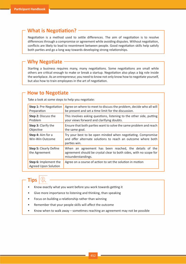
452
Par�cipant Handbook
Nego�a�on is a method used to settle differences. The aim of nego�a�on is to resolve differences through a compromise or agreement while avoiding disputes. Without nego�a�on, conflicts are likely to lead to resentment between people. Good nego�a�on skills help sa�sfy both par�es and go a long way towards developing strong rela�onships.
Star�ng a business requires many, many nego�a�ons. Some nego�a�ons are small while others are cri�cal enough to make or break a startup. Nego�a�on also plays a big role inside the workplace. As an entrepreneur, you need to know not only know how to nego�ate yourself, but also how to train employees in the art of nego�a�on.
Take a look at some steps to help you nego�ate:
Step 1: Pre-Nego�a�on Prepara�on
Agree on where to meet to discuss the problem, decide who all will be present and set a �me limit for the discussion.
Step 2: Discuss the Problem
This involves asking ques�ons, listening to the other side, put�ng your views forward and clarifying doubts.
Step 3: Clarify the Objec�ve
Ensure that both par�es want to solve the same problem and reach the same goal.
Step 4: Aim for a Win-Win Outcome
Try your best to be open minded when nego�a�ng. Compromise and offer alternate solu�ons to reach an outcome where both par�es win.
Step 5: Clearly Define the Agreement
When an agreement has been reached, the details of the agreement should be crystal clear to both sides, with no scope for misunderstandings.
Step 6: Implement the Agreed Upon Solu�on
Agree on a course of ac�on to set the solu�on in mo�on
What is Nego�a�on?
Why Nego�ate
How to Nego�ate
• Know exactly what you want before you work towards get�ng it
• Give more importance to listening and thinking, than speaking
• Focus on building a rela�onship rather than winning
• Remember that your people skills will affect the outcome
• Know when to walk away – some�mes reaching an agreement may not be possible
Tips
“The entrepreneur always searches for change, responds to it and exploits it as an opportunity.”Peter DruckerThe ability to iden�fy business opportuni�es is an essen�al characteris�c of an entrepreneur.
The word opportunity suggests a good chance or a favourable situa�on to do something offered by circumstances.
A business opportunity means a good or favourable change available to run a specific business in a given environment, at a given point of �me.
A cri�cal ques�on that all entrepreneurs face is how to go about finding the business opportunity that is right for them.Some common ques�ons that entrepreneurs constantly think about are:• Should the new enterprise introduce a new product or service based on an unmet need?
• Should the new enterprise select an exis�ng product or service from one market and offer it in another where it may not be available?
• Should the enterprise be based on a tried and tested formula that has worked elsewhere?
It is therefore extremely important that entrepreneurs must learn how to iden�fy new and exis�ng business opportuni�es and evaluate their chances of success.
An idea is an opportunity when:• It creates or adds value to a customer
• It solves a significant problem, removes a pain point or meets a demand
• Has a robust market and profit margin
• Is a good fit with the founder and management team at the right �me and place
6.5.5 Business Opportuni�es Iden�fica�on: Entrepreneurs and Opportuni�es
What is an Opportunity?
Common Ques�ons Faced by Entrepreneurs
When is an Idea an Opportunity?
Consider the following when looking for business opportuni�es:
• Economic trends • Market trends• Changes in funding • Changes in poli�cal support• Changing rela�onships between vendors,
partners and suppliers• Shi� in target audience
Factors to Consider When Looking for Opportuni�es
453
Auto Service Technician Level 4
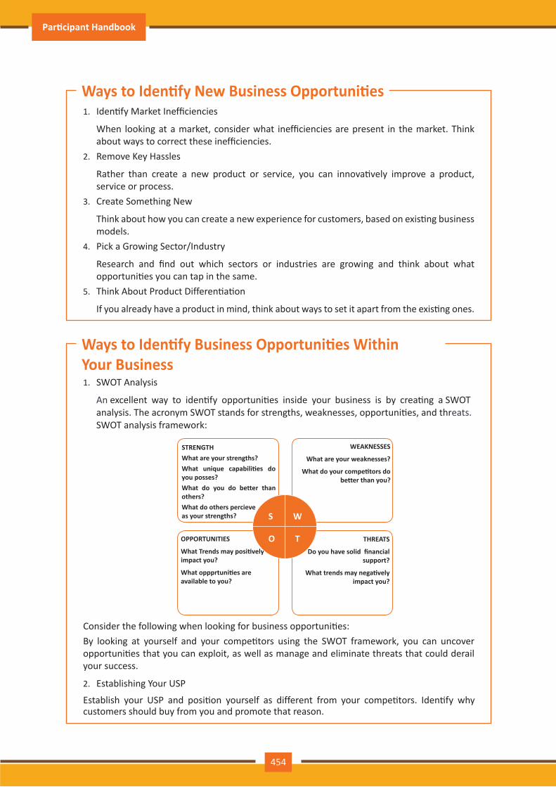
454
Par�cipant Handbook
1. SWOT Analysis
An eats.
excellent way to iden�fy opportuni�es inside your business is by crea�ng a SWOTanalysis. The acronym SWOT stands for strengths, weaknesses, opportuni�es, and thrSWOT analysis framework:
STRENGTHWhat are your strengths?What unique capabili�es do you posses?What do you do better than others?What do others percieve as your strengths?
WEAKNESSES
What are your weaknesses?
What do your compe�tors do better than you?
OPPORTUNITIES
What Trends may posi�vely impact you?
What oppprtuni�es are available to you?
THREATS
Do you have solid financial support?
What trends may nega�vely impact you?
S W
O T
Consider the following when looking for business opportuni�es:By looking at yourself and your compe�tors using the SWOT framework, you can uncover opportuni�es that you can exploit, as well as manage and eliminate threats that could derail your success.
2. Establishing Your USP
Establish your USP and posi�on yourself as different from your compe�tors. Iden�fy why customers should buy from you and promote that reason.
1. Iden�fy Market Inefficiencies
When looking at a market, consider what inefficiencies are present in the market. Think about ways to correct these inefficiencies.
2. Remove Key Hassles
Rather than create a new product or service, you can innova�vely improve a product, service or process.
3. Create Something New
Think about how you can create a new experience for customers, based on exis�ng business models.
4. Pick a Growing Sector/Industry
Research and find out which sectors or industries are growing and think about what opportuni�es you can tap in the same.
5. Think About Product Differen�a�on
If you already have a product in mind, think about ways to set it apart from the exis�ng ones.
Ways to Iden�fy Business Opportuni�es Within Your Business
Ways to Iden�fy New Business Opportuni�es
Once you have iden�fied an opportunity, you need to analyze it.To analyze an opportunity, you must:• Focus on the idea
• Focus on the market of the idea
• Talk to industry leaders in the same space as the idea
• Talk to players in the same space as the idea
Opportunity Analysis
• Remember, opportuni�es are situa�onal.
• Look for a proven track record.
• Avoid the latest craze.
• Love your idea.
Tips
455
Auto Service Technician Level 4
456
Par�cipant Handbook
An entrepreneur is a person who:
• Does not work for an employee
• Runs a small enterprise
• Assumes all the risks and rewards of the enterprise, idea, good or service
There are four main types of entrepreneurs:
1. The Tradi�onal Entrepreneur: This type of entrepreneur usually has some kind of skill –they can be a carpenter, mechanic, cook etc. They have businesses that have been around for numerous years like restaurants, shops and carpenters. Typically, they gain plenty of experience in a par�cular industry before they begin their own business in a similar field.
2. The Growth Poten�al Entrepreneur: The desire of this type of entrepreneur is to start an enterprise that will grow, win many customers and make lots of money. Their ul�mate aim is to eventually sell their enterprise for a nice profit. Such entrepreneurs usually have a science or technical background.
3. The Project-Oriented Entrepreneur: This type of entrepreneur generally has a background in the Arts or psychology. Their enterprises tend to be focus on something that they are very passionate about.
4. The Lifestyle Entrepreneur: This type of entrepreneur has usually worked as a teacher or a secretary. They are more interested in selling something that people will enjoy, rather than making lots of money.
6.5.6 Entrepreneurship Support Eco - System: What is an Entrepreneur?
Types of Entrepreneurs
Successful entrepreneurs have the following characteris�cs:
• They are highly mo�vated
• They are crea�ve and persuasive
• They are mentally prepared to handle each and every task
• They have excellent business skills – they know how to evaluate their cash flow, sales and revenue
• They are willing to take great risks
• They are very proac�ve – this means they are willing to do the work themselves, rather than wait for someone else to do it
• They have a vision – they are able to see the big picture
• They are flexible and open-minded
• They are good at making decisions
Characteris�cs of an Entrepreneur
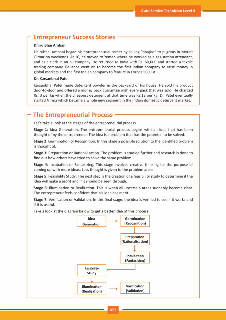
Dhiru Bhai Ambani
Dhirubhai Ambani began his entrepreneurial career by selling “bhajias” to pilgrims in Mount Girnar on weekends. At 16, he moved to Yemen where he worked as a gas-sta�on attendant, and as a clerk in an oil company. He returned to India with Rs. 50,000 and started a tex�le trading company. Reliance went on to become the first Indian company to raise money in global markets and the first Indian company to feature in Forbes 500 list.
Dr. Karsanbhai Patel
Karsanbhai Patel made detergent powder in the backyard of his house. He sold his product door-to-door and offered a money back guarantee with every pack that was sold. He charged Rs. 3 per kg when the cheapest detergent at that �me was Rs.13 per kg. Dr. Patel eventually started Nirma which became a whole new segment in the Indian domes�c detergent market.
Let’s take a look at the stages of the entrepreneurial process.
Stage 1: Idea Genera�on. The entrepreneurial process begins with an idea that has been thought of by the entrepreneur. The idea is a problem that has the poten�al to be solved.
Stage 2: Germina�on or Recogni�on. In this stage a possible solu�on to the iden�fied problem is thought of.
Stage 3: Prepara�on or Ra�onaliza�on. The problem is studied further and research is done to find out how others have tried to solve the same problem.
Stage 4: Incuba�on or Fantasizing. This stage involves crea�ve thinking for the purpose of coming up with more ideas. Less thought is given to the problem areas.
Stage 5: Feasibility Study: The next step is the crea�on of a feasibility study to determine if the idea will make a profit and if it should be seen through.
Stage 6: Illumina�on or Realiza�on. This is when all uncertain areas suddenly become clear. The entrepreneur feels confident that his idea has merit.
Stage 7: Verifica�on or Valida�on. In this final stage, the idea is verified to see if it works and if it is useful.
Take a look at the diagram below to get a better idea of this process.
IdeaGenera�on
Germina�on (Recogni�on)
Illumina�on (Realisa�on)
Fasibility Study
Prepara�on (Ra�onalisa�on)
Incuba�on (Fantasising)
Varifica�on (Valida�on)
Entrepreneur Success Stories
The Entrepreneurial Process
457
Auto Service Technician Level 4
458
Par�cipant Handbook
The entrepreneurship support ecosystem signifies the collec�ve and complete nature of entrepreneurship. New companies emerge and flourish not only because of the courageous, visionary entrepreneurs who launch them, but they thrive as they are set in an environment or ‘ecosystem’ made of private and public par�cipants. These players nurture and sustain the new ventures, facilita�ng the entrepreneurs’ efforts.An entrepreneurship ecosystem comprises of the following six domains:1. Favourable Culture: This includes elements such as tolerance of risk and errors, valuable
networking and posi�ve social standing of the entrepreneur.2. Facilita�ng Policies & Leadership: This includes regulatory framework incen�ves and
existence of public research ins�tutes.3. Financing Op�ons: Angel financing, venture capitalists and micro loans would be good
examples of this.4. Human Capital: This refers to trained and untrained labour, entrepreneurs and
entrepreneurship training programmes, etc. 5. Conducive Markets for Products & Services: This refers to an existence or scope of
existence of a market for the product/service. 6. Ins�tu�onal & Infrastructural Support: This includes legal and financing advisers,
telecommunica�ons, digital and transporta�on infrastructure, and entrepreneurship networking programmes.
These domains indicate whether there is a strong entrepreneurship support ecosystem and what ac�ons should the government put in place to further encourage this ecosystem. The six domains and their various elements have been graphically depicted.
What is an Entrepreneur?
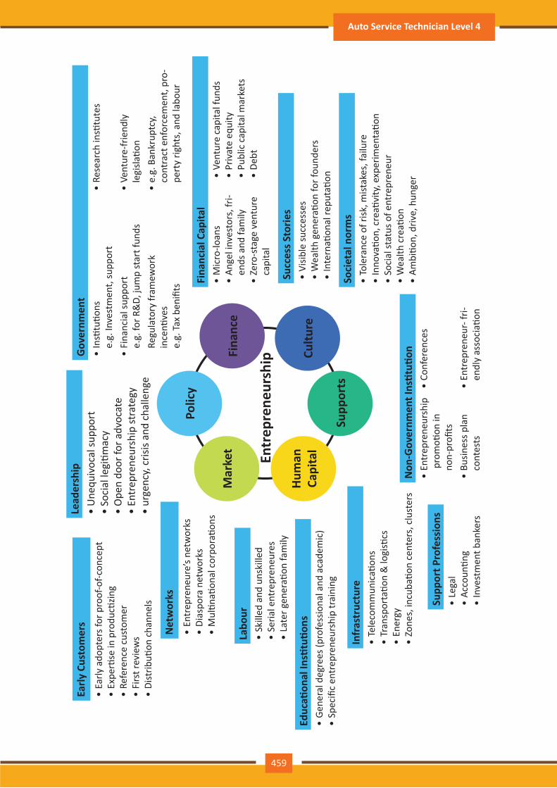
459
Mar
ket
Polic
y
Fina
nce
Cultu
re
Supp
orts
Hum
an
Capi
tal
Entr
epre
neur
ship
Lead
ersh
ip•
Une
quiv
ocal
supp
ort
• So
cial
legi
�mac
y•
Ope
n do
or fo
r adv
ocat
e•
Entr
epre
neur
ship
stra
tegy
• ur
genc
y, cr
isis a
nd c
halle
nge
Fina
ncia
l Cap
ital
• M
icro
-loan
s•
Ange
l inv
esto
rs, f
ri-en
ds a
nd fa
mily
• Ze
ro-s
tage
ven
ture
ca
pita
l
• Ve
ntur
e ca
pita
l fun
ds•
Priv
ate
equi
ty•
Publ
ic c
apita
l mar
kets
• De
bt
Succ
ess S
torie
s•
Visib
le su
cces
ses
• W
ealth
gen
era�
on fo
r fou
nder
s•
Inte
rna�
onal
repu
ta�o
n
Supp
ort P
rofe
ssio
ns•
Lega
l•
Acco
un�n
g •
Inve
stm
ent b
anke
rs
Infr
astr
uctu
re•
Tele
com
mun
ica�
ons
• Tr
ansp
orta
�on
& lo
gis�
cs•
Ener
gy•
Zone
s, in
cuba
�on
cent
ers,
clu
ster
s
Educ
a�on
al In
s�tu
�ons
• Ge
nera
l deg
rees
(pro
fess
iona
l and
aca
dem
ic)
• Sp
ecifi
c en
trep
rene
ursh
ip tr
aini
ng
Net
wor
ks•
Entr
epre
neur
e’s n
etw
orks
• Di
aspo
ra n
etw
orks
• M
ul�n
a�on
al c
orpo
ra�o
ns
Early
Cus
tom
ers
• Ea
rly a
dopt
ers f
or p
roof
-of-c
once
pt•
Expe
r�se
in p
rodu
c�zin
g•
Refe
renc
e cu
stom
er•
Firs
t rev
iew
s•
Dist
ribu�
on c
hann
els
Labo
ur•
Skill
ed a
nd u
nski
lled
• Se
rial e
ntre
pren
eure
s•
Late
r gen
era�
on fa
mily
Soci
etal
nor
ms
• To
lera
nce
of ri
sk, m
istak
es, f
ailu
re•
Inno
va�o
n, c
rea�
vity
, exp
erim
enta
�on
• So
cial
stat
us o
f ent
repr
eneu
r•
Wea
lth c
rea�
on•
Ambi
�on,
driv
e, h
unge
r
Gov
ernm
ent
• In
s�tu
�ons
e.g.
Inve
stm
ent,
supp
ort
• Re
sear
ch in
s�tu
tes
• Fi
nanc
ial s
uppo
rte.
g. fo
r R&
D, ju
mp
star
t fun
ds•
Vent
ure-
frie
ndly
le
gisla
�on
Regu
lato
ry fr
amew
ork
ince
n�ve
se.
g. T
ax b
enifi
ts
• e.
g. B
ankr
uptc
y,
cont
ract
enf
orce
men
t, pr
o-pe
rty
right
s, a
nd la
bour
Non
-Gov
ernm
ent I
ns�t
u�on
• En
trep
rene
ursh
ip
pro
mo�
on in
no
n-pr
ofits
• Co
nfer
ence
s
• Bu
sines
s pla
n co
ntes
ts•
Entr
epre
neur
- fri-
endl
y as
soci
a�on
Auto Service Technician Level 4
460
Par�cipant Handbook
Every entrepreneurship support ecosystem is unique and all the elements of the ecosystem are interdependent. Although every region’s entrepreneurship ecosystem can be broadly described by the above features, each ecosystem is the result of the hundred elements interac�ng in highly complex and par�cular ways.
Entrepreneurship ecosystems eventually become (largely) self-sustaining. When the six domains are resilient enough, they are mutually beneficial. At this point, government involvement can and should be significantly minimized. Public leaders do not need to invest a lot to sustain the ecosystem. It is impera�ve that the entrepreneurship ecosystem incen�ves are formulated to be self-liquida�ng, hence focusing on sustainability of the environment.
Encouraging new ventures is a major focus for policymakers. Governments across the world are recognizing that new businesses flourish in dis�nc�ve types of suppor�ve environments. Policymakers should study the scenario and take into account the following points whilst they formulate policies and regula�ons that enable successful entrepreneurship support ecosystems.
1. Policymakers should avoid regula�ons that discourage new entrants and work towards building efficient methods for business startups. Policies and regula�ons that favour exis�ng, dominant firms over entrepreneurial ventures, restrict compe��on and obstruct entry for new companies.
2. Instead of developing policies conceptually intended to correct market failures, policymakers should interact with entrepreneurs and understand the challenges faced by them. The feedback should be used to develop policies that incite idea explora�on, product development and increased rates of deal flow.
3. Entrepreneurial supporters should create a database that enables iden�fying who the par�cipants in the ecosystem are and how they are connected. These ecosystem maps are useful tools in developing engagement strategies.
4. Disrup�ons are unavoidable in economic and social life. However, it’s important to note that economic disrup�on gives rise to entrepreneurial opportuni�es. Architects of the entrepreneurship ecosystems (entrepreneurs, mentors, policymakers and consumers,) should an�cipate these dips, thus capitalizing on the opportuni�es they create.
The need for effec�ve strategies to enable local entrepreneurship support ecosystems is a prac�cal one. Better understanding of the actual ecosystems provides a framework within which policy makers can ask relevant ques�ons, envisage more efficient approaches, and assess ensuing outcomes.
Government’s Role in the Entrepreneurship Ecosystem
Entrepreneurship has earned a newfound respect in India. Many Indians, with exposure to the world of business, who tradi�onally would have opted for a job, are set�ng up their own ventures. Many elements of the entrepreneurship ecosystem are beginning to come together. For example, increase in venture capitalists, government schemes and incubators, academia industry linkages, and emerging clusters and support to rural economy. All these ini�a�ves are effec�ve but there is a need to scale up and enrich the ecosystem further in the following ways:1. We need to review our at�tude towards failures and accept them as learning experiences.2. We must encourage the educated to become entrepreneurs and provide students in
schools and colleges with entrepreneurship skills.
Snapshot of the Entrepreneurship Ecosystem in India
461
3. Universi�es, research labs and the government need to play the role of enablers in the entrepreneurship support ecosystem.
4. Policymakers need to focus on reducing the obstacles such as corrup�on, red tape and bureaucracy.
5. We need to improve our legal systems and court interna�onal venture capital firms and bring them to India.
6. We must devise policies and methods to reach the secondary and ter�ary towns in India, where people do not have access to the same resources available in the ci�es.
Today, there is a huge opportunity in this country to introduce innova�ve solu�ons that are capable of scaling up, and collabora�ng within the ecosystem as well as enriching it.
• Research the exis�ng market, network with other entrepreneurs, venture capitalists, angel investors, and thoroughly review the policies in place to enable your entrepreneurship.
• Failure is a stepping stone and not the end of the road. Review yours and your peers’ errors and correct them in your future venture.
• Be proac�ve in your ecosystem. Iden�fy the key features of your ecosystem and enrich them to ensure self-sustainability of your entrepreneurship support ecosystem.
Tips
Every entrepreneur has certain needs. Some of their important needs are:
• To easily get loans
• To easily find investors
• To get tax exemp�ons
• To easily access resources and good infrastructure
• To enjoy a procedure that is free of hassles and is quick
• To be able to easily partner with other firms
The Make in India campaign, launched by Prime Minister Modi aims to sa�sfy all these needs of young, aspiring entrepreneurs. Its objec�ve is to:
• Make investment easy
• Support new ideas
• Enhance skill development
• Safeguard the ideas of entrepreneurs
• Create state-of-the-art facili�es for manufacturing goods
Make in India Campaign
Auto Service Technician Level 4
462
Par�cipant Handbook
Entrepreneurs are inherently risk takers. They are path-makers not path-takers. Unlike a normal, cau�ous person, an entrepreneur would not think twice about quit�ng his job (his sole income) and taking a risk on himself and his idea. An entrepreneur is aware that while pursuing his dreams, assump�ons can be proven wrong and unforeseen events may arise. He knows that a�er dealing with numerous problems, success is s�ll not guaranteed. Entrepreneurship is synonymous with the ability to take risks. This ability, called risk-appe�te, is an entrepreneurial trait that is partly gene�c and partly acquired.
Risk appe�te is defined as the extent to which a company is equipped to take risk, in order to achieve its objec�ves. Essen�ally, it refers to the balance, struck by the company, between possible profits and the hazards caused by changes in the environment (economic ecosystem, policies, etc.). Taking on more risk may lead to higher rewards but have a high probability of losses as well. However, being too conserva�ve may go against the company as it can miss out on good opportuni�es to grow and reach their objec�ves.
The levels of risk appe�te can be broadly categorized as “low”, “medium” and “high.” The company’s entrepreneur(s) have to evaluate all poten�al alterna�ves and select the op�on most likely to succeed. Companies have varying levels of risk appe�tes for different objec�ves. The levels depend on:
• The type of industry
• Market pressures
• Company objec�ves
For example, a startup with a revolu�onary concept will have a very high risk appe�te. The startup can afford short term failures before it achieves longer term success. This type of appe�te will not remain constant and will be adjusted to account for the present circumstances of the company.
6.5.7 Risk Appe�te & Resilience: Entrepreneurship and Risk
What is Risk Appe�te?
Companies have to define and ar�culate their risk appe�te in sync with decisions made about their objec�ves and opportuni�es. The point of having a risk appe�te statement is to have a framework that clearly states the acceptance and management of risk in business. It sets risk taking limits within the company. The risk appe�te statement should convey the following:
• The nature of risks the business faces.
• Which risks the company is comfortable taking on and which risks are unacceptable.
• How much risk to accept in all the risk categories.
• The desired tradeoff between risk and reward.
• Measures of risk and methods of examining and regula�ng risk exposures.
Risk Appe�te Statement
463
Entrepreneurs are characterized by a set of quali�es known as resilience. These quali�es play an especially large role in the early stages of developing an enterprise. Risk resilience is an extremely valuable characteris�c as it is believed to protect entrepreneurs against the threat of challenges and changes in the business environment.
Resilience is used to describe individuals who have the ability to overcome setbacks related to their life and career aspira�ons. A resilient person is someone who is capable of easily and quickly recovering from setbacks. For the entrepreneur, resilience is a cri�cal trait. Entrepreneurial resilience can be enhanced in the following ways:
• By developing a professional network of coaches and mentors
• By accep�ng that change is a part of life
• By viewing obstacles as something that can be overcome
The characteris�cs required to make an entrepreneur resilient enough to go the whole way in their business enterprise are:
• A strong internal sense of control • Ability to diversify and expand• Strong social connec�ons • Survivor at�tude• Skill to learn from setbacks • Cash-flow conscious habits• Ability to look at the bigger picture • Atten�on to detail
Entrepreneurship and Resilience
What is Entrepreneurial Resilience?
Characteris�cs of a Resilient Entrepreneur
• Cul�vate a great network of clients, suppliers, peers, friends and family. This will not only help you promote your business, but will also help you learn, iden�fy new opportuni�es and stay tuned to changes in the market.
• Don’t dwell on setbacks. Focus on what the you need to do next to get moving again.
• While you should try and curtail expenses, ensure that it is not at the cost of your growth.
Tips
Auto Service Technician Level 4
Shyam is a famous entrepreneur, known for his success story. But what most people don’t know, is that Shyam failed numerous �mes before his enterprise became a success. Read his interview to get an idea of what entrepreneurship is really about, straight from an entrepreneur who has both, failed and succeeded.Interviewer: Shyam, I have heard that entrepreneurs are great risk-takers who are never afraid of failing. Is this true?Shyam: Ha ha, no of course it’s not true! Most people believe that entrepreneurs need to be fearlessly enthusias�c. But the truth is, fear is a very normal and valid human reac�on, especially when you are planning to start your own business! In fact, my biggest fear was the fear of failing. The reality is, entrepreneurs fail as much as they succeed. The trick is to not allow the fear of failing to stop you from going ahead with your plans. Remember, failures are lessons for future success! Interviewer: What, according to you, is the reason that entrepreneurs fail?Shyam: Well, there is no one single reason why entrepreneurs fail. An entrepreneur can fail due to numerous reasons. You could fail because you have allowed your fear of failure to defeat you. You could fail because you are unwilling to delegate (distribute) work. As the saying goes, “You can do anything, but not everything!” You could fail because you gave up too easily – maybe you were not persistent enough. You could fail because you were focusing your energy on small, insignificant tasks and ignoring the tasks that were most important. Other reasons for failing are partnering with the wrong people, not being able to sell your product to the right customers at the right �me at the right price… and many more reasons!Interviewer: As an entrepreneur, how do you feel failure should be looked at?Shyam: I believe we should all look at failure as an asset, rather than as something nega�ve. The way I see it, if you have an idea, you should try to make it work, even if there is a chance that you will fail. That’s because not trying is failure right there, anyway! And failure is not the worst thing that can happen. I think having regrets because of not trying, and wondering ‘what if’ is far worse than trying and actually failing. Interviewer: How did you feel when you failed for the first �me?Shyam: I was completely heartbroken! It was a very painful experience. But the good news is, you do recover from the failure. And with every subsequent failure, the recovery process gets a lot easier. That’s because you start to see each failure more as a lesson that will eventually help you succeed, rather than as an obstacle that you cannot overcome. You will start to realize that failure has many benefits. Interviewer: Can you tell us about some of the benefits of failing?Shyam: One of the benefits that I have experienced personally from failing is that the failure made me see things in a new light. It gave me answers that I didn’t have before. Failure can make you a lot stronger. It also helps keep your ego in control. Interviewer: What advice would you give entrepreneurs who are about to start their own enterprises?Shyam: I would tell them to do their research and ensure that their product is something that is actually wanted by customers. I’d tell them to pick their partners and employees very wisely and cau�ously. I’d tell them that it’s very important to be aggressive – push and market your product as aggressively as possible. I would warn them that star�ng an enterprise is veryexpensive and that they should be prepared for a situa�on where they run out of money.
6.5.8 Success & Failures: Understanding Successes and Failures in Entrepreneurship
464
Par�cipant Handbook
465
I would tell them to create long term goals and put a plan in ac�on to achieve that goal. I would tell them to build a product that is truly unique. Be very careful and ensure that you are not copying another startup. Lastly, I’d tell them that it’s very important that they find the right investors. Interviewer: That’s some really helpful advice, Shyam! I’m sure this will help all entrepreneurs to be more prepared before they begin their journey! Thank you for all your insight!
• Remember that nothing is impossible.
• Iden�fy your mission and your purpose before you start.
• Plan your next steps – don’t make decisions has�ly.
Tips
Auto Service Technician Level 4
466
Par�cipant Handbook
Market research is the process of gathering, analyzing and interpre�ng market informa�on on a product or service that is being sold in that market. It also includes informa�on on:
• Past, present and prospec�ve customers
• Customer characteris�cs and spending habits
• The loca�on and needs of the target market
• The overall industry
• Relevant compe�tors
Market research involves two types of data:
• Primary informa�on. This is research collected by yourself or by someone hired by you.
• Secondary informa�on. This is research that already exists and is out there for you to find and use.
6.6.1 Market Study / The 4 Ps of Marke�ng / Importance of an IDEA: Understanding Market Research
6.6: Preparing to be an Entrepreneur
At the end of this unit, you will be able to:
1. Discuss how market research is carried out
2. Describe the 4 Ps of marke�ng
3. Discuss the importance of idea genera�on
4. Recall basic business terminology
5. Discuss the need for CRM
6. Discuss the benefits of CRM
7. Discuss the need for networking
8. Discuss the benefits of networking
9. Understand the importance of set�ng goals
10. Differen�ate between short-term, medium-term and long-term goals
11. Discuss how to write a business plan
12. Explain the financial planning process
13. Discuss ways to manage your risk
14. Describe the procedure and formali�es for applying for bank finance
15. Discuss how to manage your own enterprise
16. List important ques�ons that every entrepreneur should ask before star�ng an enterprise
Unit Objec�ves
467
The 4 Ps of marke�ng are Product, Price, Promo�on and Place. Let’s look at each of these 4 Ps in detail.
A product can be:
• A tangible good • An intangible service
Whatever your product is, it is cri�cal that you have a clear understanding of what you are offering, and what its unique characteris�cs are, before you begin with the marke�ng process.
Some ques�ons to ask yourself are:
• What does the customer want from the product/service?
• What needs does it sa�sfy?
• Are there any more features that can be added?
• Does it have any expensive and unnecessary features?
• How will customers use it?
• What should it be called?
• How is it different from similar products?
• How much will it cost to produce?
• Can it be sold at a profit?
The 4 Ps of Marke�ng
Product
Primary researchPrimary research can be of two types:• Exploratory: This is open-ended and usually involves detailed, unstructured interviews.
• Specific: This is precise and involves structured, formal interviews. Conduc�ng specific research is the more expensive than conduc�ng exploratory research.
Secondary researchSecondary research uses outside informa�on. Some common secondary sources are:• Public sources: These are usually free and have a lot of good informa�on. Examples are
government departments, business departments of public libraries etc.
• Commercial sources: These offer valuable informa�on but usually require a fee to be paid. Examples are research and trade associa�ons, banks and other financial ins�tu�ons etc.
• Educa�onal ins�tu�ons: These offer a wealth of informa�on. Examples are colleges, universi�es, technical ins�tutes etc.
Auto Service Technician Level 4
468
Par�cipant Handbook
Once all the elements of Product have been established, the Price factor needs to be considered. The Price of a Product will depend on several factors such as profit margins, supply, demand and the marke�ng strategy.Some ques�ons to ask yourself are:• What is the value of the product/service to customers?
• Do local products/services have established price points?
• Is the customer price sensi�ve?
• Should discounts be offered?
• How is your price compared to that of your compe�tors?
Once you are certain about your Product and your Price, the next step is to look at ways to promote it. Some key elements of promo�on are adver�sing, public rela�ons, social media marke�ng, email marke�ng, search engine marke�ng, video marke�ng and more.Some ques�ons to ask yourself are:• Where should you promote your product or service?
• What is the best medium to use to reach your target audience?
• When would be the best �me to promote your product?
• How are your compe�tors promo�ng their products?
Price
Promo�on
According to most marketers, the basis of marke�ng is about offering the right product, at the right price, at the right place, at the right �me. For this reason, selec�ng the best possible loca�on is cri�cal for conver�ng prospec�ve clients into actual clients.Some ques�ons to ask yourself are:• Will your product or service be looked for in a physical store, online or both?
• What should you do to access the most appropriate distribu�on channels?
• Will you require a sales force?
• Where are your compe�tors offering their products or services?
• Should you follow in your compe�tors’ footsteps?
• Should you do something different from your compe�tors?
Ideas are the founda�on of progress. An idea can be small or ground-breaking, easy to accomplish or extremely complicated to implement. Whatever the case, the fact that it is an idea gives it merit. Without ideas, nothing is possible. Most people are afraid to speak out their ideas, out for fear of being ridiculed. However, if are an entrepreneur and want to remain compe��ve and innova�ve, you need to bring your ideas out into the light.
Place
Importance of an IDEA
469
Some ways to do this are by:• Establishing a culture of brainstorming where you invite all interested par�es to contribute
• Discussing ideas out loud so that people can add their ideas, views, opinions to them
• Being open minded and not limi�ng your ideas, even if the idea who have seems ridiculous
• Not discarding ideas that you don’t work on immediately, but instead making a note of them and shelving them so they can be revisited at a later date
• Keep in mind that good ideas do not always have to be unique.
• Remember that �ming plays a huge role in determining the success of your idea.
• Situa�ons and circumstances will always change, so be flexible and adapt your idea accordingly.
Tips
Auto Service Technician Level 4
470
Par�cipant Handbook
If your aim is to start and run a business, it is crucial that you have a good understanding of basic business terms. Every entrepreneur should be well versed in the following terms:
• Accoun�ng: A systema�c method of recording and repor�ng financial transac�ons.
• Accounts payable: Money owed by a company to its creditors.
• Accounts Receivable: The amount a company is owed by its clients.
• Assets: The value of everything a company owns and uses to conduct its business.
• Balance Sheet: A snapshot of a company’s assets, liabili�es and owner’s equity at a given moment.
• Bottom Line: The total amount a business has earned or lost at the end of a month.
• Business: An organiza�on that operates with the aim of making a profit.
• Business to Business (B2B): A business that sells goods or services to another business.
• Business to Consumer (B2C): A business that sells goods or services directly to the end user.
• Capital: The money a business has in its accounts, assets and investments. The two main types of capital are debt and equity.
• Cash Flow: The overall movement of funds through a business each month, including income and expenses.
• Cash Flow Statement: A statement showing the money that entered and exited a business during a specific period of �me.
• Contract: A formal agreement to do work for pay.
• Deprecia�on: The degrading value of an asset over �me.
• Expense: The costs that a business incurs through its opera�ons.
• Finance: The management and alloca�on of money and other assets.
• Financial Report: A comprehensive account of a business’ transac�ons and expenses.
• Fixed Cost: A one-�me expense.
• Income Statement (Profit and Loss Statement): Shows the profitability of a business during a period of �me.
• Liabili�es: The value of what a business owes to someone else.
• Marke�ng: The process of promo�ng, selling and distribu�ng a product or service.
• Net Income/Profit: Revenues minus expenses.
• Net Worth: The total value of a business.
• Payback Period: The amount of �me it takes to recover the ini�al investment of a business.
• Profit Margin: The ra�o of profit, divided by revenue, displayed as a percentage.
• Return on Investment (ROI): The amount of money a business gets as return from an investment.
6.6.2 Business En�ty Concepts: Basic Business Terminology

471
• Revenue: The total amount of income before expenses are subtracted.
• Sales Prospect: A poten�al customer.
• Supplier: A provider of supplies to a business.
• Target Market: A specific group of customers at which a company’s products and services are aimed.
• Valua�on: An es�mate of the overall worth of the business.
• Variable Cost: Expenses that change in propor�on to the ac�vity of a business.
• Working Capital: Calculated as current assets minus current liabili�es.
Auto Service Technician Level 4
472
Par�cipant Handbook
CRM stands for Customer Rela�onship Management. Originally the expression Customer Rela�onship Management meant managing one’s rela�onship with customers. However, today it refers to IT systems and so�ware designed to help companies manage their rela�onships.
The better a company can manage its rela�onships with its customers, the higher the chances of the company’s success. For any entrepreneur, the ability to successfully retain exis�ng customers and expand the enterprise is paramount. This is why IT systems that focus on addressing the problems of dealing with customers on a daily basis are becoming more and more in demand.
Customer needs change over �me, and technology can make it easier to understand what customers really want. This insight helps companies to be more responsive to the needs of their customers. It enables them to modify their business opera�ons when required, so that their customers are always served in the best manner possible. Simply put, CRM helps companies recognize the value of their clients and enables them to capitalize on improved customer rela�ons.
CRM has a number of important benefits:
• It helps improve rela�ons with exis�ng customers which can lead to:
� Increased sales
� Iden�fica�on of customer needs
� Cross-selling of products
• It results in better marke�ng of one’s products or services
• It enhances customer sa�sfac�on and reten�on
• It improves profitability by iden�fying and focusing on the most profitable customers
6.6.3 CRM & Networking: What is CRM?
The Need for CRM
Benefits of CRM
In business, networking means leveraging your business and personal connec�ons in order to bring in a regular supply of new business. This marke�ng method is effec�ve as well as low cost. It is a great way to develop sales opportuni�es and contacts. Networking can be based on referrals and introduc�ons, or can take place via phone, email, and social and business networking websites.
Networking is an essen�al personal skill for business people, but it is even more important for entrepreneurs. The process of networking has its roots in rela�onship building. Networking results in greater communica�on and a stronger presence in the entrepreneurial ecosystem. This helps build strong rela�onships with other entrepreneurs.
What is Networking?
The Need for Networking
473
Networking offers numerous benefits for entrepreneurs. Some of the major benefits are:
• Get�ng high quality leads
• Increased business opportuni�es
• Good source of relevant connec�ons
• Advice from like-minded entrepreneurs
• Gaining visibility and raising your profile
• Mee�ng posi�ve and enthusias�c people
• Increased self-confidence
• Sa�sfac�on from helping others
• Building strong and las�ng friendships
Benefits of Networking
• Use social media interac�ons to iden�fy needs and gather feedback.
• When networking, ask open-ended ques�ons rather than yes/no type ques�ons.
Tips
Business networking events held across the globe play a huge role in connec�ng like-minded entrepreneurs who share the same fundamental beliefs in communica�on, exchanging ideas and conver�ng ideas into reali�es. Such networking events also play a crucial role in connec�ng entrepreneurs with poten�al investors. Entrepreneurs may have vastly different experiences and backgrounds but they all have a common goal in mind – they all seek connec�on, inspira�on, advice, opportuni�es and mentors. Networking offers them a pla�orm to do just that.
Auto Service Technician Level 4
Set�ng goals is important because it gives you long-term vision and short-term mo�va�on. Goals can be short term, medium term and long term.
Short-Term Goals
• These are specific goals for the immediate future.
Example: Repairing a machine that has failed.
Medium-Term Goals
• These goals are built on your short term goals.
• They do not need to be as specific as your short term goals.
Example: Arranging for a service contract to ensure that your machines don’t fail again.
Long-Term Goals
These goals require �me and planning.
They usually take a year or more to achieve.
Example: Planning your expenses so you can buy new machinery
A business plan is a tool for understanding how your business is put together. It can be used to monitor progress, foster accountable and control the fate of the business. It usually offers a 3-5 year projec�on and outlines the plan that the company intends to follow to grow its revenues. A business plan is also a very important tool for get�ng the interest of key employees or future investors.A business plan typically comprises of eight elements.
6.6.4 Business Plan: Why Set Goals
Why Create a Business Plan
Execu�ve Summary
The execu�ve summary follows the �tle page. The summary should clearly state your desires as the business owner in a short and businesslike way. It is an overview of your business and your plans. Ideally this should not be more than 1-2 pages.
Your Execu�ve Summary should include:
• The Mission Statement: Explain what your business is all about.
Example: Nike’s Mission Statement
Nike’s mission statement is “To bring inspira�on and innova�on to every athlete in the world.”
• Company Informa�on: Provide informa�on like when your business was formed, the names and roles of the founders, the number of employees, your business loca�on(s) etc.
• Growth Highlights: Men�on examples of company growth. Use graphs and charts where possible.
• Your Products/Services: Describe the products or services provided.
• Financial Informa�on: Provide details on current bank and investors.
• Summarize future plans: Describe where you see your business in the future.
Elements of a Business Plan
474
Par�cipant Handbook
475
Business Descrip�on
The second sec�on of your business plan needs to provide a detailed review of the different elements of your business. This will help poten�al investors to correctly understand your business goal and the uniqueness of your offering.
Your Business Descrip�on should include:
• A descrip�on of the nature of your business
• The market needs that you are aiming to sa�sfy
• The ways in which your products and services meet these needs
• The specific consumers and organiza�ons that you intend to serve
• Your specific compe��ve advantages
Market Analysis
The market analysis sec�on usually follows the business descrip�on. The aim of this sec�on is to showcase your industry and market knowledge. This is also the sec�on where you should lay down your research findings and conclusions.
Your Market Analysis should include:
• Your industry descrip�on and outlook
• Informa�on on your target market
• The needs and demographics of your target audience
• The size of your target market
• The amount of market share you want to capture
• Your pricing structure
• Your compe��ve analysis
• Any regulatory requirementsOrganiza�on & ManagementThis sec�on should come immediately a�er the Market Analysis.Your Organiza�on & Management sec�on should include:• Your company’s organiza�onal structure
• Details of your company’s ownership
• Details of your management team
• Qualifica�ons of your board of directors
• Detailed descrip�ons of each division/department and its func�on
• The salary and benefits package that you offer your people
• The incen�ves that you offer
Service or Product LineThe next sec�on is the service or product line sec�on. This is where you describe your service or product, and stress on their benefits to poten�al and current customers. Explain in detail why your product of choice will fulfill the needs of your target audience.
Auto Service Technician Level 4
476
Par�cipant Handbook
Your Service or Product Line sec�on should include:• A descrip�on of your product/service
• A descrip�on of your product or service’s life cycle
• A list of any copyright or patent filings
• A descrip�on of any R&D ac�vi�es that you are involved in or planning
Marke�ng & SalesOnce the Service or Product Line sec�on of your plan has been completed, you should start on the descrip�on of the marke�ng and sales management strategy for your business.Your Marke�ng sec�on should include the following strategies:• Market penetra�on strategy: This strategy focuses on selling your exis�ng products or
services in exis�ng markets, in order to increase your market share.
• Growth strategy: This strategy focuses on increasing the amount of market share, even if it reduces earnings in the short-term.
• Channels of distribu�on strategy: These can be wholesalers, retailers, distributers and even the internet.
• Communica�on strategy: These can be written strategies (e-mail, text, chat), oral strategies (phone calls, video chats, face-to-face conversa�ons), non-verbal strategies (body language, facial expressions, tone of voice) and visual strategies (signs, webpages, illustra�ons).
Your Sales sec�on should include the following informa�on:
• A salesforce strategy: This strategy focuses on increasing the revenue of the enterprise.
• A breakdown of your sales ac�vi�es: This means detailing out how you intend to sell your products or services – will you sell it offline or online, how many units do you intend to sell, what price do you plan to sell each unit at, etc.
Funding Request
This sec�on is specifically for those who require funding for their venture.
The Funding Request sec�on should include the following informa�on:
• How much funding you currently require.
• How much funding you will require over the next five years. This will depend on your long-term goals.
• The type of funding you want and how you plan to use it. Do you want funding that can be used only for a specific purpose, or funding that can be used for any kind of requirement?
• Strategic plans for the future. This will involve detailing out your long-term plans – what these plans are and how much money you will require to put these plans in mo�ons.
• Historical and prospec�ve financial informa�on. This can be done by crea�ng and maintaining all your financial records, right from the moment your enterprise started, to the present day. Documents required for this are your balance sheet which contains details of your company’s assets and liabili�es, your income statement which lists your company’s revenues, expenses and net income for the year, your tax returns (usually for the last three years) and your cash flow budget which lists the cash that came in, the cash that went out and states whether you had a cash deficit (nega�ve balance) or surplus (posi�ve balance) at the end of each month.
477
Financial Planning
Before you begin building your enterprise, you need to plan your finances. Take a look at the steps for financial planning:
Step 1: Create a financial plan. This should include your goals, strategies and �melines for accomplishing these goals.
Step 2: Organize all your important financial documents. Maintain a file to hold your investment details, bank statements, tax papers, credit card bills, insurance papers and any other financial records.
Step 3: Calculate your net worth. This means figure out what you own (assets like your house, bank accounts, investments etc.), and then subtract what you owe (liabili�es like loans, pending credit card amounts etc.) the amount you are le� with is your net worth.
Step 4: Make a spending plan. This means write down in detail where your money will come from, and where it will go.
Step 5: Build an emergency fund. A good emergency fund contains enough money to cover at least 6 months’ worth of expenses.
Step 6: Set up your insurance. Insurance provides long term financial security and protects you against risk.
Risk Management
As an entrepreneur, it is cri�cal that you evaluate the risks involved with the type of enterprise that you want to start, before you begin set�ng up your company. Once you have iden�fied poten�al risks, you can take steps to reduce them. Some ways to manage risks are:
• Research similar business and find out about their risks and how they were minimized.
• Evaluate current market trends and find out if similar products or services that launched a while ago are s�ll being well received by the public.
• Think about whether you really have the required exper�se to launch your product or service.
• Examine your finances and see if you have enough income to start your enterprise.
• Be aware of the current state of the economy, consider how the economy may change over �me, and think about how your enterprise will be affected by any of those changes.
• Create a detailed business plan.
• Ensure all the important elements are covered in your plan.
• Scru�nize the numbers thoroughly.
• Be concise and realis�c.
• Be conserva�ve in your approach and your projec�ons.
• Use visuals like charts, graphs and images wherever possible.
Tips
Auto Service Technician Level 4
478
Par�cipant Handbook
For entrepreneurs, one of the most difficult challenges faced involves securing funds for startups. With numerous funding op�ons available, entrepreneurs need to take a close look at which funding methodology works best for them. In India, banks are one of the largest funders of startups, offering funding to thousands of startups every year.
When approaching a bank, entrepreneurs must have a clear idea of the different criteria that banks use to screen, rate and process loan applica�ons. Entrepreneurs must also be aware of the importance of providing banks with accurate and correct informa�on. It is now easier than ever for financial ins�tu�ons to track any default behaviour of loan applicants. Entrepreneurs looking for funding from banks must provide banks with informa�on rela�ng to their general creden�als, financial situa�on and guarantees or collaterals that can be offered.General Creden�alsThis is where you, as an entrepreneur, provide the bank with background informa�on on yourself. Such informa�on includes:• Letter(s) of Introduc�on: This letter should be written by a respected business person
who knows you well enough to introduce you. The aim of this letter is set across your achievements and vouch for your character and integrity.
• Your Profile: This is basically your resume. You need to give the bank a good idea of your educa�onal achievements, professional training, qualifica�ons, employment record and achievements.
• Business Brochure: A business brochure typically provides informa�on on company products, clients, how long the business has been running for etc.
• Bank and Other References: If you have an account with another bank, providing those bank references is a good idea.
• Proof of Company Ownership or Registra�on: In some cases, you may need to provide the bank with proof of company ownership and registra�on. A list of assets and liabili�es may also be required.
Financial Situa�onBanks will expect current financial informa�on on your enterprise. The standard financial reports you should be prepared with are:
• Balance Sheet • Profit-and-Loss Account• Cash-Flow Statement • Projected Sales and Revenues• Business Plan • Feasibility Study
Guarantees or CollateralsUsually banks will refuse to grant you a loan without security. You can offer assets which the bank can seize and sell off if you do not repay the loan. Fixed assets like machinery, equipment, vehicles etc. are also considered to be security for loans.
6.6.5 Procedure and Formali�es for Bank Finance: The Need for Bank Finance
What Informa�on Should Entrepreneurs Offer Banks for Funding?
479
Your request for funding will have a higher chance of success if you can sa�sfy the following lending criteria:• Good cash flow
• Adequate shareholders’ funds
• Adequate security
• Experience in business
• Good reputa�on
To apply for funding the following procedure will need to be followed.1. Submit your applica�on form and all other required documents to the bank.
2. The bank will carefully assess your credit worthiness and assign ra�ngs by analyzing your business informa�on with respect to parameters like management, financial, opera�onal and industry informa�on as well as past loan performance.
3. The bank will make a decision as to whether or not you should be given funding.
The Lending Criteria of Banks
The Procedure
• Get advice on funding op�ons from experienced bankers.
• Be cau�ous and avoid borrowing more than you need, for longer than you need, at an interest rate that is higher than you are comfortable with.
Tips
Auto Service Technician Level 4
480
Par�cipant Handbook
To manage your enterprise effec�vely you need to look at many different aspects, right from managing the day-to-day ac�vi�es to figuring out how to handle a large scale event. Let’s take a look at some simple steps to manage your company effec�vely.Step 1: Use your leadership skills and ask for advice when required.Let’s take the example of Ramu, an entrepreneur who has recently started his own enterprise. Ramu has good leadership skills – he is honest, communicates well, knows how to delegate work etc. These leadership skills definitely help Ramu in the management of his enterprise. However, some�mes Ramu comes across situa�ons that he is unsure how to handle. What should Ramu do in this case? One solu�on is for him to find a more experienced manager who is willing to mentor him. Another solu�on is for Ramu to use his networking skills so that he can connect with managers from other organiza�ons, who can give him advice on how to handle such situa�ons. Step 2: Divide your work amongst others – realize that you cannot handle everything yourself. Even the most skilled manager in the world will not be able to manage every single task that an enterprise will demand of him. A smart manager needs to realize that the key to managing his enterprise lies in his dividing all his work between those around him. This is known as delega�on. However, delega�ng is not enough. A manager must delegate effec�vely if he wants to see results. This is important because delega�ng, when done incorrectly, can result in you crea�ng even more work for yourself. To delegate effec�vely, you can start by making two lists. One list should contain the things that you know you need to handle yourself. The second list should contain the things that you are confident can be given to others to manage and handle. Besides incorrect delega�on, another issue that may arise is over-delega�on. This means giving away too many of your tasks to others. The problem with this is, the more tasks you delegate, the more �me you will spend tracking and monitoring the work progress of those you have handed the tasks to. This will leave you with very little �me to finish your own work. Step 3: Hire the right people for the job.Hiring the right people goes a long way towards effec�vely managing your enterprise. To hire the best people suited for the job, you need to be very careful with your interview process. You should ask poten�al candidates the right ques�ons and evaluate their answers carefully. Carrying out background checks is always a good prac�ce. Running a credit check is also a good idea, especially if the people you are planning to hire will be handling your money. Create a detailed job descrip�on for each role that you want filled and ensure that all candidates have a clear and correct understanding of the job descrip�on. You should also have an employee manual in place, where youput down every expecta�on that you have from your employees. All these ac�ons will help ensure that the right people are approached for running your enterprise.
Step 4: Mo�vate your employees and train them well.Your enterprise can only be managed effec�vely if your employees are mo�vated to work hard for your enterprise. Part of being mo�vated involves your employees believing in the vision and mission of your enterprise and genuinely wan�ng to make efforts towards pursuing the same. You can mo�vate your employees with recogni�on, bonuses and rewards for achievements. You can also mo�vate them by telling them about how their efforts have led to the company’s success. This will help them feel pride and give them a sense of responsibility that will increase their mo�va�on.
6.6.6 Enterprise Management - An Overview: How to Manage Your Enterprise
481
Besides mo�va�ng your people, your employees should be constantly trained in new prac�ces and technologies. Remember, training is not a one-�me effort. It is a consistent effort that needs to be carried out regularly. Step 5: Train your people to handle your customers well.Your employees need to be well-versed in the art of customer management. This means they should be able to understand what their customers want, and also know how to sa�sfy their needs. For them to truly understand this, they need to see how you deal effec�vely with customers. This is called leading by example. Show them how you sincerely listen to your clients and the efforts that you put into understand their requirements. Let them listen to the type of ques�ons that you ask your clients so they understand which ques�ons are appropriate. Step 6: Market your enterprise effec�vely. Use all your skills and the skills of your employees to market your enterprise in an effec�ve manner. You can also hire a marke�ng agency if you feel you need help in this area. Now that you know what is required to run your enterprise effec�vely, put these steps into play, and see how much easier managing your enterprise becomes!
• Get advice on funding op�ons from experienced bankers.
• Be cau�ous and avoid borrowing more than you need, for longer than you need, at an interest rate that is higher than you are comfortable with.
Tips
Auto Service Technician Level 4
1. Why am I star�ng a business?
2. What problem am I solving?
3. Have others attempted to solve this problem before? Did they succeed or fail?
4. Do I have a mentor1 or industry expert that I can call on?
5. Who is my ideal customer2?
6. Who are my compe�tors3?
7. What makes my business idea different from other business ideas?
8. What are the key features of my product or service?
9. Have I done a SWOT4 analysis?
10. What is the size of the market that will buy my product or service?
11. What would it take to build a minimum viable product5 to test the market?
12. How much money do I need to get started?
13. Will I need to get a loan?
14. How soon will my products or services be available?
15. When will I break even6 or make a profit?
16. How will those who invest in my idea make a profit?
17. How should I set up the legal structure7 of my business?
18. What taxes8 will I need to pay?
19. What kind of insurance9 will I need?
20. Have I reached out to poten�al customers for feedback?
6.6.7. 20 Ques�ons to Ask Yourself Before Considering Entrepreneurship
• It is very important to validate your business ideas before you invest significant �me, money and resources into it.
• The more ques�ons you ask yourself, the more prepared you will be to handle to highs and lows of star�ng an enterprise.
Footnotes:
1. A mentor is a trusted and experienced person who is willing to coach and guide you.
2. A customer is someone who buys goods and/or services.
3. A compe�tor is a person or company that sells products and/or services similar to your products and/or services.
4. SWOT stands for Strengths, Weaknesses, Opportuni�es and Threats. To conduct a SWOT analysis of your company, you need to list down all the strengths and weaknesses of your company, the opportuni�es that are present for your company and the threats faced by your company.
Tips
482
Par�cipant Handbook

483
5. A minimum viable product is a product that has the fewest possible features, that can be sold to customers, for the purpose of get�ng feedback from customers on the product.
6. A company is said to break even when the profits of the company are equal to the costs.
7. The legal structure could be a sole proprietorship, partnership or limited liability partnership.
8. There are two types of taxes – direct taxes payable by a person or a company, or indirect taxes charged on goods and/or services.
9. There are two types of insurance – life insurance and general insurance. Life insurance covers human life while general insurance covers assets like animals, goods, cars etc.
Auto Service Technician Level 4

484
Par�cipant Handbook
Notes

Address:
Email:Web:Phone:
Sat Paul Mi�al Building, 1/6, Siri Ins�tu�onal Area,, Khel Gaon Road, New Delhi, Delhi 110049
011 4186 8090
978-1-111-22222-45-7Price: `