
Paper id 12502 final versionjournal
20
Electrical Fault Detection and Diagnosis of Induction Motor using Fuzzy Logic *V. P. Mini, **S. Ushakumari, Department of Electrical Engineering, College of Engineering Trivandrum, Kerala, 695 016, INDIA * [email protected], ** [email protected] Abstract Induction motors are critical components in many industrial processes and online monitoring of the parameters of these high capacity induction motors is becoming increasingly important. The motor experiences different type of faults, like electrical faults, mechanical faults etc. Objective of the paper is to study the effects of various types of electrical faults such as stator winding faults and external faults. It is also proposed to formulate fuzzy inference algorithms for detecting various faults and analyzing their severity. The mathematical model of three phase induction motor, under healthy condition is taken as the reference for fault detection and analysis. The asymmetrical induction motor model is used for inter-turn short circuit fault detection. For the earth fault and external fault detection, the symmetrical induction motor model is used. In this work, fuzzy logic inference algorithms are used to formulate decisions about the motor condition with high degree of accuracy. Key words Induction Motor, Electrical fault, Modeling, Fuzzy logic, Fault detection and diagnosis. 1. Introduction Three phase induction motor is popular in industries due to the simple construction, high reliability, low cost etc. Because of costly repair, external process down time, health and safety problem are the areas focusing attention for fault detection and predictive maintenance strategies for an industrial plant. For the past 25 years, substantial amounts of research have been carried out for the formulation of new condition monitoring techniques for induction motor drives. Some fault analysis methods for single phase and three phase induction motors are given by M. Chow et al. (1991) and F. Filippetti et al. (1993). The induction motor faults are categorised into three viz. internal, external and environmental related faults. Electrical and mechanical faults are the two
-
Upload
sep11-insiteadd-ons-courtyarddesign -
Category
Documents
-
view
2 -
download
0
Transcript of Paper id 12502 final versionjournal

Electrical Fault Detection and Diagnosis of Induction Motor using
Fuzzy Logic
*V. P. Mini, **S. Ushakumari,
Department of Electrical Engineering, College of Engineering Trivandrum, Kerala, 695 016, INDIA
* [email protected], ** [email protected]
Abstract
Induction motors are critical components in many industrial processes and online monitoring
of the parameters of these high capacity induction motors is becoming increasingly important. The
motor experiences different type of faults, like electrical faults, mechanical faults etc. Objective of
the paper is to study the effects of various types of electrical faults such as stator winding faults and
external faults. It is also proposed to formulate fuzzy inference algorithms for detecting various
faults and analyzing their severity. The mathematical model of three phase induction motor, under
healthy condition is taken as the reference for fault detection and analysis. The asymmetrical
induction motor model is used for inter-turn short circuit fault detection. For the earth fault and
external fault detection, the symmetrical induction motor model is used. In this work, fuzzy logic
inference algorithms are used to formulate decisions about the motor condition with high degree of
accuracy.
Key words
Induction Motor, Electrical fault, Modeling, Fuzzy logic, Fault detection and diagnosis.
1. Introduction
Three phase induction motor is popular in industries due to the simple construction, high
reliability, low cost etc. Because of costly repair, external process down time, health and safety
problem are the areas focusing attention for fault detection and predictive maintenance strategies
for an industrial plant. For the past 25 years, substantial amounts of research have been carried out
for the formulation of new condition monitoring techniques for induction motor drives. Some fault
analysis methods for single phase and three phase induction motors are given by M. Chow et al.
(1991) and F. Filippetti et al. (1993). The induction motor faults are categorised into three viz.
internal, external and environmental related faults. Electrical and mechanical faults are the two

classifications of internal faults. Electrical faults are further sub divided into stator and rotor faults.
Mechanical faults are the faults associated with bearings of the machine.
Stator inter-turn short circuit fault detection method of three phase squirrel cage induction
motor, by analyzing the axial flux linkage of the machine is given by J. Penman et al. (1994). A
method for the detection of rotor fault and mechanical fault of a squirrel cage induction motor is
given by Tarek Aroul et al. (2009) and R. Samsi (2006).
Several techniques such as Fast Fourier Transform (FFT), spectrum analysis, vibration
analysis, temperature analysis etc. are explained by J. Penman et al. (2000), C. J. Dister et al.
(1998) and M. E. H. Benbouzid et al. (2000). The dynamic motor model is required for the
detection and analysis of faults of an induction motor using above methods. Due to the complexity
of the mathematical model, the computation cost and time is very high in the said techniques.
Currently, artificial intelligence based techniques such as fuzzy logic, genetic algorithm and Neural
network are introduced by M. E. H. Benbouzid et al. (2001), Lasurt et al. (2000), L. Cristaldi et al.
(2004), F. Flipperti et al. (1993), R. Saravanakumar et al. (2009) and V. P. Mini et al. (2010) due to
their simplicity, speed of computation and low computation cost. This paper applies fuzzy logic for
the diagnosis of stator conditions and open circuit conditions in phases of an induction motor, based
on the amplitude of stator currents. It is proposed to present a more realistic and straightforward
method to simulate external faults such as open circuit in any of stator phases, under voltage fault,
over load fault, unbalanced fault, earth faults and inter-turn short circuit fault in stator winding.
Two fuzzy logic algorithms are proposed for identifying and analyzing these faults. First algorithm
is used to detect and analyze the inter-turn stator short circuit faults and open circuit faults.
External faults of an induction motor are analyzed with the second fuzzy logic algorithm.
2. Causes and effects of electrical faults
Electrical related faults are frequent in three phase induction motors. Because of these, more
heat will be produced on both stator and rotor windings, which will reduce life of the machine. The
causes and effects of different type of electrical faults such as inter-turn short circuit faults, open
circuit faults, unbalanced supply voltage fault, under voltage fault, over voltage fault, over load
fault and earth faults are discussed here. The causes and after effects of stator faults of electric
motors are given by Ojo et al. (2002), Trutt et al. (2002). The incipient winding faults in a single
stator coil may have relatively little effect on the performance of the motor but may affect the
overall motor reliability and longevity.
Open delta transformers, unbalanced loading, unequal tap settings of the transformer etc. are
the causes of unbalanced voltage faults. The effects are reduction in motor efficiency, temperature
rise and reduction in starting torque. The under voltage fault occurs when a reduced supply voltage

is applied to the motor with a rated mechanical load. Increased stator current, excess heating of
machine are the effects of under voltage fault. When the mechanical load on the motor is increased
beyond the rated value, over load fault will occur. Effects of over load faults are, increase in stator
current and overheating of the machine. Ground faults are more prevalent in motors than other
power system devices. The ground fault is identified and analyzed by measuring leakage currents.
The effects of earth faults are thermal stress due to fault current and hazards to human safety. The
protection scheme for three phase induction motor from incipient faults is discussed by M. Sudha et
al. (2009).
3. Induction motor model under healthy condition
Model of an induction motor is the circuit representation of the motor. As per the explanation
given by R.M. Tallam et al. (2000), M. Arkan et al. (2005) and V. P. Mini et al. (2011), the model
of the induction motor can be used for fault detection and its analysis. Asymmetrical induction
motor model is used as the reference for inter-turn short circuit fault analysis and symmetrical
induction motor model is used for external fault analysis.
3. a. Asymmetrical Induction motor model Mathematical equations of an asymmetrical induction machine are explained by P. Krause et
al. (1995). The performance evaluation of a three phase induction motor and its fault analysis is
given by V. P. Mini et al. (2010). To derive voltage equations for asymmetrical stator winding and
rotor, following assumptions are made.
Each stator phase of the motor has a different number of turns, but with uniform spatial
displacement.
Magnetic saturation is not present.
With the appropriate superscripts as, bs, cs, ar, br and cr, the voltage equations of the magnetically
coupled stator and rotor circuits can be written as, rabc
rabc
rabc
sabc
sabc
sabc pirpir 0,vs
abc where p=d/dt. (1)
Applying a stationary reference frame transformation to the above equation yields the
corresponding qd0 equation, then (1) becomes
0000001010
,v sqdo
rqdo
rqdor
rqdo
rqdo
sqdo
sqdo
sqdo
pir
pir
(2)
In matrix notation, the flux linkages of the stator and rotor windings can be written in terms of the
winding inductances and the current as

rabc
rrabc
sabc
rsabc
rabc
rabc
srabc
sabc
ssabc
sabc
iLiLiLiL
(3)
The stator and rotor flux linkages in qd0 frame are obtained by applying transformation to the stator
and rotor abc flux linkages in (3),
rqdo
rrqdo
sqdo
rsqdo
rqdo
rqdo
srqdo
sqdo
ssqdo
sqdo
iLiL
iLiL
(4)
Normally, an induction machine is connected to a three phase supply by a three-wire connection.
The stator and rotor flux linkages in (4) may be expressed compactly as
rd
rq
sd
sq
rrsrsr
rrsrsr
srsrssss
srsrssss
rd
rq
sd
sq
iiii
LLLLLL
LLLLLLLL
222221
111211
22212221
12111211
00
(5)
3. a. i. Determination of Inductances
To define asymmetrical machine inductances, as per the explanation given by M. Arkan et al.
(2005) and V. P. Mini et al. (2011), it is assumed that the stator phases as, bs and cs have number
of winding turns Na, Nb, and Nc respectively and the rotor phases ar, br and cr have number of
winding turns Nar = Nbr = Ncr = Nr. The new parameters of an asymmetrical machine stator self
inductance, stator mutual inductances and rotor self and mutual inductances can be defined from
the known parameters of symmetrical machine with reference number of stator turns Ns.
The stator self-inductances for phases as, bs and cs can be calculated as
mlsLbNmLlsL
sN
bNbsbsLmlsamls
s
aasas LNLL
NNL 2
3
22
2
, 32 2
2
2
(6)
mlscmlss
c LNLLNN 2
2
2
32
where
mls
smls LL
NL
321
2
(7)
The stator mutual inductances between phases as and bs, bs and cs, and cs and as can be derived as
mssbas
mbabsasasbs LNN
NLNNLL
23
221
(8)
msscbs
mcbcsbsbscs LNN
NLNNLL
23
221
(9)
msscas
mcacsasascs LNN
NLNNLL
23
221 where
23
1 s
mmss N
LL (10)
The rotor self and mutual inductances can be found by a similar way. Because the rotor is assumed
symmetric, the total self-inductances of rotor phases ar, br and cr are equal. Therefore,

32
2
2
marlrms
rlrcrcrbrbrarar LLL
NNLLLL
Where
ms
rmar L
NNL
2
2
32
(11)
For the same reason, rotor mutual inductances are also equal to each other and given by
m
s
rcrarbrcrarbr L
NNLLL 2
2
32
21
(12)
Because of rotor symmetry, the stator to rotor mutual inductances will be Lasar = Lasbr = Lascr,
Lbsar = Lbsbr = Lbscr and Lcsar = Lcsbr = Lcscr. The rotor phase mutual inductances will be
msrms
raascrasbrasar LL
NNNLLL a2 N
32
where m
s
rmsr L
NNL
2
2
32 (13)
N and N ccscb msrrcsbrcsarmsrbscrbsbrbsar LLLLLLLL (14)
3. b. Symmetrical Induction motor model
To derive symmetrical induction machine model, it is assumed that the winding turns in the
three stator phases of an asymmetrical induction machine are equal and it is taken by Ns. The
parameters of a symmetrical machine stator self inductance, stator mutual inductances between the
phases and rotor self and mutual inductances can be expressed as
mls LL
32L L L cscsbsbsasas
(15)
The stator mutual inductances between phases as and bs, bs and cs, and cs and as can be derived as
LmLLL csasbscsasbs
31
(16)
The rotor self and mutual inductances can also be found by a similar manner. As the rotor is also
symmetric, the total self-inductances of rotor phases ar, br and cr are equal. Therefore,
ms
rmarmarlrm
s
rlrcrcrbrbrarar L
NNLLLL
NNLLLL 2
2
2
2
32 where,
32
(17)
For the same reason, rotor mutual inductances are also equal to each other and is given by
m
s
rcrarbrcrarbr L
NNLLL
2
2
32
21 (18)
Because of the rotor and stator symmetry the stator to rotor mutual inductances are equal
32
csc
m
s
rrcsbrcsarbsbrbsar L
NNLLLL
(19) 4. Simulation of the Induction Motor model
Here the induction motor model equations are rearranged and flux linkages obtained from (2)
for a three-wire system can be written as

dtir
dtir
dtirirv
dtirirv
rd
rr
rqr
rd
rq
rr
rdr
rq
sd
ssq
ssd
sd
sd
ssq
ssq
sq
2221
1211
(20)
The stator currents can be found by inverting (5). The speed of the machine can be obtained
from the torque equation as
dtTTTJ
Pt dampmechemr 2
(21)
Tem is the electromagnetic torque impressed on the shaft of the machine and can be expressed as
sd
sq
sq
sdem iiPT
223
(22) Tmech is the externally applied mechanical torque in the direction of the rotor speed, Tdamp is
the damping torque in the opposite direction of the rotor speed and J is the inertia. By using (20) -
(22) with resistances and inductances, a motor with symmetrical windings can be simulated. The
block diagram representing the model for simulation for the fault analysis of the symmetrical motor
is shown in Fig. 1.
Fig. 1. Block Diagram of fault detection system for a symmetrical induction motor model
5. Induction motor model with inter-turn stator short circuit faults The causes and after effects of stator inter-turn short circuit fault of three phase induction
motor and its modeling is given by Gojko M. et al. (2000). One phase group of three coils in a three
phase induction motor is shown in fig. 2. For explaining inter-turn short circuit fault, it is assumed
that inter-turn short circuit arises between points ‘a’ and ‘b’ of the coil AX. From simple theory, it
is clear that the current flow path from the point A to X is divided into two independent circuits
such as the phase current and the current which flows through the short circuit path. Firstly, when a
short circuit occurs, the MMF is reduced due to the decrease in the number of turns in the phase
winding. Secondly, short-circuit current MMF is opposite to the MMF of the phase winding.
Therefore, inter-turn short circuits have a cumulative effect in decreasing the MMF in the vicinity
of the short-circuited turns.

Fig. 2. One phase of three coils with Inter-turn short circuit between points a and b
In three phase induction motors, the inter-turn short circuits are commonly occurred in
between the turns of the same coil, because the coils of commercially available induction motors
are insulated from one another in slot region and end winding region.
Fig. 3. Stator star and delta winding configuration with an inter-turn short circuit fault
The stator star winding and delta winding arrangement with an inter-turn short circuit fault is
shown in fig. 3. As a result of the inter-turn short circuit fault, an independent circuit with fault
current Ish is established. To develop an induction motor model with a stator inter-turn short circuit,
it is assumed that the phase ‘as’ has two windings in series comprising of un-shorted turns Nus
turns and Nsh shorted turns, where Nas = Nus+Nsh, the overall number of turns is Ns. Nbs = Ncs = Ns.
The motor winding model in qd0 axis representation with an inter-turn short circuit fault occurs in
stator winding is shown in Fig. 4. The inter-turn short fault affects only the part of the q-axis stator
winding. An external resistance known as external short circuit current limiting resistance (rext) is
connected across the short circuited stator winding to limit the short circuit current. It may be noted
that the voltage vqsh will be zero when the external resistance rext is zero.

Fig. 4. Motor winding model in dq0 axis with inter-turn short circuit
The fault severity can be changed by varying the number of shorted turns and by a current
limiting resistance across the short circuit windings. The same assumptions that were made for the
first model are valid for this model also. The self-inductances for the phases as, bs and cs in (6) and
(7) can be written as
cscs2' L and mlssbsbsshshshususshususasas LNLLLLLL (23)
As it can be seen from (23), the self-inductance in phase ‘as’ contains the un-shorted self-
inductance Lusus, the mutual inductance between un - shorted and shorted turns Lussh, and the shorted
turns self-inductance Lshsh.
The stator mutual inductances for symmetrical case can be written as
mcsbsbscsascsshbsusbsasbs LLLLLLL31 , '
(24)
The stator-to-rotor mutual inductances for symmetrical case can be re-written as
ms
rscsrbsrsharusarm
s
raascrasbrasarasr L
NNNLLLLL
NNNLLLL 22 3
2 , 32
(25)
Stator and rotor flux linkages and stator resistances for the new model of a squirrel cage induction motors is written as
, and
00000
0000000
'scsbsshasas
rd
rq
sd
sq
shq
rrd
srd
rrq
srq
shrq
srd
ssd
srq
ssq
sshq
shrq
sshq
shq
rd
rq
sd
sq
shq
rrrrrr
iiiii
LLLLL
LLLLLLLL
(26)
Flux linkages may be obtained from (2) for a three-wire system in the stationary reference frame to give
dtir
dtir
dtirirv
dtirirvv
dtirv
rd
rr
rqr
rd
rq
rr
rdr
rq
sd
ssq
ssd
sd
sd
ssq
sshq
sq
sq
shqsh
shq
shq
2221
1211
(27)

6. Induction motor model with external faults In order to develop the model of induction motor with external faults such as open circuit,
unbalance, under voltage and earth faults etc., the symmetrical machine model is considered. The
external faults are applied during running condition, the open circuit fault is applied by opening any
one phase or more than one phases of symmetrical induction motor, the earth fault is applied by
grounding any one phase or more than one phases of the motor and under voltage faults and
unbalanced faults are applied by changing the supply voltage.
7. Fuzzy logic based diagnosis approach Fuzzy logic is known as a multi-valued logic derived from fuzzy sets for approximate
reasoning. The application of fuzzy logic system in condition monitoring of electrical machines is
given by Lasurt. et al. (2000) and M. E. H. Benbouzid et al. (2001). During the fault diagnosis,
there may arise situations where the fault may fall into some range which cannot be categorized as
“good" or “bad" perse. Since fuzzy logic mimics human thinking, it can be used for fault diagnosis
from vague information. A diagnostic technique can be developed by integrating human knowledge
and experience with fuzzy sets and fuzzy rules (which are obtained from the amplitude features of
the stator current). These fuzzy rules and fuzzy sets which help in the formulation of the knowledge
database that from the basis for fuzzy inference. The induction motor condition can then be
diagnosed using a compositional rule of fuzzy inference. This fuzzy inference system comprises the
fuzzy system input output variables and linguistic variables. A summary is added in the following
sections.
7. a. Fuzzy system input-output variables
The stator current, negative sequence current and speed are taken as the input variables for
condition monitoring algorithm. The induction motor condition can be deduced by observing the
amplitudes of stator current, negative sequence currents and speed of the machine under
corresponding fault condition. Interpretation of results, directly from the input variables is very
difficult because, the input amplitudes are vague. Therefore, fuzzy logic is used to represent
numerical data as linguistic information. In this work, two fuzzy logic algorithms have been used,
one for inter-turn short circuit and open circuit faults in stator windings and the other for earth fault
and external fault detection. For the first case, three variables such as each phase rms amplitude of
stator current Ia, Ib, and Ic are used as the input variables, and for the second case, five variables
such as each phase rms amplitude of stator current Ia, Ib, Ic , amplitude of negative sequence

current Ineg and amplitude of speed are used as the input variables. The motor condition, ‘MC’, is
chosen as the output variable. All the system inputs and outputs are defined using fuzzy set theory.
7. b. Linguistic Variables
It is known that basic tools of fuzzy logic are linguistic variables. Their values are words or
sentences in a natural or artificial language, providing a meaningful systematic manipulation of
vague and imprecise concepts. For inter-turn short circuit and open circuit fault analysis, the output
is the term set T(MC), interpreting motor condition, ‘MC’, as a linguistic variable, could be T(MC )
= Normal , Damaged, Seriously damaged, Open circuit_A, Open circuit_B, Open circuit_C and
the input variables Ia, Ib, and Ic are interpreted as linguistic variables, with T(Q) = Zero(Z),
Small(S), Medium(M), Big(B). Similarly for earth fault and external fault analysis the output
variable is the term set T(MC ) = NR, AEF, BEF, CEF, ABEF, BCEF, ACEF,ABCEF, MOL,
HOL, MUB, HUB, VHUB, MUVF, HUVF and the input variables of stator current amplitudes Ia,
Ib and Ic, negative sequence current amplitude Ineg and speed amplitude N are interpreted as
linguistic variables, with T(Q)= Normal (NR) Slightly high (SLH) medium (M), positive medium
(PM), High (H) Very high (VH), T(Ineg )= Very very small(VVS), very small(VS), small(S),
medium(M), large(L), very large(VL), and T(N )= Very very low(VVL), very low(VL), low(L),
medium(M), positive medium(PM, Normal(NR)
where Q = ia, ib, ic respectively.
8. c. Fuzzy membership functions
In order to handle the fuzzy data, it is necessary to convert the actual data into the fuzzy data
based on certain membership functions. Here two types of membership functions such as
trapezoidal and triangular functions are used.
Table 1. Fuzzy output membership function value ranges and corresponding motor condition for
inter-turn short circuit and open circuit faults
Output membership value range Motor condition
0.0 – 1.0 Healthy
1.5 – 2.5 Damaged
3.0 – 3.5 Open circuit A
4.0 – 4.5 Open circuit B
5.0 – 5.5 Open circuit C
6.0 – 10.0 Seriously damaged
Fuzzy rules and membership functions have been constructed by observing the data set. For
the measurements related to the stator currents, more insight into the data is needed, so membership
functions will be generated for all input and output variables. According to severity of the fault,
each fault condition is divided into a number of fuzzy sets. The output fuzzy linguistic variables
and their membership function value ranges of each fuzzy set for inter-turn short circuit and open
circuit fault detection algorithm are given in table1 and for earth fault and external fault detection
algorithm are given in table 2. For detection and diagnosis of faults, the amplitudes measured of
stator currents, negative sequence component of stator current and speed were converted into
corresponding fuzzy value as inputs. The outputs are then evaluated by fuzzy logic inference
engine using the knowledgebase.
Table 2. Fuzzy output membership function and motor condition for earth fault and external fault Output
membership value
Fault condition Output
membership value
Fault condition
-2.0 to 2.0 Normal 20.2 to 22.6 MOL (Medium Over Load)
2.2 to 4.6 AEF (Earth fault at A Phase) 22.8 to 25.2 HOL (Heavy Over Load)
4.8 to 7.2 BEF (Earth fault at B Phase) 25.4 to 27.8 MUB (Medium Unbalance)
7.4 to 9.8 CEF (Earth fault at C Phase) 27.9 to 29.1 HUB (Highly Unbalance)
10.0 to 12.4 ABEF (Earth fault at A &B Phases) 29.2 to 20.4 VHUB (Very High Unbalance)
12.6 to 15.0 BCEF (Earth fault at B&C Phases) 30.5 to 31.7 MUVF (Medium Under Voltage Fault)
15.2 to 17.6 ACEF (Earth fault at A&C Phases) 31.8 to 34.0 VHUVF (Very High Under Voltage Fault)
17.8 to 20.2 ABCEF (Earth fault all Phases)
9. Simulation results under inter-turn short circuit fault and open circuit fault
A fuzzy logic algorithm is developed for the detection and diagnosis of the inter-turn short
circuit fault in the stator winding and open circuit fault of an induction motor. The mathematical
model of induction motor is developed and simulated by MATLAB® SIMULINK toolbox and the
simulation results are given below for a 2 hp motor with parameters given in Appendix A. The
results are taken during acceleration from standstill to full speed. Fig. 5a. and Fig 5b. show the
speed and torque responses of an asymmetrical machine under normal condition and with 5 turns
shorted condition respectively. In the normal condition, the starting torque is about 60 Nm and the
speed is about 159 rad/sec and the motor will maintain the constant speed within 0.4 sec and
because of stator asymmetry in the 5 turns shorted condition, the torque graph shows more
pulsation and will take more time (0.7 sec) to reach steady state as compared to the normal running
condition.

0 0.2 0.4 0.6 0.8 1 1.20
50
100
150
200
0 0.2 0.4 0.6 0.8 1 1.20
20
40
60
80
100
120
140
160
0 0.2 0.4 0.6 0.8 1 1.2-20
0
20
40
60
80
0 0.2 0.4 0.6 0.8 1 1.2
-50
0
50
100
150
Fig. 5a. Speed and Torque response under
normal condition
Fig. 5b. Speed and Torque response with 5 turns
shorted
0 0.2 0.4 0.6 0.8 1 1.20
5
10
15
20
25
30
iaibic
0 0.2 0.4 0.6 0.8 1 1.20
0.005
0.01
0.015
0.02
0.025
ineg
Fig. 6a. Stator current amplitude under normal
condition
Fig. 6b. Negative sequence current amplitude
under normal condition
0 0.2 0.4 0.6 0.8 1 1.2
-50
0
50
100
150
speedtorque
0 0.2 0.4 0.6 0.8 1 1.20
10
20
30
0 0.2 0.4 0.6 0.8 1 1.20
10
20
30
0 0.2 0.4 0.6 0.8 1 1.20
10
20
30
Fig. 7. Speed and Torque responses with five
turns shorted with 1.5 Ω resistance
Fig. 8. Three phase stator rms currents with five
turns shorted.
N (r
ad/s
ec),
T (N
m)
Time (sec)
I a rm
s (A
) I b
rms (
A)
I c rm
s (A
)
Time (sec)
N (r
ad/s
ec)
T (N
m)
N (r
ad/s
ec)
T (N
m)
Time (sec) Time (sec)
Time (sec) Time (sec)
Cur
rent
(A)
Cur
rent
(A)
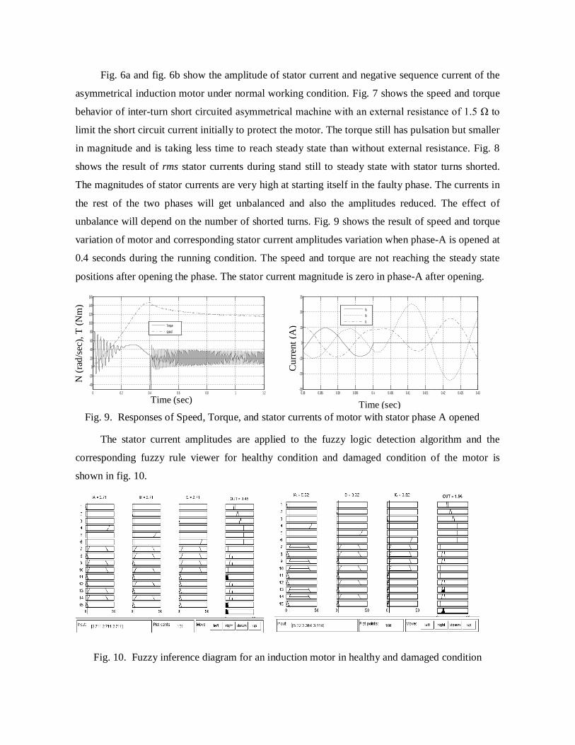
Fig. 6a and fig. 6b show the amplitude of stator current and negative sequence current of the
asymmetrical induction motor under normal working condition. Fig. 7 shows the speed and torque
behavior of inter-turn short circuited asymmetrical machine with an external resistance of 1.5 Ω to
limit the short circuit current initially to protect the motor. The torque still has pulsation but smaller
in magnitude and is taking less time to reach steady state than without external resistance. Fig. 8
shows the result of rms stator currents during stand still to steady state with stator turns shorted.
The magnitudes of stator currents are very high at starting itself in the faulty phase. The currents in
the rest of the two phases will get unbalanced and also the amplitudes reduced. The effect of
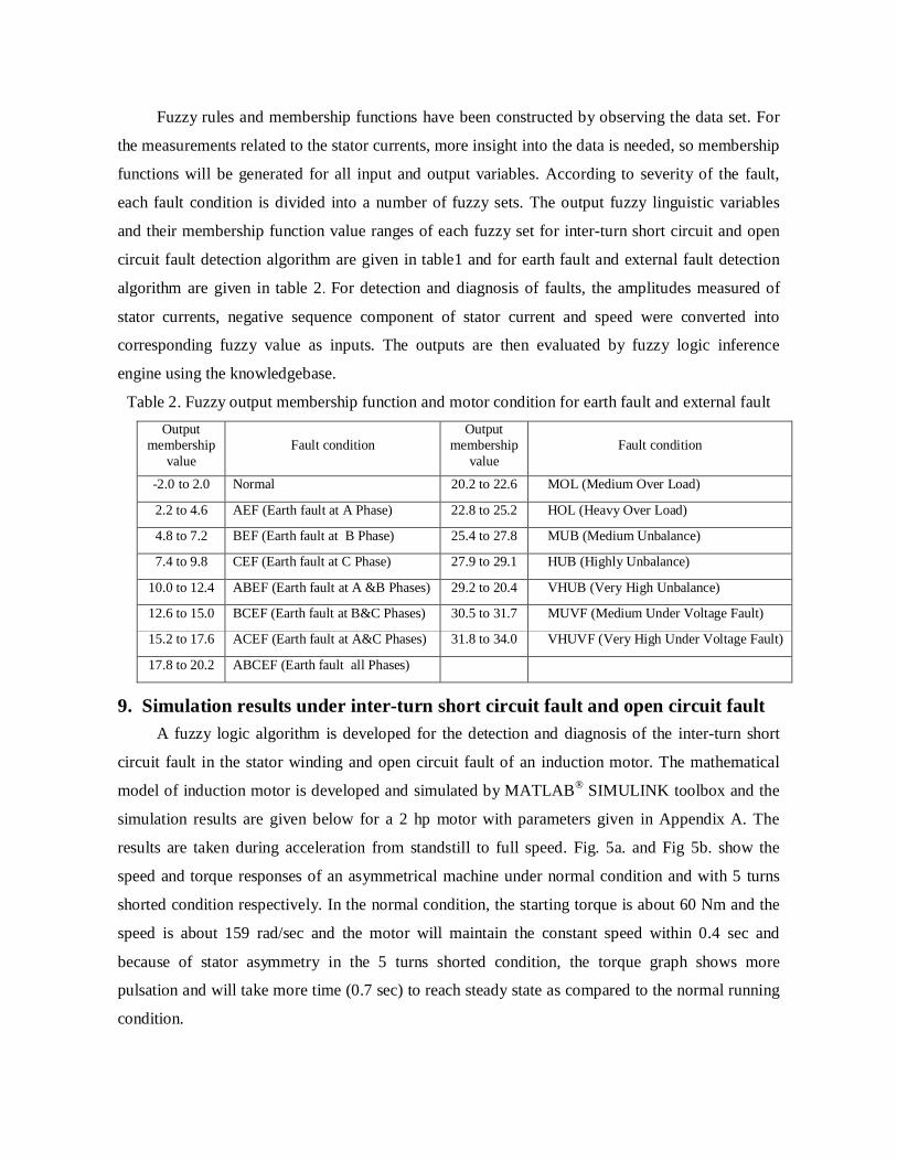
unbalance will depend on the number of shorted turns. Fig. 9 shows the result of speed and torque
variation of motor and corresponding stator current amplitudes variation when phase-A is opened at
0.4 seconds during the running condition. The speed and torque are not reaching the steady state
positions after opening the phase. The stator current magnitude is zero in phase-A after opening.
0 0.2 0.4 0.6 0.8 1 1.2
-40
-20
0
20
40
60
80
100
120
140
160
Torquespeed
0.38 0.385 0.39 0.395 0.4 0.405 0.41 0.415 0.42 0.425 0.43
-30
-20
-10
0
10
20
30
IaIbIc
Fig. 9. Responses of Speed, Torque, and stator currents of motor with stator phase A opened
The stator current amplitudes are applied to the fuzzy logic detection algorithm and the
corresponding fuzzy rule viewer for healthy condition and damaged condition of the motor is
shown in fig. 10.
Fig. 10. Fuzzy inference diagram for an induction motor in healthy and damaged condition
Time (sec) Time (sec)
N (r
ad/s
ec),
T (N
m)
Cur
rent
(A)

In fig. 10, values of input current are Ia = Ib= Ic = 2.71A and its output membership function
value is 0.45 for healthy condition and the magnitudes of each phase current in damaged condition
are Ia = 5.32 A, Ib = 3.32 A and Ic= 1.96 A and its output membership function value is 1.96. As per
the fuzzy output membership function value ranges and motor condition for inter-turn short circuit
faults and open circuit faults given in table 1. These output membership function values indicate
healthy condition and damaged condition respectively.
The input current magnitudes and output fuzzy membership values for all fault conditions
such as healthy condition, damaged, seriously damaged, open circuit at ‘a’ phase, ‘b’ phase and ‘c’
phases respectively are given in table 3. The motor condition will be decided, according to the
output membership function value considered in the design of fuzzy logic detection algorithm. The
output membership function value ranges are given in table 1 for different types of motor condition.
Table 3. Simulated results of Fuzzy detection algorithm for inter-turn short circuit fault and
open circuit fault
Input Output Ia(A) Ib(A) Ic(A) MC Condition
2.71 2.71 2.71 0.45 Healthy 5.32 3.32 3.82 1.96 Damaged 38.80 21.27 18.00 8.25 Seriously damaged 0.00 22.00 19.00 3.30 Open at 'a' phase 26.80 0.00 28.00 4.40 Open at 'b' phase 17.80 25.80 0.00 5.20 Open at 'c' phase
10. Simulation results under Earth faults and External faults Another fuzzy logic algorithm is developed for the detection and diagnosis of incipient fault
such as unbalanced fault, under voltage fault, earth fault and over load fault in a symmetrical
induction motor and the corresponding simulation results are given below for the same machine.
The results are taken during acceleration from standstill to full speed. Fig. 11 shows the responses
of torque, speed and the stator phase currents ia, ib and ic of the machine under unbalanced fault
condition (Va = 230V, Vb= 190V and Vc = 160V). Due to unbalance in supply voltage, the currents
are in an unbalanced condition, so the motor will take more time (about 3.5 sec) to attain the steady
state speed. The starting torque gets reduced and the torque response consists of ripples and also the
premature failure of motor winding and nuisance of over load tripping will occur. The torque speed
characteristics and stator current waveforms of the induction motor in under voltage fault condition
is shown in fig. 12. The supply voltage is reduced to 60% of rated voltage on all the three phases
for simulating the under voltage fault. During under voltage fault, the stator current becomes very

high. Due to these high current, more heat is produced and it will take very large time to attain the
steady state speed.
0 0.5 1 1.5 2 2.5 3 3.5 4 4.5 5-20
0
20
40
60
80
100
120
140
160
Time(Sec)
Torq
ue(N
m),S
peed
(rad/
sec)
SpeedTorque
0 0.5 1 1.5 2 2.5 3 3.5 4 4.5 50
2
4
6
8
10
12
14
16
18
Time(Sec)
Cur
rent
(A)
IaIbIc
Fig. 11. Responses of Speed, Torque and Stator currents ia , ib and ic under unbalanced fault
condition
0 0.5 1 1.5 2 2.5 3 3.5 4 4.5 5-20
0
20
40
60
80
100
120
140
160
Time(Sec)
Torq
ue(N
m),S
peed
(rad/
sec)
SpeedTorque
0 0.5 1 1.5 2 2.5 3 3.5 4 4.5 50
2
4
6
8
10
12
14
16
Time(Sec)
Cur
rent
(A)
iaibic
Fig. 12. Responses of speed, torque and stator currents ia , ib and ic for under voltage fault condition
The speed and torque responses and corresponding currents in three phases such as a, b and c
of three phase induction motor under single phase to ground fault is shown fig. 13.
0 0.5 1 1.5 2 2.5 3 3.5 4 4.5 5-100
-50
0
50
100
150
200
Time(Sec)
Torq
ue(N
m),
Spee
d (ra
d/se
c)
SpeedTorque
0 0.5 1 1.5 2 2.5 3 3.5 4 4.5 5
0
5
10
15
20
25
30
Time(Sec)
Cur
rent
(A)
iaibic
Fig. 13. Responses of speed, torque and stator currents ia , ib and ic on single phase to ground fault
During normal running condition, at 1 sec, phase A is earthed and cleared at 2 sec for
simulating the single phase to ground fault. Due to this, more pulsation is occurred in speed and
torque responses, which will reduce the life time of the motor. Due to single phase to ground fault,
the unbalance is occurred in the stator currents and because of this, turn to turn insulation failure
and finally, the motor insulation failure will occur.
Table 4. Simulated results of Fuzzy detection algorithm for external and earth faults

Input Output Ia (A) Ib (A) Ic (A) Ineg (A) N (rad/sec) MC Condition 2.45 1.94 4.09 0.00811 157.0 27.3 Unbalance fault
12.80 11.90 1.90 0.0406 112.0 16.4 Earth fault 13.40 13.60 13.40 0.0043 77.9 32.9 Under voltage fault 15.30 24.70 24.30 0.0062 82.5 24 Over load fault
Fig. 14. Fuzzy inference diagram for unbalance fault condition
The over load fault is created by increasing the mechanical torque on the motor by changing
the load torque value in the simulation environment. Due to this, the phase current is increased by
more than 7 times of the rated current and the motor will over heat. The stator current rms
amplitudes, speed and leakage current amplitudes are applied as input to the fuzzy logic fault
detection algorithm for incipient fault detection and the corresponding fuzzy rule viewer for
unbalance fault of the motor are shown in fig. 14. The input magnitudes of phase currents, negative
sequence current and speed and output membership values for all fault conditions such as
unbalance fault, earth fault, under voltage fault and over load faults are given in table 4. Here also
the motor condition can be assessed, according to the output membership function value obtained
in the design of fuzzy logic detection algorithm. The output membership function value ranges for
different types of motor fault conditions are given in table 2. Depending on the severity of the
fault, each fault condition of the motor is divided into different fuzzy sets. For example according
to severity of the unbalance, the unbalance fault condition is again divided into three fuzzy sets
named as ‘medium unbalance (MUB)’, ‘highly unbalance (HUB)’ and ‘very high unbalance
(VHUB)’.
11. Discussion
The work done in paper on electric fault detection and diagnosis of three phase induction
motor using fuzzy logic algorithm is accessible to any industry who can install the detection
algorithm module in concerned three phase induction motors. The extracted current and speed
signals from the working machine are applied to the fuzzy inference algorithm after processing.
This algorithm will indicate the motor condition whether it is healthy or damaged. Two algorithms
are developed in this work. First one is used for detection and diagnosis of stator inter-turn short
circuit fault and open circuit fault. The second algorithm is used to detect unbalance fault, under
voltage fault, over load fault and earth fault of three phase induction motor. Additional features are
also added to the algorithm for analyzing the severity of the fault. This fuzzy inference algorithm
facilitates the early detection of the motor fault, thereby reducing the maintenance cost and protects
the machine from the catastrophic faults.
12. Conclusion and future scope
The asymmetrical induction motor model is proposed for analyzing inter-turn short circuit
faults and the symmetrical induction motor model is proposed for analyzing different types of
incipient faults such as earth fault, unbalanced fault, under voltage faults and overloads faults and
open circuit faults. No such attempts are reported in the literature, in the context of induction
machine protection. The proposed models are based on general machine parameters so that it is not
necessary to know detailed geometry or physical layout of the windings. Inter-turn short circuit
fault of the stator winding of an induction motor is simulated by using the developed model of
asymmetrical induction motor and the fault severity is analyzed by varying the number of shorted
turns and an optional current limiting resistance across the short circuit windings. For analyzing the
external faults, the developed model of symmetrical induction motor is used. Simulation results
such as the stator current, negative sequence leakage current and speed are used as inputs to the
fault detection algorithms to detect the condition of the motor. A method using fuzzy logic to
interpret stator current signals and speed of induction motor for its condition monitoring is also
presented. The fuzzy decision system is achieved with high diagnosis accuracy. The proposed
method can be extended to identify and analyze the rotor fault of an induction motor by using fuzzy
inference or a rigorous modeling technique.
References 1. M. Chow and S. O. Yee, "Methodology for online incipient fault detection in single-phase
squirrel-cage induction motors using artificial neural networks," IEEE Transactions on Energy
Conversion, vol. 6, no.3, pp. 536-545, 1991.
2. F. Filippetti, G. Franceschini and C. Tassoni, "Neural networks aided on-line diagnostics of
induction motor rotor faults," Proceedings of Conference Record IEEE Industry Applications
Society Annual Meeting, 1993, pp. 98-108, Alibris, UK.
3. J. Penman, H. G. Sedding, B. A. Lloyd and W. T. Fink, “Detection and location of inter-turn
short circuits in the stator windings of the operating motors,” IEEE Transactions on Energy
conversions, vol. 9, no.4, pp. 652-658, 1994.
4. P. Krause, O. Wasynczuk and S. D. Sudhoff, Analysis of Electric Machinery, IEEE Inc, 1995,
ISBN 0-7803-1101-9.
5. R.M. Tallam, T.G. Habetler and R.G. Harley, “Transient Model for Induction Machines with
Stator Winding Turn Faults”, in: Proceedings of the IEEE Industry Applications Conference
35th Annual Meeting- World Conference on Industrial Applications of Electrical Energy,
Rome, Italy, October, 2000.
6. M. Arkan, D. Kostic-Perovic and P. J. Unsworth, “Modelling and simulation of induction
motors with inter-turn faults for diagnostics”, Electric Power System Research, Science Direct,
May, pp. 57-66, 2005
7. C. J. Dister and R. Scheferl, “Using temperature, voltage and/or speed measurements to
improve tending of induction motor RMS currents in process control and diagnostic,”
Proceedings of IEEE Industry Applications Conference. 33rd Industry Applications Society,
Annual meeting, pp. 383 – 388,1998.
8. Lasurt, A. F. Stronach and J. Penman, "A fuzzy logic approach to the interpretation of higher
order spectra applied to fault diagnosis in electrical machines," Proceedings of 19th
International Conference of the North American Fuzzy Information Processing Society, 2000.
9. M. E. H Benbouzid, “A Review of induction motors signature analysis as a medium for fault
detection,” IEEE Transactions on Industrial Electronics, vol. 47, no.5, pp. 984-993, 2000.
10. M. E. H. Benbouzid and H. Nejjari, "A simple fuzzy logic approach for induction motors stator
condition monitoring," Proceedings of IEEE International Electric Machines and Drives
Conference, pp. 634-639, 2001.
11. F. C. Trutt, J. Sottile and J. L. Kohler, “Online condition monitoring of induction motors”
IEEE Transactions on Industry Applications, Nov.-Dec. 2002, vol. 38, no. 6, pp. 1627-1632.
12. O. Ojo, O. Osaloni and P. Kshirsagar, “Models for the control and simulation of synchronous
type machine drives under various fault conditions”, Conference Record of Industrial
Applications Conference, 37th IAS Annual Meeting, vol. 3, pp. 1533-1540, IEE, 2002.
13. L. Cristaldi, M. Lazzaroni, A. Monti, F. Ponci and F. E. Zocchi, "A genetic algorithm for fault
identification in electrical drives: a comparison with neuro-fuzzy computation," Proceedings of
the 21st IEEE Instrumentation and Measurement Technology Conference,Como Italy (IMTC
04), vol.3, pp.1454-1459, 2004.
14. M. Zeraoulia, A. Mamoune, H. Mangel and M. E. H. Benbouzid, “A simple fuzzy logic
approach for induction motors stator condition monitoring,” Journal of Electrical Systems
vol.1, no.1, pp. 15-25, 2005.
15. R. Samsi, A probabilistic framework for fault detection in induction motors," Ph.D.
dissertation, The Pennsylvania State University, 2006
16. M, Sudha, P. Anbalagan. “A Protection Scheme for three phase induction motor from
incipient faults using embedded controller,” Asian Journal of Scientific research vol.2, no.1,
pp. 28-50, ISSN 1992 -1454, 2009.
17. R. Saravana Kumar, K. Vinoth Kumar and K. K. Ray,“ Fuzzy Logic Based fault detection in
induction machines using Lab view” IJCSNS International Journal of Computer Science
and Network Security, vol. 9, no. 9, pp. 226-243, Sept. 2009.
18. Tarek Aroul, Yassine Poubaa and Ahmed Toumi “Clustering of the Self-Organizing Map
based Approach in Induction Machine Rotor Faults Diagnostics”, Leonardo Journal of
Sciences ISSN 1583-0233, Issue 15, pp. 1-14, July-December 2009.
19. V. P. Mini, Sivakottiah and S. Ushakumari, “Fault Detection and Diagnosis an Induction
Motor using Fuzzy Logic,” Proceedings of the IEEE Region 8 International Conference on
Computational Technologies in Electrical and Electronics Engineering (SIBIRCON), pp. 459-
464, Irkutsk Listvyanka, Russia, July 2010.
20. V. P. Mini and S. Ushakumari, “Incipient Fault Detection and Diagnosis of an Induction
Motor using Fuzzy Logic”, Proceedings of the IEEE International Conference on Recent
Advances in Intelligent Computational Systems - RAICS 2011”, Trivandrum, India, 2011.
21. Gojko M. Joksimovic´ and Jim Penman, “Detection of inter-turn short circuits in the stator
windings of the operating motors,” IEEE Transactions on industrial Electronics, vol. 47, no. 5,
Oct. 2000.
Appendix A: Motor Parameters Horse Power: 2 hp, Line Voltage: 415 V, No. of Poles: 4, Rated speed: 1500 rpm / 50Hz,
Turns / phase: 252, Stator winding resistance: 4.05 Ω, Stator leakage inductance: 13.97 mH,
Rotor leakage inductance: 13.97 mH, Rotor resistance: 2.6 Ω, Magnetic inductance: 538.68 mH
Nomenclature
sabcv : stator voltage matrix in abc frame s
abcr : stator resistance matrix in abc frame sabci : stator current matrix in abc s
abc : stator flux linkage matrix in abc frame r
abcr : rotor resistance matrix in abc frame 0s
qdr : stator resistance matrix in qd0 frame

rqdor : rotor resistance matrix in qd0 frame
ssabcL : stator to stator inductance in abc frame
srabcL : stator to rotor inductance in abc frame
ssqdoL
: stator to stator inductance in qd0
srqdoL
: stator to rotor inductance in qd0 frame shqL : short circuit winding inductance in q-axis
sd ,
sq : d-axis and q- axis stator flux r
d ,rq : d-axis and q-axis rotor flux linkages
sdi , s
qi : d-axis and q- axis stator current rdi , r
qi : d-axis and q-axis rotor current shqi : q-axis short circuit current sshqL : mutual inductance between stator and short circuit in q- axis shrqL : mutual inductance between rotor and short circuit in q- axis