Final Paper
11
PCABS (Pneumatic Control Antilock Breaking System) Parag Verma (UPES, Dehradun, [email protected] ) Vishal Ojha(UPES, Dehradun, [email protected] ) Sunil Sunny(UPES, Dehradun, [email protected] ) Abstract: In today’s world, braking is the most important system in an Automobile. Brakes are energy conversion devices, which convert kinetic energy of the vehicle into thermal energy. In Antilock Braking System, we can prevent the locking of the wheel and hence skidding, using an Electro Mechanical Control System. The main reason behind this issue of safety is, when applying break it locks the wheel due to the driver control lost and the wheel skidding problem occur. Around the world 77% accidental cases is the happen by the wheel skidding problem, and 19% are happen due to the stop distance. Antilock Braking system is the best solutions of both of these issues (Wheel skidding and stopping distance) occur in the severe braking system. Antilock Braking System method allows the motion wheel to continue interacting attractively with road surface as directed by driver steering inputs while braking, preventing the wheels from the locked up (ceasing rotation) and therefore avoiding skidding. In this paper we worked on PCABS i.e. pneumatic control anti-lock breaking system. The aim of this paper is to give a short overview of working of ABS system controlled by the pneumatic system as control unit. Basically ABS works on hydraulic system but we have worked on pneumatic system. Keywords: Introduction, Pneumatic System, ABS control algorithm, ABS Components, Empiric Experiment (Design of Test Derive): 1. Introduction: In recent years, with advancement in design & technology, Disc brakes are fast replacing drum brakes. ABS was first developed for Aircrafts braking system but soon started replacing the conventional braking system in trucks and cars. Recent improvements in ABS
Transcript of Final Paper

PCABS(Pneumatic Control Antilock Breaking System)
Parag Verma (UPES, Dehradun, [email protected])
Vishal Ojha(UPES, Dehradun, [email protected])
Sunil Sunny(UPES, Dehradun, [email protected])
Abstract:
In today’s world, braking is the mostimportant system in an Automobile.Brakes are energy conversion devices,which convert kinetic energy of thevehicle into thermal energy. InAntilock Braking System, we canprevent the locking of the wheel andhence skidding, using an ElectroMechanical Control System. The mainreason behind this issue of safety is,when applying break it locks the wheeldue to the driver control lost and thewheel skidding problem occur. Aroundthe world 77% accidental cases is thehappen by the wheel skidding problem,and 19% are happen due to the stopdistance. Antilock Braking system isthe best solutions of both of theseissues (Wheel skidding and stoppingdistance) occur in the severe brakingsystem.
Antilock Braking System method allowsthe motion wheel to continueinteracting attractively with roadsurface as directed by driver steering
inputs while braking, preventing thewheels from the locked up (ceasingrotation) and therefore avoidingskidding. In this paper we worked onPCABS i.e. pneumatic control anti-lockbreaking system. The aim of this paperis to give a short overview of workingof ABS system controlled by thepneumatic system as control unit.Basically ABS works on hydraulicsystem but we have worked on pneumaticsystem.
Keywords:
Introduction, Pneumatic System, ABScontrol algorithm, ABS Components,Empiric Experiment (Design of TestDerive):
1. Introduction:
In recent years, with advancement indesign & technology, Disc brakes arefast replacing drum brakes. ABS wasfirst developed for Aircrafts brakingsystem but soon started replacing theconventional braking system in trucksand cars. Recent improvements in ABS

allow preventing wheel whenaccelerated on wet or slipperysurface. An Antilock braking system(ABS) is a safety system that maintaindriver control and stability of themotors vehicle (Like; Bikes, Cars,Trucks, Airways etc.) during emergencyBraking. In the present scenario ofthe breaking system (Conventionalbreaking system), we used the strategyto locked wheels that are applicableto slow down a rotated wheel but willnot provide steering ability to motorvehicle wheel[2][5]. The main functionof the ABS is to provide prevention ofthe wheel lockup and thus maintainsboth, steerability and vehiclestability assuring at the same timeshorter stopping distances as comparedto locked wheel breaking system onmost road surfaces and thereforeavoiding skidding.
In this paper we represent theAntilock Breaking System (ABS) withpneumatic control. In pneumaticcontrol ABS baking operation areperformed by compressed air. In thisprocedure during a braking event, thefunction of the control system is tomaintain maximum possible wheel gripon the road - without the wheellocking - by adjusting the pneumaticcompressed air pressure to each brakeby way of electronically controlledsolenoid valves.
2. Components of Pneumatic controlABS:
A skidding wheel (where the tirecontact patch is sliding relative tothe road) has less traction than anon-skidding wheel. By keeping thewheels from skidding, anti-lock brakesbenefit the wheels in two ways: i)stop faster ii) provide abilities tosteer while wheel controller (driver)stop. To modulate the breaksindividually to provide the abovefunctionality and to prevent them fromlocking, ABS combined of bothelectronics and pneumatic systems. Asper the pneumatic control ABS includessome of the components are as follows;
A. Pneumatic Control Unit:
A Pneumatic control unit consists ofcompressor pump (vacuum tube), areservoir tank (enables capacitystorage on demand supply), a pressureregulator, directional proportionalvalves, Air lines and end usecomponent or tool. The most importantand basic part of pneumatic system iscompressed air to transmit and controlenergy[2][8]. It is used to operatesystems and equipment from remotelocations (i.e. inside wings, orexternal hatches).
Pneumatic System is high effective,durable and reliable, high adaptableto harsh environment, light weight,compact, sturdy and easily maintained.

Pneumatic systems are used in severalareas such as controlling train doors,automatic production lines, mechanicalclamps, etc.
PCU components: The main PCUcomponents include;
(i) Components that produce andtransport compressed air: Theproduction and transportation ofcompressed air components includescompressors and pressure regulatingcomponents. These components areresponsible to produce the compressedair as well as to transport thatcompressed air, compressor andpressure regulators are responsible toperform these task.
Compressor:Compressor can convert the mechanicalenergy from motors and engines intothe potential energy in compressedair. It is able to compress air to therequired pressures. It may be linearand rotary.
Pressure regulating component:Pressure regulator is able to providepressure stability when variationoccurs in the compressed air. It isformed by various components, each ofwhich has its own pneumatic symbol:a) Filter: can remove impurities fromcompressed air before it is fed to thepneumatic components.b) Pressure regulator: to stabilizethe pressure and regulate theoperation of pneumatic components.
c) Lubricator: To provide lubricationfor pneumatic components.
(ii) Components that consumecompressed air: It includes thosecomponents that are responsible toconsumption of this compressed air invarious ways. It includes executioncomponents (cylinders), directionalcontrol valves and assistant valves.
(a) Execution component:It provides a rectilinear or rotarymovement; it includes cylinderpistons, pneumatic motors, etc.Rectilinear motion is produced bycylinder pistons, while pneumaticmotors provide continuous rotations.Various cylinders are there, such assingle acting cylinders and doubleacting cylinders.(i) Single acting cylinderIt has only one entrance that allowscompressed air to flow through.Therefore, it can only produce thrustin one direction. The piston rod ispropelled in the opposite direction byan internal spring, or by the externalforce provided by mechanical movementor weight of a load.
(ii) Double acting cylinderIn a double acting cylinder, airpressure is applied alternately to therelative surface of the piston,
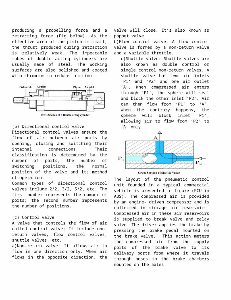
producing a propelling force and aretracting force (Fig below). As theeffective area of the piston is small,the thrust produced during retractionis relatively weak. The impeccabletubes of double acting cylinders areusually made of steel. The workingsurfaces are also polished and coatedwith chromium to reduce friction.
(b) Directional control valveDirectional control valves ensure theflow of air between air ports byopening, closing and switching theirinternal connections. Theirclassification is determined by thenumber of ports, the number ofswitching positions, the normalposition of the valve and its methodof operation.Common types of directional controlvalves include 2/2, 3/2, 5/2, etc. Thefirst number represents the number ofports; the second number representsthe number of positions. (c) Control valveA valve that controls the flow of aircalled control valve; It include non-return valves, flow control valves,shuttle valves, etc.a)Non-return valve: It allows air toflow in one direction only. When airflows in the opposite direction, the
valve will close. It’s also known aspoppet valve.b)Flow control valve: A flow controlvalve is formed by a non-return valveand a variable throttle.
c)Shuttle valve: Shuttle valves arealso known as double control orsingle control non-return valves. Ashuttle valve has two air inlets‘P1’ and ‘P2’ and one air outlet‘A’. When compressed air entersthrough ‘P1’, the sphere will sealand block the other inlet ‘P2’. Aircan then flow from ‘P1’ to ‘A’.When the contrary happens, thesphere will block inlet ‘P1’,allowing air to flow from ‘P2’ to‘A’ only.
The layout of the pneumatic controlunit founded in a typical commercialvehicle is presented in figure (PCU inABS). The compressed air is providedby an engine- driven compressor and iscollected in storage air reservoirs.Compressed air in these air reservoirsis supplied to break valve and relayvalve. The driver applies the brake bypressing the brake pedal mounted onthe brake valve. This action metersthe compressed air from the supplyports of the brake valve to itsdelivery ports from where it travelsthrough hoses to the brake chambersmounted on the axles.

Figure: Pneumatic control Unit with ABS
B. Electronic Control Unit (ECU):
Whenever the brake apply theElectronic control unit (ECU) readssignals from electronic sensorsmonitoring wheel rotation. Anelectronic control unit is connectionof different components;
(i) A step down transformer: It isbeing installed to ourcontroller circuit to stepdown the voltage supply from220V A.C. to 24V A.C.
(ii) Rectifier circuit: Thiscircuit being installed toprovide D.C. voltage, hence inour model it converts 24V A.C.to 24V D.C.
(iii) Voltage regulator circuit: thevoltage regulator circuitconsists of the 7805 IC. 7805IC regulate the input voltageand produced 5V D.C. constantvoltage irrespective of theinput voltage.
(iv) A 555 timer: A 555 timer is anintegrated circuit, which isused in a variety of timer,pulse generation andoscillator applications. Themain function of 555 timer inour experiment is to set anelectrical signal path with iseither high (1) or low (0)after a delay, or constantlyoscillate with a square waveor other waveform.
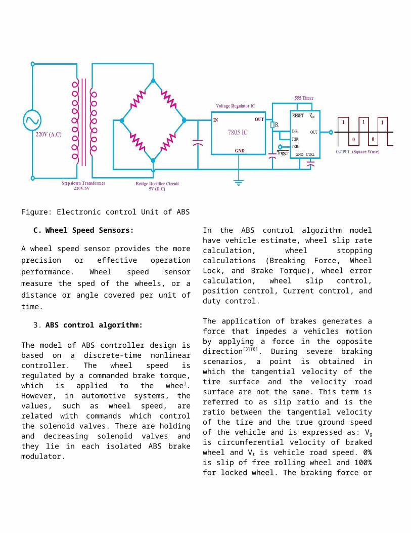
Figure: Electronic control Unit of ABS
C. Wheel Speed Sensors:
A wheel speed sensor provides the moreprecision or effective operationperformance. Wheel speed sensormeasure the sped of the wheels, or adistance or angle covered per unit oftime.
3. ABS control algorithm:
The model of ABS controller design isbased on a discrete-time nonlinearcontroller. The wheel speed isregulated by a commanded brake torque,which is applied to the whee].However, in automotive systems, thevalues, such as wheel speed, arerelated with commands which controlthe solenoid valves. There are holdingand decreasing solenoid valves andthey lie in each isolated ABS brakemodulator.
In the ABS control algorithm modelhave vehicle estimate, wheel slip ratecalculation, wheel stoppingcalculations (Breaking Force, WheelLock, and Brake Torque), wheel errorcalculation, wheel slip control,position control, Current control, andduty control.
The application of brakes generates aforce that impedes a vehicles motionby applying a force in the oppositedirection[3][8]. During severe brakingscenarios, a point is obtained inwhich the tangential velocity of thetire surface and the velocity roadsurface are not the same. This term isreferred to as slip ratio and is theratio between the tangential velocityof the tire and the true ground speedof the vehicle and is expressed as: Vg
is circumferential velocity of brakedwheel and Vt is vehicle road speed. 0%is slip of free rolling wheel and 100%for locked wheel. The braking force or

the adhesion coefficient of brakingforce (μf) measured in the directionthe wheel is turning is function ofslip. μf depends on a number offactors, and the main ones are: a) Road surface material condition b) Tyre material, inflation pressure,treads depth, tread pattern andconstruction.
λ=vg−vt
vgThe fiction coefficient varies withthe condition of the road surface. Itis a function of slip rate. During thevehicle braking, the ABS controlleruses based on the mathematical brakingcalculation, are given as follows;The wheel slip rate s is defined by:
Sij=vFuz−ωRvFuz
=ν−Rwij
νThe wheel acceleration is defined by:
awheel=δvwheel
δt≈Δvwheel
Δt
where, i = F (Front) and R (Rear), j =L (Left) and R (Right), and wheelspeed and vehicle speed are defined byvwheel and vFuz respectively[4][6]. Thevalue of slip rate s = 0 characterizesthe free motion of the wheel. That isto say that there is no frictionforce. If the value is s = 1, then thewheel is locked (w = 0) [2].
In the ABS system for each breakcontrolled having a break line with avalve. Form beginning to end of theABS activation each control loop phasecategories into three positions:
1) Pressure Build-up Position: Inthis position the valves are
open. Pressure from the mastercylinder is passed right throughto the brake and the shoe isslide with the rotated wheel.
2) Pressure Holding Position: Inthis, valves block the breaklines, isolating that brake fromthe master cylinder. Thisposition prevents the pressurefrom rising further should thedriver push the brake pedalharder.
3) Pressure Release Position: Valvereleases some of the pressurefrom the brake; due to ABSprevent form the wheel lockup.
During the initial brake phase, thepressure increases quickly. Then byadjusting the input, holding anddecreasing pressure are applied. Whenroad condition is confirmed, thecontrol pressure will switch to theproper level. The control algorithmcycle in this subsystem includesholding, slow increasing anddecreasing pressure. These controlloop phase (“pressure build-up”,“pressure holding” and “pressurerelease”) is determined by theovercoming of a threshold[4]. The ABScontrol algorithm is described as:
ifs>sH (Pressurerelease)Svalve2=1Svalve1=1
elseifs>sL (Pressurebuild−up)Svalve2=0Svalve1=0
else (Pressureholding)Svalve1=1Svalve1=1
where, Svalve1 and Svalve2 are the controlsignals of the ABS compressed airregulating valve. SH and SL are

threshold, and generally SH = 0.25 andSL = 0.1.
4. Empiric Experiment (Design ofTest Derive):
The focal scenario of our experimentis to determine whether the existenceof behavioral adaptation could beinferred from differences in observedoperating speeds (Stopping distance,Steerability and Stability) betweenABS system and Non-ABS system vehiclesin real world conditions.
The laboratory setup of ABS of ourexperiment consists of one rollingwheel (We uses a wooden wheel), whenthe wheel is animated or rolling at acertain spend ABS system is activatedto stopping the wheel without locking
the wheel. In order to accelerate thewheel a flat DC motor is coupled onit. When the driver (controller) wantsto stopping the wheel, controlleractivated the control circuit,resulting controlling circuit sendsthe signal to the connected pneumaticvalve (two stock valve) and it opensthe forward stroke of the piston andfew micro second (µ sec) it sends thesignal to the valve to retract thepiston and the piston comes with thereverse stoke. During the forwardstroke the horse break shoe (twowheeler) slides with the wheel and thewheel locks and during the reversestroke of the piston the wheelunlocks. This whole process is repeatsuntil the control circuit isactivated.
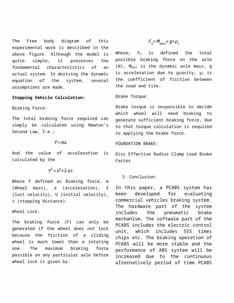
The Free body diagram of thisexperimental work is described in theabove figure. Although the model isquite simple, it preserves thefundamental characteristics of anactual system. In deriving the dynamicequation of the system, severalassumptions are made.
Stopping Vehicle Calculation:
Braking Force:
The total braking force required cansimply be calculated using Newton’sSecond Law, I.e.;
F=ma
And the value of acceleration iscalculated by the
V2=U2+2as
Where F defined as Braking force, m(Wheel mass), a (acceleration), V(last velocity), U (initial velocity),s (stopping distance).
Wheel Lock:
The braking force (F) can only begenerated if the wheel does not lockbecause the friction of a slidingwheel is much lower than a rotatingone. The maximum braking forcepossible on any particular axle beforewheel lock is given by:
FA=MWdyn∗g∗μr
Where; FA is defined the totalpossible braking force on the axle(N), MWdyn is the dynamic axle mass, gis acceleration due to gravity, µr isthe coefficient of friction betweenthe road and tire.
Brake Torque:
Brake torque is responsible to decidewhich wheel will need braking togenerate sufficient braking force, dueto that torque calculation is requiredto applying the brake force.
FOUNDATION BRAKE:
Disc Effective Radius Clamp Load BrakeFactor
5. Conclusion:
In this paper, a PCABS system hasbeen developed for evaluatingcommercial vehicles braking system.The hardware part of the systemincludes the pneumatic brakemechanism. The software part of thePCABS includes the electric controlunit, which includes 555 timeschips etc. The braking operation ofPCABS will be more stable and theperformance of ABS system will beincreased due to the continuousalternatively period of time PCABS

providing the controlling strategyto Driver.As per future aspects thistechnology becomes very powerfulfor in breaking system. The onlyconstraint is that we need toinstall a compressor to the systemthat will make the system bulky andneeds an extra space too. We canuse this technology for our futurebraking systems.
References:
1) Yesim Oniz, Erdal Kayacan andOkyay Kaynak “Simulated andExperimental Study of AntilockBraking System Using GreySliding Mode Control”.
2) International Journal ofCAD/CAM Vol. 10, No. 1, pp.29~37 (2010), Hardware-in-the-Loop Simulation of PneumaticAntilock Braking System Basedon Modelica by ZhangHongchang, Zhang Yunqing, andChen Liping (Center forComputer-Aided Design HuazhongUniversity of Science &Technology, Wuhan, China).
3) International Journal ofScientific & EngineeringResearch Volume 3, Issue 7,July-2012 ISSN 2229-5518 FUZZYLOGIC ANTI-LOCK BRAKE SYSTEMby: Darshan Modi, Co-Author:Zarana Padia, Kartik Patel.
4) Fangjun Jiang and Zhiqiang Gao“An Application of Nonlinear
PID Control to a Class ofTruck ABS Problems”.
5) Dragan Antic, VlastimirNikolic, Darko Mitic, MarkoMilojkovic, StanisaPeric,“SLIDING MODE CONTROL OFANTI-LOCK BRAKING SYSTEM: ANOVERVIEW” Automatic Controland Robotics Vol. 9, No 1,2010, pp. 41 – 58.
6) Ioan Ursu, Felicia Ursu “AnInterlligent ABS Control BasedOn Fuzzy Logoic AircraftApplication”.
7) International J. Vehicle SystemsModelling and Testing, Vol. 2, No.4,2007, “Modular design andtesting for anti-lock brakeactuation and control using ascaled vehicle system” byChinmaya B. Patil and Raul G.Longoria.
8) Andy, R., Huang, W., Chen, C.(2003). A Low-Cost DrivingSimulator for Full VehicleDynamics Simulation. Int. J.IEEE Transactions on VehicularTechnology, 52, 1, 162-172.
9) Automobile Simulation Researchon Anti-lock Braking SystemBased on LabVIEW by ChuChangbao ; Dept. of Mech. &Electr. Eng., Nanchang Inst.of Technol., Nanchang, China ;Zhang Xingwang Published in:Electrical and ControlEngineering (ICECE), 2010ISBN: 978-1-4244-6880 5.