PAKISTAN STEEL INTERNSHIP REPORT SUBMITTED TO: -Mr. NISAR A. KHOWAJA SUBMITTED BY: -Mr. AQIB RASUL...
43
PAKISTAN STEEL INTERNSHIP REPORT SUBMITTED TO: - Mr. NISAR A. KHOWAJA SUBMITTED BY: - Mr. AQIB RASUL KHARAL Mr. M.JAHANGIR SADIQ Mr. SHEHRYAR Mr. RIZWAN ALAM DESCIPLINE: - CHEMICAL ENGINEERING 1
-
Upload
independent -
Category
Documents
-
view
1 -
download
0
Transcript of PAKISTAN STEEL INTERNSHIP REPORT SUBMITTED TO: -Mr. NISAR A. KHOWAJA SUBMITTED BY: -Mr. AQIB RASUL...
PAKISTAN STEEL
INTERNSHIP REPORT
SUBMITTED TO: - Mr. NISAR A. KHOWAJA
SUBMITTED BY: - Mr. AQIB RASUL KHARAL Mr.M.JAHANGIR SADIQ Mr.SHEHRYAR Mr.RIZWAN ALAM
DESCIPLINE: - CHEMICAL ENGINEERING
1
No.OF WEEKS :- FOUR (4)
DURATION :- FROM 14-06-2010 TO 09-07-2010
UNIVERSITY :- NFC INSTITUTE of ENGINEERING & TECHNOLOGICAL TRAINING CENTRE MULTAN.
ACKNOWLEDGEMENT
First of all, I want to thank ALMIGHTY ALLAH, The Most
Beneficent and The Most Merciful, who blessed us the courage,
Strength and capability of doing this report and to complete it..
Now I would like to thank honorable CEO,Pakistan Steel,
2

MALIK ISRAR HUSSAIN for providing meopportunity for
Training .
We wish to express my deep gratefulness to Mr.Rizwan Ahmad,
Director (HRD) for his consideration andsupervision .
We are also thankful to Mr. NISAR A. KHOWAJAincharge
(Training Wing) & Mr.YOUSAF AYUB, Dy.Manager/Incharge
(In-Plant Training) for his precious aadviceand for the great encouragement
And cooperation, because of which we havecompleted our internship at
PAKISTAN STEEL where we learned alot.
3

CONTENTS
OXYGEN PLANT.
COKE OVEN & BYPRODUCT PLANT.
WASTE WATER COLLECTION &TREATMENT PLANT.
BLAST FURNACE ( IMD ).
4

OXYGEN PLANT
OXYGEN PLANT:
Oxygen plant is made mainly to fulfilloxygen demand of steel making department.Gaseous oxygen & nitrogen supplied to allproduction units of steel mills majorconsumers are CMD shops. Gaseous oxygenmainly used in blowing of converter, SMD, CMDshops. Nitrogen is used for shielding &purging at CRM, at COBP is used as dryquenching agent & TPP-TBS used for purging.In oxygen plant, oxygen is prepared byseparation of air using cryogenicdistillation process.Plant Specification:Component Production Capacity
(m3/hour)Purity Pressure
(Bar.g)Oxygen 15200 99.5 % 0.15Nitrogen 4500 99.9% .80Waste nitrogen
66000
5
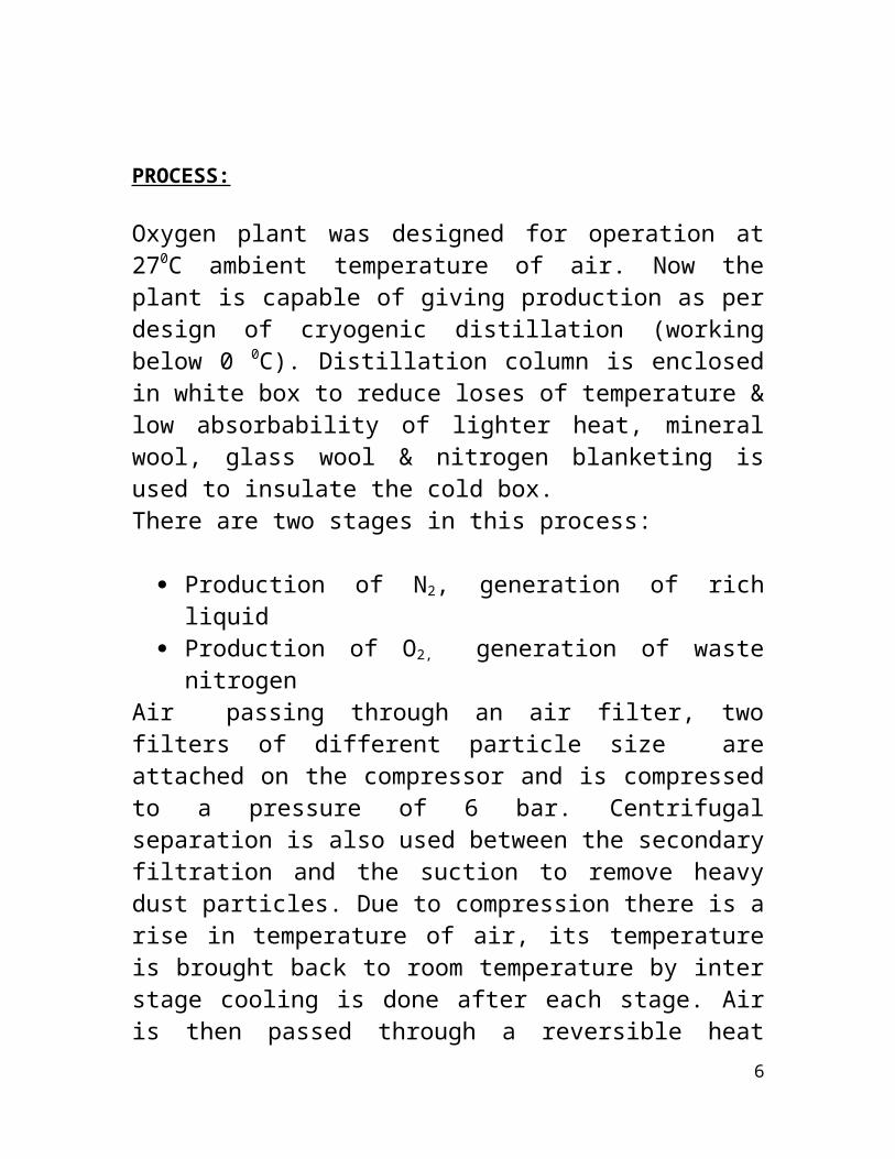
PROCESS:
Oxygen plant was designed for operation at270C ambient temperature of air. Now theplant is capable of giving production as perdesign of cryogenic distillation (workingbelow 0 0C). Distillation column is enclosedin white box to reduce loses of temperature &low absorbability of lighter heat, mineralwool, glass wool & nitrogen blanketing isused to insulate the cold box. There are two stages in this process:
Production of N2, generation of richliquid
Production of O2, generation of wastenitrogen
Air passing through an air filter, twofilters of different particle size areattached on the compressor and is compressedto a pressure of 6 bar. Centrifugalseparation is also used between the secondaryfiltration and the suction to remove heavydust particles. Due to compression there is arise in temperature of air, its temperatureis brought back to room temperature by interstage cooling is done after each stage. Airis then passed through a reversible heat
6

exchanger in which heat exchange between theexiting gases from the distillation columnand entering air takes place. Air temperaturelowers down to –176 oC. At this temperature,CO2 and water vapors in air are solidifiedand are retained in heat exchanger.Air then enters the high pressure section ofdistillation column, separating processed airinto liquid nitrogen and oxygen-rich liquid(40%). Pressure maintained in this column is5.4 bars. This liquid mixture then goes tosilica gel adsorbed to remove oil andhydrocarbon traces. This raw-liquid afterfurther heat exchange with liquid nitrogengoes to the low pressure zone of thedistillation column where pressure ismaintained at 0.45 bar. In this column aseries of successive contacts between downflow liquid and up flow vapor takes place bymeans of perforated trays in the column. Eachtray contains liquid of specific composition,the lower trays being filled with liquidhaving less volatile component (O2). Betweenhigh and low pressure column, a heatexchanger extracts heat from the bottomportion of the column, thus nitrogen in thevicinity of the heat exchanger condenses, andnitrogen is pumped to storage tanks.
7
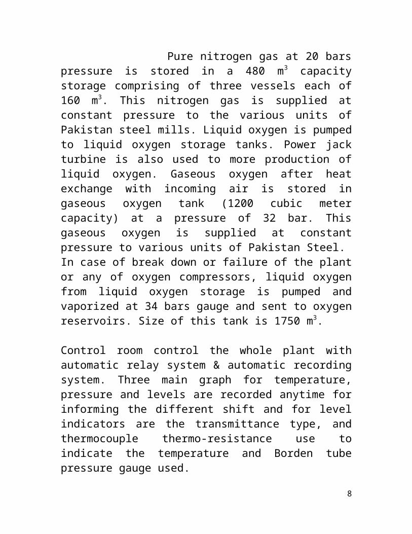
Pure nitrogen gas at 20 barspressure is stored in a 480 m3 capacitystorage comprising of three vessels each of160 m3. This nitrogen gas is supplied atconstant pressure to the various units ofPakistan steel mills. Liquid oxygen is pumpedto liquid oxygen storage tanks. Power jackturbine is also used to more production ofliquid oxygen. Gaseous oxygen after heatexchange with incoming air is stored ingaseous oxygen tank (1200 cubic metercapacity) at a pressure of 32 bar. Thisgaseous oxygen is supplied at constantpressure to various units of Pakistan Steel.In case of break down or failure of the plantor any of oxygen compressors, liquid oxygenfrom liquid oxygen storage is pumped andvaporized at 34 bars gauge and sent to oxygenreservoirs. Size of this tank is 1750 m3.
Control room control the whole plant withautomatic relay system & automatic recordingsystem. Three main graph for temperature,pressure and levels are recorded anytime forinforming the different shift and for levelindicators are the transmittance type, andthermocouple thermo-resistance use toindicate the temperature and Borden tubepressure gauge used.
8

Safety points for working at plant are: Occupational Noise Safety shoes Gloves Safety goggles Fire extinguisher Dust mask
COKE OVEN BY PRODUCT PLANT
Coke oven by product plant:In steel mills Coke oven & by product plantis specially designed for the production ofcoking coal. Coking coal is used as a fuel inblast furnace to reduce the iron ore to
9

iron .the reaction between the fuel and theair generates the CO2.the main by product ofthis plant is coke oven gas .This plantfacilitate for processing treatment of cokeoven gas & recovery of various by productsfor example Ammonia, Benzole, Naphtha andcoal tar etc . This treatment makes coke ovengas suitable for the use as a fuel at cokeoven batteries, thermal power plant (TPP),sintering plant, refractories and limeproduction units. Another by product is coaltar used in making pitch. Coke oven gas is avaluable fuel and has a calorific valueranging from 3510 to 4520 Kcal/m3 .Thus theannual production complex may be summarizedas follows:1) Coke 970,000 mTons2) Coke oven gas 499 m m3 3) Dehydrated Tar 45,500 m Tons 4) Ammonium sulphate 17,200 m Tons
PRODUCTION UNITS :
Five main production units including:1) Coal Handling Plant & Processing Plant (CH&PP)
2) Coke Oven Plant (COP)3) Coke Quenching Plant(CQP)
10
4) By Products Plant (BPP)5) Bio chemicals Treatment Plant(BCTP)
COKE HANDLING & PROCESSING PLANT :
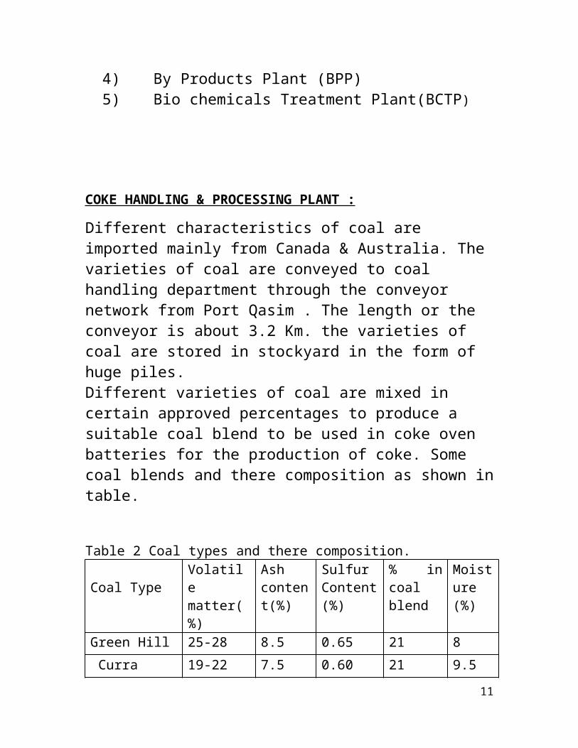
Different characteristics of coal are imported mainly from Canada & Australia. The varieties of coal are conveyed to coal handling department through the conveyor network from Port Qasim . The length or the conveyor is about 3.2 Km. the varieties of coal are stored in stockyard in the form of huge piles.Different varieties of coal are mixed in certain approved percentages to produce a suitable coal blend to be used in coke oven batteries for the production of coke. Some coal blends and there composition as shown intable.
Table 2 Coal types and there composition.
Coal TypeVolatilematter(%)
Ashcontent(%)
SulfurContent(%)
% incoalblend
Moisture(%)
Green Hill 25-28 8.5 0.65 21 8 Curra 19-22 7.5 0.60 21 9.5
11

GermanCreek
12-20.5 9.0 0.66 16 8.0
Mouradox 34.0 9.0 0.60 21 8.0GlennisCreek
38.4 9.0 0.60 21 7.0
Table 2 show coal varieties and compositionat air dried basis.The objectives of coal handling & process plant is
Coal stocking yard of open type Foreign objects Bins Crushing section Mixing section Coal tower Junction bridges and Galleries
WORKING
First coal is stored in stock yard in form of16 piles .Coal stock yard is equipped withfour multi purpose stacking machines calledthe Universal Machine.Coal from stock yard via unit for foreign objects separation called UFFO (unit for foreign objects) then it is send to the proportioning bins .There was 12 proportioning bins each having a capacity of 750 T/hr. Each coal variety is stored in
12
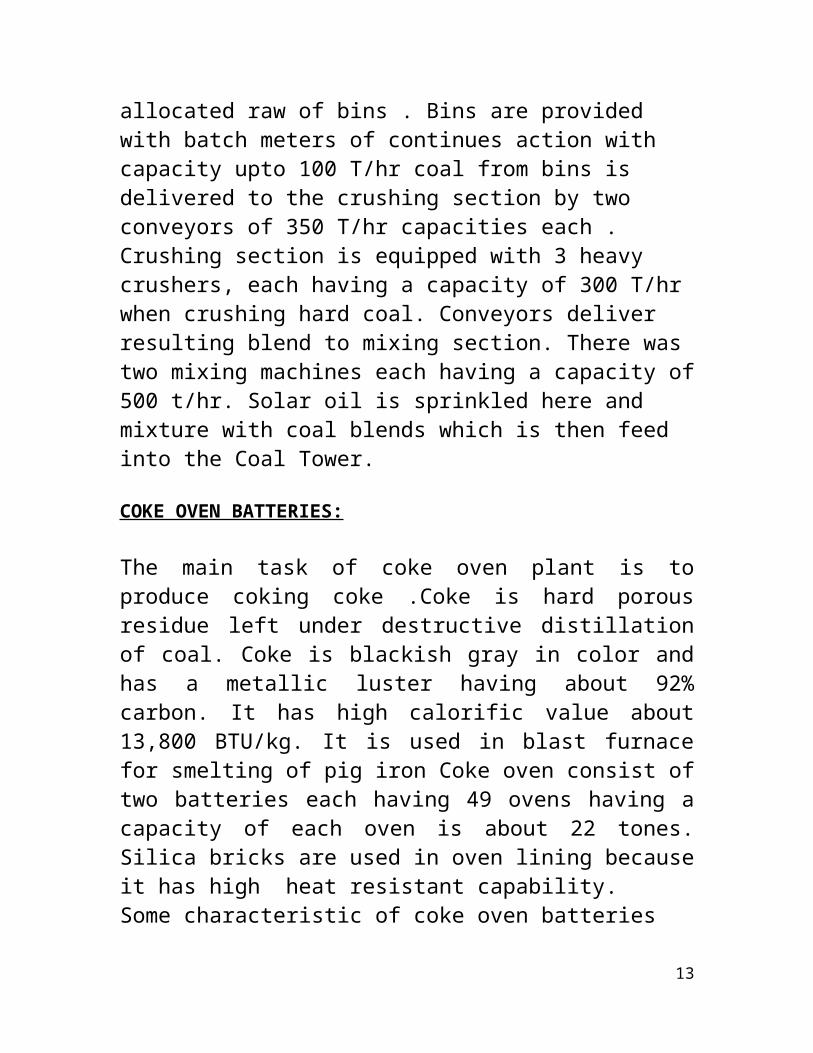
allocated raw of bins . Bins are provided with batch meters of continues action with capacity upto 100 T/hr coal from bins is delivered to the crushing section by two conveyors of 350 T/hr capacities each . Crushing section is equipped with 3 heavy crushers, each having a capacity of 300 T/hr when crushing hard coal. Conveyors deliver resulting blend to mixing section. There was two mixing machines each having a capacity of500 t/hr. Solar oil is sprinkled here and mixture with coal blends which is then feed into the Coal Tower.
COKE OVEN BATTERIES:
The main task of coke oven plant is toproduce coking coke .Coke is hard porousresidue left under destructive distillationof coal. Coke is blackish gray in color andhas a metallic luster having about 92%carbon. It has high calorific value about13,800 BTU/kg. It is used in blast furnacefor smelting of pig iron Coke oven consist oftwo batteries each having 49 ovens having acapacity of each oven is about 22 tones.Silica bricks are used in oven lining becauseit has high heat resistant capability.Some characteristic of coke oven batteries
13

Characteristics of coke oven batteries: Effective volume of carbonization3.0 cubic meter
Effective length14200 mm
Effective height5200 mm
Average width410 mm
Thickness of wall105 mm
Thickness of oven flooring1030 mm
Single charge one oven with22.4 tons
Coking cycle of oven15.3 hr
Gases produced are collected in main pipeline via stand pipe provided with eachoven .There is a lining of 30 burners inbetween the ovens which heat the oven at atemperature of 1050 oC . Coke oven gas isused as a fuel.
14

WorkingAbout 22.4 tone of coal blend is charge peroven .17 tones of product is obtainedremaining used as a volatile compound.Duration of coking periods depends upontemperature of 1050 oC coking period is about22 hr and also coking take place in absenceof air.In the first one-third of total coking period, all the matter present in the oven ismelted and converted into molten form and vapors of higher hydrocarbons, naphthalene and ammonia are vaporizes in the form of cokeoven gas and are collected in the gas collector . In the second one-third period the molten mass is converted into a single hard mass while in the last one-third period,lumps is broken, mass shrinks and cracks appear .at this stage the coke is ready to bedischarging side is also opened by door extractor machine which provides bucket in which red hot coke pushed . Three pushers are used to pushed the material from the batteries and collect into the electric locomotive and then in charging car which takes it to the Quenching section.
15
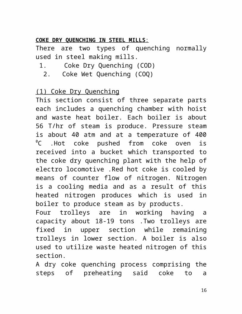
COKE DRY QUENCHING IN STEEL MILLS : There are two types of quenching normallyused in steel making mills.1. Coke Dry Quenching (COD) 2. Coke Wet Quenching (COQ)
(1) Coke Dry QuenchingThis section consist of three separate partseach includes a quenching chamber with hoistand waste heat boiler. Each boiler is about56 T/hr of steam is produce. Pressure steamis about 40 atm and at a temperature of 4000C .Hot coke pushed from coke oven isreceived into a bucket which transported tothe coke dry quenching plant with the help ofelectro locomotive .Red hot coke is cooled bymeans of counter flow of nitrogen. Nitrogenis a cooling media and as a result of thisheated nitrogen produces which is used inboiler to produce steam as by products.Four trolleys are in working having acapacity about 18-19 tons .Two trolleys arefixed in upper section while remainingtrolleys in lower section. A boiler is alsoused to utilize waste heated nitrogen of thissection. A dry coke quenching process comprising thesteps of preheating said coke to a
16

temperature of not lower than 1200°C.,cooling said coke to a temperature of notlower than 700°C by way of passing therethrough a flow of a mixture consistingessentially of hydrocarbons and water vapor,subsequently cooling said coke to atemperature of not higher than 200° C. bypassing there through a flow of inert gas.
WOKING
Hot coke is received from the coke oven istransported to the dry quenching zone. Hotcoke is about 1050 0C is lifted up throughhoist assembly and fed into the quenchingchambers .Red hot coke is cooled down withthe counter current flow of nitrogen .Thisheated nitrogen is used is used in the wasteheat boiler to generate steam at a pressureof 39 Kg/cm3 and at a temperature of 420 0C.Then Quenched coke is then transported tocoke screening section then supplied to theblast furnace and sintering stockyard. Ittakes 3 to 3.5 hrs to complete this process
17

Special aspects to start this section include:Temperature of cokesupplied to chamber
950 oC to 1050 oC
Temperature of quenchedcoke
250 oC
Temperature of circulatinggases before boiler
150 oC to 200 oC
Interval between chargingof the chamber with coke
20 minutes
Maximum number ofdischarging from chamberper hour
35
(2) WET QUENCHING:It is a easy way to cool down the hot cokingcoal with the help of sprinkling of water.But the problem occurred too much water isrequired for this purpose, environmentalhazards and decreased the quality of cokingcoal.
WORKINGIn case of some problem occur in Dryquenching section. Wet quenching section isused as alternate method to cool the coke.Main purpose of quenching of coal is to cooldown the red hot coke in closed atmosphereotherwise it is converted into ash. A wetunit is provided, consisting of pump house
18
settling tanks, spray chamber and clarifiedwater collecting tank and steam ventilationsystem from the top .Avoid from wet quenching because this processhuge amount of water is used and alsopolluted the atmosphere.
COKE SCREENING SYSTEM:
This network is used to separate the quenchedcoke of size +80 mm and -80 mm by using thenetwork of screening. +80 mm size coke isstored into a bunker from where it may bemarketed about 150 tons capacity of eachbunker 4-6% of water by rain may not beaffected the coal in stock.This system consist of : Coke wharf Coke screens with bunkers for coke size +80mm
Conveyor Junction and Galleries
Dry quenched coke is received from dry/wet quenching plant of function through the conveyor of capacity 300 tons/hr and send to the 4 roller type screens here coke is screened and is segregate into +80 mm and -80mm size coke and further screening is done which provides the supply of different typesof coke size 80 mm by conveyor route 250
19

ton/hr capacity is handed down to coke screening station where it is screened into size 25-80 mm and 0-25 mm & 25-80 mm metallurgical coke is sent to the iron makingdepartment through conveyor 0-25 mm coke is supplied to sintering plant.Also water showering system is also provided to settle the dust particles.
BY PRODUCT SECTION:
By-product recovery plant consists of the following sections and facilities:
1. Tar condensation and gas cooling section.
2. Machine room.3. Ammonium sulfate preparation section.4. Final gas coolers.
The by-product plant recovers following products:
1. Anhydrous Tar 46500 T/year2. Ammonium sulfate 17200 T/year.
20

Crude tar is used as a fuel at the thermalpower plant. Ammonium sulfate is marketed asfertilizer. Cooled and purified coke oven gasis used as a fuel in coke oven batteries andother plants of Pakistan steel mill.Coke oven gas is collected in the gascollector from coke oven batteries. Thetemperature of the gas when it exits from thecoking chamber is about 1000 0C, so everycompound is in the vapor state. Temperatureis lowered down to 80 0C in gas collector bythe showering of the ammonia liquor. At thistemperature coal tar condenses. The gas-liquid mixture goes to the separator wheregas and condensate is separated from eachother. The gas goes to the primary gas coolerwhile the condensate consisting ofnaphthalene, phenol, coal tar, liquor ammoniaand sludge goes to decanter, in whichcomponents settle by density difference. Thesludge containing phenol, naphthalene andother components settles at the bottom. Coaltar has its layer over the sludge. Ammonialiquor is at the top. There is a scrapperbelt in the decanter having length of 22 mand speed of 1 revolution per day which isused to separate the sludge. There is a levelof coal tar maintained in the decanter. Whenit becomes higher then it is discharged to
21
the storage tank by telescope. This coal taris then pumped to the final gas cooler. Thethird component is condensate ammonia liquorwhich is overflowed to the storage tank fromwhere it goes to battery where it is used tocool the coke oven gas in the gas collector.In primary gas cooler, as the cooler is ashell and tube type, the gas is in the shelland water is in the tubes. Here the gas iscooled to 30 to 35 0C. The vapors of some ofthe components of the component of the gasare condensed at this temperature.The blower in machine room creates a vacuumof 200 mmH2O, so the blower sucks the gas andsends it to ammonium sulfate section. Theammonium sulfate section serves for therecovery of ammonia from coke oven gas in theform of ammonium sulfate. The gas enters intoa saturator from top and is bubbled through alayer of weak sulfuric acid having acidity 3to 3.5, forming first ammonium bisulfate thatconverts into ammonium sulfate when reactswith more amount of ammonia. The lower partof saturator is filled with mother liquor.The mother liquor is vigorously agitated insaturator so it facilitates crystallizationand promotes crystal growth.
Reaction:
22

NH 3 H 2SO 4 NH 4 HSO4NH 3 NHSO 4 NH 4 2
SO4
The crystals of ammonium sulfate settle onthe bottom of the saturator. The crystals arepumped together with liquor by means ofcrystals pump to crystal receiver from wherethe liquor is returned to the saturator. Theliquid in saturator has a constant level andsurplus liquor flows over a weir into acirculating pot from where it goes to themother liquor tank. The crystals accumulatedin crystals receiver is passed to acentrifuge where crystals are separated fromliquor. The liquor expelled by the centrifugeis returned to the saturator. The crystalsstill contain moisture (2%), so it goes tothe drier for drying. The drier is composedof a conveyer along which the crystals aremoved by the shaking motion while being driedwith hot air. Air is fed to the drier by fanand is preheated with indirect steam contact.From ammonium sulfate section, the gas at thetemperature of 60 – 70 0C goes to finalcooler. The gas enters the cooler from thebottom, and comes in direct contact ofshowering water from the top. By theshowering of water, the temperature of thegas is reduced to 25 – 30 0C. There are twosections for the gas cooler. Upper portion is
23
to reduce the temperature by the showering ofwater while the lower portion is for theremoval of naphthalene. The cooled gas goesto the distribution section from where it isdistributed according to requirement of theplant. The water goes to the lower or coaltar section of cooler where all ofnaphthalene is absorbed from water. Coaltarafter absorption goes to the settling tankfrom where it is stored in coaltar storage.There are two scrubbers in series, eachdivided into two portions. Gas may be passedthrough each portion one by one where it iswashed by solar oil due to which remainingnaphthalene traces may be removed form gas.
BIO CHEMICAL WATER TREATMENT PLANT:Bio-chemical treatment plant treats the
cooling water used in By-product plant forremoval of phenol and other toxic substances,so that it can be disposed off in sea waterwithout any hazard to marine life.Waste water from coke oven by-product plantis collected in tanks. It is then pumped topre-aerator where FeSO4 is added at the rateof 50 – 100 gm/cubic meter of waste water.FeSO4 destabilizes the emulsion. The wastewater goes to primary settling tank for
24

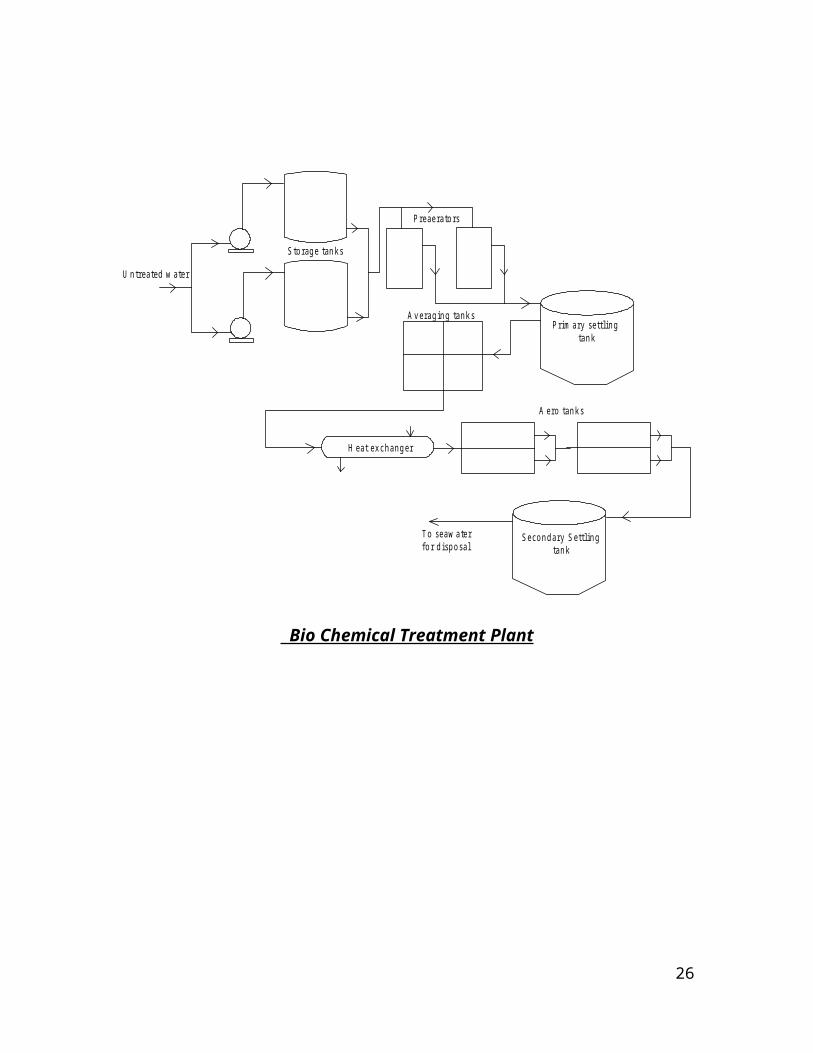
settling of tar and ash particles. Oil formsa layer at the top, which is removed by ascrapper. Water goes to averaging tanks whereintensive aeration is carried out. At thisstage water has the following composition:
Phenol Upto 300 mg/litNH3 1000 mg/litCyanide 60 mg/litBenzolic Hydrocarbons 50 mg/litOxygen Upto 2 mg/litPH 7.5 to 9.0
From averaging tank, it goes into aero tanksthrough shell and tube heat exchanger toensure that the temperature is in the rangeof 28 to 35 oC. Bacteria (microbes), whichdecompose phenol, are added in these tanks.Phosphoric acid is added into these tanks atthe rate of 20 mg/lit. Aeration is carriedout at 50 m3 of air per m3 of wastewater.Waste is broken down by bacteria, which isremoved as sludge in secondary settling tank.Treated water is then pumped to seawater pumphouse for its disposal into seawater.In treated water, phenol content is reducedto 5 mg/lit.
25
U ntreated w ater
S torage tanks
P reaerators
P rim ary settling tank
A veraging tanks
H eat exchanger
A ero tanks
S econdary S ettling tank
T o seaw ater for disposal
Bio Chemical Treatment Plant
26

WASTE WATER CHEMICAL TREATMENT PLANT
WASTE WATER CHEMICAL & TREATMENT PLANT (WWCTP):
The waste water collection and treatmentplant installed on the recommendation ofWorld Health Organization (W.H.O) forprotection of clean and healthy environmentwhich is being realized in Pakistan Steel,who is pioneer in setting a biological wastewater treatment plant. The theme of wastewater treatment is abiological processing in wastewater, so as toeliminate the harmful or un-pleasanteffect.Waste water contains a large number oforganic wastes (These organic wastes comefrom vegetable, fruit packing dairy process,meat making, processing of poultry, oil,paper fiber & many more.Another classification of waste is inorganicwastes such as sand, Salt, Calcium, Iron,Ammonium, Sodium, Potassium, Magnesium,Bicarbonates, Sulphate, Chloride & etc.
i)Area of plant45950 M2
ii) Total Cost of plantRs. 1,29,36182 (Approx.)
27
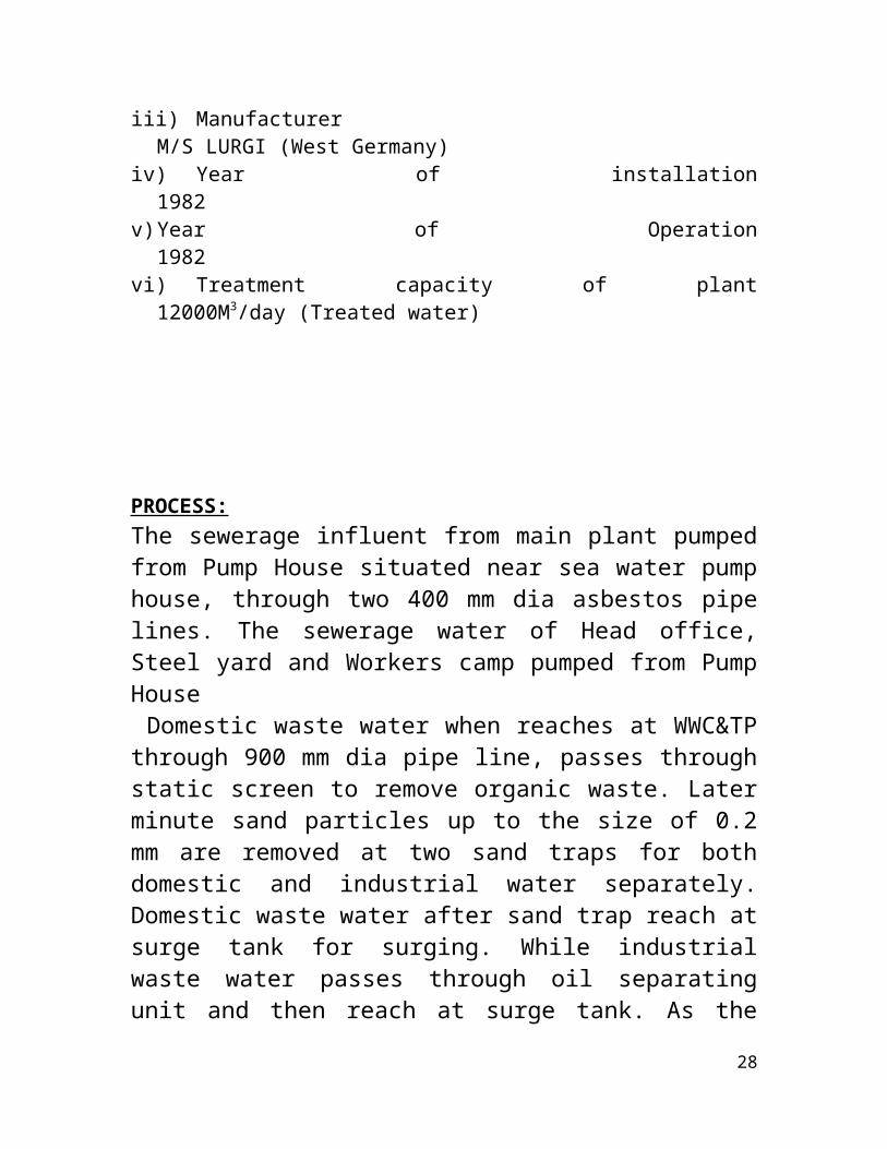
iii) ManufacturerM/S LURGI (West Germany)
iv) Year of installation1982
v)Year of Operation1982
vi) Treatment capacity of plant12000M3/day (Treated water)
PROCESS:The sewerage influent from main plant pumpedfrom Pump House situated near sea water pumphouse, through two 400 mm dia asbestos pipelines. The sewerage water of Head office,Steel yard and Workers camp pumped from PumpHouse Domestic waste water when reaches at WWC&TPthrough 900 mm dia pipe line, passes throughstatic screen to remove organic waste. Laterminute sand particles up to the size of 0.2mm are removed at two sand traps for bothdomestic and industrial water separately.Domestic waste water after sand trap reach atsurge tank for surging. While industrialwaste water passes through oil separatingunit and then reach at surge tank. As the
28
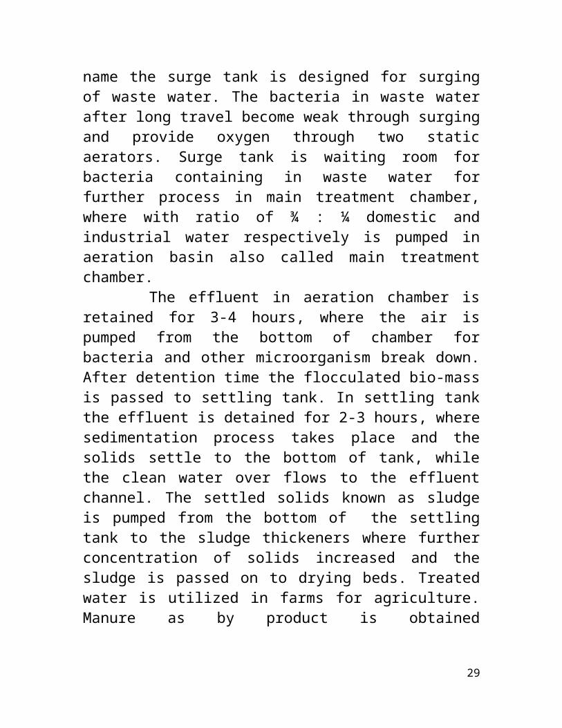
name the surge tank is designed for surgingof waste water. The bacteria in waste waterafter long travel become weak through surgingand provide oxygen through two staticaerators. Surge tank is waiting room forbacteria containing in waste water forfurther process in main treatment chamber,where with ratio of ¾ : ¼ domestic andindustrial water respectively is pumped inaeration basin also called main treatmentchamber. The effluent in aeration chamber isretained for 3-4 hours, where the air ispumped from the bottom of chamber forbacteria and other microorganism break down.After detention time the flocculated bio-massis passed to settling tank. In settling tankthe effluent is detained for 2-3 hours, wheresedimentation process takes place and thesolids settle to the bottom of tank, whilethe clean water over flows to the effluentchannel. The settled solids known as sludgeis pumped from the bottom of the settlingtank to the sludge thickeners where furtherconcentration of solids increased and thesludge is passed on to drying beds. Treatedwater is utilized in farms for agriculture.Manure as by product is obtained
29

approximately 40 to 50 M3 / month for use inhorticulture Department and also sold to theemployee at Rs.40/= per bag + 15% sales tax.
FLOW DIAGRAM (WWC&TP)
NET WORK (SEWER TRUNK) INFLUENT (DOMESTIC) PUMPINGMONITORING SCREENING. RECORDING OF FLOWNET WORK (INDUSTRIAL) OF DOMESTIC WATER.MONITORING.
SCREENINGSAND TRAP CONTAMINATED PUMPING OF OIL SEPARATING. WATER STORAGE. WASTE WATER.TESTING. (DOMESTIC & INDUSTRIAL)
AIR BLOWING. SLUDGE SETTLING. MEASURING THE FLOW
TO THE CUSTOMERS.EFFLUENT TETING.
30
START RECEIVING PROCESS
PROCESS STORAGE PROCESS
PROCESSPROCESS
DISTRIBUTION

TEST REPORTS.
CUSTOMER SATISFACTION MONITORING OF CUSTOMERS TEST REPORTS.
THROUGH CUSTOMERS FEED PERCEPTION. RECORD OF BACK SYSTEM & ISSUES REVIEW OF REQUIRTMENT.
RESULT.CUSTOMERS COMPLAIN. NEW PROSESS.
31
RECORDS
CUSTOMERFEED BACK MONITORING
32

BLAST FURNACE
A blast furnace is a type of metallurgical furnace used for smelting toproduce industrial metals, generally iron.In a blast furnace, fuel and ore are continuously supplied through the top of the furnace, while air (sometimes with oxygen enrichment) is blown into the bottom of the chamber, so that the chemical reactions take place throughout the furnace as the material moves downward. The end products are usually molten metal and slag phases tapped from the bottom, and flue gases exiting from the top of the furnace.Blast furnaces are to be contrasted with airfurnaces (such as reverberatory furnaces),which were naturally aspirated, usually bythe convection of hot gases in a chimneyflue. According to this broaddefinition, bloomeries for iron, blowinghouses for tin, andsmelt mills for lead,would be classified as blast furnaces.However, the term has usually been limited tothose used for smelting iron ore to
33

produce pig iron, an intermediate materialused in the production of commercial ironand steel.INFORMATION ABOUT BLAST FURNACE
Maximun production capacity of one blastfurnace 1750 ton/day
Total water coolers installed in oneblast furnace 674 Nos
Total weight of carbon blocks installedin one blast furnace along with relatedfixing material 452.45 tons
Total weight of refractory bricksinstalled in one blast furnace along withrelated fixing material 1356.8 tons
HISTORYBlast furnaces existed in China from about the 5th century BC, and in the West from the High Middle Ages. They spread from the region around Namur in Wallonia (Belgium) in the late 15th century, being introduced to England in 1491. The fuel used in these was invariablycharcoal. The successful substitution of coke for charcoal is widely attributed to Abraham Darby in 1709. The efficiency of the process was further enhanced by the practice of preheating the
34

blast, patented by James Beaumont Neilson in 1828.The blast furnace is distinguished from the bloomery in that the object of the blast furnace is to produce molten metal that can be tapped from the furnace, whereas the intention in the bloomery is to avoid it melting so that carbon does not become dissolved in the iron. Bloomeries were also artificially blown using bellows, but the term "blast furnace" is normally reserved forfurnaces where iron (or other metals) are refined from ore.
Different Zones of Blast Furnace
Hot blast from Cowper stovesMelting zone (bosh)Reduction zone of ferrous oxide (barrel)Reduction zone of ferric oxide (stack)Pre-heating zone (throat)Feed of ore, limestone, and cokeExhaust gasesColumn of ore, coke and limestoneRemoval of slagTapping of molten pig ironCollection of waste gases
MODERN FURNACES 35
Modern furnaces are equipped with an array ofsupporting facilities to increase efficiency,such as ore storage yards where barges are unloaded. The raw materials are transferred to the stockhouse complex by ore bridges, or rail hoppers and ore transfer cars. Rail-mounted scale cars or computer controlled weight hoppers weigh out the various raw materials to yield the desired hot metal and slag chemistry. The raw materials are broughtto the top of the blast furnace via a skip car powered by winches or conveyor belts. There are different ways in which the raw materials are charged into the blast furnace.Some blast furnaces use a "double bell" system where two "bells" are used to control the entry of the raw material into the blast furnace. The purpose of the two bells is to minimize the loss of hot gases in the blast furnace. First the raw materials are emptied into the upper or small bell. The bell is then rotated a predetermined amount in order to distribute the charge more accurately. Thesmall bell then opens to empty the charge into the large bell. The small bell then closes, to seal the blast furnace, while the large bell dispenses the charge into the
36
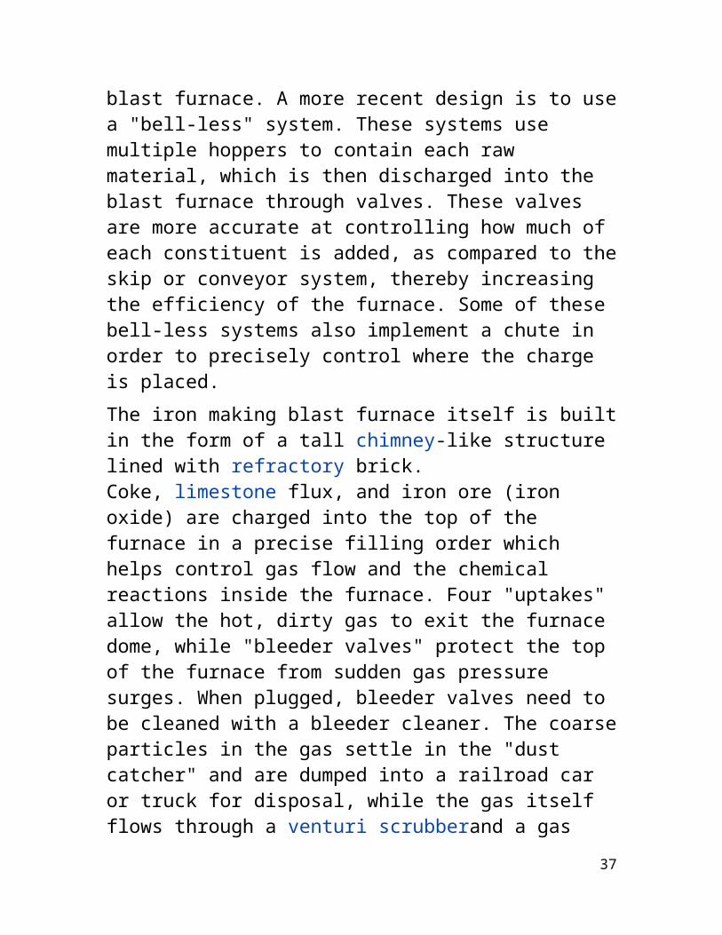
blast furnace. A more recent design is to usea "bell-less" system. These systems use multiple hoppers to contain each raw material, which is then discharged into the blast furnace through valves. These valves are more accurate at controlling how much of each constituent is added, as compared to theskip or conveyor system, thereby increasing the efficiency of the furnace. Some of these bell-less systems also implement a chute in order to precisely control where the charge is placed. The iron making blast furnace itself is builtin the form of a tall chimney-like structure lined with refractory brick. Coke, limestone flux, and iron ore (iron oxide) are charged into the top of the furnace in a precise filling order which helps control gas flow and the chemical reactions inside the furnace. Four "uptakes" allow the hot, dirty gas to exit the furnace dome, while "bleeder valves" protect the top of the furnace from sudden gas pressure surges. When plugged, bleeder valves need to be cleaned with a bleeder cleaner. The coarseparticles in the gas settle in the "dust catcher" and are dumped into a railroad car or truck for disposal, while the gas itself flows through a venturi scrubberand a gas
37

cooler to reduce the temperature of the cleaned gas. The "casthouse" at the bottom half of the furnace contains the bustle pipe, tuyeres andthe equipment for casting the liquid iron andslag. Once a "taphole" is drilled through therefractory clay plug, liquid iron and slag flow down a trough through a "skimmer" opening, separating the iron and slag. Modern, larger blast furnaces may have as many as four tapholes and two casthouses.[31] Once the pig iron and slag has been tapped, the taphole is again plugged with refractory clay.The tuyeres are used to implement a hot blast, which is used to increase the efficiency of the blast furnace. The hot blast is directed into the furnace through water-cooled copper nozzles called tuyeres near the base. The hot blast temperature can be from 900 °C to 1300 °C (1600 °F to 2300 °F) depending on the stove design and condition. The temperatures they deal with may be 2000 °C to 2300 °C (3600 °F to 4200 °F). Oil, tar, natural gas, powdered coal and oxygen can also be injectedinto the furnace at tuyere level to combine with the coke to release additional energy which is necessary to increase productivity.
38

PROCESS DESCRIPTION
Blast furnaces are usually tall shaft-type steel vessels, up to ten stories high, internally lined with refractory brick, and superimposed over a crucible-like hearth. Thenecessary charge to produce molten pig iron consists of iron-bearing materials, coke, andflux. The charge is introduced into the furnace at the top. Blasts of heated air fromlarge blast stoves, and in most cases gaseous, liquid, or powdered fuel, are injected into the furnace through openings (tuyeres) at the bottom of the shaft just above the hearth crucible. As the hot air encounters the coke, the coke is burned alongwith the injected fuels, producing the necessary heat and reducing gas to remove oxygen from the ore in the reduction process.As the iron melts, it descends and accumulates in the crucible. The molten pig iron and slag are drained from the crucible through different tapping holes. The gas thatexits from the top of the furnace goes through a cleaning process. The cleaned hot gas is then used in other operations of the plant, e.g. to pre-heat the blast air, while the collected dust is sent to the sintering
39

plant for recycling back into the blast furnace. Once fired-up, a blast furnace burnscontinuously until the lining needs replacement (approximately 5-6 years)
The purpose of a blast furnace is to chemically reduce and physically convert ironoxides into liquid iron called "hot metal". The blast furnace is a huge, steel stack lined with refractory brick, where iron ore, coke and limestone are dumped into the top, and preheated air is blown into the bottom. The raw materials require 6 to 8 hours to descend to the bottom of the furnace where they become the final product of liquid slag and liquid iron. These liquid products are drained from the furnace at regular intervals. The hot air that was blown into the bottom of the furnace ascends to the top in 6 to 8 seconds after going through numerous chemical reactions. Once a blast furnace is started it will continuously run for four to ten years with only short stops to perform planned maintenance.Iron oxides can come to the blast furnace plant in the form of raw ore, pellets or sinter. The raw ore is removed from the earthand sized into pieces that range from 0.5 to 1.5 inches. This ore is either Hematite
40

(Fe2O3) or Magnetite (Fe3O4) and the iron content ranges from 50% to 70%. This iron rich ore can be charged directly into a blastfurnace without any further processing. Iron ore that contains a lower iron content must be processed or beneficiated to increase its iron content. Pellets are produced from this lower iron content ore. This ore is crushed and ground into a powder so the waste material called gangue can be removed. The remaining iron-rich powder is rolled into balls and fired in a furnace to produce strong, marble-sized pellets that contain 60%to 65% iron. Sinter is produced from fine rawore, small coke, sand-sized limestone and numerous other steel plant waste materials that contain some iron. These fine materials are proportioned to obtain a desired product chemistry then mixed together. This raw material mix is then placed on a sintering strand, which is similar to a steel conveyor belt, where it is ignited by gas fired furnace and fused by the heat from the coke fines into larger size pieces that are from 0.5 to 2.0 inches. The iron ore, pellets and sinter then become the liquid iron produced in the blast furnace with any of their remaining impurities going to the liquid slag.
41
The coke is produced from a mixture of coals.The coal is crushed and ground into a powder and then charged into an oven. As the oven isheated the coal is cooked so most of the volatile matter such as oil and tar are removed. The cooked coal, called coke, is removed from the oven after 18 to 24 hours ofreaction time. The coke is cooled and screened into pieces ranging from one inch tofour inches. The coke contains 90 to 93% carbon, some ash and sulphur but compared to raw coal is very strong. The strong pieces ofcoke with a high energy value provide permeability, heat and gases which are required to reduce and melt the iron ore, pellets and sinter.
The final raw material in the ironmaking process in limestone. The limestone is removed from the earth by blasting with explosives. It is then crushed and screened to a size that ranges from 0.5 inch to 1.5 inch to become blast furnace flux. This flux can be pure high calcium limestone, dolomiticlimestone containing magnesia or a blend of the two types of limestone.
Composition of different elements in blastfurnace
42

Iron (Fe) = 93.5 - 95.0%
Silicon (Si) = 0.30 - 0.90%
Sulphur (S) = 0.025 - 0.050%
Manganese (Mn) = 0.55 - 0.75%
Phosphorus (P) = 0.03 - 0.09%
Titanium (Ti) = 0.02 - 0.06%
Carbon (C) = 4.1 - 4.4%
BLAST FURNACE GAS COMPOSITION
Carbon mono oxide 23 %Carbon dioxide 17 %Methane 0.5 %Hydrogen 3.5 %Nitrogen 56 %
43