Mr. John Purcell, Roper Pump: ―Gear Pumps‖ Mr. Jim Brennan, IMO Pump: ―Multiple-Screw Pumps‖...
134
-
Upload
independent -
Category
Documents
-
view
6 -
download
0
Transcript of Mr. John Purcell, Roper Pump: ―Gear Pumps‖ Mr. Jim Brennan, IMO Pump: ―Multiple-Screw Pumps‖...


Library of Congress Cataloging-in-Publication Data
Nelik, Lev.
Centrifugal and rotary pumps : fundamentals with applications / Lev
Nelik.
p. cm.
Includes bibliographical references and index.
ISBN 0-8493-0701-5 (alk. paper)
1. Centrifugal pumps. 2. Rotary pumps. I. Title.
TJ919.N34 1999
621.6′7--dc21 98-49382
CIP
This book contains information obtained from authentic and highly regarded sources. Reprinted material
is quoted with permission, and sources are indicated. A wide variety of references are listed. Reasonable
efforts have been made to publish reliable data and information, but the author and the publisher cannot
assume responsibility for the validity of all materials or for the consequences of their use.
Neither this book nor any part may be reproduced or transmitted in any form or by any means, electronic or
mechanical, including photocopying, microfilming, and recording, or by any information storage or retrieval
system, without prior permission in writing from the publisher.
The consent of CRC Press LLC does not extend to copying for general distribution, for promotion, for
creating new works, or for resale. Specific permission must be obtained in writing from CRC Press LLC for
such copying.
Direct all inquiries to CRC Press LLC, 2000 N.W. Corporate Blvd., Boca Raton, Florida 33431.
Trademark Notice: Product or corporate names may be trademarks or registered trademarks, and are used
only for identification and explanation, without intent to infringe.
Visit the CRC Press Web site at www.crcpress.com
© 1999 by CRC Press LLC
No claim to original U.S. Government works
International Standard Book Number 0-8493-0701-5
Library of Congress Card Number 98-49382
Printed in the United States of America 2 3 4 5 6 7 8 9 0 Printed on acid-free paper
©1999 CRC Press LLC

Preface My motivation in writing this book was to relate fundamental principles of the
operation of kinetic and positive displacement pumps, with direct relation to appli-
cation specifics and user needs. In today‘s reality, pump users demand simpler,
easier-to-read, and more practical material on pumps. New, young engineers who
enter the workforce are faced with immediate practical challenges presented to them
by the plants‘ environments: to solve pumping problems and improve equipment
reliability and availability — in the most cost-effective manner. To meet these
challenges, plant personnel must first understand the fundamentals of pump opera-
tions, and then apply this knowledge to solve their immediate short-term, and long-
term, problems. Pumps are the most widely used type of machinery throughout the
world, yet, unfortunately, they are covered very little, or not at all, at the college
level, leaving engineering graduates unprepared to deal with — not to mention
troubleshoot — this equipment. The variety of pump types also adds to the confusion
of an engineer entering the workforce: Which pump type, among many, to choose
for a given application? Available books on pumps are good but do not reflect the
rapid changes taking place at the plants — tougher applications, new corrosive
chemicals, and resistance to the abrasives, which because of cost pressures are no
longer adequately removed from the streams before they enter a pump‘s suction,
etc. In recent years, heightened attention to a safe workplace environment, and
plants‘ demand for better equipment reliability have necessitated improvements in
mean time between failures (MTBF), as well as a better understanding of pump
fundamentals and differences — real or perceived. In addition, existing books often
contain complicated mathematics with long derivations that typically make them
better suited for academic researchers, not practicing engineers, operators, or main-
tenance personnel looking for practical advice and a real solution for their immediate
needs. The emphasis of this book, therefore, is on simplicity — to make it useful,
easy, and interesting to read for a broad audience.
For new engineers, mechanics, operators, and plant management, this book will
provide a clear and simple understanding of pump types, as defined by the Hydraulic
Institute (HI). For more experienced users, it will provide a timely update on the
recent trends and developments, including actual field troubleshooting cases
where the causes for each particular problem are traced back to pump fundamentals
in a clear and methodical fashion. The pump types covered include: centrifugal, gear,
lobe, vane, screw, diaphragm, progressing cavity, and other miscellaneous types.
The variation in types of pumps is presented in terms of hydraulic design and
performance, principles of operation, design similarities and differences, and histor-
ical trends and technological changes. After covering fundamentals, the focus shifts
to real field cases, in terms of applications, pumpage, system interaction, reliability
©1999 CRC Press LLC

and failure analysis, as well as practical solutions for improvements. Upon completion
of the book, readers should be able to immediately implement the techniques covered
in the book to their needs, as well as share what they have learned with colleagues in
the field.
Existing material on pumps and pumping equipment covers predominately cen-
trifugal pumps. Centrifugal pumps have dominated the overall pumping population
in the past, but this situation has been changing in the last 10 to 15 years. New
chemicals, industrial processes, and technologies have introduced processes and
products with viscosities in ranges significantly beyond the capabilities of centrifugal
pumps. Many users still attempt to apply centrifugal pumps to such unsuited appli-
cations, unaware of new available pump types and improvements in rotary pump
designs. Furthermore, there is very little published material on gear pump designs
— the effects of clearances on performance and priming capabilities are virtually
unknown to users. Progressing cavity pumps, now widely used in wastewater treat-
ment plants and paper mills, are virtually uncovered in the available literature, and
even the principle of their operation is only understood by a few specialists among
the designers. The same applies to multiple-screw pumps: a controversy still exists
about whether outside screws in three-screw designs provide additional pumping or
not.
An example of published literature which when used alone is no longer adequate
is A.J. Stepanoff‘s well-known book Centrifugal and Axial Flow Pumps. It describes
the theory of centrifugal pumps well, but has no information on actual applications
to guide the user and help with actual pump selection for his or her applications.
Besides, the material in the book does not nearly cover any of the latest develop-
ments, research findings, and field experience in the last 20 to 30 years. Another
example comes from a very obscure publication on progressing cavity pumps, The
Progressing Cavity Pumps, by H. Cholet,21 published in 1996. However, this book
concentrates mostly on downhole applications, and is more of a general overview,
with some applicational illustrations, and does not contain any troubleshooting
techniques of a ―what-to-do-if.‖ In the U.S., this book is essentially unknown and
can be obtained only in certain specialized conferences in Europe. There is a good
publication by H.P. Bloch, Process Plant Machinery,19 which covers a variety of
rotating and stationary machinery, as well as being a good source for the technical
professional. It provides an overview of pumps, but for detailed design and appli-
cational specifics, a dedicated book on pumps would be a very good supplement.
Finally, the Kirk-Othmer Encyclopedia of Chemical Technology contains a chapter
on ―Pumps,‖ written by the author,1 and includes comparative descriptions of various
pump types, with applicational recommendations and an extensive list of references.
However, while being a good reference source, it is generally used primarily as it
was intended— as an encyclopedial material, designed to provide the reader with a
starting foundation, but is not a substitute for an in-depth publication on pumping
details.
For the above reasons, this new book on centrifugal and rotary pumps will
provide much needed and timely material to many plant engineers, maintenance
©1999 CRC Press LLC

personnel, and operators, as well as serving as a relevant textbook for college courses on
rotating machinery, which are becoming more and more popular, as technological trends
bring the need to study pumping methods to the attention of college curricula. This book
is unique not only because it covers the latest pump designs and theory, but also
because it provides an unintimidating reference resource to practicing professionals
in the U.S. and throughout the world.
©1999 CRC Press LLC
Author Lev Nelik is Vice President of Engineering and Quality Assurance of Roper Pump
Company, located in Commerce, GA. He has 20 years of experience working with
centrifugal and positive displacement pumps at Ingersoll-Rand (Ingersoll-Dresser),
Goulds Pumps (ITT), and Roper Industries. Dr. Nelik is the Advisory Committee
member for the Texas A&M International Pump Users Symposium, an Advisory
Board member of Pumps & Systems Magazine and Pumping Technology Magazine,
and a former Associate Technical Editor of the Journal of Fluids Engineering. He
is a Full Member of the ASME, and a Certified APICS (CIRM). A graduate of
Lehigh University with a Ph.D. in Mechanical Engineering and a Masters in Man-
ufacturing Systems, Dr. Nelik is a Registered Professional Engineer, who has pub-
lished over 40 documents on pumps and related equipment worldwide, including a
―Pumps‖ section for the Kirk-Othmer Encyclopedia of Chemical Technology and a
section for The Handbook of Fluid Dynamics (CRC Press). He consults on pump
designs, teaches training courses, and troubleshoots pump equipment and pumping
systems applications.
©1999 CRC Press LLC

Acknowledgments The author wishes to thank people and organizations whose help made this publication
possible. Particularly helpful contributions in certain areas of this book were made by:
Mr. John Purcell, Roper Pump: ―Gear Pumps‖
Mr. Jim Brennan, IMO Pump: ―Multiple-Screw Pumps‖
Mr. Kent Whitmire, Roper Pump: ―Progressing Cavity Pumps‖
Mr. Herbert Werner, Fluid Metering, Inc.: ―Metering Pumps‖
Mr. Luis Rizo, GE Silicones: General feedback as a pump user as well as other
comments and assistance which took place during numerous discussions.
Special appreciation for their guidance and assistance goes to the staff of CRC Press,
who made this publication possible, as well as thanks for their editorial efforts with text
and illustrations, which made this book more presentable and appealing to the readers.
Finally, and with great love, my thanks to my wife, Helaine, for putting up with my
many hours at home working on pumps instead of on the lawn mower, and to Adam,
Asher, and Joshua, for being motivators to their parents.
Lev Nelik
©1999 CRC Press LLC

Table of Contents Chapter 1
Introduction
Chapter 2
Classification of Pumps
Chapter 3
Concept of a Pumping System
Liquid Transfer
Input Power, Losses, and Efficiency
System Curve
Pump Curve
Chapter 4
Centrifugal Pump — Fundamentals
Affinity Laws
Helpful Formulas Per Centrifugal Pump Triangles
Quiz #1 — Velocity Triangles
Performance Curves
Quiz #2 — How Much Money Did AMaintenance Mechanic Save
His Plant?
Performance Modifications
Quiz #3 — A Valve Puzzle
Underfiling and Overfiling
Design Modeling Techniques
Specific Speed (Ns)
Chapter 5
Gear Pumps — Fundamentals
Quiz #4 — Gear Pump Capacity
Cavitation in Gear Pumps
Trapping Methods
Lubrication
User Comments:
External Gear Pumps
Internal Gear Pumps
Sliding Vane Pumps
Lobe Pumps
©1999 CRC Press LLC

Chapter 6
Multiple-Screw Pumps
Three-Screw Pumps
Design and Operation
Two-Screw Pumps
Design and Operations
User Comments
Chapter 7
Progressing Cavity (Single-Screw) Pumps
Principle of Operation
Pump Performance Considerations
Power Requirements
Fluid Velocity and Shear Rate
Fluid Viscosity
Inlet Conditions
Suction Lift
High Vapor Pressure Fluid
Vacuum Pot Installations
Guidance for Proper Selection and Installation
Abrasion
Particles
Carrier Fluids
Temperature Effects and Limits
Mounting and Vibration
The Drive Frame
Progressing Cavity Pump Applications
Troubleshooting
User Comments
Chapter 8
Metering Pumps
Definition
Features
Where are Metering Pumps Used?
Types of Metering Pumps
Components of Metering Pumps
Metering Pumps Selection
Control and Integration
Accessories
Typical Applications
Chapter 9
The Advantages of Rotary Pumps
©1999 CRC Press LLC

Chapter 10
Case History #1 — Double-Suction Centrifugal Pump
Suction Problems
Quiz #5 — Are Ns and Nss Dependent on Speed?
Chapter 11
Case History #2 — Lube Oil Gear Pump: Noise and
Wear Reduction
Quiz #6 — Double Gear Pump Life in Ten Minutes?
Chapter 12
Case History #3 — Progressing Cavity Pump Failures
Chapter 13
Troubleshooting “Pointers” as Given by Interviewed Pump
Users and Plant Personnel
Chapter 14
Application Criteria and Specification Parameters
Chapter 15
Closing Remarks
Appendix A: Nomenclature
Appendix B: Conversion Formulas
Appendix C: Rotary Pump Coverage Guide
References
©1999 CRC Press LLC

1
Introduction Pumps are used in a wide range of industrial and residential applications. Pumping
equipment is extremely diverse, varying in type, size, and materials of construction.
There have been significant new developments in the area of pumping equipment
since the early 1980s.1 There are materials for corrosive applications, modern sealing
techniques, improved dry-running capabilities of sealless pumps (that are magneti-
cally driven or canned motor types), and applications of magnetic bearings in
multistage high energy pumps. The passage of the Clean Air Act of 1980 by the
U.S. Congress, a heightened attention to a safe workplace environment, and users‘
demand for greater equipment reliability have all led to improved mean time between
failures (MTBF) and scheduled maintenance (MTBSM). 0-8493-????-?/97/$0.00+$.50 © 1997 by CRC Press LLC
©1999 CRC Press LLC

R ferences e 1. Nelik, L., Pumps, Kirk-Othmer Encyclopedia of Chemical Technology, Vol. 4, 4th ed,
John Wiley & Sons, New York, 1996.
2. Hydraulic Institute, Hydraulic Institute Standards for Centrifugal, Rotary & Recip-
rocating Pumps, Parsippany, NJ, 1994.
3. Russell, G. Hydraulics, 5th ed., Henry Holt and Company, New York, 1942.
4. Stepanoff, A. J. Centrifugal and Rotary Pumps, 2nd ed., John Wiley & Sons, New
York, 1948.
5. Shigley, J. and Mischke, C., Gears, Mechanical Engineering Design, 5th ed.,
McGraw-Hill, New York, 1989.
6. Avallone, E., Hydrodynamics Bearings, in Marks’ Handbook for Mechanical Engi-
neers, Section 8, 9th ed., McGraw-Hill, New York, 1986.
7. Budris, A., Preventing Cavitation in Rotary Gear Pumps, Chemical Engineering, May
5, 1980.
8. SKF, SKF General Catalog No. 4000US (Bearings), King of Prussia, PA, 1991.
9. Luer, K. and Marder, A., Wear Resistant Materials for Boiler Feed Pump Internal
Seals, Advances in Steam Turbine Technology for Power Generation,ASME Reprint
from PWR Book No. G00518, Vol. 10, 1990.
10. Nelik, L., Positive Displacement Pumps, paper presented at the Texas A&M 15th Int.
Pump Users Symp., section on Screw Pumps by J. Brennan, Houston, March, 1998.
11. Dillon, M. and Vullings, K., Applying the NPSHR Standard to Progressing Cavity
Pumps, Pumps and Systems, 1995.
12. Bourke, J., Pumping Abrasive Liquids with Progressing Cavity Pumps, J. Paint Tech.,
Vol. 46, Federation of Societies for Paint Technologies, Philadelphia, PA, August,
1974.
13. Platt, R., Pump Selection: Progressing Cavity, Pumps and Systems, August, 1995.
14. Nelik, L., Progressing Cavity Pumps, Downhole Pumps, and Mudmotors: Geometry
and Fundamentals (in press).
15. Schlichting, H., Boundary-Layer Theory, 7th ed., McGraw-Hill, New York, 1979.
16. Heald, C., Cameron Hydraulic Data, 18th ed., Ingersoll-Dresser Pumps, Liberty
Corner, NJ, 1996.
17. The Sealing Technology Guidebook, 9th ed., Durametallic Corp., Kalamazoo, MI,
1991.
18. Specification for Horizontal End Suction Centrifugal Pumps for Chemical Process,
ANSI/ASME B73.1M-1991 Standard, ASME, New York, 1991.
19. Block, H., Process Plant Machinery, Butterworth & Co. Publishers Ltd., Kent, U.K.,
1989.
20. Karassik, I., et al., Pumps Handbook, McGraw-Hill, New York, 1976.
21. Cholet, H., The Progressing Cavity Pumps, Editions Technip, France, 1996. 0-8493-????-?/97/$0.00+$.50 © 1997 by CRC Press LLC
©1999 CRC Press LLC
22. Fritsch, H., Metering Pumps: Principles, Designs, Applications, 2nd ed., Verlag
Moderne Industrie, Germany, 1994.
23. Florjancic, D., Net Positive Suction Head for Feed Pumps, Sulzer Report, 1984.
24. Feedpump Operation and Design Guidelines, Summary Report TR-102102, Sulzer
Brothers and EPRI, Winterthur, Switzerland, 1993. 25. Nelik, L., How Much NPSHA is Enough?, Pumps and Systems, March, 1995.
26. Varga, J., Sebestyen, G., and Fay, A., Detection of Cavitation by Acoustic and
Vibration Measurement Methods, La Houville Blancha, 1969.
27. Kale, R. and Sreedhar, B., A Theoretical Relationship Between NPSH and Erosion
Rate for a Centrifugal Pump, Vol. 190, ASME FED, 1994, 243.
28. Nelik, L., Salvaggio, J., Joseph, J., and Freeman, J., Cooling Water Pump Case Study
— Cavitation Performance Improvement, paper presented at the Texas A&M Int.
Pump Users Symp., Houston, TX, March, 1995.
29. API Standard 610, Centrifugal Pumps for General Refinery Service, 8th ed, Wash-
ington, D.C., 1995.
30. Frazer, H., Flow Recirculation in Centrifugal Pumps, presented at the ASME Meeting,
1981.
31. Karassik, I., Flow Recirculation in Centrifugal Pumps: From Theory to Practice,
presented at the ASME Meeting, 1981.
32. The Characteristics of 78 Related Airfoil Sections from Tests in the Variable Density
Wind Tunnel, Report No. 460, NACA.
33. Florjancic, D., Influence of Gas and Air Admissions the Behavior of Single- and
Multi-Stage Pumps, Sulzer Research, No. 1970.
34. Nelik, L. and Cooper, P., Performance of Multi-Stage Radial-Inflow Hydraulic Power
Recovery Turbines, ASME, 84-WA/FM-4.
©1999 CRC Press LLC

2
Classification of Pumps One general source of pump terminology, definitions, rules, and standards is the
Hydraulic Institute (HI) Standards,2 approved by the American National Standards
Institute (ANSI) as national standards. A classification of pumps by type, as defined by
the HI, is shown in Figure 1.
Pumps are divided into two fundamental types based on the manner in which
they transmit energy to the pumped media: kinetic or positive displacement. In
kinetic displacement, a centrifugal force of the rotating element, called an impeller,
―impels‖ kinetic energy to the fluid, moving the fluid from pump suction to the
discharge. On the other hand, positive displacement uses the reciprocating action of
one or several pistons, or a squeezing action of meshing gears, lobes, or other moving
bodies, to displace the media from one area into another (i.e., moving the material
from suction to discharge). Sometimes the terms ‗inlet‘ (for suction) and ‗exit‘ or
‗outlet‘ (for discharge) are used. The pumped medium is usually liquid; however,
many designs can handle solids in the forms of suspension, entrained or dissolved
gas, paper pulp, mud, slurries, tars, and other exotic substances, that, at least by
appearance, do not resemble liquids. Nevertheless, an overall liquid behavior must
be exhibited by the medium in order to be pumped. In other words, the medium
must have negligible resistance to tensile stresses.
The HI classifies pumps by type, not by application. The user, however, must
ultimately deal with specific applications. Often, based on personal experience,
preference for a particular type of pump develops, and this preference is passed on
in the particular industry. For example, boiler feed pumps are usually of a multistage
diffuser barrel type, especially for the medium and high energy (over 1000 hp)
applications, although volute pumps in single or multistage configurations, with
radially or axially split casings, also have been applied successfully. Examples of
pump types and applications and the reasons behind applicational preferences will
follow. 0-8493-????-?/97/$0.00+$.50 © 1997 by CRC Press LLC
©1999 CRC Press LLC

,
FIGURE 1 Types of pumps. (Courtesy of Hydraulic Institute.)
©1999 CRC Press LLC

3
Concept of a
Pumping System LIQUID TRANSFER
To truly understand pump operation, one needs to carefully examine the specifics
of each individual system in which a pump is installed and operating (see Figure
2). The main elements of a pumping system are:
• Supply side (suction or inlet side)
• Pump (with a driver)
• Delivery side (discharge or process)
The energy delivered to a pump by the driver is spent on useful energy to move the
fluid and to overcome losses:
Energyinput = Energyuseful + Losses (1)
Efficiency = Energyuseful /Energyinput (2)
Losses = Mechanical + Volumetric + Hydraulic (3)
⇓ ⇓ ⇓
bearings leakage (slip) friction
coupling entrance/exit
rubbing vortices
separation
disc friction
From the pump user viewpoint, there are two major parameters of interest:
Flow and Pressure
Flow is a parameter that tells us how much of the fluid needs to be moved
(i.e., transferring from a large storage tank to smaller drums for distribution
and sale, adding chemicals to a process, etc.).
Pressure tells us how much of the hydraulic resistance needs to be overcome
by the pumping element, in order to move the fluid.
In a perfect world of zero losses, all of the input power would go into moving
the flow against given pressure. We could say that all of the available driver power
was spent on, or transferred to, a hydraulic (i.e., useful) power. Consider the simple 0-8493-????-?/97/$0.00+$.50 © 1997 by CRC Press LLC
©1999 CRC Press LLC
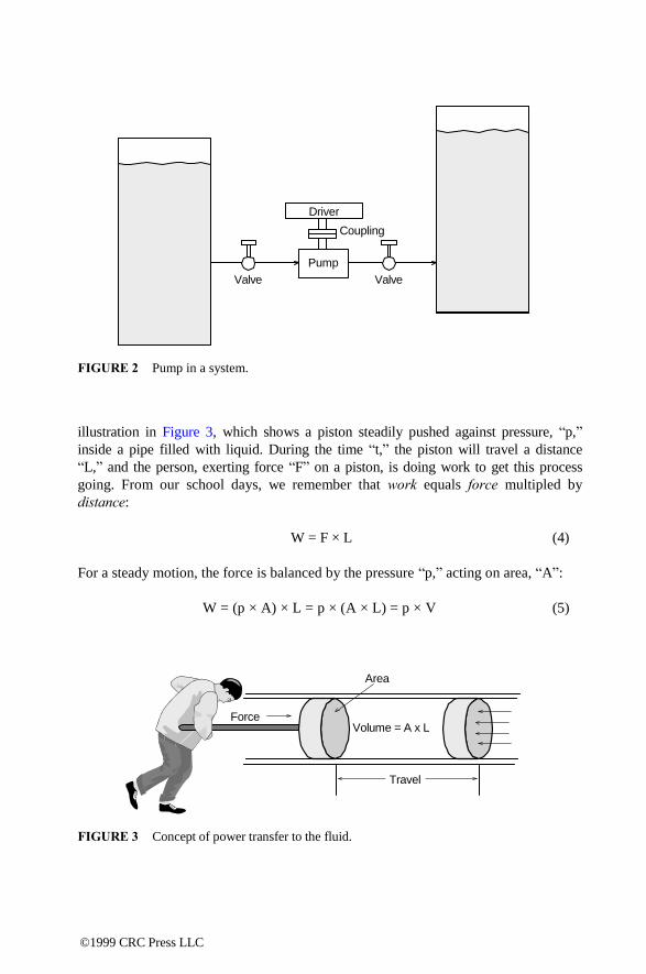
Driver
Coupling
Pump
Valve Valve
FIGURE 2 Pump in a system.
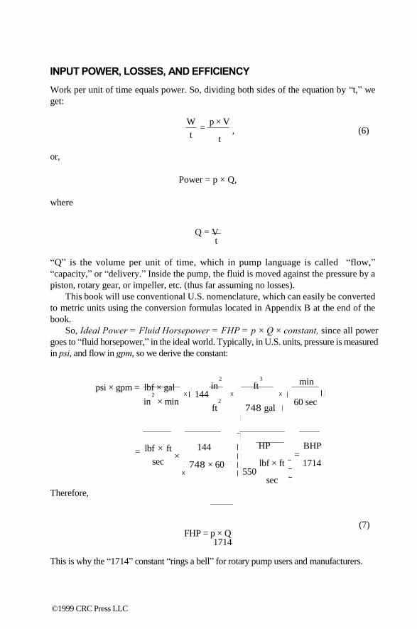
illustration in Figure 3, which shows a piston steadily pushed against pressure, ―p,‖
inside a pipe filled with liquid. During the time ―t,‖ the piston will travel a distance
―L,‖ and the person, exerting force ―F‖ on a piston, is doing work to get this process
going. From our school days, we remember that work equals force multipled by
distance:
W = F × L (4)
For a steady motion, the force is balanced by the pressure ―p,‖ acting on area, ―A‖:
W = (p × A) × L = p × (A × L) = p × V (5)
Area
Force Volume = A x L
Travel
FIGURE 3 Concept of power transfer to the fluid.
©1999 CRC Press LLC
INPUT POWER, LOSSES, AND EFFICIENCY
Work per unit of time equals power. So, dividing both sides of the equation by ―t,‖ we
get:
W
t
or,
= p × V
, (6) t
Power = p × Q,
where
Q = V t
―Q‖ is the volume per unit of time, which in pump language is called ―flow,‖
―capacity,‖ or ―delivery.‖ Inside the pump, the fluid is moved against the pressure by a
piston, rotary gear, or impeller, etc. (thus far assuming no losses).
This book will use conventional U.S. nomenclature, which can easily be converted
to metric units using the conversion formulas located in Appendix B at the end of the
book.
So, Ideal Power = Fluid Horsepower = FHP = p × Q × constant, since all power
goes to ―fluid horsepower,‖ in the ideal world. Typically, in U.S. units, pressure is measured
in psi, and flow in gpm, so we derive the constant:
psi × gpm = lbf × gal 2
in × min
2 3
in ft × 144 × ×
2
ft 748 gal
min
60 sec
=
Therefore,
lbf × ft
sec
144 ×
748 × 60 ×
FHP = p × Q 1714
HP BHP =
lbf × ft 1714 550
sec
(7)
This is why the ―1714‖ constant ―rings a bell‖ for rotary pump users and manufacturers.
©1999 CRC Press LLC

Returning to the ―real world,‖ let us ―turn on the friction‖ exerted by the walls of the
imperfect pipes on liquid, and consider the rubbing of the piston against the pipe walls,
as well as the ―sneaking‖ of some of the liquid back to low pressure through the
clearances between the piston and pipe walls. BHP = FHP + Losses, or introducing the
efficiency concept:
η = FHP , BHP
or
(8)
FHP = BHP × η.
We can now correct Equation 7 with the efficiency:
BHP = p × Q η × 1714
(9)
Jumping ahead a little, Equation 9 is typically used when dealing with positive
displacement pumps (which include rotary pumps), but a ―centrifugal world‖ is more
accustomed to expressing pressure traditionally in feet of head, using specific
gravity3:
H = p
which turns Equation 9 into
× 231.
SG
( feet of water ) (10)
BHP =
H × SG 231 ×
η × 1714
Q H × Q × SG
= (11) η × 3960
This is why a ―3960‖ constant should now ―ring a bell‖ for centrifugal pumps users.
Both Equation 9 and 11 produce identical results, providing that proper units are
used.
SYSTEM CURVE
From the discussion above, we have established that flow and pressure are the two main
parameters for a given application. Other parameters, such as pump speed, fluid
viscosity, specific gravity, and so on, will have an effect on flow and/or pressure, by
modifying the hydraulics of a pumping system in which a given pump operates. A
mechanism of such changes can be traced directly to one of the components of losses,
namely the hydraulic losses.
©1999 CRC Press LLC
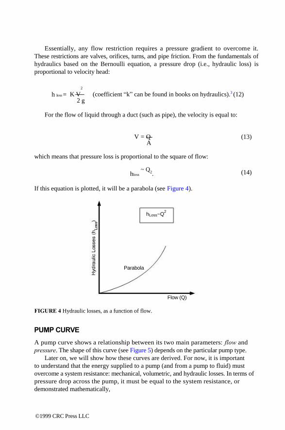
Essentially, any flow restriction requires a pressure gradient to overcome it.
These restrictions are valves, orifices, turns, and pipe friction. From the fundamentals of
hydraulics based on the Bernoulli equation, a pressure drop (i.e., hydraulic loss) is
proportional to velocity head: 2
h loss = K V 2 g
(coefficient ―k‖ can be found in books on hydraulics).3 (12)
For the flow of liquid through a duct (such as pipe), the velocity is equal to:
V = Q A
which means that pressure loss is proportional to the square of flow:
hloss
~ Q2.
If this equation is plotted, it will be a parabola (see Figure 4). hLoss~Q
2
Parabola
Flow (Q)
FIGURE 4 Hydraulic losses, as a function of flow.
PUMP CURVE
(13)
(14)
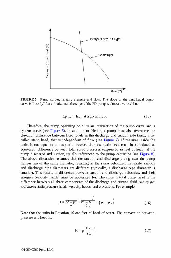
A pump curve shows a relationship between its two main parameters: flow and
pressure. The shape of this curve (see Figure 5) depends on the particular pump type.
Later on, we will show how these curves are derived. For now, it is important
to understand that the energy supplied to a pump (and from a pump to fluid) must
overcome a system resistance: mechanical, volumetric, and hydraulic losses. In terms of
pressure drop across the pump, it must be equal to the system resistance, or
demonstrated mathematically,
©1999 CRC Press LLC
Rotary (or any PD-Type)
Centrifugal
Flow (Q)
FIGURE 5 Pump curves, relating pressure and flow. The slope of the centrifugal pump
curve is ―mostly‖ flat or horizontal; the slope of the PD-pump is almost a vertical line.
∆ppump = hloss, at a given flow. (15)
Therefore, the pump operating point is an intersection of the pump curve and a
system curve (see Figure 6). In addition to friction, a pump must also overcome the
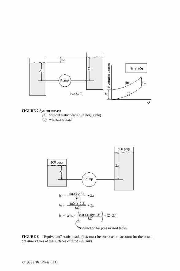
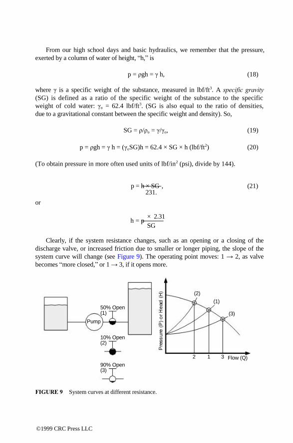
elevation difference between fluid levels in the discharge and suction side tanks, a so-
called static head, that is independent of flow (see Figure 7). If pressure inside the
tanks is not equal to atmospheric pressure then the static head must be calculated as
equivalent difference between total static pressures (expressed in feet of head) at the
pump discharge and suction, usually referenced to the pump centerline (see Figure 8).
The above discussion assumes that the suction and discharge piping near the pump
flanges are of the same diameter, resulting in the same velocities. In reality, suction
and discharge pipe diameters are different (typically, a discharge pipe diameter is
smaller). This results in difference between suction and discharge velocities, and their
energies (velocity heads) must be accounted for. Therefore, a total pump head is the
difference between all three components of the discharge and suction fluid energy per
unit mass: static pressure heads, velocity heads, and elevations. For example, 2
s
1
H = pd – ps + V2 – V γ 2 g
+ ( zd – z s ). (16)
Note that the units in Equation 16 are feet of head of water. The conversion between
pressure and head is:
H = p
× 2.31
SG
(17)
©1999 CRC Press LLC

H
Pump
System
P
Pump
System
Q
(a) Centrifugal
Operating point
Q
(b) Rotary
Operating point
Q
slip
(c) Rotary pump
P
FIGURE 6 Pump operating point — intersection of a pump and a system curves.
Note: Due to the almost vertical curve slope of rotary pumps (b), their performance curves are
usually and historically plotted as shown on (c) (i.e., flow vs. pressure).
©1999 CRC Press LLC
ho
Zs
Pump
FIGURE 7 System curves:
Zd ho = f(Q)
(b) ho
ho=Zd-Zs ho (a)
Q
(a) without static head (ho = negligible)
(b) with static head
500 psig
100 psig Zd
Zs
Pump
hd =
hs =
500 x 2.31
SG
100 x 2.31
SG
+ Zd
+ Zs
ho = hd-hs = (500-100)x2.31 + (Zd-Zs) SG
Correction for pressurized tanks.
FIGURE 8 ―Equivalent‖ static head, (ho), must be corrected to account for the actual
pressure values at the surfaces of fluids in tanks.
©1999 CRC Press LLC
From our high school days and basic hydraulics, we remember that the pressure,
exerted by a column of water of height, ―h,‖ is
p = ρgh = γ h, (18)
where γ is a specific weight of the substance, measured in lbf/ft3. A specific gravity
(SG) is defined as a ratio of the specific weight of the substance to the specific
weight of cold water: γo = 62.4 lbf/ft3. (SG is also equal to the ratio of densities,
due to a gravitational constant between the specific weight and density). So,
SG = ρ/ρo = γ/γo, (19)
p = ρgh = γ h = (γoSG)h = 62.4 × SG × h (lbf/ft2) (20)
(To obtain pressure in more often used units of lbf/in2 (psi), divide by 144).
p = h × SG , (21) 231.
or
h = p × 2.31
SG
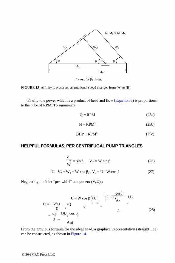
Clearly, if the system resistance changes, such as an opening or a closing of the
discharge valve, or increased friction due to smaller or longer piping, the slope of the
system curve will change (see Figure 9). The operating point moves: 1 → 2, as valve
becomes ―more closed,‖ or 1 → 3, if it opens more.
(2)
(1) 50% Open (1) (3)
Pump
10% Open (2)
2 1 3 Flow (Q)
90% Open (3)
FIGURE 9 System curves at different resistance.
©1999 CRC Press LLC

V U V U
4
Centrifugal Pumps —
Fundamentals A centrifugal pump is known to be a ―pressure generator,‖ vs. a ―flow generator,‖
which a rotary pump is. Essentially, a centrifugal pump has a rotating element,
or several of them, which ―impel‖ (hence the name impeller) the energy to the
fluid. A collector (volute or a diffusor) guides the fluid to discharge. Figure 10
illustrates the principle of the developed head by the centrifugal pump. A good
detailed derivation of the ideal head, generated by the impeller, is based on the
change of the angular momentum between the impeller inlet and exit.4 Equation
22 is a final result:
( ) – ( ) θ
2
H i = θ 1
g (22)
Above, index ―1‖ indicates conditions at the impeller inlet, and index ―2‖
indicates conditions at the impeller exit. The velocity triangles, used to calculate the
developed head, must actually be constructed immediately before the impeller inlet,
and immediately after the exit (i.e., slightly outside the impeller itself). The inlet
component (V × U)1 is called pre-rotation, and must be accounted for. In many cases
the pre-rotation is zero, as flow enters the impeller in a straight, non-rotating manner.
Its effect is relatively small, and we will disregard it in this writing. As flow enters
the impeller, the blade row takes over the direction of flow, causing sudden change
at the inlet (shock). As flow progresses through the impeller passages, it is guided
by the blades in the direction determined by the blade relative angle (βb2). However,
a flow deviation from the blades occurs and depends on the hydraulic loading of the
blades. Parameters affecting this loading include the number of blades and the blade
angle. As a result, by the time the flow reaches the impeller exit, its relative direction
(flow angle βf2) is less than the impeller blade angle (βb2). This means that the actual
tangential component of the absolute velocity (Vθ2 ) is less than it would be if constructed solely based on the impeller exit blade angle. The resultant ideal head
would, correspondingly, be less. The flow deviation from the blade direction has
nothing to do with hydraulic losses, which must be further subtracted from the ideal head,
to finally arrive at the actual head (Ha ).
0-8493-????-?/97/$0.00+$.50 © 1997 by CRC Press LLC
©1999 CRC Press LLC

More head (Vθ2
Impeller
b2
2 Volute
D2 V2 U2
(OD) 1 W2
1 (βf≈βb,
2 h βb as a first
approximation).
Normal to “relative” area Normal to “meridional” area
FIGURE 10A Am2 = πD2b2, Ax = bzhzz
z = number of blades (8 here)
u = peripheral velocity vector
w = relative velocity vector
v = absolute (resultant) velocity vector
―1‖ = inlet, ―2‖ = exit of impeller
V W Vm2
αf βf
Vθ2 Wθ2
U2
(a) More flow (Vm2 × Am2)
Less head (Vθ2U2)
Vm2 > Vm2′ ,
FIGURE 10B Impeller velocity triangles.
V´m2 α´f βf
V´θ2
U2
(b) Less flow (Vm2′ Am2)
′ U2)
Vθ2 < Vθ2′
©1999 CRC Press LLC

βb1
Shock Losses (mostly)
H
Ideal Head
Actual Friction (mostly) Head
Q
Entrance:
2a (Just Left Blade Row)
2 (Ready to Exit Blade Row)
Exit 1 (Entered Blade Row)
Blade 1a (Just Prior Blade Row)
Inlet
1a: V1a ↑ velocity vector in absolute direction (relative direction not meaningful yet), V1a ≈ Vm1
1: blades dictate direction according to blade
inlet angle βb1
Vm 1
If 1a and 1 represented together
V 1a
Exit:
V 1 W 1
βb 1
U 1
Inlet Incidence Angle
βb1
Velocity triangles do not differ very much between 2 and 2a; i.e., there is no shock losses, as
compared to inlet. (Actually, they do differ per Busemann‘s slip factor, but that discussion is
significantly beyond the scope and simplifications of this book.) Low Flow High Flow
Large W2
Small W2
βbβ βbβ 2 2
FIGURE 11 The nature of hydraulic losses in the impeller.
With regard to flow, it is a product of corresponding velocity and area:
Q = Vm × Am = W × Ax. (23)
―Vm‖ is called a ―meriodional‖ velocity (a component of the absolute velocity into
the meriodional direction), and ―W‖ is a relative velocity of the fluid passing through
the impeller passages. Hydraulic losses reduce the generated head, as shown in
Figure 11. Note that at low flow the relative velocity (W) through the impeller is
©1999 CRC Press LLC

small. Since relative velocity characterizes the movement of fluid through the impel-
ler passages, it determines friction losses: relative velocity is higher at higher flow,
hence friction losses are predominant there. At low flow, the relative velocity is small
and friction is negligible. The main component of losses is inlet recirculation and
incidence. At design point (BEP) the fluid enters the impeller smoothly (shockless),
which can be seen as the absolute velocity V1 is presented as a vectorial triangle
that includes V1, U1, and W1. Therefore, on both sides of the best efficiency point
(BEP), the relative component W1a (just before entering the blades row) would be
different from W1 (just inside), causing shock losses. As a result, at higher flow,
friction is a predominant loss component, and at low flow, incidence and shock are
predominant loss components.
AFFINITY LAWS
In an Affinity Law, the ratios between the internal hydraulic parameters of a given
device, such as a pump, remain constant when an ―external‖ influence is exerted on
the device. Rotating speed (RPM) is one such influence. When pump speed changes,
the ―affinity‖ of the velocity triangles (i.e., their shape) remains the same (see Figure 12).
Affinity
30o A 50
o
30o B 50
o
No Affinity
40o C 35
o
FIGURE 12 Illustration of the Affinity principle.
In geometric terms, this means that the relative flow angle, βf (which is, as first
approximation could be assumed, equal to the impeller blade angle, βb), as well as
the absolute flow angle αf all remain constant as the speed increases (see Figure 13).
The ratio of velocities also remains constant:
U V W V V RPM A mA
U A θ A A
= = = = V W V V
A
= (24) RPM
B mB B θB B B
Since velocity is proportional to RPM, and flow is in direct relationship with velocity
(see Equation 9), the flow is thus proportional to RPM. From Equation 8, the ideal
head is proportional to (VθU)2 (i.e., Hi ~ RPM2), and, neglecting a correction for
losses, the actual head is therefore approximately proportional to RPM squared,
H ~ RPM2.
©1999 CRC Press LLC
RPMB > RPMA
VA WA WB
α β β
UA
UB
αA=αB , βA=βB=βblade
FIGURE 13 Affinity is preserved as rotational speed changes from (A) to (B).
Finally, the power which is a product of head and flow (Equation 6) is proportional
to the cube of RPM. To summarize:
Q ~ RPM
H ~ RPM2
BHP ~ RPM3.
HELPFUL FORMULAS, PER CENTRIFUGAL PUMP TRIANGLES
V
(25a)
(25b)
(25c)
m = sin W
β, Vm = W sin β (26)
U - Vθ = Wθ = W cos β, Vθ = U - W cos β (27)
Neglecting the inlet ―pre-whirl‖ component (VθU)1:
cosβ U – W cos β ) U U – Q U 2
Ax Hi = VθU
g = ( 2
2 2
g 2
= g (28)
= u2
2
g
QU cos β 2 2
– Axg
From the previous formula for the ideal head, a graphical representation (straight line)
can be constructed, as shown in Figure 14.
©1999 CRC Press LLC

Hi
U2
g
UAx
Cosβ
Hi= U2 -
g
QUCosβ
Ax g
FIGURE 14 Construction of the ideal head vs. flow. 2
At Q = O, Hi = U 2
g
At
H = O, Q = U2Ax
cos β 2
× 0321 U2 = RPM × OD a nd Vm = Q2 229 Am2
Note: Linear dimensions are in inches, area is in square inches, flow is in gpm, head is in
feet, and velocities are in ft/sec.
QUIZ #1 — VELOCITY TRIANGLES
Referring to Figure 15, construct a velocity triangle at the impeller exit, and predict a
pump head for this 50 gpm single-stage overhung centrifugal pump, running at 1800
RPM. What is an absolute flow angle αf 2?
©1999 CRC Press LLC

b2 =
1/4”
β2b=20o
Ax=hxb2Z
8” OD
FIGURE 15 Impeller geometry for Quiz #1.
Solution to Quiz #1
2
U2 = RPM × D 229
1800 × 8 = = 63 ft sec
229
A
m2 = π D2b = 314 × 8 × 025 = 63 in 2 2
Vm = Q 2
× 0321
A
50 × 0321 = = 26 ft sec
63 m 2
W 2 = V m
2
sin β
= 2
26
sin 20
°
= 75 ft sec
Vθ = U2 – W
cos
β =
63 –
75 ×
cos 20 ° = 56 ft sec 2
H i = Vθ U 2 2
g
2 2
56 × 63 = = 110 ft
322
As was mentioned earlier, we are using an impeller exit angle for the exit velocity
triangles, disregarding flow angle deviation from the blade angle, as an approxima-
tion (i.e., assuming = β2 = βf2 ≈ βb2).
–1 V m2
α f = tan = tan
– 1 26 = 27°
2 V θ 2
56
©1999 CRC Press LLC

56
2.6 20o
2.7o
63
Hi, ft
110
50 Q,gpm
FIGURE 16 Resultant impeller exit velocity triangle and operating point for Quiz #1.
The resultant velocity triangle and a single operating point on the performance
curve are shown in Figure 16. To construct a complete curve, such calculations must
be performed for several flows, producing a series of points of the ideal head (Figure
17). If we could now calculate hydraulic losses at each flow, we would obtain another
set of points for the actual head, which is the next step (see Figure 18).
Hi, feet
110
50 Q,gpm
FIGURE 17 Ideal head is calculated at several flows, producing a set of Hi-Q points.
However, these calculations are too involved for the scope of this book, and the
composition of losses is very different for different pump types. An approximate
technique could be used for a rough estimate of the H-Q curve, as explained below.
The 50 gpm in previous discussion was an arbitrary flow. If the 50 gpm is
actually a best efficiency point (BEP) of this pump, then as a first approximation
and as a rule of thumb, a value of 85% for the hydraulic efficiency can be used at
BEP, and is typical (practical) for many API and ANSI type centrifugal pumps. The
©1999 CRC Press LLC
Ha=Hi-hLosses
Hi, feet
Ha, feet
Losses
Q,gpm
FIGURE 18 Calculated losses, at each flow, are subtracted from the ideal head (Hi),
producing a new set of points for the actual head (Ha).
value of hydraulic efficiency at off-BEP points is a more involved matter. The actual head
at BEP would then be equal to:
H = Hi × ηH = 110 × 0.85 = 94 ft .
The actual head at zero flow (shutoff), for these types of pumps, ranges between 10 to
30% higher than the BEP head, which means:
Hso
≈ 1.2 × 94 ft = 113 ft .
Having these two points, we can roughly sketch the approximate the H-Q curve (Figure
19). H
113’
94
Hso = KH x HBEP , KH = f(NS)
Efficiency
Losses=110-94=16’ (at 50 gpm)
50 Q (BEP)
FIGURE 19 Shut-off (shut valve) head, Hso, is assumed as 20% rise from the BEP value,
which is typical for many pumps, in a wide range of specific speeds (Ns) is discussed later.
Let us also construct a system curve. Suppose that the pump in Quiz #1 was
installed in a system, as shown in Figure 2, with relatively short piping, and a 60 ft
differential between the liquid levels in its tanks (i.e., 60 ft static head). For relatively
©1999 CRC Press LLC

low viscosity liquids (applications in which centrifugal pumps mostly are used),
friction losses can be neglected for a short piping run, and therefore all pressure drop
(hydraulic loss) is taken across the valve — a resultant parabola, as was explained
earlier, is shown in Figure 20. H, ft
(b) 113`
94
ho=60`
Efficiency Curves
(a) (c)
50 Q,gpm
Note 1: Thus far only two points of pump curve have been calculated (at 50 gpm and at
shut-off).
Note 2: Efficiency curves demonstrate possible positions (depending on pump internals) of
operating point (a) if 50 gpm is BEP (assumed here), and (b) and (c) are for BEP to the left of 50
gpm, or to the right of it.
FIGURE 20 Operating point — intersection of pump and system curves.
Hvalve
= Hstatic
+ KQ2 (30)
Substituting the known values from the pump data in the previous valve equation, we
can get the coefficient ―k‖:
94' = 60' + K × 502, K = 0.014.
This finalizes the valve (i.e., system) equation,
Hsystem
= 60' + 0.014Q2,
which can be re-plotted now more accurately in Figure 20.
PERFORMANCE CURVES
Mathematically, if the discharge valve is throttled, its loss coefficient ―k‖ changes
(higher for a more closed valve). Inside the pump, however, there is one particular
flow (BEP), where the hydraulic losses are minimal. Generally, at higher flows, the
friction losses are predominant, and at lower flows the more significant components
of losses are flow separation and vortices (see Figure 11). The flow requirements in
many applications change continuously: the production requirements change, different
©1999 CRC Press LLC

liquids require different amounts of additives to the process, etc. A common and simple
way to change the flow is to open or close the discharge valve; however, this method
is also the least efficient. As we shall see later, for a type of pump in Quiz #1, a 20%
reduction in flow may cause a 10 to 12% loss in efficiency, and this costs money.
QUIZ #2 — HOW MUCH MONEY DID A MAINTENANCE MECHANIC SAVE
HIS PLANT?
Refer to Figure 21: How much money would a mechanic in a chemical plant bring
home next year, due to a raise he got for finding a better way to change the pump flow
than by valving? (There is no need to assume 50 gpm as a BEP point; it can be
anywhere along the performance curve, since the example is only for relative
comparative illustration.)
New BEP Old BEP H, ft
100’
(b)
(a)
P3 P1
(75%) (75%) Efficiency
P2
(65%)
40 50 Q,gpm
FIGURE 21 Different ways to shift pump operating point, for Quiz #2.
(a) Inefficient way: Pump operating point shifted from (P1) 50 gpm to 40 gpm (P2 ), by valve
throttling, with efficiency drop from 75 to 65%.
(b) Efficient way: Operating point moved from P1 to P3 , by volute modifications (or, equally
effective, by speed change with VFD), keeping efficiency high at 75%.
Solution to Quiz #2
1. BHP(inefficient way) =
H × Q × SG
3960 η
40 × 100
40 × 100 × 10 = = 155 HP
3960 × 065
2. BHP(efficient way) = 3960 × 075
= 135 HP
3. ∆ = 0.2 HP ≈ 0.15 kW
For one year (8760 hours), at 10 cents per kilowatt, this would result in:
(0.15 × 8760) × 0.10 = $130 per pump
©1999 CRC Press LLC

An example of such an efficient way would be a volute (or diffusor) modification,
to rematch it to the new operating conditions of 40 gpm. Another way is to reduce
the speed, which would reduce the flow proportionally — this can be done with a
variable frequency drive (VFD). For a 1000-pump plant, this could be a savings of
$130,000. Now, if the mechanic‘s boss would allocate at least 1% of savings to the
mechanic‘s bonus, this $1300 would make a nice present at the year‘s end! And this
is just for a small 1.5 HP pump — how about the larger ones?!
PERFORMANCE MODIFICATIONS
Let us now assume that the pump in our previous example has been properly sized for the
application, and has been operating at its best efficiency point, Q = 50 gpm, and
developing head, H = 94 ft — the operating point being an intersection of a pump
curve and a system curve, with static head of h = 60 ft. The pump‘s suction line is
connected to the supply tank, which is positioned at the supply silo, below the ground
level. A supplier of chemicals used by the processing plant has advised that the raw
chemicals can be supplied in truck-mounted containers and pumped out directly from the
trucks, without unloading of the containers to the ground, thereby saving time and money.
As a result, a suction level is now higher, and, since nothing different was done on the
discharge side, the net static level (discharge level minus suction level) has decreased
from the original 60 ft to 20 ft. All other variables, including the valve setting, remain
the same.
A new system curve move, is shown in Figure 22, and intersects the pump curve at a
higher flow (65 gpm) and a lower head (80 ft). The pump now operates at the run-out, to
the right of the BEP, and the efficiency dropped from its BEP value of 75% to 68%, as
shown on the efficiency curve.
The equation for the system changed only with regard to a static head is:
Hsystem
= 20 + 0.014 Q2.
(i.e., 60' changed to 20', but the valve constant k = 0.014 remained the same, for the
same valve setting).
A few weeks later, a plant started to process a new chemical, requiring only 30 gpm
flow. A discharge valve was closed, forcing the pump back along its curve. At 30 gpm, the
pump is developing 105 feet of head, and is operating at 60% efficiency (see Figure 23).
The higher value of head is not important, and does not affect the process. It is
anticipated that the plant will continue to produce the new chemical for a long time, and a
plant manager had expressed concern about the pump operating at low efficiency.
Operators also noticed that other problems with the pump had started to crop up: higher
vibrations, seal failures, and noise, emanating from somewhere near the suction end of a
pump, which sounded like cavitation. The issue became to maintain 30 gpm flow, but in
such a way that the pump would still operate at the BEP. This challenge is similar to the
problem in Quiz #2.
©1999 CRC Press LLC

80
70
140
120
100
8
0
60
40
20
0
75% 68%
113´ P1 110’
105´ P2
94´
80´
System Change
0 10 20 30 40 50 60 70 Flow, gpm
60
50
40
30
20
80
FIGURE 22 P1: original operating conditions (Q = 50 gpm, H = 94') P2: system static head changed from 60' to 20', causing the pump to run out to Q =
65 gpm, H = 80') (Note efficiency drop.)
An engineering consultant has recommended to trim the impeller outside diameter
(OD), claiming that the pump BEP would move in certain proportion to the impeller
cut: flow would move in direct ratio with a cut, and head would change as a square
of a cut, similar to the relationship of flow and head with speed. A plant engineer was
skeptical about this, asked to see actual calculations based on the first principles using
velocity triangles, which he learned from the pump hydraulics course he took the
previous year. The consultant made the analysis, and below are his reasons.
Since the discharge valve setting remains the same, the system curve does not
change, but the pump curve would change. The new BEP needs to be at 30 gpm,
and the system curve shows 45 feet of head (which can be read from the system
curve in Figure 24 or calculated from the system curve equation established earlier).
Therefore, the impeller OD cut would need to be such that, at 30 gpm, it would
produce 45 feet of head. This requires several iterations. As a first iteration, try a
10% cut:
8 × 0.9 = 7.2", new impeller OD (D2).
Then,
©1999 CRC Press LLC
75%
140
120
100
8
0
60
40
20
0
60% 68%
113´
105´
80´
System
0 10 20 30 40 50 60 70 80 Flow, gpm
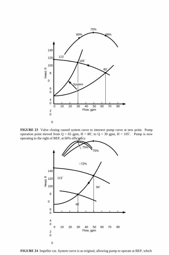
FIGURE 23 Valve closing caused system curve to intersect pump curve at new point. Pump
operation point moved from Q = 65 gpm, H = 80', to Q = 30 gpm, H = 105'. Pump is now
operating to the right of BEP, at 60% efficiency.
75% 75%
≈72%
140
120
100
8
0
60
40
20
0
113´
94´
45´
0 10 20 30 40 50 60 70 80 Flow, gpm
FIGURE 24 Impeller cut. System curve is as original, allowing pump to operate at BEP, which

moves from 50 gpm to 30 gpm efficiently. (Actually, efficiency will show a slight decrease, 2 to
3%.)
©1999 CRC Press LLC
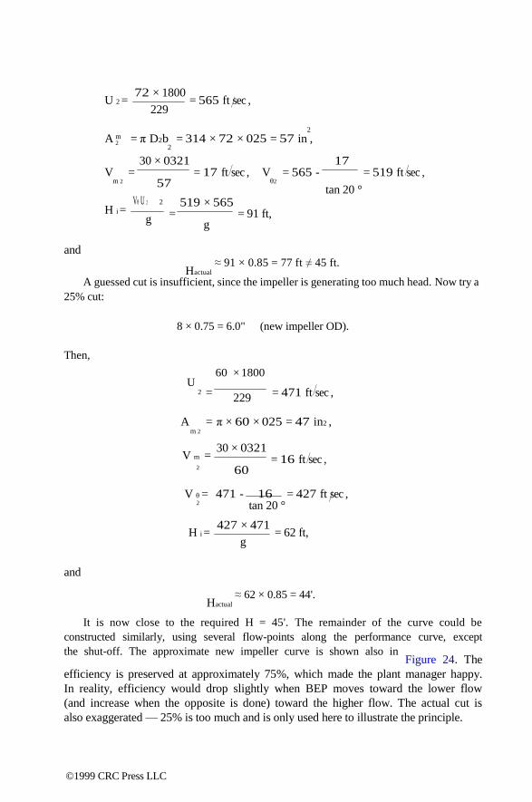
U 2 =
72 × 1800
229
= 565 ft sec ,
2
A m 2 = π D2b = 314 × 72 × 025 = 57 in ,
2
30 × 0321 17 V
m 2
= = 17 ft sec , 57
V = 565 - = 519 ft sec , θ2
tan 20 °
H i =
and
Vθ U 2 2
g
519 × 565 = = 91 ft,
g
Hactual
≈ 91 × 0.85 = 77 ft ≠ 45 ft.
A guessed cut is insufficient, since the impeller is generating too much head. Now try a
25% cut:
8 × 0.75 = 6.0" (new impeller OD).
Then,
60 × 1800 U
2
A m 2
=
=
229
π × 60 ×
= 471 ft sec ,
025 = 47 in2 ,
V m = 30 × 0321
= 16 ft sec , 2
V θ =
60
471 - 16 = 427 ft sec , 2 tan 20 °
H i =
and
427 × 471
g = 62 ft,
Hactual
≈ 62 × 0.85 = 44'.
It is now close to the required H = 45'. The remainder of the curve could be
constructed similarly, using several flow-points along the performance curve, except
the shut-off. The approximate new impeller curve is shown also in Figure 24. The
efficiency is preserved at approximately 75%, which made the plant manager happy.
In reality, efficiency would drop slightly when BEP moves toward the lower flow
(and increase when the opposite is done) toward the higher flow. The actual cut is
also exaggerated — 25% is too much and is only used here to illustrate the principle.
©1999 CRC Press LLC

f V U
Usually, a 10-15% cut is maximum. Beyond that, a pump efficiency begins to suffer
appreciably, due to the fact that the impeller ―loses‖ its blades.
The solution worked, but the plant engineer still had an issue with the consultant.
He pointed out that the impeller cut was 0.75 (6.0/8.0), the flow changed by 0.6 (30/50),
and the head changed by 0.56 (45/94) (i.e., both flow and head changed almost as a
square of the cut: (0.752 = .56)). Yet, the consultant claimed the flow would change
linearly. Both were right, for the following reason: theoretically, both flow and head
should indeed change as a square of the OD cut, as can be easily seen from the change
in velocity triangles. With the change of OD, peripheral velocity changes in direct
proportion (see Figure 25), and the tangential component does the same, in order to
preserve the relative and absolute angles: maintain BEP, and the hydraulic losses are
minimized (matching the flow to the blades as before the cut). The incidence of absolute
velocity at the volute tips must also be similar (i.e., maintaining direction). Such
preservance of the velocity triangles at the discharge is, indeed, the Affinity Law.
VθA
VθB
VmB
f = ODB/ODA, cut
UB = fUA
VθB = fVθA, VmB = fVmA
VmA
α β β
uB
uA b
OD
Cut
AmB = πDb = π(fD
A) b = fA
mA, if b = const.
( V U ) 2( ) θ B θ B
HiB = = g g
b
= f2 × HiA, QB = VmBAmB = fVmAfAmA = f2QA
b But f b ≠ const. (e.g., bB ≈ A A
), then: AmB = πDBbB = π(fDA)( ) = AmA, and QB = fQA
f f
FIGURE 25 Effects of the impeller cut.
©1999 CRC Press LLC

Therefore, all velocities are reduced linearly with the cut ratio. The meridional area
(as well as relative area) changes linearly since the diameter is decreased, but the width
is not. The product (i.e., flow) of meridional velocity multiplied by the area, therefore
changes as a square of the cut. This is what the plant engineer had observed. The
reason for the consultant‘s claim that flow is linear with the cut is that, usually, the
impeller width also changes (it gets wider). This change compensates for the decrease
in the diameter, with the resulting area staying approximately the same. The product
of the smaller velocity and constant area would therefore produce the linear flow
relationship.
It has been found empirically that the reduction in the impeller diameter tends
to follow, in practice, a relationship similar to affinity law for the speed changes:
Q ~ OD (31a)
H ~ OD2 (31b)
BHP ~ OD3. (31c)
The above relationships were proposed by A.J. Stepanoff and are valid for a
considerable range of specific speeds, except for very high or very low. Impellers of
very low specific speeds have narrow impeller width, which stays nearly constant for a
considerable distance away from the OD. The high specific speed designs have short
blades, which are more sensitive to a cut, causing them to deviate from the above
general rule.
QUIZ #3 — A VALVE PUZZLE
Why was the valve throttled so much to begin with? (Hint: Did we just use it to
illustrate the mechanism of flow/pressure restriction?)
Answer to Quiz #3:
A valve was used for illustration purposes only, in order to simulate the hydraulic loss.
It just as well could have been any equivalent length of pipe friction due to flow of
viscous fluid in a long pipe of small diameter. Of course, in a real situation, you should try
to keep the valves sized properly, keeping them in the most open position, to avoid
unnecessary losses. For flow control purposes and for ease of illustration, a valve can
be opened to mathematically reduce system losses, and the pump runs out in flow; but
the friction loss cannot be ―turned off‖ (i.e., it would be more difficult to illustrate the
concept).
UNDERFILING AND OVERFILING
Underfiling (see Figure 26) is a way to achieve modest (3 to 5%) gain in head. The
increased exit area causes a reduction in impeller relative velocity and an increase in
tangential component, Vθ.
©1999 CRC Press LLC

hA
hB VθB
VθA
Removed Metal
β2B β2A
hB = hA
Underfiling: hB > hA, β2B > β2A, Vθ2B > Vθ2A, Ax = h × b × z,
(V U) (V U) AxB > AxA H =
B
θ B
> H g
θ A
= A
g Overfiling: The net area between blades does not change, i.e., no appreciable change in head (except slight, due to smoother blades, improved efficiency).
FIGURE 26 Underfiling and overfiling of blade exits.
W = Q , A x
Vθ = U – W × cos β (32)
which causes head increase for a given flow. This also can be viewed as if the exit angle
was increased via underfiling. These two views of the same resulting effect reflect
different approaches to pump hydraulics by the two traditional schools of thought:
Anderson (area method) vs. Stepanoff (angles). Either approach, if followed correctly,
leads to the same results.
Overfiling is a technique to increase the efficiencies (though modest) by making the
exits smoother. Notice that the exit area does not change, thereby having no effect on
head-capacity curve. (In actuality, a slight improvement in head does occur due to
lowering friction and reduced exit turbulence.)
DESIGN MODELING TECHNIQUES
When designing a new pump, a designer has two choices: to design from scratch, or to
model from other available (similar) designs.
©1999 CRC Press LLC

―Blank piece of paper‖ designs are rare, and are developed for special applications
and extreme or unusual conditions. Computer programs on CAD are at the disposal of
pump hydraulic design engineers, and are often in the realm of the R&D departments
specializing in such activities.
A much more conventional approach is using modeling techniques,4
Q ~ S3 (33a)
H ~ S2 (33b)
BHP ~ S5 (33c)
where ―s‖ is a linear scaling dimension of all linear dimensions (i.e., multiple of the
diameter, width, eye size, etc.). The deviation of Equation 33 is beyond the scope of this
book, and is therefore given for reference only.
SPECIFIC SPEED (Ns)
Pump Specific Speed is defined as a dimensionless parameter, equal to
× Ns = RPM 075.
Q , (34)
H
where Q = gpm, and H = feet. The question is sometimes asked, ―Why do we call the
Ns ‗dimensionless,‘ when in fact, by direct substitution of values, it does have a
dimensional property?‖ This property is true and can be shown by straight substitution:
RPM × gpm 075
=
12
1 gal min × min
= 3/ 4
12
gal
3 12
ft ×
748 gal 32 34
ft ft
= ( dropping off the constants ) =
32
ft 34
min × ft 34
ft = ≠ unity = 1
32
min ft3 4 min
However, if a consistent set of units is used, including a gravitational constant ―g,‖
then a nondimensionality can indeed be demonstrated:
Q Ωs = N
34
( gH )
1 3
ft sec ft = sec =
34
ft 32
32
= 1 = unity (35) 32
ft
2 ft sec s
sec
©1999 CRC Press LLC

Here Ωs is nondimensional and is called a ―universal specific speed.‖ Pump efficiency
depends on specific speed and flow, as illustrated in Figure 27.
FIGURE 27 Pump efficiency as a function of specific speed and flow.4
©1999 CRC Press LLC

5
Gear Pumps —
Fundamentals Gear pumps belong to a positive displacement rotary group, and are made by
enclosing two or more gears in a close-fitting housing. A driver turns a shaft
connected to one of the gears, causing it to rotate. This gear drives the other gear
through the meshing of the teeth of the two gears, just as with power transmission
gears.5 As the gears rotate, on one side, the teeth are coming out of mesh with each
other (see Figure 28). As a tooth is pulled out of the space between two teeth of the
other gear, it creates a vacuum. Since the housing forms a seal all around the set of
gears, the liquid that rushes into this space to fill this void has to come in through
the pump‘s suction port. Once the spaces between gear teeth are filled with liquid,
the liquid rides in these pockets, trapped in place by the housing, until it reaches
the discharge side of the pump. The liquid stays in place between the teeth until it
reaches the other side of the gear mesh, where the teeth are coming together. Then,
when a tooth from the other gear comes into the space between the teeth, the liquid
there is forced out. Since the housing still forms a seal around the gears, the only
place for the displaced liquid to go is out the pump‘s discharge port. The pump thus
operates like a conveyor belt, with the pockets of liquid between the gear teeth being
picked up at the gear mesh, carried to the other side, and dropped off at the other
side of the mesh.
There are two basic types of gear pumps: external and internal. External gear
pumps usually have two gears with an equal number of teeth on the outside of each
gear. Internal gear pumps have one larger gear with the teeth turned inward, meshing
with a smaller gear with external teeth. If the larger gear has one tooth more than
the inner gear, the two gears form a seal by themselves. If the larger gear has at
least two teeth more than the smaller gear, then a crescent-shaped projection of the
housing goes between the two gears to help form a seal. The operating principle is
the same for all of these types of pumps, and they operate in similar fashion.
The displacement of a pump is the volume of liquid moved in those pockets
between gear teeth. It is the theoretical output of the pump before any losses are
subtracted. The instantaneous mode of displacement varies slightly as the teeth move
through different positions in the mesh, so displacement per shaft revolution cannot
be calculated exactly. However, there are some good approximations. For example,
if the cavity area between the gear teeth is assumed to be approximately equal to
the area of the teeth themselves (i.e., a cavity is an inverse of a tooth), then the
0-8493-????-?/97/$0.00+$.50 © 1997 by CRC Press LLC
©1999 CRC Press LLC
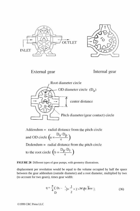
W in rev
FIGURE 28 Different types of gear pumps, with geometry illustrations.
displacement per revolution would be equal to the volume occupied by half the space
between the gear addendum (outside diameter) and a root diameter, multiplied by two
(to account for two gears), times gear width:
q =
π
4
( D2 –
D
2 1 3
r )× × 2 × ( ) ; (36) 2
©1999 CRC Press LLC

Da Dr W
or, simplifying and dividing by 231, to convert in3/rev to gal/rev:
2 2
q = 00034 × ( – ) , (37)
where
q = displacement (gallons/revolution)
Da = gear outside diameter (inches)
Dr = gear root diameter (inches)
W = gear face width (inches).
This formula assumes that both gears have the same outside diameter and number of
teeth. The addendum of gears for pumps is often extended when compared to power
transmission gears. This is to increase the pump‘s displacement. Gears with smaller
numbers of teeth have larger addendum for a given center distance. So, most gear pumps
have 12 or less teeth on the gears. Examples of gears with various numbers of teeth,
pitches, and sizes are shown in Figure 29.
FIGURE 29 Pumping gears with different number of teeth (Z), pitch diameters (Dp), and
pitches (Z/Dp).
©1999 CRC Press LLC

Some pumps have as few as six teeth. This is about the minimum for relatively
smooth power transmission between gears. Lobe pumps are similar to gear pumps with
two or three teeth, but they use separate timing gears, outside of the liquid, to transmit
power from the driving to the driven shaft.
QUIZ #4 — GEAR PUMP CAPACITY
A plant mechanic has measured the pump gear at the repair shop:
Da
= Gear OD = 3"
Dr
= ID (root) = 2" Width = 4"
Predict how much oil this gear pump will deliver at 1200 RPM.
SOLUTION TO QUIZ #4
Using Equation 37,
2
q = 00034 × ( D2 – D r
) W =
2 2
00034 ( 3 – 2 )× 4 = 007 gal rev ,
Q = q × RPM = 007 × 1200 = 80 gpm.
Slip is the difference between the theoretical flow (displacement × speed) and actual
flow, assuming that there is no cavitation. Slip is the leakage of liquid from the high
pressure side of the pump back to the low pressure side. There are a number of
separate slip paths in any gear pump, including any liquid from the outlet of the
pump that is bled off to flush a seal chamber or lubricate bearings. Three paths are
common to all gear pumps: between the ends of the gears and the endplates (known
as lateral clearance), between the tips of the gear teeth and the inside of the casing
(known as radial clearance), and between the profiles of the meshing teeth. The slip
through this last path is very small and is usually ignored.
Slip varies strongly with differential pressure and viscosity and, to some extent,
with speed. Slip is directly proportional to differential pressure. It varies inversely,
but not proportionally, with viscosity. Slip varies asymptotically with viscosity,
approaching zero slip at high viscosities. This means that at low viscosities, small
changes can mean large differences in slip. Slip varies inversely with speed to a
small extent, but this is normally ignored, and predictions are made slightly conser-
vatively at higher speeds. There is also a strong relationship between clearances and
slip. Slip, through a particular clearance, varies directly with the cube of that
clearance. This is similar to the oil flow in a hydrodynamic bearing,6 and, indeed,
the interaction between gear ends and the casing wall (or wearplate) is also similar,
producing a like hydrodynamic bearing effect. This means that if you double the
lateral clearance, you will get eight times as much slip through that clearance. The
percentage of slip through each slip path varies with pump design, but in most gear
©1999 CRC Press LLC

pumps, over half of the slip goes through the lateral clearance; this is because it is
usually the largest clearance and it has the shortest distance from high to low
pressure. This is why some high pressure pumps eliminate lateral clearance
altogether by using discharge pressure to hold movable endplates against the gear faces
while the pump is running.
CAVITATION IN GEAR PUMPS
Cavitation is the formation of voids or bubbles in a liquid as the pressure drops
below the vapor pressure of the liquid in the pump‘s inlet. These bubbles then
collapse when they reach the high pressure side of the pump. This collapse can,
over time, damage the pump and erode hard surfaces. Cavitation causes a drop in
output flow that can sometimes be mistaken for slip, but cavitation can usually be
identified by its distinctive sound. Significant cavitation will usually sound like gravel
rattling around inside the pump. A rule of thumb is that the liquid velocity in the
inlet port should be no more than 5 ft/sec for low-required net inlet pressure.
When pumping viscous fluids, the rotational speed of the pump must be such
that the fluid has enough time to fill the voids between gear teeth at the inlet. In
other words, the pump can only move the fluid out if there is sufficient suction
pressure to push the liquid into the pump inlet. Otherwise, the voids are not filled
completely, effectively reducing actual flow through the pump. Therefore, minimum
allowable suction pressure depends on the rotating speed, size (pitch diameter),
number of gear teeth, and viscosity of the fluid. An empirical approximate relation-
ship, based on charts is7:
V p
pmin =
where
0826 009
× SSU
614
( psia ) (38)
Vp =
and
Dp × RPM × 313.
Z
( in min per tooth ) ,
Z = number of gear teeth
Dp = pitch diameter (inches) SSU = viscosity.
Therefore, pump suction pressure must be greater than the minimum allowable
value. If this condition is not maintained, the pump flow will decrease, accompanied
by noise, vibrations, and possible damage to the equipment. The cavitation damage
in gear pumps, however, is not as severe as in centrifugal pumps. Typically, gear
pumps are used for oil and similar liquids which have a significantly lower cavitation
(boiling) intensity. The resulting bubbles implode less vigorously than in the case
©1999 CRC Press LLC

of cold water, and their impact against the equipment‘s internal boundaries is,
therefore, less severe.
TRAPPING METHODS
As the teeth mesh, they can form closed spaces where one pair of teeth come together
before the pair ahead of them has broken contact. This closed space decreases in
volume as the teeth continue to move, and the liquid trapped inside can reach very
high pressures and come out through the pump‘s lateral clearances at extremely high
velocities. This damages the pump by eroding the endplates and gears; it also causes
excessive noise and power consumption by the pump. Trapping problems are worse
at high speeds and high pressures. Two methods are used to prevent trapping: helical
gears and grooves.
Helical gears have the teeth twisted around the gear in a helix, so that any two teeth
can only be in contact at one point. The trapped liquid can move axially along both teeth to
escape the mesh.
Grooves in the gears or endplates are used to provide escape routes for trapped
liquid. Grooves in endplates must be open to the trapped volume until it reaches its
minimum size, and then another groove opens to the trapped space as it expands again.
The two grooves must stay far enough apart so that a tooth is always in between
them to ensure there is never an opening from inlet to discharge which would increase
slip.
LUBRICATION
Journal bearings are the simplest type of bearing used in pumps. They are often
called sleeve bearings because they are basically a sleeve that the shaft fits into.
However, they are the most critical part of applying a pump to a particular application
because they do not depend on rigid, mechanical parts for operation, but on a self-
forming hydrodynamic film of liquid that separates the moving and stationary parts.
A journal bearing can operate in three ways.8 First, it can operate with the shaft
rubbing the bearing; this is called boundary lubrication. Second, the shaft may form a
liquid film that completely separates it from the shaft; this is called hydrodynamic film
operation. And finally, the third and most common mode is mixed film lubrication;
this is where parts of the bearing and shaft are separated by a liquid film while other
parts are in rubbing contact.
Boundary lubrication occurs at low shaft speeds or low fluid viscosities where the
strength of the liquid film is insufficient to support the load on the bearing. Since the parts
are rubbing under load, they will wear. Limits have been established that attempt to keep
this wear down to acceptable levels. The limits are based on the amount of heat that can be
removed from the bearing surfaces actually in contact, and on surface chemistry
interactions between the shaft, bearing, and liquid. Boundary lubrication is often called
―PV-lubrication‖ because the bearing load per unit area (P) and the relative velocity between
the parts (V) are the factors. Typically, the following values are used to estimate load
capabilities of various bearing materials:
©1999 CRC Press LLC

Material PV-value (psi × ft/min)
carbon 120,000
bronze 60,000
iron 30,000
plastics 3,000
Hydrodynamic operation is different from boundary lubrication in that the bearing
material is not important, and the viscosity instead of the chemistry of the liquid is
important. Bearing clearance also becomes a very important factor.
Roller bearings are often used on gear pumps where journal bearings will not
work because of high loads, low speeds, or low viscosities. The bearing manufac-
turer‘s recommendations should be followed8 in applying these bearings, except that
most bearing manufacturers do not have information on bearing performance with
lubricants below 150 SSU. In the absence of any better information, use the following
rules of thumb:
• Liquid viscosity above 5 cSt — use full bearing catalog rating
• Liquid viscosity 5 to 2.5 cSt — use 75% of catalog rating
• Liquid viscosity 2.5 to 1 cSt — use 25% of catalog rating
(Note: cSt = viscosity in centistokes)
It may seem surprising, but the ends of the gears usually operate with hydro-
dynamic lubrication. The loads here are generally low, and the teeth form an
excellent type of thrust bearing called a step thrust bearing. Wearplates can be used
between the ends of the gears and the housing when the combination of gear and
housing material could cause wear or galling problems. Galling is wear by adhesion
of material from one part onto the other and is characteristic of stainless steel sliding
against a similar metal under load. Wearplates can also be used when there is no
hydrodynamic film on the ends of the gears. The wearplates will then be made
from a material with good boundary lubrication characteristics, such as carbon or
bronze.
Wear seldom occurs to the teeth of steel or cast iron gears unless there are
abrasives present in the liquid, or when the gear teeth are heavily loaded and the
material that they are made from does not have the strength necessary to resist
deterioration of the tooth surface. Even with very low viscosity liquids, the loads
on the gear teeth are normally low, and the contact is intermittent, so boundary
lubrication is adequate. However, stainless steel gears generally exhibit severe wear9
unless a full liquid film separates the teeth. Any particular pump at a certain speed
will have a liquid viscosity below which the gears will begin to gall.
The choice of materials greatly affects the point where galling begins. Some
materials are restricted to use only under full film lubrication conditions, while others
can operate down well into the mixed film region without problems. Hardened
martensitic stainless steels, particularly 440C, have good resistance to galling. 440C
can be run against itself and is no more likely to gall than carbon steel. The other
©1999 CRC Press LLC
extreme is 18-8 austenitic stainless steels, like 304 or 316. These will gall when run
against themselves or each other if there is any contact at all between the gears.
USER COMMENTS
The following are some direct comments on various types of rotary pumps made by
the users interviewed at the chemical plants, as they see it:
EXTERNAL GEAR PUMPS
Workhorse of the industry, applied mostly for low capacity and high pressure. Range
of viscosities is very wide: from lube oil to one million SSU. Application issues include
close clearances between the gears and casing. Bearings are immersed in product and
are therefore product lubricated, which makes them product sensitive. Both extremes
of viscosity (very low and very high) may present lubrication problems. Seal chambers
are restrictive, since gear pump manufacturers are only now beginning to come up with
large sealing chambers — something centrifugal pump manufacturers have addressed
5 to 10 years ago. Due to these sealing chamber size restrictions, some standard
mechanical seals may not fit in these pumps, without special design alterations. Gear
pumps are often noisy in operation, and generate flow pulsations downstream.
Flow control of all positive displacement pumps is not as straightforward as for
centrifugals. However, recent advances in variable frequency drives (VFD) make such
method of flow control convenient, and relatively inexpensive. It also allows wiring
the VFD signal to the operator control room, for remote control and monitoring.
Abrasive applications are an issue, just as for any other pump type. To combat abrasion,
speed should be decreased, because wear is exponential with speed. Coatings include
carburizing (low carbon steel), nitriding (alloy steel), or exotic materials (nickel alloys).
Cavitation is not a big issue for gear pumps, for many reasons. First of all, they typically
operate at lower speeds. Second, the ―positive filling‖ of the inlets makes them less
sensitive to flow non-uniformity, separation, and backflow — which is a very serious factor
for centrifugal pumps. Third, gear pumps typically pump oils, and similar fluids, the
properties of which are such (e.g., latent heat of vaporization, characterizing the intensity
of cavitation damage, is much lower) that even if cavitation does occur, the damage to the
internals is less.4
The necessity to have the relief valve (internal in-built, or external) is a limitation.
Without a relief valve, very high discharge pressures may result, damaging the pump
or connecting piping, as well as cause safety issues. Therefore, a relief valve must
always be present. The integral relief valve, which is a part of a pump, is not designed
to regulate the flow, but only relieves occasional overpressure, for a limited time. If
the relief valve opens, and the equipment is not shut-down relatively soon, or the
problem is not corrected otherwise, fluid overheating could result in a matter of minutes
or less. Attention to relief valve operation is very important.
©1999 CRC Press LLC

INTERNAL GEAR PUMPS
Designed for low pressure at low speed. Drive gear is cantilever, vs. between-bearings
arrangement of external gear pumps. A cantilever design requires a bigger shaft, to
minimize deflections. This may shorten seal life.
These pumps are simple to assemble and repair, with little training, and, when applied
appropriately, can do the job well and inexpensively.
The issues are similar to the external gear pumps — close clearances, with possibility of
contact, wear or galling, if stainless construction (in which case wearplates made from
carbon or bronze are required). In general, issues, benefits, and limitations are similar to
those for external gear pumps.
SLIDING VANE PUMPS
These are mainly applied for low viscosity liquids. However, pumping lube oils and
gasoline is not uncommon. Vanes slide (i.e., adjust) to compensate for wear and are
easy to replace. If not replaced on time, however, vanes can wear out to the point of
breakage, causing catastrophic failures. Preventative maintenance, therefore, should
include vane replacement, and should be done at regular, established intervals. Vanes
are available in softer or harder materials — as required for various liquids, for mildly
abrasive and corrosive applications. However, very little development work seems to
have been done in vane material, and manufacturers should be encouraged to do so.
These pumps can be extremely noisy at speeds over 300 RPM.
LOBE PUMPS
Similar to external gear pumps, but they require timing gears since the lobes are
designed for no contact and do not transmit torque. Occasional contact can happen in
reality, as differential pressure deflects the shaft, pushing gears to rub against the casing
walls. Larger and stiffer shafts minimize such deflections, to prevent gear contact.
Information about the rotors‘ deflection with differential pressure can be obtained from
the manufacturer, or estimates can be done by the plant engineers. Lobe pumps are
good for high displacements (flows) and low pressure applications, and are often used
for blowers/vacuum applications, as well as food applications.
©1999 CRC Press LLC

6
Multiple-Screw Pumps Rotary screw pumps have existed for many years and are manufactured around the
world. More demanding service requirements impose challenges on screw pump
manufacturers to provide higher pressure or flow capability, better wear resistance,
improved corrosion resistance, and lower leakage emissions. Better materials and
more precise machining techniques as well as engineering innovation have led to
improvements in all these areas.
The first screw pump built was probably an Archimedes design used to lift large
volumes of water over small vertical distances; they are still manufactured and used for
this service. Today‘s three-screw, high performance pump can deliver liquids to pressures
above 4500 psi and flows to 3300 gpm with long-term reliability and excellent
efficiency. Power levels to 1000 hp are available. Twin-screw pumps are available for
flow rates to 18,000 gpm, pressures to 1450 psi, and can handle corrosive or easily
stained materials, again at good efficiencies. Power ranges to 1500 hp operate on critical
applications.
In multiple-screw pumps, each wrap of screw thread effectively forms a stage of
pressure capability. High pressure pumps have 5 to 12 stages or wraps where low
pressure pumps may have only 2 or 3 wraps. This staged pressure capability is
illustrated in Figure 30. More wraps are incorporated in pumps designed for higher
pressure service.
THREE-SCREW PUMPS
Three screw pumps are the largest class of multiple-screw pumps in service today.10 They
are commonly used for machinery lubrication, hydraulic elevators, fuel oil transport and
burner service, powering hydraulic machinery and in refinery processes for high
temperature viscous products such as asphalt, vacuum tower bottoms, and residual fuel
oils. Three-screw pumps, also are used extensively in crude oil pipeline service as well as
the gathering, boosting, and loading of barges and ships. They are common in engine
rooms on most of the world‘s commercial marine vessels and many combat ships. Subject
to material selection limitations, three-screw pumps are also used for polymer pumping in
the manufacture of synthetic fibers such as nylon and lycra. Designs are available in
sealless configurations such as magnetic drives and canned arrangements (see Figure 31).
The magnetic drive screw pump is used extensively for pumping isocyanate, a
plastic component which is an extremely difficult fluid to seal using conventional 0-8493-????-?/97/$0.00+$.50 © 1997 by CRC Press LLC
©1999 CRC Press LLC

FIGURE 30 Staging effects of multiple-screw pumps. (Courtesy of IMO Pump.)
FIGURE 31 Three-screw canned motor pump. (Courtesy of IMO Pump.)
technology. Three-screw pumps are renowned for their low noise levels, high
reliability, and long life. They are not, however, very low cost pumps.
DESIGN AND OPERATION
Three-screw pumps are manufactured in two basic styles: single suction and double
suction (see Figure 32).
©1999 CRC Press LLC

FIGURE 32 Single and double suctions three-screw pumps. (Courtesy of IMO Pump.)
The single suction design is used for low to medium flow rates and low to very high
pressure. The double suction design is really two pumps parallel in one casing. They are
used for medium to high flow rates at low to medium pressure.
Three-screw pumps generally have only one mechanical shaft seal and one, or
perhaps two, bearings that locate the shaft axially. Internal hydraulic balance is such that
axial and radial hydraulic forces are opposed and cancel each other. Bearing loads are
thus very low. Another common characteristic of three-screw pumps is that all but the
smallest low pressure designs incorporate replaceable liners in which the pumping screws
rotate. This simplifies field repairs.
The center screw, called the power rotor, performs all the pumping. The meshed
outside screws, called idler rotors, cause each liquid-holding chamber to be separated
from the adjacent one except for running clearances. This effectively allows staging of
the pump pressure to rise. Because the center screw is performing all the pumping
work, the drive torque transferred to the idler rotors is only necessary to overcome the
viscous drag of the cylindrical rotor spinning within its liner clearance. The
theoretical flow rate of these pumps is a function of speed, screw set diameter, and
the lead angle of the threads. Flow rate is a function of the cube of the center screw
diameter. Slip, however, depends on clearances, differential pressure, and
viscosity, and is only a square of the power rotor diameter. This results in larger
pumps being inherently more efficient than smaller pumps, a fact that applies to most
rotating machinery.
Speed is ultimately limited by the application‘s capability to deliver flow to the
pump inlet at a sufficient pressure to avoid cavitation. This is true of all pumps.
Three-screw pumps tend to be high speed pumps, not unlike centrifugal pumps.
Two-pole (3600 RPM) and four-pole motors are most commonly used. When large
flows, very high viscosities, or low available inlet pressures dictate, slower speed
may be necessary. For example, some polymer services handle liquid at 250,000
SSU or more. Three-screw pumps on such service would typically be operated in
the 50 to 150 RPM range. Gas turbine fuel injection service would more commonly
be in the 3000 to 3600 RPM range since the fuels tend to be low in viscosity (1 to
20 centistokes), and the pump inlet is normally boosted to a positive pressure from
a fuel treatment skid pump. The high speed operation is desirable when handling
©1999 CRC Press LLC

low viscosity liquids since the idler rotors generate a hydrodynamic liquid film in their
load zones that resists radial hydraulic loads, very similar to hydrodynamic sleeve
bearings found in turbomachinery.
In order to achieve the highest pressure capability from three-screw pumps, it
is necessary to control the shape of the screws while under hydraulic load. This is
best achieved by the use of five axis NC profile grinding which allows complete
dimensional control and a high degree of repeatability. Opposed loading of the idler
rotor outside diameters on the power rotor root diameter dictate that these surfaces
be heat treated to withstand the cyclic stresses. Profile thread grinding allows the
final screw contour to be produced while leaving the rotors quite hard, on the order
of 58 RC (58 on the Rockwell C scale). This hard surface better resists abrasive
wear from contaminants.
Because some three-screw pump applications range to pressures of 4500 psi,
pumping element loading due to hydrostatic pressure can be quite high. Without
hydraulic balance to counteract this loading in one or two planes, bearing loads
would be excessive and operating life shortened.
Single-ended pumps use two similar, but different, techniques to accomplish
axial hydraulic balance. The center screw, called a power rotor, incorporates a
balancing piston at the discharge end of the screw thread (see Figure 33a). The area
of the piston is made about equal to the area of the power rotor thread exposed to
discharge pressure. Consequently, equal opposing forces produce zero net axial force
due to discharge pressure, and place the power rotor in tension. The balance piston
rotates within a close clearance stationary bushing, which may be hardened or hard
coated to resist erosive wear. The drive shaft side of the piston is normally internally
or externally ported to the pump inlet chamber. Balance leakage flow across this
running clearance flushes the pump mechanical seal which remains at nominal pump
inlet pressure. The two outer screws, called idler rotors, also have their discharge
ends exposed to discharge pressure. Through various arrangements, discharge pres-
sure is introduced into a hydrostatic pocket area at the inlet end of the idler rotors
(see Figure 33b).
The effective area is just slightly less than the exposed discharge end area,
resulting in approximately equal opposing axial forces on the idler rotors. The idler
rotors are therefore in compression. Should any force cause the idler rotor to move
toward discharge, a resulting loss of pressure, acting on the cup shoulder area or
hydrostatic land area, tends to restore the idler rotor to its design running position.
The upper view in Figure 33b shows a stationary thrust block (cross hatched) and
a stationary, radially self-locating balance cup. Discharge pressure is brought into
the cup via internal passages within the pump or rotor itself. The lower view shows
a hydrostatic pocket machined into the end face of the idler rotor. It too is fed with
discharge pressure. The gap shown is exaggerated and is actually very near zero.
For some contaminated liquid services, the hydrostatic end faces of the idler
rotors are gas-nitride-hardened or manufactured from solid tungsten carbide, and
shrink fitted to the inlet end of the idler rotors. When the cup design is used, the cup
inside the diameter and shoulder area are normally gas-nitride hardened. Both
techniques are used to resist wear due to the fine contaminants.
©1999 CRC Press LLC
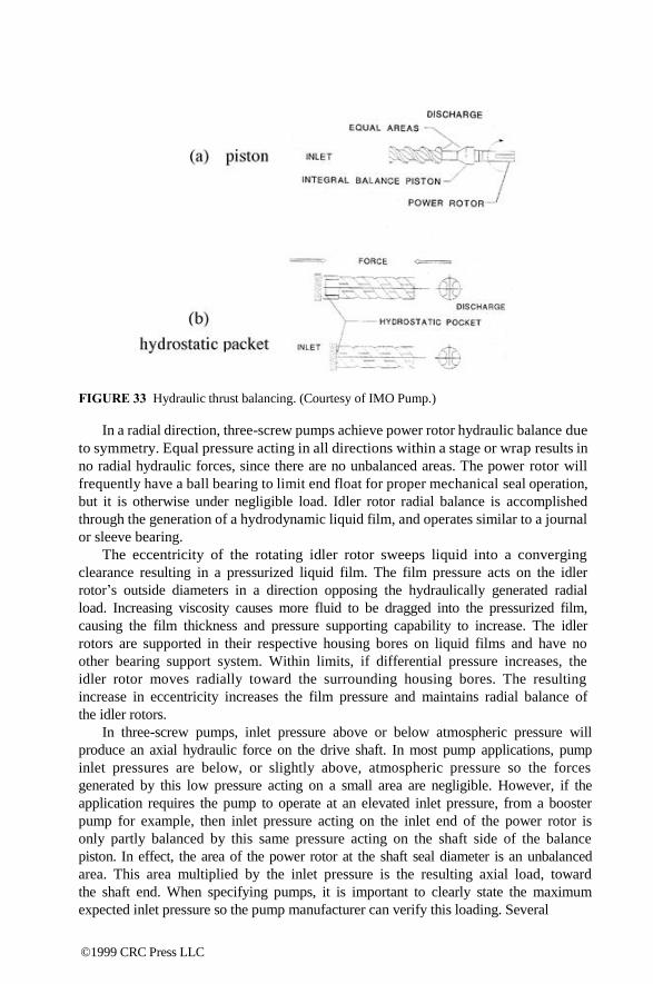
FIGURE 33 Hydraulic thrust balancing. (Courtesy of IMO Pump.)
In a radial direction, three-screw pumps achieve power rotor hydraulic balance due
to symmetry. Equal pressure acting in all directions within a stage or wrap results in
no radial hydraulic forces, since there are no unbalanced areas. The power rotor will
frequently have a ball bearing to limit end float for proper mechanical seal operation,
but it is otherwise under negligible load. Idler rotor radial balance is accomplished
through the generation of a hydrodynamic liquid film, and operates similar to a journal
or sleeve bearing.
The eccentricity of the rotating idler rotor sweeps liquid into a converging
clearance resulting in a pressurized liquid film. The film pressure acts on the idler
rotor‘s outside diameters in a direction opposing the hydraulically generated radial
load. Increasing viscosity causes more fluid to be dragged into the pressurized film,
causing the film thickness and pressure supporting capability to increase. The idler
rotors are supported in their respective housing bores on liquid films and have no
other bearing support system. Within limits, if differential pressure increases, the
idler rotor moves radially toward the surrounding housing bores. The resulting
increase in eccentricity increases the film pressure and maintains radial balance of
the idler rotors.
In three-screw pumps, inlet pressure above or below atmospheric pressure will
produce an axial hydraulic force on the drive shaft. In most pump applications, pump
inlet pressures are below, or slightly above, atmospheric pressure so the forces
generated by this low pressure acting on a small area are negligible. However, if the
application requires the pump to operate at an elevated inlet pressure, from a booster
pump for example, then inlet pressure acting on the inlet end of the power rotor is
only partly balanced by this same pressure acting on the shaft side of the balance
piston. In effect, the area of the power rotor at the shaft seal diameter is an unbalanced
area. This area multiplied by the inlet pressure is the resulting axial load, toward
the shaft end. When specifying pumps, it is important to clearly state the maximum
expected inlet pressure so the pump manufacturer can verify this loading. Several
©1999 CRC Press LLC
reliable methods are in use to carry this load, including antifriction bearing such as
double extending the power rotor out the inlet end of the pump (which adds a second shaft
seal) or sizing the balance piston to counterbalance this axial force.
As versatile as three-screw pumps are, they are not suitable for some applica-
tions. While many advances in materials engineering are taking place, the state of
the art for three-screw pumps is such that very corrosion-resistant materials, such
as high nickel steels, have too great a galling tendency. The rotors of three-screw
pumps touch, and thus any materials that tend to gall are unsuitable. Unfortunately,
this includes many corrosion-resistant materials. Viscosities too low to allow hydro-
dynamic film support generation are also application areas for which the three-screw
pump is not optimal.
TWO-SCREW PUMPS
Generally, two-screw (or twin-screw) pumps are more costly to produce than three-
screw pumps and thus are not in as extensive use. They can, however, handle
applications that are well beyond many other types of pumps, including three-screw
designs. Twin-screw pumps are especially suited to very low available inlet pressure
applications, and more so if the required flow rates are high. Services similar to
three-screw pumps include: crude oil pipelining; refinery hot, viscous product pro-
cessing, synthetic fiber processing; barge unloading; fuel oil burner and transfer; as
well as unique applications such as: adhesive manufacture; nitrocellulose explosive
processing; high water cut crude oil; multiphase (gas/oil mixtures) pumping; light
oil flush of hot process pumping; cargo off-loading with ballast water as one of the
fluids; and tank stripping service where air content can be high and paper pulp
production needs to pump over about 10% solids.
DESIGN AND OPERATIONS
The vast majority of twin-screw pumps are of the double suction design (see Figure
34). The opposed thread arrangement provides inherent axial hydraulic balance due
to symmetry. The pumping screws do not touch each other and thus lend themselves
well to manufacture from corrosion-resistant materials. The timing gears serve to
both synchronize the screw mesh as well as to transmit half the total power input
from the drive shaft to the driven shaft. Each shaft effectively handles half the flow,
and thus half the power. Each end of each shaft has a support bearing for the
unbalanced radial hydraulic loads. A few designs leave the bearings and timing gears
operating in the liquid pumped. While this results in a significantly lower cost pump
design, it defeats much of the value that twin-screw pumps bring to applications.
The more common and better design keeps the timing gears and bearings external
to the liquid pumped. They need not rely upon the lubricating qualities of the pumped
liquid or its cleanliness. Four mechanical shaft seals keep these bearings and timing
gears isolated and operating in a controlled environment.
Hydraulic radial forces on a two-screw pump rotor due to differential pressure
are illustrated in Figure 35. The forces are uniform along the length of the pumping
threads. These hydraulic forces cause deflection ―y‖ for which running clearance
©1999 CRC Press LLC

FIGURE 34 Double suction two-screw pump. (Courtesy of IMO Pump.)
FIGURE 35 Radial forces in twin-screw pumps. (Courtesy of IMO Pump.)
must be provided in the surrounding pump body. Greater deflection requires larger
clearances, resulting in more slip flow or volumetric inefficiency, so ―y‖ must be
kept to a minimum. Excessive deflection will cause damage to the surrounding body
and/or contribute to rotating bend fatigue which will ultimately result in shaft
breakage. The following is the general form of the deflection equation,
©1999 CRC Press LLC

3
y = F × L c × E × I
< radial clearance (39)
where ―F‖ is the summation of the hydraulic forces, ―L‖ is the bearing span, ―c‖ is
a constant, ―E‖ is the shaft material modulus of elasticity, and ―I‖ is the shaft moment
of inertia. The shaft moment of inertia is a function of ―D4,‖ where ―D‖ is the
effective shaft diameter. This equation is simplified and, in practice, must account
for the varying shaft and screw diameters as they change along the length of the
rotor. If screw ―shells‖ are not integral with the shaft, that is, not made from a single
piece of material, then material differences as well as attachment schemes must be
factored into the deflection calculation. In any event, it is easy to see that the bearing
span, ―L,‖ must be kept to a minimum to minimize deflection. The use of large
diameter shafts and screw root sections helps to maintain minimum deflection.
Depending on the direction in which the threads are machined (left or right hand),
and the direction of shaft rotation, the pump manufacturer can predetermine the
deflection to be in either of the two radial directions: up or down, for a horizontal
pump. These radial deflection loads are absorbed through externally lubricated anti-
friction bearings. Higher differential pressure produces higher radial loads or forces.
Smaller lead angles of the screw set reduce both these radial loads and the flow rate.
Larger lead angles increase both flow rate and radial loading. Bearings are usually
sized to provide 25,000 or more hours, ―L10,‖8 bearing life at the maximum allowable
radial loading and maximum design operating speed. Because of this pumpage-inde-
pendent bearing system, two-screw pumps with external timing gears and bearings
can handle high gas content as well as light oil flushes, water, etc.
Twin-screw pumps are manufactured from a broader range of materials, includ-
ing 316 stainless steel. When extreme galling tendencies exist between adjacent
running components, a slight increase in clearance is provided to minimize potential
for contact. In addition, the stationary bores in which the screws rotate can be
provided with a thick industrial hard chrome coating which further reduces the
likelihood of galling as well as providing a very hard, durable surface for wear
resistance. Such coatings do, however, require the capability of inside diameter
grinding to achieve finished geometry within tolerances. For highly abrasive services,
the outside diameter of the screws can be coated with various hard facings to better
resist wear. Among these coatings are tungsten carbide, stellite, chrome oxide,
alumina titanium dioxide, and others. Figure 36 shows a finished screw with a hard
surfaced outside diameter. The high efficiency performance is a clear advantage over
centrifugal pumps where liquid viscosity exceeds 100 SSU (20 centistokes). For
pressures requiring two or more stages in a centrifugal pump, multiple-screw pumps
frequently will be very competitive on a first cost basis as well. Operating liquid
temperatures as high as 600°F have been achieved in twin-screw pumps for the
ROSE® deasphalting process (see Figure 37). Timing gears and bearings are force
cooled while the pump body is jacketed for a hot oil circulating system to bring the
pump to process temperature in a gradual, controlled manner. Three-screw pumps
have been applied to the same elevated temperature, more commonly on asphalt or
vacuum tower bottoms services in refineries.
©1999 CRC Press LLC
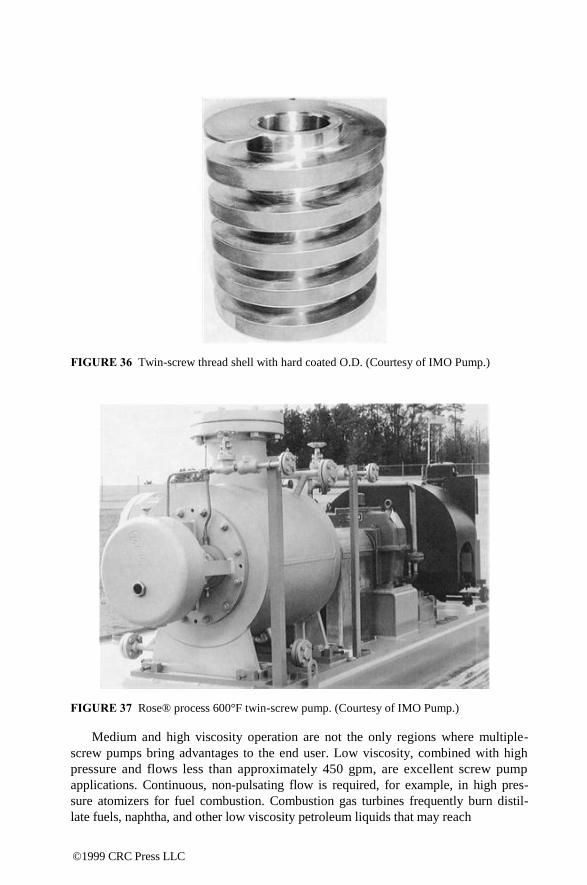
FIGURE 36 Twin-screw thread shell with hard coated O.D. (Courtesy of IMO Pump.)
FIGURE 37 Rose® process 600°F twin-screw pump. (Courtesy of IMO Pump.)
Medium and high viscosity operation are not the only regions where multiple-
screw pumps bring advantages to the end user. Low viscosity, combined with high
pressure and flows less than approximately 450 gpm, are excellent screw pump
applications. Continuous, non-pulsating flow is required, for example, in high pres-
sure atomizers for fuel combustion. Combustion gas turbines frequently burn distil-
late fuels, naphtha, and other low viscosity petroleum liquids that may reach
©1999 CRC Press LLC

1 centistoke or less and require pumping pressures in the 950 to 1300 psi range. The
combination of modest flow, low viscosity, and high pressure is a difficult service
for all but reciprocating pumps. The pressure and flow pulsation from reciprocating
pumps usually cannot be tolerated in fuel burning systems, especially combustion
gas turbines.
Ongoing research and development efforts will further extend the capabilities of
these machines allowing better performance over a broader range of applications.
Multiple-screw pumps are uniquely suited to many of the applications described
herein and offer long-term benefits to their users.
USER COMMENTS
The following comments on various types of pumps were made by the chemical
plant users interviewed:
Multiple-screw pumps are the most technically complex and expensive of all rotary
pumps. However, they have certain very important advantages. Applied to high pressures
(2000 psi range) and high temperatures (designs are known to 800°F range), they can operate
at a wide range of viscosities, from grease to rubber. Due to close clearance, these pumps have
high efficiencies. Timing gears may, or may not, be required, depending on the design (two-
vs. three-screw designs). Pinned rotors could be prone to failures but are a less expensive
option. With external bearings and timing gears, four seals are required, and field work, for
alterations and repair, is not trivial. Advantages of screw pumps are their quiet operation,
low pulsations, and good NPSHR (net positive static suction head required) characteristics.
©1999 CRC Press LLC
7
Progressing Cavity
(Single-Screw) Pumps The progressing cavity pump was invented as a supercharger for an airplane engine
by Dr. René Moineau, following World War I. Due to the multiphase and high suction
capability of the pump and its ability to convey large quantities of air, vapor, or gas
in a fluid (which may also contain solids), this pump is not usually used in the same
way or considered to be the same as other rotary positive displacement pumps. The
progressing cavity pump was designed as a combination of a rotary pump and a piston
pump. It represents an integration of the specific advantages of both types of pump
constructions, such as high pumping flow rates, high pressure capabilities, minimal
pulsation, valveless operation, and excellent pressure stability.11 While the objective
of this section is to introduce the pump user to the basic design principles, applications,
operation, and maintenance of progressing cavity pumps, the focus on the theoretical
will be limited and the emphasis will be on more practical, everyday issues. However,
to get started we must understand how the pump operates, which requires some theory.
(Additional information may be found in References 12 and 13).
PRINCIPLE OF OPERATION
The progressing cavity pump is a helical pump belonging to the rotary, positive
displacement pump family, as classified by the HI.2 The pump consists of an internal
thread stator with a double thread and an external thread rotor with a single thread.
The meshing of the two forms a series of cavities 180° apart, which progress along
the axis of the assembly as the rotor is rotated. As one cavity decreases in volume,
the opposing cavity increases at exactly the same rate. Therefore, the sum of the
two discharges is a constant volume. This results in pulsationless flow from the pump.
The cross section of the stator is two semicircles of diameter, ―D,‖ separated by
a rectangle with sides ―4e‖ and ―D‖ (see Figure 38). The cross section of the rotor
is a circle of diameter, ―D,‖ which is offset from the centerline by the eccentricity,
―e.‖ The pitch of thread of the stator is ―Ps,‖ and is twice the pitch of the rotor.
The dimensions of the cavity formed when the rotor and stator are meshed
together is equal to the void of the cross section, filled with fluid:
Afluid
= 4eDPs
. (40)
0-8493-????-?/97/$0.00+$.50 © 1997 by CRC Press LLC
©1999 CRC Press LLC
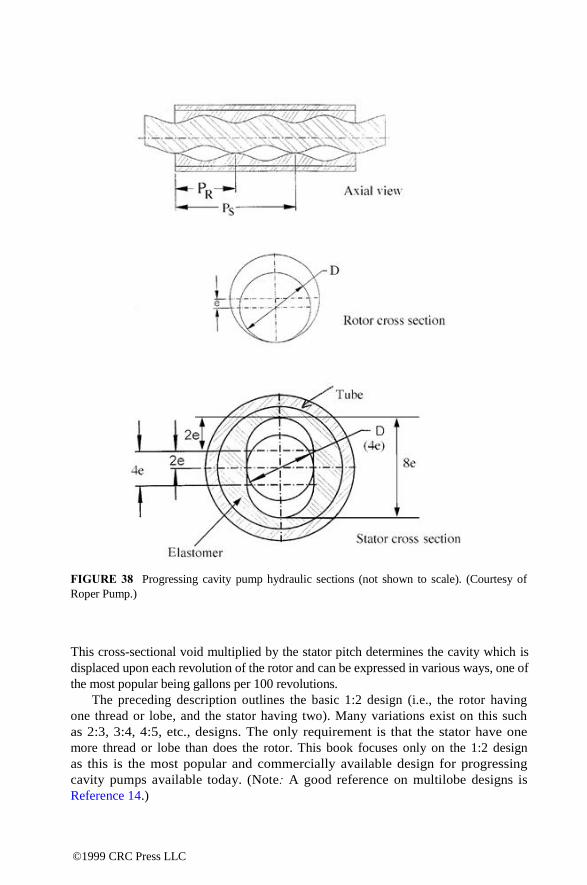
FIGURE 38 Progressing cavity pump hydraulic sections (not shown to scale). (Courtesy of
Roper Pump.)
This cross-sectional void multiplied by the stator pitch determines the cavity which is
displaced upon each revolution of the rotor and can be expressed in various ways, one of
the most popular being gallons per 100 revolutions.
The preceding description outlines the basic 1:2 design (i.e., the rotor having
one thread or lobe, and the stator having two). Many variations exist on this such
as 2:3, 3:4, 4:5, etc., designs. The only requirement is that the stator have one
more thread or lobe than does the rotor. This book focuses only on the 1:2 design
as this is the most popular and commercially available design for progressing
cavity pumps available today. (Note: A good reference on multilobe designs is
Reference 14.)
©1999 CRC Press LLC
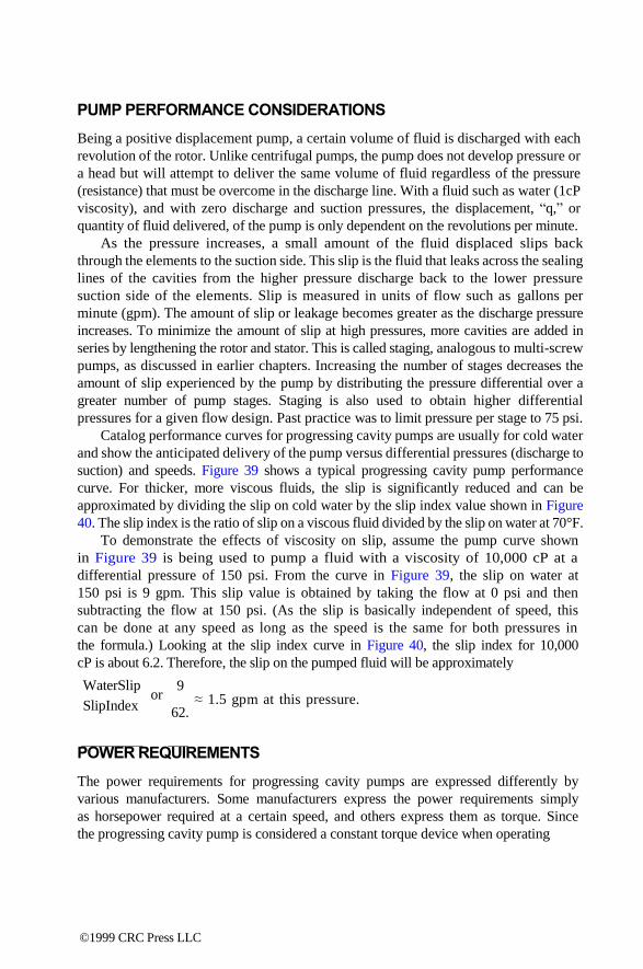
PUMP PERFORMANCE CONSIDERATIONS
Being a positive displacement pump, a certain volume of fluid is discharged with each
revolution of the rotor. Unlike centrifugal pumps, the pump does not develop pressure or
a head but will attempt to deliver the same volume of fluid regardless of the pressure
(resistance) that must be overcome in the discharge line. With a fluid such as water (1cP
viscosity), and with zero discharge and suction pressures, the displacement, ―q,‖ or
quantity of fluid delivered, of the pump is only dependent on the revolutions per minute.
As the pressure increases, a small amount of the fluid displaced slips back
through the elements to the suction side. This slip is the fluid that leaks across the sealing
lines of the cavities from the higher pressure discharge back to the lower pressure
suction side of the elements. Slip is measured in units of flow such as gallons per
minute (gpm). The amount of slip or leakage becomes greater as the discharge pressure
increases. To minimize the amount of slip at high pressures, more cavities are added in
series by lengthening the rotor and stator. This is called staging, analogous to multi-screw
pumps, as discussed in earlier chapters. Increasing the number of stages decreases the
amount of slip experienced by the pump by distributing the pressure differential over a
greater number of pump stages. Staging is also used to obtain higher differential
pressures for a given flow design. Past practice was to limit pressure per stage to 75 psi.
Catalog performance curves for progressing cavity pumps are usually for cold water
and show the anticipated delivery of the pump versus differential pressures (discharge to
suction) and speeds. Figure 39 shows a typical progressing cavity pump performance
curve. For thicker, more viscous fluids, the slip is significantly reduced and can be
approximated by dividing the slip on cold water by the slip index value shown in Figure
40. The slip index is the ratio of slip on a viscous fluid divided by the slip on water at 70°F.
To demonstrate the effects of viscosity on slip, assume the pump curve shown
in Figure 39 is being used to pump a fluid with a viscosity of 10,000 cP at a
differential pressure of 150 psi. From the curve in Figure 39, the slip on water at
150 psi is 9 gpm. This slip value is obtained by taking the flow at 0 psi and then
subtracting the flow at 150 psi. (As the slip is basically independent of speed, this
can be done at any speed as long as the speed is the same for both pressures in
the formula.) Looking at the slip index curve in Figure 40, the slip index for 10,000
cP is about 6.2. Therefore, the slip on the pumped fluid will be approximately
WaterSlip
SlipIndex or
9 ≈ 1.5 gpm at this pressure.
62.
POWER REQUIREMENTS
The power requirements for progressing cavity pumps are expressed differently by
various manufacturers. Some manufacturers express the power requirements simply
as horsepower required at a certain speed, and others express them as torque. Since
the progressing cavity pump is considered a constant torque device when operating
©1999 CRC Press LLC
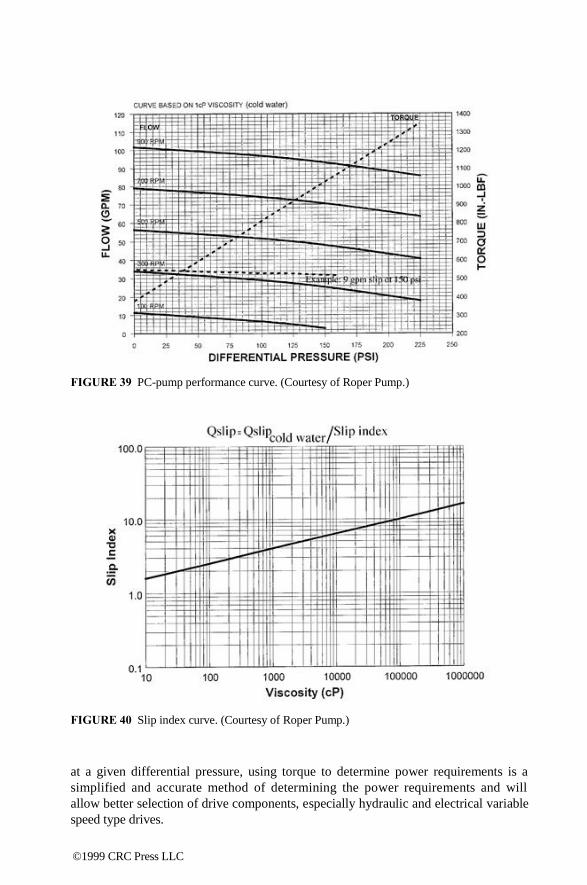
FIGURE 39 PC-pump performance curve. (Courtesy of Roper Pump.)
FIGURE 40 Slip index curve. (Courtesy of Roper Pump.)
at a given differential pressure, using torque to determine power requirements is a
simplified and accurate method of determining the power requirements and will
allow better selection of drive components, especially hydraulic and electrical variable
speed type drives.
©1999 CRC Press LLC

The stator is usually made from an elastomeric material, although designs with a
metallic (or rigid) stator for specialized applications are known. This elastomeric stator
allows the pump elements to have a compression fit and also offers a good abrasion
resistant surface for handling particles in suspension. This compression fit, however,
does cause a resistance to turning (torque) which is dependent on the element
geometry and is shown on the performance curve as the initial torque required at 0
psi. There is also a starting torque which must be overcome. As a rule of thumb, this
value is roughly four times the initial torque. Horsepower can be derived from the
torque value by the formula
Hp = TN , 63025
(47)
where T is torque in inch pounds, and N is pump speed in RPM.
Progressing cavity pumps are rarely applied on fluids with a viscosity of 1 cP,
and there is an added torque which is dependent on the viscosity of the fluid and
the geometry of the elements. On slurries, the added torque required is dependent
upon the particle size and concentration of solids. Most progressing cavity pump
manufacturers include power adder information for viscosity and slurries with their
standard technical literature. Typical power adder charts are reproduced below. These
charts will, of course, vary with individual pump size and model.
TABLE 1
Apparent Viscosity — Torque Additive (in × ebf) and Maximum Speed
cPs 100 1000 2500 5000 10,000 50,000 100,000 150,000 200,000
T-add 156 456 696 960 1335 2790 3840 4635 5325
RPM 900 900 900 600 320 80 40 30 25
TABLE 2
Water Base Slurry Torque Additive (in × ebf)
Size Fine Medium Coarse
% 0.01" to 0.04" 0.04" to 0.08" 0.08" & Larger*
10 175 219 325
30 526 657 976
50 877 1095 1627
*Note: Maximum particle size 0.6 inch
FLUID VELOCITY AND SHEAR RATE
With rotation of the rotor, fluid in the cavity moves in a spiral path along the
centerline of the pump. The velocity of the fluid will be dependent on the speed of
©1999 CRC Press LLC
rotation as well as the distance from the centerline. Internal velocity information is
available from manufacturers and is important for ensuring an adequate supply of fluid
to the elements. The subsequent section on inlet conditions will discuss this aspect a
bit more.
The shear rate of the pump can be determined from diameter, ―D,‖ eccentricity,
―e,‖ and the pitch of thread of the stator, ―Ps,‖ and is available from pump manu-
facturers for their particular models of pumps. Shear rate is defined as the difference
in velocity between two layers of fluid, divided by the distance between the layers
(measured in inverse seconds: s-1 or 1/s. This definition comes from the classical
relationship between shear stress and velocity gradient, with dynamic viscosity being
a proportionality constant.15 In general, progressing cavity pumps have a very low
shear rate. This is of particular importance when pumping shear sensitive fluids,
such as latex and some polymers, that decompose if sheared too much during
handling.
The shear rate of the pump can also be used to determine the apparent viscosity (the
shear stress divided by the shear rate, measured in units of viscosity) of a nonNewtonian
fluid inside the pump. This is useful in determining the power requirements of the pump,
as explained in the next section.
FLUID VISCOSITY
The dynamic viscosity (µ) of a fluid is the property of a fluid that resists flow; it is the
ratio of the shearing stress to the rate of shear. For fluids other than oil, the most common
unit of measure for absolute (dynamic) viscosity is centipoise (cP). Sometimes the fluid
viscosity is expressed in centistokes, which is the kinematic viscosity or the absolute
viscosity divided by the specific gravity. When a fluid‘s viscosity is constant as the rate
of shear is increased, it is said to be a Newtonian fluid. Most fluids that are handled by
the progressing cavity pump do not obey this law and are said to be non-Newtonian.
With a non-Newtonian fluid, the viscosity of the fluid changes as the rate of shear
changes.
Some fluids will show a decrease in viscosity (thixotropic) as the rate of shear
increases. The curves in Figure 41 show the viscosity in centipoise against the shear
rate in inverse seconds. Often, when initially determining the requirements for a
pump, the main emphasis is on operating point (i.e., where a pump would normally
operate). Unfortunately, little attention is paid to other points along the performance
curve, particularly the region of low flows, the assumption being that sizing of the
equipment (pump and a driver) at operating conditions would ensure start-up. This
may be a relatively safe approach for Newtonian and dilatent fluids, for which the
starting torque is lower than the operating torque, and the driver (electric motor)
would be able to start up the pump. For thixotropic fluids, however, such disregard
may cause problems, since the shear stresses are higher near the start-up condition
than at the operating regime. If the motor, in such a case, is sized for the operating
conditions, it would not be able to start up the pump, in order to overcome the fluid
resistance, having a higher viscosity at these conditions. Examples of thixotropic
fluids are: adhesives, fruit juice concentrates, glues, animal oils, asphalts, lacquers,
bentonite, lard, latex, cellulose compounds, waxes, syrups, fish oils, molasses, paints,
©1999 CRC Press LLC

7 6 5
4 3
2
9 8 7 6 5 4
3
2
0.1 ∂u
∂n
Dilatent
Newtonian
Thixotropic
1.0 10.0 100.0
, Shear Rate (Sec-1
) Dilatent
Newtonian
Range of thixotropic
τ = η ∂u
∂n
Shear Rate
Pump at Start-up Pump Operating Point
FIGURE 41 Starting torque may be a problem, if viscosity behavior is unknown.
tar, rayon, printing inks, varnishes, resins, vegetable oils, and shortenings. An estimation
of the apparent viscosity of the fluid can be made knowing several readings of the
viscosity at known shear rates. The torque or power requirement for the pump can then be
predicted at various speeds or shear rates.
Dilatent fluids are rather uncommon and are mostly high-concentrated slurries. A
dilatent fluid increases in viscosity as the shear rate is increased. Again, the power
requirements can be determined knowing the apparent viscosity.
There are certain fluids or materials which cannot be classified in the preceding
categories and can be handled very nicely with the progressing cavity pump. These
materials, such as filter cake, dewatered slurries or sludges, and paper stock are
semi-dry and will not readily flow into the normal suction opening of the pump nor
is it possible to obtain a viscosity measurement indicative of the thickness of the
material. These applications are best handled by a pump where the standard suction
housing is replaced with a flanged hopper and an auger is attached to the connecting
rod to assist movement of the material into the pumping elements.
Usually the viscosity of a fluid changes when there are changes in fluid
temperature. Lower temperatures usually increase a fluid‘s viscosity while higher
©1999 CRC Press LLC

temperatures reduce them. The temperature of the fluid must be considered in
determining the viscosity of any fluid.
INLET CONDITIONS
The key to obtaining good performance from a progressing cavity pump, as with all
other positive displacement pumps, lies in a complete understanding and control of
inlet conditions and the closely related parameters of speed and viscosity. To ensure
quiet and efficient operation, it is necessary to completely fill the cavities with fluid
as they open to the inlet. This becomes more difficult as viscosity, speed, or suction
lift increases. Essentially, it can be said that if the fluid can be properly introduced
into the pumping elements, the pump will perform satisfactorily. However, the
problem lies in getting the fluid in. A pump does not pull or lift liquid into itself.
Some external force must be present to initially push the fluid into the pumping
elements. Normally, atmospheric pressure is the only force present, although there
are some applications where a positive inlet pressure is available.
Naturally, the more viscous the fluid, the greater the resistance to flow, and, the
slower the rate of filling the moving cavities in the inlet. Conversely, low viscosity
fluids will flow quite rapidly and will quickly fill the cavities. It is obvious that if
the cavities are moving too fast, the filling will be incomplete and a reduction in
output will result. The rate of fluid flow into the cavities should always be greater
than the rate of cavity travel, in order to obtain complete filling. Most progressing
cavity pump manufacturers provide recommended maximum speeds for their pumps
when handling viscous fluids that minimize the effects of incomplete filling.
The net positive suction head (NPSH) calculations are routinely used in centrifugal
or high velocity pump applications. In many positive displacement pump
applications where the pump velocities are usually low, the calculation of NPSH has
little significance. There are applications, however, where this calculation
becomes very important. These are suction lift, vacuum pot applications, and
applications where the fluid vapor pressure is high.
The net positive suction head available (NPSHA) is the head available at the
inlet of the pump and is the atmospheric pressure available minus the fluid vapor
pressure, the lift, and suction line losses. The net positive static suction head required
(NPSHR) is a function of the pump design and pump speed. The NPSHR for a
specific pump is available from the pump manufacturer, usually included with
standard performance information. Note, that in contrast to centrifugal pumps, the
NPSHA definition for positive displacement pumps does not include (i.e., it disre-
gards) a velocity head component, due typically to low velocities of PD pumps.
SUCTION LIFT
The following is an example that illustrates NPSH calculations.
A particular progressing cavity pump operating at 900 RPM is required to lift
70°F water 10 ft vertically through a 3 in line. The vapor pressure of the fluid is
.363 psia (.84 ft), and the suction line losses are .01 ft. The pump is physically
©1999 CRC Press LLC

located at or near sea level. The pump manufacturer‘s literature indicates the pump has
an NPSHR of 6.9 ft. The calculations are as follows:
Atmospheric pressure: 33.90 ft
Lift: -10.00 ft
Line losses: -.01 ft
Vapor pressure: -.84 ft
Total NPSHA: 23.05 ft
Total NPSHR: 6.90 ft
From this example, there will be 16.15 ft of NPSH margin over the required amount, and
this will be acceptable.
HIGH VAPOR PRESSURE FLUID
Another application where NPSH becomes important is when the fluid‘s vapor
pressure is high. Vapor pressure is a key property of fluids which must always be
recognized and considered. This is particularly true of volatile petroleum products
such as gasoline, which has a very high vapor pressure. The vapor pressure of a
fluid is the absolute pressure at which the fluid will change to vapor (boil) at a
given temperature. A common example is the vapor pressure of water at 212°F,
which is 14.7 psia. For petroleum products, the Reid vapor pressure (absolute) is
usually the only information available. This is vapor pressure as determined by
the ASTM D323 procedure. Vapor pressure tables for water can usually be found
in most hydraulic books.16 Vapor pressure estimates for other fluids can be made
if the boiling point is known (i.e., a fluid will boil at atmospheric conditions when
its vapor pressure reaches 14.7 psia). The absolute pressure must not be allowed
to drop below the vapor pressure of the fluid. This will prevent boiling which will
cause cavitation.
In the previous example, 70°F water with a vapor pressure of .363 psia was
used. If the temperature of the water was 190°F, the vapor pressure would be 9.34
psia or 21.6 ft, which would exceed the 16.15 ft margin between NPSHA and
NPSHR, and the fluid would vaporize or boil. The calculations would now be as
follows:
Atmospheric pressure: 33.90 ft
Lift: -10.00 ft
Line losses: -.01 ft
Vapor pressure: -21.60 ft
Total NPSHA: 2.29 ft
Total NPSHR: 6.90 ft
In this example, there is not enough NPSHA to operate the pump. To overcome this
situation, the amount of lift would have to be shortened or, possibly, a different sized
pump, operating at a reduced speed, could be used.
©1999 CRC Press LLC
VACUUM POT INSTALLATIONS
In a vacuum pot application, the fluid is in a vessel that is under a high or partial
vacuum. This will affect the NPSHA to the pump. The following information is
another example that illustrates NPSH calculations.
A particular progressing cavity pump is pumping water out of a vessel that is
under 20 in of mercury vacuum, which corresponds to 11.20 ft of absolute pressure.
There is 10 ft of 3 in horizontal line connecting the suction of the pump to the vessel,
and the water is 70°F. As in the suction lift example, the vapor pressure of the fluid
is .363 psia (.84 ft), and the suction line losses are .01 ft. From the pump manufac-
turer‘s literature, the pump NPSHR is 6.9 ft. The corresponding calculations are as
follows:
Vessel pressure: 11.20 ft
Lift: - 0.00 ft
Line losses: -.01 ft
Vapor pressure: -.84 ft
Total NPSHA: 10.35 ft
Total NPSHR: 6.90 ft
From this example, there will be 3.45 feet of head over the required amount, and this
would be acceptable.
On vacuum pot and suction lift applications, it is necessary to fill or partially
fill the suction housing and lines with fluid to provide a lubricant for the elements
during lift or until the pumping fluid reaches the elements. Since there are more
sealing points on the side that is normally considered the suction side of a progressing
cavity pump, better operation can be achieved if the pump is operated in reverse.
By doing so, the normal discharge port is used as the suction port. This would now
put the packing or seal17 under pressure from the discharge, and caution should be
used not to overpressure the suction housing. Progressing cavity pump manufacturers
can provide helpful information on operating their pumps in reverse and should
definitely be consulted if high discharge pressures are anticipated.
To allow pump manufacturers to offer the most economical selection and also
assure a quiet installation, accurate inlet conditions should be clearly stated. Spec-
ifying a higher suction lift than actually exists may result in the selection of a pump
at a lower speed than necessary. This means not only a larger and more expensive
pump, but also a costlier driver. If the suction lift is higher than stated, the outcome
could be a very noisy pump installation coupled with higher maintenance costs.
GUIDANCE FOR PROPER SELECTION
AND INSTALLATION ABRASION
The progressing cavity pump is one of the best pumps available for handling abrasive
slurries; however, there are some considerations in pump size that need to be made
©1999 CRC Press LLC

in order to achieve maximum performance. It is necessary to minimize the slip and
internal velocities to achieve good results. Most progressing cavity pump manufacturers
limit these items by publishing reduced maximum speeds and pressures for pumps
handling abrasive materials.
Determining the degree of abrasion is largely judgmental; however, the make-
up of the particles will offer some clues as to how it is to be classified. A closer
look at what causes abrasion may be helpful in determining its classification. The
components of abrasion are the particle, the carrier fluid, and the velocity.
Particles
Size — Wear increases with particle size.
Hardness — Wear increases rapidly with particle hardness when it exceeds
the rotor surface hardness.
Concentration — The higher the concentration, the more rapid the wear.
Density — Heavier particles will not pass through the pump as easily as
lighter ones.
Relating the material hardness to some common materials on a 1 to 15 scale, with 15
being the hardest, the following list can be used as a guide:
Talc slurry 1
Sodium sulfate 2
Drilling mud 3
Kaolin clay 4
Lime slurry 5
Toothpaste, potters‘ glaze 6
Gypsum 7
Fly ash 8
Fine sand slurry 9
Grout, plaster 10
Titanium dioxide 11
Ceramic slurry 12
Lapping compound 13
Emery dust slurry 14
Carborundum slurry 15
Carrier Fluids
Corrosivity — Surfaces attacked by corrosion will set up a corrosion-erosion
effect.
Viscosity — A high viscosity fluid will tend to keep particles in suspension
and not be as abrasive.
Velocity — Low fluid velocity, or pump speed, will minimize abrasive effects.
(For a heavy abrasive fluid, it is recommended to keep the average velocity
©1999 CRC Press LLC

in the elements between 3 to 5 ft/sec. A medium abrasive fluid should be
limited to 6 to 10 ft/sec, and a light abrasive should be limited to 10 to
15 ft/sec. These velocity limits are usually listed in catalogs as pump rpm
limits for various size pumps in conjunction with the abrasive nature of the
fluid.)
As mentioned earlier, determining the degree of abrasion is largely judgmental:
however, the examples below will provide a simple rule of thumb guide to abrasive
classification:
No Abrasives — Clear water, gasoline, fuel oil, lubricating oil.
Light Abrasives — Dirty water containing silt or small amounts of sand or
earth.
Medium Abrasives — Clay slurries, potters glazes, porcelain enamel, sludge. Heavy
Abrasives — Plaster, grout, emery dust, mill scale, lapping compounds,
roof gypsum.
As with the shear rate, the maximum particle size that can be handled by a
progressing cavity pump can be determined from the element design and is available from
pump manufacturers for their particular models of pumps. Depending on pump size, the
maximum particle size that can be successfully handled without pump damage ranges
up to about 2 in.
TEMPERATURE EFFECTS AND LIMITS
The fluid temperature will affect the pump performance in two different ways. First,
since the stator is an elastomeric material, the thermal expansion is roughly ten times
greater than that of the metal rotor which is usually steel or stainless steel. This will
cause a tighter fit for the elements, and higher starting and running torques. When
the temperature reaches a certain limit it is then advisable to use an undersized rotor
which compensates for the difference in size. Second, the life of the elastomer is
greatly affected by heat. Table 3 shows limits from one manufacturer for elastomers
which are being worked such as in a stator, and will differ from other published
information on elastomers used in a static state such as o-rings and gaskets. There-
fore, when a stator is being applied at less than its maximum pressure rating, the
operating limit can be exceeded slightly but cannot exceed the static rating.
MOUNTING AND VIBRATION
The progressing cavity pump is inherently an unbalanced machine due to the eccen-
tric rotation of the rotor. The vibration which occurs is dependent on the size of the
element, the offset, and the speed of rotation. For this reason, the speed of the pump
is limited with typical limiting speeds reaching 1200 RPM for small pumps
(.02 gal/rev and lower), decreasing to limits of 300 RPM for large pumps (3 gal/rev and
larger).
©1999 CRC Press LLC

TABLE 3
Stator Temperature Ratings
Temperature Rating (°F)
Material Stator Rating Maximum (Static) Rating
Nitrile 180 250
Natural rubber 185 225
EPDM 300 350
Fluoroelastomer 300 400
The magnitude of the induced vibration is of a low frequency and a relatively
high amplitude. This will not produce offensive noise; however, it should be a factor
in mounting. It is generally recommended that progressing cavity pumps be mounted
on structural steel baseplates securely lagged down to concrete foundations. These
baseplates should be provided with means to grout them into place on the foundation
for rigidity and dampening. In all cases, the manufacturer‘s instructions and recom-
mendations on mounting should be consulted to ensure an adequate installation.
THE DRIVE FRAME
The progressing cavity elements are normally adapted to a drive end which will provide
an acceptable life span when properly applied and maintained. As with ANSI centrifugal
pumps,18 the drive shaft is supported in a separate bearing housing (usually cast iron),
by antifriction bearings (either deep groove ball or tapered roller bearings). These bearings
are normally sealed from contamination by conventional lip type seals.19 The bearings
in a progressing cavity pump are almost always lubricated by grease. Due to the
relatively low speed of progressing cavity pump applications, this is quite acceptable.
Because of the rotor‘s eccentric motion, there must be some means of transferring the
torque from the concentric rotating shaft to the rotor. The usual means of achieving
this is by using a connecting rod and universal joints. This combination allows the rotor
to move freely through the eccentric circle and carries the torque and thrust created by
the differential pressure on the elements. Several types of universal joints are used, with
the two most popular being a simple pin and rod joint, and the other a more elaborate
crowned gear joint. Some manufacturers even offer a flexible shaft, eliminating the
universal joints entirely.
The pin and rod pumps are considered the more traditional type pumps (see
Figure 42). Pins are installed at both ends of the connecting rod to secure it to the
shaft and rotor. In operation, the connecting rod rocks on the pins from the eccentric
motion of the rotor. Rubber o-rings or some other seal (often proprietary) keeps
pumpage from the joint and retains lubricant. The pins and connecting rod are made
from heat-treated alloy steels to provide a long service life. When a stainless material
is required for corrosion resistance in the pumping application, the pins and rod
cannot usually be hardened. Most manufacturers can increase the drive frame size
©1999 CRC Press LLC

FIGURE 42 Typical pin joint pump. (Courtesy of Roper Pump.)
of pumps requiring these corrosion-resistant materials in order to provide an acceptable
service life. If differential pressures are relatively low (less than 75 psi), then this
increase in frame size may not be necessary.
Unfortunately, the rocking between the pin and rod is a wearing action that
eventually renders the pin unusable. To overcome this and prolong service life,
progressing cavity pump manufacturers also employ a crowned gear type joint which
has approximately five times the load carrying capacity of the conventional rod and
pins (see Figure 43). The gear joint is essentially a modified ball and socket joint,
with gear teeth on the ball mating with a similar tooth profile in the socket. These
joints are usually designed for the larger size pumps (≈0.1 gal/rev and larger) where
the initial expense is outweighed by the maintenance and replacement costs of the
rod and pin type.
PROGRESSING CAVITY PUMP APPLICATIONS
The number of applications for progressing cavity pumps are as many and as varied
as there are progressing cavity pumps manufactured. As mentioned earlier, progress-
ing cavity pumps have many applications in industrial processes, construction, waste-
water treatment, oil field service, pulp and paper processes, and food processing,
just to name a few. Flow rates available range from fractions of gal/min, to around
2000 gpm, with differential pressures reaching upward to 2000 psi.
As with every pump type, there are certain advantages and disadvantages
characteristic of the progressing cavity design. These should be recognized in selecting
the best pump for a particular application.20
Advantages:
• Wide range of flows and pressures.
• Wide range of liquids and viscosities.
©1999 CRC Press LLC
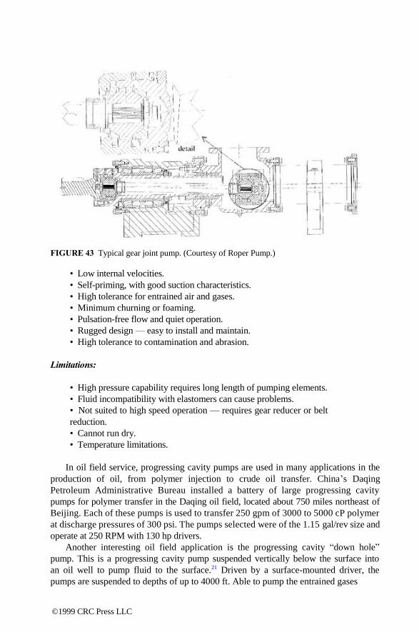
FIGURE 43 Typical gear joint pump. (Courtesy of Roper Pump.)
• Low internal velocities.
• Self-priming, with good suction characteristics.
• High tolerance for entrained air and gases.
• Minimum churning or foaming.
• Pulsation-free flow and quiet operation.
• Rugged design — easy to install and maintain.
• High tolerance to contamination and abrasion.
Limitations:
• High pressure capability requires long length of pumping elements.
• Fluid incompatibility with elastomers can cause problems.
• Not suited to high speed operation — requires gear reducer or belt
reduction.
• Cannot run dry.
• Temperature limitations.
In oil field service, progressing cavity pumps are used in many applications in the
production of oil, from polymer injection to crude oil transfer. China‘s Daqing
Petroleum Administrative Bureau installed a battery of large progressing cavity
pumps for polymer transfer in the Daqing oil field, located about 750 miles northeast of
Beijing. Each of these pumps is used to transfer 250 gpm of 3000 to 5000 cP polymer
at discharge pressures of 300 psi. The pumps selected were of the 1.15 gal/rev size and
operate at 250 RPM with 130 hp drivers.
Another interesting oil field application is the progressing cavity ―down hole‖
pump. This is a progressing cavity pump suspended vertically below the surface into
an oil well to pump fluid to the surface.21 Driven by a surface-mounted driver, the
pumps are suspended to depths of up to 4000 ft. Able to pump the entrained gases
©1999 CRC Press LLC
and sands, progressing cavity down hole pumps are an economical alternative to
conventional rod pumps in many wells with difficult-to-pump fluids. They are prov-
ing to be particularly well suited to the heavy crudes in the oil fields of Canada.
Progressing cavity pumps are also useful in mining operations worldwide. In
Australia, progressing cavity pumps are used in the gold mines for dewatering
service in the mines. Located about 700 ft underground, these pumps deliver 560 gpm
at a discharge pressure of 330 psi to keep the mines from flooding. The water contains
about 5% earth solids, with an average particle size of .040 in. The units selected for
this service were in the 1.75 gal/rev size and operate at 340 RPM, using 175 hp
drivers.
The construction industry is a large user of progressing cavity pumps. In Salt
Lake City, Utah, spackling (wall joint compound) with an apparent viscosity of
30,000 cP is pumped at 11/2 to 2 gpm against discharge pressures of 80 psi. The units
selected for this service were in the 0.02 gal/rev size and operate at 140 RPM using 3
hp drivers.
Another construction application involves grout injection. In Southern California,
portable units are made to inject grout under bridges to shore them up without closing
them to traffic. These pumps deliver 35 gpm against 250 to 350 psi discharge pressures.
The units selected for this application were in the .22 to .28 gal/rev size and operate
at 175 RPM, using 25 hp drivers. Many manufacturers of grout equipment use pro-
gressing cavity pumps; this represents a large segment of their usage.
Wastewater treatment is another area where progressing cavity pumps are widely
used. Their use ranges from scum and sludge handling to polymer injection. In one
Illinois correctional facility, units are installed in the 0.28 gal/rev size operating at 400
RPM, using 10 hp drivers. These units deliver 100 gpm against a discharge pressure
of 30 psi.
The pulp and paper industry uses a wide variety of progressing cavity pumps
in the making of paper. Coating kitchen applications is a prime example of this.
Both Ohio and Mississippi paper plants use progressing cavity pumps to pump paper
coatings in their coating of kitchens. The units are of the 1.15 gal/rev size and operate
at 235 RPM, using 75 hp drivers. These units deliver 200 gpm against a 170 psi
discharge pressure.
In food processing, many chicken processing plants use progressing cavity
pumps to pump chicken parts (heads, feet, eviscera, etc.) as waste. One Arkansas
plant uses several units sized for 0.44 gal/rev operating at 200 RPM, to deliver 80
gpm against a 100 psi discharge pressure. These units are driven by a 20 hp driver.
These pumps use a specially enlarged suction housing and auger feed to ensure that
the material reaches the pumping elements.
Progressing cavity pumps are not only limited to handling waste in food pro-
cessing plants. They are also manufactured in food grade designs to pump foods
and pharmaceuticals. Pumps used for these services offer quick disassembly for
cleaning and are made from food grade materials. Some manufacturers offer designs
to meet 3-A sanitary standards. Applications for these units range from pumping
toothpaste to maraschino cherries, the latter with less than a 1% damage rate.
©1999 CRC Press LLC
TROUBLESHOOTING
The progressing cavity pump is usually forgiving in most installations, but there are
times when troubles occur. Accurate identification of the problem is usually 99% of the
cure. The following guides will assist in identifying the problem and offer some
suggestions for rectifying the situation. The guides can assist in tracking down
potential troubles, and most of them are useful for all rotary positive displacement
pumps, not only progressing cavity pumps.
No Liquid Delivered:
• Pump rotating in wrong direction.
• Inlet lift too high; check this with gage at pump inlet.
• Clogged inlet line.
• Inlet pipe not submerged.
• Air leaks in inlet line.
• Faulty pressure relief device in system.
• Pump worn.
Rapid Wear:
• Excessive discharge pressure.
• Pump runs dry.
• Incompatibility of liquid and pump materials.
• Pipe strain on pump.
• Speed too high for abrasives present in liquid.
Excessive Noise:
• Starved pump.
• Air leaks in inlet line.
• Air or gases in liquid.
• Pump speed too high.
• Improper mounting; check alignment thoroughly.
Pump Takes Too Much Power:
• Speed too high.
• Liquid more viscous than previously anticipated.
• Operating pressure higher than specified; check this with gage at pump
discharge.
• Discharge line obstructed.
• Mechanical defect such as bent shaft.
• Packing too tight.
• Pipe strain on pump.
©1999 CRC Press LLC

• Incompatibility of liquid and pump material causing stator swell.
• Pressure relief device in system not operating properly.
Rotors:
Other than normal wear on a rotor, there is little that can cause a problem. Occasionally,
however, a problem will arise with the chrome plate lifting. This is usually caused by
corrosion of the base metal of the rotor. In these situations, a stainless steel rotor is
usually the solution. On fluids of pH 3 or less, the fluid will remove the chrome and a
non-plated rotor should be used.
Stators:
Three modes of stator failure are bond failure, chemical attack, and high heat:
• Bond Failure — In the stator manufacturing process, a special curing type
adhesive is applied to a grit blasted tube prior to injection of the elastomer.
The bond to the tube is stronger than the tensile strength of the elastomer
and is sufficient to hold the rubber in place during operation. On fluids with a
pH of 10 or greater, there exists the potential of chemical attack on the bond,
and it will eventually break loose from the inside of the tube. Very high heat
(as from an acetylene torch) or cryogenic temperatures will also break the
bond.
• Chemical Attack — The effect of chemical attack is usually a swelling
and softening of the elastomer. The pump operates well at first, and then
gradually increases in power requirements as swelling occurs, until the
elastomer fails. Analysis of this problem should be made immediately,
because after ―drying out,‖ the elastomer will return to its original state and
appear fine. When there is doubt about material compatibility, small test slugs
of elastomer can be immersed in the fluid to study the effects before the
pump is purchased. These test slugs are available from many progressing
cavity pump manufacturers.
• High Heat — The enemy of rubber is heat, and it will have a different
effect on different materials. Nitrile and fluoroelastomer will harden to a
hardness similar to steel and will have a glossy and crazed appearance.
EPDM and natural rubber will have a tendency to get gummy and have
a melted appearance. The source of excessive heat can come from several
sources. The fluid temperature can go over the allowable limit or the heat
can be internally generated. This internal heat can come from overrating
the pump, pumping against a closed discharge, or running dry. In the first
two cases, the stator usually will show signs of coming apart in chunks.
Progressing cavity pumps are widely used in handling many difficult-to-pump mate-
rials. In many cases, a progressing cavity pump is the only pump that can suitably
handle these materials. Properly understanding how this pump works and how to
specify the operating characteristics can help the user to assist progressing cavity
©1999 CRC Press LLC

pump manufacturers in selecting the most economical unit to solve many difficult
pumping problems. When properly selected, progressing cavity pumps are quiet in
operation and forgiving of many operational problems that arise in the system.
Initially an oddity, progressing cavity pumps now are gaining a foothold in the mainstream
of pumping applications.
USER COMMENTS
The following comments were made by pump users interviewed at chemical plants.
These pumps are excellent for abrasive services, as well as to pump suspended solids.
They can pump sewage, filter coat application, and other tough pumpages. Low shear
and low turbulence make them a good choice for the shear-sensitive fluids. Viscosity
ranges to extremes — to 5 million SSU. Bearings are mounted externally, outside of
pumpage, eliminating the dependence on lubricating properties of the pumpage.
Elastomer (liner) compatibility with pumped fluids is important, and dry running can
be catastrophic, and fast. Seal design, although better than for other rotary pumps,
is still space restrictive, and would benefit by the manufacturers‘ attention to this
issue. Volumetric efficiency is high, due to tight clearances and low slip. However,
friction between the rotor and stator can negate the benefit of tight slip, due to friction
losses, resulting in lower mechanical (overall) efficiency. These rubbing concerns
limit the RPM to around 300 to 500 RPM, or lower for abrasive applications, and
require a gear reducer or a VFD. These pumps require a considerable footprint area,
which could be an issue if space is limited. However, if installed at an open yard
area, this is not a problem.
©1999 CRC Press LLC

8
Metering Pumps (Note: Due to the specialized application of these pumps, and in an effort to be
complete, this chapter extends beyond just rotary types and into the area of other types
of positive displacement pumps, such as piston/plunger, diaphragm, peristaltic, etc.)
DEFINITION
The metering pump is a controlled volume, positive displacement pump, which will
accurately transfer a predetermined volume of fluid (liquid, gas, or slurry) at a
specified amount or rate into a process or system. Metering pumps are capable of both
continuous flow metering and dispensing.
FEATURES • Positive displacement imparts energy to the liquid in a pulsating fashion
rather than continuously.
• Flow rates are predetermined accurately and are repeatable within ± 1%
(within the specified range and turn-down ratio).
• Adjustable volume control is typically inherent in the design.
• Traditionally they were reciprocating (back & forth action) designs,
although rotary configurations (gear and peristaltic) are increasingly
applied to metering applications.
• Ideally, a metering pump should be capable of handling a wide range of
liquids, including those that are toxic, corrosive, dangerous, volatile, and
abrasive.
• Should be capable of generating sufficient pressure to permit injection of
liquids into processes.
WHERE ARE METERING PUMPS USED?
Metering pumps are utilized in virtually every segment of industry to inject, transfer,
dispense, or proportion fluids. The chemical process industries have by far the
greatest diversity of applications. However, in addition to a broad range of industrial
applications, metering pumps and dispensers are used extensively in laboratory,
analytical instrumentation, and automated medical diagnostic equipment: 0-8493-????-?/97/$0.00+$.50 © 1997 by CRC Press LLC
©1999 CRC Press LLC

• Industrial — Chemical, petroleum, electronics, water and wastewater treat-
ment, food processing, agriculture, metal finishing, aerospace, automotive,
mining
• Analytical Instrumentation — Chemical analyzers, environmental monitors
• Medical — Diagnostic systems, dialysis, disposable component assembly
TYPES OF METERING PUMPS
Although a wide variety of both pumping and non-pumping designs are used to meter
or proportion fluids, not all are considered metering pumps.22 Pump designs, such as
centrifugal, can be used to transfer fluids but would not be considered a metering
pump. Venturi tubes or proportioning valves are examples of non-pump metering
designs. Accuracy of these systems typically vary between 5 and 10%, which for certain
applications is acceptable. What these systems lack the accuracy and repeatability
inherent in positive displacement pump designs which transfer fluid in units of controlled
volume.
The following designs of pumps are generally accepted as metering pumps.
Although their designs differ, they are all positive displacement and are designed for
precision fluid transfer — repeatable accuracy.
• Packed Plunger — reciprocating plunger or piston moves fluid through
inlet and outlet check valves
• Diaphragm — uses a flexible diaphragm to move fluid through inlet and
outlet check valves
• Gear Pumps — use the spacing between gear sets to move fluid
• Peristaltic Tubing Pumps — use rollers to move fluid through flexible
tubing
• Rotating/Reciprocating: Valveless Pump — uses only one moving part, a
rotating reciprocating piston, both to move fluid and to accomplish valving
functions
COMPONENTS OF METERING PUMPS
THE POWER END OR DRIVE
The power end or drive is the source of power for the pump:
• Electric Motors — AC, DC, stepper motors; can be fixed or variable speed.
• Pneumatic — Pneumatic cylinder piston is controlled by valves or pneu-
matic rotary drive.
• Electromagnetic — Reciprocating linear motion is driven by solenoids.
• Mechanical — Pedestal pumps are driven by chains, belts, and gears.
©1999 CRC Press LLC
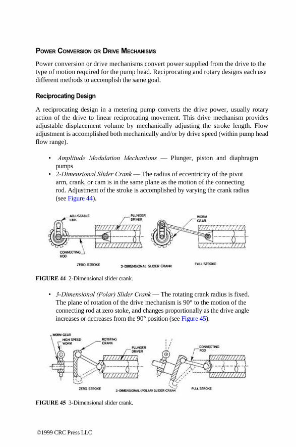
POWER CONVERSION OR DRIVE MECHANISMS
Power conversion or drive mechanisms convert power supplied from the drive to the
type of motion required for the pump head. Reciprocating and rotary designs each use
different methods to accomplish the same goal.
Reciprocating Design
A reciprocating design in a metering pump converts the drive power, usually rotary
action of the drive to linear reciprocating movement. This drive mechanism provides
adjustable displacement volume by mechanically adjusting the stroke length. Flow
adjustment is accomplished both mechanically and/or by drive speed (within pump head
flow range).
• Amplitude Modulation Mechanisms — Plunger, piston and diaphragm
pumps
• 2-Dimensional Slider Crank — The radius of eccentricity of the pivot
arm, crank, or cam is in the same plane as the motion of the connecting
rod. Adjustment of the stroke is accomplished by varying the crank radius
(see Figure 44).
FIGURE 44 2-Dimensional slider crank.
• 3-Dimensional (Polar) Slider Crank — The rotating crank radius is fixed.
The plane of rotation of the drive mechanism is 90° to the motion of the
connecting rod at zero stoke, and changes proportionally as the drive angle
increases or decreases from the 90° position (see Figure 45). FIGURE 45 3-Dimensional slider crank.
©1999 CRC Press LLC

• Lost Motion Drive Mechanisms — They are mechanisms which limit
stroke (see Figure 46).
• Mechanical (Eccentric Cam Drive) — Provides for changes in the flow
rate through variation of the plunger return position.
• Hydraulic Bypass — Permits a portion of hydraulic fluid to escape through
a bypass valve which returns this unused fluid to a reservoir within the
pump.
FIGURE 46 Lost motion drives.
Rotary Design
Direct, geared, or magnetically coupled, rotary drive mechanisms are used to couple gear
or peristaltic pump heads to drives. Flow adjustment is accomplished by changing the
pump head displacement components (gear set, tubing size), or through variable speed
drives.
• Flow Rate = Volume/Stroke × Stroke Rate — For pumps with adjustable
displacement, flow rate can be varied without varying drive speed (RPM).
For pumps which do not have adjustable volumes, flow is varied by
adjusting the drive speed. Gear and peristaltic pumps are examples of
pumps which vary flow directly by varying drive speed.
• Flow Range — Typically fixed for a specific size displacement element.
The displacement element could be a diaphragm, bellows, piston, gear
set, peristaltic tubing, etc.
• Turn-down Ratio — The ratio of the maximum flow to the minimum flow
value, where, at the minimum, accuracy is maintained.
PUMP MECHANISM (PUMP HEAD MODULE)
A pump mechanism is a transfer mechanism which is in contact with the fluid and gives
each specific pump technology its unique characteristic.
©1999 CRC Press LLC
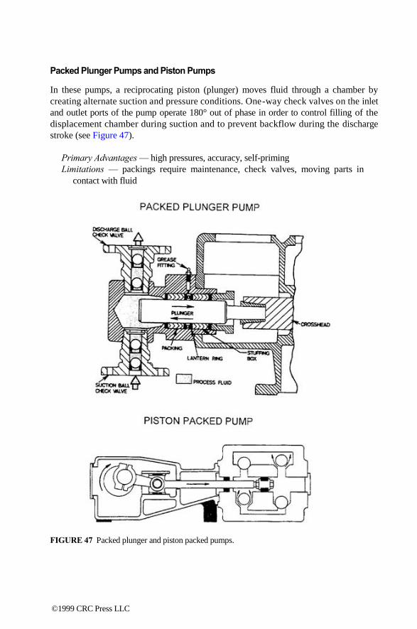
Packed Plunger Pumps and Piston Pumps
In these pumps, a reciprocating piston (plunger) moves fluid through a chamber by
creating alternate suction and pressure conditions. One-way check valves on the inlet
and outlet ports of the pump operate 180° out of phase in order to control filling of the
displacement chamber during suction and to prevent backflow during the discharge
stroke (see Figure 47).
Primary Advantages — high pressures, accuracy, self-priming
Limitations — packings require maintenance, check valves, moving parts in
contact with fluid
FIGURE 47 Packed plunger and piston packed pumps.
©1999 CRC Press LLC

Diaphragm Pumps
In these pumps, a flexible disc, tube, or bellows is actuated by a connecting rod,
eccentric cam, or a hydraulically coupled plunger. The fluid chamber is designed so that
the diaphragm is one of the fluid containment components. As it reciprocates, the
diaphragm changes the volume of the fluid chamber. This in turn creates alternate suction
and pressures conditions in the chamber, which with the aid of check valves, draws fluid
into the inlet port during suction, and moves fluid out of the discharge port when the
pressure increases.
• Mechanical Diaphragm — The power side of the pump is identical to
piston and plunger pumps. However, in place of a piston rod or plunger,
the mechanical diaphragm pump uses a connecting rod fastened to the
center of the diaphragm. The configuration of the diaphragm can take on
many forms, but the most popular designs are the flat disc, the convoluted
disc, and the bellows.
• Hydraulic Diaphragm Pump — Hydraulically balanced, it is a hybrid of
the piston and mechanical diaphragm pumps described previously. The
power (or drive) end, as well as capacity control, are the same. It is also
similar to the plunger pump in that a plunger or piston reciprocates within
a precision cylinder (also referred to as a chamber or liner). It is similar
to the mechanical diaphragm in that a diaphragm contacts the process
fluid rather than the plunger. At a set stoke length, the plunger displaces
a precise volume of hydraulic oil, which in turn exerts pressure on a
diaphragm. The hydraulic oil moves the diaphragm forward and backward,
causing a displacement that expels the process fluid through the discharge
check valve and, on the suction stroke, takes in an equal amount through
the suction check valve.
• Double Disc Diaphragm — Redundant diaphragms eliminate the need
for contour plates.
• Tubular Diaphragms or Bellows — Uses a tube-shaped diaphragm.
Primary Advantages — discharge pressure: to 250 psig (mechanical design)
and up to 4000 psi (hydraulic version); chemically inert wetted parts;
adjustable stroke and RPM
Limitations — presence of check valves (balls, springs, o-rings); diaphragms
require routine maintenance
The following are examples of diaphragm pumps:
Gear Pumps for Metering Applications
In gear pumps, one of the gears is turned by a power source and drives the other
gear(s). The spaces between the gear teeth carry the fluid from the inlet to the outlet
ports. The gear mesh point prevents the fluid from returning to the inlet side.
Typically, the drive is magnetically coupled to the gear mechanism (see Figure 48).
©1999 CRC Press LLC

FIGURE 48 Gear pumps for metering applications.
(a) cavity style pump head
(b) pressure-loaded pump head.
Primary Advantages — pulseless flow; magnetically coupled drive eliminates
seals; differential pressure: 100 psi; system pressure: 300 psi (typical)
Limitations — liquids with particles and slurries cause gear problems; self-
priming only about 1 ft lift
The following are examples of gear pumps used for metering applications:
• Cavity-Style Pump Heads — They depend on the surrounding pressure
in the magnet cup cavity to hold the gears tightly together. Since it is
imperative that the gear tips mesh exactly, cavity style pump heads often
use helical gears composed of extremely low friction material, such as
Teflon, as a good alternative to stainless steels when galling is an issue, as
well as for moderate pressure applications.
• Pressure-Loaded Pump Heads — They increase volumetric efficiency and
use a suction shoe which works with the fluid pressure in the magnet cup
to seal the gears tightly together. As the discharge pressure on the suction
shoe increases, so does the efficiency of the pump. The pressure on the
outlet side of the pump should be greater than the pressure on the inlet side
in order to force the suction shoe and gears together.
Peristaltic Tubing Pumps
In a peristaltic tubing pump, the pump head consists of two parts: the rotor, which
contains three or more tubing rollers, and the housing. The tubing is placed in the
―tubing bed‖ between the rotor and housing. The rollers on the rotor move across
the tubing, squeezing it against the housing and pushing the fluid. The tubing behind
the rollers recovers its shape, creates a vacuum, and draws fluid in behind it. A
pocket of fluid is formed between the rollers. This volume is specific to the inside
©1999 CRC Press LLC
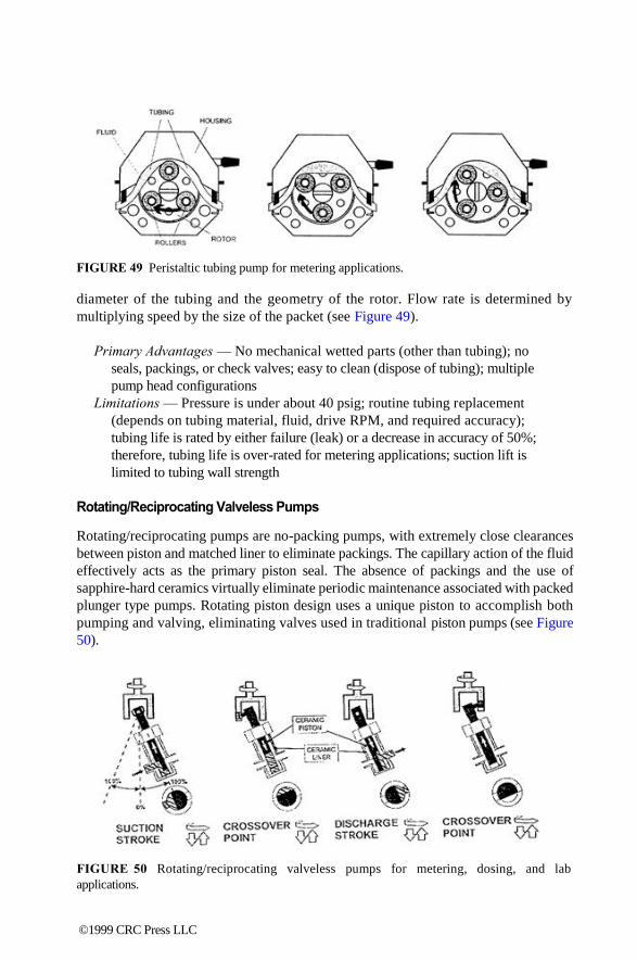
FIGURE 49 Peristaltic tubing pump for metering applications.
diameter of the tubing and the geometry of the rotor. Flow rate is determined by
multiplying speed by the size of the packet (see Figure 49).
Primary Advantages — No mechanical wetted parts (other than tubing); no
seals, packings, or check valves; easy to clean (dispose of tubing); multiple
pump head configurations
Limitations — Pressure is under about 40 psig; routine tubing replacement
(depends on tubing material, fluid, drive RPM, and required accuracy);
tubing life is rated by either failure (leak) or a decrease in accuracy of 50%;
therefore, tubing life is over-rated for metering applications; suction lift is
limited to tubing wall strength
Rotating/Reciprocating Valveless Pumps
Rotating/reciprocating pumps are no-packing pumps, with extremely close clearances
between piston and matched liner to eliminate packings. The capillary action of the fluid
effectively acts as the primary piston seal. The absence of packings and the use of
sapphire-hard ceramics virtually eliminate periodic maintenance associated with packed
plunger type pumps. Rotating piston design uses a unique piston to accomplish both
pumping and valving, eliminating valves used in traditional piston pumps (see Figure
50).
FIGURE 50 Rotating/reciprocating valveless pumps for metering, dosing, and lab
applications.
©1999 CRC Press LLC

The piston rotates and reciprocates. As the piston is pulled back and the piston
flat opens to the inlet port, suction is created, and fluid fills the pump chamber.
The inlet port is then sealed and cross-over occurs. As the inlet port is sealed
and the pump chamber is full, the outlet port opens up. Only one port is open at
any time, and at no time are both ports interconnected. The piston is forced down
and the piston flat opens to the outlet port. Discharge is created, and fluid is
pumped out. The position bottoms for maximum bubble clearing. When the outlet
port is sealed and the pump chamber is empty, the inlet port opens to start another
suction stroke.
Primary Advantages — no valves to clog, hang up, or service; no packings
or seals which require routine maintenance; one moving part; self-priming
to 15 ft lift; dimensionally stable ceramic internal parts
Limitations — the process fluid is the seal and lubricant; flush gland required
for air-sensitive fluids
METERING PUMPS SELECTION
Metering pumps are used in a very diverse range of applications. Specifications for
metering pump applications generally consider the following parameters:
Volume — Flow rate or volume per dispense.
Pressure — Operating pressure, system pressure, differential pressure (pressure
across the inlet and discharge ports).
Accuracy — Accuracy, precision (repeatability).
Temperature — Process temperature, ambient temperature, non-operating
temperature (component sterilization).
Plumbing — Connection size, material, fitting (Example: 1.5', 316 SS, san-
itary). Suction side tubing size is critical to preventing cavitation, which
may occur when the tubing size is too small to allow adequate flow of
fluid to enter the pump. Cavitation can cause problems including ham-
mering, flow variation, bubble formation and loss of prime, and eventually
pump damage.
Drive Power — AC, DC, pneumatic, stepper, mechanical.
Flow Control — Fixed, variable, reversing.
Control Source — Manual, electronic (Example: 4-20 mA loop), mechanical.
Special Requirements — Hazardous (X-Proof), sanitary (3A Approved),
sterile, outdoor.
The user also needs to specify and address the following: fluid characteristics,
chemical compatibility (with pump wetted parts or fluid path), viscosity, corro-
sive application (pH = ?), specific gravity, suspended solids (percent and particle
size), air sensitivity, crystallizing characteristics, shear sensitivity, size, and
price.
©1999 CRC Press LLC
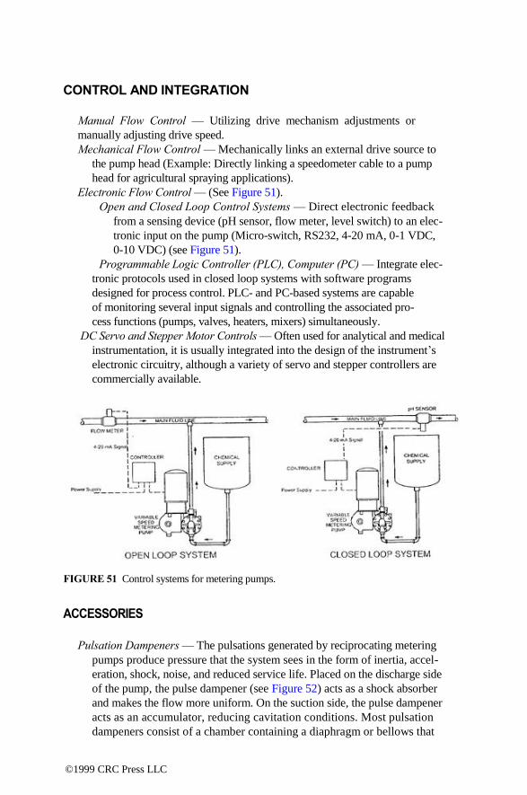
CONTROL AND INTEGRATION Manual Flow Control — Utilizing drive mechanism adjustments or
manually adjusting drive speed.
Mechanical Flow Control — Mechanically links an external drive source to
the pump head (Example: Directly linking a speedometer cable to a pump
head for agricultural spraying applications).
Electronic Flow Control — (See Figure 51).
Open and Closed Loop Control Systems — Direct electronic feedback
from a sensing device (pH sensor, flow meter, level switch) to an elec-
tronic input on the pump (Micro-switch, RS232, 4-20 mA, 0-1 VDC,
0-10 VDC) (see Figure 51).
Programmable Logic Controller (PLC), Computer (PC) — Integrate elec-
tronic protocols used in closed loop systems with software programs
designed for process control. PLC- and PC-based systems are capable
of monitoring several input signals and controlling the associated pro-
cess functions (pumps, valves, heaters, mixers) simultaneously.
DC Servo and Stepper Motor Controls — Often used for analytical and medical
instrumentation, it is usually integrated into the design of the instrument‘s
electronic circuitry, although a variety of servo and stepper controllers are
commercially available.
FIGURE 51 Control systems for metering pumps.
ACCESSORIES
Pulsation Dampeners — The pulsations generated by reciprocating metering
pumps produce pressure that the system sees in the form of inertia, accel-
eration, shock, noise, and reduced service life. Placed on the discharge side
of the pump, the pulse dampener (see Figure 52) acts as a shock absorber
and makes the flow more uniform. On the suction side, the pulse dampener
acts as an accumulator, reducing cavitation conditions. Most pulsation
dampeners consist of a chamber containing a diaphragm or bellows that
©1999 CRC Press LLC

separates the process fluid from pressurized gas. With each pulse, the gas will
compress and relieve a portion of the pressure generated. Devices as simple as
corrugated in-line tubing can also be used in many applications to reduce
pulsation.
Strainers and Filters — Remove solid particles from fluid stream that could
damage internal pump components that usually have very tight clearances.
Check Valves — Incorporated into most metering pump designs, additional
check valves are often added to increase pumping efficiency by preventing
backflow. They also help maintain pressure on the suction side of
pressureloaded gear pump heads.
Pressure Relief Valve — Since metering pumps are positive displacement
pumps, a pressure relief valve is often considered for the discharge piping
to relieve extreme pressure conditions, thereby protecting the process instru-
mentation, piping, and in most cases, the pump itself.
Flow Detection Device — Most pumps rely on the presence of fluid for both
cooling and lubrication. Flow detection devices are often installed to detect
a no-flow or dry condition on the suction side to protect the pump from
running dry. A provision must be made, usually in the form of a time delay,
to allow the pump to prime, or not to be falsely shut down by small volumes
of air.
Pump Head Heating Devices — Usually steam, hot water, or electric, these
devices heat the pump head, allowing viscous fluids to flow more easily.
Isolation Glands — Used to isolate air-sensitive process fluids from seals and
packings.
FIGURE 52 Pulsation dampener.
Other auxiliaries may include back pressure valve, pressure gauges, etc.
TYPICAL APPLICATIONS
Industrial:
Water and Wastewater Treatment — addition of sanitizing agents, pH
control and conditioning
©1999 CRC Press LLC

Chemical Process and Instrumentation — catalysts, additives, paints and pig-
ments, etc.
Agricultural Spraying, Chemigation, and Mosquito Control — metering pes-
ticides, herbicides, nutrients into fluid lines; grain storage preservatives
Metal Stamping, Finishing, and Casting — stamping lubricants, coatings,
foundry catalysts
Precision Cleaning — parts washing, laboratory glassware washers, car
washes
Battery Manufacturing — dispensing electrolytes, slurries, and stamping lubri-
cants for button cell batteries
Semiconductor Manufacturing — dispensing of photo chemicals, developing
and etching solutions, wafer cleaning, slurry metering
Food — addition of ingredients, colors, flavors, preservatives, and coatings
for candy
Tobacco Manufacturing — controlling moisture content and flavor (menthol)
addition
Pharmaceutical Manufacturing — laboratory, process chemistry, and packag-
ing (filling and dispensing)
Analytical Instrumentation:
Preparative Chromatography
On-Line Process Analyzers
Air and Water Sampling Analyzers — emissions from factories (stack gas)
Titration and Dissolution Apparatus
Spectrometers
Medical:
Diagnostic Equipment and Clinical Chemistry — automated in-vitro
diagnostics
Dialysis Equipment — precision re-circulation of dialysate
Contact Lens Manufacturing — soft lens filling fluid
Pharmaceutical and Biomedical Product Mfg. — manufacturing and packaging
Disposable Kits — adhesive dispensing for plastic medical components using
UV curable adhesives and solvent welding
©1999 CRC Press LLC
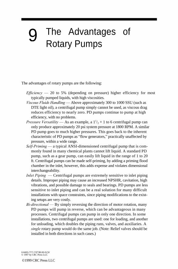
9
The Advantages of
Rotary Pumps The advantages of rotary pumps are the following:
Efficiency — 20 to 5% (depending on pressure) higher efficiency for most
typically pumped liquids, with high viscosities.
Viscous Fluids Handling — Above approximately 300 to 1000 SSU (such as
DTE light oil), a centrifugal pump simply cannot be used, as viscous drag
reduces efficiency to nearly zero. PD pumps continue to pump at high
efficiency, with no problems.
Pressure Versatility — As an example, a 11/2 × 1 to 6 centrifugal pump can
only produce approximately 20 psi system pressure at 1800 RPM. A similar
PD pump goes to much higher pressures. This goes back to the inherent
characteristic of PD pumps as ―flow generators,‖ practically unaffected by
pressure, within a wide range.
Self-Priming — a typical ANSI-dimensioned centrifugal pump that is com-
monly found in many chemical plants cannot lift liquid. A standard PD
pump, such as a gear pump, can easily lift liquid in the range of 1 to 20
ft. Centrifugal pumps can be made self-priming, by adding a priming flood
chamber in the inlet, however, this adds expense and violates dimensional
interchangeability.
Inlet Piping — Centrifugal pumps are extremely sensitive to inlet piping
details. Improper piping may cause an increased NPSHR, cavitation, high
vibrations, and possible damage to seals and bearings. PD pumps are less
sensitive to inlet piping and can be a real solution for many difficult
installations with space constraints, since piping modifications to the exist-
ing setups are very costly.
Bi-directional — By simply reversing the direction of motor rotation, many
PD pumps will pump in reverse, which can be advantageous in many
processes. Centrifugal pumps can pump in only one direction. In some
installations, two centrifugal pumps are used: one for loading, and another
for unloading, which doubles the piping runs, valves, and auxiliaries. A
single rotary pump would do the same job. (Note: Relief valves should be
installed in both directions in such cases.) 0-8493-????-?/97/$0.00+$.50 © 1997 by CRC Press LLC
©1999 CRC Press LLC

Flow Maintainability — PD pumps produce almost constant flow, regardless
of fluids‘ properties and conditions (viscosity, pressure, and temperature).
For centrifugal pumps, a change in fluid properties and external conditions
would result in a definite change in performance.
Metering Capability — PD pumps can be used as convenient and simple
metering devices. Centrifugal pumps have no such capabilities.
Inventory Reduction — Since PD pumps can pump a wide variety of fluids in
an extreme range of viscosities, the same pump parts inventory is required
for a wide range of applications throughout the plant. Centrifugal pumps
require a greater multitude of sizes for different applications, which results
in increased inventory of parts.
Nevertheless, centrifugal pumps also have numerous advantages and operate very well,
especially at very low viscosities (such as water, etc.) when applied properly, as will be
seen from the examples that follow.
©1999 CRC Press LLC

10
Case History #1 —
Double-Suction
Centrifugal Pump
Suction Problems The job of a centrifugal pump is to generate enough pressure to overcome system
hydraulic resistance. But it is the ―responsibility‖ of the liquid to get to the pump. If the
suction pressure is too low, the hydraulic losses can ―eat away‖ enough pressure so that it
could drop below the liquid vapor pressure. (A simplification of boiling mechanism
with reduced pressure is shown in Figure 53.) Such formation of vapor bubbles (cavities)
is called cavitation. If there is a lot of bubbles in the impeller inlet, the impeller may
become ―vapor locked,‖ and the pump will stop delivering flow. If cavitation is less
severe, a partial loss of flow will occur, accompanied by noise, pulsations, vibrations, and
pump failures.23
As bubbles progress through the impeller, they enter the area of increased
pressure. The bubbles then collapse with high intensity, as sort of micro-explosions.
Some of these bubbles collapse within and into the surrounding liquid, causing
micro-shocks (high frequency pulsations), and those that happen to be in close
proximity to impeller walls (blades, shrouds) will transfer their ―micro-hammer‖-
like impulses to the metal itself, eventually eroding it. These erosions can become
very substantial and can eat away big chunks of blades, especially in the inlet region
(Figure 54).24 This is another reason why this suction phenomenon is called ―cavi-
tation‖ (i.e., blades being cavitating away). The best way to fight cavitation is to
ensure that the suction pressure is adequate for the pump and for the particular liquid
it is pumping.25
Often, the suction pressure is expressed in feet of head above the vapor pressure
(also expressed in feet), with adjustment for losses (see Figure 55). Obviously, the
available NPSH (NPSHA) must be greater than that required by the pump (NPSHR):
NPSHA > NPSHR, or NPSHA = NPSHR + safety addition. (43)
The NPSHR is a characteristic of a pump and is determined by testing at the
manufacturer‘s test facilities. During the test, the suction pressure is lowered until
0-8493-????-?/97/$0.00+$.50 © 1997 by CRC Press LLC
©1999 CRC Press LLC

Boiling
Incipient A)
B)
Incipient
3%
HEAD,ft
NPSHR3% NPSHA
FIGURE 53 Concept of incipient cavitation, bubble formation and growth, to full boiling.
the pump flow begins to drop. The HI has defined the NPSHR as when the pump
head has decreased by 3%, from the stable condition. There is often controversy
about what stable condition is, as we shall see later.
There are two ways to drop suction pressure during testing: by evacuating the
suction tank or by throttling the suction valve in front of the pump. The throttling
is simpler, but the valve causes flow disturbances, propagating toward and into the
pump. These disturbances cause the pump head to drop sooner than it would in case
of a more uniform (unobstructed by the valve) flow (i.e., the tested NPSHR value
would be conservatively, or artificially, high). The vacuum method is more ―pure,‖
and produces more ―scientific‖ results, unobscured by the presence of the valve.
There are arguments, though, that the valving method is better because it represents
the reality of actual field installations that always have some obstructions in the inlet
and must be accounted for. So, an extra margin, obtained via a throttling test, may
actually be desirable from the conservative standpoint.
The NPSH tests are conducted at various flow rates, and results are cross-plotted
as head vs. NPSHA curves, as well as NPSHR vs. flow curves (see Figure 56).
©1999 CRC Press LLC

FIGURE 54 Cavitation damage of the impeller blades in the inlet region.24
FIGURE 55 Concept of NPSHA, with defining calculations.
©1999 CRC Press LLC
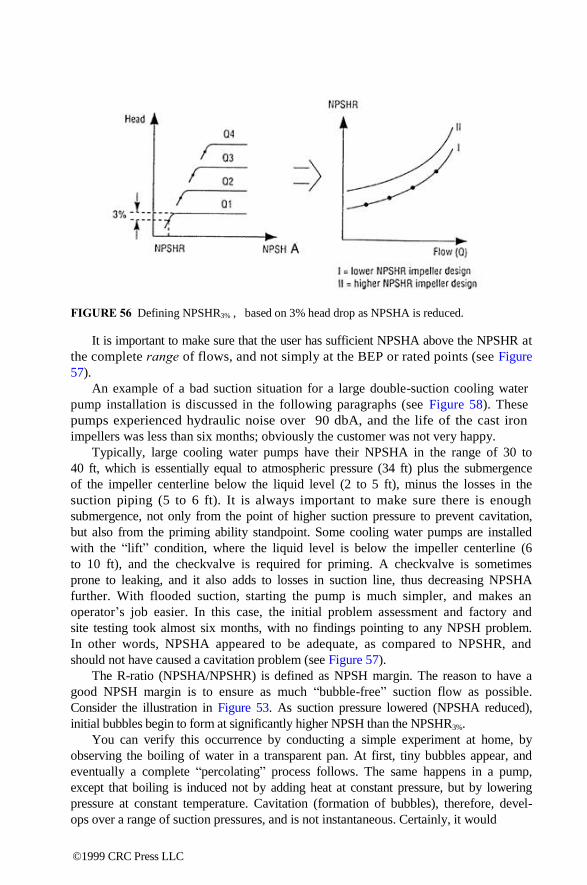
FIGURE 56 Defining NPSHR3% , based on 3% head drop as NPSHA is reduced.
It is important to make sure that the user has sufficient NPSHA above the NPSHR at
the complete range of flows, and not simply at the BEP or rated points (see Figure
57).
An example of a bad suction situation for a large double-suction cooling water
pump installation is discussed in the following paragraphs (see Figure 58). These
pumps experienced hydraulic noise over 90 dbA, and the life of the cast iron
impellers was less than six months; obviously the customer was not very happy.
Typically, large cooling water pumps have their NPSHA in the range of 30 to
40 ft, which is essentially equal to atmospheric pressure (34 ft) plus the submergence
of the impeller centerline below the liquid level (2 to 5 ft), minus the losses in the
suction piping (5 to 6 ft). It is always important to make sure there is enough
submergence, not only from the point of higher suction pressure to prevent cavitation,
but also from the priming ability standpoint. Some cooling water pumps are installed
with the ―lift‖ condition, where the liquid level is below the impeller centerline (6
to 10 ft), and the checkvalve is required for priming. A checkvalve is sometimes
prone to leaking, and it also adds to losses in suction line, thus decreasing NPSHA
further. With flooded suction, starting the pump is much simpler, and makes an
operator‘s job easier. In this case, the initial problem assessment and factory and
site testing took almost six months, with no findings pointing to any NPSH problem.
In other words, NPSHA appeared to be adequate, as compared to NPSHR, and
should not have caused a cavitation problem (see Figure 57).
The R-ratio (NPSHA/NPSHR) is defined as NPSH margin. The reason to have a
good NPSH margin is to ensure as much ―bubble-free‖ suction flow as possible.
Consider the illustration in Figure 53. As suction pressure lowered (NPSHA reduced),
initial bubbles begin to form at significantly higher NPSH than the NPSHR3%.
You can verify this occurrence by conducting a simple experiment at home, by
observing the boiling of water in a transparent pan. At first, tiny bubbles appear, and
eventually a complete ―percolating‖ process follows. The same happens in a pump,
except that boiling is induced not by adding heat at constant pressure, but by lowering
pressure at constant temperature. Cavitation (formation of bubbles), therefore, devel-
ops over a range of suction pressures, and is not instantaneous. Certainly, it would
©1999 CRC Press LLC

NPSHA > NPSHR NPSHA < NPSHR
35
NPSHA 30
25
NPSHR 20
15
Range of Operation
220
200
180
160 Ns = 2260
Nss = 10,050 140
120
100
0 2 4 6 8 10 12 14 16 18 20
Flow, gpm
FIGURE 57 Within the pump operating region, the NPSHA margin should not have caused
problems in this example. So, why are there problems?
be ‗nice‘ to have NPSHA > NPSHi (i = incipient, with no bubbles at all), but this is
impractical because the R-value would need to be in the range of R = 10 to 20, in order
to achieve nearly bubble-free flow. Besides, each foot of extra NPSHA would require
increased construction costs, since the cooling tower would need to be raised. These
economic considerations have led historically to typical R-values of 1.2 to 1.6 for
cooling water pumps.
It is known from the previous field and lab studies on cavitation that the maxi-
mum damage to the impeller occurs not at the NPSHR3%, as might be intuitively
expected, but at somewhere between that value and NPSH i.26,27 In the region of
incipient cavitation, bubbles are too small and too few, and most of them collapse
into the liquid which surrounds them. The hydro-acoustic noise in that region can
©1999 CRC Press LLC

FIGURE 58 Double-suction cooling tower water pumps installed at major chemical plants.28
be detected only with the use of specialized equipment. As pressure is reduced
further, more bubbles form, and noise, pulsations, and vibrations quickly begin to
rise. At some point, there are so many bubbles in the stream, and they are so large,
that some of them begin to cushion the collapsing impulses of others. The noise is
reduced, while the pump still continues to pump (see Figure 59). Further reduction
in pressure produces a great amount of bubbles to the extent that the suction passages
become vapor-locked, and choke the flow — the pump stops producing head and
flow, and it essentially is running dry. Lowering the pressure beyond this region
extends the cloud of bubbles from the impeller eye upstream into the suction pipe,
causing a very severe flow regime — intermittent chunks of liquid, followed by
vapor, then again by liquid slugs, and so on — a very unstable and violent process,
with high vibrations, noise, and damage to the equipment. The nature of this type
of noise is different: a more ―metallic‖ sound, rather than the ―pebble-like‖ sound
of ―classic‖ cavitation. You better get the pump out of this region fast!
As was explained earlier, the best way to avoid cavitation is to go as far as
possible into the region ―R‖ (to the ―right‖ of the maximum damage point on a
curve, see Figure 60), thereby into higher suction pressure range. For many small
process pumps, such as ANSI, API,29 etc., this is not too difficult to accomplish. For
example, a 1.5 × 1 - 8 ANSI pump running at 1800 RPM may require, say, 5 ft
NPSHR, and a 10-fold margin (Ri = NPSHi/NPSHR = 10), would mean 50 ft
©1999 CRC Press LLC

Mechanical (violent)
NPSH
3%
NPSH
Pulsations, noise, vibrations, damage curve
Inflection (rapid change of slope)
NPSH i NPSHA
(max. damage)
FIGURE 59 ―Damage curve,‖ as a function of NPSHA.
Region “L” Region “R”
Dmax
Rd =
NPSHmd
NPSHR
a = 3 to 5 (Nss depending)
NPSHR NPSHmd NPSHi
FIGURE 60 ―D-curve,‖ damage vs. NPSHA
(or approximately 20 psia ≈ 5 psig) suction pressure. This is easy to achieve for
small pressurized tanks. However, for large pumps, such as cooling tower water
pumps, there is no economic way to increase suction pressure, and some other
methods to fight cavitation are needed. Since it is not possible to move away from
the maximum damage zone into the ―R‖ region, perhaps a shift into the ―L‖ region
could help. There is little room to maneuver, however, in order to fine-tune the pump
in that region, since the ―L‖ region is rather small and its boundaries are not known
©1999 CRC Press LLC

a priori: going too far will get into a fully cavitating region with considerable loss of
flow, and not going far enough does not solve the damage problem significantly.
First, we need to pinpoint the ―L‖ region more accurately, and the shape of the
noise curve must be determined. The simplest way to accomplish this is with a handheld
sound meter, although measuring pulsations and/or vibrations would work as well.
Pulsation measurement is a somewhat specialized process, requiring transducers, power
supply, and processing equipment. Vibrations, on the other hand, are simpler, but may
not produce enough magnitude variation between the data points to pinpoint with
sufficient accuracy the slope of the changes of what is going on inside the pump. Sound
measurements are easy.
As can be seen from Figure 59, the shape of the noise curve has an inflection where
the slope changes to a more rapidly rising curve. This is known as an onset of
recirculation, as famous papers by Frazer30 and Karassik31 explain. The onset of
recirculation modifies the NPSHR characteristic. Suction recirculation is not desirable.
A mechanism of suction recirculation is shown in Figure 61.
Suction Recirculation Vortex
Recirculation
No Recirculation
Flow
FIGURE 61 Impeller eye recirculation increases NPSHR3%. More NPSHA is required to
compensate.
A significant effect on the recirculation can be made by changing the impeller eye
size — the larger the eye, the more prone is the impeller to recirculation (see Figure
62). However, if the eye is too small, the fluid velocity entering the impeller eye is
increased, and (back to Bernoulli) the higher velocity causes static pressure to decrease,
thus raising NPSHR.
©1999 CRC Press LLC

Volute
Large eye
Small eye
recirculation begins
Flow
FIGURE 62 Large eye allows less NPSHR (and, therefore, NPSHA), but pump operation is at
limited flow range. Small eye requires more NPSHR (NPSHA) at the BEP margin, but allows
operation at lower flow due to preventing (delaying) recirculation.
Let us now introduce the concept of suction specific speed (Nss):
Nss = RPM Q NPSHR0.75 .
(44)
Equation 44 is similar to Equation 34, except that the head is substituted by the
NPSHR at the BEP. Just as Ns characterizes the ―contour‖ of the impeller mostly
at the discharge region, the Nss characterizes its suction (eye) shape (see Figure 63).
Typically, the range of Nss varies from 7000 to 15,000, with special designs
(inducers) of even higher values. Through experience, mainly from the pump users‘
community (Amoco Oil, DuPont, and others), it has been found that over approximately
Nss = 9500, the rate of pump failures attributed to suction increases significantly (see
Figure 64). The HI has suggested even a more conservative design value, of Nss = 8500,
which limits the eye size.
It is true that if a given pump was never to operate outside its BEP point, a much
higher value of Nss could be used (and is even desirable), resulting in lower NPSHR
(see Figure 62), and therefore allowing lower NPSHA, thereby lowering construction
cost. There are some rare cases when such designs are made, such as in an existing
installation with inadequate NPSHA, where the low NPSHR impeller is the only
solution, provided that the range of flows is very narrow and stays around the BEP.
In most cases, however, centrifugal pumps operate in a wide range of flows, below
and past the BEP point, reflecting the variable plant need for cooling water. When
©1999 CRC Press LLC

Ns: 500 3000 10,000
• • • •
Ns = 2000
Nss: 8,000 10,000 15,000
• • • •
FIGURE 63 Specific speed (Ns) characterizes the overall impeller profile shape. Suction
specific speed (Nss) characterizes the eye size, for given specific speed (Ns). Nss
FIGURE 64 Industrial pump users‘ experience: number of failures tend to increase very rapidly
above Nss ≈ 9500.
operating at low flow, a recirculation becomes a reality, and the lower Nss designs
could become ―life savers,‖ as they are more forgiving in that regard. This is why
it is customary to limit the designs to Nss = 9000 to 10000. (Note: There is some
confusion in deciding which flow to use to calculate the value of Nss for double
suction pumps. In some papers, this flow is taken as half total pump flow, i.e., flow
per eye.) The HI, however, maintains a definition of Nss based on total pump flow.
©1999 CRC Press LLC
For this reason, when comparing Nss for different designs, make sure you know
which flow was used for the Nss definition).
QUIZ #5 — ARE NS AND NSS DEPENDENT ON SPEED?
Show that Ns defines the impeller contour only by hypothetically speeding up your
pump. Will Ns change? Why?
SOLUTION TO QUIZ #5
Ns = N
Q *
, N = KN ( K = speed increase multiple ) H 75
By Affinity,
so:
) KQ
( new )
Q*/Q = K, H*/H ~ K2,
K3 2NQ 12 N Q *
N* = (KN ( K2H )
75 = = = const. , N = Ns = const. 34 75 s
K32H H
To return to our case, since we could not find anything wrong mechanically, and the
NPSHA also appeared to be adequate, suction recirculation became suspect, and
two design modifications were made. First, a smaller eye impeller was
designed and tested in the field. As can be seen from Figure 65, the smaller eye
indeed suppressed the onset of recirculation toward lower flow, and the sound
curve has shifted to the left (toward lower flow), thus making the sound level
lower for most of the operating region.
As would be (unfortunately) expected, the pump now could not, however,
operate as far out to higher flows beyond the BEP because of NPSHR ―stonewalling‖ at
high flow, quickly exceeding the NPSHA in that region. Fortunately, the plant concern
was in the lower region, where this pump needed to operate, and coverage for higher
flows was not important. The solution, therefore, was considered an improvement.
Upon closer examination of Figure 65, the sound level appears to be reduced
even more than simply by the curve shift (toward the low flow) — as if by some
additional effect. The reason for this additional improvement in noise reduction is
that the eye size was not the only design change made for suction performance
improvements. The actual shape of the impeller blade inlet tips is also very critical
(Figure 66). Analogous with an airplane wing,32 a blunt and badly contoured blade
leading edge causes vertices, flow separation, turbulence, and loss of performance.
The shape of the impeller inlets is important. A proper contouring of the inlets can
improve suction characteristics and impeller life very significantly. Also, a proper
©1999 CRC Press LLC

(a)
(b)
(c)
Operating Flow Region
FIGURE 65 (a) Original large eye impeller
(b) Expected curve shift, with smaller eye
(c) Actual improvement, including combined effects of smaller eye, better
blade inlet profiling, and casing suction splitter modifications (contouring)
FIGURE 66 Impeller blade inlet profiling improves suction performance.
©1999 CRC Press LLC

FIGURE 67 Comparison between the old (left) and new (right) splitter design for better flow feed
into the impeller eye.
design of the suction splitter (see Figure 67) of the casing can further improve flow
uniformity and suction performance.
Therefore, the new design combined all three improvement features: smaller eye size,
a so-called ―P-blade‖ contour, and a casing suction splitter modification (better profiling).
Low flow separation was much deterred and improved, which explains additional noise
reduction benefits.
These, and similar troubleshooting techniques, can be applied to ―stubborn‖
cooling water pumps. In each such case, you need to examine the installation
carefully, gather data, and evaluate the design in terms of inlet conditions. A com-
bination of analysis, modifications, modeling, and testing may be required. Usually,
the choice of the recommended actions is wide, and it is important to pinpoint the
most effective and economical ways to solve each particular pumping problem.
©1999 CRC Press LLC

11
Case History #2 —
Lube Oil Gear Pump:
Noise and Wear
Reduction Next, we will examine the troubleshooting methods for the case of an external gear
pump operating at 415 RPM (3.55:1 gearbox reduction from 1470 RPM motor
speed), delivering 219 gpm of heavy oil (2500 SSU) in the blending plant. The pump
operation was reported to be noisy, and the customer contacted the pump supplier, after
a local environmental inspector reported his findings on noise levels as exceeding the
allowable limit and in need of correction.
First, the alignment of the endplate and faceplate to the casing was checked,
to ensure that the dowel pins‘ location was correct — otherwise, the bushings
―mis-position‖ would offset the shafts (with gears on them) onto the case, causing
rubbing and, therefore, noise and wear. Gear pumps are often made from cast iron,
which is known to have good self-lubricating properties due to high carbon content.
This ensures non-galling operation, even if gears, deflected by the pressure dif-
ferential, contact the casing. While not always causing catastrophic failures, this
could result in noise and premature wear. The inspection of the pump components
had shown that the parts were machined correctly and the dowels were positioned
properly, so that no mechanical contact between gears and the case should be
occurring (see Figure 68).
The design of a gear pump is typically such that the bearings‘ clearance is less
then the clearance between the gears and case. This is very important for stainless
steel pumps (especially 316ss material), particularly when pumping thin liquids, but
even in the case of iron construction, it is still a good design practice to follow the
rule of avoiding mechanical contact (which appeared to be true for this problem
pump case).
QUIZ #6 — DOUBLE GEAR PUMP LIFE IN
TEN MINUTES?
Can a worn-out gear pump life be doubled with no new parts and modifications? 0-8493-????-?/97/$0.00+$.50 © 1997 by CRC Press LLC
©1999 CRC Press LLC

CR
C B
CL
2CR = diametral clearance between the gear and case 2CL = total lateral clearance, gear/endplates 2CB = diametral clearance between the bushings and shaft journals
Backplate Case Faceplate
Discharge Relief Valve Adjusting Screw
Inlet
FIGURE 68 Gear pump for Case #2. (Courtesy of Roper Pump.)
SOLUTION TO QUIZ #6
If a gear pump casing is turned around, for example, as discharge and suction ports
are swapped, the worn-out part of the casing would now face the discharge end, and
the non-worn section would face toward the suction end. The wear of the casing is
caused by the differential pressure pushing (deflecting) the shafts, with gears, onto
the casing wall. The force moves the gears away from the discharge portion of the
casing, and toward the suction, where wear takes place. When the casing is turned
©1999 CRC Press LLC

around, the non-worn part of the casing will actually restore the radial clearance
between the gears and casing, thereby reducing the slip, and restoring the pump
flow. Certainly, this solution is not a permanent fix, for the casing and gears will
continue to wear, but it will prolong the operating life while a new pump is procured (see
Figure 69). The main problem, however, is that the pump is probably misapplied to begin
with: the differential pressure must be reduced, or a higher pressure rated pump design
should be installed.
FIGURE 69 Increasing life of the worn-out pump.
Continuing on with our problem. Because no obvious mechanical problems were
found, the hydraulics was suspected next, and cavitation was considered, as
explained below.
For rotary gear pumps, the measure of suction performance is minimum allowable
suction pressure. This is different from the centrifugal pumps, where NPSHR (and not
suction pressure itself) is used as a criterion. Similarly, with centrifugals, a certain
percentage drop in suction performance is used to establish p smin, except that instead
of the drop in head (as in centrifugals), a drop in flow is used. The HI defines a 5%
decrease in flow as a threshold at which minimum required suction pressure is defined
(see Figure 70).
For multicomponent liquids, which are indeed often pumped by the gear pumps
(i.e., complex oils), the shape of the curve may not have a well-pronounced drop,
but a more gradual, sloping decrease (―droop‖). The reason for this is a ―step-like‖
vaporization of the components (e.g., aromatics) as pressure is reduced. Data about
minimum required suction pressure is available from the manufacturers and should
be carefully considered when selecting a pump. This data is based not only on
cavitation aspects in a ―classic‖ sense (i.e., vaporization, or bubble formation), but
also should include considerations of the effect of a different nature — that is the
ability of the incoming liquid to fill the cavities between the gear teeth during the
time these cavities are exposed to the incoming liquid during the revolution of the
shaft, as was explained in the earlier section on gear pumps.
©1999 CRC Press LLC
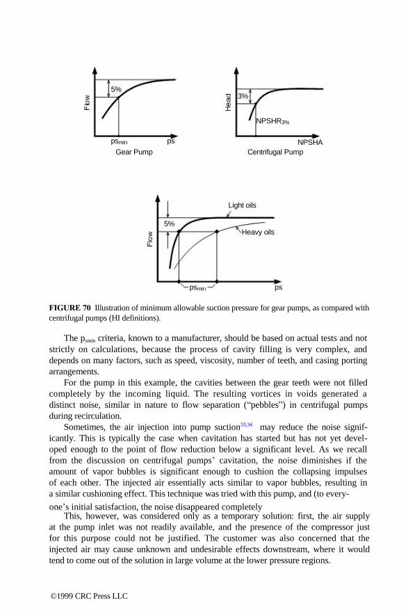
one‘s initial satisfaction, the noise disappeared completely
5% 3%
NPSHR3%
psmin ps NPSHA
Gear Pump Centrifugal Pump
Light oils
5% Heavy oils
psmin ps
FIGURE 70 Illustration of minimum allowable suction pressure for gear pumps, as compared with
centrifugal pumps (HI definitions).
The psmin criteria, known to a manufacturer, should be based on actual tests and not
strictly on calculations, because the process of cavity filling is very complex, and
depends on many factors, such as speed, viscosity, number of teeth, and casing porting
arrangements.
For the pump in this example, the cavities between the gear teeth were not filled
completely by the incoming liquid. The resulting vortices in voids generated a
distinct noise, similar in nature to flow separation (―pebbles‖) in centrifugal pumps
during recirculation.
Sometimes, the air injection into pump suction33,34 may reduce the noise signif-
icantly. This is typically the case when cavitation has started but has not yet devel-
oped enough to the point of flow reduction below a significant level. As we recall
from the discussion on centrifugal pumps‘ cavitation, the noise diminishes if the
amount of vapor bubbles is significant enough to cushion the collapsing impulses
of each other. The injected air essentially acts similar to vapor bubbles, resulting in
a similar cushioning effect. This technique was tried with this pump, and (to every-
This, however, was considered only as a temporary solution: first, the air supply
at the pump inlet was not readily available, and the presence of the compressor just
for this purpose could not be justified. The customer was also concerned that the
injected air may cause unknown and undesirable effects downstream, where it would
tend to come out of the solution in large volume at the lower pressure regions.
©1999 CRC Press LLC

Therefore, a method similar to the one discussed in the previous example with a
centrifugal pump was tried. To drop suction pressure sufficiently, to enter region
―L,‖ the suction valve was throttled. The noise was reduced substantially as shown
in Figure 71. When the valve is throttled even further, the noise would rise again,
and much more violently now with a distinct metallic ‖clanking,‖ as gears begin to
run essentially dry — this is similar to the example with the centrifugal pump in
the previous case. In other words, the valve position would have to be fine-tuned
very accurately during the operation, in order to stay away from the high noise level,
but not to the extent of choking off the suction completely. If the level in the supply
tank would change, the inlet pressure in front of the pump would force the pump
to operate either back at the high noise point of cavitation, or swing the other way,
dangerously close to vaporlocking condition. Manual readjustment of the valve
would thus be required each time the process variations resulting in the tank level
changed, which would be often and unpredictably. To automate valve position and
adjust tank level would be impractical and expensive. ps
Pump
10% 100% psuction
open (full open)
(or % suction valve open)
FIGURE 71 Inlet valve position alters pump suction pressure, changing noise level.
As is often the case, the problem was certainly a combination of a pump and a
system interaction — a different pump in the same system, or the same pump at a
different system, operated satisfactory with no problems. In fact, the puzzling thing was
the fact that the same design operated without problem in a multitude of other
installations around the world.
In general, when looking at ways to improve a pump design, by making it less
sensitive to suction conditions, a filling ability of the tooth cavity, as was explained
in the earlier section on centrifugal pumps, is one of the most obvious areas of
potential improvements. Many large gear pumps have small diametral pitch, i.e.,
few teeth for the pitch diameter. The number of teeth could be as little as six. If the
number of teeth is increased, the cavity between the teeth gets smaller (just as a
©1999 CRC Press LLC

tooth itself gets smaller), making it easier to fill the cavity during the limited time
of its exposure to suction port (see Figure 72). However, this has a significant impact
on the design: if the same casing is to be used (by maintaining the same distance
between gear centers, i.e., same pitch diameter), then the new pitch requires new
hobs (cutting tools used to machine the gears), thereby adding cost. Besides, smaller
pitch would produce smaller teeth, which would reduce pump capacity per each
revolution (refer to the example in Quiz #4). If the design change is impractical and
costly, a simpler way is to reduce the pump speed. The resident time of the cavity
exposed to the suction port would increase, although the net flow would decrease.
Sometimes the decrease in flow is acceptable (for example, in non-critical oil transfer
applications), and this solution could reduce the noise substantially. This is what
was done in this case; a gear reducer was retrofitted with a different set of trans -
mission gears, and the pump speed was reduced from 414 RPM (3.55:1) to 284
RPM (5.18:1). The noise reduction was indeed substantial, and the solution was
accepted by the plant.
FIGURE 72 Liquid must completely fill the space between the gear teeth to avoid cavitation.
Certainly, there are many situations where the reduction in flow would not be
acceptable due to the process flow requirements, but for simple transfer services
there is usually room to work. For cases where flow must be maintained (or even
increased), a larger pump, running more slowly, would be a better initial choice.
There are some other methods which can be considered, each of which must be
analyzed on its own merits for applicability in each particular case, where seemingly
insignificant nuances of the installation may turn out to be the Achilles heel that
makes or breaks the success of the troubleshooting job.
Before jumping to quick solutions, it is important first to understand all of the
variables and relevant factors, which can even possibly affect your pump and a
system. Next, you must identify and decide which variables are critical, and plan
the potential solutions to solve a problem, step by step. Often, if analysis and
planning are done upfront, considerable time and effort could be saved overall in
the long run.
©1999 CRC Press LLC

12
Case History #3 —
Progressing Cavity
Pump Failures As mentioned earlier, progressing cavity pumps (PC pumps) are known to operate
very well in many particularly tough environments where abrasion and wear make
other types of pumps impractical. In the case of this example, a medium-size PC
pump was installed at the wastewater plant in the last stage of the treatment process.
At that stage, all bacterial and other contamination impurities are already removed
by the upstream processes (chemical additives, settling tanks, etc.). Now, the pump-
age had to be transferred, as a final sludge of very high viscosity (500,000 cp), into
large containers for trucks, to be subsequently hauled as fertilizer to the farm fields.
The problem reported was that the pump would stop pumping in less then one
week. Rotors would wear badly, and increased leakage path would result, losing all of
the pumped flow in slip. It was first suspected that the initial fit between the rotor and a
stator was too tight, which, in the presence of a very dry viscous pumpage, would
cause high friction and wear.
The relationship between the rotor/stator clearance and slip is not linear (see
Figure 73). A good thing about the fit being tight is that there is practically no slip,
especially if the number of stages is large at the same time. PC pumps are typically
designed for approximately 75 psi per stage. A 300 psi application is typical for PC
pumps, although there are extremes in both directions, with pressures as high as 2000
psi. For 300 psi, a 4-5 stage design would keep slip to a minimum. A bad thing,
however, about a tight fit is high mechanical friction, resulting in high running, as well as
starting, torque.
If fit is reduced, but still tight, the pump flow would remain relatively constant,
and would not change much until the value of -0.015" diametral interference is
reached (‗-‘ indicates interferences, and ‗+‘ means clearance). Eventually, slip begins
to take place, and increases almost linearly with change in interference, until about
line-to-line fit is reached. After that, slip increases exponentially and very rapidly,
and at +0.015"/+0.020" most of the flow could be recirculating back to suction, (i.e.,
fully slipped). The volumetric efficiency follows the trend as explained previously.
(Note: the values are approximate and depend on other factors, some of which are
explained subsequently). 0-8493-????-?/97/$0.00+$.50 © 1997 by CRC Press LLC
©1999 CRC Press LLC
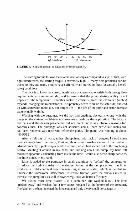
torque slip
-60 -40 -20 0 20 40 60 80
- interface + clearance
FIGURE 73 Slip and torque, as functions of rotor/stator fit.
The starting torque follows the reverse relationship as compared to slip. At first, with
tight interference, the starting torque is extremely high — many field problems can be
traced to this, and many motors have suffered when started in these (essentially locked
rotor) conditions.
The trick is to know the correct interference or clearance, to satisfy both throughflow
requirements with minimum slip, and to ensure that the pump starting ability is not
impacted. The temperature is another factor to consider, since the elastomer (rubber)
expands, changing the rotor/stator fit. It is probably better to err on the safe side, and end
up with somewhat more slip, but longer life — the life of the rotor and stator decrease
exponentially with fit.
Working with the customer, we did not find anything obviously wrong with the
pump or the system; no blatant mistakes were made in the application. The factory
test data and the design parameters did not point out at any obvious reasons for
concern either. The pumpage was not abrasive, and all hard particulate inclusions
had been removed way upstream before the pump. The pump was running at about
450 RPM.
After a full day of work, rather disappointed with lack of porgies, I stood some
distance away from the pump, thinking about other possible causes of the problem.
Absentmindedly, I picked up a handful of lime, which had seeped out of the bag laying
nearby. Mauling it around in my hand, and thinking about the pump, my hand felt
moisture apparently emanating from inside the lime. I could also sense sharp particles,
like little stones, in my hand.
Lime is added to the pumpage in small quantities to ―soften‖ the pumpage or
to reduce the high viscosity of the sludge. Added at the pump suction, the lime
produces a mild chemical reaction resulting in some water, which is helpful to
lubricate the stator/rotor interference, to reduce friction (with the obvious intent to
increase the pump life), as well as save energy cost via better efficiency.
We picked more lime, placed it in a container, and washed it out. The lime
―melted away‖ and washed, but a few stones remained at the bottom of the container.
The label on the bag indicated the lime contained only a very small percentage of
©1999 CRC Press LLC

Particle ejected
Stresses
Particle embedded
Flow
Rubber
Particle enters
FIGURE 74 Resistance to wear, due to rubber elastic energy to receive/eject particles.
impurities. Although the process sludge is not abrasive, the addition of the hard
particulates with lime changed what was entering the pump suction.
Generally, PC pumps work well on abrasive applications, provided that the
rotational speed is selected properly. When abrasives pass throughout the PC pump,
it is the unique characteristics of the elastomers, such as rubber, that save the day:
instead of fighting it, the rubber actually catches the particles, deflecting into itself,
like a trampoline. This deflection results in elastic energy, which is then released to
catapult (i.e., to eject) the particles out. Very little damage to the rubber results, but
it can be spotted upon the examination as many small, often microscopic, cuts (see
Figure 74).
When the clearance between the rotor and a stator is sufficient, there is enough
space for the particles to be released to; otherwise, some of them get ―jammed‖ just
when the catapulting action is about to release them. If this natural swing-like
mechanism of embedding-and-release is interrupted, or gets out of synchronism
(similar to a swing abruptly stopped), the elastic energy is lost, and the particle
remains embedded in the rubber. Depending on rotor/stator fit and particle size and
shape, enough particles may become embedded in the elastomer, creating a very
abrasive surface (see Figure 75). The wear that it causes is then obvious. Even if
this lime was purchased at a premium with lower residual limestone, it would not
take long to create the abrasive surface; perhaps one week failure rate could be
stretched to two, but no more. The only way to handle these particulates is to remove
them. Working together, we devised a simple cyclone separator, sort of a trap, to
keep the particles from jumping over the wall of the ―stopper‖ device we designed
for the suction line (see Figure 76). Periodically (we calculated once a day), a hatch
in the bottom of the trap would have to be opened and cleaned of particles — either
manually or automatically.
The solution may be good for this relatively small pump size, but would it work for
larger sizes? The inlet trap may or may not work for the larger sizes because the settling
velocity of the injected lime could be different (if too high, it would carry the particles
over the wall of the barrier), and again, some experimentation could be required. Often a
simpler and possibly better solution, from the beginning, would be to apply a larger pump
size, running at slower speed, perhaps 150 to 200 RPM. The slower speed would be more
forgiving to abrasives. The somewhat higher initial cost could have been paid up in
repairs, parts, and process downtime. The fit between the rotor and stator should also be
loosened.
©1999 CRC Press LLC
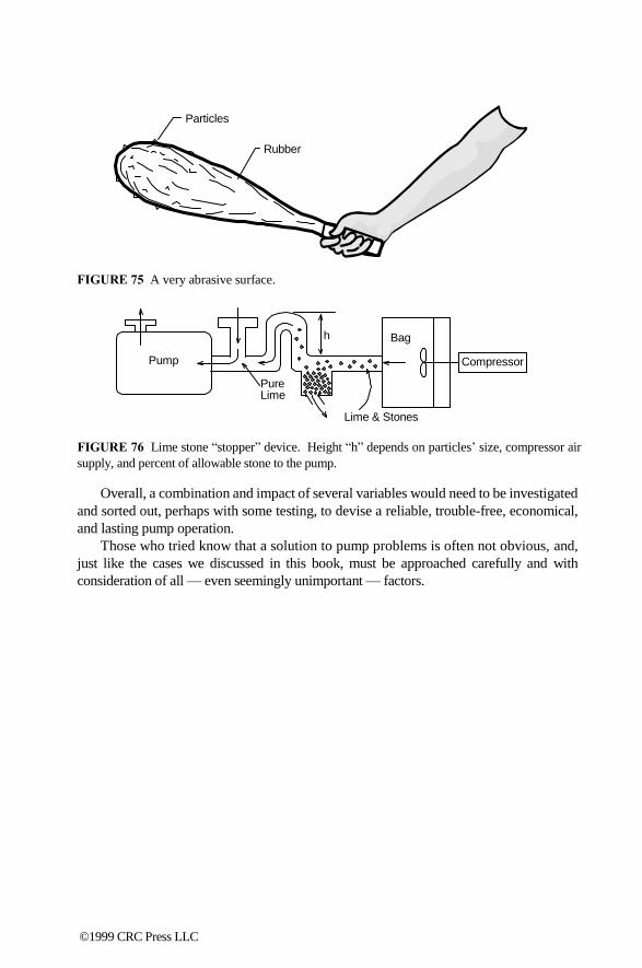
Particles
Rubber
FIGURE 75 A very abrasive surface.
h Bag
Pump Compressor
Pure Lime
Lime & Stones
FIGURE 76 Lime stone ―stopper‖ device. Height ―h‖ depends on particles‘ size, compressor air
supply, and percent of allowable stone to the pump.
Overall, a combination and impact of several variables would need to be investigated
and sorted out, perhaps with some testing, to devise a reliable, trouble-free, economical,
and lasting pump operation.
Those who tried know that a solution to pump problems is often not obvious, and,
just like the cases we discussed in this book, must be approached carefully and with
consideration of all — even seemingly unimportant — factors.
©1999 CRC Press LLC

13
Troubleshooting
“Pointers” as Given
by Interviewed Pump
Users and Plant
Personnel • Rule Number One: ―Always do the easy stuff first!‖
• Always check the rotation of the pump.
• Make sure relief valve setting is correct.
• Check speed for belt-driven, or vari-drive, cases. Do not take them for
granted.
• Check the integrity of the coupling.
• Alignment: How and who? Is piping forced to flanges?
• Trace the system and make sure the valves are open and that you are
pumping from the correct vessel.
• For heavy viscosities, make sure the pump is warmed up prior to starting.
• Check for high temperature on the bearing housing to detect excessive
thrust conditions. Bearings could tell you a good story.
• Inspect oil level in the bearing housing.
• Check for signs of discoloration.
• Inspect seals for leakage.
• Discuss changes in operating condition: New product introduction or
adjustment? Compare stories.
• Discuss changes in line-up or changes in operating performance.
• Only after the above questions are resolved, consider the removal of the
pump from service. 0-8493-????-?/97/$0.00+$.50 © 1997 by CRC Press LLC
©1999 CRC Press LLC

14
Application Criteria and
Specification Parameters The variety of pump types and sizes may be, and usually are, very confusing, and
it is difficult even for the experienced pump users to make a proper/optimal selection,
for his or her application. In many cases, a given plant simply follows the past
practice in specifying, purchasing, and repairing of the rotating equipment. The
requirements of various departments within the plant could also be conflicting at
times, adding to the complexity of the decisions on pump application strategy. For
example, low MTBF would require frequent repairs and a high maintenance budget,
but the initial pump cost could be low and, in that sense, attractive to the purchasing
group. A total cost would need to be evaluated, including cost of lost production
during outages, spare parts, etc.
Another example could be an ease of flow control: It is easy to change the
operating point of a centrifugal pump simply by throttling a discharge valve, and
this could be attractive from the operator‘s viewpoint, especially when fast change
in flow is critical to a process. However, flow control by valve throttling is
inefficient and also causes high radial thrust (seals‘ and bearings‘ life reduced) at
low flows or excessive NPSHR at high flows (cavitation damage and low impeller
life). For a small, low horsepower pump, this may not be a critical issue, and
operators‘ ease of control and flexibility would be a more important factor to
consider. For high energy pumps, such as cooling water units, boiler feed and
similarly, the savings in operating at or near the BEP vs. running the pumps off-
peak, could be substantial. The investment into variable frequency drives might
be a good option in such cases.
In reality, for the existing applications a change in a pump type, or even size,
is usually difficult to implement for the above reasons, unless the problem is very
pressing and serious. Technically, the change is usually not very difficult, but the
implementation logistics prevent such changes. A centrifugal pump may have a very
bad piping configuration at the suction side, causing cavitation, noise, and failures,
but the realities of the existing space constraints may be such that piping changes
are prohibitive, and the best approach well may be to just continue the existing
policy and try to minimize the downside as much as possible (i.e., have spare parts
0-8493-????-?/97/$0.00+$.50 © 1997 by CRC Press LLC
©1999 CRC Press LLC

(seals) on hand, conduct predictive maintenance to better pinpoint parts replacements
before catastrophic failures occur, etc.).
For the new applications, the options are much more open. If a new facility is
only at the design stage, this is the best time to investigate pumping options. The
limitation of having to fit a different pump type or size into the existing piping is
no longer a constraint in these cases, and does not require an additional investment
(piping modifications to the existing installations can be very expensive, especially
for larger pumps).
Referring to the HI pump chart (see Figure 1), the initial step is deciding on a
pump type: kinetic, or a positive displacement. Although there are exceptions, as a
general rule, kinetic pumps are used for higher flows and lower pressures (heads),
while positive displacement types are used for lower flows and higher pressures.
APPLICATION POINT #1: PUMP TYPE —
SPECIFIC SPEED CRITERION (NS)
Ns = RPM Q
H0.75
If Ns > 500, you are most likely in the area of centrifugal pumps.
If Ns < 500, a positive displacement pump is a likely candidate.
Keep in mind that a specific speed characterizes an individual impeller. For multi-
stage pumps, a specific speed must be based on the head per stage, i.e., total head
divided by the number of stages. For the initial selection, however, a particular pump
type is not yet determined so the total head must be used to point out a pump type,
in order to start off the selection process. As was mentioned earlier, there are
exceptions to the rule. Some kinetic pump types can generate very high head (such
as regenerative turbine pumps), and the specific speed criterion, as suggested above
would not hold true for them. For the majority of cases, however, this criterion
should give the user a reasonably reliable and quick method to determine the most
likely solution to his or her application selection. If the user is aware of a reliable
supplier of such special pumps, an additional inquiry may be worthwhile as it might
turn out to be the best solution after all, for a given application.
APPLICATION POINT #2 — WITHIN THE PUMP TYPE
Assuming the pump type is known, we need to begin to narrow down the pump
type more specifically. If a centrifugal pump is selected, the choice is the overhung
impeller, or between-bearings design. There is also a turbine type design, but the
other selections are more straightforward and are traditionally reflected in the appli-
cations: space limitations of power plants and the need to take suction from the pit
with relatively high flow of water, brine, or similar pumpage, agriculture, cooling
water, etc.
©1999 CRC Press LLC

Familiarity with the existing pump specifications is helpful, and a copy of these
specs should be at the plant engineering department. Examples of major specifica-
tions are ANSI, typically used for applications at the chemical plants, and API,
generally used for the refineries. Over the years, both ANSI and API specifications
have grown to rather comprehensive documents, which now cover single-stage
overhung centrifugal pumps (and more for API) and include dimensional require-
ments, sealing arrangements, materials of construction, etc. You can learn a lot about
pumps, just from studying these specs and understanding the reasons for their
particular requirements, and your training department may want to coordinate a short
seminar for the plant operators, maintenance, engineering, and purchasing personnel.
Such training is done either by internal experts or external consultants, and the time
spent on such training is well worth the effort.
If you are going to pump water, for a very general application, a centrifugal
pump is probably your best choice. It does not need to be an ANSI pump; you should base
your decision on cost and reputation of the pump supplier. You would not go wrong
with the ANSI pump, particularly if you envision changes in the future: dimensional
interchangability of the ANSI pumps is a plus, making it easy to fit an ANSI pump made
by any manufacturer into the same piping. The ANSI pump would cost a little more, but
has the benefits mentioned before.
APPLICATION POINT #3 — FLOW/PRESSURE
If a positive displacement pump type is considered, the reciprocating pump is the
best choice for very high pressures, approaching 10,000 psi or more. For lower
pressures, a rotary pump design could be selected. A ―Rotary Pumps Coverage‖
chart featured in Appendix B may serve as a good guide for flow-pressure ranges
of various rotary pumps. As you will see, such ranges reach 2000 to 3000 psi, above
which reciprocating pumps take over. Large screw pumps reach 8000 to 9000 gpm,
at lower pressures, but most of the rotary pumps are somewhere under 1000 to 1500
gpm or less.
APPLICATION POINT #4 — VISCOSITY
Centrifugal pumps are not recommended above approximately 500 SSU. The viscous
friction becomes high and the flow and pressure reduction is dramatic. For example,
above 1000 to 2000 SSU, there is practically no flow though the pump. The HI1 has a
chart for flow, head, and efficiency correction with viscosity. This is another good
reference material to keep in your engineering department.
On the other hand, rotary displacement pumps may not be your first choice at
very low viscosities. They are seldom applied under 300 to 500 SSU. (Reciprocating
pumps are the exception to this, due to their very tight clearances; they maintain
flow, with low slip, even at the water-like pumpages.) There are also some exceptions
to this rule. Gear pumps are sometimes made with pressure-loaded endplates to
minimize lateral clearance to the thickness of the liquid film. However, their radial
clearances (between gears and case) cannot be made too tight in order to avoid
©1999 CRC Press LLC
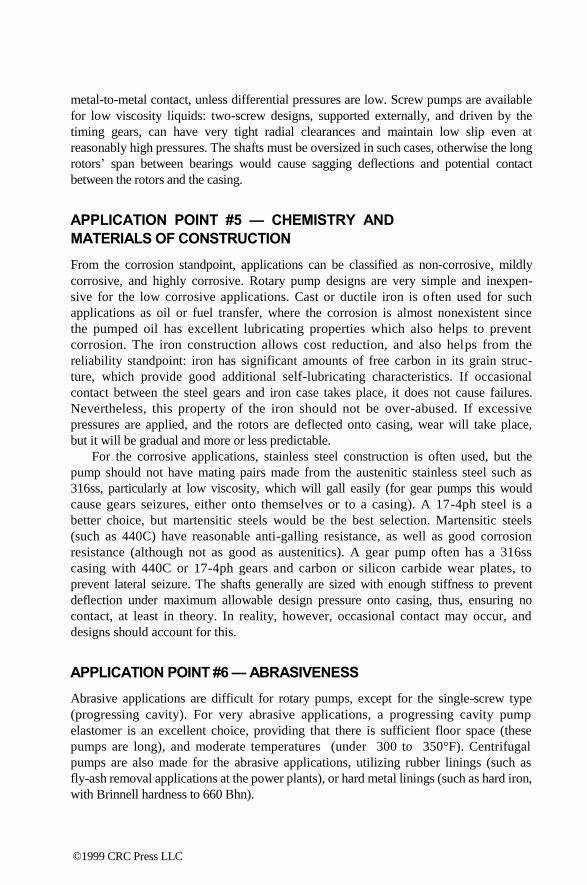
metal-to-metal contact, unless differential pressures are low. Screw pumps are available
for low viscosity liquids: two-screw designs, supported externally, and driven by the
timing gears, can have very tight radial clearances and maintain low slip even at
reasonably high pressures. The shafts must be oversized in such cases, otherwise the long
rotors‘ span between bearings would cause sagging deflections and potential contact
between the rotors and the casing.
APPLICATION POINT #5 — CHEMISTRY AND
MATERIALS OF CONSTRUCTION
From the corrosion standpoint, applications can be classified as non-corrosive, mildly
corrosive, and highly corrosive. Rotary pump designs are very simple and inexpen-
sive for the low corrosive applications. Cast or ductile iron is often used for such
applications as oil or fuel transfer, where the corrosion is almost nonexistent since
the pumped oil has excellent lubricating properties which also helps to prevent
corrosion. The iron construction allows cost reduction, and also helps from the
reliability standpoint: iron has significant amounts of free carbon in its grain struc-
ture, which provide good additional self-lubricating characteristics. If occasional
contact between the steel gears and iron case takes place, it does not cause failures.
Nevertheless, this property of the iron should not be over-abused. If excessive
pressures are applied, and the rotors are deflected onto casing, wear will take place,
but it will be gradual and more or less predictable.
For the corrosive applications, stainless steel construction is often used, but the
pump should not have mating pairs made from the austenitic stainless steel such as
316ss, particularly at low viscosity, which will gall easily (for gear pumps this would
cause gears seizures, either onto themselves or to a casing). A 17-4ph steel is a
better choice, but martensitic steels would be the best selection. Martensitic steels
(such as 440C) have reasonable anti-galling resistance, as well as good corrosion
resistance (although not as good as austenitics). A gear pump often has a 316ss
casing with 440C or 17-4ph gears and carbon or silicon carbide wear plates, to
prevent lateral seizure. The shafts generally are sized with enough stiffness to prevent
deflection under maximum allowable design pressure onto casing, thus, ensuring no
contact, at least in theory. In reality, however, occasional contact may occur, and
designs should account for this.
APPLICATION POINT #6 — ABRASIVENESS
Abrasive applications are difficult for rotary pumps, except for the single-screw type
(progressing cavity). For very abrasive applications, a progressing cavity pump
elastomer is an excellent choice, providing that there is sufficient floor space (these
pumps are long), and moderate temperatures (under 300 to 350°F). Centrifugal
pumps are also made for the abrasive applications, utilizing rubber linings (such as
fly-ash removal applications at the power plants), or hard metal linings (such as hard iron,
with Brinnell hardness to 660 Bhn).
©1999 CRC Press LLC
Abrasion is exponential with speed, so slower running pumps would last longer. As a
rule of thumb, for the abrasive applications, do not run rotary pumps much faster
than 300 to 400 RPM. These slower speeds would require a gear reducer between
the pump and a motor, unless a variable speed drive is used.
It may be useful to know the size of the abrasive particles — if the particles
are too small, they will rub through the clearances, where wear is usually most
detrimental. The large particles, however, would pass through the pump, and
cause wear of the impellers (or gears, rotors, etc.) and casing, but this wear
would be more predictable and not occur as quickly. In reality, however, there
are doubtful applications, where the particles are only a certain size — usually,
these large particles crush and break apart, and the pumpage carries along a
wide variety of particles of all sizes. The bottom line is, if there is abrasive
material present in the pumpage, it will probably do damage to the pump, sooner
or later. Slow speeds, rubber linings, and harder materials will delay this process,
to a tolerable degree.
APPLICATION POINT #7 — TEMPERATURE
Under approximately 150°F, the application can be considered normal; between 150 to
250°F, it is moderate; and above 300°F, it is hot. For hot applications, elastomers
are the determining factors, and appropriate selection charts are available. Use
these charts with care — they usually contain static ratings, for ―laboratory‖
conditions. Pump operating conditions are far more severe than laboratory
conditions, and the temperature rating should be derated somewhat, perhaps by 50 to
70°F.
For very hot applications, 700 to 800°F, you may consider API-coded centrif-
ugal pumps, or certain designs of the multiple-screw pumps. In any case, designs
would contain opened-up clearances, external cooling methods (jackets), as well
as requiring special start-up and shut-down procedures to ensure gradual warm-
up and non-stratified fluid distribution inside the pump, and to ensure no sudden
contact between the rotating and stationary parts, which could cause catastrophic
seizure and failure.
APPLICATION POINT #8 — SELF-PRIMING
Centrifugal pumps cannot ―lift‖ the fluid, unless special self-priming designs are
applied. Self-priming is not a forte of centrifugal pumps. Rotary pumps can prime very
well, but designs require special features, such as tight clearance with wear plates and
minimized cross-drilling, in order to avoid short-circuited air passage from discharge
back to suction, and other problems. As a rule of thumb, three tiers of lift capabilities can
be considered:
1 to 2 ft lift: Almost any rotary pump can provide this, as a standard, with no
special design accommodations.
©1999 CRC Press LLC
3 to 6 ft lift: Tighter clearance must be used, and the standard ―off-the-shelf‖
rotary pump will probably not work. The cost of such special designs could
be roughly twice the standard design.
6 to 15 ft lift: Very special approach to design, pressure loaded end-plates,
tight radial clearances, oversized rotors to minimize deflection, etc. These
pumps may cost 5 to 10 times more.
For lift values over 15 to 25 ft, the progressing cavity or diaphragm pumps should be
considered.
APPLICATION POINT #9 — DRIVER
Consider your power availability. For the electric motors, specify frequency, voltage,
and power. Ensure the driver is sized for a complete operating range: remember
from the previous chapters that the thixotrophic fluids may require more torque at
the lower shear rate (i.e., near the start-up). Usually the AC motors are specified —
they are more popular, reliable, and inexpensive. For very low powers, fractional
power motors which are often DC, are used. Consider how pump flow will be varied
(even if in the future): DC drives are easy to control, but the cost of the variable
frequency drives (VFD) for the AC motors has been dropping steadily, and their
reliability has increased dramatically. A VFD for pump under 5 hp could cost around
$500 to $700. Above 5 hp, a rule of thumb (as of 1998) is $150 per hp (i.e., a 50
hp VFD should be around $7000 to $8000, and would probably be half of that value
in three to four years).
APPLICATION POINT #10 — FOOD APPLICATIONS
For obvious reasons standards and specifications govern pumps applications in the
food industry. The Food and Drug Administration (FDA) specification does not detail
any particular requirements for pump types or design parameters; it covers only
allowable construction materials. Typically, these materials include stainless steel,
certain plastics, and certain grades of carbon. Another specification called 3-A is
produced by the U.S. Dairy Association. It covers many design issues specific to
pumps: self-cleaning capabilities, absence of internal crevices where bacteria may
spread, seals and seal chamber dimensions, etc. Lobe pumps are often used in these
applications — lobes do not contact (in theory), and they are driven by the external
timing gears. Absence of contact prevents any material shavings to pass on with the
pumpage, thus contaminating the product. Shafts are robust, as is the rest of the
pump, to ensure low deflections of rotors, resistance to piping loads, etc.
The above listed rules are general in nature, and each application has its nuances
and specifics. It may be prudent for the plant personnel responsible for selection
and specification of pumps to have a detailed checklist that would contain these and
other points for the pump manufacturer to address during the quotation period. Some
©1999 CRC Press LLC

specifications such as API and PIP (the latter a recent specification within the process
petrochemical industry — Process Industry Practices) already have similar checklists. It
is advisable to have the latest versions of these and other relevant documents at your local
facility.
©1999 CRC Press LLC
15
Closing Remarks
The interaction between the pump and a system is a complex phenomenon. All
factors, major and minor, must be addressed. The problem is that it is difficult to
know, at the beginning, which of these factors are major and which are minor. It is
always clear at the end what they are, but rarely at the beginning, when it is most
needed to save time. Training and understanding the basic principles of what makes the
pumps tick are prerequisites for successful troubleshooting. In the last several years,
heightened attention to the equipment reliability and increase in MTBF has revived
interest in better understanding and appreciation of pumping equipment. With a
multitude of pump types operating in vastly different applications, successful plant
operation is directly related to the attention given to the pumping equipment, which, as
we learned in this book, can be tricky and stubborn, and must be approached
systematically and diligently.
The author and publisher of this book hope the practical methods described here
will help practicing engineers, plant operators, and maintenance personnel solve
actual problems in their daily work. Understanding pump fundamentals should make
their troubleshooting efforts easier and more rewarding. As a teaching reference,
this book will be useful to college students in mechanical, chemical, and environ-
mental disciplines. We believe that, for a technical and technologically-oriented
environment, theory must continue to be tightly linked with practical and applied
needs, creating an important and useful foundation for the engineering profession.
In writing this book, I tried to pay close attention to the accuracy, simplicity, and
consistency of the material; however, it is difficult to avoid mistakes and controversy.
I would be very grateful for any comments, criticisms, corrections, or suggestions
that might aid in the creation or subsequent editions. Please send all remarks to me at
the following addresses:
Dr. Lev Nelik, P.E.
140 Bedford Drive
Athens, GA 30606
[email protected] 0-8493-????-?/97/$0.00+$.50 © 1997 by CRC Press LLC
©1999 CRC Press LLC

Appendix A:
Nomenclature p
pd
ps
∆p
Q
q
FHP
BHP
η
ηH
H
Hi
Ha
Hso
Hsys
hloss
VS
V 2
2 g
g
Zd
Zs
NPSH
NPSHA
NPSHR
NPSHR3%
NPSHi
= pressure (psi)
= pump discharge pressure (psi or psia)
= pump suction pressure (psig or psia)
= pump differential pressure (psi)
= pump flow (gpm)
= pump unit flow (gal/rev or gpr)
= fluid horsepower (hp)
= break horsepower (hp)
= total pump efficiency
= hydraulic efficiency
= pump head (general symbol)
= pump ideal head (ft)
= pump actual head (ft)
= pump head at shut-off (shut valve) (ft)
= system head (ft)
= hydraulic losses (ft)
= velocity in suction (Vs), and discharge (Vd) pipe (ft/sec)
= velocity head (ft)
= gravitation constant (32.2 ft/sec2)
= discharge side liquid level elevation above pump centerline (ft)
= suction side liquid level elevation above pump centerline (ft)
= net positive suction head (ft)
= available NPSH (ft)
= NPSH required by the pump (ft)
= NPSH when 3% head drop had occurred (ft)
= NPSH incipient, when first vapor bubbles begin to form (ft)
N Q Ns =
H.75
N specific speed
Q
Nss = NPSHR.75 suction specific speed
Ωs = universal specific speed OD = D2 impeller outside diameter, (in) αf = absolute flow angle (degrees)
βf = relative flow angle (degrees)
βb = blade angle in the relative (W) direction (degrees) Ax2 = impeller exit area in relative direction (in2)
©1999 CRC Press LLC

Am = impeller meridional area (in2)
Afluid = 4eDPs: fluid area for the progressing cavity pump cross section
Pr = PC pump rotor pitch (in)
Ps = PC pump stator pitch (in
e = PC pump eccentricity (in)
psmin = minimum required suction pressure for gear pumps (psia)
T = torque (in × lbs)
N = RPM = rotating speed
SSU = units Saybolt viscosity
cSt = viscosity in centistokes (approximately = SSU/5, for SSU >100)
ρ = fluid density (lbm/ft3)
γ = fluid specific weight (lbf/ft3)
γo = specific weight for water at room temperature (lbf/ft3)
SG = γ/γo specific gravity
y = shaft deflection (in)
L = bearing span (in)
V, Vm, Vθ, = components of the velocity triangles for the centrifugal impeller
W, Wθ, U
©1999 CRC Press LLC

A pendix B:
p Conversion Formulas This book emphasizes the fundamentals of different types of pumps, their similarities,
and their differences. The number of formulas is not overwhelming, and the few
formulas used are simple and straightforward. The user should have no difficulties
understanding the formulas and their derivations. The units used in the book are U.S.
system units. Listed below are a few formulas — covering major pump variables, such
as flow, pressure, and power — for converting U.S. system units of measure to metric
units:
Flow:
GPM
4403
= m3 HR ,
GPM GPM ( US ) = liters sec , = GPM ( Imp )
15.9 12
Pressure and Head:
psi
147.
Power:
=
psi psi atmospheres , = BARS, = MPa
14.5 145
HP × 0.746 = KW
Other conversion formulas, if required, may be found in most engineering books and
tables.16
0-8493-????-?/97/$0.00+$.50 © 1997 by CRC Press LLC
©1999 CRC Press LLC

A pendix C:
p Rotary Pump Coverage Guide 0-8493-????-?/97/$0.00+$.50 © 1997 by CRC Press LLC
©1999 CRC Press LLC