
P ARTS MANUAL - DLF DK
28
PARTS MANUAL MAN 4164188 Rev. B 01-2010 Original Language Instructions PUSH-TYPE SCARIFIER- POWER RAKE 744865D REN-O-THIN BRIGGS & STRATTON 744877A REN-O-THIN HONDA
-
Upload
khangminh22 -
Category
Documents
-
view
1 -
download
0
Transcript of P ARTS MANUAL - DLF DK

PA
RTS
MA
NU
AL
MA
N 4
1641
88R
ev. B
01-
2010
Orig
inal
Lan
guag
e In
stru
ctio
ns
PUSH-TYPE SCARIFIER- POWER RAKE
744865DREN-O-THIN BRIGGS & STRATTON
744877AREN-O-THIN HONDA

CALIFORNIAProposition 65 Warning
Diesel engine exhaust and some of its constituents are known to the State of California to cause cancer, birth defects and other reproductive harm.
Californie Proposition 65 Avertissement
Les échappements des moteurs diesel et certains de leurs composés sont recon-nus par l’Etat de Californie pour être cancérigènes, provoquer des défauts con-génitaux et d’autres dangers en matière de reproduction.
ADvErtENCIA
AvErtISSEMENt
WARNINGthe engine exhaust from this product contains chemicals known to the State of California to cause cancer, birth defects or other reproductive harm.
California Advertencia de la Proposicion 65
El estado de California hace saber que los gases de escape de los motores diesel y algunos de sus componen-tes producen cáncer, defectos de nacimiento y otros daños en el proceso de reproducción humana.
L’émission du moteur de ce matériel contient des produits chimiques que l’Etat de Californie considère être cancérigènes, provoquer des défauts congénitaux et d’autres dangers en matière de reproduction.
El estado de California hace saber que los gases de escape de este pro-ducto contienen productos quÍmicos que producen cáncer, defectos de nacimiento y otros daños en el proceso de reproducción humana.
CALIFORNIAProposition 65 Warning
Battery posts, terminals, wiring insulation, and related accessories contain lead and lead compounds, chemicals known to the State of California to cause cancer and birth defects or other reproductive harm. WASH HANDS AFTER HANDLING.

1
REN-O-THIN
01-2010
IMPORTANT MESSAGEthank you for purchasing this Schiller Grounds Care, Inc. product. You have purchased a world class product, one of the best designed and built anywhere.
this machine comes with an Operator's and a Parts manual containing safety, operation, parts, maintenance and service information. the useful life and good service you receive from this machine depends to a large extent on how well you read and understand this manual. treat your machine properly, lubricate and adjust it as instructed, and it will give you many years of reliable service.
Your safe use of this Schiller Grounds Care, Inc. product is one of our prime design objectives. Many safety features are built in, but we also rely on your good sense and care to achieve accident-free operation. For best protection, study the manual thoroughly. Learn the proper operation of all controls. Observe all safety precau-tions. Follow all instructions and warnings completely. Do not remove or defeat any safety features. Make sure those who operate this machine are as well informed and careful in its use as you are.
See a Schiller Grounds Care, Inc. dealer for any service or parts needed. Schiller Grounds Care, Inc. service ensures that you continue to receive the best results possible from Schiller Grounds Care, Inc. products. You can trust Schiller Grounds Care, Inc. replacement parts because they are manufactured with the same high precision and quality as the original parts.
Schiller Grounds Care, Inc. designs and builds its equipment to serve many years in a safe and productive man-ner. For longest life, use this machine only as directed in the manual, keep it in good repair and follow safety warnings and instructions. You'll always be glad you did.
Schiller Grounds Care, Inc.One Bob Cat Lane
Johnson Creek, WI 53038-0469
TABLE OF CONTENTS ................................................................................................ PAGESAFEtY ........................................................................................................................................................2, 3LABELS ............................................................................................................................................................4SEt-UP .........................................................................................................................................................5, 6ADJUStMENtS ...............................................................................................................................................7BELt / BLADE rEPLACEMENt ..................................................................................................................8, 9StOrAGE/SPECIFICAtIONS .......................................................................................................................10PArtS SECtION ........................................................................................................................................... 11CHASSIS GrOUP FIGUrE 1 .................................................................................................................... 12, 13ENGINE AND GUArD GrOUP FIGUrE 2 ................................................................................................ 14, 15FLAIL BLADE rEEL FIGUrE 3 ................................................................................................................. 16, 171/8" FIXED BLADE rEEL FIGUrE 4 ......................................................................................................... 18, 191/16" FIXED BLADE rEEL FIGUrE 5 ...................................................................................................... 20, 211/32" FIXED BLADE rEEL FIGUrE 6 ...................................................................................................... 22, 23HANDLE FIGUrE 7 ................................................................................................................................... 24, 25
OPErAtOr'S MANUAL 4163709

2
REN-O-THIN
MODEL NUMBER: this number appears on sales literature, technical manuals and price lists.
SERIAL NUMBER: this number appears only on your mower. It contains the model number followed consecutively by the serial number. Use this number when ordering parts or seeking warranty information.
SAFETY
NOTICE !!!Unauthorized modifications may present extreme safety hazards to operators and bystanders and could also result in product damage.
Schiller Grounds Care, Inc. strongly warns against, rejects and disclaims any modifications, add-on accessories or product alterations that are not designed, developed, tested and approved by Schiller Grounds Care, Inc. Engineering Department. Any Schiller Grounds Care, Inc. product that is altered, modified or changed in any manner not specifically authorized after original manufacture–including the addition of “after-market” accessories or component parts not specifically approved by Schiller Grounds Care, Inc.–will result in the Schiller Grounds Care, Inc. Warranty being voided.
Any and all liability for personal injury and/or property damage caused by any unauthorized modifications, add-on accessories or products not approved by Schiller Grounds Care, Inc. will be considered the responsibility of the individual(s) or company designing and/or making such changes. Schiller Grounds Care, Inc. will vigorously pursue full indemnification and costs from any party responsible for such unauthorized post-manufacture modifications and/or accessories should personal injury and/or property damage result.
this symbol means: ATTENTION! BECOME ALERT!
Your safety and the safety of others is involved.
Signal word definitions:the signal words below are used to identify levels of hazard seriousness. these words appear in this manual and on the safety labels attached to Schiller Grounds Care, Inc. machines. For your safety and the safety of others, read and follow the information given with these signal words and/or the symbol shown above.
DANGER indicates a hazardous situation which, if not avoided, WILL result in death or serious injury.
WARNING indicates a hazardous situation which, if not avoided, COULD result in death or serious injury.
CAUTION used with the safety alert symbol, indicates a hazardous situation which, if not avoided, COULD result in minor or moderate injury.
CAUTION used without the safety alert symbol is used to address practices no related to personal injury.

3
REN-O-THIN
MAINTENANCE AND STORAGE SAFETYIn general- Maintain machine according to manufacturer's
schedule and instructions for maximum safety and best results.
- Park machine on level ground. - Never allow untrained personnel to service ma-
chine. - Guards should only be removed by a qualified
technician for maintenance or service. replace guards when work is complete.
- Adjust or repair only after the engine has been stopped and the blades have quit rotating.
- Disconnect spark plug wire(s) before making any repairs.
- replace parts if worn, damaged or faulty. For best results, always replace with parts recommended by the manufacturer.
- Do not dismantle the machine without releasing or restraining forces which may cause parts to move suddenly.
- Provide adequate support, e.g. jackstands for lifted machine or parts if working beneath.
- Do not put hands or feet near or under rotating parts.
- Clean up spilled oil or fuel thoroughly.- Replace faulty mufflers.- To reduce fire hazards, keep the engine, muf-
fler, and fuel storage area free of grass, leaves, debris buildup or grease.
- Particular care must be taken when adjusting the carburetor while the engine is running. Keep hands and feet clear. Shut off PtO.
- When working underneath lifted parts or machines, make sure adequate support is provided.
- Keep all nuts, bolts and screws tight to be sure the equipment is in safe working condition.
- replace worn or damaged parts for safety.- Use only replacement parts supplied by original
manufacturer.- Stop the engine and allow to cool before storing- Do not store the machine or fuel container near
heating appliances with an open flame such as a water heater or an appliance with a pilot light.
Blades- Only replace blades. Never
straighten or weld them. - Keep other persons away
from blades.
Fuel- Petrol (gasoline) and diesel
fuels are flammable; petrol (gasoline) vapors are explosive. Use extra care when handling.
- Drain the fuel tank outdoors only.
- Store only in containers specifically designed for fuel.
- When refueling or checking fuel level: - Stop the engine and allow to cool; - Do not smoke; - Refuel outdoors only; - Use a funnel; - Do not overfill; - If fuel is spilled, do not attempt to start the
engine until the spill is cleaned up and vapors have cleared.
- replace caps on fuel contianers and tanks securely.
Sparks from static electricity can start fires or cause explosions. Flowing fuel can generate static electric-ity. to prevent static electricty sparks:- Keep fuel containers electrically grounded.- Do not fill containers in a vehicle or on a truck or
trailer bed with a plastic liner. Fill containers on the ground away from the vehicle.
- When practical, remove petrol (gasoline) pow-ered equipment from the truck or trailer and refuel it on the ground. If equipment must be refueled on the truck or trailer, refuel from a por-table container rather than a dispenser nozzle.
- Keep the dispenser nozzle in contact with the rim of the fuel tank or container opening until fueling is complete. Do not use a nozzle lock-open device.
WARNING
WARNING
SAFETY
- Keep petrol (gasoline) storage area free of grass, leaves and excessive grease to reduce fire haz-ard.
- Keep the machine and fuel containers in a locked storage place to prevent tampering and to keep children from playing with them.

4
REN-O-THINSET-UP
GENERAL NOTE: FRONT, REAR, RIGHT HAND AND LEFT HAND REFERENCES BELOW ARE WITH RESPECT TO AN OPERATOR AT THE CONTROLS.
EQUIPMENT AND PARTS INSPECTION remove equipment and parts from the packing box and inspect for possible shipping damage. You
should have the following items:
-Upper and lower handle. -Pre-assembled chassis and engine. -Loose parts bag. -reel assembly (if ordered with unit).
ASSEMBLY INSTRUCTIONS.
HANDLE INSTALLATION
1. Assemble the upper and lower handle sections using the hardware provided in the loose parts bag.
2. Mount the handle to the unit by placing the bottom ends of the handle over the pins at the top edge center of the chassis. Secure the handle with hairpins (from loose parts bag).
3. Connect one end of the spring (from loose parts bag) to the clutch cable and the other end to the arm of the clutch bail on the handle.
4. remove the belt guard.

5
REN-O-THIN
REEL INSTALLATION
1. Set the reel on the floor in front of the machine with the pulley to the left side of the machine.
Block the unit as required to prevent it from
falling accidentally.
2. tilt the machine back and push it over the reel. Install the reel camp rods C into the reel clamps A, then left the reel into posistion andsecure with the reel clamp, washers, and nuts E on each side. the grooves in the bearing housings provide correct alignment of the bearings. tighten nuts E securely but do not over tighten. Check reel to make sure it rotates freely.
IMPORTANT: When this unit is tilted backwards, oil will flow into the valve cover. Limit tilt time to less than one minute to prevent oil from running into carburetor through the breather hose.
PULLEY AND BELT INSTALLATION
1. Gently tap the woodruff key (from loose parts bag) into the slot on the reel shaft.
2. Start the two (2) set screws into the reel pulley.
3. Slide the pulley F, hub side inward, onto the reel shaft. tap it into position over the woodruff key.
4. Align the reel pulley with the engine pulley H. Placing a straight edge across both pulleys will show when the two pulleys are aligned.
5. tighten the reel pulley set screws and check the engine pulley set screws to make sure they are also tight.
6. Place the new belts between the idler pulley I and the snubber G on the idler arm, then over the engine and reel pulleys.
SET-UP

6
REN-O-THINSET-UP
CONTROL CABLE INSTALLATION
1. Pull the bail back against the handle. the idler pulley should be tight against the reel belts when the bail is against the handle.
2. release the bail. the idler pulley should move away from the reel belts and allow the belts to slip on the engine pulley when the bail is released.
3. reinstall the belt guards. the belt stop rods K should be positioned outside the belts. See Belt Guard rod Adjustment
WHEEL BEARING LUBRICATION Grease the wheel bearings. Do this at setup and after every 25 hours of service.
NOTE: Fill each wheel cavity at setup. the cavity is full when grease is seen coming out of bearing.

7
REN-O-THINADJUSTMENTS
BELT GUARD ROD ADJUSTMENT
there are two belt guide rods A mounted in the belt guard. the guides hold the belt so it doesn't grab when declutched. Adjust as necessary so belt declutches.
BLADE HEIGHT ADJUSTMENT
Blade height is adjusted by loosening the locking lever L and turning the adjusting knob M to raise or lower the front wheels.
After installing any reel, make the first adjustment on a hard level surface.
Adjust the blades to 1/8" (3 mm) above the surface. test this setting on a small area, then adjust the blades to turf conditions as required. Each number on the adjustment decal represents a change of 1/8" (3mm).
If the desired blade position cannot be obtained by adjusting the front wheels, the rear wheels can be adjusted. Mounting the wheels in the top hole lowers the blades and mounting the wheels in the bottom hole raises the blades.
the front axle may be locked in the down position to prevent the floating action if desired. Install and secure 1/2" screws, washers, lock washers and nuts in the slots above the axle. this will prevent the axle from moving.

8
REN-O-THINBELT/BLADE REPLACEMENT
BLADE REPLACEMENT
Fixed Blade Reels - to replace worn or damaged blades or to change to different blade and/or spacer combination.
1. remove reel assembly from chassis.
2. remove bearing from end of shaft (opposite the pulley end). Loosen the set screw securing the locking collar. With a small punch, tap the bearing approximately one quarter turn in the opposite direction of the reel rotation. this relieves the cam lock action of the bearing and it can be removed from the shaft.
3. Hold the shaft to keep it from turning and remove the shaft nut. remove the blades and spacers from the shaft and replace or rearrange as required.
NOTE: When reassembling the reel, it is important to start and end with a spacer. DO NOT assemble with a blade next to the shaft nut at either end.
Fixed blades must be placed on the shaft in a pattern 60o off center from the previous blade.
4. re-install the shaft nut and tighten securely to keep the blades from coming loose.
5. re-install the reel bearing by exactly reversing the steps taken to remove it.
BELT REPLACEMENT
Belt tension is maintained by a spring loaded idler, controlled by the clutch bail. No belt tension adjustment is necessary when proper belts are used.
NOTE: A matched pair of belts must be used for correct operation. If one belt needs to be replaced, you MUST replace both belts to assure proper belt tension.
1. remove belt guards and old belts from unit.
2. Place the new belts between the idler pulley E and the snubber F on the idler arm and then over the engine and reel pulleys.
3. Install the belt guards. Make sure the belt stop rod G is outside of the belt.
NOTE: Blades that are worn on one cutting face may be reversed and used again.
Flail Blade reels
Work on only one of the six blade shaft assemblies at a time.
1. remove reel assembly from chassis.
2. remove the cotter pin from one end of one of the blade shafts and pull the shaft out.
3. replace the blades and other worn parts and re-assemble in the proper order while sliding the shaft back into place.
4. replace blades only in sets to maintain balance.
5. Install a new cotter pin to secure the shaft.

9
REN-O-THINBELT / BLADE REPLACEMENT
START SPACER
END SPACER
SHAFT NUT
LOCK COLLAR
PULLEY END
FIXED BLADE
COTTER PIN
PULLEY END
FLAIL BLADE

10
REN-O-THINSTORAGE/SPECIFICATIONS
STORAGE INSTRUCTIONS
to prevent possible explosion or ignition of
vaporized fuel, do not store equipment with fuel in tank or carburetor in enclosure with open flame (for example, a furnace or water heater pilot light).
After daily usage of unit.
1. Wash the unit with water after the engine has cooled down.
2. Check the reel blades for damage. replace any cracked, broken, bent or worn blades.
3. Check the engine oil level and inspect the air cleaner for excessive dirt or any obstructions.
4. Service engine according to engine manufacturer's recommendations. refer to engine manual for all recommendations.
Before the equipment is put in to storage for any period exceeding 30 days, the following steps should be taken.
1. Drain all fuel from the fuel tank and fuel lines.
2. Start the engine and run until all the fuel is used from the carburetor float bowl and the engine stops.
3. While the engine is still warm, drain the crankcase oil and replace with the proper weight oil corresponding to the season the equipment will next be used.
4. remove the spark plug and squirt a small amount of engine oil into the cylinder. Slowly pull the starter a few times to distribute oil in the cylinder and reinstall the spark plug.
5. Check the reel for damaged blades and replace as needed.
6. Lubricate the wheel bearings with a standard lithium based lubricant.
To put the equipment into service after an extended period of storage:
1. Check for loose parts and tighten if necessary.
2. Check for damaged blades and replace as necessary.
3. Fill the fuel tank and then check the engine oil level.
4. Start the engine and check for fuel leaks. repair any leaks before operating the unit.

11
REN-O-THINPARTS SECTION
PARTS SECTION

12
REN-O-THINFIGURE 1
CHASSIS GROUP
2 7 32 13
29
30
28
29
32
4
2019
34
3012
25
16
23
24
33
35
15
1132
1329
286
1
3229
365 21
3
9 10
8
3118
17
7
2714
22

13
ITEM PART NO. DESCRIPTION QTY ITEM PART NO. DESCRIPTION QTY
REN-O-THINFIGURE 1
CHASSIS GROUP
1-1 64140-9 COttEr PIN, 12 x 1.12 YS 21-2 64123-107 BLt-HEX 5/16-18X7/8 21-3 64006-02 LCKWSHEr-HELICAL 5/16 21-4 64123-31 BOLt-1/2-13X3 HEX 21-5 64025-02 NUt-HEX 5/16-18 21-6 64025-30 NUt-HEX 1/2-20 SLOt 21-7 64025-19 NUt-1/2-13 HEX 41-8 517226 BrG,SLv .33 .50 .20 IrON 21-9 4164055.7 CLAMP, rEEL 21-10 4130674 CLAMP, rOD LOWEr 21-11 520875 BUSHING,FLANGED 21-12 520877 rOD,HINGE (PLAtED) 11-13 522256 WASHEr,FELt 41-14 522375 LEvEr,LOCKING (PLAtING) 11-15 522385 AXLE PLAtING 11-16 4164061 CHASSIS AY - SErvICE 1 (INCLUDES ItEMS 17 & 19)
1-17 4163713 DECAL,INStrUCtION 11-18 2702143 NUt-.38-24 FLEXLOCK 21-19 4163712 DECAL,WArNING-OPEr 11-20 4161123 LABEL-FrONt, rYAN 11-21 64163-55 WASHEr .328X.75X14 GA 21-22 64163-73 WSHr-.625IDX1.12DX.062 21-23 545859 PIvOt AY (PLAtED) 1 (INCLUDES ItEM 24)
1-24 316947 PIN,SPIrOL.312 1.250PS 21-25 545861 SHIELD AY,trAILING 1 (INCLUDES ItEM 26)
1-26* 548238 rIvEt,.187.625 PA POP 51-27 540273 SCrEW AY,ADJUStING 11-28 4124193 WHEEL, 8X1.75 .75BrG SP 4 (INCLUDES ItEM 29)
1-29 520983 BALL BEArING 81-30 64229-02 LOCK NUt-NYLON 5/16-18 21-31 64163-31 WASHEr, 25/64X1X12 21-32 64163-67 WASHEr-.516X1X12GA 101-33 64163-61 WSHr .81X.406X16GA 11-34 548190 PIN,HAIr.69 1.88.09 YS 21-35 64140-3 COttEr PIN-3/32X3/4 11-36 4124338 LABEL-FrONt, rEN-O-tHIN 1
*NOT ILLUSTRATED

14
REN-O-THINFIGURE 2
ENGINE AND GUARD GROUP
14
16
38
40
35
HONDA MUFFLER GUARD
B & S MUFFLER GUARD
37 41 393836
41
39
40

15
ITEM PART NO. DESCRIPTION QTY ITEM PART NO. DESCRIPTION QTY
REN-O-THINFIGURE 2
ENGINE AND GUARD GROUP
2-1 64163-55 WASHEr .328X.75X14GA (QtY 1 USED ON B & S) (QtY 2 USED ON HONDA)
2-2 64268-02 NUt-FL NYLON LCK 5/16-18 42-3 64164-19 KEY WOODrUFF.19X.75 #9 12-4 91-0508 BOLt,5/16-24 X 1 12-5 64025-01 NUt-1/4-20 HEX 22-6 64123-69 BOLt-5/16-18X1-1/2 HEX 42-7 64123-16 BLt-HEX 3/8-16X1-1/4 12-8 64141-6 NUt, 5/16-18 42-9 517226 BrG,SLv .33 .50 .20 12-10 517139 PULLEY 12-11 4133104.7 ArM,DEFLECtOr 12-12 520870 PULLEY,2.75 DIA 12-13 64163-29 WASHEr 22-14 64207-08 NUt-HEX M5-.8 EDGE LOCK 32-15 520902 rOD,StUD tHrEADED 22-16 4164270.7 GUArD-MUFFLEr (HONDA) 12-17 4163591 LABEL-BELtS/SErv EU 12-18 4133065.7 ArM AY,IDLEr 12-19 4164344 GUArD AY 1
(INCLUDES 8 & 15)
2-20 4136053 CABLE AY 12-21 548052 NUt,.38-16 HX UNItOrQ 22-22 64163-31 WASHEr, 25/64X1X12 12-23 64163-19 WSHr-33/64X1-1/4X12GA 12-24 524801 BELt,v-2 MAtCHED 30 3/8 12-25 64163-61 WSHr .81X.406X16GA 22-26 64044-18 SCrEW-SEt 5/16-18 x 5/16 42-27 64123-07 BOLt-1/4-20X1-1/2 HEX 12-28 64139-13 BLt-WLF 5/16-18X1/2 32-29 548995 SPrING,EXtENSION 12-30 64123-87 BOLt-HEX 3/8-16X1-3/4 12-31 805875 KEY,.19SQ X 1.75LG PS 12-32 524779 PULLEY, 3 INCH DIA. 12-33 4161125 DECAL, rYAN 12-34* 4163971 SPArK PLUG-B&S ONLY 1
2-35 4164186.7 GUArD, MUFFLEr (B&S) 12-36 4160485.7 BrKt-HOrIZONtAL 12-37 4160484.7 BrKt-vErtICAL 12-38 64163-02 WSHr .321/.328X.593/.608X11 122-39 64208-038 BLt-MEtrIC M6-1.00X20 42-40 64152-56 SCrEW-HS StAP #12X1/2 42-41 64006-01 LOCKWSHr-1/4 HELICAL 4 (ItEMS 34-41 USED ON B&S ENGINES ONLY)
16
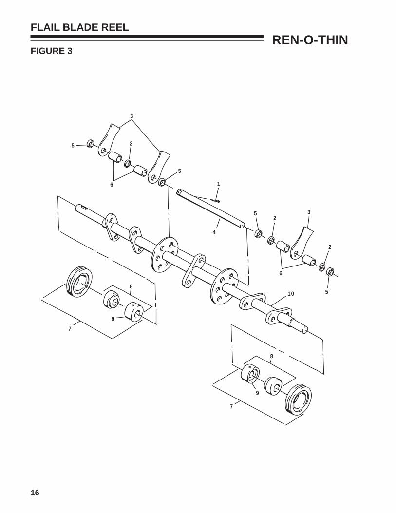
REN-O-THINFIGURE 3
FLAIL BLADE REEL
5
3
2
6
5
1
4
52
3
6
2
510
7
8
9
79
8

17
ITEM PART NO. DESCRIPTION QTY ITEM PART NO. DESCRIPTION QTY
REN-O-THINFIGURE 3
FLAIL BLADE REEL
3-1 306956 COttEr PIN 63-2 64163-67 WASHEr-.516X1X12GA 183-3 516897 BLADE,FLAIL 183-4 517155 SHAFt 63-5 517162 SPACEr, .328 (8mm) 243-6 517163 SPACEr, .891 (23mm) 243-7 545640 PILLOW BLOCK AY 2 (INCLUDES ItEMS 8 & 9)
3-8 548101 BEArING 23-9 521857 COLLAr,BrG LOCKING 23-10 546377.7 SHAFt 13-11* 544440A rEEL AY, FLAIL 1 (INCLUDES ItEMS 1-10)
* NOT ILLUSTRATED
18
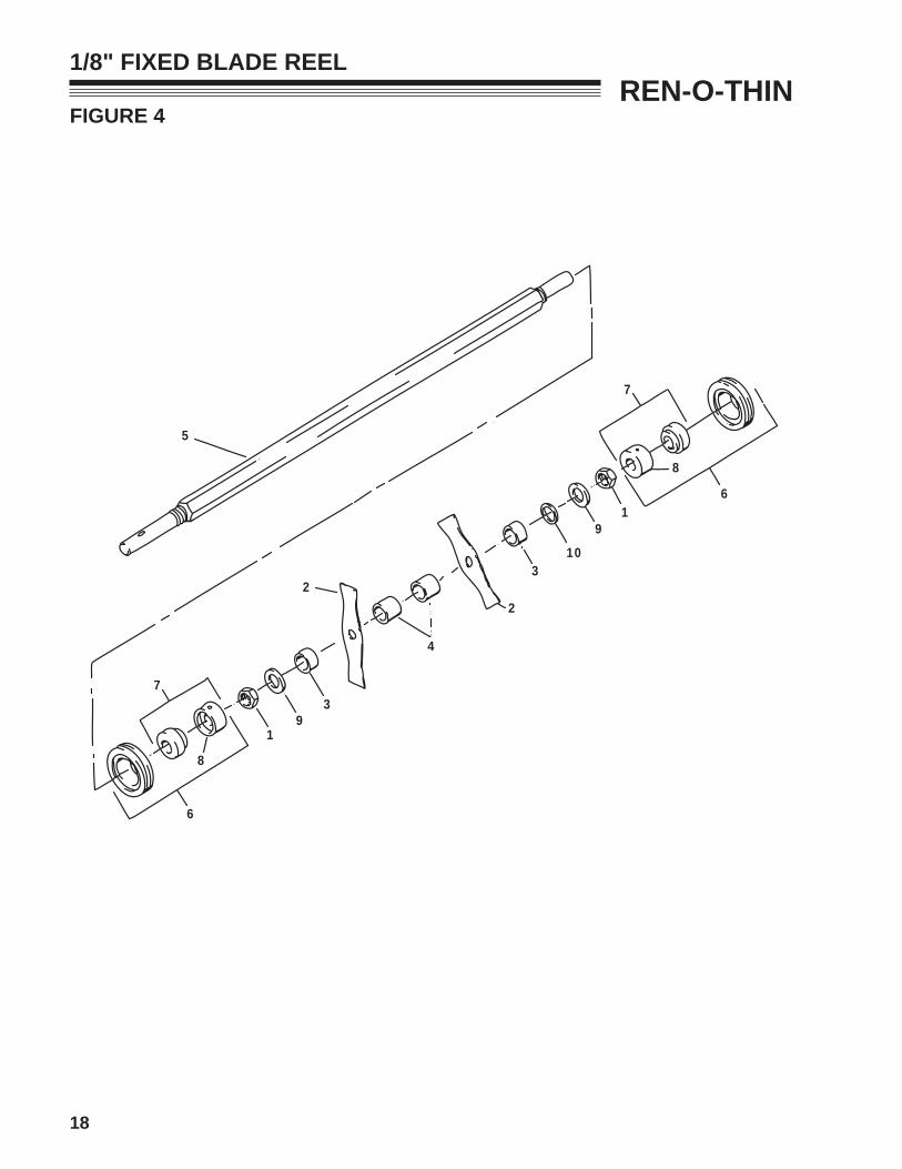
REN-O-THINFIGURE 4
1/8" FIXED BLADE REEL
5
6
8
7
19
3
2
4
2
310
91
6
8
7

19
ITEM PART NO. DESCRIPTION QTY ITEM PART NO. DESCRIPTION QTY
REN-O-THINFIGURE 4
1/8" FIXED BLADE REEL
5-1 305134 NUt,.88-14 YS HX JAM (KC) 25-2 516898 BLADE, 1/8" (3.2mm) 105-3 516904 SPACEr, .700 (19.6mm) 25-4 516905 SPACEr, .900 (23mm) 185-5 517148 SHAFt 15-6 545640 PILLOW BLOCK AY 2 (INCLUDES ItEMS 7 & 8)
5-7 548101 BEArING 25-8 521857 COLLAr,BrG LOCKING 25-9 548176 WSHr,.88 1.50.10 YS FLAt 25-10 820484 WSHr, FLAt 1.17 1.75 .13 A/r (USE WASHErS AS rEQUIrED SO tHAt tHE NUt (ItEM 1) WILL NOt CONtACt HEX SHAFt (ItEM 5) WHEN tIGHt)
5-11* 545440A rEEL AY, .12 BLADE X 2.0 1 (INCLUDES ItEMS 1-10)
* NOT ILLUSTRATED
20
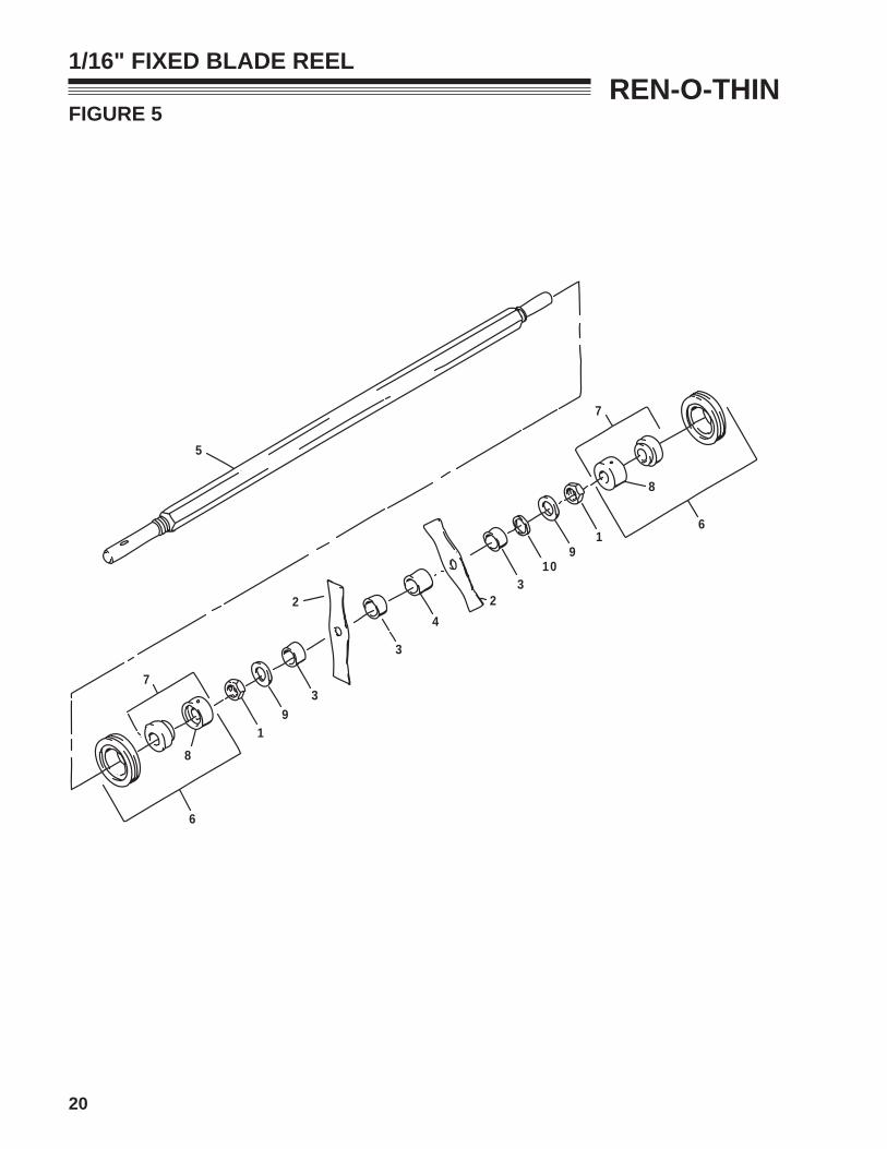
REN-O-THINFIGURE 5
1/16" FIXED BLADE REEL
5
6
8
7
19
3
2
3
42
310
91
6
8
7

21
ITEM PART NO. DESCRIPTION QTY ITEM PART NO. DESCRIPTION QTY
REN-O-THINFIGURE 5
1/16" FIXED BLADE REEL
5-1 305134 NUt,.88-14 YS HX JAM (KC) 25-2 516900 BLADE,DE-tHAtCH.075 tH 135-3 516903 SPACEr 145-4 516905 SPACEr 125-5 517148 SHAFt 15-6 545640 PILLOW BLOCK AY 2 (INCLUDES ItEMS 7 & 8)
5-7 548101 BEArING 25-8 521857 COLLAr,BrG LOCKING 25-9 548176 WSHr,.88 1.50.10 YS FLAt 25-10 820484 WSHr, FLAt 1.17 1.75 .13 A/r (USE WASHErS AS rEQUIrED SO tHAt tHE NUt (ItEM 1) WILL NOt CONtACt HEX SHAFt (ItEM 5) WHEN tIGHt)
5-11* 547452A rEEL AY, .06 BLADE X 1.5 1 (INCLUDES ItEMS 1-10)
* NOT ILLUSTRATED

22
REN-O-THINFIGURE 6
1/32" FIXED BLADE REEL
7
6
8
19
103
24
2
39
1
7
8
6
5

23
ITEM PART NO. DESCRIPTION QTY ITEM PART NO. DESCRIPTION QTY
REN-O-THINFIGURE 6
1/32" FIXED BLADE REEL
6-1 305134 NUt,.88-14 YS HX JAM (KC) 26-2 516901 BLADE, 1/32" (0.8mm) 256-3 516903 SPACEr, .500 (12.7mm) 26-4 516904 SPACEr, .700 (19.6mm) 246-5 517148 SHAFt 16-6 545640 PILLOW BLOCK AY 2 (INCLUDES ItEMS 7 & 8)
6-7 548101 BEArING 26-8 521857 COLLAr,BrG LOCKING 26-9 548176 WSHr,.88 1.50.10 YS FLAt 26-10 820484 WSHr, FLAt 1.17 1.75 .13 A/r (USE WASHErS AS rEQUIrED SO tHAt tHE NUt (ItEM 1) WILL NOt CONtACt HEX SHAFt (ItEM 5) WHEN tIGHt)
6-11* 547453A rEEL AY, FIXED 1/32 X 3/4 1 (INCLUDES ItEMS 1-10)
* NOT ILLUSTRATED

24
REN-O-THINFIGURE 7
HANDLE
9
10
11
12
5
3
2
4
1
87
13
1516
14
17
18
6 613
13
15
15
25
ITEM PART NO. DESCRIPTION QTY ITEM PART NO. DESCRIPTION QTY
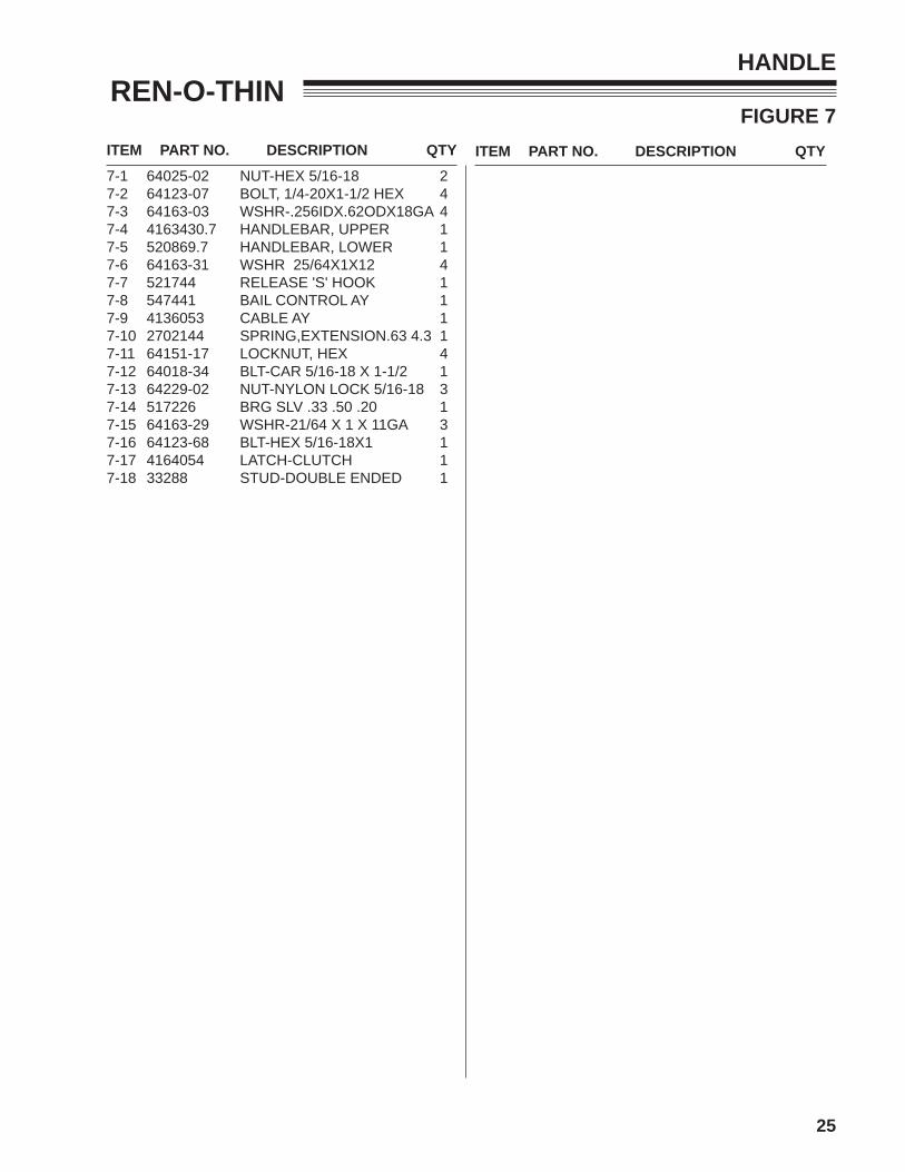
REN-O-THINFIGURE 7
HANDLE
7-1 64025-02 NUt-HEX 5/16-18 27-2 64123-07 BOLt, 1/4-20X1-1/2 HEX 47-3 64163-03 WSHr-.256IDX.62ODX18GA 47-4 4163430.7 HANDLEBAr, UPPEr 17-5 520869.7 HANDLEBAr, LOWEr 17-6 64163-31 WSHr 25/64X1X12 47-7 521744 rELEASE 'S' HOOK 17-8 547441 BAIL CONtrOL AY 17-9 4136053 CABLE AY 17-10 2702144 SPrING,EXtENSION.63 4.3 17-11 64151-17 LOCKNUt, HEX 47-12 64018-34 BLt-CAr 5/16-18 X 1-1/2 17-13 64229-02 NUt-NYLON LOCK 5/16-18 37-14 517226 BrG SLv .33 .50 .20 17-15 64163-29 WSHr-21/64 X 1 X 11GA 37-16 64123-68 BLt-HEX 5/16-18X1 17-17 4164054 LAtCH-CLUtCH 17-18 33288 StUD-DOUBLE ENDED 1

BOB-CAT BUNTON RYAN STEINER
SCHILLER GROUNDS CARE, INC.ONE BOB-CAT LANEP.O. BOX 469JOHNSON CREEK, WI 53038920-699-2000www.schillergc.com